Embed Size (px)
Citation preview
5/12/2020
1
Module 3: ACMV(Air-Conditioning and Mechanical Ventilation)
Ng Yong KongCouncil Member - Session 2019 – 20209th May 2020
malaysiaGBC WEBINAR SUSTAINABLE SERIES
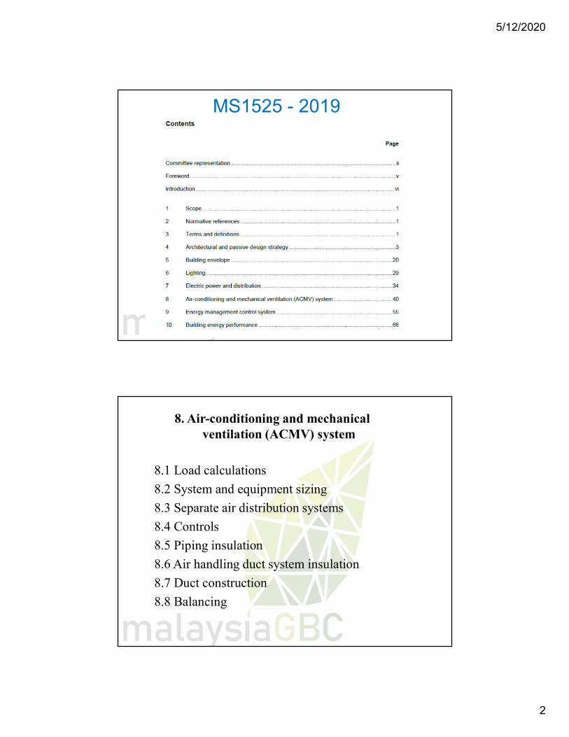
MS 1525:2019
Minimum Baseline
Code of Practice on Energy Efficiency and Use of Renewable Energy for Non-Residential Buildings (Third Revision)
5/12/2020
2
MS1525 - 2019
8. Air-conditioning and mechanicalventilation (ACMV) system
8.1 Load calculations
8.2 System and equipment sizing
8.3 Separate air distribution systems
8.4 Controls
8.5 Piping insulation
8.6 Air handling duct system insulation
8.7 Duct construction
8.8 Balancing
5/12/2020
3
8. Air-conditioning and mechanicalventilation (ACMV) system
8.9 ACMV systems8.10 ACMV unitary system8.11 ACMV applied system8.12 ACMV applied system (heat operated)
cooling mode8.13 System testing and commissioning8.14 Operation and maintenance (O&M) manual
and as-built drawings8.15 Preventive maintenance8.16 Life Cycle analysis.
1.ASHRAE Handbook – SI and Imperial Unitsa. Fundamentals 2021b. HVAC Systems and Equipment 2020c. HVAC Applications 2019d. Refrigeration 2018
2. Air Conditioning System Design - CARRIER3. Handbook of A/C Design – TRANE4. CIBSE / AIRAH 5. MS 1525:2019 : Code of Practice6. Uniform Building By – Laws 1984 (UBBL) 7. Guide to Fire Protection in Malaysia8. MS1910 – 2006: Fixed Fire Fighting Systems
5/12/2020
4
ASHRAE 4-VOLUMEHANDBOOKS
5/12/2020
5
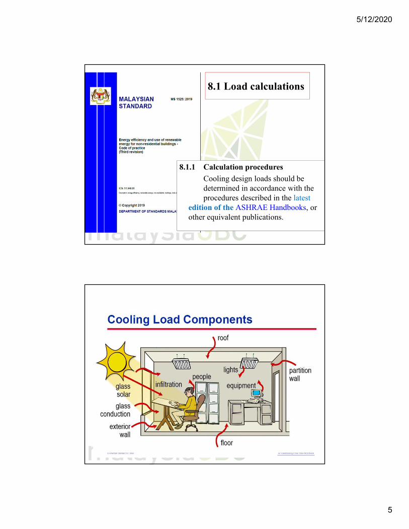
8.1 Load calculations
8.1.1 Calculation procedures
Cooling design loads should be determined in accordance with the procedures described in the latest
edition of the ASHRAE Handbooks, or other equivalent publications.
5/12/2020
6
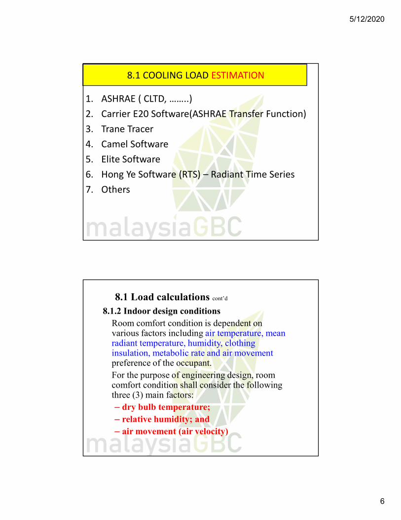
8.1 COOLING LOAD ESTIMATION
1. ASHRAE ( CLTD, ……..)2. Carrier E20 Software(ASHRAE Transfer Function)3. Trane Tracer4. Camel Software5. Elite Software6. Hong Ye Software (RTS) – Radiant Time Series7. Others
8.1 Load calculations cont’d
8.1.2 Indoor design conditionsRoom comfort condition is dependent on various factors including air temperature, mean radiant temperature, humidity, clothing insulation, metabolic rate and air movementpreference of the occupant.For the purpose of engineering design, room comfort condition shall consider the following three (3) main factors:– dry bulb temperature;– relative humidity; and– air movement (air velocity)
5/12/2020
7
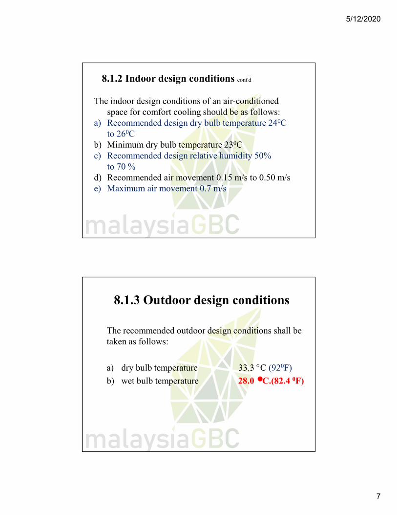
8.1.2 Indoor design conditions cont'd
The indoor design conditions of an air-conditioned space for comfort cooling should be as follows:
a) Recommended design dry bulb temperature 240C to 260C
b) Minimum dry bulb temperature 230Cc) Recommended design relative humidity 50%
to 70 % d) Recommended air movement 0.15 m/s to 0.50 m/s e) Maximum air movement 0.7 m/s
8.1.3 Outdoor design conditions
The recommended outdoor design conditions shall be taken as follows:
a) dry bulb temperature 33.3 C (920F)
b) wet bulb temperature 28.0 C.(82.4 0F)
5/12/2020
8
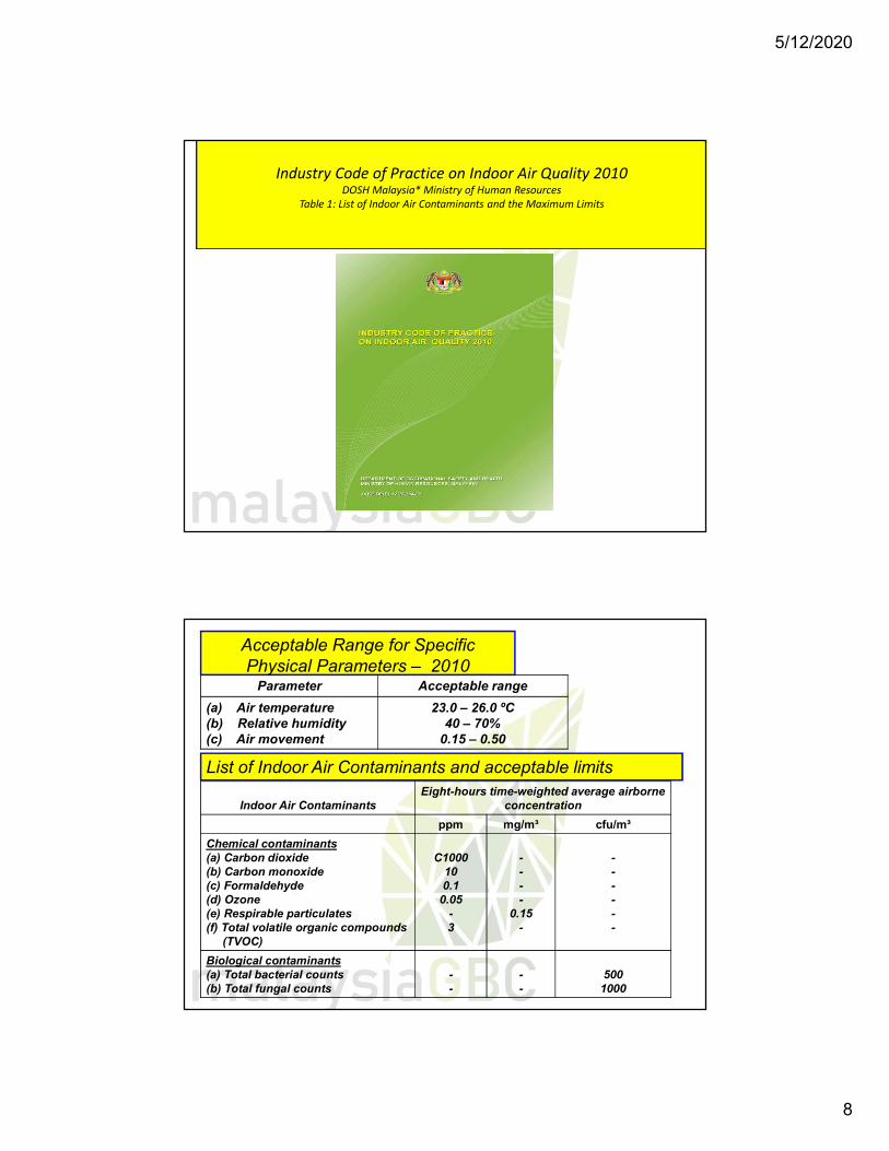
Industry Code of Practice on Indoor Air Quality 2010DOSH Malaysia* Ministry of Human Resources
Table 1: List of Indoor Air Contaminants and the Maximum Limits
Parameter Acceptable range
(a) Air temperature(b) Relative humidity(c) Air movement
23.0 – 26.0 ºC40 – 70%
0.15 – 0.50
Acceptable Range for Specific Physical Parameters – 2010
List of Indoor Air Contaminants and acceptable limits
Indoor Air ContaminantsEight-hours time-weighted average airborne
concentration
ppm mg/m³ cfu/m³
Chemical contaminants(a) Carbon dioxide(b) Carbon monoxide(c) Formaldehyde(d) Ozone(e) Respirable particulates(f) Total volatile organic compounds
(TVOC)
C1000100.1
0.05-3
----
0.15-
------
Biological contaminants(a) Total bacterial counts(b) Total fungal counts
--
--
5001000
5/12/2020
9
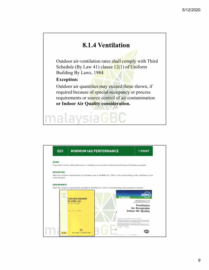
8.1.4 Ventilation
Outdoor air-ventilation rates shall comply with Third Schedule (By Law 41) clause 12(1) of Uniform Building By Laws, 1984.
Exception:
Outdoor air quantities may exceed those shown, if required because of special occupancy or process requirements or source control of air contamination or Indoor Air Quality consideration.
5/12/2020
10
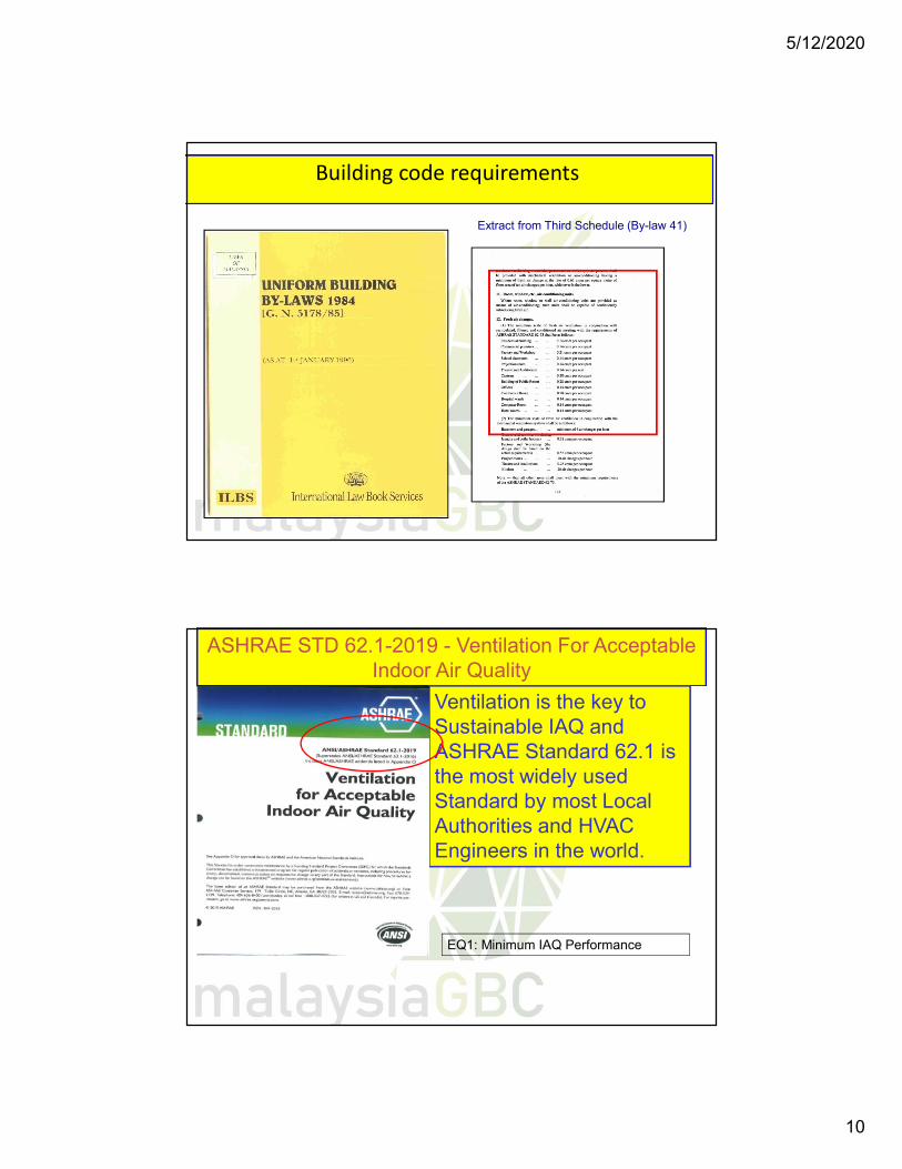
Building code requirements
Extract from Third Schedule (By-law 41)
ASHRAE STD 62.1-2019 - Ventilation For Acceptable Indoor Air Quality
Ventilation is the key to Sustainable IAQ and ASHRAE Standard 62.1 is the most widely used Standard by most Local Authorities and HVAC Engineers in the world.
EQ1: Minimum IAQ Performance
5/12/2020
11
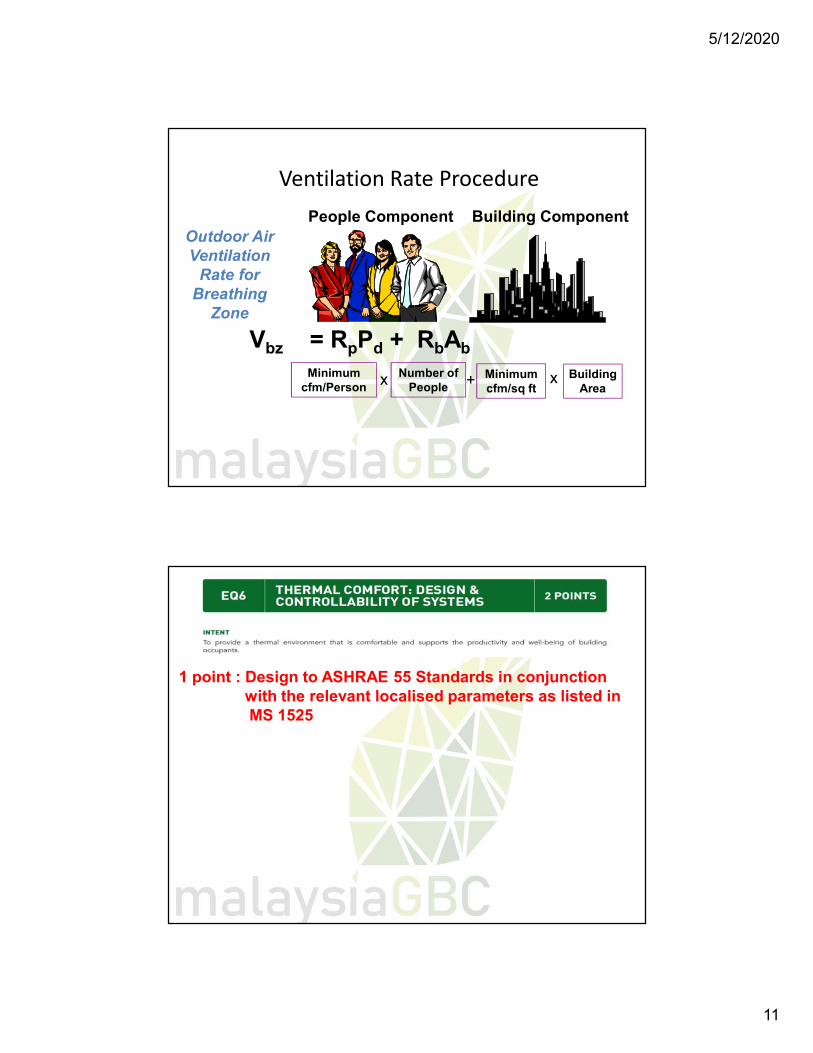
Ventilation Rate ProcedurePeople Component Building Component
Outdoor Air Ventilation
Rate for Breathing
Zone
Minimum cfm/Person
Number of People
Minimum cfm/sq ft
Building Area
Vbz = RpPd + RbAb
x x+
1 point : Design to ASHRAE 55 Standards in conjunction with the relevant localised parameters as listed in MS 1525
5/12/2020
12
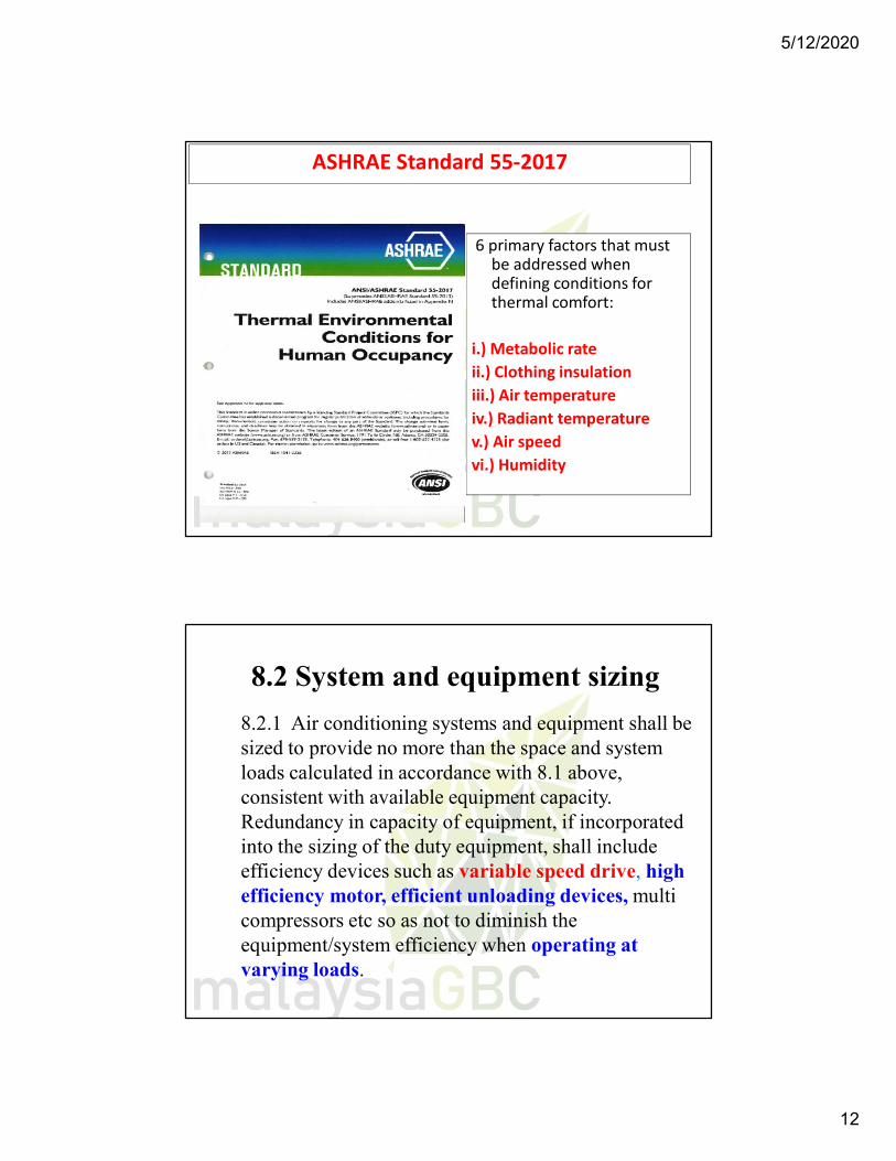
ASHRAE Standard 55-2017
6 primary factors that must be addressed when defining conditions for thermal comfort:
i.) Metabolic rateii.) Clothing insulationiii.) Air temperatureiv.) Radiant temperaturev.) Air speedvi.) Humidity
8.2 System and equipment sizing
8.2.1 Air conditioning systems and equipment shall be sized to provide no more than the space and system loads calculated in accordance with 8.1 above, consistent with available equipment capacity. Redundancy in capacity of equipment, if incorporated into the sizing of the duty equipment, shall include efficiency devices such as variable speed drive, high efficiency motor, efficient unloading devices, multi compressors etc so as not to diminish the equipment/system efficiency when operating at varying loads.
5/12/2020
13
8.2 System and equipment sizing cont’d
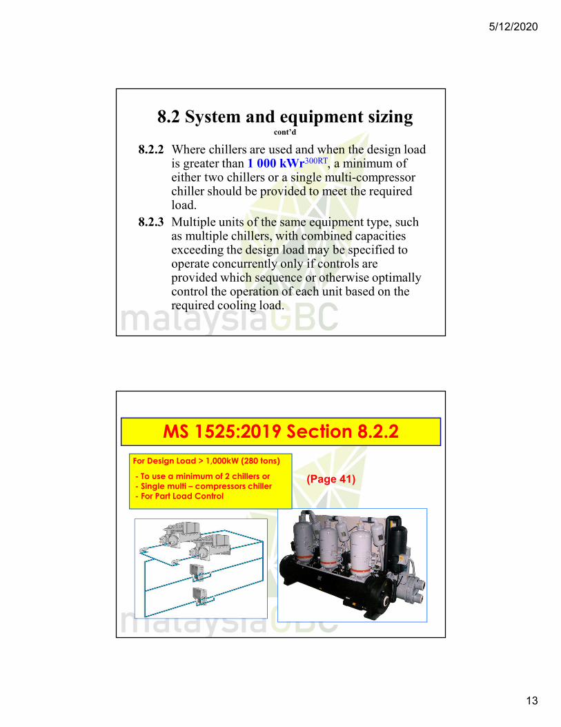
8.2.2 Where chillers are used and when the design load is greater than 1 000 kWr300RT, a minimum of either two chillers or a single multi-compressor chiller should be provided to meet the required load.
8.2.3 Multiple units of the same equipment type, such as multiple chillers, with combined capacities exceeding the design load may be specified to operate concurrently only if controls are provided which sequence or otherwise optimally control the operation of each unit based on the required cooling load.
MS 1525:2019 Section 8.2.2
(Page 41)
For Design Load > 1,000kW (280 tons)
- To use a minimum of 2 chillers or- Single multi – compressors chiller- For Part Load Control
5/12/2020
14
8.2.5 Hydronic System
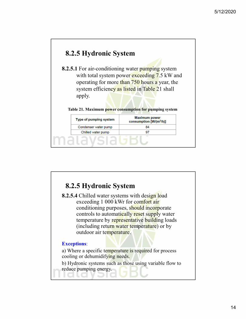
8.2.5.1 For air-conditioning water pumping system with total system power exceeding 7.5 kW and operating for more than 750 hours a year, the system efficiency as listed in Table 21 shall apply.
Table 21. Maximum power consumption for pumping system
8.2.5 Hydronic System8.2.5.4 Chilled water systems with design load
exceeding 1 000 kWr for comfort air conditioning purposes, should incorporate controls to automatically reset supply water temperature by representative building loads (including return water temperature) or by outdoor air temperature.
Exceptions: a) Where a specific temperature is required for process cooling or dehumidifying needs. b) Hydronic systems such as those using variable flow to reduce pumping energy.
5/12/2020
15
8.4 Controls
8.4.1 Temperature control
Each system shall be provided with at least one thermostat for the regulation of temperature.
Each thermostat shall be capable of being set by adjustment or selection of sensors over a minimum range of between 23 C to 27 C.
Multi-stage thermostat shall be provided for equipment exceeding 35/65 kWr in conjunction with 8.2.4.
8.4 Controls cont’d
8.4.2 Humidity control
In a system requiring moisture removal to maintain specific selected relative humidity in spaces or zones, no new source of energy(such as electric reheat) shall be used to produce a space relative humidity below 70 %for comfort cooling purposes.
5/12/2020
16
8.4 Controls cont’d
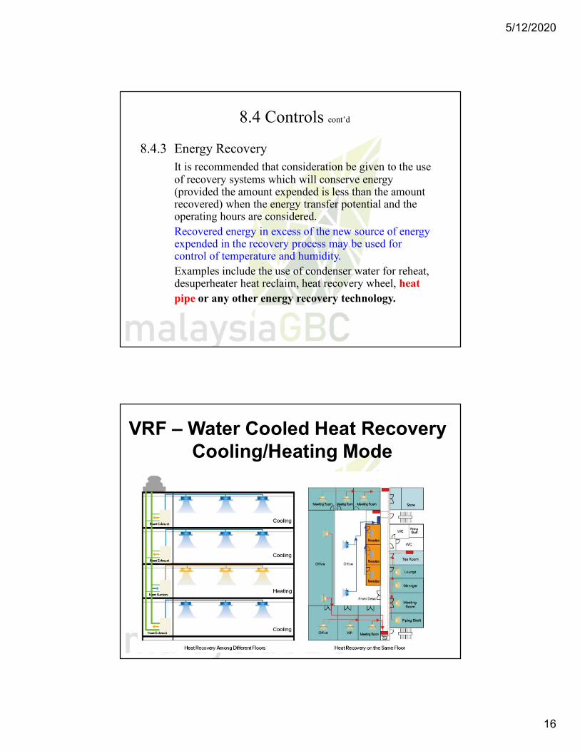
8.4.3 Energy RecoveryIt is recommended that consideration be given to the use of recovery systems which will conserve energy (provided the amount expended is less than the amount recovered) when the energy transfer potential and the operating hours are considered. Recovered energy in excess of the new source of energy expended in the recovery process may be used for control of temperature and humidity. Examples include the use of condenser water for reheat, desuperheater heat reclaim, heat recovery wheel, heat pipe or any other energy recovery technology.
VRF – Water Cooled Heat RecoveryCooling/Heating Mode
5/12/2020
17
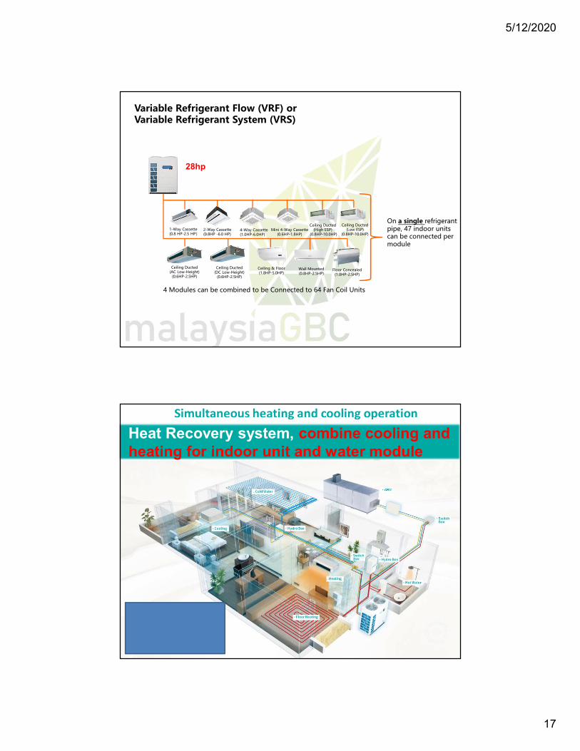
Variable Refrigerant Flow (VRF) or Variable Refrigerant System (VRS)
Ceiling Ducted(AC Low-Height)
(0.6HP-2.5HP)
Ceiling Ducted(DC Low-Height)
(0.6HP-2.5HP)
Ceiling & Floor(1.8HP-5.0HP)
1-Way Cassette(0.8 HP-2.5 HP)
2-Way Cassette(0.8HP -6.0 HP)
4-Way Cassette(1.0HP-6.0HP)
Mini 4-Way Cassette(0.6HP-1.8HP)
Ceiling Ducted (High ESP)
(0.8HP-10.0HP)
Ceiling Ducted(Low ESP)
(0.8HP-10.0HP)
Wall Mounted(0.8HP-2.5HP)
Floor Concealed(1.0HP-2.5HP)
On a single refrigerant pipe, 47 indoor units can be connected per module
4 Modules can be combined to be Connected to 64 Fan Coil Units
28hp
Simultaneous heating and cooling operation
Heat Recovery system, combine cooling and heating for indoor unit and water module
5/12/2020
18
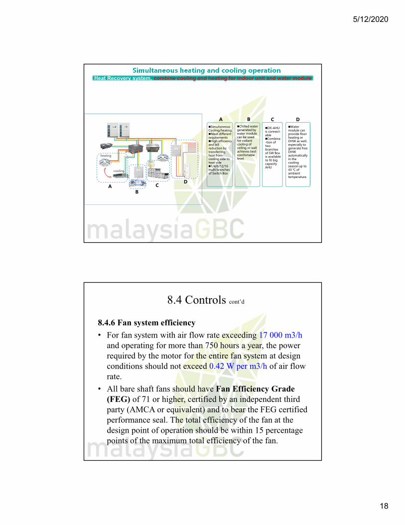
Simultaneous heating and cooling operationHeat Recovery system, combine cooling and heating for indoor unit and water module
cooling
heating
Water module can provide floor heating or DHW as well,especially to generate free DHW automatically in the cooling season up to 43 ℃ of ambient temperature.
DX-AHU is connect-ableCombina-tion of two branches of SW Box is available to fit big capacity AHU
Chilled water generated by water module can be used for radiant cooling of ceiling or wall achieves best comfortable level.
Simultaneous Cooling/heatingMeet different requirementsHigh efficiency and bill reduction by transferring heat from cooling side to heat side1/4/8/12/16 multi branches of Switch Box
AB
CD
A B C D
8.4 Controls cont’d
8.4.6 Fan system efficiency
• For fan system with air flow rate exceeding 17 000 m3/h and operating for more than 750 hours a year, the power required by the motor for the entire fan system at design conditions should not exceed 0.42 W per m3/h of air flow rate.
• All bare shaft fans should have Fan Efficiency Grade (FEG) of 71 or higher, certified by an independent third party (AMCA or equivalent) and to bear the FEG certified performance seal. The total efficiency of the fan at the design point of operation should be within 15 percentage points of the maximum total efficiency of the fan.
5/12/2020
19
8.4 Controls cont’d
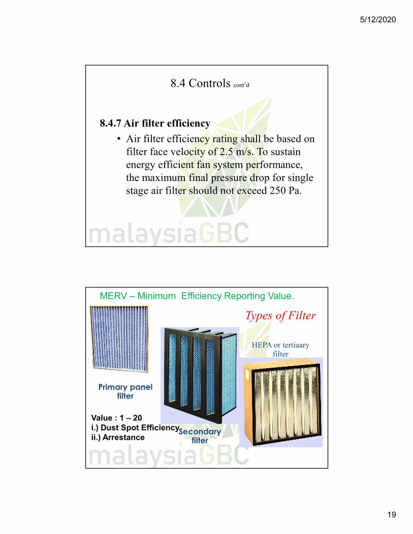
8.4.7 Air filter efficiency
• Air filter efficiency rating shall be based on filter face velocity of 2.5 m/s. To sustain energy efficient fan system performance, the maximum final pressure drop for single stage air filter should not exceed 250 Pa.
Primary panel filter
Secondary filter
HEPA or tertiaary filter
Types of Filter
Value : 1 – 20i.) Dust Spot Efficiency ii.) Arrestance
MERV – Minimum Efficiency Reporting Value.
5/12/2020
20
8.5 Piping insulation All piping installed to serve buildings and within buildings should be adequately insulated to prevent excessive energy losses. Additional insulation with vaporbarriers may be required to prevent condensation under some conditions.
Exceptions: Piping insulation is not required under any of the following circumstances:
a) piping installed within ACMV equipment; b) piping at fluid temperatures between 23 °C and 49 °C; and c) when the heat loss and/or heat gain of the piping, without
insulation, does not increase the energy requirements of the building.
8.8 Balancing
The system design shall provide means for balancingthe air and water system such as but not limited todampers, temperature and pressure test connectionsand balancing valves.
5/12/2020
21
8.9 ACMV Systems
• For the purposes of this part, ‘ACMV System’ are considered to be of two basic types:
• a) Unitary system• b) Central system – This system comprises:
i.) Water distributionii.) Air distribution
8.9 ACMV Systemsa.) Unitary System
…one or more assembled units, which include evaporator, compressor and condenser, perform the cooling and dehumidification functions on the recirculated air from the conditioned space ( plus OA ).…distribution of air can either be ducted or non-
ducted type.…compressor may be with fixed speed (non-inverter) or
variable speed (inverter ) control.
5/12/2020
22
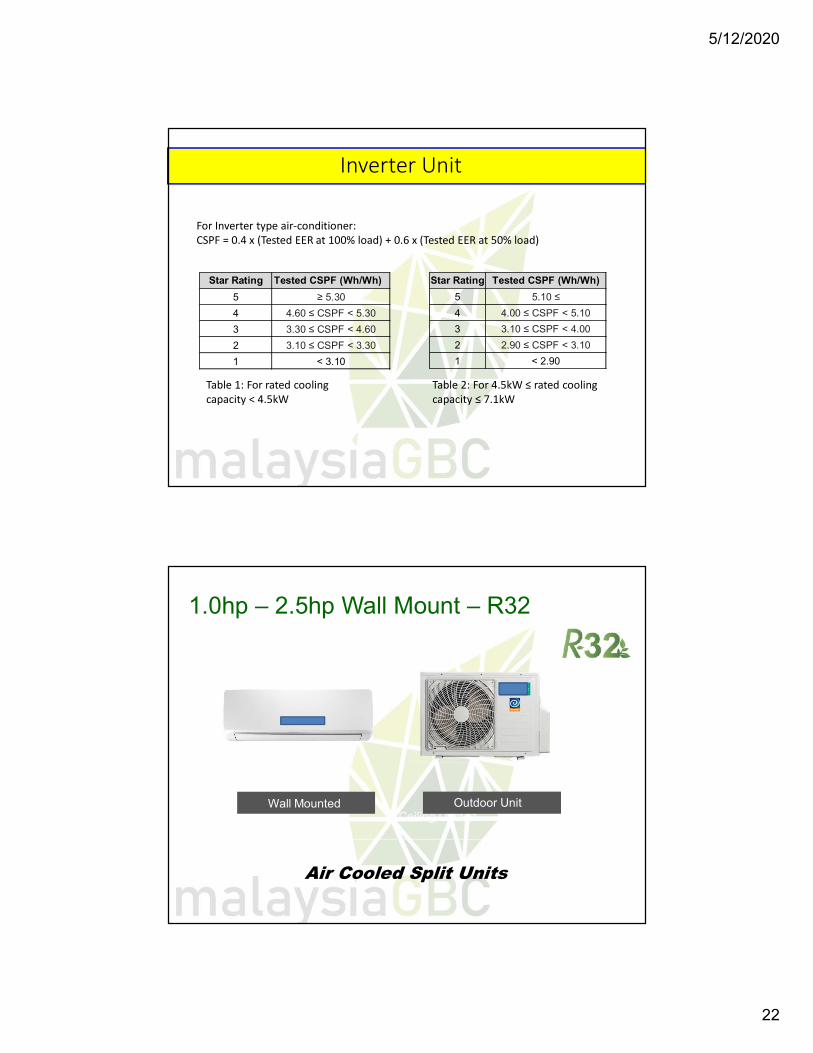
Inverter Unit
For Inverter type air-conditioner:CSPF = 0.4 x (Tested EER at 100% load) + 0.6 x (Tested EER at 50% load)
Star Rating Tested CSPF (Wh/Wh)
5 ≥ 5.30
4 4.60 ≤ CSPF < 5.30
3 3.30 ≤ CSPF < 4.60
2 3.10 ≤ CSPF < 3.30
1 < 3.10
Star Rating
5
4
3
2
1
Tested CSPF (Wh/Wh)
5.10 ≤
4.00 ≤ CSPF < 5.10
3.10 ≤ CSPF < 4.00
2.90 ≤ CSPF < 3.10
< 2.90
Table 1: For rated cooling capacity < 4.5kW
Table 2: For 4.5kW ≤ rated cooling capacity ≤ 7.1kW
Air Cooled Split UnitsCeiling Cassette
Wall MountedCeiling Ducted
Outdoor Unit
1.0hp – 2.5hp Wall Mount – R32
5/12/2020
23
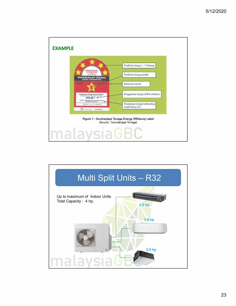
EXAMPLE
Multi Split Units – R32
Up to maximum of Indoor UnitsTotal Capacity : 4 hp.
2.0 hp
2.0 hp
1.0 hp
5/12/2020
24
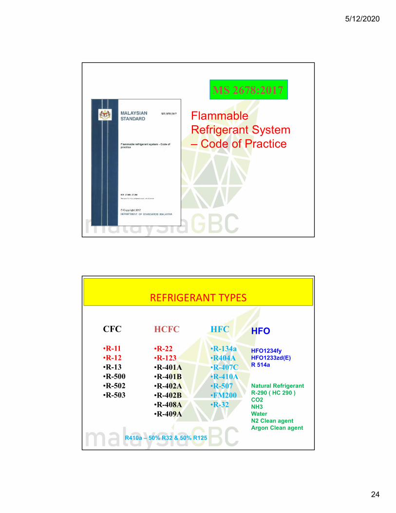
MS 2678:2017
Flammable Refrigerant System – Code of Practice
CFC
•R-11•R-12•R-13•R-500•R-502•R-503
HCFC
•R-22•R-123•R-401A•R-401B•R-402A•R-402B•R-408A•R-409A
HFC
•R-134a•R404A•R-407C•R-410A•R-507•FM200•R-32
HFO
HFO1234fyHFO1233zd(E)R 514a
Natural RefrigerantR-290 ( HC 290 )CO2NH3WaterN2 Clean agentArgon Clean agent
REFRIGERANT TYPES
R410a – 50% R32 & 50% R125
5/12/2020
25
1-49
1-50
Safety of Refrigerants
Safety concerns:• Flammability• Toxicity• Environmental impact

5/12/2020
26
ASHRAE Standard 15 - 2019
ASHRAE Standard 34 – 2019
Flammability and Toxicity
52
Incr
easi
ng F
l am
mab
il ity
Safety Group
Higher Flammability
A3 B3
A2 B2
A2L B2L
No Flame Propogation
A1 B1Incr
easi
ng F
l am
mab
il ity
Lower Flammmability
Increasing Toxicity
5/12/2020
27
7.1 Alternating Current (AC) Electric Motors
7.1.2 Motor Efficiencies
Only motors with efficiencies higher than standard efficiency motors (IEC efficiency class IE1) should be used where operating hours exceed 750 h per year. Decisions on motors selection between IE2 ( high efficiency). IE3 (premium efficiency) and IE4 (super premium efficiency) should be done on an economic justification basis. The efficiencies for the various classes of motors are as in Annex B.
7.1 Alternating Current (AC) Electric Motors
7.1.3 Inverters
Inverters or Variable Speed Drives (VSD) should be used for motors serving fluctuating loads.VSDs can reduce energy consumption by adjusting motor speeds to cater for variable torque loads like fans and pumps, which traditionally vary their output by energy consuming mechanical means.
5/12/2020
28
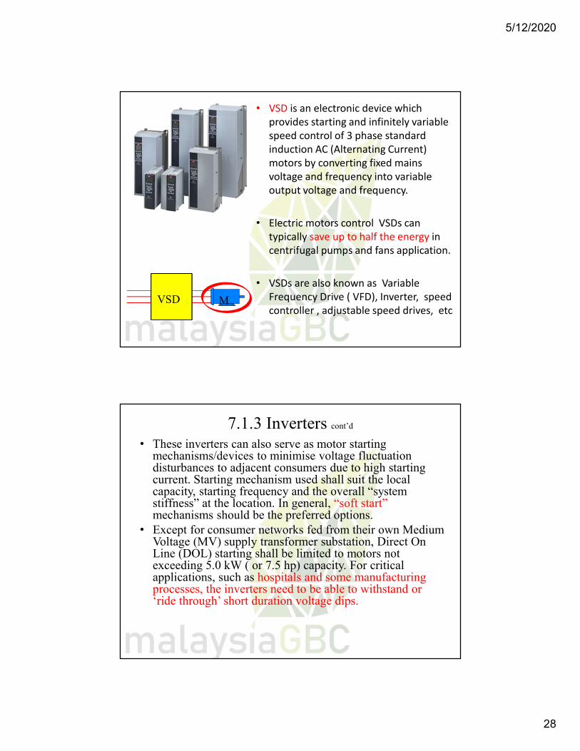
• VSD is an electronic device which provides starting and infinitely variable speed control of 3 phase standard induction AC (Alternating Current) motors by converting fixed mains voltage and frequency into variable output voltage and frequency.
• Electric motors control VSDs can typically save up to half the energy in centrifugal pumps and fans application.
• VSDs are also known as Variable Frequency Drive ( VFD), Inverter, speed controller , adjustable speed drives, etc
37 million
VSD M
7.1.3 Inverters cont’d
• These inverters can also serve as motor starting mechanisms/devices to minimise voltage fluctuation disturbances to adjacent consumers due to high starting current. Starting mechanism used shall suit the local capacity, starting frequency and the overall “system stiffness” at the location. In general, “soft start” mechanisms should be the preferred options.
• Except for consumer networks fed from their own Medium Voltage (MV) supply transformer substation, Direct On Line (DOL) starting shall be limited to motors not exceeding 5.0 kW ( or 7.5 hp) capacity. For critical applications, such as hospitals and some manufacturing processes, the inverters need to be able to withstand or ‘ride through’ short duration voltage dips.
5/12/2020
29
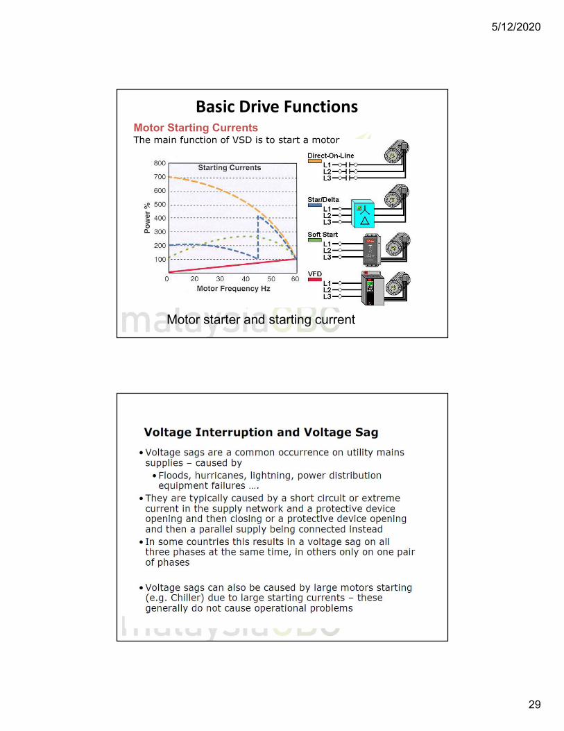
Basic Drive FunctionsMotor Starting CurrentsThe main function of VSD is to start a motor
Motor starter and starting current
5/12/2020
30
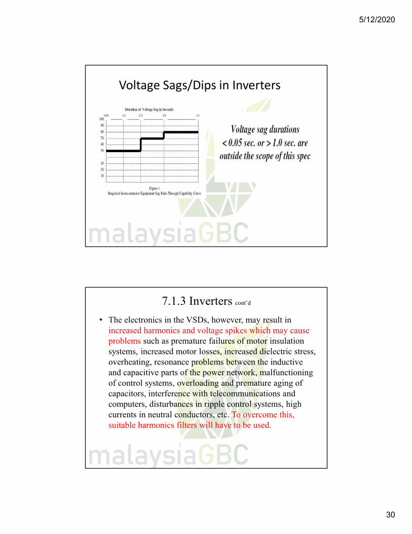
Voltage Sags/Dips in Inverters
7.1.3 Inverters cont’d
• The electronics in the VSDs, however, may result in increased harmonics and voltage spikes which may cause problems such as premature failures of motor insulation systems, increased motor losses, increased dielectric stress, overheating, resonance problems between the inductive and capacitive parts of the power network, malfunctioning of control systems, overloading and premature aging of capacitors, interference with telecommunications and computers, disturbances in ripple control systems, high currents in neutral conductors, etc. To overcome this, suitable harmonics filters will have to be used.
5/12/2020
31
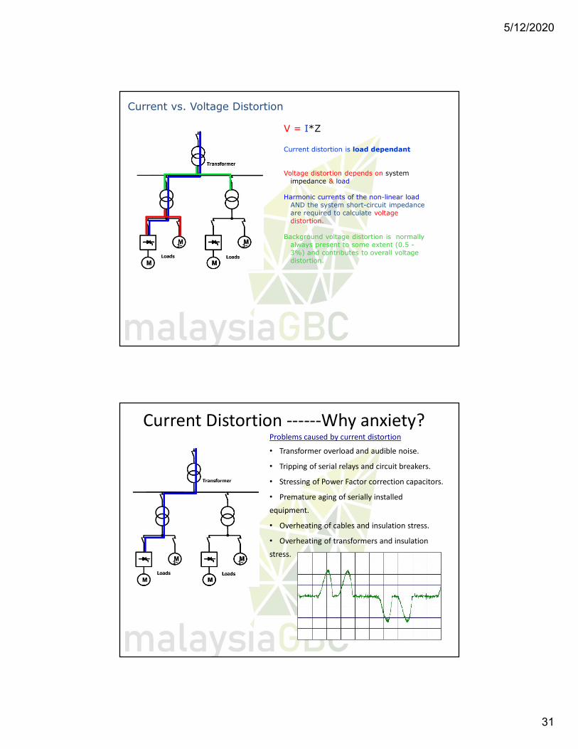
Current vs. Voltage Distortion
V = I*Z
Current distortion is load dependant
Voltage distortion depends on systemimpedance & load
Harmonic currents of the non-linear loadAND the system short-circuit impedance are required to calculate voltage distortion.
Background voltage distortion is normally always present to some extent (0.5 -3%) and contributes to overall voltage distortion.
Problems caused by current distortion
• Transformer overload and audible noise.
• Tripping of serial relays and circuit breakers.
• Stressing of Power Factor correction capacitors.
• Premature aging of serially installed
equipment.
• Overheating of cables and insulation stress.
• Overheating of transformers and insulation
stress.
Current Distortion ------Why anxiety?
5/12/2020
32
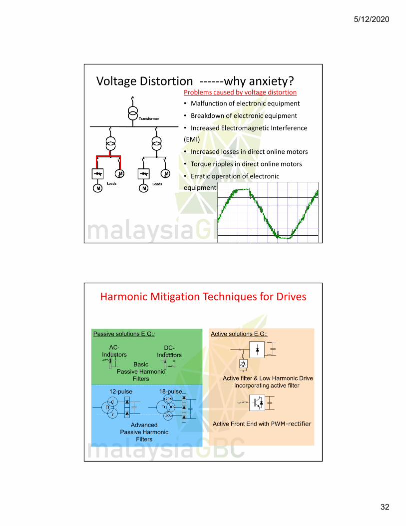
Problems caused by voltage distortion• Malfunction of electronic equipment
• Breakdown of electronic equipment
• Increased Electromagnetic Interference
(EMI)
• Increased losses in direct online motors
• Torque ripples in direct online motors
• Erratic operation of electronic
equipment
Voltage Distortion ------why anxiety?
Passive solutions E.G::
DC-Inductors
18-pulse
Advanced Passive Harmonic
Filters
Active solutions E.G::
///
Active Front End with PWM-rectifier
/// ///
Active filter & Low Harmonic Drive incorporating active filter
12-pulse
AC-Inductors
Harmonic Mitigation Techniques for Drives
Basic Passive Harmonic
Filters
5/12/2020
33
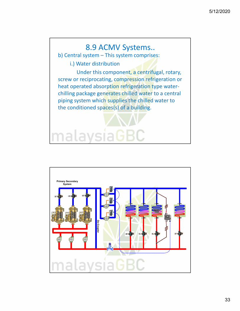
8.9 ACMV Systems..b) Central system – This system comprises:
i.) Water distributionUnder this component, a centrifugal, rotary,
screw or reciprocating, compression refrigeration or heat operated absorption refrigeration type water-chilling package generates chilled water to a central piping system which supplies the chilled water to the conditioned spaces(s) of a building.
Co
nst
an
t S
pe
ed
Ch
ille
r
Primary Secondary System
DP sensor
CriticalUnit
Co
nst
an
t S
pe
ed
Ch
ille
r
Co
nst
an
t S
pe
ed
Ch
ille
r
De
-Co
up
ler
5/12/2020
34
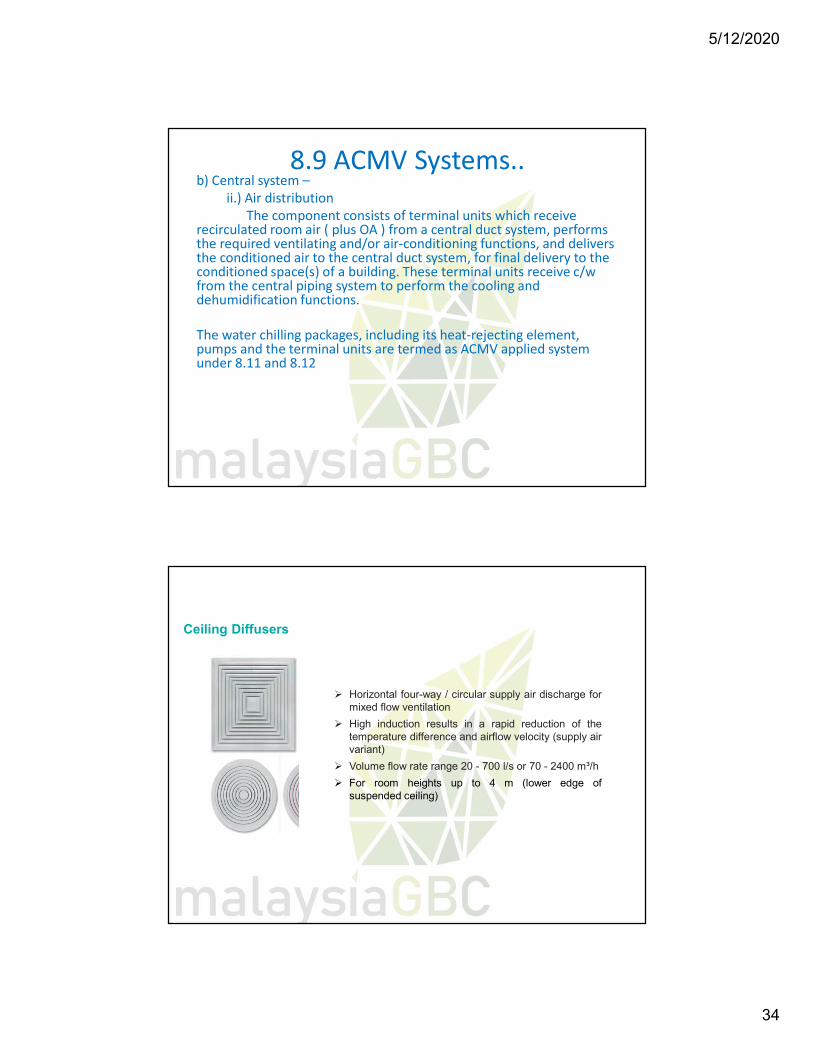
8.9 ACMV Systems..b) Central system –
ii.) Air distributionThe component consists of terminal units which receive
recirculated room air ( plus OA ) from a central duct system, performs the required ventilating and/or air-conditioning functions, and delivers the conditioned air to the central duct system, for final delivery to the conditioned space(s) of a building. These terminal units receive c/w from the central piping system to perform the cooling and dehumidification functions.
The water chilling packages, including its heat-rejecting element, pumps and the terminal units are termed as ACMV applied system under 8.11 and 8.12
Ceiling Diffusers
Horizontal four-way / circular supply air discharge formixed flow ventilation
High induction results in a rapid reduction of thetemperature difference and airflow velocity (supply airvariant)
Volume flow rate range 20 - 700 l/s or 70 - 2400 m³/h
For room heights up to 4 m (lower edge ofsuspended ceiling)
5/12/2020
35
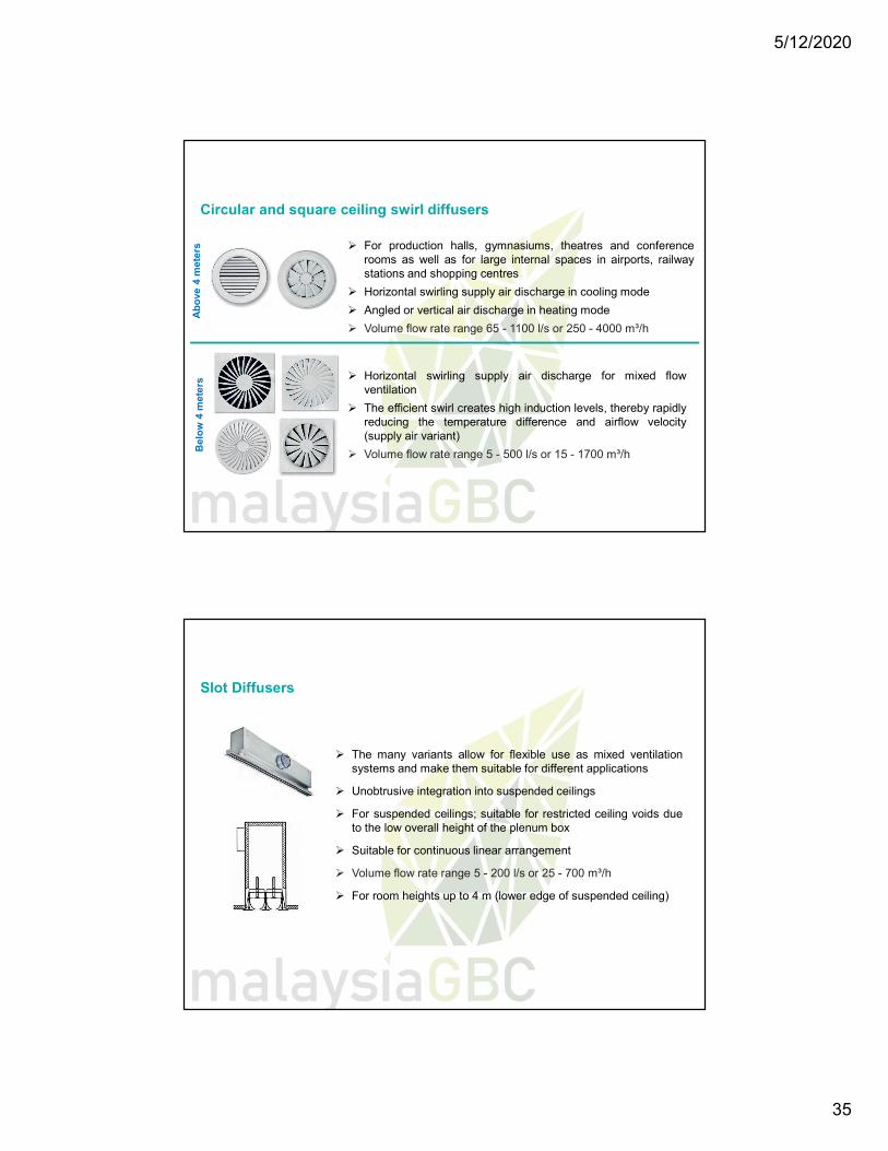
Horizontal swirling supply air discharge for mixed flowventilation
The efficient swirl creates high induction levels, thereby rapidlyreducing the temperature difference and airflow velocity(supply air variant)
Volume flow rate range 5 - 500 l/s or 15 - 1700 m³/h
For production halls, gymnasiums, theatres and conferencerooms as well as for large internal spaces in airports, railwaystations and shopping centres
Horizontal swirling supply air discharge in cooling mode
Angled or vertical air discharge in heating mode
Volume flow rate range 65 - 1100 l/s or 250 - 4000 m³/h
Circular and square ceiling swirl diffusersB
elo
w 4
met
ers
Ab
ove
4 m
eter
s
The many variants allow for flexible use as mixed ventilationsystems and make them suitable for different applications
Unobtrusive integration into suspended ceilings
For suspended ceilings; suitable for restricted ceiling voids dueto the low overall height of the plenum box
Suitable for continuous linear arrangement
Volume flow rate range 5 - 200 l/s or 25 - 700 m³/h
For room heights up to 4 m (lower edge of suspended ceiling)
Slot Diffusers
5/12/2020
36
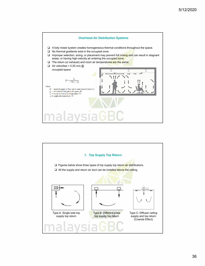
A fully mixed system creates homogeneous thermal conditions throughout the space. No thermal gradients exist in the occupied zone. Improper selection, sizing, or placement may prevent full mixing and can result in stagnant
areas, or having high-velocity air entering the occupied zone. The return (or exhaust) and room air temperatures are the same. Air velocities > 0.25 m/s @
occupied space
Overhead Air Distribution Systems
Figures below show three types of top supply top return air distributions.
All the supply and return air duct can be installed above the ceiling.
Type A: Single side top supply top return
Type B: Different sides top supply top return
Type C: Diffuser ceiling supply and top return
(Coanda Effect)
1. Top Supply Top Return
5/12/2020
37
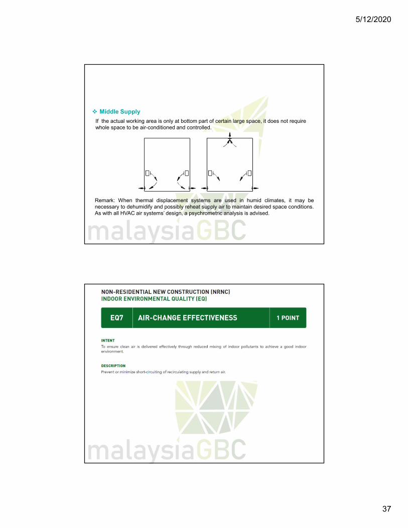
Middle Supply
If the actual working area is only at bottom part of certain large space, it does not require whole space to be air-conditioned and controlled.
Remark: When thermal displacement systems are used in humid climates, it may benecessary to dehumidify and possibly reheat supply air to maintain desired space conditions.As with all HVAC air systems’ design, a psychrometric analysis is advised.
5/12/2020
38
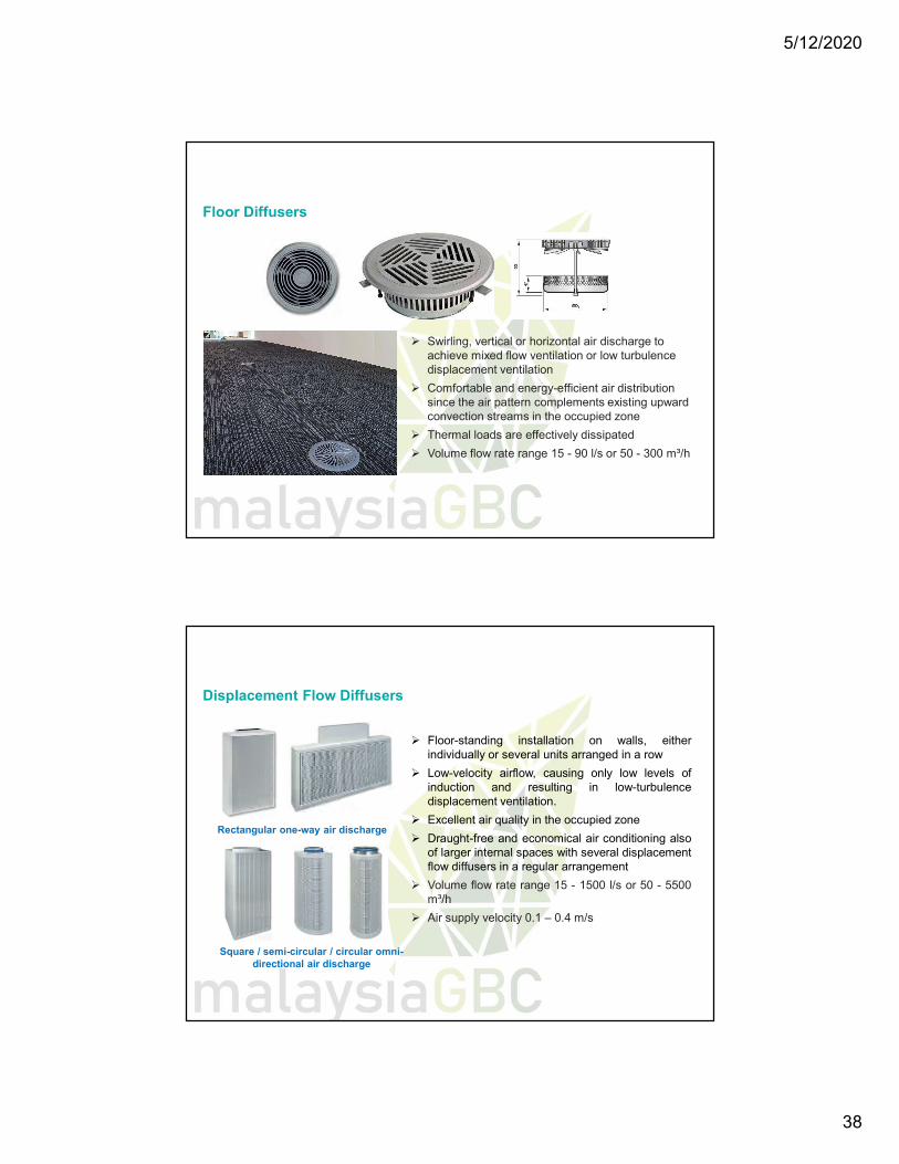
Swirling, vertical or horizontal air discharge to achieve mixed flow ventilation or low turbulence displacement ventilation
Comfortable and energy-efficient air distribution since the air pattern complements existing upward convection streams in the occupied zone
Thermal loads are effectively dissipated
Volume flow rate range 15 - 90 l/s or 50 - 300 m³/h
Floor Diffusers
Floor-standing installation on walls, eitherindividually or several units arranged in a row
Low-velocity airflow, causing only low levels ofinduction and resulting in low-turbulencedisplacement ventilation.
Excellent air quality in the occupied zone
Draught-free and economical air conditioning alsoof larger internal spaces with several displacementflow diffusers in a regular arrangement
Volume flow rate range 15 - 1500 l/s or 50 - 5500m³/h
Air supply velocity 0.1 – 0.4 m/s
Rectangular one-way air discharge
Square / semi-circular / circular omni-directional air discharge
Displacement Flow Diffusers
5/12/2020
39
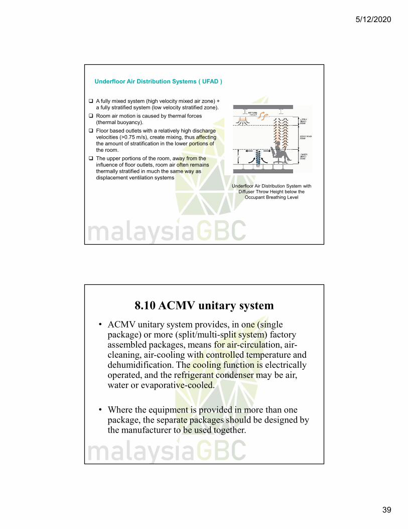
A fully mixed system (high velocity mixed air zone) + a fully stratified system (low velocity stratified zone).
Room air motion is caused by thermal forces (thermal buoyancy).
Floor based outlets with a relatively high discharge velocities (>0.75 m/s), create mixing, thus affecting the amount of stratification in the lower portions of the room.
The upper portions of the room, away from the influence of floor outlets, room air often remains thermally stratified in much the same way as displacement ventilation systems
Underfloor Air Distribution Systems ( UFAD )
Underfloor Air Distribution System with Diffuser Throw Height below the
Occupant Breathing Level
8.10 ACMV unitary system
• ACMV unitary system provides, in one (single package) or more (split/multi-split system) factory assembled packages, means for air-circulation, air-cleaning, air-cooling with controlled temperature and dehumidification. The cooling function is electrically operated, and the refrigerant condenser may be air, water or evaporative-cooled.
• Where the equipment is provided in more than one package, the separate packages should be designed by the manufacturer to be used together.
5/12/2020
40
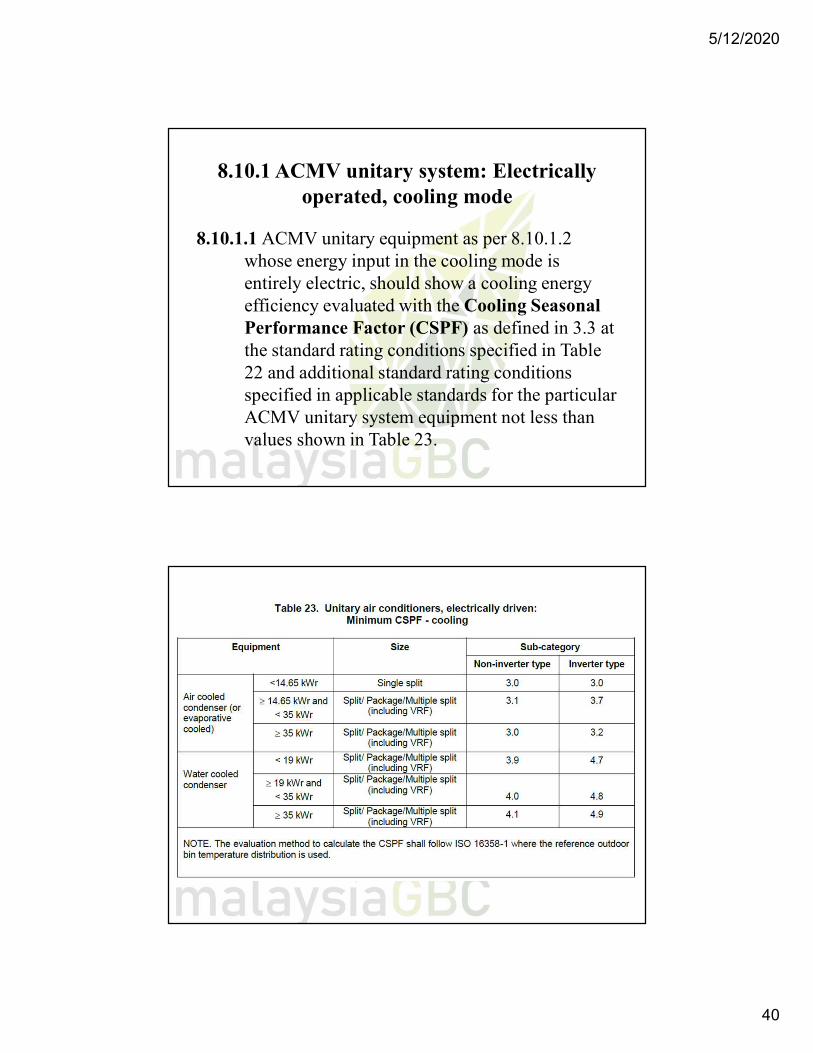
8.10.1 ACMV unitary system: Electrically operated, cooling mode
8.10.1.1 ACMV unitary equipment as per 8.10.1.2 whose energy input in the cooling mode is entirely electric, should show a cooling energy efficiency evaluated with the Cooling Seasonal Performance Factor (CSPF) as defined in 3.3 at the standard rating conditions specified in Table 22 and additional standard rating conditions specified in applicable standards for the particular ACMV unitary system equipment not less than values shown in Table 23.
5/12/2020
41
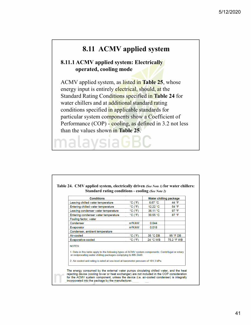
8.11 ACMV applied system
8.11.1 ACMV applied system: Electrically operated, cooling mode
ACMV applied system, as listed in Table 25, whose energy input is entirely electrical, should, at the Standard Rating Conditions specified in Table 24 for water chillers and at additional standard rating conditions specified in applicable standards for particular system components show a Coefficient of Performance (COP) - cooling, as defined in 3.2 not less than the values shown in Table 25.
Table 24. CMV applied system, electrically driven (See Note 1) for water chillers: Standard rating conditions - cooling (See Note 2)
5/12/2020
42
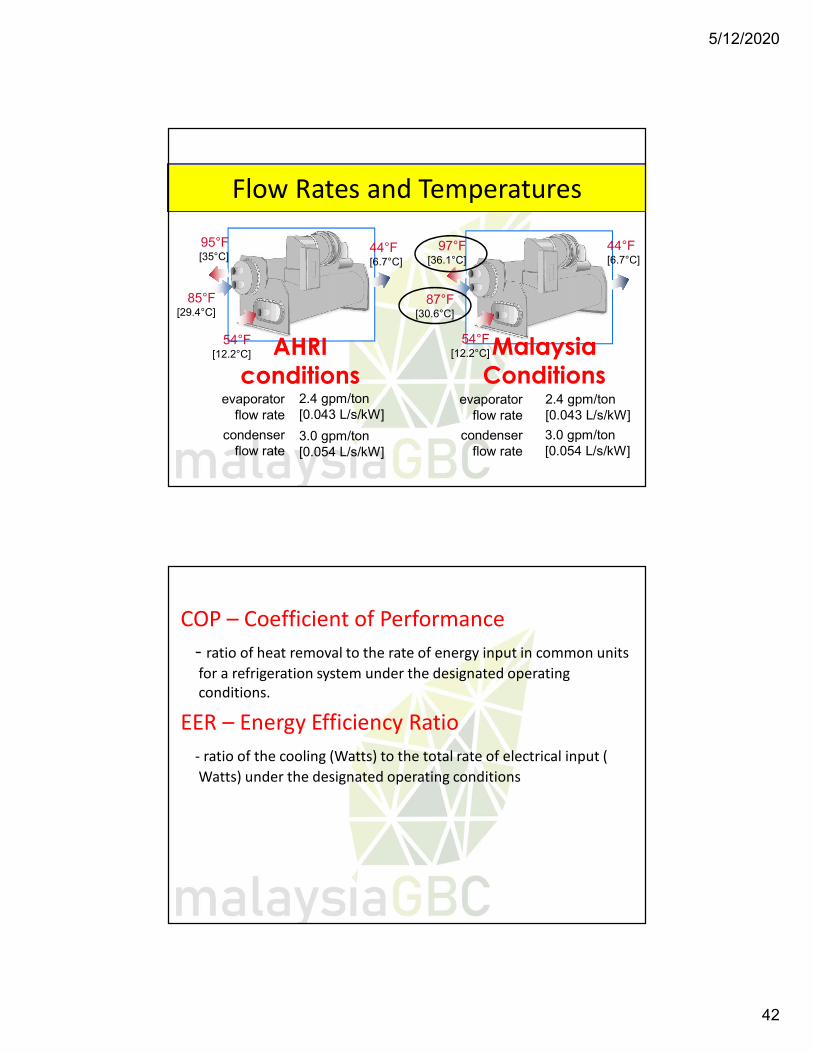
Flow Rates and Temperatures
2.4 gpm/ton[0.043 L/s/kW]
44°F [6.7°C]
54°F[12.2°C]
85°F[29.4°C]
95°F[35°C]
3.0 gpm/ton[0.054 L/s/kW]
AHRIconditions
2.4 gpm/ton[0.043 L/s/kW]
44°F [6.7°C]
54°F[12.2°C]
87°F[30.6°C]
97°F[36.1°C]
3.0 gpm/ton[0.054 L/s/kW]
Malaysia Conditions
evaporatorflow rate
condenserflow rate
evaporatorflow rate
condenserflow rate
COP – Coefficient of Performance- ratio of heat removal to the rate of energy input in common units for a refrigeration system under the designated operating conditions.
EER – Energy Efficiency Ratio- ratio of the cooling (Watts) to the total rate of electrical input ( Watts) under the designated operating conditions
5/12/2020
43
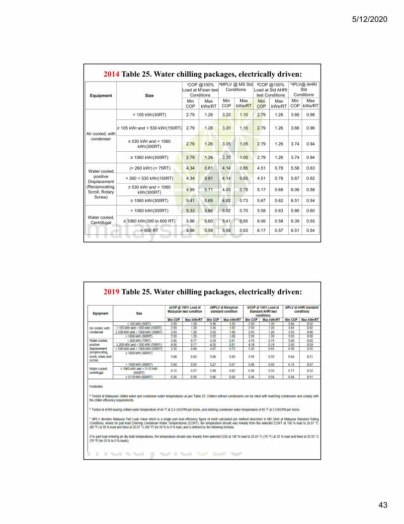
2014 Table 25. Water chilling packages, electrically driven:
Equipment Size
1COP @100% Load at M’sian test
Conditions
aMPLV @ MS Std Conditions
2COP @100% Load at Std AHRI
test Conditions
bIPLV@ AHRI Std
Conditions
Min COP
Max kWe/RT
Min COP
Max kWe/RT
Min COP
Max kWe/RT
Min COP
Max kWe/RT
Air cooled, with condenser
< 105 kWr(30RT) 2.79 1.26 3.20 1.10 2.79 1.26 3.66 0.96
≥ 105 kWr and < 530 kWr(150RT) 2.79 1.26 3.20 1.10 2.79 1.26 3.66 0.96
≥ 530 kWr and < 1060 kWr(300RT)
2.79 1.26 3.35 1.05 2.79 1.26 3.74 0.94
≥ 1060 kWr(300RT) 2.79 1.26 3.35 1.05 2.79 1.26 3.74 0.94
Water cooled, positive
Displacement (Reciprocating, Scroll, Rotary
Screw)
(< 260 kWr) (< 75RT) 4.34 0.81 4.14 0.85 4.51 0.78 5.58 0.63
> 260 < 530 kWr(150RT) 4.34 0.81 4.14 0.85 4.51 0.78 5.67 0.62
≥ 530 kWr and < 1060 kWr(300RT)
4.95 0.71 4.45 0.79 5.17 0.68 6.06 0.58
≥ 1060 kWr(300RT) 5.41 0.65 4.82 0.73 5.67 0.62 6.51 0.54
Water cooled, Centrifugal
< 1060 kWr(300RT) 5.33 0.66 5.02 0.70 5.58 0.63 5.86 0.60
≥ 1060 kWr(300 to 600 RT) 5.86 0.60 5.41 0.65 6.06 0.58 6.39 0.55
> 600 RT 5.96 0.59 5.58 0.63 6.17 0.57 6.51 0.54
2019 Table 25. Water chilling packages, electrically driven:
5/12/2020
44
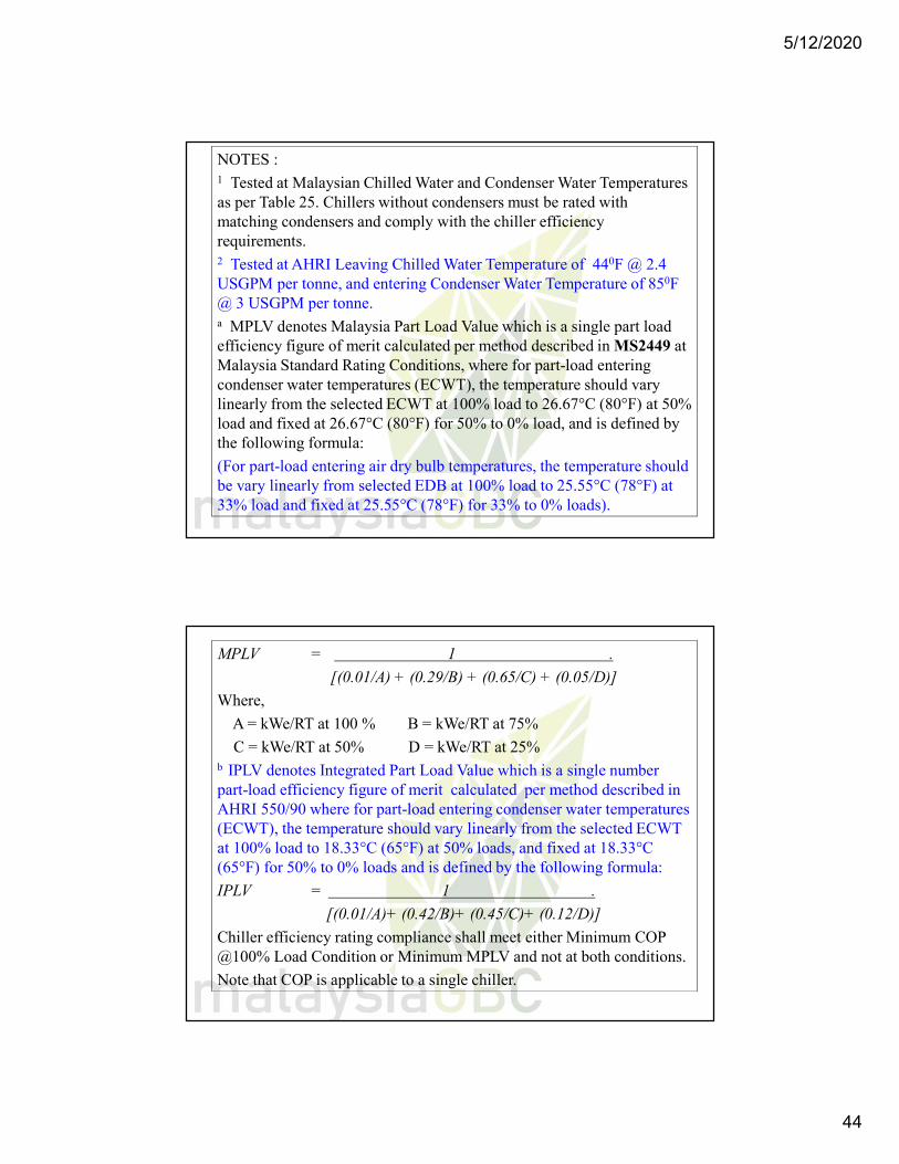
NOTES :1 Tested at Malaysian Chilled Water and Condenser Water Temperatures as per Table 25. Chillers without condensers must be rated with matching condensers and comply with the chiller efficiency requirements.2 Tested at AHRI Leaving Chilled Water Temperature of 440F @ 2.4 USGPM per tonne, and entering Condenser Water Temperature of 850F @ 3 USGPM per tonne.a MPLV denotes Malaysia Part Load Value which is a single part load efficiency figure of merit calculated per method described in MS2449 at Malaysia Standard Rating Conditions, where for part-load entering condenser water temperatures (ECWT), the temperature should vary linearly from the selected ECWT at 100% load to 26.67°C (80°F) at 50% load and fixed at 26.67°C (80°F) for 50% to 0% load, and is defined by the following formula:
(For part-load entering air dry bulb temperatures, the temperature should be vary linearly from selected EDB at 100% load to 25.55°C (78°F) at 33% load and fixed at 25.55°C (78°F) for 33% to 0% loads).
MPLV = 1 .
[(0.01/A) + (0.29/B) + (0.65/C) + (0.05/D)]
Where,
A = kWe/RT at 100 % B = kWe/RT at 75%
C = kWe/RT at 50% D = kWe/RT at 25% b IPLV denotes Integrated Part Load Value which is a single number part-load efficiency figure of merit calculated per method described in AHRI 550/90 where for part-load entering condenser water temperatures (ECWT), the temperature should vary linearly from the selected ECWT at 100% load to 18.33°C (65°F) at 50% loads, and fixed at 18.33°C (65°F) for 50% to 0% loads and is defined by the following formula:
IPLV = 1 .
[(0.01/A)+ (0.42/B)+ (0.45/C)+ (0.12/D)]
Chiller efficiency rating compliance shall meet either Minimum COP @100% Load Condition or Minimum MPLV and not at both conditions.
Note that COP is applicable to a single chiller.
5/12/2020
45
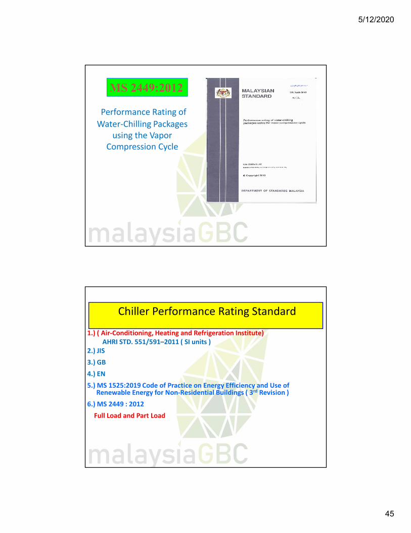
Performance Rating of Water-Chilling Packages
using the Vapor Compression Cycle
MS 2449:2012
Chiller Performance Rating Standard
1.) ( Air-Conditioning, Heating and Refrigeration Institute) AHRI STD. 551/591–2011 ( SI units )
2.) JIS
3.) GB
4.) EN
5.) MS 1525:2019 Code of Practice on Energy Efficiency and Use of Renewable Energy for Non-Residential Buildings ( 3rd Revision )
6.) MS 2449 : 2012
Full Load and Part Load
5/12/2020
46
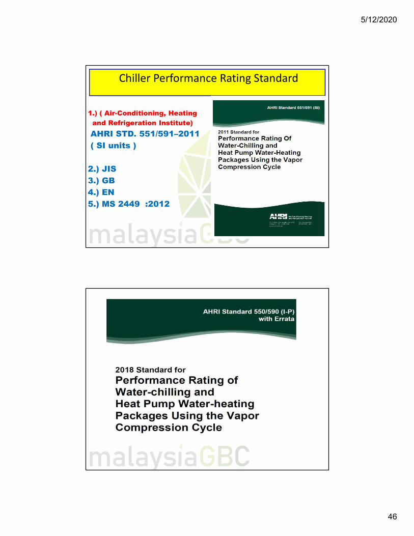
Chiller Performance Rating Standard
1.) ( Air-Conditioning, Heating and Refrigeration Institute)AHRI STD. 551/591–2011( SI units )
2.) JIS3.) GB4.) EN5.) MS 2449 :2012
5/12/2020
47
1-93
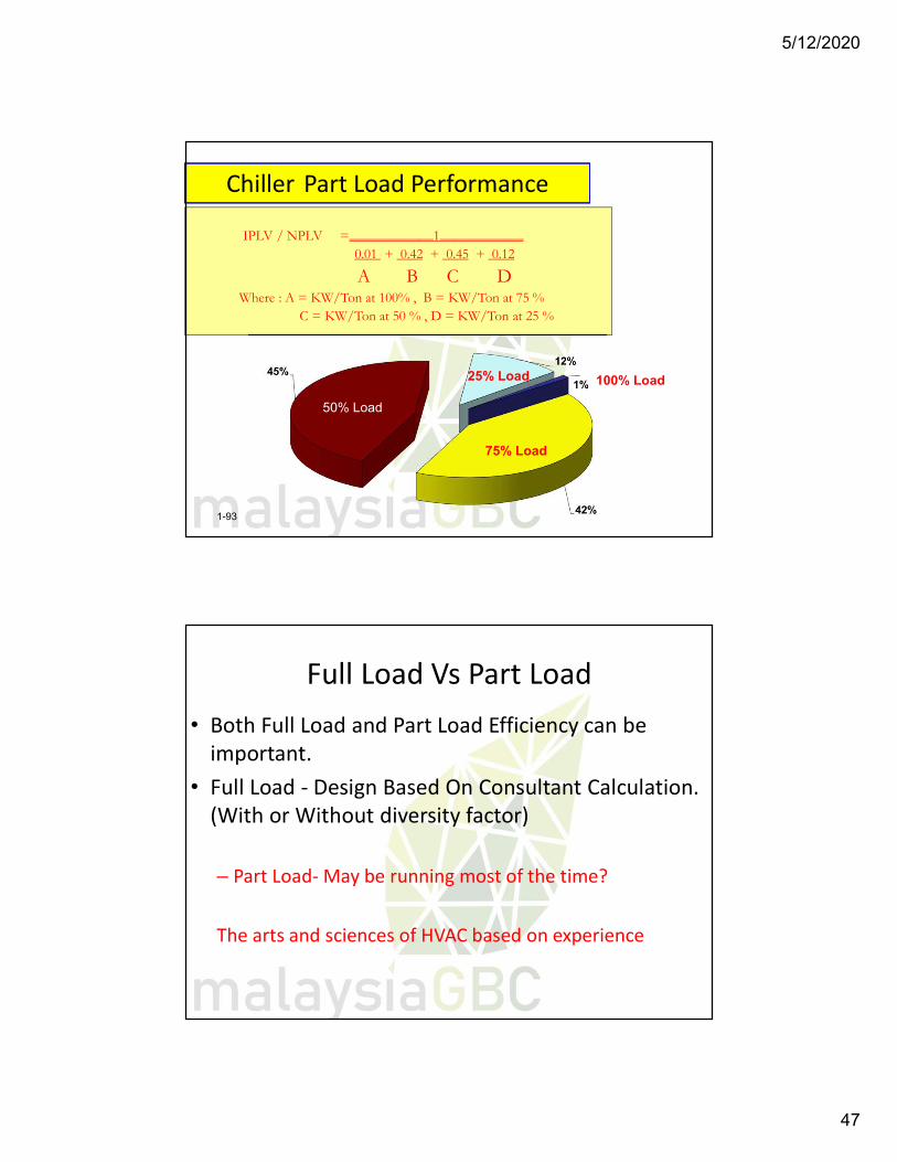
Chiller Part Load Performance
IPLV / NPLV =____________1____________ 0.01 + 0.42 + 0.45 + 0.12
A B C DWhere : A = KW/Ton at 100% , B = KW/Ton at 75 %
C = KW/Ton at 50 % , D = KW/Ton at 25 %
50% Load
75% Load
25% Load 100% Load
Full Load Vs Part Load• Both Full Load and Part Load Efficiency can be
important.• Full Load - Design Based On Consultant Calculation.
(With or Without diversity factor)
– Part Load- May be running most of the time?
The arts and sciences of HVAC based on experience
5/12/2020
48
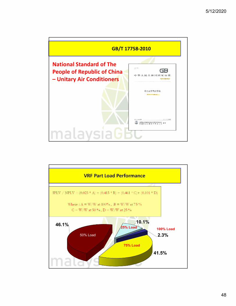
GB/T 17758-2010
National Standard of The People of Republic of China – Unitary Air Conditioners
VRF Part Load Performance
IPLV / NPLV = (0.023 * A) + (0.415 * B) + (0.461 * C)+ (0.101 * D)
Where : A = W/W at 100% , B = W/W at 75 %
C = W/W at 50 % , D = W/W at 25 %
50% Load50% Load50% Load
75% Load
25% Load 100% Load
5/12/2020
49
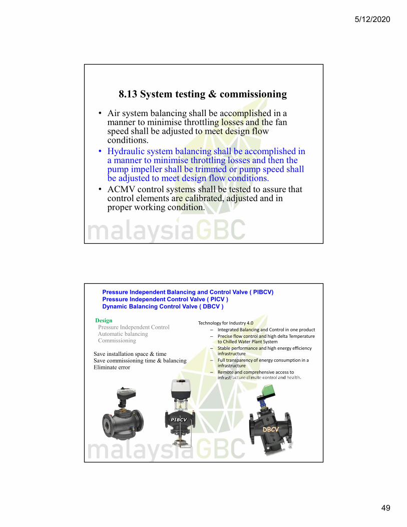
8.13 System testing & commissioning
• Air system balancing shall be accomplished in a manner to minimise throttling losses and the fan speed shall be adjusted to meet design flow conditions.
• Hydraulic system balancing shall be accomplished in a manner to minimise throttling losses and then the pump impeller shall be trimmed or pump speed shall be adjusted to meet design flow conditions.
• ACMV control systems shall be tested to assure that control elements are calibrated, adjusted and in proper working condition.
Technology for Industry 4.0– Integrated Balancing and Control in one product– Precise flow control and high delta Temperature
to Chilled Water Plant System– Stable performance and high energy efficiency
infrastructure– Full transparency of energy consumption in a
infrastructure– Remote and comprehensive access to
infrastructure climate control and health.
DesignPressure Independent ControlAutomatic balancingCommissioning
Save installation space & timeSave commissioning time & balancingEliminate error
Pressure Independent Balancing and Control Valve ( PIBCV)Pressure Independent Control Valve ( PICV )Dynamic Balancing Control Valve ( DBCV )
PIBCV
5/12/2020
50
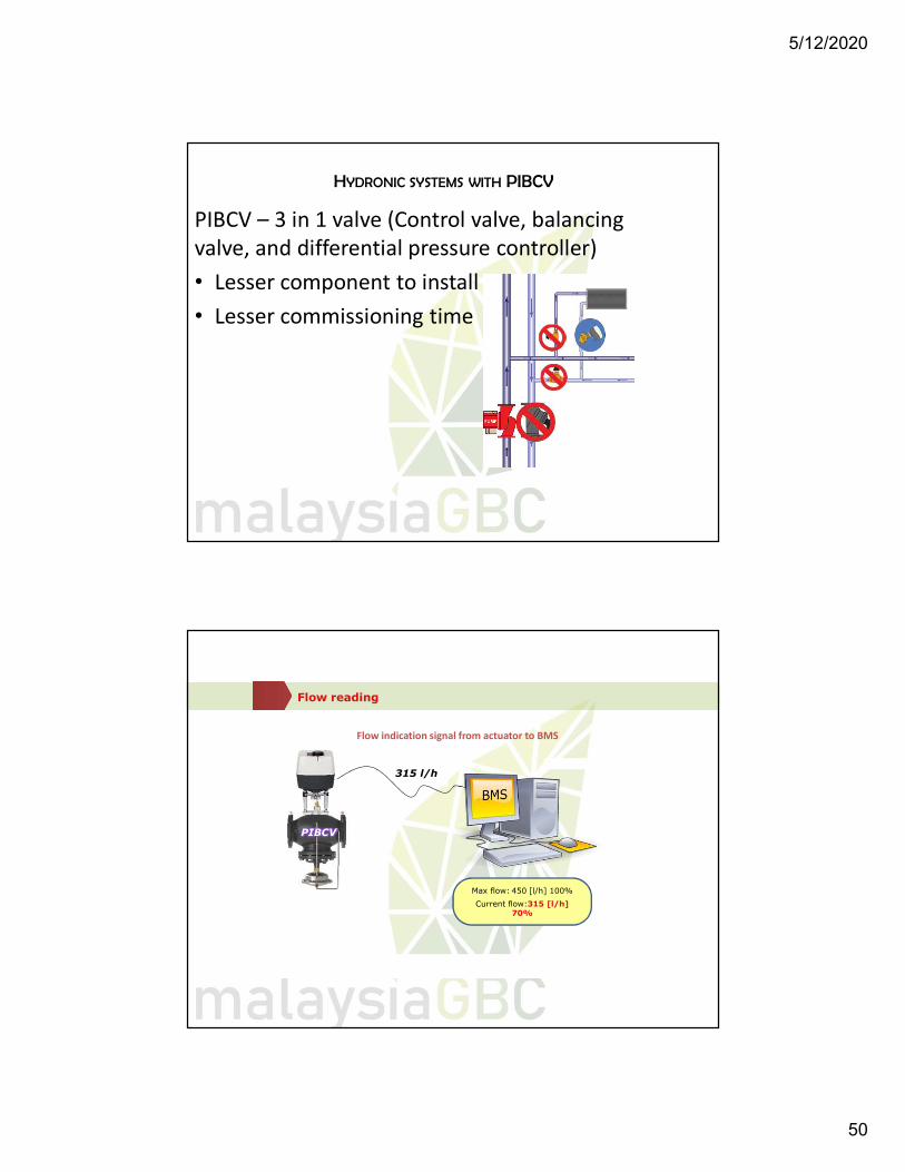
HYDRONIC SYSTEMS WITH PIBCV
PIBCV – 3 in 1 valve (Control valve, balancing valve, and differential pressure controller)• Lesser component to install• Lesser commissioning time
315 l/h315l/h
Flow reading
Flow indication signal from actuator to BMS
Max flow: 450 [l/h] 100%
Current flow:315 [l/h] 70%
PIBCV
5/12/2020
51
6°C
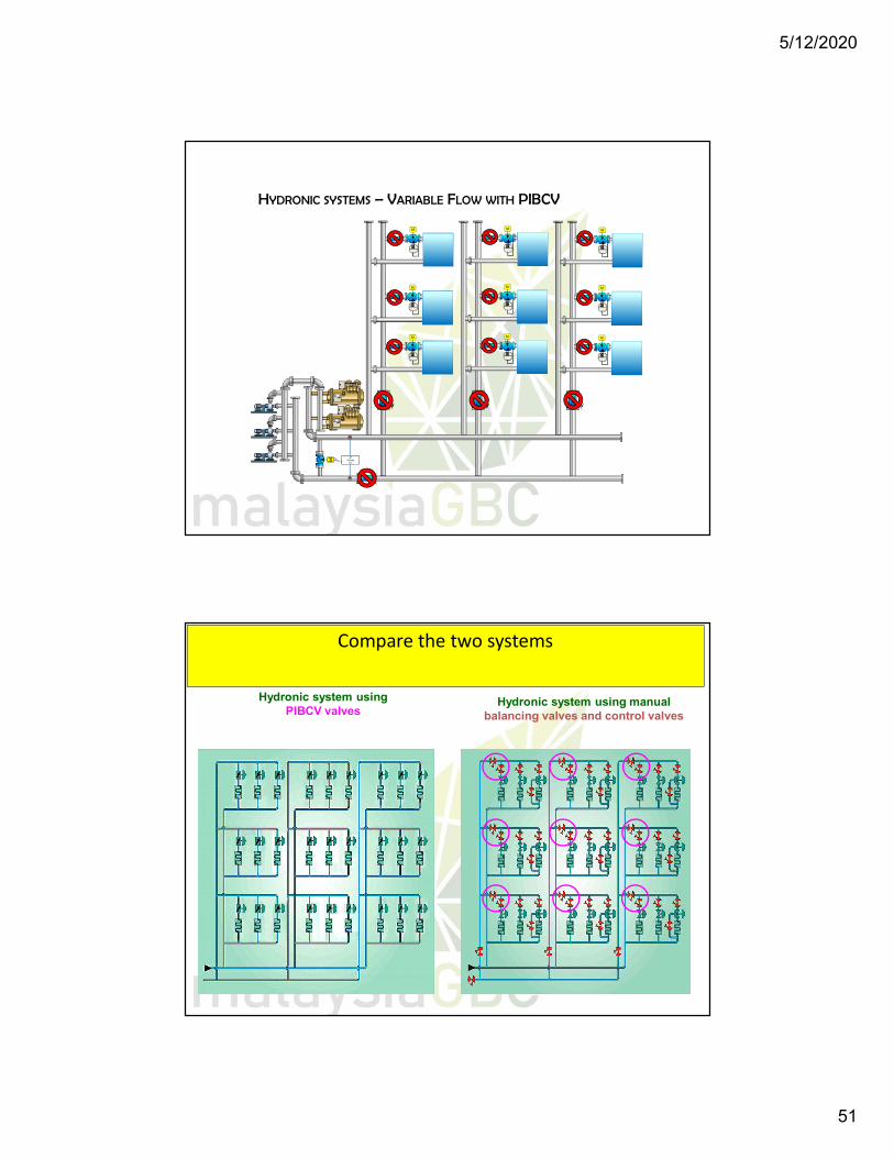
HYDRONIC SYSTEMS – VARIABLE FLOW WITH PIBCV
6°C
M ∆PControl
ler
M
M
M
M
M
M
M
M
M
Hydronic system using PIBCV valves
Hydronic system using manual balancing valves and control valves
Compare the two systems
5/12/2020
52
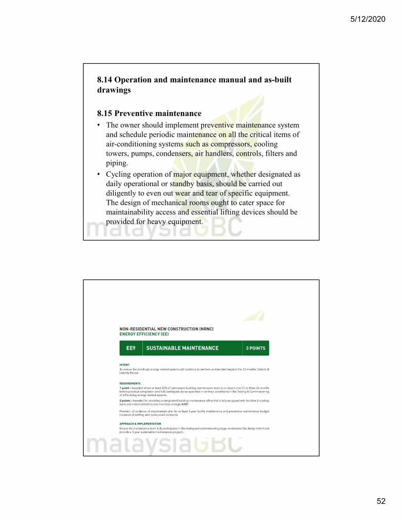
8.14 Operation and maintenance manual and as-built drawings
8.15 Preventive maintenance • The owner should implement preventive maintenance system
and schedule periodic maintenance on all the critical items of air-conditioning systems such as compressors, cooling towers, pumps, condensers, air handlers, controls, filters and piping.
• Cycling operation of major equipment, whether designated as daily operational or standby basis, should be carried out diligently to even out wear and tear of specific equipment. The design of mechanical rooms ought to cater space for maintainability access and essential lifting devices should be provided for heavy equipment.
5/12/2020
53
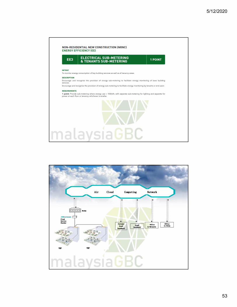
VRF
Customer
Staff
(anywhere)
Officein China
Office
in Malaysia
Air Cloud Computing Network
Cloud Service Checker
Modem
Staff(anywhere)
VRF
5/12/2020
54
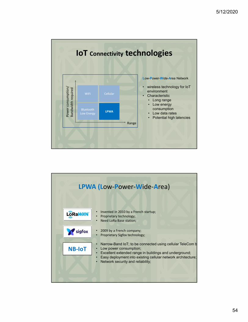
IoT Connectivity technologies
WiFi Cellular
Bluetooth Low Energy LPWA
Range
Pow
er c
onsu
mpt
ion/
Band
wid
th re
quire
d
Low-Power-Wide-Area Network
• wireless technology for IoT environment
• Characteristic• Long range• Low energy
consumption• Low data rates• Potential high latencies
LPWA (Low-Power-Wide-Area)
NB-IoT
• 2009 by a French company;• Proprietary Sigfox technology;
• Invented in 2010 by a French startup;• Proprietary technology;• Need LoRa Base station;
• Narrow-Band IoT; to be connected using cellular TeleCom bands;• Low power consumption;• Excellent extended range in buildings and underground;• Easy deployment into existing cellular network architecture;• Network security and reliability;
5/12/2020
55
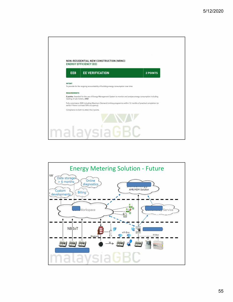
Energy Metering Solution - Future
Bacnet, M-bus, Modbus, Lonworks network application all available.
5/12/2020
56
8.16 Life cycle analysis
The owner is encouraged to carry out life cycle analysis of ACMV system performance and efficiency before purchasing new equipment and considering early replacement.
THANK YOUNg Yong Kong, P.E.,
GBIF,MGBC, MASHRAECouncil Member - Session
2019 – 20209th May 2020
malaysiaGBC WEBINAR SUSTAINABLE SERIES


