Embed Size (px)
Citation preview
Mössbauer study of Fe powder mechanically alloyed by power
ultrasonicsNadutov V.M., Mordyuk B.N., Volosevich P.Yu.,
Svystunov Ye.O.
G.V. Kurdyumov Institute for Metal Physics
of the National Academy of Sciences of Ukraine
2
• Mechanical alloying
• Ultrasonic method for MA
• Fe-C powder
• Fe-Ni-C
• Conclusion remarks
Outline
3
Mechanical Alloying“MA is a technique for processing of powder in a high-energy ball mill. Originally it was developed to produce oxide-dispersion strengthened Ni- and Fe-based superalloys for application in aerospace industry.
MA has now been shown to be capable of synthesizing a variety of equilibrium and non-equilibrium phases starting from blended elemental or prealloyedpowders.
The non-equilibrium phases include: supersaturated solid solutions, metastablecrystalline and quasicrystalline phases, nano structures and amorphous alloys
C. Suryanarayana. Progress in Material Science, 46, 2001, 1-184
4
Mechanical Alloying
Different types of high-energy milling equipment are used to produce mechanically alloyed powders.
They differ in their capacity, efficiency of milling and additional arrangements for cooling, heating, etc.
A conventional ball mill consists of a rotating drum (horizontal or planet-like movement of its vials) half-filled with small steel balls and powder (few hundred g of the powder can be milled at a time).
C. Suryanarayana. Progress in Material Science, 46, 2001, 1-184
5
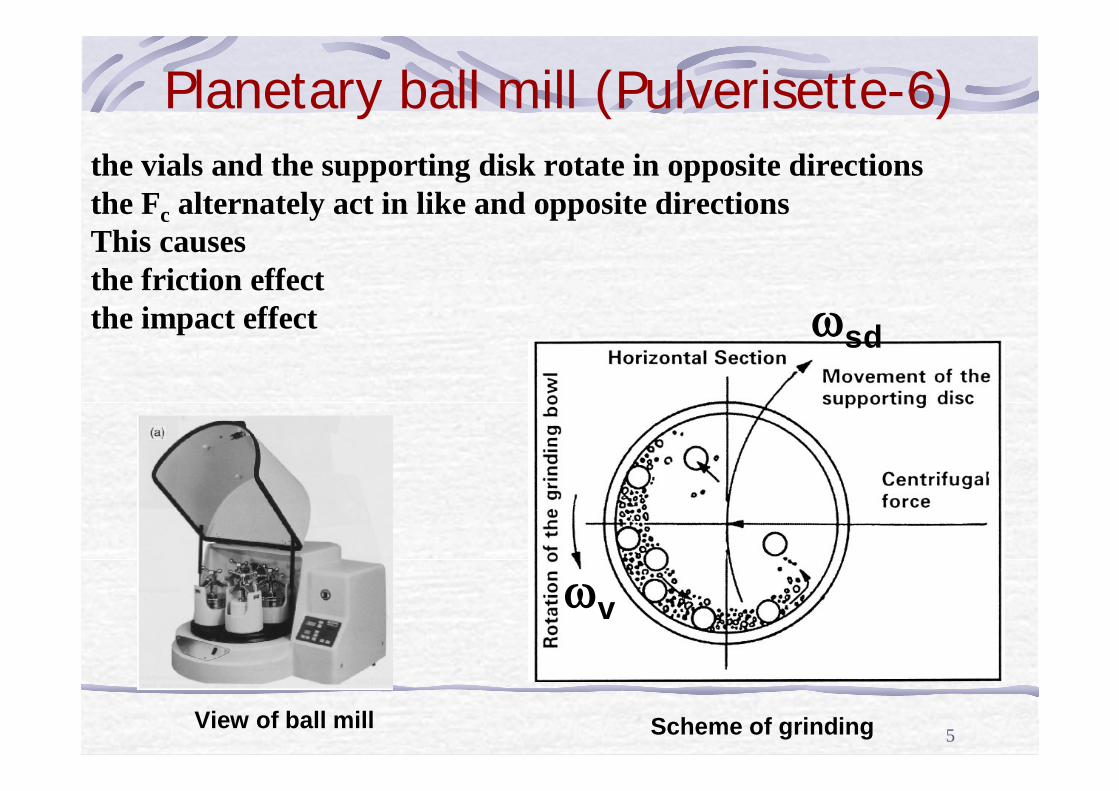
Planetary ball mill (Pulverisette-6)
View of ball mill Scheme of grinding
ωv
ωsd
the vials and the supporting disk rotate in opposite directionsthe Fc alternately act in like and opposite directionsThis causes the friction effect the impact effect
6
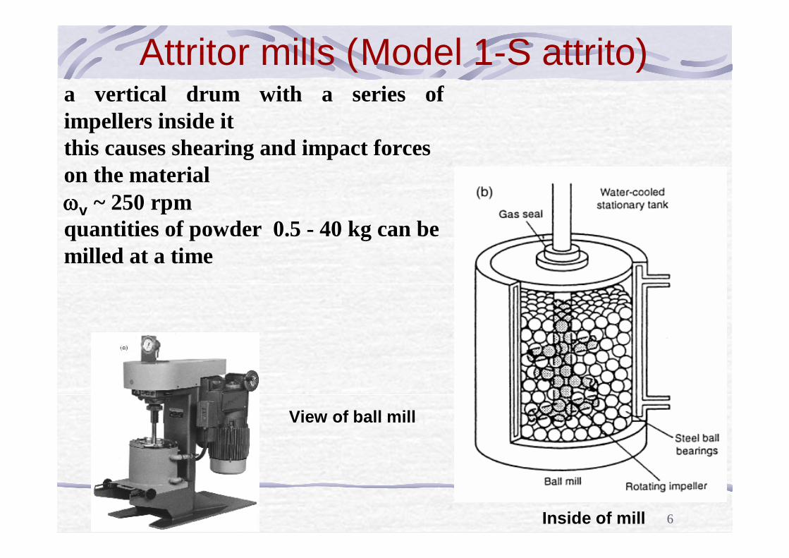
Attritor mills (Model 1-S attrito)
View of ball mill
Inside of mill
a vertical drum with a series of impellers inside it this causes shearing and impact forces on the material ωv ~ 250 rpm quantities of powder 0.5 - 40 kg can be milled at a time
7B.M. Mordyuk, G.I. Prokopenko.
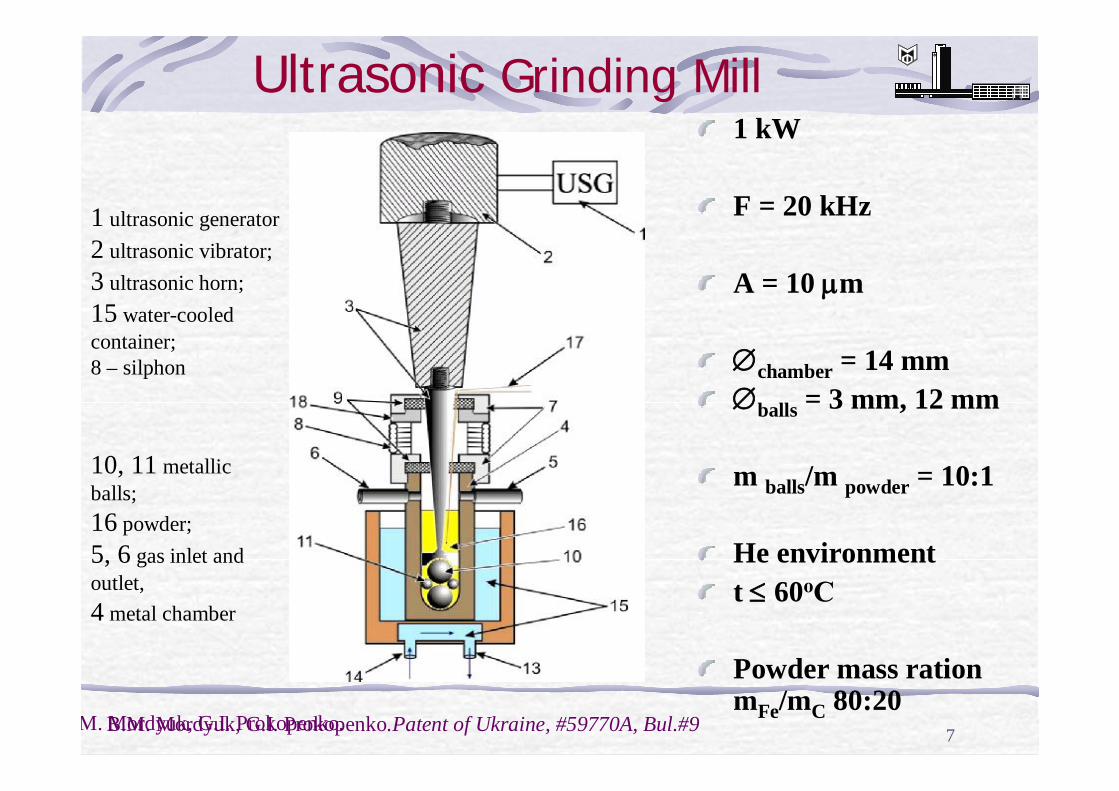
Ultrasonic Grinding Mill1 kW
F = 20 kHz
A = 10 µm
∅chamber = 14 mm∅balls = 3 mm, 12 mm
m balls/m powder = 10:1
He environment t ≤ 60оС
Powder mass ration mFe/mC 80:20
1 ultrasonic generator 2 ultrasonic vibrator;3 ultrasonic horn; 15 water-cooled container; 8 – silphon
10, 11 metallic balls; 16 powder;5, 6 gas inlet and outlet,4 metal chamber
B.M. Mordyuk, G.I. Prokopenko.Patent of Ukraine, #59770A, Bul.#9
8
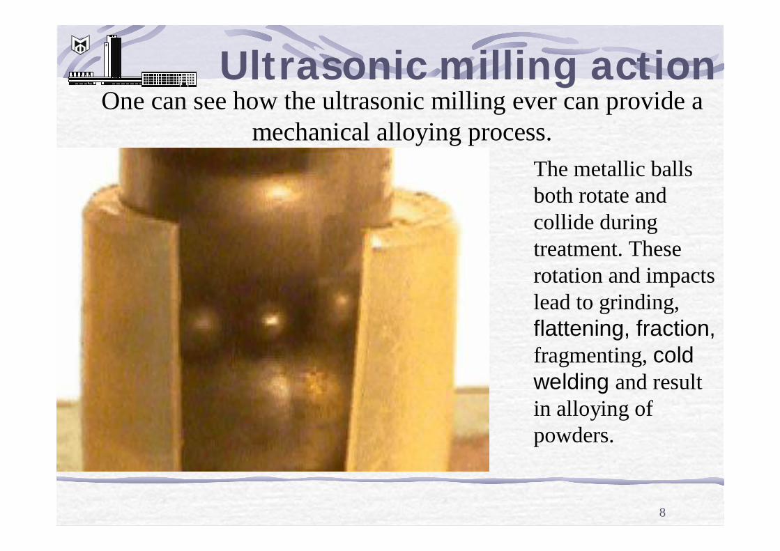
One can see how the ultrasonic milling ever can provide a mechanical alloying process.
The metallic balls both rotate and collide during treatment. These rotation and impacts lead to grinding, flattening, fraction,fragmenting, coldwelding and result in alloying of powders.
Ultrasonic milling action
9
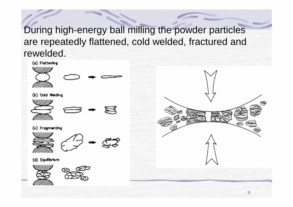
During high-energy ball milling the powder particles are repeatedly flattened, cold welded, fractured and rewelded.
10
Fe-C
• Fe-C system is the basis of a number of steels.
The solubility of C •in α–Fe is approximately 0.02 wt % •in γ–Fe is 2.1 wt %
11
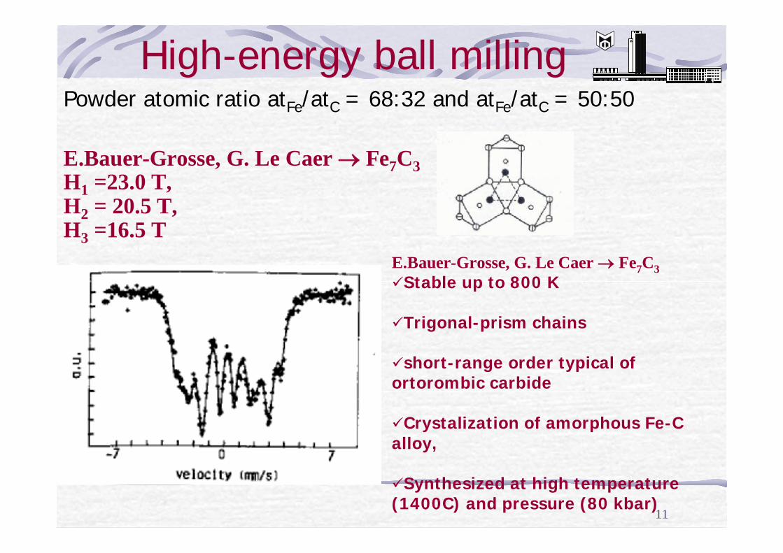
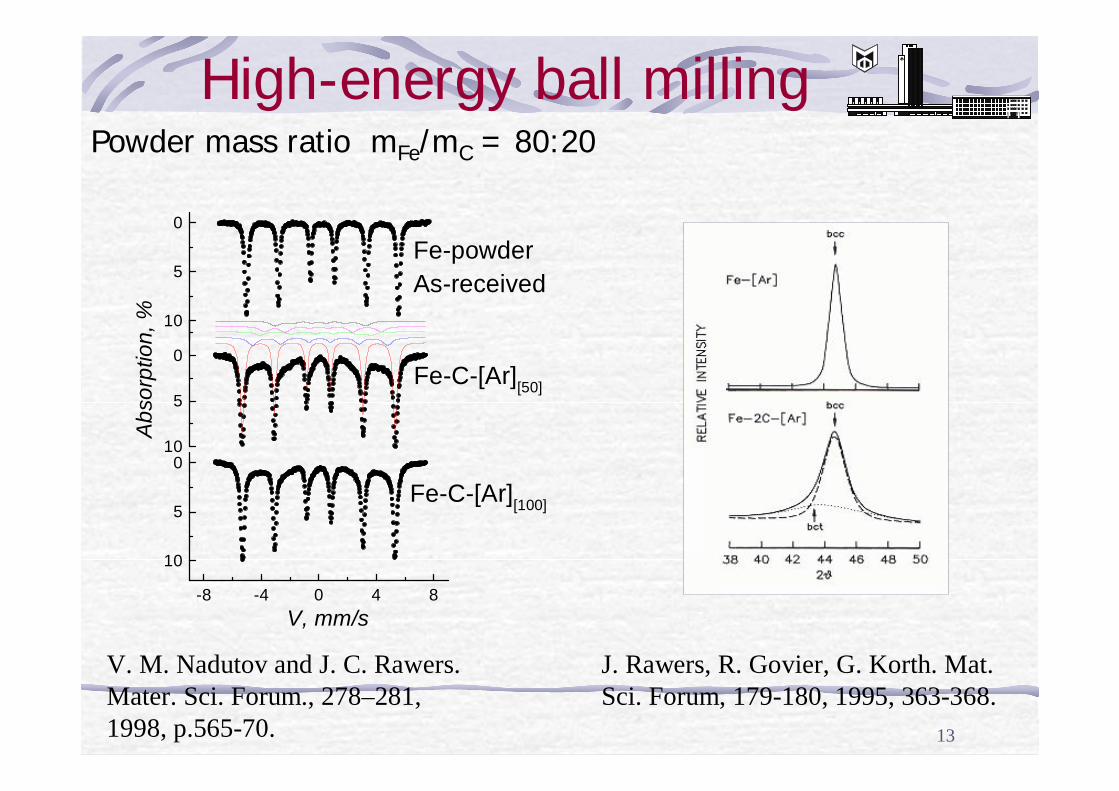
High-energy ball milling
E.Bauer-Grosse, G. Le Caer → Fe7C3 H1 =23.0 T, H2 = 20.5 T, H3 =16.5 T
Powder atomic ratio atFe/atC = 68:32 and atFe/atC = 50:50
E.Bauer-Grosse, G. Le Caer → Fe7C3 üStable up to 800 K
üTrigonal-prism chains
üshort-range order typical of ortorombic carbide
üCrystalization of amorphous Fe-C alloy,
üSynthesized at high temperature (1400C) and pressure (80 kbar)
12
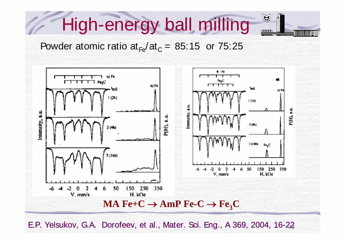
High-energy ball milling
E.P. Yelsukov, G.A. Dorofeev, et al., Mater. Sci. Eng., A 369, 2004, 16-22
Powder atomic ratio atFe/atC = 85:15 or 75:25
MA Fe+C → AmP Fe-C → Fe3C
E.P. Yelsukov, G.A. Dorofeev, et al., Mater. Sci. Eng., A 369, 2004, 16-22
13
High-energy ball milling
V. M. Nadutov and J. C. Rawers. Mater. Sci. Forum., 278–281, 1998, p.565-70.
10
5
0Fe-C-[Ar][50]
Fe-powderAs-received
Abs
orpt
ion,
% 10
5
0
-8 -4 0 4 8
10
5
0
Fe-C-[Ar][100]
V, mm/s
J. Rawers, R. Govier, G. Korth. Mat. Sci. Forum, 179-180, 1995, 363-368.
Powder mass ratio mFe/mC = 80:20
14
The goal of the work
to reveal the change in structure and the hyperfine parameters in Fe-particles without alloying and alloyed with C (atFe/atC = 46:54) by means of power ultrasonics in He environment
15
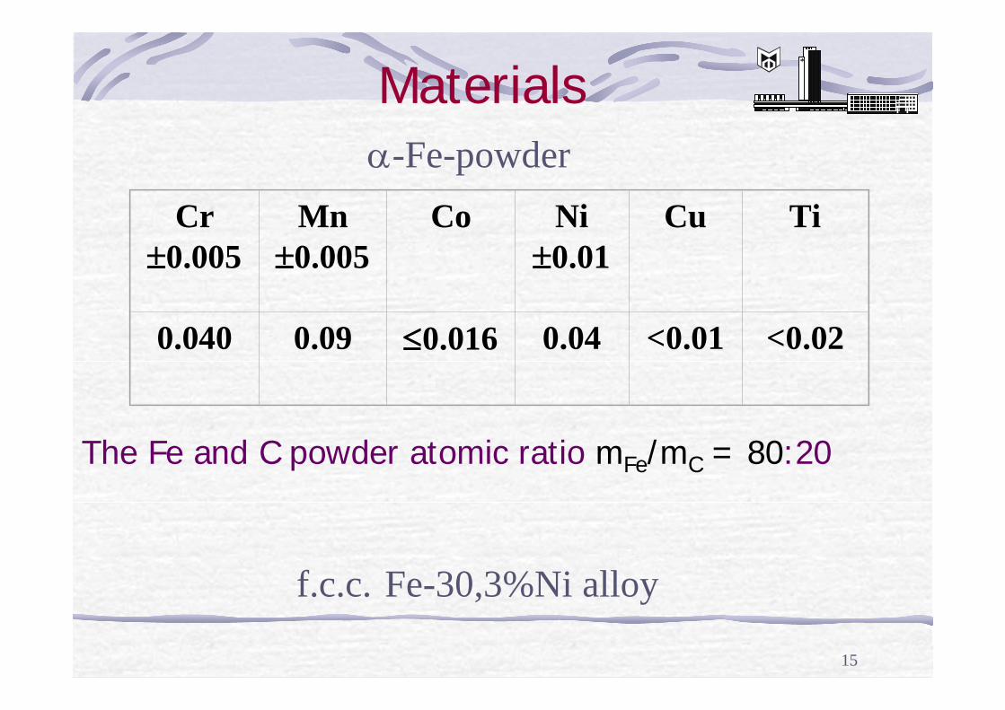
Materials
f.c.c. Fe-30,3%Ni alloy
α-Fe-powder Cr
±0.005Mn
±0.005Co Ni
±0.01Cu Ti
0.040 0.09 ≤0.016 0.04 <0.01 <0.02
The Fe and C powder atomic ratio mFe/mC = 80:20
16
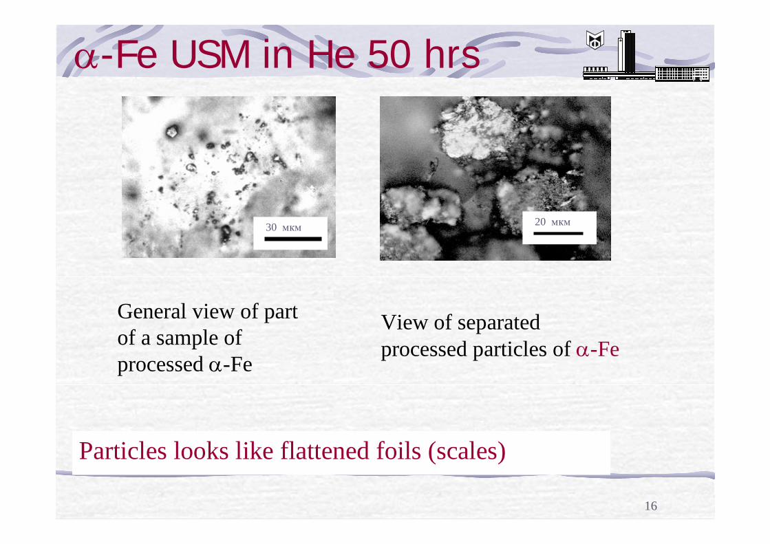
α-Fe USM in He 50 hrs
30 мкм 20 мкм
Particles looks like flattened foils (scales)
View of separated processed particles of α-Fe
General view of part of a sample of processed α-Fe
17
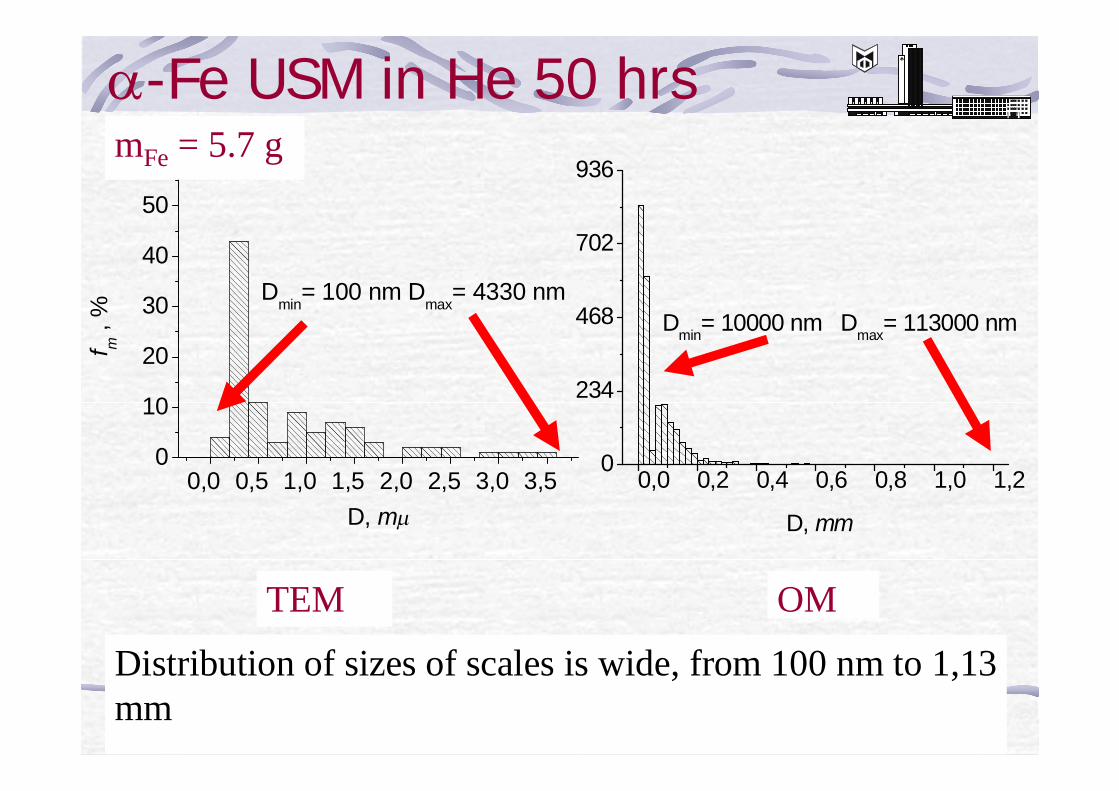
α-Fe USM in He 50 hrs
0,0 0,5 1,0 1,5 2,0 2,5 3,0 3,50
10
20
30
40
50
f m ,
%
D, mµ
Dmin= 100 nm Dmax= 4330 nm
mFe = 5.7 g
0,0 0,2 0,4 0,6 0,8 1,0 1,20
234
468
702
936
D, mm
Dmin= 10000 nm Dmax= 113000 nm
OMTEM
Distribution of sizes of scales is wide, from 100 nm to 1,13 mm
18
-8 -4 0 4 8
15
10
5
0
V, mm/s
Abs
orpt
ion,
%
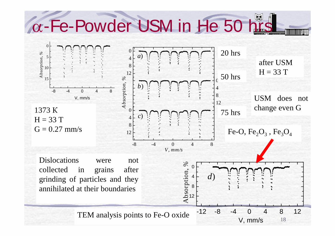
1373 КH = 33 TG = 0.27 mm/s
12840
a)
12840
b)
Abs
orpt
ion,
%
-8 -4 0 4 8
12840
c)
V, mm/s
-12 -8 -4 0 4 8 12
12
8
4
0
V, mm/s
d)A
bsor
ptio
n, %
α-Fe-Powder USM in He 50 hrs
after USMH = 33 T
Fe-O, Fe2O3 , Fe3O4
USM does not change even G
Dislocations were not collected in grains after grinding of particles and they annihilated at their boundaries
20 hrs
50 hrs
75 hrs
TEM analysis points to Fe-O oxide
19
20 мкм
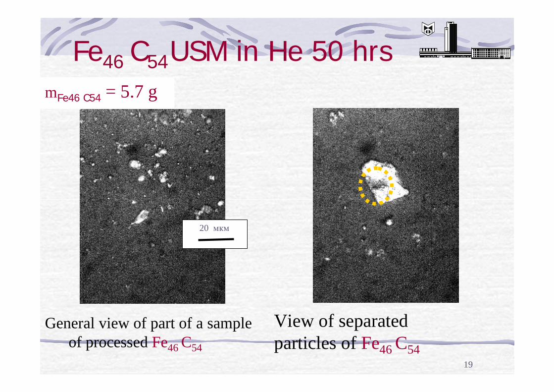
Fe46 C54USM in He 50 hrsmFe46 C54 = 5.7 g
General view of part of a sample of processed Fe46 C54
View of separated particles of Fe46 C54
20
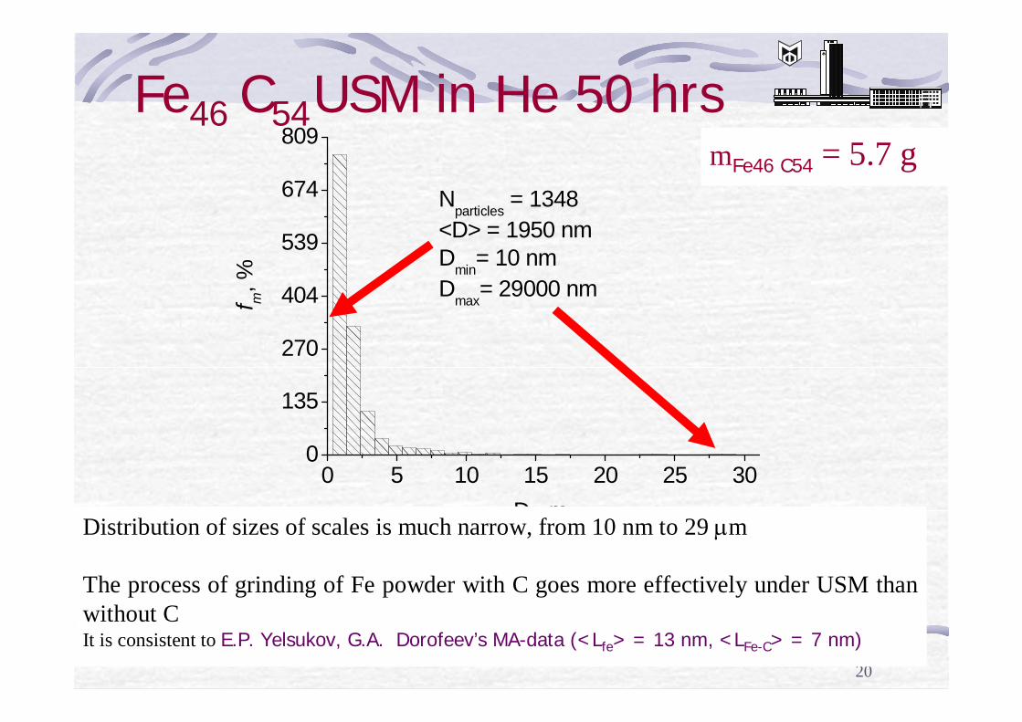
Fe46 C54USM in He 50 hrs
0 5 10 15 20 25 300
135
270
404
539
674
809
Nparticles = 1348<D> = 1950 nm Dmin= 10 nmDmax= 29000 nmf m
, %
D, mµ
mFe46 C54 = 5.7 g
Distribution of sizes of scales is much narrow, from 10 nm to 29 µm
The process of grinding of Fe powder with C goes more effectively under USM than without C It is consistent to E.P. Yelsukov, G.A. Dorofeev’s MA-data (<Lfe> = 13 nm, <LFe-C> = 7 nm)
21
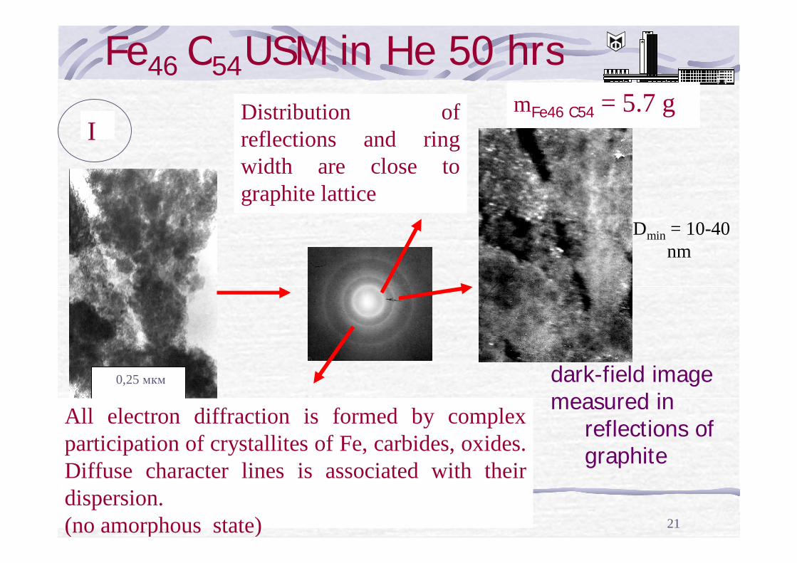
Fe46 C54USM in He 50 hrsmFe46 C54 = 5.7 g
0,25 мкм dark-field imagemeasured in
reflections of graphite
IDistribution of reflections and ring width are close to graphite lattice
Dmin = 10-40 nm
All electron diffraction is formed by complex participation of crystallites of Fe, carbides, oxides. Diffuse character lines is associated with their dispersion. (no amorphous state)
22
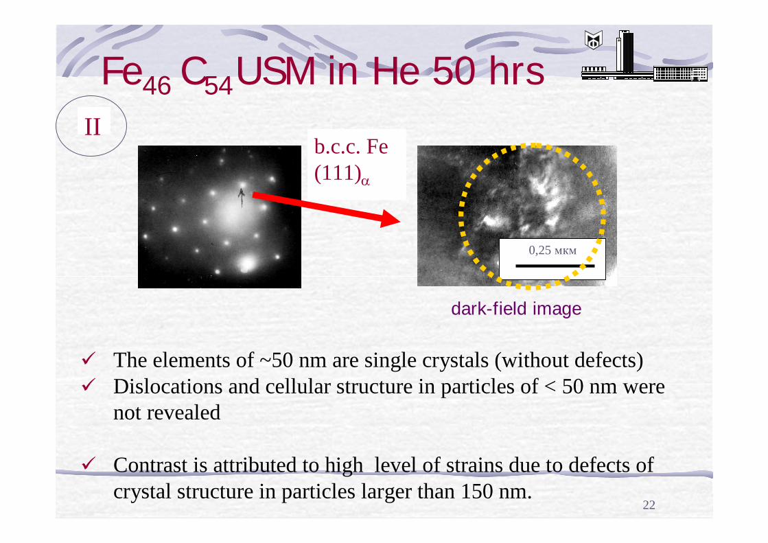
Fe46 C54USM in He 50 hrs
dark-field image
0,25 мкм
II
ü The elements of ~50 nm are single crystals (without defects)ü Dislocations and cellular structure in particles of < 50 nm were
not revealed
ü Contrast is attributed to high level of strains due to defects of crystal structure in particles larger than 150 nm.
b.c.c. Fe(111)α
23
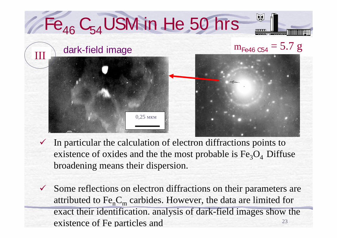
Fe46 C54USM in He 50 hrsmFe46 C54 = 5.7 g
III
ü In particular the calculation of electron diffractions points toexistence of oxides and the the most probable is Fe3O4 Diffuse broadening means their dispersion.
ü Some reflections on electron diffractions on their parameters are attributed to FenCm carbides. However, the data are limited for exact their identification. analysis of dark-field images show the existence of Fe particles and
dark-field image
0,25 мкм
24
Ultrasonic milling
15
10
5
0
s2 s3
Abso
rptio
n, %
-8 -4 0 4 8
10
5
0
-5 s4s5s6 s7s1
V, mm/s
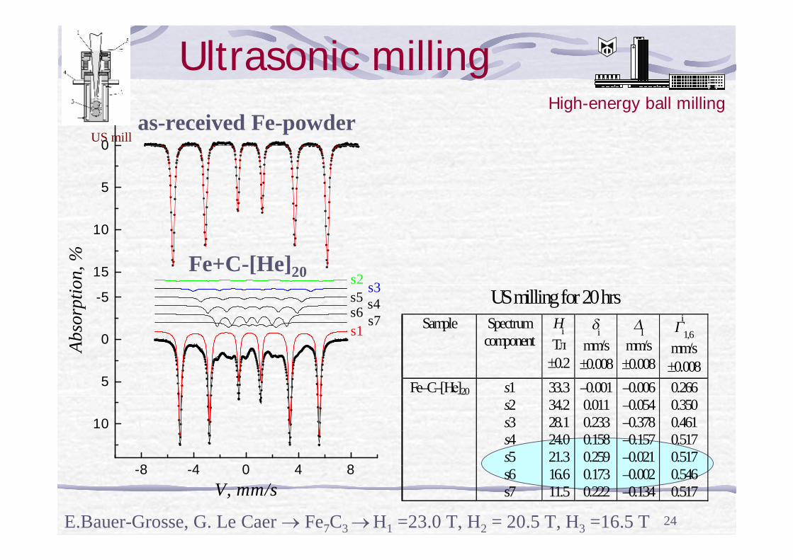
as-received Fe-powder
Fe+C-[He]20
US milling for 20 hrs Sample Spectrum
component
Hi Tл
±0.2
δi mm/s ±0.008
∆I mm/s ±0.008
Γi1,6
mm/s ±0.008
s1 33.3 –0.001 –0.006 0.266 s2 34.2 0.011 –0.054 0.350 s3 28.1 0.233 –0.378 0.461 s4 24.0 0.158 –0.157 0.517 s5 21.3 0.259 –0.021 0.517 s6 16.6 0.173 –0.002 0.546
Fe–C–[Не]20
s7 11.5 0.222 –0.134 0.517
US mill
High-energy ball milling
E.Bauer-Grosse, G. Le Caer → Fe7C3 → H1 =23.0 T, H2 = 20.5 T, H3 =16.5 T
25
-8 -4 0 4 8
10
5
0
-5
s2s3s4s5s6s8
s7s1
Abso
rptio
n, %
V, mm/s
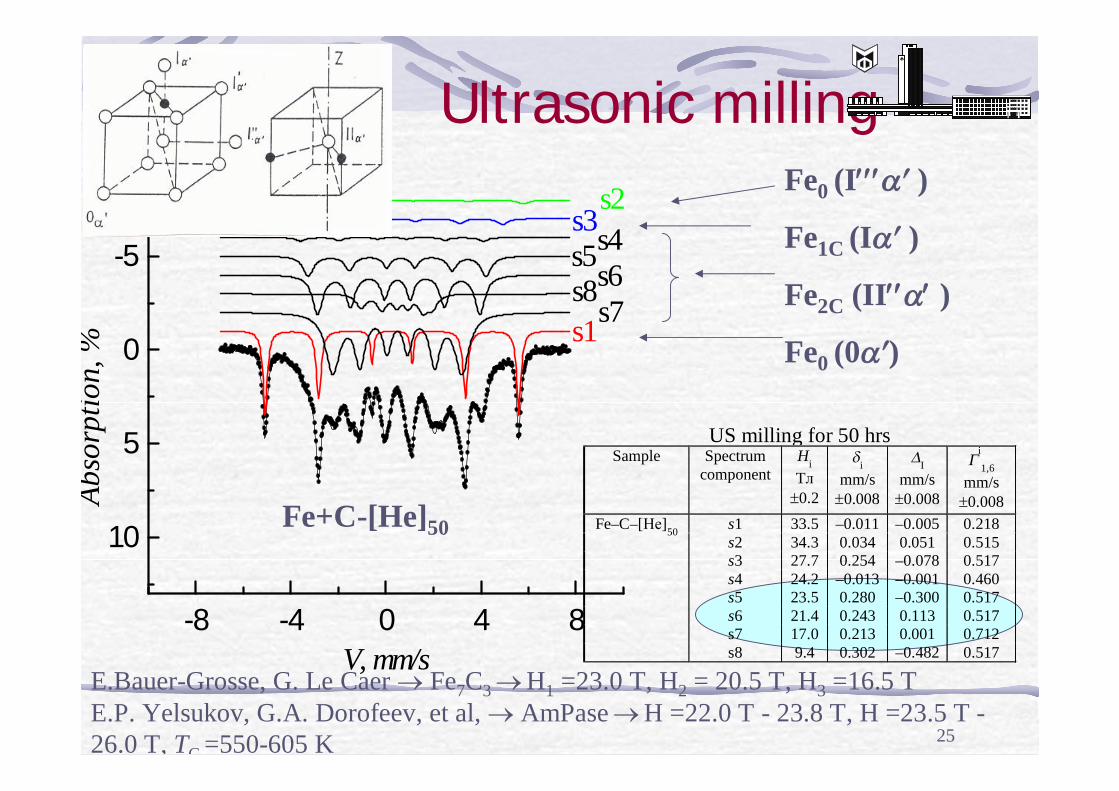
Ultrasonic milling
Fe+C-[He]50
Fe0 (I′′′α′ )
Fe1C (Iα′ )
Fe2C (II′′α′ )
Fe0 (0α′)
E.Bauer-Grosse, G. Le Caer → Fe7C3 → H1 =23.0 T, H2 = 20.5 T, H3 =16.5 TE.P. Yelsukov, G.A. Dorofeev, et al, → AmPase → H =22.0 T - 23.8 T, H =23.5 T -26.0 T, TC =550-605 K
US milling for 50 hrs Sample Spectrum
component
Hi Tл
±0.2
δi mm/s
±0.008
∆I mm/s
±0.008
Γi
1,6 mm/s
±0.008 s1 33.5 –0.011 –0.005 0.218 s2 34.3 0.034 0.051 0.515 s3 27.7 0.254 –0.078 0.517 s4 24.2 –0.013 –0.001 0.460 s5 23.5 0.280 –0.300 0.517 s6 21.4 0.243 0.113 0.517 s7 17.0 0.213 0.001 0.712
Fe–C–[Не]50
s8 9.4 0.302 –0.482 0.517
26
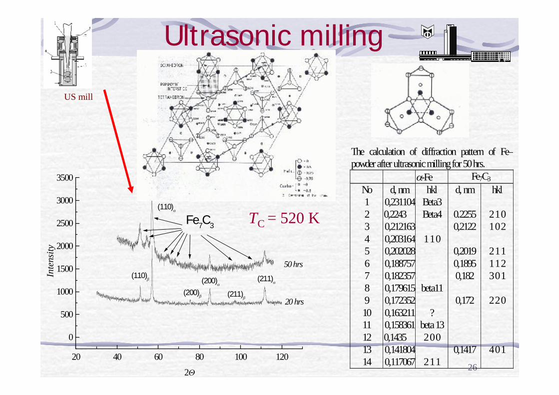
Ultrasonic milling
20 40 60 80 100 120
0
500
1000
1500
2000
2500
3000
3500
Fe7C3
20 hrs
(110)β
(110)α
(200)β
(200)α
(211)β
(211)α
50 hrs
Inte
nsity
2Θ
The calculation of diffraction pattern of Fe–powder after ultrasonic milling for 50 hrs.
α-Fe Fe7C3 No d, nm hkl d, nm hkl 1 0,231104 Beta3 2 0,2243 Beta4 0.2255 2 1 0 3 0,212163 0,2122 1 0 2 4 0,203164 1 1 0 5 0,202028 0,2019 2 1 1 6 0,188757 0,1895 1 1 2 7 0,182357 0,182 3 0 1 8 0,179615 beta11 9 0,172352 0,172 2 2 0 10 0,163211 ? 11 0,158361 beta 13 12 0,1435 2 0 0 13 0,141804 0,1417 4 0 1 14 0,117067 2 1 1
US mill
TC = 520 K
27
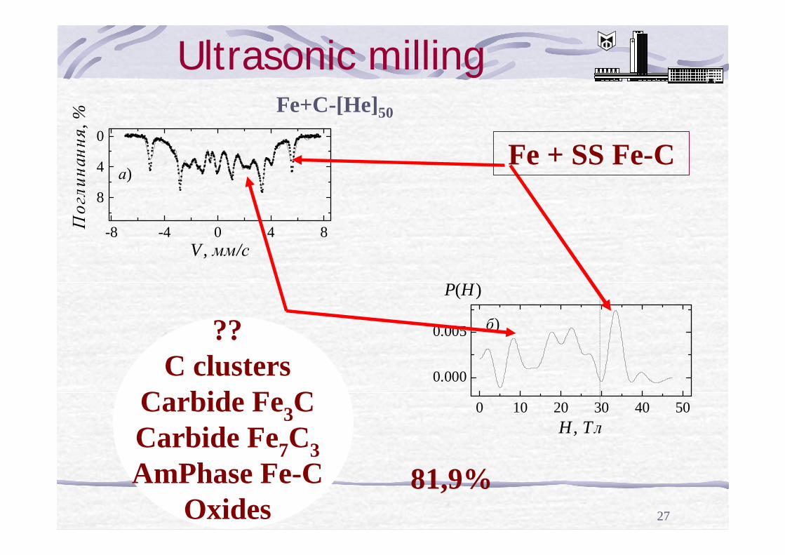
??C clusters
Carbide Fe3CCarbide Fe7C3 AmPhase Fe-C
Oxides
Fe+C-[He]50
-8 -4 0 4 8
8
4
0
а)
V, мм/с
Пог
лина
ння,
%
0 10 20 30 40 50
0.000
0.005 б)
P(H)
H, Tл
Fe + SS Fe-C
81,9%
Ultrasonic milling
28
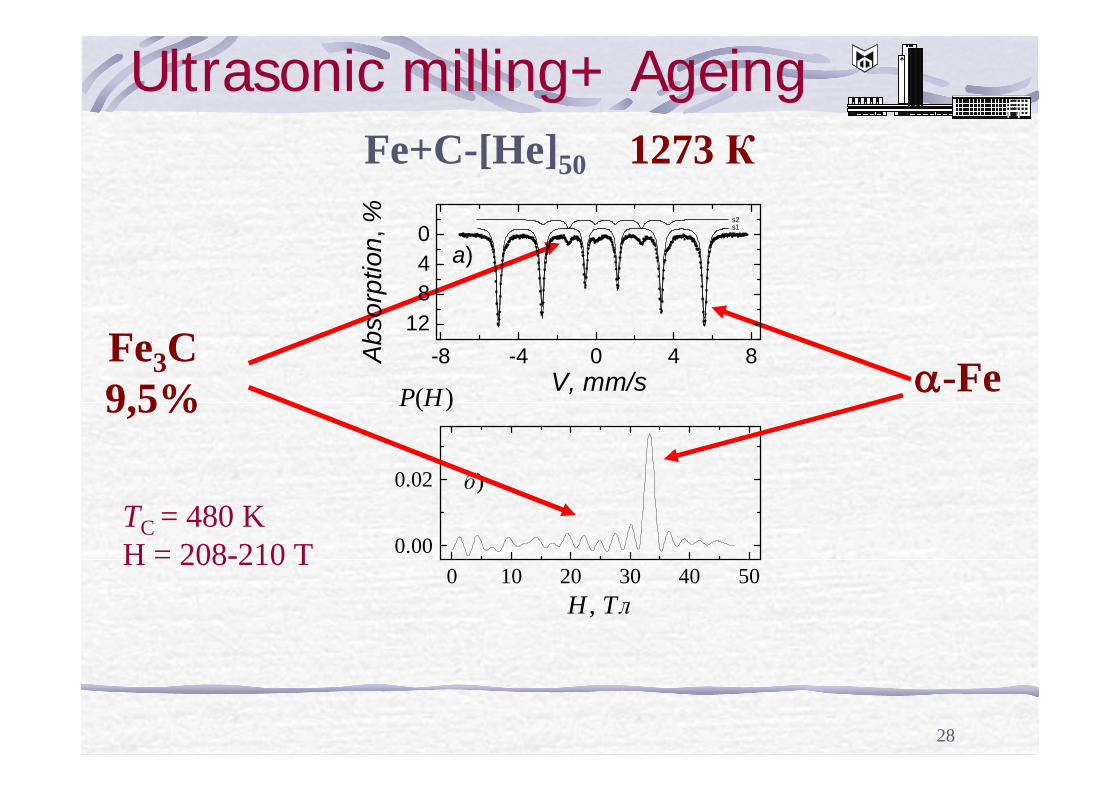
Ultrasonic milling+ Ageing
0 10 20 30 40 500.00
0.02 б)
P(H)
H, Tл
Fe3C 9,5%
Fe+C-[He]50 1273 К
α-Fe -8 -4 0 4 812
840
s2s1
a)
V, mm/sA
bsor
ptio
n, %
TC = 480 KH = 208-210 T
29
Line Nо
Experiment d, nm
α-Fe [1]
Fe3C [1]
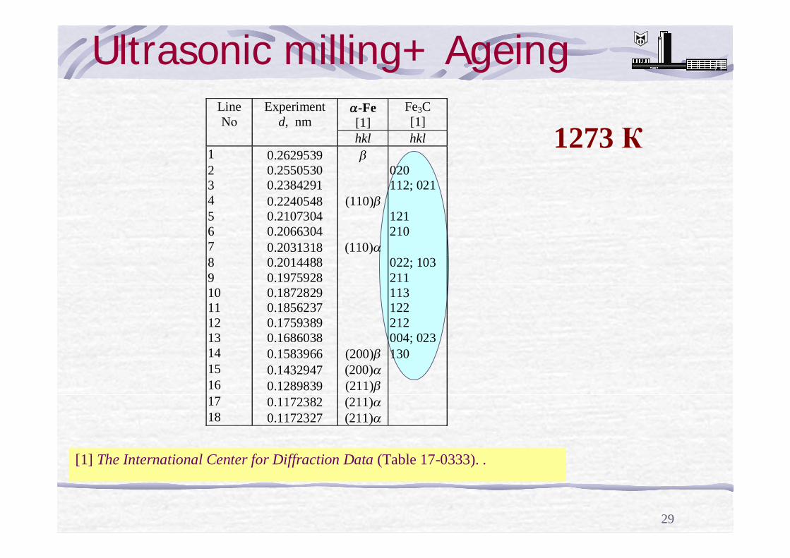
hkl hkl 1 0.2629539 β 2 0.2550530 020 3 0.2384291 112; 021 4 0.2240548 (110)β 5 0.2107304 121 6 0.2066304 210 7 0.2031318 (110)α 8 0.2014488 022; 103 9 0.1975928 211 10 0.1872829 113 11 0.1856237 122 12 0.1759389 212 13 0.1686038 004; 023 14 0.1583966 (200)β 130 15 0.1432947 (200)α 16 0.1289839 (211)β 17 0.1172382 (211)α 18 0.1172327 (211)α
1273 К
[1] The International Center for Diffraction Data (Table 17-0333). .
Ultrasonic milling+ Ageing
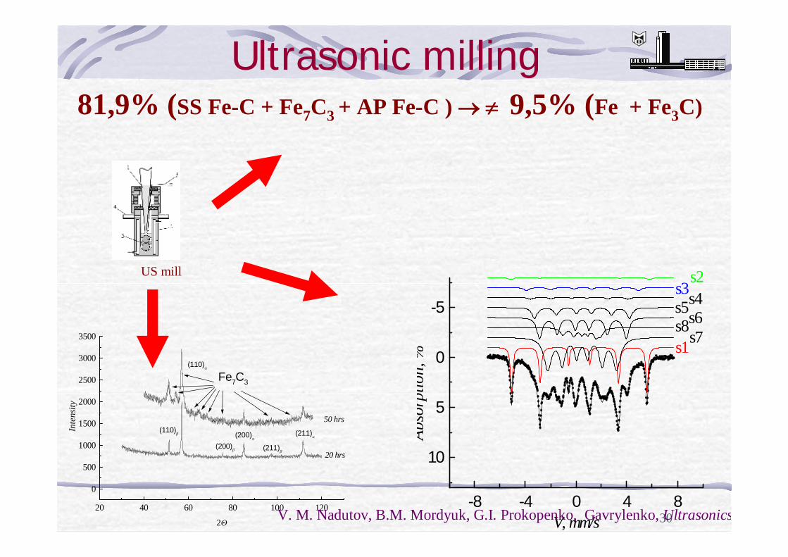
3020 40 60 80 100 120
0
500
1000
1500
2000
2500
3000
3500
Fe7C3
20 hrs
(110)β
(110)α
(200)β
(200)α
(211)β
(211)α
50 hrs
Inte
nsity
2Θ
-8 -4 0 4 8
10
5
0
-5
s2s3s4s5s6s8
s7s1
Abso
rptio
n, %
V, mm/sV. M. Nadutov, B.M. Mordyuk, G.I. Prokopenko, Gavrylenko, Ultrasonics
US mill
Ultrasonic milling81,9% (SS Fe-C + Fe7C3 + AP Fe-C ) → ≠ 9,5% (Fe + Fe3C)
31
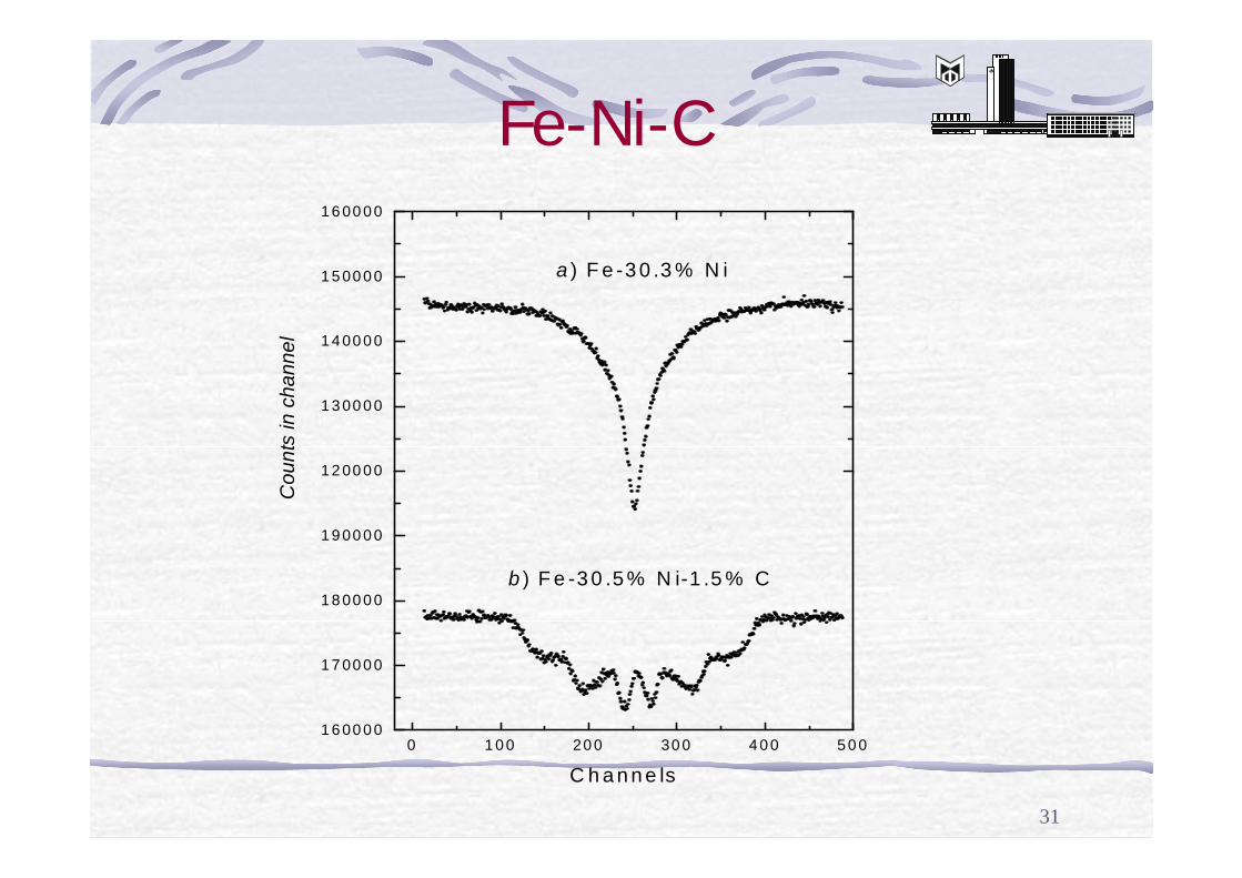
Fe-Ni-C
0 1 0 0 20 0 30 0 4 0 0 5 0 01 6 00 0 0
1 7 00 0 0
1 8 00 0 0
1 9 00 0 0
a ) F e -3 0 .3 % N i
b ) F e -3 0 .5 % N i-1 .5 % C
Cou
nts
in c
hann
el
C h a n n e ls
1 2 00 0 0
1 3 00 0 0
1 4 00 0 0
1 5 00 0 0
1 6 00 0 0
32
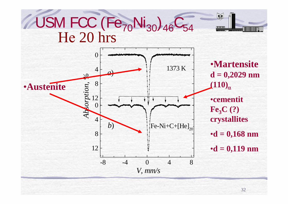
USM FCC (Fe70Ni30)46C54
12
8
4
0
a) 1373 K
Abso
rptio
n, %
-8 -4 0 4 8
12
8
4
0
b) Fe-Ni+C+[He]20
V, mm/s
•Martensited = 0,2029 nm (110)α
•cementitFe3C (?) crystallites
•d = 0,168 nm
•d = 0,119 nm
•Austenite
Не 20 hrs
33
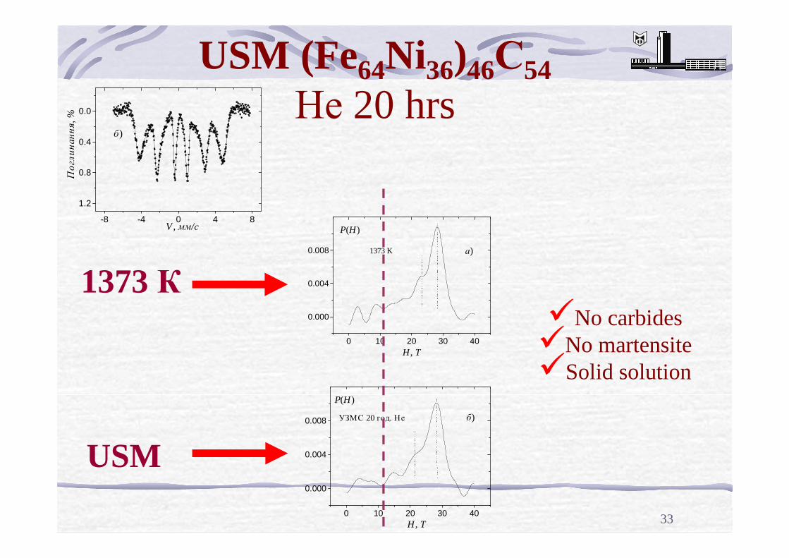
-8 -4 0 4 8
1.2
0.8
0.4
0.0
б)
Погли
нанн
я, %
V , мм/с
USM (Fe64Ni36)46С54Не 20 hrs
1373 К
USM
üNo carbides üNo martensiteüSolid solution
0 10 20 30 40
0.000
0.004
0.008 1373 K а)
H, T
P(H)
0 10 20 30 40
0.000
0.004
0.008 УЗМС 20 год. Не
H, T
б)
P(H)
34
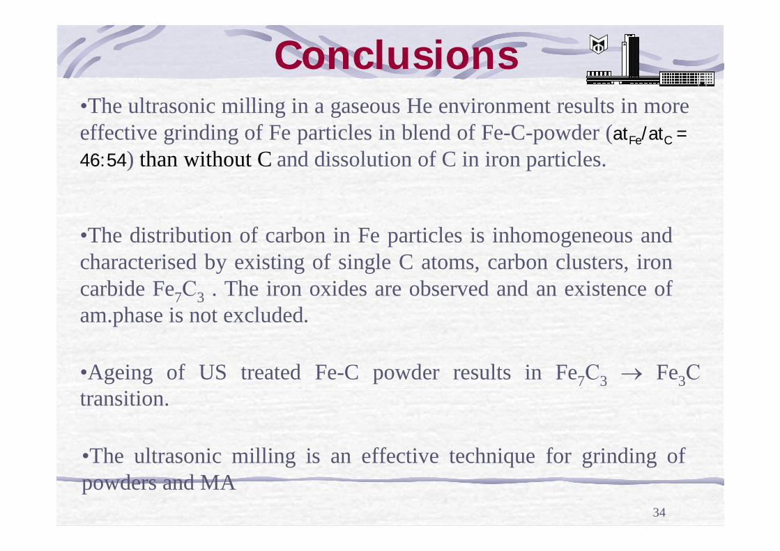
Conclusions•The ultrasonic milling in a gaseous He environment results in more effective grinding of Fe particles in blend of Fe-C-powder (atFe/atC = 46:54) than without C and dissolution of C in iron particles.
•The distribution of carbon in Fe particles is inhomogeneous and characterised by existing of single C atoms, carbon clusters, ironcarbide Fe7С3 . The iron oxides are observed and an existence of am.phase is not excluded.
•The ultrasonic milling is an effective technique for grinding ofpowders and MA
•Ageing of US treated Fe-C powder results in Fe7С3 → Fe3Сtransition.
35
The #2412 and NN32 STCU projects supported these studies
36
Дякую за увагу !
Thanks for your attention !


