Embed Size (px)
Citation preview
L.5 : FERROUS CASTINGS - MOULD, CORE, PATTERN MATERIALS AND PROCESSES
Sukomal Ghosh,
Scientist, National Metallurgical Laboratory, Jamshedpur
Any amount of care in melting and pouring of metals and alloys
cannot help in producing good quality castings if no proper attention is paid
in preparation of moulds and cores. In fact, mould and core production may
account for one-third of the cost of finished castings. No economy measure
is complete without proper selection of moulding materials and maintain-
ing their specification through control tests. Choice of the right type of raw
materials for preparation of moulds and cores and specification control
ensure a mould or core of uniform quality and minimises the number of
defective castings, and this is considered as an important aspect in
productivity.
Depending on the specific use, dimensions, accuracy required, ease
of operation and above all economic considerations, several moulding
methods have been developed over the years - like, sand clay-water system,
shell niotilding, no-bake processes etc. Iii all these cases, basic mould/core
moulding materials had been sand with different binders. The sand, too,
In majority of the eases Is silica sand. The baste Ingredients, thus, in case
of mould or core preparations are sand, binders, additives and coatings.
SANDS
Silica Sand : Foundry sands, in general, are composed of grains of quartz
or quartzite, crystalline forms of silica or other minerals of highly siliceous
character which may be found associated with some form of clays. These
sands as they occur in nature, may not be suitable for foundry use. It may
be necessary to prepare the sand by washing, grading or mixing. The
element silica has a density of 2.4 g/cc and a melting point of 1420°C, where
L5-1
as quartz, the principal constituents of silica sand has a density of
2.66 g/cc and a melting point of about 1750°C. Quartz is in the stable form of
silica at room temperature. On heating a series of allotropic changes occur
which are accompanied by volume changes. The greatest drawback of
silica sand for use as a mould material is the sudden expansion that occurs
at 575°C and it is this expansion which governs the tendency of mould face
to spall at some stare during casting causing scabs and sand inclusions.
Silica sand which is essentially SiO2 also contains various percentages of
impurities like iron oxide, lime, magnesia, potash, alumina etc. The
influence of these constituents on the properties of sand is shown in Table-
1. Silica sands can be broadly classified as :
- Natural moulding sands .
Crude silica sands
-
High silica sands
Natural moulding sands contain appreciable amount of clay of
unspecified mineralogical constituents and they are normally used directly
for preparation of mould and cores. The foundry properties of natural
moulding sands depend on the clay mineral present. The quantity of clayey
mat Ler associated with natural moulding sand is usually in excess, of the
actual requirements for developing required strength in the sand mixture.
It is therefore, customary to blend such natural moulding sands with
relatively clay free river sand to get optimum properties in sand mixture.
Crude silica sands are obtained from river beds, sea coasts and
dunes. Owing to this nature of origin and occurrence, they, contain low
percentage of clayey matter. These sands are used for mould making after
blending with natural moulding sand.
High silica sands are usually obtained by processing loosely consoli-
dated sand deposits of sedimentary origin. Majority of these sands do not
require elaborate processing and some of them may even be available with
L5-2
requisite grading and can be used as mined. Those that are not sufficiently
well graded, are washed and sieved for grading into fine, medium and
coarse fractions. High silica sands may also be produced artificially by
crushing quartzite sand stones with subsequent washing and grading.
High silica sands are usually high in silica and contain very little clayey
matter: Depending on the silica content, high silica sands are divided into
following grades :
Grade A : Si02 content over 98%
B : Si02 content above 95% and upto 98%
C Si02 content above 90% and upto 95%.
Special Sands : The use of special sands like zircon, chromite, olivine
etc. is to overcome the limitation of silica sands. High thermal expansion
and phase change of silica sand can lead to expansion defects particularly
when fine grained sands are employed. Special sands can be grouped under
three major headings :
(n) Zircon sand. (I)) Chromite sand, and (c) Olivine sand
Zircon Sand : Zircon (ZrS10,1) occurs together with other heavy minerals
- notably rutile and ilmenite in certain beach sands. Zircon is believed to
dissociate into Zr02 and Si02 at elevated temperature, but this does not
appear to affect its performance in foundry. Its low and regular thermal
expansion provides high resistance to scabbing defects. The grains tend to
be rounded and sand is free from clayey material. The sand offers high
resistance to metal penetration and excellent surface finish owing to fine
grain size, high refractoriness and low thermal expansion.
Chromite Sand : Natural chrome ore from which foundry sands are
obtained contains 44 to 50% Cr203. The other constituents are
serpentine. Pyroxene, feldspar, quartz, chlorites and carbonates. Suitable
foundry sands are therefore produced by crushing, removing the gangue and
L5-3
screening to the desired grades. High refractoriness and low regular thermal
expansions are characteristics of chromite sand which makes it resistant to
thermal cracking, spalling or scabbing. Chromite sand shows lower wetting
property in contact with steel or metal oxide and exhibit exceptional penetration
resistance in comparison to zircon or silica sand. When bonded with acid
catalysed furan resins, the sand, however poses problem due to its slow
hardening rate. In such cases, sand with consistently low acid demand value
requires to be selected. Chromite sand also forms a very strong sintered layer
(Frit) at the metal - mould interface.
Olivine Sand : Olivine sand is essentially a solid solLItion of two silicates :
Magnesium orthosilicate (forsterite, Mg2SiO4) and iron orthosilicate (fayalite,
Fe2SiO4) with impuri.ies like serpentine, pyroxene, chlorites, talc etc. The
quality of sand is dependent upon the ratio of forsterite to fayalite - the higher
the amount of forsterite, the better. Its bonding with clays are satisfactory, in
fact, less amount of bentonite is required in comparison to silica sand.
Limitation lies in its use with acid catalysed furane resin binder due to its basic
nature.
Chamotte Sand : It is calcined clay fired so that clay fuses together in hard
Imps. The It imps are Hien groi Ind and screened to size suitable for nun tiding.
The sand quality is dependent on firing and quality of clay. The better is the
grade of chamotte, the less is the danger of mould surface fracture.
The average chemical composition of special sands and their prop-
erties are shown in Table-2 and Table-3 respectively.
BINDERS
The basic requirements of the raw materials for mould making is that
the sand particles should bond together in such a way that the desired
shape is easily formed, which should be strong enough to support and hold
the molten metal, yet weak enough for casting to be knocked out of the mould
L5-4
easily. The binder provides this bond. The moulding process when classified
based on the materials used, differs due to adoption of binders to bond the sand
grains. In general, the binders used for the moulding processes can be
categorised as :
a) Inorganic binders
b) Organic binders
c) Synthetic resin binders
Inorganic Binder : Most widely used binder of this group is clay - which is
essentially used for making moulds. Clays are group of minerals in which chief
constituent is hydrated silicate of alumina. Of all the clay groups 'bentonite' clay
is most common. Bentonites have 75% or more crystalline clay like minerals
(A12034Si02x1-1.20)) montmorillonite or beidellite. Table-4 lists characteristics of
some clay minerals used for bonding moulding sands.
When sand and clay are mulled together, each sand grain is evenly
coated with clay. So far as the bonding mechanism is concerned, each flake can
be regarded as a thick structural unit. At the initial stage of mulling, most of
the water molecules are randomly oriented. As the mulling progresses, the clay
aggregates breakdown into individual flakes, thus increasing surface exposed
to water. The water films now gets coated uniformly and distributed in a regular
fashion. The coating thickness becomes thinner and more stable, and result in
more cohesion between clay and sand particles bringing in a developed
strength. The optimum water requirement to develop strength however, differs
from one type of clay to another.
Sodium Silicate : Aqueous sodium silicate (Na20, SiO2xH2O) is another type
of inorganic binder which is used in conjunction'vvith a hardener to bond the
sand grains and develop strength.
The hardening mechanism of sodium silicate binder suggests that
strength in sand aggregates is imparted due to (a) chemical reaction -
responsible for formation of silica gel as a result of reaction with hardener
L5-5
and (b) a physical reaction -causing dehydration responsible for further
increase in strength values with time, making the process dependent on
time (self set process).
In fact, Si02 : Na20 ratio influences strength as stability of silica in
sodium silicate is in a state of delicate balance and largely depend on solids
to water concentration. Silica gel is precipitated when this balance is lost.
With high ratio silicates, precipitation of silica gel could be even due to the
evaporation or dehydration of water. The gelation in lower ratio silicates is
generally accelerated by chemical reactions with hardener. The most
common hardener which are in use for strength development are Carbon
dioxide, Ferrosilicon, Dicalcium silicate, and portland cement.
Cement : Cement as binder finds specific use and claim economy for the
production of large castings like ingot moulds and_.general engineering
castings. The moulding mix consists of sand with 8 to 12% cement and 4
to 6 % water. The sand develops great hardness and strength by the setting
action of portland cement. The characteristic slow curing rate of cement
sand process is accelerated by use of molasses. The molasses as an additive
also impartsa better collapsibility to the mix which is otherwise exhibits a
poor breakdown.
Organic binder : Organic binders are combustible in nature, thus
collapsibility is improved when organic binders are used. In fact organic
binders are mainly used in core-making processes. These binder systems
may be categorised based on material used as listed below :
(a) Oil
(b) Phenolics
(c) Polyurethane
(d) Urea formaldehyde
(e) Furan
L5-6
Oil Binder : Linseed oil and alkyd oil are the binders extensively used for
core making. The linseed oil consists of glycerides of unsaturated fatty
acids. A typical composition consists of 22% oleic acid, 17% linoleic acid
and 51% linolenic acid. The oxygen attacks the point of unsaturation and
polymerises the oil to a solid, cohesive, flexible gel which binds the sand
grains.
The alkyd oil consists glyceryl-phthalate-ester-linked linseed oil. The
curing is through oxidative polymerisation of the oil similar to linseed oil.
The reaction is generally initiated by an oxidizing agent, viz. sodium
perborate and catalysed by a metallic dryer, viz. cobalt or lead napthanaite.
Alternatively, the curing can be achieved by isocynate also.
Phenolic binder : Phenol formaldehyde resins belong to this category.
These resins are prepared by the condensation of phenol with formalde-
hyde. Depending on condition used, two types of PF resins are in use.
(a) Novolac (Phenol: Formaldehyde :: 1:0.7)
(b) Resol (PhenOl: Formaldehyde 1: 1.5 to 1.3)
Novolac resin is also termed as shell resin finds application in
fillet nal ing humidity and temperature conditions...En its curing, it is mixed
with liexa', which is a mixture of hexamethylene tetramine and calcium
sienrate in the ratio of 70:30. When the precoatcd shell sand conies In
contact with the heated mould or core box at (245° ± 15°C), the hexamine
decomposes and reacts with the residual water in resin to liberate ammonia
and formaldehyde. The formaldehyde reacts with novolac resin, produces
cross-linked phenolic polymer which bonds the sand grains. Calcium
stearate improves the flowability of the mix and ease the core or mould
withdrawal.
Urethane Binders : This group of binders derive it name as the developed
bond is through urethane polymer. The binder system consists of phenolic
resin (Novolac) and isocyanate (Diphenyl methane di-isocyanate : MDI)
L5-7
which is gassed through amine gas (TEA, Triethyl amine; or DMEA,
Dimethyle ethyle amine). The process is a no-bake process and popularly
known as 'cold-box' process of core making.
Ureaformaldehyde binders :These resins are prepared by reacting urea
and formaldehyde in mildly alkaline condition. These resins can be
crosslinked using acid catalyst, e.g. ferric chloride. The hot strength and
resistance to thermal stress are however low.
A combination of phonolic cresol (PF) Urea formaldehyde (UF)/Furan
resin (FA) gives better binder performance and are the most common 'hot-box'
binders. However, owing to presence of nitrogen, it is not used for steel castings.
Furan Binders • These resins are made from furfuryl alcohol. The binders
reaction is polymerisation of these chains alongwith a certain amount of
cross-linking. Mildly acidic chloride salts promote the setting reaction.
Based on material used and method of curing, the organic binders
cnil he. grouped as loilows :
Heat cured
a) Phenolic novolac (Shell process)
b) Linseed Oil
c) Phenolic hot box
d) Alkyd oil isocyanate
Gas cured
. a) Silicate _-
b) Phenolic /isocyanate /Amine (Urethane bond)
c) Phenolic/S02
d) Furan/ SO2
L5-8
Nallbake t 4 t
a) Alkyd/isocyanate
b) Furan/acid
c) Phenolic/isocyanate
d) Phenolic/acid
e) Phenolic/ester
f) Silicate/ester, ferrosilicon, dicalciumsilicate
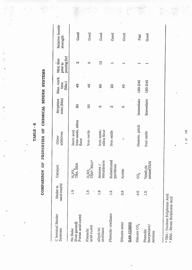
The organic binder systems and their comparative properties are
given in Table-5 and Table 6 respectively.
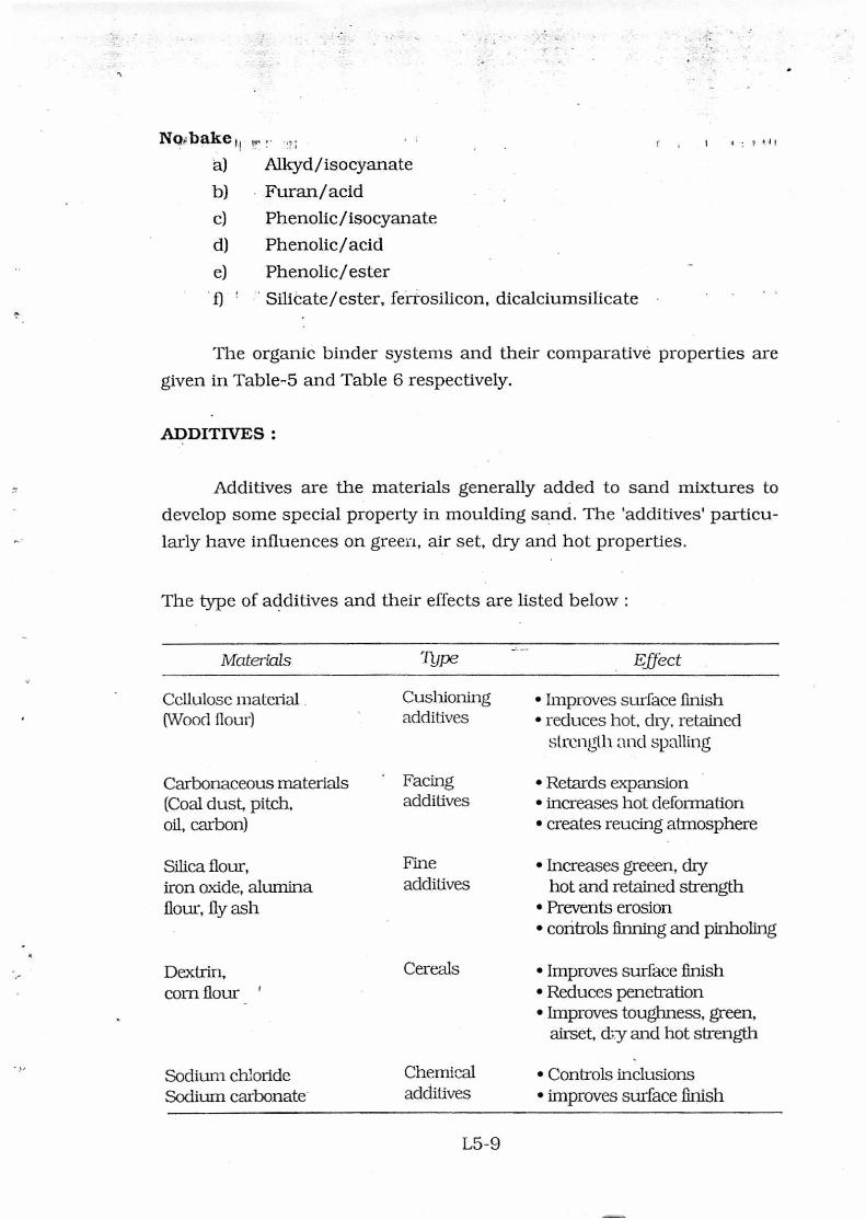
ADDITIVES :
Additives are the materials generally added to sand mixtures to
develop some special property in moulding sand. The 'additives' particu-
larly have influences on green, air set, dry and hot properties.
The type of additives and their effects are listed below :
Materials
71-me
Effect
Cellulose material . (Wood flour)
Carbonaceous materials (Coal dust, pitch, oil, carbon)
Silica flour, iron oxide, alumina flour, fly ash
Dextrin, corn flour '
Sodium chloride Sodium carbonate
Cushioning additives
Facing additives
Fine additives
Cereals
Chemical additives
• Improves surface finish • reduces hot, dry, retained
strength and spatting
• Retards expansion • increases hot deformation • creates reucing atmosphere
• Increases greeen, dry hot and retained strength
• Prevents erosion • controls finning and pinholing
• Improves surface finish • Reduces penetration • Improves toughness, green,
airset, d;y and hot strength
• Controls inclusions • improves surface finish
L5-9
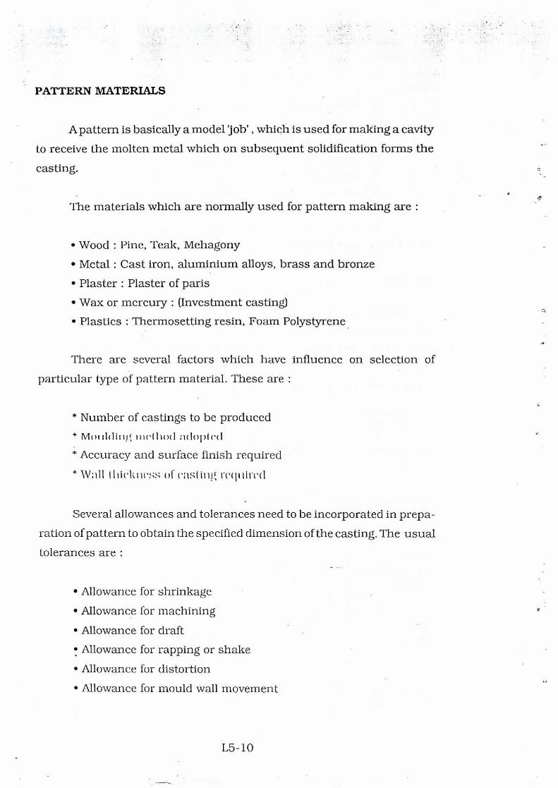
PATTERN MATERIALS
A pattern is basically a model jobs , which is used for making a cavity
to receive the molten metal which on subsequent solidification forms the
casting.
The materials which are normally used for pattern making are :
• Wood : Pine, Teak, Mehagony
• Metal : Cast iron, aluminium alloys, brass and bronze
• Plaster : Plaster of paris
• Wax or mercury : (Investment casting)
• Plastics : Thermosetting resin, Foam Polystyrene .
There are several factors which have influence on selection of
particular type of pattern material. These are :
* Number of castings to be produced
* moulding method adopted
* Accuracy and surface finish required
* \Vail thickness casting required
Several allowances and tolerances need to be incorporated in prepa-
ration of pattern to obtain the specified dimension of the casting. The usual
tolerances are :
• Allowance for shrinkage
• Allowance for machining
• Allowance for draft
• Allowance for rapping or shake
• Allowance for distortion
• Allowance for mould wall movement
L5-10
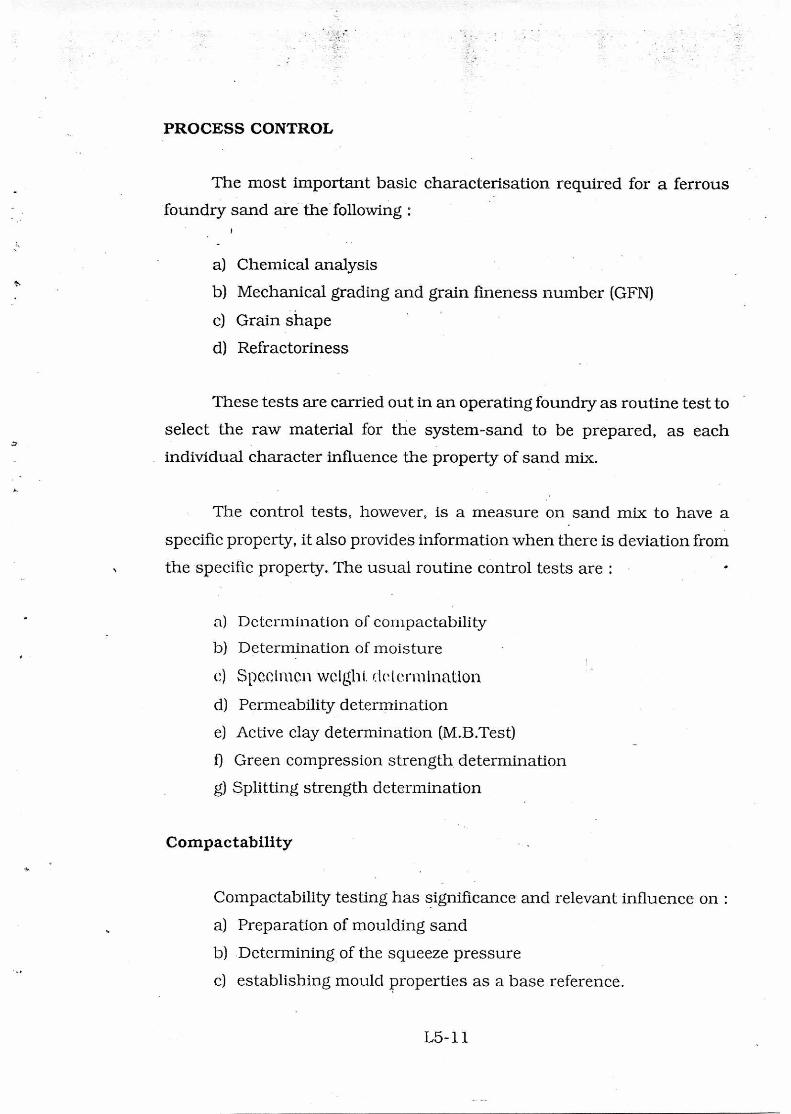
PROCESS CONTROL
The most important basic characterisation required for a ferrous
foundry sand are the following :
a) Chemical analysis
b) Mechanical grading and grain fineness number (GFN)
c) Grain shape
d) Refractoriness
These tests are carried out in an operating foundry as routine test to
select the raw material for the system-sand to be prepared, as each
individual character influence the property of sand mix.
The control tests, however, is a measure on sand mix to have a
specific property, it also provides information when there is deviation from
the specific property. The usual routine control tests are :
a) Determination of compactability
b) Determination of moisture
e) Specimen weight determination
d) Permeability determination
e) Active clay determination (M.B.Test)
f) Green compression strength, determination
g) Splitting strength determination
Compactability
Compactability testing has significance and relevant influence on :
a) Preparation of moulding sand
b) Determining of the squeeze pressure
c) establishing mould properties as a base reference.
L5- 1 1
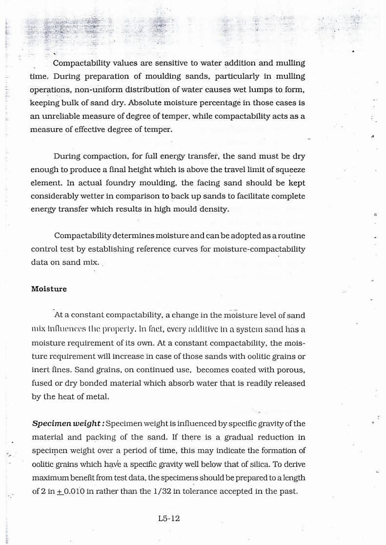
Compactability values are sensitive to water addition and mulling
time. During preparation of moulding sands, particularly in mulling
operations, non-uniform distribution of water causes wet lumps to form,
keeping bulk of sand dry. Absolute moisture percentage in those cases is
an unreliable measure of degree of temper, while compactability acts as a
measure of effective degree of temper.
During compaction, for full energy transfer, the sand must be dry
enough to produce a final height which is above the travel limit of squeeze
element. In actual foundry moulding, the facing sand should be kept
considerably wetter in comparison to back up sands to facilitate complete
energy transfer which results in high mould density.
Compactability determines moisture and can be adopted as a routine
control test by establishing reference curves for moisture-compactability
data on sand mix.
Moisture
At a constant compactability, a change in the moisture level of sand
mix innilt'llets8 I he properly, In fact, every additive in a system sand has a
moisture requirement of its own. At a constant compactability, the mois-
ture requirement will increase in case of those sands with oolitic grains or
inert fines. Sand grains, on continued use, becomes coated with porous,
fused or dry bonded material which absorb water that is readily released
by the heat of metal.
Specimen weight : Specimen weight is influenced by specific gravity of the
material and packing of the sand. If there is a gradual reduction in
specimen weight over a period of time, this may indicate the formation of
oolitic grains which have a specific gravity well below that of silica. To derive
maximum benefit from test data, the specimens should be prepared to a length
of 2 in ± 0.010 in rather than the 1/32 in tolerance accepted in the past.
L5-12
Permeability
The actual packing of the sand grains is reflected through achieved
permeability. In this respect it is a realistic measure than the AFS screen
analysis. An increase in permeability indicates a more open structure and
can lead to rough casting surface, burn-in and meta! penetration. A
decrease in permeability is indicative of too tight a packing indicating
moulds are prone to blow holes, pin holes, and gas roughened surface.
Active clay determination
In system sand a part of bentonite becomes inactive or dead in
continuous cycle. The estimation of live clay is necessary to estimate fresh
clay addition. The Methylene blue test provides three clay values that can
be used in control of system sand. These are total live clay - which is
determined by using ultrasonic scrubber; the dispersed clay - determined
using only a disc agitator and suppressed clay - which is difference between
total clay and dispersed clay. The suppressed clay is the amount of live clay
entrapped in lumps or otherwise not responding to methylene blue.
Suppressed clay indicates the effectiveness of mulling operation, and the
degree. of interaction oladd it Ives. System sand formulation requires special
attention when the suppressed clay is observed greater than- 0.7%.
Green Compression
The green compression test is in practice for primary sand control in
foundries. It is considered that proportion of _clay present has a direct
bearing on G. C.S value though there are other factors too, which influence
the GCS. The degree of mulling, the compactability and additives also have
influence on GCS. The test is best applied in conjunction with some other
mechanical test to derive and effective clay value.
L5-13
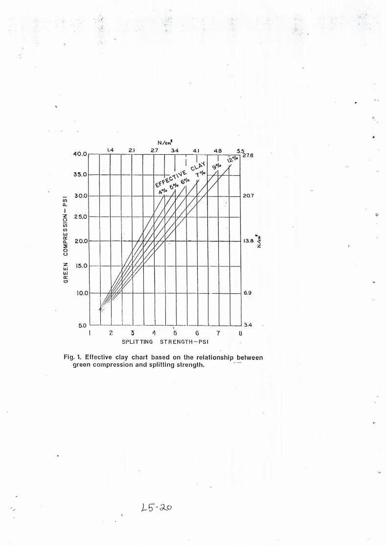
Splitting Strength
The splitting strength is not affected as much by the presence of inert
fines as is the case with GCS test. In this test, the specimen is loaded on
its side between two plane surfaces. With the splitting strength test, the
plane of rupture is at right angles to the plane of rupture in the older, green
tensile strength. Fig-1 shows the relationship between compression and
splitting strength for lines of constant effective clay. The splitting strength
is not affected by some of the factors that alter the green compression and
the ratio between the two test results can be used as a control in its own
right.
SUMMARY
While qualitative assessment of sand is the basis of sand selection
for specific application in a ferrous foundry, routine check for incoming raw
materials, in general, ensure homogeneity and consistency. The specific
requirements may vary depending on the process adopted. For example, a
green strength of 15 to 16 psi with a green deformation of 0.016 to 0.02 in/
In considered to be ideal in the production of iron castings weighing
I wtwecii 20 and 1/10 kg, when conventional jolt squeeze machine is used.
Castings of similar range when produced by high pressure moulding,
opcfnilng wee! 120 In 150 psi squeeze pressure, needs a green
compression strength of 25 to 32 psi. The standard for specific process thus
need to be set and constant monitoring through control test is essential for
adopting modern and improved methods of production for producing
quality castings to specification at competitive price.
In the present scenario of global liberalisation, the 'development' and -
'quality' are key words for survival. With the firm belief that industrial
development is the back bone for prosperity of a country, the challenges of
modern technological developments in foundry is being met by National
Metallbrgical Laboratory, Jamshedpur and its foundry units at Ahmedabad,
Batala, Howrah and Madras, with a motto to provide R&D support and
ensuring quality by choice only.
L5-14
Selected Bibliography
1. Non metallic foundry raw materials for moulds and cores, G.N.Rao, V.A.Altekar; Foundry Directory, 1975 (IIF Publication)
2. Alternative to silica sand for mould production; J.Middleton, Chemi-cal Binders in. Foundries, BCIRA Publication, 1976.
3. Indian Foundry Sand - availability and quality; S.Ghosh, G.N.Rao, V.A.Altekar; Seminar on Foundry day celebration; IIF, NRB. August 1982.
4. The silica-soda ratios of sodium silicate - Its foundry importance; S.Ghosh, R.R.Dash, G.N. Rao; NML Technical Journal, Vol.22, 1980.
5. Significance of non-conventional testing methods for foundry mould-ing sands; S.Ghosh, G.N.Rao, Seminar organized by IIF, ERB, Sept. 1983.
6. Characterisation and control of moulding materials for production of sound castings; S.Ghosh, R.R.Dash, O.N. Mohanty; Invited lecture at industry workshop organised by SISI, Patna, December 1986.
7. Compacability testing a new approach in sand research; F.Horman, H.W.Dietert; Trans. AFS, 1964, pp 134.
8. A new methylene blue procedure for determination of clay in system sa nd ;11.W. Die tea, A.L.Graham, J.S.Schumachers; Trans, AFS,1970.
9. Moulding processes - practice and advances; S.Ghosh; Preprint; (Aise on Advances In foundry technology; 1W JSR. Chapter, 1986.
10. Sand preparation and control; A.Bhattacharjee; Preprint, Course on Advances in foundry technology; IIF JSR Chapter, April, 1988.
11. Core making with synthetic binders system; A.K. Sarkar; Preprint; Course on Advances in foundry technology; IIF JSR Chapter, April, 1988.
12. A sand control program that saves castings; H.W.Dietert, A.L. Graham, Trans AFS, 1974.
13. Cast Quest; Issue 3 (1987); Issue March (8/B2) (1988); Issue 13/C2, August(1988); IIF JSR Chapter.
14. Foundry raw materials hand book, IIFJSR Chapter, Publication 1993.
L5-15
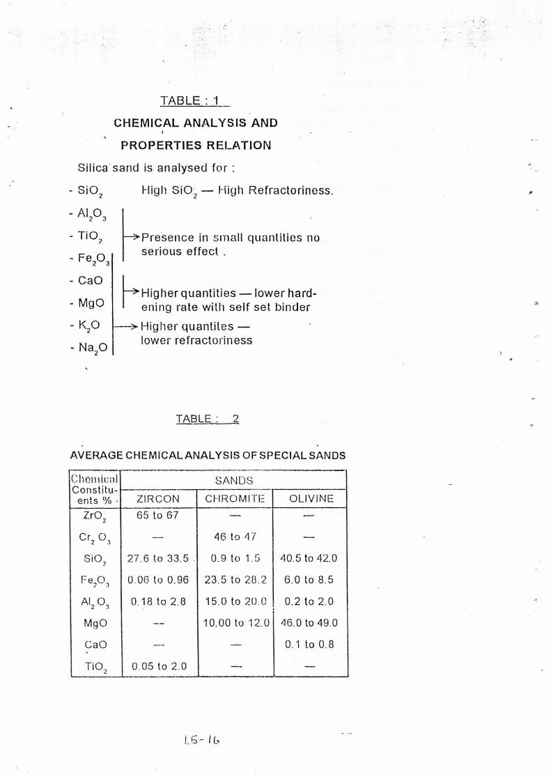
TABLE :
CHEMICAL ANALYSIS AND
PROPERTIES RELATION
Silica sand is analysed for :
- Si02
- A1203
1-102
Fe203
CaO
Mg0
- K20
- Na20
High SiO2 — High Refractoriness.
---->Presence in small quantities no serious effect .
HHigher quantities — lower hard-ening rate with self set binder
--> Higher quantites — lower refractoriness
TABLE : 2
AVERAGE CHEMICAL ANALYSIS OF SPECIAL SANDS
Chonlicni SANDS Constitu-ents % • ZIRCON CHROMITE OLIVINE
Zr02 65 to 67
Cr2 03 — 46 to 47 —
SiO2 27.6 to 33.5 . 0.9 to 1.5 40.5 to 42.0
1=e203 0.00 to 0.96 23.5 to 28.2 6.0 to 8.5
A12 03 0.18 to 2.8 15.0 to 20.0 0.2 to 2.0
MgO — 10.00 to 12.0 46.0 to 49.0
CaO -- — 0.1 to 0.8
TiO2 0.05 to 2.0 — —
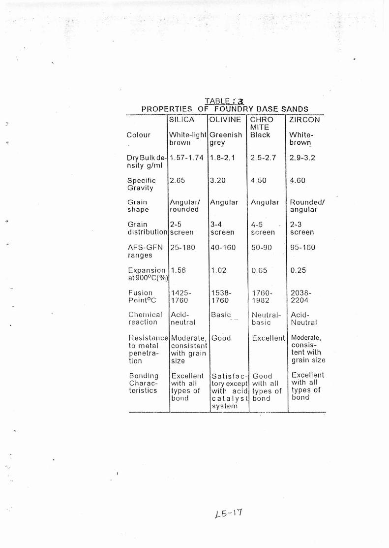
TABLE 3 PROPERTIES OF FOUNDRY BASE SANDS
Colour •
SILICA
White-light brown
OLIVINE
Greenish grey
CHRO MITE Black
ZIRCON
White-brown
Dry Bulk de- nsity g/m1
1.57-1.74 1.8-2.1 2.5-2.7 2.9-3.2
Specific 2.65 3.20 4.50 4.60 Gravity
Grain Angular/ Angular Angular Rounded/ shape rounded angular
Grain 2-5 3-4 4-5 - 2-3 distribution screen screen screen screen
AFS-GFN ranges
25-180 40-160 50-90 95-160
Expansion at 900°C(%)
1.56 1.02 0.65 0.25
Fusion 1425- 1538- 1760- 2038- Point°C 1760 1760 1982 2204
Chemical Acid- Basic Neutral- Acid- reaction neutral - - basic Neutral
Resistance to metal
Moderate, consistent
Good Excellent Moderate, consis-
penetra- with grain tent with tion size grain size
Bonding Excellent S a tisfa c- Gond Excellent Charac- with all tory except with all with all teristics types of with acid types of types of
bond catalyst systeril
bond bond

OXYGEN (AIR) 220.-±10
SODIUM PERBORATE ACCELERATOR COBALT NAP 1 I IANA I Ar .:C151 I1 IA 1 011 COITAL NAI•l HANATE
SET1INO AMBIENT. FULL CURE : MOVING
AMBIEN•1
High. Na is 1150- Very high gel Very high Flake size
adsorbed ion, 1345°C
forming less than pH = 8-10 .00001in.
High. Ca adsorbed ion pH = 4-6.50
Very Low
980°C+ Slight little tendency to gel
1650- Very low Low 1700°C non-gel
forming
Fite clays are often ground and therefore may he Fob tivety coals()
or may be ground to a flour.
Very high Flake size less than .00001 in.
TABLE 1.4
Characteristics of some clay minerals used for bonding molding sand
CURING TEM•°C
1. ALKYD 011 ;) MDI
Clay mineral typo
Montmorillonite class 1A
Composition type
(01.1)4 Al4 Si, 020 n1.120 Ex. 90% montmorilionite 10% Quartz, Feldspar, Mica, etc.
(OH)4 AL4 Si, 020 hl-12° Ex. 85% Mon1morillonite, 15% quartz, limonite, etc:.
(011)4 AL4 Si4 0, Ex.60% Kanlinite, 30% Mite. 10% Cl113117, etc.
Refractori- Swelling shrinkage Particle
ness
due to due to loss size and
Base Exchange (softening water. of water shape. point)
Montomorillonite class 1B
Kaolinite class IV, fire clay
grundite (011)4 Ky (Al4Fe4Mg4 Mge) ( Si, - y ALy) 02,
Moderate 1370°C Low, non-gel forming
Moderate.
TABLE :.5
ORGANIC BINDER SYSTEMS FOR POPULAR CORE/MOULD MAKING PROCESS
PROCESS BINDER HARMER/ , CATALYST
LINSEED LINSEED OIL OIL/DEXTRIN DEXTRIN
WATER ALKYD OIL. ALKYD OIL nj AIR SET
b) NO BARI
SI lEt L
PF (NOVOLA() I 'EXAMINE 245±15
I.101 L1OX
Kim, mixt_ 225±2t3 F/UF, OF/FA
COLD BOX a) AMINE PART-1 : PF
GASSED (NOVOLAK) PART-2 : MDI
b) SO2 GASSED PF (RESOL) PF/FA
TEA, DMEA
AMBIENT
SO2, MEKP AMBIENT
• PHENOLIC COLD SET a) ISOCYANATE
b) ACID CATALYSED
PART-1: PF (NOVOLAK) PART-2: MDI PF (RESOL) PF/FA PF/UF/FA OF/FA
PPP
PTSA, XSA, BSA, H3PO4, AMBIENT 1-1250., & THEIR MIXTURES
DEFINITION : I3SA - BENZENE SULPHONIC ACID DMEA - D1METHYLETHYLEAMINE H2SO4 - SULPHURIC ACID 1-13PO4 - PHOSPHORIC ACID MDI - DIPHENYLMETHANE DIISOCYANTE MF.KP - METHYL ETHYL KETONE PEROXIDE PF - PHENOLFORMALDEHYDE RESIN PF/FA - PHENOLIC FURAN RESIN PF/UF/FA - COPOLYMER RESIN, PIENOLFORMALDEHYDE/UREA-FORMALDEHYDE/FURFURYL ALCOHOL PPP - 4-(3-PHENYL PROPYL) PYRIDINE PTSA - PARATOLUENE SULPHONIC ACID TEA - TRIETHYLAMINE OF/FA - UREA FURAN RESIN XSA - XYLENE SULPHONIC ACID
1-5 -IS
L if) IC) CO
Si l
ica t
e es
ter A
SY
ST
EM
S
PR
OP
ER
TI E
S
0
0
a..
0 a)
rt:s res not • 0
O O
0 0 0 0 C) 0
r-4 r-4 r-4 r-4
o o TJ, gct4 to to • to •t° 0 o co co
-!-■ ctS 0 0 .r.1
P0 CO CO a) a)
al C.) o-4
,. O C.)
'0 aS a) a; ;-' a.) .-,
a a)
..-, rci 'Li ''
'0 rti 1:1 ) . *P •P , i ,...) 0 'P 0 0 .2 O 0 cz
- o o o () o o 0 0 0 0 0 4.) 0
co P4
•
1,94 c21 ;-1
.r4 -... a)-4-1 0 li
(i) csa 0 4 g ou a) r.Ci
1311 0 Wc4
'St Q
E-4 EA (/) a 0
Ph
e no
lic
ure
t ha
ne
to co
izi (1) -ci a) ;...
.5
u Po Ts 78 a) co nt c) o (f) — <.) 1_, .,-,
ctl ° --, *E5
a) 4_, CA 0 0 iz:s r5
(/) 0 4.) Ti T.) 0 4 •(.1
(..) 0 Z 5-..-- tx... 10-, cz '.
N /crni 1.4
2.1
2.7 3.4
4.1
4.8
0-601,3 A
Aar
c)-0'"
pr ,
el°
00
1°1° (301°
\e?, .3
t1/4°17
A,
ii
.----
20.7
13.8 2
6.9
3.4
5.5 27.6 40.0
35.0
CO
MP
RE
SS
ION- P
SI 30.0
25.0
20.0
15.0
CC cD
10.0
5.0
t3
7 8
SPLITTING STRENGTH — PSI
Fig. t Effective clay chart based on the relationship between green compression and splitting strength.
)_ -


