Embed Size (px)
Citation preview
Multimodality for Plastic User Interfaces: Models, Methods, and Principles
Jean Vanderdonckt1, Gaëlle Calvary2, Joëlle Coutaz2, Adrian Stanciulescu1
1Université catholique de Louvain, Louvain School of Management(LSM), Belgian Lab. of Computer-Human Interaction (BCHI), Place des Doyens, 1 – B-1348 Louvain-la-Neuve, Belgium {jean.vanderdonckt, adrian.stanciulescu}@uclouvain.be
2Université Joseph Fourier, Grenoble Informatics Laboratory (LIG), 385 rue de la Bibliothèque, BP 53 – F-38041 Grenoble cedex 9, France {gaelle.calvary, joelle.coutaz}@imag.fr
1 Introduction
In the early nineties, research in multimodal user interface design was pri-marily concerned with the goal of mimicking human interpersonal capa-bilities [26], reminiscent of the “Put That There” paradigm [6]. More re-cently, multimodality has been viewed as a means to improve interaction flexibility, adaptation, and robustness [28]: • Interaction adaptation denotes the ability of the system to adapt itself or
to be adapted according to the constraints imposed by the context of use, where the context of use in understood as the combination of a user us-ing a given computing platform in a particular physical environment [9]. For example, when the user switches from a desktop platform to a mo-bile platform, the user interface may be adapted by relying on other in-teraction techniques than those previously available on the initial plat-form.
• Interaction flexibility denotes the multiplicity of ways the user and the system exchange information [18]. For example, commercial navigation
systems use verbal outputs as well as graphics maps and icons to pro-vide drivers with understandable instructions. The system, as well as the user, can choose the most convenient and effective way to acquire in-formation and convey meaning.
• Interaction robustness covers features of the interaction that support the successful achievement and assessment of goals, whether these goals are human goals or system goals) [18]. For example, in a noisy environ-ment, the system may draw upon visual facial features to improve its understanding of spoken utterances, making the interaction more robust. Today, context-aware processing capabilities are being developed to en-
hance system adaptation, flexibility, and robustness. As a result, from user interfaces whose spectrum of modalities is pre-defined by-design, research is now concerned with multimodal user interfaces (UIs) where the set of modalities and their combination may evolve dynamically to accommodate and take advantage of the changes in the real world. By extension, we call plasticity, the capacity of interactive systems to adapt to the context of use while preserving, or even enhancing, the usability of the system [9,35]. Usability expresses the useworthiness of the system, that is the value that this system has in the real world [10]. Therefore, the major difference be-tween adaptation and plasticity is that there is no guarantee that the adapta-tion will lead to a value in the real world in the first case as opposed to an explicit guarantee in the second case.
The context of use is a dynamic structured information space whose fi-nality is to inform the adaptation process. It includes a model of the user who is intended to use (or is actually using) the system, the social and physical environments where the interaction is supposed to take place (or is actually taking place), and the hardware-software platform to be used (or is actually being used). The latter covers the set of computing, sensing, communication, and interaction resources that bind together the physical environment with the digital world.
UI adaptation has been studied in Artificial Intelligence (AI) for many years but the context of use has often been restricted to a user model [8]. Today, Model Driven Engineering (MDE) is being rediscovered and ex-plored as a generic framework to address the problem of plastic UIs [9]. Significant results have been demonstrated for plastic distributed graphics UIs [12,13]. On the other hand, multimodality has been covered in a rather limited way, rather as a by-product than as a driving force for adaptation [4,15,38]. Similarly, work in multimodal UI has focused primarily on the problem of synergistic blending at multiple levels of abstraction [24], rarely on adaptation issues or viewing multimodality as an explicit means to adapt UI according to their context of use [32,33]. In this article, we bring together the main results from the developments in plastic UIs and in
multimodal UIs using a theoretic and conceptual perspective as a unifying approach. It is aimed at defining models useful to support UI plasticity by relying on multimodality, at introducing and discussing basic principles that can drive the development of such UIs, and at describing some tech-niques as proof-of-concept of the aforementioned models and principles. In the following section, we introduce running examples that will serve as illustration throughout our discussion of the use of multimodality to sup-port plasticity.
2 Running Examples
This section includes a brief description of two examples we have imple-mented using multimodality as a means for UI plasticity: a neuro-surgery system and a web site.
2.1 The assisted neuro-surgery system
Our neuro-surgery system supports a craniotomy task. This task consists of drawing a surgery path over the patient’s head. Three technical stages are necessary to provide the surgeon with the appropriate guidance: 1. In the pre-operative stage, the surgeon selects the structures of interest
that must be segmented from pre-operative images. He may also define additional information, such as annotations that are relevant to the task execution as well as commands for auditory output.
2. At the pre-operative calibration stage, the segmented structures are reg-istered along with the physical scene as well as any movement of the pa-tient or microscope compensated for. The optics of the microscope is calibrated.
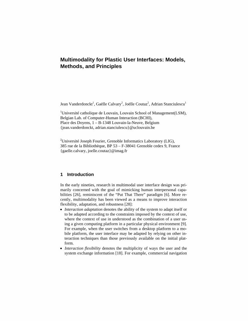
3. Finally, during the surgical intervention, the virtual structures aug-mented with the annotations are visualized and/or rendered via the audio channel. In order to constantly display useful information, the patient head is de-
composed into three zones (Figure 1): the region labeled as 1 has the low-est priority, the region labeled as 2 has medium priority and the region la-beled as 3 has the highest priority. The algorithm first tries to place annotations only in the level 1 area to avoid intersection with the level 2 zone. If the available area is not sufficient, the algorithm tries to place an-notations by spanning over the level 2 zone while avoiding to overlay an-notations onto the level 3 zone. If this is still not possible, annotation is automatically rendered through the audio output. Annotation localization is
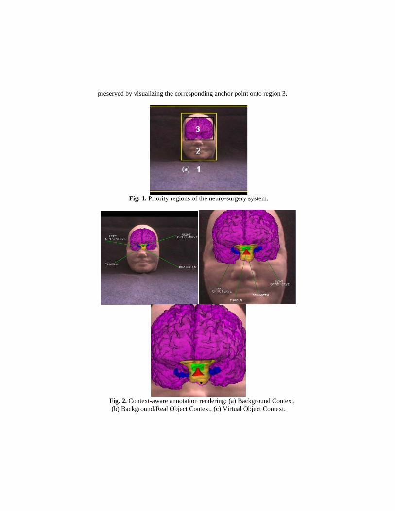
preserved by visualizing the corresponding anchor point onto region 3.
Fig. 1. Priority regions of the neuro-surgery system.
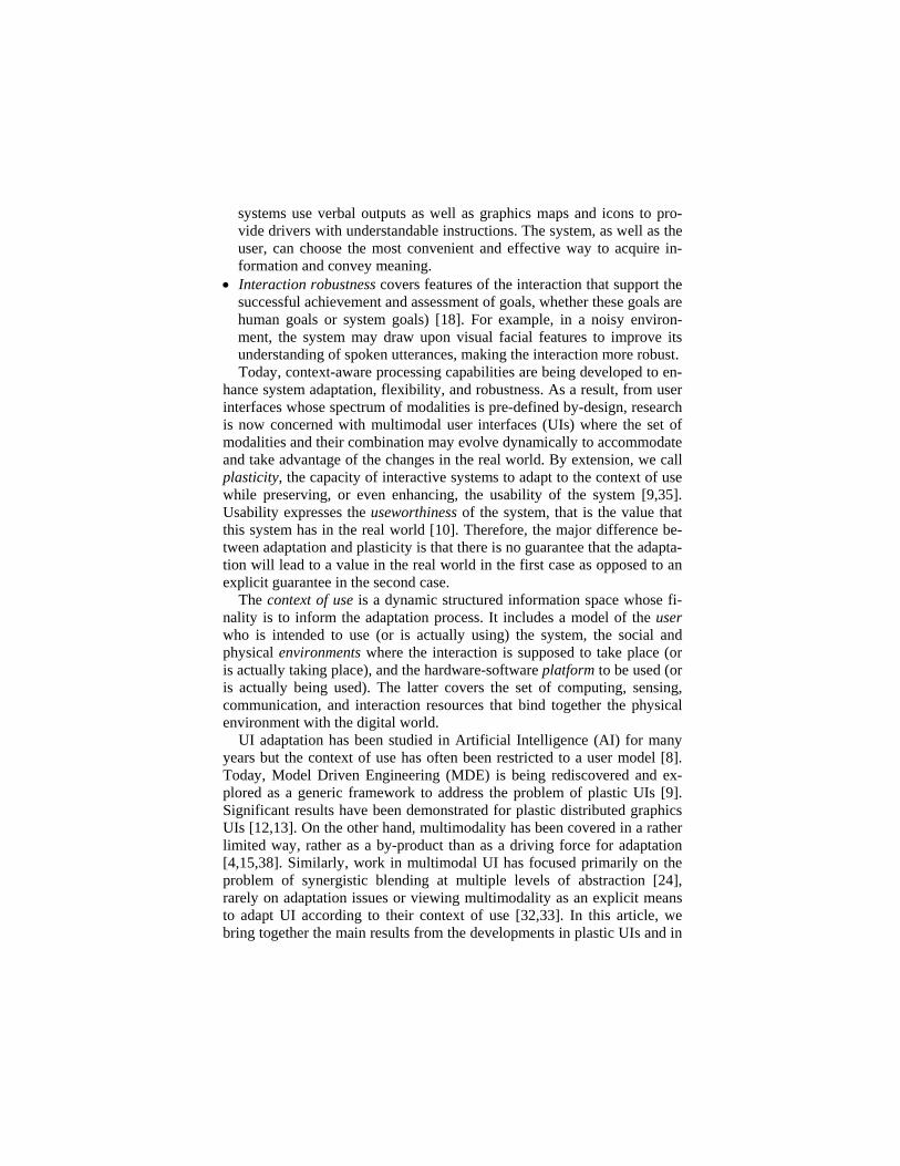
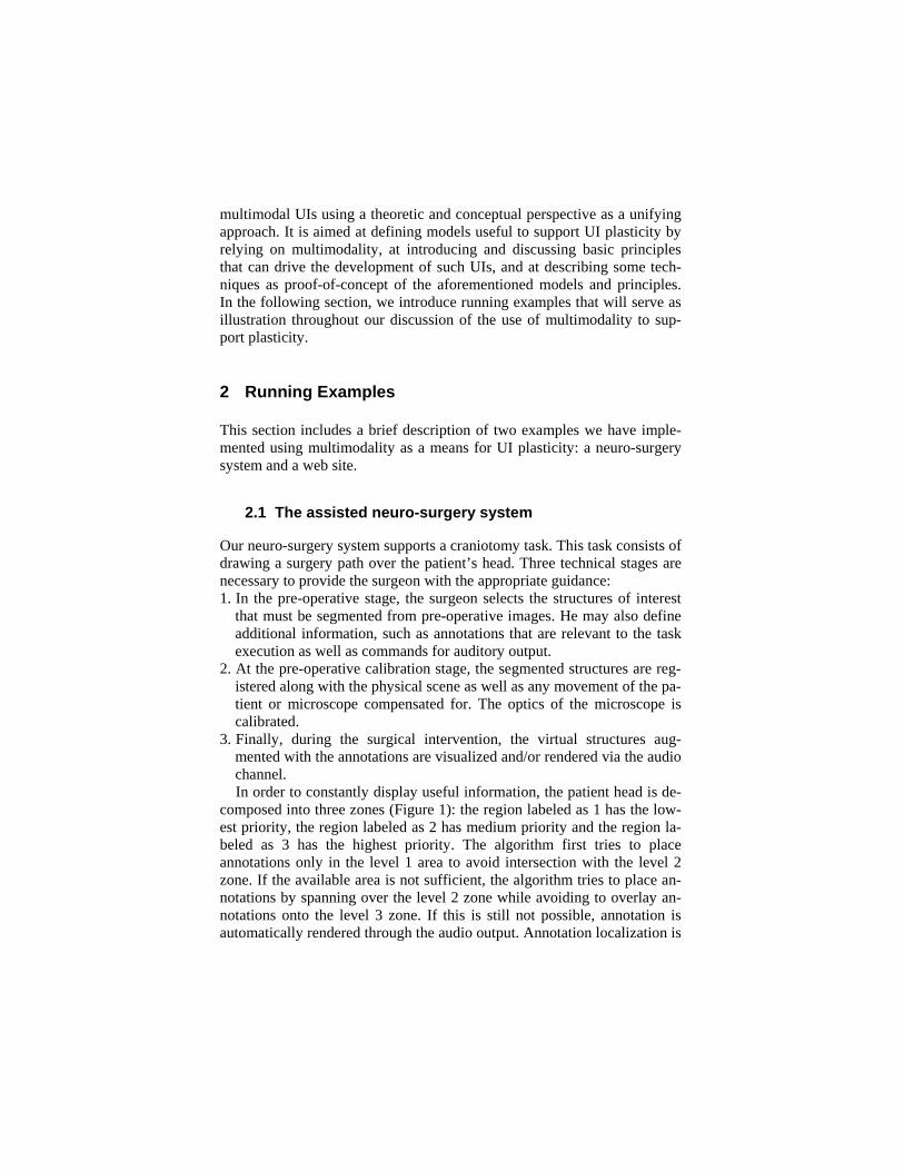
Fig. 2. Context-aware annotation rendering: (a) Background Context, (b) Background/Real Object Context, (c) Virtual Object Context.
(a) (b) (c)
Switching between the different renderings shown in Figure 2 depends
on the distance between the patient’s head and the surgeon’s head as well as on the angle of the surgeon’s body with respect to the vertical axis. 1. When the surgeon is in the background context (which means a maxi-
mum degree of 5° with respect to vertical axis and more than 60 cm from the patient’s head), the rendering is performed as in Figure 2a.
2. When the surgeon is in the background/Real object context (which means between 5° and 10° with respect to vertical axis and between 30 and 60 cm from the patient’s head), Figure 2b is rendered.
3. When the surgeon is in the virtual Object context (which means more than 20° with respect to vertical axis and less than 30 cm from the pa-tient’s head), graphics text is replaced with vocal rendering.
2.2 The Sedan-Bouillon Web Site
The Sedan-Bouillon Web site (www.sedan-bouillon.com, a web site de-veloped by UJF within the European IST Cameleon project - http://giove. cnuce.cnr.it/cameleon.html) provides tourists with information for visiting and sojourning in the regions of Sedan and Bouillon. Figure 3a shows a simplified version of the actual Web site when a user is logged in from a PC workstation. By dynamically logging to the same web site with a PDA, users are informed on the PDA that they can allocate UI components across the interaction resources currently available.
In the example of Figure 3b, the user asks for the following distribution: the title of the page must appear on the PDA as well as on the PC (the title slots are ticked for the two browsers), the main content should stay on the PC, and the navigation bar should be rendered on the PDA. Fig. shows the resulting UI. In this configuration, the PDA is used like a remote controller to browse the information space displayed on a shared public surface. At any time, the user can ask for a reconfiguration of the UI by selecting the “meta-UI” link in the navigation bar of the PDA.
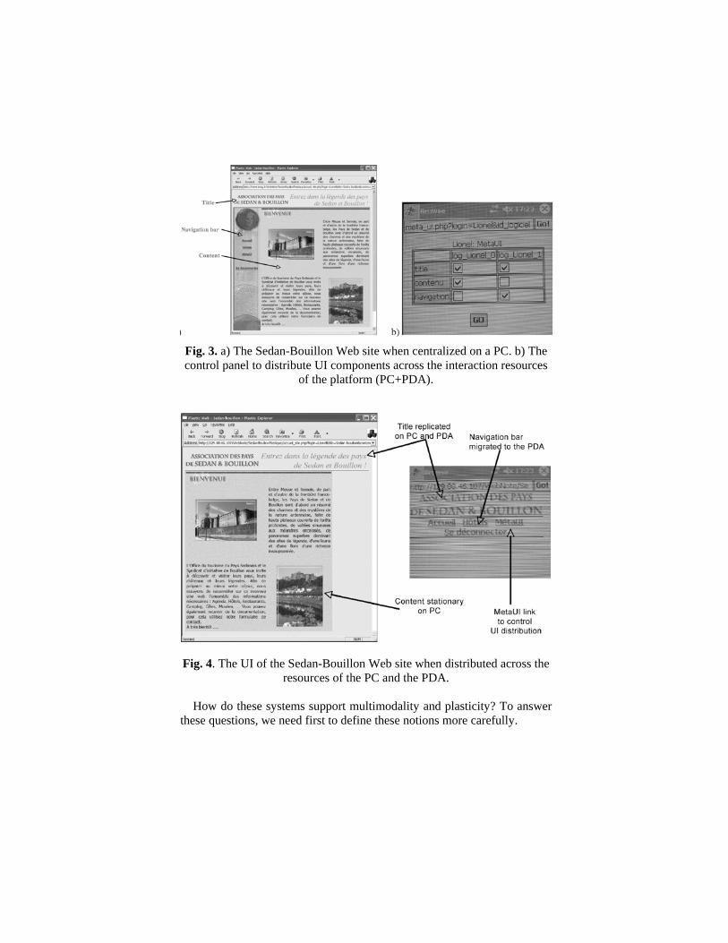
Fig. 3. a) The Sedan-Bouillon Web site when centralized on a PC. b) The control panel to distribute UI components across the interaction resources
of the platform (PC+PDA).
Fig. 4. The UI of the Sedan-Bouillon Web site when distributed across the resources of the PC and the PDA.
How do these systems support multimodality and plasticity? To answer
these questions, we need first to define these notions more carefully.
3 Modality and Multimodality
The scientific community has now debated definitions and uses of multi-modality for more than twenty years without reaching clear consensus. The concepts of “modality” and “multimodality” mean different things to dif-ferent stakeholders. In cognitive psychology, a modality denotes a human sense (e.g., vision, audition, taste, etc.) whereas in Human-Computer In-teraction (HCI), multimodality corresponds more or less to interaction techniques that involve multiple human senses simultaneously. Much de-pends on the perspective, e.g., from a user or a system point of view, or on the degree of precision needed to solve or discuss a particular problem. In this section, we present our choices using a system perspective.
3.1 Definitions
Reusing Nigay and Coutaz’s definition [23], we define a modality M as the coupling of an interaction language L with a physical device d:
M ::= <L, d>
An interaction language defines a set of well-formed expressions (i.e. a conventional assembly of symbols) that convey meaning. The generation of a symbol, or a set of symbols, results from actions on physical devices. A physical device is an element of the host platform of the interactive sys-tem that plays the role of an interaction resource: it acquires (input device) or delivers (output device) information. For instance: • A speech input modality is described as the couple <pseudo natural lan-
guage NL, microphone>, where NL is defined by a specific grammar. • A written (typed) natural language corresponds to <pseudo natural lan-
guage NL, keyboard>. • A speech output modality is modeled as <pseudo natural language NL,
loudspeaker>. • A graphics output modality as <graphics language, screen>. • A direct manipulation modality as the couple <manipulation language,
mouse>. A more detailed expression of the interaction modality as an interaction
language coupled to a device is expressed in terms of a UML class dia-gram in [7]. From a system perspective, the distinction between “interac-tion language” and “device” is relevant for two reasons:
1. It is consistent with the logical and physical separation of concerns ad-vocated by the Arch software architecture model for structuring the UI
rendering [3] as explained in Chapter 9. The Logical Presentation (LP) level is interaction language-dependent but device-independent, whereas the Physical Presentation (PP) level is both language and device de-pendent. Thus, coupling an interaction language with a different device would result in the modification of the PP level. Modifying the interac-tion language would have an impact on both the LP and PP levels.
2. It is consistent with human experience. From the system perspective, coupling an interaction language with a different device would result in a new modality. This is true as well for the human. For example, ma-nipulating a graphical object with a mouse, or performing the same task with a brick [16] would provide users with a very distinctive experience.
In addition, a modality can play the role of an input device to produce sentences of an interaction language. For example, the words of a sentence of a pseudo-natural language may be produced by selecting the appropriate words from pull-down menus using a mouse. In this case, the keyboard device is replaced by the modality <select within pull-down menus, mouse>. The general definition of a modality is thus expressed in the following way:
M ::= <interaction language, d> | <interaction language, M>
Multimodality can be loosely defined by the many ways of combining modalities:
• An input multimodal system is a system that combines two or more user input modes in a coordinated manner with multimedia system output [1,27,29,30,36]. For instance, MultimodaliXML [37,38] enables the user to rely on graphical interaction, vocal interaction, and/or tactile interac-tion to provide information to an information system. The multimodal UI is specified in UsiXML [39], a XML-compliant language for describ-ing multimodal UIs based on semantics of multimodal UIs [17].
• An output multimodal system is a system that presents information in an “intelligent” way by combining two or more communication modalities [32,33]. This is the case for our neuro-surgery system where graphics and audio outputs are used.
In the following section, we analyze the combination of modalities in a more precise way using the CARE properties. Other taxonomic spaces such as TYCOON [21] could equally be used. The motivation for using the CARE properties is that they have served to structure the development of software tools for multimodal interfaces (See Chapter 9).
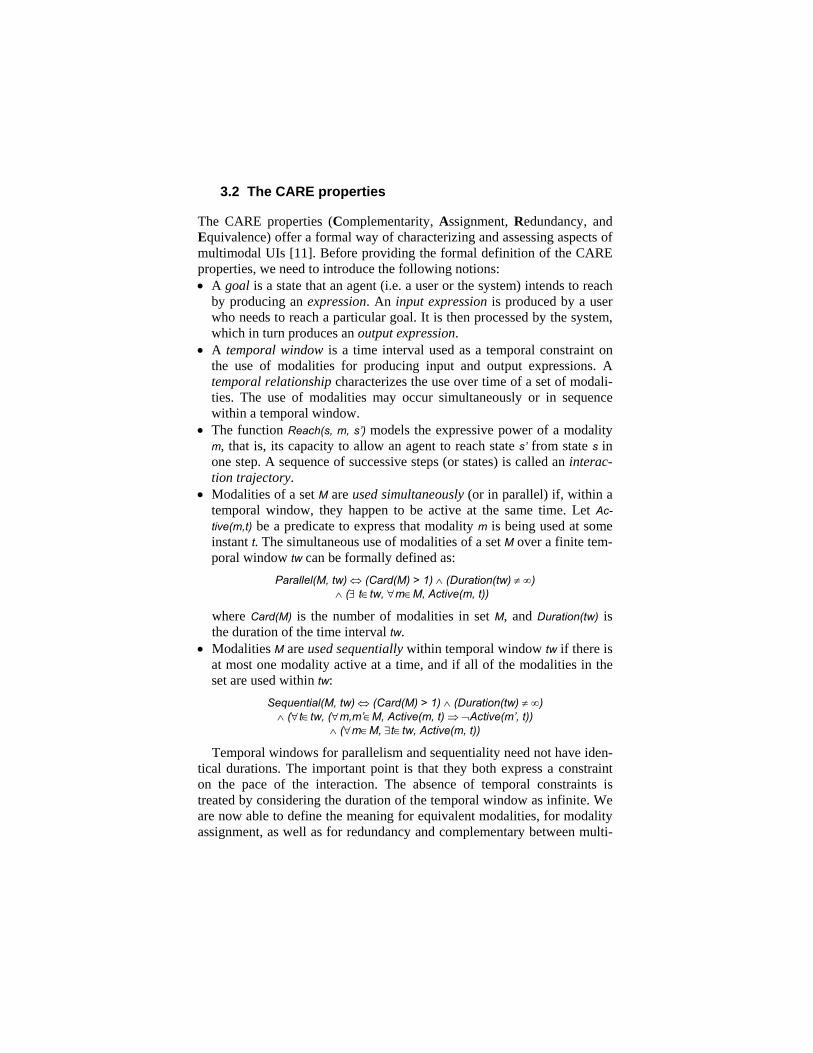
3.2 The CARE properties
The CARE properties (Complementarity, Assignment, Redundancy, and Equivalence) offer a formal way of characterizing and assessing aspects of multimodal UIs [11]. Before providing the formal definition of the CARE properties, we need to introduce the following notions: • A goal is a state that an agent (i.e. a user or the system) intends to reach
by producing an expression. An input expression is produced by a user who needs to reach a particular goal. It is then processed by the system, which in turn produces an output expression.
• A temporal window is a time interval used as a temporal constraint on the use of modalities for producing input and output expressions. A temporal relationship characterizes the use over time of a set of modali-ties. The use of modalities may occur simultaneously or in sequence within a temporal window.
• The function Reach(s, m, s’) models the expressive power of a modality m, that is, its capacity to allow an agent to reach state s’ from state s in one step. A sequence of successive steps (or states) is called an interac-tion trajectory.
• Modalities of a set M are used simultaneously (or in parallel) if, within a temporal window, they happen to be active at the same time. Let Ac-tive(m,t) be a predicate to express that modality m is being used at some instant t. The simultaneous use of modalities of a set M over a finite tem-poral window tw can be formally defined as:
Parallel(M, tw) ⇔ (Card(M) > 1) ∧ (Duration(tw) ≠ ∞) ∧ (∃ t∈tw, ∀m∈M, Active(m, t))
where Card(M) is the number of modalities in set M, and Duration(tw) is the duration of the time interval tw.
• Modalities M are used sequentially within temporal window tw if there is at most one modality active at a time, and if all of the modalities in the set are used within tw:
Sequential(M, tw) ⇔ (Card(M) > 1) ∧ (Duration(tw) ≠ ∞) ∧ (∀t∈tw, (∀m,m’∈M, Active(m, t) ⇒ ¬Active(m’, t))
∧ (∀m∈M, ∃t∈tw, Active(m, t))
Temporal windows for parallelism and sequentiality need not have iden-tical durations. The important point is that they both express a constraint on the pace of the interaction. The absence of temporal constraints is treated by considering the duration of the temporal window as infinite. We are now able to define the meaning for equivalent modalities, for modality assignment, as well as for redundancy and complementary between multi-
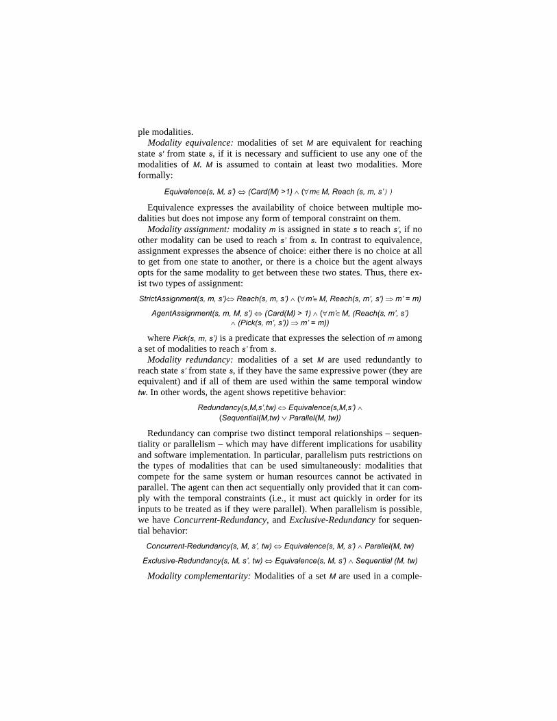
ple modalities. Modality equivalence: modalities of set M are equivalent for reaching
state s' from state s, if it is necessary and sufficient to use any one of the modalities of M. M is assumed to contain at least two modalities. More formally:
Equivalence(s, M, s’) ⇔ (Card(M) >1) ∧ (∀m∈M, Reach (s, m, s’))
Equivalence expresses the availability of choice between multiple mo-dalities but does not impose any form of temporal constraint on them.
Modality assignment: modality m is assigned in state s to reach s’, if no other modality can be used to reach s’ from s. In contrast to equivalence, assignment expresses the absence of choice: either there is no choice at all to get from one state to another, or there is a choice but the agent always opts for the same modality to get between these two states. Thus, there ex-ist two types of assignment: StrictAssignment(s, m, s’)⇔ Reach(s, m, s’) ∧ (∀m’∈M, Reach(s, m’, s’) ⇒ m’ = m)
AgentAssignment(s, m, M, s’) ⇔ (Card(M) > 1) ∧ (∀m’∈M, (Reach(s, m’, s’) ∧ (Pick(s, m’, s’)) ⇒ m’ = m))
where Pick(s, m, s’) is a predicate that expresses the selection of m among a set of modalities to reach s’ from s.
Modality redundancy: modalities of a set M are used redundantly to reach state s’ from state s, if they have the same expressive power (they are equivalent) and if all of them are used within the same temporal window tw. In other words, the agent shows repetitive behavior:
Redundancy(s,M,s’,tw) ⇔ Equivalence(s,M,s’) ∧ (Sequential(M,tw) ∨ Parallel(M, tw))
Redundancy can comprise two distinct temporal relationships – sequen-tiality or parallelism – which may have different implications for usability and software implementation. In particular, parallelism puts restrictions on the types of modalities that can be used simultaneously: modalities that compete for the same system or human resources cannot be activated in parallel. The agent can then act sequentially only provided that it can com-ply with the temporal constraints (i.e., it must act quickly in order for its inputs to be treated as if they were parallel). When parallelism is possible, we have Concurrent-Redundancy, and Exclusive-Redundancy for sequen-tial behavior:
Concurrent-Redundancy(s, M, s’, tw) ⇔ Equivalence(s, M, s’) ∧ Parallel(M, tw)
Exclusive-Redundancy(s, M, s’, tw) ⇔ Equivalence(s, M, s’) ∧ Sequential (M, tw)
Modality complementarity: Modalities of a set M are used in a comple-
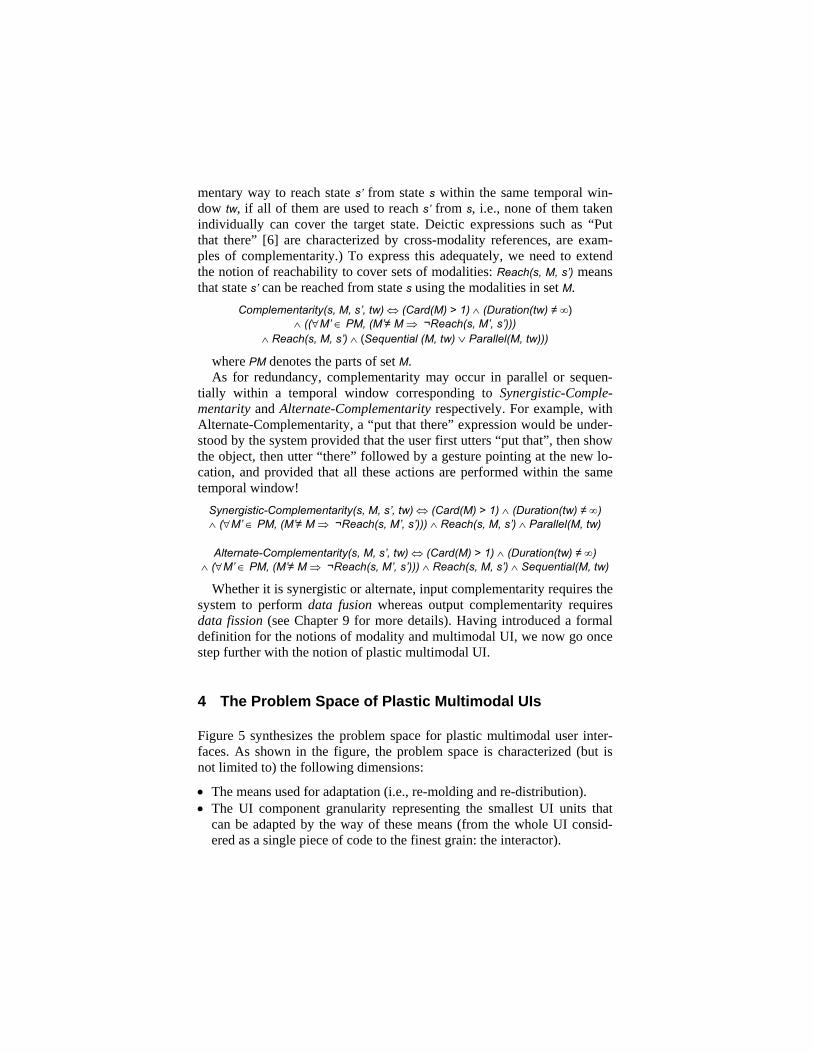
mentary way to reach state s’ from state s within the same temporal win-dow tw, if all of them are used to reach s’ from s, i.e., none of them taken individually can cover the target state. Deictic expressions such as “Put that there” [6] are characterized by cross-modality references, are exam-ples of complementarity.) To express this adequately, we need to extend the notion of reachability to cover sets of modalities: Reach(s, M, s’) means that state s’ can be reached from state s using the modalities in set M.
Complementarity(s, M, s’, tw) ⇔ (Card(M) > 1) ∧ (Duration(tw) ≠ ∞) ∧ ((∀M’ ∈ PM, (M’≠ M ⇒ ¬Reach(s, M’, s’)))
∧ Reach(s, M, s’) ∧ (Sequential (M, tw) ∨ Parallel(M, tw)))
where PM denotes the parts of set M. As for redundancy, complementarity may occur in parallel or sequen-
tially within a temporal window corresponding to Synergistic-Comple-mentarity and Alternate-Complementarity respectively. For example, with Alternate-Complementarity, a “put that there” expression would be under-stood by the system provided that the user first utters “put that”, then show the object, then utter “there” followed by a gesture pointing at the new lo-cation, and provided that all these actions are performed within the same temporal window!
Synergistic-Complementarity(s, M, s’, tw) ⇔ (Card(M) > 1) ∧ (Duration(tw) ≠ ∞) ∧ (∀M’ ∈ PM, (M’≠ M ⇒ ¬Reach(s, M’, s’))) ∧ Reach(s, M, s’) ∧ Parallel(M, tw)
Alternate-Complementarity(s, M, s’, tw) ⇔ (Card(M) > 1) ∧ (Duration(tw) ≠ ∞) ∧ (∀M’ ∈ PM, (M’≠ M ⇒ ¬Reach(s, M’, s’))) ∧ Reach(s, M, s’) ∧ Sequential(M, tw)
Whether it is synergistic or alternate, input complementarity requires the system to perform data fusion whereas output complementarity requires data fission (see Chapter 9 for more details). Having introduced a formal definition for the notions of modality and multimodal UI, we now go once step further with the notion of plastic multimodal UI.
4 The Problem Space of Plastic Multimodal UIs
Figure 5 synthesizes the problem space for plastic multimodal user inter-faces. As shown in the figure, the problem space is characterized (but is not limited to) the following dimensions:
• The means used for adaptation (i.e., re-molding and re-distribution). • The UI component granularity representing the smallest UI units that
can be adapted by the way of these means (from the whole UI consid-ered as a single piece of code to the finest grain: the interactor).

• The state recovery granularity after adaptation has occurred (from the session level to the user’s last action).
• The UI deployment (static or dynamic) as a way to characterize how much adaptation has been pre-defined at design-time vs computed at runtime.
• The context coverage to denote the causes for adaptation with which the system is able to cope.
• The coverage of the technological spaces as a way to characterize the degree of technical heterogeneity supported by the system.
• The existence of a meta-UI to allow users to control and evaluate the adaptation process. These dimensions are now developed in details in the next subsections.
Adaptationmeans
Technologicalspace coverage
Contextof use UI
deployment
Re-molding
Redistribution
Total level
Dialog space level
Interactor levelUI component
granularity
State recoverygranularity
Session levelTask level
Action level
Static
Dynamic
User
Computing platform
Environment
Multi-TSInter-TS Intra-TS
No Meta-UIMeta-UI without negotiation
Meta-UI with negotiationPlastic Meta-UI
Fig. 5. The problem space of plastic multimodal user interfaces.
4.1 Two Adaptation Means: UI Re-molding and UI Re-distribution
UI re-molding denotes any UI reconfiguration that is perceivable to the user and that results from the application of transformations on the UI. It may result in a graceful degradation or in a graceful upgradation. Trans-formations include: • Insertion of new UI components to provide access to new services rele-
vant in the new context of use. For instance, if more screen space be-
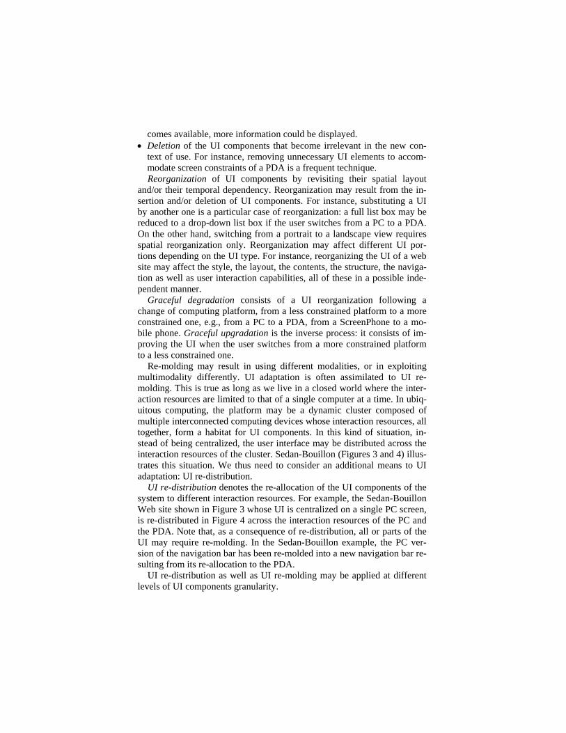
comes available, more information could be displayed. • Deletion of the UI components that become irrelevant in the new con-
text of use. For instance, removing unnecessary UI elements to accom-modate screen constraints of a PDA is a frequent technique. Reorganization of UI components by revisiting their spatial layout
and/or their temporal dependency. Reorganization may result from the in-sertion and/or deletion of UI components. For instance, substituting a UI by another one is a particular case of reorganization: a full list box may be reduced to a drop-down list box if the user switches from a PC to a PDA. On the other hand, switching from a portrait to a landscape view requires spatial reorganization only. Reorganization may affect different UI por-tions depending on the UI type. For instance, reorganizing the UI of a web site may affect the style, the layout, the contents, the structure, the naviga-tion as well as user interaction capabilities, all of these in a possible inde-pendent manner.
Graceful degradation consists of a UI reorganization following a change of computing platform, from a less constrained platform to a more constrained one, e.g., from a PC to a PDA, from a ScreenPhone to a mo-bile phone. Graceful upgradation is the inverse process: it consists of im-proving the UI when the user switches from a more constrained platform to a less constrained one.
Re-molding may result in using different modalities, or in exploiting multimodality differently. UI adaptation is often assimilated to UI re-molding. This is true as long as we live in a closed world where the inter-action resources are limited to that of a single computer at a time. In ubiq-uitous computing, the platform may be a dynamic cluster composed of multiple interconnected computing devices whose interaction resources, all together, form a habitat for UI components. In this kind of situation, in-stead of being centralized, the user interface may be distributed across the interaction resources of the cluster. Sedan-Bouillon (Figures 3 and 4) illus-trates this situation. We thus need to consider an additional means to UI adaptation: UI re-distribution.
UI re-distribution denotes the re-allocation of the UI components of the system to different interaction resources. For example, the Sedan-Bouillon Web site shown in Figure 3 whose UI is centralized on a single PC screen, is re-distributed in Figure 4 across the interaction resources of the PC and the PDA. Note that, as a consequence of re-distribution, all or parts of the UI may require re-molding. In the Sedan-Bouillon example, the PC ver-sion of the navigation bar has been re-molded into a new navigation bar re-sulting from its re-allocation to the PDA.
UI re-distribution as well as UI re-molding may be applied at different levels of UI components granularity.
4.2 UI Components Granularity
UI components granularity denotes the smallest software UI unit that can be affected by re-molding and/or re-distribution: • Re-molding and/or re-distribution may be total (the whole UI is af-
fected) or partial. • When partial, re-molding and/or re-distribution may work at the work-
space level, or at the interactor level. A workspace is a logical space that supports the execution of a set of
logically connected tasks. In fine, workspaces are populated with interac-tors (e.g., graphics widgets, speech widgets). For example, a UI expressed in SVG supports total re-molding only: it is not possible to resize subparts of the UI to maintain text legibility as the display area is shrunk. In Sedan-Bouillon, re-molding, as well as re-distribution, is performed at the work-space level: the title, content, and the navigation bar are the smallest units for re-molding and re-distribution. Whatever the means used for adaptation (re-molding and/or re-distribution) and the UI components granularity, an-other important dimension is the granularity of the state recovery.
4.3 State Recovery Granularity
State recovery granularity characterizes the effort users must apply to carry on their activity after adaptation has occurred: • When the system state is saved at the session level, users have to restart
their activity from the system initial state, that is, the state that the sys-tem enters when it is launched.
• At the task level, the user can pursue the job from the beginning of the current interrupted task (provided that the task is attainable in the retar-geted UI).
• At the physical action level, the user is able to carry on the current task at the exact point within the current task (provided that the task is attain-able in the new version of the user interface). Sedan-Bouillon supports a task level state recovery: if re-distribution
occurs while filling a form, users have to refill the form.
4.4 UI Deployment
UI deployment denotes the installation of the UI components in its habitat. The installation may be static or dynamic.
A static deployment means that UI adaptation is performed at the time
the system is launched and from then, no re-molding and no re-distribution can be performed.
At the opposite, a dynamic deployment means that re-molding and re-distribution can be performed on the fly.
Note that a dynamic deployment that supports a session level state re-covery is different from a static deployment. In the first case, re-molding and/or re-distribution can occur on the fly while bringing the user back to the entry state. On the other hand, static deployment forces the user to quit the session and to launch the appropriate version of the system.
Typical examples of static deployments are web sites that recognize the use of a PDA through the “user agent” field of the http header, and then se-lect the appropriate version of the web site. This version has been pre-designed and pre-computed for that particular platform. Rekimoto’s pre-distributed pick and drop is an example of a static UI deployment [31]. Se-dan-Bouillon, on the other hand, support dynamic UI deployment.
4.5 Coverage of the Context of Use
We have defined the context of use as the triple: <user, physical and social environment, computing platform>. Each one of these dimensions is a rich in-formation space. For example, in Sedan-Bouillon, a platform is a cluster of connected computing devices. In turn, this cluster may be static or dy-namic (computing devices may appear and disappear on the fly), and the cardinality of this cluster is an important factor to consider in relation to scalability and usability. Computing devices are also characterized by the interaction resources they support. The platform dimension of the context of use is probably the most frequently addressed portion of the context to accommodate the UI with. We will discuss coverage of context of use in more detail in Section 5 with the notion of domain of plasticity.
4.6 Coverage of Technological Spaces
“A technological space is a working context with a set of associated con-cepts, body of knowledge, tools, required skills, and possibilities.” [20]. Examples of technological spaces include documentware concerned with digital documents expressed in XML, dataware related to data base sys-tems, ontologyware, and so on. Most UIs are implemented within a single Technological Space (TS), such as Tcl/Tk, Swing, or HTML. This homo-geneity does not hold any more for plastic multimodal UIs since re-distribution to different computing devices may require crossing techno-logical spaces. For example, a Java-based UI must be transformed into
WML 2.0 when migrating from a PDA to a WAP-enabled mobile phone. TS coverage denotes the capacity of the underlying infrastructure to
support UI plasticity across technological spaces: • Intra-TS corresponds to UIs that are implemented and adapted within a
single TS. Sedan-Bouillon (HTML, PHP) is an example of intra-TS coverage.
• Inter-TS corresponds to the situation where the source UI, which is ex-pressed in a single TS, is transformed into a single distinct target TS.
• Multi-TS is the flexible situation where the source and/or the target user interfaces are composed of components expressed in distinct techno-logical spaces.
4.7 Existence of a Meta-UI
A meta-UI is to ambient computing what the desktop metaphor is to con-ventional workstations [12]. The concept of meta-UI is defined here as a simplification of a end-user development environment. A full fledge meta-UI should allow end-users to program (configure, and control) their inter-active spaces, to debug (evaluate) them, and to maintain and re-use pro-grams. It binds together the activities that can be performed within an in-teractive space. In particular, it provides users with the means to configure, control, and evaluate the adaptation process. It may, or may not, negotiate the alternatives for adaptation with the user. It may or may not be plastic.
A meta-UI without negotiation makes observable the state of the adapta-tion process, but does not allow the user to intervene. The system is autonomous.
A meta-UI incorporates negotiation when, for example, it cannot make sound decisions between multiple forms of adaptation, or when the user must fully control the outcome of the process. This is the case for Sedan-Bouillon where the user can decide on the allocation of the UI compo-nents.
The balance between system autonomy and too many negotiation steps is an open question. Another issue is the plasticity of the meta-UI itself since it lives within an evolving habitat. Thus, the recursive dimension of the meta-UI calls for the definition of a native bootstrap meta-UI capable of instantiating the appropriate meta-UI as the system is launched. This is yet another research issue.
So far, we have defined the primary dimensions of the problem space for UI plasticity. In the next two sections, we refine re-molding with re-gard to the use of modalities and to its impact on the levels of abstractions of an interactive system.
4.8 UI Re-molding and Modalities
Re-molding a UI from a source to a target UI may imply changes in the set of the supported modalities and/or changes in the way the CARE proper-ties are supported. For example, because of the lack of computing power, the synergistic-complementarity of the source multimodal UI may be transformed into an alternate-complementarity, or complementarity itself may disappear.
UI re-molding is intra-modal when the source UI components that need to be changed are retargeted within the same modality. Note that if the source user interface is multimodal, then, the target UI is multimodal as well: intra-modal remolding does not provoke any loss in the modalities set.
Re-molding is inter-modal when the source UI components that need to be changed are retargeted into a different modality. Inter-modal retargeting may engender a modality loss or a modality gain. Thus, a source multimo-dal UI may be retargeted into a mono-modal UI and conversely, a mono-modal UI may be transformed into a multimodal UI. The reconfiguration of the Sedan-Bouillon web site between Figures 3 and 4 is an example of an inter-modal remolding: the navigation bar uses the same interaction language but the device has changed from a PC to a PDA. In addition, if the user decides to replicate the navigation bar on the PC and on the PDA, we then have redundancy (i.e. two modalities to navigate through the web site). The neuro-surgery system supports inter-modal re-molding (i.e. from <text, screen> to <text, loudspeaker>) when the surgeon leans over the pa-tient’s head (see Figure 2c).
Re-molding is multi-modal when it uses a combination of intra- and in-ter-modal transformations. For example, TERESA supports multi-modal re-molding between graphics and vocal modalities [4]. As for inter-modal re-molding, multi-modal re-molding may result in a modality loss or a modality gain.
Given that a modality is defined as M ::= <L, d> | <L, M>, a modality change may result:
• From a device substitution (provided that the new device supports the
original interaction language), • From an interaction language substitution (provided that the original de-
vice supports the new interaction language), • Or from a radical change with both a device and interaction language
substitution.
4.9 UI Re-molding and Levels of Abstraction
UI re-molding may range from cosmetic changes to deep software reor-ganization. We suggest using the levels of abstraction of the Arch architec-tural model as a classification scheme (See Chapter 9 for more details).
At the Physical Presentation (PP) level, physical interactors (widgets) used for representing functions and concepts are kept unchanged but their rendering and behavior may change. For example, if a concept is rendered as a button class, this concept is still represented as a button in the target UI. However, the look and feel of the button or its location in the work-space may vary.
At the Logical Presentation (LP) level, adaptation consists in changing the representation of functions and concepts. Changes at the LP level im-ply changes at the PP level.
At the Dialogue Component (DC) level, the tasks that can be executed with the system are kept unchanged but their organization is modified. As a result, the structure of the dialogue structure is changed. AVANTI’s po-lymorphic tasks [34] are an example of a DC level adaptation. Changes at the DC level imply changes at the LP and PP levels.
At the Functional Core Adaptor (FCA) level, the entities as well as the functions exported by (or adapted from) the functional core (the services) are changed.
The Functional Core (FC) level corresponds to the dynamic composi-tion of services such as Web services. This is a very difficult problem that we are not in a position to solve in the short term.
4.10 Summary
The problem space expresses a set of requirements for the design and im-plementation of plastic multimodal user interfaces. To summarize, the most demanding case corresponds to the following situation:
• All aspects of the CARE properties are supported, from synergistic-complementary multimodality to mono-modal user interfaces.
• The set of the supported modalities includes a mix of “conversation-oriented” modalities such as speech and gesture, and of “world model” modalities such as GUI-WIMP and post-WIMP modalities.
• Re-molding and re-distribution are both supported. • Re-molding and re-distribution both operate at the interactor level while
guaranteeing state recovery at the user’s action level. • Re-molding and re-distribution cover all three aspects of the context of
use (i.e. user, environment, platform). In particular, the platform can be composed of a dynamic set of heterogeneous resources whose cardinal-ity is possibly “high”.
• Re-molding and re-distribution are able to cross over technological spaces, and they include a plastic meta-UI.
• The meta-UI is a complete end-user development environment. • Re-molding draws upon multiple modalities that may impact all of the
levels of abstraction of an interactive system from the Functional Core to the Physical Presentation level.
• And all this can be deployed dynamically. Figure 5 provides a simple way to characterize and compare interactive
systems with regard to plasticity and multimodality. The coverage of con-text of use by a particular system may be refined, if needed, with the no-tion of domain of plasticity.
5 Domain of Plasticity of a User Interface
UI plasticity can be characterized by the sets of contexts it is able to ac-commodate. Contexts at the boundaries of a set define the plasticity threshold of the user interface for this set. The sum of the surfaces covered by each set, or the sum of the cardinality of each set, defines an overall ob-jective quantitative metrics for plasticity. In other word, this sum can be used to compare solutions to plasticity: A user interface U1 is more plastic than a user interface U2 if the cardinality of the set of contexts covered by U1 is greater than that of U2.
We suggest additional metrics to refine the overall measure of plasticity in relation to discontinuity [18]. These include: • The size of the largest surface: large surfaces denote a wide spectrum
of adaptation without technical rupture. • The number of distinct sets: a large number of sets reveals multiple
sources for technical discontinuities. Are these discontinuities com-patible with user's expectation? Typically, GSM does not work every-where.
• Surface shapes: a convex surface denotes a comfortable continuous space (Figure 6a). Conversely, concave curvatures may raise important design issues (Figure 6b). Typically, ring shape surfaces indicate that the interior of the ring is not covered by the user interface. It expresses a technical discontinuity for contexts that are contiguous in the ranking scheme. Is this inconsistency, a problem from the user's perspective? A hole within a surface depicts the case where the user interface is nearly plastic over both sets of contexts, but not quite. Is this "tiny" rupture in
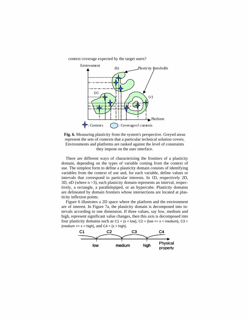
context coverage expected by the target users?
Platform
EnvironmentPlasticity thresholds
(a)
(b)
(c)
: Context s : Coverage of contexts
Fig. 6. Measuring plasticity from the system's perspective. Greyed areas represent the sets of contexts that a particular technical solution covers. Environments and platforms are ranked against the level of constraints
they impose on the user interface.
There are different ways of characterizing the frontiers of a plasticity domain, depending on the types of variable coming from the context of use. The simplest form to define a plasticity domain consists of identifying variables from the context of use and, for each variable, define values or intervals that correspond to particular interests. In 1D, respectively 2D, 3D, nD (where n >3), each plasticity domain represents an interval, respec-tively, a rectangle, a parallelepiped, or an hypercube. Plasticity domains are delineated by domain frontiers whose intersections are located at plas-ticity inflexion points.
Figure 6 illustrates a 2D space where the platform and the environment are of interest. In Figure 7a, the plasticity domain is decomposed into in-tervals according to one dimension. If three values, say low, medium and high, represent significant value changes, then this axis is decomposed into four plasticity domains such as C1 = {x < low}, C2 = {low <= x < medium}, C3 = {medium <= x < high}, and C4 = {x > high}.
low medium high
C1 C2 C3 C4
Physicalpropertylow medium high
C1 C2 C3 C4
low medium high
C1 C2 C3 C4
Physicalproperty
low medium high Physicalproperty 1
low
medium
high
Physicalproperty 2
C1 C2 C3 C4
C5 C6 C7 C8
C9 C10 C11 C12
C13 C14 C15 C16
Plasticity inflexion point Plasticity domain frontier
low medium high Physicalproperty 1
low
medium
high
Physicalproperty 2
C1 C2 C3 C4
C5 C6 C7 C8
C9 C10 C11 C12
C13 C14 C15 C16
Plasticity inflexion point Plasticity domain frontier
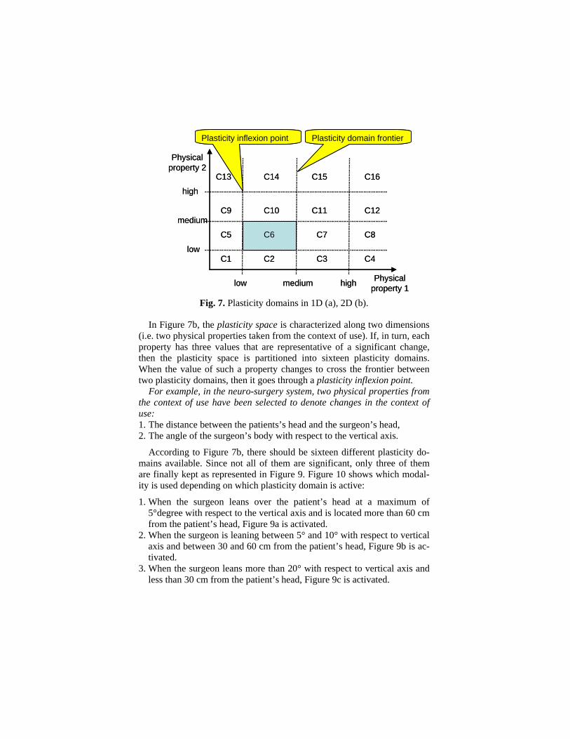
Fig. 7. Plasticity domains in 1D (a), 2D (b).
In Figure 7b, the plasticity space is characterized along two dimensions (i.e. two physical properties taken from the context of use). If, in turn, each property has three values that are representative of a significant change, then the plasticity space is partitioned into sixteen plasticity domains. When the value of such a property changes to cross the frontier between two plasticity domains, then it goes through a plasticity inflexion point.
For example, in the neuro-surgery system, two physical properties from the context of use have been selected to denote changes in the context of use: 1. The distance between the patients’s head and the surgeon’s head, 2. The angle of the surgeon’s body with respect to the vertical axis.
According to Figure 7b, there should be sixteen different plasticity do-mains available. Since not all of them are significant, only three of them are finally kept as represented in Figure 9. Figure 10 shows which modal-ity is used depending on which plasticity domain is active:
1. When the surgeon leans over the patient’s head at a maximum of 5°degree with respect to the vertical axis and is located more than 60 cm from the patient’s head, Figure 9a is activated.
2. When the surgeon is leaning between 5° and 10° with respect to vertical axis and between 30 and 60 cm from the patient’s head, Figure 9b is ac-tivated.
3. When the surgeon leans more than 20° with respect to vertical axis and less than 30 cm from the patient’s head, Figure 9c is activated.
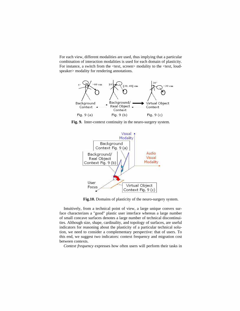
For each view, different modalities are used, thus implying that a particular combination of interaction modalities is used for each domain of plasticity. For instance, a switch from the <text, screen> modality to the <text, loud-speaker> modality for rendering annotations.
Fig. 9. Inter-context continuity in the neuro-surgery system.
Fig.10. Domains of plasticity of the neuro-surgery system.
Intuitively, from a technical point of view, a large unique convex sur-
face characterizes a "good" plastic user interface whereas a large number of small concave surfaces denotes a large number of technical discontinui-ties. Although size, shape, cardinality, and topology of surfaces, are useful indicators for reasoning about the plasticity of a particular technical solu-tion, we need to consider a complementary perspective: that of users. To this end, we suggest two indicators: context frequency and migration cost between contexts.
Context frequency expresses how often users will perform their tasks in
a given context. Clearly, if the largest surfaces correspond to the less fre-quent contexts and/or if a multitude of small surfaces is related to frequent contexts, then designers should revise their technical solution space: the solution offers too much potential for interactional ruptures in the interac-tional process.
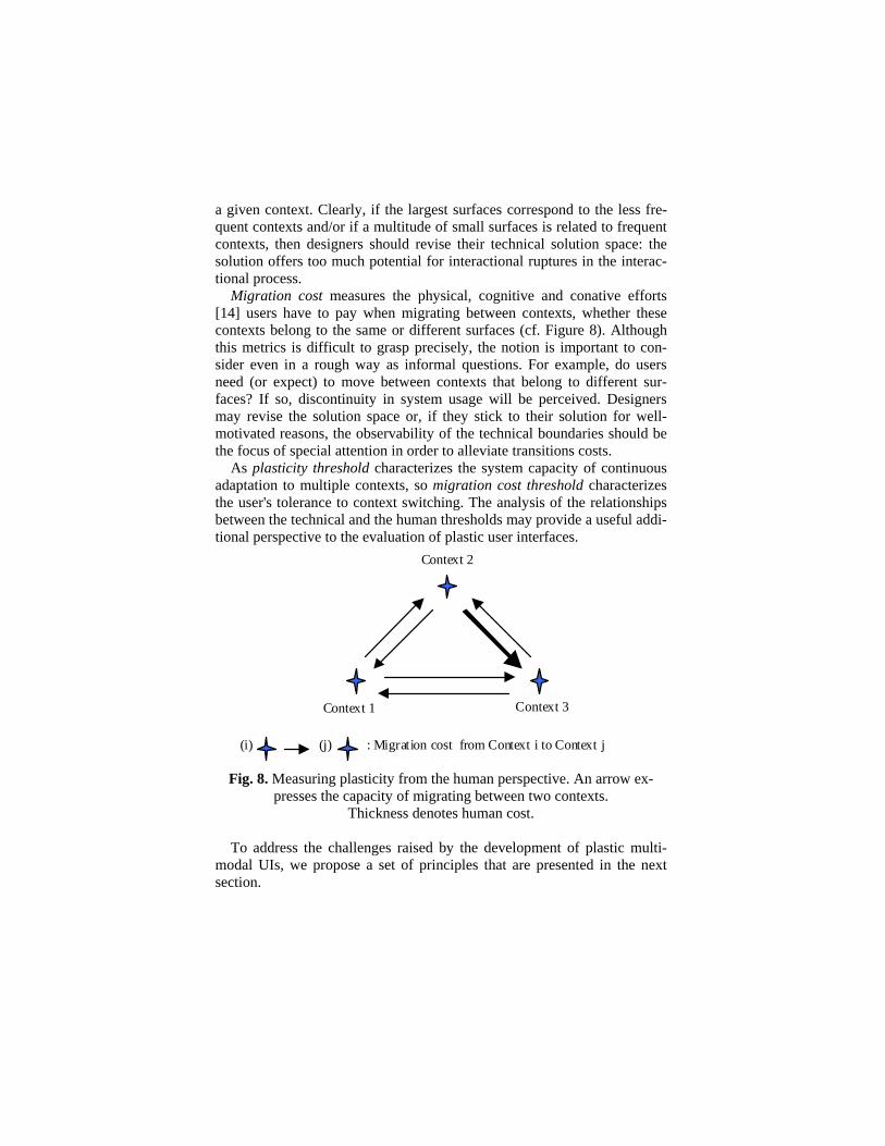
Migration cost measures the physical, cognitive and conative efforts [14] users have to pay when migrating between contexts, whether these contexts belong to the same or different surfaces (cf. Figure 8). Although this metrics is difficult to grasp precisely, the notion is important to con-sider even in a rough way as informal questions. For example, do users need (or expect) to move between contexts that belong to different sur-faces? If so, discontinuity in system usage will be perceived. Designers may revise the solution space or, if they stick to their solution for well-motivated reasons, the observability of the technical boundaries should be the focus of special attention in order to alleviate transitions costs.
As plasticity threshold characterizes the system capacity of continuous adaptation to multiple contexts, so migration cost threshold characterizes the user's tolerance to context switching. The analysis of the relationships between the technical and the human thresholds may provide a useful addi-tional perspective to the evaluation of plastic user interfaces.
(j)(i)
Context 2
Context 1 Context 3
: Migration cost from Context i to Context j
Fig. 8. Measuring plasticity from the human perspective. An arrow ex-presses the capacity of migrating between two contexts.
Thickness denotes human cost. To address the challenges raised by the development of plastic multi-
modal UIs, we propose a set of principles that are presented in the next section.
6 Three Principles for the Development of Plastic Multimodal UIs
We have identified three principles that we have applied to the develop-ment of plastic multimodal UIs: (1) Blur the distinction between design-time and run-time, (2) Mix close and open adaptiveness and (3) Keep hu-mans in the loop.
6.1 Blurring the Distinction between Design-time and Run-time
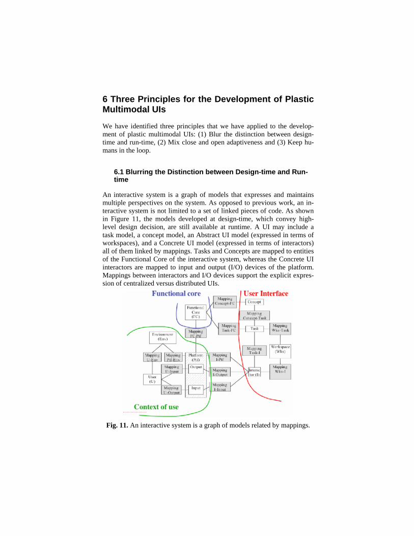
An interactive system is a graph of models that expresses and maintains multiple perspectives on the system. As opposed to previous work, an in-teractive system is not limited to a set of linked pieces of code. As shown in Figure 11, the models developed at design-time, which convey high-level design decision, are still available at runtime. A UI may include a task model, a concept model, an Abstract UI model (expressed in terms of workspaces), and a Concrete UI model (expressed in terms of interactors) all of them linked by mappings. Tasks and Concepts are mapped to entities of the Functional Core of the interactive system, whereas the Concrete UI interactors are mapped to input and output (I/O) devices of the platform. Mappings between interactors and I/O devices support the explicit expres-sion of centralized versus distributed UIs.
Fig. 11. An interactive system is a graph of models related by mappings.
Transformations and Mappings are models as well. In the conventional model-driven approach to UI generation, transformation rules are diluted within the tool. Consequently, “the connection between specifications and final results can be quite difficult to control and to understand” [22]. In our approach, transformations are promoted as models expressed in ATL [5]. QVT and XSLT are interesting options as well.
6.2 Mixing Close and Open Adaptiveness
A system is close-adaptive when adaptation is self-contained. The system is open-adaptive “if new adaptation plans can be introduced during run-time” [25]. By design, an interactive system has an innate domain of plas-ticity: it is close-adaptive for the set of contexts of use for which this sys-tem can adapt on its own (see Section 6 for a detailed discussion on domain of plasticity). If the system is able to learn adjustments for addi-tional contexts of use, then the domain of plasticity extends dynamically, but this extension relies only on the internal computing capabilities of the system.
In ubiquitous computing, unplanned contexts of use are unavoidable, forcing the system to go beyond its domain of plasticity. If continuity must be guaranteed, then the interactive system must call upon a tier infrastruc-ture that takes over the adaptation process [2]. The role of this infrastruc-ture is to sense, perceive and identify the current context of use (including the interactive system state), to detect changes in the context of use that the interactive system cannot cope with, compute the best possible adaptation by applying new transformations and mappings on the system models and/or by looking for the appropriate UI executable components sitting somewhere in the global computing fabric. The infrastructure then sup-presses the “defective” UI components of the interactive system, and in-serts the new computed ones.
6.3 Keeping Humans in the Loop
On the one hand, the criteria of user explicit control states that end-users should always be in control of the UI, even if the UI is executing tasks for them. This means in theory that no UI operation should escape from being controlled by end-users. This is also valid when UI adaptation is executed. The user should stay in control of the adaptation process as well.
On the other hand, HCI design methods produce a large body of con-templative models (i.e. models that cannot be processed by a machine) such as scenarios, drawings, storyboards, and mock-ups. These models are
useful reference material during the design process. On the other hand, be-cause they are contemplative, they can only be transformed manually into productive models. Manual transformation supports creative inspiration, but is prone to wrong interpretation and to loss of key information. On the other hand, experience shows that automatic generation is limited to very conventional user interfaces.
To address this problem, we advocate a mix of automated, semi-auto-mated, and manual transformations. Semi-automated and manual trans-formations may be performed by designers and/or end-users. For example, given our current level of knowledge, the transformation of a “value-centered model” into a “usability model” can only be performed manually by designers. Semi-automation allows designers (or end-users) to adjust the target models that result from transformations. For example, a designer may decide to map a workspace with UI services developed with the latest post-WIMP toolkit. The only constraint is that the hand-coded executable piece be encapsulated as a service. This service can then be dynamically retrieved by a tier infrastructure and linked to the models of the interactive space by the way of mappings. Thus, the UI services of a particular system at runtime can be a mix of generated and hand-coded highly tuned pieces of UI. By the way of a meta-UI, end-users can dynamically inform the ad-aptation process of their preferences.
7 Conclusion
In an ever-evolving world, multimodality deserves the best attention since it delivers much more capabilities to adapt a user interface to human needs than traditional Graphical User Interfaces (GUIs). Identifying the appropriate interaction modalities and combining them in a way that im-proves the usability of the whole system remain an open problem for which no general solution exists today. Many individual solutions demon-strate the superiority of bi- or tri-modal user interfaces over mono-modal user interfaces. But these combinations should be carefully operated to take the best benefit from multimodality. Otherwise, there is a risk of overcomplexifying a user interface by adding more and more modalities which, at the end, do not improve the whole usability.
Apart from the problem of combining interaction modalities, the prob-lem of finding the appropriate interaction modalities as well as their com-bination for UI plasticity raises many many new questions that have not been explored so far. The use of multiple modalities, especially at run-time, opens new doors for more usable user interfaces than ever. Let us
hope that this odyssey in a world of multiple modalities will bring us with clear decisions for the ultimate benefit of the end-user, not only for design-ers or developers.
Acknowledgments
We gratefully acknowledge the support of the Request research project under the umbrella of the WIST (Wallonie Information Société Technolo-gies) program under convention n°031/5592 RW REQUEST) and the sup-port of the SIMILAR network of excellence (http://www. similar.cc), the European research task force creating human-machine interfaces similar to human-human communication of the European Sixth Framework Pro-gramme (FP6-2002-IST1-507609) as well as the E-MODE ITEA-1 pro-ject.
References
1. André, E. (2000) The generation of multimedia presentations. In: Dale R., Mois L.H. & Somers H. (eds.), A handbook of natural language processing: techniques and applications for the processing of language as text, Marcel Dekker Inc., pp. 305–327.
2. Balme, L., Demeure, A., Barralon, N., Coutaz, J., and Calvary, G. (2004) CAMELEON-RT: A Software Architecture Reference Model for Distributed, Migratable, and Plastic User Interfaces. In: Proceedings of 2nd European Sym-posium on Ambient Intelligence EUSAI’2004 (Eindhoven, November 8-11, 2004), Lecture Notes in Computer Science, Vol. 3295, Springer, Heidelberg, pp. 291–302.
3. Bass, L. (1992) A Metamodel for the Runtime Architecture of an Interactive System, The UIMS Developers Workshop. ACM SIGCHI Bulletin, 24, 1: 32–37.
4. Berti, S. and Paternò, F. (2000) Migratory multimodal interfaces in multide-vice environments. In: Proc. of 7th ACM Int. Conf. on Multimodal Interfaces ICMI’2005 (Trento, October 4-6, 2005), ACM Press, New York, pp. 92–99.
5. Bézivin, J., Dupé, G., Jouault, F., Pitette, G., and Rougui, J. (2003) First Ex-periments with the ATL Transformation Language: Transforming XSLT into Xquery. In: Proc. of OOPSLA Workshop on Transformations (Anaheim, 2003), http://www.softmetaware.com/oopsla2003/bezivin.pdf.
6. Bolt, R.A. (1980) Put-that-there: Voice and gesture at the graphics interface. Computer Graphics, 14(3): 262–270.
7. Bouchet, J., Nigay, L. (2004) ICARE: A Component-Based Approach for the Design and Development of Multimodal Interfaces. In: Proceedings of the
ACM Conference on Human factors in computing systems CHI’2004 (Vi-enna, April 24-29, 2004), Extended abstracts, ACM Press, New York, pp. 1325–1328.
8. Browne, D., Totterdell, P., and Norman, M. (1990) Adaptive User Interfaces, Academic Press, Computer and People Series.
9. Calvary, G., Coutaz, J., Thevenin, D., Limbourg, Q., Bouillon, L., and Van-derdonckt, J. (2003) A Unifying Reference Framework for Multi-Target User Interfaces. Interacting with Computers, 15,3: 289–308.
10. Cockton, G. (2004) From Quality in Use to Value in the World. In: Proceed-ings of the ACM Conference on Human factors in computing systems CHI’2004 (Vienna, April 24-29, 2004), Extended abstracts, ACM Press, New York, pp. 1287–1290.
11. Coutaz, J., Nigay, L., Salber, D., Blandford, A., May, J., and Young, R. (1995) Four Easy Pieces for Assessing the Usability of Multimodal Interac-tion: The CARE properties. In: Proc. of the IFIP TC 13 Int. Conf. on Human-Computer Interaction INTERACT'95 Lillehammer, 27-29 June 1995), Nord-byn, K., Helmersen, P.H., Gilmore, D.J., Arnesen S.A. (eds.), Chapman & Hall, London, pp. 115–120.
12. Coutaz, J. (2006) Meta-User Interfaces for Ambient Spaces. In: Proc. of 4th Int. Workshop on Task Models and Diagrams for User Interface Design Ta-modia’2006 (Hasselt, October 23-24, 2006). Lecture Notes in Computer Sci-ence, Vol. 4385, Springer, Heidelberg, pp. 1–15.
13. Coutaz, J. and Calvary, G. (2007) HCI and Software Engineering: Designing for User Interface Plasticity. In: Sears A. and Jacko J. (eds.), The Human-Computer Interaction Handbook: Fundamentals, Evolving Technologies and Emerging Applications, 2nd ed., Taylor & Francis Publishers.
14. Dowell, J. and Long, J. (1989) Toward a conception for an engineering disci-pline of human factors. Ergonomics 32, 11: 1513–1535.
15. Dragicevic, P. and Fekete, J.-D. (2004) ICON: The Input Configurator Tool-kit: towards High Input Adaptability in Interactive Applications. In: Proceed-ings of the ACM Working Conference on Advanced Visual Interfaces AVI 2004 (Gallipoli, May 25-28, 2004), ACM Press, New York, pp. 244–247.
16. Fitzmaurice, G., Ishii, H., and Buxton, W. (1995) Bricks: Laying the founda-tions for graspable user interfaces. In: Proceedings of the ACM Conference on Human Factors in Computing Systems CHI’95 (Denver, May 07-11, 1995). ACM Press, New York, pp. 442–449.
17. Furtado, E., Furtado, J.J.V., Silva, W.B., Rodrigues, D.W.T., Taddeo, L.S., Limbourg, Q., and Vanderdonckt, J. (2001) An Ontology-Based Method for Universal Design of User Interfaces. In: Proc. of Workshop on Multiple User Interfaces over the Internet: Engineering and Applications Trends MUI’2001 (Lille, 10 September 2001), Seffah A., Radhakrishnan T., and Canals G. (eds.),http://www.cs.concordia.ca/~faculty/seffah/ihm2001/papers/furtado.pdf
18. Gram, C. and Cockton, G. (1996) Design Principles for Interactive Software, Chapman & Hall, London.
19. Katsurada, K., Nakamura, Y., Yamada, H., Nitta, T. (2003) XISL: A Lan-guage for Describing Multimodal Interaction Scenarios. In: Proceedings of
the 5th ACM International Conference on Multimodal Interfaces ICMI’2003 (Vancouver, November 5-7, 2003), ACM Press, New York, pp. 281–284.
20. Kurtev, I., Bézivin, J., and Aksit, M. (2002) Technological Spaces: an Initial Appraisal. CoopIS, DOA'2002 Federated Conferences, Industrial track, Ir-vine, 2002, http://www.sciences.univ-nantes.fr/lina/atl/www/papers/Position PaperKurtev.pdf
21. Martin, J.-C. (1998) TYCOON: Theoretical Framework and Software Tools for Multimodal Interfaces. In: Lee J (ed.), Intelligence and Multimodality in Multimedia Interfaces, AAAI Press.
22. Myers, B., Hudson, S.E., and Pausch, R. (2000) Past, Present, and Future of User Interface Software Tools. ACM Transactions on Computer-Human In-teraction, 7,1: 3–28.
23. Nigay, L. and Coutaz, J. (1993) A Design Space for Multimodal Systems: Concurrent Processing and Data Fusion. In: Proceedings of ACM Conf. on Human Factors in Computing Systems InterCHI’93 (Amsterdam, April 24-29, 1993), ACM Press, New York, pp. 172–178.
24. Nigay, L. and Coutaz, J. (1995) A Generic Platform for Addressing the Mul-timodal Challenge. In: Proceedings of the ACM Conference on Human Fac-tors in Computing Systems CHI’95 (Denver, May 07-11, 1995), ACM Press, New York, pp. 98–105.
25. Oreizy, P., Gorlick, M., Taylor, R., Heimbigner, D., Johnson, G., Medvido-vic, N., Quilici, A., Rosenblum, D., and Wolf, A. (1999) An Architecture-Based Approach to Self-Adaptive Software, IEEE Intelligent Systems, 14,3: 54–62.
26. Oviatt, S. and Wahlster, W (1997). Special issue on Multimodal Interfaces. Human Computer Interaction, 12, 1&2.
27. Oviatt, S. (2002) Multimodal interfaces. In: Handbook of human-computer interaction, Jacko J. and Sears A. (eds.), Lawrence Erlbaum, Mahwah.
28. Oviatt, S., Darrell, T., Flikner, M. (2004) Multimodal Interfaces that Flex, Adapt, and Persist. Communication of the ACM, 47, 1: 30–33.
29. Oviatt, S. (1999) Ten myths of multimodal interaction, Communications of the ACM, 42, 11: 74–81.
30. Palanque, Ph. and Schyn, A. (2003) A Model-Based Approach for Engineer-ing Multimodal Interactive. In: Proc. of 9th IFIP TC13 Int. Conf. on Human-Computer Interaction Interact'2003 (Zurich, September 1-5, 2003), IOS Press, Amsterdam, pp. 543–550.
31. Rekimoto, J. (1997) Pick and Drop: A Direct Manipulation Technique for Multiple Computer Environments. In: Proc. of 10th ACM Symposium on User Interface Software Technologies UIST’97 (Banff, October 14-17, 1997), ACM Press, New York, pp. 31–39.
32. Rousseau, C., Bellik, Y., Vernier, F., and Bazalgette, D. (2006) A Framework for the Intelligent Multimodal Presentation of Information, Signal Processing, 88, 12: 3696–3713.
33. Rousseau, C., Bellik, Y., and Vernier, F. (2005) Multimodal output specifica-tion/simulation platform: In: Proc. of 7th ACM Int. Conf. on Multimodal In-terfaces ICMI’2005 (Trento, October 4-6, 2005), ACM Press, New York, pp.
84–91. 34. Stephanidis, C. and Savidis, A. (2001) Universal Access in the Information
Society: Methods, Tools, and Interaction Technologies, Journal of the Uni-versal Access in Information Society, 1, 1: 40–55.
35. Thevenin, D. and Coutaz, J. (1999) Plasticity of User Interfaces: Framework and Research Agenda. In: Proceedings of IFIP TC 13 Conf. on Human-Computer Interaction Interact’99 (Edinburgh, September 1999), Sasse A & Johnson Ch. (eds.), IOS Press, Amsterdam, pp. 110–117.
36. Sinha, A.K. and Landay, J.A. (2003) Capturing User Tests in a Multimodal, Multidevice Informal Prototyping Tool. In: Proceedings of the 5th ACM In-ternational Conference on Multimodal Interfaces ICMI’2003 (Vancouver, November 5-7, 2003), ACM Press, New York, pp. 117–124.
37. Stanciulescu, A. and Vanderdonckt, J. (2006) Design Options for Multimodal Web Applications. In: Proc. of 6th Int. Conf. on Computer-Aided Design of User Interfaces CADUI’2006 (Bucharest, June 6-8, 2006), Springer, Berlin, pp. 41–56.
38. Stanciulescu, A., Limbourg, Q., Vanderdonckt, J., Michotte, B., and Montero, F. (2006) A Transformational Approach for Multimodal Web User Interfaces based on UsiXML. In: Proc. of 7th ACM Int. Conf. on Multimodal Interfaces ICMI’2005 (Trento, 4-6 October 2005), ACM Press, New York, 2005, pp. 259–266.
39. Vanderdonckt, J. (2005) A MDA-Compliant Environment for Developing User Interfaces of Information Systems. In: Proc. of 17th Conf. on Advanced Information Systems Engineering CAiSE'05 (Porto, June 13-17, 2005), Pastor O. & Falcão e Cunha J. (eds.), Lecture Notes in Computer Science, Vol. 3520, Springer, Heidelberg, pp. 16–31.


