Embed Size (px)
Citation preview
N 2555 Geometrical tolerancing Overview
7th edition (2006-09) Corrected and enlarged (2008-06) 4 497 017 719
© Robert Bosch GmbH 2008. All rights reserved, also regarding any disposal, exploitation, reproduction, editing, distribution, as well as in the event of applications for industrial property rights.
N2555 Geometrical tolerances Overview 7th edition (2006-09) Part number: 4 497 017 719 Corrected and enlarged (2008-06) Intended for internal use It is not allowed to pass on this brochure to external third parties Responsible for content: C/CTN2-Rupprecht Translated by: C/CTN1-Barth Layout : C/CTN2-Hahn C/CTN2-Rupprecht
2 | Foreword
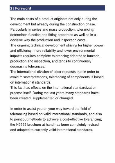
The main costs of a product originate not only during the development but already during the construction phase. Particularly in series and mass production, tolerancing determines function and fitting properties as well as in a decisive way the production and inspection costs. The ongoing technical development striving for higher power and efficiency, more reliability and lower environmental impacts requires complete tolerancing adapted to function, production and inspection, and tends to continuously decreasing tolerances. The international division of labor requests that in order to avoid misinterpretations, tolerancing of components is based on international standards. This fact has effects on the international standardization process itself. During the last years many standards have been created, supplemented or changed. In order to assist you on your way toward the field of tolerancing based on valid international standards, and also to point out methods to achieve a cost-effective tolerancing, the N2555 brochure at hand has been completely revised and adapted to currently valid international standards.
Contents | 3
Contents Page
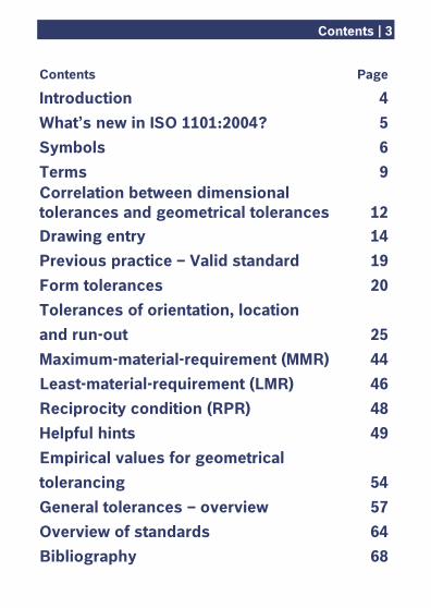
Introduction 4 What’s new in ISO 1101:2004? 5 Symbols 6 Terms 9 Correlation between dimensional tolerances and geometrical tolerances 12 Drawing entry 14 Previous practice – Valid standard 19 Form tolerances 20 Tolerances of orientation, location and run-out 25 Maximum-material-requirement (MMR) 44 Least-material-requirement (LMR) 46 Reciprocity condition (RPR) 48 Helpful hints 49 Empirical values for geometrical tolerancing 54 General tolerances – overview 57 Overview of standards 64 Bibliography 68
4 | Introduction
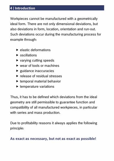
Workpieces cannot be manufactured with a geometrically ideal form. There are not only dimensional deviations, but also deviations in form, location, orientation and run-out. Such deviations occur during the manufacturing process for example through:
elastic deformations oscillations varying cutting speeds wear of tools or machines guidance inaccuracies release of residual stresses temporal material behavior temperature variations
Thus, it has to be defined which deviations from the ideal geometry are still permissible to guarantee function and compatibility of all manufactured workpieces, in particular with series and mass production. Due to profitability reasons it always applies the following principle: As exact as necessary, but not as exact as possible!
What’s new in ISO 1101:2004? | 5
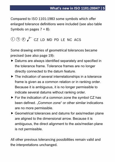
Compared to ISO 1101:1983 some symbols which offer enlarged tolerance definitions were included (see also table Symbols on pages 7 + 8): CZ LD MD PD LE NC ACS Some drawing entries of geometrical tolerances became precised (see also page 19):
Datums are always identified separately and specified in the tolerance frame. Tolerance frames are no longer directly connected to the datum feature.
The indication of several interrelationships in a tolerance frame is given as a common relation or in ranking order. Because it is ambiguous, it is no longer permissible to indicate several datums without ranking order.
For the indication of a common zone the symbol CZ has been defined. „Common zone“ or other similar indications are no more permissible.
Geometrical tolerances and datums for axis/median plane are aligned to the dimensional arrow. Because it is ambiguous, the direct alignment to the axis/median plane is not permissible.
All other previous tolerancing possibilities remain valid and the interpretations unchanged.
6 | Symbols
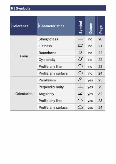
Tolerance Characteristics
Sym
bol
Dat
um
Pag
e
Straightness no 20
Flatness no 21
Roundness no 22
Cylindricity no 22
Profile any line no 23
Form
Profile any surface no 24
Parallelism yes 25
Perpendicularity yes 29
Angularity yes 32
Profile any line yes 23
Orientation
Profile any surface yes 24
Symbols | 7
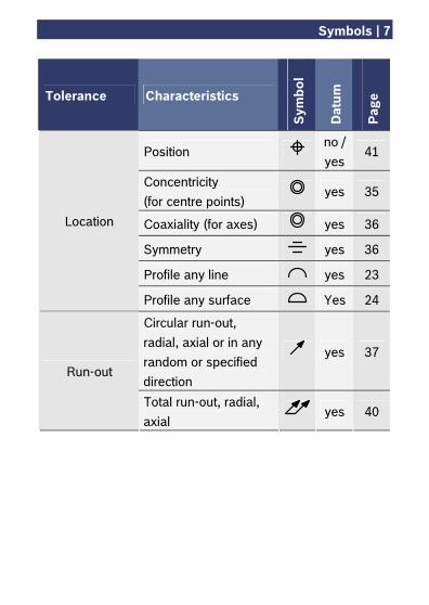
Tolerance Characteristics
Sym
bol
Dat
um
Pag
e
Position no / yes
41
Concentricity (for centre points)
yes 35
Coaxiality (for axes) yes 36
Symmetry yes 36
Profile any line yes 23
Location
Profile any surface Yes 24
Circular run-out, radial, axial or in any random or specified direction
yes 37 Run-out
Total run-out, radial, axial
yes 40
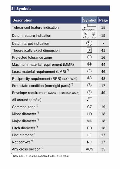
8 | Symbols
Description Symbol Page
Toleranced feature indication 15
Datum feature indication 15
Datum target indication -
Theoretically exact dimension 41
Projected tolerance zone 16
Maximum material requirement (MMR) 44
Least material requirement (LMR) *) 46
Reciprocity requirement (RPR) (ISO 2692) 48
Free state condition (non-rigid parts) *) 17
Envelope requirement (when ISO 8015 is used) 49
All around (profile) -
Common zone *) CZ 19
Minor diameter *) LD 18
Major diameter *) MD 18
Pitch diameter *) PD 18
Line element *) LE 27
Not convex *) NC 17
Any cross-section *) ACS 35 *)
New in ISO 1101:2004 compared to ISO 1101:1983
50
Terms | 9
Datum Theoretically exact geometrical feature (for example axis, plane, straight line) to which toleranced features refer. May be based on one or more datum features. Datum feature Datums belonging to a part (for example edge, plane surface, bore) which is used for the determination of location and orientation of a feature. Datum system Group of several individual datums referring to the toleranced feature. The ranking order of the datums of a toleranced feature is exactly specified through their arrangement within the tolerance frame. Datum target indication Points where the test equipment touches the workpiece (points, lines or limited surfaces) and which determine the required reference elements. Form tolerance Limits the deviation from the geometrically ideal form of an individual feature and determines the tolerance. The feature shall comply with this tolerance, and may have any random form.
10 | Terms
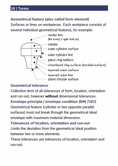
Geometrical feature (also called form element) Surfaces or lines on workpieces. Each workpiece consists of several individual geometrical features, for example:
Geometrical tolerance Collective term of all tolerances of form, location, orientation and run-out, however without dimensional tolerances. Envelope principle / envelope condition (DIN 7167) Geometrical feature (cylinder or two opposite parallel surfaces) must not break through the geometrical ideal envelope with maximum material dimension. Tolerances of location, orientation and run-out Limits the deviation from the geometrical ideal position between two or more elements. These tolerances are tolerances of location, orientation and run-out.
Terms | 11
Dimensional tolerance Difference between permissible upper and lower deviation. The dimensional tolerance is an absolute value without sign. Maximum material dimension
Maximum dimension of external dimensions (for example shafts)
Minimum dimension of internal dimensions (for example bores)
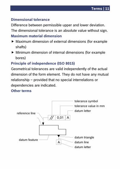
Principle of independence (ISO 8015) Geometrical tolerances are valid independently of the actual dimension of the form element. They do not have any mutual relationship – provided that no special interrelations or dependencies are indicated. Other terms
tolerance symbol
datum triangle
datum line
datum letter
0,01 A
A
datum letter
tolerance value in mm
reference line
datum feature
12 | Correlation between dimensional tolerances and geometrical tolerances As a rule, at Bosch the envelope principle in accordance with DIN 7167 is applicable for dimensioning and tolerancing. It always applies if not specified otherwise on the drawing. In order to avoid misinterpretations it is recommended to indicate the applicability of the envelope principle in accordance with DIN 7167 on all drawings. Under the envelope principle the dimensional tolerance is limiting
the dimensional deviation, all deviations in form, the deviation from parallelism
and the camming deviation.
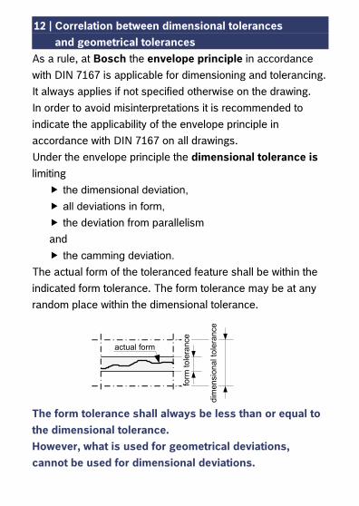
The actual form of the toleranced feature shall be within the indicated form tolerance. The form tolerance may be at any random place within the dimensional tolerance.
The form tolerance shall always be less than or equal to the dimensional tolerance. However, what is used for geometrical deviations, cannot be used for dimensional deviations.
dim
ensi
onal
tole
ranc
e
form
tole
ranc
e
actual form
Correlation between dimensional tolerances | 13 and geometrical tolerances
The following geometrical deviations are always independent from the dimensional tolerance:
perpendicularity deviation angularity deviation symmetry deviation coaxiality deviation concentricity deviation position deviation circular run-out deviation
For all the above specified geometrical deviations the tolerances have to be given either as collective indication in form of general tolerances or as direct tolerance entry. Otherwise the specification is incomplete.
14 | Drawing entry
Dimensional and geometrical tolerances are given directly at the geometrical feature (for example: H11 or ±0,1 for dimensional tolerances or for roundness tolerances) or for all not directly toleranced features as collective indication using general tolerances (for example: ISO 2768-mH for metal-cutting parts or DIN 16901-140 for molded plastic parts). Collective indication For some manufacturing procedures there are standards specifying general tolerances which are often distinguished by tolerance classes. In these cases the collective indication consists of standard number and tolerance class. Note: The amount of the general tolerances defined in these standards varies significantly with regard to the tolerance types. An overview of the tolerance types, each covered by standardized general tolerances can be found in this brochure, beginning at page 57.
Drawing entry | 15
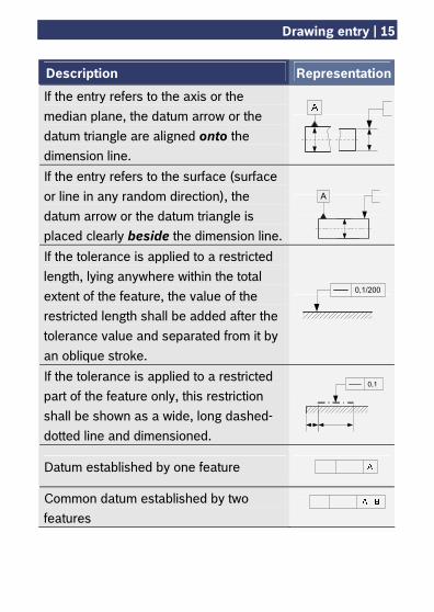
Description Representation
If the entry refers to the axis or the median plane, the datum arrow or the datum triangle are aligned onto the dimension line.
If the entry refers to the surface (surface or line in any random direction), the datum arrow or the datum triangle is placed clearly beside the dimension line.
If the tolerance is applied to a restricted length, lying anywhere within the total extent of the feature, the value of the restricted length shall be added after the tolerance value and separated from it by an oblique stroke.
If the tolerance is applied to a restricted part of the feature only, this restriction shall be shown as a wide, long dashed-dotted line and dimensioned.
Datum established by one feature
Common datum established by two features
A
0,1/200
0,1
16 | Drawing entry
Description Representation
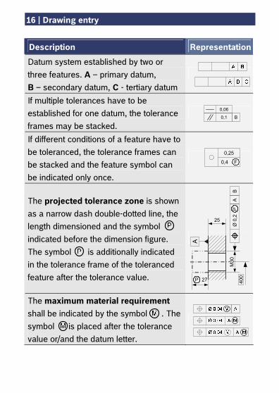
Datum system established by two or three features. A – primary datum, B – secondary datum, C - tertiary datum
If multiple tolerances have to be established for one datum, the tolerance frames may be stacked.
If different conditions of a feature have to be toleranced, the tolerance frames can be stacked and the feature symbol can be indicated only once.
The projected tolerance zone is shown as a narrow dash double-dotted line, the length dimensioned and the symbol indicated before the dimension figure. The symbol is additionally indicated in the tolerance frame of the toleranced feature after the tolerance value.
The maximum material requirement shall be indicated by the symbol . The symbol is placed after the tolerance value or/and the datum letter.
0,4 F
0,25
0,06
0,1 B
A
P
Ø 0
,2A
BP
400
M30
25
27
Drawing entry | 17
Description Representation
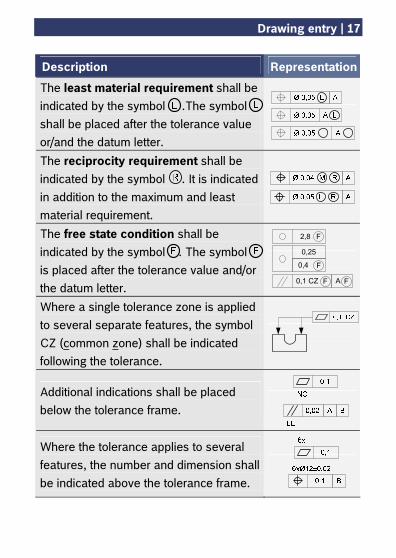
The least material requirement shall be indicated by the symbol .The symbol shall be placed after the tolerance value or/and the datum letter.
The reciprocity requirement shall be indicated by the symbol . It is indicated in addition to the maximum and least material requirement.
The free state condition shall be indicated by the symbol . The symbol is placed after the tolerance value and/or the datum letter.
Where a single tolerance zone is applied to several separate features, the symbol CZ (common zone) shall be indicated following the tolerance.
Additional indications shall be placed below the tolerance frame.
Where the tolerance applies to several features, the number and dimension shall be indicated above the tolerance frame.
0,1 CZ F A F
0,25
0,4 F
2,8 F
18 | Drawing entry
Description Representation
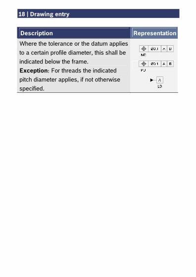
Where the tolerance or the datum applies to a certain profile diameter, this shall be indicated below the frame. Exception: For threads the indicated pitch diameter applies, if not otherwise specified.
Previous practice – Valid standard | 19
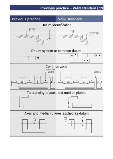
Previous practice Valid standard
Datum system or common datum
Datum identification
Common zone
Tolerancing of axes and median planes
Axes and median planes applied as datum
0,2
20 | Form tolerances
Straightness tolerance
Drawing entry
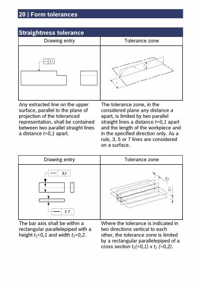
Any extracted line on the upper surface, parallel to the plane of projection of the toleranced representation, shall be contained between two parallel straight lines a distance t=0,1 apart.
The tolerance zone, in the considered plane any distance a apart, is limited by two parallel straight lines a distance t=0,1 apart and the length of the workpiece and in the specified direction only. As a rule, 3, 5 or 7 lines are considered on a surface.
Drawing entry Tolerance zone
The bar axis shall be within a rectangular parallelepiped with a height t1=0,1 and width t2=0,2.
Where the tolerance is indicated in two directions vertical to each other, the tolerance zone is limited by a rectangular parallelepiped of a cross section t1(=0,1) x t2 (=0,2).
Tolerance zone
Form tolerances | 21
Straightness tolerance (continued) Flatness tolerance
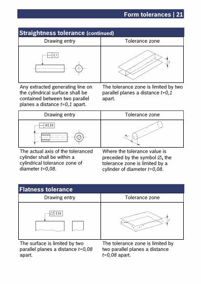
Any extracted generating line on the cylindrical surface shall be contained between two parallel planes a distance t=0,1 apart.
The tolerance zone is limited by two parallel planes a distance t=0,1 apart.
Drawing entry
The actual axis of the toleranced cylinder shall be within a cylindrical tolerance zone of diameter t=0,08.
Drawing entry Tolerance zone
Where the tolerance value is preceded by the symbol ∅, the tolerance zone is limited by a cylinder of diameter t=0,08.
Drawing entry Tolerance zone
The surface is limited by two parallel planes a distance t=0,08 apart.
The tolerance zone is limited by two parallel planes a distance t=0,08 apart.
Tolerance zone
22 | Form tolerances
Roundness tolerance Cylindricity tolerance
See also Helpful hints beginning on page 49.
Drawing entry Tolerance zone
Drawing entry Tolerance zone
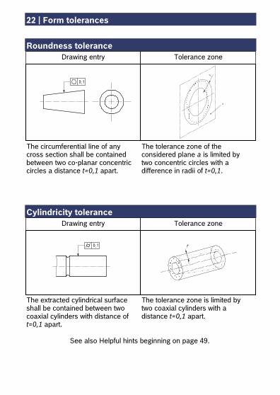
The circumferential line of any cross section shall be contained between two co-planar concentric circles a distance t=0,1 apart.
The tolerance zone of the considered plane a is limited by two concentric circles with a difference in radii of t=0,1.
The tolerance zone is limited by two coaxial cylinders with a distance t=0,1 apart.
The extracted cylindrical surface shall be contained between two coaxial cylinders with distance of t=0,1 apart.
Form tolerances | 23
Profile tolerance - line not related to a datum Profile tolerance - line related to a datum system
Drawing entry Tolerance zone
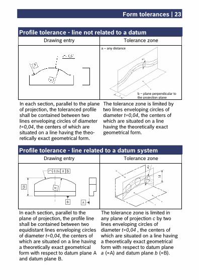
The tolerance zone is limited by two lines enveloping circles of diameter t=0,04, the centers of which are situated on a line having the theoretically exact geometrical form.
In each section, parallel to the plane of projection, the toleranced profile shall be contained between two lines enveloping circles of diameter t=0,04, the centers of which are situated on a line having the theo-retically exact geometrical form.
Drawing entry Tolerance zone
The tolerance zone is limited in any plane of projection c by two lines enveloping circles of diameter t=0,04 , the centers of which are situated on a line having a theoretically exact geometrical form with respect to datum plane a (=A) and datum plane b (=B).
In each section, parallel to the plane of projection, the profile line shall be contained between two equidistant lines enveloping circles of diameter t=0,04, the centers of which are situated on a line having a theoretically exact geometrical form with respect to datum plane A and datum plane B.
a – any distance
b – plane perpendicular to the projection plane
24 | Form tolerances
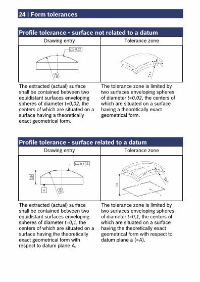
Profile tolerance - surface not related to a datum Profile tolerance - surface related to a datum
Drawing entry Tolerance zone
The tolerance zone is limited by two surfaces enveloping spheres of diameter t=0,02, the centers of which are situated on a surface having a theoretically exact geometrical form.
The extracted (actual) surface shall be contained between two equidistant surfaces enveloping spheres of diameter t=0,02, the centers of which are situated on a surface having a theoretically exact geometrical form.
The tolerance zone is limited by two surfaces enveloping spheres of diameter t=0,1, the centers of which are situated on a surface having the theoretically exact geometrical form with respect to datum plane a (=A).
The extracted (actual) surface shall be contained between two equidistant surfaces enveloping spheres of diameter t=0,1, the centers of which are situated on a surface having the theoretically exact geometrical form with respect to datum plane A.
Drawing entry Tolerance zone
Tolerances of orientation, location and run-out | 25
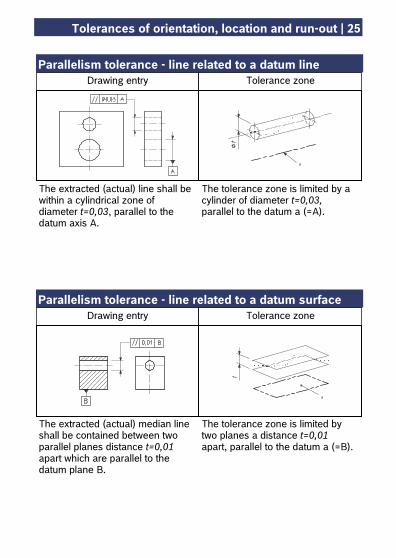
Parallelism tolerance - line related to a datum line Parallelism tolerance - line related to a datum surface
The tolerance zone is limited by a cylinder of diameter t=0,03, parallel to the datum a (=A).
The extracted (actual) line shall be within a cylindrical zone of diameter t=0,03, parallel to the datum axis A.
Drawing entry Tolerance zone
Drawing entry Tolerance zone
The tolerance zone is limited by two planes a distance t=0,01 apart, parallel to the datum a (=B).
The extracted (actual) median line shall be contained between two parallel planes distance t=0,01 apart which are parallel to the datum plane B.
26 | Tolerances of orientation, location and run-out
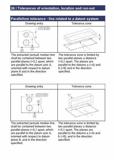
Parallelism tolerance - line related to a datum system
The tolerance zone is limited by two parallel planes a distance t=0,1 apart. The planes are parallel to the datums a (=A) and b (=B) and in the direction specified.
The extracted (actual) median line shall be contained between two parallel planes t=0,1 apart, which are parallel to the datum axis A, oriented with respect to datum plane B and in the direction specified.
Drawing entry Tolerance zone
The tolerance zone is limited by two parallel planes a distance t=0,1 apart. The planes are parallel to the datums a (=A) and b (=B), and in the direction specified.
The extracted (actual) median line shall be contained between two parallel planes t=0,1 apart, which are parallel to the datum axis A, oriented with respect to datum plane B, and in the direction specified.
Drawing entry Tolerance zone
Tolerances of orientation, location and run-out | 27
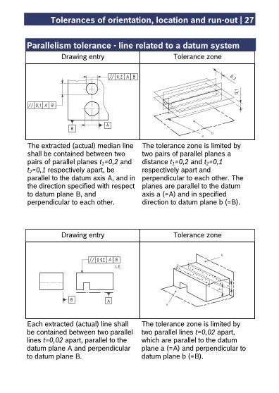
Parallelism tolerance - line related to a datum system
The tolerance zone is limited by two pairs of parallel planes a distance t1=0,2 and t2=0,1 respectively apart and perpendicular to each other. The planes are parallel to the datum axis a (=A) and in specified direction to datum plane b (=B).
The extracted (actual) median line shall be contained between two pairs of parallel planes t1=0,2 and t2=0,1 respectively apart, be parallel to the datum axis A, and in the direction specified with respect to datum plane B, and perpendicular to each other.
Drawing entry Tolerance zone
The tolerance zone is limited by two parallel lines t=0,02 apart, which are parallel to the datum plane a (=A) and perpendicular to datum plane b (=B).
Each extracted (actual) line shall be contained between two parallel lines t=0,02 apart, parallel to the datum plane A and perpendicular to datum plane B.
Drawing entry Tolerance zone
28 | Tolerances of orientation, location and run-out
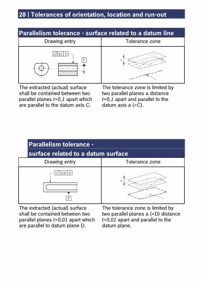
Parallelism tolerance - surface related to a datum line
Parallelism tolerance - surface related to a datum surface
The tolerance zone is limited by two parallel planes a distance t=0,1 apart and parallel to the datum axis a (=C).
The extracted (actual) surface shall be contained between two parallel planes t=0,1 apart which are parallel to the datum axis C.
Drawing entry Tolerance zone
The tolerance zone is limited by two parallel planes a (=D) distance t=0,01 apart and parallel to the datum plane.
The extracted (actual) surface shall be contained between two parallel planes t=0,01 apart which are parallel to datum plane D.
Drawing entry Tolerance zone
Tolerances of orientation, location and run-out | 29
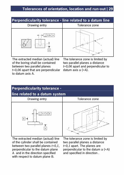
Perpendicularity tolerance - line related to a datum line Perpendicularity tolerance - line related to a datum system
The tolerance zone is limited by two parallel planes a distance t=0,06 apart and perpendicular to datum axis a (=A).
The extracted median (actual) line of the boring shall be contained between two parallel planes t=0,06 apart that are perpendicular to datum axis A.
Drawing entry Tolerance zone
The tolerance zone is limited by two parallel planes a distance t=0,1 apart. The planes are perpendicular to the datum a (=A) and specified in direction .
The extracted median (actual) line of the cylinder shall be contained between two parallel planes t=0,1, perpendicular to the datum plane A and in the direction specified with respect to datum plane B.
Drawing entry Tolerance zone
30 | Tolerances of orientation, location and run-out
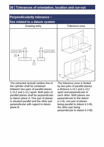
Perpendicularity tolerance – line related to a datum system
Drawing entry Tolerance zone
The tolerance zone is limited by two pairs of parallel planes a distance t2=0,1 and t1=0,2 apart and perpendicular to each other. Both planes are perpendicular to the datum a (=A), one pair of planes being parallel to datum b (=B), the other pair being perpendicular to datum b (=B).
The extracted (actual) median line of the cylinder shall be contained between two pairs of parallel planes t1=0,2 and t2=0,1 apart. Both pairs of parallel planes shall be perpendicular to datum plane A. One pair of planes is situated parallel and the other pair perpendicular with regard to datum plane B.
Tolerances of orientation, location and run-out | 31
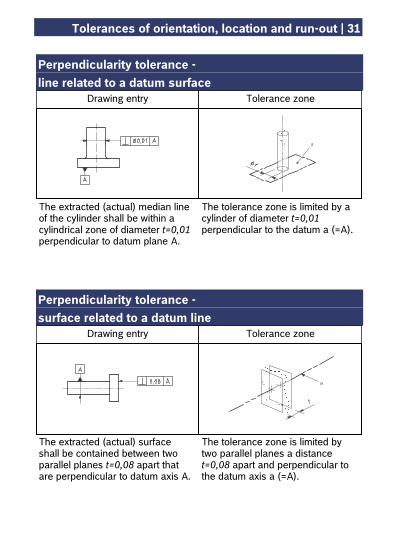
Perpendicularity tolerance - line related to a datum surface Perpendicularity tolerance - surface related to a datum line
The tolerance zone is limited by a cylinder of diameter t=0,01 perpendicular to the datum a (=A).
The extracted (actual) median line of the cylinder shall be within a cylindrical zone of diameter t=0,01 perpendicular to datum plane A.
Drawing entry Tolerance zone
The tolerance zone is limited by two parallel planes a distance t=0,08 apart and perpendicular to the datum axis a (=A).
The extracted (actual) surface shall be contained between two parallel planes t=0,08 apart that are perpendicular to datum axis A.
Drawing entry Tolerance zone
32 | Tolerances of orientation, location and run-out
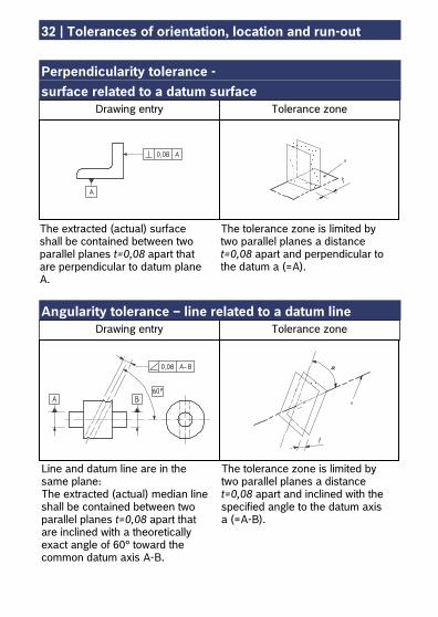
Perpendicularity tolerance - surface related to a datum surface Angularity tolerance – line related to a datum line
The extracted (actual) surface shall be contained between two parallel planes t=0,08 apart that are perpendicular to datum plane A.
The tolerance zone is limited by two parallel planes a distance t=0,08 apart and perpendicular to the datum a (=A).
Drawing entry Tolerance zone
The tolerance zone is limited by two parallel planes a distance t=0,08 apart and inclined with the specified angle to the datum axis a (=A-B).
Line and datum line are in the same plane: The extracted (actual) median line shall be contained between two parallel planes t=0,08 apart that are inclined with a theoretically exact angle of 60° toward the common datum axis A-B.
Drawing entry Tolerance zone
Tolerances of orientation, location and run-out | 33
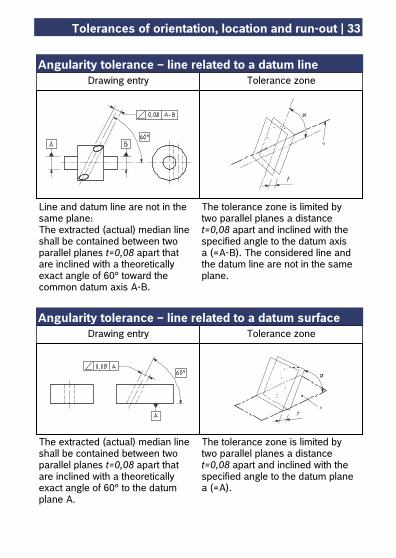
Angularity tolerance – line related to a datum line Angularity tolerance – line related to a datum surface
The tolerance zone is limited by two parallel planes a distance t=0,08 apart and inclined with the specified angle to the datum axis a (=A-B). The considered line and the datum line are not in the same plane.
Line and datum line are not in the same plane: The extracted (actual) median line shall be contained between two parallel planes t=0,08 apart that are inclined with a theoretically exact angle of 60° toward the common datum axis A-B.
Drawing entry Tolerance zone
Drawing entry Tolerance zone
The extracted (actual) median line shall be contained between two parallel planes t=0,08 apart that are inclined with a theoretically exact angle of 60° to the datum plane A.
The tolerance zone is limited by two parallel planes a distance t=0,08 apart and inclined with the specified angle to the datum plane a (=A).
34 | Tolerances of orientation, location and run-out
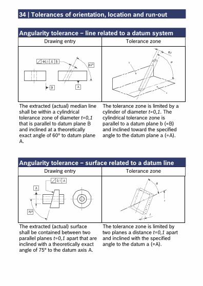
Angularity tolerance – line related to a datum system Angularity tolerance – surface related to a datum line
The tolerance zone is limited by a cylinder of diameter t=0,1. The cylindrical tolerance zone is parallel to a datum plane b (=B) and inclined toward the specified angle to the datum plane a (=A).
The extracted (actual) median line shall be within a cylindrical tolerance zone of diameter t=0,1 that is parallel to datum plane B and inclined at a theoretically exact angle of 60° to datum plane A.
Drawing entry Tolerance zone
The tolerance zone is limited by two planes a distance t=0,1 apart and inclined with the specified angle to the datum a (=A).
The extracted (actual) surface shall be contained between two parallel planes t=0,1 apart that are inclined with a theoretically exact angle of 75° to the datum axis A.
Drawing entry Tolerance zone
Tolerances of orientation, location and run-out | 35
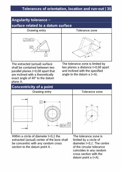
Angularity tolerance – surface related to a datum surface Concentricity of a point
The extracted (actual) surface shall be contained between two parallel planes t=0,08 apart that are inclined with a theoretically exact angle of 40° to the datum plane A.
The tolerance zone is limited by two planes a distance t=0,08 apart and inclined with the specified angle to the datum a (=A).
Drawing entry Tolerance zone
The tolerance zone is limited by a circle of diameter t=0,1. The centre of the circular tolerance coincides in any random cross section with the datum point a (=A).
Within a circle of diameter t=0,1 the extracted (actual) center of the bore shall be concentric with any random cross section to the datum point A .
Drawing entry Tolerance zone
36 | Tolerances of orientation, location and run-out
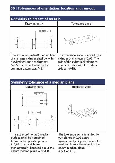
Coaxiality tolerance of an axis Symmetry tolerance of a median plane
The tolerance zone is limited by a cylinder of diameter t=0,08. The axis of the cylindrical tolerance zone coincides with the datum axis a (=A-B).
The extracted (actual) median line of the large cylinder shall be within a cylindrical zone of diameter t=0,08 the axis of which is the common datum axis A-B.
Drawing entry Tolerance zone
The tolerance zone is limited by two planes t=0,08 apart, symmetrically disposed about the median plane with respect to the datum median plane a (=A or A-B).
The extracted (actual) median surface shall be contained between two parallel planes t=0,08 apart which are symmetrically disposed about the datum median plane A or A-B.
Drawing entry Tolerance zone
Tolerances of orientation, location and run-out | 37
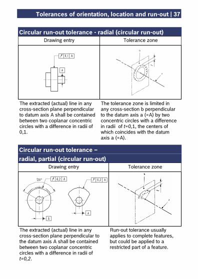
Circular run-out tolerance - radial (circular run-out) Circular run-out tolerance – radial, partial (circular run-out)
The tolerance zone is limited in any cross-section b perpendicular to the datum axis a (=A) by two concentric circles with a difference in radii of t=0,1, the centers of which coincides with the datum axis a (=A).
The extracted (actual) line in any cross-section plane perpendicular to datum axis A shall be contained between two coplanar concentric circles with a difference in radii of 0,1.
Drawing entry Tolerance zone
Run-out tolerance usually applies to complete features, but could be applied to a restricted part of a feature.
The extracted (actual) line in any cross-section plane perpendicular to the datum axis A shall be contained between two coplanar concentric circles with a difference in radii of t=0,2.
Drawing entry Tolerance zone
38 | Tolerances of orientation, location and run-out
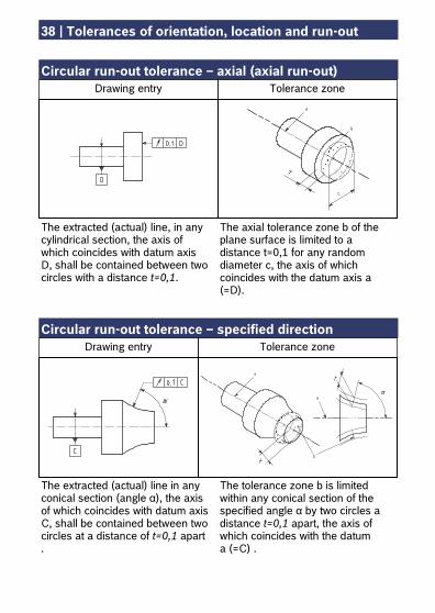
Circular run-out tolerance – axial (axial run-out) Circular run-out tolerance – specified direction
The axial tolerance zone b of the plane surface is limited to a distance t=0,1 for any random diameter c, the axis of which coincides with the datum axis a (=D).
The extracted (actual) line, in any cylindrical section, the axis of which coincides with datum axis D, shall be contained between two circles with a distance t=0,1.
Drawing entry Tolerance zone
The tolerance zone b is limited within any conical section of the specified angle α by two circles a distance t=0,1 apart, the axis of which coincides with the datum a (=C) .
The extracted (actual) line in any conical section (angle α), the axis of which coincides with datum axis C, shall be contained between two circles at a distance of t=0,1 apart .
Drawing entry Tolerance zone
Tolerances of orientation, location and run-out | 39
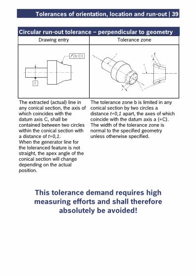
Circular run-out tolerance – perpendicular to geometry
This tolerance demand requires high measuring efforts and shall therefore
absolutely be avoided!
The extracted (actual) line in any conical section, the axis of which coincides with the datum axis C, shall be contained between two circles within the conical section with a distance of t=0,1. When the generator line for the toleranced feature is not straight, the apex angle of the conical section will change depending on the actual position.
The tolerance zone b is limited in any conical section by two circles a distance t=0,1 apart, the axes of which coincide with the datum axis a (=C). The width of the tolerance zone is normal to the specified geometry unless otherwise specified.
Drawing entry Tolerance zone
40 | Tolerances of orientation, location and run-out
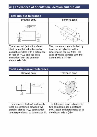
Total run-out tolerance Total axial run-out tolerance
The tolerance zone is limited by two parallel planes a distance t=0,1 apart and perpendicular to the datum axis a (=D).
The extracted (actual) surface (b) shall be contained between two parallel planes t=0,1 apart which are perpendicular to datum axis D.
Drawing entry Tolerance zone
Drawing entry Tolerance zone
The tolerance zone is limited by two coaxial cylinders with a difference in radii of t=0,1, the axes of which coincide with the datum axis a (=A-B).
The extracted (actual) surface shall be contained between two coaxial cylinders with a difference in radii of t=0,1 and the axes coincident with the common datum axis A-B
Tolerances of orientation, location and run-out | 41
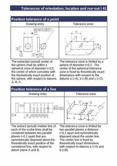
Position tolerance of a point Position tolerance of a line
The tolerance zone is limited by a sphere of diameter t=0,3 . The center of the spherical tolerance zone is fixed by theoretically exact dimensions with respect to the datums a (=A), b (=B) and c (=C).
The extracted (actual) center of the sphere shall be within a spherical zone of diameter t=0,3, the center of which coincides with the theoretically exact position of the sphere, with respect to datums A, B, C.
Drawing entry Tolerance zone
The tolerance zone is limited by two parallel planes a distance t=0,1 apart and symmetrically disposed about the center line. The center line is fixed by theoretically exact dimensions with respect to datums a (=A) and b (=B).
The extract (actual) median line of each of the scribe lines shall be contained between two parallel planes t=0,1 apart that are symmetrically disposed about the theoretically exact position of the considered line, with respect to datum plane A and B.
Drawing entry Tolerance zone
42 | Tolerances of orientation, location and run-out
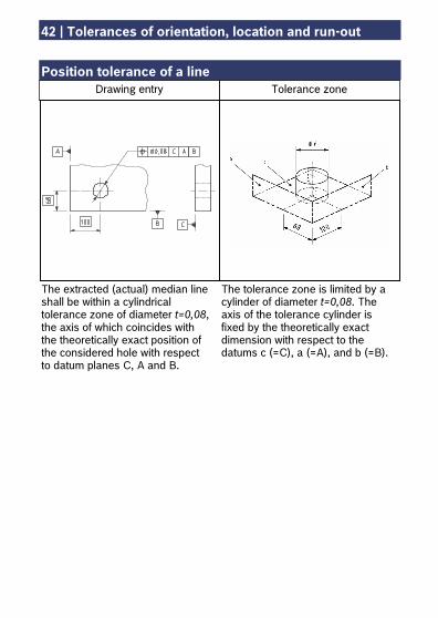
Position tolerance of a line
The tolerance zone is limited by a cylinder of diameter t=0,08. The axis of the tolerance cylinder is fixed by the theoretically exact dimension with respect to the datums c (=C), a (=A), and b (=B).
The extracted (actual) median line shall be within a cylindrical tolerance zone of diameter t=0,08, the axis of which coincides with the theoretically exact position of the considered hole with respect to datum planes C, A and B.
Drawing entry Tolerance zone
Tolerances of orientation, location and run-out | 43
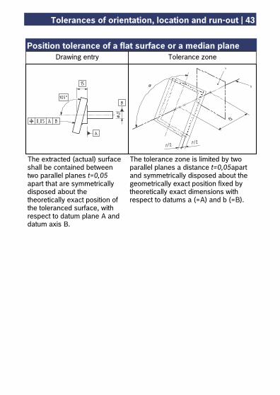
Position tolerance of a flat surface or a median plane
The tolerance zone is limited by two parallel planes a distance t=0,05apart and symmetrically disposed about the geometrically exact position fixed by theoretically exact dimensions with respect to datums a (=A) and b (=B).
The extracted (actual) surface shall be contained between two parallel planes t=0,05 apart that are symmetrically disposed about the theoretically exact position of the toleranced surface, with respect to datum plane A and datum axis B.
Drawing entry Tolerance zone
44 | Maximum material requirement (MMR)
The maximum material requirement is a tolerancing principle for axes and symmetrical surfaces which, by applying the symbol, considers the reciprocal dependency between dimensional tolerance and geometrical tolerances. It allows to enlarge the geometrical tolerance by the not used portion of the dimensional tolerance, provided that the geometrical feature does not break through the maximum material condition. When boring a hole in a plate it applies: If the diameter of the bore is larger than the maximum material requirement, its position may deviate by the same measure without impeding the fitting. The maximum material requirement can be applied for the toleranced feature as well as for the datum feature or for both. The maximum material requirement is preferred for positional tolerancing. The maximum material requirement shall always be applied if the function of the part allows for it.
M
Maximum material requirement (MMR) | 45
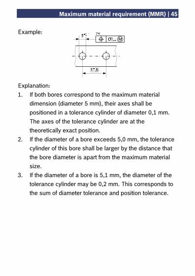
Example: Explanation: 1. If both bores correspond to the maximum material
dimension (diameter 5 mm), their axes shall be positioned in a tolerance cylinder of diameter 0,1 mm. The axes of the tolerance cylinder are at the theoretically exact position.
2. If the diameter of a bore exceeds 5,0 mm, the tolerance cylinder of this bore shall be larger by the distance that the bore diameter is apart from the maximum material size.
3. If the diameter of a bore is 5,1 mm, the diameter of the tolerance cylinder may be 0,2 mm. This corresponds to the sum of diameter tolerance and position tolerance.
46 | Least material requirement (LMR)
The least material requirement is a tolerancing principle for axes and symmetrical surfaces which, by applying the symbol , considers the reciprocal dependency between dimensional tolerance and geometrical tolerances. It allows to enlarge the geometrical tolerance by the not used part of the dimensional tolerance, provided that the geometrical feature does not break the least material condition. When boring a hole in a plate it applies: If the diameter of the bore is smaller than the least material requirement its position may deviate by the same dimension without breaking the minimum wall thickness. The least material requirement can be applied for the toleranced feature as well as for the datum feature or for both. It is preferred for the positional and coaxiality tolerancing in order to assure for example a minimum wall thickness or machining allowances. The least material requirement shall always be applied if the function of the part allow for it.
L
Least material requirement (LMR) | 47
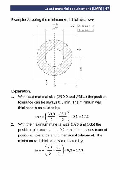
Example: Assuring the minimum wall thickness mins
Explanation: 1. With least material size (∅69,9 and ∅35,1) the position
tolerance can be always 0,1 mm. The minimum wall thickness is calculated by:
2. With the maximum material size (∅70 and ∅35) the
position tolerance can be 0,2 mm in both cases (sum of positional tolerance and dimensional tolerance). The minimum wall thickness is calculated by:
17,30,12
35,1
2
69,9smin =−−= ⎟
⎠⎞⎜
⎝⎛
17,30,22
35
2
70smin =−−= ⎟
⎠⎞
⎜⎝⎛
35
70Ø0,1 A BL
Ø0,1 A BL
44
44B
A
0-0,1
+0,1 0
48 | Reciprocity requirement (RPR)
The reciprocity requirement is an additional requirement to the maximum material requirement or least material requirement and accompanied by the symbol . This requirement makes it possible to apply not used tolerance fractions for geometrical deviations and enlarge the respective dimensional tolerance. In case of the maximum material requirement it means to enlarge the dimensional tolerance by the fraction not used for geometrical tolerancing. The least material size must not be reduced. In case of the least material requirement it means also to enlarge the dimensional tolerance by the fraction not used for geometrical tolerancing. The maximum material size must not be exceeded. The reciprocity requirement must only be applied to the toleranced feature. The reciprocity requirement shall always be applied if the function of the part allows for it.
M
L
Helpful hints | 49
Tolerancing principle To avoid misinterpretations please indicate on all drawings the tolerance principle for:
the envelope principle: tolerancing principle DIN 7167
the principle of independency: tolerancing principle ISO 8015 (or DIN ISO 8015)
The symbol is used only in drawings to which the principle of independency in accordance with ISO 8015 applies. It shall be indicated in the drawing explicitly for all dimensions respectively. Complete specification Indicate only the geometrical tolerances which are absolutely required, that is as a rule only for features that are relevant for function. For all other features the general tolerances which are on the drawing as collective indication apply. Please note that not for each manufacturing method general tolerances are specified for all geometrical deviations (cf. pages 57ff). Datum feature / datum systems Select the features on which depends the location and orientation of the component in mounted condition. If possible, use the same features for production and inspection.
50 | Helpful hints
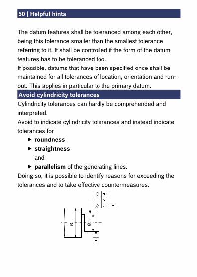
The datum features shall be toleranced among each other, being this tolerance smaller than the smallest tolerance referring to it. It shall be controlled if the form of the datum features has to be toleranced too. If possible, datums that have been specified once shall be maintained for all tolerances of location, orientation and run-out. This applies in particular to the primary datum. Avoid cylindricity tolerances Cylindricity tolerances can hardly be comprehended and interpreted. Avoid to indicate cylindricity tolerances and instead indicate tolerances for
roundness straightness and
parallelism of the generating lines. Doing so, it is possible to identify reasons for exceeding the tolerances and to take effective countermeasures.
Ø...
Ø...
Helpful hints | 51
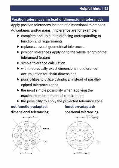
Position tolerances instead of dimensional tolerances Apply position tolerances instead of dimensional tolerances. Advantages and/or gains in tolerance are for example:
complete and unique tolerancing corresponding to function and requirements
replaces several geometrical tolerances position tolerances applying to the whole length of the toleranced feature
simple tolerance calculation with theoretically exact dimensions no tolerance accumulation for chain dimensions
possibilities to utilize cylindrical instead of parallel-epiped tolerance zones
the most simple possibility when applying the maximum or least material requirement
the possibility to apply the projected tolerance zone not function-adapted: function-adapted: dimensional tolerancing positional tolerancing
Ø 30 ±0,1
8x Ø11 +0,27Ø 0,85 AM M
Ø 50
A
52 | Helpful hints
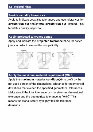
Avoid coaxiality tolerances Avoid to indicate coaxiality tolerances and use tolerances for circular run-out and/or total circular run-out instead. This facilitates quality inspection. Apply projected tolerance zones Apply and indicate the projected tolerance zone for bolted joints in order to assure the compatibility. Apply the maximum material requirement (MMR) Apply the maximum material condition to profit by the not used portion of the dimensional tolerance for geometrical deviations that exceed the specified geometrical tolerances. Make sure if the total tolerance can be given as dimensional tolerance and the geometrical tolerance as "0 " This means functional safety by highly flexible tolerance demands.
45P
P2025
P
Helpful hints | 53
Apply the least material requirement (LMR) Apply the least material condition to assure minimum wall thicknesses. Always both features forming the wall thickness have to be toleranced. Apply the least material condition to profit by the not used portion of the dimensional tolerance for geometrical deviations that exceed the specified geometrical tolerance. Make sure if the total tolerance can be given as dimensional tolerance and the geometrical tolerance as "0 " This means functional safety by highly flexible tolerance demands. Reciprocity requirement (RpR) The reciprocity requirement is a supplement to and and allows that the dimensional tolerance being interrelated with the respective geometrical tolerance may be exceeded if the geometrical tolerance had not completely be used. Original drawing with tolerancing principle If you often have to design similar parts, create an original drawing on the basis of approved dimensioning and tolerancing. This original drawing shall be agreed with authorities in production and quality inspection. If such similar parts occur repeatedly, you may create a constructional catalog containing agreed and approved solutions.
54 | Empirical values for geometrical tolerancing
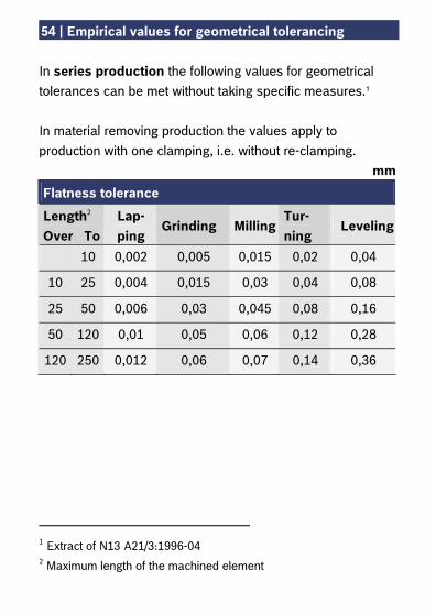
In series production the following values for geometrical tolerances can be met without taking specific measures.1 In material removing production the values apply to production with one clamping, i.e. without re-clamping.
mm
Flatness tolerance
Length2 Over To
Lap-ping
Grinding MillingTur-ning
Leveling
10 0,002 0,005 0,015 0,02 0,04
10 25 0,004 0,015 0,03 0,04 0,08
25 50 0,006 0,03 0,045 0,08 0,16
50 120 0,01 0,05 0,06 0,12 0,28
120 250 0,012 0,06 0,07 0,14 0,36
1 Extract of N13 A21/3:1996-04 2 Maximum length of the machined element

Empirical values for geometrical tolerancing | 55
mm Parallelism tolerance
Length1 Over To
Turning Milling Grinding Pressed insula-tion parts
10 0,03 0,05 0,01 0,06
10 25 0,05 0,05 0,02 0,1
25 50 0,1 0,1 0,05 0,2
50 120 0,1 0,15 0,08 0,2
120 250 0,15 0,2 0,1 0,3
mm Roundness tolerance
Turning Grinding
Diameter Over To between
centers in chuck/in tongs
between centers
w/o centers/in chuck/ in tongs
10 0,003 0,005 0,002 0,003
10 50 0,005 0,015 0,002 0,005
50 120 0,008 0,03 0,003 0,008
120 250 0,01 0,05 0,005 0,01
1 Maximum length of the machined element
56 | Empirical values for geometrical tolerancing
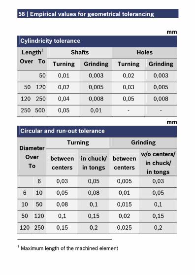
mm Cylindricity tolerance
Shafts Holes Length1 Over To Turning Grinding Turning Grinding
50 0,01 0,003 0,02 0,003
50 120 0,02 0,005 0,03 0,005
120 250 0,04 0,008 0,05 0,008
250 500 0,05 0,01 - -
mm Circular and run-out tolerance
Turning Grinding Diameter
Over To
between centers
in chuck/in tongs
between centers
w/o centers/in chuck/ in tongs
6 0,03 0,05 0,005 0,03
6 10 0,05 0,08 0,01 0,05
10 50 0,08 0,1 0,015 0,1
50 120 0,1 0,15 0,02 0,15
120 250 0,15 0,2 0,025 0,2
1 Maximum length of the machined element
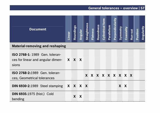
General tolerances – overview | 57
Document
Line
ar
Rou
ndin
gs
Ang
ular
Str
aigh
tnes
s
Flat
ness
Rou
ndne
ss
Cyl
indr
ical
form
Par
alle
lism
Per
pend
icul
arity
Sym
met
ry
Coa
xial
ity
Run
-out
Pos
ition
Ang
ular
ity
Material-removing and reshaping
ISO 2768-1: 1989 Gen. toleran-ces for linear and angular dimen-sions
X X X
ISO 2768-2:1989 Gen. toleran-ces; Geometrical tolerances
X X X X X X X X X
DIN 6930-2:1989 Steel stamping X X X X X X
DIN 6935:1975 (hist.) Cold bending
X X
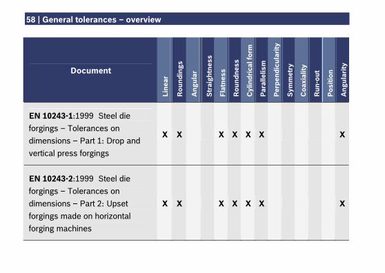
58 | General tolerances – overview
Document
Line
ar
Rou
ndin
gs
Ang
ular
Str
aigh
tnes
s
Flat
ness
Rou
ndne
ss
Cyl
indr
ical
form
Par
alle
lism
Per
pend
icul
arity
Sym
met
ry
Coa
xial
ity
Run
-out
Pos
ition
Ang
ular
ity
EN 10243-1:1999 Steel die forgings – Tolerances on dimensions – Part 1: Drop and vertical press forgings
X X X X X X
X
EN 10243-2:1999 Steel die forgings – Tolerances on dimensions – Part 2: Upset forgings made on horizontal forging machines
X X X X X X
X
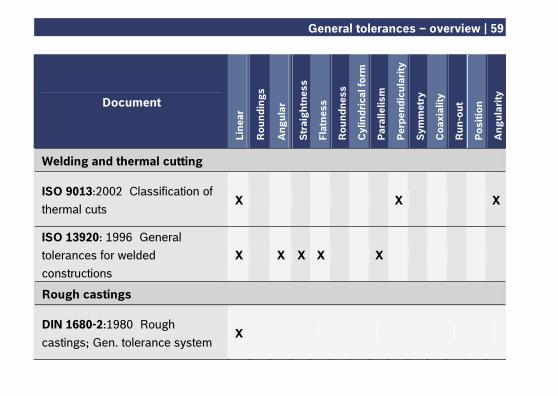
General tolerances – overview | 59
Document
Line
ar
Rou
ndin
gs
Ang
ular
Str
aigh
tnes
s
Flat
ness
Rou
ndne
ss
Cyl
indr
ical
form
Par
alle
lism
Per
pend
icul
arity
Sym
met
ry
Coa
xial
ity
Run
-out
Pos
ition
Ang
ular
ity
Welding and thermal cutting
ISO 9013:2002 Classification of thermal cuts
X X
X
ISO 13920: 1996 General tolerances for welded constructions
X X X X X
Rough castings
DIN 1680-2:1980 Rough castings; Gen. tolerance system
X
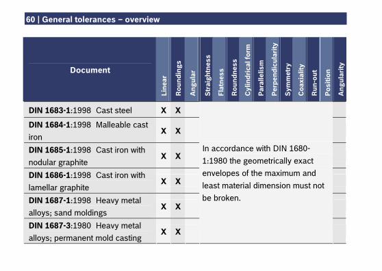
60 | General tolerances – overview
Document
Line
ar
Rou
ndin
gs
Ang
ular
Str
aigh
tnes
s
Flat
ness
Rou
ndne
ss
Cyl
indr
ical
form
Par
alle
lism
Per
pend
icul
arity
Sym
met
ry
Coa
xial
ity
Run
-out
Pos
ition
Ang
ular
ity
DIN 1683-1:1998 Cast steel X X
DIN 1684-1:1998 Malleable cast iron
X X
DIN 1685-1:1998 Cast iron with nodular graphite
X X
DIN 1686-1:1998 Cast iron with lamellar graphite
X X
DIN 1687-1:1998 Heavy metal alloys; sand moldings
X X
DIN 1687-3:1980 Heavy metal alloys; permanent mold casting
X X
In accordance with DIN 1680-1:1980 the geometrically exact envelopes of the maximum and least material dimension must not be broken.
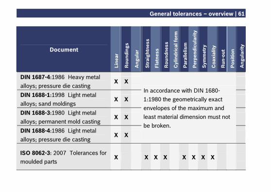
General tolerances – overview | 61
Document
Line
ar
Rou
ndin
gs
Ang
ular
Str
aigh
tnes
s
Flat
ness
Rou
ndne
ss
Cyl
indr
ical
form
Par
alle
lism
Per
pend
icul
arity
Sym
met
ry
Coa
xial
ity
Run
-out
Pos
ition
Ang
ular
ity
DIN 1687-4:1986 Heavy metal alloys; pressure die casting
X X
DIN 1688-1:1998 Light metal alloys; sand moldings
X X
DIN 1688-3:1980 Light metal alloys; permanent mold casting
X X
DIN 1688-4:1986 Light metal alloys; pressure die casting
X X
In accordance with DIN 1680-1:1980 the geometrically exact envelopes of the maximum and least material dimension must not be broken.
ISO 8062-3: 2007 Tolerances for moulded parts
X X X X X X X X
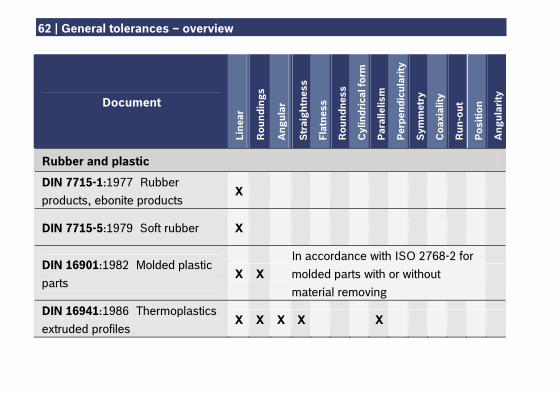
62 | General tolerances – overview
Document
Line
ar
Rou
ndin
gs
Ang
ular
Str
aigh
tnes
s
Flat
ness
Rou
ndne
ss
Cyl
indr
ical
form
Par
alle
lism
Per
pend
icul
arity
Sym
met
ry
Coa
xial
ity
Run
-out
Pos
ition
Ang
ular
ity
Rubber and plastic
DIN 7715-1:1977 Rubber products, ebonite products
X
DIN 7715-5:1979 Soft rubber X
DIN 16901:1982 Molded plastic parts
X X In accordance with ISO 2768-2 for molded parts with or without material removing
DIN 16941:1986 Thermoplastics extruded profiles
X X X X X
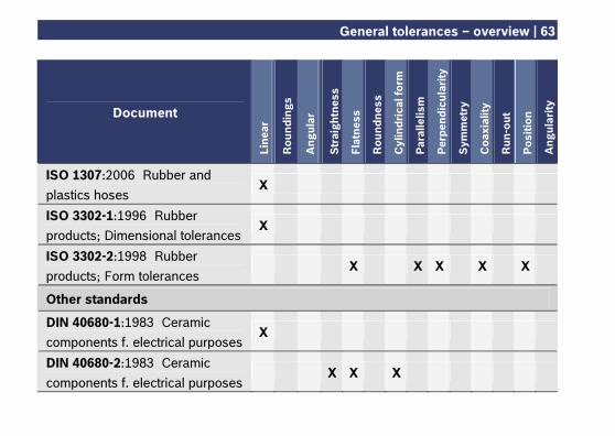
General tolerances – overview | 63
Document
Line
ar
Rou
ndin
gs
Ang
ular
Str
aigh
tnes
s
Flat
ness
Rou
ndne
ss
Cyl
indr
ical
form
Par
alle
lism
Per
pend
icul
arity
Sym
met
ry
Coa
xial
ity
Run
-out
Pos
ition
Ang
ular
ity
ISO 1307:2006 Rubber and plastics hoses
X
ISO 3302-1:1996 Rubber products; Dimensional tolerances
X
ISO 3302-2:1998 Rubber products; Form tolerances
X X X X X
Other standards
DIN 40680-1:1983 Ceramic components f. electrical purposes
X
DIN 40680-2:1983 Ceramic components f. electrical purposes
X X X
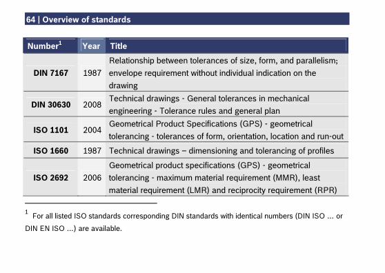
64 | Overview of standards
Number1 Year Title
DIN 7167 1987 Relationship between tolerances of size, form, and parallelism; envelope requirement without individual indication on the drawing
DIN 30630 2008 Technical drawings - General tolerances in mechanical engineering - Tolerance rules and general plan
ISO 1101 2004 Geometrical Product Specifications (GPS) - geometrical tolerancing - tolerances of form, orientation, location and run-out
ISO 1660 1987 Technical drawings – dimensioning and tolerancing of profiles
ISO 2692 2006 Geometrical product specifications (GPS) - geometrical tolerancing - maximum material requirement (MMR), least material requirement (LMR) and reciprocity requirement (RPR)
1 For all listed ISO standards corresponding DIN standards with identical numbers (DIN ISO … or
DIN EN ISO …) are available.
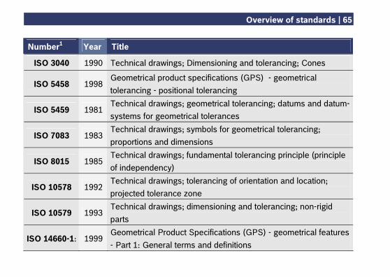
Overview of standards | 65
Number1 Year Title
ISO 3040 1990 Technical drawings; Dimensioning and tolerancing; Cones
ISO 5458 1998 Geometrical product specifications (GPS) - geometrical tolerancing - positional tolerancing
ISO 5459 1981 Technical drawings; geometrical tolerancing; datums and datum-systems for geometrical tolerances
ISO 7083 1983 Technical drawings; symbols for geometrical tolerancing; proportions and dimensions
ISO 8015 1985 Technical drawings; fundamental tolerancing principle (principle of independency)
ISO 10578 1992 Technical drawings; tolerancing of orientation and location; projected tolerance zone
ISO 10579 1993 Technical drawings; dimensioning and tolerancing; non-rigid parts
ISO 14660-1: 1999 Geometrical Product Specifications (GPS) - geometrical features - Part 1: General terms and definitions
66 | Overview of standards
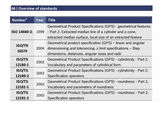
Number1 Year Title
ISO 14660-2: 1999 Geometrical Product Specifications (GPS) - geometrical features - Part 2: Extracted median line of a cylinder and a cone, extracted median surface, local size of an extracted feature
ISO/TR 16570
2004 Geometrical product specification (GPS) – linear and angular dimensioning and tolerancing: ± limit specifications – Step dimensions, distances, angular sizes and radii
ISO/TS 12180-1
2003 Geometrical Product Specifications (GPS) - cylindricity - Part 1: Vocabulary and parameters of cylindrical form
ISO/TS 12180-2
2003 Geometrical Product Specifications (GPS) - cylindricity - Part 2: Specification operators
ISO/TS 12181-1
2003 Geometrical Product Specifications (GPS) - roundness - Part 1: Vocabulary and parameters of roundness
ISO/TS 12181-2
2003 Geometrical Product Specifications (GPS) - roundness - Part 2: Specification operators
Overview of standards | 67
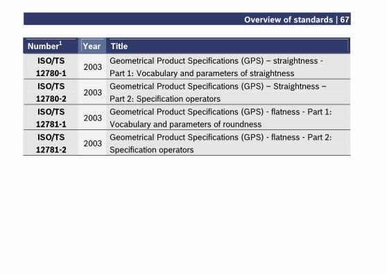
Number1 Year Title
ISO/TS 12780-1
2003 Geometrical Product Specifications (GPS) – straightness - Part 1: Vocabulary and parameters of straightness
ISO/TS 12780-2
2003 Geometrical Product Specifications (GPS) – Straightness – Part 2: Specification operators
ISO/TS 12781-1
2003 Geometrical Product Specifications (GPS) - flatness - Part 1: Vocabulary and parameters of roundness
ISO/TS 12781-2
2003 Geometrical Product Specifications (GPS) - flatness - Part 2: Specification operators
68 | List of literature
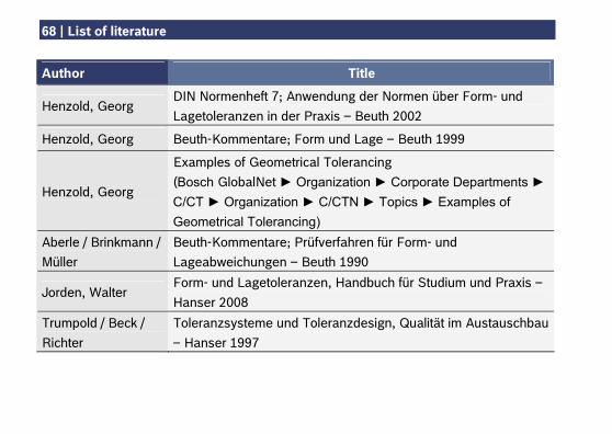
Author Title
Henzold, Georg DIN Normenheft 7; Anwendung der Normen über Form- und Lagetoleranzen in der Praxis – Beuth 2002
Henzold, Georg Beuth-Kommentare; Form und Lage – Beuth 1999
Henzold, Georg
Examples of Geometrical Tolerancing (Bosch GlobalNet ► Organization ► Corporate Departments ► C/CT ► Organization ► C/CTN ► Topics ► Examples of Geometrical Tolerancing)
Aberle / Brinkmann / Müller
Beuth-Kommentare; Prüfverfahren für Form- und Lageabweichungen – Beuth 1990
Jorden, Walter Form- und Lagetoleranzen, Handbuch für Studium und Praxis – Hanser 2008
Trumpold / Beck / Richter
Toleranzsysteme und Toleranzdesign, Qualität im Austauschbau – Hanser 1997
Robert Bosch GmbH C/CTN PO Box 30 02 40 70442 Stuttgart Germany www.bosch.com Printed in Germany 100% chlorine free paper


![2012 [2555] ระบอบการเมืองที่ฝืนการเปลี่ยนแปลงคืออันตรายที่แท้จริง](https://img.pdfslide.net/doc/110x75/6322010664690856e108f5e2/2012-2555-.jpg)


