Embed Size (px)
Citation preview
11111
N68C-GS UCC /N68C-S UCC
User Manual
Version 1.2Published May 2010
Copyright©2010 ASRock INC. All rights reserved.
22222
Copyright Notice:Copyright Notice:Copyright Notice:Copyright Notice:Copyright Notice:No part of this manual may be reproduced, transcribed, transmitted, or translated inany language, in any form or by any means, except duplication of documentation bythe purchaser for backup purpose, without written consent of ASRock Inc.Products and corporate names appearing in this manual may or may not be regis-tered trademarks or copyrights of their respective companies, and are used only foridentification or explanation and to the owners’ benefit, without intent to infringe.
Disclaimer:Disclaimer:Disclaimer:Disclaimer:Disclaimer:Specifications and information contained in this manual are furnished for informa-tional use only and subject to change without notice, and should not be constructedas a commitment by ASRock. ASRock assumes no responsibility for any errors oromissions that may appear in this manual.With respect to the contents of this manual, ASRock does not provide warranty ofany kind, either expressed or implied, including but not limited to the implied warran-ties or conditions of merchantability or fitness for a particular purpose.In no event shall ASRock, its directors, officers, employees, or agents be liable forany indirect, special, incidental, or consequential damages (including damages forloss of profits, loss of business, loss of data, interruption of business and the like),even if ASRock has been advised of the possibility of such damages arising from anydefect or error in the manual or product.
This device complies with Part 15 of the FCC Rules. Operation is subject to thefollowing two conditions:(1) this device may not cause harmful interference, and(2) this device must accept any interference received, including interference that
may cause undesired operation.
CALIFORNIA, USA ONLYThe Lithium battery adopted on this motherboard contains Perchlorate, a toxicsubstance controlled in Perchlorate Best Management Practices (BMP) regulationspassed by the California Legislature. When you discard the Lithium battery inCalifornia, USA, please follow the related regulations in advance.“Perchlorate Material-special handling may apply, seewww.dtsc.ca.gov/hazardouswaste/perchlorate”
ASRock Website: http://www.asrock.com
33333
ContentsContentsContentsContentsContents1 .1 .1 .1 .1 . IntroductionIntroductionIntroductionIntroductionIntroduction ....................................................................................................................................................................................................................................................................................................... 5 5 5 5 5
1.1 Package Contents ..................................................................... 51.2 Specifications ............................................................................ 61.3 Motherboard Layout (N68C-GS UCC / N68C-S UCC) .............. 111.4 I/O Panel (N68C-GS UCC) ......................................................... 121.5 I/O Panel (N68C-S UCC) ........................................................... 13
2.2.2.2.2. InstallationInstallationInstallationInstallationInstallation ...................................................................................................................................................................................................................................................................................................................... 14 14 14 14 14Pre-installation Precautions ............................................................... 142.1 CPU Installation ......................................................................... 152.2 Installation of CPU Fan and Heatsink ....................................... 152.3 Installation of Memory Modules (DIMM) .................................... 162.4 Expansion Slots (PCI and PCI Express Slots) .................................. 182.5 Easy Multi Monitor Feature ........................................................ 192.6 Jumpers Setup .......................................................................... 202.7 Onboard Headers and Connectors .......................................... 212.8 SATAII Hard Disk Setup Guide .................................................. 252.9 Serial ATA (SATA) / Serial ATAII (SATAII) Hard Disks
Installation ................................................................................. 262.10 Hot Plug and Hot Swap Functions for SATA / SATAII HDDs .... 262.11 SATA / SATAII HDD Hot Plug Feature and Operation Guide ..... 272.12 Driver Installation Guide ............................................................ 292.13 Installing Windows® 7 / 7 64-bit / VistaTM / VistaTM 64-bit / XP /
XP 64-bit Without RAID Functions ............................................ 292.14 Installing Windows® 7 / 7 64-bit / VistaTM / VistaTM 64-bit / XP /
XP 64-bit With RAID Functions ................................................. 292.14.1 Installing Windows® XP / XP 64-bit With RAID
Functions ...................................................................... 292.14.2 Installing Windows® 7 / 7 64-bit / VistaTM /
VistaTM 64-bit With RAID Functions .............................. 302.15 Untied Overclocking Technology .............................................. 31
3.3.3.3.3. BIOS SBIOS SBIOS SBIOS SBIOS SETUP UTILITYETUP UTILITYETUP UTILITYETUP UTILITYETUP UTILITY ............................................................................................................................................................................................................................................................... 32 32 32 32 323.1 Introduction ............................................................................... 33
3.1.1 BIOS Menu Bar ............................................................... 333.1.2 Navigation Keys ............................................................. 34
3.2 Main Screen .............................................................................. 343.3 OC Tweaker Screen ................................................................. 353.4 Advanced Screen .................................................................... 42
3.4.1 CPU Configuration .......................................................... 433.4.2 Chipset Configuration ..................................................... 443.4.3 ACPI Configuration ......................................................... 45
44444
3.4.4 Storage Configuration .................................................... 473.4.5 PCIPnP Configuration ...................................................... 493.4.6 Floppy Configuration ...................................................... 503.4.7 Super IO Configuration ................................................... 503.4.8 USB Configuration .......................................................... 52
3.5 Hardware Health Event Monitoring Screen ............................. 533.6 Boot Screen .............................................................................. 54
3.6.1 Boot Settings Configuration ........................................... 543.7 Security Screen ........................................................................ 553.8 Exit Screen ............................................................................... 56
4.4.4.4.4. Software SupportSoftware SupportSoftware SupportSoftware SupportSoftware Support ............................................................................................................................................................................................................................................................... 57 57 57 57 574.1 Install Operating System ........................................................... 574.2 Support CD Information ............................................................. 57
4.2.1 Running Support CD ....................................................... 574.2.2 Drivers Menu .................................................................. 574.2.3 Utilities Menu ................................................................... 574.2.4 Contact Information ........................................................ 57
55555
1.1.1.1.1. IntroductionIntroductionIntroductionIntroductionIntroductionThank you for purchasing ASRock N68C-GS UCC / N68C-S UCC motherboard, areliable motherboard produced under ASRock’s consistently stringent quality control.It delivers excellent performance with robust design conforming to ASRock’s com-mitment to quality and endurance.In this manual, chapter 1 and 2 contain introduction of the motherboard and step-by-stepguide to the hardware installation. Chapter 3 and 4 contain the configuration guide toBIOS setup and information of the Support CD.
Because the motherboard specifications and the BIOS software might beupdated, the content of this manual will be subject to change withoutnotice. In case any modifications of this manual occur, the updatedversion will be available on ASRock website without further notice. Youmay find the latest VGA cards and CPU support lists on ASRock websiteas well. ASRock website http://www.asrock.comIf you require technical support related to this motherboard, please visitour website for specific information about the model you are using.www.asrock.com/support/index.asp
1.11 .11 .11 .11 .1 PPPPPackackackackackage Contentsage Contentsage Contentsage Contentsage ContentsOne ASRock N68C-GS UCC / N68C-S UCC Motherboard
(Micro ATX Form Factor: 9.6-in x 8.2-in, 24.4 cm x 20.8 cm)One ASRock N68C-GS UCC / N68C-S UCC Quick Installation GuideOne ASRock N68C-GS UCC / N68C-S UCC Support CDTwo Serial ATA (SATA) Data Cables (Optional)One I/O Panel Shield
66666
1.21.21.21.21.2 SpecificationsSpecificationsSpecificationsSpecificationsSpecifications
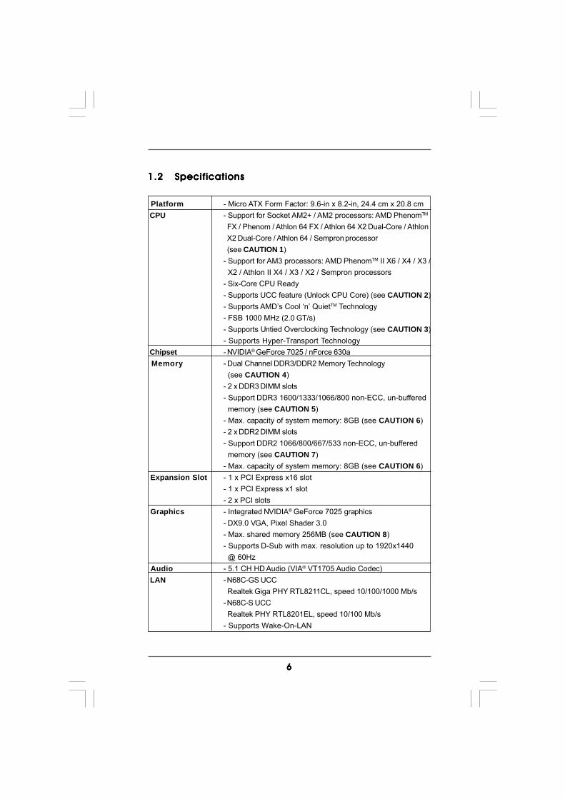
Platform - Micro ATX Form Factor: 9.6-in x 8.2-in, 24.4 cm x 20.8 cm CPU - Support for Socket AM2+ / AM2 processors: AMD PhenomTM
FX / Phenom / Athlon 64 FX / Athlon 64 X2 Dual-Core / Athlon X2 Dual-Core / Athlon 64 / Sempron processor (see CAUTION 1)- Support for AM3 processors: AMD PhenomTM II X6 / X4 / X3 / X2 / Athlon II X4 / X3 / X2 / Sempron processors- Six-Core CPU Ready- Supports UCC feature (Unlock CPU Core) (see CAUTION 2)- Supports AMD’s Cool ‘n’ QuietTM Technology- FSB 1000 MHz (2.0 GT/s)- Supports Untied Overclocking Technology (see CAUTION 3)- Supports Hyper-Transport Technology
Chipset - NVIDIA® GeForce 7025 / nForce 630a Memory - Dual Channel DDR3/DDR2 Memory Technology
(see CAUTION 4)- 2 x DDR3 DIMM slots- Support DDR3 1600/1333/1066/800 non-ECC, un-buffered memory (see CAUTION 5)- Max. capacity of system memory: 8GB (see CAUTION 6)- 2 x DDR2 DIMM slots- Support DDR2 1066/800/667/533 non-ECC, un-buffered memory (see CAUTION 7)- Max. capacity of system memory: 8GB (see CAUTION 6)
Expansion Slot - 1 x PCI Express x16 slot- 1 x PCI Express x1 slot- 2 x PCI slots
Graphics - Integrated NVIDIA® GeForce 7025 graphics- DX9.0 VGA, Pixel Shader 3.0- Max. shared memory 256MB (see CAUTION 8)- Supports D-Sub with max. resolution up to 1920x1440 @ 60Hz
Audio - 5.1 CH HD Audio (VIA® VT1705 Audio Codec) LAN - N68C-GS UCC
Realtek Giga PHY RTL8211CL, speed 10/100/1000 Mb/s- N68C-S UCC Realtek PHY RTL8201EL, speed 10/100 Mb/s- Supports Wake-On-LAN
77777
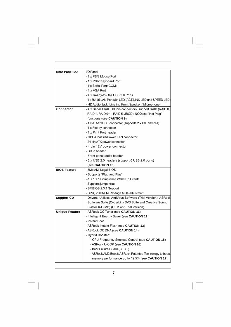
Rear Panel I/O I/O Panel- 1 x PS/2 Mouse Port- 1 x PS/2 Keyboard Port- 1 x Serial Port: COM1- 1 x VGA Port- 4 x Ready-to-Use USB 2.0 Ports- 1 x RJ-45 LAN Port with LED (ACT/LINK LED and SPEED LED)- HD Audio Jack: Line in / Front Speaker / Microphone
Connector - 4 x Serial ATAII 3.0Gb/s connectors, support RAID (RAID 0, RAID 1, RAID 0+1, RAID 5, JBOD), NCQ and “Hot Plug” functions (see CAUTION 9)- 1 x ATA133 IDE connector (supports 2 x IDE devices)- 1 x Floppy connector- 1 x Print Port header- CPU/Chassis/Power FAN connector- 24 pin ATX power connector- 4 pin 12V power connector- CD in header- Front panel audio header- 3 x USB 2.0 headers (support 6 USB 2.0 ports) (see CAUTION 10)
BIOS Feature - 8Mb AMI Legal BIOS- Supports “Plug and Play”- ACPI 1.1 Compliance Wake Up Events- Supports jumperfree- SMBIOS 2.3.1 Support- CPU, VCCM, NB Voltage Multi-adjustment
Support CD - Drivers, Utilities, AntiVirus Software (Trial Version), ASRock Software Suite (CyberLink DVD Suite and Creative Sound Blaster X-Fi MB) (OEM and Trial Version)
Unique Feature - ASRock OC Tuner (see CAUTION 11)- Intelligent Energy Saver (see CAUTION 12)- Instant Boot- ASRock Instant Flash (see CAUTION 13)- ASRock OC DNA (see CAUTION 14)- Hybrid Booster:
- CPU Frequency Stepless Control (see CAUTION 15)- ASRock U-COP (see CAUTION 16)- Boot Failure Guard (B.F.G.)- ASRock AM2 Boost: ASRock Patented Technology to boost memory performance up to 12.5% (see CAUTION 17)
88888
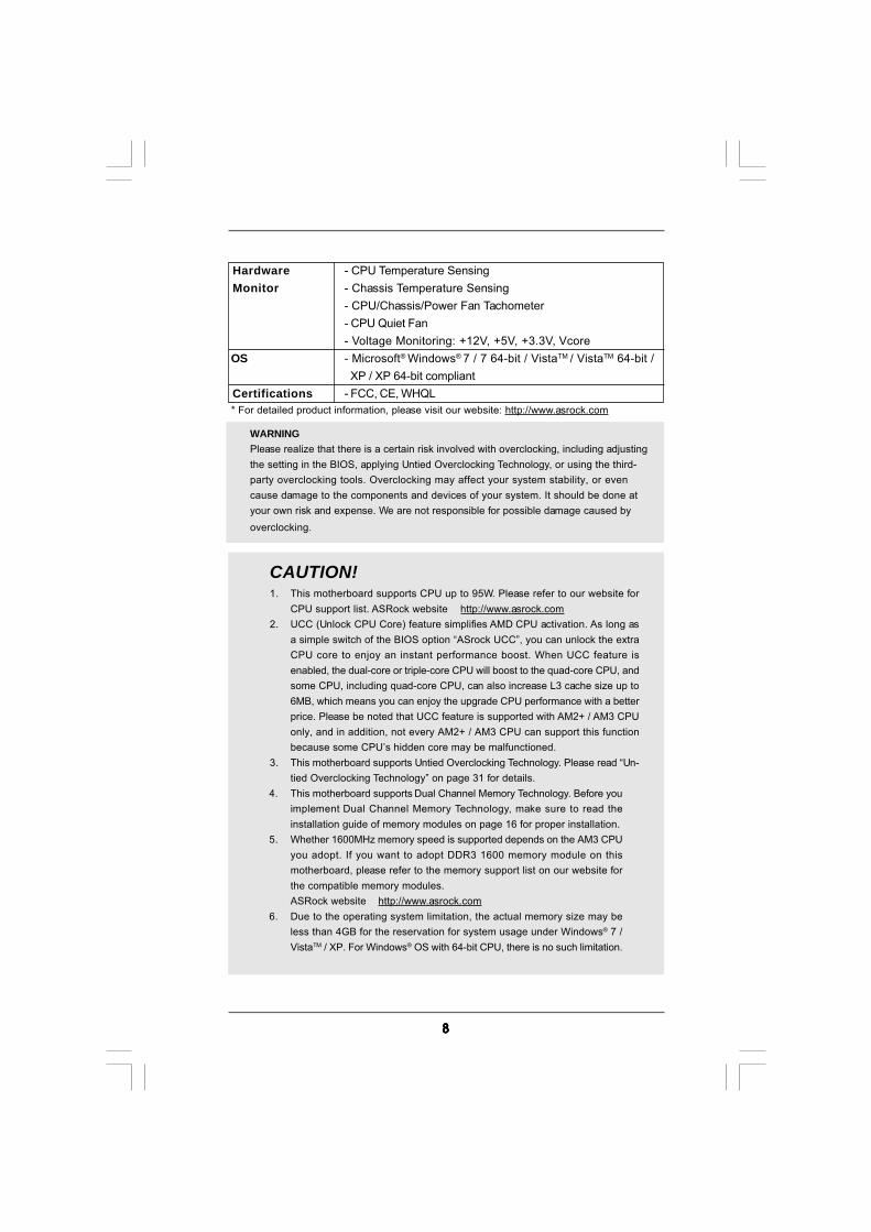
WARNINGPlease realize that there is a certain risk involved with overclocking, including adjustingthe setting in the BIOS, applying Untied Overclocking Technology, or using the third-party overclocking tools. Overclocking may affect your system stability, or evencause damage to the components and devices of your system. It should be done atyour own risk and expense. We are not responsible for possible damage caused byoverclocking.
CAUTION!1. This motherboard supports CPU up to 95W. Please refer to our website for
CPU support list. ASRock website http://www.asrock.com2. UCC (Unlock CPU Core) feature simplifies AMD CPU activation. As long as
a simple switch of the BIOS option “ASrock UCC”, you can unlock the extraCPU core to enjoy an instant performance boost. When UCC feature isenabled, the dual-core or triple-core CPU will boost to the quad-core CPU, andsome CPU, including quad-core CPU, can also increase L3 cache size up to6MB, which means you can enjoy the upgrade CPU performance with a betterprice. Please be noted that UCC feature is supported with AM2+ / AM3 CPUonly, and in addition, not every AM2+ / AM3 CPU can support this functionbecause some CPU’s hidden core may be malfunctioned.
3. This motherboard supports Untied Overclocking Technology. Please read “Un-tied Overclocking Technology” on page 31 for details.
4. This motherboard supports Dual Channel Memory Technology. Before youimplement Dual Channel Memory Technology, make sure to read theinstallation guide of memory modules on page 16 for proper installation.
5. Whether 1600MHz memory speed is supported depends on the AM3 CPUyou adopt. If you want to adopt DDR3 1600 memory module on thismotherboard, please refer to the memory support list on our website forthe compatible memory modules.ASRock website http://www.asrock.com
6. Due to the operating system limitation, the actual memory size may beless than 4GB for the reservation for system usage under Windows® 7 /VistaTM / XP. For Windows® OS with 64-bit CPU, there is no such limitation.
Hardware - CPU Temperature Sensing Monitor - Chassis Temperature Sensing
- CPU/Chassis/Power Fan Tachometer- CPU Quiet Fan- Voltage Monitoring: +12V, +5V, +3.3V, Vcore
OS - Microsoft® Windows® 7 / 7 64-bit / VistaTM / VistaTM 64-bit / XP / XP 64-bit compliant
Certifications - FCC, CE, WHQL * For detailed product information, please visit our website: http://www.asrock.com
99999
7. Whether 1066MHz memory speed is supported depends on the AM2+ CPUyou adopt. If you want to adopt DDR2 1066 memory module on thismotherboard, please refer to the memory support list on our website forthe compatible memory modules.ASRock website http://www.asrock.com
8. The maximum shared memory size is defined by the chipset vendor andis subject to change. Please check NVIDIA® website for the latestinformation.
9. Before installing SATAII hard disk to SATAII connector, please read the “SATAIIHard Disk Setup Guide” on page 25 to adjust your SATAII hard disk drive toSATAII mode. You can also connect SATA hard disk to SATAII connectordirectly.
10. Power Management for USB 2.0 works fine under Microsoft® Windows® 764-bit / 7 / VistaTM 64-bit / VistaTM / XP 64-bit / XP SP1 or SP2.
11. It is a user-friendly ASRock overclocking tool which allows you to surveilyour system by hardware monitor function and overclock your hardwaredevices to get the best system performance under Windows® environment.Please visit our website for the operation procedures of ASRock OCTuner. ASRock website: http://www.asrock.com
12. Featuring an advanced proprietary hardware and software design,Intelligent Energy Saver is a revolutionary technology that deliversunparalleled power savings. The voltage regulator can reduce thenumber of output phases to improve efficiency when the CPU cores areidle. In other words, it is able to provide exceptional power saving andimprove power efficiency without sacrificing computing performance.To use Intelligent Energy Saver function, please enable Cool ‘n’ Quietoption in the BIOS setup in advance. Please visit our website for theoperation procedures of Intelligent Energy Saver.ASRock website: http://www.asrock.com
13. ASRock Instant Flash is a BIOS flash utility embedded in Flash ROM.This convenient BIOS update tool allows you to update system BIOSwithout entering operating systems first like MS-DOS or Windows®.With this utility, you can press <F6> key during the POST or press <F2>key to BIOS setup menu to access ASRock Instant Flash. Just launchthis tool and save the new BIOS file to your USB flash drive, floppy diskor hard drive, then you can update your BIOS only in a few clicks withoutpreparing an additional floppy diskette or other complicated flash utility.Please be noted that the USB flash drive or hard drive must use FAT32/16/12 file system.
14. The software name itself – OC DNA literally tells you what it is capable of.OC DNA, an exclusive utility developed by ASRock, provides a conve-nient way for the user to record the OC settings and share with others. Ithelps you to save your overclocking record under the operating systemand simplifies the complicated recording process of overclocking settings.With OC DNA, you can save your OC settings as a profile and share withyour friends! Your friends then can load the OC profile to their own systemto get the same OC settings as yours! Please be noticed that the OCprofile can only be shared and worked on the same motherboard.
1 01 01 01 01 0
15. Although this motherboard offers stepless control, it is not recommendedto perform over-clocking. Frequencies other than the recommended CPUbus frequencies may cause the instability of the system or damage theCPU.
16. While CPU overheat is detected, the system will automatically shutdown.Before you resume the system, please check if the CPU fan on themotherboard functions properly and unplug the power cord, then plug itback again. To improve heat dissipation, remember to spray thermalgrease between the CPU and the heatsink when you install the PC system.
17. This motherboard supports ASRock AM2 Boost overclocking technology. Ifyou enable this function in the BIOS setup, the memory performance willimprove up to 12.5%, but the effect still depends on the AM2 CPU you adopt.Enabling this function will overclock the chipset/CPU reference clock. However,we can not guarantee the system stability for all CPU/DRAM configurations.If your system is unstable after AM2 Boost function is enabled, it may not beapplicative to your system. You may choose to disable this function forkeeping the stability of your system.
1 11 11 11 11 1
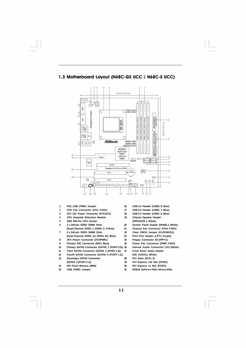
1.3 Motherboard Layout (N68C-GS UCC / N68C-S UCC)1.3 Motherboard Layout (N68C-GS UCC / N68C-S UCC)1.3 Motherboard Layout (N68C-GS UCC / N68C-S UCC)1.3 Motherboard Layout (N68C-GS UCC / N68C-S UCC)1.3 Motherboard Layout (N68C-GS UCC / N68C-S UCC)
1 PS2_USB_PWR1 Jumper 16 USB 2.0 Header (USB8_9, Blue) 2 CPU Fan Connector (CPU_FAN1) 17 USB 2.0 Header (USB6_7, Blue) 3 ATX 12V Power Connector (ATX12V1) 18 USB 2.0 Header (USB4_5, Blue) 4 CPU Heatsink Retention Module 19 Chassis Speaker Header 5 AM2 940-Pin CPU Socket (SPEAKER 1, White) 6 2 x 240-pin DDR2 DIMM Slots 20 System Panel Header (PANEL1, White)
(Dual Channel: DDRII_1, DDRII_2; Yellow) 21 Chassis Fan Connector (CHA_FAN1) 7 2 x 240-pin DDR3 DIMM Slots 22 Clear CMOS Jumper (CLRCMOS1)
(Dual Channel: DDR3_A1, DDR3_B1; Blue) 23 Print Port Header (LPT1, Purple) 8 ATX Power Connector (ATXPWR1) 24 Floppy Connector (FLOPPY1) 9 Primary IDE Connector (IDE1, Blue) 25 Power Fan Connector (PWR_FAN1)10 Primary SATAII Connector (SATAII_1 (PORT 0.0)) 26 Internal Audio Connector: CD1 (White)11 Third SATAII Connector (SATAII_3 (PORT 1.0)) 27 Front Panel Audio Header12 Fourth SATAII Connector (SATAII_4 (PORT 1.1)) (HD_AUDIO1, White)13 Secondary SATAII Connector 28 PCI Slots (PCI1- 2)
(SATAII_2 (PORT 0.1)) 29 PCI Express x16 Slot (PCIE2)14 SPI Flash Memory (8Mb) 30 PCI Express x1 Slot (PCIE1)15 USB_PWR2 Jumper 31 NVIDIA GeForce 7025 / nForce 630a
NVIDIAGeForce
7025 /nForce
630a
FS
B8
00
DD
RII
_1
(64
bit
,2
40
-pin
mo
du
le)
DD
R3
_A
1(6
4b
it,
24
0-p
inm
od
ule
)
IDE1
SATAII_1SATAII_2 SATAII_4
(PORT 0.0)
(PORT 0.1) (PORT 1.1)
SATAII_3 (PORT 1.0)
CHA_FAN1
SPEAKER1
1
HDLED RESET
PLED PWRBTN
1
PANEL 1
11
AT
XP
WR
1
8MbBIOS
CMOS
BATTERY
1CLRCMOS1
CPU_FAN1 ATX12V1
PS2_USB_PWR1
1
20.8cm (8.2-in)
24
.4c
m(9
.6-i
n)
1
US
B4
_5
SOC
KETAM
2
FS
B8
00
DD
RII
_2
(64
bit
,2
40
-pin
mo
du
le)
DD
R3
_B
1(6
4b
it,2
40
-pin
mo
du
le)
1
US
B6
_7
1
US
B8
_9
HD_AUDIO1
1
FLOPPY1CD1
LANPHY
AUDIOCODEC
SuperI/O
PCIE1
PCIE2
PCI1
PCI2
PWR_FAN1
Phenom IIAM2+/AM3
DDR2 1066
Dual Channel
RoHS
1 2 43 6 75
8
9
1011
12
13
14
15
16
1718192021222324252627
28
29
30
USB 2.0T: USB0B: USB1
Top:RJ-45
Top
:L
INE
IN
Cen
ter:F
RO
NT
Bo
ttom
:M
ICIN
PS
2
Mo
use
PS
2K
eyboardV
GA
1
USB 2.0T: USB2B: USB3
CO
M1
1
LPT1
DDR3 1600
De
sig
ne
din
Ta
ipe
i
Support 6-Core CPU
USB_PWR2
1
31
1 21 21 21 21 2
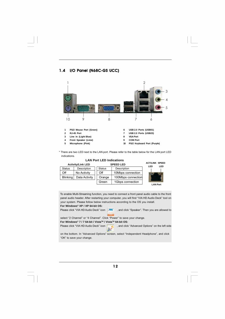
1.41.41.41.41.4 I/O Panel (N68C-GS UCC)I/O Panel (N68C-GS UCC)I/O Panel (N68C-GS UCC)I/O Panel (N68C-GS UCC)I/O Panel (N68C-GS UCC)
1 PS/2 Mouse Port (Green) 6 USB 2.0 Ports (USB01)2 RJ-45 Port 7 USB 2.0 Ports (USB23)3 Line In (Light Blue) 8 VGA Port4 Front Speaker (Lime) 9 COM Port5 Microphone (Pink) 10 PS/2 Keyboard Port (Purple)
1 2
67
4
3
5
8910
To enable Multi-Streaming function, you need to connect a front panel audio cable to the front panel audio header. After restarting your computer, you will find “VIA HD Audio Deck” tool on your system. Please follow below instructions according to the OS you install. For Windows® XP / XP 64-bit OS: Please click “VIA HD Audio Deck” icon , and click “Speaker”. Then you are allowed to
select “2 Channel” or “4 Channel”. Click “Power” to save your change. For Windows® 7 / 7 64-bit / VistaTM / VistaTM 64-bit OS: Please click “VIA HD Audio Deck” icon , and click “Advanced Options” on the left side
on the bottom. In “Advanced Options” screen, select “Independent Headphone”, and click “OK” to save your change.
* There are two LED next to the LAN port. Please refer to the table below for the LAN port LED indications.
LAN Port LED Indications Activity/Link LED SPEED LEDStatus Description Status DescriptionOff No Activity Off 10Mbps connectionBlinking Data Activity Orange 100Mbps connection
Green 1Gbps connectionLAN Port
ACT/LINK LED
SPEED LED
1 31 31 31 31 3
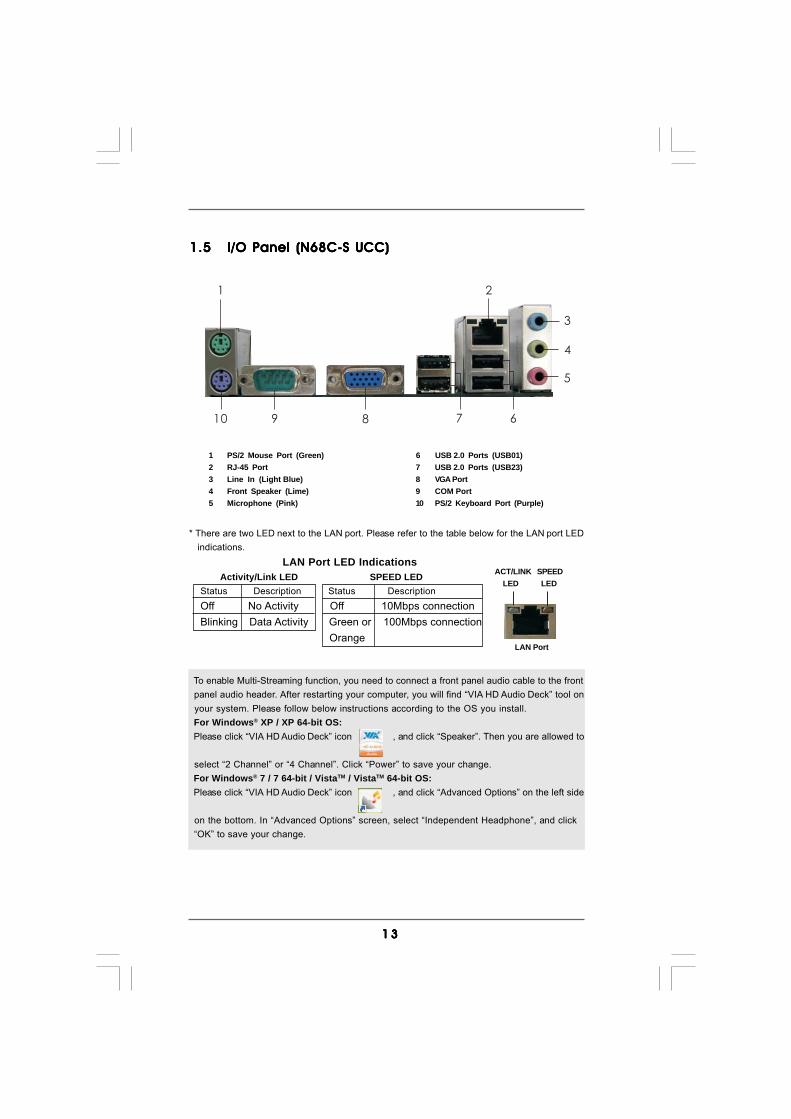
1.51.51.51.51.5 I/O Panel (N68C-S UCC)I/O Panel (N68C-S UCC)I/O Panel (N68C-S UCC)I/O Panel (N68C-S UCC)I/O Panel (N68C-S UCC)
1 PS/2 Mouse Port (Green) 6 USB 2.0 Ports (USB01)2 RJ-45 Port 7 USB 2.0 Ports (USB23)3 Line In (Light Blue) 8 VGA Port4 Front Speaker (Lime) 9 COM Port5 Microphone (Pink) 10 PS/2 Keyboard Port (Purple)
1 2
67
4
3
5
8910
To enable Multi-Streaming function, you need to connect a front panel audio cable to the front panel audio header. After restarting your computer, you will find “VIA HD Audio Deck” tool on your system. Please follow below instructions according to the OS you install. For Windows® XP / XP 64-bit OS: Please click “VIA HD Audio Deck” icon , and click “Speaker”. Then you are allowed to
select “2 Channel” or “4 Channel”. Click “Power” to save your change. For Windows® 7 / 7 64-bit / VistaTM / VistaTM 64-bit OS: Please click “VIA HD Audio Deck” icon , and click “Advanced Options” on the left side
on the bottom. In “Advanced Options” screen, select “Independent Headphone”, and click “OK” to save your change.
* There are two LED next to the LAN port. Please refer to the table below for the LAN port LED indications.
LAN Port LED Indications Activity/Link LED SPEED LEDStatus Description Status DescriptionOff No Activity Off 10Mbps connectionBlinking Data Activity Green or 100Mbps connection
OrangeLAN Port
ACT/LINK LED
SPEED LED
1 41 41 41 41 4
2.2.2.2.2. InstallationInstallationInstallationInstallationInstallationThis is a Micro ATX form factor (9.6-in x 8.2-in, 24.4 cm x 20.8 cm) motherboard.Before you install the motherboard, study the configuration of your chassis to en-sure that the motherboard fits into it.
Pre-installation PrecautionsPre-installation PrecautionsPre-installation PrecautionsPre-installation PrecautionsPre-installation PrecautionsTake note of the following precautions before you install motherboardcomponents or change any motherboard settings.
Before you install or remove any component, ensure that thepower is switched off or the power cord is detached from thepower supply. Failure to do so may cause severe damage to themotherboard, peripherals, and/or components.
1. Unplug the power cord from the wall socket before touching anycomponent.
2. To avoid damaging the motherboard components due to staticelectricity, NEVER place your motherboard directly on the carpet orthe like. Also remember to use a grounded wrist strap or touch asafety grounded object before you handle components.
3. Hold components by the edges and do not touch the ICs.4. Whenever you uninstall any component, place it on a grounded anti-
static pad or in the bag that comes with the component.5. When placing screws into the screw holes to secure the motherboard
to the chassis, please do not over-tighten the screws! Doing so maydamage the motherboard.
1 51 51 51 51 5
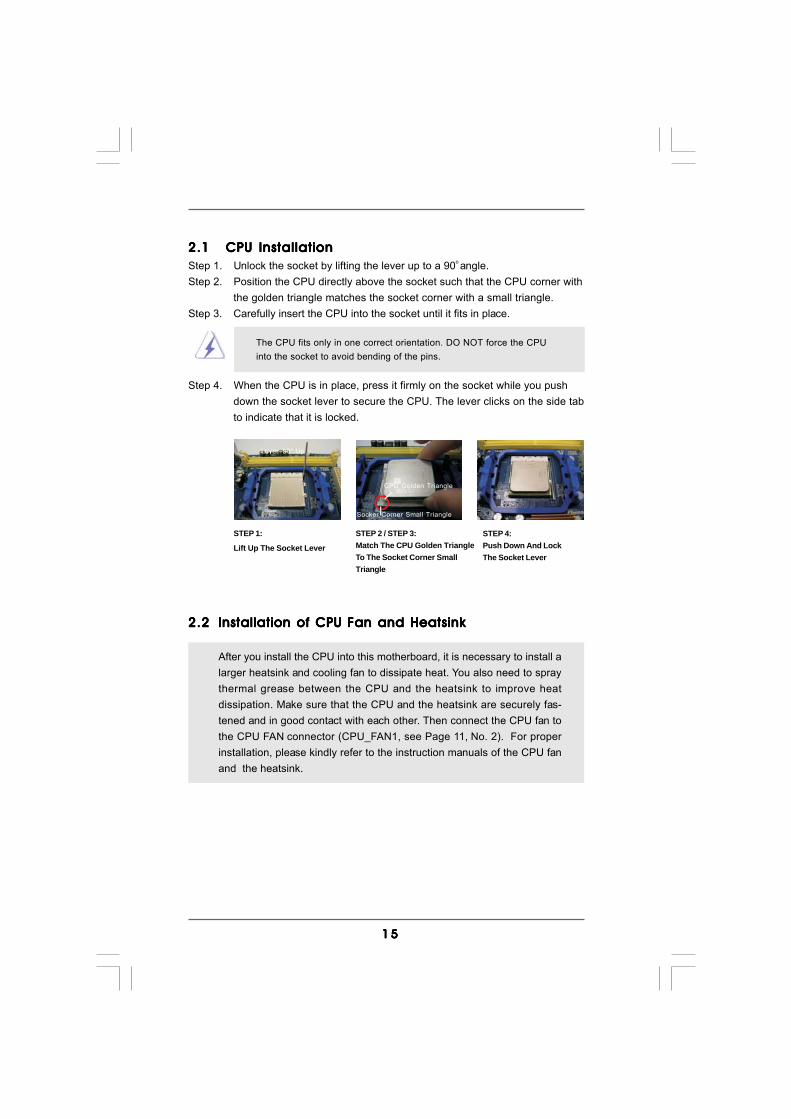
2.12.12.12.12.1 CPU InstallationCPU InstallationCPU InstallationCPU InstallationCPU InstallationStep 1. Unlock the socket by lifting the lever up to a 90o angle.Step 2. Position the CPU directly above the socket such that the CPU corner with
the golden triangle matches the socket corner with a small triangle.Step 3. Carefully insert the CPU into the socket until it fits in place.
The CPU fits only in one correct orientation. DO NOT force the CPUinto the socket to avoid bending of the pins.
Step 4. When the CPU is in place, press it firmly on the socket while you pushdown the socket lever to secure the CPU. The lever clicks on the side tabto indicate that it is locked.
2.22.22.22.22.2 Installation of CPU Fan and HeatsinkInstallation of CPU Fan and HeatsinkInstallation of CPU Fan and HeatsinkInstallation of CPU Fan and HeatsinkInstallation of CPU Fan and Heatsink
After you install the CPU into this motherboard, it is necessary to install alarger heatsink and cooling fan to dissipate heat. You also need to spraythermal grease between the CPU and the heatsink to improve heatdissipation. Make sure that the CPU and the heatsink are securely fas-tened and in good contact with each other. Then connect the CPU fan tothe CPU FAN connector (CPU_FAN1, see Page 11, No. 2). For properinstallation, please kindly refer to the instruction manuals of the CPU fanand the heatsink.
STEP 1:
Lift Up The Socket Lever
STEP 2 / STEP 3:Match The CPU Golden TriangleTo The Socket Corner SmallTriangle
STEP 4:Push Down And LockThe Socket Lever
Lever 90° Up
CPU Golden Triangle
Socker Corner Small Triangle
1 61 61 61 61 6
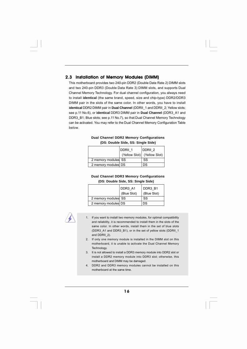
1. If you want to install two memory modules, for optimal compatibilityand reliability, it is recommended to install them in the slots of thesame color. In other words, install them in the set of blue slots(DDR3_A1 and DDR3_B1), or in the set of yellow slots (DDRII_1and DDRII_2).
2. If only one memory module is installed in the DIMM slot on thismotherboard, it is unable to activate the Dual Channel MemoryTechnology.
3. It is not allowed to install a DDR3 memory module into DDR2 slot orinstall a DDR2 memory module into DDR3 slot; otherwise, thismotherboard and DIMM may be damaged.
4. DDR2 and DDR3 memory modules cannot be installed on thismotherboard at the same time.
2.3 Installation of Memory Modules (DIMM)2.3 Installation of Memory Modules (DIMM)2.3 Installation of Memory Modules (DIMM)2.3 Installation of Memory Modules (DIMM)2.3 Installation of Memory Modules (DIMM)This motherboard provides two 240-pin DDR2 (Double Data Rate 2) DIMM slotsand two 240-pin DDR3 (Double Data Rate 3) DIMM slots, and supports DualChannel Memory Technology. For dual channel configuration, you always needto install identical (the same brand, speed, size and chip-type) DDR2/DDR3DIMM pair in the slots of the same color. In other words, you have to installidentical DDR2 DIMM pair in Dual Channel (DDRII_1 and DDRII_2; Yellow slots;see p.11 No.6), or identical DDR3 DIMM pair in Dual Channel (DDR3_A1 andDDR3_B1; Blue slots; see p.11 No.7), so that Dual Channel Memory Technologycan be activated. You may refer to the Dual Channel Memory Configuration Tablebelow.
Dual Channel DDR2 Memory Configurations (DS: Double Side, SS: Single Side)
DDR3_A1 DDR3_B1 (Blue Slot) (Blue Slot)
2 memory modules SS SS2 memory modules DS DS
Dual Channel DDR3 Memory Configurations (DS: Double Side, SS: Single Side)
DDRII_1 DDRII_2 (Yellow Slot) (Yellow Slot)
2 memory modules SS SS2 memory modules DS DS
1 71 71 71 71 7
notch
break
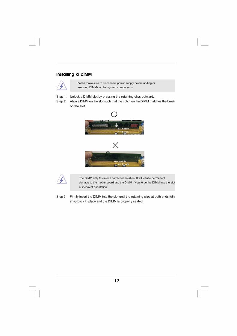
Installing a DIMMInstalling a DIMMInstalling a DIMMInstalling a DIMMInstalling a DIMM
Please make sure to disconnect power supply before adding orremoving DIMMs or the system components.
Step 1. Unlock a DIMM slot by pressing the retaining clips outward.Step 2. Align a DIMM on the slot such that the notch on the DIMM matches the break
on the slot.
The DIMM only fits in one correct orientation. It will cause permanentdamage to the motherboard and the DIMM if you force the DIMM into the slotat incorrect orientation.
Step 3. Firmly insert the DIMM into the slot until the retaining clips at both ends fullysnap back in place and the DIMM is properly seated.
notch
break

1 81 81 81 81 8
2.4 Expansion Slots (PCI and PCI Express Slots)2.4 Expansion Slots (PCI and PCI Express Slots)2.4 Expansion Slots (PCI and PCI Express Slots)2.4 Expansion Slots (PCI and PCI Express Slots)2.4 Expansion Slots (PCI and PCI Express Slots)There are 2 PCI slots and 2 PCI Express slots on this motherboard.PCI slots: PCI slots are used to install expansion cards that have the 32-bit PCI
interface.PCIE slots: PCIE1 (PCIE x1 slot) is used for PCI Express cards with x1 lane width
cards, such as Gigabit LAN card, SATA2 card, etc.PCIE2 (PCIE x16 slot) is used for PCI Express cards with x16 lanewidth graphics cards.
Installing an expansion cardInstalling an expansion cardInstalling an expansion cardInstalling an expansion cardInstalling an expansion cardStep 1. Before installing the expansion card, please make sure that the power
supply is switched off or the power cord is unplugged. Please read thedocumentation of the expansion card and make necessary hardwaresettings for the card before you start the installation.
Step 2. Remove the bracket facing the slot that you intend to use. Keep the screwsfor later use.
Step 3. Align the card connector with the slot and press firmly until the card iscompletely seated on the slot.
Step 4. Fasten the card to the chassis with screws.
1 91 91 91 91 9
2.5 Easy Multi Monitor Feature2.5 Easy Multi Monitor Feature2.5 Easy Multi Monitor Feature2.5 Easy Multi Monitor Feature2.5 Easy Multi Monitor FeatureThis motherboard supports Multi Monitor upgrade. With the internal onboard VGA andthe external add-on PCI Express VGA card, you can easily enjoy the benefits of MultiMonitor feature. Please refer to the following steps to set up a multi monitorenvironment:1. Install the NVIDIA® PCI Express VGA card to PCIE2 (PCIE x16 slot). Please refer to page 18 for proper expansion card installation procedures for details.2. Connect the D-Sub monitor cable to the VGA/D-Sub port on the I/O panel of this motherboard. Connect another D-Sub monitor cable to the VGA/D-Sub connector of the add-on PCI Express VGA card. Connect the DVI-D monitor cable to the VGA/DVI-D connector of the add-on PCI Express VGA card.3. Boot your system. Press <F2> to enter BIOS setup. Enter “Share Memory” option to adjust the memory capability to [16MB], [32MB], [64MB], [128MB] or [256MB] to enable the function of onboard VGA/D-sub. Please make sure that the value you select is less than the total capability of the system memory. If you do not adjust the BIOS setup, the default value of “Share Memory”, [Auto], will disable onboard VGA/D-Sub function when the add-on VGA card is inserted to this motherboard.4. Install the onboard VGA driver to your system. If you have installed the onboard VGA driver already, there is no need to install it again.5. Set up a multi-monitor display. For Windows® XP / XP 64-bit OS:
Right click the desktop, choose “Properties”, and select the “Settings” tab sothat you can adjust the parameters of the multi-monitor according to the stepsbelow.A. Click the “Identify” button to display a large number on each monitor.B. Right-click the display icon in the Display Properties dialog that you wish to be your primary monitor, and then select “Primary”. When you use multiple monitors with your card, one monitor will always be Primary, and all additional monitors will be designated as Secondary.C. Select the display icon identified by the number 2.D. Click “Extend my Windows desktop onto this monitor”.E. Right-click the display icon and select “Attached”, if necessary.F. Set the “Screen Resolution” and “Color Quality” as appropriate for the second monitor. Click “Apply” or “OK” to apply these new values.G. Repeat steps C through E for the diaplay icon identified by the number one, two and three.
For Windows® 7 / 7 64-bit / VistaTM / VistaTM 64-bit OS:Right click the desktop, choose “Personalize”, and select the “DisplaySettings” tab so that you can adjust the parameters of the multi-monitoraccording to the steps below.A. Click the number ”2” icon.
2 02 02 02 02 0
+5V
1_2
+5VSB
2_3
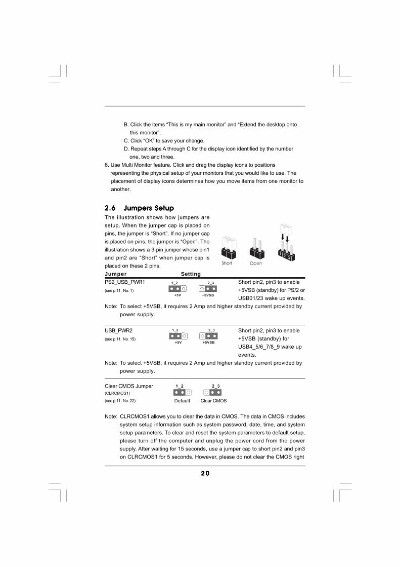
2.62.62.62.62.6 Jumpers SetupJumpers SetupJumpers SetupJumpers SetupJumpers SetupThe illustration shows how jumpers aresetup. When the jumper cap is placed onpins, the jumper is “Short”. If no jumper capis placed on pins, the jumper is “Open”. Theillustration shows a 3-pin jumper whose pin1and pin2 are “Short” when jumper cap isplaced on these 2 pins.Jumper SettingPS2_USB_PWR1 Short pin2, pin3 to enable(see p.11, No. 1) +5VSB (standby) for PS/2 or
USB01/23 wake up events.Note: To select +5VSB, it requires 2 Amp and higher standby current provided by
power supply.
USB_PWR2 Short pin2, pin3 to enable(see p.11, No. 15) +5VSB (standby) for
USB4_5/6_7/8_9 wake upevents.
Note: To select +5VSB, it requires 2 Amp and higher standby current provided bypower supply.
Clear CMOS Jumper(CLRCMOS1)
(see p.11, No. 22)
Note: CLRCMOS1 allows you to clear the data in CMOS. The data in CMOS includessystem setup information such as system password, date, time, and systemsetup parameters. To clear and reset the system parameters to default setup,please turn off the computer and unplug the power cord from the powersupply. After waiting for 15 seconds, use a jumper cap to short pin2 and pin3on CLRCMOS1 for 5 seconds. However, please do not clear the CMOS right
Clear CMOS
2_31_2
Default
B. Click the items “This is my main monitor” and “Extend the desktop onto this monitor”.C. Click “OK” to save your change.D. Repeat steps A through C for the display icon identified by the number one, two and three.
6. Use Multi Monitor feature. Click and drag the display icons to positions representing the physical setup of your monitors that you would like to use. The placement of display icons determines how you move items from one monitor to another.
+5V
1_2
+5VSB
2_3
2 12 12 12 12 1
FLOPPY1Pin1
the red-striped side to Pin1
2.7 Onboard Headers and Connectors2.7 Onboard Headers and Connectors2.7 Onboard Headers and Connectors2.7 Onboard Headers and Connectors2.7 Onboard Headers and Connectors
Onboard headers and connectors are NOT jumpers. Do NOT placejumper caps over these headers and connectors. Placing jumper capsover the headers and connectors will cause permanent damage of themotherboard!•
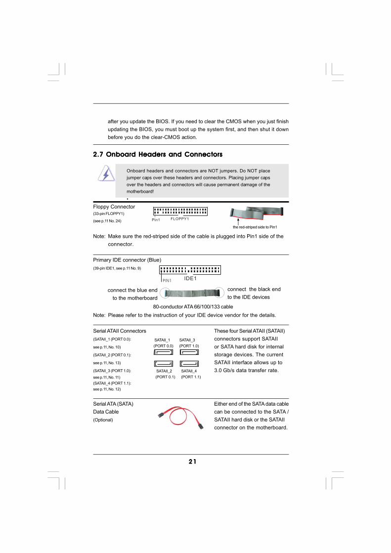
Floppy Connector(33-pin FLOPPY1)
(see p.11 No. 24)
Note: Make sure the red-striped side of the cable is plugged into Pin1 side of theconnector.
Primary IDE connector (Blue)(39-pin IDE1, see p.11 No. 9)
Note: Please refer to the instruction of your IDE device vendor for the details.
Serial ATAII Connectors These four Serial ATAII (SATAII)(SATAII_1 (PORT 0.0): connectors support SATAIIsee p.11, No. 10) or SATA hard disk for internal(SATAII_2 (PORT 0.1): storage devices. The currentsee p.11, No. 13) SATAII interface allows up to(SATAII_3 (PORT 1.0): 3.0 Gb/s data transfer rate.see p.11, No. 11)(SATAII_4 (PORT 1.1):see p.11, No. 12)
Serial ATA (SATA) Either end of the SATA data cableData Cable can be connected to the SATA /(Optional) SATAII hard disk or the SATAII
connector on the motherboard.
connect the black endto the IDE devices
connect the blue endto the motherboard
IDE1PIN1
80-conductor ATA 66/100/133 cable
SATAII_1 SATAII_3(PORT 0.0) (PORT 1.0)
SATAII_2 SATAII_4(PORT 0.1) (PORT 1.1)
after you update the BIOS. If you need to clear the CMOS when you just finishupdating the BIOS, you must boot up the system first, and then shut it downbefore you do the clear-CMOS action.
2 22 22 22 22 2
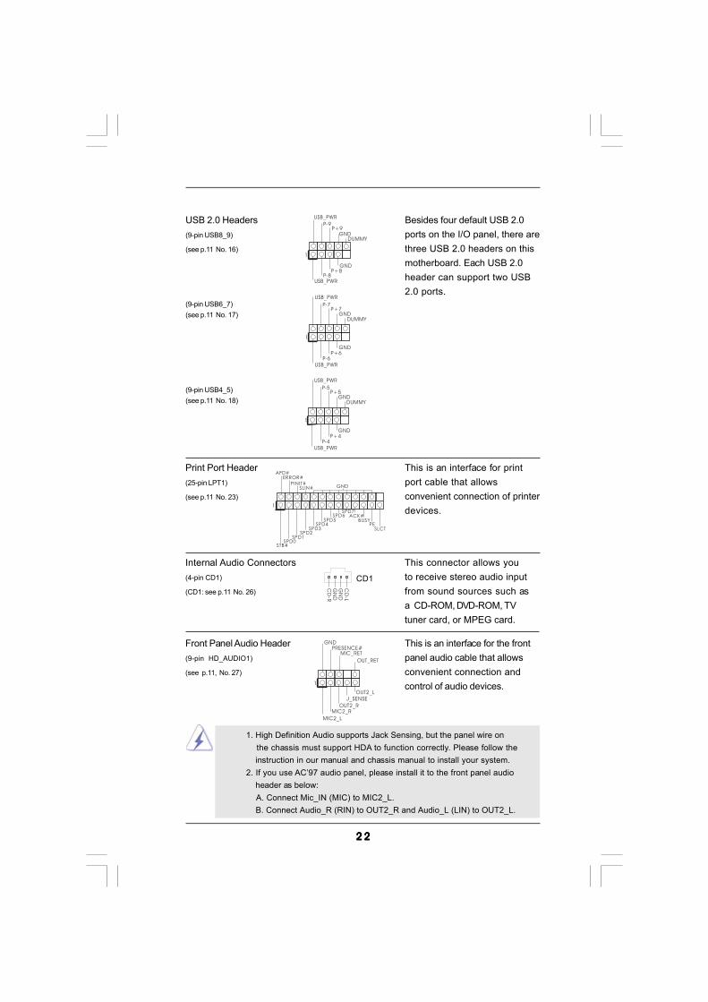
USB 2.0 Headers Besides four default USB 2.0(9-pin USB8_9) ports on the I/O panel, there are(see p.11 No. 16) three USB 2.0 headers on this
motherboard. Each USB 2.0header can support two USB2.0 ports.
(9-pin USB6_7)(see p.11 No. 17)
(9-pin USB4_5)(see p.11 No. 18)
J_SENSE
OUT2_L
1
MIC_RETPRESENCE#
GND
OUT2_RMIC2_R
MIC2_L
OUT_RET
Front Panel Audio Header This is an interface for the front(9-pin HD_AUDIO1) panel audio cable that allows(see p.11, No. 27) convenient connection and
control of audio devices.
USB_PWR
USB_PWR
P+5P-5
P+4P-4
GND
GND
DUMMY
1
USB_PWR
USB_PWR
P+7P-7
P+6P-6
GND
GND
DUMMY
1
1
USB_PWRP-8
GND
DUMMY
USB_PWR
P+8
GND
P-9P+9
Internal Audio Connectors This connector allows you(4-pin CD1) to receive stereo audio input(CD1: see p.11 No. 26) from sound sources such as
a CD-ROM, DVD-ROM, TVtuner card, or MPEG card.
CD
-L
GN
DG
ND
CD
-R
CD1
1. High Definition Audio supports Jack Sensing, but the panel wire on the chassis must support HDA to function correctly. Please follow the
instruction in our manual and chassis manual to install your system.2. If you use AC’97 audio panel, please install it to the front panel audio header as below: A. Connect Mic_IN (MIC) to MIC2_L. B. Connect Audio_R (RIN) to OUT2_R and Audio_L (LIN) to OUT2_L.
Print Port Header This is an interface for print(25-pin LPT1) port cable that allows(see p.11 No. 23) convenient connection of printer
devices.1
AFD#ERROR#
PINIT#GNDSLIN#
STB#SPD0
SPD1SPD2
SPD3SPD4
SPD5SPD6
SPD7ACK#
BUSYPE
SLCT
2 32 32 32 32 3
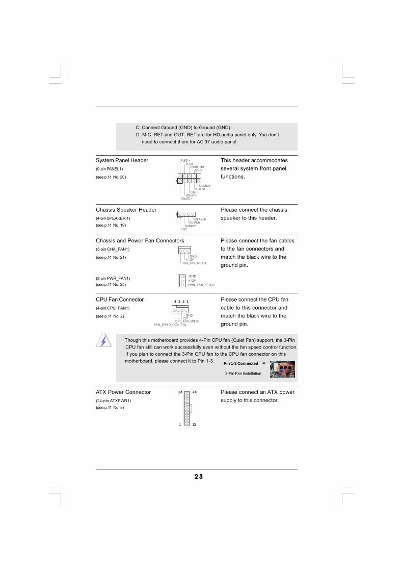
ATX Power Connector Please connect an ATX power(24-pin ATXPWR1) supply to this connector.(see p.11 No. 8)
Though this motherboard provides 4-Pin CPU fan (Quiet Fan) support, the 3-Pin CPU fan still can work successfully even without the fan speed control function. If you plan to connect the 3-Pin CPU fan to the CPU fan connector on this motherboard, please connect it to Pin 1-3.
3-Pin Fan Installation
Pin 1-3 Connected
12
1
24
13
CPU Fan Connector Please connect the CPU fan(4-pin CPU_FAN1) cable to this connector and(see p.11 No. 2) match the black wire to the
ground pin.
GND+12V
CPU_FAN_SPEEDFAN_SPEED_CONTROL
4 3 2 1
Chassis Speaker Header Please connect the chassis(4-pin SPEAKER 1) speaker to this header.(see p.11 No. 19)
Chassis and Power Fan Connectors Please connect the fan cables(3-pin CHA_FAN1) to the fan connectors and(see p.11 No. 21) match the black wire to the
ground pin.
(3-pin PWR_FAN1)(see p.11 No. 25)
System Panel Header This header accommodates(9-pin PANEL1) several system front panel(see p.11 No. 20) functions.
+5V
DUMMYDUMMY
SPEAKER
1
GND
PWRBTN#PLED-
PLED+
DUMMYRESET#
GND
HDLED+HDLED-
1
GND+12V
CHA_FAN_SPEED
PWR_FAN_SPEED
GND
+12V
C. Connect Ground (GND) to Ground (GND). D. MIC_RET and OUT_RET are for HD audio panel only. You don’t need to connect them for AC’97 audio panel.
2 42 42 42 42 4
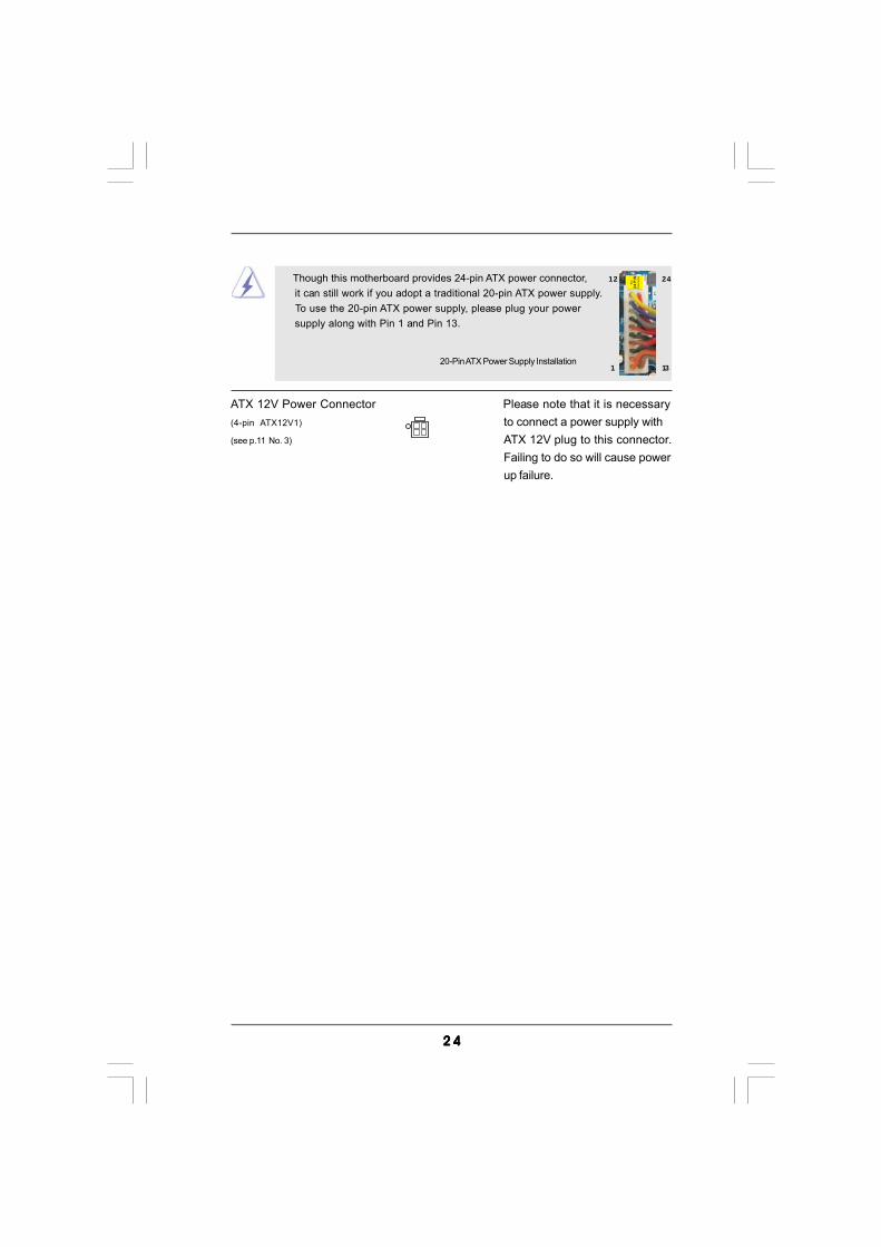
ATX 12V Power Connector Please note that it is necessary(4-pin ATX12V1) to connect a power supply with(see p.11 No. 3) ATX 12V plug to this connector.
Failing to do so will cause powerup failure.
20-Pin ATX Power Supply Installation
Though this motherboard provides 24-pin ATX power connector, it can still work if you adopt a traditional 20-pin ATX power supply. To use the 20-pin ATX power supply, please plug your power supply along with Pin 1 and Pin 13.
12
1
24
13
2 52 52 52 52 5
2 .82 .82 .82 .82 .8 SASASASASATTTTTAII Hard Disk Setup GuideAII Hard Disk Setup GuideAII Hard Disk Setup GuideAII Hard Disk Setup GuideAII Hard Disk Setup GuideBefore installing SATAII hard disk to your computer, please carefully read belowSATAII hard disk setup guide. Some default setting of SATAII hard disks may not beat SATAII mode, which operate with the best performance. In order to enable SATAIIfunction, please follow the below instruction with different vendors to correctly adjustyour SATAII hard disk to SATAII mode in advance; otherwise, your SATAII hard diskmay fail to run at SATAII mode.
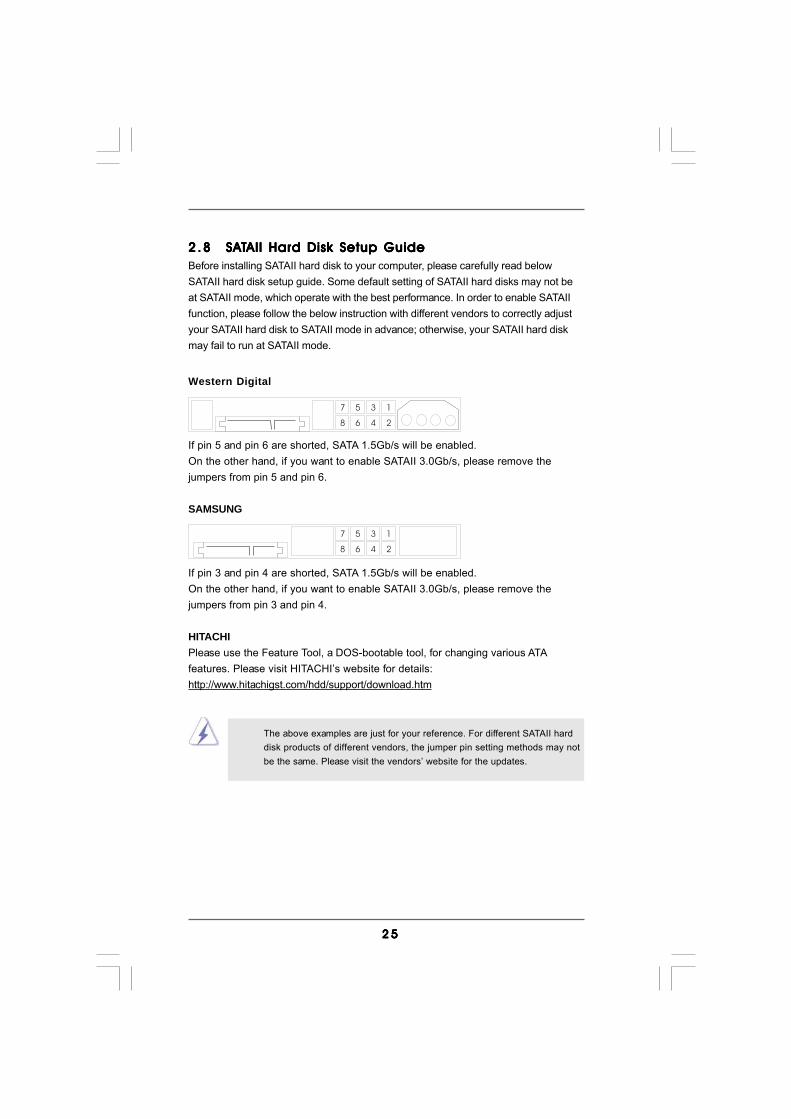
Western Digital
If pin 5 and pin 6 are shorted, SATA 1.5Gb/s will be enabled.On the other hand, if you want to enable SATAII 3.0Gb/s, please remove thejumpers from pin 5 and pin 6.
SAMSUNG
If pin 3 and pin 4 are shorted, SATA 1.5Gb/s will be enabled.On the other hand, if you want to enable SATAII 3.0Gb/s, please remove thejumpers from pin 3 and pin 4.
HITACHIPlease use the Feature Tool, a DOS-bootable tool, for changing various ATAfeatures. Please visit HITACHI’s website for details:http://www.hitachigst.com/hdd/support/download.htm
1357
2468
1357
2468
The above examples are just for your reference. For different SATAII harddisk products of different vendors, the jumper pin setting methods may notbe the same. Please visit the vendors’ website for the updates.
2 62 62 62 62 6
2 .92 .92 .92 .92 .9 Serial ASerial ASerial ASerial ASerial ATTTTTA (SAA (SAA (SAA (SAA (SATTTTTA) / Serial AA) / Serial AA) / Serial AA) / Serial AA) / Serial ATTTTTAII (SAAII (SAAII (SAAII (SAAII (SATTTTTAII) Hard DisksAII) Hard DisksAII) Hard DisksAII) Hard DisksAII) Hard Disks
InstallationInstallationInstallationInstallationInstallationThis motherboard adopts NVIDIA® GeForce 7025 / nForce 630a chipset that supportsSerial ATA (SATA) / Serial ATAII (SATAII) hard disks and RAID functions. You mayinstall SATA / SATAII hard disks on this motherboard for internal storage devices. Thissection will guide you to install the SATA / SATAII hard disks.
STEP 1: Install the SATA / SATAII hard disks into the drive bays of your chassis.STEP 2: Connect the SATA power cable to the SATA / SATAII hard disk.STEP 3: Connect one end of the SATA data cable to the motherboard’s SATAII
connector.STEP 4: Connect the other end of the SATA data cable to the SATA / SATAII hard
disk.
2.102.102.102.102.10 Hot Plug and Hot Swap FHot Plug and Hot Swap FHot Plug and Hot Swap FHot Plug and Hot Swap FHot Plug and Hot Swap Functions for SAunctions for SAunctions for SAunctions for SAunctions for SATTTTTA / SAA / SAA / SAA / SAA / SATTTTTAIIAIIAIIAIIAII
HDDsHDDsHDDsHDDsHDDsThis motherboard supports Hot Plug and Hot Swap functions for SATA / SATAIIDevices.
NOTEWhat is Hot Plug Function?If the SATA / SATAII HDDs are NOT set for RAID configuration, it iscalled “Hot Plug” for the action to insert and remove the SATA / SATAIIHDDs while the system is still power-on and in working condition.However, please note that it cannot perform Hot Plug if the OS hasbeen installed into the SATA / SATAII HDD.
What is Hot Swap Function?If SATA / SATAII HDDs are built as RAID1 or RAID 5 then it is called“Hot Swap” for the action to insert and remove the SATA / SATAIIHDDs while the system is still power-on and in working condition.
2 72 72 72 72 7
Caution1. Without SATA 15-pin power connector interface, the SATA / SATAII Hot Plug cannot be processed.2. Even some SATA / SATAII HDDs provide both SATA 15-pin power connector and IDE 1x4-pin conventional power connector interfaces, the IDE 1x4-pin conventional power connector interface is definitely not able to support Hot Plug and will cause the HDD damage and data loss.
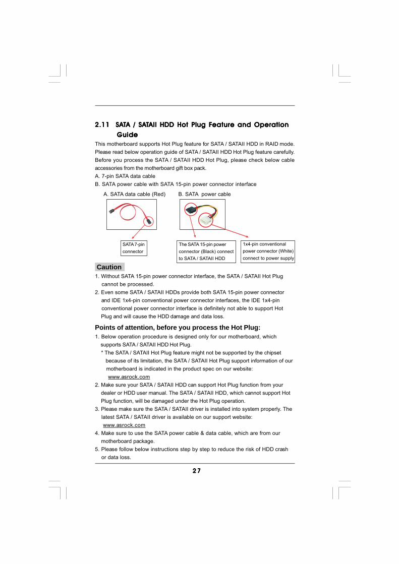
SATA 7-pinconnector
1x4-pin conventionalpower connector (White)connect to power supply
A. SATA data cable (Red) B. SATA power cable
2.11 SA2.11 SA2.11 SA2.11 SA2.11 SATTTTTA / SAA / SAA / SAA / SAA / SATTTTTAII HDD Hot Plug FAII HDD Hot Plug FAII HDD Hot Plug FAII HDD Hot Plug FAII HDD Hot Plug Feature and Operationeature and Operationeature and Operationeature and Operationeature and Operation
Guide Guide Guide Guide GuideThis motherboard supports Hot Plug feature for SATA / SATAII HDD in RAID mode.Please read below operation guide of SATA / SATAII HDD Hot Plug feature carefully.Before you process the SATA / SATAII HDD Hot Plug, please check below cableaccessories from the motherboard gift box pack.A. 7-pin SATA data cableB. SATA power cable with SATA 15-pin power connector interface
The SATA 15-pin powerconnector (Black) connectto SATA / SATAII HDD
Points of attention, before you process the Hot Plug:1. Below operation procedure is designed only for our motherboard, which supports SATA / SATAII HDD Hot Plug. * The SATA / SATAII Hot Plug feature might not be supported by the chipset because of its limitation, the SATA / SATAII Hot Plug support information of our motherboard is indicated in the product spec on our website: www.asrock.com2. Make sure your SATA / SATAII HDD can support Hot Plug function from your dealer or HDD user manual. The SATA / SATAII HDD, which cannot support Hot Plug function, will be damaged under the Hot Plug operation.3. Please make sure the SATA / SATAII driver is installed into system properly. The latest SATA / SATAII driver is available on our support website: www.asrock.com4. Make sure to use the SATA power cable & data cable, which are from our motherboard package.5. Please follow below instructions step by step to reduce the risk of HDD crash or data loss.
2 82 82 82 82 8
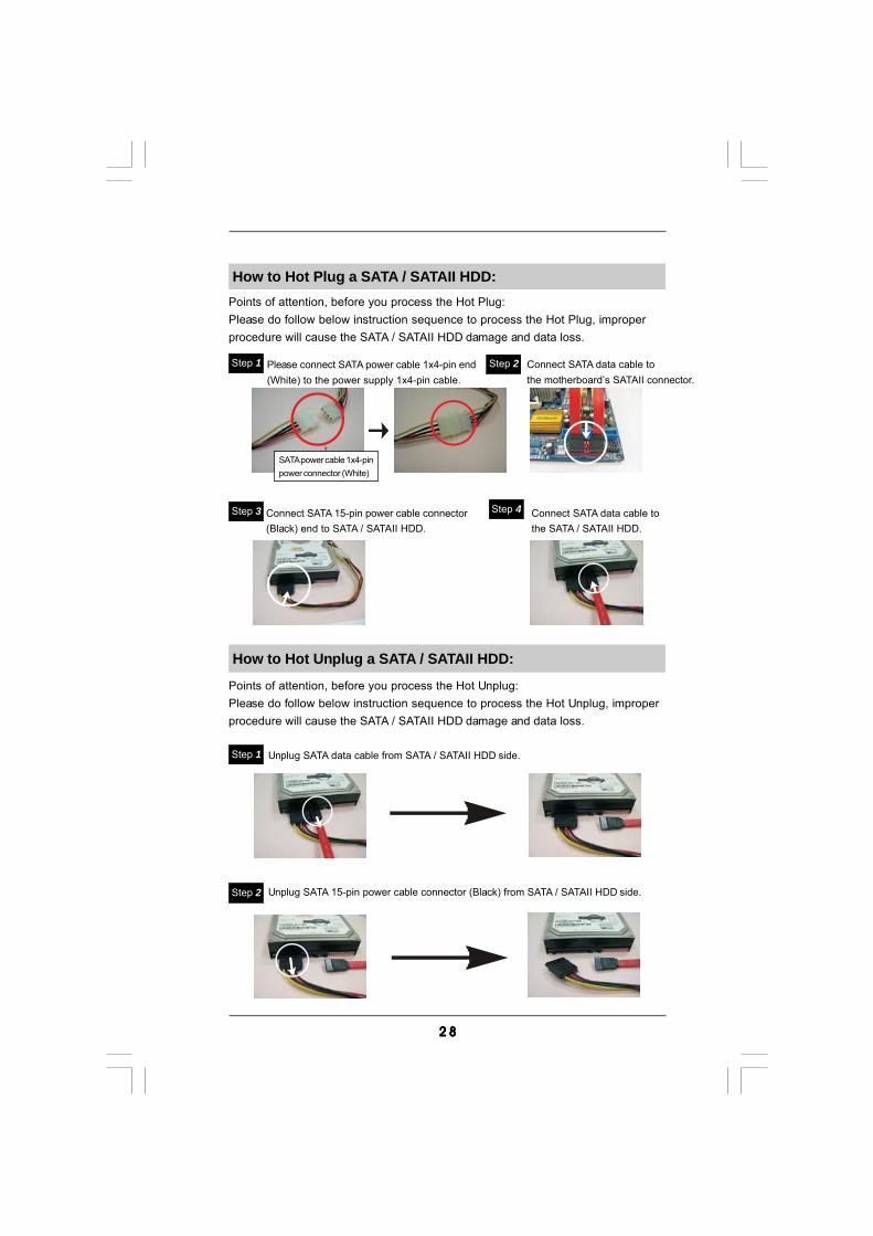
How to Hot Plug a SATA / SATAII HDD:Points of attention, before you process the Hot Plug:Please do follow below instruction sequence to process the Hot Plug, improperprocedure will cause the SATA / SATAII HDD damage and data loss.
Connect SATA data cable tothe motherboard’s SATAII connector.
Connect SATA 15-pin power cable connector(Black) end to SATA / SATAII HDD.
Connect SATA data cable tothe SATA / SATAII HDD.
How to Hot Unplug a SATA / SATAII HDD:
Points of attention, before you process the Hot Unplug:Please do follow below instruction sequence to process the Hot Unplug, improperprocedure will cause the SATA / SATAII HDD damage and data loss.
Please connect SATA power cable 1x4-pin end(White) to the power supply 1x4-pin cable.
Step 1 Step 2
Step 3 Step 4
Step 2
SATA power cable 1x4-pinpower connector (White)
Unplug SATA data cable from SATA / SATAII HDD side.
Unplug SATA 15-pin power cable connector (Black) from SATA / SATAII HDD side.
Step 1
2 92 92 92 92 9
2.122.122.122.122.12 Driver Installation GuideDriver Installation GuideDriver Installation GuideDriver Installation GuideDriver Installation GuideTo install the drivers to your system, please insert the support CD to your optical drivefirst. Then, the drivers compatible to your system can be auto-detected and listed onthe support CD driver page. Please follow the order from up to bottom side to installthose required drivers. Therefore, the drivers you install can work properly.
2.132.132.132.132.13 Installing WindowsInstalling WindowsInstalling WindowsInstalling WindowsInstalling Windows®®®®® 7 / 7 64-bit / Vista 7 / 7 64-bit / Vista 7 / 7 64-bit / Vista 7 / 7 64-bit / Vista 7 / 7 64-bit / VistaTMTMTMTMTM / / / / /
VistaVistaVistaVistaVistaTMTMTMTMTM 64-bit / XP / XP 64-bit Without RAID Functions 64-bit / XP / XP 64-bit Without RAID Functions 64-bit / XP / XP 64-bit Without RAID Functions 64-bit / XP / XP 64-bit Without RAID Functions 64-bit / XP / XP 64-bit Without RAID FunctionsIf you just want to install Windows® 7 / 7 64-bit / VistaTM / VistaTM 64-bit / XP / XP 64-bit on your SATA / SATAII HDDs without RAID functions, you don’t have to make aSATA / SATAII driver diskette. Besides, there is no need for you to change the BIOSsetting. You can start to install Windows® 7 / 7 64-bit / VistaTM / VistaTM 64-bit / XP / XP64-bit on your system directly.
2.142.142.142.142.14 Installing WindowsInstalling WindowsInstalling WindowsInstalling WindowsInstalling Windows®®®®® 7 / 7 64-bit / Vista 7 / 7 64-bit / Vista 7 / 7 64-bit / Vista 7 / 7 64-bit / Vista 7 / 7 64-bit / VistaTMTMTMTMTM / / / / /
VistaVistaVistaVistaVistaTMTMTMTMTM 64-bit / XP / XP 64-bit With RAID Functions 64-bit / XP / XP 64-bit With RAID Functions 64-bit / XP / XP 64-bit With RAID Functions 64-bit / XP / XP 64-bit With RAID Functions 64-bit / XP / XP 64-bit With RAID FunctionsIf you want to install Windows® 7 / 7 64-bit / VistaTM / VistaTM 64-bit / XP / XP 64-bit OSon your SATA / SATAII HDDs with RAID functions, please follow below proceduresaccording to the OS you install.
2.14.1 Installing Windows2.14.1 Installing Windows2.14.1 Installing Windows2.14.1 Installing Windows2.14.1 Installing Windows®®®®® XP / XP 64-bit With RAID XP / XP 64-bit With RAID XP / XP 64-bit With RAID XP / XP 64-bit With RAID XP / XP 64-bit With RAID
Functions Functions Functions Functions FunctionsIf you want to install Windows® XP or Windows® XP 64-bit on your SATA / SATAIIHDDs with RAID functions, please follow below steps.
STEP 1: Set Up BIOS.A. Enter BIOS SETUP UTILITY Advanced screen Storage Configuration.B. Set the “SATA Operation Mode” option to [IDE].STEP 2: Make a SATA / SATAII Driver Diskette.A. Insert the ASRock Support CD into your optical drive to boot your system.B. During POST at the beginning of system boot-up, press <F11> key, and then a window for boot devices selection appears. Please select CD-ROM as the boot device.C. When you see the message on the screen, “Generate Serial ATA driver diskette [YN]?”, press <Y>.
3 03 03 03 03 0
2.14.2 Installing Windows2.14.2 Installing Windows2.14.2 Installing Windows2.14.2 Installing Windows2.14.2 Installing Windows®®®®® 7 / 7 64-bit / Vista 7 / 7 64-bit / Vista 7 / 7 64-bit / Vista 7 / 7 64-bit / Vista 7 / 7 64-bit / VistaTMTMTMTMTM / / / / /
Vista Vista Vista Vista VistaTMTMTMTMTM 64-bit With RAID Functions 64-bit With RAID Functions 64-bit With RAID Functions 64-bit With RAID Functions 64-bit With RAID FunctionsIf you want to install Windows® 7 / 7 64-bit / VistaTM / VistaTM 64-bit on your SATA /SATAII HDDs with RAID functions, please follow below steps.
STEP 1: Set Up BIOS.A. Enter BIOS SETUP UTILITY Advanced screen Storage Configuration.B. Set the “SATA Operation Mode” option to [RAID].STEP 2: Use “RAID Installation Guide” to set RAID configuration.Before you start to configure RAID function, you need to check the RAID installationguide in the Support CD for proper configuration. Please refer to the BIOS RAIDinstallation guide part of the document in the following path in the Support CD:.. \ RAID Installation Guide
NOTE. If you install Windows® XP / Windows® XP 64-bit on IDE HDDs and want to manage(create, convert, delete, or rebuild) RAID functions on SATA / SATAII HDDs, you stillneed to set up “SATA Operation Mode” to [RAID] in BIOS first. Then, please set theRAID configuration by using the Windows RAID installation guide in the following pathin the Support CD:.. \ RAID Installation Guide
D. Then you will see these messages, Please insert a blank formatted diskette into floppy drive A: press any key to start Please insert a floppy diskette into the floppy drive, and press any key.E. The system will start to format the floppy diskette and copy SATA / SATAII drivers into the floppy diskette.STEP 3: Set Up BIOS.A. Enter BIOS SETUP UTILITY Advanced screen Storage Configuration.B. Set the “SATA Operation Mode” option to [RAID].STEP 4: Use “RAID Installation Guide” to set RAID configuration.Before you start to configure RAID function, you need to check the RAID installationguide in the Support CD for proper configuration. Please refer to the BIOS RAIDinstallation guide in the following path in the Support CD:.. \ RAID Installation GuideSTEP 5: Install Windows® XP / XP 64-bit OS on your system.You can start to install Windows® XP / Windows® XP 64-bit OS on your system. At thebeginning of Windows® setup, press F6 to install a third-party RAID driver. Whenprompted, insert the SATA / SATAII driver diskette containing the NVIDIA® RAID driver.After reading the floppy disk, the driver will be presented. Select the driver to installaccording to the mode you choose and the OS you install.
3 13 13 13 13 1
2.152.152.152.152.15 Untied Overclocking TUntied Overclocking TUntied Overclocking TUntied Overclocking TUntied Overclocking TechnologyechnologyechnologyechnologyechnologyThis motherboard supports Untied Overclocking Technology, which means duringoverclocking, FSB enjoys better margin due to fixed PCI / PCIE buses. Before youenable Untied Overclocking function, please enter “Overclock Mode” option of BIOSsetup to set the selection from [Auto] to [CPU, PCIE, Async.]. Therefore, CPU FSB isuntied during overclocking, but PCI / PCIE buses are in the fixed mode so that FSB canoperate under a more stable overclocking environment.
Please refer to the warning on page 8 for the possible overclocking risk beforeyou apply Untied Overclocking Technology.
NOTE. If you install Windows® 7 / 7 64-bit / VistaTM / VistaTM 64-bit on IDE HDDs and want tomanage (create, convert, delete, or rebuild) RAID functions on SATA / SATAII HDDs,you still need to set up “SATA Operation Mode” to [RAID] in BIOS first. Then, please setthe RAID configuration by using the Windows RAID installation guide in the followingpath in the Support CD:.. \ RAID Installation Guide
NOTE. For Windows® 7 / 7 64-bit users, you do not need to load RAID driver from ASRocksupport CD. Please use the native driver to install Windows® 7 / 7 64-bit OS, and theninstall ASRock All-in-1 driver.
STEP 3: Install Windows® 7 / 7 64-bit / VistaTM / VistaTM 64-bit OS on your system.Insert the Windows® 7 / 7 64-bit / VistaTM / VistaTM 64-bit optical disk into the opticaldrive to boot your system, and follow the instruction to install Windows® 7 / 7 64-bit/ VistaTM / VistaTM 64-bit OS on your system. When you see “Where do you want toinstall Windows?” page, please insert the ASRock Support CD into your optical drive,and click the “Load Driver” button on the left on the bottom to load the NVIDIA® RAIDdrivers. NVIDIA® RAID drivers are in the following path in our Support CD:.. \ I386 (For Windows® VistaTM OS).. \ AMD64 (For Windows® VistaTM 64-bit OS)After that, please insert Windows® VistaTM / VistaTM 64-bit optical disk into the opticaldrive again to continue the installation.
3 23 23 23 23 2
3.3.3.3.3. BIOS SETUP UTILITYBIOS SETUP UTILITYBIOS SETUP UTILITYBIOS SETUP UTILITYBIOS SETUP UTILITY3.1 Introduction3.1 Introduction3.1 Introduction3.1 Introduction3.1 IntroductionThis section explains how to use the BIOS SETUP UTILITY to configure your system.The SPI Memory on the motherboard stores the BIOS SETUP UTILITY. You may runthe BIOS SETUP UTILITY when you start up the computer. Please press <F2> or<Del> during the Power-On-Self-Test (POST) to enter the BIOS SETUP UTILITY,otherwise, POST will continue with its test routines.If you wish to enter the BIOS SETUP UTILITY after POST, restart the system bypressing <Ctl> + <Alt> + <Delete>, or by pressing the reset button on the systemchassis. You may also restart by turning the system off and then back on.
Because the BIOS software is constantly being updated, the followingBIOS setup screens and descriptions are for reference purpose only,and they may not exactly match what you see on your screen.
3.1.13.1.13.1.13.1.13.1.1 BIOS Menu BarBIOS Menu BarBIOS Menu BarBIOS Menu BarBIOS Menu BarThe top of the screen has a menu bar with the following selections:Main To set up the system time/date informationOC Tweaker To set up overclocking featuresAdvanced To set up the advanced BIOS featuresH/W Monitor To display current hardware statusBoot To set up the default system device to locate and load the
Operating SystemSecurity To set up the security featuresExit To exit the current screen or the BIOS SETUP UTILITYUse < > key or < > key to choose among the selections on the menu bar,and then press <Enter> to get into the sub screen.
3 33 33 33 33 3
BIOS SETUP UTILITY
Main OC Tweaker H/W Monitor Boot Security ExitAdvanced
Use [Enter], [TAB]
or [SHIFT-TAB] to
select a field.
Use [+] or [-] to
configure system Time.
Select Screen
Select Item
+- Change Field
Tab Select Field
F1 General Help
F9 Load Defaults
F10 Save and Exit
ESC Exit
v02.54 (C) Copyright 1985-2005, American Megatrends, Inc.
System Overview
System Time
System Date[ :00:09]
[Fri 02/12/2010]
BIOS Version
Processor Type
Processor Speed
Microcode Update
L1 Cache Size
L2 Cache Size
Total Memory
DDRII_1
DDRII_2
: N68C-GS UCC P1.00
: AMD Athlon (tm) 64 X2 Dual Core
Processor 4000+ (64bit)
: 2000MHz
: 40F32/62
: 256KB
: 2048KB
: 1024MB with 128MB shared memory
Single-Channel Memory Mode
: 1024MB/266MHz DDR2_533
: None
17
3.1.23.1.23.1.23.1.23.1.2 Navigation KeysNavigation KeysNavigation KeysNavigation KeysNavigation KeysPlease check the following table for the function description of each navigationkey.
Navigation Key(s) Function Description / Moves cursor left or right to select Screens / Moves cursor up or down to select items + / - To change option for the selected items<Enter> To bring up the selected screen<F1> To display the General Help Screen<F9> To load optimal default values for all the settings<F10> To save changes and exit the BIOS SETUP UTILITY<ESC> To jump to the Exit Screen or exit the current screen
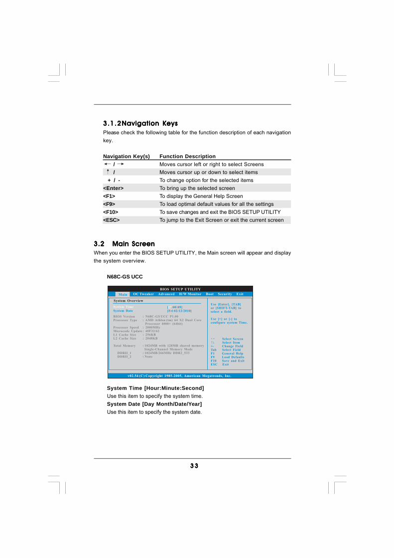
3.23.23.23.23.2 Main ScreenMain ScreenMain ScreenMain ScreenMain ScreenWhen you enter the BIOS SETUP UTILITY, the Main screen will appear and displaythe system overview.
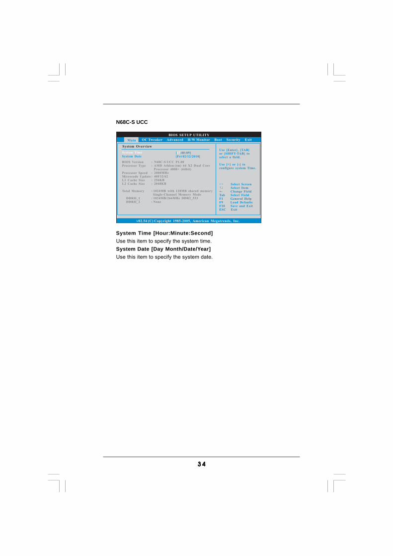
N68C-GS UCC
System Time [Hour:Minute:Second]Use this item to specify the system time.System Date [Day Month/Date/Year]Use this item to specify the system date.
3 43 43 43 43 4
N68C-S UCC
System Time [Hour:Minute:Second]Use this item to specify the system time.System Date [Day Month/Date/Year]Use this item to specify the system date.
BIOS SETUP UTILITY
Main OC Tweaker H/W Monitor Boot Security ExitAdvanced
Use [Enter], [TAB]
or [SHIFT-TAB] to
select a field.
Use [+] or [-] to
configure system Time.
Select Screen
Select Item
+- Change Field
Tab Select Field
F1 General Help
F9 Load Defaults
F10 Save and Exit
ESC Exit
v02.54 (C) Copyright 1985-2005, American Megatrends, Inc.
System Overview
System Time
System Date[ :00:09]
[Fri 02/12/2010]
BIOS Version
Processor Type
Processor Speed
Microcode Update
L1 Cache Size
L2 Cache Size
Total Memory
DDRII_1
DDRII_2
: N68C-S UCC P1.00
: AMD Athlon (tm) 64 X2 Dual Core
Processor 4000+ (64bit)
: 2000MHz
: 40F32/62
: 256KB
: 2048KB
: 1024MB with 128MB shared memory
Single-Channel Memory Mode
: 1024MB/266MHz DDR2_533
: None
17
3 53 53 53 53 5
BIOS SETUP UTILITY
Main Advanced H/W Monitor Boot Security Exit
Overclocking may cause
damage to your CPU and
motherboard.
It should be done at
your own risk and
expense.
Select Screen
Select Item
Enter Go to Sub Screen
F1 General Help
F9 Load Defaults
F10 Save and Exit
ESC Exit
v02.54 (C) Copyright 1985-2005, American Megatrends, Inc.
OC Tweaker
EZ Overclocking
Load Optimized CPU OC Setting [Press Enter]
CPU Configuration
CPU Frequency (MHz)
PCIE Frequency (MHz)
Overclock Mode[200]
[100]
[Auto]
Boot Failure GuardCPU/LDT
Spread SpectrumSATA Spread Spectrum
Spread SpectrumPCIE
Processor Maximum FrequencyProcessor Maximum Voltage
x10.5 2100 MHZ1.2500 V
[Enabled]
[Enabled]
[Enabled]
[Enabled]
Multiplier/Voltage Change
HT Bus Speed
HT Bus Width
[Auto]
[Auto]
[Auto]
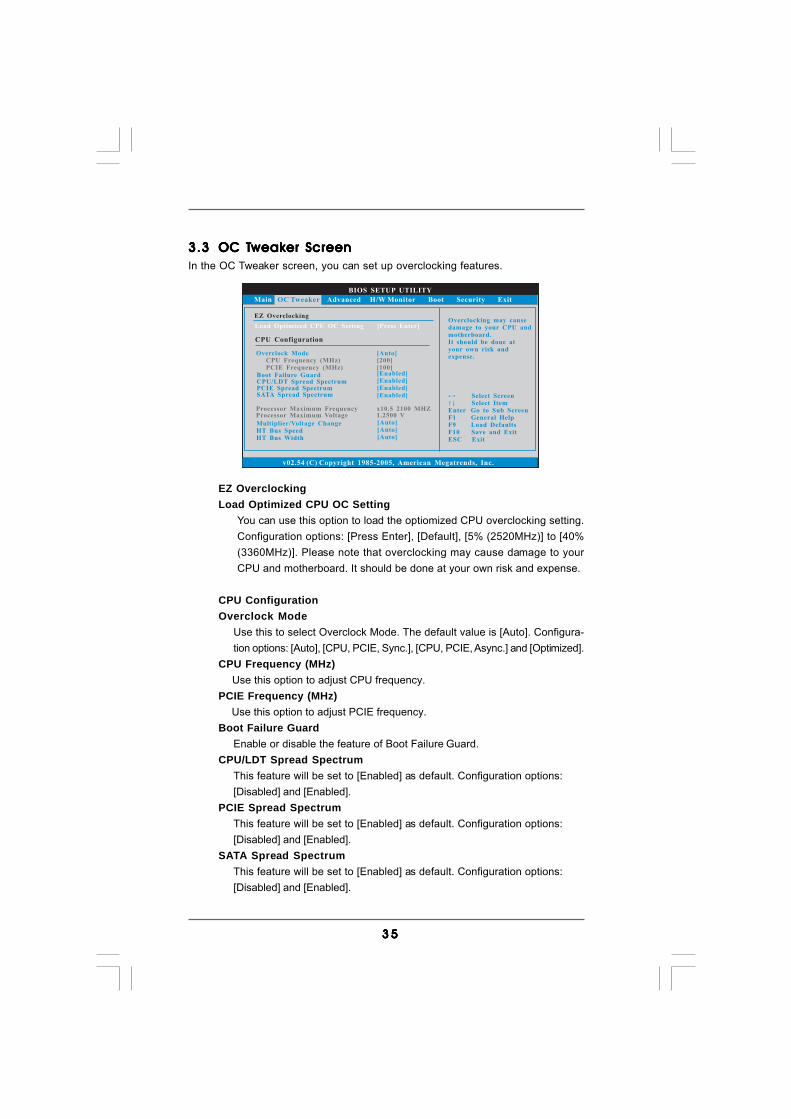
3.33.33.33.33.3 OC TOC TOC TOC TOC Tweakweakweakweakweaker Screener Screener Screener Screener ScreenIn the OC Tweaker screen, you can set up overclocking features.
EZ OverclockingLoad Optimized CPU OC Setting
You can use this option to load the optiomized CPU overclocking setting.Configuration options: [Press Enter], [Default], [5% (2520MHz)] to [40%(3360MHz)]. Please note that overclocking may cause damage to yourCPU and motherboard. It should be done at your own risk and expense.
CPU ConfigurationOverclock Mode
Use this to select Overclock Mode. The default value is [Auto]. Configura-tion options: [Auto], [CPU, PCIE, Sync.], [CPU, PCIE, Async.] and [Optimized].
CPU Frequency (MHz) Use this option to adjust CPU frequency.
PCIE Frequency (MHz) Use this option to adjust PCIE frequency.
Boot Failure GuardEnable or disable the feature of Boot Failure Guard.
CPU/LDT Spread SpectrumThis feature will be set to [Enabled] as default. Configuration options:[Disabled] and [Enabled].
PCIE Spread SpectrumThis feature will be set to [Enabled] as default. Configuration options:[Disabled] and [Enabled].
SATA Spread SpectrumThis feature will be set to [Enabled] as default. Configuration options:[Disabled] and [Enabled].
3 63 63 63 63 6
BIOS SETUP UTILITY
Main Advanced H/W Monitor Boot Security Exit
Overclocking may cause
damage to your CPU and
motherboard.
It should be done at
your own risk and
expense.
Select Screen
Select Item
Enter Go to Sub Screen
F1 General Help
F9 Load Defaults
F10 Save and Exit
ESC Exit
v02.54 (C) Copyright 1985-2005, American Megatrends, Inc.
OC Tweaker
EZ Overclocking
Load Optimized CPU OC Setting [Press Enter]
CPU Configuration
CPU Frequency (MHz)
PCIE Frequency (MHz)
Overclock Mode[200]
[100]
[Auto]
Boot Failure GuardCPU/LDT
Spread SpectrumSATA Spread Spectrum
Spread SpectrumPCIE
Processor Maximum FrequencyProcessor Maximum Voltage
x10.5 2100 MHZ1.2500 V
[Enabled]
[Enabled]
[Enabled]
[Enabled]
Multiplier/Voltage Change
Processor Multiplier
Processor Voltage
[Manual]
[x10.5 2100 MHz]
[1.2500 V]
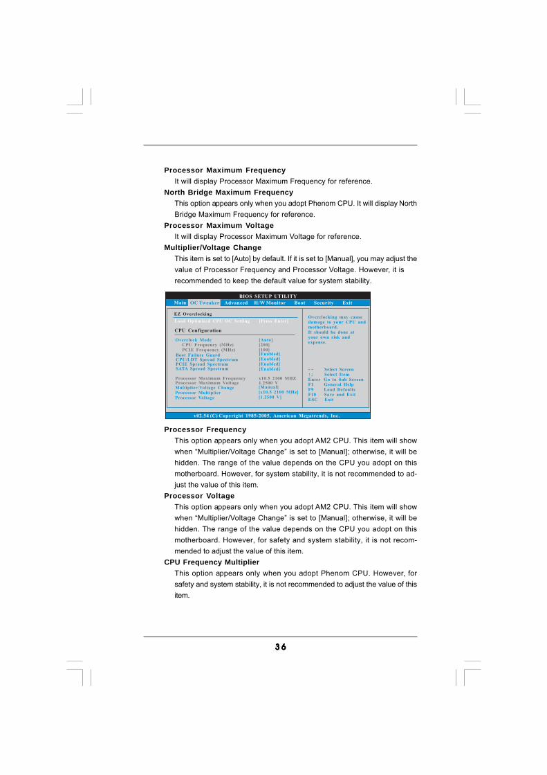
Processor FrequencyThis option appears only when you adopt AM2 CPU. This item will showwhen “Multiplier/Voltage Change” is set to [Manual]; otherwise, it will behidden. The range of the value depends on the CPU you adopt on thismotherboard. However, for system stability, it is not recommended to ad-just the value of this item.
Processor VoltageThis option appears only when you adopt AM2 CPU. This item will showwhen “Multiplier/Voltage Change” is set to [Manual]; otherwise, it will behidden. The range of the value depends on the CPU you adopt on thismotherboard. However, for safety and system stability, it is not recom-mended to adjust the value of this item.
CPU Frequency MultiplierThis option appears only when you adopt Phenom CPU. However, forsafety and system stability, it is not recommended to adjust the value of thisitem.
Processor Maximum FrequencyIt will display Processor Maximum Frequency for reference.
North Bridge Maximum FrequencyThis option appears only when you adopt Phenom CPU. It will display NorthBridge Maximum Frequency for reference.
Processor Maximum VoltageIt will display Processor Maximum Voltage for reference.
Multiplier/Voltage ChangeThis item is set to [Auto] by default. If it is set to [Manual], you may adjust thevalue of Processor Frequency and Processor Voltage. However, it isrecommended to keep the default value for system stability.
3 73 73 73 73 7
NB Frequency MultiplierThis option appears only when you adopt Phenom CPU. However, forsafety and system stability, it is not recommended to adjust the value of thisitem.
HT Bus SpeedThis feature allows you selecting Hyper-Transport bus speed. Configura-tion options: [Auto], [x1 200 MHz], [x2 400 MHz], [x3 600 MHz], [x4 800MHz] and [x5 1000 MHz].
HT Bus WidthThis feature allows you selecting Hyper-Transport bus width. Configura-tion options: [Auto], [8 Bit] and [16 Bit].
ASRock UCCUCC (Unlock CPU Core) feature simplifies AMD CPU activation. As long as asimple switch of the BIOS option “ASRock UCC”, you can unlock the extraCPU core to enjoy an instant performance boost. When UCC feature isenabled, the dual-core or triple-core CPU will boost to the quad-coreCPU, and some CPU, including quad-core CPU, can also increase L3 cachesize up to 6MB, which means you can enjoy the upgrade CPU performancewith a better price. Please be noted that UCC feature is supported withAM2+ / AM3 CPU only, and in addition, not every AM2+ / AM3 CPU cansupport this function because some CPU’s hidden core may bemalfunctioned.
Memory ConfigurationMemory Clock
This item can be set by the code using [Auto]. You can set one of thestandard values as listed for DDR2 memory modules: [200MHz DDR2_400],[266MHz DDR2_533], [333MHz DDR2_667] and [400MHz DDR2_800]. If youadopt Phenom CPU, there is one more option: [533MHz DDR2_1066]. Youcan set one of the standard values as listed for DDR3 memory modules:[400MHz DDR3_800], [533MHz DDR3_1066], [667MHz DDR3_1333] and[800MHz DDR3_1600].
DRAM VoltageUse this to select DRAM voltage. Configuration options: [Auto], [1.794V] to[2.201V]. The default value is [Auto].
3 83 83 83 83 8
BIOS SETUP UTILITY
Memory Timing
Select Screen
Select Item
+- Change Option
F1 General Help
F9 Load Defaults
F10 Save and Exit
ESC Exit
v02.54 (C) Copyright 1985-2003, American Megatrends, Inc.
OC Tweaker
Select Screen
Select Item
+- Change Option
F1 General Help
F9 Load Defaults
F10 Save and Exit
ESC Exit
Power Down Enable
Bank Interleaving
Channel Interleaving
[Enabled]
[Auto]
[Hash 1]
Memory Controller Mode [Unganged]
CAS Latency (CL)
TRCD
TRP
TRAS
TRTP
TRRD
TWTR
TWR
TRC
TRWTWB
TRWTTO
TWRRD
TWRWR
[Auto]
[Auto]
[Auto]
[Auto]
[Auto]
[Auto]
[Auto]
[Auto]
[Auto]
[Auto]
[Auto]
[Auto]
[Auto]
4
4
4
12
2
2
2
4
16
0
4
0
2
Memory Timing
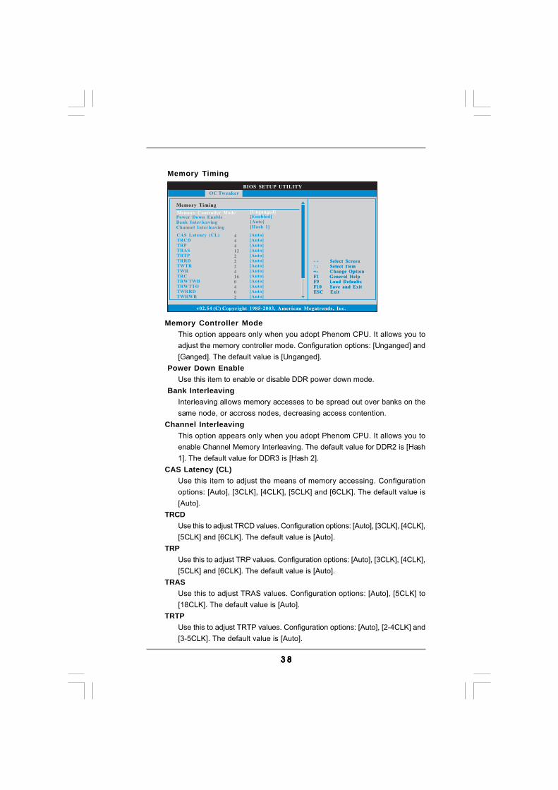
Memory Controller ModeThis option appears only when you adopt Phenom CPU. It allows you toadjust the memory controller mode. Configuration options: [Unganged] and[Ganged]. The default value is [Unganged].
Power Down EnableUse this item to enable or disable DDR power down mode.
Bank InterleavingInterleaving allows memory accesses to be spread out over banks on thesame node, or accross nodes, decreasing access contention.
Channel InterleavingThis option appears only when you adopt Phenom CPU. It allows you toenable Channel Memory Interleaving. The default value for DDR2 is [Hash1]. The default value for DDR3 is [Hash 2].
CAS Latency (CL)Use this item to adjust the means of memory accessing. Configurationoptions: [Auto], [3CLK], [4CLK], [5CLK] and [6CLK]. The default value is[Auto].
TRCDUse this to adjust TRCD values. Configuration options: [Auto], [3CLK], [4CLK],[5CLK] and [6CLK]. The default value is [Auto].
TRPUse this to adjust TRP values. Configuration options: [Auto], [3CLK], [4CLK],[5CLK] and [6CLK]. The default value is [Auto].
TRASUse this to adjust TRAS values. Configuration options: [Auto], [5CLK] to[18CLK]. The default value is [Auto].
TRTPUse this to adjust TRTP values. Configuration options: [Auto], [2-4CLK] and[3-5CLK]. The default value is [Auto].
3 93 93 93 93 9
TRRDUse this to adjust TRRD values. Configuration options: [Auto], [2CLK], [3CLK],[4CLK] and [5CLK]. The default value is [Auto].
TWTRUse this to adjust TWTR values. Configuration options: [Auto], [1CLK],[2CLK] and [3CLK]. The default value is [Auto].
TWRUse this to adjust TWR values. Configuration options: [Auto], [3CLK], [4CLK],[5CLK] and [6CLK]. The default value is [Auto].
TRCUse this to adjust TRC values. Configuration options: [11CLK] to [26CLK].The default value is [Auto].
TRWTWBUse this to adjust TRWTWB values. Configuration options: [3CLK] to [10CLK].The default value is [Auto].
TRWTTOThis option appears only when you adopt AM2 CPU. Use this to adjustTRWTTD values. Configuration options: [Auto], [2CLK], [3CLK], [4CLK],[5CLK], [6CLK], [7CLK], [8CLK] and [9CLK]. The default value is [Auto].
TWRRDThis option appears only when you adopt AM2 CPU. Use this to adjustTWRRD values. Configuration options: [Auto], [0CLK], [1CLK], [2CLK] and[3CLK]. The default value is [Auto].
TWRWRThis option appears only when you adopt AM2 CPU. Use this to adjustTWRWR values. Configuration options: [Auto], [1CLK], [2CLK] and [3CLK].The default value is [Auto].
TRDRDThis option appears only when you adopt AM2 CPU. Use this to adjustTRWTTD values. Configuration options: [Auto], [2CLK], [3CLK], [4CLK] and[5CLK]. The default value is [Auto].
TRFC0Use this to adjust TRFC0 values. Configuration options: [Auto], [75ns],[105ns], [127.5ns], [195ns] and [327.5ns]. The default value is [Auto].
TRFC1Use this to adjust TRFC1 values. Configuration options: [Auto], [75ns],[105ns], [127.5ns], [195ns] and [327.5ns]. The default value is [Auto].
MA TimingUse this to adjust values for MA timing. Configuration options: [Auto], [2T],[1T]. The default value is [Auto].
4 04 04 04 04 0
CHA ADDR/CMD DelayUse this to adjust values for CHA ADDR/CMD Delay feature. Configurationoptions: [Auto], [No Delay], [1/64CLK] to [31/64CLK]. The default value is[Auto].
CHA ADDR/CMD SetupUse this to adjust values for CHA ADDR/CMD Setup feature. Configurationoptions: [Auto], [1/2CLK] and [1CLK]. The default value is [Auto].
CHA CS/ODT DelayUse this to adjust values for CHA CS/ODT Delay feature. Configurationoptions: [Auto], [No Delay], [1/64CLK] to [31/64CLK]. The default value is[Auto].
CHA CS/ODT SetupUse this to adjust values for CHB CS/ODT Setup feature. Configurationoptions: [Auto], [1/2CLK] and [1CLK]. The default value is [Auto].
CHB ADDR/CMD DelayUse this to adjust values for CHB ADDR/CMD Delay feature. Configurationoptions: [Auto], [No Delay], [1/64CLK] to [31/64CLK]. The default value is[Auto].
CHB ADDR/CMD SetupUse this to adjust values for CHB ADDR/CMD Setup feature. Configurationoptions: [Auto], [1/2CLK] and [1CLK]. The default value is [Auto].
CHB CS/ODT DelayUse this to adjust values for CHB CS/ODT Delay feature. Configurationoptions: [Auto], [No Delay], [1/64CLK] to [31/64CLK]. The default value is[Auto].
CHB CS/ODT SetupUse this to adjust values for CHB CS/ODT Setup feature. Configurationoptions: [Auto], [1/2CLK] and [1CLK]. The default value is [Auto].
CHA CKE DriveUse this to adjust values for CHA CKE Drive. Configuration options: [Auto],[1.00x], [1.25x], [1.50x] and [2.00x]. The default value is [Auto].
CHA CS/ODT DriveUse this to adjust values for CHA CS/ODT Drive. Configuration options:[Auto], [1.00x], [1.25x], [1.50x] and [2.00x]. The default value is [Auto].
CHA ADDR/CMD DriveUse this to adjust values for CHA ADDR/CMD Drive. Configuration options:[Auto], [1.00x], [1.25x], [1.50x] and [2.00x]. The default value is [Auto].
CHA CLK DriveUse this to adjust values for CHA CLK Drive. Configuration options: [Auto],[0.75x], [1.00x], [1.25x] and [1.50x]. The default value is [Auto].
4 14 14 14 14 1
CHA DATA DriveUse this to adjust values for CHA DATA Drive. Configuration options: [Auto],[0.75x], [1.00x], [1.25x] and [1.50x]. The default value is [Auto].
CHA DQS DriveUse this to adjust values for CHA DQS Drive. Configuration options: [Auto],[0.75x], [1.00x], [1.25x] and [1.50x]. The default value is [Auto].
CHA Processor ODTUse this to adjust values for CHA Processor ODT. Configuration options:[Auto], [300 ohms], [150 ohms] and [75 ohms]. The default value is [Auto].
CHB CKE DriveUse this to adjust values for CHB CKE Drive. Configuration options: [Auto],[1.00x], [1.25x], [1.50x] and [2.00x]. The default value is [Auto].
CHB CS/ODT DriveUse this to adjust values for CHB CS/ODT Drive. Configuration options:[Auto], [1.00x], [1.25x], [1.50x] and [2.00x]. The default value is [Auto].
CHB ADDR/CMD DriveUse this to adjust values for CHB ADDR/CMD Drive. Configuration options:[Auto], [1.00x], [1.25x], [1.50x] and [2.00x]. The default value is [Auto].
CHB CLK DriveUse this to adjust values for CHB CLK Drive. Configuration options: [Auto],[0.75x], [1.00x], [1.25x] and [1.50x]. The default value is [Auto].
CHB DATA DriveUse this to adjust values for CHB DATA Drive. Configuration options: [Auto],[0.75x], [1.00x], [1.25x] and [1.50x]. The default value is [Auto].
CHB DQS DriveUse this to adjust values for CHB DQS Drive. Configuration options: [Auto],[0.75x], [1.00x], [1.25x] and [1.50x]. The default value is [Auto].
CHB Processor ODTUse this to adjust values for CHB Processor ODT. Configuration options:[Auto], [300 ohms], [150 ohms] and [75 ohms]. The default value is [Auto].
Chipset SettingsChipset Voltage
Use this to select chipset voltage. Configuration options: [Auto], [1.262V] to[1.423V]. The default value is [Auto].
Would you like to save current setting user defaults?In this option, you are allowed to load and save three user defaultsaccording to your own requirements.
4 24 24 24 24 2
BIOS SETUP UTILITY
Main OC Tweaker H/W Monitor Boot Security Exit
Select Screen
Select Item
Enter Go to Sub Screen
F1 General Help
F9 Load Defaults
F10 Save and Exit
ESC Exit
v02.54 (C) Copyright 1985-2005, American Megatrends, Inc.
Advanced
Advanced Settings
WARNING : Setting wrong values in below sections
may cause system to malfunction.
CPU Configuration
ACPI Configuration
Chipset Configuration
Storage Configuration
PCIPnP Configuration
Floppy Configuration
SuperIO Configuration
USB Configuration
Options for CPU
BIOS Update Utility
ASRock Instant Flash
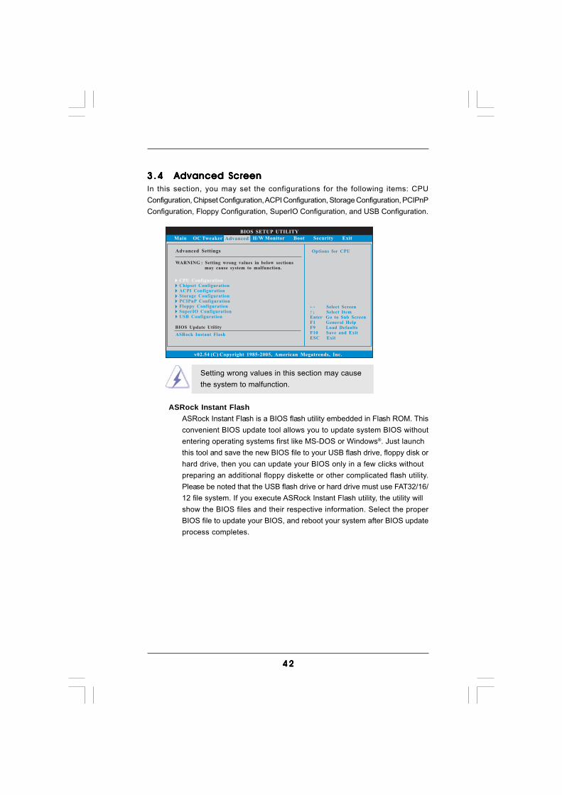
3.43 .43 .43 .43 .4 Advanced ScreenAdvanced ScreenAdvanced ScreenAdvanced ScreenAdvanced ScreenIn this section, you may set the configurations for the following items: CPUConfiguration, Chipset Configuration, ACPI Configuration, Storage Configuration, PCIPnPConfiguration, Floppy Configuration, SuperIO Configuration, and USB Configuration.
Setting wrong values in this section may causethe system to malfunction.
ASRock Instant FlashASRock Instant Flash is a BIOS flash utility embedded in Flash ROM. Thisconvenient BIOS update tool allows you to update system BIOS withoutentering operating systems first like MS-DOS or Windows®. Just launchthis tool and save the new BIOS file to your USB flash drive, floppy disk orhard drive, then you can update your BIOS only in a few clicks withoutpreparing an additional floppy diskette or other complicated flash utility.Please be noted that the USB flash drive or hard drive must use FAT32/16/12 file system. If you execute ASRock Instant Flash utility, the utility willshow the BIOS files and their respective information. Select the properBIOS file to update your BIOS, and reboot your system after BIOS updateprocess completes.
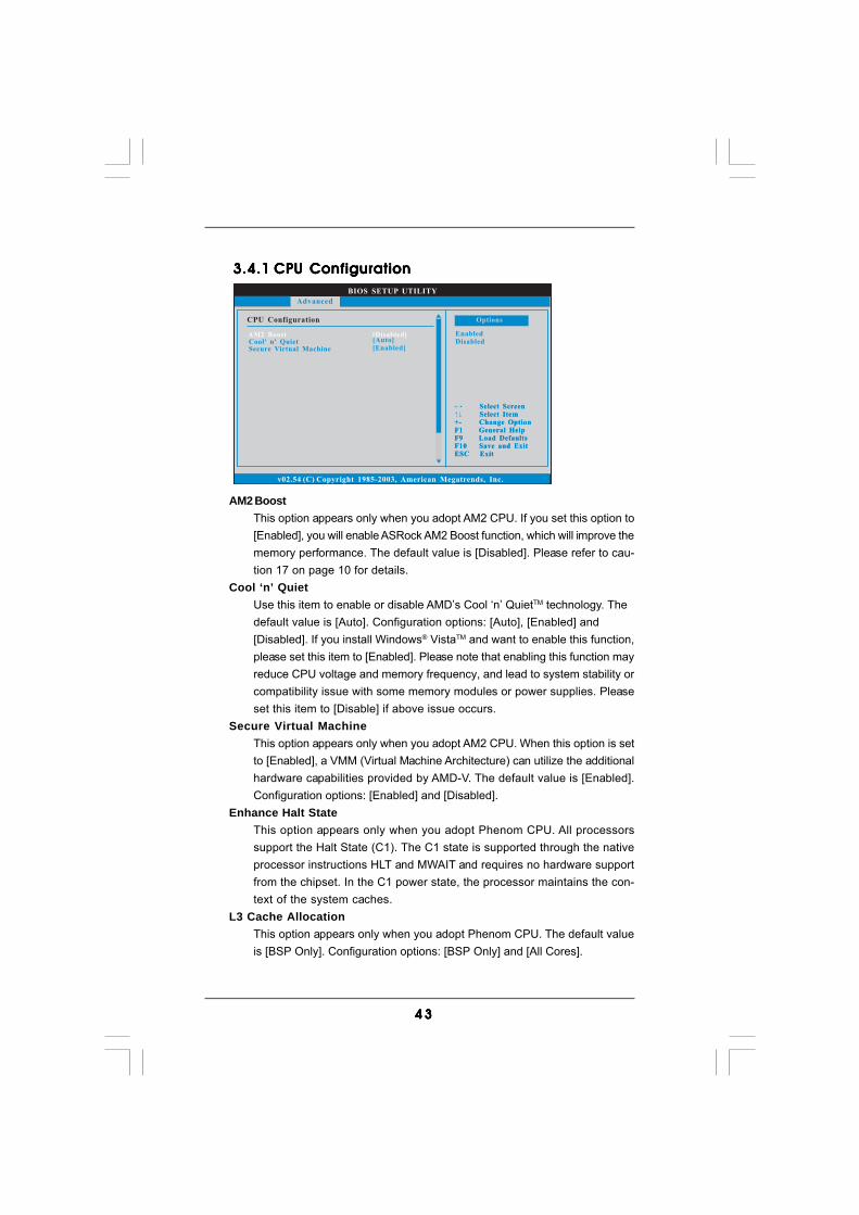
4 34 34 34 34 3
BIOS SETUP UTILITY
CPU Configuration
Select Screen
Select Item
+- Change Option
F1 General Help
F9 Load Defaults
F10 Save and Exit
ESC Exit
v02.54 (C) Copyright 1985-2003, American Megatrends, Inc.
Advanced
Select Screen
Select Item
+- Change Option
F1 General Help
F9 Load Defaults
F10 Save and Exit
ESC Exit
AM2 Boost [Disabled]Cool' n' QuietSecure Virtual Machine
[Auto]
[Enabled]
Enabled
Disabled
Options
3.4.13.4.13.4.13.4.13.4.1 CPU ConfigurationCPU ConfigurationCPU ConfigurationCPU ConfigurationCPU Configuration
AM2 BoostThis option appears only when you adopt AM2 CPU. If you set this option to[Enabled], you will enable ASRock AM2 Boost function, which will improve thememory performance. The default value is [Disabled]. Please refer to cau-tion 17 on page 10 for details.
Cool ‘n’ QuietUse this item to enable or disable AMD’s Cool ‘n’ QuietTM technology. Thedefault value is [Auto]. Configuration options: [Auto], [Enabled] and[Disabled]. If you install Windows® VistaTM and want to enable this function,please set this item to [Enabled]. Please note that enabling this function mayreduce CPU voltage and memory frequency, and lead to system stability orcompatibility issue with some memory modules or power supplies. Pleaseset this item to [Disable] if above issue occurs.
Secure Virtual MachineThis option appears only when you adopt AM2 CPU. When this option is setto [Enabled], a VMM (Virtual Machine Architecture) can utilize the additionalhardware capabilities provided by AMD-V. The default value is [Enabled].Configuration options: [Enabled] and [Disabled].
Enhance Halt StateThis option appears only when you adopt Phenom CPU. All processorssupport the Halt State (C1). The C1 state is supported through the nativeprocessor instructions HLT and MWAIT and requires no hardware supportfrom the chipset. In the C1 power state, the processor maintains the con-text of the system caches.
L3 Cache AllocationThis option appears only when you adopt Phenom CPU. The default valueis [BSP Only]. Configuration options: [BSP Only] and [All Cores].
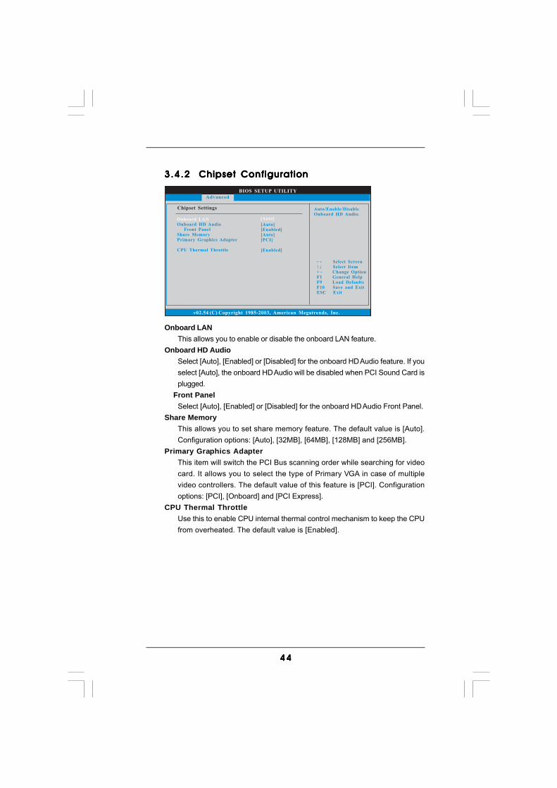
4 44 44 44 44 4
BIOS SETUP UTILITY
v02.54 (C) Copyright 1985-2003, American Megatrends, Inc.
Chipset Settings
Onboard HD Audio
Front Panel
Share Memory
Graphics Adapter
CPU Thermal Throttle
Primary
[Auto]
[Enabled]
[Auto]
[PCI]
[Enabled]
Select Screen
Select Item
+ - Change Option
F1 General Help
F10 Save and Exit
ESC Exit
F9 Load Defaults
Advanced
Onboard LAN [Auto]
Auto/Enable/Disable
Onboard HD Audio.
3.4.23.4.23.4.23.4.23.4.2 Chipset ConfigurationChipset ConfigurationChipset ConfigurationChipset ConfigurationChipset Configuration
Onboard LANThis allows you to enable or disable the onboard LAN feature.
Onboard HD AudioSelect [Auto], [Enabled] or [Disabled] for the onboard HD Audio feature. If youselect [Auto], the onboard HD Audio will be disabled when PCI Sound Card isplugged.
Front PanelSelect [Auto], [Enabled] or [Disabled] for the onboard HD Audio Front Panel.
Share MemoryThis allows you to set share memory feature. The default value is [Auto].Configuration options: [Auto], [32MB], [64MB], [128MB] and [256MB].
Primary Graphics AdapterThis item will switch the PCI Bus scanning order while searching for videocard. It allows you to select the type of Primary VGA in case of multiplevideo controllers. The default value of this feature is [PCI]. Configurationoptions: [PCI], [Onboard] and [PCI Express].
CPU Thermal ThrottleUse this to enable CPU internal thermal control mechanism to keep the CPUfrom overheated. The default value is [Enabled].
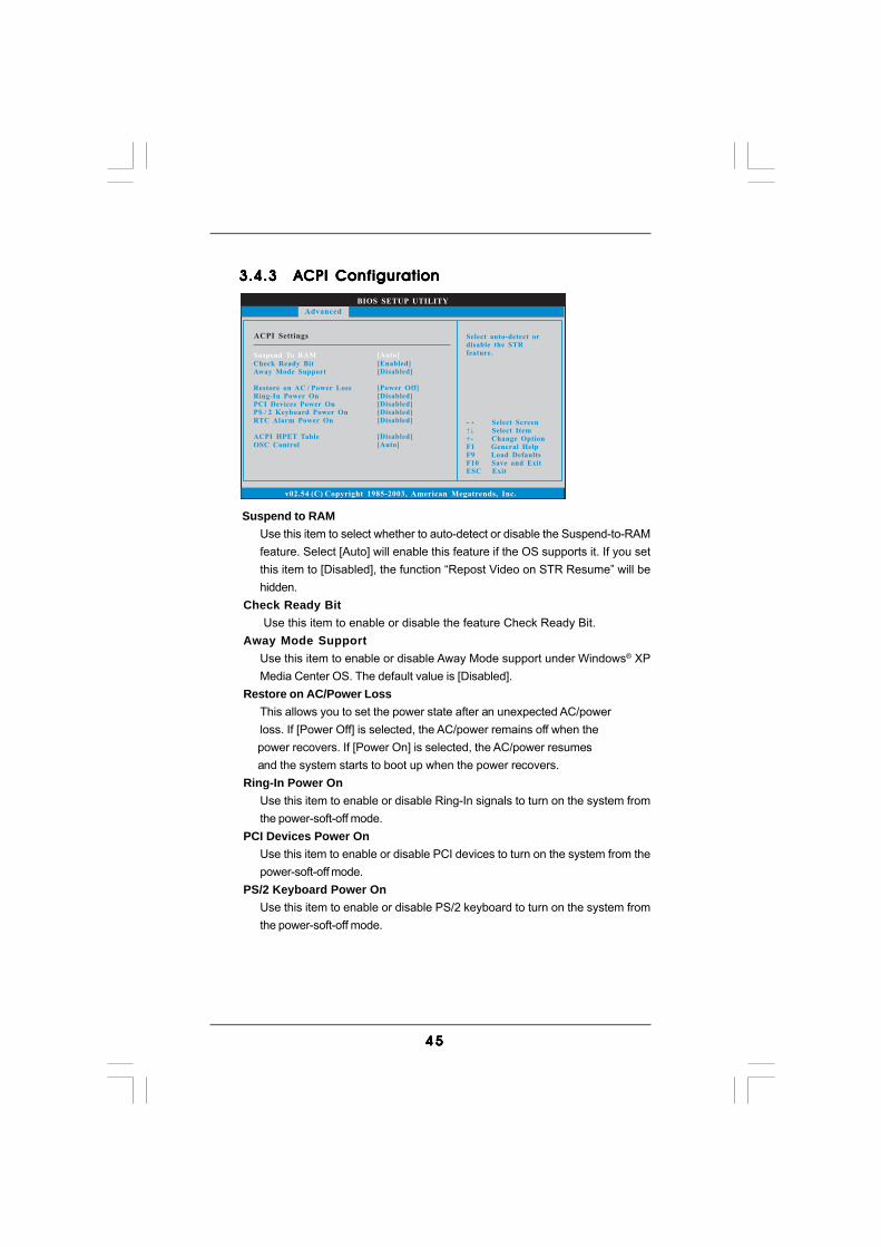
4 54 54 54 54 5
BIOS SETUP UTILITY
ACPI Settings Select auto-detect or
disable the STR
feature.
Select Screen
Select Item
+- Change Option
F1 General Help
F9 Load Defaults
F10 Save and Exit
ESC Exit
v02.54 (C) Copyright 1985-2003, American Megatrends, Inc.
Advanced
Suspend To RAM
Check Ready Bit
Away Mode Support
ACPI HPET Table
OSC Control
Restore on AC / Power Loss
Ring-In Power On
PCI Devices Power On
PS / 2 Keyboard Power On
RTC Alarm Power On
[Auto]
[Enabled]
[Disabled]
[Power Off]
[Disabled]
[Disabled]
[Disabled]
[Disabled]
[Disabled]
[Auto]
3.4.33.4.33.4.33.4.33.4.3 ACPI ConfigurationACPI ConfigurationACPI ConfigurationACPI ConfigurationACPI Configuration
Suspend to RAMUse this item to select whether to auto-detect or disable the Suspend-to-RAMfeature. Select [Auto] will enable this feature if the OS supports it. If you setthis item to [Disabled], the function “Repost Video on STR Resume” will behidden.
Check Ready Bit Use this item to enable or disable the feature Check Ready Bit.Away Mode Support
Use this item to enable or disable Away Mode support under Windows® XPMedia Center OS. The default value is [Disabled].
Restore on AC/Power LossThis allows you to set the power state after an unexpected AC/powerloss. If [Power Off] is selected, the AC/power remains off when the
power recovers. If [Power On] is selected, the AC/power resumes and the system starts to boot up when the power recovers.
Ring-In Power OnUse this item to enable or disable Ring-In signals to turn on the system fromthe power-soft-off mode.
PCI Devices Power OnUse this item to enable or disable PCI devices to turn on the system from thepower-soft-off mode.
PS/2 Keyboard Power OnUse this item to enable or disable PS/2 keyboard to turn on the system fromthe power-soft-off mode.
4 64 64 64 64 6
RTC Alarm Power OnUse this item to enable or disable RTC (Real Time Clock) to power on thesystem.
ACPI HPET TableUse this item to enable or disable ACPI HPET Table. The default value is[Disabled]. Please set this option to [Enabled] if you plan to use thismotherboard to submit Windows® VistaTM certification.
OSC ControlUse this item to enable or disable OSC control. Configuration options: [Auto],[Enabled] and [Disabled]. The default value is [Auto].
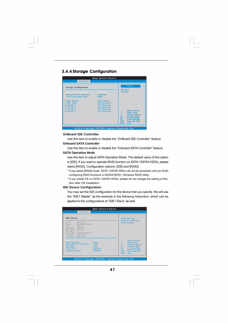
4 74 74 74 74 7
BIOS SETUP UTILITY
Storage Configuration
v02.54 (C) Copyright 1985-2003, American Megatrends, Inc.
Advanced
Onboard IDE Controller
Onboard SATA Controller
SATA Operation Mode
IDE1 Master
IDE1 Slave
SATAII_1
SATAII_2
SATAII_3
SATAII_4
[Enabled]
[Enabled]
[IDE]
[Hard Disk]
[Not Detected]
[Not Detected]
[Not Detected]
[Not Detected]
[Not Detected] Select Screen
Select Item
+- Change Option
F1 General Help
F9 Load Defaults
F10 Save and Exit
ESC Exit
Select Screen
Select Item
+- Change Option
F1 General Help
F9 Load Defaults
F10 Save and Exit
ESC Exit
Disabled
Enabled
Options
3.4.43.4.43.4.43.4.43.4.4 Storage ConfigurationStorage ConfigurationStorage ConfigurationStorage ConfigurationStorage Configuration
OnBoard IDE ControllerUse this item to enable or disable the “OnBoard IDE Controller” feature.
Onboard SATA ControllerUse this item to enable or disable the “Onboard SATA Controller” feature.
SATA Operation ModeUse this item to adjust SATA Operation Mode. The default value of this optionis [IDE]. If you want to operate RAID function on SATA / SATAII HDDs, pleaseselect [RAID]. Configuration options: [IDE] and [RAID].* If you select [RAID] mode, SATA / SATAII HDDs can not be accessed until you finish configuring RAID functions in NVIDIA BIOS / Windows RAID Utility.* If you install OS on SATA / SATAII HDDs, please do not change the setting of this item after OS installation.
IDE Device ConfigurationYou may set the IDE configuration for the device that you specify. We will usethe “IDE1 Master” as the example in the following instruction, which can beapplied to the configurations of “IDE1 Slave” as well.
BIOS SETUP UTILITY
IDE Master Select the type
of device connected
to the system.
Select Screen
Select Item
+- Change Option
F1 General Help
F9 Load Defaults
F10 Save and Exit
ESC Exit
v02.54 (C) Copyright 1985-2003, American Megatrends, Inc.
Advanced
Type
LBA/Large Mode
Block (Multi-Sector Transfer)
PIO Mode
DMA Mode
S . M . A . R . T .
32Bit Data Transfer
[Auto]
[Auto]
[Auto]
[Auto]
[Auto]
[Disabled]
[Disabled]
Device
Vendor
Size
LBA Mode
Block Mode
PIO Mode
Async DMA
Ultra DMA
S.M.A.R.T.
:Hard Disk
:MAXTOR 6L080J4
:80.0 GB
:Supported
:16Sectors
:4
:MultiWord DMA-2
:Ultra DMA-6
:Supported
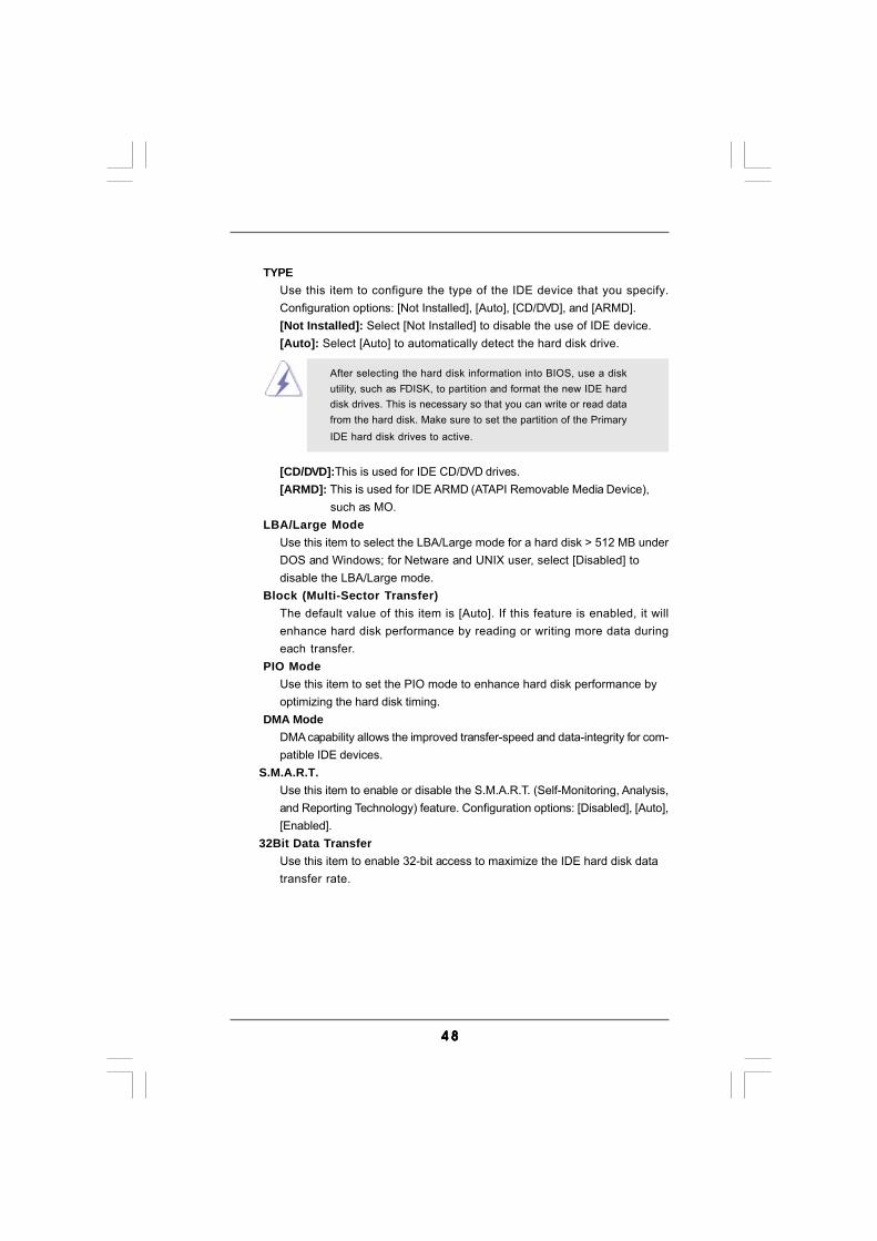
4 84 84 84 84 8
TYPEUse this item to configure the type of the IDE device that you specify.Configuration options: [Not Installed], [Auto], [CD/DVD], and [ARMD].[Not Installed]: Select [Not Installed] to disable the use of IDE device.[Auto]: Select [Auto] to automatically detect the hard disk drive.
After selecting the hard disk information into BIOS, use a diskutility, such as FDISK, to partition and format the new IDE harddisk drives. This is necessary so that you can write or read datafrom the hard disk. Make sure to set the partition of the PrimaryIDE hard disk drives to active.
[CD/DVD]:This is used for IDE CD/DVD drives.[ARMD]: This is used for IDE ARMD (ATAPI Removable Media Device),
such as MO.LBA/Large Mode
Use this item to select the LBA/Large mode for a hard disk > 512 MB underDOS and Windows; for Netware and UNIX user, select [Disabled] todisable the LBA/Large mode.
Block (Multi-Sector Transfer)The default value of this item is [Auto]. If this feature is enabled, it willenhance hard disk performance by reading or writing more data duringeach transfer.
PIO ModeUse this item to set the PIO mode to enhance hard disk performance byoptimizing the hard disk timing.
DMA ModeDMA capability allows the improved transfer-speed and data-integrity for com-patible IDE devices.
S.M.A.R.T.Use this item to enable or disable the S.M.A.R.T. (Self-Monitoring, Analysis,and Reporting Technology) feature. Configuration options: [Disabled], [Auto],[Enabled].
32Bit Data TransferUse this item to enable 32-bit access to maximize the IDE hard disk datatransfer rate.
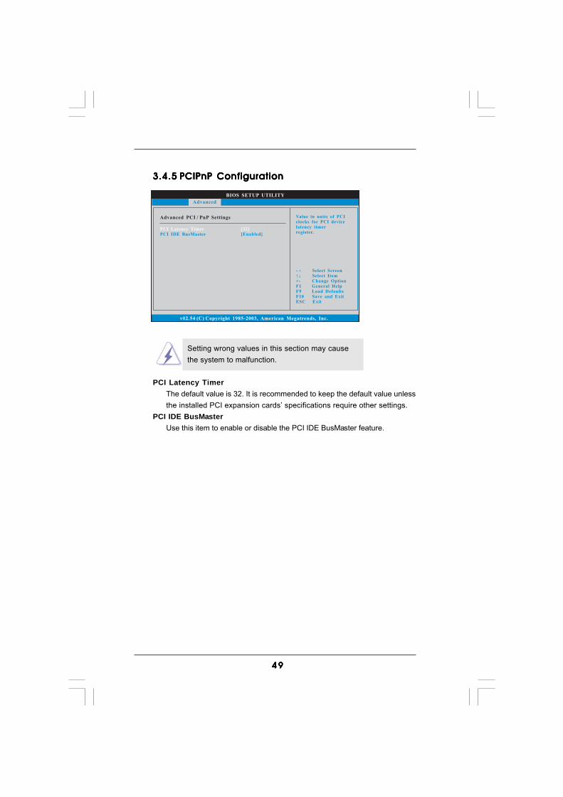
4 94 94 94 94 9
BIOS SETUP UTILITY
Advanced PCI / PnP Settings Value in units of PCI
clocks for PCI device
latency timer
register.
Select Screen
Select Item
+- Change Option
F1 General Help
F9 Load Defaults
F10 Save and Exit
ESC Exit
v02.54 (C) Copyright 1985-2003, American Megatrends, Inc.
PCI Latency Timer
PCI IDE BusMaster
[32]
[Enabled]
Advanced
3.4.53.4.53.4.53.4.53.4.5 PCIPnP ConfigurationPCIPnP ConfigurationPCIPnP ConfigurationPCIPnP ConfigurationPCIPnP Configuration
Setting wrong values in this section may causethe system to malfunction.
PCI Latency TimerThe default value is 32. It is recommended to keep the default value unlessthe installed PCI expansion cards’ specifications require other settings.
PCI IDE BusMasterUse this item to enable or disable the PCI IDE BusMaster feature.
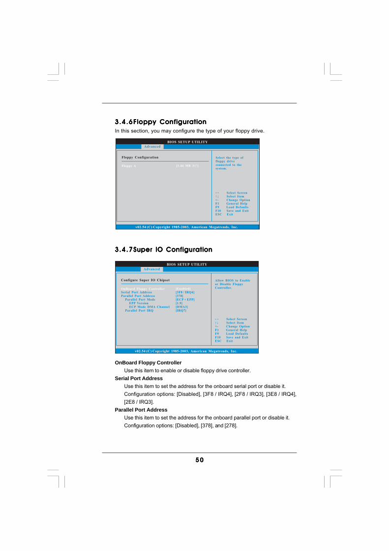
5 05 05 05 05 0
BIOS SETUP UTILITY
Floppy Configuration Select the type of
floppy drive
connected to the
system.
Select Screen
Select Item
+- Change Option
F1 General Help
F9 Load Defaults
F10 Save and Exit
ESC Exit
v02.54 (C) Copyright 1985-2003, American Megatrends, Inc.
Advanced
Floppy A [1.44 MB 3 "]12
BIOS SETUP UTILITY
Configure Super IO Chipset Allow BIOS to Enable
or Disable Floppy
Controller.
Select Screen
Select Item
+- Change Option
F1 General Help
F9 Load Defaults
F10 Save and Exit
ESC Exit
v02.54 (C) Copyright 1985-2003, American Megatrends, Inc.
Advanced
OnBoard Floppy ControllerSerial Port Address
Parallel Port Address
Parallel Port Mode
EPP Version
ECP Mode DMA Channel
Parallel Port IRQ
[Enabled][3F8 / IRQ4]
[378]
[ECP + EPP]
[1.9]
[DMA3]
[IRQ7]
3.4.63.4.63.4.63.4.63.4.6 Floppy ConfigurationFloppy ConfigurationFloppy ConfigurationFloppy ConfigurationFloppy ConfigurationIn this section, you may configure the type of your floppy drive.
3.4.73.4.73.4.73.4.73.4.7 Super IO ConfigurationSuper IO ConfigurationSuper IO ConfigurationSuper IO ConfigurationSuper IO Configuration
OnBoard Floppy ControllerUse this item to enable or disable floppy drive controller.
Serial Port AddressUse this item to set the address for the onboard serial port or disable it.Configuration options: [Disabled], [3F8 / IRQ4], [2F8 / IRQ3], [3E8 / IRQ4],[2E8 / IRQ3].
Parallel Port AddressUse this item to set the address for the onboard parallel port or disable it.Configuration options: [Disabled], [378], and [278].
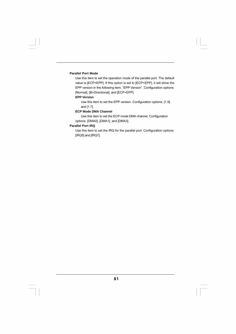
5 15 15 15 15 1
Parallel Port ModeUse this item to set the operation mode of the parallel port. The defaultvalue is [ECP+EPP]. If this option is set to [ECP+EPP], it will show theEPP version in the following item, “EPP Version”. Configuration options:[Normal], [Bi-Directional], and [ECP+EPP].EPP Version
Use this item to set the EPP version. Configuration options: [1.9]and [1.7].
ECP Mode DMA ChannelUse this item to set the ECP mode DMA channel. Configuration
options: [DMA0], [DMA1], and [DMA3].Parallel Port IRQ
Use this item to set the IRQ for the parallel port. Configuration options:[IRQ5] and [IRQ7].
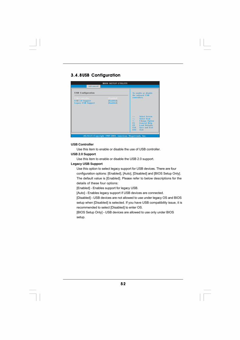
5 25 25 25 25 2
BIOS SETUP UTILITY
USB Configuration To enable or disable
the onboard USB
controllers.
Select Screen
Select Item
+- Change Option
F1 General Help
F9 Load Defaults
F10 Save and Exit
ESC Exit
v02.54 (C) Copyright 1985-2003, American Megatrends, Inc.
Advanced
USB Controller
USB 2.0 Support
Legacy USB Support
[Enabled]
[Enabled]
[Enabled]
3.4.83.4.83.4.83.4.83.4.8 USB ConfigurationUSB ConfigurationUSB ConfigurationUSB ConfigurationUSB Configuration
USB ControllerUse this item to enable or disable the use of USB controller.
USB 2.0 SupportUse this item to enable or disable the USB 2.0 support.
Legacy USB SupportUse this option to select legacy support for USB devices. There are fourconfiguration options: [Enabled], [Auto], [Disabled] and [BIOS Setup Only].The default value is [Enabled]. Please refer to below descriptions for thedetails of these four options:[Enabled] - Enables support for legacy USB.[Auto] - Enables legacy support if USB devices are connected.[Disabled] - USB devices are not allowed to use under legacy OS and BIOSsetup when [Disabled] is selected. If you have USB compatibility issue, it isrecommended to select [Disabled] to enter OS.[BIOS Setup Only] - USB devices are allowed to use only under BIOSsetup.
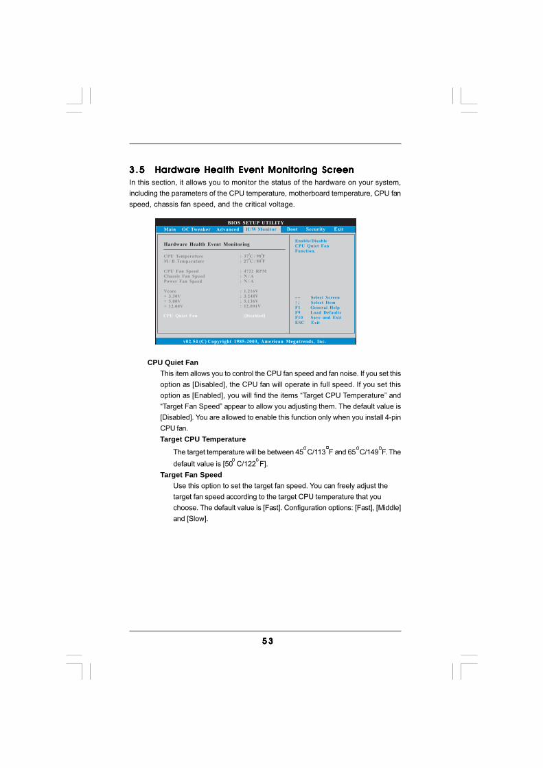
5 35 35 35 35 3
BIOS SETUP UTILITY
Hardware Health Event Monitoring
Select Screen
Select Item
F1 General Help
F9 Load Defaults
F10 Save and Exit
ESC Exit
v02.54 (C) Copyright 1985-2003, American Megatrends, Inc.
CPU Temperature
M / B Temperature
CPU Fan Speed
Chassis Fan Speed
Vcore
+ 3.30V
+ 5.00V
+ 12.00V
Power Fan Speed
: 37 C / 98 F
: 4722 RPM
: 1.216V
: 3.248V
: 5.136V
: 12.091V
: 27 C / 80 F
: N / A
: N / A
Main OC Tweaker Advanced Boot Security ExitH/W Monitor
Enable/Disable
CPU Quiet Fan
Function.
CPU Quiet Fan [Disabled]
3.53 .53 .53 .53 .5 Hardware Health Event Monitoring ScreenHardware Health Event Monitoring ScreenHardware Health Event Monitoring ScreenHardware Health Event Monitoring ScreenHardware Health Event Monitoring ScreenIn this section, it allows you to monitor the status of the hardware on your system,including the parameters of the CPU temperature, motherboard temperature, CPU fanspeed, chassis fan speed, and the critical voltage.
CPU Quiet FanThis item allows you to control the CPU fan speed and fan noise. If you set thisoption as [Disabled], the CPU fan will operate in full speed. If you set thisoption as [Enabled], you will find the items “Target CPU Temperature” and“Target Fan Speed” appear to allow you adjusting them. The default value is[Disabled]. You are allowed to enable this function only when you install 4-pinCPU fan.
Target CPU Temperature
The target temperature will be between 45 C/113 F and 65 C/149 F. Thedefault value is [50 C/122 F].
Target Fan SpeedUse this option to set the target fan speed. You can freely adjust thetarget fan speed according to the target CPU temperature that youchoose. The default value is [Fast]. Configuration options: [Fast], [Middle]and [Slow].
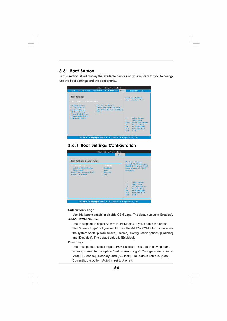
5 45 45 45 45 4
BIOS SETUP UTILITY
Main OC Tweaker Advanced H/W Monitor Security Exit
Boot SettingsConfigure Settings
during System Boot.
Select Screen
Select Item
Enter Go to Sub Screen
F1 General Help
F9 Load Defaults
F10 Save and Exit
ESC Exit
v02.54 (C) Copyright 1985-2005, American Megatrends, Inc.
Boot
Boot Settings Configuration
1st Boot Device
2nd Boot Device
3rd Boot Device
4th Boot Device
Hard Disk Drives
Removable Drives
CD/DVD Drives
[1st Floppy Device]
[HDD: PM - HDS722580VL]
[CD / DVD: 3S - CD - ROM C]
[USB]
BIOS SETUP UTILITY
Boot Settings ConfigurationDisabled: Displays
normal POST messages.
Enabled: Displays OEM
Logo instead of POST
messages.
Select Screen
Select Item
+ - Change Option
F1 General Help
F9 Load Defaults
F10 Save and Exit
ESC Exit
v02.54 (C) Copyright 1985-2003, American Megatrends, Inc.
Boot
AddOn ROM Display
Boot Logo
Boot From Onboard LAN
Bootup Num-Lock
[Enabled]
[Auto]
[Disabled]
[On]
Full Screen Logo [Enabled]
3.63.63.63.63.6 Boot ScreenBoot ScreenBoot ScreenBoot ScreenBoot ScreenIn this section, it will display the available devices on your system for you to config-ure the boot settings and the boot priority.
3.6.13.6.13.6.13.6.13.6.1 Boot Settings ConfigurationBoot Settings ConfigurationBoot Settings ConfigurationBoot Settings ConfigurationBoot Settings Configuration
Full Screen LogoUse this item to enable or disable OEM Logo. The default value is [Enabled].
AddOn ROM DisplayUse this option to adjust AddOn ROM Display. If you enable the option“Full Screen Logo” but you want to see the AddOn ROM information whenthe system boots, please select [Enabled]. Configuration options: [Enabled]and [Disabled]. The default value is [Enabled].
Boot LogoUse this option to select logo in POST screen. This option only appearswhen you enable the option “Full Screen Logo”. Configuration options:[Auto], [S-series], [Scenery] and [ASRock]. The default value is [Auto].Currently, the option [Auto] is set to Aircraft.
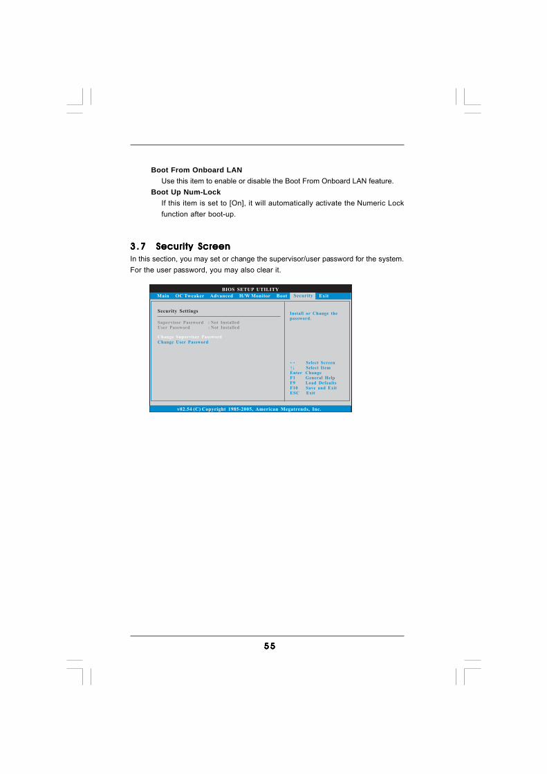
5 55 55 55 55 5
3 .73 .73 .73 .73 .7 Security ScreenSecurity ScreenSecurity ScreenSecurity ScreenSecurity ScreenIn this section, you may set or change the supervisor/user password for the system.For the user password, you may also clear it.
BIOS SETUP UTILITY
Main OC Tweaker Advanced H/W Monitor Boot Exit
Install or Change the
password.
Select Screen
Select Item
Enter Change
F1 General Help
F10 Save and Exit
ESC Exit
F9 Load Defaults
v02.54 (C) Copyright 1985-2005, American Megatrends, Inc.
Security
Change Supervisor Password
Change User Password
Security Settings
Supervisor Password : Not Installed
User Password : Not Installed
Boot From Onboard LANUse this item to enable or disable the Boot From Onboard LAN feature.
Boot Up Num-LockIf this item is set to [On], it will automatically activate the Numeric Lockfunction after boot-up.
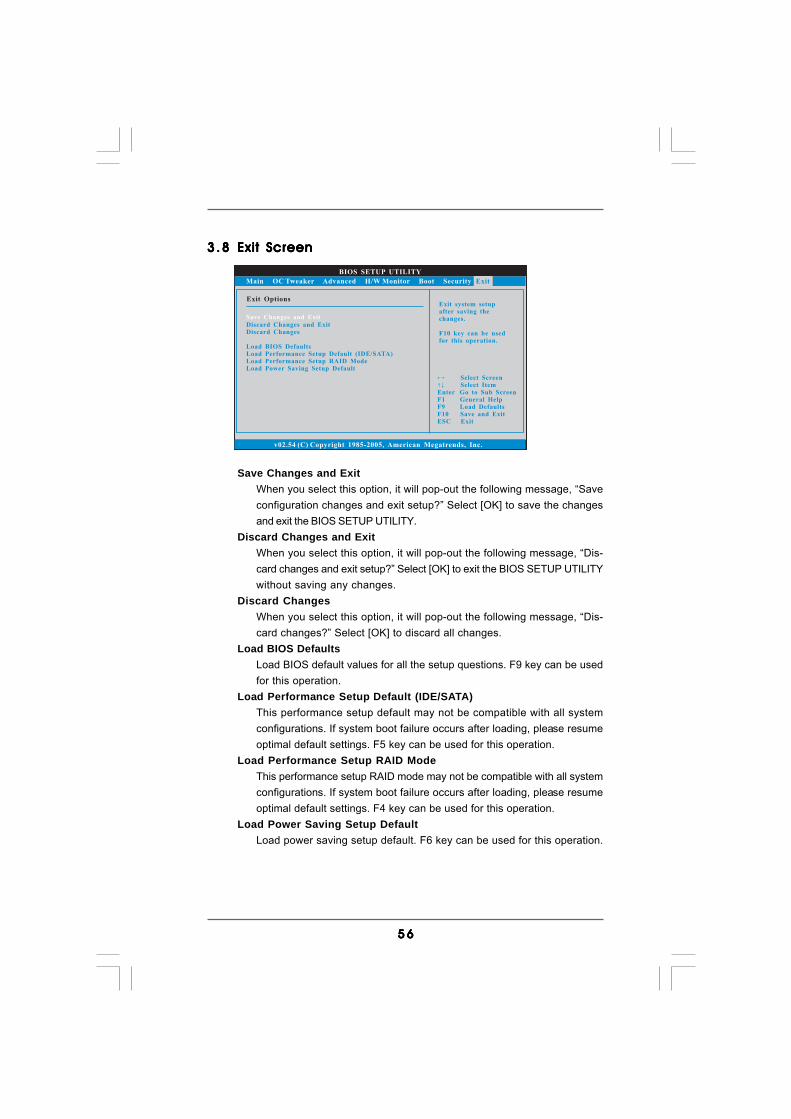
5 65 65 65 65 6
BIOS SETUP UTILITY
Main OC Tweaker Advanced H/W Monitor Boot Security
Exit system setup
after saving the
changes.
F10 key can be used
for this operation.
Select Screen
Select Item
Enter Go to Sub Screen
F1 General Help
F10 Save and Exit
ESC Exit
F9 Load Defaults
v02.54 (C) Copyright 1985-2005, American Megatrends, Inc.
Exit
Save Changes and Exit
Discard Changes and Exit
Discard Changes
Load BIOS Defaults
Load Performance Setup Default (IDE/SATA)
Load Performance Setup RAID Mode
Load Power Saving Setup Default
Exit Options
3.83 .83 .83 .83 .8 Exit ScreenExit ScreenExit ScreenExit ScreenExit Screen
Save Changes and ExitWhen you select this option, it will pop-out the following message, “Saveconfiguration changes and exit setup?” Select [OK] to save the changesand exit the BIOS SETUP UTILITY.
Discard Changes and ExitWhen you select this option, it will pop-out the following message, “Dis-card changes and exit setup?” Select [OK] to exit the BIOS SETUP UTILITYwithout saving any changes.
Discard ChangesWhen you select this option, it will pop-out the following message, “Dis-card changes?” Select [OK] to discard all changes.
Load BIOS DefaultsLoad BIOS default values for all the setup questions. F9 key can be usedfor this operation.
Load Performance Setup Default (IDE/SATA)This performance setup default may not be compatible with all systemconfigurations. If system boot failure occurs after loading, please resumeoptimal default settings. F5 key can be used for this operation.
Load Performance Setup RAID ModeThis performance setup RAID mode may not be compatible with all systemconfigurations. If system boot failure occurs after loading, please resumeoptimal default settings. F4 key can be used for this operation.
Load Power Saving Setup DefaultLoad power saving setup default. F6 key can be used for this operation.
5 75 75 75 75 7
4.4.4.4.4. SofSofSofSofSof tware Supportware Supportware Supportware Supportware Supporttttt4.1 Install Operating System4.1 Install Operating System4.1 Install Operating System4.1 Install Operating System4.1 Install Operating SystemThis motherboard supports various Microsoft® Windows® operating systems: 7 /7 64-bit / VistaTM / VistaTM 64-bit / XP / XP 64-bit. Because motherboard settings andhardware options vary, use the setup procedures in this chapter for general refer-ence only. Refer to your OS documentation for more information.
4.2 Support CD Information4.2 Support CD Information4.2 Support CD Information4.2 Support CD Information4.2 Support CD InformationThe Support CD that came with the motherboard contains necessary drivers anduseful utilities that enhance the motherboard features.
4.2.1 Running The Support CD4.2.1 Running The Support CD4.2.1 Running The Support CD4.2.1 Running The Support CD4.2.1 Running The Support CDTo begin using the support CD, insert the CD into your CD-ROM drive. The CDautomatically displays the Main Menu if “AUTORUN” is enabled in your computer.If the Main Menu did not appear automatically, locate and double click on the file“ASSETUP.EXE” from the BIN folder in the Support CD to display the menus.
4.2.2 Drivers Menu4.2.2 Drivers Menu4.2.2 Drivers Menu4.2.2 Drivers Menu4.2.2 Drivers MenuThe Drivers Menu shows the available devices drivers if the system detects theinstalled devices. Please install the necessary drivers to activate the devices.
4.2.3 Utilities Menu4.2.3 Utilities Menu4.2.3 Utilities Menu4.2.3 Utilities Menu4.2.3 Utilities MenuThe Utilities Menu shows the applications software that the motherboard supports.Click on a specific item then follow the installation wizard to install it.
4.2.44.2.44.2.44.2.44.2.4 Contact InformationContact InformationContact InformationContact InformationContact InformationIf you need to contact ASRock or want to know more about ASRock, welcometo visit ASRock’s website at http://www.asrock.com; or you may contact yourdealer for further information.


