Embed Size (px)
Citation preview

Ultra Cloud Core 5G Session Management Function, Release 2020.02 -Configuration and Administration GuideFirst Published: 2020-04-30
Last Modified: 2020-07-10
Americas HeadquartersCisco Systems, Inc.170 West Tasman DriveSan Jose, CA 95134-1706USAhttp://www.cisco.comTel: 408 526-4000
800 553-NETS (6387)Fax: 408 527-0883

THE SPECIFICATIONS AND INFORMATION REGARDING THE PRODUCTS IN THIS MANUAL ARE SUBJECT TO CHANGE WITHOUT NOTICE. ALL STATEMENTS,INFORMATION, AND RECOMMENDATIONS IN THIS MANUAL ARE BELIEVED TO BE ACCURATE BUT ARE PRESENTED WITHOUT WARRANTY OF ANY KIND,EXPRESS OR IMPLIED. USERS MUST TAKE FULL RESPONSIBILITY FOR THEIR APPLICATION OF ANY PRODUCTS.
THE SOFTWARE LICENSE AND LIMITED WARRANTY FOR THE ACCOMPANYING PRODUCT ARE SET FORTH IN THE INFORMATION PACKET THAT SHIPPED WITHTHE PRODUCT AND ARE INCORPORATED HEREIN BY THIS REFERENCE. IF YOU ARE UNABLE TO LOCATE THE SOFTWARE LICENSE OR LIMITED WARRANTY,CONTACT YOUR CISCO REPRESENTATIVE FOR A COPY.
The Cisco implementation of TCP header compression is an adaptation of a program developed by the University of California, Berkeley (UCB) as part of UCB's public domain version ofthe UNIX operating system. All rights reserved. Copyright © 1981, Regents of the University of California.
NOTWITHSTANDING ANY OTHERWARRANTY HEREIN, ALL DOCUMENT FILES AND SOFTWARE OF THESE SUPPLIERS ARE PROVIDED “AS IS" WITH ALL FAULTS.CISCO AND THE ABOVE-NAMED SUPPLIERS DISCLAIM ALL WARRANTIES, EXPRESSED OR IMPLIED, INCLUDING, WITHOUT LIMITATION, THOSE OFMERCHANTABILITY, FITNESS FOR A PARTICULAR PURPOSE AND NONINFRINGEMENT OR ARISING FROM A COURSE OF DEALING, USAGE, OR TRADE PRACTICE.
IN NO EVENT SHALL CISCO OR ITS SUPPLIERS BE LIABLE FOR ANY INDIRECT, SPECIAL, CONSEQUENTIAL, OR INCIDENTAL DAMAGES, INCLUDING, WITHOUTLIMITATION, LOST PROFITS OR LOSS OR DAMAGE TO DATA ARISING OUT OF THE USE OR INABILITY TO USE THIS MANUAL, EVEN IF CISCO OR ITS SUPPLIERSHAVE BEEN ADVISED OF THE POSSIBILITY OF SUCH DAMAGES.
Any Internet Protocol (IP) addresses and phone numbers used in this document are not intended to be actual addresses and phone numbers. Any examples, command display output, networktopology diagrams, and other figures included in the document are shown for illustrative purposes only. Any use of actual IP addresses or phone numbers in illustrative content is unintentionaland coincidental.
All printed copies and duplicate soft copies of this document are considered uncontrolled. See the current online version for the latest version.
Cisco has more than 200 offices worldwide. Addresses and phone numbers are listed on the Cisco website at www.cisco.com/go/offices.
Cisco and the Cisco logo are trademarks or registered trademarks of Cisco and/or its affiliates in the U.S. and other countries. To view a list of Cisco trademarks, go to this URL:https://www.cisco.com/c/en/us/about/legal/trademarks.html. Third-party trademarks mentioned are the property of their respective owners. The use of the word partner does not imply apartnership relationship between Cisco and any other company. (1721R)
© 2020 Cisco Systems, Inc. All rights reserved.

C O N T E N T S
About this Guide xxxviiP R E F A C E
Conventions Used xxxvii
5G Architecture 1C H A P T E R 1
Feature Summary and Revision History 1
Summary Data 1
Revision History 1
Overview 2
Control Plane NFs 2
User Plane NF 3
Subscriber Microservices Infrastructure Architecture 3
Control Plane Network Function Architecture 4
5G SMF Overview 7C H A P T E R 2
Feature Summary and Revision History 7
Summary Data 7
Revision History 7
Product Description 8
Use Cases and Features 9
Base SMF Configuration 9
4G Session Support with 5GS SBI Interfaces 9
5G Session Support 9
5GS-EPS Interworking 10
Access and Mobility Support 10
Charging Integration 11
Cloud Native Infrastructure 11
Ultra Cloud Core 5G Session Management Function, Release 2020.02 - Configuration and Administration Guideiii

High Availability Support 11
IPAM Support 11
Lawful Intercept 12
NRF Discovery Support 12
Policy Integration 12
RADIUS Support 12
SMF Emergency Support 13
SMF Inline Services 13
SMF Specification Compliance 13
UPF Integration 13
VoLTE Support 14
VoNR Support 14
WiFi Support 14
Deployment Architecture and Interfaces 14
SMF Architecture 14
SMF Deployment 15
Supported Interfaces 16
Life Cycle of Data Packet 17
License Information 22
Standards Compliance 22
Limitations 22
Deploying and Configuring SMF through Ops Center 23C H A P T E R 3
Feature Summary and Revision History 23
Summary Data 23
Revision History 23
Feature Description 24
SMF Ops Center 24
Prerequisites 25
Deploying and Accessing SMF 25
Deploying SMF 25
Accessing the SMF Ops Center 25
Day 0 Configuration 26
SMF Service Configuration 27
Ultra Cloud Core 5G Session Management Function, Release 2020.02 - Configuration and Administration Guideiv
Contents

Configuring SMF 28
Loading Day 1 Configuration 29
Day1config.cli 30
Smart Licensing 47C H A P T E R 4
Feature Summary and Revision History 47
Summary Data 47
Revision History 47
Smart Software Licensing 47
Cisco Software Central 48
Smart Accounts/Virtual Accounts 48
Request a Cisco Smart Account 48
SMF Smart Licensing 49
Software Tags and Entitlement Tags 49
Configuring Smart Licensing 50
Users with Access to CSC 50
Users without Access to CSC 55
Monitoring and Troubleshooting Smart Licensing 60
SMF Rolling Software Update 61C H A P T E R 5
Feature Summary and Revision History 61
Summary Data 61
Revision History 61
Introduction 61
Updating SMF 63
Rolling Software Update Using SMI Cluster Manager 63
Prerequisites 64
Triggering the Rolling Software Upgrade 68
Monitoring the Upgrade 69
Viewing the Pod Details 70
Pods and Services Reference 73C H A P T E R 6
Feature Summary and Revision History 73
Summary Data 73
Ultra Cloud Core 5G Session Management Function, Release 2020.02 - Configuration and Administration Guidev
Contents

Revision History 73
Feature Description 74
Pods 75
Services 78
Associating Pods to the Nodes 80
Viewing the Pod Details and Status 81
States 81
3GPP Specification Compliance for SMF Interfaces 83C H A P T E R 7
Feature Summary and Revision History 83
Summary Data 83
Revision History 83
Feature Description 84
Standards Compliance 84
Configuring Interfaces 85
Sample Configuration 87
4G to 5G Data Session Handover Support 89C H A P T E R 8
Feature Summary 89
Summary Data 89
Revision History 89
Feature Description 90
How it Works 90
Architecture 90
Call Flows 90
EPS to 5G Handover with N26 Interface – Preparation Call Flow 91
EPS to 5G Handover with N26 Interface – Execution Call Flow 93
UE Idle Mode Mobility from EPS to 5GS using N26 Interface 94
Standards Compliance 100
Limitations 100
Emergency SoS Support 101
Feature Description 101
How it Works 101
Configuring Emergency SoS Support 104
Ultra Cloud Core 5G Session Management Function, Release 2020.02 - Configuration and Administration Guidevi
Contents

Configuring Local Authorization 104
Configuring Secondary Authentication 104
Configuring Charging Failure Handling 104
5GSM Cause Handling 107C H A P T E R 9
Feature Summary and Revision History 107
Feature Summary 107
Revision History 107
Feature Description 107
PDU Session Establishment Reject 108
PDU Session Modification Reject 109
PDU Session Release Reject 109
PDU Session Release Request 110
PDU Session Modification Command Reject 110
How it Works 111
Standards Compliance 111
Configuring the 5GSM Cause Handling Feature 111
5GSM Cause Handling OAM Support 111
Statistics 111
AN Modification Call Flow Support 115C H A P T E R 1 0
Feature Summary and Revision History 115
Summary Data 115
Revision History 115
Feature Description 116
How it Works 116
Application-based Alerts 123C H A P T E R 1 1
Feature Summary and Revision History 123
Summary Data 123
Revision History 123
Feature Description 124
How it Works 124
Configuring Alert Rules 124
Ultra Cloud Core 5G Session Management Function, Release 2020.02 - Configuration and Administration Guidevii
Contents

Viewing Alert Logger 126
Call Flow Procedure Alerts 126
4G PDN Modify 127
4G PDN Release Success 127
4G PDN Setup Success 127
4G to 5G HO Success 128
4G To WiFi HO Success 128
5G N2 HO Success 128
5G PDU Idle Success 129
5G PDU Modify Success 129
5G PDU Release Success 129
5G PDU Setup Success 130
5G to 4G HO Success 130
5G To WiFi HO Success 130
5G Xn HO Success 131
PDN Session Create 131
PDU Session Create 131
PDU Session Modify 132
PDU Session Release 132
Interface Specific Alerts 132
GTPC Peer Down 132
N4 Message Success 133
N4 UPF Association Down 133
N4 UPF Association Up 133
N7 Interface Outbound 134
N7 Interface Inbound 134
N7 Message Timed Out 134
N10 Interface 135
N11 Interface Inbound 135
N11 Interface Outbound 135
N11 Message Timed Out 136
N40 Interface Inbound 136
N40 Interface Outbound 136
N40 Message Timed Out 137
Ultra Cloud Core 5G Session Management Function, Release 2020.02 - Configuration and Administration Guideviii
Contents

NRF Discovery 137
SMF Service Start 137
IP Pool 137
IP Pool Used 138
Message Level Alerts 138
N11 SM Create 138
N11 SM Update 138
N11 SM Release 139
N1 N2 Message Transfer 139
N11 EBI Assignment 139
N11 SM Status Notify 140
N11 SM Context Retrieve 140
N7 SM Policy Create 140
N7 SM Policy Update 141
N7 SM Policy Delete 141
N7 SM Policy Notify Update 141
N7 SM Policy Notify Terminate 142
N10 UE Register 142
N10 UE DeRegister 142
N10 SM Subscription Fetch 143
N10 SM Subscribe for Notification 143
N10 Charging Data Request 143
N10 Charging Data Notify 144
Policy Rule Alerts 144
Addition of Dynamic PCC Rules 144
Modification of Dynamic PCC Rules 145
Removal of Dynamic PCC Rules 145
SMF Overload/Congestion 145
SMF Overload 145
SMF Sessions 146
Session Release Rate 146
Session Setup Failure 146
Session Setup Rate 146
Subscriber Limit 147
Ultra Cloud Core 5G Session Management Function, Release 2020.02 - Configuration and Administration Guideix
Contents
Bulk Statistics and Key Performance Indicators 149C H A P T E R 1 2
Feature Summary and Revision History 149
Summary Data 149
Revision History 149
Feature Description 149
How it Works 150
Supported KPIs 150
Cisco Common Data Layer 161C H A P T E R 1 3
Feature Summary and Revision History 161
Summary Data 161
Revision History 161
Feature Description 162
Architecture 162
How it Works 162
Call Flows 163
CDL Endpoint Failure Call Flow 163
Limitations 164
Configuring the CDL Through SMF Ops Center 164
Configuring the CDL Session Database and Defining the Base Configuration 164
Configuring the Zookeeper in CDL 165
Sample Configuration 166
CHF and PCF Integration for Access and Mobility Procedures 167C H A P T E R 1 4
Feature Summary and Revision History 167
Summary Data 167
Revision History 167
Feature Description 168
How it Works 168
Call Flows 169
CHF and PCF Integration for Intra-AMF and Inter-AMF N2-Based Handovers Call Flow 169
CHF and PCF Integration for N26 4G to 5G Handover Call Flow 171
CHF and PCF Integration for N26 5G to 4G Handover Call Flow 173
Ultra Cloud Core 5G Session Management Function, Release 2020.02 - Configuration and Administration Guidex
Contents

CHF and PCF Integration for Xn Handover Call Flow 175
CHF and PCF Integration for Service Request Procedures 177
Standards Compliance 178
Content Filtering, Event Detail Records, and X-Header Enrichment Support 179C H A P T E R 1 5
Feature Summary and Revision History 179
Summary Data 179
Revision History 180
Feature Description 180
Content Filtering Support 180
EDR Support 181
Metadata Provided by SMF for EDR 181
X-Header Insertion Support 181
Supported X-Header Information 182
Configuring Content Filtering, EDR, and X-Header Insertion Support 182
Configuring Content Filtering Support 183
Configuring Content Filtering under Active Charging Service 183
Configuring Content Filtering under Rulebase 183
Configuring Content Filtering under APN 183
Content Filtering Policy ID on N7 Interface 184
Configuring EDR Support 184
Configuring X-Header Insertion Support 184
Configuring an X-Header Format 184
Configuring Charging Action for Insertion of X-Header Fields 185
Bearer QCI Support 185
Feature Description 185
Customization of StarOS-based UPF on N4 Interface 189C H A P T E R 1 6
Feature Summary and Revision History 189
Summary Data 189
Revision History 189
Feature Description 190
Support for Prime PFD Message 190
Dynamic IP Pool Provisioning on UPF 191
Ultra Cloud Core 5G Session Management Function, Release 2020.02 - Configuration and Administration Guidexi
Contents

Absence of NodeID Attribute from N4 Messages 191
Non Standard Attribute Type 191
Single QFI Support 191
DNS Proxy Integration 193C H A P T E R 1 7
Feature Summary and Revision History 193
Summary Data 193
Revision History 193
Feature Description 193
How it Works 194
Call Flows 194
Configuring the DNS Proxy Feature 195
Configuring SMF DNS Proxy Replica 195
Configuring SMF DNS Proxy 196
DSCP Marking 197C H A P T E R 1 8
Feature Summary and Revision History 197
Summary Data 197
Revision History 197
Feature Description 197
How it Works 198
Configuring 5QI-QoS Mapping 198
EPS Interworking 201C H A P T E R 1 9
Feature Summary and Revision History 201
Summary Data 201
Revision History 202
Feature Description 202
Architecture 202
How it Works 203
Standards Compliance 204
Support for UE Initial Attach on E-UTRAN 204
Feature Description 204
How it Works 205
Ultra Cloud Core 5G Session Management Function, Release 2020.02 - Configuration and Administration Guidexii
Contents

Configuring the UE Initial Attach Feature 207
Define FQDN in SMF Profile Configuration 207
Configure S5 Binding Address in SMF Service Configuration 207
Enable Kubernetes Configuration for SMF GTP Endpoint PODs 208
Verifying the UE Initial Attach Feature Configuration 208
Detach Procedure for EPS on SMF and P-GW 209
Feature Description 209
How it Works 209
Dedicated Bearer Activation and Deactivation 211
Feature Description 211
How it Works 211
EPS Fallback 217
Feature Description 217
How it Works 218
EPS Fallback Guard Timer Support 219
Feature Description 219
How It Works 219
Standards Compliance 221
Configuring the EPS Fallback Guard Timer 221
Indirect Data Forwarding Tunnel (IDFT) Timer Support 222
Feature Description 222
Call Flows 222
Configuring the IDFT Timer 226
Bearer Modification for EPS Session on SMF 226
Feature Description 226
How it Works 226
Standards Compliance 233
Session Management Procedures for EPS and 5GC Interworking 233
Feature Description 233
How it Works 235
Call Flows 235
Standards Compliance 256
Limitations 256
Generating EPS PDN Connection Parameters from 5G PDU Session Parameters 256
Ultra Cloud Core 5G Session Management Function, Release 2020.02 - Configuration and Administration Guidexiii
Contents

5G to EPS Handover Using N26 Interface 257
Feature Description 257
How it Works 257
Standards Compliance 259
Create Dedicated Bearer Delay and Retry Support 260
Feature Description 260
How It Works 260
Call Flows 260
Configuring Create Dedicated Bearer Delay and Retry Support 262
Handling GTP-U Error Indication for 4G Sessions 263
Feature Description 263
Standards Compliance 263
How it Works 263
GTP-U Error Handling Procedure 263
GTP Path Failure Handling, Restoration, and Recovery 265
Feature Description 265
Call Flows 266
GTP-C Path Management 266
GTP-C Echo Request Handling 267
GTP-C Restoration on PGW-C/SMF 267
Memory and Performance Impact 268
Configuration 268
Sample Configuration 268
show Command 269
Bulk Statistics 269
Limitations 270
Configuration Support for Rejecting 4G-only Devices 270
Flow Failure Handling for Access and Mobility Procedures 271C H A P T E R 2 0
Feature Summary and Revision History 271
Summary Data 271
Revision History 271
Feature Description 272
How it Works 272
Ultra Cloud Core 5G Session Management Function, Release 2020.02 - Configuration and Administration Guidexiv
Contents

Call Flows 272
Standards Compliance 293
Inter gNodeB Handover 295C H A P T E R 2 1
Feature Summary and Revision History 295
Summary Data 295
Revision History 295
Feature Description 296
How it Works 296
Call Flows 296
Xn-based Inter NG-RAN Handover 296
N2-based Inter NG-RAN Handover 299
Limitations 308
OAM Support 308
Statistics Support 308
IP Address Management 309C H A P T E R 2 2
Feature Summary and Revision History 309
Summary Data 309
Revision History 309
Feature Description 310
How it Works 310
IPAM Integration in SMF 311
Feature Description 311
Architecture 311
IPAM Integration in SMF 311
Components 312
How it Works 313
Call Flows 313
Configuring the IPAM Feature 314
Configuring IPv4 Address Ranges 315
Configuring IPv6 Address Ranges 315
Configuring IPv6 Prefix Ranges 316
Configuring SMF Tags 317
Ultra Cloud Core 5G Session Management Function, Release 2020.02 - Configuration and Administration Guidexv
Contents

Configuring IPv4 Threshold 317
Configuring IPv6 Address Range Threshold 318
Configuring IPv6 Prefix-Range Threshold 318
Configuring IPv4 Address Range Spilt 319
Configuring IPv6 Address and Prefix Address-Range-Spilt 320
Configuring Global Threshold 321
Configuring IPAM Source 321
Verifying the IPAM Integration Configuration 322
Static IP Support 324
Feature Description 324
How it Works 324
Configuring Static IP Support 328
Dual-Stack Static IP Support Through IPAM 329
Feature Description 329
How it Works 329
Limitations 330
Configuring Dual-Stack Static IP Support Using IPAM Feature 330
Configuring IPAM No-Split 330
IPAM Offline Mode Support 330
Feature Description 330
Configuring the IPAM Offline Mode 331
Configuring Pool to Offline Mode 331
Configuring IPv4 Address-Range to Offline Mode 331
Configuring IPv6 Prefix-Ranges to Offline Mode 332
IPAM Redundancy Support Per UPF 332
Feature Description 332
How it Works 333
IPAM Quarantine Timer Support 333
Feature Description 333
Configuring the IPAM Quarantine Timer Support Feature 334
Configuring IPAM Quarantine Timer 334
show ipam pool 334
show ipam pool <pool-name> 335
show ipam pool <pool-name> ipv4-addr 335
Ultra Cloud Core 5G Session Management Function, Release 2020.02 - Configuration and Administration Guidexvi
Contents

show ipam pool <pool-name> ipv6-addr 335
show ipam pool <pool-name> ipv6-prefix 335
show ipam dp 336
show ipam dp <dataplane-name> 336
show ipam dp <dataplane-name> ipv4-address 336
show ipam dp <dataplane-name> ipv6-addr 337
show ipam dp <dataplane-name> ipv6-prefix 337
show ipam 337
Load-based Selection of UPF 339C H A P T E R 2 3
Feature Summary and Revision History 339
Summary Data 339
Revision History 339
Feature Description 339
SMF Support for Load Control Feature 340
Load Based UPF Selection 340
Standards Compliance 340
Monitor Subscriber and Monitor Protocol 341C H A P T E R 2 4
Feature Summary and Revision History 341
Summary Data 341
Revision History 341
Feature Description 341
Configuring the Monitor Subscriber and Monitor Protocol Feature 342
Monitoring the Subscriber 342
Viewing the Sorted File on SMF Ops Center 342
Monitoring the Interface Protocol 343
Viewing Transaction History Logs 343
Sample Transaction Log 343
Multiple and Virtual DNN Support 347C H A P T E R 2 5
Feature Summary and Revision History 347
Summary Data 347
Revision History 347
Ultra Cloud Core 5G Session Management Function, Release 2020.02 - Configuration and Administration Guidexvii
Contents

Feature Description 348
How it Works 348
Limitations 348
Configuring the Virtual DNN Feature 349
Configuring Subscriber Policy 349
show full 349
Configuring Operator Policy and Associating a DNN Policy 349
Verifying the Configuration 349
Configuring a DNN Policy 350
Verifying the Configuration 350
Configuring a Virtual DNN under a DNN Profile 350
Verifying the Configuration 350
Associating Subscriber Policy under the SMF Service 351
Verifying the Configuration 351
Dynamic Configuration Change Support 351
Feature Description 351
How it Works 351
Limitations 353
Configuring Dynamic Configuration Change Support 353
Configuring the DNN Profile to Offline Mode 353
Dynamic Configuration Change OAM Support 354
Statistics 354
IP Pool Allocation per DNN 354
Feature Description 354
How it Works 354
Configuring IP Pool Allocation 355
Allocating the IP Pool per DNN 355
Network-initiated Messages Support 357C H A P T E R 2 6
Feature Summary and Revision History 357
Summary Data 357
Revision History 357
Feature Description 357
How it Works 358
Ultra Cloud Core 5G Session Management Function, Release 2020.02 - Configuration and Administration Guidexviii
Contents

Call Flows 358
Downlink Data Notification User Plane Activation Call Flow for UE in CM-Connected State358
Downlink Data Notification User Plane Activation Call Flow for UE in CM-Idle State 360
Network-InitiatedModification Call Flow for Active User Plane and UE in CM-Connected State362
Network-initiated Modification Call Flow for Inactive User Plane and UE in CM-ConnectedState 364
Network-initiated Modification Call Flow for Inactive User Plane and UE in CM-Idle State 364
Limitations 366
Standards Compliance 366
OAM Support 366
Statistics Support 366
Network-Initiated Service Request 367C H A P T E R 2 7
Feature Summary and Revision History 367
Summary Data 367
Revision History 367
Feature Description 367
How it Works 368
Call Flows 368
UE-initiated Idle to Active Transition 368
Network-initiated Idle to Active Transition 369
Network Initiated Service Request 372
Limitations 375
Configuring N3 Tunnel Profile 375
NRF Discovery 377C H A P T E R 2 8
Feature Summary and Revision History 377
Summary Data 377
Revision History 378
Feature Description 378
Architecture 378
How it Works 379
Ultra Cloud Core 5G Session Management Function, Release 2020.02 - Configuration and Administration Guidexix
Contents

Call Flows 379
Standards Compliance 381
Limitations 381
NF Heartbeat Support 381
Feature Description 381
How it Works 381
Standards Compliance 383
Caching Support for NF Discovery 384
Feature Description 384
Relationships 384
Standards Compliance 386
Limitations 386
NRF Support for SMF Subscription and Notification 387
Feature Description 387
How it Works 387
Limitations 390
Configuring NRF Support for SMF Subscription and Notification 391
NRF Interface per Endpoint 391
Feature Description 391
Standards Compliance 392
Limitations 392
Configuring the NRF Interface Per Endpoint 392
Associating a Discovery Group with NF Type 393
Configuring Locality for NF Types 393
Associating NRF Management and SMF Locality to NRF Endpoint 394
Configuring the NRF Endpoints Profile Parameters 394
Configuring Locality for SMF 396
Configuring NF Profiles for a DNN 396
Configuring Network Element Profile Parameters for the NF 397
NRF Failure Handling Support 399
Feature Description 399
How it Works 399
Verifying the NRF Failure Handling 402
NF Management Failure Handling 402
Ultra Cloud Core 5G Session Management Function, Release 2020.02 - Configuration and Administration Guidexx
Contents

NF Discovery Failure Handling 403
Local Configuration for NF Management 403
Feature Description 403
Relationships 404
Standards Compliance 404
Limitations 404
Configuring the NFs for NF Discovery 404
Configuring Locality for SMF 404
Configuring NF Profiles for a DNN 405
Configuring Network Element Profile Parameters for the NF 405
Configuring NF Client Profile 406
Defining Locality within NF Profile 407
Configuring NF Endpoint Profile Parameters 408
Verifying the Local Configuration for NF Discovery Feature 410
Fallback to Static IP Address Support 411
Feature Description 411
Relationships 411
How it Works 411
Standards Compliance 414
Limitations 414
Configuring the Fallback to Static IP Address Support Feature 414
Configuring the Failure Template 414
Sample Configurations 414
Configuring NF Service and Message Type 415
Configuring NF Failure Retry, Action, and Message Type 417
Configuring Invalidate (Purge) NF Discovery Cache 418
NF Profile Update 419
Feature Description 419
Standards Compliance 419
Limitations 419
How it Works 419
Configuration Support for List of Tracking Areas and Tracking Area Ranges 422
Feature Description 422
Configuring TAI Group 422
Ultra Cloud Core 5G Session Management Function, Release 2020.02 - Configuration and Administration Guidexxi
Contents

Configuring TAC List 422
Configuring TAC Range List 423
Verifying the TAI Group Configuration 423
Dynamic Configuration Change Support 424
Feature Description 424
NRF Show Command Enhancements 424
show nrf registration-info 424
show nrf subscription-info 425
show nrf discovery info 425
show nrf discovery-info AMF discovery-filter 425
show nrf discovery-info AMF discovery-filter dnn=intershat nf-discovery-profile 425
show nrf discovery-info AMF discovery-filter dnn=intershat nf-discovery-profilef9882966-a253-32d1-8b82-c785b34a7cc9 nf-service 426
Peer NF Failure Handling Support 427C H A P T E R 2 9
Feature Summary and Revision History 427
Summary Data 427
Revision History 427
Offline Failover Support for Charging 428
Feature Description 428
How it Works 428
Selecting a CHF Server 428
HTTP Cause Code Mapping with Failure Actions 429
SMF Behaviour for Failure Actions 429
Standards Compliance 430
Limitations 430
Configuring the Offline Failover Support for Charging 430
Configuring Failure Handling Profile in an NF Library 431
Configuring an Offline Server Client and an Offline Failure Handling Profile 432
SMF Failover to Secondary PCF 432
Feature Description 432
SMF Functionality 432
SMF PCF Failure Handling 433
Configuring SMF Failover to Secondary PCF Support 434
Ultra Cloud Core 5G Session Management Function, Release 2020.02 - Configuration and Administration Guidexxii
Contents

Statistics 435
UPF Failure Handling 436
Feature Description 436
Configuring the UPF Failure Handling on N4 Interface 436
Monitoring and Troubleshooting 438
Protocol Data Unit RAN Tunnel Endpoint Identifier Session 441C H A P T E R 3 0
Feature Summary and Revision History 441
Summary Data 441
Revision History 441
Feature Description 442
How it Works 442
Deactivation of the User Plane Connection of a PDU Session 442
Activation of the User Plane Connection of a PDU Session 444
Always-On PDU Session Support 445
Feature Description 445
How it Works 446
Configuring Always-On PDU Session Support 449
Verifying Always-On PDU Session Support 450
Bulk Statistics for Always-On PDU Session Support 451
Policy and User Plane Management 453C H A P T E R 3 1
Feature Summary and Revision History 453
Summary Data 453
Revision History 453
Feature Description 454
QoS Management on SMF 454
Feature Description 454
Use Cases 454
Subscribed QoS 457
QoS Negotiation 457
QoS Flow Management 459
QoS Communication on 3GPP Interfaces 460
QoS Modification 461
Ultra Cloud Core 5G Session Management Function, Release 2020.02 - Configuration and Administration Guidexxiii
Contents

Handling of Authorized QoS for Default Bearer 461
Feature Description 461
How it Works 462
Default-Bearer QoS Handling for 4G and WiFi Sessions 462
Default-Bearer QoS Handling for 5G Sessions 462
Default-Bearer QoS Handling During WiFi Handovers 463
Default-Bearer QoS Modification During Failure Handling 463
Limitations 464
Authorized QoS Handling OAM Support 464
Statistics Support 464
SMF Affinity 464
Dynamic Configuration Change Support 465
Feature Description 465
How it Works 465
Configuring Dynamic Configuration Change Support 466
Verifying Dynamic Configuration Change Support Configuration 467
Dynamic PCC Rules Enforcement 467
Feature Description 467
Supported Features Negotiation 467
Provisioning and Management of Session AMBR and Default QoS 468
Provisioning of Policy Revalidation Time 469
UPF Node Selection and Control 469
Provisioning and Management of Additional QoS Flows 471
QoS Enforcement 473
Policy Control Request Triggers 473
Gating Control 475
How it Works 475
Standards Compliance 477
Limitations 477
Configuring the Dynamic PCC Rules Enforcement Feature 477
Creating QoS Profile 477
Configuring QoS Parameters 478
Defining QoS Profile in DNN Profile Configuration 478
Verifying the Dynamic PCC Rules Enforcement Feature Configuration 479
Ultra Cloud Core 5G Session Management Function, Release 2020.02 - Configuration and Administration Guidexxiv
Contents

Troubleshooting Information 479
Static PCC Rules Support 479
Feature Description 479
Relationships 480
How it Works 480
Pre-processing During Configuration 480
During PDU Session Creation 481
During PDU Session Modification 481
Limitations 482
Configuring the Static PCC Rules Support 482
Configuring ACS 483
Configuring Charging Action 483
Configuring Packet Filter 485
Configuring ACS Ruledef 486
Configuring ACS Group of Ruledefs 488
Configuring Rulebase and Predefined Rule Prefix 488
Configuring ACS Rulebase (APN Configuration Mode) 489
Configuring URR ID 489
Configuring GTPP Group 489
Configuring Access Point Name (APN) 490
Associating GTPP Group with APN 490
Configuring ACS Rulebase (ACS Configuration Mode) 490
Defining UPF APN Profile in DNN Profile Configuration 492
Configuring QoS Parameters 492
Verifying the Static PCC Rules Support Feature Configuration 493
Predefined PCC Rules 495
Feature Description 495
Predefined Rules vs Static Rules 495
Combined Application of Static, Predefined, and Dynamic Rules 495
Support for Configuring the Bandwidth ID 496
Feature Description 496
Limitations 496
Configuring Bandwidth ID 496
Verifying Bandwidth ID Configuration 497
Ultra Cloud Core 5G Session Management Function, Release 2020.02 - Configuration and Administration Guidexxv
Contents

Generating UE Camping Report for PCF 497
Feature Description 497
RADIUS Client 499C H A P T E R 3 2
Feature Summary and Revision History 499
Summary Data 499
Revision History 500
Feature Description 500
Architecture 501
RADIUS Integration in Mobile CNAT Architecture 501
RADIUS Client Integration in SMF 501
How it Works 502
RADIUS Authentication Method 502
RADIUS Client - Dictionary 502
RADIUS Client – UDP Source Port Generation Logic 503
RADIUS Client – POD Replica Support 504
RADIUS Client – Attributes Encoding 504
Call Flows 511
SMF - RADIUS Authentication Call Flow 511
SMF - Secondary Authentication Flow 512
Standards Compliance 513
Limitations and Restrictions 513
Configuring the RADIUS Client Feature 514
Configuring RADIUS Server 514
Configuration Example 515
Configuring RADIUS Server Selection Logic 515
Configuration Example 515
Configuring RADIUS NAS-Identifier 516
Configuration Example 516
Configuring RADIUS Detect-dead-server 516
Configuration Example 516
Configuring RADIUS Dead-time 517
Configuration Example 517
Configuring RADIUS Max-retry 517
Ultra Cloud Core 5G Session Management Function, Release 2020.02 - Configuration and Administration Guidexxvi
Contents

Configuration Example 517
Configuring RADIUS Timeout 518
Configuration Example 518
Configuring RADIUS POD 518
Configuration Example 518
Configuring RADIUS NAS-IP 519
Configuration Example 519
Configuring Secondary Authentication Method 519
Configuration Example 519
RADIUS Client OA&M Support 520
Statistics 520
Resource Management 521C H A P T E R 3 3
Feature Summary and Revision History 521
Summary Data 521
Revision History 521
Feature Description 521
Call Flows 522
IP and ID Allocation 522
IP and ID Deallocation 522
Router Solicit and Router Advertisement 525C H A P T E R 3 4
Feature Summary and Revision History 525
Summary Data 525
Revision History 525
Feature Description 525
Unsolicited Router Advertisement 526
Solicited Router Advertisement 526
ICMPv6 Profile Configuration 527
Session and Service Continuity Mode 529C H A P T E R 3 5
Feature Summary and Revision History 529
Summary Data 529
Revision History 529
Ultra Cloud Core 5G Session Management Function, Release 2020.02 - Configuration and Administration Guidexxvii
Contents

Feature Description 530
Session and Service Continuity 530
Session and Service Continuity Mode Selection 530
Priority for Choosing Session and Service Continuity Mode 530
Session and Service Continuity Mode Selection Method 530
Configuration 531
SMF Charging 533C H A P T E R 3 6
Feature Summary and Revision History 533
Summary Data 533
Revision History 533
Overview 534
Converged Charging 535
Chargeable Events 535
Charging Identifier 535
Charging Information 535
How it Works 536
Charging Session 536
Offline Charging and Online Charging 536
CHF Selection 538
Charging Activities at SMF 538
Static and Predefined Rules for Charging 541
Modification Scenarios in Charging 542
URR Linking 543
Local Configuration 543
Call Flows 544
Standards Compliance 546
3GPP June 2019 Compliance for Charging Interface 546
Configuring SMF Charging 546
DNN Profile Configuration 546
Charging Characteristics Profile Configuration 547
Charging Profile Configuration 547
Static PCC Rules Configuration 549
Mapping of Charging Scenario on Various Interfaces 550
Ultra Cloud Core 5G Session Management Function, Release 2020.02 - Configuration and Administration Guidexxviii
Contents

Feature Description 550
How it Works 550
Limitations 556
Standards Compliance 556
Error Handling Scenarios 556
Application Error and Result Code Handling 556
Application Error Codes 557
RG-level Result Codes 558
CHF Server Reconciliation 558
Dynamic Configuration Change Support 559
Feature Description 559
Limitations 559
How it Works 560
Failure Handling Profile 560
Charging Profile 561
SMF Deregistration with NRF 565C H A P T E R 3 7
Feature Summary and Revision History 565
Summary Data 565
Revision History 565
Feature Description 565
How it Works 566
Call Flows 566
Standards Compliance 568
Limitations 568
Support for the Unsubscribe-To-Notifications Messages 569C H A P T E R 3 8
Feature Summary and Revision History 569
Summary Data 569
Revision History 569
Feature Description 570
How it Works 570
Standards Compliance 570
Call Flows 570
Ultra Cloud Core 5G Session Management Function, Release 2020.02 - Configuration and Administration Guidexxix
Contents

Unsubscribe-to-Notifications Call Flow 570
OAM Support for the Unsubscribe-To-Notifications Messages 571
Statistics Support 571
SMF Interface for Metrics 573C H A P T E R 3 9
Feature Summary and Revision History 573
Summary Data 573
Revision History 573
Feature Description 573
SMF Rest EP Microservice 574
Counters 574
Labels 574
SMF Service 575
Labels 576
SMF Protocol Microservice 576
Counters 576
Labels 577
SMF Logging 579C H A P T E R 4 0
Feature Summary and Revision History 579
Summary Data 579
Revision History 579
Feature Description 579
Timers Support 581C H A P T E R 4 1
Feature Summary and Revision History 581
Summary Data 581
Revision History 581
Feature Description 581
3GPP-compliant Timers 582
Feature Description 582
How it Works 582
Standards Compliance 583
Configuration Support for the 3GPP Timers Feature 583
Ultra Cloud Core 5G Session Management Function, Release 2020.02 - Configuration and Administration Guidexxx
Contents
Configuring the N11 Timers 583
Configuring the GTP Timers 584
Custom-driven Timers 584
Absolute Timer Support 584
Feature Description 584
Configuring Absolute Session Timeout 585
Inactivity Timer Support 585
Feature Description 585
Configuring UP Inactivity Timer 585
Configuring CP and UP Session Idle Timer 586
UDP Proxy for SMF 587C H A P T E R 4 2
Feature Summary and Revision History 587
Summary Data 587
Revision History 587
Feature Description 587
Relationships 588
Architecture 588
How it Works 589
Port and Sequence Number Selection 589
Protocol POD Selection for Peer Initiated Messages 590
High Availability for the UDP Proxy 590
Call Flows 590
UPF Path Management and Restoration 593C H A P T E R 4 3
Feature Summary and Revision History 593
Summary Data 593
Revision History 593
Feature Description 594
Standards Compliance 594
How it Works 594
Configuration Support for UPF Path Management and Restoration 595
Configuring the Heartbeat Parameters for UPF 595
Verifying the Heartbeat Configuration for UPF 596
Ultra Cloud Core 5G Session Management Function, Release 2020.02 - Configuration and Administration Guidexxxi
Contents

Configuring the Heartbeat Parameters for the UPF Profile 596
Verifying the Heartbeat Configuration for UPF Group 597
Associating UPF Group to Individual UPF Network Configuration 597
Verifying the Association of the UPF Group with the Individual UPF 597
OAM Support 597
Bulk Statistics 598
Voice over New Radio 599C H A P T E R 4 4
Feature Summary and Revision History 599
Summary Data 599
Revision History 599
Feature Description 600
Standards Compliance 600
VoNR P-CSCF Address Support 600
Feature Description 600
How it Works 600
Limitations 604
Configuring the VoNR P-CSCF Address Support 604
Creating P-CSCF Profile 604
Configuring P-CSCF Server Selection 605
Configuring P-CSCF IPv4 Server 605
Configuring P-CSCF IPv6 Server 606
Configuring P-CSCF IPv4v6 Server 606
Defining P-CSCF Profile in DNN Profile Configuration 607
Verifying the Feature Configuration 608
VoNR MO and MT Call Support 608
Feature Description 608
Call Flows 608
Paging Policy Differentiation Support 617
Feature Description 617
Call Flows 617
Configuring the VoNR Paging Profile Differentiation 620
Creating PPD Profile 620
Configuring PPD Profile Parameters 620
Ultra Cloud Core 5G Session Management Function, Release 2020.02 - Configuration and Administration Guidexxxii
Contents

Enabling PPD in DNN Profile Configuration 621
Verifying the Feature Configuration 621
P-CSCF FQDN 621
Feature Description 621
Relationships 621
Configuring the P-CSCF FQDN 622
Verifying the Feature Configuration 622
VoLTE Support 623C H A P T E R 4 5
Feature Summary and Revision History 623
Summary Data 623
Revision History 623
Feature Description 623
How it Works 624
Call Flows 624
Standards Compliance 632
Limitations 633
VoWiFi Support 635C H A P T E R 4 6
Feature Summary and Revision History 635
Summary Data 635
Revision History 635
Feature Description 635
Architecture 636
How it Works 636
Call Flows 636
Standards Compliance 642
Limitations 642
Wi-Fi Handovers 643C H A P T E R 4 7
Feature Summary and Revision History 643
Summary Data 643
Revision History 643
Feature Description 644
Ultra Cloud Core 5G Session Management Function, Release 2020.02 - Configuration and Administration Guidexxxiii
Contents

Architecture 644
ePDG and 5GS Interworking for Handover 644
EPS and ePDG Interworking for Handover 646
How it Works 647
EPC to Non-3GPP Untrusted Wi-Fi Handover Call Flow 647
Non-3GPP Untrusted Wi-Fi to EPC Handover Call Flow 650
Non-3GPP Untrusted Wi-Fi to 5GS Handover Call Flow 654
5GS to Non-3GPP Untrusted Wi-Fi Handover Call Flow 657
Standards Compliance 661
Configuring Compliance Profile 662
Wireless Priority Services 663C H A P T E R 4 8
Feature Summary and Revision History 663
Summary Data 663
Revision History 663
Feature Description 664
Use Cases 664
Multimedia Priority Services 664
Mission Critical Services 667
Expanded Prioritization for VoLTE/VoNR/Emergency Calls 668
DSCP Marking for N3/S5-U/S2-B over PFCP 668
WPS Profile Support 668
How it Works 669
License Information 669
Standards Compliance 669
Configuring Wireless Priority Services 669
Configuring the WPS Profile 669
Associating WPS Profile under DNN Profile 670
WPS OAM Support 671
5G SMF Serviceability CLI Enhancements 673C H A P T E R 4 9
Feature Summary and Revision History 673
Summary Data 673
Revision History 673
Ultra Cloud Core 5G Session Management Function, Release 2020.02 - Configuration and Administration Guidexxxiv
Contents

Feature Description 674
show subscriber pei <imei> 674
show subscriber <gpsi> 675
show endpoint info 676
Troubleshooting Information 677C H A P T E R 5 0
Feature Summary and Revision History 677
Summary Data 677
Revision History 678
clear subscriber 678
clear subscriber supi imsi <imsi_value> 678
clear subscriber supi imsi <imsi_value> psid <psid_value> 679
show subscriber 679
show subscriber count 679
show subscriber count all 680
show subscriber count chf <chf_address> 680
show subscriber count chf <chf_address> dnn <dnn_value> 681
show subscriber count supi <supi_value> 681
show subscriber debug-info supi <supi_value> 681
show subscriber debug-info supi <supi_value> psid <psid_value> 682
Sample SMF Configuration 683C H A P T E R 5 1
Feature Summary and Revision History 683
Summary Data 683
Revision History 683
Sample Configuration 683
Ultra Cloud Core 5G Session Management Function, Release 2020.02 - Configuration and Administration Guidexxxv
Contents

Ultra Cloud Core 5G Session Management Function, Release 2020.02 - Configuration and Administration Guidexxxvi
Contents

About this Guide
This preface describes the 5G Session Management Function Guide, how it is organized and its documentconventions.
This guide describes the Cisco SessionManagement Function (SMF) and includes infrastructure and interfaces,feature descriptions, specification compliance, session flows, configuration instructions, and CLI commandsfor monitoring and troubleshooting the system.
• Conventions Used, on page xxxvii
Conventions UsedThe following tables describe the conventions used throughout this documentation.
DescriptionNotice Type
Provides information about important features orinstructions.
Information Note
Alerts you of potential damage to a program, device,or system.
Caution
Alerts you of potential personal injury or fatality. Mayalso alert you of potential electrical hazards.
Warning
DescriptionTypeface Conventions
This typeface represents displays that appear on yourterminal screen, for example:
Login:
Text represented as a screen display
This typeface represents commands that you enter,for example:
show ip access-list
This document always gives the full form of acommand in lowercase letters. Commands are notcase sensitive.
Text represented as commands
Ultra Cloud Core 5G Session Management Function, Release 2020.02 - Configuration and Administration Guidexxxvii

DescriptionTypeface Conventions
This typeface represents a variable that is part of acommand, for example:
show card slot_number
slot_number is a variable representing the desiredchassis slot number.
Text represented as a command variable
This typeface represents menus and sub-menus thatyou access within a software application, for example:
Click the File menu, then click New
Text represented as menu or sub-menu names
Ultra Cloud Core 5G Session Management Function, Release 2020.02 - Configuration and Administration Guidexxxviii
About this GuideAbout this Guide

C H A P T E R 15G Architecture
• Feature Summary and Revision History, on page 1• Overview, on page 2• Subscriber Microservices Infrastructure Architecture, on page 3• Control Plane Network Function Architecture, on page 4
Feature Summary and Revision History
Summary DataTable 1: Summary Data
SMFApplicable Product(s) or FunctionalArea
SMIApplicable Platform(s)
Not ApplicableFeature Default Setting
Not ApplicableRelated Changes in this Release
Not ApplicableRelated Documentation
Revision HistoryTable 2: Revision History
ReleaseRevision Details
Pre-2020.02.0First introduced.
Ultra Cloud Core 5G Session Management Function, Release 2020.02 - Configuration and Administration Guide1

OverviewThe Ultra Cloud Core is Cisco's solution supporting 3GPP's standards for 5G new radio (NR) standalone (SA)mode. These standards define various network functions (NFs) based on the separation of control plane (CP)and user plane (UP) (e.g. CUPS) functionality for increased network performance and capabilities.
Control Plane NFsThe CP-related NFs that comprise the Ultra Cloud Core are based on a common architecture designed aroundthe following tenants:
• Cloud-scale — Fully virtualized for simplicity, speed, and flexibility
• Automation and orchestration — Optimized operations, service creation, and infrastructure
• Security — Multiple layers of security across the deployment stack from the infrastructure through theNF applications
• API exposure — Open and extensive for greater visibility, control, and service enablement
• Access agnostic — Support for heterogeneous network types (e.g. 5G, 4G, 3G, Wi-Fi, etc.)
These CP NFs are each designed as containerized applications (e.g. microservices) for deployment via theSubscriber Microservices Infrastructure (SMI).
The SMI defines the common application layers for functional aspects of the NF such as life cycle management(LCM), operations and management (OAM), and packaging.
Figure 1: Ultra Cloud Core CP Architectural Components
Ultra Cloud Core 5G Session Management Function, Release 2020.02 - Configuration and Administration Guide2
5G ArchitectureOverview

User Plane NFThe 5G UP NF within the Ultra Cloud Core is the User Plane Function. Unlike the CP-related NFs, the 5GUPF is leverages the same Vector Packet Processing (VPP) technology currently in use by the user planecomponent within Cisco's 4G CUPS architecture. This commonality ensures the delivery of a consistent setof capabilities between 4G and 5G such as:
• Ultra-fast packet forwarding
• Extensive integrated IP services such as Subscriber Firewall, Tethering, Deep-Packet Inspection (DPI),Internet Content Adaption Protocol (ICAP), Application Detection and Control (ADC), and headerenrichment (HE)
• Integrated third-party applications for traffic and TCP optimization
Refer to the Ultra Cloud Core 5G UPF Configuration and Administration Guide for more information.
Subscriber Microservices Infrastructure ArchitectureThe Ultra Cloud Core Subscriber Microservices Infrastructure (SMI) is a layered stack of cloud technologiesthat enable the rapid deployment of, and seamless life cycle operations for microservices-based applications.
The SMI stack consists of the following:
• SMI Cluster Manager — Creates the Kubernetes (K8s) cluster, creates the software repository, andprovides ongoing LCM for the cluster including deployment, upgrades, and expansion.
• Kubernetes Management— Includes the K8s master and etcd functions, which provide LCM for the NFapplications deployed in the cluster. This component also provides cluster health monitoring and resourcesscheduling.
• Common Execution Environment (CEE) — Provides common utilities and OAM functionalities forCisco cloud native NFs and applications, including licensing and entitlement functions, configurationmanagement, telemetry and alarm visualization, logging management, and troubleshooting utilities.Additionally, it provides consistent interaction and experience for all customer touch points and integrationpoints in relation to these tools and deployed applications.
• Common Data Layer (CDL) — Provides a high performance, low latency, stateful data store, designedspecifically for 5G and subscriber applications. This next generation data store offers HA in local orgeo-redundant deployments.
• Service Mesh — Provides sophisticated message routing between application containers, enablingmanaged interconnectivity, additional security, and the ability to deploy new code and new configurationsin low risk manner.
• NF/Application Worker nodes — The containers that comprise an NF application pod.
• NF/Application Endpoints (EPs) – The NF's/application's interfaces to other entities on the network.
• Application Programming Interfaces (APIs)—SMI provides various APIs for deployment, configuration,and management automation.
The following figure depicts how these components interconnect to comprise a microservice-basedNF/application.
Ultra Cloud Core 5G Session Management Function, Release 2020.02 - Configuration and Administration Guide3
5G ArchitectureUser Plane NF

Figure 2: SMI Components
See the Overview chapter in the Ultra Cloud Core Subscriber Microservices Infrastructure documentationfor more information.
Control Plane Network Function ArchitectureCPNFs are designed around a three-tiered architecture that take advantage of the stateful/stateless capabilitiesafforded within cloud native environments.
The architectural tiers are as follows:
• Protocol Load Balancer Services — These are stateless microservices that are primarily responsible fordynamic discovery of application containers as well as for protocol proxy and/or termination. Theseinclude traditional 3GPP protocols and new protocols introduced with 5G.
• Applications Services — Responsible for implementing the core application/business logic, these arethe stateless services that render the actual application based on the received information. This layer maycontain varying degrees of microservice granularity. Application services are stateless.
• State management services — Enable stateless application services by providing a common data layer(CDL) to store/cache state information (e.g. session and subscriber data). This layer supports variousdata storage technologies from in-memory caches to full-fledge databases.
Ultra Cloud Core 5G Session Management Function, Release 2020.02 - Configuration and Administration Guide4
5G ArchitectureControl Plane Network Function Architecture

Figure 3: Control Plan Network Function Tiered Architecture
The three-tiered architecture on which Cisco's CP NFs are designed full support the 5G core (5GC)Service-based Architecture (SBA) defined by 3GPP. These NFs communicate with each other and withthird-party NFs over the Service-based Interface (SBI) using HTTP/2 over TCP as defined by 3GPP.
Figure 4: Cisco CP NF Service-based Architecture Support
Ultra Cloud Core 5G Session Management Function, Release 2020.02 - Configuration and Administration Guide5
5G ArchitectureControl Plane Network Function Architecture

Refer to the Overview Chapter for more information on the respective Cisco NF.
Ultra Cloud Core 5G Session Management Function, Release 2020.02 - Configuration and Administration Guide6
5G ArchitectureControl Plane Network Function Architecture

C H A P T E R 25G SMF Overview
• Feature Summary and Revision History, on page 7• Product Description, on page 8• Use Cases and Features, on page 9• Deployment Architecture and Interfaces, on page 14• Life Cycle of Data Packet, on page 17• License Information, on page 22• Standards Compliance, on page 22• Limitations, on page 22
Feature Summary and Revision History
Summary DataTable 3: Summary Data
SMFApplicable Product(s) or Functional Area
SMIApplicable Platform(s)
Not ApplicableFeature Default Setting
Not ApplicableRelated Changes in this Release
Not ApplicableRelated Documentation
Revision HistoryTable 4: Revision History
ReleaseRevision Details
Pre-2020.02.0First introduced.
Ultra Cloud Core 5G Session Management Function, Release 2020.02 - Configuration and Administration Guide7

Product DescriptionThe Cisco Session Management Function (SMF) is one of the Control Plane Network Functions (NF) of the5G core network (5GC). The SMF is responsible for the session management with the supported individualfunctions on a per-session basis.
A single instance of SMF can support some or all the functionalities of the SMF. As specified in 3GPP TS23.501, the SMF supports the following functionalities:
• Handles session management. For example, session establishment, modification and release, includingthe tunnel between the User Plane function (UPF) and the access network (AN).
• Handles user element (UE) IP address allocation and management, which includes an optionalauthorization.
• Performs Dynamic Host Configuration Protocol for IPv4 (DHCPv4) and DHCPv6 functions, both asserver and client.
• Performs Allocation and Retention Priority (ARP) proxying and IPv6 Neighbor Solicitation Proxyingfunctionality for the Ethernet PDUs. The SMF communicates with the ARP and the IPv6 NeighborSolicitation Request by providing the MAC address. This address corresponds to the IP address thatexists in the request.
• Selects and controls the UPF for the Ethernet PDU sessions. The UP function includes controlling theUPF to proxy ARP or IPv6 Neighbor Discovery, and forwarding all ARP or IPv6 Neighbor Solicitationtraffic to the SMF.
• Configures Traffic Steering at the UPF to route traffic to the corresponding Data Network (DN).
• Terminates interfaces toward the Policy Control Function (PCF).
• Handles the Lawful Intercept (LI) for Session Manager (SM) events and interface to the LI system.
• Controls and synchronizes the charging data collection at the UPF.
• Terminates the SM parts of Non-Access-Stratum (NAS) messages.
• Routes packets and ensures the delivery of information through the Downlink Data Notification (DDN).
• Initiates the AN-specific SM information that is sent through the Access and Mobility ManagementFunction (AMF) to AN over the N2 interface.
• Determines the session and service continuity (SSC) mode of a session.
• Provides the following roaming functionalities:
• Manages the local enforcement to apply Quality of Service (QoS) SLAs (VPLMN).
• Collects charging data and supports the charging interfaces.
• Supports communication with the external Data Network (DN). The communication is for thetransport of signaling for the PDU Session authorization or authentication by an external DN.
Ultra Cloud Core 5G Session Management Function, Release 2020.02 - Configuration and Administration Guide8
5G SMF OverviewProduct Description

Use Cases and FeaturesThis section describes the use cases that SMF supports in this release.
Base SMF ConfigurationThe SMF base configuration provides a detailed view of the configurations that are required for making theSMF operational. This includes setting up the infrastructure to deploy the SMF, deploying the SMF throughSMI, and configuring the Ops Center for exploiting the SMF capabilities over time.
For more information on SMI, see the Ultra Cloud Core SMI Cluster Deployer Operations Guide.
The following feature is related to this use case:
• Deploying and Configuring SMF through Ops Center, on page 23
4G Session Support with 5GS SBI InterfacesSMF leverages the 3GPP provision for the UEs that can support both 5G and 4G NAS to connect to both 4Gand 5G core networks. With this provision, the SMF includes the EPS interworking support and acts as aPGW-C+SMF. The interfaces, such as the Gx, Gy, or Gz, which are used for a 4G session creation are replacedwith the corresponding 5G core SBI interfaces, such as the Npcf and Nchf.
The following feature is related to this use case:
• 4G to 5G Data Session Handover Support, on page 89.
5G Session SupportThe Session and Service Continuity (SSC) support in 5G system architecture addresses the continuousrequirements of different applications and services for a User Equipment (UE). The 5G system supports theSSC modes such that the network maintains the connectivity service to the UE. The SMF manages the UEIP address and ID allocation for establishing sessions. The SMF also maintains session connectivity oninterfaces, such as N40, N4, N7, and N10, to facilitate charging.
The SMF uses the Xn interface to handover a UE from a source NG-RAN to the target NG-RAN when theAMF is unchanged, and without relocating the UPF. The SMF includes the N3 tunnel profile configurationto enable the notifications on the Control Plane (CP) and enable buffering on the UPF. The SMF supportsactivation and deactivation of the User Plane (UP) connection of a PDU session. The SMF also includes theDNS proxy feature to configure proxy servers for resolving the host names and their IP addresses.
The following features are related to this use case:
• Inter gNodeB Handover, on page 295
• DNS Proxy Integration, on page 193
• IP Pool Allocation per DNN, on page 354
• Load-based Selection of UPF, on page 339
• Protocol Data Unit RAN Tunnel Endpoint Identifier Session, on page 441
Ultra Cloud Core 5G Session Management Function, Release 2020.02 - Configuration and Administration Guide9
5G SMF OverviewUse Cases and Features

• Resource Management, on page 521
• Session and Service Continuity Mode, on page 529
5GS-EPS InterworkingThe SMF supports interworking with EPS using the N26 interface (which is an inter-CN interface betweenthe MME and the 5GS AMF) to enable interworking between the Evolved Packet Core (EPC) and the NGcore networks. Support of the N26 interface in the network is optional for interworking. The N26 interfacesupports a subset of the functionalities over S10 interface to enable interworking. The UE uses the EPC NASor 5GC NAS procedures that are based on the core network. The SMF supports QoS flow failures for accessand mobility procedures.
The following features are related to this use case:
• 4G to 5G Data Session Handover Support, on page 89
• Timers Support, on page 581
• EPS Interworking, on page 201
• Flow Failure Handling for Access and Mobility Procedures, on page 271
Access and Mobility SupportThe SMF supports the access and mobility through session management procedures for PDU sessionestablishment, modification, and release. The SMF supports N2-based handovers for intra- or inter-AMFwhen a UE moves from one NG-RAN to another NG-RAN for Data Forwarding Tunnel (DFT) and IndirectData Forwarding Tunnel (IDFT) cases. With the multi-DNN support, SMF has multiple PDN connectionsfor providing various services including Internet and Voice over New Radio (VoNR) services. The SMFsupports network-initiated messages when a UE is either in the CM-Idle state or in the CM-Connected state.
Access and mobility support includes the intra-5G handover use case, which has the following handoversupport:
• Xn Handover
• Intra-AMF N2 Handover
• Inter-AMF N2 Handover
The following features are related to this use case:
• CHF and PCF Integration for Access and Mobility Procedures, on page 167
• Inter gNodeB Handover, on page 295
• Multiple and Virtual DNN Support, on page 347
• Network-initiated Messages Support, on page 357
• Policy and User Plane Management, on page 453
• Voice over New Radio, on page 599
Ultra Cloud Core 5G Session Management Function, Release 2020.02 - Configuration and Administration Guide10
5G SMF Overview5GS-EPS Interworking

Charging IntegrationThe SMF supports converged charging and uses the Nchf or N40 interface to generate charging events. TheSMF supports offline failover for charging when a charging (CHF) server fails. Based on the charging datainformation that SMF receives, it provides reporting level support for online and offline charging.
The following feature is related to this use case:
• SMF Charging, on page 533
Cloud Native InfrastructureThe SMF services includes the configuration to process PDU SessionManagement API calls. The IP AddressManagement (IPAM) technique is integrated with the SMF in the Application Services layer for tracking andmanaging the IP address space of a network. The SMF uses the Operations Center interface, which is asystem-level infrastructure, to initiate the deployment of micro-services, to push application specificconfiguration to one or more micro-services, and to run application-specific commands to invoke APIs inapplication-specific pods.
The following features are related to this use case:
• NRF Discovery, on page 377
• Policy and User Plane Management, on page 453
• Router Solicit and Router Advertisement, on page 525
• Static IP Support, on page 324
High Availability SupportThe SMF supports high availability with the new "smf-udp-proxy" Kubernetes pod. This pod performs thefollowing functions:
• Acts as a proxy for all types of UDP messages.
• Sends the UDP payload out after it receives the payload from the protocol pods.
• Opens the UDP sockets on a virtual IP (VIP) instead of a physical IP to enable node-level high availabilityfor the UDP proxy.
The following feature is related to this use case:
• UDP Proxy for SMF, on page 587
IPAM SupportIP Address Management (IPAM) is a technique for tracking and managing IP addresses of a network. IPAMis one of the core components of the subscriber management system. The IPAM provides all the functionalitiesnecessary for working with the cloud-native subscriber management system. Also, the IPAM acts as a genericIP address management system for the different network functions such as the Session Management Function(SMF), Policy Control Function (PCF), and so on.
Ultra Cloud Core 5G Session Management Function, Release 2020.02 - Configuration and Administration Guide11
5G SMF OverviewCharging Integration

The following feature is related to this use case:
• IP Address Management, on page 309
Lawful InterceptThe Lawful Intercept (LI) feature enables law enforcement agencies (LEAs) to intercept subscribercommunications. The LI functionality provides the network operator the capability to intercept and controldata messages of targeted mobile users. The SMF that handles the Control Plane actions for the PDU sessionsincludes an IRI-POI that has the LI capability to generate the related xIRI.
For more details, contact your Cisco account representative.
NRF Discovery SupportBased on the 3GPP-defined architecture model for 5G systems for data connectivity, SMF discovers the setof NF instances and their associate NF service instances. These instances, which are based on the NF profiles,are registered in the Network Repository Function (NRF) and meet the various input query parameters.
The following feature is related to this use case:
• NRF Discovery, on page 377
Policy IntegrationThe SMF communicates with the Unified Data Management (UDM) and Policy Control Function (PCF) todo the following:
• Procure the subscribed and authorizedQoS parameters for the Guaranteed Bit Rate ( GBR) and non-GBRflows
• Pass the relevant information to the UE (NAS), gNB (NGAP), and UPF (PFCP)
This ensures that all nodes on the network provide the desired QoS to the PDU session
The SMF uses the service-based N7 interface with the PCF to retrieve the session management policyinformation corresponding to the PDU session of the UE. The SMF selects the PCF during the PDU SessionEstablishment procedure. It also acts as a consumer of the PCF-provided session management policy service.
The following feature is related to this use case:
• Policy and User Plane Management, on page 453
RADIUS SupportIn the 5G architecture, the serving network authenticates the Subscription Permanent Identifier (SUPI) duringauthentication and the key agreement between the UE and the network. In addition, the serving network canperform a secondary authentication for data networks outside the mobile operator domain. For this purpose,various EAP-based authentication methods and associated credentials are used among which the RADIUSprotocol is one of the widely used authentication protocols.
The following feature is related to this use case:
Ultra Cloud Core 5G Session Management Function, Release 2020.02 - Configuration and Administration Guide12
5G SMF OverviewLawful Intercept

• RADIUS Client, on page 499
SMF Emergency SupportThe Emergency SoS Support feature enables the co-located cloud-native SMF and PGW-C to support thefollowing:
• SoS emergency over LTE for subscribers camped on the 4G network
• SoS emergency service fallback to LTE for subscribers camped on the 5G network
The following feature is related to this use case:
• Emergency SoS Support, on page 101
SMF Inline ServicesThe SMF uses the Inline Services feature such as the Enhanced Charging Service (ECS) that enables operatorsto reduce billing-related costs and gives the ability to offer tiered, detailed, and itemized billing to theirsubscribers. Using shallow and deep packet inspection (DPI), the ECS [also known as Active Charging Service(ACS)] allows operators to charge subscribers based on the actual usage, number of bytes, premium services,location, and so on. The ECS also generates charging records for postpaid and prepaid billing systems.
The following features are related to this use case:
• Policy and User Plane Management, on page 453
• Content Filtering, Event Detail Records, and X-Header Enrichment Support, on page 179
SMF Specification ComplianceThe SMF supports different 3GPP specification versions for the SMF interfaces. It processes the messagesfrom the interfaces as per the compliance profile configured for the corresponding services.
The following feature is related to this use case:
• 3GPP Specification Compliance for SMF Interfaces, on page 83
UPF IntegrationThe SMF uses the available StarOS-based UPF node to meet the non-standard requirements on the UPF nodeto interwork with this UPF. To comply with the IPv6 Stateless Auto-configuration, the SMF supports ICMPv6Router Solicit and Advertisement.
The following features are related to this use case:
• Customization of StarOS-based UPF on N4 Interface, on page 189
• Router Solicit and Router Advertisement, on page 525
Ultra Cloud Core 5G Session Management Function, Release 2020.02 - Configuration and Administration Guide13
5G SMF OverviewSMF Emergency Support

VoLTE SupportThe SMF supports Voice over Long-Term Evolution or LTE (VoLTE). The VoLTE technology utilizes theIP Multimedia Subsystem (IMS) to support cellular calls over the LTE access network.
The following feature is related to this use case:
• VoLTE Support, on page 623
VoNR SupportThe SMF supports the Voice over New Radio (VoNR) solution for the voice and video communication for5G networks. The voice services in 5GS over NG-RAN continues to be based on the IPMultimedia Subsystem(IMS), such as Voice over LTE (VoLTE).
The following feature is related to this use case:
• Voice over New Radio, on page 599
WiFi SupportThe SMF supports Voice over Wi-Fi (VoWiFi). The VoWiFi technology provides the telephony servicesusing Voice over IP (VoIP) from the mobile devices that are connected across a Wi-Fi network.
The following feature is related to this use case:
• VoWiFi Support, on page 635
• Wi-Fi Handovers, on page 643
Deployment Architecture and InterfacesThe Cisco SMF is a part of the 5G core network functions portfolio with a common mobile core platformarchitecture. The core network functions include Access andMobilityManagement Function (AMF), NetworkRepository Function (NRF), Policy Control Function (PCF), Network Slice Selection Function (NSSF), andUser Plane Function (UPF).
SMF ArchitectureThe SMF network function consists of loosely coupledmicroservices together. Themicroservice decompositionis based on a three-layered architecture as illustrated in the following figure.
Ultra Cloud Core 5G Session Management Function, Release 2020.02 - Configuration and Administration Guide14
5G SMF OverviewVoLTE Support

Figure 5: SMF 3-Layered Micro Services Architecture
Following are the three layers of the SMF architecture:
• Layer 1—Protocol and Load Balancer services (Stateless)
• Layer 2—Application services (Stateless)
• Layer 3—Database services (Stateful)
SMF DeploymentThe 5G Mobility NFs deployment supports the following modes:
• Standalonemode: In this mode, each NF together with the requiredmicroservices is deployed in a separatename space in Kubernetes.
• Convergedmode: In this mode, several NFs are deployed together in a single name space andmicro-servicecommon to NFs render the service to all the deployed NFs.
The following figure illustrates the SMF and SAEGW service that is deployed in the converged mode.
Ultra Cloud Core 5G Session Management Function, Release 2020.02 - Configuration and Administration Guide15
5G SMF OverviewSMF Deployment

Figure 6: SMF and SAEGW Service Deployment in Converged Mode
Supported InterfacesThis section describes the interfaces supported between the SMF and other network functions in the 5GC.
• N4—Reference point between the SMF and UPF.
• N7—Reference point between the SMF and PCF.
• N10—Reference point between the UDM and SMF.
• N11—Reference point between the AMF and SMF.
• N40—Reference point between the SMF and CHF.
• S5—Interface between the PGW-C and S-GW.
• S2b—Interface between the PGW-C and ePDG.
Ultra Cloud Core 5G Session Management Function, Release 2020.02 - Configuration and Administration Guide16
5G SMF OverviewSupported Interfaces

Life Cycle of Data PacketThe following call flow depicts the life cycle of a data packet traversing through various pods of the SMF fora successful PDU session establishment.
The SMF application includes the following pods:
• REST-EP
• Cache
• Service
• Nodemgr
• Protocol
• UDP-Proxy
• CDL
Ultra Cloud Core 5G Session Management Function, Release 2020.02 - Configuration and Administration Guide17
5G SMF OverviewLife Cycle of Data Packet

Figure 7: End-to-End PDU Session Establishment Call Flow for Data Packets
Table 5: End-to-End PDU Session Establishment Call Flow Description
DescriptionStep
The AMF sends N11:SMContextCreateRequest to the SMF, which terminates on theVIP-IP/external IP of REST-EP pod.
1
Ultra Cloud Core 5G Session Management Function, Release 2020.02 - Configuration and Administration Guide18
5G SMF OverviewLife Cycle of Data Packet

DescriptionStep
The REST-EP pod performs look-up for session affinity with cache pod. The SMF doesnot have the entry for the user session. The cache output does not result in anySMF-service affinity for the user session.
Kubernetes service/ISTIO load balancer selects one SMF-service pod from multipleSMF-service pods that are configured.
2
The REST-EP starts the timer associated with transaction-1. The PDU sessionestablishment procedure involves using three transactions which are started at differentstages of the call flow.
The default transaction timer on SMF is 10 seconds. The transaction timers areconfigurable through Service Level Agreement (SLA) feature.
3
The REST-EP forwards the N11:SMContextCreateRequest to the selected SMF-service.4
The SMF-service starts procedure timer (guard timer/SLA timer). The SLA timers areconfigurable.
5
The SMF-service adds affinity entry with cache pod for the session. The SMF continuesto use the same selected SMF-service in the subsequent stages of the call flow until thecache is expired.
6
The SMF-service instructs the REST-EP pod to trigger N10: Registration Request.7
The REST-EP decides whether to perform NF discovery or static NF selection of UDMbased on the configuration.
8
The REST-EP encodes and sends UDM discovery request to the NRF and receives asuccessful response with the list of UDMs.
9
The REST-EP encodes and sends N10:RegistrationRequest to the selected UDM.10
The REST-EP starts messageResponseTimer. The default value of the configurablemessageResponseTimeout is 2 seconds. The messageResponseTimer is applicable forall outbound HTTP2 messages initiated by SMF. They are not explicitly called out inthe subsequent stages of the call flow.
11
The REST-EP receives successful N10:RegistrationResponse from the UDM.12
The REST-EP stops messageResponseTimer.13
The REST-EP forwards the N10:RegistrationResponse to the SMF-service.14
The SMF-service instructs the REST-EP pod to trigger N10:SubscriptionFetchRequest.15
The REST-EP encodes and sends N10: SubscriptionFetchRequest to the UDM. TheREST-EP receives a response from the UDM.
16
The REST-EP forwards the N10:SubscriptionFetchResponse to the SMF-service.17
The SMF-service instructs the REST-EP pod to triggerN10:SubscribeNotificationRequest.
18
The REST-EP encodes and sends N10:SubscribeNotificationRequest to UDM. TheREST-EP receives a response from the UDM.
19
The REST-EP forwards the N10:SubscribeNotificationRequest to the SMF-service.20
Ultra Cloud Core 5G Session Management Function, Release 2020.02 - Configuration and Administration Guide19
5G SMF OverviewLife Cycle of Data Packet

DescriptionStep
The SMF-service sends N11:SMContextCreateResponse to the REST-EP.21
The REST-EP forwards the N11:SMContextCreateResponse to the AMF.22
The REST-EP stops the transaction-1 timer started in step 3.23
The SMF-service adds the session entry information in the CDL.24
The SMF-service starts an internal transaction by sendingNIntSelfTxnPduSetupmessage.25
The SMF-service starts the timer associated with transaction-2.26
The SMF-service instructs the REST-EP pod to trigger N7:SMPolicyCreateReq.27
The REST-EP decides whether to perform NF discovery or static NF selection of PCFbased on the configuration.
28
The REST-EP encodes and sends the PCF discovery request to the NRF and receives asuccessful response with the list of PCFs.
29
The REST-EP encodes and sends N7:SMPolicyCreateReq to the selected PCF. TheREST-EP receives a response from the PCF.
30
The REST-EP forwards N7:SmPolicyCreateSuccess to the SMF-service.31
The SMF-service performs the UPF selection.32
The SMF-service sends ResourceMgmtReq to IPAMmodule of Nodemgr to request theIP address for the UE.
33
The SMF-service receives ResourceMgmtResp from the IPAMmodule of the Nodemgrwith the IP address to the UE.
34
The SMF-service instructs the REST-EP pod to trigger N7:SMPolicyUpdateReq withtrigger "UE_IP_CH".
35
The REST-EP encodes and sends N7:SMPolicyUpdateReq with UE_IP_CH trigger tothe selected PCF. The REST-EP receives a response from the PCF.
36
The REST-EP sends N7:SMPolicyUpdateSuccess to the SMF-service.37
The SMF-service instructs the REST-EP pod to trigger N40:ChargingDataRequest.38
The REST-EP decides whether to perform the NF discovery or static NF selection ofCHF based on the configuration.
39
The REST-EP encodes and sends the CHF discovery request to the NRF. The REST-EPreceives a successful response with the list of CHFs.
40
The REST-EP encodes and sends N40:ChargingDataRequest to the selected CHF. TheREST-EP receives a response from the CHF.
41
The REST-EP forwards N40:ChargingDataResponse to the SMF-service.42
The SMF-service instructs the SMF-Protocol pod to triggerN4:SessionEstablishmentRequest.
43
The SMF-Protocol encodes and sends the N4:SessionEstablishmentRequest to theUDP-Proxy pod.
44
Ultra Cloud Core 5G Session Management Function, Release 2020.02 - Configuration and Administration Guide20
5G SMF OverviewLife Cycle of Data Packet

DescriptionStep
The UDP-Proxy pod sends the N4:SessionEstablishmentRequest to the UPF. TheUDP-Proxy receives a response from the UPF.
45
The UDP-Proxy forwards the N4:SessionEstablishmentResponse to the SMF-Protocolpod.
46
The SMF-protocol forwards the N4:SessionEstablishmentResponse to the SMF-service.47
The SMF-service instructs the REST-EP to trigger N11:N1N2MessageTransferReq.48
The REST-EP decides whether to perform NF discovery or static NF selection of AMFbased on the configuration.
49
The REST-EP encodes and sends the AMF discovery request to the NRF. The REST-EPreceives a successful response with the list of AMFs.
50
The REST-EP encodes and sends N11:N1N2MessageTransferReq to the selected AMF.The REST-EP receives a successful response from the AMF.
51
The REST-EP forwards the N11:N1N2MessageTransferSuccess to the SMF-service.52
The REST-EP stops the transaction-2 timer started in step 26.53
The SMF-service updates the session entry in the CDL.54
The REST-EP receives N11:SMContextUpdate from the AMF.55
The REST-EP looks-up for session affinity in the cache pod and identifies theSMF-service handling the session.
56
The REST-EP starts the timer associated with transaction-3.57
The REST-EP forwards the N11:SMContextUpdate to the SMF-service pod learnt instep 56.
58
The SMF-service instructs the SMF-Protocol pod to triggerN4:SessionModificationRequest.
59
The SMF-Protocol encodes and sends the N4:SessionModificationRequest to theUDP-Proxy pod.
60
The UDP-Proxy pod sends the N4:SessionModificationRequest to the UPF. TheUDP-Proxy receives a response from the UPF.
61
The UDP-Proxy forwards the N4:SessionModificationResponse to the SMF-Protocolpod.
62
The SMF-protocol forwards the N4:SessionModificationResponse to the SMF-service.63
The SMF-service forwards the N11:SMContextUpdateSuccess to the REST-EP.64
The REST-EP forwards the N11:SMContextUpdateSuccess to the AMF.65
The REST-EP stops the transaction-3 timer started in step 57.66
The SMF-service updates the session entry in the CDL.67
The SMF-service stops the procedure timer (guard timer/SLA timer).68
Ultra Cloud Core 5G Session Management Function, Release 2020.02 - Configuration and Administration Guide21
5G SMF OverviewLife Cycle of Data Packet

License InformationThe SMF supports Cisco Smart Licensing. For more information, see the Smart Licensing, on page 47 chapterin this document.
Standards ComplianceCisco SMF complies with the following 3GPP standards as per Release 15 Dec 2018:
• 3GPP TS 23.501
• 3GPP TS 23.502
• 3GPP TS 23.503
• 3GPP TS 23.510
• 3GPP TS 24.008
• 3GPP TS 24.501
• 3GPP TS 29.244
• 3GPP TS 29.501
• 3GPP TS 29.502
• 3GPP TS 29.503
• 3GPP TS 29.510
• 3GPP TS 29.512
• 3GPP TS 29.518
• 3GPP TS 32.255
• 3GPP TS 32.290
• 3GPP TS 32.291, Release 15 June 2019
• 3GPP TS 38.413
LimitationsThe SMF has the following limitation:
• QoS flow modifications and errors are not supported.
Ultra Cloud Core 5G Session Management Function, Release 2020.02 - Configuration and Administration Guide22
5G SMF OverviewLicense Information

C H A P T E R 3Deploying and Configuring SMF through OpsCenter
• Feature Summary and Revision History, on page 23• Feature Description, on page 24• Deploying and Accessing SMF, on page 25• SMF Service Configuration, on page 27• Loading Day 1 Configuration, on page 29
Feature Summary and Revision History
Summary DataTable 6: Summary Data
SMFApplicable Product(s) or Functional Area
SMIApplicable Platform(s)
Disabled - Configuration RequiredFeature Default Setting
Not ApplicableRelated Changes in this Release
Not ApplicableRelated Documentation
Revision HistoryTable 7: Revision History
ReleaseRevision Details
Pre-2020.02.0First introduced.
Ultra Cloud Core 5G Session Management Function, Release 2020.02 - Configuration and Administration Guide23

Feature DescriptionThe SMF deployment and configuration procedure involves deploying the SMF through the SubscriberMicroservices Infrastructure (SMI) Cluster Deployer and configuring the settings or customizations throughthe SMF Operations (Ops) Center. The Ops Center is based on the ConfD CLI. The SMF configurationincludes the NRF profile data configuration and the externally visible IP addresses and ports.
SMF Ops CenterThe Ops Center is a system-level infrastructure that provides the following functionality:
• A user interface to trigger a deployment of microservices with the flexibility of providing variable helmchart parameters to control the scale and properties of Kubernetes objects (deployment, pod, services,and so on) associated with the deployment.
• A user interface to push application-specific configuration to one or more microservices throughKubernetes configuration maps.
• A user interface to issue application-specific execution commands (such as show and clear commands).These commands:
• Invoke some APIs in application-specific pods
• Display the information returned on the user interface application
The following screenshot is a sample of the web-based command line interface presented to the user.
Figure 8: Web-based CLI of Ops Center
Ultra Cloud Core 5G Session Management Function, Release 2020.02 - Configuration and Administration Guide24
Deploying and Configuring SMF through Ops CenterFeature Description

The SMF Ops Center allows you to configure the features such as licensing, SMF engine, REST Endpoint,and CDL.
PrerequisitesBefore deploying SMF on the SMI layer:
• Ensure that all the virtual network functions (VNFs) are deployed.
• Run the SMI synchronization operation for the SMF Ops Center and Cloud Native Common ExecutionEnvironment (CN-CEE)
Deploying and Accessing SMFThis section describes how to deploy SMF and access the SMF Ops Center.
Deploying SMFThe SMI platform is responsible for deploying and managing the Cloud Native 5G SMF application and othernetwork functions.
For deploying SMF Ops Center on a vCenter environment, seeDeploying and Upgrading the Product sectionin the UCC SMI Cluster Deployer Operations Guide.
For deploying SMF Ops Center on a OpenStack environment, see UAME-based VNF Deployment section inthe UAME-based 4G and 5G VNF Deployment Automation Guide, Release 6.9
Accessing the SMF Ops CenterYou can connect to the SMF Ops Center through SSH or the web-based CLI console.
• SSH:
ssh admin@ops_center_pod_ip -p 2024
• Web-based console:
1. Log in to the Kubernetes master node.
2. Run the following command:
kubectl get ingress <namespace>
The available ingress connections get listed.
3. Select the appropriate ingress and access the SMF Ops Center.
4. Access the following URL from your web browser:
cli.<namespace>-ops-center.<ip_address>.nip.io
By default, the Day 0 configuration is loaded into the SMF.
Ultra Cloud Core 5G Session Management Function, Release 2020.02 - Configuration and Administration Guide25
Deploying and Configuring SMF through Ops CenterPrerequisites

Day 0 ConfigurationTo view the Day 0 configuration, run the following command.
show running-config
The following is a sample Day 0 configuration:root@smf-cluster# ssh -p 2024 admin@$(kubectl get svc -n smf-smf --no-headers | grepsmf-ops-center| grep 2024 |awk '{print $3}')[email protected]'s password:Welcome to the CLIadmin connected from 2.2.2.2 using ssh on ops-center-smf-smf-ops-center-76bbc7f4df-rkrffproduct smf# show running-confighelm default-repository base-reposhelm repository base-reposurlhttps://engci-maven-master.cisco.com/artifactory/smi-fuse-internal-snapshot/mobile-cnat-smf/smf-products/master/exitk8s namespace smf-smfk8s registry dockerhub.cisco.com/smi-fuse-docker-internalk8s single-node falsek8s use-volume-claims falsek8s ingress-host-name 1.1.1.2.nip.ioaaa authentication users user adminuid 117gid 117password $1$fvlWGa/b$GW6OyeqG77lQ.Xu/qcbgu.ssh_keydir /tmp/admin/.sshhomedir /tmp/adminexitaaa ios level 0prompt "\h> "exitaaa ios level 15prompt "\h# "exitaaa ios privilege execlevel 0command actionexitcommand autowizardexitcommand enableexitcommand exitexitcommand helpexitcommand startupexitexitlevel 15command configureexitexitexitnacm write-default denynacm groups group LIuser-name [ liadmin ]exitnacm groups group adminuser-name [ admin ]exit
Ultra Cloud Core 5G Session Management Function, Release 2020.02 - Configuration and Administration Guide26
Deploying and Configuring SMF through Ops CenterDay 0 Configuration

nacm rule-list admingroup [ admin ]rule li-deny-tapmodule-name lawful-interceptpath /lawful-interceptaccess-operations *action denyexitrule li-deny-clearmodule-name tailf-mobile-smfpath /clear/lawful-interceptaccess-operations *action denyexitrule any-accessaction permitexitexitnacm rule-list confd-api-managergroup [ confd-api-manager ]rule any-accessaction permitexitexitnacm rule-list lawful-interceptgroup [ LI ]rule li-accept-tapmodule-name lawful-interceptpath /lawful-interceptaccess-operations *action permitexitrule li-accept-clearmodule-name tailf-mobile-smfpath /clear/lawful-interceptaccess-operations *action permitexitexitnacm rule-list any-groupgroup [ * ]rule li-deny-tapmodule-name lawful-interceptpath /lawful-interceptaccess-operations *action denyexitrule li-deny-clearmodule-name tailf-mobile-smfpath /clear/lawful-interceptaccess-operations *action denyexitexit
SMF Service ConfigurationThe SMF service requires the basic configuration to process PDU Session Management API calls.
Ultra Cloud Core 5G Session Management Function, Release 2020.02 - Configuration and Administration Guide27
Deploying and Configuring SMF through Ops CenterSMF Service Configuration

Configuring SMFThe SMF configuration is provided using the Ops Center infrastructure.
The following is a sample SMF configuration:smf-settings base-url-nrf http://10.81.71.223:8082/NRFsmf-settings base-url-amf http://10.81.71.223:8090smf-settings base-url-udm http://10.81.71.224:8099smf-settings upf-ip-addr 10.81.71.224smf-settings n4-peer-addr 10.81.71.224smf-settings n4-peer-port 8809smf-settings datastore-endpoint datastore-ep-smf:8980smf-settings redis-endpoint redis-primary:6379smf-settings rest-ep no-of-replicas 1smf-settings rest-ep external-ip [ 10.81.71.224 ]smf-settings service no-of-replicas 1smf-settings upmgmt no-of-replicas 1smf-settings protocol no-of-replicas 1smf-settings protocol external-ip [ 10.81.71.228 ]
The following table describes the supported SMF commands:
Table 8: Supported SMF Commands
DescriptionConfigurationNo.
Configures a new SMF service.Entering this command results in asub commandmode. service_nameis the name of the SMF service.
smf-services service_name1
Specifies the NF name that is sentto the NRF during the SMFregistration. This is a command inthe smf-services mode.
smf-name node_name2
Configures the base endpoint URLto be sent in the NRF registrationof the SMF. This is a command inthe smf-services mode.
http-endpoint base-url url3
Specifies the SMF-served DNNname. This is sent to the NRFduring the SMF registration. Thisis a command in the smf-servicesmode.
dnn dnn_name4
Specifies the slice information towhich the SMF belongs. Thisincludes the slice type (sst) andslice descriptor (sdt). This is sentto the NRF during the SMFregistration. This is a command inthe smf-services mode.
slices name slice_name sdt sdt_value sst sst_value5
Ultra Cloud Core 5G Session Management Function, Release 2020.02 - Configuration and Administration Guide28
Deploying and Configuring SMF through Ops CenterConfiguring SMF

DescriptionConfigurationNo.
Specifies the URL for the SBIinterface towards the NRF, UDM,AMF, and PCF. Theseconfigurations are used when thenodes are not discovered throughthe NRF discovery procedure.
Specifies the number of replicas forthe different microservices of theSMF.
smf-settings base-url-nrf nrf_url
smf-settings base-url-amf amf_url
smf-settings base-url-pcf pcf_url
smf-settings base-url-udm udm_url
smf-settings rest-ep no-of-replicas num_replicas
6
Specifies the peer UPF IP addressand port configuration.
smf-settings upf-ip-addr upf_ip_address
smf-settings n4-peer-addr upf_ip_address
smf-settings n4-peer-port upf_port
7
Specifies the N4 interface IPaddress of the SMF towards thepeer UPF.
smf-settings n4-addr pfcp_intf_address8
Specifies the endpoints for themongodb and redis data stores.
smf-settings datastore-endpoint datastore_endpoint
smf-settings redis-endpoint redis_store_endpoint
9
Specifies the number of replicas forthe different microservices of theSMF.
smf-settings rest-ep no-of-replicas num_replicas
smf-settings service no-of-replicas num_replicas
smf-settings upmgmt no-of-replicas num_replicas
smf-settings protocol no-of-replicas num_replicas
10
Specifies the service IP to beexposed for the rest-ep andsmf-protocol services.
smf-settings rest-ep external-ip [ restep_external_ip]
smf-settings protocol external-ip [smfprot_external_IP ]
11
Specifies the IP pool to assign theIPv4 address in the CIDR notationto the UE session.
ue-pool ipv4_address12
Contact your Cisco Account representative for the corresponding yang and render.yaml files.
Loading Day 1 ConfigurationTo load the Day 1 configuration for SMF, run the following command:
ssh admin@ops_center_pod_ip -p 2024 < Day1config.cli
Ultra Cloud Core 5G Session Management Function, Release 2020.02 - Configuration and Administration Guide29
Deploying and Configuring SMF through Ops CenterLoading Day 1 Configuration
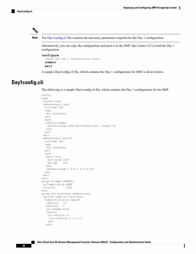
The Day1config.cli file contains the necessary parameters required for the Day 1 configuration.Note
Alternatively, you can copy the configuration and paste it in the SMF Ops Center CLI to load the Day 1configuration.
configure<Paste the Day 1 configuration here>commitexit
A sample Day1config.cli file, which contains the Day 1 configuration for SMF is shown below.
Day1config.cliThe following is a sample Day1config.cli file, which contains the Day 1 configuration for the SMF.configipamsource localaddress-pool ipv6vrf-name ISPtagsdnn intershatexitipv6prefix-rangesprefix-range 2001:4870:e00b:1500:: length 56exitexitexitaddress-pool poolv4vrf-name ISPtagsdnn intershatexitipv4split-sizeper-cache 1024per-dp 256exitaddress-range 0.0.0.1 0.0.0.254exitexitexitgroup nf-mgmt NFMGMT1nrf-mgmt-group MGMTlocality LOC1exitgroup nrf discovery udmdiscoveryservice type nrf nnrf-discendpoint-profile epprofcapacity 10priority 1uri-scheme httpversionuri-version v1full-version 1.1.1.[1]exitexit
Ultra Cloud Core 5G Session Management Function, Release 2020.02 - Configuration and Administration Guide30
Deploying and Configuring SMF through Ops CenterDay1config.cli

endpoint-name endpointNamepriority 1capacity 100primary ip-address ipv4 3.3.3.3primary ip-address port 8082exitexitexitexitgroup nrf mgmt MGMTservice type nrf nnrf-nfmendpoint-profile mgmt-1priority 1uri-scheme httpendpoint-name mgmt-1primary ip-address ipv4 3.3.3.3primary ip-address port 8082secondary ip-address ipv4 3.3.3.3secondary ip-address port 8083tertiary ip-address ipv4 3.3.3.3tertiary ip-address port 8084exitexitexitexitcdl node-type smf-cdlcdl zookeeper replica 2cdl kafka replica 2etcd replicas 1endpoint nodemgrexitendpoint gtpreplicas 1vip-ip 4.4.4.4exitendpoint pfcpreplicas 1nodes 2exitendpoint servicereplicas 1nodes 1exitendpoint protocolreplicas 1nodes 2vip-ip 4.4.4.4exitendpoint sbireplicas 1nodes 2vip-ip 4.4.4.4interface nrfloopbackPort 7005vip-ip 20.20.20.5 vip-port 9005exitinterface n7loopbackPort 7001vip-ip 20.20.20.1 vip-port 9001exitinterface n10loopbackPort 7004vip-ip 20.20.20.4 vip-port 9004exit
Ultra Cloud Core 5G Session Management Function, Release 2020.02 - Configuration and Administration Guide31
Deploying and Configuring SMF through Ops CenterDay1config.cli
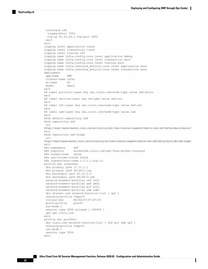
interface n40loopbackPort 7003vip-ip 20.20.20.3 vip-port 9003exitexitlogging level application tracelogging level transaction tracelogging level tracing offlogging name infra.config.core level application debuglogging name infra.config.core level transaction warnlogging name infra.config.core level tracing warnlogging name infra.resource_monitor.core level application warnlogging name infra.resource_monitor.core level transaction warndeploymentapp-name SMFcluster-name Localdc-name DCmodel smallexitk8 label protocol-layer key smi.cisco.com/node-type value smf-protoexitk8 label service-layer key vm-type value smf-svcexitk8 label cdl-layer key smi.cisco.com/node-type value smf-cdlexitk8 label oam-layer key smi.cisco.com/node-type value oamexithelm default-repository smfhelm repository smfurlhttps://engci-maven-master.cisco.com/artifactory/smi-fuse-internal-snapshot/mobile-cnat-smf/smf-products/master/exithelm repository smf-stageurlhttps://engci-maven-master.cisco.com/artifactory/smi-fuse-internal-snapshot/mobile-cnat-smf/smf-products/dev-smf-stage/exitk8s namespace smfk8s registry dockerhub.cisco.com/smi-fuse-docker-internalk8s single-node falsek8s use-volume-claims falsek8s ingress-host-name 1.1.1.1.nip.ioprofile dnn intershatdns primary ipv4 11.11.1.1dns primary ipv6 66:66:1::aadns secondary ipv4 22.22.2.2dns secondary ipv6 66:66:2::bbnetwork-element-profiles chf chf1network-element-profiles amf amf1network-element-profiles pcf pcf1network-element-profiles udm udm1dnn starent.com network-function-list [ upf ]charging-profile chgprf1virtual-mac b6:6d:47:47:47:47pcscf-profile pcscf1ssc-mode 1session type IPV4 allowed [ IPV4V6 ]upf apn cisco.comexitprofile dnn profDnn1dnn cisco.com network-function-list [ chf pcf udm upf ]charging-profile chgprf1ssc-mode 1session type IPV4exit
Ultra Cloud Core 5G Session Management Function, Release 2020.02 - Configuration and Administration Guide32
Deploying and Configuring SMF through Ops CenterDay1config.cli

profile dnn profDnn2dnn cisco.com network-function-list [ chf pcf rmgr udm upf ]charging-profile chgprf1ssc-mode 1session type IPV4exitprofile charging chgprf1method [ offline ]limit volume 20limit duration 60tight-interworking-mode truereporting-level online rating-groupreporting-level offline service-idexitprofile pcscf pcscf1v4-listprecedence 3primrary 3.3.3.1secondary 3.3.3.2exitprecedence 5primrary 5.5.5.1secondary 5.5.5.2exitprecedence 7primrary 7.7.7.1secondary 7.7.7.2exitexitv6-listprecedence 3primrary 33:33::1secondary 33:33::2exitprecedence 5primrary 55:55::1secondary 55:55::2exitexitv4v6-listprecedence 3primrary ipv4 46.46.33.1primrary ipv6 46:46:33::1secondary ipv4 46.46.33.2secondary ipv6 46:46:33::2exitprecedence 5primrary ipv4 46.46.55.1primrary ipv6 46:46:55::1secondary ipv4 46.46.55.2secondary ipv6 46:46:55::2exitprecedence 7primrary ipv4 46.46.77.1primrary ipv6 46:46:77::1secondary ipv4 46.46.77.2secondary ipv6 46:46:77::2exitexitexitprofile charging-characteristics 1charging-profile chgprf1exitprofile icmpv6 icmpprf1
Ultra Cloud Core 5G Session Management Function, Release 2020.02 - Configuration and Administration Guide33
Deploying and Configuring SMF through Ops CenterDay1config.cli

options virtual-mac b6:6d:57:45:45:45exitprofile smf smf1locality LOC1bind-address ipv4 4.4.4.4bind-port 8090fqdn 5.5.5.5allowed-nssai [ slice1 slice2 ]plmn-id mcc 123plmn-id mnc 456service name nsmf-pdutype pdu-sessionschema httpversion 1.Rn.0.0http-endpoint base-url http://smf-serviceicmpv6-profile icmpprf1compliance-profile dec18access-profile access1policy subscriber polSubexitexitprofile compliance dec18service nsmf-pdusessionversion uri v1version full 1.0.0version spec 15.2.0exitservice namf-commversion uri v1version full 1.0.0version spec 15.2.0exitservice n1version uri v1version full 1.0.0version spec 15.2.0exitservice n2version uri v1version full 1.0.0version spec 15.2.0exitservice nudm-sdmversion uri v1version full 1.0.0version spec 15.2.1exitservice nudm-uecmversion uri v1version full 1.0.0version spec 15.2.1exitservice nnrf-discversion uri v1version full 1.0.0version spec 15.2.0exitservice nnrf-nfmversion uri v1version full 1.0.0version spec 15.2.0exitservice npcf-smpolicycontrolversion uri v1
Ultra Cloud Core 5G Session Management Function, Release 2020.02 - Configuration and Administration Guide34
Deploying and Configuring SMF through Ops CenterDay1config.cli

version full 1.0.0version spec 15.2.0exitservice nchf-convergedchargingversion uri v2version full 1.0.0version spec 15.2.1exitexitprofile network-element amf amf1nf-client-profile amfP1failure-handling-profile FH3query-params [ dnn ]exitprofile network-element pcf pcf1nf-client-profile pcfP1failure-handling-profile FH1rulebase-prefix cbn#predefined-rule-prefix crn#exitprofile network-element udm udm1nf-client-profile udmP1failure-handling-profile FH1exitprofile network-element upf upf1n4-peer-address ipv4 6.6.6.6n4-peer-port 8805keepalive 60dnn-list [ dnn1 intershat starent ]exitprofile network-element chf chf1nf-client-profile chfP1failure-handling-profile FH2nf-client-profile-offline CP2failure-handling-profile-offline FH2exitprofile qos abcambr ul "250 Kbps"ambr dl "500 Kbps"qi5 7arp priority-level 14arp preempt-cap NOT_PREEMPTarp preempt-vuln PREEMPTABLEpriority 120max data-burst 2000dscp-map qi5 2 arp-priority-level 3 uplink user-datagram dscp-marking 0x1cdscp-map qi5 2 arp-priority-level 3 downlink user-datagram dscp-marking 0x1a encsp-headerdscp-marking 0x1bdscp-map qi5 3 arp-priority-level 3 uplink user-datagram dscp-marking 0x4dscp-map qi5 3 arp-priority-level 3 downlink user-datagram dscp-marking 0x3 encsp-headercopy-innerexitprofile access access1eps-fallback cbr delay 500 max-retry 10 timeout 3n26 idft enable timeout 15n2 idft enable timeout 15exitprofile nf-client nf-type udmudm-profile udmP1locality LOC1priority 30service name type nudm-sdmendpoint-profile EP1capacity 30
Ultra Cloud Core 5G Session Management Function, Release 2020.02 - Configuration and Administration Guide35
Deploying and Configuring SMF through Ops CenterDay1config.cli

uri-scheme httpendpoint-name EP1primary ip-address ipv4 3.3.3.3primary ip-address port 9007exitexitexitservice name type nudm-uecmendpoint-profile EP1capacity 30uri-scheme httpendpoint-name EP1primary ip-address ipv4 3.3.3.3primary ip-address port 9001exitexitexitexitexitexitprofile nf-client nf-type pcfpcf-profile pcfP1locality LOC1priority 30service name type npcf-am-policy-controlendpoint-profile EP1capacity 30uri-scheme httpendpoint-name EP1priority 50primary ip-address ipv4 3.3.3.3primary ip-address port 9003exitexitexitservice name type npcf-smpolicycontrolendpoint-profile EP1capacity 30uri-scheme httpendpoint-name EP1priority 5primary ip-address ipv4 3.3.3.3primary ip-address port 9003exitendpoint-name realPCFpriority 10primary ip-address ipv4 7.7.7.7primary ip-address port 9082exitexitexitexitexitexitprofile nf-client nf-type amfamf-profile amfP1locality LOC1priority 10service name type namf-commendpoint-profile EP1capacity 20uri-scheme httpendpoint-name EP1priority 30
Ultra Cloud Core 5G Session Management Function, Release 2020.02 - Configuration and Administration Guide36
Deploying and Configuring SMF through Ops CenterDay1config.cli

primary ip-address ipv4 3.3.3.3primary ip-address port 9002exitexitexitexitexitexitprofile nf-client nf-type chfchf-profile CP2locality LOC1priority 31service name type nchf-convergedchargingendpoint-profile EP1capacity 30uri-scheme httpversionuri-version v2exitexitendpoint-name EP1priority 56primary ip-address ipv4 3.3.3.3primary ip-address port 9906exitexitexitexitexitchf-profile chfP1locality LOC1priority 10service name type nchf-convergedchargingendpoint-profile EP1capacity 30uri-scheme httpversionuri-version v2exitexitendpoint-name EP1priority 50primary ip-address ipv4 3.3.3.3primary ip-address port 9904exitendpoint-name EP2priority 80primary ip-address ipv4 3.3.3.3primary ip-address port 9905exitexitexitexitexitexitprofile nf-pair nf-type UDMlocality client LOC1locality geo-server GEOexitprofile nf-pair nf-type AMFlocality client LOC1locality geo-server GEOexitprofile nf-pair nf-type PCF
Ultra Cloud Core 5G Session Management Function, Release 2020.02 - Configuration and Administration Guide37
Deploying and Configuring SMF through Ops CenterDay1config.cli
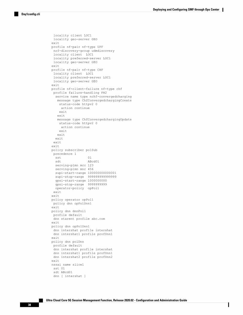
locality client LOC1locality geo-server GEOexitprofile nf-pair nf-type UPFnrf-discovery-group udmdiscoverylocality client LOC1locality preferred-server LOC1locality geo-server GEOexitprofile nf-pair nf-type CHFlocality client LOC1locality preferred-server LOC1locality geo-server GEOexitprofile nf-client-failure nf-type chfprofile failure-handling FH2service name type nchf-convergedchargingmessage type ChfConvergedchargingCreatestatus-code httpv2 0action continueexitexitmessage type ChfConvergedchargingUpdatestatus-code httpv2 0action continueexitexitexitexitexitpolicy subscriber polSubprecedence 1sst 01sdt ABcd01serving-plmn mcc 123serving-plmn mnc 456supi-start-range 100000000000001supi-stop-range 999999999999999gpsi-start-range 1000000000gpsi-stop-range 9999999999operator-policy opPol1exitexitpolicy operator opPol1policy dnn opPolDnn1exitpolicy dnn dnnPol1profile defaultdnn starent profile abc.comexitpolicy dnn opPolDnn1dnn intershat profile intershatdnn intershat1 profile profDnn1exitpolicy dnn polDnnprofile defaultdnn intershat profile intershatdnn intershat1 profile profDnn1dnn intershat2 profile profDnn2exitnssai name slice1sst 01sdt ABcd01dnn [ intershat ]
Ultra Cloud Core 5G Session Management Function, Release 2020.02 - Configuration and Administration Guide38
Deploying and Configuring SMF through Ops CenterDay1config.cli

exitnssai name slice2sst 02sdt 000003dnn [ cisco.com ]exitactive-charging service acs1packet-filter pkt1ip local-port range 2 to 23ip protocol = 23ip remote-address = 10.10.10.0/24ip remote-port range 12 to 34ip tos-traffic-class = 23 mask = 23priority 23exitpacket-filter pkt2direction uplinkip local-port = 100ip protocol = 100ip remote-address = 1.1.1.1/32ip remote-port = 140priority 100exitpacket-filter pkt3direction downlinkip local-port = 111ip protocol = 111ip remote-address = 2.2.2.2/31ip remote-port = 111priority 111exitcharging-action ca1allocation-retention-priority 12 pci NOT_PREEMPT pvi NOT_PREEMPTABLEflow limit-for-bandwidth direction uplink peak-data-rate 1000000 peak-burst-size 100
violate-action discard committedDataRate 2000000 committed-burst-size 100 exceed-actiondiscardflow limit-for-bandwidth direction downlink peak-data-rate 2000000 peak-burst-size 100
violate-action discard committedDataRate 3000000 committed-burst-size 100 exceed-actiondiscardqos-class-identifier 3tft-notify-uetos af11tft packet-filter pkt1exitcharging-action ca10flow limit-for-bandwidth direction uplink peak-data-rate 2000000000 peak-burst-size 100
violate-action discardflow limit-for-bandwidth direction downlink peak-data-rate 3000000000 peak-burst-size 100violate-action discardtos af11exitcharging-action ca11flow limit-for-bandwidth direction uplink peak-data-rate 2000000000 peak-burst-size 100
violate-action discardflow limit-for-bandwidth direction downlink peak-data-rate 3000000000 peak-burst-size 100violate-action discardexitcharging-action ca12flow limit-for-bandwidth direction uplink peak-data-rate 2000000 peak-burst-size 100
violate-action discardflow limit-for-bandwidth direction downlink peak-data-rate 3000000 peak-burst-size 100
violate-action discardexitcharging-action ca13
Ultra Cloud Core 5G Session Management Function, Release 2020.02 - Configuration and Administration Guide39
Deploying and Configuring SMF through Ops CenterDay1config.cli

flow limit-for-bandwidth direction uplink peak-data-rate 2000000 peak-burst-size 100violate-action discardflow limit-for-bandwidth direction downlink peak-data-rate 3000000 peak-burst-size 100
violate-action discardexitcharging-action ca2allocation-retention-priority 13 pci NOT_PREEMPT pvi NOT_PREEMPTABLEflow limit-for-bandwidth direction uplink peak-data-rate 2000000000 peak-burst-size 100
violate-action discard committedDataRate 3000000000 committed-burst-size 100 exceed-actiondiscardflow limit-for-bandwidth direction downlink peak-data-rate 3000000000 peak-burst-size 100violate-action discard committedDataRate 4000000000 committed-burst-size 100 exceed-actiondiscardqos-class-identifier 2tft-notify-uetos af11tft packet-filter pkt2exitcharging-action ca20flow limit-for-bandwidth direction uplink peak-data-rate 1000000 peak-burst-size 100
violate-action discardflow limit-for-bandwidth direction downlink peak-data-rate 1000000 peak-burst-size 100
violate-action discardexitcharging-action ca21flow limit-for-bandwidth direction uplink peak-data-rate 1000000 peak-burst-size 100
violate-action discardflow limit-for-bandwidth direction downlink peak-data-rate 1000000 peak-burst-size 100
violate-action discardexitcharging-action ca22flow limit-for-bandwidth direction uplink peak-data-rate 1000000 peak-burst-size 100
violate-action discardflow limit-for-bandwidth direction downlink peak-data-rate 1000000 peak-burst-size 100
violate-action discardexitcharging-action ca23flow limit-for-bandwidth direction uplink peak-data-rate 1000000 peak-burst-size 100
violate-action discardflow limit-for-bandwidth direction downlink peak-data-rate 1000000 peak-burst-size 100
violate-action discardexitcharging-action ca3allocation-retention-priority 14 pci NOT_PREEMPT pvi NOT_PREEMPTABLEflow limit-for-bandwidth direction uplink peak-data-rate 2000000 peak-burst-size 100
violate-action discard committedDataRate 1000000 committed-burst-size 100 exceed-actiondiscardflow limit-for-bandwidth direction downlink peak-data-rate 4000000 peak-burst-size 100
violate-action discard committedDataRate 3000000 committed-burst-size 100 exceed-actiondiscardqos-class-identifier 1tft-notify-uetos af11tft packet-filter pkt3exitcharging-action ca4allocation-retention-priority 11 pci NOT_PREEMPT pvi NOT_PREEMPTABLEflow limit-for-bandwidth direction uplink peak-data-rate 2000000 peak-burst-size 100
violate-action discard committedDataRate 3000000 committed-burst-size 100 exceed-actiondiscardflow limit-for-bandwidth direction downlink peak-data-rate 4000000 peak-burst-size 100
violate-action discard committedDataRate 4000000 committed-burst-size 100 exceed-actiondiscardqos-class-identifier 4
Ultra Cloud Core 5G Session Management Function, Release 2020.02 - Configuration and Administration Guide40
Deploying and Configuring SMF through Ops CenterDay1config.cli

tft-notify-uetos af11tft packet-filter pkt1exitcharging-action ca5allocation-retention-priority 11 pci NOT_PREEMPT pvi NOT_PREEMPTABLEflow limit-for-bandwidth direction uplink peak-data-rate 2000000 peak-burst-size 100
violate-action discard committedDataRate 3000000 committed-burst-size 100 exceed-actiondiscardflow limit-for-bandwidth direction downlink peak-data-rate 4000000 peak-burst-size 100
violate-action discard committedDataRate 4000000 committed-burst-size 100 exceed-actiondiscardqos-class-identifier 4tft-notify-uetos af11tft packet-filter pkt2exitcharging-action ca6allocation-retention-priority 11 pci NOT_PREEMPT pvi NOT_PREEMPTABLEflow limit-for-bandwidth direction uplink peak-data-rate 2000000 peak-burst-size 100
violate-action discard committedDataRate 3000000 committed-burst-size 100 exceed-actiondiscardflow limit-for-bandwidth direction downlink peak-data-rate 4000000 peak-burst-size 100
violate-action discard committedDataRate 4000000 committed-burst-size 100 exceed-actiondiscardqos-class-identifier 4tft-notify-uetos af11tft packet-filter pkt3exitcharging-action ca7allocation-retention-priority 1 pci NOT_PREEMPT pvi NOT_PREEMPTABLEflow limit-for-bandwidth direction uplink peak-data-rate 2000000 peak-burst-size 100
violate-action discardflow limit-for-bandwidth direction downlink peak-data-rate 400000 peak-burst-size 100
violate-action discardqos-class-identifier 7tft-notify-uetos af11exitcharging-action caGyGzbilling-action egcdrcca charging credit rating-group 102content-id 102service-identifier 202exitcharging-action caOfflinebilling-action egcdrcontent-id 100service-identifier 200exitcharging-action caOffline1billing-action egcdrcontent-id 11service-identifier 21exitcharging-action caOffline2billing-action egcdrcontent-id 12service-identifier 22exitcharging-action caOffline3billing-action egcdrcontent-id 13
Ultra Cloud Core 5G Session Management Function, Release 2020.02 - Configuration and Administration Guide41
Deploying and Configuring SMF through Ops CenterDay1config.cli

service-identifier 23exitcharging-action caOffline4billing-action egcdrcontent-id 40exitcharging-action caOfflineOnlinebilling-action egcdrcca charging creditcontent-id 30service-identifier 60exitcharging-action caOfflineOnline1billing-action egcdrcca charging creditcontent-id 31service-identifier 61exitcharging-action caOnlinecca charging credit rating-group 100content-id 100service-identifier 200exitcharging-action caOnline1cca charging credit rating-group 101content-id 101service-identifier 201exitcharging-action caOnline2cca charging creditcontent-id 102service-identifier 202exitcharging-action caOnline3cca charging creditcontent-id 103service-identifier 203exitcharging-action caOnline4cca charging creditcontent-id 110exitcharging-action nochargingexitrulebase cbn#spp-tmobileaction priority 1 ruledef crn#test_1 charging-action ca1action priority 2 ruledef crn#test_2 charging-action ca2exitrulebase rba1action priority 1 dynamic-only ruledef rda1 charging-action ca1 description myrule1action priority 2 dynamic-only ruledef rda2 charging-action ca2 description myrule2action priority 3 dynamic-only ruledef rda3 charging-action ca3 description myrule3exitrulebase rba2action priority 10 ruledef rda10 charging-action ca10 description myrule10action priority 11 ruledef rda11 charging-action ca11 description myrule11action priority 12 dynamic-only ruledef rda12 charging-action ca12 description myrule12action priority 13 dynamic-only ruledef rda13 charging-action ca13 description myrule13exitrulebase rba3action priority 20 ruledef rda20 charging-action ca20 description myrule20action priority 21 ruledef rda21 charging-action ca21 description myrule21action priority 22 dynamic-only ruledef rda22 charging-action ca22 description myrule22action priority 23 dynamic-only ruledef rda23 charging-action ca23 description myrule23
Ultra Cloud Core 5G Session Management Function, Release 2020.02 - Configuration and Administration Guide42
Deploying and Configuring SMF through Ops CenterDay1config.cli

exitrulebase rba4action priority 30 ruledef rda3 charging-action ca3 description myrule3action priority 31 dynamic-only ruledef rda3 charging-action ca3 description myrule3exitrulebase rba5action priority 50 dynamic-only ruledef rda50 charging-action ca4 description myrule50action priority 51 dynamic-only ruledef rda51 charging-action ca5 description myrule51action priority 52 dynamic-only ruledef rda52 charging-action ca6 description myrule52exitrulebase rba6action priority 60 dynamic-only ruledef rda60 charging-action ca1 description myrule60action priority 61 dynamic-only ruledef rda61 charging-action ca1 description myrule61action priority 62 dynamic-only ruledef rda62 charging-action ca1 description myrule62exitrulebase rba7action priority 50 ruledef rda50 charging-action ca4 description myrule50action priority 51 ruledef rda51 charging-action ca5 description myrule51action priority 52 ruledef rda52 charging-action ca6 description myrule52exitrulebase rba8action priority 60 ruledef rda60 charging-action ca1 description myrule60action priority 61 ruledef rda61 charging-action ca1 description myrule61action priority 62 ruledef rda62 charging-action ca1 description myrule62exitrulebase rbaStaticaction priority 10 ruledef rda20 charging-action caOfflineexitrulebase rbaStatic-Onlineaction priority 20 ruledef rdaStatic charging-action caOnlineexitrulebase rbaStatic1action priority 10 ruledef rda20 charging-action caOfflineexitrulebase rba_GyGzegcdr threshold volume downlink 100000 uplink 100000action priority 20 dynamic-only ruledef rdaPredefined charging-action caGyGzaction priority 30 ruledef rda20 charging-action caGyGzexitrulebase rba_charging_StaticDynamic_Offline_Online_mixcca diameter requested-service-unit sub-avp volume cc-input-octets 11000 cc-output-octets12000 cc-total-octets 23000credit-control-group onlineofflineegcdr threshold interval 100egcdr threshold volume downlink 150000 uplink 150000 total 300000action priority 20 dynamic-only ruledef rdaPredefined charging-action caOffline1action priority 21 dynamic-only ruledef rdaPredefined1 charging-action caOnline1action priority 31 ruledef rdaStatic charging-action caOfflineOnlineexitrulebase rba_charging_StaticDynamic_offlineegcdr threshold volume downlink 100000 uplink 100000action priority 20 dynamic-only ruledef rdaPredefined charging-action caOffline1action priority 30 ruledef rda20 charging-action caOfflineexitrulebase rba_charging_StaticDynamic_onlineaction priority 20 ruledef rda20 charging-action caOnlineaction priority 30 dynamic-only ruledef rdaPredefined charging-action caOnline1exitrulebase rbs1action priority 1 ruledef rds1 charging-action ca1 description myrules1action priority 2 ruledef rds2 charging-action ca2 description myrules2exiturr-list urr_smfrating-group 10 service-identifier 20 urr-id 1
Ultra Cloud Core 5G Session Management Function, Release 2020.02 - Configuration and Administration Guide43
Deploying and Configuring SMF through Ops CenterDay1config.cli

rating-group 11 service-identifier 21 urr-id 2rating-group 12 service-identifier 22 urr-id 3rating-group 13 service-identifier 23 urr-id 4rating-group 30 service-identifier 60 urr-id 20rating-group 31 service-identifier 61 urr-id 21rating-group 100 service-identifier 200 urr-id 5rating-group 101 service-identifier 201 urr-id 6rating-group 102 service-identifier 202 urr-id 7rating-group 103 service-identifier 203 urr-id 8exitruledef rda1ip server-ip-address = 10.10.10.10exitruledef rda10ip any-match = TRUEexitruledef rda11ip any-match = TRUEexitruledef rda12ip any-match = TRUEexitruledef rda13ip any-match = TRUEexitruledef rda2ip server-ip-address = 10.165.161.77/32exitruledef rda20ip any-match = TRUEexitruledef rda21ip any-match = TRUEexitruledef rda22ip any-match = TRUEexitruledef rda23ip any-match = TRUEexitruledef rda3ip server-ip-address = 8.8.8.8/28exitruledef rda40ip any-match = TRUEexitruledef rda50ip server-ip-address = 50.50.50.50exitruledef rda51ip server-ip-address = 51.51.51.51exitruledef rda52ip server-ip-address = 52.52.52.52exitruledef rda60ip dst-address = 60.60.60.60exitruledef rda61ip dst-address = 61.61.61.61exitruledef rda62ip dst-address = 62.62.62.62exit
Ultra Cloud Core 5G Session Management Function, Release 2020.02 - Configuration and Administration Guide44
Deploying and Configuring SMF through Ops CenterDay1config.cli

ruledef rdaPredefinedip any-match = TRUEexitruledef rdaStaticip any-match = TRUEexitruledef rdaStatic1ip any-match = TRUEexitruledef rdaStatic2ip any-match = TRUEexitruledef rds1ip any-match = TRUEexitruledef rds2ip any-match = TRUEexitcredit-control group onlineofflinediameter ignore-service-id trueexitexitapn intershatgtpp group group1active-charging rulebase rba1exitgtpp group group1gtpp egcdr service-data-flow threshold interval 60gtpp egcdr service-data-flow threshold volume downlink 100000 uplink 100000 total 200000apn intershatgtpp group group1exitsmiuser add-user username liadmin password Cisco@123smiuser change-password username liadmin current_password Cisco@123 new_password Mitg_123confirm_password Mitg_123smiuser add-group groupname LIsmiuser assign-user-group username liadmin group LIsmiuser add-user username liadmin2 password Cisco@123smiuser change-password username liadmin2 current_password Cisco@123 new_password Mitg_123confirm_password Mitg_123smiuser add-group groupname LI2smiuser assign-user-group username liadmin2 group LI2smiuser add-user username liadmin3 password Cisco@123smiuser change-password username liadmin3 current_password Cisco@123 new_password Mitg_123confirm_password Mitg_123smiuser add-group groupname LI3smiuser assign-user-group username liadmin3 group LI3nacm groups group LI2user-name [ liadmin2 ]exitnacm groups group LI3user-name [ liadmin3 ]exitnacm rule-list lawful-interceptgroup [ LI LI2 LI3 ]commitendconfigsystem mode runningcommitendexit
Ultra Cloud Core 5G Session Management Function, Release 2020.02 - Configuration and Administration Guide45
Deploying and Configuring SMF through Ops CenterDay1config.cli
Ultra Cloud Core 5G Session Management Function, Release 2020.02 - Configuration and Administration Guide46
Deploying and Configuring SMF through Ops CenterDay1config.cli

C H A P T E R 4Smart Licensing
• Feature Summary and Revision History, on page 47• Smart Software Licensing, on page 47• Configuring Smart Licensing, on page 50• Monitoring and Troubleshooting Smart Licensing, on page 60
Feature Summary and Revision History
Summary DataTable 9: Summary Data
SMFApplicable Products or Functional Area
SMIApplicable Platform(s)
Disabled - Configuration RequiredFeature Default Setting
Not ApplicableRelated Changes in this Release
Not ApplicableRelated Documentation
Revision HistoryTable 10: Revision History
ReleaseRevision Details
Pre-2020.02.0First introduced.
Smart Software LicensingSmart Licensing is a cloud-based approach to licensing that simplifies the purchase, deployment, andmanagement of Cisco software assets. Entitlements are purchased through your Cisco account via Cisco
Ultra Cloud Core 5G Session Management Function, Release 2020.02 - Configuration and Administration Guide47

CommerceWorkspace (CCW) and immediately deposited into your Virtual Account for usage. This eliminatesthe need to install license files on every device. Products that are smart enabled communicate directly to Ciscoto report consumption. A single location is available to customers to manage Cisco software licenses — theCisco Software Central (CSC). License ownership and consumption are readily available to help make betterpurchase decision based on consumption or business need. Seehttps://www.cisco.com/c/en/us/buy/smart-accounts/software-licensing.html for more information about CiscoSmart Licensing.
Comparison Between Legacy Licensing and Smart Licensing
Cisco employs two types of license models - Legacy Licensing and Smart Software Licensing. LegacyLicensing consists of software activation by installing Product Activation Keys (PAK) on to the Cisco product.A Product Activation Key is a purchasable item, ordered in the same manner as other Cisco equipment andused to obtain license files for feature set on Cisco Products. Smart Software Licensing is a cloud-basedlicensing of the end-to-end platform through the use of a few tools that authorize and deliver license reporting.Smart Software Licensing functionality incorporated into the NFs complete the product registration andauthorization.
Cisco Software CentralCisco Software Central (CSC) enables the management of software licenses and Smart Account from a singleportal. The interface allows you to activate your product, manage entitlements, and renew and upgrade software.A functioning Smart Account is required to complete the registration process. To access the Cisco SoftwareCentral, see https://software.cisco.com.
Smart Accounts/Virtual AccountsA Smart Account provides a single location for all Smart-enabled products and entitlements. It helps speedprocurement, deployment, and maintenance of Cisco Software. When creating a Smart Account, you musthave the authority to represent the requesting organization. After submitting, the request goes through a briefapproval process.
A Virtual Account exists as a sub-account within the Smart Account. Virtual Accounts are a customer-definedstructure based on organizational layout, business function, geography or any defined hierarchy. They arecreated and maintained by the Smart Account administrator.
See https://software.cisco.com to learn about the set up or manage the Smart Accounts.
Request a Cisco Smart AccountA Cisco Smart Account is an account where all products enabled for Smart Licensing are deposited. A CiscoSmart Account allows you to manage and activate your licenses to devices, monitor license use, and trackCisco license purchases. Through transparent access, you have a real-time view into your Smart Licensingproducts. IT administrators can manage licenses and account users within your organization's Smart Accountthrough the Software Central.
Step 1 In a browser window, enter the following URL:
https://software.cisco.com
Ultra Cloud Core 5G Session Management Function, Release 2020.02 - Configuration and Administration Guide48
Smart LicensingCisco Software Central

Step 2 Log in using your credentials, and then click Request a Smart Account in the Administration area.
The Smart Account Request window is displayed.
Step 3 Under Create Account, select one of the following options:
• Yes, I have authority to represent my company and want to create the Smart Account – If you select thisoption, you agree to authorization to create and manage product and service entitlements, users, and roles on behalfof your organization.
• No, the person specified below will create the account – If you select this option, you must enter the email addressof the person who will create the Smart Account.
Step 4 Under Account Information:a) Click Edit beside Account Domain Identifier.b) In the Edit Account Identifier dialog box, enter the domain, and click OK. By default, the domain is based on the
email address of the person creating the account and must belong to the company that will own this account.c) Enter the Account Name (typically, the company name).
Step 5 Click Continue.The Smart Account request will be in pending status until it has been approved by the Account Domain Identifier. Afterapproval, you will receive an email confirmation with instructions for completing the setup process.
SMF Smart LicensingAt present, the Smart Licensing feature supports application entitlement for online and offline licensing forall 5G applications (PCF, SMF and NRF). The application usage is unrestricted during all stages of licensingincluding Out of Compliance (OOC) and expired stages.
A 90 day evaluation period is granted for all licenses in use. Currently, the functionality and operation of the5G applications is unrestricted even after the end of the evaluation period.
Note
Software Tags and Entitlement TagsTags for the following software and entitlements have been created to identify, report, and enforce licenses.
Software Tags
Software tags uniquely identify each licenseable software product or product suite on a device. The followingsoftware tags exist for the SMF.
Software TagProduct Type / Description
regid.2020-04.com.cisco.SMF,1.0_37ffdc21-3e95-4192-bcda-d3225b6590ceUltra Cloud Core - SessionManagement Function(SMF), Base Minimum
Ultra Cloud Core 5G Session Management Function, Release 2020.02 - Configuration and Administration Guide49
Smart LicensingSMF Smart Licensing

Entitlement Tags
The following entitlement tags identify licenses in use:
Entitlement TagProduct Type /Description
regid.2020-04.com.cisco.SMF_BASE,1.0_b49f5997-21aa-4d15-9606-0cff88729f69Ultra Cloud Core -Session ManagementFunction (SMF), BaseMinimum
The license information is retained during software upgrades and rollback.Note
Configuring Smart LicensingYou can configure Smart Licensing after a new SMF deployment.
Users with Access to CSCThis section describes how to configure Smart Licensing if you have access to CSC portal from yourenvironment.
Setting Up the Product and Entitlement in CSC
Before you begin, you need to setup your product and entitlement in the CSC. To setup your product andentitlement:
1. Log in to your CSC account.
2. Click Add Product and enter the following details.
• Product name – Specify the name of the deployed product. For example, SMF.
• Primary PM CEC ID – Specify the primary Project Manager's CEC ID for the deployed product.
• Dev Manager CEC ID – Specify the Development Manager's CEC ID for the deployed product.
• Description (Optional) – Specify a brief description of the deployed product.
• Product Type – Specify the product type.
• Software ID Tag – Specify the software ID Tag provided by the Cisco Accounts team.
3. Click Create.
4. Select your product from the Product/Entitlement Setup grid.
5. Click Entitlement drop-down and select Create New Entitlement.
6. Select New Entitlement in Add Entitlement and enter the following details.
Ultra Cloud Core 5G Session Management Function, Release 2020.02 - Configuration and Administration Guide50
Smart LicensingConfiguring Smart Licensing

• Entitlement Name – Specify the license entitlement name. For example, SMF_BASE.
• Description (Optional) – Specify a breif description about the license entitlement.
• Entitlement Tag – Specify the entitlement tag provided by the Cisco Accounts team.
• Entitlement Type – Specify the type of license entitlement.
• Vendor String – Specify the vendor name.
7. Click Entitlement Allocation.
8. Click Add Entitlement Allocation.
9. In New License Allocation, provide the following details:
• Product – Select your product from the drop-down list.
• Entitlement – Select your entitlement from the drop-down list.
10. Click Continue.
11. In New License Allocation window, provide the following details:
• Quantity – Specify the number of licenses.
• License Type – Specify the type of license.
• Expiring Date – Specify the date of expiry for the license purchased.
12. Click Create.
13. Verify the status of Smart Licensing using the following command.
show license all
Example:
SMF# show license all
Smart Licensing Status=======================Smart Licensing is ENABLED
Registration:Status: UNREGISTEREDExport-Controlled Functionality: Not Allowed
License Authorization:Status: EVAL MODEEvaluation Period Remaining: 83 days, 0 hr, 15 min, 8 secLast Communication Attempt: NONE
License Conversion:Automatic Conversion Enabled: trueStatus: NOT STARTED
Utility:Status: DISABLED
Transport:Type: CALLHOME
Ultra Cloud Core 5G Session Management Function, Release 2020.02 - Configuration and Administration Guide51
Smart LicensingUsers with Access to CSC

Evaluation Period:Evaluation Mode: In UseEvaluation Period Remaining: 83 days, 0 hr, 15 min, 8 sec
License Usage=============License Authorization Status: EVALUATION MODEEvaluation Period Remaining: 83 days, 0 hr, 15 min, 8 sec
UCC 5G SMF BASE (SMF_BASE)Description: Ultra Cloud Core - Session Management Function (SMF), Base MinimumCount: 1Version: 1.0Status: EVAL MODEExport status: RESTRICTED_NOTALLOWEDFeature Name: <empty>Feature Description: <empty>
Product Information===================UDI: PID:SMF,SN:6GKJ2OA-NMUWA7Y
Agent Version=============Smart Agent for Licensing: 3.0.13
Registering Smart Licensing
You must register the product entitled to the license with CSC. In order to register, you must generate an IDtoken from CSC.
1. Log in to your CSC account.
2. Click General > New Token and enter the following details:
• Description – Specify a brief description about the ID token.
• Expires After – Specify the number of days for the token to expire.
• Max. Number Users – Specify the maximum number of users.
3. Click Create Token.
4. Select new ID token in Product Instance Registration Token.
5. Click Actions > Copy.
6. Log in to SMF Ops Center CLI and paste the ID token using the following command.
license smart register idtoken
Example:
SMF# license smart registerValue for 'idtoken' (<string>): MTI2Y2FlNTAtOThkMi00YTAxLWE4M2QtOTNhNzNjNjY4ZmFiLTE2MTc4NTky%0AMTA5MDh8ck1jUHNwc3k1ZC9nWFFCSnVEcUp4QU1jTFoxOGxDTU5kQ3lpa25E%0Ab04wST0%3D%0ASMF#
7. Verify the Smart Licensing status using the following command.
show license all
Ultra Cloud Core 5G Session Management Function, Release 2020.02 - Configuration and Administration Guide52
Smart LicensingUsers with Access to CSC

Example:
SMF# show license all
Smart Licensing Status=======================Smart Licensing is ENABLED
Registration:Status: REGISTEREDSmart Account: Cisco Systems, Inc.Virtual Account: SMF-SMFExport-Controlled Functionality: AllowedInitial Registration: SUCCEEDED on Apr 15 05:45:07 2020 GMTLast Renewal Attempt: SUCCEEDED on Apr 15 05:45:07 2020 GMTNext Renewal Attempt: Oct 12 05:45:07 2020 GMTRegistration Expires: Apr 15 05:40:31 2021 GMT
License Authorization:Status: AUTHORIZED on Apr 15 05:45:12 2020 GMTLast Communication Attempt: SUCCEEDED on Apr 15 05:45:12 2020 GMTNext Communication Attempt: May 15 05:45:12 2020 GMTCommunication Deadline: Jul 14 05:40:40 2020 GMT
License Conversion:Automatic Conversion Enabled: trueStatus: NOT STARTED
Utility:Status: DISABLED
Transport:Type: CALLHOME
Evaluation Period:Evaluation Mode: Not In UseEvaluation Period Remaining: 83 days, 0 hr, 10 min, 43 sec
License Usage=============License Authorization Status: AUTHORIZED as of Apr 15 05:45:12 2020 GMT
UCC 5G SMF BASE (SMF_BASE)Description: Ultra Cloud Core - Session Management Function (SMF), Base MinimumCount: 1Version: 1.0Status: AUTHORIZEDExport status: RESTRICTED_ALLOWEDFeature Name: <empty>Feature Description: <empty>
Product Information===================UDI: PID:SMF,SN:6GKJ2OA-NMUWA7Y
Agent Version=============Smart Agent for Licensing: 3.0.13
NOTES:
• license smart register – Registers Smart Licensing with CSC.
• idtoken – Specifies the ID token generated from CSC.
Ultra Cloud Core 5G Session Management Function, Release 2020.02 - Configuration and Administration Guide53
Smart LicensingUsers with Access to CSC

Deregistring Smart Licensing
To deregister Smart Licensing:
1. Log in to SMF Ops Center CLI and use the following command.
license smart deregister
2. Verify the Smart Licensing status using the following command.
show license all
Example:
SMF# show license all
Smart Licensing Status=======================Smart Licensing is ENABLED
Registration:Status: UNREGISTEREDExport-Controlled Functionality: Not Allowed
License Authorization:Status: EVAL MODEEvaluation Period Remaining: 83 days, 0 hr, 10 min, 43 secLast Communication Attempt: NONE
License Conversion:Automatic Conversion Enabled: trueStatus: NOT STARTED
Utility:Status: DISABLED
Transport:Type: CALLHOME
Evaluation Period:Evaluation Mode: In UseEvaluation Period Remaining: 83 days, 0 hr, 10 min, 43 sec
License Usage=============License Authorization Status: EVALUATION MODEEvaluation Period Remaining: 83 days, 0 hr, 10 min, 43 sec
UCC 5G SMF BASE (SMF_BASE)Description: Ultra Cloud Core - Session Management Function (SMF), Base MinimumCount: 1Version: 1.0Status: EVAL MODEExport status: RESTRICTED_NOTALLOWEDFeature Name: <empty>Feature Description: <empty>
Product Information===================UDI: PID:SMF,SN:6GKJ2OA-NMUWA7Y
Agent Version=============Smart Agent for Licensing: 3.0.13
Ultra Cloud Core 5G Session Management Function, Release 2020.02 - Configuration and Administration Guide54
Smart LicensingUsers with Access to CSC

SMF#
NOTES:
• license smart deregister – Deregisters Smart Licensing from CSC.
Users without Access to CSCThe Smart License Reservation feature – Perpetual Reservation – is reserved for customers without access toCSC from their internal environments. With this feature, Cisco allows customers to reserve licenses fromtheir virtual account and tie them to their devices Unique Device Identifier (UDI). This enables customers touse their devices with reserved licenses in a disconnected mode.
The subsequent sections describe the procedure involved in reserving Smart License for users without accessto CSC from their internal environment.
Enabling Smart License Reservation
To enable Smart License reservation through SMF Ops Center CLI:
1. Log in to SMF Ops Center CLI and use the following configuration.
configure terminallicense smart reservationcommitexit
NOTES:
• license smart reservation – Enables license reservation.
Generating Smart License Reservation Request Code
To generate the Smart License reservation request code:
1. Log in to SMF Ops Center CLI.
2. To enable reservation, use the following configuration.
configure terminallicense smart reservationcommitexit
3. To request for a reservation code, use the following command.
license smart reservation request
Example:
SMF# license smart reservation requestreservation-request-code CJ-ZSMF:6GKJ2OA-NMUWA7Y-Ai75GxtBs-3BSMF#Message from confd-api-manager at 2020-04-15 05:51:37...Global license change NotifyReservationInProgress reason code Success - Successful.SMF#
Ultra Cloud Core 5G Session Management Function, Release 2020.02 - Configuration and Administration Guide55
Smart LicensingUsers without Access to CSC

NOTES:
• license smart reservation – Enables license reservation request code.
• license smart reservation request – Generates the license reservation request code.
You must copy the generated license request code from the SMF Ops CenterCLI.
Important
Generating an Authorization Code from CSC
To generate an authorization code from CSC using the license reservation request code:
1. Log in to your CSC account.
2. Click License Reservation.
3. Enter the Request Code: Paste the license reservation request code copied from the SMF Ops Center CLIin the Reservation Request Code text-box.
4. Select the Licenses: Click Reserve a Specific License radio-button and select UCC 5G SMF BASE.
In the Reserve text-box enter the value 1.Note
5. Review your selection.
6. Click Generate Authorization Code.
7. Download the response file: The authorization code is generated and displayed on-screen. ClickDownloadas File to download the authorization code.
8. Click Close.
Reserving Smart Licensing
To reserve Smart License for the deployed product using the authorization code generated in CSC:
1. Log in to SMF Ops Center CLI and use the following command.
license smart reservation install authorization_code
Example:SMF# license smart reservation installValue for 'key' (<string>):<specificPLR><authorizationCode><flag>A</flag><version>C</version><piid>35757dc6-2bdf-4fa1-ba7e-4190f5b6ea22</piid><timestamp>1586929992297</timestamp><entitlements><entitlement><tag>regid.2020-04.com.cisco.SMF_BASE,1.0_60b1da6f-3832-4687-90c9-8879dc815a27</tag><count>1</count><startDate>2020-Apr-08 UTC</startDate><endDate>2020-Oct-05 UTC</endDate><licenseType>TERM</licenseType><displayName>UCC 5G SMF BASE</displayName><tagDescription>Ultra Cloud Core - Session Management Function (SMF), BaseMinimum</tagDescription><subscriptionID></subscriptionID></entitlement></entitlements></authorizationCode><signature>MEYCIQC/9v5LpgFoEk2l4omIgjjk83g5WXjzs09kQnsO8D0jRgIhAMh+
Ultra Cloud Core 5G Session Management Function, Release 2020.02 - Configuration and Administration Guide56
Smart LicensingUsers without Access to CSC

D6DRuYmqh1TlfJoZxNte0fPKw6fHEY5CEF3+kPQj</signature><udi>P:SMF,S:6GKJ2OA-NMUWA7Y</udi></specificPLR>SMF#
2. Verify the smart licensing status using the following command.
show license all
Example:
SMF# show license all
Smart Licensing Status=======================Smart Licensing is ENABLEDLicense Reservation is ENABLED
Registration:Status: REGISTERED - SPECIFIC LICENSE RESERVATIONExport-Controlled Functionality: AllowedInitial Registration: SUCCEEDED on Wed Apr 15 05:53:31 GMT 2020Last Renewal Attempt: None
License Authorization:Status: AUTHORIZED - RESERVED on Wed Apr 15 05:53:31 GMT 2020
Utility:Status: DISABLED
Transport:Type: CALLHOME
Evaluation Period:Evaluation Mode: Not In UseEvaluation Period Remaining: 83 days, 0 hr, 5 min, 15 sec
License Usage=============License Authorization Status:Status: AUTHORIZED - RESERVED on Wed Apr 15 05:53:31 GMT 2020Last Communication Attempt: SUCCEEDED on Apr 15 05:53:31 2020 GMTNext Communication Attempt: NONECommunication Deadline: NONE
UCC 5G SMF BASE (SMF_BASE)Description: Ultra Cloud Core - Session Management Function (SMF),
Base MinimumCount: 1Version: 1.0Status: AUTHORIZEDExport status: NOT RESTRICTEDFeature Name: <empty>Feature Description: <empty>Reservation:Reservation Status: SPECIFIC INSTALLEDTotal Reserved Count: 1Term expiration: 2020-Oct-05 GMT
Product Information===================UDI: PID:SMF,SN:6GKJ2OA-NMUWA7Y
Ultra Cloud Core 5G Session Management Function, Release 2020.02 - Configuration and Administration Guide57
Smart LicensingUsers without Access to CSC

Agent Version=============Smart Agent for Licensing: 3.0.13
NOTES:
• license smart reservation install authorization_code – Installs a Smart License Authorization code.
Returning the Reserved License
You can return the reserved license to CSC if required. Use the following procedure to return the reservedlicense:
1. When the license reservation authorization code is installed in the SMF Ops Center.
a. Log in to the SMF Ops Center CLI and use the following command.
license smart reservation return
Example:
SMF# license smart reservation returnreservation-return-code CJ6m3k-RAvu6b-hMNmwf-mrdcko-NoSwKL-tF7orz-9aNtEu-yVjGAm-D6jSMF#
b. Copy the license reservation return code generated in SMF Ops Center CLI.
c. Log in to your CSC account.
d. Select your product instance from the list.
e. Click Actions > Remove.
f. Paste the license reservation return code in Return Code text-box.
NOTES:
• license smart reservation return – Returns a reserved Smart License.
2. When the license reservation authorization code is not installed in the SMF Ops Center.
a. Log in to the SMF Ops Center CLI and use the following command to generate the return code.
license smart reservation returnauthorization_code
Paste the license reservation authorization code generated in CSC to generate the return code.Important
b. Log in to your CSC account.
c. Select your product instance from the list.
d. Click Actions > Remove.
e. Paste the license reservation return code in Return Code text-box.
3. Verify the smart licensing status using the following command.
Ultra Cloud Core 5G Session Management Function, Release 2020.02 - Configuration and Administration Guide58
Smart LicensingUsers without Access to CSC

show license all
Example:
SMF# show license all
Smart Licensing Status=======================Smart Licensing is ENABLEDLicense Reservation is ENABLED
Registration:Status: UNREGISTEREDExport-Controlled Functionality: Not Allowed
License Authorization:Status: EVAL MODEEvaluation Period Remaining: 83 days, 0 hr, 5 min, 15 secLast Communication Attempt: SUCCEEDED on Apr 15 05:53:31 2020 GMTNext Communication Attempt: NONECommunication Deadline: NONE
License Conversion:Automatic Conversion Enabled: trueStatus: NOT STARTED
Utility:Status: DISABLED
Transport:Type: CALLHOME
Evaluation Period:Evaluation Mode: In UseEvaluation Period Remaining: 83 days, 0 hr, 5 min, 15 sec
License Usage=============License Authorization Status: EVALUATION MODEEvaluation Period Remaining: 83 days, 0 hr, 5 min, 15 sec
UCC 5G SMF BASE (SMF_BASE)Description: Ultra Cloud Core - Session Management Function (SMF), Base MinimumCount: 1Version: 1.0Status: EVAL MODEExport status: RESTRICTED_NOTALLOWEDFeature Name: <empty>Feature Description: <empty>
Product Information===================UDI: PID:SMF,SN:6GKJ2OA-NMUWA7Y
Agent Version=============Smart Agent for Licensing: 3.0.13
SMF#
Ultra Cloud Core 5G Session Management Function, Release 2020.02 - Configuration and Administration Guide59
Smart LicensingUsers without Access to CSC

Monitoring and Troubleshooting Smart LicensingYou can use the following show commands to view Smart Licensing related information in the SMF OpsCenter.
show license [ all | UDI | displaylevel | reservation | smart | status |summary | tech-support | usage ]
NOTES:
• all – Displays an overview of Smart Licensing information that includes license status, usage, productinformation and Smart Agent version.
• UDI – Displays Unique Device Identifiers (UDI) details.
• displaylevel – Depth to display information.
• reservation – Displays Smart Licensing reservation information.
• smart – Displays Smart Licensing information.
• status – Displays the overall status of Smart Licensing.
• summary – Displays a summary of Smart Licensing.
• tech-support – Displays Smart Licensing debugging information.
• usage – Displays the license usage information for all the entitlements that are currently in use.
Ultra Cloud Core 5G Session Management Function, Release 2020.02 - Configuration and Administration Guide60
Smart LicensingMonitoring and Troubleshooting Smart Licensing

C H A P T E R 5SMF Rolling Software Update
• Feature Summary and Revision History, on page 61• Introduction, on page 61• Updating SMF, on page 63
Feature Summary and Revision History
Summary DataTable 11: Summary Data
SMFApplicable Product(s) or Functional Area
SMIApplicable Platform(s)
Not ApplicableFeature Default Setting
Not ApplicableRelated Changes in this Release
Not ApplicableRelated Documentation
Revision HistoryTable 12: Revision History
ReleaseRevision Details
Pre-2020.02.0First introduced.
IntroductionThe Cisco SMF has a three-tier architecture consisting of Protocol, Service, and Session tiers. Each tier includesa set of microservices (pods) for a specific functionality. Within these tiers, there exists a Kubernetes Clustercomprising of Kubernetes (K8s) master, and worker nodes (including Operation and Management nodes).
Ultra Cloud Core 5G Session Management Function, Release 2020.02 - Configuration and Administration Guide61

For high availability and fault tolerance, a minimum of two K8s worker nodes are required for each tier. Youcan have multiple replicas for each worker node. Kubernetes orchestrates the pods using the StatefulSetscontroller. The pods require a minimum of two replicas for fault tolerance.
Figure 9: SMF Architecture
The following figure depicts an SMF K8s Cluster with 12 nodes – three Master nodes, three Operations andManagement (OAM) worker nodes, two Protocol worker nodes, two Service worker nodes, and two Session(data store) worker nodes.
Figure 10: SMF Kubernetes Cluster
• OAM worker nodes: These nodes host the Ops Center pods for configuration management and metricspods for statistics and Key Performance Indicators (KPIs).
• Protocol worker nodes: These nodes host the SMF protocol-related pods for service-based interfaces(N11, N7, N10, N40, NRF) and UDP-based protocol interfaces (N4, S5/S8).
• Service worker nodes: These nodes host the SMF application-related pods that perform sessionmanagement processing.
• Session worker nodes: These nodes host the database-related pods that store subscriber session data.
Note
Ultra Cloud Core 5G Session Management Function, Release 2020.02 - Configuration and Administration Guide62
SMF Rolling Software UpdateIntroduction

Updating SMFThe following section describes the procedure involved in updating the SMF software.
Rolling Software Update Using SMI Cluster ManagerThe SMF software update or in-service update procedure utilizes the K8s rolling strategy to update the podimages. In K8s rolling update strategy, the pods of a StatefulSet are updates sequentially to ensure that theongoing process remains unaffected. Initially, a rolling update on a StatefulSet causes a single pod instanceto terminate. A pod with an updated image replaces the terminated pod. This process continues until all thereplicas of the StatefulSet are updated. The terminating pods exit gracefully after competing all the ongoingprocesses. Other in-service pods continue to receive and process the traffic to provide a seamless softwareupdate. You can control the software update process through the Ops Center CLI.
Each pod needs a minimum of two pods for high availability. In a worst-case scenario, the processing capacityof the pod may briefly reduce to 50% while the software update is in-progress.
Note
The following figure illustrates an SMF rolling update for SMFREST Endpoint pods (two replicas) on Protocolworker nodes along with SMF Service pods (three replicas) on Service worker nodes.
Ultra Cloud Core 5G Session Management Function, Release 2020.02 - Configuration and Administration Guide63
SMF Rolling Software UpdateUpdating SMF
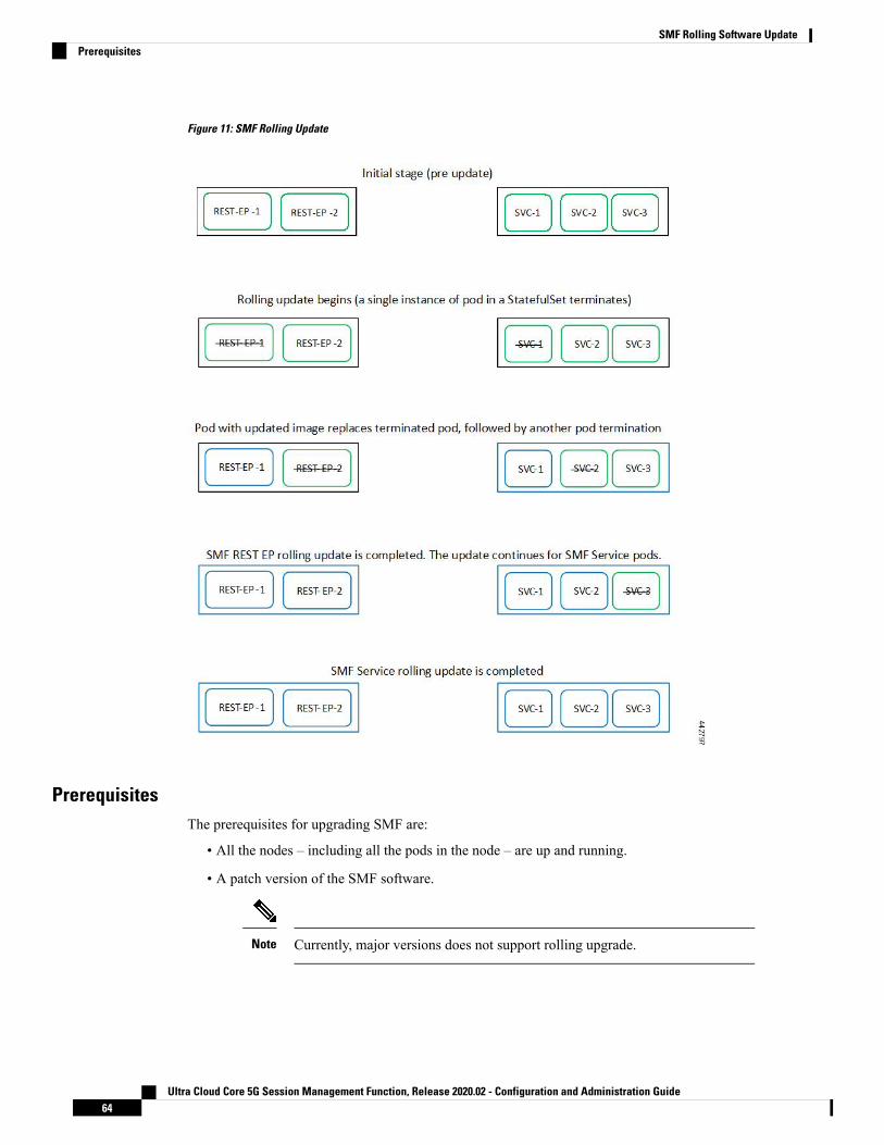
Figure 11: SMF Rolling Update
PrerequisitesThe prerequisites for upgrading SMF are:
• All the nodes – including all the pods in the node – are up and running.
• A patch version of the SMF software.
Currently, major versions does not support rolling upgrade.Note
Ultra Cloud Core 5G Session Management Function, Release 2020.02 - Configuration and Administration Guide64
SMF Rolling Software UpdatePrerequisites

Trigger rolling upgrade only when the CPU usage of the nodes is less than 50%.Important
SMF Health Check
You need to perform an health check to ensure that all the services are running and nodes are in ready state.To perform an health check:
1. Log in to master node and use the following configuration
kubectl get pods -n smikubectl get nodeskubectl get pod --all-namespaces -o widekubectl get pods -n smf-wsp -o widekubectl get pods -n cee-wsp -o widekubectl get pods -n smi-vips -o widehelm listkubectl get pods -A | wc -l
Ensure that all the services are running and nodes are in ready state before you proceed further.Important
Preparing the Upgrade
This section describes the procedure involved creating a backup configuration, logs and deployment files. Tobackup the files:
1. Log in to the SMI Cluster Manager Node as an ubuntu user.
2. Create a new directory for deployment.
Example:
test@smismf-cm01:~$ mkdir -p "temp_$(date +'%m%d%Y_T%H%M')" && cd "$_"
3. Move all the working files into the newly created deployment directory.
4. Untar the smf deployment file.
Example:
test@smi1smf01-cm01:~/temp_08072019_T1651$ tar -xzvf smf.2020.01.0-1.SPA.tgz././smf_REL_KEY-CCO_RELEASE.cer./cisco_x509_verify_release.py./smf.2020.01.0-1.tar./smf.2020.01.0-1.tar.signature.SPA./smf.2020.01.0-1.tar.SPA.README
5. Verify the downloaded image.
Example:
test@smi1smf01-cm01:~/temp_08072019_T1651$ cat smf.2020.01.0-1.tar.SPA.README
Ultra Cloud Core 5G Session Management Function, Release 2020.02 - Configuration and Administration Guide65
SMF Rolling Software UpdateSMF Health Check

Follow the procedure mentioned in the SPA.README file to verify the build before proceeding to the nextstep.
Important
Back Up Ops Center Configuration
This section describes the procedure involved in creating a backup of the Ops Center configurations.
To perform a backup of the Ops Center configurations:
1. Log in to SMI Cluster Manager node as an ubuntu user.
2. Run the following command to backup the SMIOps Center configuration to /home/ubuntu/smiops.backupfile.
ssh -p <port_number> admin@$(kubectl get svc -n smi | grep'.*netconf.*<port_number>' | awk '{ print $4 }') "show run | nomore"> smiops.backup_$(date +'%m%d%Y_T%H%M')
3. Run the following command to backup the CEEOps Center configuration to /home/ubuntu/ceeops.backupfile.
ssh admin@<cee-vip> "show run | nomore" > ceeops.backup_$(date+'%m%d%Y_T%H%M')
4. Run the following command to backup the SMF Ops Center configuration to/home/ubuntu/smfops.backup file.
ssh admin@<smf-vip> "show run | nomore" > smfops.backup_$(date+'%m%d%Y_T%H%M')
Back Up CEE and SMF Ops Center Configuration
This section describes the procedure involved in creating a backup of CEE and Ops Center configuration fromthe master node. To perform a backup of CEE and Ops Center configuration:
1. Log in to the master node as an ubuntu user.
2. Create a directory to backup the configuration files.
mkdir backups_$(date +'%m%d%Y_T%H%M') && cd "$_"
3. Backup the SMF Ops Center configuration and verify the line count of the backup files.
ssh -p <port_number> admin@$(kubectl get svc -n $(kubectl get namespaces| grep -oP 'smf-(\d+|\w+)') | grep <port_number> | awk '{ print $3}') "show run | nomore" > smfops.backup_$(date +'%m%d%Y_T%H%M') && wc-l smfops.backup_$(date +'%m%d%Y_T%H%M')
Example:
ubuntu@posmf-mas01:~/backups_09182019_T2141$ ssh -p 2024 admin@$(kubectl get svc -n$(kubectl get namespaces | grep -oP 'smf-(\d+|\w+)') | grep <port_number> | awk '{ print$3 }') "show run | nomore" > smfops.backup_$(date +'%m%d%Y_T%H%M') && wc -lsmfops.backup_$(date +'%m%d%Y_T%H%M')admin@<ipv4address>'s password: smf-OPS-PASSWORD334 smfops.backup
Ultra Cloud Core 5G Session Management Function, Release 2020.02 - Configuration and Administration Guide66
SMF Rolling Software UpdateBack Up Ops Center Configuration

4. Backup the CEE Ops Center configuration and verify the line count of the backup files.
ssh -p <port_number> admin@$(kubectl get svc -n $(kubectl get namespaces| grep -oP 'cee-(\d+|\w+)') | grep <port_number> | awk '{ print $3}') "show run | nomore" > ceeops.backup_$(date +'%m%d%Y_T%H%M') && wc-l ceeops.backup_$(date +'%m%d%Y_T%H%M')
Example:
ubuntu@posmf-mas01:~/backups_09182019_T2141$ ssh -p <port_number> admin@$(kubectl getsvc -n $(kubectl get namespaces | grep -oP 'cee-(\d+|\w+)') | grep <port_number> | awk'{ print $3 }') "show run | nomore" > ceeops.backup_$(date +'%m%d%Y_T%H%M') && wc -lceeops.backup_$(date +'%m%d%Y_T%H%M')admin@<ipv4address>'s password: CEE-OPS-PASSWORD233 ceeops.backup
5. Move the SMI Ops Center backup file (from the SMI Cluster Manager) to the backup directory.
scp $(grep cm01 /etc/hosts | awk '{ print $1}'):/home/ubuntu/smiops.backup_$(date +'%m%d%Y_T%H%M') .
Example:
ubuntu@posmf-mas01:~/backups_09182019_T2141$ scp $(grep cm01 /etc/hosts | awk '{ print$1 }'):/home/ubuntu/smiops.backup_$(date +'%m%d%Y_T%H%M') .ubuntu@<ipv4address>'s password: SMI-CM-PASSWORDsmiops.backup 100% 9346 22.3MB/s
00:00
6. Verify the line count of the backup files.
Example:
ubuntu@posmf-mas01:~/backups_09182019_T2141$ wc -l *233 ceeops.backup334 smfops.backup361 smiops.backup928 total
Staging a New SMF Image
This section describes the procedure involved in staging a new SMF image before initiating the upgrade.
To stage the new SMF image:
1. Download and verify the new SMF image.
2. Log in to the SMI Cluster Manager node as an ubuntu user.
3. Copy the images to Uploads directory.
sudo mv <smf_new_image.tar> /data/software/uploads
The SMI uses the new image present in the Uploads directory to upgrade.Note
4. Verify whether the image is picked up by the SMI for processing from the Uploads directory.
sleep 30; ls /data/software/uploads
Example:
Ultra Cloud Core 5G Session Management Function, Release 2020.02 - Configuration and Administration Guide67
SMF Rolling Software UpdateStaging a New SMF Image

ubuntu@posmf-cm01:~/temp_08072019_T1651$ sleep 30; ls /data/software/uploadsubuntu@posmf-cm01:~/temp_08072019_T1651$
5. Verify whether the images were successfully picked up and processed.
Example:
auser@unknown:$ sudo du -sh /data/software/packages/*1.6G /data/software/packages/cee.2019.075.3G /data/software/packages/smf.2019.08-0416K /data/software/packages/sample
The SMI must unpack the images into the packages directory successfully to complete the staging.Note
Triggering the Rolling Software UpgradeThe SMF utilizes the SMI Cluster Manager to perform a rolling software update. To update SMF using SMICluster Manager, use the following configurations:
Before you begin, ensure that SMF is up and running with the current version of the software.Important
1. Log in to SMI Cluster Manager Ops Center.
2. Download the latest TAR ball from the URL.
software-packages download url
Example:SMI Cluster Manager# software-packages download <url>
3. Verify whether the TAR balls are loaded.
software-packages list
Example:SMI Cluster Manager# software-packages list[ smf-2019-08-21 ][ sample ]
4. Update the product repository URL with the latest version of the product chart.
If the repository URL contains multiple versions, the Ops Center automatically selects the latest version.Note
configurecluster cluster_name
ops-centers app_name smf_instance_name
repository url
exitexit
Example:
Ultra Cloud Core 5G Session Management Function, Release 2020.02 - Configuration and Administration Guide68
SMF Rolling Software UpdateTriggering the Rolling Software Upgrade

SMI Cluster Manager# configSMI Cluster Manager(config)# clusters test2SMI Cluster Manager(config-clusters-test2)# ops-centers smf dataSMI Cluster Manager(config-ops-centers-smf/data)# repository <url>SMI Cluster Manager(config-ops-centers-smf/data)# exitSMI Cluster Manager(config-clusters-test2)# exit
5. Run the cluster sync command to update to the latest version of the product chart.
clusters cluster_name actions sync run
Example:SMI Cluster Manager# clusters test2 actions sync run
• The cluster synchronization updates the SMF Ops Center, which in turn updates the application pods(through helm sync command) one at a time automatically.
• When you trigger rolling upgrade on a specific pod, the SMF avoids routing new calls to that pod.
• The SMF honors in-progress call by waiting for 30 seconds before restarting the pod where rollingupgrade is initiated. Also, the SMF establishes all the in-progress calls completely within 30 secondsduring the upgrade period (maximum call-setup time is 10 seconds).
Important
• software-packages download url – Specifies the software packages to be downloaded throughHTTP/HTTPS.
• software-packages list – Specifies the list of available software packages.
• cluster – Specifies the K8s cluster.
• cluster_name – Specifies the name of the cluster.
• ops-centers app_name instance_name – Specifies the product Ops Center and instance. app_name isthe application name. instance_name is the name of the instance.
• repository url – Specifies the local registry URL for downloading the charts.
• actions – Specifies the actions performed on the cluster.
• sync run – Triggers the cluster synchronization.
Note
Monitoring the UpgradeYou can monitor the status of the upgrade through SMI Cluster Manager Ops Center. To monitor the upgradestatus, use the following configurations:
configureclusters cluster_name actions sync run debug trueclusters cluster_name actions sync logsmonitor sync-logs cluster_name
Ultra Cloud Core 5G Session Management Function, Release 2020.02 - Configuration and Administration Guide69
SMF Rolling Software UpdateMonitoring the Upgrade

clusters cluster_name actions sync statusexit
Example:
SMI Cluster Manager# clusters test1 actions sync runSMI Cluster Manager# clusters test1 actions sync run debug trueSMI Cluster Manager# clusters test1 actions sync logsSMI Cluster Manager# monitor sync-logs test1SMI Cluster Manager# clusters test1 actions sync status
• clusters cluster_name – Specifies the information about the nodes to be deployed. cluster_name is thename of the cluster.
• actions – Specifies the actions performed on the cluster.
• sync run – Triggers the cluster synchronization.
• sync logs – Shows the current cluster synchronization logs.
• sync status – Shows the current status of the cluster synchronization. debug true – Enters the debugmode.
• monitor sync logs – Monitors the cluster synchronization process.
Important
You can view the pod details after the upgrade through CEE Ops Center. For more information on pod details,see Viewing the Pod Details section.
Important
Viewing the Pod DetailsYou can view the details of the current pods through CEE Ops Center. To view the pod details, use thefollowing command (in CEE Ops Center CLI):
cluster pods instance_name pod_name detail
• cluster pods – Specifies the current pods in the cluster.
• instance_name – Specifies the name of the instance.
• pod_name – Specifies the name of the pod.
• detail – Displays the details of the specified pod.
Note
The following example displays the details of the pod named alertmanager-0 in the smf-data instance.
Example:
cee# cluster pods smf-data alertmanager-0 detaildetails apiVersion: "v1"kind: "Pod"metadata:annotations:
Ultra Cloud Core 5G Session Management Function, Release 2020.02 - Configuration and Administration Guide70
SMF Rolling Software UpdateViewing the Pod Details

alermanager.io/scrape: "true"cni.projectcalico.org/podIP: "<ipv4address/subnet>"config-hash: "5532425ef5fd02add051cb759730047390b1bce51da862d13597dbb38dfbde86"
creationTimestamp: "2020-02-26T06:09:13Z"generateName: "alertmanager-"labels:component: "alertmanager"controller-revision-hash: "alertmanager-67cdb95f8b"statefulset.kubernetes.io/pod-name: "alertmanager-0"
name: "alertmanager-0"namespace: "smf"ownerReferences:- apiVersion: "apps/v1"kind: "StatefulSet"blockOwnerDeletion: truecontroller: truename: "alertmanager"uid: "82a11da4-585e-11ea-bc06-0050569ca70e"
resourceVersion: "1654031"selfLink: "/api/v1/namespaces/smf/pods/alertmanager-0"uid: "82aee5d0-585e-11ea-bc06-0050569ca70e"
spec:containers:- args:- "/alertmanager/alertmanager"- "--config.file=/etc/alertmanager/alertmanager.yml"- "--storage.path=/alertmanager/data"- "--cluster.advertise-address=$(POD_IP):6783"env:- name: "POD_IP"valueFrom:fieldRef:apiVersion: "v1"fieldPath: "status.podIP"
image: "<path_to_docker_image>"imagePullPolicy: "IfNotPresent"name: "alertmanager"ports:- containerPort: 9093name: "web"protocol: "TCP"
resources: {}terminationMessagePath: "/dev/termination-log"terminationMessagePolicy: "File"volumeMounts:- mountPath: "/etc/alertmanager/"name: "alertmanager-config"
- mountPath: "/alertmanager/data/"name: "alertmanager-store"
- mountPath: "/var/run/secrets/kubernetes.io/serviceaccount"name: "default-token-kbjnx"readOnly: true
dnsPolicy: "ClusterFirst"enableServiceLinks: truehostname: "alertmanager-0"nodeName: "for-smi-cdl-1b-worker94d84de255"priority: 0restartPolicy: "Always"schedulerName: "default-scheduler"securityContext:fsGroup: 0runAsUser: 0
serviceAccount: "default"serviceAccountName: "default"
Ultra Cloud Core 5G Session Management Function, Release 2020.02 - Configuration and Administration Guide71
SMF Rolling Software UpdateViewing the Pod Details

subdomain: "alertmanager-service"terminationGracePeriodSeconds: 30tolerations:- effect: "NoExecute"key: "node-role.kubernetes.io/oam"operator: "Equal"value: "true"
- effect: "NoExecute"key: "node.kubernetes.io/not-ready"operator: "Exists"tolerationSeconds: 300
- effect: "NoExecute"key: "node.kubernetes.io/unreachable"operator: "Exists"tolerationSeconds: 300
volumes:- configMap:
defaultMode: 420name: "alertmanager"
name: "alertmanager-config"- emptyDir: {}name: "alertmanager-store"
- name: "default-token-kbjnx"secret:defaultMode: 420secretName: "default-token-kbjnx"
status:conditions:- lastTransitionTime: "2020-02-26T06:09:02Z"status: "True"type: "Initialized"
- lastTransitionTime: "2020-02-26T06:09:06Z"status: "True"type: "Ready"
- lastTransitionTime: "2020-02-26T06:09:06Z"status: "True"type: "ContainersReady"
- lastTransitionTime: "2020-02-26T06:09:13Z"status: "True"type: "PodScheduled"
containerStatuses:- containerID: "docker://821ed1a272d37e3b4c4c9c1ec69b671a3c3fe6eb4b42108edf44709b9c698ccd"
image: "<path_to_docker_image>"imageID: "docker-pullable://<path_to_docker_image>"lastState: {}name: "alertmanager"ready: truerestartCount: 0state:running:startedAt: "2020-02-26T06:09:05Z"
hostIP: "<host_ipv4address>"phase: "Running"podIP: "<pod_ipv4address>"qosClass: "BestEffort"startTime: "2020-02-26T06:09:02Z"
cee#
Ultra Cloud Core 5G Session Management Function, Release 2020.02 - Configuration and Administration Guide72
SMF Rolling Software UpdateViewing the Pod Details

C H A P T E R 6Pods and Services Reference
• Feature Summary and Revision History, on page 73• Feature Description, on page 74• Associating Pods to the Nodes, on page 80• Viewing the Pod Details and Status, on page 81
Feature Summary and Revision History
Summary DataTable 13: Summary Data
SMFApplicable Products or Functional Area
SMIApplicable Platform(s)
Enabled – Always-onFeature Default Setting
Not ApplicableRelated Changes in this Release
Not ApplicableRelated Documentation
Revision HistoryTable 14: Revision History
ReleaseRevision Details
Pre-2020.02.0First introduced.
Ultra Cloud Core 5G Session Management Function, Release 2020.02 - Configuration and Administration Guide73

Feature DescriptionThe SMF is built on the Kubernetes cluster strategy, which implies that it has adopted the native concepts ofcontainerization, high availability, scalability, modularity, and ease of deployment. To achieve the benefitsoffered by Kubernetes, SMF uses the construct that includes the components such as pods and services.
Depending on your deployment environment, the SMF deploys the pods on the virtual machines that youhave configured. Pods operate through the services that are responsible for the intrapod communications. Ifthe machine hosting the pods fail or experiences network disruption, the pods are terminated or deleted.However, this situation is transient and SMF spins new pods to replace the invalid pods.
The following workflow provides a high-level visibility into the host machines, and the associated pods andservices. It also represents how the pods interact with each other. The representation might defer based onyour deployment infrastructure.
Figure 12: Communication Workflow of Pods
Kubernetes deployment includes the kubectl command-line tool to manage the Kubernetes resources in thecluster. You can manage the pods, nodes, and services.
For generic information on the Kubernetes concepts, see the Kubernetes documentation.
For more information on the Kubernetes components in SMF, see the following.
• Pods
• Services
Ultra Cloud Core 5G Session Management Function, Release 2020.02 - Configuration and Administration Guide74
Pods and Services ReferenceFeature Description

PodsA pod is a process that runs on your Kubernetes cluster. Pod encapsulates a granular unit known as a container.A pod contains one or multiple containers.
Kubernetes deploys one or multiple pods on a single node which can be a physical or virtual machine. Eachpod has a discrete identity with an internal IP address and port space. However, the containers within a podcan share the storage and network resources.
The following tables list the SMF and Common Execution Environment (CEE) pod names and the hosts onwhich they are deployed depending on the labels that you assign. For information on how to assign the labels,see Associating Pods to the Nodes.
Table 15: SMF Pods
Host NameDescriptionPod Name
OAMFunctions as the confDAPI pod forthe SMF Ops Center.
api-smf-ops-center
OAMSupports Smart Licensing feature.base-entitlement-smf
ProtocolOperates as the pod to cache anysort of system information that willbe used by other pods as applicable.
cache-pod
SessionProvides an interface to the CDL.cdl-ep-session-c1
SessionPreserves the mapping of keys tothe session pods.
cdl-index-session-c1
SessionOperates as the CDL Session podto store the session data.
cdl-slot-session-c1
OAMContains the documentation.documentation
OAMHosts the etcd for the SMFapplication to store informationsuch as pod instances, leaderinformation, NF-UUID, endpoints,and so on.
etcd-smf-etcd-cluster
OAMContains the default dashboard ofapp-infra metrics in Grafana.
grafana-dashboard-app-infra
OAMContains the default dashboard ofCDL metrics in Grafana.
grafana-dashboard-cdl
OAMContains the default dashboard ofSMF-service metrics in Grafana.
grafana-dashboard-smf
ProtocolOperates as GTPC endpoint ofSMF.
gtpc-ep-n0
ProtocolHosts the Kafka details for the CDLreplication.
kafka
ProtocolOperates as Lawful Interceptendpoint of SMF.
li-ep-n0
Ultra Cloud Core 5G Session Management Function, Release 2020.02 - Configuration and Administration Guide75
Pods and Services ReferencePods

Host NameDescriptionPod Name
OAMOperates as the pod to facilitateOps Center actions like showcommands, configurationcommands, monitor protocolmonitor subscriber, and so on.
oam-pod
OAMActs as the SMF Ops Center.ops-center-smf-ops-center
OAMOperates as the utility pod for theSMF Ops Center.
smart-agent-smf-ops-center
ServicePerforms node level interactionssuch as N4 link establishment,management (heart-beat), and soon. Also, generates uniqueidentifiers such as UE IP address,SEID, CHF-ID, Resource URI, andso on.
smf-nodemgr-n0
ProtocolOperates as encoder and decoderof application protocols (PFCP,GTP, RADIUS, and so on) whoseunderlying transport protocol isUDP.
smf-protocol-n0
ProtocolOperates as RADIUS and DNSendpoint of SMF.
smf-radius-dns-n0
ProtocolOperates as REST endpoint of SMFfor HTTP2 communication.
smf-rest-ep-n0
ServiceContains main business logic ofSMF.
smf-service-n0
ProtocolOperates as proxy for all UDPmessages. Owns UDP client andserver functionalities.
smf-udp-proxy
OAMOperates as the utility pod for theSMF Ops Center.
swift-smf-ops-center
OAMAssists Kafka for topologymanagement.
zookeeper
Table 16: CEE Pods
Host NameDescriptionPod Name
OAMStores the history of active andresolved alerts.
alert-logger
OAMDuplicates alerts and sends outresolution of alerts when they areresolved in Prometheus.
alertmanager
Ultra Cloud Core 5G Session Management Function, Release 2020.02 - Configuration and Administration Guide76
Pods and Services ReferencePods

Host NameDescriptionPod Name
OAMFunctions as the confDAPI pod forthe CEE Ops Center.
api-cee-global-ops-center
OAMAssists to retrieve bulkstats savedby Prometheus containers.
bulk-stats
OAMContains the productdocumentation (API, CLI, and soon).
cee-global-product-documentation
All the nodes except ETCD nodes.Assists in retrieving the coredumps.
core-retriever
OAMContains the documentation(metrics and usage).
documentation
OAMAssists in collating Grafanametricson the dashboard.
grafana-dashboard-metrics
OAMContains the Grafana metrics forCEE.
grafana
OAMAssists in generating metrics aboutthe state of Kubernetes objects:node status, node capacity (CPUand memory), and so on.
kube-state-metrics
All the nodes except ETCD nodes.Assists in retrieving Kernel,Kubelet, and Container level logsthrough output to JournalD driver.
logs-retriever
All the nodes.Exports the node metrics.node-exporter
OAMProvides NETCONF and CLIinterface to the application.
ops-center-cee-global-ops-center
All the nodes except ETCD nodes.Provisions the local storagevolume.
path-provisioner
OAMPgpool is a middleware that worksbetween PostgreSQL servers and aPostgreSQL database.
pgpool
OAMStorage of alerts and Grafanadashboards.
postgres
OAMStores all metrics and generatesalerts by alerting rules.
prometheus-hi-res
OAMContains the default alerting rulesand recording rules for Prometheus.
prometheus-rules
OAMSynchronizes the Prometheusscrape configuration.
prometheus-scrapeconfigs-synch
OAMProvisions the local storagevolume.
pv-manager
Ultra Cloud Core 5G Session Management Function, Release 2020.02 - Configuration and Administration Guide77
Pods and Services ReferencePods

Host NameDescriptionPod Name
OAMProvisions the local storagevolume.
pv-provisioner
OAMAssists in creating and deletingdebug package.
show-tac-manager
OAMOperates as the utility pod for theCEE Ops Center.
smart-agent-cee-global-ops-center
OAMSends the SNMP traps based ontriggered alerts.
snmp-trapper
OAMOperates as the utility pod for theCEE Ops Center
swift-cee-global-ops-center
OAMImplements the Thanos query forPrometheus HA.
thanos-query-hi-res
All the nodes except ETCD nodes.Assists in log forwarding to theexternal logs collector.
fluentbit
ServicesThe SMF configuration is composed of several microservices that run on a set of discrete pods. Microservicesare deployed during the SMF deployment. SMF uses these services to enable communication between thepods. When interacting with another pod, the service identifies the pod's IP address to initiate the transactionand acts as an endpoint for the pod.
The following table describes the SMF services and the pod on which they run.
Table 17: SMF Services and Pods
DescriptionPod NameService Name
Supports Smart Licensing feature.base-entitlement-smfbase-entitlement-smf
Responsible for the CDL session.cdl-ep-session-c1datastore-ep-session
Responsible for sending thenotifications from the CDL to thesmf-service through smf-rest-ep.
smf-rest-epdatastore-notification-ep
Responsible for the secure CDLconnection.
cdl-ep-session-c1datastore-tls-ep-session
Responsible for the SMFdocuments.
documentationdocumentation
Responsible for pod discoverywithin the namespace.
etcd-smf-etcd-cluster-0,etcd-smf-etcd-cluster-1,etcd-smf-etcd-cluster-2
etcd
Responsible for synchronization ofdata among the etcd cluster.
etcd-smf-etcd-cluster-0etcd-smf-etcd-cluster-0
Ultra Cloud Core 5G Session Management Function, Release 2020.02 - Configuration and Administration Guide78
Pods and Services ReferenceServices

DescriptionPod NameService Name
Responsible for synchronization ofdata among the etcd cluster.
etcd-smf-etcd-cluster-1etcd-smf-etcd-cluster-1
Responsible for synchronization ofdata among the etcd cluster.
etcd-smf-etcd-cluster-2etcd-smf-etcd-cluster-2
Responsible for the defaultdashboard of app-infra metrics inGrafana.
grafana-dashboard-app-infragrafana-dashboard-app-infra
Responsible for the defaultdashboard of CDL metrics inGrafana.
grafana-dashboard-cdlgrafana-dashboard-cdl
Responsible for the defaultdashboard of SMF-service metricsin Grafana.
grafana-dashboard-smfgrafana-dashboard-smf
Responsible for inter-podcommunication with GTP-C pod.
gtpc-ep-n0gtpc-ep
Manages the Ops Center API.api-smf-ops-centerhelm-api-smf-ops-center
Processes the Kafka messages.kafkakafka
Responsible for lawful-interceptinteractions.
li-ep-n0li-ep
Responsible for leveraging OpsCenter credentials by otherapplications like Grafana.
ops-center-smf-ops-centerlocal-ldap-proxy-smf-ops-center
Responsible to facilitate Execcommands on the Ops Center.
oam-podoam-pod
Manages the SMF Ops Center.ops-center-smf-ops-centerops-center-smf-ops-center
To access SMF Ops Center withexternal IP address.
ops-center-smf-ops-centerops-center-smf-ops-center-expose-cli
Responsible for the SMF OpsCenter API.
smart-agent-smf-ops-centersmart-agent-smf-ops-center
Responsible for routing incomingHTTP2 messages to REST-EPpods.
smf-rest-epsmf-sbi-service
Responsible for routing incomingN10 messages to REST-EP pods.
smf-rest-epsmf-n10-service
Responsible for routing incomingN11 messages to REST-EP pods.
smf-rest-epsmf-n11-service
Responsible for routing incomingN40 messages to REST-EP pods.
smf-rest-epsmf-n40-service
Responsible for routing incomingN7 messages to REST-EP pods.
smf-rest-epsmf-n7-service
Ultra Cloud Core 5G Session Management Function, Release 2020.02 - Configuration and Administration Guide79
Pods and Services ReferenceServices

DescriptionPod NameService Name
Responsible for routing incomingNRF messages to REST-EP pod.
smf-rest-epsmf-nrf-service
Responsible for inter-podcommunication with smf-nodemgrpod.
smf-nodemgrsmf-nodemgr
Responsible for inter-podcommunication with smf-protocolpod
smf-protocolsmf-protocol
Responsible for inter-podcommunicationwith smf-radius-dnspod
smf-radius-dnssmf-radius-dns
Responsible for inter-podcommunication with smf-rest-eppod
smf-rest-epsmf-rest-ep
Responsible for inter-podcommunication with smf-servicepod
smf-servicesmf-service
Operates as the utility pod for theSMF Ops Center
swiftswift-smf-ops-center
Assists Kafka for topologymanagement
zookeeperzookeeper
Assists Kafka for topologymanagement
zookeeperzookeeper-service
Associating Pods to the NodesThis section describes how to associate a pod to the node based on their labels.
After you have configured a cluster, you can associate pods to the nodes through labels. This associationenables the pods to get deployed on the appropriate node based on the key-value pair.
Labels are required for the pods to identify the nodes where they must get deployed and to run the services.For example, when you configure the protocol-layer label with the required key-value pair, the pods aredeployed on the nodes that match the key-value pair.
1. To associate pods to the nodes through the labels, use the following configuration:
configurelabelcdl-layerkey key_value
value value
oam-layerkey key_value
value value
Ultra Cloud Core 5G Session Management Function, Release 2020.02 - Configuration and Administration Guide80
Pods and Services ReferenceAssociating Pods to the Nodes

protocol-layerkey key_value
value value
service-layerkey key_value
value value
end
NOTES:
• If you opt not to configure the labels, then SMF assumes the labels with the default key-value pair.
• label { cdl-layer { key key_value | value value }: Configures the key value pair for CDL.
• oam-layer { key key_value | value value }: Configures the key value pair for OAM layer.
• protocol-layer { key key_value | value value }: Configures the key value pair for protocol layer.
• service-layer { key key_value | value value }: Configures the key value pair for the service layer.
Viewing the Pod Details and StatusIf the service requires additional pods, SMF creates and deploys the pods. You can view the list of pods thatare participating in your deployment through the SMF Ops Center.
You can run the kubectl command from the master node to manage the Kubernetes resources.
1. To view the comprehensive pod details, use the following command.
kubectl get pods -n smf pod_name -o yaml
The pod details are available in YAML format. The output of this command results in the following information:
• The IP address of the host where the pod is deployed.
• The service and application that is running on the pod.
• The ID and name of the container within the pod.
• The IP address of the pod.
• The current state and phase in which the pod is.
• The start time from which pod is in the current state.
Use the following command to view the summary of the pod details.
kp get pods -n smf_namespace -o wide
StatesUnderstanding the pod's state lets you determine the current health and prevent the potential risks. The followingtable describes the pod's states.
Ultra Cloud Core 5G Session Management Function, Release 2020.02 - Configuration and Administration Guide81
Pods and Services ReferenceViewing the Pod Details and Status

Table 18: Pod States
DescriptionState
The pod is healthy and deployed on a node.
It contains one or more containers.
Running
The application is in the process of creating thecontainer images for the pod.
Pending
Indicates that all the containers in the pod aresuccessfully terminated. These pods cannot berestarted.
Succeeded
One ore more containers in the pod have failed thetermination process. The failure occurred as thecontainer either exited with non zero status or thesystem terminated the container.
Failed
The state of the pod could not be determined.Typically, this could be observed because the nodewhere the pod resides was not reachable.
Unknown
Ultra Cloud Core 5G Session Management Function, Release 2020.02 - Configuration and Administration Guide82
Pods and Services ReferenceStates

C H A P T E R 73GPP Specification Compliance for SMFInterfaces
This chapter covers the following topics:
• Feature Summary and Revision History, on page 83• Feature Description, on page 84• Configuring Interfaces, on page 85• Sample Configuration, on page 87
Feature Summary and Revision History
Summary DataTable 19: Summary Data
SMFApplicable Product(s) or Functional Area
SMIApplicable Platform(s)
Enabled – Always-onDefault Setting
Not ApplicableRelated Changes in this Release
Not ApplicableRelated Documentation
Revision HistoryTable 20: Revision History
ReleaseRevision Details
Pre-2020.02.0First introduced.
Ultra Cloud Core 5G Session Management Function, Release 2020.02 - Configuration and Administration Guide83

Feature DescriptionThe SMF currently supports either the December 2018 compliance version of 3GPP specification or the June2019 compliance version of 3GPP specification for the SMF interfaces such as N1, N2, N4, N7, N10, N11,N40, and Nnrf. The SMF processes the messages from these interfaces as per the compliance profile configuredfor the corresponding services. For information on the compliance profile configurations, see the ConfiguringInterfaces, on page 85 section.
Currently, only IE encoding and decoding is supported. The existing features work with the June 2019specification versions. No additional features in the June 2019 version are supported.
The SMF continues to support the older versions of 3GPP specifications and the compliance profileconfiguration controls the same for the SMF interfaces.
Note
Standards ComplianceThe SMF is one of the control plane (CP) NFs of the 5G core network. The SMF uses different interfaces tocommunicate with the other NFs or nodes. For example, the N4 interface exists between the SMF and UserPlane Function (UPF). Each of the SMF interfaces comply to a specific version of the 3GPP specificationdepending on the compliance version supported.
Use the following table to determine the compliance mapping of each SMF interface and the 3GPP Standardsspecification versions.
Version3GPP SpecificationRelationshipInterface
For December 2018ComplianceSupport: 15.2.0
For June 2019ComplianceSupport: 15.4.0
29.518
29.502
Between AMF and SMFN11
For December 2018ComplianceSupport: 15.2.0
For June 2019ComplianceSupport: 15.4.0
29.512Between PCF and SMFN7
For December 2018ComplianceSupport: 15.2.0
For June 2019ComplianceSupport: 15.4.0
29.244Between UPF and SMFN4
Ultra Cloud Core 5G Session Management Function, Release 2020.02 - Configuration and Administration Guide84
3GPP Specification Compliance for SMF InterfacesFeature Description

Version3GPP SpecificationRelationshipInterface
For December 2018ComplianceSupport: 15.0.0
For June 2019ComplianceSupport: 15.4.0
29.510Between NRF and SMFNnrf
For December 2018ComplianceSupport: 15.2.1
For June 2019ComplianceSupport: 15.4.0
29.503Between UDM and SMFN10
For December 2018ComplianceSupport: 15.1.0
For June 2019ComplianceSupport: 15.3.0
32.291Between SMF and CHFN40
For December 2018ComplianceSupport: 15.2.0
For June 2019ComplianceSupport:15.4.0
24.501Between UE and SMFN1
For December 2018ComplianceSupport: 15.2.0
For June 2019ComplianceSupport:15.4.0
38.314Between RAN and SMFN2/NGAP
Configuring InterfacesUse the following commands to configure the SMF interfaces in compliance with the 3GPP specifications.
configureprofile compliance profile_name
servicen1 version full version_format spec spec_version uri_version uri_version
n2 version full version_format spec spec_version uri_version uri_version
namf-comm version full version_format spec spec_version uri_version
Ultra Cloud Core 5G Session Management Function, Release 2020.02 - Configuration and Administration Guide85
3GPP Specification Compliance for SMF InterfacesConfiguring Interfaces

uri_versionnchf-convergedcharging version full version_format spec spec_version
uri_version uri_version
nnrf-disc version full version_format spec spec_version uri_versionuri_version
nnrf-nfm version full version_format spec spec_version uri_versionuri_version
npcf-smpolicycontrol version full version_format spec spec_version
uri_version uri_version
nsmf-pdusession version full version_format spec spec_version
uri_version uri_version
nudm-sdm version full version_format spec spec_version uri_versionuri_version
nudm-uecm version full version_format spec spec_version uri_versionuri_version
range!!
Service selection is based only on the specification version. In future releases, the full API version will beused.
Important
NOTES:
• version full: Specifies the API full version for each service in the following format:
<Major-version>.<Minor-version>.<patch-version>.[alpha-<draft-number>]
The format is specified in 3GPP TS 29.501 V15.2.0, section 4.3.1.1.
• version spec: Specifies the 3GPP specification version number. It can be one of the following values:
• 15.0.0
• 15.1.0
• 15.2.0
• 15.2.1
• 15.4.0
Configuring the 3GPP specification version value depends on the SMF interface.Not all the preceding versions are options for the SMF interfaces. Only acombination of the preceding versions exist as options for the 3GPP versioncompliance configuration. For details on the compliance version, see the StandardsCompliance, on page 84 section.
Important
For example, to support 3GPP June 2019 specification compliance for the N7 (PCF) interface, configurethe specification version as 15.4.0.
The default version number depends on the SMF interface. For example, the default version is 15.2.0for the N7 interface. Similarly, for the N10 interface, the default version is 15.2.1.
Ultra Cloud Core 5G Session Management Function, Release 2020.02 - Configuration and Administration Guide86
3GPP Specification Compliance for SMF InterfacesConfiguring Interfaces

• version uri: Specifies the API version URI for each service in the following format:
"v" concatenated with a number
It can be both v1 and v2, or either v1 or v2.
For example, for the compliance version 15.4.0 in the NRF configuration for the service typenudm-sdm/nudm-uecm,mandate the configuration of the uri-version in the versions to ‘v2’. For complianceversion 15.2.1, this configuration is optional.
For example, version v1: (- url: '{apiRoot}/nsmf-pdusession/v1')
• service: The service names as specified in 3GPP TS 29.510 V15.2.0, section 6.1.6.3.11.
Sample ConfigurationThe following is a sample output of the interface configuration:product smf(config-compliance-comp1)# show fullprofile compliance comp1
service nsmf-pdusessionversion uri v1version full 1.0.0version spec 15.2.0
product smf(config-service-nsmf-pdu)# compliance-profile comp1product smf(config)# show full-configuration profile smfprofile smf smf1
service name nsmf-pdu--------------------------------------------------------------compliance-profile comp1--------------------------------------------------------------
!!
Ultra Cloud Core 5G Session Management Function, Release 2020.02 - Configuration and Administration Guide87
3GPP Specification Compliance for SMF InterfacesSample Configuration

Ultra Cloud Core 5G Session Management Function, Release 2020.02 - Configuration and Administration Guide88
3GPP Specification Compliance for SMF InterfacesSample Configuration

C H A P T E R 84G to 5G Data Session Handover Support
• Feature Summary , on page 89• Feature Description, on page 90• How it Works, on page 90• Emergency SoS Support, on page 101
Feature Summary
Summary DataTable 21: Summary Data
SMFApplicable Product(s) or Functional Area
SMIApplicable Platform(s)
Disabled - Configuration RequiredFeature Default Setting
Not ApplicableRelated Changes in this Release
Not ApplicableRelated Documentation
Revision HistoryTable 22: Revision History
ReleaseRevision Details
Pre-2020.02.0First introduced.
Ultra Cloud Core 5G Session Management Function, Release 2020.02 - Configuration and Administration Guide89

Feature DescriptionThe SMF leverages the 3GPP provision for the UEs that can support both 5G and 4G NAS to connect toE-UTRAN and 5G core network. With this provision, the SMF includes the EPS interworking support andacts as PGW-C+SMF. The SMF uses the S5 or S8 interface to receive the 4G Session Creation Request. Theinterfaces, such as the Gx, Gy, or Gz, that are used for a 4G session creation are replaced with the corresponding5G core SBI interfaces, such as the NPCF and NCHF.
After a PDU session is created on PGW-C+SMF through E-UTRAN,MME, and S-GW, the SMF can performthe 4G to 5G data session handover.
How it WorksTo interwork with EPS, a UE that supports both 5GC and EPS NAS works in one of the following modes:
• Single-registration Mode—In this mode, the UE has only one active MM state, which is either the RMstate in 5GC or EMM state in EPS. In addition, this state is either in 5GC NAS mode or in EPS NASmode when connected to 5GC or EPS, respectively.
• Dual-registrationMode—In this mode, the UE handles independent registrations for 5GC and EPS usingseparate RRC connections. The UE may be registered to 5GC only, EPS only, or to both 5GC and EPS.
ArchitectureThis section describes the network architecture for the EPS-5G Core interworking.
Call FlowsThis section describes the following call flows.
Ultra Cloud Core 5G Session Management Function, Release 2020.02 - Configuration and Administration Guide90
4G to 5G Data Session Handover SupportFeature Description

• EPS to 5G Handover with N26 Interface – Preparation Call Flow
• EPS to 5G Handover with N26 Interface – Execution Call Flow
• UE Idle Mode Mobility from EPS to 5GS using N26 Interface – PDU is in Inactive State
• UE Idle Mode Mobility from EPS to 5GS using N26 interface – User Plane Connection ReactivationRequest
EPS to 5G Handover with N26 Interface – Preparation Call FlowThis section describes the call flow of the preparation of the EPS to 5G Handover with the N26 interface.
Figure 13: Preparation of the EPS to 5G Hand-over with the N26 Interface Call Flow
Table 23: Preparation of the EPS to 5G Hand-over with the N26 Interface Call Flow Description
DescriptionStep
Call handover initiation starts from UE and E-UTRAN toward each other, proceedsfrom E-UTRAN to the S-GW, and then for roaming calls, call handover initiationproceeds from S-GW to the UPF+P-GW-U.
1
The E-UTRAN sends the Handover Call Request to the MME.2
The MME forwards the Relocation Request to the AMF.3
Ultra Cloud Core 5G Session Management Function, Release 2020.02 - Configuration and Administration Guide91
4G to 5G Data Session Handover SupportEPS to 5G Handover with N26 Interface – Preparation Call Flow

DescriptionStep
TheAMF invokes the Nsmf_PDUSession_CreateSMContext service operation on SMF.The PGW-C+SMF address identifies this service operation. The service operations canbe UE EPS PDN Connection, AMF ID, or Direct Forwarding Flag. The AMF thenindicates the handover preparation to avoid switching the UP path. The SMF searchesfor the corresponding PDU session that is based on EPS Bearer Contexts. The AMFincludes Direct Forwarding Flag to inform the SMF of the applicability of indirect dataforwarding.
4
If you have deployed the dynamic PCC, the SMF+ PGW-C initiates the SMF-initiatedSM Policy Modification toward the PCF.
Cisco SMF does not support this step in this release.Important
5
The PGW-C+SMF sends the N4 SessionModification to PGW-U+UPF to establish theCN tunnel for a PDU Session. The PGW-U+UPF receives the uplink packets fromNG-RAN. This step involves creating uplink PDRs and FARs for the 5G session alongwith the QFIs that are mapped from the existing 4G bearers.
6
The PGW-C+SMF sends a Nsmf_PDUSession_CreateSMContext Response to theAMF. This response includes PDU Session ID, S-NSSAI, and N2 SM Information.
The N2 SM Information includes PDU Session ID, S-NSSAI, QFIs, QoS Profiles, EPSBearer Setup List, mapping between EBIs and QFIs, CN Tunnel information, and causecode details.
The SMF includesmapping between EBIs andQFIs as the N2 SM Information container.If the P-GW-C+SMF determines that session continuity from EPS to 5GS is notsupported for the PDU session, then the P-GW-C+SMF does not provide the SessionManager information for the corresponding PDU session. However, the P-GW-C+SMFincludes the cause code details for rejecting the PDU session transfer in the N2 SMinformation.
7
The V-SMF and V-UPF establish an N4 session with each other.8
The AMF sends the Handover Request to NG-RAN.9
The NG-RAN sends the Handoff Request Acknowledgment for the received HandoverRequest to the AMF.
10
The AMF sends a Nsmf_PDUSession_UpdateSMContext Request, T-RAN SM N3forwarding information list message to the SMF for updating the N3 tunnel information.
The Nsmf_PDUSession_UpdateSMContext request includes a PDU Session ID,S-NSSAI, and N2 SM Information. The tunnel information exists in the NGAP IE DLForwarding UP TNL Information of the Handoff Request Acknowledgment that isreceived from NG-RAN.
11
The SMF+PGW-C performs the N4 sessionmodification towardUPF+PGW-U to createthe indirect tunnel to forward the DL data from eNodeB to NG-RAN. This step includescreating UL PDRs for the redirected DL data and associating FARswith them to forwardthe FARs to NG-RAN. The mapping of these PDRs and FARs is based on QFI and thecorresponding bearer ID.
12
Ultra Cloud Core 5G Session Management Function, Release 2020.02 - Configuration and Administration Guide92
4G to 5G Data Session Handover SupportEPS to 5G Handover with N26 Interface – Preparation Call Flow

DescriptionStep
The PGW-C+SMF sends the Nsmf_PDUSession_UpdateSMContext Response to theAMF. This response includes PDU Session ID, EPS Bearer Setup List, and CN tunnelinformation for data forwarding. At this point, the indirect tunnels are established forDL data forwarding.
13
The AMF sends the Forward Relocation Response to the MME.14
The MME sends the creation request for the indirect data forwarding tunnel to theS-GW. The S-GW sends the response for the indirect data forwarding tunnel to theMME.
15
EPS to 5G Handover with N26 Interface – Execution Call FlowThis section describes the call flow of the execution of the EPS to 5G Handover with the N26 interface.
Figure 14: Execution of the EPS to 5G Hand-over with the N26 Interface Call Flow
Table 24: Execution of the EPS to 5G Hand-over with the N26 Interface Call Flow Description
DescriptionStep
Call handover initiation starts from the UE and E-UTRAN toward each other, proceedsfrom E-UTRAN to S-GW, and then for roaming calls, call handover initiation proceedsfrom S-GW to the UPF+P-GW-U.
The MME sends the handover command to E-UTRAN.
1
The E-UTRAN sends the handover command to the UE.2
Ultra Cloud Core 5G Session Management Function, Release 2020.02 - Configuration and Administration Guide93
4G to 5G Data Session Handover SupportEPS to 5G Handover with N26 Interface – Execution Call Flow

DescriptionStep
The UE sends the confirmation message to NG-RAN for the received handover to5G-RAN.
3
The NG-RAN sends the Handover Notification message to the AMF.4
The AMF sends the Forward Relocation Complete Notification to the MME.5
The MME sends the Acknowledgment Response for the received Forward RelocationComplete Notification.
6
The AMF sends Nsmf_PDUSession_UpdateSMContext Request to SMF +PGW-C.This request includes Handover Complete Indication for PDU Session ID details. Forindirect forwarding, a timer in SMF+PGW-C starts to check when resources in UPFare to be released.
7
The SMF performs N4 Modification Request with UPF+PGW-U to update the DLtunnel information for the FARs that are associated with DL PDRs of the 5G session.The DL data path is activated. At this point, the indirect tunnel also exists.
8
The SMF informs PCF of the RAT type change.
Cisco SMF does not support this step in this release.Important
9
The SMF sends Nsmf_PDUSession_UpdateSMContext Response, with PDU SessionID, to SMF. The SMF confirms the reception of Handover Complete.
10
After the timer that started in Step 7 expires, the SMF sends N4 Modification Requestto UPF. This request is to remove the PDRs and FARs that are associated with theindirect data tunnel.
11
The UE starts the EPS to 5GS mobility registration procedure and sends it to H-PCF.12
The E-UTRAN performs the resource cleanup in EPC by MME.13
UE Idle Mode Mobility from EPS to 5GS using N26 InterfaceSMF and PGW-C supports EPS to 5GS Idle Mode Mobility procedure. For Idle Mode Mobility from EPS to5GS, UE performs Mobility Registration Update Procedure with AMF. AMF and SMF retrieves MM andSM context from EPC and moves UE context from EPS to 5GS by interacting with other core NFs.
This feature enables the EPS and 5GS core network elements to support the following use cases during EPSto 5GS Idle Mode Mobility procedure.
• UE idle mode mobility from EPS to 5GS using N26 interface - PDU session in inactive state
• UE idle modemobility from EPS to 5GS using N26 interface - User Plane connection reactivation request
PDU Session is in Inactive State
The following call flows captures information on UE IdleModeMobility from EPS to 5GS using N26 Interfacewhen PDU session is in inactive state.
Ultra Cloud Core 5G Session Management Function, Release 2020.02 - Configuration and Administration Guide94
4G to 5G Data Session Handover SupportUE Idle Mode Mobility from EPS to 5GS using N26 Interface

Figure 15: PDU Session in Inactive State
Table 25: PDU Session in Inactive State
DescriptionStep
AMF sends a POST request towards SMF/PGW-C of each UE EPS PDN connectionwith following information:
• UE EPS PDN connection, including the EPS bearer contexts, received from theMME, representing the individual SM context to be created.
• EPS Bearer Context Status attribute, indicating the status of all the EPS bearercontexts in the UE, if corresponding information is received in the RegistrationRequest from the UE.
1
Upon receipt of such a request, if:
• a corresponding PDU session is found based on the EPS bearer contexts.
• the default EPS bearer context of the corresponding PDU session is not reportedas inactive by the UE in the EPS Bearer Connection Status attribute, if received;and
• it is possible to proceed with moving the PDN connection to 5GS.
2
Ultra Cloud Core 5G Session Management Function, Release 2020.02 - Configuration and Administration Guide95
4G to 5G Data Session Handover SupportPDU Session is in Inactive State

DescriptionStep
SMF returns a 201 Created response including the following information:
• PDU Session ID corresponding to the default EPS bearer ID of the EPS PDNconnection.
• Allocated EBI List, containing the EBI(s) allocated to the PDU session.
The Location header present in the POST response contains the URI of the created SMcontext resource.
AMF stores the association of the PDU Session ID and the SMF ID, and allocatedEBI(s) associated to the PDU Session ID.
If the EPS Bearer Context Status attribute is received in the request, the SMF checkswhether some EPS bearer(s) of the corresponding PDU session have been deleted bythe UE but not notified to the EPS. If so, SMF releases these EPS bearers, correspondingQoS rules and QoS flow level parameters locally.
2a
SMF returns 4xx/5xx failure response if:
• SMF determines that seamless session continuity fromEPS to 5GS is not supportedfor the PDU session. SMF sets the cause attribute in the Problem Details structureto NO_EPS_5GS_CONTINUITY.
• The default EPS Bearer Context of the PDU session is reported as inactive by theUE in the EPS Bearer Context Status attribute. SMF sets the cause attribute in theProblem Details structure to DEFAULT_EPS_BEARER_INACTIVE.
2b
User Plane Connection Reactivation Request
The following call flows captures information on UE idle mode mobility from EPS to 5GS with UP (UserPlane) connection reactivation using N26 interface.
Ultra Cloud Core 5G Session Management Function, Release 2020.02 - Configuration and Administration Guide96
4G to 5G Data Session Handover SupportUser Plane Connection Reactivation Request

Figure 16: User Plane Connection Reactivation Request
Table 26: User Plane Connection Reactivation Request
DescriptionStep
AMF sends a POST request towards SMF/PGW-C of each UE EPS PDN connectionwith following information:
• UE EPS PDN connection, including the EPS bearer contexts, received from theMME, representing the individual SM context to be created.
• the PDU Sessions Activate List attribute, including the PDU Session ID of allthe PDU session(s) to be re-activated.
• EPS Bearer Context Status attribute, indicating the status of all the EPS bearercontexts in the UE, if corresponding information is received in the RegistrationRequest from the UE.
1
Upon receipt of such a request, if:
• a corresponding PDU session is found based on the EPS bearer contexts.
• the default EPS bearer context of the corresponding PDU session is not reportedas inactive by the UE in the EPS Bearer Context attribute, if received; and
• it is possible to proceed with moving the PDN connection to 5GS.
2
Ultra Cloud Core 5G Session Management Function, Release 2020.02 - Configuration and Administration Guide97
4G to 5G Data Session Handover SupportUser Plane Connection Reactivation Request

DescriptionStep
SMF returns a 201 Created response including the following information:
• PDU Session ID corresponding to the default EPS bearer ID of the EPS PDNconnection.
• Allocated EBI List, containing the EBI(s) allocated to the PDU session.
and, if the PDU session that is derived by the SMF based on the EPS bearer contextswas requested to be re-activated, i.e. if the PDU Session ID was present in the PDUSessions Activate List,
• the User Plane Connection State attribute is set to ACTIVATING.
• N2 SM information to request the 5G-AN to assign resources to the PDU session(PDU Session Resource Setup Request Transfer), including the transport layeraddress and tunnel endpoint of the uplink termination point for the user planedata for this PDU session (i.e. UPF's GTP-U F-TEID for uplink traffic).
The Location header present in the POST response contains the URI of the createdSM context resource.
AMF stores the association of the PDU Session ID and the SMF ID, and allocatedEBI(s) associated to the PDU Session ID.
If the EPS Bearer Context Status attribute is received in the request, the SMF checkswhether some EPS bearer(s) of the corresponding PDU session have been deletedby the UE but not notified to the EPS. If so, SMF releases these EPS bearers,corresponding QoS rules and QoS flow level parameters locally.
2a
SMF returns 4xx/5xx failure response if:
• SMF determines that seamless session continuity from EPS to 5GS is notsupported for the PDU session. SMF sets the cause attribute in the ProblemDetails structure to NO_EPS_5GS_CONTINUITY.
• The default EPS Bearer Context of the PDU session is reported as inactive bythe UE in the EPS Bearer Context Status attribute. SMF sets the cause attributein the Problem Details structure to DEFAULT_EPS_BEARER_INACTIVE.
2b
Ultra Cloud Core 5G Session Management Function, Release 2020.02 - Configuration and Administration Guide98
4G to 5G Data Session Handover SupportUser Plane Connection Reactivation Request

DescriptionStep
If the SMF returns a 200 OK response, the AMF subsequently updates the SM contextin the SMF by sending POST request with the following information:
• N2 SM information received from the 5G-AN (PDU Session Resource SetupResponse Transfer IE), including the transport layer address and tunnel endpointof one or two downlink termination point(s). It also includes the associated listof QoS flows for this PDU session (i.e. 5G-AN's GTP-U F-TEID(s) for downlinktraffic), if the 5G-AN succeeded in establishing resources for the PDU sessions;or
• N2 SM information received from the 5G-AN (PDU Session Resource SetupUnsuccessful Transfer IE), including the Cause of the failure, if resources failedto be established for the PDU session.
Upon receipt of this request, the SMF:
• Updates the UPF with the 5G-AN's F-TEID(s) and sets the User PlaneConnection State attribute to ACTIVATED, if the 5G-AN succeeds inestablishing resources for the PDU sessions; or
• Considers that the activation of the User Plane connection has failed and setsthe User Plane Connection State attribute to DEACTIVATED.
3
SMF returns a 200 OK response including the User Plane Connection State attributerepresenting the final state of the user plane connection.
4
Message Flows
The following message flow describes the different scenarios of idle mode mobility procedure across 5GSnetwork elements and subscriber.
Ultra Cloud Core 5G Session Management Function, Release 2020.02 - Configuration and Administration Guide99
4G to 5G Data Session Handover SupportMessage Flows

Figure 17: Message Flow across 5GS NEs and Subscriber
Standards ComplianceThe SMF Support for 4G to 5G Data Session Handover feature complies with the following standard:
• 3GPP TS 23.502 V15.2.0 (2018-09)
LimitationsIn this release, this feature has the following limitations:
• SMF supports N26 4G to 5G handoff with single UPF, which implies that UPF selection and UPFmodification are not supported.
• SMF does not support PCF trigger.
Ultra Cloud Core 5G Session Management Function, Release 2020.02 - Configuration and Administration Guide100
4G to 5G Data Session Handover SupportStandards Compliance

• SMF does not support charging and PCF integration.
• SMF does not support the roaming scenario.
Emergency SoS Support
Feature DescriptionThe Emergency SoS Support feature enables the co-located cloud-native SMF and PGW-C to support SoSemergency over LTE for subscribers camped on the 4G network and SoS emergency service fallback to LTEfor subscribers camped on the 5G network.
The Emergency SoS Support feature supports the following functionalities:
• Provides a new configuration to skip UDM interaction.
• Enables an emergency PDN connection creation in 4G (LTE) for PGW-C.
• Supports emergency service fallback to LTE requirement for SMF serving subscriber in NR.
• Supports interworking with an existing charging interface failure handling to ‘continue’ emergency callcreation upon failure.
• Supports interworking with an existing secondary authentication using radius to skip radius authenticationfor emergency calls when not configured.
• Provides inter-RAT handover support (4G to 5G and 5G to 4G) for EPS interworking capable subscribers.
How it WorksThis section provides a brief of how the Emergency SoS Support feature works.
Call Flows
This section includes the following call flows.
Ultra Cloud Core 5G Session Management Function, Release 2020.02 - Configuration and Administration Guide101
4G to 5G Data Session Handover SupportEmergency SoS Support

Emergency Session Creation in LTE Call Flow
Figure 18: Emergency Session Creation in LTE
DescriptionStep
When an emergency service is required and an emergency PDU session is not alreadyestablished, the UE initiates the UE-requested PDU session establishment procedurewith a request type indicating, "Emergency Request" in LTE.
1
The MME selects an APN or DNN for the emergency PDN creation, and sends a‘Create Session Request’ to the P-GW via the S-GW.
2
The DNN profile lookup at P-GW is based on the subscriber policy or DNN policy.These policies are associated in the SMF profile. The subscriber policy has higherprecedence over DNN policy when both the configurations are present.
3
The DNN policy can have the DNN profile configuration for each of the UE-requestedAPN or DNN received in the “Create Session Request” from the MME or S-GW.
4
When a new configuration ‘authorization local’ under the selected DNN profile ispresent:
• P-GW skips the UDM interaction for fetch subscription and uses the valuesreceived in the ‘Create Session Request’ message from the MME.
• P-GW skips the UDM interaction to ‘Subscribe-for-Notification’ from the UDM.
5
When the ‘Secondary Authentication Radius’ under the selected DNN profile is notpresent, the PGW-C rejects the RADIUS-based secondary authentication.
6
When ‘failure handling’ for charging interaction is set as ‘action continue’:
• P-GW continues the call if converged charging is not configured.
• P-GW falls back to offline charging and continues the call.
7
Ultra Cloud Core 5G Session Management Function, Release 2020.02 - Configuration and Administration Guide102
4G to 5G Data Session Handover SupportEmergency Session Creation in LTE Call Flow

DescriptionStep
During handover from 4G to 5G using N26, if the emergency PDN gets handed over,the SMF checks the DNN profile and if ‘authentication local’ is present, it skips theUDM interactions for registration and deregistration.
8
Emergency Services Fallback to LTE Call Flow
Figure 19: Emergency Services Fallback to LTE
DescriptionStep
UE camps on E-UTRA or NR cell in the 5GS (in either CM_IDLE orCM_CONNECTED state).
1
UE has a pending IMS emergency session request (example, voice) from the upperlayers.
2
If the AMF has indicated support for emergency services using fallback via the“RegistrationAccept”message for the current RAT, the UE sends a “Service Request”message indicating that it requires an emergency services fallback.
3
The 5GC executes an NG-AP procedure in which it indicates to the NG-RAN thatthis is a fallback for emergency services. This procedure triggers the “EmergencyServices Fallback” request. Currently the Cisco SMF and PGW-C supports EmergencyServices in the EPC core Network (LTE). The AMF includes the EPC as a target CNto trigger inter-RAT fallback. When the AMF initiates the redirection for UEs thatare successfully authenticated, AMF includes the security context in the request totrigger fallback towards the NG-RAN.
4
The NG-RAN initiates the handover or redirection to the E-UTRAN connected to theEPS (N26 interface based handover or redirection procedure). The NG-RAN uses thesecurity context that the AMF to secure the redirection procedure.
If the redirection procedure is used, the target CN is also conveyed to the UE to enableit to perform the S1 mode NAS procedures. The UE uses the emergency indicationin the RRC message and E-UTRAN provides the emergency indication to the MMEduring the “Tracking Area Update”.
5
Ultra Cloud Core 5G Session Management Function, Release 2020.02 - Configuration and Administration Guide103
4G to 5G Data Session Handover SupportEmergency Services Fallback to LTE Call Flow

DescriptionStep
After handover to the target cell, the UE establishes a PDU session or PDN connectionfor IMS emergency services and performs the IMS procedures for establishment ofan IMS emergency session (example, voice).
6
Configuring Emergency SoS SupportThis section describes how to configure the Emergency SoS Support feature.
Configuring the Emergency SoS Support involves the following steps:
1. Local authorization configuration under DNN profile
2. Secondary authentication configuration under DNN profile
3. Charging failure handling configuration under Charging profile
Configuring Local AuthorizationTo configure the local authorization under the DNN profile, use the following commands:
configureprofile dnn pool_name
[ no ] authorization localend
NOTES:
no: Disables the local authorization under the DNN profile.
Configuring Secondary AuthenticationTo configure secondary authentication under the DNN profile, use the following commands:
configureprofile dnn pool_name
[ no ] secondary authentication radiusend
NOTES:
• no: Disables the secondary authentication under the DNN profile.
• radius: Specifies RADIUS for secondary authentication.
Configuring Charging Failure HandlingTo configure failure handling action for both converged charging and offline charging failure cases under thecharging profile, use the following commands:
configureprofile network-element chf charging_profile_name
nf-client-profile offline_charging_profile_name
failure-handling-profile failure_handling_profile_name
Ultra Cloud Core 5G Session Management Function, Release 2020.02 - Configuration and Administration Guide104
4G to 5G Data Session Handover SupportConfiguring Emergency SoS Support

exitexit
NOTES:
• profile network-element chf charging_profile_name: Specifies the charging function (CHF) as thenetwork element profile. charging_profile_name must an alphanumeric string representing thecorresponding network element profile name.
• nf-client-profile offline_charging_profile_name: Specifies the local NF clientprofile.offline_charging_profile_name must an alphanumeric string representing the corresponding NFclient profile name.
• failure-handling-profile failure_handling_profile_name: Specifies the NRF failure handling networkprofile for the configured NF type. failure_handling_profile-name must an alphanumeric stringrepresenting the corresponding NRF failure handling network profile name.
Sample Configuration
The following is a sample configuration of the failure handling action for converged charging:
profile nf-client-failure nf-type chfprofile failure-handling [failure_handling_profile_name]service name type nchf-convergedchargingmessage type ChfConvergedchargingCreatestatus-code httpv2 0action continueexit
Ultra Cloud Core 5G Session Management Function, Release 2020.02 - Configuration and Administration Guide105
4G to 5G Data Session Handover SupportConfiguring Charging Failure Handling

Ultra Cloud Core 5G Session Management Function, Release 2020.02 - Configuration and Administration Guide106
4G to 5G Data Session Handover SupportConfiguring Charging Failure Handling

C H A P T E R 95GSM Cause Handling
• Feature Summary and Revision History, on page 107• Feature Description, on page 107• How it Works, on page 111• Configuring the 5GSM Cause Handling Feature, on page 111
Feature Summary and Revision History
Feature Summary
Feature Summary
SMFApplicable Product(s) or Functional Area
SMIApplicable Platform(s)
Enabled - Always-onFeature Default Setting
Not ApplicableRelated Changes in this Release
Not ApplicableRelated Documentation
Revision HistoryTable 27: Revision History
ReleaseRevision Details
2020.02.0First introduced.
Feature DescriptionThe SMF supports 5GSM cause handling for the UE and Network initiated procedures.
Ultra Cloud Core 5G Session Management Function, Release 2020.02 - Configuration and Administration Guide107

The procedures include:
• PDU-Session-Establishment
• PDU-Session-Modification
• PDU-Session-Release
PDU Session Establishment RejectIf the connectivity with the requested DN is rejected by the network, SMF sets the 5GSM cause IE of thePDU Session Establishment Reject message to indicate the reason for rejecting the PDU Session Establishmentprocedure.
The SMF supports the following causes in the PDU Session Establishment Reject message.
SMF BehaviorReject Cause / 5GSM Cause
The SMF includes this cause when it receives N2SmInfoTypewith "PDU_RES_SETUP_FAIL" along with any of thefollowing N2 causes:
• RadioNetwork/Radio_resources_not_available
• RadioNetwork/Failure_in_the_radio_interface_procedure
• Misc/Not_enough_user_plane_processing_resources
Cause #26 – insufficient resources
The SMF includes this cause when DNN is not present inSmContextCreateData even though it is required and notconfigured in SMF.
Cause #27 – missing or unknown DNN
The SMF includes this cause when the PDU SessionEstablishment Request message includes a PDU session typethat is not supported by SMF.
Cause #28 – unknown PDU session type
The SMF includes this cause when DN authentication of theUE was performed and completed unsuccessfully (RadiusAuthentication Timeout).
Cause #29 – user authentication orauthorization failed
The SMF supports this cause when the validation of receivedS-NSSAI fails against the allowed list of S-NSSAI.
Cause #32 – service option not supported
The SMF supports this cause when the UE requests a serviceoption for which it has no subscription.
Cause #33 – requested service option notsubscribed
The SMF supports this cause when the requested service wasrejected due to an error in the network. This includes any internalfailures or no response from any external NF during thePDN-setup procedure.
Cause #38 – network failure
The SMF supports this cause when it does not have anyinformation about the PDU session which is requested by theUE to transfer between 3GPP access and non-3GPP access orfrom the EPS to the 5GS.
Cause #54 – PDU session does not exist
Ultra Cloud Core 5G Session Management Function, Release 2020.02 - Configuration and Administration Guide108
5GSM Cause HandlingPDU Session Establishment Reject

SMF BehaviorReject Cause / 5GSM Cause
The SMF supports this cause when the slice configuration ispresent but the requested DNN is not configured under the slicein the SMF.
Cause #70 – missing or unknown DNN ina slice
Protocol errors
This 5GSM cause reports receipt of a message with semanticallyincorrect content.
For mandatory parameters (PDU Session Identityand Procedure Transaction Identity) withnon-semantical error also, the SMF sends this cause.
Important
Cause #95 – Semantically incorrectmessage
PDU Session Modification RejectIf the SMF does not accept the request to modify the PDU session, it sets the 5GSM cause IE of the PDUSession Modification Reject message to indicate the reason for rejecting the PDU session modificationprocedure.
The SMF supports the following causes in the PDU Session Modification Reject message.
SMF BehaviorReject Cause / 5GSM Cause
The SMF sends this cause when SMF does not havethe session.
Cause #43 – Invalid PDU session identity
Protocol errors
This 5GSM cause reports receipt of a message withsemantically incorrect content.
For mandatory parameters (PDU SessionIdentity and Procedure TransactionIdentity) with non-semantical error also,the SMF sends this cause.
Important
Cause #95 – Semantically incorrect message
PDU Session Release RejectIf the SMF does not accept the request to release the PDU session, SMF sets the 5GSM Cause IE of the PDUSession Release Reject message to indicate the reason for rejecting the PDU session release.
The SMF supports the following causes in the PDU Session Release Reject message.
SMF BehaviorReject Cause / 5GSM Cause
The SMF supports this cause when SMF does nothave the session.
Cause #43 – Invalid PDU session identity
Protocol errors
Ultra Cloud Core 5G Session Management Function, Release 2020.02 - Configuration and Administration Guide109
5GSM Cause HandlingPDU Session Modification Reject

SMF BehaviorReject Cause / 5GSM Cause
This 5GSM cause reports receipt of a message withsemantically incorrect content.
For mandatory parameters (PDU SessionIdentity and Procedure TransactionIdentity) with non-semantical error also,the SMF sends this cause.
Important
Cause #95 – Semantically incorrect message
PDU Session Release RequestTo initiate the UE-requested PDU Session Release procedure, UE sends the PDU Session Release Requestmessage with the 5GSM Cause IE to indicate the reason for releasing the PDU session.
The SMF supports the following causes in the PDU Session Release Request message.
SMF BehaviorReject Cause / 5GSM Cause
The SMF retains the statistics based on the cause andcontinues with the Release procedure.
Cause #36 – regular deactivation
The SMF retains the statistics based on the cause andcontinues with the Release procedure.
Cause #41 – Semantic error in the TFT operation
The SMF retains the statistics based on the cause andcontinues with the Release procedure.
Cause #42 – Syntactical error in the TFT operation
The SMF retains the statistics based on the cause andcontinues with the Release procedure.
Cause #44 – Semantic errors in packet filter(s)
The SMF retains the statistics based on the cause andcontinues with the Release procedure.
Cause #45 – Syntactical errors in packet filter(s)
PDU Session Modification Command RejectIf the UE rejects the PDU-Session-Modification-Command, it sets the 5GSM cause IE of the PDU SessionModification Reject message to indicate the reason for rejecting the PDU session modification.
The SMF supports the following 5GSM causes.
SMF Behavior5GSM Cause
The SMF retains the statistics based on the cause.Cause #26 – insufficient resources
The SMF retains the statistics based on the cause andreleases the existing PDU session.
Cause #43 – Invalid PDU session identity
The SMF retains the statistics based on the cause.Cause #44 – Semantic error in packet filter(s)
The SMF retains the statistics based on the cause.Cause #45 – Syntactical error in packet filter(s)
Ultra Cloud Core 5G Session Management Function, Release 2020.02 - Configuration and Administration Guide110
5GSM Cause HandlingPDU Session Release Request

SMF Behavior5GSM Cause
The SMF retains the statistics based on the cause.Cause #83 – Semantic error in the QoS operation
The SMF retains the statistics based on the cause.Cause #85 – Syntactical error in the QoS operation
How it WorksThe SMF supports 5GSM cause handling for the PDU-Session-Establishment, PDU-Session-Modificationand PDU-Session-Release procedures. An appropriate SM cause will be sent over the N1 message to the UE.
Standards ComplianceThe 5GSM Cause Handling feature complies with the 3GPP TS 24.501, version 15.4.0, Release 15(Non-Access-Stratum (NAS) protocol for 5G System (5GS)).
Configuring the 5GSM Cause Handling Feature
5GSM Cause Handling OAM SupportThis section describes operations, administration, and maintenance information for this feature.
StatisticsThe 5GSM Cause Handling feature supports the following statistics to track the number of failures based onthe 5GSM cause.
SMF N1 Message Stats
PDU-Session-Establishment-Reject:
• NETWORK_FAILURE: The number of PDU-Session-Establishment-Reject messages sent from SMFwith N1 Cause "NETWORK_FAILURE".
• UNKNOWN_PDU_SESSION_TYPE: The number of PDU-Session-Establishment-Reject messagessent from SMF with N1 Cause "UNKNOWN_PDU_SESSION_TYPE".
• USER_AUTHENTICATION_OR_AUTHORIZATION_FAILED: The number ofPDU-Session-Establishment-Reject messages sent from SMF with N1 Cause"USER_AUTHENTICATION_OR_AUTHORIZATION_FAILED".
• REQUESTED_SERVICE_OPTION_NOT_SUBSCRIBED: The number ofPDU-Session-Establishment-Reject messages sent from SMF with N1 Cause"REQUESTED_SERVICE_OPTION_NOT_SUBSCRIBED".
• MISSING_OR_UNKNOWN_DNN: The number of PDU-Session-Establishment-Reject messages sentfrom SMF with N1 Cause "MISSING_OR_UNKNOWN_DNN".
• SERVICE_OPTION_NOT_SUPPORTED: The number of PDU-Session-Establishment-Rejectmessagessent from SMF with N1 Cause "SERVICE_OPTION_NOT_SUPPORTED".
Ultra Cloud Core 5G Session Management Function, Release 2020.02 - Configuration and Administration Guide111
5GSM Cause HandlingHow it Works

• INSUFFICIENT_RESOURCES: The number of PDU-Session-Establishment-Rejectmessages sent fromSMF with N1 Cause "INSUFFICIENT_RESOURCES".
• MISSING_OR_UNKNOWN_DNN_IN_A_SLICE: The number of PDU-Session-Establishment-Rejectmessages sent from SMF with N1 Cause "MISSING_OR_UNKNOWN_DNN_IN_A_SLICE".
• PDU_SESSION_DOES_NOT_EXIST: The number of PDU-Session-Establishment-Reject messagessent from SMF with N1 Cause "PDU_SESSION_DOES_NOT_EXIST".
PDU-Session-Modification-Reject:
• INVALID_PDU_SESSION_IDENTITY: The number of PDU-Session-Modification-Reject messagessent from SMF with N1 Cause "INVALID_PDU_SESSION_IDENTITY".
PDU-Session-Release-Reject:
• INVALID_PDU_SESSION_IDENTITY: The number of PDU-Session-Release-Reject messages sentfrom SMF with N1 Cause "INVALID_PDU_SESSION_IDENTITY".
PDU-Session-Release-Request:
• REGULAR_DEACTIVATION: The number of PDU-Session-Release-Request messages received inSMF with N1 Cause "REGULAR_DEACTIVATION".
• SEMANTIC_ERRORS_IN_PACKET_FILTER: The number of PDU-Session-Release-Requestmessagesreceived in SMF with N1 Cause "SEMANTIC_ERRORS_IN_PACKET_FILTER".
• SYNTACTICAL_ERROR_IN_PACKET_FILTER: The number of PDU-Session-Release-Requestmessages received in SMF with N1 Cause "SYNTACTICAL_ERROR_IN_PACKET_FILTER".
• SEMANTIC_ERROR_IN_THE_TFT_OPERATION: The number of PDU-Session-Release-Requestmessages received in SMF with N1 Cause "SEMANTIC_ERROR_IN_THE_TFT_OPERATION".
• SYNTACTICAL_ERROR_IN_THE_TFT_OPERATION: The number of PDU-Session-Release-Requestmessages received in SMF with N1 Cause "SYNTACTICAL_ERROR_IN_THE_TFT_OPERATION".
PDU-Session-Modification-Command-Reject:
• INSUFFICIENT_RESOURCES: The number of PDU-Session-Modification-Command-Rejectmessagesreceived in SMF with N1 Cause "INSUFFICIENT_RESOURCES".
• INVALID_PDU_SESSION_IDENTITY: The number of PDU-Session-Modification-Command-Rejectmessages received in SMF with N1 Cause "INVALID_PDU_SESSION_IDENTITY".
• SEMANTIC_ERRORS_IN_PACKET_FILTER: The number ofPDU-Session-Modification-Command-Reject messages received in SMF with N1 Cause"SEMANTIC_ERRORS_IN_PACKET_FILTER".
• SYNTACTICAL_ERROR_IN_PACKET_FILTER: The number ofPDU-Session-Modification-Command-Reject messages received in SMF with N1 Cause"SYNTACTICAL_ERROR_IN_PACKET_FILTER".
• SEMANTIC_ERROR_IN_THE_QOS_OPERATION: The number ofPDU-Session-Modification-Command-Reject messages received in SMF with N1 Cause"SEMANTIC_ERROR_IN_THE_QOS_OPERATION".
Ultra Cloud Core 5G Session Management Function, Release 2020.02 - Configuration and Administration Guide112
5GSM Cause HandlingStatistics

• SYNTACTICAL_ERROR_IN_THE_TFT_OPERATION: The number ofPDU-Session-Modification-Command-Reject messages received in SMF with N1 Cause"SYNTACTICAL_ERROR_IN_THE_TFT_OPERATION".
Ultra Cloud Core 5G Session Management Function, Release 2020.02 - Configuration and Administration Guide113
5GSM Cause HandlingStatistics

Ultra Cloud Core 5G Session Management Function, Release 2020.02 - Configuration and Administration Guide114
5GSM Cause HandlingStatistics

C H A P T E R 10AN Modification Call Flow Support
• Feature Summary and Revision History, on page 115• Feature Description, on page 116• How it Works, on page 116
Feature Summary and Revision History
Summary DataTable 28: Summary Data
SMFApplicable Product(s) or FunctionalArea
SMIApplicable Platform(s)
Enabled – Always-onFeature Default Setting
Not ApplicableRelated Changes in this Release
Not ApplicableRelated Documentation
Revision HistoryTable 29: Revision History
ReleaseRevision Details
2020.02.0First introduced.
Ultra Cloud Core 5G Session Management Function, Release 2020.02 - Configuration and Administration Guide115

Feature DescriptionThis procedure is used to release the logical NG-AP signalling connection for the UE between the (R)AN andthe AMF and the associated N3 User Plane connections, and (R)AN signalling connection between the UEand the (R)AN and the associated (R)AN resources.
How it WorksWhen the NG-AP signalling connection is lost due to (R)AN or AMF failure, the AN release is performedlocally by the AMF or the (R)AN as described in the following procedure without using or relying on any ofthe signalling shown between (R)AN and AMF. The AN release causes all UP connections of the UE to bedeactivated.
The initiation of AN release may be due to:
• (R)AN-initiated with cause, for example, O&M Intervention, Unspecified Failure, (R)AN (for example,Radio) Link Failure, User Inactivity, Inter-System Redirection, request for establishment of QoS Flowfor IMS voice, Release due to UE-generated signalling connection release, mobility restriction, ReleaseAssistance Information (RAI) from the UE, and so on, or
• AMF-initiated with cause like Unspecified Failure, and so on
Both (R)AN-initiated and AMF-initiated AN Release procedures are shown in the following figure.
If Service Gap Control is applied for the UE and the Service Gap timer is not already running, the ServiceGap timer is started in AMF and UE when entering CM-IDLE, unless the connection was initiated after apaging of an MT event, or after a Registration procedure without Uplink data status.
For this procedure, the impacted SMF and UPF are all under control of the PLMN serving the UE, for example,in Home Routed roaming case the SMF and UPF in HPLMN are not involved.
Ultra Cloud Core 5G Session Management Function, Release 2020.02 - Configuration and Administration Guide116
AN Modification Call Flow SupportFeature Description
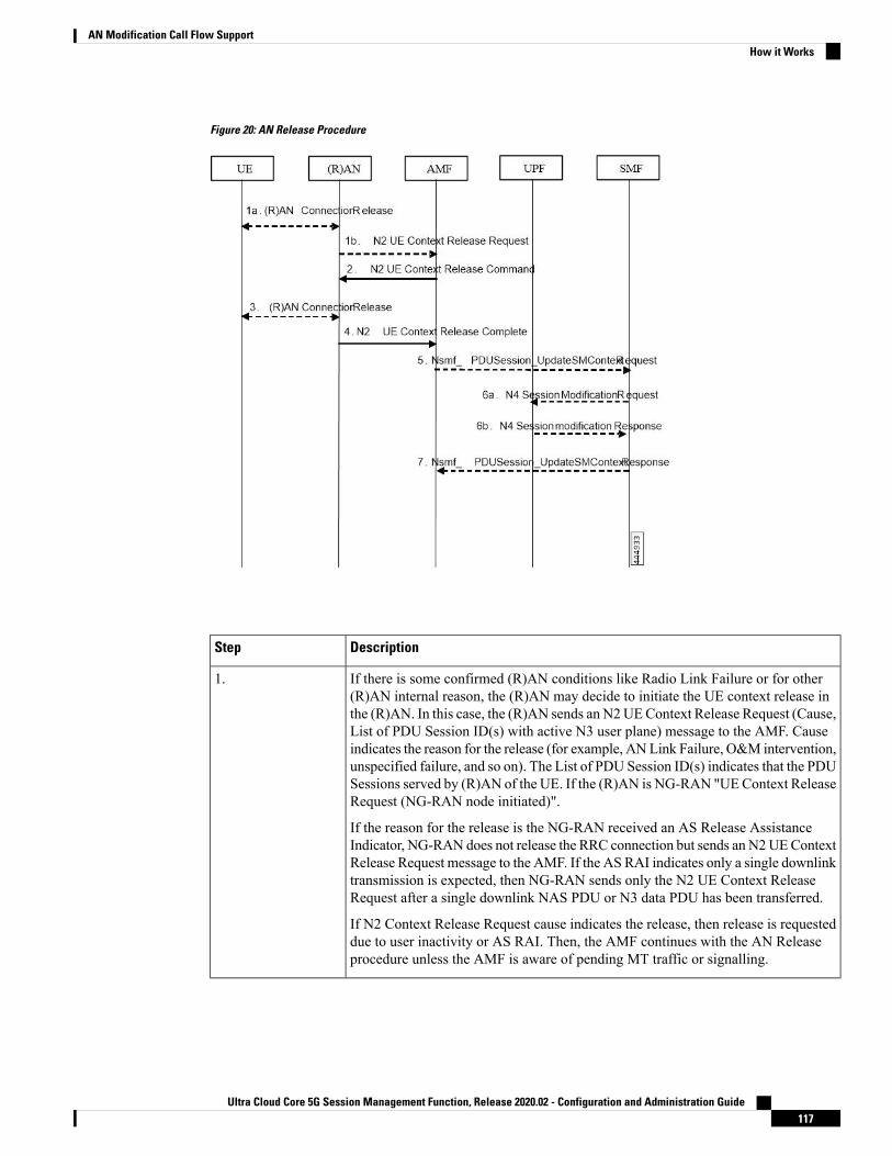
Figure 20: AN Release Procedure
DescriptionStep
If there is some confirmed (R)AN conditions like Radio Link Failure or for other(R)AN internal reason, the (R)AN may decide to initiate the UE context release inthe (R)AN. In this case, the (R)AN sends an N2UEContext Release Request (Cause,List of PDU Session ID(s) with active N3 user plane) message to the AMF. Causeindicates the reason for the release (for example, ANLink Failure, O&M intervention,unspecified failure, and so on). The List of PDU Session ID(s) indicates that the PDUSessions served by (R)AN of the UE. If the (R)AN is NG-RAN "UEContext ReleaseRequest (NG-RAN node initiated)".
If the reason for the release is the NG-RAN received an AS Release AssistanceIndicator, NG-RAN does not release the RRC connection but sends an N2UEContextRelease Request message to the AMF. If the AS RAI indicates only a single downlinktransmission is expected, then NG-RAN sends only the N2 UE Context ReleaseRequest after a single downlink NAS PDU or N3 data PDU has been transferred.
If N2 Context Release Request cause indicates the release, then release is requesteddue to user inactivity or AS RAI. Then, the AMF continues with the AN Releaseprocedure unless the AMF is aware of pending MT traffic or signalling.
1.
Ultra Cloud Core 5G Session Management Function, Release 2020.02 - Configuration and Administration Guide117
AN Modification Call Flow SupportHow it Works

DescriptionStep
If the AMF receives the N2UEContext Release Request message or due to an internalAMF event, including the reception of Service Request or Registration Request toestablish another NAS signalling connection still via (R)AN, the AMF sends an N2UE Context Release Command (Cause) to the (R)AN. The Cause indicates eitherthe Cause from (R)AN in step 1 or the Cause due to an AMF event. In case the (R)ANis a NG-RAN this step, "UE Context Release (AMF initiated)". In case the (R)ANis an N3IWF/TNGF/W-AGF this step.
If the AMF receives Service Request or Registration Request to establish anotherNAS signalling connection still via (R)AN, after successfully authenticating the UE,the AMF releases the old NAS signalling connection, and then continues the ServiceRequest or Registration Request procedure.
2.
If the (R)AN connection (for example, RRC connection or NWu connection) withthe UE is not already released (step 1), either:
1. The (R)AN requests the UE to release the (R)AN connection. Upon receiving(R)AN connection release confirmation from the UE, the (R)AN deletes the UE'scontext, or
2. If the Cause in the N2 UE Context Release Command indicates that the UE hasalready locally released the RRC connection, the (R)AN locally releases the RRCconnection.
3.
The (R)AN confirms the N2 Release by returning an N2 UE Context ReleaseComplete (List of PDU Session ID(s) with active N3 user plane, User LocationInformation, Age of Location Information) message to the AMF. The List of PDUSession ID(s) indicates that the PDU Sessions served by (R)AN of the UE. The AMFalways stores the latest UE Radio Capability information or NB-IoT specific UERadio Access Capability Information received from the NG-RAN node received.TheN2 signalling connection between the AMF and the (R)AN for that UE is released.The (R)AN provides the list of recommended cells / TAs / NG-RAN node identifiersfor paging to the AMF.
If the PLMN has configured secondary RAT usage reporting, the NG-RAN nodeprovides RAN usage data Report.
This step is performed immediately after step 2, for example, in a situation wherethe UE does not acknowledge the RRC Connection Release.
The NG-RAN includes Paging Assistance Data for CE capable UE, if available, inthe N2 UEContext Release Complete message. The AMF stores the received PagingAssistance Data for CE capable UE in the UE context for subsequent Pagingprocedure.
4.
Ultra Cloud Core 5G Session Management Function, Release 2020.02 - Configuration and Administration Guide118
AN Modification Call Flow SupportHow it Works

DescriptionStep
For each of the PDU Sessions in the N2 UE Context Release Complete, the AMFinvokes Nsmf_PDUSession_UpdateSMContext Request (PDU Session ID, PDUSession Deactivation, Cause, Operation Type, User Location Information, Age ofLocation Information, N2 SM Information (Secondary RAT usage data)). The Causein step 5 is the same Cause in step 2. If List of PDU Session ID(s) with active N3user plane is included in step 1b, the step 5 through step 7 are performed before step2. The Operation Type is set to "UP deactivate" to indicate deactivation of user planeresources for the PDU Session.
For PDU Sessions using Control Plane CIoT 5GS Optimization and if the UE hasnegotiated the use of extended Idle mode DRX, the AMF informs the SMFimmediately that the UE is not reachable for downlink data. For PDU Sessions usingControl Plane CIoT 5GS Optimization and if the UE has negotiated the use of MICOmode with Active Time, the AMF informs the SMF that the UE is not reachable fordownlink data once the Active Time has expired.
5.
The SMF sends N4 Session Modification Request (AN or N3 UPF Tunnel Info tobe removed, Buffering on/off) to the UPF.
For PDU Sessions not using Control Plane CIoT 5GSOptimization, the SMF initiatesan N4 Session Modification procedure indicating the need to remove Tunnel Info ofAN or UPF terminating N3. Buffering on/off indicates whether the UPF has to bufferincoming DL PDU or not.
If the SMF has received an indication from the AMF that the UE is not reachable fordownlink data for PDU Sessions using Control Plane CIoT 5GS Optimization, theSMF initiates an N4 SessionModification procedure to activate buffering in the UPF.
If multiple UPFs are used in the PDU Session and the SMF determines to release theUPF terminating N3, step 6a is performed towards the UPF (for example, PSA)terminating N9 towards the current N3 UPF. The SMF then releases the N4 sessiontowards the N3 UPF (the N4 release is not shown in the call flow).
If the cause of AN Release is because of User Inactivity, or UE Redirection, the SMFpreserves the GBR QoS Flows. Otherwise, the SMF triggers the PDU SessionModification procedure for the GBR QoS Flows of the UE after the AN Releaseprocedure is completed.
If the redundant I-UPFs are used for URLLC, the N4 Session Modification Requestprocedure is done for each I-UPF. In this case, the SMF selects both the redundantI-UPFs to buffer the DL packets for this PDU Session or drop the DL packets forthis PDU session or forward the DL packets for this PDU session to the SMF, basedon buffering instruction provided by the SMF.
If the redundant N3 tunnels are used for URLLC, the N4 SessionModification Requestprocedure to the UPF of N3 terminating point is to remove the dual AN Tunnel Infofor N3 tunnel of the corresponding PDU Session.
6.
The UPF sends N4 Session Modification Response acknowledging the SMF requestto the SMF.
6b.
Ultra Cloud Core 5G Session Management Function, Release 2020.02 - Configuration and Administration Guide119
AN Modification Call Flow SupportHow it Works

DescriptionStep
The SMF sends Nsmf_PDUSession_UpdateSMContext Response for step 5 to theAMF. Once the procedure is completed, the AMF considers the N2 andN3 as releasedand enters CM-IDLE state. After completion of the procedure, the AMF reportstowards the NF consumers.
7.
Dual Connectivity Support
This procedure is used to transfer QoS Flows to and from Secondary RAN Node. During this procedure, theSMF, and UPF are never re-allocated. The presence of IP connectivity between the UPF and the Master RANnode, as well as between the UPF and the Secondary RAN node is assumed.
If QoS Flows for multiple PDU Sessions need to be transferred to or from Secondary RANNode, the procedureshown in the below figure below is repeated for each PDU Session.
Figure 21: NG-RAN initiated QoS Flow mobility procedure
DescriptionStep
TheMaster RAN node sends a N2 QoS Flowmobility Indication (PDU Session ID,QFI(s), AN Tunnel Info) message to the AMF. AN Tunnel Info includes the newRAN tunnel endpoint for the QFI(s) for which the ANTunnel Info shall be modified.
1.
AMF to SMF, Nsmf_PDUSession_UpdateSMContext request (N2 QoS Flowmobility Indication message PDU Session ID).
2.
The SMF sends an N4 Session Modification Request (PDU Session ID(s), QFI(s),AN Tunnel Info for downlink user plane) message to the UPF.
3.
Ultra Cloud Core 5G Session Management Function, Release 2020.02 - Configuration and Administration Guide120
AN Modification Call Flow SupportHow it Works

DescriptionStep
The UPF returns an N4 Session Modification Response (CN Tunnel Info for uplinktraffic) message to the SMF after requested QFIs are switched.
Step 7 can occur anytime after receipt of N4 Session ModificationResponse at the SMF.
Important
4.
SMF toAMF,Nsmf_PDUSession_UpdateSMContext response (N2 SM information(CN Tunnel Info for uplink traffic)) for QFIs of the PDU Session which have beenswitched successfully. If none of the requested QFIs are switched successfully, theSMF sends an N2 QoS Flow mobility Failure message.
5.
In order to assist the reordering function in the Master RAN node and/or SecondaryRAN node, for each affected N3 tunnel the UPF sends one or more "end marker"packets on the old tunnel immediately after switching the tunnel for the QFI. TheUPF starts sending downlink packets to the Target NG-RAN.
6.
The AMF relays message 5 to the Master RAN node.7.
Ultra Cloud Core 5G Session Management Function, Release 2020.02 - Configuration and Administration Guide121
AN Modification Call Flow SupportHow it Works

Ultra Cloud Core 5G Session Management Function, Release 2020.02 - Configuration and Administration Guide122
AN Modification Call Flow SupportHow it Works

C H A P T E R 11Application-based Alerts
• Feature Summary and Revision History, on page 123• Feature Description, on page 124• How it Works, on page 124• Configuring Alert Rules, on page 124
Feature Summary and Revision History
Summary DataTable 30: Summary Data
SMFApplicable Product(s) or Functional Area
SMIApplicable Platform(s)
Disabled - Configuration RequiredFeature Default Setting
Not ApplicableRelated Changes in this Release
Not ApplicableRelated Documentation
Revision HistoryTable 31: Revision History
ReleaseRevision Details
Pre-2020.02.0First introduced.
Ultra Cloud Core 5G Session Management Function, Release 2020.02 - Configuration and Administration Guide123

Feature DescriptionWhen the system detects an anomaly, it generates an alert notification. The system statistics are the cause forthese alert notifications. You can set an expression to trigger an alert when the expression becomes true.
How it WorksThe Common Execution Environment (CEE) uses the Prometheus Alert Manager for alerting operations. TheCEE YANG model - either through CLI or API - allows users to view the active alerts, silenced alerts, andalert history. Also, the applications can call the alert API directly to add or clear alerts. The Prometheus AlertManager API (v2) is the standard API used.
The Prometheus Alerts Manager includes the following options:
• Defining Alert Rules: This option defines the types of alerts that the Alert Manager should trigger. Usethe Prometheus Query Language (PromQL) to define the alerts.
• Defining Alert Routing: This option defines the action the Alert Manager should take after receivingthe alerts. At present, the SNMP Trapper is supported as the outbound alerting. Also, the CEE providesan Alert Logger for storing the generated alerts.
Configuring Alert RulesTo configure the alert rules, use the following configuration:
configurealerts rules group alert_group_name
interval-seconds seconds
rule rule_name
expression promql_expression
duration duration
severity severity_level
type alert-type
annotation annotation_name
value annotation_value
exitexit
NOTES:
• alerts rules: Specifies the Prometheus alerting rules.
• group alert_group_name: Specifies the Prometheus alerting rule group. One alert group can havemultiplelists of rules. alert-group-name is the name of the alert group. The alert-group-name must be a string inthe range of 0–64 characters.
• interval-seconds seconds: Specifies the evaluation interval of the rule group in seconds.
• rule rule_name: Specifies the alerting rule definition. rule_name is the name of the rule.
Ultra Cloud Core 5G Session Management Function, Release 2020.02 - Configuration and Administration Guide124
Application-based AlertsFeature Description

• expression promql_expression: Specifies the PromQL alerting rule expression. promql_expression isthe alert rule query expressed in PromQL syntax.
• duration duration: Specifies the duration of a true condition before it is considered true. duration is thetime interval before the alert is triggered.
• severity severity_level: Specifies the severity of the alert. severity-level is the severity level of the alert.The severity levels are critical, major, minor, and warning.
• type alert_type: Specifies the type of the alert. alert_type is the user-defined alert type. For example,Communications Alarm, Environmental Alarm, Equipment Alarm, Indeterminate Integrity ViolationAlarm, Operational Violation Alarm, Physical Violation Alarm, Processing Error Alarm, Quality ofService Alarm, Security Service Alarm, Mechanism Violation Alarm, or Time Domain Violation Alarm.
• annotation annotation_name: Specifies the annotation to attach to the alerts. annotation_name is thename of the annotation.
• value annotation_value: Specifies the annotation value. annotation_value is the value of the annotation.
The following example configures an alert, which is triggeredwhen the percentage of UnifiedDataManagement(UDM) responses is less than the specified threshold limit.
Example:
configure terminalalerts rules group SMFUDMchk_incrinterval-seconds 300rule SMFUDMchk_increxpression "sum(increase(smf_restep_http_msg_total{nf_type=\"udm\",
message_direction=\"outbound\", response_status=~\"2..\"}[3m])) /sum(increase(smf_restep_http_msg_total{nf_type=\"udm\", message_direction=\"outbound\"}[3m]))< 0.95"severity majortype "Communications Alarm"annotation summaryvalue "This alert is fired when the percentage of UDM responses is less than threshold“exitexitexit
You can view the configured alert using the show running-config alerts command.
Example:
The following example displays the alerts configured in the running configuration:show running-config alertsinterval-seconds 300rule SMFUDMchk_increxpression "sum(increase(smf_restep_http_msg_total{nf_type=\"udm\",
message_direction=\"outbound\", response_status=~\"2..\"}[3m])) /sum(increase(smf_restep_http_msg_total{nf_type=\"udm\", message_direction=\"outbound\"}[3m]))< 0.95"severity majortype "Communications Alarm"annotation summaryvalue "This alert is fired when the percentage of UDM responses is less than threshold“
exitexitexit
Ultra Cloud Core 5G Session Management Function, Release 2020.02 - Configuration and Administration Guide125
Application-based AlertsConfiguring Alert Rules

Viewing Alert LoggerThe Alert Logger stores all the generated alerts by default. You can view the stored alerts using the followingshow command.
show alert history [ filtering ]
You can narrow down the result using the following filtering options:
• annotations: Specifies the annotations of the alert.
• endsAt: Specifies the end time of the alert.
• labels: Specifies the additional labels of the alert.
• severity: Specifies the severity of the alert.
• source: Specifies the source of the alert.
• startsAt: Specifies the start time of the alert.
• type: Specifies the type of the alert.
The following example displays the history of the alerts configured in the system:
Example:
show alerts historyalerts active SMFUDMchk_incr ac2a970ab621state activeseverity majortype "Communications Alarm"startsAt 2019-11-15T08:26:48.283Zsource Systemannotations [ "summary:This alert is fired when the percentage of UDM responses is lessthan threshold.” ]
You can view the active and silenced alerts with the show alerts active and show alerts active commands.
The following example displays the active alerts. The alerts remain active as long as the evaluated expressionis true.
Example:
show alerts activealerts active SMFUDMchk_incr ac2a970ab621state activeseverity majortype "Communications Alarm"startsAt 2019-11-15T08:26:48.283Zsource Systemannotations [ "summary:This alert is fired when the percentage of UDM responses is lessthan threshold.” ]
Call Flow Procedure AlertsThis section provides detail of commands that are required to configure alerts related to various call flowprocedures.
Ultra Cloud Core 5G Session Management Function, Release 2020.02 - Configuration and Administration Guide126
Application-based AlertsViewing Alert Logger

4G PDN ModifyUse the following commands to configure alerts related to the 4G PDN Modify procedure.
alerts rules group SMFPDN
interval-seconds 300
rule SMFPDNModify
expression“sum(smf_service_stats{procedure_type=~\”pdn_ho_location_changed|pdn_ho_rat_type_changed|pdn_inter_sgw_handover|pdn_mbr\”, status=\“success\”}) /sum(smf_service_stats{procedure_type=~\”pdn_ho_location_changed|pdn_ho_rat_type_changed|pdn_inter_sgw_handover|pdn_mbr\”, status=\“attempted\”}) < 0.95”severity major
type "Communications Alarm"
annotation summary
value "This alert is fired when the percentage successful 4G PDN Modify is belowthreshold”
exitexit
4G PDN Release SuccessUse the following commands to configure alerts related to the 4G PDN Release Success procedure.
alerts rules group SMFPDN
interval-seconds 300
rule SMFPDNRelease
expression “sum(smf_service_stats{procedure_type=~\“.*pdn_sess_rel\” ,status=\“success\”}) / sum(smf_service_stats{procedure_type=~\“.*pdn_sess_rel\” ,status=\“attempted\”} < 0.95 “
severity major
type "Communications Alarm"
annotation summary
value "This alert is fired when the percentage successful 4G PDN Release is belowthreshold.”
exitexit
4G PDN Setup SuccessUse the following commands to configure alerts related to the 4G PDN Setup Success procedure.
alerts rules group SMFPDN
interval-seconds 300
rule SMFPDNSetup
expression “sum(smf_service_stats{procedure_type=\”pdn_sess_create\” ,status=\“success\”}) / sum(smf_service_stats{procedure_type=\”pdn_sess_create\” ,status=\“attempted\”} < 0.95 “
severity major
type "Communications Alarm"
annotation summary
value "This alert is fired when the percentage successful 4G PDN Setup is belowthreshold.”
exitexit
Ultra Cloud Core 5G Session Management Function, Release 2020.02 - Configuration and Administration Guide127
Application-based Alerts4G PDN Modify

4G to 5G HO SuccessUse the following commands to configure alerts related to the 4G to 5G HO Success procedure.
alerts rules group Handover
interval-seconds 300
rule 4gTo5gHOSuccess
expression“sum(smf_service_stats{procedure_type=~\“n26_4g_to_5g_handover|n26_4g_to_5g_im_mobility\”, status=\“success\”}) /sum(smf_service_stats{procedure_type=~\“n26_4g_to_5g_handover|n26_4g_to_5g_im_mobility\” ,status=\“attempted\”}) < 0.95 “severity major
type "Communications Alarm"
annotation summary
value "This alert is fired when the percentage successful 4G to 5G HO is belowthreshold.”
exitexit
4G To WiFi HO SuccessUse the following commands to configure alerts related to the 4G to WiFi HO Success procedure.
alerts rules group Handover
interval-seconds 300
rule 4GtoWifiHOSuccess
expression “sum(smf_service_stats{procedure_type=\”enb_to_untrusted_wifi_handover\”, status=\“success\”}) /sum(smf_service_stats{procedure_type=\“enb_to_untrusted_wifi_handover\” ,status=\“attempted\”}) < 0.95 “
severity major
type "Communications Alarm"
annotation summary
value "This alert is fired when the percentage of N4 responses sent is lesser than 95%."exit
exit
5G N2 HO SuccessUse the following commands to configure alerts related to the 5G N2 HO Success procedure.
alerts rules group Handover
interval-seconds 300
rule N2HOSuccess
expression “sum(smf_service_stats{procedure_type=\“n2_handover\” , status=\“success\”})/ sum(smf_service_stats{procedure_type=\“n2_handover\” , status=\“attempted\”}) < 0.95 “severity major
type "Communications Alarm"
annotation summary
value "This alert is fired when the percentage successful 5G N2 HO is below threshold.”
exitexit
Ultra Cloud Core 5G Session Management Function, Release 2020.02 - Configuration and Administration Guide128
Application-based Alerts4G to 5G HO Success

5G PDU Idle SuccessUse the following commands to configure alerts related to the 5G PDU Idle Success procedure.
alerts rules group SMFPDU
interval-seconds 300
rule SMFPDUIdleSuccess
expression “sum(smf_service_stats{procedure_type=~\“.*idle\” , status=\“success\”})/ sum(smf_service_stats{procedure_type=~\“.*idle\” , status=\“attempted\”}) < 0.95 “
severity major
type "Communications Alarm"
annotation summary
value "This alert is fired when the percentage successful 5G PDU Idle is below threshold”
exitexit
5G PDU Modify SuccessUse the following commands to configure alerts related to the 5G PDU Modify Success procedure.
alerts rules group SMFPDU
interval-seconds 300
rule SMFSessionModifySuccess
expression “sum(smf_service_stats{procedure_type=~\“.*pdu_sess_mod\” ,status=\“success\”}) / sum(smf_service_stats{procedure_type=~\“.*pdu_sess_mod\” ,status=\“attempted\”}) < 0.95 “
severity major
type "Communications Alarm"
annotation summary
value "This alert is fired when the percentage successful 5G PDU Modify is belowthreshold”
exitexit
5G PDU Release SuccessUse the following commands to configure alerts related to the 5G PDU Release Success procedure.
alerts rules group SMFPDU
interval-seconds 300
rule SMFSessionReleaseFailure
expression “sum(smf_service_stats{procedure_type=~\“.*pdu_sess_rel\” ,status=\“success\”}) / sum(smf_service_stats{procedure_type=~\“.*pdu_sess_rel\” ,status=\“attempted\”}) < 0.95 “
severity major
type "Communications Alarm"
annotation summary
value "This alert is fired when the percentage successful 5G PDU Setup is belowthreshold”
exitexit
Ultra Cloud Core 5G Session Management Function, Release 2020.02 - Configuration and Administration Guide129
Application-based Alerts5G PDU Idle Success

5G PDU Setup SuccessUse the following commands to configure alerts related to the 5G PDU Setup Success procedure.
alerts rules group SMFPDU
interval-seconds 300
rule SMFSessionSetupFailure
expression “sum(smf_service_stats{procedure_type=\”pdu_sess_create\” ,status=\“success\”}) / sum(smf_service_stats{procedure_type=\”pdu_sess_create\” ,status=\“attempted\”} < 0.95 “
severity major
type "Communications Alarm"
annotation summary
value "This alert is fired when failed to setup sessions is more than 5%”
exitexit
5G to 4G HO SuccessUse the following commands to configure alerts related to the 5G to 4G HO Success procedure.
alerts rules group Handover
interval-seconds 300
rule 5gTo4gHOSuccess
expression“sum(smf_service_stats{procedure_type=~\“pdn_5g_4g_handover|pdn_5g_4g_handover_dft|eps_fb_5g_4g_handover_dft|eps_fb_5g_4g_handover_idft|pdn_5g_4g_handover_idft\”, status=\“success\”}) /sum(smf_service_stats{procedure_type=~\“pdn_5g_4g_handover|pdn_5g_4g_handover_dft|eps_fb_5g_4g_handover_dft|eps_fb_5g_4g_handover_idft|pdn_5g_4g_handover_idft\”, status=\“attempted\”}) < 0.95 “severity major
type "Communications Alarm"
annotation summary
value "This alert is fired when the percentage successful 5G to 4G HO is belowthreshold.”
exitexit
5G To WiFi HO SuccessUse the following commands to configure alerts related to the 5G to WiFi HO Success procedure.
alerts rules group Handover
interval-seconds 300
rule 5GtoWifiHOSuccess
expression “sum(smf_service_stats{procedure_type=\”nr_to_untrusted_wifi_handover\” ,status=\“success\”}) / sum(smf_service_stats{procedure_type=\“nr_to_untrusted_wifi_handover\”, status=\“attempted\”}) < 0.95 “severity major
type "Communications Alarm"
annotation summary
value "This alert is fired when the percentage of N4 responses sent is lesser than 95%."exit
exit
Ultra Cloud Core 5G Session Management Function, Release 2020.02 - Configuration and Administration Guide130
Application-based Alerts5G PDU Setup Success

5G Xn HO SuccessUse the following commands to configure alerts related to the 5G Xn HO Success procedure.
alerts rules group Handover
interval-seconds 300
rule XnHOSuccess
expression “sum(smf_service_stats{procedure_type=\“xn_handover\” , status=\“success\”})/ sum(smf_service_stats{procedure_type=\“xn_handover\” , status=\“attempted\”}) < 0.95 “severity major
type "Communications Alarm"
annotation summary
value "This alert is fired when the percentage successful 5G Xn HO is below threshold.”
exitexit
PDN Session CreateUse the following commands to configure alerts related to the PDN Session Create procedure.
alerts rules group SMFProcStatus
interval-seconds 300
rule PDNSessCreate
expression"sum(increase(smf_service_stats{app_name=\"SMF\",procedure_type=\"pdn_sess_create\",status=\"success\”}[5m]))/
sum(increase(smf_service_stats{app_name=\"SMF\",procedure_type=\"pdn_sess_create\",status=\"attempted\”}[5m]))< 0.95"severity major
type "Communications Alarm"
annotation summary
value "This alert is fired when the success percentage of pdn_sess_create procedure islesser threshold.”exit
exit
PDU Session CreateUse the following commands to configure alerts related to the PDU Session Create procedure.
alerts rules group SMFProcStatus
interval-seconds 300
rule PDUSessCreate
expression"sum(increase(smf_service_stats{app_name=\"SMF\",procedure_type=\"pdu_sess_create\",status=\"success\”}[5m]))/
sum(increase(smf_service_stats{app_name=\"SMF\",procedure_type=\"pdu_sess_create\",status=\"attempted\”}[5m]))< 0.95"severity major
type "Communications Alarm"
annotation summary
value "This alert is fired when the success percentage of pdu_sess_create procedure islesser threshold.”exit
exit
Ultra Cloud Core 5G Session Management Function, Release 2020.02 - Configuration and Administration Guide131
Application-based Alerts5G Xn HO Success

PDU Session ModifyUse the following commands to configure alerts related to the PDU Session Modify procedure.
alerts rules group SMFProcStatus
interval-seconds 300
rule PDUSessModify
expression"sum(increase(smf_service_stats{app_name=\"SMF\",procedure_type=~\".*req_pdu_sess_mod\",status=\"success\”}[5m]))/
sum(increase(smf_service_stats{app_name=\"SMF\",procedure_type=~\”.*req_pdu_sess_mod\",status=\"attempted\”}[5m]))< 0.95"severity major
type "Communications Alarm"
annotation summary
value "This alert is fired when the success percentage of req_pdu_sess_mod procedureis lesser threshold.”
exitexit
PDU Session ReleaseUse the following commands to configure alerts related to the PDU Session Release procedure.
alerts rules group SMFProcStatus
interval-seconds 300
rule PDUSessRelease
expression"sum(increase(smf_service_stats{app_name=\"SMF\",procedure_type=~\".*req_pdu_sess_rel\",status=\"success\”}[5m]))/
sum(increase(smf_service_stats{app_name=\"SMF\",procedure_type=~\”.*req_pdu_sess_rel\",status=\"attempted\”}[5m]))< 0.95"severity major
type "Communications Alarm"
annotation summary
value "This alert is fired when the success percentage of req_pdu_sess_rel procedureis lesser threshold.”
exitexit
Interface Specific AlertsThis section provides detail of commands that are required to configure alerts related to various interfaces.
GTPC Peer DownUse the following commands to configure alerts related to the GTPC Peer Down procedure.
alerts rules group GTPCPeerDown
interval-seconds 300
rule GTPCPeerDown
expression nodemgr_gtpc_peer_status{gtpc_peer_status=\“gtpc_peer_path_down\”})
severity major
type "Communications Alarm"
annotation summary
Ultra Cloud Core 5G Session Management Function, Release 2020.02 - Configuration and Administration Guide132
Application-based AlertsPDU Session Modify

value “This alert is fired when the GTPC Path failure detected for peer crossesthreshold”
exitexit
N4 Message SuccessUse the following commands to configure alerts related to the N4 Message Success procedure.
alerts rules group SMFSvcStatus
interval-seconds 300
rule SMFN4MessageSuccess
expression "sum(smf_protocol_udp_res_msg_total{message_direction=\"inbound\",status=\”accepted\”}) / sum(smf_protocol_udp_res_msg_total{message_direction=\"inbound\”,status=~\”accepted|denied\”}) < 0.95"severity major
type "Communications Alarm"
annotation summary
value "This alert is fired when the percentage of N4 responses sent is lesser than 95%."exit
exit
N4 UPF Association DownUse the following commands to configure alerts related to the N4UPFAssociation Down query by N4 address.
alerts rules group N4Association
interval-seconds 300
rule SMFAssociationRelease
expression ”smf_proto_udp_res_msg_total{procedure_type=\“n4_association_release_res\”,message_direction= \“inbound\”, status=\“accepted\”}) ”severity major
type "Communications Alarm"
annotation summary
value “This alert is fired when the N4 Association with UPF is released”
exitexit
N4 UPF Association UpUse the following commands to configure alerts related to the N4 UPF Association Up query by N4 address.
alerts rules group N4Association
interval-seconds 300
rule N4AssociationUP
expression ”smf_proto_udp_res_msg_total{procedure_type=\“n4_association_setup_res\”,message_direction= \“inbound\”, status=\“accepted\”}”severity major
type "Communications Alarm"
annotation summary
value “This alert is fired when the N4 Association with UPF is established”
exitexit
Ultra Cloud Core 5G Session Management Function, Release 2020.02 - Configuration and Administration Guide133
Application-based AlertsN4 Message Success

N7 Interface OutboundUse the following commands to configure alerts related to an outbound N7 interface.
alerts rules group SMFSvcStatus
interval-seconds 300
rule SMFN7Outbound
expression "sum(increase(smf_restep_http_msg_total{nf_type=\"pcf\",message_direction=\"outbound\", response_status=~\”2..\”}[5m])) /sum(increase(smf_restep_http_msg_total{nf_type=\"pcf\", message_direction=\"outbound\”}[5m]))< 0.95"severity major
type "Communications Alarm"
annotation summary
value "This alert is fired when the percentage of N7 responses received is lesserthreshold.”
exitexit
N7 Interface InboundUse the following commands to configure alerts related to an inbound N7 interface.
alerts rules group SMFSvcStatus
interval-seconds 300
rule SMFN7Inbound
expression "sum(increase(smf_restep_http_msg_total{nf_type=\"pcf\",message_direction=\"inbound\", response_status=~\”2..\”}[5m])) /sum(increase(smf_restep_http_msg_total{nf_type=\"pcf\", message_direction=\"inbound\”}[5m]))< 0.95"severity major
type "Communications Alarm"
annotation summary
value "This alert is fired when the percentage of N7 responses sent is lesser threshold.”
exitexit
N7 Message Timed OutUse the following commands to configure alerts related to the N7 Message Timed Out procedure.
alerts rules group MessageTimeout
interval-seconds 300
rule SMFN7Timeout
expression ”sum(irate(smf_restep_http_msg_total{nf_type=\“pcf\”,message_direction=\”inbound\”, response_status=\”504\”}[5m])) > 5”
severity major
type "Communications Alarm"
annotation summary
value “This alert is fired when the increase in timeout for N7 messages toward PCFcrosses threshold”
exitexit
Ultra Cloud Core 5G Session Management Function, Release 2020.02 - Configuration and Administration Guide134
Application-based AlertsN7 Interface Outbound

N10 InterfaceUse the following commands to configure alerts related to the N10 interface.
alerts rules group SMFSvcStatus
interval-seconds 300
rule SMFN10
expression "sum(increase(smf_restep_http_msg_total{nf_type=\"udm\",message_direction=\"outbound\", response_status=~\”2..\”}[5m])) /sum(increase(smf_restep_http_msg_total{nf_type=\"udm\", message_direction=\"outbound\”}[5m]))< 0.95"severity major
type "Communications Alarm"
annotation summary
value "This alert is fired when the percentage of N10 responses received is lesserthreshold.”
exitexit
N11 Interface InboundUse the following commands to configure alerts related to an inbound N11 interface.
alerts rules group SMFSvcStatus
interval-seconds 300
rule SMFN11Inbound
expression "sum(increase(smf_restep_http_msg_total{nf_type=\"amf\",message_direction=\"inbound\", response_status=~\”2..\”}[5m])) /sum(increase(smf_restep_http_msg_total{nf_type=\"amf\", message_direction=\"inbound\”}[5m]))< 0.95"severity major
type "Communications Alarm"
annotation summary
value "This alert is fired when the percentage of N11 responses sent is lesserthreshold.”
exitexit
N11 Interface OutboundUse the following commands to configure alerts related to an outbound N11 interface.
alerts rules group SMFSvcStatus
interval-seconds 60
rule SMFN11Outbound
expression "sum(increase(smf_restep_http_msg_total{nf_type=\"amf\",message_direction=\"outbound\", response_status=~\”2..\”}[5m])) /sum(increase(smf_restep_http_msg_total{nf_type=\"amf\", message_direction=\"outbound\”}[5m]))< 0.95"severity major
type "Communications Alarm"
annotation summary
value "This alert is fired when the percentage of N11 responses received is lesserthreshold.”
exitexit
Ultra Cloud Core 5G Session Management Function, Release 2020.02 - Configuration and Administration Guide135
Application-based AlertsN10 Interface

N11 Message Timed OutUse the following commands to configure alerts related to the N11 Message Timed Out procedure.
alerts rules group MessageTimeout
interval-seconds 300
rule SMFN40Timeout
expression ”sum(irate(smf_restep_http_msg_total{nf_type=\“chf\”,message_direction=\”inbound\”, response_status=\”504\”}[5m])) > 5”
severity major
type "Communications Alarm"
annotation summary
value “This alert is fired when the increase in timeout for N11 messages toward AMFcrosses threshold”
exitexit
N40 Interface InboundUse the following commands to configure alerts related to an inbound N40 interface.
alerts rules group SMFSvcStatus
interval-seconds 300
rule SMFN40Inbound
expression "sum(increase(smf_restep_http_msg_total{nf_type=\"chf\",message_direction=\"inbound\", response_status=~\”2..\”}[5m])) /sum(increase(smf_restep_http_msg_total{nf_type=\"chf\", message_direction=\"inbound\”}[5m]))< 0.95"severity major
type "Communications Alarm"
annotation summary
value "This alert is fired when the percentage of N40 responses sent is lesserthreshold.”
exitexit
N40 Interface OutboundUse the following commands to configure alerts related to an outbound N40 interface.
alerts rules group SMFSvcStatus
interval-seconds 300
rule SMFN40Outbound
expression "sum(increase(smf_restep_http_msg_total{nf_type=\"chf\",message_direction=\"outbound\", response_status=~\”2..\”}[5m])) /sum(increase(smf_restep_http_msg_total{nf_type=\"chf\", message_direction=\"outbound\”}[5m]))< 0.95"severity major
type "Communications Alarm"
annotation summary
value "This alert is fired when the percentage of N40 responses received is lesserthreshold.”
exitexit
Ultra Cloud Core 5G Session Management Function, Release 2020.02 - Configuration and Administration Guide136
Application-based AlertsN11 Message Timed Out

N40 Message Timed OutUse the following commands to configure alerts related to the N40 Message Timed Out procedure.
alerts rules group MessageTimeout
interval-seconds 300
rule SMFN11Timeout
expression ”sum(irate(smf_restep_http_msg_total{nf_type=\“chf\”,message_direction=\”inbound\”, response_status=\”504\”}[5m])) > 5”
severity major
type "Communications Alarm"
annotation summary
value “This alert is fired the increase in timeout for N40 messages toward CHF crossesthreshold”exit
exit
NRF DiscoveryUse the following commands to configure alerts related to the NRF Discovery procedure.
alerts rules group NRF
interval-seconds 300
rule NRFDiscovery
expression“sum(nf_discover_messages_total{result=~\”success|failure\”,svc_name=\”nnrf-disc\”,service_name=\”smf-rest-ep\”}) < 0.95”
severity major
type "Communications Alarm"
annotation summary
value "This alert is fired when the percentage of N4 responses sent is lesser than 95%."exit
exit
SMF Service StartUse the following commands to configure alerts related to the SMF Service Start procedure.
alerts rules group SMFService
interval-seconds 300
rule SMFServiceStart
expression “irate(outgoing_response_msg_total{msg_type=\”NrfNfmRegistration\”}[5m])”
severity major
type "Communications Alarm"
annotation summary
value "This alert is fired when SMF-Service starts upon registration with NRF”
exitexit
IP PoolThis section provides detail of commands that are required to configure alerts related to IP Pool.
Ultra Cloud Core 5G Session Management Function, Release 2020.02 - Configuration and Administration Guide137
Application-based AlertsN40 Message Timed Out

IP Pool UsedUse the following commands to configure alerts related to the IP Pool used procedure.
alerts rules group IPPool
interval-seconds 300
rule IPPool
expression “sum(IPAM_address_allocations_current) > THRESHOLD”
severity major
type "Communications Alarm"
annotation summary
value “This alert is fired when the percentage IP pool addresses used is above thethreshold”
exitexit
Message Level AlertsThis section provides detail of commands that are required to configure alerts related to various messages.
N11 SM CreateUse the following commands to configure alerts related to N11 SM Create.
alerts rules group SMFSvcStatus
interval-seconds 300
rule SMFN11Success
expression "sum(increase(smf_restep_http_msg_total{api_name=\"amf_create_sm_context\",message_direction=\"inbound\", response_status=\"201\”}[5m])) /sum(increase(smf_restep_http_msg_total{api_name=\"amf_create_sm_context\",message_direction=\"inbound\”}[5m])) < 0.95"
severity major
type "Communications Alarm"
annotation summary
value "This alert is fired when the percentage of amf_create_sm_context responses sentis lesser threshold.”exit
exit
N11 SM UpdateUse the following commands to configure alerts related to N11 SM Update.
alerts rules group SMFSvcStatus
interval-seconds 300
rule SMFN11Update
expression "sum(increase(smf_restep_http_msg_total{api_name=\"amf_update_sm_context\",message_direction=\"inbound\", response_status=\"200\"}[5m])) /sum(increase(smf_restep_http_msg_total{api_name=\"amf_update_sm_context\",message_direction=\"inbound\”}[5m])) < 0.95"
severity major
type "Communications Alarm"
annotation summary
value "This alert is fired when the percentage of amf_update_sm_context responses sent
Ultra Cloud Core 5G Session Management Function, Release 2020.02 - Configuration and Administration Guide138
Application-based AlertsIP Pool Used

is lesser threshold.”exit
exit
N11 SM ReleaseUse the following commands to configure alerts related to N11 SM Release.
alerts rules group SMFSvcStatus
interval-seconds 300
rule SMFN11Release
expression "sum(increase(smf_restep_http_msg_total{api_name=\"amf_release_sm_context\",message_direction=\"inbound\", response_status=\"204\”}[5m])) /sum(increase(smf_restep_http_msg_total{api_name=\"amf_release_sm_context\",message_direction=\"inbound\”}[5m])) < 0.95"
severity major
type "Communications Alarm"
annotation summary
value "This alert is fired when the percentage of amf_release_sm_context responses sentis lesser threshold.”exit
exit
N1 N2 Message TransferUse the following commands to configure alerts related to N1 N2 Message Transfer.
alerts rules group SMFSvcStatus
interval-seconds 300
rule SMFN1N2Transfer
expression "sum(increase(smf_restep_http_msg_total{api_name=\"amf_n1_n2_transfer\",message_direction=\"outbound\", response_status=\"200\”}[5m])) /sum(increase(smf_restep_http_msg_total{api_name=\"amf_n1_n2_transfer\",message_direction=\"outbound\”}[5m])) < 0.95"
severity major
type "Communications Alarm"
annotation summary
value "This alert is fired when the percentage of amf_n1_n2_transfer responses receivedis lesser threshold.”exit
exit
N11 EBI AssignmentUse the following commands to configure alerts related to N11 EBI Assignment.
alerts rules group SMFSvcStatus
interval-seconds 300
rule SMFN11EBI
expression "sum(increase(smf_restep_http_msg_total{api_name=\"amf_assign_ebi\",message_direction=\"outbound\", response_status=\"200\”}[5m])) /sum(increase(smf_restep_http_msg_total{api_name=\"amf_assign_ebi\",message_direction=\"outbound\”}[5m])) < 0.95"
severity major
type "Communications Alarm"
annotation summary
Ultra Cloud Core 5G Session Management Function, Release 2020.02 - Configuration and Administration Guide139
Application-based AlertsN11 SM Release

value "This alert is fired when the percentage of amf_assign_ebi responses received islesser threshold.”exit
exit
N11 SM Status NotifyUse the following commands to configure alerts related to N11 SM Status Notify.
alerts rules group SMFSvcStatus
interval-seconds 300
rule SMFN11StatusNotify
expression "sum(increase(smf_restep_http_msg_total{api_name=\"amf_status_notify\",message_direction=\"outbound\", response_status=\"201\”}[5m])) /sum(increase(smf_restep_http_msg_total{api_name=\"amf_status_notify\",message_direction=\"outbound\”}[5m])) < 0.95"
severity major
type "Communications Alarm"
annotation summary
value "This alert is fired when the percentage of amf_status_notify responses receivedis lesser threshold.”exit
exit
N11 SM Context RetrieveUse the following commands to configure alerts related to N11 SM Context Retrieve.
alerts rules group SMFSvcStatus
interval-seconds 300
rule SMFN11ContextRetrieve
expression "sum(increase(smf_restep_http_msg_total{api_name=\"amf_retrieve_sm_context\",message_direction=\"inbound\", response_status=\"201\”}[5m])) /sum(increase(smf_restep_http_msg_total{api_name=\"amf_retrieve_sm_context\",message_direction=\"inbound\”}[5m])) < 0.95"
severity major
type "Communications Alarm"
annotation summary
value "This alert is fired when the percentage of amf_retrieve_sm_context responsessent is lesser threshold.”
exitexit
N7 SM Policy CreateUse the following commands to configure alerts related to N7 SM Policy Create.
alerts rules group SMFSvcStatus
interval-seconds 300
rule SMFN7PolicyCreate
expression"sum(increase(smf_restep_http_msg_total{api_name=\"pcf_sm_policy_control_create\",message_direction=\"outbound\", response_status=\"201\”}[5m])) /sum(increase(smf_restep_http_msg_total{api_name=\"pcf_sm_policy_control_create\",message_direction=\"outbound\”}[5m])) < 0.95"
severity major
Ultra Cloud Core 5G Session Management Function, Release 2020.02 - Configuration and Administration Guide140
Application-based AlertsN11 SM Status Notify

type "Communications Alarm"
annotation summary
value "This alert is fired when the percentage of pcf_sm_policy_control_create responsesreceived is lesser threshold.”exit
exit
N7 SM Policy UpdateUse the following commands to configure alerts related to N7 SM Policy Update.
alerts rules group SMFSvcStatus
interval-seconds 300
rule SMFN7PolicyUpdate
expression"sum(increase(smf_restep_http_msg_total{api_name=\"pcf_sm_policy_control_update\",message_direction=\"outbound\", response_status=\"200\”}[5m])) /sum(increase(smf_restep_http_msg_total{api_name=\"pcf_sm_policy_control_update\",message_direction=\"outbound\”}[5m])) < 0.95"
severity major
type "Communications Alarm"
annotation summary
value "This alert is fired when the percentage of pcf_sm_policy_control_update responsesreceived is lesser threshold.”exit
exit
N7 SM Policy DeleteUse the following commands to configure alerts related to N7 SM Policy Delete.
alerts rules group SMFSvcStatus
interval-seconds 300
rule SMFN7PolicyDelete
expression"sum(increase(smf_restep_http_msg_total{api_name=\"pcf_sm_policy_control_delete\",message_direction=\"outbound\", response_status=\"204\”}[5m])) /sum(increase(smf_restep_http_msg_total{api_name=\"pcf_sm_policy_control_delete\",message_direction=\"outbound\”}[5m])) < 0.95"
severity major
type "Communications Alarm"
annotation summary
value "This alert is fired when the percentage of pcf_sm_policy_control_delete responsesreceived is lesser threshold.”exit
exit
N7 SM Policy Notify UpdateUse the following commands to configure alerts related to N7 SM Policy Notify Update.
alerts rules group SMFSvcStatus
interval-seconds 300
rule SMFN7PolicyUpdateNotify
expression"sum(increase(smf_restep_http_msg_total{api_name=\"pcf_sm_policy_control_update_notify\",
Ultra Cloud Core 5G Session Management Function, Release 2020.02 - Configuration and Administration Guide141
Application-based AlertsN7 SM Policy Update

message_direction=\"inbound\", response_status=\"201\”}[5m])) /sum(increase(smf_restep_http_msg_total{api_name=\"pcf_sm_policy_control_update_notify\",message_direction=\"inbound\”}[5m])) < 0.95"
severity major
type "Communications Alarm"
annotation summary
value "This alert is fired when the percentage of pcf_sm_policy_control_update_notifyresponses sent is lesser threshold.”exit
exit
N7 SM Policy Notify TerminateUse the following commands to configure alerts related to N7 SM Policy Terminate.
alerts rules group SMFSvcStatus
interval-seconds 300
rule SMFN7PolicyTerminateNotify
expression"sum(increase(smf_restep_http_msg_total{api_name=\"pcf_sm_policy_control_terminate_notify\",message_direction=\"inbound\", response_status=\"201\”}[5m])) /sum(increase(smf_restep_http_msg_total{api_name=\"pcf_sm_policy_control_terminate_notify\",message_direction=\"inbound\”}[5m])) < 0.95"severity major
type "Communications Alarm"
annotation summary
value "This alert is fired when the percentage of pcf_sm_policy_control_terminate_notifyresponses sent is lesser threshold.”exit
exit
N10 UE RegisterUse the following commands to configure alerts related to N10 UE Register.
alerts rules group SMFSvcStatus
interval-seconds 300
rule SMFN10UERegister
expression "sum(increase(smf_restep_http_msg_total{api_name=\"register_ue\",message_direction=\"outbound\", response_status=\"201\”}[5m])) /sum(increase(smf_restep_http_msg_total{api_name=\"register_ue\",message_direction=\"outbound\”}[5m])) < 0.95"
severity major
type "Communications Alarm"
annotation summary
value "This alert is fired when the percentage of register_ue responses received islesser threshold.”
exitexit
N10 UE DeRegisterUse the following commands to configure alerts related to N10 UE DeRegister.
alerts rules group SMFSvcStatus
interval-seconds 300
Ultra Cloud Core 5G Session Management Function, Release 2020.02 - Configuration and Administration Guide142
Application-based AlertsN7 SM Policy Notify Terminate

rule SMFN10UEDeRegister
expression "sum(increase(smf_restep_http_msg_total{api_name=\"deregister_ue\",message_direction=\"outbound\", response_status=\"201\”}[5m])) /sum(increase(smf_restep_http_msg_total{api_name=\"deregister_ue\",message_direction=\"outbound\”}[5m])) < 0.95"
severity major
type "Communications Alarm"
annotation summary
value "This alert is fired when the percentage of deregister_ue responses received islesser threshold.”exit
exit
N10 SM Subscription FetchUse the following commands to configure alerts related to N10 Subscription Fetch.
alerts rules group SMFSvcStatus
interval-seconds 300
rule SMFN10SubscriptionFetch
expression "sum(increase(smf_restep_http_msg_total{api_name=\"subscription_req\",message_direction=\"outbound\", response_status=\"200\”}[5m])) /sum(increase(smf_restep_http_msg_total{api_name=\"subscription_req\",message_direction=\"outbound\”}[5m])) < 0.95"
severity major
type "Communications Alarm"
annotation summary
value "This alert is fired when the percentage of subscription_req responses receivedis lesser threshold.”exit
exit
N10 SM Subscribe for NotificationUse the following commands to configure alerts related to N10 Subscribe for Notification.
alerts rules group SMFSvcStatus
interval-seconds 300
rule SMFN10SubscriptionNotification
expression "sum(increase(smf_restep_http_msg_total{api_name=\"sdm_subscription_req\",message_direction=\"outbound\", response_status=\"201\”}[5m])) /sum(increase(smf_restep_http_msg_total{api_name=\"sdm_subscription_req\",message_direction=\"outbound\”}[5m])) < 0.95"
severity major
type "Communications Alarm"
annotation summary
value "This alert is fired when the percentage of sdm_subscription_req responses receivedis lesser threshold.”exit
exit
N10 Charging Data RequestUse the following commands to configure alerts related to N10 Charging Data Request.
Ultra Cloud Core 5G Session Management Function, Release 2020.02 - Configuration and Administration Guide143
Application-based AlertsN10 SM Subscription Fetch

alerts rules group SMFSvcStatus
interval-seconds 300
rule SMFN10ChargingRequest
expression"sum(increase(smf_restep_http_msg_total{api_name=\"chf_charging_data_request\",message_direction=\"outbound\", response_status=\"201\”}[5m])) /sum(increase(smf_restep_http_msg_total{api_name=\"chf_charging_data_request\",message_direction=\"outbound\”}[5m])) < 0.95"
severity major
type "Communications Alarm"
annotation summary
value "This alert is fired when the percentage of chf_charging_data_request responsesreceived is lesser threshold.”exit
exit
N10 Charging Data NotifyUse the following commands to configure alerts related to N10 Charging Data Notify.
alerts rules group SMFSvcStatus
interval-seconds 300
rule SMFN10ChargingDataNotify
expression "sum(increase(smf_restep_http_msg_total{api_name=\"chf_abort_notify\",message_direction=\"inbound\", response_status=\"201\”}[5m])) /sum(increase(smf_restep_http_msg_total{api_name=\"chf_abort_notify\",message_direction=\"inbound\”}[5m])) < 0.95"
severity major
type "Communications Alarm"
annotation summary
value "This alert is fired when the percentage of chf_abort_notify responses sent islesser threshold.”
exitexit
Policy Rule AlertsThis section provides detail of commands that are required to configure alerts related to various policy rules.
Addition of Dynamic PCC RulesUse the following commands to configure alerts related to addition of dynamic PCC rules.
alerts rules group SMFPolicyStatus
interval-seconds 300
rule AddPCCRule
expression"sum(increase(policy_dynamic_pcc_rules_total{app_name=\"SMF\",event=\"success\",operation=\"install\”}[5m]))/
sum(increase(policy_dynamic_pcc_rules_total{app_name=\"SMF\",event=\"attempted\",operation=\"install\”}[5m]))< 0.95"severity major
type "Communications Alarm"
annotation summary
value "This alert is fired when the percentage of successful addition of dynamic pcc
Ultra Cloud Core 5G Session Management Function, Release 2020.02 - Configuration and Administration Guide144
Application-based AlertsN10 Charging Data Notify

rules is lesser threshold.”exit
exit
Modification of Dynamic PCC RulesUse the following commands to configure alerts related to modification of dynamic PCC rules.
alerts rules group SMFPolicyStatus
interval-seconds 300
rule ModifyPCCRule
expression"sum(increase(policy_dynamic_pcc_rules_total{app_name=\"SMF\",event=\"success\",operation=\"modify\”}[5m]))/
sum(increase(policy_dynamic_pcc_rules_total{app_name=\"SMF\",event=\"attempted\",operation=\"modify\”}[5m]))< 0.95"severity major
type "Communications Alarm"
annotation summary
value "This alert is fired when the percentage of successful modification of dynamicpcc rules is lesser threshold.”
exitexit
Removal of Dynamic PCC RulesUse the following commands to configure alerts related to removal of dynamic PCC rules.
alerts rules group SMFPolicyStatus
interval-seconds 300
rule RemovePCCRule
expression"sum(increase(policy_dynamic_pcc_rules_total{app_name=\"SMF\",event=\"success\",operation=\"remove\”}[5m]))/
sum(increase(policy_dynamic_pcc_rules_total{app_name=\"SMF\",event=\"attempted\",operation=\"remove\”}[5m]))< 0.95"severity major
type "Communications Alarm"
annotation summary
value "This alert is fired when the percentage of successful removal of dynamic pccrules is lesser threshold.”
exitexit
SMF Overload/CongestionThis section provides detail of commands that are required to configure alerts related to various SMFOverload/Congestion.
SMF OverloadUse the following commands to configure alerts related to the SMF Overload procedure.
alerts rules group SMFSvcStatus
interval-seconds 300
Ultra Cloud Core 5G Session Management Function, Release 2020.02 - Configuration and Administration Guide145
Application-based AlertsModification of Dynamic PCC Rules

rule SMFOverload
expression “sum by (component) (system_overload_status) == true”
severity major
type "Communications Alarm"
annotation summary
value "This alert is fired when increase in events not processed due to system overload”
exitexit
SMF SessionsThis section provides detail of commands that are required to configure alerts related to various SMF sessions.
Session Release RateUse the following commands to configure alerts related to the Session Release Rate procedure.
alerts rules group SMFSession
interval-seconds 300
rule SMFSessionReleaseRate
expression “sum(rate(smf_service_stats{procedure_type=~\“.*pdu_sess_rel|.*pdn_sess_rel\”, status=\“attempted\”}[5m])) > THRESHOLD ”severity major
type "Communications Alarm"
annotation summary
value “This alert is fired when the session release rate exceeds the threshold”
exitexit
Session Setup FailureUse the following commands to configure alerts related to the Session Setup Failure procedure.
alerts rules group SMFSession
interval-seconds 300
rule SMFSessionSetupFailure
expression “sum(smf_service_stats{procedure_type=~\”pdu_sess_create|pdn_sess_create\”, status=\“failures\”}) /sum(smf_service_stats{procedure_type=\”pdu_sess_create|pdn_sess_create\” ,status=\“attempted\”}) > 0.05 “
severity major
type "Communications Alarm"
annotation summary
value "This alert is fired when failed to setup sessions is more than 5%”
exitexit
Session Setup RateUse the following commands to configure alerts related to the Session Setup Rate procedure.
alerts rules group SMFSession
interval-seconds 300
Ultra Cloud Core 5G Session Management Function, Release 2020.02 - Configuration and Administration Guide146
Application-based AlertsSMF Sessions

rule SMFSessionSetupRate
expression“sum(rate(smf_service_stats{procedure_type=~\”pdu_sess_create|pdn_sess_create\” ,status=\“attempted\”}[5m]))> THRESHOLD ”
severity major
type "Communications Alarm"
annotation summary
value “This alert is fired when the session setup rate exceeds the threshold”
exitexit
Subscriber LimitUse the following commands to configure alerts related to the Subscriber Limit procedure.
alerts rules group SMFSession
interval-seconds 300
rule SMFSubscriberLimit
expression “sum(smf_session_counters{pdu_type=~\”ipv4v6|ipv4|ipv6\”}) > THRESHOLD”
severity major
type "Communications Alarm"
annotation summary
value "This alert is fired when the max number of subscribers is more than the threshold”
exitexit
Ultra Cloud Core 5G Session Management Function, Release 2020.02 - Configuration and Administration Guide147
Application-based AlertsSubscriber Limit

Ultra Cloud Core 5G Session Management Function, Release 2020.02 - Configuration and Administration Guide148
Application-based AlertsSubscriber Limit

C H A P T E R 12Bulk Statistics and Key Performance Indicators
• Feature Summary and Revision History, on page 149• Feature Description, on page 149• How it Works, on page 150
Feature Summary and Revision History
Summary DataTable 32: Summary Data
SMFApplicable Product(s) or Functional Area
SMIApplicable Platform(s)
Enabled – Always-onFeature Default Setting
Not ApplicableRelated Changes in this Release
Not ApplicableRelated Documentation
Revision HistoryTable 33: Revision History
ReleaseRevision Details
Pre-2020.02.0First introduced.
Feature DescriptionThis chapter provides details of bulk statistics, and Key Performance Indicators (KPIs) used for performanceanalysis on SMF.
Ultra Cloud Core 5G Session Management Function, Release 2020.02 - Configuration and Administration Guide149

There are two types of bulk statistics:
• Gauge - A snapshot value that shows the statistic at that reporting moment (for example, the number ofcurrent PDP contexts, simultaneous Active EPS Bearers). Gauge statistics can increment or decrementcontinuously.
• Counter - A historic value that shows the statistic that accumulated over time (for example, the totalnumber of CSR requests received). Counter values can only increment except in two cases: rollover,where a counter exceeds its maximum value and rolls over to zero, and reset, where a counter is manuallyreset to zero.
How it WorksThe following bulk statistics are supported in SMF for Attempted, Success, and Failures:
• 4G and WiFi message-level statistics (CREATE, DELETE, UPDATE)
• PCF and CHF message-level statistics
• Handover:
• 4G to 5G
• 5G to 4G
• Voice over New Radio (VoNR)
• WiFi to NR
• NR to WiFi
• WiFi to eNB
• eNB to WiFi
Supported KPIs
Common Statistics
The following table provides details of KPIs related to common statistics.
LabelDescription/FormulaTypeKPI Name
status="attempted",dnn,rat_typeTotal number of PCF Createattempted
(%smPolicyCreate%)
CounterTotal PCFPolicy CreateAttempted
dnn,rat_type(%smPolicyCreate%)
Total PCF Policy CreateAttempted - Total PCFPolicy Create Failure
CounterTotal PCFPolicy CreateSuccess
Ultra Cloud Core 5G Session Management Function, Release 2020.02 - Configuration and Administration Guide150
Bulk Statistics and Key Performance IndicatorsHow it Works

LabelDescription/FormulaTypeKPI Name
status="failed",dnn,rat_type(%smPolicyCreate%)CounterTotal PCFPolicy CreateFailure
status="attempted", dnn, rat_type(%smPolicyUpdate%)CounterTotal PCFPolicy UpdateAttempted
dnn,rat_type(%smPolicyUpdate%)
Total PCF Policy UpdateAttempted - Total PCFPolicy Update Failure
CounterTotal PCFPolicy UpdateSuccess
status="failed", dnn, rat_type(%smPolicyUpdate%)CounterTotal PCFPolicy UpdateFailure
status="accepted",dnn, rat_type(%smPolicyUpdateNotify%)CounterTotal PCFUpdate NotifyReceived
dnn, rat_typeTotal PCF Update NotifyReceived - Total PCFUpdateNotify failure
CounterTotal PCFUpdate Notifysuccess
status="rejected"/status="failed",dnn, rat_type(%smPolicyUpdateNotify%)CounterTotal PCFUpdate NotifyFailure
status="attempted", dnn, rat_type(%smPolicyTerminate%)CounterTotal PCFTerminateAttempted
status="success",dnn, rat_type(%smPolicyTerminate %)CounterTotal PCFTerminateSuccess
status="failure", dnn, rat_type(%smPolicyTerminate%)CounterTotal PCFTerminateFailures
status="attempted", dnn, rat_type(%charging_update%)CounterTotal CHFUpdateAttempted
status="success", dnn, rat_type(%charging_update%)CounterTotal CHFUpdate Success
status="failure", dnn, rat_typpe(%charging_update%)CounterTotal CHFUpdateFailure/Timeout
status="attempted", dnn, rat_type(%charging_terminate%)CounterTotal CHFterminateAttempted
Ultra Cloud Core 5G Session Management Function, Release 2020.02 - Configuration and Administration Guide151
Bulk Statistics and Key Performance IndicatorsSupported KPIs
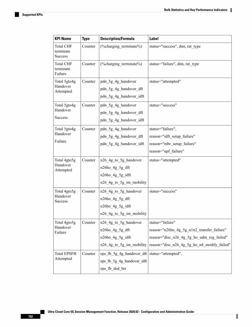
LabelDescription/FormulaTypeKPI Name
status="success", dnn, rat_type(%charging_terminate%)CounterTotal CHFterminateSuccess
status="failure", dnn, rat_type(%charging_terminate%)CounterTotal CHFterminateFailure
status="attempted"pdn_5g_4g_handover
pdn_5g_4g_handover_dft
pdn_5g_4g_handover_idft
CounterTotal 5gto4gHandoverAttempted
status="success"pdn_5g_4g_handover
pdn_5g_4g_handover_dft
pdn_5g_4g_handover_idft
CounterTotal 5gto4gHandover
Success
status="failure",
reason="idft_setup_failure"
reason="mbr_setup_failure"
reason="upf_failure"
pdn_5g_4g_handover
pdn_5g_4g_handover_dft
pdn_5g_4g_handover_idft
CounterTotal 5gto4gHandover
Failure
status="attempted"n26_4g_to_5g_handover
n26ho_4g_5g_dft
n26ho_4g_5g_idft
n26_4g_to_5g_im_mobility
CounterTotal 4gto5gHandoverAttempted
status="success"n26_4g_to_5g_handover
n26ho_4g_5g_dft
n26ho_4g_5g_idft
n26_4g_to_5g_im_mobility
CounterTotal 4gto5gHandoverSuccess
status="failure"
reason="n26ho_4g_5g_n1n2_transfer_failure"
reason="disc_n26_4g_5g_ho_udm_reg_failed"
reason="disc_n26_4g_5g_ho_n4_modify_failed"
n26_4g_to_5g_handover
n26ho_4g_5g_dft
n26ho_4g_5g_idft
n26_4g_to_5g_im_mobility
CounterTotal 4gto5gHandoverFailure
status="attempted",eps_fb_5g_4g_handover_dft
eps_fb_5g_4g_handover_idft
eps_fb_ded_brr
CounterTotal EPSFBAttempted
Ultra Cloud Core 5G Session Management Function, Release 2020.02 - Configuration and Administration Guide152
Bulk Statistics and Key Performance IndicatorsSupported KPIs

LabelDescription/FormulaTypeKPI Name
status="success",eps_fb_5g_4g_handover_dft
eps_fb_5g_4g_handover_idft
eps_fb_ded_brr
CounterTotal EPSFB
Success
status="failure",
reason="idft_setup_failure"
reason="mbr_setup_failure"
reason="upf_failure"
reason="sgw_failure"
eps_fb_5g_4g_handover_dft
eps_fb_5g_4g_handover_idft
eps_fb_ded_brr
CounterTotal EPSFBFailure
status="attempted"nr_to_untrusted_wifi_handover
pdn_5g_4g_handover
pdn_5g_4g_handover_dft
pdn_5g_4g_handover_idft
CounterTotalNRtoWifiAttempted
status="success"nr_to_untrusted_wifi_handover
pdn_5g_4g_handover
pdn_5g_4g_handover_dft
pdn_5g_4g_handover_idft
CounterTotalNRtoWifiSuccess
status="failure",
reason="nr_to_untrusted_wifi_invalid_json"
reason="nr_to_untrusted_wifi_invalid_paa"
reason="nr_to_untrusted_wifi_invalid_msg"
reason="nr_to_untrusted_wifi_pcf_failed"
reason="nr_to_untrusted_wifi_n40_failed"
reason="nr_to_untrusted_wifi_n4_failed"
reason="nr_to_untrusted_wifi_pcf_failed_post_cb"
reason="nr_to_untrusted_wifi_n40_failed_post_cb"
reason="nr_to_untrusted_wifi_n4_failed_post_cb"
reason="nr_to_untrusted_wifi_cbr_failed"
reason="nr_to_untrusted_wifi_n1n2_release_failed"
reason="nr_to_untrusted_wifi_n4_failed_post_ho"
reason="nr_to_untrusted_wifi_pcf_update_failed_post_ho"
reason="nr_to_untrusted_wifi_chf_update_failed_post_ho"
nr_to_untrusted_wifi_handover
pdn_5g_4g_handover
pdn_5g_4g_handover_dft
pdn_5g_4g_handover_idft
CounterTotalNRtoWifiFailure
Ultra Cloud Core 5G Session Management Function, Release 2020.02 - Configuration and Administration Guide153
Bulk Statistics and Key Performance IndicatorsSupported KPIs

LabelDescription/FormulaTypeKPI Name
status="attempted"n26_4g_to_5g_handover
n26ho_4g_5g_dft
n26ho_4g_5g_idft
CounterTotalWifitoNRAttempted
status="success"n26_4g_to_5g_handover
n26ho_4g_5g_dft
n26ho_4g_5g_idft
CounterTotalWifitoNRSuccess
status="failure"n26_4g_to_5g_handover
n26ho_4g_5g_dft
n26ho_4g_5g_idft
CounterTotalWifitoNRFailure
status="attempted"enb_to_untrusted_wifi_handoverCounterTotaleNBtoWifiAttempted
status="success"enb_to_untrusted_wifi_handoverCounterTotaleNBtoWifiSuccess
Ultra Cloud Core 5G Session Management Function, Release 2020.02 - Configuration and Administration Guide154
Bulk Statistics and Key Performance IndicatorsSupported KPIs

LabelDescription/FormulaTypeKPI Name
status="failure",
reason="enb_to_untrusted_wifi_to_enb_ho_reject"
reason="enb_to_untrusted_wifi_to_enb_invalid_sess_state"
reason="enb_to_untrusted_wifi_to_enb_invalid_json"
reason="enb_to_untrusted_wifi_to_enb_invalid_paa"
reason="enb_to_untrusted_wifi_to_enb_invalid_msg"
reason="enb_to_untrusted_wifi_to_enb_udm_failed"
reason="enb_to_untrusted_wifi_to_enb_n40_failed"
reason="enb_to_untrusted_wifi_to_enb_n4_failed"
reason="enb_to_untrusted_wifi_to_enb_pcf_failed_post_cb"
reason="enb_to_untrusted_wifi_to_enb_mbr_failed"
reason="enb_to_untrusted_wifi_to_enb_n4_failed_post_mbr"
reason="enb_to_untrusted_wifi_to_enb_n40_failed_post_cb"
reason="enb_to_untrusted_wifi_to_enb_n4_failed_post_cb"
reason="enb_to_untrusted_wifi_to_enb_n40_failed_post_db"
reason="enb_to_untrusted_wifi_to_enb_pcf_failed_post_db"
reason="enb_to_untrusted_wifi_to_enb_cbr_failed"
reason="enb_to_untrusted_wifi_to_enb_dbr_failed"
enb_to_untrusted_wifi_handoverCounterTotaleNBtoWifiFailure
status="attempted"untrusted_wifi_to_enb_handoverCounterTotalWifitoeNBAttempted
status="success",untrusted_wifi_to_enb_handoverCounterTotalWifitoeNBSuccess
Ultra Cloud Core 5G Session Management Function, Release 2020.02 - Configuration and Administration Guide155
Bulk Statistics and Key Performance IndicatorsSupported KPIs

LabelDescription/FormulaTypeKPI Name
status="failure",
reason="enb_to_untrusted_wifi_to_enb_ho_reject"
reason="enb_to_untrusted_wifi_to_enb_invalid_sess_state"
reason="enb_to_untrusted_wifi_to_enb_invalid_json"
reason="enb_to_untrusted_wifi_to_enb_invalid_paa"
reason="enb_to_untrusted_wifi_to_enb_invalid_msg"
reason="enb_to_untrusted_wifi_to_enb_udm_failed"
reason="enb_to_untrusted_wifi_to_enb_n40_failed"
reason="enb_to_untrusted_wifi_to_enb_n4_failed"
reason="enb_to_untrusted_wifi_to_enb_pcf_failed_post_cb"
reason="enb_to_untrusted_wifi_to_enb_mbr_failed"
reason="enb_to_untrusted_wifi_to_enb_n4_failed_post_mbr"
reason="enb_to_untrusted_wifi_to_enb_n40_failed_post_cb"
reason="enb_to_untrusted_wifi_to_enb_n4_failed_post_cb"
reason="enb_to_untrusted_wifi_to_enb_n40_failed_post_db"
reason="enb_to_untrusted_wifi_to_enb_pcf_failed_post_db"
reason="enb_to_untrusted_wifi_to_enb_cbr_failed"
reason="enb_to_untrusted_wifi_to_enb_dbr_failed"
untrusted_wifi_to_enb_handoverCounterTotalWifitoeNBFailure
4G Subscriber
The following table provides details of KPIs related to 4G subscriber statistics.
Labels dnn, qci and rat_type are used to filter the counters. Here, rat_type is eutra.Note
Ultra Cloud Core 5G Session Management Function, Release 2020.02 - Configuration and Administration Guide156
Bulk Statistics and Key Performance IndicatorsSupported KPIs

LabelDescription/FormulaTypeKPI Name
dnn,rat_type="eutra"Total number of PDNContexts
(%smf_session_counters%)
GaugeTotal Active sessions
dnnTotal number of activeBearers
(%total_bearer%)
GaugeTotal Active Bearers
dnn(%total_bearer-dedicated_bearer%)
GaugeTotal Active DefaultBearers
dnnTotal number of activeDedicated Bearers
(%dedicated_bearer%)
GaugeTotal Active DedicatedBearers
status="attempted",dnn(%pdn_sess_create+pcf_req_ded_brr_create +eps_fb_ded_brr)
CounterTotal Bearer CreationAttempted
status="success",dnn(%pdn_sess_create+pcf_req_ded_brr_create +eps_fb_ded_brr)
CounterTotal Bearers CreationSuccess
status="failure",dnn(%pdn_sess_create+pcf_req_ded_brr_create +eps_fb_ded_brr)
CounterTotal Bearers CreationFailure
status="attempted",dnn(%pcf_req_ded_brr_create+ eps_fb_ded_brr %)
CounterTotal Dedicated BearersAttempted
status="failure",dnn(%pcf_req_ded_brr_create+ eps_fb_ded_brr %)
CounterTotal Dedicated BearersFailure/Rejected
status="success", dnn,rat_type="eutra"
(%pcf_req_ded_brr_create+ eps_fb_ded_brr %)
CounterTotal Dedicated BearersSuccess
status="attempted",dnn(%pdn_sess_create%)CounterTotal CSR Attempted
status="failure",dnn,(%pdn_sess_create%)CounterTotal CSRFailure/Rejected
status="success",dnn(%pdn_sess_create%)CounterTotal CSR Success
status="attempted",dnn,fiveqi,rat_type="eutra"
(%create_bearer_request%)CounterTotal CBR Attempted
status="failure", fiveqi,dnn, rat_type="eutra"
(%create_bearer_request%)CounterTotal CBR failure
status="success",dnn,fiveqi,rat_type="eutra"
(%create_bearer_request%)CounterTotal CBR success
status="retransmit",dnn,fiveqi,rat_type="eutra"
(%create_bearer_request%)CounterTotal CBR retransmissionrx
Ultra Cloud Core 5G Session Management Function, Release 2020.02 - Configuration and Administration Guide157
Bulk Statistics and Key Performance IndicatorsSupported KPIs

LabelDescription/FormulaTypeKPI Name
status="attempted",dnn,fiveqi,rat_type="eutra"
(%delete_bearer_request%)
CounterTotal DBR Attempted
status="failure", fiveqi,dnn, rat_type="eutra"
(%delete_bearer_request%)CounterTotal DBRfailure/Rejected
status="success", fiveqi,dnn,fiveqi,rat_type="eutra"
(%delete_bearer_request%)
CounterTotal DBR success
status="retransmit", dnn,fiveqi, rat_type="eutra"
(%delete_bearer_request%)CounterTotal DBR retransmissiontx
status="attempted",dnn,fiveqi,rat_type="eutra"
(%update_bearer_request%)
CounterTotal UBR Attempted
status="failure", fiveqi,dnn, rat_type="eutra"
(%update_bearer_request%)
CounterTotal UBRfailure/Rejected
status="success", fiveqi,dnn, rat_type="eutra"
(%update_bearer_request%)
CounterTotal UBR Success
status="retransmit",dnn ,rat_type="eutra"
(%update_bearer_request%)CounterTotal UBR retransmission
dnn(%eps_fb_ded_brr%)CounterTotal EPSFB DedicatedBearers
5G Subscriber
The following table provides details of KPIs related to 5G subscriber statistics.
LabelDescription/FormulaTypeKPI Name
dnn,rat_type="nr"Total number of PDUContexts
(%smf_session_counters%)
GaugeTotal Active sessions
dnn,fiveqi,rat_type="nr"(%policy_pdu_flows_current%)GaugeTotal Active Flows
status="attempted",dnn,fiveqi, rat_type="nr"
(%policy_pdu_flows_total%)CounterTotal Flow CreationAttempted
status="success",dnn,fiveqi, rat_type="nr"
(%policy_pdu_flows_total%)CounterTotal Flow CreationSuccess
status="failure",dnn,fiveqi, rat_type="nr"
(%policy_pdu_flows_total%)CounterTotal Flow CreationFailure
WiFi Subscriber
The following table provides details of KPIs related to WiFi subscriber statistics.
Ultra Cloud Core 5G Session Management Function, Release 2020.02 - Configuration and Administration Guide158
Bulk Statistics and Key Performance IndicatorsSupported KPIs

LabelDescription/FormulaTypeKPI Name
status="attempted",dnn,rat_type="wlan"
(%untrusted_wifi_to_enb_handover%)
CounterTotal CSR Attempted
status="failure",dnn,rat_type="wlan"
(%untrusted_wifi_to_enb_handover%)
CounterTotal CSRfailure/Rejected
status="success",dnn ,rat_type="wlan"
(%untrusted_wifi_to_enb_handover%)
CounterTotal CSR success
status="attempted",rat_type="wlan"
(%create_bearer_request%)CounterTotal CBR Attempted
status="failure",rat_type="wlan"
(%create_bearer_request%)CounterTotal CBR failure
status="success",rat_type="wlan"
(%create_bearer_request%)CounterTotal CBR success
status="attempted",rat_type="wlan"
(%delete_bearer_request%)CounterTotal DBR Attempted
status="failure",rat_type="wlan"
(%delete_bearer_request%)
CounterTotal DBRfailure/Rejected
status="success",rat_type="wlan"
(%delete_bearer_request%)
CounterTotal DBR success
Ultra Cloud Core 5G Session Management Function, Release 2020.02 - Configuration and Administration Guide159
Bulk Statistics and Key Performance IndicatorsSupported KPIs

Ultra Cloud Core 5G Session Management Function, Release 2020.02 - Configuration and Administration Guide160
Bulk Statistics and Key Performance IndicatorsSupported KPIs

C H A P T E R 13Cisco Common Data Layer
• Feature Summary and Revision History, on page 161• Feature Description, on page 162• How it Works, on page 162• Call Flows, on page 163• Configuring the CDL Through SMF Ops Center, on page 164
Feature Summary and Revision History
Summary DataTable 34: Summary Data
SMFApplicable Product(s) or Functional Area
SMIApplicable Platform(s)
Disabled – Configuration RequiredFeature Default Setting
Not ApplicableRelated Changes in this Release
Not ApplicableRelated Documentation
Revision HistoryTable 35: Revision History
ReleaseRevision Details
Pre-2020.02.0First introduced.
Ultra Cloud Core 5G Session Management Function, Release 2020.02 - Configuration and Administration Guide161

Feature DescriptionThe PCF extends support to the Geo Redundant (GR) version of the Cisco CommonData Layer (CDL).Whenthe primary CDL endpoint fails, PCF attempts the same operation on the next highly rated secondary endpointthus providing a non-disrupted N7 or Diameter message handling. If the next rated endpoint is unavailable,then PCF reattempts the operation on the subsequent endpoint that has the highest rating and so on.
ArchitectureThe following figure depicts the failover that happens when the SMF service is unable to access the CDLdatastore endpoint.
Figure 22: CDL Datastore Architecture
With relevance to this architecture, you can configure CDL through SMFOps Center. When the SMF connectsto the CDL, it uses the local endpoints.
How it WorksWhen you configure the CDL in SMF through the SMF Ops Center, SMF gets enabled to support multipleCDL datastore endpoints. You can configure the endpoints by specifying the IP addresses, ports, and assigningratings to each endpoint. By default, SMF considers the local endpoint as the primary endpoint, which hasthe highest rating. SMF performs CDLAPI operations on the primary endpoint. If this endpoint is unavailable,then SMF routes the operations to the next highest rated endpoint. SMF keeps failing over to the accessiblesecondary endpoint or until all the configured secondaries are exhausted. It does not reattempt a query on thenext rated endpoint if the endpoint is reachable but responds with error or timeout.
If SMF is unable to access any of the endpoints in the cluster, then CDL operation fails with the "DatastoreUnavailable" error.
Ultra Cloud Core 5G Session Management Function, Release 2020.02 - Configuration and Administration Guide162
Cisco Common Data LayerFeature Description

Call FlowsThis section describes the call flow that is associated with this feature.
• CDL Endpoint Failure Call Flow, on page 163
CDL Endpoint Failure Call FlowThis section describes the SMF local data store endpoint failure call flow.
Figure 23: CDL Endpoint Failure Call Flow
Table 36: CDL Endpoint Failure Call Flow Description
DescriptionStep
The AMF sends a Create Request to SMF REST endpoint over the N11 interface.1
After receiving the request, the SMFREST endpoint forwards the Create Request to the SMF service.2
The SMF service attempts to reach the CDL endpoint to send the session creation request. However,the CDL endpoint is unreachable.
3
The Create Request is evaluated in the stored session and the SMF service forwards the request tothe CDL endpoint.
4
After the call request is successful, the SMF service notifies the Success Message to the SMF RESTendpoint.
5
The SMF REST endpoint forwards the Success Message to the AMF.6
Ultra Cloud Core 5G Session Management Function, Release 2020.02 - Configuration and Administration Guide163
Cisco Common Data LayerCall Flows

LimitationsThe CDL configuration in SMF has the following limitations:
• The SMF service attempts to reroute the calls only when it encounters gRPC errors such asUNAVAILABLE. It does not acknowledge errors that the datastore endpoint returns and actual gRPCtimeouts such as DEADLINE_EXCEEDED gRPC status code.
• The SMF service does not resolve failures occurring with the datastore such as indexing and slot failures.The CDL layer must resolve these failures and if necessary, send an API call on the remote.
Configuring the CDL Through SMF Ops CenterThe configuration of the CDL using SMF Ops Center involves the following steps:
1. Configuring the CDL Session Database and Defining the Base Configuration, on page 164
2. Configuring the Zookeeper in CDL, on page 165
Configuring the CDL Session Database and Defining the Base ConfigurationThis section describes how to configure the CDL session database and define the base configuration in SMF.
1. From the SMF Ops Center, run the following command to configure the CDL session database and baseconfiguration.
configurecdl system-id system_id
cdl node-type node_type
cdl zookeeper replica zookeeper_replica_id
exitcdl logging default-log-level debug_level
cdl datastore sessioncluster-id cluster_id
endpoint replica 1
endpoint replica num_replica
index map map_value
slot replica num_replica
slot map num_map/shards
slot write-factor write_factor
slot notification host host
slot notification port port
slot notification limit tps
index replica num_replica
index map num_map/shards
index write-factor write_factor
end
NOTES:
Ultra Cloud Core 5G Session Management Function, Release 2020.02 - Configuration and Administration Guide164
Cisco Common Data LayerLimitations

• cdl system-id system_id: This is an optional command. Specifies the system or Kubernetes clusteridentity. The default value is 1.
• cdl node-type node_type: This is an optional command. Specifies the Kubernetes node label to configurethe node affinity. The default value is “session.” Accepted length of the value is 0–64 alphabets.
• cdl zookeeper replica zookeeper_replica_id: Specifies the zookeeper replica server's ID.
• endpoint replica num_replica: This is an optional command. Specifies the number of replicas to becreated. The default value is 1. Must be an integer in the range of 1–16.
• slot replica num_replica: This is an optional command. Specifies the number of replicas to be created.The default value is 1. num_replica must be an integer in the range of 1–16.
• slot map num_map/shards: This is an optional command. Specifies the number of partitions in a slot.The default value is 1. num_map/shards must be an integer in the range of 1–1024.
• slot write-factor write_factor: This is an optional command. Specifies the number of copies to be writtenbefore successful response. The default value is 1. write_factor must be an integer in the range of 0–16.Make sure that the value is lower than or equal to the number of replicas.
• slot notification host host: This is an optional command. Specifies the notification server hostname orIP address. The default value is datastore-notification-ep.
• slot notification port port: This is an optional command. Specifies the notification server Port number.The default value is 8890.
• slot notification limit tps: This is an optional command. Specifies the notification limit per second. Thedefault value is 2000.
• index replica num_replica: This is an optional command. Specifies the number of replicas to be created.The default value is 2. num_replica must be an integer in the range of 1–16.
• index map num_map/shards: This is an optional command. Specifies the number of partitions in a slot.The default value is 1. num_map/shards must be an integer in the range of 1–1024. Avoid modifyingthis value after deploying the CDL.
• index write-factor write_factor: This is an optional command. Specifies the number of copies to bewritten before successful response. The default value is 1. write_factor must be an integer in the rangeof 0–16.
Configuring the Zookeeper in CDLThis section describes how to configure the Zookeeper in CDL.
1. Open the Policy Ops Center console and navigate to the datastore CLI.
2. Run the following command to define the parameters.
configurecdl zookeeper data-storage-size data_storage_size_in_gb
log-storage-size log_storage_size_in_gb
replica number_of_replicas
enable-JMX-metrics boolean_value
Ultra Cloud Core 5G Session Management Function, Release 2020.02 - Configuration and Administration Guide165
Cisco Common Data LayerConfiguring the Zookeeper in CDL

enable-persistence boolean_value
end
NOTES:
All the following parameters are optional.
• cdl zookeeper data-storage-size data_storage_size_in_gb: Specifies the size of the Zookeeper datastorage in gigabyte. The default value is 20 GB. Accepted value is an integer in the range of 1-64.
• log-storage-size log_storage_size_in_gb: Specifies the size of the Zookeeper data log's storage ingigabyte. The default value is 20 GB. Accepted value is an integer in the range of 1-64.
• replica num_replicas: Specifies the number of replicas that must be created. The default value is 3.Accepted value is an integer in the range of one to 16.
• enable-JMX-metrics boolean_value: Specifies the status of the JMX metrics. The default value istrue.
• enable-persistence boolean_value: Specifies the status of the persistent storage for Zookeeper data.The default value is false.
Sample ConfigurationThis section shows a sample configuration of CDL in a HA environment.cdl system-id system_idcdl zookeeper replica num_zk_replicacdl datastore sessionendpoint replica ep_replicaindex map index_shard_countslot replica slot_replicaslot map slot_shard_countexit
Ultra Cloud Core 5G Session Management Function, Release 2020.02 - Configuration and Administration Guide166
Cisco Common Data LayerSample Configuration

C H A P T E R 14CHF and PCF Integration for Access and MobilityProcedures
• Feature Summary and Revision History, on page 167• Feature Description, on page 168• How it Works, on page 168
Feature Summary and Revision History
Summary DataTable 37: Summary Data
SMFApplicable Product(s) or Functional Area
SMIApplicable Platform(s)
Enabled - Always-onFeature Default Setting
Not ApplicableRelated Changes in this Release
Not ApplicableRelated Documentation
Revision HistoryTable 38: Revision History
ReleaseRevision Details
Pre-2020.02.0First introduced.
Ultra Cloud Core 5G Session Management Function, Release 2020.02 - Configuration and Administration Guide167

Feature DescriptionThe SMF leverages the 3GPP provision for the access and mobility procedures. With this provision, the SMFintegrates the Charging Function (CHF) and Policy Control Function (PCF). SMF supports the followingintegration functions:
• CHF and PCF Integration for Intra-AMF and Inter-AMF N2-Based Handovers—SMF supports thisfunction when a UE moves from one NG-RAN to another NG-RAN for Data Forwarding Tunnel (DFT)and Indirect Data Forwarding Tunnel (IDFT) cases.
• CHF and PCF Integration for N26 4G to 5G Handover—SMF supports the EPS to 5GS procedures withthe N26 interface. SMF establishes Uplink (UL) Packet Detection Rule (PDR) or Downlink (DL) PDRtoward with the qualified EPS Bearer Identity (EBI) list in 5GS and replicate EBIs to the respectiveflows. SMF also creates IDFT to support the Downlink forwarding traffic between SGW-U to NR overUPF.
• CHF and PCF Integration for N26 5G to 4G Handover—SMF supports 5GS to EPS procedures with theN26 interface. PGW-C establishes UL PDRs or DL PDRs toward SGW-U with qualified flows in 5GSand replicate EBIs to respective flows. PGW-C also creates an IDFT tunnel to support Downlinkforwarding traffic between NR to SGW-U over UPF. Session-Level or Rating-Group level ChargingTriggers are received during PDU Session establishment or in response to SMF-initiated Charging UpdateRequest or CHF-initiated Charging Update Notify response in EPS procedures.
• CHF and PCF Integration for Xn Handover—SMF supports the Xn-based inter NG-RAN handover withand without UPF reallocation. The SMF supports Xn handovers for intra-AMF mobility only. SMFprocesses the received SM context update request that includes the path switch request N2-based messageand the access-ide parameters. These parameters identify the CHF and PCF triggers that are receivedduring PDU session establishment.
• CHF and PCF Integration for Service Request Procedures—SMF supports the service requests from boththe UE and network-initiated procedures. Either a UE in CM-Idle state or the 5GC uses the ServiceRequest procedure to request the establishment of a secure connection to an AMF. The UE in both theCM-Idle and in CM-Connected state use the Service Request procedure to activate a User Plane connectionfor an established PDU Session. The UE does not initiate a Service Request procedure if an ongoingService Request procedure exists.
SMF saves the CHF and PCF triggers that SMF receives from CHF and PCF as part of session creation orPCF or UE-initiated modifications. When a UE triggers access and mobility procedures for the precedingfunctions, SMF identifies the triggers from CHF and PCF against the received access parameters. Then, SMFsends an update toward CHF and PCF.
How it WorksThe SMF integrates the CHF and PCF functions based on the following information:
• Policy control request triggers that are received in the SM policy decision while PDU session is establishedor PCF or UE initial modification.
• Session-level or rating-group-level charging triggers that are received while PDU session is establishedor in response to SMF-initiated Charging Update Request or CHF-initiated Charging Update NotifyRequest.
Ultra Cloud Core 5G Session Management Function, Release 2020.02 - Configuration and Administration Guide168
CHF and PCF Integration for Access and Mobility ProceduresFeature Description

The SMF supports the following access-side information to detect the PCF and CHF triggers. The SMF sendsthe trigger information to the CHF and PCF during the N2-based handover.
Table 39: Access-Side Information for PCF and CHF Triggers
PCF-TriggersCHF-TriggersAccess-Side
SAREA_CHUSER_LOCATION_CHANGEUserLocation
SAREA_CHUE_TIMEZONE_CHANGEUeTimeZone
PLMN_CHPLMN_CHANGEServingNetwork
SERVING_NODE_CHANGETargetServingNfId
Call FlowsThis section describes the following call flows:
• CHF and PCF Integration for Intra-AMF and Inter-AMF N2-Based Handovers Call Flow
• CHF and PCF Integration for N26 4G to 5G Handover Call Flow
• CHF and PCF Integration for N26 5G to 4G Handover Call Flow
• CHF and PCF Integration for Xn Handover Call Flow
• CHF and PCF Integration for Service Request Procedures
CHF and PCF Integration for Intra-AMF and Inter-AMF N2-Based Handovers Call FlowThis section describes the call flow for the CHF and PCF Integration for Intra-AMF and Inter-AMFN2-basedhandovers.
Ultra Cloud Core 5G Session Management Function, Release 2020.02 - Configuration and Administration Guide169
CHF and PCF Integration for Access and Mobility ProceduresCall Flows

Figure 24: CHF and PCF Integration for Intra-AMF and Inter-AMF N2-Based Handovers Call Flow
Table 40: CHF and PCF Integration for Intra-AMF and Inter-AMF N2-Based Handovers Call Flow Description
DescriptionStep
The PDU session is established over S-AMF and SMF by communicating with UPF,PCF, or CHF for IPv4, IPv6, or dual-stack.
The PCF provides Policy Control Request trigger for SM policy decision as responseto the request for creation of SM policy control.
The CHF provides session-level and rating-group-level triggers to SMF as the ChargingData Create Response.
1
The T-AMF sends SMContext Update Request by including handover state to the SMF.The handover state includes the information on preparation, UE location, UE time zone,target serving NFID, and serving network. The AMF includes target serving NFIDinformation for inter-AMF handoff.
2
The SMF detects access-side changes that are received in the SMContext Update Requestand the charging triggers with the information that is available in Step 2.
2a
The SMF detects the PCF triggers with the information that is available in Step 2.2b
Ultra Cloud Core 5G Session Management Function, Release 2020.02 - Configuration and Administration Guide170
CHF and PCF Integration for Access and Mobility ProceduresCHF and PCF Integration for Intra-AMF and Inter-AMF N2-Based Handovers Call Flow

DescriptionStep
The N2-based Handover Preparation procedure starts from T-AMF towards the SMFand CHF and vice-versa.
3
In the N2-based Handover Execution procedure, in case of inter-AMF handoff, the SMFreceives SM Context Release Request from S-AMF and responds with the SM ContextRelease Response to the S-AMF.
4
In N2-based Handover Execution procedure, the UPF provides the usage report as partof N4 modification response. The SMF holds the final SM Context Release Responsewhen the SMF detects the CHF or PCF triggers.
5
The SMF sends the Charging Data Update Request to the CHF. This request includesthe information on session-level triggers, multi-unit-Information (with rating-group-leveltriggers with usage report), customer identification, and PDU session charginginformation.
6
The CHF sends the ChargingData Update Responsewith optional multi-unit-information.The CHF also sends the new session or rating-group-level triggers to the SMF.
7
The SMF processes the Charging Data Update Response and updates the PDU session.The SMF does not send the N4 modification request to the UPF for the newly receivedinformation from the CHF.
7a
The SMF posts the internal transaction to send the SM policy update information forPCF triggers.
8
The SMF sends the SM Context Update Response, for which the handover state iscomplete, to the T-AMF.
9
The SMF sends the SM Policy Control Update information to the PCF. The SM PolicyControl Update information includes details, such as the user location information, UEtime zone, and serving network.
10
The PCF sends the SMPolicy Control Update Response, which is the SM policy decision,to the SMF.
11
The SMF processes the SM policy decision that is received as response and handles theresponse as PCF Initiation Modify procedure.
12
CHF and PCF Integration for N26 4G to 5G Handover Call FlowThis section describes the call flow for the CHF and PCF Integration for N26 4G to 5G handovers.
Ultra Cloud Core 5G Session Management Function, Release 2020.02 - Configuration and Administration Guide171
CHF and PCF Integration for Access and Mobility ProceduresCHF and PCF Integration for N26 4G to 5G Handover Call Flow

Figure 25: CHF and PCF Integration for N26 4G to 5G Handover Call Flow
Table 41: CHF and PCF Integration for N26 4G to 5G Handover Call Flow Description
DescriptionStep
The PDU session is established over MME, SGW, and SMF by communicating withUPF, PCF, or CHF for IPv4, IPv6, or dual-stack.
The PCF provides Policy Control Request trigger for SM policy decision as responseto the request for creation of SM policy control.
The CHF provides session-level and rating-group-level triggers to SMF as the ChargingData Create Response.
1
The T-AMF sends SMContext Update Request by including handover state to the SMF.The SMContext Update Request includes the information on handover state as preparing,UE location, UE time zone, serving NFID, serving network, and RAT type.
2
The SMF detects access-side changes that are received in the SMContext Create Requestand the charging triggers with the information that is available in Step 2.
2a
The SMF detects the PCF triggers with the information that is available in Step 2.2b
The N26-based Handover Preparation procedure starts from T-AMF toward the SMFor PGW-C and UHF and vice versa, as defined in 3GPP TS 23.502, section 4.1.9.3.
3
Ultra Cloud Core 5G Session Management Function, Release 2020.02 - Configuration and Administration Guide172
CHF and PCF Integration for Access and Mobility ProceduresCHF and PCF Integration for N26 4G to 5G Handover Call Flow
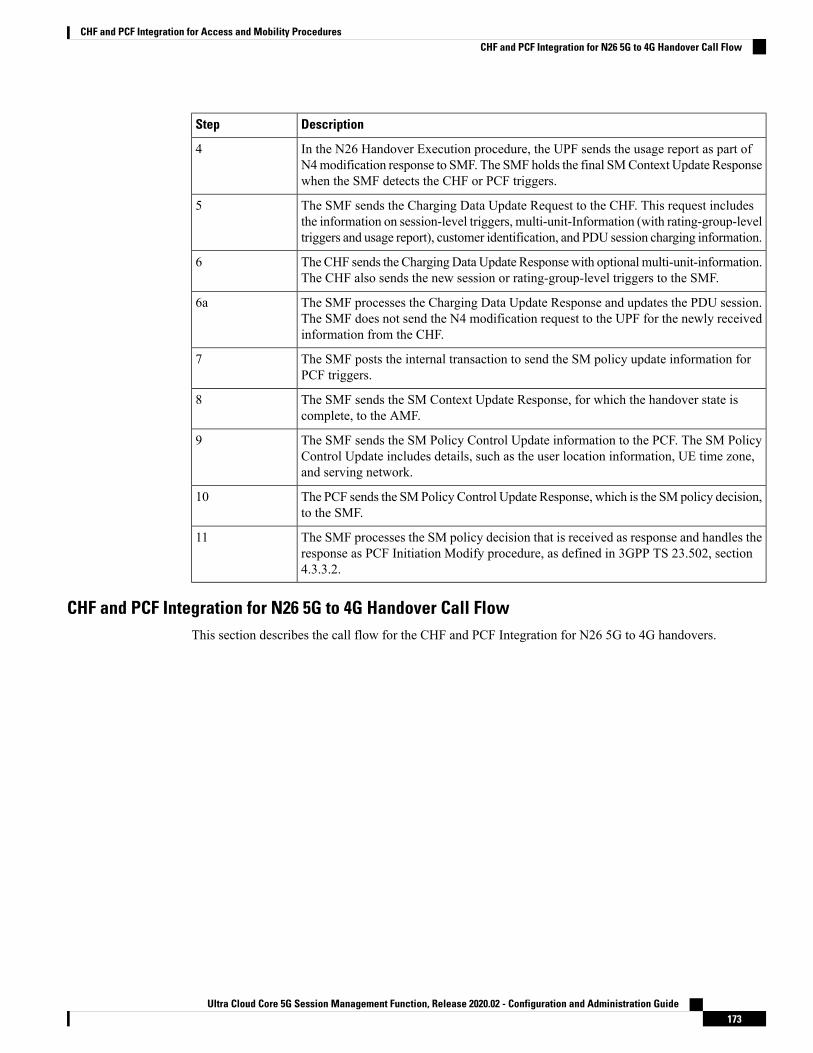
DescriptionStep
In the N26 Handover Execution procedure, the UPF sends the usage report as part ofN4modification response to SMF. The SMF holds the final SMContext Update Responsewhen the SMF detects the CHF or PCF triggers.
4
The SMF sends the Charging Data Update Request to the CHF. This request includesthe information on session-level triggers, multi-unit-Information (with rating-group-leveltriggers and usage report), customer identification, and PDU session charging information.
5
The CHF sends the ChargingData Update Responsewith optional multi-unit-information.The CHF also sends the new session or rating-group-level triggers to the SMF.
6
The SMF processes the Charging Data Update Response and updates the PDU session.The SMF does not send the N4 modification request to the UPF for the newly receivedinformation from the CHF.
6a
The SMF posts the internal transaction to send the SM policy update information forPCF triggers.
7
The SMF sends the SM Context Update Response, for which the handover state iscomplete, to the AMF.
8
The SMF sends the SM Policy Control Update information to the PCF. The SM PolicyControl Update includes details, such as the user location information, UE time zone,and serving network.
9
The PCF sends the SMPolicy Control Update Response, which is the SM policy decision,to the SMF.
10
The SMF processes the SM policy decision that is received as response and handles theresponse as PCF Initiation Modify procedure, as defined in 3GPP TS 23.502, section4.3.3.2.
11
CHF and PCF Integration for N26 5G to 4G Handover Call FlowThis section describes the call flow for the CHF and PCF Integration for N26 5G to 4G handovers.
Ultra Cloud Core 5G Session Management Function, Release 2020.02 - Configuration and Administration Guide173
CHF and PCF Integration for Access and Mobility ProceduresCHF and PCF Integration for N26 5G to 4G Handover Call Flow

Figure 26: CHF and PCF Integration for N26 5G to 4G Handover Call Flow
Table 42: CHF and PCF Integration for N26 5G to 4G Handover Call Flow Description
DescriptionStep
The PDU session is established over S-AMF or SMF by communicating with UPF, PCF,or CHF for IPv4, IPv6, or dual-stack.
The PCF provides Policy Control Request trigger for SM policy decision as responseto the request for creation of SM policy control.
The CHF provides session-level and rating-group-level triggers to SMF as the ChargingData Create Response.
1
The 5G to 4G Handover procedure starts from AMF toward the SMF or PGW-C andvice versa. AMF initiates the SM Context Retrieve Request to establish the UL PDRsand send SM Context Update Response to start the IDFT tunnel, if necessary.
2
In the N26 5G to 4GHandover Execution procedure, the SGW sends the GTPv2ModifyBearer Request to PGW-C. This request includes the information on UE location, UEtime zone, RAT type, and Bearer Context List.
3
The SMF detects access-side changes that are received in the SMContext Update Requestand the charging triggers with the information that is available in Step 3.
3a
Ultra Cloud Core 5G Session Management Function, Release 2020.02 - Configuration and Administration Guide174
CHF and PCF Integration for Access and Mobility ProceduresCHF and PCF Integration for N26 5G to 4G Handover Call Flow

DescriptionStep
The SMF detects the PCF triggers with the information that is available in Step 3.3b
In the N26 Handover 5G to 4G Execution procedure, the PGW-C requests UPF to createa GTP-U tunnel for each flow. This tunnel is for the EBIs received in the Bearer ContextList of GTPv2 Modify Bearer Request. After the DL PDRs are established, UPF sendsthe usage report as part of N4 modification response to SMF. The SMF holds the finalGTPv2 Modify Bearer Response when the SMF detects the CHF or PCF triggers.
4
The SMF sends the Charging Data Update Request to the CHF. This request includesthe information on session-level triggers, multi-unit-Information (with rating-group-leveltriggers and usage report), customer identification, and PDU session charging information.
5
The CHF sends the ChargingData Update Responsewith optional multi-unit-information.The CHF also sends the new session or rating-group-level triggers to the SMF.
6
The SMF or PGW-C processes the Charging Data Update Response and updates thePDU session. The SMF does not send the N4 modification request to the UPF for thenewly received information from the CHF.
6a
The SMF or PGW-C posts the internal transaction to send the SM policy updateinformation for PCF triggers.
7
The SMF or PGW-C sends the SM Context Update Response, for which the handoverstate is complete, to the AMF.
8
The SMF or PGW-C sends the SM Policy Control Update information to the PCF. TheSM Policy Control Update includes details, such as the user location information, UEtime zone, and serving network.
9
The PCF sends the SMPolicy Control Update Response, which is the SM policy decision,to the SMF.
10
The SMF processes the SM policy decision that is received as response and handles theresponse as PCF Initiation Modify procedure, as defined in 3GPP TS 23.502, section4.3.3.2.
11
CHF and PCF Integration for Xn Handover Call FlowThis section describes the call flow for the CHF and PCF Integration for the Xn handover.
Ultra Cloud Core 5G Session Management Function, Release 2020.02 - Configuration and Administration Guide175
CHF and PCF Integration for Access and Mobility ProceduresCHF and PCF Integration for Xn Handover Call Flow

Figure 27: CHF and PCF Integration for Xn Handover Call Flow
Table 43: CHF and PCF Integration for Xn Handover Call Flow Description
DescriptionStep
The PDU session is established over MME, SGW, and SMF by communicating withUPF, PCF, or CHF for IPv4, IPv6, or dual-stack.
The PCF provides Policy Control Request trigger for SM policy decision as responseto the request for creation of SM policy control.
The CHF provides session-level and rating-group-level triggers to SMF as the ChargingData Create Response.
1
The AMF sends SM Context Update Request to the SMF. The SM Context UpdateRequest includes the information on UE location, UE time zone, and path switch requestN2 message.
2
The SMF detects access-side changes that are received in the SMContext Update Requestand the charging triggers with the information that is available in Step 2.
2a
The SMF detects the PCF triggers with the information that is available in Step 2.2b
Ultra Cloud Core 5G Session Management Function, Release 2020.02 - Configuration and Administration Guide176
CHF and PCF Integration for Access and Mobility ProceduresCHF and PCF Integration for Xn Handover Call Flow

DescriptionStep
The Xn Handover Preparation procedure starts from SMF toward UPF and vice versa,as defined in 3GPP TS 23.502 section 4.9.1.2.
SMF sends the N4 Modification Request to UPF and updates the received DL tunnelinformation of T-gNB. After the tunnel information is updated, UPF provides the usagereport as part of N4modification response. The SMF holds the final SMContext UpdateResponse when the SMF detects the CHF or PCF triggers.
3
The SMF sends the Charging Data Update Request to the CHF. This request includesthe information on session-level triggers, multi-unit-Information (with rating-group-leveltriggers and usage report), customer identification, and PDU session charging information.
4
The CHF sends the ChargingData Update Responsewith optional multi-unit-information.The CHF also sends the new session or rating-group-level triggers to the SMF.
5
The SMF processes the Charging Data Update Response and updates the PDU session.The SMF does not send the N4 modification request to the UPF for the newly receivedinformation from the CHF.
5a
The SMF posts the internal transaction to send the SM policy update information forPCF triggers.
6
The SMF sends the SM Context Update Response to the AMF. This response includesthe path switch request acknowledgment N2 message.
7
The SMF sends the SM Policy Control Update information to the PCF. The SM PolicyControl Update includes details, such as the user location information and UE time zone.
8
The PCF sends the SMPolicy Control Update Response, which is the SM policy decision,to the SMF.
9
The SMF processes the SM policy decision that is received as response and handles theresponse as PCF Initiation Modify procedure, as defined in 3GPP TS 23.502, section4.3.3.2.
10
CHF and PCF Integration for Service Request ProceduresThis section describes the CHF and PCF integration for service request procedures.
SMF processes the received SM Context Update Request to update N3 tunnel path state from Idle to Activeor Active to Idle. SMF performs the following steps:
1. When UE is in CM-Idle state at AMF, which is Active to Idle mode—Based on the configuration, SMFupdates UPF for N3 tunnel state to drop or buffer by sending the N4 session mode request. Based oncharging configuration, SMF receives a usage report. Based on the Charging Triggers that qualify duringsession creation, SMF sends the N40 Charging Update request.
2. When UE is in CM-Connected state at AMF, which implies SMF receives UE-requested Procedures tochange the subscriber N3 Tunnel Path from Idle to Active State—SMF receives the updated user locationand UE time zone in the SM Context Update Request. SMF sends the N4 Session Modification Requestto UPF to update the DL tunnel details of gNB. Based on charging configuration, SMF receives a usagereport. Based on the Charging Triggers that qualify during session creation, SMF sends the N40 ChargingUpdate request.
Ultra Cloud Core 5G Session Management Function, Release 2020.02 - Configuration and Administration Guide177
CHF and PCF Integration for Access and Mobility ProceduresCHF and PCF Integration for Service Request Procedures

3. When the N3 Tunnel is unavailable for the Network Service Request Triggers, which implies that UE isin CM-Idle state at AMF—SMF initiates the Network Service Request Procedures for AMF to initiatePaging toward the end user. Then, AMF begins the UE Service Request Procedures to configure the N3Tunnel as specified in Step 2.
Standards ComplianceThe CHF and PCF integration for Intra-AMF and Inter-AMF N2-based handovers feature complies with thefollowing standards:
• 3GPP TS 23.502 V15.2.0 (2018-09)
Ultra Cloud Core 5G Session Management Function, Release 2020.02 - Configuration and Administration Guide178
CHF and PCF Integration for Access and Mobility ProceduresStandards Compliance

C H A P T E R 15Content Filtering, Event Detail Records, andX-Header Enrichment Support
• Feature Summary and Revision History, on page 179• Feature Description, on page 180• Content Filtering Support, on page 180• EDR Support, on page 181• Metadata Provided by SMF for EDR, on page 181• X-Header Insertion Support, on page 181• Supported X-Header Information, on page 182• Configuring Content Filtering, EDR, and X-Header Insertion Support, on page 182• Bearer QCI Support, on page 185
Feature Summary and Revision History
Summary DataTable 44: Summary Data
SMFApplicable Product(s) or Functional Area
SMIApplicable Platform(s)
Disabled - Configuration RequiredFeature Default Setting
Not ApplicableRelated Changes in this Release
Not ApplicableRelated Documentation
Ultra Cloud Core 5G Session Management Function, Release 2020.02 - Configuration and Administration Guide179

Revision HistoryTable 45: Revision History
ReleaseRevision Details
Pre-2020.02.0First introduced.
Feature DescriptionThe SMF supports the following functionality:
• Content Filtering
• Event Detail Record (EDR)
• X-header Enrichment
Content Filtering SupportThe Content Filtering (CF) service prevents subscribers from inadvertently getting exposed to universallyunacceptable content, or content that is inappropriate as per subscriber preferences. Based on the URLs in thesubscriber requests, the CF service filters HTTP and WAP requests from mobile subscribers. Operators canfilter and control the content for an individual subscriber to access.
The CF service provides the following solutions:
• URL Blacklisting—In this solution, all HTTP or WAP URLs in subscriber requests must match againsta database of "blacklisted" URLs. If there is a match, it discards the flow, redirects, or terminates as perthe configuration. In case of no match, subscribers view the content as usual.
URL Blacklisting may not be a subscriber opt-in service. Operators can enable URL Blacklisting eitherfor all subscribers or for a subset of subscribers. Typical cases include applying a blacklisted databaseof child porn URLs to all subscribers so that they are inadvertently not exposed to the universallyunacceptable content.
• Category-based Static Content Filtering—In this solution, all HTTP orWAPURLs in subscriber requestsmust match against a static URL categorization database. Action initiates based on the URL's categoryand as per the configuration in the subscriber CF policy. Possible actions include:
• Permitting
• Blocking
• Redirecting
• Inserting content
Ultra Cloud Core 5G Session Management Function, Release 2020.02 - Configuration and Administration Guide180
Content Filtering, Event Detail Records, and X-Header Enrichment SupportRevision History

EDR SupportEDRs are usage records with support to configure content information, format, and generation of triggers bythe system administrative user. The EDRs are generated according to explicit action statements in rulecommands. Several EDR schema types, where each schema type includes a series of analyzer parameternames, exist in the EDR. The EDRs are generated in CSV format at the time of each event.
The EDRs are stored in timestamped files that you can download through SFTP from the configured context.The EDRs are generated on per flow basis, and they catch whatever bytes get transmitted over that flowincluding those retransmitted.
Metadata Provided by SMF for EDRThe SMF provides the following metadata to the User Plane Function (UPF), which includes the data in thegenerated EDRs:
• Called-Station-ID: Specifies the DNN for the session
• Calling-Station-ID: Specifies the MSISDN of the UE
• RAT Type: RAT type for the current session (NR or EUTRAN)
• ULI: User location for the current session
The UPF receives the above data in the "Subscriber Parameters" IE in the PFCP Session Establishment Requestmessage. The RAT type and ULI can change during the lifetime of session (for events, such as 5G to 4Ghandover). The UPF receives the changed values of these parameters in the PFCP Session ModificationRequest message.
NOTES:
• All the parameters are always sent from the SMF to the UPF irrespective of EDR configuration beingavailable. These parameters ensure that any change in configuration after the session creation isimmediately applied on the UPF.
• The SMF supports EDR-related configurations. However, the SMF does not require these configurationsfor its functionality. These configurations are sent to the UPF through RCM.
X-Header Insertion SupportWith the X-Header Insertion and X-Header Encryption features, collectively known as Header Enrichment,you can append headers to HTTP or WSP GET and POST request packets, and HTTP response packets foruse by end applications. For example, mobile advertisement insertion (MSISDN, IMSI, IP address,user-customizable, and so on.
Ultra Cloud Core 5G Session Management Function, Release 2020.02 - Configuration and Administration Guide181
Content Filtering, Event Detail Records, and X-Header Enrichment SupportEDR Support

Supported X-Header InformationOut of all the configurable X-header information, some information requires control plane (SMF) to send thecorresponding values to the user plane (UPF). The following table lists the information that is sent from theSMF to the UPF for X-header Insertion support.
Modified in SessionModification
Present in SessionEstablishment
DescriptionXheader Field
N/AN/AInserts the configured string in xheaderString Constant
N/AYesPer Flow/Bearer Charging IdCharging ID
N/AYesIMEI for the callIMEI
N/AYesIMSI for the callIMSI
YesYesRAT type for the UE sessionRat-Type
N/AYesMCC/MNC of the SGW/AMFs-mcc-mnc
YesYesAMF/SGW addressSgsn-address
YesYesUser Location InfoULI
YesYesN4/S5 endpoint of SMFGGSN-Address
N/AN/AMSISDN of the UERadius-station-ID
YesYesRulebase for a callSn-rulebase
N/AN/AIP address allocated to UESubscriber-ip-address
NoYesObtained from MSISDNMsisdn-no-cc
The subscriber-specific fields—IMSI, MSIDN, and IMEI—are encoded in the "User ID" standard IE. See,3GPP 29.244, Section 8.2.101 for more information.
Rest of the fields are sent in the "Subscriber Parameters" proprietary AVP. Some fields, such as the "Rulebase"and "UE IP address", are sent as a part of the created PDRs.
NOTES:
• All the parameters are always sent from the SMF to the UPF irrespective of whether X-headerconfiguration is available. These parameters ensure that any change in configuration after session creationis immediately applied on the UPF.
• The SMF supports X-header Insertion-related configurations. The SMF does not require theseconfigurations for its functionality. These configurations are sent to the UPF through the RCM.
Configuring Content Filtering, EDR, and X-Header InsertionSupport
This section describes how to configure the following:
Ultra Cloud Core 5G Session Management Function, Release 2020.02 - Configuration and Administration Guide182
Content Filtering, Event Detail Records, and X-Header Enrichment SupportSupported X-Header Information

• Content Filtering
• Event Detail Records (EDRs)
• X-Header Enrichment
Configuring Content Filtering SupportThis section describes how to configure CF support.
NOTE: Apart from the following configurations, all other configurations are used only in the UPF, and areonly sent from the SMF to the UPF via RCM. The SMF does not use these configurations.
Configuring Content Filtering under Active Charging ServiceTo configure CF support under the active charging service, use the following configuration:
configureactive-charging service service_name
content-filtering category policy-id cf_policy_id
analyze priority priority { all | category category | x-categoryxcategory } action { allow | content-insert content_string | discard |redirect-url url | terminate-flow | www-reply-code-and-terminate-flowreply_code } [ edr edr_format ] failure-action { allow | content-insertcontent_string | discard | redirect-url url | terminate-flow |www-reply-code-and-terminate-flow reply_code } [ edr edr_format ]
end
Configuring Content Filtering under RulebaseTo configure CF under the rulebase, use the following configuration:
configureactive-charging service service_name
content-filtering category policy-id cf_policy_id
content-filtering mode category static-onlyend
Configuring Content Filtering under APNTo configure CF under the APN, use the following configuration:
configurecontext context_name
apn apn_name
content-filtering category policy-id cf_policy_id
end
Ultra Cloud Core 5G Session Management Function, Release 2020.02 - Configuration and Administration Guide183
Content Filtering, Event Detail Records, and X-Header Enrichment SupportConfiguring Content Filtering Support

Content Filtering Policy ID on N7 InterfaceThe CF categories are configured under the active charging service under specific policy IDs. The rulebaseand APN also have an associated policy ID. For any session, one policy ID can be associated with the sessionat anytime. The categories configured under that CF policy ID are applicable for the session on the UPF.
The PCF can override the CF policy ID by sending this value on the N7 interface. For this purpose, a proprietaryIE is available in the YAML definition for the N7 interface. The hierarchy for the CF policy ID is as follows:
smPolicyDecisionciscoAvpSet:
cfPolicyId: uint32 value
When the PCF does not send a CF policy ID, the existing CF policy ID in the rulebase configuration or thepolicy ID configured in the APN configuration is selected, in the order of precedence. This CF policy IDvalue is sent to the UPF in PFCP Session Establishment Request message in the "Subscriber Parameters"attribute. During PDU Session Modification, if the PCF changes the CF policy ID, the ID is sent to the UPFin PFCP Session Modification Request message.
Configuring EDR SupportThe SMF supports EDR-related configurations. The SMF does not require configurations for EDR functionality.The required configurations are sent to the UPF through RCM.
To configure the EDR formats, use the following configuration:
configureactive-charging service acs_service_name
edr-format edr_format_name
attribute attribute_name { [ format { MM/DD/YY-HH:MM: SS |MM/DD/YYYY-HH:MM:SS | YYYY/MM/DD-HH:MM:SS | YYYYMMDDHHMMSS | seconds } ][ localtime ] | [ { ip | tcp } { bytes | pkts } { downlink | uplink } ]priority priority_value }
rule-variable protocol rule priority priority
event-label event_label priority priority
delimiter { comma | tab }end
Configuring X-Header Insertion SupportThe SMF supports X-Header Insertion-related configurations. The SMF does not require configurations forX-Header Insertion functionality. The required configurations are sent to the UPF through RCM.
Configuring an X-Header FormatTo create and/or configure an x-header format, use the following configuration:
configureactive-charging service acs_service_name
xheader-format xheader_format_name
insert xheader_field_name { string-constant xheader_field_value | variable{ bearer { 3gpp { apn | charging-characteristics | charging-id | imei |
Ultra Cloud Core 5G Session Management Function, Release 2020.02 - Configuration and Administration Guide184
Content Filtering, Event Detail Records, and X-Header Enrichment SupportContent Filtering Policy ID on N7 Interface

imsi | qos | rat-type | s-mcc-mnc | sgsn-address } | acr | customer-id| ggsn-address | mdn | msisdn-no-cc | radius-string |radius-calling-station-id | session-id | sn-rulebase |subscriber-ip-address | username } [ encrypt ] | http { host | url } }
end
Configuring Charging Action for Insertion of X-Header FieldsTo configure a charging action for insertion of x-header fields, use the following configuration:
configureactive-charging service acs_service_name
charging-action charging_action_name
xheader-insert xheader-format xheader_format_name [ encryption {rc4md5 | aes-256-gcm-sha384 [ salt ] } [ encrypted ] key key ] [first-request-only ] [ msg-type { response-only | request-and-response }] [ -noconfirm ]
end
Bearer QCI Support
Feature DescriptionThe User Plane function (UPF) requires the Bearer level information (BLI) for each QoS flow like QFI for5G and Bearer Id for 4G, 5G QoS Identifier (5QI) allocation and retention priority (ARP), and Charging ID,to support inline services. The Bearer QCI Support feature facilitates this requirement with the SMF.
The Bearer QCI Support feature also includes support for Bli_ID and QFI values in the “Create PDR”message.Note
The SMF sends the Bearer QoS Class Identifier (QCI) Information Element (IE), which is cisco proprietaryIE, in the PFCP session establishment request and PFCP session modification request. The UPF implicitlyderives the deletion indication. If a BLI ID is no longer associated with any PDR, the UPF removes it fromthe PFCP session context. The UPF adds the 5QI or QCI value in the EDR. Currently, the Bearer QCI fieldis used for 5G to add the 5QI.
The BLI is reported to the UPF as shown in the following table. The formats and encoding and decoding ofthese IEs are the same as other 3GPP IEs as described in TS 29.244.
DescriptionData TypeMandatory
/Optional
Information
Elements
Validity of the Bearerlevel information IE
guint8valid
QoS flow identifier (QFI)of 5G or Bearer ID (4G)
PfcpBliIdMandatorybli_id
Ultra Cloud Core 5G Session Management Function, Release 2020.02 - Configuration and Administration Guide185
Content Filtering, Event Detail Records, and X-Header Enrichment SupportConfiguring Charging Action for Insertion of X-Header Fields
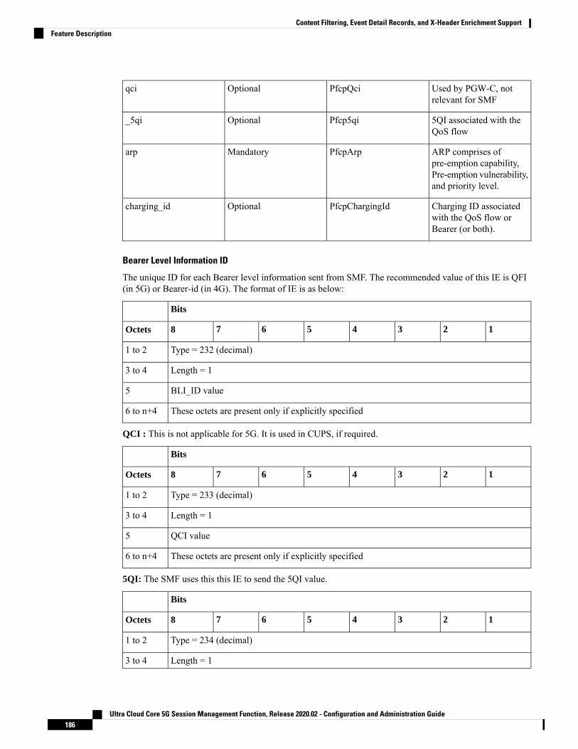
Used by PGW-C, notrelevant for SMF
PfcpQciOptionalqci
5QI associated with theQoS flow
Pfcp5qiOptional_5qi
ARP comprises ofpre-emption capability,Pre-emption vulnerability,and priority level.
PfcpArpMandatoryarp
Charging ID associatedwith the QoS flow orBearer (or both).
PfcpChargingIdOptionalcharging_id
Bearer Level Information ID
The unique ID for each Bearer level information sent from SMF. The recommended value of this IE is QFI(in 5G) or Bearer-id (in 4G). The format of IE is as below:
Bits
12345678Octets
Type = 232 (decimal)1 to 2
Length = 13 to 4
BLI_ID value5
These octets are present only if explicitly specified6 to n+4
QCI : This is not applicable for 5G. It is used in CUPS, if required.
Bits
12345678Octets
Type = 233 (decimal)1 to 2
Length = 13 to 4
QCI value5
These octets are present only if explicitly specified6 to n+4
5QI: The SMF uses this this IE to send the 5QI value.
Bits
12345678Octets
Type = 234 (decimal)1 to 2
Length = 13 to 4
Ultra Cloud Core 5G Session Management Function, Release 2020.02 - Configuration and Administration Guide186
Content Filtering, Event Detail Records, and X-Header Enrichment SupportFeature Description

5QI value5
These octets are present only if explicitly specified6 to n+4
ARP: The ARP value is sent with this IE.
From SMF, the ARP value is encoded as arp->pci)<<4) | arp->pl)<<2)| arp->pvi)Note
Bits
12345678Octets
Type = 235 (decimal)1 to 2
Length = 13 to 4
ARP value5
These octets are present only if explicitly specified6 to n+4
Charging ID: The Charging IE is sent with this IE.
Bits
12345678Octets
Type = 236 (decimal)1 to 2
Length = 13 to 4
Charging Id value5
These octets are present only if explicitly specified6 to n+4
Triggers for Bearer Level Information IE
The following are the triggers for sending the BLI IE in PFCP messages:
PFCP Session Establishment Message
The Bearer level information IE is sent for each new QoS flow with the unique QFI ID. This IE is added inthe policy decision in the N7 Policy Control Create Response message from the PCF. Therefore, SMF sendsmultiple instances of this IE, in a single PFCP message.
PFCP Session Modification Message:
Any new QoS flow addition or new PCC rule referring to an existing QoS flow that results in a new QER orPDR IE that has a new Bearer level information IE for each unique QFI ID.
The BLI IE is not included in the PFCP SessionModificationMessage if the modification is for IDFT tunnels.
Ultra Cloud Core 5G Session Management Function, Release 2020.02 - Configuration and Administration Guide187
Content Filtering, Event Detail Records, and X-Header Enrichment SupportFeature Description

Ultra Cloud Core 5G Session Management Function, Release 2020.02 - Configuration and Administration Guide188
Content Filtering, Event Detail Records, and X-Header Enrichment SupportFeature Description

C H A P T E R 16Customization of StarOS-based UPF on N4Interface
• Feature Summary and Revision History, on page 189• Feature Description, on page 190
Feature Summary and Revision History
Summary DataTable 46: Feature Summary
SMFApplicable Product(s) or Functional Area
SMIApplicable Platform(s)
Enabled – Always-onFeature Default Setting
Not ApplicableRelated Changes in this Release
Not ApplicableRelated Documentation
Revision HistoryTable 47: Revision History
ReleaseRevision Details
Pre-2020.02.0First introduced.
Ultra Cloud Core 5G Session Management Function, Release 2020.02 - Configuration and Administration Guide189

Feature DescriptionThe initial trials for SMF are planned using the StarOS-based UPF node that is already available. The SMFmust meet some non-standard requirements on the UPF node to interwork with this UPF.
Currently, the SMF does not support the Node Level Report Messages from the UPF.Important
Support for Prime PFD MessageThe StarOS-based UPF node needs basic ECS rules configuration pushed from SMF. These default rules needto be provisioned in UPF dynamically even for dynamic PCC policy.
• The StarOSUPF expects SMF to send the configuration in a new custommessage. This message is calledSX_PRIME_PFD_MANAGEMENT_REQUEST. The custom message ID of this message is 0x2F.
• The response sent by UPF for this message is SX_PRIME_PFD_MANAGEMENT_RESPONSE withmessage ID 0x30.
The following snapshot shows the contents of this message:
[U-PLANE]PFCP Rx PDU, from 192.60.181.6:40259 to 192.60.181.2:8805 (81)SEID: NA, Message type: SX_MSG_PRIME_PFD_MANAGEMENT_REQUEST (0x2F)Sequence Number: 0x000001 (1)PFCP HEADER
Version number: 1SEID flag: Not presentMessage Length: 0x004D (77)
INFORMATION ELEMENTSCONFIG ACTION:
Type: 202 Length: 1Value: ADDHex: 00CA 0001 01
CORRELATION ID:Type: 203 Length: 2Value: 4Hex: 00CB 0002 0004
SUB PART NUMBER:Type: 204 Length: 1Value: 245Hex: 00CC 0001 F5
CONTENT TLV:Type: 206 Length: 53Value:
Content Type: ACS_LEVEL_INFOContent Length: 50
Hex: 00CE 0035 0B00 325C 00F1 015F 5F64 657F6661 756C 745F 5F10 0113 2C01 0111 C801132C 0101 132C 0101 532C 0101 0155 01FF01FF 0101 1001 032C 01
Tuesday August 21 2018<<<<OUTBOUND 09:43:39:380 Eventid:221302(3)[U-PLANE]PFCP Tx PDU, from 192.60.181.2:8805 to 192.60.181.6:40259 (19)SEID: NA, Message type: SX_MSG_PRIME_PFD_MANAGEMENT_RESPONSE (0x30)Sequence Number: 0x000001 (1)
Ultra Cloud Core 5G Session Management Function, Release 2020.02 - Configuration and Administration Guide190
Customization of StarOS-based UPF on N4 InterfaceFeature Description

PFCP HEADERVersion number: 1SEID flag: Not presentMessage Length: 0x000F (15)
INFORMATION ELEMENTSCAUSE:
Type: 19 Length: 1Value:
Cause: PFCP_CAUSE_REQUEST_ACCEPTED (0x01)Hex: 0013 0001 01
CORRELATION ID:Type: 203 Length: 2Value: 4Hex: 00CB 0002 0004
Dynamic IP Pool Provisioning on UPFThe StarOS UPF expects SMF to send the configured IP pool range for assigning the IP address to UE duringPDU Session Creation. The UPF uses this information to install static routes for the entire range of IP addressesand advertises the same. The IP pool range information consists of:
• Start and End IP address of the pool range.
• VPN context ID in which the pool will be dynamically configured in UPF.
• SMF does not have any VPN ID supported in this release. It sends a configured value that also needs tobe configured on UPF.
• IP pool chunk ID.
SMF currently does not break the pool into smaller chunks and hence, it always sends 1 as the chunkID.
• The IP pool information is sent to UPF in an N4 Association Update Request message after the N4Association Setup Request/Response has been successfully exchanged with UPF and also after the SXPrime PFD Management Request/Response has been exchanged. The Content TLV IE (IE type 206) isused to send this pool information in the N4 Association Update Request.
Absence of NodeID Attribute from N4 MessagesAs per 3GPP specifications, the NodeID attribute uniquely identifies an SMF to a UPF. This IE is a mandatoryattribute in the N4 Session Establishment Request/Response message. The StarOS UPF currently does notsupport this IE in any of the Session Management related messages. As a customization, the SMF does notsend this IE and does not expect this IE in the response messages.
Non Standard Attribute TypeAs per 3GPP specifications, the FAR ID attribute has an ID type 108. The StarOS UPF assumes this IE typeas 200. As a customization, the SMF sets 200 as the FAR ID IE type.
Single QFI SupportAs per 3GPP specifications, the PDR sent to UPF may have a list of QFIs associated to all the QERs. TheStarOS UPF currently supports only one QFI. As a customization, the SMF includes only one QFI.
Ultra Cloud Core 5G Session Management Function, Release 2020.02 - Configuration and Administration Guide191
Customization of StarOS-based UPF on N4 InterfaceDynamic IP Pool Provisioning on UPF

Ultra Cloud Core 5G Session Management Function, Release 2020.02 - Configuration and Administration Guide192
Customization of StarOS-based UPF on N4 InterfaceSingle QFI Support

C H A P T E R 17DNS Proxy Integration
• Feature Summary and Revision History, on page 193• Feature Description, on page 193• Configuring the DNS Proxy Feature, on page 195
Feature Summary and Revision History
Summary DataTable 48: Summary Data
SMFApplicable Product(s) or Functional Area
SMIApplicable Platform(s)
Disabled – Configuration RequiredFeature Default Setting
Not ApplicableRelated Changes in this Release
Not ApplicableRelated Documentation
Revision HistoryTable 49: Revision History
ReleaseRevision Details
Pre-2020.02.0First introduced.
Feature DescriptionThe Domain Name System (DNS) is a network of servers that translates numeric IP addresses into readable,hierarchical Internet addresses, and vice-versa. The DNS Proxy allows you to configure the proxy servers
Ultra Cloud Core 5G Session Management Function, Release 2020.02 - Configuration and Administration Guide193

(one or more) for resolving the host names. The DNS queries – for resolving host names to their IP addresses– are sent to the configured DNS servers through the DNS proxy servers.
The DNS proxy feature is integrated in the SMF network function.
How it WorksThe DNS proxy feature is integrated in the SMF cluster. For sending the list of host names to resolve the DNSProxy server, the SMF Client Library calls the smfdnsclnt.DNSLookupRequest() Request. The DNS Proxyserver forwards the request to the Open source DNS package for host name to IP address resolution.
Figure 28: DNS Proxy Feature Integration
Call FlowsThe following call flow illustrates the communication between the DNS client and the Proxy server.
Ultra Cloud Core 5G Session Management Function, Release 2020.02 - Configuration and Administration Guide194
DNS Proxy IntegrationHow it Works

Figure 29: DNS Client and Proxy Server Communication Call Flow
Configuring the DNS Proxy FeatureThis section describes how to configure the DNS proxy feature.
Configuring the DNS proxy feature involves the following steps:
1. Configuring SMF DNS proxy replica
2. Configuring SMF DNS proxy
Configuring SMF DNS Proxy ReplicaUse the following configuration to configure the SMF DNS proxy replica.
configurek8 smf profile dns-proxy no-of-replicas integer
commitend
NOTES:
• k8 smf profile dns-proxy no-of-replicas integer : Specifies the number of replicas of the DNS proxypod.
Ultra Cloud Core 5G Session Management Function, Release 2020.02 - Configuration and Administration Guide195
DNS Proxy IntegrationConfiguring the DNS Proxy Feature

• commit: Commits the configuration.
Configuring SMF DNS ProxyUse the following configuration to configure the SMF DNS proxy feature.
configureprofile dns-proxy
timeout integer
query-type { ipv4v6 | ipv4 | ipv6 }servers string
ip string
port integer
priority integer
protocol { tcp | udp }commit
NOTES:
• profile dns-proxy – Enters the DNS Proxy Configuration mode.
• timeoutinteger – Specifies the client timeout value.
• query-type – Specifies the DNS query type.
• servers string – Specifies the name of the DNS server. For example, serv1.
• ip string – Specifies the IP address of the DNS server.
• port integer – Specifies the priority of the DNS server.
• protocol – Specifies the protocol of the DNS server.
• commit – Commits the configuration.
The following is an example configuration where two DNS servers – serv1 and serv2 – are configured:
show running-config profile dns-proxy profile1query-type ipv4timeout 5servers serv1ip 10.105.227.227port 53protocol tcppriority 1exit
servers serv2ip 10.105.227.228port 20protocol udppriority 2exit
exit
Ultra Cloud Core 5G Session Management Function, Release 2020.02 - Configuration and Administration Guide196
DNS Proxy IntegrationConfiguring SMF DNS Proxy

C H A P T E R 18DSCP Marking
• Feature Summary and Revision History, on page 197• Feature Description, on page 197• Configuring 5QI-QoS Mapping, on page 198
Feature Summary and Revision History
Summary DataSMFApplicable Product(s) or Functional Area
SMIApplicable Platform(s)
Disabled – Configuration RequiredFeature Default Setting
Not ApplicableRelated Changes in this Release
Not ApplicableRelated Documentation
Revision HistoryReleaseRevision Details
Pre-2020.02.0First introduced.
Feature DescriptionDSCPMarking supports granular configuration of DSCP. For Interactive Traffic Class (ITC), the SMF supportsper-APN configurable DSCPmarking for Uplink andDownlink direction that is based on 5QI andARP-Prioritylevel. This allows users to assign different DSCP values for flows with the same 5QI but different ARP priorityvalues. For example, the ability to assign DSCP values that are based on 5QI+ARP can be used to meetcompliance on priority and emergency calling via VoLTE.
Ultra Cloud Core 5G Session Management Function, Release 2020.02 - Configuration and Administration Guide197

DSCPMarking is a CLI-controlled feature, which enables to create andmap 5QI andARP values to enforceableQoS parameters.
How it WorksAllocation of different DSCP values for flows with the same 5QI, but different ARP values, works as follows:
• Allows DSCP marking of packets that is based on 5QI+ARP combination.
• 5QI+ARP configuration overrides any pre-entry of DSCPmarking of packets that was based on 5QI+ARPcombination.
• 5QI-only DSCP entry overrides all existing 5QI+ARP configuration.
• Allows implementation of associatedDSCPmarking for 5QI+ARP for Uplink andDownlink functionality.
Configuring 5QI-QoS MappingUse the following CLI commands to create and map 5QI values to enforceable QoS parameters.
configureprofile qos qos_name
dscp-map qi5 qi5_value [ arp-priority-level arp_value ] uplinkuser-datagram dscp-marking dscp_marking_value
dscp-map qi5 5qi_value [ arp-priority-level arp_value ] downlink {encaps-header { copy-inner | dscp-marking dscp_marking_value } | user-datagramdscp-marking dscp_marking_value encaps-header { copy-inner | dscp-marking
dscp_marking_value } }commit
NOTES:
• dscp-map: Configures 5QI (referred as qi5 in the code) to DSCP-Marking mapping.
• qi5 5qi_value: Identifier for the authorized QoS parameters. The 5qi_value must be within the range of0 through 255.
• arp-priority-level arp_value: Configures the ARP Priority Level. The arp_value must be an integerfrom 1 through 15.
• downlink: Configures the downlink traffic.
• uplink: Configures the uplink traffic.
• user-datagram: Specifies the DSCP value to be applied to user datagram. Use this keyword to set theDSCP in the inner IP header in uplink/downlink direction.
• dscp-marking: Specifies the DSCP value to be applied to packets with this 5QI. The dscp_marking_valuemust be a hexadecimal number from 0x00 through 0x3F.
• encaps-header: Configures the DSCP value to be applied to encaps header. Use this keyword to set theDSCP in the outer-ip header in downlink direction.
• copy-inner: Copies the DSCP value from inner IP header to the outer IP header.
Ultra Cloud Core 5G Session Management Function, Release 2020.02 - Configuration and Administration Guide198
DSCP MarkingHow it Works

• The following is a sample configuration.
profile qos testdscp-map qi5 1 downlink encaps-header copy-innerdscp-map qi5 1 downlink encaps-header dscp-marking 0x3bdscp-map qi5 2 downlink user-datagram dscp-marking 0x3bdscp-map qi5 3 downlink user-datagram dscp-marking 0x3b encaps-header copy-innerdscp-map qi5 4 downlink user-datagram dscp-marking 0x3b encaps-header dscp-marking0x3fdscp-map qi5 2 uplink user-datagram dscp-marking 0x3b
dscp-map qi5 1 arp-priority-level 1 downlink encaps-header copy-innerdscp-map qi5 2 arp-priority-level 2 downlink encaps-header dscp-marking 0x3bdscp-map qi5 4 arp-priority-level 3 downlink user-datagram dscp-marking 0x3bdscp-map qi5 2 arp-priority-level 4 downlink user-datagram dscp-marking 0x3bencaps-header copy-innerdscp-map qi5 4 arp-priority-level 5 downlink user-datagram dscp-marking 0x3bencaps-header dscp-marking 0x3fdscp-map qi5 4 arp-priority-level 5 uplink user-datagram dscp-marking 0x3b
Ultra Cloud Core 5G Session Management Function, Release 2020.02 - Configuration and Administration Guide199
DSCP MarkingConfiguring 5QI-QoS Mapping

Ultra Cloud Core 5G Session Management Function, Release 2020.02 - Configuration and Administration Guide200
DSCP MarkingConfiguring 5QI-QoS Mapping
C H A P T E R 19EPS Interworking
• Feature Summary and Revision History, on page 201• Feature Description, on page 202• Support for UE Initial Attach on E-UTRAN, on page 204• Detach Procedure for EPS on SMF and P-GW, on page 209• Dedicated Bearer Activation and Deactivation, on page 211• EPS Fallback, on page 217• EPS Fallback Guard Timer Support, on page 219• Indirect Data Forwarding Tunnel (IDFT) Timer Support, on page 222• Bearer Modification for EPS Session on SMF, on page 226• Session Management Procedures for EPS and 5GC Interworking, on page 233• 5G to EPS Handover Using N26 Interface, on page 257• Create Dedicated Bearer Delay and Retry Support, on page 260• Handling GTP-U Error Indication for 4G Sessions, on page 263• GTP Path Failure Handling, Restoration, and Recovery, on page 265• Configuration Support for Rejecting 4G-only Devices, on page 270
Feature Summary and Revision History
Summary DataTable 50: Summary Data
SMFApplicable Product(s) or Functional Area
SMIApplicable Platform(s)
Enabled – Always-onFeature Default Setting
Not ApplicableRelated Changes in this Release
Not ApplicableRelated Documentation
Ultra Cloud Core 5G Session Management Function, Release 2020.02 - Configuration and Administration Guide201
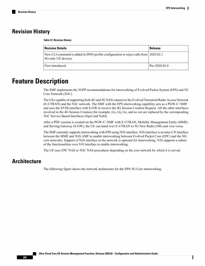
Revision HistoryTable 51: Revision History
ReleaseRevision Details
2020.02.1New CLI command is added in DNN profile configuration to reject calls from4G-only UE devices.
Pre-2020.02.0First introduced.
Feature DescriptionThe SMF implements the 3GPP recommendations for interworking of Evolved Packet System (EPS) and 5GCore Network (5GC).
The UEs capable of supporting both 4G and 5GNAS connect to the Evolved Terrestrial Radio Access Network(E-UTRAN) and the 5GC network. The SMF with the EPS interworking capability acts as a PGW-C+SMFand uses the S5/S8 interface with S-GW to receive the 4G Session Creation Request. All the other interfacesinvolved in the 4G Session Creation (for example, Gx, Gy, Gz, and so on) are replaced by the corresponding5GC Service Based Interfaces (Npcf and Nchf).
After a PDU session is created on the PGW-C+SMF with E-UTRAN, Mobility Management Entity (MME)and Serving Gateway (S-GW), the UE can hand over E-UTRAN to 5G New Radio (NR) and vice-versa.
The SMF currently supports interworking with EPS using N26 interface. N26 interface is an inter-CN interfacebetween the MME and 5GS AMF to enable interworking between Evolved Packet Core (EPC) and the NGcore networks. Support of N26 interface in the network is optional for interworking. N26 supports a subsetof the functionalities over S10 interface to enable interworking.
The UE uses EPC NAS or 5GC NAS procedures depending on the core network by which it is served.
ArchitectureThe following figure shows the network architecture for the EPS-5G Core interworking.
Ultra Cloud Core 5G Session Management Function, Release 2020.02 - Configuration and Administration Guide202
EPS InterworkingRevision History

Figure 30: 3GPP Non-Roaming Architecture for EPS-5GC Interworking
How it WorksA UE that supports only EPS based Dual Connectivity with secondary RAT NR:
• always performs initial access through E-UTRA (LTE-Uu) but never through NR
• performs EPS NAS procedures over E-UTRA (i.e. Mobility Management, Session Management etc.) asdefined in 3GPP specification 24.301
A UE that supports camping on 5G Systems with 5GC NAS:
• Performs initial access either through E-UTRAN that connects to 5GC or NR towards 5GC
• Performs initial access through E-UTRAN towards EPS, if supported and needed
• Performs EPS NAS or 5GC NAS procedures over E-UTRAN or NR respectively (that is, MobilityManagement, Session Management, and so on) depending on whether the UE requests 5GC access orEPS access, if the UE also supports EPS NAS
For interworking with EPS, the UE that supports both 5GC and EPS NAS can operate in one of the followingmodes:
Ultra Cloud Core 5G Session Management Function, Release 2020.02 - Configuration and Administration Guide203
EPS InterworkingHow it Works

• Single-registration mode: UE has only one active MM state (either RM state in 5GC or EMM state inEPS) and it is either in 5GC NAS mode or in EPS NAS mode (when connected to 5GC or EPS,respectively).
• Dual-registration mode: UE handles independent registrations for 5GC and EPS using separate RRCconnections. In this mode, the UE may be registered to 5GC only, EPS only, or to both 5GC and EPS.
Networks that support interworking with EPS, may support interworking procedures that use the N26 interfaceor interworking procedures that do not use the N26 interface.
• Interworking procedures with N26 support provide IP address continuity on inter-system mobility toUEs that support 5GC NAS and EPS NAS and that operate in single registration mode. Interworkingprocedures using the N26 interface, enables the exchange of MM and SM states between the source andtarget network.
• Networks that support interworking procedures without N26 support procedures to provide IP addresscontinuity on inter-systemmobility to UEs operating in both single-registrationmode and dual-registrationmode. For interworking without the N26 interface, IP address preservation is provided to the UEs oninter-system mobility by storing and fetching PGW-C+SMF and corresponding APN/DNN informationvia the HSS+UDM.
NOTE: Interworking of SMF and EPS currently works only with N26 interface.
Standards ComplianceThe 5GC and EPS Interworking feature complies with the following standards:
• 3GPP TS 23.401, Version 15.6.0
• 3GPP TS 23.501, Version 15.4.0
• 3GPP TS 23.502, Version 15.4.0
• 3GPP TS 29.502, Version 15.2.1
• 3GPP TS 29.512, Version 15.2.0
Support for UE Initial Attach on E-UTRAN
Feature DescriptionThe SMF supports the UE performing initial attach on E-UTRAN via MME and S-GW to create the defaultbearer.
Initial attach on E-UTRAN or EPS follows the procedure defined in 3GPP specification 23.401, Section5.3.2.1. There are few deviations from the defined procedure to enable connectivity through the 5G core. Thedeviations are as follows:
• The Packet Data Network Gateway (P-GW) in the procedure is replaced by SMF+PGW.
• The IP-CAN Session establishment andmodification is replaced by SMPolicy Association Establishmentprocedure.
Ultra Cloud Core 5G Session Management Function, Release 2020.02 - Configuration and Administration Guide204
EPS InterworkingStandards Compliance

• The online and offline charging functionality using Gy and Gz interfaces is replaced by integrated chargingover Nchf interface with Charging Function (CHF).
• The interface with the user-plane node is through N4 interface instead of Sxb interface.
How it Works
Call Flows
Initial Attach on E-UTRAN/EPS Procedure
The following figure shows the call flow derived from 3GPP reference for initial attach on E-UTRAN/EPS.
Figure 31: Initial Attach on E-UTRAN via 5G Core Call Flow
Table 52: Initial Attach on E-UTRAN via 5G Core Call Flow Description
DescriptionStep
UE sends Attach Request to MME through eNodeB.1
Ultra Cloud Core 5G Session Management Function, Release 2020.02 - Configuration and Administration Guide205
EPS InterworkingHow it Works

DescriptionStep
MME determines that the UE is capable and subscribed for handoff to NR. It selects aSMF+PGW-C node as the P-GW for this PDU session.
2
MME sends Create Session Request to the selected S-GW and includes the selectedSMF+PGW-C address in it.
3
S-GW initiates Create Session Request towards SMF+PGW-C.4
SMF+PGW-C extracts the PDU Session Id sent by UE in the Protocol Configuration Option(PCO) 001AH (PDU session ID) and saves it. It then performs a Unified DataManagement(UDM) registration and sends PGW Fully Qualified Domain Name (FQDN) to the UDM.After registration, SMF+PGW-C initiates subscription fetch from UDM.
5
SMF+PGW-C sends Npcf_SMPolicyControl_Create to PCF to initiate SM policyAssociation Establishment.
In this procedure, the PGW-C+SMF includes the information elements received in CreateSession Request message into the Npcf_SMPolicyControl_Create Service as follows:
• The SUPI contains the IMSI.
• The DNN contains the APN.
• The PEI contains the IMEI-SV.
• The Session AMBR contains the APN-AMBR.
• The default QoS information that contains the default EPS bearer QoS. Note that QCIvalues are mapped into 5QI values.
6
The PGW-C+SMF receives Policy Charging and Control (PCC) Rules and PDU SessionPolicy Information, 5G QoS information in the PCC Rule and in PDU Session PolicyInformation which are mapped into EPS QoS information. The SMF+PGW-C createsTraffic Flow Template (TFT) from the Service Data Filters (SDFs) received in PCC rulesand associates them with the corresponding default and dedicated bearers.
7
Based on the charging policies received from PCF, SMF+PGW-C initiatesNchf_ConvergedCharging_Create operation towards CHF. This procedure is similar to a5G session and is based on the charging rules received from PCF.
8
SMF+PGW-C performs aUPF+PGW-U selection andN4 Session Establishment procedure.Since this session is a 4G session connecting to SMF+PGW-C, a separate CN tunnel iscreated for each bearer and QoS Flow ID (QFI) is not sent in the QoS Enforcement Rule(QER) and Packet Detection Rule (PDR).
9
SMF+PGW-C sends Create Session Response to SGWand includes the bearer informationand Tunnel Endpoint Identifier (TEID) for the default bearer. SMF+PGW-C also includesthe 5G QoS parameters in PCO options 001CH (QoS rules), 001DH (Session-AMBR),001EH (PDU session address lifetime) and 001FH (QoS flow descriptions) to the UE.
10
S-GW sends Create Session Response to MME.11
MME sends Initial Context Setup Request to eNodeB with N1 Attach Accept message.12
eNodeB and UE perform Radio Resource Control (RRC) configuration.13
UE sends Direct transfer message to eNodeB.14
Ultra Cloud Core 5G Session Management Function, Release 2020.02 - Configuration and Administration Guide206
EPS InterworkingInitial Attach on E-UTRAN/EPS Procedure

DescriptionStep
eNodeB sends Attach Complete message in Initial Context Setup Response to MME alongwith the TEID of eNodeB.
15
MME sends a Modify Bearer Request to S-GW with eNodeB TEID.16
SMF+PGW-C sends the Modify Bearer Response to S-GW.17
S-GW sends Modify Bearer Response to MME.18
Configuring the UE Initial Attach FeatureThis section describes how to configure the UE Initial Attach feature.
Configuring the UE Initial Attach feature involves the following steps:
1. Define FQDN in SMF Profile Configuration
2. Configure S5 Binding Address in SMF Service Configuration
3. Enable Kubernetes Configuration for SMF GTP Endpoint PODs
Define FQDN in SMF Profile ConfigurationUse the following configuration to specify the FQDN of SMF+PGW-C. The configured FQDN is sent to theUDM during registration.
configureprofile smf smf_profile_name
fqdn fqdn_name
end
NOTES:
• fqdn fqdn_name: Configures the FQDN of SMF+PGW-C. fqdn_name must be an alphanumeric string.
Configure S5 Binding Address in SMF Service ConfigurationUse the following configuration to configure the S5 binding address, that is, the address at which the SMFlistens for GTP messages from S-GW (S5 interface).
configureprofile smf smf_profile_name
service name smf_service_name
s5 bind-address { ipv4 ipv4_address | ipv6 ipv6_address }end
NOTES:
• s5 bind-address { ipv4 ipv4_address | ipv6 ipv6_address }: Enter the IP address at which SMF listensfor GTP messages from S-GW via S5 interface. Enter the address in either standard IPv4 dotted decimalformat or in standard IPv6 colon notation format.
Ultra Cloud Core 5G Session Management Function, Release 2020.02 - Configuration and Administration Guide207
EPS InterworkingConfiguring the UE Initial Attach Feature

Enable Kubernetes Configuration for SMF GTP Endpoint PODsUse the following configuration to define the SMF GTP Endpoint (gtp-ep) PODs.
configurek8 smf profile gtp-ep { external-ip | grpc-port | no-of-replicas }end
NOTES:
• k8 smf profile gtp-ep: Specifies Kubernetes configuration for SMF gtp-ep PODs.
• no-of-replicas: Enter the number of replicas for gtp-ep POD to be created. Default is 1.
• external-ip: Specifies the IP address on which gtp-ep kubernetes service listens.
• grpc-port: Enter the grpc port at which gtp-ep POD listens on for internal grpc messages, Default is9003.
Verifying the UE Initial Attach Feature ConfigurationThis section describes how to verify the UE Initial Attach feature configuration.
The following configuration is a sample output of the show running-config command:
show running-config...profile smf smf1node-id ABC123bind-address ipv4 127.0.0.1bind-port 8008allowed-nssai [ slice1 ]plmn-id mcc 123plmn-id mnc 456fqdn ciscosmf1service name nsmf-pdutype pdu-session...n4 bind-address ipv4 10.81.70.229s5 bind-address ipv4 10.81.70.229http-endpoint base-url http://smf-service
.
.
.k8 smf local redis-endpoint redis-primary:6379k8 smf local service no-of-replicas 1k8 smf local nodemgr no-of-replicas 1k8 smf local tracing enable true...
Ultra Cloud Core 5G Session Management Function, Release 2020.02 - Configuration and Administration Guide208
EPS InterworkingEnable Kubernetes Configuration for SMF GTP Endpoint PODs

Detach Procedure for EPS on SMF and P-GW
Feature DescriptionThe SMF supports the default bearer deletion procedures for a UE attached through E-UTRAN, MME, andS-GW.
How it Works
Call Flows
This section describes the call flows associated with this feature.
UE-initiated EPS Call Release Procedure
The following figure shows the call flow for UE-initiated release of EPS call.
Figure 32: UE-initiated Release of EPS Call Flow
The detach procedures for the EPS are defined in 3GPP 23.401, Section 5.3.8. When the UE is attached toE-UTRAN, the detach procedure remains the same as mentioned in the specified 3GPP section except for thefollowing changes:
• Any interaction towards PCRF (CCR-T), that is PCEF initiated IP-CAN session between P-GW andPCRF, is replaced byNpcf_SMPolicyControl_Update Request from the SMF to the PCF. The parameterssent in this message follow a mapping from Delete Session Request contents in a way similar to theCreate Session Request message for initial attach.
Ultra Cloud Core 5G Session Management Function, Release 2020.02 - Configuration and Administration Guide209
EPS InterworkingDetach Procedure for EPS on SMF and P-GW

• All Gy and Gz interface messages are replaced by Nchf_ConvergedCharging_Release service operations.
• The user plane resources are removed using the N4 Session Release procedure towards UPF.
UE-initiated Call Release Detail Procedure
The following figure shows the detailed procedure of UE-initiated release of EPS call.
Figure 33: Detailed Call Flow of UE-initiated EPS Call Release
PCF-initiated Call Release Detail Procedure
The following figure shows the detailed procedure of PCF-initiated release of EPS call.
Ultra Cloud Core 5G Session Management Function, Release 2020.02 - Configuration and Administration Guide210
EPS InterworkingUE-initiated Call Release Detail Procedure

Figure 34: Detailed Call Flow of PCF-initiated EPS Call Release
Dedicated Bearer Activation and Deactivation
Feature DescriptionSMF supports the PCF-initiated dedicated bearer creation and dedicated bearer deletion procedures for a UEattached via E-UTRAN, MME, and S-GW.
How it Works
Call Flows
This section describes the call flows associated with this feature.
Ultra Cloud Core 5G Session Management Function, Release 2020.02 - Configuration and Administration Guide211
EPS InterworkingDedicated Bearer Activation and Deactivation

Dedicated Bearer Creation Call Flow
The following figure describes the Dedicated Bearer Creation procedure.
Figure 35: Dedicated Bearer Creation Call Flow
The dedicated bearer creation or activation procedure for the EPS session is defined in 3GPP 23.401, Section5.4.1. When the UE is attached to E-UTRAN, the dedicated bearer procedure remains the same as mentionedin the specified 3GPP section except for the following changes:
• Any interaction towards PCRF (RAR from PCRF/CCR-U to PCRF) are replaced byNpcf_SMPolicyControl_UpdateNotify request from PCF to SMF and Npcf_SMPolicyControl_UpdateRequest from the SMF to the PCF respectively.
• The PCC rules provided by PCF are mapped to TFTs for the new dedicated bearer and the associatedQoS is mapped to 4G QoS as defined in the Generating EPS PDN Connection Parameters from 5G PDUSession Parameters, on page 256.
• All Gy and Gz interface messages are replaced by Nchf_ConvergedCharging_Update service operations.
• The user plane resources for dedicated bearers are added using the N4 Session Modification proceduretowards UPF where PDRs, QERs and FARs are added for the SDF filters for the new dedicated bearer.
• SMF+PGW-C saves the EBI for the dedicated bearer as received in Create Bearer response.
The following figure describes the PCF-initiated Dedicated Bearer Activation procedure.
Ultra Cloud Core 5G Session Management Function, Release 2020.02 - Configuration and Administration Guide212
EPS InterworkingDedicated Bearer Creation Call Flow

Figure 36: PCF-initiated Dedicated Bearer Activation
Dedicated Bearer Deactivation Call Flow
The following figure describes the Dedicated Bearer Deactivation procedure.
Ultra Cloud Core 5G Session Management Function, Release 2020.02 - Configuration and Administration Guide213
EPS InterworkingDedicated Bearer Deactivation Call Flow

Figure 37: Dedicated Bearer Deactivation Call Flow
The dedicated bearer deactivation procedure for the EPS session is defined in 3GPP 23.401, Section 5.4.4.When the UE is attached to E-UTRAN, the dedicated bearer procedure remains the same as mentioned in thespecified 3GPP section except for the following changes:
• Any interaction towards PCRF (RAR from PCRF/CCR-U to PCRF) are replaced byNpcf_SMPolicyControl_UpdateNotify request from PCF to SMF and Npcf_SMPolicyControl_UpdateRequest from the SMF to the PCF respectively.
• The PCC rules removed by PCF aremapped to corresponding dedicated bearers and the bearer deactivationis triggered for these bearers.
• All Gy and Gz interface messages are replaced by Nchf_ConvergedCharging_Update service operations.
• The user plane resources for dedicated bearers are removed using the N4 SessionModification proceduretowards UPF where PDRs, QERs and Forward Action Rule (FARs) are removed for the SDF filters forthe deleted dedicated bearer.
MME-initiated Dedicated Bearer Deactivation
The MME uses the UE or MME requested PDN Disconnection procedure to initiate the release of PDNconnections. The following call flow illustrates the procedure in which the dedicated bearers are deactivated.
Ultra Cloud Core 5G Session Management Function, Release 2020.02 - Configuration and Administration Guide214
EPS InterworkingDedicated Bearer Deactivation Call Flow

The default bearers are not affected during the disconnection process.Note
Figure 38: MME-initiated Dedicated Bearer Deactivation
DescriptionStep
Radio bearers for the UE in the ECM-CONNECTED state are released due to localreasons, for example, abnormal resource limitation. The UE deletes the bearer contextsrelated to the released radio bearers.
1
When eNodeB releases radio bearers, it sends an indication of bearer release to theMME. This indication could either be the Bearer Release Request (EPS Bearer Identity)message to the MME, or Initial Context Setup Complete, Handover Request Ack andUE Context Response. Path Switch Request can also indicate the release of a bearer.The eNodeB includes the ECGI and TAI in the indication sent to the MME.
2
Ultra Cloud Core 5G Session Management Function, Release 2020.02 - Configuration and Administration Guide215
EPS InterworkingDedicated Bearer Deactivation Call Flow

DescriptionStep
The MME sends the Delete Bearer Command (EPS Bearer Identity, User LocationInformation, UE Time Zone, RAN/NASRelease Cause if available) message per PDNconnection to the S-GW to deactivate the selected dedicated bearer. RAN/NASReleaseCause indicates the RAN release cause and/or the NAS release cause. RAN/NASRelease Cause is only sent by the MME to the P-GW if this is permitted according tothe MME operator's policy.
3
The S-GW sends the Delete Bearer Command (EPS Bearer Identity, User LocationInformation, UE Time Zone, RAN/NAS Release Cause) message per PDN connectionto the P-GW.
4
If PCC infrastructure is deployed, the P-GW informs the PCRF about the loss ofresources by means of a PCEF-initiated IP-CAN Session Modification procedure asdefined in TS 23.203 and provides the User Location Information, UE Time Zone andRAN/NAS Release cause (if available) received in the Delete Bearer Command fromthe S-GW if requested by the PCRF as defined in TS 23.203. The PCRF sends anupdated PCC decision to the P-GW.
User Location Information and UE Time Zone might not be available if theMME or the S-GW are of a previous release and did not provide thisinformation.
Note
5
The P-GW sends a Delete Bearer Request (EPS Bearer Identity) message to the S-GW.6
The S-GW sends the Delete Bearer Request (EPS Bearer Identity) message to theMME.
7
Steps between steps 5 and 8 are invoked. They are omitted if the bearer deactivationwas triggered by the eNodeB in step 1 and step 2.
Also, these steps are omitted if the MME initiated bearer release due to failed bearerset up during handover, the UE and the MME deactivate the failed contexts locallywithout peer-to peer ESM signaling.
8
The MME deletes the bearer contexts related to the deactivated EPS bearer andacknowledges the bearer deactivation to the S-GWby sending a Delete Bearer Response(EPS Bearer Identity, User Location Information (ECGI)) message.
9
The S-GW deletes the bearer context related to the deactivated EPS bearer andacknowledges the bearer deactivation to the P-GWby sending a Delete Bearer Response(EPS Bearer Identity) message.
10
SMF-initiated Dedicated Bearer Deactivation
The following procedure describes the SMF-initiated dedicated bearer deactivation process as defined in 3GPPTS 23.203.
Default bearers are not affected during the dedicated bearer deactivation process.Note
Ultra Cloud Core 5G Session Management Function, Release 2020.02 - Configuration and Administration Guide216
EPS InterworkingDedicated Bearer Deactivation Call Flow

• The SMF-initiated delete bearer is triggered using the clear subscriber command.
• If the PCC infrastructure is deployed, the P-GW informs the PCRF about the loss of resources by meansof a PCEF-initiated IP-CAN SessionModification procedure and provides the User Location Information,UE Time Zone and RAN/NAS Release cause (if available) received in the clear subscriber commandif requested by the PCRF. The PCRF sends an updated PCC decision to the P-GW.
• The P-GW sends a Delete Bearer Request (EPS Bearer Identity) message to the S-GW.
• The S-GW deletes the bearer context related to the deactivated EPS bearer and acknowledges the bearerdeactivation to the P-GW by sending a Delete Bearer Response (EPS Bearer Identity) message.
The following call flow illustrates the SMF-initiated dedicated bearer deactivation.
Figure 39: SMF-initiated Dedicated Bearer Deactivation
EPS Fallback
Feature DescriptionSMF supports fallback to EPS from 5GC for IMS sessions if gNB rejects the dedicated bearer creation withims-voice-eps-fallback or rat-fallback triggered.
Ultra Cloud Core 5G Session Management Function, Release 2020.02 - Configuration and Administration Guide217
EPS InterworkingEPS Fallback

For the UE devices not supporting VoNR, the SMF performs a fallback to EPS for voice calls. This includes5G to EPS handover and dedicated bearer creation in 4G for voice call.
How it Works
Call Flows
The following call flow depicts the EPS Fallback procedure.
Figure 40: EPS Fallback Call Flow
Table 53: EPS Fallback Call Flow Description
DescriptionStep
In the 5GS, UE is with NG-RAN and a Mobile-Originated (MO) or aMobile-Terminated (MT) IMS voice session establishment is initiated.
1
The Network-initiated PDU Session modification request to setup QoS flow for voicereaches the NG-RAN.
2
The NG-RAN is configured to support the EPS fallback for IMS voice. Based on theUE functionalities, indication from the AMF to redirect EPS fallback for voice, networkconfiguration, and radio conditions, the NG-RAN triggers fallback to EPS. If theNG-RAN determines to not trigger the fallback to EPS, then the procedure stops, andthe following steps are not performed.
The NG-RAN may initiate measurement report solicitation from the UE includingE-UTRAN as target.
3
Ultra Cloud Core 5G Session Management Function, Release 2020.02 - Configuration and Administration Guide218
EPS InterworkingHow it Works

DescriptionStep
The NG-RAN rejects the PDU Session modification request received in Step 2 withan indication that mobility due to fallback for IMS voice is ongoing.
The NG-RAN indicates the rejection of the PDU session modification to configureQoS flow for IMS voice that is received in Step 2 as PDU Session Response messagetoward the SMF through the AMF. This message includes the details on the ongoingmobility due to fallback for IMS voice. The SMF maintains the PCC rules that areassociated with the QoS flows.
For a roaming scenario, the PDU Session Response message is sent toward H-SMFthrough V-SMF.
4
Based on the UE functionalities, the NG-RAN initiates handover to EPS. The SMFreports change of the RAT type, if the PCF is subscribed for it.
A timer starts to track failure in the EPS fallback. After the timer expires, the SMFnotifies the PCF about the dedicated bearer creation failure and new statistics, withthe “smf_eps_fb” and “timeout” labels, is incremented.
5
For 5GS to EPS handover, the UE initiates TAU procedure.6a
The UE attaches the PDN connectivity request with the “handover” request type.6b
After the completion of the 5GS to EPS handover procedure, the SMF or P-GWre-initiates the configuration of the dedicated bearer for IMS voice and mapping the5G QoS to EPC QoS parameters. The SMF notifies about the Successful ResourceAllocation and Access Network Information, if the PCF is subscribed for it.
7
The IMS voice session establishment continues.8
EPS Fallback Guard Timer Support
Feature DescriptionSMF supports the guard timer to track failure in the EPS fallback. After the timer starts, it waits for the EPSfallback to happen before the bearer creation failure information is communicated to PCF.
How It WorksThe EPS fallback timer starts after receiving the notification for dedicated bearer creation failure with theEPS fallback cause from gNB through AMF. In this case, SMF does not send the failure notification to PCFand waits for 5G to 4G handover to complete. Then, SMF triggers the bearer creation in 4G. The EPS fallbacktimer stops on the completion of the 5G to 4G handover.
In case the timer expires before the completion of the 5G to 4G handover, SMF sends a notification fordedicated bearer creation failure to PCF. Then, the new statistics counter, with the “smf_eps_fb” and “timeout”labels, is incremented. However, the 5G to 4G handover procedure continues.
Call Flows
This section includes the following call flow.
Ultra Cloud Core 5G Session Management Function, Release 2020.02 - Configuration and Administration Guide219
EPS InterworkingEPS Fallback Guard Timer Support

EPS Fallback Guard Timer Call Flow
This section describes the 5G to EPS fallback guard timer call flow.
Figure 41: EPS Fallback Guard Timer Call Flow
Table 54: EPS Fallback Guard Timer Call Flow Description
DescriptionStep
gNB sends the dedicated bearer creation failure information with the fallback causethrough AMF.
1
EPS fallback timer starts.2
In the successful EPS fallback with 5G to 4G handover scenario, Steps 3 –12 happen.
EPS fallback timer stops and triggers pending dedicated bearer creation.3
SMF(+S5-C) sends the PFCP session modification request to UPF(+S5-U).4
PDR and FAR are created.5
UPF(+S5-U) sends the PFCP session modification response to SMF(+S5-C).6
Ultra Cloud Core 5G Session Management Function, Release 2020.02 - Configuration and Administration Guide220
EPS InterworkingEPS Fallback Guard Timer Call Flow

DescriptionStep
The information on the created PDR with the GTP-U TEID is available.7
SMF(+S5-C) sends the Create Bearer Request to SGW.8
SGW sends the Create Bearer Response to SMF(+S5-C).9
SMF(+S5-C) sends the PFCP Session Modification Request to UPF(+S5-U).10
UPF(+S5-U) sends the notification of the successful dedicated bearer creation to PCF.11
EPS fallback guard timer stops.12
PCF sends the “200 OK” acknowledgment to SMF(+S5-C)13
In the EPS fallback timer expiry before handover completion scenario, Steps 13–15 happen.
SMF(+S5-C) sends the failure notification of the dedicated bearer creation to PCF.14
PCF sends the “200 OK” acknowledgment to SMF(+S5-C).15
The 5G to 4G handover procedure continues.16
Standards ComplianceThe EPS fallback guard timer support feature complies with the following standards:
• 3GPP TS 23.502 V16.1.1 (2019-06).
Configuring the EPS Fallback Guard TimerThis section describes how to configure the EPS Fallback Guard Timer feature.
configureprofile access test [ eps-fallback | n2 | n26 ]eps-fallback guard timeout timeout_value
n26 idft enable timeout n26_timeout_value
n2 idft enable timeout n2_timeout_value
end
NOTES:
• profile access: Accesses the profile configuration.
• test: Accesses the profile instance.
• eps-fallback: Enters the EPS fallback configuration.
• eps-fallback guard timeout: Enters the value for the EPS fallback timer from the range of 500 to 15000milliseconds
• n26: Enters the N26 interface, which is the E-UTRAN and NG-RAN configuration
• n2: Enters the N2 interface, which is the NG-RAN configuration.
• idft enable timeout: Enters the value from 15 to 60 for the IDFT timer to expire.
Ultra Cloud Core 5G Session Management Function, Release 2020.02 - Configuration and Administration Guide221
EPS InterworkingStandards Compliance

Indirect Data Forwarding Tunnel (IDFT) Timer Support
Feature DescriptionSMF supports the Indirect Data Forwarding Tunnel (IDFT) timer during the IDFT procedures for 5G to a 4Ghandover. During the handover, the IDFT tunnels of 5G are released. SMF receives the NSMF PDU SessionUpdate SM Context Request to release the forwarding tunnels from AMF. When SMF does not receive thisrequest, the IDFT timer ensures the release of unused tunnels.
Call FlowsThis section includes the following call flow.
5G to EPS Handover with IDFT Timer Call Flow
This section describes the 5G to EPS handover with IDFT timer call flow.
Figure 42: 5G to EPS Handover with IDFT Timer Call Flow
Ultra Cloud Core 5G Session Management Function, Release 2020.02 - Configuration and Administration Guide222
EPS InterworkingIndirect Data Forwarding Tunnel (IDFT) Timer Support

Table 55: 5G to EPS Handover with IDFT Timer Call Flow Description
DescriptionStep
NG-RAN determines to handover UE to E-UTRAN. If NG-RAN is configured toperform inter-RAT mobility due to the IMS voice fallback that is triggered by QoSflow setup and request to set up QoS flow for IMS voice is received, then NG-RANindicates the rejection of the QoS flow establishment. This indication is because ofmobility due to fallback for the IMS voice through N2 SM information and triggersthe handover to E-UTRAN. The NG-RAN sends a Handover Required message tothe AMF. This message includes the details on target eNB ID, direct forwarding pathavailability, source to target transparent container, and inter-system handover indication.NG-RAN uses the source to target transparent container to indicate bearers for thecorresponding 5G QoS flows for data forwarding.
1
AMF sends the NSMF PDU Session Context Request to the SMF+PGW-C to provideSM Context.
2a
SMF+PGW-C sends the N4 session modification to PGW-U+UPF to establish theCN tunnel for each EPS bearer. The bearer mapping to the 5G QoS and PCC rules,which PCC sends, are available in the SMF. The SMF also has the bearer IDs that arereceived from the bearer ID allocation procedure. The SMF+PGW-C creates newPDRs for the N4 session and gets the TEID allocated for each bearer as required bythe 4G system.
The timer in SMF+PGW-C starts in this step. This timer monitors the resources forindirect data forwarding in UPF that are to be released.
Following are the cases for the IDFT timer expiry:
• Step 21a does not happen and the timer expires—The PDRs and FARs that arenot required for the indirect tunnels, are removed before Step 21a.
• The timer expires before or during the Steps 14a and 16—The PDRs and FARsthat are not required for the indirect tunnels, are removed and the call flowcontinues independently.
• Step 21a happens after the timer expiry—The SMF does not send the N4Modification Request to UPF+PGW-U as the resources are released on the timerexpiry.
2b
SMF+PGW-C sends the EPS bearer contexts to AMF. The bearer context is a stringwith the byte format, which is the base64-encoded characters, encoding the UE EPSPDN Connection IE.
The SMF+PGW-C also provides the CN tunnel information to AMF for all the bearersfor the uplink traffic from E-UTRAN.
2c
AMF sends a Forward Relocation Request to MME. The AMF includes the mappedSM EPS UE Contexts for the PDU Sessions with and without active UP connections.
3
MME sends the Create Session Request to SGW. See S1-based handover in the normalcase section in 3GPP TS 23.401 clause 5.5.1.2.2 for details.
4
SGW sends the Create Session Response to MME. See S1-based handover in thenormal case section in 3GPP TS 23.401 clause 5.5.1.2.2 for details.
5
Ultra Cloud Core 5G Session Management Function, Release 2020.02 - Configuration and Administration Guide223
EPS Interworking5G to EPS Handover with IDFT Timer Call Flow

DescriptionStep
MME sends the handover request to E-UTRAN.6
E-UTRAN sends the handover request acknowledgment to MME.7
MME and SGW send and receive the indirect data forwarding request and responseto each other.
8
MME sends the Relocation Response to AMF.9
In case of indirect data forwarding, AMF sends the NSMF PDU Session Update SMContext Request to PGW-C+SMF. This request is for SGW addresses and SGW DLTEIDs for data forwarding and for creating the indirect data forwarding tunnel.
10a
PGW-C+SMF sends the N4 Modification Request to UPF+PGW-U to create morePDRs and FARs. The PDRs and FARS are created to receive the redirected DL dataover the indirect tunnel fromNGRAN and to forward them to eNodeB. The UL PDRshave the QFI to match the forwarded DL data from NG RAN. The associated QERhas the QFI to forward the data to eNodeB. Also, the FAR redirects the received datato eNodeB over the appropriate tunnel based on the QFI.
10b
PGW-C+SMF sends the NSMF PDU Session Update SM Context Response to AMF.This response includes details on cause, CN tunnel information for data forwarding,and QoS flows for data forwarding. PGW-C+SMF sends this response to create indirectdata forwarding. Based on the correlation between QFIs and SGW addresses andTEIDs for data forwarding, the PGW-U+UPF maps the QoS flows into the dataforwarding tunnels in EPC.
10c
AMF sends the Handover Command to the source NG-RAN.11a
The source NG-RAN sends the Handover Command to UE to handover to the targetaccess network.
The UE correlates the ongoing QoS Flows with the indicated EPS Bearer IDs (EBI)that are to be set up in the handover command. If the QoS Flow associated with thedefault QoS rule in the PDU Session has an unassigned EBI, the UE deletes the PDUSession locally. If the QoS Flow that is associatedthat is with the default QoS rule hasan assigned EBI, the UE retains the PDU session. For the QoS Flow with unassignedEBIs, the UE deletes the QoS rules and the QoS Flow level QoS parameters locallyif any associatedwith those QoS Flows. Then, the UE notifies the impacted applicationsthat the dedicated QoS resource has been released. The UE deletes any UE-derivedQoS rules. The EBI that was assigned for the QoS Flow of the default QoS rule in thePDU Session becomes the EBI of the default bearer in the corresponding PDNconnection.
11b
UE sends the notification of handover completion to E-UTRAN.12a
E-UTRAN sends the Handover Notify request to MME.12b
MME sends the Relocation Complete Notification to AMF.12c
AMF sends the Relocation Complete Notification acknowledgment to MME.12d
MME sends the Modify Bearer Request to SGW.13
Ultra Cloud Core 5G Session Management Function, Release 2020.02 - Configuration and Administration Guide224
EPS Interworking5G to EPS Handover with IDFT Timer Call Flow
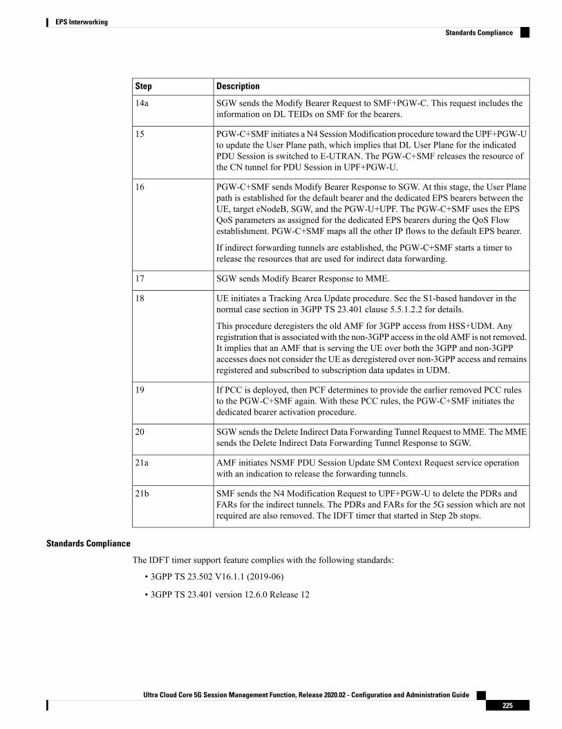
DescriptionStep
SGW sends the Modify Bearer Request to SMF+PGW-C. This request includes theinformation on DL TEIDs on SMF for the bearers.
14a
PGW-C+SMF initiates a N4 SessionModification procedure toward the UPF+PGW-Uto update the User Plane path, which implies that DL User Plane for the indicatedPDU Session is switched to E-UTRAN. The PGW-C+SMF releases the resource ofthe CN tunnel for PDU Session in UPF+PGW-U.
15
PGW-C+SMF sends Modify Bearer Response to SGW. At this stage, the User Planepath is established for the default bearer and the dedicated EPS bearers between theUE, target eNodeB, SGW, and the PGW-U+UPF. The PGW-C+SMF uses the EPSQoS parameters as assigned for the dedicated EPS bearers during the QoS Flowestablishment. PGW-C+SMF maps all the other IP flows to the default EPS bearer.
If indirect forwarding tunnels are established, the PGW-C+SMF starts a timer torelease the resources that are used for indirect data forwarding.
16
SGW sends Modify Bearer Response to MME.17
UE initiates a Tracking Area Update procedure. See the S1-based handover in thenormal case section in 3GPP TS 23.401 clause 5.5.1.2.2 for details.
This procedure deregisters the old AMF for 3GPP access from HSS+UDM. Anyregistration that is associated with the non-3GPP access in the old AMF is not removed.It implies that an AMF that is serving the UE over both the 3GPP and non-3GPPaccesses does not consider the UE as deregistered over non-3GPP access and remainsregistered and subscribed to subscription data updates in UDM.
18
If PCC is deployed, then PCF determines to provide the earlier removed PCC rulesto the PGW-C+SMF again. With these PCC rules, the PGW-C+SMF initiates thededicated bearer activation procedure.
19
SGW sends the Delete Indirect Data Forwarding Tunnel Request to MME. TheMMEsends the Delete Indirect Data Forwarding Tunnel Response to SGW.
20
AMF initiates NSMF PDU Session Update SM Context Request service operationwith an indication to release the forwarding tunnels.
21a
SMF sends the N4 Modification Request to UPF+PGW-U to delete the PDRs andFARs for the indirect tunnels. The PDRs and FARs for the 5G session which are notrequired are also removed. The IDFT timer that started in Step 2b stops.
21b
Standards Compliance
The IDFT timer support feature complies with the following standards:
• 3GPP TS 23.502 V16.1.1 (2019-06)
• 3GPP TS 23.401 version 12.6.0 Release 12
Ultra Cloud Core 5G Session Management Function, Release 2020.02 - Configuration and Administration Guide225
EPS InterworkingStandards Compliance

Configuring the IDFT TimerThis section describes how to configure the IDFT timer.
configureprofile access test [ eps-fallback | n2 | n26 ]eps-fallback guard enable timeout timeout_value
n26 idft enable timeout n26_timeout_value
n2 idft enable timeout n2_timeout_value
endexit
NOTES:
• profile access: Accesses the profile configuration.
• test: Accesses the profile instance.
• eps-fallback: Enters the EPS fallback configuration.
• n26: Enters the N26 interface, which is the E-UTRAN and NG-RAN configuration
• n2: Enters the N2 interface, which is the NG-RAN configuration.
• idft enable timeout: Enters the value from 15 to 60 for the IDFT timer to expire.
Bearer Modification for EPS Session on SMF
Feature DescriptionSMF supports modification of EPS bearer that a PCF or an MME initiates. The SMF+PGW handles thefollowing triggers for this feature:
• QoS modifications.
• RAT, ULI, and SGW modifications.
• UE time zone modifications.
How it WorksThe bearer modification for an EPS session on SMF works with the following modifications:
• PCF and MME-Initiated Bearer Modifications for EPS session on SMF—These procedures are usedeither when one or multiple EPS Bearer QoS parameters QCI, GBR, MBR, or ARP are modified or tomodify the APN-AMBR. The PCF-initiated or the MME-initiated bearer modification procedures donot support the modification from a QCI of non-GBR resource type to a GBR resource type QCI andvice versa.
• X2 and S1 Based Handover for EPS Session Connected to SMF—The X2-based handover procedure isused to hand over a UE from a source eNodeB to a target eNodeB using X2. In this procedure, the MMEis unchanged and the MME determines to relocate the SGW.
Ultra Cloud Core 5G Session Management Function, Release 2020.02 - Configuration and Administration Guide226
EPS InterworkingConfiguring the IDFT Timer

The S1-based handover procedure is used when the X2-based handover cannot be used. The sourceeNodeB initiates a handover by sending the Handover Required message over the S1-MME referencepoint. This procedure may relocate the MME or the SGW.
Call Flows
This section includes the following call flows:
• PCF-Initiated Bearer Modification for EPS session on SMF call flow
• MME-Initiated Bearer Modification for EPS session on SMF call flow
• X2 and S1 Based Handover for EPS Session Connected to SMF call flow
PCF-initiated Bearer Modification for EPS session on SMF Call Flow
This section describes the PCF-Initiated Bearer Modification for EPS session on SMF call flow.
Figure 43: PCF-Initiated Bearer Modification for EPS session on SMF Call Flow
Table 56: PCF-Initiated Bearer Modification for EPS session on SMF Call Flow Description
DescriptionStep
PCF initiates the N7 Policy Update Notify with the updated parameters of QoS orTFT toward SMF.
1
SMF sends the “200 OK” acknowledgment to PCF. The PCC rules that the PCFprovides are mapped to TFTs for the modified dedicated bearer. The associated QoSis mapped to 4G QoS.
2
SMF sends the Update Bearer Request to SGW.3
Ultra Cloud Core 5G Session Management Function, Release 2020.02 - Configuration and Administration Guide227
EPS InterworkingCall Flows

DescriptionStep
SGW sends the Update Bearer Response to SMFwith EPS Bearer ID and the modifiedQoS or TFT for the associated bearer.
4
SMF initiates the PFCP Modification request toward UPF.5
UPF sends the PFCP Modification Response to SMF with updated QER.6
SMF sends the PCF Notify message to PCF.7
PCF sends the “200 OK” acknowledgment to SMF.8
MME-initiated Bearer Modification for EPS session on SMF Call Flow
This section describes the MME-Initiated Dedicated Bearer Modification for EPS session on SMF call flow.
Figure 44: MME-Initiated Bearer Modification for EPS session on SMF Call Flow
Ultra Cloud Core 5G Session Management Function, Release 2020.02 - Configuration and Administration Guide228
EPS InterworkingMME-initiated Bearer Modification for EPS session on SMF Call Flow

Table 57: MME-Initiated Bearer Modification for EPS session on SMF Call Flow Description
DescriptionStep
HSS sends an Insert Subscriber Data message to the MME. The subscription dataincludes the details on IMSI, EPS subscribed QoS (QCI and ARP), and the subscribedUE-AMBR and APN-AMBR.
1
If the subscribed UE-AMBR is modified, theMME calculates a newUE-AMBR valueand sends the Modify Bearer Command to SGW.
2
SGW sends the Modify Bearer Command message to the SMF or PDN GW. Thismessage includes the details on EPS Bearer Identity, EPS Bearer QoS, andAPN-AMBR.
3
SMF or PDN GW sends the updated APN-AMBR to PCF.4
PCF sends the updated PCC decision to the SMF or PDN GW. The PCF modifies theAPN-AMBR that is associated with the default bearer in response to the SMF or PDNGW.
5
SMF sends the Update Bearer Request to SGW.6
SGW sends the Update Bearer Request to MME. This request message includes thedetails on EBI, EPS Bearer QoS, TFT, and APN-AMBR.
7
MME sends the Update Bearer Response to SGW.8
SGWsends theUpdate Bearer Response as acknowledgment for the bearermodificationto the SMF or PDN GW. The response message includes the details on EBI and userlocation information.
9
UPF sends the PFCP Session Modification Response to SMF. Based on the PCCdecision provision message (QoS policy) that is received from the PCF, the SMF orPDN GW initiates the dedicated bearer modification procedure. SMF or PDN GWuses the QoS policy to determine if a service data flow is to be added or removed froman active bearer or if the authorized QoS of a service data flow is changed.
10
UPF updates the PFCP parameters and sends a PFCP Session Modification Responseto the SMF or PDN GW. UPF confirms the successful modification of the PFCPsession.
11
SMF or PDNGWnotifies PCF on the requested PCC decision whether it was enforcedor not.
12
PCF sends the “200 OK” acknowledgment to SMF or PDN GW.13
X2 and S1 based Handover for EPS Session Connected to SMF
This section describes the X2 and S1-Based Handover for EPS Session Connected to SMF.
Ultra Cloud Core 5G Session Management Function, Release 2020.02 - Configuration and Administration Guide229
EPS InterworkingX2 and S1 based Handover for EPS Session Connected to SMF

Figure 45: X2 and S1 based Handover for EPS Session Connected to SMF
Table 58: X2 and S1 based Handover Call Flow Description
DescriptionStep
The SGW sends the Modify Bearer Request to the SMF. This request includes theuser location information IE, UE time zone IE, and the serving network IE per PDNconnection to the associated PDN GWs information that is received from the MME.
1
In case of change in S-GW, SMF or P-GW sends the PFCP Session ModificationRequest to the UPF.
2
If Step 2 occurs, the UPF sends the PFCP Session Modification Response to SMF orPDN GW.
3
After receiving the response from the UPF, the SMF or P-GW sends theModify BearerResponse to S-GW.
4
If PCF has armed notification for QoS modification, the SMF or P-GW sends anotification to the PCF.
5
If Step 5 occurs, the PCF sends the “200 OK” acknowledgment to the SMF or P-GW.6
If PCF has armed notification for ULI or RATmodifications, SMF or PDNGW sendsa notification to PCF.
7
If Step 7 occurs, PCF sends the “200 OK” acknowledgment to SMF or PDN GW.8
If CHF has armed notification for QoS, ULI, or RAT modifications, SMF or PDNGW sends a notification to PCF.
9
Ultra Cloud Core 5G Session Management Function, Release 2020.02 - Configuration and Administration Guide230
EPS InterworkingX2 and S1 based Handover for EPS Session Connected to SMF

DescriptionStep
If Step 9 occurs, PCF sends the “200 OK” acknowledgment to SMF or PDN GW.10
The following call flow shows the X2-based handover with S-GW relocation:
Figure 46: X2-Based Handover with SGW Relocation Call Flow
For call flow description, see the section 5.5.1.1.3 "X2-based handover with Serving GW relocation" from3GPP TS 23.401.
The following call flow shows the S1-based handover:
Ultra Cloud Core 5G Session Management Function, Release 2020.02 - Configuration and Administration Guide231
EPS InterworkingX2 and S1 based Handover for EPS Session Connected to SMF

Figure 47: S1-based Handover Call Flow
For call flow description, see section 5.5.1.2.2 "S1-based handover, normal" from 3GPP TS 23.401.
Ultra Cloud Core 5G Session Management Function, Release 2020.02 - Configuration and Administration Guide232
EPS InterworkingX2 and S1 based Handover for EPS Session Connected to SMF

Standards ComplianceThe Bearer Modification for EPS Session on SMF feature complies with the following standards:
• 3GPP TS 23.401
• 3GPP TS 23.502 V16.1.1 (2019-06)
SessionManagementProceduresforEPSand5GCInterworking
Feature DescriptionThe 5G Session Management procedures defined in 3GPP TS 23.502 ensure that the EPS interworking issuccessful when the UE moves to an LTE 4G radio after performing the initial attach to a 5G NR radio.
Support for Number of Packet Filters in NAS Message
The UE sends the Number of packet filter IE to the SMF in PDU Establishment and Modification requestmessages. By default, the UE sends a maximum of 16 packet filters.
The UE supports more than 16 packet filters in the following scenarios:
• When the UE is attaching to the SMF in N1 mode.
• When the initial attach to the SMF in S1 mode is complete and the 4G to 5G handover is ongoing.
The SMF sends the maximum filters to the PCF in PolicyCreateControl in "NumOfPackFilter" field. If theNumber of packet filter IE is received from the UE in N1 mode, then the SMF uses the “Maximum numberof supported filters” field in PDU establishment request. If this IE is not received from the UE in N1 modeor if the received value is lesser than 16, the SMF sends the max filters as 16. If the UE attaches to the SMFin S1 mode and the 4G to 5G or 5G to 4G handover is ongoing, the SMF sends the default value, that is, 16packet filters.
If there is any change in the packet filter value, then the SMF sends the new value to the PCF throughPolicyUpdate message along with NUM_OF_PACKET_FILTER trigger.
The SMF controls the maximum filters allowed per PDU session based on the numOfPackFilter IE. If thenumber of packet filters crosses the maximum allowed by the UE, the SMF caps the packet filters. This meansthat the SMF drops the PCC rules when the limit crosses and sends the rule report with INCOR_FLOW_INFOfailure code.
INCOR_FLOW_INFO is not the correct failure code for this kind of deletion. Use the appropriate failurecode when available in the 3GPP specification.
Maximum supported filters are only valid for dynamic rules and not for static and predefined rules.
Note
The "pcc_rule_report_max_supported_filter" statistics is introduced under the policy_pcc_rule_report category.This statistics is incremented if the PCC rule report is generated upon reaching the maximum supported filters.
Ultra Cloud Core 5G Session Management Function, Release 2020.02 - Configuration and Administration Guide233
EPS InterworkingStandards Compliance

Support for PCF ID in SmContextCreate
The AMF includes the PCF ID in the Nsmf_PDUSession_CreateSMContext Request. The PCF ID identifiesthe Home Policy Control Function (H-PCF) in the non-roaming case and the Visited Policy Control Function(V-PCF) in the local breakout roaming case. See the 3GPP specification 23.501, section 6.3.7.1 for moredetails on when the AMF forwards the PCF ID to the SMF.
When the SMF receives the PCF ID, use the following CLI configuration in the PCF network profile to controlthe SMF behaviour in using the PCF ID.
UseAmfProvidedPCF [True/False]
The default behaviour is to use the PCF ID provided by AMF in SmContextCreate.
If the PCF ID provided by AMF is not reachable, the SMF behaves as per the configured failure handlingtemplate. In this case, it uses the static configuration.
Support for DNN Selection Mode in SmContextCreate
The SMF uses the DNN Selection Mode for deciding whether to accept or reject the UE request.
The SMF uses the DNNSelectionMode for deciding whether to retrieve the SessionManagement Subscriptiondata. In case the DNN, S-NSSAI of the HPLMN is not explicitly subscribed, the SMF uses the localconfiguration instead of the Session Management Subscription data.
The preceding use case is not supported.Note
The SMF validates the IE present in SmContextCreate data. If there is a DnnSelectionMode failure due to themismatch between DnnSelectionMode and the configured CLI, the SMF does not proceed with the registration.When the DnnSelectionMode failure is observed, the “disc_pdusetup_sm_cxt_unsupported_ie" is incrementedas part of the disconnect reasons.
DescriptionDnnSelectionMode Type
The SMF sends the subscription request to fetch the subscription data.Not Present
The SMF sends the subscription request to fetch the subscription data.Verified
If the dnn-selection-mode verified ue-providedCLI command is configuredas shown in the following configuration, the SMF sends the subscriptionrequest to fetch the subscription data. Otherwise, the SMF rejects the ContextRequest with "Invalid DNN selection Mode" cause.
UE_DNN_NOT_VERIFIED
If the dnn-selection-mode verified network-providedCLI is configured, theSMF sends the subscription request to fetch the subscription data. Otherwise,the SMF rejects the Context Request with "Invalid DNN selection Mode"cause.
NW_DNN_NOT_VERIFIED
The SMF uses the following configuration to configure the DnnSelectionMode.
configureprofile smf profile_name
dnn-selection-mode [ verified ue-provided | network-provided ]end
Ultra Cloud Core 5G Session Management Function, Release 2020.02 - Configuration and Administration Guide234
EPS InterworkingFeature Description

One or more DnnSelectionMode types can be configured. By default, the DnnSelectionMode is verified.
Post the subscription request, if no subscription data is fetched from UDM, the SMF falls back to the localDNN profile for subscription data. Neither the subscription data is fetched from the UDM nor the localconfiguration is present, the SMF sends the SmContextCreateError with subscription failure.
How it Works
Call FlowsThis section describes the 5G Session Management procedures to support EPS and 5GC interworking.
PDU Session Creation Call Flow
This section describes the PDU Session Creation procedure as specified in 3GPP TS 23.502, Section 4.3.2.2.1.
Ultra Cloud Core 5G Session Management Function, Release 2020.02 - Configuration and Administration Guide235
EPS InterworkingHow it Works

Figure 48: PDU Session Creation Call Flow
Table 59: PDU Session Creation Call Flow Description
DescriptionStep
The UE initiates the UERequested PDU Session Establishment procedure by transmittinga NAS message containing a PDU Session Establishment Request within the N1 SMcontainer. The PDUSession Establishment Request includes a PDU session ID, RequestedPDUSession Type, a Requested SSCmode, 5GSMCapability PCO, SMPDUDNRequestContainer, Number of Packet Filters, and optionally Always-on PDU Session Requested.
1
The AMF performs SMF selection as described in 3GPP specification.2
Ultra Cloud Core 5G Session Management Function, Release 2020.02 - Configuration and Administration Guide236
EPS InterworkingPDU Session Creation Call Flow

DescriptionStep
The AMF includes EPS Interworking Indication in theNsmf_PDUSession_CreateSMContext Request message sent to the SMF. This parameterindicates whether the UE can perform 4G to 5G handover (and vice versa) and if it isallowed with or without the presence of the N26 interface between the AMF and MME.
3
If the EPS Interworking Indication received from the AMF indicates that the UE supportsEPS interworking and the SMF determines (for example, if EPS interworking is allowedfor this DNN and S-NSSAI based on UE subscription data) that the PDU session supportsEPS interworking, the PGW-C+SMF FQDN for the S5/S8 interface is included in theNudm_UECM_Registration Request message.
4
The SMF sends either Nsmf_PDUSession_CreateSMContext Response (Cause, SMContext ID or N1 SM container (PDU Session Reject (Cause))) or anNsmf_PDUSession_UpdateSMContext Response depending on the Request received inStep 3.
If the SMF received Nsmf_PDUSession_CreateSMContext Request in Step 3 and theSMF can process the PDUSession Establishment Request, the SMF creates an SM contextand responds to the AMF by providing an SM Context Identifier.
5
(Optional). If the Request Type in Step 3 indicates "Existing PDU Session", the SMFdoes not perform secondary authorization and authentication.
If the Request Type received in Step 3 indicates "Emergency Request" or "ExistingEmergency PDU Session", the SMF does not perform secondary authorization andauthentication.
If the SMF needs to perform secondary authorization and authentication during theestablishment of the PDU Session by a DN-AAA server as described in 3GPP TS 23.501,Section 5.6.6, the SMF triggers the PDU session establishment authentication andauthorization as described in 3GPP TS 23.501, Section 4.3.2.3.
6
If dynamic PCC is to be used for the PDU Session, the SMF performs PCF selection asdescribed in 3GPP TS 23.501, Section 6.3.7.1. If the Request Type indicates "ExistingPDU Session" or "Existing Emergency PDU Session", the SMF uses the PCF alreadyselected for the PDU Session. Otherwise, the SMF may apply local policy.
7a
The SMF performs the mapping of PCC rules and 5G QoS parameters to 4G TFTs and4G QoS as described in the Generating EPS PDN Connection Parameters from 5G PDUSession Parameters section in this document. Based on the QoS flows, the SMF+PGW-Calso determines the number of dedicated bearers required for the session when it handsoff to EPS and the required flows (all non-GBR flows) in the default bearer. TheSMF+PGW-C saves the mapping of 5G flows to 4G bearers.
7b
If the Request Type in Step 3 indicates "Initial request", the SMF selects an SSC modefor the PDU Session as described in 3GPP TS 23.501, Section 5.6.9.3. The SMF alsoselects one or more UPFs as needed as described in 3GPP TS 23.501, Section 6.3.3.
8
Ultra Cloud Core 5G Session Management Function, Release 2020.02 - Configuration and Administration Guide237
EPS InterworkingPDU Session Creation Call Flow

DescriptionStep
The SMF performs an SMF-initiated SM Policy Association Modification procedure asdefined in 3GPP TS 23.502, Section 4.16.5.1 to provide information on the Policy ControlRequest Trigger conditions that have been met. If Request Type is "initial request" anddynamic PCC is deployed and PDU Session Type is IPv4 or IPv6 or IPv4v6, the SMFnotifies the PCF (if the Policy Control Request Trigger condition is met) with the allocatedUE IP address/prefix(es).
SMF+PGW-C initiates the EBI allocation procedure as defined in 3GPP TS 23.502,Section 4.11.1.4.
9
If the Request Type indicates "initial request", the SMF initiates an N4 SessionEstablishment procedure with the selected UPF. Otherwise, it initiates an N4 SessionModification procedure with the selected UPF.
If multiple UPFs are selected for the PDU Session, the SMF initiates N4 SessionEstablishment/Modification procedure with each UPF of the PDU Session in this step.
10
In the non-roaming or LBO scenario, the PGW-C+SMF includes the mapped EPS bearercontext(s) and the corresponding QoS flow(s) to be sent to the UE in the N1 SM container.The PGW-C+SMF also indicates the mapping between the QoS flow(s) and mapped EPSbearer context(s) in the N1 SM container. The PGW-C+SMF also includes the mappingbetween the received EBI(s) and QFI(s) in the N2 SM information to be sent to theNG-RAN. The PGW-C+SMF sends the N1 SM container and N2 SM information to theAMF through the Namf_Communication_N1N2MessageTransfer message.
11
The AMF sends N2 PDU Session Request (N2 SM information, NAS message (PDUSession ID, N1 SM container (PDU Session Establishment Accept))) to the (R)AN.
The AMF sends the NAS message containing PDU Session ID and PDU SessionEstablishment Accept targeted to the UE and the N2 SM information received from theSMF within the N2 PDU Session Request to the (R)AN.
12
The (R)AN may issue AN-specific signaling exchange with the UE that is related withthe information received from the SMF. For example, in case of an NG-RAN, an RRCConnection Reconfiguration may take place with the UE establishing the necessaryNG-RAN resources related to the QoS rules for the PDU Session Request received inStep 12.
13
(R)AN issues N2 PDU Session Response (PDU Session ID, Cause, N2 SM information(PDU Session ID, AN Tunnel Info, List of accepted/rejected QFI(s), User PlaneEnforcement Policy Notification)) to the AMF.
14
The AMF sends Nsmf_PDUSession_UpdateSMContext Request (N2 SM information,Request Type) to the SMF.
The AMF forwards the N2 SM information received from (R)AN to the SMF.
15
The SMF initiates an N4 SessionModification procedure with the UPF. The SMF providesAN Tunnel Information and the corresponding forwarding rules to the UPF.
16a
Ultra Cloud Core 5G Session Management Function, Release 2020.02 - Configuration and Administration Guide238
EPS InterworkingPDU Session Creation Call Flow

DescriptionStep
The UPF provides an N4 Session Modification Response to the SMF.
If multiple UPFs are used in the PDU session, the UPF in Step 16a refers to the UPFterminating N3.
After this step, the UPF delivers any downlink packets to the UE that may have beenbuffered for this PDU session.
16b
The SMF sends Nsmf_PDUSession_UpdateSMContext Response (Cause) to the AMF.17
(Conditional) The SMF sends Nsmf_PDUSession_SMContextStatusNotify (Release) tothe AMF.
If during the procedure, any time after Step 5, the PDU Session establishment is notsuccessful, the SMF informs the AMF by invokingNsmf_PDUSession_SMContextStatusNotify (Release). The SMF also releases any N4session(s) created, any PDU session address if allocated (for example, IP address) andreleases the association with PCF, if any.
18
If the PDU Session Type is IPv6 or IPv4v6, the SMF generates an IPv6 RouterAdvertisement and sends it to the UE via N4 and the UPF.
19
If the PDU Session Establishment failed after Step 4, the SMF performs the following:
• The SMF unsubscribes to the modifications of Session Management Subscriptiondata for the corresponding (SUPI, DNN, S-NSSAI), usingNudm_SDM_Unsubscribe(SUPI, Session Management Subscription data, DNN, S-NSSAI), if the SMF is nomore handling a PDU session of the UE for this (DNN, S-NSSAI). The UDM mayunsubscribe to the modification notification from UDR by Nudr_DM_Unsubscribe(SUPI, Subscription Data, SessionManagement Subscription data, S-NSSAI, DNN).
• The SMF deregisters for the given PDU session using Nudm_UECM_Deregistration(SUPI, DNN, PDU Session ID). The UDM may update corresponding UE contextby Nudr_DM_Update (SUPI, Subscription Data, UE context in SMF data).
20
PDU Session Modification Call Flow
This section describes the PDU session modification procedure as specified in 3GPP TS 23.502, Section4.3.3.2.
Ultra Cloud Core 5G Session Management Function, Release 2020.02 - Configuration and Administration Guide239
EPS InterworkingPDU Session Modification Call Flow

Figure 49: PDU Session Modification Call Flow
Table 60: PDU Session Modification Call Flow Description
DescriptionStep
The UE initiates the UE Requested PDU SessionModification procedure by transmittinga NAS message containing a PDU Session Modification Request within the N1 SMcontainer. The PDU Session Modification Request includes a PDU session ID, PacketFilters, Operation, Requested QoS, Segregation, and 5GSM Core Network Capability.
1a
(SMF-requestedmodification) The PCF performs a PCF-initiated SMPolicy AssociationModification procedure to notify the SMF about the modification of policies. The policydecision or upon AF requests, for example, Application Function influence on trafficrouting, triggers this procedure.
1b
Ultra Cloud Core 5G Session Management Function, Release 2020.02 - Configuration and Administration Guide240
EPS InterworkingPDU Session Modification Call Flow

DescriptionStep
(SMF-requested modification) The UDM updates the subscription data of SMF byNudm_SDM_Notification (SUPI, Session Management Subscription Data). The SMFupdates the Session Management Subscription Data and acknowledges the UDM byreturning an Ack with (SUPI).
1c
(SMF-requested modification) The SMF decides to modify PDU session. This procedureis also triggered based on locally configured policy or triggered from the (R)AN.
If the SMF receives one of the triggers in step 1b to 1d, the SMF starts SMF-requestedPDU Session Modification procedure.
1d
(AN-initiated modification) (R)AN indicates to the SMF when the AN resources ontowhich a QoS Flow is mapped are released irrespective of whether notification control isconfigured.
(R)AN sends the N2 message (PDU Session ID, N2 SM information) to the AMF. TheN2 SM information in the smf_PDU_Session_UpdateContext includes the followinginformation:
• QoS Flow Identifier (QFI)
• User location Information
• QoS Flow Release List IE - list of QoS flows which are released by NG-RAN node
• QoS Flow Notify List IE and Notification Cause IE - list of GBR QoS flows thatfulfilled a specific criteria, and the flows that missed fulfilling the criteria
The SMF supports AN-initiated modification to release the QFI from RAN. For detailson this support, see the following section.
1e
The SMF reports the subscribed event to the PCF by performing an SMF-initiated SMPolicy Association Modification procedure. The SMF skips this step if the PDU SessionModification procedure is triggered by step 1b or 1d. If the dynamic PCC is not deployed,the SMF may apply local policy to decide whether to change the QoS profile. The SMFdoes not invoke the steps 3 to 7 when the PDU Session Modification requires only actionat a UPF (for example, gating).
2
For UE or AN-initiated modification, the SMF responds to the AMF throughNsmf_PDUSession_UpdateSMContext including N2 SM information and N1 SMcontainer.
The N2 SM information carries information that the AMF provides to the (R)AN. Itincludes the QoS profiles and the corresponding QFIs to notify the (R)AN that one ormore QoS flows were added, or modified. It includes only QFI(s) to notify the (R)ANthat one or more QoS flows were removed.
The N1 SM container carries the PDU Session Modification Command that the AMFprovides to the UE. It includes the QoS rule(s), QoS rule operation, QoS Flow level QoSparameters if needed for the QoS Flow(s) associated with the QoS rule(s), andSession-AMBR.
3a
Ultra Cloud Core 5G Session Management Function, Release 2020.02 - Configuration and Administration Guide241
EPS InterworkingPDU Session Modification Call Flow
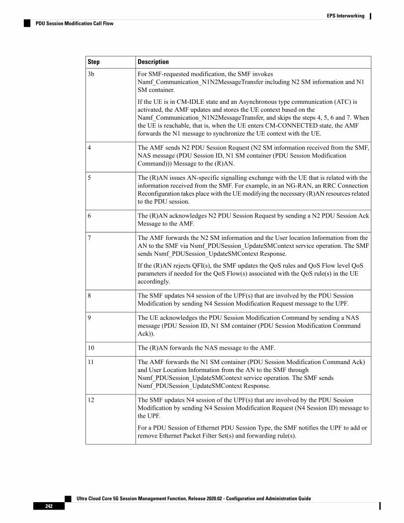
DescriptionStep
For SMF-requested modification, the SMF invokesNamf_Communication_N1N2MessageTransfer including N2 SM information and N1SM container.
If the UE is in CM-IDLE state and an Asynchronous type communication (ATC) isactivated, the AMF updates and stores the UE context based on theNamf_Communication_N1N2MessageTransfer, and skips the steps 4, 5, 6 and 7. Whenthe UE is reachable, that is, when the UE enters CM-CONNECTED state, the AMFforwards the N1 message to synchronize the UE context with the UE.
3b
The AMF sends N2 PDU Session Request (N2 SM information received from the SMF,NAS message (PDU Session ID, N1 SM container (PDU Session ModificationCommand))) Message to the (R)AN.
4
The (R)AN issues AN-specific signalling exchange with the UE that is related with theinformation received from the SMF. For example, in an NG-RAN, an RRC ConnectionReconfiguration takes place with the UEmodifying the necessary (R)AN resources relatedto the PDU session.
5
The (R)AN acknowledges N2 PDU Session Request by sending a N2 PDU Session AckMessage to the AMF.
6
The AMF forwards the N2 SM information and the User location Information from theAN to the SMF via Nsmf_PDUSession_UpdateSMContext service operation. The SMFsends Nsmf_PDUSession_UpdateSMContext Response.
If the (R)AN rejects QFI(s), the SMF updates the QoS rules and QoS Flow level QoSparameters if needed for the QoS Flow(s) associated with the QoS rule(s) in the UEaccordingly.
7
The SMF updates N4 session of the UPF(s) that are involved by the PDU SessionModification by sending N4 Session Modification Request message to the UPF.
8
The UE acknowledges the PDU Session Modification Command by sending a NASmessage (PDU Session ID, N1 SM container (PDU Session Modification CommandAck)).
9
The (R)AN forwards the NAS message to the AMF.10
The AMF forwards the N1 SM container (PDU Session Modification Command Ack)and User Location Information from the AN to the SMF throughNsmf_PDUSession_UpdateSMContext service operation. The SMF sendsNsmf_PDUSession_UpdateSMContext Response.
11
The SMF updates N4 session of the UPF(s) that are involved by the PDU SessionModification by sending N4 Session Modification Request (N4 Session ID) message tothe UPF.
For a PDU Session of Ethernet PDU Session Type, the SMF notifies the UPF to add orremove Ethernet Packet Filter Set(s) and forwarding rule(s).
12
Ultra Cloud Core 5G Session Management Function, Release 2020.02 - Configuration and Administration Guide242
EPS InterworkingPDU Session Modification Call Flow
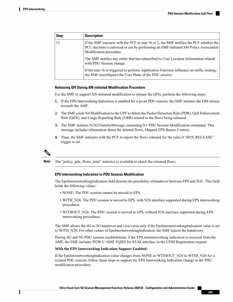
DescriptionStep
If the SMF interacts with the PCF in step 1b or 2, the SMF notifies the PCF whether thePCC decision is enforced or not by performing an SMF-initiated SM Policy AssociationModification procedure.
The SMF notifies any entity that has subscribed to User Location Information relatedwith PDU Session change.
If the step 1b is triggered to perform Application Function influence on traffic routing,the SMF reconfigures the User Plane of the PDU session.
13
Releasing QFI During AN-initiated Modification Procedure
For the SMF to support AN-initiated modification to release the QFIs, perform the following steps:
1. If the EPS Interworking Indication is enabled for a given PDU session, the SMF initiates the EBI releasetowards the AMF.
2. The SMF sends N4Modification to the UPF to delete the Packet Detection Rule (PDR), QoS EnforcementRule (QER), and Usage Reporting Rule (URR) related to the flows being released.
3. The SMF initiates N1N2TransferMessage containing N1 PDU Session Modification command. Thismessage includes information about the deleted flows, Mapped EPS Bearer Context.
4. Then, the SMF interacts with the PCF to report the flows released for the rules if “RES_RELEASE”trigger is set.
The "policy_pdu_flows_total" statistics is available to check the released flows.Note
EPS Interworking Indication in PDU Session Modification
The EpsInternetworkingIndication field denotes the possibility of handover between EPS and 5GC. This fieldholds the following values:
• NONE: The PDU session cannot be moved to EPS.
• WITH_N26: The PDU session is moved to EPS, with N26 interface supported during EPS interworkingprocedures.
• WITHOUT_N26: The PDU session is moved to EPS, without N26 interface supported during EPSinterworking procedures.
The SMF allows the 4G to 5G handover and vice-versa only if the EpsInternetworkingIndication value is setto WITH_N26. For other values of EpsInternetworkingIndication, the SMF rejects the handovers.
During 4G and 5G PDU session establishment, if the EPS internetworking indication is received from theAMF, the SMF includes PGW-C+SMF FQDN for S5/S8 interface in the UDM Registration request.
With the EPS Interworking Indication Support Enabled:
If the EpsInternetworkingIndication value changes from NONE or WITHOUT_N26 to WITH_N26 for acreated PDU session, follow these steps to support the EPS Interworking Indication change in the PDUmodification procedure.
Ultra Cloud Core 5G Session Management Function, Release 2020.02 - Configuration and Administration Guide243
EPS InterworkingPDU Session Modification Call Flow

1. The AMF invokes the Nsmf_PDUSession_UpdateSMContext request with the changedEpsInterworkingIndication value.
2. The SMF receives the Nsmf_PDUSession_UpdateSMContext request from the AMF, and initiates theNamf_Communication_EbiAssignmentRequest. This request includes the PDU Session ID andAllocation/Retention Priority (ARP) List.
3. The AMF sends Namf_Communication_EbiAssignmentResponse to the SMF. The AMF sends thefollowing through the response:
• assignedEbiList containing the successfully assigned EBIs.
• failedArpList containing the failed ARPs for which the EBI assignment failed.
• 4XX/5XX error along with AssignEbiError representing the EBI assignment failure.
4. The SMF sends N1N2MessageTransfer request message if the EBIs are created successfully. This requestincludes the following:
• N1:PDU SESSION MODIFICATION COMMAND ([Mapped EPS Bearer Contexts,Create])
• N2:N2_PDU_SESSION_RESOURCE_MODIFY_REQUEST_TRANSFER (QoS Flow Add orModify Request Item with EPS Radio Access Bearer (E-RAB) ID and QoS Flow ID)
If the UE is in Idle mode, the SMF skips sending the N2 message.Note
5. The SMF informs mapped EPS bearer context in the UE using N1 message. The SMF waits for N1: PDUSESSION MODIFICATION COMPLETE message.
6. The SMF informs EBI to QoS Flow Identifier (QFI) mapping to gNodeB using N2 message. The SMFwaits for N2: PDU SESSION RESOURCE MODIFY RESPONSE TRANSFER message.
7. The SMF completes the PDU Session Modification procedure.
With the EPS Interworking Indication Support Disabled:
If the EpsInternetworkingIndication value changes from WITH_N26 to NONE or WITHOUT_N26 for acreated PDU session, follow these steps to support the EPS Interworking Indication change in the PDUmodification procedure.
1. The SMF receives the Nsmf_PDUSession_UpdateSMContext request with the changedEpsInterworkingIndication value from the AMF.
2. The SMF sends N1N2MessageTransfer request message. This request includes the following:
• N1:PDU SESSION MODIFICATION COMMAND ([Mapped EPS Bearer Contexts,Delete])
• N2:N2_PDU_SESSION_RESOURCE_MODIFY_REQUEST_TRANSFER
If the UE is in Idle mode, the SMF skips sending the N2 message.Note
Ultra Cloud Core 5G Session Management Function, Release 2020.02 - Configuration and Administration Guide244
EPS InterworkingPDU Session Modification Call Flow

3. The SMF deletes Mapped EPS bearer context in UE using N1 message. The SMF waits for N1: PDUSESSION MODIFICATION COMPLETE message.
4. The SMF deletes EBI to QFI mapping to gNodeB using N2 message. The SMF waits for N2: PDUSESSION RESOURCE MODIFY RESPONSE TRANSFER message.
5. The SMF completes the PDU Session Modification procedure.
Use the show subscriber command to determine the EPS interworking status of the PDU session, and theEBI mapping for the QoS flows.
PDU Session Release Call Flow
The PDU Session Release procedure is used to release all the resources associated with a PDU session,including:
• The IP address/prefixes allocated for an IP-based PDU session
• Any UPF resource that was used by the PDU session.
• Any access resource that was used by the PDU session.
The SMF notifies any entity associated with the PDU session: PCF, Data Network (DN) (for example, whenDN authorization has taken place at PDU session establishment), and so on.
There are different ways to initiate the PDU session release. It can be from UE, network, AMF, or RAN.
UE-initiated PDU Session Release Call Flow
The UE-initiated PDU session release procedure allows the UE to request the release of the PDU session. Inthe case of Local Breakout (LBO), the procedure is as in the case of non-roaming with the difference that theAMF, the SMF, the UPF, and the PCF are located in the visited network.
The following figure depicts the UE-initiated PDU session release procedure to support EPS interworking onthe SMF as specified in 3GPP TS 23.502, section 4.3.4.2.
Ultra Cloud Core 5G Session Management Function, Release 2020.02 - Configuration and Administration Guide245
EPS InterworkingPDU Session Release Call Flow
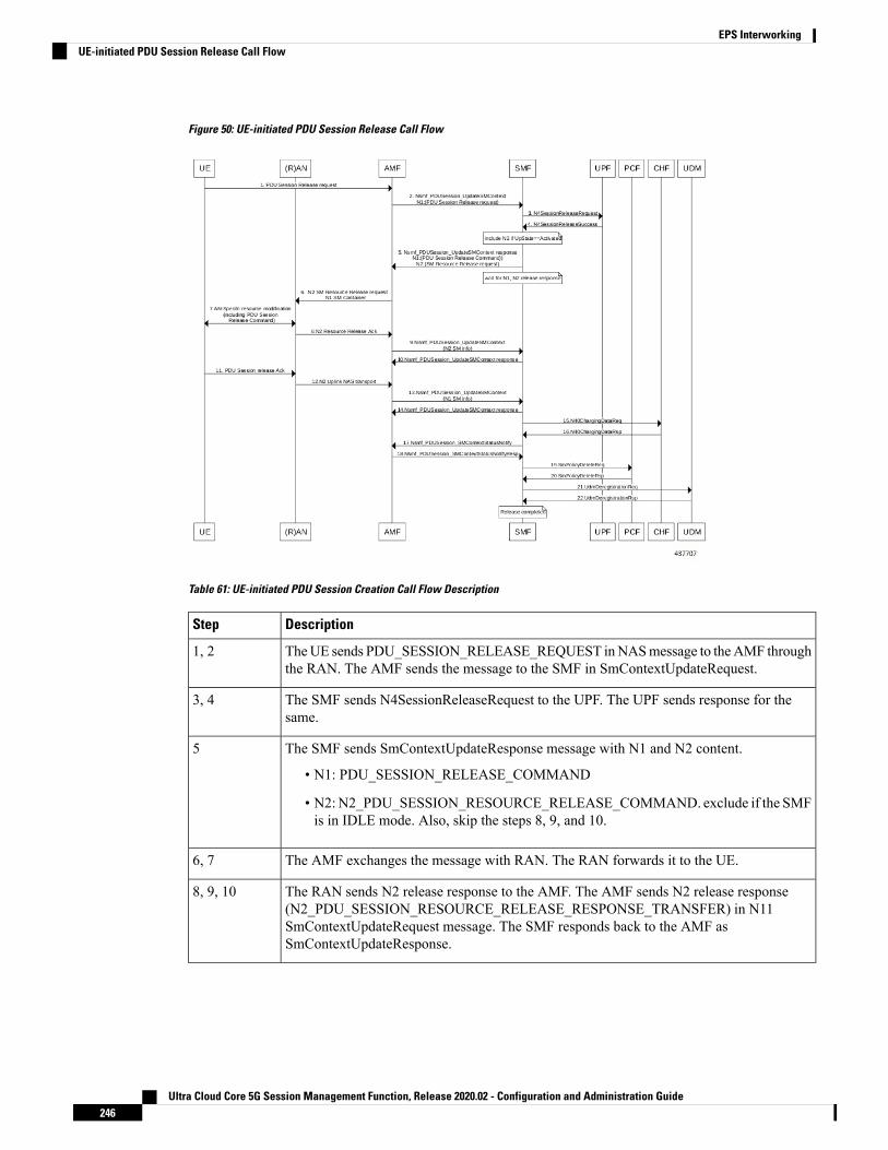
Figure 50: UE-initiated PDU Session Release Call Flow
Table 61: UE-initiated PDU Session Creation Call Flow Description
DescriptionStep
TheUE sends PDU_SESSION_RELEASE_REQUEST inNASmessage to theAMF throughthe RAN. The AMF sends the message to the SMF in SmContextUpdateRequest.
1, 2
The SMF sends N4SessionReleaseRequest to the UPF. The UPF sends response for thesame.
3, 4
The SMF sends SmContextUpdateResponse message with N1 and N2 content.
• N1: PDU_SESSION_RELEASE_COMMAND
• N2:N2_PDU_SESSION_RESOURCE_RELEASE_COMMAND. exclude if the SMFis in IDLE mode. Also, skip the steps 8, 9, and 10.
5
The AMF exchanges the message with RAN. The RAN forwards it to the UE.6, 7
The RAN sends N2 release response to the AMF. The AMF sends N2 release response(N2_PDU_SESSION_RESOURCE_RELEASE_RESPONSE_TRANSFER) in N11SmContextUpdateRequest message. The SMF responds back to the AMF asSmContextUpdateResponse.
8, 9, 10
Ultra Cloud Core 5G Session Management Function, Release 2020.02 - Configuration and Administration Guide246
EPS InterworkingUE-initiated PDU Session Release Call Flow

DescriptionStep
The UE sends N1 release response in NAS message to the AMF through the RAN. TheAMF sends N1 release response (PDU_SESSION_RELEASE_COMPLETE) in N11SmContextUpdateRequest message. The SMF responds back to the AMF asSmContextUpdateResponse.
11, 12, 13, 14
The SMF sends delete charging request to the CHF. The CHF responds back to the SMFwith delete response.
15, 16
The SMF sends SmContextStausNotify to the AMF. The AMF responds back withSmContextStausNotifyResponse message.
17, 18
The SMF sends delete request to the PCF. The PCF responds back to the SMF with deleteresponse
19, 20
The SMF sends UDM deregistration request. The UDM responds back to the SMF withderegistration response.
21, 22
Network-initiated PDU Session Release Call Flow
The network-initiated PDU session release procedure allows the AMF, the SMF or the PCF to initiate therelease of a PDU session.
The following figure depicts the network-initiated PDU session release call flow.
Ultra Cloud Core 5G Session Management Function, Release 2020.02 - Configuration and Administration Guide247
EPS InterworkingNetwork-initiated PDU Session Release Call Flow
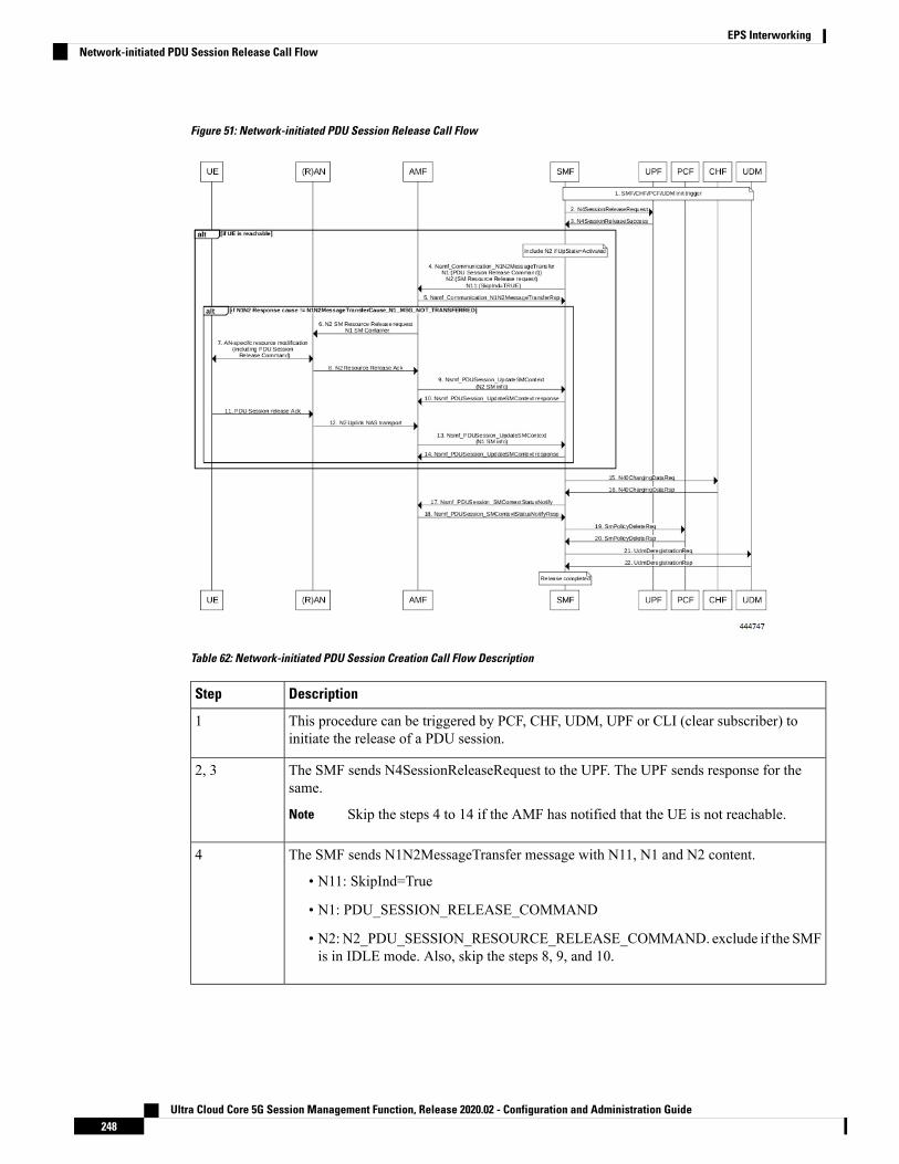
Figure 51: Network-initiated PDU Session Release Call Flow
Table 62: Network-initiated PDU Session Creation Call Flow Description
DescriptionStep
This procedure can be triggered by PCF, CHF, UDM, UPF or CLI (clear subscriber) toinitiate the release of a PDU session.
1
The SMF sends N4SessionReleaseRequest to the UPF. The UPF sends response for thesame.
Skip the steps 4 to 14 if the AMF has notified that the UE is not reachable.Note
2, 3
The SMF sends N1N2MessageTransfer message with N11, N1 and N2 content.
• N11: SkipInd=True
• N1: PDU_SESSION_RELEASE_COMMAND
• N2:N2_PDU_SESSION_RESOURCE_RELEASE_COMMAND. exclude if the SMFis in IDLE mode. Also, skip the steps 8, 9, and 10.
4
Ultra Cloud Core 5G Session Management Function, Release 2020.02 - Configuration and Administration Guide248
EPS InterworkingNetwork-initiated PDU Session Release Call Flow

DescriptionStep
TheAMF responds back to the SMFwith the cause included in theN1N2MessageTransferRspmessage.
Skip the steps 6 to 14 if the AMF sends the cause asN1_MSG_NOT_TRANSFERRED in step 5.
Note
5
The AMF exchanges the message with RAN. The RAN forwards it to the UE.6, 7
The RAN sends N2 release response to the AMF. The AMF transfers N2 release response(N2_PDU_SESSION_RESOURCE_RELEASE_RESPONSE_TRANSFER) in N11SmContextUpdateRequest message. The SMF responds back to the AMF asSmContextUpdateResponse.
8, 9, 10
The UE sends N1 release response in the NAS message to the AMF through the RAN. TheAMF sends the N1 release response (PDU_SESSION_RELEASE_COMPLETE) in N11SmContextUpdateRequest message. The SMF responds back to the AMF asSmContextUpdateResponse.
11, 12, 13, 14
The SMF sends delete charging request to the CHF. The CHF responds back to the SMFwith delete response.
15, 16
The SMF sends SmContextStausNotify to the AMF. The AMF responds back with theSmContextStausNotifyResponse message.
17, 18
The SMF sends delete request to the PCF. The PCF responds back to the SMF with deleteresponse.
19, 20
The SMF sends UDM deregistration request. The UDM responds back to the SMF withderegistration response.
21, 22
AMF-initiated PDU Session Release
The AMF-initiated PDU session release procedure allows the AMF to initiate the release of a PDU session.
The following figure depicts the AMF-initiated PDU session release call flow.
Ultra Cloud Core 5G Session Management Function, Release 2020.02 - Configuration and Administration Guide249
EPS InterworkingAMF-initiated PDU Session Release

Figure 52: AMF-initiated PDU Session Release Call Flow
Table 63: AMF-initiated PDU Session Creation Call Flow Description
DescriptionStep
The AMF sends SmContextReleaseRequest.1
The SMF sends N4SessionReleaseRequest to the UPF. The UPF sends response for thesame.
2, 3
The SMF sends SmContextReleaseResponse to the AMF.4
The SMF sends delete charging request to the CHF. The CHF responds back to the SMFwith delete response.
5, 6
The SMF sends delete request to the PCF. The PCF responds back to the SMF with deleteresponse.
7, 8
The SMF sends UDM deregistration request. The UDM responds back to the SMF withderegistration response.
9, 10
AMF-initiated PDU Session Release with N11 Release=True
The AMF-initiated PDU session release procedure allows the AMF to initiate the release of a PDU sessionwith the N11 release in the SmContextModifyRequest being set to True.
The following figure depicts the AMF-initiated PDU session release call flow with the N11 release=True.
Ultra Cloud Core 5G Session Management Function, Release 2020.02 - Configuration and Administration Guide250
EPS InterworkingAMF-initiated PDU Session Release with N11 Release=True

Figure 53: AMF-initiated PDU Session Release with N11 Release=True
Table 64: AMF-initiated PDU Session Creation Call Flow (N11 release=true) Description
DescriptionStep
The AMF sends SmContextModifyRequest with release=True in 2 causesREL_DUE_TO_DUPLICATE_SESSION_ID orREL_DUE_TO_SLICE_NOT_AVAILABLE.
1
The SMF sends N4SessionReleaseRequest to the UPF. The UPF sends response for thesame.
2, 3
The SMF sends SmContextUpdateResponse message with N1 and N2 content.
• N1: PDU_SESSION_RELEASE_COMMAND, exclude if cause isREL_DUE_TO_DUPLICATE_SESSION_ID, skip steps 10,11,12,13
• N2:N2_PDU_SESSION_RESOURCE_RELEASE_COMMAND. exclude if the SMFis in IDLE mode. Also, skip the steps 7, 8, and 9.
4
The AMF exchanges message with RAN. The RAN forwards it to the UE.5, 6
Ultra Cloud Core 5G Session Management Function, Release 2020.02 - Configuration and Administration Guide251
EPS InterworkingAMF-initiated PDU Session Release with N11 Release=True
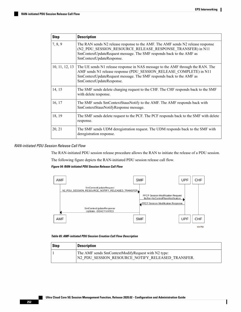
DescriptionStep
The RAN sends N2 release response to the AMF. The AMF sends N2 release response(N2_PDU_SESSION_RESOURCE_RELEASE_RESPONSE_TRANSFER) in N11SmContextUpdateRequest message. The SMF responds back to the AMF asSmContextUpdateResponse.
7, 8, 9
The UE sends N1 release response in NAS message to the AMF through the RAN. TheAMF sends N1 release response (PDU_SESSION_RELEASE_COMPLETE) in N11SmContextUpdateRequest message. The SMF responds back to the AMF asSmContextUpdateResponse.
10, 11, 12, 13
The SMF sends delete charging request to the CHF. The CHF responds back to the SMFwith delete response.
14, 15
The SMF sends SmContextStausNotify to the AMF. The AMF responds back withSmContextStausNotifyResponse message.
16, 17
The SMF sends delete request to the PCF. The PCF responds back to the SMF with deleteresponse.
18, 19
The SMF sends UDM deregistration request. The UDM responds back to the SMF withderegistration response.
20, 21
RAN-initiated PDU Session Release Call Flow
The RAN-initiated PDU session release procedure allows the RAN to initiate the release of a PDU session.
The following figure depicts the RAN-initiated PDU session release call flow.
Figure 54: RAN-initiated PDU Session Release Call Flow
Table 65: AMF-initiated PDU Session Creation Call Flow Description
DescriptionStep
The AMF sends SmContextModifyRequest with N2 type:N2_PDU_SESSION_RESOURCE_NOTIFY_RELEASED_TRANSFER.
1
Ultra Cloud Core 5G Session Management Function, Release 2020.02 - Configuration and Administration Guide252
EPS InterworkingRAN-initiated PDU Session Release Call Flow

DescriptionStep
The SMF sends N4SessionModificationRequest to the UPF with changing packet rule toBuffer from Forward. The UPF sends the response for the same, that is, the SMF movingto IDLE state.
2, 3
The SMF sends SmContextUpdateResponse message with UpState as Deactivated.4
EPS Bearer ID Allocation
This section describes the EPS Bearer ID Allocation procedure.
Figure 55: EPS Bearer ID Allocation Call Flow
Ultra Cloud Core 5G Session Management Function, Release 2020.02 - Configuration and Administration Guide253
EPS InterworkingEPS Bearer ID Allocation

Not all the steps in the preceding call flow are supported. For more details, see the descriptions in the followingtable.
Note
Table 66: EPS Bearer ID Allocation Call Flow Description
DescriptionStep
The EBI Assignment procedure is initiated as specified in the relevant sections of 3GPPTS 23.502. The relevant steps of the procedure are executed as specified in the precedingcall flow.
Roaming scenarios are currently not supported.Note
1
If the PGW-C+SMF (or H-SMF for home-routed cases) determines that EPS bearer IDs(based on operator policies, S-NSSAI, User Plane Security Enforcement information) needto be assigned to the QoS flows in the PDU session, the PGW-C+SMF invokesNamf_Communication_EBIAssignment Request (PDU Session ID, ARP list).
2
Step 3 through Step 6 apply only when the AMF needs to revoke EBI that was previously allocated for aUE to serve a new SMF request of EBI for the same UE.
(Conditional) If the AMF has no available EBIs, the AMF may revoke an EBI that wasassigned to QoS flows based on the ARPs and S-NSSAI stored during PDU SessionEstablishment, EBI information in the UE context and local policies. If an assigned EBIis to be revoked, the AMF invokes Nsmf_PDUSession_UpdateSMContext (EBI(s) to berevoked) to request the related SMF (called “SMF serving the released resources”) torelease the mapped EPS QoS parameters corresponding to the EBI to be revoked. TheAMF stores the association of the assigned EBI, ARP pair to the corresponding PDUSession ID and SMF address.
3
The “SMF serving the released resources” that receives the request in Step 3 invokesNamf_Communication_N1N2Message Transfer (N2 SM information (PDU Session ID,EBI(s) to be revoked), N1 SM container (PDU Session Modification Command (PDUSession ID, EBI(s) to be revoked))) to inform the (R)AN and the UE to remove the mappedEPS QoS parameters corresponding to the EBI(s) to be revoked. In home-routed roamingscenario, the H-SMF includes EBI(s) to be revoked to V-SMF to informV-SMF to removethe mapped EPS bearer context corresponding to the EBI(s) to be revoked.
The SMF can also decide to remove the QoS flow if it is not acceptable to continue theservice when no corresponding EPS QoS parameters can be assigned.
For home-routed roaming scenario, the "SMF serving the released resources" sends an N4Session Modification Request to request the PGW-U+UPF to release the N4 sessioncorresponding to the revoked EBI(s).
In home-routed roaming case, the V-SMF starts a VPLMN-initiated QoSModification forthe PDU session. The V-SMF invokes the Namf_Communication_N1N2Message Transferbased on the corresponding QoS modification message received from H-SMF.
4
Ultra Cloud Core 5G Session Management Function, Release 2020.02 - Configuration and Administration Guide254
EPS InterworkingEPS Bearer ID Allocation

DescriptionStep
If the UE is in CM-CONNECTED state, the AMF sends N2 PDU Session Request (N2SM information received from SMF, NAS message (PDU Session ID, N1 SM container(PDU Session Modification Command))) message to the (R)AN.
If the UE is in CM-IDLE state and an ATC is activated, the AMF updates and stores theUE context based on the Namf_Communication_N1N2MessageTransfer and Step 5 andStep 6 are skipped. When the UE is reachable, for example, when the UE entersCM-CONNECTED state, the AMF forwards the N1message to synchronize the UE contextwith the UE.
5
The relevant steps of the procedure are executed as specified in the preceding figure.6
If the AMF successfully assigns EBI(s), it responds with the assigned EBI(s). Otherwise,it responds with a cause indicating EBI assignment failure.
If a PDU session from another SMF already exists towards the same DNN, the AMF eitherrejects the EBI assignment request, or revokes the EBI(s) from the existing PDU session(s)to the same DNN but different SMF. The AMF makes the decision based on the operatorpolicy.
The preceding statement applies only when the S-NSSAI(s) for the PDU sessionsare different, otherwise the same SMF is selected for PDU sessions to the sameDNN.
Note
7
The PGW-C+SMF sends an N4 Session Establishment/Modification Request to thePGW-U+UPF.
For home-routed roaming scenario, if the EBI is assigned successfully, the PGW-C+SMFprepares the CN Tunnel Info for each EPS bearer. If the CN Tunnel info is allocated bythe PGW-C+SMF, the PGW-U tunnel info for the EPS bearer may be provided toPGW-U+UPF. If the CN Tunnel info is allocated by PGW-U+UPF, the PGW-U+UPFsends the PGW-U tunnel info for the EPS bearer to the PGW-C+SMF. The PGW-U+UPFis ready to receive the uplink packets from E-UTRAN.
In the home-routed roaming scenario, the PGW-C+SMF prepares the CNTunnelInfo for each EPS bearer and provides it to the V-SMF. Thus, when the UEmoves to EPS network, the V-SMF does not need to interact with thePGW-C+SMF to get the EPS bearer context(s).
Note
If the CN Tunnel info is allocated by the PGW-C+SMF and not provided toPGW-U+UPF at PDU session establishment, when the UE moves to the targetRAT the PGW-U+UPF cannot receive uplink (UL) data until the PGW-C+SMFhas provided the Tunnel Info to the PGW-U+UPF in N4 Session Modification.This causes a short interruption to the UL data during the inter-system handoverexecution.
Note
8
Ultra Cloud Core 5G Session Management Function, Release 2020.02 - Configuration and Administration Guide255
EPS InterworkingEPS Bearer ID Allocation

DescriptionStep
If the PGW-C+SMF receives any EBI(s) from the AMF, it adds the EBI(s) received intothe mapped EPS bearer context(s).
In home-routed roaming scenario, the PGW-C+SMF generates EPS bearer context, whichincludes per EPS bearer PGW-U tunnel information. In addition, if the default EPS beareris generated for the corresponding PDN Connection of PDU Session (that is, during thePDU Session establishment procedure), the PGW-C+SMF generates the PGW-C tunnelinformation of the PDN connection and includes it in UE EPS PDN connection.
9
(Conditional) In non-roaming or LBO scenario, the PGW-C+SMF includes the mappedEPS bearer context(s) and the corresponding QoS Flow(s) to be sent to the UE in the N1SM container. PGW-C+SMF also indicates the mapping between the QoS flow(s) andmapped EPS bearer context(s) in the N1 SM container. PGW-C+SMF also includes themapping between the received EBI(s) and QFI(s) in the N2 SM information to be sent tothe NG-RAN. The PGW-C+SMF sends the N1 SM container and N2 SM information tothe AMF via Namf_Communication_N1N2MessageTransfer.
9a
(Conditional) In home-routed roaming scenario, the PGW-C+SMF sends the mapped EPSbearer context(s), the mapping between the received EBI(s) and QFI(s), and EPS bearercontext to the V-SMF via Nsmf_PDUSession_Create Response during PDU SessionEstablishment, or via Nsmf_PDUSession_Update Request during PDU SessionModification. The V-SMF stores the EPS bearer context, and generates N1 SM containerand N2 SM information, and forwards them to the AMF viaNamf_Communication_N1N2MessageTransfer.
9b
The N1 SM container and N2 SM information are sent to the UE andNG-RAN respectively.The relevant steps of the procedure are executed as specified in the preceding figure.
10
Standards ComplianceThis feature complies with the following standards:
• 3GPP TS 23.401, Version 15.6.0
• 3GPP TS 23.502, Version 15.4.0
LimitationsTFT IE in mapped EPS bearer context is currently not supported.
Generating EPS PDN Connection Parameters from 5G PDU Session ParametersThis section describes how to generate the EPS PDN connection parameters from the 5G PDU sessionparameters in the PGW-C+SMF.
When the PGW-C+SMF is requested to set up or modify a PDN connection or a PDU session that supportsinterworking between EPS and 5GC, the PGW-C+SMF generates the PDN connection parameters from thePDU session parameters.
When the PGW-C+SMF generates the PDN connection parameters based on the PDU session parameters,the following rules hold:
Ultra Cloud Core 5G Session Management Function, Release 2020.02 - Configuration and Administration Guide256
EPS InterworkingStandards Compliance

• PDN Type: The PDN type is set to IPv4 or IPv6 if the PDU Session Type is IPv4 or IPv6 respectively.The PDN type is set to Non-IP for Ethernet and Unstructured PDU Session Types.
• EPS Bearer ID: The EBI is requested from the AMF during the establishment of a QoS Flow as describedin 3GPP TS 23.502, Section 4.11.1.4.1, for PDU sessions that support interworking between EPS and5GC. The EBI is obtained from MME during the establishment of an EPS bearer (that is triggered by anestablishment of the QoS Flow) as defined in 3GPP TS 23.401 for PDN connections hosted byPGW-C+SMF. The association between EBI and QoS Flow is stored by the SMF.
• APN-AMBR:APN-AMBR is set according to the operator policy. For example, taking the session AMBRinto account.
• EPS QoS parameters (including ARP, QCI, GBR, and MBR):
• If the QoS Flow is mapped to one EPS bearer: ARP, GBR, and MBR of the EPS bearer is set to therespective ARP, GFBR, and MFBR of the corresponding QoS Flow.
• For standardized 5QIs, the QCI is mapped 1:1 to the 5QI. For non-standardized 5QIs, thePGW-C+SMF derives the QCI based on the 5QI and operator policy.
A GBR QoS flow is mapped 1:1 to a GBR dedicated EPS Bearer if an EBI has been assigned. All other GBRQoS flows will be terminated during interworking. If multiple QoS flows are mapped to one EPS bearer, theEPS bearer parameters are set based on the operator policy. For example, EPS bearer QoS parameters are setaccording to the highest QoS of all mapped QoS flows.
Note
Non-GBR QoS flows for which no EBI has been assigned are mapped to the default EPS bearer.Note
5G to EPS Handover Using N26 Interface
Feature DescriptionThe SMF supports handover of PDU sessions to EPS on 5GC when the N26 interface is present between theMME and the AMF. The handover supports the creation of applicable default and dedicated bearers.
How it WorksThis section describes the 5G to EPS handover procedure and the 5G to EPS handover cancellation procedure.
Call Flows
This section describes the following call flows:
• 5G to EPS Handover Call Flow
• 5G to EPS Handover Cancellation Flow
Ultra Cloud Core 5G Session Management Function, Release 2020.02 - Configuration and Administration Guide257
EPS Interworking5G to EPS Handover Using N26 Interface

5G to EPS Handover Call Flow
This section describes the 5G to EPS handover call flow with N26 interface.
The 5G to EPS Handover procedure for the EPS session is compliant with 3GPP 23.502, section 4.11.1.2.1.
1. The AMF requests the SMF to provide the SM Context using Nsmf_PDUSession_ContextRequest.
2. The SMF sends N4 Session Modification to the UPF to establish the CN tunnel for each EPS bearer.The bearer mapping to the 5G QoS and PCC rules received from PCC must already be present with theSMF. The SMF must also have the bearer IDs obtained from the Bearer ID Allocation procedure. TheSMF creates new PDRs for the N4 session and gets TEID allocated for each bearer as required by the4G system.
3. The SMF provides EPS bearer contexts to the AMF. The SMF also provides the CN tunnel informationto AMF for all bearers for the uplink traffic from E-UTRAN.
4. If indirect data forwarding applies, the AMF sends the Nsmf_PDUSession_UpdateSMContext Request(S-GW address(es) and S-GW DL TEID(s) for data forwarding) to the SMF, for creating the indirectdata forwarding tunnel.
5. The SMF sends N4 Modification Request to the UPF to create additional PDRs and FARs to receivethe redirected DL data over the indirect tunnel fromNGRAN and forwards them to eNodeB. The uplinkPDRs must have QFI to match the forwarded DL data from NG-RAN and the associated QER will nothave QFI as data needs to be forwarded to the eNodeB. The FAR redirects the received data to theeNodeB over appropriate tunnel based on the QFI.
6. The S-GW sends Modify Bearer Request to the SMF with DL TEIDs on the SMF for the bearers.
7. The SMF sends N4 Modification Request to the UPF to activate the DL data path to E-UTRAN. At thistime, both the indirect tunnel and the direct DL path are activated towards the eNodeB.
8. The SMF sends the Modify Bearer Response to S-GW.
9. TheAMF initiates Nsmf_PDUSession_UpdateSMContext Request service operation with an indicationto release the forwarding tunnels.
10. The SMF sends N4 Modification Request to the UPF to remove the PDRs and FARs for the indirecttunnels. The PDRs and FARs for the 5G session which are not required are also removed.
5G to EPS Handover Cancellation Call Flow
When the Source Radio Access Network (RAN) triggers a handover cancellation after the preparation phase,the AMF invokes the "Nsmf_PDUSession_UpdateSMContext request (SUPI, Relocation Cancel Indication)toward the SMF. Based on the Relocation Cancel Indication, the SMF deletes the session resources establishedduring the handover preparation phase. That is, the SMF removes all the Packet Detection Rules (PDRs),Forwarding Action Rules (FARs), and other rules that were allocated in preparation of handoff for indirecttunnel and the 5G session.
The following call flow depicts the 5GS to EPS handover cancellation procedure.
Ultra Cloud Core 5G Session Management Function, Release 2020.02 - Configuration and Administration Guide258
EPS Interworking5G to EPS Handover Call Flow

Figure 56: 5GS to EPS Handover Cancellation Call Flow
Table 67: 5GS to EPS Handover Cancellation Call Flow Description
DescriptionStep
The AMF requests the SMF to cancel the handover of an existing PDU session bysending a POST request for SmContext Update service, with the following information:
• updating the hoState attribute of the individual SM Context resource in the SMFto CANCELLED
• cause information
1
The SMF returns a 200 OK response message including the following information:
• hoState attribute set to CANCELLED
The SMF cancels the execution of the handover, for example, releases the resourcesreserved for the handover to the target RAN. Then, the SMF sets the hoState to NONEand deletes any stored targetServingNfId.
2
Standards ComplianceThe 5G to EPS Handover feature complies with the 3GPP TS 23.502, version 15.3.0.
Ultra Cloud Core 5G Session Management Function, Release 2020.02 - Configuration and Administration Guide259
EPS InterworkingStandards Compliance
Create Dedicated Bearer Delay and Retry Support
Feature DescriptionThe Create Dedicated Bearer Delay and Retry Support feature facilitates the following:
• Delays the creation of the dedicated bearer that is based on the configured time after handover is complete.
• Retries the creation of the dedicated bearer for the IMS bearer in either of the following scenarios:
• When the MME fails with the handover in progress.
• When the IMS bearer is temporarily unreachable.
• After the handover is complete, the SMF service starts with the configured timer. Then, the dedicatedbearer creation begins.
• If the IMS dedicated bearer creation fails, the maximum retries configuration determines the number ofretries the creation process attempts. The configured timeout determines the delay of each retry attempt.
How It WorksThis section provides a brief of how the Create Dedicated Bearer Delay and Retry Support feature works.
Call FlowsThis section includes the following call flow.
Ultra Cloud Core 5G Session Management Function, Release 2020.02 - Configuration and Administration Guide260
EPS InterworkingCreate Dedicated Bearer Delay and Retry Support

Figure 57: EPS Fallback Guard Timer Call Flow
Table 68: EPS Fallback Guard Timer Call Flow Description
DescriptionStep
gNB sends the dedicated bearer creation failure information with the fallback causethrough AMF.
1
EPS fallback timer starts.2
With the successful EPS fallback following the 5G to 4G handover, steps 3 to12 occur.
EPS triggers pending dedicated bearer creation.3
Delay timer starts.4
Ultra Cloud Core 5G Session Management Function, Release 2020.02 - Configuration and Administration Guide261
EPS InterworkingCall Flows
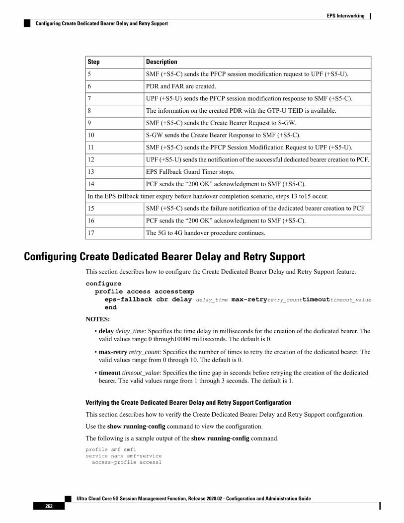
DescriptionStep
SMF (+S5-C) sends the PFCP session modification request to UPF (+S5-U).5
PDR and FAR are created.6
UPF (+S5-U) sends the PFCP session modification response to SMF (+S5-C).7
The information on the created PDR with the GTP-U TEID is available.8
SMF (+S5-C) sends the Create Bearer Request to S-GW.9
S-GW sends the Create Bearer Response to SMF (+S5-C).10
SMF (+S5-C) sends the PFCP Session Modification Request to UPF (+S5-U).11
UPF (+S5-U) sends the notification of the successful dedicated bearer creation to PCF.12
EPS Fallback Guard Timer stops.13
PCF sends the “200 OK” acknowledgment to SMF (+S5-C).14
In the EPS fallback timer expiry before handover completion scenario, steps 13 to15 occur.
SMF (+S5-C) sends the failure notification of the dedicated bearer creation to PCF.15
PCF sends the “200 OK” acknowledgment to SMF (+S5-C).16
The 5G to 4G handover procedure continues.17
Configuring Create Dedicated Bearer Delay and Retry SupportThis section describes how to configure the Create Dedicated Bearer Delay and Retry Support feature.
configureprofile access accesstemp
eps-fallback cbr delay delay_time max-retryretry_counttimeouttimeout_valueend
NOTES:
• delay delay_time: Specifies the time delay in milliseconds for the creation of the dedicated bearer. Thevalid values range 0 through10000 milliseconds. The default is 0.
• max-retry retry_count: Specifies the number of times to retry the creation of the dedicated bearer. Thevalid values range from 0 through 10. The default is 0.
• timeout timeout_value: Specifies the time gap in seconds before retrying the creation of the dedicatedbearer. The valid values range from 1 through 3 seconds. The default is 1.
Verifying the Create Dedicated Bearer Delay and Retry Support Configuration
This section describes how to verify the Create Dedicated Bearer Delay and Retry Support configuration.
Use the show running-config command to view the configuration.
The following is a sample output of the show running-config command.profile smf smf1service name smf-serviceaccess-profile access1
Ultra Cloud Core 5G Session Management Function, Release 2020.02 - Configuration and Administration Guide262
EPS InterworkingConfiguring Create Dedicated Bearer Delay and Retry Support

!!profile access access1eps-fallback cbr delay 100 max-retry 5 timeout 2
Handling GTP-U Error Indication for 4G Sessions
Feature DescriptionThis section describes how the SMF handles GPRS tunneling protocol, user plane (GTP-U) error indicationfor the 4G sessions.
Serving Gateway (S-GW) sends GTP-U error indication message including the tunnel IDs to UPF when itreceives a GTP-U message with an unknown Tunnel Endpoint Identifier (TEID). The UPF on receivingGTP-U error indication sends N4SessionReportRequest towards SMF including error indication (ERIR). TheSMF retrieves EBI based on Fteid included in the N4SessionReportRequest, and initiates deletion of thesession or bearer. The SMF sends Delete Bearer Request towards S-GW. On receiving the response fromS-GW, the SMF sends either an N4 session modification request or N4 session release request to the UPFbased on the bearer type, that is, dedicated or default bearer. CHF and PCF are also notified based on thebearer type.
When the SMF receives PFCPSessionReportRequest, the IntSelfTxnN4SessRptReq message is displayed aspart of the debug message.
Note
Standards ComplianceThe GTP-U Error Indication Handling feature complies with the following standards:
• 3GPP TS 29.244, Version 15.6.0
• 3GPP TS 23.527, Version 15.3.0
How it Works
GTP-U Error Handling ProcedureThis section describes the call flow associated with the GTP-U error handling procedure for the 4G sessions.
Ultra Cloud Core 5G Session Management Function, Release 2020.02 - Configuration and Administration Guide263
EPS InterworkingHandling GTP-U Error Indication for 4G Sessions

Figure 58: GTP-U Error Indication Handling Call Flow
Table 69: GTP-U Error Handling Call Flow Description
DescriptionStep
S-GW sends GTP-U Error Indication towards UPF, indicating the bearer with thefailed bearer ID.
1
After receiving GTP-U error indication, the UPF sends PFCPSessionReport towardsSMF along with the failed bearer ID.
2
The SMF sends PFCPSessionReport Success message and N4 Session ModificationRequest for dropped packet towards the UPF.
3a and 3b
Ultra Cloud Core 5G Session Management Function, Release 2020.02 - Configuration and Administration Guide264
EPS InterworkingGTP-U Error Handling Procedure

DescriptionStep
The UPF sends N4 Session Modification Response to the SMF.4
The SMF sends Delete Bearer Request towards S-GW along with TEID, EBI, andcause.
5
The S-GW sends Delete Bearer Response towards SMF along with TEID, EBI, andcause as request accepted.
6
If the TEID is a dedicated bearer, then the SMF sends N4 SessionModification Requestwith Delete PDR.
7a
The UPF sends N4 Session Modification Response.7b
If it is a default bearer, the SMF sends N4 Session Release Request.8a
The UPF sends N4 Session Release Response.8b
The SMF sends Charging Data Terminate Request towards CHF.9a
The CHF responds with Charging Data Terminate Response.9b
The SMF sends SMPolicyControl Update Request towards PCF.10a
The PCF sends SMPolicyControl Update Response to the SMF.10b
GTP Path Failure Handling, Restoration, and Recovery
Feature DescriptionSMF now supports:
• Handling of the following GTP-C path management messages as per 3GPP TS 29.274
• Echo Request
• Echo Response
• Sending Echo Request message to the newly discovered GTP-C peer as per the configuration.
• Sending Echo Response message as a reply if it receives Echo Request message from GTP-C peer.
• Retransmitting Echo Request message to GTP-C peer for configured number of times if no response isreceived.
• Clearing all the subscribers associated to a GTP-C peer if no response is received for Echo Requestmessage for configured number of times for that GTP-C peer.
• Clearing all the subscribers associated to a GTP-C peer if a different recovery value is received fromthat GTP-C peer.
The feature complies with the following standards:
Ultra Cloud Core 5G Session Management Function, Release 2020.02 - Configuration and Administration Guide265
EPS InterworkingGTP Path Failure Handling, Restoration, and Recovery

• 3GPP TS 29.274
• 3GPP TS 23.007
Call FlowsThe following call flows captures information specific to howGTP-C path management and GTP-C restorationmessages are handled.
GTP-C Path ManagementFigure 59: GTP-C Path Management
Table 70: GTP-C Path Management
DescriptionStep
Once the GTP-C peer is discovered (an Initial GTP-C Create Session Request or anGTP-C Modify Bearer Request message is received), CN SMF/PGW-C starts sendingGTP-C Echo RequestMessages periodically to the newGTP-C Peer as per configuration.
1
If GTP-C Echo response is not received, CN SMF/PGW-C retries sending GTP-C EchoRequest (configured) N3 times for every configured T3 timer expiry.
2
Once all retries are exhausted, CN SMF/PGW-C clears all the sessions associated to thatGTP-C peer.
3
Ultra Cloud Core 5G Session Management Function, Release 2020.02 - Configuration and Administration Guide266
EPS InterworkingCall Flows

GTP-C Echo Request HandlingFigure 60: GTP-C Echo Request Handling
Table 71: GTP-C Echo Request Handling
DescriptionStep
Whenever a GTP-C Echo Request message is received from a GTP-C peer, CNSMF/PGW-C sends GTP-C Echo Response message as a reply.
1
GTP-C Restoration on PGW-C/SMFPGW-C/SMF can detect that there is a change in recovery value of SGW. PGW-C/SMF can detect this valuefrom the following messages:
• Create Session Request
• Modify Bearer Request
• Create Bearer Response
• Echo Response
If PGW-C/SMF detects that there is a change in recovery value, then it initiates the cleanup of all the PDNconnections associated with the SGW.
Ultra Cloud Core 5G Session Management Function, Release 2020.02 - Configuration and Administration Guide267
EPS InterworkingGTP-C Echo Request Handling

Figure 61: GTP Restoration due to SGW Restart
Memory and Performance ImpactThe Node Manager pod to GTP-C peer path mapping is maintained in etcd and also in the local cache ofNodeMgr and GTP-C Pods.
ConfigurationThe following echo sending related parameters need to be configured at GTP endpoint.
configendpoint gtpinterface <s2b s5 s8>
echo interval <val>
echo retransmission-timeout <val>
echo max-retransmissions <val>
Sample Configuration[unknown] smf# configEntering configuration mode terminal[unknown] smf(config)# endpoint gtp[unknown] smf(config-endpoint-gtp)#[unknown] smf(config-endpoint-gtp)# interfaces2b s5 s8[unknown] smf(config-endpoint-gtp)# interface s5[unknown] smf(config-interface-s5)# echo interval 60echo – Enable gtpc path managementinterval - Configure echo interval in seconds, ranging from <60-360>
Ultra Cloud Core 5G Session Management Function, Release 2020.02 - Configuration and Administration Guide268
EPS InterworkingMemory and Performance Impact

[unknown] smf(config-interface-s5)# echo retransmission-timeout 3retransmission-timeout - Configure the echo retransmission timeout in seconds, ranging from<1–20>[unknown] smf(config-interface-s5)# echo max-retransmissions 10max-retransmissions - Configure maximum retries for GTP echo request, ranging from <0-10>[unknown] smf(config-interface-s5)#
show CommandThe show peers gtp command can be used to display all the connected GTP peers and their node information.
Example:
[unknown] smf# show peers gtp
Ip Address Recovery Value============================1.1.1.2 101.1.1.3 21
Bulk StatisticsThe following dedicated disconnect reason is used for PDN connections cleared due to peer GTP-C restartor path failure.
• disc_pdnrel_gtpc_peer_restart
• disc_pdnrel_gtpc_peer_pathfail
The following statistics are added in smf-nodemgr pod.# HELP nodemgr_gtpc_msg_stats Gtpc Msg Stats# TYPE nodemgr_gtpc_msg_stats counternodemgr_gtpc_msg_stats{app_name="SMF",cluster="Local",data_center="DC",gtpc_msg_type="gtpc_echo_req_rx",gtpc_peer_ip="10.105.35.209",instance_id="0",service_name="smf-nodemgr"}1nodemgr_gtpc_msg_stats{app_name="SMF",cluster="Local",data_center="DC",gtpc_msg_type="gtpc_echo_req_tx",gtpc_peer_ip="10.105.35.209",instance_id="0",service_name="smf-nodemgr"}4nodemgr_gtpc_msg_stats{app_name="SMF",cluster="Local",data_center="DC",gtpc_msg_type="gtpc_echo_res_rx",gtpc_peer_ip="10.105.35.209",instance_id="0",service_name="smf-nodemgr"}1nodemgr_gtpc_msg_stats{app_name="SMF",cluster="Local",data_center="DC",gtpc_msg_type="gtpc_echo_res_tx",gtpc_peer_ip="10.105.35.209",instance_id="0",service_name="smf-nodemgr"}1# HELP nodemgr_gtpc_peer_status Gtpc Peer Status# TYPE nodemgr_gtpc_peer_status counternodemgr_gtpc_peer_status{app_name="SMF",cluster="Local",data_center="DC",gtpc_peer_ip="10.105.35.209",gtpc_peer_status="gtpc_peer_path_down",instance_id="0",service_name="smf-nodemgr"}1nodemgr_gtpc_peer_status{app_name="SMF",cluster="Local",data_center="DC",gtpc_peer_ip="10.105.35.209",gtpc_peer_status="gtpc_peer_path_up",instance_id="0",service_name="smf-nodemgr"}1nodemgr_gtpc_peer_status{app_name="SMF",cluster="Local",data_center="DC",gtpc_peer_ip="10.105.35.209",gtpc_peer_status="gtpc_peer_restarted",instance_id="0",service_name="smf-nodemgr"}1
Ultra Cloud Core 5G Session Management Function, Release 2020.02 - Configuration and Administration Guide269
EPS Interworkingshow Command

LimitationsFrom 3GPP TS 23.007, Section 20: It is recommended that GTPv2 Echo Request should be sent only whena GTP-C entity has not received any GTP response message for a previously sent request message on theGTP-C path for, an implementation dependent time period.
Currently, this is not supported.
Even if SMF receives GTPC echo req from peer, it is considered as path is up. The subsequent Echo Reqfrom SMF is received after the echo interval expiry.
Configuration Support for Rejecting 4G-only DevicesThe SMF provides configuration support to reject calls from 4G-only UE devices.
To reject calls from 4G-only UE devices, use the following configuration:
configureprofile dnn dnnprofile_name
only-nr-capable-ue trueend
NOTES:
• only-nr-capable-ue true: Enable this command to reject any new call attempt for PDN session creationfrom a 4G only capable UE device.
Ultra Cloud Core 5G Session Management Function, Release 2020.02 - Configuration and Administration Guide270
EPS InterworkingLimitations

C H A P T E R 20Flow Failure Handling for Access and MobilityProcedures
• Feature Summary and Revision History, on page 271• Feature Description, on page 272
Feature Summary and Revision History
Summary DataTable 72: Summary Data
SMFApplicable Product(s) or Functional Area
SMIApplicable Platform(s)
Disabled - Configuration RequiredFeature Default Setting
Not ApplicableRelated Changes in this Release
Not ApplicableRelated Documentation
Revision HistoryTable 73: Revision History
ReleaseRevision Details
Pre-2020.02.0First introduced
Ultra Cloud Core 5G Session Management Function, Release 2020.02 - Configuration and Administration Guide271

Feature DescriptionThe SMF supports the QoS flow failures for access and mobility procedures. The SMF receives the QoS flowfailure details as part of the following call flows from NG-RAN to N2 messages.
• Xn handover
• Service request procedures (UE and network-initiated)
• N2 handover with or without changing AMF
• N26 4G to 5G handover
• N26 5G to 4G handover
How it WorksThe SMF processes N11 messages with N2 message details to determine the accepted and failed QoS flowIDs. For failed QoS flow IDs, the SMF excludes the resources locally and communicates the followinginformation to the external interfaces:
• Sends the N4 Session Modification Request to UPF to delete the QERs, URRs, UL or DL PDRs, UL orDL FARs which are applicable to the QoS flow IDs.
• Sends the Charging Data Update Request to CHF by including multi-unit usage details for the removedURRs. If SMF receives a usage report from UPF, SMF sends this report to CHF.
• Sends the N1 N2 transfer message with N1 message details to UE as the PDU Session ModificationCommand.
• Based on the received Policy Control Request Triggers and SM Policy Decision last Request Rule Data,SMF sends the Rule Reports SM Policy Control Update to PCF.
Call FlowsThis section describes the following call flows:
• QoS flow failure handling for Xn handover call flow
• QoS flow failure handling for N2 handover call flow
• QoS Flow failure handling for N26 4G to 5G handover call flow
• QoS flow failures for service request procedures
• PDU UE synchronization procedure
• Flow Failure Management Call Flows
QoS Flow Failure Handling During Xn Handover
This section describes the QoS flow failure handling during the Xn handover.
Ultra Cloud Core 5G Session Management Function, Release 2020.02 - Configuration and Administration Guide272
Flow Failure Handling for Access and Mobility ProceduresFeature Description

Figure 62: QoS Flow Failure Handling during Xn Handover
Table 74: QoS Flow Failure Handling Call Flow Description
DescriptionStep
The PDU session is established over S-AMF and SMF by communicating withUPF, PCF, or CHF for IPv4, IPv6, or dual-stack.
The PCF provides Policy Control Request trigger for SM policy decision asresponse to the request for creation of SM policy control.
The CHF provides session-level and rating-group-level triggers to the SMF as theCharging Data Create Response.
1
The AMF sends SM Context Update Request to SMF. This request includes theinformation on UE location, UE time zone, and N2 message path switch requestwith the list of the accepted QoS Flow Identifier (QFI).
2
Ultra Cloud Core 5G Session Management Function, Release 2020.02 - Configuration and Administration Guide273
Flow Failure Handling for Access and Mobility ProceduresQoS Flow Failure Handling During Xn Handover

DescriptionStep
The SMF identifies the access-side modifications that are received in SM ContextUpdate Request. The charging triggers are identified through the information thatis received in Step 2.
2a
The SMF extracts the list of failed QFI, failed rule report, and failed EPS bearerID (EBI) from the received list of the accepted QFIs.
2b
The PCF triggers are identified through the information that is received in Step 2.2c
For Xn handover preparation procedures, the SMF sends the N4 SessionModification Request to the UPF to update the received DL tunnel informationof T-gNB. After the tunnel information is updated, the UPF sends the usage reportto the SMF as N4 modification response. The SMF retains the final SM ContextUpdate Response as charging or PCF triggers are identified.
3
The SMF sends the Charging Data Update Request to the CHF. This requestincludes the details, such as session-level triggers, multi-unit information withrating-group-level triggers and usage report, customer identification information,and the PDU session charging information.
4
The CHF sends the Charging Data Update Response to the SMF. This responsemay include the multi-unit information with new session or rating-group-leveltriggers.
5
The SMF processes the Charging Data Update Response and updates the PDUsession. SMF does not send the N4 Mode Request to the UPF for the informationthat is received from the CHF.
5a
The SMF sends the SM Context Update Response by including the N2 messagepath switch request acknowledgment and the list of failed EBI list.
6
The SMF and T-AMF process the N1 N2 Transfer Request for the PDU Sessionmodification for the QoS about failed QFIs. The SMF includes the PDU SessionModification command to communicate the information on the QoS flow failurelist to the UE.
7
The AMF sends the SM Context Update Request N1 message to the SMF tocommunicate about the handover completion.
8
The SMF sends the SM Context Update Response as “200/204 OK” to T-AMF.The SMF does not process the received N1 message from UE.
9
The SMF posts the internal transaction to send the SM Policy Update for PCFtriggers to send to the PCF. The SMF posts this information to communicate RuleReport for the failed QFIs or any identified armed access-side triggers.
10
The SMF sends the SM Policy Control Update to the PCF. This update includesdetails, such as user location information and UE time zone.
11
The PCF sends the SM Policy Control Update Response, which is the SM policydecision, to the SMF.
12
The SMF processes the received SM policy decision and initiates the PCF modifyprocedures.
13
Ultra Cloud Core 5G Session Management Function, Release 2020.02 - Configuration and Administration Guide274
Flow Failure Handling for Access and Mobility ProceduresQoS Flow Failure Handling During Xn Handover

QoS Flow Failure Handling During N2 Handover
This section describes the flow failure handling procedure during the N2 handover.
Figure 63: Flow Failure Handling During N2 Handover
Table 75: Description for Flow Failure Handling During N2 Handover
DescriptionStep
The PDU session is established over S-AMF and SMF by communicating withUPF, PCF, or CHF for IPv4, IPv6, or dual-stack.
The PCF provides Policy Control Request trigger for SM policy decision asresponse to the request for creation of SM policy control.
The CHF provides session-level and rating-group-level triggers to the SMF asthe Charging Data Create Response.
1
Ultra Cloud Core 5G Session Management Function, Release 2020.02 - Configuration and Administration Guide275
Flow Failure Handling for Access and Mobility ProceduresQoS Flow Failure Handling During N2 Handover

DescriptionStep
The T-AMF sends SMContext Update Request to the SMF. This request includesthe information on handover state as preparing, UE location, UE time zone,target serving NF ID, and serving network. In case of inter-AMF handoff, theAMF includes the target serving NF ID.
2
The SMF identifies the access-sidemodifications that are received in SMContextUpdate Request. The charging triggers are identified through the informationthat is received in Step 2.
2a
The PCF triggers are identified through the information that is received in Step2.
2b
The T-AMF sends the SM Context Update Request to the SMF. This requestincludes the information on handover state as prepared along with N2 messageon Handover Required Transfer Request. The transfer request includes the listof failed QFIs.
3
The SMF validates the list of failed QFIs to extract the list of failed rule reportand failed EBIs.
3a
For N2 handover preparation procedures, the SMF sends the N4 SessionModification Request to the UPF to update the received DL tunnel informationof T-gNB. After the tunnel information is updated, the UPF sends the usagereport to the SMF as N4 modification response. The SMF retains the final SMContext Update Response as charging or PCF triggers are identified.
4
The SMF sends the Charging Data Update Request to the CHF. This requestincludes the details, such as session-level triggers, multi-unit information withrating-group-level triggers and usage report, customer identification information,and the PDU session charging information.
5
The CHF sends the Charging Data Update Response to the SMF. This responsecontains the multi-unit information along with new session-level or rating-grouplevel triggers.
6
The SMF processes the Charging Data Update Response and updates the PDUsession. The SMF does not send the N4 Mode Request to the UPF for theinformation that is received from the CHF.
6a
The SMF sends the SM Context Update Response to the T-AMF with handoverstate as completed. This response also includes list of the released EBIs and thefailed EBIs.
7
The SMF and T-AMF process the N1N2 Transfer Request. This request includesthe N1 message as PDU Session Modification Command to communicate theinformation on the QoS flow failure list to the UE.
8
The CHF sends the SM Context Update Request with an N1 message for thecompletion of the PDU session modification.
9
The SMF sends the SM Context Update Response as “200/204 OK” to theT-AMF. The SMF does not process the received N1 message from the UE.
10
Ultra Cloud Core 5G Session Management Function, Release 2020.02 - Configuration and Administration Guide276
Flow Failure Handling for Access and Mobility ProceduresQoS Flow Failure Handling During N2 Handover

DescriptionStep
The SMF posts the internal transaction to send the SM Policy Update for PCFtriggers. The SMF sends this update to communicate the rule report about thefailed QFIs or any armed access-side triggers.
11
The SMF sends the SM Policy Control Update to the PCF. This update includesthe details on the user location and UE time zone.
12
The PCF sends the SM Policy Control Update response, which is the SM policydecision, to the SMF.
13
The SMF processes the SM policy decision and treats it as the PCF-initiatedPDU Session Modification procedure.
14
QoS Flow Failure Handling During N26 4G to 5G Handover
This section describes the flow failure handling procedure during the N26 4G to 5G handover.
Ultra Cloud Core 5G Session Management Function, Release 2020.02 - Configuration and Administration Guide277
Flow Failure Handling for Access and Mobility ProceduresQoS Flow Failure Handling During N26 4G to 5G Handover

Figure 64: QoS Flow Failure Handling During N26 4G to 5G Handover
Table 76: Description for QoS Flow Failure Handling During N26 4G to 5G Handover
DescriptionStep
The PDU session is established over S-AMF and SMF by communicating with UPF,PCF, or CHF for IPv4, IPv6, or dual-stack.
The PCF provides Policy Control Request trigger for SM policy decision as responseto the request for creation of SM policy control.
The CHF provides session-level and rating-group-level triggers to the SMF as theCharging Data Create Response.
1
Ultra Cloud Core 5G Session Management Function, Release 2020.02 - Configuration and Administration Guide278
Flow Failure Handling for Access and Mobility ProceduresQoS Flow Failure Handling During N26 4G to 5G Handover

DescriptionStep
The T-AMF sends SM Context Update Request to the SMF. This request includesthe information on handover state as prepared, UE location, UE time zone, targetserving NF ID, serving network. In case of inter-AMF handoff, the AMF includesthe target serving NF ID and the N2 message path switch request with the list of theaccepted QFIs to the SMF.
2
The SMF identifies the access-side modifications that are received in SM ContextUpdate Request. The charging triggers are identified through the information that isreceived in Step 2.
2a
The PCF triggers are identified through the information that is received in Step 2.2b
The T-AMF sends the SMContext Update Request to the SMF. This request includesthe information on handover state as prepared along with N2 message on HandoverRequired Transfer Request. The transfer request includes the list of failed QFIs.
3
The SMF validates the list of failed QFIs to extract the list of failed rule report andfailed EBIs.
3a
For N26 handover preparation procedures, the SMF sends theN4 SessionModificationRequest to the UPF to update the received DL tunnel information of T-gNB. Afterthe tunnel information is updated, the UPF sends the usage report to the SMF as N4Modification Response. The SMF retains the final SM Context Update Response ascharging or PCF triggers are identified.
4
The SMF sends the Charging Data Update Request to the CHF. This request includesthe details, such as session-level triggers, multi-unit information withrating-group-level triggers and usage report, customer identification information,and the PDU session charging information.
5
The CHF sends the Charging Data Update Response to the SMF. This responsecontains the multi-unit information along with new session-level or rating-grouplevel triggers.
6
The SMF processes the ChargingData Update Response and updates the PDU session.The SMF does not send the N4 Mode Request to the UPF for the information that isreceived from the CHF.
6a
The SMF sends the SM Context Update Response to the T-AMF with the handoverstate as completed. This response also includes list of the released EBIs and the failedEBIs.
7
The SMF and T-AMF process the N1 N2 Transfer Request. This request includesthe N1 message as PDU Session Modification Command to communicate theinformation on the QoS flow failure list to the UE.
8
The CHF sends the SM Context Update Request with an N1 message for thecompletion of the PDU session modification.
9
the SMF sends the SM Context Update Response as “200/204 OK” to the T-AMF.The SMF does not process the received N1 message from the UE.
10
The SMF posts the internal transaction to send the SMPolicy Update for PCF triggers.The SMF sends this update to communicate the rule report about the failed QFIs orany armed access-side triggers.
11
Ultra Cloud Core 5G Session Management Function, Release 2020.02 - Configuration and Administration Guide279
Flow Failure Handling for Access and Mobility ProceduresQoS Flow Failure Handling During N26 4G to 5G Handover

DescriptionStep
The SMF sends the SM Policy Control Update to the PCF. This update includes thedetails on the user location and UE time zone.
12
The PCF sends the SM Policy Control Update response, which is the SM policydecision, to the SMF.
13
The SMF processes the SM policy decision and treats it as the PCF-initiated PDUSession Modification procedure.
14
QoS Flow Failures for Service Request Procedures
The SMF supports both UE andNetwork Service Request procedures. For these procedures, the SMF processesthe received SM Context Update Request to update the N3 tunnel path from idle to active state.
The QoS flow failures for service request procedures are handled in the same way as described in the 3GPP23.502, Section 4.2.3.2. However, QoS flow failure list is handled with the PDU Session Setup ResponseTransfer N2 message, which is received as SM Context Update Response when subscriber moves from Idleto Active State.
Ultra Cloud Core 5G Session Management Function, Release 2020.02 - Configuration and Administration Guide280
Flow Failure Handling for Access and Mobility ProceduresQoS Flow Failures for Service Request Procedures

Figure 65: PDUIM Idle to Active Mode
Table 77: QoS Flow Failures for Service Request Procedure
DescriptionStep
The SMF sends the SM Context Update Request message for the User PlaneConnection State as Activated.
1
Ultra Cloud Core 5G Session Management Function, Release 2020.02 - Configuration and Administration Guide281
Flow Failure Handling for Access and Mobility ProceduresQoS Flow Failures for Service Request Procedures

DescriptionStep
SMF sends 200 response along with PDU Session Setup Request towards AMF.AMF sends N2 message PDU Session Setup Response Transfer which containsQoS flow faliure list.
2
SMF validates failed QFIs to extract failed PCC rules and failed flows.3
SMF updates received DL tunnel information (gNB, delete PDRs, delete QERs).After the tunnel information is updated, SMF removes URR based on failed flowsand sends N4 Session Modification Request towards UPF.
4
UPF provides usage report as part of N4 SessionModification Response. SMF sendsSM Context Update Response for User Plane Connection State as Activated alongwith released EBIs as failed EBIs and triggers internal transaction to process chargingand PCF triggers.
5
SMF sends Charging Data Update Request to CHF. This request includes the details,such as session-level triggers, multi-unit information with rating-group-level triggersand usage report, customer identification information, and the PDU session charginginformation.
6
SMF sends internal transaction based on failed QFIs to initiate PDU UE SyncProcedure to send N1/NAS signalling. Refer to PDU UE Sync Procedure call flowdiagram for N1N2 message transfer
7
PDU UE Synchronization Procedure
This section describes the UE synchronization procedure.
1. PDU UE synchronization procedure in idle mode receives the failed QFIs, QoS rules and EBIs.
2. UE synchronization procedure fills N1 message PDU Session Modification command with QoSDescriptions, QoS Rules, and EPS Bearer Context from received QFI, QoS rule ID, and EBI respectively.
3. The SMF includes the created N1 container to N11 message without any N2 content.
4. The SMF sends N1N2 Transfer Request message towards AMF and starts the N1N2 retransmission timer.The SMF waits for N1N2 Transfer Response.
5. If N1N2 Transfer Success is received, the SMF waits for SM Context Update Request with N1 update.The N1 update includes resource modify success/resource modify reject information.
Statistics
This procedure creates statistics for the following events:
• N1N2TransferRequest Attempt
• N1 modify success
• N1 modify failure
• UE sync procedure suspend
• On resuming UE sync procedure if it was suspended by other procedure
Ultra Cloud Core 5G Session Management Function, Release 2020.02 - Configuration and Administration Guide282
Flow Failure Handling for Access and Mobility ProceduresPDU UE Synchronization Procedure

N1N2 Retransmission
Once N1N2 retransmission timer expires, following action is taken:
1. SMF increments the N1N2 retry counter
2. SMF sends N11N1N2 Transfer Request message towards AMF and restarts the N1N2 retransmissiontimer. SMF waits for N1N2 Transfer Response.
3. If N1N2 Transfer Success is received, SMF waits for SM Context Update Request with N1 update. TheN1 update includes resource modify success/resource modify reject information.
4. Once the N1N2 retry counter reaches the configured maximum number, the procedure is aborted.
Collision Case
AMF informs SMF about HO procedure by rejecting the N1N2 Transfer Request with temporary reject cause.Also any other procedure can pre-empt the UE synchronization procedure while it is awaiting N1 update fromthe UE.
Ultra Cloud Core 5G Session Management Function, Release 2020.02 - Configuration and Administration Guide283
Flow Failure Handling for Access and Mobility ProceduresN1N2 Retransmission

Figure 66: Collision Case
Table 78: Collision Case
DescriptionStep
If N1N2 Transfer Failure with cause as Temporary Reject Handover Ongoing isreceived, SMF awaits HO procedure to pre-empt PDU UE Sync Procedure.
1
While awaiting N1 Update or handover from UE, if any procedure (includinghandover) is triggered then:
• If suspended by the handover procedure, it starts the N1N2 retry timer.
• If aborted by PDU release or PDU setup procedure, it cleans up all the timersand aborts the N1N2 retry.
2
Ultra Cloud Core 5G Session Management Function, Release 2020.02 - Configuration and Administration Guide284
Flow Failure Handling for Access and Mobility ProceduresCollision Case

DescriptionStep
In case UE sync procedure is suspended by handover then on expiry of N1N2 RetryTimer, UE sync resumes after handover is processed.
3
On resuming if the UE sync procedure finds that the RAT has changed then it abortsthe procedure and stop any timers.
4
On resuming the procedure in the same RAT the UE sync procedure reinitiatesN11N1N2Transfer request message.
5
Handling Failed QoS Flow Identifier During PDU Setup Procedure
The SMF supports handling of the failed QoS Flow Identifier (QFI) during the PDU setup procedure.
NG-RAN rejects a QoS flow due to various reasons. When the NG-RAN node reports unsuccessfulestablishment of a QoS flow, the SMF uses cause value to identify the reason for the unsuccessful establishment.
Figure 67: Handling Failed QFIs During PDU Setup
Ultra Cloud Core 5G Session Management Function, Release 2020.02 - Configuration and Administration Guide285
Flow Failure Handling for Access and Mobility ProceduresHandling Failed QoS Flow Identifier During PDU Setup Procedure

Table 79: Description for Failed QFI Handling During PDU Setup
DescriptionStep
The SMF, AMF, UDM, PCF, CHF, andUPF communicate with each other to performthe PDU setup procedure as defined in the 3GPP specification.
1-7
The AMF sends SM Context Update Request to the SMF. This request carries N2payload “PDU Session Resource Setup Response Transfer”. This message includesthe list of QoS flows failed to be established, if any, in the QoS Flow Failed to SetupList IE.
The SMF marks the failed PCC rules and the charging descriptors associated withthem for deletion.
8
The SMF sends PFCP Session Modification message to the UPF. This messagecarries Remove Packet Detection Rules (PDR), Remove QoS Enforcement Rules(QER), and Remove Usage Reporting Rules (URR) for the failed PCC rules inaddition to the existing Update FAR for Downlink (DL) Tunnel Endpoint Identifier(TEID) of the successful PCC rules.
9
The SMF sends the CHF Update Request message to the CHF upon receiving atermination request. The CHF sends the CHFUpdate Response as an acknowledgment.
10
If the PCF has subscribed for notification on failed PCC rules, the SMF sends PCFUpdate Request with rule report containing the failed PCC rules dropped by theNG-RAN.
11
The SMF sends the PDU Session Update Response to the AMF.
The SMF triggers internal transaction based on the failed QFI list. Then, the SMFinitiates PDU UE Sync Procedure to send N1/NAS signalling.
The SMF notifies the UE about the failed QoS flows using N1 messaging, and theUPF and PCF nodes about the associated failed PCC rules.
12
Handling Failed QoS Flow Identifier During PDU Session Modification
The SMF supports handling of the failed QoS flows over N2 interface during the PDU session modification.
If themodification of a PDU session or a QoS flow fails, the NG-RAN node falls back to the older configuration.That is, it falls back to the configuration of the session or the flow that was available before receiving thePDU SESSION RESOURCE MODIFY REQUEST message.
The SMF receives the QoS Flow Identifier for which the flow add/modify failed during the PDU SESSIONRESOURCE MODIFY REQUEST.
If the new flow addition fails, the SMF performs the following:
• Removes the failed flow towards N1 (UE)
• Stops sending the failed flow-related information towards N4 (UPF)
• Stops sending the failed flow-related information towards N40 (CHF)
• Checks if the triggers are enabled and then sends the rule report for the failed flow towards N7 (PCF).
If the modification of flow fails, the SMF performs the following:
Ultra Cloud Core 5G Session Management Function, Release 2020.02 - Configuration and Administration Guide286
Flow Failure Handling for Access and Mobility ProceduresHandling Failed QoS Flow Identifier During PDU Session Modification

• Replaces the old information for the failed flow towards N1 (UE)
• Stops sending the modified flow-related information towards N4 (UPF)
• Stops sending the modified flow-related information towards N40 (CHF)
• Checks if the triggers are enabled and then sends the Rule Report for the failed flow towards N7 (PCF).
The following table captures the SMF behavior for the cause values included in the PDU Session ResourceModify Unsuccessful Transfer IE. These cause values are applicable for the PDU session modificationprocedure.
CommentSMF BehaviorCause ValueCause Group
Radio Network Layer Cause
GeneralUnspecified
N1 FiveGSM Causereactivation requested
Delete the sessionUnknown PDU SessionID
Send delete details to N1
Send PCF report aboutrule(s)
Unknown QoS Flow ID
Delete the sessionMultiple PDU Session IDInstances
N1 FiveGSM Causereactivation requested
Delete the sessionMultiple QoS Flow IDInstances
Act based on collisionhandling
Xn handover triggered
Send delete details to N1
Send PCF report aboutrule(s)
Not supported 5QI value
Already supportedIMS voice EPS fallbackor RAT fallback triggered
Transport Layer Cause
Send delete details to N1
Send PCF report aboutrule(s)
Transport resourceunavailable
Unspecified
NAS Cause
Delete the sessionNormal release
Delete the sessionAuthentication failure
Ultra Cloud Core 5G Session Management Function, Release 2020.02 - Configuration and Administration Guide287
Flow Failure Handling for Access and Mobility ProceduresHandling Failed QoS Flow Identifier During PDU Session Modification
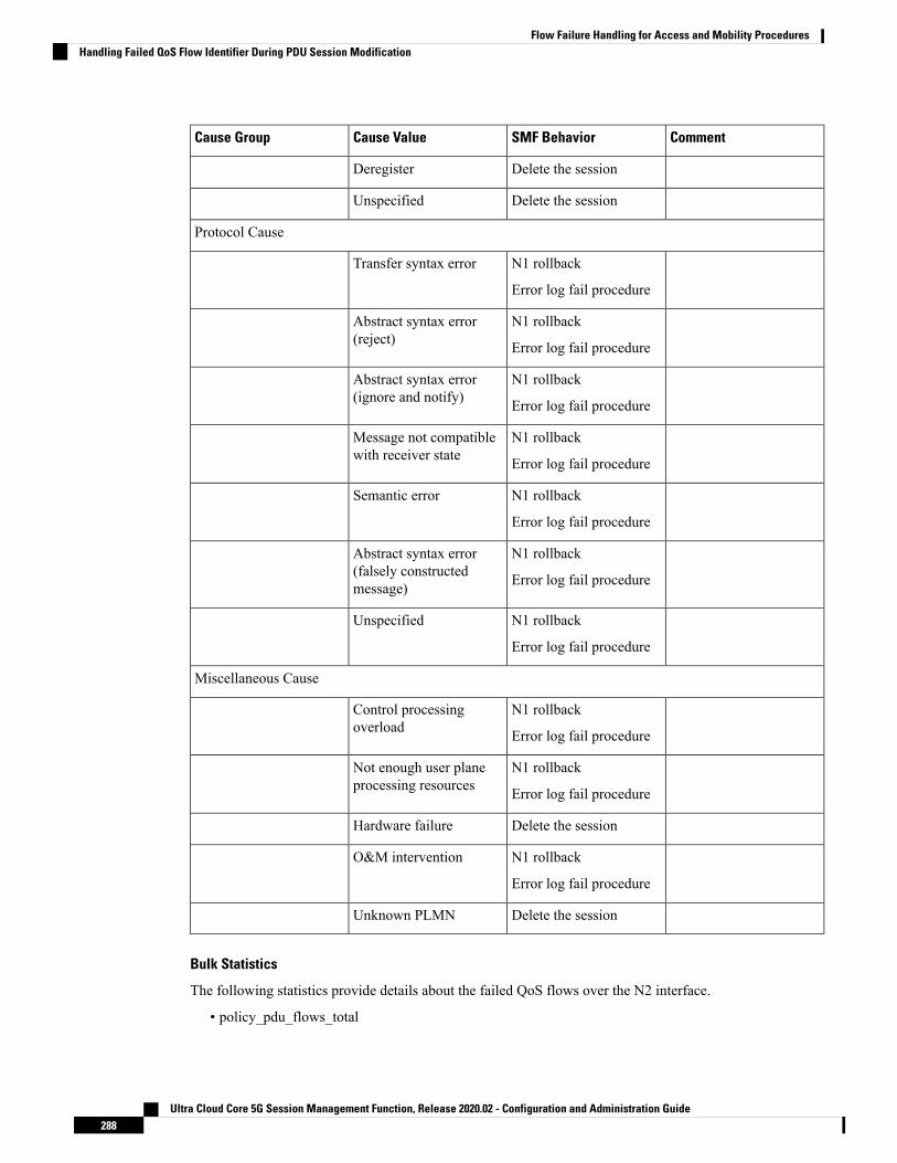
CommentSMF BehaviorCause ValueCause Group
Delete the sessionDeregister
Delete the sessionUnspecified
Protocol Cause
N1 rollback
Error log fail procedure
Transfer syntax error
N1 rollback
Error log fail procedure
Abstract syntax error(reject)
N1 rollback
Error log fail procedure
Abstract syntax error(ignore and notify)
N1 rollback
Error log fail procedure
Message not compatiblewith receiver state
N1 rollback
Error log fail procedure
Semantic error
N1 rollback
Error log fail procedure
Abstract syntax error(falsely constructedmessage)
N1 rollback
Error log fail procedure
Unspecified
Miscellaneous Cause
N1 rollback
Error log fail procedure
Control processingoverload
N1 rollback
Error log fail procedure
Not enough user planeprocessing resources
Delete the sessionHardware failure
N1 rollback
Error log fail procedure
O&M intervention
Delete the sessionUnknown PLMN
Bulk Statistics
The following statistics provide details about the failed QoS flows over the N2 interface.
• policy_pdu_flows_total
Ultra Cloud Core 5G Session Management Function, Release 2020.02 - Configuration and Administration Guide288
Flow Failure Handling for Access and Mobility ProceduresHandling Failed QoS Flow Identifier During PDU Session Modification
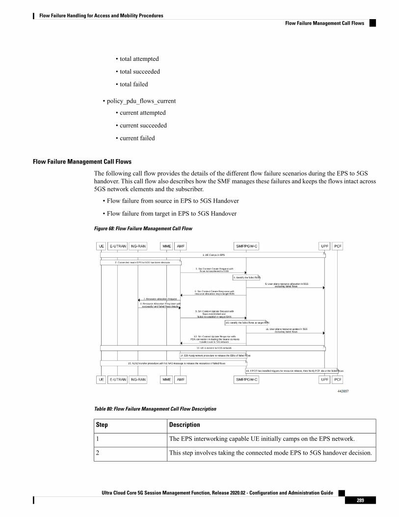
• total attempted
• total succeeded
• total failed
• policy_pdu_flows_current
• current attempted
• current succeeded
• current failed
Flow Failure Management Call Flows
The following call flow provides the details of the different flow failure scenarios during the EPS to 5GShandover. This call flow also describes how the SMFmanages these failures and keeps the flows intact across5GS network elements and the subscriber.
• Flow failure from source in EPS to 5GS Handover
• Flow failure from target in EPS to 5GS Handover
Figure 68: Flow Failure Management Call Flow
Table 80: Flow Failure Management Call Flow Description
DescriptionStep
The EPS interworking capable UE initially camps on the EPS network.1
This step involves taking the connected mode EPS to 5GS handover decision.2
Ultra Cloud Core 5G Session Management Function, Release 2020.02 - Configuration and Administration Guide289
Flow Failure Handling for Access and Mobility ProceduresFlow Failure Management Call Flows

DescriptionStep
During the EPS to 5GS handover procedure, the PDN Connection in the SmContext Create request from the AMF carries the EPS bearer contexts to behanded over to 5GS network.
3
The SMF identifies the bearer contexts that were established in EPS and missingin PDN connection as failed flows.
4
The SMF performs the resource allocation in 5GS network and sends it to theUPF excluding the failed flows.
5
The SMF sends the SmContext Create Response with resource allocation requestto the target RAN.
6
The AMF forwards the resource allocation request to the NG-RAN.7
The NG-RAN sends the resource allocation response with the details ofsuccessful and failed flows to the AMF.
The target RAN node may not be able to allocate the resources for all therequested flows during EPS to 5GS handover procedure. The target RAN sharesinformation about such failed flows in the resource allocation response.
8
The AMF sends the Sm Context Update Request with flows established andfailed to establish in the target RAN.
9
The SMF identifies the failed flows at the target RAN.10
The SMF performs the user plane resource update in 5G network excluding thefailed flows.
11
The SMF sends the SmContext Update Responsewith PDN connection includingthe bearer contexts handed over to the 5GS network.
12
The UE is moved to the 5GS network.13
The SMF uses the EBI assignment procedure to release the EBIs of failed flows.14
The SMF sends the N1N2 transfer request with the N1 NAS message to the UEto remove the resources of failed flows.
15
If the PCF has installed triggers to release the resources, then the SMF notifiesthe PCF about the failed flows.
16
Handling of Flow Failures from Source in EPS to 5GS Handover
The following call flow depicts the handling of flow failure from source RAN in EPS to the 5GS handover.
Ultra Cloud Core 5G Session Management Function, Release 2020.02 - Configuration and Administration Guide290
Flow Failure Handling for Access and Mobility ProceduresHandling of Flow Failures from Source in EPS to 5GS Handover

Figure 69: Flow Failure Handling Call Flow (From Source in EPS to 5GS Handover)
Table 81: Flow Failure Handling Call Flow Description (From Source in EPS to 5GS Handover)
DescriptionStep
TheAMF sends a POST request for SmContext Create Service, with the followingadditional information:
• UE EPS PDN connection, including the EPS bearer contexts, representingthe individual SM context resource to be created. The UE EPS PDNconnection may not carry the flows which source does not want to establishin the 5GS network.
• hoState attribute set to PREPARING
• targetId identifying the target RAN Node ID and TAI based on the TargetID IE received in the Forward Relocation Request message from the sourceMME.
1
Ultra Cloud Core 5G Session Management Function, Release 2020.02 - Configuration and Administration Guide291
Flow Failure Handling for Access and Mobility ProceduresHandling of Flow Failures from Source in EPS to 5GS Handover

DescriptionStep
If the corresponding PDU session is detected based on the EPS bearer contextsand the handover of the PDN connection to 5GS network is possible, then theSMF returns a 201 Created response including the following information:
• hoState attribute set to PREPARING and N2 SM information to request thetarget RAN to assign resources to the PDU session, excluding the flowswhich are not received in the UE EPS PDN connection.
• PDU Session ID corresponding to the default EPS bearer ID of the EPS PDNconnection.
• allocatedEbiList containing the EBIs allocated to the PDU session.
The POST response includes the Location header and the URI of the created SMcontext resource.
The AMF stores the association of the PDU Session ID and the SMF ID, and theallocated EBIs associated to the PDU Session ID.
2
Handling of Flow Failures from Target in EPS to 5GS Handover
The following call flow depicts the handling of flow failure from target RAN in EPS to the 5GS handover.
Figure 70: Flow Failure Handling Call Flow (From Target in EPS to 5GS Handover)
Ultra Cloud Core 5G Session Management Function, Release 2020.02 - Configuration and Administration Guide292
Flow Failure Handling for Access and Mobility ProceduresHandling of Flow Failures from Target in EPS to 5GS Handover

Table 82: Flow Failure Handling Call Flow Description (From Target in EPS to 5GS Handover)
DescriptionStep
The AMF updates the SM context in the SMF by sending POST request with thefollowing information:
• hoState attribute set to PREPARED
• N2 SM information received from the target RAN, including the transportlayer address and tunnel endpoint of the downlink termination point for theuser data for this PDU session (that is, GTP-U F-TEID of the target RANfor downlink traffic), if the target RAN succeeded in establishing resourcesfor the PDU session; the target RAN may not be able to establish resourcesfor all the flows; the target RAN includes such failed flows information
1
If the target RAN succeeded in establishing resources for the PDU sessions, theSMF sets the hoState attribute to PREPARED and returns a 200 OK responseincluding the following information:
• hoState attribute set to PREPARED
• the epsBearerSetup IEs containing the list of EPS bearer contexts successfullyhanded over to the 5GS and the CN tunnel information for data forwarding,generated based on the list of accepted QFIs received from the RAN; Thisis the final list of flows handed over to the 5GS network.
2
Standards ComplianceThe QoS Flow Failure Handling for Access and Mobility Procedures feature complies with the followingstandards:
• 3GPP TS 23.502 V16.1.1 (2019-06)
Ultra Cloud Core 5G Session Management Function, Release 2020.02 - Configuration and Administration Guide293
Flow Failure Handling for Access and Mobility ProceduresStandards Compliance

Ultra Cloud Core 5G Session Management Function, Release 2020.02 - Configuration and Administration Guide294
Flow Failure Handling for Access and Mobility ProceduresStandards Compliance

C H A P T E R 21Inter gNodeB Handover
This chapter covers the following topics:
• Feature Summary and Revision History, on page 295• Feature Description, on page 296• How it Works, on page 296• OAM Support, on page 308
Feature Summary and Revision History
Summary DataTable 83: Summary Data
SMFApplicable Product(s) or Functional Area
SMIApplicable Platform(s)
Not ApplicableFeature Default Setting
Not ApplicableRelated Changes in this Release
Not ApplicableRelated Documentation
Revision History
Revision History
ReleaseRevision Details
Pre-2020.02.0First introduced.
Ultra Cloud Core 5G Session Management Function, Release 2020.02 - Configuration and Administration Guide295

Feature DescriptionThe SMF supports the Xn-based and N2-based handover procedures to hand over a UE from a source NG-RANnode to a target NG-RAN node using the Xn or N2 reference points. Initiation of this procedure can be dueto new radio conditions, load balancing or due to a specific service.
The SMF releases the QoS flows that failed to set up on the target NG-RAN during Xn and N2 handovers onthe respective interfaces N4 (UPF) and N1 (UE). The SMF sends appropriate notification to N7 (PCF) basedon the triggers if armed. The SMF also sends the usage report to N40 (CHF) for the released QoS flows.
How it Works
Call FlowsThe following sections explain the execution of Xn-based and N2-based handover procedures.
Xn-based Inter NG-RAN HandoverThis section provides details regarding the Xn-based inter NG-RAN handover without UPF reallocation.
The handover preparation and the execution stages are implemented as specified in 3GPP TS 38.300. Whenperforming the handover in a shared network, the source NG-RAN determines a PLMN to be used in thetarget network as specified in 3GPP TS 23.501. If the serving PLMN changes during the Xn handover, thesource NG-RAN node indicates the selected PLMN ID to the target NG-RAN node.
If the AMF generates the N2 downlink signalling and receives a rejection to an N2 interface procedure dueto the ongoing Xn handover procedure, the AMF reattempts the same N2 interface procedure either when thehandover is complete or the handover is deemed to have failed. The failure is known by expiry of the timerguarding the N2 interface procedure.
Upon reception of an SMF-initiated N1 and/or N2 request(s) with an indication that the request has beentemporarily rejected due to the ongoing Xn handover procedure, the SMF starts a locally configured guardtimer. The SMF holds signalling messages targeted towards the AMF during the handover preparation phaseunless it detects that the handover is completed or the handover has failed or cancelled. The SMF reattempts,up to a pre-configured number of times, when either it detects that the handover is completed or has failedusing message reception or at expiry of the guard timer.
The Xn-based inter NG-RAN handover is used to hand over a UE from a source NG-RAN to target NG-RANusing Xn when the AMF is unchanged and the SMF decides to keep the existing UPF.
The following figure depicts the call flow of the Xn-based inter NG-RAN handover without the UPFreallocation.
Ultra Cloud Core 5G Session Management Function, Release 2020.02 - Configuration and Administration Guide296
Inter gNodeB HandoverFeature Description

Figure 71: Xn-based Inter NG-RAN Handover without UPF Reallocation
Table 84: Xn-based Inter NG-RAN Handover Call Flow Description (Without UPF Reallocation)
DescriptionStep
During the handover execution, the source NG-RAN node provides RAN usage dataReport to the AMF. The source NG-RAN node provides this report only when the targetNG-RAN has confirmed handover over Xn interface.
This report includes N2 SM Information (Secondary RAT usage data), Handover Flag,and Source to Target transparent container. The Handover Flag indicates that the reportneeds to be buffered by the SMF.
1a
The target NG-RAN sends an N2 Path Switch Request message to the AMF to informthat the UE has moved to a new target cell. The NG-RAN provides a List Of PDUSessions To Be Switched. The N2 SM Information includes the AN Tunnel Info foreach PDU Session to be switched.
1b
The AMF sends N2 SM information by invoking theNsmf_PDUSession_UpdateSMContext request service operation for each PDU sessionin the lists of PDU Sessions received in the N2 Path Switch Request.
2
The SMF sends an N4 Session Modification Request message to the UPF. The SMFmay notify the UPF that originated the Data Notification to discard downlink data forthe PDU Sessions and/or to not provide further Data Notification messages.
3
The UPF returns an N4 Session Modification Response message to the SMF after therequested PDU sessions are switched.
4
Ultra Cloud Core 5G Session Management Function, Release 2020.02 - Configuration and Administration Guide297
Inter gNodeB HandoverXn-based Inter NG-RAN Handover

DescriptionStep
The UPF sends one or more "end marker" packets for each N3 tunnel on the old pathimmediately after switching the path. The UPF starts sending downlink packets to thetarget NG-RAN.
5
The SMF sends an Nsmf_PDUSession_UpdateSMContext response (CN Tunnel Info)to the AMF for PDU sessions which have been switched successfully.
Step 6 can occur any time after the receipt of N4 Session ModificationResponse at the SMF.
Important
6
Once the Nsmf_PDUSession_UpdateSMContext response is received from all the SMFs,the AMF aggregates the received CN Tunnel Info and sends this aggregated informationas a part of N2 SM Information along with the Failed PDU Sessions in N2 Path SwitchRequest Ack to the target NG-RAN. If none of the requested PDU sessions have beenswitched successfully, the AMF sends an N2 Path Switch Request Failure message tothe target NG-RAN.
7
The target NG-RAN confirms success of the handover by sending Release Resourcesmessage to the source NG-RAN.
8
The UE initiates Mobility Registration Update procedure if one of the triggers ofregistration procedure applies.
9
The following figure shows the detailed call flow of the Xn handover without UPF reallocation.
Figure 72: Xn Handover Without UPF Relocation Call Flow
Ultra Cloud Core 5G Session Management Function, Release 2020.02 - Configuration and Administration Guide298
Inter gNodeB HandoverXn-based Inter NG-RAN Handover

Table 85: Detailed Call Flow Description for the Xn Handover Without UPF Relocation
DescriptionStep
The NF Service Consumer (AMF) requests the SMF to switch the user planeconnection of the PDU session. The AMF sends a POST request with the followinginformation:
• The toBeSwitched indication.
• N2 SM information received from the 5G-AN (PDU session path switchrequest transfer IE), including the new transport layer address and tunnelendpoint of the downlink termination point for the user data for this PDUsession.
• User location and user location timestamp.
• Other information, if necessary.
1
The SMF switches the N3 tunnel of the PDU session after receiving the request.The SMF initiates PFCP session modification procedure toward the UPF withdownlink FAR updated with the following option:
• Forwarding Action is enabled with the remote node “forwarding parameters”details, such as the IP address and GTP-U F-TEID.
2
The SMF marks the PDU handover as successful after receiving the successfulresponse from the UPF node.
3
The SMF initiates the 200 OK response. This response includes the N2 SMinformation, which has the transport layer address and tunnel endpoint of the uplinktermination point for the user plane data for this PDU session, that is UPFs GTP-UF-TEID for the uplink traffic.
4
N2-based Inter NG-RAN HandoverThe source NG-RAN decides to initiate an N2-based handover (HO) to the target NG-RAN. Initiation of thisprocedure could be due to any of the following reasons:
• New radio conditions
• Load balancing
• If there is no Xn connectivity to the target NG-RAN
• An error indication from the target NG-RAN after an unsuccessful Xn-based handover (that is, no IPconnectivity between Target RAN (T-RAN) and Source UPF (S-UPF))
• Based on dynamic information learnt by the Source RAN (S-RAN)
The source NG-RAN determines the availability of a direct forwarding path and indicates the same to theSMFs. If the IP connectivity is available between the source and target NG-RAN and security association isin place between them, a direct forwarding path is available. If a direct forwarding path is not available, usethe indirect forwarding. The SMFs use the indication from the source NG-RAN to choose the data forwardingpath.
Ultra Cloud Core 5G Session Management Function, Release 2020.02 - Configuration and Administration Guide299
Inter gNodeB HandoverN2-based Inter NG-RAN Handover

When performing the handover in a shared network, the source NG-RAN determines a PLMN for use in thetarget network as specified by 3GPP TS 23.501. The source NG-RAN indicates the selected PLMN ID to theAMF as part of the Tracking Area sent in the HO Required message.
If the AMF generates the N2 downlink signalling and receives a rejection to a N2 interface procedure due tothe ongoing N2 handover, the AMF reattempts the same N2 interface procedure either when the handover iscomplete or the handover is deemed to have failed. If the Inter NG-RAN node handover changes the servingAMF, the source AMF terminates any other ongoing N2 interface procedures except the handover procedure.
If the AMF is still the serving AMF, the AMF pauses non-handover related N2 interface procedures andresumes them after the N2 handover is complete.
If the AMF detects that it needs to be changed, the AMF rejects any SMF-initiated N2 request and includesan indication that the request has been temporarily rejected due to the ongoing N2 handover procedure.
The following figure depicts the call flow for the preparation phase of the N2-based inter NG-RAN handoverprocedure.
Figure 73: Inter NG-RAN Node N2-based Handover - Preparation Phase
Ultra Cloud Core 5G Session Management Function, Release 2020.02 - Configuration and Administration Guide300
Inter gNodeB HandoverN2-based Inter NG-RAN Handover

Table 86: Inter NG-RAN Node N2-based Handover Call Flow Description - Preparation Phase
DescriptionStep
The SourceNG-RAN (S-RAN) sends theHandover Requiredmessage to the SourceAMF (S-AMF). This message includes the following:
• Target ID
• Source to Target transparent container
• SM N2 info list
• PDU Session IDs
• Intra system handover indication
The Source to Target transparent container includes NG-RAN information for usein Target RAN (T-RAN), and is transparent to 5GC. It also contains thecorresponding User Plane Security Enforcement information, QoS flows/DRBsinformation subject to data forwarding.
If direct data forwarding is available, the SM N2 info includes Direct ForwardingPath Availability.
Direct Forwarding Path Availability indicates whether direct forwarding is availablefrom the S-RAN to the T-RAN. This indication from S-RAN is based on thepresence of IP connectivity and security association between the S-RAN and theT-RAN.
1
When the S-AMF cannot serve the UE anymore, the S-AMF selects the T-AMFas described in clause 6.3.5 on "AMF Selection Function" in TS 23.501.
2
Ultra Cloud Core 5G Session Management Function, Release 2020.02 - Configuration and Administration Guide301
Inter gNodeB HandoverN2-based Inter NG-RAN Handover

DescriptionStep
The S-AMF initiates Handover resource allocation procedure by invoking theNamf_Communication_CreateUEContext service operation towards the T-AMF.
The Namf_Communication_CreateUEContext Request includes the following:
• N2 Information
• Target ID
• Source to Target transparent container
• SM N2 information list
• PDU Session IDs
• UE context information
• SUPI
• Service area restriction
• Allowed NSSAI for each Access Type if available
• Tracing Requirements
• The list of PDU Session IDs along with the corresponding SMFinformation and the corresponding S-NSSAI(s), PCF ID(s), and DNN
When the S-AMF can still serve the UE, this step and step 12 are not needed.
3
For each PDU session indicated by S-RAN, the AMF invokes theNsmf_PDUSession_UpdateSMContext Request to the associated SMF. However,if the S-NSSAI associated with PDU session is not available in the T-AMF, theT-AMF does not invoke Nsmf_PDUSession_UpdateSMContext for this PDUsession.
If the T-AMF detects that the UE moves into a restricted area based on Servicearea restrictions, the T-AMF notifies that the UE is only reachable for regulatoryprioritized services to each NF consumer which has subscribed for UE reachabilityevent.
4
Based on the Target ID, the SMF checks the acceptance of N2 handover for theindicated PDU session. The SMF also checks the UPF Selection Criteria. If theUE has moved out of the service area of the UPF connecting to NG-RAN, the SMFselects a new intermediate UPF.
5
If the SMF selects a new UPF to act as intermediate UPF for the PDU session, andthe different CN Tunnel Info need to be used, the SMF sends N4 SessionModification Request message to UPF (PDU Session Anchor (PSA)). If the SMFallocates the CN Tunnel Info, it provides the CN Tunnel Info on N9, and the UPF(PSA) associates CN Tunnel Info with UL Packet detection rules.
6a
Ultra Cloud Core 5G Session Management Function, Release 2020.02 - Configuration and Administration Guide302
Inter gNodeB HandoverN2-based Inter NG-RAN Handover

DescriptionStep
The UPF (PSA) sends an N4 Session Establishment Response message to the SMF.If the UPF (PSA) allocates CN Tunnel Info (on N9) of UPF (PSA), it provides CNTunnel Info (on N9) to the SMF. The UPF (PSA) associates the CN Tunnel Info(on N9) with UL Packet detection rules provided by the SMF.
6b
If the SMF selects a new intermediate UPF (T-UPF) and if the T-UPF allocatesthe CNTunnel Info, the SMF sends an N4 Session Establishment Request messageto the T-UPF. This request enables the Packet detection, enforcement, and reportingrules to be installed on the T-UPF. The T-UPF receives the CN Tunnel Info (onN9) of UPF (PSA) for this PDU session, which is used to set up N9 tunnel.
6c
The T-UPF sends an N4 Session Establishment Response message to the SMFwith DL CN Tunnel Info and UL CN Tunnel Info (that is, N3 tunnel info). TheSMF starts a timer to release the resource of S-UPF, which is to be used in step13a of the Execution Phase.
6d
If N2 handover for the PDU session is accepted, the SMF includes the N2 SMInformation in the Nsmf_PDUSession_UpdateSMContext response. The N2 SMInformation contains the N3 UP address and the UL CN Tunnel ID of the UPF andthe QoS parameters indicating that the N2 SM Information is for the TargetNG-RAN.
If the N2 SM information received at step 4 does not include the Direct ForwardingPath Availability and the SMF knows that there is no indirect data forwardingconnectivity between source and target, the N2 SM Information includes a Dataforwarding not possible indication.
If the N2 handover for the PDU session is not accepted as described in step 5, theSMF does not include the N2 SM Information to avoid establishment of radioresources at the target NG-RAN. The SMF provides a reason for non-acceptance.If the SMF receives notification from T-AMF that UE is only reachable forregulatory prioritized service, the SMF deactivates the PDU session.
7
TheAMF supervises theNsmf_PDUSession_UpdateSMContextResponsemessagesfrom the involved SMFs. At the expiry of maximum wait time or when allNsmf_PDUSession_UpdateSMContext Responsemessages are received, the AMFcontinues with the N2 Handover procedure (Handover Request message in step9).
8
If the subscription information includes Tracing Requirements, the target AMFprovides the target RAN with Tracing Requirements in the Handover Request.
The Handover request includes Source to Target transparent container, N2 MMInformation, N2 SM Information list, and Tracing Requirements.
The T-AMF determines T-RAN based on Target ID. T-AMF allocates a 5G-GUTIvalid for the UE in the AMF and target TAI.
N2 MM Information includes, for example, security information and MobilityRestriction List if available in the T-AMF. N2 SM Information list includes N2SM Information for the T-RAN in the Nsmf_PDUSession_UpdateSMContextResponse messages received within allowed max delay supervised by the T-AMFin step 8.
9
Ultra Cloud Core 5G Session Management Function, Release 2020.02 - Configuration and Administration Guide303
Inter gNodeB HandoverN2-based Inter NG-RAN Handover
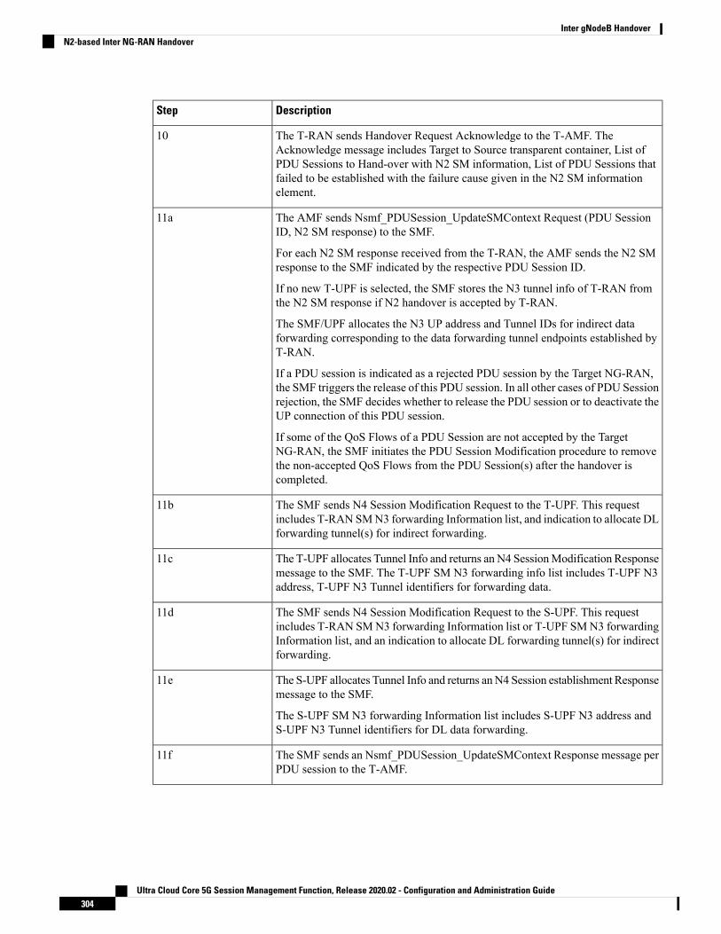
DescriptionStep
The T-RAN sends Handover Request Acknowledge to the T-AMF. TheAcknowledge message includes Target to Source transparent container, List ofPDU Sessions to Hand-over with N2 SM information, List of PDU Sessions thatfailed to be established with the failure cause given in the N2 SM informationelement.
10
The AMF sends Nsmf_PDUSession_UpdateSMContext Request (PDU SessionID, N2 SM response) to the SMF.
For each N2 SM response received from the T-RAN, the AMF sends the N2 SMresponse to the SMF indicated by the respective PDU Session ID.
If no new T-UPF is selected, the SMF stores the N3 tunnel info of T-RAN fromthe N2 SM response if N2 handover is accepted by T-RAN.
The SMF/UPF allocates the N3 UP address and Tunnel IDs for indirect dataforwarding corresponding to the data forwarding tunnel endpoints established byT-RAN.
If a PDU session is indicated as a rejected PDU session by the Target NG-RAN,the SMF triggers the release of this PDU session. In all other cases of PDU Sessionrejection, the SMF decides whether to release the PDU session or to deactivate theUP connection of this PDU session.
If some of the QoS Flows of a PDU Session are not accepted by the TargetNG-RAN, the SMF initiates the PDU Session Modification procedure to removethe non-accepted QoS Flows from the PDU Session(s) after the handover iscompleted.
11a
The SMF sends N4 Session Modification Request to the T-UPF. This requestincludes T-RAN SMN3 forwarding Information list, and indication to allocate DLforwarding tunnel(s) for indirect forwarding.
11b
The T-UPF allocates Tunnel Info and returns an N4 SessionModification Responsemessage to the SMF. The T-UPF SM N3 forwarding info list includes T-UPF N3address, T-UPF N3 Tunnel identifiers for forwarding data.
11c
The SMF sends N4 Session Modification Request to the S-UPF. This requestincludes T-RAN SMN3 forwarding Information list or T-UPF SMN3 forwardingInformation list, and an indication to allocate DL forwarding tunnel(s) for indirectforwarding.
11d
The S-UPF allocates Tunnel Info and returns an N4 Session establishment Responsemessage to the SMF.
The S-UPF SM N3 forwarding Information list includes S-UPF N3 address andS-UPF N3 Tunnel identifiers for DL data forwarding.
11e
The SMF sends an Nsmf_PDUSession_UpdateSMContext Response message perPDU session to the T-AMF.
11f
Ultra Cloud Core 5G Session Management Function, Release 2020.02 - Configuration and Administration Guide304
Inter gNodeB HandoverN2-based Inter NG-RAN Handover

DescriptionStep
TheAMF supervises theNsmf_PDUSession_UpdateSMContext Responsemessagefrom the involved SMFs. At the expiry of maximum wait time or when allNsmf_PDUSession_UpdateSMContext Response messages are received, theT-AMF sends the Namf_Communication_CreateUEContext Response to theS-AMF.
12
The following figure depicts the call flow for the execution phase of the N2-based inter NG-RAN handoverprocedure.
Figure 74: Inter NG-RAN Node N2-based Handover - Execution Phase
Ultra Cloud Core 5G Session Management Function, Release 2020.02 - Configuration and Administration Guide305
Inter gNodeB HandoverN2-based Inter NG-RAN Handover

Table 87: Inter NG-RAN Node N2-based Handover Call Flow Description - Execution Phase
DescriptionStep
The Source AMF (S-AMF) sends the Handover Command to the Source NG-RAN(S-RAN).
The Handover Command includes Target to Source transparent container, List OfPDU Sessions to be handed-over with N2 SM information containing informationreceived from T-RAN during the handover preparation phase, and List Of PDUSessions failed to be set up.
The SM forwarding info list includes T-RAN SMN3 forwarding info list for directforwarding or S-UPF SM N3 forwarding info list for indirect data forwarding.
The S-RAN uses the PDU Sessions failed to be setup list and the indicated reasonfor failure to decide whether to proceed with the N2 handover procedure.
1
The S-RAN sends Handover Command (UE container) to the UE.
The UE container is a UE part of the Target to Source transparent container whichis sent transparently from T-RAN via AMF to S-RAN and is provided to the UEby the S-RAN.
2
The S-RAN sends the Uplink RAN Status Transfer message to the S-AMF. TheS-RAN refrains from sending this message if none of the radio bearers of the UEare treated with Packet Data Convergence Protocol (PDCP) status preservation.
2a - 2c
The T-RAN sends the uplink packets to the T-UPF and UPF (PSA). The UPF(PSA) sends the downlink packets to the S-RAN via S-UPF.
The S-RAN forwards the downlink data towards the T-RAN for QoS flows or DataRadio Bearers (DRBs) subject to data forwarding. The data forwarding path iseither direct (step 3a) or indirect forwarding (step 3b).
3
After the UE has successfully synchronized to the target cell, it sends a HandoverConfirm message to the T-RAN.
4
The T-RAN sends Handover Notify message to the T-AMF. This message is sentto indicate that the handover is successful.
5
The T-AMF notifies to the S-AMF about the N2 handover notify received fromthe T-RAN by invoking the Namf_Communication_N2InfoNotify.
The S-AMF uses a timer to supervise the release of resources in S-RAN.
6a.
The S-AMF acknowledges by sending the Namf_Communication_N2InfoNotifyACK to the T-AMF.
6b
The S-AMF sends Nsmf_PDUSession_ReleaseSMContext Request to the SMF.This request includes SUPI, PDU Session ID, and N2 SM Information (SecondaryRAT Usage Data).
If the PDU Session(s) is not accepted by the T-AMF, the S-AMF triggers PDUSession Release procedure after the reception of N2 Handover Notify.
6c
Ultra Cloud Core 5G Session Management Function, Release 2020.02 - Configuration and Administration Guide306
Inter gNodeB HandoverN2-based Inter NG-RAN Handover

DescriptionStep
The T-AMF sends Nsmf_PDUSession_UpdateSMContext Request to the SMF.This request includes Handover Complete indication for PDU Session ID, UEpresence in LADN service area, and N2 SM Information (Secondary RAT usagedata).
The T-AMF sends Handover Complete indication per each PDU Session to thecorresponding SMF to indicate the success of the N2 handover.
7
If a new T-UPF is inserted or an existing intermediate S-UPF is reallocated, theSMF sends N4 Session Modification Request indicating DL AN Tunnel Info ofT-RAN to the T-UPF.
8a
The T-UPF acknowledges by sending N4 SessionModification Response messageto the SMF.
8b
If the UPF is not reallocated, the SMF sends N4 Session Modification Requestindicating DL AN Tunnel Info of T-RAN to the S-UPF.
9a
The S-UPF acknowledges by sending N4 SessionModification Response messageto SMF.
9b
For non-roaming or local breakout roaming scenario, the SMF sends N4 SessionModification Request message to PDU Session Anchor UPF, UPF (PSA). If a newT-UPF is inserted or an existing intermediate S-UPF is reallocated, the SMFprovides N3 AN Tunnel Info of T-RAN or the DL CN Tunnel Info of T-UPF.
If the T-UPF is not inserted or an existing intermediate S-UPF is not reallocated,skip the step 10a and step 10b.
10a
The UPF (PSA) sends N4 Session Modification Response message to the SMF.
When there are multiple UPFs (PSA), perform step 10a and step 10b for each UPF(PSA).
10b
The SMF sends Nsmf_PDUSession_UpdateSMContext Response (PDU SessionID) to the T-AMF. The SMF confirms reception of Handover Complete.
11
The UE initiates Mobility Registration Update procedure as defined in 3GPP TS23.502.
12
If there is a source intermediate UPF, the SMF initiates resource release by sendingan N4 Session Release Request (Release Cause) to the source UPF. This messageis also used to release the indirect data forwarding resource in the S-UPF.
13a
The S-UPF acknowledgeswith anN4 Session Release Responsemessage to confirmthe release of resources.
In case of indirect data forwarding, the resource of indirect data forwarding is alsoreleased.
13b
After the expiry of timer (defined in step 6a), the AMF sends UE Context ReleaseCommand.
14a
Ultra Cloud Core 5G Session Management Function, Release 2020.02 - Configuration and Administration Guide307
Inter gNodeB HandoverN2-based Inter NG-RAN Handover
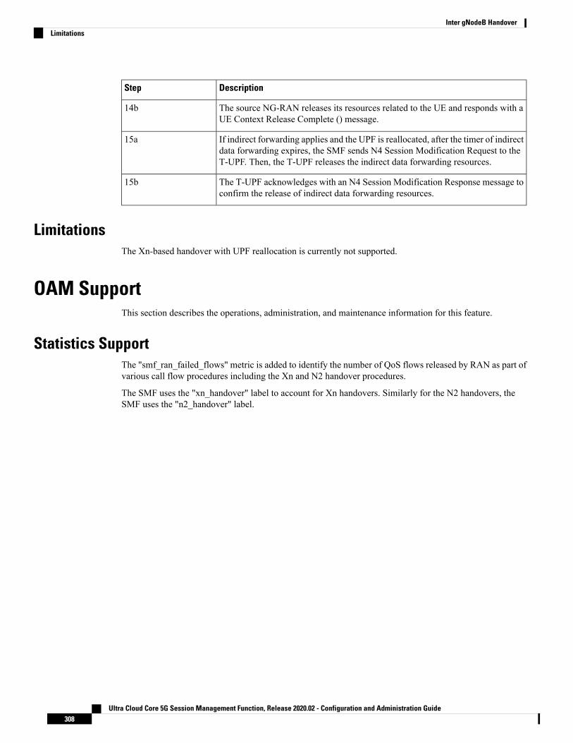
DescriptionStep
The source NG-RAN releases its resources related to the UE and responds with aUE Context Release Complete () message.
14b
If indirect forwarding applies and the UPF is reallocated, after the timer of indirectdata forwarding expires, the SMF sends N4 Session Modification Request to theT-UPF. Then, the T-UPF releases the indirect data forwarding resources.
15a
The T-UPF acknowledges with an N4 Session Modification Response message toconfirm the release of indirect data forwarding resources.
15b
LimitationsThe Xn-based handover with UPF reallocation is currently not supported.
OAM SupportThis section describes the operations, administration, and maintenance information for this feature.
Statistics SupportThe "smf_ran_failed_flows" metric is added to identify the number of QoS flows released by RAN as part ofvarious call flow procedures including the Xn and N2 handover procedures.
The SMF uses the "xn_handover" label to account for Xn handovers. Similarly for the N2 handovers, theSMF uses the "n2_handover" label.
Ultra Cloud Core 5G Session Management Function, Release 2020.02 - Configuration and Administration Guide308
Inter gNodeB HandoverLimitations

C H A P T E R 22IP Address Management
• Feature Summary and Revision History, on page 309• Feature Description, on page 310• How it Works, on page 310• IPAM Integration in SMF, on page 311• Static IP Support, on page 324• Dual-Stack Static IP Support Through IPAM, on page 329• IPAM Offline Mode Support, on page 330• IPAM Redundancy Support Per UPF, on page 332• IPAM Quarantine Timer Support, on page 333
Feature Summary and Revision History
Summary DataTable 88: Summary Data
SMFApplicable Product(s) or Functional Area
SMIApplicable Platform(s)
Enabled – Always-onFeature Default Setting
Not ApplicableRelated Changes in this Release
Not ApplicableRelated Documentation
Revision HistoryTable 89: Revision History
ReleaseRevision Details
Pre-2020.02.0First introduced.
Ultra Cloud Core 5G Session Management Function, Release 2020.02 - Configuration and Administration Guide309

Feature DescriptionIP Address Management (IPAM) is a method of tracking and managing IP addresses of a network. IPAM isone of the core components of the subscriber management system. Traditional IPAM functionalities areinsufficient in Cloud-Native network deployments. Hence, IPAM requires additional functionalities to workwith the Cloud-Native subscriber management system. The Cloud-Native IPAM system is used in variousnetwork functions, such as SMF and PCF.
The IPAM system includes the following functionalities to serve the Cloud Native and Control and User PlaneSeparation (CUPS) architecture:
• Centralized IP resource management —Based on the needs of the Internet Service Provider (ISP), theControl Plane (CP) is deployed either on a single (centralized) cluster or multiple (distributed) clusters.For multiple cluster deployments, the IPAM automatically manages the single IP address space acrossthe multiple CPs that are deployed in the distributed environment.
• IP address-range reservation per user-plane—For subscribers connecting to the Internet core, theUser Plane (UP) provides the physical connectivity. The UP uses the summary-routes to advertisesubscriber routes to the Internet core. For CPs that are managingmultiple UPs, the CP reserves a convergedIP subnet to the UPs. In such a scenario, the IPAM splits the available address space into smalleraddress-ranges and assigns it to different UPs.
• IP address assignment from pre-reserved address-ranges—When subscribers request for an IP address,the IPAM assigns addresses from the pre-reserved address range of their respective UP.
How it WorksIPAM uses the following sub-modules for the Cloud-Native subscriber management system:
• IPAM Server—This module manages the complete list of pools and address-space configurations. TheIPAM server splits the configured address ranges into smaller address-ranges statically or dynamicallyto distribute them to IPAM cache modules. The IPAM server is deployed as a centralized entity to servegroup of Cloud-Native clusters or can be an integrated entity within a single cluster.
• IPAM Cache—This module receives the free address-ranges from the IPAM server and allocates theindividual IP addresses to the IPAM clients. Usually, the IPAM cache is deployed in a distributed moderunning within each cluster to communicate with the co-located or remotely-located IPAM server. TheIPAM cache also handles address-range reservation per UP and pool threshold monitoring. The IPAMserver and cache modules can run as an integrated mode.
• IPAM Client—This module handles the request and release of an individual IP address from the IPAMcache for each IP managed end-device. The IPAM client is tightly coupled with a respectivenetwork-function.
Ultra Cloud Core 5G Session Management Function, Release 2020.02 - Configuration and Administration Guide310
IP Address ManagementFeature Description

IPAM Integration in SMF
Feature DescriptionThe IP Address Management (IPAM) is a technique for tracking and managing the IP address space of anetwork. A core component of the subscriber management system, the IPAM provides all the functionalitiesnecessary for working with the Cloud-Native subscriber management system. Also, the IPAM acts as a genericIP address management system for the different network functions such as the SMF, Policy Control Function(PCF), and so on.
The IPAM is integrated with the SMF in the Application Services layer.
ArchitectureThis section describes the IPAM integration in the SMF architecture.
IPAM Integration in SMFThe SMF comprises of loosely coupled microservices that enables the SMF to perform session management(session establishment, modification, and release) and other associated functions. The decomposition of thesemicroservices is based on the following three-layered architecture:
1. Layer 1: Protocol and Load Balancer Services (Stateless)
2. Layer 2: Application services (Stateless)
3. Layer 3: Database Services (Stateful)
The IPAM and SMF integration happens in the Application Services layer.
The following describes the SMF and IPAM integration architecture in the Application Services layer.
Ultra Cloud Core 5G Session Management Function, Release 2020.02 - Configuration and Administration Guide311
IP Address ManagementIPAM Integration in SMF

Figure 75: IPAM Integration in SMF
• SMF Node-Manager Application – The SMF Node-Manager application takes care of the UPF, IDresource, and IP address management. Therefore, the SMF Node-Manager application integrates IPAMCache and IPAM client modules. The UPF Manager uses the IPAM Client module foraddress-range-reservation per UPF.
• SMF Service Application – The SMF Service application provides PDU session services. During sessionestablishment and termination, the IP addresses are requested and released back. The SMF Serviceapplication invokes the IPC to RMGR in Node Manager, which receives (free) the IP from the IPAMmodule.
• IPAM Server Application – Based on the deployment model, the IPAM Server application can run asan independent microservice, as a part of the same cluster, or in a remote-cluster. For standalonedeployments, the IPAM Servers are an integral part of the IPAM cache.
ComponentsThis section describes the different components of the IPAM system.
IPAM Sub-Modules
The IPAM system includes the following sub-modules:
• IPAM Server – The IPAM Server module manages the complete list of pools and address-spaceconfiguration. It splits the configured address-ranges into smaller address-ranges (statically anddynamically) and distributes it to the IPAM Cache modules. You can deploy the IPAM Server either as
Ultra Cloud Core 5G Session Management Function, Release 2020.02 - Configuration and Administration Guide312
IP Address ManagementComponents

a centralized entity to serve a group of cloud native clusters or as an integrated entity within a singlecluster.
• IPAM Cache – The IPAM Cache acquires free address-ranges from the IPAM Server and allocatesindividual IP addresses to the IPAM clients. Deployed in a distributed mode running within each cluster,the IPAM Cache communicates with co-located and remotely located IPAM Servers. Additionally, theIPAM Cache takes care of the address-range reservation per Data-Plane and pool threshold monitoring.
• IPAM Client – The IPAM Client module handles the request and release of the individual IP addressesfrom the IPAM Cache for each IP managed end-device. Based on the use cases, the IPAM Client modulecaters the needs of specific network functions (such as SMF, PCF, and so on).
How it WorksThis section describes the call flows pertaining to the integration of the IPAM in the SMF.
Call FlowsThe following call flow depicts the integration of the IPAM in the SMF.
Ultra Cloud Core 5G Session Management Function, Release 2020.02 - Configuration and Administration Guide313
IP Address ManagementHow it Works

Figure 76: Integration of IPAM in SMF Call Flow
Configuring the IPAM FeatureThis section describes how to configure the IPAM in the SMF.
Configuring the IPAM in the SMF involves the following steps:
1. Configuring IPv4 address ranges.
2. Configuring IPv6 address ranges.
3. Configuring IPv6 prefix ranges.
4. Configuring SMF tags.
5. Configuring IPv4 threshold.
6. Configuring IPv6 address range threshold.
Ultra Cloud Core 5G Session Management Function, Release 2020.02 - Configuration and Administration Guide314
IP Address ManagementConfiguring the IPAM Feature

7. Configuring IPv6 prefix range threshold.
8. Configuring IPv4 address range split.
9. Configuring IPv6 address and prefix address range split.
10. Configuring global threshold.
11. Configuring IPAM source.
Configuring IPv4 Address RangesUse the following configuration to configure the IPv4 address ranges.
configureipam
address-pool pool_name
vrf-name string
ipv4address-range start_ipv4_address end_ipv4_address
commit
NOTES:
• ipam: Enters the IPAM configuration mode.
• address-pool pool_name: Configures the address pool configuration. pool_name must be the name ofthe address pool.
• vrf-name string: Configures the Virtual routing and forwarding (VRF) name of the pool.
• ipv4: Enters the IPv4 mode of the pool.
• address-range start_ipv4_address end_ipv4_address: Configures the IPv4 range. start_ipv4_addressspecifies the starting IPv4 address. end_ipv4_address specifies the ending IPv4 address.
The following is a sample configuration:configure
ipamaddress-pool p1
vrf-name oneipv4
address-range 1.1.1.10 1.1.1.255address-range 2.2.2.1 2.2.2.255
Configuring IPv6 Address RangesUse the following configuration to configure the IPv6 address ranges:
configureipam
address-pool pool_name
vrf-name string
ipv6address-range start_ipv6_address end_ipv6_address
commit
Ultra Cloud Core 5G Session Management Function, Release 2020.02 - Configuration and Administration Guide315
IP Address ManagementConfiguring IPv4 Address Ranges

NOTES:
• ipam: Enters the IPAM configuration mode.
• address-pool pool_name: Configures the address pool configuration. pool_name must be the name ofthe address pool.
• vrf-name string: Configures the VRF name of the pool.
• ipv6: Enters the IPv6 mode of the pool.
• address-range start_ipv6_address end_ipv6_address: Configures the IPv6 range. start_ipv6_addressspecifies the starting IPv6 address. end_ipv6_address specifies the ending IPv6 address.
The following is a sample configuration:configure
ipamaddress-pool p1
vrf-name oneipv6
address-range 1::1 1::1000address-range 2::1 2::1000
Configuring IPv6 Prefix RangesUse the following configuration to configure the IPv6 prefix ranges:
configureipam
address-pool pool_name
vrf-name string
ipv6prefix-ranges
prefix-range prefix_value prefix-length length
commit
NOTES:
• ipam: Enters the IPAM configuration mode.
• address-pool pool_name: Configures the address pool configuration. pool_name must be the name ofthe address pool.
• vrf-name string: Configures the VRF name of the pool.
• ipv6: Enters the IPv6 mode of the pool.
• prefix-ranges: Enters the prefix ranges mode.
• prefix-range prefix_value prefix-length length : Configures the IPv6 prefix range. prefix-rangeprefix_value specifies the IPv6 prefix range. prefix-length length specifies the IPv6 prefix length.
The following is a sample configuration:configure
ipamaddress-pool p3
vrf-name threeipv6
Ultra Cloud Core 5G Session Management Function, Release 2020.02 - Configuration and Administration Guide316
IP Address ManagementConfiguring IPv6 Prefix Ranges

prefix-rangesprefix-range 1:1:: prefix-length 48prefix-range 2:1:: prefix-length 48
Configuring SMF TagsUse the following configuration to configure the SMF tags.
configureipam
address-pool pool_name
tagsnssai string
dnn string
serving-area string
commit
NOTES:
• ipam: Enters the IPAM configuration mode.
• address-pool pool_name: Configures the address pool configuration. pool_name must be the name ofthe address pool.
• tag : Enters the tag section of the pool.
• nssai string: Specifies the NSSAI value.
• dnn string : Specifies the DNN value.
• serving-area string: Specifies the serving-area value.
The following is a sample configuration:configure
ipamaddress-pool p1
tagsnssai onednn twoserving-area three
Configuring IPv4 ThresholdUse the following configuration to configure the IPv4 threshold:
configureipam
address-pool pool_name
ipv4threshold
upper-threshold percentage
commit
NOTES:
• ipam: Enters the IPAM Configuration mode.
Ultra Cloud Core 5G Session Management Function, Release 2020.02 - Configuration and Administration Guide317
IP Address ManagementConfiguring SMF Tags

• address-pool pool_name: Configures the address pool configuration. pool_name must be the name ofthe address pool.
• ipv4 : Enters the IPv4 mode of the pool.
• threshold : Enters the threshold sub-mode.
• upper-threshold percentage: Specifies the IPv4 upper threshold value in percentage.
The following is a sample configuration:configure
ipamaddress-pool p1
ipv4threshold
upper-threshold 80
Configuring IPv6 Address Range ThresholdUse the following configuration to configure the IPv6 address range threshold.
configureipam
address-pool pool_name
ipv6address-ranges
thresholdupper-threshold percentage
commit
NOTES:
• ipam: Enters the IPAM configuration mode.
• address-pool pool_name: Configures the address pool configuration. pool_name must be the name ofthe address pool.
• ipv6 : Enters the IPv6 mode of the pool.
• address-ranges: Enters the IPv6 address ranges sub-mode.
• threshold : Enters the threshold sub-mode.
• upper-threshold percentage: Specifies the IPv6 upper-threshold value in percentage.
The following is an example configuration:configure
ipamaddress-pool p2
ipv6address-ranges
thresholdupper-threshold 75
Configuring IPv6 Prefix-Range ThresholdUse the following configuration to configure the IPv6 prefix-range threshold.
Ultra Cloud Core 5G Session Management Function, Release 2020.02 - Configuration and Administration Guide318
IP Address ManagementConfiguring IPv6 Address Range Threshold
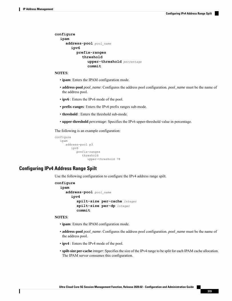
configureipam
address-pool pool_name
ipv6prefix-ranges
thresholdupper-threshold percentage
commit
NOTES:
• ipam: Enters the IPAM configuration mode.
• address-pool pool_name: Configures the address pool configuration. pool_name must be the name ofthe address pool.
• ipv6 : Enters the IPv6 mode of the pool.
• prefix-ranges: Enters the IPv6 prefix ranges sub-mode.
• threshold : Enters the threshold sub-mode.
• upper-threshold percentage: Specifies the IPv6 upper-threshold value in percentage.
The following is an example configuration:configure
ipamaddress-pool p3
ipv6prefix-ranges
thresholdupper-threshold 78
Configuring IPv4 Address Range SpiltUse the following configuration to configure the IPv4 address range spilt.
configureipam
address-pool pool_name
ipv4spilt-size per-cache integer
spilt-size per-dp integer
commit
NOTES:
• ipam: Enters the IPAM configuration mode.
• address-pool pool_name: Configures the address pool configuration. pool_name must be the name ofthe address pool.
• ipv4 : Enters the IPv4 mode of the pool.
• spilt-size per-cache integer: Specifies the size of the IPv4 range to be split for each IPAM cache allocation.The IPAM server consumes this configuration.
Ultra Cloud Core 5G Session Management Function, Release 2020.02 - Configuration and Administration Guide319
IP Address ManagementConfiguring IPv4 Address Range Spilt

• spilt-size-per-dp integer: Specifies the size of the IPv4 range to be spilt for each Data-Plane (User-Plane)allocation. The IPAM cache consumes this configuration.
The following is a sample configuration:configure
ipamaddress-pool p1
ipv4split-size per-cache 1024split-size per-dp 256
Configuring IPv6 Address and Prefix Address-Range-SpiltUse the following configuration to configure the IPv6 address and prefix address range spilt.
configureipam
address-pool pool_name
ipv6address-ranges
spilt-size per-cache integer
spilt-size per-dp integer
commitprefix-ranges
spilt-size per-cache integer
spilt-size per-dp integer
commit
NOTES:
• ipam: Enters the IPAM configuration mode.
• address-pool pool_name: Configures the address pool configuration. pool_name must be the name ofthe address pool.
• ipv6 : Enters the IPv6 mode of the pool.
• address-ranges: Enters the IPv6 address-ranges sub-mode.
• spilt-size per-cache integer: Specifies the size of the IPv6 adress-ranges or prefix-ranges to be split foreach IPAM cache allocation. The IPAM server consumes this configuration.
• spilt-size-per-dp integer: Specifies the size of the IPv6 adress-ranges or prefix-ranges to be spilt foreach Data-Plane (User-Plane) allocation. The IPAM cache consumes this configuration.
• prefix-ranges: Enters the IPv6 prefix ranges sub-mode.
The following is a sample configuration:configure
ipamaddress-pool p1
ipv6address-ranges
split-size per-cache 4096split-size per-dp 1024!
prefix-ranges
Ultra Cloud Core 5G Session Management Function, Release 2020.02 - Configuration and Administration Guide320
IP Address ManagementConfiguring IPv6 Address and Prefix Address-Range-Spilt

split-size per-cache 8192split-size per-dp 2048
Configuring Global ThresholdUse the following configuration to configure the global threshold.
configureipam
thresholdipv4-addr percentage
ipv6-addr percentage
ipv6-prefix percentage
commit
NOTES:
• ipam: Enters the IPAM Configuration mode.
• threshold: Enters the threshold sub-mode.
• ipv4-addr percentage : Specifies the IPv4 threshold value in percentage.
• ipv6-addr percentage : Specifies the IPv6 threshold value in percentage.
• ipv6-prefix percentage : Specifies the IPv6 prefix threshold value in percentage.
The following is a sample configuration:configure
ipamthreshold
ipv4-addr 80ipv6-addr 75ipv6-prefix 70
Configuring IPAM SourceUse the following configuration to configure the IPAM source.
configureipam
source localsource external ipam
host ip_address
port integer
vendor type
commit
NOTES:
• ipam: Enters the IPAM Configuration mode.
• source local: Enters the local datastore as the pool source.
• source external ipam : Enters the external IPAM server as the pool source.
• host ip_address : Specifies the host name of the external IPAM server.
• port integer : Specifies the port of the external IPAM server.
Ultra Cloud Core 5G Session Management Function, Release 2020.02 - Configuration and Administration Guide321
IP Address ManagementConfiguring Global Threshold

• vendor type: Specifies the vendor type of the external IPAM server.
The following is a sample configuration:ipamsource external ipamhost 1.1.1.1port 10000vendor cisco
Verifying the IPAM Integration ConfigurationThis section describes how to verify the IPAM integration in the SMF feature configuration.
Use the show ipam pool command to view the summary of current threshold of each pool.
The following is a sample output of the show ipam pool command.
show ipam pool================================================================PoolName Ipv4Threshold Ipv6AddrThreshold Ipv6PrefixThreshold================================================================p1 80% 80% 0%p2 75% 0% 70%
================================================================
Use the show ipam pool pool_name command to view more details of a specific pool name.
The following is a sample output of the show ipam pool pool_name command.
show ipam pool p1--------------------------------------------------------Ipv4Addr [Total/Used/Threshold] = 7680 / 7680 / 80%Ipv6Addr [Total/Used/Threshold] = 512 / 512 / 80%Ipv6Prefix [Total/Used/Threshold] = 0 / 0 / 0%--------------------------------------------------------
Use the show ipam pool_name ipv4-addr command to view the IPv4-address ranges for the given pool-name.Based on the configuration, the address ranges are dynamically split. You can also view whether the addressrange is free or allocated to a Data Plane (User Plane) using this command.
The following is a sample output of the show ipam pool_name ipv4-addr command.
show ipam pool p1 ipv4-addr===========================================StartAddress EndAddress AllocContext===========================================1.1.1.0 1.1.3.255 Upf-1001.1.4.0 1.1.7.255 Upf-2001.1.8.0 1.1.10.255 Free2.2.1.0 2.2.3.255 Upf-1002.2.4.0 2.2.7.255 Upf-3002.2.8.0 2.2.10.255 Free3.3.1.0 3.3.3.255 Free3.3.4.0 3.3.7.255 Free3.3.8.0 3.3.10.255 Free
===========================================
Ultra Cloud Core 5G Session Management Function, Release 2020.02 - Configuration and Administration Guide322
IP Address ManagementVerifying the IPAM Integration Configuration

Use the show ipam pool pool_name ipv6-perfix command to view the prefix-ranges for the given pool-name.Based on the configuration, the address ranges are dynamically split. You can also view whether the addressrange is free or allocated to a Data Plane (User Plane) using this command.
The following is a sample output of the show ipam pool pool_name ipv6-perfix command.
show ipam pool p2 ipv6-prefix==============================================Prefix AllocContext==============================================aaaa:bbbb:ccc0::/64 Upf-100aaaa:bbbb:ccc1::/64 Freeaaaa:bbbb:dd00::/64 Upf-200==============================================
Use the show ipam dp command to view the summary of the current threshold for each Data Plane (UserPlane).
The following is a sample output of the show ipam dp command.
show ipam dp================================================================DpName Ipv4Threshold Ipv6AddrThreshold Ipv6PrefixThreshold================================================================UPF-100 20% 40% 70%UPF-200 40% 20% 20%================================================================
Use the show ipam dp dataplane_name command to view more details of a specific Data Plane (User Plane).
The following is a sample output of the show ipam dp dataplane_name command.
show ipam dp UPF-100--------------------------------------------------------Ipv4Addr [Total/Used/Threshold] = 512 / 100 / 20%Ipv6Addr [Total/Used/Threshold] = 512 / 200 / 40%Ipv6Prefix [Total/Used/Threshold] = 512 / 300 / 70%--------------------------------------------------------
Use the show ipam dp dataplane_name ipv4-addr command to view the IPv4-address ranges assigned to adata plane.
The following is a sample output of the show ipam dp dataplane_name ipv4-addr command.
show ipam dp UPF-100 ipv4-addr======================================================StartAddress EndAddress AllocContext Route======================================================1.1.1.1 1.1.1.255 Pool-1 1.1.1.0/242.2.1.1 2.2.1.255 Pool-2 2.2.1.0/24======================================================
Use the show ipam dp dataplane_name ipv6-addr command to view the IPv6-address ranges assigned to adata plane.
The following is a sample output of the show ipam dp dataplane_name ipv6-addr command.
show ipam dp UPF-100 ipv6-addr========================================================
Ultra Cloud Core 5G Session Management Function, Release 2020.02 - Configuration and Administration Guide323
IP Address ManagementVerifying the IPAM Integration Configuration

StartAddress EndAddress AllocContext Route========================================================100::1 100::100 Pool-1 100::/12000::1 200::100 Pool-2 200::/120========================================================
Use the show ipam dp dataplane_name ipv6-prefix command to view the IPv6-address ranges assigned toa data plane.
The following is a sample output of the show ipam dp dataplane_name ipv6-prefix command.
show ipam dp UPF-100 ipv6-prefix============================================================Prefix AllocContext Route============================================================aaaa:bbbb:cccc::/64 Pool-1 aaaa:bbbb:cccc::/48aaaa:bbbb:dd00::/64 Pool-1 aaaa:bbbb:dd00::/40============================================================
Static IP Support
Feature DescriptionIPAM is the core component of the subscriber management system. Traditional IPAM functionalities proveinsufficient in the Cloud Native network deployments. Hence, IPAM requires additional functionalities towork with the Cloud Native subscriber management system.
The Static IP Support feature enables the support of static IP on the SMF using IPAM. This feature supportsthe following functionalities:
• Supports static pool configuration.
• Splits static address-ranges into smaller chunks and associates them with the configured UPFs.
• Enables program routes according to static address-range reservation during UPF association.
• Enables secondary authentication under the DNN profile.
• Selects UPF based on reserved address-range and Framed-IP received from the Authentication response.
How it WorksThis section provides a brief of how the Static IP Support feature feature works.
The SMF receives a framed-IP address of the subscriber from external AAA servers such as RADIUS. WhileIPAM is not involved in individual IP address management in this scenario, it still handles the route managementand UPF management for static address-ranges.
IPAM splits the ‘static’ address-ranges equally according to number of UPFs present in the SMF configuration.Unlike dynamic IP, IPAM splits all static-IP address-ranges and assigns them for all configured UPFs. IPAMinvolves and selects an UPF when the external AAA server returns the framed-IP of the subscriber. IPAMlooks for the route which includes this static-IP and then selects the UPF where the route is already configured.
Ultra Cloud Core 5G Session Management Function, Release 2020.02 - Configuration and Administration Guide324
IP Address ManagementStatic IP Support

Procedure
1. IPAM splits the static ranges into equal number of address-ranges based on number of configured UPFs.
2. The UPMGR programs the corresponding static routes on the associated UPFs.
3. Subscribers get static IP from Radius server authorize response.
4. SMF service selects the right UPF based onADDR ranges andUPFmap allocation from the NodeManager.
Address-Range Split
Splitting a given address-range into smaller address-ranges is a key functionality of the IPAM server andIPAM cache. The following guidelines determine address-range split:
1. Size of a split address-range depends upon the ‘configured’ value or the ‘default’ value as per the AFItype.
2. Size of a split address-range must be a ‘power-of-2’ or at least to the closest of it. That is, it should beable to represent the split range in “subnet/mask” notation such that a route can be added in the Data Plane(User Plane) if required.
3. ‘Configured’ or ‘default’ address-range-size must be at the ‘power-of-2’.
The address-range must be split into smaller ranges immediately on configuration or initial start-up. Thishelps in better sorting of address-ranges based on size and faster allocation during actualaddress-range-allocation requests. The address-range exchange between modules is always in the mentionedsize.
Ultra Cloud Core 5G Session Management Function, Release 2020.02 - Configuration and Administration Guide325
IP Address ManagementHow it Works

Table 90: Examples of IPv4 Address-Range Split
Route NotationSplit-ranges
(* Odd sized ranges)
Split-Size (number ofaddresses per range)
Address-Range
[1] 1.1.1.0/25
[2] 1.1.1.128/25
[1] 1.1.1.0 – 1.1.1.127
[2] 1.1.1.128 – 1.1.1.255
1281.1.1.0 - 1.1.1.255
[1] 1.1.0.0/24
[2] 1.1.1.0/24
[3] 1.1.2.0/24
...
[n] 1.1.10.0/24
[1] 1.1.0.0 – 1.1.0.255
[2] 1.1.1.0 – 1.1.1.255
[3] 1.1.2.0 – 1.1.2.255
...
[n] 1.1.10.0 – 1.1.10.255
2561.1.0.0 – 1.1.10.255
[1] 1.1.0.0/24
[2] 1.1.1.0/24
[3] 1.1.2.0/24
[1] 1.1.0.5 – 1.1.0.255 *
[2] 1.1.1.0 – 1.1.1.255
[3] 1.1.2.0 – 1.1.2.200 *
2561.1.0.5 – 1.1.2.200
Table 91: Examples of IPv6 Address-Range Split
Route NotationSplit-ranges
(* Odd sized ranges)
Split-Size (number ofaddresses per range)
Address-Range
[1] 1::/118
[2] 1::400/118
[3] 1::800/118
[4] 1::C00/118
[1] 1:: – 1::3FF
[2] 1::400 – 1::7FF
[3] 1::800 – 1::BFF
[4] 1::C00 – 1::FFF
10241:: - 1::1000
[1] 1::/118
[2] 1::400/118
[3] 1::800/118
…
[n] 1::1C00/118
[1] 1::3 – 1::3FF *
[2] 1::400 – 1::7FF
[3] 1::800 – 1::BFF
…
[n] 1::1C00 – 1::1DEF *
10241::3 - 1::1DEF
Examples of IPv6 Address-Range Split
Prefix split needs two length fields for performing the split.
• Network length
• Host length
Prefixes are split between these and a new route is calculated.
Example 1: network-length = 48, prefix-length = 64
Ultra Cloud Core 5G Session Management Function, Release 2020.02 - Configuration and Administration Guide326
IP Address ManagementHow it Works

Total (64-48) = 16 bits (that is, 65536 prefixes are available for the split)
Example 2: network-length = 32, prefix-length = 56
Total (56-32) = 24 bits (that is, 16 million prefixes available for the split)
For Cloud-Native 5G SMF, the host-length is hard-coded as ‘64’. Only network-length can be configured viathe CLI.
Note
Table 92: Examples of IPv6 Address-Range Split
Route NotationSplit-ranges
(* Odd sized ranges)
Split-Size (number ofaddresses per range)
Prefix-Range
[1]1:2:3::/51
[2]1:2:3:2000/51
[3]1:2:3:3000/51
...
[1]1:2:3:: ... 1:2:3:1fff
[2]1:2:3:2000:: ...1:2:3:2fff::
[3]1:2:3:3000:: ...1:2:3:3fff::
...
81921:2:3::
Nw-len = 48
Host-len = 64
Call Flows
This section includes the following call flow.
Figure 77: SMF Static IP Call Flow
Figure 78:
DescriptionStep
Configures the static-address ranges and UPF list.1
Splits the static-address ranges into equal number of ranges for UPFs.2
Ultra Cloud Core 5G Session Management Function, Release 2020.02 - Configuration and Administration Guide327
IP Address ManagementCall Flows

DescriptionStep
Enables program routes for the assigned static address-range.3
Brings up the session.4
Enables secondary authentication under the DNN profile.5
The SMF sends the Authentication Request to the RADIUS server.
The RADIUS server sends an Authentication Response with the 'static-ip' of thesubscriber. The SMF selects the UPF based on the 'static-ip' and continues with theprogramming.
6
Completes the subscriber programming.7
Limitations
The Static IP Support feature has the following limitations:
• Change of a pool from dynamic to static and vice-versa is not supported when in system-running mode.
• Addition or removal of UPF is not supported when in system-running mode.
• The address-range split must be optimal based on the number of UPFs and number of addresses in theranges.
For example:
• If there are 2 UPFs and 1024 addresses specified in the range, then specify the per-dp-split-size as512.
• If there are 3 UPFs and 1024 addresses, then specify the per-dp-split-size as 256.
Configuring Static IP SupportUse the following commands to configure the Static IP Support feature.
configureipam
address-pool pool_name
staticend
NOTES:
• ipam: Enters the IPAM configuration mode.
• address-pool pool_name: Specifies the name of the address pool to enter the pool configuration.pool_name must be the name of the address pool.
• static: Enables the static IP mode.
Ultra Cloud Core 5G Session Management Function, Release 2020.02 - Configuration and Administration Guide328
IP Address ManagementLimitations

Dual-Stack Static IP Support Through IPAM
Feature DescriptionThe SMF supports dual-stack static IP using IPAM. For dual-stack sessions, the AAA server sends both theIPv4 and IPv6 address prefixes as part of the Access-Accept message. In the SMF-IPAM configuration, boththe IPv4 and IPv6 address prefixes are added in the same pool. The IPAM assigns both the IPv4 and IPv6routes to a single UPF.
During the UPF selection, the Node Manager application uses the UPF for both the IPv4 and IPv6 addressesfrom the IPAM to handle them accordingly.
How it WorksThe SMF supports dual-stack static IP through IPAM in the following ways:
• Pool to UPF mapping—Based on the number of UPFs available, the IPv4 address-ranges and IPv6prefix-ranges are split into smaller chunks. Then, the pair (chunk) is configured into the same IPAMpool.
IPAM assigns all the addresses and prefixes that are configured in one dual-stack pool to a UPF in themanner they are received. The AAA server returns the dual-stack addresses from the same pair. Fromthese addresses, SMF selects one UPF for dual-stack programming.
The load-balancing of number of addresses and prefixes are managed. IPAM performs only the dual-stackstatic-pool to UPF mapping.
• Address-range no-split configuration—IPAM uses the "no-split" configuration to prevent splitting theaddress-ranges into smaller chunks. This configuration helps to prevent having multiple routesprogramming for a specific range.
The following table lists the errors or exceptions and how to handle them:
Table 93: Error and Exception Handling
Exception HandlingError or Exception
1. Select an active UPF. In case both the UPFs areactive, select the UPF with the IPv4 address.
2. Reset the IP information of the other stack and updatethe PDU session type accordingly.
IPv4UPF and IPv6UPF are configured incorrectly
Select the UPF with IPv4 address and update the PDUsession type accordingly.
IPv4 address is invalid or null
Select the UPF with IPv6 address and update the PDUsession-type accordingly.
IPv6 prefix is invalid or null
Both the IPv4 address and IPv6 prefix are rejected.IPv4 address and IPv6 prefix are invalid
Ultra Cloud Core 5G Session Management Function, Release 2020.02 - Configuration and Administration Guide329
IP Address ManagementDual-Stack Static IP Support Through IPAM

LimitationsThe dual-stack static IP support using IPAM feature has the following limitation:
When the system is in running mode, the change in ‘no-split' configuration is not supported.
Configuring Dual-Stack Static IP Support Using IPAM FeatureThis section describes how to configure the dual-stack static IP support using IPAM.
Configuring IPAM No-SplitThis section describes how to configure the IPAM no-split.
configureipam
address-pool pool_name
ipv4split-size no-splitexit
ipv6 prefix_ranges
split-size no-splitexit
exit
NOTES:
• split-size no-split—Prevents the IPv4 address-ranges or IPv6 prefix-ranges from splitting into smallerchunks.
IPAM Offline Mode Support
Feature DescriptionThe SMF supports the addition of a dynamic pool, IPv4, or IPv6 address-range to a dynamic pool by default.The new chunks are added to the respective tags, such as DNN, and are assigned from the same pool.
To delete a dynamic pool or an IPv4 or IPv6 address-range from a dynamic pool:
1. Configure the pool or address-range as offline. The IPAM then stops assigning addresses from the respectivepool or address-range.
2. Use the following clear-subscriber CLI commands to delete the subscribers based on respective pool oraddress range that are configured to offline mode:
• clear subscriber ipv4-pool pool_name
• clear subscriber ipv4-range pool_name/start_of_range
• clear subscriber ipv6-pool pool_name
• clear subscriber ipv6-range pool_name/start_of_range
Ultra Cloud Core 5G Session Management Function, Release 2020.02 - Configuration and Administration Guide330
IP Address ManagementLimitations

3. Use the following cdl show-sub CLI commands and wait until all the subscribers are deleted:
• cdl show sessions count summary filter { key ipv4-pool: pool_name condition match }
• cdl show sessions count summary filter { key ipv4-range: pool_name/start_of_range conditionmatch }
• cdl show sessions count summary filter { key ipv6-pool: pool_name condition match }
• cdl show sessions count summary filter { key ipv6-range: pool_name/start_of_range conditionmatch }
4. After all the subscribers are deleted, delete the pool or address-range from the IPAM configuration.
Configuring the IPAM Offline ModeThis section describes how to configure the IPAM offline feature for pool, IPv4 address-range, and IPv6prefix-ranges.
Configuring Pool to Offline ModeUse the following command to configure the entire pool to offline mode.
configureipam
address-pool pool_name
offline...exit
exit
NOTES:
• address-pool pool_name—Specifies the name of the pool to enter the pool configuration. pool_namemust be the name of the address pool.
• offline—Configures the pool to offline mode.
Configuring IPv4 Address-Range to Offline ModeUse the following command to configure the IPv4 address-range to offline mode.
configureipam
address-pool pool_name
vrf-name vrf_name_value
ip4address-range start_ipv4_address end_ipv4_address offlineaddress-range start_ipv4_address end_ipv4_address
!!
!
Ultra Cloud Core 5G Session Management Function, Release 2020.02 - Configuration and Administration Guide331
IP Address ManagementConfiguring the IPAM Offline Mode

NOTES:
• address-pool pool_name—Specifies the name of the pool to enter the pool configuration. pool_namemust be the name of the address pool.
• ipv4—Enters the IPv4 mode.
• address-range start_ipv4_address end_ipv4_address—Specifies the IP addresses for the start and endIPv4 address-range.
• offline—Configures the selected address-range to offline mode.
Configuring IPv6 Prefix-Ranges to Offline ModeUse the following commands to configure IPv6 prefix-range to offline mode.
configureipam
address-pool pool_name
vrf-name vrf_name_value
ipv6prefix-rangesprefix-rangeprefix_value length length_valueoffline
prefix-rangeprefix_value length length_value!
!!
!
NOTES:
• address-pool pool_name—Specifies the name of the pool to enter the pool configuration. pool_namemust be the name of the address pool.
• ipv6—Enters the IPv6 mode.
• prefix-ranges—Enters the prefix-ranges mode.
• prefix-range prefix_value length length_value—Specifies the prefix-range and prefix-length of the IPv6prefix-range.
• offline—Configures the selected address-range to offline mode.
IPAM Redundancy Support Per UPF
Feature DescriptionThe SMF supports IPAM redundancy and load-balancing for each UPF. The IPAM running in the NodeManager microservice has two IPAM instances that are associated to each UPF. When one IPAM instance isinactive, the other IPAM instance manages the address allocation requests for the UPF.
The IPAM redundancy support per UPF feature supports the following functionality:
Ultra Cloud Core 5G Session Management Function, Release 2020.02 - Configuration and Administration Guide332
IP Address ManagementConfiguring IPv6 Prefix-Ranges to Offline Mode

How it WorksThis section provides a brief of how the IPAM redundancy support per UPF feature works.
• Peer Selection—The Node Manager peer is selected during the UPF association.
• UPF Registration with Peer IPAM—IPAM is notified with the instance ID of the peer for the UPF duringthe registration of the UPF call. IPAM allocates routers from the local data for the specific DNN andchecks if the peer IPAM instance is in active or inactive state.
If the peer IPAM instance is active, a REST call is sent to it to register to the same UPF in the localinstance and to receive the routes as response.
If the peer IPAM instance is inactive, the local instance takes over the IPAM context of the remoteinstance. Then, the local instance registers to the UPF, receives the routes, and keeps the data back inthe cache-pod. After the peer instance is active, it restores the same data from the cache-pod.
Routes from both the instances are sent to UPF for load-balanced address allocations from both theinstances.
• Address Allocation in Load-Balanced Model—As one UPF is registered to two IPAM servers, SMFsends the address allocation requests to any peer that is load-balanced. Respective IPAM instances assignnew addresses from their local address bitmap. If one peer instance is inactive, the other peer instancehandles all the requests.
• Address-Release Request Handling—In IPAM, the Address Release request is sent to the instance thathad allocated the IP the first time. If that peer is inactive, the Address Release request is sent to the peerIPAM.
The IPAM instance that receives the address releases for remote instances, keeps buffering these instanceslocally and updates the cache-pod periodically. After the remote peers are active, they handle the bufferedaddress-release requests.
• Release of the UPF—When a peer IPAM is active during the release of a UPF, a REST call is sent toclear the data. If the peer IPAM is inactive, the existing IPAM instance takes over the operational dataof the remote IPAM, clears the UPF information, and updates the cache-pod.
IPAM Quarantine Timer Support
Feature DescriptionThe IPAM Quarantine Timer Support feature supports the IPAM quarantine timer for the IP pool address.This feature keeps the released IP address busy until the quarantine timer expires to prevent the reuse of thatIP address. Each IP pool must be configured with a timer value. This value determines the duration of arecently released address to be in the quarantine state before it is available for allocation. After the timerexpires, the IP address is available in the list of free addresses for allocation by the subscriber. A released IPaddress with no address quarantine timer is considered to be in use for allocation. If a subscriber attempts toreconnect when the address quarantine timer is armed even if it is the same subscriber ID, the subscriber doesnot receive the same IP address.
Ultra Cloud Core 5G Session Management Function, Release 2020.02 - Configuration and Administration Guide333
IP Address ManagementHow it Works

Configuring the IPAM Quarantine Timer Support FeatureThis section describes how to configure the IPAM quarantine timer support feature.
Configuring IPAM Quarantine TimerThis section describes how to configure the IPAM quarantine timer.
configureipam
address-pool pool_name
address-quarantine-timer quarantine_timer_value
vrf-name vrf_name_value
ip4address-range start_ipv4_address end_ipv4_address
address-range start_ipv4_address end_ipv4_address
!!
!
NOTES:
• ipam—Enter the IPAM configuration.
• address-pool pool_name—Specifies the name of the pool to enter the pool configuration. pool_namemust be the name of the address pool.
• address-quarantine-timer quarantine_timer_value—Specifies the value of the quarantine timer inseconds. The default value is 4.
• vrf-name vrf_name_value—Specifies the name of the VPN routing and forwarding (VRF) for the pool.
• ipv4—Enters the IPv4 mode.
• address-range start_ipv4_address end_ipv4_address—Specifies the IP addresses for start and end IPv4address-range.
show ipam poolDescriptionField
Name of the Address Pool.PoolName
Utilization percentage for IPv4 address for this pool.Ipv4Utilization
Utilization percentage for IPv6 address for this pool.Ipv6AddrUtilization
Utilization percentage for IPv6 prefix address for this pool.Ipv6PrefixUtilization
Ultra Cloud Core 5G Session Management Function, Release 2020.02 - Configuration and Administration Guide334
IP Address ManagementConfiguring the IPAM Quarantine Timer Support Feature
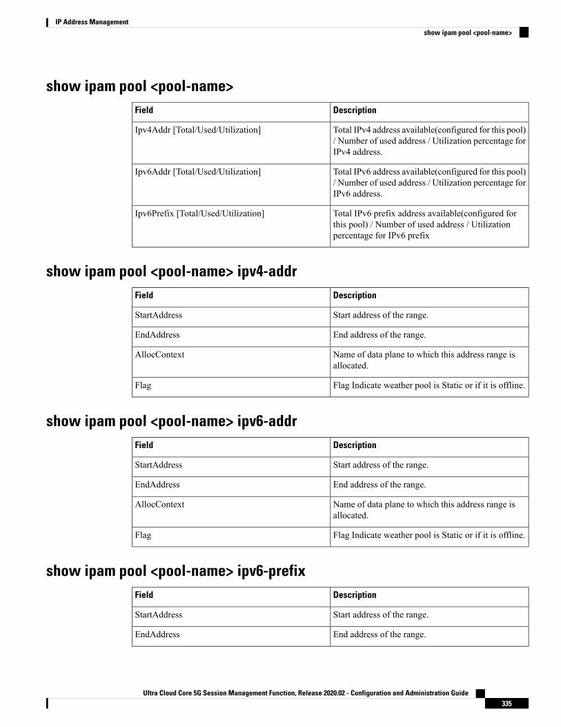
show ipam pool <pool-name>DescriptionField
Total IPv4 address available(configured for this pool)/ Number of used address / Utilization percentage forIPv4 address.
Ipv4Addr [Total/Used/Utilization]
Total IPv6 address available(configured for this pool)/ Number of used address / Utilization percentage forIPv6 address.
Ipv6Addr [Total/Used/Utilization]
Total IPv6 prefix address available(configured forthis pool) / Number of used address / Utilizationpercentage for IPv6 prefix
Ipv6Prefix [Total/Used/Utilization]
show ipam pool <pool-name> ipv4-addrDescriptionField
Start address of the range.StartAddress
End address of the range.EndAddress
Name of data plane to which this address range isallocated.
AllocContext
Flag Indicate weather pool is Static or if it is offline.Flag
show ipam pool <pool-name> ipv6-addrDescriptionField
Start address of the range.StartAddress
End address of the range.EndAddress
Name of data plane to which this address range isallocated.
AllocContext
Flag Indicate weather pool is Static or if it is offline.Flag
show ipam pool <pool-name> ipv6-prefixDescriptionField
Start address of the range.StartAddress
End address of the range.EndAddress
Ultra Cloud Core 5G Session Management Function, Release 2020.02 - Configuration and Administration Guide335
IP Address Managementshow ipam pool <pool-name>

DescriptionField
Name of data plane this address range is allocated.AllocContext
Flag Indicates whether pool is Static or if it is offline,S(Static) and O(Offline).
Flag
show ipam dpDescriptionField
Name of the data plane which is registered.DpName
Utilization percentage for IPv4 by this data plane.Ipv4Utilization
Utilization percentage for Ipv6 address by this dataplane.
Ipv6AddrUtilization
Utilization percentage for Ipv6 prefix by this dataplane.
Ipv6PrefixUtilization
show ipam dp <dataplane-name>DescriptionField
Total IPv4 address available(configured for this dataplane) / Number of used address / Utilizationpercentage for IPv4.
Ipv4Addr [Total/Used/Utilization]
Total IPv6 address available(configured for this dataplane) / Number of used address / Utilizationpercentage for IPv6.
Ipv6Addr [Total/Used/Utilization]
Total IPv6 prefix address available(configured forthis data plane) / Number of used address / Utilizationpercentage for IPv6 prefix.
Ipv6Prefix [Total/Used/Utilization]
show ipam dp <dataplane-name> ipv4-addressDescriptionField
Start address of the range.StartAddress
End address of the range.EndAddress
Route allocated for this data plane.Route
Ultra Cloud Core 5G Session Management Function, Release 2020.02 - Configuration and Administration Guide336
IP Address Managementshow ipam dp
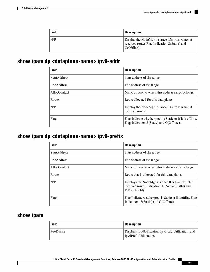
DescriptionField
Display the NodeMgr instance IDs from which itreceived routes Flag Indication S(Static) andO(Offline).
N/P
show ipam dp <dataplane-name> ipv6-addrDescriptionField
Start address of the range.StartAddress
End address of the range.EndAddress
Name of pool to which this address range belongs.AllocContext
Route allocated for this data plane.Route
Display the NodeMgr instance IDs from which itreceived routes.
N/P
Flag Indicate whether pool is Static or if it is offline,Flag Indication S(Static) and O(Offline).
Flag
show ipam dp <dataplane-name> ipv6-prefixDescriptionField
Start address of the range.StartAddress
End address of the range.EndAddress
Name of pool to which this address range belongs.AllocContext
Route that is allocated for this data plane.Route
Displays the NodeMgr instance IDs from which itreceived routes Indication, N(Native InstId) andP(Peer InstId).
N/P
Flag Indicate weather pool is Static or if it offline FlagIndication, S(Static) and O(Offline).
Flag
show ipamDescriptionField
Displays Ipv4Utilization, Ipv6AddrUtilization, andIpv6PrefixUtilization.
PoolName
Ultra Cloud Core 5G Session Management Function, Release 2020.02 - Configuration and Administration Guide337
IP Address Managementshow ipam dp <dataplane-name> ipv6-addr

DescriptionField
Displays Ipv4Utilization, Ipv6AddrUtlization, andIpv6PrefixUtlization.
DpName
Ultra Cloud Core 5G Session Management Function, Release 2020.02 - Configuration and Administration Guide338
IP Address Managementshow ipam

C H A P T E R 23Load-based Selection of UPF
• Feature Summary and Revision History, on page 339• Feature Description, on page 339
Feature Summary and Revision History
Summary DataTable 94: Summary Data
SMFApplicable Product(s) or Functional Area
SMIApplicable Platform(s)
Enabled – Always-onFeature Default Setting
Not ApplicableRelated Changes in this Release
Not ApplicableRelated Documentation
Revision HistoryTable 95: Revision History
ReleaseRevision Details
Pre-2020.02.0First introduced.
Feature DescriptionLoad based User Plane Function (UPF) selection in SMF distributes calls among active UPFs associated withSMF.
Ultra Cloud Core 5G Session Management Function, Release 2020.02 - Configuration and Administration Guide339

SMF Support for Load Control Feature3GPP specifies Load Control feature as optional feature over N4 reference points. This enables UPF to sendits load information to CP functions. To support Load Control feature, SMF can receive UPF provided LoadControl information in the following PFCP messages:
• Session Establishment Response
• Session Modification Response
• Session Deletion Response
• Session Report Request
Load Control procedure details are mentioned in 3GPP TS 29.244 v14.0.0 Release 14 Section 6.2.3 and SMFadheres to the CP functionality.
Load Based UPF SelectionSMF stores the load information provided by UPF and uses it in selecting the UPF for new sessions beingestablished. SMF selects the less loaded UPF among the candidate (DNN based) active UPFs.
This feature considers priority and capacity configured statically against each UPF. In cases where UPF doesnot send the load information statically, configured capacity is considered while selecting the UPFs.
Standards ComplianceThe feature complies with the following standards:
• 3GPP TS 29.244 v14.0.0 Release 14
Ultra Cloud Core 5G Session Management Function, Release 2020.02 - Configuration and Administration Guide340
Load-based Selection of UPFSMF Support for Load Control Feature

C H A P T E R 24Monitor Subscriber and Monitor Protocol
• Feature Summary and Revision History, on page 341• Feature Description, on page 341• Configuring the Monitor Subscriber and Monitor Protocol Feature, on page 342
Feature Summary and Revision History
Summary DataTable 96: Summary Data
SMFApplicable Product(s) or Functional Area
SMIApplicable Platform(s)
Enabled – Always-onFeature Default Setting
Not ApplicableRelated Changes in this Release
Not ApplicableRelated Documentation
Revision HistoryTable 97: Revision History
ReleaseRevision Details
Pre-2020.02.0First introduced.
Feature DescriptionThe SMF supports theMonitor Subscriber andMonitor Protocol on the Kubernetes environment. This featureallows to capture messages of subscribers and protocols.
Ultra Cloud Core 5G Session Management Function, Release 2020.02 - Configuration and Administration Guide341

Configuring the Monitor Subscriber and Monitor ProtocolFeature
Monitoring the SubscriberUse the following CLI command to monitor the subscriber in the SMF.
monitor subscriber supi supi_id [ capture-duration duration_sec |internal-messages { yes } | transaction-logs { yes } ]
NOTES:
• supi supi_id: Specifies the subscriber identifier. For example, imsi-123456789, imsi-123*
• capture-duration duration_sec: Specifies the duration in seconds during which the monitor subscriberis enabled. The default is 300 seconds (5 minutes).
• internal-messages { yes }: Enables internal messages. By default, internal messages are disabled.
• transaction-logs { yes }: Enables transaction logs. By default, transaction logs are disabled.
The monitor subscriber CLI command can be run simultaneously on multiple terminals. For example, runthe CLI simultaneously in two SMF Ops Center terminals for two subscribers (for example,imsi-123456789012345 and imsi-456780123456789) to implement the following:
• Monitor the duration when the monitor subscriber is enabled.
• View internal messages for the specified subscriber.
• View transaction logs for the specified subscriber
Terminal 1: The following command monitors and displays subscriber messages for the specified subscriber.monitor subscriber supi imsi-123456789012345 capture-duration 1000 internal-messages yes
Terminal 2: The following command monitors and displays transaction logs for the specified subscriber.monitor subscriber supi imsi-456780123456789 capture-duration 500 internal-messages yestransaction-logs yes
After the capture-duration is over or to stop the CLI, use theCtrl+C keys. The captured messages are reorderedand stored in a file. To retrieve the list of stored files, use the monitor subscriber list CLI command.
For example:monitor subscriber listRELEASE_NAMESPACE: 'smf''monsublogs/subscriberID_imsi-*_AT_2019-10-22T09:19:05.586237087.txt.sorted'monsublogs/subscriberID_imsi-123456789012345_AT_2019-10-22T09:20:11.122225534.txt.sorted
Viewing the Sorted File on SMF Ops CenterUse the following CLI command to view the sorted file on the SMF Ops Center screen.
monitor subscriber dump filename filename
Ultra Cloud Core 5G Session Management Function, Release 2020.02 - Configuration and Administration Guide342
Monitor Subscriber and Monitor ProtocolConfiguring the Monitor Subscriber and Monitor Protocol Feature

For example:monitor subscriber dump filenamemonsublogs/subscriberID_imsi-123456789012345_AT_2019-10-22T09:20:11.122225534.txt.sorted
Monitoring the Interface ProtocolUse the following CLI command to monitor the interface protocol on the SMF.
monitor protocol interface endpoint_name capture-duration duration_sec
NOTES:
• interface endpoint_name: Specifies the endpoint name on which PCAP is captured. This CLI allows theconfiguration of multiple endpoint names in a single CLI command.
• capture-duration duration_sec: Specifies the duration in seconds during which the monitor subscriberis enabled. The default is 300 seconds (5 minutes).
• The configured endpoint names can be retrieved using the show endpoint CLI command.
Themonitor protocolCLI can be run simultaneously onmultiple terminals. Also, the interface endpoint_nameCLI allows the configuration of multiple endpoint names in a single CLI command. For example:
monitor protocol interface sbi,N4:10.86.73.161:8805,gtpc capture-duration1000
Viewing Transaction History LogsUse the following CLI command to view the transaction history on an OAM pod shell. On another terminal,use the kubectl command to tail the logs of the OAMpod and then run the following CLI from the Ops Center.
dump transactionhistory
NOTES:
In this release, the most recent transaction logs are stored in a circular queue of size 1024 transaction logs.
Sample Transaction LogThe following is a sample transaction log.InstanceInfo: SMF.smf-service.DC.Local.0TimeStamp: 2019-11-13 03:01:33.614095848 +0000 UTC************* TRANSACTION: 00091 *************TRANSACTION SUCCESS:
Txn Type : 24Priority : 1Session State : Update_SessionSubscriber Id : imsi-123456789012345Session Keys : imsi-123456789012345:5 (primary)
LOG MESSAGES:2019/11/13 03:01:33.565 [INFO] [infra.application.core] Queue data 912019/11/13 03:01:33.565 [DEBUG] [infra.transaction.core] Processing transaction Id: 91
Type: 24 SubscriberID: Keys: []2019/11/13 03:01:33.565 [TRACE] [infra.message_log.core] >>>>>>>
IPC messageName: N11SmContextReleaseReq
Ultra Cloud Core 5G Session Management Function, Release 2020.02 - Configuration and Administration Guide343
Monitor Subscriber and Monitor ProtocolMonitoring the Interface Protocol

MessageType: N11SmContextReleaseReqKey:--body--{"smcontextreleasedata":{"cause":7}}
2019/11/13 03:01:33.566 [DEBUG] [infra.transaction.core] Trying to load session2019/11/13 03:01:33.566 [DEBUG] [infra.session_cache.core] Get session by pk
imsi-123456789012345:52019/11/13 03:01:33.566 [DEBUG] [infra.session_cache.core] Record found in local cache
by key imsi-123456789012345:52019/11/13 03:01:33.566 [DEBUG] [infra.transaction.core] Queuing new transaction for
processing2019/11/13 03:01:33.566 [DEBUG] [smf-service0.smf-app.messageprocessor] GetLockPriority
for txn id: 91, Type: 242019/11/13 03:01:33.566 [DEBUG] [infra.transaction.core] Session lock priority 0 txn
lock priority 102019/11/13 03:01:33.567 [DEBUG] [infra.transaction.core] Session locked with priority
102019/11/13 03:01:33.567 [DEBUG] [smf-service0.smf-app.gen] Handle Idle Events2019/11/13 03:01:33.567 [DEBUG] [smf-service0.smf-app.amf] Handling SM Context Release
Event2019/11/13 03:01:33.567 [DEBUG] [smf-service0.smf-app.upf] Send N4 Release Request2019/11/13 03:01:33.567 [DEBUG] [infra.transaction.core] Requested host Setname:
smf-protocol Name: Version: ApiRoot:2019/11/13 03:01:33.567 [DEBUG] [infra.transaction.core] Selected remote host by set
name is Id 5 Name: smf-protocol4 Setname: smf-protocol Host: smf-protocol Port: 9003 Url:of available 10 hosts
2019/11/13 03:01:33.567 [INFO] [infra.transaction.core] Calling RPC smf-protocol onhost smf-protocol4 proc-name smf-protocol proc-method: Sync
2019/11/13 03:01:33.567 [DEBUG] [infra.ipc_action.core] Calling IPC RPC with Retry,Retry Counter is 3
2019/11/13 03:01:33.597 [DEBUG] [infra.ipc_action.core] Time taken to execute IPC is0.03
2019/11/13 03:01:33.597 [DEBUG] [infra.ipc_action.core] Destination Host 192.168.1.163serviced the IPC Message N4SessionReleaseReq
2019/11/13 03:01:33.597 [DEBUG] [smf-service0.smf-app.upf] UPF N4 Session Release done2019/11/13 03:01:33.597 [DEBUG] [smf-service0.smf-app.messageprocessor] Returning
newStage (RELEASE: Idle)2019/11/13 03:01:33.597 [DEBUG] [infra.transaction.core] Last stage ( init_done ) ->
Next stage ( RELEASE: Idle )2019/11/13 03:01:33.598 [DEBUG] [smf-service0.smf-app.upf] Processing N4 Response
awtUpfRelProcUpfReleaseResp2019/11/13 03:01:33.599 [DEBUG] [infra.transaction.core] Requested host Setname: Name:
192.168.2.150 Version: ApiRoot:2019/11/13 03:01:33.599 [DEBUG] [infra.transaction.core] Exact match found. Selected
remote host is Id 11 Name: 192.168.2.150 Setname: Host: 192.168.2.150 Port: 9003 Url:2019/11/13 03:01:33.599 [INFO] [infra.transaction.core] Calling RPC smf-nodemgr on host
192.168.2.150 proc-name smf-nodemgr proc-method: Sync2019/11/13 03:01:33.600 [DEBUG] [infra.ipc_action.core] Calling IPC RPC with Retry,
Retry Counter is 32019/11/13 03:01:33.609 [DEBUG] [infra.ipc_action.core] Time taken to execute IPC is
0.012019/11/13 03:01:33.609 [DEBUG] [infra.ipc_action.core] Destination Host 192.168.2.150
serviced the IPC Message NmgrRersourceMgmtRequest2019/11/13 03:01:33.609 [DEBUG] [smf-service0.smf-app.resource] NodeMgr Resource(IP and
commonID) Release Sent2019/11/13 03:01:33.609 [DEBUG] [smf-service0.smf-app.messageprocessor] Returning
newStage (RELEASE: Await UPF Release)2019/11/13 03:01:33.609 [DEBUG] [infra.transaction.core] Last stage ( RELEASE: Idle )
-> Next stage ( RELEASE: Await UPF Release )2019/11/13 03:01:33.609 [DEBUG] [smf-service0.smf-app.resource] Processing Rmgr Response
awtRmgrRelProcNmgrResourceMgmtRsp2019/11/13 03:01:33.609 [DEBUG] [smf-service0.smf-app.resource] NodeMgr Resource(IP and
commonID) Release done2019/11/13 03:01:33.610 [DEBUG] [smf-service0.smf-app.amf] Sending Sm context Release
Ultra Cloud Core 5G Session Management Function, Release 2020.02 - Configuration and Administration Guide344
Monitor Subscriber and Monitor ProtocolSample Transaction Log

Response2019/11/13 03:01:33.610 [DEBUG] [smf-service0.smf-app.messageprocessor] Returning
newStage (RELEASE: Await Resource Release)2019/11/13 03:01:33.610 [DEBUG] [infra.transaction.core] Last stage ( RELEASE: Await
UPF Release ) -> Next stage ( RELEASE: Await Resource Release )2019/11/13 03:01:33.610 [DEBUG] [smf-service0.smf-app.messageprocessor] Returning
newStage (finished)2019/11/13 03:01:33.610 [DEBUG] [infra.transaction.core] Last stage ( RELEASE: Await
Resource Release ) -> Next stage ( finished )2019/11/13 03:01:33.610 [DEBUG] [infra.transaction.core] Updating session2019/11/13 03:01:33.610 [DEBUG] [infra.session_cache.core] Save session with key
imsi-123456789012345:5 in cache2019/11/13 03:01:33.612 [DEBUG] [infra.session_cache.core] Queued datastore write for
key imsi-123456789012345:52019/11/13 03:01:33.613 [TRACE] [infra.message_log.core] <<<<<<<<2019/11/13 03:01:33.613 [DEBUG] [infra.transaction.core] sent response message for 91
Ultra Cloud Core 5G Session Management Function, Release 2020.02 - Configuration and Administration Guide345
Monitor Subscriber and Monitor ProtocolSample Transaction Log

Ultra Cloud Core 5G Session Management Function, Release 2020.02 - Configuration and Administration Guide346
Monitor Subscriber and Monitor ProtocolSample Transaction Log

C H A P T E R 25Multiple and Virtual DNN Support
• Feature Summary and Revision History, on page 347• Feature Description, on page 348• Configuring the Virtual DNN Feature, on page 349• Dynamic Configuration Change Support, on page 351• IP Pool Allocation per DNN, on page 354
Feature Summary and Revision History
Summary DataTable 98: Summary Data
SMFApplicable Product(s) or Functional Area
SMIApplicable Platform(s)
Disabled – Configuration RequiredFeature Default Setting
Not ApplicableRelated Changes in this Release
Not ApplicableRelated Documentation
Revision HistoryTable 99: Revision History
ReleaseRevision Details
Pre-2020.02.0First introduced.
Ultra Cloud Core 5G Session Management Function, Release 2020.02 - Configuration and Administration Guide347

Feature DescriptionMulti DNN support enables the SMF to have multiple PDN connections for end users to provide differentservices including Internet and VONR services.
The SMF fetches locally configured DNN profile-based DNN in PDU Session Establishment Request fromthe AMF and maintains the PDN connections based on using SUPI and pdu-session-id. SMF includes thereceived DNN in all SBI interfaces to authorize the end user to fetch subscription information, policy andcharging related information and provisions forward path information to the UPF. The SMF integratesMulti-DNN Support with IPAM (IP Address Management) Module to allocate address to end-user based onreceived DNN, which maps the DNN-Profile that is derived from subscriber policies. The SMF also fetchesDNN and IPv4 and IPv6 path information based on IPAM pool configuration and updates the UPF as a partof node association interactions.
Multiple DNN is supported only for 5GS procedures and is not qualified for EPS Session using SBI interfaces.Note
The SMF supports Virtual DNNmapping based on a subscriber profile. It supports mapping of a UE requestedDNN to a configured DNN and sends the selected DNN profile towards the configured network interfaces.
How it WorksThe DNN profile lookup is based on subscriber policy or DNN policy. They are associated in the SMF profileconfiguration. The subscriber policy has a higher precedence over the DNN policy when both the configurationsare present.
The subscriber policy consists of a list of precedence values, and the selection of the precedence is based onthe subscriber's SUPI, GPSI, Serving PLMN, and NSSAI value. Each precedence has an associated operatorpolicy and the DNN policy is picked from the selected operator-policy.
The DNN policy can have a DNN profile configuration for each UE-requested DNN. The DNN profile hasa Virtual or Mapped DNN with its list of interfaces.
The order of selection for a Virtual DNN is as follows:
• Based on subscriber policy, the order of selection is as follows: smf-profile > smf-service >subscriber-policy > precedence > operator-policy > dnn-policy > dnn-profile (based on UE requestedDNN) > Virtual DNN mapping.
• Based on the DNN policy, the order of selection is as follows: smf-profile > dnn-policy > dnn-profile(based on UE requested DNN) > Virtual DNN mapping.
PCF, CHF, UDM, UPF, and RMGR are the supported interfaces for Virtual DNN mapping.
If the Virtual DNN mapping is not configured, the UE-requested DNN is used across all the interfaces.
LimitationsThe SMF includes first-configured DNN profile in "dnnSmfInfoList" of NFProfile during registration withNRF.
Ultra Cloud Core 5G Session Management Function, Release 2020.02 - Configuration and Administration Guide348
Multiple and Virtual DNN SupportFeature Description

Configuring the Virtual DNN FeatureThis section describes how to configure the Virtual DNN feature.
Configuring the Virtual DNN feature involves the following steps:
1. Configuring subscriber policy
2. Configuring operator policy and associating a DNN policy
3. Configuring DNN policy
4. Configuring virtual DNN under DNN profile
5. Associating subscriber policy and DNN policy under SMF profile
Configuring Subscriber PolicyTo configure the subscriber policy use the following configuration:
configurepolicy subscriber policy_name
precedence precedence_value operator-policy policy_name
end
NOTES:
• operator-policy policy_name: Specifies the operator policy to be associated with the subscriber policy.
show fullThe output of this command displays the following information based on the configuration:
• policy subscriber policy_name
Configuring Operator Policy and Associating a DNN PolicyTo configure the operator policy, use the following configuration:
configurepolicy operator policy_name
policy dnn policy_name
end
NOTES:
• policy dnn policy_name: Specifies the DNN policy to be associated with the operator policy.
Verifying the ConfigurationThis section describes how to verify the above configuration.
Ultra Cloud Core 5G Session Management Function, Release 2020.02 - Configuration and Administration Guide349
Multiple and Virtual DNN SupportConfiguring the Virtual DNN Feature

show full
The output of this command displays the following information based on the configuration:
• policy subscriber policy_name
Configuring a DNN PolicyTo configure the DNN policy, use the following configuration:
configurepolicy dnn policy_name
dnn profile_name profile profile_name
profile profile_name
end
NOTES:
• dnn profile_name: Maps the specified Virtual DNN profile with the specified network DNN profile.profile_name must be an alphanumeric string.
• profile profile_name: Specifies the network DNN profile. profile_name must be an alphanumeric string.
Verifying the ConfigurationThis section describes how to verify the above configuration.
show full
The output of this command displays the following information based on the configuration:
• policy subscriber policy_name
Configuring a Virtual DNN under a DNN ProfileTo configure a virtual DNN under a DNN profile, use the following configuration:
configureprofile dnn profile_name
dnn profile_name network-function-list [ chf | pcf | upf ]profile profile_name
end
NOTES:
• dnn profile_name: Specifies the DNN profile name. profile_name must be an alphanumeric string.
• network-function-list: Specifies the network functions that the selected DNN profile will be sent.Supported values are chf, pcf, and upf.
Verifying the ConfigurationThis section describes how to verify the above configuration.
Ultra Cloud Core 5G Session Management Function, Release 2020.02 - Configuration and Administration Guide350
Multiple and Virtual DNN Supportshow full

show full
The output of this command displays the following information based on the configuration:
• policy subscriber policy_name
Associating Subscriber Policy under the SMF ServiceTo associate a subscriber policy under SMF service, use the following configuration:
configureprofile smf smf_profile_name
service name nsmf-pdusubscriber-policy subscriber_policy_name
end
NOTES:
• subscriber-policy subscriber_policy_name: Specifies the subscriber policy name. policy_namemust bean alphanumeric string.
Verifying the ConfigurationThis section describes how to verify the above configuration.
show full
The output of this command displays the following information based on the configuration:
• policy subscriber policy_name
Dynamic Configuration Change Support
Feature DescriptionThe Dynamic Configuration Change Support feature allows new sessions, or subsequent messages of existingsessions, to use the updated configuration values.
This feature supports the following SMF configurations:
• DNN Policy
• DNN Profile
• Subscriber Policy
How it WorksThis section describes how dynamic change in configuration works for the supported SMF configurations.
Ultra Cloud Core 5G Session Management Function, Release 2020.02 - Configuration and Administration Guide351
Multiple and Virtual DNN Supportshow full

DNN Policy
DNNPolicy configuration defines the DNN Profile mapping with the DNN. After the DNN to profile mappingis changed, new subscriber for the sameDNN uses the updated DNNProfile. So, there is no impact on existingsubscribers.
DNN Profile
DNN Profile defines the various parameters for a DNN.
The following table describes if the configuration change can be dynamically allowed or if you must set theDNN to an offline mode.
Impact on Existing SessionsDynamic ChangeConfiguration Parameters
No impactAllowedDnsServers
New values are used after database reloadof the session
AllowedDnnInfo
Not recommended (SeeNOTES)
NetworkElementProfile
No impactAllowedTimeout
Not recommended (SeeNOTES)
ChargingProfile
No impactAllowedRemoteVmac
No impactAllowedPcscfProfile
Immediate (new values are used)AllowedPpdProfile
No impactAllowedDefaultSscMode
No impactAllowedDefaultPduSession
No impactAllowedAllowedPduSession
Immediate (new values are used)AllowedQosProfile
No impactAllowedUpfApn
No impactAllowedSecondaryAuthen
No impactAllowedLocalAuthorization
NOTES:
• In this release, we do not recommend changing (modify or delete) the NetworkElementProfile andChargingProfile configuration parameters. If they are changed, the behavior for:
• NetworkElementProfile: Messages for the existing sessions may be sent on new servers.
• ChargingProfile: There may be some inconsistency between SMF and UPF related to URRs.
• For modifying the DNN Profile mapping, the DNN Profile must be in the offline mode.
• The SMF may report a warning when the configurations are modified. These modifications may havean impact on the ongoing calls. We recommend that you review the warning messages and take theappropriate action.
Ultra Cloud Core 5G Session Management Function, Release 2020.02 - Configuration and Administration Guide352
Multiple and Virtual DNN SupportDNN Policy

• You can switch the DNN profile to an offline mode when dynamically configuring the parameters. Thisstep avoids the network impact, which is caused by the configuration changes.
Subscriber Policy
Subscriber Policy is used for selecting operator policy based on SUPI range, slice information, and so on.Change in Subscriber Policy configuration can be applied dynamically as it has no impact on existing sessions.Operator policy for the new sessions are selected based on the updated configurations.
LimitationsThe following limitations apply when the DNN is in the offline mode:
• The subsequent 5G calls for the offline DNN are rejected with the HTTP Cause -HTTP_STATUS_CODE_503_SERVICE_UNAVILABLE, and 5GSMCause as “Service optiontemporarily out of order”.
• The subsequent 4G calls for the offline DNN are rejected with the GTP cause “No resources available".
Configuring Dynamic Configuration Change SupportThis section describes how to enable dynamic configuration for the DNN Profile.
Configuring the DNN Profile to Offline ModeUse the following command to configure the DNN Profile to offline mode.
configprofile dnn profile_name
mode offlineend
NOTES:
• config: Enters the configuration mode.
• profile dnn profile_name: Specifies the DNN profile.
• mode: Specifies the mode of operation.
• offline: Specifies the mode as offline.
Verifying the DNN Profile Offline Mode Configuration
This section describes how to verify if the DNN profile is configured in the offline mode.
The following configuration is a sample output of the show running-config profile dnn profile_namecommand:show running-config profile dnn intershatprofile dnn intershatmode offline/online [default: online]network-element-profiles chf chf1network-element-profiles amf amf1network-element-profiles pcf pcf1network-element-profiles udm udm1charging-profile chgprf1
Ultra Cloud Core 5G Session Management Function, Release 2020.02 - Configuration and Administration Guide353
Multiple and Virtual DNN SupportSubscriber Policy

virtual-mac b6:6d:47:47:47:47ssc-mode 2 allowed [ 3 ]session type IPV4 allowed [ IPV6 IPV4V6 ]upf apn intershatdcnr trueexit
Dynamic Configuration Change OAM SupportThis section describes operations, administration, and maintenance information for this feature.
StatisticsThe following label is introduced as part of this feature:
• LABEL_DISC_PDUSETUP_DNN_OFFLINE: This label is defined to indicate that the call is rejectedbecause the DNN is in the offline mode.
IP Pool Allocation per DNN
Feature DescriptionThe IP Pool Allocation per DNN feature supports mapping of a UE-requested DNN to a configured DNN forIP Pool selection. This feature is supported for the SMF and PGW-C in 5GC and 4G.
The IP Pool Allocation per DNN feature supports the following functionalities:
• Enables SMF to support the new configuration under the DNN profile to enable mapping of theUE-requested DNN to IP pool DNN.
• Sends the mapped DNN over GRPC to the ResourceManager functionality under NodeManager servicefor IP allocation.
• Supports the new configuration for IP Pool DNN over the virtual DNN with Redundancy Manager, ifpresent
• Sends the UE-requested DNN when both the new configuration for IP pool and the virtual DNN are notpresent.
How it WorksThis section provides a brief of how the IP Pool Allocation per DNN feature works.
• The DNN profile lookup is based on the subscriber policy or DNN policy. The DNN profiles are associatedin the SMF profile configuration. The subscriber policy takes precedence over the DNN policy whenboth the configurations are present.
• The subscriber policy contains a list of precedence values. The selection of the precedence is based onthe SUPI, GPSI, serving PLMN, and NSSAI value of the subscriber.
• Each precedence has an associated operator policy. The DNN policy is picked from the selected operatorpolicy.
Ultra Cloud Core 5G Session Management Function, Release 2020.02 - Configuration and Administration Guide354
Multiple and Virtual DNN SupportDynamic Configuration Change OAM Support

• The DNN policy can have a DNN profile configuration for each of the UE-requested DNN.
• The DNN profile contains the virtual or mapped DNN with its list of interfaces. This is an existingconfiguration and Redundancy Manager is also in the list of interfaces. For more information, see the“Configuring a Virtual DNN under a DNN Profile” section.
• The new configuration under the DNN profile contains the mapping of the UE-requested DNN to IPPool DNN.
• The DNN profile selection occurs in the following order:
• Based on subscriber policy, the order of selection is as follows: smf-profile > smf-service >subscriber-policy > precedence > operator-policy > dnn-policy > dnn-profile (based on UE requestedDNN) > Virtual DNN mapping.
• Based on the DNN policy, the order of selection is as follows: smf-profile > dnn-policy > dnn-profile(based on UE requested Dnn) > Virtual DNN mapping.
• New IP pool DNN mapping takes precedence over the existing virtual DNN configuration if theRedundancy Manager configuration exists.
• If the both the configurations for the Redundancy Manager are not present, the UE-requested DNN isused to select the IP pool.
• If the mapped DNN does not have the IP pool configured, then IP allocation fails, and the call is. deleted.
• Both the EPS and 5G calls follow the same principles for IP allocation for a DNN.
Note
Configuring IP Pool AllocationThis section describes how to configure the IP Pool Allocation per DNN feature.
Configuring the IP Pool Allocation per DNN involves either one of the following steps:
1. Configuring virtual DNN under DNN profile. For more information, see the “Configuring a Virtual DNNunder a DNN Profile” section.
This is a generic configuration along with other interfaces as an option.Note
2. Allocating the IP pool per DNN.
This configuration is specifically only for IP allocation.Note
Allocating the IP Pool per DNNTo allocate the IP pool per DNN, use the following commands:
Ultra Cloud Core 5G Session Management Function, Release 2020.02 - Configuration and Administration Guide355
Multiple and Virtual DNN SupportConfiguring IP Pool Allocation

configureprofile dnn pool_name
dnn rmgr rmgr_name
end
NOTES:
• profile dnn pool_name: Maps the specified Virtual DNN profile with the specified network DNN profilepool_name must be the name of the address pool.
• dnn rmgr rmgr_name: Specifies the Redundancy Manager to which the DNN profile will be sent.rmgr_name must be an alphanumeric string.
Ultra Cloud Core 5G Session Management Function, Release 2020.02 - Configuration and Administration Guide356
Multiple and Virtual DNN SupportAllocating the IP Pool per DNN

C H A P T E R 26Network-initiated Messages Support
• Feature Summary and Revision History, on page 357• Feature Description, on page 357• How it Works, on page 358• OAM Support, on page 366
Feature Summary and Revision History
Summary DataTable 100: Summary Data
SMFApplicable Product(s) or Functional Area
SMIApplicable Platform(s)
Enabled – Always-onFeature Default Setting
Not ApplicableRelated Changes in this Release
Not ApplicableRelated Documentation
Revision HistoryTable 101: Revision History
ReleaseRevision Details
Pre-2020.02.0First introduced.
Feature DescriptionConnection Management (CM) includes the functions to establish and release a NAS signaling connectionbetween a UE and the Access andMobilityManagement Function (AMF) over the N1 interface. This signalingconnection enables the NAS signaling exchange between the UE and the core network.
Ultra Cloud Core 5G Session Management Function, Release 2020.02 - Configuration and Administration Guide357

The 5GS CM states determine the NAS signaling connection of the UE with the AMF. The following are theCM states:
• CM-Idle—When a UE is in the CM-Idle state, the UE has no NAS signaling connection establishedwith the AMF over the N1 interface. The AN signaling connection, N2 connection, and N3 connectiondo not exist in this state.
• CM-Connected—When a UE is in the CM-Connected state, the UE has a NAS signaling connectionwith the AMF over the N1 interface. A NAS signaling connection uses an RRC Connection between theUE and the NG-RAN and an NGAP UE association between the AN and the AMF for the 3GPP access.
The CM states for the 3GPP access and the non-3GPP access are independent of each other. It implies thatboth the access can be in the CM-Idle state and the CM-Connected state simultaneously.
SMF supports network-initiated messages when a UE is either in the CM-Idle state or in the CM-Connectedstate.
How it WorksWhen connected to the 5G core, a UE can be in CM-Connected with RRC Inactive state too. This state isbetween the CM-Idle and CM-Connected states.
The SMF cannot identify the UE CM state when the state is between UE and AMF. The SMF only identifiesthe user plane connection state. This state and the N1 and N2 transfer message response status control thebehavior of SMF for network-initiated messages. These messages are for signaling modification or downlinkdata-related user plane activation procedures. The details for these procedures are described in the followingcall flows.
Call FlowsThis section describes the following call flows:
• Downlink Data Notification User Plane Activation Call Flow for UE in CM-Connected State
• Downlink Data Notification User Plane Activation Call Flow for UE in CM-Idle State
• Network-Initiated Modification Call Flow for Active User Plane and UE in CM-Connected State
• Network-initiated Modification Call Flow for Inactive User Plane and UE in CM-Idle State
• Network-initiated Modification Call Flow for Inactive User Plane and UE in CM-Connected State
Downlink Data Notification User Plane Activation Call Flow for UE in CM-Connected StateThis section describes the downlink data notification User Plane activation call flow when UE is in theCM-Connected state.
Ultra Cloud Core 5G Session Management Function, Release 2020.02 - Configuration and Administration Guide358
Network-initiated Messages SupportHow it Works

Figure 79: Downlink Data Notification User Plane Activation Call Flow for UE in CM-Connected State
Table 102: Downlink Data Notification User Plane Activation Call Flow Description for UE in CM-Connected State
DescriptionStep
When the UPF receives the downlink data for a PDU session and if no AN tunnelinformation is saved in the UPF for the PDU session, the UPF buffers the downlink data.The buffering is done based on the instruction from the SMF.
1
The UPF sends data notification towards SMF. This notification includes the N4 sessionID, the information to identify the QoS flow for the DL data packet, and the DSCP details.
2
The SMF sends the acknowledgement data notification to the UPF.3
The SMF initiates the NAMF communication N1 and N2 message transfer towards theAMF. This message transfer includes details, such as PDU session ID, N2 SM information(QFIs, QoS profiles), CNN3 tunnel information, S-NSSAI, ARP, Paging Policy Indicator,5QI, N1 and N2 transfer failure notification target address, and the PDU session resourcesetup request IE.
4
As the UE is in CM-Connected state, the AMF initiates N1 and N2 transfer response. Thisresponse includes the “200 OK” status code and the “N1_N2_TRANSFER_INITIATED”cause.
5
The User Plane Reactivation procedures begin. The reactivation procedures set up theradio resources and activate the user plane to establish the N3 tunnel.
6
The AMF sends the NSMF PDU Session Update SM Context Request toward SMF. Thisrequest contains the SM information of the N2 interface. The connection state of userplane is activated.
7
The SMF sends the N4 modification procedure toward the UPF to activate the sessionand to update the AN tunnel information, which is the IP and TEID. The session is activatedby performing the remove buffer action and the set forward action.
8
Ultra Cloud Core 5G Session Management Function, Release 2020.02 - Configuration and Administration Guide359
Network-initiated Messages SupportDownlink Data Notification User Plane Activation Call Flow for UE in CM-Connected State

DescriptionStep
The UPF modifies the session and sends the acknowledgement of the modification to theSMF.
9
The SMF responds back to the AMF with “200 OK” status code for NSMF PDU SessionUpdate SM Context Request with the connection state of user plane as activated.
10
The following N1 and N2 response error cases are handled:Note
• For 404 Context Not Found status, a PDU session is released.
• For 504 or 403 status with the "UE_IN_NON_ALLOWED_AREA" and "NOT_REACHABLE" cause,an N4 modification request is sent to drop the buffered packets and to not send the CP notification forthe downlink data.
• For the N1and N2 transfer notification failure, the N4 modification request is sent to drop the bufferedpackets and to not send the CP notification for downlink data.
• For 409 status code with the Retry After timer value, the N1 and N2 transfer is re-initiated after thetimeout value.
• For the 409 status code with "HIGHER_PRIORITY_REQUEST_ONGOING" cause, the lower priorityN1 and N2 transfers are not allowed. Only the higher priority transfers are communicated to the AMF.
Downlink Data Notification User Plane Activation Call Flow for UE in CM-Idle StateThis section describes the downlink data notification User Plane activation call flow when UE is in CM-Idlestate.
Ultra Cloud Core 5G Session Management Function, Release 2020.02 - Configuration and Administration Guide360
Network-initiated Messages SupportDownlink Data Notification User Plane Activation Call Flow for UE in CM-Idle State

Figure 80: Downlink Data Notification User Plane Activation Call Flow for UE in CM-Idle State
Table 103: Downlink Data Notification User Plane Activation Call Flow Description for UE in CM-Idle State
DescriptionStep
When the UPF receives the downlink data for a PDU session and if no AN tunnelinformation is saved in the UPF for the PDU session, then based on the instruction fromthe SMF, the UPF buffers the downlink data.
1
The UPF sends data notification towards the SMF. This notification includes the N4 SessionID, the information to identify the QoS flow for the DL data packet, and the DSCP details.
2
The SMF sends the acknowledgement data notification to the UPF.3
The SMF initiates the NAMF communication N1 and N2 message transfer toward AMF.This message transfer includes details, such as PDU session ID, N2 SM information (QFIs,QoS profiles), CN N3 tunnel information, S-NSSAI, ARP, Paging Policy Indicator, 5QI,and N1 and N2 transfer failure notification target address.
4
As the UE is in CM-Connected state, the AMF initiates N1 and N2 transfer response. Thisresponse includes the “202Accepted” status code and “ATTEMPTING_TO_REACH_UE”cause.
5
The AMF triggers the paging procedure towards the UE.6
The UE receives the paging request and initiates the requested service to activate thesession.
7
Ultra Cloud Core 5G Session Management Function, Release 2020.02 - Configuration and Administration Guide361
Network-initiated Messages SupportDownlink Data Notification User Plane Activation Call Flow for UE in CM-Idle State

DescriptionStep
The AMF initiates the NSMF PDU Session Update SM Context Request towards SMFwith connection state of user plane configured as activating.
8
The SMF responds back to the AMF with “200 OK” status code for the NSMF PDUSession Update SM Context Request. This request includes details, such as N2 SMinformation (QFIs, QoS profiles), CN N3 tunnel information, S-NSSAI, ARP, PagingPolicy Indicator, 5QI, N1 and N2 transfer failure notification target address, and the PDUsession resource setup request IE.
9
The AMF sends the NSMF PDU Session Update SM Context Request towards the SMF.This request contains the SM information of the N2 interface. The connection state of userplane is Activating.
10
The SMF initiates the N4 modification procedure towards the UPF to activate the sessionand to update the AN tunnel information, which is the IP and TEID. The session is activatedby performing the remove buffer action and set forward action.
11
The UPF modifies the session and sends the acknowledgement of the modification to theSMF.
12
The SMF responds back to the AMF with “200 OK” status code for NSMF PDU SessionUpdate SM Context Request with connection state of user plane as Activated.
13
Network-Initiated Modification Call Flow for Active User Plane and UE in CM-Connected StateThis section describes the network-initiated modification call flow when the UE is in CM-Connected Stateand the User Plane is activated. The network can be PCF, UDM, or SMF.
Ultra Cloud Core 5G Session Management Function, Release 2020.02 - Configuration and Administration Guide362
Network-initiated Messages SupportNetwork-Initiated Modification Call Flow for Active User Plane and UE in CM-Connected State

Figure 81: Network-Initiated Modification Call Flow for UE in CM-Connected State and Activated User Plane
Table 104: Network-Initiated Modification Call Flow Description for UE in CM-Connected State and Activated User Plane
DescriptionStep
The PCF sends the notification towards SMF with policy decision to apply.1
The SMF sends an acknowledgement for the policy notification to the PCF.2
The SMF identifies the changes in QoS model that occur due to policy decision andtriggers the NAMF Communication N1 and N2 message transfer toward AMF. Thismessage transfer includes details, such as PDU Session ID, N2 SM information, N1SM information, and N1 and N2 transfer failure notification target address. N2 includesthe PDU session resource modify request transfer IE and N1 includes the PDU sessionmodification request.
3
As UE is in CM-Connected state, the AMF initiates N1 and N2 transfer response. Thisresponse includes the “200 OK” status code and “N1_N2_TRANSFER_INITIATED”cause.
4
The user plane modification procedures begin both towards RAN and UE.5
After receiving a response fromRAN, the AMF sends the NSMF PDUSession UpdateSM Context Request towards the SMF. This request contains the SM information ofthe N2 interface.
6
The SMF responds back to the AMF with “200 OK” status code for the NSMF PDUSession Update SM Context Request.
7
Ultra Cloud Core 5G Session Management Function, Release 2020.02 - Configuration and Administration Guide363
Network-initiated Messages SupportNetwork-Initiated Modification Call Flow for Active User Plane and UE in CM-Connected State

DescriptionStep
After receiving a response from the UE, the AMF sends the NSMF PDU SessionUpdate SM Context Request toward SMF. This request contains the SM informationof the N1 interface.
8
The SMF responds back to the AMF with “200 OK” status code for NSMF PDUSession Update SM Context Request.
9
Based on the new QoS information, the SMF initiates the N4 Modification proceduretowards the UPF to modify the session.
10
The UPF modifies the session and sends the acknowledgement of modification to theSMF.
11
Network-initiated Modification Call Flow for Inactive User Plane and UE in CM-Connected StateThis section describes the network-initiated modification procedure when the UE is in CM-Connected stateand the User Plane (UP) context is deactivated.
1. The PCF sends a policy update notification to the SMF for a PDU session with rules and QoS change.The SMF handles the updated policy rules when received in a notification from the PCF.
2. The SMF returns the “200 OK” status code to the PCF.
3. The SMF sends only N1message PDU SessionModification Command to the UEwith the modified rulesand QoS change, using the NAMF Communication N1 N2 Message Transfer service operation towardsthe AMF.
4. The AMF sends the NAMFCommunication N1 N2Message Transfer response to the SMF. This responseincludes the “200 OK” status code and the “N1N2_TRANSFER_INITIATED” cause.
5. The SMF waits for the Nsmf_PDUSession_UpdateSMContext message from the AMF.
6. After receiving the response from UE, the SMF updates the subscriber’s session in the UPF with themodified parameter values and the UP context state remains as deactivated.
7. The SMF sends N4 Session Modification request to the UPF updating the User Plane tunnel modifiedrules and the QoS details.
8. The UPF sends the N4 Session Modification response for the PDU session.
9. The SMF activates the UP connection as a result of the trigger to send downlink or uplink data.
Network-initiated Modification Call Flow for Inactive User Plane and UE in CM-Idle StateThis section describes the network-initiated modification procedure when the UE is in CM-Idle state and theUser Plane (UP) context is deactivated.
The SMF supports the following use cases during the network-initiated PDU session modification procedure:
• When the UE turns active with the service request for PDN activation
• When the UE turns active with the control service request
Use case 1: When the UE turns active with the service request for PDN activation
Ultra Cloud Core 5G Session Management Function, Release 2020.02 - Configuration and Administration Guide364
Network-initiated Messages SupportNetwork-initiated Modification Call Flow for Inactive User Plane and UE in CM-Connected State

1. The PCF sends a policy update notification to the SMF for a PDU session with rules and QoS change.The SMF handles the updated policy rules when received in a notification from the PCF.
2. The SMF returns the “200 OK” status code to the PCF.
3. The SMF sends only N1 message PDU Session Modification Command to the UE with the modifiedrules and QoS change, using the NAMF Communication N1 N2 Message Transfer service operationtowards the AMF.
4. The AMF sends the NAMF Communication N1 N2 Message Transfer response to the SMF. Thisresponse includes the “200 OK” status code and the “ATTEMPTING_TO_REACH_UE” cause.
5. The SMF stops the retransmission of the N1 - PDU Session Modification response message to the UE.Further, it stops the N1 PDU Modification Command retransmission timer and waits for a responsefrom the UE.
6. The UE receives the paging request from the AMF and initiates the requested service to activate thePDU session. The UE includes the PDU Session ID in PDU Session-to-Activate list only if the UPcontext needs to be activated.
The SMF initiates the Idle-to-Active PDU Session transition procedure and suspends the currentmodification procedure.
7. After the Idle-to-Active procedure is complete, the SMF restarts the modification procedure and sendsboth the N1 and N2 content in N1 N2 transfer message and waits for both N1 and N2 response fromthe UE and gNB respectively.
8. The SMF receives the N2 response from gNB, and the N1 response from the UE respectively.
9. The SMF sends N4 Session Modification request to the UPF updating the User Plane tunnel modifiedrules and the QoS details.
10. The UPF sends the N4 Session Modification response for the PDU session.
Use case 2: When the UE turns active with the control service request
1. The PCF sends a policy update notification to the SMF for a PDU session with rules and QoS change.The SMF handles the updated policy rules when received in a notification from the PCF.
2. The SMF returns the “200 OK” status code to the PCF.
3. The SMF sends only N1message PDU SessionModification Command to the UEwith the modified rulesand QoS change, using the NAMF Communication N1 N2 Message Transfer service operation towardsthe AMF.
4. The AMF sends the NAMFCommunication N1 N2Message Transfer response to the SMF. This responseincludes the “200 OK” status code and the “ATTEMPTING_TO_REACH_UE” cause.
5. The SMF stops the retransmission of the N1 - PDU Session Modification response message to the UE.Further, it stops the N1 PDUModification Command retransmission timer and waits for a response fromthe UE.
6. The AMF initiates the paging procedure towards the UE and the UE turns active with the Service Requestfor control message.
7. The SMF receives the N1 response from the UE.
Ultra Cloud Core 5G Session Management Function, Release 2020.02 - Configuration and Administration Guide365
Network-initiated Messages SupportNetwork-initiated Modification Call Flow for Inactive User Plane and UE in CM-Idle State
8. The SMF sends N4 Session Modification request to the UPF updating the User Plane tunnel modifiedrules and the QoS details. Then, the SMF sets the Forwarding Action Rule (FAR) action for the new rulesas ‘drop’.
9. The UPF sends the N4 Session Modification response for the PDU session.
LimitationsIn this release, this feature has the following limitation:
• Temporary rejections due to ongoing handover and registration procedures are not handled.
Standards ComplianceThe network-initiated messages support for UE in CM-Idle or CM-Connected state feature complies with the3GPP TS 23.502, V15.6.0 (2019-10).
OAM SupportThis section describes the operations, administration, and maintenance information for this feature.
Statistics SupportThe SMF maintains the following statistics triggered during the network-initiated modification procedure.
• Total number of attempted network-initiated modifications triggered when the UP context is deactivated.
• Total number of succeeded network-initiated modifications triggered when the UP context is deactivated.
• Total number of failed network-initiated modifications triggered when the UP context is deactivated.
• Total number of "ATTEMPTING_TO_REACH_UE" status received when the network-initiatedmodification procedure is triggered and the UP context is deactivated.
• Total number of "N1N2_TRANSFER_INITIATED" status received when the network-initiatedmodification procedure is triggered and the UP context is deactivated.
Ultra Cloud Core 5G Session Management Function, Release 2020.02 - Configuration and Administration Guide366
Network-initiated Messages SupportLimitations

C H A P T E R 27Network-Initiated Service Request
• Feature Summary and Revision History, on page 367• Feature Description, on page 367• How it Works, on page 368• Configuring N3 Tunnel Profile, on page 375
Feature Summary and Revision History
Summary DataTable 105: Summary Data
SMFApplicable Product(s) or Functional Area
SMIApplicable Platform(s)
Enabled – Always-onFeature Default Setting
Not ApplicableRelated Changes in this Release
Not ApplicableRelated Documentation
Revision HistoryTable 106: Revision History
ReleaseRevision Details
Pre-2020.02.0First introduced.
Feature DescriptionThe N3 tunnel profile helps in defining the forwarding action rules while moving from active to idle transition.
The N3 tunnel profile configuration includes:
Ultra Cloud Core 5G Session Management Function, Release 2020.02 - Configuration and Administration Guide367

• Enabling control plane notification (notify)
• Enabling buffering on UPF (buffer UPF)
How it Works
Call Flows
UE-initiated Idle to Active TransitionThe following call flow depicts the UE initiated idle to active transition.
Figure 82: Idle to Active Transition (UE-Initiated) Call Flow
Ultra Cloud Core 5G Session Management Function, Release 2020.02 - Configuration and Administration Guide368
Network-Initiated Service RequestHow it Works

Table 107: Idle to Active Transition (UE-Initiated) Call Flow Description
DescriptionStep
The AMF requests SMF to activate the user plane connection of the PDU session bysending a POST request with the following information:
• upCnxState attribute set to ACTIVATING.
• User location, user location timestamp and access type associated to the PDU session(if modified).
• Other information (if necessary).
1
Upon receipt of the request, the SMF starts activating the N3 tunnel of the PDU session.The SMF returns a 200 OK response with the following information:
• upCnxState attribute set to ACTIVATING;
• N2 SM information to request the 5G-AN to assign resources to the PDU sessionincluding the transport layer address and tunnel endpoint of the uplink terminationpoint for the user plane data for the current PDU session (i.e. UPF's GTP-U F-TEIDfor uplink traffic).
2
Subsequently, the AMF requests the SMF by sending POST request with the followinginformation:
• N2 SM information received from the 5G-AN, including the transport layer addressand tunnel endpoint of the downlink termination point for the user data for the currentPDU session (i.e. 5G-AN's GTP-U F-TEID for downlink traffic), if the 5G-ANsucceeded in establishing resources for the PDU sessions.
3
The SMF initiates PFCP Session Modification Procedure towards UPF with down linkFAR updated with the following options:
• Forwarding Action enabled along with remote node “forwarding parameters” detailslike the IP address and GTP-U F-TEID.
4
Upon receipt of successful response fromUPF node, the SMF sets the upCnxState attributeto ACTIVATED for the PDU session.
5
SMF then initiates 200OK response including the upCnxState attribute set to ACTIVATEDtowards AMF.
6
Network-initiated Idle to Active TransitionThe following call flow depicts network initiated idle to active transition.
Ultra Cloud Core 5G Session Management Function, Release 2020.02 - Configuration and Administration Guide369
Network-Initiated Service RequestNetwork-initiated Idle to Active Transition

Figure 83: Idle to Active Transition (NW Initiated) Call Flow
Table 108: Idle to Active Transition (NW Initiated) Call Flow
DescriptionStep
The UPF sends "PFCP session report request" to the SMF.
• Report Type as DLDR (Downlink Data Report).
• The "Downlink Data Report" IE contains corresponding "PDR ID".
1
The SMF sends the PFCP session report response.2
Ultra Cloud Core 5G Session Management Function, Release 2020.02 - Configuration and Administration Guide370
Network-Initiated Service RequestNetwork-initiated Idle to Active Transition

DescriptionStep
The SMF sends "N1N2MessageTransfer" to AMF with the following attributes:
• SUPI, PDU Session ID,
• N2SMInformation as "ngapIeType":77 (id-PDUSessionResourceSetupListSUReq),"ngapMessageType":27 (id-PDUSessionResourceSetup).
• PDUSessionResourceSetupListSUReq has the PDU session id, QFI, QoS profile,UPF's GTP-U F-TEID for uplink traffic, QFI, QoS profile, S-NSSAI, User PlaneSecurity Enforcement, UE Integrity Protection Maximum Data Rate, and Cause.
• Area of validity for N2 SM information, ARP, Paging Policy Indication, 5QI,N1N2TransferFailure Notification Target Address (n1n2FailureTxfNotifURI).
3
The SMF receives the “N1N2TransferResponse” with the following status codes:
• 200/202 OK and cause as "N1_N2_TRANSFER_INITIATED" (proceed to Step 6).
• 409/504 and Cause “UE_IN_NON_ALLOWED_AREA” (proceed to Step 7).
4
The AMF sends the N1N2 Transfer failure response. If the UE is not reachable, move toStep 7.
5
Subsequently, the AMF requests the SMF by sending POST request with the followinginformation:
• N2 SM information received from the 5G-AN, including the transport layer addressand tunnel endpoint of the downlink termination point for the user data for the currentPDU session (i.e. 5G-AN's GTP-U F-TEID for downlink traffic), if the 5G-ANsucceeded in establishing resources for the PDU sessions.
6
The SMF initiates PFCP Session Modification Procedure towards UPF with down linkFAR updated with following options:
• If N2 Transfer is successful, Forwarding Action is enabled along with remote node“forwarding parameters” details like IP address and GTP-U F-TEID.
• If the cause of transfer failure is ATTEMPTING_TO_REACH_UE orUE_IN_NON_ALLOWED_AREA:
• Update FAR > Apply Action > NOCP: 1
• Update FAR > Apply Action > DROP:1
• PFCPSMReq-Flags > DROBU:1
• If the cause of transfer failure is UE_NOT_REACHABLE:
• Update FAR > Apply Action > NOCP: 0
• Update FAR > Apply Action > DROP:1
• PFCPSMReq-Flags > DROBU:1
7
Ultra Cloud Core 5G Session Management Function, Release 2020.02 - Configuration and Administration Guide371
Network-Initiated Service RequestNetwork-initiated Idle to Active Transition
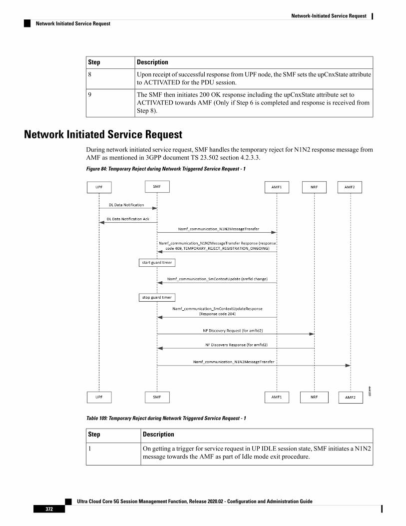
DescriptionStep
Upon receipt of successful response fromUPF node, the SMF sets the upCnxState attributeto ACTIVATED for the PDU session.
8
The SMF then initiates 200 OK response including the upCnxState attribute set toACTIVATED towards AMF (Only if Step 6 is completed and response is received fromStep 8).
9
Network Initiated Service RequestDuring network initiated service request, SMF handles the temporary reject for N1N2 response message fromAMF as mentioned in 3GPP document TS 23.502 section 4.2.3.3.
Figure 84: Temporary Reject during Network Triggered Service Request - 1
Table 109: Temporary Reject during Network Triggered Service Request - 1
DescriptionStep
On getting a trigger for service request in UP IDLE session state, SMF initiates a N1N2message towards the AMF as part of Idle mode exit procedure.
1
Ultra Cloud Core 5G Session Management Function, Release 2020.02 - Configuration and Administration Guide372
Network-Initiated Service RequestNetwork Initiated Service Request

DescriptionStep
If UE registration procedure with new AMF is in progress then AMF responds withtemporary reject for N1N2 message with response code 409 and cause as:
TEMPORARY_REJECT_REGISTRATION_ONGOING
OR
TEMPORARY_REJECT_HANDOVER_ONGOING SMF
2
On receiving the response, SMF starts a guard timer of 2 seconds that is configuredlocally.
3
While guard timer is running, SMF expects either a SM Context Update with AMF IDchange or SM Context Update for handover.
4
On receiving SM Context Update with AMF ID change, SMF:
1. Stops the guard timer.
2. Removes the reference to the discovery information for old AMF.
3. Stores the newUE location information, PLMN information andAMF information.
4. Send SM Context Update response success without content.
5. Reinitiates N1N2 message transfer to the new AMF. This involves NF discoveryand subsequent transmission to the new AMF.
5
On receiving SM Context Update for N2 handover, SMF:
1. Starts the Handover procedure.
2. Suspends the Idle mode exit procedure and stops the guard timer.
3. As part of the Handover procedure completion, old AMF details are removed andnew AMF information is stored.
4. Idle mode exit procedure resumes after Handover procedure is complete.
5. Reinitiates N1N2 message transfer, if required, to the new AMF. This involves NFdiscovery and subsequent transmission to new AMF.
6
Ultra Cloud Core 5G Session Management Function, Release 2020.02 - Configuration and Administration Guide373
Network-Initiated Service RequestNetwork Initiated Service Request

Figure 85: Temporary Reject during Network Triggered Service Request - 2
Table 110: Temporary Reject during Network Triggered Service Request - 2
DescriptionStep
On getting a trigger for service request in UP IDLE session state, SMF initiates a N1N2message towards the AMF as part of Idle mode exit procedure.
1
If UE registration procedure with new AMF is in progress then AMF responds withtemporary reject for N1N2 message with response code 409 and cause as:
TEMPORARY_REJECT_REGISTRATION_ONGOING
OR
TEMPORARY_REJECT_HANDOVER_ONGOING SMF
2
On receiving the response, SMF starts a guard timer of 2 seconds that is configured locally.3
Ultra Cloud Core 5G Session Management Function, Release 2020.02 - Configuration and Administration Guide374
Network-Initiated Service RequestNetwork Initiated Service Request

DescriptionStep
Once guard timer expires, SMF:
1. Sets the UE CM status as NotReachable.
2. Deactivates the UP session state.
4
LimitationsThe following are limitations in this release:
• It does not support location update and access-type changes.
• It does not support QoS flow modifications/errors.
Configuring N3 Tunnel ProfileTo configure the N3 tunnel profile, use the following configuration:
confign3-tunnel-profile profile_name
buffer upf
notifyend
NOTES:
• buffer upf: Configures buffering for Downlink Data.
• notify: Enables data notification from UPF.
Ultra Cloud Core 5G Session Management Function, Release 2020.02 - Configuration and Administration Guide375
Network-Initiated Service RequestLimitations

Ultra Cloud Core 5G Session Management Function, Release 2020.02 - Configuration and Administration Guide376
Network-Initiated Service RequestConfiguring N3 Tunnel Profile

C H A P T E R 28NRF Discovery
• Feature Summary and Revision History, on page 377• Feature Description, on page 378• NF Heartbeat Support, on page 381• Caching Support for NF Discovery, on page 384• NRF Support for SMF Subscription and Notification, on page 387• NRF Interface per Endpoint, on page 391• NRF Failure Handling Support, on page 399• Local Configuration for NF Management, on page 403• Fallback to Static IP Address Support, on page 411• NF Profile Update, on page 419• Configuration Support for List of Tracking Areas and Tracking Area Ranges, on page 422• Dynamic Configuration Change Support, on page 424• NRF Show Command Enhancements , on page 424
Feature Summary and Revision History
Summary DataTable 111: Summary Data
SMFApplicable Product(s) or Functional Area
SMIApplicable Platform(s)
Enabled – Always-onFeature Default Setting
Not ApplicableRelated Changes in this Release
Not ApplicableRelated Documentation
Ultra Cloud Core 5G Session Management Function, Release 2020.02 - Configuration and Administration Guide377

Revision HistoryTable 112: Revision History
ReleaseRevision Details
Pre-2020.02.0First introduced.
Feature DescriptionThe 3GPP-defined architecture model for 5G systems provides data connectivity based on techniques suchas network function virtualization, software defined networking, and service-based interfaces. Some of thekey principles are:
• Separate the User Plane (UP) functions from the Control Plane (CP) functions allowing independentscalability, evolution, and flexible deployments, such as centralized location or distributed (remote)location.
• Support "stateless" NFs where the "compute" resource is decoupled from the "storage" resource.
This feature discovers the set of NF instances (and their associated NF service instances), represented by theirNF profile, that are currently registered in Network Repository Function (NRF) and satisfy several input queryparameters.
ArchitectureThe SMFNF comprises of loosely coupledmicroservices.Microservice decomposition is based on three-layeredarchitecture philosophies:
1. Layer 1: Protocol and Load Balancer Services (Stateless)
2. Layer 2: Application Services (Stateless)
3. Layer 3: Database Services (Stateful)
Ultra Cloud Core 5G Session Management Function, Release 2020.02 - Configuration and Administration Guide378
NRF DiscoveryRevision History

Figure 86: SMF 3-layered Micro Services Architecture
How it WorksThe service operation is executed by querying the "nf-instances" resource. The request is sent to an NRF inthe same PLMN of the NF service consumer.
Call FlowsThe Service Discovery Request call flow described in 3GPP TS 29.510 v15.2.0 illustrates the NF-levelmessages for NF discovery.
Service Discovery Request Call Flow
This section describes the Session Discovery Request call flow.
Figure 87: Service Discovery Request Call Flow
Ultra Cloud Core 5G Session Management Function, Release 2020.02 - Configuration and Administration Guide379
NRF DiscoveryHow it Works
Table 113: Service Discovery Request Call Flow Description
DescriptionStep
The NF Service Consumer sends an HTTPGET request to the resource URI "nf-instances"collection resource. The input filter criteria for the discovery request is included in queryparameters.
1
On success, "200 OK" is returned. The response body contains a validity period, duringwhich the search result can be cached by the NF Service Consumer, and an array of NFprofile object that satisfy the search filter criteria (for example, all NF Instances offeringa certain NF Service name).
2a
If the NF Service Consumer is not allowed to discover the NF services for the requestedNF type provided in the query parameters, the NRF returns "403 Forbidden" response.
If the discovery request fails at the NRF due to errors in the input data in the URI queryparameters, the NRF returns "400 Bad Request" status code with the “ProblemDetails” IEproviding details of the error.
If the discovery request fails at the NRF due to NRF internal errors, the NRF returns "500Internal Server Error" status code with the “ProblemDetails” IE providing details of theerror.
2b
The NF profile objects that are returned in a successful result contains generic data of each NF instance,applicable to any NF type, and it can also contain NF-specific data, for those NF instances belonging to aspecific type (for example, the attribute "udrInfo" is typically present in the NF profile when the type of theNF instance takes the value "UDR"). In addition, the attribute "customInfo" can be present in the NF profilefor NF instances with custom NF types. For NF instances, the "customInfo" attribute is returned by NRF, ifavailable, as part of the NF profiles returned in the discovery response.
SMF service communicates with different NFs, such as UDM, AMF, PCF, CHF and so on, when the sessionis brought up. The NF discovery is based on set of filters that are associated with the session. The SMF servicediscovers the NFs, matching the filter criteria for the session, to send messages to NF.
NRF Library (NRF-LIB) provides APIs to discover and send a message to an NF matching a set of filterparameters. The NRF-LIB performs NF discovery for the filter and caches the discovered NFs in a local cache.The following filter parameters are supported:
• Dnn
• Tai
• TargetNfFqdn
• TargetPlmnList
• TargetNfInstanceId
• Snssais
• Preferred locality
The discovered NFs are cached with the filter as the key. The endpoint selection for sending the message isbased on probabilistic load balancing algorithm (IETF RFC 2782) using the priority and capacity parameters.The NF discovery response carries a validity time, which decides the cache validity period.
Ultra Cloud Core 5G Session Management Function, Release 2020.02 - Configuration and Administration Guide380
NRF DiscoveryService Discovery Request Call Flow

NRF-LIB sends the messages to a new target based on the Location header URL in response to initial messagessent to NF.
NRF-LIB supports stickiness wherein the endpoint, service instance, and NF instance details of the selectedendpoint for a message that is sent, will be provided to the App/Rest-Ep so that the same can be specified insubsequent message (instead of discovery filter). This helps maintaining stickiness for a session to a selectedNF.
Standards ComplianceThe NF Discovery feature complies with the following standards:
• 5G System; Network Function Repository Services; Stage 3 (Release 15):
• 3GPP TS 29.510 version 15.0.0 (2018-06)
• 3GPP TS 29.510 version 15.2.0 (2018-12)
LimitationsThe following are known limitations of this feature:
• The cache maintained is local to the library. Therefore, in case of deployment with multiple replicas ofRest-Ep, if two Discovery/Send messages with the same discovery filter land on different pods, then theNF discovery will be triggered by both pods.
• Only UDM, PCF, CHF, and AMF discovery and load balancing are supported. UPF discovery is notsupported.
• Dynamic configuration changes of NRF endpoints are not supported.
NF Heartbeat Support
Feature DescriptionThe NF heartbeat implementation helps the NFs to notify the NRF that the NF is operational. Each NFregistered with the NRF contacts the NRF periodically by invoking the NFUpdate service operation. The timeinterval at which the NRF is contacted is deployment-specific and is returned by the NRF to the NF ServiceConsumer as a result of a successful registration.
How it Works
Call Flows
NF Heartbeat Procedure
The following figure illustrates the NF Heartbeat call flow.
Ultra Cloud Core 5G Session Management Function, Release 2020.02 - Configuration and Administration Guide381
NRF DiscoveryStandards Compliance
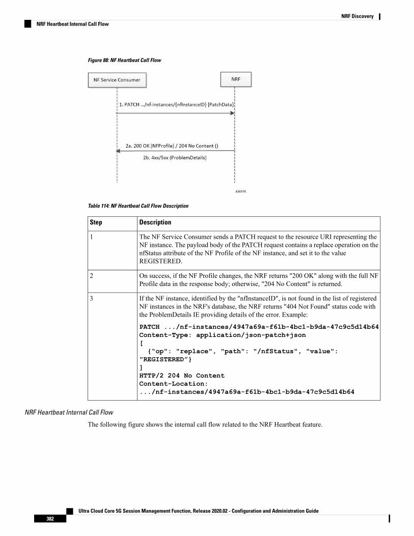
Figure 88: NF Heartbeat Call Flow
Table 114: NF Heartbeat Call Flow Description
DescriptionStep
The NF Service Consumer sends a PATCH request to the resource URI representing theNF instance. The payload body of the PATCH request contains a replace operation on thenfStatus attribute of the NF Profile of the NF instance, and set it to the valueREGISTERED.
1
On success, if the NF Profile changes, the NRF returns "200 OK" along with the full NFProfile data in the response body; otherwise, "204 No Content" is returned.
2
If the NF instance, identified by the "nfInstanceID", is not found in the list of registeredNF instances in the NRF's database, the NRF returns "404 Not Found" status code withthe ProblemDetails IE providing details of the error. Example:
PATCH .../nf-instances/4947a69a-f61b-4bc1-b9da-47c9c5d14b64Content-Type: application/json-patch+json[{“op": "replace", "path": "/nfStatus", "value":
"REGISTERED”}]HTTP/2 204 No ContentContent-Location:.../nf-instances/4947a69a-f61b-4bc1-b9da-47c9c5d14b64
3
NRF Heartbeat Internal Call Flow
The following figure shows the internal call flow related to the NRF Heartbeat feature.
Ultra Cloud Core 5G Session Management Function, Release 2020.02 - Configuration and Administration Guide382
NRF DiscoveryNRF Heartbeat Internal Call Flow

Figure 89: NRF Heartbeat Internal Call Flow
The SMF NF heartbeat implementation helps in notifying the NRF that the SMF is operational. The defaultheartbeat frequency is once in 10 seconds. If the NRF returns a different heartbeat frequency, the same is usedfor the periodic heartbeat. As part of the heartbeat, HTTP PATCH Request to the resource URI representingthe NF instance is sent to the NRF. The payload body of the PATCH Request contains a "replace" operationon the "nfStatus" attribute of the NF profile of the NF instance, and sets it to the value "REGISTERED". Otherparameters like load and capacity are not supported in this release.
Like NF registration, NF heartbeat is also triggered from the elected master node manager. Also, the heartbeatcontinues even on the elected node manager restart.
Standards ComplianceThe NF Heartbeat feature complies with 3GPP TS 29.510, Version 15.2.0.
Ultra Cloud Core 5G Session Management Function, Release 2020.02 - Configuration and Administration Guide383
NRF DiscoveryStandards Compliance

Caching Support for NF Discovery
Feature DescriptionThe SMF provides caching support for discovered caching profiles. It uses the NF discovery (nnrf-disc)function to discover profiles such as AMF, UDM, PCF, and CHF. The received discovery response is associatedwith validity time. SMF caches the discovery response and uses the same response for future NF selectionsuntil the cache is valid. This caching support helps in reducing the number of NRF interactions during anongoing session.
RelationshipsCaching support for NF Discovery has functional relationship with the following features:
• NRF Support for SMF Subscription and Notification
• NRF Interface Per Endpoint
How it Works
The SMF maintains the cache data in a Cache pod. It uses the cache pod to share the NF discovery cacheacross multiple instances of SBI pods. The SBI pod periodically updates the cache pod on receiving an NFdiscovery response. All SBI pods refreshes its cache data periodically with the help of the cache pod.
Currently, the SMF does not invalidate the NF discovery cache entry even on the expiration of the validitytime. If a message is sent to a NF that meets a specific criterion, the SMF looks up the cache data for furtherprocessing. During a cache look-up:
• On a cache hit without an expired entry, the selected cached NF response is used to send a message foran endpoint selection.
• On a cache hit with an expired entry, SMF sends NF discovery requests to NRF to fetch a new list of NFdiscovery responses.
• If there is a cache miss, the SMF sends the NF discovery request again to the NRF to retrieve a new listof discovery responses.
Call Flows
Cache Lookup Call Flow
This section describes the Cache Lookup call flow.
NRF-LIB (in smf-rest-ep/SBI) maintains a local cache and updates the external cache (cache-pod). The keyfor a cache is a combination of nfType and filter (a string that is prepared from multiple filter parameters in"key1=value, key2=value2" format).
Ultra Cloud Core 5G Session Management Function, Release 2020.02 - Configuration and Administration Guide384
NRF DiscoveryCaching Support for NF Discovery

Figure 90: Caching Support Call Flow
Ultra Cloud Core 5G Session Management Function, Release 2020.02 - Configuration and Administration Guide385
NRF DiscoveryCache Lookup Call Flow

Table 115: Caching Support Call Flow Description
DescriptionStep
On Startup, NRF-LIB (in smf-rest-ep/SBI):
1. Retrieves all the cache entries that were modified since epoch from cache-pod so thatit can build the local cache. Once the local cache is built, the same cache is used in thesendmessage flow for lookup.
2. A periodic refresh routine is initiated to refresh the local cache using the cache-pod.
1
Periodic Refresh, NRF-LIB (in smf-rest-ep/SBI):
Local cache is periodically refreshed by getting all records from the cache-pod that weremodified since last refresh. The resultant record list is traversed, and the local cache isupdated.
2
Send Message NRF-LIB (in smf-rest-ep/SBI):
1. When smf-rest-ep (SBI) triggers a send message (say to UDM), NRF-LIB looks upthe local cache for the cache entry with the nfType and filter key:
a. When a cache lookup miss occurs, a discovery query is sent to NRF to fetch NFprofiles from NRF. If NRF responds with NF profiles, then these NF profiles arestored in a local cache and updated in cache-pod.
b. On a successful lookup, the cached entry is used to send a message for endpointselection.
2. The NF profiles are load-balanced, and a message is sent to the selected endpoint.
3
Standards ComplianceThe Caching Support for NF Discovery feature complies with the following standards:
• 3GPP TS 29.510, V15.2.0
• 3GPP TS 29.510, V15.0.0
LimitationsThe Caching Support for NF Discovery feature has the following limitations:
• This feature only supports UDM, PCF, AMF discovery, and load-balancing.
• It does not support UPF discovery.
• It does not support Dynamic Configuration changes of NRF endpoints.
• It does not support Liveliness check of the NRF endpoints.
• NF Discovery is always attempted on primary host followed by the secondary and then tertiary host.
Ultra Cloud Core 5G Session Management Function, Release 2020.02 - Configuration and Administration Guide386
NRF DiscoveryStandards Compliance

NRF Support for SMF Subscription and Notification
Feature DescriptionThe SMF uses the NRF-provided Subscribe service to subscribe to NF status changes that the NF receives asa discovery response. This helps in updating the cached NF discovery responses.
The SMF honors only the notification changes in load, capacity, status at the NF level, and at the service level.It ignores all other parameter changes in the notification.
How it WorksTheNRF Support for 5G-SMF Subscription and Notification feature uses the NF Subscribe service to subscribeto changes on the status of NF instances that the NF receives as discovery responses. The SMF sends asubscription for the response validity period for each of the NF profiles that it receives in the discoveryresponse. The SMF checks if an existing NF instance subscription time needs an extension or not dependingon the current response time validity. If a subscription needs an extension, a subscription PATCH is sent withthe extended validity time.
During subscription, the NRFmay respond with a modified validity time. This validity time might differ fromthe SMF validity time request. In such a scenario, the SMF tracks the required subscription time and the actualsubscription time returned by the NRF.
The SMF periodically (every two minutes) checks in database if there is any subscription with the actualsubscription time ending soon (as in next five minutes) but has required validity time more than the actualvalidity time. In this scenario, the SMF sends a PATCH subscription to extend the subscription validity time.
The SMF fills the Status Notification URI based on the interface NRF configuration that is specified in theconfiguration. The notification vip ip and vip port are used to frame the status notification URI.
http://{nrfinterface.vip-ip}:{ nrfinterface.vip-port}/{notifResourceURI}
On status notification, the SMF updates the local cache and the external cache (cache pod) with the changedattributes.
Call Flows
This section provides the call flows for this feature.
Subscription(PATCH) Call Flow
The NRF updates the subscription to notifications on NF Instances to refresh the validity time, when thespecified time is due to expire. The SMF can request a new validity time to the NRF. The NRF can assignand provide a new validity time to the NF, if the operation is successful.
Updating the "subscriptionID" resource, initiates the Subscription(PATCH) operation. Issuing an HTTPPATCH request on the URI representing the individual resource, starts the operation.
Ultra Cloud Core 5G Session Management Function, Release 2020.02 - Configuration and Administration Guide387
NRF DiscoveryNRF Support for SMF Subscription and Notification

Figure 91: Subscription to NF Instances in the Same PLMN
Table 116: Call Flow Description for Subscription to NF Instances in the Same PLMN
DescriptionStep
The SMF sends a PATCH request to the resource URI identifying the individualsubscription resource. The payload body of the PATCH request contains a "replace"operation on the "validityTime" attribute of the SubscriptionData structure. The requestalso contains a new suggested value for the "validityTime" attribute. This replaceoperation does not replace any other attribute of the resource.
1
When a subscription is successful, the NRF sends a "204 No Content" response. Thisindicates that the NRF accepts:
• Extension of the lifetime of the subscription
• Value of the "validityTime" attribute
2a
The NRF returns a "400 Bad Request" status code with the problem details if thesubscription fails due to errors in the JSON Patch object in the request body.
2b
The NRF returns a "500 Internal Server Error" with the problem details if thesubscription fails due to internal errors in the NRF.
Example:
PATCH .../subscriptions/2a58bf47Content-Type: application/json-patch+json[{ "op": "replace", "path": "/validityTime", "value": "2018-12-30T23:20:50Z"},]
2c
Subscription(POST) Call Flow
The Subscription service operation allows to:
• Create a subscription such that the SMF can request notification (depending on certain filters) in thefollowing scenarios:
• When there is a registration or deregistration in the NRF.
• When there is a modification to a profile.
• Create a subscription to a specific NF instance such that the SMF can request notification in the followingscenarios:
Ultra Cloud Core 5G Session Management Function, Release 2020.02 - Configuration and Administration Guide388
NRF DiscoverySubscription(POST) Call Flow

• When there is a modification to an NF instance.
• When there is a deregistration of an NF instance.
Currently, SMF only supports subscription of NF instances that the NF receives as its discovery response.Important
Figure 92: Subscription to NF Instances in the Same PLMN
Implementing the subscription to notifications on NF instances creates a new individual resource under thecollection resource "subscriptions." Issuing a POST request starts the operation on the Uniform ResourceIdentifier (URI) representing the "subscriptions" resource.
Table 117: Call Flow Description for Subscription to NF Instances in the Same PLMN
DescriptionStep
The NF Service Consumer sends a POST request to the resource URI representing the"subscriptions" collection resource.
The request body includes data that indicates the type of notifications that the SMF hassubscribed to receive. It also contains a callback URI, where the SMF prepares toreceive the actual notification from the NRF. The notification contains the SMFsuggested validity time, which represents the time span during which the subscriptionremains active.
The subscription request may also include more parameters indicating the list ofattributes in the NF Profile to monitor (or to exclude from monitoring). This requestdetermines if the NRF must send a notification, when there is a change in any of theattributes of the profile.
1
When a subscription is successful, the NRF sends a "201 Created" response. Thisresponse contains newly created subscription data that includes the NRF-determinedvalidity time beyond which, the subscription is invalid. When the subscription expires,the SMF creates a new subscription in the NRF to continue receiving status notifications.
2a
The NRF returns a "400 Bad Request" status code with the problem details if thesubscription fails due to errors in the subscription data.
The NRF returns a "500 Internal Server Error" with the problem details if thesubscription fails due to internal errors in the NRF.
2b
Ultra Cloud Core 5G Session Management Function, Release 2020.02 - Configuration and Administration Guide389
NRF DiscoverySubscription(POST) Call Flow

NFStatus Notify Call Flow
Issuing a POST request to each callback URI of the various subscribed NF Instances, initiates the NFStatusNotify operator.
Figure 93: Notification from NRF in the Same PLMN
Table 118: Call Flow Description for Notification from NRF in the Same PLMN
DescriptionStep
The NRF sends a POST request to the callback URI.
The request body for a profile change notification request includes the following:
• event: This attribute indicates the notification type. It can be one of the following:
• NF_REGISTERED
• NF_DEREGISTERED
• NF_PROFILE_CHANGED
• nfInstanceUri: Uniform Resource Identifier (URI) of the NF Instance associatedto the notification event.
• nfProfile: Indicates the new or updated NF profile.
1
When the notification is successful, the NRF sends a "204 No content" response.2a
The SMF returns a "404 Not Found" status code with the problem details if the SMFdisregards the "nfStatusNotificationURI" as a valid notification URI. For example, ifthe URI does not belong to any of the existing subscriptions that the SMF has createdin the NRF.
2b
LimitationsIn this release, the NRF Support for SMF Subscription and Notification feature has the following limitations:
• NF status notification supports only NF profile load, NF profile capacity, NF profile status, service load,service capacity, and service status parameter changes.
• SMF supports only the NFPofiile field in the "NotificationData." It does not support the "Change item"field.
Ultra Cloud Core 5G Session Management Function, Release 2020.02 - Configuration and Administration Guide390
NRF DiscoveryNFStatus Notify Call Flow

Configuring NRF Support for SMF Subscription and NotificationThis section describes how to configure the NRF Support for SMF Subscription and Notification feature.
Use the following commands to configure the NRF interface, vip-ip, vip-port, and loopback Port to open theserver endpoints for the NF status notification.
configureendpoint sbi
replicas integer
vip-ip ip_address
interface nrfvip-ip ip_address
vip-port port_number
loopbackPort port_number
end
NOTES:
• endpoint sbi: Specifies the service-based interface (sbi) as the endpoint.
• replicas: Specifies the number of instances of the service-based interface.
• vip-ip ip_address: Specifies the virtual IP address of the virtual host.
• interface nrf: Specifies the interface as NRF.
• vip-ip ip_address: Specifies the virtual IP address of the virtual host. The SMF uses this as the listeningIP address for the status notification.
• vip-port port_number: Specifies the port number of the virtual host. The SMF uses this as the listeningport for the status notification.
• loopbackPort port_number:: Specifies the internal port number of the loopback host. The SMF usesthis port for the NF status notification.
NRF Interface per Endpoint
Feature DescriptionThe Network Repository Function (NRF) deployment can be logically segmented as global, regional, and soon, for a reliable network management. You can accomplish this segmentation by specifying different NRFendpoint groups for the discovery of different network functions. With associating a single NRF interface foreach endpoint, the self-management of an NF improves the productivity.
For example, the SMF interacts with Region 1 NRF endpoints for management and AMF discovery. ForUDM, CHF, and PCF discovery, the SMF communicates with the Global NRF endpoints.
Ultra Cloud Core 5G Session Management Function, Release 2020.02 - Configuration and Administration Guide391
NRF DiscoveryConfiguring NRF Support for SMF Subscription and Notification

Figure 94: NRF Deployment
Standards ComplianceThe NRF Interface Per Endpoint feature complies with the following standards:
• 3GPP TS 29.510 V15.2.0 (2018-12)
• 3GPP TS 29.510 V15.0.0 (2019-06)
LimitationsThe NRF Interface Per Endpoint feature has the following limitations:
• The NF discovery and load-balancing capabilities are available only for UDM, PCF, CHF, and AMF.
• The dynamic configuration changes of NRF endpoints is not available.
• Support for the liveliness check of the NRF endpoints is not available.
• The SMF attempts the NF discovery first on the primary host. In the absence of the primary host, SMFattempts the discovery on the secondary host and switches to the tertiary if both primary and secondaryare unavailable.
Configuring the NRF Interface Per EndpointThis section describes how to configure the NRF Interface Per Endpoint feature.
Configuring the NRF Interface Per Endpoint feature involves the following steps:
1. Associating a Discovery Group with NF Type
2. Configuring Locality for NF Types
3. Associating NRF Management and SMF Locality to NRF Endpoint
4. Configuring the NRF Group
5. Configuring Locality for SMF
Ultra Cloud Core 5G Session Management Function, Release 2020.02 - Configuration and Administration Guide392
NRF DiscoveryStandards Compliance

6. Configuring NF Profiles for a DNN
7. Configuring Network Element Profile Parameters for the NF
Associating a Discovery Group with NF TypeUse the following CLI commands for pairing a discovery group with NF types.
configureprofile nf-pair nf-type nf_type
profile nf-pair nf-type nf_type nrf-discovery-group nrf_discovery_group_name
end
NOTES:
• nf-type nf_type: Specifies the NF type. The nf_type can be: 5G_EIR, AF, AMF, AUSF, BSF, CHF,GMLC, LMF, N3IWF, NEF, NRF, NSSF, NWDAF, PCF, SEPP, SMF, SMSF, UDM, UDR, UDSF,UPF, or range.
• nrf-discovery-group nrf_discovery_group_name: Specifies the discovery group name.
• Discovery group is the logical link to the NRF endpoint groups (nrf-group). For each NF type, you canassociate a discovery group and the locality information.
Configuring Locality for NF TypesThe SMF provides locality aware NF discovery.
Use the following configuration to configure locality for NF types.
configureprofile nf-pair nf-type nf_type locality { client client_name | geo-server
geo_server_name | preferred-server preferred_server_name }end
NOTES:
• client client_name: Specifies the client locality information. Client locality is the SMF's locality and isa mandatory parameter.
• geo-server geo_server_name: Specifies the geo-server locality information. Geo-server locality is georedundant site for the preferred locality and is generally used as the next best server locality after preferredlocality, during NF discovery.
• preferred-server preferred_server_name: Specifies the preferred server locality information. Preferredserver locality is the locality that should be considered as the locality of preference during thecorresponding NF discovery.
Verifying the Association of the Discovery Group and Locality Configuration
This section describes how to verify the discovery group association and locality configuration for NF.
show running-config profile nf-pairprofile nf-pair nf-type UDM
Ultra Cloud Core 5G Session Management Function, Release 2020.02 - Configuration and Administration Guide393
NRF DiscoveryAssociating a Discovery Group with NF Type

nrf-discovery-group DISC1locality client LOC1locality preferred-server PREF_LOClocality geo-server GEOexit
Associating NRF Management and SMF Locality to NRF EndpointUse the following CLI commands for configuring NRF Management (nrf-group) and SMF Locality andassociating them to NRF Endpoint.
configuregroup nf-mgmt mgmt_name
nrf-mgmt-group nrf_group_name
locality locality_name
end
Verifying the Association of the NRF Management and SMF Locality to NRF Endpoint
This section describes how to verify the configuration that associates the NRFManagement and SMFLocalityto NRF Endpoint.
show running-config group nf-mgmtgroup nf-mgmt NFMGMT1nrf-mgmt-group MGMTlocality LOC1exit
Configuring the NRF Endpoints Profile ParametersThe SMF provides CLI for configuring NRF endpoints for different services that are supported by NRF, suchas nnrf-nfm (NF management) and nnrf-nfd (NF Discovery).
For a discovery group, only the nnrf-disc service can be configured. For management service, only nnrf-nfmcan be configured.
Note
The CLI configuration allows configuring multiple endpoints under each endpoint profile. The SMF uses thepriority and capacity parameters to load balance between these endpoints. Primary, secondary, and tertiaryhost [ip:port] can be configured within each endpoint. Both IPv4 and IPv6 address can be specified. If bothare specified, then IPv4 address is preferred.
A URI uniquely identifies a resource. In the 5GC SBI APIs, when a resource URI is an absolute URI, itsstructure is specified as follows:
{apiRoot}/{apiName}/{apiVersion}/{apiSpecificResourceUriPart}
" apiRoot " is a concatenation of the following parts: scheme ("http" or "https")
In this release of the specification, both HTTP and HTTPS scheme URIs are allowed. See 3GPP TS 33.501,Subclause 13.1 for further details on security of service-based Interfaces.
Note
Ultra Cloud Core 5G Session Management Function, Release 2020.02 - Configuration and Administration Guide394
NRF DiscoveryAssociating NRF Management and SMF Locality to NRF Endpoint

• the fixed string "://"
• authority (host and optional port) as defined in IETF RFC 3986
• an optional deployment-specific string (API prefix) that starts with a "/" character. [api-root in CLI]
configuregroup nrf { mgmt mgmt_name | discovery discovery_name }
service type nrf { nnrf-nfm | nnrf-disc }endpoint-profile epprofile_name
priority priority_value
capacity capacity
api-root api_string
api-uri-prefix uri_prefix_string
uri-scheme { http | https }endpoint-name ep_name { capacity capacity | primary ip-address {
ipv4 ipv4_address | ipv6 ipv6_address | port port_num } | secondary ip-address{ ipv4 ipv4_address | ipv6 ipv6_address | port port_num } | tertiary ip-address{ ipv4 ipv4_address | ipv6 ipv6_address | port port_num } }
version [ uri-version version_num full version version_num ]end
NOTES:
• api-root api_string : Specifies the deployment-specific service API prefix that is used within the {apiRoot }.
• api-uri-prefix uri_prefix_string: Specifies the {apiName}. If not configured, it takes the standard APIname for the service as per the specification.
• capacity capacity: Specifies the profile capacity.
• endpoint-name ep_name { capacity capacity | primary ip-address { ipv4 ipv4_address | ipv6ipv6_address | port port_num } | secondary ip-address { ipv4 ipv4_address | ipv6 ipv6_address | portport_num } | tertiary ip-address { ipv4 ipv4_address | ipv6 ipv6_address | port port_num } }: Specifiesthe endpoint name. You can configure the primary, secondary, and tertiary host (IP: Port) within eachendpoint for NF server failover handling. The server failover configuration accepts both the IPv4 andIPv6 addresses. However, the SMF gives preference to the IPv4 address.
• capacity capacity: Specifies the node capacity for the endpoint. capacity must be an integer in the rangeof 0-65535.
• The endpoint selection for sending the message is based on probabilistic load-balancing algorithm (IETFRFC 2782) using the priority and capacity parameters.
• primary ip-address { ipv4 ipv4_address | ipv6 ipv6_address | port port_num }: Specifies the primaryendpoint IPv4 address, IPv6 address or port.
• secondary ip-address { ipv4 ipv4_address | ipv6 ipv6_address | port port_num }: Specifies the secondaryendpoint IPv4 address, IPv6 address or port.
• tertiary ip-address { ipv4 ipv4_address | ipv6 ipv6_address | port port_num }: Specifies the tertiaryendpoint IPv4 address, IPv6 address, or port.
• priority priority_value: Specifies the priority for the service to select the appropriate profile using theload-balancing logic. priority must be an integer in the range of 0-65535.
Ultra Cloud Core 5G Session Management Function, Release 2020.02 - Configuration and Administration Guide395
NRF DiscoveryConfiguring the NRF Endpoints Profile Parameters

• uri-scheme { http | https }: Specifies the URI scheme, as http or https.
• version [ uri-version version_num full version version_num ]: Specifies the api/Version. The full versionformat is <Major-version>.<Minor-version>.<patch-version>.[alpha-<draft-number>].
Verifying the NRF Endpoints Profile Parameters
This section describes how to verify the configuration of the NRF Endpoints Profile Parameters.
show running-config group nrfgroup nrf discovery udmdiscoveryservice type nrf nnrf-discendpoint-profile epprofcapacity 10priority 1api-uri-prefix nudm-sdmapi-root rooturi-scheme httpversionuri-version v1full-version 1.1.1.[1]exitexitendpoint-name endpointNamepriority 1capacity 100primary ip-address ipv4 231.1.1.1primary ip-address port 3021exitexitexitexit
Configuring Locality for SMFThis section describes how to configure the locality for SMF.
This is a mandatory configuration if the SMF performs NF discovery using the NRF.
configureprofile smf smf_profile_name
locality value
end
NOTES:
• locality value: Specifies the SMF locality. valuemust be an alphanumeric string representing the deployedSMF locality. By default, this CLI command is disabled.
• To disable this configuration, use the no locality value command.
Configuring NF Profiles for a DNNThis section describes how to configure the NF profile that the configured Data Network Name (DNN) uses.
configureprofile dnn dnn_profile_name
Ultra Cloud Core 5G Session Management Function, Release 2020.02 - Configuration and Administration Guide396
NRF DiscoveryVerifying the NRF Endpoints Profile Parameters

network-element-profiles { amf | chf | pcf | udm } nf_profile_name
end
NOTES:
• network-element-profiles { amf | chf | pcf | udm } nf_profile_name: Specifies one or more NF typessuch as AMF, CHF, PCF, and UDM as the network element profile. nf_profile_name must be analphanumeric string representing the corresponding network element profile name.
• This is an optional configuration. By default, this CLI command is disabled.
• You can configure multiple profiles within a given service.
• To disable this configuration, use the no network-element-profiles { amf | chf | pcf | udm }nf_profile_name command.
Configuring Network Element Profile Parameters for the NFThis section describes how to configure the network element profile parameters for the configured NF.
configureprofile network-element { { amf | chf | pcf | udm } nf_profile_name }
failure-handling-profile profile_name
nf-client-profile profile_name
query-params { dnn | supi | tai | target-nf-instance-id | target-plmn}
end
NOTES:
• failure-handling-profile profile_name: Specifies the NRF failure handling network profile for theconfigured NF type. profile_name must be an alphanumeric string representing the corresponding NRFfailure handling network profile name.
• nf-client-profile profile_name: Specifies the local NF client profile. profile_namemust be an alphanumericstring representing the corresponding NF client profile name.
• query-params { dnn | supi | tai | target-nf-instance-id | target-plmn }: Specifies one of the followingquery parameters to include in the NF discovery request towards the NRF.
• dnn: Specifies a DNN as the query parameter in the NF discovery request towards the NRF.
• supi: Specifies a SUPI as the query parameter in the NF discovery request towards the NRF.
• tai: Specifies a TAI as the query parameter in the NF discovery request towards the NRF.
• target-nf-instance-id: Specifies a target NF instance Identifier as the query parameter in the NFdiscovery request towards the NRF.
• target-plmn: Specifies a target PLMN as the query parameter in the NF discovery request towardsthe NRF.
• limit: Specifies a limit for the maximum number of profiles that the NRF sends in the NF discoveryresponse.
• max-payload-size: Specifies the maximum payload size as the query parameter in the NF discoveryrequest towards the NRF.
Ultra Cloud Core 5G Session Management Function, Release 2020.02 - Configuration and Administration Guide397
NRF DiscoveryConfiguring Network Element Profile Parameters for the NF

• requester-snssais: Specifies the list of Single Network Slice Selection Assistance Information(S-NSSAIs) as the query parameter in the NF discovery request towards the NRF.
• This is an optional configuration. By default, these CLI commands are disabled.
• To disable this configuration, use the no variant of these commands. For example, no nf-client-profileCLI command.
Verifying the Local Configuration for the NRF Interface Per Endpoint
This section describes how to verify the configuration for the NRF Interface Per Endpoint feature.
configprofile dnn cisconetwork-element-profiles chf chf1network-element-profiles amf amf1network-element-profiles pcf pcf1network-element-profiles udm udm1ssc-mode 2 allowed [ 3 ]session type IPV4 allowed [ IPV4V6 ]upf apn intershatexit
profile smf smf1node-id 12b888e1-8e7d-49fd-9eb5-e2622a57722locality LOC1bind-address ipv4 127.0.0.1bind-port 8008fqdn cisco.com.apn.epc.mnc456.mcc123plmn-id mcc 123plmn-id mnc 456exit
profile network-element amf amf1nf-client-profile AMF-L1failure-handling-profile FH1query-params [ target-nf-instance-id ]exitprofile network-element pcf pcf1nf-client-profile PCF-L1failure-handling-profile FH1exitprofile network-element udm udm1nf-client-profile UDM-L1failure-handling-profile FH1exitprofile network-element chf chf1nf-client-profile CHF-L1failure-handling-profile FH2exitend
Ultra Cloud Core 5G Session Management Function, Release 2020.02 - Configuration and Administration Guide398
NRF DiscoveryVerifying the Local Configuration for the NRF Interface Per Endpoint

NRF Failure Handling Support
Feature DescriptionThe Network Repository Function (NRF) communication failure handling logic is implemented within theNRF client library. The NRF client library uses the NF registration messages for tracking the managementNRF group operational status.
How it Works
In the preceding diagram, NRF 1 is Primary and NRF 2 is secondary for SMF. On bringing up, the SMFregisters (NF registration) with NRF 1 and starts NF heartbeat with NRF 1. The SMF uses the heartbeatresponse to track the operational status.
In case, the SMF detects NRF 1 failure by missing NF heartbeat response, the SMF registers to NRF 2(secondary NRF) and starts sending NF heartbeat. The SMF continues to send NF Register message1 to NRF1 to keep track of its status.
If the SMF receives register response from NRF 1, it detects that the NRF 1 is up again. The SMFmarks NRF1 as active once it recovers and stops sending NF heartbeats to NRF 2.
Ultra Cloud Core 5G Session Management Function, Release 2020.02 - Configuration and Administration Guide399
NRF DiscoveryNRF Failure Handling Support

NF Reregistration (default behavior) on failover and fallback should be configuration driven. When NRF 2detects that the SMF has stopped sending heartbeats, it checks from NRF 1 if it has received SMF registrationby using discovery with SMF instance ID.
Note
As the management and discovery endpoint groups are separate, the Registration based operation status checkis not used for NRF failure handling during NF discovery. During NF discovery, the configured NRF endpointswithin the group are attempted in the priority order. If the first choice NRF endpoint is not responding thenext best NRF endpoint is chosen and so on.
Call Flow
The following diagram shows the basic NF management call flows covering the NF registration, NFmanagement and the NRF failure handling.
Ultra Cloud Core 5G Session Management Function, Release 2020.02 - Configuration and Administration Guide400
NRF DiscoveryCall Flow
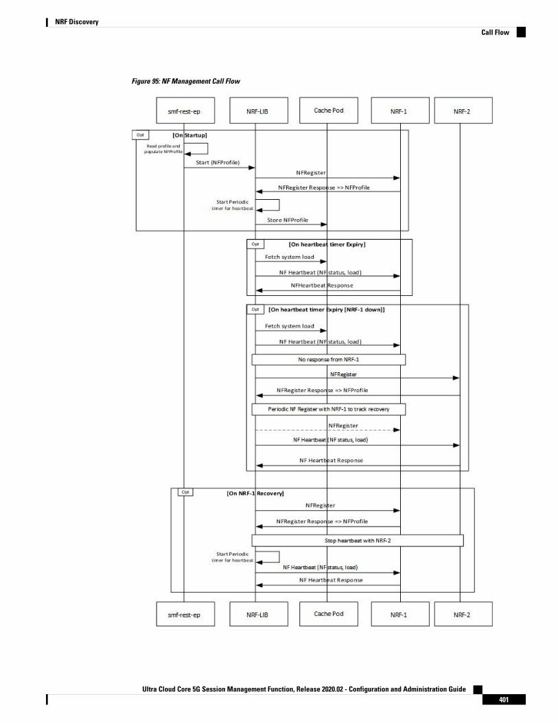
Figure 95: NF Management Call Flow
Ultra Cloud Core 5G Session Management Function, Release 2020.02 - Configuration and Administration Guide401
NRF DiscoveryCall Flow

Verifying the NRF Failure Handling
NF Management Failure HandlingManagement NRF endpoint configuration sample is shown below.product smf# show running-config group nf-mgmtgroup nf-mgmt MGMnrf-mgmt-group mgmt_grouplocality LOC1exitproduct smf# show running-config group nrf mgmtgroup nrf mgmt mgmt_groupservice type nrf nnrf-nfmendpoint-profile epprofuri-scheme httpendpoint-name EP1priority 2primary ip-address ipv4 10.105.227.219primary ip-address port 8082secondary ip-address ipv4 10.105.227.220secondary ip-address port 8082exitendpoint-name EP2priority 10primary ip-address ipv4 10.1.227.21primary ip-address port 8082secondary ip-address ipv4 10.1.227.22secondary ip-address port 8082exitexitexitexitproduct smf#
In the sample configuration, EP1 is the higher priority endpoint name as its priority is lesser than EP2 (2against 10). So on bringing up, SMF sends NF registration to primary ip:port of EP1 [10.105.227.219:8082].SMF uses secondary ip:port of EP1 if primary is down. SMF failovers to EP2 only if all ip:port of EP1 isdown.
On successful registration with EP1 primary, SMF starts heartbeat with EP1 primary. If EP1 primary goesdown, SMF detects the same by missing heartbeat response. On detecting EP1 primary down, SMF sendsheartbeat to EP1 secondary [no reregistration]. Also, it periodically sends NF Heartbeat to EP1 primary todetect if it has recovered.
If SMF detects that EP1 primary and secondary is down, SMF failovers to EP2. When SMF failovers to EP2primary, it sends reregistration (default behavior). It is assumed that all the endpoints with an endpoint nameshares the database and so reregistration is only supported when failover is across endpoint names. In thiscase, EP1 primary and secondary shares the database. EP2 has a separate database and EP2 primary andsecondary shares the database. On failover to EP2 primary, periodic NF registration is sent to primary of theEP1 only (to detect recovery).
Whenever a higher priority endpoint name is detected to be recovered, SMF falls back to the recovered IP:Port.For example, here the current active NRF endpoint is EP2 primary and SMF detects that EP1 primary hasrecovered, then SMF does reregistration with EP1 primary (default behavior) and stops heartbeat on EP2primary.
Ultra Cloud Core 5G Session Management Function, Release 2020.02 - Configuration and Administration Guide402
NRF DiscoveryVerifying the NRF Failure Handling

Within endpoint NF heartbeat is used to track operational status. Across endpoints, registration is used totrack the operational status. Message send timeout/RPC error and HTTP response codes 408, 429, 500, 501,502, 503 are considered as failure to move to next NRF.
NF Discovery Failure HandlingDiscovery NRF endpoint configuration sample is shown below.product smf# show running-config profile nf-pair nf-type UDMprofile nf-pair nf-type UDMnrf-discovery-group others_grouplocality client LOC1exitproduct smf# show running-config group nrf discovery others_groupgroup nrf discovery others_groupservice type nrf nnrf-discendpoint-profile ep1capacity 30priority 50uri-scheme httpendpoint-name ED1priority 56primary ip-address ipv4 110.105.227.219primary ip-address port 8082secondary ip-address ipv4 110.105.227.220secondary ip-address port 8082exitendpoint-name ED2priority 10primary ip-address ipv4 110.1.227.21primary ip-address port 8082secondary ip-address ipv4 110.1.227.22secondary ip-address port 8082exitexitexitexitproduct smf#
In the sample configuration, ED1 has the higher priority endpoint name as its priority is lesser than ED2 (2against 10). So, whenever there is a NRF discovery required primary ip:port of ED1 [110.105.227.219:8082]is attempted. SMF uses secondary ip:port of ED1 if primary is down. SMF failovers to ED2 only if all ip:portof ED1 is down. There is no state maintained regarding NRF discovery failure with any NRF endpoint. Everytime SMF needs to send NRF discovery, SMF starts with ED1 primary and failovers to ED1 secondary incase of failure, followed by ED2 primary and so on.
Local Configuration for NF Management
Feature DescriptionThe SMF learns about the other NF endpoints such as Unified DataManagement (UDM), Access andMobilityManagement Function (AMF), Policy Control Function (PCF), Charging Function (CHF) and so on, throughNF discovery service exposed by Network Repository Function (NRF) or through the CLI configuration. TheSMF prioritizes the NF discovery through the NRF. If the NRF is not available, then the SMF uses the localconfiguration of NF endpoints to discover the NFs.
Ultra Cloud Core 5G Session Management Function, Release 2020.02 - Configuration and Administration Guide403
NRF DiscoveryNF Discovery Failure Handling
RelationshipsThe Local Configuration for NF Discovery feature depends on the configuration of NRF endpoints, and theresponse from NRF. That is, the SMF uses the locally configured endpoints of the NFs only if the NRFendpoints remain unconfigured or if the NRF did not return any NFs matching the preferred server localityor geo locality.
For more information, see the NRF Interface per Endpoint, on page 391 section in this chapter.
Standards ComplianceThe Local Configuration for NF Discovery feature complies with 3GPP TS 29.510, Versions 15.0.0 and15.2.0.
LimitationsThe Local Configuration for NF Discovery feature has the following limitations:
• Discovery and load balancing are available only for the UDM, PCF, CHF, and AMF but not for the UPF.
• Support for the liveliness check of the NF endpoints is currently not available.
• The SMF attempts the NF discovery first on the primary host. In the absence of the primary host, theSMF attempts the discovery on the secondary host and switches to the tertiary if both the primary andsecondary are unavailable.
Configuring the NFs for NF DiscoveryThis section describes the Local Configuration for NF Discovery feature.
Configuring the NF for NF Discovery feature involves the following steps:
1. Configuring Locality for SMF
2. Configuring NF Profiles for a DNN
3. Configuring Network Element Profile Parameters for the NF
4. Configuring NF Client Profile
5. Defining Locality within NF Profile
6. Configuring NF Endpoint Profile Parameters
Configuring Locality for SMFThis section describes how to configure the locality for SMF. This is a mandatory configuration if the SMFperforms the NF discovery using the NRF.
configureprofile smf smf_profile_name
locality value
end
NOTES:
Ultra Cloud Core 5G Session Management Function, Release 2020.02 - Configuration and Administration Guide404
NRF DiscoveryRelationships

• locality value: Specifies the SMF locality. valuemust be an alphanumeric string representing the deployedSMF locality. By default, this CLI command is disabled.
• To disable this configuration, use the no locality value command.
Configuring NF Profiles for a DNNThis section describes how to configure the NF profile that the configured Data Network Name (DNN) uses.
configureprofile dnn dnn_profile_name
network-element-profiles { amf | chf | pcf | udm } nf_profile_name
end
NOTES:
• network-element-profiles { amf | chf | pcf | udm } nf_profile_name : Specifies one or more NF typessuch as AMF, CHF, PCF, and UDM as the network element profile. nf_profile_name must be analphanumeric string representing the corresponding network element profile name.
• This is an optional configuration. By default, this CLI command is disabled.
• You can configure multiple profiles within a given service.
• To disable this configuration, use the no network-element-profiles { amf | chf | pcf | udm }nf_profile_namecommand.
Configuring Network Element Profile Parameters for the NFThis section describes how to configure the network element profile parameters for the configured NF.
configurenetwork-element-profiles { { amf | chf | pcf | udm } nf_profile_name }
failure-handling-profile profile_name
nf-client-profile profile_name
query-params { dnn | supi | tai | target-nf-instance-id | target-plmn}
end
NOTES:
• failure-handling-profile profile_name: Specifies the NRF failure handling network profile for theconfigured NF type. profile_name must be an alphanumeric string representing the corresponding NRFfailure handling network profile name.
• nf-client-profile profile_name: Specifies the local NF client profile. profile_namemust be an alphanumericstring representing the corresponding NF client profile name.
• query-params { dnn | supi | tai | target-nf-instance-id | target-plmn }: Specifies to include one of thefollowing query parameters in the NF Discovery Request towards the NRF.
• dnn: Specifies a DNN as the query parameter in the NF discovery request towards the NRF.
• supi: Specifies a SUPI as the query parameter in the NF discovery request towards the NRF.
Ultra Cloud Core 5G Session Management Function, Release 2020.02 - Configuration and Administration Guide405
NRF DiscoveryConfiguring NF Profiles for a DNN

• tai: Specifies a TAI as the query parameter in the NF discovery request towards the NRF.
• target-nf-instance-id: Specifies a target NF instance Identifier as the query parameter in the NFdiscovery request toward the NRF.
• target-plmn: Specifies a target PLMN as the query parameter in the NF discovery request towardthe NRF.
• limit: Specifies a limit for the maximum number of profiles that the NRF sends in the NF discoveryresponse.
• max-payload-size: Specifies the maximum payload size as the query parameter in the NF discoveryrequest towards the NRF.
• requester-snssais: Specifies the list of Single Network Slice Selection Assistance Information(S-NSSAIs) as the query parameter in the NF discovery request towards the NRF.
• This is an optional configuration. By default, these CLI commands are disabled.
• To disable this configuration, use the no variants of these commands. For example, no nf-client-profileCLI command.
Configuring NF Client ProfileThis section describes how to configure the NF endpoints for AMF, CHF, PCF, and UDM.
configureprofile nf-client { nf-type { amf amf-profile | chf chf-profile | pcf
pcf-profile | udm udm-profile } nf_profile_name }end
NOTES:
• profile nf-client { nf-type { amf amf-profile | chf chf-profile | pcf pcf-profile | udm udm-profile }nf_profile_name }: Specifies the required NF client profiles and provides the local configuration for anyof the following configured NFs:
• amf: Enables the AMF local configuration
• chf: Enables the CHF local configuration
• pcf: Enables the AMF local configuration
• udm: Enables the AMF local configuration
For example, if you are configuring the amf amf-profile keyword, then this command enables theAMF local configuration. The same approach applies for the other configured NFs too.
nf_profile_name must be an alphanumeric string representing the corresponding NF client profilename.
• You can configure multiple NF profiles within a given service.
• To disable this configuration, use the no profile nf-client { nf-type { amf amf-profile | chf chf-profile| pcf pcf-profile | udm udm-profile } nf_profile_name } command.
Ultra Cloud Core 5G Session Management Function, Release 2020.02 - Configuration and Administration Guide406
NRF DiscoveryConfiguring NF Client Profile

Defining Locality within NF ProfileThis section describes how to define the locality of the NF endpoints. For the NF endpoint selection, the SMFfirst considers the preferred locality that is configured with the profile nf-pair CLI command. The admindetermines the preferred locality based on the proximity of the locality and the network function. The SMFthen uses the geo-server locality configurations as the next preferred locality for the NF discovery. Forinformation on the profile nf-pair command, see Configuring Locality for NF Types, on page 393 in the NRFInterface per Endpoint, on page 391 section.
The SMF selects the other locality endpoints if the profile nf-pairCLI command does not include the preferredserver locality configuration, or if the profile nf-clientCLI command does not include the endpoint configuredwith the preferred server or geo server locality. For the other locality endpoint selection, the SMF uses thepriority configuration within the locality CLI command.
configureprofile nf-client { nf-type { amf amf-profile | chf chf-profile | pcf
pcf-profile | udm udm-profile } nf_profile_name }locality locality_name [ priority priority | service name type service_types
{ endpoint-profile epprofile_name } ]end
NOTES:
• locality locality_name: Specifies the locality of the NF endpoint. The SMF uses the locality configurations(that is, the preferred server locality and geo server locality) to select the appropriate NF endpoints.
• priority priority: Specifies the priority for the locality configuration.
• service name type service_types: Specifies the configured NF service types. The service types varydepending the configured service.
The AMF service supports the following service types:
• namf-comm
• namf-evts
• namf-loc
• namf-mt
The CHF service supports the following service types:
• nchf-convergedcharging
• nchf-spendinglimitcontrol
The PCF service supports the following service types:
• npcf-am-policy-control
• npcf-bdtpolicycontrol
• npcf-eventexposure
• npcf-policyauthorization
• npcf-smpolicycontrol
Ultra Cloud Core 5G Session Management Function, Release 2020.02 - Configuration and Administration Guide407
NRF DiscoveryDefining Locality within NF Profile
• npcf-ue-policy-control
The UDM service supports the following service types:
• nudm-ee
• nudm-pp
• nudm-sdm
• nudm-ueau
• nudm-uecm
• endpoint-profile epprofile_name: Specifies the endpoints at a per NF service level. The NF-specificservices are available within the locality configuration.
• You can configure multiple endpoints per profile name for the configured NF.
Configuring NF Endpoint Profile ParametersThis section describes how to configure the NF endpoint profiles within the service, and its associatedparameters.
The CLI configuration allows configuring multiple endpoints under each endpoint profile. The SMF uses thepriority and capacity parameters to load balance between these endpoints. All endpoints under an endpointprofile share the session context. That is, when selecting an endpoint profile for initial message of a session,then the SMF sends the subsequent messages (for example, update, delete, and so on) of the session to anyof the endpoints in the endpoint profile.
NRF Library (NRF-LIB) provides APIs to discover and send a message to an NF matching a set of filterparameters.
A URI uniquely identifies a resource. In the 5GC SBI APIs, when a resource URI is an absolute URI, itsstructure is specified as follows:
{apiRoot}/{apiName}/{apiVersion}/{apiSpecificResourceUriPart}
" apiRoot " is a concatenation of the following parts:
• scheme ("http" or "https")
• the fixed string "://"
• authority (host and optional port) as defined in IETF RFC 3986
• an optional deployment-specific string (API prefix) that starts with a "/" character. [api-root in CLI]
configureprofile nf-client { nf-type { amf amf-profile | chf chf-profile |
pcf pcf-profile | udm udm-profile } nf_profile_name }locality locality_name [ priority priority | service name type
service_types ]endpoint-profile epprofile_name
api-root api_string
api-uri-prefix uri_prefix_string
Ultra Cloud Core 5G Session Management Function, Release 2020.02 - Configuration and Administration Guide408
NRF DiscoveryConfiguring NF Endpoint Profile Parameters

capacity capacity
endpoint-name ep_name { capacity capacity | primary ip-address{ ipv4 ipv4_address | ipv6 ipv6_address | port port_num } | secondaryip-address { ipv4 ipv4_address | ipv6 ipv6_address | port port_num } | tertiaryip-address { ipv4 ipv4_address | ipv6 ipv6_address | port port_num } }
priority priority_value
uri-scheme { http | https }version [ uri-version version_num full version version_num ]end
In this release of the specification, both HTTP and HTTPS scheme URIs are allowed. See 3GPP TS 33.501subclause 13.1 for further details on security of service-based interfaces.
Important
NOTES:
• api-root api_string : Specifies the deployment-specific service API prefix that is used within the {apiRoot }.
• api-uri-prefix uri_prefix_string: Specifies the {apiName}. If not configured, it takes the standard APIname for the service as per the specification.
• capacity capacity: Specifies the profile capacity.
• endpoint-name ep_name { capacity capacity | primary ip-address { ipv4 ipv4_address | ipv6ipv6_address | port port_num } | secondary ip-address { ipv4 ipv4_address | ipv6 ipv6_address | portport_num } | tertiary ip-address { ipv4 ipv4_address | ipv6 ipv6_address | port port_num } }: Specifiesthe endpoint name. You can configure the primary, secondary, and tertiary host (IP: Port) within eachendpoint for NF server failover handling. The server failover configuration accepts both the IPv4 andIPv6 addresses. However, the SMF gives preference to the IPv4 address.
• capacity capacity: Specifies the node capacity for the endpoint. capacity must be an integer in therange of 0-65535.
The endpoint selection for sending the message is based on probabilistic load balancing algorithm(IETF RFC 2782) using the priority and capacity parameters.
• primary ip-address { ipv4 ipv4_address | ipv6 ipv6_address | port port_num }: Specifies theprimary endpoint IPv4 address, IPv6 address or port.
• secondary ip-address { ipv4 ipv4_address | ipv6 ipv6_address | port port_num }: Specifies thesecondary endpoint IPv4 address, IPv6 address or port.
• tertiary ip-address { ipv4 ipv4_address | ipv6 ipv6_address | port port_num }: Specifies the tertiaryendpoint IPv4 address, IPv6 address or port.
• priority priority_value: Specifies the priority for the service to select the appropriate profile using theload-balancing logic. priority must be an integer in the range 0-65535.
• uri-scheme { http | https }: Specifies the URI scheme as http or https.
• version [ uri-version version_num full version version_num ]: Specifies the api/Version. The full versionformat is <Major-version>.<Minor-version>.<patch-version>.[alpha-<draft-number>].
Ultra Cloud Core 5G Session Management Function, Release 2020.02 - Configuration and Administration Guide409
NRF DiscoveryConfiguring NF Endpoint Profile Parameters

Verifying the Local Configuration for NF Discovery FeatureThis section describes how to verify the Local Configuration for NF Discovery feature.
Use the following show command to verify the feature configuration details.
show running-config
The following is a sample output of this show command.
configprofile dnn cisconetwork-element-profiles chf chf1network-element-profiles amf amf1network-element-profiles pcf pcf1network-element-profiles udm udm1ssc-mode 2 allowed [ 3 ]session type IPV4 allowed [ IPV4V6 ]upf apn intershatexit
profile smf smf1node-id 12b888e1-8e7d-49fd-9eb5-e2622a57722locality LOC1bind-address ipv4 127.0.0.1bind-port 8008fqdn cisco.com.apn.epc.mnc456.mcc123plmn-id mcc 123plmn-id mnc 456exit
profile network-element amf amf1nf-client-profile AMF-L1failure-handling-profile FH1query-params [ target-nf-instance-id ]exitprofile network-element pcf pcf1nf-client-profile PCF-L1failure-handling-profile FH1exitprofile network-element udm udm1nf-client-profile UDM-L1failure-handling-profile FH1exitprofile network-element chf chf1nf-client-profile CHF-L1failure-handling-profile FH2exitend
profile nf-client nf-type udmudm-profile PROF1locality PREF_LOCpriority 10service name type nudm-sdmendpoint-profile epprofapi-uri-prefix nudm-sdmapi-root rooturi-scheme httpversionuri-version v1full-version 1.1.1.[1]
Ultra Cloud Core 5G Session Management Function, Release 2020.02 - Configuration and Administration Guide410
NRF DiscoveryVerifying the Local Configuration for NF Discovery Feature

exitexitendpoint-name endpointNamepriority 1capacity 100primary ip-address ipv4 231.1.1.1primary ip-address port 3021exitexitexitexitexitexit
Fallback to Static IP Address Support
Feature DescriptionThe SMF follows a priority order for the different NF selection options. It prioritizes the NF discovered fromthe network repository function (NRF) over the local configuration. The SMF uses the locally configured NFsin the following scenarios:
• When the NRF endpoints (for discovery) are not configured.
• When the NF discovery response has no valid NFs.
Depending on the deployment, the preferred server and geo locality server are configured for each of the NFs.The general rule is to select NFs in the preferred server locality followed by NFs in the geo locality server incase the preferred server NFs fail.
For each NF, the SMF provides an option to configure preferred and geo server locality [ profile nf-pair ].For more details, see Configuring Locality for NF Types, on page 393 in the NRF Interface per Endpoint, onpage 391 section.
In addition, each NF discovery response comes with associated validity time. The SMF caches this NFdiscovery response and uses it to fetch subsequent sessions. The SMF performs the NF discovery in thefollowing conditions:
• The NF discovery response cache has no matching entries.
• The NF discovery response cache has matching entries, but the validity has expired.
RelationshipsThe Fallback to Static IP Address feature has functional relationship with the following features:
• NF Discovery, NF Selection, and Load Balancing
• NRF Interface Per Endpoint
• Caching Support for NF Discovery
How it WorksThe SMF follows this sequence for NF selection:
Ultra Cloud Core 5G Session Management Function, Release 2020.02 - Configuration and Administration Guide411
NRF DiscoveryFallback to Static IP Address Support
1. It looks up the local cache (NF discovery response cache) for the NF
2. If the NF is a valid entry (not expired), it uses that entry. Else, SMF proceeds to Step 3.
3. The SMF reaches NRF for discovery [see, NRF Discovery (Priority 1)]. Else, SMF moves to Step 4.
4. If SMF cannot use the NRF for discovery, it uses the expired NF cache [see, Expired NF Cache ( Priority2)]. If expired NF cache is not available, SMF moves to Step 5.
5. If SMF does not find the NF in the local cache nor is it able to get it in the NRF discovery response, ituses the locally-configured NF [see, NF Local configuration (Priority 3)].
The priority order for NF selection is as follows:
1. NRF Discovery (Priority 1)
The SMS uses the NRF-provided, NF discovery service to discover NFs like AMF, UDM, and PCF. TheSMF sets the preferred locality as provided in the "profile nf-pair" configuration in the discovery query.(For more details about the "profile nf-pair nf-type" CLI configuration, see Configuring Locality for NFTypes, on page 393 in the NRF Interface per Endpoint, on page 391 section.) For each NF, the queryparameters are configurable. (For more details, see Configuring Network Element Profile Parameters forthe NF, on page 397in the NRF Interface per Endpoint, on page 391 section) The NRF returns all the NFsmatching the query criteria. When present, the NRF prefers NF profiles with a locality attribute thatmatches the preferred-locality. The NRF could return more NFs in the response, which are not matchingthe preferred target NF location. This occurs when there is no NF profile that is found matching thepreferred target NF location. To avoid this, the NRF could set a lower priority for any additional NFs onthe response not matching the preferred target NF location than those matching the preferred target NFlocation. The locality-aware NF selection logic of SMF is as follows:
a. If the NF has both the preferred and geo locality server configurations, all the NFs in the responsethat are matching these are cached. SMF ignores the balance NFs. The load-balancing logic firstselects the preferred locality NFs. If the preferred locality NFs fail, SMF picks the geo locality NFsfor a retry. If N retry is allowed, N-1 retries are on the preferred locality and the last retry is on thegeo locality NF. If the N-1 endpoints are unavailable in the preferred locality, SMF attempts all theendpoints of the preferred locality. Else, SMF picks up the geo locality endpoints for the remainingretries. Multiple retries on the same host (port) is not attempted.
b. If the NF has only the preferred locality configuration, all the NFs in the response that match thepreferred locality are cached. The load-balancing logic selects the endpoints from these NFs.
c. If the NF does not have the preferred locality or geo locality configuration, then SMS caches all thediscovery response NFs. The load-balancing logic selects from these NFs.
• The load-balancing logic is based on priority, capacity, and load. The logic is similar to server selectionas defined in IETF RFC 2782. But the weight is considered as "capacity * (100 - load)".
• If SMF selects the NRF-discovered NFs (in any of the three cases), even when all attempts to reachpreferred and geo locality fail, the SMF does not fall back to the local configuration NFs for a retry.
Note
2. Expired NF Cache (Priority 2)
The SMF performs an NF discovery only in the following scenarios:
Ultra Cloud Core 5G Session Management Function, Release 2020.02 - Configuration and Administration Guide412
NRF DiscoveryHow it Works

• If the matching entries are not present for the query filter in its NF discovery cache
• If matching entries are present in its NF discovery cache but the validities of these entries haveexpired
The retention of an expired cache entry is configuration-based. If the expired cache entry is presentand the NRF is not reachable or returns an error, then SMF uses the expired cache entry for NFselection. You can configure the SMF to control the cache entry usage with the following options:
• Invalidate the cache entry on expiration of validity.
• Use the invalidated cache entry for a configurable time period (timeout) and fallback to thestatic configuration after the timeout expires.
The SMF controls the cache entry usage - only when the NRF is down - throughthese options. The configurations are based on the profile nf-pair. Additionally,the SMF provides flexibility in configuring different cache usage rule for differentNFs. For instance, the SMF always uses the expired cache to discover PCF whenthe NRF is down. But, for discovering the UDM, the SMF uses the expired cachefor a timeout period of 10 milliseconds (ms) when the NRF is down.
Note
3. NF Local Configuration (Priority 3)
The locally configured NFs are the last option for NF endpoint selection. (For more details, see the LocalConfiguration for NFManagement, on page 403 section.) The local configuration too considers the preferredand geo server locality for NF selection. The priority order is as follows:
a. If the preferred server is configured for the NF [ in profile nf-pair ], SMF selects the NF endpointsunder the preferred locality, first. The load-balancing logic is applicable for endpoint profiles andendpoints within the locality as per the configured priority and capacity values.
b. If the geo locality is configured for the NF [ in profile nf-pair ], SMF selects the NF endpoints underthe geo locality as the fallback option. That is, if the preferred server locality NF endpoints fail orpreferred server locality endpoints are not configured. The load-balancing logic is applicable forendpoint profiles and endpoints within the locality as per the configured priority and capacity values.
c. If the preferred server and geo locality server are not applicable, SMF picks up the locality based onthe priority that is configured for each locality in the local NF configuration. The load-balancing logicis applicable for endpoint profiles and endpoints within the locality as per the configured priority andcapacity values.
The priority under locality is applicable only if the preferred and geo locality servers are not applicable.Note
The failure template is configurable for each of the NFs. Also, the message type in the template canset the retry count and action for the possible HTTP return codes. For a sample configuration, see theConfiguring the Fallback to Static IP Address Support Feature, on page 414 section.
Ultra Cloud Core 5G Session Management Function, Release 2020.02 - Configuration and Administration Guide413
NRF DiscoveryHow it Works

Standards ComplianceThe Fallback to Static IP Address Support feature complies with the following standards:
• 3GPP TS 29.510 V15.2.0 (2018-12)
• 3GPP TS 29.510 V15.0.0 (2019-06)
LimitationsThe Fallback to Static IP Address Support feature has the following limitation:
There is no support for dynamic configuration changes of NRF endpoints.
Configuring the Fallback to Static IP Address Support FeatureThis section describes how to configure the Fallback to Static IP Address Support feature.
Configuring the Failure TemplateThis section describes how to configure the failure template.
configureprofile nf-client-failure { nf-type { amf | chf | pcf | udm }
profile failure-handling failure_handling_name
end
NOTES:
• profile nf-client-failure { nf-type { amf | chf | pcf | udm }: Specifies the required NF client failureprofile and provides the local configuration support for the following configured NF:
• amf: Enables the AMF local configuration
• chf: Enables the CHF local configuration
• pcf: Enables the PCF local configuration
• udm: Enables the UDM local configuration
For example, if the NF type that is selected is udm, then this command enables the UDM localconfiguration. The same approach applies for the other configured NFs.
• profile failure-handling profile_name: Specifies the failure handling profile name. For example,"udmFail".
Sample ConfigurationsThe following is a sample configuration of the failure template mapping to dnn:
profile dnn cisconetwork-element-profiles chf chf1network-element-profiles amf amf1network-element-profiles pcf pcf1network-element-profiles udm udm1
Ultra Cloud Core 5G Session Management Function, Release 2020.02 - Configuration and Administration Guide414
NRF DiscoveryStandards Compliance

ssc-mode 2 allowed [ 3 ]session type IPV4 allowed [ IPV4V6 ]upf apn intershatexit
The following is a sample configuration of the failure template mapping to smf:
profile smf smf1node-id 12b888e1-8e7d-49fd-9eb5-e2622a57722locality LOC1bind-address ipv4 127.0.0.1bind-port 8008fqdn cisco.com.apn.epc.mnc456.mcc123plmn-id mcc 123plmn-id mnc 456exit
profile network-element amf amf1nf-client-profile AMF-L1failure-handling-profile FH1query-params [ target-nf-instance-id ]exitprofile network-element pcf pcf1nf-client-profile PCF-L1failure-handling-profile FH1exitprofile network-element udm udm1nf-client-profile UDM-L1failure-handling-profile FH1exitprofile network-element chf chf1nf-client-profile CHF-L1failure-handling-profile FH2exitend
For more information, see Configuring NF Profiles for a DNN, on page 396 in the NRF Interface per Endpoint,on page 391 section.
Configuring NF Service and Message TypeThis section describes how to configure the NF service and its different message types.
configureprofile nf-client-failure { nf-type { amf | chf | pcf | udm }
profile failure-handling failure_handling_name
service name type service_type
message type message_type
end
NOTES:
• service name type service_type: Specifies the configured NF service types and provides the localconfiguration support for the following configured NF. The service types vary depending on the configuredservice.
The AMF service supports the following service types:
• namf-comm
• namf-evts
Ultra Cloud Core 5G Session Management Function, Release 2020.02 - Configuration and Administration Guide415
NRF DiscoveryConfiguring NF Service and Message Type

• namf-loc
• namf-mt
The CHF service supports the following service types:
• nchf-convergedcharging
• nchf-spendinglimitcontrol
The PCF service supports the following service types:
• npcf-am-policy-control
• npcf-bdtpolicycontrol
• npcf-eventexposure
• npcf-policyauthorization
• npcf-smpolicycontrol
• npcf-ue-policy-control
The UDM service supports the following service types:
• nudm-ee
• nudm-pp
• nudm-sdm
• nudm-ueau
• nudm-uecm
For example, if the service_type that is selected is nudm-sdm, then this command enables the UDMlocal configuration. The same approach applies for the other configured NFs.
• message type message_type: Specifies the configured NF message type and provides the localconfiguration support for the following configured NF.
The message types are varied depending on the configured profile and service type.
The following example provides a sample of the configured profile, service, and message type options.
Message Type OptionsService TypeProfile
• AmfCommEBIAssignment
• AmfCommN1N2MessageTransfer
• AmfCommSMStatusChangeNotify
• range
namf-commamf
Ultra Cloud Core 5G Session Management Function, Release 2020.02 - Configuration and Administration Guide416
NRF DiscoveryConfiguring NF Service and Message Type

Message Type OptionsService TypeProfile
• ChfConvergedchargingCreate
• ChfConvergedchargingDelete
• ChfConvergedchargingUpdate
• range
nchf-convergedchargingchf
• PcfSmpolicycontrolCreate
• PcfSmpolicycontrolDelete
• PcfSmpolicycontrolUpdate
• Range
npcf-am-policy-controlpcf
• UdmRegistrationReq
• UdmSdmGetUESMSubscriptionData
• UdmSdmSubscribeToNotification
• UdmSubscriptionReq
• UdmUecmRegisterSMF
• UdmUecmUnregisterSMF
• UdmSdmUnsubscribeToNotification
• range
nudm-sdmudm
The example does not cover all the message options that are provided for each profile and service type.Note
Configuring NF Failure Retry, Action, and Message TypeThis section describes how to configure the failure retry and action for each service of the NF and its differentmessage types.
configureprofile nf-client-failure { nf-type { amf | chf | pcf | udm }profile failure-handling failure_handling_name
service name type service_type
message type message_type
status-code httpv2 { integer }retry integer
action { continue | retry-and-continue | retry-and-terminate| terminate }
end
NOTES:
Ultra Cloud Core 5G Session Management Function, Release 2020.02 - Configuration and Administration Guide417
NRF DiscoveryConfiguring NF Failure Retry, Action, and Message Type

• status code httpv2 { integer }: Specifies the status code for the retry and action for the NF service.Currently only "http" status code is provided. integer specifies the status code. integermust be an integerin the range of 300-599.
• retry integer: Specifies the number of times the NF service must retry before proceeding with the action.
• action: Specifies the action. The different actions supported are:
• continue: Specifies to continue the session without any retry. The retry count configuration is invalidwith this action.
• retry-and-continue: Specifies to retry as per the configured retry count and continue the session.
• retry-and-terminate: Specifies to retry as per the configured retry count and terminate the sessionin case all retry fails.
• terminate: Specifies to terminate the session without any retry. Retry count configuration is invalidwith this action.
The retry and action for a message send is picked based on the first send status code failure. Adifferent status code in the retry does not lead to picking a new retry count and action.
Configuring Invalidate (Purge) NF Discovery CacheThis section describes how to configure the cache entry invalidation (purge) for the NF discovery cache.
configureprofile nf-pair nf-type { amf | chf | pcf | udm }
cache invalidation { false | true [ timeout integer ] }end
NOTES:
• cache invalidation { false | true [ timeout integer ] } : Configures the interval and cache invalidationrule. The default value is false.
• false : Specifies that the cache entry will never be invalidated.
• true timeout integer : Specifies that the cache entry will be invalidated. timeout integer specifiesthe time period in milliseconds (ms) for controlling the usage of the expired cache entry (when NRFis unreachable). The default value is 0 ms.
The following is a sample configuration that sets the cache invalidation to false for the UDM discovery:profile nf-pair nf-type UDMcache invalidation falseend
The following is a sample configuration that sets the cache invalidation to true for the UDM discovery:profile nf-pair nf-type UDMcache invalidation true timeout 10end
Ultra Cloud Core 5G Session Management Function, Release 2020.02 - Configuration and Administration Guide418
NRF DiscoveryConfiguring Invalidate (Purge) NF Discovery Cache

NF Profile Update
Feature DescriptionThe SMF invokes NF Update service operation when there are changes to the NF registration parameters dueto the SMF profile configuration change.
NF Update service updates the profile of NF that was previously registered in the NRF by providing theupdated profile of the requesting NF to the NRF. The update operation could be a whole NF profile update(complete replacement of the existing profile with a new profile), or an update to only a subset of the NFprofile parameters (including adding, deleting, or replacing services to the NF profile).
Standards ComplianceThe NF Profile Update feature complies with the 3GPP TS 29.510, V15.2.0 (2018-12).
LimitationsThe SMF currently supports only the complete replacement of NF profile.
How it WorksThe following figure illustrates a call flow representing the complete NF profile replacement.
Figure 96: NF Profile Complete Replacement
Table 119: NF Update Call Flow Description
DescriptionStep
The NF Service Consumer sends a PUT request to the resource URI representing the NFinstance. The payload body of the PUT request contains an update operation on the NFProfile of the NF instance
1
Ultra Cloud Core 5G Session Management Function, Release 2020.02 - Configuration and Administration Guide419
NRF DiscoveryNF Profile Update

DescriptionStep
On success, if the NF Profile changes, the NRF returns "200 OK" along with the full NFProfile data in the response body.
2a
If the NF instance, identified by the "nfInstanceID", is not found in the list of registeredNF instances in the NRF database, the NRF returns 4xx or 5xx status code with theProblemDetails IE providing details of the error.
2b
The following figure illustrates the call flow representing the NF registration and NF update messaging fromNRF client library on NF profile change trigger from SMF-rest-ep.
Ultra Cloud Core 5G Session Management Function, Release 2020.02 - Configuration and Administration Guide420
NRF DiscoveryHow it Works

Figure 97: NF Registration and NF Update Call Flow
1. The SMF rest-ep, on start-up, reads the SMF profile configuration and accordingly populates the NFmanagement Profile. The rest-ep then triggers NRF-LIB to indicate the NF Profile change.
2. NRF library (NRF-LIB)maintains the NF registration status and the registered profile in an external cachepod. The NRF client detects whether the NF registration with NRF is completed. If the NRF client detects
Ultra Cloud Core 5G Session Management Function, Release 2020.02 - Configuration and Administration Guide421
NRF DiscoveryHow it Works

that the registration is not completed during NF profile change handling, perform Step 3. If the NFregistration is complete, perform Step 4.
3. The NRF-LIB sends NF Register to NRF. It allows an NF Instance to register its NF profile in the NRF.It includes the registration of the general parameters of the NF Instance along with the list of servicesexposed by the NF Instance.
4. NRF-LIB fetches the registered NF profile and then compares it with the new profile.
5. The NRF-LIB NF sends NF update (PUT) request to the NRF when any of the parameters in the NFmanagement profile changes due to SMF profile configuration change.
6. The NRF-LIB ignores the trigger if there is no change detected.
The NF update is sent only from the elected master.Important
Load parameter is not set as part of NF update PUT message. Heartbeat is set as the current active heartbeatinterval.
Configuration Support for List of Tracking Areas and TrackingArea Ranges
Feature DescriptionThe SMF provides an optional configuration to configure the supported list of Tracking Areas and TrackingArea Ranges for a Public Land Mobile Network (PLMN). When a new configuration is present, the SMFsends the configured Tracking Area Identity (TAI), that is, TAIList and TAIRangeList, to the Network Function(NF) Repository Function (NRF) during the SMF Service Registration.
Any change in the configuration results in SMF Service update towards the NRF with the new configuredTAIList and TAIRangeList values.
The PLMN value sent in the NRF discovery message remains the same as the PLMN configured on the SMF.
Important
For more details on the NF Registration and NF Registration Update, see the NF Profile Update, on page 419section.
Configuring TAI GroupThis section describes how to configure the TAI Group.
Configuring TAC ListUse the following configuration to configure the TAC list within TAI profile.
Ultra Cloud Core 5G Session Management Function, Release 2020.02 - Configuration and Administration Guide422
NRF DiscoveryConfiguration Support for List of Tracking Areas and Tracking Area Ranges
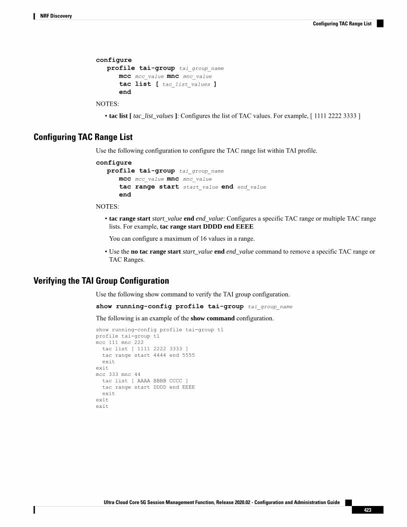
configureprofile tai-group tai_group_name
mcc mcc_value mnc mnc_value
tac list [ tac_list_values ]end
NOTES:
• tac list [ tac_list_values ]: Configures the list of TAC values. For example, [ 1111 2222 3333 ]
Configuring TAC Range ListUse the following configuration to configure the TAC range list within TAI profile.
configureprofile tai-group tai_group_name
mcc mcc_value mnc mnc_value
tac range start start_value end end_value
end
NOTES:
• tac range start start_value end end_value: Configures a specific TAC range or multiple TAC rangelists. For example, tac range start DDDD end EEEE
You can configure a maximum of 16 values in a range.
• Use the no tac range start start_value end end_value command to remove a specific TAC range orTAC Ranges.
Verifying the TAI Group ConfigurationUse the following show command to verify the TAI group configuration.
show running-config profile tai-group tai_group_name
The following is an example of the show command configuration.show running-config profile tai-group t1profile tai-group t1mcc 111 mnc 222tac list [ 1111 2222 3333 ]tac range start 4444 end 5555exit
exitmcc 333 mnc 44tac list [ AAAA BBBB CCCC ]tac range start DDDD end EEEEexit
exitexit
Ultra Cloud Core 5G Session Management Function, Release 2020.02 - Configuration and Administration Guide423
NRF DiscoveryConfiguring TAC Range List

Dynamic Configuration Change Support
Feature DescriptionGlobal configuration table was built for NRF configurations and rebuilt each time when there was a changein configuration. NRF transaction/procedure (such as discovery, management, and so on) picked theconfiguration for the respective transaction/procedure from the global configuration tables. Therefore, theongoing transactions were impacted if the configurations were modified in the middle of thetransaction/procedure.
With this feature:
• NRF transaction/procedure picks a configuration version (v1) and uses the same version till the NRFtransaction/procedure complete.
• If a user changes the configuration during an ongoing NRF transaction, then a new configuration version(v2) is created. However, the new configuration is not applied to the ongoing transaction.
The dynamic configuration changes are for the following data structures:
• NrfFailureProfileSt
• NrfClntProfileSt
• NrfGrpSt
• NrfPairProfileSt
• NrfMgmtGrpSt
NRF Show Command Enhancements
show nrf registration-infoDescriptionField
Displays NRF Registration Information.NF Status
Displays Time of Registration with NRF.Registration Time
Active NRF Management End Point name.Active MgmtEP Name
Displays Heart Beat Duration.Heartbeat Duration
Displays Uri Information.Uri
Displays NRF Host Type Information.Host Type
Ultra Cloud Core 5G Session Management Function, Release 2020.02 - Configuration and Administration Guide424
NRF DiscoveryDynamic Configuration Change Support
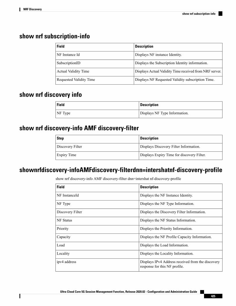
show nrf subscription-infoDescriptionField
Displays NF instance Identity.NF Instance Id
Displays the Subscription Identity information.SubscriptionID
Displays Actual Validity Time received fromNRF server.Actual Validity Time
Displays NF Requested Validity subscription Time.Requested Validity Time
show nrf discovery infoDescriptionField
Displays NF Type Information.NF Type
show nrf discovery-info AMF discovery-filterDescriptionStep
Displays Discovery Filter Information.Discovery Filter
Displays Expiry Time for discovery Filter.Expiry Time
shownrfdiscovery-infoAMFdiscovery-filterdnn=intershatnf-discovery-profileshow nrf discovery-info AMF discovery-filter dnn=intershat nf-discovery-profile
DescriptionField
Displays the NF Instance Identity.NF InstanceId
Displays the NF Type Information.NF Type
Displays the Discovery Filter Information.Discovery Filter
Displays the NF Status Information.NF Status
Displays the Priority Information.Priority
Displays the NF Profile Capacity Information.Capacity
Displays the Load Information.Load
Displays the Locality Information.Locality
Displays IPv4 Address received from the discoveryresponse for this NF profile.
ipv4 address
Ultra Cloud Core 5G Session Management Function, Release 2020.02 - Configuration and Administration Guide425
NRF Discoveryshow nrf subscription-info

DescriptionField
Displays the IPv6 Address received from thediscovery response for this NF profile.
ipv6 address
shownrfdiscovery-infoAMFdiscovery-filterdnn=intershatnf-discovery-profilef9882966-a253-32d1-8b82-c785b34a7cc9 nf-service
show nrf discovery-info AMF discovery-filter dnn=intershat nf-discovery-profilef9882966-a253-32d1-8b82-c785b34a7cc9 nf-service
DescriptionField
Displays the NF Service Instance ID.ServiceInstanceId
Displays the NF Service Name.ServiceName
Displays the Uri Scheme Information.UriScheme
Ultra Cloud Core 5G Session Management Function, Release 2020.02 - Configuration and Administration Guide426
NRF Discoveryshow nrf discovery-info AMF discovery-filter dnn=intershat nf-discovery-profile f9882966-a253-32d1-8b82-c785b34a7cc9 nf-service

C H A P T E R 29Peer NF Failure Handling Support
• Feature Summary and Revision History, on page 427• Offline Failover Support for Charging, on page 428• SMF Failover to Secondary PCF, on page 432• UPF Failure Handling, on page 436
Feature Summary and Revision History
Summary DataTable 120: Summary Data
SMFApplicable Products or Functional Area
SMIApplicable Platform(s)
Disabled - Configuration RequiredFeature Default Setting
Not ApplicableRelated Changes in this Release
Not ApplicableRelated Documentation
Revision HistoryTable 121: Revision History
ReleaseRevision Details
Pre-2020.02.0First introduced.
Ultra Cloud Core 5G Session Management Function, Release 2020.02 - Configuration and Administration Guide427

Offline Failover Support for Charging
Feature DescriptionThe SMF supports offline failover for charging when a CHF server fails. When the SMF continues after theCHF server failure, the SMF relays the offline charging services to the offline CHF server.
How it WorksThe offline failover support for the charging feature works as follows.
Selecting a CHF ServerThe CHF server selection involves the following steps:
1. The smf-service sends packets to rest-ep. The NF library of rest-ep attempts to search a CHF server throughNRF discovery. This library receives a CHF server IP address or the list along with the priority as a searchresult.
2. The NF library selects the CHF server based on the priority from the list that is received through NRFdiscovery. If no CHF server is selected, NF library falls back to the static configuration that exists in theCHF network profile.
After selecting a CHF server or a list, NF library relays the message to the first CHF server according to thepriority.
Handling a CHF Server Failure
The CHF server failure occurs when the selected CHF sends failure response or sends no response. For a CHFserver failure, the NF library sends status code that is based on the failure template. This template is associatedwith the CHF network profile. The smf-service sends the profile information to smf-rest-ep while sending theIPC message.
The failure template is configured with the list of HTTP error codes and the associated failure actions andretry count, as required. Following are the failure actions as available in the feature template for this feature:
• Retry and Continue—For this failure action, NF library attempts until the configured number of timesbefore fallback. After the configured number of times completes, the NF library falls back to the lowerpriority CHF server IP address. If the failure or no response is received from CHF server, the "continue"action is returned to the smf-service.
• Terminate—For this failure action, NF library does not attempt to send message to other CHF servers.The library sends a reply to smf-service with the action as "terminate". For the "terminate" failure action,the smf-service deletes the session.
• Continue—For this failure action, the smf-service continues the session and sends the charging messageto the offline CHF server. This server is configured as part of the local static CHF profile that is meantfor the offline purpose. In addition, the failure handling profile for offline CHF is configured.
Ultra Cloud Core 5G Session Management Function, Release 2020.02 - Configuration and Administration Guide428
Peer NF Failure Handling SupportOffline Failover Support for Charging
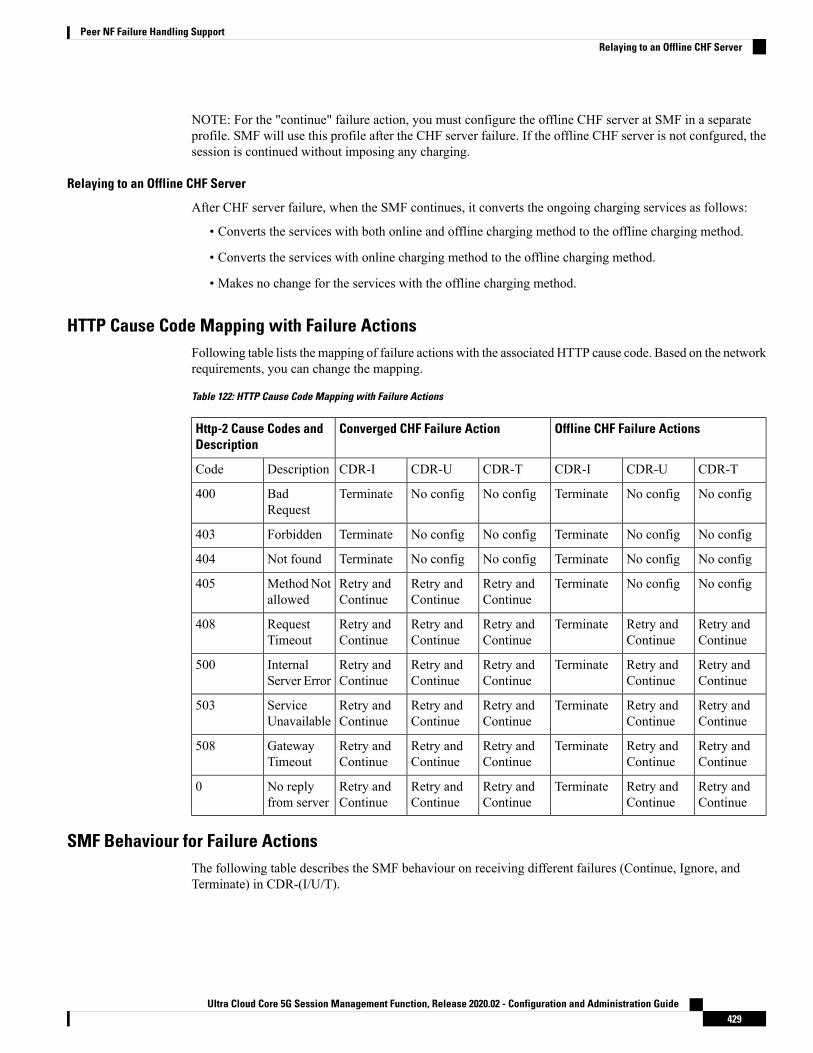
NOTE: For the "continue" failure action, you must configure the offline CHF server at SMF in a separateprofile. SMF will use this profile after the CHF server failure. If the offline CHF server is not confgured, thesession is continued without imposing any charging.
Relaying to an Offline CHF Server
After CHF server failure, when the SMF continues, it converts the ongoing charging services as follows:
• Converts the services with both online and offline charging method to the offline charging method.
• Converts the services with online charging method to the offline charging method.
• Makes no change for the services with the offline charging method.
HTTP Cause Code Mapping with Failure ActionsFollowing table lists the mapping of failure actions with the associated HTTP cause code. Based on the networkrequirements, you can change the mapping.
Table 122: HTTP Cause Code Mapping with Failure Actions
Offline CHF Failure ActionsConverged CHF Failure ActionHttp-2 Cause Codes andDescription
CDR-TCDR-UCDR-ICDR-TCDR-UCDR-IDescriptionCode
No configNo configTerminateNo configNo configTerminateBadRequest
400
No configNo configTerminateNo configNo configTerminateForbidden403
No configNo configTerminateNo configNo configTerminateNot found404
No configNo configTerminateRetry andContinue
Retry andContinue
Retry andContinue
MethodNotallowed
405
Retry andContinue
Retry andContinue
TerminateRetry andContinue
Retry andContinue
Retry andContinue
RequestTimeout
408
Retry andContinue
Retry andContinue
TerminateRetry andContinue
Retry andContinue
Retry andContinue
InternalServer Error
500
Retry andContinue
Retry andContinue
TerminateRetry andContinue
Retry andContinue
Retry andContinue
ServiceUnavailable
503
Retry andContinue
Retry andContinue
TerminateRetry andContinue
Retry andContinue
Retry andContinue
GatewayTimeout
508
Retry andContinue
Retry andContinue
TerminateRetry andContinue
Retry andContinue
Retry andContinue
No replyfrom server
0
SMF Behaviour for Failure ActionsThe following table describes the SMF behaviour on receiving different failures (Continue, Ignore, andTerminate) in CDR-(I/U/T).
Ultra Cloud Core 5G Session Management Function, Release 2020.02 - Configuration and Administration Guide429
Peer NF Failure Handling SupportRelaying to an Offline CHF Server

Offline CHFConverged CHFCHF FailureActions
CDR-TCDR-UCDR-ICDR-TCDR-UCDR-I
Continue thesessiondeletion
Continue thesessionwithoutcharging
Continue thesessionwithoutcharging
Send CDR tooffline CHF ifoffline CHF isconfigured
Send CDR tooffline CHF.If offline CHFis notconfigured,continue thesessionwithoutcharging.
Send CDR tooffline CHF.If offline CHFis notconfigured,continue thesessionwithoutcharging.
Continue
Continue thesessiondeletion
Delete thesession
Delete thesession
Continue thesessiondeletion
Delete thesession
Delete thesession
Terminate
Continue thesessiondeletion
No actiontaken.Record(s) willbereattempted inthe next CDRrequest.
Delete thesession
Continue thesessiondeletion
No actiontaken.Record(s) willbereattempted inthe next CDRrequest.
Delete thesession
Ignore
Standards ComplianceThe offline failover support for charging feature complies with the following standards:
• 3GPP TS 32.255
• 3GPP TS 32.290
• 3GPP TS 32.291
LimitationsThe offline failover support for charging feature has the following limitations:
• Session Level Limits are mandatory from CHF or you must configure them locally. As per the 3GPPspecification, the last linked URR cannot be removed when online URR needs to be delinked from theoffline URR.
Configuring the Offline Failover Support for ChargingThis section describes how to configure the offline failover support for charging feature.
Configuring the offline failover support for charging feature involves the following steps:
1. Configure failure handling profile in an NF library
2. Configuring an offline server client and an offline failure handling profile
Ultra Cloud Core 5G Session Management Function, Release 2020.02 - Configuration and Administration Guide430
Peer NF Failure Handling SupportStandards Compliance
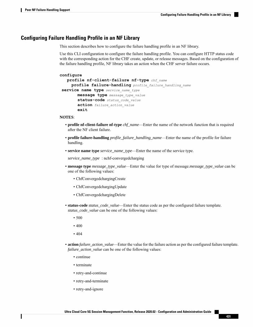
Configuring Failure Handling Profile in an NF LibraryThis section describes how to configure the failure handling profile in an NF library.
Use this CLI configuration to configure the failure handling profile. You can configure HTTP status codewith the corresponding action for the CHF create, update, or release messages. Based on the configuration ofthe failure handling profile, NF library takes an action when the CHF server failure occurs.
configureprofile nf-client-failure nf-type chf_name
profile failure-handling profile_failure_handling_name
service name type service_name_type
message type message_type_value
status-code status_code_value
action failure_action_value
exit
NOTES:
• profile nf-client-failure nf-type chf_name—Enter the name of the network function that is requiredafter the NF client failure.
• profile failure-handling profile_failure_handling_name—Enter the name of the profile for failurehandling.
• service name type service_name_type—Enter the name of the service type.
service_name_type : nchf-convergedcharging
• message type message_type_value—Enter the value for type of message.message_type_value can beone of the following values:
• ChfConvergedchargingCreate
• ChfConvergedchargingUpdate
• ChfConvergedchargingDelete
• status-code status_code_value—Enter the status code as per the configured failure template.status_code_value can be one of the following values:
• 500
• 400
• 404
• action failure_action_value—Enter the value for the failure action as per the configured failure template.failure_action_value can be one of the following values:
• continue
• terminate
• retry-and-continue
• retry-and-terminate
• retry-and-ignore
Ultra Cloud Core 5G Session Management Function, Release 2020.02 - Configuration and Administration Guide431
Peer NF Failure Handling SupportConfiguring Failure Handling Profile in an NF Library

Configuring an Offline Server Client and an Offline Failure Handling ProfileThis section describes how to configure the offline server client and offline failure handling profile.
Use this CLI to configure the offline client profile and offline failure handling profile for the selected CHFserver.
configureprofile network-element chf chf_name
nf-client-profile nf_client_profile_name
failure-handling-profile failure_handling_profile_name
query-params [ dnn ]nf-client-profile-offline nf_client_profile_offline_IP_port_number
failure-handling-profile-offline failure_handling_profile_offline_name
exit
NOTES:
• profile network-element chf – Enter the name of the CHF server.
• nf-client-profile – Enter the name of the client profile.
• failure-handling-profile – Enter the name of the failure handling profile.
• query-params – Enter the query parameter value, which is the data network name.
• nf-client-profile-offline – Enter the name of the offline client profile.
• failure-handling-profile-offline – Enter the name of the offline failure handling profile.
SMF Failover to Secondary PCF
Feature DescriptionThe NF failover support is available in the SMF using the NRF Client profile configuration and the NRFfailure profile configuration. The following functionality is supported:
• Configure multiple endpoints for a service as primary and secondary endpoints.
• Specify the failure behavior based on:
• Message Type
• HTTP Status Codes in the response messages
SMF FunctionalityThe SMF utilizes the NF Failover to achieve the PCF failover support functionality. This section coversworking of SMF for message-level failures handling and the corresponding HTTP Status Code-based failure.
The SMF PCF failover supports the following messages that are initiated from the SMF.
• PcfSmpolicycontrolCreate
Ultra Cloud Core 5G Session Management Function, Release 2020.02 - Configuration and Administration Guide432
Peer NF Failure Handling SupportConfiguring an Offline Server Client and an Offline Failure Handling Profile

• PcfSmpolicycontrolUpdate
• PcfSmpolicycontrolDelete
During the PDU session lifecycle, the SMF exchanges the preceding messages at various stages with the PCF.Depending on the HTTP Status code configured in the NRF failure profile, the SMF receives one of thefollowing actions:
• Ignore
• Continue
• Terminate
Table 123: Relationship between SMF PCF Failover Messages and Actions
PcfSmpolicy
controlDelete
PcfSmpolicy
controlUpdate
PcfSmpolicy
controlCreate
Current failure ignored.
Session is deleted.
PCF-Interaction Status:Session deleted
Continue with ‘currentlyavailable snapshot’ of policyparameters.
Contact PCF for subsequentmessages.
PCF-Interaction Status:ON
Continue with locallyconfigured/UDM-providedpolicy parameters.
Do not contactPCF forsubsequentmessages.
Note
PCF-Interaction Status:OFF
Ignore
Current failure ignored.
Session is deleted.
PCF-Interaction Status:Session deleted
Continue with ‘currentlyavailable snapshot’ of policyparameters.
Do not contactPCF forsubsequentmessages.
Note
PCF-Interaction Status:OFF
Continue with locallyconfigured/UDM-providedpolicy parameters.
Do not contactPCF forsubsequentmessages.
Note
PCF-Interaction Status:OFF
Continue
Terminate the session.Terminate the session.Terminate the session.Terminate
The messages in Table 123: Relationship between SMF PCF Failover Messages and Actions, on page 433 areSMF-initiated messages.
Note
SMF PCF Failure Handling• PCF-Interaction Status: ON
Ultra Cloud Core 5G Session Management Function, Release 2020.02 - Configuration and Administration Guide433
Peer NF Failure Handling SupportSMF PCF Failure Handling

SMF-initiated messages: The SMF continues to initiate the messages towards the PCF whenever thecriteria is met.
PCF-initiated messages: The SMF continues to accept all the messages initiated from the PCF towardsthe SMF.
• PCF-Interaction Status: OFF
SMF-initiated messages: The SMF does not initiate or send the messages towards the PCF whenever thecriteria is met. The SMF treats the PCF as if it is not available and continues further actions.
PCF-initiated messages: There are two messages initiated by the PCF.
• SmPolicyUpdateNotifyReq: On receiving this message, the SMF sends a 404 error code in responseand cleans up the session and does not send the Delete Request to the PCF.
The SMF also sends FIVEGSM_CAUSE value as REACTIVATIONREQUESTED in the FIVEG_PDU_SESSION_RELEASE_COMMAND toUEfor 5G. In case of 4G, the SMF sends cause REACTIVATION REQUESTEDin DELETE BEARER REQUEST message to the S-GW.
Note
• SmPolicyAssociationTerminationReq: On receiving this message, the SMF sends a success responseand cleans up the session. As part of this interaction, the SMF sends a Delete Request to the PCF.
This is an exception when the PCF-Interaction Status is set to OFF.Note
Configuring SMF Failover to Secondary PCF SupportUse the following configuration to configure the PCF failure handling profile with action config:
profile nf-client-failure nf-type pcf
profile failure-handling FH1
service name type npcf-smpolicycontrolmessage type PcfSmpolicycontrolCreatestatus-code httpv2 0action continue
Use the following configuration to configure the association of FH profile in the respective network element:
profile network-element pcf pcf1
nf-client-profile PP1
failure-handling-profile FH1
query-params [ dnn ]rulebase-prefix cbn#predefined-rule-prefix crn#exit
Use the following configuration to configure secondary and tertiary IP addresses:
Ultra Cloud Core 5G Session Management Function, Release 2020.02 - Configuration and Administration Guide434
Peer NF Failure Handling SupportConfiguring SMF Failover to Secondary PCF Support

profile nf-client nf-type pcf
pcf-profile PP1
locality LOC1
priority 30
service name type npcf-smpolicycontrolendpoint-profile EP1
capacity 30
uri-scheme httpendpoint-name EP1
priority 56
primary ip-address ipv4 primaryipaddress
primary ip-address port 8098
secondary ip-address ipv4 secondaryipaddress
secondary ip-address port 9098
end
StatisticsThe following statistics are added in support of SMF Failover to Secondary PCF feature.
• PcfSmpolicyControlCreate
• Number of ignore responses
• Number of continue responses
• Number of terminate responses
• PcfSmPolicyControlUpdate
• Number of ignore responses
• Number of continue responses
• Number of terminate responses
• PcfSmpolicyControlDelete
• Number of ignore responses
• Number of continue responses
• Number of terminate responses
• PolicyUpdateNotifyReq
• Number of accepted requests
• Number of rejected requests
• Number of skipped requests
• PolicyDeleteReq
• Number of accepted requests
• Number of rejected requests
Ultra Cloud Core 5G Session Management Function, Release 2020.02 - Configuration and Administration Guide435
Peer NF Failure Handling SupportStatistics

• Number of skipped requests
• PolicyUpdateRequest
• Number of accepted requests
• Number of rejected requests
• Number of skipped requests
• Gauge counter for number of subscribers with policy type local/pcf.
UPF Failure Handling
Feature DescriptionDuring a session, if the User Plane function (UPF) is in congested state, it rejects the Packet ForwardingControl Protocol (PFCP) establishment messages from SMF with a cause code in the response message. Toreduce the call loss, SMF retries to send PFCP establishment messages to a different UPF. Then, SMF selectsa UPF based on priority (configuration) and capacity (load information from UPF).
The UPF failure handling support on N4 interface feature in SMF introduces a new failure handling template(FHT) profile for PFCP. This profile is associated with the UPF profile in SMF (in network elements).
The FHT template provides flexibility for SMF to fine tune its interactions with UPFs for sessions. It supportsSMF to handle the error cause codes in response from UPF for both new and existing sessions. Based on theerror cause codes in response from UPF, this feature provides the following configurable actions:
• terminate
• retry-terminate
Configuring the UPF Failure Handling on N4 InterfaceThis section describes how to configure the UPF failure handling on N4 interface feature.
configureprofile failure-handling pfcp_name
interface pfcp message N4SessionEstablishmentReqcause-code pfcp-entity-in-congestionaction retry-terminate max-retry value
end
NOTES:
• profile failure-handling: Specifies the UPF profile that is associated with FHT.
• interface pfcp message {N4SessionEstablishmentReq | N4SessionModificationReq}: Specifies thefailure handling for N4SessionEstablishmentReq (for new sessions) and N4SessionModificationReqmessages (for existing sessions).
Ultra Cloud Core 5G Session Management Function, Release 2020.02 - Configuration and Administration Guide436
Peer NF Failure Handling SupportUPF Failure Handling

UPF reselection is not applicable for message type N4SessionModificationReqbecause the session is already active on a UPF.
Note
• cause-code {pfcp-entity-in-congestion | mandatory-ie-incorrect | mandatory-ie-missing |session-ctx-not-found | system-failure | service-not-supported | no-resource-available |no-response-received | reject}: Specifies the error codes that SMF receives in the failure responsemessage from UPF.
• The no-response-received cause code is introduced in this feature to identifythe scenarios where SMF does not receive any response from UPF.
• FHT does not support the following cause codes, which are configured withtheir default behaviour:
request-reject-unspecified, cond-ie-missing, invalid-length,invalid-fw-policy, invalid-fteid-alloc-opt, no-established-pfcp-assoc,rule-creation-mod-failure.
Note
• pfcp-entity-in-congestion: Specifies the cause code when UPF is congested.
• reject: Specifies the option to handle the cause codes in the failure response message from UPF,which are not configured by using the CLI commands available for this feature.
• action {retry-terminate | terminate}: Specifies the action to perform based on the error cause codereceived in the failure response message from UPF.
• retry-terminate: Specifies a retry attempt to an alternate UPF. If the retry attempt fails, the sessionis terminated.
If all UPFs are in congested state, call fails even if the action is set to continue.Note
• max-retry: Specifies the number of retry attempts to reselect an alternate UPF.
• Default value: 2
• Maximum value: 5
Configuring the Failure Profile Association
This section describes how to configure the failure profile association in this feature.
configureprofile upf-group upf upf_group_name
failure-profile pfcp_name
end
NOTES:
Ultra Cloud Core 5G Session Management Function, Release 2020.02 - Configuration and Administration Guide437
Peer NF Failure Handling SupportConfiguring the UPF Failure Handling on N4 Interface

• profile upf-group upf: Specifies the UPF group.
• failure-profile: Specifies the FHT profile for PFCP.
Configuration Matrix
This section describes the configuration options available for N4 Session Establishment Request and N4Session Modification Request messages in this feature.
Default BehaviourApplicable Cause CodeApplicable ActionMessage Type
terminate• pfcp-entity-in-congestion
• system-failure
• service-not-supported
• no-resource-available
• no-response-received
retry-terminateN4SessionEstablishmentReq
continue• mandatory-ie-incorrect
• session-ctx-not-found
• no-response-received
terminateN4SessionModificationReq
Monitoring and TroubleshootingThis section describes the show command that is supported by the UPF failure handling on N4 interfacefeature.
show running-config
Use the show running-config command to view the configuration.
The following configuration is a sample output of the show running-config command:profile network-element upf upf1
pfcp pfcp-failure-profile pfcp1node-id n4-peer-upf1n4-peer-address ipv4 1.1.1.1n4-peer-port 0000keepalive 60dnn-list [ uncarrier.5g ]capacity 10priority 1exitprofile failure-handling pfcp1interface pfcp message N4SessionEstablishmentReqcause-code pfcp-entity-in-congestionaction retry-terminate max-retry 2exitexitinterface pfcp message N4SessionModificationReqcause-code mandatory-ie-incorrectaction terminateexit
Ultra Cloud Core 5G Session Management Function, Release 2020.02 - Configuration and Administration Guide438
Peer NF Failure Handling SupportMonitoring and Troubleshooting

exitexit
Ultra Cloud Core 5G Session Management Function, Release 2020.02 - Configuration and Administration Guide439
Peer NF Failure Handling SupportMonitoring and Troubleshooting

Ultra Cloud Core 5G Session Management Function, Release 2020.02 - Configuration and Administration Guide440
Peer NF Failure Handling SupportMonitoring and Troubleshooting

C H A P T E R 30Protocol Data Unit RAN Tunnel EndpointIdentifier Session
This chapter covers the following topics:
• Feature Summary and Revision History, on page 441• Feature Description, on page 442• Always-On PDU Session Support, on page 445
Feature Summary and Revision History
Summary DataTable 124: Summary Data
SMFApplicable Product(s) or Functional Area
SMIApplicable Platform(s)
Not ApplicableFeature Default Setting
Not ApplicableRelated Changes in this Release
Not ApplicableRelated Documentation
Revision HistoryTable 125: Revision History
ReleaseRevision Details
Pre-2020.02.0First introduced.
Ultra Cloud Core 5G Session Management Function, Release 2020.02 - Configuration and Administration Guide441

Feature DescriptionThe SMF supports activation and deactivation of the user plane connection of a PDU session.
How it WorksLabels are introduced at SMF-service to account active-to-idle and idle-to-active transitions. Existing idleand connected counters are used to track number of PDU sessions that are currently active or idle.
DescriptionLabel
New label introduced.
ue_req_active_to_idle
ue_req_idle_to_active
PROCEDURE TYPE
Deactivation of the User Plane Connection of a PDU SessionThis procedure is used to release the logical NG-AP signaling connection and the associated N3 user planeconnections, and (R)AN RRC signaling and resources.
The following reasons may trigger the initiation of AN release:
• (R)AN-initiated with cause. For example, O&M Intervention, unspecified failure. (R)AN (For example,Radio) link failure, user inactivity, inter-system redirection, request for establishment of QoS flow forIMS voice, release due to UE generated signaling connection release, mobility restriction and so on.
• AMF-initiated with cause. For example, unspecified failure.
Limitations
• In this release, SMF supports only UE-initiated deactivation.
• Location update is not supported.
Ultra Cloud Core 5G Session Management Function, Release 2020.02 - Configuration and Administration Guide442
Protocol Data Unit RAN Tunnel Endpoint Identifier SessionFeature Description

Call Flow
Figure 98: Deactivation of the User Plane Connection of a PDU Session Call Flow
Table 126: Deactivation of the User Plane Connection of a PDU Session Call Flow Description
DescriptionStep
NF Service Consumer requests the SMF to deactivate the user plane connection of the PDUsession by sending a POST request with the following information:
• upCnxState attribute set to DEACTIVATED.
• User location and user location timestamp.
• Cause of the user plane deactivation. The cause may indicate a cause received fromthe 5G-AN or due to an AMF internal event.
• Other information (if required).
1
SMF deactivates and releases the N3 tunnel of the PDU session after receiving such arequest. SMF initiates PFCP session modification procedure towards UPF with downlinkFAR updated with the following options:
• Buffering Action is enabled without remote node “forwarding parameters” detailslike IP address and GTP-U F-TEID.
NOCP (Notify the CP function) is not enabled. Support for notification is notavailable on SMF.
Note
2
SMF sets the upCnxState attribute to DEACTIVATED for the PDU session after receivingsuccessful response from UPF node.
3
SMF initiates 200 OK response including the upCnxState attribute set to DEACTIVATEDtowards AMF.
4
Ultra Cloud Core 5G Session Management Function, Release 2020.02 - Configuration and Administration Guide443
Protocol Data Unit RAN Tunnel Endpoint Identifier SessionCall Flow

Activation of the User Plane Connection of a PDU SessionThe service request procedure is used when the UE is in CM-IDLE and in CM CONNECTED to activate auser plane connection for an established PDU session. The UE in CM IDLE state initiates the service requestprocedure to send uplink signaling messages, user data or as a response to a network paging request.
Limitations
• In this release, SMF supports only UE-initiated service requests.
• Paging and network-initiated service requests are not supported.
• Location update and access-type changes are not supported.
• QoS flow modifications and errors are not supported.
Call Flow
Figure 99: Activation of the User Plane Connection of a PDU Session Call Flow
Ultra Cloud Core 5G Session Management Function, Release 2020.02 - Configuration and Administration Guide444
Protocol Data Unit RAN Tunnel Endpoint Identifier SessionActivation of the User Plane Connection of a PDU Session

Table 127: Activation of the User Plane Connection of a PDU Session Call Flow Description
DescriptionStep
AMF requests the SMF to activate the user plane connection of the PDU session bysending a POST request with the following information:
• upCnxState attribute set to ACTIVATING.
• User location, user location timestamp, and access type associated to the PDUsession (if modified)
• Other information (if required).
1
SMF starts activating the N3 tunnel of the PDU session after receiving the request. SMFreturns a 200 OK response including the following information:
• upCnxState attribute set to ACTIVATING.
• N2 SM information to request the 5G-AN to assign resources to the PDU sessionincluding the transport layer address and tunnel endpoint of the uplink terminationpoint for the user plane data for this PDU session that is UPF's GTP-U F-TEID foruplink traffic.
2
AMF requests the SMF by sending POST request, with the following information:
• SM information received from the 5G-AN, including the transport layer addressand tunnel endpoint of the downlink termination point for the user data for this PDUsession, 5G-AN's GTP-U F-TEID for downlink traffic if the 5G-AN succeeded inestablishing resources for the PDU sessions.
3
SMF initiates PFCP session modification procedure towards UPF with down link FARupdated with following options:
• Forwarding Action is enabled with remote node “forwarding parameters” detailslike IP address and GTP-U F-TEID.
4
SMF sets the upCnxState attribute to ACTIVATED for the PDU session after receivingsuccessful response from UPF node.
5
SMF initiates 200 OK response including the upCnxState attribute set to ACTIVATEDtowards AMF.
6
Always-On PDU Session Support
Feature DescriptionSome applications like the IP Multimedia Subsystem (IMS) require an always-on Protocol Data Unit (PDU)session that the User Plane resource establishes for every transition from the 5GMM-IDLE mode to the5GMM-CONNECTED mode. The UE requests the establishment of a PDU session as an always-on PDU
Ultra Cloud Core 5G Session Management Function, Release 2020.02 - Configuration and Administration Guide445
Protocol Data Unit RAN Tunnel Endpoint Identifier SessionAlways-On PDU Session Support

session based on the request indication of the upper layers. It is the network that decides whether to establisha PDU session as an always-on PDU session.
How it Works
Call Flows
This section includes the following call flows.
PDU Session Establishment Call Flow
This section describes the call flow of the PDU session establishment.
Figure 100: PDU Session Establishment Call Flow
Table 128: PDU Session Establishment Call Flow Description
DescriptionStep
If the UE requests to establish an always-on PDU session, the UE includes an‘Always-on PDU Session Requested’ IE in the PDU Session Establishment Requestmessage.
1
The SMF checks the DNN profile to determine whether the “always-on” support isenabled.
2
Ultra Cloud Core 5G Session Management Function, Release 2020.02 - Configuration and Administration Guide446
Protocol Data Unit RAN Tunnel Endpoint Identifier SessionHow it Works

DescriptionStep
The SMF includes an ‘Always-on PDU Session Indication’ in the PDU SessionEstablishment Accept message if any one of the following is true:
• 'Always-on PDU Session Indication' is sent with value as "enabled" if thealways-on configuration is enabled under the DNN profile.
• 'Always-on PDU Session Indication' is sent with value as "disabled" when'Always-on PDU Session Request' IE is received and configuration is disabled.
3
The SMF does not include an ‘Always-on PDU Session Indication’ only when boththese conditions are true:
• If the UE did not send an ‘Always-on PDU Session Requested’ IE
• If always-on configuration is disabled in the DNN profile.
4
UE-Requested PDU Session Modification Call Flow
This section describes the call flow of the UE-requested PDU session modification.
Figure 101: UE-Requested PDU Session Modification Call Flow
Ultra Cloud Core 5G Session Management Function, Release 2020.02 - Configuration and Administration Guide447
Protocol Data Unit RAN Tunnel Endpoint Identifier SessionUE-Requested PDU Session Modification Call Flow

Table 129: UE-Requested PDU Session Modification Call Flow Description
DescriptionStep
The UE sends an ‘Always-on PDU Session Requested’ IE in the PDU SessionModification Request message.
1
The SMF checks the DNN profile to determine whether the “always-on” support isenabled.
2
The SMF includes an ‘Always-on PDU Session Indication’ in the PDU SessionModification Command when any one of the following is true:
• 'Always-on PDU Session Indication' is sent with the value as "enabled" whenthe always-on configuration is enabled under the DNN profile.
• 'Always-on PDU Session Indication' is sent with the value as "disabled" whenan 'Always-on PDU Session Request' IE is received and configuration is disabled.
3
The SMF does not include an ‘Always-on PDU Session Indication’ only when boththese conditions are true:
• If the UE did not send an ‘Always-on PDU Session Requested’ IE.
• If always-on configuration is disabled in the DNN profile.
As per specification 23502, for a PDU session that was established in theEPS, when the UE moves from EPS to 5GS for the first time, the UEincludes an 'Always-on PDU Session Requested' indication in the PDUSessionModification Request message if it wants to change the PDU sessionto an "always-on" PDU session.
Note
4
Network-Requested PDU Session Modification Call Flow
This section describes the call flow of the network-requested PDU session modification.
Ultra Cloud Core 5G Session Management Function, Release 2020.02 - Configuration and Administration Guide448
Protocol Data Unit RAN Tunnel Endpoint Identifier SessionNetwork-Requested PDU Session Modification Call Flow
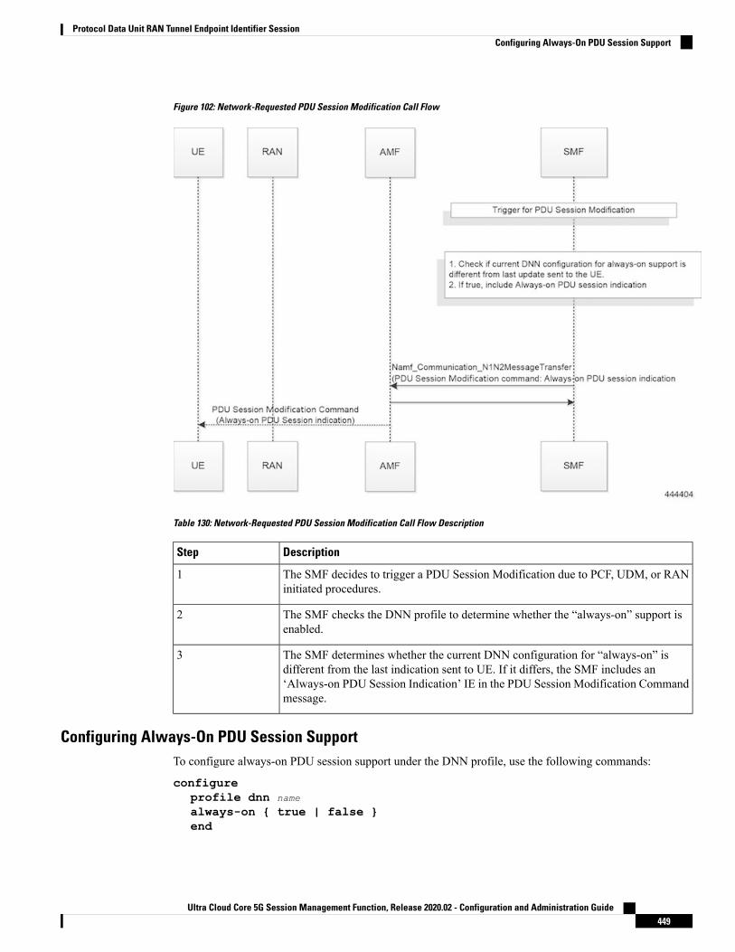
Figure 102: Network-Requested PDU Session Modification Call Flow
Table 130: Network-Requested PDU Session Modification Call Flow Description
DescriptionStep
The SMF decides to trigger a PDU Session Modification due to PCF, UDM, or RANinitiated procedures.
1
The SMF checks the DNN profile to determine whether the “always-on” support isenabled.
2
The SMF determines whether the current DNN configuration for “always-on” isdifferent from the last indication sent to UE. If it differs, the SMF includes an‘Always-on PDU Session Indication’ IE in the PDU Session Modification Commandmessage.
3
Configuring Always-On PDU Session SupportTo configure always-on PDU session support under the DNN profile, use the following commands:
configureprofile dnn name
always-on { true | false }end
Ultra Cloud Core 5G Session Management Function, Release 2020.02 - Configuration and Administration Guide449
Protocol Data Unit RAN Tunnel Endpoint Identifier SessionConfiguring Always-On PDU Session Support
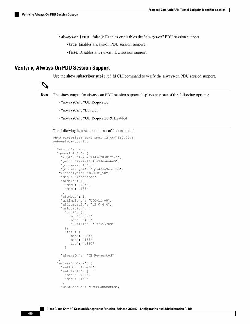
• always-on { true | false }: Enables or disables the "always-on" PDU session support.
• true: Enables always-on PDU session support.
• false: Disables always-on PDU session support.
Verifying Always-On PDU Session SupportUse the show subscriber supi supi_id CLI command to verify the always-on PDU session support.
The show output for always-on PDU session support displays any one of the following options:
• “alwaysOn”: “UE Requested”
• “alwaysOn”: “Enabled”
• “alwaysOn”: “UE Requested & Enabled”
Note
The following is a sample output of the command:show subscriber supi imsi-123456789012345subscriber-details{"status": true,"genericInfo": {"supi": "imsi-123456789012345","pei": "imei-123456786666660","pduSessionId": 5,"pduSesstype": "Ipv4PduSession","accessType": "ACCESS_5G","dnn": "intershat","plmnId": {"mcc": "123","mnc": "456"
},"sScMode": 1,"uetimeZone": "UTC+12:00","allocatedIp": "12.0.4.4","nrLocation": {"ncgi": {"mcc": "123","mnc": "456","nrCellId": "123456789"
},"tai": {"mcc": "123","mnc": "456","tac": "1820"
}}“alwaysOn”: “UE Requested”
},"accessSubData": {"amfID": "AFbe08","amfPlmnId": {"mcc": "123","mnc": "456"
},"ueCmStatus": "UeCMConnected",
Ultra Cloud Core 5G Session Management Function, Release 2020.02 - Configuration and Administration Guide450
Protocol Data Unit RAN Tunnel Endpoint Identifier SessionVerifying Always-On PDU Session Support

"amfNrfID": "76517361-338e-4d77-bc76-713a79779574"},"policySubData": {"TotalDynamicRules": 1,"TotalFlowCount": 1,"TotalNonGBRFlows": 1,"pccRuleList": [{"pccRuleId": "defaultrule","qfi": 1,"mbrDl": 125000000,"mbrUl": 100000000,"flowInformation": [{"flowDirection": 3,"flowDescription": "permit out ip from any to any"
}]
}],"qosFlow": [{"qfi": 1,"GBRFlow": "False","bindingParameters": {"x5Qi": 5,"arp": {"preemptCap": 1,"preemptVuln": 1,"priorityLevel": 15
},"priorityLevel": 1
},"AggregatedULMFbr": 100000000,"AggregatedDLMFbr": 125000000,"pccRuleList": "defaultrule"
}]
},"chargingData": {},"upfServData": {"numberOfTunnels": 1,"smfSeid": 21790984727,"UPState": "Activated","mapping": {"tunnelMapping": [{"TunnelID": 1,"tunnelName": "gnbTunnel"
}]
}}
}
Bulk Statistics for Always-On PDU Session SupportThe following statistics are introduced for the Always-On PDU Session Support feature.
Table 131: Bulk Statistics for Always-On PDU Session Support
DescriptionBulk Statistics
Ultra Cloud Core 5G Session Management Function, Release 2020.02 - Configuration and Administration Guide451
Protocol Data Unit RAN Tunnel Endpoint Identifier SessionBulk Statistics for Always-On PDU Session Support

Tracks the number of always-on PDU sessions.always-on-pdu
Requests the always-on PDU session.Always-on-pdu-requested
Accepts the always-on PDU session request.always-on-pdu-accepted
Rejects the always-on PDU session request.Always-on-pdu-rejected
Indicates the number of session establishment requestsreceived with 'Always-On PDU Session Requested'.
pdusetup_req_alwayson_requested
Indicates the number of session establishment acceptmessages sent with the 'Always-On PDU SessionIndication enabled.
pdusetup_acc_alwayson_allowed
Indicates that the number of session establishmentaccept messages sent with the 'Always-On PDUSession Indication' disabled.
pdusetup_acc_alwayson_not_allowed
Indicates the number of session modification requestsreceived with 'Always-On PDU Session Requested'.
pdumod_req_alwayson_requested
Indicates the number of session modificationcommands sent with the 'Always-On PDU sessionindication' enabled.
pdumod_cmd_alwayson_allowed
Indicates the number of session modificationcommands sent with the 'Always-On PDU sessionindication' disabled.
pdumod_cmd_alwayson_not_allowed
Indicates the number of network initiated sessionmodification commands sent with the 'Always-OnPDU session indication' enabled.
pdumod_cmd_nw_init_alwayson_allowed
Indicates that the gauge updated to show the numberof active always-on pdu sessions.
smf_session_counters
Ultra Cloud Core 5G Session Management Function, Release 2020.02 - Configuration and Administration Guide452
Protocol Data Unit RAN Tunnel Endpoint Identifier SessionBulk Statistics for Always-On PDU Session Support

C H A P T E R 31Policy and User Plane Management
• Feature Summary and Revision History, on page 453• Feature Description, on page 454• QoS Management on SMF, on page 454• Handling of Authorized QoS for Default Bearer, on page 461• SMF Affinity, on page 464• Dynamic Configuration Change Support, on page 465• Dynamic PCC Rules Enforcement, on page 467• Static PCC Rules Support, on page 479• Predefined PCC Rules, on page 495• Support for Configuring the Bandwidth ID, on page 496• Generating UE Camping Report for PCF, on page 497
Feature Summary and Revision History
Summary DataTable 132: Summary Data
SMFApplicable Product(s) or Functional Area
SMIApplicable Platform(s)
Disabled – Configuration RequiredFeature Default Setting
Not ApplicableRelated Changes in this Release
Not ApplicableRelated Documentation
Revision HistoryTable 133: Revision History
ReleaseRevision Details
Pre-2020.02.0First introduced.
Ultra Cloud Core 5G Session Management Function, Release 2020.02 - Configuration and Administration Guide453

Feature DescriptionThe SMF is one of the control plane NFs that provide the SessionManagement service in the 5G core network.The SMF manages the PDU session lifecycle through the following session management procedures:
• PDU Session Establishment
• PDU Session Modification
• PDU Session Release
This chapter describes the policy and user plane management features.
• Policy Management—Policy Control Function (PCF) or the local configuration controls the policiesmanaged on SMF. The PCF sends Policy and Charging Control (PCC) rules along with the applicableQoS and charging information to the SMF. The SMF uses this information to define QoS flows and applyQoS enforcement (via User Plane Function (UPF) and charging towards Charging Function (CHF). ThePCC rules can be configured locally as well. The locally configured policy rules are labelled as static orpredefined rules.
• User PlaneManagement—The user planemanagement on SMF includes selection of UPF andmaintainingper session and node level user plane data. The SMF performs Path management of the UPF nodes. Ata per session level, SMF publishes the Packet Detection Rules (PDRs), QoS Enforcement Rules (QERs),Forwarding Action Rules (FARs), and Usage Reporting Rules (URRs) to the UPF. Then, the SMFenforces the policy rules received from PCF or configured locally.
QoS Management on SMF
Feature DescriptionThe primary functionality of the SMF is to manage the flow-based QoSmodel. SMF interacts with the UnifiedData Management (UDM) and Policy Control Function (PCF) to get the subscribed and authorized QoSparameters for GBR and non-GBR flows and passes on the relevant information to UE (NAS), gNB (NGAP),and UPF (PFCP) so that all nodes on the network provide the desired QoS to the PDU session.
Use CasesThis section describes the various use case scenarios that can lead to creation, modification, and deletion ofQoS-Profile and the corresponding actions taken.
QoS-Profile associated to the PDU Context will be modified in the following scenarios:
• Response from PCF for SMPolicyContextData
• Update Notify from PCF
• Update response from PCF on behalf of Update request sent initially from SMF
• Update request from SMF will be triggered in the following cases:
• UE triggered modify request
Ultra Cloud Core 5G Session Management Function, Release 2020.02 - Configuration and Administration Guide454
Policy and User Plane ManagementFeature Description

• AN triggered modify request
• UDM triggered modify request
Setup Creation
Figure 103: Setup Creation
Based on the content received in SMPolicyDecision, SMF pushes the following towards various interfaces.
• UPF:
• Set of PDR derived from PCC rules
• Set of QER derived from QoS flows which in turn are derived fromQosDescription/QosCharacteristics from PCF
• One extra QER that will be shared will be derived from SessRules
• N1:
• Set of QoS rules derived from QosFlows
• Each QosRule has its associated packet filter
• N2:
• Set of QoS Flow information
Ultra Cloud Core 5G Session Management Function, Release 2020.02 - Configuration and Administration Guide455
Policy and User Plane ManagementSetup Creation

UE/AN-initiated Modify
Figure 104: UE/AN-initiated Modify
UDM/PCF-initiated Modify
Figure 105: UDM/PCF-initiated Modify
• N1:
Ultra Cloud Core 5G Session Management Function, Release 2020.02 - Configuration and Administration Guide456
Policy and User Plane ManagementUE/AN-initiated Modify

• PDU Session Modification command will be triggered from SMF. It can change Session-AMBRand QoS rules.
• PDU Session Modification Request will be triggered from UE. It can change the QoS rules andmaximum number of support-ed packet filters.
In either case, the QoS rule change can happen from the following:
• Packet filter add/delete/replace
• Rule Precedence of QoS Rule
• QoS Parameter – 5QI/MBR/GBR
• N2:
• PDU Session Resource Modify Request will be triggered from SMF. It can change the existing QoSflow that is installed or delete the QoS flow already installed. If the Modify request is received, theparameters - ARP, GBR/MBR, Priority level, and so on, can change.
• PDU Session Resource Notify will be triggered from AN. This happens when certain flow is to bereleased, not fulfilled any-more and fulfilled again.
Subscribed QoSTheUDMNFmaintains the subscribedQoS for the UE in the SessionManagement SubscriptionData. Duringthe PDU setup procedure, the SMF posts an HTTP2 GET request (see 3GPP TS 29.503) for a resource URI"/{supi}/sm-data" to fetch the Session Management Subscription Data. The subscription data has a set ofDNN configurations, one for each DNN which the subscriber is allowed to access. Each DNN configurationconsists of the following parameters:
• sessionAMBR: The maximum aggregated uplink and downlink bit rates to be shared across all non-GBRQoS flows in each PDU session.
• 5gQosProfile: The default 5G QoS Indicator (5QI) and default ARP values are provided to the SMF inthe Session Management Subscription Data in this attribute of the DNN configuration.
The SMF saves the subscribed QoS parameters and sends this across to the PCF during the SM PolicyAssociation Establishment procedure.
QoS NegotiationThe SMF negotiates the QoS with the PCF by initiating a Policy Association Establishment procedure asdefined in 3GPP TS 23.502, Section 4.16.4. The sessionAMBR and 5gQosProfile parameters that are receivedfrom subscription are included in the Npcf_SMPolicyControl_Create request to PCF. The response from PCFmay contain the following:
• Session Rules: A session rule consists of policy information elements that are associated with the PDUsession. The QoS related information is Authorized session AMBR and Authorized default QoS.
• Policy Charging and Control (PCC) Rules: The PCC rule includes the FlowDescription,FlowDirection, and RefQosData parameters among other information. There could be one or morePCC rules in the response from PCF.
Ultra Cloud Core 5G Session Management Function, Release 2020.02 - Configuration and Administration Guide457
Policy and User Plane ManagementSubscribed QoS

• FlowDescription: This parameter contains packet filters for IP flows. For IP PDU SessionType, the Packet Filter Set supports packet filtering based on at least any combination of:
- Source / Destination IP address or IPv6 prefix
- Source / Destination port number
- Protocol ID of the protocol above IP/Next header type
- Type of Service (TOS) (IPv4) / Traffic class (IPv6) and mask
- Flow Label (IPv6)
- Security parameter index
• FlowDirection: This parameter indicates the direction of data traffic on which the rule has tobe applied. This could be UPLINK, DOWNLINK, or BIDIRECTIONAL.
• RefQosData: This parameter refers to the QoS description to be applied to this PCC Rule. Thismatches the QosId of at least one of the QoS Description entries in the response from PCF.
• QoS Characteristics: The QoS characteristics include parameters such as:
• Resource Type (GBR, Delay critical GBR, or non-GBR)
• Priority Level
• Packet Delay Budget
• Packet Error Rate
• Averaging Window
• Maximum Data Burst Volume (for the Delay-critical GBR resource type only)
This attribute in the response from PCF is meant to be used only for non-standard 5QI values.For standard 5QI values, the characteristics are already defined in 3GPP TS 23.501, Section5.7.4.
• QoS Description: The QoS Description parameter consists of the following:
• 5QI: Standard or non-standard from the QoS Characteristics attribute
• Uplink and Downlink GBR
• Uplink and Downlink MBR
• Maximum Packet Loss Rate
• QosId – Referenced in PCC rules
• Default QoS Indication
There could be more than one QoS Description attribute in the response from PCF.
Ultra Cloud Core 5G Session Management Function, Release 2020.02 - Configuration and Administration Guide458
Policy and User Plane ManagementQoS Negotiation

QoS Flow ManagementThe information, that is received from PCF in the Npcf_SMPolicyControl_Create response, is used to createand update QoS Flows in the SMF. Each QoS flow has a unique QoS Flow ID (QFI) and one or more PCCrules map to a single QoS flow.
The following figure illustrates how to manage the QoS information at the SMF.
Figure 106: QoS Information Management at SMF
Each QoS Flow in SMF is a combination of three sets of information:
• QoS profile: A QoS profile stores all QoS attributes for a particular QoS Flow.
• Some QoS parameters known as the QoS flow binding parameters make a unique combination forone QoS Flow of one PDU Session. This means that, for a PDU session, each unique combinationof these parameters represents a separate QoS Flow. These parameters are – 5QI, ARP, Priority,Maximum Data Burst Volume, Average Window and QNC.
• If the 5QI for the QoS profile of a QoS Flow is non-standard, some additional QoS characteristicssuch as Resource Type, Packet Delay Budget, Packet Error rate, and Averaging Window are alsosaved in the QoS profile.
• The QoS profile also maintains multiple QoS Descriptions, each with a unique QoSId for a specificPDU session. Each QoS Description contains the uplink and downlink GBR, uplink and downlinkMBR, maximum packet loss rate and default QoS indication.
• QoS Rules: A QoS rule is a collection of packet filters that associates with a particular QoS Descriptionin the QoS profile of the QoS flow. The packet filters directly map to the flow descriptions received inthe PCC rules in the Npcf_SMPolicyControl_Create response from PCF. The QoS rules have a referenceto the QoSId of the QoS Descriptions that the rules associate with.
Ultra Cloud Core 5G Session Management Function, Release 2020.02 - Configuration and Administration Guide459
Policy and User Plane ManagementQoS Flow Management

• PDRs: Each QoS rule maps to two Packet Detection Rules (PDR) to be sent to the UPF. One PDR is foruplink direction and the other PDR is for downlink direction. The Service Data Flow (SDF) filters in thePacket Detection Information (PDI) attribute within the PDRs map the packet filters of the QoS rule.Each PDR then maps to a Forwarding Action Rule (FAR), which determines the forwarding action forthe packets matching the SDF filters. Each PDR is also associated to a QoS Enforcement Rule (QER)which carries the QoS information and it maps to the QoS description associated with the QoS rule.
QoS Communication on 3GPP InterfacesThe negotiated QoS mainly needs to be communicated to the UE (N1 interface using NAS protocol), gNB(N2 interface using NGAP protocol), and UPF (N4 interface using PFCP protocol).
• N1 Interface: On the N1 interface, the session management messages are exchanged between UE andSMF through AMF. The NAS messages are encoded into an N1 container and sent to SMF or receivedfrom SMF.
• All the negotiated/authorized QoS related information that needs to be sent out to the UE are foundin theAuthorizedQoS rules and Session-AMBRattributes of the PDUSESSIONESTABLISHMENTACCEPTmessage in an N1 container, during the PDU session establishment (see 3GPP TS 24.501,Section 8.3.2).
• The PDU SESSION MODIFICATION REQUEST message from UE contains the Requested QoSRules during the UE initiated QoS modification.
• The Authorized QoS rules and Session-AMBR attributes are also present in the PDU SESSIONMODIFICATION COMMANDmessage sent from SMF to UE during the PCF/SMF initiated QoSmodification.
• The format of the QoS Rule NAS attribute is defined in 3GPP TS 24.501, Section 9.10.4.9. Thisattribute mainly consists of the packet filter list, QFI, and QoS parameters on a per QoS rule basis.This information is available in the QoS rule within the QoS flow.
• N2 Interface: On the N2 interface, SMF sends an N2 container to the gNB through AMF. The N2 containeris ASN.1 encoded data and consists of specific information elements of NGAP messages. All the QoSrelated information to gNB is encoded and sent/received in N2 containers to/from SMF. The NGAP IEsand the corresponding NGAP messages that will finally carry the IE from AMF to gNB are listed in3GPP TS 29.502, Section 6.1.6.4.3.
• During the PDU session setup, the SMF sends N1N2MessageTransfer to AMFwith the N2 containerin the PDU Session Re-source Setup Request Transfer IE. This IE contains PDU Session AggregateMaximum Bit Rate and QoS Flow Setup Request List. The QoS Flow Setup Request List containsQoS Flow Level QoS Parameters (GBR flow information, 5QI, and so on). These are defined in3GPP TS 38.413, Section 9.3.1.
• Similar information (QoS Flow Level QoS Parameters) is also sent by SMF in the PDU SessionResource Modify Request Transfer IE in an N2 container during the PCF/SMF initiated QoSModification procedure.
The information required to create the N2 container in SMF is present in the QoS profile of a QoSflow as described in the previous section.
• N4 Interface: On the N4 interface, the SMF sends the QoS information in the form of Packet DetectionRule (PDR), Forwarding Action Rule (FAR), and QoS Enforcement Rule (QER).
Ultra Cloud Core 5G Session Management Function, Release 2020.02 - Configuration and Administration Guide460
Policy and User Plane ManagementQoS Communication on 3GPP Interfaces

• The PDR contains the SDF filters in the PDI IE. These SDF filters are the packet filters set in theQoS Rule of a QoS flow.
• TheQER contains the QoS parameters as per the QoSDescription to which the QoS rule is associated.
The contents of PDR, FAR, and QER are defined in 3GPP TS 29.244.
QoS ModificationQoS modification may result in one of the following scenarios:
• QoS Flow Addition: Whenever a negotiated QoS is received from PCF either as part of UE initiatedmodification or PCF initiated QoS modification, the SMF extracts the received QoS Flow BindingParameters (5QI, ARP, Priority, Max Data Burst Volume, QNC). If there is no QoS Flowwith the receivedcombination of the flow binding parameters, SMF adds a new QoS flow and the received PCC rules willbe mapped against the new QoS flow. As a result, the new QoS flow rules/QoS descriptions/PDR/QERare created and the corresponding interfaces (N1, N2, and N4) are updated by creating new flows.
• QoS FlowModification: Whenever a negotiated QoS is received from PCF either as part of UE initiatedmodification or PCF initiated QoS modification, the SMF extracts the received QoS Flow BindingParameters (5QI, ARP, Priority, Maximum Data Burst Volume, QNC). If there exists a QoS flow withthe same combination of binding parameters, the QoS profile, QoS rules, PDR, and QER for that QoSflow are updated on N1, N2 and N4 interfaces.
Handling of Authorized QoS for Default Bearer
Feature DescriptionThe CHF server interacts with PCF to report the user quota exhaustion. Then, the PCF initiates a policy updaterequest towards SMF to modify the authorized default Quality of Service (QoS) of a session rule. The QoScan be QoS Class Identifier (QCI) or 5GQoS Indicator (5QI), session AggregateMaximumBit Rate (AMBR),or both QCI/5QI and session AMBR.
Whenever the quota of user exhausts, this QoS modification results in downgrading:
• the DSCP marking of the data packets for the session
• the AMBR of the session
When you replenish the quota, the PCF reverts to the previous authorized QoS for the default bearer.
Be aware of the following changes whenever the QCI/5QI changes for the default flow or bearer.
• The QCI/5QI information is updated in the Event Data Record (EDR) generated for that session. Then,the SMF sends the updated bearer level information over Packet Forwarding Control Protocol (PFCP)message to support the EDR functionality.
• DSCP marking for the data packets is updated for all Packet Detection Rules (PDRs) pertaining to thedefault bearer or flow.
• Any QCI information sent in LI packets are updated.
Ultra Cloud Core 5G Session Management Function, Release 2020.02 - Configuration and Administration Guide461
Policy and User Plane ManagementQoS Modification

• Rulebase change and Ruledef activation or deactivation work as expected along with 5QI change andsession AMBR change.
• Any modified QoS is sent in Charging Data Request (Update) message to the CHF. Also, change inQCI/5QI in the authorized QoS is treated as a QoS change trigger for charging and CDR-U is sent.
How it WorksThis section provides detailed changes in SMF to support change of QCI/5QI value in authorized QoS oncethe PDU session is established.
Default-Bearer QoS Handling for 4G and WiFi SessionsThe following procedure explains how the SMF handles the modification of authorized default QoS in 4Gand WiFi sessions.
1. The SMF receives SmPolicyUpdateNotify from PCF with changed QCI/5QI in AuthorizedDefaultQoSand/or a different session AMBR value.
2. The SMF initiates Update Bearer Request towards S-GW for the default bearer.
a. In the Update Bearer Request, Bearer Context IE is included for the default bearer and the correspondingBearer QoS is updated with the changed QCI value.
b. For the 4G session, the extended Protocol Configuration Options (ePCO), if supported, is includedin the Update Bearer Request message. The ePCO includes 5G Authorized QoS Flow Informationwith updated QCI value for the default flow when the interworking (IWF) is enabled for the session.Otherwise, PCO IE is sent with the same details.
c. For the WiFi session, Additional Protocol Configuration Options (APCO) is included in the UpdateBearer Request message. The APCO contains 5G Authorized QoS Flow Information with updatedQCI value for the default flow.
3. The SMF accepts the Update Bearer Response from S-GW.
4. On the N4 interface, the following changes are done:
a. New instance of the BearerLvlInfo IE is included with the changed QCI value for default bearer tunnel.
b. Update PDR is sent for all PDRs which are a part of default flow to reflect the association with thenew BearerLvlInfo IE.
c. FAR associated with all PDRs in the default flow is updated with the new DSCP marking value if the5QI-DSCP mapping configuration has a different value for the changed 5QI.
Default-Bearer QoS Handling for 5G SessionsThe following procedure explains how the SMF handles the modification of authorized QoS for the defaultbearer in a 5G session.
1. The SMF receives SmPolicyUpdateNotify from PCF with changed 5QI in AuthorizedDefaultQoS and/ora different session AMBR value.
Ultra Cloud Core 5G Session Management Function, Release 2020.02 - Configuration and Administration Guide462
Policy and User Plane ManagementHow it Works

2. The SMF initiates N1N2MessageTransfer procedure with AMF to send N1 PDU Session ModificationCommand and N2 PDU Session Resource Modify Request Transfer IE in this message.
a. In the N1message, the default QoS flow is modified in Authorized QoS FlowDescription IE to updatethe 5QI value.
b. In the N1 message, the Mapped EPS Bearer Context IE is modified to update the QCI of the defaultbearer.
c. In the N2 message, the QoS flow level QoS parameter for the default flow is modified to update the5QI value.
3. The SMF accepts the SMContextUpdate Request fromAMFwith the responses for the N1 and N2 requestssent in N1N2Message Transfer message.
4. On the N4 interface, the following changes are done:
a. New instance of the BearerLvlInfo IE is included with the changed 5QI to QFI mapping.
b. Update PDR is sent for all PDRs which are a part of default flow to reflect the association with thenew BearerLvlInfo IE.
c. Forwarding Action Rule (FAR) associated with all PDRs in the default flow is updated with the newDSCP marking value if the 5QI-DSCP mapping configuration has a different value for the changed5QI.
Default-Bearer QoS Handling During WiFi HandoversThe following procedure explains how the SMF handles the modification of authorized default QoS duringWiFi handover and other handovers.
1. The SMF sends SMPolicy Update Request to the PCF at the end of each handover procedure. For example,when the PCF arms different policy triggers, the SMF sends SMPolicy Update Request to the PCF. Theresponse from PCF contains the changed QCI in Session Rule (Authorized Default QoS). The SMFinitiates the modification procedure towards RAN/UE, and communicates the same information on N1,N2, N4, and S5 interfaces.
2. For all handovers (excludingWiFi-NR/EPS andNR/EPS-WiFi), the SMF sends SMPolicy Update Requestto the PCF indicating the RAT type change. The response from PCF contains the changed QCI in SessionRule (Authorized Default QoS). The SMF initiates the modification procedure towards RAN/UE, andcommunicates the same information on N1, N2, N4, and S5 interfaces.
The handovers involving WiFi are different from the other handovers. The SMF triggers SMPolicy UpdateRequest towards PCF during the handover and not after the handover. For the handovers involving WiFi, thetarget RAN installs the flows and bearers as new instead of an update. The SMF sends the latest QCI receivedin the response from PCF while installing the default flow and bearer during the handover.
Default-Bearer QoS Modification During Failure HandlingFor a 5G session, the modification of QCI/5QI typically does not fail on the N1 or N2 interface as the defaultflow is a non-GBR flow and no resource reservation is required for the QCI/5QI modification. However, ifthe modification procedure fails due to no N1 or N2 responses from AMF, the modification is rolled backand the session continues with the old QCI/5QI and session AMBR values. If the N2 rejects the flowmodification, the session is deleted as it cannot remain without the default flow.
Ultra Cloud Core 5G Session Management Function, Release 2020.02 - Configuration and Administration Guide463
Policy and User Plane ManagementDefault-Bearer QoS Handling During WiFi Handovers

For a 4G session, the Update Bearer response does not fail for default bearer modification. However, if theUpdate bearer Response is missing or if it fails, the modification is rolled back and the session continues withthe old 5QI and session AMBR values.
For both 4G and 5G sessions, if the N4 update fails or the response is not received, then the SMF takes theaction according to the UPF failure handling template configuration. For 4G and WiFi sessions, if there is afailure on the N4 interface, another Update Bearer Request is sent with the old 5QI and AMBR values toS-GW and ePDG respectively.
The failure handling mechanism remains the same for the PCF-initiated modification procedure.
LimitationsThe Authorized QoS Handling for Default Bearer feature has the following limitations:
• The SMF supports only the standard QCI/5QI change in authorized default QoS IE of the Session Rules.It does not support any change to the Guaranteed Bit Rate (GBR) QCI/5QI of authorized QoS. The SMFrejects any request for modification of QCI/5QI of a QoS data associated with Policy and ChargingControl (PCC) rule.
• The SMF does not support QCI/5QI change for dynamic rules.
• The SMF supports QCI/5QI change only for predefined and static rules that are associated to the defaultbearer. If a predefined rule is associated with a non-default flow or bearer, the SMF does not supportQCI/5QI change for that rule.
• The combination of QoS flow binding parameters, such as 5QI, ARP, and so on, for the authorized QoSnever remains the same as that of a dedicated bearer or flow. That is, change in QCI/5QI should not resultin the default flow having the binding parameters similar to another flow.
• The SMF does not support changes to any other binding parameter including Allocation and RetentionPriority (ARP) except the QCI/5QI (with or without session AMBR) in the Session Rules.
• When the QCI/5QI changes, the existing default bearer flow is modified towards N1, N2, and N4interfaces. In this case, the SMF does not delete the existing flow instead creates a new flow.
Authorized QoS Handling OAM SupportThis section describes operations, administration, and maintenance information for this feature.
Statistics SupportThe SMFmaintains the label "SESSRULE_CHANGE" to indicate any changes to the AMBR value, QCI/5QIvalue, or a combination of both AMBR and QCI/5QI values.
SMF AffinityThe SMF Affinity support is required in the CN architecture to facilitate stateless architecture.
When a session management procedure is ongoing for a subscriber session in some SMF service instance andanother event from the network comes for the same subscriber in the meantime. Then, the SMF protocol layermicro-services such as "smf-rest-ep" and "smf-protocol" direct these events towards the concerned SMF
Ultra Cloud Core 5G Session Management Function, Release 2020.02 - Configuration and Administration Guide464
Policy and User Plane ManagementLimitations

service instance. This ensures that all network events pertaining to an ongoing procedure of a subscribersession are handled by the same SMF service instance until the completion of the procedure.
Upon completion of the procedure, the subscriber session information is updated in the database and thesession affinity towards the SMF service instance is removed. Subsequent network events can be handled byany of the available SMF service instances, by fetching the relevant subscriber session information from thedatabase.
Dynamic Configuration Change Support
Feature DescriptionThe Dynamic Configuration Change Support feature allows new sessions, or subsequent messages of existingsessions, with the updated configuration values.
This feature supports the following SMF configurations:
• SMF Profile
• SMF Service Profile
SMF provides flexibility to supportMaintenanceOperational Procedure for certain SMF Profile/Service-Profileconfiguration parameters. This Maintenance Operational Procedure operation helps to keep the SMF systemin maintenance mode so that it doesn't impact the system by rejecting the new sessions. Also, MaintenanceOperational Procedure provides flexibility to operators to clear subscribers manually by executing clearsubscriber all command.
SMF updates configuration parameters change to NRF by sending "NFUPdate" using PUT Method.
How it WorksThis section describes the Maintenance Operational Procedure and how dynamic change in configurationworks for the supported SMF configurations.
Maintenance Operational Procedure
1. Shutdown (offline) SMF by executing mode offline CLI command under SMF Profile.
SMF sends NFUpdate with Method PUT and NFStatus as “UNDISCOVERABLE”
2. Clean up the sessions using clear subscriber sess all CLI command.
3. Change the configurations and remove mode offline CLI command.
SMF sends NFUpdate with Method PUT and NFStatus as “Registered”.
SMF Profile and SMF-Service Profile
The following table describes how dynamic change in configuration works for the supported SMFconfigurations.
Ultra Cloud Core 5G Session Management Function, Release 2020.02 - Configuration and Administration Guide465
Policy and User Plane ManagementDynamic Configuration Change Support

MaintenanceOperationalProcedure
NRF UpdateImpact on Existing SessionsDynamic ChangeConfigurationparameters
AllowedNot RequiredSessions will start using thenewer values.
Allowedlocality
Not ApplicableNot ApplicableNo ImpactNot Applicablenode-id
AllowedAllowedSMF always fetches the latestFQDN value for sessionswhile interacting with UDM.
Allowedfqdn
AllowedAllowedSessions will start using thenewer values.
Allowedallowed-nssai
AllowedAllowedSessions will start using thenewer values.
Allowedplmn-id
AllowedAllowedSessions will start using thenewer values.
Allowedservice name,schema,service-id,version
AllowedAllowedSessions will start using thenewer values.
Allowedhttp-endpoint
Not RequiredNot RequiredSessions will start using thenewer values.
Allowedicmpv6-profile
Not RequiredNot RequiredSMF might performparse-failure because ofincompatibility issues betweenSMF and other NFs forvarious SBI interfaces.
Allowedcompliance-profile
Not RequiredNot RequiredSessions will start using thenewer values.
Allowedaccess-profile
Not RequiredNot RequiredSessions will start using thenewer values.
Allowedsubscriber-policy
Configuring Dynamic Configuration Change SupportUse the following configuration to enable offline mode of operation under SMF profile.
configureprofile smf profile_name
mode offlineend
NOTES:
• mode: Specifies the mode of operation.
Ultra Cloud Core 5G Session Management Function, Release 2020.02 - Configuration and Administration Guide466
Policy and User Plane ManagementConfiguring Dynamic Configuration Change Support

• offline: Specifies the mode is offline and new sessions are rejected.
Verifying Dynamic Configuration Change Support ConfigurationUse the show running-config profile smf CLI command to verify if the feature is enabled. When enabled,the following field will be displayed as part of the show command output:
• mode offline
Dynamic PCC Rules Enforcement
Feature DescriptionSMF uses either the Policy and Charging Control (PCC) rules from Policy Control Function (PCF) or thelocally configured policy rules to control the policy management. The PCF sends the PCC rules along withthe applicable QoS and charging information to the SMF. The SMF uses this information to define the QoSflows and apply the QoS enforcement (via UPF) and charging towards CHF.
The PCC rules can be configured locally as well. The locally configured policy rules are labelled as static orpredefined rules.
The following sections provide information on the features that are implemented for the dynamic policymanagement.
Supported Features NegotiationThe SMF and the PCF negotiate the supported features during Policy Context Creation and during PDUsession establishment. Based on the negotiated features, the PCF provides the relevant information.
The following table lists the features that can be negotiated as defined in the 3GPP specification 29.512.
Table 134: Supported Negotiated Features
DescriptionFeature NameFeatureNumber
This feature indicates support for traffic steering control in the (S)Gi-LANor routing of the user traffic to a local Data Network identified by the DNAIper Application Function (AF) request. If the SMF supports this feature, thePCF performs the functions as described in 3GPP specification 29.512,subclause 4.2.6.2.20.
TSC1
This feature indicates the support of service data flows that share resources.If the SMF supports this feature, the PCF performs the functions as describedin 3GPP specification 29.512, subclause 4.2.7.4.
ResShare2
This feature indicates the support of application detection and control.ADC4
This feature indicates the support of the Access Network InformationReporting for 5GS.
NetLoc6
This feature indicates the support for the detailed release cause codeinformation from the access network.
RAN-NAS-Cause7
Ultra Cloud Core 5G Session Management Function, Release 2020.02 - Configuration and Administration Guide467
Policy and User Plane ManagementVerifying Dynamic Configuration Change Support Configuration

The SMF sends supportedFeatures attribute in the Npcf_SMPolicyControl_Create message, and furtherincludes a bitmap representing the supported features. The PCF also sends the supportedFeatures attribute inthe response message. The response should either match or be a subset of the request.
The string contains a bitmask indicating supported features in hexadecimal representation. Each character inthe string takes a value of "0" to "9" or "A" to "F" and represents the support of the features as described inthe preceding table. The most significant character representing the highest-numbered features appears firstin the string, and the character representing features 1–4 appears last in the string. The list of features andtheir numbering (starting with 1) are defined separately for each API.
Provisioning and Management of Session AMBR and Default QoSFor the N4 interface, the SMF sends the QoS information in the form of:
• Packet Detection Rule (PDR)
• Forwarding Action Rule (FAR)
• QoS Enforcement Rule (QER)
The SessionAMBR includes the maximum aggregated uplink and downlink bit rates to be shared across allnon-GBR QoS flows in each PDU session. The SMF sends the session level QER for non-GBR flows alongwith existing QER to the UPF.
The SMF receives sessionRule from PCF in SmPolicyDecision during PDU session creation. The sessionRuleconsists of authSessAmbr and authDefQos. The authorized AMBR consists of the Uplink (UL) and Downlink(DL) MBR at a session level and authDefQos contains the 5Qi, ARP, and other QoS binding parameters forthe default QoS flow.
The SMF performs the following actions:
• Any PCC rules received from the PCF that have an associated QoSDesc with the same binding parametersas received in authDefQos are tagged with the default QoS flow.
• On the N4 interface, the UL and DL Packet Detection Rules (PDRs) are created for each PCC rule thatis associated with the default QoS flow. For session AMBR enforcement, the SMF creates a QoSEnforcement Rule (QER) with appropriate AMBR and associates it with all PDRs for non-GBR rules.
• On the N1 interface, the "QoS Flow Description" attribute in the PDU SESSION ESTABLISHMENTACCEPT message contains the QFI and MFBR and 5Qi values. The Session AMBR is also sent in thismessage.
• On the N2 interface, the PDU Session Resource Setup Transfer Request IE contains the AMBR and the"QoS flow level QoS parameters" (5Qi, ARP, and so on) and QFI.
• The SMF supports the UDM-initiated Session AMBR modification. In this case:
• The SMF sends Npcf_SMPolicyControl_Update to the PCF along with the new subscribed sessionAMBR within the "subsSessAmbr" attribute and the SE_AMBR_CH policy control request triggerwithin the "repPolicyCtrlReqTriggers". On receiving the change of session AMBR, the PCFprovisions the new authorized session AMBR to the SMF in the response.
• Update the QERs on N4 interface for Session AMBR enforcement.
• Initiate N1N2MessageTransfer towards the AMF with Sess AMBR in PDU SESSIONMODIFICATIONCOMMANDmessage inN1 interface and PDUSession ResourceModify Requesttransfer IE in N2 container having the new AMBR.
Ultra Cloud Core 5G Session Management Function, Release 2020.02 - Configuration and Administration Guide468
Policy and User Plane ManagementProvisioning and Management of Session AMBR and Default QoS
Provisioning of Policy Revalidation Time
Feature Description
The PCF instructs the SMF to trigger PCF interaction to request PCC rule from the PCF if not provided yet.The PCF performs this operation by providing revalidation time within the "revalidationTime" attribute andthe RE_TIMEOUT policy control request trigger within the "policyCtrlReqTriggers" attribute inSmPolicyDecision. The PCF can change the revalidation time by including a new value for the"revalidationTime" attribute. The PCF can also disable the revalidation function by removing RE_TIMEOUTpolicy control request trigger if it has been provided.
If the SMF receives the existing revalidation time or the new revalidation time, the SMF stores the receivedvalue and starts the timer based on it. Then, the SMF sends the PCC rule request before the indicatedrevalidation time. If the RE_TIMEOUT policy control request trigger is removed, the SMF stops the timerfor revalidation.
When the RE_TIMEOUT is removed, the revalidation time value previously provided to the SMF is no longerapplicable.
Note
How it Works
Revalidation time is a string of the format "date-time" as defined in OpenAPI specification. The SMF, onreceiving the revalidation time in "revalidationTime" attribute and RE_TIMEOUT trigger in"policyCtrlReqTriggers" attribute, starts a timer for the difference duration (revalidationTime – currentTime– 5 seconds buffer). Once the timer expires, the SMF initiates the PCF interaction to request PCC rules.
Standard Compliance
The Policy Revalidation Time feature complies with 3GPP TS 29.512, v15.2.0.
UPF Node Selection and Control
Feature Description
The SMF selection of a UPF node is based on certain selection criteria from a list of all UPFs having activeassociation with the SMF, and serving the desired Network Slice Selection Assistance Information (NSSAI)and Data Network Name (DNN).
How it Works
The SMF and UPF association setup and IP management involves the following:
1. During the N4Association Setup procedure initiated by peer UPF, the SMF validates the local configurationpresent.
2. The IP pools configured under DNN are divided into chunks and the IPAM module provides a chunk tothe SMF during N4 Association.
3. The SMF publishes the obtained chunks to the corresponding UPF nodes in the N4 Association Updatemessage.
The SMF selects a UPF node using the local configuration.
Ultra Cloud Core 5G Session Management Function, Release 2020.02 - Configuration and Administration Guide469
Policy and User Plane ManagementProvisioning of Policy Revalidation Time

The following figure depicts how the UPF node selection is performed.
1. The SMF obtains a list of all UPFs with active association and filters the list to get all the UPFs supportingthe NSSAI and DNN for this session.
2. The SMF checks whether the PCF has provided a TrafficControlData along with PCCRule during policycontext creation. If this condition is met, the SMF filters the UPFs from the fetched list to get a list ofUPFs supporting the required DNAI.
3. The SMF performs the UPF selection based on the capacity and priority of the UPF server.
The NSSAI and DNN are known to the SMF during session establishment before UPF selection.Note
Ultra Cloud Core 5G Session Management Function, Release 2020.02 - Configuration and Administration Guide470
Policy and User Plane ManagementHow it Works
Limitations
Post nodemgr POD restart, UPF association should be re-established for subsequent PDU session establishmentsto be successful.
Configuring the UPF Selection
This section describes how to configure UPF node selection.
Configuring the UPF node selection involves configuring criteria-based UPF selection.
Configuring Criteria-based UPF Selection
Use the following configuration to configure the selection of locally configured UPF.
The UPF profile contains a list of UPFs configured in the SMF. The selection mechanism uses the capacityand priority assigned to the UPF in the UPF profile.
configureprofile network-element upf upf_name
capacity service_capacity
priority priority_value
end
NOTES:
• capacity service_capacity: Indicates the static weight relative to other UPFs of the same type.server_capacity must be an integer value in the range of 0-65535. Default: 10.
• priority priority_value: Indicates the static priority relative to other UPFs of the same type. priority_valuemust be an integer value in the range of 0-65535. Default: 1
Verifying the Criteria-based UPF Selection Configuration
This section describes how to verify the criteria-based UPF selection configuration.
The following configuration is a sample output of the show configuration command:profile network-element nrf nrf1http-endpoint base-url http://1.1.1.111:8082…profile network-element upf upf2capacity 10priority 1n4-peer-address ipv4 1.2.3.4n4-peer-port 8805keepalive 60dnn-list [ dnn1 intershat cisco.com ]…
Provisioning and Management of Additional QoS FlowsThe PCF can create, modify, or delete multiple GBR and non-GBR PCC rules.
The following scenarios are possible:
1. Multiple non-GBR and GBR PCC rules are activated during PDU session establishment. In this case:
a. The SMF creates the QoS flow according to the QoS flow binding principle as described in the QoSManagement section.
Ultra Cloud Core 5G Session Management Function, Release 2020.02 - Configuration and Administration Guide471
Policy and User Plane ManagementLimitations

b. On the N4 interface, the UL and DL PDRs are created for each PCC rule that is associated with allthe flows. For flow-level QoS enforcement, the SMF creates QERs with the MFBR and GFBR (forGBR flows) values and associates it with each PDR of a flow.
c. On the N1 interface, the "QoS FlowDescription" attribute in the PDU SESSION ESTABLISHMENTACCEPT message contains the QFI and MFBR, GFBR, and 5Qi values. The packet filters associatedwith each QoS rule are sent on the N1 interface in the "Authorized QoS Rules" attribute.
d. Different types of packet filters are supported on both the N4 and the N1 interfaces. This list includes:
Packet filter component type identifierBits8 7 6 5 4 3 2 10 0 0 0 0 0 0 1 Match-all type0 0 0 1 0 0 0 0 IPv4 remote address type0 0 0 1 0 0 0 1 IPv4 local address type0 0 1 0 0 0 0 1 IPv6 remote address/prefix length type0 0 1 0 0 0 1 1 IPv6 local address/prefix length type0 0 1 1 0 0 0 0 Protocol identifier/Next header type0 1 0 0 0 0 0 0 Single local port type0 1 0 0 0 0 0 1 Local port range type0 1 0 1 0 0 0 0 Single remote port type0 1 0 1 0 0 0 1 Remote port range type
e. On the N2 interface, the PDU Session Resource Setup Transfer Request IE contains the "QoS flowlevel QoS parameters" (5Qi, ARP, and so on) and QFIs for each of the flows. The "GBR QoS FlowInformation" field of the IE contains the MFBR and GFBR of the GBR flows.
2. Modification of PCC rules after PDU session establishment. In this case, the following scenarios areobserved:
a. Modification, addition, and removal of packet filters of one or more PCC rules:
1. In this case, the SDF filters of the PDR on the N4 interface are changed by invoking N4 sessionmodification.
2. The SMF initiates N1N2MessageTransfer towards the AMFwith "AuthorizedQoSRules" attributein PDU SESSION MODIFICATION COMMAND message in N1 interface. The rule operationcode in this attribute is one of the following:
0 1 1 Modify existing QoS rule and add packet filters1 0 0 Modify existing QoS rule and replace all packet filters1 0 1 Modify existing QoS rule and delete packet filter
b. Change in QoS associated with one or more PCC rules:
1. The SMF performs QoS flow binding evaluation which in turn results in the following operations:
1. Addition of a new QoS flow results in change of QFI on the N4 interface for some of the PDRs.
2. Movement of a PCC rule from one QoS flow to another QoS flow. In this case, the PDR/QERof impacted PCC rules are modified to update the QFI.
3. Removal of a QoS flow when the last PCC rule in that flow is moved to a different QoS flow.In this case, the PDR/QER of impacted PCC rules are modified to update the QFI.
2. In the preceding cases, on the N1 interface the Authorized QoS Rules and Authorized QoSDescriptors are sent with the operation code as one of the following:
Ultra Cloud Core 5G Session Management Function, Release 2020.02 - Configuration and Administration Guide472
Policy and User Plane ManagementProvisioning and Management of Additional QoS Flows
0 0 1 Create new QoS flow description0 1 0 Delete existing QoS flow description0 1 1 Modify existing QoS flow description
3. On the N2 interface, QoS Flow Level QoS parameters of the PDU Session Resource ModifyRequest transfer IE carry the modified GFBR, MFBR, 5Qi and so on. For any flow removal, theQoS Flow to re-lease List is included in this IE.
c. PCC rule removal:
1. In this case, the SMF removes all the PDRs associated with a QoS flow on the N4 interface.
2. On the N1 interface, the Authorized QoS Rules and Authorized QoS Descriptors are sent withthe operation code as one of the following:
0 1 0 Delete existing QoS flow description
3. On the N2 interface, the PDU Session Resource Modify Request transfer IE carries the QoS Flowto release List.
QoS EnforcementThe SMF enforces QoS at PCC rule (SDF) level, QoS flow level, and session level by creating one QER:
• per PCC rule level to enforceMBR/GBR as per the associated QoS Desc supplied by PCF and associatedto the given PCC rule.
• at QoS flow level which has aggregated MBR/GBR of all the PCC rules associated with a QFI.
• at session level to enforce the Session AMBR for all non-GBR QoS flows.
Once these QERs are created, the SMF associates:
• the session level QER to all PDRs belonging to the non-GBR QoS category.
• the SDF level QER to each individual PCC rule.
For anyQoSmodification includingmovement of the PCC rules from one flow to another andQoSmodificationwithin flow, the SMF modifies the GFBR/MFBR (or Session AMBR) and updates the QERs accordingly onthe N4 interface.
Policy Control Request TriggersThe PCF provides one or more policy control request trigger(s) by including the triggers in the"policyCtrlReqTriggers" attribute(s) in the SmPolicyDecision data structure.
During the lifetime of the PDU session, the PCF updates or removes the policy control request triggers. Toupdate the trigger, the PCF provides a new complete list of applicable policy control request triggers byincluding the trigger(s) in the "policyCtrlReqTriggers" attribute.
The PCF removes all previously provided triggers by providing a "policyCtrlReqTriggers" attribute set toNULL value. Upon reception of a policy control request trigger with this value, the SMF does not informPCF of any trigger except for those triggers that are always reported and does not require provisioning fromthe PCF.
Ultra Cloud Core 5G Session Management Function, Release 2020.02 - Configuration and Administration Guide473
Policy and User Plane ManagementQoS Enforcement

Whenever the PCF provisions the trigger, unless otherwise specified in the trigger's value definition, the SMFsends the corresponding currently applicable values (for example, access type, RAT type, user locationinformation, and so on) to the PCF within the UeCampingRep data structure in the response of the HTTPPOST message. In this case, the "repPolicyCtrlReqTriggers" attribute is not included.
The list of supported triggers is as follows:
DescriptionTrigger
A request for resource modification has been received by the SMF. This is a mandatorytrigger.
This request is sent from SMF to PCFwhenUE/AMF requestedQoSmodificationis triggered.
Note
RES_MO_RE
UE IP address change. This is a mandatory trigger.UE_IP_CH
Default QoS Change. This is a mandatory trigger.DEF_QOS_CH
Session AMBR Change. This is a mandatory trigger.SE_AMBR_CH
Location Change about the Serving Area in N11 update.SAREA_CH
Location Change about the Serving CN node. See the following section for details on howthe SMF supports this trigger during the different handover scenarios.
SCNN_CH
Indicates that the SMF has generated the request because there has been a PCC revalidationtimeout (that is, Enforced PCC rule request as defined in Table 6.1.3.5.-1 of 3GPP TS29.503).
RE_TIMEOUT
Support SCNN_CH Trigger in Handovers
The SMF supports the serving network change trigger in the following handovers:
• Inter AMF Handover: If the "SCNN_CH" is provisioned, when the SMF detects a change of servingNetwork Function (for example, the AMF), the SMF includes the "SCNN_CH" within the"repPolicyCtrlReqTriggers" attribute and the current serving Network Function in the "servNfId" attribute.When the serving Network Function is an AMF, the SMF includes the AMF Network Function InstanceIdentifier within the "servNfInstId" attribute and the Globally Unique AMF Identifier within the "guami"attribute.
• 5G to 4G handover: When the UE handed over from the 5GS to EPC/E-UTRAN, the SMF includes, ifthe "SCNN_CH" policy control request trigger is provisioned and met, the "servNfId" attribute includingthe S-GW identification within the "anGwAddr" attribute.
• 4G to 5G handover: The SMF includes the AMF Network Function Instance Identifier within the"servNfInstId" attribute and the Globally Unique AMF Identifier within the "guami" attribute.
• WiFi to 5G handover: The SMF includes the AMF Network Function Instance Identifier within the"servNfInstId" attribute and the Globally Unique AMF Identifier within the "guami" attribute.
• 5G to WiFi handover: When the UE handed over from the 5GS to EPC non-3GPP access, the SMFincludes, if the "SCNN_CH" policy control request trigger is provisioned andmet, the ePDG identificationwithin the "anGwAddr" attribute included in the "servNfId" attribute.
Ultra Cloud Core 5G Session Management Function, Release 2020.02 - Configuration and Administration Guide474
Policy and User Plane ManagementPolicy Control Request Triggers

Gating Control
Feature Description
Gating control is the capability to block or allow IP packets belonging to a certain IP flow, based on thedecisions by the PCF. The PCF could, for example, make gating decisions based on session events (start andstop of service) reported by the AF.
The AF instructs the PCF to temporarily block the user traffic corresponding to a specific PCC rule on uplinkor downlink direction, or both the directions.
To enable the PCF gating control decisions, the AF reports session events (for example, session termination,modification) to the PCF. For example, session termination, in gating control, triggers the blocking of packetsor "closing the gate".
Gating Control applies only for service data flows of IP type.Note
How it Works
The Gating Control feature works in the following manner:
1. PCF sends flowStatus attribute in TrafficControlData referenced by the PCC rule. The value of thisattribute is set to "enabled", "disabled", "enable_uplink", or "enable_downlink" based on the PCF decision.
2. On receiving this attribute, the SMF instructs the UPF to open or close the GATE for the UL or DL PacketDetection Rule (PDR), or both UL andDL PDRs for the associated PCC rule. The Gate Status InformationElement (IE) in Create QoS Enhancement Rule (QER) or Update QER associated with the PDR is set toOPEN or CLOSED.
3. If there is any subsequent change, the PCF triggers a N4 modification request to change the GATE status.
Standard Compliance
The Gating Control feature complies with 3GPP TS 29.512, v15.2.0.
How it WorksThe SMF requests the policy information from PCF. The PCF in turn provides the policy rules during andafter PDU session creation to enable the dynamic policy application. Dynamic policy management involvesthe following operations:
• Policy Context Creation: This operation is performed at the time of PDU session create and the PCFsends the PCC rules and the associated QoS, Charging and other policy data in the response message.
• Policy Context Update: For any RAN-initiated or UE-initiated policy updates and for notification oftrigger events, the SMF initiates a policy context update. In response, the PCF sends the changed policydata that impacts the QoS and charging.
• Policy Context Update Notification: During the lifecycle of a PDU session, the PCF can initiate a policyupdate based on interaction with the AF or local configuration changes at PCF. The SMF handles theupdated policy rules when received in a notification from the PCF.
• Policy Context Delete: At the end of a PDU session, the SMF terminates the Policy Context with PCF.
Ultra Cloud Core 5G Session Management Function, Release 2020.02 - Configuration and Administration Guide475
Policy and User Plane ManagementGating Control

The following figure illustrates the dynamic policy management procedure for a PDU session.
Figure 107: Dynamic Policy Management Call Flow
Ultra Cloud Core 5G Session Management Function, Release 2020.02 - Configuration and Administration Guide476
Policy and User Plane ManagementHow it Works

Standards ComplianceThe Dynamic PCC Rules Enforcement feature complies with the 3GPP TS 29.512, Release 15.2.0.
LimitationsThe Dynamic PCC Rules Enforcement feature has the following limitations:
• SMF supports only the following combination of operations:
• Creation of new PCC Rule with new QoS descriptor to create new QoS Flow
• Addition of new PCC Rule to an existing QoS Flow
• Removal of PCC rule
• Updating of GBR/MBR parameters associated with the rule
• Session AMBR Changes
• Session AMBR Changes and PCC Rules cannot be combined in the same update operation
• The current implementation supports only QoSDescriptors with standard 5QI and ignores the non-standardones. If all the QoS Desc received are non-standard, then all are ignored and the default one created bySMF is used.
Configuring the Dynamic PCC Rules Enforcement FeatureThis section describes how to configure the Dynamic PCC Rules Enforcement feature.
Configuring the Dynamic PCC Rules Enforcement feature involves the following steps:
1. Creating QoS Profile
2. Configuring QoS Parameters
3. Defining QoS Profile in DNN Profile Configuration
Creating QoS ProfileThis section describes how to create an instance of a quality of service (QoS) profile.
configureprofile qos qos_profile_name
end
NOTES:
• qos qos_profile_name: This command creates a quality of service profile and provides access to the QoSProfile Configuration mode to use the commands to configure the QoS parameters. See the qos-profilesection of the Command Line Interface Reference for command information. qos_profile_name must bean alphanumeric string uniquely identifying the QoS profile.
Ultra Cloud Core 5G Session Management Function, Release 2020.02 - Configuration and Administration Guide477
Policy and User Plane ManagementStandards Compliance

Configuring QoS ParametersThis section describes how to configure the QoS parameters.
configureprofile qos qos_profile_name
ambr { ul uplink_ambr | dl downlink_ambr }arp { preempt-cap preemption_capability | preempt-vuln
preemption_vulnerability | priority-level priority_level}max data-burst burst_volume
priority qos_priority
qi5 5qi_value
end
NOTES:
• ambr { ul uplink_ambr | dl downlink_ambr }: Defines the Aggregate Maximum Bit Rate (AMBR) forthe uplink (subscriber to network) and the downlink (network to subscriber) traffic.
• arp preempt-cap preemption_capability: Specifies the preemption capability flag. Options are:
• MAY_PREEMPT: Bearer may be preempted
• NOT_PREEMPT: Bearer cannot be preempted
• arp preempt-vuln preemption_vulnerability: Specifies the preemption vulnerability flag. Options are:
• PREEMPTABLE: Bearer may be preempted
• NOT_PREEMPTABLE: Bearer cannot be preempted
• arp priority-level priority_level: Defines the Allocation and Retention Priority (ARP) for the servicedata. The default value of priority_level is 8.
• max data-burst burst_volume: Defines the maximum data burst volume. burst_volume must be aninteger value in the range of 1–4095.
• priority qos_priority: Specifies the 5QI priority level. qos_prioritymust be an integer value in the rangeof 1–127.
• qi5 5qi_value: Specifies the 5G QoS Identifier (5QI) for the authorized QoS parameters. 5qi_valuemustbe an integer value in the range of 0–255.
Defining QoS Profile in DNN Profile ConfigurationThis section describes how to configure the QoS profile in the existing DNN profile configuration.
configureprofile dnn dnn_profile_name
qos-profile qos_profile_name
end
NOTES:
Ultra Cloud Core 5G Session Management Function, Release 2020.02 - Configuration and Administration Guide478
Policy and User Plane ManagementConfiguring QoS Parameters

• qos-profile qos_profile_name: This command defines locally configured default QoS profile. This profileis configured under the existing DNN Profile Configuration. qos_profile_name must be the name of theconfigured QoS profile.
Verifying the Dynamic PCC Rules Enforcement Feature ConfigurationThis section describes how to verify the Dynamic PCC Rules Enforcement feature configuration.
Use the following show command to verify the feature configuration details.
show full-configuration
The following is an example of this show command output.
show full-configurationprofile dnn dnn1qos-profile qos1!profile qos qos1ambr ul 1024ambr dl 1024qi5 128arp priority-level 8arp preempt-cap NOT_PREEMPTarp preempt-vuln NOT_PREEMPTABLEpriority 9max data-burst 2048exit
Troubleshooting InformationThis section provides information for troubleshooting any issues that may arise during the feature operation.
The SMFmaintains various logs such as trace logs, event logs, and so on. Use kubectl get pods -n namespaceCLI command to check all the pods and the services that are currently running. Then, use kubectl logspodname -n namespace command to display the log in a pod.
If you encounter any error during the operation of this feature, use the SMF service logs for a particularsubscriber session to identify the issues and determine the solution to your problem.
Static PCC Rules Support
Feature DescriptionStatic PCC rules are configured in the SMF. These rules can be activated immediately upon PDU sessionestablishment. Static rule is identified by the ruledef configuration using the action priority CLI command.
The local configuration on SMF represents the rulebase which is sent to the UPF during session establishment.The SMF uses the configuration representing the PCC rules, QoS Desc, and Charging Data received fromPCF to perform QoS flow binding. This configuration is present in the UPF as well. The SMF does not sendthe PDRs, QERs, and FARs, instead sends only the rulebase name in a default PDR (referred as rulebasePDR) over the N4 interface. The UPF generates the PDRs, FARs, QERs, and URRs for predefined rules basedon the rulebase configuration.
Ultra Cloud Core 5G Session Management Function, Release 2020.02 - Configuration and Administration Guide479
Policy and User Plane ManagementVerifying the Dynamic PCC Rules Enforcement Feature Configuration

The Static PCC Rules Support on SMF is applicable to both 4G and 5G calls.Important
RelationshipsThis feature utilizes the functionalities provided by PDU Session Lifecycle feature.
How it WorksPCF must send the rulebase name to enable the static PCC rule support on SMF.
When the PCF provides the rulebase name, the SMF performs the following steps during the PDU sessioncreation:
1. The SMF sends Npcf_SMPolicycontrolCreate message to PCF. In response to this message, the PCF maysend SMPolicyDecision with a PccRule. If the rule ID of the PccRule is in cbn# rulebase name format,the SMF assumes that the rule id is representing a rulebase name.
2. The SMF sends the rulebase name to the UPF in PFCP Session Establishment Request in a proprietaryIE within Create PDR IE.
The SMF sends this name only in the default PDR which does not have any SDF filters. No other PDR, FAR,QER, and URR are sent to the UPF for the static rules. The UPF can derive the same from the rulebase name.
Note
Pre-processing During ConfigurationOnce the Active Charging Service configuration is done (including rulebase, associated ruledefs, and chargingactions), SMF processes the configured values and derives PCC Rules, QoSData, and ChargingData from theconfigured values. The following principles are used to create these entities:
1. QoSData:
a. Each configured charging action results in a QoSDesc creation.
b. The flow-limit-bandwidth configured under charging action provides the GBR/MBR for the QoSData.
c. The QCI and ARP configured in charging action constitute the 5QI and ARP of the QoSData. If noQCI and ARP are configured, the 5QI and ARP of the default QoS flow are associated with thisQoSData.
2. ChargingData:
a. The billing-action configuration under charging action determines whether offline charging is enabledin the created ChargingData.
b. The cca charging credit configuration under charging action determines whether online charging isenabled in the created ChargingData.
c. The rating group and service ID of the ChargingData are provided by content-id and service-identifierconfiguration under charging action.
Ultra Cloud Core 5G Session Management Function, Release 2020.02 - Configuration and Administration Guide480
Policy and User Plane ManagementRelationships

3. PCCRule:
a. Each ruledef under a rulebase results in creation of a PCCRule.
b. The packet-filter configured under charging action is used for the FlowInformation in the PCCRule.
c. The QoSData and ChargingData associated with this ruledef in the rulebase configuration form therefQoS and refChg for this PCCRule.
All the created PCCRules, QoSData, and ChargingData are saved per rulebase.
During PDU Session Creation1. During PDU session creation, PCF sends the rulebase name (value configured under upf-apn is selected
if the PCF does not send it) as PCCRule with ID set to cbn# configured rulebase name. It may also sendany predefined rule to be activated as another PCCRule with ID set to crn# configured ruledef name. Allsuch PCC rules will have only the RuleId attribute present.
2. On receiving such a request, SMF selects the constructed PCCRules, QoSData, and ChargingData whichcorrespond to the received rulebase and ruledef names, and uses these to create QoS flows in QoSModel.
3. On the N4 interface, the SMF sends the rulebase name in the CreatePDR IE in a Cisco Proprietary IWnamed "rulebase".
4. For all activated predefined rules, SMF sends one uplink and one downlink PDR containing the ruledefname in "Activate Predefined Rule" IE.
5. The UPF also has similar configuration for active charging service. From the rulebase name and ruledefnames, it can create the corresponding QER and URR.
6. On N1 and N2 interfaces, the processing of the predefined and static rules are the same as that of dynamicrule.
7. For all static and activated predefined rules, QoSRules are sent on N1 interface if packet-filters wereconfigured.
8. The GFBR and MFBR of a flow are computed using the GBR/MBR of the QoSData associated with allstatic and activated predefined rules at any point of time and the same is sent on N2 interface in anAuthorisedQoSDescription IE on N1 interface.
During PDU Session Modification1. During PDU session modification, PCF sends the rulebase name as PCCRule with ID set to
cbn#configured rulebase name. In case of predefined rule PCF can activate new rule crn#configuredruledef name or delete the existing rule (crn#"nil"). All such PCC Rules will have only the RuleIdattribute present.
2. On receiving new rule addition request, SMF selects the constructed PCCRules, QoSData andChargingData which correspond to the received rulebase and ruledef names, and uses these to createQoS flows in QoSModel.
3. On receiving an existing rule deletion request, if the SMF received a ruledef name with nil value or arulebase name different from the existing one, the SMF deletes the QoS flows which correspond toprevious rulebase name or ruledef in QoSModel.
Ultra Cloud Core 5G Session Management Function, Release 2020.02 - Configuration and Administration Guide481
Policy and User Plane ManagementDuring PDU Session Creation

4. On N4 interface, SMF sends the new rulebase name in the CreatePDR IE in a Cisco Proprietary IWnamed "rulebase" and RemovePDR with PDR ID which correspond to the old rulebase name.
5. For all activated predefined rules, SMF sends one uplink and one downlink PDR containing the ruledefname in "Activate Predefined Rule" IE.
6. For all deactivated predefined rules, SMF sends RemovePDR with PDR ID which corresponds to thepredefined rule.
7. The UPF also has similar configuration for active charging service. From the rulebase name and ruledefnames, it can create or delete the corresponding QER and URR.
8. OnN1 and N2 interfaces, the processing of the predefined and static rules are the same as that of dynamicrule.
9. For all static and activated/deactivated predefined rules, QoSRules are sent on N1 interface if packet-filterswere configured.
10. The GFBR and MFBR of a flow are computed using the GBR/MBR of the QoSData associated withall static and activated/deactivated predefined rules at any point of time and the same is sent on N2interface in an AuthorisedQoSDescription IE on N1 interface.
LimitationsThe Dynamic PCC Rules Enforcement feature has the following limitations:
• SMF supports only the following combination of operations:
• Creation of new PCC Rule with new QoS descriptor to create new QoS Flow
• Addition of new PCC Rule to an existing QoS Flow
• Removal of PCC rule
• Updating of GBR/MBR parameters associated with the rule
• Session AMBR Changes
• Session AMBR Changes and PCC Rules cannot be combined in the same update operation
• The current implementation supports only QoSDescriptors with standard 5QI and ignores the non-standardones. If all the QoS Desc received are non-standard, then all are ignored and the default one created bySMF is used.
Configuring the Static PCC Rules SupportThis section describes how to configure the Static PCC Rules Support on SMF.
The configuration for static and predefined rules is based on the ECS configuration of the StarOS based P-GW.This is to ensure that the UPF can work seamlessly with the SMF.
Configuring the Static PCC Rules Support involves the following steps:
1. Configuring ACS
2. Configuring Charging Action
Ultra Cloud Core 5G Session Management Function, Release 2020.02 - Configuration and Administration Guide482
Policy and User Plane ManagementLimitations

3. Configuring Packet Filter
4. Configuring ACS Ruledef
5. Configuring ACS Group of Ruledefs
6. Configuring Rulebase and Predefined Rule Prefix
7. Configuring ACS Rulebase (ACS Configuration Mode)
8. Configuring URR ID
9. Configuring GTPP Group
10. Configuring Access Point Name (APN)
11. Associating GTPP Group with APN
12. Configuring ACS Rulebase (APN Configuration Mode)
13. Defining UPF APN Profile in DNN Profile Configuration
14. Configuring QoS Parameters
15. Associating Default Session Rule to DNN Profile
Configuring ACSACS provides flexible, differentiated, and detailed billing to subscribers through Layer 3 through Layer 7packet inspection and the ability to integrate with back-end billing mediation systems.
In this release, only one active charging service can be configured per system.Important
This section describes how to configure ACS.
configureactive-charging service service_name
end
NOTES:
• active-charging service service_name: Specifies the name of an Active Charging Service. service_namemust be an alphanumeric string of 1 to 15 characters.
• If the named ACS does not exist, it is created, and the CLI mode changes to the ACS ConfigurationMode wherein the service can be configured. If the named ACS already exists, the CLI mode changesto the ACS Configuration Mode. The ACS Configuration mode is used to manage ACS or enhancedcharging service (ECS) configurations.
Configuring Charging ActionThis section describes how to configure charging action. The charging action represents actions to be takenwhen a configured rule is matched. Actions could range from generating an accounting record (for example,an EDR) to dropping the IP packet, and so on. The charging action will also determine the metering
Ultra Cloud Core 5G Session Management Function, Release 2020.02 - Configuration and Administration Guide483
Policy and User Plane ManagementConfiguring ACS

principle—whether to count retransmitted packets and which protocol field to use for billing (L3, L4, L7, andso on).
The charging action configuration is used to define the QoS and charging related parameters associated withruledefs.
configureactive-charging service service_name
charging-action charging_action
allocation-retention-priority priority [ pci pci_value | pvi pvi_value
billing-action egcdrcca charging credit [ rating-group coupon_ id ] [
preemptively-request ]content-id content_id
flow action { discard [ downlink | uplink ] | redirect-urlredirect_url | terminate-flow }
flow limit-for-bandwidth { { direction { downlink | uplink }peak-data-rate bps peak-burst-size bytes violate-action { discard |lower-ip-precedence } [ committed-data-rate bps committed-burst-size bytes
[ exceed-action { discard | lower-ip-precedence } ] ] } | { id id } }nexthop-forwarding-address ipv4_address/ipv6_address
qos-class-identifier qos_class_identifier
service-identifier service_id
tft packet-filter packet_filter_name
tft-notify-uetos { af11 | af12 | af13 | af21 | af22 | af23 | af31 | af32 |
af33 | af41 | af42 | af43 | be | ef | lower-bits tos_value } [ downlink |uplink ]
NOTES:
• charging-action charging_action_name: Specifies the name of a charging action. charging_action_namemust be an alphanumeric string of 1 to 63 characters and can contain punctuation characters. Eachcharging action must have a unique name.
• If the named charging action does not exist, it is created, and the CLI mode changes to the ACS ChargingAction Configuration Mode wherein the charging action can be configured.
• If the named charging action already exists, the CLI mode changes to the ACS Charging ActionConfiguration Mode for that charging action.
• allocation-retention-priority priority [ pcipci_value | pvi pvi_value : Configures the AllocationRetention Priority (ARP). priority must be an integer value in the range of 1-15.
• pci pci_value : Specifies the Preemption Capability Indication (PCI) value. The options are:
• MAY_PREEMPT - Flow can be preempted. This is the default value.
• NOT_PREEMPT - Flow cannot be preempted
• pvi pvi_value: Specifies the Preemption Vulnerability Indication (PVI) value. The options are:
• NOT_PREEMPTABLE - Flow cannot be preempted. This is the default value.
• PREEMPTABLE - Flow can be preempted
Ultra Cloud Core 5G Session Management Function, Release 2020.02 - Configuration and Administration Guide484
Policy and User Plane ManagementConfiguring Charging Action

• billing-action: Configures the billing action for packets that match specific rule definitions.
• cca charging credit: Enables or disables Credit Control Application (CCA) and configures theRADIUS/Diameter prepaid charging behavior.
• content-id: Configures the rating group.
• flow action: Specifies the action to take on packets that match rule definitions.
• flow limit-for-bandwidth: Configures the QoS parameters such as MBR, GBR, and so on.
• peakdatarate(MBR): Default is 3000 bps
• peakburstsize: Default is 3000 bytes
• committedDataRate(GBR): Default is 144000 bps
• committedBurstSize: Default is 3000 bytes
• nexthop-forwarding-address ipv4_address/ipv6_address ,: Configures the nexthop forwarding address.
• qos-class-identifier qos_class_identifier : Configures the QoS Class Identifier (QCI) for a chargingaction. qos_class_identifier must be an integer value in the range of 1-9 or from 128-254 (Operatorspecific).
• service_identifier service_id: Configures the service identifier to use in generated billingrecords.service_id must be an integer value in the range of 1-2147483647.
• tft packet-filter packet_filter_name: Specifies the packet filter to add or remove from the current chargingaction. packet_filter_name must be the name of a packet filter, and must be an alphanumeric string of 1to 63 characters.
• tft-notify-ue: Control the TFT updates towards the UE based on certain trigger conditions.
• tos: Configures the Type of Service (ToS) octets.
Configuring Packet FilterThis section describes the commands that are used to configure packet filter.
configureactive-charging service service_name
packet-filter packet_filter_name
direction { bi-directional | downlink | uplink }ip local-port { = port_number | range start_port_number to end_port_number
}ip protocol = protocol_number
ip remote-port { = port_number | range start_port_number to end_port_number
}ip tos-traffic-class = { type-of-service | traffic class } mask {
= mask-value}priority priority
end
NOTES:
Ultra Cloud Core 5G Session Management Function, Release 2020.02 - Configuration and Administration Guide485
Policy and User Plane ManagementConfiguring Packet Filter

• packet-filter packet_filter_name: Configures the packet filters to be sent to UE. packet_filter_namemust be the name of the packet filter, and must be an alphanumeric string of 1 to 15 characters.
• direction { bi-directional | downlink | uplink }: Configures the direction in which the packet filter hasto be applied. The default value is bi-directional.
• ip local-port: Configures the IP 5-tuple local port(s) for the current packet filter.
• ip protocol: Configures the IP protocol(s) for the current packet filter.
• ip remote-address: Configures the IP remote address(es) for the current packet filter.
• ip remote-port: Configures the IP remote port(s) for the current packet filter.
• ip tos-traffic-class: Configures Type of Service (TOS)/Traffic class under charging action in the Packetfilter mode.
• priority priority: Configures the current packet filter's priority.
Configuring ACS RuledefA ruledef represents a set of matching conditions across multiple L3 – L7 protocol based on protocol fieldsand state information. Each ruledef can be used across multiple rulebases within the active charging service.
This section describes how to create, configure, or delete ACS rule definitions.
configureactive-charging service service_name
ruledef ruledef_name
ip any-match [ = | != ] [ TRUE | FALSE ]ip dst-address { operator { { ipv4_address | ipv6_address } | {
ipv4_address/mask | ipv6_address/mask} | address-group ipv6_address } | { !range |range } host-pool host_pool_name }
multi-line-or all-linesrule-application { charging | post-processing | routing }end
NOTES:
• ruledef ruledef_name: Specifies the ruledef to add, configure, or delete. ruledef_namemust be the nameof an ACS ruledef, and must be an alphanumeric string of 1 to 63 characters, and can contain punctuationcharacters. Each ruledef must have a unique name. Host pool, port map, IMSI pool, and firewall, routing,and charging ruledefs must have unique names.
• If the named ruledef does not exist, it is created, and the CLI mode changes to the ACS RuledefConfiguration Mode wherein the ruledef can be configured.
• If the named ruledef already exists, the CLI mode changes to the ACS Ruledef Configuration Mode forthat ruledef. The ACS Ruledef Configuration Mode is used to create and manage rule expressions inindividual rule definitions (ruledefs).
• ip any-match [= | !=] [TRUE | FALSE]: This command defines the rule expressions to match IPv4/IPv6packets. The operator and condition in the command specifies the following:
• operator
• !=: Does not equal
Ultra Cloud Core 5G Session Management Function, Release 2020.02 - Configuration and Administration Guide486
Policy and User Plane ManagementConfiguring ACS Ruledef

• < =: Equals
• condition
• FALSE
• TRUE
• ip dst-address { operator { { ipv4_address | ipv6_address } | { ipv4_address/mask |ipv6_address/mask} | address-group ipv6_address } | { !range | range } host-pool host_pool_name }: This command allowsdefining rule expressions to match IP destination address field within IP headers.
• ipv4_address | ipv6_address: Specifies the IP address of the destination node for outgoing traffic.ipv4_address | ipv6_address must be an IP address in IPv4 dotted-decimal or IPv6colon-separated-hexadecimal notation.
• ipv4_address/mask | ipv6_address/mask: Specifies the IP address of the destination node for outgoingtraffic. ipv4_address/mask | ipv6_address/mask must be an IP address in IPv4 dotted-decimal orIPv6 colon-separated-hexadecimal notation with subnet mask bit. The mask bit is a numeric valuewhich corresponds to the number of bits in the subnet mask.
• address-group ipv6_address: Specifies a group of IPv6 addresses configured with wildcard inputand/or specialized range input. Multiple wildcard characters can be accepted as input and only one2 byte range input will be accepted. Both wildcard character input and 2-byte range input can beconfigured together within a given IPv6 address.
• host-pool host_pool_name: Specifies the name of the host pool. host_pool_name must be analphanumeric string of 1 to 63 characters.
• The operator in the command specifies the following:
• !=: Does not equal
• <: Lesser than or equals
• =: Equals
• >=: Greater than or equals
• multi-line-or all-lines: This command allows a single ruledef to specify multiple URL expressions.When a ruledef is evaluated, if the multi-line-or all-lines command is configured, the logical OR operatoris applied to all the rule expressions in the ruledef to decide if the ruledef matches or not. If themulti-line-or all-lines command is not configured, the logical AND operator is applied to all the ruleexpressions.
• rule-application { charging | post-processing | routing }: This command specifies the rule applicationfor a rule definition.
• charging: Specifies that the current ruledef is for charging purposes.
• post-processing: Specifies that the current ruledef is for post-processing purposes. This enablesprocessing of packets even if the rule matching for them has been disabled.
• routing: Specifies that the current ruledef is for routing purposes. Up to 256 rule definitions can bedefined for routing in an Active Charging Service. Default: Disabled.
Ultra Cloud Core 5G Session Management Function, Release 2020.02 - Configuration and Administration Guide487
Policy and User Plane ManagementConfiguring ACS Ruledef

Configuring ACS Group of RuledefsA group-of-ruledefs can contain optimizable ruledefs. Ruledef group optimization depends on the optimizationability of ruledefs in the group-of-ruledefs, and the optimization configuration of the group in a rulebase.
Upon adding a new ruledef, the following checks occur:
• Determines if the new ruledef is part of any existing group of ruledefs
• Identifies if the new ruledef requires optimization
Use the following configuration to combine a set of ruledefs together to apply the same charging action onthem.
configureactive-charging service service_name
group-of-ruledefs ruledef_group_name
add-ruledef priority ruledef_priority ruledef ruledef_name
end
NOTES:
• group-of-ruledefs ruledef_group_name : Specifies the ruledef group name to add, configure, or delete.This command allows up to a maximum of 128 group of ruledef configurations.
• add-ruledef: This command allows you to add or remove ruledefs from a group-of-ruledefs. Thiscommand allows up to a maximum of 128 ruledef configurations.
• priority: Specifies the priority of the ruledef in the current group of ruledefs. ruledef_priority is aninteger from 1 through 10000.
• ruledef ruledef_name: Specifies name of the ruledef to add to the current group-of-ruledefs. ruledef_namemust be the name of an ACS ruledef, and must be an alphanumeric string of 1 to 63 characters.
Configuring Rulebase and Predefined Rule PrefixRulebase and predefined rule prefix configuration is mandatory for static rule installation from PCF. The SMFsupports the predefined rule installation with prefix and without prefix. The SMF also supports thegroup-of-ruledef installation for both predefined and static rules.
Use the following configuration to configure the rulebase prefix and predefined rule prefix.
configureprofile network-element pcf pcf_service_name
predefined-rule-prefix predef_rule_prefix
rulebase-prefix rulebase_prefix
end
NOTES:
• predefined-rule-prefix predef_rule_prefix : Specifies the predefined rule prefix to be added. For example,the prefix for predefined rule is cbr.
• This is an optional configuration for the predefined rule. When there is no prefix defined within the PCFnetwork element profile, the predefined rule application behaves as defined in the 3GPP TS 29.244specification.
Ultra Cloud Core 5G Session Management Function, Release 2020.02 - Configuration and Administration Guide488
Policy and User Plane ManagementConfiguring ACS Group of Ruledefs

• rulebase-prefix rulebase_prefix : Specifies the rulebase prefix to be added. For example, the prefix forrulebase is rbn. This is a mandatory configuration for the static rule.
Configuring ACS Rulebase (APN Configuration Mode)This section describes how to enable and configure an ACS rulebase to be used for subscribers who use theconfigured APN.
configureapn apn_name
active-charging rulebase rulebase_name
end
NOTES:
• active-charging rulebase rulebase_name: Specifies the name of the ACS rulebase. rulebase_namemustbe an alphanumeric string of 1 to 63 characters.
Configuring URR IDThis section describes how to configure the Usage Reporting Rules (URR) ID for the rating and service groups.
configureactive-charging service service_name
urr-list list_name
rating-group rating_id service-identifier service_id_value urr-idurr_id_valueend
NOTES:
• urr-list list_name: Specifies the name of the URR list, and must be an alphanumeric string of 1 to 63characters.
• rating-group rating_id: Specifies the rating ID used in charging. rating_id must be an integer value inthe range of 0-2147483647.
• service-identifier service_id_value: Configures the service identifier value. service_id_value must bean integer value in the range of 0-2147483647.
• urr-id urr_id_value: Configures URR identifier for rating/service group. urr_id_valuemust be an integervalue in the range of 1-8388607.
• The URR ID configuration is per rating group and service ID. For different rating group and service IDcombinations, use the URR ID configuration command as many times as needed.
Configuring GTPP GroupThis section describes the commands that are used to configure GTPP group.
configuregtpp group group_name
Ultra Cloud Core 5G Session Management Function, Release 2020.02 - Configuration and Administration Guide489
Policy and User Plane ManagementConfiguring ACS Rulebase (APN Configuration Mode)

gtpp trigger { time-limit | volume-limit }end
NOTES:
• gtpp group group_name: Specifies the GTPP group name. group_name must be an alphanumeric stringof 1 to 63 characters.
• gtpp trigger { time-limit | volume-limit }: Configures triggers for CDR.
• time-limit: Enables time-limit trigger for the CDR.
• volume-limit: Enables volume-limit trigger for the CDR.
Configuring Access Point Name (APN)This section describes how to create APN templates. This APN configuration represents the access pointconfiguration in the UPF and further facilitates configuring a rulebase name within.
configureapn apn_name
end
NOTES:
• apn apn_name: Specifies a name for the APN template as an alphanumeric string of 1 to 62 charactersand is case insensitive.
Associating GTPP Group with APNThis section describes how to associate the GTTP group with the configured APN.
configureapn apn_name
gtpp group group_name
end
NOTES:
• gtpp group group_name: Associates the defined GTPP group with the already configured APN.
Configuring ACS Rulebase (ACS Configuration Mode)This section describes how to create, configure, or delete an ACS rulebase. A rulebase is a collection ofprotocol rules to match a flow and associated actions to be taken for matching flow. The default rulebase isused when a subscriber/APN is not configured with a specific rulebase to use.
Rulebase configuration is the one that combines all the specified configurations together to construct the staticand predefined PCC rules.
configureactive-charging service service_name
rulebase rulebase_name
action priority action_priority { [ dynamic-only ] |
Ultra Cloud Core 5G Session Management Function, Release 2020.02 - Configuration and Administration Guide490
Policy and User Plane ManagementConfiguring Access Point Name (APN)

static-and-dynamic | timedef timedef_name ] { group-of-ruledefsruledefs_group_name | ruledef ruledef_name } charging-action charging_action_name [monitoring-key monitoring_key ] [ description description ] }
cca quota { holding-time holding_time content-id content_id |retry-time retry_time [ max-retries retries ] }
cca quota time-duration algorithm { consumed-time seconds [plus-idle ] | continuous-time-periods seconds | parking-meter seconds } [content-id content_id ]
credit-control-group cc_group_name
dynamic-rule order { always-first | first-if-tied }egcdr threshold { interval interval [ regardless-of-other-triggers
] | volume { downlink | total | uplink } bytes }route priority route_priority ruledef ruledef_name analyzer { dns |
file-transfer | ftp-control | ftp-data | h323 | http | imap | mipv6 | mms| pop3 | pptp | radius | rtcp | rtp | rtsp | sdp | secure-http | sip [advanced | basic-and-advanced ] | smtp | tftp | wsp-connection-less |wsp-connection-oriented } [ description description ]
tcp check-window-sizetcp mss tcp_mss { add-if-not-present | limit-if-present }tcp packets-out-of-order { timeout timeout_duration | transmit [
after-reordering | immediately ] }end
NOTES:
• rulebase rulebase_name: Specifies the name of theACS rulebase. rulebase_namemust be an alphanumericstring of 1 to 63 characters.
• action priority action_priority { [ dynamic-only ] | static-and-dynamic | timedef timedef_name ] {group-of-ruledefs ruledefs_group_name | ruledef ruledef_name } charging-action charging_action_name[ monitoring-key monitoring_key ] [ description description ] }: Configures the priority order in whichruledefs are matched and the associated charging action.
• priority must be an integer value in the range of 1-65535.
• monitoring_key must be an integer value in the range of 100000-4000000000.
• cca quota { holding-time holding_time content-id content_id | retry-time retry_time [ max-retriesretries ] }: Configures the quota for the online charging.
• holding_time: must be an integer value in the range of 1-4000000000
• content_id: must be an integer value in the range of 1-2147483647
• retry_time: must be an integer value in the range of 0-86400
• retries: must be an integer value in the range of 1-65535
• cca quota time-duration algorithm { consumed-time seconds [ plus-idle ] | continuous-time-periodsseconds | parking-meter seconds } [ content-id content_id ]
• consumed-time: must be an integer value in the range of 1-4294967295
• content-id: must be an integer value in the range of 1-2147483647
• continuous-time-periods: must be an integer value in the range of 1-4294967295
Ultra Cloud Core 5G Session Management Function, Release 2020.02 - Configuration and Administration Guide491
Policy and User Plane ManagementConfiguring ACS Rulebase (ACS Configuration Mode)

• parking-meter: must be an integer value in the range of 1-4294967295
• credit-control-group cc_group_name: Configures the online charging parameters used by this rulebase.cc_group_name must be an alphanumeric string of 1 to 63 characters.
• dynamic-rule order: Configures the order of dynamic rule matching vs the static rules in a rulebase.
• egcdr threshold { interval interval [ regardless-of-other-triggers ] | volume { downlink | total | uplink} bytes }: Configures the threshold for offline charging.
• interval: must be an integer value in the range of 60-40000000.
• downlink: must be an integer value in the range of 100000-4000000000. Default: 4000000000.
• uplink: must be an integer value in the range of 100000-4000000000. Default: 4000000000.
• total: must be an integer value in the range of 100000-4000000000.
• route priority route_priority ruledef ruledef_name analyzer { dns | file-transfer | ftp-control | ftp-data| h323 | http | imap | mipv6 | mms | pop3 | pptp | radius | rtcp | rtp | rtsp | sdp | secure-http | sip [advanced | basic-and-advanced ] | smtp | tftp | wsp-connection-less | wsp-connection-oriented } [description description ]: This command is used only on UPF.
• route_priority must be an integer value in the range of 0-65535.
• ruledef_name must be an alphanumeric string of 1 to 63 characters.
• tcp check-window-size: This command is used only on UPF.
• tcp mss tcp_mss: This command is used only on UPF. tcp_mss must be an integer value in the range of496-65535.
• tcp packets-out-of-order { timeout timeout_duration | transmit [ after-reordering | immediately ] }:This command is used only on UPF.
• timeout_duration must be an integer value in the range of 100-30000. Default value is 5000.
Defining UPF APN Profile in DNN Profile ConfigurationThis section describes how to configure the UPF APN profile in the existing DNN Profile Configuration.
configureprofile dnn dnn_profile_name
upf apn apn_name
end
NOTES:
• upf apn apn_name: This command enables UPF APN profile configuration. This profile is configuredunder the existing DNN profile configuration. apn_name must be the name of the APN template, andmust be an alphanumeric string of 1 to 62 characters.
Configuring QoS ParametersThis section describes how to configure the QoS parameters.
Ultra Cloud Core 5G Session Management Function, Release 2020.02 - Configuration and Administration Guide492
Policy and User Plane ManagementDefining UPF APN Profile in DNN Profile Configuration

configureprofile qos qos_profile_name
ambr { ul uplink_ambr | dl downlink_ambr }arp { preempt-cap preemption_capability | preempt-vuln
preemption_vulnerability | priority-level priority_level}max data-burst burst_volume
priority qos_priority
qi5 5qi_value
end
NOTES:
• ambr { ul uplink_ambr | dl downlink_ambr }: Defines the Aggregate Maximum Bit Rate (AMBR) forthe uplink (subscriber to network) and the downlink (network to subscriber) traffic.
• arp preempt-cap preemption_capability: Specifies the preemption capability flag. Options are:
• MAY_PREEMPT: Bearer may be preempted
• NOT_PREEMPT: Bearer cannot be preempted
• arp preempt-vuln preemption_vulnerability: Specifies the preemption vulnerability flag. Options are:
• PREEMPTABLE: Bearer may be preempted
• NOT_PREEMPTABLE: Bearer cannot be preempted
• arp priority-level priority_level: Defines the Allocation and Retention Priority (ARP) for the servicedata. The default value of priority_level is 8.
• max data-burst burst_volume: Defines the maximum data burst volume. burst_volume must be aninteger value in the range of 1–4095.
• priority qos_priority: Specifies the 5QI priority level. qos_prioritymust be an integer value in the rangeof 1–127.
• qi5 5qi_value: Specifies the 5G QoS Identifier (5QI) for the authorized QoS parameters. 5qi_valuemustbe an integer value in the range of 0–255.
Verifying the Static PCC Rules Support Feature ConfigurationThis section describes how to verify the Static PCC Rules Support configuration.
Use the following show command to verify the feature configuration details.
show full-configuration
The following is an example of this show command output.
active-charging service acscharging-action ca1arp priority-level 15 preempt-cap MAY_PREEMPT preempt-vuln PREEMPTABLEcca charging credit preemptively-requestcontent-id 320001flow limit-for-bandwidth direction uplink peak-data-rate 1000000 peak-burst-size 1000000
violate-action discard committedDataRate 2000000 committed-burst-size 2000000 exceed-actionlower-ip-precedence
Ultra Cloud Core 5G Session Management Function, Release 2020.02 - Configuration and Administration Guide493
Policy and User Plane ManagementVerifying the Static PCC Rules Support Feature Configuration

nexthop-forwarding-address fa00:965a:c263:25::16/128qos-class-identifier 9service-identifier 32000tft packet-filter pf1tft-notify-uetos af11 downlink
rulebase rb1cca quota time-duration algorithm parking-meter 1000 content-id 18000credit-control-group cg1dynamic-rule order first-if-tiedegcdr threshold volume total 400000tcp packets-out-of-order transmit immediatelyaction priority 95 timedef ruledef rd6 charging-action ca6 description ruledefaction priority 96 ruledef rd3 charging-action ca5action priority 97 group-of-ruledefs grd3 charging-action ca4 monitoring-key 200000action priority 98 static-and-dynamic group-of-ruledefs grd2 charging-action ca2action priority 99 dynamic-only ruledef rd1 charging-action ca1 monitoring-key 100000action priority 100 dynamic-only group-of-ruledefs grd1 charging-action ca1 monitoring-key100000 description gruledefsroute priority 1 ruledef rd1 analyzer dns description dns
exitpacket-filter pk1direction uplinkip local-port = 23ip protocol = 23ip remote-address = 10.10.10.0/24ip remote-port = 23ip tos-traffic-class = 23 mask = 10priority 4
exitruledef prepaidBglmulti-line-or all-linesrule-application chargingip any-match = TRUEip server-ip-address range host-pool 12ip dst-address = 10.10.10.10
exiturr-list urrlocalrating-group 1 service-identifier 1 urr-id 2rating-group 1 service-identifier 3 urr-id 2
exitexit
Use the following show command to verify the group-of-ruledefs configuration details.
show running-config
The following is an example of this show command output.
show running-configprofile network-element pcf pcf1rulebase-prefix rbnpredefined-rule-prefix cbr!active-charging service acs1group-of-ruledefs IPV6-whtlst-https_2300add-ruledef priority 1 ruledef IPV6-whtlst-https_2300_01add-ruledef priority 2 ruledef IPV6-whtlst-https_2300_02add-ruledef priority 3 ruledef IPV6-whtlst-https_2300_03add-ruledef priority 4 ruledef IPV6-whtlst-https_2300_04add-ruledef priority 5 ruledef IPV6-whtlst-https_2300_05add-ruledef priority 6 ruledef IPV6-whtlst-https_2300_06add-ruledef priority 7 ruledef IPV6-whtlst-https_2300_07add-ruledef priority 8 ruledef IPV6-whtlst-https_2300_08
Ultra Cloud Core 5G Session Management Function, Release 2020.02 - Configuration and Administration Guide494
Policy and User Plane ManagementVerifying the Static PCC Rules Support Feature Configuration

add-ruledef priority 9 ruledef IPV6-whtlst-https_2300_09add-ruledef priority 10 ruledef IPV6-whtlst-https_2300_10add-ruledef priority 11 ruledef IPV6-2dns-whtlst-https_2300_01add-ruledef priority 12 ruledef IPV6-2dns-whtlst-https_2300_02add-ruledef priority 13 ruledef IPV6-2dns-whtlst-https_2300_03
exitgroup-of-ruledefs rdg1add-ruledef priority 10 ruledef rd2add-ruledef priority 12 ruledef rd1
exitexit
Predefined PCC Rules
Feature DescriptionMost of the concepts applicable for static rules also apply for predefined rules. The configuration set, mechanismfor QoS binding and pre-constructed QoS model remain the same.
Predefined PCC Rules are applicable to both 4G and 5G calls.Important
Predefined Rules vs Static RulesThis section lists the differences between the predefined and static rules.
• Predefined rule is identified by the dynamic-only keyword in the action priority associated with a ruledefunder rulebase configuration.
• Predefined rules are not activated automatically but are enabled or disabled by PCF on a per rule basis.The PCF sends a PCC rule with the ruledef name alone or ruledef and rulebase names together as therule ID to activate the predefined rule and sends the PCC rule mapwith null entry for the ruledef previouslyactivated to deactivate a predefined rule.
• The QoS binding and modelling is not done for predefined rules at the time of configuration unlike thestatic rule. Instead during PDU session activation/modification the ECS configuration of activated ruledefsare considered to create or change the QoS model applicable for the session.
• On N4 interface, one PDR and corresponding FAR per ruledef activated by the PCF is sent to the UPFwith ruledef name in the Activate predefined Rule IE and rulebase name is sent in Rulebase IE in defaultPDR. On rule removal, the corresponding PDR is removed.
The PCF sends the predefined rules, and activates these rules only if the UPFAPN is configured with "rulebase"name. Otherwise, the PCF must send the rule name along with the "rulebase" name.
Note
Combined Application of Static, Predefined, and Dynamic RulesAll three static, predefined, and dynamic rules can coexist for a session. In such a case:
Ultra Cloud Core 5G Session Management Function, Release 2020.02 - Configuration and Administration Guide495
Policy and User Plane ManagementPredefined PCC Rules

• Pre-constructed QoSmodel is prepared only for static rules. During PDU session activation/modification,any dynamic and predefined rules are evaluated to modify the QoS model and accordingly modificationsare done on N1, N2, and N4 interfaces.
• If the rating-group and service ID for a dynamic rule are the same as that of a configured predefined andstatic rule, then the URR ID for the static and predefined rule is retained even for the dynamic rule.
Support for Configuring the Bandwidth ID
Feature DescriptionThe SMF expects the user to configure the bandwidth limitation, for both downlink and uplink packets, in allcharging actions, even if the bandwidth limitation configuration is the same for all the charging actions.
To optimise these configurations, the SMF allows the user to define a bandwidth ID to include all bandwidthrelated configurations and associate the bandwidth ID under the charging actions.
If the bandwidth value is changed, the new subscribers use the configured bandwidth values while the existingsubscribers continue to use the old values.
LimitationsThe SMF allows up to 64 k flow ID configurations within the bandwidth-policy.
Configuring Bandwidth IDUse the following configuration to define the bandwidth ID within the charging action.
configureactive-charging service service_name
bandwidth-policy policy_name
flow limit-for-bandwidth id bandwidth_id group-id group_id
group-id group_id direction { downlink | uplink } peak-data-ratepeak_data_rate peak-burst-size peak_burst_size violate-action { discard |lower-ip-precedence } [ committed-data-rate committed_data_rate
committed-burst-size committed_burst_size [ exceed-action { discard |lower-ip-precedence } ] ]
exitactive-charging service service_name
charging-action charging_action_name
flow limit-for-bandwidth bandwidth_id
end
• flow limit-for-bandwidth id bandwidth_id : Defines a bandwidth ID to include all the bandwidth relatedconfigurations within the charging action for predefined and static rules.
bandwidth_id is an integer ranging from 1 to 65535.
• group-id group_id: This command specifies the group ID as an integer ranging from 1 to 65535.
Ultra Cloud Core 5G Session Management Function, Release 2020.02 - Configuration and Administration Guide496
Policy and User Plane ManagementSupport for Configuring the Bandwidth ID

The group ID identifies the QoS parameters such as MBR, GBR, and so on. Each group ID is mappedto a particular bandwidth ID.
• If the bandwidth ID is configured and the individual uplink and downlink limit-for-bandwidth are alsoconfigured in the charging actions, then the bandwidth ID configuration takes the precedence.
Verifying Bandwidth ID ConfigurationUse the following show command to verify the bandwidth ID configuration.
show config-error
This show command helps in identifying any invalid configurations such as the configured bandwidth IDbeing removed but still defined in the charging action. For such invalid configurations, this show commanddisplays appropriate errors as shown in the following example output:
show-config-error
ERROR COMPONENT ERROR DESCRIPTION--------------------------------------------------------------------------------------------------RuleBase Default bandwidth policy does not exist in rulebase <rba1> for chargingaction <ca1> .Dropping ruleDef <rda1>RuleBase Default bandwidth policy does not exist in rulebase <rba6> for chargingaction <ca1>.Dropping ruleDef <rda60>RuleBase Default bandwidth policy does not exist in rulebase <rba6> for chargingaction <ca1>.Dropping ruleDef <rda61>ChargingAction Packet filter <pkt1234> configured for charging action <ca4> associatedwith rulebase <rb1> does not existBandWidthPolicy Uplink peak data rate less than commited data rate in charging action<ca6>Dropping ruleDef <rd6>
Generating UE Camping Report for PCF
Feature DescriptionPCF needs to be aware of UE location, RAT type, access type, and other details to provision relevant policiesduring the PDU session life cycle. To facilitate this, during PCF initiated policy update procedure, the SMFsends "UeCampingRep" attribute in the response message based on the triggers enabled by PCF.
The SMF sends the UeCampingRep to PCF as per the Table 5.5.2.2-2 defined in 3GPP specification 29.512.When validation of all the PCF provided rules succeed, the SMF sends the UeCampingRep in the updateresponse message to the PCF.
If validation of any of the rules fail, then the SMF sends the ueCampingRep in “PartialSuccessReport” asdefined in 4.2.3.2 section of 3GPP specification 29.512.
The fields in the "UeCampingRep" IE are populated based on the following triggers set by PCF.
• Access type (AC_TY_CH)
• RAT change (RAT_TY_CH)
• User location change (SAREA_CH)
• PLMN Change (PLMN_CH)
Ultra Cloud Core 5G Session Management Function, Release 2020.02 - Configuration and Administration Guide497
Policy and User Plane ManagementVerifying Bandwidth ID Configuration

The SMF supports the following attributes:
• accessType
• ratType
• servingNetwork
• userLocationInfo
The SMF currently does not support the ueTimeZone attribute.Important
Ultra Cloud Core 5G Session Management Function, Release 2020.02 - Configuration and Administration Guide498
Policy and User Plane ManagementFeature Description

C H A P T E R 32RADIUS Client
• Feature Summary and Revision History, on page 499• Feature Description, on page 500• Architecture, on page 501• RADIUS Integration in Mobile CNAT Architecture, on page 501• RADIUS Client Integration in SMF, on page 501• How it Works, on page 502• SMF - RADIUS Authentication Call Flow, on page 511• SMF - Secondary Authentication Flow, on page 512• Standards Compliance, on page 513• Limitations and Restrictions, on page 513• Configuring the RADIUS Client Feature, on page 514• Configuring RADIUS Server Selection Logic, on page 515• Configuring RADIUS NAS-Identifier, on page 516• Configuring RADIUS Detect-dead-server, on page 516• Configuring RADIUS Dead-time, on page 517• Configuring RADIUS Max-retry, on page 517• Configuring RADIUS Timeout, on page 518• Configuring RADIUS POD, on page 518• Configuring RADIUS NAS-IP, on page 519• Configuring Secondary Authentication Method, on page 519• RADIUS Client OA&M Support, on page 520
Feature Summary and Revision History
Summary DataTable 135: Summary Data
SMFApplicable Product(s) or Functional Area
SMIApplicable Platform(s)
Disabled – Configuration RequiredFeature Default Setting
Ultra Cloud Core 5G Session Management Function, Release 2020.02 - Configuration and Administration Guide499

Not ApplicableRelated Changes in this Release
Not ApplicableRelated Documentation
Revision HistoryTable 136: Revision History
ReleaseRevision Details
Pre-2020.02.0First introduced.
Feature DescriptionIn 5G architecture, serving network authenticates the Subscription Permanent Identifier (SUPI) duringauthentication and key agreement between UE and the network. In addition, the secondary authentication canalso be performed for data networks outside the mobile operator domain. For this purpose, various EAP-basedauthentication methods and associated credentials can be used among which, RADIUS protocol is one of thewidely used authentication protocols.
The RADIUS Client feature, which is integrated with SMF Network Function, enables generic Cloud Native5GRADIUS functionality to be used for the authentication purpose.When RADIUSClient feature is enabled,the SMF performs secondary authentication with the configured external AAA server (for example, RADIUSServer) as per 3GPP TS 23.501.
NOTE: Only RADIUS protocol is currently used for secondary authentication.
RADIUS Client feature supports the following functionality:
• Server Selection
• Monitor Server and Dead Server Detection
• Timeout and Retry
Server Selection
RADIUS servers are configured with IP:Port as the key. The "algorithm" CLI specifies thefail-over/load-balancing algorithm to select the RADIUS server to which the request (authentication/accounting)must be sent. Servers that are marked "dead" are not considered for selection until they are marked "alive".The supported algorithms are first-server and round-robin.
• First-server: Specifies that the request must be sent to RADIUS server with the highest priority. If thisserver becomes unreachable, the request is sent to the server with the next highest configured priority.This is the default algorithm.
• Round-robin: Specifies that the request must be sent based on load balancing in circular queue fashion.The server that is last used is stored to maintain the round-robin selection. The order of the list is basedon the configured relative priority of the servers.
Monitor Server and Dead Server Detection
MonitorServer revisits the server database and marks the server which has not received response beyond theconfigured "timeout" value after the first request is sent to it. The server is marked "dead" and remains in
Ultra Cloud Core 5G Session Management Function, Release 2020.02 - Configuration and Administration Guide500
RADIUS ClientRevision History

dead-state for seconds configured as "deadtime". After the "deadtime" elapses, the server's dead-variable isreset to again mark it as up and ready to process requests. If the server is still not reachable, it is marked "dead"as part of the next request response timeout routine.
Timeout and Retry
After a server is selected and request is sent to the server, an entry is maintained in the request queue untilresponse is received from the RADIUS server or until timeout occurs. MonitorRequests is called to check onthe requests queue for response timeouts and retry. It walks through all the entries and checks if any requesttimeout value configured as "responseTimeout" is hit. For such requests, if the number of retries is less thanthe configured "maxRetries" value, the request is resent to the RADIUS server. Else, if the "maxRetries" countis reached, the request is deleted from the request queue. After a request is deleted, even if response comesfor such requests, the response is discarded and not sent to the user.
Architecture
RADIUS Integration in Mobile CNAT ArchitectureThe Mobile CNAT architecture has four distinct layers:
1. Cloud - Host OS + Kubernetes installation.
2. Runtime - These are the "plugins" to Kubernetes provided by the Cloud. This includes the containerruntime (Docker version) and Kubernetes plugins for Volume (storage), Networking, and Load-Balancing.
3. Orchestration - Kubernetes functionality. Kubernetes provides abstractions for provided plugins(Networking/Volumes/Load-Balancing) so the CNAT components do not need to have knowledge ofthem.
4. Mobile CNAT Components - Application layer where the applications are built for Mobility dependingonly on Kubernetes as much as possible.
For more details about Mobile CNAT architecture, visit the following link:https://wwwin-github.cisco.com/pages/mobile-cnat-infrastructure/architecture/arch/cnat_architecture.html
5GC Network Functions (NFs), such as PCF, SMF, and so on, run in the "Application/CNAT Component"layer of this architecture. RADIUS Client is integral part of SMF and PCF NFs.
RADIUS Client Integration in SMFSMF Network Function comprises of loosely coupled micro-services. Micro-service decomposition is basedon the following 3-layered architecture:
1. Layer 1: Protocol and Load Balancer Services (Stateless)
2. Layer 2: Application services (Stateless)
3. Layer 3: Database Services (Stateful)
RADIUS Client POD is integrated as part of the "Protocol" layer.
Ultra Cloud Core 5G Session Management Function, Release 2020.02 - Configuration and Administration Guide501
RADIUS ClientArchitecture

The following figure illustrates the integration of RADIUS Client in SMF.
Radius-EP App (RADIUS-Client POD): RADIUSClient functionality is added in a newPOD. It is responsiblefor handling RADIUS protocol-specific functions such as authentication, accounting, and so on.
NOTE: In this release, only Authentication is supported.
SMF Service App (SMF Service POD): SMF Service App is responsible for providing PDU session service.During session bring-up, SMF service decides if secondary authentication is required or not and actsaccordingly.
UDP-Proxy App (UDP-Proxy POD): UDP-Proxy App is enabled with host-networking and helps withsending and receiving of packets using external Virtual-IPs. All RADIUS packets are transmitted out andreceived from an outside cluster using this app.
How it WorksThis section describes about authentication method applied by RADIUS.
RADIUS Authentication MethodRADIUS uses the following authentication methods:
• User-Name: Only MSISDN-based user-authentication is supported. The GPSI/MSISDN value is set asthe User-Name in RADIUS Authentication requests (with stripped-off "msisdn-" string). Other methodssuch as PAP, CHAP, MSCHAP, and so on, are not supported in this release.
• User-Password: RADIUS server's "secret" key is used as password of the user.
RADIUS Client - DictionaryThe primary purpose of the dictionary is to map descriptive names to attribute numbers in a packet. Forefficiency reasons, each packet contains an encoded version of an attribute. The encoded version is binarydata and is non-readable. The secondary function is to define data types for an attribute. On the client side,the dictionary file is used to determine the attribute type and encoding or decoding of attribute values are
Ultra Cloud Core 5G Session Management Function, Release 2020.02 - Configuration and Administration Guide502
RADIUS ClientHow it Works

based on the type. For example, to determine that the attribute should be interpreted as a User-Name attributeof type string when the header contains Type field as 1. Each RADIUS attribute contains a header with Type,Length, and Value fields. For standard attributes, the type is fixed and for VSA attributes the type is 26. Incase of VSA attributes, there are two headers - the outermost is a normal RADIUS attribute header, and theinner header contains information like VSAType, Length, Vendor-Id, and Attribute Value.
The dictionary file is defined based on the RFC .dct file format. The following is an example of RADIUSdictionary file:
# radius standard attributes, vsa with enum values# format is based on rfc .dct files
# Standard attributesATTRIBUTE User-Name Standard(1) stringATTRIBUTE User-Password Standard(2) octetsATTRIBUTE Service-Type Standard(6) integerVALUE Service-Type Login-User 1VALUE Service-Type Framed-User 2VALUE Service-Type Callback-Login-User 3VALUE Service-Type Callback-Framed-User4VALUE Service-Type Outbound-User 5VALUE Service-Type Administrative-User 6VALUE Service-Type NAS-Prompt-User 7VALUE Service-Type Authenticate-Only 8VALUE Service-Type Callback-NAS-Prompt 9VALUE Service-Type Call-Check 10VALUE Service-Type Callback-Administrative11
# VSAATTRIBUTE 3GPP-IMSI 3GPP-VSA(1) stringATTRIBUTE 3GPP-IMSI-MCC-MNC 3GPP-VSA(8) stringATTRIBUTE 3GPP-User-Location-Info 3GPP-VSA(22) UeLocTypeATTRIBUTE 3GPP-MS-Time-Zone 3GPP-VSA(23) octets
The first column denotes if it is an ATTRIBUTE entry or VALUE entry to indicate an attribute or enum valueof an attribute respectively. The second column contains name of the attribute in case of both ATTRIBUTEand VALUE entries. For ATTRIBUTE entries, the third column denotes if the attribute is a Standard attributewith attribute type number, or in case of VSA attribute it contains the VendorName with vendor attribute typenumber. For VALUE entries, the third column contains the enum description. The last column denotes thedata type of attribute in case of ATTRIBUTE or the enum value of an attribute in case of VALUE entry.
Basic RADIUS attribute types are integer, string, octets, ipaddr, and vsa. If new attribute types are needed,encode/decode functions should be defined in the backend for the newly defined types.
RADIUS Client – UDP Source Port Generation LogicThe following logic is used for generating UDP source Port.
3 Bits - Reserved for future use
6 Bits - Max 64 Replicas instances
7 Bits - Max 128 Source ports per instance
Ultra Cloud Core 5G Session Management Function, Release 2020.02 - Configuration and Administration Guide503
RADIUS ClientRADIUS Client – UDP Source Port Generation Logic

x 256 IDs - Max 32 Outstanding RADIUS Requests per instance
13 Bits Total- Max 8000 Source ports per instance
x 256 IDs - Max 2 million Outstanding RADIUS Requests per cluster
RADIUS Client – POD Replica SupportMultiple RADIUS PODs can be spawned based on the need. Replicas work as follows:
• SMF Service requests are sent to any of the RADIUS POD using cluster's load-balancing method.RADIUS POD, which receives the request, initiates access-request packet and uniquely reserves a UDPsource Port using the "instance-id" logic.
• UDP-Proxy, when it receives the response back, finds the actual instance of RADIUS POD by decodingthe UDP-Dest-Port value, and unicasts the packet to respective RADIUS POD.
The following figure illustrates the way POD replica works.
RADIUS Client – Attributes EncodingThe following attributes in the access-request packet are supported in this release.
Encoding TypeReference SpecificationATTRIBUTE
StringRFC2865 - 5.1USER-NAME
Encrypted StringRFC2865 - 5.2PASSWORD
StringRFC2865 - 5.31CALLING-STATION-ID
StringRFC2865 - 5.30CALLED-STATION-ID
IPv4 AddressRFC2865 - 5.4NAS-IP-ADDRESS
StringRFC2865 - 5.32NAS-IDENTIFIER
Octets - 4 bytesRFC2865 - 5.6SERVICE-TYPE
Octets - 4 bytesRFC2865 - 5.7FRAMED-PROTOCOL
Octets - 4 bytesRFC2865 - 5.41NAS-PORT-TYPE
Octets - 4 bytesRFC2865 - 5.5NAS-PORT
String3GPP 29.061 - 16.4.7.2-13GPP-IMSI
Octets - 4 bytes3GPP 29.061 - 16.4.7.2-23GPP-CHARGING-ID
Octets - 4 bytes3GPP 29.061 - 16.4.7.2-33GPP-PDP-TYPE
Ultra Cloud Core 5G Session Management Function, Release 2020.02 - Configuration and Administration Guide504
RADIUS ClientRADIUS Client – POD Replica Support

Encoding TypeReference SpecificationATTRIBUTE
IPv4 Address3GPP 29.061 - 16.4.7.2-43GPP-CHARGING-GATEWAY-ADDR
Special EncodedOctets
3GPP 29.061 - 16.4.7.2-53GPP-GPRS-NEG-QOS-PROFILE
3GPP 29.274 - 8.7
IPv4 Address3GPP 29.061 - 16.4.7.2-63GPP-SGSN-ADDRESS
IPv4 Address3GPP 29.061 - 16.4.7.2-73GPP-GGSN-ADDRESS
String3GPP 29.061 - 16.4.7.2-83GPP-IMSI-MCC-MNC
String3GPP 29.061 - 16.4.7.2-93GPP-GGSN-MCC-MNC
String3GPP 29.061 -16.4.7.2-10
3GPP-NSAPI
String3GPP 29.061 -16.4.7.2-12
3GPP-SELECTION-MODE
String3GPP 29.061 -16.4.7.2-13
3GPP-CHARGING-CHARACTERISTICS
String3GPP 29.061 -16.4.7.2-18
3GPP-SGSN-MCC-MNC
String3GPP 29.061 -16.4.7.2-20
3GPP-IMEISV
Octet - 1 byte3GPP 29.061 -16.4.7.2-21
3GPP-RAT-TYPE
Special EncodedOctets
3GPP 29.061 -16.4.7.2-22
3GPP-USER-LOCATION
3GPP 29.274 - 8.21-4
3GPP 29.274 - 8.21-5
Special EncodedOctets
3GPP 29.061 -16.4.7.2-23
3GPP-MS-TIMEZONE
3GPP 29.274 - 8.44
Octet - 1 byte3GPP 29.061 -16.4.7.2-26
3GPP-NEGOTIATED-DSCP
• USER-NAME
Description: String value encoded as per RFC 2865.
• 5G call: GPSI value is used, with stripped-off "msisdn-"
• 4G call: MSISDN value is used, with stripped-off "msisdn-"
NOTE: PAP, CHAP, and MSCHAP authentication methods are not supported in this release.
• PASSWORD
Description: Encrypted string value encoded as per RFC 2865.
Ultra Cloud Core 5G Session Management Function, Release 2020.02 - Configuration and Administration Guide505
RADIUS ClientRADIUS Client – Attributes Encoding

For both 5G and 4G calls, selected RADIUS server's "secret" is set as user-password.
• CALLING-STATION-ID
Description: String value encoded as per RFC 2865.
5G call: GPSI value is used, with stripped of "msisdn-"
4G call: MSISDN value is used, with stripped of "msisdn-"
• CALLED-STATION-ID
Description: String value encoded as per RFC 2865.
For both 5G and 4G calls, DNN value is set as called-station-id.
• NAS-IP-ADDRESS
Description: IPv4 address value encoded as per RFC 2865.
For both 5G and 4G calls, user-configured RADIUS Client interface-type's VIP-IP is used.
• NAS-IDENTIFIER
Description: String value encoded as per RFC 2865.
For both 5G and 4G calls, user-configured nas-identifier attribute value is used.
• SERVICE-TYPE
Description: 4-byte Octet (int) value encoded as per RFC 2865.
For both 5G and 4G calls, "FRAMED (2)" value is set.
• FRAMED-PROTOCOL
Description: 4-byte Octet (int) value encoded as per RFC 2865.
For both 5G and 4G calls, "GPRS-PDP-CONTEXT (7)" value is set.
• NAS-PORT-TYPE
Description: 4-byte Octet (int) value encoded as per RFC 2865.
For both 5G and 4G calls, "WIRELESS-OTHER (18)" value is set.
• NAS-PORT
Description: 4-byte Octet (int) value encoded as per RFC 2865.
For both 5G and 4G calls, the base value of respective instance is used. That is:
0x40 00 00 00 is set for replica-0
0x40 00 00 01 is set for replica-1
• 3GPP-IMSI
Description: String value encoded as per 3GPP TS 29.061.
5G call: SUPI value is used.
4G call: IMSI value is used.
• 3GPP-CHARGING-ID
Description: 4-byte octet (int) value encoded as per 3GPP TS 29.061.
Ultra Cloud Core 5G Session Management Function, Release 2020.02 - Configuration and Administration Guide506
RADIUS ClientRADIUS Client – Attributes Encoding

For both 5G and 4G calls, charging-ID is set.
• 3GPP-PDP-TYPE
Description: 4-byte octet (int) value encoded as per 3GPP TS 29.061.
For both 5G and 4G calls, pdp-type is set as follows:
• 0 = IPv4
• 2 = IPv6
• 3 = IPv4v6
• 3GPP-CHARGING-GATEWAY-ADDR
Description: 4-byte octet (IPv4-address) value encoded as per 3GPP TS 29.061.
For both 5G and 4G calls, charging gateway address is set.
• 3GPP-GPRS-NEG-QOS-PROFILE
Description: Octets (special encoding) value encoded as per 3GPP TS 29.061 & 29.274.
For 5G call, the values from default-qos profile of the system are used and the encoding is performed asfollows:
Table 137: Non-GBR case
<Release indicator>- = "15" (UTF-8 encoded)1-2
"-" (UTF-8 encoded)3
ARP (UTF-8 encoded)4-5
5QI (UTF-8 encoded)6-7
UL Session-AMBR length (UTF-8 encoded)8-9
UL Session-AMBR (UTF-8 encoded)10-m
DL Session-AMBR length (UTF-8 encoded)(m+1) - (m+2)
DL Session-AMBR (UTF-8 encoded)(m+3) – n
Table 138: GBR case
<Release indicator> = "15" (UTF-8 encoded)1-2
"-" (UTF-8 encoded)3
ARP (UTF-8 encoded)4-5
5QI (UTF-8 encoded)6-7
UL MFBR length (UTF-8 encoded)8-9
UL MFBR (UTF-8 encoded)10-m
DL MFBR length (UTF-8 encoded)(m+1)-(m+2)
DL MFBR (UTF-8 encoded)(m+3)-n
Ultra Cloud Core 5G Session Management Function, Release 2020.02 - Configuration and Administration Guide507
RADIUS ClientRADIUS Client – Attributes Encoding

UL GFBR length (UTF-8 encoded)(n+1)-(n+2)
UL GFBR (UTF-8 encoded)(n+3)-o
UL GFBR length (UTF-8 encoded)(o+1) – (o+2)
DL GFBR (UTF-8 encoded)(o+3) - p
For 4G call, the values from the default-qos profile of the system are used and the encoding is performedas follows:
Table 139: Non-GBR case
<Release indicator>- = "08" (UTF-8 encoded)1-2
"-" (UTF-8 encoded)3
ARP (UTF-8 encoded)4-5
5QI (UTF-8 encoded)6-7
UL Session-AMBR (UTF-8 encoded)8-11
DL Session-AMBR (UTF-8 encoded)12-15
Table 140: GBR case
<Release indicator> = "08" (UTF-8 encoded)1-2
"-" (UTF-8 encoded)3
ARP (UTF-8 encoded)4-5
5QI (UTF-8 encoded)6-7
UL MBR (UTF-8 encoded)8-11
DL MBR (UTF-8 encoded)12-15
UL GBR (UTF-8 encoded)16-19
DL GBR (UTF-8 encoded)20-23
• 3GPP-SGSN-ADDRESS
Description: 4-byte octet (IPv4-address) value encoded as per 3GPP TS 29.061.
For 5G call, the AMF address is set.
For 4G call, the S-GW address is set.
• 3GPP-GGSN-ADDRESS
Description: 4-byte octet (IPv4-address) value encoded as per 3GPP TS 29.061.
For both 5G and 4G call, SMF-Service IP is set.
• 3GPP-IMSI-MCC-MNC
Description: String value encoded as per 3GPP TS 29.061.
For 5G call, SUPIs MCC and MNC values are set.
Ultra Cloud Core 5G Session Management Function, Release 2020.02 - Configuration and Administration Guide508
RADIUS ClientRADIUS Client – Attributes Encoding

For 4G call, IMSIs MCC and MNC values are set.
MCC is first 3 bytes, MNC is next 2 or 3 bytes.
If MCC value is any of the following, then MNC will be of 3 bytes, else MNC will be of 2 bytes.
300 302 310 311 312 313 316 334 338 342 344 346 348 354 356 358 360 365 376 405 708 722 732
• 3GPP-GGSN-MCC-MNC
Description: String value encoded as per 3GPP TS 29.061.
For both 5G and 4G call, configured MCC and MNC value of SMF is used.
MCC is first 3 bytes, and MNC is next 2 or 3 bytes.
• 3GPP-SGSN-MCC-MNC
Description: String value encoded as per 3GPP TS 29.061.
For 5G call, AMFs MCC and MNC values are set.
For 4G call, SGWs MCC and MNC values are set.
MCC is first 3 bytes, and MNC is next 2 or 3 bytes.
• 3GPP-NSAPI
Description: String value encoded as per 3GPP TS 29.061.
For 5G call, QFI value from the defaultQos profile is set.
For 4G call, EPS bearer ID is set.
• 3GPP-SELECTION-MODE
Description: String value encoded as per 3GPP TS 29.061.
For both 4G and 5G call, value is set to "0".
• 3GPP-CHARGING-CHARACTERISTICS
Description: String value encoded as per 3GPP TS 29.061.
For both 4G and 5G call, generic charging character is set.
• 3GPP-IMEISV
Description: String value encoded as per 3GPP TS 29.061.
For 5G call, PEI value is set.
For 4G call, IMEI value is set.
• 3GPP-RAT-TYPE
Description: 1-byte octet encoded as per 3GPP TS 29.061.
For 5G call, value "NR (10)" is set.
For 4G call, value "EUTRAN (6)" is set.
• 3GPP-USER-LOCATION
Description: Special encoded octet value encoded as per 3GPP TS 29.061.
For 5G call, the following encoding logic is used:
Ultra Cloud Core 5G Session Management Function, Release 2020.02 - Configuration and Administration Guide509
RADIUS ClientRADIUS Client – Attributes Encoding

Location-Type
Only TAI = 136
Only NCGI = 135
Both TAI + NCGI =137
1
TAI-Encoding (if present)2-6
NCGI-Encoding (if present)7-14
TAI Encoding header:
MCC digit 1MCC digit 21
MCC digit 3MNC digit 32
MNC digit 1MNC digit 23
TAC value4-5
NCGI Encoding header:
MCC digit 1MCC digit 21
MCC digit 3MNC digit 32
MNC digit 1MNC digit 23
NCISPARE4
NR Cell Identifier (NCI)5-8
For 4G call, the following encoding logic is used:
Location-Type1
Only TAI = 128
Only ECGI = 129
Both TAI + ECGI =130
TAI-Encoding (if present)2-6
ECGI-Encoding (if present)7-13
TAI Encoding header:
MCC digit 1MCC digit 21
MCC digit 3MNC digit 32
MNC digit 1MNC digit 23
TAC value4-5
ECGI Encoding header:
MCC digit 1MCC digit 21
Ultra Cloud Core 5G Session Management Function, Release 2020.02 - Configuration and Administration Guide510
RADIUS ClientRADIUS Client – Attributes Encoding

MCC digit 3MNC digit 32
MNC digit 1MNC digit 23
ECISpare4
EUTRAN Cell Identifier (ECI)5-7
• 3GPP-MS-TIMEZONE
Description: Special encoded octet value encoded as per 3GPP TS 29.061.
Timezone string (for example: -07:00+1) is encoded as two-byte value mentioned below:
First byte timezone – NA
Second byte daylight – two bits used (00-0, 01-+1, 10-+2, 11 – Unused)
TIMEZONE1
DAYLIGHT SAVING 0, or +1 or +22
• 3GPP-NEGOTIATED-DSCP
Description: 1-byte octet encoded as per 3GPP TS 29.061
For both 5G and 4G calls, DSCP configuration from DNN qos-profile configuration is used.
Sub -> DNN profile -> QosProfile -> DSCPMap -> Qi5 value check -> ARP priority check
Call Flows
SMF - RADIUS Authentication Call FlowThe following figure illustrates the end to end call flow between SMF server and RADIUS-EP functionality.
Ultra Cloud Core 5G Session Management Function, Release 2020.02 - Configuration and Administration Guide511
RADIUS ClientCall Flows

Table 141: RADIUS Authentication Call Flow
DescriptionStep
Bring up RADIUS-POD: Add respective endpoint configuration, withVIP-IP same as protocol-ep VIP-IP. Add radius-server information toprofile-radius configuration.
1
Add “secondary authentication radius” configuration to required DNNprofiles.
2
During session-bringup, after successful UDM validation, DNN profilechecks if secondary authentication is enabled:
• If not enabled, continue with PCF.
• If enabled, send IPC to Radius-POD to authenticate the subscriber.
3
RADIUS-POD prepares the access-request packet that is destined to aconfigured radius-server, sends the packet to UDP Proxy POD to proxythe packet out.
4
UPD Proxy POD creates a socket (if not already present) and sends outpacket to the radius-server.
6
Radius-server validates access-request. If accepted, responds“access-accept”. Else, responds “access-reject”.
7
UDP Proxy responds to respective Radius-ep instance.8
Radius-ep instance validates the response, fetches framed-ip (if present)and updates smf-service.
9
Smf-service, upon success response from radius-ep, continues with PCFflow. Else, disconnects the subscriber.
10
SMF - Secondary Authentication FlowThe following flowchart explains the smf-service handling of secondary authentication of 4G/5G subscribers.After successful UDM Subscriber-Notification response, smf-service invokes secondary authentication ifenabled in the DNN-profile configuration. Currently, only RADIUS method is supported. It does a sync-waitfor RADIUS-response and continues with PCF create upon successful response. If secondary authenticationfails, subscriber is deleted.
Ultra Cloud Core 5G Session Management Function, Release 2020.02 - Configuration and Administration Guide512
RADIUS ClientSMF - Secondary Authentication Flow

Figure 108: SMF - Secondary Authentication Flow
Standards ComplianceThe RADIUS Client feature complies with the following standard:
• RFC 2865: Remote Authentication Dial in User Service (RADIUS)
Limitations and RestrictionsThe RADIUS Client feature has the following limitations:
Ultra Cloud Core 5G Session Management Function, Release 2020.02 - Configuration and Administration Guide513
RADIUS ClientStandards Compliance

• AAA group concept is not supported.
• Global RADIUS profile configuration is supported, which is applicable to all DNNs.
• Authorization and Accounting is not supported.
• User authentication based on PAP, CHAP, MSCHAP, and so on, is not supported. Only MSISDN-baseduser authentication is supported in this release.
• RADIUS Client interfaces' VIP-IP is mandatory configuration for RADIUS Client to work.
• Currently, only one VIP-IP is supported.
• VIP-IP must be same as the UDP-PROXY PODs IP.
• Currently, RADIUS POD-level VIP-IP is not applicable.
Configuring the RADIUS Client FeatureThis section describes how to configure the RADIUS Client feature.
Configuring the RADIUS Client feature involves the following steps:
1. Configuring RADIUS Server
2. Configuring RADIUS Server Selection Logic
3. Configuring RADIUS NAS-Identifier
4. Configuring RADIUS Detect-dead-server
5. Configuring RADIUS Dead-time
6. Configuring RADIUS Max-retry
7. Configuring RADIUS Timeout
8. Configuring RADIUS POD
9. Configuring RADIUS NAS-IP
10. Configuring Secondary Authentication Method
Configuring RADIUS ServerThis section describes how to configure the RADIUS Server.
configureprofile radius
server ipv4_address auth_port
secret secret_key
priority priority_value
commit
NOTES:
Ultra Cloud Core 5G Session Management Function, Release 2020.02 - Configuration and Administration Guide514
RADIUS ClientConfiguring the RADIUS Client Feature

• profile radius: Enters RADIUS configuration mode.
• server ipv4_address auth_port: Specifies IPv4 address and authorization port of RADIUS server.
• secret secret_key: Specifies the secret key.
• priority priority_value: Specifies the priority of server.
• commit: Commits the configuration.
Configuration Example
profile dnn intershat...authentication secondary radiusexit
Configuring RADIUS Server Selection LogicThis section describes how to configure the RADIUS Server selection logic.
configureprofile radius
algorithm first-serveralgorithm round-robincommit
NOTES:
• profile radius: Enters RADIUS configuration mode.
• algorithm first-server: Sets the selection logic as highest priority first. This is the default behavior.
• algorithm round-robin: Sets the selection logic as round-robin order of servers.
• commit: Commits the configuration.
Configuration Example
profile radiusserver 1.2.3.4 1812secret $8$73a0i4G3ILj0Np+8tn2QOoWDj3QkB+oefPc2ZK6RE6A=priority 1exitserver 1.2.5.6 1812secret $8$VccEEUVou7m5ptA9WZRPR7KDmxQ/L3KlJ3QqgHjexkk=priority 2exitexit
Ultra Cloud Core 5G Session Management Function, Release 2020.02 - Configuration and Administration Guide515
RADIUS ClientConfiguration Example
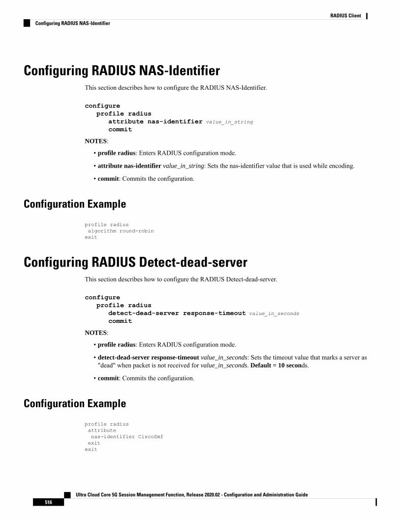
Configuring RADIUS NAS-IdentifierThis section describes how to configure the RADIUS NAS-Identifier.
configureprofile radius
attribute nas-identifier value_in_string
commit
NOTES:
• profile radius: Enters RADIUS configuration mode.
• attribute nas-identifier value_in_string: Sets the nas-identifier value that is used while encoding.
• commit: Commits the configuration.
Configuration Example
profile radiusalgorithm round-robinexit
Configuring RADIUS Detect-dead-serverThis section describes how to configure the RADIUS Detect-dead-server.
configureprofile radius
detect-dead-server response-timeout value_in_seconds
commit
NOTES:
• profile radius: Enters RADIUS configuration mode.
• detect-dead-server response-timeout value_in_seconds: Sets the timeout value that marks a server as"dead" when packet is not received for value_in_seconds. Default = 10 seconds.
• commit: Commits the configuration.
Configuration Example
profile radiusattributenas-identifier CiscoSmfexitexit
Ultra Cloud Core 5G Session Management Function, Release 2020.02 - Configuration and Administration Guide516
RADIUS ClientConfiguring RADIUS NAS-Identifier

Configuring RADIUS Dead-timeThis section describes how to configure the RADIUS Dead-time.
configureprofile radius
deadtime value_in_minutes
commit
NOTES:
• profile radius: Enters RADIUS configuration mode.
• deadtime value_in_minutes: Sets the time to elapse between RADIUS server marked unreachable andwhen we can re-attempt to connect. Default = 10 minutes.
• commit: Commits the configuration.
Configuration Example
profile radiusdetect-dead-server response-timeout 100exit
Configuring RADIUS Max-retryThis section describes how to configure the RADIUS Max-retry.
configureprofile radius
max-retry value
commit
NOTES:
• profile radius: Enters RADIUS configuration mode.
• max-retry value: Sets the maximum number of times system will attempt retry with RADIUS server.Default = 5.
• commit: Commits the configuration.
Configuration Example
profile radiusdeadtime 15exit
Ultra Cloud Core 5G Session Management Function, Release 2020.02 - Configuration and Administration Guide517
RADIUS ClientConfiguring RADIUS Dead-time

Configuring RADIUS TimeoutThis section describes how to configure the RADIUS Timeout.
configureprofile radius
timeout value_in_seconds
commit
NOTES:
• profile radius: Enters RADIUS configuration mode.
• timeout value_in_seconds: Sets the time to wait for response fromRADIUS server before re-transmitting.Default = 3 seconds
• commit: Commits the configuration.
Configuration Example
profile radiusmax-retry 2exit
Configuring RADIUS PODThis section describes how to configure the RADIUS POD.
configureendpoint radius-dns
replicas number_of_replicas
commit
NOTES:
• endpoint radius-dns: Enters endpoint radius-ep configuration mode.
• replicas number_of_replicas: Sets the number of replicas required.
• commit: Commits the configuration.
Configuration Example
profile radiustimeout 4exit
Ultra Cloud Core 5G Session Management Function, Release 2020.02 - Configuration and Administration Guide518
RADIUS ClientConfiguring RADIUS Timeout

Configuring RADIUS NAS-IPThis section describes how to configure the RADIUS NAS-IP
configureendpoint radius-dns
interface radius-clientvip-ip ipv4_address
commit
NOTES:
• endpoint radius-dns: Enters endpoint radius-ep configuration mode.
• interface radius-client: Enters the radius-client interface-type configuration mode.
• vip-ip ipv4_address: Sets the NAS-IP value, which is also used as source-ip in UDP requests towardRADIUS server.
• commit: Commits the configuration.
Configuration Example
endpoint radius-dnsreplicas 3exit
Configuring Secondary Authentication MethodThis section describes how to configure the secondary authentication method.
configureprofile dnn dnn_name
authentication secondary radiuscommit
NOTES:
• profile dnn dnn_name: Enters the DNN Profile configuration mode.
• authentication secondary radius: Enables the "secondary-authentication" under the DNN profile andsets method as "RADIUS".
• commit: Commits the configuration.
Configuration Example
endpoint radius-dnsinterface radius-client
Ultra Cloud Core 5G Session Management Function, Release 2020.02 - Configuration and Administration Guide519
RADIUS ClientConfiguring RADIUS NAS-IP

vip-ip 10.86.73.89exitexit
RADIUS Client OA&M SupportThis section describes operations, administration, and maintenance information for this feature.
StatisticsFollowing statistics are available related to RADIUS functionality:
• SMF-Service:
• Number of Secondary-Authentication requests sent
• Number of Secondary-Authentication response received
• RADIUS-EP:
• Number of Secondary-Authentication requests sent
• Number of Secondary-Authentication response received
• Number of RADIUS packets sent
• Number of RADIUS packets received
Ultra Cloud Core 5G Session Management Function, Release 2020.02 - Configuration and Administration Guide520
RADIUS ClientRADIUS Client OA&M Support
C H A P T E R 33Resource Management
• Feature Summary and Revision History, on page 521• Feature Description, on page 521
Feature Summary and Revision History
Summary DataTable 142: Feature Summary
SMFApplicable Product(s) or Functional Area
SMIApplicable Platform(s)
Enabled – Always-onFeature Default Setting
Not ApplicableRelated Changes in this Release
Not ApplicableRelated Documentation
Revision HistoryTable 143: Revision History
ReleaseRevision Details
Pre-2020.02.0First introduced.
Feature DescriptionThe UE IP address and ID allocation and management (resource management) feature is used by the SMFservice and supported by the NodeMgr.
The Master NodeMgr initializes the following in Redis-DB:
Ultra Cloud Core 5G Session Management Function, Release 2020.02 - Configuration and Administration Guide521

• IP pools for all DNN profiles
• Running counter for ID
• Free list for ID
The NodeMgr hosts the resource management server functionality and exposes the APIs for:
• IP allocation and management
• IP allocation
• IP release
• IP reallocation (release the current IP and allocate new IP for UE)
• ID allocation and management
• ID allocation
• ID release
• ID reallocation (release the current ID and allocate new ID)
The SMF service runs the resource management client to use the Rmgr services.
Call Flows
IP and ID AllocationThe following call flow illustrates the IP and ID allocation.
Figure 109: IP and ID Allocation Call Flow
IP and ID DeallocationThe following call flow illustrates the IP and ID deallocation.
Ultra Cloud Core 5G Session Management Function, Release 2020.02 - Configuration and Administration Guide522
Resource ManagementCall Flows

Figure 110: IP and ID Deallocation Call Flow
Ultra Cloud Core 5G Session Management Function, Release 2020.02 - Configuration and Administration Guide523
Resource ManagementIP and ID Deallocation

Ultra Cloud Core 5G Session Management Function, Release 2020.02 - Configuration and Administration Guide524
Resource ManagementIP and ID Deallocation

C H A P T E R 34Router Solicit and Router Advertisement
This chapter covers the following topics:
• Feature Summary and Revision History, on page 525• Feature Description, on page 525• ICMPv6 Profile Configuration, on page 527
Feature Summary and Revision History
Summary DataTable 144: Summary Data
SMFApplicable Product(s) or Functional Area
SMIApplicable Platform(s)
Enabled – Always-onFeature Default Setting
Not ApplicableRelated Changes in this Release
Not ApplicableRelated Documentation
Revision HistoryTable 145: Revision History
ReleaseRevision Details
Pre-2020.02.0First introduced.
Feature DescriptionTo comply to IPv6 Stateless Auto-configuration, SMF supports ICMPv6 Router Solicit and Advertisement.
The following ICMPv6 options are supported in Router Advertisement:
Ultra Cloud Core 5G Session Management Function, Release 2020.02 - Configuration and Administration Guide525

• Prefix Information - Allocated UE IPv6 Prefix is sent.
• MTU - Value is taken from configuration. Default is 1500.
• Source Link Layer Address: Value is taken from configuration local virtual mac.
Unsolicited Router AdvertisementSMF sends unsolicited router advertisement on successful PDU session establishment to share the allocatedIPv6 prefix to UE. RA message is sent over the GTPU tunnel, which is created between the SMF and UPFduring the Session Establishment procedure. SMF also installs PDRs and FARs on the UPF to enable routingfor RS/RA messages.
Solicited Router AdvertisementTo get the allocated IPv6 prefix, UE can send a router solicit message. On receiving router solicit message,SMF sends router advertisement message towards UE containing the allocated UE IPv6 prefix.
Ultra Cloud Core 5G Session Management Function, Release 2020.02 - Configuration and Administration Guide526
Router Solicit and Router AdvertisementUnsolicited Router Advertisement
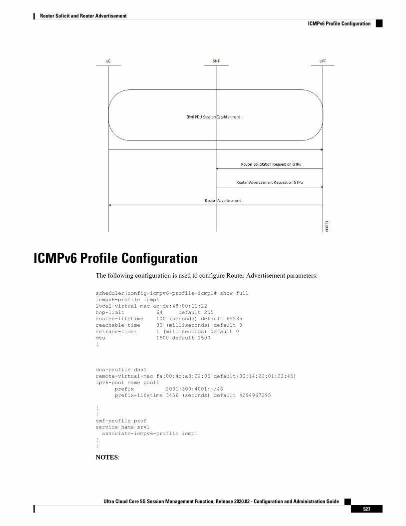
ICMPv6 Profile ConfigurationThe following configuration is used to configure Router Advertisement parameters:
scheduler(config-icmpv6-profile-icmp1# show fullicmpv6-profile icmp1local-virtual-mac ac:de:48:00:11:22hop-limit 64 default 255router-lifetime 100 (seconds) default 65535reachable-time 30 (milliseconds) default 0retrans-timer 1 (milliseconds) default 0mtu 1500 default 1500!
dnn-profile dnn1remote-virtual-mac fa:00:4c:a8:22:05 default(00:14:22:01:23:45)ipv6-pool name pool1
prefix 2001:300:4001::/48prefix-lifetime 3456 (seconds) default 4294967295
!!smf-profile profservice name srv1associate-icmpv6-profile icmp1
!!
NOTES:
Ultra Cloud Core 5G Session Management Function, Release 2020.02 - Configuration and Administration Guide527
Router Solicit and Router AdvertisementICMPv6 Profile Configuration

• /48 is the only prefix supported in this release.
Ultra Cloud Core 5G Session Management Function, Release 2020.02 - Configuration and Administration Guide528
Router Solicit and Router AdvertisementICMPv6 Profile Configuration

C H A P T E R 35Session and Service Continuity Mode
This chapter covers the following topics:
• Feature Summary and Revision History, on page 529• Feature Description, on page 530• Configuration, on page 531
Feature Summary and Revision History
Summary DataTable 146: Summary Data
SMFApplicable Product(s) or Functional Area
SMIApplicable Platform(s)
Enabled – Always-onFeature Default Setting
Not ApplicableRelated Changes in this Release
Not ApplicableRelated Documentation
Revision HistoryTable 147: Revision History
ReleaseRevision Details
Pre-2020.02.0First introduced.
Ultra Cloud Core 5G Session Management Function, Release 2020.02 - Configuration and Administration Guide529

Feature Description
Session and Service ContinuityThe Session and Service Continuity (SSC) support in 5G system architecture enables to address the variouscontinuity requirements of different applications and services for the User Equipment (UE). The 5G systemsupports different SSC modes. The SSC mode associated with a PDU session does not change during thelifespan of a PDU session. The following three modes are specified:
• With SSC mode 1, the network preserves the connectivity service provided to the UE. For the case ofPDU session of IPv4 or IPv6 or IPv4v6 type, the IP address is preserved.
• With SSC mode 2, the network may release the connectivity service delivered to the UE and also mayrelease the corresponding PDU session(s). For the case of IPv4 or IPv6 or IPv4v6 type, the release ofthe PDU session induces the release of IP address(s) that had been allocated to the UE.
• With SSC mode 3, changes to the user plane can be visible to the UE, while the network ensures that theUE suffers no loss of connectivity. A connection through new PDU session anchor point is establishedbefore the previous connection is terminated in order to allow for better service continuity. For the caseof IPv4 or IPv6 or IPv4v6 type, the IP address is not preserved in this mode when the PDU session anchorchanges.
Session and Service Continuity Mode SelectionThe SSCmode selection policy is used to determine the type of session and service continuity mode associatedwith an application or group of applications for the UE. The SMF receives the list of supported SSC modesand the default SSC mode per DNN per S-NSSAI as part of the subscription information from the UDM.
To select the SSC mode, when UE sends SSC mode in PDU session establishment request, it is checkedagainst subscriber data and local SMF configuration and allowed SSC mode is determined.
In this release, SMF supports only SSC mode-1.Important
Priority for Choosing Session and Service Continuity ModePriority #1: Subscriber data from UDM has highest priority. UDM sends DefaultSscMode andAllowedSscMode.
Priority #2: Local SSC mode configuration data present in DNN profile which contains ssc-mode andallowed-ssc-mode.
Session and Service Continuity Mode Selection MethodThe SSC mode has the following selection methods:
Ultra Cloud Core 5G Session Management Function, Release 2020.02 - Configuration and Administration Guide530
Session and Service Continuity ModeFeature Description

• The SMF verifies if UE sent SSC mode is part of either default ssc mode or allowed ssc mode in orderof priority mentioned above. If it is found then PDU establishment procedure continues, otherwise PDUsession establishment reject message will be sent to UE with allowed ssc modes in reject message.
• If the SMF does not receive SSC mode from UE, then default ssc mode in the order of above priority ischosen and used to establish PDU session.
• Since current release only supports SSC Mode-1, in case UE sends any other modes, PDU sessionestablishment will be rejected.
NOTES:
WhenUE requests SSCmode-2 ormode-3, as long as the UE's subscription (in the order of priority: UDM/Localconfiguration on SMF) allows SSC mode-1 along with SSC mode-2/3, SMF will send PDU sessionestablishment reject with 5GSM cause: 68 (Not supported SSC mode) and Allowed SSC mode as 01. Thisapproach is used to allow the UE to retry with SSC mode-1. As per 3GPP spec: 24.501, 5GSM cause: 68 tobe sent when the requested SSC mode is not supported by the subscription.
To honor PDU session establishment, SMF expects SSC mode either via UDM subscription or via localconfiguration. Otherwise, irrespective of SSC mode reception from UE, if SMF doesn't have SSC mode aspart of UDM subscription or via local configuration, SMFwould reject PDU session establishment with 5GSMcause: 31 (Request rejected and unspecified).
ConfigurationTo configure the SSC Mode in SMF DNN profile, use the following configuration:
configprofile dnn dnn_name
ssc-mode 1 allowed-ssc-mode 2commit
commit complete
To remove the configuration of the SSC Mode from SMF DNN profile, use the following configuration:
configprofile dnn dnn_name
no ssc-modecommit
commit complete
Ultra Cloud Core 5G Session Management Function, Release 2020.02 - Configuration and Administration Guide531
Session and Service Continuity ModeConfiguration

Ultra Cloud Core 5G Session Management Function, Release 2020.02 - Configuration and Administration Guide532
Session and Service Continuity ModeConfiguration

C H A P T E R 36SMF Charging
• Feature Summary and Revision History, on page 533• Overview, on page 534• Mapping of Charging Scenario on Various Interfaces, on page 550• Error Handling Scenarios, on page 556• Dynamic Configuration Change Support, on page 559
Feature Summary and Revision History
Summary DataTable 148: Summary Data
SMFApplicable Product(s) or Functional Area
SMIApplicable Platform(s)
Disabled – Configuration RequiredFeature Default Setting
Not ApplicableRelated Changes in this Release
Not ApplicableRelated Documentation
Revision HistoryTable 149: Revision History
ReleaseRevision Details
Pre-2020.02.0First introduced.
Ultra Cloud Core 5G Session Management Function, Release 2020.02 - Configuration and Administration Guide533

OverviewThe SMF acts as a Charging Transfer Function (CTF). The CTF generates charging events toward the ChargingFunction (CHF), which is responsible for generating Charging Data Records (CDRs).
This SMFNF interacts with various interfaces such as N40, N4, N7, and N10, facilitating charging in entirety.Currently, the Cisco SMF uses the Nchf/N40 interface to generate charging events.
Figure 111: SMF as a Charging Transfer Function
The SMF Charging feature supports the following functionality:
• Converged Online and Offline charging.
• PDU session charging using the service-based interface.
• Network slice instance charging.
• Charging information collection per PDU session for UEs served under 3GPP access.
• Each PDU session is assigned a unique identity number for billing purposes.
• Data volumes on both the uplink and downlink directions are counted separately. The data volumesreflect the data as delivered to and forwarded from the user.
• The charging mechanism provides the date and time information when the PDU session starts.
• The SMF handles Charging Characteristics specific to a subscription or a subscribed DNN.
• The SMF identifies data volumes, elapsed time, or events for individual service data flows (flow-basedcharging). One PCC rule identifies one service data flow.
• SMF allows usage reporting of a service or a detected application per rating group or per combinationof the rating group and service ID. This reporting level can be activated per PCC rule.
• Quota management is done per Rating Group (RG) per PDU session.
• SMF supports charging for IP-based PDU session types.
Ultra Cloud Core 5G Session Management Function, Release 2020.02 - Configuration and Administration Guide534
SMF ChargingOverview

Converged ChargingThe 5G system supports converged charging for offline and online charging scenarios.
The SMF performs converged charging for each of the following:
• Charging data that is related to PDU session.
• Charging data that are related to service-data flows within a PDU session.
The scope of convergent charging in this implementation includes quota management and usage reporting.For convergent charging, the SMF interacts with the CHF for charging data related to PDU sessions. TheCharging Data Request and the Charging Data Response messages are exchanged between the SMF and theCHF based on session-based charging (SCUR scenarios). The Charging Data Request is issued by the SMFonly when conditions that are related to chargeable events are met.
Chargeable EventsPCC rules can be activated, deactivated, and modified at any time during the PDU session lifetime.
The following attributes can be modified by the PCF in a dynamic PCC rule active in the SMF:
• Charging Key
• Service Identifier
• Measurement Method
Activities on PCC rules and QoS flows are not chargeable events. However, change of charging rule in PCCrules lead to chargeable events such as:
• Start of service data flow
• Termination of service data flow, for the last service data flow for the original PCC rule
The charging key (that is, rating group) is used to request online charging quota.
Charging IdentifierThe charging identifier corelates charging information between the SMF and CHF during the duration of aPDU session. The SMF generates and assigns a charging identifier when a PDU session is established. Thecharging identifier is unique for that PDU session and is used in all messages that are exchanged in that PDUsession.
Charging InformationThe SMF collects the following charging information for converged online and offline charging:
• Usage of access and core network resources: Describes the amount of data that is delivered to andforwarded from the UE.
• Usage duration: Time interval from PDU Session Establishment to PDU Session Release.
• User: UE information used by the user for a PDU session.
• Data network: Data network address as determined by the DNN.
• Start time: PDU session start time.
Ultra Cloud Core 5G Session Management Function, Release 2020.02 - Configuration and Administration Guide535
SMF ChargingConverged Charging
• User location: HPLMN and VPLMN reporting area.
For service-data flows (flow-based charging), the SMF collects the following information:
• PDU session description.
• Data that are transmitted in uplink and downlink directions based on the rating-group information, or acombination of rating-group and service ID during volume-based charging.
• Duration of service data flow based on the rating group, or a combination of rating-group and serviceID during event-based charging.
• Events and timestamps based on rating-group or based on a combination of the rating-group and serviceID during event-based charging.
The SMF collects charging information for service data flows per UPF, within a PDU session, based on therating-group or based on a combination of rating-group and service ID.
How it Works
Charging SessionThe SMF supports converged session-based charging (SCUR) as specified in 3GPP TS 32.290, Section 5.3.2.3.
The SMF establishes charging session with the CHF with the Charging Data Request and Response (Initial)exchange. During the life of the PDU session, usage is reported with Charging Data Request/Response (Update)exchange. After the session is released, Charging Data Request/Response (Termination) messages areexchanged.
Offline Charging and Online ChargingCharging is enabled for a session based on the input that is received from the PCF.
For offline charging, the SMF sends Charging Data Request Initial toward the Charging Function (CHF)based on the presence of charging descriptors and refChgData field set in the smPolicyDecisionmessage fromthe PCF in SmPolicyControlCreate response.
On determining if charging is required during initial session establishment or post-session establishment,charging is enabled for the PDU session. Once charging is enabled, SMF sends the Charging Data Request(Initial) Message toward the CHF.
The SMF determines Volume/Time threshold value either locally or from Charging Data Response. Thesevalues are used to update Volume/Time threshold IE in URR and to set the reporting trigger accordingly. Themeasurement method that is used in URR is derived from charging data.
For online charging, the SMF receives the Volume/Time Threshold and Quota values from the CHF. Thesevalues are received in the Charging Data Response (Initial) or using a Charging Data Request (Update) duringa PDU Session Establishment. The SMF relays these Volume/Time Threshold and quota values to the UPFin the corresponding URR.
NOTE: The threshold values from CHF always override the locally configured values.
The following table maps the IEs that are shared with the UPF during Create/Update URR during online/offlinecharging scenarios:
Ultra Cloud Core 5G Session Management Function, Release 2020.02 - Configuration and Administration Guide536
SMF ChargingHow it Works

Derived FromOfflineOnlineIE
CHF Response/Local ConfigurationYesYesVolume Limit
CHF Response/Local ConfigurationYesYesTime Limit
CHF ResponseNoYesVolume Quota
CHF ResponseNoYesTime Quota
CHF Response—YesQuota Holding Time
• Local configuration for offlinecharging
• CHF response for online charging
YesYesMonitoring Time
The respective triggers that are set asshown in the following table.
YesYesReporting Trigger
Derived FromReporting Trigger
If Volume threshold is setVolume Threshold Trigger
If Time threshold is setTime Threshold Trigger
If Quota Exhausted trigger is set from CHFVolume Quota Trigger
If Quota Exhausted trigger is set from CHFTime Quota Trigger
If URR contains Linked URRLIUSA Trigger
Quota Management
The SMF requests quota from the CHF upon meeting any of the following conditions:
• The Rating Group (RG) is installed for the first time and the charging method is Online for the dynamicrule.
• The start of traffic trigger is initiated from the UPF for the RG in the case of static or predefined rules.
• A specific trigger type, as defined in the 3GPP specification 32.255, is received in the usage report forthe online charging service from the UPF.
The SMF uses the quota request always CLI command to request the quota always. This CLI command isavailable in the Charging Profile configuration mode. Upon configuring this CLI command, the SMF alwaysrequests for quota when reporting the usage to the CHF for the online services. The quota requesting endswhen the charging service stops.
Irrespective of the quota request [ always | standard ] CLI configuration, the quota request is disabled forthe trigger type "qht" configured through the quota suppress triggers CLI command.
For command details, see the Charging Profile Configuration, on page 547 section in the SMF Charging chapterof this guide.
Service Units for Quota Management
The SMF sends Charging Data Request (CDR) to the Charging Function (CHF) for the service to be grantedauthorization to start, and to reserve the number of units. While triggering the CDR, the SMF requests volume
Ultra Cloud Core 5G Session Management Function, Release 2020.02 - Configuration and Administration Guide537
SMF ChargingQuota Management

(uplink, downlink, total) and time quota from CHF to support VoLTE and other use cases. The values of therequested units for static rules are obtained from the Diameter configuration under Active Charging Service.For the dynamic audio or video rules, the values for the requested service units are configured through therequested-service-unit CLI command in the Charging Profile Configuration mode. For command details,see the Charging Profile Configuration, on page 547 section in the SMF Charging chapter of this guide.
Support for Validity Time
The SMF uses time quota value and its corresponding trigger on N4 interface to arm the UPF about the timewhen the SMF needs the reporting of validity time.
The CHF arms the SMF to report the usage for the rating group when the timer associated with the validity_timeexpires.
Based on the presence of Validity Quota and Time Quota, the SMF behaves as specified in the followingways:
• When the CHF sends only the Time Quota and not the Validity Quota, the SMF relays the CDR-U tothe CHF and reports as Quota_EXHAUSTED upon receiving the usage report from the UPF.
• When the CHF sends only the Validity Quota and not the Time Quota, the SMF relays the CDR-U tothe CHF and reports as VALIDITY_TIME upon receiving the usage report from the UPF.
• When the CHF sends both the Validity Quota and the Time Quota, the SMF determines the lower valueof time_quota and validity_time, and then relays the CDR-U to the CHF accordingly. The SMF sendsthe "VALIDITY_TIME" trigger when the validity_time is lesser than the time_quota value. Similarly,when the validity_time is greater than the time_quota value, the SMF sends the "Quota_EXHAUSTED"trigger.
CHF SelectionThe CHF selection, that is, CHF address determination by the SMF is performed during PDU SessionEstablishment. This selection is based on the following in order of priority:
1. PCF provides one or more CHF addresses as part of the PCC rule.
2. UDM-provided charging characteristics.
3. NRF-based discovery.
4. SMF locally provisioned charging characteristics.
NOTE: The local configuration is currently used to get CHF IP/port.
Charging Activities at SMFURR Generation Toward N4
The SMF receives charging-data and usage-monitoring-data from the PCF. Based on this information, theSMF derives URR toward N4. In case the SMF is configured with volume/time limit at the session level, theSMF creates session-level URR.
Handling of Initial Event in Charging Component
The session context of SMF is configured with trigger/threshold as per the default described in 3GPP TS32.255. It overrides the same based on configuration present in the charging profile. The same values can be
Ultra Cloud Core 5G Session Management Function, Release 2020.02 - Configuration and Administration Guide538
SMF ChargingSupport for Validity Time

further overridden by CHF Charging Data Response Initial. Currently, trigger/threshold cannot be overriddenwhen in PDU Establishment state.
The charging profile is referenced from the charging-characteristic profile. The CC profile is taken fromUDMsubscription for PDU session. If the CC profile is not mentioned in the UDM response, it is taken from theDNN profile.
After trigger/threshold/quota are determined, the SMF N4 Setup Request with set of Create URRs are derivedfrom charging-data with one session-level URR.
If the session-level reporting is determined, the session-level URR is associated to each SDF URR.
The following triggers are supported:
• Volume/Time trigger at session/RG level
• AMBR change
• QoS change
• Quota threshold and quota exhausted
• Quota handling time
• Tariff time change
Obtaining Threshold Values at SMF
Threshold values, during online charging, are always obtained from the CHF. Whereas the threshold values,during offline charging, are obtained either from the CHF or from the charging profile configuration.
If charging profile is not determined during PDU establishment, the SMF refers to the charging profile fromthe DNN profile. Once the Charging Profile is determined, the SMF uses the determined Charging Profile toobtain the threshold values for Session/SDF URR.
The configuration has threshold values at a session level or rating-group level. The rating-group level thresholdvalues are generic and not about a rating-group. These threshold values are overwritten by CHF response.
NOTE: The CHF response has various triggers. If some trigger is present at the session level or rating-grouplevel, and if the volume or time threshold value is not available, then these values are assumed to be disabledat the corresponding level.
Trigger Determination at SMF
The SMF has triggers enabled by default, as specified in 3GPP TS 32.255, Section 5.2.1.4.
These triggers can be overwritten at a session level by trigger configurations present in the charging profile.Further, these triggers can also be overwritten by CHF responses.
Trigger configuration in charging profile is only applicable at a session level. It is not applicable forrating-groups.
NOTE: The CHF response has various triggers. If some triggers are present at a session or rating-group leveland other triggers are not present, then these triggers are assumed to be disabled.
Reporting Category
The charging trigger can be of two reporting categories – Immediate and Deferred. The usage report of theimmediate category must be reported to the CHF immediately. For reporting events that must be deferred,
Ultra Cloud Core 5G Session Management Function, Release 2020.02 - Configuration and Administration Guide539
SMF ChargingObtaining Threshold Values at SMF

the SMF will store the usage report locally, and will publish either when the next trigger of the immediatecategory is invoked, or when the storage limit is exhausted.
When reporting stored usage reports to the CHF, the usage report is triggered because of the trigger type inUsedUnitCategory and the message is triggered because of the trigger type in ChargingDataRequest.
Sometimes, a scenario can have two triggers hit at the same time. AMBR_Change and QoS Change canhappen at the same time. In which case, all the triggers as applicable at the RG level or session level will havemultiple trigger values.
A trigger can be enabled at the RG level, and for some RG it can be immediate reporting and for others it canbe deferred reporting. When a trigger event is hit, various usage reports will have a corresponding categoryfilled respectively in usedUnitContainer.
Deferred CDR will be relayed in the following scenarios:
• An immediate category event happens.
• Maximum number of charging conditions are crossed.
• Configured number of maximum deferred reporting is crossed.
Maximum Charging Characteristics (CC) is reset whenever there are push CDRs. This could be because ofmaximum CC limits being crossed or because of immediate category reporting.
NOTE: Currently, SMF does not support two charging descriptors with the same rating group.
Handling Reporting Level
The reporting category is classified into the following:
• Rating Group (RG) level: The RG is mandatory at this level.
• Service ID level: The RG and service ID is mandatory at this level.
• Sponsor ID level: The RG and Sponsor ID is mandatory at this level.
The reporting level is conveyed to the SMF from PCF in the Charging Data Request. If the reporting-level isRG, RG is the primary key. If the reporting level is Service_level or SponserLevl, the primary key becomesRG and Service ID or RG or Sponsor ID respectively. The SMF drops the charging descriptors from the PCFif the above requirement is not satisfied.
Re-Authorization
The CHF triggers Reauthorization of charging descriptors using Charging Notify request. Reauthorization isimplemented at the session-level or at a RG-level for both online and offline charging.
The SMF processes the reauthorization details (which contain an array of RG, ServiceId, QuotaMgmtIndicator)received in CHF Notify and retrieves the charging descriptors associated with the current PDU session. Anyunmatched reauthorization item is skipped.
For the charging descriptors identified for reauthorization, the SMF queries for usage reports from UPF andsends it to the CHF.
As part of the CHF response, the SMF detects any change in quota/threshold information and performs N4Session Modification to update URRs.
Ultra Cloud Core 5G Session Management Function, Release 2020.02 - Configuration and Administration Guide540
SMF ChargingHandling Reporting Level

Final Unit Indication Support
The SMF supports Final Unit Indication (FUI) in the Charging Data Initial/Update Response from CHF asper 3GPP TS 32.291, Section 6.1.6.2.1.12.
On receiving FUA, the SMF installs new FAR and associates it's FAR-ID in the URR, in the FAR ID QuotaAction IE. If a FAR with same parameters exists, the SMF uses it's FAR-ID in the Create/Update URR. TheUPF initiates appropriate actions set in FAR after quota exhaustion.
Currently, the SMF only supports Terminate and Redirect FU actions.
NOTES:
• At any instance, CHF provides granted unit (Quota) to the SMF along with FUI.
• When SMF receives the granted unit with FUI, the SMF creates FAR toward N4 and associates it to thecorresponding URR which carries the Quota information.
• UPF on receiving FAR associated with the URR, the corresponding FAR action is implemented whenthe quota exhausts.
Static and Predefined Rules for ChargingConfiguration of static/predefined rules is similar to the procedures on SMF and UPF. The layout of configuredis as follows:
1. Rulebase: A one-to-many rule base is configurable. For a single PDU session, a single rule base can beactivated at a given time. The rule base can be activated at SMF by the PCF by sending the rule base namein the PCC rule.
2. Ruledef: Each rule base can have one-to-many ruledef configurations. A ruledef can either be of static orpredefined type. Each ruledef is assigned to a charging action.
3. Charging Action: Contains QoS and charging information.
Ultra Cloud Core 5G Session Management Function, Release 2020.02 - Configuration and Administration Guide541
SMF ChargingFinal Unit Indication Support

The SMF derives charging data for each charging action in the rule base. Charging action associated to staticrules in the rule base is immediately derived and updated in the PDU context. Charging action associated topredefined rules is derived and updated when the said predefined rule is activated at SMF from PCF.
The charging action derived URR has the following behavior:
• Online charging is identified by the "cca charging credit" configuration under charging action.
• Offline charging is identified by the "billing action egcdr" configuration under charging action.
• Armed triggers for volume-limit and time-limit are under the gtpp group configuration, under APN. TheUPF automatically detects these values and sends the respective usage reports.
• The SMF, unlike the dynamic case, does not send the Create URR immediately for charging data that isderived from configured rules.
• Only when charging action is configured with "cca charging credit preemptively-request", the SMFsends the Create URR message. In all other cases, the SMF does not send the Create URR.
NOTE: This CLI is not qualified in the current release.
• For URR derived from configured rules, the SMF generates URR-ID from "urr-list". This configurationhas one URR-ID for each set of RG and service ID.
Therefore, when the UPF sends the usage report for a URR ID, the SMF does not identify thecorresponding URR, RG/service ID to be used for reporting toward the CHF.
• Using the online charging method, the UPF sends usage report with trigger "Start". The SMF uses CHFto derive the quota for the RG and relays the same information to the UPF in the Update URR message.
• The UPF threshold can be configured at a rule base level. It creates a rulebase-level URR that is linkedto all ruledef-level URR within the rule base.
Modification Scenarios in Charging
PCF Update
The PCF performs the following actions during a modification scenario:
• Addition of PCC rules
• Modification of reference data
• Deletion of PCC rules
• Content update in charging data - using Measurement method
CHF Response
The CHF response, during an exchange, sends updated volume and time thresholds and quota. The SMF relaysthe updated URR toward N4.
A change in threshold/trigger/quota triggers an Update URR, which leads to the N4 relay.
The Update URR is sent based on the following triggers:
• Volume/time threshold
• Volume/time quota
Ultra Cloud Core 5G Session Management Function, Release 2020.02 - Configuration and Administration Guide542
SMF ChargingModification Scenarios in Charging

• Tariff time change
• Quota holding time, and so on
URR Linking• If session-level volume/time value is configured locally or is received from the CHF, the SMF createssession-level URR and links it to all URR corresponding to offline charging descriptors.
• If multiple charging descriptors received by PCF are of the same rating group, the SMF creates extraURR and links it to all URR derived from charging descriptors of the same rating group.
URR Format
The URR ID format is as given below:
• URR ID is 32 bit.
• MSB (32nd) bit for static/predefined URRs is set to 1, and for dynamic URRs is set to 0.
• First four LSB bits are set for interface type.
• 1 for offline
• 7 for online
• Bit 4-31 is for URR ID number.
For example: Dynamic first URR if ID is 1:
0x00 00 01 01 Offline
0x00 00 01 07 Online
Static/Predefined first URR if ID is 1:
0x80 00 01 01 Offline
0x80 00 01 07 Online
Local ConfigurationThe following figure illustrates how local configuration works.
Ultra Cloud Core 5G Session Management Function, Release 2020.02 - Configuration and Administration Guide543
SMF ChargingURR Linking

NOTES:
1. The SMF supports up to 16 charging characteristic profiles.
2. Each CC profile comprises of charging group and charging profile.
3. The charging server group and charging profile are linked to the DNN profile. Currently, the chargingprofile supports configuration for trigger and thresholds.
Call FlowsThis section presents the following call flows:
PDU Session Establishment
The following figure illustrates the call flow of PDU session establishment.
Ultra Cloud Core 5G Session Management Function, Release 2020.02 - Configuration and Administration Guide544
SMF ChargingCall Flows

DescriptionStep
Call Setup1.
SMF performs a Policy Create exchange with PCF. In this exchange, the SMFmightreceive Charging Data that is associated to a PCCRule. This indicates that chargingis enabled for the session in progress.
It is possible that PCF has enabled Static/Predefined rules. These rules can be alsoenabled with charging, based on the configuration.
2.
Once charging is detected at SMF, it initiates a Charging Data Request Initialexchange with CHF. In this exchange SMF may receive the following from CHF:
• CC triggers at session or RG level
• Session level Time or Volume limits
• Time or Volume limits at RG level
• Quota at RG level
3.
N1N2 Exchange and SM Context Update Exchange4.
Ultra Cloud Core 5G Session Management Function, Release 2020.02 - Configuration and Administration Guide545
SMF ChargingPDU Session Establishment

DescriptionStep
SMF initiates N4 session establishment request exchange with UPF, and in the samerequest it relays information that is related to charging in the Create URRs.
5.
Standards ComplianceThe SMF Charging feature complies with the following standards:
• 3GPP TS 32.255
• 3GPP TS 32.290
3GPP June 2019 Compliance for Charging InterfaceThe SMF is compliant with the 3GPP June 2019 specification TS 32.290 version 15.3.0.
For the June release the messages goes over the version "v2" as indicated below in URI format.
nchf-convergedcharging/v2/chargingdata
The CLI command for compliance configuration is: service nchf-convergedcharging. If this CLI commandor version is not configured, the default version from 3GPP December 2018 is applied.
With the 3GPP June 2019 compliance, the following new information elements (IE) are added:
• Authorized QoS
• Subscribed QoS
• IEs in QoSData
• Serving Network Function ID
Configuring SMF ChargingSMF Charging involves the following configurations:
• DNN Profile Configuration
• Charging Characteristics Profile Configuration
• Charging Profile Configuration
DNN Profile ConfigurationUse the following configuration to configure a DNN profile for SMF Charging.
configureprofile dnn profile_name
charging-profile profile_name
network-element-profiles { amf | chf | pcf | udm } profile_name
end
NOTES:
Ultra Cloud Core 5G Session Management Function, Release 2020.02 - Configuration and Administration Guide546
SMF ChargingStandards Compliance

• charging-profile: Specifies the Charging Profile configuration.
• network-element-profiles: Specifies the network element profile. Network element profile can be oneof the following:
• amf: Specifies the AMF network element profile.
• chf: Specifies the CHF network element profile.
• pcf: Specifies the PCF network element profile.
• udm: Specifies the UDM network element profile.
• profile_name must be a string.
Charging Characteristics Profile ConfigurationUse the following configuration to configure charging characteristics profile for SMF Charging.
configureprofile charging-characteristics cc_value
charging-profile profile_name
end
NOTES:
• cc_value: Specifies the charging characteristics value which is an integer from 1 to 16.
Charging Profile ConfigurationUse the following configuration to configure the charging profile parameters for SMF charging.
configureprofile charging profile_name
limit [ rating-group ] { duration duration_value | volume volume_value }max-charging-condition max_cc_value
max-deferred-urr max_urr_value
method { none | offline | online }quota request [ always | standard ]quota suppress triggers [ qht ]reporting-level { offline | online { [rating-group] | rating-group
| service-id }requested-service-unit time seconds volume downlink downlink_value uplink
uplink_value total total_value
tight-interworking-mode { false | true }triggers session session_level_triggers
end
NOTES:
• limit: Specifies the threshold limit.
• duration: Specifies the duration threshold for charging. The threshold value ranges from 0 through2147483647.
Ultra Cloud Core 5G Session Management Function, Release 2020.02 - Configuration and Administration Guide547
SMF ChargingCharging Characteristics Profile Configuration

• volume: Specifies the volume threshold for charging. The threshold value ranges from 0 through9223372036854775807.
• rating-group: Specifies the volume and duration threshold for a Rating Group.
• max-charging-condition max_cc_value: Specifies the maximum number of changes to the chargingcondition. max_cc_value must be an integer ranging from 0 through 500. The default value is 20.
• max-deferred-urr max_urr_value: Specifies the maximum number of deferred USU containers.max_urr_value must be an integer ranging from 0 through 200. The default value is 50.
• method: Specifies the charging method. The default charging method is offline.
• quota request [ always | standard ]: Controls the requesting of quota from the CHF for online chargingservices based on the configuration. If the quota request always is configured, the SMF always requestsfor quota. If the no quota request or quota request standard CLI command is configured, then theSMF requests the quota for specific trigger types as defined in standard, which is the default behaviour.
• quota suppress triggers [ qht ]: Suppresses the quota from the CHF upon configuring the usage reporttrigger type "qht".
• reporting-level: Specifies the reporting level configuration to be used for offline and online charging.
The default value is [rating-group] level.
• requested-service-unit: Configures the value for the requested service units.
• time seconds: Configures the time quota value in seconds from 1 through 4000000000.
• downlink downlink_value: Configures the downlink volume in bytes from 1 through 4000000000.
• uplink uplink_value: Configures the uplink volume in bytes from 1 through 4000000000.
• total total_value: Configures the total volume in bytes from 1 through 4000000000.
• tight-interworking-mode: Configuration to enable tight interworking mode for online/offline chargingmethods.
• triggers: List of triggers to be configured.
• session session_level_triggers: Specifies the list for Session Level Triggers. The list of Session LevelTriggers is as follows:
• repor3gpp-ps-change
• ambr-change
• max-number-of-changes-in-charging-conditions
• plmn-change
• qos-change
• rat-change
• serv-node-change
• tarrif-time-change
• ue-pra-change
Ultra Cloud Core 5G Session Management Function, Release 2020.02 - Configuration and Administration Guide548
SMF ChargingCharging Profile Configuration

• ue-time-change
• upf-add
• upf-rem
• user-loc-change
The following is a sample configuration for SMF Charging:configure
charging-server ch1fqdn abc.comcapacity 10 (default : 10)priority 1 (default: 1)ip-address 127.0.0.1port 1234!!
dnn-profile dnn1charging-server-name [ chserv1 ]charging-profile chProf1!
profile charging ch1limit volume tot 2000limit duration 20limit rating-group volume tot 4000limit rating-group duration 40triggers session [ ambr-change qos-change]
max-charging-condition 20max-deferred-urr 100reporting-level service-idrequested-service-unit time 20 volume downlink 8000 uplink 2000 total 10000!
profile charging-characteristics 1charging-profile ch1!
Static PCC Rules ConfigurationFor information on Configuring Static PCC Rules for Charging, refer to Configuring the Static PCC RulesSupport on SMF section in the Policy and User Plane Management chapter.
The following is an example Static PCC Rule configuration:
configureactive-charging service acs
credit-control group 1diameter ignore-service-id truepending-traffic-treatment forced-reauth droppending-traffic-treatment noquota passquota holding-time 10usage-reporting quotas-to-report based-on-grant report-only-granted-volumeexit
urr-list urrlocalrating-group 320011 service-identifier 10 urr-id 1
charging-action ca95billing-action egcdrcca charging creditcontent-id 320011service-identifier 10
Ultra Cloud Core 5G Session Management Function, Release 2020.02 - Configuration and Administration Guide549
SMF ChargingStatic PCC Rules Configuration

exitcharging-action testcca charging credit preemptively-request //This is not in scope of current release
exitrulebase rb1
action priority 10 ruledef rd95 charging-action ca95action priority 11 dynamic-only ruledef rd93 charging-action ca93
exit
gtpp group group1gtpp egcdr service-data-flow threshold interval 1234
gtpp egcdr service-data-flow threshold volume downlink 13000gtpp egcdr service-data-flow threshold volume uplink 17000gtpp egcdr service-data-flow threshold volume total 22222
exit
Mapping of Charging Scenario on Various Interfaces
Feature DescriptionSMF supports charging on the N7, N40, and N4 interfaces. Based on the charging data information that SMFreceives, it provides reporting level support for online and offline charging. The behavior of SMF changesaccording to the messages received on the N7, N4, and N40 interfaces.
How it WorksSMF provides the different reporting levels for online and offline charging with the following rules:
• Configured rules are derived from the static or predefined charging actions.
• Session-level Usage Reporting Rule (URR) is derived from CHF trigger or local configuration.
• SMF does not associate session-level URR for online and offline method charging description.
• SMF does not associate session-level URR to the configured charging-action URRs.
• Rulebase URR is applicable only for the offline configured URR.
• For the configured online or online-offline charging method, if Ignore Service ID configuration exists,the URR list must contain "rg x urr-id y". Else, the SMF drops the charging actions as malformed.
SMF supports multiple charging methods within the same rating group.Important
Charging Mapping
The N7 interface uses Charging Data from PCC rules or local configuration, N4 interface uses URR or PacketDetection Rule (PDR), and N40 interface uses Used Unit Container (UUC).
SMF charging mapping on N7, N4, and N40 interfaces with various charging methods is described as follows.
Offline Method When Charging Data is Derived from One PCC Rule
• Reporting level: Rating Group level or Service ID level
Ultra Cloud Core 5G Session Management Function, Release 2020.02 - Configuration and Administration Guide550
SMF ChargingMapping of Charging Scenario on Various Interfaces

• N4 interface:
• First URR is derived from the first Charging Data. Charging data limits from rating group triggeror local configuration.
• Second URR is derived from Session Limit, which is CHF or local configuration.
• Second URR is linked to the first URR.
• First PDR is derived from the first PCC rule.
• First and second URRs are linked to the first PDR.
• N40 interface:
• First UUC is derived from the usage report of the first URR.
• First UUC may or may not have a service identifier.
NOTES:
• Session-level URR is not associated to the configured URRs.
• If configured, rulebase URR replaces session-level URR.
• If configured and rulebase URR exists, it is linked to the first URR.
Online Method When Charging Data is Derived from One PCC Rule
• Reporting level: Service ID level or Rating Group level
• N4 interface:
• First URR is derived from the first Charging Data, which is threshold or quota from rating groupgranted-unit.
• Second URR is derived from Session Limit, which is CHF or local configuration.
• Second URR is linked to the first URR.
• First PDR is derived from the first PCC rule.
• First and second URRs are linked to the first PDR.
• N40 interface:
• First UUC is derived from usage report of the first URR.
• First UUC may or may not have a service identifier.
NOTES:
• Session-level URR is not associated to the configured URRs.
Offline Method When Charging Data is Derived from Two PCC Rules
• Reporting level: Service ID level
Ultra Cloud Core 5G Session Management Function, Release 2020.02 - Configuration and Administration Guide551
SMF ChargingOnline Method When Charging Data is Derived from One PCC Rule

• N4 interface:
• First URR is derived from the first Charging Data. Charging data has no limit and the rating triggermust be LIUSA.
• Second URR is derived from the second Charging Data. Charging data has no limit and the ratingtrigger must be LIUSA.
• Third URR is derived from rating group level, which limits from Rating-Group trigger or localconfiguration.
• Fourth URR is derived from Session Limit, which is CHF or local configuration.
• The third and fourth URRs are linked to the first and second URRs.
• First PDR is derived from first PCC rule.
• Second PDR is derived from second PCC rule.
• First, third, and fourth URRs are linked to the first PDR.
• Second, third, and fourth URRs are linked to the second PDR.
• N40 interface:
• First UUC is derived from the usage report of the first URR.
• Second UUC is derived from the usage report of the second URR.
• Both the first and the second UUCs have a service identifier.
NOTES:
• Session-level URR is not associated to the configured URRs.
• If configured, rulebase URR is linked to the first and second URRs.
Online Method When Charging Data is Derived from Two PCC Rules
• Reporting level: Service ID level
• N4 interface:
• First URR is derived from the first Charging Data. Charging data has no limit and the rating triggermust be LIUSA.
• Second URR is derived from the second Charging Data. Charging data has no limit and the ratingtrigger must be LIUSA.
• Third URR is derived from rating group level, which is threshold or quota from the rating groupgranted unit.
• Fourth URR is derived from Session Limit, which is CHF or local configuration.
• Third and fourth URRs are linked to the second and fourth URRs.
• First PDR is derived from the first PCC rule.
• Second PDR is derived from the second PCC rule.
Ultra Cloud Core 5G Session Management Function, Release 2020.02 - Configuration and Administration Guide552
SMF ChargingOnline Method When Charging Data is Derived from Two PCC Rules

• First, third, and fourth URRs are linked to the first PDR.
• Second, third, and fourth URRs are linked to the second PDR.
• N40 interface:
• First UUC is derived from usage report of the first URR.
• Second UUC is derived from the usage report of the second URR.
• Both the first and the second UUCs have a service identifier.
NOTES:
• Session-level URR is not associated to the configured URRs.
• If Ignore Service ID is configured, this method is not valid.
Offline-Online Method When Charging Data is Derived from One PCC Rule
• Reporting level: Service ID level or Rating Group level
• N4 interface:
• Offline URR is derived from the first Charging Data, which limits rating group trigger or localconfiguration.
• Online URR is derived from the first Charging Data, which limits from the granted unit.
• First PDR is derived from the first PCC rule.
• Offline and online URRs are linked to the first PDR.
• N40 interface:
• First UUC is derived from the usage report of the offline URR.
• Second UUC is derived from the usage report of the online URR.
Offline-Online Method When Charging Data is Derived from Two PCC Rules
• Reporting level: Service ID level
• N4 interface:
• First offline URR is derived from the first Charging Data. Charging data has no limit and the ratingtrigger must be LIUSA. Charging data has the linked URR ID as URR_Off3.
• Second offline URR is derived from the second Charging Data. Charging data has no limit and therating trigger must be LIUSA. Charging data has the linked URR ID as URR_Off3.
• Third offline URR is the rating group level, which limits the rating group trigger or localconfiguration.
• First online URR is derived from the first Charging Data. Charging data has no limit and the ratingtrigger must be LIUSA. Charging data has the linked URR ID as URR_Online3.
Ultra Cloud Core 5G Session Management Function, Release 2020.02 - Configuration and Administration Guide553
SMF ChargingOffline-Online Method When Charging Data is Derived from One PCC Rule
• Second online URR is derived from the second Charging Data. Charging data has no limit and therating trigger must be LIUSA. Charging data has the linked URR ID as URR_Online3.
• Third online URR is the rating group level, which limits from the granted unit.
• First PDR is derived from the first PCC rule.
• Second PDR is derived from the second PCC rule.
• First offline URR, first online URR, third offline URR, and third online URR are linked to the firstPDR.
• Second offline URR, third online URR, third offline URR, and third online URR are linked to thesecond PDR.
• N40 interface:
• First UUC is derived from the usage report of the first offline URR and has a service identifier.
• Second UUC is derived from the usage report of the second offline URR and has a service identifier.
• Third UUC is derived from the usage report of the first online URR and has a service identifier.
• Fourth UUC is derived from the usage report of the second online URR and has a service identifier.
Offline-Online Method When Charging Data is Derived from One PCC Rule with No Service Identifier
• Offline Reporting level: Service ID level
• Online Reporting level: Rating Group level
• Prerequisite: No Reporting Level from PCF
• CLI:
• Tight interworking mode
• Ignore Service Identifier
• Offline Reporting: Service Identifier
• Online Reporting: Rating Group
NOTES:
• SMF ignores the volume or time limit trigger from CHF at the rating group level.
• Session-level URR is not associated to URRs that are derived from the first Charging Data.
• N4 interface:
• Offline URR is derived from the first Charging Data. Charging data has no limit and the ratingtrigger must be LIUSA. Charging data has the linked URR ID as URR_Online.
• Online URR is derived from the first Charging Data, which limits from the granted unit.
• First PDR is derived from the first PCC rule.
• Online URR and offline URR are linked to the first PDR.
Ultra Cloud Core 5G Session Management Function, Release 2020.02 - Configuration and Administration Guide554
SMF ChargingOffline-Online Method When Charging Data is Derived from One PCC Rule with No Service Identifier

• N40 interface:
• First UUC is derived from the usage report of the offline URR and has a service identifier.
• Second UUC is derived from the usage report of the online URR and does not have a serviceidentifier.
NOTES:
• Session-level URR is not associated to the configured URRs.
• If URR is configured, URR rulebase is derived from egcdr and is linked to both the offline and the onlineURRs.
Offline-Online Method When Charging Data is Derived from Two PCC Rules with No Service Identifier
• Offline Reporting level: Service ID level
• Online Reporting level: Rating Group level
• Prerequisite: No Reporting Level from PCF
• CLI:
• Tight interworking mode
• Ignore Service Identifier
• Offline Reporting: Service Identifier
• Online Reporting: Rating Group
NOTES:
• SMF ignores the volume or time limit trigger from CHF at the rating group level.
• Session-level URR is not associated to URRs that are derived from the first Charging Data.
• N4 interface:
• First offline URR is derived from the first Charging Data. Charging data has no limit and the ratingtrigger must be LIUSA. Charging data has the linked URR ID as URR_Online.
• Second online URR is derived from the second Charging Data. Charging data has no limit and therating trigger must be LIUSA. Charging data has the linked URR ID as URR_Online.
• URR_Online is derived from the second Charging Data, which limits from the granted unit.
• First PDR is derived from the first PCC rule.
• Second PDR is derived from the second PCC rule.
• First offline URR and URR_Online are linked to the first PDR.
• Second offline URR and URR_Online are linked to the second PDR.
• N40 interface:
• First UUC is derived from the usage report of the first offline URR and has a service identifier.
Ultra Cloud Core 5G Session Management Function, Release 2020.02 - Configuration and Administration Guide555
SMF ChargingOffline-Online Method When Charging Data is Derived from Two PCC Rules with No Service Identifier

• Second UUC is derived from the usage report of the second offline URR and has a service identifier.
• Third UUC is derived from the usage report of the URR_Online and does not have a service identifier.
NOTES:
• Session-level URR is not associated to the configured URRs.
• If URR is configured, URR rulebase is derived from egcdr and is linked to both the first and secondoffline URRs along with URR_Online.
LimitationsThis feature has the following limitations:
• Same rating group is not supported for multiple Charging-action of rulebase and Dynamic Charg-Desc.
• Tight interworking mode is not supported for the service which is at the rating group level.
• One service at the rating group level and another service at service ID level are not supported.
Standards ComplianceThe Different Reporting Level Support for Online and Offline Charging feature complies with the followingstandards:
• 3GPP TS 32.255
• 3GPP TS 32.290
Error Handling ScenariosThis section describes the different handling scenarios associated with the errors that are encountered duringSMF charging.
Application Error and Result Code HandlingSMF supports the application error codes from CHF at command level as defined in section 6.1.7.3 ofspecification 3GPP 32.291, v15.3.0. The SMF also supports RG-level result codes as defined in section6.1.6.3.14 of specification 3GPP 32.291, v15.3.0.
The following labels are defined under "chf_appl_err_stats" counter to indicate the CHF response failures atthe application level.
• http2_err_code - The possible values are:
• 403
• 400
• 404
• appl_err_code - The possible values are:
Ultra Cloud Core 5G Session Management Function, Release 2020.02 - Configuration and Administration Guide556
SMF ChargingLimitations

• END_USER_REQUEST_REJECTED
• END_USER_SERVICE_DENIED
• QUOTA_LIMIT_REACHED
• CHARGING_NOT_APPLICABLE
• appl_err_action - The possible values are:
• drop_traffic
• disable_charging
• terminate
• appl_err_exchg_type - The possible values are:
• initial
• update
Application Error CodesThe following table provides details of the application error codes with the corresponding SMF action.
LimitationsCHF ExpectedActions
SMF ActionHTTP2 CodeApplicationError/Session Level
NoneNoneTerminate400CHARGING_FAILED
-Take correctiveaction
None400RE_AUTHORIZATION_FAILED
NoneNoneContinue subscribersession withoutCharging (no offlinecharging as well)
403CHARGING_NOT_APPLICABLE
NoneNoneTerminate404USER_UNKNOWN
NoneNoneTerminate403END_USERREQUEST_DENIED
CHF sends notify(RAR) after thiscondition isrecovered for thesession
Drop traffic for theonline services.Offline services arenot impacted.
403QUOTA_LIMIT_REACHED
NOTES:
• The error code 403 is not configured in the failure handling template.
Ultra Cloud Core 5G Session Management Function, Release 2020.02 - Configuration and Administration Guide557
SMF ChargingApplication Error Codes

• CHARGING_NOT_APPLICABLE (Disable charging) for static and predefined rules is achieved bysending a proprietary IE “Charging Disabled” in subscriber params in N4 modification / establishmentrequest, so that UPF does not generate Start of Traffic for the URRs pending for activation.
RG-level Result CodesThe following table provides details of the result code with the corresponding SMF action.
LimitationsCHF ExpectedBehaviour
SMF BehaviourHTTP Status CodeResult code/RGlevel
NoneNoneDrop trafficcorresponding to therating group
200RATING_FAILED
NoneNoneConvert to offline200QUOTA_MANAGEMENT_NOT_APPLICABLE
NoneNot expected fromCHF
Ignored (supportedonly at session level)
200USER_UNKNOWN
Traffic will bedropped for offlineservice as well foronline/offlineservices.
CHF sends notify(RAR) after thiscondition isrecovered for therating group.
Drop trafficcorresponding to therating group
200END_USERSERVICE_DENIED
NoneCHF sends notify(RAR) after thiscondition isrecovered for thesession
Drop trafficcorresponding to therating group
200QUOTA_LIMIT_REACHED
NoneCHF sends notify(RAR) after thiscondition isrecovered for thesession
Drop trafficcorresponding to therating group
200END_USERSERVICE_REJECTED
CHF Server ReconciliationThe SMF falls back to the first available offline CHF server when the NF selected by NRF discovery isunreachable. The CHF Reconciliation feature involves deleting the existing subscribers that are associated toa set of offline NFs, and the subscribers that are in offline fallback mode.
The CHF server reconciliation works when any of the following two conditions are met:
1. if the NRF detects that an offline CHF server is now active
2. if the RAR is recieved from the CHF server on an offline converted session
For the condition #2, the session gets deleted directly. With the NRF discovery, this feature involves thefollowing steps:
Ultra Cloud Core 5G Session Management Function, Release 2020.02 - Configuration and Administration Guide558
SMF ChargingRG-level Result Codes

1. SMF subscribes for the notification of NF instance IDs fromNRF through NF_LIB component of Rest-ep.
2. If the NF discovery query determines that all the NFs are down, the NF_LIB component treats these setof NFs as offline. If any one of the NFs is available again, the NRF triggers notification for the same tothe SMF.
3. The SMF performs NRF discovery after re-validation timer. If the NRF detects any new NF, the SMFreceives the corresponding notification from the NRF.
4. When the SMF learns that an NF is online and it satisfies the NF discovery query parameters, then theSMF initiates the CHF server reconciliation.
The following labels are introduced as part of this feature:
• disc_pdurel_chf_reconciliation: This label is defined under SMF_DISCONNECT_STATS to indicatethe disconnect reason.
• chf_reconl_pdu_sess_rel: This label is defined under smf_service_stats metric to display the number oftimes the PDU session release procedure is initiated.
Dynamic Configuration Change Support
Feature DescriptionThe Failure Handling Profile contains the configurations that are invoked when a failure occurs. Now, theFailure Handling feature supports the N11 and GTPC interface. With the dynamic configuration, you canchange the dynamic attributes associated with the Failure Handling Profile while SMF is running.
Similarly, the Dynamic Configuration Change Support feature allows SMF to dynamically handle theconfiguration changes of the Charging Profile parameters while minimizing the configuration errors. Theexisting and new SMF Charging parameters can implement dynamic configuration updates. This featuresupports the following charging configurations:
• Charging Profile
• Charging Characteristics
• Charging-Action
• Credit-Control-group
• Urr-Id Map
• Rulebase and GTPP Group
• Upf-Apn Configuration Group
LimitationsIn this release, the Dynamic Configuration Change Support for Charging Profile has the following limitations:
• For online charging, the URR ID configuration and creation time on SMF and UPF may differ causinga discrepancy in the following configurations:
Ultra Cloud Core 5G Session Management Function, Release 2020.02 - Configuration and Administration Guide559
SMF ChargingDynamic Configuration Change Support

• Rating Group (RG) and Service ID configuration within the Charging-Action
• URR-ID list that contains the URR IDs created for static or predefined URR
• Ignore-Service in Credit-Control group
• Mapping of Ruledef with the Charging-Action Profile
• Dynamic configuration of changes for the methods within the charging-action configuration are notsupported.
How it WorksThis section describes how dynamic change in configuration works for the supported Failure Handling Profileand Charging Profile configuration.
Failure Handling ProfileThe Failure Handling Profile defines the various parameters for failure handling.
The following table lists the configurations that allow dynamic update.
Ultra Cloud Core 5G Session Management Function, Release 2020.02 - Configuration and Administration Guide560
SMF ChargingHow it Works

Table 150: Failure Handling Profile Parameters
Impact on ExistingSessions
DynamicChange
ConfigurationConfigurationParameters
Sessions that use the oldvalue in a call flow andprocedure continues touse the old value.
Allowedprofile failure-handling name
interface gtpc/n11 message message
cause-code cause_code
actionaction timeout timeout
max-retry retry_count
Supported values:
• interface: gtpc or n11
• message:
• gtpc-message:
• S5S8CreateBearerReq
• S5S8CreateBearerReq
• S5S8CreateBearerReq
• N11-message: n1n2transfer
• cause-code:
• gtpc-cause-code: temp-fail
• N11-cause-code:temp-reject-handover/temp-reject-register
• action: retry/clear/terminate
• timeout: Range: [1000-5000] (default:1000)
• max-retry: Range: [0-5] (default: 1)
Note • The timeout and max-retryparameters are applicable onlyif the action is set to ‘retry’.
• The CLI supports only the‘retry’ action.
profilefailure-handling
Charging ProfileThe Charging Profile supports dynamically updating the configuration based on the values that you passduring the runtime. The refresh operation of the values takes place considering the following scenarios:
Ultra Cloud Core 5G Session Management Function, Release 2020.02 - Configuration and Administration Guide561
SMF ChargingCharging Profile

• Configuration reflects in the next encounter to access: If the values are updated while an operationis in-progress, the SMF ignores the new values and continues to use the old values. For example, Limitsin Charg-Profile, CC triggers.
• Configuration reflects only on a new session: If the configuration is specific to a session and the sessionhas already ingested the values, then SMF does not consider the new values. For example, PduContext(DB entry). This indicates that any update to the configuration does not impact the sessions that arealready created. For instance, Charging Method in Profile or Charg-Profile in Charging Characteristics.
• Configuration reflects instantly:Configurations immediately ingest the dynamic values whenever theyare updated. If SMF has already used a configuration and it is later updated, then it uses the latest values.
If a session is created using a Charging Profile, which later gets deleted from the Ops Center, the sessionmight attempt to access the configuration structure of the deleted profile. In such cases, the Smf-Service podmaintains a default profile mapped to the sessions whose profiles are missing.
The Charging Profile is responsible for handling the SMF charging parameters.
The following table illustrates if configuration parameters allow dynamic configuration change.
Table 151: Charging Profile Parameters
Impact on Existing SessionsDynamic ChangeConfiguration Parameters
New values are used during the newURR creation or the subsequentURR update for the existingsessions.
The dynamicconfiguration does notinitiate a URR update.
Note
Allowedlimit rating-group duration
No impactAllowedmax-charging-condition
No impactAllowedmax-deferred-urr
New values are used during the newURR creation for the existingsessions.
Allowedmetering-method
No impactAllowedmethod
No impactAllowedreporting-level
No impactAllowedrequested-service-unit time
No impactAllowedtight-interworking-mode
No impactAllowedtriggers session
No impactAllowedRequest Quota
Ultra Cloud Core 5G Session Management Function, Release 2020.02 - Configuration and Administration Guide562
SMF ChargingCharging Profile

Charging-Characteristics Profile
The Charging-Characteristics Profile configuration defines the various parameters for a managing a chargingcharacteristics for SMF Charging.
The following table illustrates if configuration parameters allow dynamic configuration change.
Table 152: Charging-Characteristics Profile Parameters
Impact on Existing SessionsDynamic ChangeConfiguration Parameters
The configuration is used only oncewhile setting up the session.
Not Allowedcharging-profile
Charging-Action Profile
The Charging-Action Profile configuration defines the QoS and charging related parameters associated withthe rule definitions.
The following table illustrates if configuration parameters allow dynamic configuration change.
Table 153: Charging-Action Profile Parameters
Impact on Existing SessionsDynamic ChangeConfiguration Parameters
No impactAllowedRating group and Service ID
Usage Reporting Rules ID Profile
The Usage Reporting Rules (URR-ID) specifies the configuration for the rating and service groups.
The following table illustrates if configuration parameters allow dynamic configuration change.
Table 154: URR-ID Parameters
Impact on Existing SessionsDynamic ChangeConfiguration Parameters
No impactAllowedURR ID for rg and ServID*
Credit-Control-Group Profile
The Credit-Control-Group configuration defines the parameters to be used for subscribers who use the mappedrulebase.
The following table illustrates if configuration parameters allow dynamic configuration change.
Table 155: Credit-Control-Group Profile Parameters
Impact on Existing SessionsDynamic ChangeConfiguration Parameters
No impactAllowedIgnore Service ID
Rulebase Profile
The Rulebase configuration parameters define the protocol rules to match a flow and associated actions to betaken for matching flow.
Ultra Cloud Core 5G Session Management Function, Release 2020.02 - Configuration and Administration Guide563
SMF ChargingCharging-Characteristics Profile

The following table illustrates if configuration parameters allow dynamic configuration change.
Table 156: Rulebase Profile Parameters
Impact on Existing SessionsDynamic ChangeConfiguration Parameters
No impactAllowedRuledef association toCharging-action
The configuration is used only oncewhile setting up the session.
AllowedCredit-Control-Group
GTPP Group Profile
The GTPP Group Profile configuration specifies the parameters for creating the GRPP group.
The following table illustrates if configuration parameters allow dynamic configuration change.
Table 157: GTPP Group Profile Parameters
Impact on Existing SessionsDynamic ChangeConfiguration Parameters
New values are used during the newURR creation for the existingsessions.
AllowedLimits for offline configured urrs
Upf-Apn Configuration Profile
The Upf-Apn Configuration Profile configuration defines the various parameters for the Upf-Apn parameters.
The following table illustrates if configuration parameters allow dynamic configuration change.
Table 158: Upf-Apn Configuration Profile Parameters
Impact on Existing SessionsDynamic ChangeConfiguration Parameters
The configuration is used only oncewhile setting up the session.
AllowedAssociation of gttp Group
Network Profile for Peer CHF
The network profile for peer CHF configuration defines the various network configurations.
The following table illustrates if configuration parameters allow dynamic configuration change.
Table 159: Network Profile for Peer CHF Parameters
Impact on Existing SessionsDynamic ChangeConfiguration Parameters
No impactAllowedSet of CHf’s configured
Ultra Cloud Core 5G Session Management Function, Release 2020.02 - Configuration and Administration Guide564
SMF ChargingGTPP Group Profile

C H A P T E R 37SMF Deregistration with NRF
• Feature Summary and Revision History, on page 565• Feature Description, on page 565
Feature Summary and Revision History
Summary DataTable 160: Summary Data
SMFApplicable Product(s) or Functional Area
SMIApplicable Platform(s)
Disabled – Configuration RequiredFeature Default Setting
Not ApplicableRelated Changes in this Release
Not ApplicableRelated Documentation
Revision HistoryTable 161: Revision History
ReleaseRevision Details
Pre-2020.02.0First introduced.
Feature DescriptionThe SMF supports the deregistration of Network Function (NF) Repository Function (NRF), wherein the NFderegister service operation of the SMF removes the profile of a network function that is registered in theNRF.
Ultra Cloud Core 5G Session Management Function, Release 2020.02 - Configuration and Administration Guide565
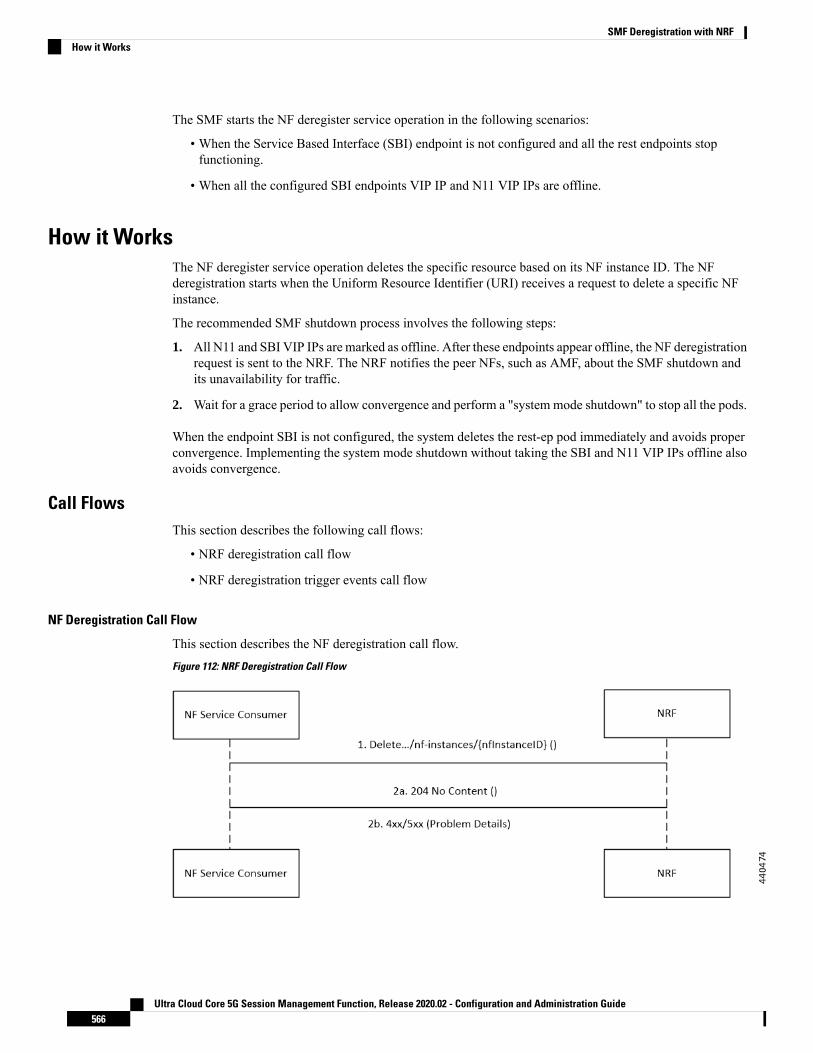
The SMF starts the NF deregister service operation in the following scenarios:
• When the Service Based Interface (SBI) endpoint is not configured and all the rest endpoints stopfunctioning.
• When all the configured SBI endpoints VIP IP and N11 VIP IPs are offline.
How it WorksThe NF deregister service operation deletes the specific resource based on its NF instance ID. The NFderegistration starts when the Uniform Resource Identifier (URI) receives a request to delete a specific NFinstance.
The recommended SMF shutdown process involves the following steps:
1. All N11 and SBI VIP IPs are marked as offline. After these endpoints appear offline, the NF deregistrationrequest is sent to the NRF. The NRF notifies the peer NFs, such as AMF, about the SMF shutdown andits unavailability for traffic.
2. Wait for a grace period to allow convergence and perform a "system mode shutdown" to stop all the pods.
When the endpoint SBI is not configured, the system deletes the rest-ep pod immediately and avoids properconvergence. Implementing the system mode shutdown without taking the SBI and N11 VIP IPs offline alsoavoids convergence.
Call FlowsThis section describes the following call flows:
• NRF deregistration call flow
• NRF deregistration trigger events call flow
NF Deregistration Call Flow
This section describes the NF deregistration call flow.
Figure 112: NRF Deregistration Call Flow
Ultra Cloud Core 5G Session Management Function, Release 2020.02 - Configuration and Administration Guide566
SMF Deregistration with NRFHow it Works

Table 162: NRF Deregistration Call Flow Description
DescriptionStep
The NF Service Consumer sends a Delete request to the resource URI that indicatesthe NF instance. The request body is empty.
1
If the deletion of the specified resource is successful, the “204 No Content” messageappears. The response body remains empty.
2a
If the NF instance, which is identified with the NF instance ID, does not exist in thelist of registered NF instances in the NRF database, the NRF sends the “404 NotFound” status code with the problem details.
2b
NF Deregistration Trigger Events Call Flow
This section describes the NF deregistration trigger events call flow.
Figure 113: NF Deregistration Trigger Events Call Flow
Table 163: NF Deregistration Trigger Events Call Flow Description
DescriptionStep
On startup
The SMF rest-ep registers for topology manager events to identify the state of otherrest-ep instances and keeps a track of these instances in an instance state database.
1
The SMF rest-ep registers for the termination handler with the application infrastructurefor receiving notification when the application infrastructure stops functioning. Aspart of the termination handler, the SMF rest-ep monitors the instance state databasefor any other working rest-ep.
2
Ultra Cloud Core 5G Session Management Function, Release 2020.02 - Configuration and Administration Guide567
SMF Deregistration with NRFNF Deregistration Trigger Events Call Flow

DescriptionStep
The SMF rest-ep starts the topology event.3
The SMF rest-ep saves the status of other rest-ep replicas in the instance state database.4
When the N11 and SBI endpoints are offline
The SMF rest-ep sends the Handle NF deregister message to the NRF-Lib.5
When all the SBI and N11 VIP IP endpoints are offline, the SMF rest-ep sends thederegistration request to the NRF.
6
The NRF sends the NF deregister response to the NRF-Lib.7
The NRF-Lib resets all the management information that is configured in the cachepod.
8
When no SBI endpoint exists
The SMF rest-ep starts the topology event to stop the other rest-ep.9
The SMF rest-ep starts the termination handler callback.10
The SMF rest-ep checks the instance status database for any other working rest-ep.11
When no rest-ep is functional
The SMF rest-ep sends the Handle NF deregister message to the NRF-Lib.12
The SMF rest-ep sends the deregistration request to the NRF.13
The NRF sends the NF deregistration response to the NRF-Lib.14
The NRF-Lib resets all the management information that is configured in the cachepod.
15
Standards ComplianceThe SMF deregistration with NRF feature complies with the 3GPP standard TS 29.510 V15.2.0 (2018-12).
LimitationsThe SMF deregistration with NRF feature has the following limitation:
• When N11 and SBI VIP IPs are not marked offline, the NF deregistration is not sent for the system modeshutdown because there is no specific order for pod deletion. Also, no monitoring procedure exists tocheck if the rest-ep pods are working.
Ultra Cloud Core 5G Session Management Function, Release 2020.02 - Configuration and Administration Guide568
SMF Deregistration with NRFStandards Compliance

C H A P T E R 38Support for the Unsubscribe-To-NotificationsMessages
• Feature Summary and Revision History, on page 569• Feature Description, on page 570• How it Works, on page 570• OAM Support for the Unsubscribe-To-Notifications Messages, on page 571
Feature Summary and Revision History
Summary DataTable 164: Summary Data
SMFApplicable Product(s) or Functional Area
SMIApplicable Product(s) or Functional Area
Enabled – Always-onFeature Default Setting
Not ApplicableRelated Changes in this Release
Not ApplicableRelated Documentation
Revision HistoryTable 165: Revision History
ReleaseRevision Details
2020.02.2First introduced.
Ultra Cloud Core 5G Session Management Function, Release 2020.02 - Configuration and Administration Guide569

Feature DescriptionThe Unified Data Management (UDM) is responsible for primarily storing the subscriber data, which SMFaccesses for managing the user sessions on the network. The SMF explicitly subscribes to receive thenotifications about the events that occur in the subscriber data such session terminate. When the SMF wantsto stop receiving the notifications, it initiates the Unsubscribe-to-Notification messages to UDM. Uponreceiving these messages, the UDM cancels the subscription by removing the notification subscription forthe subscribed session.
How it WorksThis section provides a brief of how the SMF andUDM interact over the Unsubscribe-to-Notificationsmessage:
1. The NF such as SMF sends an Unsubscribe-to-Notifications request to the resource identified by the URIto the UDM. The SMF transacts the request to the UDM over the N10 interface. TheUnsubscribe-to-Notifications request lets the SMF unsubscribe from notifications for a specific subscribersession. The SMF receives the URI details during the subscription creation process.
The Unsubscribe-to-Notifications request contains the ‘SUPI’ and ‘subscriptionId’ in the URI.
2. The UDM processes the request, and based on the response; it sends a response code to the SMF. Forexample, if the unsubscription is successful, then UDM sends 204 code. If the request is not processed,then the appropriate HTTP status code indicating the error is returned in the response body along withthe additional error information.
3. The SMF is equipped to handle the timeout and failure that occurs when sending theUnsubscribe-to-Notificationsmessages to the UDM. In the event, the Unsubscribe-to-Notifications requestfails, the SMF continues to purge the corresponding sessions.
The Unsubscribe-to-Notification message is required for sessions that are hosted on the EUTRA network.They may not be a requirement for sessions that are released on the NR and WLAN network. For theseaccess types, the SMF sends the UDM registration and deregistration messages that include subscriptionto notifications through implicit-unsubscribe during the deregistration.
Standards ComplianceThe Support for the Unsubscribe-To-Notifications Messages feature complies with the following standards:
• 3GPP TS 29.503 - 5G System; Unified Data Management Services
Call FlowsThis section describes the call flow for the Unsubscribe-To-Notifications message support.
Unsubscribe-to-Notifications Call FlowThis section describes the call flow on how the SMF sends a request to the UDM to unsubscribe fromnotifications of data changes.
Ultra Cloud Core 5G Session Management Function, Release 2020.02 - Configuration and Administration Guide570
Support for the Unsubscribe-To-Notifications MessagesFeature Description

Figure 114: Unsubscribe-to-Notifications Interaction with UDM
Table 166: Unsubscribe-to-Notifications Interaction Call Flow Description
DescriptionStep
The NF service consumer such as SMF sends a request to the UDM to unsubscribefrom notifications. By unsubscribing, the UDM no longer sends notifications toSMF when the data modifications occur in the respective subscriber session.
The NF service consumer sends a DELETE request to the resource identified bythe URI. The NF service consumer receives the URI when the subscription getscreated.
1
If the deletion of request is successful, the UDM responds with "204 No Content".2a
If the subscription is invalid, which could be due to an unknown subscriptionIdvalue, then the HTTP status code "404 Not Found" is returned along with theadditional error information in the response body (as part of the "ProblemDetails"element).
If the request is not processed, then the appropriate HTTP status code indicatingthe error is returned in the DELETE response body along with the additional errorinformation.
2b
OAM Support for the Unsubscribe-To-Notifications MessagesThis section describes operations, administration, and maintenance information for this feature.
Statistics SupportThe SMF maintains the following labels on the smf-rest-ep pod for monitoring the number ofunsubscribe-to-notifications messages that are initiated towards UDM:
• nfType – “udm”
• messageDirection – “outbound”
• apiName – “sdm_unsubscription_req”
• nfUri – “nf_uri”
• respStatus – “response_status”
Ultra Cloud Core 5G Session Management Function, Release 2020.02 - Configuration and Administration Guide571
Support for the Unsubscribe-To-Notifications MessagesOAM Support for the Unsubscribe-To-Notifications Messages

• rspCause – “response_cause”
Ultra Cloud Core 5G Session Management Function, Release 2020.02 - Configuration and Administration Guide572
Support for the Unsubscribe-To-Notifications MessagesStatistics Support

C H A P T E R 39SMF Interface for Metrics
• Feature Summary and Revision History, on page 573• Feature Description, on page 573
Feature Summary and Revision History
Summary Data
Feature Summary
SMFApplicable Product(s) or Functional Area
SMIApplicable Platform(s)
Enabled – Always-onFeature Default Setting
Not ApplicableRelated Changes in this Release
Not ApplicableRelated Documentation
Revision HistoryTable 167: Revision History
ReleaseRevision Details
Pre-2020.02.0First introduced.
Feature DescriptionSMF uses Prometheus for gathering statistics/counters from its microservices.
Grafana is used as the user interface to view metrics. It pulls the data from the Prometheus data store. Defaultgraphs for KPI are available using Grafana for rendering a graphical view of the statistics with timelines.
Ultra Cloud Core 5G Session Management Function, Release 2020.02 - Configuration and Administration Guide573

For each microservice, counters and a set of labels are defined. Counters are incremented/decremented withthe set of labels depending on the functionality.
The following snapshot is a sample of the Grafana dashboard.
Figure 115: Grafana Dashboard
SMF Rest EP MicroserviceThis section describes the supported counters and set of labels for the SMF Rest EP microservice.
CountersThe SMF REST EP microservice includes the following counters:
Table 168: SMF REST EP Microservice Counters
DescriptionMetricNumber
This counter is incremented with every HTTPmessage received/sent at rest-ep microservice.
smf_restep_http_msg_total1
This counter is incremented with every HTTPmessage received/sent at rest-ep microservicealong with the time taken to serve the message.
smf_restep_http_msg2
LabelsThe SMF REST EP microservice includes the following labels for the counters:
Ultra Cloud Core 5G Session Management Function, Release 2020.02 - Configuration and Administration Guide574
SMF Interface for MetricsSMF Rest EP Microservice

Table 169: SMF REST EP Microservice Labels for Counters
DescriptionLabelNumber
This label can be any 5GNode that interacts withSMF. For example: AMF, PCF, NRF
NF TYPE1
Displays the direction of the HTTPmessage withrespect to the REST EP microservice. Thepossible values are:
“inbound”
“outbound”
MESSAGE DIRECTION2
Displays the service name being served. It canbe:
"register_ue"
"deregister_ue"
"subscription_req"
"nf_registration"
"nf_discovery"
"slice_selection"
"amf_create_sm_context"
"amf_update_sm_context"
"amf_release_sm_context"
"amf_n1_n2_transfer"
"pcf_sm_policy_control_create"
"pcf_sm_policy_control_update"
"pcf_sm_policy_control_delete"
"pcf_sm_policy_control_update_notify"
"pcf_sm_policy_control_terminate_notify"
API NAME3
Displays the rest-ep URI used in the HTTPmessage (can be FQDN).
NF URI4
Displays the HTTP Response. It can be any 2xx,4xx or 5xx response.
RESPONSE STATUS5
SMF ServiceThis section describes the supported counters and set of labels for the SMF service.
Ultra Cloud Core 5G Session Management Function, Release 2020.02 - Configuration and Administration Guide575
SMF Interface for MetricsSMF Service

LabelsThe SMF service includes the following labels for the counters:
Table 170: SMF Service Labels for Counters
DescriptionLabelNumber
This label can take any value depending on thetype of procedure queried for:
"pdu_sess_create"
"ue_req_pdu_sess_mod"
"smf_req_pdu_sess_mod"
"pcf_req_pdu_sess_mod"
"ue_req_pdu_sess_rel"
"smf_req_pdu_sess_rel"
"pcf_req_pdu_sess_rel"
"amf_req_pdu_sess_rel"
PROCEDURE TYPE1
Displays the status type. The possible values are:
“attempted”
“success”
“failure”
STATUS2
Displays the PDU connection type. The possiblevalues are:
“ipv4”
“ipv6”
“ipv4v6”
PDU CONNECTION TYPE3
Displays the PDU state. The possible values are:
“idle”
“connected”
PDU STATE4
SMF Protocol MicroserviceThis section describes the supported counters and set of labels for the SMF Protocol microservice.
CountersThe SMF service includes the following counters:
Ultra Cloud Core 5G Session Management Function, Release 2020.02 - Configuration and Administration Guide576
SMF Interface for MetricsLabels

Table 171: SMF Service Counters
DescriptionMetricNumber
This counter is incremented with every query madeto the smf-service.
smf_service_stats1
This is a gauge counter and can beincremented/decremented based on the functionalitywith every query made to the smf-service.
smf_service_counters2
LabelsThe SMF Protocol service includes the following labels for the counters:
Table 172: SMF Protocol Service Labels for Counters
DescriptionLabelNumber
This label can take any value depending on theprocedure queried for:
"n4_session_establishment_req"
"n4_session_establishment_res"
"n4_session_modification_req"
"n4_session_modification_res"
"n4_session_report_req"
"n4_session_report_res"
"n4_session_deletion_req"
"n4_session_deletion_res"
"n4_association_setup_req"
"n4_association_setup_res"
"n4_association_update_req"
"n4_association_update_res"
"n4_association_release_req"
"n4_association_release_res"
"n4_prime_pfd_management_req"
"n4_prime_pfd_management_res"
"n4_heartbeat_req"
"n4_heartbeat_res"
"n4_node_report_req"
"n4_node_report_res"
MESSAGE NAME1
Ultra Cloud Core 5G Session Management Function, Release 2020.02 - Configuration and Administration Guide577
SMF Interface for MetricsLabels

DescriptionLabelNumber
Displays the direction of the HTTPmessage withrespect to the REST EP microservice. Thepossible values are:
“inbound”
“outbound”
MESSAGE DIRECTION2
Displays the status of the message. The possiblevalues are:
“accepted”
“denied”
“discarded”
STATUS3
Ultra Cloud Core 5G Session Management Function, Release 2020.02 - Configuration and Administration Guide578
SMF Interface for MetricsLabels

C H A P T E R 40SMF Logging
• Feature Summary and Revision History, on page 579• Feature Description, on page 579
Feature Summary and Revision History
Summary Data
Feature Summary
SMFApplicable Product(s) or Functional Area
SMIApplicable Platform(s)
Enabled - Always-onFeature Default Setting
Not ApplicableRelated Changes in this Release
Not ApplicableRelated Documentation
Revision HistoryTable 173: Revision History
ReleaseRevision Details
Pre-2020.02.0First introduced.
Feature DescriptionSMF utilizes the common logging framework to generate logs from its micro-services.
The supported logging levels are:
• Error
Ultra Cloud Core 5G Session Management Function, Release 2020.02 - Configuration and Administration Guide579

• Warn
• Info
• Debug
• Trace
Ultra Cloud Core 5G Session Management Function, Release 2020.02 - Configuration and Administration Guide580
SMF LoggingFeature Description

C H A P T E R 41Timers Support
• Feature Summary and Revision History, on page 581• Feature Description, on page 581• 3GPP-compliant Timers, on page 582• Custom-driven Timers, on page 584
Feature Summary and Revision History
Summary DataTable 174: Summary Data
SMFApplicable Product(s) or Functional Area
SMIApplicable Platform(s)
Disabled – Configuration RequiredFeature Default Setting
Not ApplicableRelated Changes in this Release
Not ApplicableRelated Documentation
Revision HistoryTable 175: Revision History
ReleaseRevision Details
2020.02.0First introduced.
Feature DescriptionThe SMF supports configurable timers that are either 3GPP compliant or custom-driven.
Ultra Cloud Core 5G Session Management Function, Release 2020.02 - Configuration and Administration Guide581

This chapter provides detailed information about the function, operation and configuration of the timers. Thischapter covers the following topics:
• 3GPP-compliant timers
• GTP timer
• N11 timer
• Custom-driven timers
• Absolute timer
• Control plane inactive timer
• User plane inactive timer
3GPP-compliant Timers
Feature DescriptionThe SMF supports retransmission through the GTP and N11 timers. With this provision, when the peer doesnot respond with the timer value, the SMF retransmits the GTP and N11 requests. The SMF lets you configurethe maximum number of retransmissions.
The SMF provides configuration support for GTP timer and N11 timers.Note
How it WorksThe SMF supports the following 3GPP timers:
• GTP retransmission timer:
The SMF/PGW-C starts the timer denoted in the T3-RESPONSE. The timer is invoked when a signallingmessage (for which a reply is expected) is sent. A signalling message or the triggered message might getlost if a response is not received before the T3-RESPONSE timer expires.
Once the T3-RESPONSE timer expires, the message corresponding to the T3-RESPONSE timer is thenretransmitted if the total number of retry attempts is less than N3REQUESTS.
• 5G N1N2 reattempt timer:
If AMF rejects the N1N2 MessageTransfer with cause code as "Temporary reject registration ongoing"or "Temporary reject handover ongoing', then the SMF starts the timer for reattempting N1N2MessageTransfer.
Once the timer expires, the message corresponding to N1N2 MessageTransfer is reattempted based onthe configured retry attempts.
Ultra Cloud Core 5G Session Management Function, Release 2020.02 - Configuration and Administration Guide582
Timers Support3GPP-compliant Timers

Standards ComplianceThe 3GPP timers support feature complies with the following standards:
• 3GPP TS 29.510 V15.2.0 (2018-12)
Configuration Support for the 3GPP Timers FeatureThis section describes how to configure the 3GPP timers support feature.
Configuring the N11 TimersThis section describes how to configure the N11 timers.
The N11 timer configuration is invoked when AMF rejects the N1N2 message transfer with the cause codeas "Temporary reject registration ongoing" or "Temporary reject handover ongoing", then SMF considers thetimer and reattempts the message transfer. When the timer expires, the transfer is reattempted based on theconfigured retry count.
configureprofile failure-handling failure_handling_name
interface [ gtpc | N11 ] message message_type
cause-code [ temp-reject-register | temp-reject-handover ]action [ retry { timeout timeout_duration | max-retry retry_count }
|clear | terminate ]end
NOTES:
• profile failure-handling failure_handling_name— Enter the name of the profile for failure handling.
• interface [ gtpc | N11 ] —Configures the interface over which the message transfer must happen.
• message message_type—Configures the message type that must be transferred over the interface. TheN11 interface supports the message type as n1n2transfer.
• cause-code [ temp-reject-register | temp-reject-handover ] —Configures the HTTP cause code. Youcan configure multiple cause code values for a message.
• action [ retry | clear | terminate ]—Configures the action that must be performed when the messagetransfer is not successful.
Clear and terminate are not supported for the N11 interface.Note
• action [ retry { max-retry retry_count | timeout timeout_duration } — Specifies the number of timesthe message transfer must be reattempted and the time interval between the consecutive attempts.
Example Configuration
Following is an example of N11 timer configuration.show running-configprofile failure-handling n11-fhtinterface n11 message n1n2transfer
Ultra Cloud Core 5G Session Management Function, Release 2020.02 - Configuration and Administration Guide583
Timers SupportStandards Compliance

cause-code temp-reject-registeraction retrytimeout 1000max-retry 2
Configuring the GTP TimersThis section describes how to configure the GTP timers.
The GTP timer configuration is implemented when a signaling message or triggered message (for which areply is expected) is lost as it did not get a response before the T3-RESPONSE timer expired. After theT3-RESPONSE timer expires, the message corresponding to the T3-RESPONSE timer is retransmitted if thetotal number of retry attempts is less than the N3-REQUESTS times.
configureendpoint gtp
retransmission { max-retry retry_count | timeout timeout_duration }end
NOTES:
• endpoint gtp— Enters the GTP retransmission configuration.
• max-retry retry_count—Specifies the number of times the signalling message request to SMF must bereattempted. The accepted range is 0–5. Default range is 3. When the retry_count is set to "0", theretransmission feature is disabled.
• timeout timeout_duration—Configures the interval of time (in milliseconds) after which the GTPretransmission request is reattempted. The accepted range is 0–10. Default range is 2. When thetimeout_duration is set to "0", the retransmission feature is disabled.
Example Configuration
Following is an example of GTP timer configuration.show running-configendpoint gtpretransmission max-retry 2 timeout 5
Custom-driven Timers
Absolute Timer Support
Feature DescriptionThe SMF supports Absolute Session Timeout for each PDU session. With this support, the SMF can retainthe PDU session resources until the Absolute Session Timer expires.
You can configure Absolute Session Timeout value under the DNN-Profile. If you have not configured thetimeout value, the session timeout feature appears disabled and no timer is initiated.
Based on the configured value under the DNN-Profile, the Absolute Session Timer is triggered during thesession creation. You cannot modify the timer value during interim of handling any access and mobility
Ultra Cloud Core 5G Session Management Function, Release 2020.02 - Configuration and Administration Guide584
Timers SupportConfiguring the GTP Timers

procedures for that session. After the timer expires, the SMF performs SMF-initiated release by informingall SBI interfaces and N4 Interfaces, that is, toward UE, UDM, PCF, CHF, and UPF interfaces.
Configuring Absolute Session TimeoutTo configure Absolute Session Timeout parameter under the DNN profile:
configureprofile dnn dnnprofile_name
timeout absolute absolutetimer_value
end
NOTES:
• absolutetimer_value: Specifies the maximum duration of the session (in seconds), before the systemautomatically terminates the session. The default value is 0, which indicates the function is disabled.
absolutetimer_value must be an integer in the range of 0-2147483647.
The following is a sample configuration.smf(config)# profile dnn intershat timeout absolute 900
Inactivity Timer Support
Feature DescriptionThe SMF supports the following timers to handle the user plane (UP) and control plane (CP) inactive requests:
• UP inactivity timer
• UP idle timer
• CP idle timer
Configuring UP Inactivity TimerTo configure the UP inactivity timer under DNN profile, use the following commands:
configureprofile dnn dnnprofile_name
userplane-inactivity-timer timer_value
end
NOTES:
• userplane-inactivity-timer timer_value: Specifies the timer value in seconds. timer_value must be aninteger in the range of 0-86400. The default value of the timer is 0, which means the function is disabled.
• The SMF sends the configured inactivity timer to the UPF through the N4 PDU Session Establishmentrequest. After the session establishment, if the configured value changes, the SMF reports the changesto the UPF through N4 modification request.
• The UPF starts the inactivity timer when there is no uplink or downlink data transmission over the N3tunnel. The UPF stops the timer when the data transmission over N3 tunnel is resumed. On expiry of thetimer, the UPF sends session report to the SMF with the user plane inactivity request (UPIR) flag set.
Ultra Cloud Core 5G Session Management Function, Release 2020.02 - Configuration and Administration Guide585
Timers SupportConfiguring Absolute Session Timeout

After receiving the report indication for a session, the SMF clears the session if it is a 4G session andinitiates idle mode entry if it is a 5G session.
Configuring CP and UP Session Idle TimerTo configure the CP and UP idle timers under DNN profile, use the following commands:
configureprofile dnn dnnprofile_name
timeout { cp-idle timer_value | up-idle timer_value }end
NOTES:
• cp-idle timer_value: Specifies the maximum duration of the 5G session after the migration to CP idlestate and before the automatic termination. The default value is 0, which indicates the function is disabled.timer_value must be an integer in the range of 0-2147483647.
• up-idle timer_value: Specifies the maximum duration of the 5G session after the migration to UP idlestate and before the automatic termination. The default value is 0, which indicates the function is disabled.timer_value must be an integer in the range of 0-2147483647.
• The up-idle timer starts when an AN-initiated or Network-initiated 5G session enters the idle mode. Thistimer stops when the session exits the idle mode. On expiry of the timer, the SMF clears the 5G sessions.
• The cp-idle timer starts when any 4G or 5G procedure ends, and stops when any new procedure starts.If the timer expires, the SMF clears the session.
Ultra Cloud Core 5G Session Management Function, Release 2020.02 - Configuration and Administration Guide586
Timers SupportConfiguring CP and UP Session Idle Timer

C H A P T E R 42UDP Proxy for SMF
• Feature Summary and Revision History, on page 587• Feature Description, on page 587
Feature Summary and Revision History
Summary DataTable 176: Summary Data
SMFApplicable Product(s) or Functional Area
SMIApplicable Platform(s)
Enabled – Always-onFeature Default Setting
Not ApplicableRelated Changes in this Release
Not ApplicableRelated Documentation
Revision HistoryTable 177: Revision History
ReleaseRevision Details
Pre-2020.02.0First introduced.
Feature DescriptionThe SMF has UDP interfaces toward the UPF (N3) and SGW (s5/s8 for EPS interworking). With the help ofthe protocol layer pods (smf-protocol and gtp-ep), the messages are encoded and decoded and exchanged onthese UDP interfaces. For achieving the functionalities mentioned on the 3GPP specifications:
Ultra Cloud Core 5G Session Management Function, Release 2020.02 - Configuration and Administration Guide587

• It is mandatory for the protocol layer pods to receive the original source and destination IP address andport number. But the original IP and UDP header is not preserved when the incoming packets arrive atthe UDP service in the Kubernetes (K8s) cluster.
• Similarly, for the outgoing messages, the source IP set to the external IP address of the UDP service(published to the peer node) is mandatory. But the source IP is selected as per the egress interface, whendifferent instances of protocol layer pods send outgoing messages from different nodes of the K8s cluster.
The protocol layer POD spawns on the node, which has the physical interface configured with the externalIP address to achieve the conditions mentioned earlier. However, spawning the protocol layer pods has thefollowing consequences:
• It is not possible to achieve the node level HA (High Availability) because the protocol pods are spawnedon the same node of the K8s cluster. Any failure to that node may result in loss of service.
• The protocol pods (smf-protocol, gtp-ep, and radius-ep) must include their own UDP client and serverfunctionalities. In addition, each protocol layer pod may require labeling of the K8s nodes with the affinityrules. This restricts the scaling requirements of the protocol layer pods.
The SMF addresses these issues with the introduction of a newK8s POD called "smf-udp-proxy." The primaryobjectives of this POD are:
• The "smf-udp-proxy" POD acts as a proxy for all kinds of UDP messages. It also owns the UDP clientand server functionalities.
• The protocol pods perform the individual protocol (PFCP, GTP, Radius) encoding and decoding andprovide the UDP payload to the "smf-udp-proxy" POD. The "smf-udp-proxy" POD sends the UDPpayload out after it receives the payload from the protocol pods.
• The "smf-udp-proxy" POD opens the UDP sockets on a virtual IP (VIP) instead of a physical IP. Thisensures that the "smf-udp-proxy" POD does not have any strict affinity to a specific K8s node (VM).Thus, enabling node level HA for the UDP proxy.
NOTE: One instance of the "smf-udp-proxy" POD is spawned by default in all the worker nodes in the K8scluster. There are no changes to the configurations in this release.
RelationshipsThe UDP proxy for SMF feature has functional relationship with the following feature:
• Virtual IP Address.
ArchitectureThe "smf-udp-proxy" POD is placed in the worker nodes in the K8s cluster.
1. Each of the K8s worker node contains one instance of the "smf-udp-proxy" POD. However, only one ofthe K8s worker node owns the virtual IP at any time. The worker node that owns the virtual IP remainsin the active mode while all the other worker nodes remain in the standby mode.
2. The active "smf-udp-proxy" POD binds to the virtual IP and the designated ports for listening to the UDPmessages from the peer nodes (UPF and SGW).
Ultra Cloud Core 5G Session Management Function, Release 2020.02 - Configuration and Administration Guide588
UDP Proxy for SMFRelationships

3. The UDP payload received from the peer nodes are forwarded to one instance of the smf-protocol, gtp-ep,or radius-ep pods. The payload is forwarded either on the same node or different node for further processing.
4. The response message from the smf-protocol, gtp-ep, or radius-ep pods is forwarded back to the activeinstance of the "smf-udp-proxy" POD. The "smf-udp-proxy" POD sends the response message back tothe corresponding peer nodes.
5. The SMF-initiated messages are encoded at the smf-protocol, gtp-ep, or radius-ep pods. In addition, theUDP payload is sent to the "smf-udp-proxy" POD. Eventually, the "smf-udp-proxy" POD comprises ofthe complete IP payload and sends the message to the peer. When the response from the peer is received,the UDP payload is sent back to the same smf-protocol, gtp-ep, or radius-ep POD fromwhich the messageoriginated.
Figure 116: UDP Proxy Architecture
How it WorksThe following sections describe the UDP proxy working principles.
Port and Sequence Number SelectionThe duplicate messages are detected based on the source IP, source address, and sequence number for allUDP-based protocols. Each message from the peer includes a unique combination of these three parameters(source IP, source address, and sequence number).
In this release, only the sequence number changes for each new SMF initiated message. The SMF initiatedmessages use the same source IP (Virtual IP) and same port (fixed to 8809) number.
The sequence number (PFCP) is a 24-bit value. The 8 MSBs (Most Significant Bit) specify the smf-protocolpod's instance number. The 16 LSBs (Least Significant Bit) are incrementing counters, which generate aunique number for each instance of the smf-protocol POD.
NOTE: The UDP proxy uses the smf-protocol POD instance sequence number to determine the smf-protocolinstance to which the response message must be forwarded to.
NOTE: Message retransmission and duplicate detection are not supported in this release.
Ultra Cloud Core 5G Session Management Function, Release 2020.02 - Configuration and Administration Guide589
UDP Proxy for SMFHow it Works

Protocol POD Selection for Peer Initiated MessagesWhen the "smf-udp-proxy" POD receives the peer node (for instance UPF) initiated messages, it is loadbalanced across the smf-protocol instances to select any instance of the smf-protocol POD. An entry of thisinstance number is stored along with the source IP and source port number of the peer node. This ensures thatthe messages form the same source IP and source port are sent to the same instance that was selected earlier.
NOTE: This release does not support the landing of retransmitted messages (from the peer nodes) on thesame instance of the smf-protocol where duplicate messages are detected.
High Availability for the UDP ProxyThe UDP proxy's HA model is based on the keepalived virtual IP concepts. A VIP is designated to the N4interface during deployment. Also, a keepalived instance manages the VIP and ensures that the IP address ofthe VIP is created as the secondary address of an interface in one of the worker nodes of the K8s cluster.
The "smf-udp-proxy" instance on this worker node binds to the VIP and assumes the role of the active"smf-udp-proxy" POD. All "smf-udp-proxy" instances in other worker nodes remain in the standby mode.
When the worker node hosting the VIP fails, the keepalived instance moves the VIP to another worker nodein the K8s cluster. The "smf-udp-proxy" instance in that worker node assumes the active role now.
NOTE: In this release, the VIP support for the "smf-udp-proxy" is enabled with single instance of"smf-udp-proxy." The failover scenario is not supported in this release.
Call FlowsThis section describes the call flow defined for the UDP proxy feature.
UDP Proxy for SMF Call Flow
The following call flow describes the flow of messages for the SMF initiated messages (applicable to messagesinitiated by peer nodes as well).
Figure 117: UDP Proxy for SMF Call Flow
Ultra Cloud Core 5G Session Management Function, Release 2020.02 - Configuration and Administration Guide590
UDP Proxy for SMFProtocol POD Selection for Peer Initiated Messages
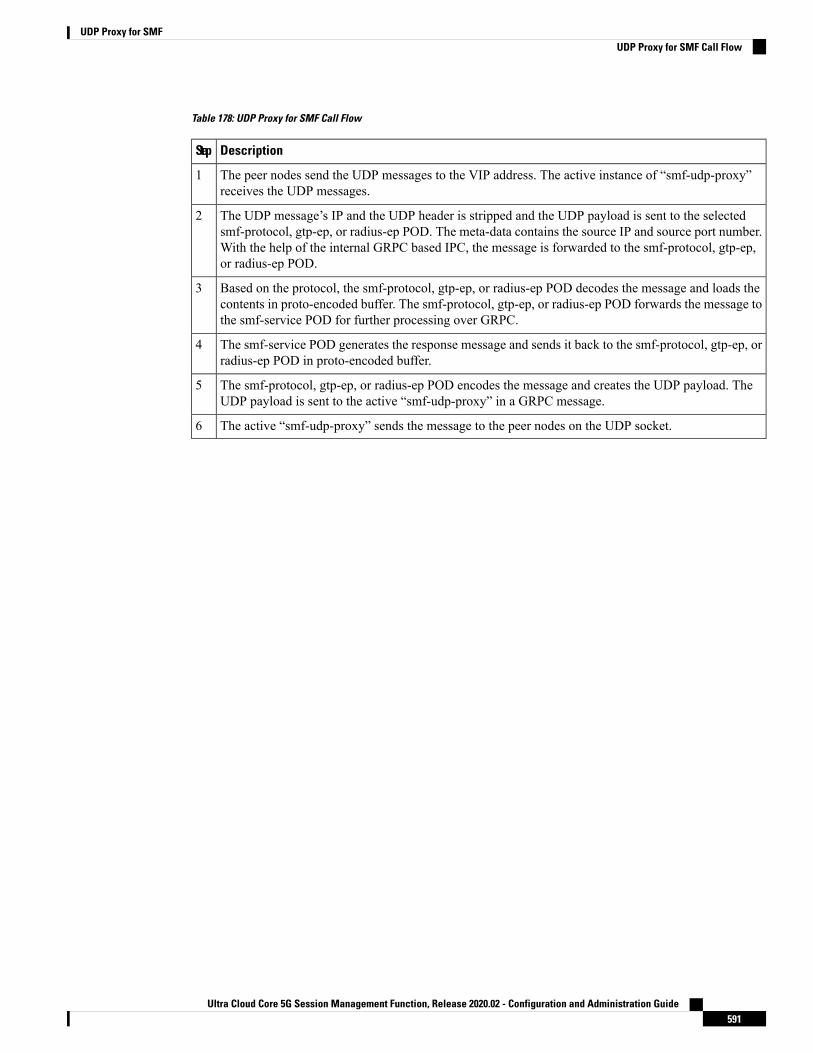
Table 178: UDP Proxy for SMF Call Flow
DescriptionStep
The peer nodes send the UDP messages to the VIP address. The active instance of “smf-udp-proxy”receives the UDP messages.
1
The UDP message’s IP and the UDP header is stripped and the UDP payload is sent to the selectedsmf-protocol, gtp-ep, or radius-ep POD. The meta-data contains the source IP and source port number.With the help of the internal GRPC based IPC, the message is forwarded to the smf-protocol, gtp-ep,or radius-ep POD.
2
Based on the protocol, the smf-protocol, gtp-ep, or radius-ep POD decodes the message and loads thecontents in proto-encoded buffer. The smf-protocol, gtp-ep, or radius-ep POD forwards the message tothe smf-service POD for further processing over GRPC.
3
The smf-service POD generates the response message and sends it back to the smf-protocol, gtp-ep, orradius-ep POD in proto-encoded buffer.
4
The smf-protocol, gtp-ep, or radius-ep POD encodes the message and creates the UDP payload. TheUDP payload is sent to the active “smf-udp-proxy” in a GRPC message.
5
The active “smf-udp-proxy” sends the message to the peer nodes on the UDP socket.6
Ultra Cloud Core 5G Session Management Function, Release 2020.02 - Configuration and Administration Guide591
UDP Proxy for SMFUDP Proxy for SMF Call Flow

Ultra Cloud Core 5G Session Management Function, Release 2020.02 - Configuration and Administration Guide592
UDP Proxy for SMFUDP Proxy for SMF Call Flow

C H A P T E R 43UPF Path Management and Restoration
• Feature Summary and Revision History, on page 593• Feature Description, on page 594• How it Works, on page 594• Configuration Support for UPF Path Management and Restoration, on page 595• OAM Support, on page 597
Feature Summary and Revision History
Summary DataTable 179: Summary Data
SMFApplicable Product(s) or Functional Area
SMIApplicable Platform(s)
Disabled – Configuration RequiredFeature Default Setting
Not ApplicableRelated Changes in this Release
Not ApplicableRelated Documentation
Revision HistoryTable 180: Revision History
ReleaseRevision Details
2020.02.0First introduced.
Ultra Cloud Core 5G Session Management Function, Release 2020.02 - Configuration and Administration Guide593

Feature DescriptionA heartbeat is used to monitor the status of a UPF node in terms of its responsiveness. The heartbeat initiatesa bilateral flow of request and response between the SMF and UPF.
The SMF periodically sends a signal in the form of a heartbeat request to the registered UPF node to determineif it is active. If the SMF does not receive a response fromUPF after the retransmission attempts are exhausted,then SMF recognizes that a failure has occurred and purges the subscribers that are mapped to that UPF node.
You can control the number of heartbeat requests that SMF sends to UPF, the interval between the consecutiverequests, and the duration until which SMF waits for a response.
Standards ComplianceThe heartbeat transmission between SMF and UPF complies with the following standards:
• 3GPP TS 23.527
• 3GPP TS 23.007
How it WorksYou can configure the heartbeat capability at the interface-level, UPF profile group-level, or both. Theinterface-level configuration is mandatory. If the interface-level configuration is unavailable, then the heartbeatparameters get configured with the default values. The profile-level configuration overrides the interface-levelconfiguration.
The heartbeat feature is also extended to achieve high-availability for the Node Manager.
Interface and profile-level heartbeat
The SMF-UPF interaction to detect the UPF path failure using the heartbeat messages involves the followingsteps:
1. The SMF sends a heartbeat request message to the discovered UPF instances or profile groups based onthe configured schedule.
2. If the UPF instance or profile is alive, it sends a heartbeat response to the SMF indicating that it isoperational. In case the UPF does not send a heartbeat response, then SMF retransmits the heartbeatrequest based on the configured interval and the number of permitted attempts.
3. After the configured count of heartbeat message reattempts is exhausted and the SMF does not receive aresponse fromUPF, then SMF starts 'Network requested PDUSession Release' procedure for the subscribersthat are associated with that UPF.
Heartbeat and high-availability in Node Manager
Each UPF instance is associated with a primary and secondary Node Manager. The secondary Node Manageracts as a standby system on which the primary manager fails over. The primary Node Manager is responsiblefor the IP allocation and managing the association-specific messages such as association create, update, ordelete request. To achieve uninterrupted access to the UPF and ensure a high-availability environment, thefollowing interactions occur:
Ultra Cloud Core 5G Session Management Function, Release 2020.02 - Configuration and Administration Guide594
UPF Path Management and RestorationFeature Description

• When the Node Manager goes down or reinstated, it updates its status to all the mapped UPFs.
• In case the primary Node Manager is down, the secondary manager is notified. The secondary managersends a heartbeat request to the UPF node to determine if the node is alive.
• When the secondary NodeManager is informed that the primary NodeManager is available, the secondarymanager suspends the heartbeat timers and retransmission for the UPF node that is managed by theprimary Node Manager.
Configuration Support for UPF Path Management andRestoration
This section describes how to configure the support for monitoring the UPF status.
Configuring the support for detecting the UPF status using the heartbeat feature involves the following steps:
• Configuring the Heartbeat Parameters for UPF
• Configuring the Heartbeat Parameters for UPF Profile
• Associating UPF Group to Individual UPF Network Configuration
Configuring the Heartbeat Parameters for UPFThis section describes how to configure the heartbeat feature for the UPF.
To configure the heartbeat feature for UPF at the interface-level, use the following configuration:
configureendpoint pfcpinterface n4
heartbeatinterval interval
max-retransmissions max_retry
retransmission-timeout retry_count
end
NOTES:
• endpoint pfcp— Enters the endpoint configuration mode.
• interface—Configures the N4 interface over which the heartbeat messages are exchanged between SMFand UPF.
• heartbeat — Enters the heartbeat configuration.
• interval interval—Specifies the heartbeat interval in seconds. The accepted range is 60–360. The defaultvalue is 60 seconds.
Setting the interval to "0", disables the heartbeat feature.
• max-retransmissions max_retry— Specifies the maximum retries for the Packet Forwarding ControlProtocol (PFCP) heartbeat request. The accepted range is 0–10. The default value is 3.
Ultra Cloud Core 5G Session Management Function, Release 2020.02 - Configuration and Administration Guide595
UPF Path Management and RestorationConfiguration Support for UPF Path Management and Restoration

• retransmission-timeout retry_count— Specifies the heartbeat retransmission timeout in seconds. Theaccepted range is 1–20. The default value is 5.
Verifying the Heartbeat Configuration for UPFThis section describes how to verify the heartbeat configuration for UPF.
To view the configuration, use the show running-config endpoint pfcp command.
The following is a sample output of the show running-config endpoint pfcp command.show running-config endpoint pfcpendpoint pfcpinterface n4heartbeatinterval 61retransmission-timeout 3max-retransmissions 5exit
exitexit
Configuring the Heartbeat Parameters for the UPF ProfileThis section describes how to configure the heartbeat feature for the UPF profile.
To configure the heartbeat parameters for the UPF profile, use the following configuration:
configureprofile upf-group group_name
heartbeatinterval interval
retransmission-timeout max_retry
max-retransmissions retry_count
end
NOTES:
• profile upf-group group_name— Specifies the UPF group for which the heartbeat feature must beenabled.
• interface—Configures the N4 interface over which the heartbeat messages are exchanged between SMFand UPF.
• heartbeat — Enters the heartbeat configuration.
• interval interval—Specifies the heartbeat interval in seconds. The accepted range is 60–360. The defaultvalue is 60 seconds.
Setting the interval to "0", disables the heartbeat feature.
• max-retransmissions max_retry— Specifies the maximum retries for the Packet Forwarding ControlProtocol (PFCP) heartbeat request. The accepted range is 0–10. The default value is 3.
• retransmission-timeout retry_count— Specifies the heartbeat retransmission timeout in seconds. Theaccepted range is 1–20. The default value is 5.
Ultra Cloud Core 5G Session Management Function, Release 2020.02 - Configuration and Administration Guide596
UPF Path Management and RestorationVerifying the Heartbeat Configuration for UPF

Verifying the Heartbeat Configuration for UPF GroupThis section describes how to verify the heartbeat configuration for the UPF group.
To view the configuration, use the show running-config profile upf-group command.
The following is a sample output of the show running-config profile upf-group command.show running-config profile upf-groupprofile upf-group upfGroup1heartbeatinterval 62retransmission-timeout 3max-retransmissions 2
exitexit
Associating UPF Group to Individual UPF Network ConfigurationThis section describes how to associate a UPF group with a UPF configuration.
Each UPF network configuration includes the UPF profile that associates each UPF instance with a UPFprofile.
To associate an UPF group profile with a network configuration, use the following configuration:
configureprofile network-element upf upf1
upf-group-profile upf_group
end
NOTES:
• profile network-element upf—Configures the UPF network configuration.
• upf-group-profile upf_group—Configures the UPF group name that must be associated to the specifiedUPF network configuration.
Verifying the Association of the UPF Group with the Individual UPFThis section describes how to verify the association of the UPF group with the individual UPF.
To view the association, use the show running-config profile network-element upf command.
The following is a sample output of the show running-config profile network-element upf command.profile network-element upf upf1n4-peer-address ipv4 10.80.70.229n4-peer-port 8805upf-group-profile upfGroup1dnn-list [ intershat intershat1 intershat2 ]capacity 65535priority 65535
OAM SupportThis section describes the operations, administration, and maintenance information for this feature.
Ultra Cloud Core 5G Session Management Function, Release 2020.02 - Configuration and Administration Guide597
UPF Path Management and RestorationVerifying the Heartbeat Configuration for UPF Group

Bulk StatisticsThe SMFmaintains the following bulk statistics triggered during the heartbeat request and response procedure.
• nodemgr_upf_heartbeat_fail_stats— Counter that gets updated per UPF when it fails to respond to aheartbeat request.
• nodemgr_upf_hb_msg_stats— Counter for all the heartbeat messages for the specified UPF.
The nodemgr_upf_heartbeat_fail_stats counter supports the following labels:
• upf_heartbeat_req_tx— Label for the heartbeat request that the SMF sends.
• upf_heartbeat_req_retx— Label for the retransmitted heartbeat request.
• upf_heartbeat_rsp_rx— Label for the heartbeat response that the SMF receives.
Ultra Cloud Core 5G Session Management Function, Release 2020.02 - Configuration and Administration Guide598
UPF Path Management and RestorationBulk Statistics
C H A P T E R 44Voice over New Radio
• Feature Summary and Revision History, on page 599• Feature Description, on page 600• VoNR P-CSCF Address Support, on page 600• VoNR MO and MT Call Support, on page 608• Paging Policy Differentiation Support, on page 617• P-CSCF FQDN, on page 621
Feature Summary and Revision History
Summary DataTable 181: Summary Data
SMFApplicable Product(s) or Functional Area
SMIApplicable Platform(s)
Disabled – Configuration RequiredFeature Default Setting
Not ApplicableRelated Changes in this Release
Not ApplicableRelated Documentation
Revision HistoryTable 182: Revision History
ReleaseRevision Details
Pre-2020.02.0First introduced.
Ultra Cloud Core 5G Session Management Function, Release 2020.02 - Configuration and Administration Guide599

Feature DescriptionNew Radio (NR) is the 5G radio access technology, and Voice over NR (VoNR) is the voice or video overthe 5G network. VoNR is the target voice or video communication solution for 5G networks.
Voice services in 5GS over NG-RAN continue to be based on IP Multimedia Subsystem (IMS), such as Voiceover LTE (VoLTE). VoNR is supported only when 5GS is connected to the IMS core.
Standards ComplianceThe VoNR feature complies with the following standards:
• 3GPP TS 23.228, Release 15.3.0
• 3GPP TS 23.501, Release 15.4.0
• 3GPP TS 23.502, Release 15.4.0
VoNR P-CSCF Address Support
Feature DescriptionThe SMF supports IMS Protocol Data Unit (PDU) Session Creation and fetches the P-CSCF addresses to besent to the UE during initial attach over NR.
How it WorksThe serving PLMN AMF sends an indication toward the UE during the registration procedure to indicatewhether an IMS voice over PS session is supported in the 3GPP access network. A UE with "IMS voice overPS" voice capability over 3GPP access takes this indication into account when performing voice domainselection. TheUE includes extended Protocol ConfigurationOptions (ePCO) IE in "PDUSession EstablishmentRequest" by setting P-CSCF container options in the AMF. Further, the AMF forwards these ePCO IE optionsin smContextCreate Request towards the SMF. The SMF fetches the P-CSCF addresses based on DNN profile,which maintains IMS-related data. The SMF includes P-CSCF IPv4 and IPv6 address in N1N2MessageTransfer towards the AMF as per PDN-Types and requested P-CSCF container values.
The SMF does not include the P-CSCF address if the UE does not set the P-CSCF container options in theePCO IE.
Important
Call Flows
This section describes the call flow that is associated with this feature.
VoNR PDU Session Creation Call Flow
This section describes the VoNR PDU Session Creation call flow.
Ultra Cloud Core 5G Session Management Function, Release 2020.02 - Configuration and Administration Guide600
Voice over New RadioFeature Description

Figure 118: VoNR PDU Session Creation Call Flow
Table 183: VoNR PDU Session Creation Call Flow Description
DescriptionStep
Based on the UE registration with the RAN and the AMF, the UE set to "voice centric"for 5GS ensures that the voice service is always available. The UE selects the respectiveDNN for IMS. TheUE initiates N1-Messagewith “PDUSession Establishment Request”by including container identifier “P-CSCF IPv4/IPv6 Request” in ePCO IE.
NOTE: The DNN can be common for both the “voice” and “data” centric services.
1
The AMF performs the SMF selection as described in 3GPP TS 23.501.2
Ultra Cloud Core 5G Session Management Function, Release 2020.02 - Configuration and Administration Guide601
Voice over New RadioVoNR PDU Session Creation Call Flow

DescriptionStep
TheAMF sendsNsmf_PDUSession_CreateSMContext Request to the SMF by includingN1 and N2 Message as Multipart along with ePCO IE if it is received from the UE in“PDU Session Establishment Request”.
3
The SMF fetches the sessionmanagement subscription data for the corresponding SUPI,DNN, and S-NSSAI. If it is not available locally, the SMF retrieves the subscriptiondata using Nudm_SDM_Get and subscribes for the subscription data change notificationusing Nudm_SDM_Subscribe. The UDM retrieves this information from UDR usingNudr_DM_Query and subscribes to the notifications from the UDR for the same databy Nudr_DM_subscribe. The S-NSSAI used with the UDM is the S-NSSAI with valuefor the HPLMN.
The SMF uses the DNN Selection Mode to decide the retrieval of session managementsubscription data. If the SMF is not subscribed for subscription data (DNN, S-NSSAI),then the SMF uses local configuration instead of session management subscription data.
4
The UDMprovides the subscription details to the SMF. Based on the local configurationor session management subscription data from UDM for the respective DNN, the “IMSVoice over PS” is supported.
5
The SMF sends Nsmf_PDUSession_CreateSMContext Response (Cause, SM ContextID, or N1 SM container (PDU Session Reject (Cause))) by processing the PDU SessionEstablishment Request. The SMF creates an SM context and responds to the AMF byproviding an SM Context Identifier.
6
The SMF also selects one or more UPFs based on SSC mode, PDU Session-Type, andvoice or data-centric services based on DNN capabilities.
7
The SMF initiates “Npcf_SMPolicyControl_Create” Request by including“SmPolicyContextData”, which contains Supi, pduSessionId, ratType, servingNetwork,userLocationInfo, ueTimeZone, Pei, Online/Offline charging, chargingcharacteristics,PDU Session-Type, allocated UE IP address/prefix(es), subsDefQos, and information.
8
The PCF responds back with “Npcf_SMPolicyControl_CreateResponse (200 OK)” byincluding “SmPolicyDecision” in themessage to the SMF. “SmPolicyDecision” containsthe sessionRules, pccRules, qosDecs, chgDecs, chargingInfo, traffConDecs, umDecs,qosChars, and so on as defined in the 3GPP TS 29.512, Section 5.6.2.4. All theseparameters are only applicable for “IMS Voice over PS session”. This section does notcover Data and Voice PDU sessions.
When a UE initiates a Resource Modification Request, and if the SMFincludes the "qosFlowUsage" attribute containing "IMS_SIG" withinSmPolicyUpdateContextDatadata structure and the PCF accepts that a QoSflow dedicated to IMS signaling can be used, the PCF returns the"qosFlowUsage" containing "IMS_SIG" value within the SmPolicyDecisiondata structure. The PCC rules provided have the 5QI applicable for IMSsignaling.
Note
9
The SMF initiates “N4 Session Establishment Request” to the UPF and provides packetdetection, enforcement, and reporting rules to be installed on the UPF for this PDUsession.
10
Ultra Cloud Core 5G Session Management Function, Release 2020.02 - Configuration and Administration Guide602
Voice over New RadioVoNR PDU Session Creation Call Flow

DescriptionStep
The UPF acknowledges by sending an N4 Session Establishment Response. If CNTunnel Info is allocated by the UPF, the CN Tunnel Info is provided to SMF in thisstep.
11
The SMF sendsNamf_Communication_N1N2MessageTransfer to the SMF. This transfermessage includes the PDU Session ID, N2 SM information (PDU Session ID, QFI(s),QoS Profile(s), CN Tunnel Info, S-NSSAI from the Allowed NSSAI, Session-AMBR,PDU Session Type, User Plane Security Enforcement information, UE IntegrityProtectionMaximumData Rate), N1 SM container (PDU Session Establishment Accept(QoS Rule(s) and QoS Flow level QoS parameters if needed for the QoS Flow(s)associated with the QoS rule(s), selected SSCmode, S-NSSAI(s), DNN, allocated IPv4address, interface identifier, Session-AMBR, selected PDU Session Type, ReflectiveQoS Timer (if available), P-CSCF address(es), and [Always-on PDU Session])).
The N1 SM container contains the PDU Session Establishment Accept that the AMFprovides to the UE. If the UE requested P-CSCF discovery, then the message alsoincludes the P-CSCF IP addresses as determined by the SMF.
The SMF fetches these P-CSCF addresses from DNN configuration, which are locallyprovisioned under DNN with IMS-Support and list of P-CSCF addresses or P-CSCFFQDN.
12
The AMF sends N2 PDU Session Request (N2 SM information, NAS message (PDUSession ID, N1 SM container (PDU Session Establishment Accept))) to (R)AN.
13
The (R)AN issues AN-specific signaling exchange to the UE that is related with theinformation received from the SMF. The (R)AN also allocates (R)AN N3 Tunnel Infofor the PDU session.
The (R)AN forwards the NAS message (PDU Session ID, N1 SM container (PDUSession Establishment Accept)) that was provided in Step 12 to the UE. The (R)ANprovides the NAS message only if the necessary (R)AN resources are established andthe allocation of (R)AN Tunnel Info is successful.
14
The (R)AN sends N2 PDU Session Response (PDU Session ID, Cause, N2 SMinformation (PDU Session ID, AN Tunnel Info, List of accepted/rejected QFI(s), UserPlane Enforcement Policy Notification)) to the AMF. The AN Tunnel Info correspondsto the Access Network address of the N3 tunnel corresponding to the PDU session.
If the (R)AN rejects QFI(s) the SMF is responsible of updating the QoS rules and QoSflow-level QoS parameters if needed for the QoS flow associated with the QoS rule(s)in the UE accordingly.
The NG-RAN rejects the establishment of UP resources for the PDU session when itcannot fulfill User Plane Security Enforcement information with a value of Required.The SMF releases the PDU session and the NG-RAN sends notification to the SMFwhen it cannot fulfill a User Plane Security Enforcement with a value of Preferred.
15
Ultra Cloud Core 5G Session Management Function, Release 2020.02 - Configuration and Administration Guide603
Voice over New RadioVoNR PDU Session Creation Call Flow
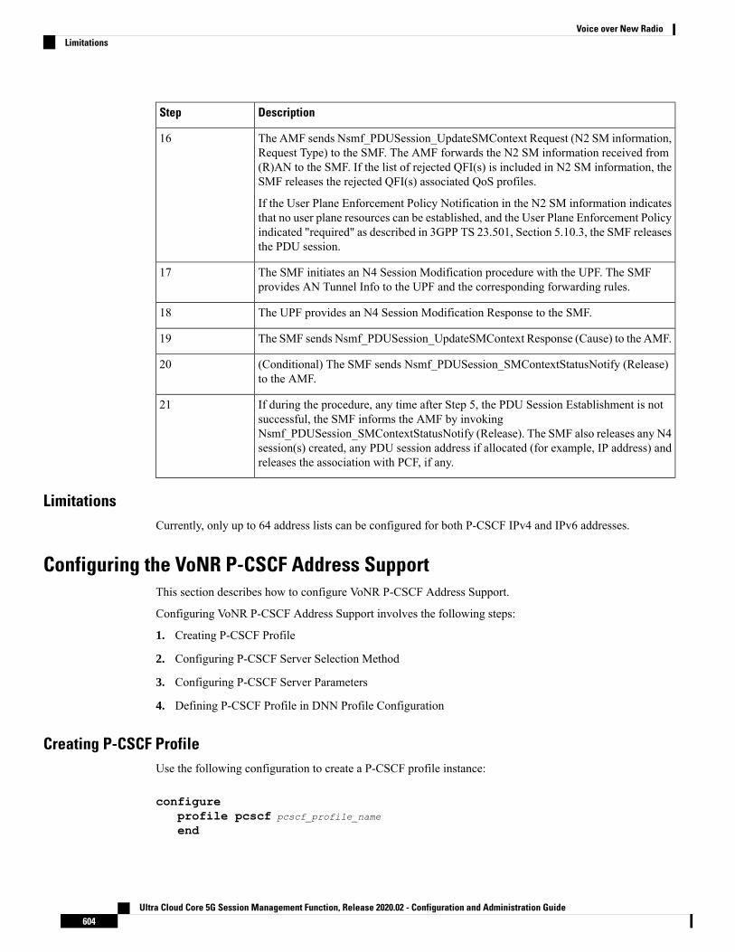
DescriptionStep
The AMF sends Nsmf_PDUSession_UpdateSMContext Request (N2 SM information,Request Type) to the SMF. The AMF forwards the N2 SM information received from(R)AN to the SMF. If the list of rejected QFI(s) is included in N2 SM information, theSMF releases the rejected QFI(s) associated QoS profiles.
If the User Plane Enforcement Policy Notification in the N2 SM information indicatesthat no user plane resources can be established, and the User Plane Enforcement Policyindicated "required" as described in 3GPP TS 23.501, Section 5.10.3, the SMF releasesthe PDU session.
16
The SMF initiates an N4 Session Modification procedure with the UPF. The SMFprovides AN Tunnel Info to the UPF and the corresponding forwarding rules.
17
The UPF provides an N4 Session Modification Response to the SMF.18
The SMF sends Nsmf_PDUSession_UpdateSMContext Response (Cause) to the AMF.19
(Conditional) The SMF sends Nsmf_PDUSession_SMContextStatusNotify (Release)to the AMF.
20
If during the procedure, any time after Step 5, the PDU Session Establishment is notsuccessful, the SMF informs the AMF by invokingNsmf_PDUSession_SMContextStatusNotify (Release). The SMF also releases any N4session(s) created, any PDU session address if allocated (for example, IP address) andreleases the association with PCF, if any.
21
LimitationsCurrently, only up to 64 address lists can be configured for both P-CSCF IPv4 and IPv6 addresses.
Configuring the VoNR P-CSCF Address SupportThis section describes how to configure VoNR P-CSCF Address Support.
Configuring VoNR P-CSCF Address Support involves the following steps:
1. Creating P-CSCF Profile
2. Configuring P-CSCF Server Selection Method
3. Configuring P-CSCF Server Parameters
4. Defining P-CSCF Profile in DNN Profile Configuration
Creating P-CSCF ProfileUse the following configuration to create a P-CSCF profile instance:
configureprofile pcscf pcscf_profile_name
end
Ultra Cloud Core 5G Session Management Function, Release 2020.02 - Configuration and Administration Guide604
Voice over New RadioLimitations

NOTES:
• pcscf pcscf_profile_name: Specifies the P-CSCF profile. This command creates a P-CSCF profile andprovides access to the P-CSCF Profile Configuration mode. For details on the commands supported inthis mode, see the pcscf-profile section in this document. pcscf_profile_name must be an alphanumericstring.
Configuring P-CSCF Server SelectionUse the following configuration to configure the P-CSCF server selection method:
configureprofile pcscf pcscf_profile_name
pcscf-selection round-robinend
NOTES:
• pcscf-selection round-robin: Configures the P-CSCF server selection method. Currently, round-robinis the only supported algorithm for the server selection.
• This command performs the round-robin selection of P-CSCF server based on the configured precedencevalue.
Configuring P-CSCF IPv4 ServerUse the following configuration to configure the P-CSCF IPv4 server:
configureprofile pcscf pcscf_profile_name
v4-listend
NOTES:
• v4-list: Prompts you to configure the P-CSCF IPv4 server details.
• Entering the v4-list command takes you to the P-CSCF IPv4 Server Configuration mode. For details onthe commands supported in this mode, see the CLI Reference Content.
Configuring P-CSCF Primary and Secondary Server IPv4 Address
Use the following configuration to configure the IPv4 address of the primary and secondary P-CSCF servers.
configureprofile pcscf pcscf_profile_name
v4-listprecedence value
primary ipv4_address
secondary ipv4_address
end
NOTES:
Ultra Cloud Core 5G Session Management Function, Release 2020.02 - Configuration and Administration Guide605
Voice over New RadioConfiguring P-CSCF Server Selection

• precedence value: Specifies the precedence value. value must be an integer in the range of 1-64. Thisprecedence value is used for the round-robin selection of P-CSCF server. The lower the precedence, thehigher the priority.
• primary ipv4_address: Specifies the IPv4 address of the primary P-CSCF server in dotted-decimalnotation.
• secondary ipv4_address: Specifies the IPv4 address of the secondary P-CSCF server in dotted-decimalnotation.
Configuring P-CSCF IPv6 ServerUse the following configuration to configure the P-CSCF IPv6 server:
configureprofile pcscf pcscf_profile_name
v6-listend
NOTES:
• v6-list: Prompts you to configure the P-CSCF IPv6 server details.
• Entering the v6-list command prompts you to the P-CSCF IPv6 Server Configuration mode. For detailson the commands supported in this mode, see the CLI Reference section.
Configuring P-CSCF Primary and Secondary Server IPv6 Address
Use the following configuration to configure the IPv6 address of the primary and secondary P-CSCF servers:
configureprofile pcscf pcscf_profile_name
v6-listprecedence value
primary ipv6_address
secondary ipv6_address
end
NOTES:
• precedence value: Specifies the precedence value. value must be an integer in the range of 1-64. Thisprecedence value is used for the round-robin selection of P-CSCF server. The lower the precedence, thehigher the priority.
• primary ipv6_address: Specifies the IPv6 address of the primary P-CSCF server in colon-separatedhexadecimal notation.
• secondary ipv6_address: Specifies the IPv6 address of the secondary P-CSCF server in colon-separatedhexadecimal notation.
Configuring P-CSCF IPv4v6 ServerUse the following configuration to configure the P-CSCF IPv4v6 server:
Ultra Cloud Core 5G Session Management Function, Release 2020.02 - Configuration and Administration Guide606
Voice over New RadioConfiguring P-CSCF IPv6 Server

configureprofile pcscf pcscf_profile_name
v4v6-listend
NOTES:
• v4v6-list: Prompts you to configure the P-CSCF IPv4v6 server details.
• Entering the v4v6-list command takes you to the P-CSCF IPv4v6 Server Configurationmode. For detailson the commands supported in this mode, see the CLI Reference section.
Configuring P-CSCF Primary and Secondary Server IPv4v6 Address
This section describes how to configure the IPv4v6 address of the primary and secondary P-CSCF servers.
configureprofile pcscf pcscf_profile_name
v4v6-listprecedence value
primary ipv4 ipv4_address ipv6 ipv6_address
secondary { [ ipv4 ipv4_address ] [ ipv6 ipv6_address ] }end
NOTES:
• precedence value: Specifies the precedence value. value must be an integer in the range of 1-64. Thisprecedence value is used for the round-robin selection of P-CSCF server. The lower the precedence, thehigher the priority.
• primary ipv4 ipv4_address ipv6 ipv6_address: Specifies the IPv4 and IPv6 address of the primaryP-CSCF server in dotted-decimal notation and colon-separated hexadecimal notation respectively.
• secondary { [ ipv4 ipv4_address ] [ ipv6 ipv6_address ] }: Specifies the IPv4 and IPv6 address of thesecondary P-CSCF server in dotted-decimal notation and colon-separated hexadecimal notationrespectively.
Defining P-CSCF Profile in DNN Profile ConfigurationUse the following configuration to configure the P-CSCF profile in the existing DNN profile configuration:
configureprofile dnn dnn_profile_name
pcscf-profile pcscf_profile_name
end
NOTES:
• pcscf-profile pcscf_profile_name: This command defines the P-CSCF profile to be associated with theDNN profile. pcscf_profile_name must be the name of the configured P-CSCF profile.
Ultra Cloud Core 5G Session Management Function, Release 2020.02 - Configuration and Administration Guide607
Voice over New RadioConfiguring P-CSCF Primary and Secondary Server IPv4v6 Address

Verifying the Feature ConfigurationUse the following show command to verify the P-CSCF FQDN feature configuration.
show running-config
The following is an example of the output of this show command:
profile pcscf pcscf1fqdn cisco.comv4-listprecedence 3primrary 3.3.3.1secondary 3.3.3.2exitprecedence 5primary 5.5.5.1secondary 5.5.5.2exit
VoNR MO and MT Call Support
Feature DescriptionThe SMF supports Mobile Originated (MO) and Mobile Terminated (MT) VoNR with 5G QoS Identifier(5QI) as Guaranteed Bit Rate (GBR) flow for UE after the IMS PDU Session Creation. The SMF furthersupports VoNR calls for the following mobility (inter gNB, inter AMF) scenarios:
• MO and MT calls for idle mode UE
• MO and MT calls when the UE is handing over
During the mobility scenario of VoNR MO and MT calls, make sure to consider the following points:
• VoNR GBR flows are supported during UE and network service request procedures, Xn and N2 basedhandover.
• QoS failures at N1 and N2 interface, which are rejected by UE and gNB, are not handled by SMF.
• Charging features are not integrated with VoNR MO and MT, and mobility features.
Call FlowsThis section describes the call flows associated with this feature.
VoNR MO Call Handling Procedure
This section describes the VoNR MO call handling procedure.
Ultra Cloud Core 5G Session Management Function, Release 2020.02 - Configuration and Administration Guide608
Voice over New RadioVerifying the Feature Configuration

Figure 119: VoNR MO Call Handling Flow
Table 184: VoNR MO Call Handling Flow Description
DescriptionStep
The SMF performs the PDU Session Establishment as described in the VoNR PDUSession Creation Call Flow, on page 600 section.
1
The UE initiates SIP Registration towards the called-party via UPF, P-CSCF throughthe backed IMS core network.
2
P-CSCF sends “Npcf_PolicyAuthorization_Update” to PCF to enforce policies, modifyservice information, gate control, modify subscription to SDF notification/deactivation,updating of traffic routing information, and so on (as defined in 3GPP TS 29.514). Thisservice allows the NF consumer to subscribe and unsubscribe the notification of events(for example, change of Access Type, RAT type, or changes of the PLMN identifier).
3
The PCF sends Npcf_SMPolicyControl_UpdateNotify request to update and/or deletethe PCC rule(s) PDU session-related policy context at the SMF and Policy ControlRequest Trigger information. This enforces PCC rules, policy control request triggers,SDF, and charging related information.
4
Ultra Cloud Core 5G Session Management Function, Release 2020.02 - Configuration and Administration Guide609
Voice over New RadioVoNR MO Call Handling Procedure

DescriptionStep
The SMF processes the received PCC rules and sends 200 OKmessage for a successfulscenario.When the processing of any content fails, the SMF includes "400 Bad Request"in “Npcf_SMPolicyControl_UpdateNotify request” and sends it along with appropriatecause value as defined in 3GPP TS 29.512.
5
The SMF sends Namf_Communication_\nN1N2MessageTransfer/Response (PDUSession ID, QFIs, QoS Profile(s), Session-AMBR), N1 SM container (PDU SessionModification Command (PDU Session ID, QoS rule(s), QoS Flow level parameters ifneeded for the QoS Flow(s) associated with the QoS rule(s), QoS rule operation, andQoS Flow level QoS parameters operation, Session-AMBR))).
If the UE is in CM-IDLE state or Mobility handover (HO) state, see the procedure inVoNR MO Call Flow for UE in Idle Mode, on page 612.
6
The AMF sends N2 PDU Session Request (N2 SM information received from SMF,NAS message (PDU Session ID, N1 SM container (PDU Session ModificationCommand))) message to the (R)AN.
7
The (R)AN issues AN specific signalling exchange with the UE that is related with theinformation received from SMF. For example, in an NG-RAN, an RRC ConnectionReconfiguration takes place with the UE modifying the necessary (R)AN resourcesrelated to the PDU session.
8
The (R)AN acknowledges N2 PDU Session Request by sending a N2 PDU SessionACK (N2 SM information (List of accepted/rejectedQFIs, ANTunnel Info, PDUSessionID, Secondary RAT usage data), User Location Information) message to the AMF. Incase of Dual Connectivity, if one or more QFIs were added to the PDU session, themaster RAN node assigns one or more of these QFIs to an NG-RAN node which wasnot involved in the PDU session earlier. In this case, the AN Tunnel Info includes a newN3 tunnel endpoint for QFIs assigned to the new NG-RAN node. Correspondingly, ifone or more QFIs were removed from the PDU session, a (R)AN node may no longerbe involved in the PDU session anymore, and the corresponding tunnel endpoint isremoved from the AN Tunnel Info. The NG-RAN rejects QFIs if it cannot fulfill theUser Plane Security Enforcement information for a corresponding QoS Profile, forexample, due to the UE Integrity Protection Maximum Data Rate being exceeded.
9
The AMF forwards the N2 SM information and the User Location Information receivedfrom the (R)AN to the SMF viaNsmf_PDUSession_UpdateSMContext service operation.
If the (R)AN rejects QFIs, the SMF updates the QoS rules and QoS parameters if neededfor the QoS flow(s) associated with the QoS rule(s) in the UE accordingly.
10
The SMF sends anNsmf_PDUSession_UpdateSMContext Response. N2 SM informationincludes Secondary RAT Usage Data.
11
The UE acknowledges the PDU Session Modification Command by sending a NASmessage (PDU Session ID, N1 SM container (PDU Session Modification CommandACK)) message.
12
The (R)AN forwards the NAS message to the AMF.13
Ultra Cloud Core 5G Session Management Function, Release 2020.02 - Configuration and Administration Guide610
Voice over New RadioVoNR MO Call Handling Procedure

DescriptionStep
The AMF forwards the N1 SM container (PDU Session Modification Command ACK)and User Location Information received from the (R)AN to the SMF viaNsmf_PDUSession_UpdateSMContext service operation.
14
The SMF sends an Nsmf_PDUSession_UpdateSMContext Response.
If the SMF-initiated modification is to delete QoS Flows (for example, triggered byPCF) which do not include QoS Flow associated with the default QoS rule and the SMFdoes not receive response from the UE, the SMF marks that the status of those QoSFlows is to be synchronized with the UE.
15
SMF sends ChargingDataUpdateReq by including Multi-Unit-Usage withRating-Group-Id that are received as part of Charging_Description ofSm_PolicyControl_UpdateNotify_Request to install PCC Rules.
16
CHF provides ChargingDataUpdtaeResp with Multi-Unit-Information for receivedRating-Group values in requested message. CHF also provides parameter changes forSession-Level and Rating-Group values.
17
The SMF updates N4 session of the UPF(s) that are involved in the PDU SessionModification by sending N4 Session Modification Request (N4 Session ID) messageto the PCF. For a PDU Session of Ethernet PDU Session Type, the SMF notifies thePCF to add or remove Ethernet Packet Filter Set(s) and forwarding rule(s).
The UPFs that are impacted in the PDU Session Modification procedure depend on themodified QoS parameters and the deployment. For example, in case of the sessionAMBR of a PDU Session with UL flow classifier (CL) changes, only the UL CL isinvolved.
18
The PCF sends an N4 sessionmodification responsemessage containing any informationthat the PCF has to provide to the SMF in response to the control information received.
19
For PCF-initiated policy modification case, the SMF notifies the PCF whether the PCCdecision could be enforced or not by performing an SMF-initiated SMPolicy AssociationModification procedure as defined in 3GPP TS 23.502, Section 4.16.5.1. The SMFnotifies any entity that has subscribed to User Location Information related with PDUSession change.
20
The PCF sends an Npcf_SMPolicyControl_Update response with updated policyinformation about the PDU session.
21
VoNR MT Call Handling Procedure
This section describes the VoNR MT call handling procedure.
Ultra Cloud Core 5G Session Management Function, Release 2020.02 - Configuration and Administration Guide611
Voice over New RadioVoNR MT Call Handling Procedure

Figure 120: VoNR MT Call Handling Flow
The VoNR MT call handling procedure remains the same as the VoNR MO call handling procedure exceptfor the SIP Registration Request initiated from UE to P-CSCF(AF) through the UPF.
VoNR MO Call Flow for UE in Idle Mode
This section describes the VoNR MO call handling procedure when the UE is in idle mode.
Ultra Cloud Core 5G Session Management Function, Release 2020.02 - Configuration and Administration Guide612
Voice over New RadioVoNR MO Call Flow for UE in Idle Mode

Figure 121: VoNR MO Call Handling Flow for UE in Idle Mode
DescriptionStep
The SMF performs the PDU session establishment as described in VoNR PDUSession Creation Call Flow, on page 600 section, and fetches the P-CSCF addressesfor sending it to the UE. The SMF programs UPFwith Paging Policy Differentiation(PPD) for the respective PDU session as part of N4 interface by provisioning flows,and traffic detection information for every PDR.
1
The UE maintains its state in CM-IDLE and RM-REGISTERED.2
The UPF maintains the UE in CM-IDLE and RM-REGISTERED state.3
The UE initiates the VoNR call in CM-IDLE state.4
Ultra Cloud Core 5G Session Management Function, Release 2020.02 - Configuration and Administration Guide613
Voice over New RadioVoNR MO Call Flow for UE in Idle Mode

DescriptionStep
The UE performs Service-Request procedures as defined in 3GPP TS 23.502.5
The RAN sends N2 message (service request) to the AMF.6
The AMF sends Nsmf_PDUSession_UpdateSMContext Request (PDU SessionID(s), Operation Type, UE Location information, Access Type, RAT Type, UEpresence in LADN service area, Indication of Access Type can be changed) to theSMF.
7
If the AMF notifies the SMF that the access type of the PDU session can be changed,and if the PCC is deployed, the SMF performs an SMF-initiated SM PolicyAssociationModification procedure as defined in 3GPP TS 23.502, Section 4.16.5.1.
8
The PCF provides the updated PCC Rule(s) to the SMF.9
The SMF performs the UPF selection.
NOTE: Selection of multiple or other UPFs is currently not supported.
10
The SMF initiates an N4 SessionModification request to the UPF. The SMF provides(R)AN Tunnel Info and the corresponding forwarding rules to the UPF. The UPFprovides an N4 Session Modification Response to the SMF.
11
The SMF sends Nsmf_PDUSession_UpdateSMContext Response (N2 SMinformation (PDU Session ID, QFI(s), QoS profile(s), CNN3 Tunnel Info, S-NSSAI,User Plane Security Enforcement, UE Integrity Protection Maximum Data Rate),N1 SM Container, Cause) to the AMF. The SMF sends N1 SM Container and/or N2SM Information to the AMF when applicable.
12
The AMF sends N2 Request (N2 SM information received from SMF, securitycontext,Mobility Restriction List, SubscribedUE-AMBR,MMNASService Accept,list of recommended cells, TAs, NG-RAN node identifiers, UE Radio Capability,Core Network Assistance Information, Tracing Requirements) to the (R)AN.
13
The NG-RAN performs RRC Connection Reconfiguration with the UE dependingon the QoS Information for all the QoS Flows of the PDU sessions whose UPconnections are activated, and Data Radio Bearers.
14
The (R)AN sends N2 Request Acknowledgement message (N2 SM information (ANTunnel Info, List of acceptedQoS Flows for the PDUSessions whose UP connectionsare activated, List of rejected QoS Flows for the PDUSessions whose UP connectionsare activated), PDU Session ID) to the AMF.
The N2 Request ACK message includes N2 SM information, for example, ANTunnel Info. NG-RAN responds N2 SM information with separate N2 message (forexample, N2 tunnel setup response) if the AMF sends separate N2 message.
15
Ultra Cloud Core 5G Session Management Function, Release 2020.02 - Configuration and Administration Guide614
Voice over New RadioVoNR MO Call Flow for UE in Idle Mode

DescriptionStep
TheAMF sendsNsmf_PDUSession_UpdateSMContextRequest (N2 SM information,RAT Type, Access Type) per PDU Session to the SMF. The AMF determines AccessType and RAT Type based on the Global RAN Node ID associated with the N2interface. If the AMF received N2 SM information (one or multiple), then the AMFforwards the N2 SM information to the relevant SMF per PDU Session ID. If theUE Time Zone has changed compared to the last reported UE Time Zone, then theAMF includes the UE Time Zone IE in this message.
16
The SMF notifies the PCF whether the PCC decision could be enforced or not byperforming an SMF-initiated SM Policy Association Modification procedure asdefined in 3GPP TS 23.502, Section 4.16.5.1. The SMF notifies any entity that hassubscribed to User Location Information related with PDU Session change.
17
The PCF sends an Npcf_SMPolicyControl_Update response with updated policyinformation about the PDU session.
18
The SMF updates N4 session of the UPF(s) that are involved in the PDU sessionmodification by sendingN4 SessionModification Request (N4 Session ID)messageto the UPF. For a PDU session of Ethernet PDU Session Type, the SMF notifies theUPF to add or remove Ethernet Packet Filter Set(s) and forwarding rule(s).
The UPFs that are impacted in the PDU Session Modification procedure depend onthe modified QoS parameters and the deployment. For example, in case of the sessionAMBR of a PDU session with UL CL changes, only the UL CL is involved.
The UPF sends an N4 session modification response message containing anyinformation that the UPF has to provide to the SMF in response to the controlinformation received.
19
The SMF sends a Nsmf_PDUSession_UpdateSMContext Response. The N2 SMinformation includes Secondary RAT Usage Data.
20
VoNR MT Call Flow for UE in Idle Mode
This section describes the VoNR MT call handling procedure when the UE is in idle mode.
Ultra Cloud Core 5G Session Management Function, Release 2020.02 - Configuration and Administration Guide615
Voice over New RadioVoNR MT Call Flow for UE in Idle Mode

Figure 122: VoNR MT Call Flow for UE in Idle Mode
The VoNR MT call flow remains the same as the VoNR MO call flow for service request when the UE is inCM-IDLE state except the following:
• The SIP-INVITE received by P-CSCF
• The PCC rule enforcements triggered from PCF towards SMF.
NOTE: The PCC rules, QoS, PDR, and traffic detection rule enforcements remain the same as the VoNRMTCall Handling procedure as defined in VoNR MT Call Handling Procedure, on page 611VoNR MT CallHandling Procedure.
When the AMF receives Namf_Communication_N1N2MessageTransfer Request (N2 SM information (PDUSession ID, QFI(s), QoS Profile(s), Session-AMBR), N1 SM container (PDU SessionModification Command(PDU Session ID, QoS rule(s), QoS Flow level parameters if needed for the QoS Flow(s) associated with the
Ultra Cloud Core 5G Session Management Function, Release 2020.02 - Configuration and Administration Guide616
Voice over New RadioVoNR MT Call Flow for UE in Idle Mode

QoS rule(s), QoS rule operation, and QoS Flow level parameters operation, Session-AMBR))) when the UEis in CM-IDLE state. If the UE is in CM-IDLE state and an Asynchronous type communication (ATC) isactivated, the AMF updates and stores the UE context based on theNamf_Communication_N1N2MessageTransfer.
The AMF performs paging operations to the UE, and the UE triggers service request procedure. Once thepaging is established, the AMF decides QoS Flows, QoS rules, and Session-AMBR that need to be accepted,which are received in Namf_Communication_N1N2MessageTransfer Request and the AMF performsNsmf_PDUSession_UpdateSMContext operation with SMF to notify on accepting the QoS Flows, QoS rules,session-AMBR, and so on.
Paging Policy Differentiation Support
Feature DescriptionThe SMF supports Paging Policy Differentiation feature by providing a configuration at PLMN, DNN, and5QI level for data and IMS DNN sessions of the UE. The SMF provides Paging Policy Indicator based onUPF data. The SMF also supports QoS flow (PPI, ARP, and 5QI) towards the AMF over N11 interface.
Call FlowsThis section describes the call flows associated with this feature.
VoNR Paging Policy Differentiation Procedure
This section describes the VoNR Paging Policy Differentiation procedure.
Ultra Cloud Core 5G Session Management Function, Release 2020.02 - Configuration and Administration Guide617
Voice over New RadioPaging Policy Differentiation Support

Figure 123: VoNR Paging Policy Differentiation Call Flow
Table 185: VoNR Paging Policy Differentiation Call Flow Description
DescriptionStep
The SMF enables Paging Policy Differentiation (PPD) under DNN profile based onDNN, 5QI, and PLMN.
1
The SMF performs the PDU session establishment as described in VoNR PDU SessionCreation Call Flow section, and fetches the P-CSCF addresses for sending it to the UE.The SMF programsUPFwith PPD for the respective PDU session as part of N4 interfaceby provisioning flows, and traffic detection information for every PDR.
2
The UPF detects if any Downlink (DL) Packet is set with \nDSCP value (TOS in IPv4/ TC in IPv6) when PPD is enabled for the PDU session.
3
The UPF detects that there is no forwarding path as there is no N3 Tunnel for the DSPmarked DL packets.
4
Ultra Cloud Core 5G Session Management Function, Release 2020.02 - Configuration and Administration Guide618
Voice over New RadioVoNR Paging Policy Differentiation Procedure

DescriptionStep
The UPF sends Data-Notification (QFI, DSCP in TOS (IPv4) / TC (IPv6) in packetheader).
5
The UPF enables DL Data buffering based on the buffering configuration. The UPFsends Data Notification (N4 Session ID, Information to identify the QoS Flow for theDL data packet, DSCP) message to the SMF.
1. On arrival of the first DL data packet for any QoS Flow, the UPF sends DataNotification message to the SMF, if the SMF has not previously notified the UPF(in which case the next steps are skipped).
2. If the UPF receives DL data packets for another QoS Flow in the same PDU session,the UPF sends another Data Notification message to the SMF.
3. If the Paging Policy Differentiation feature (as specified in TS 23.501, section 5.4.3)is supported by the UPF and if the PDU Session type is IP, the UPF includes theDSCP in TOS (IPv4) / TC (IPv6) value from the IP header of the DL data packetand the information to identify the QoS Flow for the DL data packet.
4. The SMF sends the Data Notification Acknowledgement message to the UPF.
5. The UPF forwards the DL data packets towards the SMF on request. The SMFbuffers the data packets.
6
The SMF determines the AMF and invokes theNamf_Communication_N1N2MessageTransfer to the AMF including the PDU SessionID based on N4 Session ID. The SMF, while waiting for the User Plane Connection tobe activated, receives additional Data Notification message.
The SMF derives a different Paging Policy Indicator according to the additional DataNotification or the DSCP of the data packet. The SMF invokes a newNamf_Communication_N1N2MessageTransfer indicating the higher priority or differentPaging Policy Indicator to the AMF.
When supporting Paging Policy Differentiation, the SMF determines the Paging PolicyIndicator related to the downlink data that has been received from the UPF or triggeredthe Data Notification message, based on the DSCP as described in 3GPP TS 23.501,section 5.4.3. The SMF indicates the Paging Policy Indicator in theNamf_Communication_N1N2MessageTransfer.
7
The AMF sends Namf_Communication_N1N2MessageTransfer response to the SMFwith a cause “Attempting to reach UE" if the UE is in CM_IDLE State. If the UE is inCM-CONNECTED state, then the AMF sends aNamf_Communication_N1N2MessageTransfer response to the SMF immediately witha cause "N1/N2 transfer success".
8
The SMF sends Failure Indication to the UPF on receiving a negative response fromAMF.
9
The AMF initiates paging towards the UE through the (R)AN.10
The AMF initiates NAS Notification towards the UE.11
Ultra Cloud Core 5G Session Management Function, Release 2020.02 - Configuration and Administration Guide619
Voice over New RadioVoNR Paging Policy Differentiation Procedure

DescriptionStep
TheAMF notifies the SMF by sending Namf_Communications_N1N2MessageTransferFailure Notification to the Notification Target Address provided by the SMF if the UEdoes not respond to paging. The AMF is unaware of an ongoing Mobility Management(MM) procedure that prevents the UE from responding. The AMF receives an N14Context Request message indicating that the UE performs Registration procedure withanother AMF.
12
If the UE is in CM-IDLE state, upon receiving a paging request for a PDU sessionassociated to 3GPP access, the UE initiates the UE Triggered Service Request procedureas defined in 3GPP TS 23.502, Section 4.2.3.2.
13
Configuring the VoNR Paging Profile DifferentiationThis section describes how to configure VoNR Paging Profile Differentiation feature.
Configuring VoNR Paging Profile Differentiation feature involves the following steps:
1. Creating PPD Profile
2. Configuring PPD Profile Parameters
3. Enabling PPD in DNN Profile Configuration
Creating PPD ProfileUse the following configuration to create an instance of PPD profile:
configureprofile ppd ppd_profile_name
end
NOTES:
• ppd ppd_profile_name: Specifies the PPD profile. This command creates a PPD profile and providesaccess to the PPD Profile Configuration mode. For details on the commands supported in this mode, seethe ppd-profile section in this document. ppd_profile_name must be an alphanumeric string.
Configuring PPD Profile ParametersUse the following configuration to define the PPD profile parameters:
configureprofile ppd ppd_profile_name
5qi 5qi_value
dscp dscp_value { ppi ppi_value }end
NOTES:
• 5qi: Specifies the list of 5QI Priority Level. 5qi_value must be an integer in the range of 0-127. To listthe different priority levels, use comma and hyphen as needed. For example, 5QI 3,10-15,65.
Ultra Cloud Core 5G Session Management Function, Release 2020.02 - Configuration and Administration Guide620
Voice over New RadioConfiguring the VoNR Paging Profile Differentiation

• dscp dscp_value: Specifies the DSCP value. dscp_value must be an integer in the range of 0-63.
• ppi ppi_value: Specifies the paging policy indicator value. ppi_value must be an integer in the range of0-7.
Enabling PPD in DNN Profile ConfigurationUse the following configuration to enable the PPD feature in the existing DNN profile configuration:
configureprofile dnn dnn_profile_name
ppd-profile ppd_profile_name
end
NOTES:
• ppd-profile ppd_profile_name: This command defines the PPD profile to be associated with the DNNprofile. pdd_profile_name must be the name of the configured PPD profile.
• This command enables the PPD feature in the DNN profile based on the configured values of DNN, 5QI,and PLMN.
Verifying the Feature ConfigurationUse the following show command to verify the feature configuration details.
show running-config
The following is an example of the output of this show command:
product smf# show running-configprofile dnn dnntst1pcscf-profile pcscf1!
P-CSCF FQDN
Feature DescriptionThe SMF sends the DNS queries to the DNS server through the DNS proxy server to fetch a maximum oftwo P-CSCF IP addresses. This operation helps in resolving the Fully Qualified Domain Name (FQDN) ofthe P-CSCF. This release provides the configuration support for the P-CSCF FQDN within the SMF profile.
For more information on the configuration commands, see the Configuring the P-CSCF FQDN, on page 622section.
RelationshipsThe P-CSCF FQDN feature works only when the DNS proxy is configured. For more information on the DNSproxy configuration, see the DNS Proxy Integration in SMF chapter.
Ultra Cloud Core 5G Session Management Function, Release 2020.02 - Configuration and Administration Guide621
Voice over New RadioEnabling PPD in DNN Profile Configuration

Configuring the P-CSCF FQDNUse the following configuration to define the FQDN of the P-CSCF.
configureprofile pcscf pcscf_profile_name
fqdn domain_name
end
NOTES:
• pcscf-profile pcscf_profile_name: Specifies the P-CSCF profile name, and enters into the P-CSCF ProfileConfiguration mode. pcscf_profile_name must be an alphanumeric string.
• fqdn domain_name: Specifies the FQDN of the P-CSCF server. domain_namemust be an alphanumericstring.
Verifying the Feature ConfigurationUse the following show command to verify the feature configuration details.
show running-config
The following is an example of the output of this show command:
profile ppd ppdtemp5QI 3,10-15,65dscp 15 ppi 2dscp 20 ppi 3!profile dnn imsppd-profile ppdtemp!
Ultra Cloud Core 5G Session Management Function, Release 2020.02 - Configuration and Administration Guide622
Voice over New RadioConfiguring the P-CSCF FQDN

C H A P T E R 45VoLTE Support
• Feature Summary and Revision History, on page 623• Feature Description, on page 623
Feature Summary and Revision History
Summary DataTable 186: Summary Data
SMFApplicable Product(s) or Functional Area
SMIApplicable Platform(s)
Disabled – Configuration RequiredFeature Default Setting
Not ApplicableRelated Changes in this Release
Not ApplicableRelated Documentation
Revision HistoryTable 187: Revision History
ReleaseRevision Details
Pre-2020.02.0First introduced.
Feature DescriptionThe SMF supports Voice over Long-Term Evolution or LTE (VoLTE). The VoLTE technology utilizes IPMultimedia Subsystem (IMS) to allow you to make cellular calls over the LTE access network.
Ultra Cloud Core 5G Session Management Function, Release 2020.02 - Configuration and Administration Guide623

How it WorksA 5G mobile device with LTE access requests voice services to communicate with PGW-C over S-GW andMME resulting in the establishment of a PDU session. The P-GW supports a non-GBR bearer with QCI flowsas 5 for VoLTE sessions. This support allows IMS signaling along with P-CSCF, DNS IPv4, or DNS IPv6addresses for end users. For mobile-originated (MO) or mobile-terminated (MT) calls, the Application Function(AF) provides policy authorization details to the PCF. The PCF then converts these details to GBR flows andPCC rules and sends them to PGW-C. The PGW-C then converts the GBR-flows to dedicated bearers byestablishing the dedicated bearer creation procedure with UE. The PGW-C provisions the GBR with the QCIflow as 1 to UPF. By this provisioning, the UPF supports voice communication between the calling and calleddevices over IMS network elements.
As per the E-UTRAN Attach procedure, the MME triggers the GTPv2 Create Session Request to PGW-Cover S-GW. This request includes the EPS Bearer Identity (EBI) value, ePCO options for P-CSCF and DNSIPv4 or DNS IPv6 containers, PDN-Type, and PAA options for IPv4 or IPv6 allocated address for end users.The P-GW then processes the received Create Session Request and communicates with various SBI interfacesto receive the following information:
• Subscription data from UDM by including PGW-C FQDN in the subscription request.
• Policy information from PCF by sending SM policy create request. Policy information includes details,such as PCC rules and Session-AMBR.
• Online and offline charging information from CHF by sending the charging create data request.
After communication with SBI interfaces, which are based on the local SMF profile configuration, the P-GWsends the GTPv2 Create Session Response to the end user over S-GW and MME. This response includes:
• PAA with IPv4 or IPv6 addresses that PGW-C IPAM module allocates
• ePCO option with P-CSCF
• DNS IPv4 or DNS IPv6 address based on DNN-Profile configuration
• Non-GRB with the QCI flow as 5 for IMS signaling
For an MO or MT call, if the PCF is provisioned for GBR with the QCI flow as 1 for end users, the P-GWconverts these GBR flows to the dedicated bearer creation. The GBR flows include the flow information andthe PCC rules in the SM Policy Update Notify Request. The dedicated bearer is created by sending GTPv2Create Bearer Request to UE over S-GW or MME. Another S5-U tunnel is created between S-GW and P-GWto allow GBE flow packets for the voice communication between the calling and called devices.
Call FlowsThis section describes the following call flows:
• VoLTE PDU Session Creation Call Flow
• VoLTE Mobile-Originated (MO) Call Creation Call Flow
• VoLTE Mobile-Terminated (MT) Call Creation Call Flow
VoLTE PDU Session Creation Call Flow
To enable the connectivity through a 5G core, the initial attach on the E-UTRAN or EPS deviates from thedefined 3GPP procedures in the following ways:
Ultra Cloud Core 5G Session Management Function, Release 2020.02 - Configuration and Administration Guide624
VoLTE SupportHow it Works

• An SMF+P-GW replaces the P-GW in the procedure.
• The SM Policy Association Establishment procedure replaces the IP-CAN Session Establishment andmodification.
• The integrated charging over the NCHF interface with CHF replaces the online and offline chargingfunctionality by using the Gy and Gz interfaces.
• Communication with the User Plane node happens over the N4 interface instead of the Sxb interface.
Depending on the mapped PCC rules, the SMF+PGW-C can initiate the dedicated bearer creation.Note
The following call flow depicts the creation of a VoLTE PDU session.
Figure 124: VoLTE PDU Session Creation Call Flow
Ultra Cloud Core 5G Session Management Function, Release 2020.02 - Configuration and Administration Guide625
VoLTE SupportVoLTE PDU Session Creation Call Flow

Table 188: VoLTE PDU Session Creation Call Flow Description
DescriptionStep
UE sends the attach request to MME through eNodeB.1
MME determines if the UE is active and subscribed for the handoff to NR. Then, MMEselects a SMF+PGW-C node as the P-GW for the PDU session.
2
MME sends the create session request to the selected S-GW and includes the selectedSMF+PGW-C address in the request.
3
S-GW initiates the create session request toward SMF+PGW-C by including the“P-CSCF IPv4 or IPv6 request” container identifier in the extended PCO IE options.
SMF+PGW-C extracts and saves the PDU session ID that UE sends in the PCO option.Then, SMF+PGW-C performs a UDM registration and sends both the N11 and S5 orS8 interface ID to UDM. Based on the local configuration or the session managementsubscription data, which is received from UDM for respective DNN, SMF+PGW-Cdetermines to support “IMS Voice over PS”.
4
SMF+PGW-C sends the NPCF SM policy control creation request to PCF to initiatethe SM policy association establishment procedure. In this procedure, PGW-C+SMFincludes the information elements that are received in the create session request messageinto the Npcf_SMPolicyControl_Create service. These elements comprise the followinginformation:
• SUPI contains the IMSI.
• DNN contains the APN.
• PEI contains the IMEI-SV.
• Session AMBR contains the APN-AMBR.
• Default QoS information that contains the default EPS bearer QoS. The QCIvalues are mapped into 5QI values.
5
PGW-C+SMF receives the PCC rules, PDU session policy information, and 5G QoSinformation. The PCC rules are mapped into EPSQoS information. The SMF+PGW-Ccreates TFT from the SDF filters that are received in the PCC rules. Then, SMF+PGW-Cassociates them with the corresponding default and dedicated bearers.
6
Based on the charging policies received from the PCF, the SMF+PGW-C initiates theNCHF converged charging creation procedure toward CHF. This procedure is basedon the charging rules that are received from the PCF.
7
The SMF+PGW-C starts the UPF+PGW-U selection and N4 session establishmentprocedure. As this session is a 4G session that connects to the SMF+PGW-C, a separateCN tunnel is created for each bearer. Also, the QoS Flow Identifier (QFI) is not sentin the QoS Enforcement Rule (QER) and Packet Detection Rule (PDR).
8
The SMF+PGW-C sends create session response to the S-GW. This response includesthe bearer information and the TEID for the default bearer. The SMF+PGW-C alsoincludes the 5G QoS parameters in PCO options 001CH (QoS rules), 001DH(Session-AMBR), 001EH (PDU session address lifetime), and 001FH (QoS flowdescriptions) to the UE.
9
Ultra Cloud Core 5G Session Management Function, Release 2020.02 - Configuration and Administration Guide626
VoLTE SupportVoLTE PDU Session Creation Call Flow

DescriptionStep
Based on the charging policies received from PCF, the SMF+PGW-C initiates NCHFconverged charging creation procedure toward CHF. This procedure is based on thecharging rules that are received from PCF.
10
S-GW sends create session response to MME.11
MME sends the Initial Context Setup Request to eNodeB with the N1 Attach Acceptmessage.
12
eNodeB and UE perform the RRC configuration.13
UE sends the direct transfer message to eNodeB.14
eNodeB sends the attach completion message in the Initial Context Setup Responseand the TEID of eNodeB to MME.
15
MME sends a modify bearer request to S-GW with eNodeB TEID.16
S-GW sends the modify bearer request to SMF+PGW-C with eNodeB TEID.17
SMF+PGW-C performs the N4 session modification to update the eNodeB TEID onthe data path to the UPF+PGW-U.
18
SMF+PGW-C sends the modify bearer response to the S-GW.19
S-GW sends the modify bearer response to MME.20
VoLTE Mobile-Originated (MO) Call Creation Call Flow
This section describes the VoLTE MO call creation call flow.
Ultra Cloud Core 5G Session Management Function, Release 2020.02 - Configuration and Administration Guide627
VoLTE SupportVoLTE Mobile-Originated (MO) Call Creation Call Flow

Figure 125: VoLTE MO Call Creation Call Flow
Table 189: VoLTE MO Call Creation Call Flow Description
DescriptionStep
UE requests for establishment of the IMS default bearer, PDU session, through PCF.After establishing the session, the UE receives the P-CSCF addresses from PCF.
1
UE sends the requested bearer resource modification information to MME.2
Ultra Cloud Core 5G Session Management Function, Release 2020.02 - Configuration and Administration Guide628
VoLTE SupportVoLTE Mobile-Originated (MO) Call Creation Call Flow

DescriptionStep
MME sends the bearer resource command to S-GW.2a
S-GW sends the bearer resource command to SMF+PGW-C.2b
SMF+PGW-C sends the NPCF SM policy control update request to PCF.3
PCF sends the NPCF SM Policy control update response back to SMF+PGW-C.4
UE initiates SIP signaling toward P-CSCF (AF).5
P-CSCF sends NPCF Policy Authorization Update message to PCF through CHF.5a
PCF sends the NPCF SM policy control update notify request to SMF+PGW-C.6
SMF+PGW-C sends the NPCF SMPolicy control update notify response back to PCF.6a
SMF sends ChargingDataUpdateReq by including Multi-Unit-Usage withRating-Group-Id that are received as part of Charging_Description ofSm_PolicyControl_UpdateNotify_Request to install PCC Rules.
7
CHF provides ChargingDataUpdateResp with Multi-Unit-Information for receivedRating-Group values in requested message. CHF also provides params changes forSession-Level and Rating-Group values.
8
SMF sends N4 SessionModification Request to the UPF by including Create ULPDRsand Create ULFARs. Create ULPDRs include SDFs and QER Info which are receivedas part of PCC Rule Installation.
9
UPF responds back with N4 Session Modification Response to SMF by includingCreated ULPDR and Created ULFAR. Create ULFAR contains UL Tunnel Informationof UPF for the dedicated bearer creation.
10
SMF+PGW-C sends the GTPv2 create bearer request to S-GW.11
S-GW sends the GTPv2 create bearer request to MME.12
MME sends the bearer setup request and session management request to eNodeB.13
RRC connection reconfiguration starts between UE and eNodeB.14
The eNodeB sends the bearer setup response to MME.15
UE initiates a direct transfer toward eNodeB.16
eNodeB sends the session management response to MME.17
MME sends the GTPv2 create bearer response to S-GW.18
S-GW sends the GTPv2 create bearer response to SMF+PGW-C.19
SMF+PGW-C sends the N4 sessionmodification request or response to UPF+PGW-U.20
SMF+PGW-C sends the NPCF SM policy control update request to PCF.21
PCF sends the NPCF SM policy control update response back to SMF+PGW-C.22
PCF sends the NPCF policy authorization notify request to P-CSCF (AF).23
Establishes SIP-signaling and voice call between end-users through UE and P-CSCF(AF).
24
Ultra Cloud Core 5G Session Management Function, Release 2020.02 - Configuration and Administration Guide629
VoLTE SupportVoLTE Mobile-Originated (MO) Call Creation Call Flow

NOTES:
• The PCC rules that the PCF provides are mapped to TFTs for the new dedicated bearer. The associatedQoS is mapped to 4G QoS.
• The NCHFConverged Charging Update service procedures replace all the Gy and Gz interface messages.
• The User Plane resources for dedicated bearers are added through the N4 SessionModification proceduretowards the UPF. PDRs, QERs, and FARs are added for the SDF filters for the new dedicated bearer.
• SMF+PGW-C saves the EBI for the dedicated bearer that is received in the create bearer response.
VoLTE Mobile-Terminated (MT) Call Creation Call Flow
This section describes the VoLTE MT call creation call flow.
Ultra Cloud Core 5G Session Management Function, Release 2020.02 - Configuration and Administration Guide630
VoLTE SupportVoLTE Mobile-Terminated (MT) Call Creation Call Flow

Figure 126: VoLTE MT Call Creation Call Flow
Table 190: VoLTE MT Call Creation Call Flow Description
DescriptionStep
UE requests for establishment of the IMS default bearer, PDU session, throughPCF. After establishing the session, the UE receives the P-CSCF addresses fromPCF.
1
P-CSCF (AF) sends the NPCF policy authorization update to PCF.2
Ultra Cloud Core 5G Session Management Function, Release 2020.02 - Configuration and Administration Guide631
VoLTE SupportVoLTE Mobile-Terminated (MT) Call Creation Call Flow

DescriptionStep
PCF sends the NPCF SM Policy control update notify request to SMF+PGW-C.3
SMF+PGW-C sends the NPCF SM Policy control update notify response to PCF.4
SMF sends ChargingDataUpdateReq by including Multi-Unit-Usage withRating-Group-Id that are received as part of Charging_Description ofSm_PolicyControl_UpdateNotify_Request to install PCC Rules.
5
CHF provides ChargingDataUpdateResp withMulti-Unit-Information for receivedRating-Group values in requested message. CHF also provides params changesfor Session-Level and Rating-Group values.
6
SMF sends N4 Session Modification Request to the UPF by including CreateULPDRs andCreate ULFARs. Create ULPDRs include SDFs andQER Infowhichare received as part of PCC Rule Installation.
7
UPF responds back with N4 Session Modification Response to SMF by includingCreated ULPDR and Created ULFAR. Create ULFAR contains UL TunnelInformation of UPF for the dedicated bearer creation.
8
SMF+PGW-C sends the GTPv2 create bearer request to S-GW.9
S-GW sends the GTPv2 create bearer request to MME.10
MME sends the bearer setup request and session management request to eNodeB.11
RRC connection reconfiguration starts between UE and eNodeB.12
eNodeB sends the bearer setup response to MME.13
UE initiates a direct transfer toward eNodeB.14
eNodeB sends the session management response to MME.15
MME sends the GTPv2 create bearer response to S-GW.16
S-GW sends the GTPv2 create bearer response to SMF+PGW-C.17
SMF+PGW-C sends the N4 session modification request or response toUPF+PGW-U.
18
SMF+PGW-C sends the NPCF SM policy control update request to PCF.19
PCF sends the NPCF SM policy control update response back to SMF+PGW-C.20
PCF sends the NPCF policy authorization notify request to P-CSCF (AF).21
Establishes SIP-signaling and voice call between end-users throughUE and P-CSCF(AF).
22
Standards ComplianceThe VoLTE support feature complies with the following standard:
• 3GPP TS 23.502 V15.2.0 (2018-09)
Ultra Cloud Core 5G Session Management Function, Release 2020.02 - Configuration and Administration Guide632
VoLTE SupportStandards Compliance
LimitationsThe VoLTE support feature has the following limitations:
• The UE-initiated dedicated bearer creation is not supported.
• VoLTE is not integrated with charging.
• PCF-initiated modification is not supported to change the GBR flows and PCC rules. However, theaddition and deletion of GBR flows are supported.
Ultra Cloud Core 5G Session Management Function, Release 2020.02 - Configuration and Administration Guide633
VoLTE SupportLimitations

Ultra Cloud Core 5G Session Management Function, Release 2020.02 - Configuration and Administration Guide634
VoLTE SupportLimitations
C H A P T E R 46VoWiFi Support
• Feature Summary and Revision History, on page 635• Feature Description, on page 635
Feature Summary and Revision History
Summary DataTable 191: Summary Data
SMFApplicable Product(s) or Functional Area
SMIApplicable Platform(s)
Disabled – Configuration RequiredFeature Default Setting
Not ApplicableRelated Changes in this Release
Not ApplicableRelated Documentation
Revision HistoryTable 192: Revision History
ReleaseRevision Details
Pre-2020.02.0First introduced.
Feature DescriptionThe SMF supports Voice over Wi-Fi (VoWiFi). The VoWiFi technology provides the telephony servicesusing Voice over IP (VoIP) from the mobile devices that are connected across a Wi-Fi network.
Ultra Cloud Core 5G Session Management Function, Release 2020.02 - Configuration and Administration Guide635

ArchitectureThis section describes the VoWiFi architecture.
Figure 127: VoWiFi Architecture
How it WorksA 5G mobile device connects through an untrusted Wi-Fi network for voice services to establish a PDNconnection with PGW-C. This connection is established through Internet Key Exchange Protocol version 2(IKEv2) protocol between the UE and enhanced Packet Data Gateway (ePDG). The P-GW receives the GTPv2Create Session Request from an untrustedWi-Fi ePDG over the S2b interface. The PGW-C then communicateswith the SBI interfaces for creating the default and dedicated bearers. The SBI interfaces can be an N7, N10,N40, or an NRF interface.
Call FlowsThis section describes the following call flows:
• VoWiFi PDU Session Creation Call Flow
• VoWiFi Mobile-Originated (MO) Call Creation Call Flow
• VoWifi Mobile-Terminated (MT) Call Creation Call Flow
VoWiFi PDU Session Creation Call Flow
To enable connectivity through a 5G core, the initial attach on the ePDG or EPS deviates from the defined3GPP procedures in the following ways:
• An SMF+P-GW replaces the P-GW in the procedure.
• The SM Policy Association Establishment procedure replaces the IP-CAN Session Establishment andmodification.
• The integrated charging over the NCHF interface with CHF replaces the online and offline chargingfunctionality by using the Gy and Gz interfaces.
• Communication with the User Plane node happens over the N4 interface instead of the Sxb interface.
Ultra Cloud Core 5G Session Management Function, Release 2020.02 - Configuration and Administration Guide636
VoWiFi SupportArchitecture

The following call flow depicts the creation of a VoWifi PDU session.
Figure 128: VoWiFi PDU Session Creation Call Flow
Table 193: VoWiFi PDU Session Creation Call Flow Description
DescriptionStep
The UE initiates the IKE_SA_INIT and IKE_SA_AUTH exchange.
TheUE then sends the IKE_SA_AUTH exchangemessage to ePDG to create the IPSectunnel.
1
The UE sends the IKE_SA_AUTH exchange message to the SMF+PGW-C as a GTPCreate Session Request by including the “P-CSCF IPv4 or IPv6 request and DNS IPv4or IPv6” container identifier in APCO IE Options.
2
The SMF+PGW-C extracts and saves the PDU Session ID that the UE sent in the APCOIE option. The SMF+PGW-C then performs a UDM registration and sends both theN11 and S2b interface IDs to UDM. Based on the local configuration or sessionmanagement subscription data that is received from UDM for respective DNN,SMF+PGW-C determines to support “IMS Voice over PS”.
3
Ultra Cloud Core 5G Session Management Function, Release 2020.02 - Configuration and Administration Guide637
VoWiFi SupportVoWiFi PDU Session Creation Call Flow

DescriptionStep
The SMF+PGW-C sends the NPCF SM Policy Control Creation Request to the PCFto initiate the SM Policy Association Establishment procedure. In this procedure, thePGW-C+SMF includes the information elements that are received in the Create SessionRequest message into the Npcf_SMPolicyControl_Create service. These elementscomprise the following information:
• SUPI contains the IMSI.
• DNN contains the APN.
• PEI contains the IMEI-SV.
• Session AMBR contains the APN-AMBR.
• Default QoS information that contains the default EPS bearer QoS. The QCI valuesare mapped into 5QI values.
4
The PGW-C+SMF receives the PCC rules, PDU session policy information, and 5GQoS information. The PCC rules are mapped into EPS QoS information. TheSMF+PGW-C creates TFT from the SDF filters that are received in the PCC rules. TheSMF+PGW-C then associates them with the corresponding default and dedicatedbearers.
5
Based on the charging policies received from the PCF, the SMF+PGW-C initiatesNchf_ConvergedCharging_Create procedure toward CHF. This procedure is based onthe charging rules that are received from the PCF.
6
The SMF+PGW-C starts the UPF+PGW-U selection and N4 Session Establishmentprocedure. As this session is a 4G session that connects to the SMF+PGW-C, a separateCN tunnel is created for each bearer. Also, the QoS Flow Identifier (QFI) is not sentin the QoS Enforcement Rule (QER) and Packet Detection Rule (PDR).
7
Th eSMF+PGW-C sends Create Session Response to the ePDG. This response includesthe bearer information and the TEID for the default bearer. The SMF+PGW-C alsoincludes the 5G QoS parameters in APCO options 001CH (QoS rules), 001DH(Session-AMBR), 001EH (PDU session address lifetime), and 001FH (QoS flowdescriptions) to the UE.
8
The ePDG sends IKE_SA_AUTH Response to the UE.
Then, depending on the mapped PCC rules, the SMF+PGW-C initiates the dedicatedbearer creation.
9
VoWiFi Mobile-Originated (MO) Call Creation Call Flow
This section describes the VoWiFi MO call creation call flow.
Ultra Cloud Core 5G Session Management Function, Release 2020.02 - Configuration and Administration Guide638
VoWiFi SupportVoWiFi Mobile-Originated (MO) Call Creation Call Flow

Figure 129: VoWiFi MO Call Creation Call Flow
Table 194: VoWiFi MO Call Creation Call Flow Description
DescriptionStep
UE requests for establishment of the IMS default bearer, PDU session, through PCF.After establishing the session, the UE receives the P-CSCF addresses from PCF.
1
The UE initiates the SIP signaling toward P-CSCF (AF).2
The P-CSCF (AF) sends the NPCF Policy Authorization Update message to the PCF.3
The PCF sends the NPCF SM Policy Control Update Notify Request to theSMF+PGW-C.
4
The SMF+PGW-C sends the NPCF SM Policy Control Update Notify Response backto the PCF.
5
SMF sends ChargingDataUpdateReq by including Multi-Unit-Usage withRating-Group-Id that are received as part of Charging_Description ofSm_PolicyControl_UpdateNotify_Request to install PCC Rules.
6
CHF provides ChargingDataUpdateResp with Multi-Unit-Information for receivedRating-Group values in requested message. CHF also provides params changes forSession-Level and Rating-Group values.
7
SMF sends N4 SessionModification Request to the UPF by including Create ULPDRsand Create ULFARs. Create ULPDRs include SDFs and QER Info which are receivedas part of PCC Rule Installation.
8
UPF responds back with N4 Session Modification Response to SMF by includingCreatedULPDR and CreatedULFAR. Create ULFAR contains ULTunnel Informationof UPF for the dedicated bearer creation.
9
Ultra Cloud Core 5G Session Management Function, Release 2020.02 - Configuration and Administration Guide639
VoWiFi SupportVoWiFi Mobile-Originated (MO) Call Creation Call Flow

DescriptionStep
The SMF+PGW-C sends the GTPv2 Create Bearer Request to the S-GW.10
The S-GW sends the GTPv2 Create Bearer Request to the ePDG.11
IKE_CHILD_SA exchange happens between the UE and ePDG.12
The ePDG sends the GTPv2 Create Bearer Response back to the SMF+PGW-C.13
The established N4 session is modified between SMF+PGW-C and UPF+PGW-C.14
The SMF+PGW-C sends the NPCF SM Policy Control Update Request to the PCF.15
The PCF sends the NPCF SM Policy Control Update Response back to theSMF+PGW-C.
16
PCF sends the NPCF policy authorization notify request to P-CSCF (AF).17
Establishes SIP-signaling and voice call between end-users through UE and P-CSCF(AF).
18
NOTE:
• The PCC rules that the PCF provides are mapped to TFTs for the new dedicated bearer. The associatedQoS is mapped to 4G QoS.
• The NCHFConverged Charging Update Service procedures replace all the Gy and Gz interfacemessages.
• The User Plane resources for dedicated bearers are added through the N4 SessionModification proceduretowards the UPF. PDRs, QERs, and FARs are added for the SDF filters for the new dedicated bearer.
• The SMF+PGW-C saves the EBI for the dedicated bearer that is received in the Create Bearer Response.
VoWifi Mobile-Terminated (MT) Call Creation Call Flow
This section describes the Mobile-Terminated (MT) call flow.
Ultra Cloud Core 5G Session Management Function, Release 2020.02 - Configuration and Administration Guide640
VoWiFi SupportVoWifi Mobile-Terminated (MT) Call Creation Call Flow

Figure 130: VoWifi MT Call Creation Call Flow
Table 195: VoWifi MT Call Creation Call Flow Description
DescriptionStep
UE requests for establishment of the IMS default bearer, PDU session, through PCF.After establishing the session, the UE receives the P-CSCF addresses from PCF.
1
The UE-initiates the SIP signaling towards the P-CSCF (AF).2
The P-CSCF (AF) sends the NPCF Policy Authorization Update message to the PCF.3
The PCF sends the NPCF SM Policy Control Update Notify Request to theSMF+PGW-C.
4
The SMF+PGW-C sends the NPCF SM Policy Control Update Notify Response backto the PCF.
5
SMF sends ChargingDataUpdateReq by including Multi-Unit-Usage withRating-Group-Id that are received as part of Charging_Description ofSm_PolicyControl_UpdateNotify_Request to install PCC Rules.
6
CHF provides ChargingDataUpdateResp with Multi-Unit-Information for receivedRating-Group values in requested message. CHF also provides params changes forSession-Level and Rating-Group values.
7
SMF sends N4 Session Modification Request to the UPF by including Create ULPDRsand Create ULFARs. Create ULPDRs include SDFs and QER Info which are receivedas part of PCC Rule Installation.
8
UPF responds backwith N4 SessionModification Response to SMF by including CreatedULPDR and Created ULFAR. Create ULFAR contains UL Tunnel Information of UPFfor the dedicated bearer creation.
9
Ultra Cloud Core 5G Session Management Function, Release 2020.02 - Configuration and Administration Guide641
VoWiFi SupportVoWifi Mobile-Terminated (MT) Call Creation Call Flow

DescriptionStep
The SMF+PGW-C sends the GTPv2 Create Bearer Request to the S-GW.10
The S-GW sends the GTPv2 Create Bearer Request to the ePDG.11
IKE_CHILD_SA exchange happens between the UE and ePDG.12
The ePDG sends the GTPv2 Create Bearer Response back to the SMF+PGW-C.13
The established N4 session is modified between SMF+PGW-C and UPF+PGW-C.14
The SMF+PGW-C sends the NPCF SM Policy Control Update Request to the PCF.15
The PCF sends theNPCFSMPolicy Control Update Response back to the SMF+PGW-C.16
PCF sends the NPCF policy authorization notify request to P-CSCF (AF).17
Establishes SIP-signaling and voice call between end-users through UE and P-CSCF(AF).
18
Standards ComplianceThe VoWiFi support feature complies with the following standard:
• 3GPP TS 23.502 V15.2.0 (2018-09)
LimitationsIn this release, the VoWiFi support feature has the following limitations:
• UE-initiated Dedicated Bearer Creation is not supported.
• VoWiFi is not integrated with charging.
• PCF-initiated modification is not supported to change the GBR flows and PCC rules. However, theaddition and deletion of GBR flows are supported.
• Integration of charging is not supported.
Ultra Cloud Core 5G Session Management Function, Release 2020.02 - Configuration and Administration Guide642
VoWiFi SupportStandards Compliance

C H A P T E R 47Wi-Fi Handovers
• Feature Summary and Revision History, on page 643• Feature Description, on page 644• Configuring Compliance Profile, on page 662
Feature Summary and Revision History
Summary DataSMFApplicable Product(s) or Functional Area
SMIApplicable Platform(s)
Disabled – Configuration RequiredFeature Default Setting
Not ApplicableRelated Changes in this Release
Not ApplicableRelated Documentation
Revision HistoryTable 196: Revision History
ReleaseRevision Details
2020.02.2The Wi-Fi to 5GS Handover with EPS Fallbackfeature is fully qualified in this release.
2020.02.1The Wi-Fi to 5GS Handover with EPS Fallbackfeature is not fully qualified in this release. For moreinformation, contact your Cisco Accountrepresentative.
Pre-2020.02.0First introduced.
Ultra Cloud Core 5G Session Management Function, Release 2020.02 - Configuration and Administration Guide643

Feature DescriptionThe Cloud Native based SMF+PGW-C product supports the Wi-Fi handover. The cloud-based architecturesupports the following Wi-Fi handovers in 5GS or EPS and non-3GPP untrusted access.
• EPC to non-3GPP untrusted Wi-Fi handover
• Non-3GPP untrusted Wi-Fi to EPC handover
• Non-3GPP untrusted Wi-Fi to 5GS handover with EPS fallback
• Non-3GPP untrusted Wi-Fi to 5GS handover
• 5GS to non-3GPP untrusted Wi-Fi handover
ArchitectureThe following sections describe the architecture for interworking between the ePDG or EPC and 5GS and thenon-roaming architecture within the EPS using S5 and S2b interfaces.
ePDG and 5GS Interworking for HandoverThe following figure illustrates the non-roaming architecture for interworking between the ePDG or EPC and5GS.
Ultra Cloud Core 5G Session Management Function, Release 2020.02 - Configuration and Administration Guide644
Wi-Fi HandoversFeature Description

Figure 131: Non-Roaming Architecture for Interworking between ePDG or EPC and 5GS
The interworking between the ePDG and 5GS is similar to the interworking between EPC and 5GS withoutthe N26 interface. In this interworking, the IP address preservation occurs on the UEs on inter-systemmobility.Saving and fetching PGW-C+SMF and the corresponding APN andDNN information through the HSS+UDMmakes interworking possible. In such networks, AMF also supports interworking with UEs without the N26interface during the initial registration in 5GC. The AMF may support interworking with UEs without N26in the Attach procedure in 5GS. In case of a non-3GPP untrustedWi-Fi access, the ePDG does not communicatewith the AMF because the N26 interface does not exist.
A 5GS supports network slicing and can interworkwith the EPS in its PLMNor in other PLMNs. SMF+PGW-Cperforms UDM registration for each UE with PGW-C FQDN + NSSAI values. With this registration, theAMF or ePDG identify the PGW-C IP-address from the UDM or HSS as part of the subscription informationafter the UE authorization is completed.
The mobility between 5GC to EPC does not ensure that all the active PDU sessions can be transferred to theEPC. During PDN connection establishment in the EPC, the UE allocates the PDU session ID and sends it tothe PGW-C+SMF through the PCO.
An S-NSSAI that is associated with the PDN connection is determined based on the operator policy by thePGW-C+SMF. For example, the combination of PGW-C+SMF address and APN is sent to the UE in PCOalong with a PLMN ID to which the S-NSSAI relates. If the PGW-C+SMF supports multiple S-NSSAI andthe APN is valid for multiple S-NSSAIs, the PGW-C+SMF selects only the S-NSSAI that is mapped to the
Ultra Cloud Core 5G Session Management Function, Release 2020.02 - Configuration and Administration Guide645
Wi-Fi HandoversePDG and 5GS Interworking for Handover

subscribed S-NSSAIs of the UE. The UE saves this S-NSSAI and the PLMN ID that is associated with thePDN connection. The UE derives the requested NSSAI through the received PLMN ID. The requested NSSAIis included in the NAS registration request message and RRC that is carrying the registration request whenthe UE registers in 5GC. This scenario is applicable if the UE is non-roaming or the UE has configured NSSAIfor the VPLMN in roaming case.
EPS and ePDG Interworking for HandoverThe following figure illustrates the non-roaming architecture within the EPS using S5 and S2b interfaces.
Figure 132: Non-Roaming Architecture Within EPS using S5, S2a, and S2b Interfaces
For 3GPP access to non-3GPP access untrusted Wi-Fi handover and for non-3GPP access untrusted Wi-Fi to3GPP access handover, if a UE has multiple PDN connections to different APNs in the source access and theUE can route different simultaneously active PDN connections through different access networks, the UE cantransfer from the source to the target access all the PDN connections that were active in source access beforehandover or only a subset of them. This transfer can have the restriction that multiple PDN connections tothe same APN have one access.
The transfer process can occur in the following scenarios:
• 3GPP access to non-3GPP access untrusted Wi-Fi handover
• Non-3GPP access untrusted Wi-Fi to 3GPP access handover
The UE can transfer from the source to the target access all the PDN connections that were active in sourceaccess before handover or only a subset of them if the following conditions are met:
Ultra Cloud Core 5G Session Management Function, Release 2020.02 - Configuration and Administration Guide646
Wi-Fi HandoversEPS and ePDG Interworking for Handover
• The UE has multiple PDN connections to different APNs in the source access
• The UE can route different, but simultaneously active, PDN connections through different accessnetworks."
The SMF supports untrusted Wi-Fi access for end-users over S2b interface with ePDG after establishment ofIPSec connection between the end-user and ePDG.
For untrusted Wi-Fi to EPC handover, the SMF provides a PGW-C FQDN during UDM registration andfetches the subscription information.
During UE handover, theMME fetches PGW-C FQDN fromHSS. After authentication,MME initiates GTPv2create session request indicating handover. SMF+PGW-C does not perform the UDM registration andsubscription procedures while processing handover request. SMF+PGW-C ensures that GTPv2 MB requestindicating handover is sent to perform data path switching from untrusted Wi-Fi to EPC.
For EPC to untrusted Wi-Fi handover, for the subscribers who are initially connected to EPC Access, HSSprovides SMF+PGW-C FQDN after authentication. When UE performs handover, after authentication HSSprovides SMF+PGW-C FQDN. The ePDG initiates GTPv2 create session request indicating handover towardPGW after IPSec tunnel establishment. SMF+PGW-C performs the UDM registration and no subscriptionprocedures exist while processing the handover request.
How it WorksThis section describes the Wi-Fi to LTE handover, Wi-Fi handover with EPS fallback, and Wi-Fi to 5GShandover.
EPC to Non-3GPP Untrusted Wi-Fi Handover Call FlowThis section describes the EPC to non-3GPP untrusted Wi-Fi handover call flow.
Ultra Cloud Core 5G Session Management Function, Release 2020.02 - Configuration and Administration Guide647
Wi-Fi HandoversHow it Works

Figure 133: EPC to Non-3GPP Untrusted Wi-Fi Handover Call Flow
Table 197: EPC to Non-3GPP Untrusted Wi-Fi Handover Call Flow Description
DescriptionStep
UE is attached to the 3GPP access network.
The 4G LTE PDU session is established over SMF+PGW-C by communicating withUPF, PCF, and CHF for IPv4, IPv6, or dual-stack. PCF sends the Policy Control Requesttrigger, which is the SM Policy Decision, in response to SM Policy Control Create.CHF provides session-level or rating-group-level triggers to SMF in Charging DataCreate response.
1
UE connects to an untrusted non-3GPP access and an ePDG is selected through theePDG selection process. Then, UE initiates the handover attach procedure, as definedin 3GPP TS 23.402, section 8.6.2.1. After the IKE tunnel is established between UEand ePDG and after UE is authenticated over SWM interface with AAA server, UEinitiates IKE_AUH. The IKE_AUH includes cfg_params of the earlier assigned IPv4or IPv6 addresses in EPC and P-CSCF and DNS options.
2
Ultra Cloud Core 5G Session Management Function, Release 2020.02 - Configuration and Administration Guide648
Wi-Fi HandoversEPC to Non-3GPP Untrusted Wi-Fi Handover Call Flow

DescriptionStep
ePDG sends a Create Session Request to the PDN gateway. This request includesdetails, such as IMSI, APN, handover indication, RAT type, ePDG TEID of the controlplane, ePDG address for the user plane, ePDG TEID of the user plane, EPS beareridentity, and user location. The RAT type indicates the non-3GPP access technologytype. If the UE supports the IP address preservation and is included in the port analyzeradapter (PAA), then ePDG configures the handover indication in the Create SessionRequest to allow the PDN gateway to re-allocate the same IP address or the prefixassigned to the UE. This IP address or prefix is assigned while UE is connected to the3GPP IP access and initiates the policy modification procedure with PCF.
3
SMF performs UDM registration by updating the PGW-C FQDN with UDM.
The UDM registration does not happen during the session establishment with EPC.
4
SMF detects the charging triggers with the information available in Step 3 against thecharging triggers that are received during EPC session establishment.
4a
SMF detects the PCF triggers with the information available in Step 3 against theRequest Policy Control triggers that are received in the communication with PCF duringEPC session establishment.
4b
Based on the detected armed Policy Control Triggers that are received in Step 4b, SMFsends the SM Policy Control Update request with the detected access parameters inStep 3 to PCF.
5
PCF sends the SM Policy Control Update response, which is the SM policy decision,by including new or updated PCC rules.
6
Based on the information received in Step 6 and existing policy data of EPC session,SMF prepares the information for the new or updated PCC rules.
7
If new PCC rules are received in Step 6 with new Rating Group that requires quotainformation, SMF sends the Charging Update request to CHF. SMF also includes newaccess parameters for the PDU session information.
8
CHF sends the Charging Update Response with multi-unit information that containsquota information for the requested rating-group in Step 8 to SMF. CHF may also sendthe new quota information for the existing rating-group of EPC session.
9
SMF processes the information that is received as Charging Update response fromCHF.
10
SMF sends the N4 session modification request to UPF for Wi-Fi tunnel. This requestincludes details on creation of uplink PDR, creation of QER, creation of URR forreceived new rating-group quota information, and update on URR for modified quotainformation.
11
UPF sends the UL tunnel information that is in created PDR as the N4 sessionmodification response to SMF.
12
SMF sends the GTPv2 Create Session response to S-GW. This response details onrequest accepted or request accepted partially, P-GWS2b F-TEID, PAA, APN-AMBR,bearer context creation, charging gateway address, and APCO.
13
SMF sends the GTPv2Create Bearer request to S-GW. This request includes informationon bearer context list, which contains DL tunnel information to end-user, to be created.
14
Ultra Cloud Core 5G Session Management Function, Release 2020.02 - Configuration and Administration Guide649
Wi-Fi HandoversEPC to Non-3GPP Untrusted Wi-Fi Handover Call Flow

DescriptionStep
S-GW sends the GTPv2 Create Bearer response to SMF. The response includes detailson request accepted or request accepted partially and bearer contexts.
15
SMF processes the Create Bearer response and derives the DL tunnel Information forthe established bearer and the the failed EBI list, if any. SMF sends the N4 sessionmodification request to UPF for Wi-Fi tunnel. This request is to create the DL PDRandDL FARwith DL tunnel information for each bearer, RATmodification information,and to delete resources for the 4G tunnel. SMF also deletes the N4 resources of Wi-Fitunnel for the received failed EBI list or the failed QFI list.
16
UPF sends the usage report as N4 Session Modification response to SMF.17
SMF+PGW-C sends the GTPv2 DB request to S-GW. This request includes EBI orlist of EBIs.
18
S-GW sends the GTPv2 DB response to SMF+PGW-C.19
SMF sends the Charging Update request to CHF. This request includes the PDU sessioninformation with the new access params and multi-usage report containing details onthe access params and usage report that is received in Step 8
20
CHF sends the multi-unit information as Charging Update response to SMF. Themulti-unit informationmay include new quota information for the existing rating-groups.
21
SMF sends the SM Policy Control Update request to UPF. This request includes thenew access params and rule report for failed QFI list that is received from AMF as partof Create Bearer response.
PCF sends the SM policy decision as SM Policy Control Update response.
SMF processes the SMpolicy decision and handles it as PCF InitiationModify procedureas defined in 3GPP 23.502 section 4.3.3.2.
22
Non-3GPP Untrusted Wi-Fi to EPC Handover Call FlowThis section describes the non-3GPP untrusted Wi-Fi to EPC handover call flow.
Ultra Cloud Core 5G Session Management Function, Release 2020.02 - Configuration and Administration Guide650
Wi-Fi HandoversNon-3GPP Untrusted Wi-Fi to EPC Handover Call Flow

Figure 134: Non-3GPP Untrusted Wi-Fi to EPC Handover Call Flow
Table 198: Non-3GPP Untrusted Wi-Fi to EPC Handover Call Flow Description
DescriptionStep
One or more PDU sessions are established between UE and ePDG through untrustednon-3GPP access. With the 5G NAS capability of UE, ePDG selects a combinedPGW+SMF. UE sends the PDU session ID to the PGW+SMF.
1
UE discovers the E-UTRAN access and hands over the sessions from the currentlyused non-3GPP access system to E-UTRAN. For details on UE discovery of the 3GPPaccess system, see 3GPP TS 23.401, section 4.8.
UE sends an Attach request to MME for the Handover Attach request type. E-UTRANroutes the messages received from UE to MME as defined in 3GPP TS 23.401. UEincludes the one of the APNs which are corresponding to the PDN connections in thesource non-3GPP access. The APN is provided as defined in 3GPP TS 23.401.
2
Ultra Cloud Core 5G Session Management Function, Release 2020.02 - Configuration and Administration Guide651
Wi-Fi HandoversNon-3GPP Untrusted Wi-Fi to EPC Handover Call Flow

DescriptionStep
MME and HSS perform authentication, which is followed by location update procedureand subscriber data retrieval to receive the APN information.
The MME selects an APN, an SGW and PDN gateway as defined in 3GPP TS 23.401.MME sends a Create Session Request message to SGW. This request includesinformation on IMSI, MME context ID, PDN-GW address, handover indication forthe “handover” request type, and APN.
3
SGW sends a Create Session Request, which is handover indication, message toPDN-GW in the HPLMN as described in TS 23.401. As theMME includes the handoverindication information in the Create Session Request message, the SGW sends theGTPv2 Create Session Request message to PDN GW. This message includes detailson IMSI, APN, handover indication, RAT type, S5-C TEID, S5-U TEID of the userplane, EBI, and user location information. The RAT type indicates the 3GPP IP accessE-UTRAN technology type. If the UE supports IP address preservation and is includedin PAA, the SGW configures the handover indication in the Creation Session Request.With this configuration, the PDN GW re-allocates the same IP address or prefix thatwas assigned to the UE while it was connected to the 3GPP IP access. With thisconfiguration, SGW initiates the Policy Modification Procedure to the PCF.
As the handover indication is includes, the PDN GW does not switch the tunnel fromnon-3GPP IP access to 3GPP access system at this point.
SMF does not perform the UDM Registration as the registration happens during theWi-Fi session establishment.
4
SMF detects the charging triggers with the information available in Step 3 against thecharging triggers that are received during EPC session establishment.
4a
SMF detects the PCF triggers with the information available in Step 3 against theRequest Policy Control triggers that are received in the communication with PCF duringEPC session establishment.
4b
Based on the detected armed Policy Control Triggers that are received in Step 4b, SMFsends the SM Policy Control Update request with the detected access parameters inStep 3 to PCF.
5
PCF sends the SM Policy Control Update response, which is the SM policy decision,by including new or updated PCC rules.
6
Based on the information received in Step 6 and existing policy data of EPC session,SMF prepares the information for the new or updated PCC rules.
7
If SMF receives new PCC rules in Step 6, the SMF sends the Charging Update request,with the new rating-group having quota information, to CHF. This request includes thePDU session information with the new access params.
8
CHF sends the multi-unit information as Charging Update response to SMF. Themulti-unit information includes new quota information for the rating-group and theexisting rating-group of EPC session, if any.
9
SMF prepares the charging data of the received Charging Update Response that CHFsent.
10
Ultra Cloud Core 5G Session Management Function, Release 2020.02 - Configuration and Administration Guide652
Wi-Fi HandoversNon-3GPP Untrusted Wi-Fi to EPC Handover Call Flow

DescriptionStep
SMF sends the N4 Session Modification Request to UPF. This request includes thedetails on creation of UL and DL PDR, creation of QER, creation of URR for receivednew rating-group quota information, updated URR for modified quota information,and creation of FAR.
11
UPF sends the UL tunnel information in the created PDR as N4 Session Modificationresponse to SMF.
12
SMF sends the GTPv2 Create Session response to S-GW. This response details onrequest accepted or request accepted partially, P-GWS2b F-TEID, PAA, APN-AMBR,bearer context creation, charging gateway address, and APCO.
13
SGW sends the Modification Bearer request with handover indication to PGW for datapath switching from Wi-Fi tunnel to 4G tunnel.
14
PGW sends the N4 Session Modification request to delete the Wi-Fi tunnel and toconfigure DL tunnel information that is received in GTPv2 Create Session request for4G tunnel in Step 4.
15
UPF sends the N4 Session Modification response to SMF.16
SMF sends the GTPv2 Create Session request, which includes the bearer context list,to SGW. This list includes the DL Tunnel information for the end-user.
17
SGW sends the GTPv2 Create Session response to SMF. This response includes detailson request accepted or request accepted partially and bearer contexts.
18
ePDG sends the GTPv2 Create Bearer resp (accepted EBIs with DL tunnel info to SMF19
SMF processes the Create Bearer response and derives the DL tunnel Information forthe established bearer and the failed EBI list, if any. SMF sends the N4 sessionmodification request to UPF for Wi-Fi tunnel. This request is to update the DL FARwith the DL tunnel information, RATmodification information, and to delete resourcesfor the 4G tunnel. SMF also deletes the N4 resources of Wi-Fi tunnel for the receivedfailed EBI list or the failed QFI list.
20
UPF sends the N4 Session Modification Response with usage report to SMF.21
SMF sends the Charging Update request to CHF. This request includes the PDU sessioninformation with new access params andmulti-usage report consisting of access-paramsand usage report that is received in Step 8.
22
CHF sends the Charging Update Response with multi-unit information that containsquota information for the existing rating-groups to SMF.
23
SMF+PGW-C initiates the GTPv2 DB Request toward SGW by including EBI or EBIlist.
24
SGW sends the GTPv2 DB Response toward SMF+PGW-C.25
Ultra Cloud Core 5G Session Management Function, Release 2020.02 - Configuration and Administration Guide653
Wi-Fi HandoversNon-3GPP Untrusted Wi-Fi to EPC Handover Call Flow

DescriptionStep
SMF sends the SM Policy Control Update request to UPF. This request includes thenew access params and rule report for failed QFI list that is received from AMF as partof Create Bearer response.
PCF sends the SM policy decision as SM Policy Control Update response.
SMF processes the SMpolicy decision and handles it as PCF InitiationModify procedureas defined in 3GPP 23.502 section 4.3.3.2.
26
Non-3GPP Untrusted Wi-Fi to 5GS Handover Call FlowThis section describes the non-3GPP untrusted Wi-Fi to 5GS handover call flow.
Figure 135: Non-3GPP Untrusted Wi-Fi to 5GS Handover Call Flow
Ultra Cloud Core 5G Session Management Function, Release 2020.02 - Configuration and Administration Guide654
Wi-Fi HandoversNon-3GPP Untrusted Wi-Fi to 5GS Handover Call Flow

Table 199: Non-3GPP Untrusted Wi-Fi to 5GS Handover Call Flow Description
DescriptionStep
One or more PDU sessions are established between UE and ePDG through untrustednon-3GPP access. With the 5G NAS capability of UE, ePDG selects a combinedPGW+SMF. UE sends the PDU session ID to the PGW+SMF.
1
UE sends the PDU Session Establishment request through 3GPP access to AMF. Thisrequest includes details on PDU session ID, requested PDU session type, requested SSCmode, 5GSM capability PCO, SM PDU DN request container, number of packet filters,and an optional requested always-on PDU session.
The request type with an existing PDU session indicates switching between 3GPP accessand non-3GPP access or to a PDU session handover from an existing PDN connection inEPC.
2
If the request type is “Existing PDU Session”, the AMF selects the SMF based on SMF-IDthat is received from UDM. For this request type, if AMF does not identify the PDUSession ID or the subscription context that the AMF received from UDM during theRegistration or if the subscription profile update notification procedure contains no SMFID corresponding to the PDU Session ID, an error occurs. Then, AMF updates the AccessType stored for the PDU session.
If the request type with an existing PDU session refers to a PDU session that movedbetween 3GPP access and non-3GPP access and if the S-NSSAI of the PDU session isavailable in the Allowed NSSAI of the target access type, the PDU Session Establishmentprocedure is performed when the SMF ID corresponding to the PDU Session ID and theAMF are part of the same PLMN.
AMF sends the NSMF PDU Session Create SM Context Request with the request type“Existing PDU Session” to SMF. This request includes information on SUPI, DNN,S-NSSAIs, PDU Session ID, AMF ID, Request Type, PCF ID, Priority Access, N1 SMcontainer including the PDU Session Establishment Request, User location information,Access Type, PEI, GPSI, Subscription For PDUSession Status Notification, DNNSelectionMode.
SMF analyzes the existing PDU session from the PDU Session Establishment requestusing SUPI+PDU-Session-ID. SMF also compare the IPv4 or IPv6 addresses of the receivedUE against the retrieved PDU session IPv4 or IPv6 addresses. SMF reject the request ifthe session is not retrieved or IPv4 or IPv6 addresses do not match.
3
SMF detects the PCF triggers with the information available in Step 3 against the RequestPolicy Control triggers that are received in the earlier communication with PCF duringWi-Fi session.
4
SMF detects the charging triggers with the information available in Step 3 against thecharging triggers that are received during Wi-Fi session.
4a
SMF does not perform the UDM registration as happens during Wi-Fi SessionEstablishment.
4b
SMF sends the NSMF PDU Session Create SM Context response to AMF. This responseincludes the cause, SM Context ID or N1 SM container with PDU session rejection cause.
5
Ultra Cloud Core 5G Session Management Function, Release 2020.02 - Configuration and Administration Guide655
Wi-Fi HandoversNon-3GPP Untrusted Wi-Fi to 5GS Handover Call Flow

DescriptionStep
Based on the detected armed Policy Control Triggers that are received in Step 4a, SMFsends the SM Policy Control Update request with the detected access parameters in Step3 to PCF.
6
PCF sends the SM Policy Control Update response, which is the SM policy decision, byincluding new or updated PCC rules.
7
Based on the information received in Step 7 and existing policy data of Wi-Fi session,SMF prepares the information.
8
If SMF receives new PCC rules in Step 7, the SMF sends the Charging Update request toCHF with new rating-group for quota information. This request includes the PDU sessioninformation with the new access params.
9
CHF sends the multi-unit information as Charging Update response to SMF. Themulti-unitinformation includes quota information for the rating-groups received in Step 9 and forthe existing rating-group of Wi-Fi session.
10
SMF processes the data that is received Charging Update response from CHF.11
SMF sends the N4 sessionmodification request to UPF for gnb tunnel. This request includesdetails on creation of uplink PDR, creation of QER, creation of URR for received newrating-group quota information, update on URR for modified quota information, andcreation of FAR.
12
UPF sends the UL tunnel information that is in created PDR as the N4 session modificationresponse to SMF.
13
SMF sends the EBI assignment request to AMF. This request includes the ARP list forthe PDU session ID.
14
AMF sends the list of EBIs as response to SMF.15
SMF sends the N1N2 Transfer Request toward AMF. This request includes the N2messageas “PDU Session Resource Setup Request Transfer” with supported QFI list and UL TunnelInformation of gnb Tunnel. This request also includes the N1 message as “PDU SessionEstablishment Accept” with authorized QoS rule, authorized QoS flow description, EPCO,PDN addresses, and session AMBR values.
16
AMF sends the N1 N2 Transfer acknowledgement to SMF.17
AMF sends the SM Context Update request to SMF with “PDU Session Resource SetupResponse Transfer” containing the failed QFI list and the DL tunnel information.
18
SMF sends the N4 session modification request to UPF for the gnb tunnel resources. Thisrequest is to create the DL PDR, to create DL FAR with DL tunnel information, includedetails on RAT-change and delete resources for Wi-Fi tunnel. SMF also deletes the N4resources of gnb tunnel for received failed QFI list.
19
UPF sends the N4 Session Modification Response with the usage report to SMF.20
SMF sends the SM Context Update response to AMF.21
Ultra Cloud Core 5G Session Management Function, Release 2020.02 - Configuration and Administration Guide656
Wi-Fi HandoversNon-3GPP Untrusted Wi-Fi to 5GS Handover Call Flow

DescriptionStep
SMF sends the Charging Update request to PCF. This request includes the PDU sessioninformation with new access params and multi-usage report with old access-params andusage report that is received in Step 18.
SMF receives the Charging Update response that includes new quota information forexisting rating-groups.
22
SMF+PGW-C initiates the GTPv2 DB request, which includes EBIs, to ePDG.23
ePDG sends the GTPv2 DB response to SMF+PGW-C.24
SMF receives the SM Context Update request with N1 message for PDU sessionmodification completion from AMF.
25
SMF sends 200/204 OK as SM Context Update response to AMF.26
SMF sends the SM policy decision as SM Policy Control Update response to AMF.27
SMF sends the SM Policy Control Update request to PCF. This request includes the newaccess params and rule report for failed QFI list that is received from AMF as part of N2message.
28
PCF sends the SM policy decision as SM Policy Control Update response to SMF.29
SMF processes the SM policy decision and handles it as PCF Initiation Modify procedureas defined in 3GPP 23.502 section 4.3.3.2.
30
5GS to Non-3GPP Untrusted Wi-Fi Handover Call FlowThis section describes the 5GS to non-3GPP untrusted Wi-Fi handover call flow.
Ultra Cloud Core 5G Session Management Function, Release 2020.02 - Configuration and Administration Guide657
Wi-Fi Handovers5GS to Non-3GPP Untrusted Wi-Fi Handover Call Flow

Figure 136: 5GS to Non-3GPP Untrusted Wi-Fi Handover Call Flow
Table 200: 5GS to Non-3GPP Untrusted Wi-Fi Handover Call Flow Description
DescriptionStep
The UE and the SMF or the UPF interact through the NG-RAN to establish one or morePDU sessions.
1
Ultra Cloud Core 5G Session Management Function, Release 2020.02 - Configuration and Administration Guide658
Wi-Fi Handovers5GS to Non-3GPP Untrusted Wi-Fi Handover Call Flow

DescriptionStep
The UE connects to an untrusted non-3GPP access and selects an ePDG. Then, the UEinitiates the handover attach procedure, as defined in 3GPP TS 23.402, section 8.6.2.1.After establishing the IKE tunnel between the UE and the ePDG, and authenticating theUE over SWm interface with the AAA server, the UE initiates IKE_AUH. The IKE_AUHincludes cfg_params of the earlier assigned IPv4 or IPv6 addresses in 5GS and P-CSCFand DNS options.
2
The ePDG sends a Create Session request to the P-GW. This request includes the followingdetails:
• IMSI
• APN
• handover indication
• RAT type
• ePDG TEID of the control plane
• ePDG address for the user plane
• ePDG TEID of the user plane
• EPS bearer identity
• user location
The RAT type indicates the non-3GPP access technology type. If the UE supports the IPaddress preservation and includes it in the port analyzer adapter (PAA), then the ePDGconfigures the handover indication in the Create Session request. This configuration allowsthe P-GW to reallocate the same IP address or the prefix assigned to the UE. The IP addressor prefix assignment occurs while the UE is connected to the 3GPP IP access. The policymodification procedure begins with the PCF.
3
The SMF does not perform the UDM registration as it has already been registered withUDM during the 5GS session establishment.
4
The SMF detects the charging triggers with the information available in Step 3 against thecharging triggers that are received during the Wi-Fi session.
4a
The SMF detects the policy triggers with the information available in Step 3 against therequested policy control triggers that are received while communicating with PCF duringthe Wi-Fi session establishment.
4b
Based on the detected armed Policy Control Triggers that are received in Step 4b, the SMFsends the SM Policy Control Update request with the detected access parameters to thePCF.
5
The PCF sends the SM policy decision in the SM Policy Control Update response byincluding new or updated PCC rules.
6
Based on the information received in Step 6 and the existing policy data of 5GS session,the SMF prepares the “ModPolData” information.
7
Ultra Cloud Core 5G Session Management Function, Release 2020.02 - Configuration and Administration Guide659
Wi-Fi Handovers5GS to Non-3GPP Untrusted Wi-Fi Handover Call Flow

DescriptionStep
If the SMF receives new PCC rules in Step 6, the SMF sends the Charging Update requestto the CHF with new rating-group for quota information. This request includes the PDUsession information with the new access parameters.
8
The CHF sends the multi-unit information as Charging Update response to the SMF. Themulti-unit information includes quota information for the rating-groups received in Step8 and for the existing rating-group of 5GS session.
9
The SMF processes theModChargingData in the Charging Update response received fromthe CHF.
10
The SMF sends the N4 session modification request to the UPF for Wi-Fi tunnels. Thisrequest includes details on creation of uplink FAR, creation of QER, creation of URR forthe received new rating-group quota information, and update on URR for the modifiedquota information.
11
The UPF sends the N4 session modification response to the SMF with the UL tunnelinformation in the created PDR.
12
The SMF sends the GTPv2 Create Session response to the S-GW. The response includesdetails on accepted request or partially accepted request, P-GW S2b F-TEID, PAA,APN-AMBR, creation of bearer context, charging gateway address, and APCO.
13
The SMF sends the GTPv2 Create Bearer request to the S-GW. This request includesinformation on bearer context list, which contains UL tunnel information for each dedicatedbearer to end-user.
14
The S-GW sends the GTPv2 Create Bearer response to the SMF. The response includesdetails on accepted request or partially accepted request and bearer contexts.
15
The SMF processes the Create Bearer response and derives the DL tunnel information forthe established bearer and the failed EBI list, if any. The SMF sends the N4 sessionmodification request to the UPF for Wi-Fi tunnel. This request is to create DL PDR andDL FARwith the DL tunnel information or list of charging description IDs for the detectedcharging triggers.
The SMF deletes the gnb tunnel resources and the N4 resources of the Wi-Fi tunnel forthe failed bearer context list.
16
The UPF sends the usage report in the N4 Session Modification response to the SMF.17
The SMF initiates the NAMF communication N1 N2 message transfer, to the S-GW. Thistransfer message includes the PDU Session Resource Release Request N2 message.
18
The AMF sends N1 N2 Transfer Acknowledgement to the SMF.19
The AMF sends the SM Context Update request to the SMF. This request includes the SMResource Release Acknowledgement N2 message.
20
The SMF sends the 200/204 OK as SM Context Update response to the AMF.21
The AMF sends the SM Context Update request to the SMF. This request includes thePDU Session Release Complete N1 message.
22
Ultra Cloud Core 5G Session Management Function, Release 2020.02 - Configuration and Administration Guide660
Wi-Fi Handovers5GS to Non-3GPP Untrusted Wi-Fi Handover Call Flow
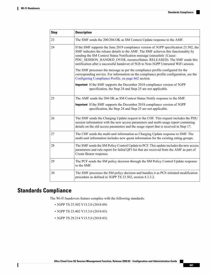
DescriptionStep
The SMF sends the 200/204 OK as SM Context Update response to the AMF.23
If the SMF supports the June 2019 compliance version of 3GPP specification 23.502, theSMF indicates the release details to the AMF. The SMF achieves this functionality bysending the SM Context Status Notification message (statusInfo {Cause:PDU_SESSION_HANDED_OVER, resourceStatus: RELEASED). The SMF sends thisnotification after a successful handover of 5GS to Non-3GPP Untrusted WiFi session.
The SMF processes the message as per the compliance profile configured for thecorresponding service. For information on the compliance profile configuration, see theConfiguring Compliance Profile, on page 662 section.
If the SMF supports the December 2018 compliance version of 3GPPspecification, the Step 24 and Step 25 are not applicable.
Important
24
The AMF sends the 204 OK as SM Context Status Notify response to the SMF.
If the SMF supports the December 2018 compliance version of 3GPPspecification, the Step 24 and Step 25 are not applicable.
Important
25
The SMF sends the Charging Update request to the CHF. This request includes the PDUsession information with the new access parameters and multi-usage report containingdetails on the old access parameters and the usage report that is received in Step 17.
26
The CHF sends the multi-unit information as Charging Update response to SMF. Themulti-unit information includes new quota information for the existing rating-groups.
27
The SMF sends the SMPolicy Control Update to PCF. This update includes the new accessparameters and rule report for failed QFI list that are received from the AMF as part ofCreate Bearer response.
28
The PCF sends the SM policy decision through the SM Policy Control Update responseto the SMF.
29
The SMF processes the SM policy decision and handles it as PCF-initiated modificationprocedure as defined in 3GPP TS 23.502, section 4.3.3.2.
30
Standards ComplianceThe Wi-Fi handovers feature complies with the following standards:
• 3GPP TS 23.502 V15.2.0 (2018-09)
• 3GPP TS 23.402 V15.3.0 (2018-03)
• 3GPP TS 29.214 V15.5.0 (2018-03)
Ultra Cloud Core 5G Session Management Function, Release 2020.02 - Configuration and Administration Guide661
Wi-Fi HandoversStandards Compliance

Configuring Compliance ProfileThe SMF provides the compliance profile support for the 3GPP specification 23.502 through the CLIconfiguration. This compliance profile is in use during the 5GS to non-3GPP untrusted WiFi handoverprocedure.
Use the following configuration to configure the SMF in compliance with the 3GPP specification.
configureprofile compliance profile_name
service threegpp23502 version spec spec_version full version_format
uri_version uri_version
range!!
NOTES:
• full: Specifies the full version in the format —<Major-version>.<Minor-version>.<patch-version>.[alpha-<draft-number>]
• spec: Specifies the 3GPP specification version number. It can be one of the following values:
• 15.4.0
• 15.6.0
To support 3GPP December 2018 specification compliance, configure the specification version as 15.4.0.The default version is 15.4.0.
To support 3GPP June 2019 specification compliance, configure the specification version as 15.6.0.
• uri: Specifies the URI version in the format — "v" concatenated with a number. It can be both v1 andv2, or either v1 or v2.
Ultra Cloud Core 5G Session Management Function, Release 2020.02 - Configuration and Administration Guide662
Wi-Fi HandoversConfiguring Compliance Profile

C H A P T E R 48Wireless Priority Services
• Feature Summary and Revision History, on page 663• Feature Description, on page 664• How it Works, on page 669• Configuring Wireless Priority Services, on page 669
Feature Summary and Revision History
Summary DataTable 201: Summary Data
SMFApplicable Product(s) or Functional Area
SMIApplicable Platform(s)
Disabled – Configuration RequiredFeature Default Setting
Not ApplicableRelated Changes in this Release
Not ApplicableRelated Documentation
Revision HistoryTable 202: Revision History
ReleaseRevision Details
2020.02.0First introduced.
This feature is not fully qualified in this release. For moreinformation, contact your Cisco Account representative.
Ultra Cloud Core 5G Session Management Function, Release 2020.02 - Configuration and Administration Guide663

Feature DescriptionTheWireless Priority Services (WPS) feature is supported on the SMF+PGW-C over 5GC. The SMF+PGW-Cvalidates prioritization of WPS services for Session Creation/Modification and various handover scenarios.It also evaluates the WPS services for Paging-Policy Differentiation for Network Triggered Service Requestprocedures.
Use CasesThe WPS feature implements the 3GPP recommendations for wireless priority support for the following usecases in 5GS and EPS. The use cases are defined as per 3GPP TS 23.501 (sections 5.16.3, 5.16.4, 5.16.5,5.16.6, 5.19, and 5.21).
WPS supports the following use cases:
• Multimedia Priority Services , on page 664
• Mission Critical Services, on page 667
• Expanded Prioritization for VoLTE/VoNR/Emergency Calls, on page 668
• DSCP Marking for N3/S5-U/S2-B over PFCP, on page 668
Multimedia Priority ServicesThe Multimedia Priority Service (MPS) allows priority access to system resources to Service Users, creatingthe ability to deliver or complete sessions of a high priority nature. Service Users are government-authorizedpersonnel, emergency management officials and/or other authorized users. MPS supports priority sessions onan "end-to-end" priority basis. MPS includes signalling priority and media priority.
MPS provides the ability to invoke, modify, maintain and release sessions with priority, and deliver the prioritymedia packets under network congestion conditions.
All MPS-subscribed UEs get priority for QoS Flows (for example, used for IMS signalling) when establishedto the DN that is configured to have priority for a given Service User by setting MPS-appropriate values inthe QoS profile in the UDM. Service Users are treated as On Demand MPS subscribers and not On DemandMPS subscribers, based on regional/national regulatory requirements. On Demand service is based on ServiceUser invocation/revocation explicitly and applied to the media QoS Flows being established. Not On DemandMPS service does not require invocation and provides priority treatment for all QoS Flows only to the DNthat is configured to have priority for a given Service User after attachment to the 5G network.
Priority treatment for MPS includes priority message handling for Mobility Management procedures. Prioritytreatment for MPS session requires appropriate ARP and 5QI setting for QoS Flows according to the operator'spolicy.
MPS priority mechanisms can be classified as subscription-related and invocation-related. Subscription relatedmechanisms are divided into - always applied and conditionally applied. Invocation-related mechanisms aredivided into - for mobile originated SIP call/sessions, for mobile terminated SIP call/sessions and for PriorityPDU connectivity services.
Subscription-related mechanisms that are conditionally applied include:
UDM: One or more ARP priority levels are assigned for prioritized or critical services. The ARP of theprioritized QoS Flows for each DN is set to an appropriate ARP priority level.
Ultra Cloud Core 5G Session Management Function, Release 2020.02 - Configuration and Administration Guide664
Wireless Priority ServicesFeature Description

PCF: The "IMS Signalling Priority" information is set for the subscriber in the UDM, and the PCF modifiesthe ARP of the QoS Flow used for IMS signalling.
On-Demand MPS Service
The invocation-related priority mechanisms for prioritized services are based on interaction with an ApplicationServer and between the Application Server and the PCF over Rx/N5 interface (as described in TS 23.228clause 5.21 in the case of MPS using IMS).
Invocation-related mechanisms for Mobile Originations (for example, via SIP/IMS) are explained below:
• PCF:
• When an indication for a session arrives over the Rx/N5 interface and the UE does not have priorityfor the signaling QoS Flow, the PCF derives the ARP and 5QI parameters plus associated QoScharacteristics as appropriate, as per the Service Provider policy (specified in clause 6.1.3.11 of TS23.503).
• For MPS sessions, when establishing or modifying a QoS Flow as part of the session originationprocedure, the PCF selects the ARP and 5QI parameters plus associated QoS characteristics asappropriate, to provide priority treatment to the QoS Flows.
• When all active sessions to a particular DN are released and the UE is not configured for prioritytreatment to that particular PDU session, the PCF downgrades the IMS Signaling QoS Flows fromappropriate settings of the ARP and 5QI parameters plus associatedQoS characteristics as appropriate,to those entitled by the UE based on subscription.
Invocation-related mechanisms for Mobile Terminations (for example, via SIP/IMS) are explained below:
• PCF: When an indication for a session arrives over the Rx/N5 interface, the mechanisms as describedabove for Mobile Originations are applied.
• UPF: If an IP packet arrives at the UPF for a UE that is CM-IDLE, the UPF sends a "Data Notification"including the information to identify the QoS Flow for the DL data packet to the SMF (specified in clause4.2.3.3 of TS 23.502).
• SMF: If a "Data Notification" message arrives at the SMF for a QoS Flow associated with an ARP prioritylevel value for priority use, delivery of priority indication during the Paging procedure is provided byinclusion of the ARP in the N11 interface "N1N2MessageTransfer" message (specified in clause 4.2.3.3of TS 23.502).
• AMF: If an "N1N2MessageTransfer" message arrives at the AMF containing an ARP priority level valuefor priority use, the AMF handles the request with priority and includes the "Paging Priority" IE in theN2 "Paging" message set to a value assigned to indicate that there is an IP packet at the UPF entitled topriority treatment (specified in clause 4.2.3.3 of TS 23.502).
• SMF: For a UE that is not configured for priority treatment, upon receiving the "N7 SessionManagementPolicy Modification" message from the PCF with an ARP priority level for priority use, the SMF sendsan "N1N2MessageTransfer" to update the ARP for the Signaling QoS Flows (specified in clause 4.3.3.2of TS 23.502).
• AMF: Upon receiving the "N1N2MessageTransfer" message from the SMF with an ARP priority levelfor priority use, the AMF updates the ARP for the Signaling QoS Flows (specified in clause 4.3.3.2 ofTS 23.502).
Ultra Cloud Core 5G Session Management Function, Release 2020.02 - Configuration and Administration Guide665
Wireless Priority ServicesOn-Demand MPS Service

• (R)AN: Inclusion of the "Paging Priority" in the N2 "Paging" message triggers priority handling of pagingin times of congestion at the (R)AN (specified in clause 4.2.3.3 of TS 23.502).
Invocation-related mechanisms for the Priority PDU connectivity services:
• PCF:
• If the state of the Priority PDU connectivity services is modified from disabled to enabled, the QoSFlows controlled by the Priority PDU connectivity services are established/modified to have theservice appropriate settings of the ARP and 5QI parameters plus associated QoS characteristics asappropriate, using the PDU SessionModification procedure (specified in clause 4.3.3 of TS 23.502).
• If the state of Priority PDU connectivity services is modified from enabled to disabled, the QoSFlows controlled by the Priority PDU connectivity services are modified from service appropriatesettings of the ARP and 5QI parameters plus associated QoS characteristics as appropriate, to thoseentitled by the UE as per subscription, using the PDU Session Modification procedure (specifiedin clause 4.3.3 of TS 23.502).
Message-Priority Indication over GTP-C
An overloaded node performsmessage prioritizationwhen handling incomingmessages during an overloadedcondition based on the relative GTP-C message priority signaled in the GTP-C header.
When message throttling is performed:
• GTP requests related to priority traffic (eMPS as described in 3GPP TS 22.153) and emergency have thehighest priority. Depending on regional/national requirements and network operator policy, these GTPrequests are the last to be throttled when applying traffic reduction. The priority traffic is exempted fromthrottling due to GTP overload control up to the point where the requested traffic reduction cannot beachieved without throttling the priority traffic.
• For other types of sessions, message throttling considers the relative priority of the messages so that lowpriority messages are considered for throttling before the other messages. The relative priority of themessages is derived from the relative priority of the procedure for which the message is being sent (asspecified in clause 12.3.9.3.2) or derived from the session parameters such as APN and ARP.
The high priority messages are given lower preference to throttle and low priority messages are given higherpreference to throttle. An overloaded node also applies these message prioritization schemes when handlingincoming initial messages during an overloaded condition, as part of the self-protection mechanism.
A sending GTP-C entity determines the relative message priority to signal in the message according to eitherprocedure based or session parameters. If the message affects multiple bearers (for example, Modify BearerRequest), the relative message priority considers the highest priority ARP among all the bearers.
A GTP-C entity sets the samemessage priority in a Triggered message or Triggered Reply message as receivedin the corresponding Initial message or Triggered message respectively. For incoming GTP-C messages thatdo not have a message priority in the GTP-C header, the receiving GTP-C entity:
• Applies a default priority if the incoming message is an Initial message.
• Applies the message priority sent in the Initial message or Triggered message if the incoming messageis a Triggered or Triggered Reply message respectively.
Ultra Cloud Core 5G Session Management Function, Release 2020.02 - Configuration and Administration Guide666
Wireless Priority ServicesMessage-Priority Indication over GTP-C

The nodes in the network homogenously support this feature; otherwise an overloaded node processes initialmessages received from the non-supporting nodes according to the default priority and processes initialmessages received from the supporting nodes according to themessage priority signaled in the GTP-Cmessage.
Message-Prioritization based on Session Parameters
Message prioritization is also performed based on the session parameters such as APN andARP. The proceduresand messages associated with the higher priority sessions are given lesser preference while throttling, ascompared to the procedures and messages associated with the lower priority sessions. Within each group ofsessions, the messages are further prioritized based on the category of the procedure for which the messageis being sent.
Message-Priority Header for PFCP
When the message throttling is performed:
• PFCP requests related to priority traffic (that is, eMPS as described in 3GPP TS 22.153) and emergencyhave the highest priority. Depending on regional/national requirements and network operator policy,these PFCP requests are the last to be throttled when applying traffic reduction. Throttling exempts thepriority traffic due to PFCP overload control up to the point where the requested traffic reduction cannotbe achieved without throttling the priority traffic.
• For other types of sessions, the message throttling considers the relative priority of the messages so thatthe messages with low priority are first considered for the throttling. The relative priority of the messagesis derived from the relative priority of the procedure for which the message is being sent or derived fromthe session parameters such as APN and ARP.
An overloaded node (UPF, SMF) may apply these message prioritization schemes when handling incominginitial messages during an overloaded condition, as part of a self-protection mechanism. Incoming messagesare handled during an overloaded condition based on the relative PFCPmessage priority signaled in the PFCPheader.
A PFCP entity determines whether to set and use the message priority in PFCP signalling, based on operatorpolicy. A sending PFCP entity determines the relative message priority to signal in the message which arederived from the session parameters such as APN and ARP. If the message affects multiple bearers, the relativemessage priority is determined considering the highest priority ARP among all the bearers. A PFCP entitymust set the same message priority in a Response message as received in the corresponding Request message.
For incoming PFCP messages that do not have a message priority in the PFCP header, the receiving PFCPentity:
• Applies a default priority if the incoming message is a Request message.
• Applies the message priority sent in the Request message if the incomingmessage is a Response message.
The SMF and UPF functions in the network homogenously support this feature; otherwise an overloaded nodewill process the Request messages received from the non-supporting nodes according to the default priorityand Request messages received from supporting nodes will be processed according to the message prioritysignalled in the PFCP message.
Mission Critical ServicesA Mission Critical Service (MCX Service) is a communication service that enables capabilities of MissionCritical Applications. The MCX service is provided to end users from Mission Critical Organizations andmission critical applications for businesses and organizations. An MCX Service is either Mission Critical
Ultra Cloud Core 5G Session Management Function, Release 2020.02 - Configuration and Administration Guide667
Wireless Priority ServicesMessage-Priority Header for PFCP

Push To Talk (MCPTT),Mission Critical Video (MCVideo), orMission Critical Data (MCData) and representsa set of requirements between two or more MCX Service types.
MCX Services are based on the ability to invoke, modify, maintain, and release sessions with priority, anddeliver the priority media packets under network congestion conditions. These services are supported in aroaming environment when roaming agreements are in place and where regulatory requirements apply.
An MCX subscription allows users to receive priority services if the network supports MCX. MCX Usersrequire the 5GS functionality for real-time, dynamic, secure and limited interaction with the QoS and policyframework for modification of the QoS and policy framework by authorized users.
Expanded Prioritization for VoLTE/VoNR/Emergency CallsThe SMF+PGW-C supports Expanded Prioritization for VoLTE/VoNR/Emergency calls. The NationalSecurity/Emergency Preparedness (NS/EP) Next Generation Network (NGN) Priority Services (NGN-PS)(formerly called NGN Government Emergency Telecommunications Service (GETS)) is a set of voice, videoand data services that are based on services available from public packet-switched Service Providers. TheNS/EP NGN-PS provides priority treatment for a Service User’s NS/EP communications and is particularlyneeded when the Service Providers’ networks are impaired due to congestion and/or damage from naturaldisasters (such as floods, earthquakes and hurricanes) and man-made disasters (such as physical, cyber orother forms of terrorist attacks).
As part of this feature, the PGW-C control message is marked with DSCPmarking and also for control messagebelonging to the eMPS session or containing Allocation and Retention Priority (ARP) associated with theeMPS profile.
DSCP Marking for N3/S5-U/S2-B over PFCP
Transport Level Marking
Transport level marking is the process of marking traffic with a DSCP value based on the locally configuredmapping from the QCI and optionally the ARP priority level. For EPC, the S-GW and P-GWperform transportlevel marking on a per EPS bearer basis. For 5GC, the S-GW and P-GW perform transport level marking ona per QoS flow basis.
The UPF performs transport level marking with a DSCP value based on themapping from the 5QI, the PriorityLevel (if explicitly signaled), and optionally the ARP priority level configured at the SMF. The CP functioncontrols transport level marking by providing the DSCP in the ToS or Traffic Class within the Transport LevelMarking IE in the FAR (associated to the PDR matching the traffic to be marked).
The UP function performs transport level marking for the detected traffic and sends the marked packet to thepeer entity. The CP function changes transport level marking by changing the Transport Level Marking IEin the related FAR.
WPS Profile SupportThe SMF+PGW-C supports theWPS profile defined with ARP and DSCPmarking value to be set for GTP-Cand PFCP Protocol IP-headers. The WPS profile sets the message priority in the GTP-C and PFCP protocols.
The SMF+PGW-C allows a maximum of 64 WPS profiles and each WPS profile will be associated under theDNN profile. See the Configuring Wireless Priority Services, on page 669 section for more information.
Ultra Cloud Core 5G Session Management Function, Release 2020.02 - Configuration and Administration Guide668
Wireless Priority ServicesExpanded Prioritization for VoLTE/VoNR/Emergency Calls

How it Works
License InformationThe WPS feature requires a license to be enabled on the SMF+PGW-C to support the related features - MPS,MCX, Prioritization for VoLTE/VoNR/Emergency Service. Contact your Cisco account representative formore information on how to obtain a license.
Standards ComplianceThe Wireless Priority Services feature complies with the following standards:
• 3GPP TS 22.153
• 3GPP TS 23.228
• 3GPP TS 23.282
• 3GPP TS 23.379
• 3GPP TS 23.501
• 3GPP TS 23.502
• 3GPP TS 23.503
• 3GPP TS 24.301
Configuring Wireless Priority ServicesThis section describes how to configure the Wireless Priority Services feature.
Configuring the WPS ProfileUse the following configuration to configure the WPS profile.
configureprofile wps wps_profile_name
arp arp_value
dscp n3 n3_value
message-priority [ gtpc pfcp ]end
NOTES:
• profile wps wps_profile_name: Accesses the Wireless Priority Services Profile configuration.wps_profile_name must be an alphanumeric string of 1 to 63 characters.
• arp arp_value: Specifies the range of ARP levels. arp_value must be an inetger from 1 to 15 separatedeither by "," or "-".
Ultra Cloud Core 5G Session Management Function, Release 2020.02 - Configuration and Administration Guide669
Wireless Priority ServicesHow it Works

• dscp n3 n3_value: Specifies the DSCP marking value for N3. n3_value specifies the UP DSCP markingvalue within the range 0 to 0x3F.
• message-priority { gtpc pfcp }: Specifies the message priority for GTP-C and PFCP.
Verifying the WPS Profile Configuration
This section describes how to verify the WPS Profile configuration.
Execute the show running-config command to view the configuration.
The following is a sample output of the show running-config command.show running-config profile wps wps1profile wps wps1arp 1,4-6,9dscp n3 10message-priority [ pfcp gtpc ]exit
Associating WPS Profile under DNN ProfileUse the following configuration to associate the WPS profile with the configured DNN profile.
configureprofile dnn intershat
wps-profile wps_profile_name
end
NOTES:
• wps-profile wps_profile_name: Enables theWireless Priority Services Profile configuration. This profileis configured under the existing DNN profile configuration.
Verifying WPS Profile under DNN Profile
This section describes how to verify the WPS profile configuration under the DNN profile.
Execute the show running-config command to view the configuration.
The following is a sample output of the show running-config command.show running-config profile dnn intershatprofile dnn intershatnetwork-element-profiles chf chf1network-element-profiles amf amf1network-element-profiles pcf pcf1network-element-profiles udm udm1charging-profile chgprf1virtual-mac b6:6d:47:47:47:47wps-profile wps1ssc-mode 2 allowed [ 3 ]session type IPV4 allowed [ IPV6 IPV4V6 ]upf apn intershatexit
Ultra Cloud Core 5G Session Management Function, Release 2020.02 - Configuration and Administration Guide670
Wireless Priority ServicesAssociating WPS Profile under DNN Profile

WPS OAM Support
SMF Session Gauge Counters
The "wps" label is introduced at the SMF service to account for session-level gauage counters that supportWPS and non-WPS functionality.
For example:smf_session_counters{always_on="disable",app_name="smf",cluster="smf",data_center="unknown",dnn="intershat",instance_id="0",pdu_type="ipv4",rat_type="NR",service_name="smf-service",ssc_mode="ssc_mode_1",wps="non_wps"}10smf_session_counters{always_on="disable",app_name="smf",cluster="smf",data_center="unknown",dnn="intershat",instance_id="0",pdu_type="ipv4",rat_type="NR",service_name="smf-service",ssc_mode="ssc_mode_1",wps="wps"}20
N4 Interface Metrics
The N4 interface counters related to message priority include:
• N4_MSG_SESSION_DELETION_REQUEST
• N4_MSG_SESSION_ESTABLISHMENT_REQUEST
• N4_MSG_SESSION_MODIFICATION_REQUEST
An example of the N4 interface metrics:smf_proto_pfcp_msg_total{app_name="SMF",cluster="Local",data_center="DC",instance_id="0",message_direction="outbound",message_name="N4_MSG_SESSION_DELETION_REQUEST",msgpriority=true,service_name="smf-protocol",status="accepted",transport_type="origin"} 4smf_proto_pfcp_msg_total{app_name="SMF",cluster="Local",data_center="DC",instance_id="0",message_direction="outbound",message_name="N4_MSG_SESSION_ESTABLISHMENT_REQUEST",msgpriority=true,service_name="smf-protocol",status="accepted",transport_type="origin"} 6smf_proto_pfcp_msg_total{app_name="SMF",cluster="Local",data_center="DC",instance_id="0",message_direction="outbound",message_name="N4_MSG_SESSION_MODIFICATION_REQUEST",msgpriority=true,service_name="smf-protocol",status="accepted",transport_type="origin"} 20
GTPv2 Metrics
The GTPv2 counters related to message priority include:
• NumCreateBearerSuccess
• NumRxCreateBearerRes
• NumTxCreateSessionReq
An example of the GTPv2 metrics:smf_gtpc_app_priority_events{app_name="SMF",cluster="Local",data_center="DC",event_type="NumCreateBearerSuccess",instance_id="0",priority_msg="true",service_name="gtpc-ep"}2smf_gtpc_app_priority_events{app_name="SMF",cluster="Local",data_center="DC",event_type="NumRxCreateBearerRes",instance_id="0",priority_msg="true",service_name="gtpc-ep"}2smf_gtpc_app_priority_events{app_name="SMF",cluster="Local",data_center="DC",event_type="NumTxCreateSessionReq",instance_id="0",priority_msg="true",service_name="gtpc-ep"}2
Ultra Cloud Core 5G Session Management Function, Release 2020.02 - Configuration and Administration Guide671
Wireless Priority ServicesWPS OAM Support

Ultra Cloud Core 5G Session Management Function, Release 2020.02 - Configuration and Administration Guide672
Wireless Priority ServicesWPS OAM Support
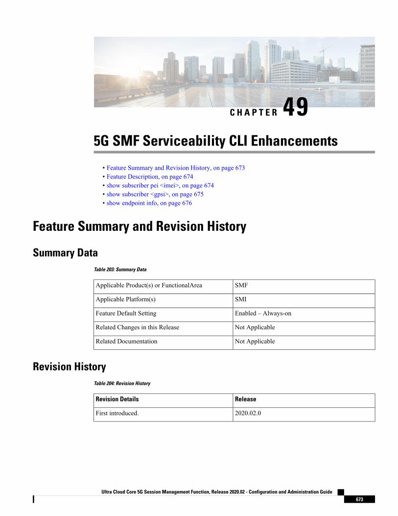
C H A P T E R 495G SMF Serviceability CLI Enhancements
• Feature Summary and Revision History, on page 673• Feature Description, on page 674• show subscriber pei <imei>, on page 674• show subscriber <gpsi>, on page 675• show endpoint info, on page 676
Feature Summary and Revision History
Summary DataTable 203: Summary Data
SMFApplicable Product(s) or FunctionalArea
SMIApplicable Platform(s)
Enabled – Always-onFeature Default Setting
Not ApplicableRelated Changes in this Release
Not ApplicableRelated Documentation
Revision HistoryTable 204: Revision History
ReleaseRevision Details
2020.02.0First introduced.
Ultra Cloud Core 5G Session Management Function, Release 2020.02 - Configuration and Administration Guide673

Feature DescriptionThis chapter describes serviceability CLI enhancements to display the information about the deployed pods.
show subscriber pei <imei>Table 205: show subscriber pei <imei>
DescriptionField
Specifies policy information.policy
Specifies IPv4 pool name.ipv4-addr
Specifies DNN value.dnn
Specifies PCF Address.pcf
Specifies RAT Type - nr/e-utran/wlan information.rat
Specifies connectivity 4g/5gconnectivity
Specifies IPv4 address range.ipv4-range
Specifies CHF address.chf
Specifies Permanent Equipment Identifier.pei
Specifies the UDM address.udm
Specifies the UPF address EP key information.upfEpKey
Specifies the IPv6 prefix information.ipv6-pfx
Specifies IPv6 Pool name.ipv6-pool
Specifies the CHF address group ID information.chfGroupId
Specifies Generic Public Subscription Identifier.gpsi
Specifies PCF Address group ID.pcfGroupId
Specifies UPF Address.upf
Specifies IPv4 Pool name.ipv4-pool
Specifies IPv4 Address-Range.ipv6-range
Specifies AMF address.amf
Specify SUPI value.supi
Specifies access information.access
Ultra Cloud Core 5G Session Management Function, Release 2020.02 - Configuration and Administration Guide674
5G SMF Serviceability CLI EnhancementsFeature Description
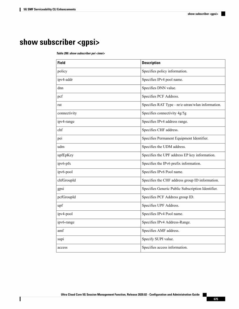
show subscriber <gpsi>Table 206: show subscriber pei <imei>
DescriptionField
Specifies policy information.policy
Specifies IPv4 pool name.ipv4-addr
Specifies DNN value.dnn
Specifies PCF Address.pcf
Specifies RAT Type - nr/e-utran/wlan information.rat
Specifies connectivity 4g/5gconnectivity
Specifies IPv4 address range.ipv4-range
Specifies CHF address.chf
Specifies Permanent Equipment Identifier.pei
Specifies the UDM address.udm
Specifies the UPF address EP key information.upfEpKey
Specifies the IPv6 prefix information.ipv6-pfx
Specifies IPv6 Pool name.ipv6-pool
Specifies the CHF address group ID information.chfGroupId
Specifies Generic Public Subscription Identifier.gpsi
Specifies PCF Address group ID.pcfGroupId
Specifies UPF Address.upf
Specifies IPv4 Pool name.ipv4-pool
Specifies IPv4 Address-Range.ipv6-range
Specifies AMF address.amf
Specify SUPI value.supi
Specifies access information.access
Ultra Cloud Core 5G Session Management Function, Release 2020.02 - Configuration and Administration Guide675
5G SMF Serviceability CLI Enhancementsshow subscriber <gpsi>

show endpoint infoTable 207: show endpoint info
DescriptionField
Specifies the Name of the endpoint.endpoint
Specifies Host and Port of endpoint.address
Specifies type of endpoint.type
Specifies current Status of endpoint.status
Specifies Interface name of endpoint.interface
Specifies type of endpoint (Internal/External).internal
Specifies Start time of endpoint.start Time
Specifies Stop time of endpoint.stop Time
Ultra Cloud Core 5G Session Management Function, Release 2020.02 - Configuration and Administration Guide676
5G SMF Serviceability CLI Enhancementsshow endpoint info

C H A P T E R 50Troubleshooting Information
• Feature Summary and Revision History, on page 677• clear subscriber, on page 678• clear subscriber supi imsi <imsi_value>, on page 678• clear subscriber supi imsi <imsi_value> psid <psid_value>, on page 679• show subscriber, on page 679• show subscriber count, on page 679• show subscriber count all, on page 680• show subscriber count chf <chf_address>, on page 680• show subscriber count chf <chf_address> dnn <dnn_value>, on page 681• show subscriber count supi <supi_value>, on page 681• show subscriber debug-info supi <supi_value>, on page 681• show subscriber debug-info supi <supi_value> psid <psid_value>, on page 682
Feature Summary and Revision History
Summary DataTable 208: Summary Data
SMFApplicable Product(s) or FunctionalArea
SMIApplicable Platform(s)
Not ApplicableFeature Default Setting
Not ApplicableRelated Changes in this Release
Not ApplicableRelated Documentation
Ultra Cloud Core 5G Session Management Function, Release 2020.02 - Configuration and Administration Guide677

Revision HistoryTable 209: Revision History
ReleaseRevision Details
Pre-2020.02.0Updated the Troubleshooting information for thisrelease.
clear subscriberTable 210: clear subscriber Command Output Description
DescriptionField
Clears all the sessions.all
Clears subscriber based on AMF address.amf
Clears subscriber based on CHF address.chf
Clears subscriber based on DNN value.dnn
Clears subscriber based on GTP-PEER address.gtp-peer
Clears subscriber based on IPv4 pool name.ipv4-pool
Clears subscriber based on IPv4 address-range.ipv4-range
Clears subscriber based on IPv6 pool name.ipv6-pool
Clears subscriber based on IPv6 prefix-range.ipv6-range
Clears subscriber based on PCF address.pcf
Clears subscriber based on policy information.policy
Clears true, if purged locally.purge
clear subscriber supi imsi <imsi_value>Table 211: clear subscriber supi imsi <imsi_value> Command Output Description
DescriptionField
Clears subscriber based on EPS bearer ID.ebi
Clears subscriber based on IMSI.imsi
Clears true, if purged locally.purge
Output modifier.|
Ultra Cloud Core 5G Session Management Function, Release 2020.02 - Configuration and Administration Guide678
Troubleshooting InformationRevision History
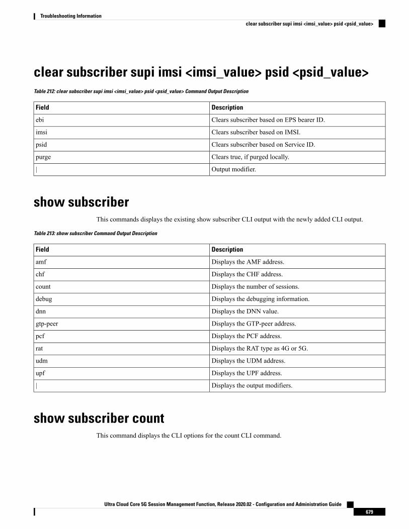
clear subscriber supi imsi <imsi_value> psid <psid_value>Table 212: clear subscriber supi imsi <imsi_value> psid <psid_value> Command Output Description
DescriptionField
Clears subscriber based on EPS bearer ID.ebi
Clears subscriber based on IMSI.imsi
Clears subscriber based on Service ID.psid
Clears true, if purged locally.purge
Output modifier.|
show subscriberThis commands displays the existing show subscriber CLI output with the newly added CLI output.
Table 213: show subscriber Command Output Description
DescriptionField
Displays the AMF address.amf
Displays the CHF address.chf
Displays the number of sessions.count
Displays the debugging information.debug
Displays the DNN value.dnn
Displays the GTP-peer address.gtp-peer
Displays the PCF address.pcf
Displays the RAT type as 4G or 5G.rat
Displays the UDM address.udm
Displays the UPF address.upf
Displays the output modifiers.|
show subscriber countThis command displays the CLI options for the count CLI command.
Ultra Cloud Core 5G Session Management Function, Release 2020.02 - Configuration and Administration Guide679
Troubleshooting Informationclear subscriber supi imsi <imsi_value> psid <psid_value>

Table 214: show subscriber count Command Output Description
DescriptionField
Displays all the SUPIs.all
Displays the AMF address.amf
Displays the CHF address.chf
Displays the DNN value.dnn
Displays the GTP-peer address.gtp-peer
Displays the PCF address.pcf
Displays the RAT type as 4G or 5G.rat
Displays the specific SUPI value.supi
Displays the UDM address.udm
Displays the UPF address.upf
Displays the output modifiers.|
show subscriber count allThis command displays the total number of sessions for all the SUPIs.
Table 215: show subscriber count all Command Output Description
DescriptionField
Displays the output modifiers.|
show subscriber count chf <chf_address>This command displays the total number of sessions for the specified parameters.
Table 216: show subscriber count chf <chf_address> Command Output Description
DescriptionField
Displays the AMF address.amf
Displays the DNN value.dnn
Displays the GTP-peer address.gtp-peer
Displays the PCF address.pcf
Displays the RAT type as 4G or 5G.rat
Displays the UDM address.udm
Ultra Cloud Core 5G Session Management Function, Release 2020.02 - Configuration and Administration Guide680
Troubleshooting Informationshow subscriber count all

DescriptionField
Displays the UPF address.upf
Displays the output modifiers.|
show subscriber count chf <chf_address> dnn <dnn_value>This command displays the total number of sessions for the specified parameters.
Table 217: show subscriber count chf <chf_address> dnn <dnn_value> Command Output Description
DescriptionField
Displays the AMF address.amf
Displays the GTP-peer address.gtp-peer
Displays the PCF address.pcf
Displays the RAT type as 4G or 5G.rat
Displays the UDM address.udm
Displays the UPF address.upf
Displays the output modifiers.|
show subscriber count supi <supi_value>This command displays the total number of sessions for the specific SUPI value.
Table 218: show subscriber count supi <supi_value> Command Output Description
DescriptionField
Displays the output modifiers.|
show subscriber debug-info supi <supi_value>This command displays the debug information for the specific SUPI value where the PSID value is optional.
Table 219: show subscriber debug-info supi <supi_value> Command Output Description
DescriptionField
Displays the Provider Service Identifier.psid
Ultra Cloud Core 5G Session Management Function, Release 2020.02 - Configuration and Administration Guide681
Troubleshooting Informationshow subscriber count chf <chf_address> dnn <dnn_value>

show subscriber debug-info supi <supi_value> psid<psid_value>
This command displays the debug information for the specific SUPI and PSID combination.
Table 220: show subscriber debug-info supi <supi_value> psid <psid_value> Command Output Description
DescriptionField
Displays the output modifiers.|
Currently, the SMF does not validate the serving PLMN received on N11 interface. Also, the SMF does notvalidate the UE PLMN when the N11 smContextCreate or GTP createSessionRequest is received.
The PLMN value received in the NSSAI included in the PCO request remain the same as the PLMN configuredon the SMF.
Note
Ultra Cloud Core 5G Session Management Function, Release 2020.02 - Configuration and Administration Guide682
Troubleshooting Informationshow subscriber debug-info supi <supi_value> psid <psid_value>
C H A P T E R 51Sample SMF Configuration
• Feature Summary and Revision History, on page 683• Sample Configuration, on page 683
Feature Summary and Revision History
Summary DataTable 221: Summary Data
SMFApplicable Product(s) or FunctionalArea
SMIApplicable Platform(s)
Not ApplicableFeature Default Setting
Not ApplicableRelated Changes in this Release
Not ApplicableRelated Documentation
Revision HistoryTable 222: Revision History
ReleaseRevision Details
Pre-2020.02.0Updated the Sample SMFConfiguration informationfor this release.
Sample ConfigurationThe following is only a sample configuration file provided solely for your reference. You must create andmodify your own configuration file according to the specific needs of your deployment.
Ultra Cloud Core 5G Session Management Function, Release 2020.02 - Configuration and Administration Guide683
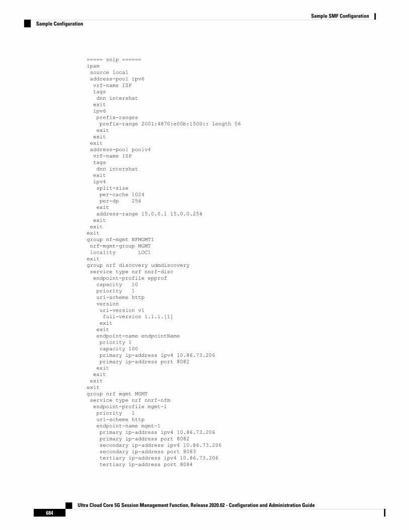
===== snip ======ipamsource localaddress-pool ipv6vrf-name ISPtagsdnn intershatexitipv6prefix-rangesprefix-range 2001:4870:e00b:1500:: length 56exitexitexitaddress-pool poolv4vrf-name ISPtagsdnn intershatexitipv4split-sizeper-cache 1024per-dp 256exitaddress-range 15.0.0.1 15.0.0.254exitexitexitgroup nf-mgmt NFMGMT1nrf-mgmt-group MGMTlocality LOC1exitgroup nrf discovery udmdiscoveryservice type nrf nnrf-discendpoint-profile epprofcapacity 10priority 1uri-scheme httpversionuri-version v1full-version 1.1.1.[1]exitexitendpoint-name endpointNamepriority 1capacity 100primary ip-address ipv4 10.86.73.206primary ip-address port 8082exitexitexitexitgroup nrf mgmt MGMTservice type nrf nnrf-nfmendpoint-profile mgmt-1priority 1uri-scheme httpendpoint-name mgmt-1primary ip-address ipv4 10.86.73.206primary ip-address port 8082secondary ip-address ipv4 10.86.73.206secondary ip-address port 8083tertiary ip-address ipv4 10.86.73.206tertiary ip-address port 8084
Ultra Cloud Core 5G Session Management Function, Release 2020.02 - Configuration and Administration Guide684
Sample SMF ConfigurationSample Configuration

exitexitexitexitcdl node-type smf-cdlcdl zookeeper replica 2cdl kafka replica 2etcd replicas 1endpoint nodemgrexitendpoint gtpreplicas 1vip-ip 10.86.73.208exitendpoint pfcpreplicas 1nodes 2exitendpoint servicereplicas 1nodes 1exitendpoint protocolreplicas 1nodes 2vip-ip 10.86.73.208exitendpoint sbireplicas 1nodes 2vip-ip 10.86.73.208interface nrfloopbackPort 7005vip-ip 20.20.20.5 vip-port 9005exitinterface n7loopbackPort 7001vip-ip 20.20.20.1 vip-port 9001exitinterface n10loopbackPort 7004vip-ip 20.20.20.4 vip-port 9004exitinterface n40loopbackPort 7003vip-ip 20.20.20.3 vip-port 9003exitexitlogging level application tracelogging level transaction tracelogging level tracing offlogging name infra.config.core level application debuglogging name infra.config.core level transaction warnlogging name infra.config.core level tracing warnlogging name infra.resource_monitor.core level application warnlogging name infra.resource_monitor.core level transaction warndeploymentapp-name SMFcluster-name Localdc-name DCmodel smallexitk8 label protocol-layer key smi.cisco.com/node-type value smf-protoexit
Ultra Cloud Core 5G Session Management Function, Release 2020.02 - Configuration and Administration Guide685
Sample SMF ConfigurationSample Configuration

k8 label service-layer key vm-type value smf-svcexitk8 label cdl-layer key smi.cisco.com/node-type value smf-cdlexitk8 label oam-layer key smi.cisco.com/node-type value oamexitsystem mode runninghelm default-repository smfhelm repository smfurlhttps://engci-maven-master.cisco.com/artifactory/smi-fuse-internal-snapshot/mobile-cnat-smf/smf-products/master/exithelm repository smf-stageurlhttps://engci-maven-master.cisco.com/artifactory/smi-fuse-internal-snapshot/mobile-cnat-smf/smf-products/dev-smf-stage/exitk8s namespace smfk8s registry dockerhub.cisco.com/smi-fuse-docker-internalk8s single-node falsek8s use-volume-claims falsek8s ingress-host-name 10.86.73.204.nip.ioprofile dnn intershatdns primary ipv4 11.11.1.1dns primary ipv6 66:66:1::aadns secondary ipv4 22.22.2.2dns secondary ipv6 66:66:2::bbnetwork-element-profiles chf chf1network-element-profiles amf amf1network-element-profiles pcf pcf1network-element-profiles udm udm1dnn starent.com network-function-list [ upf ]charging-profile chgprf1virtual-mac b6:6d:47:47:47:47pcscf-profile pcscf1ssc-mode 1session type IPV4 allowed [ IPV4V6 ]upf apn cisco.comexitprofile dnn profDnn1dnn cisco.com network-function-list [ chf pcf udm upf ]charging-profile chgprf1ssc-mode 1session type IPV4exitprofile dnn profDnn2dnn cisco.com network-function-list [ chf pcf rmgr udm upf ]charging-profile chgprf1ssc-mode 1session type IPV4exitprofile charging chgprf1method [ offline ]limit volume 20limit duration 60tight-interworking-mode truereporting-level online rating-groupreporting-level offline service-idexitprofile pcscf pcscf1v4-listprecedence 3primrary 3.3.3.1secondary 3.3.3.2exit
Ultra Cloud Core 5G Session Management Function, Release 2020.02 - Configuration and Administration Guide686
Sample SMF ConfigurationSample Configuration
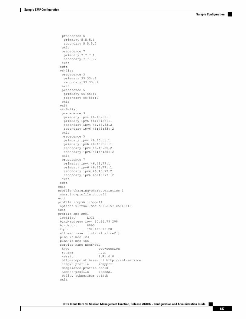
precedence 5primrary 5.5.5.1secondary 5.5.5.2exitprecedence 7primrary 7.7.7.1secondary 7.7.7.2exitexitv6-listprecedence 3primrary 33:33::1secondary 33:33::2exitprecedence 5primrary 55:55::1secondary 55:55::2exitexitv4v6-listprecedence 3primrary ipv4 46.46.33.1primrary ipv6 46:46:33::1secondary ipv4 46.46.33.2secondary ipv6 46:46:33::2exitprecedence 5primrary ipv4 46.46.55.1primrary ipv6 46:46:55::1secondary ipv4 46.46.55.2secondary ipv6 46:46:55::2exitprecedence 7primrary ipv4 46.46.77.1primrary ipv6 46:46:77::1secondary ipv4 46.46.77.2secondary ipv6 46:46:77::2exitexitexitprofile charging-characteristics 1charging-profile chgprf1exitprofile icmpv6 icmpprf1options virtual-mac b6:6d:57:45:45:45exitprofile smf smf1locality LOC1bind-address ipv4 10.86.73.208bind-port 8090fqdn 192.168.10.20allowed-nssai [ slice1 slice2 ]plmn-id mcc 123plmn-id mnc 456service name nsmf-pdutype pdu-sessionschema httpversion 1.Rn.0.0http-endpoint base-url http://smf-serviceicmpv6-profile icmpprf1compliance-profile dec18access-profile access1policy subscriber polSubexit
Ultra Cloud Core 5G Session Management Function, Release 2020.02 - Configuration and Administration Guide687
Sample SMF ConfigurationSample Configuration

exitprofile compliance dec18service nsmf-pdusessionversion uri v1version full 1.0.0version spec 15.2.0exitservice namf-commversion uri v1version full 1.0.0version spec 15.2.0exitservice n1version uri v1version full 1.0.0version spec 15.2.0exitservice n2version uri v1version full 1.0.0version spec 15.2.0exitservice nudm-sdmversion uri v1version full 1.0.0version spec 15.2.1exitservice nudm-uecmversion uri v1version full 1.0.0version spec 15.2.1exitservice nnrf-discversion uri v1version full 1.0.0version spec 15.2.0exitservice nnrf-nfmversion uri v1version full 1.0.0version spec 15.2.0exitservice npcf-smpolicycontrolversion uri v1version full 1.0.0version spec 15.2.0exitservice nchf-convergedchargingversion uri v2version full 1.0.0version spec 15.2.1exitexitprofile network-element amf amf1nf-client-profile amfP1failure-handling-profile FH3query-params [ dnn ]exitprofile network-element pcf pcf1nf-client-profile pcfP1failure-handling-profile FH1rulebase-prefix cbn#predefined-rule-prefix crn#exit
Ultra Cloud Core 5G Session Management Function, Release 2020.02 - Configuration and Administration Guide688
Sample SMF ConfigurationSample Configuration

profile network-element udm udm1nf-client-profile udmP1failure-handling-profile FH1exitprofile network-element upf upf1n4-peer-address ipv4 10.106.183.240n4-peer-port 8805keepalive 60dnn-list [ dnn1 intershat starent ]exitprofile network-element chf chf1nf-client-profile chfP1failure-handling-profile FH2nf-client-profile-offline CP2failure-handling-profile-offline FH2exitprofile qos abcambr ul "250 Kbps"ambr dl "500 Kbps"qi5 7arp priority-level 14arp preempt-cap NOT_PREEMPTarp preempt-vuln PREEMPTABLEpriority 120max data-burst 2000dscp-map qi5 2 arp-priority-level 3 uplink user-datagram dscp-marking 0x1cdscp-map qi5 2 arp-priority-level 3 downlink user-datagram dscp-marking 0x1a encsp-headerdscp-marking 0x1bdscp-map qi5 3 arp-priority-level 3 uplink user-datagram dscp-marking 0x4dscp-map qi5 3 arp-priority-level 3 downlink user-datagram dscp-marking 0x3 encsp-headercopy-innerexitprofile access access1eps-fallback cbr delay 500 max-retry 10 timeout 3n26 idft enable timeout 15n2 idft enable timeout 15exitprofile nf-client nf-type udmudm-profile udmP1locality LOC1priority 30service name type nudm-sdmendpoint-profile EP1capacity 30uri-scheme httpendpoint-name EP1primary ip-address ipv4 10.86.73.206primary ip-address port 9007exitexitexitservice name type nudm-uecmendpoint-profile EP1capacity 30uri-scheme httpendpoint-name EP1primary ip-address ipv4 10.86.73.206primary ip-address port 9001exitexitexitexitexitexit
Ultra Cloud Core 5G Session Management Function, Release 2020.02 - Configuration and Administration Guide689
Sample SMF ConfigurationSample Configuration

profile nf-client nf-type pcfpcf-profile pcfP1locality LOC1priority 30service name type npcf-am-policy-controlendpoint-profile EP1capacity 30uri-scheme httpendpoint-name EP1priority 50primary ip-address ipv4 10.86.73.206primary ip-address port 9003exitexitexitservice name type npcf-smpolicycontrolendpoint-profile EP1capacity 30uri-scheme httpendpoint-name EP1priority 5primary ip-address ipv4 10.86.73.206primary ip-address port 9003exitendpoint-name realPCFpriority 10primary ip-address ipv4 10.86.73.210primary ip-address port 9082exitexitexitexitexitexitprofile nf-client nf-type amfamf-profile amfP1locality LOC1priority 10service name type namf-commendpoint-profile EP1capacity 20uri-scheme httpendpoint-name EP1priority 30primary ip-address ipv4 10.86.73.206primary ip-address port 9002exitexitexitexitexitexitprofile nf-client nf-type chfchf-profile CP2locality LOC1priority 31service name type nchf-convergedchargingendpoint-profile EP1capacity 30uri-scheme httpversionuri-version v2exitexit
Ultra Cloud Core 5G Session Management Function, Release 2020.02 - Configuration and Administration Guide690
Sample SMF ConfigurationSample Configuration

endpoint-name EP1priority 56primary ip-address ipv4 10.86.73.206primary ip-address port 9906exitexitexitexitexitchf-profile chfP1locality LOC1priority 10service name type nchf-convergedchargingendpoint-profile EP1capacity 30uri-scheme httpversionuri-version v2exitexitendpoint-name EP1priority 50primary ip-address ipv4 10.86.73.206primary ip-address port 9904exitendpoint-name EP2priority 80primary ip-address ipv4 10.86.73.206primary ip-address port 9905exitexitexitexitexitexitprofile nf-pair nf-type UDMlocality client LOC1locality geo-server GEOexitprofile nf-pair nf-type AMFlocality client LOC1locality geo-server GEOexitprofile nf-pair nf-type PCFlocality client LOC1locality geo-server GEOexitprofile nf-pair nf-type UPFnrf-discovery-group udmdiscoverylocality client LOC1locality preferred-server LOC1locality geo-server GEOexitprofile nf-pair nf-type CHFlocality client LOC1locality preferred-server LOC1locality geo-server GEOexitprofile nf-client-failure nf-type chfprofile failure-handling FH2service name type nchf-convergedchargingmessage type ChfConvergedchargingCreatestatus-code httpv2 0action continue
Ultra Cloud Core 5G Session Management Function, Release 2020.02 - Configuration and Administration Guide691
Sample SMF ConfigurationSample Configuration
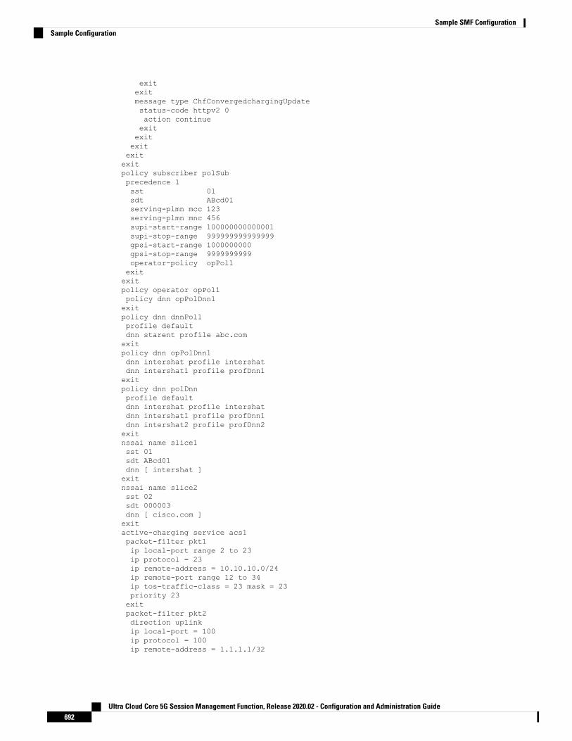
exitexitmessage type ChfConvergedchargingUpdatestatus-code httpv2 0action continueexitexitexitexitexitpolicy subscriber polSubprecedence 1sst 01sdt ABcd01serving-plmn mcc 123serving-plmn mnc 456supi-start-range 100000000000001supi-stop-range 999999999999999gpsi-start-range 1000000000gpsi-stop-range 9999999999operator-policy opPol1exitexitpolicy operator opPol1policy dnn opPolDnn1exitpolicy dnn dnnPol1profile defaultdnn starent profile abc.comexitpolicy dnn opPolDnn1dnn intershat profile intershatdnn intershat1 profile profDnn1exitpolicy dnn polDnnprofile defaultdnn intershat profile intershatdnn intershat1 profile profDnn1dnn intershat2 profile profDnn2exitnssai name slice1sst 01sdt ABcd01dnn [ intershat ]exitnssai name slice2sst 02sdt 000003dnn [ cisco.com ]exitactive-charging service acs1packet-filter pkt1ip local-port range 2 to 23ip protocol = 23ip remote-address = 10.10.10.0/24ip remote-port range 12 to 34ip tos-traffic-class = 23 mask = 23priority 23exitpacket-filter pkt2direction uplinkip local-port = 100ip protocol = 100ip remote-address = 1.1.1.1/32
Ultra Cloud Core 5G Session Management Function, Release 2020.02 - Configuration and Administration Guide692
Sample SMF ConfigurationSample Configuration

ip remote-port = 140priority 100exitpacket-filter pkt3direction downlinkip local-port = 111ip protocol = 111ip remote-address = 2.2.2.2/31ip remote-port = 111priority 111exitcharging-action ca1allocation-retention-priority 12 pci NOT_PREEMPT pvi NOT_PREEMPTABLEflow limit-for-bandwidth direction uplink peak-data-rate 1000000 peak-burst-size 100
violate-action discard committedDataRate 2000000 committed-burst-size 100 exceed-actiondiscardflow limit-for-bandwidth direction downlink peak-data-rate 2000000 peak-burst-size 100
violate-action discard committedDataRate 3000000 committed-burst-size 100 exceed-actiondiscardqos-class-identifier 3tft-notify-uetos af11tft packet-filter pkt1exitcharging-action ca10flow limit-for-bandwidth direction uplink peak-data-rate 2000000000 peak-burst-size 100
violate-action discardflow limit-for-bandwidth direction downlink peak-data-rate 3000000000 peak-burst-size 100violate-action discardtos af11exitcharging-action ca11flow limit-for-bandwidth direction uplink peak-data-rate 2000000000 peak-burst-size 100
violate-action discardflow limit-for-bandwidth direction downlink peak-data-rate 3000000000 peak-burst-size 100violate-action discardexitcharging-action ca12flow limit-for-bandwidth direction uplink peak-data-rate 2000000 peak-burst-size 100
violate-action discardflow limit-for-bandwidth direction downlink peak-data-rate 3000000 peak-burst-size 100
violate-action discardexitcharging-action ca13flow limit-for-bandwidth direction uplink peak-data-rate 2000000 peak-burst-size 100
violate-action discardflow limit-for-bandwidth direction downlink peak-data-rate 3000000 peak-burst-size 100
violate-action discardexitcharging-action ca2allocation-retention-priority 13 pci NOT_PREEMPT pvi NOT_PREEMPTABLEflow limit-for-bandwidth direction uplink peak-data-rate 2000000000 peak-burst-size 100
violate-action discard committedDataRate 3000000000 committed-burst-size 100 exceed-actiondiscardflow limit-for-bandwidth direction downlink peak-data-rate 3000000000 peak-burst-size 100violate-action discard committedDataRate 4000000000 committed-burst-size 100 exceed-actiondiscardqos-class-identifier 2tft-notify-uetos af11tft packet-filter pkt2exitcharging-action ca20flow limit-for-bandwidth direction uplink peak-data-rate 1000000 peak-burst-size 100
Ultra Cloud Core 5G Session Management Function, Release 2020.02 - Configuration and Administration Guide693
Sample SMF ConfigurationSample Configuration

violate-action discardflow limit-for-bandwidth direction downlink peak-data-rate 1000000 peak-burst-size 100
violate-action discardexitcharging-action ca21flow limit-for-bandwidth direction uplink peak-data-rate 1000000 peak-burst-size 100
violate-action discardflow limit-for-bandwidth direction downlink peak-data-rate 1000000 peak-burst-size 100
violate-action discardexitcharging-action ca22flow limit-for-bandwidth direction uplink peak-data-rate 1000000 peak-burst-size 100
violate-action discardflow limit-for-bandwidth direction downlink peak-data-rate 1000000 peak-burst-size 100
violate-action discardexitcharging-action ca23flow limit-for-bandwidth direction uplink peak-data-rate 1000000 peak-burst-size 100
violate-action discardflow limit-for-bandwidth direction downlink peak-data-rate 1000000 peak-burst-size 100
violate-action discardexitcharging-action ca3allocation-retention-priority 14 pci NOT_PREEMPT pvi NOT_PREEMPTABLEflow limit-for-bandwidth direction uplink peak-data-rate 2000000 peak-burst-size 100
violate-action discard committedDataRate 1000000 committed-burst-size 100 exceed-actiondiscardflow limit-for-bandwidth direction downlink peak-data-rate 4000000 peak-burst-size 100
violate-action discard committedDataRate 3000000 committed-burst-size 100 exceed-actiondiscardqos-class-identifier 1tft-notify-uetos af11tft packet-filter pkt3exitcharging-action ca4allocation-retention-priority 11 pci NOT_PREEMPT pvi NOT_PREEMPTABLEflow limit-for-bandwidth direction uplink peak-data-rate 2000000 peak-burst-size 100
violate-action discard committedDataRate 3000000 committed-burst-size 100 exceed-actiondiscardflow limit-for-bandwidth direction downlink peak-data-rate 4000000 peak-burst-size 100
violate-action discard committedDataRate 4000000 committed-burst-size 100 exceed-actiondiscardqos-class-identifier 4tft-notify-uetos af11tft packet-filter pkt1exitcharging-action ca5allocation-retention-priority 11 pci NOT_PREEMPT pvi NOT_PREEMPTABLEflow limit-for-bandwidth direction uplink peak-data-rate 2000000 peak-burst-size 100
violate-action discard committedDataRate 3000000 committed-burst-size 100 exceed-actiondiscardflow limit-for-bandwidth direction downlink peak-data-rate 4000000 peak-burst-size 100
violate-action discard committedDataRate 4000000 committed-burst-size 100 exceed-actiondiscardqos-class-identifier 4tft-notify-uetos af11tft packet-filter pkt2exitcharging-action ca6allocation-retention-priority 11 pci NOT_PREEMPT pvi NOT_PREEMPTABLEflow limit-for-bandwidth direction uplink peak-data-rate 2000000 peak-burst-size 100
Ultra Cloud Core 5G Session Management Function, Release 2020.02 - Configuration and Administration Guide694
Sample SMF ConfigurationSample Configuration
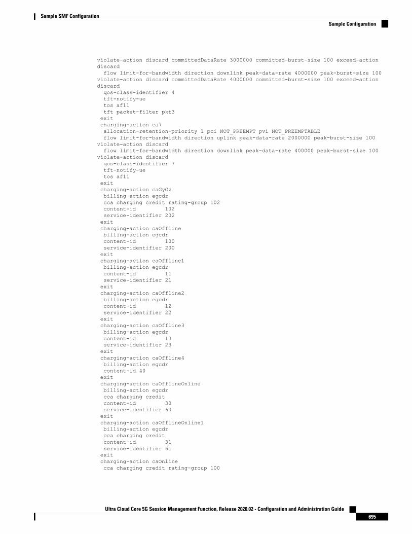
violate-action discard committedDataRate 3000000 committed-burst-size 100 exceed-actiondiscardflow limit-for-bandwidth direction downlink peak-data-rate 4000000 peak-burst-size 100
violate-action discard committedDataRate 4000000 committed-burst-size 100 exceed-actiondiscardqos-class-identifier 4tft-notify-uetos af11tft packet-filter pkt3exitcharging-action ca7allocation-retention-priority 1 pci NOT_PREEMPT pvi NOT_PREEMPTABLEflow limit-for-bandwidth direction uplink peak-data-rate 2000000 peak-burst-size 100
violate-action discardflow limit-for-bandwidth direction downlink peak-data-rate 400000 peak-burst-size 100
violate-action discardqos-class-identifier 7tft-notify-uetos af11exitcharging-action caGyGzbilling-action egcdrcca charging credit rating-group 102content-id 102service-identifier 202exitcharging-action caOfflinebilling-action egcdrcontent-id 100service-identifier 200exitcharging-action caOffline1billing-action egcdrcontent-id 11service-identifier 21exitcharging-action caOffline2billing-action egcdrcontent-id 12service-identifier 22exitcharging-action caOffline3billing-action egcdrcontent-id 13service-identifier 23exitcharging-action caOffline4billing-action egcdrcontent-id 40exitcharging-action caOfflineOnlinebilling-action egcdrcca charging creditcontent-id 30service-identifier 60exitcharging-action caOfflineOnline1billing-action egcdrcca charging creditcontent-id 31service-identifier 61exitcharging-action caOnlinecca charging credit rating-group 100
Ultra Cloud Core 5G Session Management Function, Release 2020.02 - Configuration and Administration Guide695
Sample SMF ConfigurationSample Configuration

content-id 100service-identifier 200exitcharging-action caOnline1cca charging credit rating-group 101content-id 101service-identifier 201exitcharging-action caOnline2cca charging creditcontent-id 102service-identifier 202exitcharging-action caOnline3cca charging creditcontent-id 103service-identifier 203exitcharging-action caOnline4cca charging creditcontent-id 110exitcharging-action nochargingexitrulebase cbn#spp-tmobileaction priority 1 ruledef crn#test_1 charging-action ca1action priority 2 ruledef crn#test_2 charging-action ca2exitrulebase rba1action priority 1 dynamic-only ruledef rda1 charging-action ca1 description myrule1action priority 2 dynamic-only ruledef rda2 charging-action ca2 description myrule2action priority 3 dynamic-only ruledef rda3 charging-action ca3 description myrule3exitrulebase rba2action priority 10 ruledef rda10 charging-action ca10 description myrule10action priority 11 ruledef rda11 charging-action ca11 description myrule11action priority 12 dynamic-only ruledef rda12 charging-action ca12 description myrule12action priority 13 dynamic-only ruledef rda13 charging-action ca13 description myrule13exitrulebase rba3action priority 20 ruledef rda20 charging-action ca20 description myrule20action priority 21 ruledef rda21 charging-action ca21 description myrule21action priority 22 dynamic-only ruledef rda22 charging-action ca22 description myrule22action priority 23 dynamic-only ruledef rda23 charging-action ca23 description myrule23exitrulebase rba4action priority 30 ruledef rda3 charging-action ca3 description myrule3action priority 31 dynamic-only ruledef rda3 charging-action ca3 description myrule3exitrulebase rba5action priority 50 dynamic-only ruledef rda50 charging-action ca4 description myrule50action priority 51 dynamic-only ruledef rda51 charging-action ca5 description myrule51action priority 52 dynamic-only ruledef rda52 charging-action ca6 description myrule52exitrulebase rba6action priority 60 dynamic-only ruledef rda60 charging-action ca1 description myrule60action priority 61 dynamic-only ruledef rda61 charging-action ca1 description myrule61action priority 62 dynamic-only ruledef rda62 charging-action ca1 description myrule62exitrulebase rba7action priority 50 ruledef rda50 charging-action ca4 description myrule50action priority 51 ruledef rda51 charging-action ca5 description myrule51action priority 52 ruledef rda52 charging-action ca6 description myrule52exit
Ultra Cloud Core 5G Session Management Function, Release 2020.02 - Configuration and Administration Guide696
Sample SMF ConfigurationSample Configuration

rulebase rba8action priority 60 ruledef rda60 charging-action ca1 description myrule60action priority 61 ruledef rda61 charging-action ca1 description myrule61action priority 62 ruledef rda62 charging-action ca1 description myrule62exitrulebase rbaStaticaction priority 10 ruledef rda20 charging-action caOfflineexitrulebase rbaStatic-Onlineaction priority 20 ruledef rdaStatic charging-action caOnlineexitrulebase rbaStatic1action priority 10 ruledef rda20 charging-action caOfflineexitrulebase rba_GyGzegcdr threshold volume downlink 100000 uplink 100000action priority 20 dynamic-only ruledef rdaPredefined charging-action caGyGzaction priority 30 ruledef rda20 charging-action caGyGzexitrulebase rba_charging_StaticDynamic_Offline_Online_mixcca diameter requested-service-unit sub-avp volume cc-input-octets 11000 cc-output-octets12000 cc-total-octets 23000credit-control-group onlineofflineegcdr threshold interval 100egcdr threshold volume downlink 150000 uplink 150000 total 300000action priority 20 dynamic-only ruledef rdaPredefined charging-action caOffline1action priority 21 dynamic-only ruledef rdaPredefined1 charging-action caOnline1action priority 31 ruledef rdaStatic charging-action caOfflineOnlineexitrulebase rba_charging_StaticDynamic_offlineegcdr threshold volume downlink 100000 uplink 100000action priority 20 dynamic-only ruledef rdaPredefined charging-action caOffline1action priority 30 ruledef rda20 charging-action caOfflineexitrulebase rba_charging_StaticDynamic_onlineaction priority 20 ruledef rda20 charging-action caOnlineaction priority 30 dynamic-only ruledef rdaPredefined charging-action caOnline1exitrulebase rbs1action priority 1 ruledef rds1 charging-action ca1 description myrules1action priority 2 ruledef rds2 charging-action ca2 description myrules2exiturr-list urr_smfrating-group 10 service-identifier 20 urr-id 1rating-group 11 service-identifier 21 urr-id 2rating-group 12 service-identifier 22 urr-id 3rating-group 13 service-identifier 23 urr-id 4rating-group 30 service-identifier 60 urr-id 20rating-group 31 service-identifier 61 urr-id 21rating-group 100 service-identifier 200 urr-id 5rating-group 101 service-identifier 201 urr-id 6rating-group 102 service-identifier 202 urr-id 7rating-group 103 service-identifier 203 urr-id 8exitruledef rda1ip server-ip-address = 10.10.10.10exitruledef rda10ip any-match = TRUEexitruledef rda11ip any-match = TRUEexitruledef rda12
Ultra Cloud Core 5G Session Management Function, Release 2020.02 - Configuration and Administration Guide697
Sample SMF ConfigurationSample Configuration

ip any-match = TRUEexitruledef rda13ip any-match = TRUEexitruledef rda2ip server-ip-address = 10.165.161.77/32exitruledef rda20ip any-match = TRUEexitruledef rda21ip any-match = TRUEexitruledef rda22ip any-match = TRUEexitruledef rda23ip any-match = TRUEexitruledef rda3ip server-ip-address = 10.198.87.48/28exitruledef rda40ip any-match = TRUEexitruledef rda50ip server-ip-address = 50.50.50.50exitruledef rda51ip server-ip-address = 51.51.51.51exitruledef rda52ip server-ip-address = 52.52.52.52exitruledef rda60ip dst-address = 60.60.60.60exitruledef rda61ip dst-address = 61.61.61.61exitruledef rda62ip dst-address = 62.62.62.62exitruledef rdaPredefinedip any-match = TRUEexitruledef rdaStaticip any-match = TRUEexitruledef rdaStatic1ip any-match = TRUEexitruledef rdaStatic2ip any-match = TRUEexitruledef rds1ip any-match = TRUEexitruledef rds2ip any-match = TRUEexitcredit-control group onlineofflinediameter ignore-service-id true
Ultra Cloud Core 5G Session Management Function, Release 2020.02 - Configuration and Administration Guide698
Sample SMF ConfigurationSample Configuration

exitexitapn intershatgtpp group group1active-charging rulebase rba1exitgtpp group group1gtpp egcdr service-data-flow threshold interval 60gtpp egcdr service-data-flow threshold volume downlink 100000 uplink 100000 total 200000exitaaa authentication users user adminuid 117gid 1117password $1$cRyjDAuU$7t8iCDDjhDcKdQ1/YHM2J1ssh_keydir /tmp/admin/.sshhomedir /tmp/adminexitaaa ios level 0prompt "\h> "exitaaa ios level 15prompt "\h# "exitaaa ios privilege execlevel 0command actionexitcommand autowizardexitcommand enableexitcommand exitexitcommand helpexitcommand startupexitexitlevel 15command configureexitexitexitnacm write-default denynacm groups group adminuser-name [ admin ]exitnacm rule-list admingroup [ admin ]rule any-accessaction permitexitexitnacm rule-list confd-api-managergroup [ confd-api-manager ]rule any-accessaction permitexitexit
Ultra Cloud Core 5G Session Management Function, Release 2020.02 - Configuration and Administration Guide699
Sample SMF ConfigurationSample Configuration

Ultra Cloud Core 5G Session Management Function, Release 2020.02 - Configuration and Administration Guide700
Sample SMF ConfigurationSample Configuration