Embed Size (px)
Citation preview
BRL-K17401 part A 16 April 2004
National Evaluation Guideline for the Kiwa technical approval-with-product certificate for District heating: flexible piping systems with plastic medium pipe for transport of warm drinking water
BRL-K17401 part A 16 April 2004
National Evaluation Guideline for the Kiwa technical approval-with-product certificate for District heating: flexible piping systems with plastic medium pipe for transport of warm drinking water
©2004 Copyright, Kiwa N.V. No part of this Evaluation Guideline may be reproduced and/or published by way of printed matter, photocopy, microfilm or in any other way without permission from Kiwa. Without prejudice of the approval by the ‘Harmonisatie Commissie Bouw’ of the foundation ‘Stichting Bouwkwaliteit’, all rights rests with Kiwa. The use by third parties of this Evaluation Guideline, for whatever purpose, is only permitted after a written agreement is concluded with Kiwa in which the use is arranged. Validation This Evaluation Guideline has been validated by the Director Certification and Inspection of Kiwa on 1 December 2003
Accreditation
KCSP2TTI
iwa N.V ertification and Inspection ir Winston Churchill-laan 273 .O. Box 70 280 AB Rijswijk elephone 070 – 41 444 00 elefax 070 – 41 444 20
nternet www.kiwa.nl

Preface Kiwa This National Evaluation Guideline has been prepared by the Kiwa Board of Experts “CKW” in which the parties interested in the area of district heating: flexible piping systems with plastic medium pipe for transport of warm drinking water, are represented. Kiwa will use this Evaluation Guideline in conjunction with the Kiwa Regulations for Product Certification. These regulations detail the methods employed by Kiwa for conducting the necessary investigations prior to issuing the technical approval with product certificate and the method of external control. The inspection frequency is determined by the above mentioned Board of Experts.
1 Introduction 8
1.1 Subject 8
1.2 Scope 8
1.3 Application 8
1.4 Definitions 9
2 Requirements for the piping system 15
2.1 General 15
2.2 Toxicological requirements 15
2.3 Influence on drinking water: organoleptical requirements 15
2.4 Lifetime of the system 15
2.5 Determination of Rdecl 15
2.6 Maximum calculated heat emission Rprak 15
2.7 Requirements for the joints 16
2.8 Requirements for the piping package 18
2.9 Installation instructions 19
2.10 Marking 19
3 Requirements for the medium-pipe 20
3.1 General 20
3.2 Lifetime 20
3.3 PE-X pipes 20
3.4 PB pipes 21
3.5 PE-RT pipes 23
3.6 Multi-layer pipes 24
3.7 Adhesive layer 25
3.8 Protection layer around the pipe 26
3.9 Marking of the medium-pipe 26
4 Requirements for the fitting 27
4.1 Requirements for the plastics fittings 27
4.2 Metal fittings 28
4.3 Marking 28
5 Requirements for the insulation material 29
5.1 Functional requirements 29
6 Requirements for the outer casing 30
6.1 Functional requirements 30
6.2 Material 30
6.3 Mechanical requirements of the PE or PP outer casing 31
7 Test methods 32
7.1 Multi layer pipe: Determination of dimensions 32
7.2 Sealing in longitudinal direction 32
7.3 Test methods for the multilayer pipe 33
7.4 Determination of material strength of the aluminium 33
7.5 Influence of corrosion, test method 34
7.6 Determination of the characteristics of the adhesive layer 34
8 Requirements to be met by the quality system 35
8.1 General 35
8.2 Internal quality control 35
8.3 Procedures and working instructions 35
8.4 External inspection 35
9 Summary of tests and inspections 36
9.1 Test matrix 36
10 Requirements to be met by certification bodies 37
10.1 General 37
10.2 Certification staff 37
10.3 Report pre-certification tests 38
10.4 Decision with regard to granting of the certificate 38
10.5 Quality declaration 38
10.6 Nature and frequency of external inspections 38
10.7 Report to Board of Experts 39
10.8 Interpretation of requirements 39
11 List of stated documents 40
11.1 Standards / normative documents 40
12 Annex 1: Technical approval with product certificate 43
13 Annex 2: Model IQC scheme 47
14 Annex 3: Calculation of Rdecl 48
14.1 General 48
14.2 Initial testing 48
14.3 Declared values 48
15 Annex 4: : Measuring of Rdecl 51
15.1 General 51
15.2 Test pieces 51
15.3 Test equipment 51
15.4 Calculating the measuring parameters 51
15.5 R of the pipe package 51
15.6 Thermal conductivity of the thermal insulation material 51
15.7 Determination of λWD 52
16 Annex 5: Measuring RI 53
17 Annex 6: Calculation of Reis 54
17.1 General 54
17.2 Heat transport of a piping package with return pipes 54
18 Annex 7: Thermal stability 56
18.1 Principle 56
18.2 Apparatus 56
18.3 Sample Preparation 56
18.4 Procedure 56
19 Annex 8: Dimension stability of the piping package 58
19.1 General 58
19.2 Procedure 58
8
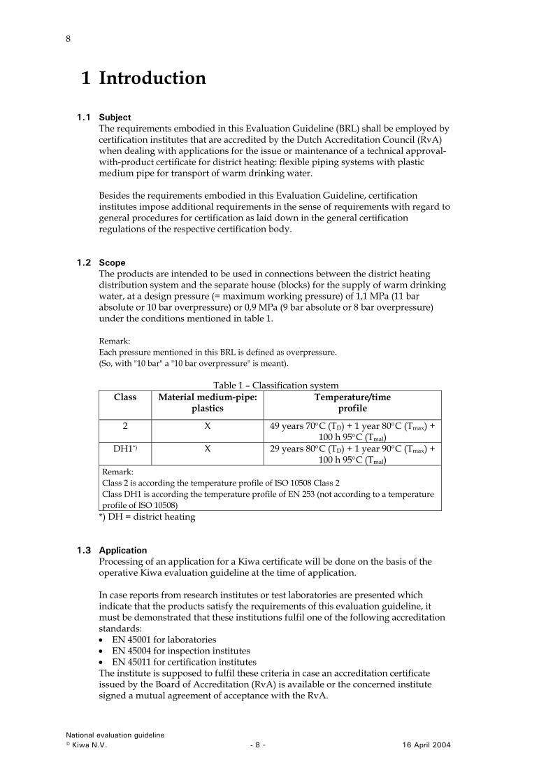
1 Introduction
1.1 Subject The requirements embodied in this Evaluation Guideline (BRL) shall be employed by certification institutes that are accredited by the Dutch Accreditation Council (RvA) when dealing with applications for the issue or maintenance of a technical approval-with-product certificate for district heating: flexible piping systems with plastic medium pipe for transport of warm drinking water. Besides the requirements embodied in this Evaluation Guideline, certification institutes impose additional requirements in the sense of requirements with regard to general procedures for certification as laid down in the general certification regulations of the respective certification body.
1.2 Scope The products are intended to be used in connections between the district heating distribution system and the separate house (blocks) for the supply of warm drinking water, at a design pressure (= maximum working pressure) of 1,1 MPa (11 bar absolute or 10 bar overpressure) or 0,9 MPa (9 bar absolute or 8 bar overpressure) under the conditions mentioned in table 1. Remark: Each pressure mentioned in this BRL is defined as overpressure. (So, with "10 bar" a "10 bar overpressure" is meant).
Table 1 – Classification system Class Material medium-pipe:
plastics Temperature/time
profile
2 X 49 years 70°C (TD) + 1 year 80°C (Tmax) + 100 h 95°C (Tmal)
DH1*) X 29 years 80°C (TD) + 1 year 90°C (Tmax) + 100 h 95°C (Tmal)
Remark: Class 2 is according the temperature profile of ISO 10508 Class 2 Class DH1 is according the temperature profile of EN 253 (not according to a temperature profile of ISO 10508)
*) DH = district heating
1.3 Application Processing of an application for a Kiwa certificate will be done on the basis of the operative Kiwa evaluation guideline at the time of application. In case reports from research institutes or test laboratories are presented which indicate that the products satisfy the requirements of this evaluation guideline, it must be demonstrated that these institutions fulfil one of the following accreditation standards: • EN 45001 for laboratories • EN 45004 for inspection institutes • EN 45011 for certification institutes The institute is supposed to fulfil these criteria in case an accreditation certificate issued by the Board of Accreditation (RvA) is available or the concerned institute signed a mutual agreement of acceptance with the RvA.
National evaluation guideline © Kiwa N.V. - 8 - 16 April 2004
9
The scope of accreditation must cover the examinations as required by this evaluation guideline. In case no accreditation certificate is available, Kiwa by itself will investigate whether the accreditation standard has been met.
1.4 Definitions
1.4.1 Definitions: general
1.4.1.1 Heat distribution systems Heat distribution is the collective use of heat, for the purpose of heating houses, businesses and other buildings and the possible delivery of warm tap water to those houses, businesses and buildings.
1.4.1.2 Flexible piping system A piping system in which possible bends in the pipe can be made without any mechanical means and in which the pipe is not deformed and the flow capacity is not reduced due to the possible bends. Remark: in case a minimum bending radius is required in the system, mechanical means according to the installation instructions of the supplier can be used.
1.4.1.3 Rigid piping system A piping system in which possible bends in the pipe have to be made by mechanical means or by means of a fitting. Remark: these systems do not apply within the scope of this BRL.
1.4.1.4 Lifetime The time during which the piping system has to function with a certain operating temperature. See table 1.
1.4.1.5 Life expectancy The time during which the piping system has to function for the intended application. In this BRL the life expectancy is put to at least 50 years or at least 30 years according table 1.
1.4.1.6 Operating temperature (TD) The temperature of the water in the piping system during operation, that occurs at least during a certain part of the lifetime of the piping system. See table 1.
1.4.1.7 Maximum temperature (Tmax) The highest temperature of the water in the piping system during operation, that occurs during a certain part of the lifetime of the piping system (the highest occurring temperature during a short time). See table 1.
1.4.1.8 Peak temperature (Tmal) The highest temperature of the water in the piping system under abnormal circumstances, for example due to malfunctioning, during a short period (maximally 100 hours per 50 years). See table 1.
1.4.1.9 Temperature profile On the basis of the employed design pressure in relation to the maximum and peak temperature, the temperature profile according table 1 may be used for a lifetime of 50 or 30 years.
National evaluation guideline © Kiwa N.V. - 9 - 16 April 2004
10
1.4.1.10 Reference lines A generic description of the minimum long-term hydrostatic pressure to be expected from a particular composite pipe construction type. The reference lines are parallel to the according ISO 9080 calculated regression lines and at least 97,5% of all individual experimental results shall lie on or above the reference lines. The procedure to find these lines is only valid for this Guideline.
1.4.1.11 LPL (or PC) Quantity with the dimension of pressure (for multilayer pipes), which represents the predicted mean pressure at a temperature T and a time t (97,5% value).
1.4.1.12 LTHS Quantity with the dimension of pressure (for multilayer pipes), which represents the predicted mean pressure at a temperature T and a time t (50% value).
1.4.1.13 Design pressure (P of PD) The allowable pressure in the piping system that may occur for 50 years during continuous use. In this BRL ‘design pressure’ is defined as the prevailing overpressure (so, for example P=10 bar means a design pressure of 11 bar absolute).
1.4.1.14 Predicted design pressure (PPD) The calculated pressure in the piping system after a lifetime of 50 years, using the 97,5% reference lines and according to the temperature profile of table 1 for a multilayer pipe construction (medium pipe). - PPD2 for Class 2; - PPD3 for Class DH1. Remark: The value of pPD is calculated using pC see formula 2 of paragraph 7.3.1.
1.4.1.15 Residual variance (sR) The calculated value for the 97,5 % (one sided) lower confidence limit of the predicted hydrostatic strength for a complete set of rapture data, using the SEM analyses model of ISO 9080.
1.4.2 Definitions: the construction
1.4.2.1 Piping system The total of pipes, (possible) outer casings, fittings (and joint assemblies), and insulation material, but excluding distributors.
1.4.2.2 Medium-pipe The medium carrying pipe which is in contact with the warm water.
1.4.2.3 Homogeneous medium-pipe Meant are the medium-pipes constructed of PE-X, PE-RT or PB and provided with an EVOH barrier layer. This barrier layer strongly prevents or reduces the diffusion of oxygen through the pipe wall. The barrier layer does not contribute to the mechanical strength of the pipe.
1.4.2.4 Multilayer pipe A multilayer plastics medium-pipe provided with a thin metal (aluminium) barrier layer. This barrier layer strongly prevents or reduces the diffusion of oxygen through the pipe wall. The barrier layer can contribute to the mechanical strength of the pipe.
1.4.2.5 Outer casing A separate applied outer layer of the piping package, protecting the construction during installation and protecting the construction against external influences (after installation).
National evaluation guideline © Kiwa N.V. - 10 - 16 April 2004
11
1.4.2.6 Insulation layer The thermal insulation layer is meant to provide for the desired insulating characteristics of the piping package.
1.4.2.7 Piping package The complete pipe, existing of the medium-pipe, an insulation layer and (in general) an outer casing.
1.4.2.8 Bonded piping package The different layers of the piping package are united in such a way that under influence of expansion forces no displacements at the interface of the mutual piping layers occur.
1.4.2.9 Non-bonded piping package The different layers of the piping package can be mutually displaced under influence of expansion forces.
1.4.2.10 Mechanical joints A connection between a pipe and a fitting, made by means of pressing a ring or case over the outside diameter of the pipe, with or without extra sealing elements and with possible use of a supporting ring in the pipe, according to NEN EN ISO 6708.
1.4.2.11 Medium pipe: electro fusion joint A joint between a pipe and a fitting realised by melting together of the outer layer of the pipe and medium layer of the fitting. The melting of the material is realised by heat developed due to induction of an electrical resistance. The electrical resistance is composed of a metal thread that is embedded in the fitting. Pipe and fitting are first pushed together till the required installation position, before the material is melted.
1.4.2.12 Medium pipe: socket fusion joint A joint between a pipe and a fitting realised by melting together of the outer layer of the pipe and medium layer of the fitting. The melting of the material is realised by a solid body with the appropriate temperature that is in contact with the material concerned during a certain amount of time: Socket shaped for the pipe and spigot shaped for the fitting. The material is first melted, after which the pipe and fitting are pushed together till the required installation position is obtained.
1.4.2.13 Medium pipe: butt fusion joint A joint between two pipes, made by heating the planed ends of the pipes by holding them against a flat heating plate until the material reaches fusion temperature. After quickly removing the heating plate, the two softened ends are pushed against each other (according to a defined time/pressure diagram) forming a fusion rill and joining both pipes together.
1.4.2.14 Mechanical outer casing joint The (watertight) joint between two outer casing parts by means of: - a contraction socket; - an electro fusion socket; - two (metallic) half plates.
1.4.3 Definitions and symbols: geometry
1.4.3.1 Dn Nominal outside diameter of the medium pipe.
National evaluation guideline © Kiwa N.V. - 11 - 16 April 2004
12
1.4.3.2 dn,m Nominal outside diameter of the outer casing (=dn,p).
1.4.3.3 dn,p Nominal outside diameter of the piping package.
1.4.3.4 dem Mean diameter of the medium-pipe.
1.4.3.5 dem,m Mean outside diameter of the outer casing.
1.4.3.6 dem,p Mean outside diameter of the piping package.
1.4.3.7 dem,b Mean outside diameter of the piping package.
1.4.3.8 di,gem Mean internal diameter of the outer casing.
1.4.3.9 di,m Internal diameter of the outer casing.
1.4.3.10 emin,m Minimum wall thickness of the outer casing.
1.4.3.11 emax,m Maximum wall thickness of the outer casing.
1.4.3.12 emin,b Minimum wall thickness of the medium pipe.
1.4.3.13 emax,b Maximum wall thickness of the medium pipe.
1.4.4 Definitions: material characteristics
1.4.4.1 S series A number without dimension identifying the pipe according to ISO 4065, where the S series prescribes the pipe series for a certain design pressure according to the following formula:
peedS σ
=−
=2
National evaluation guideline © Kiwa N.V. - 12 - 16 April 2004
13
1.4.4.2 SDR value A number without dimension identifying the pipe according to ISO 4065, where the SDR value describes a relation between the pipe and his wall thickness for a certain design pressure according to the following formula:
( ) 1.2122+=+=
+== S
ppp
edSDR n σσ
1.4.4.3 Hydrostatic tension σ Tension in the circumferential direction of the pipe wall caused by internal water pressure. This tension is derived from the internal pressure according the following formula:
e
edpx
xem
min
min
20)( −
=σ
Where: σ = the tension in the circumference direction of the pipe wall in MPa p = the internal pressure in bar; dem = the mean outside diameter of the medium pipe in mm; emin,b = the minimum wall thickness of the medium pipe in mm.
1.4.5 Definitions and symbols with regard to insulating characteristics
1.4.5.1 Reis (m.K/W) The heat loss per meter length of a piping package as allowed for a certain energy transport (requirement of the user) under local installation conditions.
1.4.5.2 RI (m.K/W) The heat loss per meter length of a piping package (including possible returning medium pipe) as it will occur under the specific local conditions at the end of the lifetime of the piping package (at local circumstances).
1.4.5.3 Rinstal (m.K/W) The heat loss per meter length of a piping package (including possible returning medium pipe) as it will occur under the specific local conditions at the end of the lifetime of the piping package (at local circumstances).
1.4.5.4 Rdecl (m.K/W) The normalised value of the heat loss per meter length of a piping package (with a single medium-pipe) as the manufacturer must demonstrate by means of measurements and calculations .
1.4.5.5 Fa A factor without dimension that charges the influence of the ageing of the insulating layer in Rinstal to the expected lifetime.
1.4.5.6 Fm A factor without dimension that charges the influence of moisture in Rinstal to the expected lifetime.
National evaluation guideline © Kiwa N.V. - 13 - 16 April 2004
14
1.4.5.7 Fc A factor without dimension that charges the influence of compression of the insulation layer in Rinstal to the expected lifetime.
1.4.5.8 Fp A factor without dimension that charges the influence of the radiation in Rinstal to the expected lifetime.
1.4.5.9 FT A factor without dimension that charges the influence of the difference in temperature between the supplying medium-pipe and the outlet medium-pipe in Rinstal to the expected lifetime.
1.4.5.10 Ftot A factor without dimension that charges the total influence of the internal and external factors in Rinstal to the expected lifetime. Remark: Values that are only used in an annex are defined in the concerning annex.
National evaluation guideline © Kiwa N.V. - 14 - 16 April 2004
15
2 Requirements for the piping system
2.1 General This chapter contains the requirements to be met by the flexible piping systems for heat distribution.
2.2 Toxicological requirements Products and materials that (can) come into contact with drinking water may not emit substances to the drinking water in such amounts that it can be harmful for consumers. For guarantee the product must fulfil the criteria as laid down in the ‘Guideline quality of materials and chemicals for drinking water supplies’ (published in the ´Staatscourant´). As proof the application procedure Attest Toxicological Aspects (ATA) must be completed successfully.
2.3 Influence on drinking water: organoleptical requirements All materials, which make contact to drinking water may not emit odour, flavour or colour in concentrations, which are disturbing for the consumer. This requirement is fulfilled if after conditioning of the test pieces according EN 1420-1 and after testing according to Kiwa publication PB 94-01, three or more members of the testing panel observe no difference in odour or flavour between the blank and test water. With regard to emitting colour the method according to EN 13052-1, with no higher intensity than 5 mg Pt/l after the third extraction, is applicable.
2.4 Lifetime of the system The complete piping system must be designed for a lifetime expectancy according to paragraph 1.2. Remark: with lifetime is meant the technical lifetime of the system during normal usage. The different lifetimes according to table 1 have to be added up in order to obtain the minimum lifetime of 50 years (class 2) or 30 years (class DH1).
2.5 Determination of Rdecl In order to be able to compare the different piping systems with regard to the energy transport capacity per meter length of the piping package, the following systematic is chosen: The manufacturer must be able to submit calculations of an approved body (see paragraph 1.5) of Rdecl (according annex 3) and/or measurements performed by an approved body (see paragraph 1.5) of Rdecl (according annex 4) of different diameters of the piping package (=piping systems).
2.6 Maximum calculated heat emission Rprak
2.6.1 General The supplier has to demonstrate that the piping system is still able to fulfil the minimum required heat emission requirements under local circumstances after 30 years (or 50 years). The below mentioned procedure (paragraph 2.6.2 and 2.6.3) can be followed.
National evaluation guideline © Kiwa N.V. - 15 - 16 April 2004
16
2.6.2 Heat emission of the piping system RI For a chosen piping system all parameters that influence the correct functioning of the piping system after installation have to be considered. These are influences like ageing of the insulation (Fa), influence of moisture (Fm), compression of the piping package (Fc), influence of radiation losses (FD ) and influence of the temperature difference between the supplying medium-pipe and discharge medium-pipe (FT). The supplier of the piping system can demonstrate the value of the allowed heat emission per meter length (at the end of the lifetime of the piping system) according to annex 5: RI (in m.K/W).
2.6.3 Heat emission of the piping system in the ground, Rprak For the determination of the total heat emission the procedure according to annex 6 can be followed. Remark: also the calculated RI has to be used in annex 6.
2.6.4 Maximum allowed heat emission, Reis The user of the piping system desires (also at the end of the lifetime) a certain minimum energy supply to the delivery point. Depending on the route to the delivery point, a maximum allowed heat emission per meter length is allowed: Reis (in m.K/W). Now has to count: Rprakt ≥ Reis
2.7 Requirements for the joints
2.7.1 General The joints in the piping system have to be tested with regard to their proper functioning. In this chapter all joint tests required for the piping system are included. The combination of a (possible) rubber seal, (possible) supporting ring and clamp construction in the fitting have to be tested with regard to the aspects mentioned in paragraph 2.7.3.
2.7.2 Rubber Possible rubber seals have to be made from a synthetic rubber and has to fulfil the requirements of BRL 2013 (these requirements are parallel to NEN EN 681, table 3. Material types according table 4: type WD). The manufacturer has to declare to the approved body which type of rubber is applied, as well as the hardness and dimensions of the rubber seals.
National evaluation guideline © Kiwa N.V. - 16 - 16 April 2004
17
2.7.3 Tightness and strength of the joints of the medium pipe The fittings shall not deform during testing in accordance with table 2. After testing, the pipe ends shall show no severe damages. If not otherwise stated, the testing temperature is (23±2) °C.
Table23 - Tightness and strength of the joints of the medium-pipe
Aspect Require- ment
Test parameters Test method
Cyclic temperature
test
no leakage
n = 5000 cycli3)4)
Tmax = (93±2) °C1)
Tmin = (23±2) °C2)
tcyclus= 30 min3). Pdesign pressure (bar)
One test piece
EN 12293
Resistance to tensile force
no leakage
t = (60±1) min. Three test pieces
F = 1,5xπ/4xdn,bxPwdesign pressure (N)
EN 712
Resistance to vacuum
≤ 0,05 bar t = (60±1) min. Three test pieces
P= -0,8 bar
EN 12294
Resistance to bending
no leakage
t = (60±1) min. Three test pieces
P= depends on pipe material
EN 713
t = 1000 h. Three test pieces
Test pressure P (bar)
Medium-pipe type
8 10
Resistance to internal
hydrostatic pressure, class 2
no leakage
PE-X PB
PE-RT PE-X/Al
PE-RT/Al
PE-X +Al
10,0 9,5
10,2 5)
5)
5)
12,5 11,9 12,8
5)
5)
5)
ISO 1167
t = 1000 h. Three test pieces
Test pressure P (bar)
Medium-pipe type
8 10
Resistance to internal
hydrostatic pressure, class DH1
no leakage
PE-X PB
PE-RT PE-X/Al
PE-RT/Al
PE-X +Al
11,0 11,6 13,7
5)
5)
5)
13,8 14,5 17,1
5)
5)
5)
ISO 1167
1) Maximum test temperature of the water 2) Minimum test temperature of the water 3) tcyclus = tmax + tmin (= 15 + 15 = 30 min total time = 2500 hours) 4) for diameters > 63 mm counts n = 100 5) on basis of the regression curve and at least equal to the value of the medium pipe
material
National evaluation guideline © Kiwa N.V. - 17 - 16 April 2004
18
2.7.4 Damage to contact surfaces
2.7.4.1 Mutual corrosion of the metals No harmful electrolytic reactions may occur between the different materials. The following applies for multi-layer pipes: In case the material of the fittings and joint assemblies do have a corroding effect on the intermediate metal layer of the pipe, then the electrical separation must be such that the electrical flow between the parts is smaller than 10 x 10 6 Ampere. This requirement is tested according to the test method of paragraph 7.5.1.
2.7.4.2 Corrosion due to water For piping systems with a multi-layer medium pipe applies that the construction must be such, that the aluminium in no case (after installation) comes into contact with the water. After testing in accordance with paragraph 7.5.2, the aluminium layer shall show no damages.
2.8 Requirements for the piping package
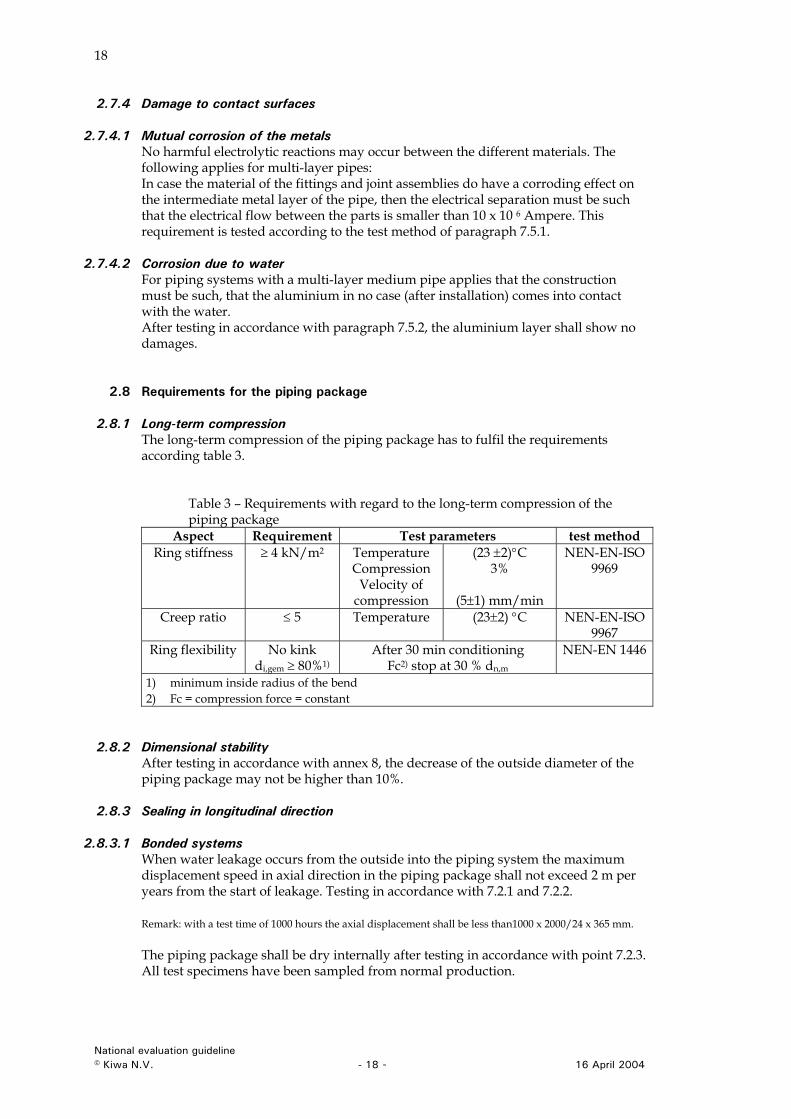
2.8.1 Long-term compression The long-term compression of the piping package has to fulfil the requirements according table 3.
Table 3 – Requirements with regard to the long-term compression of the piping package
Aspect Requirement Test parameters test method Ring stiffness ≥ 4 kN/m2 Temperature
Compression Velocity of
compression
(23 ±2)°C 3%
(5±1) mm/min
NEN-EN-ISO 9969
Creep ratio ≤ 5 Temperature (23±2) °C NEN-EN-ISO 9967
Ring flexibility No kink di,gem ≥ 80%1)
After 30 min conditioning Fc2) stop at 30 % dn,m
NEN-EN 1446
1) minimum inside radius of the bend 2) Fc = compression force = constant
2.8.2 Dimensional stability After testing in accordance with annex 8, the decrease of the outside diameter of the piping package may not be higher than 10%.
2.8.3 Sealing in longitudinal direction
2.8.3.1 Bonded systems When water leakage occurs from the outside into the piping system the maximum displacement speed in axial direction in the piping package shall not exceed 2 m per years from the start of leakage. Testing in accordance with 7.2.1 and 7.2.2. Remark: with a test time of 1000 hours the axial displacement shall be less than1000 x 2000/24 x 365 mm. The piping package shall be dry internally after testing in accordance with point 7.2.3. All test specimens have been sampled from normal production.
National evaluation guideline © Kiwa N.V. - 18 - 16 April 2004
19
2.8.3.2 Non bonded systems The manufacturer of the system shall have a provision to stop leakage in axial direction. With the use of this provision the piping package shall be dry internally after testing in accordance with point 7.2.3. All test specimens have been sampled from normal production and the joints have been installed according to the installation instruction of the manufacturer.
2.8.4 Sealing construction to main supply pipe and service pipe After installation the joint construction between the main supply pipe as well as with the service pipe shall be such that: The joint shall be leak tight at an internal pressure of 0,3 kPa, to be determined according paragraph 5.1.5 of NEN-EN 489, after a conditioning of the joint according paragraph 5.1.1 till paragraph 5.1.4 of NEN EN 489. For the purpose of the test the manufacturer of the system shall supply a joint in accordance with their installation instructions.
2.9 Installation instructions The supplier shall provide installation instructions in the Dutch language. A reference to these instructions shall be made at or near the packaging. The instructions must contain specific information with regard to storage, transport, processing temperature, construction of the joints and specific installation guidelines.
2.10 Marking After conclusion of the certification agreement, the outer casing shall be provided, at intervals of not more than 2 m, with the following clearly legible and indelible markings: - dependent on the type of medium pipe:
- “PE/X “or "PE-X/Al" or “PE-X + Al”; - “PB”; - “PE-RT” or "PE-RT/Al".
- system name; - classification (class DH1); - design pressure: 8 or 10 bar; - the number and the nominal outside diameter(s) plus wall thickness of the
medium pipe(s) in mm; - the nominal outside diameter of the outer casing in mm; - the production code.
National evaluation guideline © Kiwa N.V. - 19 - 16 April 2004
20
3 Requirements for the medium-pipe
3.1 General In this chapter the requirements for the medium/pipe have been recorded.
3.2 Lifetime The manufacturer shall submit pressure test data based on tests (in water or in air) in accordance with ISO 1167 for the raw material (PE-X, PE-RT or PB) to be used for the manufacturing of the pipes. The test specimens shall be extruded pipes manufactured from the raw material (PE-X, PE-RT or PB). The tests must have been performed for at least 10.000 hours and for the following temperatures: 60°C or 80°C, 95°C and 110°C. The data must be statistically processed and presented according ISO 9080:2002. The elaborated LPL curves must be equal or better than the curves of the relevant material according to EN ISO 15875 (for PE-X) or EN ISO 15876 (for PB) or BRL-K536 part G (PE-RT).
3.3 PE-X pipes The requirements in paragraph 3.2 and 3.3 are taken from EN ISO 15875.
3.3.1 Dimensions The dimensions of the pipes are given in table 4. For the determination of the dimensions, the method according to ISO 3126 has to be followed. Table 4 - Dimensions of PE-X pipes. Dimensions in mm.
Wall thickness (dem)
SDR 9 SDR 7,4
P = 8 bar
S = 4
P = 10bar
S = 3.2
dn
Min. Max.
Out of roundn
ess
emin,b. emax emin,b. emax 18 18,0 18,3 0,5 2,0 2,4 2,4 2,8 20 20,0 20,3 0,5 2,3 2,7 2,8 3,2 22 22,0 22,3 0,5 2,5 3,0 2,9 3,3 25 25,0 25,3 0,6 2,8 3,2 3,5 4,0 28 28,0 28,3 0,6 3,2 3,7 3,9 4,4 32 32,0 32,3 0,8 3,6 4,1 4,4 5,0 40 40,0 40,4 1,0 4,5 5,1 5,5 6,2 50 50,0 50,5 1,2 5,6 6,3 6,9 7,7 63 63,0 63,6 1,4 7,1 8,0 8,6 9,5 75 75,0 75,7 1,4 8,4 9,4 10,3 11,5 90 90,0 90,9 1,4 10,1 11,3 12,3 13,7
110 110,1 111,0 1,6 12,3 13,7 15,1 16,8 125 125,0 126,2 1,6 14,0 15,4 17,1 18,9 140 140,0 141,3 1,6 15,7 17,4 19,2 21,3 160 160,0 161,5 1,8 17,9 19,8 21,9 24,2 180 180,0 181,5 1,8 20,0 22,1 24,6 27,2 200 200,0 201,5 2,0 22,4 24,8 27,4 30,3 225 225,0 226,5 2,0 25,0 27,6 30,8 33,9 250 250,0 251,5 2,0 27,9 30,9 34,2 37,6
National evaluation guideline © Kiwa N.V. - 20 - 16 April 2004
21
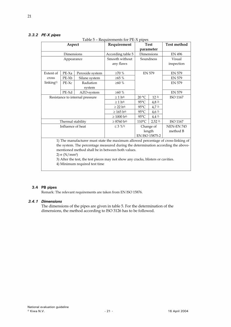
3.3.2 PE-X pipes Table 5 – Requirements for PE-X pipes
Aspect Requirement Test parameter
Test method
Dimensions According table 5 Dimensions EN 496 Appearance Smooth without
any flaws
Soundness Visual inspection
PE-Xa Peroxide system ≥70 % EN 579 PE-Xb Silane system ≥65 % EN 579 PE-Xc Radiation
system ≥60 % EN 579
Extent of cross
linking1)
PE-Xd AZO-system ≥60 %
EN 579
EN 579 ≥ 1 h4) 20 °C 12 2) ≥ 1 h4) 95°C 4,8 2) ≥ 22 h4) 95°C 4,7 2) ≥ 165 h4) 95°C 4,6 2)
Resistance to internal pressure
≥ 1000 h4) 95°C 4,4 2)
ISO 1167
Thermal stability ≥ 8760 h4) 110°C 2,52 2) ISO 1167 Influence of heat ≤ 3 %3) Change of
length EN ISO 15875-2
NEN-EN 743 method B
1) The manufacturer must state the maximum allowed percentage of cross-linking of the system. The percentage measured during the determination according the above-mentioned method shall be in between both values. 2) σ (N/mm2) 3) After the test, the test pieces may not show any cracks, blisters or cavities. 4) Minimum required test time
3.4 PB pipes Remark: The relevant requirements are taken from EN ISO 15876.
3.4.1 Dimensions The dimensions of the pipes are given in table 5. For the determination of the dimensions, the method according to ISO 3126 has to be followed.
National evaluation guideline © Kiwa N.V. - 21 - 16 April 2004
22
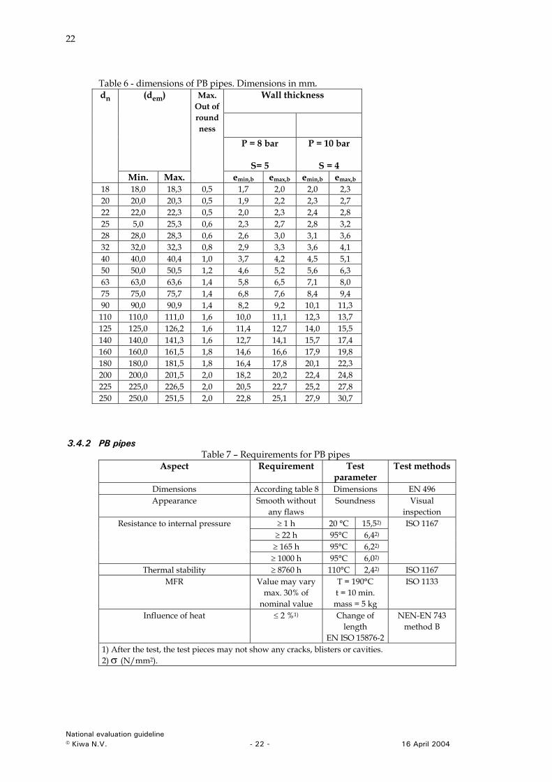
Table 6 - dimensions of PB pipes. Dimensions in mm.
Wall thickness
(dem)
P = 8 bar
S= 5
P = 10 bar
S = 4
dn
Min. Max.
Max. Out of round ness
emin,b emax,b emin,b emax,b
18 18,0 18,3 0,5 1,7 2,0 2,0 2,3 20 20,0 20,3 0,5 1,9 2,2 2,3 2,7 22 22,0 22,3 0,5 2,0 2,3 2,4 2,8 25 5,0 25,3 0,6 2,3 2,7 2,8 3,2 28 28,0 28,3 0,6 2,6 3,0 3,1 3,6 32 32,0 32,3 0,8 2,9 3,3 3,6 4,1 40 40,0 40,4 1,0 3,7 4,2 4,5 5,1 50 50,0 50,5 1,2 4,6 5,2 5,6 6,3 63 63,0 63,6 1,4 5,8 6,5 7,1 8,0 75 75,0 75,7 1,4 6,8 7,6 8,4 9,4 90 90,0 90,9 1,4 8,2 9,2 10,1 11,3
110 110,0 111,0 1,6 10,0 11,1 12,3 13,7 125 125,0 126,2 1,6 11,4 12,7 14,0 15,5 140 140,0 141,3 1,6 12,7 14,1 15,7 17,4 160 160,0 161,5 1,8 14,6 16,6 17,9 19,8 180 180,0 181,5 1,8 16,4 17,8 20,1 22,3 200 200,0 201,5 2,0 18,2 20,2 22,4 24,8 225 225,0 226,5 2,0 20,5 22,7 25,2 27,8 250 250,0 251,5 2,0 22,8 25,1 27,9 30,7
3.4.2 PB pipes Table 7 – Requirements for PB pipes
Aspect Requirement Test parameter
Test methods
Dimensions According table 8 Dimensions EN 496 Appearance Smooth without
any flaws Soundness Visual
inspection ≥ 1 h 20 °C 15,52)
≥ 22 h 95°C 6,42)
≥ 165 h 95°C 6,22)
Resistance to internal pressure
≥ 1000 h 95°C 6,02)
ISO 1167
Thermal stability ≥ 8760 h 110°C 2,42) ISO 1167 MFR Value may vary
max. 30% of nominal value
T = 190°C t = 10 min.
mass = 5 kg
ISO 1133
Influence of heat ≤ 2 %1) Change of length
EN ISO 15876-2
NEN-EN 743 method B
1) After the test, the test pieces may not show any cracks, blisters or cavities. 2) σ (N/mm2).
National evaluation guideline © Kiwa N.V. - 22 - 16 April 2004
23
3.4.3 Welded joint of PB The requirements for welded joints (socket fusion and electro fusion) in PB are according to EN ISO 15876-3.
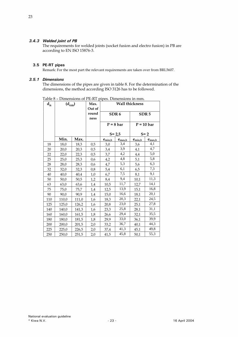
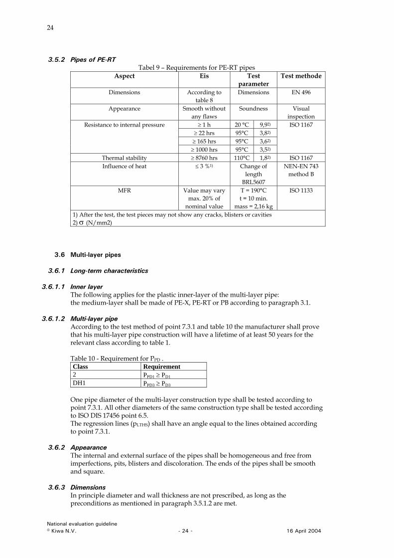
3.5 PE-RT pipes Remark: For the most part the relevant requirements are taken over from BRL5607.
3.5.1 Dimensions The dimensions of the pipes are given in table 8. For the determination of the dimensions, the method according ISO 3126 has to be followed. Table 8 – Dimensions of PE-RT pipes. Dimensions in mm.
Wall thickness
SDR 6 SDR 5
(dem) Max. Out of round ness
P = 8 bar
S= 2,5
P = 10 bar
S= 2
dn
Min. Max. emin,b emax,b emin,b emax,b 18 18,0 18,3 0,5 3,0 3,4 3,6 4,1 20 20,0 20,3 0,5 3,4 3,9 4,1 4,7 22 22,0 22,3 0,5 3,7 4,2 4,4 5,0 25 25,0 25,3 0,6 4,2 4,8 5,1 5,8 28 28,0 28,3 0,6 4,7 5,3 5,6 6,3 32 32,0 32,3 0,8 5,4 6,1 6,5 7,3 40 40,0 40,4 1,0 6,7 7,5 8,1 9,1 50 50,0 50,5 1,2 8,4 9,4 10,1 11,3 63 63,0 63,6 1,4 10,5 11,7 12,7 14,1 75 75,0 75,7 1,4 12,5 13,9 15,1 16,8 90 90,0 90,9 1,4 15,0 16,6 18,1 20,1
110 110,0 111,0 1,6 18,3 20,3 22,1 24,5 125 125,0 126,2 1,6 20,8 23,0 25,1 27,8 140 140,0 141,3 1,6 23,3 25,8 28,1 31,1 160 160,0 161,5 1,8 26,6 29,4 32,1 35,5 180 180,0 181,5 1,8 29,9 33,0 36,1 39,9 200 200,0 201,5 2,0 33,2 36,7 40,1 44,3 225 225,0 226,5 2,0 37,4 41,3 45,1 49,8 250 250,0 251,5 2,0 41,5 45,8 50,1 55,3
National evaluation guideline © Kiwa N.V. - 23 - 16 April 2004
24
3.5.2 Pipes of PE-RT Tabel 9 – Requirements for PE-RT pipes
Aspect Eis Test parameter
Test methode
Dimensions According to table 8
Dimensions EN 496
Appearance Smooth without any flaws
Soundness Visual inspection
≥ 1 h 20 °C 9,92)
≥ 22 hrs 95°C 3,82)
≥ 165 hrs 95°C 3,62)
Resistance to internal pressure
≥ 1000 hrs 95°C 3,52)
ISO 1167
Thermal stability ≥ 8760 hrs 110°C 1,82) ISO 1167 Influence of heat ≤ 3 %1) Change of
length BRL5607
NEN-EN 743 method B
MFR Value may vary max. 20% of
nominal value
T = 190°C t = 10 min.
mass = 2,16 kg
ISO 1133
1) After the test, the test pieces may not show any cracks, blisters or cavities 2) σ (N/mm2)
3.6 Multi-layer pipes
3.6.1 Long-term characteristics
3.6.1.1 Inner layer The following applies for the plastic inner-layer of the multi-layer pipe: the medium-layer shall be made of PE-X, PE-RT or PB according to paragraph 3.1.
3.6.1.2 Multi-layer pipe According to the test method of point 7.3.1 and table 10 the manufacturer shall prove that his multi-layer pipe construction will have a lifetime of at least 50 years for the relevant class according to table 1. Table 10 - Requirement for PPD . Class Requirement 2 PPD1 ≥ PD1 DH1 PPD3 ≥ PD3
One pipe diameter of the multi-layer construction type shall be tested according to point 7.3.1. All other diameters of the same construction type shall be tested according to ISO DIS 17456 point 6.5. The regression lines (pLTHS) shall have an angle equal to the lines obtained according to point 7.3.1.
3.6.2 Appearance The internal and external surface of the pipes shall be homogeneous and free from imperfections, pits, blisters and discoloration. The ends of the pipes shall be smooth and square.
3.6.3 Dimensions In principle diameter and wall thickness are not prescribed, as long as the preconditions as mentioned in paragraph 3.5.1.2 are met.
National evaluation guideline © Kiwa N.V. - 24 - 16 April 2004
25
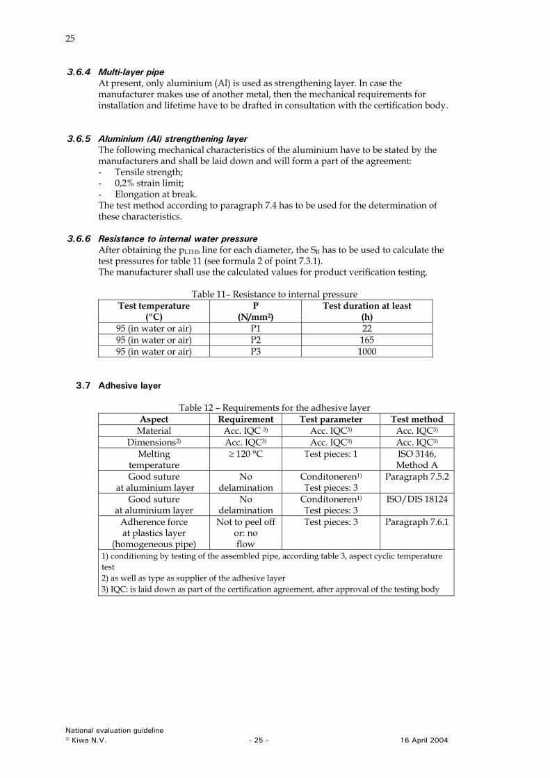
3.6.4 Multi-layer pipe At present, only aluminium (Al) is used as strengthening layer. In case the manufacturer makes use of another metal, then the mechanical requirements for installation and lifetime have to be drafted in consultation with the certification body.
3.6.5 Aluminium (Al) strengthening layer The following mechanical characteristics of the aluminium have to be stated by the manufacturers and shall be laid down and will form a part of the agreement: - Tensile strength; - 0,2% strain limit; - Elongation at break. The test method according to paragraph 7.4 has to be used for the determination of these characteristics.
3.6.6 Resistance to internal water pressure After obtaining the pLTHS line for each diameter, the SR has to be used to calculate the test pressures for table 11 (see formula 2 of point 7.3.1). The manufacturer shall use the calculated values for product verification testing.
Table 11– Resistance to internal pressure Test temperature
(ºC) P
(N/mm2) Test duration at least
(h) 95 (in water or air) P1 22 95 (in water or air) P2 165 95 (in water or air) P3 1000
3.7 Adhesive layer
Table 12 – Requirements for the adhesive layer Aspect Requirement Test parameter Test method
Material Acc. IQC 3) Acc. IQC3) Acc. IQC3)
Dimensions2) Acc. IQC3) Acc. IQC3) Acc. IQC3)
Melting temperature
≥ 120 °C Test pieces: 1 ISO 3146, Method A
Good suture at aluminium layer
No delamination
Conditoneren1)
Test pieces: 3 Paragraph 7.5.2
Good suture at aluminium layer
No delamination
Conditoneren1)
Test pieces: 3 ISO/DIS 18124
Adherence force at plastics layer
(homogeneous pipe)
Not to peel off or: no flow
Test pieces: 3 Paragraph 7.6.1
1) conditioning by testing of the assembled pipe, according table 3, aspect cyclic temperature test 2) as well as type as supplier of the adhesive layer 3) IQC: is laid down as part of the certification agreement, after approval of the testing body
National evaluation guideline © Kiwa N.V. - 25 - 16 April 2004
26
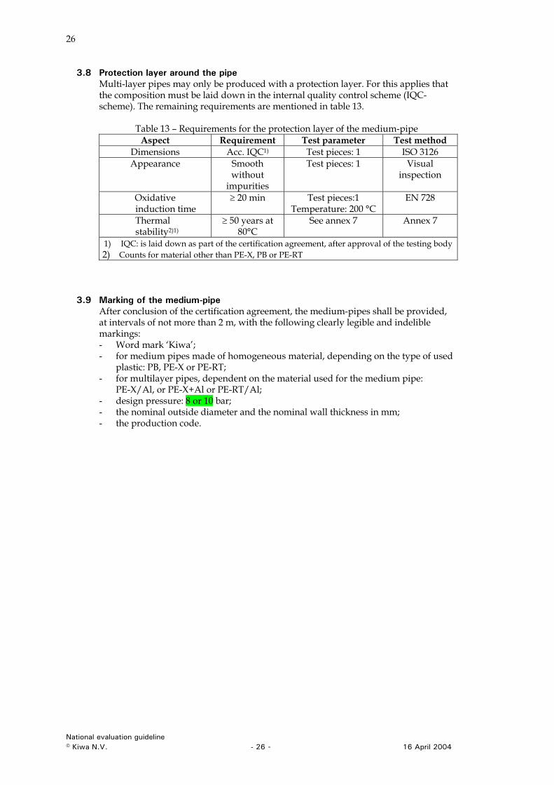
3.8 Protection layer around the pipe Multi-layer pipes may only be produced with a protection layer. For this applies that the composition must be laid down in the internal quality control scheme (IQC-scheme). The remaining requirements are mentioned in table 13.
Table 13 – Requirements for the protection layer of the medium-pipe Aspect Requirement Test parameter Test method
Dimensions Acc. IQC1) Test pieces: 1 ISO 3126 Appearance Smooth
without impurities
Test pieces: 1 Visual inspection
Oxidative induction time
≥ 20 min Test pieces:1 Temperature: 200 °C
EN 728
Thermal stability2)1)
≥ 50 years at 80°C
See annex 7 Annex 7
1) IQC: is laid down as part of the certification agreement, after approval of the testing body 2) Counts for material other than PE-X, PB or PE-RT
3.9 Marking of the medium-pipe After conclusion of the certification agreement, the medium-pipes shall be provided, at intervals of not more than 2 m, with the following clearly legible and indelible markings: - Word mark ‘Kiwa’; - for medium pipes made of homogeneous material, depending on the type of used
plastic: PB, PE-X or PE-RT; - for multilayer pipes, dependent on the material used for the medium pipe:
PE-X/Al, or PE-X+Al or PE-RT/Al; - design pressure: 8 or 10 bar; - the nominal outside diameter and the nominal wall thickness in mm; - the production code.
National evaluation guideline © Kiwa N.V. - 26 - 16 April 2004
27
4 Requirements for the fitting
4.1 Requirements for the plastics fittings
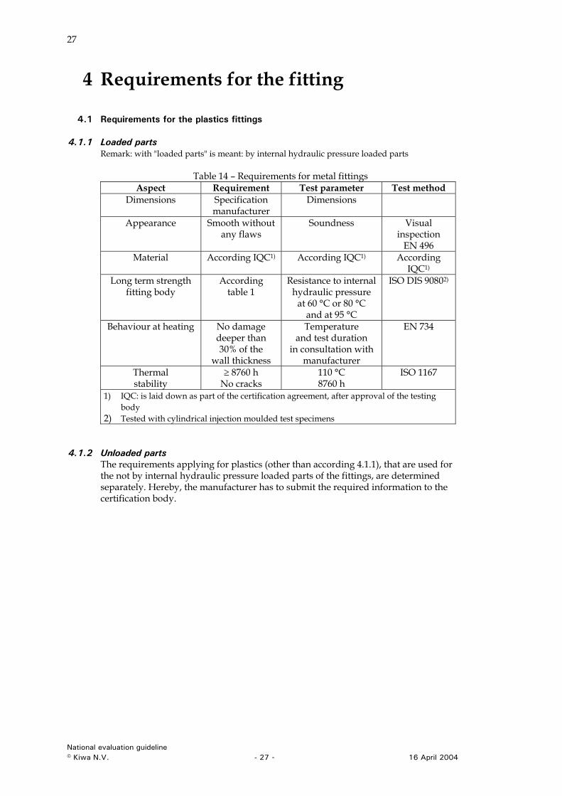
4.1.1 Loaded parts Remark: with "loaded parts" is meant: by internal hydraulic pressure loaded parts
Table 14 – Requirements for metal fittings Aspect Requirement Test parameter Test method
Dimensions Specification manufacturer
Dimensions
Appearance Smooth without any flaws
Soundness Visual inspection
EN 496 Material According IQC1) According IQC1) According
IQC1) Long term strength
fitting body According
table 1 Resistance to internal
hydraulic pressure at 60 °C or 80 °C
and at 95 °C
ISO DIS 90802)
Behaviour at heating No damage deeper than 30% of the
wall thickness
Temperature and test duration
in consultation with manufacturer
EN 734
Thermal stability
≥ 8760 h No cracks
110 °C 8760 h
ISO 1167
1) IQC: is laid down as part of the certification agreement, after approval of the testing body
2) Tested with cylindrical injection moulded test specimens
4.1.2 Unloaded parts The requirements applying for plastics (other than according 4.1.1), that are used for the not by internal hydraulic pressure loaded parts of the fittings, are determined separately. Hereby, the manufacturer has to submit the required information to the certification body.
National evaluation guideline © Kiwa N.V. - 27 - 16 April 2004
28
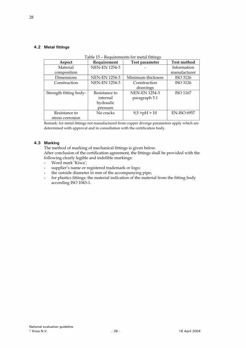
4.2 Metal fittings
Table 15 – Requirements for metal fittings Aspect Requirement Test parameter Test method
Material composition
NEN-EN 1254-3 - Information manufacturer
Dimensions NEN-EN 1254-3 Minimum thickness ISO 3126 Construction NEN-EN 1254-3 Construction
drawings ISO 3126
Strength fitting body:
Resistance to internal
hydraulic pressure
NEN-EN 1254-3 paragraph 5.1
ISO 1167
Resistance to stress corrosion
No cracks
9,5 >pH > 10 EN-ISO 6957
Remark: for metal fittings not manufactured from copper diverge parameters apply which are determined with approval and in consultation with the certification body.
4.3 Marking The method of marking of mechanical fittings is given below. After conclusion of the certification agreement, the fittings shall be provided with the following clearly legible and indelible markings: - Word mark ‘Kiwa’; - supplier’s name or registered trademark or logo; - the outside diameter in mm of the accompanying pipe; - for plastics fittings: the material indication of the material from the fitting body
according ISO 1043-1.
National evaluation guideline © Kiwa N.V. - 28 - 16 April 2004
29
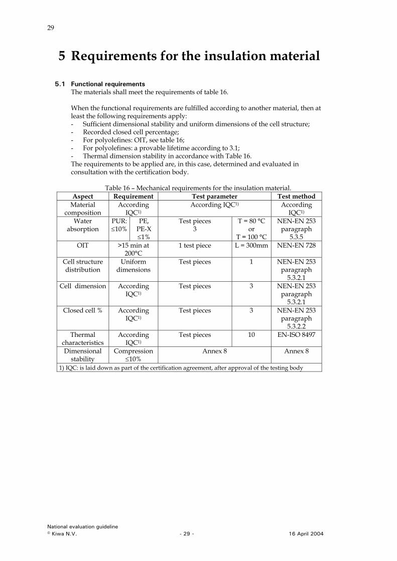
5 Requirements for the insulation material
5.1 Functional requirements The materials shall meet the requirements of table 16. When the functional requirements are fulfilled according to another material, then at least the following requirements apply: - Sufficient dimensional stability and uniform dimensions of the cell structure; - Recorded closed cell percentage; - For polyolefines: OIT, see table 16; - For polyolefines: a provable lifetime according to 3.1; - Thermal dimension stability in accordance with Table 16. The requirements to be applied are, in this case, determined and evaluated in consultation with the certification body.
Table 16 – Mechanical requirements for the insulation material. Aspect Requirement Test parameter Test method
Material composition
According IQC1)
According IQC1) According IQC1)
Water absorption
PUR: ≤10%
PE, PE-X ≤1%
Test pieces 3
T = 80 °C or
T = 100 °C
NEN-EN 253 paragraph
5.3.5 OIT >15 min at
200°C 1 test piece L = 300mm NEN-EN 728
Cell structure distribution
Uniform dimensions
Test pieces 1 NEN-EN 253 paragraph
5.3.2.1 Cell dimension According
IQC1) Test pieces 3 NEN-EN 253
paragraph 5.3.2.1
Closed cell % According IQC1)
Test pieces 3 NEN-EN 253 paragraph
5.3.2.2 Thermal
characteristics According
IQC1) Test pieces 10 EN-ISO 8497
Dimensional stability
Compression ≤10%
Annex 8 Annex 8
1) IQC: is laid down as part of the certification agreement, after approval of the testing body
National evaluation guideline © Kiwa N.V. - 29 - 16 April 2004
30
6 Requirements for the outer casing
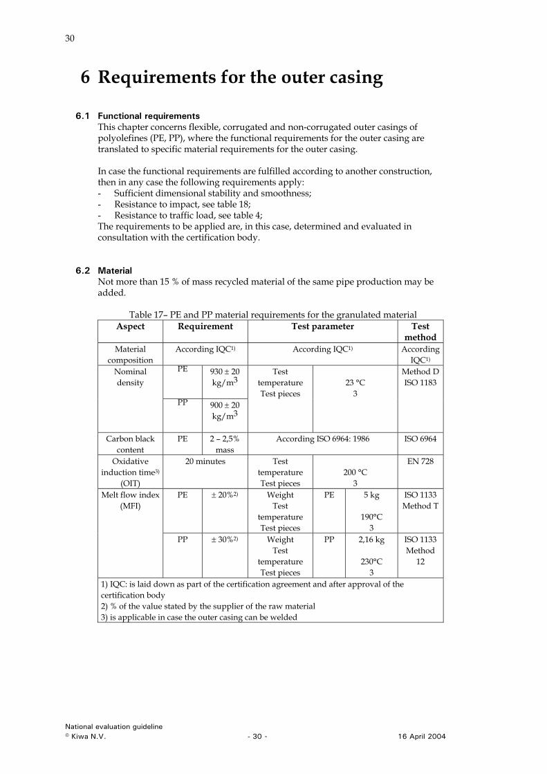
6.1 Functional requirements This chapter concerns flexible, corrugated and non-corrugated outer casings of polyolefines (PE, PP), where the functional requirements for the outer casing are translated to specific material requirements for the outer casing. In case the functional requirements are fulfilled according to another construction, then in any case the following requirements apply: - Sufficient dimensional stability and smoothness; - Resistance to impact, see table 18; - Resistance to traffic load, see table 4; The requirements to be applied are, in this case, determined and evaluated in consultation with the certification body.
6.2 Material Not more than 15 % of mass recycled material of the same pipe production may be added.
Table 17– PE and PP material requirements for the granulated material
Aspect Requirement Test parameter Test method
Material composition
According IQC1) According IQC1) According IQC1)
PE 930 ± 20 kg/m3
Nominal density
PP 900 ± 20 kg/m3
Test temperature Test pieces
23 °C
3
Method D ISO 1183
Carbon black content
PE 2 – 2,5% mass
According ISO 6964: 1986 ISO 6964
Oxidative induction time3)
(OIT)
20 minutes Test temperature Test pieces
200 °C
3
EN 728
PE ± 20%2) Weight Test
temperature Test pieces
PE 5 kg
190°C 3
ISO 1133 Method T
Melt flow index (MFI)
PP ± 30%2) Weight Test
temperature Test pieces
PP 2,16 kg
230°C 3
ISO 1133 Method
12
1) IQC: is laid down as part of the certification agreement and after approval of the certification body 2) % of the value stated by the supplier of the raw material 3) is applicable in case the outer casing can be welded
National evaluation guideline © Kiwa N.V. - 30 - 16 April 2004
31
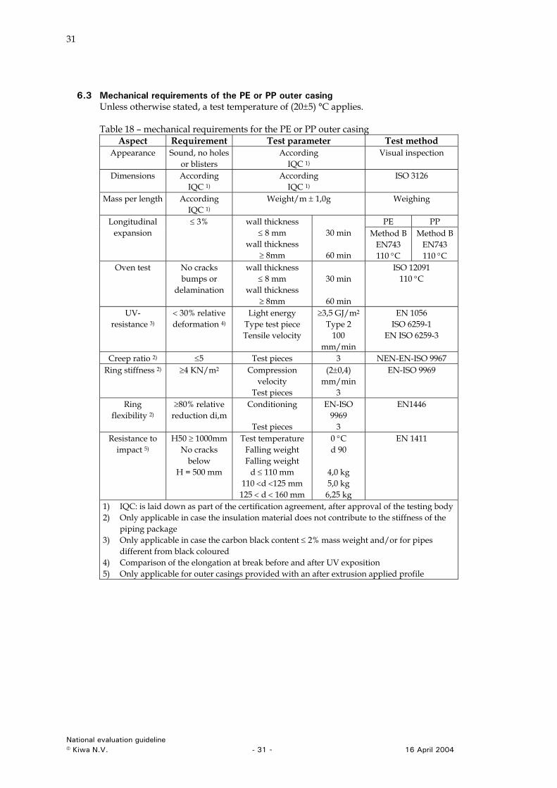
6.3 Mechanical requirements of the PE or PP outer casing Unless otherwise stated, a test temperature of (20±5) °C applies. Table 18 – mechanical requirements for the PE or PP outer casing
Aspect Requirement Test parameter Test method Appearance Sound, no holes
or blisters According
IQC 1) Visual inspection
Dimensions According IQC 1)
According IQC 1)
ISO 3126
Mass per length According IQC 1)
Weight/m ± 1,0g Weighing
PE PP Longitudinal expansion
≤ 3% wall thickness ≤ 8 mm
wall thickness ≥ 8mm
30 min
60 min
Method B EN743 110 °C
Method B EN743 110 °C
Oven test No cracks bumps or
delamination
wall thickness ≤ 8 mm
wall thickness ≥ 8mm
30 min
60 min
ISO 12091 110 °C
UV- resistance 3)
< 30% relative deformation 4)
Light energy Type test piece Tensile velocity
≥3,5 GJ/m2 Type 2
100 mm/min
EN 1056 ISO 6259-1
EN ISO 6259-3
Creep ratio 2) ≤5 Test pieces 3 NEN-EN-ISO 9967 Ring stiffness 2) ≥4 KN/m2 Compression
velocity Test pieces
(2±0,4) mm/min
3
EN-ISO 9969
Ring flexibility 2)
≥80% relative reduction di,m
Conditioning
Test pieces
EN-ISO 9969
3
EN1446
Resistance to impact 5)
H50 ≥ 1000mm No cracks
below H = 500 mm
Test temperature Falling weight Falling weight
d ≤ 110 mm 110 <d <125 mm
125 < d < 160 mm
0 °C d 90
4,0 kg 5,0 kg
6,25 kg
EN 1411
1) IQC: is laid down as part of the certification agreement, after approval of the testing body 2) Only applicable in case the insulation material does not contribute to the stiffness of the
piping package 3) Only applicable in case the carbon black content ≤ 2% mass weight and/or for pipes
different from black coloured 4) Comparison of the elongation at break before and after UV exposition 5) Only applicable for outer casings provided with an after extrusion applied profile
National evaluation guideline © Kiwa N.V. - 31 - 16 April 2004
32
7 Test methods
7.1 Multi layer pipe: Determination of dimensions The thickness of the outer-layer, the thickness of the aluminium sheet and of seams as well as the geometry of the barrier layer (distance of diffusion) are determined from a pipe ring, including the coating, of approximately 0,30 m that is cut or sawed longitudinally. The dimensions are determined according ISO 3126.
7.2 Sealing in longitudinal direction
7.2.1 General The following aspects are mandated for the testing according to 7.2.2 and 7.2.3: - Testing in accordance with ISO 1176 - Number of test pieces: 3 - Minimum diameter of piping package: 110 mm - Length of specimens between the clamps construction: 3 x dn
- Outside water temperature: 20°C - Mark fluid in the water: a mark fluid is added to the water to locate the
penetration of water in longitudinal direction. - Water above the test piece: 0,5 m Remark 1: for test fluids the penetration is visual detectable. Mostly an additive like (fluorescence natrium in ethanol) is used or ethylene bleu) is added as tracer to the fluid. Remark 2: The test piece including the test fluid can be separated from the water in a normal water bath by using a not penetrable plastic bag
7.2.2 Determination of the axial transport time of the leakage water Testing shall be executed as follows: - The test piece shall be immersed in the water without stresses; - Testing time: 1000 hours. - After the testing period the test piece shall drain for 24 hours at (23 ± 2) °C; - The test piece is cut open in axial direction; - By visual inspection the penetration of the signal fluid between the outer casing
and the insulation shall be measured.
7.2.3 Determination of water leakage through the casing joints Testing shall be executed as follows: - On one side a straight coupling shall be mounted to the piping package. On the
other side a T-piece shall be mounted. This shall be done according the installation instructions of the manufacturer;
- The test piece shall be immersed in the water without stresses; - Testing time: 1000 hours. - After the testing period the test piece shall drain for 24 hours at (23 ± 2) °C; - If possible the joints shall be removed on both sides; - The test piece is cut open in axial direction; - By visual inspection the penetration of the signal fluid shall be measured.
National evaluation guideline © Kiwa N.V. - 32 - 16 April 2004
33
7.3 Test methods for the multilayer pipe
7.3.1 Determination of long-term strength Per construction type of the pipe pPD shall be determined as follows: - Use test temperatures of 60 °C and 95 °C according to the test method of ISO DIS
17456 point 6.1, 6.2 and 6.3; - By using the SEM software of ISO 9080 (4-parameter model) the values (C1, C2, C3
and C4) shall be calculated for a LPL of 97,5% - Use the calculated lines to determine the 97,5% reference lines; - The reference values of A,B,C and D can now be used to calculate pPD as follows:
- Use the relevant design coefficient according to table 19; - Use Miners Rule (ISO 13760) in formula (1) to calculate pPD for Class 2 or
Class DH1 (see table 1):
TCpx
DCpxCTBAt xxxx
)log()log()log( +++= (1)
where: - p = PPD : the predicted design pressure (bar) - t = time (hour) - T = temperature(Kelvin) - A, B, C and D = parameters for the 4-parameter model for the reference lines - Cx = a design coefficient according to table 19.
Tabel 19 – design coefficient per temperature class Design coefficient PE-X PB PE-RT TD 1,5 1,5 1,5 Tmax 1,3 1,3 1,3 Tmat 1,0 1,0 1,0
7.3.2 Determination pressure test control values Use ISO DIS 17456 to determine the LPL lines for all diameters. By using formula (2) the 95ºC, 97,5% lines for all diameters can be calculated.
⎟⎟⎟
⎠
⎞
⎜⎜⎜
⎝
⎛−=
PsPP
C
RCPD
96,11 (2)
where PPD = predicted design pressure PC = calculated pressure (from the LPL line for 22 h, 165 h or 1000 h) SR = residual variance The values of P1, P2 en P3 can now be determined per diameter.
7.4 Determination of material strength of the aluminium Determination of the in 3.5.5 mentioned aspects takes place in accordance with NEN EN 10002, Part 1, annex A, type 1. Hereby applies: L0 = the original length of the test piece in mm; the tensile speed is 10 mm/min till the 0,2% strain limit and maximum 20 mm/min above that.
National evaluation guideline © Kiwa N.V. - 33 - 16 April 2004
34
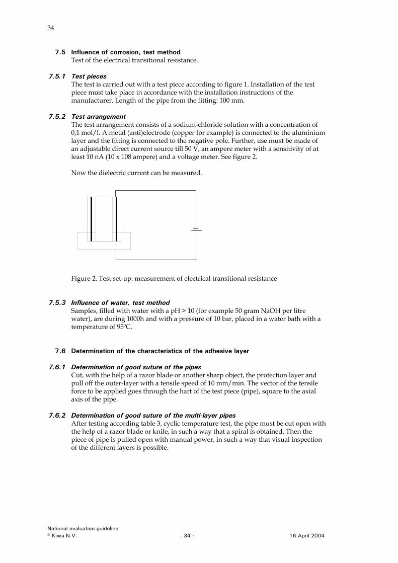
7.5 Influence of corrosion, test method Test of the electrical transitional resistance.
7.5.1 Test pieces The test is carried out with a test piece according to figure 1. Installation of the test piece must take place in accordance with the installation instructions of the manufacturer. Length of the pipe from the fitting: 100 mm.
7.5.2 Test arrangement The test arrangement consists of a sodium-chloride solution with a concentration of 0,1 mol/l. A metal (anti)electrode (copper for example) is connected to the aluminium layer and the fitting is connected to the negative pole. Further, use must be made of an adjustable direct current source till 50 V, an ampere meter with a sensitivity of at least 10 nA (10 x 108 ampere) and a voltage meter. See figure 2. Now the dielectric current can be measured.
Figure 2. Test set-up: measurement of electrical transitional resistance
7.5.3 Influence of water, test method Samples, filled with water with a pH > 10 (for example 50 gram NaOH per litre water), are during 1000h and with a pressure of 10 bar, placed in a water bath with a temperature of 95ºC.
7.6 Determination of the characteristics of the adhesive layer
7.6.1 Determination of good suture of the pipes Cut, with the help of a razor blade or another sharp object, the protection layer and pull off the outer-layer with a tensile speed of 10 mm/min. The vector of the tensile force to be applied goes through the hart of the test piece (pipe), square to the axial axis of the pipe.
7.6.2 Determination of good suture of the multi-layer pipes After testing according table 3, cyclic temperature test, the pipe must be cut open with the help of a razor blade or knife, in such a way that a spiral is obtained. Then the piece of pipe is pulled open with manual power, in such a way that visual inspection of the different layers is possible.
National evaluation guideline © Kiwa N.V. - 34 - 16 April 2004
35
8 Requirements to be met by the quality system
8.1 General This chapter contains the requirements that have to be met by the suppliers quality system and the methods used by Kiwa to evaluate this quality system.
8.2 Internal quality control As part of the quality system the manufacturer must have an internal quality control schedule (IQC schedule) at his disposal. This IQC schedule shall contain: • the inspected aspects • the used inspection methods • the inspection frequency • the way in which the inspection results are recorded and stored This IQC schedule shall be in the format as shown in the appendix.
8.3 Procedures and working instructions The manufacturer should also be able to present: - a procedure for: a. the handling of products or semi-finished products rejected or to be repaired b. the handling of complaints regarding the products and/or services supplied - the handled work instructions and inspection sheets
8.4 External inspection The manufacturers quality system shall be assessed by Kiwa with regard to at least the aspects mentioned in the Kiwa-Regulations for Product Certification. The Board of Experts will determine the inspection frequency. At the time of validation of this evaluation guideline this frequency has been fixed at 4 inspection visits per year.
National evaluation guideline © Kiwa N.V. - 35 - 16 April 2004
36
9 Summary of tests and inspections This chapter contains a summary of the following tests and inspections to be carried out in the event of certification: • Pre-certification tests; • Inspection test with regard to toxicological requirements and product
requirements; • Inspection of the quality system. The frequency with which the certification body (CB) will carry out inspection tests is also stated in the summary. See table 20.
9.1 Test matrix Table 20
Tests within the scope of Supervision by CB after granting of the certificate1)
Description of requirement Article BRL Pre-
certification tests
Inspection visit2)
Frequency (per year)
Performance requirements Toxicological aspects 2.2 X X 1 x year Organoleptic aspects 2.3 X X 1 x year Standardised heat emission 2.6 X X 1 x year Strength of the joints 2.7.3 X X3) 1 x 2 year Leak tightness of the joints 2.7.3 X X 1 x 2 year Long-term compression 2.8.1 X X 1 x 2 year Flexibility 2.8.1 X X 1 x 2 year Dimensional stability 2.8.2 X X 1 x 2 year Sealing in longitudinal direction 2.8.3 X X3) 1 x year Sealing construction to mains supply and service pipe
2.8.4 X X3) 1 x year
Product requirements Lifetime of medium-pipe material 3.2 X X3) 1 x year Mechanical aspects of medium-pipe 3.3, 3.4,
3.5, 3.6 X X 1 x year
Lifetime of plastics fitting material 4.1.1 X X3) 1 x year Mechanical aspects of plastics fitting 4.1.1 X X 1 x year Metal fitting 4.2 X X3) 1 x year Mechanical aspects of insulation material 5.1 X X 1 x 2 year Material of outer casing 6.1, 6.2 X X 1 x year Mechanical aspects of outer casing 6.3 X X 1 x year 1) When significant changes of the product or production process occur the performance requirements
have to be determined once again. 2) All product properties which can be determined within the inspection time (maximum 1 day) are
determined by the inspector or by the certificate holder in presence of an inspector. When this is not possible arrangements, how inspection will take place, will be made for this aspect between the CB and the certificate holder.
3) This aspect is compared on the basis of IKB inspection (indirectly by means of direct related parameters) with the aspect found for approval.
National evaluation guideline © Kiwa N.V. - 36 - 16 April 2004
37
10 Requirements to be met by certification bodies
10.1 General The certification body has to fulfil the requirements of EN 45011. Furthermore, the certification body has to be accredited for the subject of this BRL by the Dutch Accreditation Council (RvA) or by an equivalent accreditation body (an accreditation body with whom RvA has concluded an agreement of mutual recognition). The certification body must have the disposal of a regulation, or an equivalent document, in which the general rules for certification are laid down. In particular these are: - The general rules for carrying out the pre-certification, to be distinguished in:
• The way suppliers are informed about the handling of the application; • Execution of the pre-certification; • The decision with regard to the pre-certification executed.
- The general rules with regard to the execution of inspections and the inspection aspects to be employed: • The measures to be taken by the certification body in the event of non-
conformities; • The rules for termination of the certificate; • The possibility of lodging appeal against decisions or measures made by the
certification body.
10.2 Certification staff The staff involved in the certification may be sub-divided into: • certification experts: they are in charge of carrying out the pre-certification tests
and assessing the inspectors reports; • inspectors: they are in charge of carrying out external inspections at the supplier’s
works; • decision makers: they are in charge of taking decisions in connection with the pre-
certification tests performed, continuing the certification in connection with the inspections performed and taking decisions on the need of corrective actions.
10.2.1 Qualification requirements The Board of Experts has set the following qualification requirements for the subject matter of this Evaluation Guideline. Certification staff Education Experience Certification expert Level of higher professional education
(HBO) in one of the following disciplines: • Technology
2 years
Inspector Level of intermediate professional education (MBO) in one of the following disciplines: • Technology
1 year
Decision-maker Level of higher professional education HBO) in one of the following disciplines: • Technology
1 year management experience
National evaluation guideline © Kiwa N.V. - 37 - 16 April 2004
38
The level of education and the experience of the certification staff involved should be demonstrably recorded.
10.2.2 Qualification Certification staff must be demonstrably qualified by evaluation of education and experience of the above mentioned requirements. In case qualification takes place on the basis of other criteria, then this has to be recorded in writing. - Decision-makers: qualification of the certification and inspectors; - Management of the certification body: qualification of the decision-makers.
10.3 Report pre-certification tests The certification body records the results of the pre-certification tests in a report. The report must fulfil the following requirements: - Completeness: the report judges about all requirements of the Evaluation
Guideline; - Traceability: the findings whereupon the judgements are based must be recorded
in a traceable way; - Basis for decision: the decision-maker with regard to granting of the certificate,
must be able to base his decision upon the findings recorded in the report.
10.4 Decision with regard to granting of the certificate The decision with regard to granting of the certificate must be made by a qualified decision-maker, which was not involved at the pre-certification tests. The decision must be traceable recorded.
10.5 Quality declaration The technical approval-with-product certificate has to be in accordance with the model included in the annex.
10.6 Nature and frequency of external inspections The certification body must enforce inspections at the supplier to investigate whether the obligations are met. The Board of Experts advises about the number of inspection visits. At the time of validation of this Evaluation Guideline this frequency has been fixed at four inspection visits per year. Inspections shall invariably include: - The product specifications laid down in the quality declaration; - The production process of the supplier; - The IQC-schedule of the supplier and the results of tests recorded by the supplier; - The correct marking of the certified products; - The compliance with the required procedures. The findings of the performed inspection visits shall be traceably recorded by the certification body in a report.
National evaluation guideline © Kiwa N.V. - 38 - 16 April 2004
39
10.7 Report to Board of Experts The certification body reports at least once a year about the certification activities performed. In this reporting, the following subjects must be addressed: - Mutations in number of certificates (new/cancelled); - Number of inspections performed in relation to the fixed frequency; - Results of the inspections; - Measures imposed at non-conformities; - Complaints received from third parties concerning certified products.
10.8 Interpretation of requirements The Board of Experts may lay down the interpretation of this Evaluation Guideline in a separate interpretation document. The certification body is obliged to inform whether an interpretation document is available. If this is the case, then the interpretations as laid down in the interpretation document must be employed.
National evaluation guideline © Kiwa N.V. - 39 - 16 April 2004
40
11 List of stated documents
11.1 Standards / normative documents Number Title BRL K536/03 part G Plastic piping systems PE/Al for the transport of cold and hot
drinking water BRL 2013: 1999 Rubber rings foor joints in drinking water and sewage
systems. NEN-EN 253: 1995 Specification for pre-insulated bonded pipe systems for
underground hot water networks. Pipe assembly of steel service pipes, polyurethane thermal insulation and outer casing of high density polyethylene
NEN-EN 489: 1995 Pre-insulated bonded pipe systems for underground hot water networks. Joint assembly for steel service pipes, polyurethane thermal insulation and outer casing of polyethylene
NEN-EN 579:1994 Plastics piping systems. Cross-linked polyethylene (PE-X) pipes. Determination of degree of cross-linking by solvent extraction
NEN-EN 638: 1995 Plastics piping and ducting systems. Thermoplastics pipes. Determination of tensile properties
NEN-EN 681:1996 Elastomeric seals - Materials requirements for pipe joint seals used in water and drainage applications - Part 1:Vulcanized rubber
NEN-EN 712: 1995 Thermoplastics piping systems. End-load bearing mechanical joints between pressure pipes and fittings. Test method for resistance to pull-out under constant longitudinal force
NEN-EN 713: 1995 Plastics piping systems. Mechanical joints between fittings and Polyolefin pressure pipes. Test method for leaktightness under internal pressure of assemblies subjected to bending
NEN-EN 728: 1997 Plastics piping and ducting systems – Polyolefin pipes and fittings – Determination of oxidation induction time.
NEN-EN 743: 1995 Plastics piping and ducting systems. Thermoplastics pipes. Determination of the longitudinal reversion
NEN-EN 1056: 1996 Plastics piping and ducting systems. Plastics pipes and fittings. Method for exposure to direct (natural) weathering
NEN-EN 1254-3: 1998 Copper and copper alloys. Plumbing fittings. Fittings with compression ends for use with plastics pipes
NEN-EN 12293: 2000 Plastics piping systems. Thermoplastics pipes and fittings for hot and cold water. Test method for the resistance of mounted assemblies to temperature cycling
NEN-EN 12294: 2000 Plastic piping systems. Systems for hot and cold water. Test method for leaktightness under vacuum
NEN-EN 1411: 1996 Kunststofleiding- en mantelbuissystemen; Buizen van thermoplasten; Bepaling van de weerstand tegen uitwendige slagbelasting met de trapjesmethode
NEN-EN 1420-1: 1999 Invloed van organische materialen op water bestemd voor menselijke consumptie; Bepaling van de reuk en smaak van water in leidingsystemen; Deel 1: Beproevingsmethode
NEN-EN 1446: 1996 Plastics piping and ducting systems. Thermoplastics pipes. Determination of ring flexibility
NEN-EN 10002: 2001 Tensile testing of metallic materials. Method of test at ambient temperature
National evaluation guideline © Kiwa N.V. - 40 - 16 April 2004
41
NEN-EN 13052-1: 2001 Invloed van materialen op water bestemd voor menselijke consumptie;Organische materialen;Bepaling van de kleur en troebelheid van water in pijpleidingsystemen;Deel 1: Beproevingsmethode
NEN-EN 45004: 1995 General criteria for the operation of various types of bodies performing inspection
NEN-EN 45012: 1998 General requirements for bodies operating assessment and certification/registration of quality systems
NEN-EN 45013: 1989 General criteria for certification bodies operating certification of personnel
NEN-EN 10002: 1991 Metallic materials – Tensile testing – Method of testing at ambient temperature
NEN-EN ISO 6509: 1995 Corrosion of metals and alloys. Determination of dezincification resistance of brass
NEN-EN-ISO 6708: 1995 Pipework components – Definition and selection of DN (normal size)
NEN-EN ISO 8497: 1997 Thermal insulation. Determination of steady-state thermal transmission properties of thermal insulation for circular pipes
NEN-EN ISO 9967: 1995 Thermoplastics pipes. Determination of creep ratio NEN-EN-ISO 9969: 1995 Thermoplastics pipes. Determination of ring stiffness NEN-EN-ISO/IEC 17025; 2000
General requirements for the competence of testing and calibration laboratories
EN ISO 15875 Plastics piping systems for hot and cold water installations ⎯ Crosslinked polyethylene (PE-X)
EN ISO 15876 Plastics piping systems for hot and cold water installations ⎯ Polybutylene (PB)
ISO 1043: 2002 Plastics. Symbols and abbreviated terms. Basic polymers and their special characteristics
ISO 1183: 1999 Plastics. Methods for determining the density of non-cellular plastics. Gas pykometer method
ISO 1133: 1997 Determination of the melt mass flow rate (MFR) and the melt volume (MVR) of thermoplastics
ISO 1167: 1996 Methods of testing plastics. Thermoplastic pipes, fittings and valves. Thermoplastics pipes, for the conveyance of fluids. Resistance to internal pressure. Test method
ISO 3126 EN ISO 3126. Plastics piping systems. Plastics piping components. Measurement and determination of dimensions
ISO 3146: 2000 Plastics. Determination of melting behaviour (melting temperature or melting range) of semi-crystalline polymers by capillary tube and polarising-microscope methods
ISO 4065: 1996 Thermoplastic pipes - Universal wall thickness table. ISO 6957: 1988 Cupper alloys – ammonia test for stress corrosion resistance ISO 6259-1: 2001od. Thermoplastics pipes. Determination of tensile properties.
General test met ISO 6259-3: 1997 Thermoplastics pipes -- Determination of tensile properties --
Part 3: Polyolefin pipes ISO 6957: 1988 Copper alloys -- Ammonia test for stress corrosion resistance ISO 6964: 1986
Polyolefin pipes and fittings -- Determination of carbon black content by calcination and pyrolysis -- Test method and basic specification
ISO 10508 Thermoplastics pipes and fittings for hot and cold water systems ISO 12091 Structured-wall thermoplastics pipes -- Oven test ISO 13760: 2000 Plastics pipes for the conveyance of fluids under pressure.
Miner's rule. Calculation method for cumulative damage ISO 62591:1997 Thermoplastics pipes - Determination of tensile properties -
Part 1: General test method
National evaluation guideline © Kiwa N.V. - 41 - 16 April 2004
42
ISO 62593:1997 Thermoplastics pipes - Determination of tensile properties - Part 3: Polyolefin pipes
ISO 9080: 2002 Plastics piping and ducting systems - Determination of long term hydrostatic strength of thermoplastics materials in pipe form by standard Extrapolation method.
ISO DIS 17455: 2003 Plastics piping systems ⎯ Multilayer pipes ⎯ Determination of the oxygen permeability of the barrier pipe.
ISO DIS 17456: 2003 Plastics piping systems ⎯ Multilayer pipes ⎯ Determination of the long term hydrostatic strength.
ISO DIS 18124: 2003 Plastics piping systems ⎯ Multilayer M pipes ⎯ Test method for the adhesion of the different layers by the use of a cone
DIN 4726: 2000 Rohrleitungen für WarmwasserFussbodenheizungen; Algemeine Anforderungen.
National evaluation guideline © Kiwa N.V. - 42 - 16 April 2004
43
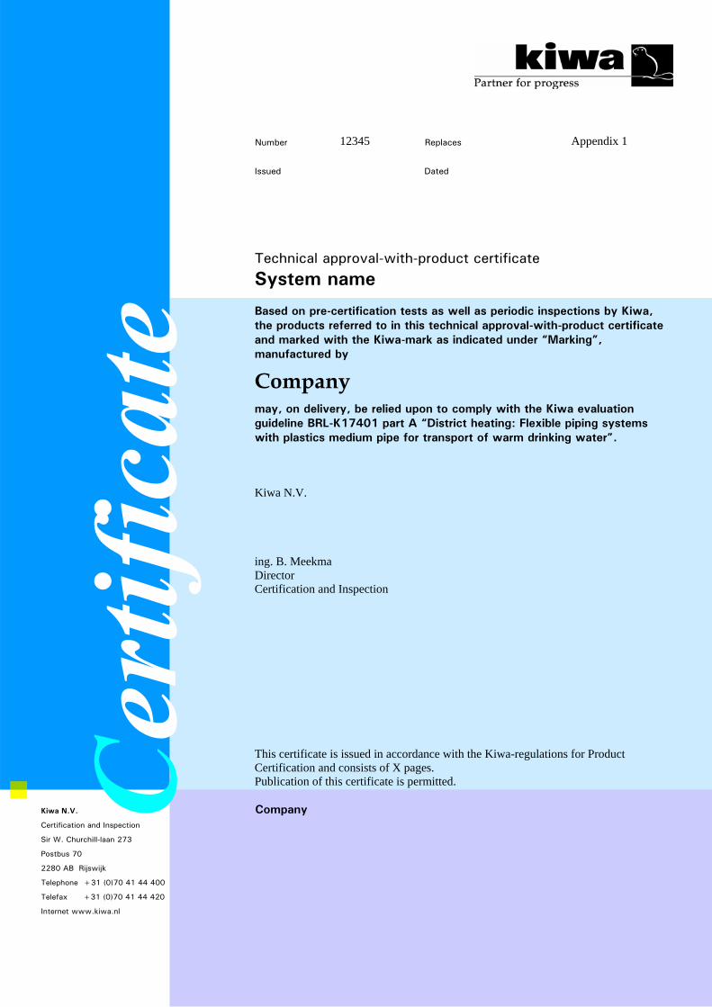
12 Annex 1: Technical approval with product certificate
National evaluation guideline © Kiwa N.V. - 43 - 16 April 2004
Number 12345 Replaces
Appendix 1
Issued Dated
Technical approval-with-product certificate
System name Based on pre-certification tests as well as periodic inspections by Kiwa, the products referred to in this technical approval-with-product certificate and marked with the Kiwa-mark as indicated under “Marking”, manufactured by
Company may, on delivery, be relied upon to comply with the Kiwa evaluation guideline BRL-K17401 part A “District heating: Flexible piping systems with plastics medium pipe for transport of warm drinking water”. Kiwa N.V. ing. B. Meekma Director Certification and Inspection
This certificate is issued in accordance with the Kiwa-regulations for Product Certification and consists of X pages. Publication of this certificate is permitted. Company Kiwa N.V.
Certification and Inspection
Sir W. Churchill-laan 273
Postbus 70
2280 AB Rijswijk
Telephone +31 (0)70 41 44 400
Telefax +31 (0)70 41 44 420
Internet www.kiwa.nl
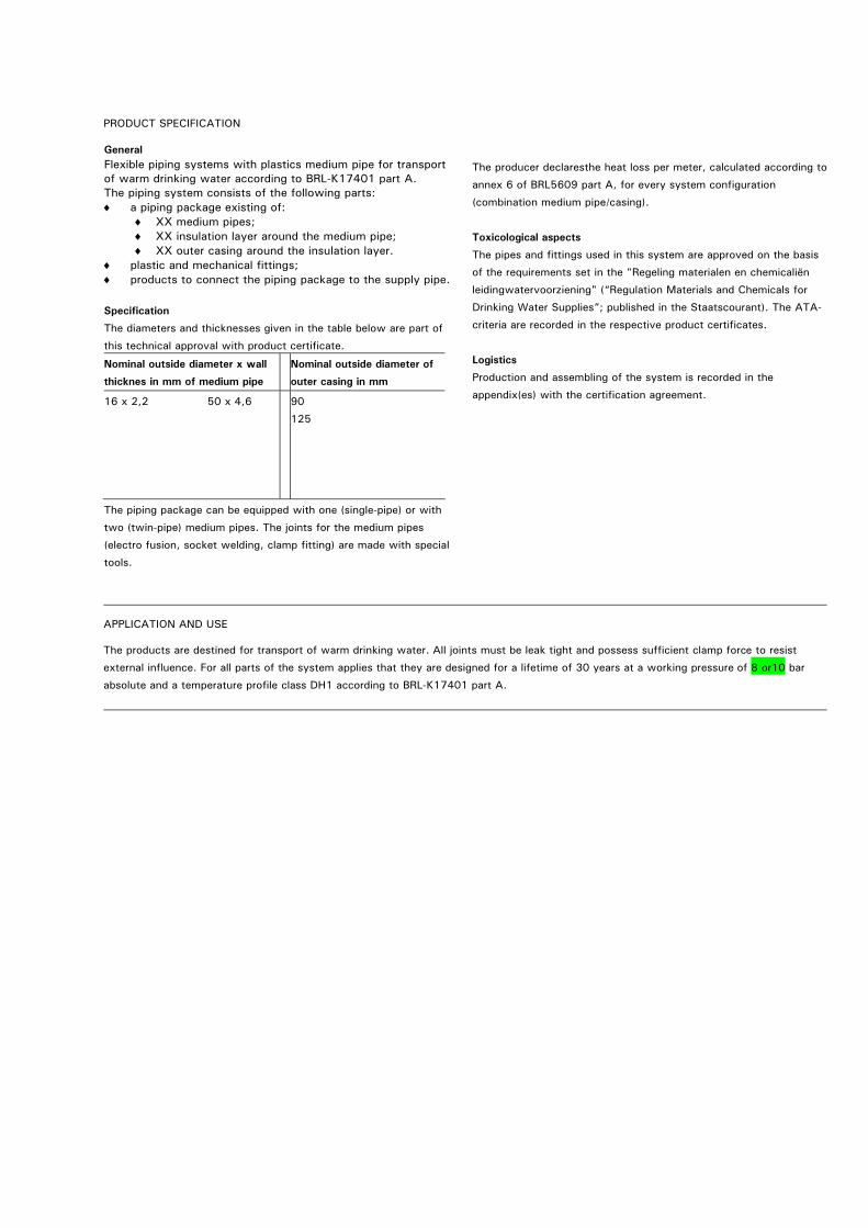
PRODUCT SPECIFICATION
General Flexible piping systems with plastics medium pipe for transport of warm drinking water according to BRL-K17401 part A. The piping system consists of the following parts: ♦
♦ ♦ ♦
♦ ♦
a piping package existing of: XX medium pipes; XX insulation layer around the medium pipe; XX outer casing around the insulation layer.
plastic and mechanical fittings; products to connect the piping package to the supply pipe.
Specification
The diameters and thicknesses given in the table below are part of
this technical approval with product certificate.
Nominal outside diameter x wall
thicknes in mm of medium pipe
Nominal outside diameter of
outer casing in mm
16 x 2,2 50 x 4,6
90
125
The piping package can be equipped with one (single-pipe) or with
two (twin-pipe) medium pipes. The joints for the medium pipes
(electro fusion, socket welding, clamp fitting) are made with special
tools.
The producer declaresthe heat loss per meter, calculated according to
annex 6 of BRL5609 part A, for every system configuration
(combination medium pipe/casing).
Toxicological aspects
The pipes and fittings used in this system are approved on the basis
of the requirements set in the "Regeling materialen en chemicaliën
leidingwatervoorziening" (“Regulation Materials and Chemicals for
Drinking Water Supplies”; published in the Staatscourant). The ATA-
criteria are recorded in the respective product certificates.
Logistics
Production and assembling of the system is recorded in the
appendix(es) with the certification agreement.
APPLICATION AND USE
The products are destined for transport of warm drinking water. All joints must be leak tight and possess sufficient clamp force to resist
external influence. For all parts of the system applies that they are designed for a lifetime of 30 years at a working pressure of 8 or10 bar
absolute and a temperature profile class DH1 according to BRL-K17401 part A.
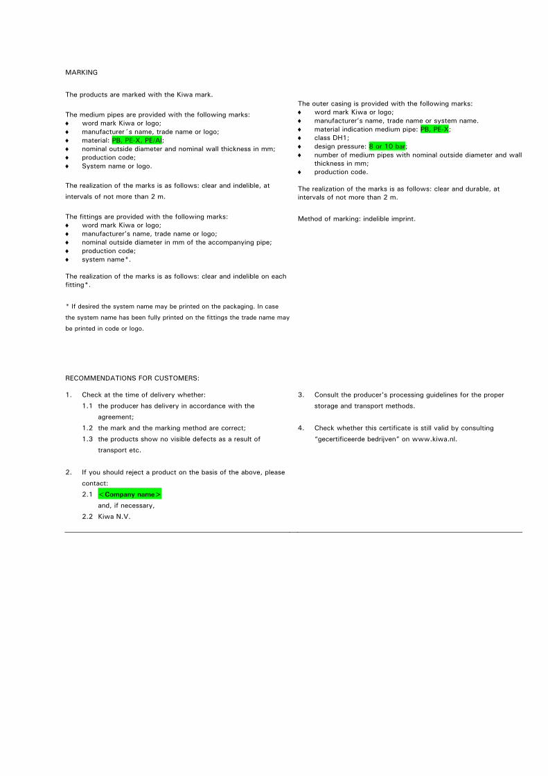
MARKING
The products are marked with the Kiwa mark.
The medium pipes are provided with the following marks: ♦ ♦
word mark Kiwa or logo; manufacturer´s name, trade name or logo;
♦ ♦ ♦ ♦
♦ ♦ ♦ ♦ ♦
♦ ♦
material: PB, PE-X, PE/Al; nominal outside diameter and nominal wall thickness in mm; production code; System name or logo.
The realization of the marks is as follows: clear and indelible, at
intervals of not more than 2 m.
The fittings are provided with the following marks:
word mark Kiwa or logo; manufacturer’s name, trade name or logo; nominal outside diameter in mm of the accompanying pipe; production code; system name*.
The realization of the marks is as follows: clear and indelible on each fitting*.
* If desired the system name may be printed on the packaging. In case
the system name has been fully printed on the fittings the trade name may
be printed in code or logo.
The outer casing is provided with the following marks:
word mark Kiwa or logo; manufacturer’s name, trade name or system name.
♦ ♦
material indication medium pipe: PB, PE-X; class DH1;
♦ ♦
♦
design pressure: 8 or 10 bar; number of medium pipes with nominal outside diameter and wallthickness in mm; production code.
The realization of the marks is as follows: clear and durable, at intervals of not more than 2 m.
Method of marking: indelible imprint.
RECOMMENDATIONS FOR CUSTOMERS:
1. Check at the time of delivery whether:
1.1 the producer has delivery in accordance with the
agreement;
1.2 the mark and the marking method are correct;
1.3 the products show no visible defects as a result of
transport etc.
2. If you should reject a product on the basis of the above, please
contact:
2.1 <Company name>
and, if necessary,
2.2 Kiwa N.V.
3. Consult the producer's processing guidelines for the proper
storage and transport methods.
4. Check whether this certificate is still valid by consulting
“gecertificeerde bedrijven” on www.kiwa.nl.
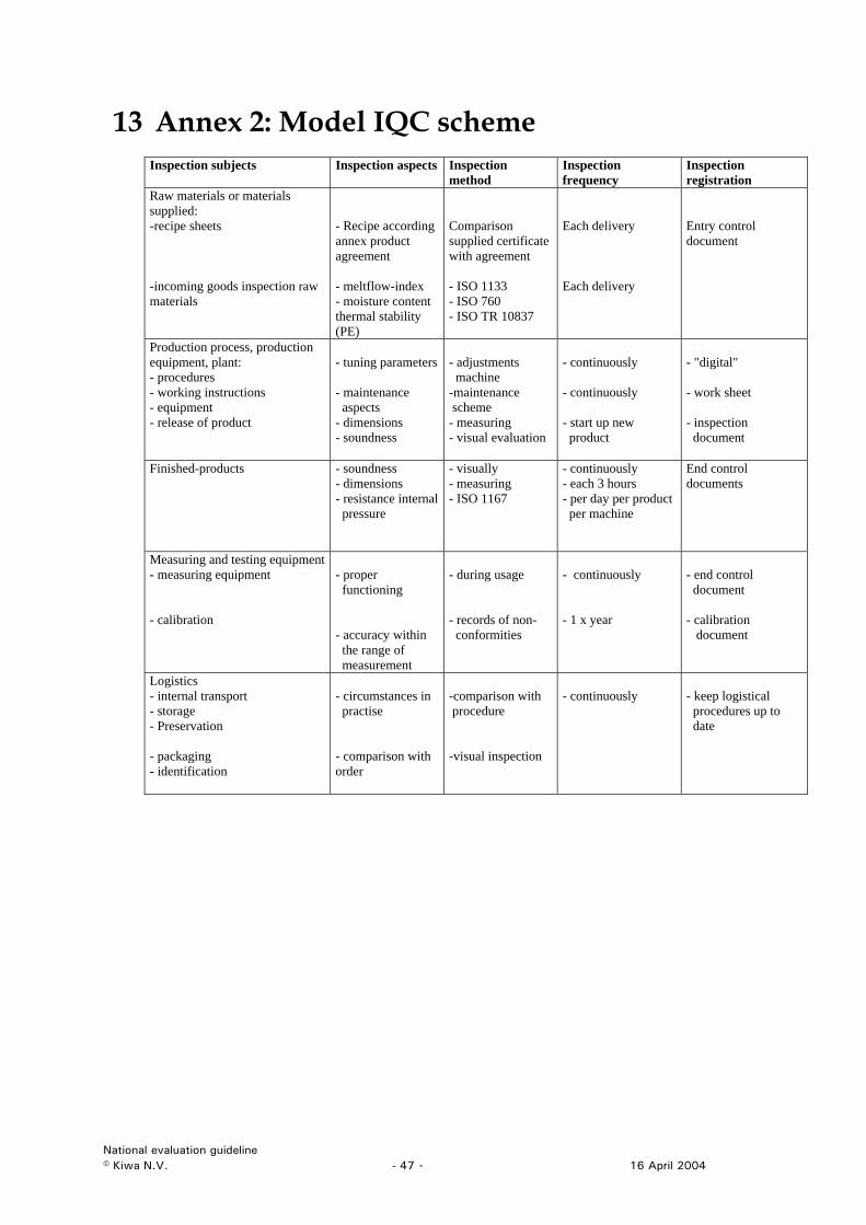
13 Annex 2: Model IQC scheme
Inspection subjects Inspection aspects Inspection method
Inspection frequency
Inspection registration
Raw materials or materials supplied: -recipe sheets -incoming goods inspection raw materials
- Recipe according annex product agreement - meltflow-index - moisture content thermal stability (PE)
Comparison supplied certificate with agreement - ISO 1133 - ISO 760 - ISO TR 10837
Each delivery Each delivery
Entry control document
Production process, production equipment, plant: - procedures - working instructions - equipment - release of product
- tuning parameters - maintenance aspects - dimensions - soundness
- adjustments machine -maintenance scheme - measuring - visual evaluation
- continuously - continuously - start up new product
- "digital" - work sheet - inspection document
Finished-products
- soundness - dimensions - resistance internal pressure
- visually - measuring - ISO 1167
- continuously - each 3 hours - per day per product per machine
End control documents
Measuring and testing equipment - measuring equipment - calibration
- proper functioning - accuracy within the range of measurement
- during usage - records of non- conformities
- continuously - 1 x year
- end control document - calibration document
Logistics - internal transport - storage - Preservation - packaging - identification
- circumstances in practise - comparison with order
-comparison with procedure -visual inspection
- continuously
- keep logistical procedures up to date
National evaluation guideline © Kiwa N.V. - 47 - 16 April 2004
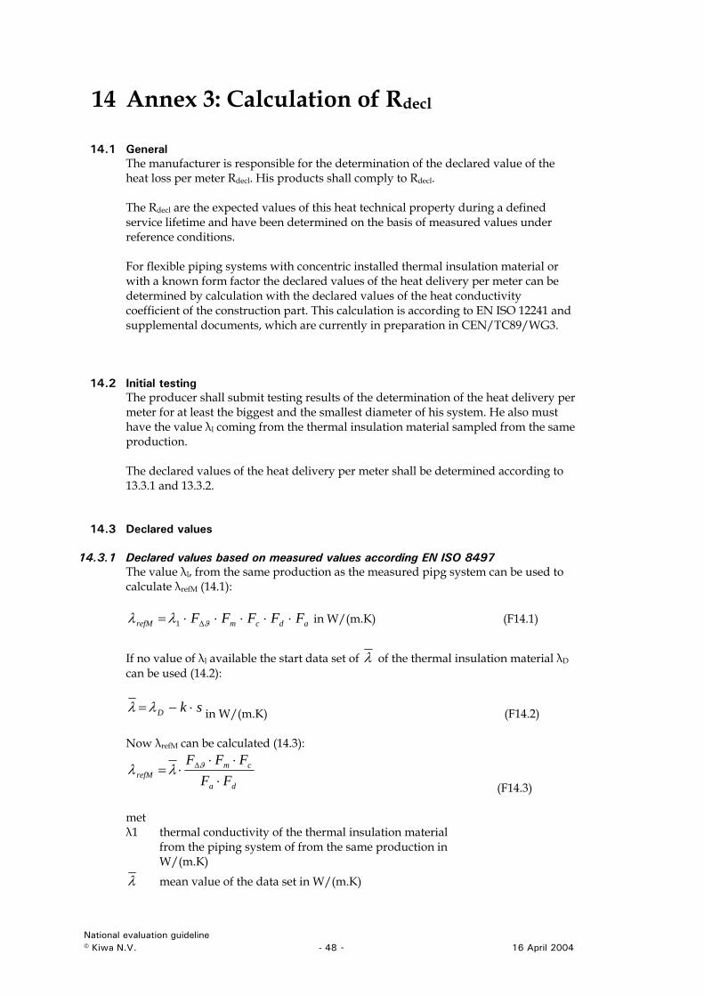
14 Annex 3: Calculation of Rdecl
14.1 General The manufacturer is responsible for the determination of the declared value of the heat loss per meter Rdecl. His products shall comply to Rdecl. The Rdecl are the expected values of this heat technical property during a defined service lifetime and have been determined on the basis of measured values under reference conditions. For flexible piping systems with concentric installed thermal insulation material or with a known form factor the declared values of the heat delivery per meter can be determined by calculation with the declared values of the heat conductivity coefficient of the construction part. This calculation is according to EN ISO 12241 and supplemental documents, which are currently in preparation in CEN/TC89/WG3.
14.2 Initial testing The producer shall submit testing results of the determination of the heat delivery per meter for at least the biggest and the smallest diameter of his system. He also must have the value λl coming from the thermal insulation material sampled from the same production. The declared values of the heat delivery per meter shall be determined according to 13.3.1 and 13.3.2.
14.3 Declared values
14.3.1 Declared values based on measured values according EN ISO 8497 The value λl, from the same production as the measured pipg system can be used to calculate λrefM (14.1):
adcmrefM FFFFF ⋅⋅⋅⋅⋅= ∆ϑλλ 1 in W/(m.K) (F14.1) If no value of λl available the start data set of λ of the thermal insulation material λD can be used (14.2):
skD ⋅−=λλ in W/(m.K) (F14.2) Now λrefM can be calculated (14.3):
da
cmrefM FF
FFF⋅
⋅⋅⋅= ∆ϑλλ
(F14.3) met λ1 thermal conductivity of the thermal insulation material
from the piping system of from the same production in W/(m.K)
λ mean value of the data set in W/(m.K)
National evaluation guideline © Kiwa N.V. - 48 - 16 April 2004
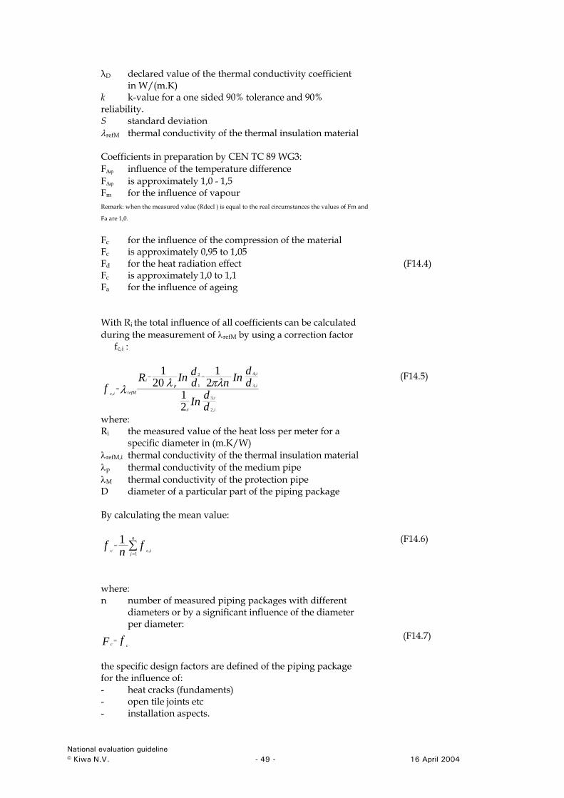
λD declared value of the thermal conductivity coefficient in W/(m.K)
k k-value for a one sided 90% tolerance and 90% reliability. S standard deviation λrefM thermal conductivity of the thermal insulation material Coefficients in preparation by CEN TC 89 WG3: F∆ϕ influence of the temperature difference F∆ϕ is approximately 1,0 - 1,5 Fm for the influence of vapour
Remark: when the measured value (Rdecl ) is equal to the real circumstances the values of Fm and
Fa are 1,0.
Fc for the influence of the compression of the material Fc is approximately 0,95 to 1,05
Fd for the heat radiation effect (F14.4)
Fc is approximately 1,0 to 1,1 Fa for the influence of ageing With Ri the total influence of all coefficients can be calculated during the measurement of λrefM by using a correction factor
fc,i :
ddIn
ddInnd
dInRf
i
i
i
i
pi
refMic
,2
,3
,3
,4
1
2
,
21
21
201
π
πλλλ−−
=
(F14.5)
where: Ri the measured value of the heat loss per meter for a
specific diameter in (m.K/W) λrefM,i thermal conductivity of the thermal insulation material λp thermal conductivity of the medium pipe λM thermal conductivity of the protection pipe D diameter of a particular part of the piping package By calculating the mean value:
∑=
=n
jicc
fnf1
,
1 (F14.6)
where: n number of measured piping packages with different
diameters or by a significant influence of the diameter per diameter:
fF cc= (F14.7)
the specific design factors are defined of the piping package for the influence of: - heat cracks (fundaments) - open tile joints etc - installation aspects.
National evaluation guideline © Kiwa N.V. - 49 - 16 April 2004
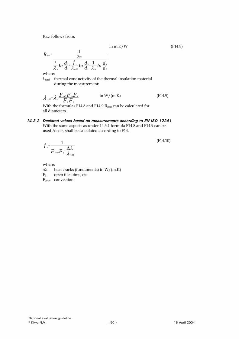
Rdecl follows from:
ddInd
dInf
ddIn
R
c
decl
432 121
1
λλ MrefDp 321
π++
=
in m.K/W (F14.8)
λrefd thermal insulation material during the measurement:
λwhere:
thermal conductivity of the
FFFFF cmϑ∆ in W/(m.K) (F14.9)
as F14.8 and F14.9 Rdecl can be calculated for all diameters.
14.3.2 1 8 and F14.9 can be
sed Also fc shall be calculated according to F14.
dadrefd λλ =
With the formul
Declared values based on measurements according to EN ISO 1224With the same aspects as under 14.3.1 formula F14.u
λλrefM
jcouv
c
FFf ∆
+
=1 (F14.10)
ents) in W/(m.K) s, etc
Fcouv convection
where: ∆λ - heat cracks (fundamFj- open tile joint
National evaluation guideline © Kiwa N.V. - 50 - 16 April 2004
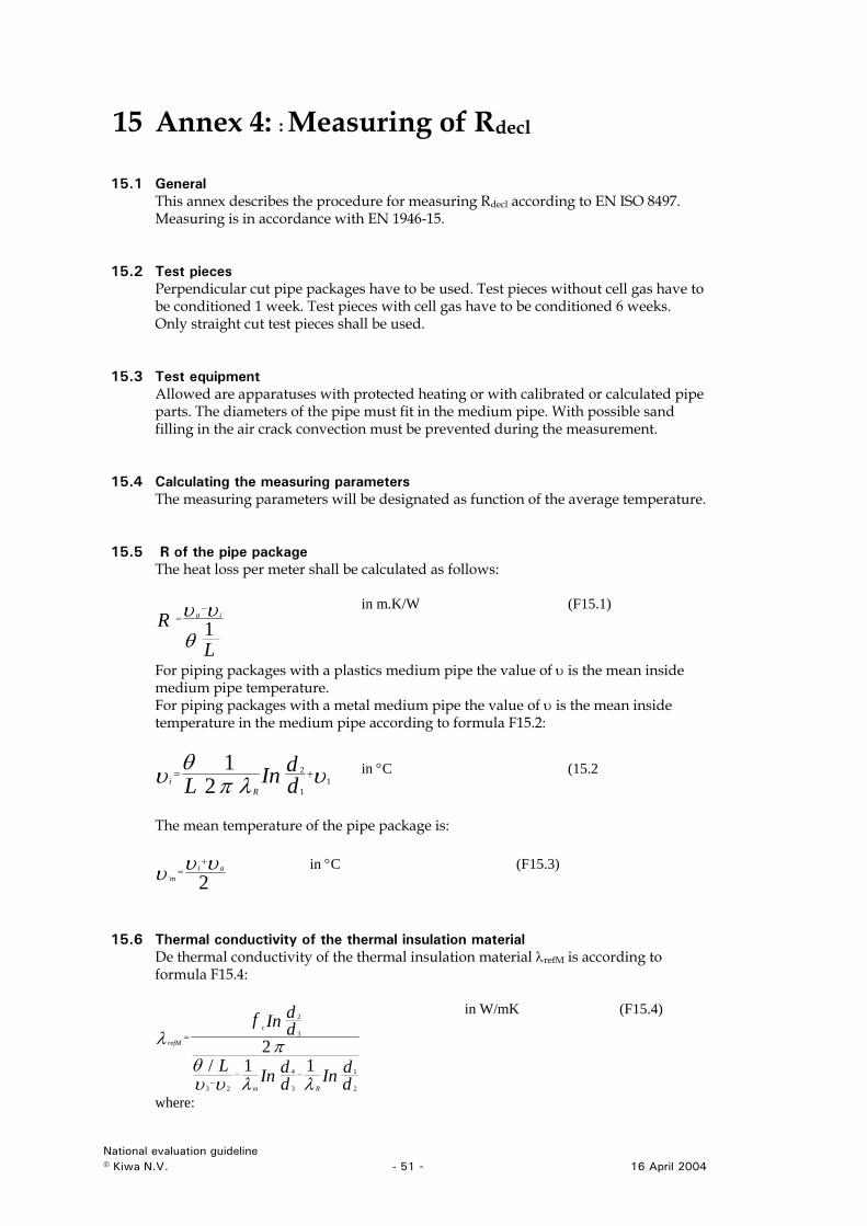
15 Annex 4: : Measuring of Rdecl
15.1 General This annex describes the procedure for measuring Rdecl according to EN ISO 8497. Measuring is in accordance with EN 1946-15.
15.2 Test pieces Perpendicular cut pipe packages have to be used. Test pieces without cell gas have to be conditioned 1 week. Test pieces with cell gas have to be conditioned 6 weeks. Only straight cut test pieces shall be used.
15.3 Test equipment Allowed are apparatuses with protected heating or with calibrated or calculated pipe parts. The diameters of the pipe must fit in the medium pipe. With possible sand filling in the air crack convection must be prevented during the measurement.
15.4 Calculating the measuring parameters The measuring parameters will be designated as function of the average temperature.
15.5 R of the pipe package The heat loss per meter shall be calculated as follows:
LR ia
1θυυ −
= in m.K/W (F15.1)
For piping packages with a plastics medium pipe the value of υ is the mean inside medium pipe temperature. For piping packages with a metal medium pipe the value of υ is the mean inside temperature in the medium pipe according to formula F15.2:
υλπθυ 1
1
2
21
+=ddInL R
i in °C (15.2
The mean temperature of the pipe package is:
2'υυυ ai
m
+= in °C (F15.3)
15.6 Thermal conductivity of the thermal insulation material De thermal conductivity of the thermal insulation material λrefM is according to formula F15.4:
ddInd
dInL
ddInf
Rm
c
refM
2
1
3
4
23
3
2
11/2
λλυυθ
πλ
−−−
=
in W/mK (F15.4)
where:
National evaluation guideline © Kiwa N.V. - 51 - 16 April 2004
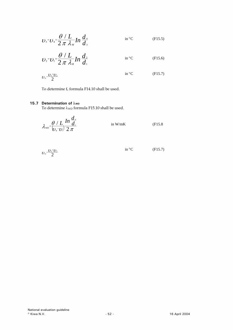
ddInL
M 3
443 2
/λπ
θυυ += in °C (F15.5)
ddInL
R 1
212 2
/λπ
θυυ += in °C (F15.6)
223 υυυ
+=
m
in °C (F15.7)
To determine fc formula F14.10 shall be used.
15.7 Determination of λWD To determine λWD formula F15.10 shall be used.
( ) πυυθλ 2
/ ddInL i
a
iaWD −
= in W/mK (F15.8
2
23 υυυ+
=m
in °C (F15.7)
National evaluation guideline © Kiwa N.V. - 52 - 16 April 2004
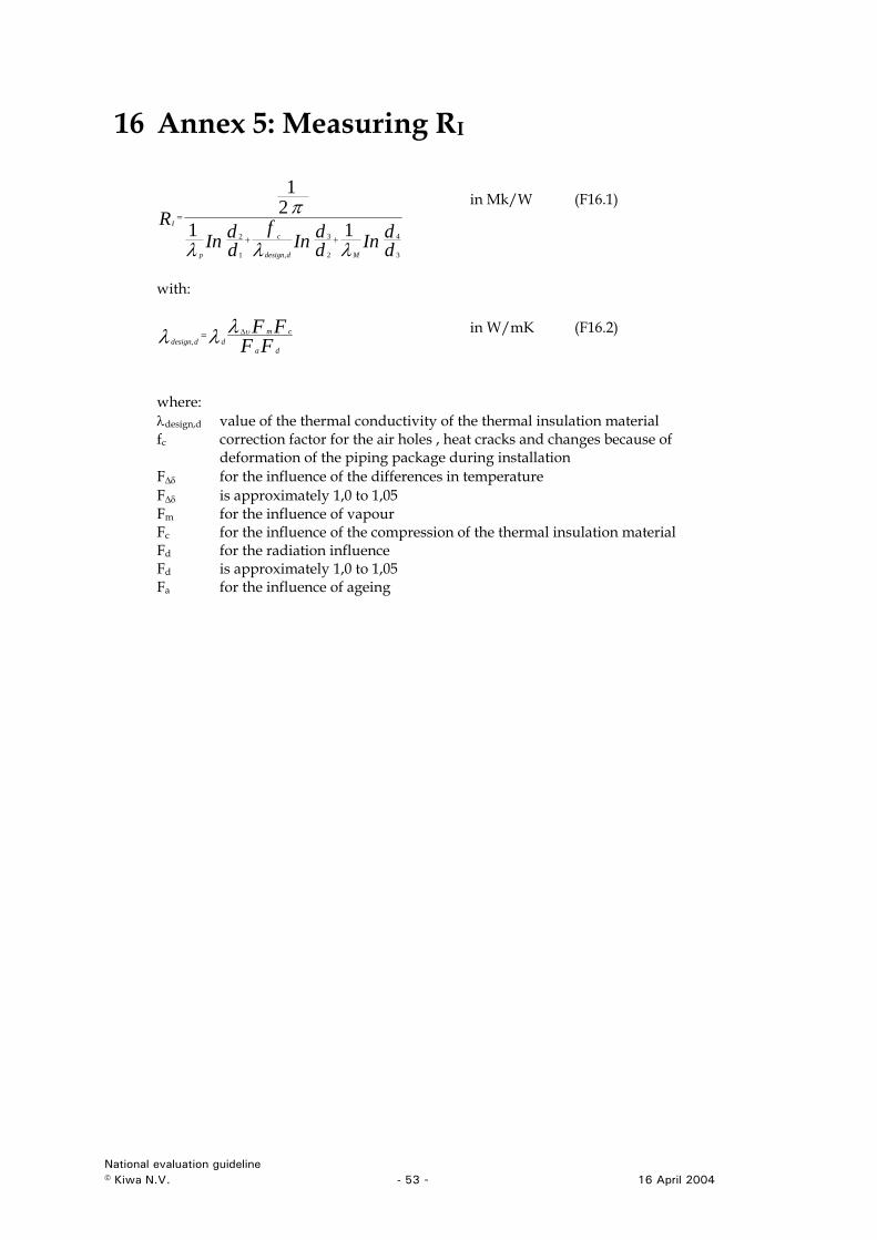
16 Annex 5: Measuring RI
ddInd
dInf
ddIn
R
Mddesign
c
p
I
3
4
2
3
,1
2 1121
λλλ
π++
=
in Mk/W (F16.1)
with:
FF
FFda
cmdddesignλλλ υ∆=
, in W/mK (F16.2)
where: λdesign,d value of the thermal conductivity of the thermal insulation material fc correction factor for the air holes , heat cracks and changes because of
deformation of the piping package during installation F∆δ for the influence of the differences in temperature F∆δ is approximately 1,0 to 1,05 Fm for the influence of vapour Fc for the influence of the compression of the thermal insulation material Fd for the radiation influence Fd is approximately 1,0 to 1,05 Fa for the influence of ageing
National evaluation guideline © Kiwa N.V. - 53 - 16 April 2004
17 Annex 6: Calculation of Reis
17.1 General With this annex the value of Reis can be calculated.
17.2 Heat transport of a piping package with return pipes See formula (17.1):
( ) WUULqq arf
rF ⎟⎟⎟
⎠
⎞
⎜⎜⎜
⎝
⎛−
+−=⎟
⎠⎞
⎜⎝⎛ + υυυ
22 21 (F17.1)
where: qf the heat loss per meter of the supply pipe qr the heat loss per meter of the return pipe L the length of the pipe package νf de heat loss per meter of the supply pipe νr de heat loss per meter of the return pipe νa de temperature of the environment (air) in °C The heat loss per meter per medium pipe:
in W/M (F17.2) ( )υυυυ araff UUq −−⎟⎠⎞
⎜⎝⎛ −=
21
in W/M (F17.3) ( ) ⎟
⎠⎞
⎜⎝⎛ −−−= υυυυ afarr UUq 21
The heat loss per meter:
( ) RRR
RRUuIs
Is221
−+
+=
in W/m.K (F17.4)
( ) RRRRU
uIs
u222
−+=
in W/m.K (F17.5)
where: Rs Heat loss per meter in the ground see F17.7 RI measured value of the heat loss per meter. Ru Heat loss per meter between the supply and return medium pipe, see F17.8
National evaluation guideline © Kiwa N.V. - 54 - 16 April 2004
Per medium pipe:
RRRUUU
uIs++
=−=1
21 in W/m.K (F17.6)
dZInR
a
c
ss
42
1λπ
= in m.K/W (F17.7)
where:
Zc correction factor for the heat resistance from ground surface to the installation depth of the package
λ sc RZZ 0
+= in m
Z distance of the ground surface to the middle of the piping package
HdZ a +=
2 in m
λs thermal conductivity of the soil = 1,5 W/m.K R0 thermal conductivity from the ground surface to the environment = 0,0685 m
K/W H Installation depth of the piping package = 0,6 m RU The value of R between supply and return pipe.
⎟⎟⎟⎟
⎠
⎞
⎜⎜⎜⎜
⎝
⎛
⎟⎟⎟
⎠
⎞
⎜⎜⎜
⎝
⎛+=
22121
cZInR c
su λπ
in m.K/W (F17.8)
where c = the distance of the centrelined medium pipes (supply and return pipe).
National evaluation guideline © Kiwa N.V. - 55 - 16 April 2004
18 Annex 7: Thermal stability
18.1 Principle Tensile test bars made of the material that has to be examined are exposed to different temperatures. After certain exposure times at the specified temperatures, the elongation at break is determined. This elongation at break as a percentage of the elongation at break of the non-exposed tensile bars is plotted versus the logarithmic exposure time for the different temperatures. In a thermal endurance graph (Arrhenius graph) the logarithm of the time to reach the specified elongation at break percentage is plotted versus the reciprocal thermodynamic (absolute) test temperature. From this graph an extrapolation is carried out to determine the temperature at an exposure time of 50 years. Remark: This way to determine the thermal stability at 50 years is derived from EN-ISO 2578.
18.2 Apparatus The oven shall be in accordance with EN-ISO 2578 clause 9, with temperature tolerances of ± 2°C. The tensile test machine shall be in accordance with EN-ISO 527-1 clause 5. The test speed shall be declared by the manufacturer and taken from the recommend test speed as described clause 5.1.2 of EN-ISO 527-1.
18.3 Sample Preparation The manufacturer shall declare the production method of the test pieces (e.g. injection moulded or pressed). The type of test pieces shall be in accordance with EN-ISO 527-2 clause 6 and shall be declared by the manufacturer. The number of test pieces shall be 5 at least for each temperature to determine the elongation at break. The number of exposure temperatures shall be at least 3.
18.4 Procedure Manufacturing of the test pieces shall be in accordance with clause 3 of this annex. For the determination of the elongation at break of the non-exposed test pieces, five test pieces shall be tensile tested on a tensile test machine in accordance with clause 2.2 of this annex. The test temperature shall be (23±2)°C. The mean elongation at break of the non-exposed test pieces is set to be 100%. For the determination of the elongation at break of the exposed test pieces, tensile testing shall be in accordance with EN-ISO 6259-1. The proposed exposure temperatures are 150- 140- 130°C. The minimum of 5 test pieces for each temperature are exposed for a certain exposure time, after this period the test pieces shall be removed from the oven and conditioned. The elongation at break of the exposed test pieces is declared as a percentage of the elongation at break of the non-exposed test pieces. The covering results of the fractional elongation at break values shall be as follows: • at least one value of the fractional elongation at break shall be between 50 and
75%; • at least two values of the fractional elongation at break shall be between 25 and
50%; • at least one value of the fractional elongation at break shall be lower than 25%.
National evaluation guideline © Kiwa N.V. - 56 - 16 April 2004
The fractional elongation at break values shall be plotted versus the logarithm of their exposure times (see figure B1). A curve shall be constructed for each temperature. The point at which these curves intersect the horizontal line representing the specified percentage of the elongation at break is taken as the time to failure. This specified percentage shall be 25%. The calculation of the thermal endurance curve (Arrhenius plot) is based on the failure times to reach the specified elongation at break percentage (see paragraph 5.4 of this annex) and the respective thermodynamic (absolute) exposure temperatures in Kelvin (see paragraph 5.3 of this annex). If mean values are used, the logarithmic mean represents the time to failure. The logarithm of the calculated elongation at break is plotted versus the reciprocal absolute temperature (see figure B2). From this graph a first-order regression line can be calculated in accordance with Annex A of EN-ISO 2578. By using the first-order regression line of the thermal endurance curve, the temperature of the 25%-elongation-at-break-value can be determined for an extrapolated exposure time of 50 years (T50y).
Figure 18.1, fractional elongation at break vs. time Figure 18.2, time vs.
temperature
X
X T2 T1
X
T3
X X
log t T
1T50y
T3
T2 T1
log t100%
50 y
25%
National evaluation guideline © Kiwa N.V. - 57 - 16 April 2004
19 Annex 8: Dimension stability of the piping package
19.1 General The measurement of the dimension stability is performed with the same method used for measuring the maximum service temperature for preformed pipe insulation according to NEN EN 14707. The test is is in accordance with NEN EN 14707 annex B, with the below mentioned adaptations.
2
1
3
1. insulation material 2. heated medium pipe 3. weights for loading
Figure 19.1 – test set up for determination of the thermal stability of the piping package
19.2 Procedure - Determine the length l0, inner diameter Di and the thickness d0 of the test
specimen according to NEN-EN 13467. - Place the insulation material over the inner pipe. - Calculation of the static load (Pw) is carried out as follows:
( )d
FFPe
wbw
+= (N/m2)
in which: Pw = static load; Fb = mass per length of the plastic pipe ( N/m) Fbw = mass per length of the water in the pipe ( N/m) de = outside diameter of the plastic pipe (m).
- The test piece will be conditioned during 24 hours with a pre-load of 10% of the
total static load at room temperature (23 ± 2°C). The height ds of the test piece after conditioning will be the initial value of the determination.
National evaluation guideline © Kiwa N.V. - 58 - 16 April 2004
- Next the test is executed according to table 25
Table 25 – Resistance of the insulation to static compression
Load (N/m ) Test temperature T (°C)
Testing time (h)
Pw 90 300 Pw 70 1000 Remark: materials with diffusion closed cells will be tested using a flushing gas (e.g. CO2) with (5 ± 3) mbar effective pressure.
- The dimensional stability is calculated as follows:
100×−
=s
sbel
dddε (%)
in which: ds = the height of the test piece after conditioning dbel = the height of the test piece after testing according to table 13.
ε = proportional decrease of the height of the test piece - For all determinations (2x 3 test pieces = 6): ε ≤ 10 %.
National evaluation guideline © Kiwa N.V. - 59 - 16 April 2004

![[Diagnosis, treatment, and follow-up of hepatitis C-virus related liver disease. Hungarian national consensus guideline]](https://img.pdfslide.net/doc/110x75/633be160cdd7b0400603a942/diagnosis-treatment-and-follow-up-of-hepatitis-c-virus-related-liver-disease.jpg)


![[Guideline of atrial fibrillation]](https://img.pdfslide.net/doc/110x75/634997ca8e60111deb0a49ae/guideline-of-atrial-fibrillation.jpg)


![[S3-guideline exocrine pancreatic cancer]](https://img.pdfslide.net/doc/110x75/6344e86f03a48733920b1c67/s3-guideline-exocrine-pancreatic-cancer.jpg)
