Embed Size (px)
Citation preview

Nanoscale
PAPER
Cite this: Nanoscale, 2015, 7, 9878
Received 23rd March 2015,Accepted 27th April 2015
DOI: 10.1039/c5nr01856k
www.rsc.org/nanoscale
A new reversal mode in exchange coupledantiferromagnetic/ferromagnetic disks: distortedviscous vortex†
Dustin A. Gilbert,a Li Ye,a Aïda Varea,b Sebastià Agramunt-Puig,c Nuria del Valle,c
Carles Navau,c José Francisco López-Barbera,c,d Kristen S. Buchanan,e
Axel Hoffmann,f Alvar Sánchez,c Jordi Sort,c,g Kai Liu*a and Josep Nogués*c,d,g
Magnetic vortices have generated intense interest in recent years due to their unique reversal mecha-
nisms, fascinating topological properties, and exciting potential applications. In addition, the exchange
coupling of magnetic vortices to antiferromagnets has also been shown to lead to a range of novel
phenomena and functionalities. Here we report a new magnetization reversal mode of magnetic vortices
in exchange coupled Ir20Mn80/Fe20Ni80 microdots: distorted viscous vortex reversal. In contrast to the
previously known or proposed reversal modes, the vortex is distorted close to the interface and viscously
dragged due to the uncompensated spins of a thin antiferromagnet, which leads to unexpected asymme-
tries in the annihilation and nucleation fields. These results provide a deeper understanding of the physics
of exchange coupled vortices and may also have important implications for applications involving
exchange coupled nanostructures.
Magnetic vortices have long been studied and remain a topicof current interest due to their fascinating fundamental pro-perties and topological characteristics.1–4 This magnetizationstate, which arises from the competition between magneto-static, exchange and anisotropy energies in nanostructuredferromagnet (FM) materials, is characterized by a (counter-)clockwise in-plane curl of the magnetization (chirality) aroundan up or down out-of-plane central core (polarity).5,6 Recentdemonstrations of chirality and polarity control7–11 havetriggered renewed interests in these entities for spintronicapplications,12–14 artificial Skyrmion lattices,15 and even bio-medical applications.16
On the other hand, exchange bias [i.e., nominally theexchange coupling between a FM and an antiferromagnet (AF)]
has received ever increasing interest across many emergingfrontiers of condensed matter physics, e.g., multiferroics,17,18
chiral ordering and exchange bias induced by Dzyaloshinskii–Moriya interactions,19,20 control of quantum magnets,21 AFspintronics,22,23 and triplet pairing in superconductingexchange biased heterostructures.24 When a magnetic vortex iscoupled to an AF (exchange bias) novel effects emerge, e.g.,biased vortex reversal hysteresis loops, reversible non-zeroremnant magnetization states, tunable angular dependentreversal modes, chirality-control, adjustable magnetizationdynamics, or suppressed stochastic effects.7,25–33 These effects,which occur due to the imprinting of different magnetic statesin the AF,34,35 can lead to additional functionalities in vortexstructures. Furthermore, it has been predicted that inexchange coupled structures the vortex cores may be tiltedalong their thickness (in contrast to conventional vorticeswhere the cores are straight) due to the pinning effects of theAF.36,37 Such a tilted structure leads to additional asymmetriesin the hysteresis loops, which are correlated with structuraland magnetic parameters (e.g., dot geometry or AF/FMexchange strength). In fact, vortices exchange coupled to AFshave been prominently featured in key technologies such asmagnetic random access memory and sensors.38
In this article we report a viscous vortex reversal mode inAF/FM exchange biased dots with a thick FM layer and varyingAF thicknesses. By changing the AF thickness, tAF, its an-isotropy energy is systematically tuned, thus changing therigidity of the AF spin structure from weak (“draggable” by the
†Electronic supplementary information (ESI) available. See DOI: 10.1039/c5nr01856k
aPhysics Department, University of California, Davis, CA, USA.
E-mail: [email protected], Electronics Department, Universitat de Barcelona, Martí i Franquès 1,
08028 Barcelona, SpaincDepartament de Física, Universitat Autònoma de Barcelona, 08193 Bellaterra
(Barcelona), SpaindICN2 – Institut Catala de Nanociencia i Nanotecnologia, Campus UAB,
08193 Bellaterra (Barcelona), SpaineDepartment of Physics, Colorado State University, Fort Collins, CO, USAfMaterials Science Division, Argonne National Laboratory, Argonne, IL, USAgInstitució Catalana de Recerca i Estudis Avançats (ICREA), Barcelona, Spain.
E-mail: [email protected]
9878 | Nanoscale, 2015, 7, 9878–9885 This journal is © The Royal Society of Chemistry 2015
Ope
n A
cces
s A
rtic
le. P
ublis
hed
on 2
8 A
pril
2015
. Dow
nloa
ded
on 2
1/05
/201
5 21
:51:
55.
Thi
s ar
ticle
is li
cens
ed u
nder
a C
reat
ive
Com
mon
s A
ttrib
utio
n 3.
0 U
npor
ted
Lic
ence
.
View Article OnlineView Journal | View Issue

FM layer) to rigid. This leads to a viscous vortex reversalmechanism in the dots, which deviates from the standard,biased and tilted vortex reversals.
ResultsMajor hysteresis loops
Major hysteresis loops of Fe20Ni80(30 nm)/Ir20Mn80(tAF) (FeNi/IrMn) films are shown in Fig. 1(a) and the HC and HE trendsare shown in Fig. 1(b). These plots show that the tAF = 0 filmhas a very small coercivity (HC = 0.4 Oe) and no bias (HE = 0),while the tAF = 3 nm film has a significantly increased HC
(28 Oe) and a small HE (3.8 Oe). For tAF > 3 nm HC decreases(2.9–4.3 Oe), but HE is established (56–81 Oe). This behaviorhas been previously attributed to the anisotropy of the AF.Specifically, for a thin AF the anisotropy is exceedingly weakand is viscously dragged by the FM while it reverses,39 leading
to enhanced HC, but no bias. For the thicker AF the anisotropyis sufficiently large so that the spins remain rigidly orientedafter the field cooling process.40,41
Major hysteresis loops for dots with 1 μm and 1.5 μm dia-meter are shown in Fig. 1(c–f ). The symmetric pinched shapeof the loops without AF, Fig. 1(c), is characteristic of a vortexstate reversal. For dots with a thin IrMn layer (tAF = 3 nm), themajor loops, Fig. 1(d), exhibit a much larger coercivity and apronounced asymmetry. However, these dots do not showappreciable exchange bias, indicating that the AF has weak an-isotropy and is dragged during the FM reversal. For dots withthicker (tAF ≥ 5 nm) IrMn layers, Fig. 1(e and f), the exchangebias is clearly established, and the HC is less than that of thetAF = 3 nm samples. Close inspection of the loops reveals asym-metries in their shape, particularly for tAF = 5 nm, suggestingthe presence of locally pinned spins. Interestingly, the majorloop shape for dots with an AF is quite complex and notindicative of any traditional magnetization reversal modes.
Fig. 1 (a) Hysteresis loops for continuous films of FeNi/IrMn with different tAF. (b) Dependence of |HE| and HC on tAF for the films and 1.0 and 1.5 µmcircular dots. Major hysteresis loops for the 1.0 and 1.5 µm circular dots with tAF of (c) 0 nm, (d) 3 nm, (e) 5 nm, and (f ) 7 nm.
Nanoscale Paper
This journal is © The Royal Society of Chemistry 2015 Nanoscale, 2015, 7, 9878–9885 | 9879
Ope
n A
cces
s A
rtic
le. P
ublis
hed
on 2
8 A
pril
2015
. Dow
nloa
ded
on 2
1/05
/201
5 21
:51:
55.
Thi
s ar
ticle
is li
cens
ed u
nder
a C
reat
ive
Com
mon
s A
ttrib
utio
n 3.
0 U
npor
ted
Lic
ence
.View Article Online

A possible reversal mechanism proposed previously inexchange biased dots is the “tilted-vortex” model.36,37 In thismodel the interfacial moments in the FM are pinned by theexchange coupling to the AF and the vortex core position atthis interface is displaced from the center, while further awayfrom the interface the vortex is more centered, hence the coreis tilted. As shown schematically in Fig. 2(a), the reversal mecha-nism is reflected in the major loops by the asymmetry of thepositive and negative annihilation fields, HA
+ and HA− respecti-
vely, after offsetting the HE. That is, in an unbiased vortex HA+
= −HA−, while in a biased vortex HA
+ − HE = −(HA− − HE), and
in a tilted vortex HA+ − HE ≠ −(HA
− − HE). Furthermore, thenucleation field, HN, should always be equally biased; fornormal, biased and tilted vortex reversal HN
+ − HE = −(HN− −
HE). We can thus define variables ΔHA = HA+ + HA
− − 2HE andΔHN = HN
+ + HN− − 2HE. By identifying ΔHA and ΔHN these
three reversal behaviors can be uniquely identified: ΔHA =ΔHN = HE = 0 for unbiased vortices, ΔHA = ΔHN = 0 and HE ≠ 0for biased vortices, and ΔHA ≠ 0, ΔHN = 0 and HE ≠ 0 for tiltedvortices. The trends for ΔHA and ΔHN are shown in Fig. 2(band c), where the nucleation/annihilation fields are deter-mined from intercepts of the linear extrapolations of magneti-zation before and after nucleation/annihilation. It can be seenthat indeed there is an asymmetry in HA, suggesting a tilted-vortex reversal. However, there is also an asymmetry in thenucleation field, which is not expected for any of the reversalbehaviors discussed above.
While the analytical theory for exchange bias inducedvortex tilting by Guslienko and Hoffmann can qualitativelyexplain several of the experimentally observed effects,36,42
some of the main experimental observations cannot beaccounted for. For example, (i) the experimental ΔHA is notproportional to the macroscopic HE as assumed in the model;(ii) on decreasing the dot diameter, ΔHA decreases rather thanincreases as is expected from the calculations; and (iii) there isa HN asymmetry, which the theory assumes to be absent.These discrepancies suggest that the microscopic magneticstructure is far more complex than the one assumed inthe theory. For instance, the model is mainly based on thedepth dependence of the effective exchange bias field, but itneglects the non-uniform spin structure at the interface.In particular, it is well accepted that the exchange bias effectcan be related to pinned and unpinned uncompensatedspins in the AF/FM interface,43–48 giving rise to loop shifts andcoercivity enhancements, respectively. In the biased vortexcase, we can naively assume that the pinned uncompensatedspins will be parallel to the cooling field, while the unpinnedones will form a curl mimicking the FM vortex. Hence,while the vortex near the FM/AF interface experiences acomplex energy landscape, away from this interface itbehaves more like a conventional vortex. These additionalinterface effects, which should be enhanced for smaller sizes,could give rise to the discrepancies between the theory andexperiments.
Fig. 2 Schematic hysteresis loops are shown in (a) for unbiased, biased, tilted, and viscous vortex reversals. The unbiased vortex reversal is shown indotted grey for reference. The viscous vortex reversal shows little to no exchange field, but asymmetries in both the nucleation and annihilation.Symbols HN
+ (HN−) and HA
+ (HA−) represent nucleation fields from positive (negative) saturation and annihilation to positive (negative) saturation,
respectively. Measured dependence of (b) ΔHA and (c) ΔHN on tAF for d = 1.0 and 1.5 µm circular dots. Error bars [smaller than symbol size in (b)] aredetermined by the radius of the curvature of the measured data at the nucleation (annihilation) corner.
Paper Nanoscale
9880 | Nanoscale, 2015, 7, 9878–9885 This journal is © The Royal Society of Chemistry 2015
Ope
n A
cces
s A
rtic
le. P
ublis
hed
on 2
8 A
pril
2015
. Dow
nloa
ded
on 2
1/05
/201
5 21
:51:
55.
Thi
s ar
ticle
is li
cens
ed u
nder
a C
reat
ive
Com
mon
s A
ttrib
utio
n 3.
0 U
npor
ted
Lic
ence
.View Article Online

Micromagnetic simulations
To highlight the origin of the novel reversal mode micromag-netic simulations were conducted. The simulated loop, shownin Fig. 3(a), exhibits a pinched loop shape, typical of vortexreversal, shifted along the field axis (with HE = 128 Oe and HC =54 Oe), in good qualitative agreement with the experimental
results. The increasing and decreasing field branches of theloop are shown to have different HA and HN [see Fig. 3(b)], withΔHA and ΔHN of about 8 Oe, reproducing the asymmetriesobserved experimentally. To elucidate the origin of this asym-metry we examine the spin maps of each layer. In Fig. 3(c) weplot the orientation of the spin moments (at H ∼ HC) at the AF/FM interface and the top FM surface of the dot [labeled layers
Fig. 3 (a) Simulated hysteresis loop of a FM disk with 504 nm diameter and 30 nm thickness pinned to an AF layer. (b) Composition of the top halfof the loops (i.e., M > 0) (black symbols) and the inverted bottom part (M < 0), corrected for the loop shift (red symbols). (c) Spin maps of the top(black) and bottom (green) FM layers at H ∼ HC for decreasing (left) and increasing (right) fields. The background intensity corresponds to the differ-ence (my1 − my5) as red (positive) and blue (negative), as discussed in the text. The bottom images are enlarged views of the highlighted areas. Thecooling field (HFC) and applied field (HAppl) directions are shown by arrows. (d) Side- and (e) top-view schematic illustration of the magnetic spins,identified as (blue) top, (yellow) middle, and (red) bottom, in a distorted vortex structure based on the simulations.
Nanoscale Paper
This journal is © The Royal Society of Chemistry 2015 Nanoscale, 2015, 7, 9878–9885 | 9881
Ope
n A
cces
s A
rtic
le. P
ublis
hed
on 2
8 A
pril
2015
. Dow
nloa
ded
on 2
1/05
/201
5 21
:51:
55.
Thi
s ar
ticle
is li
cens
ed u
nder
a C
reat
ive
Com
mon
s A
ttrib
utio
n 3.
0 U
npor
ted
Lic
ence
.View Article Online

5 and 1 in Fig. 3(d)] in green and black, respectively. The colorcontrast in Fig. 3(c) identifies the magnetization difference inthe two layers (my1 − my5) as red (positive) and blue (negative).The first remarkable result is that the core of the first and fifthlayers seems to be at the same position (within one micromag-netic cell, 6 nm), indicating no vortex tilt, in contrast withtheoretical predictions.36,37 However, as shown in Fig. 3(c) thevortices exhibit a clear distortion. While layer 1 (green) has anear perfect vortex structure, the interfacial spins in layer 5tend to tilt towards the FC direction [see Fig. 3(d and e)]. Thedistortion is more pronounced along the ascending-fieldbranch [Fig. 3(c) right panels] compared to the descending-field branch [left panels], as illustrated by the more intensebackground color. The origin of the major loop asymmetriesseems to be related to different degrees of distortion of thevortex structure close to the AF. This variation in the interfacialcoupling is manifested differently in HA and HN depending onthe previous saturation states and the field cooling direction.
First order reversal curve (FORC) analysis
To gain a detailed understanding of the dot magnetizationreversal, we have performed FORC studies on the microdotarrays [see ESI†].49–53 The FORC diagrams for the unbiaseddots [Fig. 4(a and b)] show “butterfly”-like features of a stan-dard vortex reversal with three main peaks, identified in Fig. 4(a) and discussed in the ESI (Fig. S1†): peak i corresponds tothe initial vortex nucleation from positive saturation and sub-sequent annihilation approaching positive saturation;51 peak iicorresponds to re-nucleation from negative saturation, and isaccompanied by a negative region that reflects the slopechange along successive FORCs;52 peak iii identifies sub-sequent annihilation to positive saturation, manifesting asym-metries in the dot shape.50 For tAF = 0, features i and ii are ofsimilar intensity [Fig. 4(a and b)] since the nucleation eventsare symmetric under field inversion.
For tAF = 3 nm, intensities of the FORC features i and iibecome asymmetric [Fig. 4(c and d)], indicating a deviationfrom the conventional vortex reversal and asymmetric magneti-zation reversal processes. The asymmetry is even more pro-nounced for tAF = 5 nm, where feature i has largely vanished.The suppression of feature i indicates a much-reduced irrever-sibility associated with the vortex nucleation/annihilation nearthe positive saturation, while the enhanced FORC peak iishows that the primary irreversibility is due to the vortexnucleation/annihilation near the negative saturation. Thisvortex reversal asymmetry is consistent with a depth-depen-dent magnetization configuration in the dots,51,54 since thepinning induced by the AF is stronger at the FM/AF interfacethan at the FM free surface, as suggested by the simulations.In both tAF = 3 nm and 5 nm peak ii shifts to a larger localcoercivity (HC* – see the ESI†), consistent with the proposedviscous drag reversal. For tAF = 5 nm the entire FORC distri-bution is shifted towards negative HB as the exchange bias isestablished [Fig. 4(e and f)].
Finally, for tAF = 7 nm, shown in Fig. 4(g) and (h) (and9 nm, not shown), the FORC distribution returns to a “butter-
fly”-like feature set. In addition, the nucleation/annihilationfeatures are of comparable intensity. Recalling that ΔHA isnearly zero for these samples [Fig. 2(a)], this indicates that thereversal involves simply biased vortices, not tilted vortices.
Discussions
The reversal mechanism observed for tAF = 3 and 5 nm deviatesfrom the three established behaviors discussed earlier (vortex,shifted vortex and tilted vortex), none of which predicts anasymmetry in HN. Originating from the drag of the AF andaccompanied by a distortion of the vortex structure rather thana tilt (as shown by simulations), this magnetization reversalmechanism may be viewed as distorted viscous vortex reversal.Remarkably, the dependence of HE and HC, ΔHA and ΔHN andthe evolution of the FORC features on tAF seem to indicate thatthe new reversal mode is dominated by the unpinned uncom-pensated spins, which explains its differences from the pro-posed tilted-vortex mode. Nevertheless, the asymmetriesrelated to this new mechanism should be enhanced for thicker
Fig. 4 FORC distributions for (left) 1.0 µm and (right) 1.5 µm diameterexchange biased dots with tAF of (a, b) 0 nm, (c, d) 3 nm, (e, f ) 5 nm, and(g, h) 7 nm.
Paper Nanoscale
9882 | Nanoscale, 2015, 7, 9878–9885 This journal is © The Royal Society of Chemistry 2015
Ope
n A
cces
s A
rtic
le. P
ublis
hed
on 2
8 A
pril
2015
. Dow
nloa
ded
on 2
1/05
/201
5 21
:51:
55.
Thi
s ar
ticle
is li
cens
ed u
nder
a C
reat
ive
Com
mon
s A
ttrib
utio
n 3.
0 U
npor
ted
Lic
ence
.View Article Online

FM layers (where the vortex distortion should increase) andmoderately thin AFs (where the AF has weaker anisotropy andthe drag should be larger). Even in nanostructures with thickAFs, distorted viscous vortex reversal may still emerge if thetemperature is sufficiently increased so that the AF anisotropyis concomitantly weakened.55 Interestingly, although the thick-ness of the FM layers in AF/FM dots is typically on the 10 nmscale, some hints of reversal asymmetries probably linked tothis new reversal mode can be found in the literature.4,30,55,56
Note that the viscous drag of the magnetization due to the AFalso occurs in thin films. However, in contrast to what isobserved in nanostructures, in thin films the net effect of thisviscous drag is merely an increase in coercivity without anychanges in the magnetization reversal modes.40,57 Importantly,the dragging of the AF layer is not only a general feature ofexchange biased dots, but may also be relevant for virtuallyany exchange coupled system,58 e.g., in magnetically hard/softexchange coupled nanostructures59–61 where the harder layerhas insufficient anisotropy to pin the softer layer.
The asymmetries inherent to the distorted viscous vortexreversal may have practical implications in the performance ofmagnetic devices based on exchange coupling. Thus, the poss-ible effects of the distorted viscous vortex reversal should betaken into account in the design of such devices (e.g., tuningthe thickness of the AF or FM layers or operating temperatureto avoid this effect).
Conclusions
In summary, we have found a new distorted viscous vortexreversal mode in exchange biased FeNi/IrMn dots with varyingAF thicknesses. Unbiased dots reverse via a vortex state, whiledots with an AF layer undergo a much more complex reversalprocess: dots with thin AF layers reverse via a distorted viscousvortex state with an enhanced coercivity; once the AF layer isthick enough to have sufficient anisotropy energy, the magneti-zation reverses via a biased vortex state, and the coercivityenhancement is suppressed. This viscous vortex reversal modeand the asymmetries in the annihilation and nucleation fieldsare beyond the current understanding of exchange coupledvortices, and offer interesting implications for deviceapplications.
Methods
Arrays of circular nanodots with diameters of 0.5, 1.0 and1.5 μm and vertical structures of Ta(5 nm)/Fe20Ni80(30 nm)/Ir20Mn80(tAF)/Pt(2 nm) [tAF = 0–9 nm] were fabricated on anaturally oxidized Si(001) substrate by electron-beam litho-graphy and DC magnetron sputtering from composite targetsin 1.5 mTorr Ar. The dot sizes are optimal to achieve vortexstructure. The FM layer was kept deliberately thick to promotetilted vortex reversal.36,37 Arrays with a common AF thicknesswere fabricated in a single run, with the other arrays shadowed
by a mask. The AF orientation was set by heating the sampleto 520 K (above the blocking temperature of IrMn, TB = 420 K)then cooling to room temperature in an in-plane magneticfield, HFC = 2 kOe. Hysteresis loops and first-order reversalcurve (FORC) measurements were recorded at room tempera-ture using a longitudinal magneto-optical Kerr effect (MOKE)setup, following prior procedures,49,50,62,63 with loopsmeasured along the cooling field axis, iteratively averaged at arate of 7 Hz for ∼1000 cycles.
Simulations were conducted using the same geometric con-structions as the experimental system by iteratively solvingBrown’s static equations64 using a 6 nm cubic mesh (consist-ent with the exchange length of FeNi65), making the simulatedFM 5 cells thick. The polycrystalline FeNi was simulated usingan exchange stiffness A = 1.3 × 10⁻¹¹ J m−1, a saturation mag-netization MS = 8 × 10⁵ A m−1, and magnetocrystalline an-isotropy KU = 0. The IrMn was modeled as 84% non-magneticmaterial and 16% (900 cells) randomly distributed magneti-cally contributing cells, representing uncompensated spins.The contributing cells are further divided into pinned androtatable cells43–48 in a ratio of 4 : 5, giving a moderate loopshift, HE, and coercivity, HC. The pinned cells have their mag-netization (MS = 8 × 10⁵ A m−1) fixed along the field-cool (FC)direction, while the unpinned ones have a large uniaxial an-isotropy (KU = 5 × 10⁵ J m−1) in the FC direction. These uncom-pensated spins interact via exchange (assuming JAF–FM = JFM–
FM) and magnetostatic interactions with the FM spins but onlymagnetostatically among themselves (since they represent theequivalent of isolated uncompensated spins in experimentalsystems). Since the results depend on the spatial distributionof the pinned and unpinned spins, the presented results arethe average of 8 different simulated configurations.
Acknowledgements
This work was supported by the US NSF (DMR-1008791 andECCS-1232275), the 2014-SGR-1015 project of the Generalitatde Catalunya, and MAT2010-20616-C02, CSD2007-00041 andMAT2012-35370 projects of the Spanish Ministerio de Econo-mía y Competitividad (MinECO). Work at Argonne was sup-ported by the U. S. Department of Energy, Office of Science,Materials Science and Engineering Division. Fabrication wasperformed at the Center for Nanoscale Materials, which is sup-ported by DOE, Office of Science, Basic Energy Science underContract No. DE-AC02-06CH11357. KL acknowledges supportfrom the NSFC (11328402). AS acknowledges a grant from theICREA Academia, funded by the Generalitat de Catalunya.ICN2 acknowledges support from the Severo Ochoa Program(MinECO, Grant SEV-2013-0295).
Notes and references
1 J. I. Martin, J. Nogués, K. Liu, J. L. Vicent and I. K. Schuller,J. Magn. Magn. Mater., 2003, 256, 449–501.
Nanoscale Paper
This journal is © The Royal Society of Chemistry 2015 Nanoscale, 2015, 7, 9878–9885 | 9883
Ope
n A
cces
s A
rtic
le. P
ublis
hed
on 2
8 A
pril
2015
. Dow
nloa
ded
on 2
1/05
/201
5 21
:51:
55.
Thi
s ar
ticle
is li
cens
ed u
nder
a C
reat
ive
Com
mon
s A
ttrib
utio
n 3.
0 U
npor
ted
Lic
ence
.View Article Online

2 K. Y. Guslienko, J. Nanosci. Nanotechnol., 2008, 8, 2745–2760.
3 R. P. Cowburn, D. K. Koltsov, A. O. Adeyeye, M. E. Wellandand D. M. Tricker, Phys. Rev. Lett., 1999, 83, 1042–1045.
4 F. Liu and C. A. Ross, J. Appl. Phys., 2014, 116, 194307.5 T. Shinjo, T. Okuno, R. Hassdorf, K. Shigeto and T. Ono,
Science, 2000, 289, 930–932.6 A. Wachowiak, J. Wiebe, M. Bode, O. Pietzsch,
M. Morgenstern and R. Wiesendanger, Science, 2002, 298,577–580.
7 W. Jung, F. Castaño and C. Ross, Phys. Rev. Lett., 2006, 97,247209.
8 K. Yamada, S. Kasai, Y. Nakatani, K. Kobayashi, H. Kohno,A. Thiaville and T. Ono, Nat. Mater., 2007, 6, 270–273.
9 M. Jaafar, R. Yanes, D. Perez de Lara, O. Chubykalo-Fesenko, A. Asenjo, E. M. Gonzalez, J. V. Anguita,M. Vazquez and J. L. Vicent, Phys. Rev. B: Condens. Matter,2010, 81, 054439.
10 R. K. Dumas, D. A. Gilbert, N. Eibagi and K. Liu, Phys. Rev.B: Condens. Matter, 2011, 83, 060415.
11 M. Kammerer, M. Weigand, M. Curcic, M. Noske,M. Sproll, A. Vansteenkiste, B. Van Waeyenberge, H. Stoll,G. Woltersdorf, C. H. Back and G. Schuetz, Nat. Commun.,2011, 2, 279.
12 L. Thomas, M. Hayashi, X. Jiang, R. Moriya, C. Rettner andS. S. P. Parkin, Nature, 2006, 443, 197–200.
13 A. Ruotolo, V. Cros, B. Georges, A. Dussaux, J. Grollier,C. Deranlot, R. Guillemet, K. Bouzehouane, S. Fusil andA. Fert, Nat. Nanotechnol., 2009, 4, 528–532.
14 V. S. Pribiag, I. N. Krivorotov, G. D. Fuchs, P. M. Braganca,O. Ozatay, J. C. Sankey, D. C. Ralph and R. A. Buhrman,Nat. Phys., 2007, 3, 498–503.
15 L. Sun, R. X. Cao, B. F. Miao, Z. Feng, B. You, D. Wu,W. Zhang, A. Hu and H. F. Ding, Phys. Rev. Lett., 2013, 110,167201.
16 D.-H. Kim, E. A. Rozhkova, I. V. Ulasov, S. D. Bader,T. Rajh, M. S. Lesniak and V. Novosad, Nat. Mater., 2009, 9,165–171.
17 Y. Tokunaga, Y. Taguchi, T. Arima and T. Tokura, Phys. Rev.Lett., 2014, 112, 037203.
18 W. Echtenkamp and C. Binek, Phys. Rev. Lett., 2013, 111,187204.
19 J. Li, A. Tan, R. Ma, R. F. Yang, E. Arenholz, C. Hwang andZ. Q. Qiu, Phys. Rev. Lett., 2014, 113, 147207.
20 R. Yanes, J. Jackson, L. Udvardi, L. Szunyogh andU. Nowak, Phys. Rev. Lett., 2013, 111, 217202.
21 S. Yan, D.-J. Choi, J. A. J. Burgess, S. Rolf-Pissarczyk andS. Loth, Nat. Nanotechnol., 2015, 10, 40.
22 I. Fina, X. Marti, D. Yi, J. Liu, J. H. Chu, C. Rayan-Serrao,S. Suresha, A. B. Shick, J. Zelezny, T. Jungwirth,J. Fontcuberta and R. Ramesh, Nat. Commun., 2014, 5,4671.
23 D. Ciudad, M. Gobbi, C. J. Kinane, M. Eich, J. S. Mooderaand L. E. Hueso, Adv. Mater., 2014, 26, 7561.
24 V. I. Zdravok, D. Lenk, R. Morari, A. Ullrich, G. Obermeier,C. Muller, H.-A. Krug von Niffa, A. S. Sidorenko, S. Horn,
R. Tidecks and L. R. Tagirov, Appl. Phys. Lett., 2013, 103,062604.
25 J. Mejía-López, P. Soto and D. Altbir, Phys. Rev. B: Condens.Matter, 2005, 71, 104422.
26 J. Sort, A. Hoffmann, S. H. Chung, K. Buchanan,M. Grimsditch, M. Baró, B. Dieny and J. Nogués, Phys. Rev.Lett., 2005, 95, 067201.
27 Z.-P. Li, O. Petracic, J. Eisenmenger and I. K. Schuller, Appl.Phys. Lett., 2005, 86, 072501.
28 M. Tanase, A. Petford-Long, O. Heinonen, K. Buchanan,J. Sort and J. Nogués, Phys. Rev. B: Condens. Matter, 2009,79, 014436.
29 J. Sort, G. Salazar-Alvarez, M. D. Baró, B. Dieny,A. Hoffmann, V. Novosad and J. Nogués, Appl. Phys. Lett.,2006, 88, 042502.
30 J. Sort, K. Buchanan, V. Novosad, A. Hoffmann, G. Salazar-Alvarez, A. Bollero, M. Baró, B. Dieny and J. Nogués, Phys.Rev. Lett., 2006, 97, 067201.
31 O. G. Heinonen, D. K. Schreiber and A. K. Petford-Long,Phys. Rev. B: Condens. Matter, 2007, 76, 144407.
32 K. S. Buchanan, A. Hoffmann, V. Novosad and S. D. Bader,J. Appl. Phys., 2008, 103, 07B102.
33 S. O. Parreiras, G. B. M. Fior, F. Garcia and M. D. Martins,J. Appl. Phys., 2013, 114, 203903.
34 G. Salazar-Alvarez, J. J. Kavich, J. Sort, A. Mugarza,S. Stepanow, A. Potenza, H. Marchetto, S. S. Dhesi, V. Baltz,B. Dieny, A. Weber, L. J. Heyderman, J. Nogués andP. Gambardella, Appl. Phys. Lett., 2009, 95, 012510.
35 J. Wu, D. Carlton, J. S. Park, Y. Meng, E. Arenholz,A. Doran, A. T. Young, A. Scholl, C. Hwang, H. W. Zhao,J. Bokor and Z. Q. Qiu, Nat. Phys., 2011, 7, 303–306.
36 K. Y. Guslienko and A. Hoffmann, Phys. Rev. Lett., 2006, 97,107203.
37 K. Y. Guslienko and A. Hoffmann, J. Appl. Phys., 2007, 101,093901.
38 See e.g., T. Min, Y. Guo and P. Wang, US Patent 7072208 B2,2006; B. Dieny, US Patent Appl, 2015/0063019A1, 2015;P. Kasiraj and S. Maat, US Patent 7057862B2, 2004.
39 M. S. Lund, W. A. A. Macedo, K. Liu, J. Nogués,I. K. Schuller and C. Leighton, Phys. Rev. B: Condens.Matter, 2002, 66, 054422.
40 J. Nogués and I. K. Schuller, J. Magn. Magn. Mater., 1999,192, 203–232.
41 M. Ali, C. Marrows, M. Al-Jawad, B. Hickey, A. Misra,U. Nowak and K. Usadel, Phys. Rev. B: Condens. Matter,2003, 68, 214420.
42 A. Hoffmann, J. Sort, K. S. Buchanan and J. Nogués, IEEETrans. Magn., 2008, 44, 1968–1973.
43 J. Camarero, Y. Pennec, J. Vogel, S. Pizzini, M. Cartier,F. Fettar, F. Ernult, A. Tagliaferri, N. Brookes and B. Dieny,Phys. Rev. B: Condens. Matter, 2003, 67, 020413.
44 S. Brück, G. Schütz, E. Goering, X. Ji and K. Krishnan, Phys.Rev. Lett., 2008, 101, 126402.
45 H. Ohldag, A. Scholl, F. Nolting, E. Arenholz, S. Maat,A. Young, M. Carey and J. Stöhr, Phys. Rev. Lett., 2003, 91,017203.
Paper Nanoscale
9884 | Nanoscale, 2015, 7, 9878–9885 This journal is © The Royal Society of Chemistry 2015
Ope
n A
cces
s A
rtic
le. P
ublis
hed
on 2
8 A
pril
2015
. Dow
nloa
ded
on 2
1/05
/201
5 21
:51:
55.
Thi
s ar
ticle
is li
cens
ed u
nder
a C
reat
ive
Com
mon
s A
ttrib
utio
n 3.
0 U
npor
ted
Lic
ence
.View Article Online

46 R. L. Stamps, J. Phys. D: Appl. Phys., 2000, 33, R247–R268.47 M. Fitzsimmons, B. Kirby, S. Roy, Z.-P. Li, I. Roshchin,
S. Sinha and I. Schuller, Phys. Rev. B: Condens. Matter,2007, 75, 214412.
48 J. Nogués, S. Stepanow, A. Bollero, J. Sort, B. Dieny,F. Nolting and P. Gambardella, Appl. Phys. Lett., 2009, 95,152515.
49 J. E. Davies, O. Hellwig, E. E. Fullerton, G. Denbeaux,J. B. Kortright and K. Liu, Phys. Rev. B: Condens. Matter,2004, 70, 224434.
50 R. K. Dumas, C. P. Li, I. V. Roshchin, I. K. Schuller andK. Liu, Phys. Rev. B: Condens. Matter, 2007, 75, 134405.
51 R. K. Dumas, C.-P. Li, I. V. Roshchin, I. K. Schuller andK. Liu, Phys. Rev. B: Condens. Matter, 2012, 86, 144410.
52 D. A. Gilbert, G. T. Zimanyi, R. K. Dumas, M. Winklhofer,A. Gomez, N. Eibagi, J. L. Vicent and K. Liu, Sci. Rep., 2014,4, 4204.
53 D. A. Gilbert, J. W. Liao, L. W. Wang, J. W. Lau,T. J. Klemmer, J. U. Thiele, C. H. Lai and K. Liu, APLMater., 2014, 2, 086106.
54 Z. P. Li, O. Petracic, R. Morales, J. Olamit, X. Batlle, K. Liuand I. K. Schuller, Phys. Rev. Lett., 2006, 96, 217205.
55 S. Thomas, D. Nissen and M. Albrecht, Appl. Phys. Lett.,2014, 105, 022405.
56 A. L. Dantas, G. O. G. Rebouças and A. S. Carriço, IEEETrans. Magn., 2010, 46, 2311–2313.
57 J. Nogués, J. Sort, V. Langlais, V. Skumryev, S. Suriñach,J. S. Muñoz and M. D. Baró, Phys. Rep., 2005, 422, 65.
58 J. E. Davies, O. Hellwig, E. E. Fullerton, J. S. Jiang,S. D. Bader, G. T. Zimanyi and K. Liu, Appl. Phys. Lett.,2005, 86, 262503.
59 Q. L. Ma, S. Mizukami, T. Kubota, X. M. Zhang, Y. Andoand T. Miyazaki, Phys. Rev. Lett., 2014, 112, 157202.
60 L. S. Huang, J. F. Hu, B. Y. Zong, S. W. Zeng, Ariando andJ. S. Chen, J. Phys. D: Appl. Phys., 2014, 47, 245001.
61 D. Goll and A. Breitling, Appl. Phys. Lett., 2009, 94, 052502.62 C. Pike, C. Ross, R. Scalettar and G. Zimanyi, Phys. Rev. B:
Condens. Matter, 2005, 71, 134407.63 R. K. Dumas, K. Liu, C. P. Li, I. V. Roshchin and
I. K. Schuller, Appl. Phys. Lett., 2007, 91, 202501.64 W. F. Brown Jr., Magnetostatic Principles in Ferromagnetism,
Amsterdam, North-Holland, 1962.65 S. Agramunt-Puig, N. del Valle, C. Navau and A. Sanchez,
Appl. Phys. Lett., 2014, 104, 012407.
Nanoscale Paper
This journal is © The Royal Society of Chemistry 2015 Nanoscale, 2015, 7, 9878–9885 | 9885
Ope
n A
cces
s A
rtic
le. P
ublis
hed
on 2
8 A
pril
2015
. Dow
nloa
ded
on 2
1/05
/201
5 21
:51:
55.
Thi
s ar
ticle
is li
cens
ed u
nder
a C
reat
ive
Com
mon
s A
ttrib
utio
n 3.
0 U
npor
ted
Lic
ence
.View Article Online

1
Electronic Supplementary Information
New Reversal Mode in Exchange Coupled
Antiferromagnetic/Ferromagnetic Disks: Distorted Viscous Vortex
Dustin A. Gilbert,a Li Ye,a Aïda Varea,b Sebastià Agramunt-Puig,c Nuria del Valle,c Carles
Navau,c José Francisco López-Barbera,c, d Kristen S. Buchanan,e Axel Hoffmann,f Alvar
Sánchez,c Jordi Sort,c, g Kai Liu,a, * and Josep Noguésc, d, g,*
aPhysics Department, University of California, Davis, CA, USA bMinD-in2UB, Electronics Department, Universitat de Barcelona, Martí i Franquès 1, 08028,
Barcelona, SpaincDepartament de Física, Universitat Autònoma de Barcelona, 08193 Bellaterra (Barcelona),
SpaindICN2 – InstitutCatala de Nanociencia i Nanotecnologia, Campus UAB, 08193 Bellaterra
(Barcelona), SpaineDepartment of Physics, Colorado State University, Fort Collins, CO, USA fMaterials Science Division, Argonne National Laboratory, Argonne, IL, USA gInstitució Catalana de Recerca i Estudis Avançats (ICREA), Barcelona, Spain
*Corresponding authors: [email protected], [email protected].
Details of the first order reversal curve (FORC) measurements:
First, the sample is saturated in a positive field. Then, the field is reduced to a scheduled
reversal field, HR, and the magnetization is recorded as the applied field, H, is swept back to
positive saturation, hence tracing out a single FORC. This sequence is repeated for decreasing
values of the reversal field until negative saturation is reached, measuring a family of FORCs
Electronic Supplementary Material (ESI) for Nanoscale.This journal is © The Royal Society of Chemistry 2015
2
where the magnetization, M, is recorded as a function of both H and HR. The FORC distribution,
(H,HR) is then calculated by applying a mixed second order derivative:
(1)𝜌(𝐻, 𝐻𝑅) =‒
12𝑀𝑆
∂2𝑀(𝐻, 𝐻𝑅)∂𝐻𝑅∂𝐻
,
where MS is the saturation magnetization. The resulting distribution is only non-zero for
irreversible switching processes. Recognizing that sweeping H probes the up-switching events
and stepping HR probes the down-switching events, new coordinates can be defined: the local
bias HB=(H+HR)/2 and local coercivity HC*=(H-HR)/2.
Anatomy of the FORC features for vortex, biased vortex and tilted-vortex reversals:
A schematic of a standard vortex FORC is shown in Fig. S1(a). For a magnetic vortex in
a symmetric structure, such as a circular dot, the three main features correspond to (i) nucleation
from positive saturation (at HR(i)) and annihilation to positive saturation (at H(i)), (ii) annihilation
to negative saturation (at HR(ii)) and nucleation from negative saturation (at H(ii)), and (iii)
subsequent annihilation to positive saturation (at HR(iii)=HR
(ii), H(iii)=H(i)). Feature (ii) is
accompanied by a negative feature, extending in the -H direction relative to the positive feature.
In the vortex state, the magnetization varies continuously in response to the magnetic field
(dM/dH≠0), whereas in the saturated state the magnetization remains constant (dM/dH=0). These
'unmatched' dM/dH slopes [30] leads to a negative feature. The different reversal modes can be
distinguished as follows.
Non-biased vortex: the nucleation and annihilation fields will be symmetric for positive
and negative saturation, thus HR(i)=-H(ii), H(i)=-HR
(ii) and H(iii)=H(i). Transforming these into (HC,
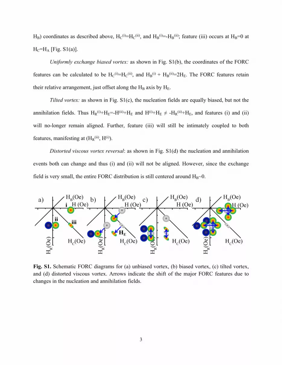
3
HB) coordinates as described above, HC(i)=HC
(ii), and HB(i)=-HB
(ii); feature (iii) occurs at HB=0 at
HC=HA [Fig. S1(a)].
Uniformly exchange biased vortex: as shown in Fig. S1(b), the coordinates of the FORC
features can be calculated to be HC(i)=HC
(ii), and HB(i) + HB
(ii)=2HE. The FORC features retain
their relative arrangement, just offset along the HB axis by HE.
Tilted vortex: as shown in Fig. S1(c), the nucleation fields are equally biased, but not the
annihilation fields. Thus HR(i)+HE=-H(ii)+HE and H(i)+HE ≠ -HR
(ii)+HE, and features (i) and (ii)
will no-longer remain aligned. Further, feature (iii) will still be intimately coupled to both
features, manifesting at (HR(ii), H(i)).
Distorted viscous vortex reversal: as shown in Fig. S1(d) the nucleation and annihilation
events both can change and thus (i) and (ii) will not be aligned. However, since the exchange
field is very small, the entire FORC distribution is still centered around HB~0.
Fig. S1. Schematic FORC diagrams for (a) unbiased vortex, (b) biased vortex, (c) tilted vortex, and (d) distorted viscous vortex. Arrows indicate the shift of the major FORC features due to changes in the nucleation and annihilation fields.


![Antiferromagnetic dipolar ordering in [Co2MnGe∕V]N multilayers](https://img.pdfslide.net/doc/110x75/6352b48f0f35c933db00ca04/antiferromagnetic-dipolar-ordering-in-co2mngevn-multilayers.jpg)


