Embed Size (px)
Citation preview
IEEE TRANSACTIONS ON IMAGE PROCESSING, VOL. 16, NO. 9, SEPTEMBER 2007 2369
Subspace-Based and DIRECT Algorithms forDistorted Circular Contour Estimation
Julien Marot and Salah Bourennane
Abstract—Circular features are commonly sought in digitalimage processing. The subspace-based line detection (SLIDE)method proposed to estimate the center and the radius of a singlecircle. In this paper, we introduce a novel method for estimatingseveral radii while extending the circle estimation to retrieve cir-cular-like distorted contours. Particularly, we develop and validatea new model for virtual signal generation by simulating a circularantenna. The circle center is estimated by the SLIDE method. Avariable speed propagation scheme toward the circular antennayields a linear phase signal. Therefore, a high-resolution methodprovides the radius. Either the gradient method or the morerobust combination of dividing rectangles and spline interpolationcan extend this method extend this method for free form objectsegmentation. The retrieval of multiple non concentric circles androtated ellipses is also considered. To evaluate the performanceof the proposed methods, we compare them with a least-squaresmethod, Hough transform, and gradient vector flow. We apply theproposed method to hand-made images while considering somereal-world images.
Index Terms—Array processing, circular antenna, contour,image, optimization.
I. INTRODUCTION
CIRCULAR features are commonly sought in digital imageprocessing. Circle fitting is suitable in several domains
such as quality inspection for food industry, mechanical parts[1], and particle trajectories [2], [3]. Circle fitting has been ap-plied in microwave engineering [4] and ball detection for roboticvision systems [5]. Nearly circular features are sought in char-acter recognition; [6] and [7] proposed a template-based systemfor online character recognition, where the representative tem-plates are automatically counted. These templates are viewedas different writing styles for any character. Ordinary or totalleast-squares methods for circle fitting seek to minimize thesquares sum of error-of-fit with respect to measures [8]–[11].Using geometric fitting [8], error distances are defined with theorthogonal, or shortest, distances from given points to the geo-metric feature to be fitted. In [10], a least-squares fitting ap-proach is proposed. It is based on the hypothesis that a set ofcircular arcs extracted from the image is related to a set of cir-cles contained in a model by translation, rotation and scaling.
Manuscript received July 18, 2006; revised June 8, 2007. The associate editorcoordinating the review of this manuscript and approving it for publication wasDr. Gaudenz Danuser.
The authors are with the Institut Fresnel/CNRS UMR 6133-Domaine Uni-versitaire de Saint Jérôme F-13397 Marseille Cedex 20, France (e-mail: [email protected]; [email protected]).
Color versions of one or more of the figures in this paper are available onlineat http://ieeexplore.ieee.org.
Digital Object Identifier 10.1109/TIP.2007.903907
[10] presents an analytical solution based on least-squares fit-ting to obtain an optimal geometric transformation for the align-ment of the circular arcs with circles. For a single circular arc,this method is easy to implement. For multiple arcs with dif-ferent centers, this method relies on the strong hypothesis thatall model circles should be transformed by the same transla-tion, rotation, and scaling operations to fit the arcs in the image.One of the major limitations of most of least-squares approachesis their sensitivity to outliers [10]; [12] and [13] focused onplanar spline interpolation between control-points by quadraticrational Bézier curves, to retrieve circular arcs. Compared to[10], this method does not take into account the prior knowl-edge of models or templates. It is based on interpolation betweencontrol-points. Other methods support circle retrieval, even ina noisy environment. The generalized Hough transform (GHT)provides estimation of the circle center coordinates when theirradius is known [14], [15]. Its main drawback is the compu-tational load, although fast versions have been proposed [16].Contour-based snakes methods [17], such as the gradient vectorflow (GVF), were largely used [18], [19] to retrieve concavitiesand weak edges with blurred boundaries. GVF limitations canbe observed when the expected contour exhibit a high curvature.Levelset type methods [20], [21] enhance blindly all contours inimages. Levelset does not provide explicitly the characteristicsof contours with particular predefined parameters. Array pro-cessing methods [22], [23] have been proposed to find somecharacteristics of circular contours. The formalism proposedby Aghajan [22] detects circular or elliptic contours. A prop-agation phenomenon and the impinging of a wavefront uponthe antenna are simulated through a variable speed propagationscheme. The center vertical and horizontal coordinates are es-timated by placing the antenna successively at the top and leftsides of the image; [22] proposed a radius estimation method,which relies on an approximation. This method can obtain asubimage from the initial image in such a way the top left corneris centered on the circle center, that was previously estimated.In [22], Aghajan showed that a truncation of the Taylor seriesof the generated signal leads to the value of the radius of the ex-pected circle.
In this paper, we propose a new approach for radius esti-mation, and for the retrieval of distortion between any nearlycircular contour and a circle. The approach uses a circular an-tenna. Particularly, we adapt an optimization method to retrievea nearly circular contour. We consider concentric and non con-centric features, either nearly circular or nearly oval. In [24] and[25], we adopted a similar strategy for approximately rectilineardistorted contours. In [24] and [25], a uniform linear array wasused. It was demonstrated that array processing methods ap-plied to contour detection are robust to noise impairment and
1057-7149/$25.00 © 2007 IEEE
Authorized licensed use limited to: FhI fur Integrierte Schaltungen Angewandte Elek. Downloaded on October 31, 2008 at 05:43 from IEEE Xplore. Restrictions apply.
2370 IEEE TRANSACTIONS ON IMAGE PROCESSING, VOL. 16, NO. 9, SEPTEMBER 2007
yield fast algorithms. As it will be illustrated later, the pro-posed approach based on circular antenna exhibits the same ro-bustness and speed properties. Another advantage of the pro-posed method over the Hough transform method is that the esti-mates in our approach are inherently continuous, whereas in theHough transform method, the resolution is limited by the binsize chosen for the parameter research interval. The proposedoptimization approach retrieves any pixel shift value, whateverthe curvature of the contour.
The remainder of the paper is organized as follows. In Sec-tion II, the problem of circle retrieval is highlighted, while ex-plaining how to generate a signal from the image, upon a cir-cular antenna. In Section III, a signal model is derived. We willshow that a linear phase signal is obtained when circles are ex-pected and either variable [26] or constant propagation param-eter is adopted for signal generation. By using the minimum de-scription length (MDL) criterion [23], [27], the number of con-centric features is detected; then a high-resolution method [28]estimates the possibly close radius values of the expected con-centric circles. Then, the proposed approach is generalized toretrieving several circles or ellipses with different centers andradii. In Section IV, the retrieval of circular contours is extendedto any closed contour fitted by a circle. Optimization methodsare investigated for this purpose. The fast variable step gradientmethod and the robust dividing rectangles (DIRECT) method[29] are accelerated using spline interpolation. In Section V, wediscuss the results obtained by the proposed approach when itis applied to hand-made and real-world images. The proposedradius estimation method is compared with least-squares fittingand Hough transform applied to radius estimation [16]. Our op-timization method is compared with GVF [18], in particular,concerning the robustness to noise and contour curvature.
II. PROBLEM STATEMENT AND SIGNAL GENERATION
A. Problem Statement
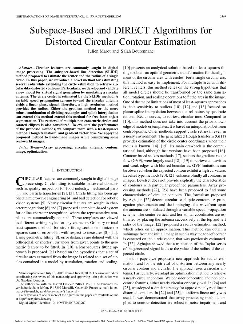
We highlight the problem of radius estimation, and the dis-tortions between a closed contour and a circle that fits with thiscontour. We propose a circular antenna that enables a particularsignal generation. We emphasize the phase of the generated sig-nals. The generated signals fit classical array processing and op-timization methods, contrary to signals derived by the existingsignal generation methods [22]. Fig. 1(a) presents a binary dig-ital image as a square matrix of dimensions . Each ele-ment represents an image pixel. An object in the image is madeof edge pixels with value 1, over a background of zero-valuedpixels. The object is fitted by a circle with radius value andcenter coordinates . Fig. 1(b) shows a subimage ex-tracted from the original image so that its top left corner is thecenter of the circle. This subimage is associated with a set ofpolar coordinates . Each pixel of the expected contour inthe subimage has the following coordinates: , . isthe shift between the contour pixel and the circle one that fitsthe contour and which has the same coordinate . We seek forstar-shaped contours, that is, contours described by the relation
, where is any function that maps to .A traditional circle fitting method is the generalized Hough
transform (GHT) [15], [16]. We employ a variant of Hough
Fig. 1. (a) Circular-like contour. (b) Bottom right quarter of the contour andpixel coordinates in the polar system (�; �) having its origin on the center of thecircle. r is the radius of the circle. �� is the value of the shift between a pixelof the contour and the pixel of the circle having same coordinate �.
transform that estimates the radii of concentric circles whentheir center is known. Its basis is to count the number of pixelswhich are located on a circle for all possible radius values.The drawback of Hough transform is its elevated computa-tional load. From this emerges the need for a faster radiusestimation. In [22], [23], and [30], Aghajan et al. replacedthe Hough transform by the much faster subspace-based linedetection (SLIDE) algorithm to retrieve straight lines. Existingalgorithms [24], [25] adapt an optimization method to signalsgenerated upon a linear antenna composed of one sensor perrow. When the expected contours consist of one pixel per row,only one unknown parameter of the optimization problem isincluded in one component of the generated signal [24], [25].
Contours which are approximately circular are supposed tobe made of more than one pixel per row for some of the rows ofthe image and more than one pixel per column for some columnsof the image. Several pixels may lead to only one signal com-ponent. A linear antenna does not lead to a linear phase signalwhen a circular contour is present in the image.
B. Virtual Signal Generation
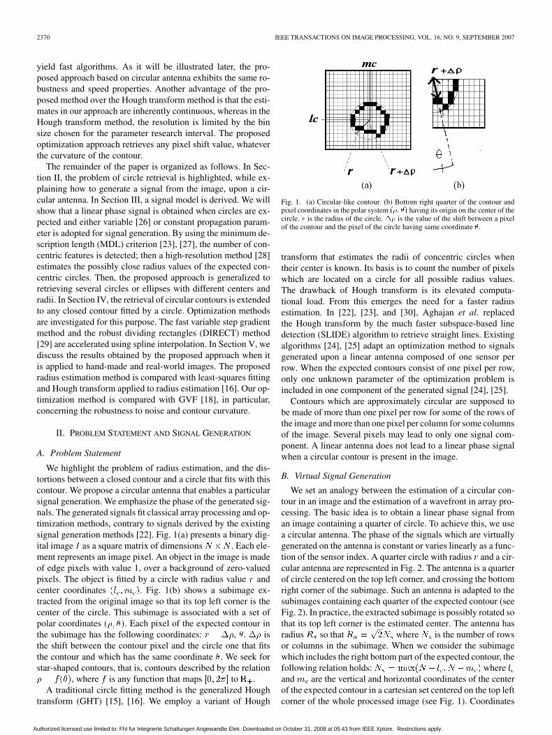
We set an analogy between the estimation of a circular con-tour in an image and the estimation of a wavefront in array pro-cessing. The basic idea is to obtain a linear phase signal froman image containing a quarter of circle. To achieve this, we usea circular antenna. The phase of the signals which are virtuallygenerated on the antenna is constant or varies linearly as a func-tion of the sensor index. A quarter circle with radius and a cir-cular antenna are represented in Fig. 2. The antenna is a quarterof circle centered on the top left corner, and crossing the bottomright corner of the subimage. Such an antenna is adapted to thesubimages containing each quarter of the expected contour (seeFig. 2). In practice, the extracted subimage is possibly rotated sothat its top left corner is the estimated center. The antenna hasradius so that where is the number of rowsor columns in the subimage. When we consider the subimagewhich includes the right bottom part of the expected contour, thefollowing relation holds: whereand are the vertical and horizontal coordinates of the centerof the expected contour in a cartesian set centered on the top leftcorner of the whole processed image (see Fig. 1). Coordinates
Authorized licensed use limited to: FhI fur Integrierte Schaltungen Angewandte Elek. Downloaded on October 31, 2008 at 05:43 from IEEE Xplore. Restrictions apply.
MAROT AND BOURENNANE: SUBSPACE-BASED AND DIRECT ALGORITHMS 2371
Fig. 2. Subimage, associated with a circular array composed of S sensors.
and are estimated by the method proposed in [22], or theone that is detailed later in this paper.
Signal generation scheme upon a circular antenna is the fol-lowing: the directions adopted for signal generation are from thetop left corner of the subimage to the corresponding sensor. Theantenna is composed of S sensors, so there are S signal compo-nents.
Let us consider , the line that makes an angle with thevertical axis and crosses the top left corner of the subimage. Theth component of the signal generated out of
the image reads
(1)
The integer (resp., ) indexes the lines (resp., the columns)of the image. stands for . is the propagation param-eter [26]. Each sensor indexed by is associated with a linehaving an orientation . In (1), the term
means that only the image pixels that belong toare considered for the generation of the th signal compo-
nent. Satisfying the constraint , that is, choosingthe pixels that belong to the line with orientation , is done intwo steps: let be the set of indexes along the vertical axis,and the set of indexes along the horizontal axis. If isless than or equal to , and
. if is greater than , and. Symbol means integer part.
The minimum number of sensors that permits a perfect char-acterization of any possibly distorted contour is the number ofpixels that would be virtually aligned on a circle quarter havingradius . Therefore, the minimum number of sensors is
.
III. PROPOSED METHOD FOR RADIUS
AND CENTER ESTIMATION
Estimation of Multiple Concentric Circles: Most often, thereexists more than one circle for one center. We demonstrate howseveral possibly close radius values can be estimated using ahigh-resolution method. We propose an estimation method forthe number of concentric circles, and each radius value. Forthis purpose, we employ a variable speed propagation scheme
[26]. We set , for each sensor indexed by. From (1), the signal received on each sensor is
(2)
where , are the values of the radius of eachcircle, and is a noise term due to outliers. All components
compose the observation vector . Total least-squares-esti-mation of parameters by rotational invariance techniques (TLS-ESPRIT) algorithm requires the estimation of the covariancematrix of several snapshots. There is no time-dependent sig-nals. So, the question arises as to how a sample covariance ma-trix can be formed. This can be done as follows [23]. From theobservation vector, we build subvectors of length with
,. To maximize the number of snapshots [24], the
first component of a snapshot is the second component of theprevious snapshot. This improves the estimation of the covari-ance matrix that is performed in TLS-ESPRIT algorithm. Wethen obtain snapshots. Grouping all subvec-tors obtained in matrix form, we get , where
(3)
is a Vandermonde type matrix of size: the th component of is . is
a length vector equal to -superscript denotestranspose- and .
The signal model of (3) suits TLS-ESPRIT method, a sub-space-based method that requires the dimension of the signalsubspace, that is, in this problem, the number of concentric cir-cles. MDL criterion estimates the dimension of the signal sub-space [23] from the eigenvalues of the covariance matrix. TLS-ESPRIT is applied on the measurements collected from twooverlapping subarrays, and falls into two parts: the covariancematrix estimation and the minimization of a total-least-squarescriterion. The radius values are obtained as [28]
(4)
where denotes imaginary part, are theeigenvalues of a diagonal unitary matrix. It relates the measure-ments from the first subarray with the measurements resultingfrom the second subarray.
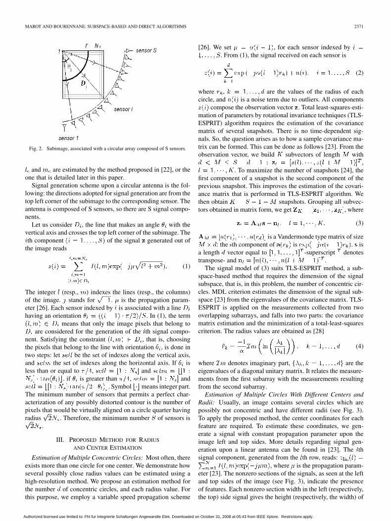
Estimation of Multiple Circles With Different Centers andRadii: Usually, an image contains several circles which arepossibly not concentric and have different radii (see Fig. 3).To apply the proposed method, the center coordinates for eachfeature are required. To estimate these coordinates, we gen-erate a signal with constant propagation parameter upon theimage left and top sides. More details regarding signal gen-eration upon a linear antenna can be found in [23]. The thsignal component, generated from the th row, reads:
, where is the propagation param-eter [23]. The nonzero sections of the signals, as seen at the leftand top sides of the image (see Fig. 3), indicate the presenceof features. Each nonzero section width in the left (respectively,the top) side signal gives the height (respectively, the width) of
Authorized licensed use limited to: FhI fur Integrierte Schaltungen Angewandte Elek. Downloaded on October 31, 2008 at 05:43 from IEEE Xplore. Restrictions apply.
2372 IEEE TRANSACTIONS ON IMAGE PROCESSING, VOL. 16, NO. 9, SEPTEMBER 2007
Fig. 3. Model for an image containing several nearly circular or elliptic fea-tures. r is the circle radius; a and b are the axial parameters of the ellipse.
the corresponding expected feature. The middle of each nonzerosection in the left (respectively, the top) side signal yields an ap-proximate value of the center (respectively, ) coordinate ofeach feature. The feature height, width, and center coordinatespermit us to select image regions. Each region contains a con-tour or a set of concentric contours. The proposed method basedon circular antenna detects the number of concentric features foreach estimated center, in each image region. It yields the valuesof the fitting circles radii. Then, an optimization method can beused to refine the estimation of each contour. Such a method isapplied to the signals generated on our circular antenna is pre-sented in the next section.
Single Circle Estimation: Using a circular antenna, aconstant parameter propagation scheme yields as wellto the radius of a single circle. Signal components are
, . The estimated valueof is: , with ,where denotes inverse cosine function and denotesreal part. In this algorithm, noise contribution is lowered byaveraging. In the next section, we use the fitting circle orellipse provided by the method presented above to retrieve anydistorted contour.
IV. OPTIMIZATION METHOD FOR THE ESTIMATION
OF NEARLY CIRCULAR CONTOURS
The optimization methods proposed in [24] and [25] estimatethe pixel shift values between a straight line and a nearly linearcontour. These methods rely on the assumption that one com-ponent of the generated signal is associated with only one un-known pixel shift value in one image row (or column). The pro-posed circular antenna adapts optimization methods to retrievedistorted star-shaped contours.
A. Proposed Optimization Method
We employ a circular antenna to retrieve the shift valuesbetween an initialization circle and the expected contour. Weprocess successively each quarter of the circle, and retrieve thedistortions between one quarter of the initialization circle andthe expected contour part that is located in the same quarter ofthe image. As an example, in Fig. 1, the right bottom quarter ofthe considered image is represented in Fig. 1(b). An optimiza-tion method inspired from [24] is defined as follows:
A contour in the considered subimage is described with a setof polar coordinates by . We estimate
the unknowns that characterize the contour, forming avector
(5)
The basic idea is to consider that can be written as(see Fig. 1), where
is the radius of a circle that fits the expected contour. Theoptimization method that we adapt to this problem estimates
, that is, the shift values between the ini-tialization circle and the expected contour.
If we take into account the position given by of all edgepixels in (1), the components of signal generated out of theimage containing the expected contour read
(6)
We try to recreate the signal , whose components are definedby (6), and in which we ignore the parameters. We start withan initialization vector , characterizing a quarter of circle thatfits the expected distorted contour in the considered subimage.The components of are equal to , the radius value that waspreviously estimated: . Then, with indexingthis recursive algorithm steps, we aim to minimize
(7)
where represents the norm induced by the usual scalarproduct of . The components of are definedsimilarly to the components of [see (6)] as a function ofthe components of , and the components of are ob-tained from the components of by adding a shift:
. To estimate ,we use the variable step gradient method. The series vectors areobtained from the relation ,where is the step for the descent. The recurrence loop is
(8)
The gradient is estimated using finite differences. When tendsto infinity, the criterion tends to zero and
, .We denote by the vector including all the estimated values
, , with tending to infinity.A more elaborated method based on DIRECT algorithm [29]
and spline interpolation can be adopted to reach the global min-imum of the criterion of (7). This method is applied to modifyrecursively the signal . At each step of the re-cursive algorithm, vector is computed by interpolating be-tween some “node” values that are retrieved by DIRECT. Themain property of DIRECT is that it obtains the global min-imum of a function. DIRECT normalizes the research spacein a hypercube and evaluates the solution which is located atthe center of this hypercube. Then, some solutions are evalu-ated and the hypercube is divided into smaller cubes, supportingthe zones were the evaluations are small. Let be an integersmaller than . A cubic spline interpolating on the partition
of that we call “node points,” tothe elements , is a function for which
Authorized licensed use limited to: FhI fur Integrierte Schaltungen Angewandte Elek. Downloaded on October 31, 2008 at 05:43 from IEEE Xplore. Restrictions apply.

MAROT AND BOURENNANE: SUBSPACE-BASED AND DIRECT ALGORITHMS 2373
for . It is a piecewise polynomial func-tion that consists of cubic polynomials defined onthe ranges . Furthermore, each is joined at
, for , so thatand are continuous. The th polynomialcurve, , is defined over the fixed interval and isa third order polynomial. Then, the interpolation provides an ap-proximate value of elements starting from elements. Splineinterpolation permits to obtain a continuous estimated contour,and cubic splines [31] provide an acceptable compromise be-tween computational load and interpolation accuracy. The com-putational load of DIRECT algorithm grows drastically whenthe number of sensors, or equivalently the number of unknownphase values, increases. We accelerate DIRECT algorithm byreducing the number of retrieved unknowns. Then, we proposespline interpolation to obtain the components of . We inter-polate a subset of values of , which are retrieved by DIRECTalgorithm. The more interpolation nodes, the more precise theestimation, but the slower the algorithm.
B. Summary of the Proposed Method
The proposed method for distorted contour estimation is sum-marized as follows.
• Generation of a signal with constant parameter, on a linearantenna placed at the top of and aside the image.
• Estimation of the centers of the circles or ellipses that fitthe expected contours.
• Variable speed propagation scheme upon the proposed cir-cular antenna: Estimation of the number of circles by MDLcriterion, estimation of the radius of each circle fitting anyexpected contour [see (1) and (2)] or the axial parametersof the ellipse.
• Estimation of the radial distortions, in a polar system, be-tween any expected contour and the circle or ellipse thatfits this contour. Either the gradient method or the combi-nation of DIRECT and spline interpolation may be used tominimize the criterion of (7).
V. RESULTS AND DISCUSSION
We compare the proposed methods with a least-squares one,Hough transform and GVF. The efficiency of the proposedmethods is measured by the mean error ME over the coordi-nates of the pixels of the contour. For the four quarters of animage, the coordinates of the pixels of the contour are containedin the vector defined in (5), and their estimates are containedin vector . ME where meansabsolute value. The proposed circle fitting method is appliedto images having columns and rows. The numberof sensors for each image quarter is , larger than theminimum acceptable value (see Section II-B). The algorithmsfor center and radius estimation are run using a propagationparameter set at . This optimal value is experi-mentally defined in [26] for almost the same number of sensors.In [26], a value for the length of each subarray was empiricallyfound to provide optimal results, namely . Otherexperiments confirmed these values [24], [25]. When a constant
Fig. 4. (a) Processed, (b) superposition processed, and result obtained afterapplying a least-squares method for circle fitting: ME = 4:5 pixels, (c) su-perposition processed, and result obtained after applying the Hough transform:ME = 0:7 pixel, (d) superposition processed and result obtained after ap-plying the proposed method: ME = 0:3 pixel.
parameter signal generation is performed, . Thisvalue of avoids phase indetermination [24], [25].
A. Hand-Made Images
We first consider the case where one circle is expected ina noisy image. Fig. 4 exemplifies the results obtained with aleast-squares fitting method [9], and the proposed circle fittingmethod.
Center coordinates are (100, 100); the radius value is80 pixels. When the image is not noisy, there is no bias overthe estimated parameters, for all methods. Fig. 4(a) contains1% of noisy pixels with value 1. We performed 100 trialswith the same circle and noise parameters, and different noiserealization for each trial. Least-squares fitting [see Fig. 4(b)]provides a 7-pixel bias, and a 9-pixel bias, respectively, overthe two center coordinates of the center, and a 1.3 pixel biasover the radius of the circle. Generalized Hough transform,with prior knowledge of the radius, provides center coordinates(100, 100). With the prior knowledge of these center coordinatevalues, Hough transform, provides a 0.2 pixel bias over theradius value [see Fig. 4(c)]. The proposed method leads toa 0.2 and 0.3 pixel bias over the coordinates of the center,and a 0.2 pixel bias over the radius value [see Fig. 4(d)]. It ismore robust to noise than the least-squares method, when asingle circle in an impaired image is considered. These resultsvalidate the remarks provided in [10], where the sensitivity ofleast-squares-fit of circle to outliers is underlined.
Fig. 4(c) exemplifies the ability of Hough transform to handlethe cases of noisy images. We compared quantitatively andstatistically the proposed method with the Hough transformmethod when a single circle is expected, in a noisy imagecontext. The nonimpaired image contains a circle with radius80 pixels. We performed 100 trials with different noise realiza-tions, with 2% of noisy pixels in the image, and obtained meanerror values over the radius which are, respectively, 1.05 pixelswhen variable parameter propagation scheme is performed[see (4)]; 1.20 when constant parameter propagation scheme
Authorized licensed use limited to: FhI fur Integrierte Schaltungen Angewandte Elek. Downloaded on October 31, 2008 at 05:43 from IEEE Xplore. Restrictions apply.
2374 IEEE TRANSACTIONS ON IMAGE PROCESSING, VOL. 16, NO. 9, SEPTEMBER 2007
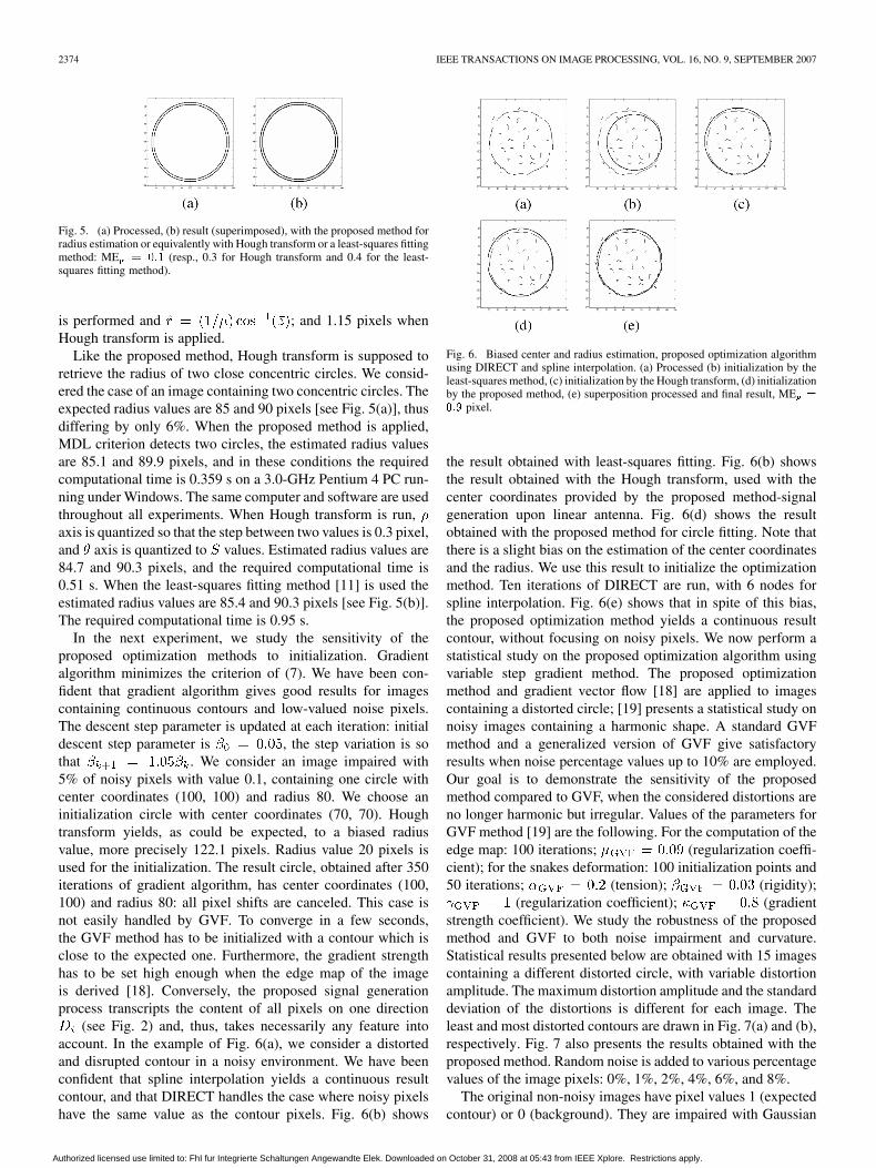
Fig. 5. (a) Processed, (b) result (superimposed), with the proposed method forradius estimation or equivalently with Hough transform or a least-squares fittingmethod: ME = 0:1 (resp., 0.3 for Hough transform and 0.4 for the least-squares fitting method).
is performed and ; and 1.15 pixels whenHough transform is applied.
Like the proposed method, Hough transform is supposed toretrieve the radius of two close concentric circles. We consid-ered the case of an image containing two concentric circles. Theexpected radius values are 85 and 90 pixels [see Fig. 5(a)], thusdiffering by only 6%. When the proposed method is applied,MDL criterion detects two circles, the estimated radius valuesare 85.1 and 89.9 pixels, and in these conditions the requiredcomputational time is 0.359 s on a 3.0-GHz Pentium 4 PC run-ning under Windows. The same computer and software are usedthroughout all experiments. When Hough transform is run,axis is quantized so that the step between two values is 0.3 pixel,and axis is quantized to values. Estimated radius values are84.7 and 90.3 pixels, and the required computational time is0.51 s. When the least-squares fitting method [11] is used theestimated radius values are 85.4 and 90.3 pixels [see Fig. 5(b)].The required computational time is 0.95 s.
In the next experiment, we study the sensitivity of theproposed optimization methods to initialization. Gradientalgorithm minimizes the criterion of (7). We have been con-fident that gradient algorithm gives good results for imagescontaining continuous contours and low-valued noise pixels.The descent step parameter is updated at each iteration: initialdescent step parameter is , the step variation is sothat . We consider an image impaired with5% of noisy pixels with value 0.1, containing one circle withcenter coordinates (100, 100) and radius 80. We choose aninitialization circle with center coordinates (70, 70). Houghtransform yields, as could be expected, to a biased radiusvalue, more precisely 122.1 pixels. Radius value 20 pixels isused for the initialization. The result circle, obtained after 350iterations of gradient algorithm, has center coordinates (100,100) and radius 80: all pixel shifts are canceled. This case isnot easily handled by GVF. To converge in a few seconds,the GVF method has to be initialized with a contour which isclose to the expected one. Furthermore, the gradient strengthhas to be set high enough when the edge map of the imageis derived [18]. Conversely, the proposed signal generationprocess transcripts the content of all pixels on one direction
(see Fig. 2) and, thus, takes necessarily any feature intoaccount. In the example of Fig. 6(a), we consider a distortedand disrupted contour in a noisy environment. We have beenconfident that spline interpolation yields a continuous resultcontour, and that DIRECT handles the case where noisy pixelshave the same value as the contour pixels. Fig. 6(b) shows
Fig. 6. Biased center and radius estimation, proposed optimization algorithmusing DIRECT and spline interpolation. (a) Processed (b) initialization by theleast-squares method, (c) initialization by the Hough transform, (d) initializationby the proposed method, (e) superposition processed and final result, ME =
0:9 pixel.
the result obtained with least-squares fitting. Fig. 6(b) showsthe result obtained with the Hough transform, used with thecenter coordinates provided by the proposed method-signalgeneration upon linear antenna. Fig. 6(d) shows the resultobtained with the proposed method for circle fitting. Note thatthere is a slight bias on the estimation of the center coordinatesand the radius. We use this result to initialize the optimizationmethod. Ten iterations of DIRECT are run, with 6 nodes forspline interpolation. Fig. 6(e) shows that in spite of this bias,the proposed optimization method yields a continuous resultcontour, without focusing on noisy pixels. We now perform astatistical study on the proposed optimization algorithm usingvariable step gradient method. The proposed optimizationmethod and gradient vector flow [18] are applied to imagescontaining a distorted circle; [19] presents a statistical study onnoisy images containing a harmonic shape. A standard GVFmethod and a generalized version of GVF give satisfactoryresults when noise percentage values up to 10% are employed.Our goal is to demonstrate the sensitivity of the proposedmethod compared to GVF, when the considered distortions areno longer harmonic but irregular. Values of the parameters forGVF method [19] are the following. For the computation of theedge map: 100 iterations; (regularization coeffi-cient); for the snakes deformation: 100 initialization points and50 iterations; (tension); (rigidity);
(regularization coefficient); (gradientstrength coefficient). We study the robustness of the proposedmethod and GVF to both noise impairment and curvature.Statistical results presented below are obtained with 15 imagescontaining a different distorted circle, with variable distortionamplitude. The maximum distortion amplitude and the standarddeviation of the distortions is different for each image. Theleast and most distorted contours are drawn in Fig. 7(a) and (b),respectively. Fig. 7 also presents the results obtained with theproposed method. Random noise is added to various percentagevalues of the image pixels: 0%, 1%, 2%, 4%, 6%, and 8%.
The original non-noisy images have pixel values 1 (expectedcontour) or 0 (background). They are impaired with Gaussian
Authorized licensed use limited to: FhI fur Integrierte Schaltungen Angewandte Elek. Downloaded on October 31, 2008 at 05:43 from IEEE Xplore. Restrictions apply.
MAROT AND BOURENNANE: SUBSPACE-BASED AND DIRECT ALGORITHMS 2375
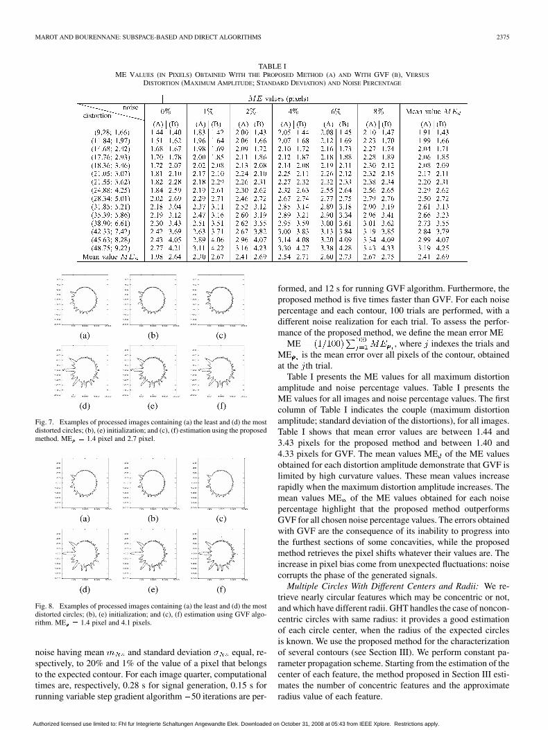
TABLE IME VALUES (IN PIXELS) OBTAINED WITH THE PROPOSED METHOD (A) AND WITH GVF (B), VERSUS
DISTORTION (MAXIMUM AMPLITUDE; STANDARD DEVIATION) AND NOISE PERCENTAGE
Fig. 7. Examples of processed images containing (a) the least and (d) the mostdistorted circles; (b), (e) initialization; and (c), (f) estimation using the proposedmethod. ME = 1.4 pixel and 2.7 pixel.
Fig. 8. Examples of processed images containing (a) the least and (d) the mostdistorted circles; (b), (e) initialization; and (c), (f) estimation using GVF algo-rithm. ME = 1.4 pixel and 4.1 pixels.
noise having mean and standard deviation equal, re-spectively, to 20% and 1% of the value of a pixel that belongsto the expected contour. For each image quarter, computationaltimes are, respectively, 0.28 s for signal generation, 0.15 s forrunning variable step gradient algorithm 50 iterations are per-
formed, and 12 s for running GVF algorithm. Furthermore, theproposed method is five times faster than GVF. For each noisepercentage and each contour, 100 trials are performed, with adifferent noise realization for each trial. To assess the perfor-mance of the proposed method, we define the mean error ME
ME , where indexes the trials andME is the mean error over all pixels of the contour, obtainedat the th trial.
Table I presents the ME values for all maximum distortionamplitude and noise percentage values. Table I presents theME values for all images and noise percentage values. The firstcolumn of Table I indicates the couple (maximum distortionamplitude; standard deviation of the distortions), for all images.Table I shows that mean error values are between 1.44 and3.43 pixels for the proposed method and between 1.40 and4.33 pixels for GVF. The mean values ME of the ME valuesobtained for each distortion amplitude demonstrate that GVF islimited by high curvature values. These mean values increaserapidly when the maximum distortion amplitude increases. Themean values ME of the ME values obtained for each noisepercentage highlight that the proposed method outperformsGVF for all chosen noise percentage values. The errors obtainedwith GVF are the consequence of its inability to progress intothe furthest sections of some concavities, while the proposedmethod retrieves the pixel shifts whatever their values are. Theincrease in pixel bias come from unexpected fluctuations: noisecorrupts the phase of the generated signals.
Multiple Circles With Different Centers and Radii: We re-trieve nearly circular features which may be concentric or not,and which have different radii. GHT handles the case of noncon-centric circles with same radius: it provides a good estimationof each circle center, when the radius of the expected circlesis known. We use the proposed method for the characterizationof several contours (see Section III). We perform constant pa-rameter propagation scheme. Starting from the estimation of thecenter of each feature, the method proposed in Section III esti-mates the number of concentric features and the approximateradius value of each feature.
Authorized licensed use limited to: FhI fur Integrierte Schaltungen Angewandte Elek. Downloaded on October 31, 2008 at 05:43 from IEEE Xplore. Restrictions apply.
2376 IEEE TRANSACTIONS ON IMAGE PROCESSING, VOL. 16, NO. 9, SEPTEMBER 2007
Fig. 9. Multiple circles: (a) processed (b) signal generated upon the left side ofthe image (c) initialization (d) result with gradient method.
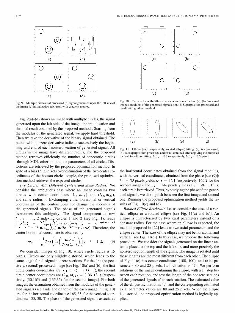
Fig. 9(a)–(d) shows an image with multiple circles, the signalgenerated upon the left side of the image, the initialization andthe final result obtained by the proposed methods. Starting fromthe modulus of the generated signal, we apply hard threshold.Then we take the derivative of the binary signal obtained. Thepoints with nonzero derivative indicate successively the begin-ning and end of each nonzero section of generated signal. Allcircles in the image have different radius, and the proposedmethod retrieves efficiently the number of concentric circles-through MDL criterion- and the parameters of all circles. Dis-tortions are retrieved by the proposed optimization method. Inspite of a bias (3, 2) pixels over estimation of the two center co-ordinates of the bottom circles couple, the proposed optimiza-tion method retrieves the expected circles.
Two Circles With Different Centers and Same Radius: Weconsider the ambiguous case where an image contains twocircles with center coordinates and ,and same radius . Exchanging either horizontal or verticalcoordinates of the centers does not change the modulus ofthe generated signals. The phase of the generated signalsovercomes this ambiguity. The signal component at row
, 1, 2 indexing circles 1 and 2 (see Fig. 1), reads
. Therefore, thecenter horizontal coordinate is obtained by
(9)
We consider images of Fig. 10, where circle radius is 15pixels. Circles are only slightly distorted, which leads to thesame length for all signal nonzero sections. For the first (respec-tively, second) processed image [see Fig. 10(a) and (b)], the firstcircle center coordinates are , the secondcircle center coordinates are [respec-tively, (30,165) and (135,35) for the second image]. For bothimages, the estimation obtained from the modulus of the gener-ated signals (see aside and on top of the each image in Fig. 10)are, for the horizontal coordinates: 165, 35; for the vertical coor-dinates: 135, 30. The phase of the generated signals associates
Fig. 10. Two circles with different centers and same radius. (a), (b) Processedimages, modulus of the generated signals. (c), (d) Superposition processed andresult with gradient method.
Fig. 11. Ellipse (and, respectively, rotated ellipse) fitting: (a), (c) processed;(b), (d) superposition processed and result obtained after applying the proposedmethod for ellipse fitting: ME = 0.7 (respectively, ME = 0.6) pixel.
the horizontal coordinates obtained from the signal modulus,with the vertical coordinates, obtained from the phase [see (9)]:
pixels yields (respectively, 165.2 for thesecond image), and pixels yields . Thus,each circle is retrieved. Thus, by studying the phase of the gener-ated signals, we distinguish between the first image and secondone. Running the proposed optimization method yields the re-sults of Fig. 10(c) and (d).
Rotated Ellipse Retrieval: Let us consider the case of a ver-tical ellipse or a rotated ellipse [see Fig. 11(a) and (c)]. Anellipse is characterized by two axial parameters instead of aconstant radius. For the case where an ellipse is expected, themethod proposed in [22] leads to two axial parameters and theellipse center. The axes of the ellipse may not be horizontal andvertical [see Fig. 11(c)]. In this case, we propose the followingprocedure. We consider the signals generated on the linear an-tenna placed at the top and the left side, and more precisely thenonzero section length of the signals. The image is rotated untilthese lengths are the most different from each other. The ellipseof Fig. 11(c) has center coordinates (100, 100), and axial pa-rameters 80 and 25 pixels. Its inclination is 47 . We performrotations of the image containing the ellipse, with a 1 step be-tween each rotation, and test the length of the nonzero sectionsof the generated signals after each rotation. The estimated valueof the ellipse inclination is 47 and the corresponding estimatedaxial parameter values are 80 and 25 pixels. When the ellipseis distorted, the proposed optimization method is logically ap-plied.
Authorized licensed use limited to: FhI fur Integrierte Schaltungen Angewandte Elek. Downloaded on October 31, 2008 at 05:43 from IEEE Xplore. Restrictions apply.
MAROT AND BOURENNANE: SUBSPACE-BASED AND DIRECT ALGORITHMS 2377
B. Real-World Images
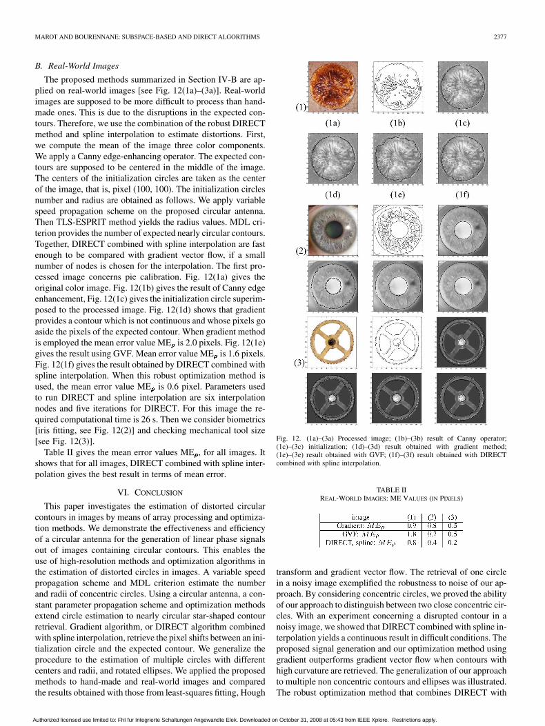
The proposed methods summarized in Section IV-B are ap-plied on real-world images [see Fig. 12(1a)–(3a)]. Real-worldimages are supposed to be more difficult to process than hand-made ones. This is due to the disruptions in the expected con-tours. Therefore, we use the combination of the robust DIRECTmethod and spline interpolation to estimate distortions. First,we compute the mean of the image three color components.We apply a Canny edge-enhancing operator. The expected con-tours are supposed to be centered in the middle of the image.The centers of the initialization circles are taken as the centerof the image, that is, pixel (100, 100). The initialization circlesnumber and radius are obtained as follows. We apply variablespeed propagation scheme on the proposed circular antenna.Then TLS-ESPRIT method yields the radius values. MDL cri-terion provides the number of expected nearly circular contours.Together, DIRECT combined with spline interpolation are fastenough to be compared with gradient vector flow, if a smallnumber of nodes is chosen for the interpolation. The first pro-cessed image concerns pie calibration. Fig. 12(1a) gives theoriginal color image. Fig. 12(1b) gives the result of Canny edgeenhancement, Fig. 12(1c) gives the initialization circle superim-posed to the processed image. Fig. 12(1d) shows that gradientprovides a contour which is not continuous and whose pixels goaside the pixels of the expected contour. When gradient methodis employed the mean error value ME is 2.0 pixels. Fig. 12(1e)gives the result using GVF. Mean error value ME is 1.6 pixels.Fig. 12(1f) gives the result obtained by DIRECT combined withspline interpolation. When this robust optimization method isused, the mean error value ME is 0.6 pixel. Parameters usedto run DIRECT and spline interpolation are six interpolationnodes and five iterations for DIRECT. For this image the re-quired computational time is 26 s. Then we consider biometrics[iris fitting, see Fig. 12(2)] and checking mechanical tool size[see Fig. 12(3)].
Table II gives the mean error values ME , for all images. Itshows that for all images, DIRECT combined with spline inter-polation gives the best result in terms of mean error.
VI. CONCLUSION
This paper investigates the estimation of distorted circularcontours in images by means of array processing and optimiza-tion methods. We demonstrate the effectiveness and efficiencyof a circular antenna for the generation of linear phase signalsout of images containing circular contours. This enables theuse of high-resolution methods and optimization algorithms inthe estimation of distorted circles in images. A variable speedpropagation scheme and MDL criterion estimate the numberand radii of concentric circles. Using a circular antenna, a con-stant parameter propagation scheme and optimization methodsextend circle estimation to nearly circular star-shaped contourretrieval. Gradient algorithm, or DIRECT algorithm combinedwith spline interpolation, retrieve the pixel shifts between an ini-tialization circle and the expected contour. We generalize theprocedure to the estimation of multiple circles with differentcenters and radii, and rotated ellipses. We applied the proposedmethods to hand-made and real-world images and comparedthe results obtained with those from least-squares fitting, Hough
Fig. 12. (1a)–(3a) Processed image; (1b)–(3b) result of Canny operator;(1c)–(3c) initialization; (1d)–(3d) result obtained with gradient method;(1e)–(3e) result obtained with GVF; (1f)–(3f) result obtained with DIRECTcombined with spline interpolation.
TABLE IIREAL-WORLD IMAGES: ME VALUES (IN PIXELS)
transform and gradient vector flow. The retrieval of one circlein a noisy image exemplified the robustness to noise of our ap-proach. By considering concentric circles, we proved the abilityof our approach to distinguish between two close concentric cir-cles. With an experiment concerning a disrupted contour in anoisy image, we showed that DIRECT combined with spline in-terpolation yields a continuous result in difficult conditions. Theproposed signal generation and our optimization method usinggradient outperforms gradient vector flow when contours withhigh curvature are retrieved. The generalization of our approachto multiple non concentric contours and ellipses was illustrated.The robust optimization method that combines DIRECT with
Authorized licensed use limited to: FhI fur Integrierte Schaltungen Angewandte Elek. Downloaded on October 31, 2008 at 05:43 from IEEE Xplore. Restrictions apply.
2378 IEEE TRANSACTIONS ON IMAGE PROCESSING, VOL. 16, NO. 9, SEPTEMBER 2007
spline interpolation was successfully applied to real-world im-ages and compared with gradient vector flow, leading to lowpixel bias. The results of the experiments show that the proposedmethod is fast and promising for feature retrieval. Further workcould consist in retrieving occluded circles and ellipses.
ACKNOWLEDGMENT
The authors would like to thank the anonymous reviewersfor their careful reading and their fruitful remarks, which havecontributed in improving the quality of the paper.
REFERENCES
[1] U. M. Landau, “Estimation of a circular arc center and its radius,”Comput. Vis. Graph. Image Process., no. 38, pp. 317–326, Jun. 1986.
[2] J. F. Crawford, “A noniterative method for fitting circular arcs to mea-sured points,” Nucl. Instrum. Meth. Phys. Res., no. 211, pp. 223–225,1983.
[3] V. Karimäki, “Effective circle fitting for particle trajectories,” Nucl.Instrum. Meth. Phys. Res., no. 305, pp. 187–191, 1991.
[4] I. Kasa, “A circle fitting procedure and its error analysis,” IEEE Trans.Instrum. Meas., vol. IM-25, no. 1, pp. 8–14, Mar. 1976.
[5] G. Coath and P. Musumeci, “Adaptive arc fitting for ball detection inrobocup,” in Proc. APRS Workshop on DIC, Brisbane, Australia, Feb.2003, pp. 63–68.
[6] S. D. Connell and A. K. Jain, “Template-based online character recog-nition,” Pattern Recognit., vol. 34, no. 1, pp. 1–14, 2001.
[7] M. A. T. Figueiredo and A. K. Jain, “Unsupervised learning of finitemixture models,” IEEE Trans. Pattern Anal. Mach. Intell., vol. 24, no.3, pp. 381–396, Mar. 2002.
[8] N. Ayache and O. D. Faugeras, “HYPER: A new approach for therecognition and positionning of two-dimensionnal objects,” IEEETrans. Pattern Anal. Mach. Intell., vol. 8, no. 1, pp. 44–54, Jan. 1986.
[9] W. Gander, G. H. Golub, and R. Strebel, “Least-squares fitting of cir-cles and ellipses,” BIT, no. 34, pp. 558–578, 1994.
[10] J. Borkowski, B. J. Matuszewski, J. Mroczka, and L.-K. Shark, “Geo-metric matching of circular features by least-squares fitting,” PatternRecognit. Lett., no. 23, pp. 885–894, 2001.
[11] P. O’Leary, M. Harker, and P. Zsombor-Murray, “Direct and least-squares fitting of coupled geometric objects for metric vision,” Proc.Inst. Elect. Eng., vol. 152, no. 6, pp. 687–694, Dec. 2005.
[12] Y. J. Ahn and H. O. Kim, “Approximation of circular arcs by Béziercurves,” J. Comput. Appl. Math., no. 81, pp. 145–163, 1997.
[13] Y. J. Ahn, Y. S. Kim, and Y. Shin, “Approximation of circular arcsand of a set curves by Bézier curves of high degree,” J. Comput. Appl.Math., no. 167, pp. 405–416, 2004.
[14] J. Illingworth and J. Kittler, “A survey of the Hough transform,”Comput. Vis. Graph. Image Process., no. 44, p. 87116, 1988.
[15] D. H. Ballard, “Generalizing the Hough transform to detect arbitraryshapes,” Pattern Recognit., vol. 13, no. 2, pp. 111–122, 1981.
[16] C. L. Tisse, L. Martin, L. Torres, and M. Robert, “Person identificationtechnique using human iris recognition,” in Proc. Int. Conf. Vision in-terface, May 2002, pp. 294–299.
[17] M. Kass, A. Witkin, and D. Terzopoulos, “Snakes: Active contourmodel,” Int. J. Comput. Vis., pp. 321–331, 1988.
[18] C. Xu and J. L. Prince, “Gradient vector flow: A new external force forsnakes,” in Proc. IEEE Comput. Soc. Conf. Computer Vision, PatternRecognition, Jun. 1997, pp. 66–71.
[19] X. Xianghua and M. Mirmehdi, “RAGS: Region-aided geometricsnake,” IEEE Trans. Image Process., vol. 13, no. 5, pp. 640–652, May2004.
[20] J. F. Aujol, G. Aubert, and L. Blanc-Féraud, “Wavelet-based level setevolution for classification of textured images,” IEEE Trans. ImageProcess., vol. 12, no. 12, pp. 1634–1641, Dec. 2003.
[21] K. Imen, R. Fablet, J.-M. Boucher, and J.-M. Augustin, “Region-basedsegmentation using texture statistics and level-set methods,” in Proc.IEEE ICASSP, Apr. 2006, no. 2, pp. 693–696.
[22] H. K. Aghajan, “Subspace Techniques for image understanding andcomputer vision,” Ph.D. dissertation, Stanford Univ., Stanford, CA,1995.
[23] H. K. Aghajan and T. Kailath, “Sensor array processing techniques forsuper resolution multi-line-fitting and straight edge detection,” IEEETrans. Image Process., vol. 2, no. 4, pp. 454–465, Oct. 1993.
[24] S. Bourennane and J. Marot, “Contour estimation by array processingmethods,” Appl. Signal Process., 2006, article ID 95634, 15 pages.
[25] S. Bourennane and J. Marot, “Optimization and interpolation for dis-torted contour estimation,” in Proc. IEEE ICASSP, Apr. 2006, no. 2,pp. 717–720.
[26] H. Aghajan and T. Kailath, “SLIDE: Subspace-based line detection,”IEEE Trans. Pattern Anal. Mach. Intell., vol. 16, no. 11, pp. 1057–1073,Nov. 1994.
[27] M. Wax and T. Kailath, “Detection of signals information theoreticcriteria,” IEEE Trans. Acoust., Speech, Signal Process., vol. ASSP-33,no. 2, pp. 387–392, Apr. 1985.
[28] R. Roy and T. Kailath, “ESPRIT: Estimation of signal parameters viarotational invariance techniques,” IEEE Trans. Acoust., Speech, SignalProcess., vol. 37, no. 7, pp. 984–995, Jul. 1989.
[29] D. R. Jones, C. D. Pertunen, and B. E. Stuckman, “Lipschitzian opti-mization without the Lipschitz constant,” J. Optim. Appl., vol. 79, no.157-81, 1993.
[30] H. K. Aghajan, B. H. Khalaj, and T. Kailath, “Estimation of multiple2-D uniform motions by SLIDE: Subspace-based line detection,” IEEETrans. Image Process., vol. 8, no. 4, pp. 517–526, Apr. 1999.
[31] G. Wolberg and I. Alfy, “Monotonic cubic spline interpolation,” inProc. Int. Conf. Computer Graphics, 1999, pp. 188–195.
Julien Marot received the physics engineeringdiploma from ENSP Marseille, France, in 2003,and the M.Sc. degree in image processing in 2004.He is currently pursuing the Ph.D. degree in themultidimensional signal processing group (GSM),Fresnel Institute (CNRS UMR-6133), Marseille
His research interests include applied image pro-cessing and signal processing.
Salah Bourennane received the Ph.D. degree fromthe Institut National Polytechnique de Grenoble,France, in 1990.
Currently, he is a Full Professor at the EcoleCentrale de Marseille, France. His research interestsare in statistical signal processing, array processing,image processing, multidimensional signal pro-cessing, and performance analysis.
Authorized licensed use limited to: FhI fur Integrierte Schaltungen Angewandte Elek. Downloaded on October 31, 2008 at 05:43 from IEEE Xplore. Restrictions apply.