Embed Size (px)
Citation preview

*
Ni-W Alloys Coatings as Ecological Alternative for Chromium Plating – Evaluation of
Corrosion Behaviour
L.Anicai**
ICPE-Advanced Research, ICPE-CA, Laboratory of Non-conventional Engineering, Splaiul
Unirii 313, sector 3, Bucharest, Romania
Among electrochemical processes having a considerable impact on technical
development in a large range of industrial areas and including implications from
environmental viewpoints, electrodeposition and electroforming play an important role.
Metallic layers as structures/microstructures formed through electrodeposition may be
further used as final products or accurate moulds whose shapes are then copied and replicated
involving sometimes again electrochemical techniques. In all cases the deposits must posses
very good mechanical, thermal stability and corrosion protection characteristics. These
complex performances may be especially assured when alloys of tungsten/molybdenum with
iron group metals are applied that can be also electrochemically obtained as coating layers or
thin metallic foils.
Moreover, under the frame of the efforts to find ecological alternatives to chromium
plating, alloyed Ni with tungsten or molybdenum as well as boron or SiC based composites
are showing promise for specific applications [1-4].
Generally alloys electrodeposition processes are more complex and more difficult to
investigate as compared with those involving pure metals, due to at least two metals
codeposition, of hydrogen evolution reaction that affects both current efficiency and deposit
* Present address: PETROMSERVICE SA, Implementation of Ecological Technologies Division, Calea Grivitei 8-10, secdtor 1, Bucharest, Romania

*
characteristics, as well as to the multiple crystallographic structures that may form according
to phase diagrams [5]. Metallic alloys electrodepositions properties are in close correlation
with their chemical composition as well as with the applied operating parameters, including
electrolyte type and composition that influence deposit appearance, uniformity and their
physical chemical characteristics (e.g. mechanical, electrical, anticorrosive properties).
Ni-W coatings belong to the so-called induced co-deposition systems, when nickel's
reaction rate enhances the codeposition of tungsten. These alloys show good mechanical
properties, good protection against certain aggressive environments and specific thermal,
electrical and magnetic properties [6-9].
Many studies have been dedicated on induced codeposition mechanism investigation
and a specific dependence of Ni-W alloys against operation parameters was evidenced [6-11].
Thus, based on catalytic reduction it was considered that a tungsten oxide is initially formed
at cathode, that furtherly is reduced by atomic hydrogen In this case, metallic species
belonging to iron group should catalyze tungsten oxide reduction to metallic W. Non-
homogenous coatings might form, that contain a certain arrangement of very thin layers of
the two metals alternatively deposited [7,12]. Obradović et al. [11] took into account Ni-W
alloy formation when Ni is mainly deposited from its citrate-ammonium complex. At low
overpotentials this reduction is activation controlled and for more electronegative values
diffusion control is evidenced due to the low electroactive species concentration and to the
low other complexes formation rate. Metal deposition takes place just in the presence of Ni-
citrate-ammonium complexes that affects W oxide layer structure. According to the reported
results in [11] Ni species reduction is not an independent process, being affected by the W
oxide presence on electrode surface at a certain potential modified by Ni itself deposition. Ni
reduction within the alloys is proposed to occur through 2 steps, involving Ni(I) intermediary
species formation whose concentration may be virtually in equilibrium with that of freshly

*
formed Ni(0) ones. These Ni(0) metallic particles in contact with electrode surface may
facilitate electrons transport towards W complex to activate it; afterwards the complete
reduction and alloy formation occurs.
Composition, structure and morphology of Ni-W electrodeposited alloys are strongly
influenced by applied operation parameters, mainly of electrolyte concentration in metallic
species and complexing agent, as well as of current density, hydrodynamic regime and
temperature [6,8,9]. Thus, it may consider that electrochemical obtaining of Ni-W alloys
represents a complex process that strongly influence their further application domain.
For practical use it is essential to get more information on their corrosion behaviour.
Hence, some investigations have been devoted to this subject, as well. It was reported [4,13
and ref.included] that corrosion is affected by the phase composition, chemical composition,
morphology and grain size of the deposit. However, few details are available on the subject.
Based on previous considerations, some preliminary investigations regarding direct
current electrodeposition and corrosion behaviour of Ni-W alloys (5-25% W) as coating
layers and thin metallic foils are presented.
EXPERIMENTAL
Deposition of Ni-W alloys has been performed in solutions containing NiSO4 and
Na2WO4 as electroactive species and Na3Cit as complexing agent. NH3 has been used to
adjust pH. To minimize the internal stress of the deposit, additions of saccharine and boric
acid have been applied. Current-potential curves for single metal and alloy deposition in
citrate-ammonium electrolytes were recorded, for a glassy carbon working electrode of 3 mm
diameter and a geometrical surface of 0.07 cm2 at a sweep rate of 10 mV/s, against a
Ag/AgCl reference electrode; the counter electrode was a Pt mesh. Electrolytes compositions
and experimental conditions are shown in Table 1.
*
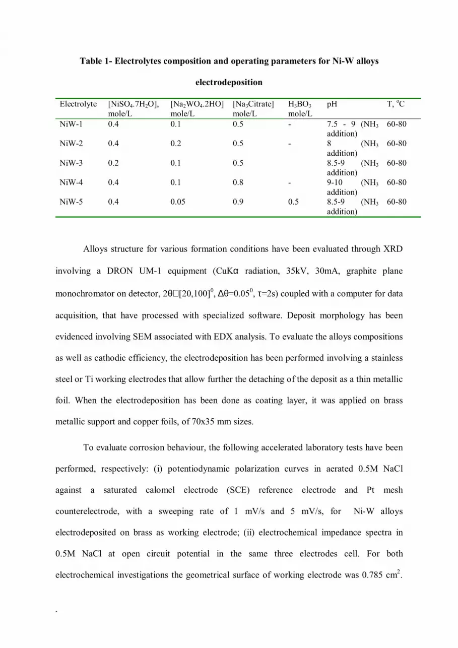
Table 1- Electrolytes composition and operating parameters for Ni-W alloys
electrodeposition
Electrolyte
[NiSO4.7H2O], mole/L
[Na2WO4.2HO] mole/L
[Na3Citrate] mole/L
H3BO3 mole/L
pH T, oC
NiW-1 0.4 0.1 0.5 - 7.5 - 9 (NH3 addition)
60-80
NiW-2 0.4 0.2 0.5 - 8 (NH3 addition)
60-80
NiW-3 0.2 0.1 0.5 8.5-9 (NH3 addition)
60-80
NiW-4 0.4 0.1 0.8 - 9-10 (NH3 addition)
60-80
NiW-5 0.4 0.05 0.9 0.5 8.5-9 (NH3 addition)
60-80
Alloys structure for various formation conditions have been evaluated through XRD
involving a DRON UM-1 equipment (CuKα radiation, 35kV, 30mA, graphite plane
monochromator on detector, 2θ∈ [20,100]0, ∆θ=0.050, τ=2s) coupled with a computer for data
acquisition, that have processed with specialized software. Deposit morphology has been
evidenced involving SEM associated with EDX analysis. To evaluate the alloys compositions
as well as cathodic efficiency, the electrodeposition has been performed involving a stainless
steel or Ti working electrodes that allow further the detaching of the deposit as a thin metallic
foil. When the electrodeposition has been done as coating layer, it was applied on brass
metallic support and copper foils, of 70x35 mm sizes.
To evaluate corrosion behaviour, the following accelerated laboratory tests have been
performed, respectively: (i) potentiodynamic polarization curves in aerated 0.5M NaCl
against a saturated calomel electrode (SCE) reference electrode and Pt mesh
counterelectrode, with a sweeping rate of 1 mV/s and 5 mV/s, for Ni-W alloys
electrodeposited on brass as working electrode; (ii) electrochemical impedance spectra in
0.5M NaCl at open circuit potential in the same three electrodes cell. For both
electrochemical investigations the geometrical surface of working electrode was 0.785 cm2.

*
A Zahner IM6e potentiostatic equipment have been used. EIS spectra have been processed
using Zview 2.4 produced by Scribner Association Inc., Derek Johnson; (iii) continuous
immersion in 0.5M NaCl at 20oC for 240 hours with intermediary visual examinations and
recording of corrosion potential for at least 3 specimens (70x35 mm) of Ni-W coatings on
brass having a thickness of 10-15µm. For all experiments, electrolytes and investigation
solutions have been prepared involving p..a. grade chemical reagents and distilled water.
RESULTS AND DISSCUSSIONS
Ni-W alloy electroformation – the influence of operating parameters
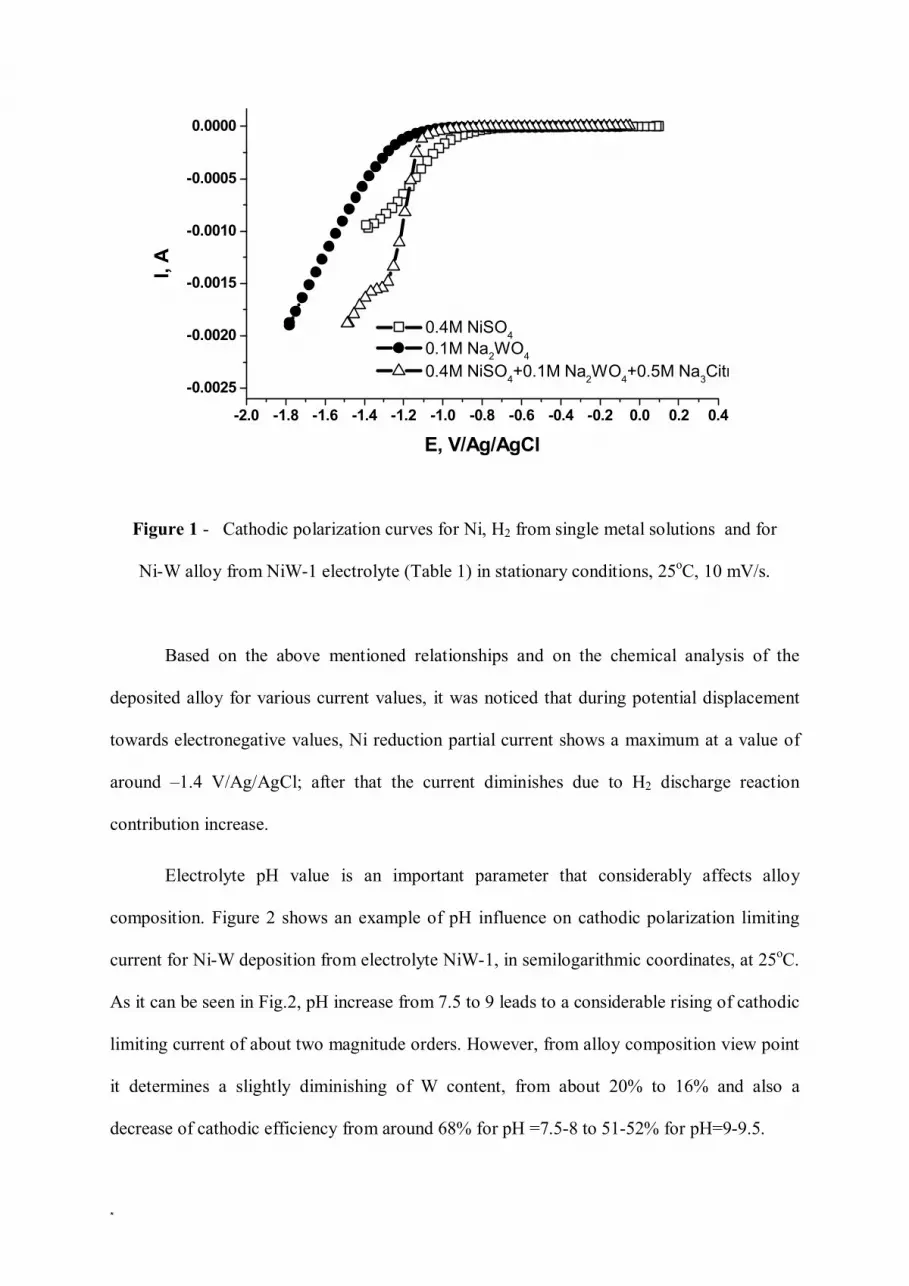
The cathodic polarization curves both for single metal solutions (0.4 M NiSO4; 0.1M
Na2WO4) and complete electrolyte containing both metallic cations in stationary conditions
are presented in Figure 1. In the case of tungstate solution, the curve represents in fact only
hydrogen evolution because in aqueous medium tungsten cannot be deposited [14]. The
current-potential curves for Ni and Ni-W deposition are quite close one by another, especially
for low current densities. This is in agreement with other literature data that evidenced a
small difference between deposition potentials of alloy and iron group metals of about 15-20
mV [15]. Ni-W alloy cathodic curve shows a small limiting current plateau, due to the
deposition limitation through diffusion process, more evidenced in stationary conditions.
Ni-W co-deposition is complicated by simultaneous discharge that occurs both during
Ni electrodeposition from individual solution and during both metallic species reduction to
form the alloy.
Partial deposition currents for Ni and W can be calculated using Equation 1:
ipartial = i alloy X (metal percentage in the alloy) (1)
and the consumed current for hydrogen discharge can be evaluated according to Equation 2:
iH2 = itotal - (iNi +iW) (2)
*
Figure 1 - Cathodic polarization curves for Ni, H2 from single metal solutions and for
Ni-W alloy from NiW-1 electrolyte (Table 1) in stationary conditions, 25oC, 10 mV/s.
Based on the above mentioned relationships and on the chemical analysis of the
deposited alloy for various current values, it was noticed that during potential displacement
towards electronegative values, Ni reduction partial current shows a maximum at a value of
around –1.4 V/Ag/AgCl; after that the current diminishes due to H2 discharge reaction
contribution increase.
Electrolyte pH value is an important parameter that considerably affects alloy
composition. Figure 2 shows an example of pH influence on cathodic polarization limiting
current for Ni-W deposition from electrolyte NiW-1, in semilogarithmic coordinates, at 25oC.
As it can be seen in Fig.2, pH increase from 7.5 to 9 leads to a considerable rising of cathodic
limiting current of about two magnitude orders. However, from alloy composition view point
it determines a slightly diminishing of W content, from about 20% to 16% and also a
decrease of cathodic efficiency from around 68% for pH =7.5-8 to 51-52% for pH=9-9.5.
-2.0 -1.8 -1.6 -1.4 -1.2 -1.0 -0.8 -0.6 -0.4 -0.2 0.0 0.2 0.4
-0.0025
-0.0020
-0.0015
-0.0010
-0.0005
0.0000
0.4M NiSO4 0.1M Na2WO4
0.4M NiSO4+0.1M Na2WO4+0.5M Na3Citr
I, A
E, V/Ag/AgCl

*
-1.6 -1.4 -1.2 -1.0 -0.8 -0.6 -0.4 -0.2 0.0 0.2 0.4
1E-7
1E-6
1E-5
1E-4
1E-3 pH = 7.5 pH = 9
I, A
E, V/Ag/AgCl
Figure 2 – Cathodic polarization curves for Ni-W electrodeposition from NiW-1 electrolyte
at different pH values (100 rpm, 25oC, 10 mV/s)
Usually pH value is corrected involving NH3 additions. Also, it is known that NH3 represents
a strong ligand for Ni2+ cations, being possible some complex compounds formation of
[Ni(NH3)n]2+ form with n=2-6. Ammonium role as complexing agent together with citrate
anion in Ni-W alloys electrodeposition has been recently taken into account [1]. In this way,
through formation of Ni2+ complexes with NH3 and citrate, the concentration of ternary
complex Ni/W/Citrate-considered as W deposition precursor is modified and consequently
the final alloy composition.
An important effect on Ni-W alloy electrodeposition from internal stress view point
decrease is assigned to alkaline citrate within the electrolyte. This aspect is correlated with
the possible deposition mechanism [1,11] that suggests formation of some precursors as
ternary complexes of [(Ni)(HWO4)(Cit)]2- type according to reactions:
[(Ni)(Cit)]- + [(HWO4)(Cit)]4- → [(Ni)(HWO4)(Cit)]2- + Cit3- (a)

*
[(Ni)(HWO4)(Cit)]2- + 8e- + 3H2O → NiW + 7(OH)- +Cit3- (b)
On one side these complexes have a high stability constant [1, 11], that leads to alloy
composition limiting through deposition partial currents limitation for a maximum citrate
concentration and on the other side cationic species reduction through these precursors
influence nucleation and growth phenomena and thus facilitate formation of microcrystalline
deposits that qualitatively are materialized by a better ductility [9]. The experimental results
confirmed these presumtions. Thus, an increase of citrate concentration from 0.5M to 0.9M
determined an improvement of deposit quality from appearance point of view, especially as
metallic foil, but W content decreased from 21% to 19%. Correspondingly, cathodic
efficiency significantly decreased from 85% to 55%.
From morphological view point, SEM microscopy revealed a coherent , crack free deposit,
with a granular structure, as is exemplified in Figure 3 for an alloy containing 20% W.
By means of XRD analysis, some information of the electroformed alloys structure
were obtained. Generally, besides the Ni characteristic peaks (at 2θ = 44o, 51o and 76o)
phases of Ni169W31 and Ni4W type have been also identified. W characteristic peaks have
not been evidenced so that it is suggested that the deposit keeps Ni structure. Taking into
account that W atomic radius is 0.1370 nm, larger than that of Ni (of 0.1245 nm) it should be
considered that Ni-W alloy is a solid solution in which Ni is the solvent and W is the solute
[8,9]. Figure 4 shows an example of X-ray diffractogram for Ni-W alloy (20% W)
electrodeposited from NiW-1 electrolyte (37 mA/cm2, 70o).
Usually, electrolytes containing more than 0.2M alkaline tungstate lead to deposits
having strong internal stress due to intense H2 discharge reaction, when alkaline citrate is in
the range 0.4-0.6M. These electrolytes having Ni:W ratio of 4:1, 2:1, 1:1 produce rich W
alloys (20-40% W) and these deposits may be used as coating layers with a good adherence
on non-ferrous metallic supports such as brass and copper.

*
Figure 3 – SEM micrograpy of Ni-W alloy (20% W) electrodeposited from
NiW-1 electrolyte (37 mA/cm2, 70o)
Figure 4 - X-ray diffractogram for Ni-W alloy (20% W) electrodeposited from
NiW-1 electrolyte (37 mA/cm2, 70o)
Beneficial effect of citrate complexing agent in high concentrations of minimum 0.8M
associated with NH3 addition has been evidenced in all cases, materialized in a significant
decrease of internal stress.
Additionally, metallic foils with a suitable flexibility and minimum internal stresses
have been obtained from low W content electrolytes as NiW-5 type from Table 1.

*
Corrosion behaviour of Ni-W alloys
To characterize Ni-W alloys from corrosion protection view point, potentiodynamic
polarization curves in 0.5M NaCl and 0.1M H2SO4 have been recorded as well as
electrochemical impedance spectra in 0.5M NaCl at open circuit potential, for immersion
periods between 0-240 hours. Figure 5 shows several polarization curves for various
immersion periods in 0.5M NaCl in the case of a Ni-W alloy (10-12% W) electrodeposited on
brass metallic support from electrolyte NiW-5 (acc.to Table 1) at a thickness layer of 10 µm.
1E-8 1E-7 1E-6 1E-5 1E-4 1E-3 0.01 0.1 1
-1.0
-0.5
0.0
0.5
1.0
1.5
2.0
E, V
/SC
E
i, A
initial 48 h 144 h
Figure 5 - Polarization curves in semilogarithmic coordinates for Ni-W alloy (10-12%W)
deposit in 0.5 M NaCl for various immersion periods (25oC, 5 mV/s)
At the beginning of conditioning, a corrosion potential around -0.86V/SCE was evaluated,
that moved towards more electropositive values for longer immersion times. Also, pitting
potential has the same evolution, from about -0.2 V/SCE towards about 0.010 V/SCE for
conditioning durations longer than 96 hours. Corrosion currents of 4 -7 µA/cm2 have been
determined, slightly higher for longer immersion periods. Table 2 summarizes characteristic

*
values resulted from polarization curves in 0.5M NaCl processing for different conditioning
periods, in the case of Ni-W alloy deposit containing 10-12% W.
Table 2 – Characteristic values resulted from polarization curves in 0.5M NaCl for
Ni-W alloy (10-12% W) during continuous immersion
Immersion period, hours Ecor, mV/ECS Epit, mV/ECS I cor, µA/cm2
0 -860 -200 4.09 48 -340 0 5.35 96 -772 10 7.5 144 -450 10 5.5 192 -475 10 6
For the same Ni-W alloy, electrochemical impedance spectra have been recorded in
0.5M NaCl at the same immersion periods, at open circuit potential in a frequency range
between 3.105 – 10-1 Hz. Figure 6 presents the recorded impedance spectra for alloy deposit
in 0.5M NaCl during immersion in Nyquist plots.
Figure 6 – Nyquist plots for Ni-W alloy deposit (10-12%W) in 0.5M NaCl at open circuit
potential, after various continuous immersion periods
0 10000 20000 30000 40000 50000 60000 700000
10000
20000
30000
40000
50000
60000
70000
80000
90000
100000
110000
- Zim
, Ω
Zre, Ω
initial 48 h 96 h 144 h

*
The shape of impedance spectra suggests that the alloy has protective properties.
Nyquist plots evidence the presence of semicircle, characteristic to layers that exhibit
relatively high polarization resistance values. To fit experimental data, an equivalent circuit
model has been proposed (as shown in Figure 7), comprising a combination of a constant
phase element (CPE) in parallel with coating resistance (Rc), in series with solution resistance
(Rsol). This CPE behaviour may suggest a variation of composition of the layer along its
thickness [13], phenomenon that can be taken into account, due to the presence of various
phases formation as also XRD revealed during electroformation process. Also, the use of
CPE takes into account the coating possible inhomogeneities and better simulates corrosion
processes [16,17]. The fitting parameters are presented in Table 3.
Figure 7 – Nyquist plot for Ni-W alloy deposition in 0.5 M NaCl at open circuit
potential (Uoc =-0.287 V/SCE) after 48 hours of immersion, representing both experimental
and fited points. Inset: the proposed equivalent circuit
-10000 0 10000 20000 30000 40000 50000 60000 70000-10000
0
10000
20000
30000
40000
50000
60000
70000
80000
Z im, Ω
Zre, Ω
NiW/Am in 0.5M NaCl after 48 h of immersion
experimental fit results

*
Table 3 - Fitting parameters of Ni-W alloy deposition in 0.5 M NaCl for various
immersion periods using the proposed equivalent circuit from the inset of Figure 7
CPE Immersion period, hours
Rş Ω.cm2
RP Ωcm2 C , F/cm2 n
Initial 36 2,4*104 1,67*10-5 0,859 48 54 2,2*105 1,18*10-5 0,827 96 59 1,45*105 1,85*10-5 0,768
144 43 7,7*105 1,27*10-5 0,855
Based on fitting results, polarization resistance values of about 24 kΩ have been
determined at the beginning of immersion, that increased with about one magnitude order
after 48 hours. This behaviour suggests formation of a passive film on metallic alloy surface
that enhance protective characteristics, materialized also by no major aspect modifications
even after 240 conditioning hours.
Ni-W alloys specimens (10-12% W) have been also evaluated by corrosion potential
evolution against immersion time in aerated 0.5M NaCl at 25oC, as is shown in Figure 8.
-24 0 24 48 72 96 120 144 168 192 216 240 264-0.35
-0.30
-0.25
-0.20
-0.15
-0.10
Ope
n ci
rcui
t pot
entia
l, U
oc, V
/EC
S
immersion time, hours
Figure 8 – Open circuit potential against continuous immersion time in 0.5M NaCl for Ni-W
alloy deposits (10-12%W)
According to Figure 8, corrosion potential slightly moves towards electronegative values
in the first 48 hours, followed by a displacement in positive direction, as an indicative of the

*
protective effect of the coating. This behaviour is in a good agreement with results presented
above, that assign the protective capacity to formation of an additional passive film that
enhance corrosion protection.
CONCLUSIONS
According to the experiments that have been performed it should be conclude that:
• Ni-W alloys with low internal stress and W contents between 5-25% W may be deposited
from citrate-ammonium type electrolytes with relatively low tungstate concetrations (0.05M-
0.2M);
• From XRD analysis phases of Ni169W31 and Ni4W type have been identified. W
characteristic peaks have not been evidenced so that it is suggested that the deposit keeps Ni
structure;
• Based on the experimental results, it should be mentioned that Ni-W alloys coatings offer
good corrosion protective characteristics materialized in corrosion currents of around 4-6
µA/cm2 and polarization resistances of minimum 25 kΩ. After 240 hours of continuous
immersion in chloride containing aggresive medium the exposed specimens didn’t exhibited
any major surface modification and no pits have been evidenced.
• Future experiments will be performed for a deeper investigation of corrosion protection in
close correlation with alloy composition and structure, as well as the application field.
Acknowledgements
This work was supported by the Romanian Ministry of Education and Research,
MATNANTECH Program, Contract 169(305)/2003. The authors wish to thank prof. T.Visan
from POLITEHNICA University of Bucharest, Department of Applied Physical Chemistry
and Electrochemistry for useful disscussions.

*
References
1. O.Younes, E.Gileadi, J.Electrochem.Soc., 149 (2002) C100.
2. L.Namburi, Electrodeposition of NiW Alloys into Deep Recess, M.Sc.Thesis, Louisiana
State University, december 2001.
3. *** Guide to Cleaner Technologies-Alternative Metal Finishes, EP/625/R-94/007, 1994,
EPA-Office of Research and Development, Washington, Cincinatti, OH
4. Neliaz, T.M.Sridhar, E.Gileadi, Electrochim.Acta, 50 (2005) 2893
5. R.Winand, Electrochim.Acta, 39 (1994) 1091.
6. H. Cesiulis, E.J.Podlaha-Murphy, Materials Science (Medziagotyra), 9(4) (2003) 329.
7. M.Donten, H.Cesiulis, Z.Stojek, Electrochim.Acta, 45 (2003) 3389.
8. T.Yamasaki, P.Schloβmacher, E.Erlich, Y.Ogino, NanoStructured Materials, 10(3)
(1998) 375.
9. T.Yamasaki, Mater.Phys.Mech.,,1 (2000) 127.
10. L.T.Romankiw, Electrochim.Acta, 42 (1997) 2985.
11. M.D.Obradović, R.M. Stevanović, AR.Despić, J.Electroanal.Chem., 552 (2003) 185.
12. Y.Wu, D.Chang, D.Kim, S-K.Kwon, Surf..and Coating Technol., 173, 259, 2003.
13. M.Obradović, J. Stevanović, AR.Despić, R. Stevanović, J.Stoch, J.Serb.Chem.Soc.,
66(11-12) (2001) 899.
14. A.Brenner, Electrodeposition of Alloys, Academic Press, New York, 1963.
15. M.A.M.Ibrahim, S.S.Abd El Rehim, S.O.Moussa, J.Appl.Electrochim., 33 (2003) 627.
16. Materials Science and Technology – A Comprehensive Treatment, Wiley-VCH Verlag
GmbH, 2000, vol.1, Editor: M.Schutze.
17. Electrochemical Impedance: Analysis and Interpretation, ASTM Publication 04-011880-
27, 1993, Editors: J.R.Scully, D.C.Silverman.


