Embed Size (px)
Citation preview
Note: Within nine months from the publication of the mention of the grant of the European patent, any person may givenotice to the European Patent Office of opposition to the European patent granted. Notice of opposition shall be filed ina written reasoned statement. It shall not be deemed to have been filed until the opposition fee has been paid. (Art.99(1) European Patent Convention).
Printed by Jouve, 75001 PARIS (FR)
Europäisches Patentamt
European Patent Office
Office européen des brevets
(19)
EP
0 76
1 94
7B
1*EP000761947B1*(11) EP 0 761 947 B1
(12) EUROPEAN PATENT SPECIFICATION
(45) Date of publication and mentionof the grant of the patent:24.05.2000 Bulletin 2000/21
(21) Application number: 96650036.5
(22) Date of filing: 27.08.1996
(51) Int Cl.7: F02C 7/24, F02C 7/045,F02K 1/38, F02K 1/48,F02K 1/60, F02K 3/06,B64C 1/40
(54) Noise reduction kit for turbofan engine
Satz für Bläsertriebwerkslärmdampfung
Ensemble amortisseur de bruit pour turbosoufflante
(84) Designated Contracting States:AT BE CH DE DK ES FI FR GB GR IE IT LI LU MCNL PT SE
(30) Priority: 29.08.1995 US 52113911.01.1996 US 584342
(43) Date of publication of application:12.03.1997 Bulletin 1997/11
(73) Proprietors:• Burbank Aeronautical Corporation II
Burbank, California 91505 (US)• McGuire, Kenneth R.
Encino, California 91316 (US)
(72) Inventors:• McGuire, Kenneth R.
Encino, California 91316 (US)• Phillips, Edward J.
San Diego, California 92127 (US)• Lillibridge, Robert W.
Woodland Hills, California 91367 (US)
• Matthews, Eugene JamesEncino, California 91316 (US)
(74) Representative: Hanna, Peter William Derek et alTomkins & Co.,5 Dartmouth RoadDublin 6 (IE)
(56) References cited:GB-A- 2 247 712 US-A- 3 696 617US-A- 4 292 803 US-A- 4 817 756US-A- 5 042 245 US-A- 5 127 602US-A- 5 169 288 US-A- 5 372 006
• J. OF THE ACOUSTICAL SOC. OF AMERICA, vol.58, no. 1, July 1975, USA, pages 155-172,XP002020367 C.L.ARCTANDER ,C.G.HODGE,R.B. TATE: "Development of noisereduction concepts for 727 and 737 airplanes."
• J.OF THE ACOUSTICAL SOC. OF AMERICA., vol.58, no. 1, July 1975, US, pages 144-154,XP002020368 M.N.NELSEN: "Development ofnoise reduction concepts for the 707 airplane."
EP 0 761 947 B1
2
5
10
15
20
25
30
35
40
45
50
55
Description
BACKGROUND
[0001] Having a turbofan engine with reduced noiseis important.[0002] This invention relates to a turbofan engine foraircraft, the engine having reduced noise. In particular,the invention is concerned with a family of engines orig-inally manufactured by Pratt & Whitney. In particular,these engines include the JT3D-3B, the JT3D-7 and theTF33 Engine, which includes the P-3/103, the P-5, theP-9, the P-100/100A and the P-102/102A Engines ("theJT3D family"). Such engines are commonly used onBoeing 707 aircraft, the Boeing KC135 and E3A aircraft,the Douglas DC8 aircraft and Lockheed C141 aircraft("Aircraft").[0003] Different techniques and systems are availa-ble to quiet an engine to reach different stages of noisereduction as defined by different governmental authori-ties. In particular, there are hush kits available to quietPratt & Whitney JT8D engines commonly used on Boe-ing 727 aircraft. Such an engine quieting system is thesubject of U.S. Patent No. 5,127,602 ("Batey"). The sys-tem uses a spacer and mixer to mix exhaust gas withfan air gas at the rear of the nozzle of the core engine.A cascade-type thrust reverser is used for thrust reverseconditions. Unlike the JT8D family, the JT3D family ofengines are designed to exhaust fan air and turbine airseparately to ambient air.[0004] In other systems and with other engines, anannular pressure duct is used to direct fan air rearwardlyto the rear zone of the exhaust nozzle. Such a systemis applied on DC8 Sixty Series aircraft. In these cases,there is no internal mixing in the nozzle area of the ex-haust air and duct air at the rear of the core engine.There is no common nozzle.[0005] In some cases, such as the DouglasDC8-62/63 series aircraft and the Lockheed C141 air-craft, the fan air is directed to a plane just upstream ofthe turbine exhaust nozzle where it ducts to ambient air.In these cases, a common thrust reverser reverses bothfan and turbine air. In other cases, such as the Boeing707, Boeing KC135 and E3A aircraft and DouglasDC8-50/61 series aircraft, the fan air is directed only ashort distance and exits to ambient air substantially for-ward of the turbine exhaust nozzle. In these caseswhere thrust reversing is desired, separate fan and tur-bine thrust reversers are required.[0006] Furthermore, these engines have a bleedvalve which, in certain situations of low power engineoperation, particularly on approach to landing, is openedto bleed air from the core engine away from the thrustgenerating exit rearwardly of the core engine, perpen-dicular to the thrust axis of the engine. The opening ofthe bleed valve relieves very hot supersonic air flow andcauses a substantial screeching noise and increasesthe noise characteristics noticeably in that operative
state of the engine.[0007] In the Applicant's experience, there is no sys-tem which exists for effectively quieting this JT3D familyof engines in a manner to reduce the perceived noiselevel of the engines, especially low frequency jet mixingnoise by at least three (3) noise decibels while maintain-ing the existing thrust levels.[0008] There is a need to provide for the effective op-eration of such engines under appropriate thrust and op-erate under the appropriate noise-reduced conditions.[0009] In particular, it is desirable to provide a turbo-fan engine with reduced noise and to provide a hush kitfor retrofitting such engines which minimizes the disad-vantages of known systems.
SUMMARY
[0010] By this invention there is provided a turbojetengine with reduced noise and a hush kit system for ret-rofitting an engine and creating a quieter engine whichhas advantages over known hush kit systems.[0011] According to the invention, there is provided anoise-reduced turbofan engine comprising a core en-gine having two (2) spool axial flow fans, multi-stagecompressors and multi-stage reaction turbines and athrust of at least about 80,064 N (18,000 lbs.) at sealevel. These engines include the JT3D-3B, the JT3D-7,and TF33, which includes the P-3/103, the P-5, the P-9, the P-100/100A and the P-102/102A engines pro-duced by Pratt & Whitney, East Hartford, Connecticut,having a thrust preferably between about 80,064 new-tons and about 93,408 newtons (about 18,000 lbs andabout 21,000 lbs.) at sea level.[0012] The fans are at an upstream end of the coreengine for generating axial fan air flow. There are by-pass ducts for receiving a major portion of the axial fanair flow from the fans. The ducts terminate at a commonnozzle located at the outlet for exhaust gas from the en-gine.[0013] The common nozzle has a mixing plane areafor each of the fan air flow and for the exhaust gas, eachin a range between 4516 and 5162 cm2 (700 and 800square inches). There is a mixer in the common nozzleassembly disposed axially to receive and exhaust theexhaust gas and fan air from the common nozzle to thetail pipe assembly. The plane area for the fan air is pref-erably in the range of about 4839 to 5033 cm2 (750 to780 square inches) and more preferably about 4852cm2 (752 square inches). The plane area for the exhaustgas is preferably in the range of about 4678 cm2 to 4904cm2 (725 to 760 square inches) and more preferablyabout 4691 cm2 (727 square inches). The exit area ofthe mixer, namely the area of the common nozzle, ispreferably about 9032 to 9677 cm2 (1,400 to 1,500square inches), and more preferably about 9561 cm2
(1,482 square inches). The static pressure of the fan exitand turbo exit is equalized for the engine pressure ratioof 1.7 to 1.86 and more preferably about 1.83 at the stat-
1 2
EP 0 761 947 B1
3
5
10
15
20
25
30
35
40
45
50
55
ic takeoff conditions. The design is such that at lowerengine pressure ratios the back pressure on the com-pressor fans and the turbine is not increased causing adecreased safety margin for engine stall while at thesame time not decreased causing a loss in enginethrust.[0014] A mixer has an upstream end and an annularmixer wall axially extending downstream therefrom. Thewall is formed into a plurality of circumferentially alter-nating radially inward and radially outward lobes, the ra-dially inward lobes defining cold chutes for radially in-wardly diverting fan air and outward lobes defining hotchutes for permitting radially outward expansion of ex-haust.[0015] An annular mixer adapter is provided for fixingthe mixer to a casing for the core engine in a positiondownstream of and coaxial with the core engine. A mixertransition contour plate has an upstream end for coaxialattachment to the downstream end of the core engine.This plate is an annular, axially extending transition con-tour plate for attachment to the upstream end of the mix-er. The plate is shaped to aerodynamically conform tothe mixer so as to effectively direct the fan air.[0016] A thrust reverser is provided which is movableinto a first position for converting axial flow of exhaustgas and fan air from the tail pipe assembly into reversethrust. It is movable into a second stowed position forpermitting the reverser doors to act as aerodynamic fair-ing for the nacelle afterbody. The thrust reverser is a tar-get-type system having opposing doors rotatable intothe first position to block and divert the flow of exhaustgases from a primary nozzle of the core engine bymeans of a mechanical linkage to an hydraulic actuationsystem. An acoustic liner is provided for the nozzle sur-rounding the mixer.[0017] A material layer is located in a spacing be-tween a tip of blades for at least some of the fans anda duct for the fans, thereby to reduce a normal clearancebetween the tip of blades for the fan and the duct.[0018] An acoustically dampened nose cone, alsoknown as an inlet centerbody, is provided for coaxial at-tachment to an upstream end of the core engine. Thenose cone is light bulb-shaped. An inlet cowling, morepreferably about 102 cm to 122 cm (40" to 48") in length,is provided with a leading edge which is heated by en-gine bleed air for anti-icing with an acoustic liner com-prising the inner air flow walls. In some cases whereblow-in doors are presently provided in the inlet to sup-plement intake air at high thrust levels of the engine, thediameter of the inlet is somewhat enlarged and the blow-in doors eliminated.[0019] The axial flow front fan is axially separated bya spacer, preferably about 8 cm to 13 cm (3" to 5"), anamount equal approximately to the axial depth of theblades of the fans. The inlet guide vanes, which directinlet air to the first row of fan blades, is moved to a po-sition, preferably in the range of 8 cm to 13 cm (3" to 5")forward of its present location, and a new engine hub
and oil-damped bearing installed.[0020] There is an inlet pressure sensing probehoused in an inlet bullet forwardly of the fans. Alterna-tively, there is an inlet pressure sensing probe housedat a location of an inlet guide vane forwardly of the fans,the probe being shaped for aerodynamic location in theinlet guide vane. The axial flow front fan is axially sep-arated from the inlet guide vane is extended relativelyforwardly.[0021] The tail pipe assembly is also configured tohave a relatively greater cross-sectional area in the exitfor accommodating an increased volume in the flowstream leading from the common nozzle. The greatercross-sectional area is relative to the turbine exhaustarea of an unmodified JT3D family of engines. The tailpipe exit plane is extended, preferably in the range of15 cm (6") to 18" to allow for mixing of the fan and turbineflows internally.[0022] A bleed air valve of the engine is selectivelyoperational to bleed air from the core engine when thevalve is open. A duct is provided for directing bleed airinto the mixing area of the common nozzle.[0023] In another form of the invention, there is pro-vided a noise reduction kit for modifying or retrofittingthe JT3D family of engines, the kit including at leastsome of the components to achieve the common nozzle.Also included in the kit is the target-type thrust reverser.The various acoustic elements are provided and the dif-ferent size cowling, the nose cone and the bleed valveduct are part of the kit.[0024] The invention further includes a method ofmodifying an engine as defined to reduce noise with thekit. Such an engine would normally include a cascade-type thrust reverser. The method for modifying the en-gine includes removing components of the engine fromthe upstream and downstream ends of the core engine.[0025] Thereafter, bypass ducts, some of which mayhave acoustical liners, are installed for receiving at leasta portion of the axial fan air flow from the fans. The ductsterminate at a common nozzle located at the outlet forexhaust gas from the engine through bypass ducts ter-minating at a common nozzle. The common nozzle hasa mixing plane area for each of the fan air flow and forthe exhaust gas, preferably in a range between 4516and 5162 cm2 (700 and 800 square inches).[0026] A mixer is installed forward of a tail pipe as-sembly disposed axially to receive and exhaust the ex-haust gas and fan air from the common nozzle. The mix-er is installed coaxially downstream to the core enginefor radially diverting fan air and permitting radially out-ward expansion of exhaust gas to mix the fan air andexhaust gas.[0027] An annular exhaust common nozzle is in-stalled coaxially, between the downstream end of thecore engine and a thrust reverser. The common nozzleextends the axial flow path of the mixed exhaust gasand fan air upstream of the reverser.[0028] The cascade reverser is replaced with a target-
3 4
EP 0 761 947 B1
4
5
10
15
20
25
30
35
40
45
50
55
type reverser having opposing doors rotatable into po-sition to block to divert the flow of exhaust gases for gen-erating reverse thrust.[0029] The invention is further described with refer-ence to the accompanying drawings.
DRAWINGS
[0030] FIGURE 1 is an exploded perspective top viewof the components making up the core engine, and thehush kit.[0031] FIGURE 2 is a bottom view of the core engine,with some hush kit components and the cowling shownin phantom, and the reverser is open.[0032] FIGURE 3 is a sectional top view of the coreengine and sectional views of the duct to the commonnozzle area of the mixer, and the reverser is closed, andshowing one embodiment where the inlet probe for at-mospheric air is in the bullet of the nose piece.[0033] FIGURE 3A is a detailed sectional top view ofthe inlet duct to the fan of the core engine, showing aninlet probe at the inlet for atmospheric air for a valve,and also an ablated space in relation to the fan.[0034] FIGURE 3B is a perspective view of the inletprobe for atmospheric air for a valve operating with thecore engine.[0035] FIGURE 4 is a cross-sectional front view fromthe nose showing the engine.[0036] FIGURE 5 is a partial perspective view fromthe top showing one of four engines mounted below apartial wing, shown in phantom, on support pylons.[0037] FIGURE 6 is a rear end view of the enginealong lines 6-6 showing the common nozzle area andthe rear of the mixer.[0038] FIGURE 7 is a perspective view, with portionsbroken away, showing the assembled mixer, contourplate and adapter for forming the common nozzle.[0039] FIGURE 8 is a flow diagram representing a ret-rofit construction procedure for applying the hush kitcomponents to a core engine.[0040] FIGURE 9 is a graphical representation show-ing the changes in corrected flow (%) in relation to theinteracting bypass or duct corrected fan air flow in rela-tion to the core stream or exhaust air flow as a functionof engine pressure ratio (EPR) at sea level static condi-tions.[0041] FIGURE 10 is a side view of the common noz-zle showing the mixer in relation to the target-type thrustreverser.
DESCRIPTION
[0042] A JT3D or TF33 core engine, as modified, isdescribed as set forth below:
I. OVERVIEW
A. Engine and Hush Kit Generally
B. General Procedure for Retrofitting EngineC. Noise Suppression Hush Kit
II. CORE ENGINE
A. Description and Operation
1. General2. Operation3. Compressor Section4. Combustion Section5. Turbine And Exhaust6. Front Accessory Section
B. Front Compressor Section
1. Front Compressor Assembly2. No. 1 Bearing Supports and Inlet CaseAssembly3. Inner Shroud4. Outer Shroud5. Front Compressor Cases
a. Front Compressor Case and VaneAssemblyb. Fan Discharge Case Assemblyc. Front Compressor Rear Case As-sembly
6. Front Compressor Stator Vanes andShrouds7. Front Compressor Rotor
C. Compressor Intermediate SectionD. Rear Compressor Section
1. Vane and Shroud Assemblies2. Air Seals3. Rear Compressor Rotor4. Diffuser Section
III. AFT CENTER BODY
IV. FAN AIR DUCTS
A. GeneralB. Constant Section and Transition Duct
V. COMMON NOZZLE
VI. MIXER
VII. MIXER ADAPTER RING - SPACER - TRANSI-TION RING
A. Mixer Installation in Common Nozzle
VIII. MIXER TRANSITION CONTOUR PLATE(FAIRING) - FAN EXHAUST DUCT SEGMENT
5 6
EP 0 761 947 B1
5
5
10
15
20
25
30
35
40
45
50
55
IX. FAN AIR SHROUD
X. THRUST REVERSER
A. Mounting Ring, Adapter, Spacer - ExhaustTransition Duct AssemblyB. Target-Type Thrust ReverserC. Thrust Reverser: Structural Description
XI. COWLING
A. GeneralB. Nose CowlC. Cowl DoorsD. Aft Cowl
XII. TAIL PIPE ASSEMBLY
XIII. INLET BULLET: CENTER BODY
XIV. RESPACED INLET GUIDE VANE (RIGV)
XV. COMPRESSOR BLEED
XVI. EXIT NOZZLE ASSEMBLY
XVII. GENERAL
I. OVERVIEW
A. Engine and Hush Kit Generally
[0043] A noise-reduced turbofan of the JT3D family ofengines comprises a core engine 20 having two spoolaxial flow fans 21 and 22, multi-stage compressors 23,24 and multi-stage reaction turbines (25) and a thrust ofat least about 80,064 newtons (18,000 lbs.) at sea level.More specifically, the generated thrust is 80,064 to93,408 newtons (18,000 to 21,000 lbs.) take-off powerat sea level on a standard day. The family of JT3D en-gines manufactured by Pratt & Whitney consists of theJT3D-3B, the JT3D-7 and the TF33 engine, which in-cludes the P-3/103, the P-5, the P-9 and the P-102/102Aengines. The JT3D family of engines is commonly usedon Boeing 707, the Boeing KC135 and E3A aircraft,Douglas DC8 series aircraft, and Lockheed C141 air-craft ("Aircraft").[0044] The fans 21 and 22 of the engine are locatedat an upstream end of the core engine for generatingaxial fan air flow. There are two bypass ducts 26 and 27on each side of the engine 20 for receiving at least aportion of the axial fan air flow from the fans 21 and 22.The ducts 26 and 27 collectively surround the core en-gine 20 and terminate at a common nozzle 28 locatedat the outlet for exhaust gas from the engine 20. Eachof the bypass-ducts 26 and 27 is composed of three sep-arable sections 26a, 26b and 26c; and 27a, 27b and27c on each side from the front to the rear of the core
engine 20. The ducts 26 and 27 are removable, in partor whole, as necessary when the core engine 20 needsmaintenance. There are two spaced fire walls 30a and30b located transversely of and about the engine 20.[0045] There is a mixer 29 in the common nozzle 28which is upstream of a tail pipe assembly generallyshown as 42. The tail pipe assembly 42 includes multi-ple components to axially receive and exhaust the ex-haust gas and fan air from the common nozzle 28 to theexit nozzle 31.[0046] The common nozzle 28 has a mixing plane ar-ea for each of the fan air flow and for the exhaust gas.This is shown in Figure 6, which represents a view ofthe mixer from the aft end. Each plane is in a range be-tween 4516 and 5162 cm2 (700 and 800 square inches).[0047] The plane area for the fan air 32 is formed ef-fectively by the area of the lobes of the mixer 29 receiv-ing the cold fan air, and is in the range of about 4839 to5033 cm2 (750 to 780 square inches), and is preferablyabout 4852 cm2 (752 square inches). The plane areafor the exhaust gas 33 is formed by the lobes of the mixer29 for receiving the hot gas, and is about 4678 to 4904cm2 (725 to 760 square inches), and preferably about4691 cm2 (727 square inches). The plane area of thecommon nozzle 28, as defined by both these plane ar-eas 40, is 9561 cm2 (1,482 square inches). The diame-ter 31 of the exit nozzle 200 is preferably between about94 cms to 99 cms (37 inches to 39 inches), and morepreferably, 98.75 cms (38.88 inches). The mix of fan airand hot gas is about 80%.[0048] The effect of the common flow accomplishedby the common nozzle 28 on the engine operating linescan be assessed by evaluating the relative changes incorrected flow (W√T/P) for the core and bypassstreams, as illustrated in Figure 9. A common flow na-celle configuration is selected to maintain the same en-gine operating point as the separate flow nacelle at stat-ic take-off, 1.83 engine pressure ratio ("EPR"). Belowtake-off power, there is a significant increase in the ef-fective fan nozzle area and a significant decrease in thecore nozzle area. The opposite is true above 1.83 EPR.Based on limited influence coefficient information, thesearea shifts result in a loss in high pressure compressorstability margin at low power and a loss in fan and lowpressure compressor stability margin at high power.[0049] The mixer 29 has an annular mixer wall 35 ax-ially extending downstream therefrom. The wall 35 isformed into a plurality of circumferentially alternating ra-dially inward and radially outward lobes 32 and 33, re-spectively. The radially inward lobes 32 define coldchutes for radially inwardly diverting fan air. The out-wardly directed lobes 33 define hot chutes to permit ra-dially outward expansion of exhaust. The particularJT3D family of engines can have different numbers oflobes in the mixer, preferably having 14 to 18 lobes. TheJT3D family of engines preferably has a 16-lobe mixer.A JT8D-200 model engine uses a 12-lobe mixer.[0050] An annular mixer adapter 36 is provided for fix-
7 8
EP 0 761 947 B1
6
5
10
15
20
25
30
35
40
45
50
55
ing the mixer to the exhaust outlet 129 for the core en-gine in a position downstream of, and coaxial with, thecore engine 20.[0051] A mixer transition contour plate is provided 34for coaxial attachment to the downstream end of thetransition contour plate 37 of the core engine 20. Thereis an annular, axially extending transition contour plate37 for attachment to the upstream end of 34. The platesare shaped to aerodynamically conform to the mixer todirect fan air. This is different to and additional to themixer adapter 36 which fits within the contour plate 37.[0052] The rear portion of the core engine 20 includesan aft center body 38. This is extended to project intothe mixer 29 and the end of cone 39 projects beyondthe aft end 40 of the mixer 29.[0053] A target-type thrust reverser 41 is provided tobe movable into a first position for converting axial flowof exhaust gas and fan air from the tail pipe assembly42 into reverse thrust. It is movable into a second stowedposition which permits the reverser doors 43 and 44 toact as aerodynamic fairings for the nacelle afterbody 45.[0054] The target-type thrust reverser system 41 hasopposing doors 43 and 44 rotatable into a position toblock and divert the flow of exhaust gases from a nozzleassembly 46 of the common nozzle 28 by means of amechanical driver linkage 47 and roller linkage 48 to anhydraulic actuation system 50. There is an acoustic linerfor nozzle assembly 46 that serves as the exhaust ductsection of the engine nacelle package and consistsstructurally of a welded sandwich barrel tail pipe 49 hav-ing the inner face perforated for noise abatement. Thisbarrel tail pipe 49 provides support for the thrust revers-er generally indicated as 41.[0055] A material layer 300 is located in a spacing be-tween a tip 301 of blades 302 for at least some of thefans and a duct for the fans, thereby to reduce a normalclearance between the tip 301 of blades 302 for the fan21 and the duct. The layer 300 is a plasma spray layerlocated about the inside wall 303 of the duct, to a thick-ness of between about 0.127 cm to about 0.229 cm(0.050 to about 0.090 of an inch). This ablation layerreduces the space between the blade tip 301 and theinside wall of the duct and thereby reduces the amountof noise generated by the core engine. The data indi-cates that this reduction is in the order of about 4 deci-bels. Different thicknesses, either greater or less, canbe used as required.[0056] An acoustically dampened nose cone 51 isprovided for coaxial attachment to an upstream end ofthe core engine 20. The nose cone 51 is light bulb-shaped.[0057] An inlet cowling 52 has a relatively increaseddiameter inlet cowling relative to an unmodified enginewhere blow-in doors are presently used.[0058] The axial flow fan blades 21 and 22 are axiallyseparated by an amount equal approximately to the ax-ial depth 53 of the fan blades 21 and 22. The inlet guidevane 55 for the front fan 21 is moved forward of its
present position, preferably in the range of about 8 cmto 15 cm (3" to about 6"), and preferably about 13 cm(about 5"), and a new engine hub and damped bearinginstalled. This is termed a "Respaced Inlet Guide Vane"["RIGV"].[0059] The acoustically dampened light bulb-shapednose cone is provided for coaxial attachment to an up-stream end of the core engine. The acoustically damp-ened nose cone, also known as an inlet centerbody, isprovided for coaxial attachment to an upstream end ofthe core engine. An inlet cowling, more preferably about102 cm to 122 cm (about 40" to 48") in length, is providedwith a leading edge which is heated by engine bleed airfor anti-icing with an acoustic liner comprising the innerair flow walls.[0060] There is an inlet pressure sensing probehoused in an inlet bullet forwardly of the fans. Alterna-tively, there is an inlet pressure sensing probe housedat a location of an inlet guide vane forwardly of the fans,the probe being shaped for aerodynamic location in theinlet guide vane. The axial flow front fan is axially sep-arated from the inlet guide vane is extended relativelyforwardly.[0061] The tail pipe assembly 42 including nozzle 31is configured to have a greater cross-sectional area inthe exit for accommodating an increased volume in theflow stream from the common nozzle 28.[0062] A bleed air valve from the core engine 20 isselectively operational to bleed air from the core engine20 when the valve is open. There is a duct 56 for direct-ing bleed air into the common nozzle 28. The duct 56for the bleed air runs parallel to and adjacent to one ofthe ducts 26 or 27 for the fan air. It ends at the commonnozzle 28 and particularly through a port provided in thefire wall 30b adjacent to the area of the common nozzle28.
B. General Procedure For Retrofitting Engine
[0063] A method of modifying the family of JT3D en-gines is to reduce noise with the kit includes removinga cascade-type thrust reverser, which is normally partof the JT3D engine installation. It is replaced with a tar-get-type thrust reverser. The method includes removingother components of the engine from the upstream anddownstream ends of the core engine. The procedure isdescribed in relation to Figure 8.[0064] Bypass ducts 26 and 27 for receiving the axialfan air flow from the fans are installed. The ducts termi-nate at a common nozzle 28 located at the outlet for ex-haust gas from the engine through bypass ducts 26 and27 terminating at the common nozzle 28.[0065] A mixer 29 is installed in a common nozzle as-sembly to receive and exhaust the exhaust gas and fanair from the common nozzle to the exit nozzle. The mixer29 provides for radially diverting fan air inwardly and forpermitting radially outward expansion of exhaust gas tomix the fan air and exhaust gas. The mixer 29 is installed
9 10
EP 0 761 947 B1
7
5
10
15
20
25
30
35
40
45
50
55
coaxially downstream to the core engine 20.[0066] An annular exhaust transition duct, which isformed between a fan air shroud 60, and contour plates34 and 37 is installed coaxially in a location relativelybetween the exit planes of 26C and 27C and the tail pipeassembly 42. The shroud 60 also extends the axial flowpath of the mixed exhaust gas and fan air upstream ofthe reverser 41.[0067] The target-type reverser 41 has opposingdoors 43 and 44 rotatable into position to block and di-vert the flow of exhaust gases for generating reversethrust, and a stowed position permitting the reverserdoors to act as aerodynamic fairings for the nacelle af-terbody 45. Fig 3.
C. Noise Suppression Hush Kit
[0068] The major components for the hush kit for theJT3D family of engines are set forth below.[0069] The elements of the noise suppression kit aresized to fit a two-spool axial flow, turbofan engine withmulti-stage compressors and fans driven by multi-stagereaction turbines designed for operation with fixed areanozzles for primary and fan discharge.[0070] The components are:
1. Fan Air Ducts - 3 components on each of twosides of the Core Engine.
2. Common Nozzle - This new component to theJT3D family of engines is for a Nozzle for the pri-mary (exhaust) gas and for the fan air discharge.
3. Mixer to assist the Common Nozzle.
4. Mixer adapter: This is a Spacer or TransitionRing.
5. Mixer Transition Contour Plate. This is a fairing,namely a Fan Exhaust Duct Segment.
6. Bleed Valve Duct terminating into the CommonNozzle.
7. Common Nozzle Duct Assembly for installationof the Thrust Reverser. This has a Thrust ReverserMounting Ring or Adapter.
8. Target-Type Reverser.
9. Acoustic Nozzle Assemblies.
10. Acoustically treated, lengthened and diametri-cally enlarged Nose Cowl with no blow in doors forthose Aircraft that originally were designed withNose Cowls having blow-in doors.
11. Acoustically treated, lengthened Center Body:
Bullet - light bulb shape
12. Respaced Inlet Guide Vane (RIGV).
13. Cowl doors - Apron.
II. CORE ENGINE
[0071] The core engine or power plant of the JT3Dfamily of engines is a two-spool axial flow turbofan en-gine with multi-stage compressors and fans driven bymulti-stage reaction turbines. The following specifica-tions are applicable to such an engine:
a. 80,064 to 93,408 newtons (18,000 to 21,000 lbs.)take-off static thrust at sea level.b. Dual axial 15 to 16 stage compressor, 4 stageturbine and 8 annular combustion chambers.c. Principal dimensions:
1. Length 345 cm to 363 cm (136" to 143")2. Width 134 cm to 139 cm (53" to 55")3. Height 142 cm to 152 cm (56" to 60")
A. Description And Operation
1. General
[0072] The JT3D family of engines is made up of en-gines which operate similarly to all turbofan versions ofa gas turbine engine. Two front compressor stages 21and 22, respectively, have vanes and blades which areconsiderably larger than other stages and are common-ly referred to as a "fan". This "fan" provides two separateair streams.[0073] A primary, or inner air stream travels throughthe engine 20 and the internal devices operate to gen-erate pressures and gases in the exhaust nozzle 46 andthereby provide propulsive force. This stream is the ex-haust stream. Secondary, or outer air stream is mechan-ically compressed by the "fan" as it enters the engineand is normally ducted to the outside engine 20 a shortdistance from "fan". This secondary air stream, termedthe "fan air", adds to propulsive force similar to a pro-peller. Although the "fan" has an effect of a geared pro-peller, it is driven at engine speed. The efficiency of theengine is increased by the dual air streams, and sincea smaller percentage of available energy is diverted tothe "fan", thrust-specific fuel consumption is lower thanthat of comparable turboprop engines.[0074] The JT3D family of engines consists of axialflow turbofan engines having a fifteen to sixteen-stagesplit compressor, an eight-can combustion chamber,and a four-stage split turbine. With all the engine-pro-vided accessory components installed (aircraft compo-nent mounting brackets excepted), each of the enginesof the JT3D family of engines weighs approximately1932 Kg to 2223 Kg (4,260 to 4,900 pounds).
11 12
EP 0 761 947 B1
8
5
10
15
20
25
30
35
40
45
50
55
2. Operation
[0075] Air enters the engine 20 through the compres-sor inlet case assembly. The airframe inlet duct is at-tached to the front of the inlet case. This inlet case as-sembly 61 is provided with vane-type multipurposestruts 62 which transmit No. 1 bearing 63 loads to theouter case structure, conduct anti-icing air and lubricat-ing oil to the inner diameter of the engine, and direct airto the front compressor section.
3. Compressor Section
[0076] The compressor section is of split-type andconsists of two rotor assemblies 69 and 65, respectively.Each rotor assembly 69 and 65 is driven by an inde-pendent turbine, and each rotor 69 and 65 is free to ro-tate at its best speed. Since it is necessary to rotate onlyone of these units during starting operation, selection ofa small rear compressor permits use of a smaller starter.[0077] Air from the inlet guide vane 55 and shroud as-sembly enters the front compressor 66, which consistsof eight rotor stages 67 and seven stage stator vanes81. The gas path of this compressor has a constant in-side diameter and decreasing outside diameter. Thiscompressor is the larger of two, and provides initial com-pression of air. Rotating parts are connected by a driveshaft 69 which passes through the inside of the rearcompressor rotor 65 and drive shaft to second and thirdstage turbines.[0078] Between the front compressor 66 and rearcompressor is an intermediate case 70. It has an auto-matic arrangement for bleeding front compressor air.This is to improve acceleration characteristics of engineinlet vanes (9th stage) to transmit No. 2 and No. 3 bear-ing loads to the outer case, conduct supply and returnoil to bearings and to the outer case, conduct supply andreturn oil to the bearings, and direct compressed air fromthe front compressor 66 to the rear compressor.[0079] The rear compressor has seven rotor stages84 and six vane stages 83. It has a constant outside di-ameter and increasing inside diameter, and is driven bya first stage turbine through an independent shaft con-centric with the front compressor drive shaft. Aft of therear compressor is a diffuser case 72.[0080] The compressor exit guide vanes at the frontof the diffuser case 72 straighten air which is then ex-panded for entry into combustion chambers 73. Strutsin the case transmit No. 4 and No. 5 bearing loads tothe outer portion of the case. In addition, these strutsconduct bearing oil pressure and suction lines and pro-vide high pressure air for such engine functions as anti-icing. They also provide a source of clean air for aircraftpressure needs. A water injection manifold is mountedon the front flange. Coolant is dispersed through sixteencurled tubes mounted on the periphery of the diffusercase, through mating holes in the case and injected intothe air stream. The outside contours of the compressor
and diffuser sections give the engine its "wasp waist"and at the same time provide convenient location for anaccessory section.[0081] The fuel manifold, which consists of eight cir-cular clusters of six fuel nozzles, is located in the diffusercase 72 annulus and injects fuel into the air stream ingoverned proportions. At this point, the air is channeledinto eight portions for burning with fuel in eight combus-tion chambers 73 and 74.
4. Combustion Section
[0082] The combustion section consists of eight sep-arate cans arranged annularly, namely the "cannularburners". The chambers 73, as viewed from the rear ofthe engine, are numbered in a clockwise direction start-ing with the uppermost chamber as No. 1. These cham-bers are connected by cross-over tubes. The com-pressed air, its velocity decreased and now with fuel par-ticles injected, is lighted initially by spark igniters in-stalled in the No. 4 and No. 5 combustion chambers.After "light-up", the flame is perpetuated by constructionof the combustion chamber and heat generated by pre-vious combustion. Exhaust gases pass through thecombustion chamber outlet duct.
5. Turbine And Exhaust
[0083] The turbine nozzle case 75 houses the firstthree stages of a four-stage turbine and is aft of the com-bustion section 73. The first stage 76 drives the rearcompressor, and the second, third, and fourth stages 77drive the front compressor 66. The turbine nozzle case75 also contains four turbine exhaust nozzles. The noz-zles are made up of a series of stationary vanes 78which direct exhaust gases through turbine blades andinto the turbine exhaust case.[0084] To the rear of the turbine nozzle case 75 thereis a turbine exhaust case 79 which houses a fourth stageturbine disk and blades and through which exhaust gas-es are ejected from the engine. The turbine exhaustcase 79 also supports the No. 6 bearing and the No. 6bearing oil sump.
6. Front Accessory Section
[0085] The front accessory section consists of one as-sembly, and front accessory drive support. The case ofthis assembly is made of magnesium. Sixteen bolts se-cure the front accessory support to the No. 1 bearingsupport. The front accessory support has one mountpad on its front face. This pad has provisions for mount-ing and driving the tachometer.[0086] The No. 1 bearing scavenge pump is mountedon its lower rear face of support. The air and oil for bleedcontrol are brought out of the No. 1, which is externallysplined, is inserted, with the "o" ring seal around it, intothe front compressor front hub engaging internal spline
13 14
EP 0 761 947 B1
9
5
10
15
20
25
30
35
40
45
50
55
in hub. It is retained by the same nut that holds the No.1 bearing inner race in position. The front accessorydrive gear meshes with and drives the tachometerdrivegear, the No. 1 bearing scavenge pump drive gear.
B. Front Compressor Section
1. Front Compressor Assembly
[0087] The front compressor, which is housed in thefront compressor front and rear cases, consists of a rotorcomposed of eight rows of blades 67 and a stator as-sembly containing eight rows of vane 81 and shroud as-semblies located between successive stages of blades.The first two rows of blades 67 are considerably largerthan the rest and are referred to as "fan" blades 21 and22.[0088] There is no second stage stator and no thirdrow of blades. At this point, the air stream is separatedinto primary and secondary streams. Separation isachieved by use of a spacer between the second andfourth stage blades. The primary air stream is directedinternally by a third stage stator while the secondary airstream is exhausted through exit struts. Numbering ofthe blade stage from the front to the rear is Nos. 1 and2 and 4 - 9, and the numbering of the stator stages isNos. 1 and 3 - 8. The ninth stage stator vanes are incor-porated in the intermediate case.[0089] The third stage vane and shroud assembly isof single piece construction, whereas the fourth througheighth stages are of split type. Spacers of the fourththrough eighth stages are integral. The inner shroudsfrom the seal ring for two air seals are on the outer di-ameter of each rotor.[0090] The compressor is driven by the shaft 69 fromthe second, third, and fourth stage turbines. Its rotationalspeed is roughly two-thirds the speed of the rear or high-speed compressor. Its function is to provide initial com-pression to air that passes through the engine 20 andtransmits this air to the rear or high-speed compressor.Stator vanes 68 and rotor blades 67 diminish in size andincrease in quantity from the front to the rear of com-pressor. This matches decreasing volume of air as thepressure of air rises.[0091] The front accessories are driven by a gear at-tached to the front hub of the front compressor rotor. Therear hub of the front compressor contains the front com-pressor drive turbine shaft coupling.[0092] The rear hub of the front compressor rotor issupported by a double ball bearing (No.2). The twohalves of the No. 2 bearing (front compressor rear) areseparated by an oil baffle in which drilled holes direct oilto the forward and aft sections of the double bearing.The No. 3 bearing (rear compressor front) inner raceand rollers are mounted on the end of the rear hub. Theoil seal on the rear end seals the bearing compartmentfrom the engine air stream.[0093] The front hub, rotor is supported by a roller
bearing (No. 1), the liner of which is in the No. 1 bearinghousing. The oil seal on the front end seals the bearingcompartment from the engine air stream. The bearingsupport is secured to the inlet case assembly and formsthe assembly.
2. No. 1 Bearing Supports and Inlet Case Assembly
[0094] These assemblies are discussed together.Supports are for the mounting in the inner diameter ofthe inlet case assembly, vanes of which, carry the struc-tural load of the No. 1 bearing (front compressor front)from the inner shroud to the outer shroud.[0095] The inlet case assembly consists of hollow ti-tanium vanes 55, incorporating foam rubber stiffenersin center bays, that are inserted between hollow, double-walled titanium inner and outer shrouds. Each vane 55extends from the inner wall of the inner shroud to theouter wall of the outer shroud. Also, vanes 55 are weldedto the outer wall of each shroud. There are holes in theside walls of the vanes 55 that are between the shroudwalls, and this forms passage for the flow of anti-icingair. The left and right anti-icing tubes feed heated air,when desired, into the outer rim of the shroud assemblyopposite the eight and four o'clock struts.[0096] Some vanes 55 have tubes inside. These arefor oil, breather and bleed valve control air lines. TheNo. 1 bearing oil pressure and oil return tubes are locat-ed in the seven o'clock and five o'clock struts, respec-tively. The purpose of these vanes 55 is to cause air toenter compressor rotor blades 66 at the best angle forbest compressor operation and to transport structuralload.
3. Inner Shroud
[0097] The inner shroud, being of double-wall con-struction, provides for the passage of anti-icing air thathas flowed inward through the guide vanes. The oil andair tubes that pass through the vanes 55 have fittingsmounted on the inner wall of the inner shroud. On thefront edge of the inner shroud, holes are drilled andtapped to hold bolts that secure the No. 1 bearing hous-ing and compressor inlet air seal assembly. The frontaccessory front support is bolted to its forward face. An-ti-icing air outlet holes are also on the front edge of theshrouds. The No. 1 bearing oil seal is bolted at its outerdiameter to a compressor inlet vane, inner shroud rearflange.
4. Outer Shroud
[0098] The outer shroud, being also of double-wallconstruction, provides for the passage of anti-icing air.The outer wall of the outer shroud forms support for out-er fittings of tubes that pass through some vanes 55.The anti-icing air inlet fitting is also in the shrouded outerwall. The pressure probe fitting passes through both
15 16
EP 0 761 947 B1
10
5
10
15
20
25
30
35
40
45
50
55
walls of the shroud to protrude into the air stream be-tween the vanes 55. The front rim of the outer shroud isdrilled and tapped to receive bolts which will hold theairframe, air inlet duct. The rear rim of the outer shroudis drilled and tapped to receive bolts that hold the shroudto the front compressor case.
5. Front Compressor Cases
[0099] There are three front compressor cases,namely: the front compressor case and vane assembly61, the fan discharge case assembly 80, and the com-pressor rear case assembly 82. The front compressorcase 80, 61 and 82 carry structural load from the engine.These cases 80, 61 and 82 decrease in diameter fromfront to rear to match decreasing diameters of statorrings.
a. Front Compressor Case and Vane Assembly
[0100] The front compressor case and vane assembly80 attaches to the rear flange of the compressor inletcase 61 and front flange of the fan discharge case 81.In the approximate center of the case, riveted to internalflanges, are titanium first stage stator vanes. At the innershroud of vanes, an aluminum stage air sealing ring isriveted. The inner shroud is constructed of titanium.From the forward internal flange to the inlet case, thefront airflow duct is inserted. From the rearward internalflange to the fan discharge case forward flange, the rearairflow duct is inserted.
b. Fan Discharge Case Assembly
[0101] Attached to the rear flange from the compres-sor case, and further attached to the van assembly bybolts and pinned to the rear airflow duct, is the fan dis-charge case 80. This case is constructed of stainlesssteel and consists of an outer shroud and an inner casewith thirty-eight steel struts between them. The strutsare secured in an inner case by a riveted locking plateat the rearward end and wired to a fairing retainingscrews at the forward end.
c. Front Compressor Rear Case Assembly
[0102] Attached to the rear innermost flange of the fandischarge case and to the forward flange of the interme-diate case is the compressor rear case assembly 82.Welded to it internally are supports for the vane andshroud assemblies.
6. Front Compressor Stator Vanes and Shrouds
[0103] The first stage stator vanes 68 were discussedabove under the front compressor case and vane as-sembly. There is no second stage stator. The third andfourth stage rows, or statuaries, are made of aluminum.
These vanes 68 are riveted into aluminum shroud rings.The fifth through eighth stator vanes 68 are made ofstainless steel and are welded into steel shroud rings.All shroud rings are wide enough to form spacers whichpermit compressor blades 67 to rotate. Statuaries arepinned to inner shrouds to which are attached rivetedinner air seal platforms. The third stage stator vanes andshroud are built into a single circular assembly which isheld stationary by a flange inserted between the fan dis-charge case 81 and the front compressor rear flanges.The fourth through eighth stage stator vanes andshrouds are split and are prevented from rotating by be-ing pinned to each other and to a third stage vane andshroud. When assembled, rings are held in the engineby shoulders on the inside of the front compressor rearcase.[0104] The angle at which vanes 68 are mounted inshrouds is set to feed air into the following row of rotorblades 67 to give the best compressor efficiency at op-erating speed. Stator vanes 68 decrease in size fromfront to rear to match the decreasing volume air and de-creasing size of the rotor blades 67.
7. Front Compressor Rotor
[0105] The front compressor rotor 66 consists of twohubs, seven disks, seven spacer assemblies, eight rowsof blades 67, two sets (sixteen each) of tie rods and as-sociated hardware. Each row of blades 66 is insertedinto undercut slots in its disk. They are held in place bylocks inserted under blades 66 and bent to secure. Theblades 66 do not have a tight fit, but rather are seatedby centrifugal force during engine operation. The fronthub forms the disk for the first row of blades 66, but therear hub is a separate unit that is held fast to the rear-ward face of the seventh stage disk by tiebolts. Spacersbetween the disks are internally reinforced with tubes.Tiebolts run through these tubes and through disks.These spacers have two knife-edges on the OD. Theserun against seal platforms on the stator vane innershroud, which was previously described. An exceptionto the above is a large spacer between the second andfourth stage compressor blades. This serves as ameans of joining the "fan" section to the remainder ofthe compressor and, in so doing, provides neededspace in that area. Each disk has twenty-four holes inits flange. Sixteen are for tierods and eight are for bal-ancing weights, when needed.[0106] The front hub has a lip on its forward face, andthe second stage disk has a similar lip on its rearwardface to which balance weights can be added when as-sembly is complete. The smaller set holds the first twostages of blades together, while the longer set holds to-gether the third through eighth stages. Both sections arejoined together by a spacer, as previously mentioned.Rotor blades 67 decrease in size from front to rear. Thefirst two stages of blades 66 are considerably larger thanthe rest and form the fan stages 21 and 22. The angle
17 18
EP 0 761 947 B1
11
5
10
15
20
25
30
35
40
45
50
55
of each row of blades 66 is set to give best efficiency atoperating speed. The rear hub flange has large holes toallow some ninth stage air into the compressor rotor.This air serves the dual purpose of providing bearingseal pressurizing and cooling. The front compressor ro-tor consists of hub (No. 1 hub only) disks, and blades21 and 22, all of which are made from titanium. The No.2 hub is made of steel.
C. Compressor Intermediate Section
[0107] Forward mounting points are on an intermedi-ate case 70 which is attached to the rear flange of thefront compressor case 82. A locating pin is used at thetop center between the two flanges. An intermediatecase 70 surrounds the rear compressor, but is not con-sidered as part of it. It serves to separate low pressurefrom the compressor from high pressure in the rear com-pressor and serves a structural function of joining exter-nal cases. The intermediate case 70 is of steel construc-tion and has a double wall on the forward end. The guidevanes are welded from the outer wall, through the innerwall and extend into the shroud ring. The front flange ofthe case is drilled and tapped for bolts that attach it tothe front compressor case 82, and the rear flange isdrilled. Nuts are spun into holes for bolting the diffusercase 72 and the intermediate case 70 together.[0108] An oil breather pad is located between themounting flanges at approximately the two o'clock posi-tion. An oil tube fitting is at the six o'clock position be-tween the mounting flanges. Toward the rear of the case70, a hole is provided for air bleeding and air bleed valvemounting. On the JT3D-7 and TF33 (DSLG) model en-gines of the JT3D family of engines, this is located in theupper-left quadrant. On the JT3D-7 and TF33 (BG)model engines of the JT3D family of engines, it is locat-ed in the lower-left quadrant.[0109] Thirty vanes on the inside front of the caseserve as air inlet guide vanes to the rear compressor.They are hollow steel vanes with openings in their sidewalls at the outer end. These openings, together withthe double wall of the case, form a breather passagefrom the upper breather connections on the case to thelower opening. Inlet vanes are welded to the No. 3 bear-ing support whose outer configuration is shaped to forman inner ring for these vanes. At the front (inner) and therear (outer) ends of this support, bolt circles are providedto receive bolts to hold the diagonal and rear bearingsupports. A hollow tubular seal is used at the rear (outer)bolt circle. One of the round plates is flat and forms adiagonal brace between the front and the rear support.The tapered plate has large holes at the top and bottomto allow air breather and passages for oil tubes. Exten-sions of the front and rear supports form seal housings.[0110] The bearing housing is integral with the centersupport. The stepped edge seal ring is bolted to supportat the outer diameter of the rear support plate. This ring,together with its mating knife-edge seal, minimizes air
leakage out of the front end of the rear compressor. Thearea inside ring and behind rear support plate is ex-posed to high pressure air extracted from the twelfthstage of compression. The air pressure outside seal ringis from the ninth stage.
D. Rear Compressor Section
[0111] The rear, or high, compressor is driven by a hol-low shaft 65 from the front stage of turbine 76. Its func-tion is to compress further air delivered by the front com-pressor and then feed this air into the diffuser case 72and burners 74.[0112] The rear compressor consists of a stator hav-ing six rows of vanes 83 and a rotor shaft 65 having sev-en rows of blades 84. Exit guide vanes are mounted inthe diffuser section 72. In function, these are part of thecompressor, but because of their structural location,they are discussed under the section regarding the dif-fuser.
1. Vane and Shroud Assemblies
[0113] There are six vane and shroud assemblies 83in the rear compressor. The vanes 83 reduce in heightfrom the front to the rear of the compressor. The outerside diameter of the air passage formed by these as-semblies is constant, decreasing size of the vanes 83 isaccomplished by increasing the diameter of the innershroud rings. The vanes 83 are made of steel and arebrazed to the inner shroud and pierced through the outershrouds on the first five vane and shroud assemblies83. The spacers separating assemblies are integral.The sixth stage does not provide spacing. However, thisis furnished by the seventh stage located in the diffusercase 72. Between each shroud, dowel pins are used tolock series of shrouds together. The rear shroud (sev-enth) is pinned to the seventh stage outer shroud to pre-vent rotation. The edge of each spacer rests against thecase shoulder to center the assembly.
2. Air Seals
[0114] The inside shroud of each row of vanes 83 hasa steel ring, with a small step riveted to it on its insideface. Two knife-edge seals on each rotor spacer ridefree of steps forming an air seal between the compres-sor stages.
3. Rear Compressor Rotor
[0115] The rotor shaft 65 includes seven rows ofblades 84 on disks, two hubs, six spacer assemblies,sixteen tie-rod bolts with nuts and washers. A knife-edgeseal ring is riveted to lip on the forward face of the tenthstage disk. This seal ring rides free of a platformed sealwhich was referred to in the compressor intermediatecase discussion.
19 20
EP 0 761 947 B1
12
5
10
15
20
25
30
35
40
45
50
55
[0116] Each row of blades 84 is inserted into undercutslots in its disk. They are held in place by locks insertedunder blades 84 and bent to secure. The blades 84 donot have a tight fit, but rather are seated by centrifugalforce during engine operation.[0117] Every disk has 32 holes in its flange. Sixteenof the holes are for tie bolts, and the remaining 16 arefor balancing weights when needed. The entire assem-bly is held together by tie bolt heads on one end and anut and washer on the other end.[0118] The spacers between disks are internally rein-forced with tubes. Tie bolts run through tubes and spac-er internal flanges, as well as disk flanges.[0119] Neither a front nor rear hub is integral with thedisk. The front hub is attached to the front face of a thirddisk and a rear hub to the rear face of the last disk. Thehubs are secured to an assembly for rotor 84 by steeltie bolts, as mentioned above. A steel tube runs fromone hub to the other inside rotor.[0120] A tube is force-fit into the inside diameter ofboth hubs and permits breathing within its inside andkeeps twelfth stage pressure air from the No. 3 and No.4 1/2 bearings.[0121] A third spacer from the front has holes drilledin it. Through these holes, twelfth-stage air is bled intoa rotor center where it is bled through holes in the fronthub. The air is directed forward to a space just behindNo. 3, bearing the rear support plate, and pressurizesthe No. 3 bearing oil seal. Since there are no holes inthe rear hub disk, the pressure of air against this diskcounteracts part of the rotor forward thrust.[0122] The case 70 of the rear compressor carries nostructural bearing loads and is thus made of relativelythin sheet metal. Its purpose is to hold stator parts of thecompressor and act as the air separator. The air pres-sure increases from front to rear and finally becomes asixteenth stage pressure. Between this case 82 and theintermediate case 81 which envelopes it, the pressureis ninth- stage air. The case has a flange at its rear endto which screws that attach the case to the diffuser sec-tion 72 are secured. Also, bolt holes are provided to holdthe intermediate case 70 to the diffuser section 72.
4. Diffuser Section
[0123] The velocity of air as it leaves the rear com-pressor is very high. This motion is both rearward andtangential around the engine. The exit guide vanes atthe forward end of the diffuser case 72 convert tangen-tial whirl into pressure energy. After the vanes, the highpressure air will have a large rearward velocity. Thegradual increasing area of air flow passages providedby the case configuration of the diffuser 72 decreasesthe air flow velocity to suitable burning speed and in-creases the pressure.
III. AFT CENTER BODY
[0124] At the aft portion of the turbine, there is a centerbody 38 about which the exhaust gas is expelled. In themodified core engine 20, the center body 38 is extendedrearwardly so that it projects rearwardly beyond the aftdirect of the mixer 29.
IV. FAN AIR DUCTS
[0125] The kit includes a bifurcated series of threeducts 26a, 26b and 26c; and 27a, 27b and 27c, respec-tively, on each side of the engine 20. The acoustically-treated ducts 26 and 27 extend from an engine fan airattachment 90 and terminate at the common nozzle 28.
A. General
[0126] The engine fan air collector consists of the twoduct assemblies 26 and 27 on the side of the engine 20.Each duct assembly 26 and 27 has three interengagingduct sections 26a, 26b and 26c; and 27a, 27b and 27c,respectively, on each respective side of the engine 20.The bi-ducts 26a and 27a are constructed of bondedaluminum honeycomb, or composites and are inter-changeable, right and left. Each duct assembly 26 and27 is from front to rear: the forward bifurcated fan airduct 26a and 27a, hinged constant section fan air duct26b and 27b, and transition section fan air duct 26c and27c. All ducts can be of bonded aluminum honeycombor composite material.
B. Forward Ducts, Constant Section Ducts andTransition Ducts
[0127] The collector system consists of the engine fanair ducting 26 and 27 and the engine turbine and ex-haust outlet section 129. During engine operation, theexhausted fan air from ducts 26 and 27 and the engineexhaust gases from outlet 129 join at the rear of the en-gine 20, into the common nozzle 28.
a. The forward bifurcated fan air ducts 26a and 27aare installed between the engine fan exit attach-ments 90 and the hinged constant section fan airducts 26b and 27b. Each bifurcated duct 26a and27a has a semi-circular shape at the forward end91 to match the shape of the exhaust from fan at-tachment 90. The ducts 26a and 27a are bolted tothe aft face of the fan exit 90 and are contoured atthe aft end 92 to fit the side of the engine 20. Theaft end 92 of the ducts 26a and 27a are fastened tothe hinged constant section fan air ducts 26b and27b, respectively, with bolted channel assemblies,which clamp the ends of the ducts 26a and 26b to-gether and 27a and 27b together. Splitter webs,preferably in the range of 3 to 6, and more prefera-bly 5, are attached to the inner surface of each duct
21 22
EP 0 761 947 B1
13
5
10
15
20
25
30
35
40
45
50
55
to direct the flow of air through the ducts 26 and 27and to provide additional supporting strength.
b. The hinged constant section fan air ducts 26band 27b are installed between the forward bifurcat-ed fan air ducts 26a and 27a and the transition sec-tion fan air ducts 26c and 27c, respectively. Theducts 26b and 27b are contoured to fit the side ofthe engine at the compressor section 70. The ducts26b and 27b are fastened to the aft end 92 of theforward bifurcated fan air ducts 26a and 27a and tothe front end 93 of the transition section fan air ducts26c and 27c, respectively, with bolted channel as-semblies, two on each side. These channel assem-blies are hinged at the top with pins. By removingthe two bolts from the upper and lower end of eachchannel assembly, the ducts can be rotated outwardand upward. Splitter webs, preferably in the rangeof 3 to 6, and more preferably 3, are mounted inter-nally in each duct 26b and 27b to direct the flow ofair through the duct and to provide additionalstrength.
c. The transition section fan air ducts 26c and 27care installed between the hinged constant sectionfan air ducts 26b and 27b. The ducts 26c and 27care contoured to fit the side of the engine 20 andare attached at the firewall 30a by three rods oneach side. The ducts 26c and 27c are attached atthe forward end 93 to the hinged constant sectionfan air ducts 26b and 27b with bolted channel as-semblies which clamp the ends of the ducts 26b and26c together, and 27b and 27c together. The aft end94 of the transition section fan air ducts 26c and27c are fastened to the common nozzle shroud 60by means of bolts. Splitter webs, preferably in therange of 3 to 6, and more preferably 4, are mountedinternally in each duct 26c and 27c to direct the flowof air through the duct and to provide additional sup-porting strength.
V. COMMON NOZZLE
[0128] The common nozzle 28 allows the air from thefans 21 and 22 to enter and exit a chamber at the sametime as the core exhaust gases from the exhaust outlet129 from the core engine 20. It is this chamber whichconstitutes the common nozzle 28.[0129] The core gas exhaust outlet 129 and fan gasesfrom duct outlets 26c and 27c enter and exit the cham-ber of the common nozzle 28 at a predetermined nozzleexit size so as not to affect the performance of the en-gine 20.[0130] The common nozzle 28 accepts a mixer 29which allows mixing of gas from the core exhaust 20 andgases from the fans 21 and 22 for maximum benefit.
VI. MIXER
[0131] The mixer means 29 in the common nozzle 28directs fan air into the core exhaust gas flow path down-stream of the core engine 20. The mixer 29 includes 12to 18 circumferentially-spaced, axially and radially elon-gated lobes 33 and 32, respectively, which define alter-nating hot and cold chutes. The fan gas (cold) chutes32 are on the outside where the fan bypass air is locatedand the turbine exhaust (hot) chutes 33 are aligned withthe interior core where the hot core air flows. The mixer29 is designed to blend fan air passing through fan ducts26 and 27, with core exhaust gas emerging from thedownstream low pressure turbine of the core engine 20from exhaust outlet 129.[0132] The mixing reduces peak temperature of theexhaust stream and therefore reduces jet noise. Sincethrust noise is a function of the peak temperature of theexhaust gas stream raised to the eighth power, evenslight reductions in the peak overall jet temperature re-sults in significant lowering of the perceived enginethrust noise. The mixer 29 provides the optimum mixingwithout adversely affecting the engine efficiency.[0133] The mixer 29 has a plurality of alternating hotgas ducts 33 and cold gas ducts 32. Gas from the by-pass ducts 26 and 27 enters into the cold gas ducts 32which incline radially inward. The colder bypass gas isdirected toward the central axis of the engine 20. Ex-haust gas from the core of the engine 20 flows throughthe hot gas ducts 33 which have a greater cross-sectionand which incline slightly outward in a radial direction.The hot and cold (primary and fan) gas mix downstreamof the mixer 29 with the result that the temperature ofthe mixed gas is less than that of the core gas from ex-haust 129. This decrease in temperature results in de-crease in noise, since the noise is a function of the max-imum gas temperature exiting the engine tail pipe 42.
VII. MIXER ADAPTER RING - SPACER - TRANSITIONRING
A. Mixer Installation In Common Nozzle
[0134] The mixer 29 is installed within the commonnozzle 28 by using an adapter ring 36 which is attachedto a flange at the end of the engine 20 and extendsdownstream of the hot and cold gases. This causes lam-inar flow air to enter the mixing chamber of the mixer 28at the proper angle and facilitate the objective of mixingby positioning the mixer at a location where fan air isintroduced in a full annular flow. The mixing chamber isdefined as the area of the lobes 32 and 33 of the mixer29. The downstream end of the ring 36 is attached tothe mixer 29 and ends at about the position where lobes32 and 33 begin.
23 24
EP 0 761 947 B1
14
5
10
15
20
25
30
35
40
45
50
55
VIII. MIXER TRANSITION CONTOUR PLATE(FAIRING) - FAN EXHAUST DUCT SEGMENT
[0135] The aerodynamic streamlining of the mixer fanstream is achieved with a circular transition contourplate 37. This transition contour plate 37 is for initiallydirecting the fan air into the cold chutes 32 of the mixer29. The plate 37 is attached to another contour plate 34by the use of mechanical screws. The contour plates 37and 34 provide laminar flow air through the downstreamposition to the mixer 29.[0136] The contour plate 37 and 34 has the samefunction as a fairing. The plate 34 does not have any ofthe formed bosses other mixers require, but is a formedsmooth annular plate 34 attached to the upstream endof the mixer 29 by mechanical screws.
IX. FAN AIR SHROUD
[0137] A fan air shroud 60 is located at the positiondownstream from the aft end 94 of the transition ducts26c and 27c. This shroud 60 engages the outside pe-rimeter 100 of the aft end 94 of duct 26c and 27c andthereby acts to assist the transition of the fan air fromducts 26 and 27 into the common nozzle 28. The shroud60 extends around the mixer 29, and about the mixeradapter ring and about the contour plate.[0138] The contour plate, or fairing 37 and 34, pro-vides a smooth air cover for the mixer 29 attack anglethereby providing laminar air flow.
X. THRUST REVERSER
A. Mounting Ring, Adapter, Spacer - ExhaustTransition Duct Assembly
[0139] The kit comprises an aerodynamic transitionring 122 from the rear outer flange of the fan air shroud60 of the common nozzle 28 of the engine 20. Theshroud 60 permits proper gas path contours for mixer29 and engine 20 performance. The thrust reverser ring121 is mounted together with the ring 122.
B. Target-Type Thrust Reverser
[0140] The thrust reverser is a four-bar link 47 and 48,target-type system. Opposing doors 43 and 44 are ro-tated into position to block and divert the flow of exhaustgases from the primary nozzle 46 (located downstreamfrom the mixer 29) by means of direct mechanical link-age to a hydraulic actuation system.[0141] Two sets of linkage 47, 48 and 48a are em-ployed for each thrust reverser door 43 and 44. Eachset 47, 48 and 48a consists of three types of links: (i) a"driver" link 48 that imparts motion to the door, (ii) an"idler" link 47 that holds the door in alignment, and (iii)an "over-center" link 48a that connects the driver link 48to the actuator 50, and provides the necessary mechan-
ical advantage for deploying or stowing the system.[0142] "Fail-safe" operation of the system is ensuredby design incorporation of: (i) dual hydraulic actuators50, each pivotally connected via the above-describedlinkage to opposing edges of the thrust reverser doors43 and 44, and (ii) dual stowage latches, either of whichis capable of overcoming initial deploy forces until theproper command sequence is given.
C. Thrust Reverser: Structural Description
[0143] The thrust reverser assembly serves two pur-poses: (i) in the stowed position, the reverser doors actas aerodynamic fairings for the nacelle afterbody 45,and (ii) in the deployed mode, the doors 43 and 44 divertthe flow of gases from the primary nozzle 46 to achievethrust reversal. The stangs 102 and 103 are located onthe top and bottom of the tail pipe assembly 42.[0144] Movement of the reverser mechanical systemis accomplished by a pair of actuators 50 mounted inbox stang structures 102 and 103 attached to the trailingportion of the nozzle 46. The "bird cage" fittings, alsomounted from these structures, provide support for thetranslating carriage guide rods and pivot points for thethrust reverser linkages 47 and 48. Actuation forces aretransmitted by the carriages to the overcenter links 48a,and then to the driver links 48.[0145] Applied reverser loads are carried through thenozzle assembly into the common nozzle 28, and react-ed at the engine exhaust flange.
XI. COWLING
A. General
[0146]
1. The forward and aft cowling sections 110 and111, attach together around the outer diameter ofthe engine 20 to form a completely enclosed nacelle112. This provides protection for the exterior of theengine 20 and accessories, and provides a smooth,unrestricted airflow around the engine 20 duringflight. The cowling consists of the nose cowl 52, inletbullet 51, cowl doors 110, and aft cowl doors 111.The thrust reverser 41 completes the nacelle after-body 45 of the engine 20.
2. The pylon apron 115 completes the upper portionof the cowling and provides the attach points for theforward cowl doors 110 and the aft cowl door 111.
B. Nose Cowl
[0147] The nose cowl 52 is the foremost section of thecowling and attaches directly to the engine inlet flange113. The leading edge 114 contains a duct which directsengine anti-icing air around the inside of the nose cowl
25 26
EP 0 761 947 B1
15
5
10
15
20
25
30
35
40
45
50
55
52.[0148] The kit incorporates an acoustically-treated,enlarged and extended nose cowl 52 in the range ofabout 107 cms to 132 cms (about 42" to 52"), and morepreferably about 122 cms (about 48"), with a bonded all-metal or composite, fail-safe construction. The nosecowl 52 has an enlarged intake area to accommodatethe largest engine of this type. The inlets are acousticallytreated by the use of sound-deadening material to theinterior surface of the nose cowl 52. This material is add-ed to attenuate forward-projected turbo-machinerynoise and serves to reduce noise during the operationof the engine 20.[0149] Removable panels in the aft bulkhead of thenose cowl 52 provide access for maintenance on ductsand other components which are installed in the nosecowl 52.
C. Cowl Doors
[0150]
1. The cowl doors 110 cover the major portion of theengine 20 and accessories, providing an unob-structed surface from the nose cowl 52 to the aftcowl 111. The doors 110 are attached to the pylonapron 115 by hinges equipped with quick-releasetype pins. Rotary-type tension latches are installedin the doors 110 to retain the doors 110 in the closedposition.
2. Integral struts, stowed on the inner surface of thedoors 110, can be released and engaged with en-gine mounted brackets to support the doors 110 inthe open position.
3. The right cowl door inlet duct provides cooling airfor the engine compartment.
4. A pressure relief door in each cowl door 110 re-lieves excess compartment pressure.
5. Limited access doors are provided for servicingwhen the cowl doors 110 are closed.
D. Aft Cowl
[0151]
1. The right and the left sections of the aft cowl 111complete the faired surface of the nacelle betweenthe forward cowl doors 110 and the thrust reverser42. The upper edge of each section is connected tothe pylon apron 115 with screws. Both sections ofaft cowls 111 join at the bottom edge and are se-cured with two latch bolts.
2. An access door for the forward latch bolt is locat-
ed above the latch in the right section.
3. An inlet duct in the right aft cowl 111 providescooling air for the engine compartment.
XII. TAIL PIPE ASSEMBLY
[0152] The noise suppression kit further includes amodified tail pipe assembly 42 which is configured tohave a greater cross sectional area in the exit plane soas to accommodate increased volume in the flow streamcaused by introduction of the various components pri-marily the mixer within the gas flow path. The assembly42 includes the nozzle assembly 46 in which there is thebarrel nozzle 49, and at its exit end there is the nozzle31.
XIII. INLET BULLET: CENTER BODY
[0153] The inlet bullet 51, having a length in the rangeof about 91 cms to 102 cms (about 36" to 40"), and morepreferably about 97 cms (about 38.35"), when installedon the engine inlet accessory drive case flange, pro-vides smooth airflow into the engine compressor 66 andprotects accessories installed on the accessory drivecase. The N1 tachometer generator and the Pt2 inletpressure sensing probe 200A are housed in the inletbullet 51.[0154] As shown in Fig. 3, suitable plumbing lines 201transfer the sensed pressure to a bleed valve 202. Thisinlet pressure sensing probe Pt2 200A is housed in aninlet bullet 51 forwardly of the fans 21.[0155] Alternatively, as shown in Fig. 3A, there is aninlet pressure sensing probe Pt2 203 housed at a loca-tion of an inlet guide vane 55 forwardly of the fans 21.The probe 203 is shaped for aerodynamic location in theinlet guide vane 55. The aerodynamic shape is illustrat-ed in Fig. 3B and includes a width 204 relatively narrow-er than a length 205 of the probe. The width 204 deter-mined in a direction transverse the air flow, and thelength 205 is in a direction longitudinal to the air flow. Asuitable mounting adapter 206 affixes the probe 203 inposition. The probe 206 has an outlet 207 for connectionwith the plumbing 201. The outside surface of the probe203 in a longitudinal direction is substantially curved inan aerofoil type effect.[0156] The axial flow front fan 21 is axially separatedfrom the inlet guide vane 55 is extended relatively for-wardly.[0157] The kit incorporates a newly-designed andlengthened center body acoustically treated with abonded all-metal, fail-safe construction. The centerbody is designed for the inlet size and shaped to accom-modate inlet flow angles. The center body is light bulb-shaped and acoustically treated by sound-deadeningmaterial to the exterior surface 116. This materials isadded to attenuate turbo machinery noise and servesto reduce noise during the operation of the engine.
27 28
EP 0 761 947 B1
16
5
10
15
20
25
30
35
40
45
50
55
XIV. RESPACED INLET GUIDE VANE (RIGV)
[0158] The noise reduction kit includes componentswhich respace the engine inlet guide vane 55 severalinches forward. This allows more space between the ro-tating face of fan blade 21 and the fixed inlet guide vane55.[0159] This relocation of the fixed guide vane 55 inrelation to the rotating fan blade 21 eliminates the sireneffect and reduces the noise levels. An acoustically-treated duct 117 is inserted between the forward end ofthe front compressor 66 and the trailing end of the inletguide vane 55.
XV. COMPRESSOR BLEED
[0160] The compressor bleed system 56 relieves theengine bleed pressure when it is not needed. A bleedvalve is located in the rear compressor section 70.[0161] When this valve is in the open position, largequantities of hot compressed air from the compressor70 are normally exhausted through an opening emittingsound equal to many decibels.[0162] In order to reduce this noise source, the noisereduction kit provides a duct 119 allowing the noise tobe attenuated before reaching the atmosphere. Thebleed dump valve incorporates a duct 119, which is at-tached to the bleed valve opening and extends from thevalve and opening and terminates in the common nozzle28. This cancels noise input from the bleed valve.
XVI. EXIT NOZZLE ASSEMBLY
[0163] The exit nozzle assembly 46 serves as the ex-haust duct section of the engine nacelle package. It con-sists structurally of a welded sandwich barrel 49, havingthe inner face sheet perforated to improve noise abate-ment.[0164] A forward flange 121 is welded into the barrelfor mounting the nozzle assembly 46 to the commonnozzle exhaust flange 122. Also attached to the forwardflange 121 is a stiffened sheet aluminum bulkheadwhich supports the aft nacelle fairing and thrust reversedoor latch fittings.[0165] Castings 50 are bolted to the aft segment ofthe barrel 49 to provide support points for the thrust re-verser assembly 42 and stang fairings 102 and 103.[0166] A closure is utilized at the nozzle trailing edgein the form of a mechanically fastened sheet aluminumzee-ring and cone, incorporating a slip joint for thermalexpansion 31.
XVII. GENERAL
[0167] Many other forms of the invention exist, eachdiffering from others in matters of detail only.[0168] By this invention, the noise from the JT3D en-gine is considerably reduced by many decibels. The by-
pass ducts lead fan air to a common nozzle, which pro-vides a first level of noise reduction. Other factors ofnoise reduction are provided in part by the bleed valvediversion to the common nozzle.[0169] One or more of the noise-reducing featurescan be omitted. Thus, the noise attenuation features ofthe cowling and inlet bullet may be omitted in some sit-uations. In some cases, there is a mixer in the commonnozzle, whereas, in different cases, the mixer is omitted.In some other cases the RIGV is omitted and the mate-rial layer is applied with the relatively normal spacing ofthe vanes. Similarly the RIGV is optional in the reloca-tion of the pressure inlet Pt2 probe, or the use of an aer-odynamically suitable probe.[0170] The invention is generally directed to providinga common nozzle for the JT3D family of engines tothereby reduce noise, while at the same time the engineretains satisfactory operating conditions. This had neverpreviously been achieved or considered possible.[0171] The invention is to be determined solely interms of the following claims.
Claims
1. A noise-reduced turbofan engine comprising:
a) a core engine (20) having two spool axial flowfans, multi-stage compressors and multi-stagereaction turbines and a thrust of at least about80,064 newtons (about 18,000 lbs) at sea level,the fans (21, 22) being at an upstream end (66)of the core engine (20) for generating axial fanair flow; andb) bypass ducts (26a, 26b, 26c, 27a, 27b, 27c)for receiving at least portion of the axial fan airflow from the fans;
the ducts terminating at a common nozzle(28) located at the outlet for exhaust gas from theengine characterized in that the common nozzle(28) has a mixing plane area (29) for each of the fanair flow and for the exhaust gas in a range between4516 and 5162 cm2 (700 and 800 square inches).
2. An engine as claimed in claim 1, wherein the planearea for the cold air is in the range of about 4839 to5033 cm2 (about 750 to 780 square inches), andpreferably about 4852 cm2 (about 752 square inch-es), and the plane area for the hot air is about 4678to 4904 cm2 (about 725 to 760 square inches), andpreferably about 4691 cm2 (about 727 square inch-es).
3. An engine as claimed in either of claim 1 or claim2, including a thrust reverser (41) movable into afirst position for converting axial flow of exhaust gasand fan air from a tail pipe assembly (42) into re-
29 30
EP 0 761 947 B1
17
5
10
15
20
25
30
35
40
45
50
55
verse thrust, or into a second stowed position to per-mit reverser doors (43, 44) to act as an aerodynamicfairing for a nacelle afterbody (45).
4. An engine as claimed in any one of claims 1 to 3,including a mixer (29) in the common nozzle dis-posed axially to receive and exhaust the exhaustgas and fan air, the mixer having an upstream endand an annualar mixer wall (35) axially extendingdownstream therefrom the wall being formed into aplurality of circumferentially alternating radially in-ward and radially outward lobes (32,33) the radiallyinward lobes (32) defining cold chutes for radiallyinwardly diverting fan air and outward lobes (33) de-fining hot chutes for permitting radially outward ex-pansion of exhaust gas.
5. An engine as claimed in any of claims 1 to 4, includ-ing an annular mixer adapter (36) fixing the mixer(29) to a casing for the core engine in a positiondownstream of and coaxial with the core engine(20).
6. An engine as claimed in any of claims 1 to 5, includ-ing a mixer transition contour plate (37) having anupstream end coaxially attached to the downstreamend of the core engine (20) and an annular, axiallyextending transition contour plate (34) attached tothe upstream end of the mixer (29), the plate beingshaped to aerodynamically conform to the mixer todirect fan air.
7. An engine as claimed in any of claims 1 to 6, includ-ing an annular transition duct (26c, 27c) axially dis-posed between the downstream end of the core en-gine and a thrust reverser (41), the duct extendingan axial flow path downstream of the core engineto permit achieving generally smooth laminar flowof mixed exhaust gas and fan air downstream of themixer (29).
8. An engine as claimed in claim 2, wherein the thrustreverser (41) includes a target-type system havingopposing doors (43, 44) rotatable into a position toblock and divert the flow of exhaust gases from thecommon nozzle of the core engine by means of amechanical linkage (47, 48, 48a) to an hydraulic ac-tuation system (50).
9. An engine as claimed in claim 8, including two setsof linkage for each thrust reverser door (43, 44),each linkage set having:
a) a driver link (48) that imports motion to thedoor;b) a link (47) for holding the door in alignment;andc) a link (48a) for connecting the driver link to
an actuator (50), and for providing a mechani-cal advantage for deploying and stowing thedoor.
10. An engine as claimed in either claim 8 or claim 9,including an acoustic liner for each interior cone ofthe thrust reverser (41).
11. An engine as claimed in any one of claims 1 to 10,including a nozzle assembly (46) for serving as anexhaust duct section, the nozzle assembly beingstructurally a welded sandwich barrel (49) with aninner face sheet perforated to acoustically dampenthe tail pipe (42).
12. An engine as claimed in any one of claims 1 to 11,including an acoustically dampened nose cowl (52)coaxially attached to an upstream end of the coreengine (20), and preferably having a length of 107cm to 132 cm (42" to 52").
13. An engine as claimed in claim 12, comprising aninlet bullet or centerhody (51), having a length ofabout 91 cm to about 102 cm (about 36" to about40"), being preferably light-bulb shaped.
14. An engine as claimed in any one of claims 1 to 13,including an inlet cowling (52) with a relatively in-creased diameter intake area (114), and preferablyhaving a length of about 107 cm to 132 cm (about42" to about 52").
15. An engine as claimed in any one of claims 1 to 14,wherein the axial flow front fan (21) is axially sepa-rated by an amount equal approximately to the axialdepth of the blades of the fan, the two fans (21, 22)are relatively spaced from each other, and whereinan inlet guide vane (55) for the fans is extended rel-atively forwardly.
16. An engine as claimed in any one of claims 1 to 15,further including a tail pipe (42) assembly config-ured to have cross sectional area greater at its exitplane than at its inlet plane for accommodating anincreased volume in the flow stream from the com-mon nozzle (28) caused by components includingthe mixer within the exhaust gas flow path.
17. An engine as claimed in any one of claims 1 to 16,further including a pylon apron (115) for fitting andattaching an upper portion of a cowling for the en-gine and for providing attachment points for doors(110) of the cowling and for an aft cowling (111).
18. An engine as claimed in any one of claims 1 to 17,including a bleed air valve (202) selectively opera-tional to bleed air from the core engine when thevalve is open, and a duct (56) for directing bleed air
31 32
EP 0 761 947 B1
18
5
10
15
20
25
30
35
40
45
50
55
to the vicinity of the common nozzle (28).
19. An engine as claimed in claim 18, wherein the bleedis directed into the common nozzle (28).
20. An engine as claimed in any one of claims 1 to 19,including a material layer (300) located in a spacingbetween a tip of blades (302) for at least some ofthe fans (21) and a duct (305) for the fans, therebyto reduce a normal clearance between the tip ofblades for the fan and the duct.
21. An engine as claimed in claim 20, wherein the layer(300) is plasma spray located about the inside wallof the duct (305).
22. An engine as claimed in claim 20 or 21, wherein thelayer (300) is located about the inside wall of theduct to a thickness of between about 1.27 mm toabout 2.29 mm (about 0.050 to about 0.090 of aninch).
23. An engine as claimed in any one of claims 1 to 22including an inlet pressure sensing probe (200a)housed in an inlet bullet (51) forwardly of the fans(21, 22).
24. An engine as claimed in any one of claims 1 to 23,including an inlet pressure sensing probe (200a)housed at a location of an inlet guide vane (55) for-wardly of the fans, the probe being shaped for aer-odynamic location in the inlet guide vane.
25. An engine as claimed in claim 24, wherein the aer-odynamic shape includes a width relatively narrow-er than a length of the probe (200), the width beingdetermined in a direction transverse the air flow andthe length in a direction longitudinal to the air flow.
26. A noise reduction kit for modifying a two spool axialflow turbofan engine with multistage compressorsand fan driven by multistage reaction turbines, anda thrust of at least about 80,064 newtons (about18,000 lbs) at sea level, including a fan (21, 22) atan upstream end of a core engine (20) for generat-ing axial fan air flow, a nose cowl coaxially definingan air intake to the fan, and a cascade type thrustreverser, the kit comprising:
a) a common nozzle (28) for providing a firstlevel of noise reduction, adapted for location atthe outlet for exhaust gas from the core engine(20) and at the termination of bypass ducts forexhausting fan air; and defining a mixing planearea (29) for each of the fan air flow and for theexhaust gas in a range between 4516 and 5162cm2 (700 and 800 square inches);b) a mixer (29) having an upstream end and an
annular mixer wall axially extending down-stream therefrom the wall being formed into aplurality of circumferentially alternating radiallyinward and radially outward lobes, the radiallyinward lobes defining cold chutes for radially in-wardly diverting fan air and outward lobes de-fining hot chutes for permitting radially outwardexpansion of exhaust gas such that the com-mon nozzle has a mixing plane area (29) foreach of the fan air flow and for the exhaust gasin a range between 4516 and 5162 cm2 (700and 800 square inches);c) an annular mixer adapter (36) for fixing themixer to the engine casing in a position down-stream of and coaxial with the core engine;d) a mixer transition contour plate (37) havingan upstream end for coaxial attachment to thedownstream end of the core engine and an an-nular, axially extending transition contour plate(34) for attachment to the upstream end of themixer, the plate being shaped to aerodynami-cally conform to the mixer to direct fan air; ande) an annular transition duct (26c, 27c) for axialdisposition between the downstream end of thecore engine and a thrust reverser (41), the ductextending an axial from path of mixed exhaustgas and fan air downstream of the mixer.
27. The kit as claimed in claim 26 wherein the thrustreverser (41) includes a four bar target-type systemincluding opposing doors (43, 44) rotatable into po-sition to block and divert the flow of exhaust gasesfrom the common nozzle of the core engine (20) bymeans of direct mechanical linkage to an hydraulicactuation system.
28. The kit as claimed in claim any one of claims 26 or27, including two sets of linkage employed for eachthrust reverser door (43, 44), each linkage set in-cluding
a) a driver link (48) that imports motion to thedoor;b) a link (47) for holding the door in alignment;andc) a link (48a) for connecting the driver link toan actuator (50) and for providing a mechanicaladvantage for deploying and stowing the door.
29. The kit as claimed in any one of claims 26 to 28,including a nozzle assembly (46) for serving as anexhaust duct section, the nozzle assembly beingstructurally a welded sandwich barrel (49) with aninner face sheet perforated for acoustically dampenthe tail pipe (42).
30. The kit as claimed in any one of claims 26 to 29,including an acoustically dampened nose cowl (52)
33 34
EP 0 761 947 B1
19
5
10
15
20
25
30
35
40
45
50
55
for coaxial attachment to the upstream end of thecore engine (20).
31. The kit as claimed in any one of claims 27 to 30,further including a tail pipe assembly (42) config-ured to have a relatively grater cross sectional areaat its exit plane then at its inlet plane for accommo-dating an increased volume in the flow stream fromthe common nozzle (28) caused by introduction ofcomponents including the mixer within the exhaustgas flow path.
32. The kit as claimed in any one of claims 27 to 31,including a pylon apron (115) for fitting and attach-ing an providing attachment points for doors (110)of the cowling and for an aft cowling (111).
33. The kit as claimed in any one of claims 27 to 32,including a duct (56) for directing bleed air to thevicinity of the common nozzle, from a bleed air valve(202) selectively operational to bleed air from thecore engine when the valve is open.
34. The kit as claimed in any of claims 27 to 33, com-prising six replacement hypass ducts (26a, 26b,26c, 27a, 27b, 27c) terminating at the common noz-zle (28) and mixer (29) in the tail pipe assembly (42)disposed to axially receive and exhaust the exhaustgas and fan air into a thrust reverser for selectivelyconverting axial flow of exhaust gas and fan air intoreverse thrust.
35. A kit as claimed in any one of claims 27 to 34, in-cluding a material layer (300) located in a spacingbetween a tip of blades (302) for at least some ofthe fans (21) and a duct (305) for the fans, therebyto reduce a normal clearance between the tip ofblades for the fan and the duct.
36. The kit as claimed in any one of claims 27 to 35,including an inlet pressure sensing probe (200a)housed in an inlet bullet (51) forwardly of the fans.
37. A method of a two spool axial flow turbofan enginewith multistage compressors and fan driven bymultistage reaction turbines, the engine having athrust of at least about 80,064 newtons (about18,000 lbs) at sea level, a fan (21, 22) at the up-stream end of the core engine for generating axialfan air flow, a nose cowl (52) coaxially defining andair intake to the fan, and a cascade type thrust re-verser, the method comprising the steps of:
a) removing components of the engine from theupstream and downstream ends of the core en-gine (20);b) installing bypass ducts (26a, 26b, 26c, 27a,27b, 27c) for receiving at least portion of the
axial fan air flow from the fans, the duct termi-nating at a common nozzle installed at the out-let for exhaust gas from the engine through by-pass ducts terminating at a common nozzle, thecommon nozzle having a mixing plane area foreach of the fan air flow and for the exhaust gasin a range between 4516 and 5162 cm2 (700and 800 square inches);c) installing an annular exhaust transition ductcoaxially, between the downstream end of thecore engine at the common nozzle and a thrustreverser, the transition duct extending the axialflow path of the mixed exhaust gas and fan airupstream of the reverser; andd) replacing the cascade reverser with a targettype reverser having opposing doors rotatableinto position to block and divert the flow of ex-haust gases for generating reverse thrust.
38. A method as claimed in claim 37, wherein the planearea for the cold air is in the range of about 4839 to5033 cm2 (about 750 to 780 square inches), andpreferably about 4852 cm2 (about 752 square inch-es), and the plane area for the hot air is about 4678to 4904 cm2 (about 725 to 760 square inches), andpreferably about 4691 cm2 (about 727 square inch-es).
39. A method as claimed in either claim 37 or claim 38,including installing a mixer (29) axially to receiveand exhaust the exhaust gas and fan air, and furtherincluding installing an annular mixer adapter (36) forfixing the mixer (29) to a casing for the core engine(20) in a position downstream of and coaxial withthe core engine.
40. A method as claimed in claim 39, including applyinga mixer transition contour plate (37) having an up-stream end for coaxial attachment to the down-stream end of the core engine (20) and an annular,axially extending transition contour plate (34) to theupstream end of the mixer, the plate being shapedto aerodynamically conform to the mixer to directfan air.
41. A method as claimed in claim 39 or claim 40, includ-ing installing an annular transition duct (26c, 27c)for axial disposition between the downstream endof the core engine and a thrust reverser (41), theduct extending an axial flow path downstream of thecore engine.
42. A method as claimed in any one of claims 39 to 41,including axially separating the axial flow fan fromthe inlet guide vane (55) with a spacer equal ap-proximately to the axial depth of the blades.
43. A method as claimed in any one of claims 39 to 42,
35 36
EP 0 761 947 B1
20
5
10
15
20
25
30
35
40
45
50
55
including replacing an existing tail pipe with a tailpipe assembly (42) configured to have a relativelygreater cross sectional area at its exit plane than atits inlet plane, for accommodating an increased vol-ume in the flow stream from the common nozzle(28) caused by the introduction of components in-cluding the mixer within the exhaust flow path.
44. A method as claimed in any one of claims 39 to 43,including directing an outlet from a bleed air valve(202) that is selectively operational to bleed air fromthe core engine when the valve is open, to the vi-cinity of the common nozzle.
45. A method as claimed in any one of claims 39 to 44,including applying a material layer (300) in a spac-ing between a tip of blades (302) for at least someof the fans (21) and a duct (305) for the fans, therebyto reduce a normal clearance between the tip ofblades for the fan and the duct.
46. A method as claimed in any one of claims 39 to 45,including locating an inlet pressure sensing probe(200a) housed in an inlet bullet (51) forwardly of thefans.
47. A method as claimed in any one of claims 39 to 46,including installing an inlet pressure sensing probe(200a) housed at a location of an inlet guide vane(55) forwardly of the fans, the probe being shapedfor aerodynamic location in the inlet guide vane.
Patentansprüche
1. Geräuschreduziertes Turbinenluftstrahlgebläse-Triebwerk mit
a) einem Kern-Triebwerk (20) mit Zweispulen-Axialventilatoren, Mehrstufen-Kompressorenund Mehrstufen-Reaktionsturbinen und einemSchub von mindestens 80064 Newton (unge-fähr 18000 lbs) auf Meereshöhe, wobei sich dieGebläse (21, 22) an einem stromaufwärts ge-legenen Ende (66) des Kern-Triebwerks (20)befinden, um einen axialen Gebläse-Luftstromzu erzeugen, undb) Bypass-Kanälen (26a, 26b, 26c, 27a, 27b,27c) zum Aufnehmen zumindest eines Teilsdes axialen Gebläse-Luftstroms von den Ge-bläsen,
wobei die Kanäle an einer gemeinsamen Düse (28)enden, die am Ausgang für Abgas von dem Trieb-werk angeordnet ist, dadurch gekennzeichnet,dass die gemeinsame Düse (28) sowohl für den Ge-bläse-Luftstrom als auch für das Abgas einenMischflächenbereich (29) im Bereich zwischen
4516 und 5162 cm2 (700 und 800 Quadratinch) auf-weist.
2. Triebwerk nach Anspruch 1, wobei der Flächenbe-reich für die kalte Luft im Bereich von ungefähr 4839bis 5033 cm2 (ungefähr 750 bis 780 Quadratinch)ist und vorzugsweise ungefähr 4852 cm2 (ungefähr752 Quadratinch), und wobei der Flächenbereichfür die heiße Luft ungefähr 4678 bis 4904 cm2 (un-gefähr 725 bis 760 Quadratinch) ist und vorzugs-weise ungefähr 4691 cm2 (ungefähr 727 Quadrat-inch).
3. Triebwerk nach Anspruch 1 oder 2, mit einer Schub-umkehrvorrichtung (41), die in eine erste Positionbewegbar ist, um die axiale Strömung von Abgasund Gebläseluft von einer Strahlrohranordnung(42) in einen umgekehrten Schub zu konvertieren,oder in eine zweite verstaute Position, um es Um-kehrtüren (43, 44) zu ermöglichen, als aerodynami-sche Verkleidung für ein Rumpf-Achterschiff (45) zuwirken.
4. Triebwerk nach einem der Ansprüche 1 - 3, mit ei-nem Mischer (29) in der gemeinsamen Düse, axialangeordnet, um das Abgas und die Gebläseluft auf-zunehmen und auszustossen, wobei der Mischerein stromaufwärts gelegenes Ende und eine ring-förmige Mischerwandung (35) aufweist, die sichhiervon axial stromabwärts erstreckt, wobei dieWandung in eine Vielzahl von Flügeln (32, 33) aus-gebildet ist, die sich in Umfangsrichtung radial nachinnen und radial nach außen abwechseln, wobei dieradial inwärtigen Flügel (32) kalte Rinnen für radialnach innen abgelenkte Gebläseluft und äußere Flü-gel (33) heiße Rinne definieren, um eine radial nachaußen gerichtete Expansion des Abgases zu er-möglichen.
5. Gebläse nach einem der Ansprüche 1 - 4, mit einemringförmigen Mischer-Adapter (36), der den Mi-scher (29) an einem Gehäuse für das Kern-Trieb-werk in einer Position stromabwärts des Kern-Triebwerks (20) und koaxial hiermit fixiert.
6. Triebwerk nach einem der Ansprüche 1 - 5, mit einerMischer-Übergangskonturplatte (37), deren strom-aufwärts gelegenes Ende koaxial an dem stromab-wärts gelegenen Ende des Kern-Triebwerks (20)befestigt ist und mit einer ringförmigen, sich axialerstreckenden Übergangskonturplatte (34), die amstromaufwärts gelegenen Ende des Mischers (29)befestigt ist, wobei die Platte so geformt ist, dasssie dem Mischer aerodynamisch entspricht, um Ge-bläseluft zu leiten.
7. Triebwerk nach einem der Ansprüche 1 - 6 mit ei-nem ringförmigen Übergangskanal, der zwischen
37 38
EP 0 761 947 B1
21
5
10
15
20
25
30
35
40
45
50
55
dem stromabwärts gelegenen Ende des Kern-Triebwerks und einer Schubumkehrvorrichtung(41) axial angeordnet ist, wobei der Kanal einenaxialen Strömungspfad stromabwärts des Kern-Triebwerks ausbaut, um es zu ermöglichen, eine imwesentlichen glatte laminare Strömung von ge-mischtem Abgas und Gebläseluft stromabwärts desMischers (29) zu erreichen.
8. Triebwerk nach Anspruch 2, wobei die Schubum-kehrvorrichtung (41) Prallplatten-System umfaßtmit zwei gegenüberliegenden Türen (43, 44), die ineine Position rotierbar sind, um den Strom der Ab-gase zu blockieren und von der gemeinsamen Düsedes Kern-Triebwerks mittels einer mechanischenKopplung (47, 48, 48a) zu einem hydraulischen Be-tätigungssystem (50) umzulenken.
9. Triebwerk nach Anspruch 8, mit zwei Sätzen vonKopplungen für jede Schubumkehrtüre (43, 44),wobei jeder Kopplungssatz folgendes umfaßt:
a) ein Antriebsglied (48), das die Türe in Bewe-gung versetzt,b) ein Glied (47), um die Türe in Ausrichtung zuhalten, undc) ein Glied (48a), um das Antriebsglied mit ei-nem Aktuator (50) zu verbinden und um einenmechanischen Vorteil zu erzielen beim Öffnenund Verstauen der Türe.
10. Triebwerk nach Anspruch 8 oder 9, mit einer aku-stischen Einlage für jeden inneren Konus derSchubumkehrvorrichtung (41).
11. Triebwerk nach einem der Ansprüche 1 - 10, mit ei-ner Düsenanordnung (46), die als Abgaskanalab-schnitt dient, wobei die Düsenanordnung strukturelleine geschweißte Sandwich-Trommel (49) mit ei-nem perforierten Blech an der Innenseite ist, umdas Strahlrohr (42) akustisch zu dämpfen.
12. Triebwerk nach einem der Ansprüche 1 - 11, mit ei-nem akustisch gedämpften Nasenaufsatz (52), deran einem stromaufwärts gelegenen Ende des Kern-Triebwerks (20) koaxial befestigt ist und der vor-zugsweise eine Länge von 107 bis 132 cm (42" -52") aufweist.
13. Triebwerk nach Anspruch 12, mit einer Eingangs-Kugel oder Mittelkörper (51) mit einer Länge vonungefähr 91 bis ungefähr 102 cm (ungefähr 36" bisungefähr 40"), der vorzugsweise leicht ballonartiggeformt ist.
14. Triebwerk nach einem der Ansprüche 1 - 13, mit ei-nem Eingangs-Aufsatz (52) mit einer Einlaßöffnung(114) mit relativ erhöhtem Durchmesser und vor-
zugsweise mit einer Länge von ungefähr 107 bis132 cm (ungefähr 42" bis ungefähr 52").
15. Triebwerk nach einem der Ansprüche 1 - 14, wobeidas vordere Axialströmungs-Gebläse (21) um ei-nen Betrag axial getrennt ist, der gleich ist in etwader axialen Tiefe der Gebläse-Flügel, wobei die bei-den Gebläse (21, 22) von einander relativ beab-standet sind und wobei sich ein Eingangs-Füh-rungsflügel (55) für die Gebläse relativ nach vorneerstreckt.
16. Triebwerk nach einem der Ansprüche 1 - 15, dasweiterhin eine Strahlrohranordnung (42) umfaßt,die so ausgebildet ist, dass sie eine Querschnitts-fläche aufweist, die an ihrer Ausgangsebene größerals an ihrer Eingangsebene ist, um im Strömungs-strom von der gemeinsamen Düse (28) ein erhöh-tes Volumen unterbringen zu können, das von Tei-len einschließlich dem Mischer innerhalb des Ab-gas-Strömungspfades verursacht wird.
17. Triebwerk nach einem der Ansprüche 1 - 16, dasweiterhin eine Pylon-Schürze (115) umfaßt, um ei-nen oberen Abschnitt einer Verkleidung für dasTriebwerk anzupassen und zu befestigen und umBefestigungspunkte für die Türen (110) der Verklei-dung und für eine Heckverkleidung (111) zu bieten.
18. Triebwerk nach einem der Ansprüche 1 - 17, mit ei-nem Abzapf-Ventil (202), welches selektiv betreib-bar ist, um Luft von dem Kern-Triebwerk abzuzap-fen, wenn das Ventil offen ist, und mit einem Kanal(56), um Abzapfluft in die Nähe der gemeinsamenDüse (28) zu richten.
19. Triebwerk nach Anspruch 18, wobei die Abzapfungin die gemeinsame Düse (28) gerichtet wird.
20. Triebwerk nach einem der Ansprüche 1 - 19, mit ei-ner Materialschicht (300), die in einem Zwischen-raum zwischen einer Flügel-Spitze (302) für zumin-dest einige der Gebläse (21) und einem Kanal (305)für die Gebläse angeordnet ist, um hierdurch einennormalen Abstand zwischen der Flügel-Spitze fürdas Gebläse und dem Kanal zu reduzieren.
21. Triebwerk nach Anspruch 20, wobei die Schicht(300) ein Plasmanebel ist, der um die innere Wan-dung des Kanals (305) angeordnet ist.
22. Triebwerk nach Anspruch 20 oder 21, wobei dieSchicht (300) um die innere Wandung des Kanalsmit einer Dicke von zwischen ungefähr 1,27 mm bisungefähr 2,29 mm (ungefähr 0,050 bis ungefähr0,090 inch) angeordnet ist.
23. Triebwerk nach einem der Ansprüche 1 - 22, mit ei-
39 40
EP 0 761 947 B1
22
5
10
15
20
25
30
35
40
45
50
55
nem Eingangsdruck-Messfühler (200a), der in einerEingangskugel (51) vor den Ventilatoren (21, 22)untergebracht ist.
24. Triebwerk nach einem der Ansprüche 1 - 23, mit ei-nem Eingangsdruck-Messfühler (200a), der an ei-nem Ort eines Eingangs-Führungsflügels (55) vorden Gebläsen untergebracht ist, wobei der Fühlerzur aerodynamischen Anordnung im Eingangs-Führungsflügel geformt ist.
25. Triebwerk nach Anspruch 24, wobei die aerodyna-mische Form eine Weite umfaßt, die relativ engerist als eine Länge des Fühlers (200), wobei die Wei-te in einer Richtung quer zum Luftstrom und dieLänge in einer Richtung längs des Luftstroms be-stimmt ist.
26. Eine geräuschreduzierende Ausstattung zum Mo-difizieren eines Zweispulen-Axialfluß-Turbinenge-bläse-Triebwerks mit Mehrstufen-Kompressorenund durch Mehrstufen-Reaktionsturbinen betrie-ben, mit einem Schub von mindestens ungefähr80064 Newton (ungefähr 18000 lbs) auf Meereshö-he, mit einem Gebläse (21, 22) an einem stromauf-wärts gelegenen Ende eines Kern-Triebwerks (20)zum Erzeugen eines axialen Gebläseluftstroms, ei-ner Nasenverkleidung, die einen Lufteintritt in dasGebläse koxial definiert, und einer Schubumkehr-vorrichtung des Kaskaden-Typs, wobei die Ausstat-tung folgendes umfaßt:
a) eine gemeinsame Düse (28), um eine ersteStufe der Geräuschverminderung zu schaffen,die zur Anordnung am Ausgang für Abgas ausdem Kern-Triebwerk (20) und am Ende von By-pass-Kanälen zum Ausstoßen von Gebläseluftangepaßt ist, und die einen Mischflächenbe-reich (29) sowohl für den Gebläse-Luftstrom alsauch für das Abgas im Bereich zwischen 4516und 5162 cm2 (700 und 800 Quadratinch) defi-niert,b) einen Mischer (29) mit einem stromaufwärtsgelegenen Ende und einer ringförmigen Mi-scherwandung, die sich hiervon axial stromab-wärts erstreckt, wobei die Wandung in eineVielzahl von umfangsmäßig abwechselnden,sich radial nach innen und radial nach außenerstreckenden Flügeln ausgebildet ist, wobeidie sich radial nach innen erstreckenden Flügelkalte Rinnen für sich radial nach innen ablen-kende Gebläseluft und die nach außen gerich-teten Flügel heiße Rinnen definieren, um eineradial nach außen gerichtete Expansion derAbgase zu erlauben, derart, dass die gemein-same Düse einen Mischflächenbereich (29) so-wohl für den Gebläseluftstrom als auch für dasAbgas im Bereich zwischen 4516 und 5162
cm2 (700 und 800 Quadratinch) aufweist,c) einen ringförmigen Mischer-Adapter (36),um den Mischer am Triebwerksgehäuse in ei-ner Position stromabwärts des Kern-Trieb-werks und koaxial mit dem Kern-Triebwerk zufixieren,d) eine Mischer-Übergangskonturenplatte (37)mit einem stromaufwärts gelegenen Ende zurkoaxialen Befestigung am stromabwärts gele-genen Ende des Kern-Triebwerks, und einerringförmigen, sich axial erstreckenden Über-gangskonturenplatte (34) zur Befestigung amstromaufwärts gelegenen Ende des Mischers,wobei die Platte so geformt ist, das sie dem Mi-scher aerodynamisch entspricht, um Gebläse-luft zu lenken, unde) einen ringförmigen Übergangskanal (26c,27c) zur axialen Anordnung zwischen demstromabwärts gelegenen Ende des Kern-Trieb-werks und der Schubumkehrvorrichtung (41),wobei der Kanal einen axialen Strömungspfadvon gemischtem Abgas und Gebläseluft strom-abwärts des Mischers ausdehnt.
27. Ausstattung nach Anspruch 26, wobei die Schub-umkehrvorrichtung (41) ein Prallplatten-System mitvier Stangen umfaßt mit gegenüberliegenden Tü-ren (43, 44), die in Positionen rotierbar sind, um dieStrömung von Abgas zu blockieren und von der ge-meinsamen Düse des Kern-Triebwerks (20) mittelseiner direkten mechanischen Verbindung zu einemhydraulischen Betätgungssystem umzulenken.
28. Ausstattung nach einem der Ansprüche 26 oder 27,mit zwei Sätzen von Koppelungen für jede Schub-umkehrtüre (43, 44), wobei jeder Kopplungssatzfolgendes umfaßt:
a) ein Antriebsglied (48), das die Türe in Bewe-gung versetzt,b) ein Glied (47), um die Türe in Ausrichtung zuhalten, undc) ein Glied (48a), um das Antriebsglied mit ei-nem Aktuator (50) zu verbinden und um einenmechanischen Vorteil zu erzielen beim Öffnenund Verstauen der Türe.
29. Ausstattung nach einem der Ansprüche 26 - 28, miteiner Düsenanordnung (46), die als Abgaskanalab-schnitt dient, wobei die Düsenanordnung strukturelleine geschweißte Sandwich-Trommel (49) mit ei-nem perforierten Blech an der Innenseite ist, umdas Strahlrohr (42) akustisch zu dämpfen.
30. Ausstattung nach einem der Ansprüche 26 - 29, ,mit einem akustisch gedämpften Nasenaufsatz(52), der an einem stromaufwärts gelegenen Endedes Kern-Triebwerks (20) koaxial befestigt ist.
41 42
EP 0 761 947 B1
23
5
10
15
20
25
30
35
40
45
50
55
31. Ausstattung nach einem der Ansprüche 27 - 30, dieweiterhin eine Strahlrohranordnung (42) umfaßt,die so ausgebildet ist, dass sie eine relativ größereQuerschnittsfläche aufweist, die an ihrer Aus-gangsebene relativ größer als an ihrer Eingangs-ebene ist, um im Strömungsstrom von der gemein-samen Düse (28) ein erhöhtes Volumen unterbrin-gen zu können, das von Teilen einschließlich demMischer innerhalb des Abgas-Strömungspfadesverursacht wird.
32. Ausstattung nach einem der Ansprüche 27 - 31, miteiner Pylon-Schürze (115) zum Anpassen und Be-festigen und Vorsehen von Befestigungspunktenfür Türen (110) der Verkleidung und für eine Heck-verkleidung (111).
33. Ausstattung nach einem der Ansprüche 27 - 32, miteinem Kanal (56) zum Richten von Abzapfluft in dieNachbarschaft der gemeinsamen Düse von einemAbzapfventil (202), das selektiv betreibbar ist, umLuft von dem Kern-Triebwerk abzuzapfen, wenndas Ventil offen ist.
34. Ausstattung nach einem der Ansprüche 27 - 33, diesechs Ersatz-Bypasskanäle (26a 26b, 26c, 27a,27b, 27c) umfaßt, die an der gemeinsamen Düse(28) enden, und Mischer (29) in der Strahlrohran-ordnung (42), die so angeordnet sind, dass sie dasAbgas und die Gebläseluft axial aufnehmen und ineine Schubumkehrvorrichtung ausstoßen, um denaxialen Strom des Abgases und der Gebläseluft se-lektiv in einen Umkehrschub umzuwandeln.
35. Ausstattung nach einem der Ansprüche 27 - 34, miteiner Materialschicht (300), die in einem Zwischen-raum zwischen einer Flügel-Spitze (302) für zumin-dest einige der Gebläse (21) und einem Kanal (305)für die Gebläse angeordnet ist, um hierdurch einennormalen Abstand zwischen der Flügel-Spitze fürdas Gebläse und dem Kanal zu reduzieren.
36. Ausstattung nach einem der Ansprüche 27 - 35, miteinem Eingangsdruck-Messfühler (200a), der in ei-ner Eingangskugel (51) vor den Ventilatoren unter-gebracht ist.
37. Verfahren bei einem Zweispulen-Axialfluß-Turbi-nengebläse-Triebwerk mit Mehrstufen-Kompresso-ren und durch Mehrstufen-Reaktionsturbinen ge-bläsebetrieben, wobei das Triebwerk einen Schubvon mindestens ungefähr 80064 Newton (ungefähr18000 lbs) in Meereshöhe aufweist, wobei ein Ge-bläse (21, 22) am stromaufwärts gelegenen Endeeines Kern-Triebwerks zum Erzeugen eines axialenGebläseluftstroms, ein Nasenaufsatz (52), der ei-nen Lufteinlaß zum Gebläse koaxial definiert, sowieeine Schubumkehr-Einrichtung des Kaskadentyps
vorgesehen sind und wobei das Verfahren folgendeSchritte aufweist:
a) Entfernen von Teilen des Triebwerks von denstromaufwärts und stromabwärts gelegenenEnden des Kern-Triebwerks (20),b) Installieren von Bypass-Kanälen (26a, 26b,26c, 27a, 27b, 27c), um zumindest einen Teilder axialen Gebläseluftströmung von den Ge-bläsen aufzunehmen, wobei der Kanal an einergemeinsamen Düse endet, die am Ausgang fürdas Abgas aus dem Triebwerk durch an einergemeinsamen Düse endenden Bypass-Kanäleendet, wobei die gemeinsame Düse einenMischflächenbereich sowohl für den Gebläse-luftstrom als auch für das Abgas im Bereichzwischen 4516 und 5162 cm2 (700 und 800Quadratinch) aufweist,c) Installation eines ringförmigen Abgas-Über-gangkanals koaxial zwischen dem stromab-wärts gelegenen Ende des Kern-Triebwerks ander gemeinsamen Düse und einer Schubum-kehrvorrichtung, wobei der Übergangskanalden axialen Strömungsweg des gemischtenAbgases und der Gebläseluft stromaufwärtsder Umkehrvorrichtung ausdehnt, undd) Ersetzen der Kaskaden-Umkehrvorrichtungdurch eine Prallplatten-Umkehrvorrichtung, diegegenüberliegende Türen aufweist, die in einePosition drehbar sind, um den Strom des Ab-gases zu blockieren und zur Erzeugung einesUmkehrschubes umzulenken.
38. Verfahren nach Anspruch 37, wobei der Flächen-bereich für die kalte Luft im Bereich von ungefähr4839 bis 5033 cm2 (ungefähr 750 bis 780 Quadrat-inch) ist und vorzugsweise ungefähr 4852 cm2 (un-gefähr 752 Quadratinch), und wobei der Flächen-bereich für die heiße Luft ungefähr 4678 bis 4904cm2 (ungefähr 725 bis 760 Quadratinch) ist und vor-zugsweise ungefähr 4691 cm2 (ungefähr 727 Qua-dratinch).
39. Verfahren nach Anspruch 37 oder Anspruch 38, beidem ein Mischer (29) axial installiert wird, um dasAbgas und die Gebläseluft aufzunehmen und aus-zustossen, wobei weiterhin ein ringförmiger Mi-scheradapter (36) installiert wird, um den Mischer(39) am Gehäuse für das Kern-Triebwerk (20) in ei-ner Position stromabwärts des Kern-Triebwerksund koaxial hiermit zu fixieren.
40. Verfahren nach Anspruch 39, bei dem eine Mi-scher-Übergangskonturenplatte (37) angewandtwird, die ein stromaufwärts gelegenes Ende zur ko-axialen Befestigung am stromabwärts gelegenenEnde des Kern-Triebwerks (20) aufweist und eineringförmige, sich axial erstreckende Übergangs-
43 44
EP 0 761 947 B1
24
5
10
15
20
25
30
35
40
45
50
55
konturenplatte (34) am stromaufwärts gelegenenEnde des Mischers, wobei die Platte so geformt ist,das sie dem Mischer aerodynamisch entspricht, umGebläseluft zu lenken.
41. Verfahren nach Anspruch 39 oder 40, bei dem einringförmiger Übergangskanal (26c, 27c) zur axialenAnordnung zwischen dem stromabwärts gelegenenEnde des Kern-Triebwerks und einer Schubum-kehrvorrichtung (41) installiert wird, wobei der Ka-nal die axiale Strömungsbahn stromabwärts desKern-Triebwerks ausdehnt.
42. Verfahren nach einem der Ansprüche 39 - 41, beidem das Axialstromgebläse vom Eingangs-Füh-rungsflügel (55) mittels eines Abstandteils axial ge-trennt wird, das ungefähr gleich der axialen Tiefeder Flügel ist.
43. Verfahren nach einem der Ansprüche 39 - 42, beidem ein existierendes Strahlrohr durch eine Strahl-rohranordnung (42) ersetzt wird, die so ausgebildetist, dass sie an ihrer Ausgangsebene eine relativgrößere Querschnittsfläche als an ihrer Eingangs-ebene hat, um im Strömungsstrom aus der gemein-samen Düse (28) ein vergrößertes Volumen unter-zubringen, das durch die Einführung von Kompo-nenten einschließlich des Mischers innerhalb derAbgasströmungsbahn verursacht ist.
44. Verfahren nach einem der Ansprüche 39 - 43, beidem der Ausgang aus einem Abzapfventil (202) indie Nähe der gemeinsamen Düse gerichtet wird,wobei das Abzapftventil selektiv betreibbar ist, umLuft vom Kern-Triebwerk abzuzapfen, wenn dasVentil offen ist.
45. Verfahren nach einem der Ansprüche 39 - 44, beidem eine Materialschicht (300) in einem Zwischen-raum zwischen einer Flügel-Spitze (302) bei zumin-dest einigen der Gebläse (21) und einem Kanal(305) für die Gebläse angewandt wird, wodurch einnormaler Abstand zwischen den Flügel-Spitzenund des Gebläses und dem Kanal reduziert wird.
46. Verfahren nach einem der Ansprüche 39 - 45, beidem ein Eingangsdruck-Messfühler (200a), vor denGebläsen in einer Eingangskugel (51) unterge-bracht wird.
47. Verfahren nach einem der Ansprüche 39 - 46, beidem ein Eingangsdruck-Messfühler (200a), der aneinem Ort in einem Eingangs-Führungsflügel (55)vor den Gebläsen untergebracht ist, installiert wird,wobei der Fühler zur aerodynamischen Anbringungim Eingangs-Führungsflügel ausgeformt ist.
Revendications
1. Turboréacteur double flux à bruit atténué compre-nant:
a) un moteur central (20) comportant deuxsoufflantes axiales, des compresseurs axiauxà plusieurs étages et des turbines à réactionaxiales à plusieurs étages, montés en doublecorps, et ayant une poussée d'au moins 80064newtons environ (18000 lbs environ) au niveaude la mer, les soufflantes (21, 22) se trouvantà une extrémité amont (66) du moteur central(20) pour engendrer un flux axial d'air de souf-flante; etb) des conduits de dérivation (26a, 26b, 26c,27a, 27b, 27c) destinés à recevoir au moinsune partie du flux axial d'air de soufflante pro-venant des soufflantes;
les conduits aboutissant à une tuyère commu-ne (28) située à la sortie prévue pour le gaz d'éjec-tion du moteur, caractérisé en ce que la tuyère com-mune (28) a une zone de plan de mélange (29) pourchacun des flux d'air de soufflante et pour le gazd'éjection, dont l'aire est dans une plage compriseentre 4516 et 5162 cm2 (700 et 800 pouces carré).
2. Réacteur selon la revendication 1, dans lequel l'airede la zone du plan pour l'air froid se situe dans laplage d'environ 4839 à 5033 cm2 (environ 750 à 780pouces carré), et est de préférence d'environ 4852cm2 (environ 752 pouces carré), et l'aire de la zonedu plan pour l'air chaud est d'environ 4678 à 4904cm2 (environ 725 à 760 pouces carré), et de préfé-rence d'environ 4691 cm2 (environ 727 pouces car-ré).
3. Réacteur selon la revendication 1 ou la revendica-tion 2, comprenant un inverseur de poussée (41)pouvant être déplacé dans une première positionpour convertir le flux axial de gaz d'éjection et d'airde soufflante, provenant d'un ensemble formant tu-be d'évacuation (42), en une poussée inverse, oùdans une seconde position escamotée pour per-mettre à des panneaux (43, 44) de l'inverseur dejouer le rôle d'un carénage aérodynamique pourune rallonge de nacelle (45).
4. Réacteur selon l'une quelconque des revendica-tions 1 à 3, comprenant un mélangeur (29) dans latuyère commune positionné axialement pour rece-voir et éjecter le gaz d'éjection et l'air de soufflante,le mélangeur ayant une extrémité amont et une pa-roi annulaire de mélangeur (35) s'étendant axiale-ment vers l'aval depuis cette dernière, la paroi étantconformée en une multiplicité de lobes (32, 33) di-rigés radialement vers l'intérieur et radialement vers
45 46
EP 0 761 947 B1
25
5
10
15
20
25
30
35
40
45
50
55
l'extérieur en alternance dans le sens circonféren-tiel, les lobes dirigés radialement vers l'intérieur(32) définissant des goulottes froides destinées àfaire dévier radialement vers l'intérieur l'air de souf-flante et les lobes dirigés vers l'extérieur (33) défi-nissant des goulottes chaudes destinées à permet-tre une détente en direction radiale vers l'extérieurdu gaz d'éjection.
5. Réacteur selon l'une quelconque des revendica-tions 1 à 4, comprenant un adaptateur annulaire demélangeur (36) assemblant le mélangeur (29) à uncarter du moteur central, dans une position en avaldu moteur central (20) et coaxiale à ce dernier.
6. Réacteur selon l'une quelconque des revendica-tions 1 à 5, comprenant une tôle de contour de tran-sition de mélangeur (37) ayant une extrémité amontfixée coaxialement à l'extrémité aval du moteur cen-tral (20) et une tôle annulaire de contour de transi-tion (34) s'étendant en direction axiale et fixée àl'extrémité amont du mélangeur (29), la tôle étantprofilée sous une forme s'adaptant aérodynamique-ment à celle du mélangeur pour diriger l'air de souf-flante.
7. Réacteur selon l'une quelconque des revendica-tions 1 à 6, comprenant un conduit annulaire detransition (26c, 27c) placé axialement entre l'extré-mité aval du moteur central et un inverseur de pous-sée (41), le conduit prolongeant un trajet d'écoule-ment axial en aval du moteur central, pour permet-tre l'établissement d'un écoulement laminaire, ré-gulier dans l'ensemble, de gaz d'éjection et d'air desoufflante mélangés, en aval du mélangeur (29).
8. Réacteur selon la revendication 2, dans lequel l'in-verseur de poussée (41) comprend un système dutype à déflecteur comportant des panneaux oppo-sés (43, 44) pouvant être amenés, par pivotement,dans une position où ils arrêtent et détournent leflux de gaz d'éjection provenant de la tuyère com-mune du moteur central, au moyen d'une liaisonmécanique articulée (47, 48, 48a) à un systèmed'actionnement hydraulique (50).
9. Réacteur selon la revendication 8, comprenantdeux ensembles de liaison articulée pour chaquepanneau (43, 44) de l'inverseur de poussée, cha-que ensemble de liaison articulée comportant:
a) une bielle d'entraînement (48) qui imprimeun mouvement au panneau;b) une bielle (47) destinée à maintenir le pan-neau en alignement; etc) une bielle (48a) destinée à relier la bielled'entraînement à un actionneur (50) et à appor-ter un avantage mécanique pour le déploie-
ment et l'escamotage du panneau.
10. Réacteur selon la revendication 8 ou la revendica-tion 9, comprenant un revêtement insonorisant pourchaque cône intérieur de l'inverseur de poussée(41).
11. Réacteur selon l'une quelconque des revendica-tions 1 à 10, comprenant un ensemble formanttuyère (46) constituant un tronçon du conduit d'éjec-tion, l'ensemble formant tuyère étant structurelle-ment un fût en stratifié soudé (49) ayant, sur sa faceinterne, une feuille perforée pour réaliser un amor-tissement acoustique du tube d'évacuation (42).
12. Réacteur selon l'une quelconque des revendica-tions 1 à 11, comprenant un capot avant (52) àamortissement acoustique, fixé à une extrémitéamont du moteur central (20), dans une positioncoaxiale à cette dernière, et ayant, de préférence,une longueur de 107 cm à 132 cm (42" à 52").
13. Réacteur selon la revendication 12, comprenantune pointe d'entrée ou un noyau central (51) ayantune longueur d'environ 91 cm à environ 102 cm (en-viron 36" à environ 40"), en étant de préférence pro-filé sous forme d'une ampoule d'éclairage.
14. Réacteur selon l'une quelconque des revendica-tions 1 à 13, comprenant un capot d'entrée (52)avec une zone d'entrée d'air (114) de diamètre re-lativement agrandi et ayant, de préférence, une lon-gueur d'environ 107 cm à 132 cm (environ 42" àenviron 52").
15. Réacteur selon l'une quelconque des revendica-tions 1 à 14, dans lequel la soufflante axiale de de-vant (21) est maintenue écartée axialement d'unedistance approximativement égale à la profondeur,en direction axiale, des pales de la soufflante, et lesdeux soufflantes (21, 22) sont espacées mutuelle-ment l'une de l'autre, une aube directrice d'admis-sion (55) pour les soufflantes s'étendant en avantde ces dernières.
16. Réacteur selon l'une quelconque des revendica-tions 1 à 15, comprenant, en outre, un ensembleformant tube d'évacuation (42) configuré de maniè-re à présenter, au niveau de son plan de sortie, unesection transversale d'aire plus grande qu'au ni-veau de son plan d'entrée, afin d'accepter un ac-croissement de volume dans l'écoulement du fluxprovenant de la tuyère commune (28), induit pardes composants incluant le mélangeur dans le tra-jet du flux de gaz d'éjection.
17. Réacteur selon l'une quelconque des revendica-tions 1 à 16, comprenant en outre un tablier de mât
47 48
EP 0 761 947 B1
26
5
10
15
20
25
30
35
40
45
50
55
(115) permettant le montage et la fixation d'une par-tie supérieure d'un capot prévu pour le réacteur etdéfinissant des points de fixation pour des pan-neaux (110) du capot et pour un capot arrière (111).
18. Réacteur selon l'une quelconque des revendica-tions 1 à 17, comprenant une vanne d'air de souti-rage (202) intervenant sélectivement pour soutirerde l'air du moteur central, lorsque la vanne estouverte, et une canalisation (56) pour diriger l'air desoutirage jusqu'au voisinage de la tuyère commune(28).
19. Réacteur selon la revendication 18, dans lequel lesoutirage est dirigé jusqu'à l'intérieur de la tuyèrecommune (28).
20. Réacteur selon l'une quelconque des revendica-tions 1 à 19, comprenant une couche de matériau(300) située dans un espacement entre une extré-mité des pales (302) de certaines au moins dessoufflantes (21) et un conduit (305) prévu pour lessoufflantes, pour ainsi réduire le jeu qui existe nor-malement entre l'extrémité des pales de la soufflan-te et le conduit.
21. Réacteur selon la revendication 20, dans lequel lacouche (300) est un dépôt de métallisation au plas-ma, situé tout autour de la paroi intérieure du con-duit (305).
22. Réacteur selon la revendication 20 ou 21, dans le-quel la couche (300) est présente tout autour de laparoi intérieure du conduit sur une épaisseur d'en-viron 1,27 mm à environ 2,29 mm (environ 0,050 àenviron 0,090 pouce).
23. Réacteur selon l'une quelconque des revendica-tions 1 à 22, comprenant une sonde de détectionde pression d'admission (200a) logée dans unepointe d'entrée (51), en avant des soufflantes (21,22).
24. Réacteur selon l'une quelconque des revendica-tions 1 à 23, comprenant une sonde de détectionde pression d'admission (200a) logée en un empla-cement d'une aube directrice d'admission (55) si-tuée en avant des soufflantes, la sonde étant dotéed'un profil en assurant un positionnement aérody-namique dans l'aube directrice d'admission.
25. Réacteur selon la revendication 24, dans lequel leprofil aérodynamique présente une largeur relative-ment plus étroite que la longueur de la sonde (200),la largeur étant définie dans une direction transver-sale au flux d'air et la longueur, dans une directionlongitudinale du flux d'air.
26. Ensemble de pièces d'atténuation de bruit pourtransformer un turboréacteur double corps et dou-ble flux axial ayant des compresseurs à plusieursétages et des soufflantes, entraînés par des turbi-nes à réaction à plusieurs étages, et une pousséed'au moins 80064 newtons environ (18000 lbs en-viron) au niveau de la mer, comportant une souf-flante (21, 22) à une extrémité amont d'un moteurcentral (20), destinée à engendrer un flux axial d'airde soufflante, un capot avant définissant coaxiale-ment une entrée d'air pour la soufflante, et un inver-seur de poussée du type à grille déviatrice, l'ensem-ble de pièces comprenant:
a) une tuyère commune (28) destinée à assurerun premier niveau d'atténuation de bruit, qui estconçue pour être placée à la sortie pour le gazd'éjection du moteur central (20) et à l'extrémitéde conduits de dérivation destinés à éjecter l'airde soufflante et qui définit une zone de plan demélange (29) pour chacun des flux d'air desoufflante et pour le gaz d'éjection, dont l'airese situe dans une plage comprise entre 4516et 5162 cm2 (700 à 800 pouces carré);b) un mélangeur (29) ayant une extrémitéamont et une paroi annulaire de mélangeurs'étendant axialement vers l'aval depuis cettedernière, la paroi étant conformée en une mul-tiplicité de lobes dirigés radialement vers l'inté-rieur et radialement vers l'extérieur en alternan-ce dans le sens circonférentiel, les lobes diri-gés radialement vers l'intérieur définissant desgoulottes froides destinées à faire dévier radia-lement vers l'intérieur l'air de soufflante et leslobes dirigés vers l'extérieur définissant desgoulottes chaudes destinées à permettre unedétente en direction radiale vers l'extérieur dugaz d'éjection, de telle sorte que la tuyère com-mune ait, pour chacun des flux d'air de souf-flante et pour le gaz d'éjection, une zone deplan de mélange (29) d'aire située dans uneplage comprise entre 4516 et 5162 cm2 (700 et800 pouces carré);c) un adaptateur annulaire de mélangeur (36)pour assembler le mélangeur au carter du mo-teur, dans une position en aval du moteur cen-tral et coaxiale à ce dernier;d) une tôle de contour de transition de mélan-geur (37) ayant une extrémité amont destinéeà être fixée coaxialement à l'extrémité aval dumoteur central et une tôle annulaire de contourde transition (34) s'étendant en direction axiale,destinée à être fixée à l'extrémité amont du mé-langeur, la tôle étant profilée sous une formes'adaptant aérodynamiquement à celle du mé-langeur pour diriger l'air de soufflante; ete) un conduit annulaire de transition (26c, 27c)destiné à être disposé axialement entre l'extré-
49 50
EP 0 761 947 B1
27
5
10
15
20
25
30
35
40
45
50
55
mité aval du moteur central et un inverseur depoussée (41), le conduit prolongeant un trajetd'écoulement axial de gaz d'éjection et d'air desoufflante mélangés, en aval du mélangeur.
27. Ensemble de pièces selon la revendication 26,dans lequel l'inverseur de poussée (41) comprendun système du type à déflecteur à quatre barrescomportant des panneaux opposés (43, 44) pou-vant être amenés, par pivotement, dans une posi-tion où ils arrêtent et détournent le flux de gazd'éjection provenant de la tuyère commune du mo-teur central (20), au moyen d'une liaison mécaniquearticulée directe à un système d'actionnement hy-draulique.
28. Ensemble de pièces selon la revendication 26 ou27, comprenant deux ensembles de liaison articu-lée employés pour chaque panneau (43, 44) de l'in-verseur de poussée, chaque ensemble de liaisonarticulée comprenant:
a) une bielle d'entraînement (48) qui imprimeun mouvement au panneau;b) une bielle (47) destinée à maintenir le pan-neau en alignement; etc) une bielle (48a) destinée à relier la bielled'entraînement à un actionneur (50) et à appor-ter un avantage mécanique pour le déploie-ment et l'escamotage du panneau.
29. Ensemble de pièces selon l'une quelconque des re-vendications 26 à 28, comprenant un ensemble for-mant tuyère (46) destiné à constituer un tronçon duconduit d'éjection, l'ensemble formant tuyère étantstructurellement un fût en stratifié soudé (49) ayant,sur sa face interne, une feuille perforée pour réali-ser un amortissement acoustique du tube d'évacua-tion (42).
30. Ensemble de pièces selon l'une quelconque des re-vendications 26 à 29, comprenant un capot avant(52) à amortissement acoustique, destiné à être fixécoaxialement à l'extrémité amont du moteur central(20).
31. Ensemble de pièces selon l'une quelconque des re-vendications 27 à 30, comprenant, en outre, un en-semble formant tube d'évacuation (42) configuré demanière à présenter, au niveau de son plan de sor-tie, une section transversale d'aire relativementplus grande qu'au niveau de son plan d'entrée, afind'accepter un accroissement de volume dansl'écoulement du flux provenant de la tuyère commu-ne (28), induit par l'introduction de composants in-cluant le mélangeur dans le trajet du flux de gazd'éjection.
32. Ensemble de pièces selon l'une quelconque des re-vendications 27 à 31, comprenant un tablier de mât(115) pour monter et fixer et définir des points defixation pour des panneaux (110) du capot et pourun capot arrière (111).
33. Ensemble de pièces selon l'une quelconque des re-vendications 27 à 32, comprenant une canalisation(56) destinée à diriger de l'air de soutirage jusqu'auvoisinage de la tuyère commune, depuis une vanned'air de soutirage (202) intervenant sélectivementpour soutirer de l'air du moteur central lorsque lavanne est ouverte.
34. Ensemble de pièces selon l'une quelconque des re-vendications 27 à 33, comprenant six conduits dedérivation de remplacement (26a, 26b, 26c, 27a,27b, 27c) aboutissant à la tuyère commune (28) etau mélangeur (29), dans l'ensemble formant tubed'évacuation (42) positionné pour recevoir et éjec-ter axialement le gaz d'éjection et l'air de soufflantedans un inverseur de poussée destiné à convertirsélectivement le flux axial de gaz d'éjection et d'airde soufflante en une poussée inverse.
35. Ensemble de pièces selon l'une quelconque des re-vendications 27 à 34, comprenant une couche dematériau (300) située dans un espacement entreune extrémité des pales (302) de certaines aumoins des soufflantes (21) et un conduit (305) prévupour les soufflantes, pour ainsi réduire le jeu quiexiste normalement entre l'extrémité des pales dela soufflante et le conduit.
36. Ensemble de pièces selon l'une quelconque des re-vendications 27 à 35, comprenant une sonde de dé-tection de pression d'admission (200a) logée dansune pointe d'entrée (51), en avant des soufflantes.
37. Procédé de transformation d'un turboréacteur dou-ble corps et double flux axial comprenant des com-presseurs à plusieurs étages et des soufflantes, en-traînés par des turbines à réaction à plusieurs éta-ges, le réacteur ayant une poussée d'au moins80064 newtons environ (18000 lbs environ) au ni-veau de la mer, et comprenant une soufflante (21,22) à l'extrémité amont du moteur central destinéeà engendrer un flux axial d'air de soufflante, un ca-pot avant (52) définissant coaxialement une entréed'air pour la soufflante, et un inverseur de pousséedu type à grille déviatrice, le procédé comprenantles étapes de:
a) retrait des composants du réacteur des ex-trémités amont et aval du moteur central (20);b) mise en place de conduits de dérivation (26a,26b, 26c, 27a, 27b, 27c) destinés à recevoir aumoins une partie du flux axial d'air de soufflante
51 52
EP 0 761 947 B1
28
5
10
15
20
25
30
35
40
45
50
55
provenant des soufflantes, les conduits abou-tissant à une tuyère commune mise en place àla sortie de gaz d'éjection du moteur, par desconduits de dérivation aboutissant à une tuyèrecommune, la tuyère commune présentant unezone de plan de mélange pour chacun des fluxd'air de soufflante et pour le gaz d'éjection, dontl'aire se situe dans une plage comprise entre4516 et 5162 cm2 (700 et 800 pouces carré);c) mise en place d'un conduit de transition an-nulaire d'éjection, en position coaxiale, entrel'extrémité aval du moteur central, au niveau dela tuyère commune, et un inverseur de pous-sée, le conduit de transition prolongeant le tra-jet d'écoulement axial du gaz d'éjection et del'air de soufflante mélangés, en amont de l'in-verseur; etd) remplacement de l'inverseur à grille déviatri-ce par un inverseur du type à déflecteur com-portant des panneaux opposés pouvant êtreamenés, par pivotement, dans une position oùils arrêtent et détournent le flux de gaz d'éjec-tion, pour produire la poussée inverse.
38. Procédé selon la revendication 37, dans lequell'aire de la zone du plan pour l'air froid se situe dansla plage d'environ 4839 à 5033 cm2 (environ 750 à780 pouces carré), et est de préférence d'environ4852 cm2 (environ 752 pouces carré), et l'aire de lazone du plan pour l'air chaud est d'environ 4678 à4904 cm2 (environ 725 à 760 pouces carré), et depréférence d'environ 4691 cm2 (environ 727 pou-ces carré).
39. Procédé selon la revendication 37 ou la revendica-tion 38, comprenant la mise en place, en directionaxiale, d'un mélangeur (29), destiné à recevoir et àéjecter le gaz d'éjection et l'air de soufflante, et com-prenant, en outre, la mise en place d'un adaptateurannulaire de mélangeur (36) permettant d'assem-bler le mélangeur (29) à un carter prévu pour le mo-teur central (20), dans une position en aval du mo-teur central et coaxiale à ce dernier.
40. Procédé selon la revendication 39, comprenant lapose d'une tôle de contour de transition de mélan-geur (37), ayant une extrémité amont destinée àêtre fixée coaxialement à l'extrémité aval du moteurcentral (20) et une tôle annulaire de contour de tran-sition (34) s'étendant en direction axiale et destinéeà être fixée à l'extrémité amont du mélangeur (29),la tôle étant profilée sous une forme s'adaptant aé-rodynamiquement à celle du mélangeur pour dirigerl'air de soufflante.
41. Procédé selon la revendication 39 ou la revendica-tion 40, comprenant la mise en place d'un conduitannulaire de transition (26c, 27c) en disposition
axiale entre l'extrémité aval du moteur central et uninverseur de poussée (41), le conduit prolongeantun trajet d'écoulement axial en aval du moteur cen-tral.
42. Procédé selon l'une quelconque des revendications39 à 41, comprenant l'écartement, en direction axia-le, de la soufflante axiale vis-à-vis de l'aube direc-trice d'admission (55), à l'aide d'une entretoised'une longueur approximativement égale à la pro-fondeur, en direction axiale, des pales.
43. Procédé selon l'une quelconque des revendications39 à 42, comprenant le remplacement d'un tubed'évacuation existant par un ensemble formant tubed'évacuation (42) configuré de manière à présenter,au niveau de son plan de sortie, une section trans-versale d'aire relativement plus grande qu'au ni-veau de son plan d'entrée, afin d'accepter un ac-croissement de volume dans l'écoulement du fluxprovenant de la tuyère commune (28), induit par l'in-troduction de composants incluant le mélangeurdans le trajet du flux de gaz d'éjection.
44. Procédé selon l'une quelconque des revendications39 à 43, comprenant l'étape consistant à diriger unesortie d'une vanne d'air de soutirage (202), qui estsélectivement opérante pour soutirer de l'air du mo-teur central lorsque la vanne est ouverte, jusqu'auvoisinage de la tuyère commune.
45. Procédé selon l'une quelconque des revendications39 à 44, comprenant la pose d'une couche de ma-tériau (300) dans un espacement entre une extré-mité des pales (302) de certaines au moins dessoufflantes (21) et un conduit (305) prévu pour lessoufflantes, pour ainsi réduire le jeu qui existe nor-malement entre l'extrémité des pales de la soufflan-te et le conduit.
46. Procédé selon l'une quelconque des revendications39 à 45, comprenant le positionnement d'une sondede détection de pression d'admission (200a) logéedans une pointe d'entrée (51), en avant des souf-flantes.
47. Procédé selon l'une quelconque des revendications39 à 46, comprenant la mise en place d'une sondede détection de pression d'admission (200a) logéeen un emplacement d'une aube directrice d'admis-sion (55) située en avant des soufflantes, la sondeétant dotée d'un profil en assurant un positionne-ment aérodynamique dans l'aube directrice d'en-trée.
53 54
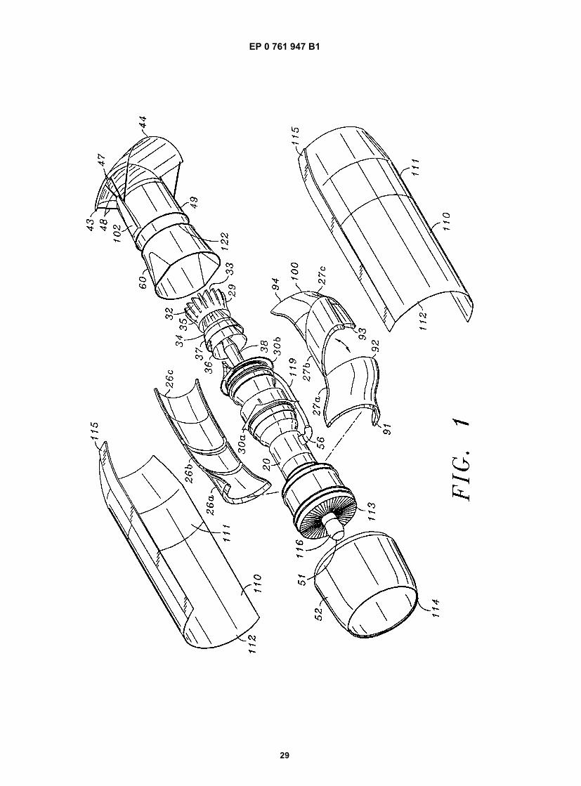
EP 0 761 947 B1
29
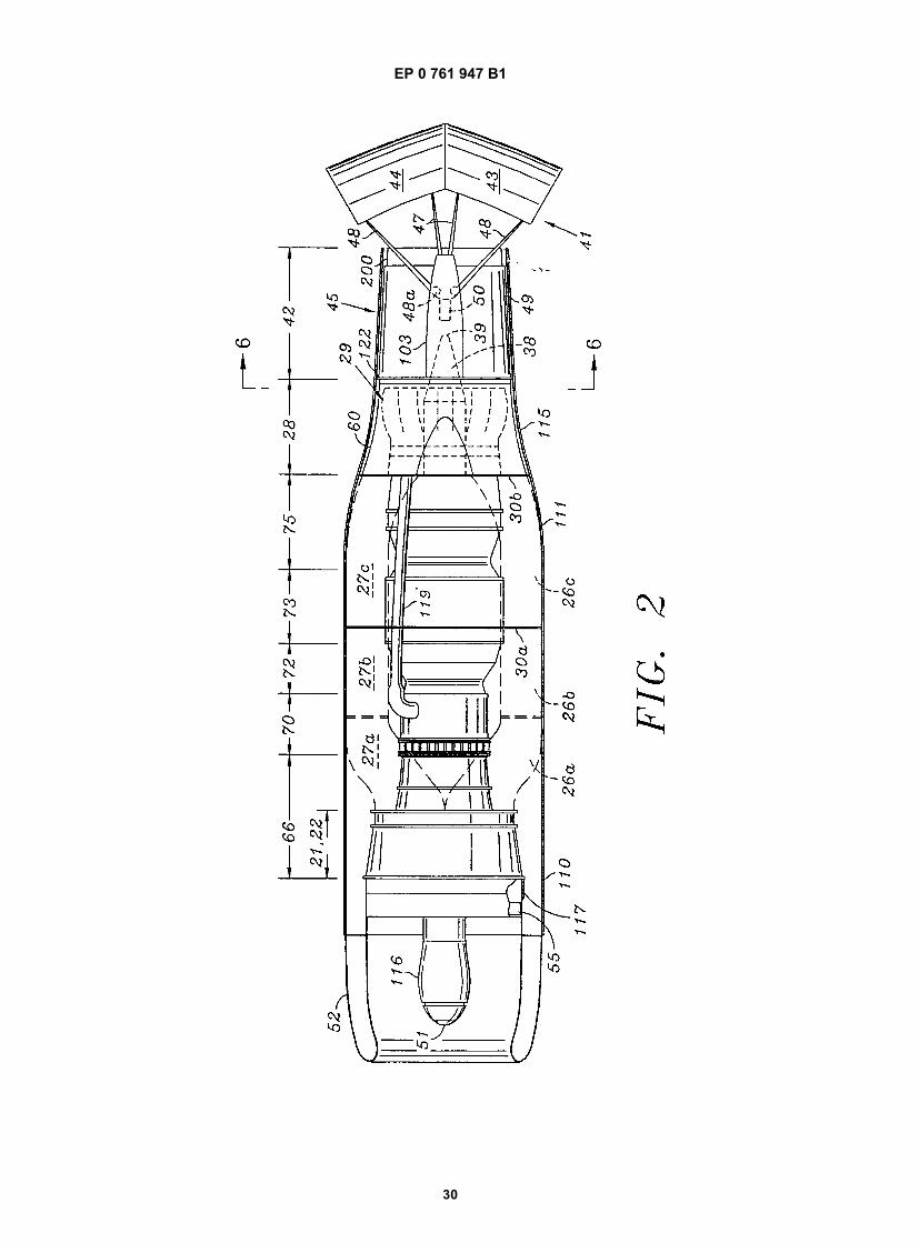
EP 0 761 947 B1
30
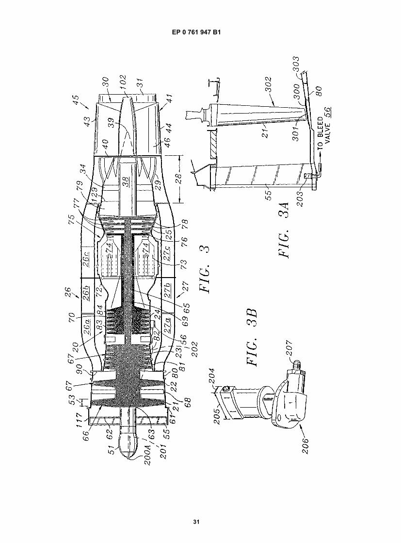
EP 0 761 947 B1
31
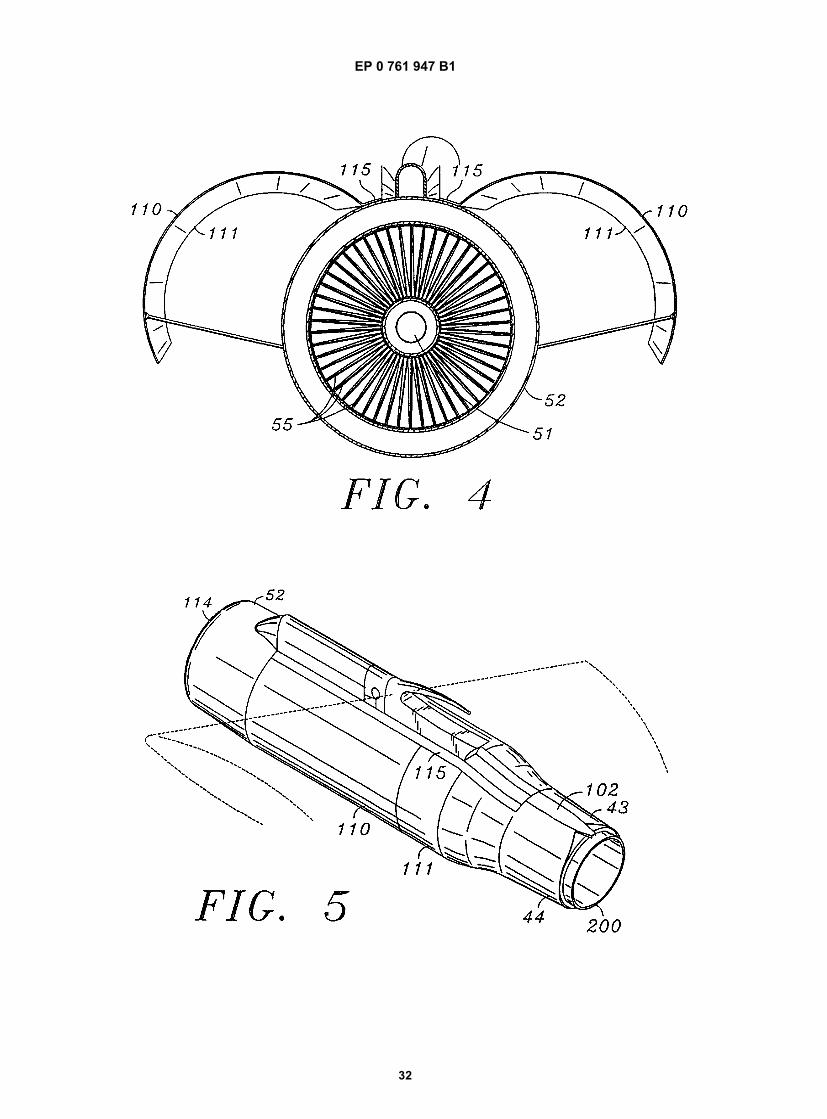
EP 0 761 947 B1
32
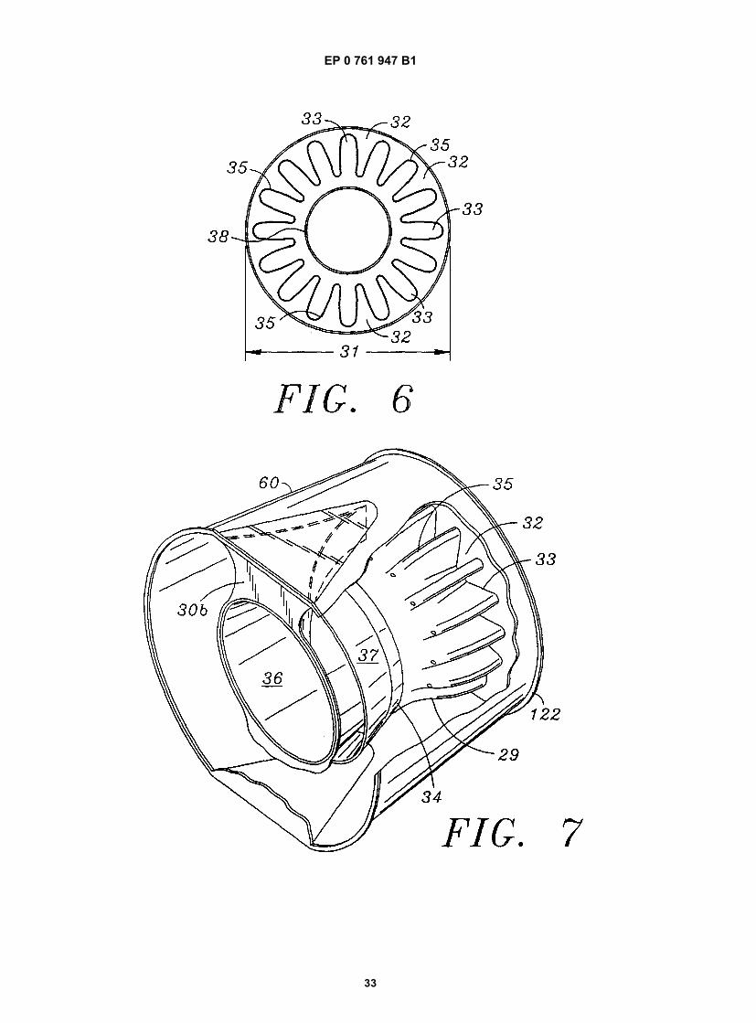
EP 0 761 947 B1
33
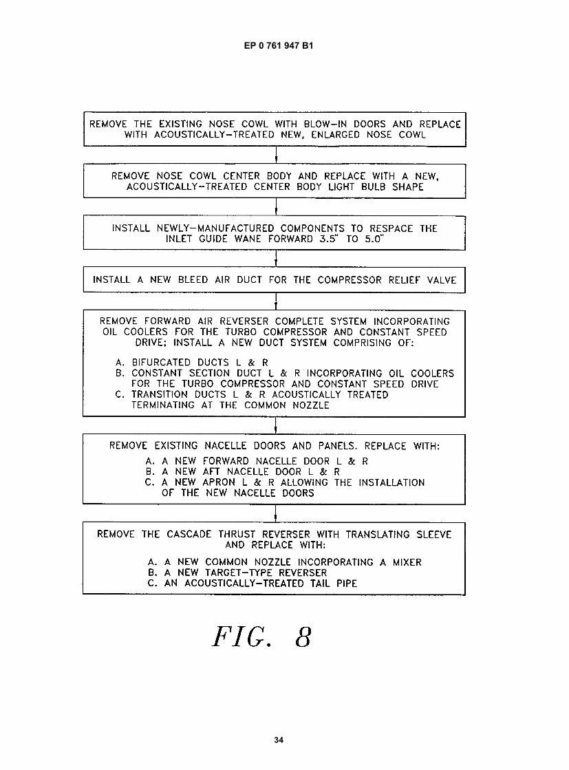
EP 0 761 947 B1
34
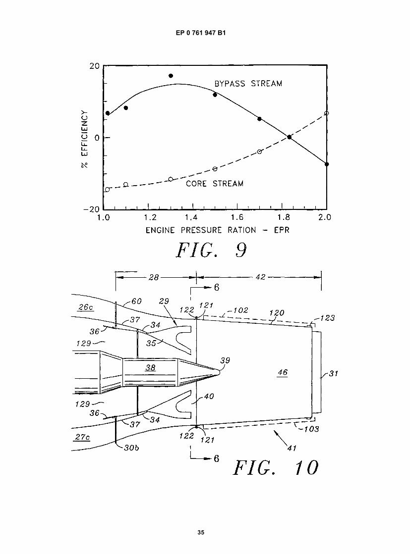
EP 0 761 947 B1
35