Embed Size (px)
Citation preview

arX
iv:q
uant
-ph/
0207
043v
2 8
Feb
200
3
Non-Local Quantum Gates: a Cavity-Quantum-Electro-Dynamics implementation
M. Paternostro and M. S. KimSchool of Mathematics and Physics, The Queen’s University, Belfast BT7 1NN, United Kingdom
G. M. PalmaDipartimento di Tecnologie dell’Informazione, Universita’ di Milano, Via Bramante 65, 26013 Crema, Italy and
NEST & INFM
(Dated: February 1, 2008)
The problems related to the management of large quantum registers could be handled in thecontext of distributed quantum computation: unitary non-local transformations among spatiallyseparated local processors are realized performing local unitary transformations and exchangingclassical communication. In this paper, we propose a scheme for the implementation of universalnon-local quantum gates such as a controlled-NOT (CNOT) and a controlled-quantum phase gate(CQPG). The system we have chosen for their physical implementation is a Cavity-Quantum-Electro-Dynamics (CQED) system formed by two spatially separated microwave cavities and two trappedRydberg atoms. We describe the procedures to follow for the realization of each step necessary toperform a specific non-local operation.
PACS numbers: 03.67.Hk, 42.50.-p, 03.67.-a, 03.65.Bz
I. INTRODUCTION
One of the major problems in the experimental imple-mentation of large scale quantum computing devices isscalability, i.e. the physical control at microscopic levelof a large number of quantum subsystems. In particu-lar the destructive effects of decoherence grow with thesize of the register [1]. Furthermore, undesired interac-tions among qubits of the same quantum register settlein an uncontrollable way [2, 3]. One possible solution tothis problem could be distributed quantum computing.In this architecture a quantum computer is thought asa network of spatially separated devices, which we calllocal processors, each operating on a small number ofqubits [4]. Such a design of a quantum computer hasrecently become particularly stimulating in view of thepapers by Eisert et al. [5] and by Collins et al. [6]. Inthese works, the minimal amount of classical and quan-tum resources needed to realize a general non-local uni-tary transformation is investigated. In the case of two-qubits gates, two bits of classical communication and themaximally entangled state of a shared pair of qubit (ebit)are proved to be necessary and sufficient resources to im-plement a controlled−U gate [5]. In particular, in ref. [5],a theoretical protocol for the optimal implementation ofa non-local controlled-NOT gate (CNOT) is described.This result is relevant since CNOT and single qubit oper-ations constitute an adequate set for quantum computa-tion [7, 8, 9, 10, 11]. We have summarized the protocol,using quantum circuit notation, in Fig. 1.
In this paper we propose an experimental scheme forthe physical implementation of a non-local CNOT (ac-cording to the protocol proposed in ref. [5]) and of anon-local controlled-quantum phase gate (CQPG) in aCavity-Quantum-Electro-Dynamics (CQED) set-up.
The paper is structured as follows: in section II we de-scribe the protocol of ref. [5] for the local implementation
of a non-local CNOT and we show how to modify it to ob-tain a non-local control quantum phase gate. This latteris a relevant result as well, because the set of quantumgates that comprehends CQPG and single qubit rotationsis universal for quantum computation [7, 8, 9]. SectionIII is devoted to a brief description of the experimentalset-up we propose in order to implement these non-localgates. A short summary of the features of the interac-tions of a two level atom with a single mode of a cavityfield is presented. We also describe an approach to theinteraction of the atom with an external classical pulse.In sections IV and V we analyze in detail each step thatcompose the experimental scheme for the physical real-ization of the non-local CNOT and CQPG. We show howthey are realizable in a CQED system including the de-scription of a procedure for the preparation of the com-putational register and we comment on the way to obtainthe required ebit. Every local operation is analyzed in fulldetail.
σ
B
A
β
α
H
z
FIG. 1: Quantum circuit for a non-local CNOT gate realizedusing a shared ebit and two classical bits of communication.In this scheme, A is the control qubit and B is the targetqubit. The joined state of qubits α and β encodes the neededebit (entanglement is represented by the wavy line). Classicalcommunication is represented by dashed lines and symbols forCNOT operation, Hadamard transform and Pauli σz operatorare shown. The measurements performed on the atomic qubitare schematically represented by detectors.

2
II. THE THEORETICAL PROTOCOLS
In this section we briefly outline the protocol proposedby Eisert et al. [5]. We also show how the protocol canbe modified to get a non-local CQPG.
Qubits A and B are, respectively, the control and thetarget of the non-local CNOT while α and β are two aux-iliary qubits encoding an ancillary ebit. Alice (Bob) hasaccess only to qubits A and α (B and β). We assumethat the initial state of qubits A and B is
|ϕin〉A ⊗ |ϕin〉B = (a |1〉 + b |0〉)A ⊗ (c |1〉 + d |0〉)B (1)
while the ebit is set in the Bell state 1√2(|01〉 + |10〉)αβ
(to optimize the fidelity of the non-local CNOT the jointstate of α and β must be a maximally entangled state[12]). The protocol can be read easily from Fig. 1. Firstof all Alice performs a local CNOTAα where A is thecontrol and α is the target followed by an orthogonalmeasurement on α. This transfers entanglement fromqubits α+β to qubits A+β. Bob then uses the classicalinformation on the measurement result of qubit α to acton qubit β: if the outcome of Alice’s measurement is |1〉α,Bob applies a NOT on qubit β while he applies 1l if Alicedetects |0〉α. This gives the following state:
ac |111〉AβB + ad |110〉AβB +
bc |001〉AβB + bd |000〉AβB .(2)
Now, Bob first applies a CNOTβB followed by aHadamard transform on qubit β and then detects itsstate. Depending on the measurement outcome, the stateof A + B is projected onto two different states. If Bobdetects |0〉β , the state of system A + B is exactly whatwe expect from a CNOTAB applied on the initial state ofthe A+B system. If, on the other hand, |1〉β is detectedAlice applies the Pauli σz operator to qubit A, shiftingthe phase of |1〉A by π and leaving |0〉A unaltered. Thisgives the desired output state
ad |11〉AB + ac |10〉AB + bc |01〉AB + bd |00〉AB . (3)
It is worth pointing out that the protocol works notonly for the product input states of A + B consideredhere but also for entangled input ones.
With a minor change, the protocol can be modifiedto implement a non-local CQPG defined in the computa-tional basis of qubits A, B as
|00〉 → |00〉 |01〉 → eiφ |01〉|10〉 → |10〉 |11〉 → |11〉 . (4)
Indeed it is enough to substitute the CNOTβB gateshown in Fig. 1 with a CQPGβB. A straightforward cal-culation shows that the overall effect of such modifiedcircuit is the desired CQPGAB.
III. THE PHYSICAL SYSTEM
The experimental set-up we propose in this paper isschematically shown in Fig. 2. Within each of two spa-tially separated high-Q millimeter-wave cavities a singleRydberg atom is trapped. The angular frequency of eachcavity mode is supposed to be nearly resonant with thetransition frequency between two Rydberg levels of therespective atom so that the atoms can be modeled as two-level systems. Let us call |g〉 , |e〉 respectively the groundand the excited atomic state. Qubits A and B are en-coded in the vacuum and one photon state |0〉 , |1〉A
and |0〉 , |1〉B of the two cavity fields while the auxil-iary qubits α and β are encoded in the |g〉, |e〉 states ofthe two atoms. To be more specific, in what follows wecan consider the two circular levels of rubidium atomswith principal quantum numbers µe = 50 (for the ex-cited state |e〉) and µg = 49 (for the ground state |g〉)[44]. We neglect here the hyperfine structure of the cho-sen atomic levels which is hardly resolved in a realis-tic experiment [14]. The |e〉 ↔ |g〉 transition frequencyis ν0 ≃ 54 GHz (wavelength λ0 ≃ 6 mm). The radia-tive lifetime τatom of these circular levels of the Rydbergspectrum of rubidium is about 30 msec [13] while, forQ ≃ 108 and a cavity mode frequency ν nearly resonantwith ν0, the field energy damping time τfield ranges from1 up to 30 msec [13]. Each cavity can be cooled by arefrigerator in order to avoid blackbody radiation. Theatom-cavity field coupling factor, measured by the Rabifrequency Ω, can be as large as 105 sec−1 so that we canwrite 1/Ω ≪ τfield, τatom. This means that it is possibleto observe coherent interaction between atom and cavityfield mode before the occurrence of dissipative or deco-hering effects due to the relaxation of the cavity fields
External fieldExternal field
0
Atom βAtom α
1
Vacuum field
Beam splitter Phase shifter
Cavity A Cavity B
Single photon state source
FIG. 2: Sketch of the experimental set-up for a non-localquantum computer implemented in a CQED system. Theatoms are trapped inside each cavity (atomic traps are notshown). The external classical fields allow the manipulationof the atomic states. We show a brief sketch of the apparatuswe intend to use to create entanglement between the atoms.
3
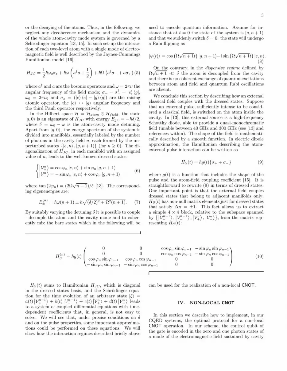
or the decaying of the atoms. Thus, in the following, weneglect any decoherence mechanism and the dynamicsof the whole atom-cavity mode system is governed by aSchrodinger equation [13, 15]. In such set-up the interac-tion of each two-level atom with a single mode of electro-magnetic field is well described by the Jaynes-CummingsHamiltonian model [16]:
HJC =1
2~ω0σz + ~ω
(
a†a+1
2
)
+ ~Ω(
a†σ− + aσ+
)
(5)
where a† and a are the bosonic operators and ω = 2πν the
angular frequency of the field mode; σ+ = σ†− = |e〉 〈g|,
ω0 = 2πν0 and σz = (|e〉 〈e| − |g〉 〈g|) are the raisingatomic operator, the |e〉 ↔ |g〉 angular frequency andthe third Pauli operator respectively.
In the Hilbert space H = Hatom ⊗ Hfield, the state|g, 0〉 is an eigenstate of HJC with energy Eg,0 = −~δ/2,where δ = ω0 − ω is the atom-cavity mode detuning.Apart from |g, 0〉, the energy spectrum of the system isdivided into manifolds, essentially labeled by the numberof photons in the cavity field n, each formed by the un-perturbed states |e, n〉 , |g, n+ 1〉 (for n ≥ 0). The di-agonalization of HJC , in each manifold with an assignedvalue of n, leads to the well-known dressed states:
∣
∣Vn+
⟩
= cosϕn |e, n〉 + sinϕn |g, n+ 1〉∣
∣Vn−
⟩
= − sinϕn |e, n〉 + cosϕn |g, n+ 1〉 (6)
where tan (2ϕn) = (2Ω√n+ 1)/δ [13]. The correspond-
ing eigenenergies are:
E(n)± = ~ω(n+ 1) ± ~
√
(δ/2)2 + Ω2(n+ 1). (7)
By suitably varying the detuning δ it is possible to couple- decouple the atom and the cavity mode and to coher-ently mix the bare states which in the following will be
used to encode quantum information. Assume for in-stance that at t = 0 the state of the system is |g, n+ 1〉and that we suddenly switch δ = 0: the state will undergoa Rabi flipping as
|ψ(t)〉 = cos(
Ω√n+ 1t
)
|g, n+ 1〉−i sin(
Ω√n+ 1t
)
|e, n〉 .(8)
On the contrary, in the dispersive regime defined byΩ√n+ 1 ≪ δ the atom is decoupled from the cavity
and there is no coherent exchange of quantum excitationsbetween atom and field and quantum Rabi oscillationsare absent.
We conclude this section by describing how an externalclassical field couples with the dressed states. Supposethat an external pulse, sufficiently intense to be consid-ered a classical field, is switched on the atom inside thecavity. In [13], this external source is a high-frequencySchottky diode, able to provide a quasi-monochromaticfield tunable between 40 GHz and 300 GHz (see [13] andreferences within). The shape of the field is mathemati-cally described by a smooth function. In electric dipoleapproximation, the Hamiltonian describing the atom-external pulse interaction can be written as
HS(t) = ~g(t)σ+ + σ− (9)
where g(t) is a function that includes the shape of thepulse and the atom-field coupling coefficient [15]. It isstraightforward to rewrite (9) in terms of dressed states.One important point is that the external field couplesdressed states that belong to adjacent manifolds only:HS(t) has non-null matrix elements just for dressed statesthat satisfy ∆n = ±1. This fact allows us to extracta simple 4 × 4 block, relative to the subspace spannedby
∣
∣Vn−1+
⟩
,∣
∣Vn−1−
⟩
,∣
∣Vn+
⟩
,∣
∣Vn−
⟩
, from the matrix rep-resenting HS(t):
H(n)S = ~g(t)
0 0 cosϕn sinϕn−1 − sinϕn sinϕn−1
0 0 cosϕn cosϕn−1 − sinϕn cosϕn−1
cosϕn sinϕn−1 cosϕn cosϕn−1 0 0− sinϕn sinϕn−1 − sinϕn cosϕn−1 0 0
(10)
HS(t) sums to Hamiltonian HJC , which is diagonalin the dressed states basis, and the Schrodinger equa-tion for the time evolution of an arbitrary state |ξ〉 =a(t)
∣
∣Vn−1+
⟩
+ b(t)∣
∣Vn−1−
⟩
+ c(t)∣
∣Vn+
⟩
+ d(t)∣
∣Vn−
⟩
leadsto a system of coupled differential equations with time-dependent coefficients that, in general, is not easy tosolve. We will see that, under precise conditions on δand on the pulse properties, some important approxima-tions could be performed on these equations. We willshow how the interaction regimes described briefly above
can be used for the realization of a non-local CNOT.
IV. NON-LOCAL CNOT
In this section we describe how to implement, in ourCQED systems, the optimal protocol for a non-localCNOT operation. In our scheme, the control qubit ofthe gate is encoded in the zero and one photon states ofa mode of the electromagnetic field sustained by cavity

4
A. Similarly, cavity B sustains the field mode represent-ing the target qubit. The initial state of modes A and Bwill be prepared in
(a |1〉 + b |0〉)A ⊗ (c |1〉 + d |0〉)B . (11)
We want to prove that the experimental scheme wepropose is able to change this state into
a |1〉A ⊗ (c |0〉 + d |1〉)B + b |0〉A ⊗ (c |1〉 + d |0〉)B. (12)
We give here the entire list of operations to implementthe non-local CNOT, leaving to the following subsectionsa detailed treatment of each one.
1. Trapping: the two-levels atoms α and β should betrapped inside the spatially separated microwavecavities.
2. Setting of the initial state of the register:using π-Rabi pulses, we prepare the initial state ofmodes A and B and of atoms α and β.
3. Setting of the ebit: preparation of an entan-
gled atomic state. We set entanglement in thejoint state of the trapped atoms letting α and βinteract directly with a previously prepared entan-gled single-photon state.Even if the expression “single-photon state” seemsto be more appropriate for the visible range of fre-quency, it will however be used, in what follows, formillimeter-wave radiation too. In this case, we sim-ply want to indicate the state of a field with a singlequantum of excitation whose energy, measured infrequency units, falls into the microwave region ofthe radiation spectrum.
4. Local CNOT cavity A→atom α and measure-
ment of the state of atom α: the gate is imple-mented driving, by an external laser pulse, a transi-tion between two specific levels of the dressed spec-trum of atom α. The measurement of the atomicstate is made inducing cyclic transitions to a thirdlevel and detecting the subsequent signal with amillimeter-wave receiver.
5. Local CNOT atom β →cavity B: we realize thistransformation with a two-photon transition be-tween two particular dressed states of atom β andusing a CNOT cavity B →atom β.
6. Hadamard transform on atom β: using π/2-pulses we create linear combinations, with equalweights, of states |e〉β and |g〉β .
Step 1: trapping of the atoms inside the cavities
We need to trap each atom inside its respective cavityfor a time sufficient to perform every step required bythe protocol for a non-local CNOT. Furthermore, the
trapping volume should be as small as possible to pledgea strong atom-cavity field coupling.
These features, long trapping time and small vol-umes, are usually typical of a Far-Off-Resonance-Trap(FORT) [17]. This is realized by a very focused laserbeam of frequency tuned below the atomic resonance [18].In these conditions the dipole force confines the atom ina potential well. Cooling is obtained by means of thescattering force furnished by optical molasses [19]. Thismixture of dipole and scattering force characterizes thistrap as an hybrid one [18].
Using a FORT to confine neutral atoms is a commonpractice in the optical domain and allows to reach trap-ping time of a hundred of seconds, in a high vacuumenvironment [20]. Recently, trapping a single atom ina cavity using Magneto-Optic-Traps (MOT) [18] and aFORT has been proved [21]. The trapping times can beimproved if a cryostat is used in addition [20].
In the microwave range of frequency, on the otherhand, the work by Spreeuw et al. [22] proved experimen-tally the possibility to combine an MOT and a microwavecavity. A MOT and a system of optical molasses arethere used to load a microwave cavity with an ensembleof alkali atoms. The minimum of the MOT trapping po-tential is located in the center of the cavity and the tem-perature of the atoms is kept, by the optical molasses,between 3 and 5 µK [22]. Even if the experiment hasbeen performed with a large number of atoms, it how-ever represents an insight into the realistic mixing of mi-crowave cavities and conventional optical trapping tech-niques (furthermore, an alternative trapping scheme thatuses microwaves and an external static magnetic field asa trap for neutral atoms has been addressed both theo-retically and experimentally [22, 23]).
The recent and fast improvement of the technique ofatomic trapping and the increase in the control of mi-crowave resonators allow to consider the scenario wepropose as not far from practical realization. Particu-larly promising, in this context, are the recently devel-oped techniques for the realization of arrays of single, se-lectively addressable dipole traps that, because of theirvery reduced dimensions, could be implanted directly in-side the cavity without spoiling its Q quality factor toomuch [24].
Step 2: preparation of the distributed register
The value of the detuning δ = 0 can be controlled bymeans of the so-called Stark switching technique that usesan external electric field applied to the atom [25]. If theatom has no permanent electric dipole moment, the Starkeffect will be quadratic in the electric field amplitude [26].This induces a relative shift on the atom’s energy spec-trum between states |e〉 and |g〉 so that the transitionfrequency changes from ω0 to another frequency ω′
0. Thecavity mode frequency, on the other hand, will remainunchanged. The width and the amplitude of the Stark

5
field pulses can be controlled with high accuracy, allowinga very precise control of the atomic level separation [25].Choosing the amplitude of the Stark field in such a waythat ω′
0 − ω ≫ 2Ω√n+ 1, we are able to decouple the
atom from the cavity field. In such dispersive regime itis possible to change the atomic state without modify-ing the cavity mode population by means of an externalelectromagnetic field, resonant with the new transitionfrequency ω′
0. It is therefore possible to prepare qubit α
(β) in a |e〉α + b |g〉α (c |e〉β + d |g〉β).The coefficients of these linear combinations can be set
fixing the width of each pulse. If the cavities are initiallyprepared in |0〉A ⊗ |0〉B (a procedure to obtain such ini-tial states for the cavities is suggested in ref. [27]) thejoint system A+B+α+β will be described by the tensorproduct state:
|ϕ〉 = (a |e〉 + b |g〉)α ⊗ (c |e〉 + d |g〉)β ⊗ |00〉AB (13)
By switching the detuning to its value δ = 0 a coherentexchange of quantum excitations between each atom andthe relative cavity field takes place. If we leave them tointeract resonantly for a time t = π/(2Ω) (π-Rabi pulse)we obtain a complete inversion between states |0e〉 and|1g〉 for each atom+cavity system (see section III). State|0g〉, on the contrary, being an eigenstate of HJC , is notmodified by the resonant interaction. The operations de-scribed above, based on the atom-cavity mode local reso-nant interaction, can be realized with high accuracy [13].The effect of the π-pulses is to change |ϕ〉αβAB into:
|g〉α ⊗ |g〉β ⊗ |ϕin〉A ⊗ |ϕin〉B =
|g〉α ⊗ |g〉β ⊗ (a |1〉 + b |0〉)A ⊗ (c |1〉 + d |0〉)B.(14)
We have created initial states of the cavity modes whichare coherent superpositions of Fock states with zero andone photon. The state for atoms α+β is, at this moment,|g〉α⊗|g〉β: we will further manipulate it, in the next stepof our scheme, to prepare the required ebit.
Step 3: preparation of the atomic ebit
In the scheme we propose, the trapped atoms α andβ encode an ebit, the quantum resource to the non-localimplementation of the CNOTAB. The state could be pre-pared by letting the atoms interact with a pair of externalmicrowave fileds previously prepared in the maximallyentangled state:
|ψ+〉 =1√2(|01〉+ |10〉). (15)
A possible way to get this state of radiation is usinga photon gun, a device which is able to generate singlephoton wave packets on demand, in a nearly determin-istic way. There are many proposals for single-photonsources: semiconductor quantum dots, one-photon emis-sion by isolated molecules, stimulated adiabatic rapid
passages of neutral atoms strongly coupled to a resonatoror strongly attenuated beams [28]. In this attenuationscheme, a pulsed laser field is simply attenuated withdensity filters until there is on average a fraction of aphoton per pulse [29]. The technique should be feasibleand can be accomplished even at the range of wavelengthsrelevant to our set-up. The pulse can then be sent to a50 : 50 beam splitter (BS), whose second input is the vac-uum field. The effect of the BS is to mix the two inputfields. By properly setting the relative phase betweenthe output fields by means of a phase shifter, the jointoutput state is the maximally entangled state written inEq. (15) [30].
Another possible scheme for the generation of single-photon states of radiation is based on the no-pass schemeof Hong and Mandel [31]: via a process of Spontaneous-Parametric-Down-Conversion (SPDC) [32], a signal andan idler photon are simultaneously generated (within anincertitude of 100 psec [31]). The two emitted photonsare entangled in momentum [33] and if one of them is de-tected, at some position and within a temporal windowT , then we are sure that there is a conjugate idler pho-ton, in the corresponding position and inside the samewindow. Thus, if by means of a photon-counting appa-ratus a single photon is detected in the signal, the idleris istantaneously prepared in a single-photon state. Fur-thermore, the experiment performed by Hong and Man-del has shown that the probability that more than justone signal photon is generated by the SPDC is negligi-ble with respect to that of a single-photon generation.This procedure is thus able to create, with a good accu-racy, a single-photon state of radiation that can, then, besent to the same BS described above in order to realizestate (15).
The next step we have to perform to get an entangledatomic state is the direct interaction of the trapped atomsα and β with |ψ+〉. The entangled photons we preparedare sent to the atoms (via suitable designed waveguidesdirectly coupled to the cavities A and B, for example).In each cavity-atom subsystem, a dispersive regime ofinteraction should be set, so that the atom dynamics isdecoupled from that of the cavity.
If the spectrum of each light pulse is sufficiently nar-row and centered at a frequency resonant to the atomictransition |g〉 ↔ |e〉, it is possible to show that settingthe interaction time in order to realize a π-pulse, the fol-lowing transformation can be realized:
|g〉α ⊗ |g〉β → 1√2(|eg〉 + |ge〉)αβ . (16)
However, these two techniques are not immune to prob-lems. In the case of the attenuated beam, at a so lowintensity level, it is not possible to be sure there beinga photon. There is always a possibility to get an emptypulse or a two-photon one. In the latter case, even if theprocedure described is able to generate atomic entangle-ment, the state consequently obtained is not of the formwe need. Even more, as we have seen, a precise control

6
of the area of the pulse is required in order to accomplishexactly the required atomic evolution.
On the other hand, the Hong and Mandel schemepresents some difficulties for the microwave range of fre-quencies because it is based on a SPDC process. Thegeneration efficiency of the couple of conjugate photons,in a down-conversion process, is very low (a rough but,for our purposes, sufficient semiclassical approach to thetheory of SPDC shows that it is directly proportionalto the fourth power of the pump beam frequency ω4
p).Tipically, optical frequency beams are used as pumps forSPDC (Ultra-Violet in [31]) and this gives a rate of gen-eration of down converted photons of the order of 10−10
sec−1. For microwave frequencies the rate of down con-version is dramatically smaller than this value and makesthe scheme useless as a photon gun. Even more, technicaldifficulties, in the microwave case, have to be managed.The crystal used for the generation of signal and idler, forexample, has to be almost transparent to the frequencyof both the pump and the down converted fields. Find-ing an appropriate candidate for a pump that falls in themicrowave range is a non trivial task.
E4
E3
E 1
E 2
FIG. 3: Scheme of the atomic levels for the generation of a mi-crowave field by means of a four- wave-mixing process. If E2 isslowly turned off while E1 enters in an optically thick medium,the quantum information carried by E1 is stored in the co-herences established between the ground, metastable statesof the atomic model. If the reading field E3 is then turnedon, for properly chosen values of its frequency, a fourth field,in the microwave range of frequencies, could be generated.
A deterministic source of one-photon states has beentheoretically proposed and, recently, experimentallydemonstrated in the microwave range of frequencies [35]:it is based on the interaction of a beam of Rydberg atomswith a field mode of a very high-Q microwave cavity (inthe experiment Q ∼ 1010). Unfortunately, the enormousQ value of the cavity used in [35] prevents significativeleakage of the field from the cavity itself and, thus, thescheme does not produce any exploitable output beam.
The recently developed techniques to store the quan-tum state of a field in a macroscopic atomic ensemblethat exibits electromagnetically-induced-transparency(EIT) [36] could represent a possible solution to the prob-
lem represented by the production of a microwave singlephoton state. Assume that the preparation of a one-photon state of an optical pulse, as experimentally donein [31], is followed by a storage step in an optically thickmedium made by three-level atoms in a Λ configura-tion [36]. For the notation of the following discussionwe refer to Fig. 3. If the field E2, with wavevector k2, isslowly turned off while E1 (wavevector k1) interacts withthe atomic medium, the quantum information about theamplitude, shape and phase of the latter is transferredto the coherences established between the two ground(metastable) states of the atomic model. To recover theinformation so stored, a reading pulse is necessary. If afield E3 is shined on the ensemble, the new electromag-netic field E4, with a wavevector k4 that satisfies thephase matching condition k1 +k2 = k3 +k4, is generatedby means of a process of forward four-wave-mixing [37].Properly choosing the values for the angular frequenciesωj = ckj (j = 1, 3), the generated field can fall in themicrowave range [38].
Step 4: local CNOT A → α and measurement of the
state of atom α
The theoretical protocol requires a CNOT having cav-ity A as control and atom α as target. Since this uni-tary operation involves just one cavity and the respectivetrapped atom, we refer to CNOTAα as a local transforma-tion to distinguish it from the non-local one we want toperform between cavity A and cavity B. The computa-tional basis for the CNOTAα is |0g〉 , |0e〉 , |1g〉 , |1e〉Aα
and the set of transformations we should realize is:
|0g〉Aα → |0g〉Aα |0e〉Aα → |0e〉Aα
|1g〉Aα → |1e〉Aα |1e〉Aα → |1g〉Aα .(17)
According to this set of transformations, the state pre-pared during Step 3:
|χ〉 =1√2(|eg〉+|ge〉)αβ(a |1〉+b |0〉)A(c |1〉+d |0〉)B (18)
has to be changed into:
CNOTAα |χ〉 =1√2a |1〉A (|gg〉 + |ee〉)αβ
+b |0〉A (|eg〉 + |ge〉)αβ (c |1〉 + d |0〉)B .
(19)
Expressions (17) and (19) show that, while the atomicstate can modify its state, the cavity mode populationdoes not change: this means that a resonant couplingbetween A and α can not be used to implement the gate.Resonant Rabi oscillations, indeed, preserves the totalnumber of excitations while the last two transformationsin (17) do not. We need a dispersive atom-cavity fieldinteraction; the atomic state will be manipulated by an

7
external electromagnetic field. If the external field is res-onant with a field mode sustained by the cavity but dif-ferent from the relevant one used to codify the cavityqubit, it can enter the resonator without feeding this lat-ter mode (for example we can choose two orthogonallypolarized field modes: in [13] two orthogonally polarizedtransverse modes, with a spacing in frequency of 70 kHz,sustained by a millimeter-wave cavity are considered).Using the Stark switching technique, the trapped atomcan then interact with the external field, being decoupledwith respect to the relevant cavity mode, for a controlledamount of time.
The Stark field can be set to change the separationbetween levels |e〉α and |g〉α and to obtain a value of δthat allows to write Ω ≪ δ. In such a condition, fromEq. (6), it results that
∣
∣Vn+
⟩
≃ |n, e〉 ,∣
∣Vn−
⟩
≃ |n+ 1, g〉.Therefore, if using an appropriate external pulse we caninduce a complete inversion of population between
∣
∣V1+
⟩
and∣
∣V0−
⟩
, we mutually exchange |1e〉 and |1g〉 with-
out involving the other dressed states,∣
∣V0+
⟩
≃ |0e〉 and∣
∣V1−
⟩
≃ |2g〉. The only approximative identification ofthe bare basis elements with the corresponding dressedstates in the limit of large detuning has only a very smalleffect on the fidelity of the gate, as we show below.
Since we want the interaction of atom α with an ex-ternal pulse, we use results obtained in III: the dressedmanifolds involved in the transition
∣
∣V1+
⟩
↔∣
∣V0−
⟩
arethose with n = 0 and n = 1 (therefore satisfying condi-
tion ∆n = ±1). We give explicit expression for H(1)S (t)
expanding each matrix element in Taylor series, to secondorder in Ω/δ:
H(1)S
~= g(t)
0 0 Ωδ
−√
2Ω2
δ2
0 0(
1 − 32
Ω2
δ2
)
−√
2Ωδ
Ωδ
(
1 − 32
Ω2
δ2
)
0 0
−√
2Ω2
δ2 −√
2Ωδ
0 0
(20)We deduce that if the experimental parameters are
such that Ω ≪ δ, the matrix elements belonging to the
central 2×2 block in H(1)S predominates over all the oth-
ers. We choose g(t) so that g(t) = p(t) cos (ωSt), withp(t) a smooth function describing the envelope shape ofthe pulse shined on the trapped atom. We set ωS to beequal to the transition frequency for
∣
∣V1+
⟩
↔∣
∣V0−
⟩
:
ωS =E1
+ − E0−
~(21)
With a suitable choice of the pulse duration, the rightinversion of population can be obtained. In particular,
it has to be∫ tp(t′)dt′ = π (we refer to this case as to
a π pulse). Any spurious phase factor can be adjustedby setting an appropriate phase in function g(t) or usingappropriate Stark field and, in what follows, we do notcare about it [15]. Achievable coupling strength for theatom-external field interaction as large as 20π kHz and
interaction times of about 50 µsec allow to get a completeπ pulse.
The effect of a finite, non null, value of the ratio Ω/δ onthe state that we instead obtain, can be seen if we prop-agate |χ〉 by means of the unitary operator that is gener-
ated by the Hermitian interaction Hamiltonian H(1)S (t).
We assume x = Ω/δ = 0.1, value that allows for theapproximations discussed above and for the discrimina-tion between the frequencies of the different transitionsinvolved; retaining just the terms up to the second orderin Ω/δ, we get an approximate expression for the evolvedstate of the system |χ〉. This expression is useful in orderto find the fidelity of the local CNOT operation we areperforming.
The definition of the fidelity function, in this case,reads F = |〈χ|CNOTAα|χ〉|2 [7] and assuming for sim-plicity a = b = 1√
2, it is possible to show that:
F(x) =1
4
1 + sin
[
π
2
(
1 − 3
2x2
)]2
+ 0.003x2. (22)
Notice that, as Ω/δ → 0, the fidelity reaches F = 1,which shows a perfect overlap between the state we needand the one we get manipulating the atomic qubit by anexternal field.
The state of the system at the end of Step 3 becomes:
1√2|g〉α ⊗ (−ia |1g〉 + b |0e〉)Aβ ⊗ |ϕin〉B +
1√2|e〉α ⊗ (−ia |1e〉 + b |0g〉)Aβ ⊗ |ϕin〉B .
(23)
We now measure the state of atom α on the bare eigen-state basis |e〉 , |g〉α. We enlarge the Hilbert space ofthe atom introducing a third energy level, |m〉α, whose
0.02 0.04 0.06 0.08 0.1x
0.9998
0.99985
0.9999
0.99995
1
Fidelity
FIG. 4: Plot of the fidelity function F of the local CNOTAα
operation as a function of the ratio x = Ω/δ and for a =b = 1/
√2. As it is shown, for values of x that range from 0
to 0.1, the gate can be performed with a very high accuracy.The high fidelity of the gate is maintained even for differentchoices of a and b.

8
parity is opposite to that of |e〉α. For example, we cantake the Rydberg level with principal quantum numberµm = 51. In this case the |e〉α ↔ |m〉α frequency is aboutνm ≃ 51.1 GHz [13]. An external microwave field cou-ples |e〉α to |m〉α. If the state of α is |e〉α, the externalfield induces cyclic transitions between these states but,if atom α is in |g〉α, because of the large frequency mis-match, we do not detect any signal. If |m〉α correspondsto a low angular quantum number, the emission time ofthe atom falls in the range of µsec [13, 39]. The radi-ation emitted by the cycling atom can be collected bya millimeter − wave receiver [39]. This is, essentially, aSchottky diode detector that mixes the signal to be mea-sured with a local reference microwave field to performa heterodyne measurement of the signal. The responsetime of the device is short enough not to represent a lim-itation for our purposes. This detection technique hasbeen successfully used in the context of micromaser spec-troscopy to directly infer the radiation of a millimeter-wave field inside a cavity [13, 39].
Depending on the state of atom α at the end of themeasurement process, system A+β+B is projected ontostates which differ just for the state of atom β. In orderto obtain the right final state at the end of the protocolfor the non-local CNOTAB, if the atomic state detectiongives |g〉α, we should change nothing in subsystem B +β. If the output of the measurement is |e〉α, a NOT isrequired for qubit β.
To obtain it we essentially need the same kind of trans-formations we introduced in the last step: |1e〉Bβ →|1g〉Bβ and |0g〉Bβ → |0e〉Bβ . They can be realized by ap-plying π-pulses for transitions between suitable dressedstates of the atom β in a dispersive regime of interaction.In any case, with a fidelity that approaches 100%, the sys-tem A+β+B can be set in (−ia |1g〉 + b |0e〉)Aβ⊗|ϕin〉Bapart from a global phase factor.For simplicity, in the following, we assume to have de-tected |g〉α.
Step 5: local CNOT β → B
The next step is the implementation of a localCNOTβB. The atomic qubit β is now the control ofthe gate. To get the right final state for the non-localCNOTAB , the set of transformations to realize is the fol-lowing:
|g0〉βB → |g1〉βB |g1〉βB → |g0〉βB
|e0〉βB → |e0〉βB |e1〉βB → |e1〉βB .(24)
It is clear that, in (24), we have |g〉 ≡ |1〉 and |e〉 ≡ |0〉.In this subsection we show how to realize these trans-formations using the two-photon transition |g0〉βB ↔∣
∣V1+
⟩
βBand a CNOTBβ .
We need such a different strategy because an approachsimilar to that used for the CNOTAα will lead us to someinconsistencies. In effect, using the same logic scheme
used to implement the Step 4, a procedure to get tran-sitions (24) could be the following. We induce a π-pulsebetween |g0〉βB and
∣
∣V0−
⟩
βB. State
∣
∣V0−
⟩
βB, for Ω ≪ δ,
is in practice the bare state |g1〉βB but, for the selection
rules relative to electric dipole transitions [26], transi-tion |g0〉βB ↔ |g1〉βB is strictly forbidden. Since
∣
∣V0−
⟩
βB
holds a little contribution from |e0〉βB [15], transition∣
∣V0−
⟩
βB↔ |g0〉 can be realized. Using the same proce-
dure of previous sections we can obtain the matrix rep-resentation of the Hamiltonian HS(t) for the interactionof the dressed atom β with the external pulse drivingthe required transition. On the ordered dressed basis
|g0〉βB ,∣
∣V0−
⟩
βB,∣
∣V0+
⟩
βB
, we have
H(0)S (t) = ~g(t)
0 −Ωδ
(
1 − 12
Ω2
δ2
)
−Ωδ
0 0(
1 − 12
Ω2
δ2
)
0 0
(25)
Here, the biggest matrix elements are those that con-nect |g0〉βB to
∣
∣V0+
⟩
βBand vice versa. For Ω ≪ δ,
∣
∣V0+
⟩
βBis essentially identified with |e0〉βB [45]. On
the contrary, the probability of a transition |g0〉βB ↔∣
∣V0−
⟩
βBis directly proportional to Ω/δ. However, since
we want Ω ≪ δ, we need a different procedure.We now proceed mapping the CNOTβB into a sequence
of three operations: two SWAP and a CNOTBβ (Fig. 5).
S
S
S
S
A A
BB
FIG. 5: A CNOTBA gate can be simulated using the sequenceof operations (SWAP)(CNOTAB)(SWAP).
It is straightforward to prove that the sequence(SWAP)(CNOTAB)(SWAP) is equivalent to CNOTBA.Since we have already seen an efficient way to imple-ment a CNOT for the cavity qubit as control and theatomic one as target, we just pass to describe a possibleprocedure to accomplish a SWAP operation in a CQEDsystem.
By the action of the SWAP gate, a transitions occursbetween |g0〉βB and |e1〉βB. For an external Stark field
satisfying Ω ≪ δ, the dressed state∣
∣V1+
⟩
Bβis about equal
to |1e〉Bβ as it can be deduced from Eq. (6). Inducing∣
∣V1+
⟩
Bβ↔ |0g〉Bβ we can get what we want. Never-
theless, these dressed states belong to dressed manifoldswhich differ for two quantum excitations and that can-not be connected by a single photon transition. Thismeans that we should go to the second order in the cou-pling coefficient, realizing a two-photon transition. We

9
choose it to be degenerate: this means that the photonsinvolved in this second order process have the same en-
ergy ~ωL = 12 (E
(1)+ − E0g), where the external field has
frequency ωL [40].The second order transition
∣
∣V1+
⟩
Bβ↔ |0g〉Bβ occurs
via virtual transitions toward the intermediary states∣
∣V0±
⟩
Bβ. In effect, because of the structure of the energy
spectrum of the dressed atom, these states have energieswhich are very close to the middle energy between |0g〉Bβ
and∣
∣V1+
⟩
Bβ. However, the transitions are not resonant,
so that the probabilitythat the system can accomplish aneffective transition to
∣
∣V0±⟩
Bβis negligible. This qualifies
∣
∣V0±
⟩
Bβas virtual states.
We model the external field as a linearly polarizedpulse of Gaussian envelope:
E(t) = E0e− t2
τ2 cos (ωLt). (26)
The electric dipole interaction gives rise to the followinginteraction Hamiltonian:
HL(t) = ~Σ0
e−t2
τ2 +iωLt |g〉〈e| + h.c.
(27)
where Σ0 is the atom-field coupling coefficient and RWAhas been used. The probability amplitude that the sys-tem, initially in |0g〉Bβ , is found at time t in
∣
∣V1+
⟩
Bβcan
be calculated using the following expression, directly de-rived from a second-order perturbation theory [41, 42]:
1
~2
∑
j=−,+
(∫ t
−∞dt′′
⟨
V1+|HL(t′′)|V0
j
⟩
ei~
(
E(1)+ −E
(0)j
)
t′′×
×∫ t′′
−∞dt′
⟨
V0j |HL(t′)|0g
⟩
ei~
(
E(0)j
−E0g
)
t′
)
(28)
(with t′′ > t′). Explicit evaluation of this expression,with numerical values Ω ≈ 105 Hz, δ ≈ 1 MHz, τ ≈ 20µsec, Σ0 ≈ 105 Hz and for t = 3τ leads to a transitionprobability equal to 0.47. The value of δ satisfies the con-dition δ ≪ ω, ω0 because, for a millimeter-wave cavity,the value of ω falls in the range from 10 to 100 GHz whilea typical value for ω0, for values of the principal quantumnumber µ ≃ 50, is 50 GHz [13]. Having Σ0 ≃ Ω0 ensuresthe observability of multiphotons transitions.Since the explicit calculation for the |1e〉Bβ → |0g〉Bβ
case leads, with the same numerical values of the previ-ous case, to the same probability of transition, our mapof a CNOTβB is valid for each initial state of the systemβ+B. Ideally, we are able to implement a CNOTβB usingjust SWAP operations and CNOTcavity−atom. In order toevaluate the fidelity of the local CNOTβB, we have to per-form essentially the same kind of calculation described inStep 4 for the case of the local CNOTAα gate. We foundthat, at the end of the operations, the state of the systemA+B + β is projected onto
ia |g〉β⊗|1〉A⊗NOT |ϕin〉B+b |0〉A⊗|e〉β⊗|ϕin〉B (29)
with a fidelity 0.54, for c = d = 1√2
and after an av-
erage over all the possible initial configurations of thesystem B + β. This low value of the fidelity of the gateis essentially due to the non ideality of the two-photontransition and represents the major theoretical limitationto the efficiency of the proposed implementation.
Step 6: Hadamard transform on atom β
We now need a Hadamard transform on qubit β. Thiscan be realized, in a CQED system, recurring again toa dispersive regime of atom-cavity field interaction. Ineffect, setting a very large detuning (leaving the eigen-states of the atom β almost bare) and shining a drivingexternal pulse on β for a time such that a π/2-pulse isrealized between |ej〉 and |gj〉 (j = 0, 1), we just obtainthe following transitions:
|gj〉 → 1√2|gj〉 − i |ej〉
|ej〉 → 1√2|ej〉 − i |gj〉 .
(30)
We have, in practice, a Hadamard transform general-ized by a relative phase factor that is not a problem forour scheme: using relations (30) in the state obtained atthe end of Step 5, we have
i√2|g〉β ⊗ a |1〉 ⊗ (NOT |ϕin〉) − b |0〉 ⊗ |ϕin〉AB +
1√2|e〉β ⊗ a |1〉 ⊗ (NOT |ϕin〉) + b |0〉 ⊗ |ϕin〉AB .
(31)
If the measurement outcome of the atom β is |e〉β ,system A + B is projected onto a state that shows theaction of the CNOTAB gate. An ulterior manipulationis required if the measurement outcome is |g〉β . In thiscase, if we want to correct the −1 relative phase factorthat appears in the A + B state we just perform a 2πresonant Rabi pulse in the subsystem A+ α (we remindthat our measurement process is a non demolition oneand that atom α can always be forced to occupy state|g〉α, as we assumed all along our discussion).
This closes the scheme for a non-local CNOT betweentwo spatially separated cavity modes.
V. NON-LOCAL π − CQPG
In this section we will describe a procedure for thephysical implementation of a non-local controlled quan-tum phase gate with φ = π. This is a very importanttask to accomplish because the set of quantum gates thatcomprehends controlled quantum phase gate and singlequbit rotations is adequate for quantum computation.Our goal is to show that the experimental set-up pro-posed in this paper is sufficiently flexible to permit, with
10
slight modifications operated in Step 5 of the previousprotocol, its feasible realization. As before, the compu-tational register is formed by the two spatially separatedcavity modes A and B while the atoms α and β encodetwo ancillary qubits whose joint state constitutes an ebit.
We assume that the initial state for system A+B hasbeen prepared as in Eq. (11). Moreover, we assume tohave a maximally entangled atomic ebit. We want toshow how to transform state |ϕin〉A ⊗ |ϕin〉B into
ac |11〉AB + ad |10〉AB + bc |01〉AB − bd |00〉AB . (32)
The experimental scheme for the non-local π-CQPG isidentical until Step 4 to that for the non-local CNOTAB.This means that, at the end of Step 4, having performedthe local CNOTAα and measured the state of atom α, thestate of system A+B + β is projected onto
(−iac |1g1〉 − iad |1g0〉+ bc |0e1〉+ bd |0e0〉)AβB (33)
while atom α is assumed to be in |g〉α.We modify the previous scheme replacing Step 5 with
the following to perform a π − CQPG on system β + B.We adopt the following map of the CQPG:
|e0〉 → |e0〉 |e1〉 → − |e1〉|g0〉 → |g0〉 |g1〉 → |g1〉 . (34)
This set of transformation is obtained by extending theatomic model to comprehend a third energy level. Weintroduce state |i〉β whose parity is opposite to that of
|e〉β . For example, as we did above, a possible choice for
the atomic levels can be |i〉 ↔ µi = 51, |e〉 ↔ µe = 50,|g〉 ↔ µg = 49.
If we set the cavity mode B resonant to |e〉 ↔ |i〉the cavity field results out of resonance with |g〉 ↔ |e〉and transitions at this frequency are strongly suppressed.Thus, setting resonance between atom β and cavity modeB for a time sufficient to realize a 2π-Rabi pulse between|e1〉βB and |i0〉βB, state |e1〉βB will acquire a −1 phase
factor [15, 43]. The phases of the other states that appearin (33) are not modified: the phases of |g0〉βB and |g1〉βB
are unchanged because of the frequency mismatch whilethat of |e0〉 does not change because it is an eigenstate ofthe Jaynes-Cummings Hamiltonian in the bidimensionalHilbert space spanned by |e〉 , |i〉β . We are, thus, able
to perform transformations (34) and the state in Eq. (33)changes into:
ia |g〉β ⊗ (c |11〉 + d |10〉)AB + b |e〉β ⊗ (c |01〉 − d |00〉)AB
(35)apart from a global phase factor.
Now, we need the set of transformations, on the systemβ + B, defined in Step 6 of the previous protocol. Thismake us obtain the final state:
i |g〉β ⊗ (ac |11〉 + ad |10〉 − bc |01〉 + bd |00〉)AB +
|e〉β ⊗ (ac |11〉 + ad |10〉 + bc |01〉 − bd |00〉)AB .(36)
If the measurement outcome of atom β is |e〉β , thejoint state of the two cavities is such that the action ofthe π − CQPG on qubits A and B is evident. If theoutcome of the measurement is |g〉β, we apply a 2π-Rabi
pulse for transition |g1〉αA ↔ |e0〉αA on system α + A.It is relevant to notice that, in order to realize the localquantum phase gate of the protocol, just simple resonantRabi oscillation in a atom-cavity system is required.
We have proposed a non-local π − CQPG betweenspatially separated cavities. Implementing a non-localCQPG is an important result, in quantum distributedcomputation, since it can help us in improving the ef-ficiency of the non-local CNOT. The non ideality of Step5 of the scheme for the CNOTAB strongly limits the effi-ciency of the gate. Since a CNOT operation can be sim-ulated using a Hadamard transform on the target qubitfollowed by a π− CQPG, and the efficiency of implemen-tation of a non-local π − CQPG is evidently better thanthat of the CNOT, the reliability of the non-local gatecan be significantly improved.
In this case, however, the time needed to accomplishthe entire non-local CNOT can represent a problem. Therealization of a Hadamard transform of the cavity fieldrequires a map of the quantum state of the field ontothe relative ancillary (atomic) qubit. The performanceof a Hadamard transform on the latter and, eventually, amap of the transformed state back onto the cavity qubit.This increases the time necessary to accomplish the non-local CNOTAB and the number of local transformationsinvolved.
VI. CONCLUSIONS
In this paper we have proposed a CQED set-up forthe implementation of a non-local CNOT and of a non-local π − CQPG. According to the optimal theoreticalprotocols described in ref. [5], our experimental schemesuse just two bits of classical communication and a singleebit, shared by the two parties.
The computational register, in the proposed set-up,is formed by two spatially separated microwave cavitieswhile the required ebit is encoded in the entangled stateof two Rydberg atoms.
For the case of the non-local CNOT, we have analizedin full details the theoretical procedures and the exper-imental requirements needed to implement the gate inour CQED system. Our analysis has shown that somepractical problems have to be taken in consideration inthe proposed experimental scenario.
In particular, some difficulties arise connected with thelow efficiency of the currently available sources of single-photon states operating in microwaves. On the otherhand, while a local CNOT cavity → atom can be effi-ciently realized via a controlled interaction of the atomwith an external field, the practical implementation of aCNOT atom → cavity is basically an inefficient opera-tion. This low efficiency is due to the fact that the real-

11
ization of this local gate passes through an atomic tran-sition that is forbidden by the electric-dipole-transitionsselection rules. To circumvent this problem, we have pro-posed to set an externally driven two-photon transitionbetween two suitably chosen states of the dressed-atomeigenspectrum. With this solution, we have found a signi-ficative improvement of the fidelity of the gate. We wantto stress that the discussed difficulties are just related tothe current state of the art: once these realizative prolemswill be solved, our experimental proposal will certainlyacquire practical reliability.
The versatility of the proposed set-up has been showndescribing how to modify the protocol for a non-localCNOT to get a non-local π − CQPG. The realization ofthis gate is based on atom-external field interactions ofthe kind used to implement a CNOT cavity → atom andon resonant atom-cavity mode interactions. Because ofthe intrinsic high reliability of these operations, we havefound that this non-local gate could be implemented in
an efficient way.
Despite the encountered difficulties to manage, theproposed set-up gives some insights in the fundamen-tal research of possible architectures for a quantum com-puter able to manage large computational registers.
Acknowledgments
We would like to thank T. Calarco, Byoung S. Ham,D. Vitali, A. Carollo and H. Jeong for helpful discussions.This work was supported by ESF under ”Quantum In-formation Theory and Quantum Computing” program,by the EU under grants IST - EQUIP, ”Entanglement inQuantum Information Processing and Communication”and by the UK Engineering and Physical Science Re-search Council through GR/R33304.
[1] G.M. Palma, K.-A. Suominen and A. K. Ekert Proc. Roy.Soc. London A 452, 567 (1996).
[2] D. P. DiVincenzo, D. Loss, Superlattices and Microstruc-
tures 23, 419 (1998), LANL e-print: cond-mat/9710259.[3] D. P. DiVincenzo, Phys. Rev. A 50, 1015 (1995),[4] J. I. Cirac, A. K. Ekert, S. F. Huelga, C. Macchiavello,
Phys. Rev. A 59, 4249 (1999).[5] J. Eisert, K. Jacobs, P. Papadopoulos, M. B. Ple-
nio, Phys. Rev. A 62, 52317 (2000), LANL e-print:quant-ph/0005101.
[6] D. Collins, N. Linden, S. Popescu, Phys. Rev. A 64,32302 (2001), LANL e-print: quant-ph/0005102.
[7] J. Preskill, Lecture Notes for Physics 229:
Quantum Information and Computation, Cali-fornia Institute of Technology (1998), e-print:www.theory.caltech.edu/ preskill/ph229.
[8] M. A. Nielsen, I. L. Chuang Quantum computation
and quantum information (Cambridge University Press,Cambridge, 2000).
[9] C. Macchiavello, G. M. Palma and A. Zeilinger, Quantum
computation and quantum information theory, (WorldScientific, Singapore. 2001)
[10] A. Ekert, P. Hayden, H. Inamori, LANL e-print:quant-ph/0011013.
[11] V. Vedral, M. B. Plenio, LANL e-print:quant-ph/9802065.
[12] J. Jang, J. Lee, M. S. Kim and Y. L. Park, LANL e-print:quant-ph/0101107.
[13] S. Haroche and J. M. Raimond, in Advanced in Atomic
and Molecular Physics, vol. 20, D. R. Bates and B. Be-denson eds., Academic Press, (1985); P. Domokos, J. M.Raimond, M. Brune, and S. Haroche, Phys. Rev. A 52,3554 (1995); A. Rauschenbeutel, G. Nogues, S. Osnaghi,P. Bertet, M. Brune, J. M. Raimond, S. Haroche, Science
288, 2024 (2000).[14] M. Brune, J. M. Raimond, and S. Haroche, Phys. Rev.
A 35, 154 (1987)[15] V. Giovannetti, D. Vitali, P. Tombesi, A. Ekert, Phys.
Rev. A 62, 32306 (2000).
[16] E. T. Jaynes, F. W. Cummings, Proc. IEEE 51, 89(1963).
[17] H. J. Lee, C. S. Adams, M. Kasevich, S. Chu Phys. Rev.
Lett. 76, 2658 (1996).[18] W. D. Phillips, in Les Houches Proceedings, Session LIII:
Systems Fondamentaux en Optique Quantique, J. Dal-ibard, J. M. Raymond and J. Zinn-Justin, eds. (1991).
[19] S. Chu, J. E. Bjorkholm, A. Ashkin, A. Cable Phys. Rev.
Lett. 57, 314 (1986).[20] K. M. O’Hara, S. R. Granade, M. E. Gehm, T. A. Savard,
S. Bali, C. Freed, J. E. Thomas, Phys. Rev. Lett. 82, 4204(1999).
[21] J. Ye, W. Vernooy, H. J. Kimble, Phys. Rev. Lett. 83,4987 (1999).
[22] R. J. C. Spreeuw, C. Gerz, L. S. Goldner, W. D. Phillips,S. L. Rolston, C. I. Westbrook, M. W. Reynolds, and I.F. Silvera, Phys. Rev. Lett. 72, 3162 (1994);
[23] C. C. Agosta, I. F. Silvera, H. T. C. Stoof, and B. J.Verhaar, Phys. Rev. Lett. 62, 2361 (1989).
[24] R. Dumke, M. Volk, T. Muther, F. B. J. Buchkremer,G. Birkl, and W. Ertmer, Phys. Rev. Lett. 89, 097903(2002); F.B.J. Buchkremer, R. Dumke, M. Volk, T.Muther, G. Birkl, W. Ertmer, Laser Physics, 12, 736(2002); G. Birkl, F.B.J. Buchkremer, R. Dumke, W. Ert-mer, Optics Comm., 191, 67 (2001).
[25] R. G. Brewer, in Non Linear Optics, P. G. Harper andB. S. Wherrett eds., Accademic Press, (1977).
[26] M. Weissbluth Atoms and Molecules Academic Press(1994).
[27] J. M. Raimond, M. Brune and S. Haroche Rev. Mod.
Phys. 73, 565 (2001).[28] A. Kuhn, M. Hennrich and G. Rempe, Phys. Rev. Lett.
89, 067901 (2002); R. Brouri, A. Beveratos, J.-P. Poizat,and P. Grangier Opt. Lett. 25, 1294 (2000); M. Pelton,C. Santori, G.S. Solomon, O. Benson and Y. Yamamoto,Eur. Phys. J. D 18, 179 (2002); A. Beveratos, S. Kuhn,R. Brouri, T. Gacoin, J.-P. Poizat and P. Grangier, Eur.
Phys. J. D, pg. 191; W.L. Barnes, G. Bjork, J.M. Gerard,P. Jonsson, J.A.E. Wasey, P.T. Worthing and V. Zwiller,

12
Eur. Phys. J. D, pg. 197.[29] M. Bourennane, F. Gibson, A. Karlsson, A. Hening, P.
Jonsson, T. Tsegaye, D. Ljunggen, E. Sundberg, Opt.
Expr. 4, 383 (1999).[30] S. M. Tan, D. F. Walls, M. J. Collett Phys. Rev. Lett.
66, 252 (1991).[31] C. K. Hong and L. Mandel, Phys. Rev. Lett. 56, 58
(1986).[32] D. N. Klyshko, Sov. Phys. JETP 28, 522 (1969); D. C.
Burnham and D. L. Weinberg,Phys. Rev. Lett. 25, 84(1970).
[33] J. G. Rarity and P. R. Tapster, Phys. Rev. Lett. 64, 2495(1990).
[34] J. I. Cirac, P. Zoller, H. J. Kimble, and H. Mabuchi,Phys. Rev. Lett. 78, 3221 (1997).
[35] S. Brattke, B. T. H. Varcoe, and H. Walther, Phys. Rev.
Lett. 86, 3534 (2001).[36] M. Fleischhauer and M. D. Lukin, Phys. Rev. Lett. 84,
5094 (2000); S. E. Harris, Phys. Today 50, 36 (1997).[37] This multichannel read-out has been very recently
demonstrated in a neat experiment by A. S. Zibrov et
al. Phys. Rev. Lett. 88, 103601 (2002).[38] We acknowledge the contribution given by B. S. Ham
about this point.[39] P. Goy, L. Moi, M. Gross, J. M. Raimond, C. Fabre,,
and S. Haroche Phys. Rev. A 26, 2065 (1982); J. R.Tucker and M. J. Feldman, Rev. Mod. Phys. 57, 1055-1113 (1985).
[40] S. Haroche, in Les Houches Proceedings, Session LIII:
Systems Fondamentaux en Optique Quantique, J. Dal-ibard, J. M. Raymond and J. Zinn-Justin eds. (1991).
[41] C. Cohen Tannoudji, B. Diu, F. Laloe, Quantum Me-
chanics (J. Wiley & sons, 1977).[42] C. Cohen-Tannoudji, J. Dupont-Roc, G. Grynberg
Atom-Photon Interactions (John Wiley & Sons, 1992).[43] A. Rauschenbeutel, G. Nogues, S. Osnaghi, P. Bertet, M.
Brune, J. M. Raimond, S. Haroche, Phys. Rev. Lett. 83,5166 (1999).
[44] Circularity means that the angular quantum number ofeach considered level is maximum: l = µ − 1.
[45] This explains how to realize an efficient π-pulse thatcould exchange |0g〉
Bβand |0e〉
Bβas required, on the
state of system A + B + β, after a measurement having|e〉
αas output.


