Embed Size (px)
Citation preview
Novel concept for full-color electronic paper
Kars-Michiel H. Lenssen (SID Member)Patrick J. Baesjou (SID Member)Frank P. M. BudzelaarMarc H. W. M. van DeldenSander J. RoosendaalLeon W. G. StofmeelAlwin R. M. Verschueren (SID Member)Jack J. van GlabbeekJohan T. M. OsengaRoland M. Schuurbiers
Abstract — Despite a steep increase in commercial devices comprising paper-like displays, a muchdesired feature is still missing: bright full-color electronic paper. A new reflective-display technologyhas been developed to solve this issue. For the first time, the principles behind this in-plane electro-phoretic technology will be presented, which enables the realization of full-color reflective displayswith a higher brightness than presently available e-paper technologies, without compromising paper-like properties such as viewing angle and ultra-low power consumption. An additional major advan-tage (e.g., for future low-cost manufacturing) is that, besides direct-drive and active-matrixconfigurations, a passive-matrix option with analog gray levels has been successfully developed.
Keywords — Electronic paper, reflective display, electrophoresis, passive matrix, color, digitalsignage.
DOI # 10.1889/JSID17.4.383
1 IntroductionElectrophoretic e-paper seems well on track towards accep-tance by the general public in mass applications. New prod-ucts are announced1 and the number of e-readers is steadilyincreasing, with the Amazon Kindle being the last addition.2
Nevertheless, an essential feature is still missing: bright fullcolor, which could truly replace (color-) printed paper. Recently,color options have been presented by several companies,3
but in our opinion further improvements are still needed tofulfill the requirements of certain applications in the future(e.g., replacing paper signage).
Some proposed options are based on the use of a color-filter array,4 but besides the costs and loss of resolution, thiseither limits the brightness of a reflective display to notmuch more than a third of the incident light, or the satura-tion of the colors is sacrificed (e.g., in the case of RGBWfilter arrays). For a higher brightness, intrinsic colors arerequired, i.e., by means of colored particles,5 colored reflec-tors,6 or colored inks.7,8 However, if subpixelation is used,the resulting brightness of such a full-color display is stillsimilar to technologies using a color filter. Theoretically, asignificantly higher brightness could be obtained by stack-ing differently colored layers, but for this it is required thateach layer can be switched to a highly transparent state,which is not the case for electrophoretic technologies inwhich the particles switch perpendicularly to the plane.Moreover, if active matrices or optical addressing would berequired,8,9 this would make the stacking option costly orimpractical for many applications.
A different concept of color electrophoretic technol-ogy based on microcapsules containing particles of threedifferent colors was reported a few years ago.10 While thiscould be suitable for black and white plus accent color, aswas demonstrated in test pixels, it is not clear how this con-cept could be extended to a bright full-color display in apractical manner. Moreover, realizing reproducible gray lev-els is notoriously difficult in perpendicular-to-the-planeswitching electrophoretic cells.
As a result of several years of development of a solu-tion for bright color electronic paper, in this paper the firstmulti-color reflective matrix display will be presented thatdoes not need subpixelation, stacking, or time-sequentialcolor schemes, and which is based on in-plane electro-phoretic e-paper technology.
2 In-plane electrophoresisIn-plane electrophoresis is a very favorable technologicaloption for bright, color electronic paper because the opti-cally active elements (i.e., colored particles) can be movedout of the viewing path completely. For that purpose, a smallpercentage of each pixel is covered by a black mask, whereparticles can be compacted and hidden. It is also very advan-tageous that this technology provides one extra color becausethe reflector color can be chosen freely or, alternatively,without a reflector, the panel can be switched to a highlytransparent state, also providing options for combinationwith a backlight.
Extended revised version of a paper presented at Display Week 2008 (SID ‘08) held May 20–23, 2008 in Los Angeles, California.
K.-M. H. Lenssen, P. J. Baesjou, F. P. M. Budzelaar, M. H. W. M. van Delden, L. W. G. Stofmeel, and A. R. M. Verschueren are with Philips Research,High Tech Campus 34, Mail Stop WB31, Eindhoven, NL-5656 AE, The Netherlands; +31-40-274-7560, fax –6330, e-mail: [email protected].
S. J. Roosendaal is with Honeywell Aerospace, Brno, Czech Republic.
J. J. van Glabbeek, J. T. M. Osenga, and R. M. Schuurbiers are with MiPlaza, Philips Research, The Netherlands.
© Copyright 2009 Society for Information Display 1071-0922/09/1704-0383$1.00
Journal of the SID 17/4, 2009 383
3 Passive matrix
3.1 GatingFor many applications it can be a big advantage if a passive-matrix configuration can be used because a passive matrix isless costly and significantly simpler to fabricate compared toan active matrix. This makes it more suitable for flexible-dis-play applications and roll-to-roll manufacturing on a shorterterm.
For passive-matrix driving, a threshold is needed: itshould be possible to write one row of pixels, while the otherrows (that are also exposed to part of the writing voltage)remain unchanged. This threshold can be an intrinsicthreshold, i.e., determined by material properties of the par-ticles and/or substrates, but this is not easy to achieve inelectrophoretic technologies and generally increases therequired driving voltages significantly.
We found an alternative way to create a threshold thatdoes not depend on material properties and therefore leavesmuch more freedom in the choice of materials: an electricgate. The in-plane electrophoretic technology allows us toadd an extra electrode between the viewing area of the pixeland the collector area (hidden by the black mask). When arepulsive voltage is applied to this electrode, it acts as a gateand no particles can move in or out the viewing area. On theother hand, if there is no repulsive voltage on the gate electrode,particles can move across freely, in a direction depending onthe potential difference between collector and viewing area.
The gate electrode also provides the effect of bistabil-ity: if a small repulsive voltage (e.g., 2 V) is applied to all gateelectrodes in a panel and there are no other potential differ-ences, then the panel is effectively in a hold mode. Main-taining the repulsive voltages requires only extremely smallcurrents and therefore power consumption is ultra low inthis mode (roughly 4 nW/cm2) and thus this state effectivelymimics bistability.
3.2 SpreadingAnother important ingredient of our color e-paper technol-ogy is the concept of spreading. Instead of always collectingand holding particles on electrode surfaces, in the viewingarea of the pixel particles are kept essentially between elec-trodes. In the first place this makes it much easier to spreadparticles over the viewing area in a controllable manner:while a single large electrode covering the viewing areawould create an equipotential plane, now a voltage gradientcan be created in the viewing area between the two viewelectrodes. Secondly, the transparency (e.g., brightness) ofthe electronic paper is improved because only a small frac-tion of the viewing area is covered with electrode material.(This even opens up the possibility of using non-transparentelectrode materials.) Last, but not least, it improves a prop-erty of passive matrix that can be an issue for some applica-tions: the relatively long update time (as will be explained inthe next section).
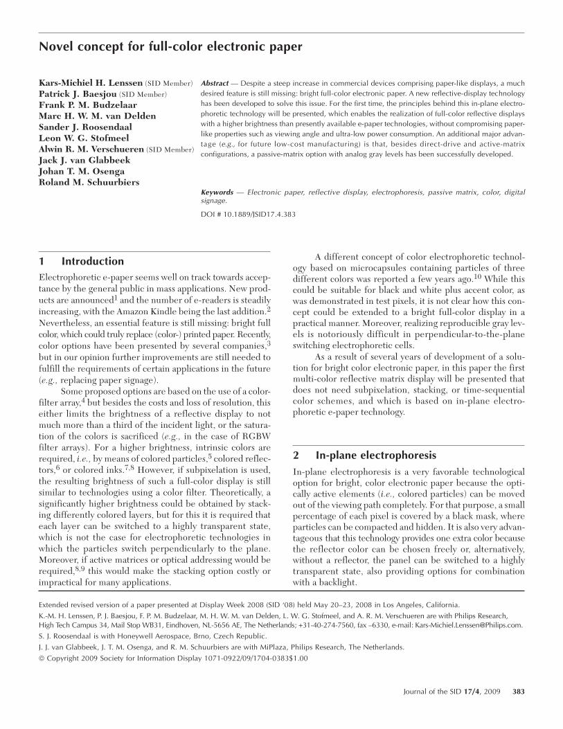
3.3 EvolutionThe optical state of a pixel is directly determined by thenumber of particles within the viewing area. Therefore, inorder to program a pixel it is not necessary to move the par-ticles from the collector electrode (i.e., the electrode hiddenby the black mask) completely towards the other side of thepixel, but it is in first instance sufficient to move themmerely from the collector across the gate. Since this dis-tance is much smaller than the pixel size, the time neededto program all pixels in a display is significantly reduced(over a factor 10 if this distance is one fifth of the pixel size).While this programming step is done per row, the sub-sequent so-called evolution step (in which the particles that
FIGURE 1 — The four phases of the passive-matrix driving scheme,respectively reset, program, evolution, hold (from top to bottom); thebars indicate applied voltages.
384 Lenssen et al. / Novel concept for full-color electronic paper
arrived in the viewing area are spread between the viewelectrodes) can be done for the entire panel at once, andthus the time involved is independent of the number of rows.
3.4 Driving schemeThe resulting driving scheme for the passive matrix consistsbasically of four phases, as illustrated in Fig. 1. The firstphase is a reset, in which all particles are collected at thecollector electrode, simultaneously for all pixels; sub-sequently all gate voltages are increased. In the second pro-gramming phase, the gate voltage in all pixels in a specificrow is lowered and depending on the desired optical state apotential difference between the collector and the first viewelectrode is applied so that in certain pixels particles cancross the gate. This programming step is repeated for allrows in the display. The third phase is the evolution phasefor the entire panel at once. Finally, when the desired opti-cal image is achieved, the panel can be switched to the holdphase with a small repulsive voltage on all gate electrodes,as described above. Note that this is a simplified example forillustration purposes; of course, many optimizations are pos-sible, e.g., multiple-row addressing, etc.
4 ExperimentalAll demos described in this paper were fabricated on glasssubstrates using optical lithography, but care was taken tomake a future transition to roll-to-roll plastic manufacturingas easy as possible. The electrodes were made of indium-tin-oxide (ITO) and the pixel walls of SU8 photoresist. The dis-tance between the substrate and cover plate (cell gap) was10–18 µm, and the pixel size 500 × 500 µm (correspondingto 50 pixels per inch). The demonstrators have been realizedwith a passive-matrix array of 100 × 100 pixels. The reflectorconsisted of standard copier paper, which was placed behindthe glass panel.
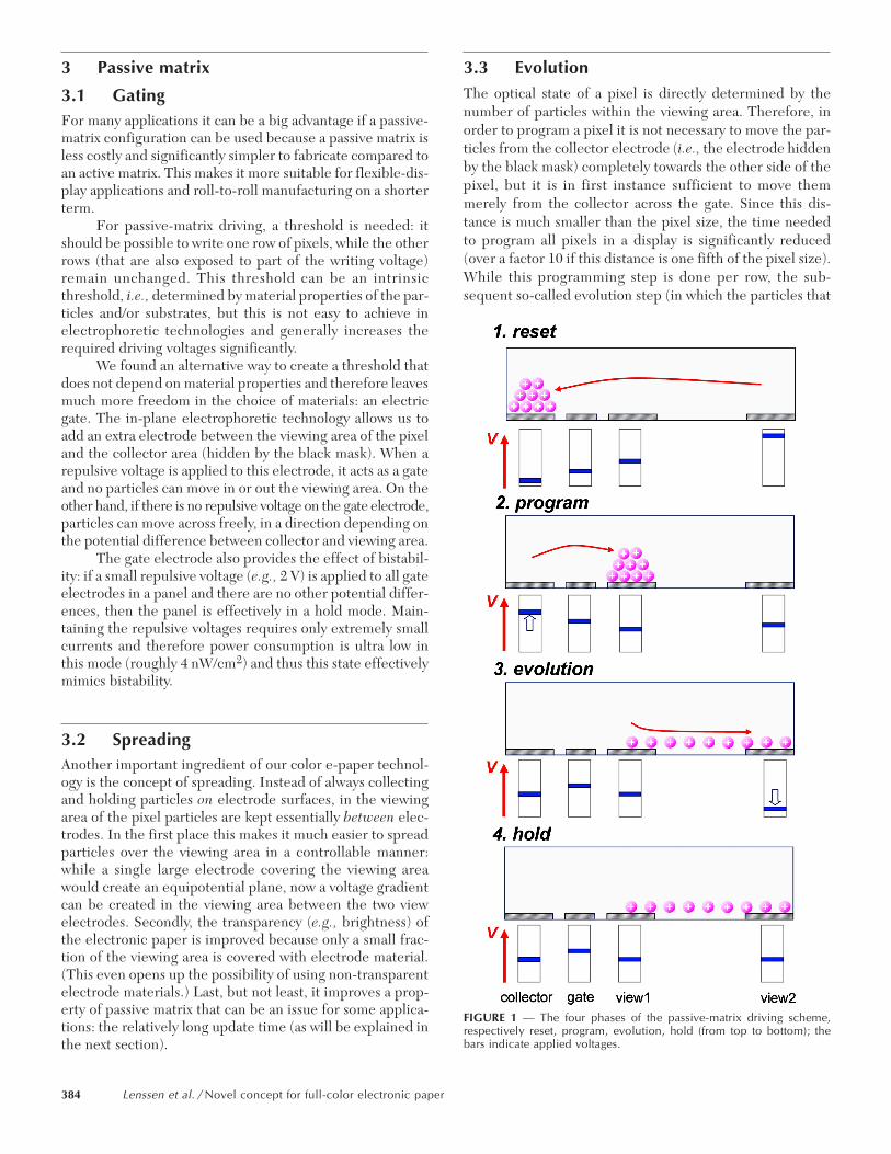
Demonstrators were filled with suspensions that weredeveloped in-house using commercially available chemicals.As the dispersant Isopar-G (Exxon Mobile) or dodecane(Aldrich) was used. Suspensions consisted of either milledpigment particles with a mixture of stabilizers (surfactants)and charging agents (such as the magenta suspension usedin Fig. 2), or dye-colored stabilized polymer particles withan added charging agent (such as the black suspensionshown in Fig. 2).
All applied voltages were 10 V or less. In a typical driv-ing scheme, the reset phase with a 10-V potential differenceapplied between the collector and view2 electrode will last120 sec. Writing the pixels with a 5-V potential differencebetween the collector and view1 electrode will take 20 secper line. The evolution phase with 10 V applied between thegate and view2 electrodes will last 80 sec. In the hold phase,2 V on the gate is sufficient to keep the particles in the col-lector and viewing area separated.
The focus of the driving of the first lab demonstratorsthat are discussed in this paper was on low voltages and notat all on update speed. Much shorter update times are cer-tainly possible, e.g., by improved suspensions, higher driv-ing voltages, and/or smaller pixel sizes. The resulting updatetime will then become similar to those of other electro-phoretic technologies (i.e., on the order of seconds), as wasalready confirmed experimentally in segmented demopanels.
5 BrightnessThe demos indeed showed the expected superior brightnesscompared to commercially available electrophoretic paperbased on perpendicularly switching particles. Optical meas-urements were performed with a goniometer (AutronicMelchers DMS 803) under collimated perpendicular illumi-nation and a spectral detector at a 45° polar angle. Thebrightness values are integrated over the measured spec-trum according to the eye sensitivity (CIELAB 1931), andconsequently normalized with a lambertian reference (Lab-sphere Spectralon). Although the design of these first demoswas conservative (resulting in an aperture of only about75%), a high brightness of 48% was measured. It is expectedthat this can still be further improved by optimizing the
FIGURE 2 — Photographs of 100 × 100-pixel passive-matrix panelsdemonstrating gray scale.
Journal of the SID 17/4, 2009 385
design, and also by using better suspensions or improvedreflectors. The measured contrast ratio was 7:1, comparableto the electrophoretic panel of a commercial e-reader. Com-puter simulations indicated that a white-state reflectance ashigh as 57% with a contrast ratio of 10:1 should be possible.
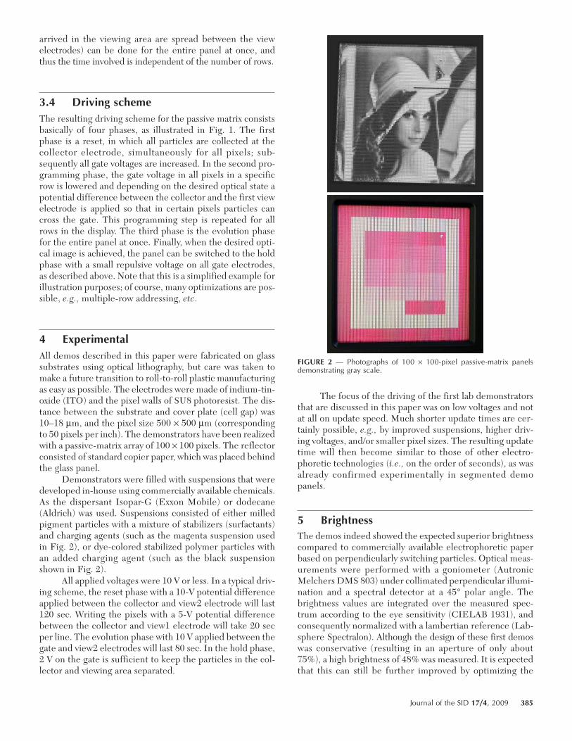
6 Gray levelsGray scale is proven to be a strength of our color-electronic-paper concept. Figure 2 shows that our passive-matrix approachcan deliver a multitude of gray levels, both with black andmagenta suspensions. In contrast to the delicate gray statesin conventional electrophoretic paper (that depend on theprecise meta-stable positions of particles), in our conceptthe gray states are well-defined and directly determined bythe number of particles in the viewing area. This number ofparticles in its turn can be precisely controlled by thenumber of particles that are allowed to cross the gate (dur-ing the program step of Fig. 1). Of course, good reproduc-ible gray scales are also a prerequisite for full-colorelectronic paper. Figure 3 shows the distribution of gray lev-els that were measured as reflectance R (at 555 nm) on themagenta panel (of Fig. 2 bottom), and subsequently scaled
into lightness values L* ≡ 116 R1/3 – 16L to better matchwith human perception. The obtained distribution of graylevels is not perfect, since it cannot be expected from themanually assembled demo panel to show the uniformity andzero defects of a factory-produced display. Nevertheless, theachieved L* range of gray levels, and the median separationbetween consecutive gray levels indicate that 32 distinguish-able gray levels (5 bits) are feasible. In addition, Fig. 3 showsthat at the scale of individual pixels, the gray levels are trulyanalog in nature (and do not result from dithering). Thisdemonstrates that the evolution step is capable of distribut-ing the particles evenly throughout the pixel.
7 ColorIn-plane electrophoretic technology provides severaloptions for color electronic paper. Obviously, a color filtercould be added to a black panel (with a white reflector) fora straight forward full-color panel. The superior brightnesswould actually result in an improvement compared to thecolor electrophoretic panels demonstrated thus far, but thissolution would not fulfill our goal of a bright full-color dis-play because of the subpixelation.
A much better option is to use a subtractive colorscheme and stack layers with a yellow, cyan, and magenta
FIGURE 3 — Distribution of gray levels as measured on a magenta panel,expressed in L*. Visible is also the truly analog nature of the gray levels.
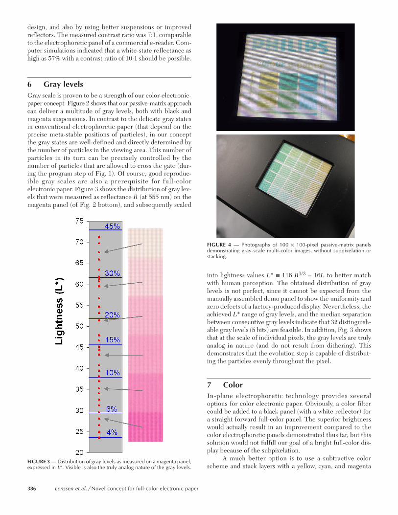
FIGURE 4 — Photographs of 100 × 100-pixel passive-matrix panelsdemonstrating gray-scale multi-color images, without subpixelation orstacking.
386 Lenssen et al. / Novel concept for full-color electronic paper
suspension on top of a white reflector. This is possible sinceevery layer can be switched to a transparent state, and there-fore all color combinations can be realized.
Besides, in-plane electrophoresis has a unique featurethat is an excellent attribute for color electronic paper: it ispossible to control more than one type of particles inde-pendently in a single layer of suspension. This means that abright multi-color reflective display can be formed in a sin-gle layer, without the need for subpixelation or stacking.This approach is actually confirmed by demonstrators thathave been realized. In Fig. 4, a photo is shown of a passive-matrix demonstrator based on a suspension with both cyanand orange particles.
Because these differently colored particles have dif-ferent charges, they can be controlled independently. As canbe seen, also mixed colors of cyan and orange can be obtainedwithout problems. The layout of this multi-color panel issimilar as described earlier, except for an additional gate andcollector electrode. To the authors’ knowledge, this is thefirst multi-color reflective matrix panel without subpixela-tion, stacking or color sequential driving; it really enables“any pixel any color.”
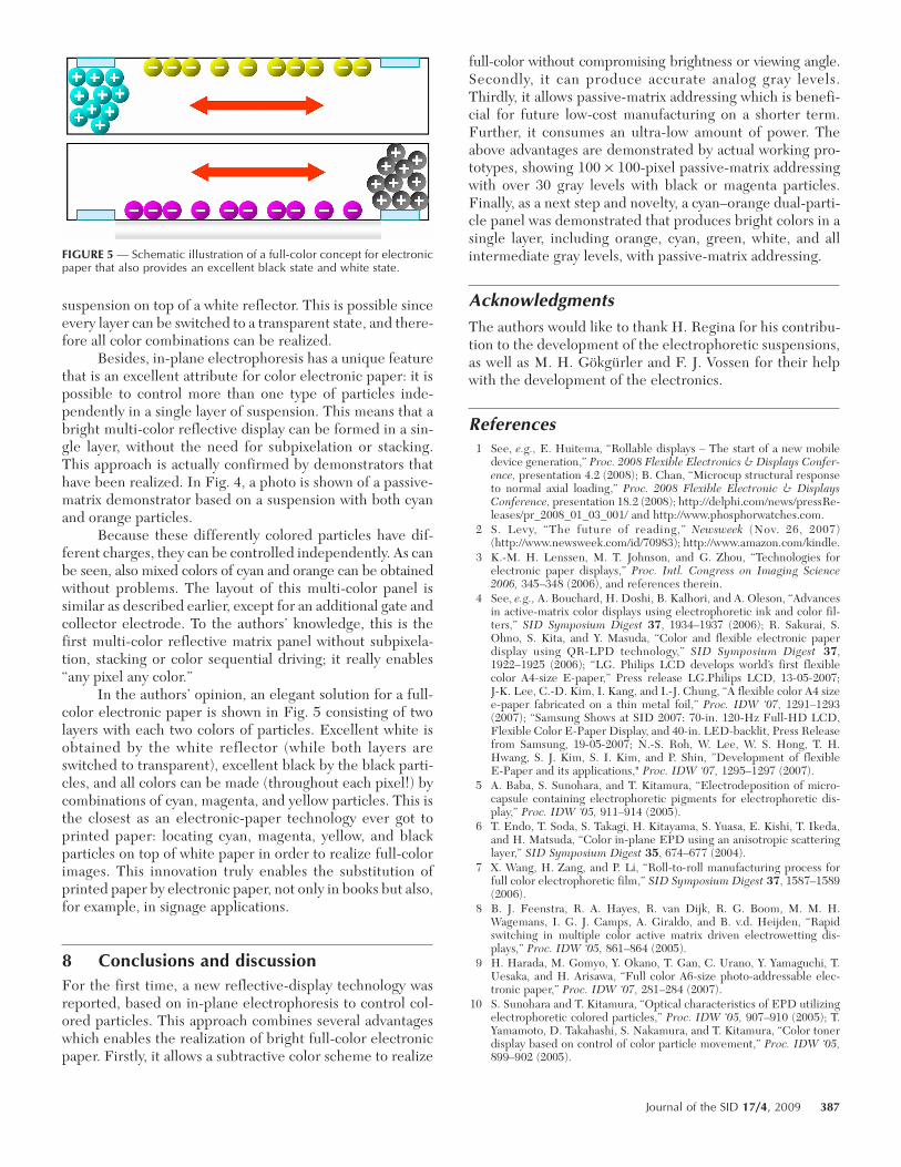
In the authors’ opinion, an elegant solution for a full-color electronic paper is shown in Fig. 5 consisting of twolayers with each two colors of particles. Excellent white isobtained by the white reflector (while both layers areswitched to transparent), excellent black by the black parti-cles, and all colors can be made (throughout each pixel!) bycombinations of cyan, magenta, and yellow particles. This isthe closest as an electronic-paper technology ever got toprinted paper: locating cyan, magenta, yellow, and blackparticles on top of white paper in order to realize full-colorimages. This innovation truly enables the substitution ofprinted paper by electronic paper, not only in books but also,for example, in signage applications.
8 Conclusions and discussionFor the first time, a new reflective-display technology wasreported, based on in-plane electrophoresis to control col-ored particles. This approach combines several advantageswhich enables the realization of bright full-color electronicpaper. Firstly, it allows a subtractive color scheme to realize
full-color without compromising brightness or viewing angle.Secondly, it can produce accurate analog gray levels.Thirdly, it allows passive-matrix addressing which is benefi-cial for future low-cost manufacturing on a shorter term.Further, it consumes an ultra-low amount of power. Theabove advantages are demonstrated by actual working pro-totypes, showing 100 × 100-pixel passive-matrix addressingwith over 30 gray levels with black or magenta particles.Finally, as a next step and novelty, a cyan–orange dual-parti-cle panel was demonstrated that produces bright colors in asingle layer, including orange, cyan, green, white, and allintermediate gray levels, with passive-matrix addressing.
AcknowledgmentsThe authors would like to thank H. Regina for his contribu-tion to the development of the electrophoretic suspensions,as well as M. H. Gökgürler and F. J. Vossen for their helpwith the development of the electronics.
References1 See, e.g., E. Huitema, “Rollable displays – The start of a new mobile
device generation,” Proc. 2008 Flexible Electronics & Displays Confer-ence, presentation 4.2 (2008); B. Chan, “Microcup structural responseto normal axial loading,” Proc. 2008 Flexible Electronic & DisplaysConference, presentation 18.2 (2008); http://delphi.com/news/pressRe-leases/pr_2008_01_03_001/ and http://www.phosphorwatches.com.
2 S. Levy, “The future of reading,” Newsweek (Nov. 26, 2007)(http://www.newsweek.com/id/70983); http://www.amazon.com/kindle.
3 K.-M. H. Lenssen, M. T. Johnson, and G. Zhou, “Technologies forelectronic paper displays,” Proc. Intl. Congress on Imaging Science2006, 345–348 (2006), and references therein.
4 See, e.g., A. Bouchard, H. Doshi, B. Kalhori, and A. Oleson, “Advancesin active-matrix color displays using electrophoretic ink and color fil-ters,” SID Symposium Digest 37, 1934–1937 (2006); R. Sakurai, S.Ohno, S. Kita, and Y. Masuda, “Color and flexible electronic paperdisplay using QR-LPD technology,” SID Symposium Digest 37,1922–1925 (2006); “LG. Philips LCD develops world’s first flexiblecolor A4-size E-paper,” Press release LG.Philips LCD, 13-05-2007;J-K. Lee, C.-D. Kim, I. Kang, and I.-J. Chung, “A flexible color A4 sizee-paper fabricated on a thin metal foil,” Proc. IDW ‘07, 1291–1293(2007); “Samsung Shows at SID 2007: 70-in. 120-Hz Full-HD LCD,Flexible Color E-Paper Display, and 40-in. LED-backlit, Press Releasefrom Samsung, 19-05-2007; N.-S. Roh, W. Lee, W. S. Hong, T. H.Hwang, S. J. Kim, S. I. Kim, and P. Shin, ”Development of flexibleE-Paper and its applications," Proc. IDW ‘07, 1295–1297 (2007).
5 A. Baba, S. Sunohara, and T. Kitamura, “Electrodeposition of micro-capsule containing electrophoretic pigments for electrophoretic dis-play,” Proc. IDW ‘05, 911–914 (2005).
6 T. Endo, T. Soda, S. Takagi, H. Kitayama, S. Yuasa, E. Kishi, T. Ikeda,and H. Matsuda, “Color in-plane EPD using an anisotropic scatteringlayer,” SID Symposium Digest 35, 674–677 (2004).
7 X. Wang, H. Zang, and P. Li, “Roll-to-roll manufacturing process forfull color electrophoretic film,” SID Symposium Digest 37, 1587–1589(2006).
8 B. J. Feenstra, R. A. Hayes, R. van Dijk, R. G. Boom, M. M. H.Wagemans, I. G. J. Camps, A. Giraldo, and B. v.d. Heijden, “Rapidswitching in multiple color active matrix driven electrowetting dis-plays,” Proc. IDW ‘05, 861–864 (2005).
9 H. Harada, M. Gomyo, Y. Okano, T. Gan, C. Urano, Y. Yamaguchi, T.Uesaka, and H. Arisawa, “Full color A6-size photo-addressable elec-tronic paper,” Proc. IDW ‘07, 281–284 (2007).
10 S. Sunohara and T. Kitamura, “Optical characteristics of EPD utilizingelectrophoretic colored particles,” Proc. IDW ‘05, 907–910 (2005); T.Yamamoto, D. Takahashi, S. Nakamura, and T. Kitamura, “Color tonerdisplay based on control of color particle movement,” Proc. IDW ‘05,899–902 (2005).
FIGURE 5 — Schematic illustration of a full-color concept for electronicpaper that also provides an excellent black state and white state.
Journal of the SID 17/4, 2009 387
Frank P. M. Budzelaar obtained his M.Sc. degreein electrical engineering from the Technical Uni-versity of Eindhoven in 1988. He worked in sev-eral projects as a hardware and softwarearchitect. In 2000, he joined the Philips ResearchLaboratories, Eindhoven, The Netherlands, assenior scientist. His contribution to the project isin designing the electronics for the passive-matrixdriving of the electrophoretic devices.
Marc H. W. M. van Delden received his B.Sc. degreein environmental chemistry in 1986. After fulfillinghis military obligations, he joined Philips Research in1987 and has since worked on the dry-etching ofsemiconductors, the growth, characterization,and analysis of CZ-grown monocrystalline andwet-grown polycrystalline ferrites, LPCVD-grownthin-film ferrites, and rubbing noise in magnetic-recording heads, MCM-D modules for mobile,and Q&R of a-SiNx:H thin films for passive inte-
gration. Since 2005, he has been involved in the characterization, driv-ing, and design of electrophoretic dispersions and devices.
Alwin R. M. Verschueren received his M.Sc. degreein applied physics in 1997 from Delft Universityof Technology, The Netherlands. Afterwards, hewas a visiting scientist at the RIKEN institute inJapan. In 1998, he joined Philips Research Labora-tories in Eindhoven, as a research scientist involvedin liquid-crystal displays. Since 2003, his corecontribution to the project has been in controllingthe particle motion by electrode and waveformdesigns.
Jack J. van Glabbeek received his degree in ana-lytical chemistry from the HLO in Eindhoven in1989. He has been with Philips Research since1986 and has been working in the field of thin-film deposition, etching and lithography for vari-ous projects such as thin-film magnetic heads,large flat thin displays, and is presently workingas a process engineer on electrophoretics.
Johan T. M. Osenga received his degree in ana-lytical chemistry from the MLO in Eindhoven in1990. He joined Philips in 1991 as a LCD devel-opment engineer at its FPD plant. From 1997 until2000, he was a member of Philips PolyLED. He iscurrently engaged as a process engineer at PhilipsMiPlaza in Eindhoven.
Roland M. Schuurbiers received his degree inmechanical engineering from the M.T.S. (Catho-lic) in Eindhoven. He joined Philips Research in1986. The largest part of his work is related tomechanical aspects for several flat displays. He ispresently working as a process engineer in theDPF department (Device Processing Facilities),which is a part of the MiPlaza facility.
Sander J. Roosendaal studied experimental phys-ics in Utrecht (The Netherlands) and Lund (Swe-den). He obtained his Ph.D. in surface sciencefrom Utrecht University in 1999. He joinedPhilips in 2000 and has worked in LCDs for mobileapplications between 2000 and 2006. From 2005to 2007, he was involved in the research describedin this paper. Currently, he works at HoneywellAerospace as a Program Manager.
Kars-Michiel H. Lenssen is a Director and Princi-pal Scientist at Philips Research Europe, leadingthe color-electronic-paper project. He receivedhis M.Sc. degree in applied physics from Eind-hoven University of Technology in 1989. In 1994,he received his Ph.D. from Delft University ofTechnology and joined Philips Research as a Sen-ior Scientist. In that function, he initiated and ledresearch projects on (giant) magnetoresistancesensors and on MRAM. From 2002 to 2003, he
worked as a Philips assignee in Arizona in the framework of the Motorola-Philips-STMicroelectronics alliance. He holds 20 granted U.S. patentsand is (co-)inventor on over 35 patent applications; he (co-)authoredover 25 papers in international scientific journals. He also works as anevaluator of research projects for the European Commission and is aFellow of the Institute of Nanotechnology and a member of the Interna-tional Advisory Committee of several conferences.
Patrick J. Baesjou is a senior scientist at PhilipsResearch in Eindhoven, The Netherlands. He receivedhis M.S. degree in chemistry from Utrecht Univer-sity in 1992, and obtained his Ph.D. from LeidenUniversity in 1997 on co-ordination chemistryand homogeneous catalysis. After a postdoc atPrinceton University, he joined Philips Researchin 2000 and started working on plastic electron-ics. Since 2002, his research activities focused onnon-aqueous dispersions for electrophoretic devices.
Leon W. G. Stofmeel graduated in Technical AppliedPhysics from the University of Professional Educationin Eindhoven. In 2001, he started as a research scien-tist at Philips Research Laboratories writing driversoftware for research on active-matrix displays. In2002, he started the characterization of transflectiveactive-matrix displays. Since 2005, he has been involvedin the optics and colorimetry of electrophoretic pan-els. In addition to that, designing scientific grademockups is one of his tasks as well.
388 Lenssen et al. / Novel concept for full-color electronic paper


![[crosti.ru] color](https://img.pdfslide.net/doc/110x75/635b0815f6a5e096120147a8/crostiru-color.jpg)