Embed Size (px)
Citation preview
Numerical Relays For Protection, Monitoring & Control
Switchgear Factory, Ahmednagar
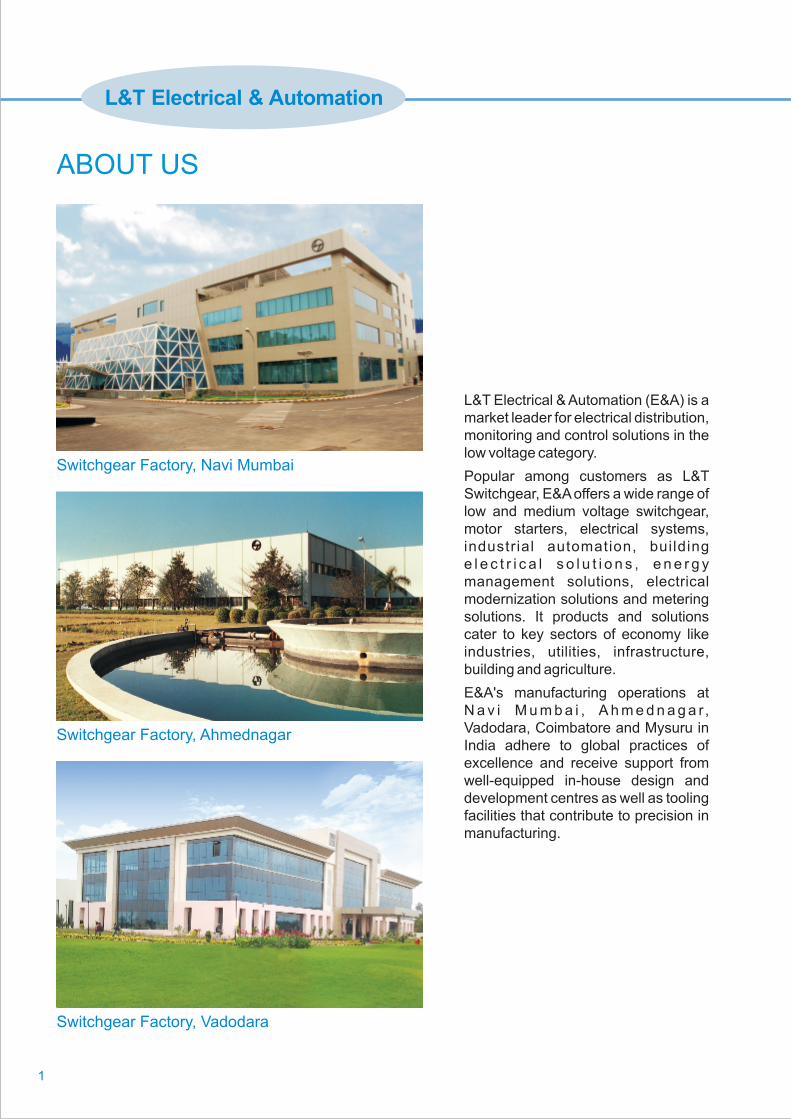
Switchgear Factory, Navi Mumbai
Switchgear Factory, Vadodara
ABOUT US
1
L&T Electrical & Automation (E&A) is a market leader for electrical distribution, monitoring and control solutions in the low voltage category.
Popular among customers as L&T Switchgear, E&A offers a wide range of low and medium voltage switchgear, motor starters, electrical systems, industrial automation, building e l e c t r i c a l s o l u t i o n s , e n e r g y management solutions, electrical modernization solutions and metering solutions. It products and solutions cater to key sectors of economy like industries, utilities, infrastructure, building and agriculture.
E&A's manufacturing operations at N a v i M u m b a i , A h m e d n a g a r, Vadodara, Coimbatore and Mysuru in India adhere to global practices of excellence and receive support from well-equipped in-house design and development centres as well as tooling facilities that contribute to precision in manufacturing.
L&T Electrical & Automation
ANSI Device Function
Time - Current Characteristics
Over Current & Earth Fault Relays - MC31AnX, MC61AnX, MC61CnX
Current Sensing Relays - MC12A
Reverse Power Relay - MRP11
Voltage Relay - MV12
1
2
3
5
7
9
Trip Circuit Supervision Relay - TCS01nX
9
Pages
Contents
Pages
Motor Protection Relays -
MM10
MC2 - 30M and MC2 - 30MW
iMMR, MPR300, MPR200nX
11
13
15
ANSI/IEEE
1
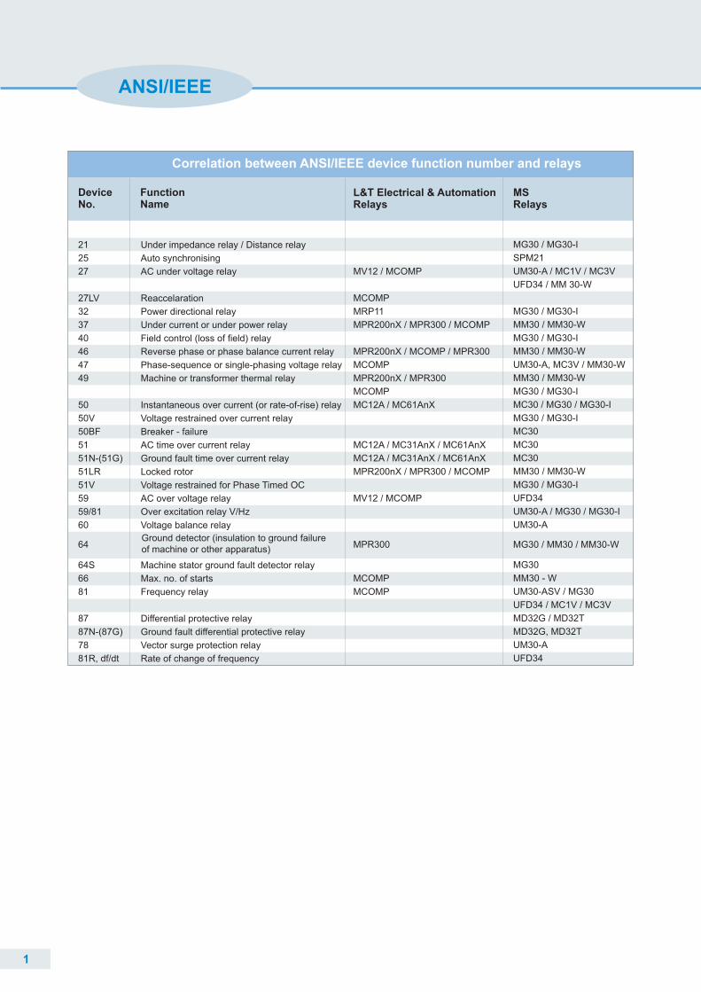
Correlation between ANSI/IEEE device function number and relays
Function Name
MS Relays
Device No.
21
25
27
27LV
32
37
40
46
47
49
50
50V
50BF
51
51N-(51G)
51LR
51V
59
59/81
60
64S
66
81
87
87N-(87G)
78
81R, df/dt
Under impedance relay / Distance relay
Auto synchronising
AC under voltage relay
Reaccelaration
Power directional relay
Under current or under power relay
Field control (loss of field) relay
Reverse phase or phase balance current relay
Phase-sequence or single-phasing voltage relay
Machine or transformer thermal relay
Instantaneous over current (or rate-of-rise) relay
Voltage restrained over current relay
Breaker - failure
AC time over current relay
Ground fault time over current relay
Locked rotor
Voltage restrained for Phase Timed OC
AC over voltage relay
Over excitation relay V/Hz
Voltage balance relay
Machine stator ground fault detector relay
Max. no. of starts
Frequency relay
Differential protective relay
Ground fault differential protective relay
Vector surge protection relay
Rate of change of frequency
Ground detector (insulation to ground failure of machine or other apparatus)
64
MG30 / MG30-I
SPM21
UM30-A / MC1V / MC3V
UFD34 / MM 30-W
MG30 / MG30-I
MM30 / MM30-W
MG30 / MG30-I
MM30 / MM30-W
UM30-A, MC3V / MM30-W
MM30 / MM30-W
MG30 / MG30-I
MC30 / MG30 / MG30-I
MG30 / MG30-I
MC30
MC30
MC30
MM30 / MM30-W
MG30 / MG30-I
UFD34
UM30-A / MG30 / MG30-I
UM30-A
MG30
MM30 - W
UM30-ASV / MG30
UFD34 / MC1V / MC3V
MD32G / MD32T
MD32G, MD32T
UM30-A
UFD34
L&T Electrical & AutomationRelays
MV12 / MCOMP
MCOMP
MRP11
MPR200nX / MPR300 / MCOMP
MPR200nX / MCOMP / MPR300
MCOMP
MPR200nX / MPR300
MCOMP
MC12A / MC61AnX
MC12A / MC31AnX / MC61AnX
MC12A / MC31AnX / MC61AnX
MPR200nX / MPR300 / MCOMP
MV12 / MCOMP
MCOMP
MCOMP
MPR300 MG30 / MM30 / MM30-W
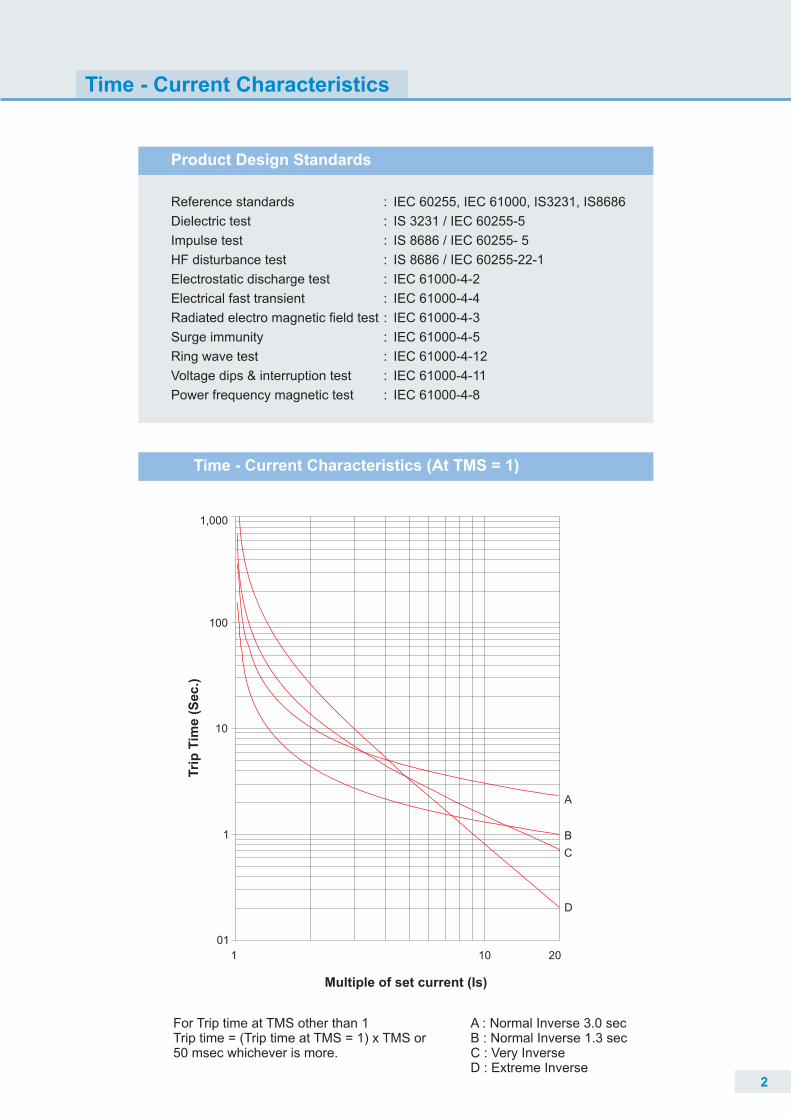
Time - Current Characteristics
Product Design Standards
Reference standards IEC 60255, IEC 61000, IS3231, IS8686
Dielectric test : IS 3231 / IEC 60255-5
Impulse test : IS 8686 / IEC 60255- 5
HF disturbance test : IS 8686 / IEC 60255-22-1
Electrostatic discharge test : IEC 61000-4-2
Electrical fast transient : IEC 61000-4-4
Radiated electro magnetic field test : IEC 61000-4-3
Surge immunity : IEC 61000-4-5
Ring wave test : IEC 61000-4-12
Voltage dips & interruption test : IEC 61000-4-11
Power frequency magnetic test : IEC 61000-4-8
:
Time - Current Characteristics (At TMS = 1)
A : Normal Inverse 3.0 secB : Normal Inverse 1.3 secC : Very InverseD : Extreme Inverse
For Trip time at TMS other than 1Trip time = (Trip time at TMS = 1) x TMS or 50 msec whichever is more.
Multiple of set current (Is)
Tri
p T
ime
(S
ec
.)
A
B
C
D
1,000
100
10
1
01
1 10 20
2
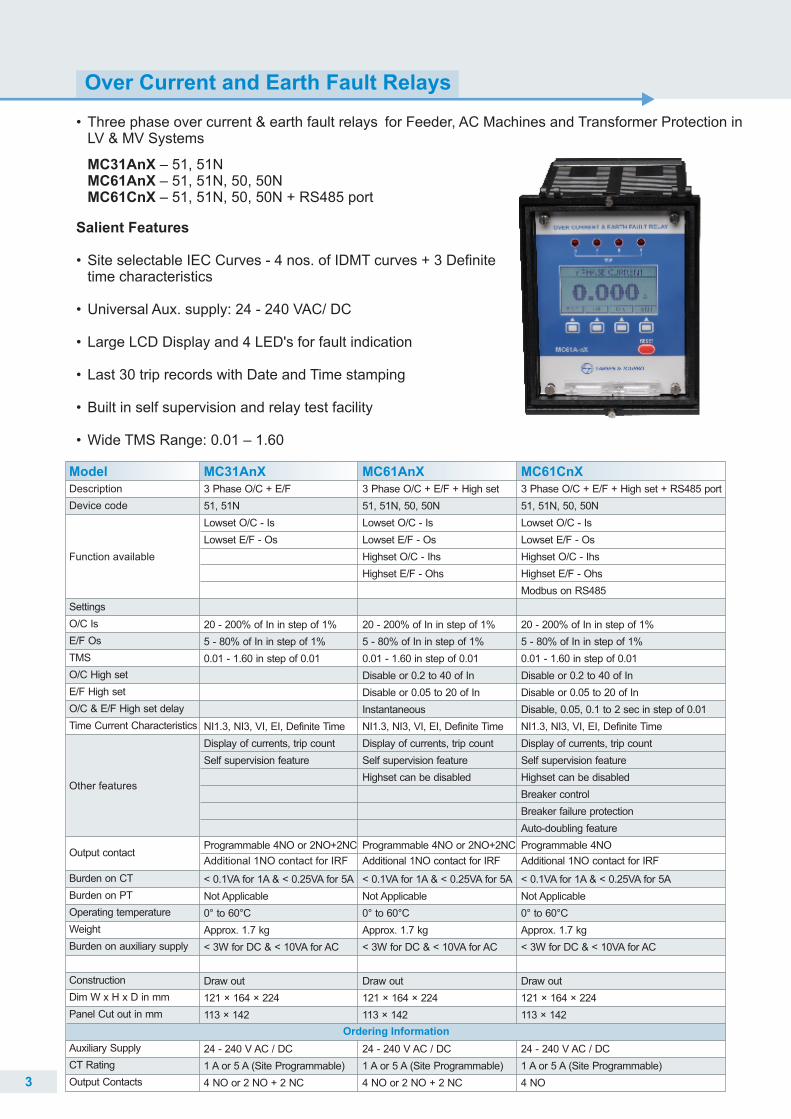
Salient Features • Site selectable IEC Curves - 4 nos. of IDMT curves + 3 Definite
time characteristics
• Universal Aux. supply: 24 - 240 VAC/ DC
• Large LCD Display and 4 LED's for fault indication
• Last 30 trip records with Date and Time stamping
• Built in self supervision and relay test facility
• Wide TMS Range: 0.01 – 1.60
Over Current and Earth Fault Relays
• LV & MV Systems
MC31AnX – 51, 51NMC61AnX – 51, 51N, 50, 50NMC61CnX – 51, 51N, 50, 50N + RS485 port
Three phase over current & earth fault relays for Feeder, AC Machines and Transformer Protection in
3
Model MC31AnXDescription
Device code
Function available
Settings
O/C Is
E/F Os
TMS
O/C High set
E/F High set
O/C & E/F High set delay
Time Current Characteristics
Burden on CT
Burden on PT
Operating temperature
Weight
Burden on auxiliary supply
Construction
Dim W x H x D in mm
Panel Cut out in mm
Auxiliary Supply
CT Rating
Output Contacts
Other features
3 Phase O/C + E/F
51, 51N
Lowset O/C - Is
Lowset E/F - Os
20 - 200% of In in step of 1%
5 - 80% of In in step of 1%
0.01 - 1.60 in step of 0.01
NI1.3, NI3, VI, EI, Definite Time
Display of currents, trip count
Self supervision feature
< 0.1VA for 1A & < 0.25VA for 5A
Not Applicable
0° to 60°C
Approx. 1.7 kg
< 3W for DC & < 10VA for AC
Draw out
121 × 164 × 224
113 × 142
24 - 240 V AC / DC
1 A or 5 A (Site Programmable)
4 NO or 2 NO + 2 NC
3 Phase O/C + E/F + High set
51, 51N, 50, 50N
Lowset O/C - Is
Lowset E/F - Os
Highset O/C - Ihs
Highset E/F - Ohs
20 - 200% of In in step of 1%
5 - 80% of In in step of 1%
0.01 - 1.60 in step of 0.01
Disable or 0.2 to 40 of In
Disable or 0.05 to 20 of In
Instantaneous
NI1.3, NI3, VI, EI, Definite Time
Display of currents, trip count
Self supervision feature
Highset can be disabled
< 0.1VA for 1A & < 0.25VA for 5A
Not Applicable
0° to 60°C
Approx. 1.7 kg
< 3W for DC & < 10VA for AC
Draw out
121 × 164 × 224
113 × 142
24 - 240 V AC / DC
1 A or 5 A (Site Programmable)
4 NO or 2 NO + 2 NC
3 Phase O/C + E/F + High set + RS485 port
51, 51N, 50, 50N
Lowset O/C - Is
Lowset E/F - Os
Highset O/C - Ihs
Highset E/F - Ohs
Modbus on RS485
20 - 200% of In in step of 1%
5 - 80% of In in step of 1%
0.01 - 1.60 in step of 0.01
Disable or 0.2 to 40 of In
Disable or 0.05 to 20 of In
Disable, 0.05, 0.1 to 2 sec in step of 0.01
NI1.3, NI3, VI, EI, Definite Time
Display of currents, trip count
Self supervision feature
Highset can be disabled
Breaker control
Breaker failure protection
Auto-doubling feature
< 0.1VA for 1A & < 0.25VA for 5A
Not Applicable
0° to 60°C
Approx. 1.7 kg
< 3W for DC & < 10VA for AC
Draw out
121 × 164 × 224
113 × 142
24 - 240 V AC / DC
1 A or 5 A (Site Programmable)
4 NO
Ordering Information
MC61AnX MC61CnX
Output contactProgrammable 4NO or 2NO+2NC
Additional 1NO contact for IRF
Programmable 4NO or 2NO+2NC
Additional 1NO contact for IRF
Programmable 4NO
Additional 1NO contact for IRF
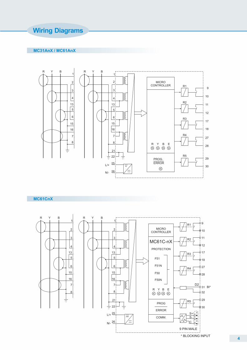
MC31AnX / MC61AnX
MC61CnX
Wiring Diagrams
R Y B R Y B1
2
4
13
5
6
15
16
7
8
3 3
1
2
4
13
5
6
15
16
7
8
22
25
26
21
L/+
N/-
MICRO CONTROLLER
R Y B E
R1
R2
R3
R4
R5
9
10
11
12
17
18
27
28
29
30˜
PROG.
ERROR
4
R Y B R Y B1
2
3
4
13
5
6
15
16
7
8
1
2
3
4
13
5
6
15
16
7
8
21
22
25
26N/-
L/+
MICROCONTROLLER
MC61C-nX
PROTECTION
F51
F51N
F50
F50N
R Y B E
PROG
ERROR
COMM.
9
10
R1
11
12
R2
17
18
R3
27
28
R4
29
30
R5
31
32
D2BI*
S+
S-
C
9 PIN MALE
* BLOCKING INPUT
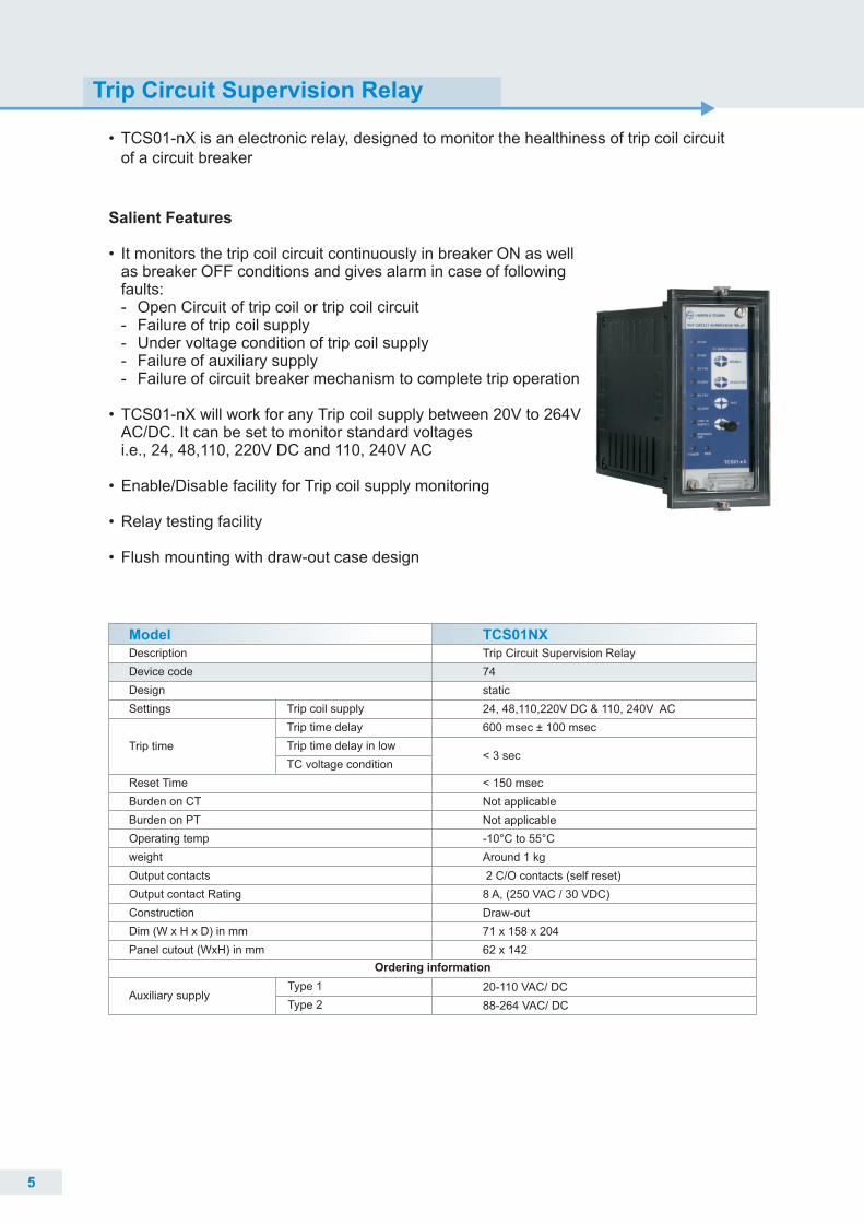
Trip Circuit Supervision Relay
• TCS01-nX is an electronic relay, designed to monitor the healthiness of trip coil circuit of a circuit breaker
Salient Features •
•
•
•
It monitors the trip coil circuit continuously in breaker ON as well as breaker OFF conditions and gives alarm in case of following faults:- Open Circuit of trip coil or trip coil circuit- Failure of trip coil supply- Under voltage condition of trip coil supply- Failure of auxiliary supply- Failure of circuit breaker mechanism to complete trip operation
TCS01-nX will work for any Trip coil supply between 20V to 264V AC/DC. It can be set to monitor standard voltages i.e., 24, 48,110, 220V DC and 110, 240V AC
Enable/Disable facility for Trip coil supply monitoring
Relay testing facility
Flush mounting with draw-out case design
•
ModelDescription
Device code
Design
Settings Trip coil supply
Trip time delay
Trip time delay in low
TC voltage condition
Reset Time
Burden on CT
Burden on PT
Operating temp
weight
Output contacts
Output contact Rating
Construction
Dim (W x H x D) in mm
Panel cutout (WxH) in mm
TCS01NX
Trip time
Auxiliary supply
Ordering information
Type 1
Type 2
Trip Circuit Supervision Relay
74
static
24, 48,110,220V DC & 110, 240V AC
600 msec ± 100 msec
< 150 msec
Not applicable
Not applicable
-10°C to 55°C
Around 1 kg
2 C/O contacts (self reset)
8 A, (250 VAC / 30 VDC)
Draw-out
71 x 158 x 204
62 x 142
20-110 VAC/ DC
88-264 VAC/ DC
< 3 sec
5
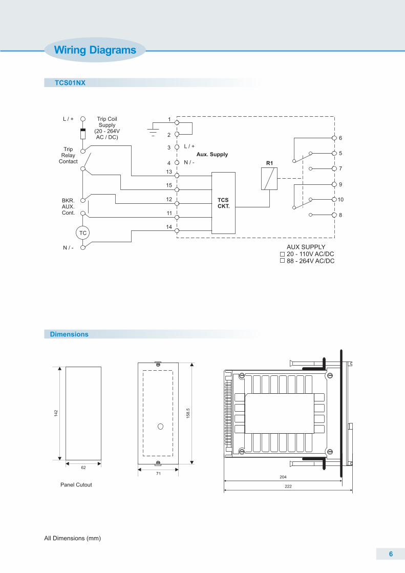
Trip CoilSupply
(20 - 264VAC / DC)
14
11
12
15
13
4
3
2
1
L / +
N / -
TCSCKT.
R1
6
5
7
9
10
8
Aux. Supply
L / +
N / -
BKR.AUX.Cont.
TripRelay
Contact
TC
AUX SUPPLY20 - 110V AC/DC88 - 264V AC/DC
TCS01NX
Wiring Diagrams
Dimensions
All Dimensions (mm)
6
14
2
62
71
15
8.5
222
204
Panel Cutout
ModelDescription
Device code
Design
Burden on CT
Burden on PT
Operating temp
Weight
Burden on auxiliary supply
Output contacts
Construction
Dim W x H x D in mm
Panel cutout
CT Rating
MC12A
Auxiliary supply
Range setting
Other features
Settings
Functions available
Ordering Information
1 Ph O/C or E/F
50/51 or 50N/51N
Microcontroller based
Lowset O/C - Is
Highset O/C - Ihs
Lowset E/F - Os
Highset E/F - Is
O/C Is = 50 - 200% Step 10% or
E/F Is = 10 - 40% Step 2% or
E/F Is = 20 - 80% Step 4%
HS O/C = (2 - 16) xls step 2 Is
HS E/F = (2 - 16) xls step 2 Is
Time characteristics available -
Nl, VI, EI, Definite time
3 ranges of def time (1, 10, 100)
TMS : 0.1 - 1.6 Step 0.1
Site selectable trip time char.
Highset can be disabled
0.25 VA on CT
Not applicable 0 00 C - 60 C
< 1.5kg
5.5 VA
2 C/O Contacts (S/R)
Drawout
71 x 158 x 224
62 x 142
20 - 110 V AC / DC or
88 - 264 V AC / DC
1 A or 5 A
10 - 40% or 20 - 80% or 50 - 200%
Site selectable
Type 1
Type 2
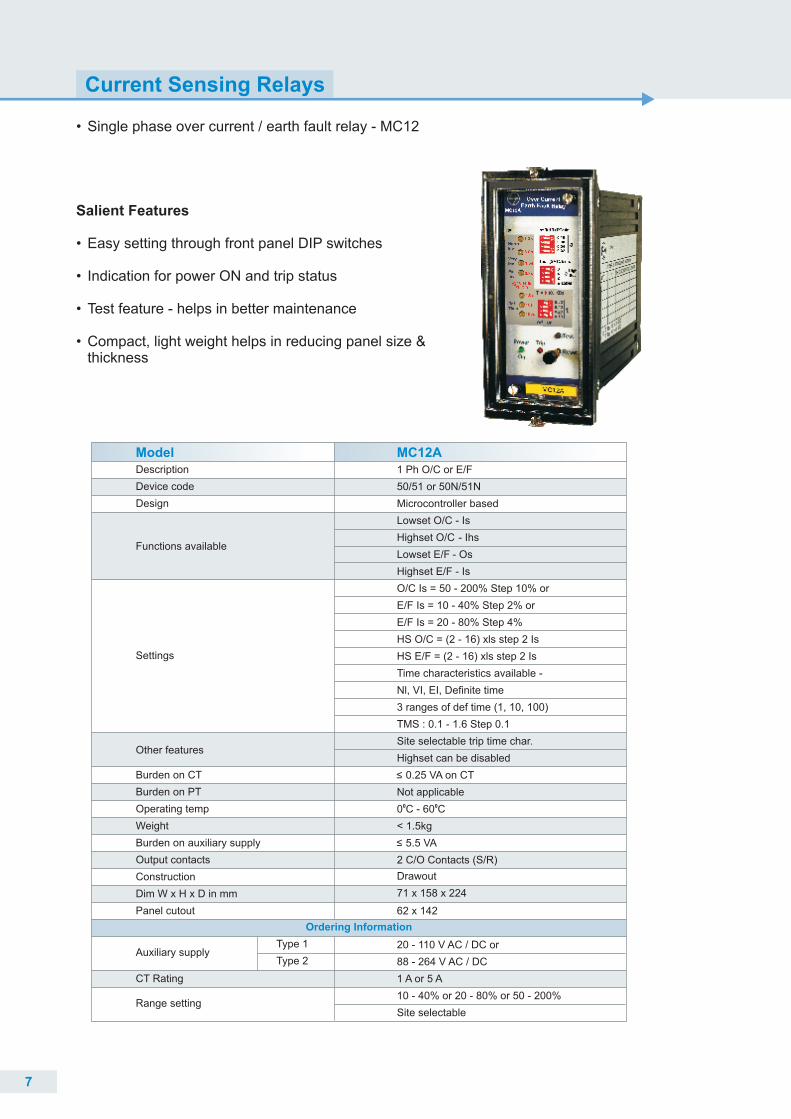
Salient Features
• Easy setting through front panel DIP switches
• Indication for power ON and trip status
• Test feature - helps in better maintenance • Compact, light weight helps in reducing panel size &
thickness
Current Sensing Relays
• Single phase over current / earth fault relay - MC12
7
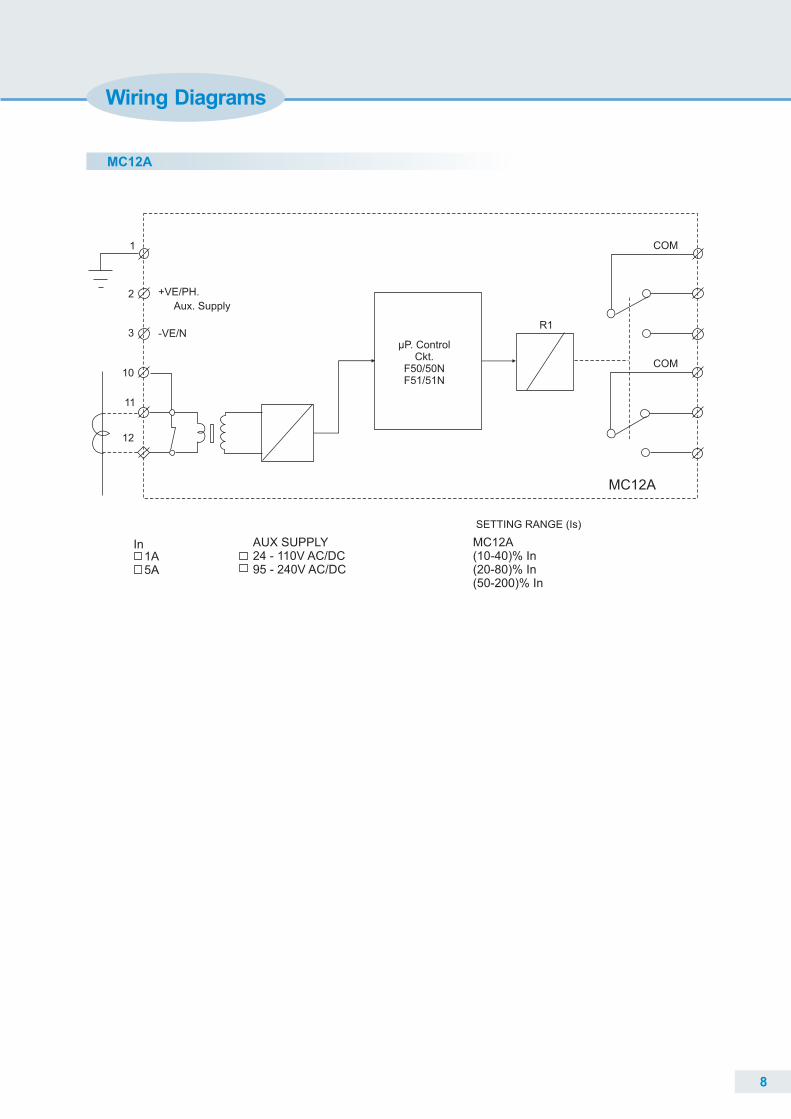
MC12A
1
2 +VE/PH.
-VE/NR1
COM
COM
SETTING RANGE (Is)
Aux. Supply
µP. ControlCkt.
F50/50NF51/51N
3
10
11
12
1AIn MC12A
(10-40)% In(20-80)% In(50-200)% In
5A
MC12A
AUX SUPPLY24 - 110V AC/DC95 - 240V AC/DC
Wiring Diagrams
8
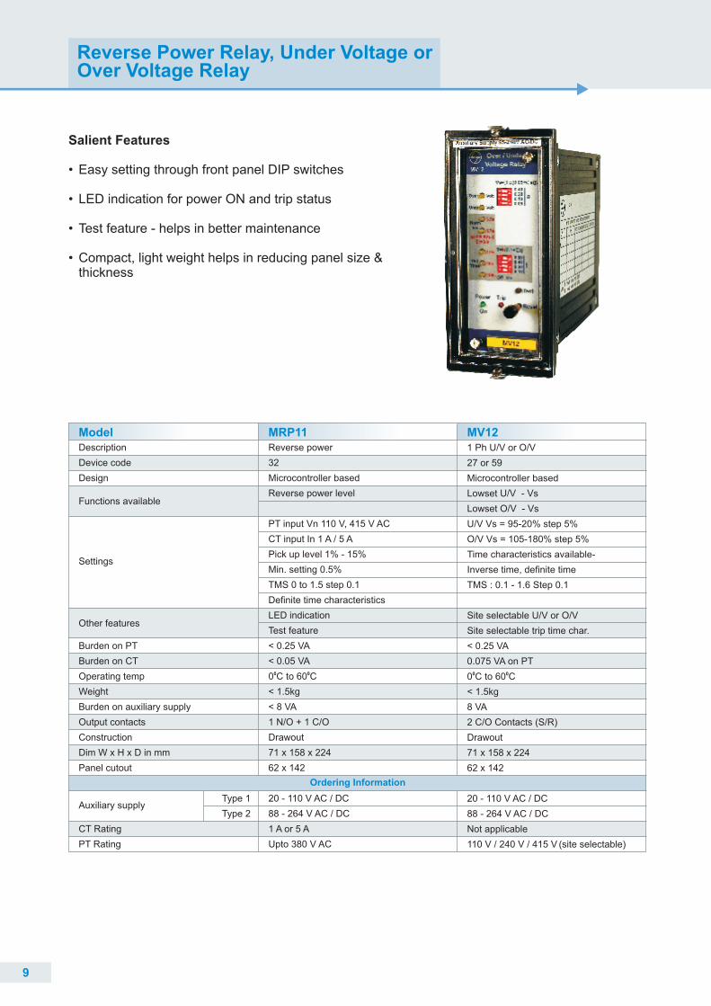
Salient Features
• Easy setting through front panel DIP switches
• LED indication for power ON and trip status
• Test feature - helps in better maintenance • Compact, light weight helps in reducing panel size &
thickness
Reverse Power Relay, Under Voltage or Over Voltage Relay
9
Model MRP11 MV12Description
Device code
Design
Burden on PT
Burden on CT
Operating temp
Weight
Burden on auxiliary supply
Output contacts
Construction
Dim W x H x D in mm
Panel cutout
Type 1
Type 2
CT Rating
PT Rating
1 Ph U/V or O/V
27 or 59
Microcontroller based
Lowset U/V - Vs
Lowset O/V - Vs
U/V Vs = 95-20% step 5%
O/V Vs = 105-180% step 5%
Time characteristics available-
Inverse time, definite time
TMS : 0.1 - 1.6 Step 0.1
Site selectable U/V or O/V
Site selectable trip time char.
< 0.25 VA
0.075 VA on PT0 00 C to 60 C
< 1.5kg
8 VA
2 C/O Contacts (S/R)
Drawout
71 x 158 x 224
62 x 142
20 - 110 V AC / DC
88 - 264 V AC / DC
Not applicable
110 V / 240 V / 415 V (site selectable)
Reverse power
32
Microcontroller based
Reverse power level
PT input Vn 110 V, 415 V AC
CT input In 1 A / 5 A
Pick up level 1% - 15%
Min. setting 0.5%
TMS 0 to 1.5 step 0.1
Definite time characteristics
LED indication
Test feature
< 0.25 VA
< 0.05 VA0 00 C to 60 C
< 1.5kg
< 8 VA
1 N/O + 1 C/O
Drawout
71 x 158 x 224
62 x 142
20 - 110 V AC / DC
88 - 264 V AC / DC
1 A or 5 A
Upto 380 V AC
Other features
Settings
Functions available
Auxiliary supply
Ordering Information
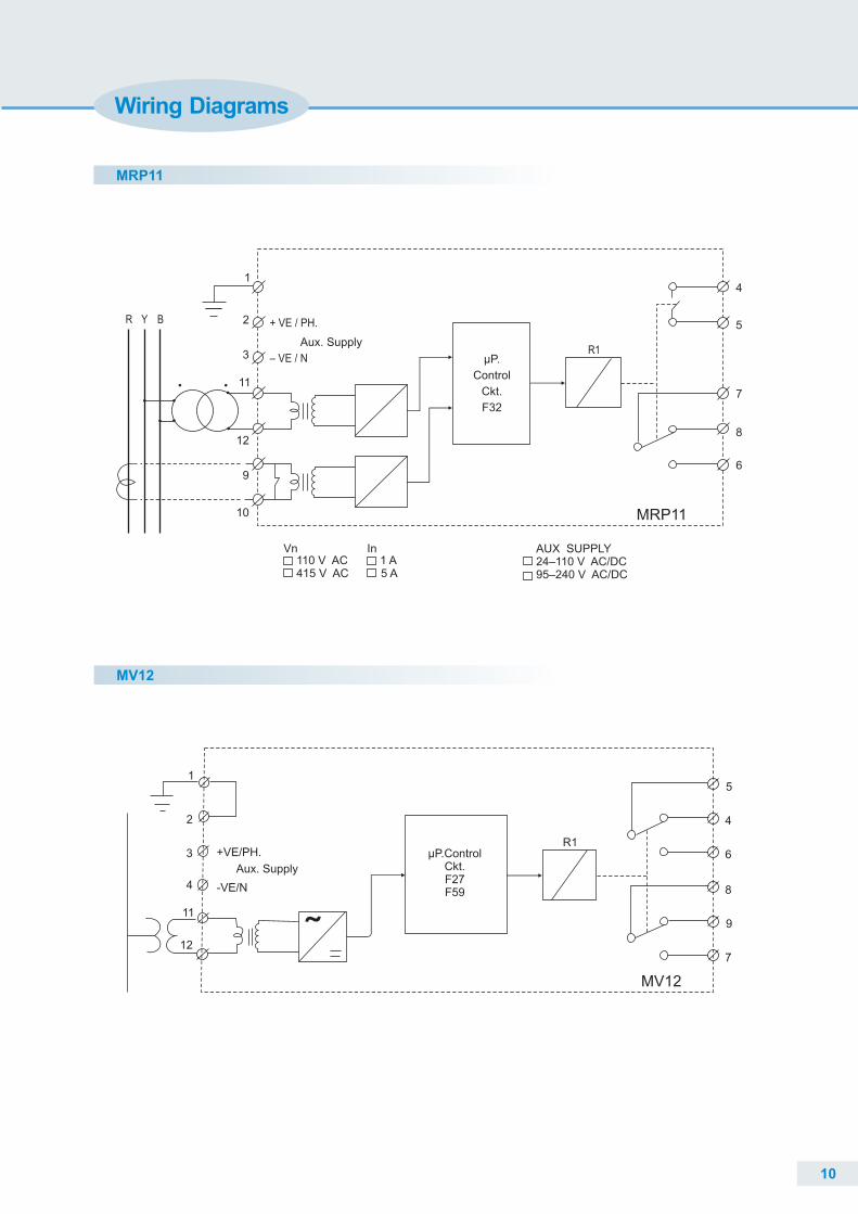
R Y
14
5
7
8
6
11
µP.
Control
Ckt.
F32
R1
Vn110 V AC 1 A415 V AC 5 A
In AUX SUPPLY24–110 V AC/DC95–240 V AC/DC
MRP11
12
2 + VE / PH.
– VE / N
Aux. Supply3
9
10
B
MRP11
MV12
5
4
6
8
9
7
R1µP.Control
Ckt.F27F59
1
2
3
11
12
MV12
+VE/PH.
Aux. Supply
-VE/N4
Wiring Diagrams
10
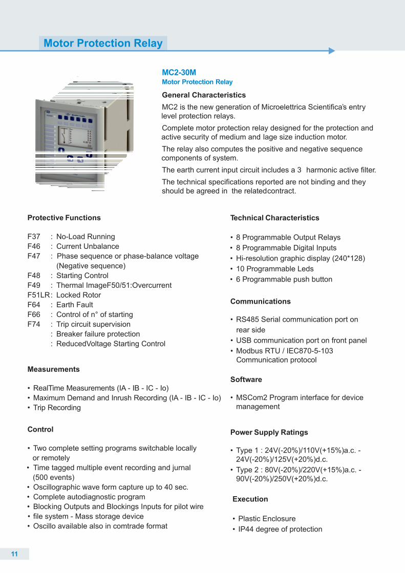
Motor Protection Relay
11
Protective Functions
F37 : No-Load Running
F46 : Current Unbalance
F47 : Phase sequence or phase-balance voltage
(Negative sequence)
F48 : Starting Control
F49 : Thermal ImageF50/51:Overcurrent
F51LR: Locked Rotor
F64 : Earth Fault
F66 : Control of n° of starting
F74 : Trip circuit supervision
: Breaker failure protection
: ReducedVoltage Starting Control
Control
•
or remotely
• Time tagged multiple event recording and jurnal
(500 events)
• Oscillographic wave form capture up to 40 sec.
• Complete autodiagnostic program
• Blocking Outputs and Blockings Inputs for pilot wire
• file system - Mass storage device
• Oscillo available also in comtrade format
Two complete setting programs switchable locally
Measurements
• RealTime Measurements (IA - IB - IC - Io)
• Maximum Demand and Inrush Recording (IA - IB - IC - Io)
• Trip Recording
Software
• MSCom2 Program interface for devicemanagement
Communications
• RS485 Serial communication port on
rear side
• USB communication port on front panel
• Modbus RTU / IEC870-5-103 Communication protocol
Power Supply Ratings
• Type 1 : 24V(-20%)/110V(+15%)a.c. - 24V(-20%)/125V(+20%)d.c.
• Type 2 : 80V(-20%)/220V(+15%)a.c. -90V(-20%)/250V(+20%)d.c.
Technical Characteristics
• 8 Programmable Output Relays
• 8 Programmable Digital Inputs
• Hi-resolution graphic display (240*128)
• 10 Programmable Leds
• 6 Programmable push button
Execution
• Plastic Enclosure
• IP44 degree of protection
General Characteristics
MC2 is the new generation of Microelettrica Scientifica’s entry level protection relays.
Complete motor protection relay designed for the protection and active security of medium and lage size induction motor.
The relay also computes the positive and negative sequence components of system.
The earth current input circuit includes a 3 harmonic active filter.
The technical specifications reported are not binding and they should be agreed in the relatedcontract.
MC2-30MMotor Protection Relay
12
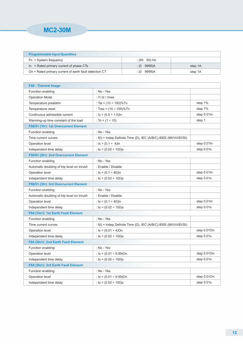
MC2-30M
Programmable Input Quantities
Fn = System frequency
In = Rated primary current of phase CTs
On = Rated primary current of earth fault detection CT
: (50 60) Hz
: (0 9999)A
: (0 9999)A
step 1A
step 1A
F49 : Thermal Image
F50/51 (1I>): 1st Overcurrent Element
F50/51 (2I>): 2nd Overcurrent Element
F50/51 (3I>): 3rd Overcurrent Element
F64 (1Io>): 1st Earth Fault Element
F64 (2Io>): 2nd Earth Fault Element
F64 (3Io>): 3rd Earth Fault Element
Function enabling
Operation Mode
Temperature prealarm
Temperature reset
Continuous admissible current
Warming-up time constant of the load
Function enabling
Time current curves
Operation level
Independent time delay
Function enabling
Automatic doubling of trip level on inrush
Operation level
Independent time delay
Function enabling
Automatic doubling of trip level on inrush
Operation level
Independent time delay
Function enabling
Time current curves
Operation level
Independent time delay
Function enabling
Operation level
Independent time delay
Function enabling
Operation level
Independent time delay
: No - Yes
: I1.I2 / Imax
: Tal = (10 ÷ 100)%Tn
: Tres = (10 ÷ 100)%Tn
: Is = (0.5 ÷ 1.5)In
: To = (1 ÷ 10)
: No - Yes
: f(t) = Indep.Definite Time (D), IEC (A/B/C),IEEE (MI/VI/I/EI/SI)
: Is = (0.1 ÷ 4)In
: ts = (0.02 ÷ 100)s
: No - Yes
: Enable / Disable
: Is = (0.1 ÷ 40)In
: ts = (0.02 ÷ 100)s
: No - Yes
: Enable / Disable
: Is = (0.1 ÷ 40)In
: ts = (0.02 ÷ 100)s
: No - Yes
: f(t) = Indep.Definite Time (D), IEC (A/B/C),IEEE (MI/VI/I/EI/SI)
: Is = (0.01 ÷ 4)On
: ts = (0.02 ÷ 100)s
: No - Yes
: Is = (0.01 ÷ 9.99)On
: ts = (0.02 ÷ 100)s
: No - Yes
: Is = (0.01 ÷ 9.99)On
: ts = (0.02 ÷ 100)s
step 1%
step 1%
step 0.01In
step 1
step 0.01In
step 0.01s
step 0.01In
step 0.01s
step 0.01In
step 0.01s
step 0.01On
step 0.01s
step 0.01On
step 0.01s
step 0.01On
step 0.01s
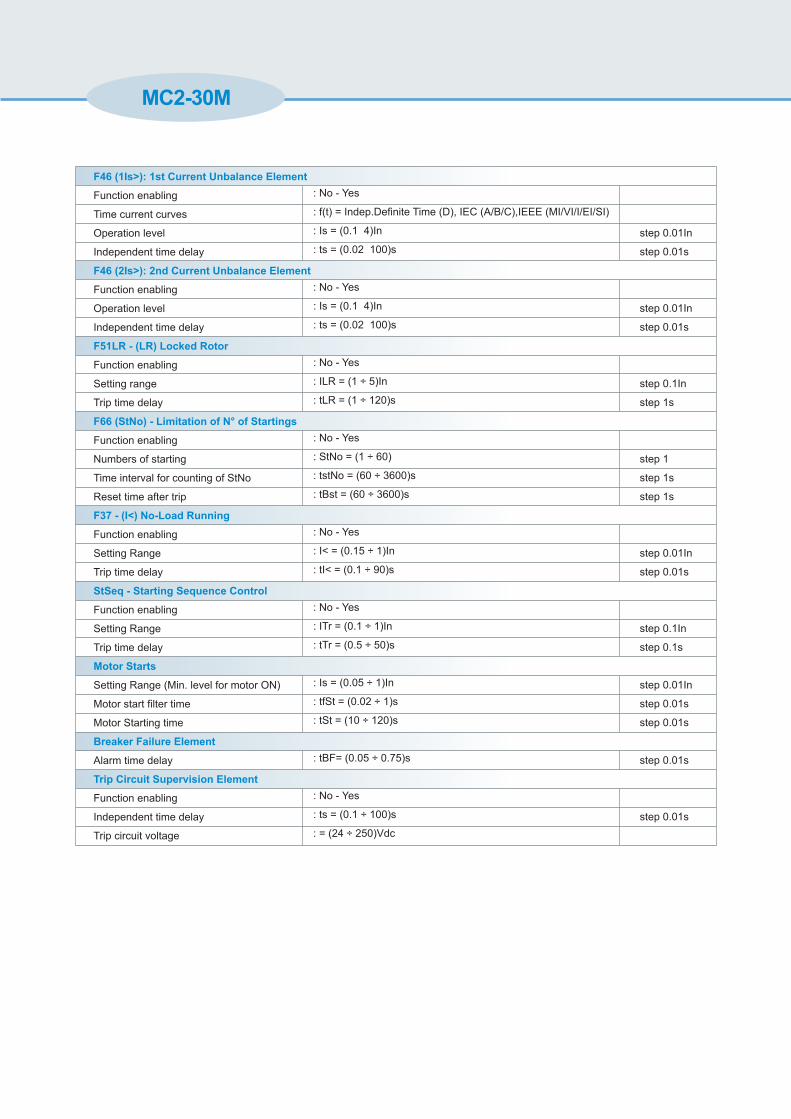
MC2-30M
F46 (1Is>): 1st Current Unbalance Element
F46 (2Is>): 2nd Current Unbalance Element
F51LR - (LR) Locked Rotor
F66 (StNo) - Limitation of N° of Startings
F37 - (I<) No-Load Running
StSeq - Starting Sequence Control
Motor Starts
Breaker Failure Element
Trip Circuit Supervision Element
Function enabling
Time current curves
Operation level
Independent time delay
Function enabling
Operation level
Independent time delay
Function enabling
Setting range
Trip time delay
Function enabling
Numbers of starting
Time interval for counting of StNo
Reset time after trip
Function enabling
Setting Range
Trip time delay
Function enabling
Setting Range
Trip time delay
Setting Range (Min. level for motor ON)
Motor start filter time
Motor Starting time
Alarm time delay
Function enabling
Independent time delay
Trip circuit voltage
: No - Yes
: f(t) = Indep.Definite Time (D), IEC (A/B/C),IEEE (MI/VI/I/EI/SI)
: Is = (0.1 4)In
: ts = (0.02 100)s
: No - Yes
: Is = (0.1 4)In
: ts = (0.02 100)s
: No - Yes
: ILR = (1 ÷ 5)In
: tLR = (1 ÷ 120)s
: No - Yes
: StNo = (1 ÷ 60)
: tstNo = (60 ÷ 3600)s
: tBst = (60 ÷ 3600)s
: No - Yes
: I< = (0.15 ÷ 1)In
: tI< = (0.1 ÷ 90)s
: No - Yes
: ITr = (0.1 ÷ 1)In
: tTr = (0.5 ÷ 50)s
: Is = (0.05 ÷ 1)In
: tfSt = (0.02 ÷ 1)s
: tSt = (10 ÷ 120)s
: tBF= (0.05 ÷ 0.75)s
: No - Yes
: ts = (0.1 ÷ 100)s
: = (24 ÷ 250)Vdc
step 0.01In
step 0.01s
step 0.01In
step 0.01s
step 0.1In
step 1s
step 1
step 1s
step 1s
step 0.01In
step 0.01s
step 0.1In
step 0.1s
step 0.01In
step 0.01s
step 0.01s
step 0.01s
step 0.01s
136
16
6
13
6
114
184
192
220
26
S8
5R
4
_
=
Alim. Ausiliaria
17Auxiliary Supply
In=
18
37
1A 5A
38
34
33
B (S-)
A (S+)
C
27
28
MC2-30MFUNZIONI
FUNCTIONS
F50N
1/5A
2BT 50
F51N
1/5A
F51
F50
R4
R3
R1
R2
R3
R11/5A
MICROP.
8
DIGITALIINGRESSI
INPUTSDIGITAL '
IT
RE
LE
D U
SC
IA
UP
UT
RE
LAY
OT
S7
9
35
1/5A
36
39
40
1
F46
F79
R8
R7
R5
R6
10
11
R2 23
24
25
D1
D2
D3
D4
D5
D6
D7
D812
16321531143013
R4
22
29
21
R5
6
5
R6
20
19
R7 3
R8
4
TCS
2
FRONT - USB
37
38
34
33
35
36
39
40
37
38
34
33
35
36
39
40
Ove
rallDim
ension
s(m
m)
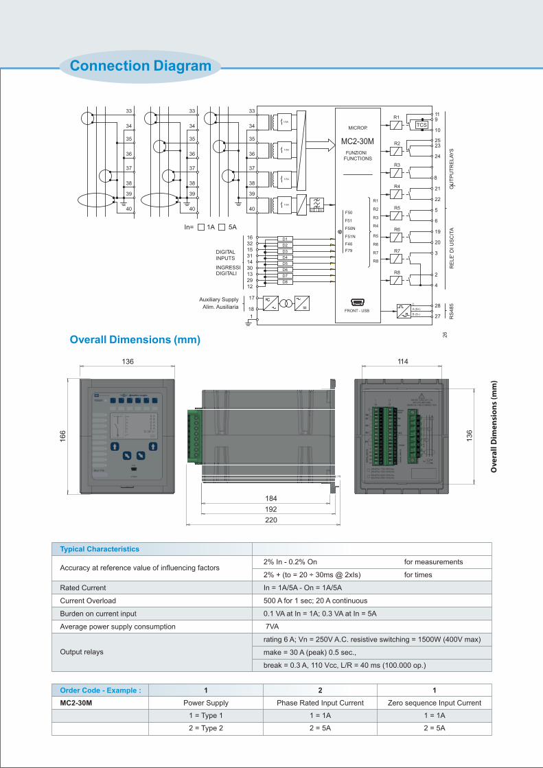
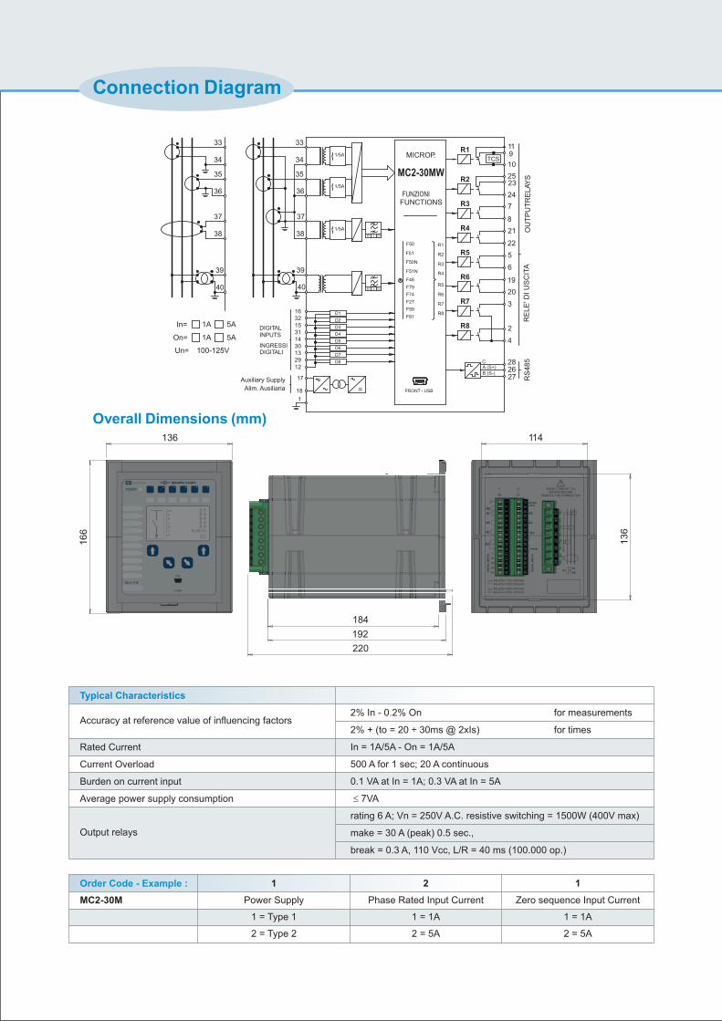
Connection Diagram
2% In - 0.2% On
2% + (to = 20 ÷ 30ms @ 2xIs)
In = 1A/5A - On = 1A/5A
500 A for 1 sec; 20 A continuous
0.1 VA at In = 1A; 0.3 VA at In = 5A
7VA
rating 6 A; Vn = 250V A.C. resistive switching = 1500W (400V max)
make = 30 A (peak) 0.5 sec.,
break = 0.3 A, 110 Vcc, L/R = 40 ms (100.000 op.)
Typical Characteristics
Rated Current
Current Overload
Burden on current input
Average power supply consumption
Accuracy at reference value of influencing factors
Output relays
Order Code - Example :
MC2-30M
1
Power Supply
1 = Type 1
2 = Type 2
2
Phase Rated Input Current
1 = 1A
2 = 5A
1
Zero sequence Input Current
1 = 1A
2 = 5A
Overall Dimensions (mm)
for measurements
for times
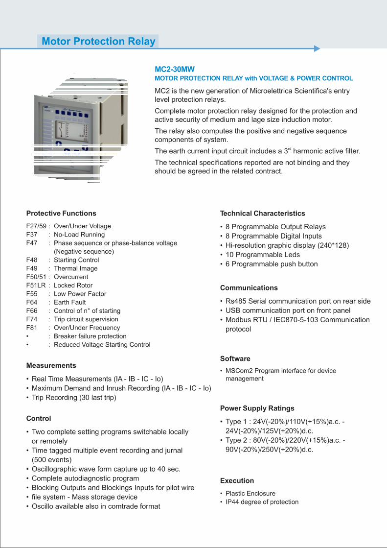
MC2 is the new generation of Microelettrica Scientifica's entry level protection relays.
Complete motor protection relay designed for the protection and active security of medium and lage size induction motor.
The relay also computes the positive and negative sequence components of system.
rdThe earth current input circuit includes a 3 harmonic active filter.
The technical specifications reported are not binding and they should be agreed in the related contract.
MC2-30MWMOTOR PROTECTION RELAY with VOLTAGE & POWER CONTROL
Motor Protection Relay
Software
• MSCom2 Program interface for devicemanagement
Communications
• Rs485 Serial communication port on rear side
• USB communication port on front panel
• Modbus RTU / IEC870-5-103 Communication
protocol
Power Supply Ratings
• Type 1 : 24V(-20%)/110V(+15%)a.c. -
24V(-20%)/125V(+20%)d.c.
• Type 2 : 80V(-20%)/220V(+15%)a.c. -
90V(-20%)/250V(+20%)d.c.
Protective Functions
F27/59 : Over/Under Voltage
F37 : No-Load Running
F47 : Phase sequence or phase-balance voltage
(Negative sequence)
F48 : Starting Control
F49 : Thermal Image
F50/51 : Overcurrent
F51LR : Locked Rotor
F55 : Low Power Factor
F64 : Earth Fault
F66 : Control of n° of starting
F74 : Trip circuit supervision
F81 : Over/Under Frequency
• : Breaker failure protection
• : Reduced Voltage Starting Control
Control
• Two complete setting programs switchable locally
or remotely
• Time tagged multiple event recording and jurnal
(500 events)
• Oscillographic wave form capture up to 40 sec.
• Complete autodiagnostic program
• Blocking Outputs and Blockings Inputs for pilot wire
• file system - Mass storage device
• Oscillo available also in comtrade format
Measurements
• Real Time Measurements (IA - IB - IC - Io)
• Maximum Demand and Inrush Recording (IA - IB - IC - Io)
• Trip Recording (30 last trip)
Technical Characteristics
• 8 Programmable Output Relays
• 8 Programmable Digital Inputs
• Hi-resolution graphic display (240*128)
• 10 Programmable Leds
• 6 Programmable push button
Execution
• Plastic Enclosure
• IP44 degree of protection
MC2-30MW
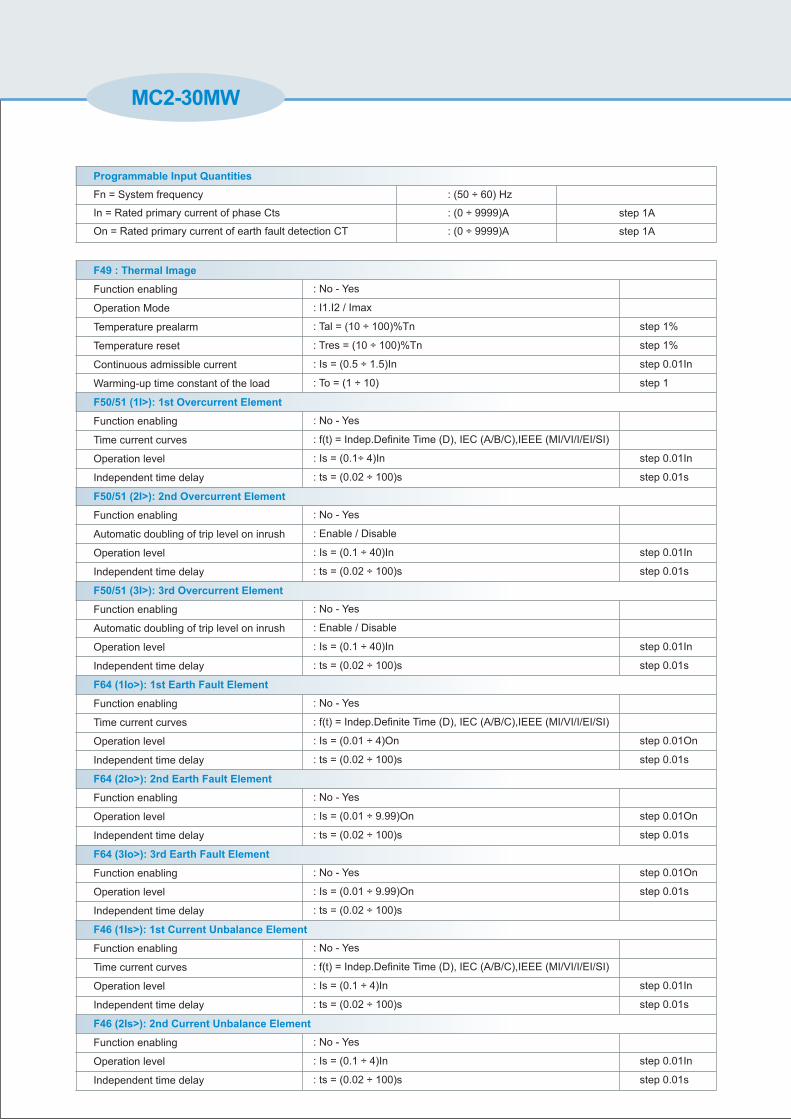
Programmable Input Quantities
Fn = System frequency
In = Rated primary current of phase Cts
On = Rated primary current of earth fault detection CT
: (50 ÷ 60) Hz
: (0 ÷ 9999)A
: (0 ÷ 9999)A
step 1A
step 1A
F49 : Thermal Image
F50/51 (1I>): 1st Overcurrent Element
F50/51 (2I>): 2nd Overcurrent Element
F50/51 (3I>): 3rd Overcurrent Element
F64 (1Io>): 1st Earth Fault Element
F64 (2Io>): 2nd Earth Fault Element
F64 (3Io>): 3rd Earth Fault Element
F46 (1Is>): 1st Current Unbalance Element
F46 (2Is>): 2nd Current Unbalance Element
Function enabling
Operation Mode
Temperature prealarm
Temperature reset
Continuous admissible current
Warming-up time constant of the load
Function enabling
Time current curves
Operation level
Independent time delay
Function enabling
Automatic doubling of trip level on inrush
Operation level
Independent time delay
Function enabling
Automatic doubling of trip level on inrush
Operation level
Independent time delay
Function enabling
Time current curves
Operation level
Independent time delay
Function enabling
Operation level
Independent time delay
Function enabling
Operation level
Independent time delay
Function enabling
Time current curves
Operation level
Independent time delay
Function enabling
Operation level
Independent time delay
: No - Yes
: I1.I2 / Imax
: Tal = (10 ÷ 100)%Tn
: Tres = (10 ÷ 100)%Tn
: Is = (0.5 ÷ 1.5)In
: To = (1 ÷ 10)
: No - Yes
: f(t) = Indep.Definite Time (D), IEC (A/B/C),IEEE (MI/VI/I/EI/SI)
: Is = (0.1÷ 4)In
: ts = (0.02 ÷ 100)s
: No - Yes
: Enable / Disable
: Is = (0.1 ÷ 40)In
: ts = (0.02 ÷ 100)s
: No - Yes
: Enable / Disable
: Is = (0.1 ÷ 40)In
: ts = (0.02 ÷ 100)s
: No - Yes
: f(t) = Indep.Definite Time (D), IEC (A/B/C),IEEE (MI/VI/I/EI/SI)
: Is = (0.01 ÷ 4)On
: ts = (0.02 ÷ 100)s
: No - Yes
: Is = (0.01 ÷ 9.99)On
: ts = (0.02 ÷ 100)s
: No - Yes
: Is = (0.01 ÷ 9.99)On
: ts = (0.02 ÷ 100)s
: No - Yes
: f(t) = Indep.Definite Time (D), IEC (A/B/C),IEEE (MI/VI/I/EI/SI)
: Is = (0.1 ÷ 4)In
: ts = (0.02 ÷ 100)s
: No - Yes
: Is = (0.1 ÷ 4)In
: ts = (0.02 ÷ 100)s
step 1%
step 1%
step 0.01In
step 1
step 0.01In
step 0.01s
step 0.01In
step 0.01s
step 0.01In
step 0.01s
step 0.01On
step 0.01s
step 0.01On
step 0.01s
step 0.01On
step 0.01s
step 0.01In
step 0.01s
step 0.01In
step 0.01s
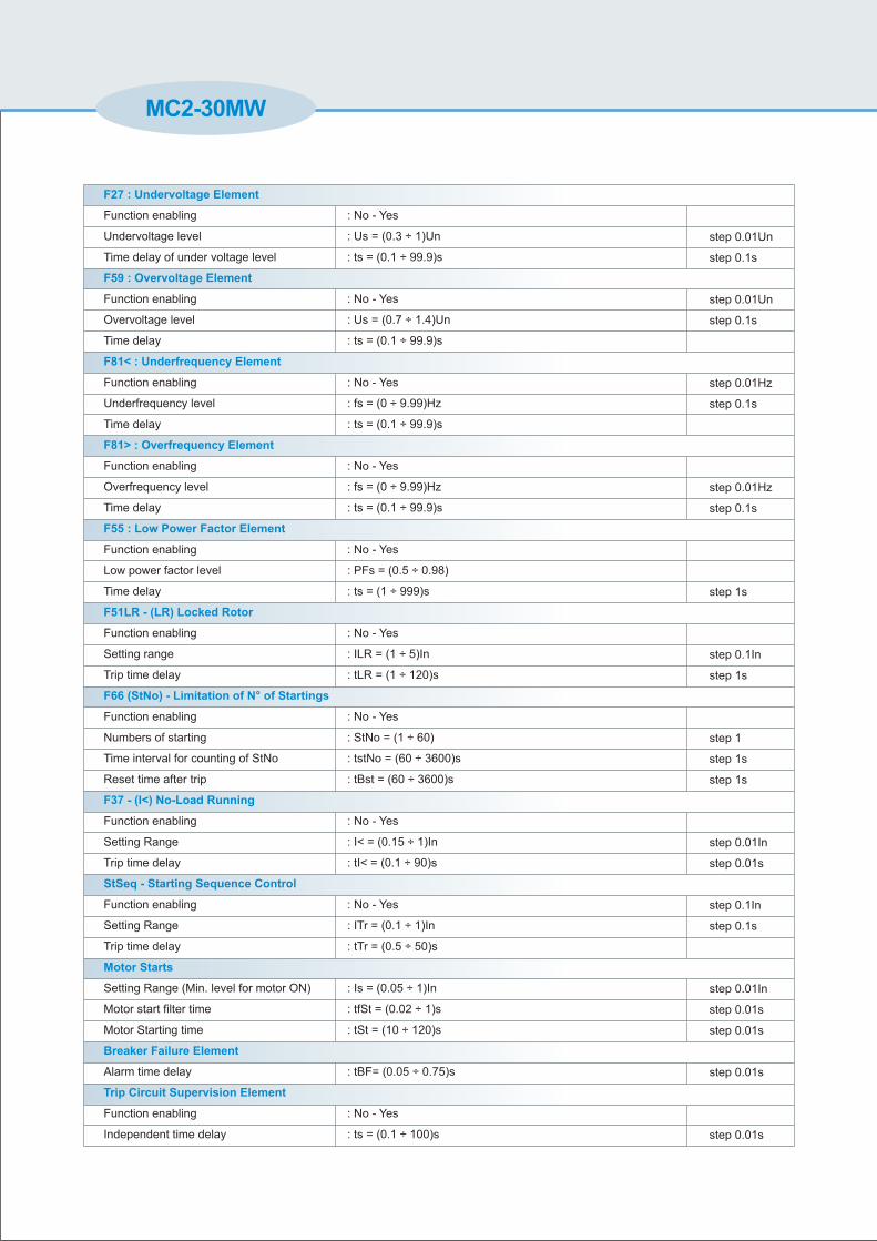
MC2-30MW
F27 : Undervoltage Element
F59 : Overvoltage Element
F81< : Underfrequency Element
F81> : Overfrequency Element
F55 : Low Power Factor Element
F51LR - (LR) Locked Rotor
F66 (StNo) - Limitation of N° of Startings
F37 - (I<) No-Load Running
StSeq - Starting Sequence Control
Motor Starts
Breaker Failure Element
Trip Circuit Supervision Element
Function enabling
Undervoltage level
Time delay of under voltage level
Function enabling
Overvoltage level
Time delay
Function enabling
Underfrequency level
Time delay
Function enabling
Overfrequency level
Time delay
Function enabling
Low power factor level
Time delay
Function enabling
Setting range
Trip time delay
Function enabling
Numbers of starting
Time interval for counting of StNo
Reset time after trip
Function enabling
Setting Range
Trip time delay
Function enabling
Setting Range
Trip time delay
Setting Range (Min. level for motor ON)
Motor start filter time
Motor Starting time
Alarm time delay
Function enabling
Independent time delay
: No - Yes
: Us = (0.3 ÷ 1)Un
: ts = (0.1 ÷ 99.9)s
: No - Yes
: Us = (0.7 ÷ 1.4)Un
: ts = (0.1 ÷ 99.9)s
: No - Yes
: fs = (0 ÷ 9.99)Hz
: ts = (0.1 ÷ 99.9)s
: No - Yes
: fs = (0 ÷ 9.99)Hz
: ts = (0.1 ÷ 99.9)s
: No - Yes
: PFs = (0.5 ÷ 0.98)
: ts = (1 ÷ 999)s
: No - Yes
: ILR = (1 ÷ 5)In
: tLR = (1 ÷ 120)s
: No - Yes
: StNo = (1 ÷ 60)
: tstNo = (60 ÷ 3600)s
: tBst = (60 ÷ 3600)s
: No - Yes
: I< = (0.15 ÷ 1)In
: tI< = (0.1 ÷ 90)s
: No - Yes
: ITr = (0.1 ÷ 1)In
: tTr = (0.5 ÷ 50)s
: Is = (0.05 ÷ 1)In
: tfSt = (0.02 ÷ 1)s
: tSt = (10 ÷ 120)s
: tBF= (0.05 ÷ 0.75)s
: No - Yes
: ts = (0.1 ÷ 100)s
step 0.01Un
step 0.1s
step 0.01Un
step 0.1s
step 0.01Hz
step 0.1s
step 0.01Hz
step 0.1s
step 1s
step 0.1In
step 1s
step 1
step 1s
step 1s
step 0.01In
step 0.01s
step 0.1In
step 0.1s
step 0.01In
step 0.01s
step 0.01s
step 0.01s
step 0.01s
Connection Diagram
136
16
6
16
3
114
184
192
220
Overall Dimensions (mm)
Alim. Ausiliaria
Auxiliary Supply 17
18
In=
_
1A 5A
35
36
34
33
=
B (S-)A (S+)C
R4
S8
5
2627
28
MC2-30MW
FUNZIONIFUNCTIONS
F50N
1/5A
2BT 50
F51N
1/5A
F51
F50
R4
R3
R1
R2
R3
MICROP.1/5AR1
8
DIGITALIINGRESSI
INPUTSDIGITAL
RL
' D U
CA
EE
IS
ITU
PT
EAY
OT
UR
LS
7
9
37
38
F46
1
F79
R8
R7
R5
R6
10
11
R223
24
25
D1
D2
D3
D4
D5
D6
D7
D812
1632153114301329
R4
22
21
R5
6
5
R6
20
19
R7 3
R8
4
2
FRONT - USB
TCS
F74
F27
F59
F81
2BT 50
39
40
35
36
34
33
37
38
39
40
On= 1A 5A
Un= 100-125V
2% In - 0.2% On
2% + (to = 20 ÷ 30ms @ 2xIs)
In = 1A/5A - On = 1A/5A
500 A for 1 sec; 20 A continuous
0.1 VA at In = 1A; 0.3 VA at In = 5A
£ 7VA
rating 6 A; Vn = 250V A.C. resistive switching = 1500W (400V max)
make = 30 A (peak) 0.5 sec.,
break = 0.3 A, 110 Vcc, L/R = 40 ms (100.000 op.)
Typical Characteristics
Rated Current
Current Overload
Burden on current input
Average power supply consumption
Accuracy at reference value of influencing factors
Output relays
Order Code - Example :
MC2-30M
1
Power Supply
1 = Type 1
2 = Type 2
2
Phase Rated Input Current
1 = 1A
2 = 5A
1
Zero sequence Input Current
1 = 1A
2 = 5A
for measurements
for times
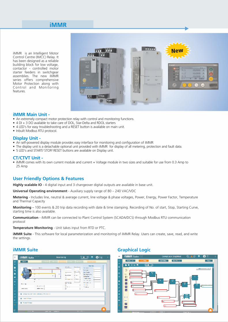
iMMR is an Intelligent Motor Control Centre (IMCC) Relay. It has been designed as a reliable building block for low voltage, contactor - controlled motor starter feeders in switchgear assemblies. The new iMMR series offers comprehensiveMotor Protection along with Control and Monitor ing features.
iMMR Main Unit -
Display Unit -
CT/CTVT Unit -
• An extremely compact motor protection relay with control and monitoring functions.• 4 DI + 3 DO available to take care of DOL, Star-Delta and RDOL starters• 4 LED's for easy troubleshooting and a RESET button is available on main unit.• Inbuilt Modbus RTU protocol.
• An self-powered display module provides easy interface for monitoring and configuration of iMMR• The display unit is a detachable optional unit provided with iMMR for display of all metering, protection and fault data.• 5 LED's and START/ STOP/ RESET buttons are available on Display unit.
• iMMR comes with its own current module and current + Voltage module in two sizes and suitable for use from 0.3 Amp to25 Amp
User Friendly Options & Features
Highly scalable IO - 4 digital input and 3 changeover digital outputs are available in base unit.
Universal Operating environment - Auxiliary supply range of 80 – 240 VAC/VDC
Metering - Includes line, neutral & average current, line voltage & phase voltages, Power, Energy, Power Factor, Temperature and Thermal Capacity
Monitoring – 100 events & 20 trip data recording with date & time stamping. Recording of No. of start, Stop, Starting Curve, starting time is also available.
Communication - iMMR can be connected to Plant Control System (SCADA/DCS) through Modbus RTU communication protocol
Temperature Monitoring - Unit takes input from RTD or PTC.
iMMR Suite - This software for local parameterization and monitoring of iMMR Relay. Users can create, save, read, and write the settings.
iMMR Suite Graphical Logic
N we
iMMR
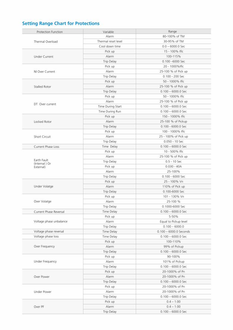
Setting Range Chart for Protections
RangeVariable
Alarm
Thermal reset level
Cool down time
Pick up
Alarm
Trip Delay
Pick up
Alarm
Trip Delay
Pick up
Alarm
Trip Delay
Pick up
Alarm
Time During Start
Time During Run
Pick up
Alarm
Trip Delay
Pick up
Alarm
Trip Delay
Time Delay
Pick up
Alarm
Trip Delay
Pick up
Alarm
Trip Delay
Pick up
Alarm
Trip Delay
Pick up
Alarm
Trip Delay
Time Delay
Pick up
Alarm
Trip Delay
Time Delay
Time Delay
Pick up
Alarm
Trip Delay
Pick up
Alarm
Trip Delay
Pick up
Alarm
Trip Delay
Pick up
Alarm
Trip Delay
Pick up
Alarm
Trip Delay
Protection Function
80-100% of TM
30-95% of TM
0.0 – 6000.0 Sec
15 - 100% Iflc
100-115%
0.100 –6000 Sec
20 - 1000%Iflc
25-100 % of Pick up
0.100 - 200 Sec
50 - 1000% Iflc
25-100 % of Pick up
0.100 – 6000.0 Sec
50 - 1000% Iflc
25-100 % of Pick up
0.100 – 6000.0 Sec
0.100 – 6000.0 Sec
150 - 1000% Iflc
25-100 % of Pickup
0.100 - 6000.0 Sec
100 - 1000% Iflc
25 - 100% of Pick up
0.050 - 10 Sec
0.100 – 6000.0 Sec
10 - 500% Iflc
25-100 % of Pick up
0.5 - 10 Sec
0.030 - 40A
25-100%
0.100 - 6000 Sec
25 - 100% Vn
110% of Pick up
0.100-6000 Sec
101 - 130% Vn
25-100 %
0.1000-6000 Sec
0.100 – 6000.0 Sec
5-50%
Equal to Pickup level
0.100 – 6000.0
0.100 – 6000.0 Seconds
0.100 – 6000.0 Sec
100-110%
99% of Pickup
0.100 – 6000.0 Sec
90-100%
101% of Pickup
0.100 – 6000.0 Sec
20-1000% of Pn
20-1000% of Pn
0.100 – 6000.0 Sec
20-1000% of Pn
20-1000% of Pn
0.100 – 6000.0 Sec
0.4 – 1.00
0.4 – 1.00
0.100 – 6000.0 Sec
Thermal Overload
Under Current
NI Over Current
Stalled Rotor
DT Over current
Locked Rotor
Short Circuit
Current Phase Loss
Earth Fault(Internal ) OrExternal)
Under Volatge
Over Volatge
Voltage phase unbalance
Under Frequency
Over Frequency
Current Phase Reversal
Voltage phase reversal
Voltage phase loss
Over Power
Under Power
Over PF
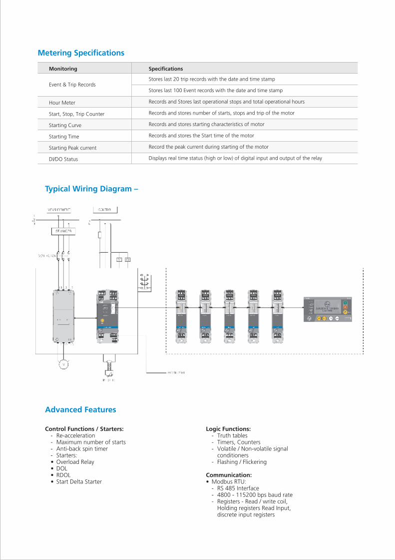
Typical Wiring Diagram –
Advanced Features
Logic Functions:- Truth tables- Timers, Counters- Volatile / Non-volatile signal
conditioners- Flashing / Flickering
Communication:• Modbus RTU:
- RS 485 Interface- 4800 - 115200 bps baud rate- Registers - Read / write coil,
Holding registers Read Input, discrete input registers
Control Functions / Starters:- Re-acceleration- Maximum number of starts- Anti-back spin timer- Starters:• Overload Relay• DOL• RDOL• Start Delta Starter
Metering Specifications
Stores last 20 trip records with the date and time stamp
Stores last 100 Event records with the date and time stamp
Records and Stores last operational stops and total operational hours
Records and stores number of starts, stops and trip of the motor
Records and stores starting characteristics of motor
Records and stores the Start time of the motor
Record the peak current during starting of the motor
Displays real time status (high or low) of digital input and output of the relay
Specifications
Hour Meter
Start, Stop, Trip Counter
Starting Curve
Starting Time
Starting Peak current
DI/DO Status
Event & Trip Records
Monitoring
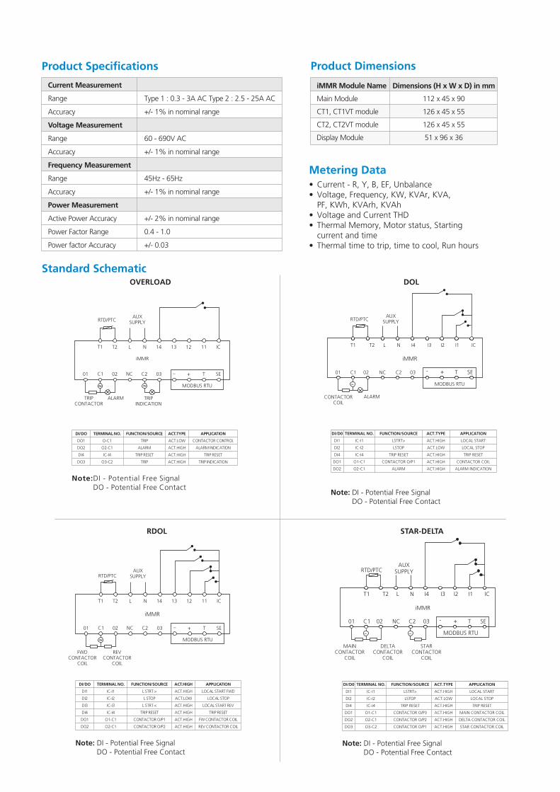
Product Dimensions
iMMR Module Name
Main Module
CT1, CT1VT module
CT2, CT2VT module
Display Module
Dimensions (H x W x D) in mm
112 x 45 x 90
126 x 45 x 55
126 x 45 x 55
51 x 96 x 36
Product Specifications
Type 1 : 0.3 - 3A AC Type 2 : 2.5 - 25A AC
+/- 1% in nominal range
60 - 690V AC
+/- 1% in nominal range
45Hz - 65Hz
+/- 1% in nominal range
+/- 2% in nominal range
0.4 - 1.0
+/- 0.03
Current Measurement
Range
Accuracy
Voltage Measurement
Range
Accuracy
Frequency Measurement
Range
Accuracy
Power Measurement
Active Power Accuracy
Power Factor Range
Power factor Accuracy
Standard SchematicDOL
TERMINAL NO.
IC-I1
IC-I2
IC-I4
O1-C1
O2-C1
FUNCTION/SOURCE
LSTRT>
LSTOP
TRIP RESET
CONTACTOR O/P1
ALARM
ACT.TYPE
ACT.HIGH
ACT.LOW
ACT.HIGH
ACT.HIGH
ACT.HIGH
APPLICATION
LOCAL START
LOCAL STOP
TRIP RESET
CONTACTOR COIL
ALARM INDICATION
DI/D0
DI1
DI2
DI4
DO1
DO2
RTD/PTCAUX
SUPPLY
ICI1I2I3I4NLT2T1
iMMR
01 C1 02 NC C2 03 - + T SE
MODBUS RTU
ALARMCONTACTOR COIL
~
Note: DI - Potential Free SignalDO - Potential Free Contact
STAR-DELTA
RTD/PTCAUX
SUPPLY
ICI1I2I3I4NLT2T1
iMMR
01 C1 02 NC C2 03 - + T SE
MODBUS RTU
MAINCONTACTOR
COIL
~ ~
DELTACONTACTOR
COIL
STARCONTACTOR
COIL
TERMINAL NO.
IC-I1
IC-I2
IC-I4
O1-C1
O2-C1
O3-C2
FUNCTION/SOURCE
LSTRT>
LSTOP
TRIP RESET
CONTACTOR O/P3
CONTACTOR O/P2
CONTACTOR O/P1
ACT.TYPE
ACT.HIGH
ACT.LOW
ACT.HIGH
ACT.HIGH
ACT.HIGH
ACT.HIGH
APPLICATION
LOCAL START
LOCAL STOP
TRIP RESET
MAIN CONTACTOR COIL
DELTA CONTACTOR COIL
STAR CONTACTOR COIL
DI/D0
DI1
DI2
DI4
DO1
DO2
DO3
Note: DI - Potential Free SignalDO - Potential Free Contact
RDOL
~
RTD/PTCAUX
SUPPLY
T1 T2 L N 1214 13 11 IC
iMMR
01 C1 02 NC C2 03
MODBUS RTU
_ + T SE
REVCONTACTOR
COIL
FWDCONTACTOR
COIL
DI/DO
DI1
DI2
DI3
DI4
DO1
DO2
TERMINAL NO.
IC-I1
IC-I2
IC-I3
IC-I4
O1-C1
O2-C1
FUNCTION/SOURCE
L STRT >
L STOP
L STRT <
TRIP RESET
CONTACTOR O/P1
CONTACTOR O/P2
ACT.HIGH
ACT.HIGH
ACT.HIGH
ACT.HIGH
ACT.HIGH
ACT.HIGH
ACT.LOW
APPLICATION
LOCAL START FWD
LOCAL STOP
LOCAL START REV
TRIP RESET
FW CONTACTOR COIL
REV CONTACTOR COIL
Note: DI - Potential Free SignalDO - Potential Free Contact
OVERLOAD
~ ~
RTD/PTCAUX
SUPPLY
T1 T2 L N 1214 13 11 IC
iMMR
01 C1 02 NC C2 03
MODBUS RTU
_ + T SE
TRIP INDICATION
TRIP CONTACTOR
ALARM
DI/DO
DO1
DO2
DI4
DO3
TERMINAL NO.
O-C1
O2-C1
IC-I4
O3-C2
FUNCTION/SOURCE
TRIP
ALARM
TRIP RESET
TRIP
ACT.TYPE
ACT.LOW
ACT.HIGH
ACT.HIGH
ACT.HIGH
APPLICATION
CONTACTOR CONTROL
ALARM INDICATION
TRIP RESET
TRIP INDICATION
Note:DI - Potential Free SignalDO - Potential Free Contact
Metering Data••
••
•
Current - R, Y, B, EF, UnbalanceVoltage, Frequency, KW, KVAr, KVA,PF, KWh, KVArh, KVAhVoltage and Current THDThermal Memory, Motor status, Startingcurrent and timeThermal time to trip, time to cool, Run hours
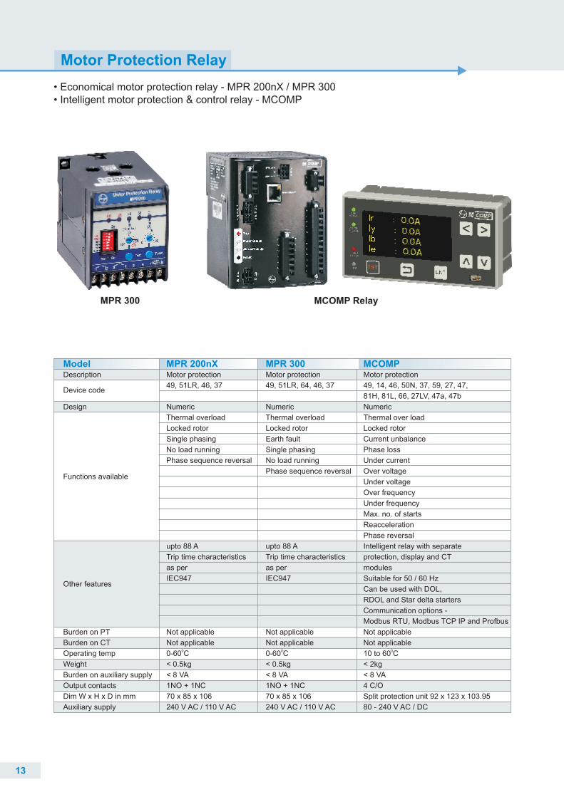
• Economical motor protection relay - MPR 300• Intelligent motor protection & control relay - MCOMP
MPR 200nX /
Motor Protection Relay
MPR 300 MCOMP Relay
13
Model
Device code
Description
Design
Burden on PT
Burden on CT
Operating temp
Weight
Output contacts
Dim W x H x D in mm
Auxiliary supply
Burden on auxiliary supply
Other features
Functions available
Motor protection
49, 51LR, 46, 37
Numeric
Thermal overload
Locked rotor
Single phasing
No load running
upto 88 A
Trip time characteristics
as per
IEC947
Not applicable
Not applicable00-60 C
< 0.5kg
< 8 VA
1NO + 1NC
240 V AC / 110 V AC
Phase sequence reversal
70 x 85 x 106
MPR 200nX MCOMPMotor protection
49, 14, 46, 50N, 37, 59, 27, 47,
81H, 81L, 66, 27LV, 47a, 47b
Numeric
Thermal over load
Locked rotor
Current unbalance
Phase loss
Under current
Over voltage
Under voltage
Over frequency
Under frequency
Max. no. of starts
Reacceleration
Phase reversal
Intelligent relay with separate
protection, display and CT
modules
Suitable for 50 / 60 Hz
Can be used with DOL,
RDOL and Star delta starters
Communication options -
Modbus RTU, Modbus TCP IP and Prof bus
Not applicable
Not applicable010 to 60 C
< 2kg
< 8 VA
4 C/O
Split protection unit 92 x 123 x 103.95
80 - 240 V AC / DC
Motor protection
49, 51LR, 64, 46, 37
Numeric
Thermal overload
Locked rotor
Earth fault
Single phasing
No load running
upto 88 A
Trip time characteristics
as per
IEC947
Not applicable
Not applicable00-60 C
< 0.5kg
< 8 VA
1NO + 1NC
240 V AC / 110 V AC
Phase sequence reversal
70 x 85 x 106
MPR 300
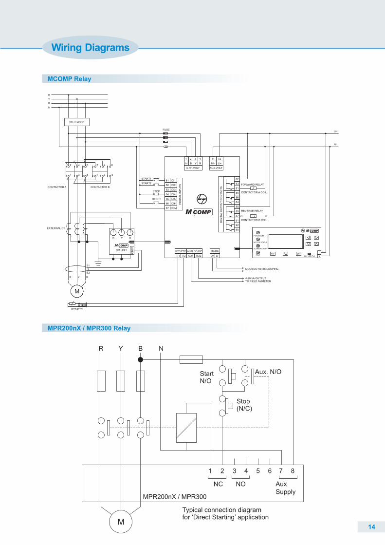
Wiring Diagrams
MCOMP Relay
14
MPR200nX / MPR300 Relay
M
1 2 3 4 5 6 7 8
NC NO
MPR200nX / MPR300
AuxSupply
R Y B N
StartN/O
Stop(N/C)
Typical connection diagramfor ‘Direct Starting’ application
Aux. N/O
S1
S2
4-20mA OUTPUT
MODBUS RS485 LOOPING
TO FIELD AMMETER
STOP
RESET
CONTACTOR A COIL
RTD/PTC
1 2 3 4
61
62
63
DI2
64
67
DI1
66 DI6
65
DI4
DI5
DIG
ITA
L I
NP
UT
S
DI3
N Y R
84
88
B
89
91
92
87
90
81
86
83
85
72
DIG
ITA
L O
UT
PU
T C
ON
TA
CT
S
82
RS485
71
PWR/COMM
MOTOR STATUS
TRIP
ALARM/PICKUP
RST ENTL
Mini USB Port N
M
COM
RTD/PTC
D+
R
D-
ANALOG O/P
L/+
Y B
FUSE
N/-
AUX.VOLT3-PH.VOLT
L/+
N/-
START2
START1
5
4 6
1
2
3
2 4
3
6
51
CONTACTOR A
TI2 AO2
CONTACTOR B
AO1TI1
MCOMP
CB
CT
CM UNIT
B Y R
SFU / MCCB
R
Y
B
N
EXTERNAL CT
MCOMP
MCOMP
FORWARD RELAY
REVERSE RELAY
CONTACTOR B COIL
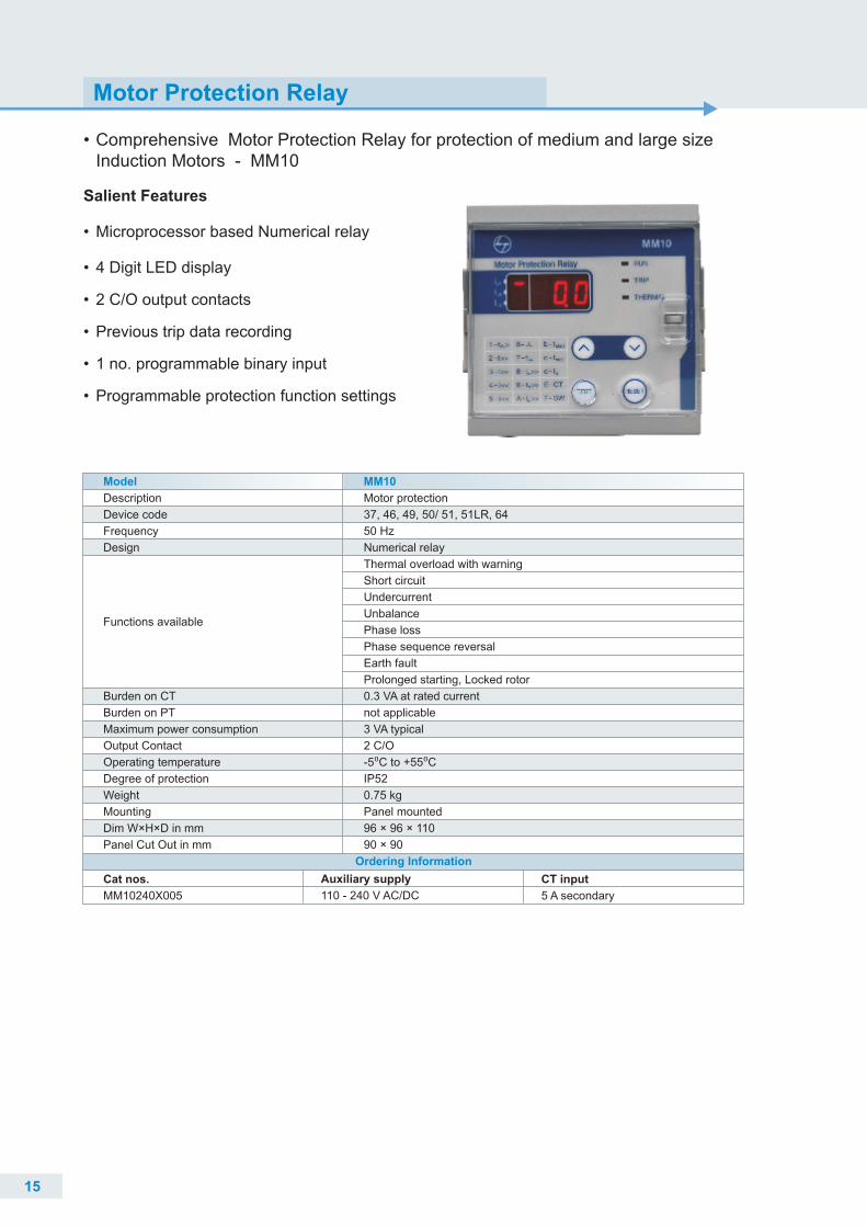
• Comprehensive Motor Protection Relay for protection of medium and large size Induction Motors - MM10
Salient Features
• Microprocessor based Numerical relay
• 4 Digit LED display
• 2 C/O output contacts
• Previous trip data recording
• 1 no. programmable binary input
• Programmable protection function settings
Motor Protection Relay
Description
Device code
Frequency
Design
Burden on CT
Burden on PT
Maximum power consumption
Output Contact
Operating temperature
Degree of protection
Weight
Mounting
Dim W×H×D in mm
Panel Cut Out in mm
Functions available
Model
Motor protection
37, 46, 49, 50/ 51, 51LR, 64
50 Hz
Numerical relay
Thermal overload with warning
Short circuit
Undercurrent
Unbalance
Phase loss
Phase sequence reversal
Earth fault
Prolonged starting, Locked rotor
0.3 VA at rated current
not applicable
3 VA typical
2 C/O
-5⁰C to +55⁰C
IP52
0.75 kg
Panel mounted
96 × 96 × 110
90 × 90
MM10
Auxiliary supply
110 - 240 V AC/DC
CT input
5 A secondary
Cat nos.
MM10240X005
Ordering Information
15
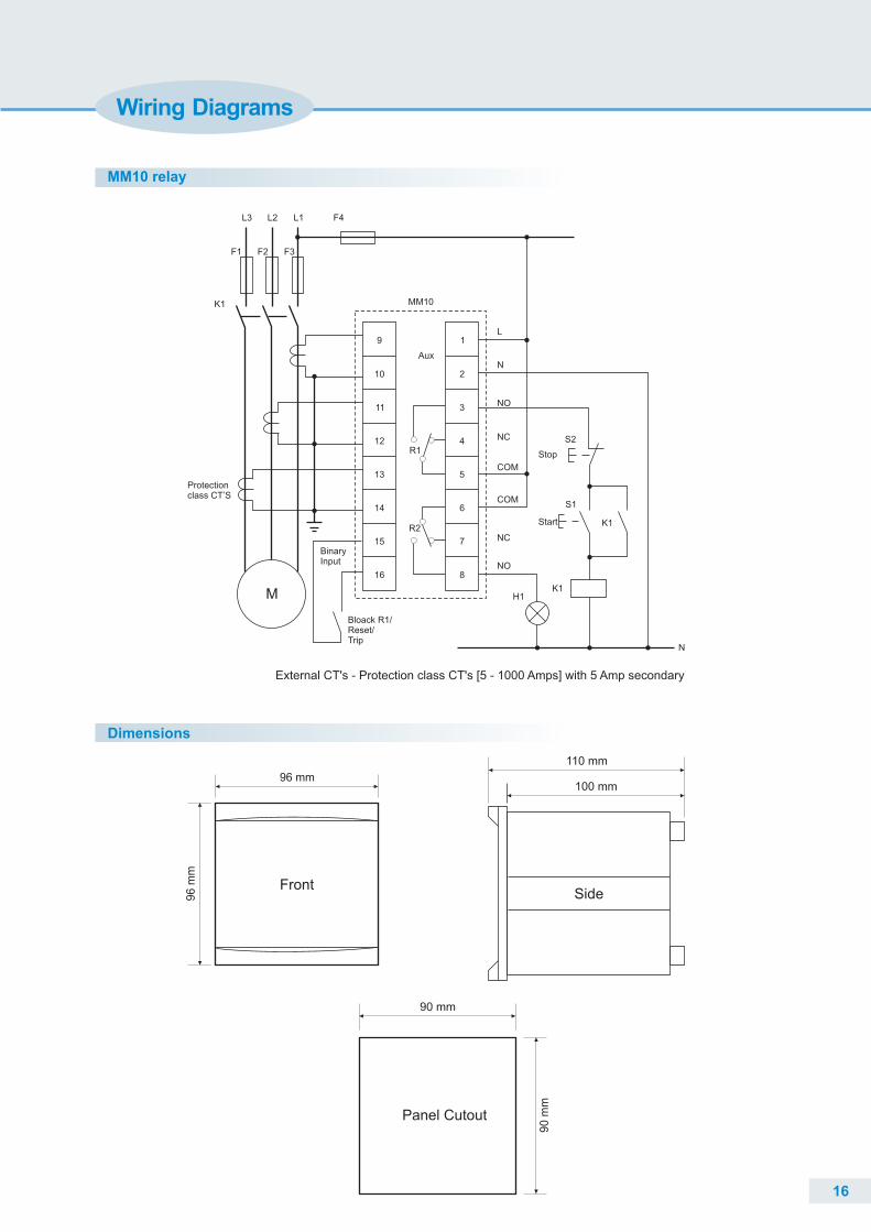
Wiring Diagrams
MM10 relay
9 1
10 2
11 3
12 4
13 5
14 6
15 7
16 8
R1
R2NC
NO
COM
COM
NC
NO
N
L
BinaryInput
MM10
Aux
Bloack R1/Reset/ Trip
F1 F2 F3
L1L2L3 F4
K1
Protectionclass CT’S
M H1K1
K1
S2
S1
Stop
Start
N
External CT's - Protection class CT's [5 - 1000 Amps] with 5 Amp secondary
Front
96 mm
96
mm
100 mm
110 mm
Side
Panel Cutout
90 mm
Dimensions
16
90
mm

Please contact any of the training centres for participation and detailed training programme schedule.
So gain the advantage and go the extra mile with:����
The typical training programmes cover:
�
�
�
�
�
14 courses on contemporary topicsCourses applicable to all switchgear brandsTraining Centers in Pune, Lucknow, Coonoor, Vadodara, Delhi & KolkataBlend of theory and practical experience
Low Voltage & Medium Voltage Switchgear
Switchboard Electrical Design
AC Drives & Building Management Solutions
Protective Relays & Earthing
Power Quality Solutions
Aimed at maximizing productivity, conserving energy, minimizing costs and enhancing safety, our Electrical
& Automation training programmes have benefitted over 1.77 Lakh professionals in the last 30 years. These
training programmes are highly beneficial as they provide right exposure and impart knowledge on
selection, installation, maintenance and testing of Electrical & Automation Products.
PuneL&T Electrical & AutomationSwitchgear Training CentreT-156 / 157, MIDCBhosari, Pune - 411 026Tel: +91 20 2712 0037 / 2712 0653 E-mail: [email protected]
Coonoor
Switchgear Training Centre Ooty-Coonoor Main RoadYellanahalli P.O., The Nilgiris - 643 243Tel. : +91 423 251 7107E-mail: [email protected]
L&T Electrical & AutomationLucknow
Switchgear Training Centre C-6 & 7, UPSIDC,P. O. Sarojininagar, Lucknow - 226 008Tel: +91 522 247 6015 / 97944 54455 E-mail: [email protected]
L&T Electrical & Automation
Vadodara
Switchgear Training CentreBehind L&T Knowledge City, Near Village Ankhol, Vadodara - 390019Tel: +91 265 614 7805 / 08E-mail: [email protected]
L&T Electrical & AutomationKolkata
Switchgear Training Centre4th Floor, 3B, Shakespeare Sarani,
Kolkata - 700071Tel: E-mail: [email protected]
L&T Electrical & Automation
Landmark - Kenil Worth Hotel
+91 33 42005975 / 44085974 / 44085978
Delhi
Switchgear Training Centre32, Shivaji Marg,
New Delhi - 110015 Tel: E-mail: [email protected]
L&T Electrical & Automation
Nearest Metro Stations Kirti Nagar/Moti Nagar,
011- 40819515, 40819695, 40819500
SP 50297 R6


