Embed Size (px)
Citation preview
Electromechanicaland solid-stateZelio® RelaysCatalog
2010


3
Reduce the size of yourenclosures and, at thesame time, increasemachine reliability...
Make the most of your energy SM
ContentsIntroductionSave Space with Zelio Relay RSL .................................................................................................... 4-5Choose long life and silent operation with Zelio Relay SSR ................................................. 6-7Electromechanical and solid-state relays panorama .................................................................... 8-9
Technical characteristicsZelio Relay RSL ................................................................................................................................. 12-17Zelio Relay RSB, RXM, RUM, RPM ............................................................................................ 18-49Zelio Relay ABR, ABS .................................................................................................................... 54-73Zelio Relay SSR .............................................................................................................................. 74-81
with these new Zelio® RelaysElectromechanical relays RSLOnly 6 mm wide, thus saving considerable spacein your enclosures
Solid-state relays SSREnhanced service life provided by electronic technology
6 mm wide
Enhanced service life
4
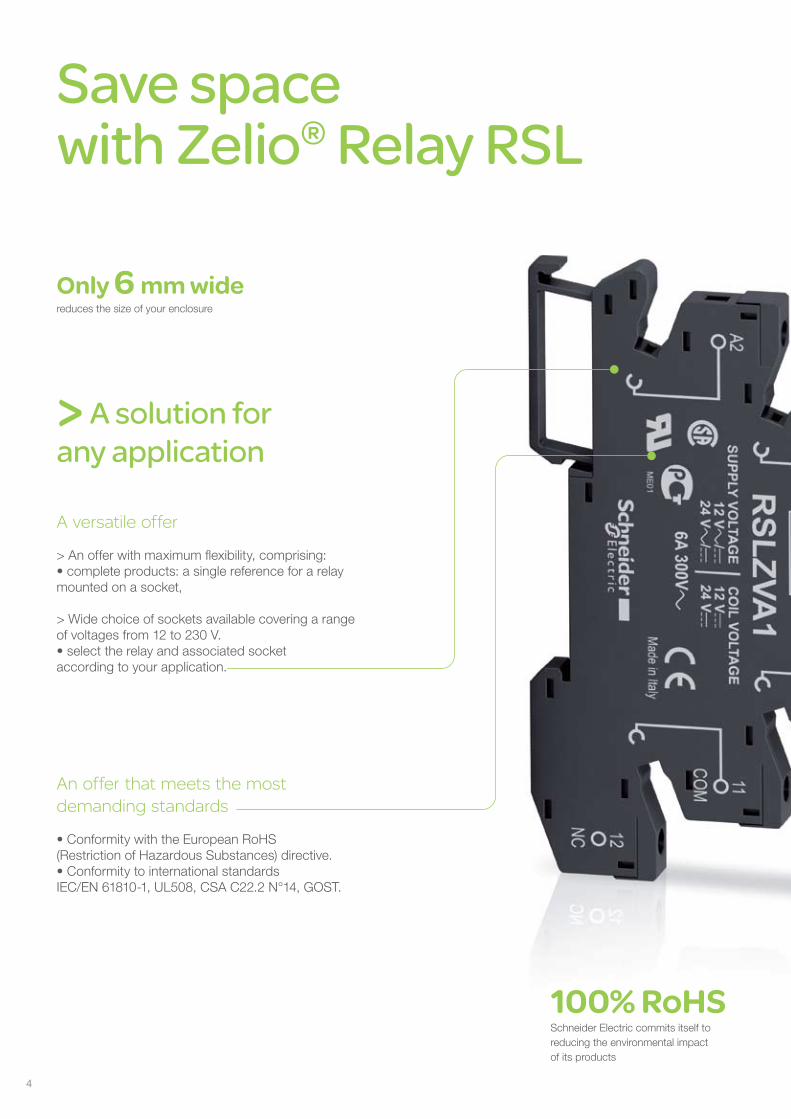
Save spacewith Zelio® Relay RSL
Only 6 mm widereduces the size of your enclosure
> A solution forany application
A versatile offer
> An offer with maximum flexibility, comprising:• complete products: a single reference for a relaymounted on a socket,
> Wide choice of sockets available covering a rangeof voltages from 12 to 230 V.• select the relay and associated socket according to your application.
An offer that meets the mostdemanding standards
• Conformity with the European RoHS(Restriction of Hazardous Substances) directive.• Conformity to international standardsIEC/EN 61810-1, UL508, CSA C22.2 N°14, GOST.
100% RoHSSchneider Electric commits itself toreducing the environmental impactof its products
5
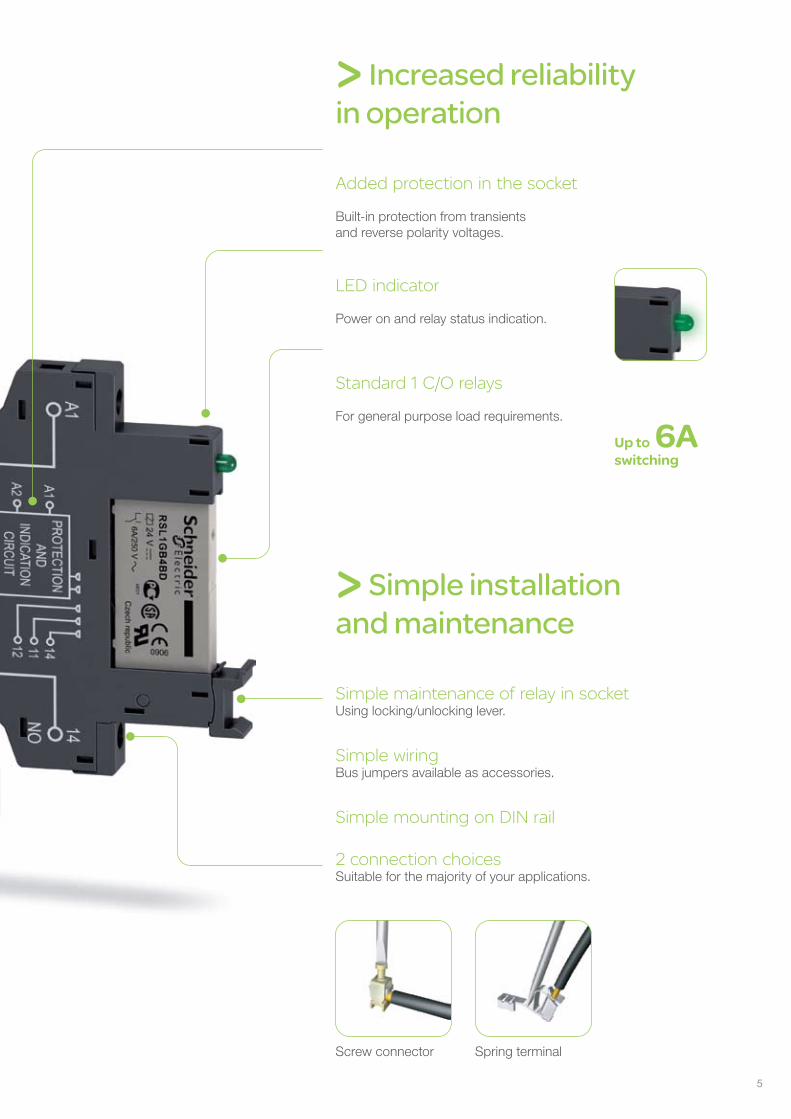
> Increased reliability in operation
Added protection in the socket
Built-in protection from transients and reverse polarity voltages.
LED indicator
Power on and relay status indication.
Standard 1 C/O relays
For general purpose load requirements.
> Simple installationand maintenance
Simple maintenance of relay in socketUsing locking/unlocking lever.
Simple wiringBus jumpers available as accessories.
Simple mounting on DIN rail
2 connection choicesSuitable for the majority of your applications.
Up to 6Aswitching
Spring terminalScrew connector
46
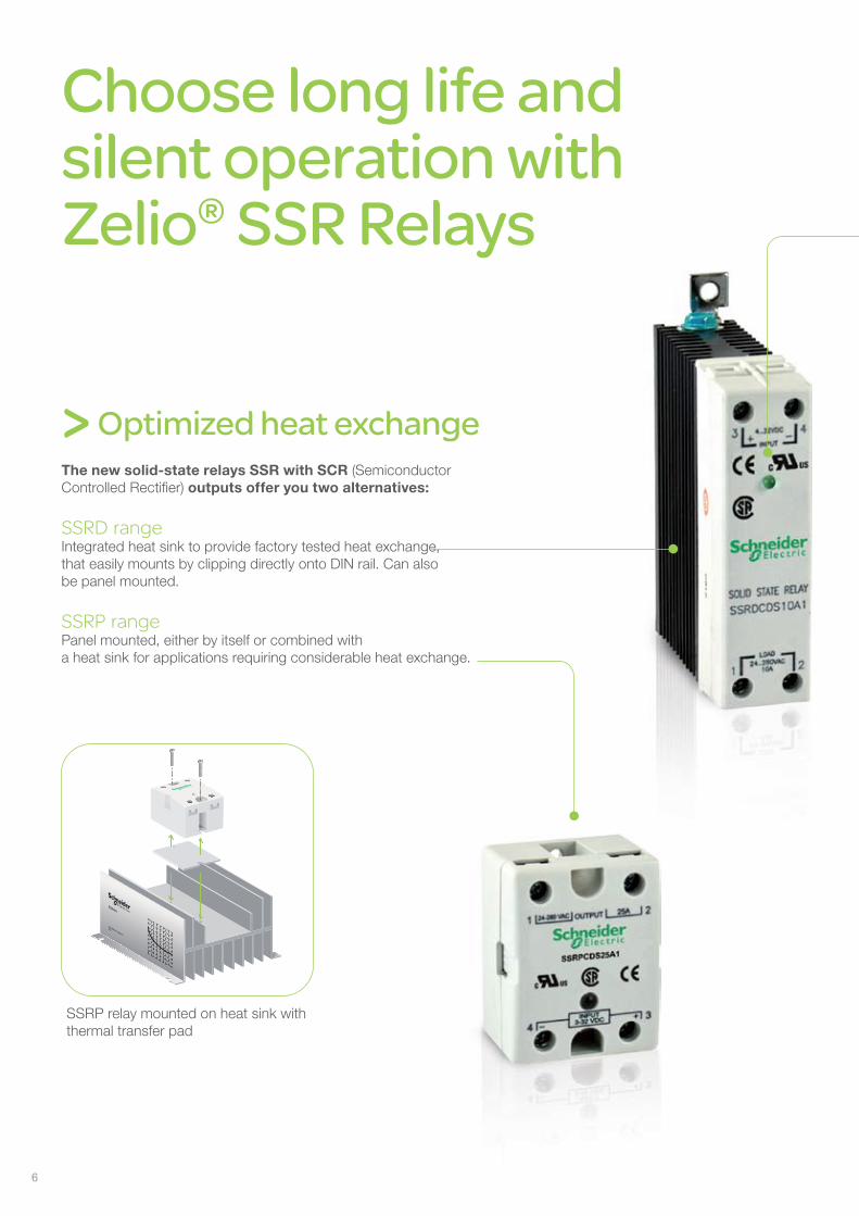
Choose long life andsilent operation withZelio® SSR Relays
> Optimized heat exchangeThe new solid-state relays SSR with SCR (SemiconductorControlled Rectifier) outputs offer you two alternatives:
SSRD rangeIntegrated heat sink to provide factory tested heat exchange,that easily mounts by clipping directly onto DIN rail. Can also be panel mounted.
SSRP rangePanel mounted, either by itself or combined witha heat sink for applications requiring considerable heat exchange.
SSRP relay mounted on heat sink withthermal transfer pad
SSRAH1
ASSEMBLED IN MEXICO
0812
7
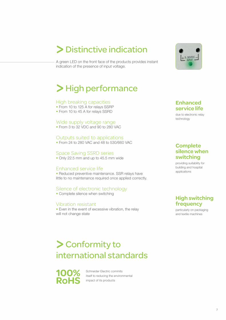
> Distinctive indicationA green LED on the front face of the products provides instantindication of the presence of input voltage.
> High performanceHigh breaking capacities• From 10 to 125 A for relays SSRP• From 10 to 45 A for relays SSRD
Wide supply voltage range• From 3 to 32 VDC and 90 to 280 VAC
Outputs suited to applications• From 24 to 280 VAC and 48 to 530/660 VAC
Space Saving SSRD series• Only 22.5 mm and up to 45.5 mm wide
Enhanced service life• Reduced preventive maintenance. SSR relays have little to no maintenance required once applied correctly.
Silence of electronic technology• Complete silence when switching
Vibration resistant• Even in the event of excessive vibration, the relaywill not change state
> Conformity tointernational standards
100%RoHS
Schneider Electric commits
itself to reducing the environmental
impact of its products
Enhancedservice lifedue to electronic relaytechnology
Completesilence whenswitchingproviding suitability forbuilding and hospitalapplications
High switchingfrequencyparticularly on packagingand textile machines
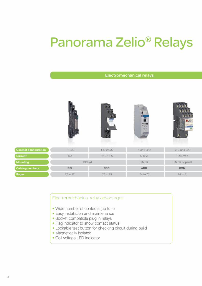
Panorama Zelio® Relays
Contact configuration
Current
Catalog numbers
1 C/O 1 or 2 C/O 1 or 2 C/O 2, 3 or 4 C/O 1, 2, 3 or 4 C/O
6 A 8-12-16 A 5-12 A 6-10-12 A 10 A 15 A
RSL RSB ABR RXM RUM RPM
12 to 17 20 to 23 54 to 73 24 to 31 32 to 41 42 to 49
2 C/O or 2 N/O
30 A
RPF
50 to 53Pages
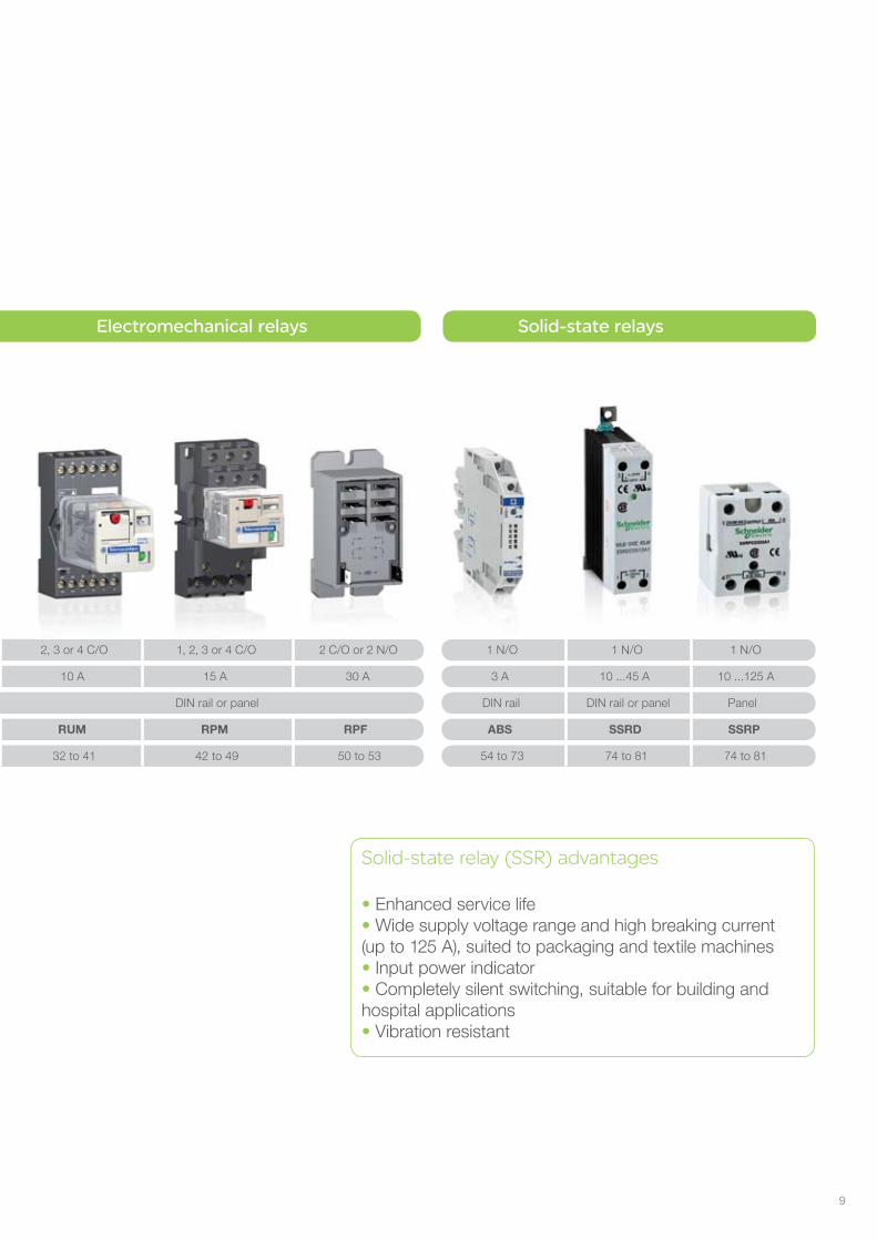
Electromechanical relays Electromechanical relays
DIN rail DIN rail DIN rail or panel DIN rail or panelMounting
1 N/O
3 A
ABS
54 to 73 74 to 81 74 to 81
Solid-state relays
2, 3 or 4 C/O
DIN rail DIN rail or panel
1 N/O
10 ...45 A 10 ...125 A
1 N/O
Panel
SSRD SSRP
Electromechanical relay advantages
• Wide number of contacts (up to 4)• Easy installation and maintenance• Socket compatible plug in relays• Flag indicator to show contact status• Lockable test button for checking circuit during build• Magnetically isolated• Coil voltage LED indicator
8
Contact configuration
Current
Catalog numbers
1 C/O 1 or 2 C/O 1 or 2 C/O 2, 3 or 4 C/O 1, 2, 3 or 4 C/O
6 A 8-12-16 A 5-12 A 6-10-12 A 10 A 15 A
RSL RSB ABR RXM RUM RPM
12 to 17 20 to 23 54 to 73 24 to 31 32 to 41 42 to 49
2 C/O or 2 N/O
30 A
RPF
50 to 53Pages
Electromechanical relays Electromechanical relays
DIN rail DIN rail DIN rail or panel DIN rail or panelMounting
1 N/O
3 A
ABS
54 to 73 74 to 81 74 to 81
Solid-state relays
2, 3 or 4 C/O
DIN rail DIN rail or panel
1 N/O
10 ...45 A 10 ...125 A
1 N/O
Panel
SSRD SSRP
Solid-state relay (SSR) advantages
• Enhanced service life• Wide supply voltage range and high breaking current(up to 125 A), suited to packaging and textile machines• Input power indicator• Completely silent switching, suitable for building and hospital applications• Vibration resistant
9
10
Zelio® Plug-In Relays
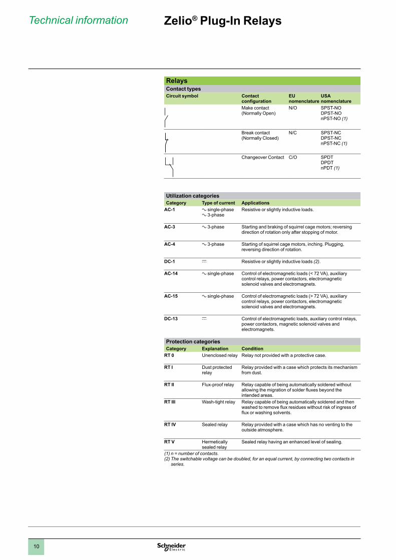
RelaysContact typesCircuit symbol Contact
configurationEU nomenclature
USA nomenclature
Make contact (Normally Open)
N/O SPST-NODPST-NOnPST-NO (1)
Break contact (Normally Closed)
N/C SPST-NCDPST-NCnPST-NC (1)
Changeover Contact C/O SPDTDPDTnPDT (1)
Utilization categoriesCategory Type of current Applications
AC-1 a single-phasea 3-phase
Resistive or slightly inductive loads.
AC-3 a 3-phase Starting and braking of squirrel cage motors; reversing direction of rotation only after stopping of motor.
AC-4 a 3-phase Starting of squirrel cage motors, inching. Plugging, reversing direction of rotation.
DC-1 c Resistive or slightly inductive loads (2).
AC-14 a single-phase Control of electromagnetic loads (< 72 VA), auxiliary control relays, power contactors, electromagnetic solenoid valves and electromagnets.
AC-15 a single-phase Control of electromagnetic loads (> 72 VA), auxiliary control relays, power contactors, electromagnetic solenoid valves and electromagnets.
DC-13 c Control of electromagnetic loads, auxiliary control relays, power contactors, magnetic solenoid valves and electromagnets.
Protection categoriesCategory Explanation Condition
RT 0 Unenclosed relay Relay not provided with a protective case.
RT I Dust protected relay
Relay provided with a case which protects its mechanism from dust.
RT II Flux-proof relay Relay capable of being automatically soldered without allowing the migration of solder fluxes beyond the intended areas.
RT III Wash-tight relay Relay capable of being automatically soldered and then washed to remove flux residues without risk of ingress of flux or washing solvents.
RT IV Sealed relay Relay provided with a case which has no venting to the outside atmosphere.
RT V Hermetically sealed relay
Sealed relay having an enhanced level of sealing.
(1) n = number of contacts.(2) The switchable voltage can be doubled, for an equal current, by connecting two contacts in
series.
Technical information
1
2
3
4
5
6
7
8
9
10
11
Zelio® Plug-In Relays
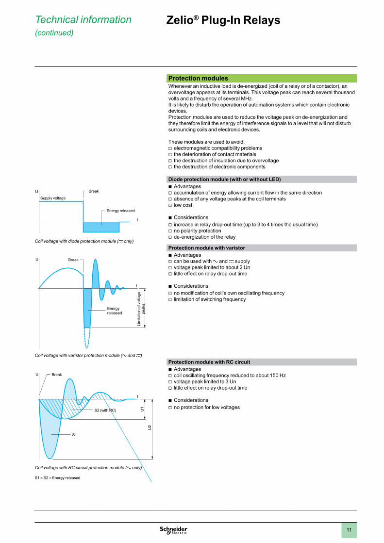
Protection modulesWhenever an inductive load is de-energized (coil of a relay or of a contactor), an overvoltage appears at its terminals. This voltage peak can reach several thousand volts and a frequency of several MHz.It is likely to disturb the operation of automation systems which contain electronic devices.Protection modules are used to reduce the voltage peak on de-energization and they therefore limit the energy of interference signals to a level that will not disturb surrounding coils and electronic devices.
These modules are used to avoid: electromagnetic compatibility problems v the deterioration of contact materialsv the destruction of insulation due to overvoltagev the destruction of electronic componentsv
Diode protection module (with or without LED)
Coil voltage with diode protection module (c only)
Advantagesb accumulation of energy allowing current flow in the same directionv absence of any voltage peaks at the coil terminalsv low costv
Considerationsb increase in relay drop-out time (up to 3 to 4 times the usual time)v no polarity protectionv de-energization of the relayv
Protection module with varistor
Coil voltage with varistor protection module (a and c)
Advantagesb can be used with v a and c supplyvoltage peak limited to about 2 Unv little effect on relay drop-out timev
Considerationsb no modification of coil’s own oscillating frequencyv limitation of switching frequencyv
Protection module with RC circuit
Coil voltage with RC circuit protection module (a only)
S1 = S2 = Energy released
Advantagesb coil oscillating frequency reduced to about 150 Hzv voltage peak limited to 3 Unv little effect on relay drop-out timev
Considerationsb no protection for low voltagesv
U
t
Supply voltage
Energy released
Break
U
t
Energyreleased
Break
Lim
itatio
n of
vol
tage
pe
aks
S1
U1
U2
U
t
Break
S2 (with RC)
Technical information (continued)
1
2
3
4
5
6
7
8
9
10
2
1
3
4
5
6
7
8
9
10
1212
Introduction Zelio® Plug-In Relays RSL slim interface relays
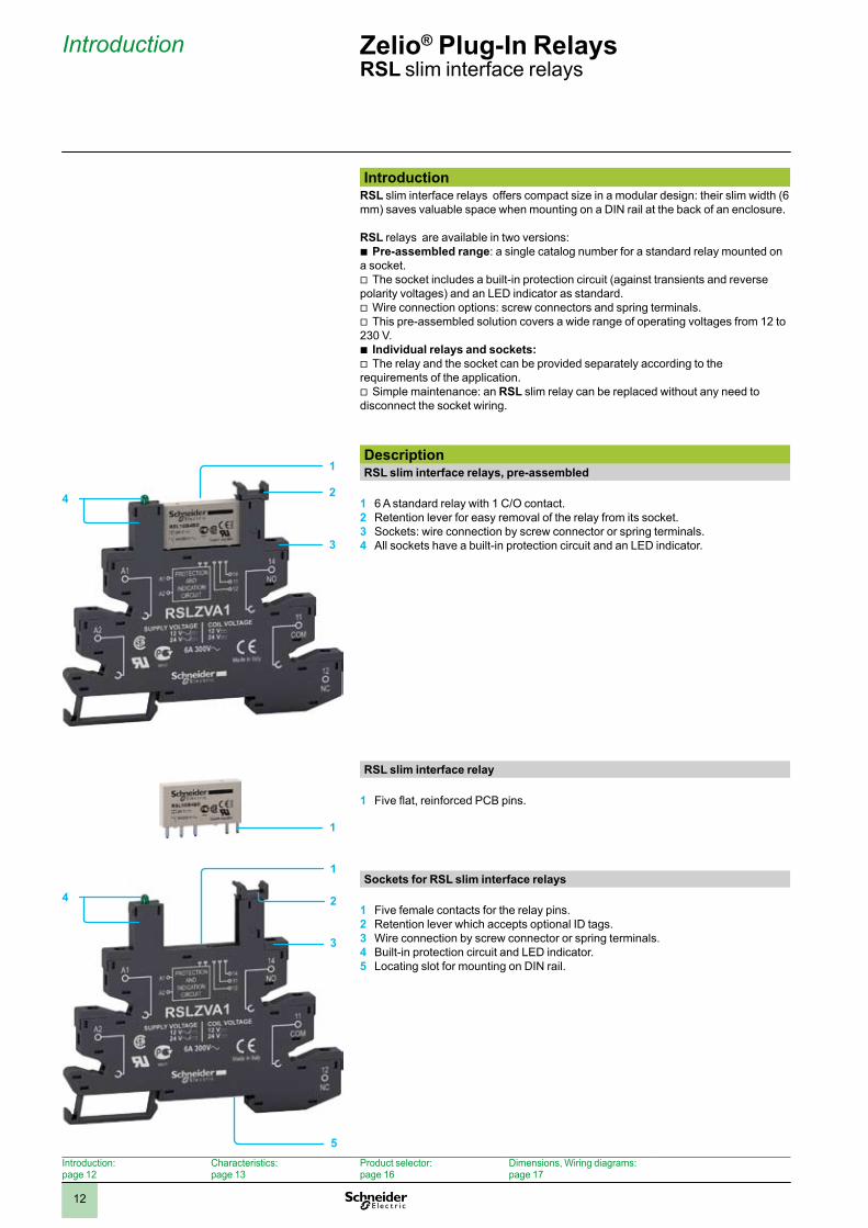
IntroductionRSL slim interface relays offers compact size in a modular design: their slim width (6 mm) saves valuable space when mounting on a DIN rail at the back of an enclosure.
RSL relays are available in two versions:Pre-assembled range b : a single catalog number for a standard relay mounted on
a socket. The socket includes a built-in protection circuit (against transients and reverse v
polarity voltages) and an LED indicator as standard.Wire connection options: screw connectors and spring terminals. vThis pre-assembled solution covers a wide range of operating voltages from 12 to v
230 V.Individual relays and sockets: bThe relay and the socket can be provided separately according to the v
requirements of the application. Simple maintenance: an v RSL slim relay can be replaced without any need to
disconnect the socket wiring.
DescriptionRSL slim interface relays, pre-assembled
6 A standard relay with 1 C/O contact.1 Retention lever for easy removal of the relay from its socket.2 Sockets: wire connection by screw connector or spring terminals.3 All sockets have a built-in protection circuit and an LED indicator.4
RSL slim interface relay
Five flat, reinforced PCB pins.1
Sockets for RSL slim interface relays
Five female contacts for the relay pins.1 Retention lever which accepts optional ID tags.2 Wire connection by screw connector or spring terminals.3 Built-in protection circuit and LED indicator.4 Locating slot for mounting on DIN5 rail.
Introduction: page 12
Characteristics: page 13
Product selector: page 16
Dimensions, Wiring diagrams: page 17
1
2
3
4
1
1
24
5
3

2
1
3
4
5
6
7
8
9
10
1313
Characteristics Zelio® Plug-In Relays RSL slim interface relays
General characteristicsConforming to standards
IEC 61810-1, UL 508, CSA C22-2 No. 14
Product certifications
UL E173076, UL E172326, CSA 240278, CSA 247510, GOST
Ambient air temperature around the device
Storage
°C - 40… + 85
Operation
°C - 40… + 55
Vibration resistanceconforming to IEC/EN 60068-2-6
In operation
10 gn
Not operating
5 gn
Degree of protection Conforming to IEC/EN 60529
IP 40 (Relays)IP 20 (Sockets)
Shock resistanceconforming to IEC/EN 60068-2-27
Opening
10 gn
Closing
5 gn
Protection category
RT III
Mounting position
Any
Insulation characteristicsRated insulation voltage (Ui)
V 250 (IEC)
Rated impulse withstand voltage (Uimp)
kV 6
Dielectric strength(rms voltage)
Between coil and contact
a V 4000
Between contacts
a V 1000
2
1
3
4
5
6
7
8
9
10
1414
Characteristics (continued) Zelio® Plug-In Relays RSL slim interface relays
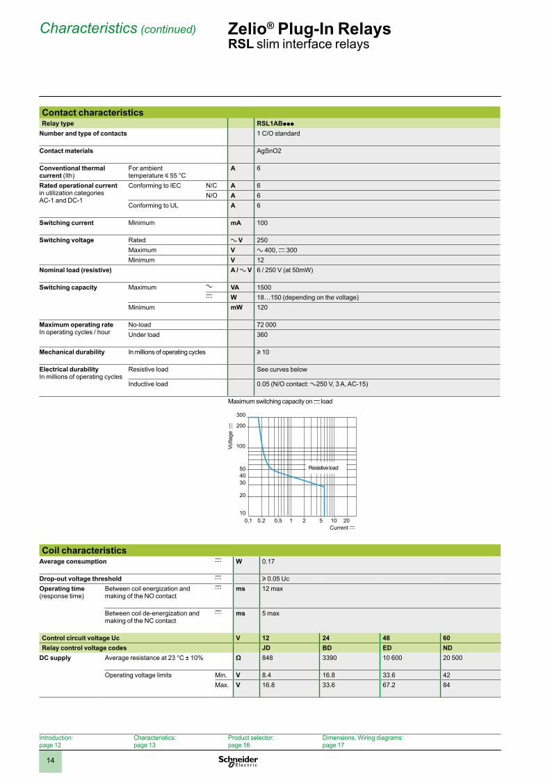
Contact characteristicsRelay type RSL1ABppp
Number and type of contacts 1 C/O standard
Contact materials AgSnO2
Conventional thermal current (Ith)
For ambient temperature y 55 °C
A 6
Rated operational current in utilization categories AC-1 and DC-1
Conforming to IEC N/C A 6N/O A 6
Conforming to UL A 6
Switching current Minimum mA 100
Switching voltage Rated a V 250Maximum V a 400, c 300 Minimum V 12
Nominal load (resistive) A / a V 6 / 250 V (at 50mW)
Switching capacity Maximum a VA 1500c W 18…150 (depending on the voltage)
Minimum mW 120
Maximum operating rateIn operating cycles / hour
No-load 72 000Under load 360
Mechanical durability In millions of operating cycles u 10
Electrical durabilityIn millions of operating cycles
Resistive load See curves below
Inductive load 0.05 (N/O contact: a250 V, 3 A, AC-15)
Maximum switching capacity on c load
Current c
Volta
ge c
0,1 0,2 0,5 1 10 202 510
20
30
5040
100
200
300
Resistive load
Coil characteristicsAverage consumption c W 0.17
Drop-out voltage threshold c u 0.05 UcOperating time(response time)
Between coil energization and making of the NO contact
c ms 12 max
Between coil de-energization and making of the NC contact
c ms 5 max
Control circuit voltage Uc V 12 24 48 60Relay control voltage codes JD BD ED ND
DC supply Average resistance at 23 °C ± 10% Ω 848 3390 10 600 20 500
Operating voltage limits Min. V 8.4 16.8 33.6 42Max. V 16.8 33.6 67.2 84
Introduction: page 12
Characteristics: page 13
Product selector: page 16
Dimensions, Wiring diagrams: page 17
2
1
3
4
5
6
7
8
9
10
1515
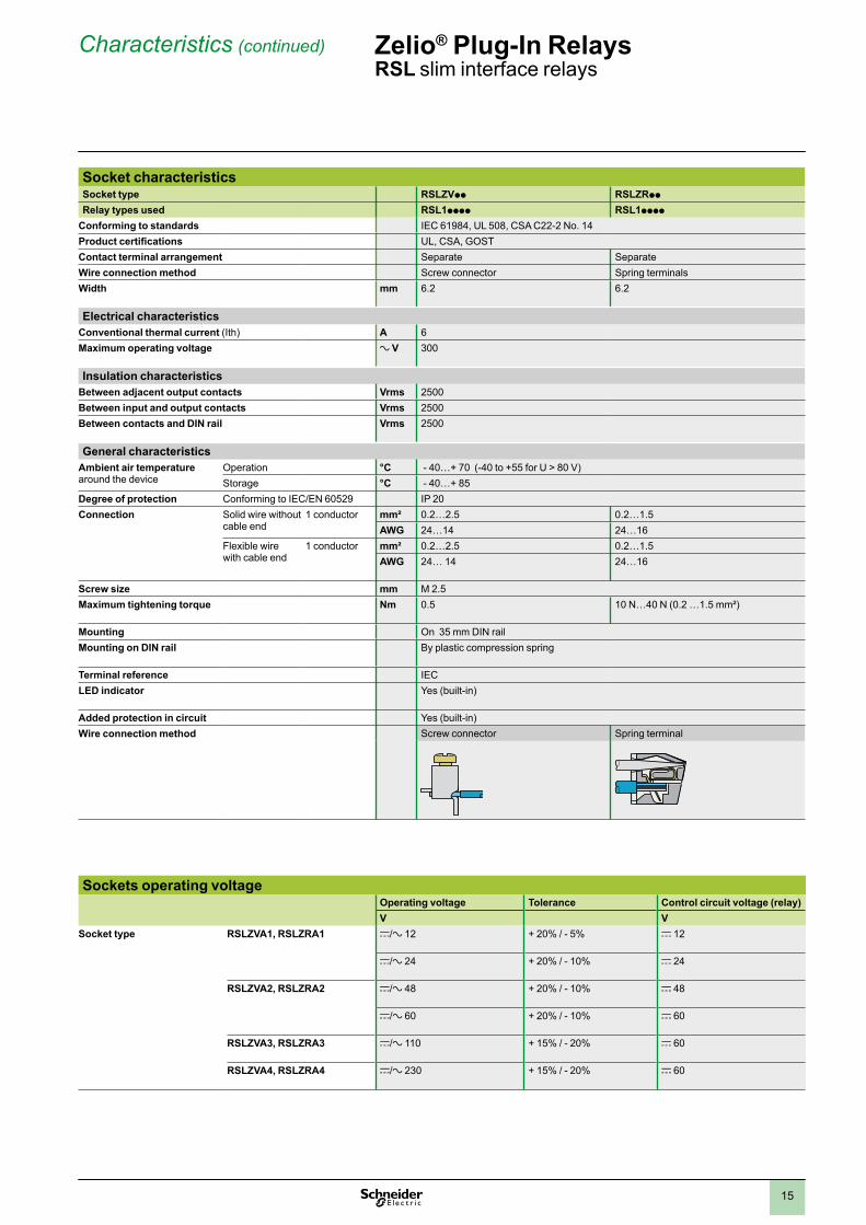
Socket characteristicsSocket type RSLZVpp RSLZRpp
Relay types used RSL1pppp RSL1pppp
Conforming to standards IEC 61984, UL 508, CSA C22-2 No. 14Product certifications UL, CSA, GOSTContact terminal arrangement Separate SeparateWire connection method Screw connector Spring terminalsWidth mm 6.2 6.2
Electrical characteristicsConventional thermal current (Ith) A 6Maximum operating voltage a V 300
Insulation characteristicsBetween adjacent output contacts Vrms 2500Between input and output contacts Vrms 2500Between contacts and DIN rail Vrms 2500
General characteristicsAmbient air temperaturearound the device
Operation °C - 40…+ 70 (-40 to +55 for U > 80 V)Storage °C - 40…+ 85
Degree of protection Conforming to IEC/EN 60529 IP 20Connection Solid wire without
cable end1 conductor mm² 0.2…2.5 0.2…1.5
AWG 24…14 24…16 Flexible wire with cable end
1 conductor mm² 0.2…2.5 0.2…1.5AWG 24… 14 24…16
Screw size mm M 2.5Maximum tightening torque Nm 0.5 10 N…40 N (0.2 …1.5 mm²)
Mounting On 35 mm DIN railMounting on DIN rail By plastic compression spring
Terminal reference IECLED indicator Yes (built-in)
Added protection in circuit Yes (built-in)Wire connection method Screw connector Spring terminal
Sockets operating voltageOperating voltage Tolerance Control circuit voltage (relay)V V
Socket type RSLZVA1, RSLZRA1 c/a 12 + 20% / - 5% c 12
c/a 24 + 20% / - 10% c 24
RSLZVA2, RSLZRA2 c/a 48 + 20% / - 10% c 48
c/a 60 + 20% / - 10% c 60
RSLZVA3, RSLZRA3 c/a 110 + 15% / - 20% c 60
RSLZVA4, RSLZRA4 c/a 230 + 15% / - 20% c 60
Characteristics (continued) Zelio® Plug-In Relays RSL slim interface relays
2
1
3
4
5
6
7
8
9
10
1616
Product selector Zelio® Plug-In Relays RSL slim interface relays
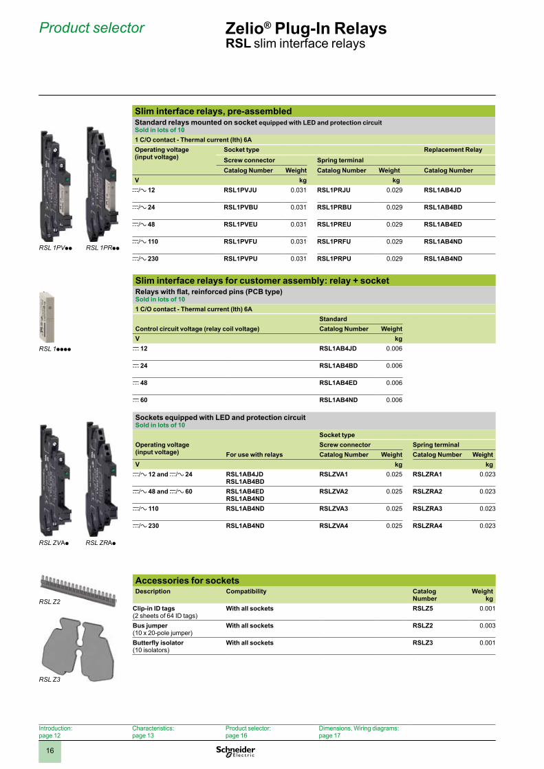
Slim interface relays, pre-assembledStandard relays mounted on socket equipped with LED and protection circuitSold in lots of 101 C/O contact - Thermal current (Ith) 6AOperating voltage (input voltage)
Socket type Replacement RelayScrew connector Spring terminalCatalog Number Weight Catalog Number Weight Catalog Number
V kg kgc/a 12 RSL1PVJU 0.031 RSL1PRJU 0.029 RSL1AB4JD
c/a 24 RSL1PVBU 0.031 RSL1PRBU 0.029 RSL1AB4BD
c/a 48 RSL1PVEU 0.031 RSL1PREU 0.029 RSL1AB4ED
c/a 110 RSL1PVFU 0.031 RSL1PRFU 0.029 RSL1AB4ND
c/a 230 RSL1PVPU 0.031 RSL1PRPU 0.029 RSL1AB4ND
Slim interface relays for customer assembly: relay + socketRelays with flat, reinforced pins (PCB type)Sold in lots of 101 C/O contact - Thermal current (Ith) 6A
StandardControl circuit voltage (relay coil voltage) Catalog Number WeightV kg
c 12 RSL1AB4JD 0.006
c 24 RSL1AB4BD 0.006
c 48 RSL1AB4ED 0.006
c 60 RSL1AB4ND 0.006
Sockets equipped with LED and protection circuitSold in lots of 10
Socket typeOperating voltage (input voltage)
Screw connector Spring terminalFor use with relays Catalog Number Weight Catalog Number Weight
V kg kgc/a 12 and c/a 24 RSL1AB4JD
RSL1AB4BDRSLZVA1 0.025 RSLZRA1 0.023
c/a 48 and c/a 60 RSL1AB4EDRSL1AB4ND
RSLZVA2 0.025 RSLZRA2 0.023
c/a 110 RSL1AB4ND RSLZVA3 0.025 RSLZRA3 0.023
c/a 230
RSL1AB4ND RSLZVA4 0.025 RSLZRA4 0.023
Accessories for socketsDescription Compatibility Catalog
NumberWeight
kgClip-in ID tags(2 sheets of 64 ID tags)
With all sockets RSLZ5 0.001
Bus jumper (10 x 20-pole jumper)
With all sockets RSLZ2 0.003
Butterfly isolator(10 isolators)
With all sockets RSLZ3 0.001
Introduction: page 12
Characteristics: page 13
Product selector:page 16
Dimensions, Wiring diagrams: page 17
RSL 1pppp
RSL ZVAp
RSL 1PVpp
RSL ZRAp
RSL 1PRpp
RSL Z2
RSL Z3
2
1
3
4
5
6
7
8
9
10
1717
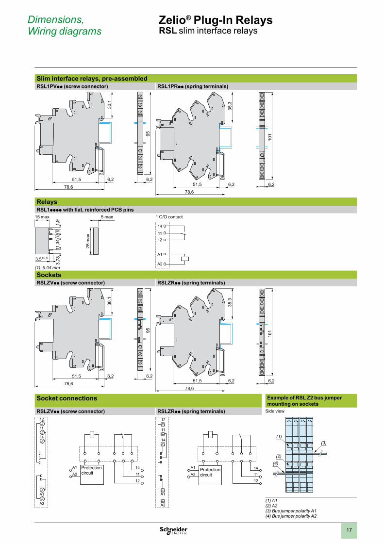
Dimensions, Wiring diagrams
Zelio® Plug-In Relays RSL slim interface relays
Slim interface relays, pre-assembledRSL1PVpp (screw connector) RSL1PRpp (spring terminals)
95
30,1
51,5 6,2 6,2
78,6
101
35,3
6,251,5 6,2
78,6
RelaysRSL1pppp with flat, reinforced PCB pins
(1): 5.04 mm
1,9
(1)
(1)
3,5±0,5
11,3
43,
78
15 max 5 max
28 m
ax
1 C/O contact
A1
A2
1211
14
SocketsRSLZVpp (screw connector) RSLZRpp (spring terminals)
95
30,1
51,5 6,2 6,2
78,6
101
35,3
6,251,5 6,2
78,6
Socket connections Example of RSL Z2 bus jumper mounting on sockets
RSLZVpp (screw connector) RSLZRpp (spring terminals) Side view
Protection circuit
14
11
A1
A2
12
12
11
14
A1
A2
Protection circuit
12
11
14
A1
A2
1411
A1
A212
(4)(2)
(1)(3)
(1) A1(2) A2(3) Bus jumper polarity A1(4) Bus jumper polarity A2
18
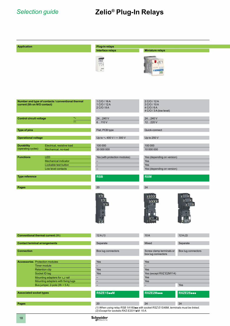
Zelio® Plug-In RelaysSelection guide
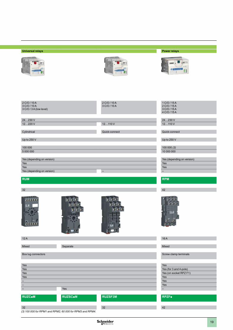
Universal relays Power relays
2 C/O / 10 A3 C/O / 10 A3 C/O / 3 A (low level)
2 C/O / 10 A3 C/O / 10 A
1 C/O / 15 A2 C/O / 15 A3 C/O / 15 A4 C/O / 15 A
24…230 V 24…230 V12…220 V 12…110 V 12…110 V
Cylindrical Quick-connect Quick-connect
Up to 250 V Up to 250 V
100 000 100 000 (3)5 000 000 10 000 000
Yes (depending on version) Yes (depending on version)Yes YesYes YesYes (depending on version) – –
RUM RPM
32 42
12 A 16 A
Mixed Separate Mixed
Box lug connectors Screw clamp terminals
Yes YesYes Yes (for 3 and 4-pole)Yes Yes (on socket RPZ F1)Yes Yes– Yes– Yes– Yes –
RUZCpM RUZSCpM RUZSF3M RPZFp
32 32 42(3) 100 000 for RPM1 and RPM2; 60 000 for RPM3 and RPM4.
Application Plug-in relaysInterface relays Miniature relays
Number and type of contacts / conventional thermal current (Ith on N/O contact)
1 C/O / 16 A1 C/O / 12 A2 C/O / 8 A
2 C/O / 12 A3 C/O / 10 A4 C/O / 6 A4 C/O / 3 A (low level)
Control circuit voltage a 24…240 V 24…240 Vc 6…110 V 12…220 V
Type of pins Flat, PCB type Quick-connect
Operational voltage Up to a 400 V / c 300 V Up to 250 V
Durability (operating cycles)
Electrical, resistive load 100 000 100 000Mechanical, no-load 30 000 000 10 000 000
Functions LED Yes (with protection modules) Yes (depending on version)Mechanical indicator – YesLockable test button – YesLow level contacts – Yes (depending on version)
Type reference RSB RXM
Pages 20 24
Conventional thermal current (Ith) 12 A (1) 10 A 12 A (2)
Contact terminal arrangements Separate Mixed Separate
Connection Box lug connectors Screw clamp terminals or box lug connectors
Box lug connectors
Accessories Protection modules Yes YesTimer module – –Retention clip Yes YesSocket ID tag Yes Yes (except RXZ E2M114)Mounting adapters for 5 rail – YesMounting adapters with fixing lugs – YesBus jumper, 2-pole (Ith = 5 A) – – Yes
Associated socket types RSZE1SppM RXZE2Mppp RXZE2Sppp
Pages 20 24 24(1) When using relay RSB 1A160pp with socket RSZ E1S48M, terminals must be linked.(2) Except for sockets RXZ E2S11pM: 10 A.
1
2
3
4
5
6
7
8
9
10
19
Universal relays Power relays
2 C/O / 10 A3 C/O / 10 A3 C/O / 3 A (low level)
2 C/O / 10 A3 C/O / 10 A
1 C/O / 15 A2 C/O / 15 A3 C/O / 15 A4 C/O / 15 A
24…230 V 24…230 V12…220 V 12…110 V 12…110 V
Cylindrical Quick-connect Quick-connect
Up to 250 V Up to 250 V
100 000 100 000 (3)5 000 000 10 000 000
Yes (depending on version) Yes (depending on version)Yes YesYes YesYes (depending on version) – –
RUM RPM
32 42
12 A 16 A
Mixed Separate Mixed
Box lug connectors Screw clamp terminals
Yes YesYes Yes (for 3 and 4-pole)Yes Yes (on socket RPZ F1)Yes Yes– Yes– Yes– Yes –
RUZCpM RUZSCpM RUZSF3M RPZFp
32 32 42(3) 100 000 for RPM1 and RPM2; 60 000 for RPM3 and RPM4.
Application Plug-in relaysInterface relays Miniature relays
Number and type of contacts / conventional thermal current (Ith on N/O contact)
1 C/O / 16 A1 C/O / 12 A2 C/O / 8 A
2 C/O / 12 A3 C/O / 10 A4 C/O / 6 A4 C/O / 3 A (low level)
Control circuit voltage a 24…240 V 24…240 Vc 6…110 V 12…220 V
Type of pins Flat, PCB type Quick-connect
Operational voltage Up to a 400 V / c 300 V Up to 250 V
Durability (operating cycles)
Electrical, resistive load 100 000 100 000Mechanical, no-load 30 000 000 10 000 000
Functions LED Yes (with protection modules) Yes (depending on version)Mechanical indicator – YesLockable test button – YesLow level contacts – Yes (depending on version)
Type reference RSB RXM
Pages 20 24
Conventional thermal current (Ith) 12 A (1) 10 A 12 A (2)
Contact terminal arrangements Separate Mixed Separate
Connection Box lug connectors Screw clamp terminals or box lug connectors
Box lug connectors
Accessories Protection modules Yes YesTimer module – –Retention clip Yes YesSocket ID tag Yes Yes (except RXZ E2M114)Mounting adapters for 5 rail – YesMounting adapters with fixing lugs – YesBus jumper, 2-pole (Ith = 5 A) – – Yes
Associated socket types RSZE1SppM RXZE2Mppp RXZE2Sppp
Pages 20 24 24(1) When using relay RSB 1A160pp with socket RSZ E1S48M, terminals must be linked.(2) Except for sockets RXZ E2S11pM: 10 A.
1
2
3
4
5
6
7
8
9
10
20
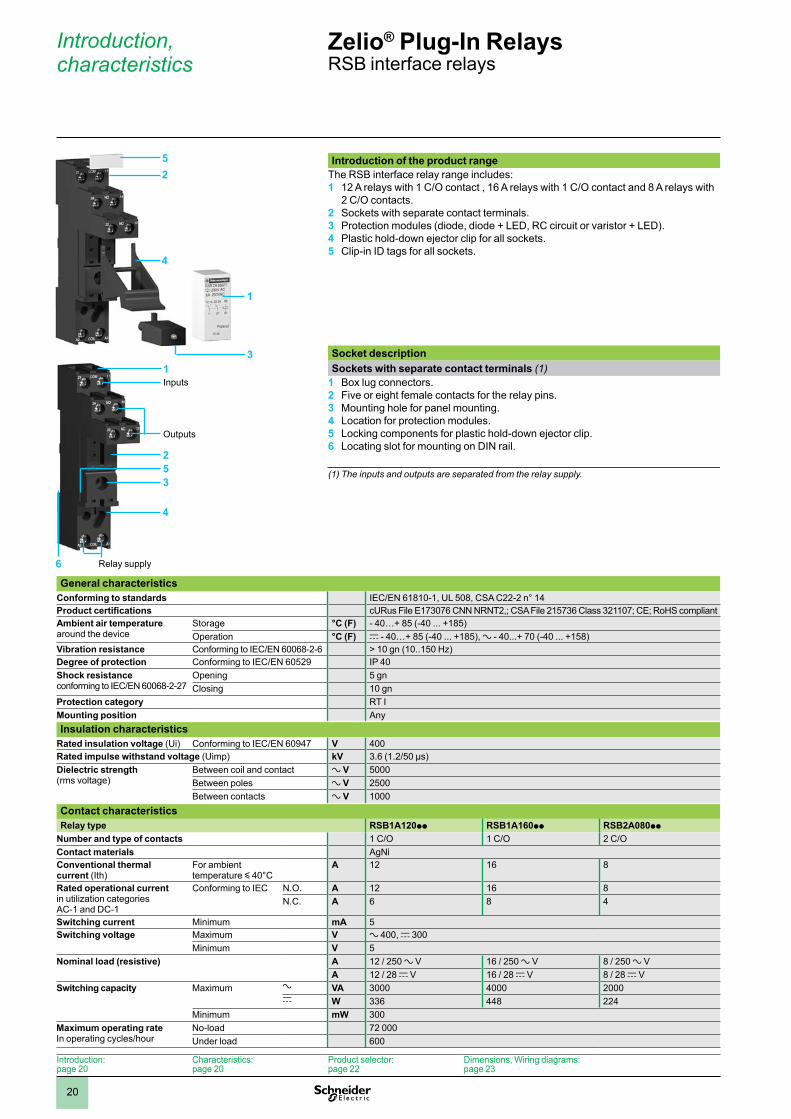
Introduction of the product rangeThe RSB interface relay range includes: 1 12 A relays with 1 C/O contact , 16 A relays with 1 C/O contact and 8 A relays with
2 C/O contacts.2 Sockets with separate contact terminals.3 Protection modules (diode, diode + LED, RC circuit or varistor + LED). 4 Plastic hold-down ejector clip for all sockets.5 Clip-in ID tags for all sockets.
Socket descriptionSockets with separate contact terminals (1)
1 Box lug connectors. 2 Five or eight female contacts for the relay pins.3 Mounting hole for panel mounting.4 Location for protection modules.5 Locking components for plastic hold-down ejector clip.6 Locating slot for mounting on DIN rail.
(1) The inputs and outputs are separated from the relay supply.
General characteristics
Conforming to standards IEC/EN 61810-1, UL 508, CSA C22-2 n° 14Product certifications cURus File E173076 CNN NRNT2,; CSA File 215736 Class 321107; CE; RoHS compliantAmbient air temperature around the device
Storage °C (F) - 40…+ 85 (-40 ... +185)Operation °C (F) c - 40…+ 85 (-40 ... +185), a - 40...+ 70 (-40 ... +158)
Vibration resistance Conforming to IEC/EN 60068-2-6 > 10 gn (10..150 Hz)Degree of protection Conforming to IEC/EN 60529 IP 40Shock resistanceconforming to IEC/EN 60068-2-27
Opening 5 gnClosing 10 gn
Protection category RT IMounting position AnyInsulation characteristics
Rated insulation voltage (Ui) Conforming to IEC/EN 60947 V 400Rated impulse withstand voltage (Uimp) kV 3.6 (1.2/50 µs)Dielectric strength(rms voltage)
Between coil and contact a V 5000Between poles a V 2500Between contacts a V 1000
Contact characteristicsRelay type RSB1A120pp RSB1A160pp RSB2A080pp
Number and type of contacts 1 C/O 1 C/O 2 C/OContact materials AgNiConventional thermal current (Ith)
For ambient temperature y 40°C
A 12 16 8
Rated operational current in utilization categories AC-1 and DC-1
Conforming to IEC N.O. A 12 16 8N.C. A 6 8 4
Switching current Minimum mA 5Switching voltage Maximum V a 400, c 300
Minimum V 5Nominal load (resistive) A 12 / 250 a V 16 / 250 a V 8 / 250 a V
A 12 / 28 c V 16 / 28 c V 8 / 28 c VSwitching capacity Maximum a VA 3000 4000 2000
c W 336 448 224Minimum mW 300
Maximum operating rateIn operating cycles/hour
No-load 72 000Under load 600
Zelio® Plug-In Relays RSB interface relays
Introduction, characteristics
1
2
35
6
4
Inputs
Outputs
Relay supply
5
4
1
2
3
Introduction:page 20
Characteristics:page 20
Product selector:page 22
Dimensions, Wiring diagrams:page 23
1
2
3
4
5
6
7
8
9
10
21
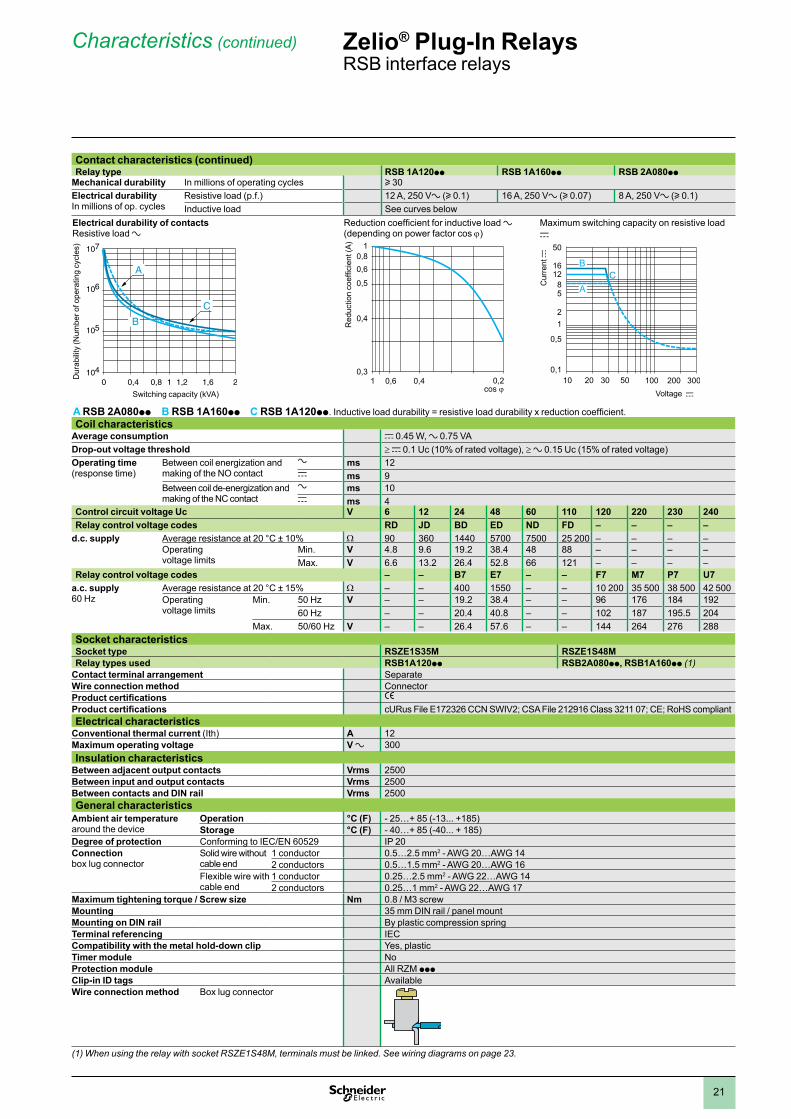
Contact characteristics (continued)Relay type RSB 1A120pp RSB 1A160pp RSB 2A080pp
Mechanical durability In millions of operating cycles u 30Electrical durabilityIn millions of op. cycles
Resistive load (p.f.) 12 A, 250 Va (u 0.1) 16 A, 250 Va (u 0.07) 8 A, 250 Va (u 0.1)Inductive load See curves below
Electrical durability of contactsResistive load a
Reduction coefficient for inductive load a (depending on power factor cos j)
Maximum switching capacity on resistive load c
A RSB 2A080pp B RSB 1A160pp C RSB 1A120pp. Inductive load durability = resistive load durability x reduction coefficient.Coil characteristics
Average consumption c 0.45 W, a 0.75 VADrop-out voltage threshold ≥ c 0.1 Uc (10% of rated voltage), ≥ a 0.15 Uc (15% of rated voltage)Operating time(response time)
Between coil energization and making of the NO contact
a ms 12c ms 9
Between coil de-energization and making of the NC contact
a ms 10c ms 4
Control circuit voltage Uc V 6 12 24 48 60 110 120 220 230 240Relay control voltage codes RD JD BD ED ND FD – – – –
d.c. supply Average resistance at 20 °C ± 10% W 90 360 1440 5700 7500 25 200 – – – –Operating voltage limits
Min. V 4.8 9.6 19.2 38.4 48 88 – – – –Max. V 6.6 13.2 26.4 52.8 66 121 – – – –
Relay control voltage codes – – B7 E7 – – F7 M7 P7 U7a.c. supply 60 Hz
Average resistance at 20 °C ± 15% W – – 400 1550 – – 10 200 35 500 38 500 42 500Operating voltage limits
Min. 50 Hz V – – 19.2 38.4 – – 96 176 184 19260 Hz – – 20.4 40.8 – – 102 187 195.5 204
Max. 50/60 Hz V – – 26.4 57.6 – – 144 264 276 288Socket characteristicsSocket type RSZE1S35M RSZE1S48MRelay types used RSB1A120pp RSB2A080pp, RSB1A160pp (1)
Contact terminal arrangement SeparateWire connection method ConnectorProduct certifications e
Product certifications cURus File E172326 CCN SWIV2; CSA File 212916 Class 3211 07; CE; RoHS compliantElectrical characteristics
Conventional thermal current (Ith) A 12Maximum operating voltage V a 300Insulation characteristics
Between adjacent output contacts Vrms 2500Between input and output contacts Vrms 2500Between contacts and DIN rail Vrms 2500General characteristics
Ambient air temperaturearound the device
Operation °C (F) - 25…+ 85 (-13... +185)Storage °C (F) - 40…+ 85 (-40... + 185)
Degree of protection Conforming to IEC/EN 60529 IP 20Connectionbox lug connector
Solid wire without cable end
1 conductor 0.5…2.5 mm2 - AWG 20…AWG 142 conductors 0.5…1.5 mm2 - AWG 20…AWG 16
Flexible wire with cable end
1 conductor 0.25…2.5 mm2 - AWG 22…AWG 142 conductors 0.25…1 mm2 - AWG 22…AWG 17
Maximum tightening torque / Screw size Nm 0.8 / M3 screwMounting 35 mm DIN rail / panel mountMounting on DIN rail By plastic compression springTerminal referencing IECCompatibility with the metal hold-down clip Yes, plasticTimer module NoProtection module All RZM pppClip-in ID tags AvailableWire connection method Box lug connector
(1) When using the relay with socket RSZE1S48M, terminals must be linked. See wiring diagrams on page 23.
104
0,80 0,4 1,21 1,6 2
107
105
106
C
A
B
Dur
abili
ty (N
umbe
r of o
pera
ting
cycl
es)
Switching capacity (kVA)
0,3
0,5
0,61 0,4 0,2
0,4
0,60,8
1
Red
uctio
n co
effic
ient
(A)
0,1
12
16
100 200 30010 20 30 50
58
12
0,5
50
CB
A
Cur
rent
c
Voltage c
Zelio® Plug-In Relays RSB interface relays
Characteristics (continued)
1
2
3
4
5
6
7
8
9
10
22
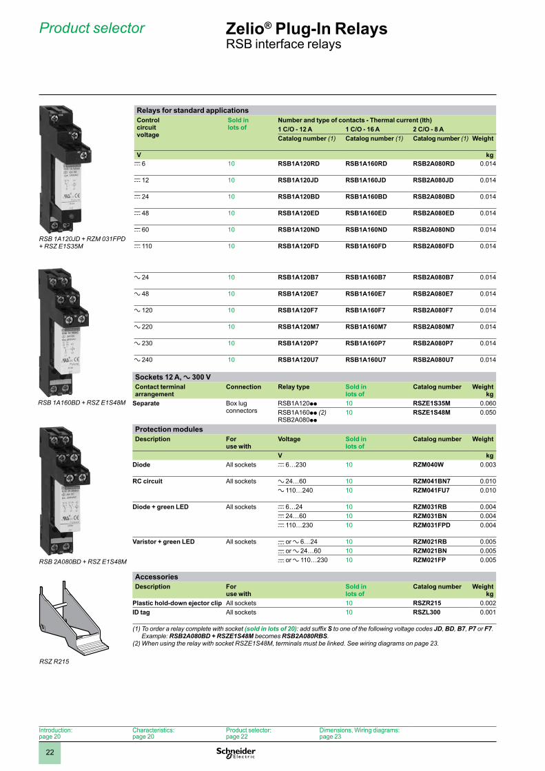
Relays for standard applicationsControl circuit voltage
Sold in lots of
Number and type of contacts - Thermal current (Ith)1 C/O - 12 A 1 C/O - 16 A 2 C/O - 8 ACatalog number (1) Catalog number (1) Catalog number (1) Weight
V kgc 6 10 RSB1A120RD RSB1A160RD RSB2A080RD 0.014
c 12 10 RSB1A120JD RSB1A160JD RSB2A080JD 0.014
c 24 10 RSB1A120BD RSB1A160BD RSB2A080BD 0.014
c 48 10 RSB1A120ED RSB1A160ED RSB2A080ED 0.014
c 60 10 RSB1A120ND RSB1A160ND RSB2A080ND 0.014
c 110 10 RSB1A120FD RSB1A160FD RSB2A080FD 0.014
a 24 10 RSB1A120B7 RSB1A160B7 RSB2A080B7 0.014
a 48 10 RSB1A120E7 RSB1A160E7 RSB2A080E7 0.014
a 120 10 RSB1A120F7 RSB1A160F7 RSB2A080F7 0.014
a 220 10 RSB1A120M7 RSB1A160M7 RSB2A080M7 0.014
a 230 10 RSB1A120P7 RSB1A160P7 RSB2A080P7 0.014
a 240 10 RSB1A120U7 RSB1A160U7 RSB2A080U7 0.014
Sockets 12 A, a 300 VContact terminal arrangement
Connection Relay type Sold in lots of
Catalog number Weightkg
Separate Box lug connectors
RSB1A120pp 10 RSZE1S35M 0.060RSB1A160pp (2)RSB2A080pp
10 RSZE1S48M 0.050
Protection modulesDescription For
use withVoltage Sold in
lots ofCatalog number Weight
V kgDiode All sockets c 6…230 10 RZM040W 0.003
RC circuit All sockets a 24…60 10 RZM041BN7 0.010a 110…240 10 RZM041FU7 0.010
Diode + green LED All sockets c 6…24 10 RZM031RB 0.004c 24…60 10 RZM031BN 0.004c 110…230 10 RZM031FPD 0.004
Varistor + green LED All sockets c or a 6…24 10 RZM021RB 0.005c or a 24…60 10 RZM021BN 0.005c or a 110…230 10 RZM021FP 0.005
AccessoriesDescription For
use withSold in lots of
Catalog number Weightkg
Plastic hold-down ejector clip All sockets 10 RSZR215 0.002ID tag All sockets 10 RSZL300 0.001
(1) To order a relay complete with socket (sold in lots of 20): add suffix S to one of the following voltage codes JD, BD, B7, P7 or F7. Example: RSB2A080BD + RSZE1S48M becomes RSB2A080RBS.
(2) When using the relay with socket RSZE1S48M, terminals must be linked. See wiring diagrams on page 23.
RSB 1A120JD + RZM 031FPD + RSZ E1S35M
RSB 1A160BD + RSZ E1S48M
RSB 2A080BD + RSZ E1S48M
RSZ R215
Zelio® Plug-In Relays RSB interface relays
Product selector
Introduction:page 20
Characteristics:page 20
Product selector:page 22
Dimensions, Wiring diagrams:page 23
1
2
3
4
5
6
7
8
9
10
23
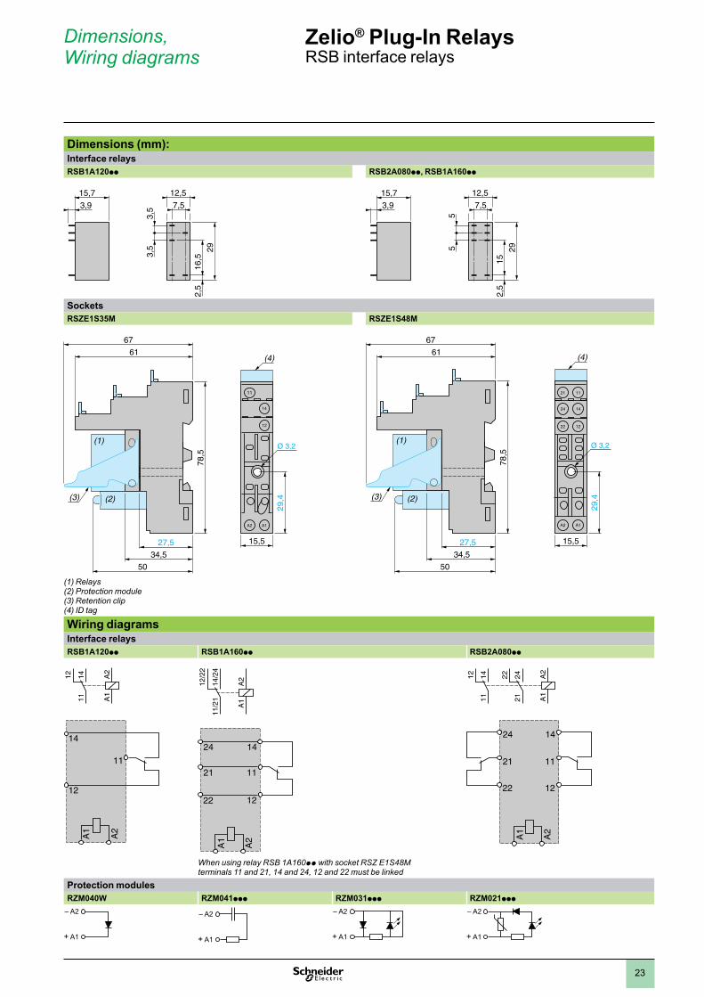
Dimensions (mm):Interface relaysRSB1A120pp RSB2A080pp, RSB1A160pp
SocketsRSZE1S35M RSZE1S48M
(1) Relays(2) Protection module(3) Retention clip(4) ID tag
Wiring diagramsInterface relaysRSB1A120pp RSB1A160pp RSB2A080pp
When using relay RSB 1A160pp with socket RSZ E1S48M terminals 11 and 21, 14 and 24, 12 and 22 must be linked
Protection modulesRZM040W RZM041ppp RZM031ppp RZM021ppp
– A2
+ A1
– A2
+ A1
– A2
+ A1
– A2
+ A1
15,7
7,5
3,5
12,5
3,929
16,5
2,5
3,5
15,7
7,5
5
12,5
3,9
5 29
152,
5
61
67
78,5
(4)
15,5
29,4
34,5
50
27,5
(3)
(1)
(2)
11
14
12
A2 A1
(4)
21 11
24 14
22 12
A2 A1
61
67
78,5
15,5
29,4
34,5
50
27,5
(3)
(1)
(2)
A2
A1
111412
A2
A1
11
14
12
A2
A1
21 11
22 12
24 14
A2
A1
11/2
114
/24
12/2
2
A2
A1
21 11
22 12
24 14
A2
A1
212422
111412
Dimensions, Wiring diagrams
Zelio® Plug-In Relays RSB interface relays
1
2
3
4
5
6
7
8
9
10
24
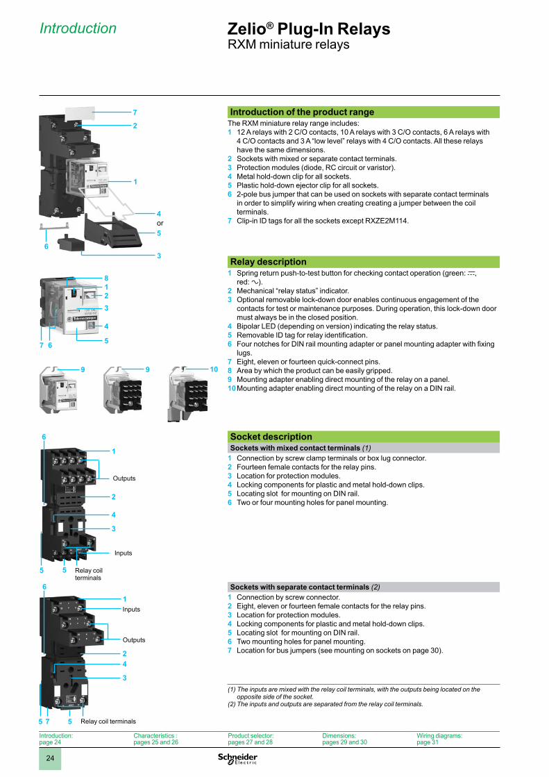
Introduction of the product range The RXM miniature relay range includes: 1 12 A relays with 2 C/O contacts, 10 A relays with 3 C/O contacts, 6 A relays with
4 C/O contacts and 3 A “low level” relays with 4 C/O contacts. All these relays have the same dimensions.
2 Sockets with mixed or separate contact terminals.3 Protection modules (diode, RC circuit or varistor). 4 Metal hold-down clip for all sockets.5 Plastic hold-down ejector clip for all sockets.6 2-pole bus jumper that can be used on sockets with separate contact terminals
in order to simplify wiring when creating creating a jumper between the coil terminals.
7 Clip-in ID tags for all the sockets except RXZE2M114.
Relay description 1 Spring return push-to-test button for checking contact operation (green: c,
red: a). 2 Mechanical “relay status” indicator.3 Optional removable lock-down door enables continuous engagement of the
contacts for test or maintenance purposes. During operation, this lock-down door must always be in the closed position.
4 Bipolar LED (depending on version) indicating the relay status.5 Removable ID tag for relay identification.6 Four notches for DIN rail mounting adapter or panel mounting adapter with fixing
lugs.7 Eight, eleven or fourteen quick-connect pins.8 Area by which the product can be easily gripped.9 Mounting adapter enabling direct mounting of the relay on a panel.10 Mounting adapter enabling direct mounting of the relay on a DIN rail.
Socket description Sockets with mixed contact terminals (1)
1 Connection by screw clamp terminals or box lug connector.2 Fourteen female contacts for the relay pins.3 Location for protection modules.4 Locking components for plastic and metal hold-down clips.5 Locating slot for mounting on DIN rail.6 Two or four mounting holes for panel mounting.
Sockets with separate contact terminals (2)1 Connection by screw connector. 2 Eight, eleven or fourteen female contacts for the relay pins.3 Location for protection modules.4 Locking components for plastic and metal hold-down clips.5 Locating slot for mounting on DIN rail.6 Two mounting holes for panel mounting.7 Location for bus jumpers (see mounting on sockets on page 30).
(1) The inputs are mixed with the relay coil terminals, with the outputs being located on the opposite side of the socket.
(2) The inputs and outputs are separated from the relay coil terminals.
7
6
2
1
5
3
4or
12
7
3
4
56
8
9 9 10
1
2
3
4
5
Outputs
Inputs
Relay coil terminals
5
6
16
2
3
4
5 7
Outputs
Inputs
Relay coil terminals5
Zelio® Plug-In RelaysRXM miniature relays
Introduction
Introduction:page 24
Characteristics :pages 25 and 26
Product selector:pages 27 and 28
Dimensions:pages 29 and 30
Wiring diagrams:page 31
1
2
3
4
5
6
7
8
9
10
25
General characteristicsConforming to standards IEC/EN 61810-1 (iss. 2), UL 508, CSA C22-2 n° 14Product certifications cULus File E164862 CCN NLDX, NLDX7; cURus File E164862 CCN NLDX2, NLDX8;
CSA; CE; RoHS compliantAmbient air temperature around the device
Storage °C (F) - 40… + 85 (-40... +185)Operation °C (F) - 40… + 55 (-40... +131)
Vibration resistanceconforming to IEC/EN 60068-2-6
In operation 3 gn (10...150 Hz/± 1 mm / 5g/5 cycles)Not operating 5 gn (10...150 Hz/± 1 mm / 5g/5 cycles)
Degree of protection Conforming to IEC/EN 60529 IP 40Shock resistanceconforming to IEC/EN 60068-2-27
Opening 15 gnClosing 15 gn
Protection category RT IMounting position Any
Insulation characteristicsRated insulation voltage (Ui) V 250 (IEC), 300 (UL, CSA)Rated impulse withstand voltage (Uimp) kV 4 (1.2/50 ms)Dielectric strength(rms voltage)
Between coil and contact a V 1550Between poles a V 1550Between contacts a V 1500
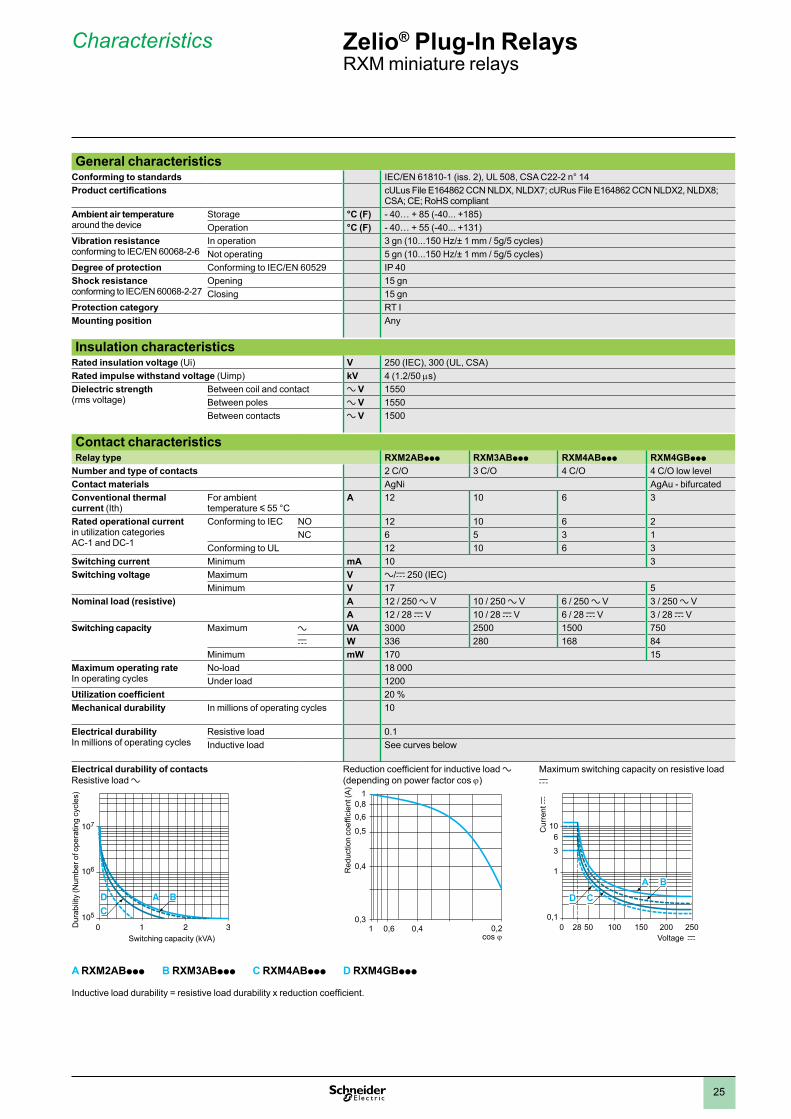
Contact characteristicsRelay type RXM2ABppp RXM3ABppp RXM4ABppp RXM4GBppp
Number and type of contacts 2 C/O 3 C/O 4 C/O 4 C/O low levelContact materials AgNi AgAu - bifurcatedConventional thermal current (Ith)
For ambient temperature y 55 °C
A 12 10 6 3
Rated operational current in utilization categories AC-1 and DC-1
Conforming to IEC NO 12 10 6 2NC 6 5 3 1
Conforming to UL 12 10 6 3Switching current Minimum mA 10 3Switching voltage Maximum V a/c 250 (IEC)
Minimum V 17 5Nominal load (resistive) A 12 / 250 a V 10 / 250 a V 6 / 250 a V 3 / 250 a V
A 12 / 28 c V 10 / 28 c V 6 / 28 c V 3 / 28 c VSwitching capacity Maximum a VA 3000 2500 1500 750
c W 336 280 168 84Minimum mW 170 15
Maximum operating rateIn operating cycles
No-load 18 000Under load 1200
Utilization coefficient 20 %Mechanical durability In millions of operating cycles 10
Electrical durabilityIn millions of operating cycles
Resistive load 0.1Inductive load See curves below
Electrical durability of contacts Resistive load a
Reduction coefficient for inductive load a (depending on power factor cos j)
Maximum switching capacity on resistive load c
A RXM2ABppp B RXM3ABppp C RXM4ABppp D RXM4GBppp
Inductive load durability = resistive load durability x reduction coefficient.
105
106
107
2 30 1
A BDC
Dur
abili
ty (N
umbe
r of o
pera
ting
cycl
es)
Switching capacity (kVA)
0,3
0,5
0,61 0,4 0,2
0,4
0,60,8
1
Red
uctio
n co
effic
ient
(A)
0,1
1
200 2500 5028 100 150
10
3
6
CDBA
Cur
rent
c
Voltage c
Zelio® Plug-In RelaysRXM miniature relays
Characteristics
1
2
3
4
5
6
7
8
9
10
26
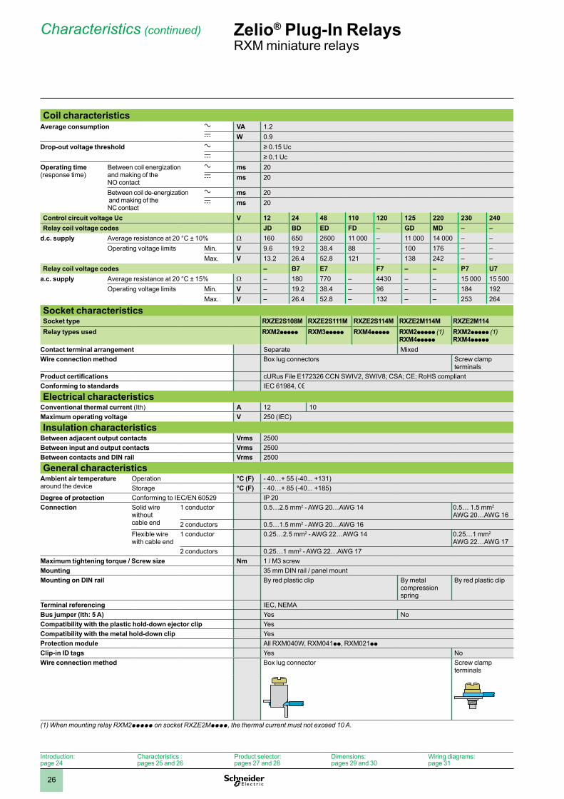
Coil characteristicsAverage consumption a VA 1.2
c W 0.9Drop-out voltage threshold a u 0.15 Uc
c u 0.1 UcOperating time(response time)
Between coil energization and making of the NO contact
a ms 20c ms 20
Between coil de-energization and making of the NC contact
a ms 20c ms 20
Control circuit voltage Uc V 12 24 48 110 120 125 220 230 240Relay coil voltage codes JD BD ED FD – GD MD – –
d.c. supply Average resistance at 20 °C ± 10% W 160 650 2600 11 000 – 11 000 14 000 – –Operating voltage limits Min. V 9.6 19.2 38.4 88 – 100 176 – –
Max. V 13.2 26.4 52.8 121 – 138 242 – –Relay coil voltage codes – B7 E7 F7 – – P7 U7
a.c. supply Average resistance at 20 °C ± 15% W – 180 770 – 4430 – – 15 000 15 500Operating voltage limits Min. V – 19.2 38.4 – 96 – – 184 192
Max. V – 26.4 52.8 – 132 – – 253 264
Socket characteristicsSocket type RXZE2S108M RXZE2S111M RXZE2S114M RXZE2M114M RXZE2M114Relay types used RXM2ppppp RXM3ppppp RXM4ppppp RXM2ppppp (1)
RXM4pppppRXM2ppppp (1)RXM4ppppp
Contact terminal arrangement Separate MixedWire connection method Box lug connectors Screw clamp
terminalsProduct certifications cURus File E172326 CCN SWIV2, SWIV8; CSA; CE; RoHS compliantConforming to standards IEC 61984, e
Electrical characteristicsConventional thermal current (Ith) A 12 10Maximum operating voltage V 250 (IEC)
Insulation characteristicsBetween adjacent output contacts Vrms 2500Between input and output contacts Vrms 2500Between contacts and DIN rail Vrms 2500
General characteristicsAmbient air temperaturearound the device
Operation °C (F) - 40…+ 55 (-40... +131)Storage °C (F) - 40…+ 85 (-40... +185)
Degree of protection Conforming to IEC/EN 60529 IP 20Connection Solid wire
without cable end
1 conductor 0.5…2.5 mm2 - AWG 20…AWG 14 0.5… 1.5 mm2 AWG 20…AWG 16
2 conductors 0.5…1.5 mm2 - AWG 20…AWG 16Flexible wire with cable end
1 conductor 0.25…2.5 mm2 - AWG 22…AWG 14 0.25…1 mm2
AWG 22…AWG 172 conductors 0.25…1 mm2 - AWG 22…AWG 17
Maximum tightening torque / Screw size Nm 1 / M3 screwMounting 35 mm DIN rail / panel mountMounting on DIN rail By red plastic clip By metal
compression spring
By red plastic clip
Terminal referencing IEC, NEMABus jumper (Ith: 5 A) Yes NoCompatibility with the plastic hold-down ejector clip YesCompatibility with the metal hold-down clip YesProtection module All RXM040W, RXM041pp, RXM021pp
Clip-in ID tags Yes NoWire connection method Box lug connector Screw clamp
terminals
(1) When mounting relay RXM2ppppp on socket RXZE2Mpppp, the thermal current must not exceed 10 A.
Zelio® Plug-In RelaysRXM miniature relays
Characteristics (continued)
Introduction:page 24
Characteristics :pages 25 and 26
Product selector:pages 27 and 28
Dimensions:pages 29 and 30
Wiring diagrams:page 31
1
2
3
4
5
6
7
8
9
10
27
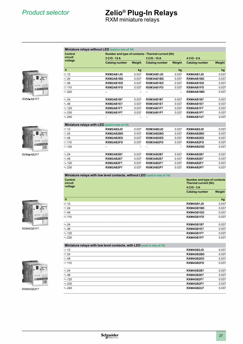
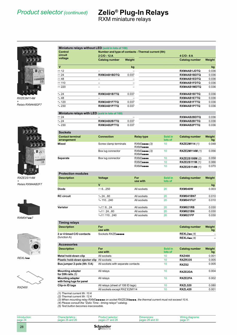
Miniature relays without LED (sold in lots of 10) Control circuit voltage
Number and type of contacts - Thermal current (Ith)2 C/O - 12 A 3 C/O - 10 A 4 C/O - 6 ACatalog number Weight Catalog number Weight Catalog number Weight
V kg kg kgc 12 RXM2AB1JD 0.037 RXM3AB1JD 0.037 RXM4AB1JD 0.037c 24 RXM2AB1BD 0.037 RXM3AB1BD 0.037 RXM4AB1BD 0.037c 48 RXM2AB1ED 0.037 RXM3AB1ED 0.037 RXM4AB1ED 0.037c 110 RXM2AB1FD 0.037 RXM3AB1FD 0.037 RXM4AB1FD 0.037c 220 – – – – RXM4AB1MD 0.037
a 24 RXM2AB1B7 0.037 RXM3AB1B7 0.037 RXM4AB1B7 0.037a 48 RXM2AB1E7 0.037 RXM3AB1E7 0.037 RXM4AB1E7 0.037a 120 RXM2AB1F7 0.037 RXM3AB1F7 0.037 RXM4AB1F7 0.037a 230 RXM2AB1P7 0.037 RXM3AB1P7 0.037 RXM4AB1P7 0.037a 240 – – – – RXM4AB1U7 0.037
Miniature relays with LED (sold in lots of 10) c 12 RXM2AB2JD 0.037 RXM3AB2JD 0.037 RXM4AB2JD 0.037c 24 RXM2AB2BD 0.037 RXM3AB2BD 0.037 RXM4AB2BD 0.037c 48 RXM2AB2ED 0.037 RXM3AB2ED 0.037 RXM4AB2ED 0.037c 110 RXM2AB2FD 0.037 RXM3AB2FD 0.037 RXM4AB2FD 0.037c 125 – – – – RXM4AB2GD 0.037
a 24 RXM2AB2B7 0.037 RXM3AB2B7 0.037 RXM4AB2B7 0.037a 48 RXM2AB2E7 0.037 RXM3AB2E7 0.037 RXM4AB2E7 0.037a 120 RXM2AB2F7 0.037 RXM3AB2F7 0.037 RXM4AB2F7 0.037a 230 RXM2AB2P7 0.037 RXM3AB2P7 0.037 RXM4AB2P7 0.037
Miniature relays with low level contacts, without LED (sold in lots of 10) Control circuit voltage
Number and type of contacts Thermal current (Ith)4 C/O - 3 ACatalog number Weight
V kgc 12 RXM4GB1JD 0.037c 24 RXM4GB1BD 0.037c 48 RXM4GB1ED 0.037c 110 RXM4GB1FD 0.037
a 24 RXM4GB1B7 0.037a 48 RXM4GB1E7 0.037a 120 RXM4GB1F7 0.037a 230 RXM4GB1P7 0.037
Miniature relays with low level contacts, with LED (sold in lots of 10) c 12 RXM4GB2JD 0.037c 24 RXM4GB2BD 0.037c 48 RXM4GB2ED 0.037c 110 RXM4GB2FD 0.037
a 24 RXM4GB2B7 0.037a 48 RXM4GB2E7 0.037a 120 RXM4GB2F7 0.037a 230 RXM4GB2P7 0.037a 240 RXM4GB2U7 0.037
RXMpAB1F7
RXMpAB2F7
RXM4GB1F7
RXM4GB2F7
Zelio® Plug-In RelaysRXM miniature relays
Product selector
1
2
3
4
5
6
7
8
9
10
28
Miniature relays without LED (sold in lots of 100)Control circuit voltage
Number and type of contacts - Thermal current (Ith)2 C/O - 12 A 4 C/O - 6 ACatalog number Weight Catalog number Weight
V kg kgc 12 – – RXM4AB1JDTQ 0.036c 24 RXM2AB1BDTQ 0.037 RXM4AB1BDTQ 0.036c 48 – – RXM4AB1EDTQ 0.036c 110 – – RXM4AB1FDTQ 0.036c 220 – – RXM4AB1MDTQ 0.036
a 24 RXM2AB1B7TQ 0.037 RXM4AB1B7TQ 0.036a 48 – – RXM4AB1E7TQ 0.036a 120 RXM2AB1F7TQ 0.037 RXM4AB1F7TQ 0.036a 230 RXM2AB1P7TQ 0.037 RXM4AB1P7TQ 0.036
Miniature relays with LED (sold in lots of 100)c 24 – – RXM4AB2BDTQ 0.036a 24 RXM2AB2B7TQ 0.037 RXM4AB2B7TQ 0.036a 230 RXM2AB2P7TQ 0.037 RXM4AB2P7TQ 0.036
SocketsContact terminal arrangement
Connection Relay type Sold in lots of
Catalog number Weightkg
Mixed Screw clamp terminals RXM2pppp (3)RXM4pppp
10 RXZE2M114 (1) 0.048
Box lug connector RXM2pppp (3)RXM4pppp
10 RXZE2M114M (1) 0.056
Separate Box lug connector RXM2pppp 10 RXZE2S108M (2) 0.058RXM3pppp 10 RXZE2S111M (1) 0.066RXM4pppp 10 RXZE2S114M (1) 0.070
Protection modulesDescription Voltage For
use withSold in lots of
Catalog number Weight
V kgDiode c 6...250 All sockets 20 RXM040W 0.003
RC circuit a 24...60 All sockets 20 RXM041BN7 0.010a 110...240 All sockets 20 RXM041FU7 0.010
Varistor a/c 6...24 All sockets 20 RXM021RB 0.030a/c 24...60 All sockets 20 RXM021BN 0.030a/c 110...240 All sockets 20 RXM021FP 0.030
Timing relaysDescription For
use withCatalog number Weight
kg2 or 4 timed C/O contacts (function A)
Sockets RXZEppppp REXL2pp (4) –REXL4pp (4) –
AccessoriesDescription For
use withSold in lots of
Catalog number Weightkg
Metal hold-down clip All sockets 10 RXZ400 0.001Plastic hold-down ejector clip All sockets 10 RXZR335 0.005Bus jumper 2-pole (Ith: 5 A) All sockets with separate contacts 10 RXZS2 0.005
Mounting adapter for DIN rails (5)
All relays 10 RXZE2DA 0.004
Mounting adapter with fixing lugs for panel
All relays 10 RXZE2FA 0.002
Clip-in ID tags All relays (sheet of 108 ID tags) 10 RXZL520 0.080All sockets except RXZ E2M114 10 RXZL420 0.001
(1) Thermal current Ith: 10 A(2) Thermal current Ith: 12 A(3) When mounting relay RXM2ppppp on socket RXZE2Mpppp, the thermal current must not exceed 10 A. (4) Please consult the "Zelio Time - timing relays" catalog.(5) Test button becomes inaccessible.
RXZE2M114M + Relais RXM4AB2F7
RXZE2S114M + Relais RXM4AB2F7
RXM041pp7
REXL4pp
RXZ400
Introduction:page 24
Characteristics :pages 25 and 26
Product selector:pages 27 and 28
Dimensions:pages 29 and 30
Wiring diagrams:page 31
Zelio® Plug-In RelaysRXM miniature relays
Product selector (continued)
1
2
3
4
5
6
7
8
9
10
29
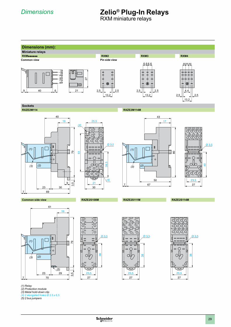
Dimensions (mm):Miniature relaysRXMpppppp RXM2 RXM3 RXM4
Common view Pin side view
SocketsRXZE2M114 RXZE2M114M
Common side view RXZE2S108M RXZE2S111M RXZE2S114M
(1) Relay(2) Protection module(3) Metal hold-down clip(4) 2 elongated holes Ø 3.5 x 6.5(5) 2 bus jumpers
(1)
(2)(3)
25,5
347
A214
A113
246
448
145
12
1
11
9
21
10
31
11
41
12
22
2
32
3
42
4
(4)19
40
309
232130
697
39,5
61
3,5
79
(4)
17
43
23,550
27677
40
80
44
8
34
7
24
6
14
5
42
4
32
3
22
2
12
1
A1
13
A2
1441
12
31
11
21
10
11
9
(3)
(1)
(2)
19
61
2923
707
3,5
79
(3) (2)
(1)
(5)23,5
27
38
41
12
11
9
44
8
14
5
A1
13
A2
14
42
4
12
1
23,5
27
38
319
346
A1
13
A2
14
32
3
218
245
22
2
117
144
12
1
23,5
27
38
41
12
31
11
21
10
11
944
8
34
7
24
6
14
542
4
32
3
22
2
12
1
A1
13
A2
14
Zelio® Plug-In RelaysRXM miniature relays
Dimensions
40 21
27
9 6 2,5 2,521
6,3
6,3
4,2
4,2
13,22,5 2,5 4,4
21
13,2
6,6 6,6
2,5 2,513,2
4,4 4,44,4
1
2
3
4
5
6
7
8
9
10
30
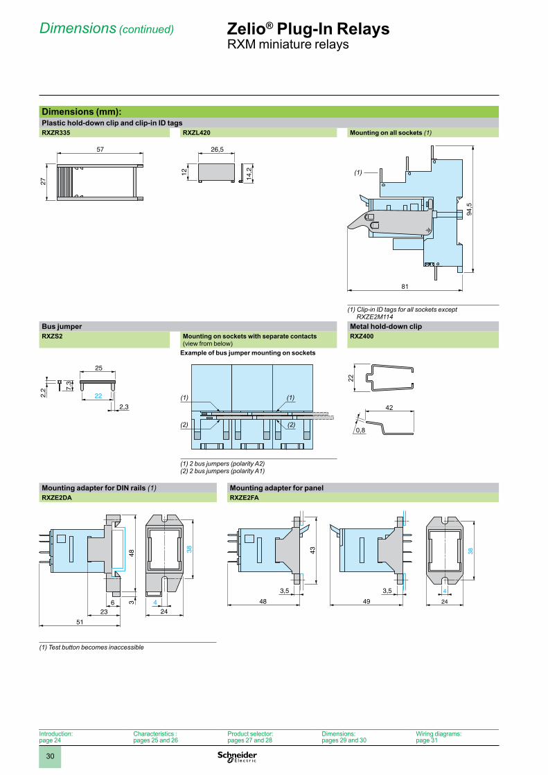
Dimensions (mm): Plastic hold-down clip and clip-in ID tagsRXZR335 RXZL420 Mounting on all sockets (1)
(1) Clip-in ID tags for all sockets except RXZE2M114
Bus jumper Metal hold-down clipRXZS2 Mounting on sockets with separate contacts
(view from below)RXZ400
Example of bus jumper mounting on sockets
(1) 2 bus jumpers (polarity A2)(2) 2 bus jumpers (polarity A1)
Mounting adapter for DIN rails (1) Mounting adapter for panelRXZE2DA RXZE2FA
(1) Test button becomes inaccessible
57
27
12
14,2
26,5
81
94,5
(1)
2,2 7,
3
25
22
2,3(1)(1)
(2)(2)
22
42
0,8
38
6 424
348
23
51
48 49
3,5
43 38
4
24
3,5
Introduction:page 24
Characteristics :pages 25 and 26
Product selector:pages 27 and 28
Dimensions:pages 29 and 30
Wiring diagrams:page 31
Zelio® Plug-In RelaysRXM miniature relays
Dimensions (continued)
1
2
3
4
5
6
7
8
9
10
31
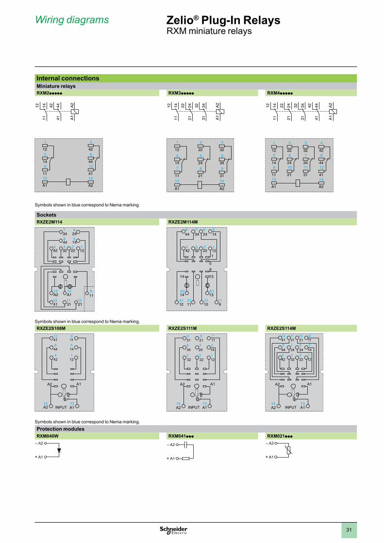
Internal connectionsMiniature relaysRXM2ppppp RXM3ppppp RXM4ppppp
Symbols shown in blue correspond to Nema marking.
Sockets RXZE2M114 RXZE2M114M
347
14A2 A1
13
246
844 14
5
1
119
2110
3111
4112
2312223242
4
448
347
246
145
12312223242
4
14A2 A1
13
14 13
1021
9
9
5
1
111131
1241
Symbols shown in blue correspond to Nema marking.RXZE2S108M RXZE2S111M RXZE2S114M
1241 11
9
844 14
5
A1
13
A2
A1A214
424
121
INPUT
A1
13
A2
A1A214
319
346
3
218
245
2
117
144
32 22 121
INPUT
A1
13
A2
A1A214
4112
3111
2110
119
448
347
246
145
424
323
222
121
INPUT
Symbols shown in blue correspond to Nema marking.Protection modules RXM040W RXM041ppp RXM021ppp
– A2
+ A1
– A2
+ A1
– A2
+ A1
A2
A1
414442
111412
1
125
149
11
4
428
4412
4113
A1
14
A2
A2
A1
313432
212422
111412
1
12
4
147
11
2
22
5
248
21
3
32
6
349
3113
A1
14
A2
A2
A1
414442
212422
313432
111412
1
125
149
11
4
428
4412
41
2
226
2410
21
3
327
3411
3113
A1
14
A2
Zelio® Plug-In RelaysRXM miniature relays
Wiring diagrams
1
2
3
4
5
6
7
8
9
10
32
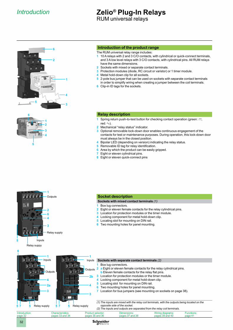
Introduction of the product range The RUM universal relay range includes: 1 10 A relays with 2 and 3 C/O contacts, with cylindrical or quick-connect terminals,
and 3 A low level relays with 3 C/O contacts, with cylindrical pins. All RUM relays have the same dimensions.
2 Sockets with mixed or separate contact terminals.3 Protection modules (diode, RC circuit or varistor) or 1 timer module. 4 Metal hold-down clip for all sockets.5 2-pole bus jumper that can be used on sockets with separate contact terminals
in order to simplify wiring when creating a jumper between the coil terminals.6 Clip-in ID tags for the sockets.
Relay description 1 Spring return push-to-test button for checking contact operation (green: c,
red: a). 2 Mechanical “relay status” indicator.3 Optional removable lock-down door enables continuous engagement of the
contacts for test or maintenance purposes. During operation, this lock-down door must always be in the closed position.
4 Bipolar LED (depending on version) indicating the relay status.5 Removable ID tag for relay identification.6 Area by which the product can be easily gripped.7 Eight or eleven cylindrical pins. 8 Eight or eleven quick-connect pins
Socket description Sockets with mixed contact terminals (1)
1 Box lug connectors. 2 Eight or eleven female contacts for the relay cylindrical pins.3 Location for protection modules or the timer module.4 Locking component for metal hold-down clip.5 Locating slot for mounting on DIN rail.6 Two mounting holes for panel mounting.
Sockets with separate contact terminals (2)1 Box lug connectors. 2 a Eight or eleven female contacts for the relay cylindrical pins.
b Eleven female contacts for the relay flat pins.3 Location for protection modules or the timer module.4 Locking component for metal hold-down clip.5 Locating slot for mounting on DIN rail.6 Two mounting holes for panel mounting.7 Location for bus jumpers (see mounting on sockets on page 38).
(1) The inputs are mixed with the relay coil terminals, with the outputs being located on the opposite side of the socket.
(2) The inputs and outputs are separated from the relay coil terminals.
6
5
2
1
3
4
12
34
5
6
1
2
3
4
5
6
Outputs
Relay supply
Inputs
Relay suppy
16
2a
3
4
5 7
Inputs
Outputs
Relay supply5
1
2b
3
4
5 7
Inputs
Outputs
Relay supply5
Zelio® Plug-In RelaysRUM universal relays
Introduction
Introduction:page 32
Characteristics:pages 33 and 34
Product selector:pages 35 and 36
Dimensions:pages 37 and 38
Wiring diagrams:pages 39 and 40
Functions:page 41
1
2
3
4
5
6
7
8
9
10
33
General characteristicsConforming to standards IEC/EN 61810-1 (iss. 2), UL 508, CSA C22-2 n° 14Product certifications cULus File E164862 CCN NLDX, NLDX7; cURus File E164862 CCN NLDX2, NLDX8;
CSA; CE; RoHS compliantAmbient air temperature around the device
Storage °C (F) - 40… + 85 (-40... +185)Operation °C (F) - 40… + 55 (-40... +131)
Vibration resistanceconforming to IEC/EN 60068-2-6
In operation 3 gn (10...150 Hz/± 1 mm / 5g/5 cycles)Not operating 4 gn (10...150 Hz/± 1 mm / 5g/5 cycles)
Degree of protection Conforming to IEC/EN 60529 IP 40Shock resistanceconforming to IEC/EN 60068-2-27
Opening 10 gnClosing 10 gn
Protection category RT IMounting position Any
Insulation characteristicsRated insulation voltage (Ui) Conforming to IEC/EN 60947 V 250 (IEC), 300 (UL, CSA)Rated impulse withstand voltage (Uimp) kV 4 (1.2/50 ms)Dielectric strength(rms voltage)
Between coil and contact a V 1550Between poles a V 1550Between contacts a V 1500
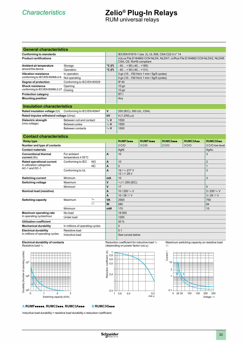
Contact characteristicsRelay type RUMF2ppp RUMF3ppp RUMC2ppp RUMC3App RUMC3Gpp
Number and type of contacts 2 C/O 3 C/O 2 C/O 3 C/O 3 C/O low levelContact materials . AgNi AgAuConventional thermal current (Ith)
For ambient temperature y 55°C
A 10 3
Rated operational current in utilization categories AC-1 and DC-1
Conforming to IEC NO A 10 2NC A 5 1
Conforming to UL A 16 / a 277 V 12 / c 28 V
3
Switching current Minimum mA 10 3Switching voltage Maximum V a/c 250 (IEC)
Minimum V 17 5Nominal load (resistive) A 10 / 250 a V 3 / 250 a V
A 10 / 28 c V 3 / 28 c VSwitching capacity Maximum a VA 2500 750
c W 280 84Minimum mW 170 15
Maximum operating rateIn operating cycles/hour
No-load 18 000Under load 1200
Utilization coefficient 20 %Mechanical durability In millions of operating cycles 5Electrical durability In millions of operating cycles
Resistive load 0.1Inductive load See curves below
Electrical durability of contactsResistive load a
Reduction coefficient for inductive load a (depending on power factor cos j)
Maximum switching capacity on resistive load c
A RUMFppppp, RUMC2ppp, RUMC3Appp B RUMC3Gppp
Inductive load durability = resistive load durability x reduction coefficient.
105
106
107
2 30 1
AB
Dur
abili
ty (N
umbe
r of o
pera
ting
cycl
es)
Switching capacity (kVA)
0,3
0,5
0,61 0,4 0,2
0,4
0,60,8
1
Red
uctio
n c
oeffi
cien
t (A
)
0,1
1
200 2500 50 100 150
10
3
B A
28
Cur
rent
c
Voltage c
Zelio® Plug-In RelaysRUM universal relays
Characteristics
1
2
3
4
5
6
7
8
9
10
34
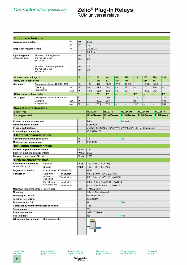
Coil characteristicsAverage consumption a VA 2...3
c W 1.4Drop-out voltage threshold a u 0.15 Uc
c u 0.1 UcOperating time(response time)
Between coil energization and making of the NO contact
a ms 20c ms 20
Between coil de-energization and making of the NC contact
a ms 20c ms 20
Control circuit voltage Uc V 12 24 48 60 110 120 125 220 230Relay coil voltage codes JD BD ED ND FD – GD MD –
d.c. supply Average resistance at 20 °C ± 10% W 120 470 1800 2790 10 000 – 10 000 3700 –Operating voltage limits
Min. V 9.6 19.2 38.4 48 88 – 100 176 –Max. V 13.2 26.4 52.8 66 121 – 137.5 242 –
Relay control voltage codes – B7 E7 – – F7 – – P7a.c. supply Average resistance at 20 °C ± 15% W – 72 290 – – 1700 – – 7200
Operating voltage limits
Min. V – 19.2 38.4 – – 96 – – 184Max. V – 26.4 52.8 – – 132 – – 253
Socket characteristicsSocket type RUZC2M RUZC3M RUZSC2M RUZSC3M RUZSF3MRelay types used RUMC2ppppp RUMC3ppppp RUMC2ppppp RUMC3ppppp RUMFppppp
Contact terminal arrangement Mixed SeparateWire connection method ConnectorProduct certifications cURus File E172326 CCN SWIV2, SWIV8; CSA; CE; RoHS compliantConforming to standards IEC 61984, e
Electrical characteristicsConventional thermal current (Ith) A 10 12Maximum operating voltage V 250 (IEC)
Insulation characteristicsBetween adjacent output contacts Vrms 2500Between input and output contacts Vrms 2500Between contacts and DIN rail Vrms 2500
General characteristicsAmbient air temperaturearound the device
Operation °C (F) - 40…+ 55 (-40... +131)Storage °C (F) - 40…+ 85 (-40.... +185)
Degree of protection Conforming to IEC/EN 60529 IP 20Connection Solid wire
without cable end
1 conductor 0.5…2.5 mm2 - AWG 20…AWG 142 conductors 0.5…1.5 mm2 - AWG 20…AWG 16
Flexible wire with cable end
1 conductor 0.25…2.5 mm2 - AWG 22…AWG 142 conductors 0.25…1 mm2 - AWG 22…AWG 17
Maximum tightening torque / Screw size Nm 1 / M3.3 screwMounting 35 mm DIN rail / panelMounting on DIN rail By red plastic clipTerminal referencing IEC, NEMABus jumper (Ith: 5 A) No YesCompatibility with the metal hold-down clip YesTimer module YesProtection module All RUW24ppp
Clip-in ID tags No YesWire connection method Box lug connector
Zelio® Plug-In RelaysRUM universal relays
Characteristics (continued)
Introduction:page 32
Characteristics:pages 33 and 34
Product selector:pages 35 and 36
Dimensions:pages 37 and 38
Wiring diagrams:pages 39 and 40
Functions:page 41
1
2
3
4
5
6
7
8
9
10
35
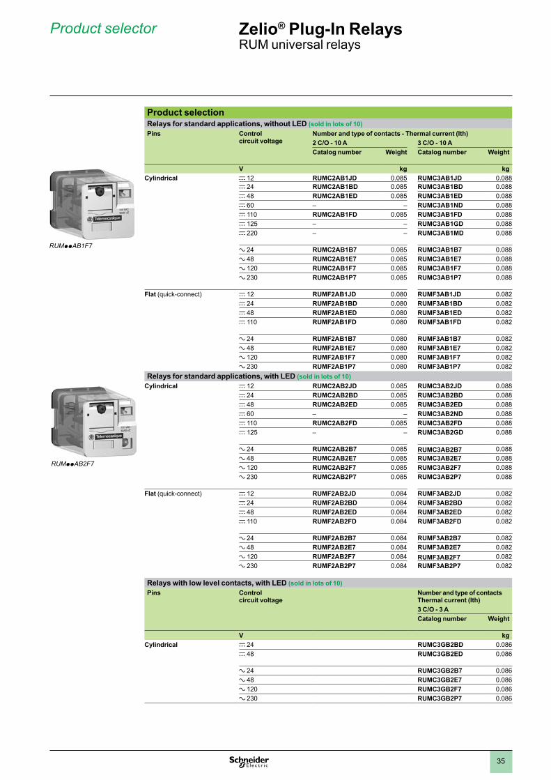
Product selectionRelays for standard applications, without LED (sold in lots of 10)Pins Control
circuit voltageNumber and type of contacts - Thermal current (Ith)2 C/O - 10 A 3 C/O - 10 ACatalog number Weight Catalog number Weight
V kg kgCylindrical c 12 RUMC2AB1JD 0.085 RUMC3AB1JD 0.088
c 24 RUMC2AB1BD 0.085 RUMC3AB1BD 0.088c 48 RUMC2AB1ED 0.085 RUMC3AB1ED 0.088c 60 – – RUMC3AB1ND 0.088c 110 RUMC2AB1FD 0.085 RUMC3AB1FD 0.088c 125 – – RUMC3AB1GD 0.088c 220 – – RUMC3AB1MD 0.088
a 24 RUMC2AB1B7 0.085 RUMC3AB1B7 0.088a 48 RUMC2AB1E7 0.085 RUMC3AB1E7 0.088a 120 RUMC2AB1F7 0.085 RUMC3AB1F7 0.088a 230 RUMC2AB1P7 0.085 RUMC3AB1P7 0.088
Flat (quick-connect) c 12 RUMF2AB1JD 0.080 RUMF3AB1JD 0.082c 24 RUMF2AB1BD 0.080 RUMF3AB1BD 0.082c 48 RUMF2AB1ED 0.080 RUMF3AB1ED 0.082c 110 RUMF2AB1FD 0.080 RUMF3AB1FD 0.082
a 24 RUMF2AB1B7 0.080 RUMF3AB1B7 0.082a 48 RUMF2AB1E7 0.080 RUMF3AB1E7 0.082a 120 RUMF2AB1F7 0.080 RUMF3AB1F7 0.082a 230 RUMF2AB1P7 0.080 RUMF3AB1P7 0.082
Relays for standard applications, with LED (sold in lots of 10)Cylindrical c 12 RUMC2AB2JD 0.085 RUMC3AB2JD 0.088
c 24 RUMC2AB2BD 0.085 RUMC3AB2BD 0.088c 48 RUMC2AB2ED 0.085 RUMC3AB2ED 0.088c 60 – – RUMC3AB2ND 0.088c 110 RUMC2AB2FD 0.085 RUMC3AB2FD 0.088c 125 – – RUMC3AB2GD 0.088
a 24 RUMC2AB2B7 0.085 RUMC3AB2B7 0.088a 48 RUMC2AB2E7 0.085 RUMC3AB2E7 0.088a 120 RUMC2AB2F7 0.085 RUMC3AB2F7 0.088a 230 RUMC2AB2P7 0.085 RUMC3AB2P7 0.088
Flat (quick-connect) c 12 RUMF2AB2JD 0.084 RUMF3AB2JD 0.082c 24 RUMF2AB2BD 0.084 RUMF3AB2BD 0.082c 48 RUMF2AB2ED 0.084 RUMF3AB2ED 0.082c 110 RUMF2AB2FD 0.084 RUMF3AB2FD 0.082
a 24 RUMF2AB2B7 0.084 RUMF3AB2B7 0.082a 48 RUMF2AB2E7 0.084 RUMF3AB2E7 0.082a 120 RUMF2AB2F7 0.084 RUMF3AB2F7 0.082a 230 RUMF2AB2P7 0.084 RUMF3AB2P7 0.082
Relays with low level contacts, with LED (sold in lots of 10)Pins Control
circuit voltageNumber and type of contacts Thermal current (Ith)3 C/O - 3 ACatalog number Weight
V kgCylindrical c 24 RUMC3GB2BD 0.086
c 48 RUMC3GB2ED 0.086
a 24 RUMC3GB2B7 0.086a 48 RUMC3GB2E7 0.086a 120 RUMC3GB2F7 0.086a 230 RUMC3GB2P7 0.086
Zelio® Plug-In RelaysRUM universal relays
Product selector
RUMppAB1F7
RUMppAB2F7
1
2
3
4
5
6
7
8
9
10
36
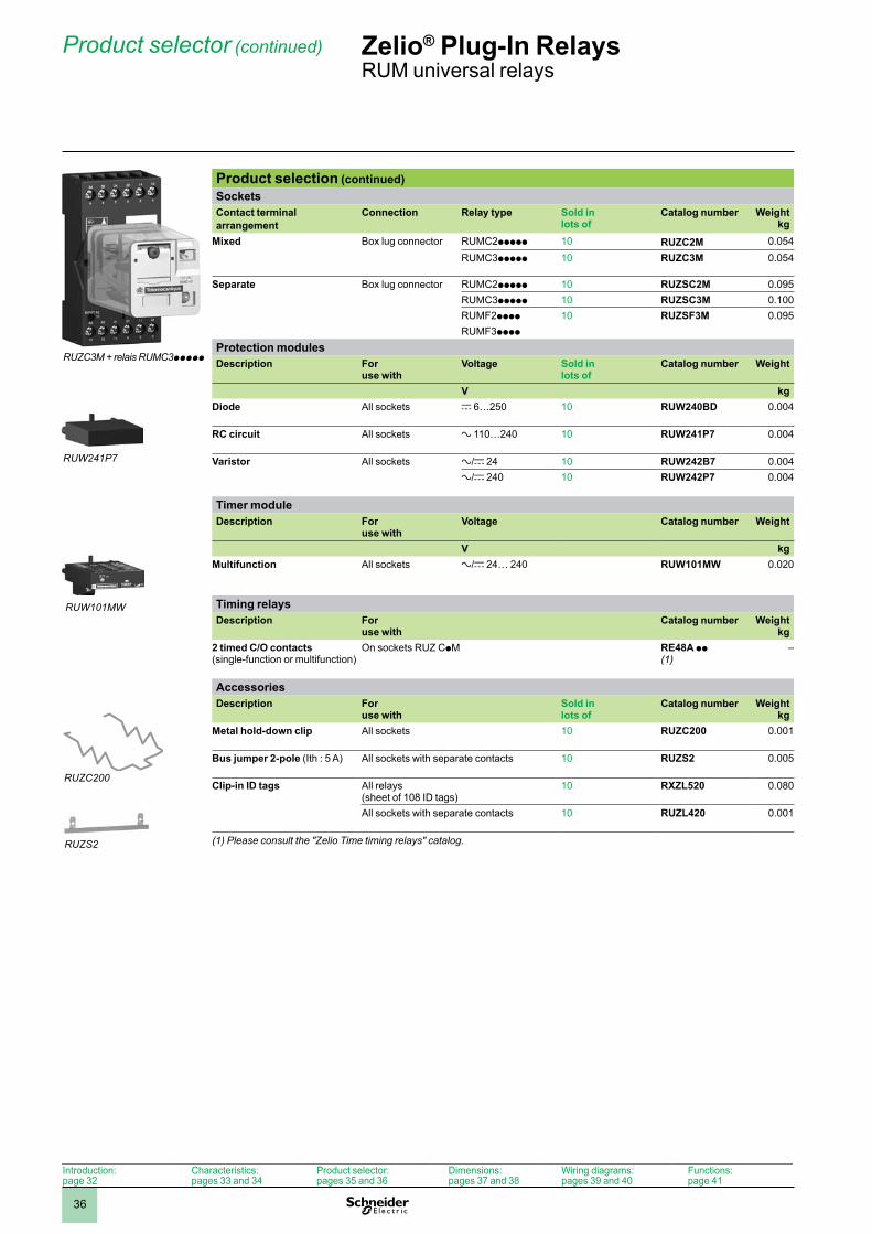
Product selection (continued)SocketsContact terminal arrangement
Connection Relay type Sold in lots of
Catalog number Weightkg
Mixed Box lug connector RUMC2ppppp 10 RUZC2M 0.054RUMC3ppppp 10 RUZC3M 0.054
Separate Box lug connector RUMC2ppppp 10 RUZSC2M 0.095RUMC3ppppp 10 RUZSC3M 0.100RUMF2pppp 10 RUZSF3M 0.095RUMF3pppp
Protection modulesDescription For
use withVoltage Sold in
lots ofCatalog number Weight
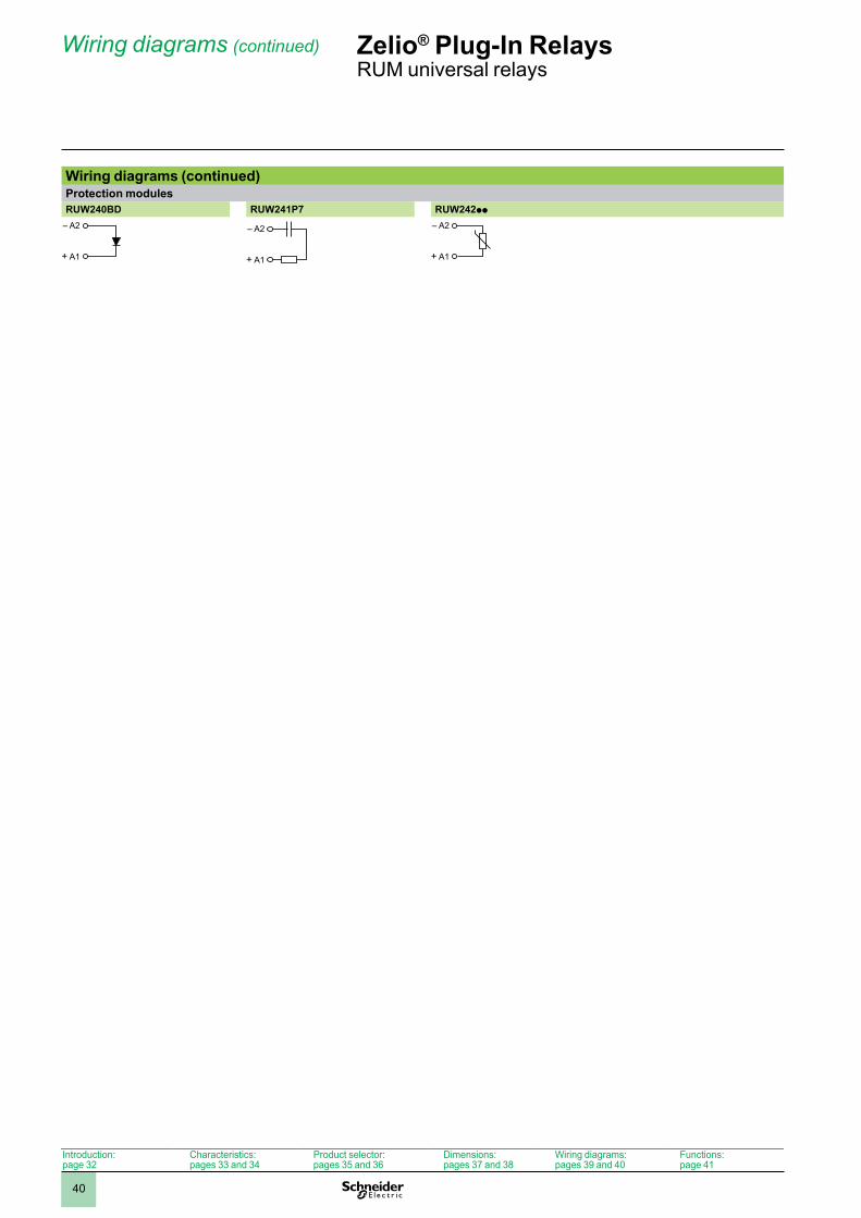
V kgDiode All sockets c 6…250 10 RUW240BD 0.004
RC circuit All sockets a 110…240 10 RUW241P7 0.004
Varistor All sockets a/c 24 10 RUW242B7 0.004a/c 240 10 RUW242P7 0.004
Timer moduleDescription For
use withVoltage Catalog number Weight
V kgMultifunction All sockets a/c 24… 240 RUW101MW 0.020
Timing relaysDescription For
use withCatalog number Weight
kg2 timed C/O contacts (single-function or multifunction)
On sockets RUZ CpM RE48A pp (1)
–
AccessoriesDescription For
use withSold in lots of
Catalog number Weightkg
Metal hold-down clip All sockets 10 RUZC200 0.001
Bus jumper 2-pole (Ith : 5 A) All sockets with separate contacts 10 RUZS2 0.005
Clip-in ID tags All relays(sheet of 108 ID tags)
10 RXZL520 0.080
All sockets with separate contacts 10 RUZL420 0.001
(1) Please consult the "Zelio Time timing relays" catalog.
Zelio® Plug-In RelaysRUM universal relays
Product selector (continued)
RUZC200
RUW101MW
RUW241P7
RUZC3M + relais RUMC3ppppp
RUZS2
Introduction:page 32
Characteristics:pages 33 and 34
Product selector:pages 35 and 36
Dimensions:pages 37 and 38
Wiring diagrams:pages 39 and 40
Functions:page 41
1
2
3
4
5
6
7
8
9
10
37
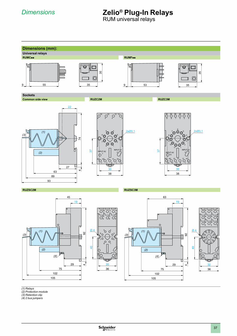
Dimensions (mm):Universal relaysRUMCpp RUMFpp
SocketsCommon side view RUZC2M RUZC3M
38
37
30
24
6
27
A2
7
A1
2
11
1
21
8
A2
7
INPUT A2INPUT A1
22
5
12
4
1
4
2
3
8
5
7
6
14
3
38
37
30
A2
10
A2
10
31
11
21
6
11
1
A1
2
34
9
32
8
24
7
22
5
14
3
12
4
210
1
6
2
5
3
4
1110
7
9
8
INPUT A2INPUT A1
RUZSC2M RUZSC3M
(1) Relays(2) Protection module(3) Retention clip(4) 2 bus jumpers
55 35
35
9
35
35539
74
27
22
6389
93
(1)(3)
(2)
4
3675
102
105
29
924
40
30
19
45
225
111
124
246
1
4
2
3
8
5
7
6
A27
A12
218
143
Ø 4
(4)
(1)(3)
(2)
3675
102
105
29
924
40
32
63
3111
216
111
32
8
22
5
12
4
349
21
5
34
11
7 6
1098
A210
A12
247
143
Ø 4(1)(3)
(2)
19
(4)
Zelio® Plug-In RelaysRUM universal relays
Dimensions
1
2
3
4
5
6
7
8
9
10
38
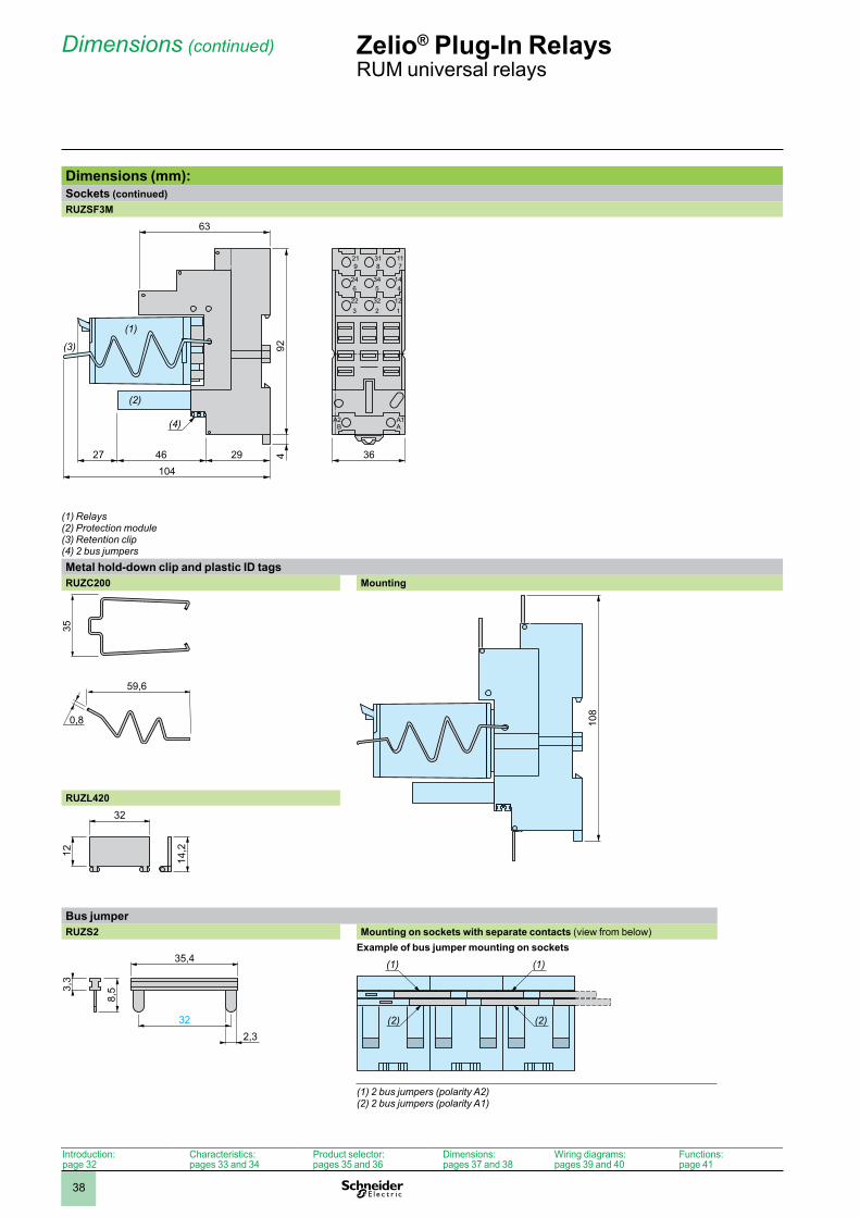
Dimensions (mm): Sockets (continued)RUZSF3M
36104
294627
924
63
219
318
117
223
322
121
246
A2B
A1A
345
144
(1)
(3)
(2)
(4)
(1) Relays(2) Protection module(3) Retention clip (4) 2 bus jumpersMetal hold-down clip and plastic ID tagsRUZC200 Mounting
0,8
59,6
35
108
RUZL420
12
14,2
32
Bus jumperRUZS2 Mounting on sockets with separate contacts (view from below)
Example of bus jumper mounting on sockets
(2)(2)
(1)(1)
(1) 2 bus jumpers (polarity A2)(2) 2 bus jumpers (polarity A1)
3,3
8,5
35,4
322,3
Dimensions (continued) Zelio® Plug-In RelaysRUM universal relays
Introduction:page 32
Characteristics:pages 33 and 34
Product selector:pages 35 and 36
Dimensions:pages 37 and 38
Wiring diagrams:pages 39 and 40
Functions:page 41
1
2
3
4
5
6
7
8
9
10
39
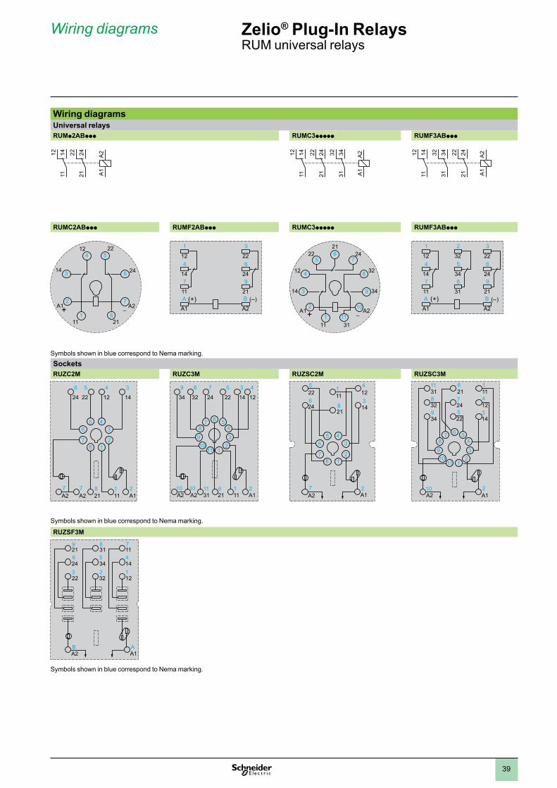
Wiring diagrams Zelio® Plug-In RelaysRUM universal relays
Wiring diagramsUniversal relaysRUMp2ABppp RUMC3ppppp RUMF3ABppp
RUMC2ABppp RUMF2ABppp RUMC3ppppp RUMF3ABppp
Symbols shown in blue correspond to Nema marking.SocketsRUZC2M RUZC3M RUZSC2M RUZSC3M
24
6
A27
A12
111
218
A27
22
5
12
4
1
4
2
3
8
5
7
6
14
3
32
8
34
9
A210
A12
111
3111
216
A210
24
7
22
5
14
3
12
4
1
6
2
5
34
1110
7
98
225
111
124
624 8
21
314
A27
A12
1
4
2
3
8
5
7
6
3111
216
111
328
225
124
349
247
143
1
6
2
5
34
1110
7
98
A210
A12
Symbols shown in blue correspond to Nema marking.
RUZSF3M
219
318
117
223
322
121
246
345
144
A2B
A1A
Symbols shown in blue correspond to Nema marking.
1211
14 2221
24 A2
A1
1211
14 2221
24 3231
34 A2
A1
1211
14 2221
243231
34 A2
A1
3
7
1 8
6
2
4 5
A1 A2
2111
14 24
2212
+
1
124
147
11
3
226
249
21A
A1
B
A2(+) ( )
4
3 9
2
1 11
10
8
56
7
A1 A2
14 34
3111
12 32
22 2421
+
(+)
1
124
147
11
2
325
348
31
3
226
249
21A
A1
B
A2( )
1
2
3
4
5
6
7
8
9
10
40
Wiring diagrams (continued)Protection modulesRUW240BD RUW241P7 RUW242pp
– A2
+ A1
– A2
+ A1
– A2
+ A1
Zelio® Plug-In RelaysRUM universal relays
Wiring diagrams (continued)
Introduction:page 32
Characteristics:pages 33 and 34
Product selector:pages 35 and 36
Dimensions:pages 37 and 38
Wiring diagrams:pages 39 and 40
Functions:page 41
1
2
3
4
5
6
7
8
9
10
41
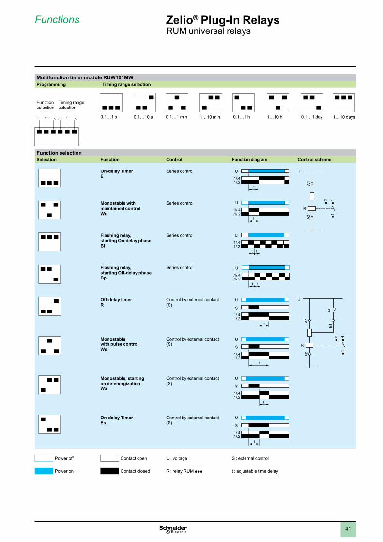
Multifunction timer module RUW101MWProgramming Timing range selection
Function selectionSelection Function Control Function diagram Control scheme
On-delay TimerE
Series control
Monostable with maintained controlWu
Series control
Flashing relay, starting On-delay phaseBi
Series control
Flashing relay, starting Off-delay phaseBp
Series control
Off-delay timerR
Control by external contact (S)
Monostable with pulse controlWs
Control by external contact (S)
Monostable, starting on de-energizationWa
Control by external contact (S)
On-delay TimerEs
Control by external contact (S)
Power off Contact open U : voltage S : external control
Power on Contact closed R : relay RUM ppp t : adjustable time delay
Functionselection
Timing rangeselection
0.1…1 s 0.1…10 s 0.1…1 min 1…10 min 0.1…1 h 1…10 h 0.1…1 day 1…10 days
t
U
.1/.4
.1/.2 A1
A2
U
RU
.1/.4
.1/.2t
U
.1/.4
.1/.2t t
U
.1/.4
.1/.2t t
S
U
.1/.4
.1/.2t
B1
A1
A2
U
R
S
S
U
.1/.4
.1/.2t
S
U
.1/.4
.1/.2t
S
U
.1/.4
.1/.2t
Zelio® Plug-In RelaysRUM universal relays
Functions
1
2
3
4
5
6
7
8
9
10
42
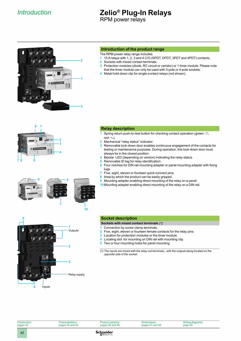
Introduction of the product range The RPM power relay range includes: 1 15 A relays with 1, 2, 3 and 4 C/O (SPDT, DPDT, 3PDT and 4PDT) contacts.2 Sockets with mixed contact terminals.3 Protection modules (diode, RC circuit or varistor) or 1 timer module. Please note
that the timer module can only be used with 3-pole or 4-pole sockets.4 Metal hold-down clip for single-contact relays (not shown).
Relay description 1 Spring return push-to-test button for checking contact operation (green: c,
red: a). 2 Mechanical “relay status” indicator.3 Removable lock-down door enables continuous engagement of the contacts for
testing or maintenance purposes. During operation, this lock-down door must always be in the closed position.
4 Bipolar LED (depending on version) indicating the relay status.5 Removable ID tag for relay identification.6 Four notches for DIN rail mounting adapter or panel mounting adapter with fixing
lugs.7 Five, eight, eleven or fourteen quick-connect pins.8 Area by which the product can be easily gripped.9 Mounting adapter enabling direct mounting of the relay on a panel.10 Mounting adapter enabling direct mounting of the relay on a DIN rail.
Socket descriptionSockets with mixed contact terminals (1)
1 Connection by screw clamp terminals. 2 Five, eight, eleven or fourteen female contacts for the relay pins.3 Location for protection modules or the timer module.4 Locating slot for mounting on DIN rail with mounting clip.5 Two or four mounting holes for panel mounting.
(1) The inputs are mixed with the relay coil terminals,, with the outputs being located on the opposite side of the socket.
9
7
Zelio® Plug-In Relays RPM power relays
2
1
3
2
7
3
56
8
4
1
9
10
1
5
2
3
Outputs
4 Inputs
Relay supply
Introduction:pages 42
Characteristics:pages 43 and 44
Product selector:pages 45 and 46
Dimensions:pages 47 and 48
Wiring diagrams:page 49
Introduction
1
2
3
4
5
6
7
8
9
10
43
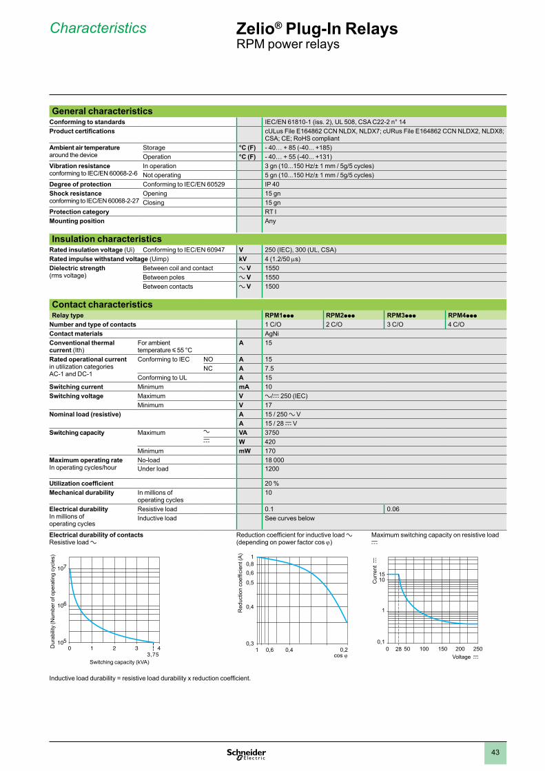
General characteristicsConforming to standards IEC/EN 61810-1 (iss. 2), UL 508, CSA C22-2 n° 14Product certifications cULus File E164862 CCN NLDX, NLDX7; cURus File E164862 CCN NLDX2, NLDX8;
CSA; CE; RoHS compliantAmbient air temperature around the device
Storage °C (F) - 40… + 85 (-40... +185)Operation °C (F) - 40… + 55 (-40... +131)
Vibration resistanceconforming to IEC/EN 60068-2-6
In operation 3 gn (10...150 Hz/± 1 mm / 5g/5 cycles)Not operating 5 gn (10...150 Hz/± 1 mm / 5g/5 cycles)
Degree of protection Conforming to IEC/EN 60529 IP 40Shock resistanceconforming to IEC/EN 60068-2-27
Opening 15 gnClosing 15 gn
Protection category RT IMounting position Any
Insulation characteristicsRated insulation voltage (Ui) Conforming to IEC/EN 60947 V 250 (IEC), 300 (UL, CSA)Rated impulse withstand voltage (Uimp) kV 4 (1.2/50 ms)Dielectric strength(rms voltage)
Between coil and contact a V 1550Between poles a V 1550Between contacts a V 1500
Contact characteristicsRelay type RPM1ppp RPM2ppp RPM3ppp RPM4ppp
Number and type of contacts 1 C/O 2 C/O 3 C/O 4 C/OContact materials AgNiConventional thermal current (Ith)
For ambient temperature y 55 °C
A 15
Rated operational current in utilization categories AC-1 and DC-1
Conforming to IEC NO A 15NC A 7.5
Conforming to UL A 15Switching current Minimum mA 10Switching voltage Maximum V a/c 250 (IEC)
Minimum V 17Nominal load (resistive) A 15 / 250 a V
A 15 / 28 c VSwitching capacity Maximum a VA 3750
c W 420Minimum mW 170
Maximum operating rateIn operating cycles/hour
No-load 18 000Under load 1200
Utilization coefficient 20 %Mechanical durability In millions of
operating cycles10
Electrical durability In millions of operating cycles
Resistive load 0.1 0.06Inductive load See curves below
Electrical durability of contactsResistive load a
Reduction coefficient for inductive load a (depending on power factor cos j)
Maximum switching capacity on resistive load c
Inductive load durability = resistive load durability x reduction coefficient.
10520 1 43
3,75
106
107
Dur
abili
ty (N
umbe
r of o
pera
ting
cycl
es)
Switching capacity (kVA)
0,3
0,5
0,61 0,4 0,2
0,4
0,60,8
1
Red
uctio
n co
effic
ient
(A)
0,1
1
200 2500 50 100 150
1015
28
Cur
rent
c
Voltage c
Characteristics Zelio® Plug-In Relays RPM power relays
1
2
3
4
5
6
7
8
9
10
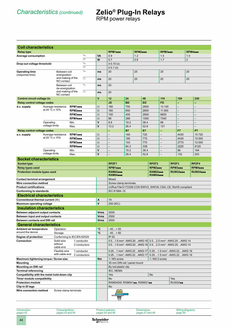
44
Coil characteristicsRelay type RPM1ppp RPM2ppp RPM3ppp RPM4ppp
Average consumption a VA 0.9 1.2 1.5 1.5c W 0.7 0.9 1.7 2
Drop-out voltage threshold a u 0.15 Ucc u 0.1 Uc
Operating time(response time)
Between coil energization and making of the NO contact
a ms 20 25 25 20
c ms 20 25 25 20
Between coil de-energization and making of the NC contact
a ms 20
c ms 20
Control circuit voltage Uc V 12 24 48 110 120 230Relay control voltage codes JD BD ED FD – –
d.c. supply Average resistance at 20 °C ± 10%
RPM1ppp W 180 750 2600 13 100 – –RPM2ppp W 160 650 2600 11 000 – –RPM3ppp W 100 400 2600 8600 – –RPM4ppp W 96 388 1550 7340 – –
Operating voltage limits
Min. V 9.6 19.2 38.4 88 – –Max. V 13.2 26.4 52.8 121 – –
Relay control voltage codes – B7 E7 – F7 P7a.c. supply Average resistance
at 20 °C ± 15%RPM1ppp W – 160 720 – 4430 15 720RPM2ppp W – 180 770 – 4430 15 000RPM3ppp W – 103 770 – 2770 12 000RPM4ppp W – 84.3 338 – 2220 9120
Operating voltage limits
Min. V – 19.2 38.4 – 96 184Max. V – 26.4 52.8 – 132 253
Socket characteristicsSocket type RPZF1 RPZF2 RPZF3 RPZF4Relay types used RPM1ppp RPM2ppp RPM3ppp RPM4ppp
Protection module types used RXM02pppRXM04ppp
RXM02pppRXM04ppp
RUW24ppp RUW24ppp
Contact terminal arrangement MixedWire connection method Screw clamp terminalsProduct certifications cURus File E172326 CCN SWIV2, SWIV8; CSA; CE; RoHS compliantConforming to standards IEC 61984, e
Electrical characteristicsConventional thermal current (Ith) A 16Maximum operating voltage V 250 (IEC)
Insulation characteristicsBetween adjacent output contacts Vrms 2500Between input and output contacts Vrms 2500Between contacts and DIN rail Vrms 2500
General characteristicsAmbient air temperaturearound the device
Operation °C - 40…+ 55Storage °C - 40…+ 85
Degree of protection Conforming to IEC/EN 60529 IP 20Connection Solid wire
without cable end
1 conductor 0.5…1.5 mm2 - AWG 20…AWG 16 0.5…2.5 mm2 - AWG 20…AWG 142 conductors 0.5…1.5 mm2 - AWG 20…AWG 16 0.5…2.5 mm2 - AWG 20…AWG 14
Flexible wire with cable end
1 conductor 0.25…1 mm2 - AWG 22…AWG 17 0.25…1.5 mm2 - AWG 22…AWG 162 conductors 0.25…1 mm2 - AWG 22…AWG 17 0.25…1.5 mm2 - AWG 22…AWG 16
Maximum tightening torque / Screw size Nm 1 / M3 screw 1 / M3.5 screwMounting 35 mm DIN rail / panel mountMounting on DIN rail By red plastic clipTerminal referencing IEC, NEMACompatibility with the metal hold-down clip Yes NoTimer module compatibility No YesProtection module RXM040W, RXM041pp, RXM021pp RUW24pp
Clip-in ID tags NoWire connection method Screw clamp terminals
Characteristics (continued) Zelio® Plug-In Relays RPM power relays
Introduction:pages 42
Characteristics:pages 43 and 44
Product selector:pages 45 and 46
Dimensions:pages 47 and 48
Wiring diagrams:page 49
1
2
3
4
5
6
7
8
9
10
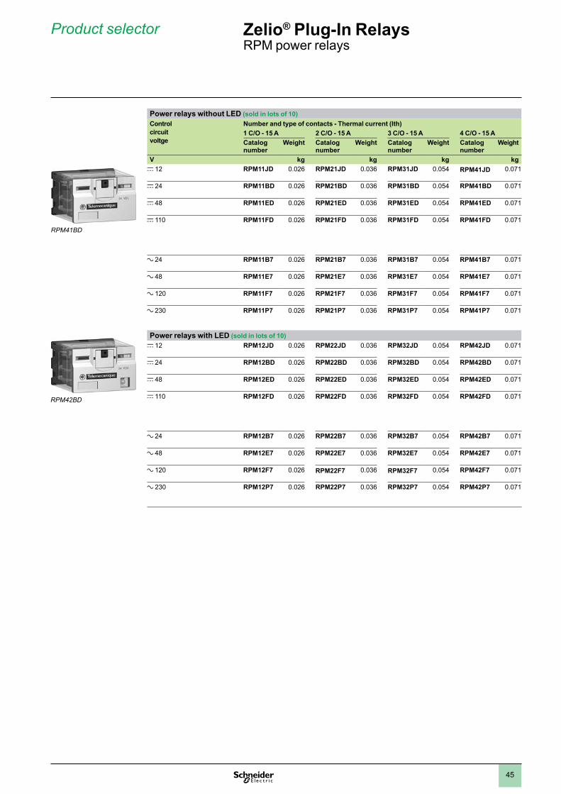
45
Power relays without LED (sold in lots of 10)Control circuit voltge
Number and type of contacts - Thermal current (Ith)1 C/O - 15 A 2 C/O - 15 A 3 C/O - 15 A 4 C/O - 15 ACatalog number
Weight Catalog number
Weight Catalog number
Weight Catalog number
Weight
V kg kg kg kgc 12 RPM11JD 0.026 RPM21JD 0.036 RPM31JD 0.054 RPM41JD 0.071
c 24 RPM11BD 0.026 RPM21BD 0.036 RPM31BD 0.054 RPM41BD 0.071
c 48 RPM11ED 0.026 RPM21ED 0.036 RPM31ED 0.054 RPM41ED 0.071
c 110 RPM11FD 0.026 RPM21FD 0.036 RPM31FD 0.054 RPM41FD 0.071
a 24 RPM11B7 0.026 RPM21B7 0.036 RPM31B7 0.054 RPM41B7 0.071
a 48 RPM11E7 0.026 RPM21E7 0.036 RPM31E7 0.054 RPM41E7 0.071
a 120 RPM11F7 0.026 RPM21F7 0.036 RPM31F7 0.054 RPM41F7 0.071
a 230 RPM11P7 0.026 RPM21P7 0.036 RPM31P7 0.054 RPM41P7 0.071
Power relays with LED (sold in lots of 10)c 12 RPM12JD 0.026 RPM22JD 0.036 RPM32JD 0.054 RPM42JD 0.071
c 24 RPM12BD 0.026 RPM22BD 0.036 RPM32BD 0.054 RPM42BD 0.071
c 48 RPM12ED 0.026 RPM22ED 0.036 RPM32ED 0.054 RPM42ED 0.071
c 110 RPM12FD 0.026 RPM22FD 0.036 RPM32FD 0.054 RPM42FD 0.071
a 24 RPM12B7 0.026 RPM22B7 0.036 RPM32B7 0.054 RPM42B7 0.071
a 48 RPM12E7 0.026 RPM22E7 0.036 RPM32E7 0.054 RPM42E7 0.071
a 120 RPM12F7 0.026 RPM22F7 0.036 RPM32F7 0.054 RPM42F7 0.071
a 230 RPM12P7 0.026 RPM22P7 0.036 RPM32P7 0.054 RPM42P7 0.071
Product selector Zelio® Plug-In Relays RPM power relays
RPM41BD
RPM42BD
1
2
3
4
5
6
7
8
9
10
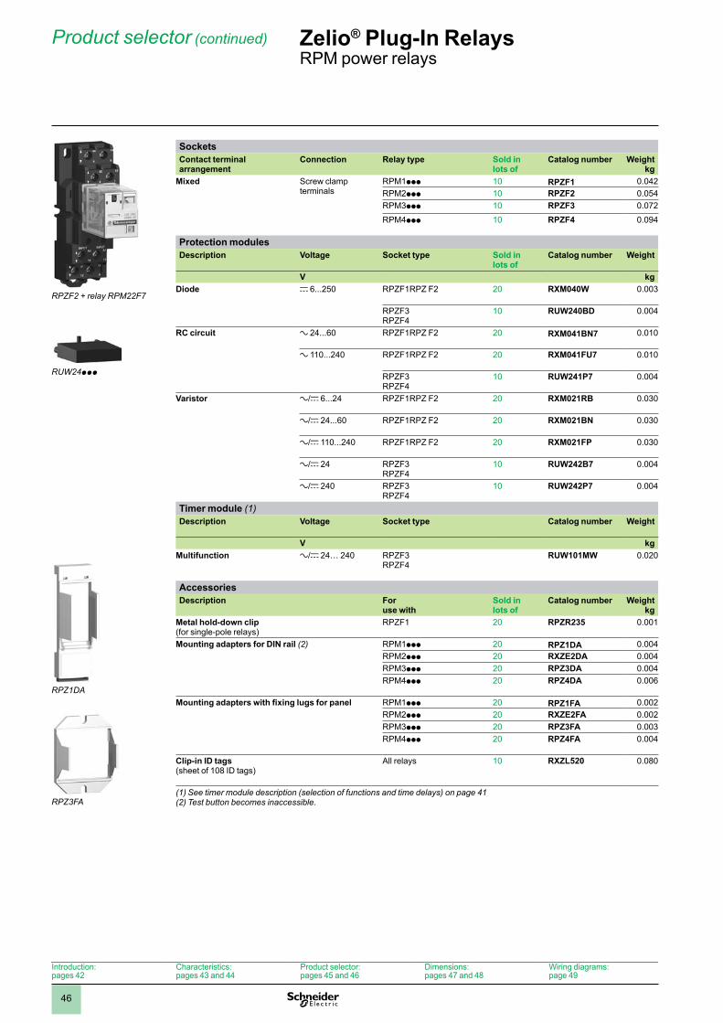
46
SocketsContact terminal arrangement
Connection Relay type Sold in lots of
Catalog number Weightkg
Mixed Screw clamp terminals
RPM1ppp 10 RPZF1 0.042RPM2ppp 10 RPZF2 0.054RPM3ppp 10 RPZF3 0.072
RPM4ppp 10 RPZF4 0.094
Protection modulesDescription Voltage Socket type Sold in
lots ofCatalog number Weight
V kgDiode c 6...250 RPZF1RPZ F2 20 RXM040W 0.003
RPZF3RPZF4
10 RUW240BD 0.004
RC circuit a 24...60 RPZF1RPZ F2 20 RXM041BN7 0.010
a 110...240 RPZF1RPZ F2 20 RXM041FU7 0.010
RPZF3RPZF4
10 RUW241P7 0.004
Varistor a/c 6...24 RPZF1RPZ F2 20 RXM021RB 0.030
a/c 24...60 RPZF1RPZ F2 20 RXM021BN 0.030
a/c 110...240 RPZF1RPZ F2 20 RXM021FP 0.030
a/c 24 RPZF3RPZF4
10 RUW242B7 0.004
a/c 240 RPZF3RPZF4
10 RUW242P7 0.004
Timer module (1)Description Voltage Socket type Catalog number Weight
V kgMultifunction a/c 24… 240 RPZF3
RPZF4RUW101MW 0.020
AccessoriesDescription For
use withSold in lots of
Catalog number Weightkg
Metal hold-down clip(for single-pole relays)
RPZF1 20 RPZR235 0.001
Mounting adapters for DIN rail (2) RPM1ppp 20 RPZ1DA 0.004RPM2ppp 20 RXZE2DA 0.004RPM3ppp 20 RPZ3DA 0.004RPM4ppp 20 RPZ4DA 0.006
Mounting adapters with fixing lugs for panel RPM1ppp 20 RPZ1FA 0.002RPM2ppp 20 RXZE2FA 0.002RPM3ppp 20 RPZ3FA 0.003RPM4ppp 20 RPZ4FA 0.004
Clip-in ID tags(sheet of 108 ID tags)
All relays 10 RXZL520 0.080
(1) See timer module description (selection of functions and time delays) on page 41(2) Test button becomes inaccessible.
Product selector (continued) Zelio® Plug-In Relays RPM power relays
Introduction:pages 42
Characteristics:pages 43 and 44
Product selector:pages 45 and 46
Dimensions:pages 47 and 48
Wiring diagrams:page 49
RPZF2 + relay RPM22F7
RUW24ppp
RPZ1DA
RPZ3FA
1
2
3
4
5
6
7
8
9
10
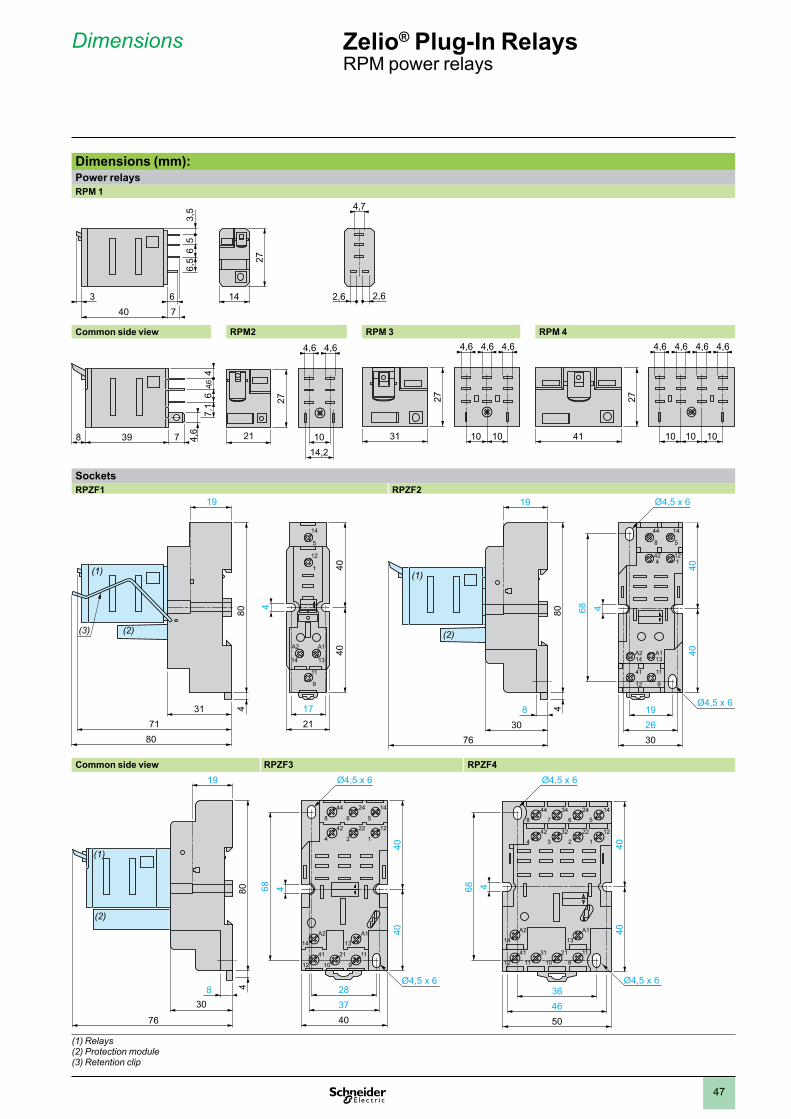
47
Dimensions (mm):Power relaysRPM 1
Common side view RPM2 RPM 3 RPM 4
SocketsRPZF1 RPZF2
14
5
12
1
A2
14
A1
13
11
9
31
19
1721
4
71
(1)
(3) (2)
80
40
804
40
44
8
14
5
424
121
A214
A113
41
12
11
9
30 2619
30
4040
4
19
8
76
80 68
4
Ø4,5 x 6
Ø4,5 x 6
(1)
(2)
Common side view RPZF3 RPZF4
30
76
804
19
8
(1)
(2)
28
4037
4040
68 4
44
8
24
6
14
542
4
A214
A113
41
12
21
10
11
9
22
2
12
1
Ø4,5 x 6
Ø4,5 x 6364650
4040
68 4
14
5
24
6
34
7
44
8
A2
14
A1
13
41
12
31
11
21
10
11
9
12
1
22
2
32
3
42
4
Ø4,5 x 6
Ø4,5 x 6
(1) Relays(2) Protection module(3) Retention clip
8 39 7
7,1
64,6
44,
6 3127
1010
4,6 4,6 4,6
41 1010 10
27
4,6 4,6 4,6 4,6
Dimensions Zelio® Plug-In Relays RPM power relays
763 14
40
27
4,7
6,5
65
3,5
2,62,6
27
21 1014,2
4,6 4,6
1
2
3
4
5
6
7
8
9
10
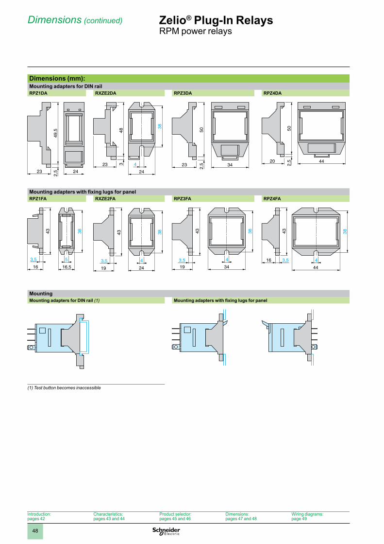
48
Dimensions (mm): Mounting adapters for DIN railRPZ1DA RXZE2DA RPZ3DA RPZ4DA
Mounting adapters with fixing lugs for panelRPZ1FA RXZE2FA RPZ3FA RPZ4FA
MountingMounting adapters for DIN rail (1) Mounting adapters with fixing lugs for panel
(1) Test button becomes inaccessible
23 24
49,5
2,5
384
24
23
483 3423
502,
5
4420
502,
5
3843
3,5 5
16,516
38
3,5 4
19
43
24
38
19
3,5 4
43
34
16 3,5 4
3843
44
Dimensions (continued) Zelio® Plug-In Relays RPM power relays
Introduction:pages 42
Characteristics:pages 43 and 44
Product selector:pages 45 and 46
Dimensions:pages 47 and 48
Wiring diagrams:page 49
1
2
3
4
5
6
7
8
9
10
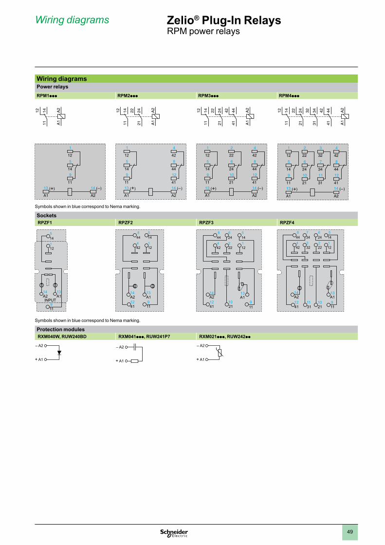
49
Wiring diagramsPower relaysRPM1ppp RPM2ppp RPM3ppp RPM4ppp
Symbols shown in blue correspond to Nema marking.
Sockets RPZF1 RPZF2 RPZF3 RPZF4
145
121
119
A214
A113
INPUT
448
145
424
121
4112A214
119
A113
4112
2110
119
A214
A113
448
246
145
424
222
121
A214
A113
4112
3111
2110
119
448
347
246
145
424
323
222
121
Symbols shown in blue correspond to Nema marking.
Protection modules RXM040W, RUW240BD RXM041ppp, RUW241P7 RXM021ppp, RUW242pp
– A2
+ A1
– A2
+ A1
– A2
+ A1
1
12
5
14
9
1113
A1
14
A2
(+) ( )
A2
A1
111412
1
125
149
11
4
428
4412
4113
A1
14
A2
(+) ( )
A2
A1
212422
111412
1
12
5
14
9
11
2
22
6
24
10
21
4
42
8
44
12
4113
A1
14
A2
(+) ( )
A2
A1
212422
414442
111412
(+)
1
12
5
14
9
11
2
22
6
24
10
21
3
32
7
34
11
31
4
42
8
44
12
4113
A1
14
A2
( )
A2
A1
212422
313432
414442
111412
Wiring diagrams Zelio® Plug-In Relays RPM power relays
1
2
3
4
5
6
7
8
9
10
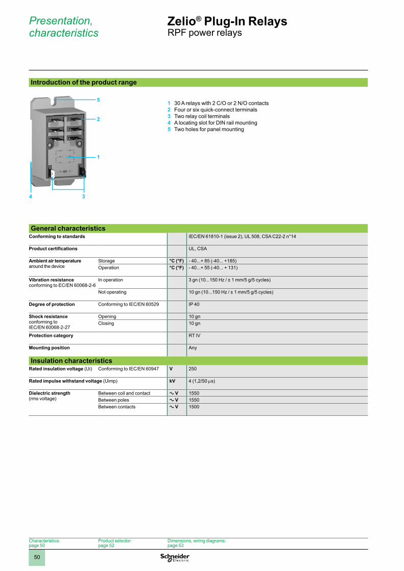
50
Introduction of the product range
1 30 A relays with 2 C/O or 2 N/O contacts2 Four or six quick-connect terminals3 Two relay coil terminals4 A locating slot for DIN rail mounting5 Two holes for panel mounting
General characteristics
Conforming to standards IEC/EN 61810-1 (issue 2), UL 508, CSA C22-2 n°14
Product certifications UL, CSA
Ambient air temperature around the device
Storage °C (°F) - 40...+ 85 (-40... +185)Operation °C (°F) - 40...+ 55 (-40... + 131)
Vibration resistanceconforming to EC/EN 60068-2-6
In operation 3 gn (10...150 Hz / ± 1 mm/5 g/5 cycles)
Not operating 10 gn (10...150 Hz / ± 1 mm/5 g/5 cycles)
Degree of protection Conforming to IEC/EN 60529 IP 40
Shock resistanceconforming to IEC/EN 60068-2-27
Opening 10 gnClosing 10 gn
Protection category RT IV
Mounting position Any
Insulation characteristicsRated insulation voltage (Ui) Conforming to IEC/EN 60947 V 250
Rated impulse withstand voltage (Uimp) kV 4 (1,2/50 ms)
Dielectric strength(rms voltage)
Between coil and contact a V 1550Between poles a V 1550Between contacts a V 1500
5
2
4 3
Presentation, characteristics
Zelio® Plug-In RelaysRPF power relays
Characteristics:page 50
Product selector:page 52
Dimensions, wiring diagrams:page 53
1
1
2
3
4
5
6
7
8
9
10
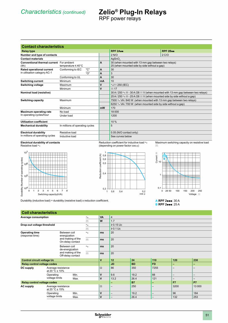
51
Contact characteristicsRelay type RPF 2App RPF 2Bpp
Number and type of contacts 2 N/O 2 C/OContact materials AgSnO2
Conventional thermal current (Ith)
For ambient temperature y 40°C
A 30 (when mounted with 13 mm gap between two relays)25 (when mounted side by side without a gap)
Rated operational current in utilisation category AC-1
Conforming to IEC "C" A 30“O” A 3
Conforming to UL A 30Switching current Minimum mA 10Switching voltage Maximum V a/c 250 (IEC)
Minimum V c 17Nominal load (resistive) 30 A / 250 a V - 30 A /28 c V (when mounted with 13 mm gap between two relays)
25 A / 250 a V - 25 A /28 c V (when mounted side by side without a gap)Switching capacity Maximum 7500 a VA / 840 W (when mounted with 13 mm gap between two relays)
6250 a VA / 700 W (when mounted side by side without a gap)Minimum mW 170
Maximum operating rateIn operating cycles/hour
No load 18 000Under load 1200
Utilization coefficient 10 %Mechanical durability In millions of operating cycles 5
Electrical durabilityIn millions of operating cycles
Resistive load 0.05 (N/O contact only)Inductive load See curves below
Electrical durability of contactsResistive load a
Reduction coefficient for inductive load a (depending on power factor cos j)
Maximum switching capacity on resistive load c
Durability (inductive load) = durability (resistive load) x reduction coefficient. A RPF 2ppp: 30 AB RPF 2ppp: 25 A
Coil characteristicsAverage consumption a VA 4
c W 1.7Drop-out voltage threshold a u 0.15 Uc
c u 0.1 UcOperating time(response time)
Between coil energization and making of the On-delay contact
a ms 20
c ms 20
Between coil de-energization and making of the Off-delay contact
a ms 20
c ms 20
Control circuit voltage Uc V 12 24 110 120 230Relay control voltage codes JD BD FD – –
DC supply Average resistance at 20 °C ± 10%
W 86 350 7255 – –
Operating voltage limits
Min. V 9.6 19.2 88 – –Max. V 13.2 26.4 121 – –
Relay control voltage codes – B7 – F7 P7AC supply Average resistance
at 20 °C ± 15%W – 250 – 3200 13 000
Operating voltage limits
Min. V – 19.2 – 96 184Max. V – 26.4 – 132 253
10420 1 43 5 6 7 8
107
105
106
Dur
abili
ty (N
umbe
r of o
pera
ting
cycl
es)
Switching capacity(kVA)
0,3
0,5
0,61 0,4 0,2
0,4
0,60,8
1
Red
uctio
n co
effic
ient
(A)
0,1
1
200 2500 5028 100 150
10B
AC
urre
nt c
Voltage c
Characteristics (continued) Zelio® Plug-In RelaysRPF power relays
1
2
3
4
5
6
7
8
9
10
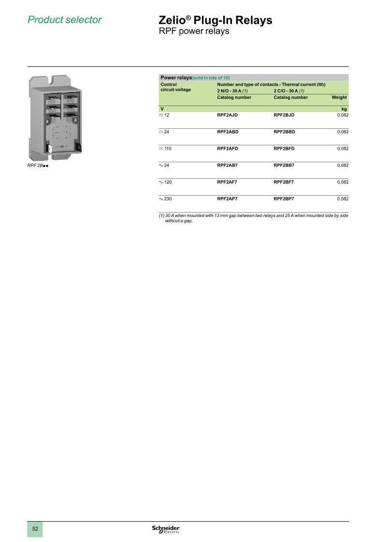
52
Power relays(sold in lots of 10)Control circuit voltage
Number and type of contacts - Thermal current (Ith)2 N/O - 30 A (1) 2 C/O - 30 A (1)Catalog number Catalog number Weight
V kgc 12 RPF2AJD RPF2BJD 0.082
c 24 RPF2ABD RPF2BBD 0.082
c 110 RPF2AFD RPF2BFD 0.082
a 24 RPF2AB7 RPF2BB7 0.082
a 120 RPF2AF7 RPF2BF7 0.082
a 230 RPF2AP7 RPF2BP7 0.082
(1) 30 A when mounted with 13 mm gap between two relays and 25 A when mounted side by side without a gap.
RPF 2Bpp
Product selector Zelio® Plug-In RelaysRPF power relays
1
2
3
4
5
6
7
8
9
10
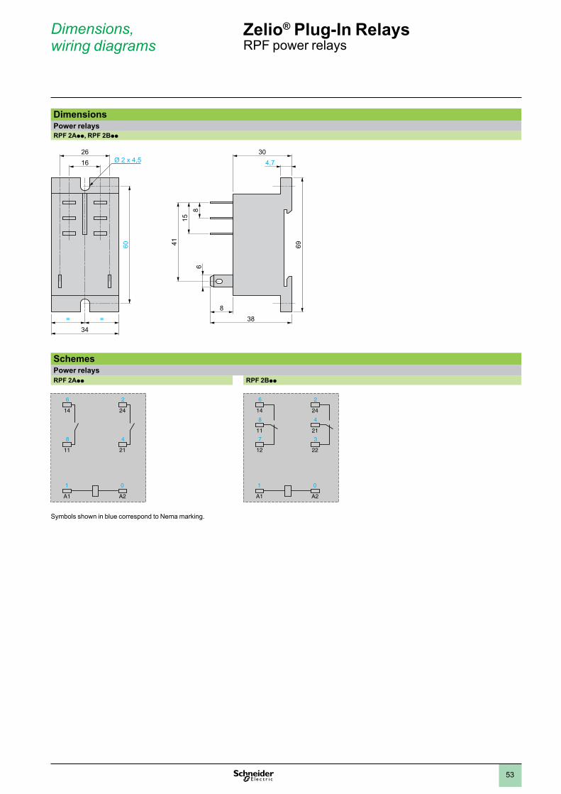
53
DimensionsPower relaysRPF 2App, RPF 2Bpp
SchemesPower relaysRPF 2App RPF 2Bpp
Symbols shown in blue correspond to Nema marking.
4115
86
30
698
3834
==
2616 4,7
60
6
14
8
11
2
24
4
21
1
A1
0
A2
6
14
8
11
7
12
2
24
4
21
3
22
1
A1
0
A2
Dimensions, wiring diagrams
Zelio® Plug-In RelaysRPF power relays
1
2
3
4
5
6
7
8
9
10
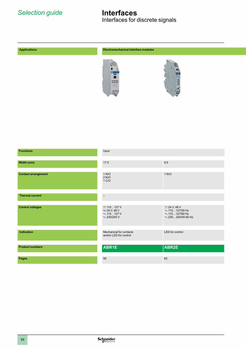
54
Solid state interface modules
Output Input and output Very low level switching
Input Output
17.5 12 17.5 9.5 9.5/17.5
1 N/O 2 N/O 1 C/O 1 N/C + 1 N/O
1 N/O 1 C/O –
12 A 5 A – 5 A
c 24 V z 24 V, 48 V a 115…127 V a 110 V
c 24 V c 5, 24, 48 V a 115…127/50 Hz a 120…127/60 Hz a 230…240/50 Hz a 230…240/60 Hz
c 24 V
Mechanical for contacts and/or LED for control
LED for control
ABR1S ABR2S ABR2pB312B ABS2E ABS2S
56 62 62 68
Applications Electromechanical interface modules
Functions Input
Width (mm) 17.5 9.5
Contact arrangement 1 N/O 2 N/O 1 C/O
1 N/O
Thermal current –
Control voltages c 110…127 V z 24 V, 48 V a 115…127 V a 230/240 V
c 24 V, 48 V a 115…127/50 Hz a 115…127/60 Hz a 230…240/50-60 Hz
Indication Mechanical for contacts and/or LED for control
LED for control
Product numbers ABR1E ABR2E
Pages 56 62
Selection guide Interfaces Interfaces for discrete signals
1
2
3
4
5
6
7
8
9
10
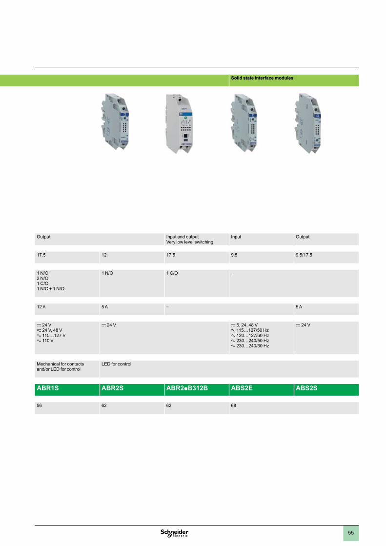
55
Solid state interface modules
Output Input and output Very low level switching
Input Output
17.5 12 17.5 9.5 9.5/17.5
1 N/O 2 N/O 1 C/O 1 N/C + 1 N/O
1 N/O 1 C/O –
12 A 5 A – 5 A
c 24 V z 24 V, 48 V a 115…127 V a 110 V
c 24 V c 5, 24, 48 V a 115…127/50 Hz a 120…127/60 Hz a 230…240/50 Hz a 230…240/60 Hz
c 24 V
Mechanical for contacts and/or LED for control
LED for control
ABR1S ABR2S ABR2pB312B ABS2E ABS2S
56 62 62 68
Applications Electromechanical interface modules
Functions Input
Width (mm) 17.5 9.5
Contact arrangement 1 N/O 2 N/O 1 C/O
1 N/O
Thermal current –
Control voltages c 110…127 V z 24 V, 48 V a 115…127 V a 230/240 V
c 24 V, 48 V a 115…127/50 Hz a 115…127/60 Hz a 230…240/50-60 Hz
Indication Mechanical for contacts and/or LED for control
LED for control
Product numbers ABR1E ABR2E
Pages 56 62
1
2
3
4
5
6
7
8
9
10
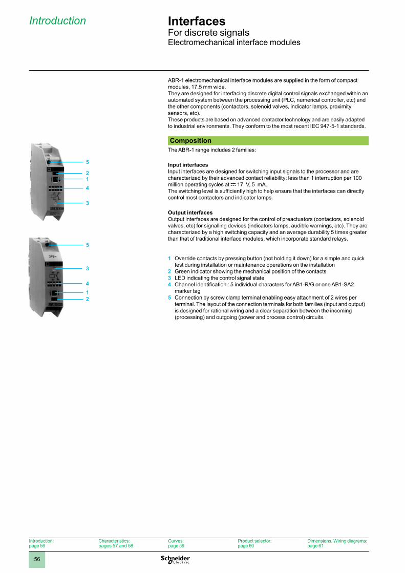
56
Interfaces 6 For discrete signalsElectromechanical interface modules
ABR-1 electromechanical interface modules are supplied in the form of compact modules, 17.5 mm wide.They are designed for interfacing discrete digital control signals exchanged within an automated system between the processing unit (PLC, numerical controller, etc) and the other components (contactors, solenoid valves, indicator lamps, proximity sensors, etc).These products are based on advanced contactor technology and are easily adapted to industrial environments. They conform to the most recent IEC 947-5-1 standards.
CompositionThe ABR-1 range includes 2 families:
Input interfaces Input interfaces are designed for switching input signals to the processor and are characterized by their advanced contact reliability: less than 1 interruption per 100 million operating cycles at c 17 V, 5 mA.The switching level is sufficiently high to help ensure that the interfaces can directly control most contactors and indicator lamps.
Output interfaces Output interfaces are designed for the control of preactuators (contactors, solenoid valves, etc) for signalling devices (indicators lamps, audible warnings, etc). They are characterized by a high switching capacity and an average durability 5 times greater than that of traditional interface modules, which incorporate standard relays.
1 Override contacts by pressing button (not holding it down) for a simple and quick test during installation or maintenance operations on the installation
2 Green indicator showing the mechanical position of the contacts3 LED indicating the control signal state4 Channel identification : 5 individual characters for AB1-R/G or one AB1-SA2
marker tag5 Connection by screw clamp terminal enabling easy attachment of 2 wires per
terminal. The layout of the connection terminals for both families (input and output) is designed for rational wiring and a clear separation between the incoming (processing) and outgoing (power and process control) circuits.
5
214
3
5
3
412
Introduction:page 56
Characteristics:pages 57 and 58
Curves:page 59
Product selector:page 60
Dimensions, Wiring diagrams:page 61
Introduction 6
1
2
3
4
5
6
7
8
9
10
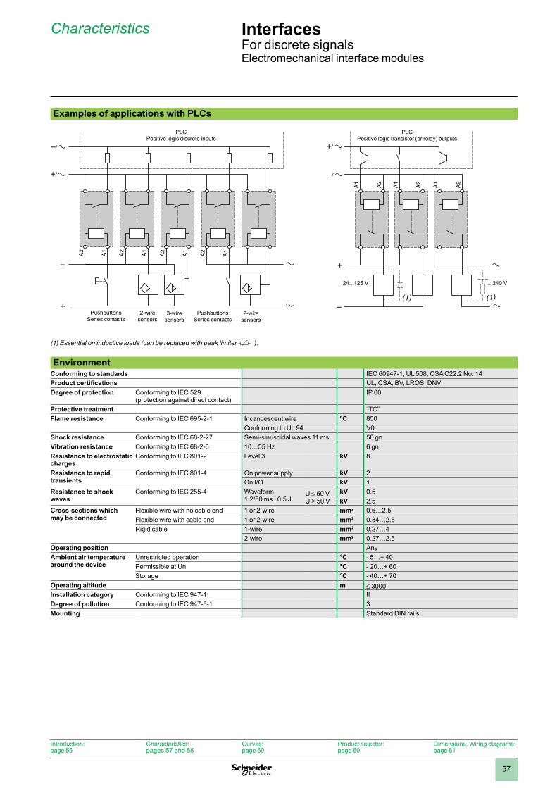
57
Interfaces 6 For discrete signalsElectromechanical interface modules
Examples of applications with PLCs
(1) Essential on inductive loads (can be replaced with peak limiter ).
–/
+/
–
+
A2
A1
A2
A1
A2
A1
A2
A1
PushbuttonsSeries contacts
2-wiresensors
3-wiresensors
PushbuttonsSeries contacts
2-wiresensors
PLCPositive logic discrete inputs
–/
+/
–
+
24...125 V ...240 V
A1
A2
(1) (1)
A1
A2
A1
A2
PLCPositive logic transistor (or relay) outputs
Environment
Conforming to standards IEC 60947-1, UL 508, CSA C22.2 No. 14Product certifications UL, CSA, BV, LROS, DNVDegree of protection Conforming to IEC 529
(protection against direct contact)IP 00
Protective treatment “TC”Flame resistance Conforming to IEC 695-2-1 Incandescent wire °C 850
Conforming to UL 94 V0Shock resistance Conforming to IEC 68-2-27 Semi-sinusoidal waves 11 ms 50 gnVibration resistance Conforming to IEC 68-2-6 10…55 Hz 6 gnResistance to electrostatic charges
Conforming to IEC 801-2 Level 3 kV 8
Resistance to rapid transients
Conforming to IEC 801-4 On power supply kV 2On I/O kV 1
Resistance to shock waves
Conforming to IEC 255-4 Waveform 1.2/50 ms ; 0.5 J
U ≤ 50 V kV 0.5U > 50 V kV 2.5
Cross-sections which may be connected
Flexible wire with no cable end 1 or 2-wire mm2 0.6…2.5Flexible wire with cable end 1 or 2-wire mm2 0.34…2.5Rigid cable 1-wire mm2 0.27…4
2-wire mm2 0.27…2.5Operating position AnyAmbient air temperature around the device
Unrestricted operation °C - 5…+ 40Permissible at Un °C - 20…+ 60Storage °C - 40…+ 70
Operating altitude m ≤ 3000Installation category Conforming to IEC 947-1 IIDegree of pollution Conforming to IEC 947-5-1 3Mounting Standard DIN rails
Introduction:page 56
Characteristics:pages 57 and 58
Curves:page 59
Product selector:page 60
Dimensions, Wiring diagrams:page 61
Characteristics 6
1
2
3
4
5
6
7
8
9
10
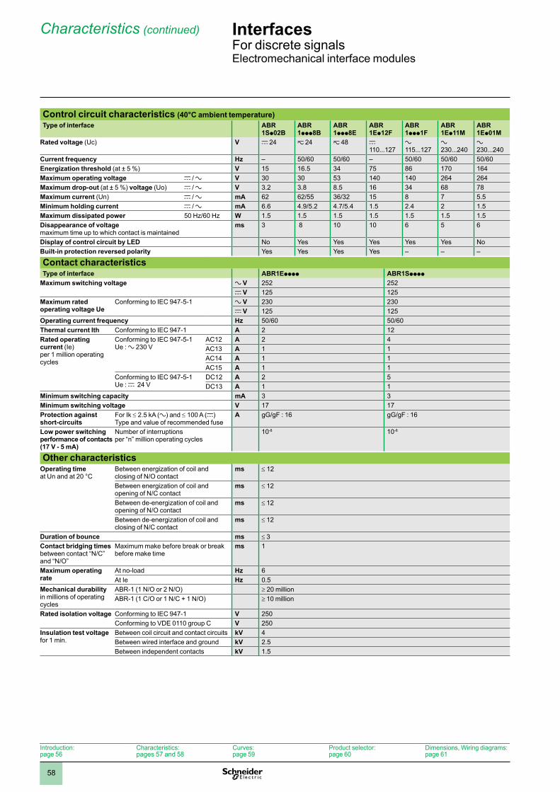
58
Interfaces 6 For discrete signalsElectromechanical interface modules
Control circuit characteristics (40°C ambient temperature)Type of interface ABR
1Sp02BABR 1ppp8B
ABR 1ppp8E
ABR 1Ep12F
ABR 1ppp1F
ABR 1Ep11M
ABR 1Ep01M
Rated voltage (Uc) V c 24 z 24 z 48 c 110...127
a 115...127
a 230...240
a 230...240
Current frequency Hz – 50/60 50/60 – 50/60 50/60 50/60Energization threshold (at ± 5 %) V 15 16.5 34 75 86 170 164Maximum operating voltage c / a V 30 30 53 140 140 264 264Maximum drop-out (at ± 5 %) voltage (Uo) c / a V 3.2 3.8 8.5 16 34 68 78Maximum current (Un) c / a mA 62 62/55 36/32 15 8 7 5.5Minimum holding current c / a mA 6.6 4.9/5.2 4.7/5.4 1.5 2.4 2 1.5Maximum dissipated power 50 Hz/60 Hz W 1.5 1.5 1.5 1.5 1.5 1.5 1.5Disappearance of voltage maximum time up to which contact is maintained
ms 3 8 10 10 6 5 6
Display of control circuit by LED No Yes Yes Yes Yes Yes NoBuilt-in protection reversed polarity Yes Yes Yes Yes – – –
Contact characteristicsType of interface ABR1Epppp ABR1Spppp
Maximum switching voltage a V 252 252 c V 125 125
Maximum rated operating voltage Ue
Conforming to IEC 947-5-1 a V 230 230 c V 125 125
Operating current frequency Hz 50/60 50/60Thermal current Ith Conforming to IEC 947-1 A 2 12Rated operating current (Ie) per 1 million operating cycles
Conforming to IEC 947-5-1 Ue : a 230 V
AC12 A 2 4AC13 A 1 1AC14 A 1 1AC15 A 1 1
Conforming to IEC 947-5-1 Ue : c 24 V
DC12 A 2 5DC13 A 1 1
Minimum switching capacity mA 3 3Minimum switching voltage V 17 17Protection against short-circuits
For Ik ≤ 2.5 kA (a) and ≤ 100 A (c) Type and value of recommended fuse
A gG/gF : 16 gG/gF : 16
Low power switching performance of contacts (17 V - 5 mA)
Number of interruptions per “n” million operating cycles
10-8 10-8
Other characteristicsOperating time at Un and at 20 °C
Between energization of coil and closing of N/O contact
ms ≤ 12
Between energization of coil and opening of N/C contact
ms ≤ 12
Between de-energization of coil and opening of N/O contact
ms ≤ 12
Between de-energization of coil and closing of N/C contact
ms ≤ 12
Duration of bounce ms ≤ 3Contact bridging times between contact “N/C” and “N/O”
Maximum make before break or break before make time
ms 1
Maximum operating rate
At no-load Hz 6At Ie Hz 0.5
Mechanical durability in millions of operating cycles
ABR-1 (1 N/O or 2 N/O) ≥ 20 millionABR-1 (1 C/O or 1 N/C + 1 N/O) ≥ 10 million
Rated isolation voltage Conforming to IEC 947-1 V 250Conforming to VDE 0110 group C V 250
Insulation test voltage for 1 min.
Between coil circuit and contact circuits kV 4Between wired interface and ground kV 2.5Between independent contacts kV 1.5
Introduction:page 56
Characteristics:pages 57 and 58
Curves:page 59
Product selector:page 60
Dimensions, Wiring diagrams:page 61
Characteristics (continued) 6
1
2
3
4
5
6
7
8
9
10
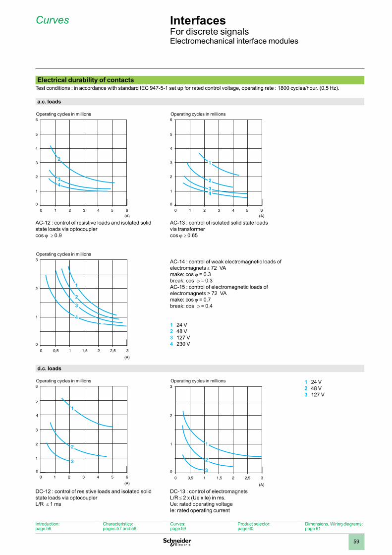
59
Interfaces 6 For discrete signalsElectromechanical interface modules
Electrical durability of contactsTest conditions : in accordance with standard IEC 947-5-1 set up for rated control voltage, operating rate : 1800 cycles/hour. (0.5 Hz).
a.c. loads
AC-12 : control of resistive loads and isolated solid state loads via optocoupler cos j ≥ 0.9
AC-13 : control of isolated solid state loads via transformer cos j ≥ 0.65
AC-14 : control of weak electromagnetic loads of electromagnets ≤ 72 VAmake: cos j = 0.3break: cos j = 0.3AC-15 : control of electromagnetic loads of electromagnets > 72 VAmake: cos j = 0.7break: cos j = 0.4
1 24 V2 48 V3 127 V4 230 V
d.c. loads
1 24 V2 48 V3 127 V
DC-12 : control of resistive loads and isolated solid state loads via optocoupler L/R ≤ 1 ms
DC-13 : control of electromagnets L/R ≤ 2 x (Ue x Ie) in ms.Ue: rated operating voltageIe: rated operating current
5
4
3
2
1
1 2 3 4 5(A)
6
0
0
34
2
6
Operating cycles in millions
5
4
3
2
1
1 2 3 4 5(A)
6
0
0
6
3
1
4
2
Operating cycles in millions
2
1
0,5 1 1,5 2 2,5
(A)
3
0
0
3
1
2
3
4
Operating cycles in millions
5
4
3
2
1
0
1 2 3 4 5
(A)
2
3
6
60
1
Operating cycles in millions
2
1
0,5 1 1,5 2 2,5
(A)
3
0
0
3
3
1
2
Operating cycles in millions
Introduction:page 56
Characteristics:pages 57 and 58
Curves:page 59
Product selector:page 60
Dimensions, Wiring diagrams:page 61
Curves 6
1
2
3
4
5
6
7
8
9
10
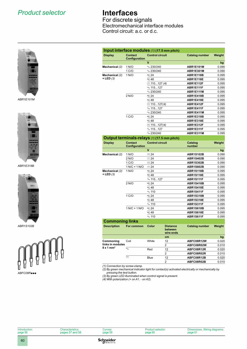
60
Interfaces 6 For discrete signalsElectromechanical interface modulesControl circuit: a.c. or d.c.
Input interface modules (1) (17.5 mm pitch)Display Contact
ConfigurationControl circuit Catalog number Weight
V kgMechanical (2) 1 N/O a 230/240 ABR1E101M 0.090
1 C/O a 230/240 ABR1E301M 0.090Mechanical (2) + LED (3)
1 N/O z 24 ABR1E118B 0.095z 48 ABR1E118E 0.095c 110...127 (4) ABR1E112F 0.095a 115...127 ABR1E111F 0.095a 230/240 ABR1E111M 0.095
2 N/O z 24 ABR1E418B 0.095z 48 ABR1E418E 0.095c 110...127(4) ABR1E412F 0.095a 115...127 ABR1E411F 0.095a 230/240 ABR1E411M 0.095
1 C/O z 24 ABR1E318B 0.095z 48 ABR1E318E 0.095c 110...127(4) ABR1E312F 0.095a 115...127 ABR1E311F 0.095a 230/240 ABR1E311M 0.095
Output terminals-relays (1) (17.5 mm pitch)Display Contact
ConfigurationControl circuit Catalog
numberWeight
V kgMechanical (2) 1 N/O c 24 ABR1S102B 0.090
2 N/O c 24 ABR1S402B 0.0901 C/O c 24 ABR1S302B 0.0901 N/C + 1 N/O c 24 ABR1S602B 0.090
Mechanical (2) + LED (3)
1 N/O z 24 ABR1S118B 0.095z 48 ABR1S118E 0.095a 115...127 ABR1S111F 0.095
2 N/O z 24 ABR1S418B 0.095z 48 ABR1S418E 0.095a 110 ABR1S411F 0.095
1 C/O z 24 ABR1S318B 0.095z 48 ABR1S318E 0.095a 110 ABR1S311F 0.095
1 N/C + 1 N/O z 24 ABR1S618B 0.095z 48 ABR1S618E 0.095a 110 ABR1S611F 0.095
Commoning linksDescription For common Color Distance
between wire ends
Catalog number Weight
cm kgCommoning links in modules 8 x 1 mm2
Coil White 12 ABFC08R12W 0.0202 ABFC08R02W 0.010
a Red 12 ABFC08R12R 0.0202 ABFC08R02R 0.010
c Blue 12 ABFC08R12B 0.0202 ABFC08R02B 0.010
(1) Connection by screw-clamp.(2) By green mechanical indicator light for contact(s) activated electrically or mechanically by
pressing the test button. (3) By green LED illuminated when control signal is present.(4) With polarization (+ on A1, - on A2).
ABR1E101M
ABR1E318B
ABR1S102B
ABFC08Rppp
Introduction:page 56
Characteristics:pages 57 and 58
Curves:page 59
Product selector:page 60
Dimensions, Wiring diagrams:page 61
Product selector 6
1
2
3
4
5
6
7
8
9
10
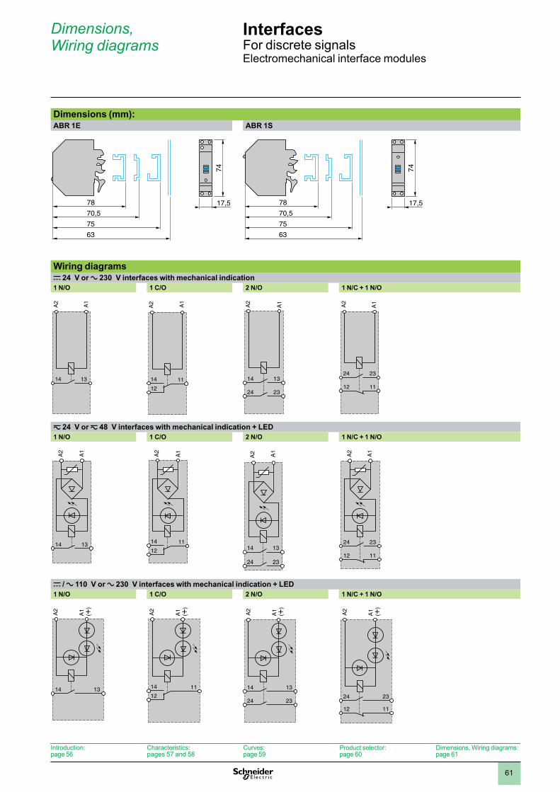
61
Interfaces 6 For discrete signalsElectromechanical interface modules
Dimensions (mm):ABR 1E ABR 1S
Wiring diagramsc 24 V or a 230 V interfaces with mechanical indication1 N/O 1 C/O 2 N/O 1 N/C + 1 N/O
z 24 V or z 48 V interfaces with mechanical indication + LED1 N/O 1 C/O 2 N/O 1 N/C + 1 N/O
c / a 110 V or a 230 V interfaces with mechanical indication + LED1 N/O 1 C/O 2 N/O 1 N/C + 1 N/O
78
75
70,517,5
74
63
78
75
70,517,5
74
63
A2
1314
A1
1114
12
A2 A1
1314
2324
A2
A1
2324
1112
A2
A1
A1
1314
A2
1114
12
A2
A1
1314
2324
A2 A1
2324
1112
A1
A2
1314
A1
(+)
A2
1114
12
A1
(+)
A2
1314
2324
A1
(+)
A2
2324
1112
A1
(+)
A2
Introduction:page 56
Characteristics:pages 57 and 58
Curves:page 59
Product selector:page 60
Dimensions, Wiring diagrams:page 61
Dimensions, Wiring diagrams 6
1
2
3
4
5
6
7
8
9
10
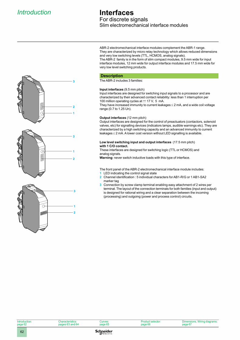
62
Introduction
ABR-2 electromechanical interface modules complement the ABR-1 range.They are characterized by micro relay technology which allows reduced dimensions and very low switching levels (TTL, HCMOS, analog signals).The ABR-2 family is in the form of slim compact modules, 9.5 mm wide for input interface modules, 12 mm wide for output interface modules and 17.5 mm wide for very low level switching products.
DescriptionThe ABR-2 includes 3 families:
Input interfaces (9.5 mm pitch) Input interfaces are designed for switching input signals to a processor and are characterized by their advanced contact reliability: less than 1 interruption per 100 million operating cycles at c 17 V, 5 mA.They have increased immunity to current leakages ≤ 2 mA, and a wide coil voltage range (0.7 to 1.25 Un).
Output interfaces (12 mm pitch) Output interfaces are designed for the control of preactuators (contactors, solenoid valves, etc) for signalling devices (indicators lamps, audible warnings etc). They are characterized by a high switching capacity and an advanced immunity to current leakages ≤ 2 mA. A lower cost version without LED signalling is available.
Low level switching input and output interfaces (17.5 mm pitch) with 1 C/O contact. These interfaces are designed for switching logic (TTL or HCMOS) and analog signals.Warning: never switch inductive loads with this type of interface.
The front panel of the ABR-2 electromechanical interface module includes:1 LED indicating the control signal state2 Channel identification : 5 individual characters for AB1-R/G or 1 AB1-SA2
marker tag3 Connection by screw clamp terminal enabling easy attachment of 2 wires per
terminal. The layout of the connection terminals for both families (input and output) is designed for rational wiring and a clear separation between the incoming (processing) and outgoing (power and process control) circuits.
3
2
1
3
2
1
ABR-2SB312B
ABR2SB312B-PRO-3-B
3
2
1
Introduction:page 62
Characteristics:pages 63 and 64
Curves:page 65
Product selector:page 66
Dimensions, Wiring diagrams:page 67
InterfacesFor discrete signalsSlim electromechanical interface modules
1
2
3
4
5
6
7
8
9
10
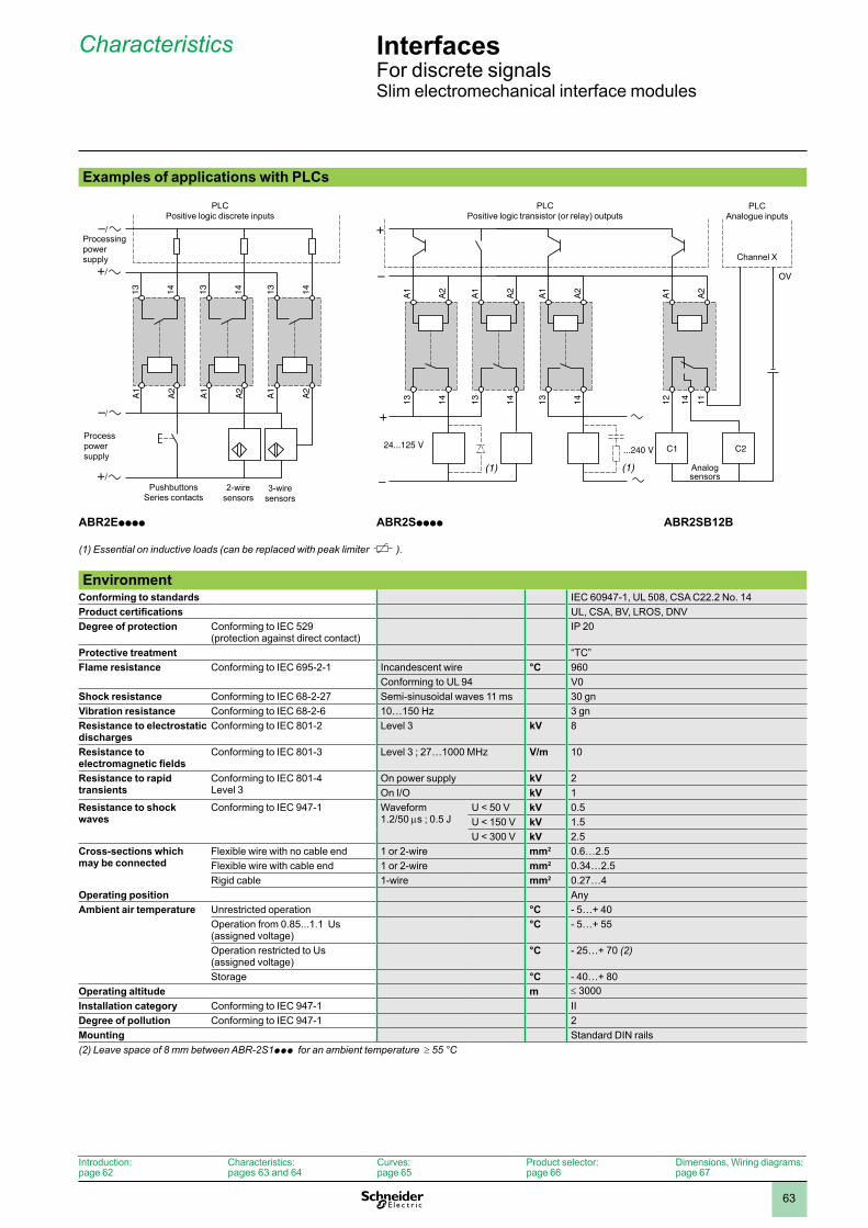
63
Characteristics
Examples of applications with PLCs
(1) Essential on inductive loads (can be replaced with peak limiter ).
–/
+/
+/
13 14 13 14 13 14
A1
A2
A1
A2
A1
A2
PLCPositive logic discrete inputs
PushbuttonsSeries contacts
2-wiresensors
3-wiresensors
ABR2Epppp
Processpowersupply
Processingpowersupply
–
+
–
+A
1
A2
(1) (1)
C1
A1
A2
A1
A2
13 14 13 14 13 14
A1
A2
12 14
C2
OV
11
PLCPositive logic transistor (or relay) outputs
PLCAnalogue inputs
Channel X
Analog sensors
ABR2Spppp ABR2SB12B
Environment
Conforming to standards IEC 60947-1, UL 508, CSA C22.2 No. 14Product certifications UL, CSA, BV, LROS, DNVDegree of protection Conforming to IEC 529
(protection against direct contact)IP 20
Protective treatment “TC”Flame resistance Conforming to IEC 695-2-1 Incandescent wire °C 960
Conforming to UL 94 V0Shock resistance Conforming to IEC 68-2-27 Semi-sinusoidal waves 11 ms 30 gnVibration resistance Conforming to IEC 68-2-6 10…150 Hz 3 gnResistance to electrostatic discharges
Conforming to IEC 801-2 Level 3 kV 8
Resistance to electromagnetic fields
Conforming to IEC 801-3 Level 3 ; 27…1000 MHz V/m 10
Resistance to rapid transients
Conforming to IEC 801-4 Level 3
On power supply kV 2On I/O kV 1
Resistance to shock waves
Conforming to IEC 947-1 Waveform 1.2/50 ms ; 0.5 J
U < 50 V kV 0.5U < 150 V kV 1.5U < 300 V kV 2.5
Cross-sections which may be connected
Flexible wire with no cable end 1 or 2-wire mm2 0.6…2.5Flexible wire with cable end 1 or 2-wire mm2 0.34…2.5Rigid cable 1-wire mm2 0.27…4
Operating position AnyAmbient air temperature Unrestricted operation °C - 5…+ 40
Operation from 0.85...1.1 Us (assigned voltage)
°C - 5…+ 55
Operation restricted to Us (assigned voltage)
°C - 25…+ 70 (2)
Storage °C - 40…+ 80Operating altitude m ≤ 3000Installation category Conforming to IEC 947-1 IIDegree of pollution Conforming to IEC 947-1 2Mounting Standard DIN rails(2) Leave space of 8 mm between ABR-2S1ppp for an ambient temperature ≥ 55 °C
Introduction:page 62
Characteristics:pages 63 and 64
Curves:page 65
Product selector:page 66
Dimensions, Wiring diagrams:page 67
InterfacesFor discrete signalsSlim electromechanical interface modules
1
2
3
4
5
6
7
8
9
10
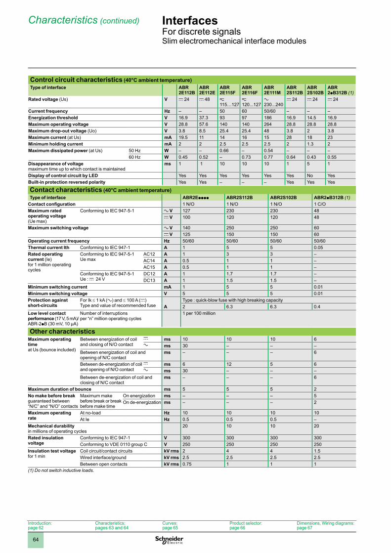
64
Characteristics (continued)
Control circuit characteristics (40°C ambient temperature)Type of interface ABR
2E112BABR 2E112E
ABR 2E115F
ABR 2E116F
ABR 2E111M
ABR 2S112B
ABR 2S102B
ABR 2pB312B (1)
Rated voltage (Us) V c 24 c 48 z 115…127
z 120...127
a 230...240
c 24 c 24 c 24
Current frequency Hz – – 50 60 50/60 – – –Energization threshold V 16.9 37.3 93 97 186 16.9 14.5 16.9Maximum operating voltage V 28.8 57.6 140 140 264 28.8 28.8 28.8Maximum drop-out voltage (Uo) V 3.8 8.5 25.4 25.4 48 3.8 2 3.8Maximum current (at Us) mA 19.5 11 14 16 15 28 18 23Minimum holding current mA 2 2 2.5 2.5 2.5 2 1.3 2Maximum dissipated power (at Us) 50 Hz W – – 0.66 – 0.54 – – –
60 Hz W 0.45 0.52 – 0.73 0.77 0.64 0.43 0.55Disappearance of voltage maximum time up to which contact is maintained
ms 1 1 10 10 10 1 5 1
Display of control circuit by LED Yes Yes Yes Yes Yes Yes No YesBuilt-in protection reversed polarity Yes Yes – – – Yes Yes Yes
Contact characteristics (40°C ambient temperature)Type of interface ABR2Epppp ABR2S112B ABR2S102B ABR2pB312B (1)
Contact configuration 1 N/O 1 N/O 1 N/O 1 C/OMaximum rated operating voltage (Ue max)
Conforming to IEC 947-5-1 a V 127 230 230 48c V 100 120 120 48
Maximum switching voltage a V 140 250 250 60c V 125 150 150 60
Operating current frequency Hz 50/60 50/60 50/60 50/60Thermal current Ith Conforming to IEC 947-1 A 1 5 5 0.05Rated operating current (Ie) for 1 million operating cycles
Conforming to IEC 947-5-1 Ue max
AC12 A 1 3 3 –AC14 A 0.5 1 1 –AC15 A 0.5 1 1 –
Conforming to IEC 947-5-1 Ue : c 24 V
DC12 A 1 1.7 1.7 –DC13 A 1 1.5 1.5 –
Minimum switching current mA 1 5 5 0.01Minimum switching voltage V 5 5 5 0.01Protection against short-circuits
For Ik ≤ 1 kA (a) and ≤ 100 A (c) Type and value of recommended fuse
Type : quick-blow fuse with high breaking capacityA 2 6.3 6.3 0.4
Low level contact performance (17 V, 5 mA)/ABR-2pB (30 mV, 10 µA)
Number of interruptions per “n” million operating cycles
1 per 100 million
Other characteristicsMaximum operating time at Us (bounce included)
Between energization of coil and closing of N/O contact
c ms 10 10 10 6a ms 30 – – –
Between energization of coil and opening of N/C contact
ms – – – 6
Between de-energization of coil and opening of N/O contact
c ms 6 12 5 6a ms 30 – – –
Between de-energization of coil and closing of N/C contact
ms – – – 6
Maximum duration of bounce ms 5 5 5 2No make before break guaranteed between “N/C” and “N/O” contacts
Maximum make before break or break before make time
On energization ms – – – 5On de-energization ms – – – 2
Maximum operating rate
At no-load Hz 10 10 10 10At Ie Hz 0.5 0.5 0.5 –
Mechanical durability in millions of operating cycles
20 10 10 20
Rated insulation voltage
Conforming to IEC 947-1 V 300 300 300 300Conforming to VDE 0110 group C V 250 250 250 250
Insulation test voltage for 1 min
Coil circuit/contact circuits kV rms 2 4 4 1.5Wired interface/ground kV rms 2.5 2.5 2.5 2.5Between open contacts kV rms 0.75 1 1 1
(1) Do not switch inductive loads.
Introduction:page 62
Characteristics:pages 63 and 64
Curves:page 65
Product selector:page 66
Dimensions, Wiring diagrams:page 67
InterfacesFor discrete signalsSlim electromechanical interface modules
1
2
3
4
5
6
7
8
9
10
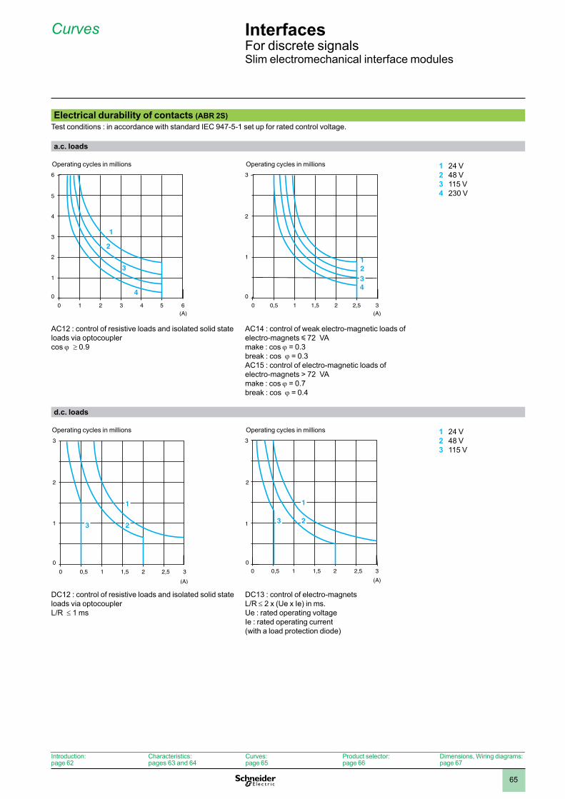
65
Curves
Electrical durability of contacts (ABR 2S)Test conditions : in accordance with standard IEC 947-5-1 set up for rated control voltage.
a.c. loads
1 24 V2 48 V3 115 V4 230 V
AC12 : control of resistive loads and isolated solid state loads via optocouplercos j ≥ 0.9
AC14 : control of weak electro-magnetic loads of electro-magnets y 72 VAmake : cos j = 0.3break : cos j = 0.3AC15 : control of electro-magnetic loads of electro-magnets > 72 VAmake : cos j = 0.7break : cos j = 0.4
d.c. loads
1 24 V2 48 V3 115 V
DC12 : control of resistive loads and isolated solid state loads via optocoupler L/R ≤ 1 ms
DC13 : control of electro-magnets L/R ≤ 2 x (Ue x Ie) in ms.Ue : rated operating voltageIe : rated operating current(with a load protection diode)
5
4
3
2
1
1 2 3 4 5(A)
6
0
0
3
4
2
6
1
Operating cycles in millions
2
1
0,5 1 1,5 2 2,5(A)
3
0
0
3
2
43
1
Operating cycles in millions
2
1
0,5 1 1,5 2 2,5
(A)
3
0
0
3
1
23
Operating cycles in millions
2
1
0
0,5 1 1,5 2 2,5
(A)
23
3
30
1
Operating cycles in millions
Introduction:page 62
Characteristics:pages 63 and 64
Curves:page 65
Product selector:page 66
Dimensions, Wiring diagrams:page 67
InterfacesFor discrete signalsSlim electromechanical interface modules
1
2
3
4
5
6
7
8
9
10
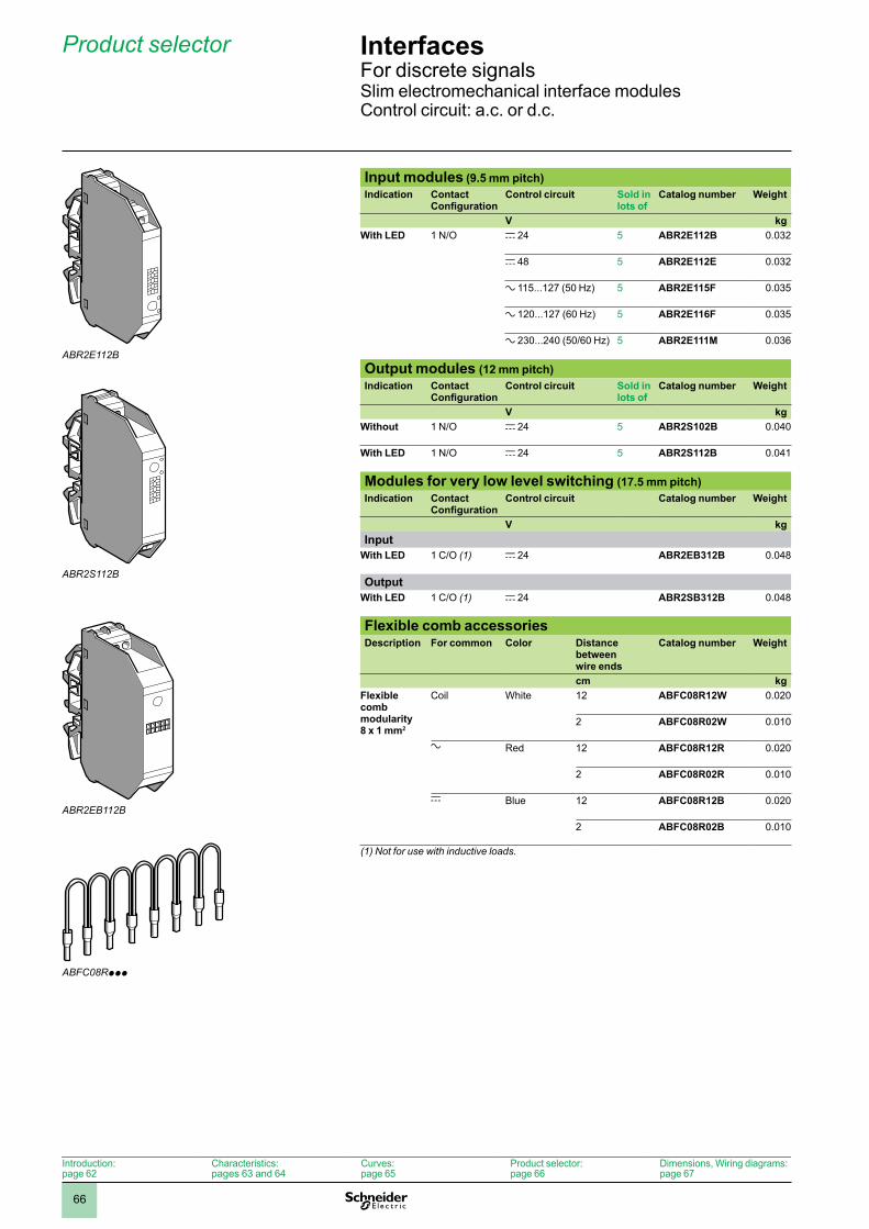
66
Product selector
Input modules (9.5 mm pitch)Indication Contact
ConfigurationControl circuit Sold in
lots ofCatalog number Weight
V kgWith LED 1 N/O c 24 5 ABR2E112B 0.032
c 48 5 ABR2E112E 0.032
a 115...127 (50 Hz) 5 ABR2E115F 0.035
a 120...127 (60 Hz) 5 ABR2E116F 0.035
a 230...240 (50/60 Hz) 5 ABR2E111M 0.036
Output modules (12 mm pitch)Indication Contact
ConfigurationControl circuit Sold in
lots ofCatalog number Weight
V kgWithout 1 N/O c 24 5 ABR2S102B 0.040
With LED 1 N/O c 24 5 ABR2S112B 0.041
Modules for very low level switching (17.5 mm pitch)Indication Contact
ConfigurationControl circuit Catalog number Weight
V kgInput
With LED 1 C/O (1) c 24 ABR2EB312B 0.048
OutputWith LED 1 C/O (1) c 24 ABR2SB312B 0.048
Flexible comb accessoriesDescription For common Color Distance
between wire ends
Catalog number Weight
cm kgFlexible comb modularity 8 x 1 mm2
Coil White 12 ABFC08R12W 0.020
2 ABFC08R02W 0.010
a Red 12 ABFC08R12R 0.020
2 ABFC08R02R 0.010
c Blue 12 ABFC08R12B 0.020
2 ABFC08R02B 0.010
(1) Not for use with inductive loads.
ABR2E112B
ABR2S112B
ABR2EB112B
ABFC08Rppp
Introduction:page 62
Characteristics:pages 63 and 64
Curves:page 65
Product selector:page 66
Dimensions, Wiring diagrams:page 67
InterfacesFor discrete signalsSlim electromechanical interface modulesControl circuit: a.c. or d.c.
1
2
3
4
5
6
7
8
9
10
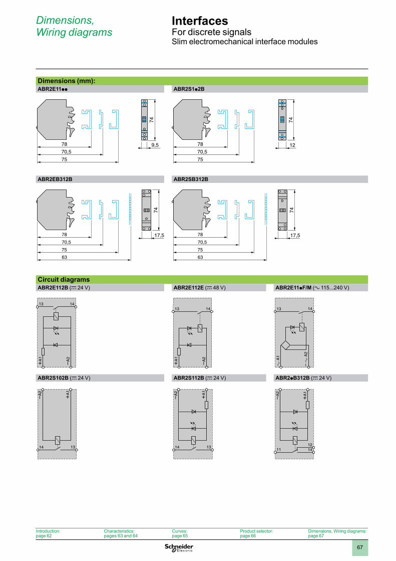
67
Dimensions, Wiring diagrams
Dimensions (mm):ABR2E11pp ABR2S1p2B
ABR2EB312B ABR2SB312B
Circuit diagramsABR2E112B (c 24 V) ABR2E112E (c 48 V) ABR2E11pF/M (a 115...240 V)
ABR2S102B (c 24 V) ABR2S112B (c 24 V) ABR2pB312B (c 24 V)
78
75
70,59,5
7478
75
70,512
74
78
75
70,5
63
17,5
74
78
75
70,5
63
17,5
74
+A
1
–A2
13 14
+A
1
–A2
1413
A1
– A
213 14
1314
+A
1
–A2
1314
+A
1
–A2
141112
+A
1
–A2
Introduction:page 62
Characteristics:pages 63 and 64
Curves:page 65
Product selector:page 66
Dimensions, Wiring diagrams:page 67
InterfacesFor discrete signalsSlim electromechanical interface modules
1
2
3
4
5
6
7
8
9
10
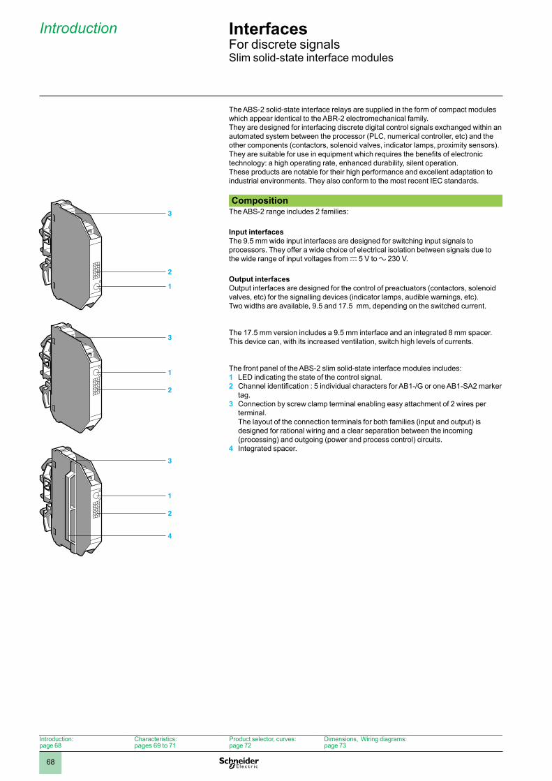
68
Interfaces 6 For discrete signalsSlim solid-state interface modules
The ABS-2 solid-state interface relays are supplied in the form of compact modules which appear identical to the ABR-2 electromechanical family.They are designed for interfacing discrete digital control signals exchanged within an automated system between the processor (PLC, numerical controller, etc) and the other components (contactors, solenoid valves, indicator lamps, proximity sensors).They are suitable for use in equipment which requires the benefits of electronic technology: a high operating rate, enhanced durability, silent operation.These products are notable for their high performance and excellent adaptation to industrial environments. They also conform to the most recent IEC standards.
CompositionThe ABS-2 range includes 2 families:
Input interfaces The 9.5 mm wide input interfaces are designed for switching input signals to processors. They offer a wide choice of electrical isolation between signals due to the wide range of input voltages from c 5 V to a 230 V.
Output interfaces Output interfaces are designed for the control of preactuators (contactors, solenoid valves, etc) for the signalling devices (indicator lamps, audible warnings, etc). Two widths are available, 9.5 and 17.5 mm, depending on the switched current.
The 17.5 mm version includes a 9.5 mm interface and an integrated 8 mm spacer. This device can, with its increased ventilation, switch high levels of currents.
The front panel of the ABS-2 slim solid-state interface modules includes:1 LED indicating the state of the control signal.2 Channel identification : 5 individual characters for AB1-/G or one AB1-SA2 marker
tag.3 Connection by screw clamp terminal enabling easy attachment of 2 wires per
terminal. The layout of the connection terminals for both families (input and output) is designed for rational wiring and a clear separation between the incoming (processing) and outgoing (power and process control) circuits.
4 Integrated spacer.
3
2
1
ABS2INTERSORT-PRO-3-B
3
2
1
ABS-2
ABS2-PRO-3-B
3
2
1
4
Introduction:page 68
Characteristics:pages 69 to 71
Product selector, curves:page 72
Dimensions, Wiring diagrams:page 73
Introduction 6
1
2
3
4
5
6
7
8
9
10
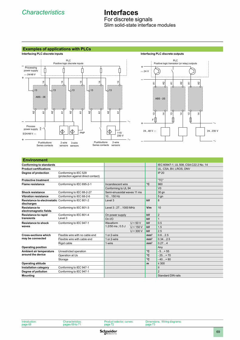
69
Interfaces 6 For discrete signalsSlim solid-state interface modules
Examples of applications with PLCsInterfacing PLC discrete inputs
Interfacing PLC discrete outputs
–
+
–
+
14
13
14
13
ABS - 2E
13
14
PNP 115/230 V
13
14
13
14A
1
A2
A1
A2
A1
A2
A1
A2
A1
A2
PLCPositive logic discrete inputs
PushbuttonsSeries contacts
2-wiresensors
3-wiresensors
PushbuttonsSeries contacts
2-wiresensors
Process power supply
Processing power supply
–
+
–
+
A1
A2
A1
A2
A1
A2
ABS - 2S
F
13 14 13 14 13 14
PLCPositive logic transistor (or relay) outputs
Environment
Conforming to standards IEC 60947-1, UL 508, CSA C22.2 No. 14Product certifications UL, CSA, BV, LROS, DNVDegree of protection Conforming to IEC 529
(protection against direct contact)IP 20
Protective treatment “TC”Flame resistance Conforming to IEC 695-2-1 Incandescent wire °C 960
Conforming to UL 94 V0Shock resistance Conforming to IEC 68-2-27 Semi-sinusoidal waves 11 ms 30 gnVibration resistance Conforming to IEC 68-2-6 10…150 Hz 5 gnResistance to electrostatic discharges
Conforming to IEC 801-2 Level 3 kV 8
Resistance to electromagnetic fields
Conforming to IEC 801-3 Level 3 ; 27…1000 MHz V/m 10
Resistance to rapid transients
Conforming to IEC 801-4 Level 3
On power supply kV 2On I/O kV 1
Resistance to shock waves
Conforming to IEC 947-1 Waveform 1.2/50 ms ; 0.5 J
U < 50 V kV 0.5U < 150 V kV 1.5U < 300 V kV 2.5
Cross-sections which may be connected
Flexible wire with no cable end 1 or 2-wire mm2 0.6…2.5Flexible wire with cable end 1 or 2-wire mm2 0.34…2.5Rigid cable 1-wire mm2 0.27…4
Operating position AnyAmbient air temperature around the device
Unrestricted operation °C - 5…+ 55Operation at Us °C - 25…+ 70Storage °C - 40…+ 80
Operating altitude m ≤ 300Installation category Conforming to IEC 947-1 IIDegree of pollution Conforming to IEC 947-1 2Mounting Standard DIN rails
Introduction:page 68
Characteristics:pages 69 to 71
Product selector, curves:page 72
Dimensions, Wiring diagrams:page 73
Characteristics 6
1
2
3
4
5
6
7
8
9
10
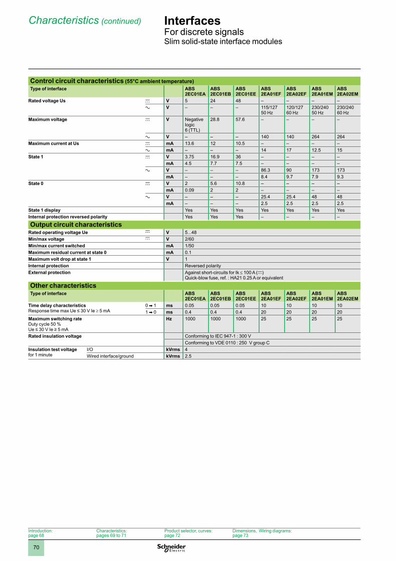
70
Interfaces 6 For discrete signalsSlim solid-state interface modules
Control circuit characteristics (55°C ambient temperature)Type of interface ABS
2EC01EAABS 2EC01EB
ABS 2EC01EE
ABS 2EA01EF
ABS 2EA02EF
ABS 2EA01EM
ABS 2EA02EM
Rated voltage Us c V 5 24 48 – – – –a V – – – 115/127
50 Hz120/127 60 Hz
230/240 50 Hz
230/240 60 Hz
Maximum voltage c V Negative logic 6 (TTL)
28.8 57.6 – – – –
a V – – – 140 140 264 264Maximum current at Us c mA 13.6 12 10.5 – – – –
a mA – – – 14 17 12.5 15State 1 c V 3.75 16.9 36 – – – –
mA 4.5 7.7 7.5 – – – –a V – – – 86.3 90 173 173
mA – – – 8.4 9.7 7.9 9.3State 0 c V 2 5.6 10.8 – – – –
mA 0.09 2 2 – – – –a V – – – 25.4 25.4 48 48
mA – – – 2.5 2.5 2.5 2.5State 1 display Yes Yes Yes Yes Yes Yes YesInternal protection reversed polarity Yes Yes Yes – – – –
Output circuit characteristicsRated operating voltage Ue c V 5...48Min/max voltage c V 2/60Min/max current switched mA 1/50Maximum residual current at state 0 mA 0.1Maximum volt drop at state 1 V 1Internal protection Reversed polarityExternal protection Against short-circuits for Ik ≤ 100 A (c)
Quick-blow fuse, ref. : HA21 0.25 A or equivalent
Other characteristicsType of interface ABS
2EC01EAABS 2EC01EB
ABS 2EC01EE
ABS 2EA01EF
ABS 2EA02EF
ABS 2EA01EM
ABS 2EA02EM
Time delay characteristics Response time max Ue ≤ 30 V Ie ≥ 5 mA
0 V 1 ms 0.05 0.05 0.05 10 10 10 101 V 0 ms 0.4 0.4 0.4 20 20 20 20
Maximum switching rate Duty cycle 50 % Ue ≤ 30 V Ie ≥ 5 mA
Hz 1000 1000 1000 25 25 25 25
Rated insulation voltage Conforming to IEC 947-1 : 300 VConforming to VDE 0110 : 250 V group C
Insulation test voltage for 1 minute
I/O kVrms 4Wired interface/ground kVrms 2.5
Introduction:page 68
Characteristics:pages 69 to 71
Product selector, curves:page 72
Dimensions, Wiring diagrams:page 73
Characteristics (continued) 6
1
2
3
4
5
6
7
8
9
10
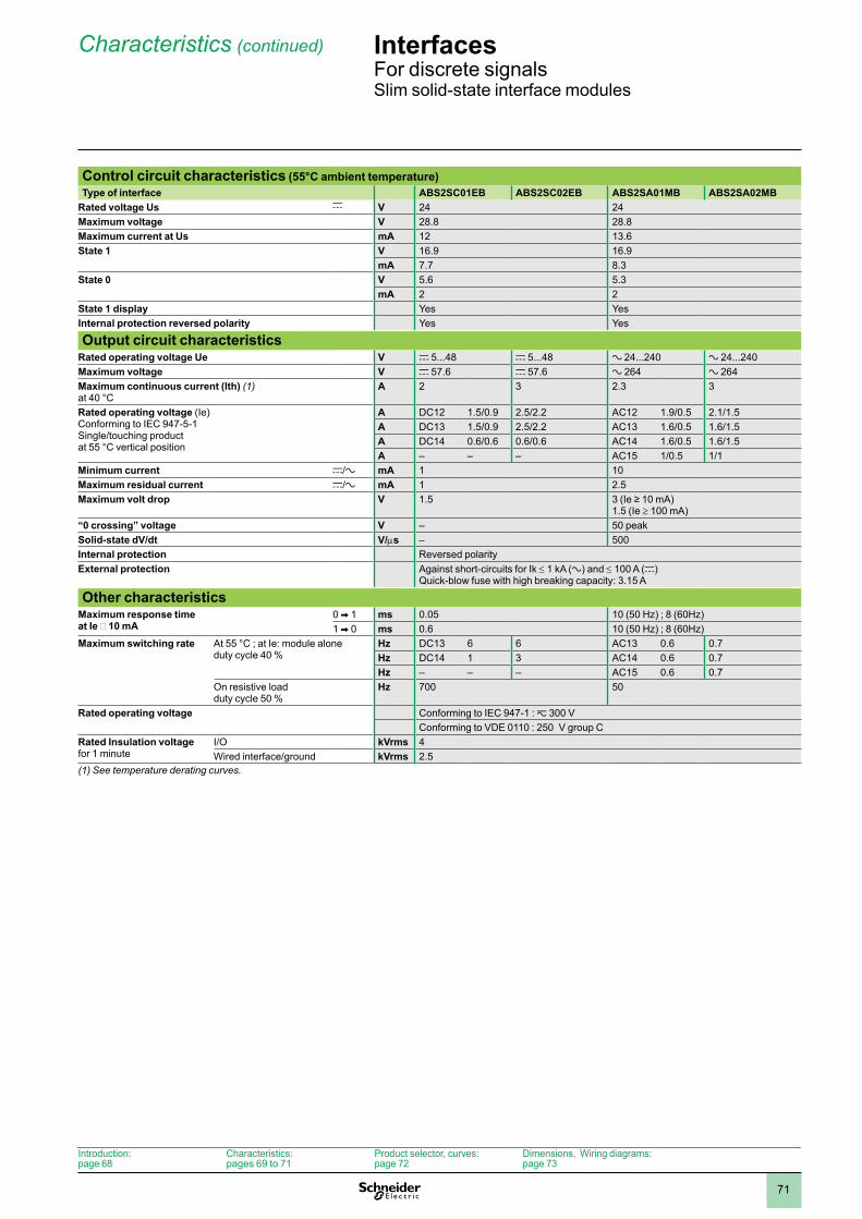
71
Interfaces 6 For discrete signalsSlim solid-state interface modules
Control circuit characteristics (55°C ambient temperature)Type of interface ABS2SC01EB ABS2SC02EB ABS2SA01MB ABS2SA02MB
Rated voltage Us c V 24 24Maximum voltage V 28.8 28.8Maximum current at Us mA 12 13.6State 1 V 16.9 16.9
mA 7.7 8.3State 0 V 5.6 5.3
mA 2 2State 1 display Yes YesInternal protection reversed polarity Yes Yes
Output circuit characteristicsRated operating voltage Ue V c 5...48 c 5...48 a 24...240 a 24...240Maximum voltage V c 57.6 c 57.6 a 264 a 264Maximum continuous current (Ith) (1) at 40 °C
A 2 3 2.3 3
Rated operating voltage (Ie) Conforming to IEC 947-5-1 Single/touching product at 55 °C vertical position
A DC12 1.5/0.9 2.5/2.2 AC12 1.9/0.5 2.1/1.5A DC13 1.5/0.9 2.5/2.2 AC13 1.6/0.5 1.6/1.5A DC14 0.6/0.6 0.6/0.6 AC14 1.6/0.5 1.6/1.5A – – – AC15 1/0.5 1/1
Minimum current c/a mA 1 10Maximum residual current c/a mA 1 2.5Maximum volt drop V 1.5 3 (Ie ≥ 10 mA)
1.5 (Ie ≥ 100 mA)“0 crossing” voltage V – 50 peakSolid-state dV/dt V/ms – 500Internal protection Reversed polarityExternal protection Against short-circuits for Ik ≤ 1 kA (a) and ≤ 100 A (c)
Quick-blow fuse with high breaking capacity: 3.15 A
Other characteristicsMaximum response time at Ie Š 10 mA
0 V 1 ms 0.05 10 (50 Hz) ; 8 (60Hz)1 V 0 ms 0.6 10 (50 Hz) ; 8 (60Hz)
Maximum switching rate At 55 °C ; at Ie: module alone duty cycle 40 %
Hz DC13 6 6 AC13 0.6 0.7Hz DC14 1 3 AC14 0.6 0.7Hz – – – AC15 0.6 0.7
On resistive load duty cycle 50 %
Hz 700 50
Rated operating voltage Conforming to IEC 947-1 : z 300 VConforming to VDE 0110 : 250 V group C
Rated Insulation voltage for 1 minute
I/O kVrms 4Wired interface/ground kVrms 2.5
(1) See temperature derating curves.
Introduction:page 68
Characteristics:pages 69 to 71
Product selector, curves:page 72
Dimensions, Wiring diagrams:page 73
Characteristics (continued) 6
1
2
3
4
5
6
7
8
9
10
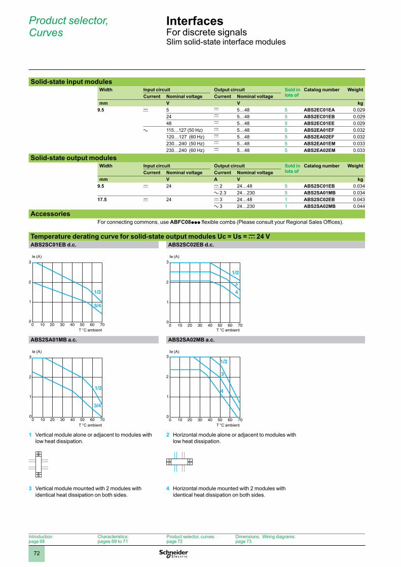
72
Interfaces 6 For discrete signalsSlim solid-state interface modules
Solid-state input modulesWidth Input circuit Output circuit Sold in
lots ofCatalog number Weight
Current Nominal voltage Current Nominal voltagemm V V kg
9.5 c 5 c 5…48 5 ABS2EC01EA 0.029 24 c 5…48 5 ABS2EC01EB 0.02948 c 5…48 5 ABS2EC01EE 0.029
a 115…127 (50 Hz) c 5…48 5 ABS2EA01EF 0.032120…127 (60 Hz) c 5…48 5 ABS2EA02EF 0.032230…240 (50 Hz) c 5…48 5 ABS2EA01EM 0.033230…240 (60 Hz) c 5…48 5 ABS2EA02EM 0.033
Solid-state output modulesWidth Input circuit Output circuit Sold in
lots ofCatalog number Weight
Current Nominal voltage Current Nominal voltagemm V A V kg
9.5 c 24 c 2 24…48 5 ABS2SC01EB 0.034 a 2.3 24…230 5 ABS2SA01MB 0.034
17.5 c 24 c 3 24…48 1 ABS2SC02EB 0.043 a 3 24…230 1 ABS2SA02MB 0.044
AccessoriesFor connecting commons, use ABFC08ppp flexible combs (Please consult your Regional Sales Offices).
Temperature derating curve for solid-state output modules Uc = Us = c 24 VABS2SC01EB d.c. ABS2SC02EB d.c.
ABS2SA01MB a.c. ABS2SA02MB a.c.
1 Vertical module alone or adjacent to modules with low heat dissipation.
2 Horizontal module alone or adjacent to modules with low heat dissipation.
3 Vertical module mounted with 2 modules with identical heat dissipation on both sides.
4 Horizontal module mounted with 2 modules with identical heat dissipation on both sides.
10 20 30 40 50 60 70
1
2
3
1/2
00
3/4
Ie (A)
T °C ambient10 20 30 40 50 60 70
1
2
3
1/2
00
4
3
Ie (A)
T °C ambient
10 20 30 40 50 60 70
1
2
3
1/2
00
3/4
Ie (A)
T °C ambient10 20 30 40 50 60 70
1
2
31/2
00
4
3
Ie (A)
T °C ambient
Introduction:page 68
Characteristics:pages 69 to 71
Product selector, curves:page 72
Dimensions, Wiring diagrams:page 73
Product selector, Curves 6
1
2
3
4
5
6
7
8
9
10
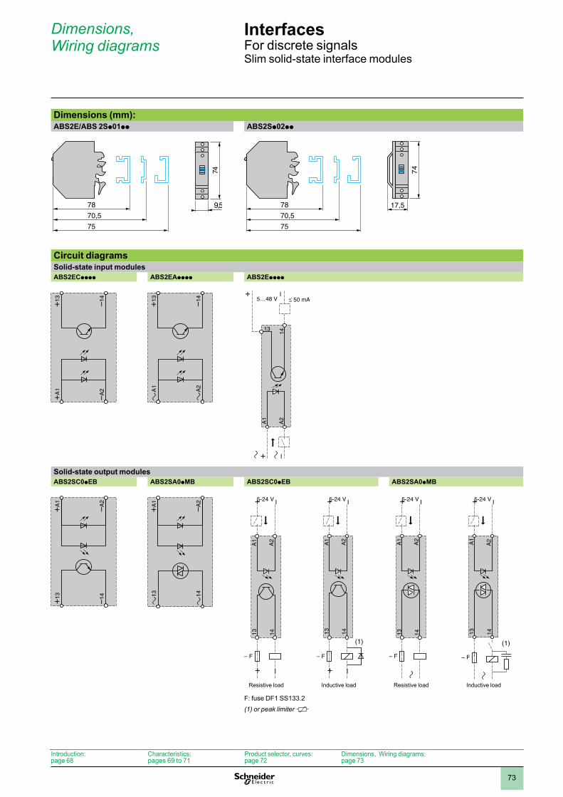
73
Interfaces 6 For discrete signalsSlim solid-state interface modules
Dimensions (mm):ABS2E/ABS 2Sp01pp ABS2Sp02pp
Circuit diagramsSolid-state input modulesABS2ECpppp ABS2EApppp ABS2Epppp
Solid-state output modulesABS2SC0pEB ABS2SA0pMB ABS2SC0pEB ABS2SA0pMB
F: fuse DF1 SS133.2(1) or peak limiter
78
75
70,574
9,5 78
75
70,5
17,5
74
+A
1
–A2
+13 –14
A
1
A
2
+13 –14
14
13
A2
A1
+ –
5…48 V
+ –
+13
–14
+A1
–A2
1
3
1
4
+A
1
–A2
1413
A2
A1
+ –
+ –
– F
5-24 V
Resistive load
1413
A2
A1
+ –
+ –
– F
5-24 V
(1)
Inductive load
1413
A2
A1
+ –
– F
5-24 V
Resistive load
1413
A2A1
+ –
– F
5-24 V
(1)
Inductive load
Introduction:page 68
Characteristics:pages 69 to 71
Product selector, curves:page 72
Dimensions, Wiring diagrams:page 73
Dimensions, Wiring diagrams 6
1
2
3
4
5
6
7
8
9
10
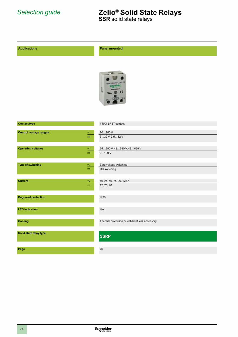
2
1
3
4
5
6
7
8
9
10
7474
Selection guide Zelio® Solid State Relays SSR solid state relays
Applications Panel mounted DIN rail mounted
Contact type 1 N/O SPST contact 1 N/O SPST contact
Control voltage ranges a 90…280 V 90…280 V 90…140 Vc 3…32 V, 3.5…32 V 4…32 V 3…32 V
Operating voltages a 24…280 V, 48…530 V, 48…660 V 24…280 Vc 0…100 V
Type of switching a Zero voltage switching Zero voltage switchingc DC switching
Current a 10, 25, 50, 75, 90, 125 A 10, 20, 30 A 45 Ac 12, 25, 40
Degree of protection IP20 IP20
LED indication Yes Yes
Cooling Thermal protection or with heat sink accessory Built-in heat sink
Solid state relay typeSSRP SSRD
Page 76 76
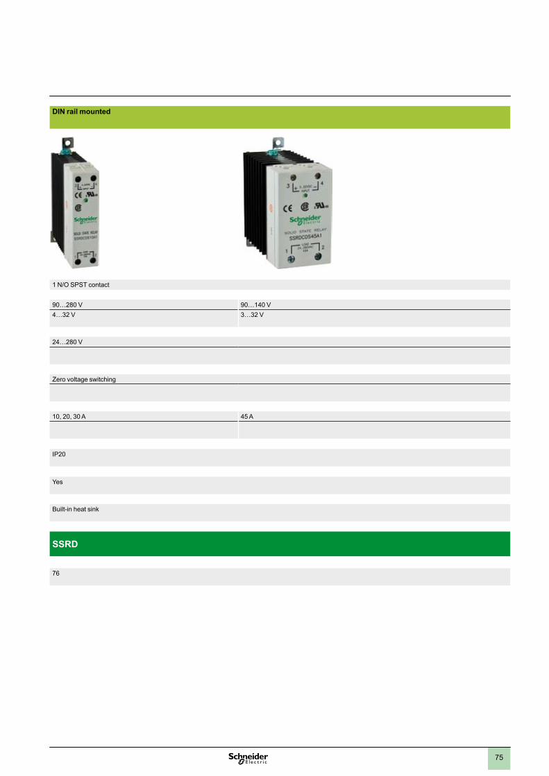
2
1
3
4
5
6
7
8
9
10
7575
Applications Panel mounted DIN rail mounted
Contact type 1 N/O SPST contact 1 N/O SPST contact
Control voltage ranges a 90…280 V 90…280 V 90…140 Vc 3…32 V, 3.5…32 V 4…32 V 3…32 V
Operating voltages a 24…280 V, 48…530 V, 48…660 V 24…280 Vc 0…100 V
Type of switching a Zero voltage switching Zero voltage switchingc DC switching
Current a 10, 25, 50, 75, 90, 125 A 10, 20, 30 A 45 Ac 12, 25, 40
Degree of protection IP20 IP20
LED indication Yes Yes
Cooling Thermal protection or with heat sink accessory Built-in heat sink
Solid state relay typeSSRP SSRD
Page 76 76
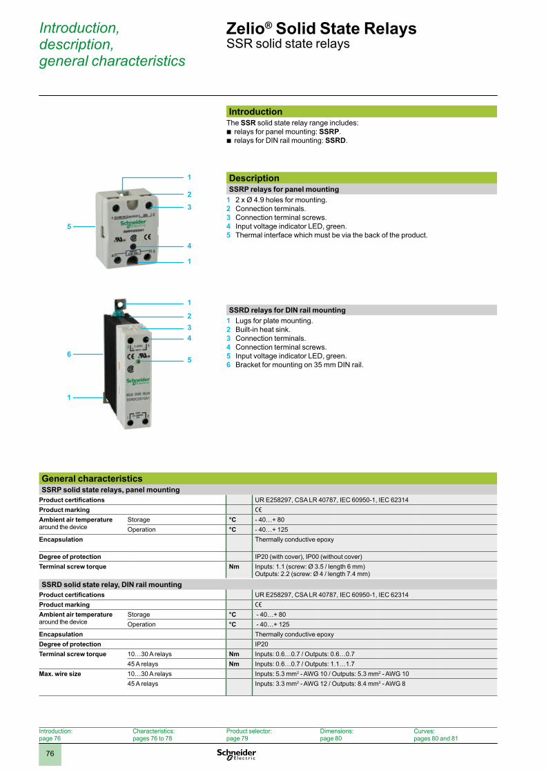
2
1
3
4
5
6
7
8
9
10
7676
Introduction, description, general characteristics
Zelio® Solid State RelaysSSR solid state relays
IntroductionThe SSR solid state relay range includes:
relays for panel mounting: b SSRP.relays for DIN rail mounting: b SSRD.
DescriptionSSRP relays for panel mounting
2 x Ø 4.9 holes for mounting.1 Connection terminals.2 Connection terminal screws.3 Input voltage indicator LED, green.4 Thermal interface which must be via the back of the product.5
SSRD relays for DIN rail mountingLugs for plate mounting.1 Built-in heat sink.2 Connection terminals.3 Connection terminal screws.4 Input voltage indicator LED, green.5 Bracket for mounting on 35 mm DIN6 rail.
Introduction: page 76
Characteristics: pages 76 to 78
Product selector: page 79
Dimensions: page 80
Curves:pages 80 and 81
1
2
4
1
5
3
1
2
56
1
43
General characteristicsSSRP solid state relays, panel mounting
Product certifications UR E258297, CSA LR 40787, IEC 60950-1, IEC 62314Product marking e
Ambient air temperature around the device
Storage °C - 40…+ 80Operation °C - 40…+ 125
Encapsulation Thermally conductive epoxy
Degree of protection IP20 (with cover), IP00 (without cover)Terminal screw torque Nm Inputs: 1.1 (screw: Ø 3.5 / length 6 mm)
Outputs: 2.2 (screw: Ø 4 / length 7.4 mm)
SSRD solid state relay, DIN rail mountingProduct certifications UR E258297, CSA LR 40787, IEC 60950-1, IEC 62314Product marking e
Ambient air temperature around the device
Storage °C - 40…+ 80Operation °C - 40…+ 125
Encapsulation Thermally conductive epoxyDegree of protection IP20Terminal screw torque 10…30 A relays Nm Inputs: 0.6…0.7 / Outputs: 0.6…0.7
45 A relays Nm Inputs: 0.6…0.7 / Outputs: 1.1…1.7Max. wire size 10…30 A relays Inputs: 5.3 mm2 - AWG 10 / Outputs: 5.3 mm2 - AWG 10
45 A relays Inputs: 3.3 mm2 - AWG 12 / Outputs: 8.4 mm2 - AWG 8
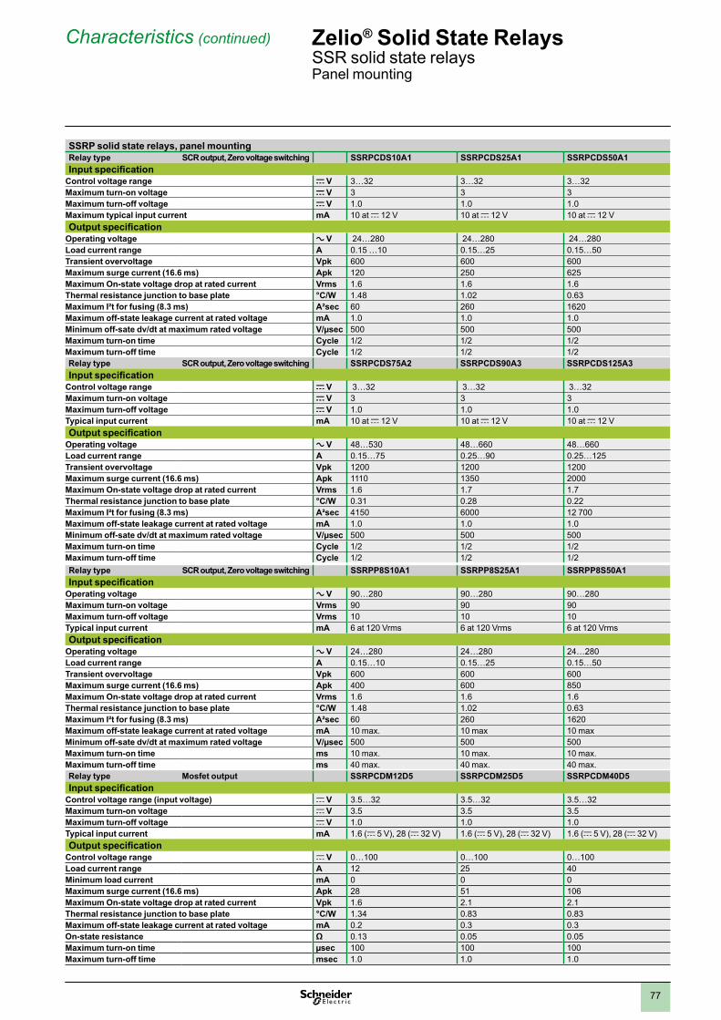
2
1
3
4
5
6
7
8
9
10
7777
Characteristics (continued) Zelio® Solid State RelaysSSR solid state relays Panel mounting
SSRP solid state relays, panel mountingRelay type SCR output, Zero voltage switching SSRPCDS10A1 SSRPCDS25A1 SSRPCDS50A1Input specification
Control voltage range c V 3…32 3…32 3…32Maximum turn-on voltage c V 3 3 3Maximum turn-off voltage c V 1.0 1.0 1.0Maximum typical input current mA 10 at c 12 V 10 at c 12 V 10 at c 12 VOutput specification
Operating voltage a V 24…280 24…280 24…280Load current range A 0.15 …10 0.15…25 0.15…50Transient overvoltage Vpk 600 600 600Maximum surge current (16.6 ms) Apk 120 250 625Maximum On-state voltage drop at rated current Vrms 1.6 1.6 1.6Thermal resistance junction to base plate °C/W 1.48 1.02 0.63Maximum I²t for fusing (8.3 ms) A²sec 60 260 1620Maximum off-state leakage current at rated voltage mA 1.0 1.0 1.0Minimum off-sate dv/dt at maximum rated voltage V/µsec 500 500 500Maximum turn-on time Cycle 1/2 1/2 1/2Maximum turn-off time Cycle 1/2 1/2 1/2Relay type SCR output, Zero voltage switching SSRPCDS75A2 SSRPCDS90A3 SSRPCDS125A3Input specification
Control voltage range c V 3…32 3…32 3…32Maximum turn-on voltage c V 3 3 3Maximum turn-off voltage c V 1.0 1.0 1.0Typical input current mA 10 at c 12 V 10 at c 12 V 10 at c 12 VOutput specification
Operating voltage a V 48…530 48…660 48…660Load current range A 0.15…75 0.25…90 0.25…125Transient overvoltage Vpk 1200 1200 1200Maximum surge current (16.6 ms) Apk 1110 1350 2000Maximum On-state voltage drop at rated current Vrms 1.6 1.7 1.7Thermal resistance junction to base plate °C/W 0.31 0.28 0.22Maximum I²t for fusing (8.3 ms) A²sec 4150 6000 12 700Maximum off-state leakage current at rated voltage mA 1.0 1.0 1.0Minimum off-sate dv/dt at maximum rated voltage V/µsec 500 500 500Maximum turn-on time Cycle 1/2 1/2 1/2Maximum turn-off time Cycle 1/2 1/2 1/2Relay type SCR output, Zero voltage switching SSRPP8S10A1 SSRPP8S25A1 SSRPP8S50A1Input specification
Operating voltage a V 90…280 90…280 90…280Maximum turn-on voltage Vrms 90 90 90Maximum turn-off voltage Vrms 10 10 10Typical input current mA 6 at 120 Vrms 6 at 120 Vrms 6 at 120 VrmsOutput specification
Operating voltage a V 24…280 24…280 24…280Load current range A 0.15…10 0.15…25 0.15…50Transient overvoltage Vpk 600 600 600Maximum surge current (16.6 ms) Apk 400 600 850Maximum On-state voltage drop at rated current Vrms 1.6 1.6 1.6Thermal resistance junction to base plate °C/W 1.48 1.02 0.63Maximum I²t for fusing (8.3 ms) A²sec 60 260 1620Maximum off-state leakage current at rated voltage mA 10 max. 10 max 10 maxMinimum off-sate dv/dt at maximum rated voltage V/µsec 500 500 500Maximum turn-on time ms 10 max. 10 max. 10 max.Maximum turn-off time ms 40 max. 40 max. 40 max.Relay type Mosfet output SSRPCDM12D5 SSRPCDM25D5 SSRPCDM40D5Input specification
Control voltage range (input voltage) c V 3.5…32 3.5…32 3.5…32Maximum turn-on voltage c V 3.5 3.5 3.5Maximum turn-off voltage c V 1.0 1.0 1.0Typical input current mA 1.6 (c 5 V), 28 (c 32 V) 1.6 (c 5 V), 28 (c 32 V) 1.6 (c 5 V), 28 (c 32 V)Output specification
Control voltage range c V 0…100 0…100 0…100Load current range A 12 25 40Minimum load current mA 0 0 0Maximum surge current (16.6 ms) Apk 28 51 106Maximum On-state voltage drop at rated current Vpk 1.6 2.1 2.1Thermal resistance junction to base plate °C/W 1.34 0.83 0.83Maximum off-state leakage current at rated voltage mA 0.2 0.3 0.3On-state resistance Ω 0.13 0.05 0.05Maximum turn-on time µsec 100 100 100Maximum turn-off time msec 1.0 1.0 1.0
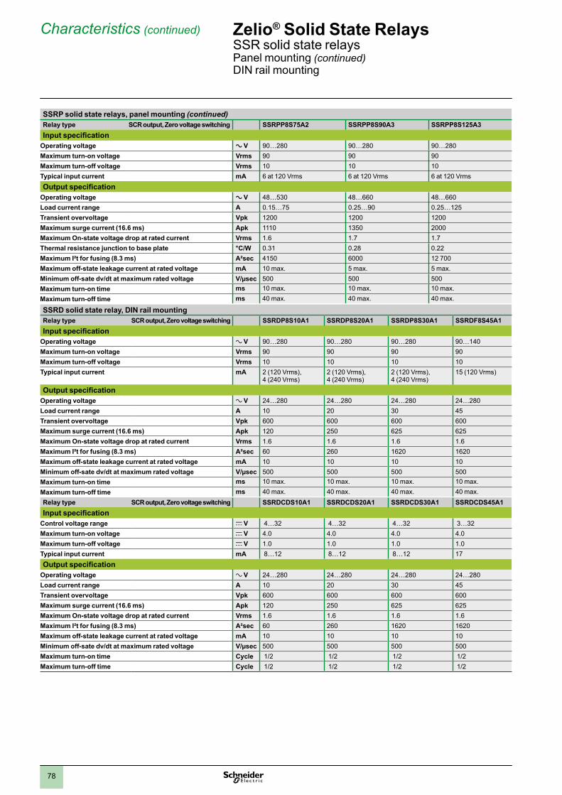
2
1
3
4
5
6
7
8
9
10
7878
Characteristics (continued) Zelio® Solid State RelaysSSR solid state relaysPanel mounting (continued)DIN rail mounting
SSRP solid state relays, panel mounting (continued)Relay type SCR output, Zero voltage switching SSRPP8S75A2 SSRPP8S90A3 SSRPP8S125A3Input specification
Operating voltage a V 90…280 90…280 90…280Maximum turn-on voltage Vrms 90 90 90Maximum turn-off voltage Vrms 10 10 10Typical input current mA 6 at 120 Vrms 6 at 120 Vrms 6 at 120 VrmsOutput specification
Operating voltage a V 48…530 48…660 48…660Load current range A 0.15…75 0.25…90 0.25…125Transient overvoltage Vpk 1200 1200 1200Maximum surge current (16.6 ms) Apk 1110 1350 2000Maximum On-state voltage drop at rated current Vrms 1.6 1.7 1.7Thermal resistance junction to base plate °C/W 0.31 0.28 0.22Maximum I²t for fusing (8.3 ms) A²sec 4150 6000 12 700Maximum off-state leakage current at rated voltage mA 10 max. 5 max. 5 max.Minimum off-sate dv/dt at maximum rated voltage V/µsec 500 500 500Maximum turn-on time ms 10 max. 10 max. 10 max.Maximum turn-off time ms 40 max. 40 max. 40 max.
SSRD solid state relay, DIN rail mountingRelay type SCR output, Zero voltage switching SSRDP8S10A1 SSRDP8S20A1 SSRDP8S30A1 SSRDF8S45A1Input specification
Operating voltage a V 90…280 90…280 90…280 90…140Maximum turn-on voltage Vrms 90 90 90 90Maximum turn-off voltage Vrms 10 10 10 10Typical input current mA 2 (120 Vrms),
4 (240 Vrms)2 (120 Vrms), 4 (240 Vrms)
2 (120 Vrms), 4 (240 Vrms)
15 (120 Vrms)
Output specificationOperating voltage a V 24…280 24…280 24…280 24…280Load current range A 10 20 30 45Transient overvoltage Vpk 600 600 600 600Maximum surge current (16.6 ms) Apk 120 250 625 625Maximum On-state voltage drop at rated current Vrms 1.6 1.6 1.6 1.6Maximum I²t for fusing (8.3 ms) A²sec 60 260 1620 1620Maximum off-state leakage current at rated voltage mA 10 10 10 10Minimum off-sate dv/dt at maximum rated voltage V/µsec 500 500 500 500Maximum turn-on time ms 10 max. 10 max. 10 max. 10 max.Maximum turn-off time ms 40 max. 40 max. 40 max. 40 max.Relay type SCR output, Zero voltage switching SSRDCDS10A1 SSRDCDS20A1 SSRDCDS30A1 SSRDCDS45A1Input specification
Control voltage range c V 4…32 4…32 4…32 3…32Maximum turn-on voltage c V 4.0 4.0 4.0 4.0Maximum turn-off voltage c V 1.0 1.0 1.0 1.0Typical input current mA 8…12 8…12 8…12 17Output specification
Operating voltage a V 24…280 24…280 24…280 24…280Load current range A 10 20 30 45Transient overvoltage Vpk 600 600 600 600Maximum surge current (16.6 ms) Apk 120 250 625 625Maximum On-state voltage drop at rated current Vrms 1.6 1.6 1.6 1.6Maximum I²t for fusing (8.3 ms) A²sec 60 260 1620 1620Maximum off-state leakage current at rated voltage mA 10 10 10 10Minimum off-sate dv/dt at maximum rated voltage V/µsec 500 500 500 500Maximum turn-on time Cycle 1/2 1/2 1/2 1/2Maximum turn-off time Cycle 1/2 1/2 1/2 1/2
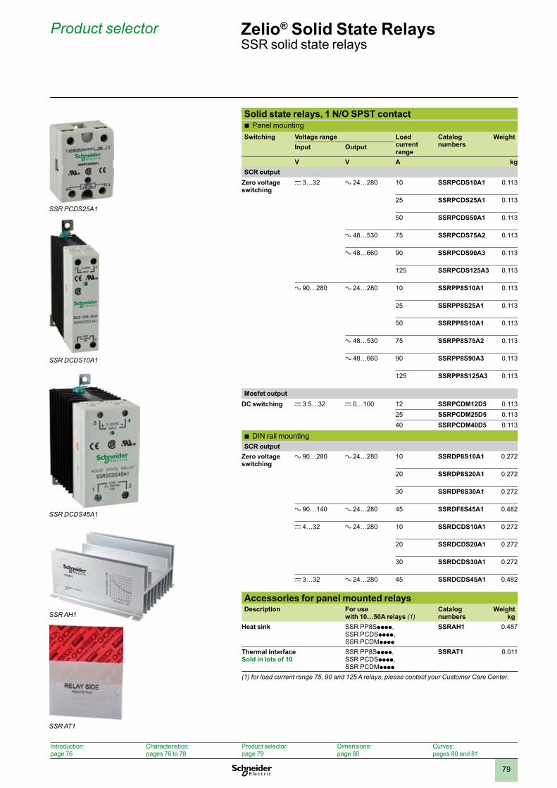
2
1
3
4
5
6
7
8
9
10
7979
Product selector Zelio® Solid State RelaysSSR solid state relays
Introduction: page 76
Characteristics: pages 76 to 78
Product selector: page 79
Dimensions: page 80
Curves:pages 80 and 81
Solid state relays, 1 N/O SPST contactPanel mounting b
Switching Voltage range Load current range
Catalog numbers
WeightInput Output
V V A kgSCR output
Zero voltage switching
c 3…32 a 24…280 10 SSRPCDS10A1 0.113
25 SSRPCDS25A1 0.113
50 SSRPCDS50A1 0.113
a 48…530 75 SSRPCDS75A2 0.113
a 48…660 90 SSRPCDS90A3 0.113
125 SSRPCDS125A3 0.113
a 90…280 a 24…280 10 SSRPP8S10A1 0.113
25 SSRPP8S25A1 0.113
50 SSRPP8S10A1 0.113
a 48…530 75 SSRPP8S75A2 0.113
a 48…660 90 SSRPP8S90A3 0.113
125 SSRPP8S125A3 0.113
Mosfet outputDC switching c 3.5…32 c 0…100 12 SSRPCDM12D5 0.113
25 SSRPCDM25D5 0.11340 SSRPCDM40D5 0.113
DIN rail mounting bSCR output
Zero voltage switching
a 90…280 a 24…280 10 SSRDP8S10A1 0.272
20 SSRDP8S20A1 0.272
30 SSRDP8S30A1 0.272
a 90…140 a 24…280 45 SSRDF8S45A1 0.482
c 4…32 a 24…280 10 SSRDCDS10A1 0.272
20 SSRDCDS20A1 0.272
30 SSRDCDS30A1 0.272
c 3…32 a 24…280 45 SSRDCDS45A1 0.482
Accessories for panel mounted relaysDescription For use
with 10…50A relays (1)Catalog numbers
Weightkg
Heat sink SSR PP8Spppp, SSR PCDSpppp, SSR PCDMpppp
SSRAH1 0.487
Thermal interfaceSold in lots of 10
SSR PP8Spppp, SSR PCDSpppp, SSR PCDMpppp
SSRAT1 0.011
(1) for load current range 75, 90 and 125 A relays, please contact your Customer Care Center.
SSR PCDS25A1
SSR DCDS10A1
SSR DCDS45A1
SSR AH1
SSR AT1
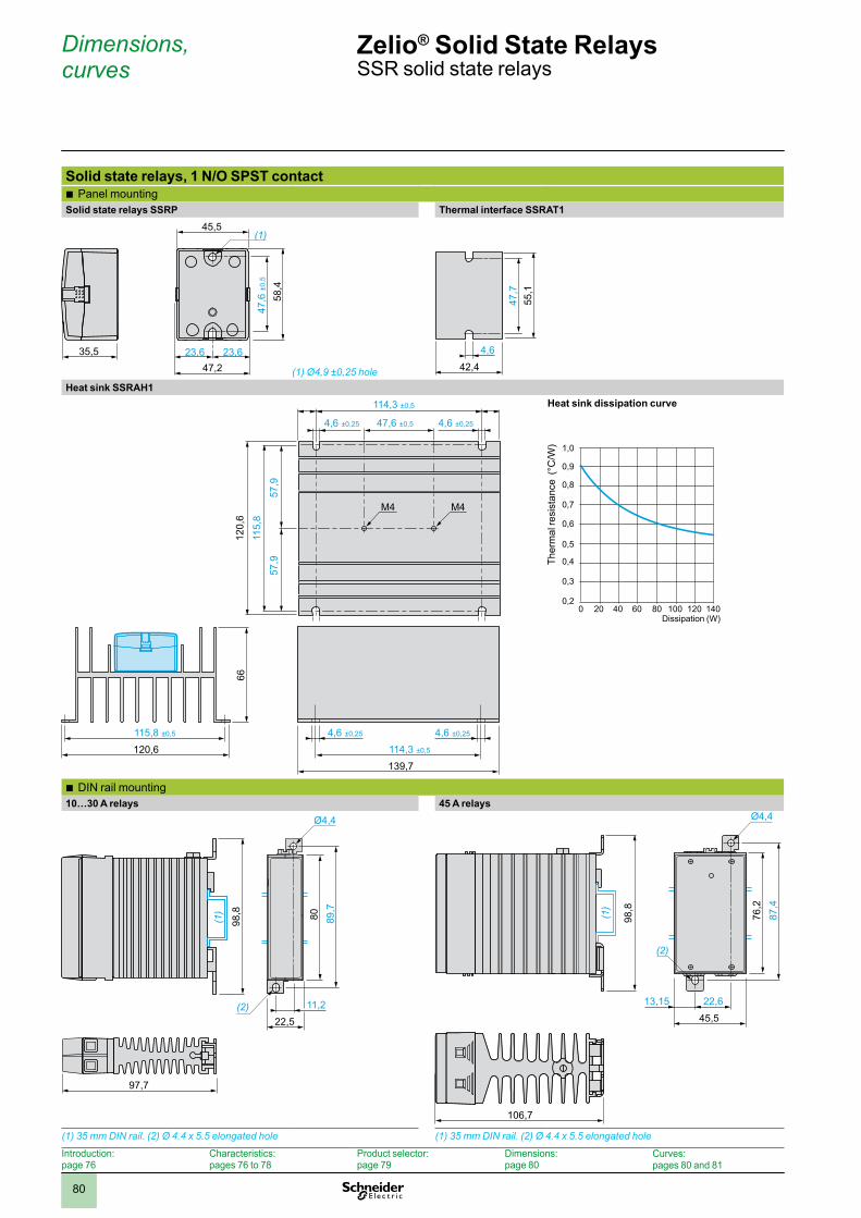
2
1
3
4
5
6
7
8
9
10
8080
Dimensions, curves
Zelio® Solid State RelaysSSR solid state relays
Introduction: page 76
Characteristics: pages 76 to 78
Product selector: page 79
Dimensions: page 80
Curves:pages 80 and 81
Solid state relays, 1 N/O SPST contact Panel mounting b
Solid state relays SSRP Thermal interface SSRAT1
35,547,2
45,5
23,6 23,6
58,4
47,6
±0,
5
(1)
(1) Ø4,9 ±0,25 hole
47,7
4,6
55,1
42,4
Heat sink SSRAH1
115,8 ±0,5
66
47,6 ±0,5 4,6 ±0,25
114,3 ±0,5
120,6139,7114,3 ±0,5
4,6 ±0,25 4,6 ±0,25
115,
8
57,9
57,9
4,6 ±0,25
120,
6
M4 M4
Heat sink dissipation curve
Ther
mal
resi
stan
ce (
°C/W
) 1,0
0,9
0,8
0,6
0,7
0,4
0,5
0,2
0,3
0 20 40 60 80 100 120 140Dissipation (W)
DIN b rail mounting 10…30 A relays 45 A relays
22,5
98,8 80 89,7
11,2(2)
(1)
97,7
Ø4,4 Ø4,4
22,6
106,7
45,513,15
(2)
98,8
76,2
87,4
(1)
(1) 35 mm DIN rail. (2) Ø 4.4 x 5.5 elongated hole (1) 35 mm DIN rail. (2) Ø 4.4 x 5.5 elongated hole
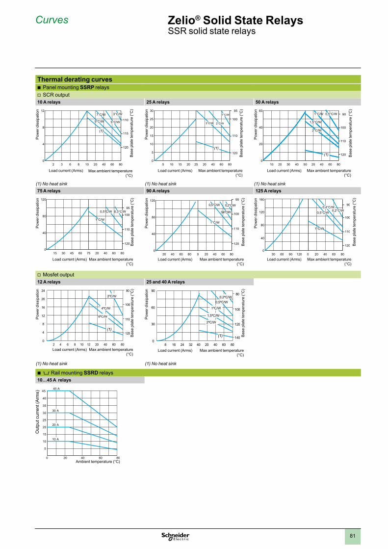
2
1
3
4
5
6
7
8
9
10
8181
Curves Zelio® Solid State RelaysSSR solid state relays
Thermal derating curvesPanel mounting b SSRP relaysSCR output v
10 A relays 25 A relays 50 A relays
02 3 6 8 10 20 40 60 80
4120
115
110
8
123°C/W
5°C/W
7°C/W
9°C/W
(1)
Load current (Arms) Max ambient temperature (°C)
Pow
er d
issi
patio
n
Bas
e pl
ate
tem
pera
ture
(°C
)
0
5
10
15
20
25
30
5 10 15 20 25 20 40 60 80
120
110
100
951°C/W
2°C/W3°C/W
(1)
Load current (Arms) Max ambient temperature (°C)
Pow
er d
issi
patio
n
Bas
e pl
ate
tem
pera
ture
(°C
)
010 20 30 40 50 20 40 60 80
20
120
100
90
40
60
110
1°C/W
2°C/W
0,5°C/W
1,5°C/W
(1)
Load current (Arms) Max ambient temperature (°C)
Pow
er d
issi
patio
n
Bas
e pl
ate
tem
pera
ture
(°C
)
(1) No heat sink (1) No heat sink (1) No heat sink75 A relays 90 A relays 125 A relays
015 30 45 60 75 20 40 60 80
40
120
110
95
80
120
1000,3°C/W0,5°C/W
1°C/W
Load current (Arms) Max ambient temperature (°C)
Pow
er d
issi
patio
n
Bas
e pl
ate
tem
pera
ture
(°C
)
020 40 60 80 0 20 40 60 80
40
120
110
95
80
120
100
0,2°C/W
0,4°C/W
1°C/W
0,5°C/W
Load current (Arms) Max ambient temperature (°C)
Pow
er d
issi
patio
n
Bas
e pl
ate
tem
pera
ture
(°C
)
030 60 90 120 0 20 40 60 80
40
120
110
90
80
120
160
100
0,2°C/W0,4°C/W
0,5°C/W
1°C/W
Load current (Arms) Max ambient temperature (°C)
Pow
er d
issi
patio
n
Bas
e pl
ate
tem
pera
ture
(°C
)
Mosfet output v12 A relays 25 and 40 A relays
Load current (Arms) Max ambient temperature (°C)
Pow
er d
issi
patio
n
Bas
e pl
ate
tem
pera
ture
(°C
)24
16
8
20
12
4
02 4 108 126 20 40 60 80
90
120
100
1106ºC/W
2ºC/W
4ºC/W
(1)
Load current (Arms) Max ambient temperature (°C)
Pow
er d
issi
patio
n
Bas
e pl
ate
tem
pera
ture
(°C
)90
60
30
08 16 32 4024 20 40 60 80
120
80
100
140
1ºC/W
2ºC/W
0,2ºC/W0,5ºC/W
1,5ºC/W
(1)
(1) No heat sink (1) No heat sink
5 b Rail mounting SSRD relays10…45 A relays
20
15
25
30
35
40
45
10
5
200 40 60 80
45 A
20 A
10 A
30 A
Out
put c
urre
nt (A
rms)
Ambient temperature (°C)

ART. 960361 DIA
3ED
2090
304E
N-U
S
Schneider Electric USA Inc. http://www.schneider-electric.us/8001 Knightdale Blvd. Knightdale, NC 27545 Tel: 919-266-3671
19 Waterman AvenueToronto, Ontario M4B 1Y2Tel: 416-752-8020
The information provided in this documentation contains general descriptions and/or technical characteristics of the performance of the products contained herein. This documentation is not intended as a substitute for and is not to be used for determining suitability or reliability of these products for specific user applications. It is the duty of any such user or integrator to perform the appropriate and complete risk analysis, evaluation and testing of the products with respect to the relevant specific application or use thereof. Neither Schneider Electric nor any of its affiliates or subsidiaries shall be responsible or liable for misuse of the information contained herein. Please note: not all parts listed in this catalog are available in all countries.
Design: Schneider ElectricPhotos: Schneider Electric
©2010 Schneider Electric. All rights reserved. 06/2010

Electromechanical and solid-state Zelio
® Relays 2010


