Embed Size (px)
Citation preview
NEORSD
OBJECT LIBRARY USER’S MANUAL
Revision 5.4 Date: March 15, 2022

Object Library Users Manual
NEORSD Object Library Users Manual Page 2 of 561 Revision 5.4
This page left blank intentionally.
Object Library Users Manual
NEORSD Object Library Users Manual Page 3 of 561 Revision 5.4
Revision History: Revision Revision Date
dd-Mmm-yyyy Author Updated Section Description
2.0.0 22-Jan-2013 PSIM All Combined previous individual object documentation; Rev’d to 2.0.0 to represent end of the earlier versions.
2.1.0 25-Jun-2013 PSIM All Numerous updates and corrections based on comments from PC&A training.
2.2.0 22-Aug-2014 PSIM All Updates to object attribute tables, graphics, etc. based on template object revisions
2.3.0 09-Jun-2015 SSA-1 Section 23, 24 Added new sections for Time_Sync_HMI, Time_Sync_SNTP, and DeviceNet Diagnostics objects
2.3.0 09-Jun-2015 SSA-1 Section 20 PLC_Status object revisions
2.4.0 16-Feb-2016 SSA-2 Section 13 Added new section for Gate object
2.4.1 14-Mar-2016 SSA-2 All Updates to object attributes per Gate testing
2.4.2 13-May-2016 SSA-2 Multiple WW Custom Historian DB + OOS Visibility
2.4.3 10-Jun-2016 SSA-2 Section 22 Enabled history for PLC_Status Seconds
2.4.4 15-Aug-2016 P. McGuire All Updated NEORSD logos
2.5.0 11-Oct-2017 APM Multiple
Added new section for PM5000, Hertz for VFD, UnCMD Stop for VFD and Motor_Discrete, OOS for Analog, Motor_Discrete_Ind, Valve_Analog_Ind and Valve_Discrete_Ind, programmatic OOS "daisy-chaining" and HMI-only Area Out of Service
2.5.1 09-May-2018 APM Multiple (PV6 to PV7 upgrade) Updated sections to remove “keypad assignment” references for the OIT and to remove any f- and k- keys
2.6.0 19-Sep-2018 APM Sections 4, 5 and 38 (Analog Readback) Updates to object attributes table and graphics.
2.7.0 1-Oct- 2018 APM Multiple
CustomHistorianDB repurposed as DB_Precision_Group. Also updates to object attribute tables and scripts based on template object revisions.
2.7.1 13-Nov-2018 APM Section 24 Updates made to Runtime AOI
2.7.2 08-Apr-2019 APM Section 24 Updates to OIT and HMI RUNTIME faceplates
2.8.0 13-Apr-2019 APM All sections Updated NEORSDUserDefined template to add WAM_ASSET_ID attribute for all children templates.
Object Library Users Manual
NEORSD Object Library Users Manual Page 4 of 561 Revision 5.4
Revision Revision Date dd-Mmm-yyyy
Author Updated Section Description
2.9.0 06-Aug-2019 APM Section 40 Added new section for UPS object
2.9.1 23-Jan-2020 SSC Section 2 Updates made to Analog AOI
3.0.0 01-Feb-2020 APM Section 22 Added DLR input to the PLC_STATUS AOI
4.0.0 03-Apr-2020 APM Section 8 Added new Analog_Suspend template to Wonderware system
4.1.0 22-Apr-2020 SSC Section 7 Added OOS graphic to Analog_Suspend_pH faceplate
4.2.0 22-Apr-2020 SSC Section 8 Added OOS graphic to Analog_Suspend faceplate
4.2.1 05-Oct-2020 SSC Section 34 Updates made to Breaker_52 object
5.0 20-Nov-20 N. Leutenberg Section 42 Added Section 42 Device Level Ring setup and
configuration.
5.1 09-Dec-20 SSC Section 22 PLC_STATUS updates (added DLR Fault Status)
5.2 26-Aug-21 P. McGuire Section 1.4.1 (Complete Object Library List)
Fixed identification of library components for “Analog_Setpoint_Mode”. Deleted repeat occurrence of “Analog_Setpoint_Mode” in table below “Valve_Discrete_Indicator” object.
5.2 26-Aug-21 P. McGuire Section 1.4.1 (Complete Object Library List)
Added missing objects “Gate” and “Help_Notes”. Fixed typo in “SEL_587Z-DPR” object name. Character “2” corrected to “Z”.
5.2 26-Aug-21 R. Meholif Sections 10, 14, 23, & 41 Corrected object names in header.
5.2 26-Aug-21 R. Meholif All analog objects, Motor-VFD, PID, and PIDE
Revised description of DB_Precision_Group. See “Analog” object, Section 2.2.7 for revision example.
5.2 26-Aug-21 R. Meholif All analog objects, Motor-VFD, PID, and PIDE
Fixed the DB_Precision_Group data type to INT (for all objetcs listed except “Analog”). Revised Notes column. See “Analog Basic” object, Section 3.3, Object Attributes table, Item 5 for revision example.
5.3 25-Jan-22 SSC2 Section 25.5 Added RunTime_Total_Hours graphic.
5.4 15-Mar-22 SSC2 Section 2 Added Out-of-Range setup and precision settings.
5.5.0 07-Apr-22 N. Trill All Sections
Updated NEORSDUserDefined template to change WAM_ASSET_ID attribute to ASSET_ID for all children templates.Also updated all Faceplate graphics to properly indicate change.

Object Library Users Manual
NEORSD Object Library Users Manual Page 5 of 561 Revision 5.4
This page left blank intentionally.

Object Library Users Manual
NEORSD Object Library Users Manual Page 6 of 561 Revision 5.4
This page left blank intentionally.
Object Library Users Manual
NEORSD Object Library Users Manual Page 7 of 561 Revision 5.4
Table of Contents: 1.0 INTRODUCTION........................................................................................................... 15
1.1 REFERENCES .................................................................................................................. 15 1.2 DEFINITIONS .................................................................................................................. 15 1.3 OPERATING PRINCIPLE ................................................................................................... 16 1.4 OBJECT LIBRARY ........................................................................................................... 17 1.5 WONDERWARE OBJECT INSTANCE CREATION STEPS ..................................................... 21 1.6 CONTROLLOGIX AOI CONFIGURATION ......................................................................... 24 1.7 REVISION CONTROL ....................................................................................................... 25
2.0 ANALOG ......................................................................................................................... 27
2.1 INTRODUCTION .............................................................................................................. 27 2.2 OBJECT FEATURES ......................................................................................................... 27 2.3 CONTROLLOGIX PLC..................................................................................................... 32 2.4 WONDERWARE HMI ...................................................................................................... 40 2.5 PANELVIEW OIT............................................................................................................ 44
3.0 ANALOG_BASIC ........................................................................................................... 49
3.1 INTRODUCTION .............................................................................................................. 49 3.2 OBJECT FEATURES ......................................................................................................... 49 3.3 OBJECT ATTRIBUTES ...................................................................................................... 50 3.4 CONTROLLOGIX PLC..................................................................................................... 51 3.5 WONDERWARE HMI ...................................................................................................... 54 3.6 PANELVIEW OIT............................................................................................................ 56
4.0 ANALOG_RW ................................................................................................................ 59
4.1 INTRODUCTION .............................................................................................................. 59 4.2 OBJECT FEATURES ......................................................................................................... 59 4.3 OBJECT ATTRIBUTES ...................................................................................................... 61 4.4 CONTROLLOGIX PLC..................................................................................................... 63 4.5 WONDERWARE HMI ...................................................................................................... 66 4.6 PANELVIEW OIT............................................................................................................ 69
5.0 ANALOG SETPOINT .................................................................................................... 71
5.1 INTRODUCTION .............................................................................................................. 71 5.2 OBJECT FEATURES ......................................................................................................... 71 5.3 OBJECT ATTRIBUTES ...................................................................................................... 73 5.4 CONTROLLOGIX PLC..................................................................................................... 74 5.5 WONDERWARE HMI ...................................................................................................... 77 5.6 PANELVIEW OIT............................................................................................................ 80
83
6.1 INTRODUCTION .............................................................................................................. 83
Object Library Users Manual
NEORSD Object Library Users Manual Page 8 of 561 Revision 5.4
6.2 OBJECT FEATURES ......................................................................................................... 83 6.3 OBJECT ATTRIBUTES ...................................................................................................... 84 6.4 CONTROLLOGIX PLC..................................................................................................... 84 6.5 WONDERWARE HMI ...................................................................................................... 85 6.6 PANELVIEW OIT............................................................................................................ 87
7.0 ANALOG SUSPEND PH ............................................................................................... 89
7.1 INTRODUCTION .............................................................................................................. 89 7.2 OBJECT FEATURES ......................................................................................................... 89 7.3 OBJECT ATTRIBUTES ...................................................................................................... 90 7.4 CONTROLLOGIX PLC..................................................................................................... 91 7.5 WONDERWARE HMI ...................................................................................................... 92 7.6 PANELVIEW OIT............................................................................................................ 94
8.0 ANALOG SUSPEND ...................................................................................................... 95
8.1 INTRODUCTION .............................................................................................................. 95 8.2 OBJECT FEATURES ......................................................................................................... 95 8.3 OBJECT ATTRIBUTES ...................................................................................................... 96 8.4 CONTROLLOGIX PLC..................................................................................................... 97 8.5 WONDERWARE HMI ...................................................................................................... 98 8.6 PANELVIEW OIT.......................................................................................................... 104
9.0 DIAGNOSTICS............................................................................................................. 105
9.1 INTRODUCTION ............................................................................................................ 105 9.2 OBJECT FEATURES ....................................................................................................... 105 9.3 OBJECT ATTRIBUTES .................................................................................................... 105 9.4 CONTROLLOGIX PLC................................................................................................... 106 9.5 WONDERWARE HMI .................................................................................................... 106 9.6 PANELVIEW OIT.......................................................................................................... 106
10.0 DEVICENET DIAGNOSTICS .................................................................................... 117
10.1 INTRODUCTION ............................................................................................................ 117 10.2 OBJECT FEATURES ....................................................................................................... 117 10.3 OBJECT ATTRIBUTES .................................................................................................... 118 10.4 CONTROLLOGIX PLC................................................................................................... 120 10.5 WONDERWARE HMI .................................................................................................... 124 10.6 PANELVIEW OIT.......................................................................................................... 129
11.0 DISCRETE .................................................................................................................... 135
11.1 INTRODUCTION ............................................................................................................ 135 11.2 OBJECT FEATURES ....................................................................................................... 135 11.3 OBJECT ATTRIBUTES .................................................................................................... 136 11.4 CONTROLLOGIX PLC................................................................................................... 137 11.5 WONDERWARE HMI .................................................................................................... 143 11.6 PANELVIEW OIT.......................................................................................................... 146
Object Library Users Manual
NEORSD Object Library Users Manual Page 9 of 561 Revision 5.4
12.0 DISCRETE_RW ........................................................................................................... 149
12.1 INTRODUCTION ............................................................................................................ 149 12.2 OBJECT FEATURES ....................................................................................................... 149 12.3 OBJECT ATTRIBUTES .................................................................................................... 150 12.4 CONTROLLOGIX PLC................................................................................................... 151 12.5 WONDERWARE HMI .................................................................................................... 154 12.6 PANELVIEW OIT.......................................................................................................... 157
13.0 DISCRETE_SETPOINT .............................................................................................. 159
13.1 INTRODUCTION ............................................................................................................ 159 13.2 OBJECT FEATURES ....................................................................................................... 159 13.3 OBJECT ATTRIBUTES .................................................................................................... 160 13.4 CONTROLLOGIX PLC................................................................................................... 161 13.5 WONDERWARE HMI .................................................................................................... 163 13.6 PANELVIEW OIT.......................................................................................................... 166
14.0 GATE ............................................................................................................................. 169
14.1 INTRODUCTION ............................................................................................................ 169 14.2 OBJECT FEATURES ....................................................................................................... 169 14.3 OBJECT ATTRIBUTES .................................................................................................... 171 14.4 CONTROLLOGIX PLC................................................................................................... 174 14.5 WONDERWARE HMI .................................................................................................... 180 14.6 PANELVIEW OIT.......................................................................................................... 185
15.0 HELP_NOTES .............................................................................................................. 191
15.1 INTRODUCTION ............................................................................................................ 191 15.2 OBJECT ATTRIBUTES .................................................................................................... 191 15.3 WONDERWARE HMI .................................................................................................... 191
16.0 MOTOR_DISCRETE................................................................................................... 193
16.1 INTRODUCTION ............................................................................................................ 193 16.2 OBJECT FEATURES ....................................................................................................... 193 16.3 OBJECT ATTRIBUTES .................................................................................................... 195 16.4 CONTROLLOGIX PLC................................................................................................... 197 16.5 WONDERWARE HMI .................................................................................................... 202 16.6 PANELVIEW OIT.......................................................................................................... 206
17.0 MOTOR_DISCRETE_INDICATOR ......................................................................... 211
17.1 INTRODUCTION ............................................................................................................ 211 17.2 OBJECT FEATURES ....................................................................................................... 211 17.3 OBJECT ATTRIBUTES .................................................................................................... 212 17.4 CONTROLLOGIX PLC................................................................................................... 213 17.5 WONDERWARE HMI .................................................................................................... 215 17.6 PANELVIEW OIT.......................................................................................................... 218
Object Library Users Manual
NEORSD Object Library Users Manual Page 10 of 561 Revision 5.4
18.0 MOTOR_VFD ............................................................................................................... 221
18.1 INTRODUCTION ............................................................................................................ 221 18.2 OBJECT FEATURES ....................................................................................................... 221 18.3 OBJECT ATTRIBUTES .................................................................................................... 223 18.4 CONTROLLOGIX PLC................................................................................................... 227 18.5 WONDERWARE HMI .................................................................................................... 238 18.6 PANELVIEW OIT.......................................................................................................... 244
19.0 MULTISTATE_INDICATOR..................................................................................... 251
19.1 INTRODUCTION ............................................................................................................ 251 19.2 OBJECT FEATURES ....................................................................................................... 251 19.3 OBJECT ATTRIBUTES .................................................................................................... 253 19.4 CONTROLLOGIX PLC................................................................................................... 255 19.5 WONDERWARE HMI .................................................................................................... 257 19.6 PANELVIEW OIT.......................................................................................................... 259
20.0 PB_SINGLE_SELECT................................................................................................. 261
20.1 INTRODUCTION ............................................................................................................ 261 20.2 OBJECT FEATURES ....................................................................................................... 261 20.3 OBJECT ATTRIBUTES .................................................................................................... 262 20.4 CONTROL LOGIX PLC .................................................................................................. 264 20.5 WONDERWARE HMI .................................................................................................... 266 20.6 PANELVIEW OIT.......................................................................................................... 268
21.0 PID .................................................................................................................................. 271
21.1 INTRODUCTION ............................................................................................................ 271 21.2 OBJECT FEATURES ....................................................................................................... 271 21.3 OBJECT ATTRIBUTES .................................................................................................... 273 21.4 CONTROLLOGIX PLC................................................................................................... 275 21.5 WONDERWARE HMI .................................................................................................... 280 21.6 PANELVIEW OIT.......................................................................................................... 282
22.0 PIDE ............................................................................................................................... 285
22.1 INTRODUCTION ............................................................................................................ 285 22.2 OBJECT FEATURES ....................................................................................................... 285 22.3 OBJECT ATTRIBUTES .................................................................................................... 287 22.4 CONTROLLOGIX PLC................................................................................................... 296 22.5 WONDERWARE HMI .................................................................................................... 301 22.6 PANELVIEW OIT.......................................................................................................... 304
23.0 PLC_STATUS ............................................................................................................... 307
23.1 INTRODUCTION ............................................................................................................ 307 23.2 OBJECT FEATURES ....................................................................................................... 307 23.3 OBJECT ATTRIBUTES .................................................................................................... 308
Object Library Users Manual
NEORSD Object Library Users Manual Page 11 of 561 Revision 5.4
23.4 CONTROLLOGIX PLC................................................................................................... 311 23.5 WONDERWARE HMI .................................................................................................... 314 23.6 PANELVIEW OIT.......................................................................................................... 318
24.0 RESTART_INHIBIT .................................................................................................... 325
24.1 INTRODUCTION ............................................................................................................ 325 24.2 OBJECT FEATURES ....................................................................................................... 325 24.3 OBJECT ATTRIBUTES .................................................................................................... 326 24.4 CONTROLLOGIX PLC................................................................................................... 327 24.5 WONDERWARE HMI .................................................................................................... 330 24.6 PANELVIEW OIT.......................................................................................................... 331
25.0 RUNTIME ..................................................................................................................... 333
25.1 INTRODUCTION ............................................................................................................ 333 25.2 OBJECT FEATURES ....................................................................................................... 333 25.3 OBJECT ATTRIBUTES .................................................................................................... 334 25.4 CONTROLLOGIX PLC................................................................................................... 335 25.5 WONDERWARE HMI .................................................................................................... 338 25.6 PANELVIEW OIT.......................................................................................................... 340
26.0 TIME_SYNC_HMI....................................................................................................... 343
26.1 INTRODUCTION ............................................................................................................ 343 26.2 OBJECT FEATURES ....................................................................................................... 343 26.3 OBJECT ATTRIBUTES .................................................................................................... 344 26.4 CONTROLLOGIX PLC................................................................................................... 345 26.5 WONDERWARE HMI .................................................................................................... 348 26.6 PANELVIEW OIT.......................................................................................................... 348
27.0 TIME_SYNC_SNTP ..................................................................................................... 351
27.1 INTRODUCTION ............................................................................................................ 351 27.2 OBJECT FEATURES ....................................................................................................... 351 27.3 OBJECT ATTRIBUTES .................................................................................................... 352 27.4 CONTROLLOGIX PLC................................................................................................... 353 27.5 WONDERWARE HMI .................................................................................................... 357 27.6 PANELVIEW OIT.......................................................................................................... 357
28.0 VALVE_ACTUATOR .................................................................................................. 361
28.1 INTRODUCTION ............................................................................................................ 361 28.2 OBJECT FEATURES ....................................................................................................... 361 28.3 OBJECT ATTRIBUTES .................................................................................................... 363 28.4 CONTROLLOGIX PLC................................................................................................... 366 28.5 WONDERWARE HMI .................................................................................................... 371 28.6 PANELVIEW OIT.......................................................................................................... 376
29.0 VALVE_ACTUATOR_SP ........................................................................................... 381
Object Library Users Manual
NEORSD Object Library Users Manual Page 12 of 561 Revision 5.4
29.1 INTRODUCTION ............................................................................................................ 381 29.2 OBJECT FEATURES ....................................................................................................... 381 29.3 OBJECT ATTRIBUTES .................................................................................................... 383 29.4 CONTROLLOGIX PLC................................................................................................... 385 29.5 WONDERWARE HMI .................................................................................................... 386 29.6 PANELVIEW OIT.......................................................................................................... 390
30.0 VALVE_ANALOG ....................................................................................................... 391
30.1 INTRODUCTION ............................................................................................................ 391 30.2 OBJECT FEATURES ....................................................................................................... 391 30.3 OBJECT ATTRIBUTES .................................................................................................... 393 30.4 CONTROLLOGIX PLC................................................................................................... 396 30.5 WONDERWARE HMI .................................................................................................... 402 30.6 PANELVIEW OIT.......................................................................................................... 408
31.0 VALVE_ANALOG_INDICATOR .............................................................................. 413
31.1 INTRODUCTION ............................................................................................................ 413 31.2 OBJECT FEATURES ....................................................................................................... 413 31.3 OBJECT ATTRIBUTES .................................................................................................... 414 31.4 CONTROLLOGIX PLC................................................................................................... 416 31.5 WONDERWARE HMI .................................................................................................... 419 31.6 PANELVIEW OIT.......................................................................................................... 422
32.0 VALVE_DISCRETE .................................................................................................... 425
32.1 INTRODUCTION ............................................................................................................ 425 32.2 OBJECT FEATURES ....................................................................................................... 425 32.3 OBJECT ATTRIBUTES .................................................................................................... 427 32.4 CONTROLLOGIX PLC................................................................................................... 430 32.5 WONDERWARE HMI .................................................................................................... 435 32.6 PANELVIEW OIT.......................................................................................................... 441
33.0 VALVE_DISCRETE_INDICATOR ........................................................................... 447
33.1 INTRODUCTION ............................................................................................................ 447 33.2 OBJECT FEATURES ....................................................................................................... 447 33.3 OBJECT ATTRIBUTES .................................................................................................... 449 33.4 CONTROLLOGIX PLC................................................................................................... 450 33.5 WONDERWARE HMI .................................................................................................... 453 33.6 PANELVIEW OIT.......................................................................................................... 456
34.0 BREAKER_52 ............................................................................................................... 459
34.1 INTRODUCTION ............................................................................................................ 459 34.2 OBJECT FEATURES ....................................................................................................... 459 34.3 OBJECT ATTRIBUTES .................................................................................................... 460 34.4 CONTROLLOGIX PLC................................................................................................... 460 34.5 WONDERWARE HMI .................................................................................................... 462
Object Library Users Manual
NEORSD Object Library Users Manual Page 13 of 561 Revision 5.4
34.6 PANELVIEW OIT.......................................................................................................... 465
35.0 DIFFERENTIAL_PROTECTION_RELAY (SEL_587Z_DPR) ............................. 467
35.1 INTRODUCTION ............................................................................................................ 467 35.2 OBJECT FEATURES ....................................................................................................... 467 35.3 OBJECT ATTRIBUTES .................................................................................................... 468 35.4 CONTROLLOGIX PLC................................................................................................... 469 35.5 WONDERWARE HMI .................................................................................................... 471 35.6 PANELVIEW OIT.......................................................................................................... 473
36.0 DIGITRIP_520MC_CB ................................................................................................ 475
36.1 INTRODUCTION ............................................................................................................ 475 36.2 OBJECT FEATURES ....................................................................................................... 475 36.3 OBJECT ATTRIBUTES .................................................................................................... 476 36.4 CONTROLLOGIX PLC................................................................................................... 476 36.5 WONDERWARE HMI .................................................................................................... 482 36.6 PANELVIEW OIT.......................................................................................................... 485
37.0 FEEDER_PROTECTION_RELAY (SEL_751A_FPR)............................................ 487
37.1 INTRODUCTION ............................................................................................................ 487 37.2 OBJECT FEATURES ....................................................................................................... 487 37.3 OBJECT ATTRIBUTES .................................................................................................... 488 37.4 CONTROLLOGIX PLC................................................................................................... 490 37.5 WONDERWARE HMI .................................................................................................... 493 37.6 PANELVIEW OIT.......................................................................................................... 498
38.0 POWER_MONITOR (AB_POWER_MONITOR_3000) ......................................... 499
38.1 INTRODUCTION ............................................................................................................ 499 38.2 OBJECT FEATURES ....................................................................................................... 499 38.3 OBJECT ATTRIBUTES .................................................................................................... 500 38.4 CONTROLLOGIX PLC................................................................................................... 502 38.5 WONDERWARE HMI .................................................................................................... 505 38.6 PANELVIEW OIT.......................................................................................................... 512
39.0 POWER_MONITOR_5000 (PM5000)........................................................................ 513
39.1 INTRODUCTION ............................................................................................................ 513 39.2 OBJECT FEATURES ....................................................................................................... 513 39.3 OBJECT ATTRIBUTES .................................................................................................... 514 39.4 CONTROLLOGIX PLC................................................................................................... 516 39.5 WONDERWARE HMI .................................................................................................... 518 39.6 PANELVIEW OIT.......................................................................................................... 525
40.0 TRANSFORMER_PROTECTION_RELAY (SEL_787_TPR) ............................... 527
40.1 INTRODUCTION ............................................................................................................ 527 40.2 OBJECT FEATURES ....................................................................................................... 527
Object Library Users Manual
NEORSD Object Library Users Manual Page 14 of 561 Revision 5.4
40.3 OBJECT ATTRIBUTES .................................................................................................... 528 40.4 CONTROLLOGIX PLC................................................................................................... 529 40.5 WONDERWARE HMI .................................................................................................... 534 40.6 PANELVIEW OIT.......................................................................................................... 538
41.0 UNINTERRUPTIBLE POWER SUPPLY (UPS) ...................................................... 539
41.1 INTRODUCTION ............................................................................................................ 539 41.2 OBJECT FEATURES ....................................................................................................... 539 41.3 OBJECT ATTRIBUTES .................................................................................................... 539 41.4 CONTROLLOGIX PLC................................................................................................... 540 41.5 WONDERWARE HMI .................................................................................................... 540 41.6 PANELVIEW OIT.......................................................................................................... 544
42.0 DEVICE LEVEL RING ............................................................................................... 545
42.1 INTRODUCTION ............................................................................................................ 545 42.2 OBJECT FEATURES ....................................................................................................... 545 42.3 CONTROLLOGIX PLC................................................................................................... 547 42.4 WONDERWARE HMI .................................................................................................... 549 42.5 PANELVIEW OIT.......................................................................................................... 552
Object Library Users Manual - Introduction
NEORSD Object Library Users Manual Page 15 of 561 Revision 5.4
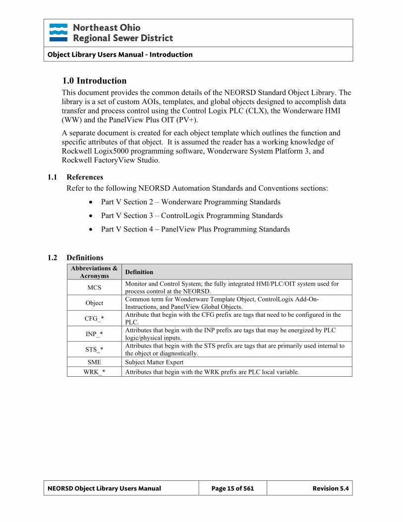
1.0 Introduction This document provides the common details of the NEORSD Standard Object Library. The library is a set of custom AOIs, templates, and global objects designed to accomplish data transfer and process control using the Control Logix PLC (CLX), the Wonderware HMI (WW) and the PanelView Plus OIT (PV+). A separate document is created for each object template which outlines the function and specific attributes of that object. It is assumed the reader has a working knowledge of Rockwell Logix5000 programming software, Wonderware System Platform 3, and Rockwell FactoryView Studio.
1.1 References Refer to the following NEORSD Automation Standards and Conventions sections:
• Part V Section 2 – Wonderware Programming Standards
• Part V Section 3 – ControlLogix Programming Standards
• Part V Section 4 – PanelView Plus Programming Standards
1.2 Definitions Abbreviations &
Acronyms Definition
MCS Monitor and Control System; the fully integrated HMI/PLC/OIT system used for process control at the NEORSD.
Object Common term for Wonderware Template Object, ControlLogix Add-On-Instructions, and PanelView Global Objects.
CFG_* Attribute that begin with the CFG prefix are tags that need to be configured in the PLC.
INP_* Attributes that begin with the INP prefix are tags that may be energized by PLC logic/physical inputs.
STS_* Attributes that begin with the STS prefix are tags that are primarily used internal to the object or diagnostically.
SME Subject Matter Expert WRK_* Attributes that begin with the WRK prefix are PLC local variable.
Object Library Users Manual - Introduction
NEORSD Object Library Users Manual Page 16 of 561 Revision 5.4
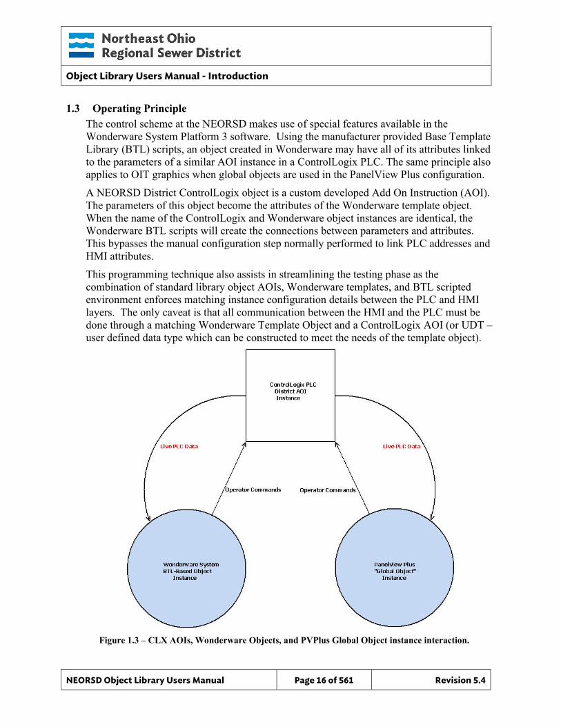
1.3 Operating Principle The control scheme at the NEORSD makes use of special features available in the Wonderware System Platform 3 software. Using the manufacturer provided Base Template Library (BTL) scripts, an object created in Wonderware may have all of its attributes linked to the parameters of a similar AOI instance in a ControlLogix PLC. The same principle also applies to OIT graphics when global objects are used in the PanelView Plus configuration. A NEORSD District ControlLogix object is a custom developed Add On Instruction (AOI). The parameters of this object become the attributes of the Wonderware template object. When the name of the ControlLogix and Wonderware object instances are identical, the Wonderware BTL scripts will create the connections between parameters and attributes. This bypasses the manual configuration step normally performed to link PLC addresses and HMI attributes. This programming technique also assists in streamlining the testing phase as the combination of standard library object AOIs, Wonderware templates, and BTL scripted environment enforces matching instance configuration details between the PLC and HMI layers. The only caveat is that all communication between the HMI and the PLC must be done through a matching Wonderware Template Object and a ControlLogix AOI (or UDT – user defined data type which can be constructed to meet the needs of the template object).
Figure 1.3 – CLX AOIs, Wonderware Objects, and PVPlus Global Object instance interaction.
Object Library Users Manual - Introduction
NEORSD Object Library Users Manual Page 17 of 561 Revision 5.4
1.4 Object Library For ease of use, the NEORSD Standard Object Library documentation has been organized into sections; one for each NEORSD Standard Object. Each section provides functional details and user implementation notes. The documentation typically contains the following subsections:
1. Introduction – Basic introduction outlining the intended purpose of the object. 2. Object Features – Highlights functional features of the object, and includes a brief
description of whether or not to use the object for a given scenario. 3. Object Attributes – Table that details the AOI / WW object parameters / attributes.
Columns under “Wonderware” are those found in the associated derived object template.
Only the parameters with direction indication are communicated between the PLC and HMI layers. Direction indications of “UDA” are configured at the Wonderware layer and PLC independently, but should match.
List items that begin with the prefix CFG_ are internal configuration parameters within the PLC AOI instance. The local AOI temporary variables (beginning with a prefix WRK_) are not displayed in the tables.
4. ControlLogix PLC – Example implementations, as well as input, configuration, and output attribute notes.
5. Wonderware HMI – Template properties, instance configuration notes, and graphic details (faceplates and symbols).
6. PanelView OIT – Global Object instance configuration notes and graphic details (faceplates and symbols).
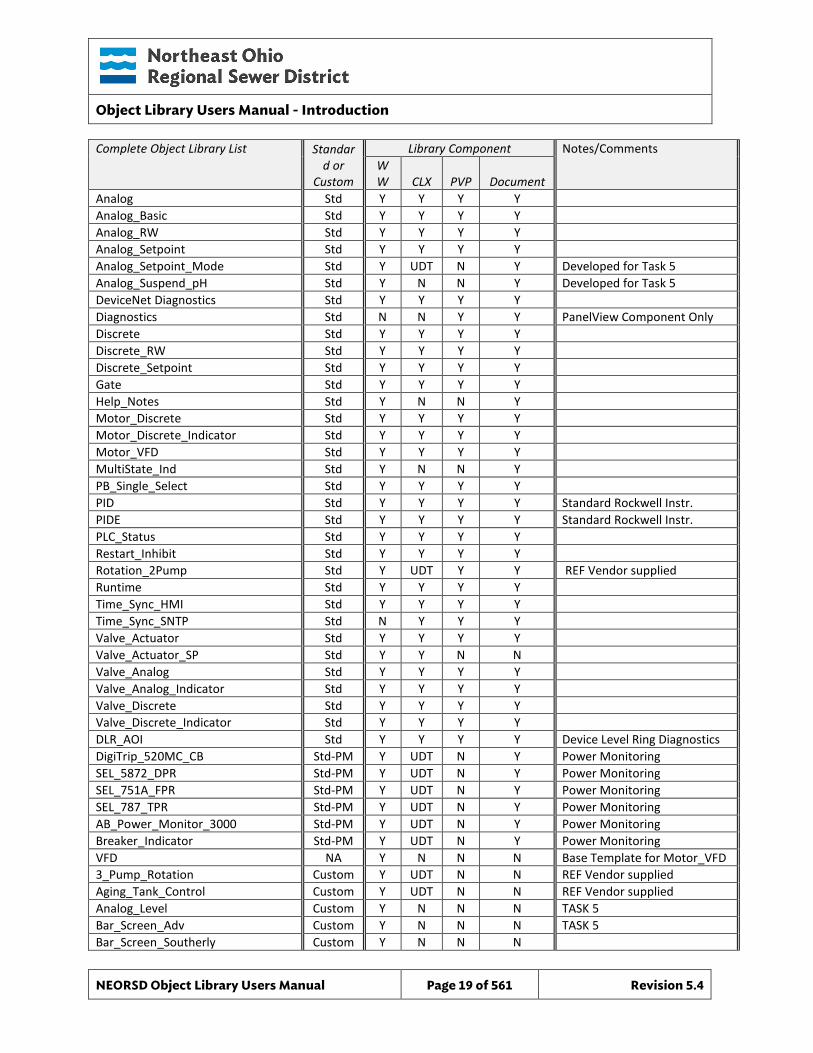
1.4.1 Object Library Templates The object library is constantly growing, by both in-house and contractor collaborative development efforts. The programmer should contact the NEORSD for the latest set of library objects and base programs. In addition to the standard objects, the Wonderware galaxy may also include additional templates that were derived from standard objects, or created new by a subcontractor for a very specific purpose. These custom objects typically consist of only a Wonderware component, and have no documentation. For that reason, the custom objects are not described in this document, but mentioned here for information only. A full list of the standard and custom objects is given below. Additionally, the document “NEORSD Object Library Users Manual - Appendix A” provides revision information for the standard objects.

Object Library Users Manual - Introduction
NEORSD Object Library Users Manual Page 18 of 561 Revision 5.4
This page left blank intentionally.
Object Library Users Manual - Introduction
NEORSD Object Library Users Manual Page 19 of 561 Revision 5.4
Complete Object Library List Standard or
Custom
Library Component Notes/Comments WW CLX PVP Document
Analog Std Y Y Y Y Analog_Basic Std Y Y Y Y Analog_RW Std Y Y Y Y Analog_Setpoint Std Y Y Y Y Analog_Setpoint_Mode Std Y UDT N Y Developed for Task 5 Analog_Suspend_pH Std Y N N Y Developed for Task 5 DeviceNet Diagnostics Std Y Y Y Y Diagnostics Std N N Y Y PanelView Component Only Discrete Std Y Y Y Y Discrete_RW Std Y Y Y Y Discrete_Setpoint Std Y Y Y Y Gate Std Y Y Y Y Help_Notes Std Y N N Y Motor_Discrete Std Y Y Y Y Motor_Discrete_Indicator Std Y Y Y Y Motor_VFD Std Y Y Y Y MultiState_Ind Std Y N N Y PB_Single_Select Std Y Y Y Y PID Std Y Y Y Y Standard Rockwell Instr. PIDE Std Y Y Y Y Standard Rockwell Instr. PLC_Status Std Y Y Y Y Restart_Inhibit Std Y Y Y Y Rotation_2Pump Std Y UDT Y Y REF Vendor supplied Runtime Std Y Y Y Y Time_Sync_HMI Std Y Y Y Y Time_Sync_SNTP Std N Y Y Y Valve_Actuator Std Y Y Y Y Valve_Actuator_SP Std Y Y N N Valve_Analog Std Y Y Y Y Valve_Analog_Indicator Std Y Y Y Y Valve_Discrete Std Y Y Y Y Valve_Discrete_Indicator Std Y Y Y Y DLR_AOI Std Y Y Y Y Device Level Ring Diagnostics DigiTrip_520MC_CB Std-PM Y UDT N Y Power Monitoring SEL_5872_DPR Std-PM Y UDT N Y Power Monitoring SEL_751A_FPR Std-PM Y UDT N Y Power Monitoring SEL_787_TPR Std-PM Y UDT N Y Power Monitoring AB_Power_Monitor_3000 Std-PM Y UDT N Y Power Monitoring Breaker_Indicator Std-PM Y UDT N Y Power Monitoring VFD NA Y N N N Base Template for Motor_VFD 3_Pump_Rotation Custom Y UDT N N REF Vendor supplied Aging_Tank_Control Custom Y UDT N N REF Vendor supplied Analog_Level Custom Y N N N TASK 5 Bar_Screen_Adv Custom Y N N N TASK 5 Bar_Screen_Southerly Custom Y N N N
Object Library Users Manual - Introduction
NEORSD Object Library Users Manual Page 20 of 561 Revision 5.4
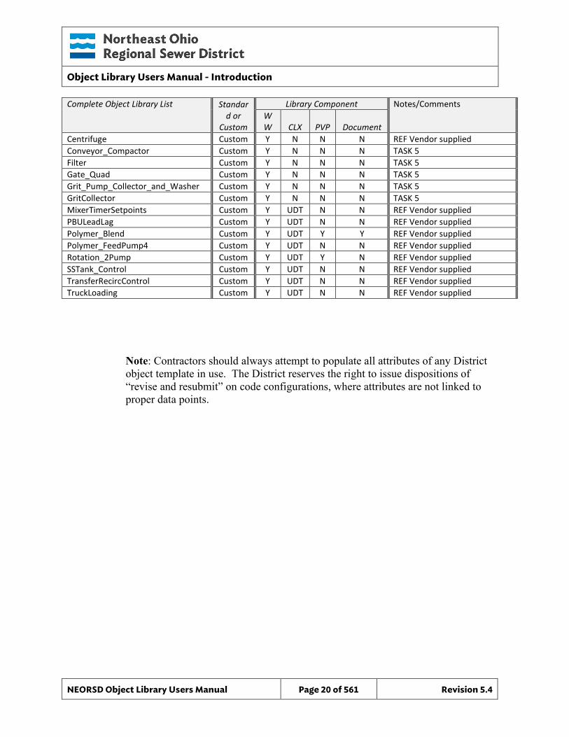
Complete Object Library List Standard or
Custom
Library Component Notes/Comments WW CLX PVP Document
Centrifuge Custom Y N N N REF Vendor supplied Conveyor_Compactor Custom Y N N N TASK 5 Filter Custom Y N N N TASK 5 Gate_Quad Custom Y N N N TASK 5 Grit_Pump_Collector_and_Washer Custom Y N N N TASK 5 GritCollector Custom Y N N N TASK 5 MixerTimerSetpoints Custom Y UDT N N REF Vendor supplied PBULeadLag Custom Y UDT N N REF Vendor supplied Polymer_Blend Custom Y UDT Y Y REF Vendor supplied Polymer_FeedPump4 Custom Y UDT N N REF Vendor supplied Rotation_2Pump Custom Y UDT Y N REF Vendor supplied SSTank_Control Custom Y UDT N N REF Vendor supplied TransferRecircControl Custom Y UDT N N REF Vendor supplied TruckLoading Custom Y UDT N N REF Vendor supplied
Note: Contractors should always attempt to populate all attributes of any District object template in use. The District reserves the right to issue dispositions of “revise and resubmit” on code configurations, where attributes are not linked to proper data points.
Object Library Users Manual - Introduction
NEORSD Object Library Users Manual Page 21 of 561 Revision 5.4
1.5 Wonderware Object Instance Creation Steps The following common steps are required to create new object instances from any of the standard NEORSD Wonderware Object Library Templates. Additional instance creation steps that are specific to a particular object template are found within that templates section.
1.5.1 How to create a new instance: 1) Find the template type you wish your instance to be derived from in the
Template Toolbox in the toolset: “NEORSD” 2) Right click on the template and choose New – Instance. In the Deployment
View a new instance is created. Name this instance following the NEORSD object naming conventions.
3) Drag and drop the new instance into the desired deployment area. If an identical area exists in the model view this instance will also be placed there. Verify proper placement by checking to see all the errors/warnings are cleared from the instance. If within a minute they don’t clear click on the instance and Validate.
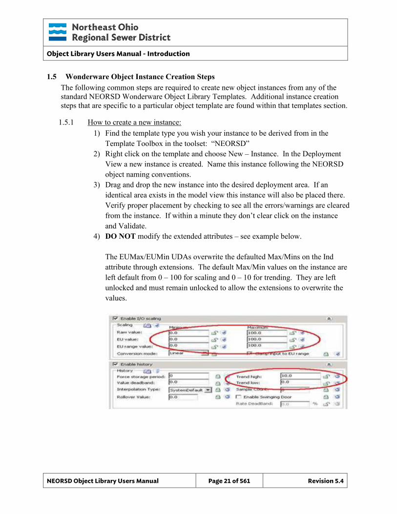
4) DO NOT modify the extended attributes – see example below. The EUMax/EUMin UDAs overwrite the defaulted Max/Mins on the Ind attribute through extensions. The default Max/Min values on the instance are left default from 0 – 100 for scaling and 0 – 10 for trending. They are left unlocked and must remain unlocked to allow the extensions to overwrite the values.
Object Library Users Manual - Introduction
NEORSD Object Library Users Manual Page 22 of 561 Revision 5.4
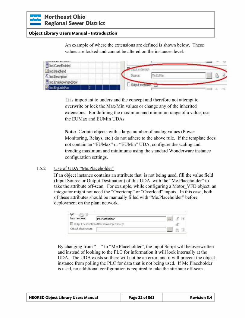
An example of where the extensions are defined is shown below. These values are locked and cannot be altered on the instances level.
It is important to understand the concept and therefore not attempt to overwrite or lock the Max/Min values or change any of the inherited extensions. For defining the maximum and minimum range of a value, use the EUMax and EUMin UDAs. Note: Certain objects with a large number of analog values (Power Monitoring, Relays, etc.) do not adhere to the above rule. If the template does not contain an “EUMax” or “EUMin” UDA, configure the scaling and trending maximum and minimums using the standard Wonderware instance configuration settings.
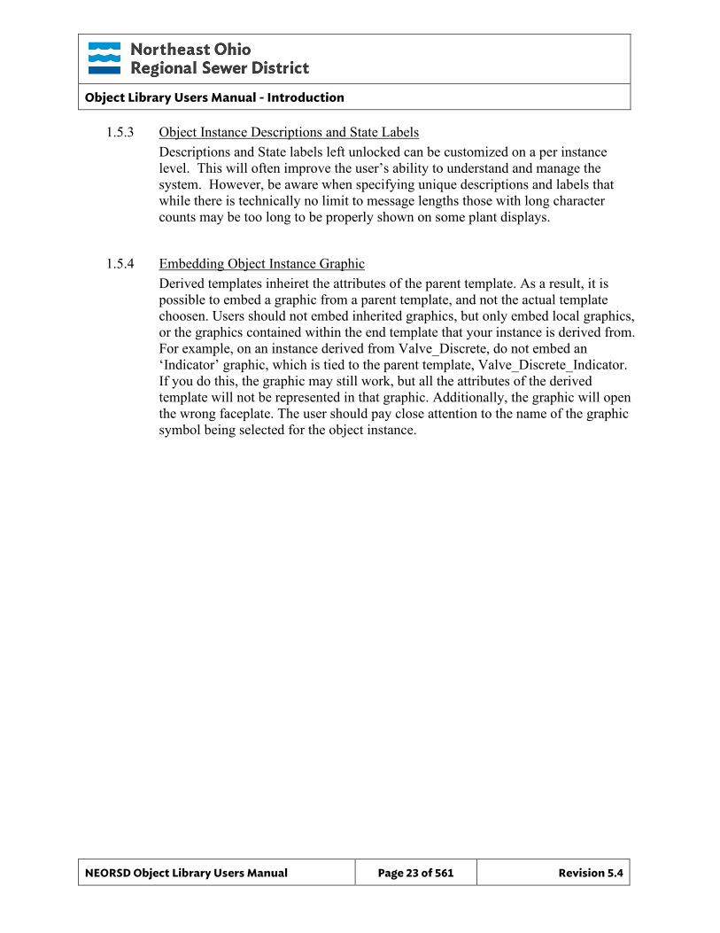
1.5.2 Use of UDA “Me.Placeholder” If an object instance contains an attribute that is not being used, fill the value field (Input Source or Output Destination) of this UDA with the “Me.Placeholder” to take the attribute off-scan. For example, while configuring a Motor_VFD object, an integrator might not need the “Overtemp” or “Overload” inputs. In this case, both of these attributes should be manually filled with “Me.Placeholder” before deployment on the plant network.
By changing from “---“ to “Me.Placeholder”, the Input Script will be overwritten and instead of looking to the PLC for information it will look internally at the UDA. The UDA exists so there will not be an error, and it will prevent the object instance from polling the PLC for data that is not being used. If Me.Placeholder is used, no additional configuration is required to take the attribute off-scan.
Object Library Users Manual - Introduction
NEORSD Object Library Users Manual Page 23 of 561 Revision 5.4
1.5.3 Object Instance Descriptions and State Labels Descriptions and State labels left unlocked can be customized on a per instance level. This will often improve the user’s ability to understand and manage the system. However, be aware when specifying unique descriptions and labels that while there is technically no limit to message lengths those with long character counts may be too long to be properly shown on some plant displays.
1.5.4 Embedding Object Instance Graphic Derived templates inheiret the attributes of the parent template. As a result, it is possible to embed a graphic from a parent template, and not the actual template choosen. Users should not embed inherited graphics, but only embed local graphics, or the graphics contained within the end template that your instance is derived from. For example, on an instance derived from Valve_Discrete, do not embed an ‘Indicator’ graphic, which is tied to the parent template, Valve_Discrete_Indicator. If you do this, the graphic may still work, but all the attributes of the derived template will not be represented in that graphic. Additionally, the graphic will open the wrong faceplate. The user should pay close attention to the name of the graphic symbol being selected for the object instance.
Object Library Users Manual - Introduction
NEORSD Object Library Users Manual Page 24 of 561 Revision 5.4
1.6 ControlLogix AOI Configuration Common configuration for ControlLogix AOI instances are as follows:
1.6.1 PLC Status Object While a ControlLogix PLC will have many AOI instances, representing the different pieces of equipment controlled by the PLC, there is only one “PLC_Status” instance. The “PLC_Status” instance exists to aggregate information for the PLC as a whole, including indications if any object is in trouble, simulation, or whether major/minor faults exist in the PLC. Every AOI instance within a PLC must reference the PLC Status object to allow monitoring of whether the object is in trouble or simulation mode.
1.6.2 Trouble Indication Create logic to set the Trouble_Bit parameter. The Trouble indicator should be tied to any hardware condition that could affect the quality of the associated object data. The trouble indication is not required for object functionality. The Trouble_Desc is an InOut Reference Tag that will link to a string variable that is defined within the PLC logic. This string variable will contain additional information regarding the reason for the active Trouble indication. If using the trouble bit, a tag must be assigned to Trouble_Desc for proper operation.
1.6.3 Simulation Monitoring Most AOI have simulation logic built in to the block. When simulation is active it must be annunciated at the HMI and OIT. Consolidate the Simulation enable bit into the PLC Status object.
Object Library Users Manual - Introduction
NEORSD Object Library Users Manual Page 25 of 561 Revision 5.4
1.7 Revision Control The following sections identify and define the required software configuration management elements. A list of software revisions is provided in the document “NEORSD Object Library Users Manual - Appendix A”.
1.7.1 PLC Code – ControlLogix / CompactLogix The following requirements apply for PLC supplied programming:
1. PLC AOI a. Revision = X.Y.Z
i. X = Major revision change due to functional changes to the software object that affects compatibility with corresponding HMI / OIT elements. SME review and approvals are required.
ii. Y = Minor revision change which can be functional but does not alter the original functional intent of the software object. SME review is typically not required.
iii. Z = Typographical corrections, or similar corrections.
b. Extended Text i. “NEORSD – Draft” – non-production release indicator
*object is not fully tested/approved ii. “NEORSD” – programming/production release indicator
*object is fully tested/approved for general use
Object Library Users Manual - Introduction
NEORSD Object Library Users Manual Page 26 of 561 Revision 5.4
1.7.2 OIT Code – PanelView Plus 1. OIT Global Objects
a. Revision = X.Y.Z i. X = Major revision change due to functional changes to the
software object that affects compatibility with corresponding PLC / HMI elements. SME review and approvals are required.
ii. Y = Minor revision change which can be functional but does not alter the original functional intent of the software object. SME review is typically not required.
iii. Z = Typographical corrections, or similar corrections.
b. Extended Text i. “NEORSD – Draft” – non-production release indicator
*object is not fully tested/approved ii. “NEORSD” – programming/production release indicator
*object is fully tested/approved for general use
1.7.3 HMI Code - Wonderware 1. ArchestrA Library Objects and System Platform Objects – the COTS
software application automatically assigns an incrementing revision number each time the code base changes. This number will be used for the revision number.
Note: The revision number in Wonderware may update automatically when opening a template to “just look around”. If this happens, the original template must be re-imported into the contractors Wonderware system to replace the accidentally revised template.
Object Library Users Manual - Analog
NEORSD Object Library Users Manual Page 27 of 561 Revision 5.4
2.0 Analog
2.1 Introduction The Analog template provides a standard representation of an analog process reading (flow, pressure, temperature, etc.) within the NEORSD control systems. Use the Analog template if any of the statements below are true:
• If the analog value has associated level (high/low) alarms • If raw input value scaling is required
Do not use the Analog template:
• If an integer value associated with a sequence step or operator selection is being displayed. Use Analog_Basic instead. If the sequence step has control from the HMI or OIT, consider using Multistate_Indicator.
2.2 Object Features
2.2.1 Value Indication This object provides analog process value indication for use with downstream logic in the PLC and for display on the HMI/OIT.
2.2.2 Status Indication This object provides the following indication for the analog: o In-Service/Out-Of-Service mode indication
2.2.3 Alarming This object supports the following alarms: o Process value level alarms High-High, High, Low, Low-Low (with condition
gate) o Process value rate of change alarms, positive and negative o Process value failalarm (out of range), if the process value exceeds
configurable expected low and high limits o Process value bad quality, activated through an input source such as the IO
module channel fault, or if the fail alarm is triggered Level alarms have configurable threshold level, minimum duration, and deadband settings. Rate of change alarms have configurable rate thresholds and sampling period. Individual limit alarms may be enabled/disabled in the object configuration.
Object Library Users Manual - Analog
NEORSD Object Library Users Manual Page 28 of 561 Revision 5.4
2.2.4 Control This object supports the following control for the analog: o Out-of-Service/In-Service mode toggle
For objects that should not have Out-of-Service capabilities, the Cfg_OOS_CMD_Enabled bit should be set to zero, and the OOS button on the HMI should be made invisible.
2.2.5 Simulation This object supports simulation of the process value.
2.2.6 Trouble This object supports hardware trouble indication.
2.2.7 DB_Precision_Group Attribute is used in the ValueDeadband script. In the script, this parameter sets the deadband of inputs. Valid values for this parameter are between 0 and 3. o 0= default group; o 1= custom ValueDeadband setting which disables the script and uses the
attribute’s ValueDeadband; o 2= high precision; o 3= non-precision REF objects (obsolete)
While 3 is an available option, it is not to be used for new objects moving forward. If changing the DB_Precision_Group to 1, you must undeploy and then deploy the object to guarantee that runtime deadband setting gets updated. A redeploy action will not update ValueDeadband.
Object Library Users Manual - Analog
NEORSD Object Library Users Manual Page 29 of 561 Revision 5.4
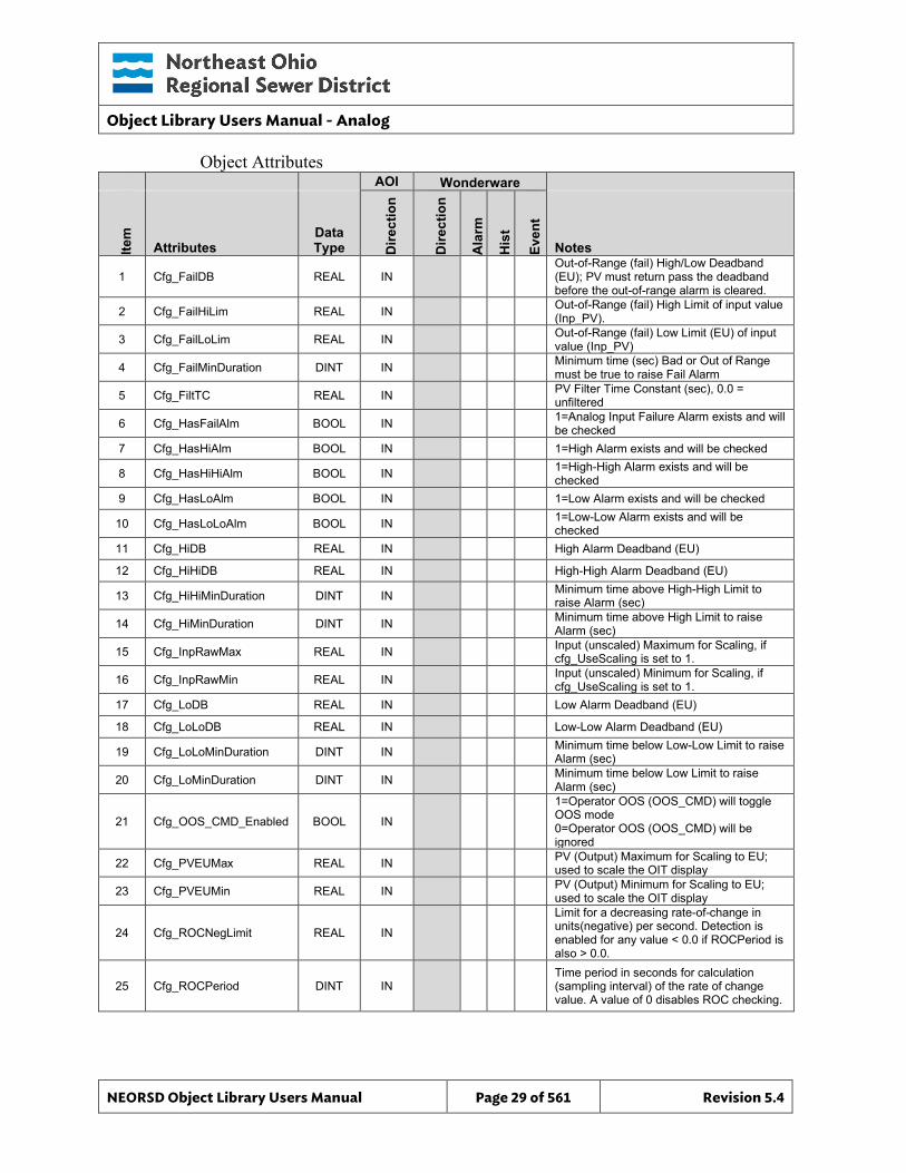
Object Attributes AOI Wonderware
Item
Attributes Data Type D
irect
ion
Dire
ctio
n
Ala
rm
His
t
Even
t
Notes
1 Cfg_FailDB REAL IN Out-of-Range (fail) High/Low Deadband (EU); PV must return pass the deadband before the out-of-range alarm is cleared.
2 Cfg_FailHiLim REAL IN Out-of-Range (fail) High Limit of input value (Inp_PV).
3 Cfg_FailLoLim REAL IN Out-of-Range (fail) Low Limit (EU) of input value (Inp_PV)
4 Cfg_FailMinDuration DINT IN Minimum time (sec) Bad or Out of Range must be true to raise Fail Alarm
5 Cfg_FiltTC REAL IN PV Filter Time Constant (sec), 0.0 = unfiltered
6 Cfg_HasFailAlm BOOL IN 1=Analog Input Failure Alarm exists and will be checked
7 Cfg_HasHiAlm BOOL IN 1=High Alarm exists and will be checked
8 Cfg_HasHiHiAlm BOOL IN 1=High-High Alarm exists and will be checked
9 Cfg_HasLoAlm BOOL IN 1=Low Alarm exists and will be checked
10 Cfg_HasLoLoAlm BOOL IN 1=Low-Low Alarm exists and will be checked
11 Cfg_HiDB REAL IN High Alarm Deadband (EU)
12 Cfg_HiHiDB REAL IN High-High Alarm Deadband (EU)
13 Cfg_HiHiMinDuration DINT IN Minimum time above High-High Limit to raise Alarm (sec)
14 Cfg_HiMinDuration DINT IN Minimum time above High Limit to raise Alarm (sec)
15 Cfg_InpRawMax REAL IN Input (unscaled) Maximum for Scaling, if cfg_UseScaling is set to 1.
16 Cfg_InpRawMin REAL IN Input (unscaled) Minimum for Scaling, if cfg_UseScaling is set to 1.
17 Cfg_LoDB REAL IN Low Alarm Deadband (EU)
18 Cfg_LoLoDB REAL IN Low-Low Alarm Deadband (EU)
19 Cfg_LoLoMinDuration DINT IN Minimum time below Low-Low Limit to raise Alarm (sec)
20 Cfg_LoMinDuration DINT IN Minimum time below Low Limit to raise Alarm (sec)
21 Cfg_OOS_CMD_Enabled BOOL IN
1=Operator OOS (OOS_CMD) will toggle OOS mode 0=Operator OOS (OOS_CMD) will be ignored
22 Cfg_PVEUMax REAL IN PV (Output) Maximum for Scaling to EU; used to scale the OIT display
23 Cfg_PVEUMin REAL IN PV (Output) Minimum for Scaling to EU; used to scale the OIT display
24 Cfg_ROCNegLimit REAL IN
Limit for a decreasing rate-of-change in units(negative) per second. Detection is enabled for any value < 0.0 if ROCPeriod is also > 0.0.
25 Cfg_ROCPeriod DINT IN Time period in seconds for calculation (sampling interval) of the rate of change value. A value of 0 disables ROC checking.
Object Library Users Manual - Analog
NEORSD Object Library Users Manual Page 30 of 561 Revision 5.4
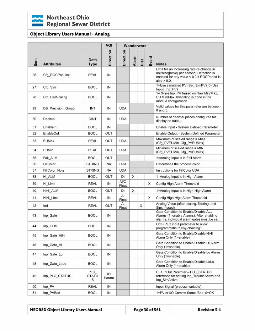
AOI Wonderware
Item
Attributes Data Type D
irect
ion
Dire
ctio
n
Ala
rm
His
t
Even
t
Notes
26 Cfg_ROCPosLimit REAL IN
Limit for an increasing rate-of-change in units(negative) per second. Detection is enabled for any value < 0.0 if ROCPeriod is also > 0.0.
27 Cfg_Sim BOOL IN 1=Use simulated PV (Set_SimPV); 0=Use Input (Inp_PV)
28 Cfg_UseScaling BOOL IN 1= Scale Inp_PV based on Raw Min/Max, EU Min/Max. 0=scaling is done in the module configuration.
29 DB_Precision_Group INT IN UDA Valid values for this parameter are between 0 and 3.
30 Decimal DINT IN UDA Number of decimal places configured for display on output
31 EnableIn BOOL IN Enable Input - System Defined Parameter
32 EnableOut BOOL OUT Enable Output - System Defined Parameter
33 EUMax REAL OUT UDA Maximum of scaled range = MAX (Cfg_PVEUMin, Cfg_PVEUMax)
34 EUMin REAL OUT UDA Minimum of scaled range = MIN (Cfg_PVEUMin, Cfg_PVEUMax)
35 Fail_ALM BOOL OUT 1=Analog Input is in Fail Alarm
36 FillColor STRING NA UDA Determines the process color
37 FillColor_Note STRING NA UDA Instructions for FillColor UDA
38 Hi_ALM BOOL OUT DI X 1=Analog Input is in High Alarm
39 Hi_Limit REAL IN AI/O Float X Config High Alarm Threshold
40 HiHi_ALM BOOL OUT DI X 1=Analog Input is in High-High Alarm
41 HiHi_Limit REAL IN AI Float X Config High-High Alarm Threshold
42 Ind REAL OUT AI Float X Analog Value (after scaling, filtering, and
Sim, if used)
43 Inp_Gate BOOL IN Gate Condition to Enable/Disable ALL Alarms (1=enable Alarms). After enabling alarms, individual alarm gates must be set.
44 Inp_OOS BOOL IN OOS PLC input parameter to allow programmatic "daisy-chaining"
45 Inp_Gate_HiHi BOOL IN Gate Condition to Enable/Disable HiHi Alarm Only (1=enable)
46 Inp_Gate_Hi BOOL IN Gate Condition to Enable/Disable Hi Alarm Only (1=enable)
47 Inp_Gate_Lo BOOL IN Gate Condition to Enable/Disable Lo Alarm Only (1=enable)
48 Inp_Gate_LoLo BOOL IN Gate Condition to Enable/Disable LoLo Alarm Only (1=enable)
49 Inp_PLC_STATUS PLC_
STATUS
IO Param
CLX InOut Paramter – PLC_STATUS reference for setting Inp_TroubleActive and Inp_SimActive
50 Inp_PV REAL IN Input Signal (process variable)
51 Inp_PVBad BOOL IN 1=PV or I/O Comms Status Bad, 0=OK
Object Library Users Manual - Analog
NEORSD Object Library Users Manual Page 31 of 561 Revision 5.4
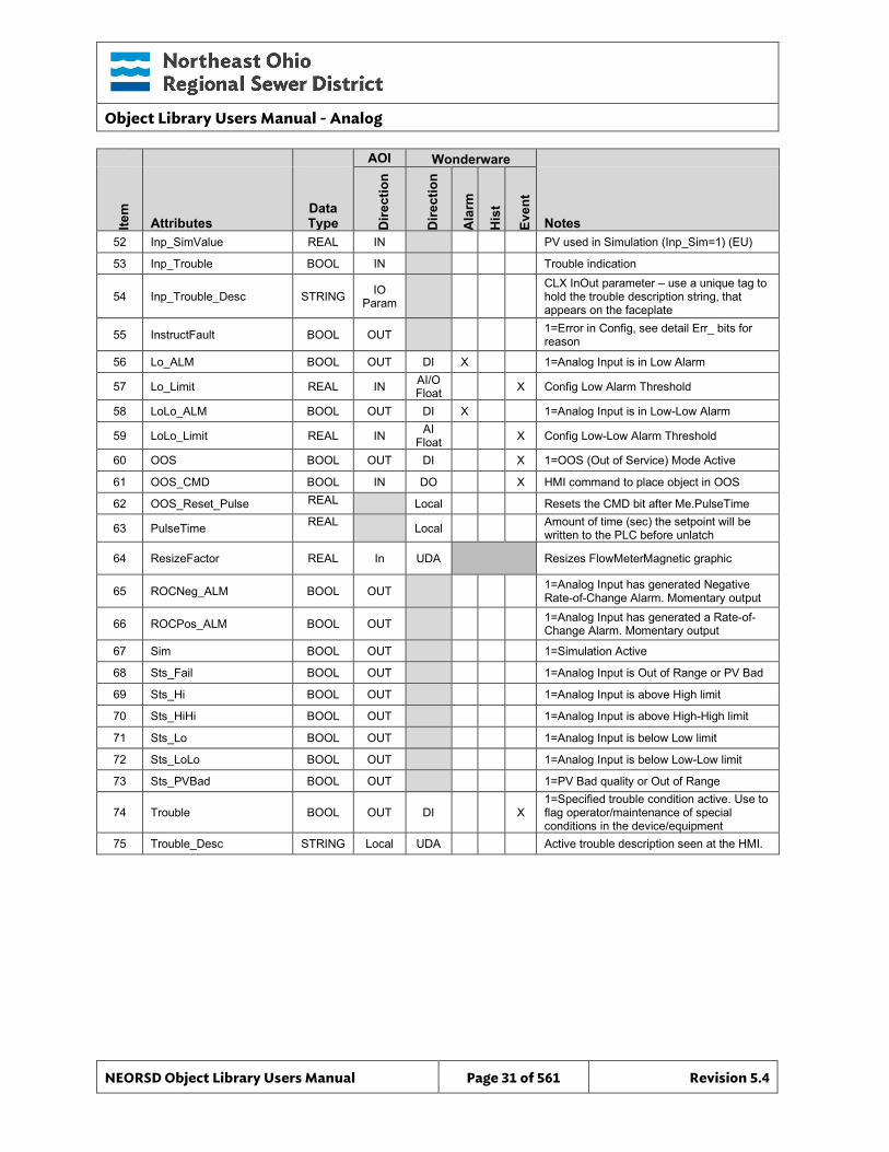
AOI Wonderware
Item
Attributes Data Type D
irect
ion
Dire
ctio
n
Ala
rm
His
t
Even
t
Notes 52 Inp_SimValue REAL IN PV used in Simulation (Inp_Sim=1) (EU)
53 Inp_Trouble BOOL IN Trouble indication
54 Inp_Trouble_Desc STRING IO Param
CLX InOut parameter – use a unique tag to hold the trouble description string, that appears on the faceplate
55 InstructFault BOOL OUT 1=Error in Config, see detail Err_ bits for reason
56 Lo_ALM BOOL OUT DI X 1=Analog Input is in Low Alarm
57 Lo_Limit REAL IN AI/O Float X Config Low Alarm Threshold
58 LoLo_ALM BOOL OUT DI X 1=Analog Input is in Low-Low Alarm
59 LoLo_Limit REAL IN AI Float X Config Low-Low Alarm Threshold
60 OOS BOOL OUT DI X 1=OOS (Out of Service) Mode Active
61 OOS_CMD BOOL IN DO X HMI command to place object in OOS
62 OOS_Reset_Pulse REAL Local Resets the CMD bit after Me.PulseTime
63 PulseTime REAL Local Amount of time (sec) the setpoint will be written to the PLC before unlatch
64 ResizeFactor REAL In UDA Resizes FlowMeterMagnetic graphic
65 ROCNeg_ALM BOOL OUT 1=Analog Input has generated Negative Rate-of-Change Alarm. Momentary output
66 ROCPos_ALM BOOL OUT 1=Analog Input has generated a Rate-of-Change Alarm. Momentary output
67 Sim BOOL OUT 1=Simulation Active
68 Sts_Fail BOOL OUT 1=Analog Input is Out of Range or PV Bad
69 Sts_Hi BOOL OUT 1=Analog Input is above High limit
70 Sts_HiHi BOOL OUT 1=Analog Input is above High-High limit
71 Sts_Lo BOOL OUT 1=Analog Input is below Low limit
72 Sts_LoLo BOOL OUT 1=Analog Input is below Low-Low limit
73 Sts_PVBad BOOL OUT 1=PV Bad quality or Out of Range
74 Trouble BOOL OUT DI X 1=Specified trouble condition active. Use to flag operator/maintenance of special conditions in the device/equipment
75 Trouble_Desc STRING Local UDA Active trouble description seen at the HMI.
Object Library Users Manual - Analog
NEORSD Object Library Users Manual Page 32 of 561 Revision 5.4
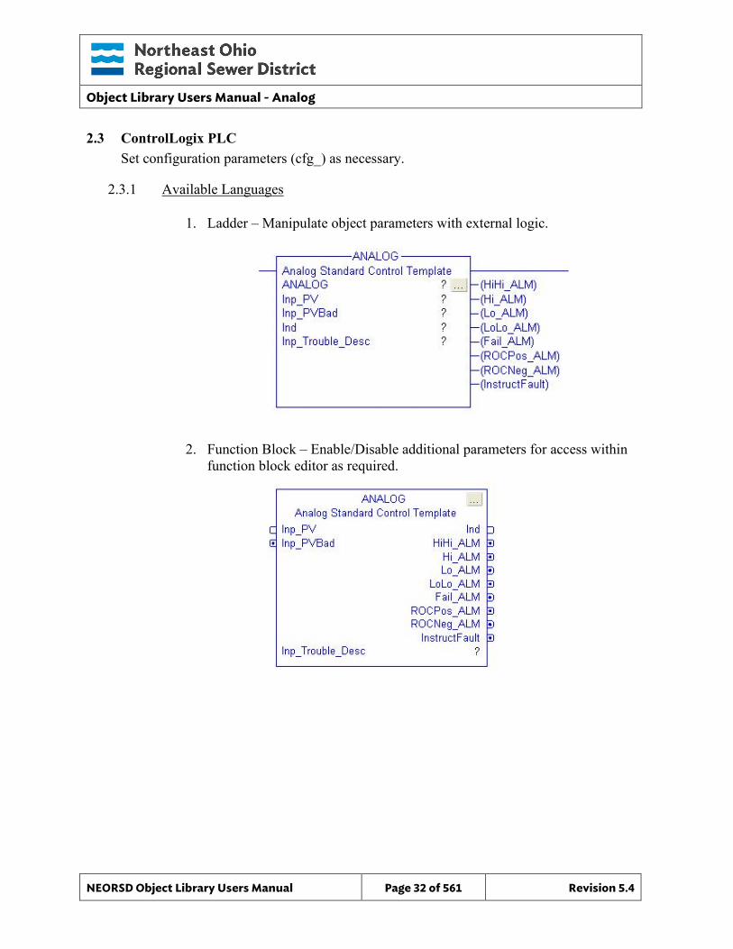
2.3 ControlLogix PLC Set configuration parameters (cfg_) as necessary.
2.3.1 Available Languages
1. Ladder – Manipulate object parameters with external logic.
2. Function Block – Enable/Disable additional parameters for access within function block editor as required.
Object Library Users Manual - Analog
NEORSD Object Library Users Manual Page 33 of 561 Revision 5.4
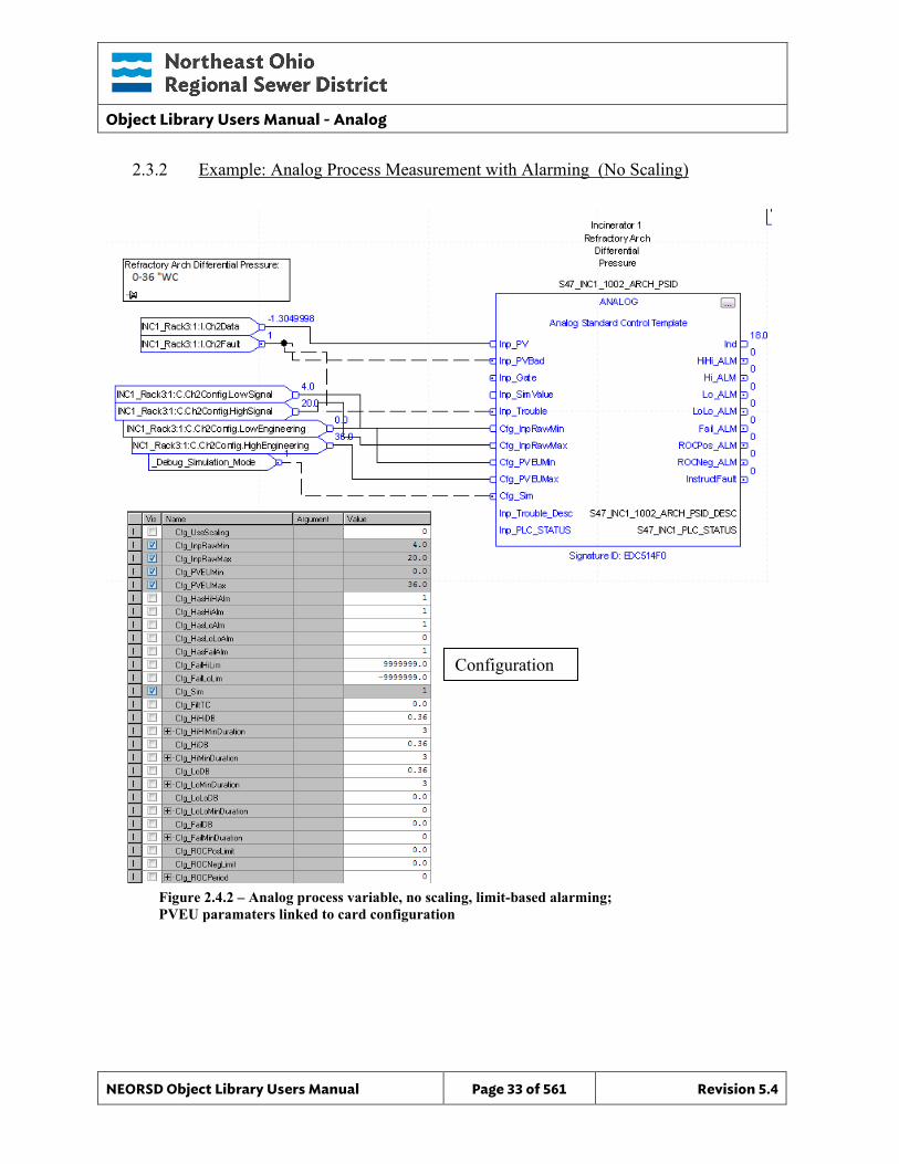
2.3.2 Example: Analog Process Measurement with Alarming (No Scaling)
Figure 2.4.2 – Analog process variable, no scaling, limit-based alarming; PVEU paramaters linked to card configuration
Configuration
Object Library Users Manual - Analog
NEORSD Object Library Users Manual Page 34 of 561 Revision 5.4
Example Highlights • Process Inputs:
o Inp_PV – Scaled process value (from module or other input source with scaling)
o Inp_PVBad – Quality status (from module, MSG status, or other) • AOI Configuration:
o Cfg_PVEUMin, Cfg_PVEUMax – Set to transmitter zero and full scale engineering unit values. Recommend to programmatically link to card configuration.
o Cfg_Has[X]Alm – Set to “1” if the block will use the [X] level alarm. o Cfg_Has[X]DB – [X] alarm must be this far from limit to turn off once
triggered. o Cfg_[X]MinDuration – How long the alarm state must be true to trigger
output. o [X]_Limit – Alarm limit value
• Block Outputs for use in External Logic: o Ind – Analog value for use with process control logic, including:
PID (PV value) o HiHi_ALM, HI_ALM, etc – For use with process control and shutdown logic,
including: Process/equipment shutdown logic (pump low discharge pressure,
vibration high-high level shutdown, etc.) Process/equipment interlocking (low tank level pump interlock, etc.) Process/equipment control strategies (tank high/low level trigger for
pump start/stop, emergency drain valve activation tank high level, etc.)
Object Library Users Manual - Analog
NEORSD Object Library Users Manual Page 35 of 561 Revision 5.4
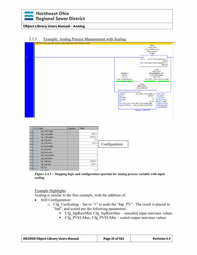
2.3.3 Example: Analog Process Measurement with Scaling
Figure 2.4.3 – Mapping logic and configuration (partial) for analog process variable with input scaling
Example Highlights Scaling is similar to the first example, with the addition of: • AOI Configuration:
o Cfg_UseScaling – Set to “1” to scale the “Inp_PV”. The result is placed in “Ind”, and scaled per the following parameters: Cfg_InpRawMin, Cfg_InpRawMax – unscaled input min/max values Cfg_PVEUMax, Cfg_PVEUMin – scaled output min/max values
Configuration
Object Library Users Manual - Analog
NEORSD Object Library Users Manual Page 36 of 561 Revision 5.4
2.3.4 Additional Attribute Notes
2.3.4.1 Inputs o Inp_Gate – Programmatically set this attribute to “0” to disable all limit
and rate of change alarming temporarily (e.g., if the analog value represents a pump discharge pressure, tie Inp_Gate to “pump running” to prevent false ‘low’ alarms when the pump is off).
o Inp_Gate_HiHi, Inp_Gate_Hi, etc. – Programmatically set these attributes to “0” to disable specific alarms temporarily (e.g., tank low and low low level alarms may be disabled for tanks not in service. However, high and high high alarms should always be active. In this case, tie “tank in service” status to Inp_Gate_Lo and Inp_Gate_LoLo.)
o Inp_SimValue – Process variable used in simulation mode (instead of “Inp_PV”)
o Inp_OOS – Programmatically set this attribute to “1” to enable Out of Service.
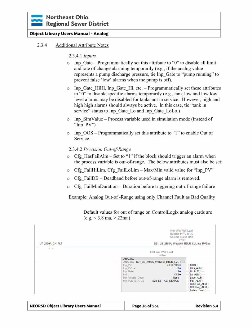
2.3.4.2 Precision Out-of-Range o Cfg_HasFailAlm – Set to “1” if the block should trigger an alarm when
the process variable is out-of-range. The below attributes must also be set: o Cfg_FailHiLim, Cfg_FailLoLim – Max/Min valid value for “Inp_PV” o Cfg_FailDB – Deadband before out-of-range alarm is removed. o Cfg_FailMinDuration – Duration before triggering out-of-range failure
Example: Analog Out-of -Range using only Channel Fault as Bad Quality Default values for out of range on ControlLogix analog cards are (e.g. < 3.8 ma, > 22ma)
Object Library Users Manual - Analog
NEORSD Object Library Users Manual Page 37 of 561 Revision 5.4
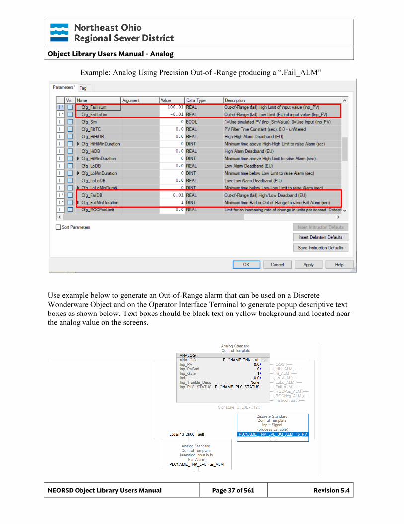
Example: Analog Using Precision Out-of -Range producing a “.Fail_ALM”
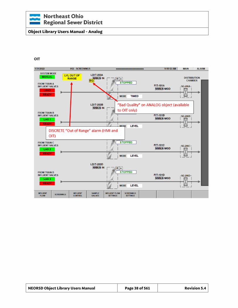
Use example below to generate an Out-of-Range alarm that can be used on a Discrete Wonderware Object and on the Operator Interface Terminal to generate popup descriptive text boxes as shown below. Text boxes should be black text on yellow background and located near the analog value on the screens.
Object Library Users Manual - Analog
NEORSD Object Library Users Manual Page 38 of 561 Revision 5.4
Object Library Users Manual - Analog
NEORSD Object Library Users Manual Page 39 of 561 Revision 5.4
2.3.4.3 Internal Configuration o Decimal – Set to the desired number of decimal places for the output Ind. o Cfg_ROCNegLimit – Engineering units/second for negative rate of
change alarm o Cfg_ROCPosLimit – Engineering units/second for a positive rate of
change alarm. o Cfg_ROCPeriod – Sampling period for rate-of-change alarming. o Cfg_FiltTC – Seconds to filter “Inp_PV” over to remove noise. Set to “0”
to disable signal filtering. o Cfg_Sim – Set to “1” to enable simulation. Block will use the input from
“Inp_SimValue” instead of “Inp_PV”. o Cfg_OOS_CMD_Enabled – Set to “1” to enable toggling of Out-of-
Service. o INP_PLC_STATUS – Must reference the PLC_Status object for this PLC.
2.3.4.4
2.3.4.5 Outputs o ROCNeg_ALM – Process variable has a high negative rate of change o ROCPos_ALM – Process variable has a high positive rate of change o Fail_ALM – True when the process variable is out-of-range o Sts_PVBad – True for a ‘bad’ process variable (i.e. card faulted), from
“Inp_PVBad” o OOS – Indicates that this instance is out-of-service
Object Library Users Manual - Analog
NEORSD Object Library Users Manual Page 40 of 561 Revision 5.4
2.4 Wonderware HMI
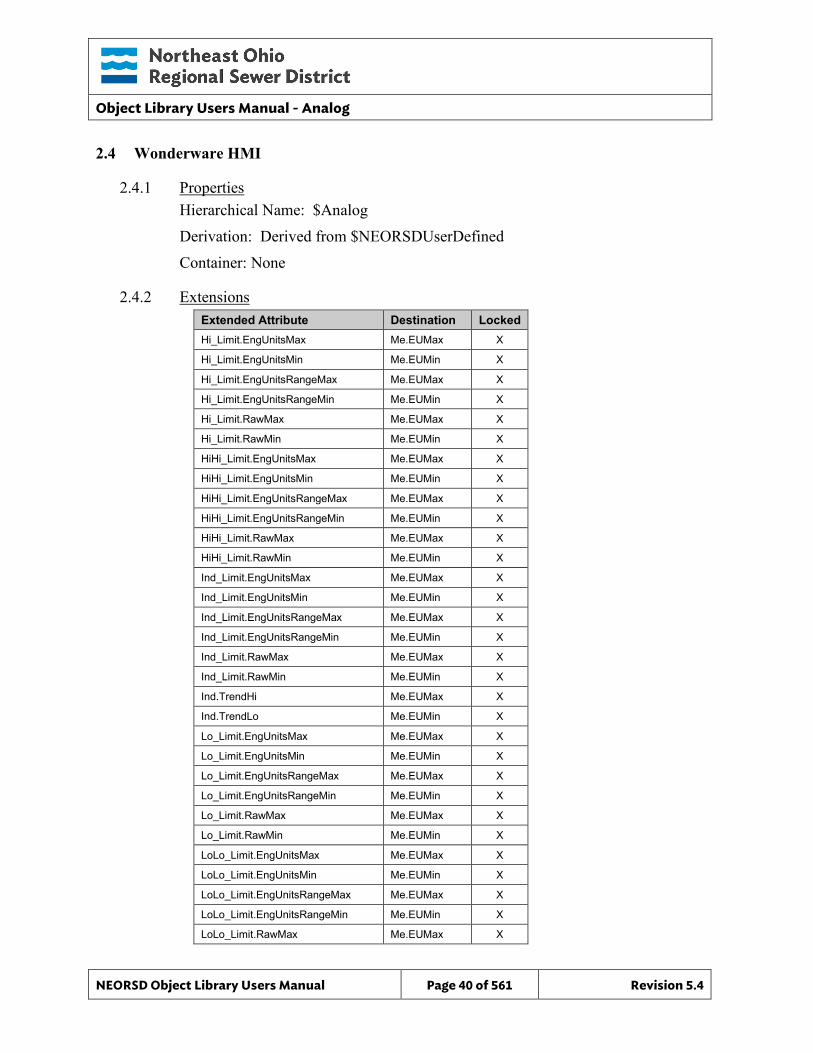
2.4.1 Properties Hierarchical Name: $Analog Derivation: Derived from $NEORSDUserDefined Container: None
2.4.2 Extensions Extended Attribute Destination Locked Hi_Limit.EngUnitsMax Me.EUMax X
Hi_Limit.EngUnitsMin Me.EUMin X
Hi_Limit.EngUnitsRangeMax Me.EUMax X
Hi_Limit.EngUnitsRangeMin Me.EUMin X
Hi_Limit.RawMax Me.EUMax X
Hi_Limit.RawMin Me.EUMin X
HiHi_Limit.EngUnitsMax Me.EUMax X
HiHi_Limit.EngUnitsMin Me.EUMin X
HiHi_Limit.EngUnitsRangeMax Me.EUMax X
HiHi_Limit.EngUnitsRangeMin Me.EUMin X
HiHi_Limit.RawMax Me.EUMax X
HiHi_Limit.RawMin Me.EUMin X
Ind_Limit.EngUnitsMax Me.EUMax X
Ind_Limit.EngUnitsMin Me.EUMin X
Ind_Limit.EngUnitsRangeMax Me.EUMax X
Ind_Limit.EngUnitsRangeMin Me.EUMin X
Ind_Limit.RawMax Me.EUMax X
Ind_Limit.RawMin Me.EUMin X
Ind.TrendHi Me.EUMax X
Ind.TrendLo Me.EUMin X
Lo_Limit.EngUnitsMax Me.EUMax X
Lo_Limit.EngUnitsMin Me.EUMin X
Lo_Limit.EngUnitsRangeMax Me.EUMax X
Lo_Limit.EngUnitsRangeMin Me.EUMin X
Lo_Limit.RawMax Me.EUMax X
Lo_Limit.RawMin Me.EUMin X
LoLo_Limit.EngUnitsMax Me.EUMax X
LoLo_Limit.EngUnitsMin Me.EUMin X
LoLo_Limit.EngUnitsRangeMax Me.EUMax X
LoLo_Limit.EngUnitsRangeMin Me.EUMin X
LoLo_Limit.RawMax Me.EUMax X
Object Library Users Manual - Analog
NEORSD Object Library Users Manual Page 41 of 561 Revision 5.4
Extended Attribute Destination Locked LoLo_Limit.RawMin Me.EUMin X
Trouble_Desc Me.Placeholder
2.4.3 Configuration All of the necessary configuration for Analog must also be done on any instance derived from this template.
1) Alarm Priority – Each configured (non Me.Placeholder input source) alarms (Hi_ALM, HiHi_ALM, Lo_ALM, and LoLo_ALM) need to have a priority defined.
2) Alarm State Labels – Each configured alarm (Hi_ALM, HiHi_ALM, Lo_ALM, and LoLo_ALM) have defaulted state labels of False = OK and True = ALARM. If different labels are desired these need to be configured on the instance.
3) If ASSET_ID is not in use the initial value will be left blank. Scripting used for ASSET_ID uses the initial value and not ASSET_ID.Description.
4) Attributes that are not used in the configured instance shall use Me.Placeholder to eliminate the point from counting against the systems total I/O scan counts. The allowed attributes for this template include:
a. Hi_Limit b. HiHi_Limit c. Lo_Limit d. LoLo_Limit e. Hi_ALM f. HiHi_ALM
g. Lo_ALM h. LoLo_ALM i. OOS j. Trouble
Object Library Users Manual - Analog
NEORSD Object Library Users Manual Page 42 of 561 Revision 5.4
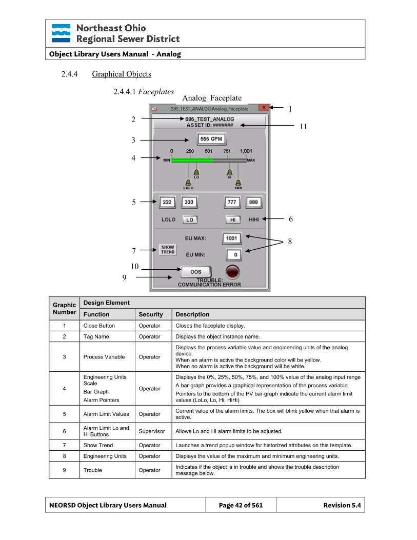
2.4.4 Graphical Objects
2.4.4.1 Faceplates
Graphic Number
Design Element
Function Security Description
1 Close Button Operator Closes the faceplate display.
2 Tag Name Operator Displays the object instance name.
3 Process Variable Operator
Displays the process variable value and engineering units of the analog device. When an alarm is active the background color will be yellow. When no alarm is active the background will be white.
4
Engineering Units Scale Bar Graph Alarm Pointers
Operator
Displays the 0%, 25%, 50%, 75%, and 100% value of the analog input range A bar-graph provides a graphical representation of the process variable Pointers to the bottom of the PV bar-graph indicate the current alarm limit values (LoLo, Lo, Hi, HiHi)
5 Alarm Limit Values Operator Current value of the alarm limits. The box will blink yellow when that alarm is active.
6 Alarm Limit Lo and Hi Buttons Supervisor Allows Lo and Hi alarm limits to be adjusted.
7 Show Trend Operator Launches a trend popup window for historized attributes on this template.
8 Engineering Units Operator Displays the value of the maximum and minimum engineering units.
9 Trouble Operator Indicates if the object is in trouble and shows the trouble description message below.
Analog_Faceplate
2
3
4
5
1
6
8
10
7
9
11
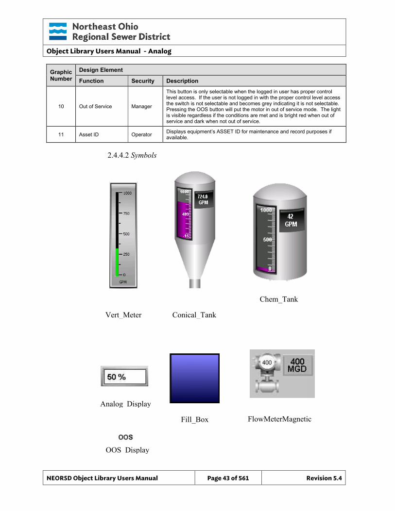
Object Library Users Manual - Analog
NEORSD Object Library Users Manual Page 43 of 561 Revision 5.4
Graphic Number
Design Element
Function Security Description
10 Out of Service Manager
This button is only selectable when the logged in user has proper control level access. If the user is not logged in with the proper control level access the switch is not selectable and becomes grey indicating it is not selectable. Pressing the OOS button will put the motor in out of service mode. The light is visible regardless if the conditions are met and is bright red when out of service and dark when not out of service.
11 Asset ID Operator Displays equipment’s ASSET ID for maintenance and record purposes if available.
2.4.4.2 Symbols
Analog_Display
Vert_Meter
Chem_Tank
Fill_Box
Conical_Tank
FlowMeterMagnetic
OOS_Display
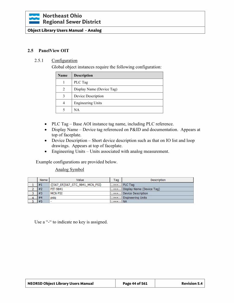
Object Library Users Manual - Analog
NEORSD Object Library Users Manual Page 44 of 561 Revision 5.4
2.5 PanelView OIT
2.5.1 Configuration Global object instances require the following configuration:
Name Description
1 PLC Tag
2 Display Name (Device Tag)
3 Device Description
4 Engineering Units
5 NA
• PLC Tag – Base AOI instance tag name, including PLC reference. • Display Name – Device tag referenced on P&ID and documentation. Appears at
top of faceplate. • Device Description – Short device description such as that on IO list and loop
drawings. Appears at top of faceplate. • Engineering Units – Units associated with analog measurement.
Example configurations are provided below.
Analog Symbol
Use a “-“ to indicate no key is assigned.
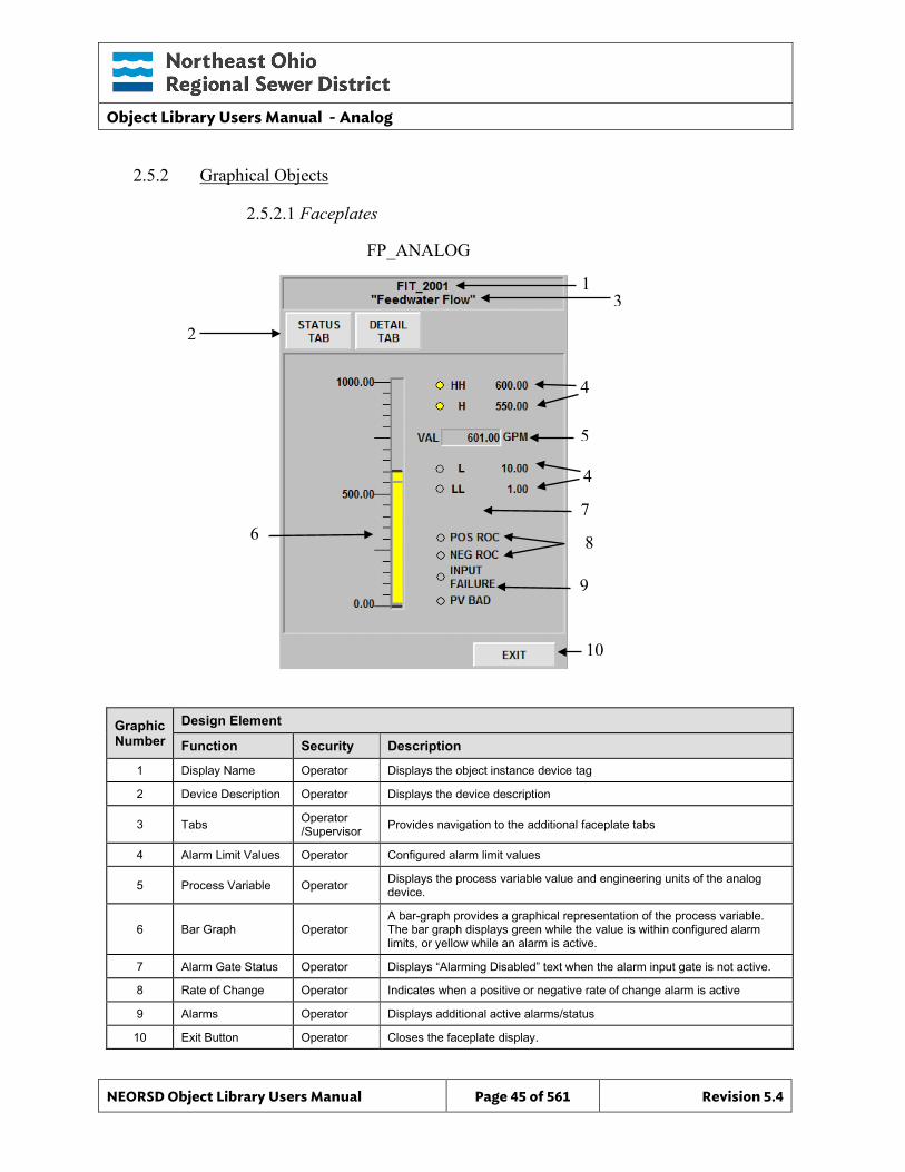
Object Library Users Manual - Analog
NEORSD Object Library Users Manual Page 45 of 561 Revision 5.4
1 3
4
5
4
10
9
8
7
2.5.2 Graphical Objects
2.5.2.1 Faceplates
Graphic Number
Design Element
Function Security Description
1 Display Name Operator Displays the object instance device tag
2 Device Description Operator Displays the device description
3 Tabs Operator /Supervisor Provides navigation to the additional faceplate tabs
4 Alarm Limit Values Operator Configured alarm limit values
5 Process Variable Operator Displays the process variable value and engineering units of the analog device.
6 Bar Graph Operator A bar-graph provides a graphical representation of the process variable. The bar graph displays green while the value is within configured alarm limits, or yellow while an alarm is active.
7 Alarm Gate Status Operator Displays “Alarming Disabled” text when the alarm input gate is not active.
8 Rate of Change Operator Indicates when a positive or negative rate of change alarm is active
9 Alarms Operator Displays additional active alarms/status
10 Exit Button Operator Closes the faceplate display.
FP_ANALOG
2
6
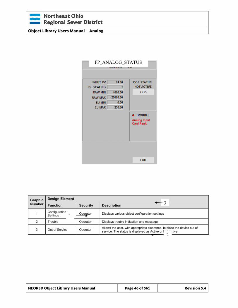
Object Library Users Manual - Analog
NEORSD Object Library Users Manual Page 46 of 561 Revision 5.4
Graphic Number
Design Element
Function Security Description
1 Configuration Settings Operator Displays various object configuration settings
2 Trouble Operator Displays trouble indication and message.
3 Out of Service Operator Allows the user, with appropriate clearance, to place the device out of service. The status is displayed as Active or Not Active.
FP_ANALOG_STATUS
1
2
3
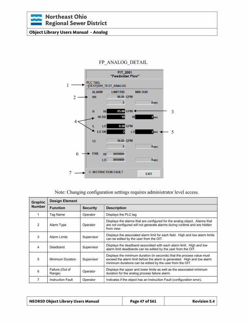
Object Library Users Manual - Analog
NEORSD Object Library Users Manual Page 47 of 561 Revision 5.4
Note: Changing configuration settings requires administrator level access.
Graphic Number
Design Element
Function Security Description
1 Tag Name Operator Displays the PLC tag
2 Alarm Type Operator Displays the alarms that are configured for the analog object. Alarms that are not configured will not generate alarms during runtime and are hidden from view.
3 Alarm Limits Supervisor Displays the associated alarm limit for each field. High and low alarm limits can be edited by the user from the OIT.
4 Deadband Supervisor Displays the deadband associated with each alarm limit. High and low alarm limit deadbands can be edited by the user from the OIT.
5 Minimum Duration Supervisor Displays the minimum duration (in seconds) that the process value must exceed the alarm limit before the alarm is generated. High and low alarm minimum durations can be edited by the user from the OIT.
6 Failure (Out of Range) Operator Displays the upper and lower limits as well as the associated minimum
duration for the analog process failure alarm.
7 Instruction Fault Operator Indicates if the object has an Instruction Fault (configuration error).
FP_ANALOG_DETAIL
4
3
6
5
1
2
7
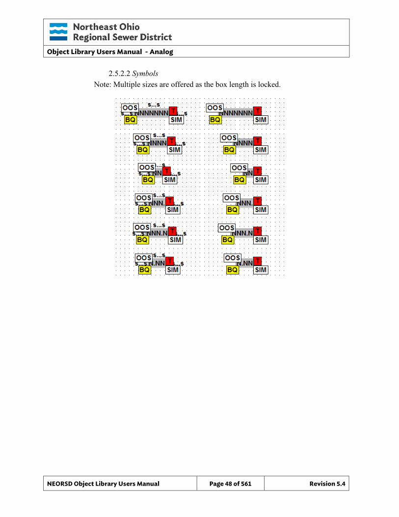
Object Library Users Manual - Analog
NEORSD Object Library Users Manual Page 48 of 561 Revision 5.4
2.5.2.2 Symbols Note: Multiple sizes are offered as the box length is locked.
Object Library Users Manual - Analog_Basic
NEORSD Object Library Users Manual Page 49 of 561 Revision 5.4
3.0 Analog_Basic
3.1 Introduction The analog basic template provides a standard representation of a scaled analog reading (flow, pressure, temperature, etc.) within the NEORSD control systems not requiring any form of limit alarming (high/low). Use the Analog_Basic template if the below is true:
• If the analog value has no associated level (high/low) alarms. Do not use the Analog_Basic template if the below is true:
• If the analog value requires scaling (i.e. is not prescaled at the input card). If the process variable requires level alarming or scaling, use the Analog template instead.
3.2 Object Features
3.2.1 Value Indication This object provides analog process value indication for use with downstream logic in the PLC, and for display on the HMI/OIT.
3.2.2 Simulation This object supports simulation of the process value.
3.2.3 Trouble This object supports hardware trouble indication.
3.2.4 DB_Precision_Group Attribute is used in the ValueDeadband script. In the script, this parameter sets the deadband of inputs. Valid values for this parameter are between 0 and 3. o 0= default group; o 1= custom ValueDeadband setting which disables the script and uses the
attribute’s ValueDeadband; o 2= high precision; o 3= non-precision REF objects (obsolete)
While 3 is an available option, it is not to be used for new objects moving forward. If changing the DB_Precision_Group to 1, you must undeploy and then deploy the object to guarantee that runtime deadband setting gets updated. A redeploy action will not update ValueDeadband.
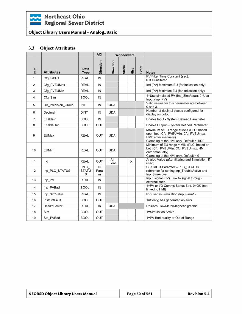
Object Library Users Manual - Analog_Basic
NEORSD Object Library Users Manual Page 50 of 561 Revision 5.4
3.3 Object Attributes
AOI Wonderware
Item
Attributes Data Type D
irect
ion
Dire
ctio
n
Ala
rm
His
t
Even
t
Notes
1 Cfg_FiltTC REAL IN PV Filter Time Constant (sec), 0.0 = unfiltered
2 Cfg_PVEUMax REAL IN Ind (PV) Maximum EU (for indication only)
3 Cfg_PVEUMin REAL IN Ind (PV) Minimum EU (for indication only)
4 Cfg_Sim BOOL IN 1=Use simulated PV (Inp_SimValue); 0=Use Input (Inp_PV)
5 DB_Precision_Group INT IN UDA Valid values for this parameter are between 0 and 3.
6 Decimal DINT IN UDA Number of decimal places configured for display on output
7 EnableIn BOOL IN Enable Input - System Defined Parameter
8 EnableOut BOOL OUT Enable Output - System Defined Parameter
9 EUMax REAL OUT UDA
Maximum of EU range = MAX (PLC: based upon both Cfg_PVEUMin, Cfg_PVEUmax, HMI: enter manually). Clamping at the HMI only. Default = 1000
10 EUMin REAL OUT UDA
Minimum of EU range = MIN (PLC: based on both Cfg_PVEUMin, Cfg_PVEUmax, HMI: enter manually). Clamping at the HMI only. Default = 0
11 Ind REAL OUT AI Float X Analog Value (after filtering and Simulation, if
used)
12 Inp_PLC_STATUS PLC_
STATUS
IO Para
m
CLX InOut Paramter – PLC_STATUS reference for setting Inp_TroubleActive and Inp_SimActive
13 Inp_PV REAL IN Input signal (PV). Link to signal through external code.
14 Inp_PVBad BOOL IN 1=PV or I/O Comms Status Bad, 0=OK (not linked to HMI)
15 Inp_SimValue REAL IN PV used in Simulation (Inp_Sim=1)
16 InstructFault BOOL OUT 1=Config has generated an error
17 ResizeFactor REAL In UDA Resizes FlowMeterMagnetic graphic
18 Sim BOOL OUT 1=Simulation Active
19 Sts_PVBad BOOL OUT 1=PV Bad quality or Out of Range
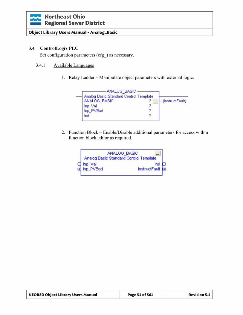
Object Library Users Manual - Analog_Basic
NEORSD Object Library Users Manual Page 51 of 561 Revision 5.4
3.4 ControlLogix PLC Set configuration parameters (cfg_) as necessary.
3.4.1 Available Languages
1. Relay Ladder – Manipulate object parameters with external logic.
2. Function Block – Enable/Disable additional parameters for access within function block editor as required.
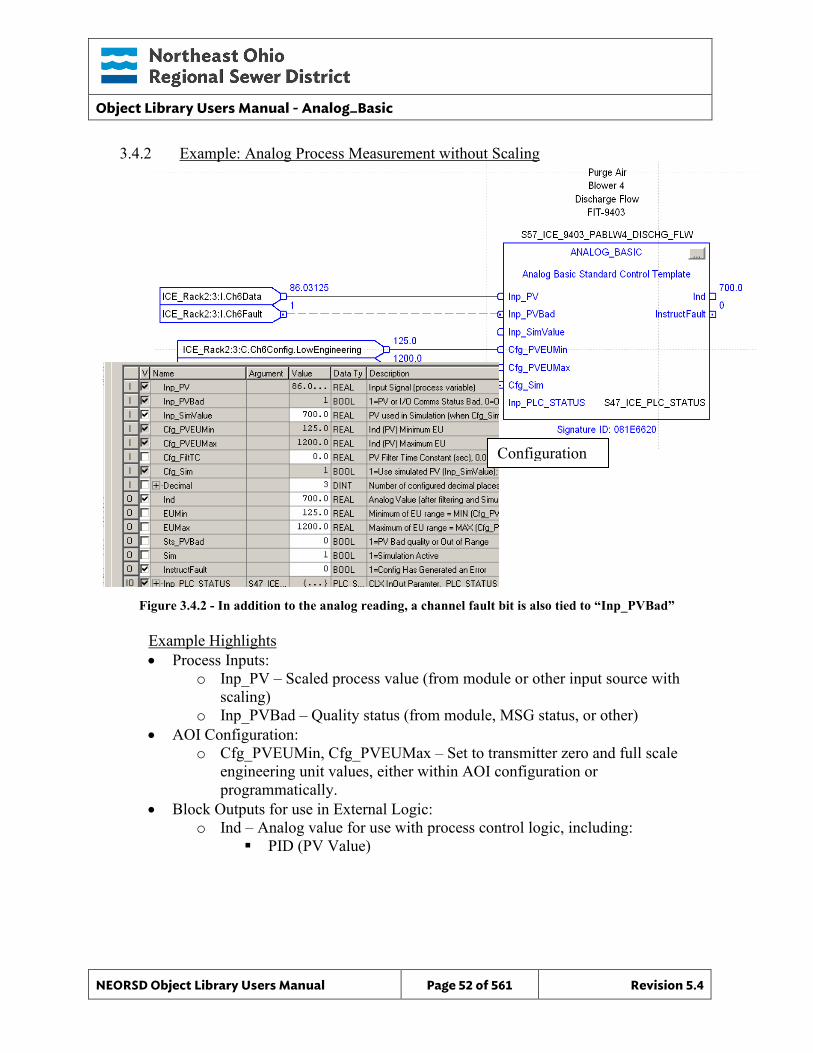
Object Library Users Manual - Analog_Basic
NEORSD Object Library Users Manual Page 52 of 561 Revision 5.4
3.4.2 Example: Analog Process Measurement without Scaling
Figure 3.4.2 - In addition to the analog reading, a channel fault bit is also tied to “Inp_PVBad”
Example Highlights • Process Inputs:
o Inp_PV – Scaled process value (from module or other input source with scaling)
o Inp_PVBad – Quality status (from module, MSG status, or other) • AOI Configuration:
o Cfg_PVEUMin, Cfg_PVEUMax – Set to transmitter zero and full scale engineering unit values, either within AOI configuration or programmatically.
• Block Outputs for use in External Logic: o Ind – Analog value for use with process control logic, including:
PID (PV Value)
Configuration
Object Library Users Manual - Analog_Basic
NEORSD Object Library Users Manual Page 53 of 561 Revision 5.4
3.4.3 Additional Attribute Notes
3.4.3.1 Inputs o Inp_SimValue – Process variable used in simulation mode (instead of
“Inp_PV”) o INP_PLC_STATUS – Must reference the PLC_Status object for this PLC.
3.4.3.2 Internal Configuration o Decimal – Set to the desired number of decimal places for the output Ind. o Cfg_FiltTC – Seconds to filter “Inp_PV” over to remove noise. Set to “0”
to disable signal filtering. o Cfg_Sim – Set to “1” to enable simulation. Block will use the input from
“Inp_SimValue” instead of “Inp_PV”.
3.4.3.3 Outputs o Sts_PVBad – True for a ‘bad’ process variable (i.e. card faulted), from
“Inp_PVBad”
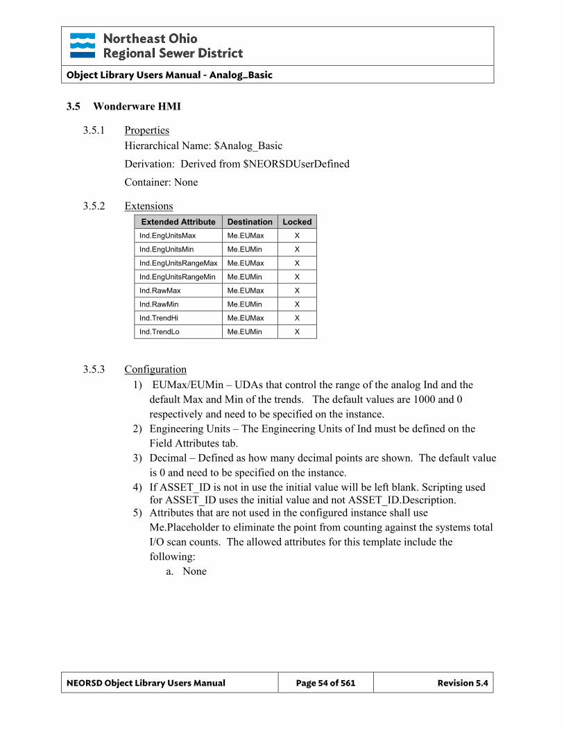
Object Library Users Manual - Analog_Basic
NEORSD Object Library Users Manual Page 54 of 561 Revision 5.4
3.5 Wonderware HMI
3.5.1 Properties Hierarchical Name: $Analog_Basic Derivation: Derived from $NEORSDUserDefined Container: None
3.5.2 Extensions Extended Attribute Destination Locked Ind.EngUnitsMax Me.EUMax X
Ind.EngUnitsMin Me.EUMin X
Ind.EngUnitsRangeMax Me.EUMax X
Ind.EngUnitsRangeMin Me.EUMin X
Ind.RawMax Me.EUMax X
Ind.RawMin Me.EUMin X
Ind.TrendHi Me.EUMax X
Ind.TrendLo Me.EUMin X
3.5.3 Configuration 1) EUMax/EUMin – UDAs that control the range of the analog Ind and the
default Max and Min of the trends. The default values are 1000 and 0 respectively and need to be specified on the instance.
2) Engineering Units – The Engineering Units of Ind must be defined on the Field Attributes tab.
3) Decimal – Defined as how many decimal points are shown. The default value is 0 and need to be specified on the instance.
4) If ASSET_ID is not in use the initial value will be left blank. Scripting used for ASSET_ID uses the initial value and not ASSET_ID.Description.
5) Attributes that are not used in the configured instance shall use Me.Placeholder to eliminate the point from counting against the systems total I/O scan counts. The allowed attributes for this template include the following:
a. None
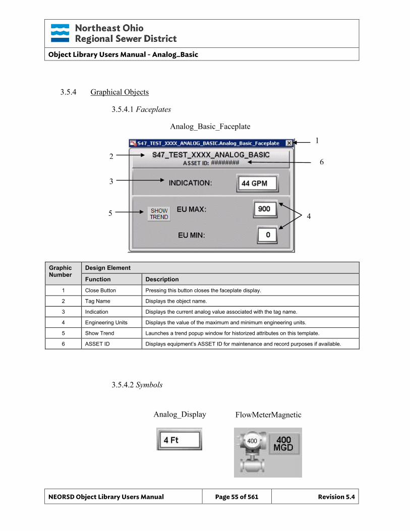
Object Library Users Manual - Analog_Basic
NEORSD Object Library Users Manual Page 55 of 561 Revision 5.4
3.5.4 Graphical Objects
3.5.4.1 Faceplates
Graphic Number
Design Element
Function Description
1 Close Button Pressing this button closes the faceplate display.
2 Tag Name Displays the object name.
3 Indication Displays the current analog value associated with the tag name.
4 Engineering Units Displays the value of the maximum and minimum engineering units.
5 Show Trend Launches a trend popup window for historized attributes on this template.
6 ASSET ID Displays equipment’s ASSET ID for maintenance and record purposes if available.
3.5.4.2 Symbols
Analog_Display
Analog_Basic_Faceplate
2
1
3
5
FlowMeterMagnetic
4
6
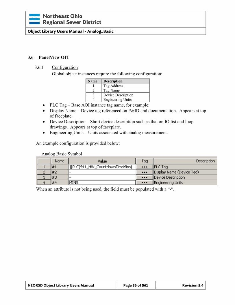
Object Library Users Manual - Analog_Basic
NEORSD Object Library Users Manual Page 56 of 561 Revision 5.4
3.6 PanelView OIT
3.6.1 Configuration Global object instances require the following configuration:
Name Description 1 Tag Address 2 Tag Name 3 Device Description 4 Engineering Units
• PLC Tag – Base AOI instance tag name, for example: • Display Name – Device tag referenced on P&ID and documentation. Appears at top
of faceplate. • Device Description – Short device description such as that on IO list and loop
drawings. Appears at top of faceplate. • Engineering Units – Units associated with analog measurement.
An example configuration is provided below: Analog Basic Symbol
When an attribute is not being used, the field must be populated with a “-“.
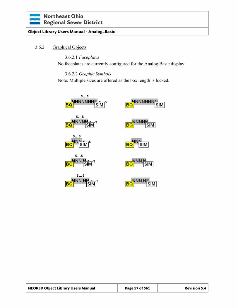
Object Library Users Manual - Analog_Basic
NEORSD Object Library Users Manual Page 57 of 561 Revision 5.4
3.6.2 Graphical Objects
3.6.2.1 Faceplates No faceplates are currently configured for the Analog Basic display.
3.6.2.2 Graphic Symbols Note: Multiple sizes are offered as the box length is locked.

Object Library Users Manual - Analog_Basic
NEORSD Object Library Users Manual Page 58 of 561 Revision 5.4
This page left blank intentionally.
Object Library Users Manual - Analog_RW
NEORSD Object Library Users Manual Page 59 of 561 Revision 5.4
4.0 Analog_RW
4.1 Introduction The Analog RW template provides a standard representation of an operator controllable analog value (flow setpoint, pressure setpoint, temperature setpoint, etc) and a separate analog indication within the NEORSD control systems. By itself, the Analog_RW provides no control. This object acts as a “container” for a setpoint value and process value, which can then be used in conjunction with other control elements or special program logic. Use the Analog_RW template if any of the statements below are true:
• If trying to provide the operator with a setpoint field and a process value readout as part of the same object.
• If trying to monitor an analog process value while controlling another analog value (typically the setpoint associated with the first process value),
• If trying to create an analog setpoint that will automatically ‘track’ another value when certain conditions are true (bumpless functionality),
Do not use the Analog_RW template if the below is true:
• If the setpoint does not need to be tied into the same object as the process value that it is controlling. If this is the case, use the Analog_Setpoint template instead.
• If the setpoint being represented does not require built-in bumpless functionality. In this case, use the Analog_Setpoint template instead.
• If the value being represented is a motor speed or valve position setpoint. In this case, use a Motor_VFD or Valve_Analog object instead.
4.2 Object Features
4.2.1 Status Indications This object will display the current value of the analog setpoint, and the current value of the associated process variable being monitored.
4.2.2 Control This object allows an operator to manually change the value of an analog value (setpoint) from the HMI/OIT to the PLC. It can also enter an automatic mode where the control of the analog value is set from within the program automatically (bumpless).
4.2.3 Alarming The following alarms exist within this object: o Setpoint value is at the operator limit (upper or lower)
Object Library Users Manual - Analog_RW
NEORSD Object Library Users Manual Page 60 of 561 Revision 5.4
o Object is configured incorrectly
4.2.4 Simulation This object supports simulation mode.
4.2.5 Trouble This object supports hardware trouble indication at the HMI; bad quality is also displayed on the OIT.
4.2.6 DB_Precision_Group Attribute is used in the ValueDeadband script. In the script, this parameter sets the deadband of inputs. Valid values for this parameter are between 0 and 3. o 0= default group; o 1= custom ValueDeadband setting which disables the script and uses the
attribute’s ValueDeadband; o 2= high precision; o 3= non-precision REF objects (obsolete)
While 3 is an available option, it is not to be used for new objects moving forward. If changing the DB_Precision_Group to 1, you must undeploy and then deploy the object to guarantee that runtime deadband setting gets updated. A redeploy action will not update ValueDeadband.
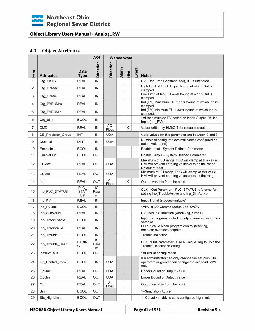
Object Library Users Manual - Analog_RW
NEORSD Object Library Users Manual Page 61 of 561 Revision 5.4
4.3 Object Attributes
AOI Wonderware
Item
Attributes Data Type D
irect
ion
Dire
ctio
n
Ala
rm
His
t
Even
t
Notes 1 Cfg_FiltTC REAL IN PV Filter Time Constant (sec), 0.0 = unfiltered
2 Cfg_OpMax REAL IN High Limit of Input. Upper bound at which Out is clamped.
3 Cfg_OpMin REAL IN Low Limit of Input. Lower bound at which Out is clamped.
4 Cfg_PVEUMax REAL IN Ind (PV) Maximum EU. Upper bound at which Ind is clamped.
5 Cfg_PVEUMin REAL IN Ind (PV) Minimum EU. Lower bound at which Ind is clamped.
6 Cfg_Sim BOOL IN 1=Use simulated PV based on block Output, 0=Use Input (Inp_PV)
7 CMD REAL IN AO Float X Value written by HMI/OIT for requested output
8 DB_Precision_Group INT IN UDA Valid values for this parameter are between 0 and 3. 9 Decimal DINT IN UDA Number of configured decimal places configured on
output value (Ind) 10 EnableIn BOOL IN Enable Input - System Defined Parameter
11 EnableOut BOOL OUT Enable Output - System Defined Parameter
12 EUMax REAL OUT UDA Maximum of EU range. PLC will clamp at this value. HMI will prevent entering values outside the range. Default = 1000
13 EUMin REAL OUT UDA Minimum of EU range. PLC will clamp at this value. HMI will prevent entering values outside the range
14 Ind REAL OUT AI Float X Output variable from the block
15 Inp_PLC_STATUS PLC_ STAT
US
IO Para
m CLX InOut Paramter – PLC_STATUS reference for
setting Inp_TroubleActive and Inp_SimActive
16 Inp_PV REAL IN Input Signal (process variable)
17 Inp_PVBad BOOL IN 1=PV or I/O Comms Status Bad, 0=OK
18 Inp_SimValue REAL IN PV used in Simulation (when Cfg_Sim=1)
19 Inp_TrackEnable BOOL IN Input for program control of output variable; overrides setpoint
20 Inp_TrackValue REAL IN Output value when program control (tracking) enabled; overrides setpoint
21 Inp_Trouble BOOL IN Trouble indication
22 Inp_Trouble_Desc STRING
IO Para
m CLX InOut Parameter: Use a Unique Tag to Hold the
Trouble Description String
23 InstructFault BOOL OUT 1=Error in configuration
24 Op_Control_Perm BOOL IN UDA 0 = administrator can only change the set point, 1= operators or greater can change the set point. WW only
25 OpMax REAL OUT UDA Upper Bound of Output Value
26 OpMin REAL OUT UDA Lower Bound of Output Value
27 Out REAL OUT AI Float Output variable from the block
28 Sim BOOL OUT 1=Simulation Active
29 Sts_HighLimit BOOL OUT 1=Output variable is at its configured high limit
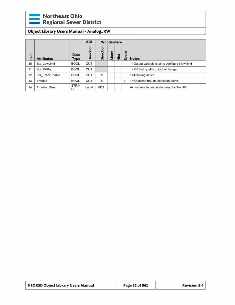
Object Library Users Manual - Analog_RW
NEORSD Object Library Users Manual Page 62 of 561 Revision 5.4
AOI Wonderware
Item
Attributes Data Type D
irect
ion
Dire
ctio
n
Ala
rm
His
t
Even
t
Notes 30 Sts_LowLimit BOOL OUT 1=Output variable is at its configured low limit
31 Sts_PVBad BOOL OUT 1=PV Bad quality or Out of Range
32 Sts_TrackEnable BOOL OUT DI 1=Tracking active
33 Trouble BOOL OUT DI x 1=Specified trouble condition active
34 Trouble_Desc STRING Local UDA Active trouble description read by the HMI
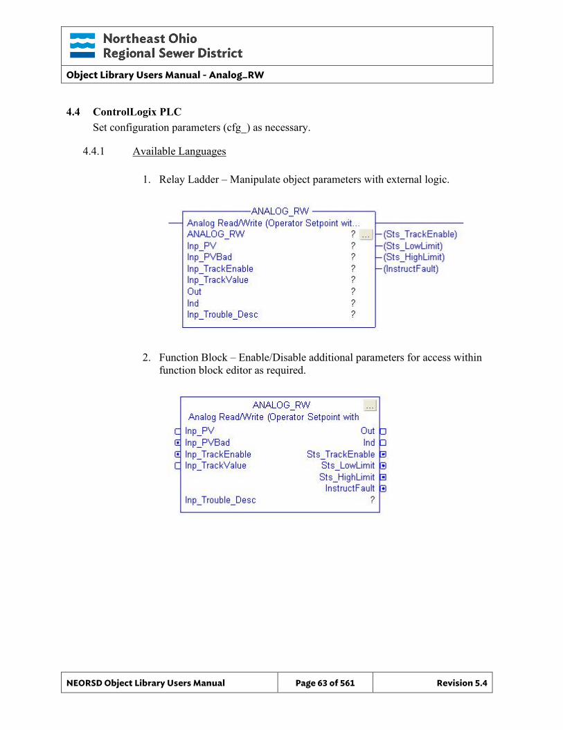
Object Library Users Manual - Analog_RW
NEORSD Object Library Users Manual Page 63 of 561 Revision 5.4
4.4 ControlLogix PLC Set configuration parameters (cfg_) as necessary.
4.4.1 Available Languages
1. Relay Ladder – Manipulate object parameters with external logic.
2. Function Block – Enable/Disable additional parameters for access within function block editor as required.
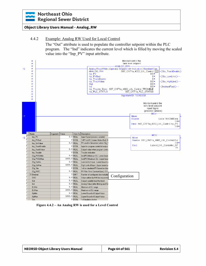
Object Library Users Manual - Analog_RW
NEORSD Object Library Users Manual Page 64 of 561 Revision 5.4
4.4.2 Example: Analog RW Used for Local Control The “Out” attribute is used to populate the controller setpoint within the PLC program. The “Ind” indicates the current level which is filled by moving the scaled value into the “Inp_PV” input attribute.
Figure 4.4.2 – An Analog RW is used for a Level Control
Configuration
Object Library Users Manual - Analog_RW
NEORSD Object Library Users Manual Page 65 of 561 Revision 5.4
Example Highlights • Process Inputs:
o Inp_PV – Scaled process value (from module or other input source with scaling)
o Inp_PVBad – Quality status (from module, MSG status, or other) • AOI Configuration:
o Cfg_PVEUMin, Cfg_PVEUMax – Set to maximum and minimum engineering unit process values.
o Cfg_OpMin, Cfg_OpMax – Set to operator controllable minimum and maximum engineering unit values (for setpoint).
• Block Outputs for use in External Logic: o Out – Automatically populated with the HMI/OIT operator entered setpoint.
Use “Out” within the program logic to refer to the entered setpoint value. For example, “Out” might be sent to the setpoint of a PID block.
o Ind – Analog process value which enteres the block through the Inp_PV attribute. Use “Ind” to monitor the current analog process value
4.4.3 Additional Attribute Notes
4.4.3.1 Inputs o Inp_TrackValue – An analog value which the setpoint value will
automatically follow. Only used if Inp_TrackEnable is set to “1”. o Inp_TrackEnable – Programatically set to “1” to cause the setpoint to
automatically be set to (or ‘follow’) the value of Inp_TrackValue. Useful when configuring bumpless control. When enabled, operator entered setpoints are ignored.
o Inp_SimValue – Value which will be used instead of “Inp_PV” which is passed to “Ind” when the block is in simulation mode. Only used if Cfg_Sim is set to “1”.
4.4.3.2 Internal Configuration o Decimal – Set to the desired number of decimal places for the output Ind. o Cfg_Sim – Set to “1” to enable simulation mode. In this mode, “Inp_PV”
will be ignored and “Inp_SimValue” will be used instead. o Cfg_FiltTC – If set to a value other than “0”, this will filter the process
value input from “Inp_PV” before passsing it to Ind. Larger values will filter over longer time intervals/samples.
4.4.3.3 Outputs o OpMin, OpMax – Use within the program to see the operator minimum
and maximum controllable limits for this instance.
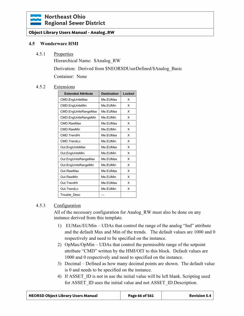
Object Library Users Manual - Analog_RW
NEORSD Object Library Users Manual Page 66 of 561 Revision 5.4
4.5 Wonderware HMI
4.5.1 Properties Hierarchical Name: $Analog_RW Derivation: Derived from $NEORSDUserDefined/$Analog_Basic Container: None
4.5.2 Extensions Extended Attribute Destination Locked
CMD.EngUnitsMax Me.EUMax X
CMD.EngUnitsMin Me.EUMin X
CMD.EngUnitsRangeMax Me.EUMax X
CMD.EngUnitsRangeMin Me.EUMin X
CMD.RawMax Me.EUMax X
CMD.RawMin Me.EUMin X
CMD.TrendHi Me.EUMax X
CMD.TrendLo Me.EUMin X
Out.EngUnitsMax Me.EUMax X
Out.EngUnitsMin Me.EUMin X
Out.EngUnitsRangeMax Me.EUMax X
Out.EngUnitsRangeMin Me.EUMin X
Out.RawMax Me.EUMax X
Out.RawMin Me.EUMin X
Out.TrendHi Me.EUMax X
Out.TrendLo Me.EUMin X
Trouble_Desc ---
4.5.3 Configuration All of the necessary configuration for Analog_RW must also be done on any instance derived from this template.
1) EUMax/EUMin – UDAs that control the range of the analog “Ind” attribute and the default Max and Min of the trends. The default values are 1000 and 0 respectively and need to be specified on the instance.
2) OpMax/OpMin – UDAs that control the permissible range of the setpoint attribute “CMD” written by the HMI/OIT to this block. Default values are 1000 and 0 respectively and need to specified on the instance.
3) Decimal – Defined as how many decimal points are shown. The default value is 0 and needs to be specified on the instance.
4) If ASSET_ID is not in use the initial value will be left blank. Scripting used for ASSET_ID uses the initial value and not ASSET_ID.Description.
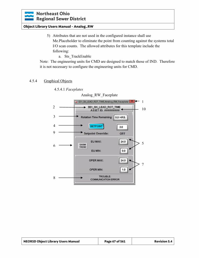
Object Library Users Manual - Analog_RW
NEORSD Object Library Users Manual Page 67 of 561 Revision 5.4
5) Attributes that are not used in the configured instance shall use Me.Placeholder to eliminate the point from counting against the systems total I/O scan counts. The allowed attributes for this template include the following:
a. Sts_TrackEnable Note: The engineering units for CMD are designed to match those of IND. Therefore it is not necessary to configure the engineering units for CMD.
4.5.4 Graphical Objects
4.5.4.1 Faceplates
Analog_RW_Faceplate
2
3
4
5
7
8
1
6
9
10
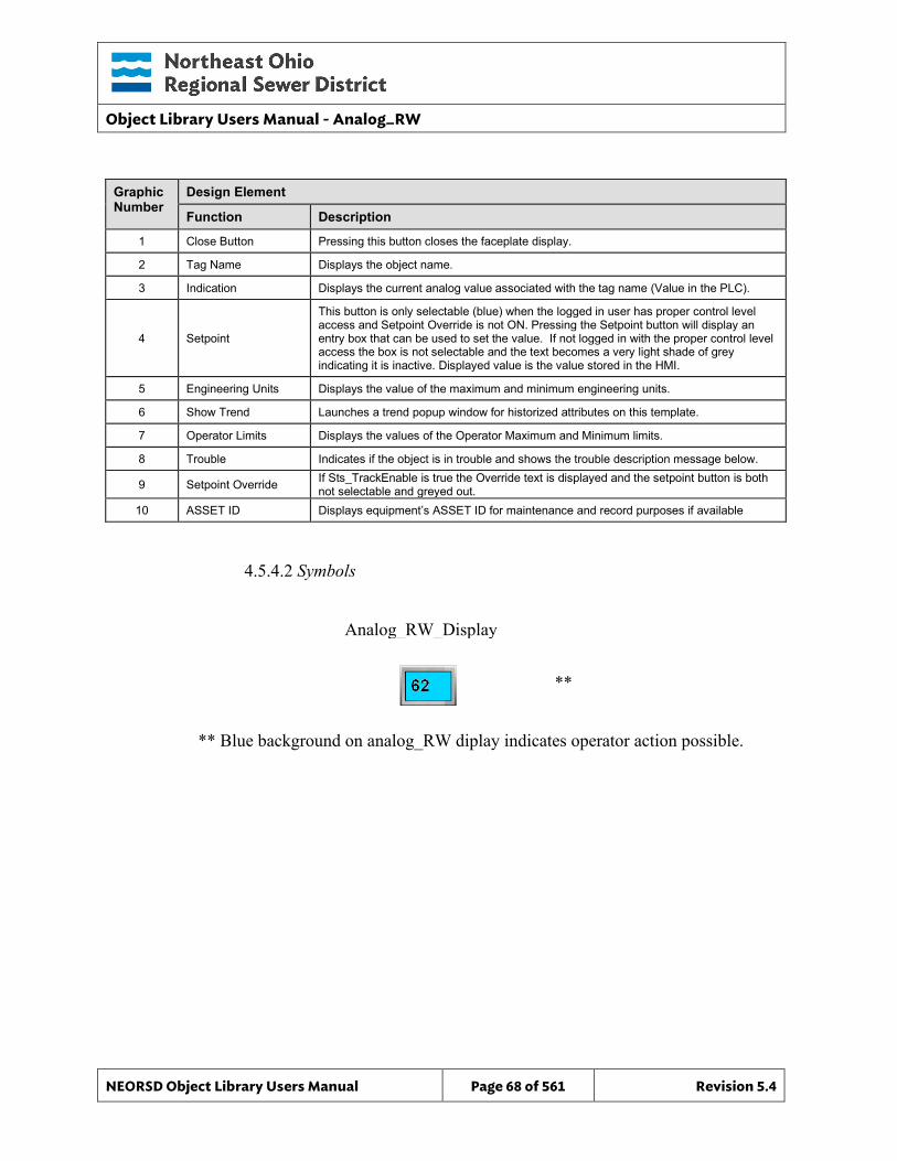
Object Library Users Manual - Analog_RW
NEORSD Object Library Users Manual Page 68 of 561 Revision 5.4
Graphic Number
Design Element
Function Description
1 Close Button Pressing this button closes the faceplate display.
2 Tag Name Displays the object name.
3 Indication Displays the current analog value associated with the tag name (Value in the PLC).
4 Setpoint
This button is only selectable (blue) when the logged in user has proper control level access and Setpoint Override is not ON. Pressing the Setpoint button will display an entry box that can be used to set the value. If not logged in with the proper control level access the box is not selectable and the text becomes a very light shade of grey indicating it is inactive. Displayed value is the value stored in the HMI.
5 Engineering Units Displays the value of the maximum and minimum engineering units.
6 Show Trend Launches a trend popup window for historized attributes on this template.
7 Operator Limits Displays the values of the Operator Maximum and Minimum limits.
8 Trouble Indicates if the object is in trouble and shows the trouble description message below.
9 Setpoint Override If Sts_TrackEnable is true the Override text is displayed and the setpoint button is both not selectable and greyed out.
10 ASSET ID Displays equipment’s ASSET ID for maintenance and record purposes if available
4.5.4.2 Symbols ** ** Blue background on analog_RW diplay indicates operator action possible.
Analog_RW_Display
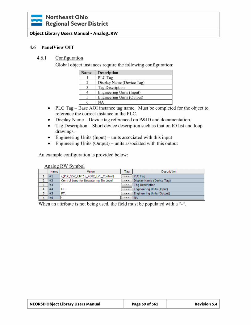
Object Library Users Manual - Analog_RW
NEORSD Object Library Users Manual Page 69 of 561 Revision 5.4
4.6 PanelView OIT
4.6.1 Configuration Global object instances require the following configuration:
Name Description 1 PLC Tag 2 Display Name (Device Tag) 3 Tag Description 4 Engineering Units (Input) 5 Engineering Units (Output) 6 NA
• PLC Tag – Base AOI instance tag name. Must be completed for the object to reference the correct instance in the PLC.
• Display Name – Device tag referenced on P&ID and documentation. • Tag Description – Short device description such as that on IO list and loop
drawings. • Engineering Units (Input) – units associated with this input • Engineering Units (Output) – units associated with this output
An example configuration is provided below: Analog RW Symbol
When an attribute is not being used, the field must be populated with a “-“.
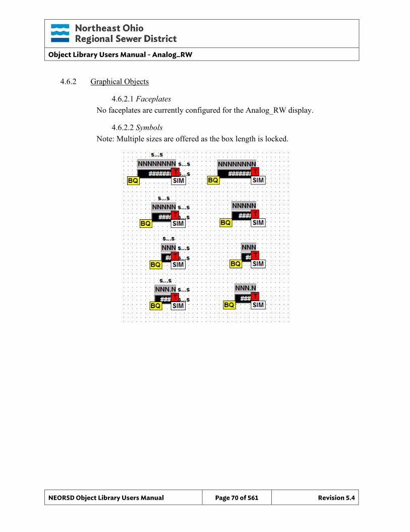
Object Library Users Manual - Analog_RW
NEORSD Object Library Users Manual Page 70 of 561 Revision 5.4
4.6.2 Graphical Objects
4.6.2.1 Faceplates No faceplates are currently configured for the Analog_RW display.
4.6.2.2 Symbols Note: Multiple sizes are offered as the box length is locked.
Object Library Users Manual - Analog_Setpoint
NEORSD Object Library Users Manual Page 71 of 561 Revision 5.4
5.0 Analog Setpoint
5.1 Introduction The analog setpoint template provides a standard representation of an operator controllable analog value (flow setpoint, pressure setpoint, temperature setpoint, etc.) within the NEORSD control systems. Use the Analog_Setpoint template if the following is true:
• If trying to place a user-modifiable analog value on an OIT or HMI display. Do not use the Analog_Setpoint template if the following is true:
• If the value being represented is a motor speed setpoint. In this case, use a Motor_VFD object instead.
5.2 Object Features
5.2.1 Status Indications This object will display the current value of the setpoint.
5.2.2 Control This object allows an operator to change the value of an analog setpoint from an HMI or OIT panel.
5.2.3 Alarming The following alarms exist within this object: • Setpoint value is at the operator limit (upper or lower) • Object is misconfigured
5.2.4 Simulation This object does not support simulation.
5.2.5 Trouble This object supports hardware trouble indication.
5.2.6 DB_Precision_Group Attribute is used in the ValueDeadband script. In the script, this parameter sets the deadband of inputs. Valid values for this parameter are between 0 and 3. o 0= default group; o 1= custom ValueDeadband setting which disables the script and uses the
attribute’s ValueDeadband; o 2= high precision; o 3= non-precision REF objects (obsolete)

Object Library Users Manual - Analog_Setpoint
NEORSD Object Library Users Manual Page 72 of 561 Revision 5.4
While 3 is an available option, it is not to be used for new objects moving forward. If changing the DB_Precision_Group to 1, you must undeploy and then deploy the object to guarantee that runtime deadband setting gets updated. A redeploy action will not update ValueDeadband.
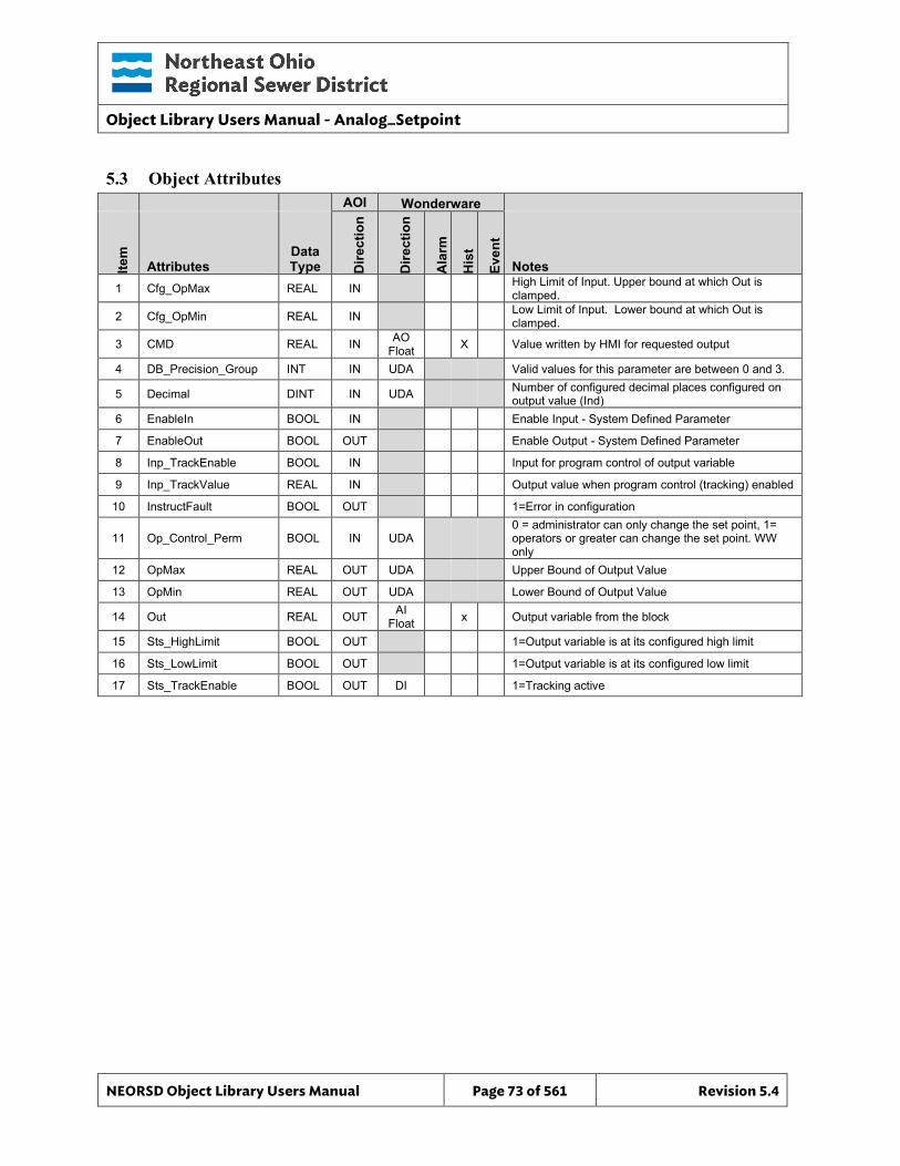
Object Library Users Manual - Analog_Setpoint
NEORSD Object Library Users Manual Page 73 of 561 Revision 5.4
5.3 Object Attributes
AOI Wonderware
Item
Attributes Data Type D
irect
ion
Dire
ctio
n
Ala
rm
His
t
Even
t
Notes 1 Cfg_OpMax REAL IN High Limit of Input. Upper bound at which Out is
clamped.
2 Cfg_OpMin REAL IN Low Limit of Input. Lower bound at which Out is clamped.
3 CMD REAL IN AO Float X Value written by HMI for requested output
4 DB_Precision_Group INT IN UDA Valid values for this parameter are between 0 and 3.
5 Decimal DINT IN UDA Number of configured decimal places configured on output value (Ind)
6 EnableIn BOOL IN Enable Input - System Defined Parameter
7 EnableOut BOOL OUT Enable Output - System Defined Parameter
8 Inp_TrackEnable BOOL IN Input for program control of output variable
9 Inp_TrackValue REAL IN Output value when program control (tracking) enabled
10 InstructFault BOOL OUT 1=Error in configuration
11 Op_Control_Perm BOOL IN UDA 0 = administrator can only change the set point, 1= operators or greater can change the set point. WW only
12 OpMax REAL OUT UDA Upper Bound of Output Value
13 OpMin REAL OUT UDA Lower Bound of Output Value
14 Out REAL OUT AI Float x Output variable from the block
15 Sts_HighLimit BOOL OUT 1=Output variable is at its configured high limit
16 Sts_LowLimit BOOL OUT 1=Output variable is at its configured low limit
17 Sts_TrackEnable BOOL OUT DI 1=Tracking active
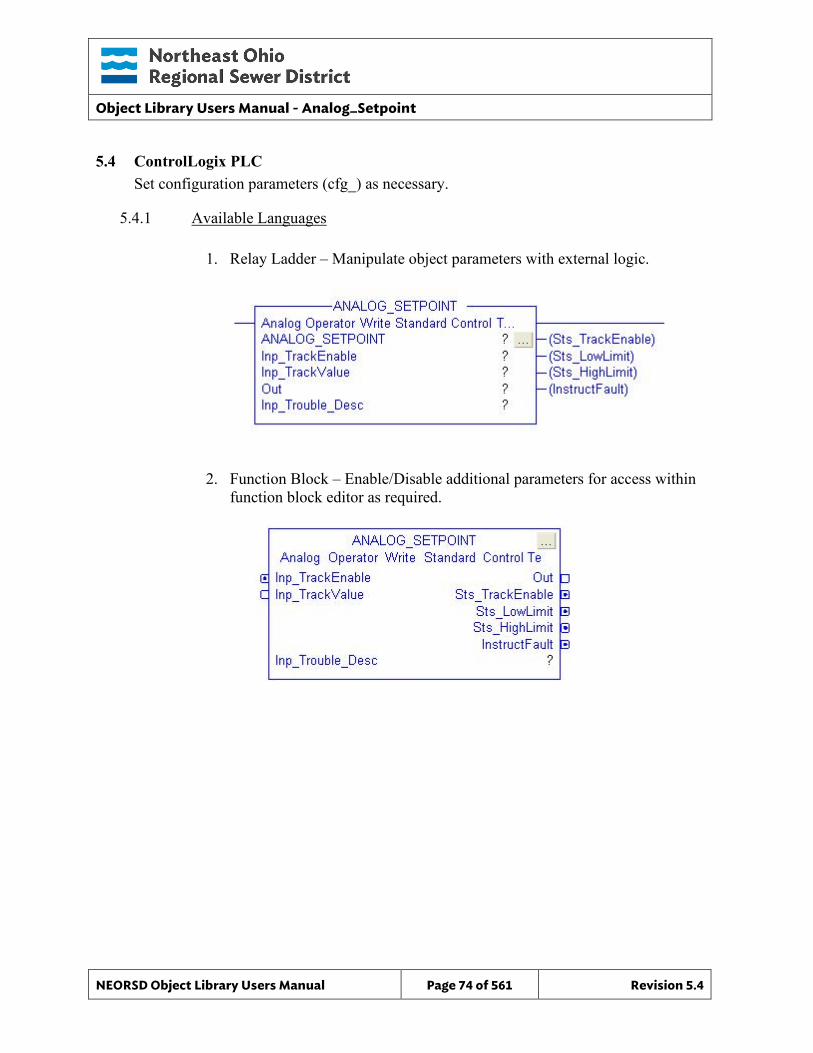
Object Library Users Manual - Analog_Setpoint
NEORSD Object Library Users Manual Page 74 of 561 Revision 5.4
5.4 ControlLogix PLC Set configuration parameters (cfg_) as necessary.
5.4.1 Available Languages
1. Relay Ladder – Manipulate object parameters with external logic.
2. Function Block – Enable/Disable additional parameters for access within function block editor as required.
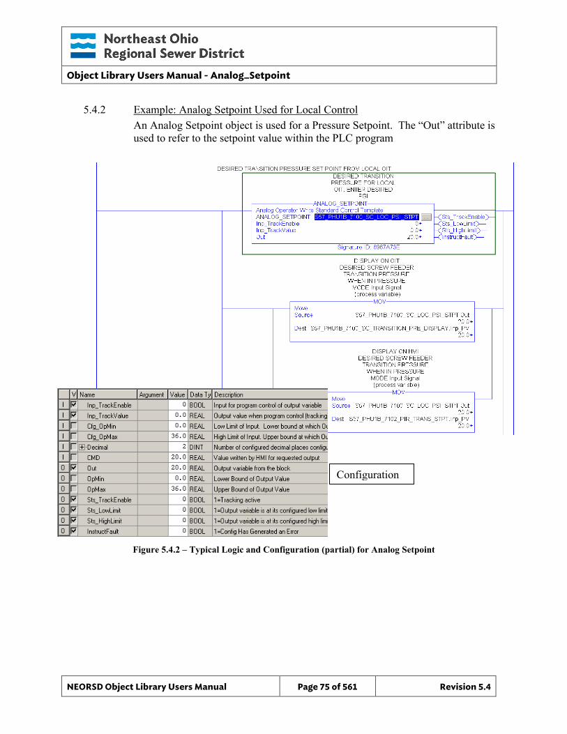
Object Library Users Manual - Analog_Setpoint
NEORSD Object Library Users Manual Page 75 of 561 Revision 5.4
5.4.2 Example: Analog Setpoint Used for Local Control An Analog Setpoint object is used for a Pressure Setpoint. The “Out” attribute is used to refer to the setpoint value within the PLC program
Figure 5.4.2 – Typical Logic and Configuration (partial) for Analog Setpoint
Configuration
Object Library Users Manual - Analog_Setpoint
NEORSD Object Library Users Manual Page 76 of 561 Revision 5.4
Example Highlights • Process Inputs:
o No inputs from the PLC code are necessary to use this block (the operator ‘input’ is passed into “CMD” from the HMI/OIT).
• AOI Configuration: o Cfg_OpMin, Cfg_OpMax – Set to operator controllable minimum and
maximum engineering unit values. • Block Outputs for use in External Logic:
o Out – Analog value for use with process control logic, including PID (SP Value)
5.4.3 Additional Attribute Notes
5.4.3.1 Inputs o Inp_TrackValue – A value which the setpoint value will automatically
follow. Only used if Inp_TrackEnable is set to “1”. o Inp_TrackEnable – Programatically set to “1” to cause the setpoint to
automatically be set to (or ‘follow’) the value of Inp_TrackValue. Useful when configuring bumpless control.
5.4.3.2 Internal Configuration o Decimal – Set to the desired number of decimal places for the output Ind.
5.4.3.3 Outputs o OpMin, OpMax – Use within the program to see the operator minimum
and maximum controllable limits for this instance.
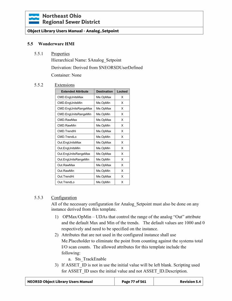
Object Library Users Manual - Analog_Setpoint
NEORSD Object Library Users Manual Page 77 of 561 Revision 5.4
5.5 Wonderware HMI
5.5.1 Properties Hierarchical Name: $Analog_Setpoint Derivation: Derived from $NEORSDUserDefined Container: None
5.5.2 Extensions Extended Attribute Destination Locked
CMD.EngUnitsMax Me.OpMax X
CMD.EngUnitsMin Me.OpMin X
CMD.EngUnitsRangeMax Me.OpMax X
CMD.EngUnitsRangeMin Me.OpMin X
CMD.RawMax Me.OpMax X
CMD.RawMin Me.OpMin X
CMD.TrendHi Me.OpMax X
CMD.TrendLo Me.OpMin X
Out.EngUnitsMax Me.OpMax X
Out.EngUnitsMin Me.OpMin X
Out.EngUnitsRangeMax Me.OpMax X
Out.EngUnitsRangeMin Me.OpMin X
Out.RawMax Me.OpMax X
Out.RawMin Me.OpMin X
Out.TrendHi Me.OpMax X
Out.TrendLo Me.OpMin X
5.5.3 Configuration All of the necessary configuration for Analog_Setpoint must also be done on any instance derived from this template.
1) OPMax/OpMin – UDAs that control the range of the analog “Out” attribute and the default Max and Min of the trends. The default values are 1000 and 0 respectively and need to be specified on the instance.
2) Attributes that are not used in the configured instance shall use Me.Placeholder to eliminate the point from counting against the systems total I/O scan counts. The allowed attributes for this template include the following:
a. Sts_TrackEnable 3) If ASSET_ID is not in use the initial value will be left blank. Scripting used
for ASSET_ID uses the initial value and not ASSET_ID.Description.
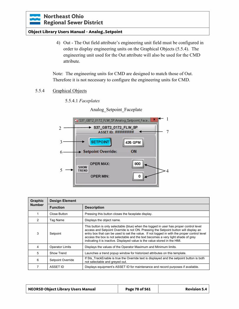
Object Library Users Manual - Analog_Setpoint
NEORSD Object Library Users Manual Page 78 of 561 Revision 5.4
4) Out - The Out field attribute’s engineering unit field must be configured in order to display engineering units on the Graphical Objects (5.5.4). The engineering unit used for the Out attribute will also be used for the CMD attribute.
Note: The engineering units for CMD are designed to match those of Out. Therefore it is not necessary to configure the engineering units for CMD.
5.5.4 Graphical Objects
5.5.4.1 Faceplates
Graphic Number
Design Element
Function Description
1 Close Button Pressing this button closes the faceplate display.
2 Tag Name Displays the object name.
3 Setpoint
This button is only selectable (blue) when the logged in user has proper control level access and Setpoint Override is not ON. Pressing the Setpoint button will display an entry box that can be used to set the value. If not logged in with the proper control level access the box is not selectable and the text becomes a very light shade of grey indicating it is inactive. Displayed value is the value stored in the HMI.
4 Operator Limits Displays the values of the Operator Maximum and Minimum limits.
5 Show Trend Launches a trend popup window for historized attributes on this template.
6 Setpoint Override If Sts_TrackEnable is true the Override text is displayed and the setpoint button is both not selectable and greyed out.
7 ASSET ID Displays equipment’s ASSET ID for maintenance and record purposes if available.
2
3
1
4
Analog_Setpoint_Faceplate
5
6
7
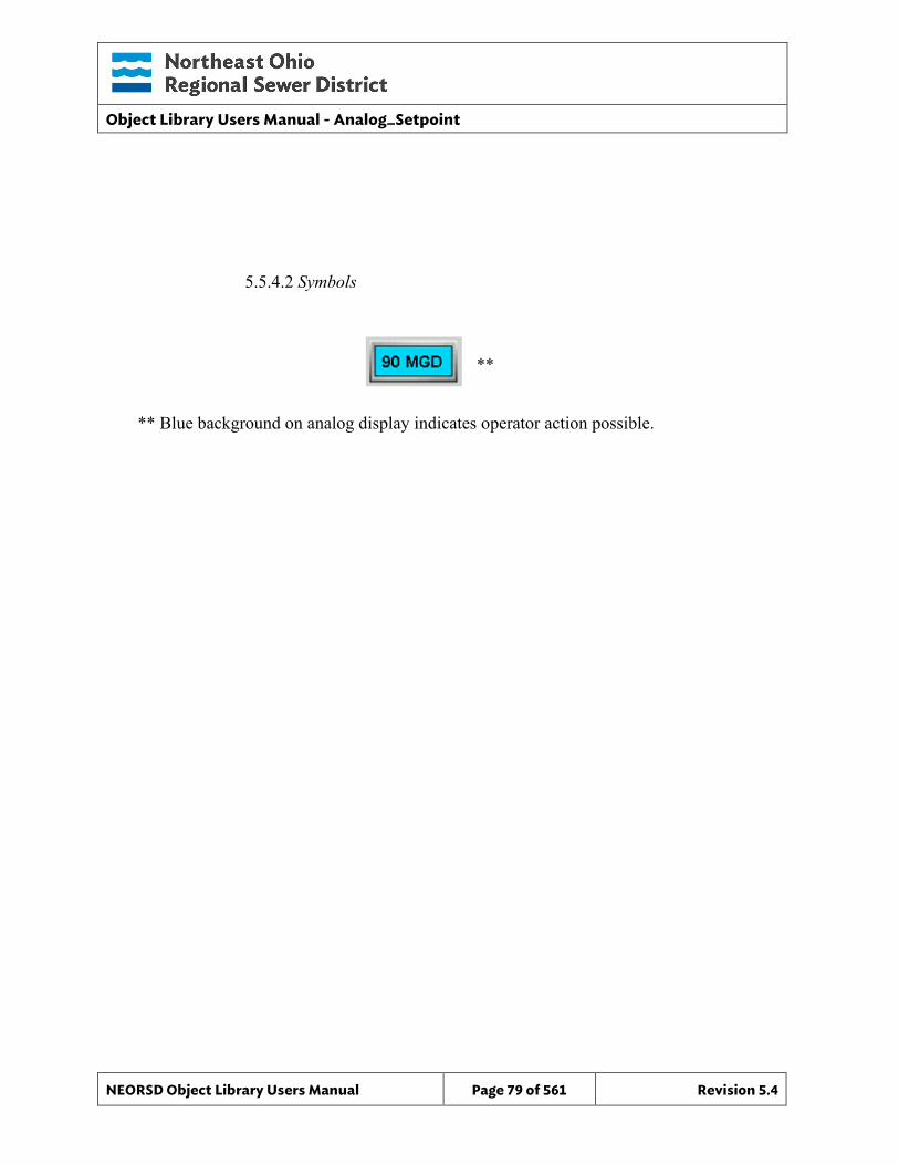
Object Library Users Manual - Analog_Setpoint
NEORSD Object Library Users Manual Page 79 of 561 Revision 5.4
5.5.4.2 Symbols **
** Blue background on analog display indicates operator action possible.
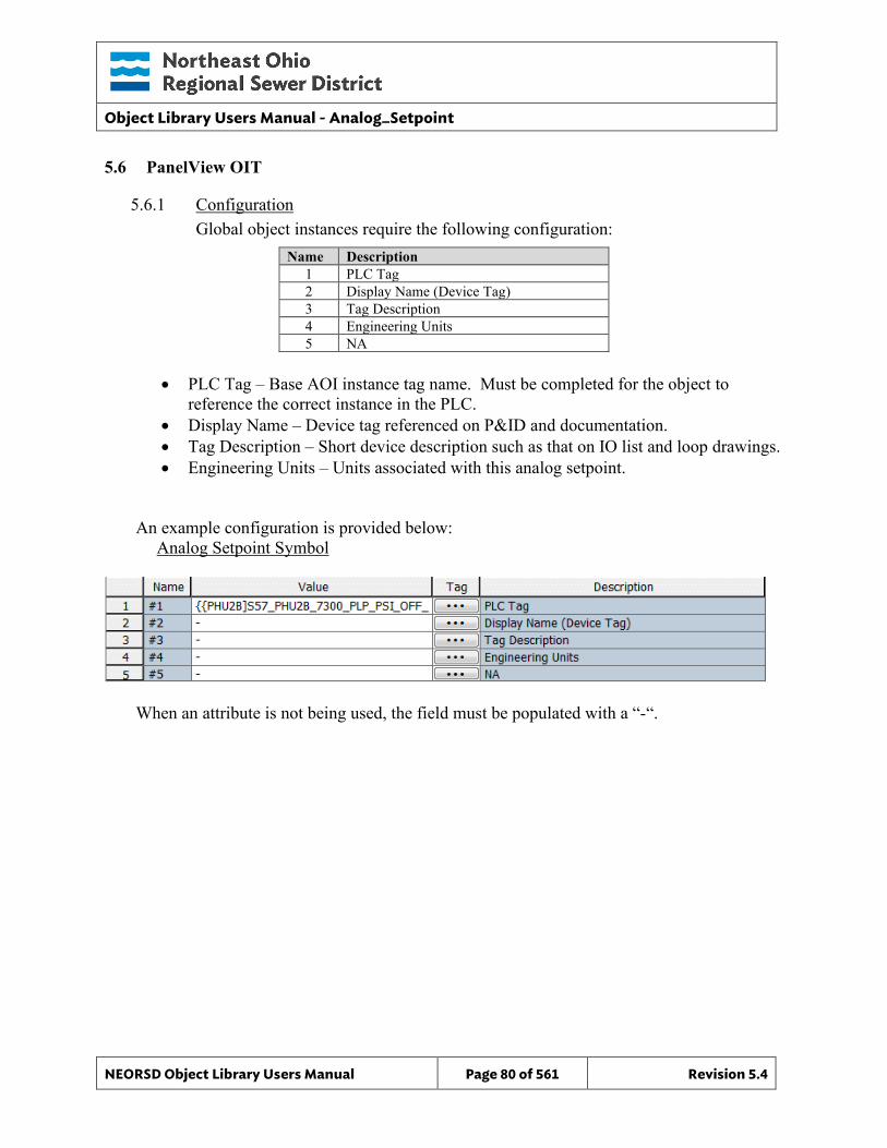
Object Library Users Manual - Analog_Setpoint
NEORSD Object Library Users Manual Page 80 of 561 Revision 5.4
5.6 PanelView OIT
5.6.1 Configuration Global object instances require the following configuration:
Name Description 1 PLC Tag 2 Display Name (Device Tag) 3 Tag Description 4 Engineering Units 5 NA
• PLC Tag – Base AOI instance tag name. Must be completed for the object to
reference the correct instance in the PLC. • Display Name – Device tag referenced on P&ID and documentation. • Tag Description – Short device description such as that on IO list and loop drawings. • Engineering Units – Units associated with this analog setpoint.
An example configuration is provided below: Analog Setpoint Symbol
When an attribute is not being used, the field must be populated with a “-“.
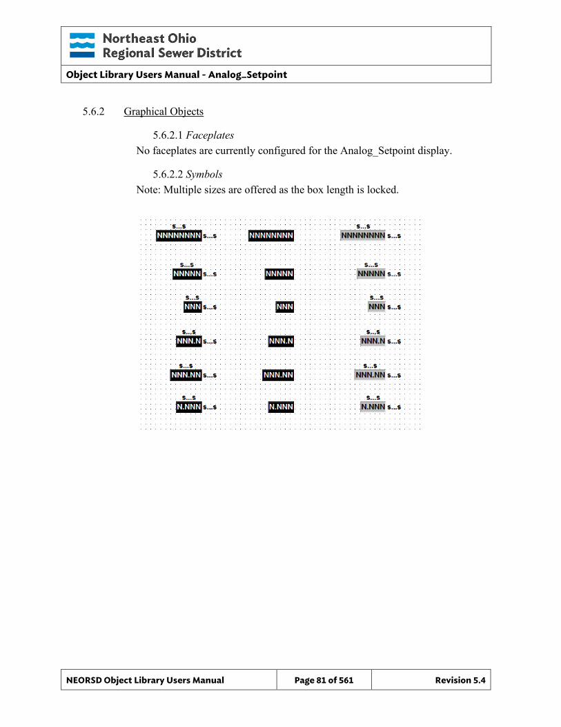
Object Library Users Manual - Analog_Setpoint
NEORSD Object Library Users Manual Page 81 of 561 Revision 5.4
5.6.2 Graphical Objects
5.6.2.1 Faceplates No faceplates are currently configured for the Analog_Setpoint display.
5.6.2.2 Symbols Note: Multiple sizes are offered as the box length is locked.

Object Library Users Manual - Analog_Setpoint
NEORSD Object Library Users Manual Page 82 of 561 Revision 5.4
This page left blank intentionally.
Object Library Users Manual - Analog_Setpoint_Mode
NEORSD Object Library Users Manual Page 83 of 561 Revision 5.4
6.0 Analog Setpoint Mode
6.1 Introduction The Analog Setpoint Mode template object is a simplified control interface, that provides a standard method to read and change the Mode and Setpoint of a control system, or individual piece of equipment. This template consists of an HMI portion only, and has no corresponding PLC or OIT component. This object was created to replicate old Cimplicity functionality.
6.2 Object Features
6.2.1 Control Control mode can be set from the faceplate. Separate set points can be entered for each mode.
6.2.2 Indications This object provides indication of the mode (Auto = 1, Manual = 0), and each set point.
6.2.3 Simulation - None
6.2.4 Trouble – None
6.2.5 DB_Precision_Group Attribute is used in the ValueDeadband script. In the script, this parameter sets the deadband of inputs. Valid values for this parameter are between 0 and 3. o 0= default group; o 1= custom ValueDeadband setting which disables the script and uses the
attribute’s ValueDeadband; o 2= high precision; o 3= non-precision REF objects (obsolete)
While 3 is an available option, it is not to be used for new objects moving forward. If changing the DB_Precision_Group to 1, you must undeploy and then deploy the object to guarantee that runtime deadband setting gets updated. A redeploy action will not update ValueDeadband.
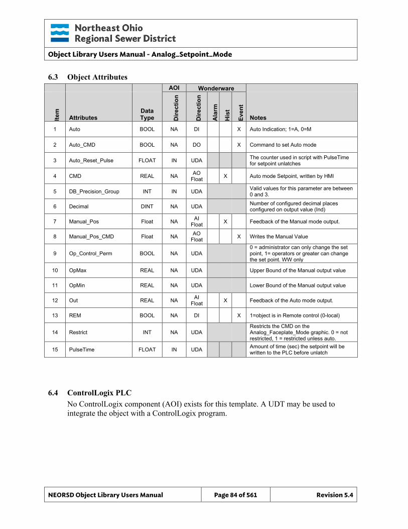
Object Library Users Manual - Analog_Setpoint_Mode
NEORSD Object Library Users Manual Page 84 of 561 Revision 5.4
6.3 Object Attributes
AOI Wonderware
Item
Attributes Data Type D
irect
ion
Dire
ctio
n
Ala
rm
His
t
Even
t
Notes
1 Auto BOOL NA DI X Auto Indication; 1=A, 0=M
2 Auto_CMD BOOL NA DO X Command to set Auto mode
3 Auto_Reset_Pulse FLOAT IN UDA The counter used in script with PulseTime for setpoint unlatches
4 CMD REAL NA AO Float X Auto mode Setpoint, written by HMI
5 DB_Precision_Group INT IN UDA Valid values for this parameter are between 0 and 3.
6 Decimal DINT NA UDA Number of configured decimal places configured on output value (Ind)
7 Manual_Pos Float NA AI Float X Feedback of the Manual mode output.
8 Manual_Pos_CMD Float NA AO Float X Writes the Manual Value
9 Op_Control_Perm BOOL NA UDA 0 = administrator can only change the set point, 1= operators or greater can change the set point. WW only
10 OpMax REAL NA UDA Upper Bound of the Manual output value
11 OpMin REAL NA UDA Lower Bound of the Manual output value
12 Out REAL NA AI Float X Feedback of the Auto mode output.
13 REM BOOL NA DI X 1=object is in Remote control (0-local)
14 Restrict INT NA UDA Restricts the CMD on the Analog_Faceplate_Mode graphic. 0 = not restricted, 1 = restricted unless auto.
15 PulseTime FLOAT IN UDA Amount of time (sec) the setpoint will be written to the PLC before unlatch
6.4 ControlLogix PLC No ControlLogix component (AOI) exists for this template. A UDT may be used to integrate the object with a ControlLogix program.
Object Library Users Manual - Analog_Setpoint_Mode
NEORSD Object Library Users Manual Page 85 of 561 Revision 5.4
6.5 Wonderware HMI
6.5.1 Properties Hierarchical Name: $Analog_Setpoint_Mode Derivation: $NEORSDUserDefined/$Analog_Setpoint Container: None
6.5.2 Extensions None
6.5.3 Instance Configuration All of the necessary configuration for Analog Setpoint Mode must also be done on any instance derived from this template. 1) Attributes that are not used in the configured instance shall use
Me.Placeholder to eliminate the point from counting against the systems total I/O scan counts. The allowed attributes for this template include the following:
a. Auto_CMD b. REM
2) If ASSET_ID is not in use the initial value will be left blank. Scripting used for ASSET_ID uses the initial value and not ASSET_ID.Description.
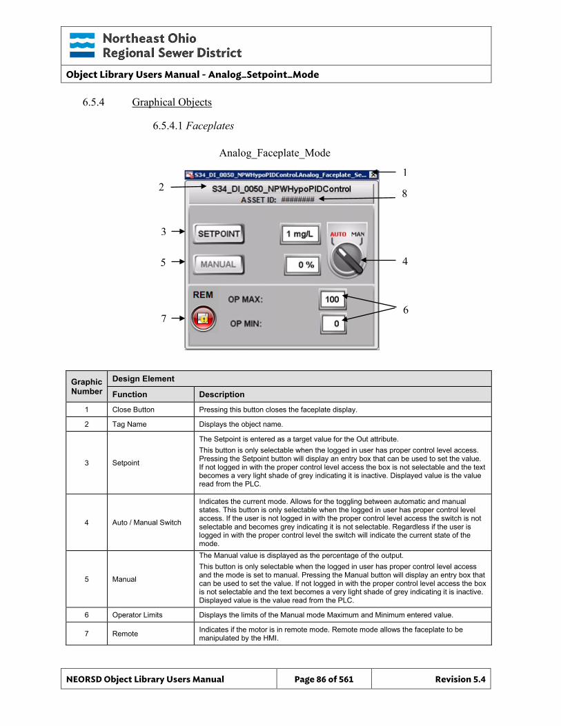
Object Library Users Manual - Analog_Setpoint_Mode
NEORSD Object Library Users Manual Page 86 of 561 Revision 5.4
6.5.4 Graphical Objects
6.5.4.1 Faceplates
Graphic Number
Design Element
Function Description
1 Close Button Pressing this button closes the faceplate display.
2 Tag Name Displays the object name.
3 Setpoint
The Setpoint is entered as a target value for the Out attribute. This button is only selectable when the logged in user has proper control level access. Pressing the Setpoint button will display an entry box that can be used to set the value. If not logged in with the proper control level access the box is not selectable and the text becomes a very light shade of grey indicating it is inactive. Displayed value is the value read from the PLC.
4 Auto / Manual Switch
Indicates the current mode. Allows for the toggling between automatic and manual states. This button is only selectable when the logged in user has proper control level access. If the user is not logged in with the proper control level access the switch is not selectable and becomes grey indicating it is not selectable. Regardless if the user is logged in with the proper control level the switch will indicate the current state of the mode.
5 Manual
The Manual value is displayed as the percentage of the output. This button is only selectable when the logged in user has proper control level access and the mode is set to manual. Pressing the Manual button will display an entry box that can be used to set the value. If not logged in with the proper control level access the box is not selectable and the text becomes a very light shade of grey indicating it is inactive. Displayed value is the value read from the PLC.
6 Operator Limits Displays the limits of the Manual mode Maximum and Minimum entered value.
7 Remote Indicates if the motor is in remote mode. Remote mode allows the faceplate to be manipulated by the HMI.
Analog_Faceplate_Mode
2 1
3
5 4
6 7
8
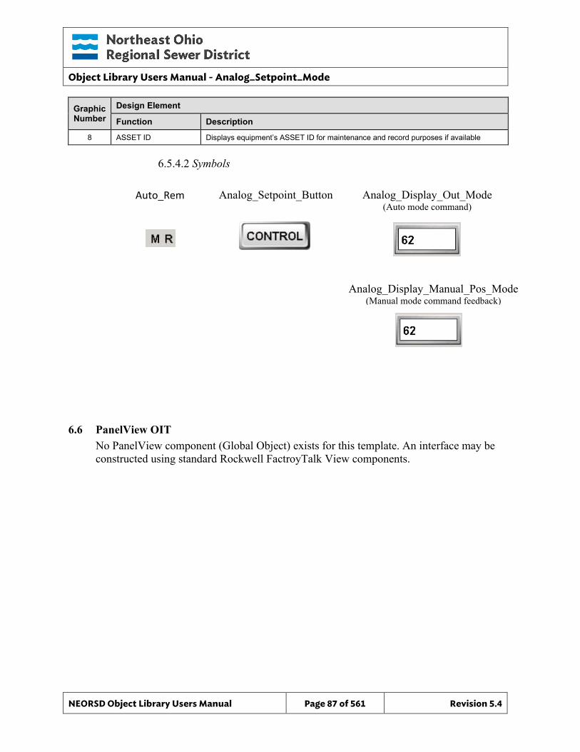
Object Library Users Manual - Analog_Setpoint_Mode
NEORSD Object Library Users Manual Page 87 of 561 Revision 5.4
Graphic Number
Design Element
Function Description
8 ASSET ID Displays equipment’s ASSET ID for maintenance and record purposes if available
6.5.4.2 Symbols
6.6 PanelView OIT No PanelView component (Global Object) exists for this template. An interface may be constructed using standard Rockwell FactroyTalk View components.
Analog_Setpoint_Button
Analog_Display_Manual_Pos_Mode (Manual mode command feedback)
Analog_Display_Out_Mode (Auto mode command)
Auto_Rem

Object Library Users Manual - Analog_Setpoint_Mode
NEORSD Object Library Users Manual Page 88 of 561 Revision 5.4
This page left blank intentionally.
Object Library Users Manual - Analog Suspend pH
NEORSD Object Library Users Manual Page 89 of 561 Revision 5.4
7.0 Analog Suspend pH
7.1 Introduction The Analog Suspend pH template provides a standard method of suspending the pH value when the pH system is in calibration. There is also a separate Reporting attribute to ensure a standard value is recorded to the historian. This template consists of an HMI portion only, and has no corresponding PLC or OIT component. While this template was developed for a very specific purpose, it can be applied to any analog value needing to be suspended programmatically.
7.2 Object Features
7.2.1 Control This object is designed to interface with a specific section of logic in use at the NEORSD. This code allows the user to manually suspend the pH value.
7.2.2 Indications This object provides indication of all standard analog alarms and when the pH is being suspended.
7.2.3 Simulation - None
7.2.4 Trouble This object supports hardware trouble indication.
7.2.5 DB_Precision_Group Attribute is used in the ValueDeadband script. In the script, this parameter sets the deadband of inputs. Valid values for this parameter are between 0 and 3. o 0= default group; o 1= custom ValueDeadband setting which disables the script and uses the
attribute’s ValueDeadband; o 2= high precision; o 3= non-precision REF objects (obsolete)
While 3 is an available option, it is not to be used for new objects moving forward. If changing the DB_Precision_Group to 1, you must undeploy and then deploy the object to guarantee that runtime deadband setting gets updated. A redeploy action will not update ValueDeadband.
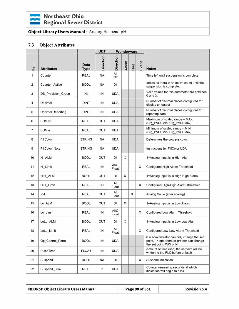
Object Library Users Manual - Analog Suspend pH
NEORSD Object Library Users Manual Page 90 of 561 Revision 5.4
7.3 Object Attributes
UDT Wonderware
Item
Attributes Data Type D
irect
ion
Dire
ctio
n
Ala
rm
His
t
Even
t
Notes
1 Counter REAL NA AI INT Time left until suspension is complete
2 Counter_Active BOOL NA DI Indicates there is an active count until the suspension is complete.
3 DB_Precision_Group INT IN UDA Valid values for this parameter are between 0 and 3.
4 Decimal DINT IN UDA Number of decimal places configured for display on output
5 Decimal Reporting DINT IN UDA Number of decimal places configured for reporting data
6 EUMax REAL OUT UDA Maximum of scaled range = MAX (Cfg_PVEUMin, Cfg_PVEUMax)
7 EUMin REAL OUT UDA Minimum of scaled range = MIN (Cfg_PVEUMin, Cfg_PVEUMax)
8 FillColor STRING NA UDA Determines the process color
9 FillColor_Note STRING NA UDA Instructions for FillColor UDA
10 Hi_ALM BOOL OUT DI X 1=Analog Input is in High Alarm
11 Hi_Limit REAL IN AI/O Float X Configured High Alarm Threshold
12 HiHi_ALM BOOL OUT DI X 1=Analog Input is in High-High Alarm
13 HiHi_Limit REAL IN AI Float X Configured High-High Alarm Threshold
14 Ind REAL OUT AI Float X Analog Value (after scaling)
15 Lo_ALM BOOL OUT DI X 1=Analog Input is in Low Alarm
16 Lo_Limit REAL IN AI/O Float X Configured Low Alarm Threshold
17 LoLo_ALM BOOL OUT DI X 1=Analog Input is in Low-Low Alarm
18 LoLo_Limit REAL IN AI Float X Configured Low-Low Alarm Threshold
19 Op_Control_Perm BOOL IN UDA 0 = administrator can only change the set point, 1= operators or greater can change the set point. WW only
20 PulseTime FLOAT IN UDA Amount of time (sec) the setpoint will be written to the PLC before unlatch
21 Suspend BOOL NA DI X Suspend indication
22 Suspend_Blink REAL In UDA Counter remaining seconds at which indication will begin to blink
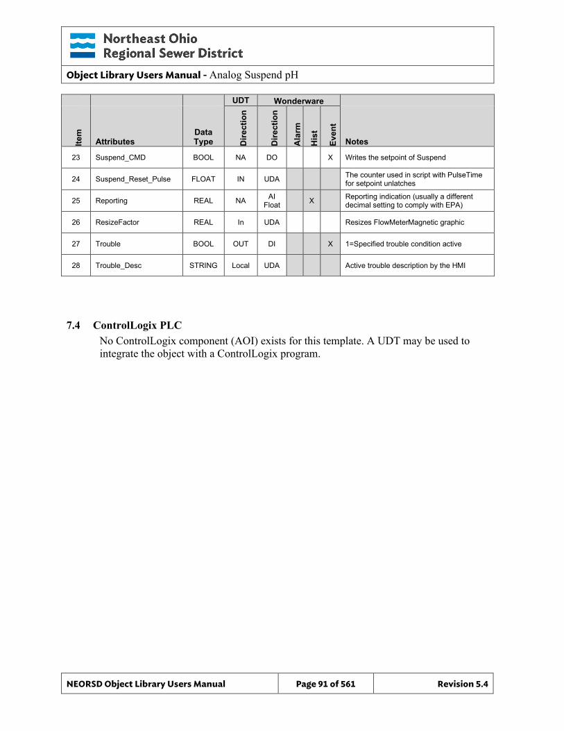
Object Library Users Manual - Analog Suspend pH
NEORSD Object Library Users Manual Page 91 of 561 Revision 5.4
UDT Wonderware
Item
Attributes Data Type D
irect
ion
Dire
ctio
n
Ala
rm
His
t
Even
t
Notes
23 Suspend_CMD BOOL NA DO X Writes the setpoint of Suspend
24 Suspend_Reset_Pulse FLOAT IN UDA The counter used in script with PulseTime for setpoint unlatches
25 Reporting REAL NA AI Float X Reporting indication (usually a different
decimal setting to comply with EPA)
26 ResizeFactor REAL In UDA Resizes FlowMeterMagnetic graphic
27 Trouble BOOL OUT DI X 1=Specified trouble condition active
28 Trouble_Desc STRING Local UDA Active trouble description by the HMI
7.4 ControlLogix PLC No ControlLogix component (AOI) exists for this template. A UDT may be used to integrate the object with a ControlLogix program.
Object Library Users Manual - Analog Suspend pH
NEORSD Object Library Users Manual Page 92 of 561 Revision 5.4
7.5 Wonderware HMI
7.5.1 Properties Hierarchical Name: $Analog_Suspend_pH Derivation: $NEORSDUserDefined/$Analog Container : None
7.5.2 Extensions None
7.5.3 Configuration All of the necessary configuration for Analog_Suspend_pH must also be done on any instance derived from this template.
1. Attributes that are not used in the configured instance shall use Me.Placeholder to eliminate the point from counting against the systems total I/O scan counts. The allowed attributes for this template include the following:
a. Hi_Limit b. HiHi_Limit c. Lo_Limit d. LoLo_Limit e. Hi_ALM f. HiHi_ALM g. Lo_ALM h. LoLo_ALM i. Suspend j. Suspend_CMD k. OOS l. OOS_CMD
2. If ASSET_ID is not in use the initial value will be left blank. Scripting used for ASSET_ID uses the initial value and not ASSET_ID.Description
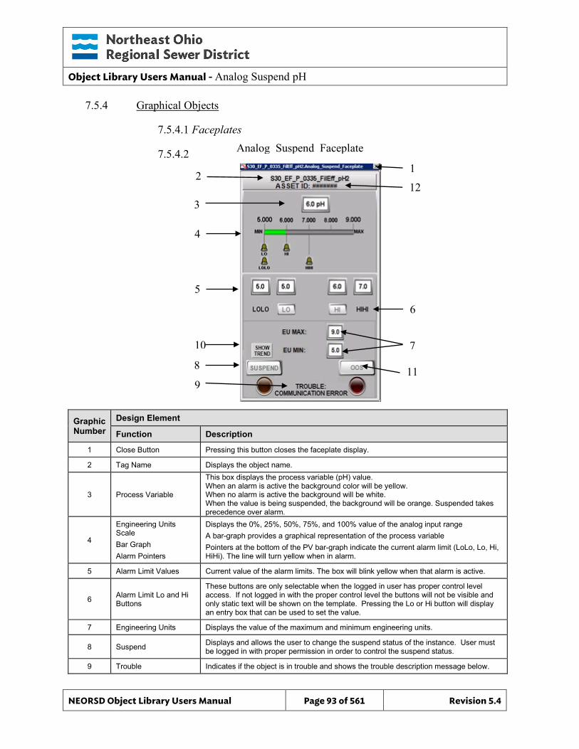
Object Library Users Manual - Analog Suspend pH
NEORSD Object Library Users Manual Page 93 of 561 Revision 5.4
7.5.4 Graphical Objects
7.5.4.1 Faceplates
7.5.4.2
Graphic Number
Design Element
Function Description
1 Close Button Pressing this button closes the faceplate display.
2 Tag Name Displays the object name.
3 Process Variable
This box displays the process variable (pH) value. When an alarm is active the background color will be yellow. When no alarm is active the background will be white. When the value is being suspended, the background will be orange. Suspended takes precedence over alarm.
4
Engineering Units Scale Bar Graph Alarm Pointers
Displays the 0%, 25%, 50%, 75%, and 100% value of the analog input range A bar-graph provides a graphical representation of the process variable Pointers at the bottom of the PV bar-graph indicate the current alarm limit (LoLo, Lo, Hi, HiHi). The line will turn yellow when in alarm.
5 Alarm Limit Values Current value of the alarm limits. The box will blink yellow when that alarm is active.
6 Alarm Limit Lo and Hi Buttons
These buttons are only selectable when the logged in user has proper control level access. If not logged in with the proper control level the buttons will not be visible and only static text will be shown on the template. Pressing the Lo or Hi button will display an entry box that can be used to set the value.
7 Engineering Units Displays the value of the maximum and minimum engineering units.
8 Suspend Displays and allows the user to change the suspend status of the instance. User must be logged in with proper permission in order to control the suspend status.
9 Trouble Indicates if the object is in trouble and shows the trouble description message below.
Analog_Suspend_Faceplate
2 1
3
4
5
6
7
8
9
10
11
12
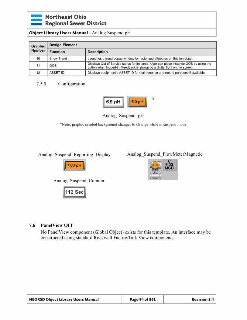
Object Library Users Manual - Analog Suspend pH
NEORSD Object Library Users Manual Page 94 of 561 Revision 5.4
Graphic Number
Design Element
Function Description
10 Show Trend Launches a trend popup window for historized attributes on this template.
11 OOS Displays Out of Service status for instance. User can place instance OOS by using the button when logged-in. Feedback is shown by a digital light on the screen.
12 ASSET ID Displays equipment’s ASSET ID for maintenance and record purposes if available
7.5.5 Configuration
7.6 PanelView OIT No PanelView component (Global Object) exists for this template. An interface may be constructed using standard Rockwell FactroyTalk View components.
Analog_Suspend_pH
*Note: graphic symbol background changes to Orange while in suspend mode
Analog_Suspend_Reporting_Display Analog_Suspend_FlowMeterMagnetic
*
Analog_Suspend_Counter
Object Library Users Manual - Analog Suspend
NEORSD Object Library Users Manual Page 95 of 561 Revision 5.4
8.0 Analog Suspend
8.1 Introduction The Analog Suspend template provides a standard method of suspending any value when a system is in calibration. There is also a separate Reporting attribute to ensure a standard value is recorded to the historian. This template consists of an HMI portion only, and has no corresponding PLC or OIT component. While this template was developed for a very specific purpose, it can be applied to any analog value needing to be suspended programmatically.
8.2 Object Features
8.2.1 Control This object is designed to interface with a specific section of logic in use at the NEORSD. This code allows the user to manually suspend any value.
8.2.2 Indications This object provides indication of all standard analog alarms and when a value is being suspended.
8.2.3 Simulation – None
8.2.4 Trouble This object supports hardware trouble indication.
8.2.5 DB_Precision_Group Attribute is used in the ValueDeadband script. In the script, this parameter sets the deadband of inputs. Valid values for this parameter are between 0 and 3. o 0= default group; o 1= custom ValueDeadband setting which disables the script and uses the
attribute’s ValueDeadband; o 2= high precision; o 3= non-precision REF objects (obsolete)
While 3 is an available option, it is not to be used for new objects moving forward. If changing the DB_Precision_Group to 1, you must undeploy and then deploy the object to guarantee that runtime deadband setting gets updated. A redeploy action will not update ValueDeadband.
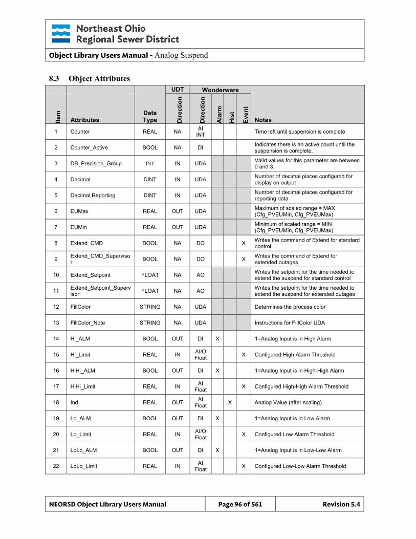
Object Library Users Manual - Analog Suspend
NEORSD Object Library Users Manual Page 96 of 561 Revision 5.4
8.3 Object Attributes
UDT Wonderware
Item
Attributes Data Type D
irect
ion
Dire
ctio
n
Ala
rm
His
t
Even
t
Notes
1 Counter REAL NA AI INT Time left until suspension is complete
2 Counter_Active BOOL NA DI Indicates there is an active count until the suspension is complete.
3 DB_Precision_Group INT IN UDA Valid values for this parameter are between 0 and 3.
4 Decimal DINT IN UDA Number of decimal places configured for display on output
5 Decimal Reporting DINT IN UDA Number of decimal places configured for reporting data
6 EUMax REAL OUT UDA Maximum of scaled range = MAX (Cfg_PVEUMin, Cfg_PVEUMax)
7 EUMin REAL OUT UDA Minimum of scaled range = MIN (Cfg_PVEUMin, Cfg_PVEUMax)
8 Extend_CMD BOOL NA DO X Writes the command of Extend for standard control
9 Extend_CMD_Supervisor BOOL NA DO X Writes the command of Extend for
extended outages
10 Extend_Setpoint FLOAT NA AO Writes the setpoint for the time needed to extend the suspend for standard control
11 Extend_Setpoint_Supervisor FLOAT NA AO Writes the setpoint for the time needed to
extend the suspend for extended outages
12 FillColor STRING NA UDA Determines the process color
13 FillColor_Note STRING NA UDA Instructions for FillColor UDA
14 Hi_ALM BOOL OUT DI X 1=Analog Input is in High Alarm
15 Hi_Limit REAL IN AI/O Float X Configured High Alarm Threshold
16 HiHi_ALM BOOL OUT DI X 1=Analog Input is in High-High Alarm
17 HiHi_Limit REAL IN AI Float X Configured High-High Alarm Threshold
18 Ind REAL OUT AI Float X Analog Value (after scaling)
19 Lo_ALM BOOL OUT DI X 1=Analog Input is in Low Alarm
20 Lo_Limit REAL IN AI/O Float X Configured Low Alarm Threshold
21 LoLo_ALM BOOL OUT DI X 1=Analog Input is in Low-Low Alarm
22 LoLo_Limit REAL IN AI Float X Configured Low-Low Alarm Threshold
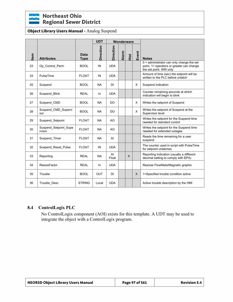
Object Library Users Manual - Analog Suspend
NEORSD Object Library Users Manual Page 97 of 561 Revision 5.4
UDT Wonderware
Item
Attributes Data Type D
irect
ion
Dire
ctio
n
Ala
rm
His
t
Even
t
Notes
23 Op_Control_Perm BOOL IN UDA 0 = administrator can only change the set point, 1= operators or greater can change the set point. WW only
24 PulseTime FLOAT IN UDA Amount of time (sec) the setpoint will be written to the PLC before unlatch
25 Suspend BOOL NA DI X Suspend indication
26 Suspend_Blink REAL In UDA Counter remaining seconds at which indication will begin to blink
27 Suspend_CMD BOOL NA DO X Writes the setpoint of Suspend
28 Suspend_CMD_Supervisor BOOL NA DO X Writes the setpoint of Suspend at the
Supervisor level
29 Suspend_Setpoint FLOAT NA AO Writes the setpoint for the Suspend time needed for standard control
30 Suspend_Setpoint_Supervisor FLOAT NA AO Writes the setpoint for the Suspend time
needed for extended outages
31 Suspend_Timer FLOAT NA AI Reads the time remaining for a user suspend
32 Suspend_Reset_Pulse FLOAT IN UDA The counter used in script with PulseTime for setpoint unlatches
33 Reporting REAL NA AI Float X Reporting indication (usually a different
decimal setting to comply with EPA)
34 ResizeFactor REAL In UDA Resizes FlowMeterMagnetic graphic
35 Trouble BOOL OUT DI X 1=Specified trouble condition active
36 Trouble_Desc STRING Local UDA Active trouble description by the HMI
8.4 ControlLogix PLC No ControlLogix component (AOI) exists for this template. A UDT may be used to integrate the object with a ControlLogix program.
Object Library Users Manual - Analog Suspend
NEORSD Object Library Users Manual Page 98 of 561 Revision 5.4
8.5 Wonderware HMI
8.5.1 Properties Hierarchical Name: $Analog_Suspend Derivation: $NEORSDUserDefined/$Analog/$Analog_Suspend_pH Container : None
8.5.2 Extensions None
8.5.3 Configuration All of the necessary configuration for Analog_Suspend must also be done on any instance derived from this template.
1. Attributes that are not used in the configured instance shall use Me.Placeholder to eliminate the point from counting against the systems total I/O scan counts. The allowed attributes for this template include the following:
m. Hi_Limit n. HiHi_Limit o. Lo_Limit p. LoLo_Limit q. Hi_ALM r. HiHi_ALM s. Lo_ALM t. LoLo_ALM u. Extend_CMD v. Extend_CMD_Supervisor w. Extend_Setpoint x. Extend_Setpoint_Supervisor y. Suspend z. Suspend_CMD aa. Suspend_CMD_Supervisor bb. Suspend_Setpoint cc. Suspend_Setpoint_Supervisor dd. Suspend_Timer ee. OOS ff. OOS_CMD
2. If ASSET_ID is not in use the initial value will be left blank. Scripting used for ASSET_ID uses the initial value and not ASSET_ID.Description.
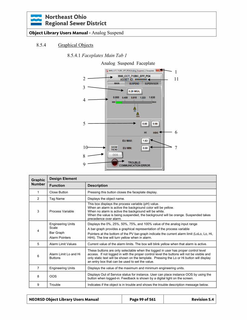
Object Library Users Manual - Analog Suspend
NEORSD Object Library Users Manual Page 99 of 561 Revision 5.4
8.5.4 Graphical Objects
8.5.4.1 Faceplates Main Tab 1
Graphic Number
Design Element
Function Description
1 Close Button Pressing this button closes the faceplate display.
2 Tag Name Displays the object name.
3 Process Variable
This box displays the process variable (pH) value. When an alarm is active the background color will be yellow. When no alarm is active the background will be white. When the value is being suspended, the background will be orange. Suspended takes precedence over alarm.
4
Engineering Units Scale Bar Graph Alarm Pointers
Displays the 0%, 25%, 50%, 75%, and 100% value of the analog input range A bar-graph provides a graphical representation of the process variable Pointers at the bottom of the PV bar-graph indicate the current alarm limit (LoLo, Lo, Hi, HiHi). The line will turn yellow when in alarm.
5 Alarm Limit Values Current value of the alarm limits. The box will blink yellow when that alarm is active.
6 Alarm Limit Lo and Hi Buttons
These buttons are only selectable when the logged in user has proper control level access. If not logged in with the proper control level the buttons will not be visible and only static text will be shown on the template. Pressing the Lo or Hi button will display an entry box that can be used to set the value.
7 Engineering Units Displays the value of the maximum and minimum engineering units.
8 OOS Displays Out of Service status for instance. User can place instance OOS by using the button when logged-in. Feedback is shown by a digital light on the screen.
9 Trouble Indicates if the object is in trouble and shows the trouble description message below.
Analog_Suspend_Faceplate
2 1
3
4
5
6
7
8
9
10
11
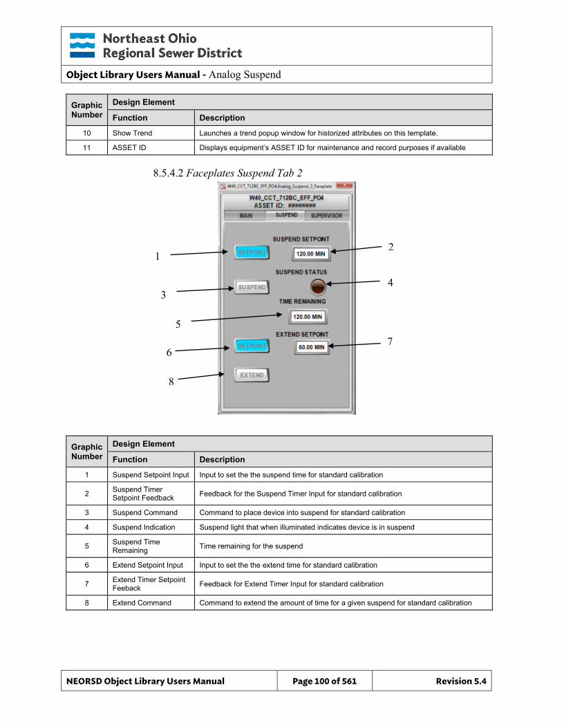
Object Library Users Manual - Analog Suspend
NEORSD Object Library Users Manual Page 100 of 561 Revision 5.4
Graphic Number
Design Element
Function Description
10 Show Trend Launches a trend popup window for historized attributes on this template.
11 ASSET ID Displays equipment’s ASSET ID for maintenance and record purposes if available
8.5.4.2 Faceplates Suspend Tab 2
Graphic Number
Design Element
Function Description
1 Suspend Setpoint Input Input to set the the suspend time for standard calibration
2 Suspend Timer Setpoint Feedback Feedback for the Suspend Timer Input for standard calibration
3 Suspend Command Command to place device into suspend for standard calibration
4 Suspend Indication Suspend light that when illuminated indicates device is in suspend
5 Suspend Time Remaining Time remaining for the suspend
6 Extend Setpoint Input Input to set the the extend time for standard calibration
7 Extend Timer Setpoint Feeback Feedback for Extend Timer Input for standard calibration
8 Extend Command Command to extend the amount of time for a given suspend for standard calibration
1 2
3 4
5 7
6
8
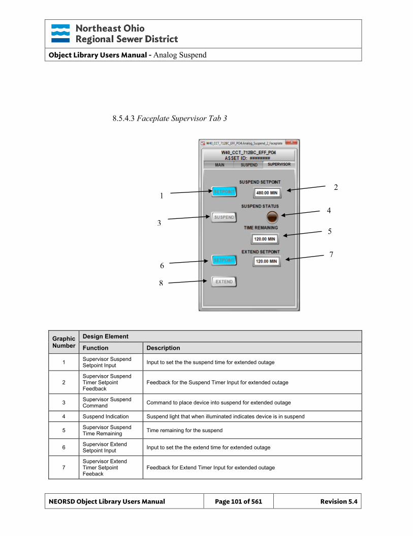
Object Library Users Manual - Analog Suspend
NEORSD Object Library Users Manual Page 101 of 561 Revision 5.4
8.5.4.3 Faceplate Supervisor Tab 3
Graphic Number
Design Element
Function Description
1 Supervisor Suspend Setpoint Input Input to set the the suspend time for extended outage
2 Supervisor Suspend Timer Setpoint Feedback
Feedback for the Suspend Timer Input for extended outage
3 Supervisor Suspend Command Command to place device into suspend for extended outage
4 Suspend Indication Suspend light that when illuminated indicates device is in suspend
5 Supervisor Suspend Time Remaining Time remaining for the suspend
6 Supervisor Extend Setpoint Input Input to set the the extend time for extended outage
7 Supervisor Extend Timer Setpoint Feeback
Feedback for Extend Timer Input for extended outage
1 2
3 4
6
5
7
8

Object Library Users Manual - Analog Suspend
NEORSD Object Library Users Manual Page 102 of 561 Revision 5.4
Graphic Number
Design Element
Function Description
8 Supervisor Extend Command Command to extend the amount of time for a given suspend for extended outage
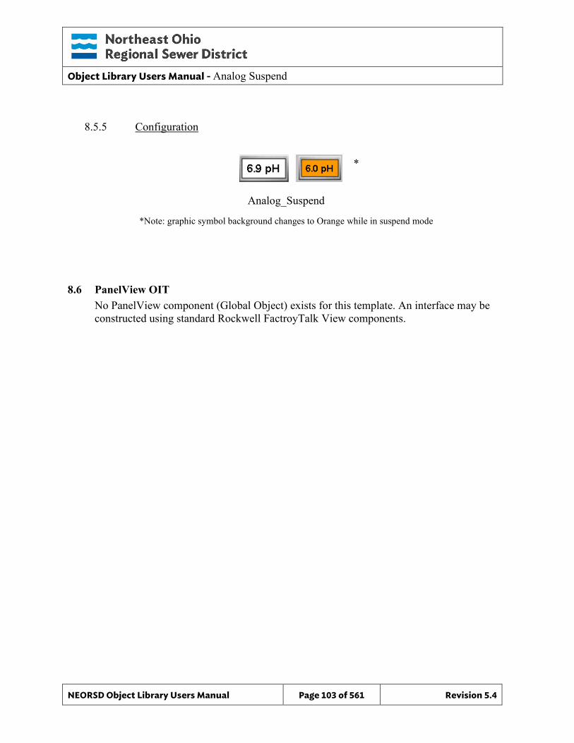
Object Library Users Manual - Analog Suspend
NEORSD Object Library Users Manual Page 103 of 561 Revision 5.4
8.5.5 Configuration
8.6 PanelView OIT No PanelView component (Global Object) exists for this template. An interface may be constructed using standard Rockwell FactroyTalk View components.
Analog_Suspend
*Note: graphic symbol background changes to Orange while in suspend mode
*
Object Library Users Manual - Diagnostics
NEORSD Object Library Users Manual Page 104 of 561 Revision 5.4
9.0 Diagnostics
9.1 Introduction The diagnostic object templates provide a standard OIT (PanelView Plus) level representation for ControlLogix and CompactLogix hardware module diagnostic information within the NEORSD control systems. Use the Diagnostic templates in the OIT if any of the statements below are true:
• If trying to represent the status of a card/module in a ControlLogix or CompactLogix rack.
• If trying to draw a static layout of the controller, backplane, and associated network equipment.
The object library contains diagnostic templates for the ControlLogix cards most commonly used at the District. If a contractor’s project includes a card that is not included in the District’s library, it is the contractor’s responsibility to create a new template for that card. The contractor should use the existing diagnostic templates as reference.
9.2 Object Features
9.2.1 Status These objects provide detailed diagnostic level status information for ControlLogix and CompactLogix hardware modules.
9.2.2 Alarming Alarming is not supported by these objects.
9.2.3 Simulation Simulation is not supported by these objects.
9.2.4 Trouble Trouble indication is not supported by these objects.
9.3 Object Attributes Diagnostic templates on the OIT do not partner with a PLC (AOI) or HMI object. The templates instead rely on the module-defined tags created within the Logix processor during I/O Configuration and RSLinx Enterprise Diagnostic information available on the PanelView Plus terminals. Module-defined tags are unique among the hardware templates.
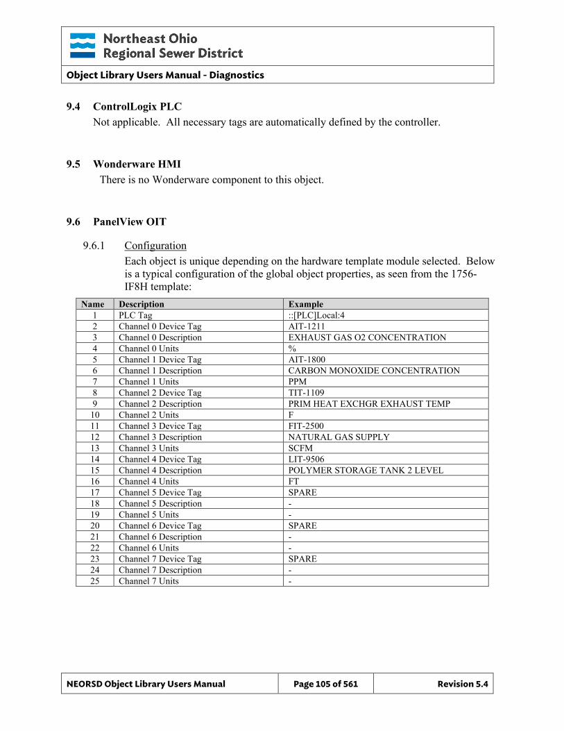
Object Library Users Manual - Diagnostics
NEORSD Object Library Users Manual Page 105 of 561 Revision 5.4
9.4 ControlLogix PLC Not applicable. All necessary tags are automatically defined by the controller.
9.5 Wonderware HMI There is no Wonderware component to this object.
9.6 PanelView OIT
9.6.1 Configuration Each object is unique depending on the hardware template module selected. Below is a typical configuration of the global object properties, as seen from the 1756-IF8H template:
Name Description Example 1 PLC Tag ::[PLC]Local:4 2 Channel 0 Device Tag AIT-1211 3 Channel 0 Description EXHAUST GAS O2 CONCENTRATION 4 Channel 0 Units % 5 Channel 1 Device Tag AIT-1800 6 Channel 1 Description CARBON MONOXIDE CONCENTRATION 7 Channel 1 Units PPM 8 Channel 2 Device Tag TIT-1109 9 Channel 2 Description PRIM HEAT EXCHGR EXHAUST TEMP
10 Channel 2 Units F 11 Channel 3 Device Tag FIT-2500 12 Channel 3 Description NATURAL GAS SUPPLY 13 Channel 3 Units SCFM 14 Channel 4 Device Tag LIT-9506 15 Channel 4 Description POLYMER STORAGE TANK 2 LEVEL 16 Channel 4 Units FT 17 Channel 5 Device Tag SPARE 18 Channel 5 Description - 19 Channel 5 Units - 20 Channel 6 Device Tag SPARE 21 Channel 6 Description - 22 Channel 6 Units - 23 Channel 7 Device Tag SPARE 24 Channel 7 Description - 25 Channel 7 Units -
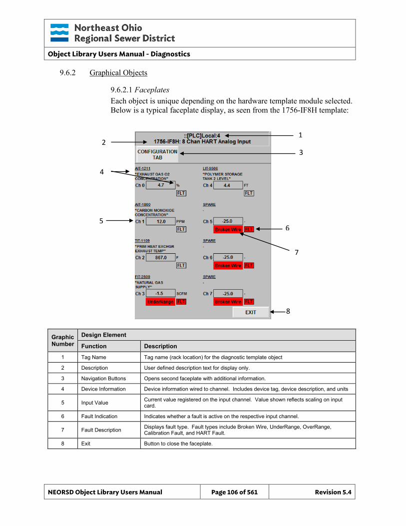
Object Library Users Manual - Diagnostics
NEORSD Object Library Users Manual Page 106 of 561 Revision 5.4
1 2
3
4
5 6
7
8
9.6.2 Graphical Objects
9.6.2.1 Faceplates Each object is unique depending on the hardware template module selected. Below is a typical faceplate display, as seen from the 1756-IF8H template:
Graphic Number
Design Element
Function Description
1 Tag Name Tag name (rack location) for the diagnostic template object
2 Description User defined description text for display only.
3 Navigation Buttons Opens second faceplate with additional information.
4 Device Information Device information wired to channel. Includes device tag, device description, and units
5 Input Value Current value registered on the input channel. Value shown reflects scaling on input card.
6 Fault Indication Indicates whether a fault is active on the respective input channel.
7 Fault Description Displays fault type. Fault types include Broken Wire, UnderRange, OverRange, Calibration Fault, and HART Fault.
8 Exit Button to close the faceplate.
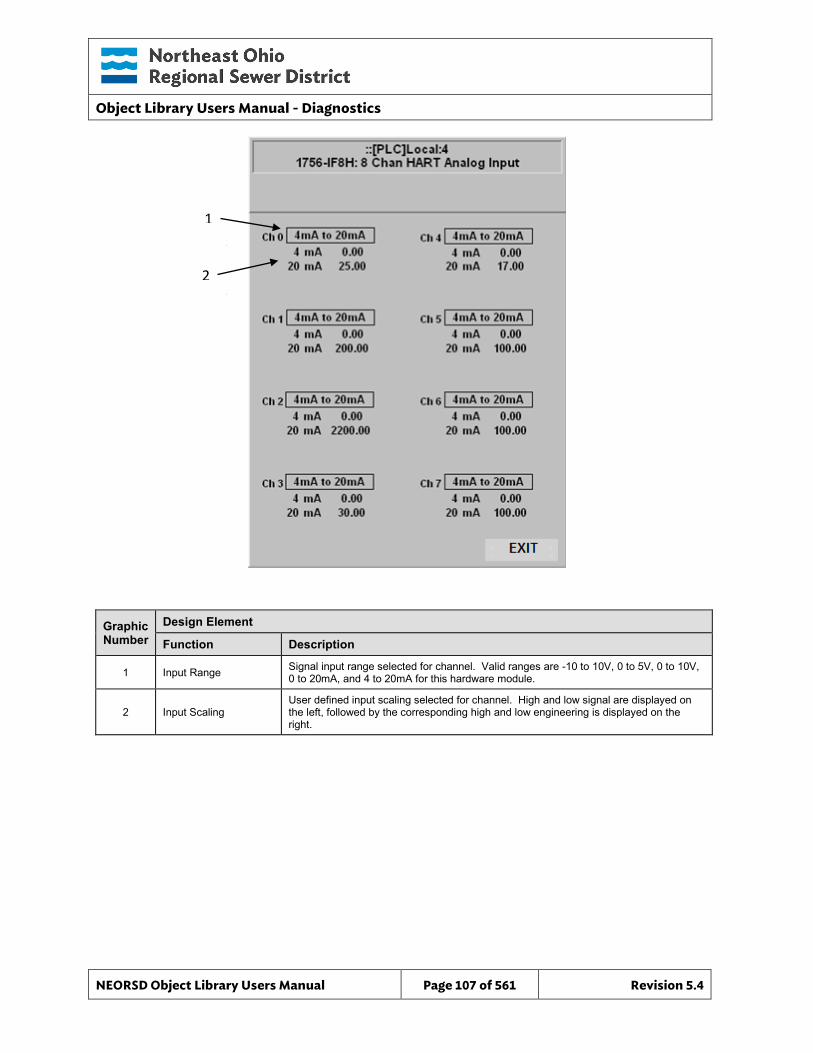
Object Library Users Manual - Diagnostics
NEORSD Object Library Users Manual Page 107 of 561 Revision 5.4
1
2
1
2
Graphic Number
Design Element
Function Description
1 Input Range Signal input range selected for channel. Valid ranges are -10 to 10V, 0 to 5V, 0 to 10V, 0 to 20mA, and 4 to 20mA for this hardware module.
2 Input Scaling User defined input scaling selected for channel. High and low signal are displayed on the left, followed by the corresponding high and low engineering is displayed on the right.
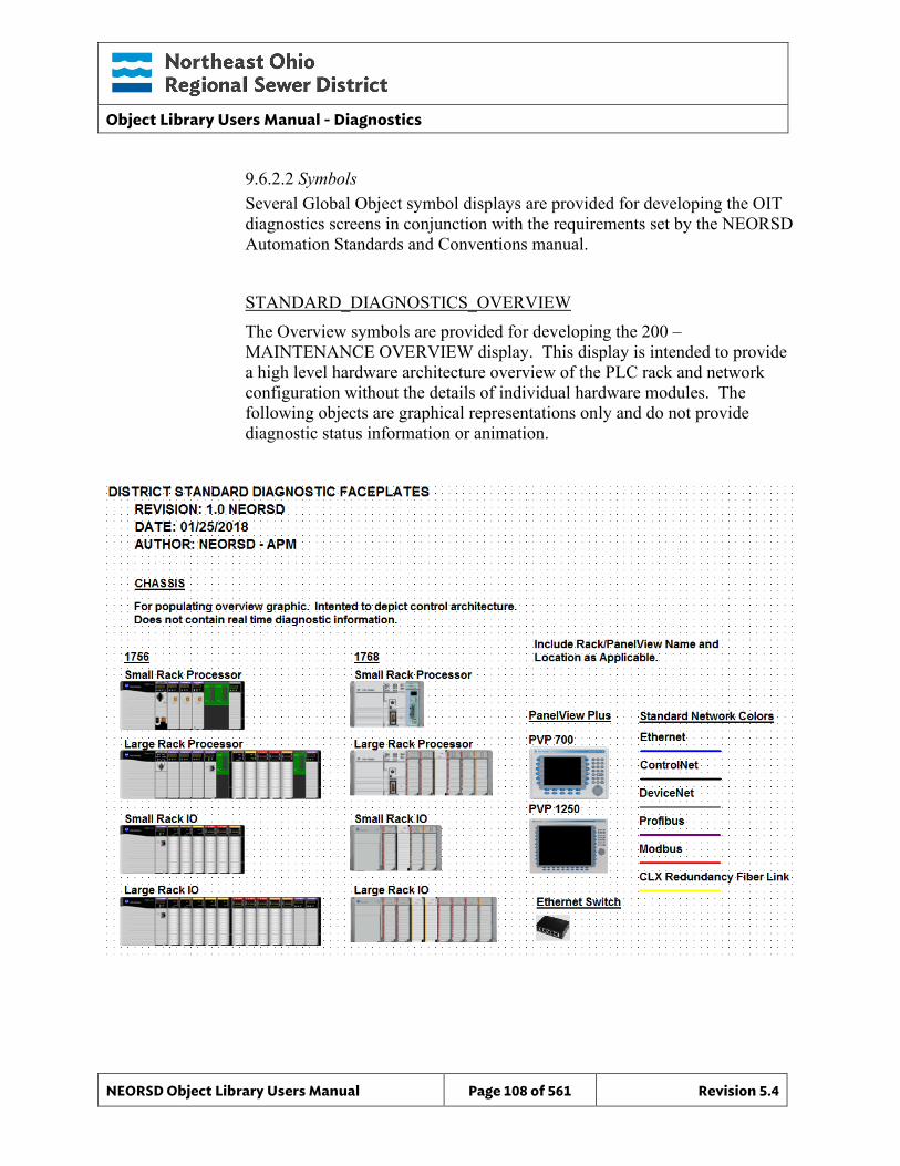
Object Library Users Manual - Diagnostics
NEORSD Object Library Users Manual Page 108 of 561 Revision 5.4
9.6.2.2 Symbols Several Global Object symbol displays are provided for developing the OIT diagnostics screens in conjunction with the requirements set by the NEORSD Automation Standards and Conventions manual. STANDARD_DIAGNOSTICS_OVERVIEW The Overview symbols are provided for developing the 200 – MAINTENANCE OVERVIEW display. This display is intended to provide a high level hardware architecture overview of the PLC rack and network configuration without the details of individual hardware modules. The following objects are graphical representations only and do not provide diagnostic status information or animation.
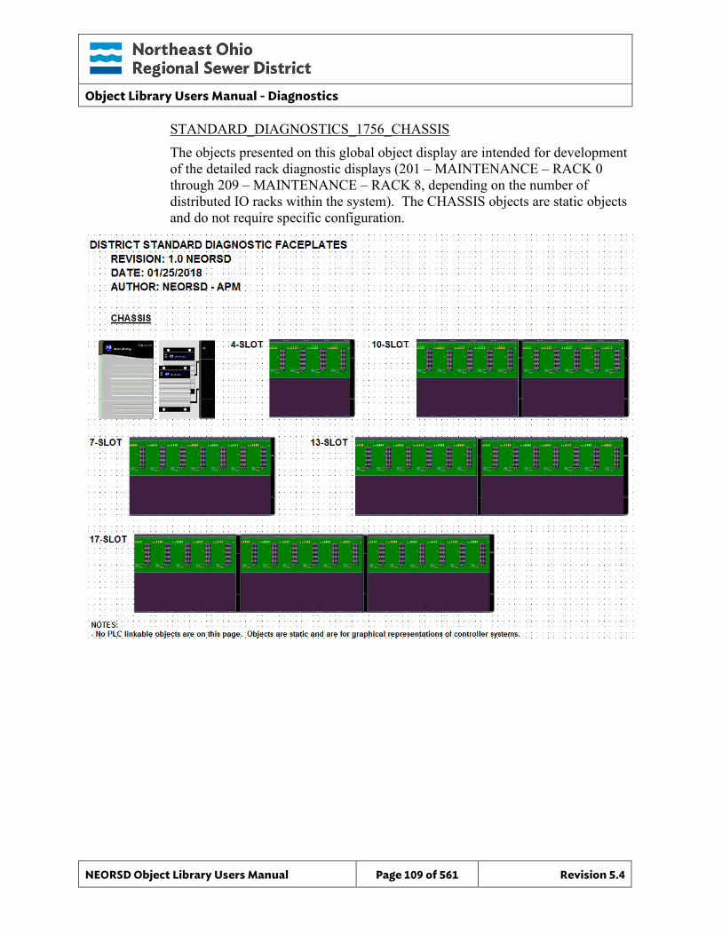
Object Library Users Manual - Diagnostics
NEORSD Object Library Users Manual Page 109 of 561 Revision 5.4
STANDARD_DIAGNOSTICS_1756_CHASSIS The objects presented on this global object display are intended for development of the detailed rack diagnostic displays (201 – MAINTENANCE – RACK 0 through 209 – MAINTENANCE – RACK 8, depending on the number of distributed IO racks within the system). The CHASSIS objects are static objects and do not require specific configuration.
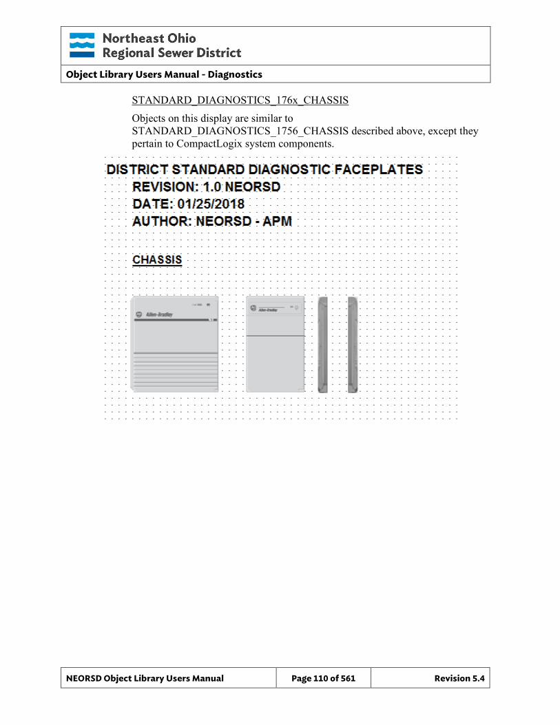
Object Library Users Manual - Diagnostics
NEORSD Object Library Users Manual Page 110 of 561 Revision 5.4
STANDARD_DIAGNOSTICS_176x_CHASSIS Objects on this display are similar to STANDARD_DIAGNOSTICS_1756_CHASSIS described above, except they pertain to CompactLogix system components.
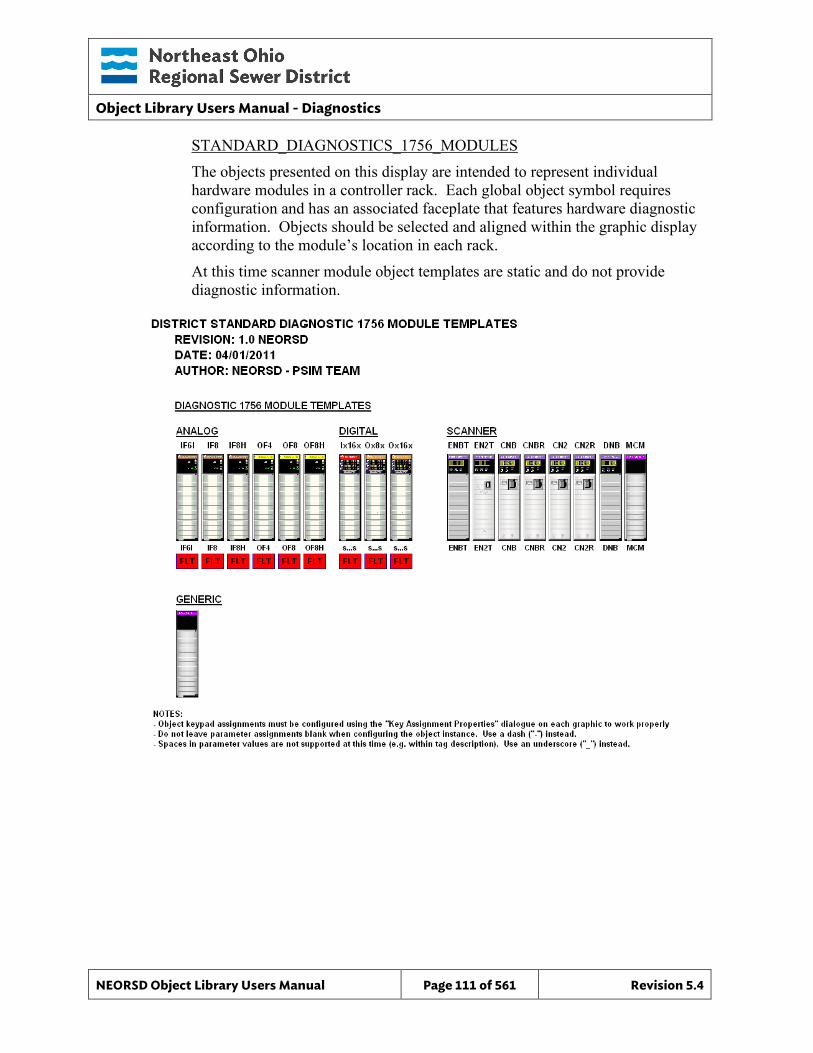
Object Library Users Manual - Diagnostics
NEORSD Object Library Users Manual Page 111 of 561 Revision 5.4
STANDARD_DIAGNOSTICS_1756_MODULES The objects presented on this display are intended to represent individual hardware modules in a controller rack. Each global object symbol requires configuration and has an associated faceplate that features hardware diagnostic information. Objects should be selected and aligned within the graphic display according to the module’s location in each rack. At this time scanner module object templates are static and do not provide diagnostic information.
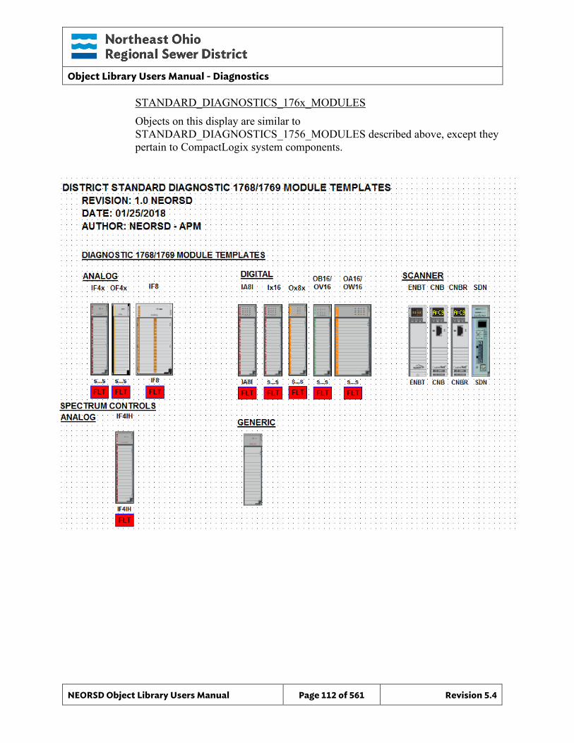
Object Library Users Manual - Diagnostics
NEORSD Object Library Users Manual Page 112 of 561 Revision 5.4
STANDARD_DIAGNOSTICS_176x_MODULES Objects on this display are similar to STANDARD_DIAGNOSTICS_1756_MODULES described above, except they pertain to CompactLogix system components.
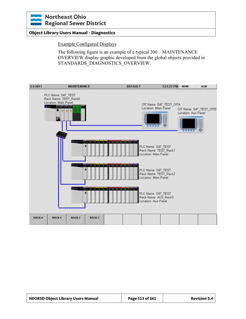
Object Library Users Manual - Diagnostics
NEORSD Object Library Users Manual Page 113 of 561 Revision 5.4
Example Configured Displays The following figure is an example of a typical 200 – MAINTENANCE OVERVIEW display graphic developed from the global objects provided in STANDARDS_DIAGNOSTICS_OVERVIEW.
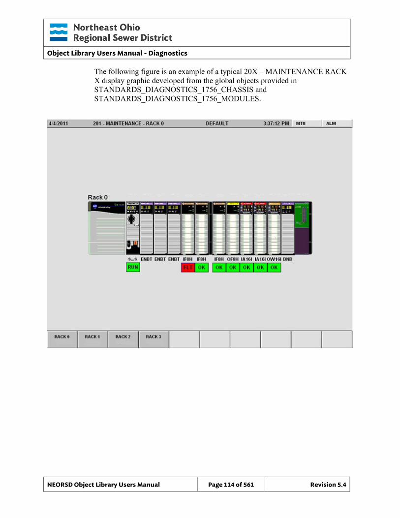
Object Library Users Manual - Diagnostics
NEORSD Object Library Users Manual Page 114 of 561 Revision 5.4
The following figure is an example of a typical 20X – MAINTENANCE RACK X display graphic developed from the global objects provided in STANDARDS_DIAGNOSTICS_1756_CHASSIS and STANDARDS_DIAGNOSTICS_1756_MODULES.

Object Library Users Manual - Diagnostics
NEORSD Object Library Users Manual Page 115 of 561 Revision 5.4
This page left blank intentionally.
Object Library Users Manual – DeviceNet Diagnostics
NEORSD Object Library Users Manual Page 116 of 561 Revision 5.4
10.0 DeviceNet Diagnostics
10.1 Introduction The DeviceNet Diagnostics template retrieves node and scanner information from a DeviceNet network. The information is displayed on the HMI and OIT for network monitoring, alarming, and to aid with commissioning and troubleshooting activities. A unique object instance is required for each DeviceNet network.
10.2 Object Features
10.2.1 Status Indications This object provides the following indications:
• Node address table – Listing of configured nodes by address with tagname • Scanner and Node DeviceNet status codes – 0 (ok), 78 (no
communication), etc. • Scanner configuration – Node number, baud, state (run, disabled, fault) • Scanner CAN diagnostics counters – Rx and Tx errors, etc. • Help notes and troubleshooting information
10.2.2 Alarming The object provides the following alarms:
• Scanner or network faults, including: scanner fault mode, scanner bus off, network power, duplicate node, and scanner not in run mode.
• Node faults, including : Device communication or other fault, device idle fault, auto verify (incorrect device and/or programming) fault
10.2.3 Simulation This object does not support a simulation mode.
10.2.4 Trouble This object does not support a trouble indication.
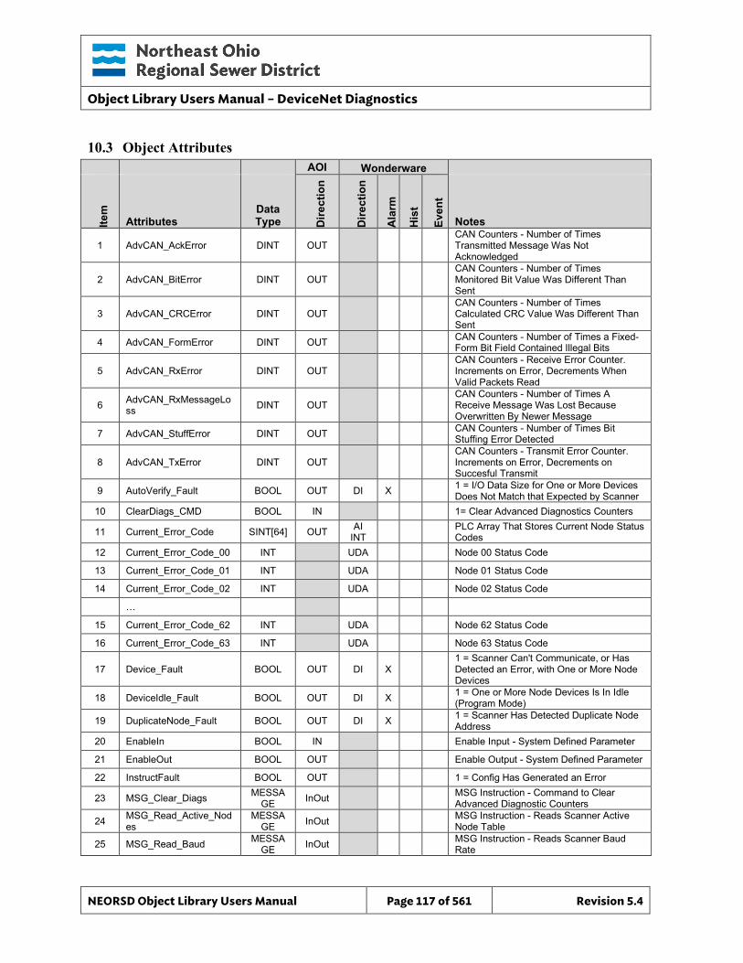
Object Library Users Manual – DeviceNet Diagnostics
NEORSD Object Library Users Manual Page 117 of 561 Revision 5.4
10.3 Object Attributes
AOI Wonderware
Item
Attributes Data Type D
irect
ion
Dire
ctio
n
Ala
rm
His
t
Even
t
Notes
1 AdvCAN_AckError DINT OUT CAN Counters - Number of Times Transmitted Message Was Not Acknowledged
2 AdvCAN_BitError DINT OUT CAN Counters - Number of Times Monitored Bit Value Was Different Than Sent
3 AdvCAN_CRCError DINT OUT CAN Counters - Number of Times Calculated CRC Value Was Different Than Sent
4 AdvCAN_FormError DINT OUT CAN Counters - Number of Times a Fixed-Form Bit Field Contained Illegal Bits
5 AdvCAN_RxError DINT OUT CAN Counters - Receive Error Counter. Increments on Error, Decrements When Valid Packets Read
6 AdvCAN_RxMessageLoss DINT OUT
CAN Counters - Number of Times A Receive Message Was Lost Because Overwritten By Newer Message
7 AdvCAN_StuffError DINT OUT CAN Counters - Number of Times Bit Stuffing Error Detected
8 AdvCAN_TxError DINT OUT CAN Counters - Transmit Error Counter. Increments on Error, Decrements on Succesful Transmit
9 AutoVerify_Fault BOOL OUT DI X 1 = I/O Data Size for One or More Devices Does Not Match that Expected by Scanner
10 ClearDiags_CMD BOOL IN 1= Clear Advanced Diagnostics Counters
11 Current_Error_Code SINT[64] OUT AI INT PLC Array That Stores Current Node Status
Codes 12 Current_Error_Code_00 INT UDA Node 00 Status Code
13 Current_Error_Code_01 INT UDA Node 01 Status Code
14 Current_Error_Code_02 INT UDA Node 02 Status Code
…
15 Current_Error_Code_62 INT UDA Node 62 Status Code
16 Current_Error_Code_63 INT UDA Node 63 Status Code
17 Device_Fault BOOL OUT DI X 1 = Scanner Can't Communicate, or Has Detected an Error, with One or More Node Devices
18 DeviceIdle_Fault BOOL OUT DI X 1 = One or More Node Devices Is In Idle (Program Mode)
19 DuplicateNode_Fault BOOL OUT DI X 1 = Scanner Has Detected Duplicate Node Address
20 EnableIn BOOL IN Enable Input - System Defined Parameter
21 EnableOut BOOL OUT Enable Output - System Defined Parameter
22 InstructFault BOOL OUT 1 = Config Has Generated an Error
23 MSG_Clear_Diags MESSAGE InOut MSG Instruction - Command to Clear
Advanced Diagnostic Counters
24 MSG_Read_Active_Nodes
MESSAGE InOut MSG Instruction - Reads Scanner Active
Node Table
25 MSG_Read_Baud MESSAGE InOut MSG Instruction - Reads Scanner Baud
Rate
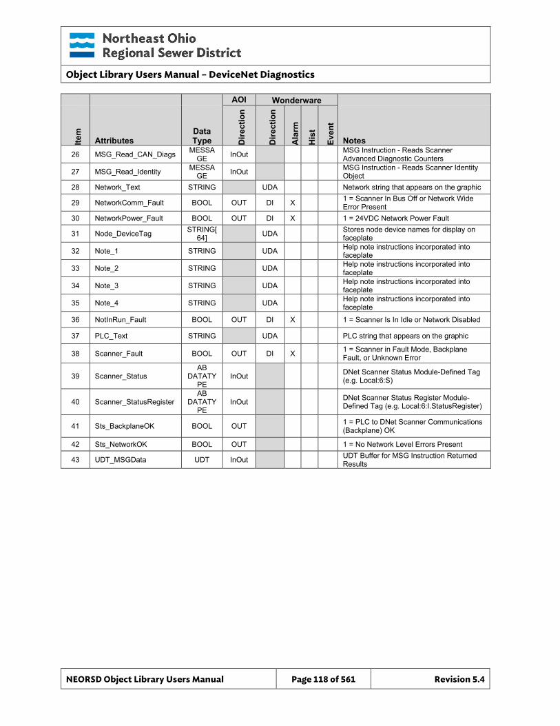
Object Library Users Manual – DeviceNet Diagnostics
NEORSD Object Library Users Manual Page 118 of 561 Revision 5.4
AOI Wonderware
Item
Attributes Data Type D
irect
ion
Dire
ctio
n
Ala
rm
His
t
Even
t
Notes 26 MSG_Read_CAN_Diags MESSA
GE InOut MSG Instruction - Reads Scanner Advanced Diagnostic Counters
27 MSG_Read_Identity MESSAGE InOut MSG Instruction - Reads Scanner Identity
Object 28 Network_Text STRING UDA Network string that appears on the graphic
29 NetworkComm_Fault BOOL OUT DI X 1 = Scanner In Bus Off or Network Wide Error Present
30 NetworkPower_Fault BOOL OUT DI X 1 = 24VDC Network Power Fault
31 Node_DeviceTag STRING[64] UDA Stores node device names for display on
faceplate
32 Note_1 STRING UDA Help note instructions incorporated into faceplate
33 Note_2 STRING UDA Help note instructions incorporated into faceplate
34 Note_3 STRING UDA Help note instructions incorporated into faceplate
35 Note_4 STRING UDA Help note instructions incorporated into faceplate
36 NotInRun_Fault BOOL OUT DI X 1 = Scanner Is In Idle or Network Disabled
37 PLC_Text STRING UDA PLC string that appears on the graphic
38 Scanner_Fault BOOL OUT DI X 1 = Scanner in Fault Mode, Backplane Fault, or Unknown Error
39 Scanner_Status AB
DATATYPE
InOut DNet Scanner Status Module-Defined Tag (e.g. Local:6:S)
40 Scanner_StatusRegister AB
DATATYPE
InOut DNet Scanner Status Register Module-Defined Tag (e.g. Local:6:I.StatusRegister)
41 Sts_BackplaneOK BOOL OUT 1 = PLC to DNet Scanner Communications (Backplane) OK
42 Sts_NetworkOK BOOL OUT 1 = No Network Level Errors Present
43 UDT_MSGData UDT InOut UDT Buffer for MSG Instruction Returned Results
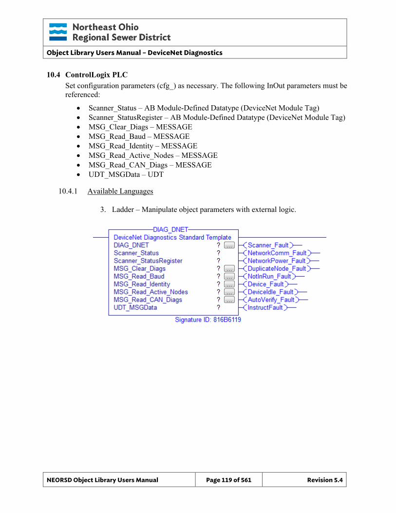
Object Library Users Manual – DeviceNet Diagnostics
NEORSD Object Library Users Manual Page 119 of 561 Revision 5.4
10.4 ControlLogix PLC Set configuration parameters (cfg_) as necessary. The following InOut parameters must be referenced:
• Scanner_Status – AB Module-Defined Datatype (DeviceNet Module Tag) • Scanner_StatusRegister – AB Module-Defined Datatype (DeviceNet Module Tag) • MSG_Clear_Diags – MESSAGE • MSG_Read_Baud – MESSAGE • MSG_Read_Identity – MESSAGE • MSG_Read_Active_Nodes – MESSAGE • MSG_Read_CAN_Diags – MESSAGE • UDT_MSGData – UDT
10.4.1 Available Languages
3. Ladder – Manipulate object parameters with external logic.
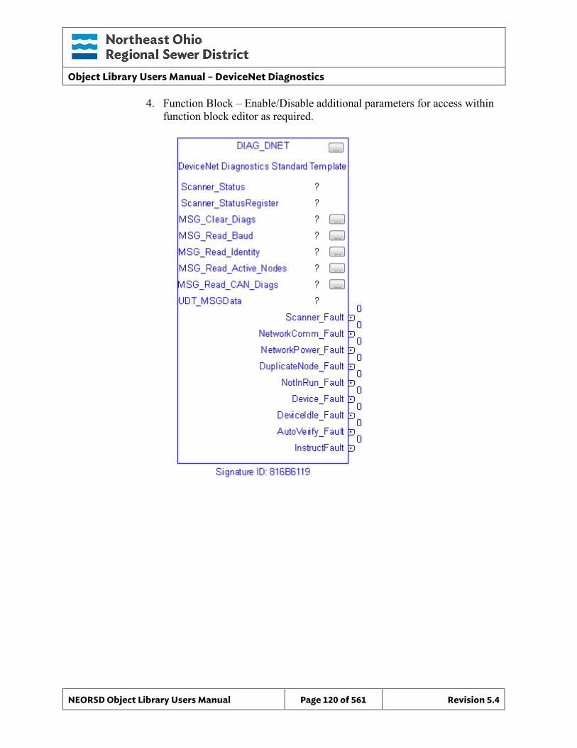
Object Library Users Manual – DeviceNet Diagnostics
NEORSD Object Library Users Manual Page 120 of 561 Revision 5.4
4. Function Block – Enable/Disable additional parameters for access within function block editor as required.
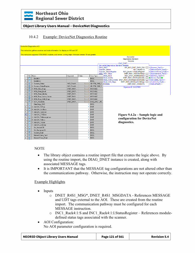
Object Library Users Manual – DeviceNet Diagnostics
NEORSD Object Library Users Manual Page 121 of 561 Revision 5.4
10.4.2 Example: DeviceNet Diagnostics Routine
NOTE
• The library object contains a routine import file that creates the logic above. By using the routine import, the DIAG_DNET instance is created, along with associated MESSAGE tags.
• It is IMPORTANT that the MESSAGE tag configurations are not altered other than the communications pathway. Otherwise, the instruction may not operate correctly.
Example Highlights • Inputs
o DNET_R4S1_MSG*, DNET_R4S1_MSGDATA - References MESSAGE and UDT tags external to the AOI. These are created from the routine import. The communication pathway must be configured for each MESSAGE instruction.
o INC1_Rack4:1:S and INC1_Rack4:1:I.StatusRegister – References module-defined status tags associated with the scanner.
• AOI Configuration: No AOI parameter configuration is required.
Figure 9.4.2a – Sample logic and configuration for DeviceNet diagnostics.
Object Library Users Manual – DeviceNet Diagnostics
NEORSD Object Library Users Manual Page 122 of 561 Revision 5.4
• Block Outputs for Use in External Logic: o The following DeviceNet statuses are available (1 = OK):
Sts_NetworkOK Sts_BackplaneOK
o The following DeviceNet alarms are available (1 = Alarm): Scanner_Fault NetworkComm_Fault NetworkPower_Fault DuplicateNode_Fault NotInRun_Fault Device_Fault DeviceIdle_Fault AutoVerify_Fault
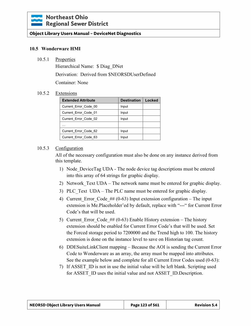
Object Library Users Manual – DeviceNet Diagnostics
NEORSD Object Library Users Manual Page 123 of 561 Revision 5.4
10.5 Wonderware HMI
10.5.1 Properties Hierarchical Name: $ Diag_DNet Derivation: Derived from $NEORSDUserDefined Container: None
10.5.2 Extensions Extended Attribute Destination Locked Current_Error_Code_00 Input Current_Error_Code_01 Input Current_Error_Code_02 Input … Current_Error_Code_62 Input Current_Error_Code_63 Input
10.5.3 Configuration All of the necessary configuration must also be done on any instance derived from this template.
1) Node_DeviceTag UDA - The node device tag descriptions must be entered into this array of 64 strings for graphic display.
2) Network_Text UDA – The network name must be entered for graphic display. 3) PLC_Text UDA – The PLC name must be entered for graphic display. 4) Current_Error_Code_## (0-63) Input extension configuration – The input
extension is Me.Placeholder’ed by default, replace with “---“ for Current Error Code’s that will be used.
5) Current_Error_Code_## (0-63) Enable History extension – The history extension should be enabled for Current Error Code’s that will be used. Set the Forced storage period to 7200000 and the Trend high to 100. The history extension is done on the instance level to save on Historian tag count.
6) DDESuiteLinkClient mapping – Because the AOI is sending the Current Error Code to Wonderware as an array, the array must be mapped into attributes. See the example below and complete for all Current Error Codes used (0-63):
7) If ASSET_ID is not in use the initial value will be left blank. Scripting used for ASSET_ID uses the initial value and not ASSET_ID.Description.
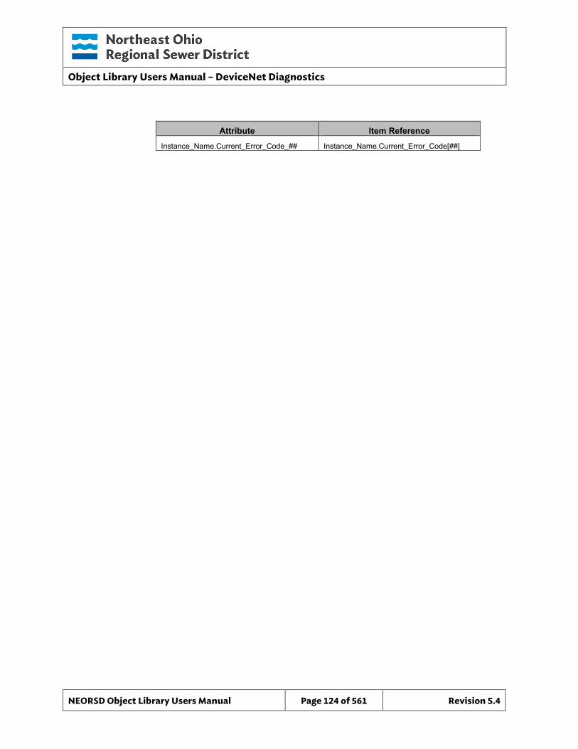
Object Library Users Manual – DeviceNet Diagnostics
NEORSD Object Library Users Manual Page 124 of 561 Revision 5.4
Attribute Item Reference Instance_Name.Current_Error_Code_## Instance_Name.Current_Error_Code[##]
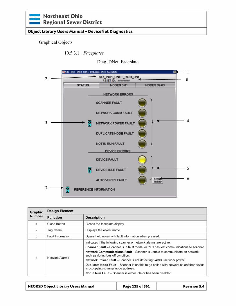
Object Library Users Manual – DeviceNet Diagnostics
NEORSD Object Library Users Manual Page 125 of 561 Revision 5.4
Graphical Objects
10.5.3.1 Faceplates
Graphic Number
Design Element
Function Description
1 Close Button Closes the faceplate display.
2 Tag Name Displays the object name.
3 Fault Information Opens help notes with fault information when pressed.
4 Network Alarms
Indicates if the following scanner or network alarms are active: Scanner Fault – Scanner is in fault mode, or PLC has lost communications to scanner Network Communications Fault – Scanner is unable to communicate on network, such as during bus off condition. Network Power Fault – Scanner is not detecting 24VDC network power Duplicate Node Fault – Scanner is unable to go online with network as another device is occupying scanner node address. Not In Run Fault – Scanner is either idle or has been disabled.
Diag_DNet_Faceplate
2
4 3
1
7
5
6
8
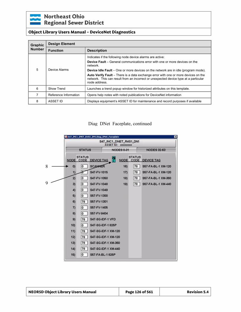
Object Library Users Manual – DeviceNet Diagnostics
NEORSD Object Library Users Manual Page 126 of 561 Revision 5.4
Graphic Number
Design Element
Function Description
5 Device Alarms
Indicates if the following node device alarms are active: Device Fault – General communications error with one or more devices on the network. Device Idle Fault – One or more devices on the network are in idle (program mode). Auto Verify Fault – There is a data exchange error with one or more devices on the network. This can result from an incorrect or unexpected device type at a particular node address.
6 Show Trend Launches a trend popup window for historized attributes on this template.
7 Reference Information Opens help notes with noted publications for DeviceNet information
8 ASSET ID Displays equipment’s ASSET ID for maintenance and record purposes if available
Diag_DNet_Faceplate, continued
8
9
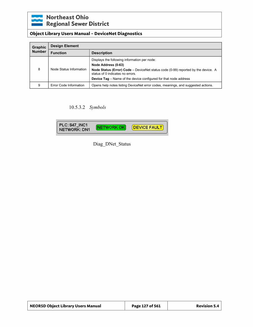
Object Library Users Manual – DeviceNet Diagnostics
NEORSD Object Library Users Manual Page 127 of 561 Revision 5.4
Graphic Number
Design Element
Function Description
8 Node Status Information
Displays the following information per node: Node Address (0-63) Node Status (Error) Code – DeviceNet status code (0-99) reported by the device. A status of 0 indicates no errors. Device Tag – Name of the device configured for that node address
9 Error Code Information Opens help notes listing DeviceNet error codes, meanings, and suggested actions.
10.5.3.2 Symbols
Diag_DNet_Status
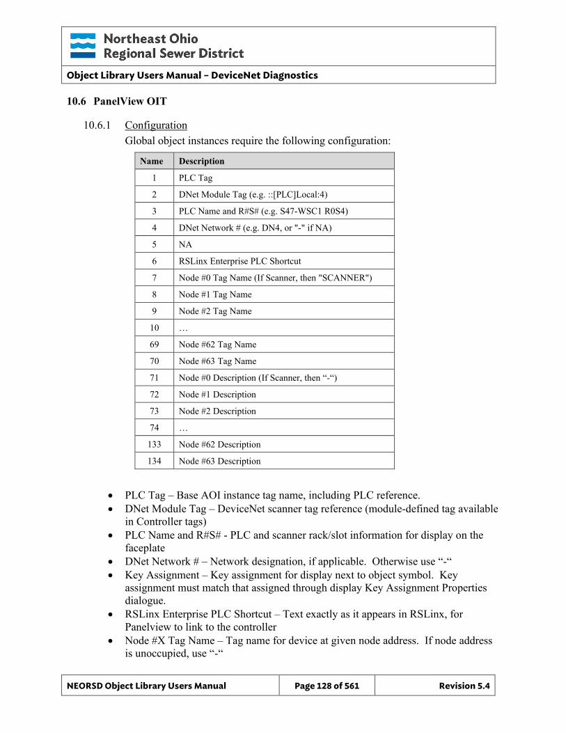
Object Library Users Manual – DeviceNet Diagnostics
NEORSD Object Library Users Manual Page 128 of 561 Revision 5.4
10.6 PanelView OIT
10.6.1 Configuration Global object instances require the following configuration:
Name Description
1 PLC Tag
2 DNet Module Tag (e.g. ::[PLC]Local:4)
3 PLC Name and R#S# (e.g. S47-WSC1 R0S4)
4 DNet Network # (e.g. DN4, or "-" if NA)
5 NA
6 RSLinx Enterprise PLC Shortcut
7 Node #0 Tag Name (If Scanner, then "SCANNER")
8 Node #1 Tag Name
9 Node #2 Tag Name
10 …
69 Node #62 Tag Name
70 Node #63 Tag Name
71 Node #0 Description (If Scanner, then “-“)
72 Node #1 Description
73 Node #2 Description
74 …
133 Node #62 Description
134 Node #63 Description
• PLC Tag – Base AOI instance tag name, including PLC reference. • DNet Module Tag – DeviceNet scanner tag reference (module-defined tag available
in Controller tags) • PLC Name and R#S# - PLC and scanner rack/slot information for display on the
faceplate • DNet Network # – Network designation, if applicable. Otherwise use “-“ • Key Assignment – Key assignment for display next to object symbol. Key
assignment must match that assigned through display Key Assignment Properties dialogue.
• RSLinx Enterprise PLC Shortcut – Text exactly as it appears in RSLinx, for Panelview to link to the controller
• Node #X Tag Name – Tag name for device at given node address. If node address is unoccupied, use “-“
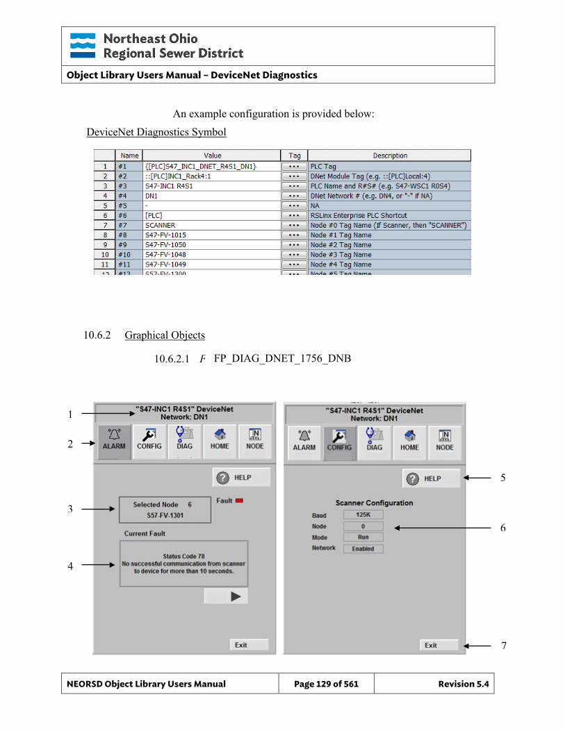
Object Library Users Manual – DeviceNet Diagnostics
NEORSD Object Library Users Manual Page 129 of 561 Revision 5.4
5
6
7
An example configuration is provided below: DeviceNet Diagnostics Symbol
10.6.2 Graphical Objects
10.6.2.1 Faceplates
FP_DIAG_DNET_1756_DNB
1
2
3
4
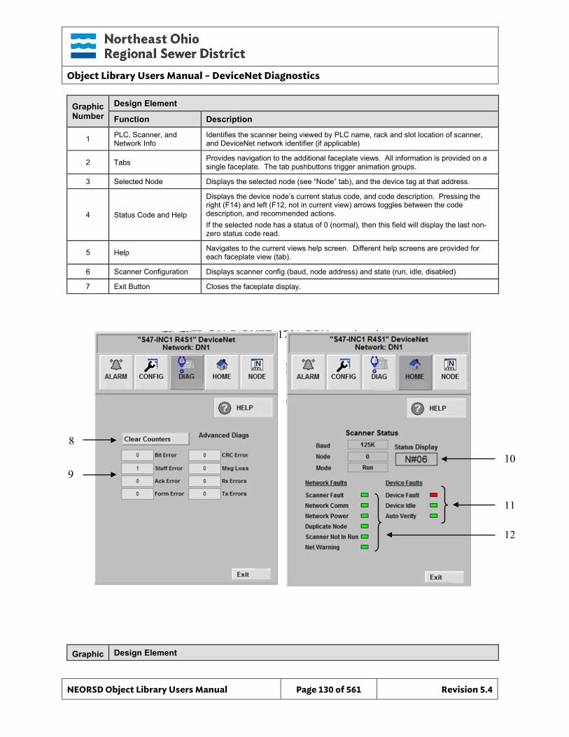
Object Library Users Manual – DeviceNet Diagnostics
NEORSD Object Library Users Manual Page 130 of 561 Revision 5.4
10
11
12
Graphic Number
Design Element
Function Description
1 PLC, Scanner, and Network Info
Identifies the scanner being viewed by PLC name, rack and slot location of scanner, and DeviceNet network identifier (if applicable)
2 Tabs Provides navigation to the additional faceplate views. All information is provided on a single faceplate. The tab pushbuttons trigger animation groups.
3 Selected Node Displays the selected node (see “Node” tab), and the device tag at that address.
4 Status Code and Help
Displays the device node’s current status code, and code description. Pressing the right (F14) and left (F12, not in current view) arrows toggles between the code description, and recommended actions. If the selected node has a status of 0 (normal), then this field will display the last non-zero status code read.
5 Help Navigates to the current views help screen. Different help screens are provided for each faceplate view (tab).
6 Scanner Configuration Displays scanner config (baud, node address) and state (run, idle, disabled)
7 Exit Button Closes the faceplate display.
Graphic Design Element
FP_DIAG_DNET_1756_DBN, continued
8
9
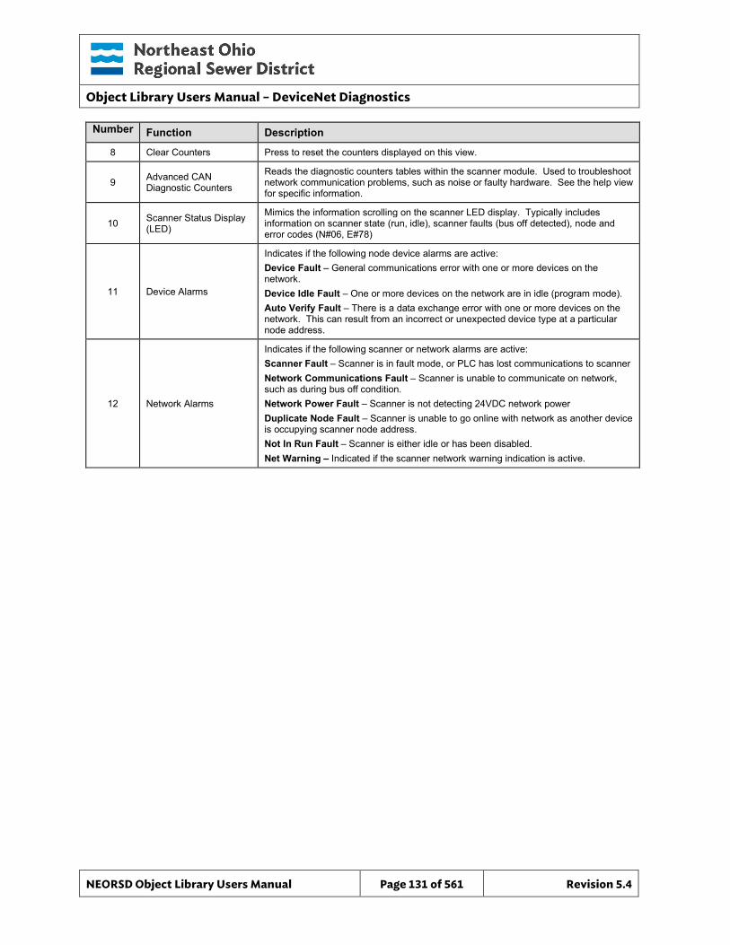
Object Library Users Manual – DeviceNet Diagnostics
NEORSD Object Library Users Manual Page 131 of 561 Revision 5.4
Number Function Description
8 Clear Counters Press to reset the counters displayed on this view.
9 Advanced CAN Diagnostic Counters
Reads the diagnostic counters tables within the scanner module. Used to troubleshoot network communication problems, such as noise or faulty hardware. See the help view for specific information.
10 Scanner Status Display (LED)
Mimics the information scrolling on the scanner LED display. Typically includes information on scanner state (run, idle), scanner faults (bus off detected), node and error codes (N#06, E#78)
11 Device Alarms
Indicates if the following node device alarms are active: Device Fault – General communications error with one or more devices on the network. Device Idle Fault – One or more devices on the network are in idle (program mode). Auto Verify Fault – There is a data exchange error with one or more devices on the network. This can result from an incorrect or unexpected device type at a particular node address.
12 Network Alarms
Indicates if the following scanner or network alarms are active: Scanner Fault – Scanner is in fault mode, or PLC has lost communications to scanner Network Communications Fault – Scanner is unable to communicate on network, such as during bus off condition. Network Power Fault – Scanner is not detecting 24VDC network power Duplicate Node Fault – Scanner is unable to go online with network as another device is occupying scanner node address. Not In Run Fault – Scanner is either idle or has been disabled. Net Warning – Indicated if the scanner network warning indication is active.
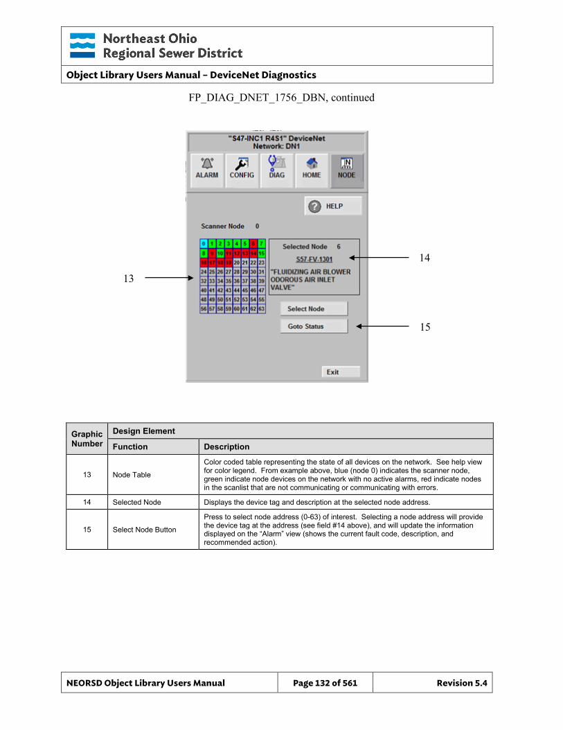
Object Library Users Manual – DeviceNet Diagnostics
NEORSD Object Library Users Manual Page 132 of 561 Revision 5.4
14
15
Graphic Number
Design Element
Function Description
13 Node Table
Color coded table representing the state of all devices on the network. See help view for color legend. From example above, blue (node 0) indicates the scanner node, green indicate node devices on the network with no active alarms, red indicate nodes in the scanlist that are not communicating or communicating with errors.
14 Selected Node Displays the device tag and description at the selected node address.
15 Select Node Button
Press to select node address (0-63) of interest. Selecting a node address will provide the device tag at the address (see field #14 above), and will update the information displayed on the “Alarm” view (shows the current fault code, description, and recommended action).
FP_DIAG_DNET_1756_DBN, continued
13
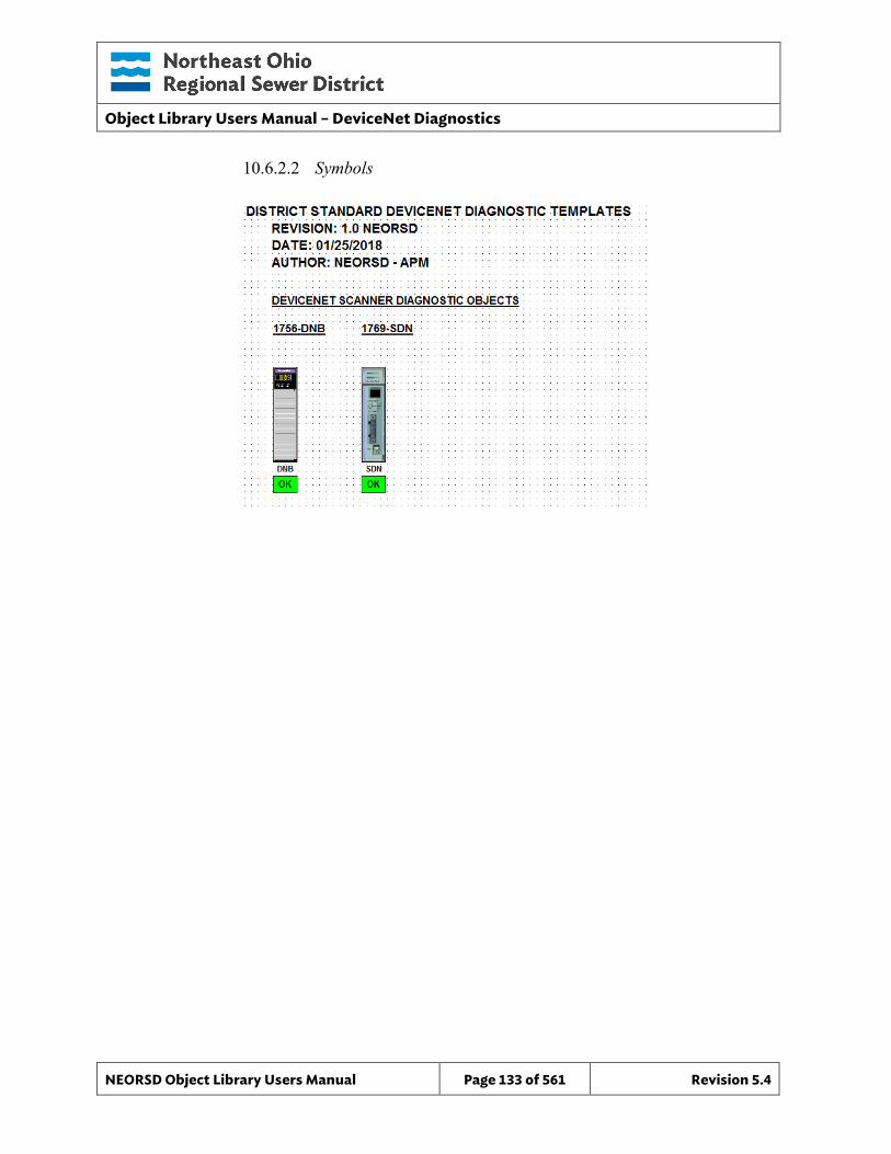
Object Library Users Manual – DeviceNet Diagnostics
NEORSD Object Library Users Manual Page 133 of 561 Revision 5.4
10.6.2.2 Symbols
Object Library Users Manual – Discrete
NEORSD Object Library Users Manual Page 134 of 561 Revision 5.4
11.0 Discrete
11.1 Introduction The Discrete object template provides a standard representation for a standalone single two-state indicator within the NEORSD control systems. Use the Discrete template if any of the statements below are true:
• If trying to represent a single indication-only status or alarm bit. • If the bit has no HMI control to toggle its state.
Do not use the Discrete template:
• If the bit can be toggled between two states. If this is the case, use Discrete_Setpoint instead.
• If the bit represents “Motor Running”. If this is the case, consider a Motor_Discrete_Indicator.
• If the bit represents a “Valve Opened/Closed”. If this is the case, consider a Valve_Discrete_Indicator.
• If the bit represents an alarm condition for a piece of equipment (“Valve Faulted”, “Motor Faulted”). Consider using the appropriate equipment template instead.
11.2 Object Features
11.2.1 Status Indications This object provides the following indications for the valve/gate: • On/Off State of the Discrete Object
11.2.2 Alarming This object can represent an alarm bit, and has an additional input to programatically toggle whether or not to examine the alarm input.
11.2.3 Simulation This object supports simulation of the running feedback.
11.2.4 Trouble This object supports hardware trouble indication.
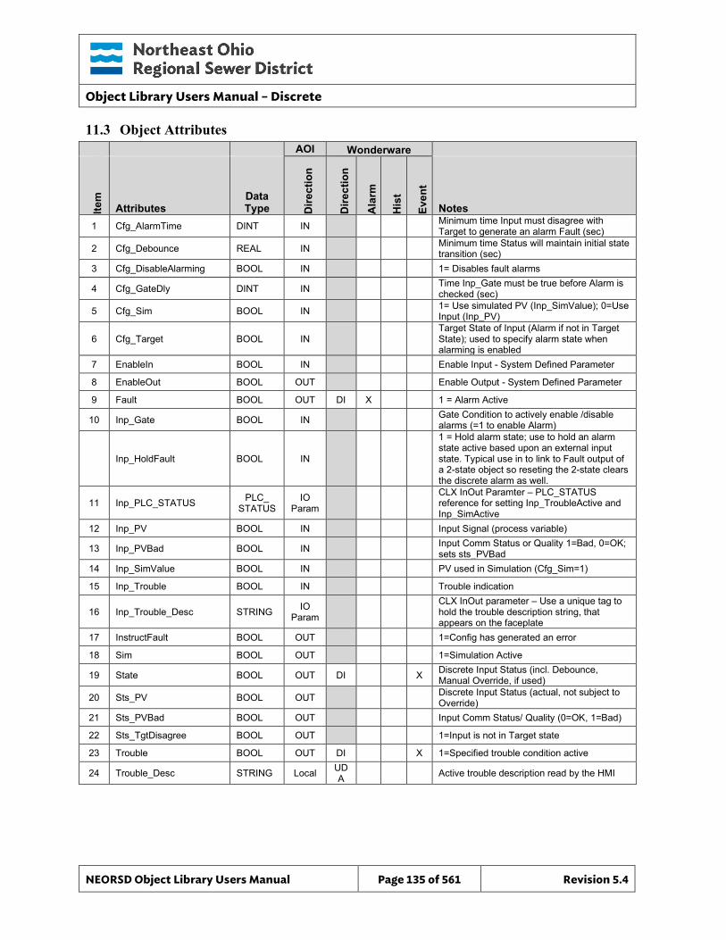
Object Library Users Manual – Discrete
NEORSD Object Library Users Manual Page 135 of 561 Revision 5.4
11.3 Object Attributes
AOI Wonderware
Item
Attributes Data Type D
irect
ion
Dire
ctio
n
Ala
rm
His
t
Even
t
Notes 1 Cfg_AlarmTime DINT IN Minimum time Input must disagree with
Target to generate an alarm Fault (sec)
2 Cfg_Debounce REAL IN Minimum time Status will maintain initial state transition (sec)
3 Cfg_DisableAlarming BOOL IN 1= Disables fault alarms
4 Cfg_GateDly DINT IN Time Inp_Gate must be true before Alarm is checked (sec)
5 Cfg_Sim BOOL IN 1= Use simulated PV (Inp_SimValue); 0=Use Input (Inp_PV)
6 Cfg_Target BOOL IN Target State of Input (Alarm if not in Target State); used to specify alarm state when alarming is enabled
7 EnableIn BOOL IN Enable Input - System Defined Parameter
8 EnableOut BOOL OUT Enable Output - System Defined Parameter
9 Fault BOOL OUT DI X 1 = Alarm Active
10 Inp_Gate BOOL IN Gate Condition to actively enable /disable alarms (=1 to enable Alarm)
Inp_HoldFault BOOL IN
1 = Hold alarm state; use to hold an alarm state active based upon an external input state. Typical use in to link to Fault output of a 2-state object so reseting the 2-state clears the discrete alarm as well.
11 Inp_PLC_STATUS PLC_ STATUS
IO Param
CLX InOut Paramter – PLC_STATUS reference for setting Inp_TroubleActive and Inp_SimActive
12 Inp_PV BOOL IN Input Signal (process variable)
13 Inp_PVBad BOOL IN Input Comm Status or Quality 1=Bad, 0=OK; sets sts_PVBad
14 Inp_SimValue BOOL IN PV used in Simulation (Cfg_Sim=1)
15 Inp_Trouble BOOL IN Trouble indication
16 Inp_Trouble_Desc STRING IO Param
CLX InOut parameter – Use a unique tag to hold the trouble description string, that appears on the faceplate
17 InstructFault BOOL OUT 1=Config has generated an error
18 Sim BOOL OUT 1=Simulation Active
19 State BOOL OUT DI X Discrete Input Status (incl. Debounce, Manual Override, if used)
20 Sts_PV BOOL OUT Discrete Input Status (actual, not subject to Override)
21 Sts_PVBad BOOL OUT Input Comm Status/ Quality (0=OK, 1=Bad)
22 Sts_TgtDisagree BOOL OUT 1=Input is not in Target state
23 Trouble BOOL OUT DI X 1=Specified trouble condition active
24 Trouble_Desc STRING Local UDA Active trouble description read by the HMI
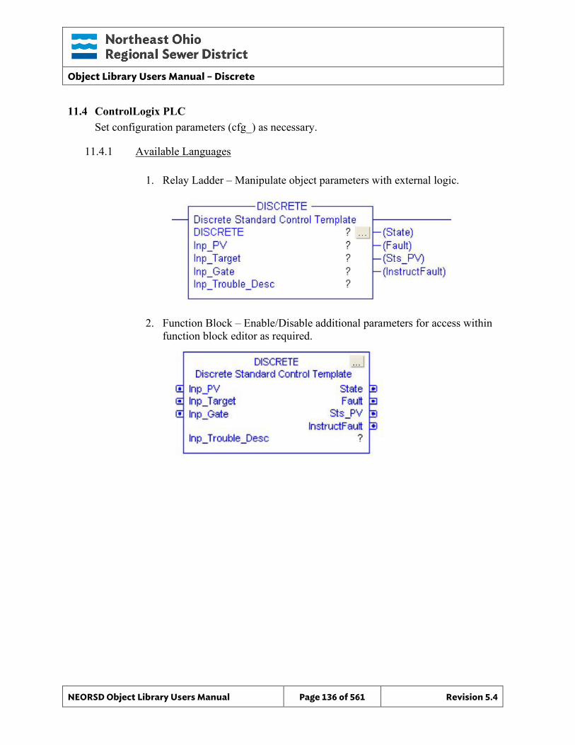
Object Library Users Manual – Discrete
NEORSD Object Library Users Manual Page 136 of 561 Revision 5.4
11.4 ControlLogix PLC Set configuration parameters (cfg_) as necessary.
11.4.1 Available Languages
1. Relay Ladder – Manipulate object parameters with external logic.
2. Function Block – Enable/Disable additional parameters for access within function block editor as required.
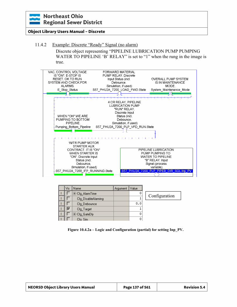
Object Library Users Manual – Discrete
NEORSD Object Library Users Manual Page 137 of 561 Revision 5.4
11.4.2 Example: Discrete “Ready” Signal (no alarm) Discrete object representing “PIPELINE LUBRICATION PUMP PUMPING WATER TO PIPELINE ‘B’ RELAY” is set to “1” when the rung in the image is true.
Figure 10.4.2a – Logic and Configuration (partial) for setting Inp_PV.
Configuration
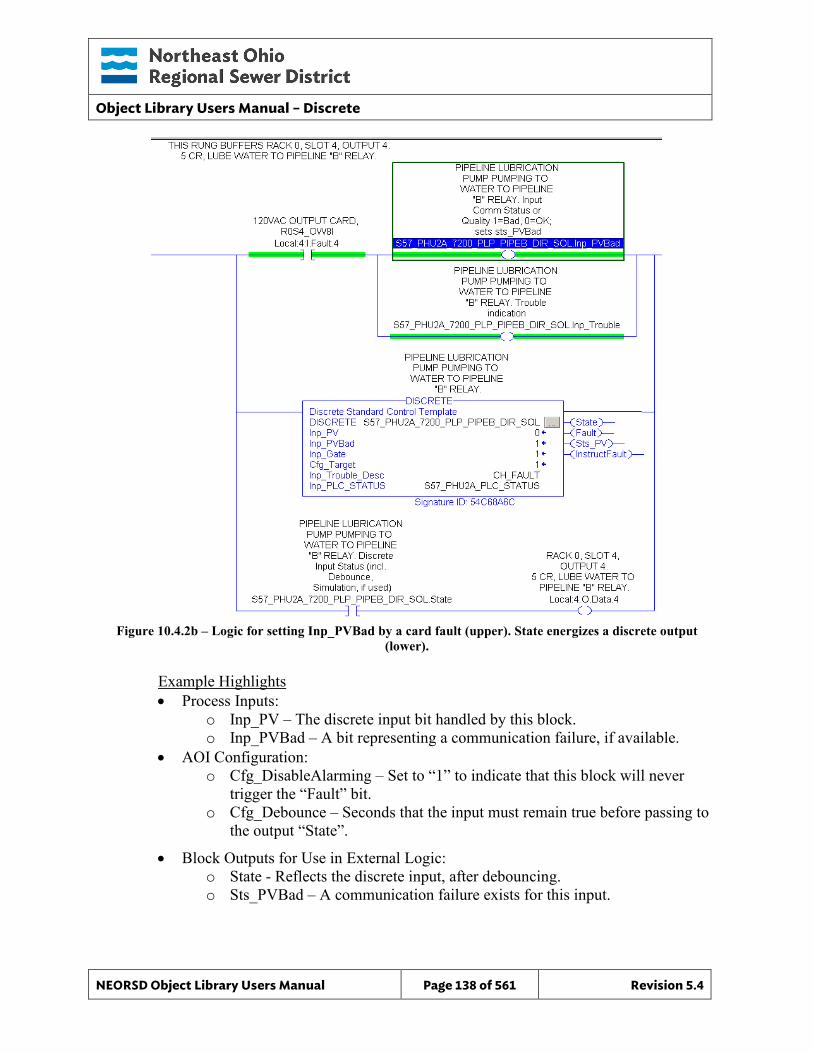
Object Library Users Manual – Discrete
NEORSD Object Library Users Manual Page 138 of 561 Revision 5.4
Figure 10.4.2b – Logic for setting Inp_PVBad by a card fault (upper). State energizes a discrete output
(lower).
Example Highlights • Process Inputs:
o Inp_PV – The discrete input bit handled by this block. o Inp_PVBad – A bit representing a communication failure, if available.
• AOI Configuration: o Cfg_DisableAlarming – Set to “1” to indicate that this block will never
trigger the “Fault” bit. o Cfg_Debounce – Seconds that the input must remain true before passing to
the output “State”.
• Block Outputs for Use in External Logic: o State - Reflects the discrete input, after debouncing. o Sts_PVBad – A communication failure exists for this input.
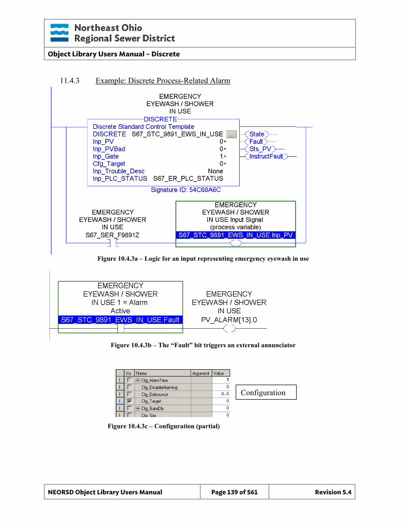
Object Library Users Manual – Discrete
NEORSD Object Library Users Manual Page 139 of 561 Revision 5.4
11.4.3 Example: Discrete Process-Related Alarm
Figure 10.4.3a – Logic for an input representing emergency eyewash in use
Figure 10.4.3b – The “Fault” bit triggers an external annunciator
Figure 10.4.3c – Configuration (partial)
Configuration
Object Library Users Manual – Discrete
NEORSD Object Library Users Manual Page 140 of 561 Revision 5.4
Example Highlights • Process Inputs:
o Inp_PV – The discrete input bit handled by this block. o Inp_PVBad – A bit representing a communication failure, if available.
• AOI Configuration: o Cfg_DisableAlarming – Set to “0” to allow this block to trigger the “Fault”
bit. o Cfg_Target – This is the “normal” state of the input. Fault will be
energized when “Inp_PV” is not at this value. For example, “Cfg_Target” of “0” means that “Fault” will energize when “Inp_PV” is “1”.
o Cfg_AlarmTime – The number of seconds an alarm state must be true (i.e. “Inp_PV” does not match “Target”) before triggering the “Fault” output.
• Block Outputs for Use in External Logic: o Fault – Will energize according to the settings defined Cfg_Target,
Cfg_DisableAlarming, and Cfg_AlarmTime.
11.4.4 Additional Attribute Notes
11.4.4.1 Inputs o Inp_PLC_STATUS - Must reference the PLC_Status object for this PLC. o Inp_SimValue – When Cfg_Sim is true, the block uses this as the primary
input (instead of Inp_PV). o Inp_Gate – When false, this will disable “Fault” from energizing. Used to
programatically prevent false alarms. Example: a discrete object represents a Pump High Pressure, with Inp_Gate tied to the “Running” attribute of the associated pump object. Additionally, assume the pump is programmed to shut off on High Pressure. The Discrete Pump High Pressure would never be seen, since the pump shutting off trigger the gate condition, eliminating the alalrm. With Inp_HoldFault tied back to the pump object Fault, then the Discrete remains in the alarm state until the pump is reset at the OIT.
• Cfg_GateDIy must also be configured. o Inp_HoldFault – Tie this input to the output Fault of another object, to keep
the discrete alarm active until the other object is reset. For example, if the Discrete object is indicating a Low Flow, and the gate input is tied to a pump running, then the Low Flow
11.4.4.2 Internal Configuration o Cfg_GateDIy – The number of seconds that “Inp_Gate” must be true
before faults are enabled. For example, if a pump running indication is
Object Library Users Manual – Discrete
NEORSD Object Library Users Manual Page 141 of 561 Revision 5.4
used for “Inp_Gate”, Cfg_GateDIy might be “10”, to allow 10 seconds before triggering the low-suction fault represented by this discrete block.
o Cfg_Sim – Sets the block into simulation mode.
11.4.4.3 Outputs o Sts_PV – Reflects the “Inp_PV” without any debouncing. Used for
debugging. o Sim – Indicates that this object is currently in simulation mode.
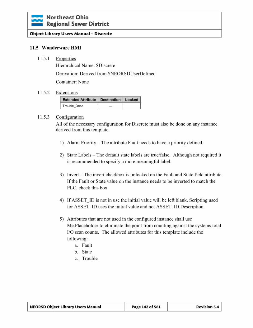
Object Library Users Manual – Discrete
NEORSD Object Library Users Manual Page 142 of 561 Revision 5.4
11.5 Wonderware HMI
11.5.1 Properties Hierarchical Name: $Discrete Derivation: Derived from $NEORSDUserDefined Container: None
11.5.2 Extensions Extended Attribute Destination Locked Trouble_Desc ---
11.5.3 Configuration All of the necessary configuration for Discrete must also be done on any instance derived from this template.
1) Alarm Priority – The attribute Fault needs to have a priority defined.
2) State Labels – The default state labels are true/false. Although not required it is recommended to specify a more meaningful label.
3) Invert – The invert checkbox is unlocked on the Fault and State field attribute.
If the Fault or State value on the instance needs to be inverted to match the PLC, check this box.
4) If ASSET_ID is not in use the initial value will be left blank. Scripting used
for ASSET_ID uses the initial value and not ASSET_ID.Description.
5) Attributes that are not used in the configured instance shall use Me.Placeholder to eliminate the point from counting against the systems total I/O scan counts. The allowed attributes for this template include the following:
a. Fault b. State c. Trouble
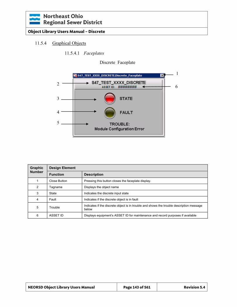
Object Library Users Manual – Discrete
NEORSD Object Library Users Manual Page 143 of 561 Revision 5.4
11.5.4 Graphical Objects
11.5.4.1 Faceplates
Graphic Number
Design Element
Function Description
1 Close Button Pressing this button closes the faceplate display.
2 Tagname Displays the object name
3 State Indicates the discrete input state
4 Fault Indicates if the discrete object is in fault
5 Trouble Indicates if the discrete object is in trouble and shows the trouble description message below
6 ASSET ID Displays equipment’s ASSET ID for maintenance and record purposes if available
Discrete_Faceplate
2
1
3
4
5
6
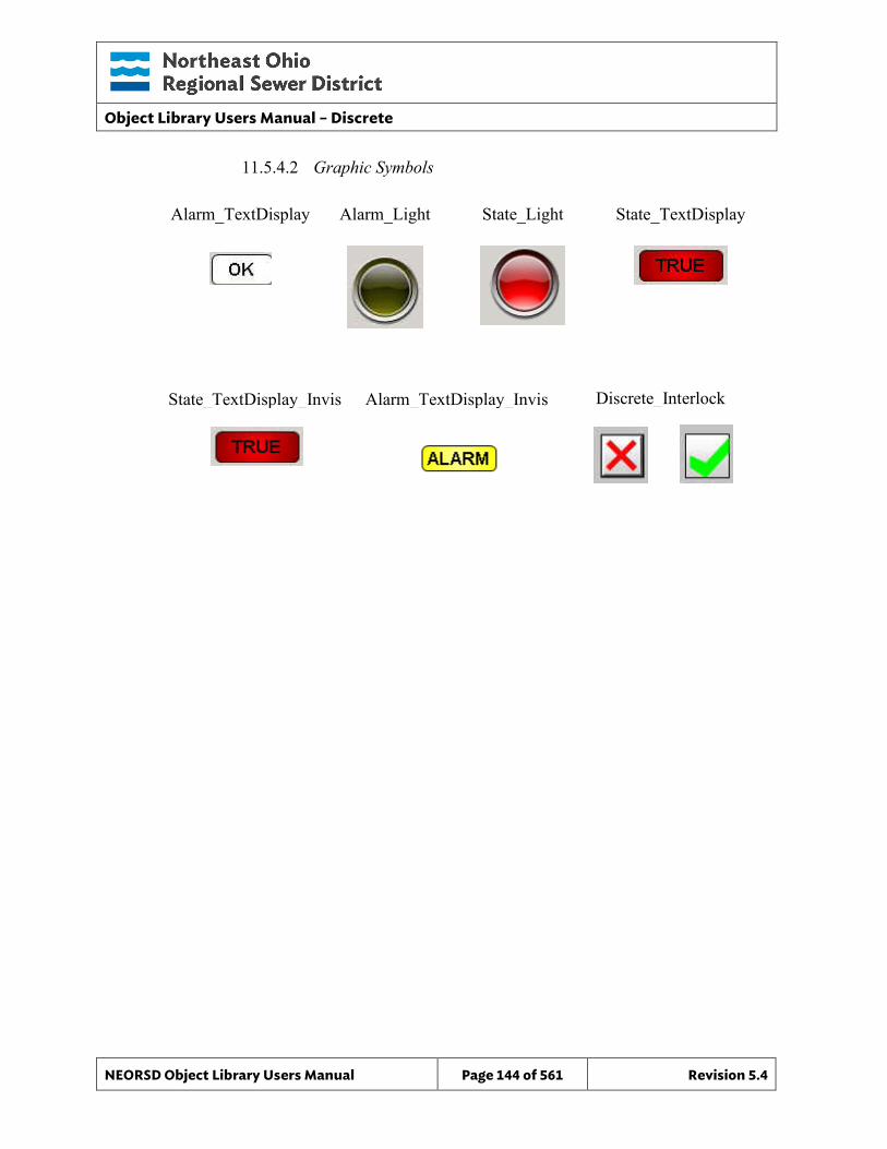
Object Library Users Manual – Discrete
NEORSD Object Library Users Manual Page 144 of 561 Revision 5.4
11.5.4.2 Graphic Symbols
Alarm_TextDisplay Alarm_Light State_Light State_TextDisplay
State_TextDisplay_Invis Alarm_TextDisplay_Invis Discrete_Interlock
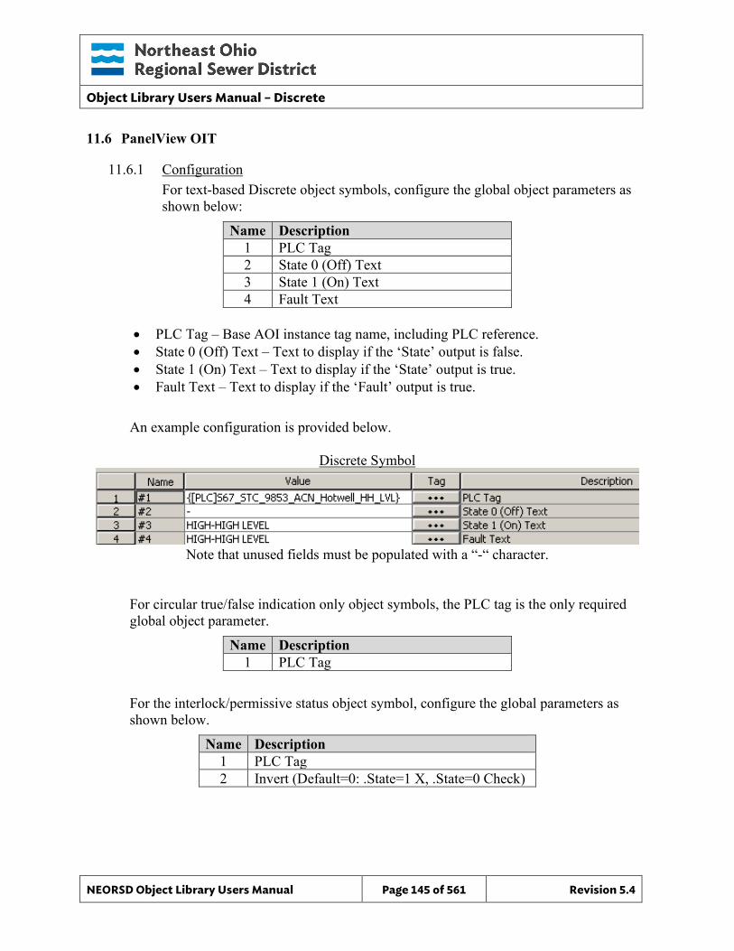
Object Library Users Manual – Discrete
NEORSD Object Library Users Manual Page 145 of 561 Revision 5.4
11.6 PanelView OIT
11.6.1 Configuration For text-based Discrete object symbols, configure the global object parameters as shown below:
Name Description 1 PLC Tag 2 State 0 (Off) Text 3 State 1 (On) Text 4 Fault Text
• PLC Tag – Base AOI instance tag name, including PLC reference. • State 0 (Off) Text – Text to display if the ‘State’ output is false. • State 1 (On) Text – Text to display if the ‘State’ output is true. • Fault Text – Text to display if the ‘Fault’ output is true.
An example configuration is provided below.
Discrete Symbol
Note that unused fields must be populated with a “-“ character.
For circular true/false indication only object symbols, the PLC tag is the only required global object parameter.
Name Description 1 PLC Tag
For the interlock/permissive status object symbol, configure the global parameters as shown below.
Name Description 1 PLC Tag 2 Invert (Default=0: .State=1 X, .State=0 Check)
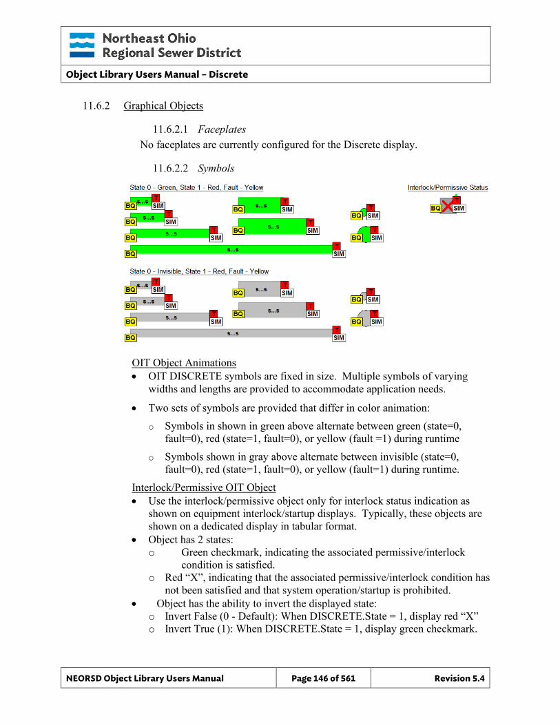
Object Library Users Manual – Discrete
NEORSD Object Library Users Manual Page 146 of 561 Revision 5.4
11.6.2 Graphical Objects
11.6.2.1 Faceplates No faceplates are currently configured for the Discrete display.
11.6.2.2 Symbols
OIT Object Animations • OIT DISCRETE symbols are fixed in size. Multiple symbols of varying
widths and lengths are provided to accommodate application needs.
• Two sets of symbols are provided that differ in color animation: o Symbols in shown in green above alternate between green (state=0,
fault=0), red (state=1, fault=0), or yellow (fault =1) during runtime
o Symbols shown in gray above alternate between invisible (state=0, fault=0), red (state=1, fault=0), or yellow (fault=1) during runtime.
Interlock/Permissive OIT Object • Use the interlock/permissive object only for interlock status indication as
shown on equipment interlock/startup displays. Typically, these objects are shown on a dedicated display in tabular format.
• Object has 2 states: o Green checkmark, indicating the associated permissive/interlock
condition is satisfied. o Red “X”, indicating that the associated permissive/interlock condition has
not been satisfied and that system operation/startup is prohibited. • Object has the ability to invert the displayed state:
o Invert False (0 - Default): When DISCRETE.State = 1, display red “X” o Invert True (1): When DISCRETE.State = 1, display green checkmark.

Object Library Users Manual – Discrete
NEORSD Object Library Users Manual Page 147 of 561 Revision 5.4
This page left blank intentionally.
Object Library Users Manual - Discrete_RW
NEORSD Object Library Users Manual Page 148 of 561 Revision 5.4
12.0 Discrete_RW
12.1 Introduction The Discrete RW (Read/Write) template provides a standard representation for maintained pushbutton control of a process with a discrete feedback (e.g. ‘purging’) within the NEORSD control systems. Discrete RW observes a discrete input bit, and allows an operator (OIT/HMI) to toggle a maintained discrete output bit. The discrete input and discrete output bits do not have to be the same. Use the Discrete RW template if all of the statements below are true:
• If an operator-toggled pushbutton is to be represented on the OIT/HMI, and • If a fault should be triggered when the commanded state does not match the feedback
state after a certain period of time. Do not use Discrete RW if:
• If trying to place a simple toggle pushbutton on the OIT/HMI without the need to monitor a separate discrete bit. For this, use the Discrete_Setpoint template instead.
• If trying to place a ‘start/stop’, ‘open/close’ or other equipment related pushbutton on the OIT/HMI. If this is the case, consider “Motor_Discrete”, “Valve_Discrete”, etc instead.
12.2 Object Features
12.2.1 Indications This object provides the following indications:
• Current state of the discrete bit controlled by this object, • Current state of the discrete bit monitoed by this object.
12.2.2 Commands This object supports the following commands:
• Maintained pushbutton function (from HMI/OIT), • Temporary program “inhibit” of pushbutton input.
12.2.3 Faults This object signals a “Fault” if the commanded state does not equal the feedback state within a configurable amount of time.
12.2.4 Simulation This object supports simulation. In simulation, state feedback matches commanded input.
12.2.5 Trouble This object supports hardware trouble indication. A trouble description tag must be configured.
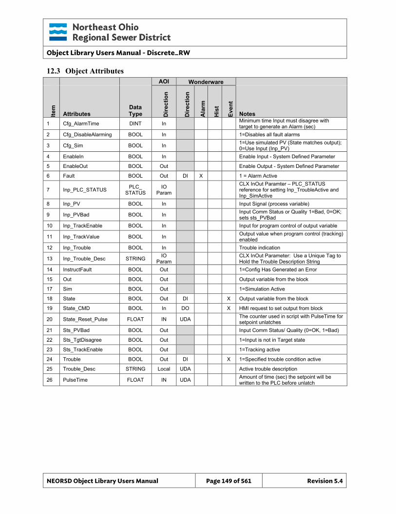
Object Library Users Manual - Discrete_RW
NEORSD Object Library Users Manual Page 149 of 561 Revision 5.4
12.3 Object Attributes
AOI Wonderware
Item
Attributes Data Type D
irect
ion
Dire
ctio
n
Ala
rm
His
t
Even
t
Notes 1 Cfg_AlarmTime DINT In Minimum time Input must disagree with
target to generate an Alarm (sec) 2 Cfg_DisableAlarming BOOL In 1=Disables all fault alarms
3 Cfg_Sim BOOL In 1=Use simulated PV (State matches output); 0=Use Input (Inp_PV)
4 EnableIn BOOL In Enable Input - System Defined Parameter
5 EnableOut BOOL Out Enable Output - System Defined Parameter
6 Fault BOOL Out DI X 1 = Alarm Active
7 Inp_PLC_STATUS PLC_ STATUS
IO Param
CLX InOut Paramter – PLC_STATUS reference for setting Inp_TroubleActive and Inp_SimActive
8 Inp_PV BOOL In Input Signal (process variable)
9 Inp_PVBad BOOL In Input Comm Status or Quality 1=Bad, 0=OK; sets sts_PVBad
10 Inp_TrackEnable BOOL In Input for program control of output variable
11 Inp_TrackValue BOOL In Output value when program control (tracking) enabled
12 Inp_Trouble BOOL In Trouble indication
13 Inp_Trouble_Desc STRING IO Param CLX InOut Parameter: Use a Unique Tag to
Hold the Trouble Description String 14 InstructFault BOOL Out 1=Config Has Generated an Error
15 Out BOOL Out Output variable from the block
17 Sim BOOL Out 1=Simulation Active
18 State BOOL Out DI X Output variable from the block
19 State_CMD BOOL In DO X HMI request to set output from block
20 State_Reset_Pulse FLOAT IN UDA The counter used in script with PulseTime for setpoint unlatches
21 Sts_PVBad BOOL Out Input Comm Status/ Quality (0=OK, 1=Bad)
22 Sts_TgtDisagree BOOL Out 1=Input is not in Target state
23 Sts_TrackEnable BOOL Out 1=Tracking active
24 Trouble BOOL Out DI X 1=Specified trouble condition active
25 Trouble_Desc STRING Local UDA Active trouble description
26 PulseTime FLOAT IN UDA Amount of time (sec) the setpoint will be written to the PLC before unlatch
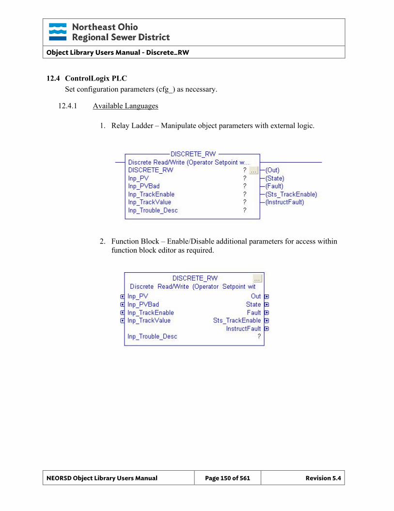
Object Library Users Manual - Discrete_RW
NEORSD Object Library Users Manual Page 150 of 561 Revision 5.4
12.4 ControlLogix PLC Set configuration parameters (cfg_) as necessary.
12.4.1 Available Languages
1. Relay Ladder – Manipulate object parameters with external logic.
2. Function Block – Enable/Disable additional parameters for access within function block editor as required.
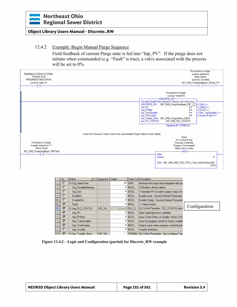
Object Library Users Manual - Discrete_RW
NEORSD Object Library Users Manual Page 151 of 561 Revision 5.4
12.4.2 Example: Begin Manual Purge Sequence Field feedback of current Purge state is fed into “Inp_PV”. If the purge does not initiate when commanded (e.g. “Fault” is true), a valve associated with the process will be set to 0%.
Figure 11.4.2 – Logic and Configuration (partial) for Discrete_RW example
Configuration
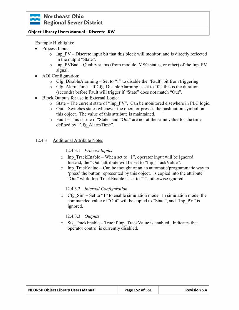
Object Library Users Manual - Discrete_RW
NEORSD Object Library Users Manual Page 152 of 561 Revision 5.4
Example Highlights: • Process Inputs:
o Inp_PV – Discrete input bit that this block will monitor, and is directly reflected in the output “State”.
o Inp_PVBad – Quality status (from module, MSG status, or other) of the Inp_PV signal.
• AOI Configuration: o Cfg_DisableAlarming – Set to “1” to disable the “Fault” bit from triggering. o Cfg_AlarmTime – If Cfg_DisableAlarming is set to “0”, this is the duration
(seconds) before Fault will trigger if “State” does not match “Out”. • Block Outputs for use in External Logic:
o State – The current state of “Inp_PV”. Can be monitored elsewhere in PLC logic. o Out – Switches states whenever the operator presses the pushbutton symbol on
this object. The value of this attribute is maintained. o Fault – This is true if “State” and “Out” are not at the same value for the time
defined by “Cfg_AlarmTime”.
12.4.3 Additional Attribute Notes
12.4.3.1 Process Inputs o Inp_TrackEnable – When set to “1”, operator input will be ignored.
Instead, the “Out” attribute will be set to “Inp_TrackValue”. o Inp_TrackValue – Can be thought of an an automatic/programmatic way to
‘press’ the button represented by this object. Is copied into the attribute “Out” while Inp_TrackEnable is set to “1”, otherwise ignored.
12.4.3.2 Internal Configuration o Cfg_Sim – Set to “1” to enable simulation mode. In simulation mode, the
commanded value of “Out” will be copied to “State”, and “Inp_PV” is ignored.
12.4.3.3 Outputs o Sts_TrackEnable – True if Inp_TrackValue is enabled. Indicates that
operator control is currently disabled.
Object Library Users Manual - Discrete_RW
NEORSD Object Library Users Manual Page 153 of 561 Revision 5.4
12.5 Wonderware HMI
12.5.1 Properties Hierarchical Name: $Discrete_RW Derivation: Derived from $NEORSDUserDefined/$Discrete Container: one
12.5.2 Extensions None
12.5.3 Configuration All of the necessary configuration for Discrete_RW must also be done on any instance derived from this template.
1) Alarm Priority – The attribute “Fault” must have a priority defined.
2) State Labels – The default state labels are true/false. Although not required, it
is recommended to specify a more meaningful label.
3) Attributes that are not used in the configured instance shall use Me.Placeholder to eliminate the point from counting against the systems total I/O scan counts. The allowed attributes for this template include the following:
a. Fault 4) If ASSET_ID is not in use the initial value will be left blank. Scripting used
for ASSET_ID uses the initial value and not ASSET_ID.Description.
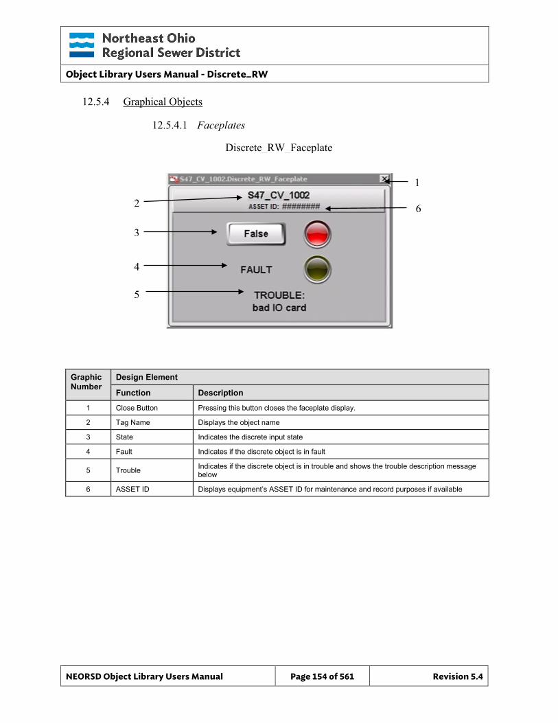
Object Library Users Manual - Discrete_RW
NEORSD Object Library Users Manual Page 154 of 561 Revision 5.4
Discrete_RW_Faceplate
12.5.4 Graphical Objects
12.5.4.1 Faceplates
Graphic Number
Design Element
Function Description
1 Close Button Pressing this button closes the faceplate display.
2 Tag Name Displays the object name
3 State Indicates the discrete input state
4 Fault Indicates if the discrete object is in fault
5 Trouble Indicates if the discrete object is in trouble and shows the trouble description message below
6 ASSET ID Displays equipment’s ASSET ID for maintenance and record purposes if available
2
1
3
4
5
6
Object Library Users Manual - Discrete_RW
NEORSD Object Library Users Manual Page 155 of 561 Revision 5.4
12.5.4.2 Symbols
Discrete_RW_State_TextDisplay
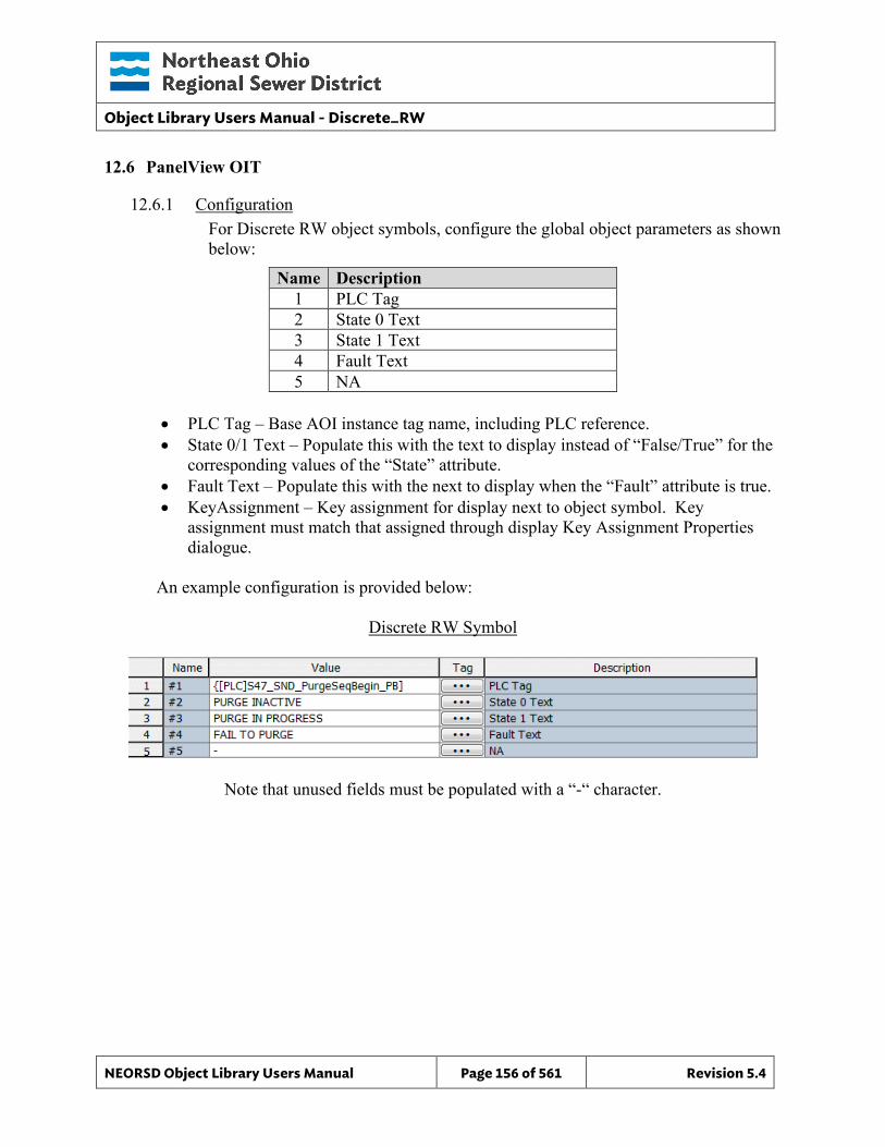
Object Library Users Manual - Discrete_RW
NEORSD Object Library Users Manual Page 156 of 561 Revision 5.4
12.6 PanelView OIT
12.6.1 Configuration For Discrete RW object symbols, configure the global object parameters as shown below:
Name Description 1 PLC Tag 2 State 0 Text 3 State 1 Text 4 Fault Text 5 NA
• PLC Tag – Base AOI instance tag name, including PLC reference. • State 0/1 Text – Populate this with the text to display instead of “False/True” for the
corresponding values of the “State” attribute. • Fault Text – Populate this with the next to display when the “Fault” attribute is true. • KeyAssignment – Key assignment for display next to object symbol. Key
assignment must match that assigned through display Key Assignment Properties dialogue.
An example configuration is provided below:
Discrete RW Symbol
Note that unused fields must be populated with a “-“ character.
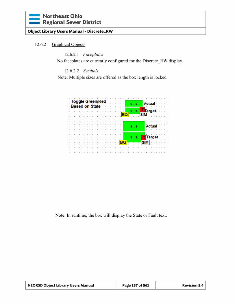
Object Library Users Manual - Discrete_RW
NEORSD Object Library Users Manual Page 157 of 561 Revision 5.4
12.6.2 Graphical Objects
12.6.2.1 Faceplates No faceplates are currently configured for the Discrete_RW display.
12.6.2.2 Symbols Note: Multiple sizes are offered as the box length is locked.
Note: In runtime, the box will display the State or Fault text.
Object Library Users Manual - Discrete_Setpoint
NEORSD Object Library Users Manual Page 158 of 561 Revision 5.4
13.0 Discrete_Setpoint
13.1 Introduction The discrete setpoint template provides a standard representation for managing a pushbutton input within the NEORSD control systems. Use the discrete setpoint template if either of the statements below are true:
• If trying to place a standalone pushbutton on the HMI application
• If trying to place a standalone pushbutton on the OIT application Do not use the discrete setpoint if:
• If trying to place a ‘start/stop’, ‘open/close’ or other equipment related pushbutton on the OIT/HMI. If this is the case, consider “Motor_Discrete”, “Valve_Discrete”, etc instead.
13.2 Object Features
13.2.1 Status Indications This object will indicate when the associated instance on the HMI or OIT is ‘pressed’.
13.2.2 Commands This object supports the following commands:
• Maintained pushbutton input from HMI/OIT • Momentary pushbutton input from HMI/OIT • Temporary programmatic “inhibit” (disable) of pushbutton input
13.2.3 Simulation This object does not support simulation.
13.2.4 Trouble This object does not support hardware trouble indication or alarming.
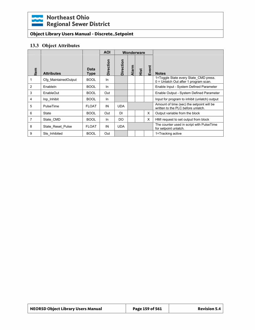
Object Library Users Manual - Discrete_Setpoint
NEORSD Object Library Users Manual Page 159 of 561 Revision 5.4
13.3 Object Attributes AOI Wonderware
Item
Attributes Data Type D
irect
ion
Dire
ctio
n
Ala
rm
His
t
Even
t
Notes 1 Cfg_MaintainedOutput BOOL In 1=Toggle State every State_CMD press.
0 = Unlatch Out after 1 program scan. 2 EnableIn BOOL In Enable Input - System Defined Parameter
3 EnableOut BOOL Out Enable Output - System Defined Parameter
4 Inp_Inhibit BOOL In Input for program to inhibit (unlatch) output
5 PulseTime FLOAT IN UDA Amount of time (sec) the setpoint will be written to the PLC before unlatch.
6 State BOOL Out DI X Output variable from the block
7 State_CMD BOOL In DO X HMI request to set output from block
8 State_Reset_Pulse FLOAT IN UDA The counter used in script with PulseTime for setpoint unlatch.
9 Sts_Inhibited BOOL Out 1=Tracking active
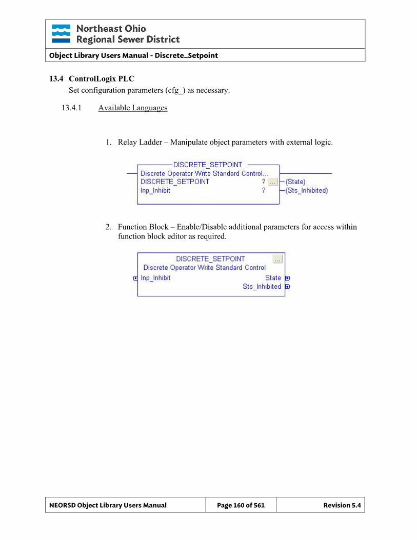
Object Library Users Manual - Discrete_Setpoint
NEORSD Object Library Users Manual Page 160 of 561 Revision 5.4
13.4 ControlLogix PLC Set configuration parameters (cfg_) as necessary.
13.4.1 Available Languages
1. Relay Ladder – Manipulate object parameters with external logic.
2. Function Block – Enable/Disable additional parameters for access within function block editor as required.
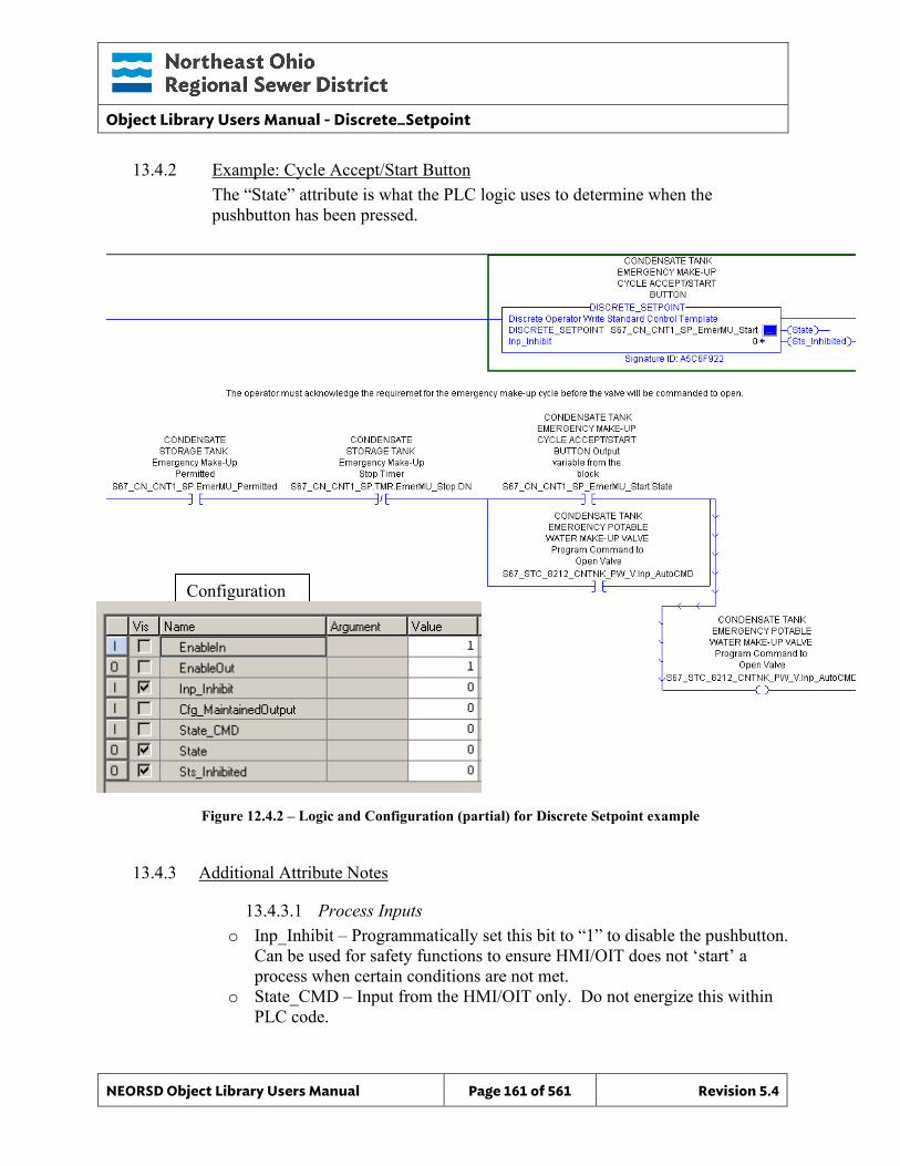
Object Library Users Manual - Discrete_Setpoint
NEORSD Object Library Users Manual Page 161 of 561 Revision 5.4
13.4.2 Example: Cycle Accept/Start Button The “State” attribute is what the PLC logic uses to determine when the pushbutton has been pressed.
Figure 12.4.2 – Logic and Configuration (partial) for Discrete Setpoint example
13.4.3 Additional Attribute Notes
13.4.3.1 Process Inputs o Inp_Inhibit – Programmatically set this bit to “1” to disable the pushbutton.
Can be used for safety functions to ensure HMI/OIT does not ‘start’ a process when certain conditions are not met.
o State_CMD – Input from the HMI/OIT only. Do not energize this within PLC code.
Configuration
Object Library Users Manual - Discrete_Setpoint
NEORSD Object Library Users Manual Page 162 of 561 Revision 5.4
13.4.3.2 Internal Configuration o Cfg_MaintainedOutput – If true, “State” will hold until another
“State_CMD” is received from the HMI/OIT. Otherwise, State will be a momentary pulse.
13.4.3.3 Outputs o State - Reflects the pushbutton input from HMI/OIT. Momentary or
maintained is determined by “Cfg_MaintainedOutput”. o Sts_Inhibited – True if this block is ‘disabled’ (Inp_Inhibit is true).
13.5 Wonderware HMI
13.5.1 Properties Hierarchical Name: $Discrete_Setpoint Derivation: Derived from $NEORSDUserDefined Container: None
13.5.2 Extensions None.
13.5.3 Configuration All of the necessary configuration for Discrete_Setpoint must also be done on any instance derived from this template.
1) State’s State Labels – The default state labels are true/false. Although not
required it is recommended to specify more meaningful labels.
2) Attributes that are not used in the configured instance shall use Me.Placeholder to eliminate the point from counting against the systems total I/O scan counts. The allowed attributes for this template include the following:
a. None 3) If ASSET_ID is not in use the initial value will be left blank. Scripting used
for ASSET_ID uses the initial value and not ASSET_ID.Description.
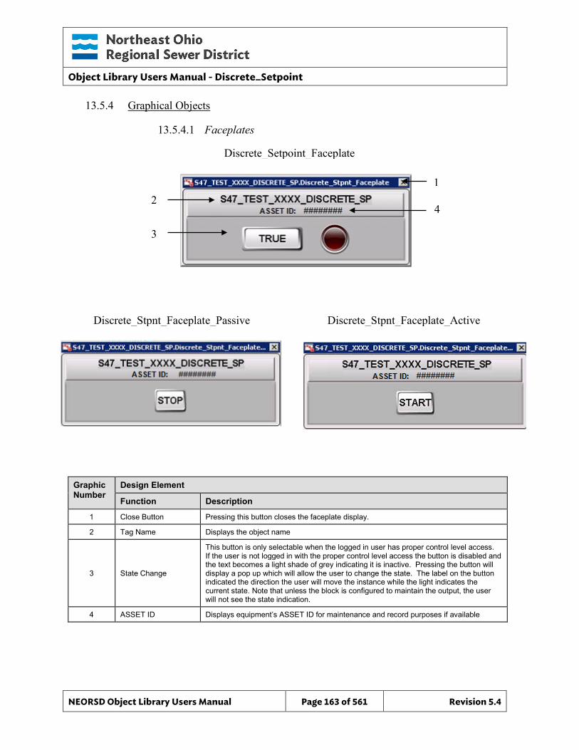
Object Library Users Manual - Discrete_Setpoint
NEORSD Object Library Users Manual Page 163 of 561 Revision 5.4
Discrete_Setpoint_Faceplate
Discrete_Stpnt_Faceplate_Active Discrete_Stpnt_Faceplate_Passive
13.5.4 Graphical Objects
13.5.4.1 Faceplates
Graphic Number
Design Element
Function Description
1 Close Button Pressing this button closes the faceplate display.
2 Tag Name Displays the object name
3 State Change
This button is only selectable when the logged in user has proper control level access. If the user is not logged in with the proper control level access the button is disabled and the text becomes a light shade of grey indicating it is inactive. Pressing the button will display a pop up which will allow the user to change the state. The label on the button indicated the direction the user will move the instance while the light indicates the current state. Note that unless the block is configured to maintain the output, the user will not see the state indication.
4 ASSET ID Displays equipment’s ASSET ID for maintenance and record purposes if available
2 1
3
4
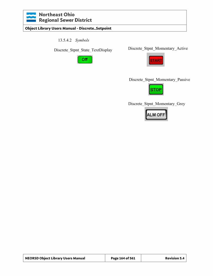
Object Library Users Manual - Discrete_Setpoint
NEORSD Object Library Users Manual Page 164 of 561 Revision 5.4
Discrete_Stpnt_State_TextDisplay Discrete_Stpnt_Momentary_Active
Discrete_Stpnt_Momentary_Grey
Discrete_Stpnt_Momentary_Passive
13.5.4.2 Symbols
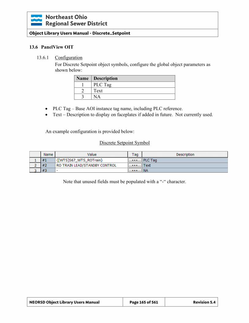
Object Library Users Manual - Discrete_Setpoint
NEORSD Object Library Users Manual Page 165 of 561 Revision 5.4
13.6 PanelView OIT
13.6.1 Configuration For Discrete Setpoint object symbols, configure the global object parameters as shown below:
Name Description 1 PLC Tag 2 Text 3 NA
• PLC Tag – Base AOI instance tag name, including PLC reference. • Text – Description to display on faceplates if added in future. Not currently used.
An example configuration is provided below:
Discrete Setpoint Symbol
Note that unused fields must be populated with a “-“ character.
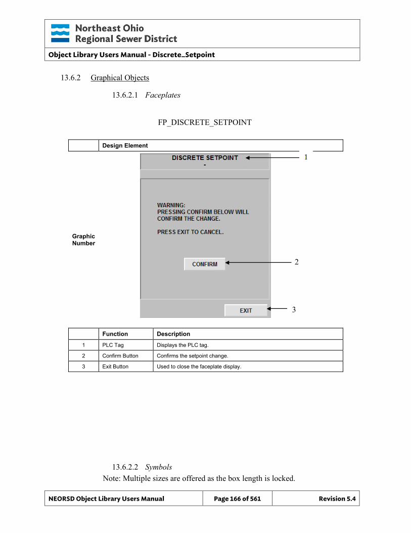
Object Library Users Manual - Discrete_Setpoint
NEORSD Object Library Users Manual Page 166 of 561 Revision 5.4
13.6.2 Graphical Objects
13.6.2.1 Faceplates
Graphic Number
Design Element
Function Description
1 PLC Tag Displays the PLC tag.
2 Confirm Button Confirms the setpoint change.
3 Exit Button Used to close the faceplate display.
13.6.2.2 Symbols Note: Multiple sizes are offered as the box length is locked.
FP_DISCRETE_SETPOINT
2
3
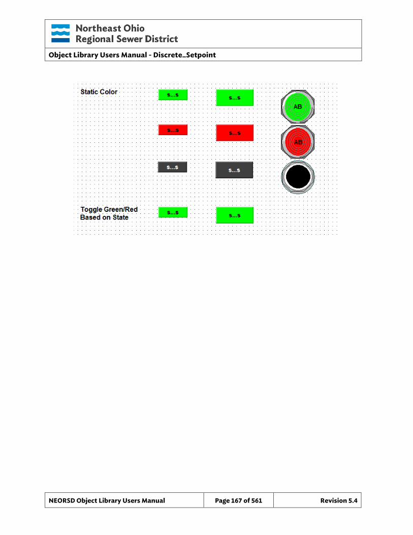
Object Library Users Manual - Discrete_Setpoint
NEORSD Object Library Users Manual Page 167 of 561 Revision 5.4
Object Library Users Manual – Gate
NEORSD Object Library Users Manual Page 168 of 561 Revision 5.4
14.0 GATE
14.1 Introduction The Gate template provides a standard representation for the control, operation, indication, and alarming of variable position water control gates throughout the NEORSD control systems. Use the Gate template if the statements below are true:
• If trying to represent a gate with variable position feedback and control. • If during object faults, interlocks, and PLC first scan the object is required to fail in
place
Do not use the Gate template:
• If during object faults, interlocks, and PLC first scan the object is required to fail to a safe state (0%). In this case see “Valve_Analog”.
• If digital control outputs are used to drive the object open, close, or stop. In this case see “Valve_Actuator”.
14.2 Object Features
14.2.1 Status Indications This object provides the following indications for the gate:
• Opened/closed limit switch feedback • Analog position feedback • Auto/Manual mode indication • Remote/Local mode feedback • In-Service/Out-Of-Service mode indication
14.2.2 Alarming This object supports the following alarms:
• Alarm if the gate is commanded to a position and does not reach it in a set period of time
• Alarm if the gate is commanded to fully-open and does not in a set period of time
• Alarm if the gate is commanded to fully-close and does not in a set period of time
• Alarm if the object loses feedback from failsafe limit switches • Alarm if an externally generated fault condition is true
When a fault condition occurs, the gate will remain at its current position and the object will enter manual mode.
Object Library Users Manual – Gate
NEORSD Object Library Users Manual Page 169 of 561 Revision 5.4
14.2.3 Control This object supports the following control for the gate:
• Command to a position setpoint (%). • Auto/Manual mode toggle • Resettable alarms • Out-of-Service/In-Service mode toggle • Interlocking to prevent operation
14.2.4 Simulation This object supports simulation of the position feedback.
14.2.5 Trouble This object supports hardware trouble indication.
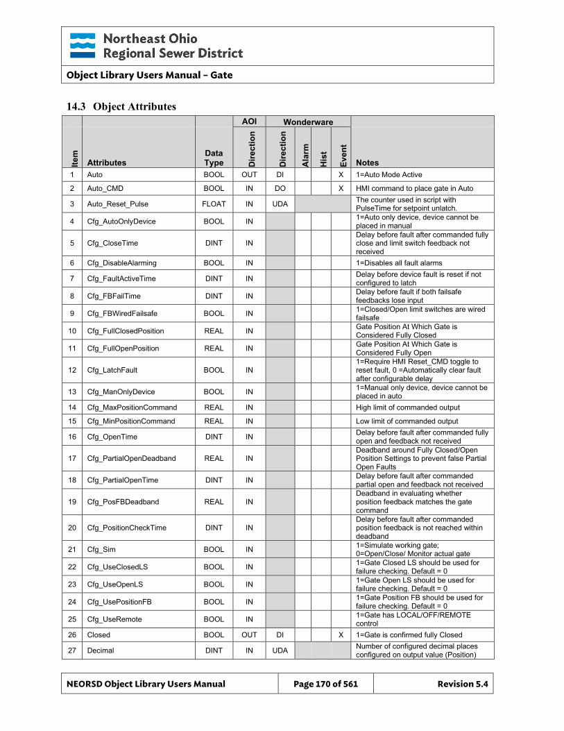
Object Library Users Manual – Gate
NEORSD Object Library Users Manual Page 170 of 561 Revision 5.4
14.3 Object Attributes
AOI Wonderware
Item
Attributes Data Type D
irect
ion
Dire
ctio
n
Ala
rm
His
t
Even
t
Notes 1 Auto BOOL OUT DI X 1=Auto Mode Active
2 Auto_CMD BOOL IN DO X HMI command to place gate in Auto
3 Auto_Reset_Pulse FLOAT IN UDA The counter used in script with PulseTime for setpoint unlatch.
4 Cfg_AutoOnlyDevice BOOL IN 1=Auto only device, device cannot be placed in manual
5 Cfg_CloseTime DINT IN Delay before fault after commanded fully close and limit switch feedback not received
6 Cfg_DisableAlarming BOOL IN 1=Disables all fault alarms
7 Cfg_FaultActiveTime DINT IN Delay before device fault is reset if not configured to latch
8 Cfg_FBFailTime DINT IN Delay before fault if both failsafe feedbacks lose input
9 Cfg_FBWiredFailsafe BOOL IN 1=Closed/Open limit switches are wired failsafe
10 Cfg_FullClosedPosition REAL IN Gate Position At Which Gate is Considered Fully Closed
11 Cfg_FullOpenPosition REAL IN Gate Position At Which Gate is Considered Fully Open
12 Cfg_LatchFault BOOL IN 1=Require HMI Reset_CMD toggle to reset fault, 0 =Automatically clear fault after configurable delay
13 Cfg_ManOnlyDevice BOOL IN 1=Manual only device, device cannot be placed in auto
14 Cfg_MaxPositionCommand REAL IN High limit of commanded output
15 Cfg_MinPositionCommand REAL IN Low limit of commanded output
16 Cfg_OpenTime DINT IN Delay before fault after commanded fully open and feedback not received
17 Cfg_PartialOpenDeadband REAL IN Deadband around Fully Closed/Open Position Settings to prevent false Partial Open Faults
18 Cfg_PartialOpenTime DINT IN Delay before fault after commanded partial open and feedback not received
19 Cfg_PosFBDeadband REAL IN Deadband in evaluating whether position feedback matches the gate command
20 Cfg_PositionCheckTime DINT IN Delay before fault after commanded position feedback is not reached within deadband
21 Cfg_Sim BOOL IN 1=Simulate working gate; 0=Open/Close/ Monitor actual gate
22 Cfg_UseClosedLS BOOL IN 1=Gate Closed LS should be used for failure checking. Default = 0
23 Cfg_UseOpenLS BOOL IN 1=Gate Open LS should be used for failure checking. Default = 0
24 Cfg_UsePositionFB BOOL IN 1=Gate Position FB should be used for failure checking. Default = 0
25 Cfg_UseRemote BOOL IN 1=Gate has LOCAL/OFF/REMOTE control
26 Closed BOOL OUT DI X 1=Gate is confirmed fully Closed
27 Decimal DINT IN UDA Number of configured decimal places configured on output value (Position)
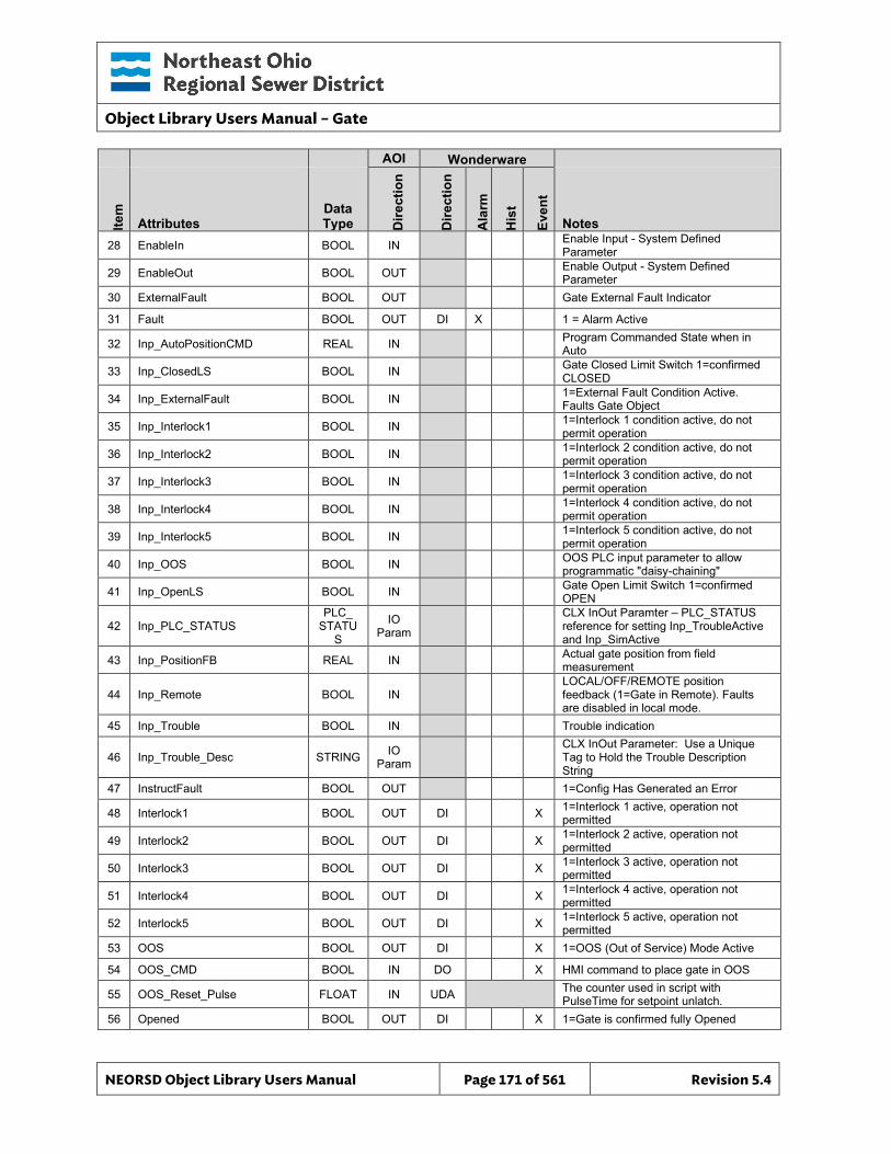
Object Library Users Manual – Gate
NEORSD Object Library Users Manual Page 171 of 561 Revision 5.4
AOI Wonderware
Item
Attributes Data Type D
irect
ion
Dire
ctio
n
Ala
rm
His
t
Even
t
Notes 28 EnableIn BOOL IN Enable Input - System Defined
Parameter
29 EnableOut BOOL OUT Enable Output - System Defined Parameter
30 ExternalFault BOOL OUT Gate External Fault Indicator
31 Fault BOOL OUT DI X 1 = Alarm Active
32 Inp_AutoPositionCMD REAL IN Program Commanded State when in Auto
33 Inp_ClosedLS BOOL IN Gate Closed Limit Switch 1=confirmed CLOSED
34 Inp_ExternalFault BOOL IN 1=External Fault Condition Active. Faults Gate Object
35 Inp_Interlock1 BOOL IN 1=Interlock 1 condition active, do not permit operation
36 Inp_Interlock2 BOOL IN 1=Interlock 2 condition active, do not permit operation
37 Inp_Interlock3 BOOL IN 1=Interlock 3 condition active, do not permit operation
38 Inp_Interlock4 BOOL IN 1=Interlock 4 condition active, do not permit operation
39 Inp_Interlock5 BOOL IN 1=Interlock 5 condition active, do not permit operation
40 Inp_OOS BOOL IN OOS PLC input parameter to allow programmatic "daisy-chaining"
41 Inp_OpenLS BOOL IN Gate Open Limit Switch 1=confirmed OPEN
42 Inp_PLC_STATUS PLC_
STATUS
IO Param
CLX InOut Paramter – PLC_STATUS reference for setting Inp_TroubleActive and Inp_SimActive
43 Inp_PositionFB REAL IN Actual gate position from field measurement
44 Inp_Remote BOOL IN LOCAL/OFF/REMOTE position feedback (1=Gate in Remote). Faults are disabled in local mode.
45 Inp_Trouble BOOL IN Trouble indication
46 Inp_Trouble_Desc STRING IO Param
CLX InOut Parameter: Use a Unique Tag to Hold the Trouble Description String
47 InstructFault BOOL OUT 1=Config Has Generated an Error
48 Interlock1 BOOL OUT DI X 1=Interlock 1 active, operation not permitted
49 Interlock2 BOOL OUT DI X 1=Interlock 2 active, operation not permitted
50 Interlock3 BOOL OUT DI X 1=Interlock 3 active, operation not permitted
51 Interlock4 BOOL OUT DI X 1=Interlock 4 active, operation not permitted
52 Interlock5 BOOL OUT DI X 1=Interlock 5 active, operation not permitted
53 OOS BOOL OUT DI X 1=OOS (Out of Service) Mode Active
54 OOS_CMD BOOL IN DO X HMI command to place gate in OOS
55 OOS_Reset_Pulse FLOAT IN UDA The counter used in script with PulseTime for setpoint unlatch.
56 Opened BOOL OUT DI X 1=Gate is confirmed fully Opened
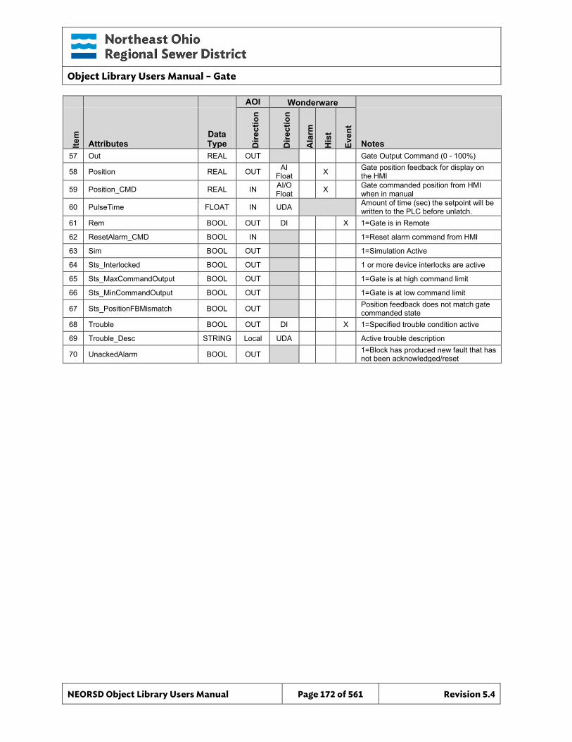
Object Library Users Manual – Gate
NEORSD Object Library Users Manual Page 172 of 561 Revision 5.4
AOI Wonderware
Item
Attributes Data Type D
irect
ion
Dire
ctio
n
Ala
rm
His
t
Even
t
Notes 57 Out REAL OUT Gate Output Command (0 - 100%)
58 Position REAL OUT AI Float X Gate position feedback for display on
the HMI
59 Position_CMD REAL IN AI/O Float X Gate commanded position from HMI
when in manual
60 PulseTime FLOAT IN UDA Amount of time (sec) the setpoint will be written to the PLC before unlatch.
61 Rem BOOL OUT DI X 1=Gate is in Remote
62 ResetAlarm_CMD BOOL IN 1=Reset alarm command from HMI
63 Sim BOOL OUT 1=Simulation Active
64 Sts_Interlocked BOOL OUT 1 or more device interlocks are active
65 Sts_MaxCommandOutput BOOL OUT 1=Gate is at high command limit
66 Sts_MinCommandOutput BOOL OUT 1=Gate is at low command limit
67 Sts_PositionFBMismatch BOOL OUT Position feedback does not match gate commanded state
68 Trouble BOOL OUT DI X 1=Specified trouble condition active
69 Trouble_Desc STRING Local UDA Active trouble description
70 UnackedAlarm BOOL OUT 1=Block has produced new fault that has not been acknowledged/reset
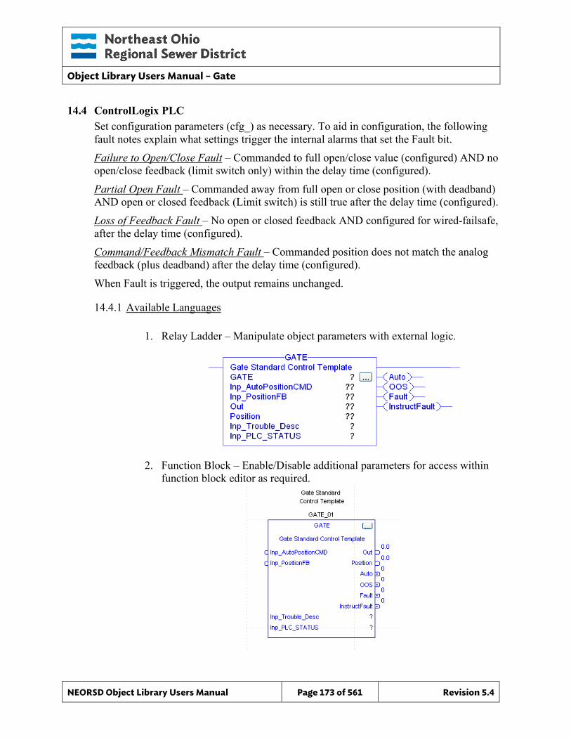
Object Library Users Manual – Gate
NEORSD Object Library Users Manual Page 173 of 561 Revision 5.4
14.4 ControlLogix PLC Set configuration parameters (cfg_) as necessary. To aid in configuration, the following fault notes explain what settings trigger the internal alarms that set the Fault bit. Failure to Open/Close Fault – Commanded to full open/close value (configured) AND no open/close feedback (limit switch only) within the delay time (configured). Partial Open Fault – Commanded away from full open or close position (with deadband) AND open or closed feedback (Limit switch) is still true after the delay time (configured). Loss of Feedback Fault – No open or closed feedback AND configured for wired-failsafe, after the delay time (configured). Command/Feedback Mismatch Fault – Commanded position does not match the analog feedback (plus deadband) after the delay time (configured). When Fault is triggered, the output remains unchanged.
14.4.1 Available Languages
1. Relay Ladder – Manipulate object parameters with external logic.
2. Function Block – Enable/Disable additional parameters for access within
function block editor as required.
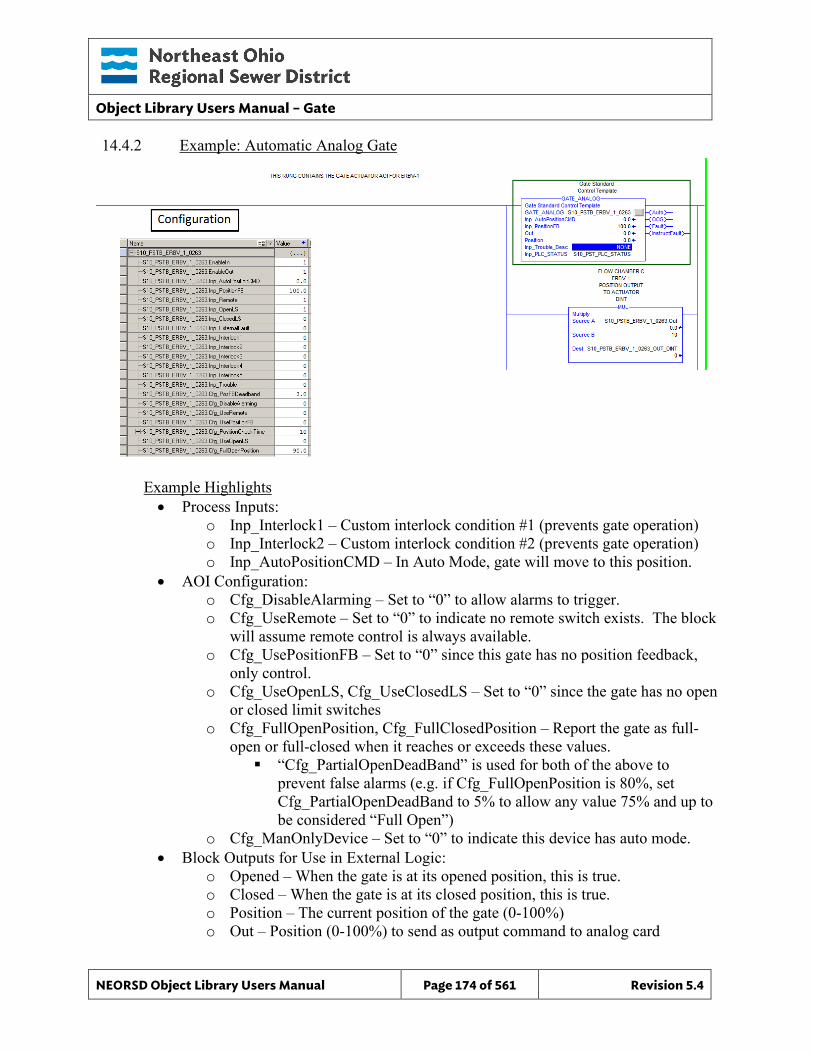
Object Library Users Manual – Gate
NEORSD Object Library Users Manual Page 174 of 561 Revision 5.4
14.4.2 Example: Automatic Analog Gate
Example Highlights • Process Inputs:
o Inp_Interlock1 – Custom interlock condition #1 (prevents gate operation) o Inp_Interlock2 – Custom interlock condition #2 (prevents gate operation) o Inp_AutoPositionCMD – In Auto Mode, gate will move to this position.
• AOI Configuration: o Cfg_DisableAlarming – Set to “0” to allow alarms to trigger. o Cfg_UseRemote – Set to “0” to indicate no remote switch exists. The block
will assume remote control is always available. o Cfg_UsePositionFB – Set to “0” since this gate has no position feedback,
only control. o Cfg_UseOpenLS, Cfg_UseClosedLS – Set to “0” since the gate has no open
or closed limit switches o Cfg_FullOpenPosition, Cfg_FullClosedPosition – Report the gate as full-
open or full-closed when it reaches or exceeds these values. “Cfg_PartialOpenDeadBand” is used for both of the above to
prevent false alarms (e.g. if Cfg_FullOpenPosition is 80%, set Cfg_PartialOpenDeadBand to 5% to allow any value 75% and up to be considered “Full Open”)
o Cfg_ManOnlyDevice – Set to “0” to indicate this device has auto mode. • Block Outputs for Use in External Logic:
o Opened – When the gate is at its opened position, this is true. o Closed – When the gate is at its closed position, this is true. o Position – The current position of the gate (0-100%) o Out – Position (0-100%) to send as output command to analog card
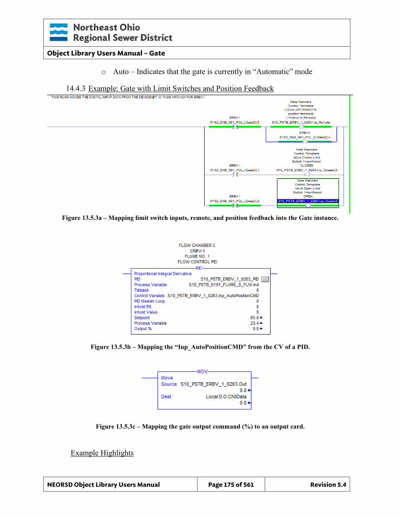
Object Library Users Manual – Gate
NEORSD Object Library Users Manual Page 175 of 561 Revision 5.4
o Auto – Indicates that the gate is currently in “Automatic” mode
14.4.3 Example: Gate with Limit Switches and Position Feedback
Figure 13.5.3a – Mapping limit switch inputs, remote, and position feedback into the Gate instance.
Figure 13.5.3b – Mapping the “Inp_AutoPositionCMD” from the CV of a PID.
Figure 13.5.3c – Mapping the gate output command (%) to an output card.
Example Highlights
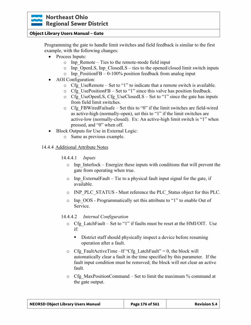
Object Library Users Manual – Gate
NEORSD Object Library Users Manual Page 176 of 561 Revision 5.4
Programming the gate to handle limit switches and field feedback is similar to the first example, with the following changes: • Process Inputs:
o Inp_Remote – Ties to the remote-mode field input o Inp_OpenLS, Inp_ClosedLS – ties to the opened/closed limit switch inputs o Inp_PositionFB – 0-100% position feedback from analog input
• AOI Configuration: o Cfg_UseRemote – Set to “1” to indicate that a remote switch is available. o Cfg_UsePositionFB – Set to “1” since this valve has position feedback. o Cfg_UseOpenLS, Cfg_UseClosedLS – Set to “1” since the gate has inputs
from field limit switches. o Cfg_FBWiredFailsafe – Set this to “0” if the limit switches are field-wired
as active-high (normally-open), set this to “1” if the limit switches are active-low (normally-closed). Ex: An active-high limit switch is “1” when pressed, and “0” when off.
• Block Outputs for Use in External Logic: o Same as previous example.
14.4.4 Additional Attribute Notes
14.4.4.1 Inputs o Inp_Interlock – Energize these inputs with conditions that will prevent the
gate from operating when true. o Inp_ExternalFault – Tie to a physical fault input signal for the gate, if
available. o INP_PLC_STATUS - Must reference the PLC_Status object for this PLC. o Inp_OOS - Programmatically set this attribute to “1” to enable Out of
Service.
14.4.4.2 Internal Configuration o Cfg_LatchFault – Set to “1” if faults must be reset at the HMI/OIT. Use
if: District staff should physically inspect a device before resuming
operation after a fault. o Cfg_FaultActiveTime –If “Cfg_LatchFault” = 0, the block will
automatically clear a fault in the time specified by this parameter. If the fault input condition must be removed; the block will not clear an active fault.
o Cfg_MaxPositionCommand – Set to limit the maximum % command at the gate output.
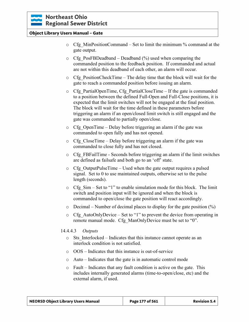
Object Library Users Manual – Gate
NEORSD Object Library Users Manual Page 177 of 561 Revision 5.4
o Cfg_MinPositionCommand – Set to limit the minimum % command at the gate output.
o Cfg_PosFBDeadband – Deadband (%) used when comparing the commanded position to the feedback position. If commanded and actual are not within this deadband of each other, an alarm will occur.
o Cfg_PositionCheckTime – The delay time that the block will wait for the gate to reach a commanded position before issuing an alarm.
o Cfg_PartialOpenTime, Cfg_PartialCloseTime – If the gate is commanded to a position between the defined Full-Open and Full-Close positions, it is expected that the limit switches will not be engaged at the final position. The block will wait for the time defined in these parameters before triggering an alarm if an open/closed limit switch is still engaged and the gate was commanded to partially open/close.
o Cfg_OpenTime – Delay before triggering an alarm if the gate was commanded to open fully and has not opened.
o Cfg_CloseTime – Delay before triggering an alarm if the gate was commanded to close fully and has not closed.
o Cfg_FBFailTime - Seconds before triggering an alarm if the limit switches are defined as failsafe and both go to an ‘off’ state.
o Cfg_OutputPulseTime – Used when the gate output requires a pulsed signal. Set to 0 to use maintained outputs, otherwise set to the pulse length (seconds).
o Cfg_Sim – Set to “1” to enable simulation mode for this block. The limit switch and position input will be ignored and when the block is commanded to open/close the gate position will react accordingly.
o Decimal – Number of decimal places to display for the gate position (%) o Cfg_AutoOnlyDevice – Set to “1” to prevent the device from operating in
remote manual mode. Cfg_ManOnlyDevice must be set to “0”.
14.4.4.3 Outputs o Sts_Interlocked – Indicates that this instance cannot operate as an
interlock condition is not satisfied. o OOS – Indicates that this instance is out-of-service o Auto – Indicates that the gate is in automatic control mode o Fault – Indicates that any fault condition is active on the gate. This
includes internally generated alarms (time-to-open/close, etc) and the external alarm, if used.

Object Library Users Manual – Gate
NEORSD Object Library Users Manual Page 178 of 561 Revision 5.4
When the gate faults, it will remain in its current position and enter manual mode.
Object Library Users Manual – Gate
NEORSD Object Library Users Manual Page 179 of 561 Revision 5.4
14.5 Wonderware HMI
14.5.1 Properties Hierarchical Name: $Gate Derivation: Derived from $NEORSDUserDefined /$Valve_Analog_Indicator Container: None
14.5.2 Extensions: None
14.5.3 Configuration All of the necessary configuration for Gate must also be done on any instance derived from this template.
1) Alarm Priority – The attribute Fault needs to have a priority defined.
2) Decimal – Defined as how many decimal points are shown. The default value
is 0 and need to be specified on the instance.
3) If ASSET_ID is not in use the initial value will be left blank. Scripting used
for ASSET_ID uses the initial value and not ASSET_ID.Description.
4) Attributes that are not used in the configured instance shall use Me.Placeholder to eliminate the point from counting against the systems total I/O scan counts. The allowed attributes for this template include the following:
a. Interlock1 to Interlock5 b. OOS c. OOS_CMD d. Fault e. Auto f. REM g. Position_CMD h. Trouble
Note: The default Engineering Units for Position is %. This can be changed but is not required.
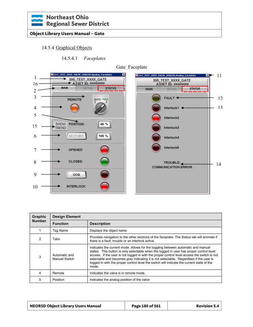
Object Library Users Manual – Gate
NEORSD Object Library Users Manual Page 180 of 561 Revision 5.4
14.5.4 Graphical Objects
14.5.4.1 Faceplates
Graphic Number
Design Element
Function Description
1 Tag Name Displays the object name
2 Tabs Provides navigation to the other sections of the faceplate. The Status tab will animate if there is a fault, trouble or an interlock active.
3 Automatic and Manual Switch
Indicates the current mode. Allows for the toggling between automatic and manual states. This button is only selectable when the logged in user has proper control level access. If the user is not logged in with the proper control level access the switch is not selectable and becomes grey indicating it is not selectable. Regardless if the user is logged in with the proper control level the switch will indicate the current state of the mode.
4 Remote Indicates the valve is in remote mode.
5 Position Indicates the analog position of the valve
Gate_Faceplate
11 1
3
4
6
8
5
7
12
14
2
13
10
9
15
16
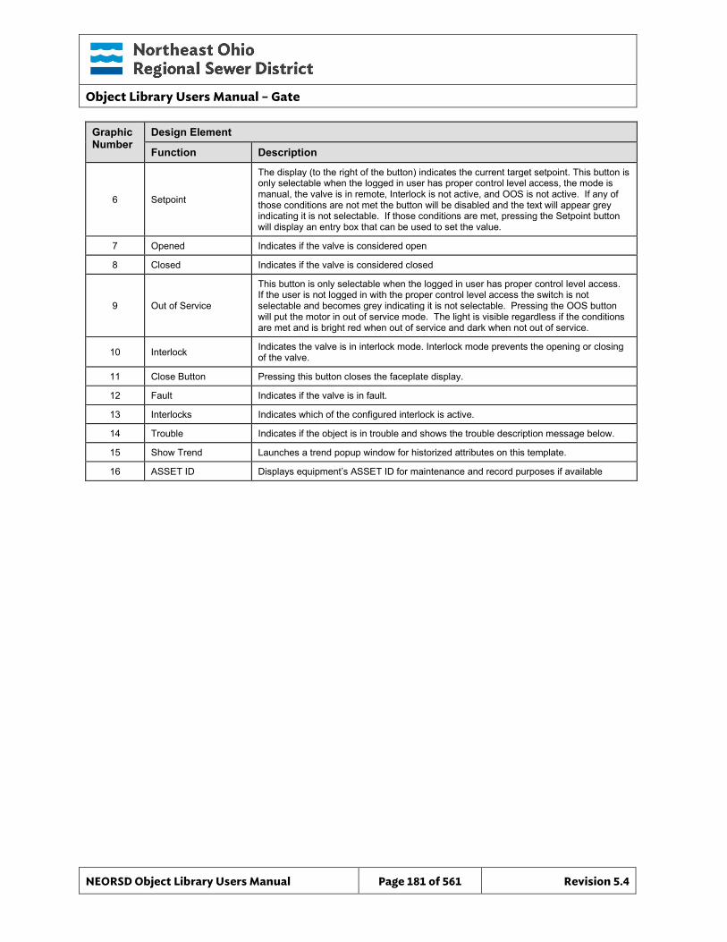
Object Library Users Manual – Gate
NEORSD Object Library Users Manual Page 181 of 561 Revision 5.4
Graphic Number
Design Element
Function Description
6 Setpoint
The display (to the right of the button) indicates the current target setpoint. This button is only selectable when the logged in user has proper control level access, the mode is manual, the valve is in remote, Interlock is not active, and OOS is not active. If any of those conditions are not met the button will be disabled and the text will appear grey indicating it is not selectable. If those conditions are met, pressing the Setpoint button will display an entry box that can be used to set the value.
7 Opened Indicates if the valve is considered open
8 Closed Indicates if the valve is considered closed
9 Out of Service
This button is only selectable when the logged in user has proper control level access. If the user is not logged in with the proper control level access the switch is not selectable and becomes grey indicating it is not selectable. Pressing the OOS button will put the motor in out of service mode. The light is visible regardless if the conditions are met and is bright red when out of service and dark when not out of service.
10 Interlock Indicates the valve is in interlock mode. Interlock mode prevents the opening or closing of the valve.
11 Close Button Pressing this button closes the faceplate display.
12 Fault Indicates if the valve is in fault.
13 Interlocks Indicates which of the configured interlock is active.
14 Trouble Indicates if the object is in trouble and shows the trouble description message below.
15 Show Trend Launches a trend popup window for historized attributes on this template.
16 ASSET ID Displays equipment’s ASSET ID for maintenance and record purposes if available
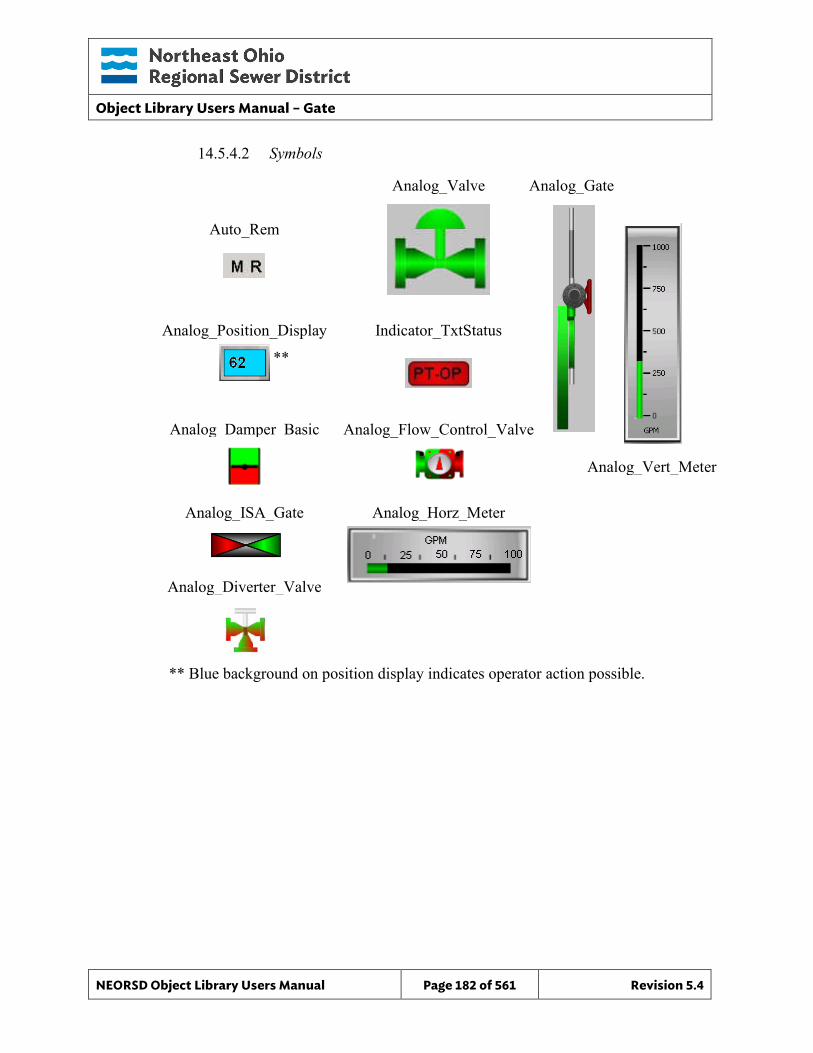
Object Library Users Manual – Gate
NEORSD Object Library Users Manual Page 182 of 561 Revision 5.4
Analog_Vert_Meter
Analog_Horz_Meter
14.5.4.2 Symbols
**
** Blue background on position display indicates operator action possible.
Auto_Rem
Analog_Valve Analog_Gate
Analog_Position_Display Indicator_TxtStatus
Analog_Damper_Basic Analog_Flow_Control_Valve
Analog_ISA_Gate
Analog_Diverter_Valve
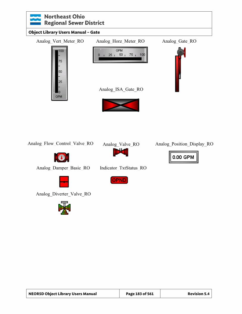
Object Library Users Manual – Gate
NEORSD Object Library Users Manual Page 183 of 561 Revision 5.4
Analog_Vert_Meter_RO Analog_Horz_Meter_RO
Analog_Gate_RO
Analog_ISA_Gate_RO
Analog_Flow_Control_Valve_RO Analog_Valve_RO
Analog_Damper_Basic_RO Indicator_TxtStatus_RO
Analog_Position_Display_RO
Analog_Diverter_Valve_RO
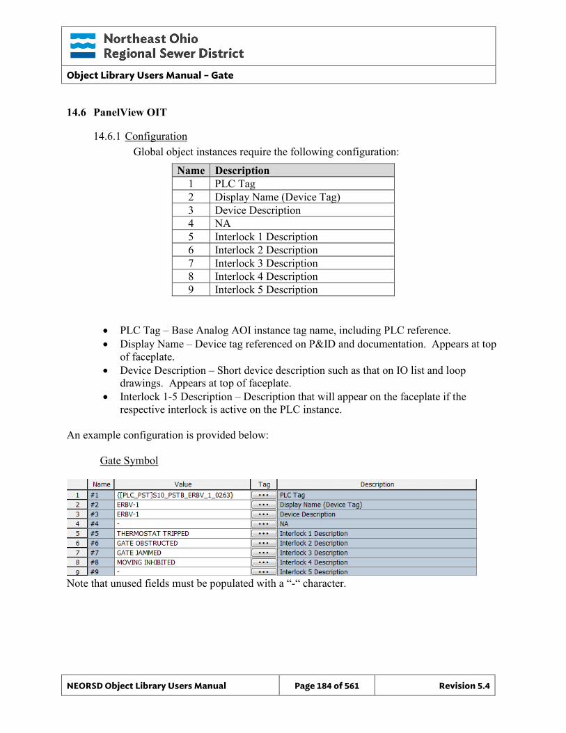
Object Library Users Manual – Gate
NEORSD Object Library Users Manual Page 184 of 561 Revision 5.4
14.6 PanelView OIT
14.6.1 Configuration Global object instances require the following configuration:
Name Description 1 PLC Tag 2 Display Name (Device Tag) 3 Device Description 4 NA 5 Interlock 1 Description 6 Interlock 2 Description 7 Interlock 3 Description 8 Interlock 4 Description 9 Interlock 5 Description
• PLC Tag – Base Analog AOI instance tag name, including PLC reference. • Display Name – Device tag referenced on P&ID and documentation. Appears at top
of faceplate. • Device Description – Short device description such as that on IO list and loop
drawings. Appears at top of faceplate. • Interlock 1-5 Description – Description that will appear on the faceplate if the
respective interlock is active on the PLC instance.
An example configuration is provided below: Gate Symbol
Note that unused fields must be populated with a “-“ character.
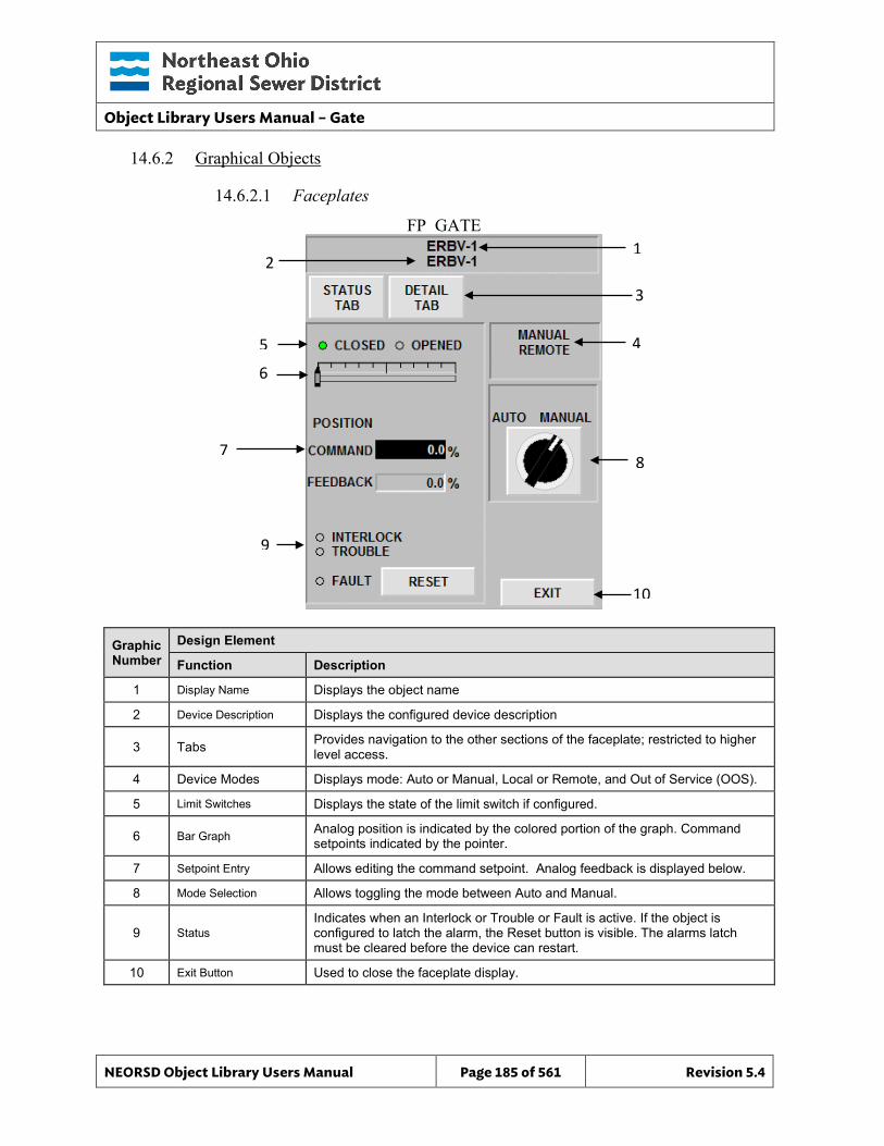
Object Library Users Manual – Gate
NEORSD Object Library Users Manual Page 185 of 561 Revision 5.4
FP_GATE 1
3
10
8
4
14.6.2 Graphical Objects
14.6.2.1 Faceplates
Graphic Number
Design Element
Function Description
1 Display Name Displays the object name
2 Device Description Displays the configured device description
3 Tabs Provides navigation to the other sections of the faceplate; restricted to higher level access.
4 Device Modes Displays mode: Auto or Manual, Local or Remote, and Out of Service (OOS).
5 Limit Switches Displays the state of the limit switch if configured.
6 Bar Graph Analog position is indicated by the colored portion of the graph. Command setpoints indicated by the pointer.
7 Setpoint Entry Allows editing the command setpoint. Analog feedback is displayed below.
8 Mode Selection Allows toggling the mode between Auto and Manual.
9 Status Indicates when an Interlock or Trouble or Fault is active. If the object is configured to latch the alarm, the Reset button is visible. The alarms latch must be cleared before the device can restart.
10 Exit Button Used to close the faceplate display.
2
5
7
9
6
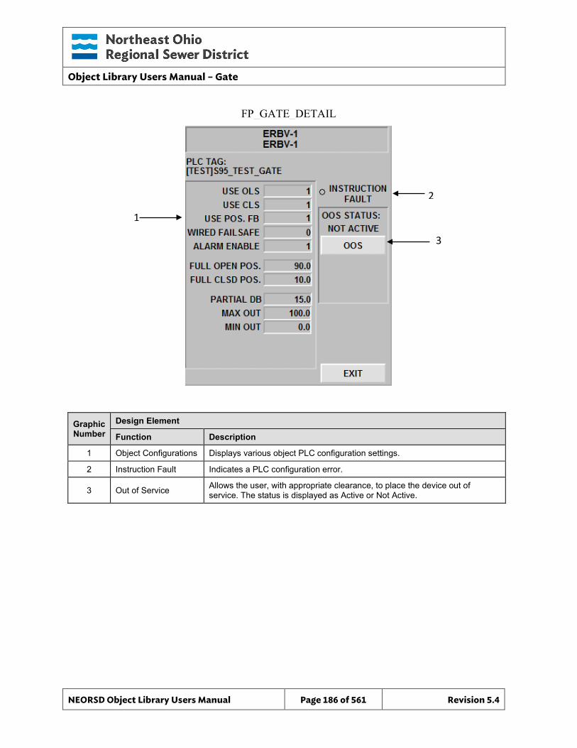
Object Library Users Manual – Gate
NEORSD Object Library Users Manual Page 186 of 561 Revision 5.4
FP_GATE_DETAIL
2
3
Graphic Number
Design Element
Function Description
1 Object Configurations Displays various object PLC configuration settings.
2 Instruction Fault Indicates a PLC configuration error.
3 Out of Service Allows the user, with appropriate clearance, to place the device out of service. The status is displayed as Active or Not Active.
1
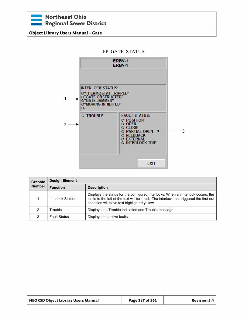
Object Library Users Manual – Gate
NEORSD Object Library Users Manual Page 187 of 561 Revision 5.4
FP_GATE_STATUS
3
Graphic Number
Design Element
Function Description
1 Interlock Status Displays the status for the configured Interlocks. When an interlock occurs, the circle to the left of the text will turn red. The interlock that triggered the first-out condition will have text highlighted yellow.
2 Trouble Displays the Trouble indication and Trouble message.
3 Fault Status Displays the active faults.
1
2
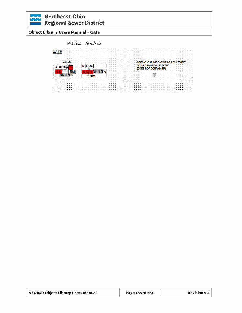
Object Library Users Manual – Gate
NEORSD Object Library Users Manual Page 188 of 561 Revision 5.4
14.6.2.2 Symbols

Object Library Users Manual – Gate
NEORSD Object Library Users Manual Page 189 of 561 Revision 5.4
This page left blank intentionally.
Object Library Users Manual - Motor_Discrete
NEORSD Object Library Users Manual Page 190 of 561 Revision 5.4
15.0 Help_Notes
15.1 Introduction The Help_Notes template provides a standard method for providing notes or instructions on graphic screens throughout the NEORSD HMI systems. There is no corresponding PLC or OIT component, as these test messages are configured entirely within Wonderware.
15.2 Object Attributes
AOI Wonderware
Item
Attributes Data Type D
irect
ion
Dire
ctio
n
Ala
rm
His
t
Even
t
Notes 1 Note STRING NA UDA Field where the note is entered
2 Note_Help STRING NA UDA Brief help descriptions describing the functions of the Note internally to the user
15.3 Wonderware HMI
15.3.1 Properties Hierarchical Name: $Help_Notes Derivation: Derived from $NEORSDUserDefined Container: None
15.3.2 Extensions None
15.3.3 Configuration All of the necessary configuration for Help_Notes must be done on any instance derived from this template. Notes are written within the UDA “Note” and are displayed on a faceplate that is launched from a symbol. The note allows 30 lines and can be made into a list form with numbers or symbols for easy reading.
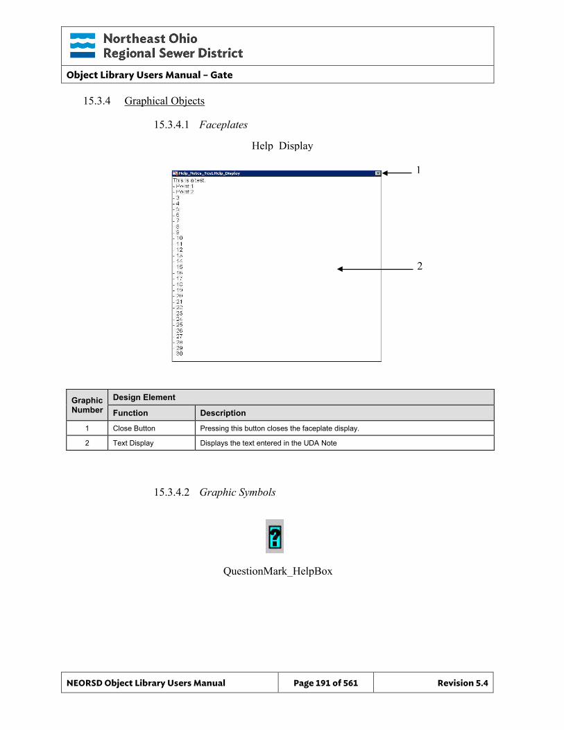
Object Library Users Manual – Gate
NEORSD Object Library Users Manual Page 191 of 561 Revision 5.4
15.3.4 Graphical Objects
15.3.4.1 Faceplates
Graphic Number
Design Element
Function Description
1 Close Button Pressing this button closes the faceplate display.
2 Text Display Displays the text entered in the UDA Note
15.3.4.2 Graphic Symbols
Help_Display
2
QuestionMark_HelpBox
1
Object Library Users Manual – Gate
NEORSD Object Library Users Manual Page 192 of 561 Revision 5.4
16.0 Motor_Discrete
16.1 Introduction The Motor_Discrete template provides a standard representation of a remotely controlled discrete (2-state) motor, fan, blower, pump, generator or other electric rotating machine within the NEORSD control systems. Use the Motor_Discrete template if both of the statements below are true:
• If trying to represent a motor with “auto/manual” and/or “remote/local” control modes.
• If the motor can be controlled from the OIT or HMI (start/stop, auto/manual, etc).
Do not use the Motor_Discrete template:
• If the motor being represented is local-only control (i.e. field panel). If the motor does not have any remote control, use Motor_Discrete_Indicator instead.
• If the motor is variable speed. If representing a variable speed motor, use Motor_VFD instead.
16.2 Object Features
16.2.1 Status Indications This object provides the following indications for the motor:
• Running feedback • Auto/Manual mode indication • Remote/Local mode feedback • In-Service/Out-Of-Service mode indication
16.2.2 Alarming This object supports the following alarms:
• An externally-generated common fault alarm for the motor • Motor high temperature alarm • Motor high vibration alarm • Sealwater failure alarm • Motor overload trip alarm • Motor interlock active alarm • Motor commanded to start and failed to start in specified time • Motor commanded to stop and failed to stop in specified time
When a fault condition occurs, the motor will stop and enter manual mode.
16.2.3 Control This object supports the following control for the motor:
Object Library Users Manual – Gate
NEORSD Object Library Users Manual Page 193 of 561 Revision 5.4
• Start/Stop • Auto/Manual mode toggle • Resettable alarms • Out-of-Service/In-Service mode toggle • Interlocking to prevent operation
16.2.4 Simulation This object supports simulation of the running feedback.
16.2.5 Trouble This object supports hardware trouble indication.
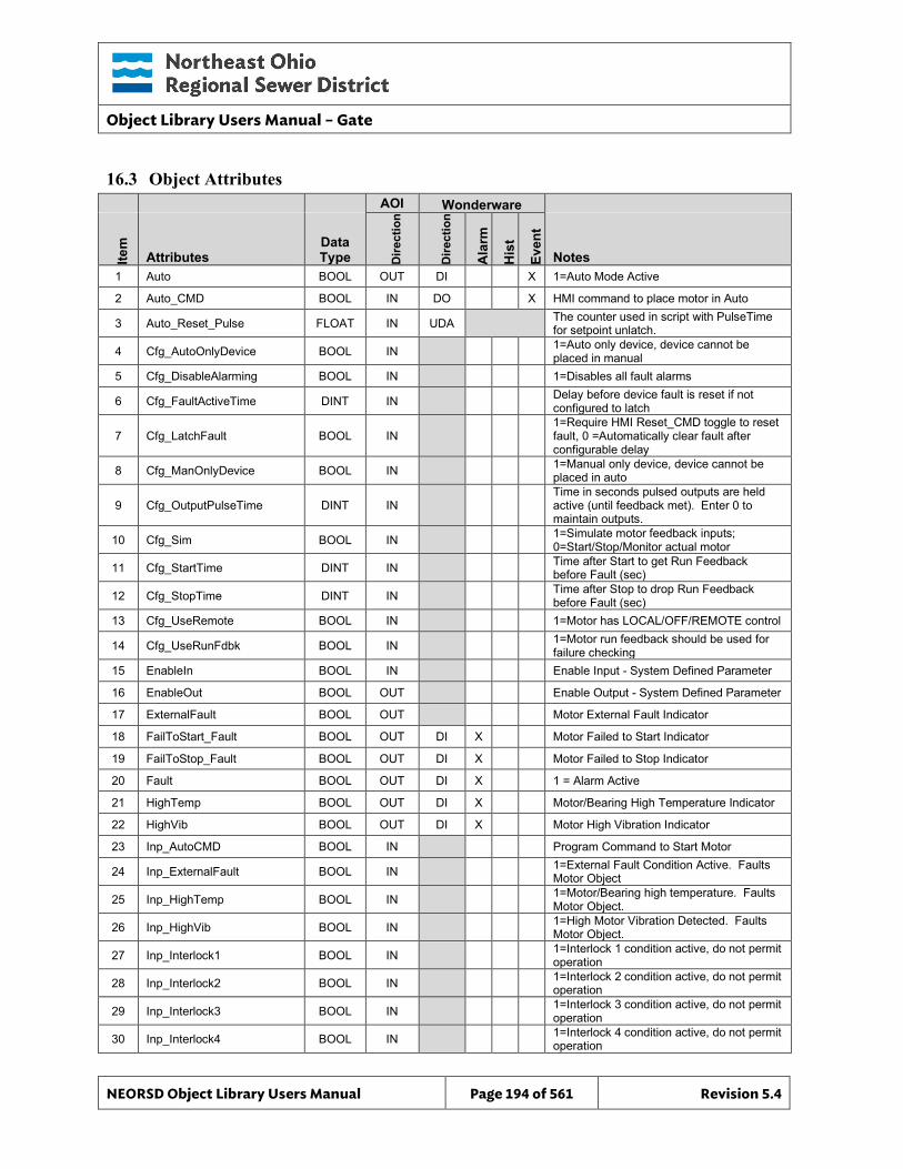
Object Library Users Manual – Gate
NEORSD Object Library Users Manual Page 194 of 561 Revision 5.4
16.3 Object Attributes
AOI Wonderware
Item
Attributes Data Type D
irect
ion
Dire
ctio
n
Ala
rm
His
t
Even
t
Notes 1 Auto BOOL OUT DI X 1=Auto Mode Active
2 Auto_CMD BOOL IN DO X HMI command to place motor in Auto
3 Auto_Reset_Pulse FLOAT IN UDA The counter used in script with PulseTime for setpoint unlatch.
4 Cfg_AutoOnlyDevice BOOL IN 1=Auto only device, device cannot be placed in manual
5 Cfg_DisableAlarming BOOL IN 1=Disables all fault alarms
6 Cfg_FaultActiveTime DINT IN Delay before device fault is reset if not configured to latch
7 Cfg_LatchFault BOOL IN 1=Require HMI Reset_CMD toggle to reset fault, 0 =Automatically clear fault after configurable delay
8 Cfg_ManOnlyDevice BOOL IN 1=Manual only device, device cannot be placed in auto
9 Cfg_OutputPulseTime DINT IN Time in seconds pulsed outputs are held active (until feedback met). Enter 0 to maintain outputs.
10 Cfg_Sim BOOL IN 1=Simulate motor feedback inputs; 0=Start/Stop/Monitor actual motor
11 Cfg_StartTime DINT IN Time after Start to get Run Feedback before Fault (sec)
12 Cfg_StopTime DINT IN Time after Stop to drop Run Feedback before Fault (sec)
13 Cfg_UseRemote BOOL IN 1=Motor has LOCAL/OFF/REMOTE control
14 Cfg_UseRunFdbk BOOL IN 1=Motor run feedback should be used for failure checking
15 EnableIn BOOL IN Enable Input - System Defined Parameter
16 EnableOut BOOL OUT Enable Output - System Defined Parameter
17 ExternalFault BOOL OUT Motor External Fault Indicator
18 FailToStart_Fault BOOL OUT DI X Motor Failed to Start Indicator
19 FailToStop_Fault BOOL OUT DI X Motor Failed to Stop Indicator
20 Fault BOOL OUT DI X 1 = Alarm Active
21 HighTemp BOOL OUT DI X Motor/Bearing High Temperature Indicator
22 HighVib BOOL OUT DI X Motor High Vibration Indicator
23 Inp_AutoCMD BOOL IN Program Command to Start Motor
24 Inp_ExternalFault BOOL IN 1=External Fault Condition Active. Faults Motor Object
25 Inp_HighTemp BOOL IN 1=Motor/Bearing high temperature. Faults Motor Object.
26 Inp_HighVib BOOL IN 1=High Motor Vibration Detected. Faults Motor Object.
27 Inp_Interlock1 BOOL IN 1=Interlock 1 condition active, do not permit operation
28 Inp_Interlock2 BOOL IN 1=Interlock 2 condition active, do not permit operation
29 Inp_Interlock3 BOOL IN 1=Interlock 3 condition active, do not permit operation
30 Inp_Interlock4 BOOL IN 1=Interlock 4 condition active, do not permit operation
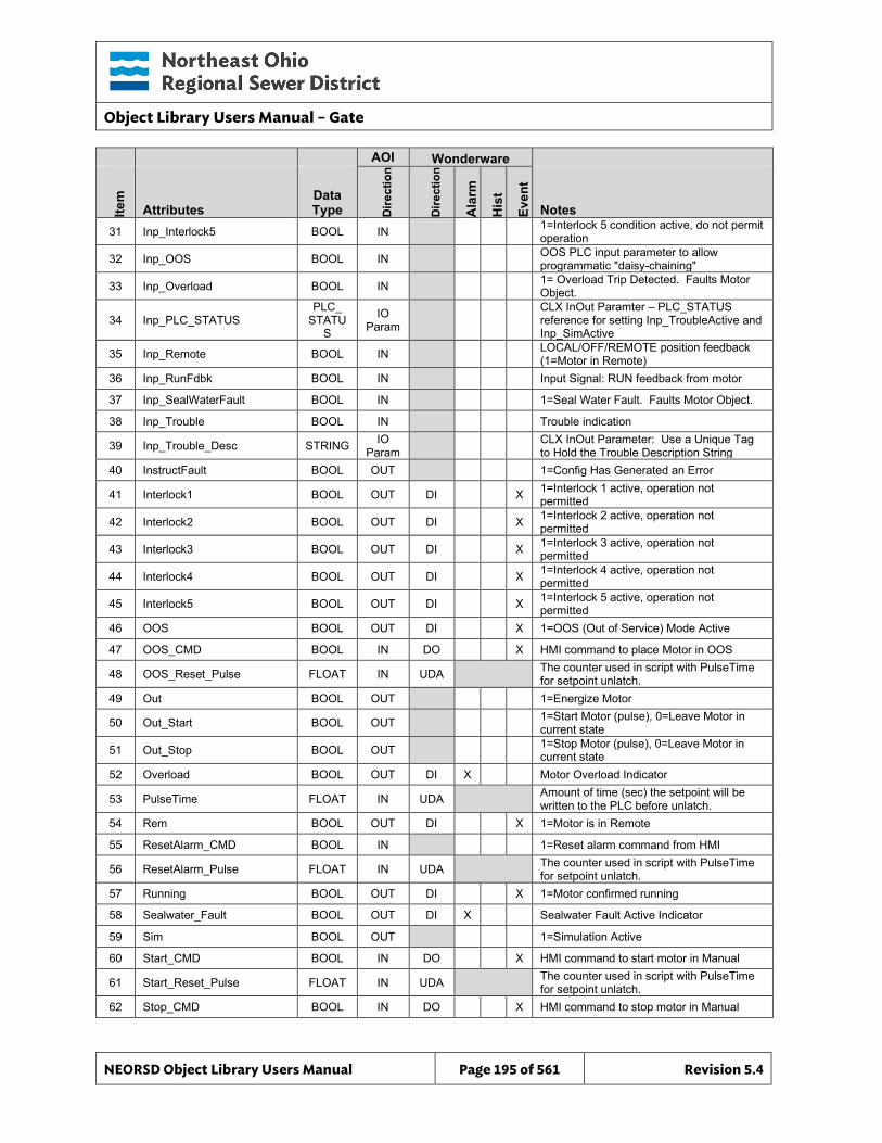
Object Library Users Manual – Gate
NEORSD Object Library Users Manual Page 195 of 561 Revision 5.4
AOI Wonderware
Item
Attributes Data Type D
irect
ion
Dire
ctio
n
Ala
rm
His
t
Even
t
Notes 31 Inp_Interlock5 BOOL IN 1=Interlock 5 condition active, do not permit
operation
32 Inp_OOS BOOL IN OOS PLC input parameter to allow programmatic "daisy-chaining"
33 Inp_Overload BOOL IN 1= Overload Trip Detected. Faults Motor Object.
34 Inp_PLC_STATUS PLC_
STATUS
IO Param
CLX InOut Paramter – PLC_STATUS reference for setting Inp_TroubleActive and Inp_SimActive
35 Inp_Remote BOOL IN LOCAL/OFF/REMOTE position feedback (1=Motor in Remote)
36 Inp_RunFdbk BOOL IN Input Signal: RUN feedback from motor
37 Inp_SealWaterFault BOOL IN 1=Seal Water Fault. Faults Motor Object.
38 Inp_Trouble BOOL IN Trouble indication
39 Inp_Trouble_Desc STRING IO Param CLX InOut Parameter: Use a Unique Tag
to Hold the Trouble Description String 40 InstructFault BOOL OUT 1=Config Has Generated an Error
41 Interlock1 BOOL OUT DI X 1=Interlock 1 active, operation not permitted
42 Interlock2 BOOL OUT DI X 1=Interlock 2 active, operation not permitted
43 Interlock3 BOOL OUT DI X 1=Interlock 3 active, operation not permitted
44 Interlock4 BOOL OUT DI X 1=Interlock 4 active, operation not permitted
45 Interlock5 BOOL OUT DI X 1=Interlock 5 active, operation not permitted
46 OOS BOOL OUT DI X 1=OOS (Out of Service) Mode Active
47 OOS_CMD BOOL IN DO X HMI command to place Motor in OOS
48 OOS_Reset_Pulse FLOAT IN UDA The counter used in script with PulseTime for setpoint unlatch.
49 Out BOOL OUT 1=Energize Motor
50 Out_Start BOOL OUT 1=Start Motor (pulse), 0=Leave Motor in current state
51 Out_Stop BOOL OUT 1=Stop Motor (pulse), 0=Leave Motor in current state
52 Overload BOOL OUT DI X Motor Overload Indicator
53 PulseTime FLOAT IN UDA Amount of time (sec) the setpoint will be written to the PLC before unlatch.
54 Rem BOOL OUT DI X 1=Motor is in Remote
55 ResetAlarm_CMD BOOL IN 1=Reset alarm command from HMI
56 ResetAlarm_Pulse FLOAT IN UDA The counter used in script with PulseTime for setpoint unlatch.
57 Running BOOL OUT DI X 1=Motor confirmed running
58 Sealwater_Fault BOOL OUT DI X Sealwater Fault Active Indicator
59 Sim BOOL OUT 1=Simulation Active
60 Start_CMD BOOL IN DO X HMI command to start motor in Manual
61 Start_Reset_Pulse FLOAT IN UDA The counter used in script with PulseTime for setpoint unlatch.
62 Stop_CMD BOOL IN DO X HMI command to stop motor in Manual
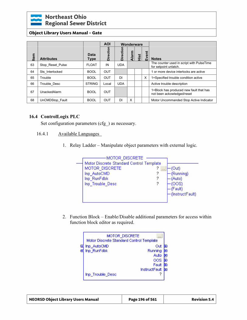
Object Library Users Manual – Gate
NEORSD Object Library Users Manual Page 196 of 561 Revision 5.4
AOI Wonderware
Item
Attributes Data Type D
irect
ion
Dire
ctio
n
Ala
rm
His
t
Even
t
Notes 63 Stop_Reset_Pulse FLOAT IN UDA The counter used in script with PulseTime
for setpoint unlatch. 64 Sts_Interlocked BOOL OUT 1 or more device interlocks are active
65 Trouble BOOL OUT DI X 1=Specified trouble condition active
66 Trouble_Desc STRING Local UDA Active trouble description
67 UnackedAlarm BOOL OUT 1=Block has produced new fault that has not been ackowledged/reset
68 UnCMDStop_Fault BOOL OUT DI X Motor Uncommanded Stop Active Indicator
16.4 ControlLogix PLC Set configuration parameters (cfg_) as necessary.
16.4.1 Available Languages
1. Relay Ladder – Manipulate object parameters with external logic.
2. Function Block – Enable/Disable additional parameters for access within function block editor as required.
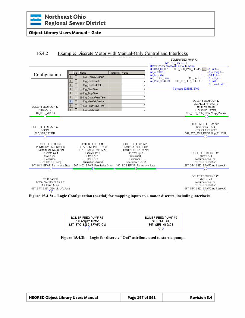
Object Library Users Manual – Gate
NEORSD Object Library Users Manual Page 197 of 561 Revision 5.4
16.4.2 Example: Discrete Motor with Manual-Only Control and Interlocks
Figure 15.4.2a – Logic Configuration (partial) for mapping inputs to a motor discrete, including interlocks.
Figure 15.4.2b – Logic for discrete “Out” attribute used to start a pump.
Configuration
Object Library Users Manual – Gate
NEORSD Object Library Users Manual Page 198 of 561 Revision 5.4
Example Highlights: • Process Inputs:
o Inp_Remote – Remote/local field switch (1=remote) o Inp_RunFdbk – Confirmed running feedback for the motor. o Inp_Interlock1 – Custom interlock condition #1 (prevents motor operation
when true) o Inp_Interlock2 – Custom interlock condition #2 (prevents motor operation
when true) • AOI Configuration:
o Cfg_DisableAlarming – Set to 0 to allow alarms to trigger o Cfg_UseRemote – Indicates that a field remote switch exists o Cfg_UseRunFdbk – Check if motor is running before triggering a fault on
alarm (i.e. do not send a “sealwater failure” if the motor is turned off). o Cfg_StartTime – Maximum time after sending a start command before
receiving ‘running’ feedback. If exceeded, a fault will be triggered. o Cfg_StopTime – Maximum time after sending a stop command for the
motor to drop the ‘running’ feedback. If exceeded, a fault will be triggered. o Cfg_ManOnlyDevice – Set to 1 to indicate that the motor has no auto mode.
• Block Outputs for Use in External Logic: o Running – Running indicator for the motor. Use in control logic, including:
Interlocking Enabling runtime accumulators
o Out – Should be tied to the physical output to the motor starter. o Rem – Indicates that the motor is in “Remote” mode.
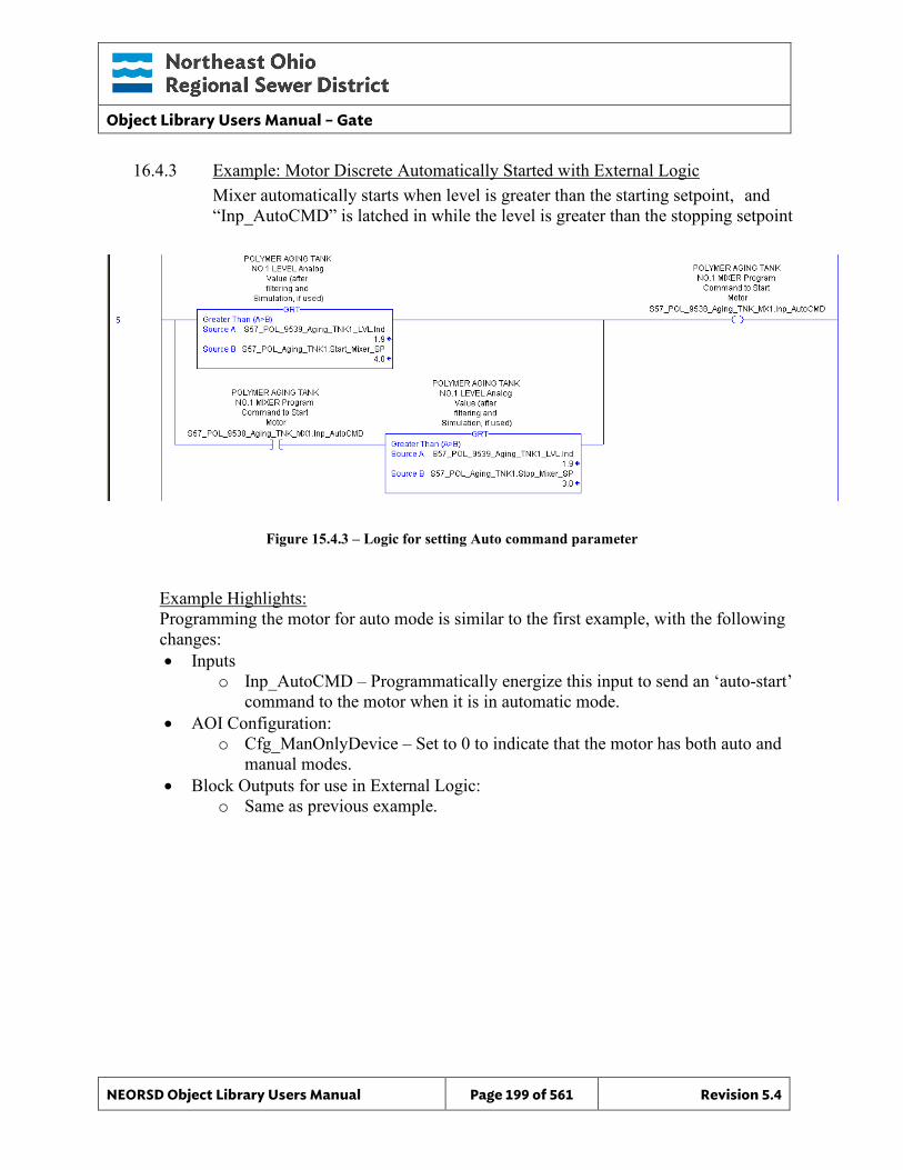
Object Library Users Manual – Gate
NEORSD Object Library Users Manual Page 199 of 561 Revision 5.4
16.4.3 Example: Motor Discrete Automatically Started with External Logic Mixer automatically starts when level is greater than the starting setpoint, and “Inp_AutoCMD” is latched in while the level is greater than the stopping setpoint
Figure 15.4.3 – Logic for setting Auto command parameter
Example Highlights: Programming the motor for auto mode is similar to the first example, with the following changes: • Inputs
o Inp_AutoCMD – Programmatically energize this input to send an ‘auto-start’ command to the motor when it is in automatic mode.
• AOI Configuration: o Cfg_ManOnlyDevice – Set to 0 to indicate that the motor has both auto and
manual modes. • Block Outputs for use in External Logic:
o Same as previous example.
Object Library Users Manual – Gate
NEORSD Object Library Users Manual Page 200 of 561 Revision 5.4
16.4.4 Additional Attribute Notes
16.4.4.1 Inputs o Inp_HighTemp, Inp_Overload, etc – These individual fault bits should be
used if the wiring exists. o INP_PLC_STATUS - Must reference the PLC_Status object for this PLC. o Inp_OOS - Programmatically set this attribute to “1” to enable Out of
Service.
16.4.4.2 Internal Configuration o Cfg_DisableAlarming – Set to “1” to turn off all alarms and interlocks for
this object.
• Cfg_LatchFault – Set to “1” if faults must be reset at the HMI/OIT. Use if District staff should physically inspect a device before resuming operation after a fault.
o Cfg_FaultActiveTime –If “Cfg_LatchFault” = 0, the block will automatically clear a fault in the time specified by this parameter. If the fault input condition must be removed; the block will not clear an active fault.
o Cfg_OutputPulseTime – Used when the motor starter requires a pulsed signal. Set to 0 to use maintained outputs, otherwise set to the pulse length (seconds).
o Cfg_Sim – Set to “1” to enable simulation mode for this block. The running feedback will be ignored and when the block is commanded to start/stop the motor “Running” output will react accordingly.
o Cfg_AutoOnlyDevice – Set to “1” to prevent the device from operating in remote manual mode. Cfg_ManOnlyDevice must be set to “0”.
16.4.4.3 Outputs o Sts_Interlocked – Indicates that this instance cannot operate as an
interlock condition is not satisfied. o OOS – Indicates that this instance is out-of-service o Out_Start, Out_Stop – Use instead of “Out” if separate start/stop
command signals are required o Auto – Indicates that the motor is in automatic control mode o Fault – Indicates that any fault condition is active on the motor. Individual
fault indicators are also available (“Overload”, “HighVib”, etc).

Object Library Users Manual – Gate
NEORSD Object Library Users Manual Page 201 of 561 Revision 5.4
• When the motor faults, it will be commanded to stop and will enter manual mode.
Object Library Users Manual – Gate
NEORSD Object Library Users Manual Page 202 of 561 Revision 5.4
16.5 Wonderware HMI
16.5.1 Properties Hierarchical Name: $Motor_Discrete Derivation: Derived from $NEORSDUserDefined /$Motor_Discrete_Indicator Container: None
16.5.2 Extensions None
16.5.3 Configuration All of the necessary configuration for Motor_Discrete must also be done on any instance derived from this template.
1) Alarm Priority – The attributes Fault, HighTemp, HighVib and Overload need
to have a priority defined. 2) If ASSET_ID is not in use the initial value will be left blank. Scripting used
for ASSET_ID uses the initial value and not ASSET_ID.Description. 3) Attributes that are not used in the configured instance shall use
Me.Placeholder to eliminate the point from counting against the systems total I/O scan counts. The allowed attributes for this template include the following:
a. Auto_CMD j. Overload b. FailToStart_Fault k. Fault c. FailToStop_Fault l. REM d. Fault m. ResetAlarm_CMD e. HighTemp n. Sealwater_Fault f. HighVib o. Start_CMD g. Interlock1 to Interlock5 p. Stop_CMD
h. OOS q.
TroublGraphical Objects
i. OOS_CMD
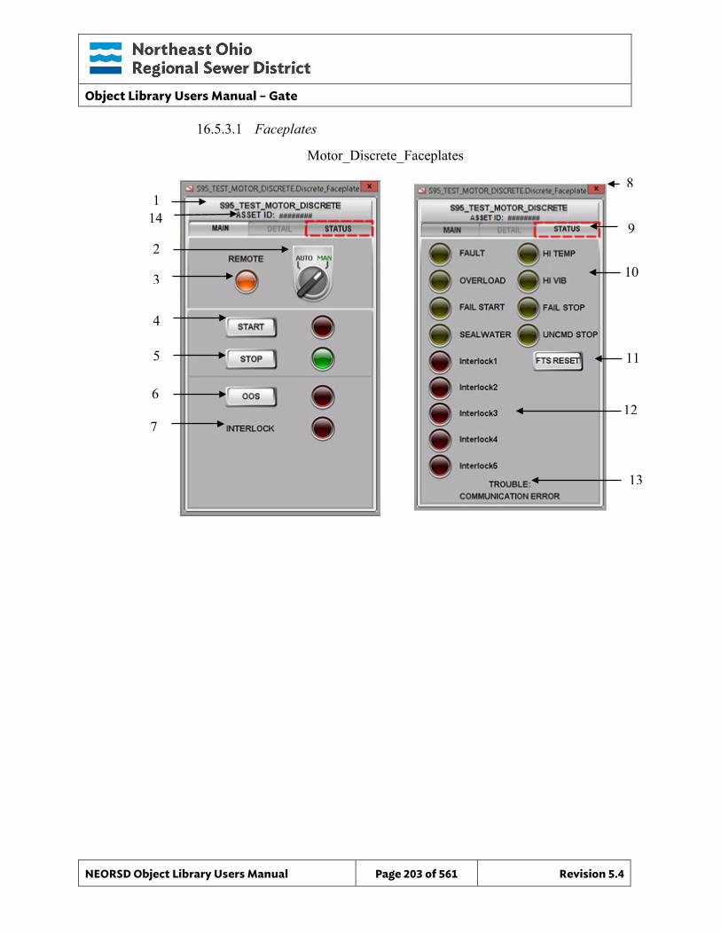
Object Library Users Manual – Gate
NEORSD Object Library Users Manual Page 203 of 561 Revision 5.4
16.5.3.1 Faceplates
12
Motor_Discrete_Faceplates
8 1
9 2
3
4
5
6
10
7
11
13
14
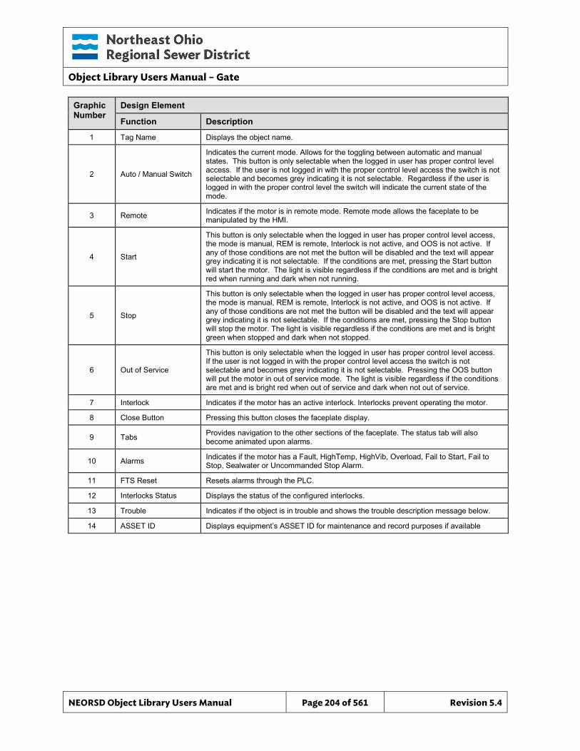
Object Library Users Manual – Gate
NEORSD Object Library Users Manual Page 204 of 561 Revision 5.4
Graphic Number
Design Element
Function Description
1 Tag Name Displays the object name.
2 Auto / Manual Switch
Indicates the current mode. Allows for the toggling between automatic and manual states. This button is only selectable when the logged in user has proper control level access. If the user is not logged in with the proper control level access the switch is not selectable and becomes grey indicating it is not selectable. Regardless if the user is logged in with the proper control level the switch will indicate the current state of the mode.
3 Remote Indicates if the motor is in remote mode. Remote mode allows the faceplate to be manipulated by the HMI.
4 Start
This button is only selectable when the logged in user has proper control level access, the mode is manual, REM is remote, Interlock is not active, and OOS is not active. If any of those conditions are not met the button will be disabled and the text will appear grey indicating it is not selectable. If the conditions are met, pressing the Start button will start the motor. The light is visible regardless if the conditions are met and is bright red when running and dark when not running.
5 Stop
This button is only selectable when the logged in user has proper control level access, the mode is manual, REM is remote, Interlock is not active, and OOS is not active. If any of those conditions are not met the button will be disabled and the text will appear grey indicating it is not selectable. If the conditions are met, pressing the Stop button will stop the motor. The light is visible regardless if the conditions are met and is bright green when stopped and dark when not stopped.
6 Out of Service
This button is only selectable when the logged in user has proper control level access. If the user is not logged in with the proper control level access the switch is not selectable and becomes grey indicating it is not selectable. Pressing the OOS button will put the motor in out of service mode. The light is visible regardless if the conditions are met and is bright red when out of service and dark when not out of service.
7 Interlock Indicates if the motor has an active interlock. Interlocks prevent operating the motor.
8 Close Button Pressing this button closes the faceplate display.
9 Tabs Provides navigation to the other sections of the faceplate. The status tab will also become animated upon alarms.
10 Alarms Indicates if the motor has a Fault, HighTemp, HighVib, Overload, Fail to Start, Fail to Stop, Sealwater or Uncommanded Stop Alarm.
11 FTS Reset Resets alarms through the PLC.
12 Interlocks Status Displays the status of the configured interlocks.
13 Trouble Indicates if the object is in trouble and shows the trouble description message below.
14 ASSET ID Displays equipment’s ASSET ID for maintenance and record purposes if available
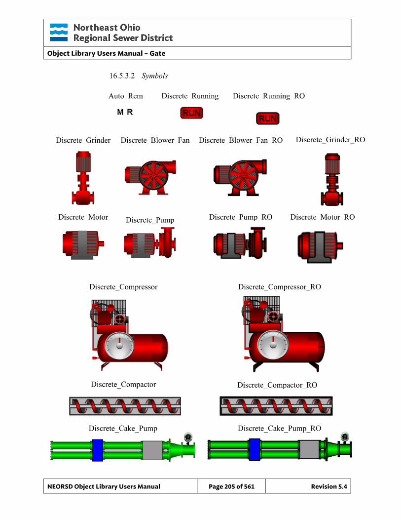
Object Library Users Manual – Gate
NEORSD Object Library Users Manual Page 205 of 561 Revision 5.4
16.5.3.2 Symbols
Discrete_Compressor
Auto_Rem Discrete_Running
Discrete_Pump
Discrete_Blower_Fan Discrete_Grinder
Discrete_Running_RO
Discrete_Blower_Fan_RO
Discrete_Pump_RO Discrete_Motor_RO
Discrete_Grinder_RO
Discrete_Motor
Discrete_Compressor_RO
Discrete_Cake_Pump
Discrete_Cake_Pump_RO
Discrete_Compactor Discrete_Compactor_RO
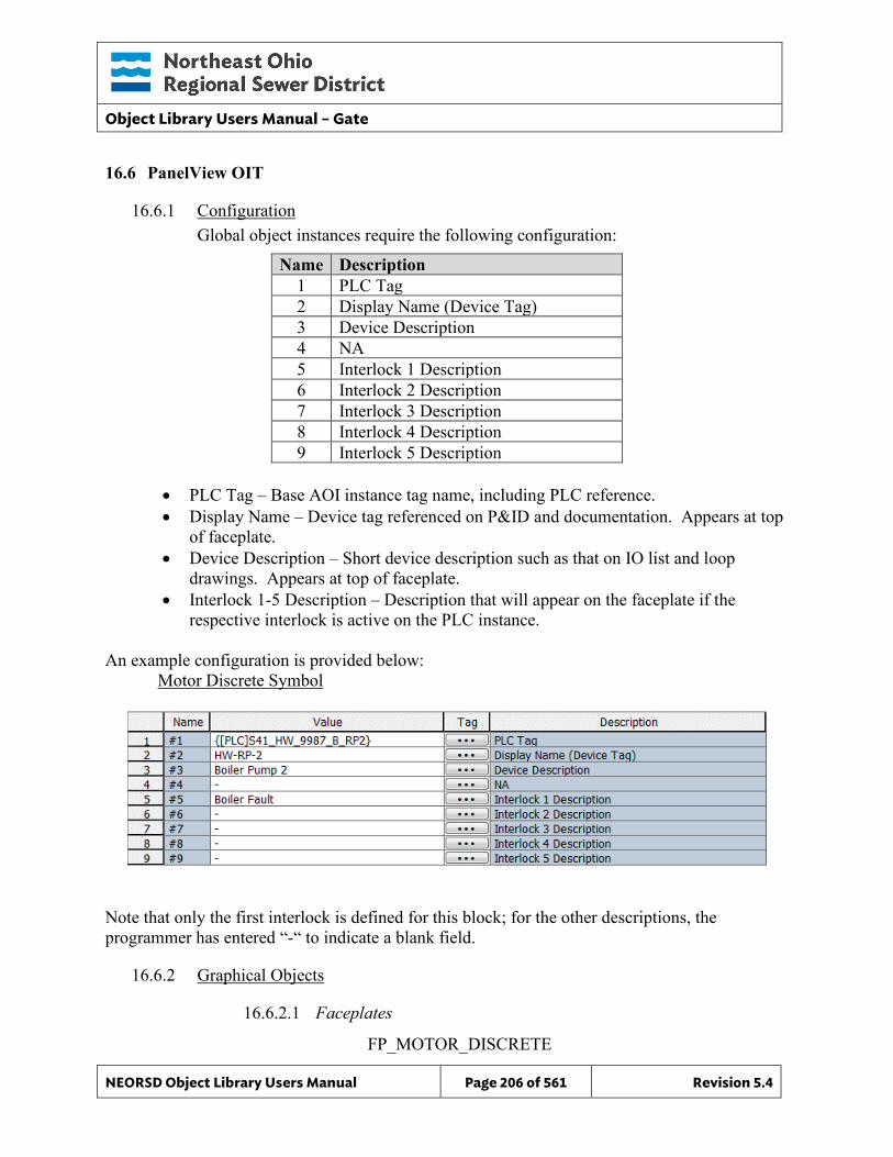
Object Library Users Manual – Gate
NEORSD Object Library Users Manual Page 206 of 561 Revision 5.4
16.6 PanelView OIT
16.6.1 Configuration Global object instances require the following configuration:
Name Description 1 PLC Tag 2 Display Name (Device Tag) 3 Device Description 4 NA 5 Interlock 1 Description 6 Interlock 2 Description 7 Interlock 3 Description 8 Interlock 4 Description 9 Interlock 5 Description
• PLC Tag – Base AOI instance tag name, including PLC reference. • Display Name – Device tag referenced on P&ID and documentation. Appears at top
of faceplate. • Device Description – Short device description such as that on IO list and loop
drawings. Appears at top of faceplate. • Interlock 1-5 Description – Description that will appear on the faceplate if the
respective interlock is active on the PLC instance. An example configuration is provided below: Motor Discrete Symbol
Note that only the first interlock is defined for this block; for the other descriptions, the programmer has entered “-“ to indicate a blank field.
16.6.2 Graphical Objects
16.6.2.1 Faceplates FP_MOTOR_DISCRETE
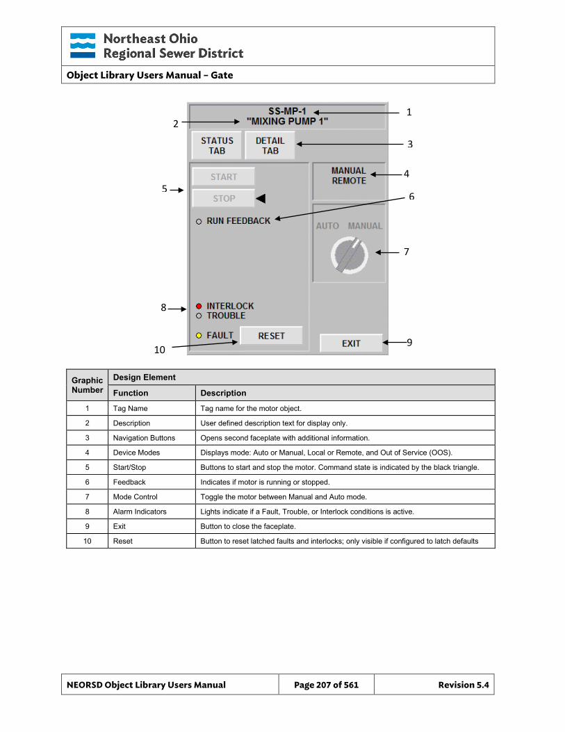
Object Library Users Manual – Gate
NEORSD Object Library Users Manual Page 207 of 561 Revision 5.4
10
1
9
7
3
4
6
Graphic Number
Design Element
Function Description
1 Tag Name Tag name for the motor object.
2 Description User defined description text for display only.
3 Navigation Buttons Opens second faceplate with additional information.
4 Device Modes Displays mode: Auto or Manual, Local or Remote, and Out of Service (OOS).
5 Start/Stop Buttons to start and stop the motor. Command state is indicated by the black triangle.
6 Feedback Indicates if motor is running or stopped.
7 Mode Control Toggle the motor between Manual and Auto mode.
8 Alarm Indicators Lights indicate if a Fault, Trouble, or Interlock conditions is active.
9 Exit Button to close the faceplate.
10 Reset Button to reset latched faults and interlocks; only visible if configured to latch defaults
2
8
5
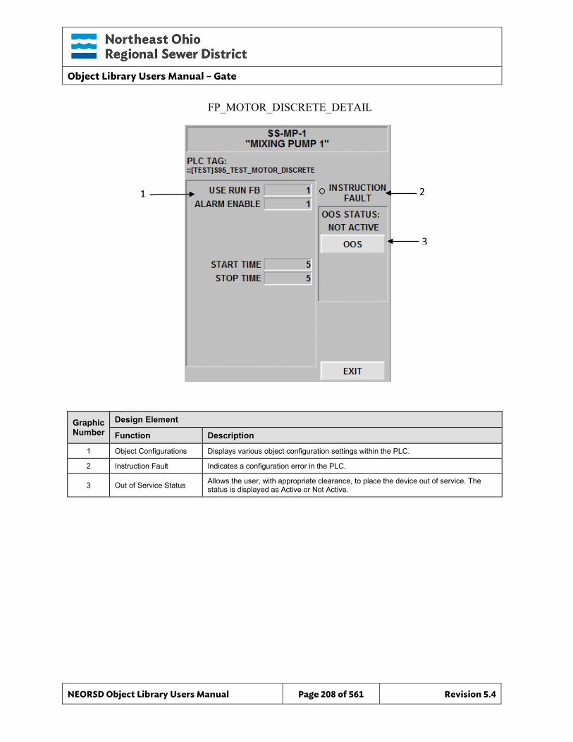
Object Library Users Manual – Gate
NEORSD Object Library Users Manual Page 208 of 561 Revision 5.4
2
3
Graphic Number
Design Element
Function Description
1 Object Configurations Displays various object configuration settings within the PLC.
2 Instruction Fault Indicates a configuration error in the PLC.
3 Out of Service Status Allows the user, with appropriate clearance, to place the device out of service. The status is displayed as Active or Not Active.
FP_MOTOR_DISCRETE_DETAIL
1
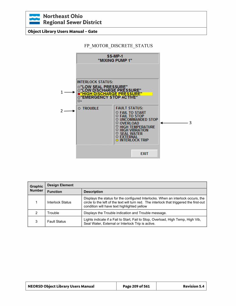
Object Library Users Manual – Gate
NEORSD Object Library Users Manual Page 209 of 561 Revision 5.4
3
Graphic Number
Design Element
Function Description
1 Interlock Status Displays the status for the configured Interlocks. When an interlock occurs, the circle to the left of the text will turn red. The interlock that triggered the first-out condition will have text highlighted yellow
2 Trouble Displays the Trouble indication and Trouble message.
3 Fault Status Lights indicate if a Fail to Start, Fail to Stop, Overload, High Temp, High Vib, Seal Water, External or Interlock Trip is active.
FP_MOTOR_DISCRETE_STATUS
1
2
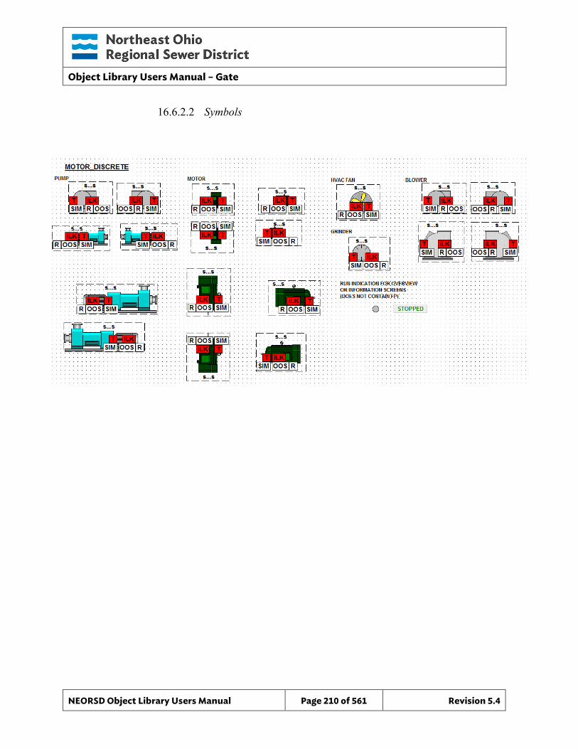
Object Library Users Manual – Gate
NEORSD Object Library Users Manual Page 210 of 561 Revision 5.4
16.6.2.2 Symbols

Object Library Users Manual – Gate
NEORSD Object Library Users Manual Page 211 of 561 Revision 5.4
Object Library Users Manual - Motor_Discrete_Indicator
NEORSD Object Library Users Manual Page 212 of 561 Revision 5.4
17.0 Motor_Discrete_Indicator
17.1 Introduction The Motor_Discrete_Indicator template provides a standard representation of a locally controlled (no remote operation) discrete (2-state) motor, generator, fan, blower, or other electric rotating machine within the NEORSD control systems. Use the Motor_Discrete_Indicator template if both of the statements below are true:
• If trying to represent monitoring-only information (running, fault) for a motor. • If the motor has no “remote” mode of operation (only field/local operation)
Do not use the Motor_Discrete_Indicator template:
• If the motor being represented has remote-control from the HMI. If the motor has any remote control (or a “remote/local” switch), use Motor_Discrete instead.
• If the motor is variable speed. If representing a variable speed motor, use Motor_VFD instead.
17.2 Object Features
17.2.1 Running/Stopped Indication This object provides running feedback from the motor for use with downstream logic in the PLC, and for display on the HMI/OIT.
17.2.2 Status Indication This object provides the following indications for the motor:
• In-Service/Out-Of-Service mode indication
17.2.3 Alarming This object supports the following alarms:
• An externally-generated common fault alarm for the motor.
17.2.4 Control This object supports the following control for the motor:
• Out-of-Service/In-Service mode toggle
17.2.5 Simulation This object supports simulation of the running feedback.
17.2.6 Trouble This object supports hardware trouble indication.
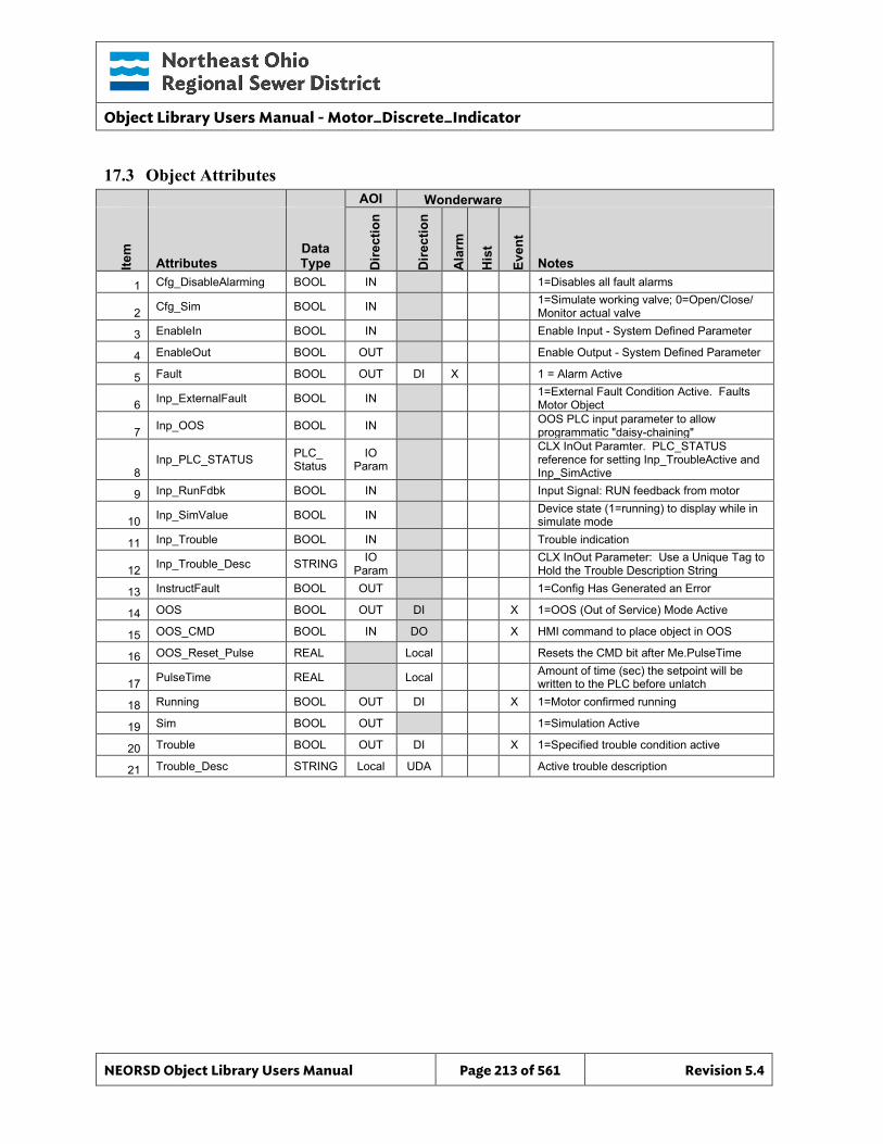
Object Library Users Manual - Motor_Discrete_Indicator
NEORSD Object Library Users Manual Page 213 of 561 Revision 5.4
17.3 Object Attributes
AOI Wonderware
Item
Attributes Data Type D
irect
ion
Dire
ctio
n
Ala
rm
His
t
Even
t
Notes 1 Cfg_DisableAlarming BOOL IN 1=Disables all fault alarms
2 Cfg_Sim BOOL IN 1=Simulate working valve; 0=Open/Close/ Monitor actual valve
3 EnableIn BOOL IN Enable Input - System Defined Parameter
4 EnableOut BOOL OUT Enable Output - System Defined Parameter
5 Fault BOOL OUT DI X 1 = Alarm Active
6 Inp_ExternalFault BOOL IN 1=External Fault Condition Active. Faults Motor Object
7 Inp_OOS BOOL IN OOS PLC input parameter to allow programmatic "daisy-chaining"
8 Inp_PLC_STATUS PLC_
Status IO
Param CLX InOut Paramter. PLC_STATUS reference for setting Inp_TroubleActive and Inp_SimActive
9 Inp_RunFdbk BOOL IN Input Signal: RUN feedback from motor
10 Inp_SimValue BOOL IN Device state (1=running) to display while in simulate mode
11 Inp_Trouble BOOL IN Trouble indication
12 Inp_Trouble_Desc STRING IO Param CLX InOut Parameter: Use a Unique Tag to
Hold the Trouble Description String
13 InstructFault BOOL OUT 1=Config Has Generated an Error
14 OOS BOOL OUT DI X 1=OOS (Out of Service) Mode Active
15 OOS_CMD BOOL IN DO X HMI command to place object in OOS
16 OOS_Reset_Pulse REAL Local Resets the CMD bit after Me.PulseTime
17 PulseTime REAL Local Amount of time (sec) the setpoint will be written to the PLC before unlatch
18 Running BOOL OUT DI X 1=Motor confirmed running
19 Sim BOOL OUT 1=Simulation Active
20 Trouble BOOL OUT DI X 1=Specified trouble condition active
21 Trouble_Desc STRING Local UDA Active trouble description
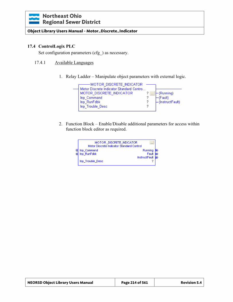
Object Library Users Manual - Motor_Discrete_Indicator
NEORSD Object Library Users Manual Page 214 of 561 Revision 5.4
17.4 ControlLogix PLC Set configuration parameters (cfg_) as necessary.
17.4.1 Available Languages
1. Relay Ladder – Manipulate object parameters with external logic.
2. Function Block – Enable/Disable additional parameters for access within function block editor as required.
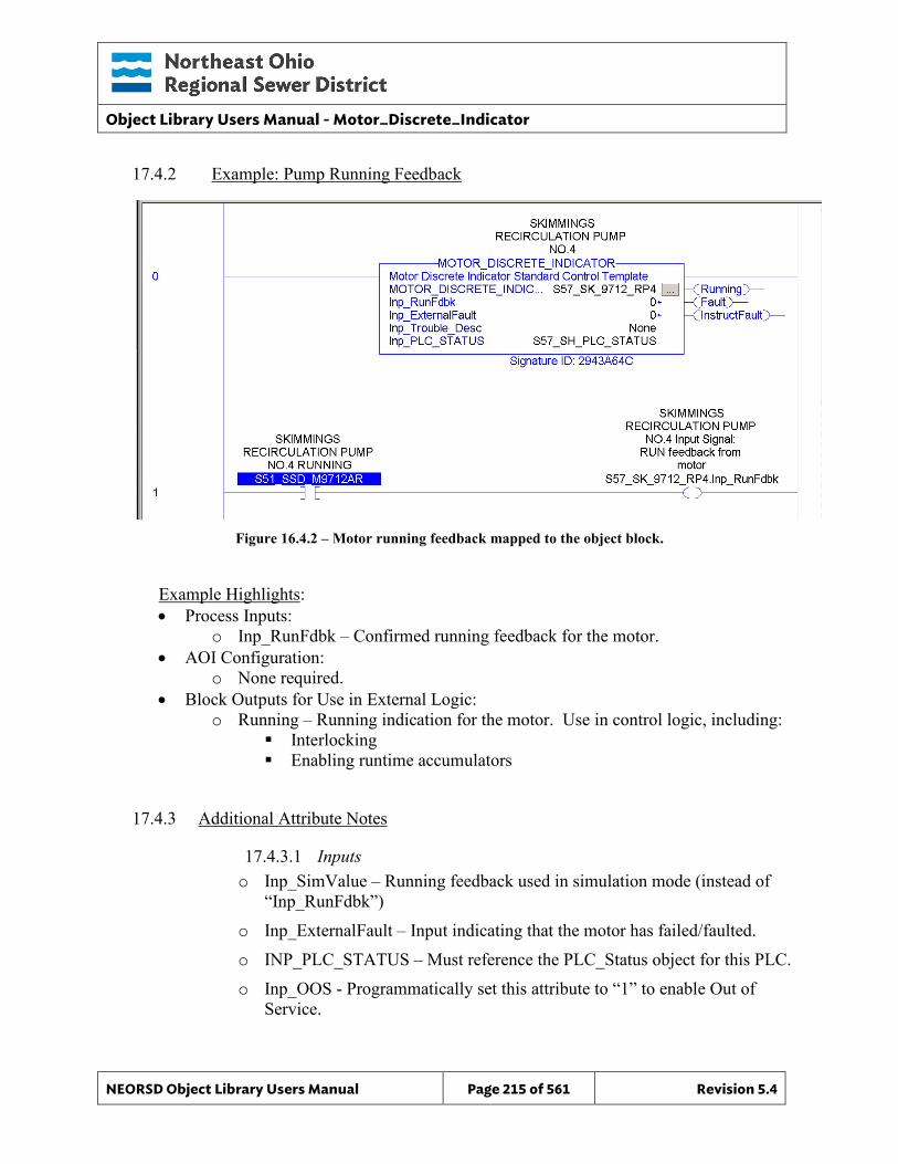
Object Library Users Manual - Motor_Discrete_Indicator
NEORSD Object Library Users Manual Page 215 of 561 Revision 5.4
17.4.2 Example: Pump Running Feedback
Figure 16.4.2 – Motor running feedback mapped to the object block.
Example Highlights: • Process Inputs:
o Inp_RunFdbk – Confirmed running feedback for the motor. • AOI Configuration:
o None required. • Block Outputs for Use in External Logic:
o Running – Running indication for the motor. Use in control logic, including: Interlocking Enabling runtime accumulators
17.4.3 Additional Attribute Notes
17.4.3.1 Inputs o Inp_SimValue – Running feedback used in simulation mode (instead of
“Inp_RunFdbk”) o Inp_ExternalFault – Input indicating that the motor has failed/faulted. o INP_PLC_STATUS – Must reference the PLC_Status object for this PLC. o Inp_OOS - Programmatically set this attribute to “1” to enable Out of
Service.
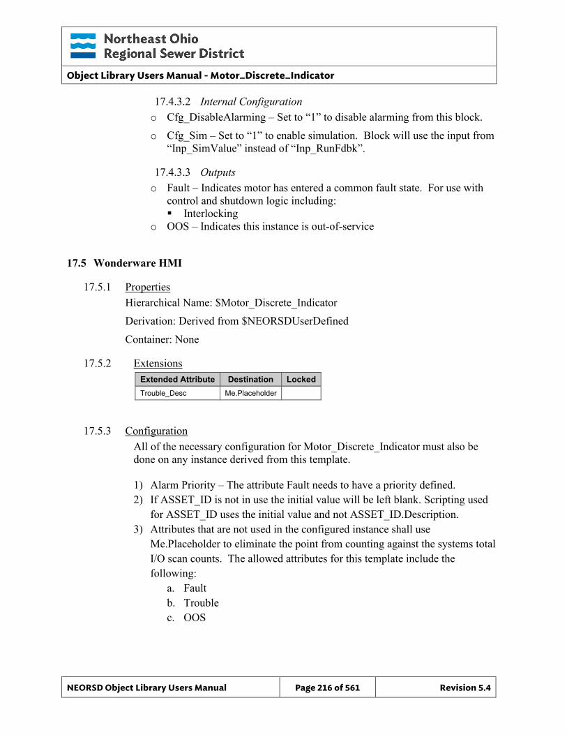
Object Library Users Manual - Motor_Discrete_Indicator
NEORSD Object Library Users Manual Page 216 of 561 Revision 5.4
17.4.3.2 Internal Configuration o Cfg_DisableAlarming – Set to “1” to disable alarming from this block. o Cfg_Sim – Set to “1” to enable simulation. Block will use the input from
“Inp_SimValue” instead of “Inp_RunFdbk”.
17.4.3.3 Outputs o Fault – Indicates motor has entered a common fault state. For use with
control and shutdown logic including: Interlocking
o OOS – Indicates this instance is out-of-service
17.5 Wonderware HMI
17.5.1 Properties Hierarchical Name: $Motor_Discrete_Indicator Derivation: Derived from $NEORSDUserDefined Container: None
17.5.2 Extensions Extended Attribute Destination Locked Trouble_Desc Me.Placeholder
17.5.3 Configuration All of the necessary configuration for Motor_Discrete_Indicator must also be done on any instance derived from this template. 1) Alarm Priority – The attribute Fault needs to have a priority defined. 2) If ASSET_ID is not in use the initial value will be left blank. Scripting used
for ASSET_ID uses the initial value and not ASSET_ID.Description. 3) Attributes that are not used in the configured instance shall use
Me.Placeholder to eliminate the point from counting against the systems total I/O scan counts. The allowed attributes for this template include the following:
a. Fault b. Trouble c. OOS
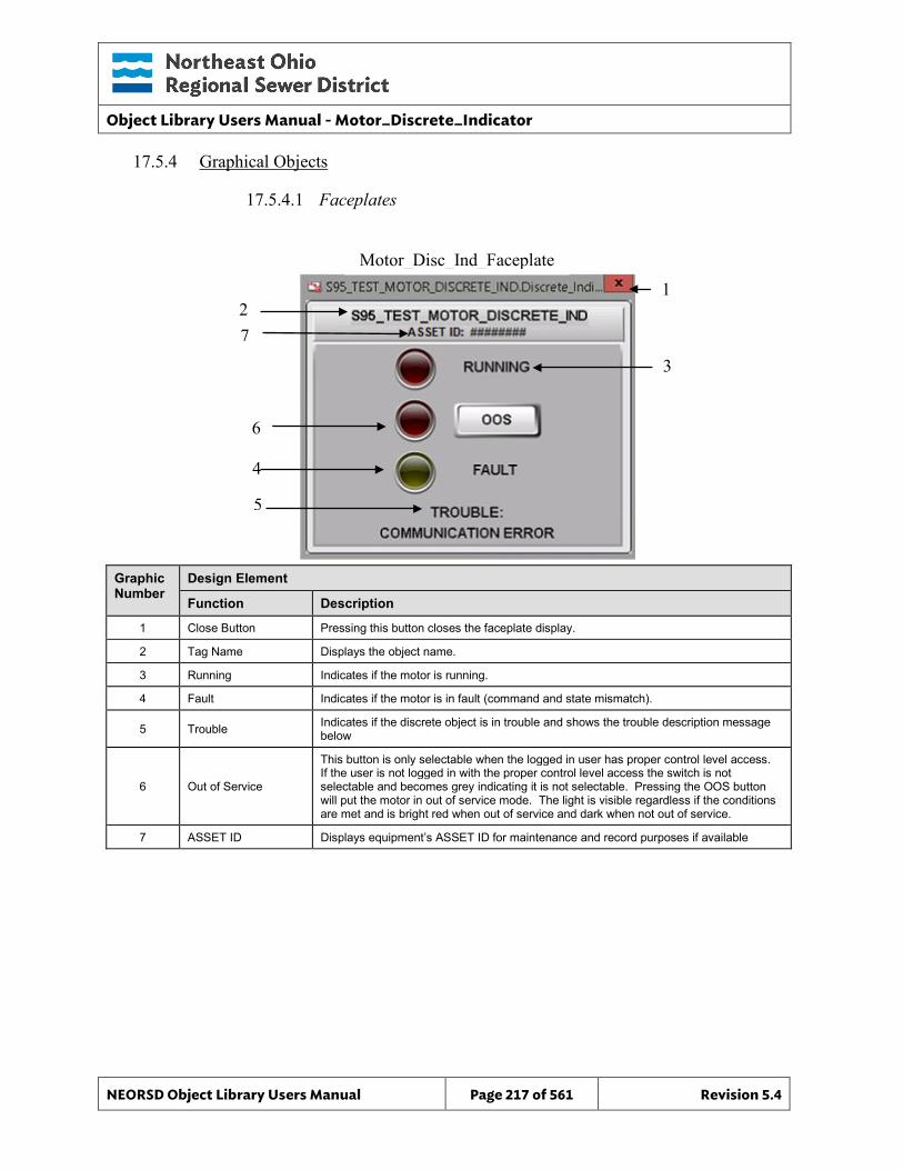
Object Library Users Manual - Motor_Discrete_Indicator
NEORSD Object Library Users Manual Page 217 of 561 Revision 5.4
17.5.4 Graphical Objects
17.5.4.1 Faceplates
Graphic Number
Design Element
Function Description
1 Close Button Pressing this button closes the faceplate display.
2 Tag Name Displays the object name.
3 Running Indicates if the motor is running.
4 Fault Indicates if the motor is in fault (command and state mismatch).
5 Trouble Indicates if the discrete object is in trouble and shows the trouble description message below
6 Out of Service
This button is only selectable when the logged in user has proper control level access. If the user is not logged in with the proper control level access the switch is not selectable and becomes grey indicating it is not selectable. Pressing the OOS button will put the motor in out of service mode. The light is visible regardless if the conditions are met and is bright red when out of service and dark when not out of service.
7 ASSET ID Displays equipment’s ASSET ID for maintenance and record purposes if available
Motor_Disc_Ind_Faceplate
2 1
4
3
5
6
7
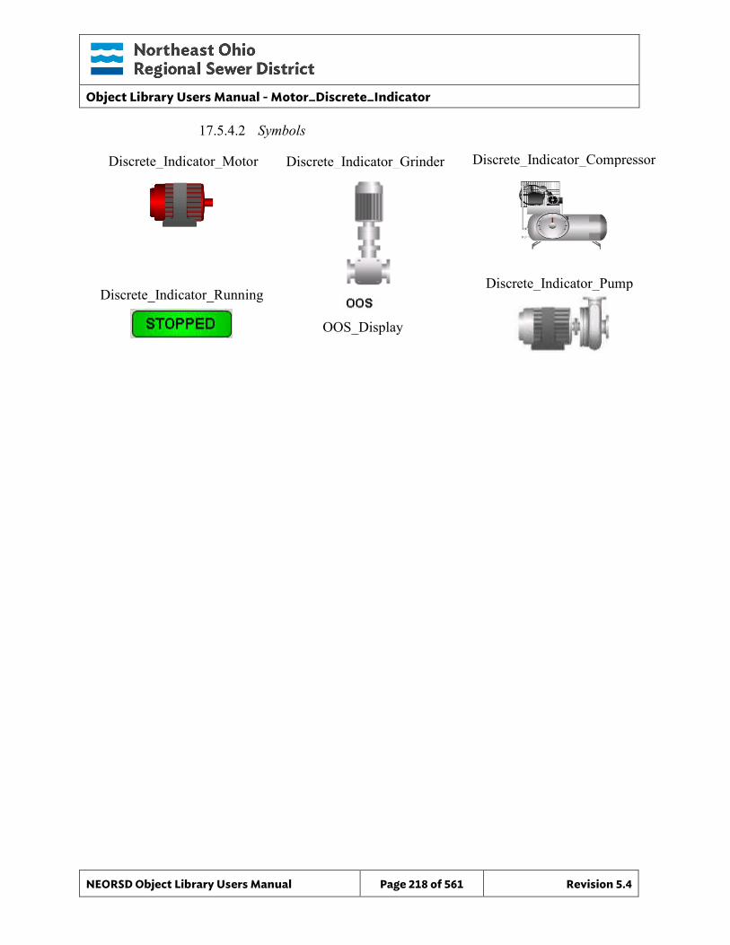
Object Library Users Manual - Motor_Discrete_Indicator
NEORSD Object Library Users Manual Page 218 of 561 Revision 5.4
17.5.4.2 Symbols
Discrete_Indicator_Running
Discrete_Indicator_Motor Discrete_Indicator_Compressor Discrete_Indicator_Grinder
Discrete_Indicator_Pump
OOS_Display
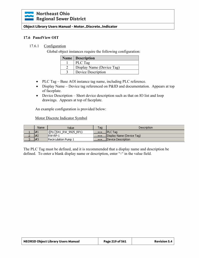
Object Library Users Manual - Motor_Discrete_Indicator
NEORSD Object Library Users Manual Page 219 of 561 Revision 5.4
17.6 PanelView OIT
17.6.1 Configuration Global object instances require the following configuration:
Name Description 1 PLC Tag 2 Display Name (Device Tag) 3 Device Description
• PLC Tag – Base AOI instance tag name, including PLC reference. • Display Name – Device tag referenced on P&ID and documentation. Appears at top
of faceplate. • Device Description – Short device description such as that on IO list and loop
drawings. Appears at top of faceplate.
An example configuration is provided below:
Motor Discrete Indicator Symbol
The PLC Tag must be defined, and it is recommended that a display name and description be defined. To enter a blank display name or description, enter “-“ in the value field.
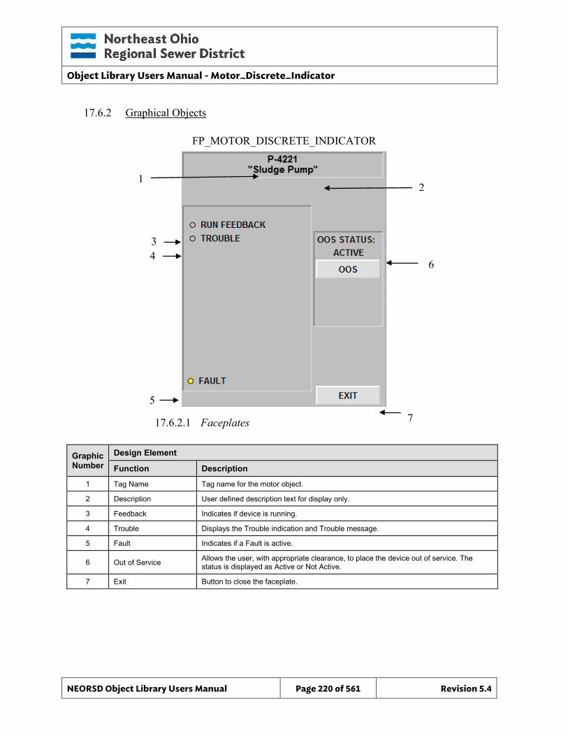
Object Library Users Manual - Motor_Discrete_Indicator
NEORSD Object Library Users Manual Page 220 of 561 Revision 5.4
17.6.2 Graphical Objects
17.6.2.1 Faceplates
Graphic Number
Design Element
Function Description
1 Tag Name Tag name for the motor object.
2 Description User defined description text for display only.
3 Feedback Indicates if device is running.
4 Trouble Displays the Trouble indication and Trouble message.
5 Fault Indicates if a Fault is active.
6 Out of Service Allows the user, with appropriate clearance, to place the device out of service. The status is displayed as Active or Not Active.
7 Exit Button to close the faceplate.
FP_MOTOR_DISCRETE_INDICATOR
1
3 4
5
2
6
7
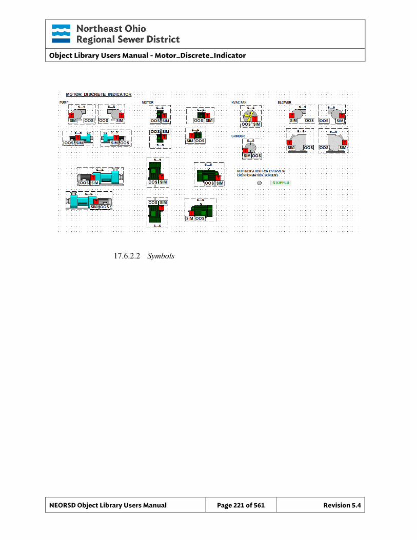
Object Library Users Manual - Motor_Discrete_Indicator
NEORSD Object Library Users Manual Page 221 of 561 Revision 5.4
17.6.2.2 Symbols
Object Library Users Manual – Motor_VFD
NEORSD Object Library Users Manual Page 222 of 561 Revision 5.4
18.0 Motor_VFD
18.1 Introduction The Motor VFD template provides a standard representation of a remotely controlled VFD motor, fan, blower, pump, generator or other electric rotating machine within the NEORSD control systems. Use the Motor_VFD template if any of the statements below are true:
• If trying to represent a variable-speed motor with “auto/manual” and/or “remote/local” control modes.
• If the motor can be controlled from the OIT or HMI (start/stop, auto/manual, etc).
Do not use the Motor_VFD template:
• If the motor is 2-state instead of variable speed. If representing a motor that is strictly on or off, use Motor_Discrete instead.
18.2 Object Features
18.2.1 Status Indications This object provides the following indications for the motor:
• Running feedback • Speed Feedback • Auto/Manual mode indication • Remote/Local mode feedback • In-Service/Out-Of-Service mode indication
18.2.2 Alarming This object supports the following alarms:
• An externally-generated common fault alarm for the motor • Motor high temperature alarm • Motor high vibration alarm • Sealwater failure alarm • Motor overload trip alarm • Motor interlock active alarm • VFD Major Fault active alarm • Motor commanded to start and failed to start in specified time • Motor commanded to stop and failed to stop in specified time
When a fault condition occurs, the motor will stop and enter manual mode.
Object Library Users Manual – Motor_VFD
NEORSD Object Library Users Manual Page 223 of 561 Revision 5.4
18.2.3 Control This object supports the following control for the motor:
• Start/Stop • Speed Control • Auto/Manual mode toggle • Resettable alarms • Out-of-Service/In-Service mode toggle • Interlocking to prevent operation
18.2.4 Simulation This object supports simulation of the running feedback.
18.2.5 Trouble This object supports hardware trouble indication.
18.2.6 DB_Precision_Group Attribute is used in the ValueDeadband script. In the script, this parameter sets the deadband of inputs. Valid values for this parameter are between 0 and 3. o 0= default group; o 1= custom ValueDeadband setting which disables the script and uses the
attribute’s ValueDeadband; o 2= high precision; o 3= non-precision REF objects (obsolete)
While 3 is an available option, it is not to be used for new objects moving forward. If changing the DB_Precision_Group to 1, you must undeploy and then deploy the object to guarantee that runtime deadband setting gets updated. A redeploy action will not update ValueDeadband.
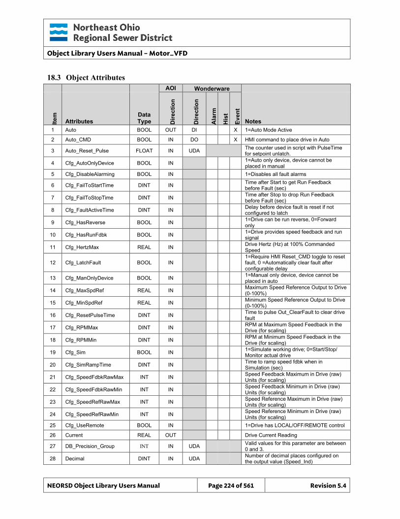
Object Library Users Manual – Motor_VFD
NEORSD Object Library Users Manual Page 224 of 561 Revision 5.4
18.3 Object Attributes
AOI Wonderware
Item
Attributes Data Type D
irect
ion
Dire
ctio
n
Ala
rm
His
t
Even
t
Notes 1 Auto BOOL OUT DI X 1=Auto Mode Active
2 Auto_CMD BOOL IN DO X HMI command to place drive in Auto
3 Auto_Reset_Pulse FLOAT IN UDA The counter used in script with PulseTime for setpoint unlatch.
4 Cfg_AutoOnlyDevice BOOL IN 1=Auto only device, device cannot be placed in manual
5 Cfg_DisableAlarming BOOL IN 1=Disables all fault alarms
6 Cfg_FailToStartTime DINT IN Time after Start to get Run Feedback before Fault (sec)
7 Cfg_FailToStopTime DINT IN Time after Stop to drop Run Feedback before Fault (sec)
8 Cfg_FaultActiveTime DINT IN Delay before device fault is reset if not configured to latch
9 Cfg_HasReverse BOOL IN 1=Drive can be run reverse, 0=Forward only
10 Cfg_HasRunFdbk BOOL IN 1=Drive provides speed feedback and run signal
11 Cfg_HertzMax REAL IN Drive Hertz (Hz) at 100% Commanded Speed
12 Cfg_LatchFault BOOL IN 1=Require HMI Reset_CMD toggle to reset fault, 0 =Automatically clear fault after configurable delay
13 Cfg_ManOnlyDevice BOOL IN 1=Manual only device, device cannot be placed in auto
14 Cfg_MaxSpdRef REAL IN Maximum Speed Reference Output to Drive (0-100%)
15 Cfg_MinSpdRef REAL IN Minimum Speed Reference Output to Drive (0-100%)
16 Cfg_ResetPulseTime DINT IN Time to pulse Out_ClearFault to clear drive fault
17 Cfg_RPMMax DINT IN RPM at Maximum Speed Feedback in the Drive (for scaling)
18 Cfg_RPMMin DINT IN RPM at Minimum Speed Feedback in the Drive (for scaling)
19 Cfg_Sim BOOL IN 1=Simulate working drive; 0=Start/Stop/ Monitor actual drive
20 Cfg_SimRampTime DINT IN Time to ramp speed fdbk when in Simulation (sec)
21 Cfg_SpeedFdbkRawMax INT IN Speed Feedback Maximum in Drive (raw) Units (for scaling)
22 Cfg_SpeedFdbkRawMin INT IN Speed Feedback Minimum in Drive (raw) Units (for scaling)
23 Cfg_SpeedRefRawMax INT IN Speed Reference Maximum in Drive (raw) Units (for scaling)
24 Cfg_SpeedRefRawMin INT IN Speed Reference Minimum in Drive (raw) Units (for scaling)
25 Cfg_UseRemote BOOL IN 1=Drive has LOCAL/OFF/REMOTE control
26 Current REAL OUT Drive Current Reading
27 DB_Precision_Group INT IN UDA Valid values for this parameter are between 0 and 3.
28 Decimal DINT IN UDA Number of decimal places configured on the output value (Speed_Ind)
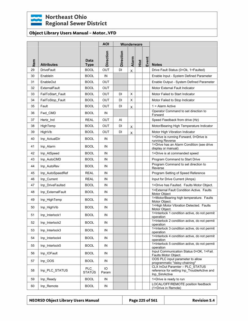
Object Library Users Manual – Motor_VFD
NEORSD Object Library Users Manual Page 225 of 561 Revision 5.4
AOI Wonderware
Item
Attributes Data Type D
irect
ion
Dire
ctio
n
Ala
rm
His
t
Even
t
Notes 29 DriveFault BOOL OUT DI X Drive Fault Status (0=Ok, 1=Faulted)
30 EnableIn BOOL IN Enable Input - System Defined Parameter
31 EnableOut BOOL OUT Enable Output - System Defined Parameter
32 ExternalFault BOOL OUT Motor External Fault Indicator
33 FailToStart_Fault BOOL OUT DI X Motor Failed to Start Indicator
34 FailToStop_Fault BOOL OUT DI X Motor Failed to Stop Indicator
35 Fault BOOL OUT DI X 1 = Alarm Active
36 Fwd_CMD BOOL IN Operator Command to set direction to Forward
37 Hertz_Ind REAL OUT AI Speed Feedback from drive (Hz)
38 HighTemp BOOL OUT DI X Motor/Bearing High Temperature Indicator
39 HighVib BOOL OUT DI X Motor High Vibration Indicator
40 Inp_ActualDir BOOL IN 1=Drive is running Forward, 0=Drive is running Reverse
41 Inp_Alarm BOOL IN 1=Drive has an Alarm Condition (see drive display or manual)
42 Inp_AtSpeed BOOL IN 1=Drive is at commanded speed
43 Inp_AutoCMD BOOL IN Program Command to Start Drive
44 Inp_AutoRev BOOL IN Program Command to set direction to Reverse
45 Inp_AutoSpeedRef REAL IN Program Setting of Speed Reference
46 Inp_Current REAL IN Input for Drive Current (Amps)
47 Inp_DriveFaulted BOOL IN 1=Drive has Faulted. Faults Motor Object.
48 Inp_ExternalFault BOOL IN 1=External Fault Condition Active. Faults Motor Object
49 Inp_HighTemp BOOL IN 1=Motor/Bearing high temperature. Faults Motor Object.
50 Inp_HighVib BOOL IN 1=High Motor Vibration Detected. Faults Motor Object.
51 Inp_Interlock1 BOOL IN 1=Interlock 1 condition active, do not permit operation
52 Inp_Interlock2 BOOL IN 1=Interlock 2 condition active, do not permit operation
53 Inp_Interlock3 BOOL IN 1=Interlock 3 condition active, do not permit operation
54 Inp_Interlock4 BOOL IN 1=Interlock 4 condition active, do not permit operation
55 Inp_Interlock5 BOOL IN 1=Interlock 5 condition active, do not permit operation
56 Inp_IOFault BOOL IN Input Communication Status 0=OK, 1=Fail. Faults Motor Object.
57 Inp_OOS BOOL IN OOS PLC input parameter to allow programmatic "daisy-chaining"
58 Inp_PLC_STATUS PLC_ STATUS
IO Param
CLX InOut Paramter – PLC_STATUS reference for setting Inp_TroubleActive and Inp_SimActive
59 Inp_Ready BOOL IN 1=Drive is ready to run
60 Inp_Remote BOOL IN LOCAL/OFF/REMOTE position feedback (1=Drive in Remote)
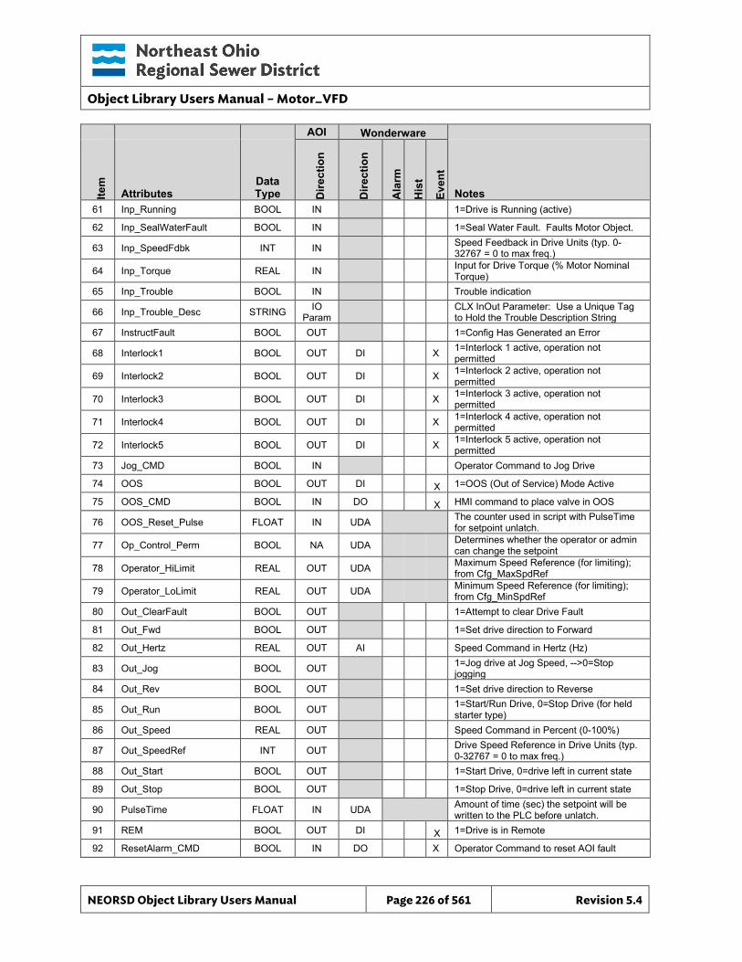
Object Library Users Manual – Motor_VFD
NEORSD Object Library Users Manual Page 226 of 561 Revision 5.4
AOI Wonderware
Item
Attributes Data Type D
irect
ion
Dire
ctio
n
Ala
rm
His
t
Even
t
Notes 61 Inp_Running BOOL IN 1=Drive is Running (active)
62 Inp_SealWaterFault BOOL IN 1=Seal Water Fault. Faults Motor Object.
63 Inp_SpeedFdbk INT IN Speed Feedback in Drive Units (typ. 0-32767 = 0 to max freq.)
64 Inp_Torque REAL IN Input for Drive Torque (% Motor Nominal Torque)
65 Inp_Trouble BOOL IN Trouble indication
66 Inp_Trouble_Desc STRING IO Param CLX InOut Parameter: Use a Unique Tag
to Hold the Trouble Description String 67 InstructFault BOOL OUT 1=Config Has Generated an Error
68 Interlock1 BOOL OUT DI X 1=Interlock 1 active, operation not permitted
69 Interlock2 BOOL OUT DI X 1=Interlock 2 active, operation not permitted
70 Interlock3 BOOL OUT DI X 1=Interlock 3 active, operation not permitted
71 Interlock4 BOOL OUT DI X 1=Interlock 4 active, operation not permitted
72 Interlock5 BOOL OUT DI X 1=Interlock 5 active, operation not permitted
73 Jog_CMD BOOL IN Operator Command to Jog Drive
74 OOS BOOL OUT DI X 1=OOS (Out of Service) Mode Active
75 OOS_CMD BOOL IN DO X HMI command to place valve in OOS
76 OOS_Reset_Pulse FLOAT IN UDA The counter used in script with PulseTime for setpoint unlatch.
77 Op_Control_Perm BOOL NA UDA Determines whether the operator or admin can change the setpoint
78 Operator_HiLimit REAL OUT UDA Maximum Speed Reference (for limiting); from Cfg_MaxSpdRef
79 Operator_LoLimit REAL OUT UDA Minimum Speed Reference (for limiting); from Cfg_MinSpdRef
80 Out_ClearFault BOOL OUT 1=Attempt to clear Drive Fault
81 Out_Fwd BOOL OUT 1=Set drive direction to Forward
82 Out_Hertz REAL OUT AI Speed Command in Hertz (Hz)
83 Out_Jog BOOL OUT 1=Jog drive at Jog Speed, -->0=Stop jogging
84 Out_Rev BOOL OUT 1=Set drive direction to Reverse
85 Out_Run BOOL OUT 1=Start/Run Drive, 0=Stop Drive (for held starter type)
86 Out_Speed REAL OUT Speed Command in Percent (0-100%)
87 Out_SpeedRef INT OUT Drive Speed Reference in Drive Units (typ. 0-32767 = 0 to max freq.)
88 Out_Start BOOL OUT 1=Start Drive, 0=drive left in current state
89 Out_Stop BOOL OUT 1=Stop Drive, 0=drive left in current state
90 PulseTime FLOAT IN UDA Amount of time (sec) the setpoint will be written to the PLC before unlatch.
91 REM BOOL OUT DI X 1=Drive is in Remote
92 ResetAlarm_CMD BOOL IN DO X Operator Command to reset AOI fault
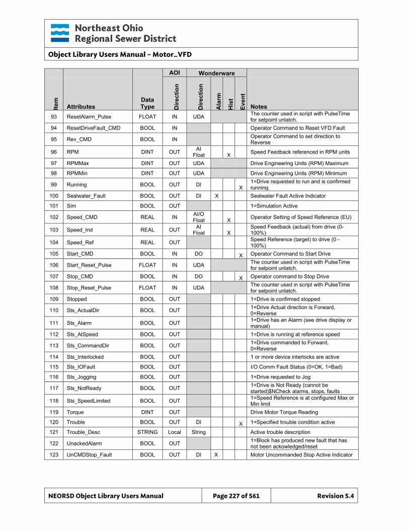
Object Library Users Manual – Motor_VFD
NEORSD Object Library Users Manual Page 227 of 561 Revision 5.4
AOI Wonderware
Item
Attributes Data Type D
irect
ion
Dire
ctio
n
Ala
rm
His
t
Even
t
Notes 93 ResetAlarm_Pulse FLOAT IN UDA The counter used in script with PulseTime
for setpoint unlatch. 94 ResetDriveFault_CMD BOOL IN Operator Command to Reset VFD Fault
95 Rev_CMD BOOL IN Operator Command to set direction to Reverse
96 RPM DINT OUT AI Float X Speed Feedback referenced in RPM units
97 RPMMax DINT OUT UDA Drive Engineering Units (RPM) Maximum
98 RPMMin DINT OUT UDA Drive Engineering Units (RPM) Minimum
99 Running BOOL OUT DI X 1=Drive requested to run and is confirmed running
100 Sealwater_Fault BOOL OUT DI X Sealwater Fault Active Indicator
101 Sim BOOL OUT 1=Simulation Active
102 Speed_CMD REAL IN AI/O Float
X Operator Setting of Speed Reference (EU)
103 Speed_Ind REAL OUT AI Float X
Speed Feedback (actual) from drive (0-100%)
104 Speed_Ref REAL OUT Speed Reference (target) to drive (0 -100%)
105 Start_CMD BOOL IN DO X Operator Command to Start Drive
106 Start_Reset_Pulse FLOAT IN UDA The counter used in script with PulseTime for setpoint unlatch.
107 Stop_CMD BOOL IN DO X Operator command to Stop Drive
108 Stop_Reset_Pulse FLOAT IN UDA The counter used in script with PulseTime for setpoint unlatch.
109 Stopped BOOL OUT 1=Drive is confirmed stopped
110 Sts_ActualDir BOOL OUT 1=Drive Actual direction is Forward, 0=Reverse
111 Sts_Alarm BOOL OUT 1=Drive has an Alarm (see drive display or manual)
112 Sts_AtSpeed BOOL OUT 1=Drive is running at reference speed
113 Sts_CommandDir BOOL OUT 1=Drive commanded to Forward, 0=Reverse
114 Sts_Interlocked BOOL OUT 1 or more device interlocks are active
115 Sts_IOFault BOOL OUT I/O Comm Fault Status (0=OK, 1=Bad)
116 Sts_Jogging BOOL OUT 1=Drive requested to Jog
117 Sts_NotReady BOOL OUT 1=Drive is Not Ready (cannot be started)$NCheck alarms, stops, faults
118 Sts_SpeedLimited BOOL OUT 1=Speed Reference is at configured Max or Min limit
119 Torque DINT OUT Drive Motor Torque Reading
120 Trouble BOOL OUT DI X 1=Specified trouble condition active
121 Trouble_Desc STRING Local String Active trouble description
122 UnackedAlarm BOOL OUT 1=Block has produced new fault that has not been ackowledged/reset
123 UnCMDStop_Fault BOOL OUT DI X Motor Uncommanded Stop Active Indicator
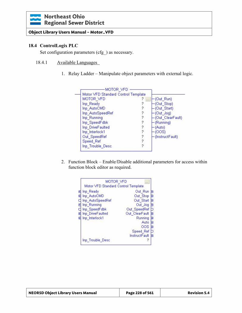
Object Library Users Manual – Motor_VFD
NEORSD Object Library Users Manual Page 228 of 561 Revision 5.4
18.4 ControlLogix PLC Set configuration parameters (cfg_) as necessary.
18.4.1 Available Languages
1. Relay Ladder – Manipulate object parameters with external logic.
2. Function Block – Enable/Disable additional parameters for access within function block editor as required.
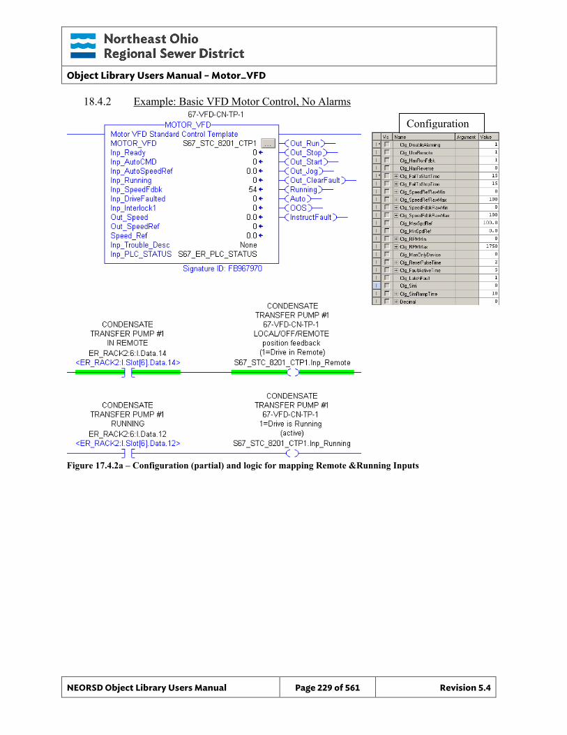
Object Library Users Manual – Motor_VFD
NEORSD Object Library Users Manual Page 229 of 561 Revision 5.4
18.4.2 Example: Basic VFD Motor Control, No Alarms
Figure 17.4.2a – Configuration (partial) and logic for mapping Remote &Running Inputs
Configuration
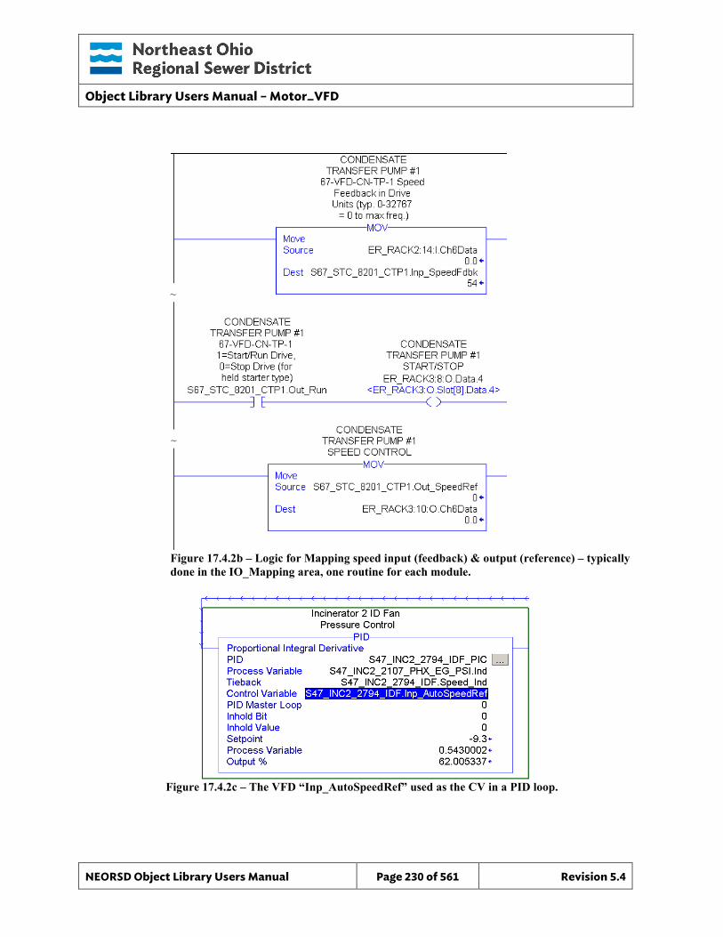
Object Library Users Manual – Motor_VFD
NEORSD Object Library Users Manual Page 230 of 561 Revision 5.4
Figure 17.4.2b – Logic for Mapping speed input (feedback) & output (reference) – typically done in the IO_Mapping area, one routine for each module.
Figure 17.4.2c – The VFD “Inp_AutoSpeedRef” used as the CV in a PID loop.
~
~
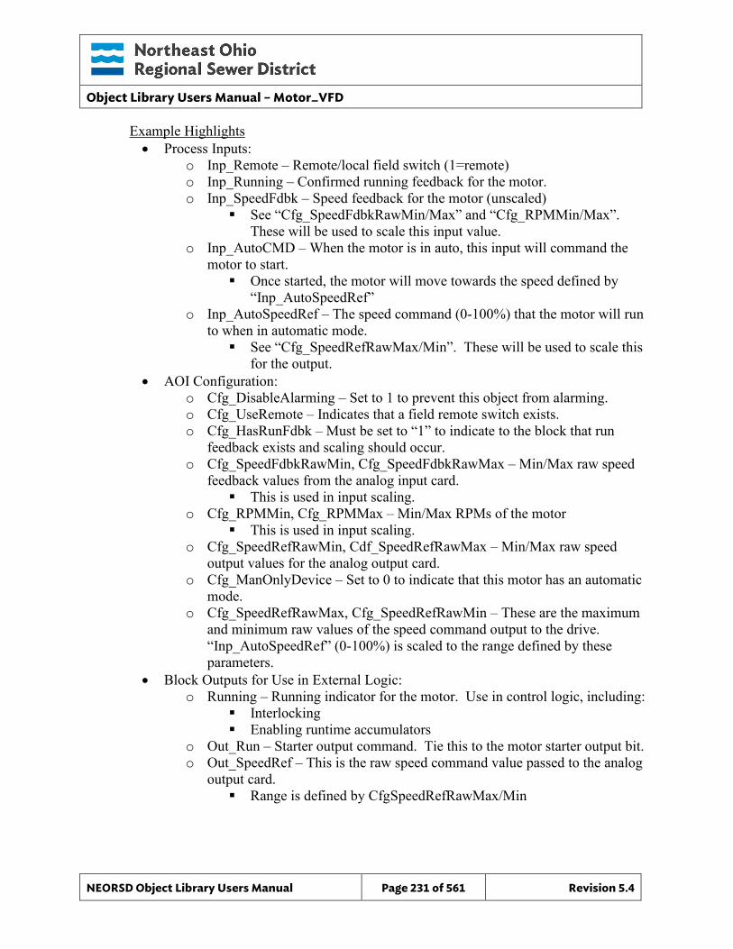
Object Library Users Manual – Motor_VFD
NEORSD Object Library Users Manual Page 231 of 561 Revision 5.4
Example Highlights • Process Inputs:
o Inp_Remote – Remote/local field switch (1=remote) o Inp_Running – Confirmed running feedback for the motor. o Inp_SpeedFdbk – Speed feedback for the motor (unscaled)
See “Cfg_SpeedFdbkRawMin/Max” and “Cfg_RPMMin/Max”. These will be used to scale this input value.
o Inp_AutoCMD – When the motor is in auto, this input will command the motor to start. Once started, the motor will move towards the speed defined by
“Inp_AutoSpeedRef” o Inp_AutoSpeedRef – The speed command (0-100%) that the motor will run
to when in automatic mode. See “Cfg_SpeedRefRawMax/Min”. These will be used to scale this
for the output. • AOI Configuration:
o Cfg_DisableAlarming – Set to 1 to prevent this object from alarming. o Cfg_UseRemote – Indicates that a field remote switch exists. o Cfg_HasRunFdbk – Must be set to “1” to indicate to the block that run
feedback exists and scaling should occur. o Cfg_SpeedFdbkRawMin, Cfg_SpeedFdbkRawMax – Min/Max raw speed
feedback values from the analog input card. This is used in input scaling.
o Cfg_RPMMin, Cfg_RPMMax – Min/Max RPMs of the motor This is used in input scaling.
o Cfg_SpeedRefRawMin, Cdf_SpeedRefRawMax – Min/Max raw speed output values for the analog output card.
o Cfg_ManOnlyDevice – Set to 0 to indicate that this motor has an automatic mode.
o Cfg_SpeedRefRawMax, Cfg_SpeedRefRawMin – These are the maximum and minimum raw values of the speed command output to the drive. “Inp_AutoSpeedRef” (0-100%) is scaled to the range defined by these parameters.
• Block Outputs for Use in External Logic: o Running – Running indicator for the motor. Use in control logic, including:
Interlocking Enabling runtime accumulators
o Out_Run – Starter output command. Tie this to the motor starter output bit. o Out_SpeedRef – This is the raw speed command value passed to the analog
output card. Range is defined by CfgSpeedRefRawMax/Min
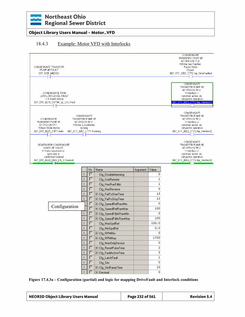
Object Library Users Manual – Motor_VFD
NEORSD Object Library Users Manual Page 232 of 561 Revision 5.4
18.4.3 Example: Motor VFD with Interlocks
Figure 17.4.3a – Configuration (partial) and logic for mapping DriveFault and Interlock conditions
Configuration
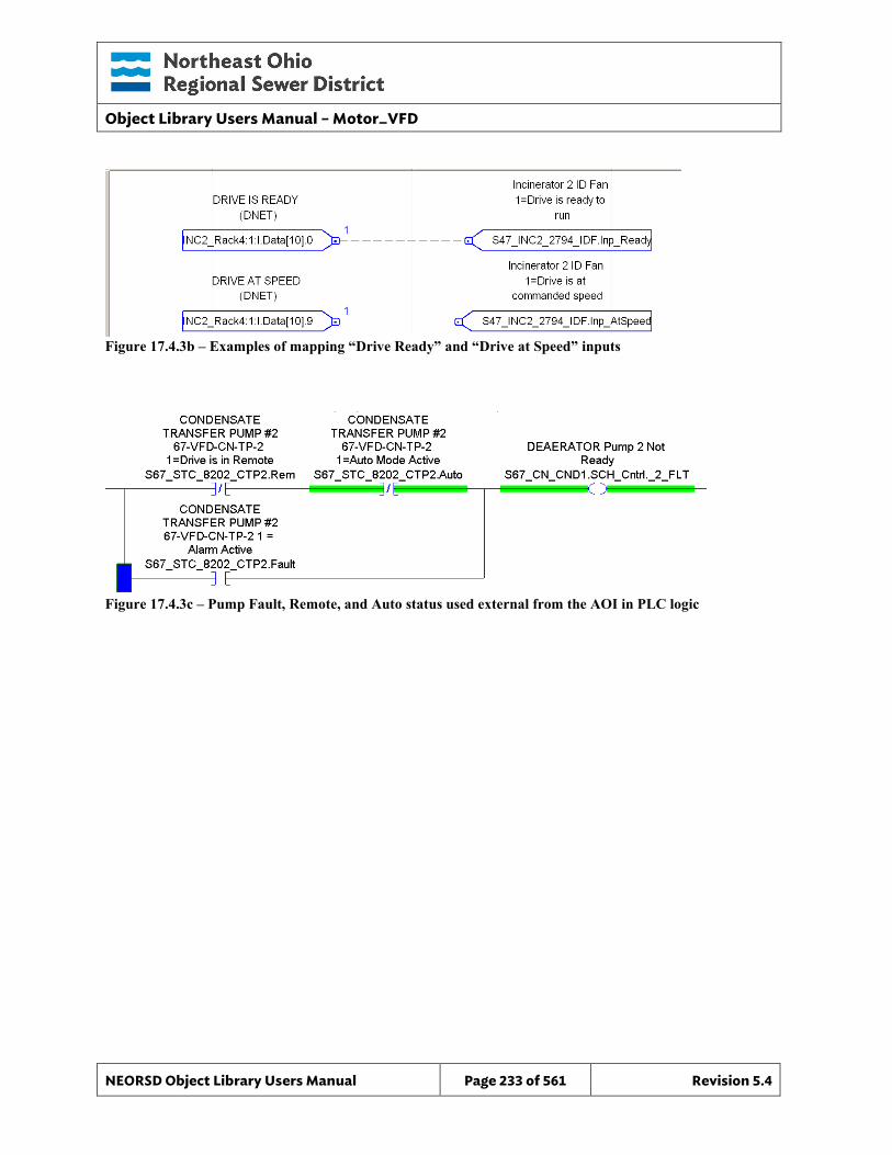
Object Library Users Manual – Motor_VFD
NEORSD Object Library Users Manual Page 233 of 561 Revision 5.4
Figure 17.4.3b – Examples of mapping “Drive Ready” and “Drive at Speed” inputs
Figure 17.4.3c – Pump Fault, Remote, and Auto status used external from the AOI in PLC logic
Object Library Users Manual – Motor_VFD
NEORSD Object Library Users Manual Page 234 of 561 Revision 5.4
Example Highlights: Programming the motor to handle faults and interlocks is similar to the first example, with the following changes: • Process Inputs:
o Inp_DriveFaulted – Indicates that the VFD has failed Operators can attempt to clear this fault from an OIT (see
Out_ClearFault) o Inp_Interlock – Custom interlock conditions that will prevent motor
operation when true. o Inp_Ready – Input indicating that the VFD is “ready” o Inp_AtSpeed – Input indicating that the drive is at speed.
• AOI Configuration: o Cfg_DisableAlarming – Set to 0 to allow alarms to occur. o Cfg_FailtoStartTime, Cfg_FailtoStopTime – If the motor is commanded to
start or stop and fails to do so within these times, an alarm will occur. • Block Outputs for Use in External Logic:
o Running – Running indicator for the motor. Use in control logic, including: Interlocking Enabling runtime accumulators
o Rem – Indicates that this motor is in Remote mode (from a field switch) o Auto – Indicates that this motor is in Automatic mode o Fault – True when any fault occurs on the motor. If a fault occurs, the
motor will stop and enter manual mode. o Sts_Interlocked – True when any interlock input is active.
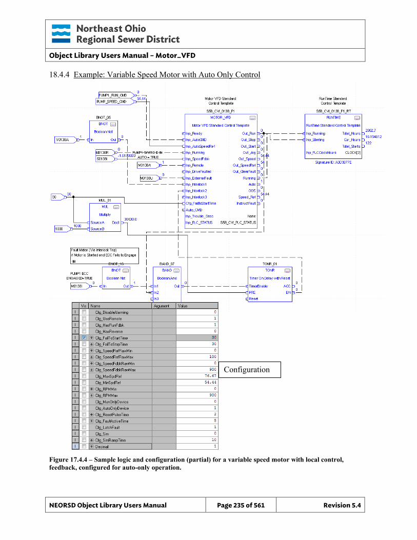
Object Library Users Manual – Motor_VFD
NEORSD Object Library Users Manual Page 235 of 561 Revision 5.4
18.4.4 Example: Variable Speed Motor with Auto Only Control
Figure 17.4.4 – Sample logic and configuration (partial) for a variable speed motor with local control, feedback, configured for auto-only operation.
Configuration
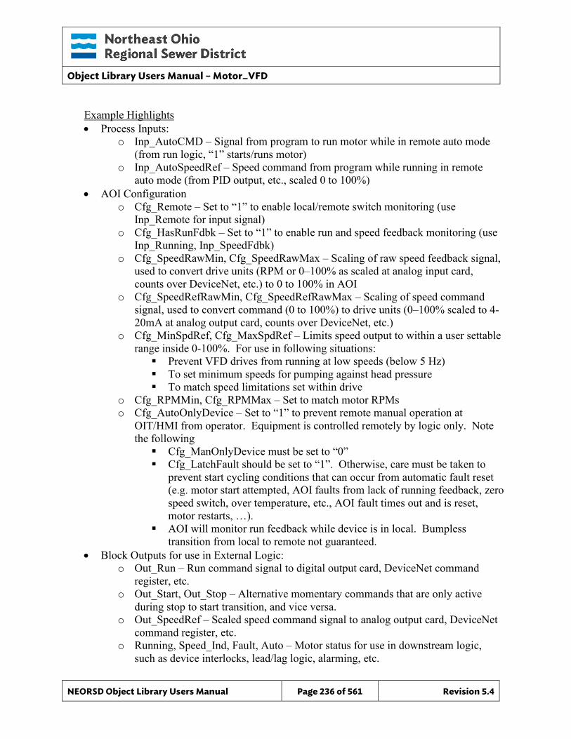
Object Library Users Manual – Motor_VFD
NEORSD Object Library Users Manual Page 236 of 561 Revision 5.4
Example Highlights • Process Inputs:
o Inp_AutoCMD – Signal from program to run motor while in remote auto mode (from run logic, “1” starts/runs motor)
o Inp_AutoSpeedRef – Speed command from program while running in remote auto mode (from PID output, etc., scaled 0 to 100%)
• AOI Configuration o Cfg_Remote – Set to “1” to enable local/remote switch monitoring (use
Inp_Remote for input signal) o Cfg_HasRunFdbk – Set to “1” to enable run and speed feedback monitoring (use
Inp_Running, Inp_SpeedFdbk) o Cfg_SpeedRawMin, Cfg_SpeedRawMax – Scaling of raw speed feedback signal,
used to convert drive units (RPM or 0–100% as scaled at analog input card, counts over DeviceNet, etc.) to 0 to 100% in AOI
o Cfg_SpeedRefRawMin, Cfg_SpeedRefRawMax – Scaling of speed command signal, used to convert command (0 to 100%) to drive units (0–100% scaled to 4-20mA at analog output card, counts over DeviceNet, etc.)
o Cfg_MinSpdRef, Cfg_MaxSpdRef – Limits speed output to within a user settable range inside 0-100%. For use in following situations: Prevent VFD drives from running at low speeds (below 5 Hz) To set minimum speeds for pumping against head pressure To match speed limitations set within drive
o Cfg_RPMMin, Cfg_RPMMax – Set to match motor RPMs o Cfg_AutoOnlyDevice – Set to “1” to prevent remote manual operation at
OIT/HMI from operator. Equipment is controlled remotely by logic only. Note the following Cfg_ManOnlyDevice must be set to “0” Cfg_LatchFault should be set to “1”. Otherwise, care must be taken to
prevent start cycling conditions that can occur from automatic fault reset (e.g. motor start attempted, AOI faults from lack of running feedback, zero speed switch, over temperature, etc., AOI fault times out and is reset, motor restarts, …).
AOI will monitor run feedback while device is in local. Bumpless transition from local to remote not guaranteed.
• Block Outputs for use in External Logic: o Out_Run – Run command signal to digital output card, DeviceNet command
register, etc. o Out_Start, Out_Stop – Alternative momentary commands that are only active
during stop to start transition, and vice versa. o Out_SpeedRef – Scaled speed command signal to analog output card, DeviceNet
command register, etc. o Running, Speed_Ind, Fault, Auto – Motor status for use in downstream logic,
such as device interlocks, lead/lag logic, alarming, etc.
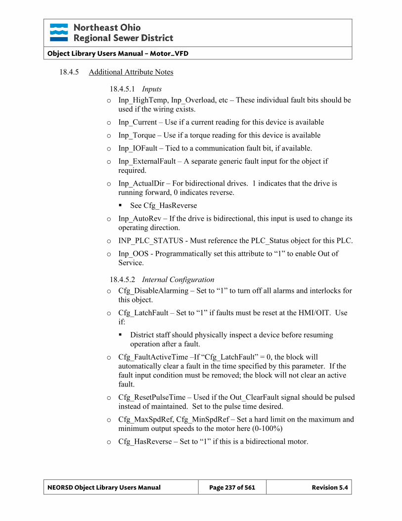
Object Library Users Manual – Motor_VFD
NEORSD Object Library Users Manual Page 237 of 561 Revision 5.4
18.4.5 Additional Attribute Notes
18.4.5.1 Inputs o Inp_HighTemp, Inp_Overload, etc – These individual fault bits should be
used if the wiring exists. o Inp_Current – Use if a current reading for this device is available o Inp_Torque – Use if a torque reading for this device is available o Inp_IOFault – Tied to a communication fault bit, if available. o Inp_ExternalFault – A separate generic fault input for the object if
required. o Inp_ActualDir – For bidirectional drives. 1 indicates that the drive is
running forward, 0 indicates reverse. See Cfg_HasReverse
o Inp_AutoRev – If the drive is bidirectional, this input is used to change its operating direction.
o INP_PLC_STATUS - Must reference the PLC_Status object for this PLC. o Inp_OOS - Programmatically set this attribute to “1” to enable Out of
Service.
18.4.5.2 Internal Configuration o Cfg_DisableAlarming – Set to “1” to turn off all alarms and interlocks for
this object. o Cfg_LatchFault – Set to “1” if faults must be reset at the HMI/OIT. Use
if: District staff should physically inspect a device before resuming
operation after a fault. o Cfg_FaultActiveTime –If “Cfg_LatchFault” = 0, the block will
automatically clear a fault in the time specified by this parameter. If the fault input condition must be removed; the block will not clear an active fault.
o Cfg_ResetPulseTime – Used if the Out_ClearFault signal should be pulsed instead of maintained. Set to the pulse time desired.
o Cfg_MaxSpdRef, Cfg_MinSpdRef – Set a hard limit on the maximum and minimum output speeds to the motor here (0-100%)
o Cfg_HasReverse – Set to “1” if this is a bidirectional motor.

Object Library Users Manual – Motor_VFD
NEORSD Object Library Users Manual Page 238 of 561 Revision 5.4
o Cfg_Sim – Set to “1” to enable simulation mode for this block. The running feedback will be ignored and when the block is commanded to start/stop the motor “Running” output will react accordingly.
o Cfg_SimRampTime – The number of seconds that the drive will ramp between minimum and maximum speed when in simulation mode.
o Cfg_AutoOnlyDevice – Set to “1” to prevent the device from operating in remote manual mode. Cfg_ManOnlyDevice must be set to “0”.
o Cfg_HertzMax - Set Max Drive Hz at 100% Commanded Speed.
18.4.5.3 Outputs o OOS – Indicates that this instance is out-of-service o Sts_ActualDir – Used for bidirectional drives. Will indicate which
direction the drive is currently operating. o Out_Start, Out_Stop – Use if momentary start/stop commands are required
instead of the maintained “Out_Run” attribute.
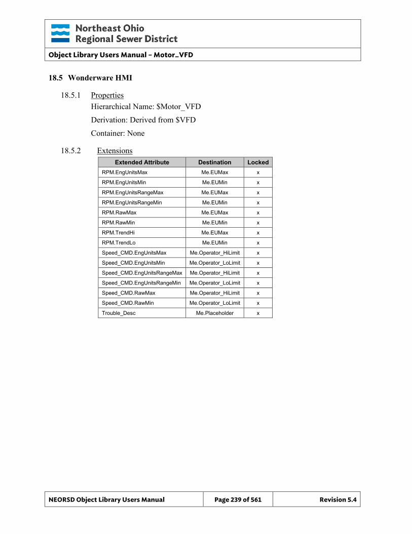
Object Library Users Manual – Motor_VFD
NEORSD Object Library Users Manual Page 239 of 561 Revision 5.4
18.5 Wonderware HMI
18.5.1 Properties Hierarchical Name: $Motor_VFD Derivation: Derived from $VFD Container: None
18.5.2 Extensions Extended Attribute Destination Locked
RPM.EngUnitsMax Me.EUMax x
RPM.EngUnitsMin Me.EUMin x
RPM.EngUnitsRangeMax Me.EUMax x
RPM.EngUnitsRangeMin Me.EUMin x
RPM.RawMax Me.EUMax x
RPM.RawMin Me.EUMin x
RPM.TrendHi Me.EUMax x
RPM.TrendLo Me.EUMin x
Speed_CMD.EngUnitsMax Me.Operator_HiLimit x
Speed_CMD.EngUnitsMin Me.Operator_LoLimit x
Speed_CMD.EngUnitsRangeMax Me.Operator_HiLimit x
Speed_CMD.EngUnitsRangeMin Me.Operator_LoLimit x
Speed_CMD.RawMax Me.Operator_HiLimit x
Speed_CMD.RawMin Me.Operator_LoLimit x
Trouble_Desc Me.Placeholder x
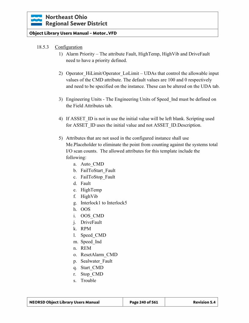
Object Library Users Manual – Motor_VFD
NEORSD Object Library Users Manual Page 240 of 561 Revision 5.4
18.5.3 Configuration 1) Alarm Priority – The attribute Fault, HighTemp, HighVib and DriveFault
need to have a priority defined.
2) Operator_HiLimit/Operator_LoLimit – UDAs that control the allowable input values of the CMD attribute. The default values are 100 and 0 respectively and need to be specified on the instance. These can be altered on the UDA tab.
3) Engineering Units - The Engineering Units of Speed_Ind must be defined on the Field Attributes tab.
4) If ASSET_ID is not in use the initial value will be left blank. Scripting used for ASSET_ID uses the initial value and not ASSET_ID.Description.
5) Attributes that are not used in the configured instance shall use Me.Placeholder to eliminate the point from counting against the systems total I/O scan counts. The allowed attributes for this template include the following:
a. Auto_CMD b. FailToStart_Fault c. FailToStop_Fault d. Fault e. HighTemp f. HighVib g. Interlock1 to Interlock5 h. OOS i. OOS_CMD j. DriveFault k. RPM l. Speed_CMD m. Speed_Ind n. REM o. ResetAlarm_CMD p. Sealwater_Fault q. Start_CMD r. Stop_CMD s. Trouble
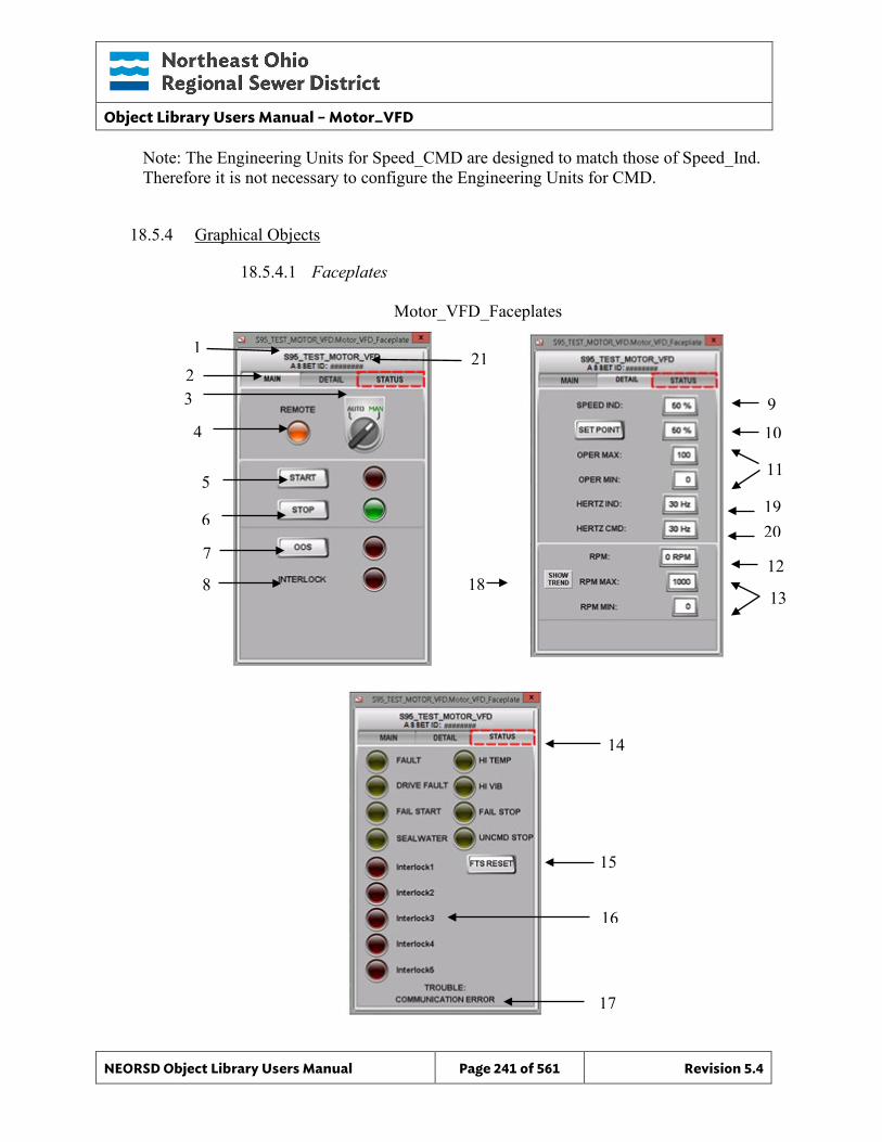
Object Library Users Manual – Motor_VFD
NEORSD Object Library Users Manual Page 241 of 561 Revision 5.4
6
14
15
16
17
Note: The Engineering Units for Speed_CMD are designed to match those of Speed_Ind. Therefore it is not necessary to configure the Engineering Units for CMD.
18.5.4 Graphical Objects
18.5.4.1 Faceplates
10
7
8
Motor_VFD_Faceplates
9
2 3
4
5 11
12
13
1
18
19 20
21
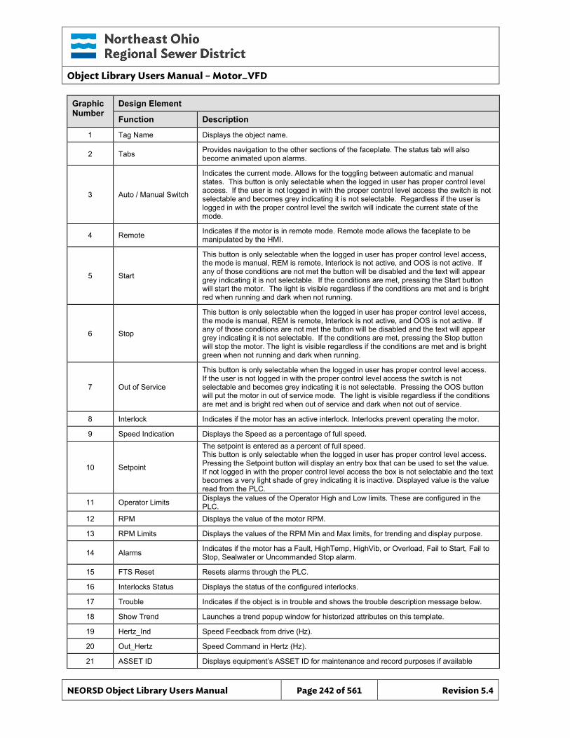
Object Library Users Manual – Motor_VFD
NEORSD Object Library Users Manual Page 242 of 561 Revision 5.4
Graphic Number
Design Element
Function Description
1 Tag Name Displays the object name.
2 Tabs Provides navigation to the other sections of the faceplate. The status tab will also become animated upon alarms.
3 Auto / Manual Switch
Indicates the current mode. Allows for the toggling between automatic and manual states. This button is only selectable when the logged in user has proper control level access. If the user is not logged in with the proper control level access the switch is not selectable and becomes grey indicating it is not selectable. Regardless if the user is logged in with the proper control level the switch will indicate the current state of the mode.
4 Remote Indicates if the motor is in remote mode. Remote mode allows the faceplate to be manipulated by the HMI.
5 Start
This button is only selectable when the logged in user has proper control level access, the mode is manual, REM is remote, Interlock is not active, and OOS is not active. If any of those conditions are not met the button will be disabled and the text will appear grey indicating it is not selectable. If the conditions are met, pressing the Start button will start the motor. The light is visible regardless if the conditions are met and is bright red when running and dark when not running.
6 Stop
This button is only selectable when the logged in user has proper control level access, the mode is manual, REM is remote, Interlock is not active, and OOS is not active. If any of those conditions are not met the button will be disabled and the text will appear grey indicating it is not selectable. If the conditions are met, pressing the Stop button will stop the motor. The light is visible regardless if the conditions are met and is bright green when not running and dark when running.
7 Out of Service
This button is only selectable when the logged in user has proper control level access. If the user is not logged in with the proper control level access the switch is not selectable and becomes grey indicating it is not selectable. Pressing the OOS button will put the motor in out of service mode. The light is visible regardless if the conditions are met and is bright red when out of service and dark when not out of service.
8 Interlock Indicates if the motor has an active interlock. Interlocks prevent operating the motor.
9 Speed Indication Displays the Speed as a percentage of full speed.
10 Setpoint
The setpoint is entered as a percent of full speed. This button is only selectable when the logged in user has proper control level access. Pressing the Setpoint button will display an entry box that can be used to set the value. If not logged in with the proper control level access the box is not selectable and the text becomes a very light shade of grey indicating it is inactive. Displayed value is the value read from the PLC.
11 Operator Limits Displays the values of the Operator High and Low limits. These are configured in the PLC.
12 RPM Displays the value of the motor RPM.
13 RPM Limits Displays the values of the RPM Min and Max limits, for trending and display purpose.
14 Alarms Indicates if the motor has a Fault, HighTemp, HighVib, or Overload, Fail to Start, Fail to Stop, Sealwater or Uncommanded Stop alarm.
15 FTS Reset Resets alarms through the PLC.
16 Interlocks Status Displays the status of the configured interlocks.
17 Trouble Indicates if the object is in trouble and shows the trouble description message below.
18 Show Trend Launches a trend popup window for historized attributes on this template.
19 Hertz_Ind Speed Feedback from drive (Hz).
20 Out_Hertz Speed Command in Hertz (Hz).
21 ASSET ID Displays equipment’s ASSET ID for maintenance and record purposes if available
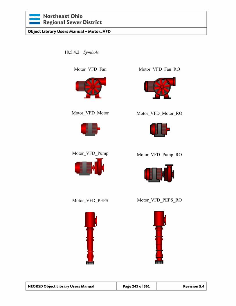
Object Library Users Manual – Motor_VFD
NEORSD Object Library Users Manual Page 243 of 561 Revision 5.4
18.5.4.2 Symbols
Motor_VFD_Fan
Motor_VFD_Motor
Motor_VFD_Pump
Motor_VFD_PEPS
Motor_VFD_Fan_RO
Motor_VFD_PEPS_RO
Motor_VFD_Motor_RO
Motor_VFD_Pump_RO
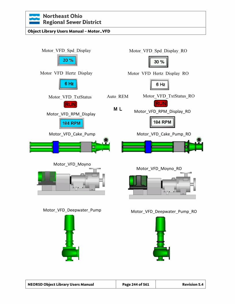
Object Library Users Manual – Motor_VFD
NEORSD Object Library Users Manual Page 244 of 561 Revision 5.4
Motor_VFD_TxtStatus
Motor_VFD_Spd_Display Motor_VFD_Spd_Display_RO
Motor_VFD_TxtStatus_RO Auto_REM
Motor_VFD_Cake_Pump
Motor_VFD_Cake_Pump_RO
Motor_VFD_Moyno Motor_VFD_Moyno_RO
Motor_VFD_Deepwater_Pump
Motor_VFD_Deepwater_Pump_RO
Motor_VFD_RPM_Display
Motor_VFD_RPM_Display_RO
Motor_VFD_Hertz_Display Motor_VFD_Hertz_Display_RO
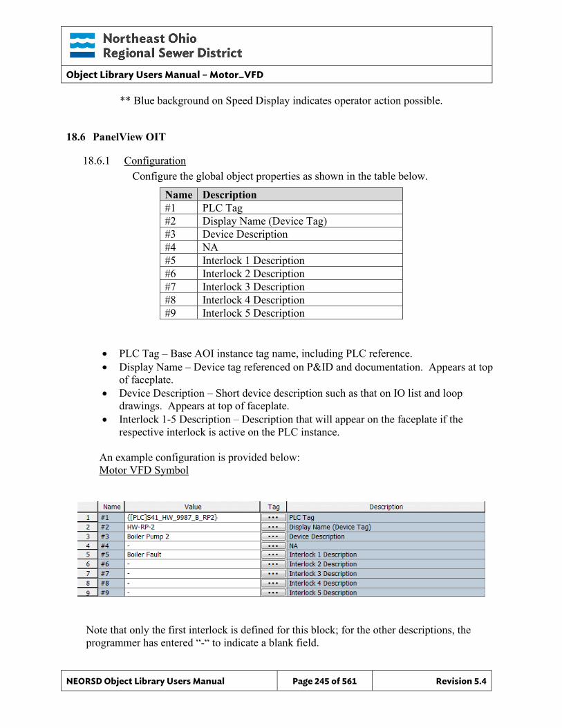
Object Library Users Manual – Motor_VFD
NEORSD Object Library Users Manual Page 245 of 561 Revision 5.4
** Blue background on Speed Display indicates operator action possible.
18.6 PanelView OIT
18.6.1 Configuration Configure the global object properties as shown in the table below.
Name Description #1 PLC Tag #2 Display Name (Device Tag) #3 Device Description #4 NA #5 Interlock 1 Description #6 Interlock 2 Description #7 Interlock 3 Description #8 Interlock 4 Description #9 Interlock 5 Description
• PLC Tag – Base AOI instance tag name, including PLC reference. • Display Name – Device tag referenced on P&ID and documentation. Appears at top
of faceplate. • Device Description – Short device description such as that on IO list and loop
drawings. Appears at top of faceplate. • Interlock 1-5 Description – Description that will appear on the faceplate if the
respective interlock is active on the PLC instance.
An example configuration is provided below: Motor VFD Symbol
Note that only the first interlock is defined for this block; for the other descriptions, the programmer has entered “-“ to indicate a blank field.
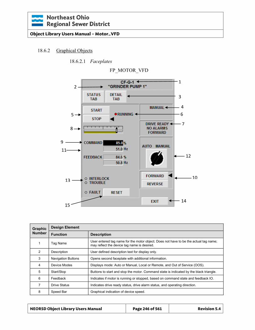
Object Library Users Manual – Motor_VFD
NEORSD Object Library Users Manual Page 246 of 561 Revision 5.4
15
1
10
7
3
4 6
14
12
18.6.2 Graphical Objects
18.6.2.1 Faceplates
Graphic Number
Design Element
Function Description
1 Tag Name User entered tag name for the motor object. Does not have to be the actual tag name; may reflect the device tag name is desired.
2 Description User defined description text for display only.
3 Navigation Buttons Opens second faceplate with additional information.
4 Device Modes Displays mode: Auto or Manual, Local or Remote, and Out of Service (OOS).
5 Start/Stop Buttons to start and stop the motor. Command state is indicated by the black triangle.
6 Feedback Indicates if motor is running or stopped, based on command state and feedback IO.
7 Drive Status Indicates drive ready status, drive alarm status, and operating direction.
8 Speed Bar Graphical indication of device speed.
FP_MOTOR_VFD
2
8
5
9
11
13
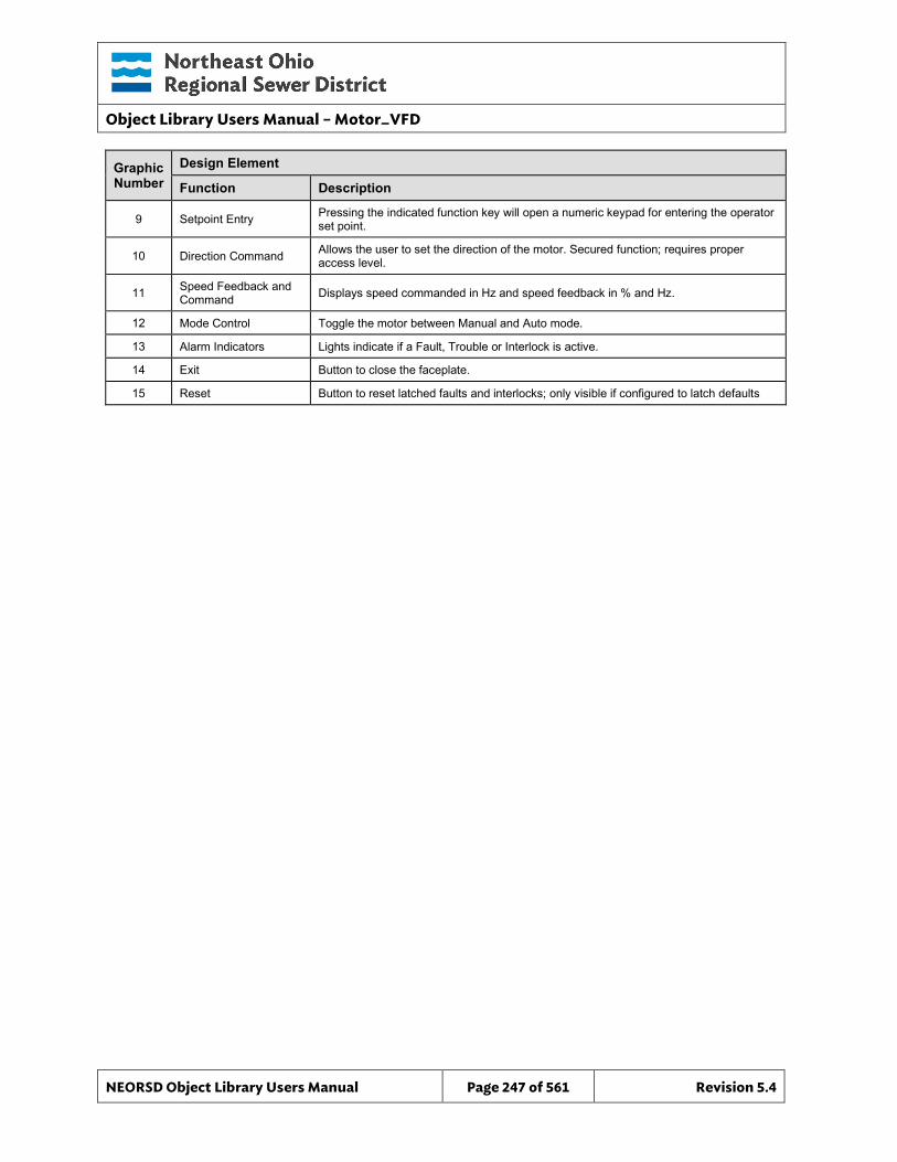
Object Library Users Manual – Motor_VFD
NEORSD Object Library Users Manual Page 247 of 561 Revision 5.4
Graphic Number
Design Element
Function Description
9 Setpoint Entry Pressing the indicated function key will open a numeric keypad for entering the operator set point.
10 Direction Command Allows the user to set the direction of the motor. Secured function; requires proper access level.
11 Speed Feedback and Command Displays speed commanded in Hz and speed feedback in % and Hz.
12 Mode Control Toggle the motor between Manual and Auto mode.
13 Alarm Indicators Lights indicate if a Fault, Trouble or Interlock is active.
14 Exit Button to close the faceplate.
15 Reset Button to reset latched faults and interlocks; only visible if configured to latch defaults
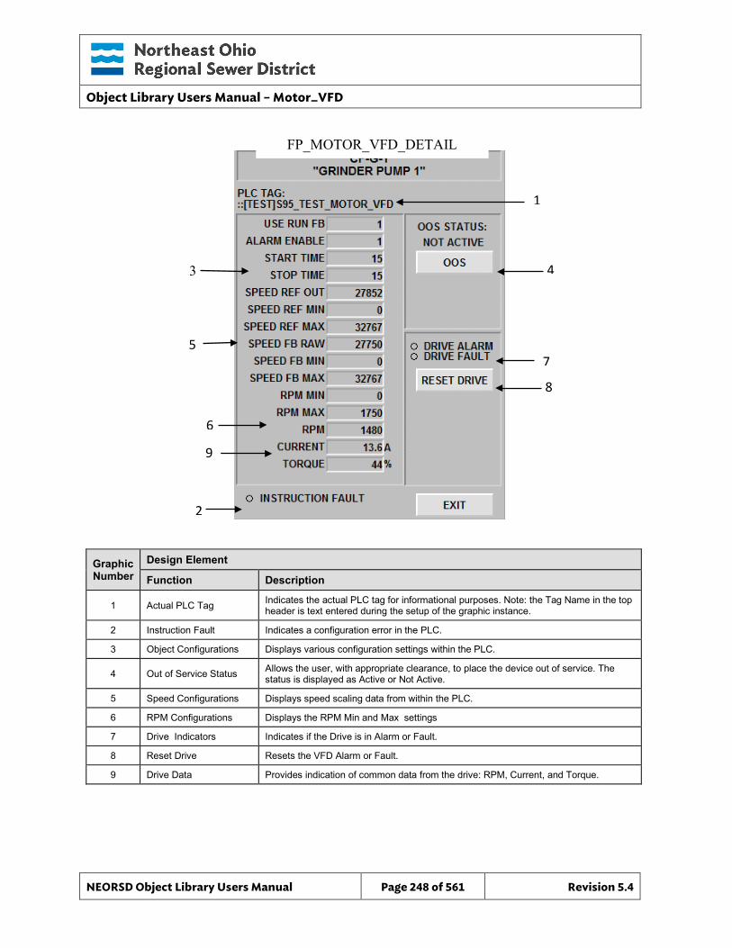
Object Library Users Manual – Motor_VFD
NEORSD Object Library Users Manual Page 248 of 561 Revision 5.4
1
4
7 8
Graphic Number
Design Element
Function Description
1 Actual PLC Tag Indicates the actual PLC tag for informational purposes. Note: the Tag Name in the top header is text entered during the setup of the graphic instance.
2 Instruction Fault Indicates a configuration error in the PLC.
3 Object Configurations Displays various configuration settings within the PLC.
4 Out of Service Status Allows the user, with appropriate clearance, to place the device out of service. The status is displayed as Active or Not Active.
5 Speed Configurations Displays speed scaling data from within the PLC.
6 RPM Configurations Displays the RPM Min and Max settings
7 Drive Indicators Indicates if the Drive is in Alarm or Fault.
8 Reset Drive Resets the VFD Alarm or Fault.
9 Drive Data Provides indication of common data from the drive: RPM, Current, and Torque.
FP_MOTOR_VFD_DETAIL
3
5
6
2
9
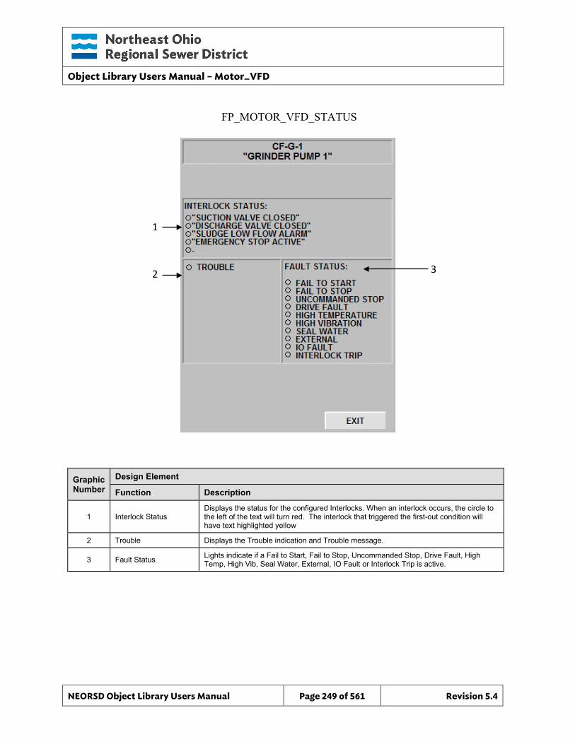
Object Library Users Manual – Motor_VFD
NEORSD Object Library Users Manual Page 249 of 561 Revision 5.4
3
Graphic Number
Design Element
Function Description
1 Interlock Status Displays the status for the configured Interlocks. When an interlock occurs, the circle to the left of the text will turn red. The interlock that triggered the first-out condition will have text highlighted yellow
2 Trouble Displays the Trouble indication and Trouble message.
3 Fault Status Lights indicate if a Fail to Start, Fail to Stop, Uncommanded Stop, Drive Fault, High Temp, High Vib, Seal Water, External, IO Fault or Interlock Trip is active.
FP_MOTOR_VFD_STATUS
1
2
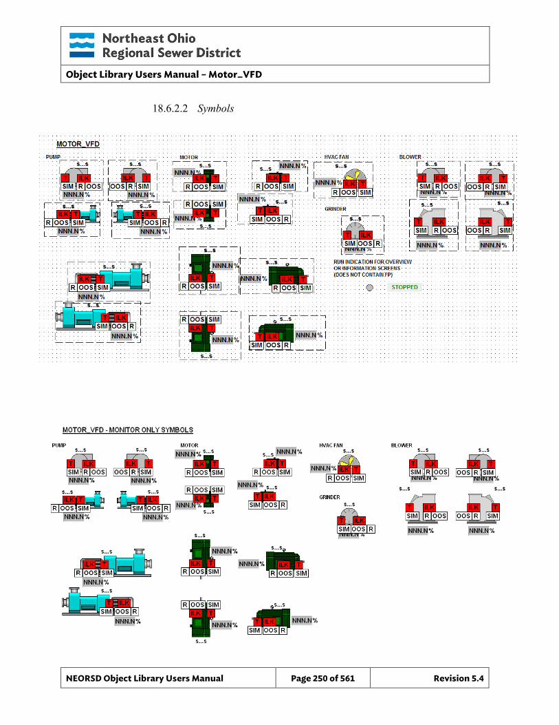
Object Library Users Manual – Motor_VFD
NEORSD Object Library Users Manual Page 250 of 561 Revision 5.4
18.6.2.2 Symbols
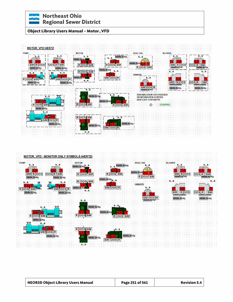
Object Library Users Manual – Motor_VFD
NEORSD Object Library Users Manual Page 251 of 561 Revision 5.4

Object Library Users Manual – Motor_VFD
NEORSD Object Library Users Manual Page 252 of 561 Revision 5.4
Object Library Users Manual – Multistate_Indicator
NEORSD Object Library Users Manual Page 253 of 561 Revision 5.4
19.0 Multistate_Indicator
19.1 Introduction The MultiState Ind object template provides a standard representation for a multiple-state indicator (with or without incrementing state-change control) within the NEORSD control systems. The indicator may represent lead-lag orders or similar multiple-state text displays.
Use the Multistate_Ind template if any of the statements below are true:
• To display state-based status for equipment or processes that have 3 or more distinct states not already handled by the District Standard templates
• To display multiple lead-lag system order
Do not use the Multistate_Ind template:
• To show states such as “running/stopped”, “opened/closed”, or controls such as “start/stop” or “open/close”. These should be handled by the appropriate equipment object instance, such as Motor_Discrete or Valve_Analog.
• To show binary states, such as “lead” or “lag”, “enabled” or “disabled”, etc. Use the Discrete object instead.
No specific ControlLogix component (AOI) exists for this template. It is recommended that the Analog_Basic be used when programming ControlLogix processors.
19.2 Object Features
19.2.1 Value Indication This object can be used to display various states of a process or equipment through text display on the HMI. States are represented through bit-wise operation of a single integer word. Each state corresponds to a single bit, starting with bit 0. Bit states are sequential up to a maximum of 16 states:
• Bit 0 (decimal value 1) – State 1 • Bit 1 (decimal value 2) – State 2 • Bit 2 (decimal value 4) – State 3 • … • Bit 15 (decimal value 32768) – State 16
Only one state may be set active at a time. No states selected (decimal value 0) is invalid and will generate an input error. The HMI text and background color is configurable at the instance level. The text box colors that should be used are as follows: Red for Active State, Green for Inactive, Yellow for Alarm, and White for Other.
Object Library Users Manual – Multistate_Indicator
NEORSD Object Library Users Manual Page 254 of 561 Revision 5.4
19.2.2 Control A momentary pushbutton is provided as part of the multistate HMI template. This pushbutton may be used to toggle external logic, such as cycling through configuration states or executing step changes. Configuration of the pushbutton is not required. The pushbutton is not compatible with CLX-based PLC hardware. The text shown on the HMI pushbutton is configurable under the “Button_Text” Wonderware UDA.
For Wonderware configuration information, see the Wonderware section of this document.
19.2.3 Simulation This object does not support simulation.
19.2.4 Trouble This object does not support hardware trouble indication.
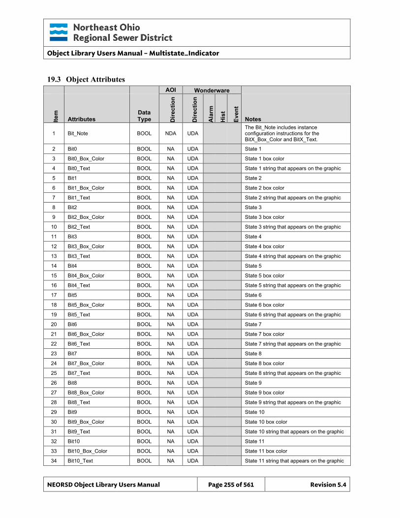
Object Library Users Manual – Multistate_Indicator
NEORSD Object Library Users Manual Page 255 of 561 Revision 5.4
19.3 Object Attributes
AOI Wonderware
Item
Attributes Data Type D
irect
ion
Dire
ctio
n
Ala
rm
His
t
Even
t
Notes
1 Bit_Note BOOL NDA UDA The Bit_Note includes instance configuration instructions for the BitX_Box_Color and BitX_Text.
2 Bit0 BOOL NA UDA State 1
3 Bit0_Box_Color BOOL NA UDA State 1 box color
4 Bit0_Text BOOL NA UDA State 1 string that appears on the graphic
5 Bit1 BOOL NA UDA State 2
6 Bit1_Box_Color BOOL NA UDA State 2 box color
7 Bit1_Text BOOL NA UDA State 2 string that appears on the graphic
8 Bit2 BOOL NA UDA State 3
9 Bit2_Box_Color BOOL NA UDA State 3 box color
10 Bit2_Text BOOL NA UDA State 3 string that appears on the graphic
11 Bit3 BOOL NA UDA State 4
12 Bit3_Box_Color BOOL NA UDA State 4 box color
13 Bit3_Text BOOL NA UDA State 4 string that appears on the graphic
14 Bit4 BOOL NA UDA State 5
15 Bit4_Box_Color BOOL NA UDA State 5 box color
16 Bit4_Text BOOL NA UDA State 5 string that appears on the graphic
17 Bit5 BOOL NA UDA State 6
18 Bit5_Box_Color BOOL NA UDA State 6 box color
19 Bit5_Text BOOL NA UDA State 6 string that appears on the graphic
20 Bit6 BOOL NA UDA State 7
21 Bit6_Box_Color BOOL NA UDA State 7 box color
22 Bit6_Text BOOL NA UDA State 7 string that appears on the graphic
23 Bit7 BOOL NA UDA State 8
24 Bit7_Box_Color BOOL NA UDA State 8 box color
25 Bit7_Text BOOL NA UDA State 8 string that appears on the graphic
26 Bit8 BOOL NA UDA State 9
27 Bit8_Box_Color BOOL NA UDA State 9 box color
28 Bit8_Text BOOL NA UDA State 9 string that appears on the graphic
29 Bit9 BOOL NA UDA State 10
30 Bit9_Box_Color BOOL NA UDA State 10 box color
31 Bit9_Text BOOL NA UDA State 10 string that appears on the graphic
32 Bit10 BOOL NA UDA State 11
33 Bit10_Box_Color BOOL NA UDA State 11 box color
34 Bit10_Text BOOL NA UDA State 11 string that appears on the graphic
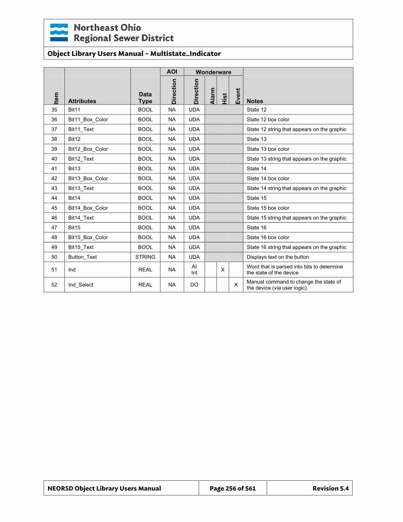
Object Library Users Manual – Multistate_Indicator
NEORSD Object Library Users Manual Page 256 of 561 Revision 5.4
AOI Wonderware
Item
Attributes Data Type D
irect
ion
Dire
ctio
n
Ala
rm
His
t
Even
t
Notes 35 Bit11 BOOL NA UDA State 12
36 Bit11_Box_Color BOOL NA UDA State 12 box color
37 Bit11_Text BOOL NA UDA State 12 string that appears on the graphic
38 Bit12 BOOL NA UDA State 13
39 Bit12_Box_Color BOOL NA UDA State 13 box color
40 Bit12_Text BOOL NA UDA State 13 string that appears on the graphic
41 Bit13 BOOL NA UDA State 14
42 Bit13_Box_Color BOOL NA UDA State 14 box color
43 Bit13_Text BOOL NA UDA State 14 string that appears on the graphic
44 Bit14 BOOL NA UDA State 15
45 Bit14_Box_Color BOOL NA UDA State 15 box color
46 Bit14_Text BOOL NA UDA State 15 string that appears on the graphic
47 Bit15 BOOL NA UDA State 16
48 Bit15_Box_Color BOOL NA UDA State 16 box color
49 Bit15_Text BOOL NA UDA State 16 string that appears on the graphic
50 Button_Text STRING NA UDA Displays text on the button
51 Ind REAL NA AI Int X Word that is parsed into bits to determine
the state of the device
52 Ind_Select REAL NA DO X Manual command to change the state of the device (via user logic).
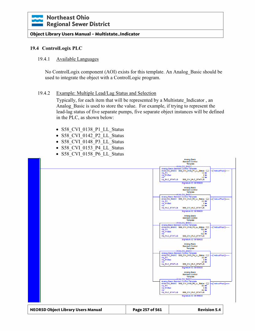
Object Library Users Manual – Multistate_Indicator
NEORSD Object Library Users Manual Page 257 of 561 Revision 5.4
19.4 ControlLogix PLC
19.4.1 Available Languages
No ControlLogix component (AOI) exists for this template. An Analog_Basic should be used to integrate the object with a ControlLogic program.
19.4.2 Example: Multiple Lead/Lag Status and Selection Typically, for each item that will be represented by a Multistate_Indicator , an Analog_Basic is used to store the value. For example, if trying to represent the lead-lag status of five separate pumps, five separate object instances will be defined in the PLC, as shown below: • S58_CVI_0138_P1_LL_Status • S58_CVI_0142_P2_LL_Status • S58_CVI_0148_P3_LL_Status • S58_CVI_0153_P4_LL_Status • S58_CVI_0158_P6_LL_Status
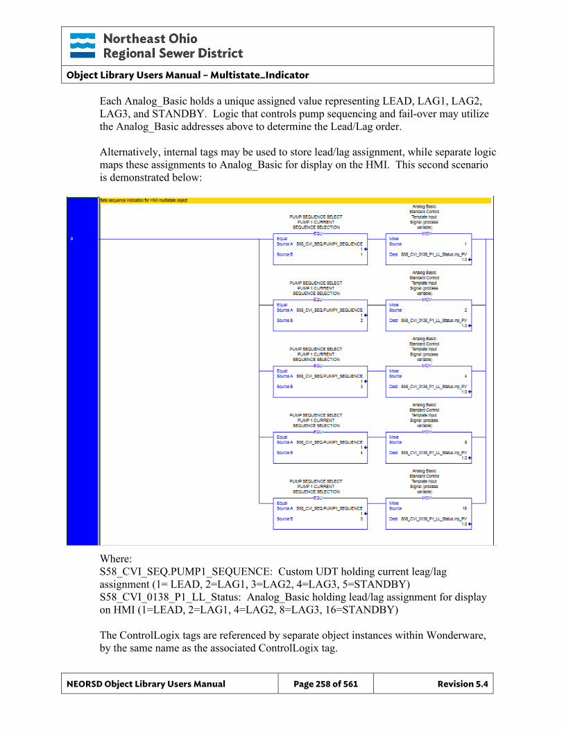
Object Library Users Manual – Multistate_Indicator
NEORSD Object Library Users Manual Page 258 of 561 Revision 5.4
Each Analog_Basic holds a unique assigned value representing LEAD, LAG1, LAG2, LAG3, and STANDBY. Logic that controls pump sequencing and fail-over may utilize the Analog_Basic addresses above to determine the Lead/Lag order. Alternatively, internal tags may be used to store lead/lag assignment, while separate logic maps these assignments to Analog_Basic for display on the HMI. This second scenario is demonstrated below:
Where: S58_CVI_SEQ.PUMP1_SEQUENCE: Custom UDT holding current leag/lag assignment (1= LEAD, 2=LAG1, 3=LAG2, 4=LAG3, 5=STANDBY) S58_CVI_0138_P1_LL_Status: Analog_Basic holding lead/lag assignment for display on HMI (1=LEAD, 2=LAG1, 4=LAG2, 8=LAG3, 16=STANDBY) The ControlLogix tags are referenced by separate object instances within Wonderware, by the same name as the associated ControlLogix tag.
Object Library Users Manual – Multistate_Indicator
NEORSD Object Library Users Manual Page 259 of 561 Revision 5.4
Example Additional Considerations The Multistate_Indicator objects above show the current lead/lag assignments for the pumps, but do not offer means to rotate the assignment. This must be accomplished through additional logic and objects. The preferred method is outlined below:
• For each pump, use an Analog_Setpoint object to allow the operator to select a numeric values between 1 and 5 representing Lead through Standby. This will represent the “pending” assignment.
• In the PLC, create logic that verifies all pending assignments have been entered and are valid (assignments are unique and not 0, process/equipment specific restrictions are satisfied). This will prevent invalid configurations from being accepted
• If pending assignments are valid from the step above, use Discrete_Setpoint to allow the operator to execute the selection. At this time, the PLC should copy the pending assignments into the active (Multistate_Indicator) registers and run cut-over logic (as applicable).
• Following the assignment change, clear out (set to 0) the Analog_Setpoint pending registers through PLC logic
19.5 Wonderware HMI
19.5.1 Properties Hierarchical Name: $MultiState_Ind Derivation: Derived from $NEORSDUserDefined Container: None
19.5.2 Extensions None
19.5.3 Configuration All of the necessary configuration for MultiState Ind must also be done on any instance derived from this template. 1) Attributes that are not used in the configured instance shall use
Me.Placeholder to eliminate the point from counting against the systems total I/O scan counts. Ind_Select can use Me.Placeholder for the input source if the multistate device is read only. The allowed attributes for this template include the following:
a. Bit0_Text thru Bit15_Text b. Ind_Select
2) The configuration is done through the input of a single word and through scripting, broken apart into the individual bits noted in item (1) which are passed into UDAs within the template. The graphics then change state based
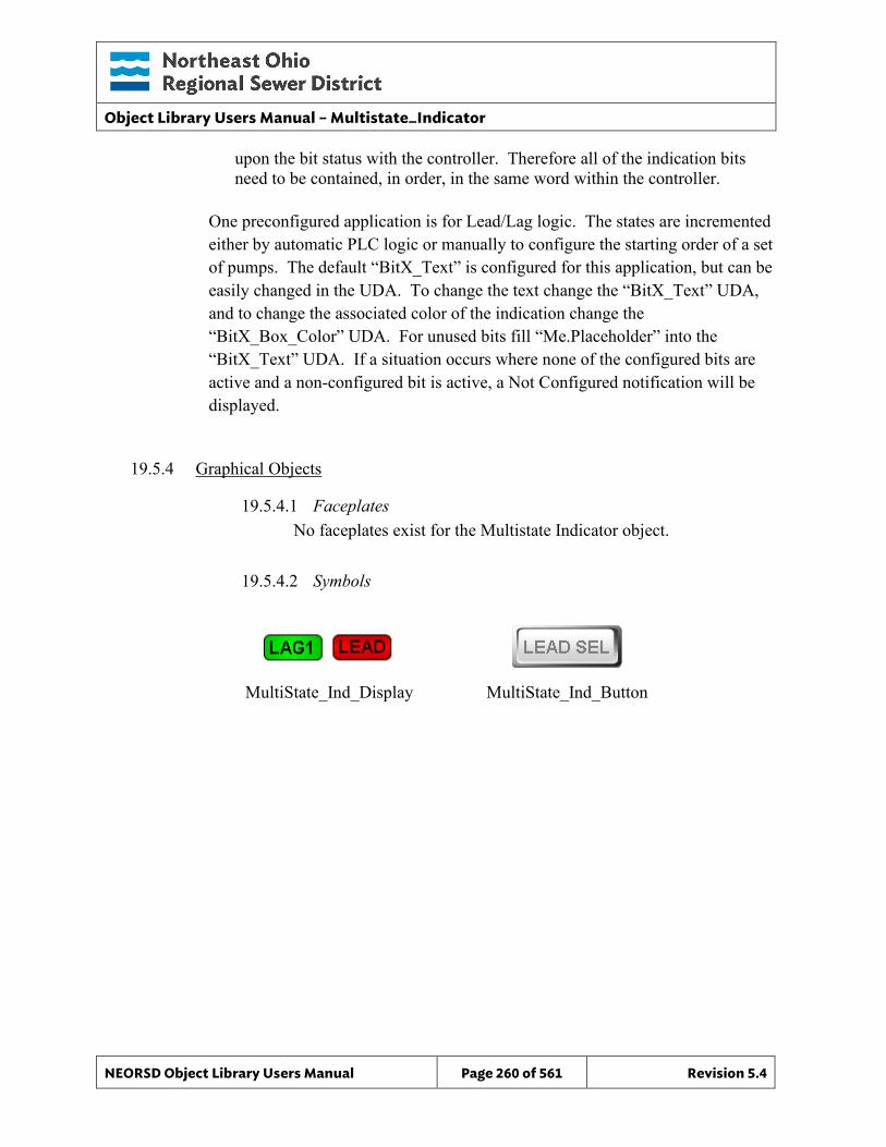
Object Library Users Manual – Multistate_Indicator
NEORSD Object Library Users Manual Page 260 of 561 Revision 5.4
upon the bit status with the controller. Therefore all of the indication bits need to be contained, in order, in the same word within the controller.
One preconfigured application is for Lead/Lag logic. The states are incremented either by automatic PLC logic or manually to configure the starting order of a set of pumps. The default “BitX_Text” is configured for this application, but can be easily changed in the UDA. To change the text change the “BitX_Text” UDA, and to change the associated color of the indication change the “BitX_Box_Color” UDA. For unused bits fill “Me.Placeholder” into the “BitX_Text” UDA. If a situation occurs where none of the configured bits are active and a non-configured bit is active, a Not Configured notification will be displayed.
19.5.4 Graphical Objects
19.5.4.1 Faceplates No faceplates exist for the Multistate Indicator object.
19.5.4.2 Symbols
MultiState_Ind_Display MultiState_Ind_Button
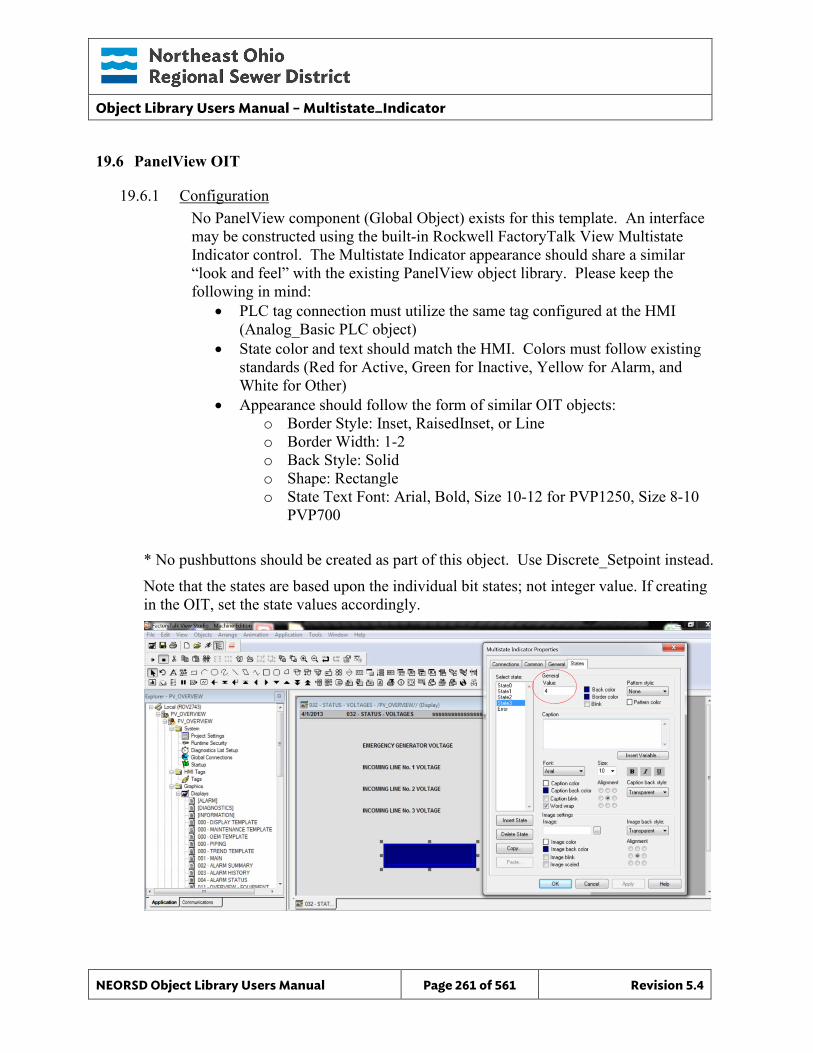
Object Library Users Manual – Multistate_Indicator
NEORSD Object Library Users Manual Page 261 of 561 Revision 5.4
19.6 PanelView OIT
19.6.1 Configuration No PanelView component (Global Object) exists for this template. An interface may be constructed using the built-in Rockwell FactoryTalk View Multistate Indicator control. The Multistate Indicator appearance should share a similar “look and feel” with the existing PanelView object library. Please keep the following in mind:
• PLC tag connection must utilize the same tag configured at the HMI (Analog_Basic PLC object)
• State color and text should match the HMI. Colors must follow existing standards (Red for Active, Green for Inactive, Yellow for Alarm, and White for Other)
• Appearance should follow the form of similar OIT objects: o Border Style: Inset, RaisedInset, or Line o Border Width: 1-2 o Back Style: Solid o Shape: Rectangle o State Text Font: Arial, Bold, Size 10-12 for PVP1250, Size 8-10
PVP700
* No pushbuttons should be created as part of this object. Use Discrete_Setpoint instead. Note that the states are based upon the individual bit states; not integer value. If creating in the OIT, set the state values accordingly.

Object Library Users Manual – Multistate_Indicator
NEORSD Object Library Users Manual Page 262 of 561 Revision 5.4
This page left blank intentionally.
Object Library Users Manual – PB_Single_Select
NEORSD Object Library Users Manual Page 263 of 561 Revision 5.4
20.0 PB_Single_Select
20.1 Introduction The PB Single Select template provides a standard representation of a set of states, selectable by an operator, within the NEORSD control systems. Unlike the Multistate Indicator object which has a single pushbutton for operators to sequence through possible states, this object utilizes individual buttons to directly commend the next mode/state. Use the PB_Single_Select template if the below is true:
• If trying to allow an operator to directly select one of multiple states or options,
• If only one state can be selected at any time Do not use the PB_Single_Select template if the below is true:
• If attempting to provide pushbuttons for start/stop, open/close, or other device-specific operations. In these cases, use the appropriate device template instead (e.g. Motor_Discrete, Valve_Discrete, etc).
• If the next state is restricted to a specific sequence, controlled through logic, where the operator can only trigger the next state. In this case use Mutistate_Indicator.
20.2 Object Features
20.2.1 Status Indications This object will display the currently active/selected state, as well as inhibited states.
20.2.2 Control This object allows an operator to select one of up to ten different states using a panel of pushbuttons. Allowable states may be inhibited through logic.
20.2.3 Alarming This object does not support alarming.
20.2.4 Simulation This object does not support simulation.
20.2.5 Trouble This object supports hardware trouble indication.
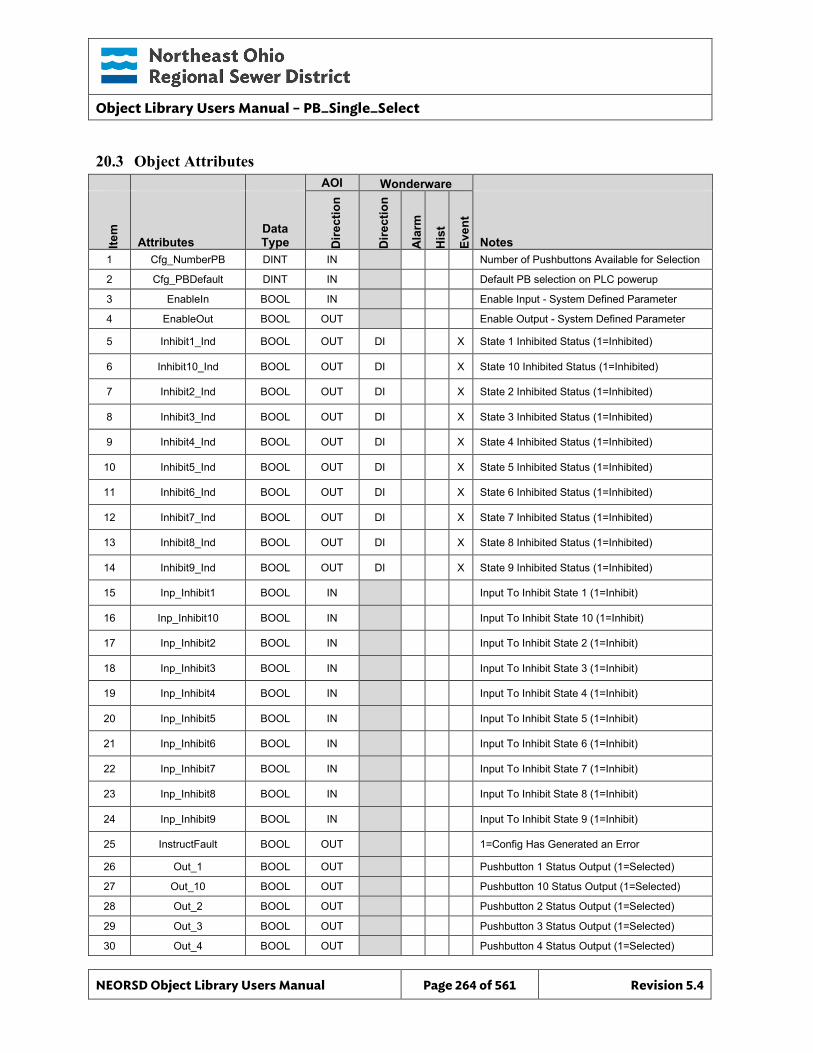
Object Library Users Manual – PB_Single_Select
NEORSD Object Library Users Manual Page 264 of 561 Revision 5.4
20.3 Object Attributes
AOI Wonderware
Item
Attributes Data Type D
irect
ion
Dire
ctio
n
Ala
rm
His
t
Even
t
Notes 1 Cfg_NumberPB DINT IN Number of Pushbuttons Available for Selection
2 Cfg_PBDefault DINT IN Default PB selection on PLC powerup
3 EnableIn BOOL IN Enable Input - System Defined Parameter
4 EnableOut BOOL OUT Enable Output - System Defined Parameter
5 Inhibit1_Ind BOOL OUT DI X State 1 Inhibited Status (1=Inhibited)
6 Inhibit10_Ind BOOL OUT DI X State 10 Inhibited Status (1=Inhibited)
7 Inhibit2_Ind BOOL OUT DI X State 2 Inhibited Status (1=Inhibited)
8 Inhibit3_Ind BOOL OUT DI X State 3 Inhibited Status (1=Inhibited)
9 Inhibit4_Ind BOOL OUT DI X State 4 Inhibited Status (1=Inhibited)
10 Inhibit5_Ind BOOL OUT DI X State 5 Inhibited Status (1=Inhibited)
11 Inhibit6_Ind BOOL OUT DI X State 6 Inhibited Status (1=Inhibited)
12 Inhibit7_Ind BOOL OUT DI X State 7 Inhibited Status (1=Inhibited)
13 Inhibit8_Ind BOOL OUT DI X State 8 Inhibited Status (1=Inhibited)
14 Inhibit9_Ind BOOL OUT DI X State 9 Inhibited Status (1=Inhibited)
15 Inp_Inhibit1 BOOL IN Input To Inhibit State 1 (1=Inhibit)
16 Inp_Inhibit10 BOOL IN Input To Inhibit State 10 (1=Inhibit)
17 Inp_Inhibit2 BOOL IN Input To Inhibit State 2 (1=Inhibit)
18 Inp_Inhibit3 BOOL IN Input To Inhibit State 3 (1=Inhibit)
19 Inp_Inhibit4 BOOL IN Input To Inhibit State 4 (1=Inhibit)
20 Inp_Inhibit5 BOOL IN Input To Inhibit State 5 (1=Inhibit)
21 Inp_Inhibit6 BOOL IN Input To Inhibit State 6 (1=Inhibit)
22 Inp_Inhibit7 BOOL IN Input To Inhibit State 7 (1=Inhibit)
23 Inp_Inhibit8 BOOL IN Input To Inhibit State 8 (1=Inhibit)
24 Inp_Inhibit9 BOOL IN Input To Inhibit State 9 (1=Inhibit)
25 InstructFault BOOL OUT 1=Config Has Generated an Error
26 Out_1 BOOL OUT Pushbutton 1 Status Output (1=Selected)
27 Out_10 BOOL OUT Pushbutton 10 Status Output (1=Selected)
28 Out_2 BOOL OUT Pushbutton 2 Status Output (1=Selected)
29 Out_3 BOOL OUT Pushbutton 3 Status Output (1=Selected)
30 Out_4 BOOL OUT Pushbutton 4 Status Output (1=Selected)
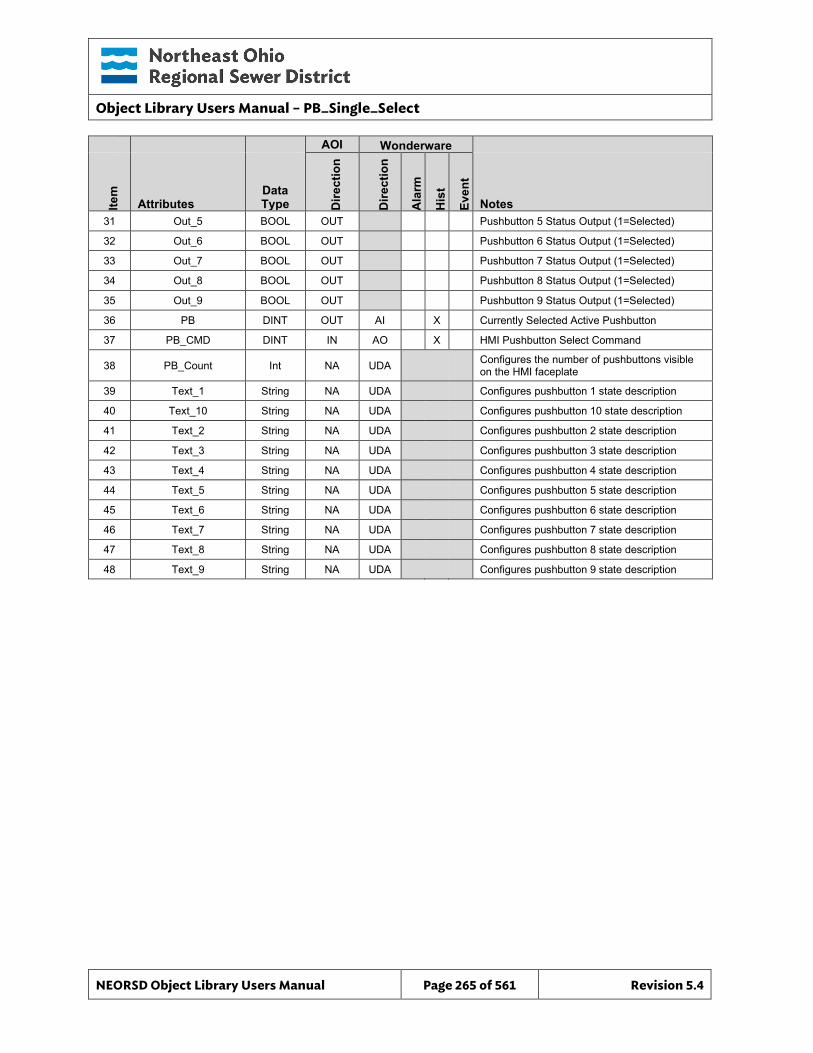
Object Library Users Manual – PB_Single_Select
NEORSD Object Library Users Manual Page 265 of 561 Revision 5.4
AOI Wonderware
Item
Attributes Data Type D
irect
ion
Dire
ctio
n
Ala
rm
His
t
Even
t
Notes 31 Out_5 BOOL OUT Pushbutton 5 Status Output (1=Selected)
32 Out_6 BOOL OUT Pushbutton 6 Status Output (1=Selected)
33 Out_7 BOOL OUT Pushbutton 7 Status Output (1=Selected)
34 Out_8 BOOL OUT Pushbutton 8 Status Output (1=Selected)
35 Out_9 BOOL OUT Pushbutton 9 Status Output (1=Selected)
36 PB DINT OUT AI X Currently Selected Active Pushbutton
37 PB_CMD DINT IN AO X HMI Pushbutton Select Command
38 PB_Count Int NA UDA Configures the number of pushbuttons visible on the HMI faceplate
39 Text_1 String NA UDA Configures pushbutton 1 state description
40 Text_10 String NA UDA Configures pushbutton 10 state description
41 Text_2 String NA UDA Configures pushbutton 2 state description
42 Text_3 String NA UDA Configures pushbutton 3 state description
43 Text_4 String NA UDA Configures pushbutton 4 state description
44 Text_5 String NA UDA Configures pushbutton 5 state description
45 Text_6 String NA UDA Configures pushbutton 6 state description
46 Text_7 String NA UDA Configures pushbutton 7 state description
47 Text_8 String NA UDA Configures pushbutton 8 state description
48 Text_9 String NA UDA Configures pushbutton 9 state description
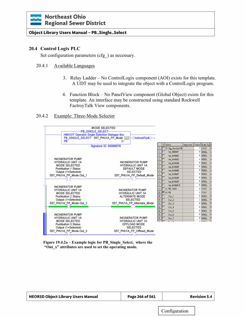
Object Library Users Manual – PB_Single_Select
NEORSD Object Library Users Manual Page 266 of 561 Revision 5.4
20.4 Control Logix PLC Set configuration parameters (cfg_) as necessary.
20.4.1 Available Languages
3. Relay Ladder – No ControlLogix component (AOI) exists for this template. A UDT may be used to integrate the object with a ControlLogix program.
4. Function Block – No PanelView component (Global Object) exists for this
template. An interface may be constructed using standard Rockwell FactroyTalk View components.
20.4.2 Example: Three-Mode Selector
Figure 19.4.2a – Example logic for PB_Single_Select, where the “Out_x” attributes are used to set the operating mode.
Configuration
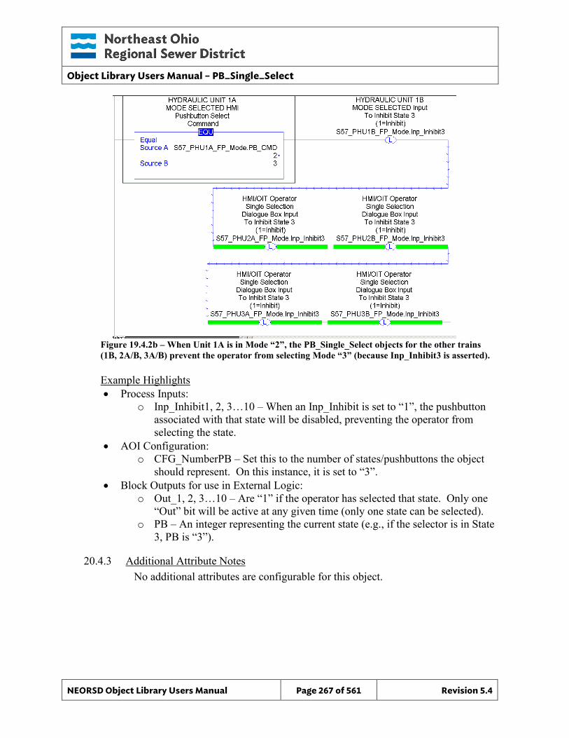
Object Library Users Manual – PB_Single_Select
NEORSD Object Library Users Manual Page 267 of 561 Revision 5.4
Figure 19.4.2b – When Unit 1A is in Mode “2”, the PB_Single_Select objects for the other trains (1B, 2A/B, 3A/B) prevent the operator from selecting Mode “3” (because Inp_Inhibit3 is asserted).
Example Highlights • Process Inputs:
o Inp_Inhibit1, 2, 3…10 – When an Inp_Inhibit is set to “1”, the pushbutton associated with that state will be disabled, preventing the operator from selecting the state.
• AOI Configuration: o CFG_NumberPB – Set this to the number of states/pushbuttons the object
should represent. On this instance, it is set to “3”. • Block Outputs for use in External Logic:
o Out_1, 2, 3…10 – Are “1” if the operator has selected that state. Only one “Out” bit will be active at any given time (only one state can be selected).
o PB – An integer representing the current state (e.g., if the selector is in State 3, PB is “3”).
20.4.3 Additional Attribute Notes No additional attributes are configurable for this object.
Object Library Users Manual – PB_Single_Select
NEORSD Object Library Users Manual Page 268 of 561 Revision 5.4
20.5 Wonderware HMI
20.5.1 Properties Hierarchical Name: $PB_Single_Select Derivation: Derived from $NEORSDUserDefined Container: None
20.5.2 Extensions None.
20.5.3 Configuration 1) If ASSET_ID is not in use the initial value will be left blank.
Scripting used for ASSET_ID uses the initial value and not ASSET_ID.Description
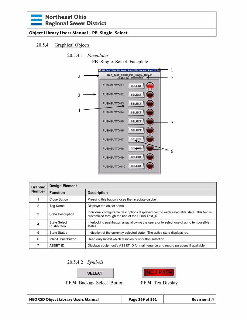
Object Library Users Manual – PB_Single_Select
NEORSD Object Library Users Manual Page 269 of 561 Revision 5.4
20.5.4 Graphical Objects
20.5.4.1 Faceplates
Graphic Number
Design Element
Function Description
1 Close Button Pressing this button closes the faceplate display.
2 Tag Name Displays the object name.
3 State Description Individual configurable descriptions displayed next to each selectable state. This text is customized through the use of the UDAs Text_X.
4 State Select Pushbutton
Interlocking pushbutton array allowing the operator to select one of up to ten possible states.
5 State Status Indication of the currently selected state. The active state displays red.
6 Inhibit Pushbutton Read only Inhibit which disables pushbutton selection.
7 ASSET ID Displays equipment’s ASSET ID for maintenance and record purposes if available.
20.5.4.2 Symbols
PB_Single_Select_Faceplate
2
3
1
4
5
6
PFP4_Backup_Select_Button
PFP4_TextDisplay
7
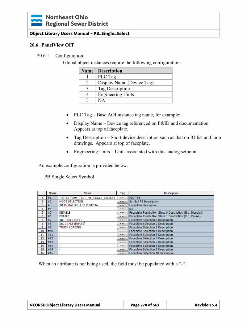
Object Library Users Manual – PB_Single_Select
NEORSD Object Library Users Manual Page 270 of 561 Revision 5.4
20.6 PanelView OIT
20.6.1 Configuration Global object instances require the following configuration:
Name Description 1 PLC Tag 2 Display Name (Device Tag) 3 Tag Description 4 Engineering Units 5 NA
• PLC Tag – Base AOI instance tag name, for example:
• Display Name – Device tag referenced on P&ID and documentation. Appears at top of faceplate.
• Tag Description – Short device description such as that on IO list and loop drawings. Appears at top of faceplate.
• Engineering Units – Units associated with this analog setpoint.
An example configuration is provided below: PB Single Select Symbol
When an attribute is not being used, the field must be populated with a “-“.
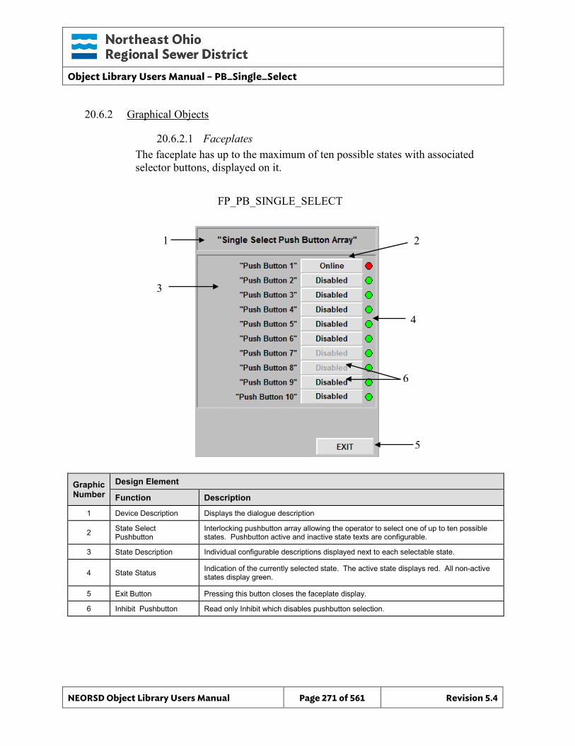
Object Library Users Manual – PB_Single_Select
NEORSD Object Library Users Manual Page 271 of 561 Revision 5.4
2
4
6
5
20.6.2 Graphical Objects
20.6.2.1 Faceplates The faceplate has up to the maximum of ten possible states with associated selector buttons, displayed on it.
Graphic Number
Design Element
Function Description
1 Device Description Displays the dialogue description
2 State Select Pushbutton
Interlocking pushbutton array allowing the operator to select one of up to ten possible states. Pushbutton active and inactive state texts are configurable.
3 State Description Individual configurable descriptions displayed next to each selectable state.
4 State Status Indication of the currently selected state. The active state displays red. All non-active states display green.
5 Exit Button Pressing this button closes the faceplate display.
6 Inhibit Pushbutton Read only Inhibit which disables pushbutton selection.
FP_PB_SINGLE_SELECT
1
3
Object Library Users Manual – PB_Single_Select
NEORSD Object Library Users Manual Page 272 of 561 Revision 5.4
20.6.2.2 Symbols A single button symbol is provided to launch the faceplate.
Object Library Users Manual – PID
NEORSD Object Library Users Manual Page 273 of 561 Revision 5.4
21.0 PID
21.1 Introduction The PID template provides a standard representation of the Rockwell-provided PID instruction within the NEORSD control systems. Only use the PID template if trying to represent the Rockwell PID instruction on the OIT or HMI. Typically, usage of the PID instruction will involve three standard objects:
• ANALOG (or ANALOG_BASIC)
• VALVE_ANALOG (or MOTOR_VFD)
• PID (or PIDE)
21.2 Object Features The Rockwell PID function block is well documented within the Rockwell programming software. The features listed below are those pertinent to the HMI and OIT components of the object.
21.2.1 Status Indications This object will display the following values:
• Process Value (PV, HMI-only) • Setpoint Value (SP, HMI and OIT) • Control Value (CV, HMI-only)
21.2.2 Control This object allows an operator to change the value of the setpoint (SP) of the PID block. Neither the HMI nor the OIT will provide mode control for this object. PID mode must be governed solely within the PLC logic, generally programmed to match the mode (Auto/Manual) of the corresponding VALVE_ANALOG, MOTOR_VFD, or similar object.
21.2.3 Alarming The PID object does not support any alarming to the HMI or OIT. The alarm capabilities of the associated ANALOG standard object template or similar should be used instead.
21.2.4 Simulation This object does not support simulation.
21.2.5 Trouble This object does not support trouble indication.
Object Library Users Manual – PID
NEORSD Object Library Users Manual Page 274 of 561 Revision 5.4
21.2.6 DB_Precision_Group Attribute is used in the ValueDeadband script. In the script, this parameter sets the deadband of inputs. Valid values for this parameter are between 0 and 3. o 0= default group; o 1= custom ValueDeadband setting which disables the script and uses the
attribute’s ValueDeadband; o 2= high precision; o 3= non-precision REF objects (obsolete)
While 3 is an available option, it is not to be used for new objects moving forward. If changing the DB_Precision_Group to 1, you must undeploy and then deploy the object to guarantee that runtime deadband setting gets updated. A redeploy action will not update ValueDeadband.
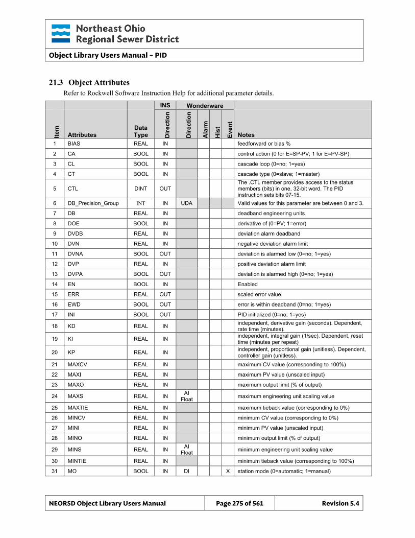
Object Library Users Manual – PID
NEORSD Object Library Users Manual Page 275 of 561 Revision 5.4
21.3 Object Attributes Refer to Rockwell Software Instruction Help for additional parameter details.
INS Wonderware
Item
Attributes Data Type D
irect
ion
Dire
ctio
n
Ala
rm
His
t
Even
t
Notes 1 BIAS REAL IN feedforward or bias %
2 CA BOOL IN control action (0 for E=SP-PV; 1 for E=PV-SP)
3 CL BOOL IN cascade loop (0=no; 1=yes)
4 CT BOOL IN cascade type (0=slave; 1=master)
5 CTL DINT OUT The .CTL member provides access to the status members (bits) in one, 32-bit word. The PID instruction sets bits 07-15.
6 DB_Precision_Group INT IN UDA Valid values for this parameter are between 0 and 3.
7 DB REAL IN deadband engineering units
8 DOE BOOL IN derivative of (0=PV; 1=error)
9 DVDB REAL IN deviation alarm deadband
10 DVN REAL IN negative deviation alarm limit
11 DVNA BOOL OUT deviation is alarmed low (0=no; 1=yes)
12 DVP REAL IN positive deviation alarm limit
13 DVPA BOOL OUT deviation is alarmed high (0=no; 1=yes)
14 EN BOOL IN Enabled
15 ERR REAL OUT scaled error value
16 EWD BOOL OUT error is within deadband (0=no; 1=yes)
17 INI BOOL OUT PID initialized (0=no; 1=yes)
18 KD REAL IN independent, derivative gain (seconds). Dependent, rate time (minutes).
19 KI REAL IN independent, integral gain (1/sec). Dependent, reset time (minutes per repeat)
20 KP REAL IN independent, proportional gain (unitless). Dependent, controller gain (unitless).
21 MAXCV REAL IN maximum CV value (corresponding to 100%)
22 MAXI REAL IN maximum PV value (unscaled input)
23 MAXO REAL IN maximum output limit (% of output)
24 MAXS REAL IN AI Float maximum engineering unit scaling value
25 MAXTIE REAL IN maximum tieback value (corresponding to 0%)
26 MINCV REAL IN minimum CV value (corresponding to 0%)
27 MINI REAL IN minimum PV value (unscaled input)
28 MINO REAL IN minimum output limit (% of output)
29 MINS REAL IN AI Float minimum engineering unit scaling value
30 MINTIE REAL IN minimum tieback value (corresponding to 100%)
31 MO BOOL IN DI X station mode (0=automatic; 1=manual)
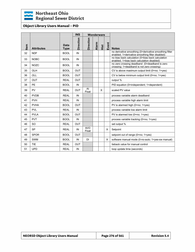
Object Library Users Manual – PID
NEORSD Object Library Users Manual Page 276 of 561 Revision 5.4
INS Wonderware
Item
Attributes Data Type D
irect
ion
Dire
ctio
n
Ala
rm
His
t
Even
t
Notes 32 NDF BOOL IN no derivative smoothing (0=derivative smoothing filter
enabled; 1=derivative smoothing filter disabled)
33 NOBC BOOL IN no bias back calculation (0=bias back calculation enabled; 1=bias back calculation disabled)
34 NOZC BOOL IN no zero crossing deadband (0=deadband is zero crossing; 1=deadband is not zero crossing)
35 OLH BOOL OUT CV is above maximum output limit (0=no; 1=yes)
36 OLL BOOL OUT CV is below minimum output limit (0=no; 1=yes)
37 OUT REAL OUT output %
38 PE BOOL IN PID equation (0=independent; 1=dependent)
39 PV REAL OUT AI Float X scaled PV value
40 PVDB REAL IN process variable alarm deadband
41 PVH REAL IN process variable high alarm limit
42 PVHA BOOL OUT PV is alarmed high (0=no; 1=yes)
43 PVL REAL IN process variable low alarm limit
44 PVLA BOOL OUT PV is alarmed low (0=no; 1=yes)
45 PVT BOOL IN process variable tracking (0=no; 1=yes)
46 SO REAL OUT set output %
47 SP REAL IN AI/O Float X Setpoint
48 SPOR BOOL OUT setpoint out of range (0=no; 1=yes)
49 SWM BOOL IN DI X software manual mode (0-no-auto; 1=yes-sw manual)
50 TIE REAL OUT tieback value for manual control
51 UPD REAL IN loop update time (seconds)
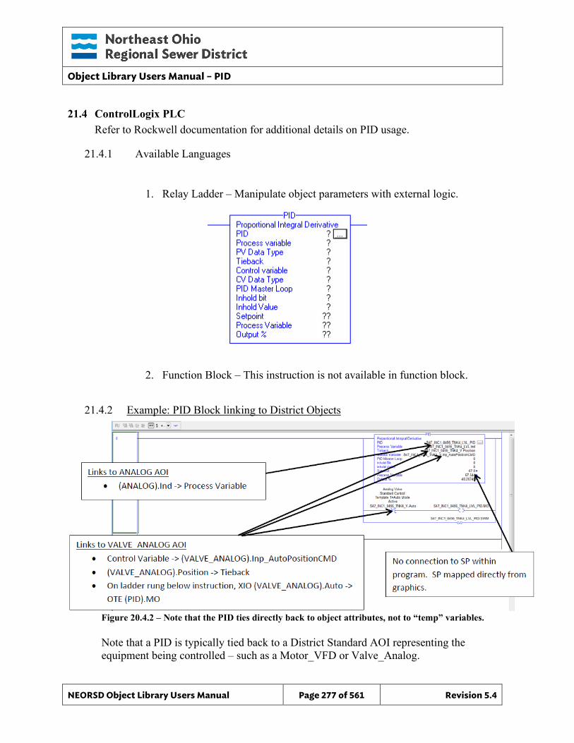
Object Library Users Manual – PID
NEORSD Object Library Users Manual Page 277 of 561 Revision 5.4
21.4 ControlLogix PLC Refer to Rockwell documentation for additional details on PID usage.
21.4.1 Available Languages
1. Relay Ladder – Manipulate object parameters with external logic.
2. Function Block – This instruction is not available in function block.
21.4.2 Example: PID Block linking to District Objects
Figure 20.4.2 – Note that the PID ties directly back to object attributes, not to “temp” variables. Note that a PID is typically tied back to a District Standard AOI representing the equipment being controlled – such as a Motor_VFD or Valve_Analog.
Object Library Users Manual – PID
NEORSD Object Library Users Manual Page 278 of 561 Revision 5.4
Example Highlights • Process Inputs:
o SWM – Typically set to “0”. o MO – MO should be set to “1” when the associated equipment is in “Local”
mode. o PV – PV should be tied to the “Ind” attribute of an Analog or Analog_Basic
object. • AOI Configuration:
o Loop Update Time is based on PID_Control Periodic Task Update Time o PV Unscaled Max – Set to the “EUMax” of the Analog object used for PV. o PV Unscaled Min – Set to the “EUMin” of the Analog object used for PV. o CV Max/Min – Set to 100%/0% by default. o Tieback Max/Min – Set to 100%/0% by default. o See the Rockwell documentation for internal block configuration.
• Block Outputs for use in External Logic: o CV is typically tied to the “Inp_AutoPositionCMD” of a Valve_Analog
object, or “Inp_AutoSpeedRef” of a Motor_VFD object.
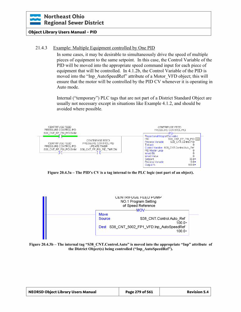
Object Library Users Manual – PID
NEORSD Object Library Users Manual Page 279 of 561 Revision 5.4
21.4.3 Example: Multiple Equipment controlled by One PID In some cases, it may be desirable to simultaneously drive the speed of multiple pieces of equipment to the same setpoint. In this case, the Control Variable of the PID will be moved into the appropriate speed command input for each piece of equipment that will be controlled. In 4.1.2b, the Control Variable of the PID is moved into the “Inp_AutoSpeedRef” attribute of a Motor_VFD object; this will ensure that the motor will be controlled by the PID CV whenever it is operating in Auto mode. Internal (“temporary”) PLC tags that are not part of a District Standard Object are usually not necessary except in situations like Example 4.1.2, and should be avoided where possible.
Figure 20.4.3a – The PID’s CV is a tag internal to the PLC logic (not part of an object).
Figure 20.4.3b – The internal tag “S38_CNT.Control.Auto” is moved into the appropriate “Inp” attribute of the District Object(s) being controlled (“Inp_AutoSpeedRef”).
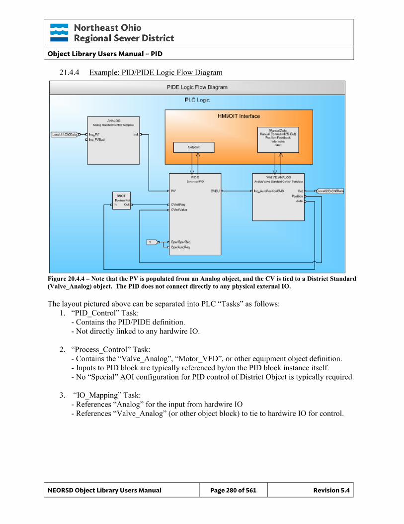
Object Library Users Manual – PID
NEORSD Object Library Users Manual Page 280 of 561 Revision 5.4
21.4.4 Example: PID/PIDE Logic Flow Diagram
Figure 20.4.4 – Note that the PV is populated from an Analog object, and the CV is tied to a District Standard (Valve_Analog) object. The PID does not connect directly to any physical external IO. The layout pictured above can be separated into PLC “Tasks” as follows:
1. “PID_Control” Task: - Contains the PID/PIDE definition. - Not directly linked to any hardwire IO.
2. “Process_Control” Task: - Contains the “Valve_Analog”, “Motor_VFD”, or other equipment object definition. - Inputs to PID block are typically referenced by/on the PID block instance itself. - No “Special” AOI configuration for PID control of District Object is typically required.
3. “IO_Mapping” Task: - References “Analog” for the input from hardwire IO
- References “Valve_Analog” (or other object block) to tie to hardwire IO for control.
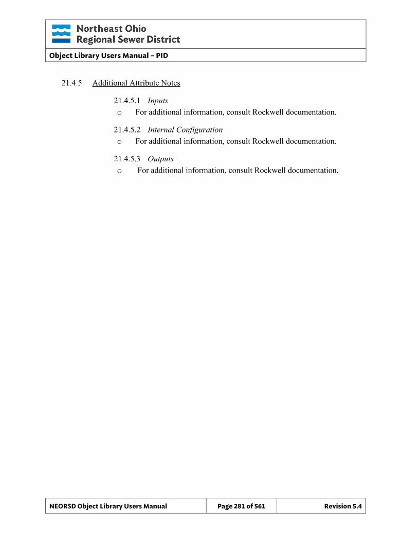
Object Library Users Manual – PID
NEORSD Object Library Users Manual Page 281 of 561 Revision 5.4
21.4.5 Additional Attribute Notes
21.4.5.1 Inputs o For additional information, consult Rockwell documentation.
21.4.5.2 Internal Configuration o For additional information, consult Rockwell documentation.
21.4.5.3 Outputs o For additional information, consult Rockwell documentation.
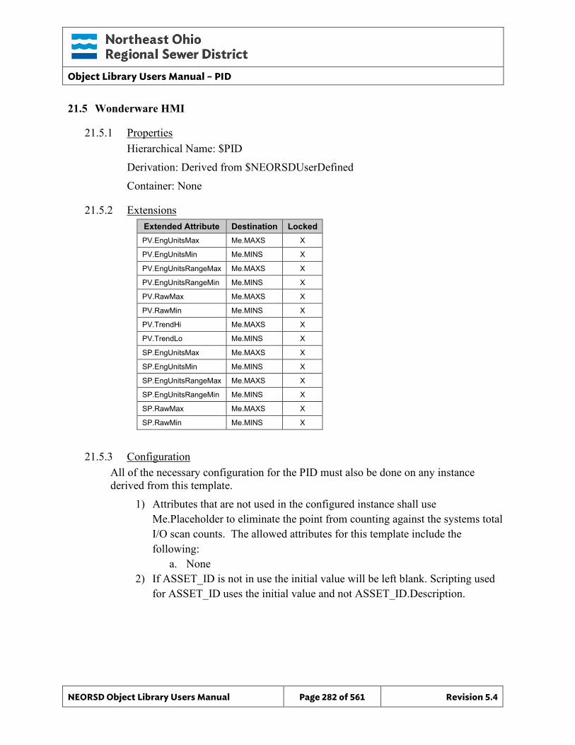
Object Library Users Manual – PID
NEORSD Object Library Users Manual Page 282 of 561 Revision 5.4
21.5 Wonderware HMI
21.5.1 Properties Hierarchical Name: $PID Derivation: Derived from $NEORSDUserDefined Container: None
21.5.2 Extensions Extended Attribute Destination Locked PV.EngUnitsMax Me.MAXS X
PV.EngUnitsMin Me.MINS X
PV.EngUnitsRangeMax Me.MAXS X
PV.EngUnitsRangeMin Me.MINS X
PV.RawMax Me.MAXS X
PV.RawMin Me.MINS X
PV.TrendHi Me.MAXS X
PV.TrendLo Me.MINS X
SP.EngUnitsMax Me.MAXS X
SP.EngUnitsMin Me.MINS X
SP.EngUnitsRangeMax Me.MAXS X
SP.EngUnitsRangeMin Me.MINS X
SP.RawMax Me.MAXS X
SP.RawMin Me.MINS X
21.5.3 Configuration All of the necessary configuration for the PID must also be done on any instance derived from this template.
1) Attributes that are not used in the configured instance shall use Me.Placeholder to eliminate the point from counting against the systems total I/O scan counts. The allowed attributes for this template include the following:
a. None 2) If ASSET_ID is not in use the initial value will be left blank. Scripting used
for ASSET_ID uses the initial value and not ASSET_ID.Description.
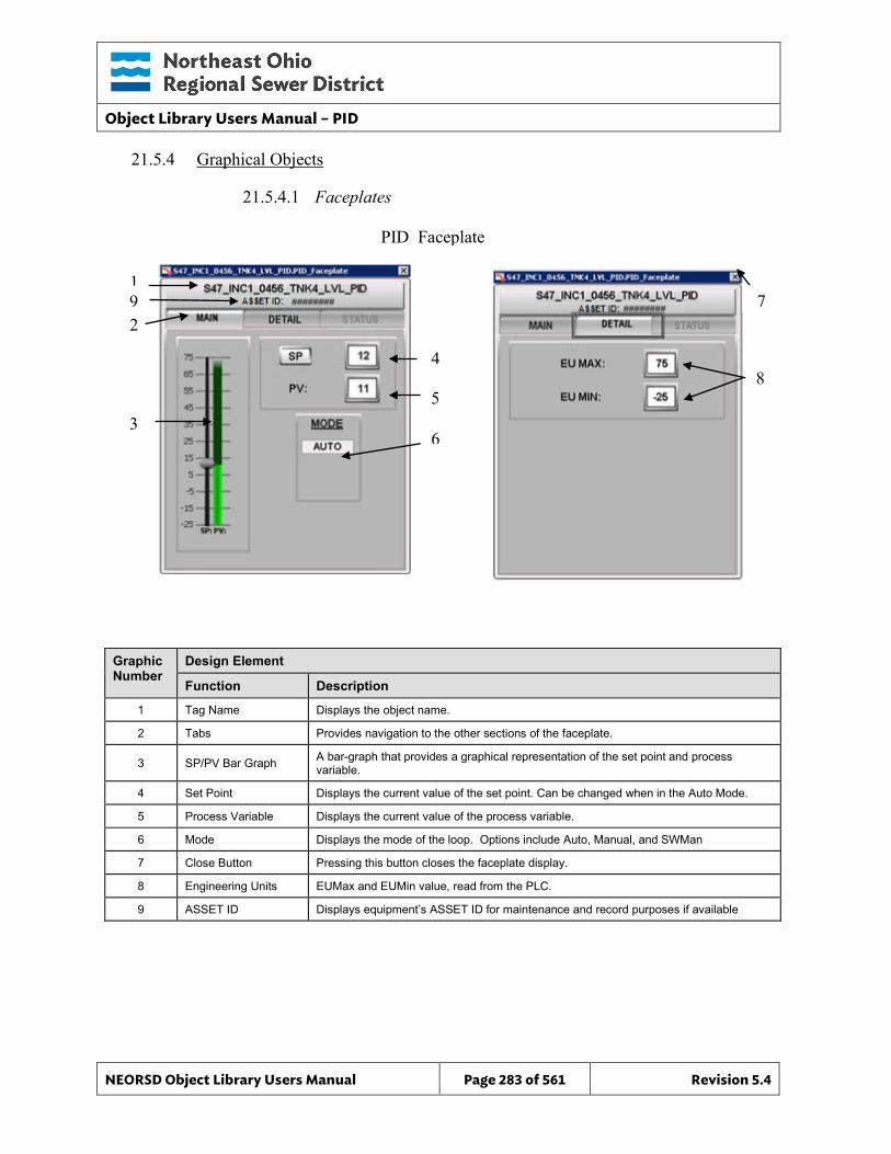
Object Library Users Manual – PID
NEORSD Object Library Users Manual Page 283 of 561 Revision 5.4
21.5.4 Graphical Objects
21.5.4.1 Faceplates
Graphic Number
Design Element
Function Description
1 Tag Name Displays the object name.
2 Tabs Provides navigation to the other sections of the faceplate.
3 SP/PV Bar Graph A bar-graph that provides a graphical representation of the set point and process variable.
4 Set Point Displays the current value of the set point. Can be changed when in the Auto Mode.
5 Process Variable Displays the current value of the process variable.
6 Mode Displays the mode of the loop. Options include Auto, Manual, and SWMan
7 Close Button Pressing this button closes the faceplate display.
8 Engineering Units EUMax and EUMin value, read from the PLC.
9 ASSET ID Displays equipment’s ASSET ID for maintenance and record purposes if available
PID_Faceplate
1
2
4
5
6
8
3
7 9
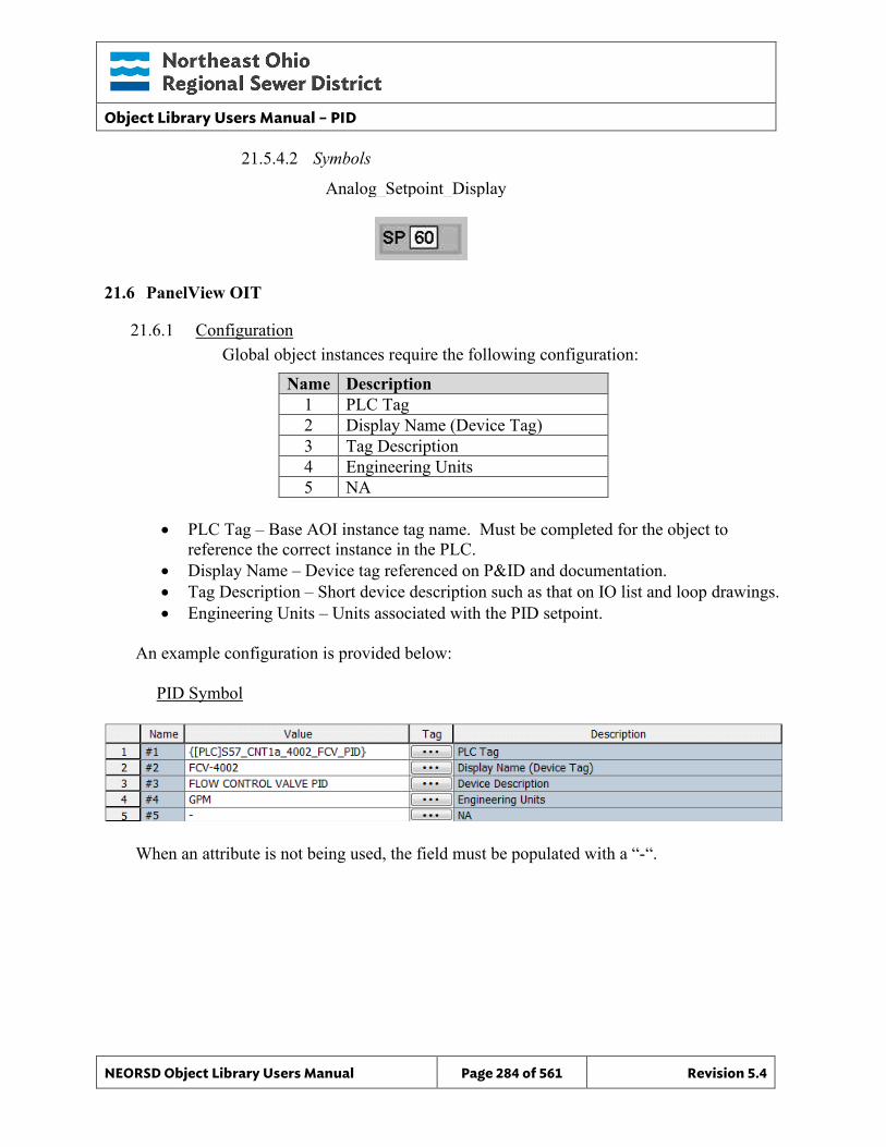
Object Library Users Manual – PID
NEORSD Object Library Users Manual Page 284 of 561 Revision 5.4
21.5.4.2 Symbols
21.6 PanelView OIT
21.6.1 Configuration Global object instances require the following configuration:
Name Description 1 PLC Tag 2 Display Name (Device Tag) 3 Tag Description 4 Engineering Units 5 NA
• PLC Tag – Base AOI instance tag name. Must be completed for the object to
reference the correct instance in the PLC. • Display Name – Device tag referenced on P&ID and documentation. • Tag Description – Short device description such as that on IO list and loop drawings. • Engineering Units – Units associated with the PID setpoint.
An example configuration is provided below: PID Symbol
When an attribute is not being used, the field must be populated with a “-“.
Analog_Setpoint_Display
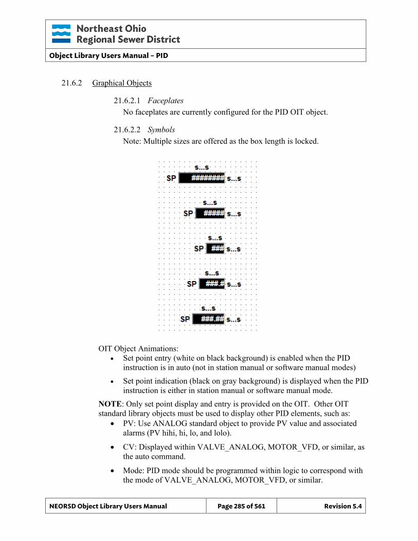
Object Library Users Manual – PID
NEORSD Object Library Users Manual Page 285 of 561 Revision 5.4
21.6.2 Graphical Objects
21.6.2.1 Faceplates No faceplates are currently configured for the PID OIT object.
21.6.2.2 Symbols Note: Multiple sizes are offered as the box length is locked.
OIT Object Animations: • Set point entry (white on black background) is enabled when the PID
instruction is in auto (not in station manual or software manual modes)
• Set point indication (black on gray background) is displayed when the PID instruction is either in station manual or software manual mode.
NOTE: Only set point display and entry is provided on the OIT. Other OIT standard library objects must be used to display other PID elements, such as:
• PV: Use ANALOG standard object to provide PV value and associated alarms (PV hihi, hi, lo, and lolo).
• CV: Displayed within VALVE_ANALOG, MOTOR_VFD, or similar, as the auto command.
• Mode: PID mode should be programmed within logic to correspond with the mode of VALVE_ANALOG, MOTOR_VFD, or similar.
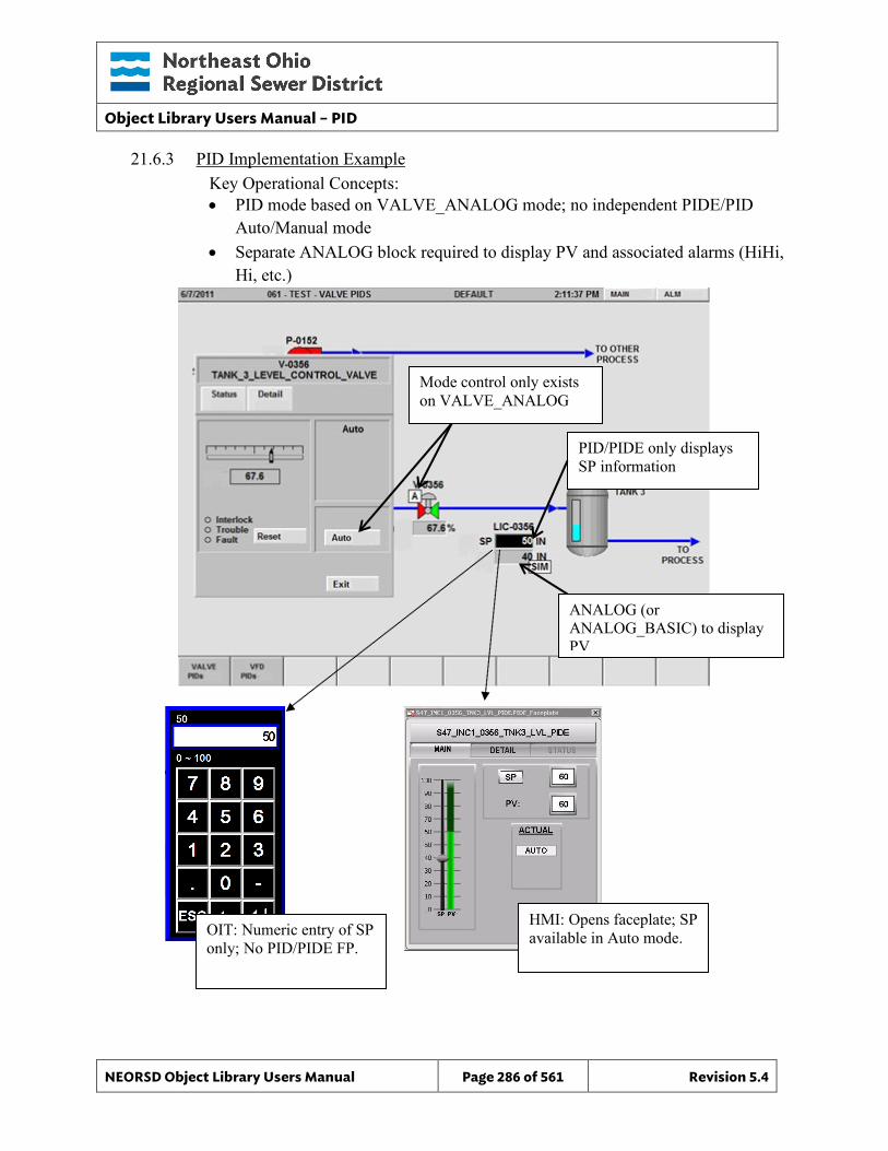
Object Library Users Manual – PID
NEORSD Object Library Users Manual Page 286 of 561 Revision 5.4
21.6.3 PID Implementation Example Key Operational Concepts:
• PID mode based on VALVE_ANALOG mode; no independent PIDE/PID Auto/Manual mode
• Separate ANALOG block required to display PV and associated alarms (HiHi, Hi, etc.)
Mode control only exists on VALVE_ANALOG
PID/PIDE only displays SP information
ANALOG (or ANALOG_BASIC) to display PV
OIT: Numeric entry of SP only; No PID/PIDE FP.
HMI: Opens faceplate; SP available in Auto mode.
Object Library Users Manual – PIDE
NEORSD Object Library Users Manual Page 287 of 561 Revision 5.4
22.0 PIDE
22.1 Introduction The PIDE template provides a standard representation of the Rockwell-provided PIDE instruction within the NEORSD control systems. The PIDE provides enhanced capabilities over the standard PID instruction, and uses the velocity form of the PID equation. Only use the PIDE template if trying to represent the Rockwell PIDE instruction on the OIT or HMI. Typically, usage of the PIDE instruction will involve three standard objects:
• ANALOG (or ANALOG_BASIC)
• VALVE_ANALOG (or MOTOR_VFD)
• PID (or PIDE)
22.2 Object Features The Rockwell PIDE function block is well documented within the Rockwell programming software; also see “Using the PIDE Instruction” (also see RA Whitepaper #LOGIX-WP008_-EN-P”). The features listed below are those pertinent to the HMI and OIT components of the object.
22.2.1 Status Indications This object will display the following values:
• Process Value (PV, HMI-only) • Setpoint Value (SP, HMI and OIT) • Control Value (CV, HMI-only)
Note: The engineering units are displayed at the HMI, but configured in the PLC.
22.2.2 Control This object allows an operator to change the value of the setpoint (SP) of the PID block. Neither the HMI nor the OIT will provide mode control for this object. PID mode must be governed solely within the PLC logic, generally programmed to match the mode (Auto/Manual) of the corresponding VALVE_ANALOG, MOTOR_VFD, or similar object.
22.2.3 Alarming The PIDE HMI and OIT objects do not support any alarming to the HMI or OIT. The alarm capabilities of the associated ANALOG standard object template or similar should be used instead.
22.2.4 Simulation This object does not support simulation.
Object Library Users Manual – PIDE
NEORSD Object Library Users Manual Page 288 of 561 Revision 5.4
22.2.5 Trouble This object does not support trouble indication.
22.2.6 DB_Precision_Group Attribute is used in the ValueDeadband script. In the script, this parameter sets the deadband of inputs. Valid values for this parameter are between 0 and 3. o 0= default group; o 1= custom ValueDeadband setting which disables the script and uses the
attribute’s ValueDeadband; o 2= high precision; o 3= non-precision REF objects (obsolete)
While 3 is an available option, it is not to be used for new objects moving forward. If changing the DB_Precision_Group to 1, you must undeploy and then deploy the object to guarantee that runtime deadband setting gets updated. A redeploy action will not update ValueDeadband.
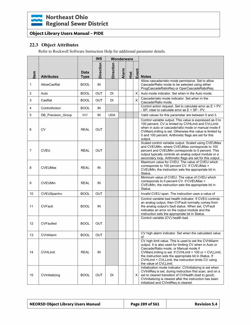
Object Library Users Manual – PIDE
NEORSD Object Library Users Manual Page 289 of 561 Revision 5.4
22.3 Object Attributes Refer to Rockwell Software Instruction Help for additional parameter details.
INS Wonderware
Item
Attributes Data Type D
irect
ion
Dire
ctio
n
Ala
rm
His
t Ev
ent
Notes
1 AllowCasRat BOOL IN Allow cascade/ratio mode permissive. Set to allow Cascade/Ratio mode to be selected using either ProgCascadeRatioReq or OperCascadeRatioReq.
2 Auto BOOL OUT DI X Auto mode indicator. Set when in the Auto mode.
3 CasRat BOOL OUT DI X Cascade/ratio mode indicator. Set when in the Cascade/Ratio mode.
4 ControlAction BOOL IN Control action request. Set to calculate error as E = PV - SP; clear to calculate error as E = SP - PV.
5 DB_Precision_Group INT IN UDA Valid values for this parameter are between 0 and 3.
6 CV REAL OUT
Control variable output. This value is expressed as 0 to 100 percent. CV is limited by CVHLimit and CVLLimit when in auto or cascade/ratio mode or manual mode if CVManLimiting is set. Otherwise this value is limited by 0 and 100 percent. Arithmetic flags are set for this output.
7 CVEU REAL OUT
Scaled control variable output. Scaled using CVEUMax and CVEUMin, where CVEUMax corresponds to 100 percent and CVEUMin corresponds to 0 percent. This output typically controls an analog output module or a secondary loop. Arithmetic flags are set for this output.
8 CVEUMax REAL IN
Maximum value for CVEU. The value of CVEU which corresponds to 100 percent CV. If CVEUMax = CVEUMin, the instruction sets the appropriate bit in Status.
9 CVEUMin REAL IN
Minimum value of CVEU. The value of CVEU which corresponds to 0 percent CV. If CVEUMax = CVEUMin, the instruction sets the appropriate bit in Status.
10 CVEUSpanInv BOOL OUT Invalid CVEU span. The instruction uses a value of
11 CVFault BOOL IN
Control variable bad health indicator. If CVEU controls an analog output, then CVFault normally comes from the analog output’s fault status. When set, CVFault indicates an error on the output module and the instruction sets the appropriate bit in Status.
12 CVFaulted BOOL OUT
Control variable (CV) health bad.
13 CVHAlarm BOOL OUT CV high alarm indicator. Set when the calculated value of
14 CVHLimit REAL IN
CV high limit value. This is used to set the CVHAlarm output. It is also used for limiting CV when in Auto or Cascade/Ratio mode, or Manual mode if CVManLimiting is set. If CVHLimit > 100 or < CVLLimit, the instruction sets the appropriate bit in Status. If CVHLimit < CVLLimit, the instruction limits CV using the value of CVLLimit.
15 CVInitializing BOOL OUT DI X
Initialization mode indicator. CVInitializing is set when CVInitReq is set, during instruction first scan, and on a set to cleared transition of CVHealth (bad to good). CVInitializing is cleared after the instruction has been initialized and CVInitReq is cleared.
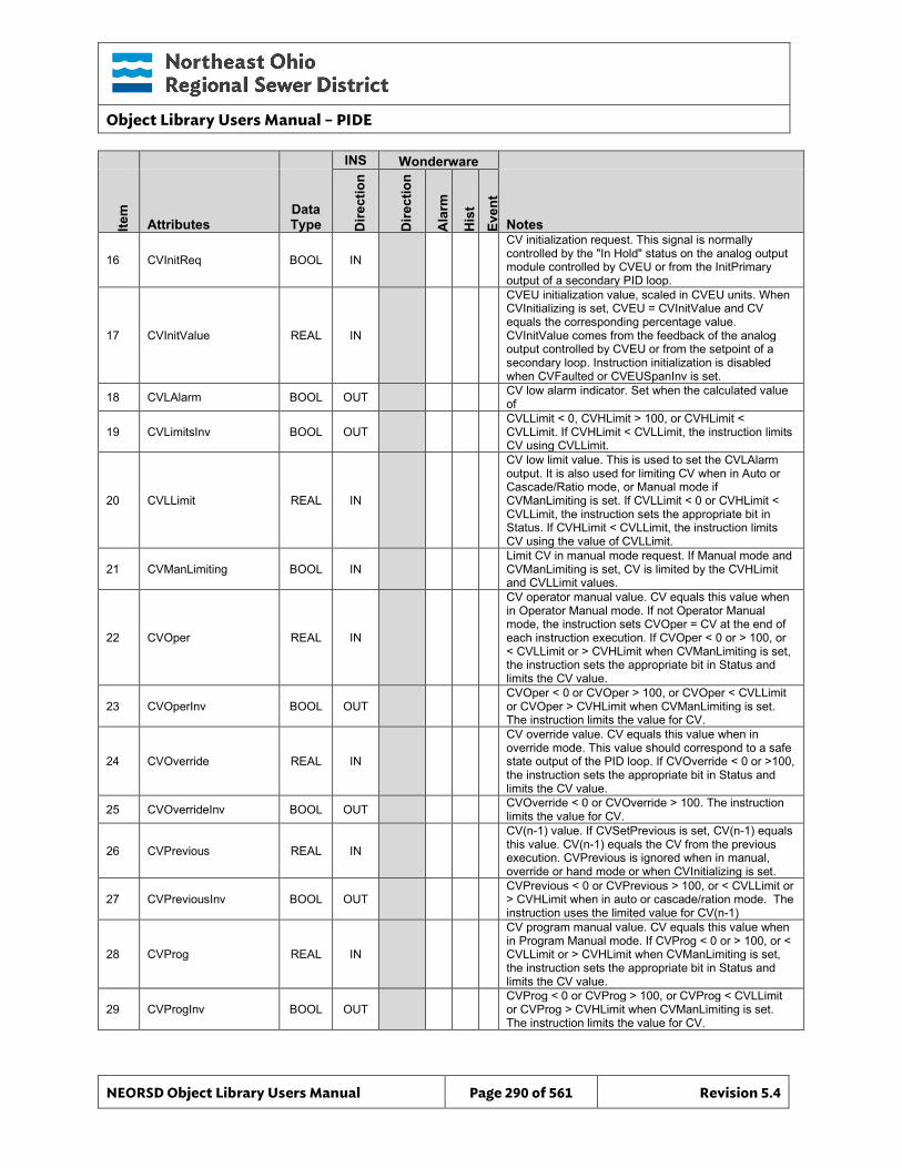
Object Library Users Manual – PIDE
NEORSD Object Library Users Manual Page 290 of 561 Revision 5.4
INS Wonderware
Item
Attributes Data Type D
irect
ion
Dire
ctio
n
Ala
rm
His
t Ev
ent
Notes
16 CVInitReq BOOL IN
CV initialization request. This signal is normally controlled by the "In Hold" status on the analog output module controlled by CVEU or from the InitPrimary output of a secondary PID loop.
17 CVInitValue REAL IN
CVEU initialization value, scaled in CVEU units. When CVInitializing is set, CVEU = CVInitValue and CV equals the corresponding percentage value. CVInitValue comes from the feedback of the analog output controlled by CVEU or from the setpoint of a secondary loop. Instruction initialization is disabled when CVFaulted or CVEUSpanInv is set.
18 CVLAlarm BOOL OUT CV low alarm indicator. Set when the calculated value of
19 CVLimitsInv BOOL OUT CVLLimit < 0, CVHLimit > 100, or CVHLimit < CVLLimit. If CVHLimit < CVLLimit, the instruction limits CV using CVLLimit.
20 CVLLimit REAL IN
CV low limit value. This is used to set the CVLAlarm output. It is also used for limiting CV when in Auto or Cascade/Ratio mode, or Manual mode if CVManLimiting is set. If CVLLimit < 0 or CVHLimit < CVLLimit, the instruction sets the appropriate bit in Status. If CVHLimit < CVLLimit, the instruction limits CV using the value of CVLLimit.
21 CVManLimiting BOOL IN Limit CV in manual mode request. If Manual mode and CVManLimiting is set, CV is limited by the CVHLimit and CVLLimit values.
22 CVOper REAL IN
CV operator manual value. CV equals this value when in Operator Manual mode. If not Operator Manual mode, the instruction sets CVOper = CV at the end of each instruction execution. If CVOper < 0 or > 100, or < CVLLimit or > CVHLimit when CVManLimiting is set, the instruction sets the appropriate bit in Status and limits the CV value.
23 CVOperInv BOOL OUT CVOper < 0 or CVOper > 100, or CVOper < CVLLimit or CVOper > CVHLimit when CVManLimiting is set. The instruction limits the value for CV.
24 CVOverride REAL IN
CV override value. CV equals this value when in override mode. This value should correspond to a safe state output of the PID loop. If CVOverride < 0 or >100, the instruction sets the appropriate bit in Status and limits the CV value.
25 CVOverrideInv BOOL OUT CVOverride < 0 or CVOverride > 100. The instruction limits the value for CV.
26 CVPrevious REAL IN
CV(n-1) value. If CVSetPrevious is set, CV(n-1) equals this value. CV(n-1) equals the CV from the previous execution. CVPrevious is ignored when in manual, override or hand mode or when CVInitializing is set.
27 CVPreviousInv BOOL OUT CVPrevious < 0 or CVPrevious > 100, or < CVLLimit or > CVHLimit when in auto or cascade/ration mode. The instruction uses the limited value for CV(n-1)
28 CVProg REAL IN
CV program manual value. CV equals this value when in Program Manual mode. If CVProg < 0 or > 100, or < CVLLimit or > CVHLimit when CVManLimiting is set, the instruction sets the appropriate bit in Status and limits the CV value.
29 CVProgInv BOOL OUT CVProg < 0 or CVProg > 100, or CVProg < CVLLimit or CVProg > CVHLimit when CVManLimiting is set. The instruction limits the value for CV.
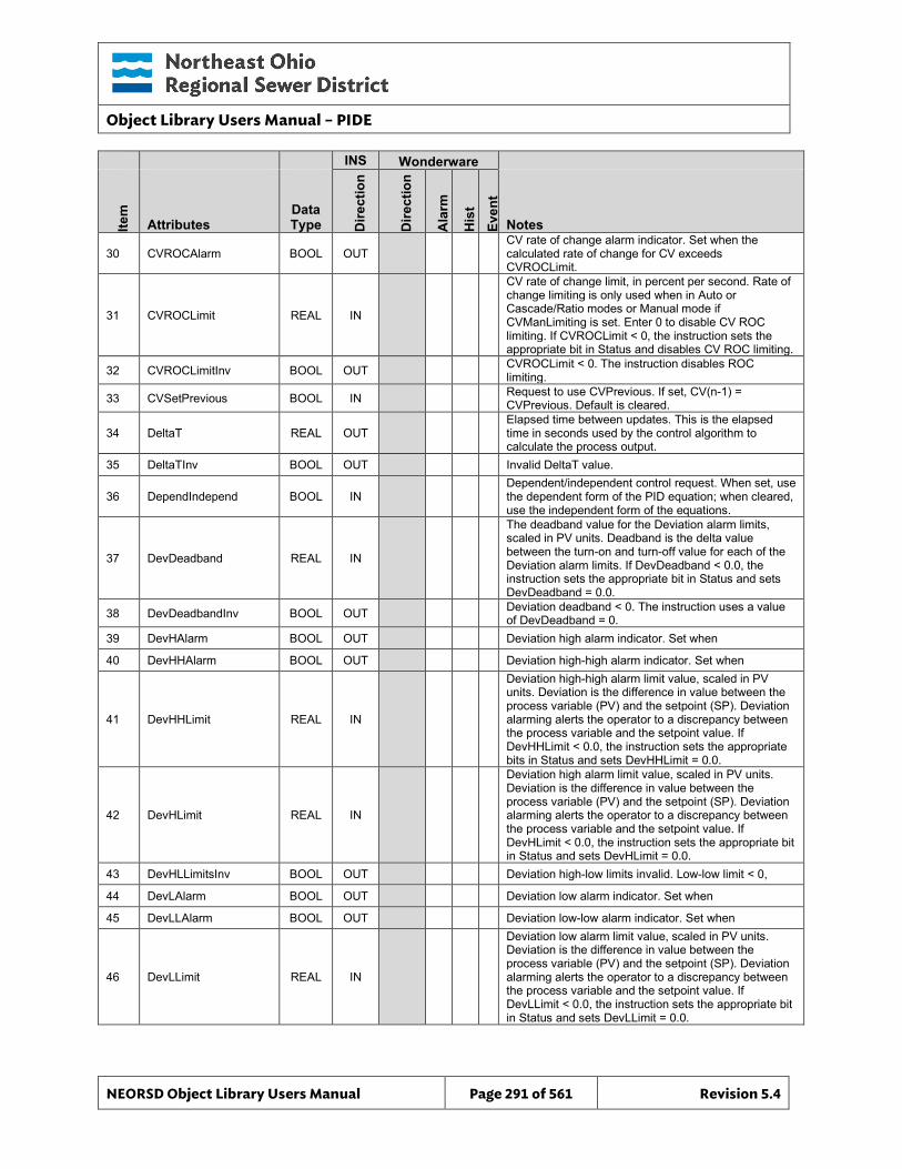
Object Library Users Manual – PIDE
NEORSD Object Library Users Manual Page 291 of 561 Revision 5.4
INS Wonderware
Item
Attributes Data Type D
irect
ion
Dire
ctio
n
Ala
rm
His
t Ev
ent
Notes
30 CVROCAlarm BOOL OUT CV rate of change alarm indicator. Set when the calculated rate of change for CV exceeds CVROCLimit.
31 CVROCLimit REAL IN
CV rate of change limit, in percent per second. Rate of change limiting is only used when in Auto or Cascade/Ratio modes or Manual mode if CVManLimiting is set. Enter 0 to disable CV ROC limiting. If CVROCLimit < 0, the instruction sets the appropriate bit in Status and disables CV ROC limiting.
32 CVROCLimitInv BOOL OUT CVROCLimit < 0. The instruction disables ROC limiting.
33 CVSetPrevious BOOL IN Request to use CVPrevious. If set, CV(n-1) = CVPrevious. Default is cleared.
34 DeltaT REAL OUT Elapsed time between updates. This is the elapsed time in seconds used by the control algorithm to calculate the process output.
35 DeltaTInv BOOL OUT Invalid DeltaT value.
36 DependIndepend BOOL IN Dependent/independent control request. When set, use the dependent form of the PID equation; when cleared, use the independent form of the equations.
37 DevDeadband REAL IN
The deadband value for the Deviation alarm limits, scaled in PV units. Deadband is the delta value between the turn-on and turn-off value for each of the Deviation alarm limits. If DevDeadband < 0.0, the instruction sets the appropriate bit in Status and sets DevDeadband = 0.0.
38 DevDeadbandInv BOOL OUT Deviation deadband < 0. The instruction uses a value of DevDeadband = 0.
39 DevHAlarm BOOL OUT Deviation high alarm indicator. Set when
40 DevHHAlarm BOOL OUT Deviation high-high alarm indicator. Set when
41 DevHHLimit REAL IN
Deviation high-high alarm limit value, scaled in PV units. Deviation is the difference in value between the process variable (PV) and the setpoint (SP). Deviation alarming alerts the operator to a discrepancy between the process variable and the setpoint value. If DevHHLimit < 0.0, the instruction sets the appropriate bits in Status and sets DevHHLimit = 0.0.
42 DevHLimit REAL IN
Deviation high alarm limit value, scaled in PV units. Deviation is the difference in value between the process variable (PV) and the setpoint (SP). Deviation alarming alerts the operator to a discrepancy between the process variable and the setpoint value. If DevHLimit < 0.0, the instruction sets the appropriate bit in Status and sets DevHLimit = 0.0.
43 DevHLLimitsInv BOOL OUT Deviation high-low limits invalid. Low-low limit < 0,
44 DevLAlarm BOOL OUT Deviation low alarm indicator. Set when
45 DevLLAlarm BOOL OUT Deviation low-low alarm indicator. Set when
46 DevLLimit REAL IN
Deviation low alarm limit value, scaled in PV units. Deviation is the difference in value between the process variable (PV) and the setpoint (SP). Deviation alarming alerts the operator to a discrepancy between the process variable and the setpoint value. If DevLLimit < 0.0, the instruction sets the appropriate bit in Status and sets DevLLimit = 0.0.
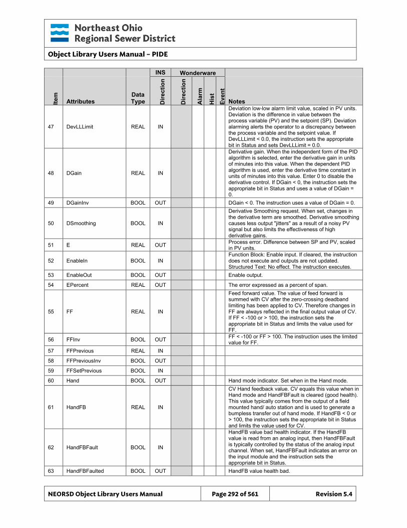
Object Library Users Manual – PIDE
NEORSD Object Library Users Manual Page 292 of 561 Revision 5.4
INS Wonderware
Item
Attributes Data Type D
irect
ion
Dire
ctio
n
Ala
rm
His
t Ev
ent
Notes
47 DevLLLimit REAL IN
Deviation low-low alarm limit value, scaled in PV units. Deviation is the difference in value between the process variable (PV) and the setpoint (SP). Deviation alarming alerts the operator to a discrepancy between the process variable and the setpoint value. If DevLLLimit < 0.0, the instruction sets the appropriate bit in Status and sets DevLLLimit = 0.0.
48 DGain REAL IN
Derivative gain. When the independent form of the PID algorithm is selected, enter the derivative gain in units of minutes into this value. When the dependent PID algorithm is used, enter the derivative time constant in units of minutes into this value. Enter 0 to disable the derivative control. If DGain < 0, the instruction sets the appropriate bit in Status and uses a value of DGain = 0.
49 DGainInv BOOL OUT DGain < 0. The instruction uses a value of DGain = 0.
50 DSmoothing BOOL IN
Derivative Smoothing request. When set, changes in the derivative term are smoothed. Derivative smoothing causes less output "jitters" as a result of a noisy PV signal but also limits the effectiveness of high derivative gains.
51 E REAL OUT Process error. Difference between SP and PV, scaled in PV units.
52 EnableIn BOOL IN Function Block: Enable input. If cleared, the instruction does not execute and outputs are not updated. Structured Text: No effect. The instruction executes.
53 EnableOut BOOL OUT Enable output.
54 EPercent REAL OUT The error expressed as a percent of span.
55 FF REAL IN
Feed forward value. The value of feed forward is summed with CV after the zero-crossing deadband limiting has been applied to CV. Therefore changes in FF are always reflected in the final output value of CV. If FF < -100 or > 100, the instruction sets the appropriate bit in Status and limits the value used for FF.
56 FFInv BOOL OUT FF < -100 or FF > 100. The instruction uses the limited value for FF.
57 FFPrevious REAL IN
58 FFPreviousInv BOOL OUT
59 FFSetPrevious BOOL IN
60 Hand BOOL OUT Hand mode indicator. Set when in the Hand mode.
61 HandFB REAL IN
CV Hand feedback value. CV equals this value when in Hand mode and HandFBFault is cleared (good health). This value typically comes from the output of a field mounted hand/ auto station and is used to generate a bumpless transfer out of hand mode. If HandFB < 0 or > 100, the instruction sets the appropriate bit in Status and limits the value used for CV.
62 HandFBFault BOOL IN
HandFB value bad health indicator. If the HandFB value is read from an analog input, then HandFBFault is typically controlled by the status of the analog input channel. When set, HandFBFault indicates an error on the input module and the instruction sets the appropriate bit in Status.
63 HandFBFaulted BOOL OUT HandFB value health bad.
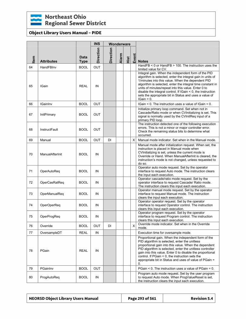
Object Library Users Manual – PIDE
NEORSD Object Library Users Manual Page 293 of 561 Revision 5.4
INS Wonderware
Item
Attributes Data Type D
irect
ion
Dire
ctio
n
Ala
rm
His
t Ev
ent
Notes 64 HandFBInv BOOL OUT HandFB < 0 or HandFB > 100. The instruction uses the
limited value for CV.
65 IGain REAL IN
Integral gain. When the independent form of the PID algorithm is selected, enter the integral gain in units of 1/minutes into this value. When the dependent PID algorithm is selected, enter the integral time constant in units of minutes/repeat into this value. Enter 0 to disable the integral control. If IGain < 0, the instruction sets the appropriate bit in Status and uses a value of IGain = 0.
66 IGainInv BOOL OUT IGain < 0. The instruction uses a value of IGain = 0.
67 InitPrimary BOOL OUT
Initialize primary loop command. Set when not in Cascade/Ratio mode or when CVInitializing is set. This signal is normally used by the CVInitReq input of a primary PID loop.
68 InstructFault BOOL OUT
The instruction detected one of the following execution errors. This is not a minor or major controller error. Check the remaining status bits to determine what occurred.
69 Manual BOOL OUT DI X Manual mode indicator. Set when in the Manual mode.
70 ManualAfterInit BOOL IN
Manual mode after initialization request. When set, the instruction is placed in Manual mode when CVInitializing is set, unless the current mode is Override or Hand. When ManualAfterInit is cleared, the instruction’s mode is not changed, unless requested to do so.
71 OperAutoReq BOOL IN Operator auto mode request. Set by the operator interface to request Auto mode. The instruction clears the input each execution.
72 OperCasRatReq BOOL IN Operator cascade/ratio mode request. Set by the operator interface to request Cascade/ Ratio mode. The instruction clears this input each execution.
73 OperManualReq BOOL IN Operator manual mode request. Set by the operator interface to request Manual mode. The instruction clears the input each execution.
74 OperOperReq BOOL IN Operator operator request. Set by the operator interface to request Operator control. The instruction clears this input each execution.
75 OperProgReq BOOL IN Operator program request. Set by the operator interface to request Program control. The instruction clears this input each execution.
76 Override BOOL OUT DI X Override mode indicator. Set when in the Override mode.
77 OversampleDT REAL IN Execution time for oversample mode.
78 PGain REAL IN
Proportional gain. When the independent form of the PID algorithm is selected, enter the unitless proportional gain into this value. When the dependent PID algorithm is selected, enter the unitless controller gain into this value. Enter 0 to disable the proportional control. If PGain < 0, the instruction sets the appropriate bit in Status and uses of value of PGain = 0.
79 PGainInv BOOL OUT PGain < 0. The instruction uses a value of PGain = 0.
80 ProgAutoReq BOOL IN Program auto mode request. Set by the user program to request Auto mode. When ProgValueReset is set, the instruction clears the input each execution.
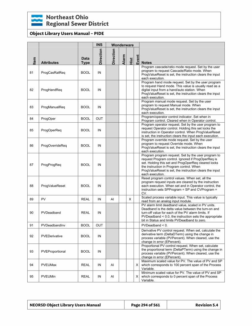
Object Library Users Manual – PIDE
NEORSD Object Library Users Manual Page 294 of 561 Revision 5.4
INS Wonderware
Item
Attributes Data Type D
irect
ion
Dire
ctio
n
Ala
rm
His
t Ev
ent
Notes
81 ProgCasRatReq BOOL IN
Program cascade/ratio mode request. Set by the user program to request Cascade/Ratio mode. When ProgValueReset is set, the instruction clears the input each execution.
82 ProgHandReq BOOL IN
Program hand mode request. Set by the user program to request Hand mode. This value is usually read as a digital input from a hand/auto station. When ProgValueReset is set, the instruction clears the input each execution.
83 ProgManualReq BOOL IN
Program manual mode request. Set by the user program to request Manual mode. When ProgValueReset is set, the instruction clears the input each execution.
84 ProgOper BOOL OUT Program/operator control indicator. Set when in Program control. Cleared when in Operator control.
85 ProgOperReq BOOL IN
Program operator request. Set by the user program to request Operator control. Holding this set locks the instruction in Operator control. When ProgValueReset is set, the instruction clears the input each execution.
86 ProgOverrideReq BOOL IN
Program override mode request. Set by the user program to request Override mode. When ProgValueReset is set, the instruction clears the input each execution.
87 ProgProgReq BOOL IN
Program program request. Set by the user program to request Program control. Ignored if ProgOperReq is set. Holding this set and ProgOperReq cleared locks the instruction in Program control. When ProgValueReset is set, the instruction clears the input each execution.
88 ProgValueReset BOOL IN
Reset program control values. When set, all the program request inputs are cleared by the instruction each execution. When set and in Operator control, the instruction sets SPProgram = SP and CVProgram = CV.
89 PV REAL IN AI X Scaled process variable input. This value is typically read from an analog input module.
90 PVDeadband REAL IN
PV alarm limit deadband value, scaled in PV units. Deadband is the delta value between the turn-on and turn-off value for each of the PV alarm limits. If PVDeadband < 0.0, the instruction sets the appropriate bit in Status and limits PVDeadband to zero.
91 PVDeadbandInv BOOL OUT PVDeadband < 0.
92 PVEDerivative BOOL IN
Derivative PV control request. When set, calculate the derivative term (DeltaDTerm) using the change in process variable (PVPercent). When cleared, use the change in error (EPercent).
93 PVEProportional BOOL IN
Proportional PV control request. When set, calculate the proportional term (DeltaPTerm) using the change in process variable (PVPercent). When cleared, use the change in error (EPercent).
94 PVEUMax REAL IN AI X Maximum scaled value for PV. The value of PV and SP which corresponds to 100 percent span of the Process Variable.
95 PVEUMin REAL IN AI X Minimum scaled value for PV. The value of PV and SP which corresponds to 0 percent span of the Process Variable.
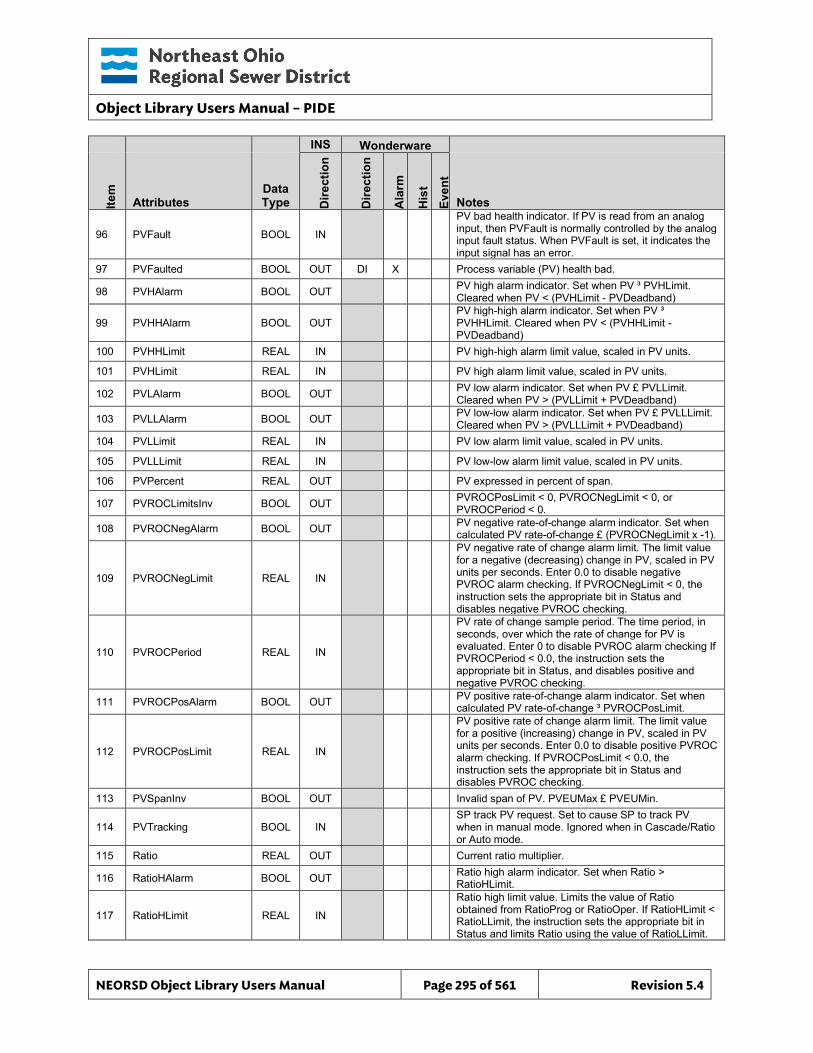
Object Library Users Manual – PIDE
NEORSD Object Library Users Manual Page 295 of 561 Revision 5.4
INS Wonderware
Item
Attributes Data Type D
irect
ion
Dire
ctio
n
Ala
rm
His
t Ev
ent
Notes
96 PVFault BOOL IN
PV bad health indicator. If PV is read from an analog input, then PVFault is normally controlled by the analog input fault status. When PVFault is set, it indicates the input signal has an error.
97 PVFaulted BOOL OUT DI X Process variable (PV) health bad.
98 PVHAlarm BOOL OUT PV high alarm indicator. Set when PV ³ PVHLimit. Cleared when PV < (PVHLimit - PVDeadband)
99 PVHHAlarm BOOL OUT PV high-high alarm indicator. Set when PV ³ PVHHLimit. Cleared when PV < (PVHHLimit - PVDeadband)
100 PVHHLimit REAL IN PV high-high alarm limit value, scaled in PV units.
101 PVHLimit REAL IN PV high alarm limit value, scaled in PV units.
102 PVLAlarm BOOL OUT PV low alarm indicator. Set when PV £ PVLLimit. Cleared when PV > (PVLLimit + PVDeadband)
103 PVLLAlarm BOOL OUT PV low-low alarm indicator. Set when PV £ PVLLLimit. Cleared when PV > (PVLLLimit + PVDeadband)
104 PVLLimit REAL IN PV low alarm limit value, scaled in PV units.
105 PVLLLimit REAL IN PV low-low alarm limit value, scaled in PV units.
106 PVPercent REAL OUT PV expressed in percent of span.
107 PVROCLimitsInv BOOL OUT PVROCPosLimit < 0, PVROCNegLimit < 0, or PVROCPeriod < 0.
108 PVROCNegAlarm BOOL OUT PV negative rate-of-change alarm indicator. Set when calculated PV rate-of-change £ (PVROCNegLimit x -1).
109 PVROCNegLimit REAL IN
PV negative rate of change alarm limit. The limit value for a negative (decreasing) change in PV, scaled in PV units per seconds. Enter 0.0 to disable negative PVROC alarm checking. If PVROCNegLimit < 0, the instruction sets the appropriate bit in Status and disables negative PVROC checking.
110 PVROCPeriod REAL IN
PV rate of change sample period. The time period, in seconds, over which the rate of change for PV is evaluated. Enter 0 to disable PVROC alarm checking If PVROCPeriod < 0.0, the instruction sets the appropriate bit in Status, and disables positive and negative PVROC checking.
111 PVROCPosAlarm BOOL OUT PV positive rate-of-change alarm indicator. Set when calculated PV rate-of-change ³ PVROCPosLimit.
112 PVROCPosLimit REAL IN
PV positive rate of change alarm limit. The limit value for a positive (increasing) change in PV, scaled in PV units per seconds. Enter 0.0 to disable positive PVROC alarm checking. If PVROCPosLimit < 0.0, the instruction sets the appropriate bit in Status and disables PVROC checking.
113 PVSpanInv BOOL OUT Invalid span of PV. PVEUMax £ PVEUMin.
114 PVTracking BOOL IN SP track PV request. Set to cause SP to track PV when in manual mode. Ignored when in Cascade/Ratio or Auto mode.
115 Ratio REAL OUT Current ratio multiplier.
116 RatioHAlarm BOOL OUT Ratio high alarm indicator. Set when Ratio > RatioHLimit.
117 RatioHLimit REAL IN
Ratio high limit value. Limits the value of Ratio obtained from RatioProg or RatioOper. If RatioHLimit < RatioLLimit, the instruction sets the appropriate bit in Status and limits Ratio using the value of RatioLLimit.
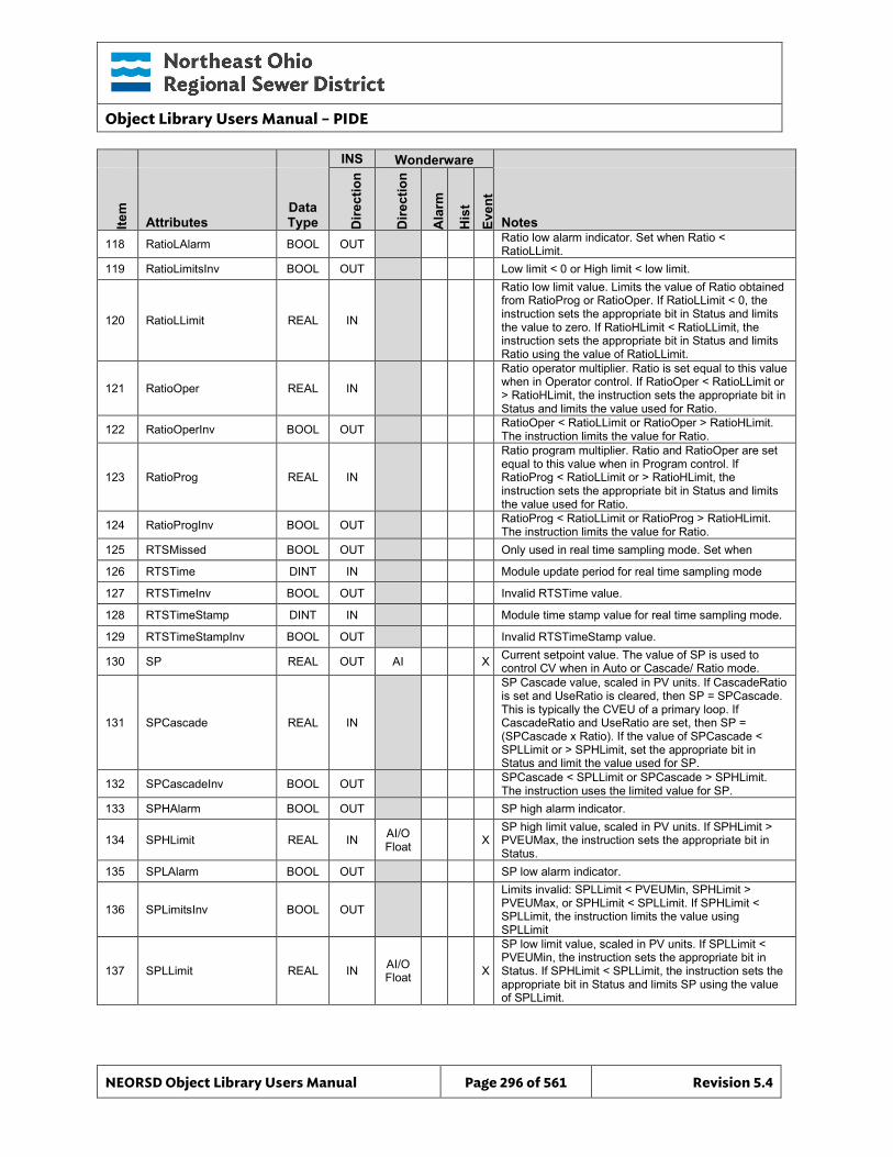
Object Library Users Manual – PIDE
NEORSD Object Library Users Manual Page 296 of 561 Revision 5.4
INS Wonderware
Item
Attributes Data Type D
irect
ion
Dire
ctio
n
Ala
rm
His
t Ev
ent
Notes 118 RatioLAlarm BOOL OUT Ratio low alarm indicator. Set when Ratio <
RatioLLimit. 119 RatioLimitsInv BOOL OUT Low limit < 0 or High limit < low limit.
120 RatioLLimit REAL IN
Ratio low limit value. Limits the value of Ratio obtained from RatioProg or RatioOper. If RatioLLimit < 0, the instruction sets the appropriate bit in Status and limits the value to zero. If RatioHLimit < RatioLLimit, the instruction sets the appropriate bit in Status and limits Ratio using the value of RatioLLimit.
121 RatioOper REAL IN
Ratio operator multiplier. Ratio is set equal to this value when in Operator control. If RatioOper < RatioLLimit or > RatioHLimit, the instruction sets the appropriate bit in Status and limits the value used for Ratio.
122 RatioOperInv BOOL OUT RatioOper < RatioLLimit or RatioOper > RatioHLimit. The instruction limits the value for Ratio.
123 RatioProg REAL IN
Ratio program multiplier. Ratio and RatioOper are set equal to this value when in Program control. If RatioProg < RatioLLimit or > RatioHLimit, the instruction sets the appropriate bit in Status and limits the value used for Ratio.
124 RatioProgInv BOOL OUT RatioProg < RatioLLimit or RatioProg > RatioHLimit. The instruction limits the value for Ratio.
125 RTSMissed BOOL OUT Only used in real time sampling mode. Set when
126 RTSTime DINT IN Module update period for real time sampling mode
127 RTSTimeInv BOOL OUT Invalid RTSTime value.
128 RTSTimeStamp DINT IN Module time stamp value for real time sampling mode.
129 RTSTimeStampInv BOOL OUT Invalid RTSTimeStamp value.
130 SP REAL OUT AI X Current setpoint value. The value of SP is used to control CV when in Auto or Cascade/ Ratio mode.
131 SPCascade REAL IN
SP Cascade value, scaled in PV units. If CascadeRatio is set and UseRatio is cleared, then SP = SPCascade. This is typically the CVEU of a primary loop. If CascadeRatio and UseRatio are set, then SP = (SPCascade x Ratio). If the value of SPCascade < SPLLimit or > SPHLimit, set the appropriate bit in Status and limit the value used for SP.
132 SPCascadeInv BOOL OUT SPCascade < SPLLimit or SPCascade > SPHLimit. The instruction uses the limited value for SP.
133 SPHAlarm BOOL OUT SP high alarm indicator.
134 SPHLimit REAL IN AI/O Float X
SP high limit value, scaled in PV units. If SPHLimit > PVEUMax, the instruction sets the appropriate bit in Status.
135 SPLAlarm BOOL OUT SP low alarm indicator.
136 SPLimitsInv BOOL OUT
Limits invalid: SPLLimit < PVEUMin, SPHLimit > PVEUMax, or SPHLimit < SPLLimit. If SPHLimit < SPLLimit, the instruction limits the value using SPLLimit
137 SPLLimit REAL IN AI/O Float X
SP low limit value, scaled in PV units. If SPLLimit < PVEUMin, the instruction sets the appropriate bit in Status. If SPHLimit < SPLLimit, the instruction sets the appropriate bit in Status and limits SP using the value of SPLLimit.
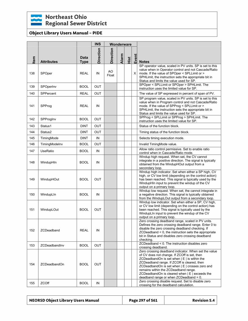
Object Library Users Manual – PIDE
NEORSD Object Library Users Manual Page 297 of 561 Revision 5.4
INS Wonderware
Item
Attributes Data Type D
irect
ion
Dire
ctio
n
Ala
rm
His
t Ev
ent
Notes
138 SPOper REAL IN AO Float X
SP operator value, scaled in PV units. SP is set to this value when in Operator control and not Cascade/Ratio mode. If the value of SPOper < SPLLimit or > SPHLimit, the instruction sets the appropriate bit in Status and limits the value used for SP.
139 SPOperInv BOOL OUT SPOper < SPLLimit or SPOper > SPHLimit. The instruction uses the limited value for SP.
140 SPPercent REAL OUT The value of SP expressed in percent of span of PV.
141 SPProg REAL IN
SP program value, scaled in PV units. SP is set to this value when in Program control and not Cascade/Ratio mode. If the value of SPProg < SPLLimit or > SPHLimit, the instruction sets the appropriate bit in Status and limits the value used for SP.
142 SPProgInv BOOL OUT SPProg < SPLLimit or SPProg > SPHLimit. The instruction uses the limited value for SP.
143 Status1 DINT OUT Status of the function block.
144 Status2 DINT OUT Timing status of the function block.
145 TimingMode DINT IN Selects timing execution mode.
146 TimingModeInv BOOL OUT Invalid TimingMode value.
147 UseRatio BOOL IN Allow ratio control permissive. Set to enable ratio control when in Cascade/Ratio mode.
148 WindupHIn BOOL IN
Windup high request. When set, the CV cannot integrate in a positive direction. The signal is typically obtained from the WindupHOut output from a secondary loop.
149 WindupHOut BOOL OUT
Windup high indicator. Set when either a SP high, CV high, or CV low limit (depending on the control action) has been reached. This signal is typically used by the WindupHIn input to prevent the windup of the CV output on a primary loop.
150 WindupLIn BOOL IN Windup low request. When set, the cannot integrate in a negative direction. This signal is typically obtained from the WindupLOut output from a secondary loop.
151 WindupLOut BOOL OUT
Windup low indicator. Set when either a SP, CV high, or CV low limit (depending on the control action) has been reached. This signal is typically used by the WindupLIn input to prevent the windup of the CV output on a primary loop.
152 ZCDeadband REAL IN
Zero crossing deadband range, scaled in PV units. Defines the zero crossing deadband range. Enter 0 to disable the zero crossing deadband checking. If ZCDeadband < 0, the instruction sets the appropriate bit in Status and disables zero crossing deadband checking.
153 ZCDeadbandInv BOOL OUT ZCDeadband < 0. The instruction disables zero crossing deadband.
154 ZCDeadbandOn BOOL OUT
Zero crossing deadband indicator. When set the value of CV does not change. If ZCOff is set, then ZCDeadbandOn is set when | E | is within the ZCDeadband range. If ZCOff is cleared, then ZCDeadbandOn is set when | E | crosses zero and remains within the ZCDeadband range. ZCDeadbandOn is cleared when | E | exceeds the deadband range or when ZCDeadband = 0.
155 ZCOff BOOL IN Zero crossing disable request. Set to disable zero crossing for the deadband calculation.
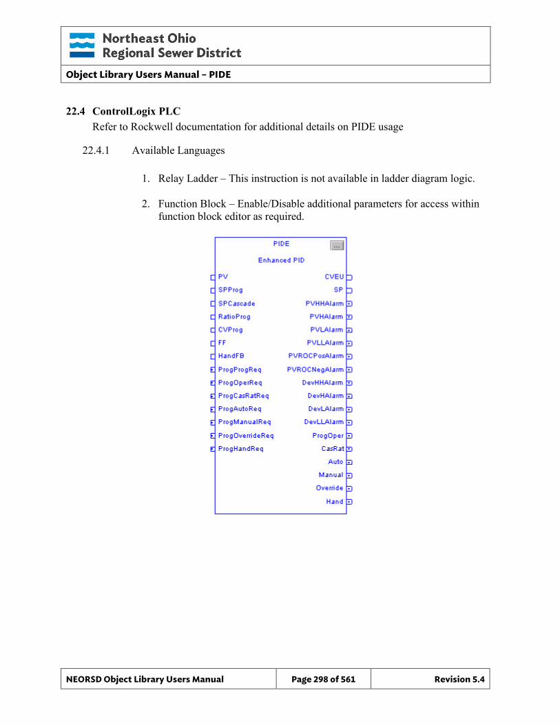
Object Library Users Manual – PIDE
NEORSD Object Library Users Manual Page 298 of 561 Revision 5.4
22.4 ControlLogix PLC Refer to Rockwell documentation for additional details on PIDE usage
22.4.1 Available Languages
1. Relay Ladder – This instruction is not available in ladder diagram logic.
2. Function Block – Enable/Disable additional parameters for access within function block editor as required.
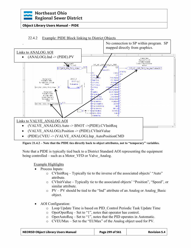
Object Library Users Manual – PIDE
NEORSD Object Library Users Manual Page 299 of 561 Revision 5.4
22.4.2 Example: PIDE Block linking to District Objects .
Figure 21.4.2 – Note that the PIDE ties directly back to object attributes, not to “temporary” variables. Note that a PIDE is typically tied back to a District Standard AOI representing the equipment being controlled – such as a Motor_VFD or Valve_Analog.
Example Highlights • Process Inputs:
o CVInitReq – Typically tie to the inverse of the associated objects’ “Auto” attribute.
o CVInitValue – Typically tie to the associated objects’ “Position”, “Speed”, or similar attribute.
o PV – PV should be tied to the “Ind” attribute of an Analog or Analog_Basic object.
• AOI Configuration:
o Loop Update Time is based on PID_Control Periodic Task Update Time o OperOperReq – Set to “1”, notes that operator has control. o OperAutoReq – Set to “1”, notes that the PID operates in Automatic. o CVEUMax – Set to the “EUMax” of the Analog object used for PV.
Links to ANALOG AOI • (ANALOG).Ind -> (PIDE).PV
Links to VALVE_ANALOG AOI • (VALVE_ANALOG).Auto -> BNOT ->(PIDE).CVInitReq • (VALVE_ANALOG).Position -> (PIDE).CVInitValue • (PIDE).CVEU -> (VALVE_ANALOG).Inp_AutoPositionCMD
No connection to SP within program. SP mapped directly from graphics.
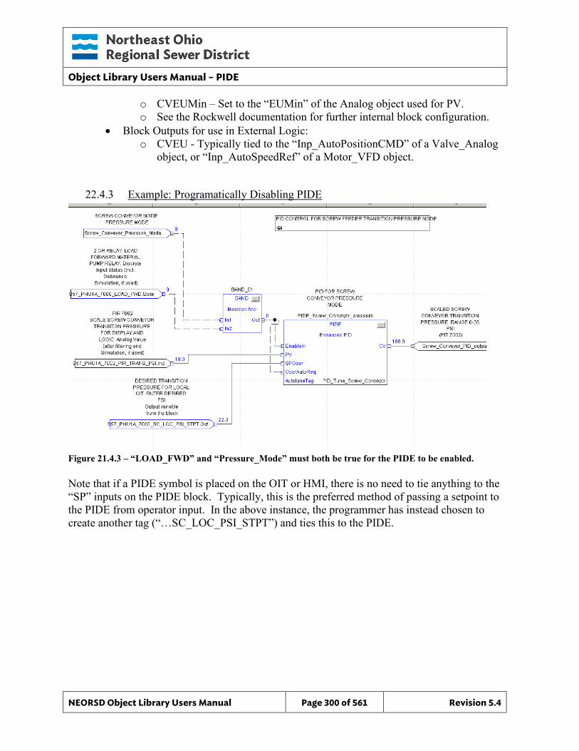
Object Library Users Manual – PIDE
NEORSD Object Library Users Manual Page 300 of 561 Revision 5.4
o CVEUMin – Set to the “EUMin” of the Analog object used for PV. o See the Rockwell documentation for further internal block configuration.
• Block Outputs for use in External Logic: o CVEU - Typically tied to the “Inp_AutoPositionCMD” of a Valve_Analog
object, or “Inp_AutoSpeedRef” of a Motor_VFD object.
22.4.3 Example: Programatically Disabling PIDE
Figure 21.4.3 – “LOAD_FWD” and “Pressure_Mode” must both be true for the PIDE to be enabled. Note that if a PIDE symbol is placed on the OIT or HMI, there is no need to tie anything to the “SP” inputs on the PIDE block. Typically, this is the preferred method of passing a setpoint to the PIDE from operator input. In the above instance, the programmer has instead chosen to create another tag (“…SC_LOC_PSI_STPT”) and ties this to the PIDE.
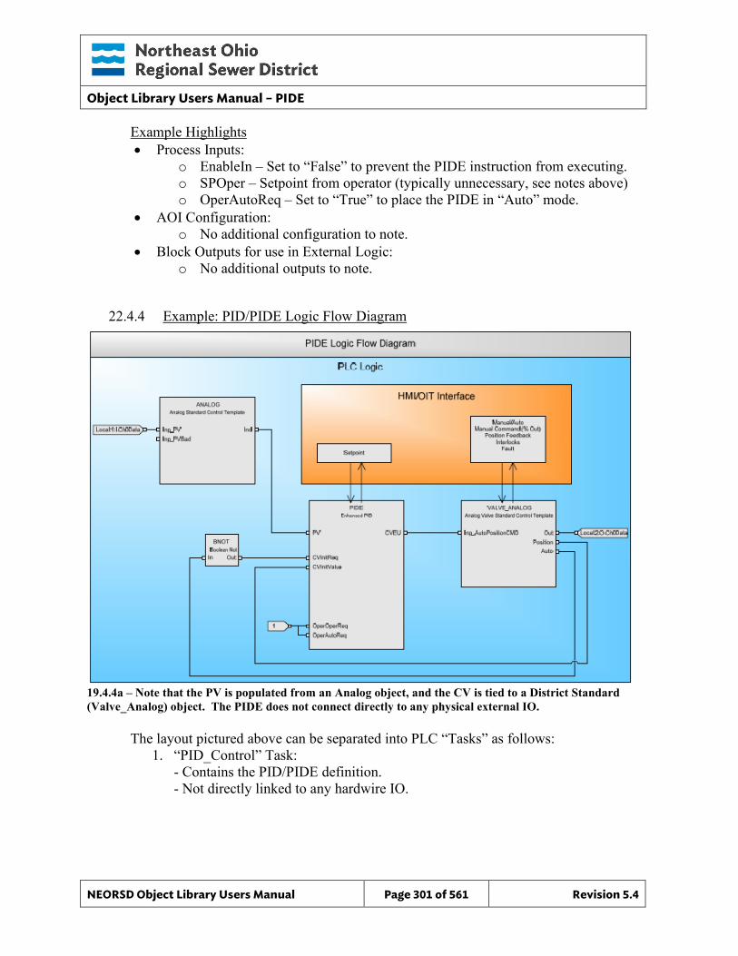
Object Library Users Manual – PIDE
NEORSD Object Library Users Manual Page 301 of 561 Revision 5.4
Example Highlights • Process Inputs:
o EnableIn – Set to “False” to prevent the PIDE instruction from executing. o SPOper – Setpoint from operator (typically unnecessary, see notes above) o OperAutoReq – Set to “True” to place the PIDE in “Auto” mode.
• AOI Configuration: o No additional configuration to note.
• Block Outputs for use in External Logic: o No additional outputs to note.
22.4.4 Example: PID/PIDE Logic Flow Diagram
19.4.4a – Note that the PV is populated from an Analog object, and the CV is tied to a District Standard (Valve_Analog) object. The PIDE does not connect directly to any physical external IO.
The layout pictured above can be separated into PLC “Tasks” as follows: 1. “PID_Control” Task:
- Contains the PID/PIDE definition. - Not directly linked to any hardwire IO.
Object Library Users Manual – PIDE
NEORSD Object Library Users Manual Page 302 of 561 Revision 5.4
2. “Process_Control” Task: - Contains the “Valve_Analog”, “Motor_VFD”, or other equipment object definition. - Inputs to PID block are typically referenced by/on the PIDE block instance itself. - No “Special” AOI configuration for PIDE control of District Object is typically required.
3. “IO_Mapping” Task: - References “Analog” for the input from hardwire IO
- References “Valve_Analog” (or other object block) to tie to hardwire IO for control.
22.4.5 Additional Attribute Notes
22.4.5.1 Inputs o For additional information, consult Rockwell documentation.
22.4.5.2 Internal Configuration o For additional information, consult Rockwell documentation.
22.4.5.3 Outputs o For additional information, consult Rockwell documentation.
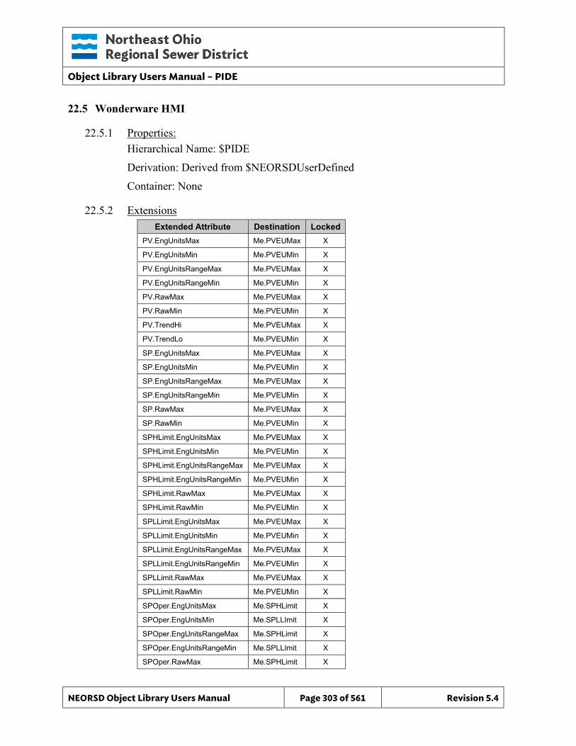
Object Library Users Manual – PIDE
NEORSD Object Library Users Manual Page 303 of 561 Revision 5.4
22.5 Wonderware HMI
22.5.1 Properties: Hierarchical Name: $PIDE Derivation: Derived from $NEORSDUserDefined Container: None
22.5.2 Extensions Extended Attribute Destination Locked
PV.EngUnitsMax Me.PVEUMax X
PV.EngUnitsMin Me.PVEUMin X
PV.EngUnitsRangeMax Me.PVEUMax X
PV.EngUnitsRangeMin Me.PVEUMin X
PV.RawMax Me.PVEUMax X
PV.RawMin Me.PVEUMin X
PV.TrendHi Me.PVEUMax X
PV.TrendLo Me.PVEUMin X
SP.EngUnitsMax Me.PVEUMax X
SP.EngUnitsMin Me.PVEUMin X
SP.EngUnitsRangeMax Me.PVEUMax X
SP.EngUnitsRangeMin Me.PVEUMin X
SP.RawMax Me.PVEUMax X
SP.RawMin Me.PVEUMin X
SPHLimit.EngUnitsMax Me.PVEUMax X
SPHLimit.EngUnitsMin Me.PVEUMin X
SPHLimit.EngUnitsRangeMax Me.PVEUMax X
SPHLimit.EngUnitsRangeMin Me.PVEUMin X
SPHLimit.RawMax Me.PVEUMax X
SPHLimit.RawMin Me.PVEUMin X
SPLLimit.EngUnitsMax Me.PVEUMax X
SPLLimit.EngUnitsMin Me.PVEUMin X
SPLLimit.EngUnitsRangeMax Me.PVEUMax X
SPLLimit.EngUnitsRangeMin Me.PVEUMin X
SPLLimit.RawMax Me.PVEUMax X
SPLLimit.RawMin Me.PVEUMin X
SPOper.EngUnitsMax Me.SPHLimit X
SPOper.EngUnitsMin Me.SPLLImit X
SPOper.EngUnitsRangeMax Me.SPHLimit X
SPOper.EngUnitsRangeMin Me.SPLLImit X
SPOper.RawMax Me.SPHLimit X
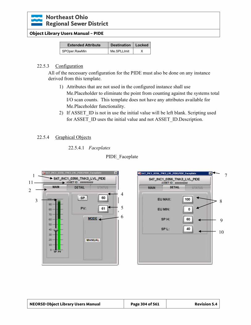
Object Library Users Manual – PIDE
NEORSD Object Library Users Manual Page 304 of 561 Revision 5.4
Extended Attribute Destination Locked SPOper.RawMin Me.SPLLImit X
22.5.3 Configuration All of the necessary configuration for the PIDE must also be done on any instance derived from this template.
1) Attributes that are not used in the configured instance shall use Me.Placeholder to eliminate the point from counting against the systems total I/O scan counts. This template does not have any attributes available for Me.Placeholder functionality.
2) If ASSET_ID is not in use the initial value will be left blank. Scripting used for ASSET_ID uses the initial value and not ASSET_ID.Description.
22.5.4 Graphical Objects
22.5.4.1 Faceplates
PIDE_Faceplate
2 4
5
6
8 3
1 7
9
10
11
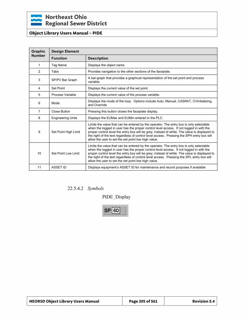
Object Library Users Manual – PIDE
NEORSD Object Library Users Manual Page 305 of 561 Revision 5.4
Graphic Number
Design Element
Function Description
1 Tag Name Displays the object name.
2 Tabs Provides navigation to the other sections of the faceplate.
3 SP/PV Bar Graph A bar-graph that provides a graphical representation of the set point and process variable.
4 Set Point Displays the current value of the set point.
5 Process Variable Displays the current value of the process variable.
6 Mode Displays the mode of the loop. Options include Auto, Manual, CASRAT, CVInitializing, and Override
7 Close Button Pressing this button closes the faceplate display.
8 Engineering Units Displays the EUMax and EUMin entered in the PLC.
9 Set Point High Limit
Limits the value that can be entered by the operator. The entry box is only selectable when the logged in user has the proper control level access. If not logged in with the proper control level the entry box will be grey; instead of white. The value is displayed to the right of the text regardless of control level access. Pressing the SPH entry box will allow the user to set the set point low high value.
10 Set Point Low Limit
Limits the value that can be entered by the operator. The entry box is only selectable when the logged in user has the proper control level access. If not logged in with the proper control level the entry box will be grey; instead of white. The value is displayed to the right of the text regardless of control level access. Pressing the SPL entry box will allow the user to set the set point low high value.
11 ASSET ID Displays equipment’s ASSET ID for maintenance and record purposes if available
22.5.4.2 Symbols
PIDE_Display
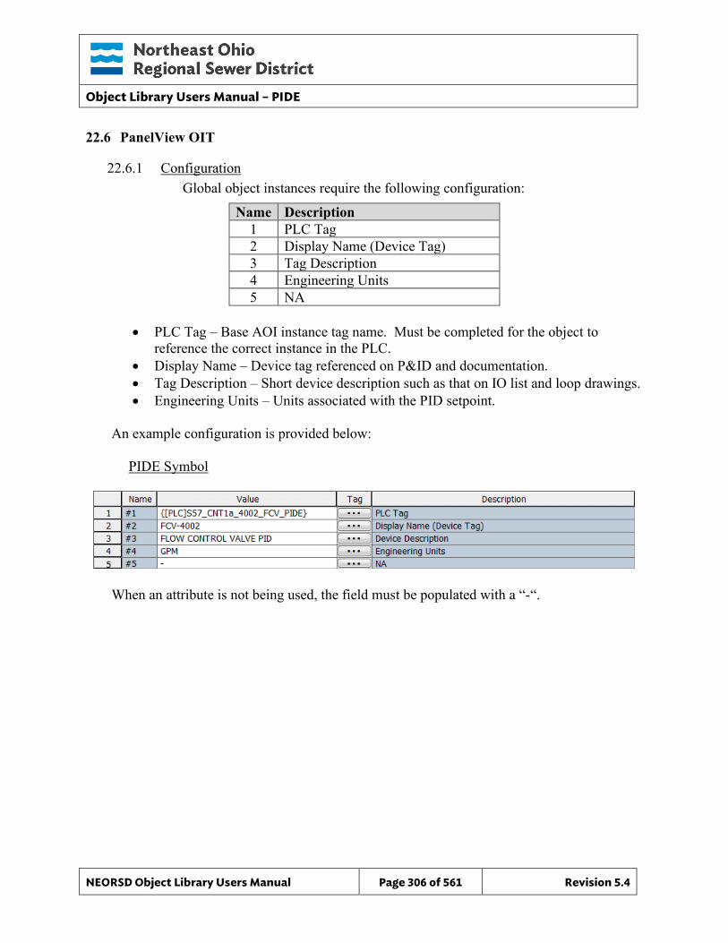
Object Library Users Manual – PIDE
NEORSD Object Library Users Manual Page 306 of 561 Revision 5.4
22.6 PanelView OIT
22.6.1 Configuration Global object instances require the following configuration:
Name Description 1 PLC Tag 2 Display Name (Device Tag) 3 Tag Description 4 Engineering Units 5 NA
• PLC Tag – Base AOI instance tag name. Must be completed for the object to
reference the correct instance in the PLC. • Display Name – Device tag referenced on P&ID and documentation. • Tag Description – Short device description such as that on IO list and loop drawings. • Engineering Units – Units associated with the PID setpoint.
An example configuration is provided below: PIDE Symbol
When an attribute is not being used, the field must be populated with a “-“.
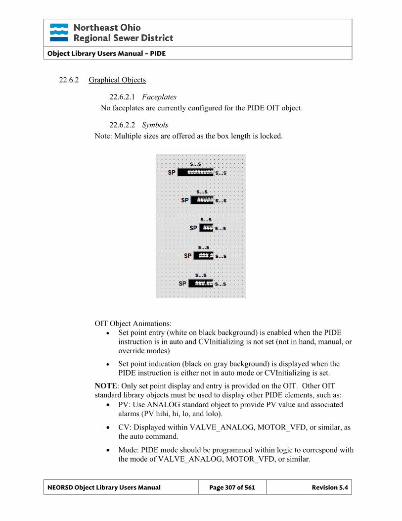
Object Library Users Manual – PIDE
NEORSD Object Library Users Manual Page 307 of 561 Revision 5.4
22.6.2 Graphical Objects
22.6.2.1 Faceplates No faceplates are currently configured for the PIDE OIT object.
22.6.2.2 Symbols Note: Multiple sizes are offered as the box length is locked.
OIT Object Animations: • Set point entry (white on black background) is enabled when the PIDE
instruction is in auto and CVInitializing is not set (not in hand, manual, or override modes)
• Set point indication (black on gray background) is displayed when the PIDE instruction is either not in auto mode or CVInitializing is set.
NOTE: Only set point display and entry is provided on the OIT. Other OIT standard library objects must be used to display other PIDE elements, such as:
• PV: Use ANALOG standard object to provide PV value and associated alarms (PV hihi, hi, lo, and lolo).
• CV: Displayed within VALVE_ANALOG, MOTOR_VFD, or similar, as the auto command.
• Mode: PIDE mode should be programmed within logic to correspond with the mode of VALVE_ANALOG, MOTOR_VFD, or similar.

Object Library Users Manual – PIDE
NEORSD Object Library Users Manual Page 308 of 561 Revision 5.4
22.6.3 PIDE Implementation Example Key Operational Concepts:
• PID mode based on VALVE_ANALOG mode; no independent PIDE/PID Auto/Manual mode
• Separate ANALOG block required to display PV and associated alarms (HiHi, Hi, etc.)
Mode control only exists on VALVE_ANALOG
PID/PIDE only displays SP information
ANALOG (or ANALOG_BASIC) to display PV
OIT: Numeric entry of SP only; No PID/PIDE FP.
HMI: Opens faceplate; SP available in Auto mode.
Object Library Users Manual – PLC_Status
NEORSD Object Library Users Manual Page 309 of 561 Revision 5.4
23.0 PLC_Status
23.1 Introduction The PLC_Status object template provides a standard representation of the “health” of the PLC and provides status information to the HMI/OIT for diagnostics and troubleshooting purposes within the NEORSD control systems.
Every PLC program at NEORSD is required to have a single instance of the PLC_Status object included and scanned within its logic. Every object instance in a PLC must refer to this PLC_Status instance via the INP_PLC_STATUS attribute.
23.2 Object Features
23.2.1 Status Indications This object provides the following indications for the PLC:
• Force Status of the PLC • PLC Controller Product Code • Redundant partner monitoring of the above (if available) • PLC Seconds Count
23.2.2 Alarming This object provides the following alarms:
• PLC Major and Minor Faults • PLC Connection Fault • PLC Low Battery Fault • One or more devices in Simulation Mode • Device Level Ring Fault
23.2.3 Control This object supports the following control for the PLC Status:
• (HMI-only) Area Out-of-Service/In-Service mode toggle
23.2.4 Simulation This object will indicate if any other instances in the PLC are in simulation. The PLC Status object itself does not have a simulate mode.
23.2.5 Trouble This object will indicate if any other instances in the PLC are reporting ‘trouble’.
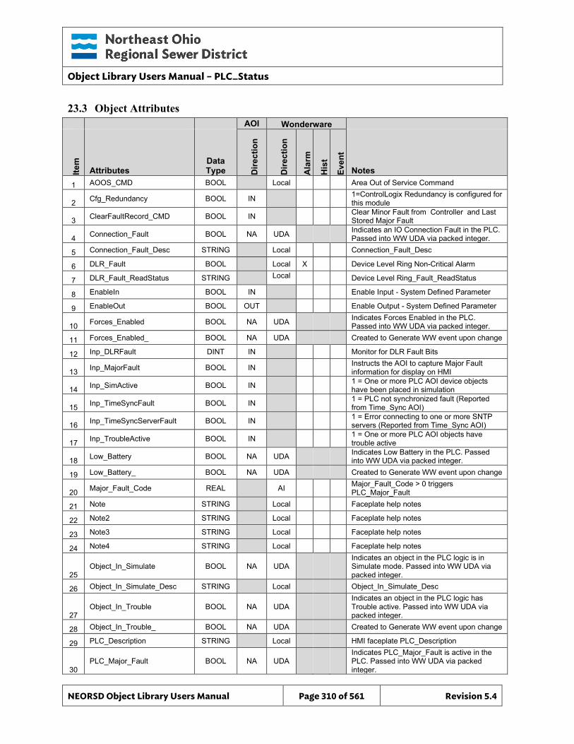
Object Library Users Manual – PLC_Status
NEORSD Object Library Users Manual Page 310 of 561 Revision 5.4
23.3 Object Attributes
AOI Wonderware
Item
Attributes Data Type D
irect
ion
Dire
ctio
n
Ala
rm
His
t
Even
t
Notes 1 AOOS_CMD BOOL Local Area Out of Service Command
2 Cfg_Redundancy BOOL IN 1=ControlLogix Redundancy is configured for this module
3 ClearFaultRecord_CMD BOOL IN Clear Minor Fault from Controller and Last Stored Major Fault
4 Connection_Fault BOOL NA UDA Indicates an IO Connection Fault in the PLC. Passed into WW UDA via packed integer.
5 Connection_Fault_Desc STRING Local Connection_Fault_Desc
6 DLR_Fault BOOL Local X Device Level Ring Non-Critical Alarm
7 DLR_Fault_ReadStatus STRING Local Device Level Ring_Fault_ReadStatus
8 EnableIn BOOL IN Enable Input - System Defined Parameter
9 EnableOut BOOL OUT Enable Output - System Defined Parameter
10 Forces_Enabled BOOL NA UDA Indicates Forces Enabled in the PLC. Passed into WW UDA via packed integer.
11 Forces_Enabled_ BOOL NA UDA Created to Generate WW event upon change
12 Inp_DLRFault DINT IN Monitor for DLR Fault Bits
13 Inp_MajorFault BOOL IN Instructs the AOI to capture Major Fault information for display on HMI
14 Inp_SimActive BOOL IN 1 = One or more PLC AOI device objects have been placed in simulation
15 Inp_TimeSyncFault BOOL IN 1 = PLC not synchronized fault (Reported from Time_Sync AOI)
16 Inp_TimeSyncServerFault BOOL IN 1 = Error connecting to one or more SNTP servers (Reported from Time_Sync AOI)
17 Inp_TroubleActive BOOL IN 1 = One or more PLC AOI objects have trouble active
18 Low_Battery BOOL NA UDA Indicates Low Battery in the PLC. Passed into WW UDA via packed integer.
19 Low_Battery_ BOOL NA UDA Created to Generate WW event upon change
20 Major_Fault_Code REAL AI Major_Fault_Code > 0 triggers PLC_Major_Fault
21 Note STRING Local Faceplate help notes
22 Note2 STRING Local Faceplate help notes
23 Note3 STRING Local Faceplate help notes
24 Note4 STRING Local Faceplate help notes
25 Object_In_Simulate BOOL NA UDA
Indicates an object in the PLC logic is in Simulate mode. Passed into WW UDA via packed integer.
26 Object_In_Simulate_Desc STRING Local Object_In_Simulate_Desc
27 Object_In_Trouble BOOL NA UDA
Indicates an object in the PLC logic has Trouble active. Passed into WW UDA via packed integer.
28 Object_In_Trouble_ BOOL NA UDA Created to Generate WW event upon change
29 PLC_Description STRING Local HMI faceplate PLC_Description
30 PLC_Major_Fault BOOL NA UDA
Indicates PLC_Major_Fault is active in the PLC. Passed into WW UDA via packed integer.
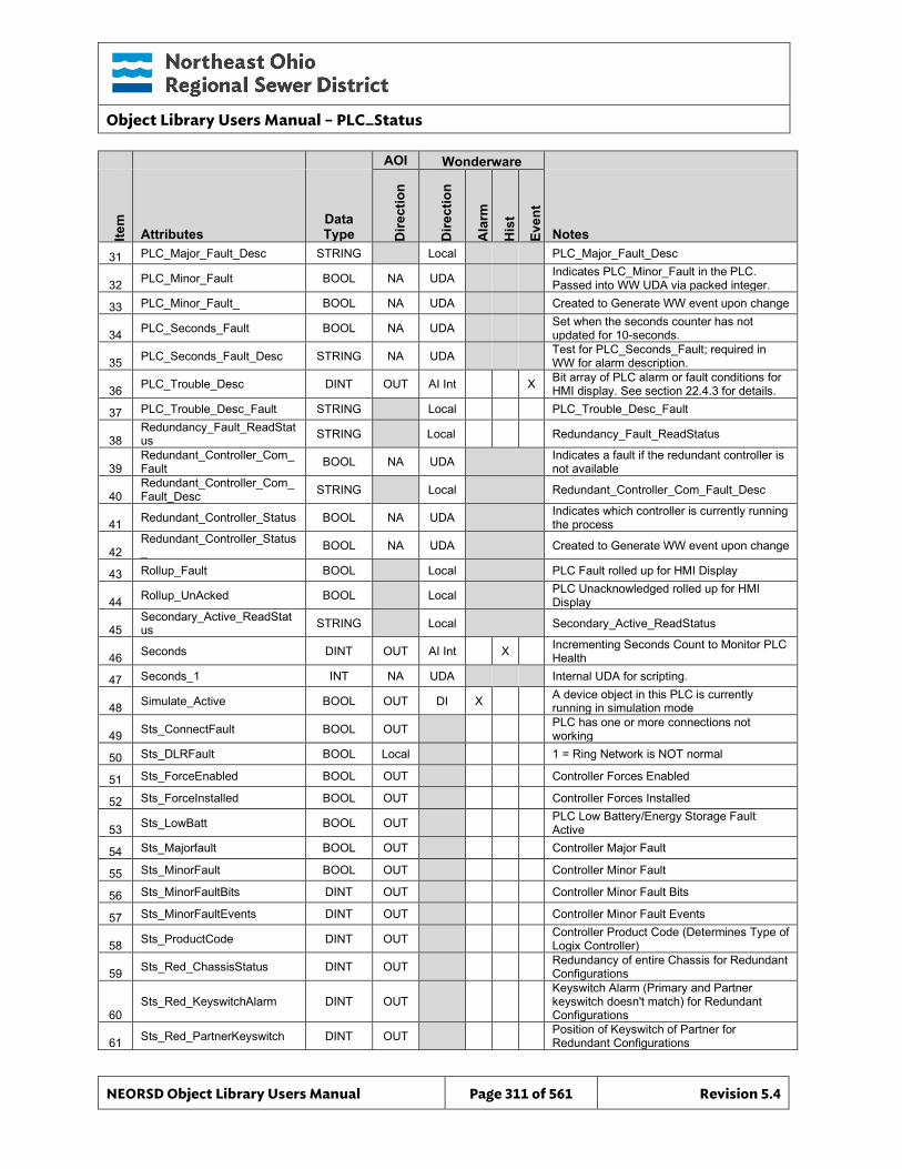
Object Library Users Manual – PLC_Status
NEORSD Object Library Users Manual Page 311 of 561 Revision 5.4
AOI Wonderware
Item
Attributes Data Type D
irect
ion
Dire
ctio
n
Ala
rm
His
t
Even
t
Notes 31 PLC_Major_Fault_Desc STRING Local PLC_Major_Fault_Desc
32 PLC_Minor_Fault BOOL NA UDA Indicates PLC_Minor_Fault in the PLC. Passed into WW UDA via packed integer.
33 PLC_Minor_Fault_ BOOL NA UDA Created to Generate WW event upon change
34 PLC_Seconds_Fault BOOL NA UDA Set when the seconds counter has not updated for 10-seconds.
35 PLC_Seconds_Fault_Desc STRING NA UDA Test for PLC_Seconds_Fault; required in WW for alarm description.
36 PLC_Trouble_Desc DINT OUT AI Int X Bit array of PLC alarm or fault conditions for HMI display. See section 22.4.3 for details.
37 PLC_Trouble_Desc_Fault STRING Local PLC_Trouble_Desc_Fault
38 Redundancy_Fault_ReadStatus STRING Local Redundancy_Fault_ReadStatus
39 Redundant_Controller_Com_Fault BOOL NA UDA Indicates a fault if the redundant controller is
not available
40 Redundant_Controller_Com_Fault_Desc STRING Local Redundant_Controller_Com_Fault_Desc
41 Redundant_Controller_Status BOOL NA UDA Indicates which controller is currently running the process
42 Redundant_Controller_Status_ BOOL NA UDA Created to Generate WW event upon change
43 Rollup_Fault BOOL Local PLC Fault rolled up for HMI Display
44 Rollup_UnAcked BOOL Local PLC Unacknowledged rolled up for HMI Display
45 Secondary_Active_ReadStatus STRING Local Secondary_Active_ReadStatus
46 Seconds DINT OUT AI Int X Incrementing Seconds Count to Monitor PLC Health
47 Seconds_1 INT NA UDA Internal UDA for scripting.
48 Simulate_Active BOOL OUT DI X A device object in this PLC is currently running in simulation mode
49 Sts_ConnectFault BOOL OUT PLC has one or more connections not working
50 Sts_DLRFault BOOL Local 1 = Ring Network is NOT normal
51 Sts_ForceEnabled BOOL OUT Controller Forces Enabled
52 Sts_ForceInstalled BOOL OUT Controller Forces Installed
53 Sts_LowBatt BOOL OUT PLC Low Battery/Energy Storage Fault Active
54 Sts_Majorfault BOOL OUT Controller Major Fault
55 Sts_MinorFault BOOL OUT Controller Minor Fault
56 Sts_MinorFaultBits DINT OUT Controller Minor Fault Bits
57 Sts_MinorFaultEvents DINT OUT Controller Minor Fault Events
58 Sts_ProductCode DINT OUT Controller Product Code (Determines Type of Logix Controller)
59 Sts_Red_ChassisStatus DINT OUT Redundancy of entire Chassis for Redundant Configurations
60 Sts_Red_KeyswitchAlarm DINT OUT
Keyswitch Alarm (Primary and Partner keyswitch doesn't match) for Redundant Configurations
61 Sts_Red_PartnerKeyswitch DINT OUT Position of Keyswitch of Partner for Redundant Configurations
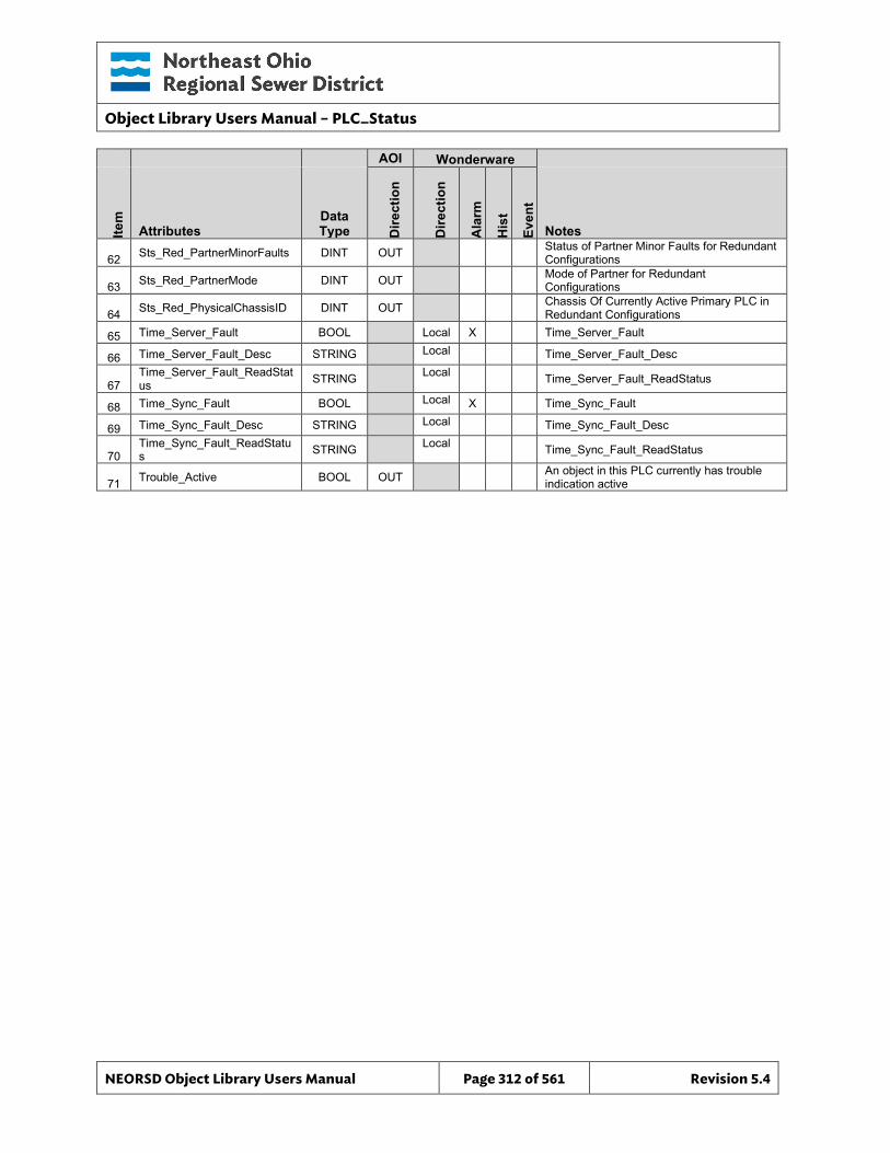
Object Library Users Manual – PLC_Status
NEORSD Object Library Users Manual Page 312 of 561 Revision 5.4
AOI Wonderware
Item
Attributes Data Type D
irect
ion
Dire
ctio
n
Ala
rm
His
t
Even
t
Notes
62 Sts_Red_PartnerMinorFaults DINT OUT Status of Partner Minor Faults for Redundant Configurations
63 Sts_Red_PartnerMode DINT OUT Mode of Partner for Redundant Configurations
64 Sts_Red_PhysicalChassisID DINT OUT Chassis Of Currently Active Primary PLC in Redundant Configurations
65 Time_Server_Fault BOOL Local X Time_Server_Fault
66 Time_Server_Fault_Desc STRING Local Time_Server_Fault_Desc
67 Time_Server_Fault_ReadStatus STRING Local Time_Server_Fault_ReadStatus
68 Time_Sync_Fault BOOL Local X Time_Sync_Fault
69 Time_Sync_Fault_Desc STRING Local Time_Sync_Fault_Desc
70 Time_Sync_Fault_ReadStatus STRING Local Time_Sync_Fault_ReadStatus
71 Trouble_Active BOOL OUT An object in this PLC currently has trouble indication active
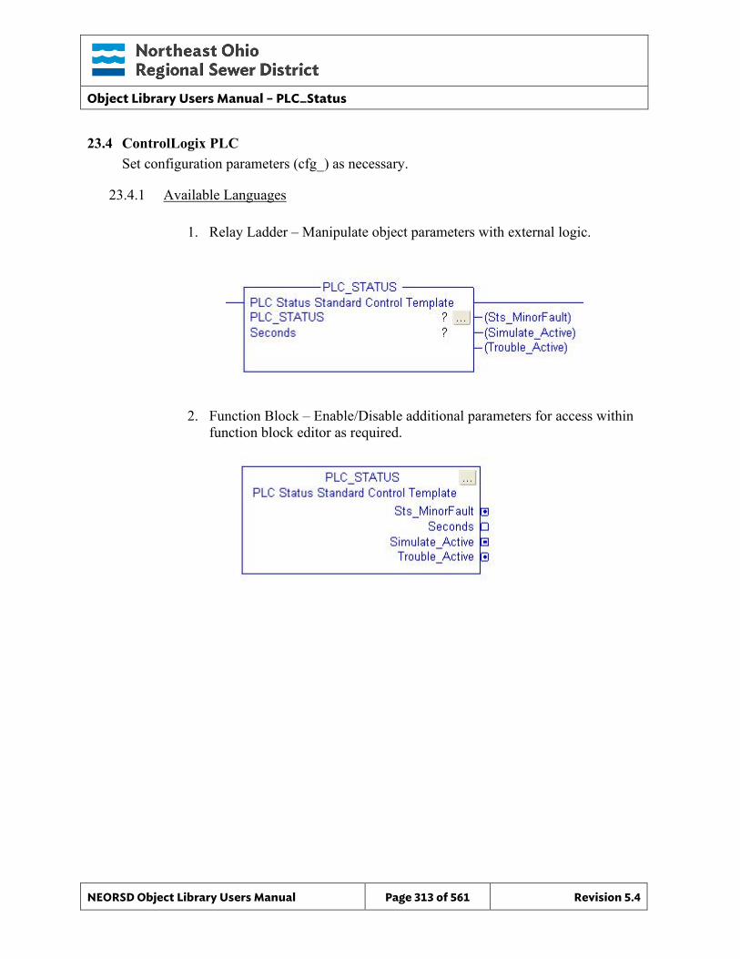
Object Library Users Manual – PLC_Status
NEORSD Object Library Users Manual Page 313 of 561 Revision 5.4
23.4 ControlLogix PLC Set configuration parameters (cfg_) as necessary.
23.4.1 Available Languages
1. Relay Ladder – Manipulate object parameters with external logic.
2. Function Block – Enable/Disable additional parameters for access within function block editor as required.
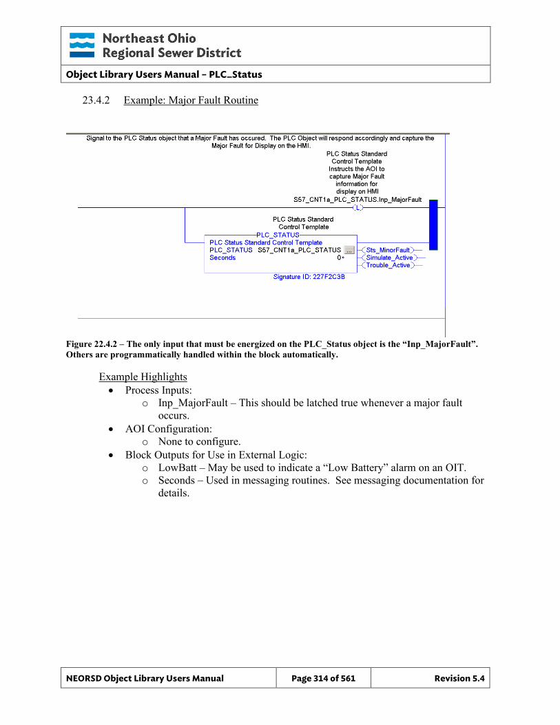
Object Library Users Manual – PLC_Status
NEORSD Object Library Users Manual Page 314 of 561 Revision 5.4
23.4.2 Example: Major Fault Routine
Figure 22.4.2 – The only input that must be energized on the PLC_Status object is the “Inp_MajorFault”. Others are programmatically handled within the block automatically.
Example Highlights • Process Inputs:
o Inp_MajorFault – This should be latched true whenever a major fault occurs.
• AOI Configuration: o None to configure.
• Block Outputs for Use in External Logic: o LowBatt – May be used to indicate a “Low Battery” alarm on an OIT. o Seconds – Used in messaging routines. See messaging documentation for
details.
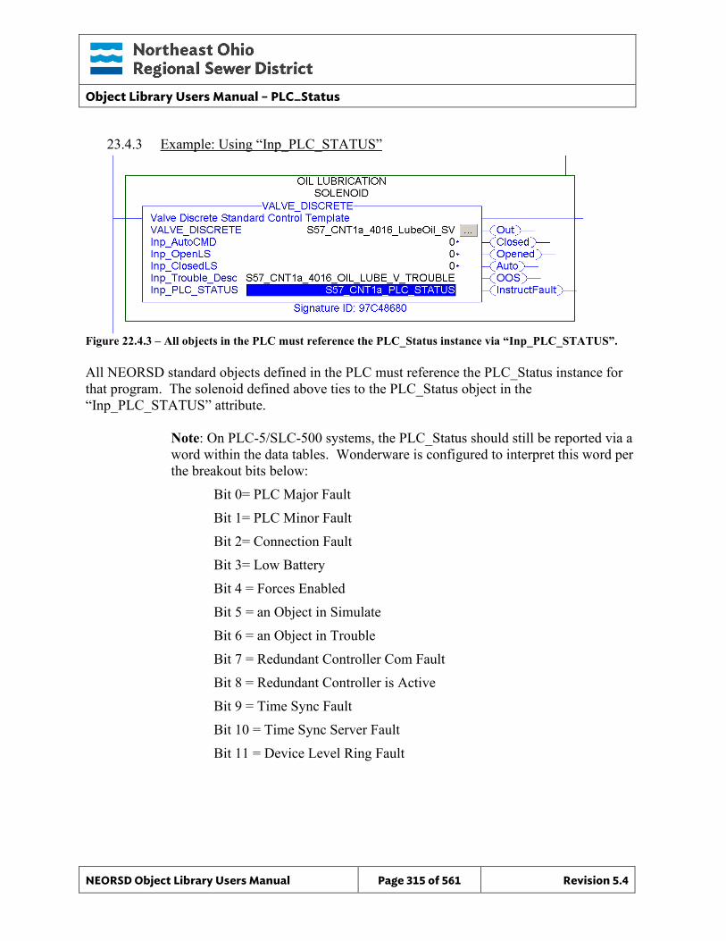
Object Library Users Manual – PLC_Status
NEORSD Object Library Users Manual Page 315 of 561 Revision 5.4
23.4.3 Example: Using “Inp_PLC_STATUS”
Figure 22.4.3 – All objects in the PLC must reference the PLC_Status instance via “Inp_PLC_STATUS”. All NEORSD standard objects defined in the PLC must reference the PLC_Status instance for that program. The solenoid defined above ties to the PLC_Status object in the “Inp_PLC_STATUS” attribute.
Note: On PLC-5/SLC-500 systems, the PLC_Status should still be reported via a word within the data tables. Wonderware is configured to interpret this word per the breakout bits below: Bit 0= PLC Major Fault
Bit 1= PLC Minor Fault Bit 2= Connection Fault Bit 3= Low Battery Bit 4 = Forces Enabled Bit 5 = an Object in Simulate Bit 6 = an Object in Trouble Bit 7 = Redundant Controller Com Fault Bit 8 = Redundant Controller is Active Bit 9 = Time Sync Fault Bit 10 = Time Sync Server Fault Bit 11 = Device Level Ring Fault
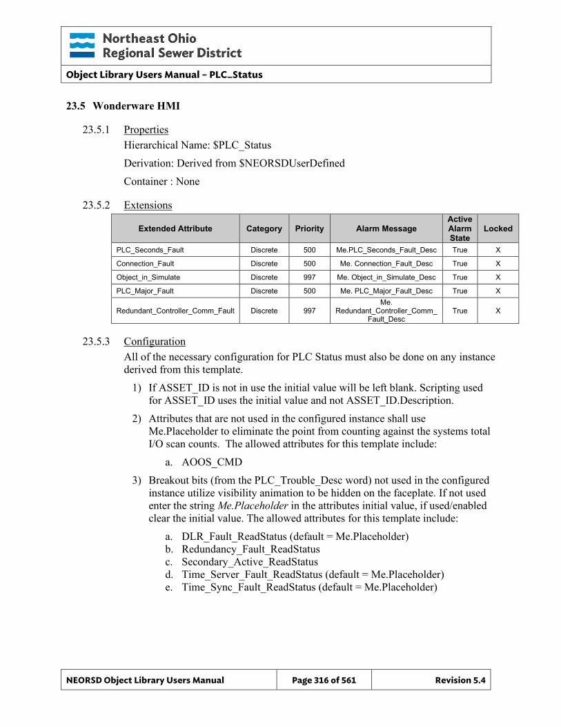
Object Library Users Manual – PLC_Status
NEORSD Object Library Users Manual Page 316 of 561 Revision 5.4
23.5 Wonderware HMI
23.5.1 Properties Hierarchical Name: $PLC_Status Derivation: Derived from $NEORSDUserDefined Container : None
23.5.2 Extensions
Extended Attribute Category Priority Alarm Message Active Alarm State
Locked
PLC_Seconds_Fault Discrete 500 Me.PLC_Seconds_Fault_Desc True X
Connection_Fault Discrete 500 Me. Connection_Fault_Desc True X
Object_in_Simulate Discrete 997 Me. Object_in_Simulate_Desc True X
PLC_Major_Fault Discrete 500 Me. PLC_Major_Fault_Desc True X
Redundant_Controller_Comm_Fault Discrete 997 Me.
Redundant_Controller_Comm_Fault_Desc
True X
23.5.3 Configuration All of the necessary configuration for PLC Status must also be done on any instance derived from this template.
1) If ASSET_ID is not in use the initial value will be left blank. Scripting used for ASSET_ID uses the initial value and not ASSET_ID.Description.
2) Attributes that are not used in the configured instance shall use Me.Placeholder to eliminate the point from counting against the systems total I/O scan counts. The allowed attributes for this template include:
a. AOOS_CMD 3) Breakout bits (from the PLC_Trouble_Desc word) not used in the configured
instance utilize visibility animation to be hidden on the faceplate. If not used enter the string Me.Placeholder in the attributes initial value, if used/enabled clear the initial value. The allowed attributes for this template include:
a. DLR_Fault_ReadStatus (default = Me.Placeholder) b. Redundancy_Fault_ReadStatus c. Secondary_Active_ReadStatus d. Time_Server_Fault_ReadStatus (default = Me.Placeholder) e. Time_Sync_Fault_ReadStatus (default = Me.Placeholder)
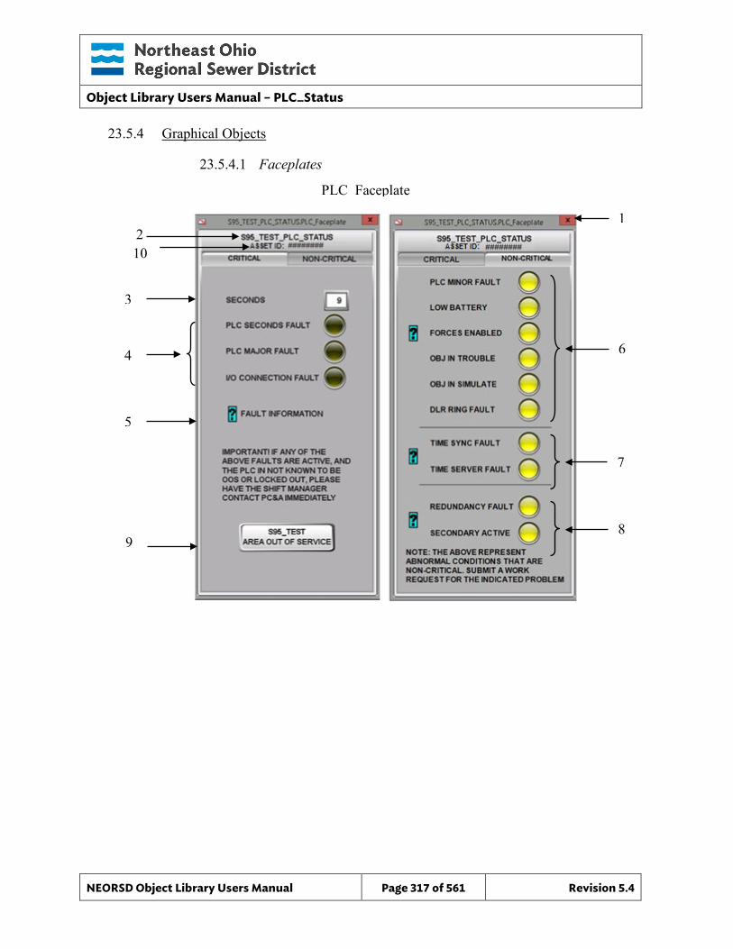
Object Library Users Manual – PLC_Status
NEORSD Object Library Users Manual Page 317 of 561 Revision 5.4
23.5.4 Graphical Objects
23.5.4.1 Faceplates
PLC Faceplate
2 1
3
4
5
6
7
8 9
10
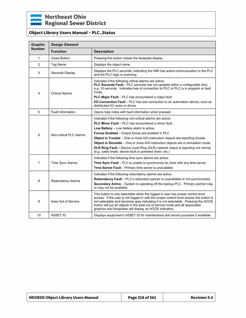
Object Library Users Manual – PLC_Status
NEORSD Object Library Users Manual Page 318 of 561 Revision 5.4
Graphic Number
Design Element
Function Description
1 Close Button Pressing this button closes the faceplate display.
2 Tag Name Displays the object name.
3 Seconds Display Displays the PLC seconds, indicating the HMI has active communication to the PLC and the PLC logic is scanning.
4 Critical Alarms
Indicates if the following critical alarms are active: PLC Seconds Fault – PLC seconds has not updated within a configurable time, e.g. 10 seconds. Indicates loss of connection to PLC or PLC is in program or fault mode. PLC Major Fault – PLC has encountered a major fault I/O Connection Fault – PLC has lost connection to an automation device, such as distributed I/O racks or drives.
5 Fault Information Opens help notes with fault information when pressed.
6 Non-critical PLC Alarms
Indicates if the following non-critical alarms are active: PLC Minor Fault – PLC has encountered a minor fault. Low Battery – Low battery alarm is active. Forces Enabled – Output forces are enabled in PLC Object in Trouble – One or more AOI instruction objects are reporting trouble. Object in Simulate – One or more AOI instruction objects are in simulation mode. DLR Ring Fault – Device Level Ring (DLR) network status is reporting not normal (e.g. cable break, device fault or powered down, etc.)
7 Time Sync Alarms Indicates if the following time sync alarms are active: Time Sync Fault – PLC is unable to synchronize its clock with any time server. Time Server Fault – Primary time server is unavailable
8 Redundancy Alarms
Indicates if the following redundancy alarms are active: Redundancy Fault – PLC’s redundant partner is unavailable or not synchronized. Secondary Active – System is operating off the backup PLC. Primary partner may or may not be available.
9 Area Out of Service
This button is only selectable when the logged in user has proper control level access. If the user is not logged in with the proper control level access the button is not selectable and becomes grey indicating it is not selectable. Pressing the AOOS button will put all objects in the area out of service mode and all associated graphics and faceplates will display an AOOS indication.
10 ASSET ID Displays equipment’s ASSET ID for maintenance and record purposes if available
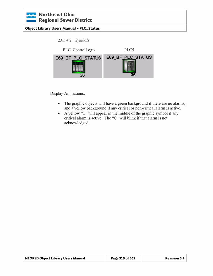
Object Library Users Manual – PLC_Status
NEORSD Object Library Users Manual Page 319 of 561 Revision 5.4
23.5.4.2 Symbols
Display Animations:
• The graphic objects will have a green background if there are no alarms, and a yellow background if any critical or non-critical alarm is active.
• A yellow “C” will appear in the middle of the graphic symbol if any critical alarm is active. The “C” will blink if that alarm is not acknowledged.
PLC_ControlLogix PLC5
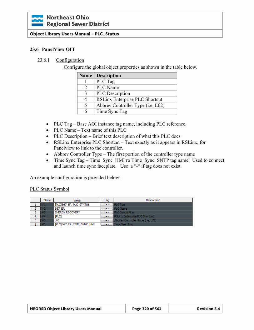
Object Library Users Manual – PLC_Status
NEORSD Object Library Users Manual Page 320 of 561 Revision 5.4
23.6 PanelView OIT
23.6.1 Configuration Configure the global object properties as shown in the table below.
Name Description 1 PLC Tag 2 PLC Name 3 PLC Description 4 RSLinx Enterprise PLC Shortcut 5 Abbrev Controller Type (i.e. L62) 6 Time Sync Tag
• PLC Tag – Base AOI instance tag name, including PLC reference. • PLC Name – Text name of this PLC • PLC Description – Brief text description of what this PLC does • RSLinx Enterprise PLC Shortcut – Text exactly as it appears in RSLinx, for
Panelview to link to the controller. • Abbrev Controller Type – The first portion of the controller type name • Time Sync Tag – Time_Sync_HMI ro Time_Sync_SNTP tag name. Used to connect
and launch time sync faceplate. Use a “-“ if tag does not exist. An example configuration is provided below: PLC Status Symbol
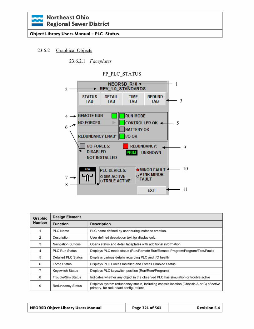
Object Library Users Manual – PLC_Status
NEORSD Object Library Users Manual Page 321 of 561 Revision 5.4
FP_PLC_STATUS
23.6.2 Graphical Objects
23.6.2.1 Faceplates
Graphic Number
Design Element
Function Description
1 PLC Name PLC name defined by user during instance creation.
2 Description User defined description text for display only.
3 Navigation Buttons Opens status and detail faceplates with additional information.
4 PLC Run Status Displays PLC mode status (Run/Remote Run/Remote Program/Program/Test/Fault)
5 Detailed PLC Status Displays various details regarding PLC and I/O health
6 Force Status Displays PLC Forces Installed and Forces Enabled Status
7 Keyswitch Status Displays PLC keyswitch position (Run/Rem/Program)
8 Trouble/Sim Status Indicates whether any object in the observed PLC has simulation or trouble active
9 Redundancy Status Displays system redundancy status, including chassis location (Chassis A or B) of active primary, for redundant configurations
1 2
3
4 5
6
11
10
7 8
9
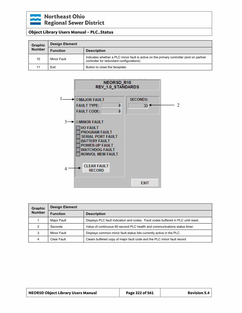
Object Library Users Manual – PLC_Status
NEORSD Object Library Users Manual Page 322 of 561 Revision 5.4
FP_PLC_STATUS_STATUS
Graphic Number
Design Element
Function Description
10 Minor Fault Indicates whether a PLC minor fault is active on the primary controller (and on partner controller for redundant configurations)
11 Exit Button to close the faceplate.
Graphic Number
Design Element
Function Description
1 Major Fault Displays PLC fault indication and codes. Fault codes buffered in PLC until reset.
2 Seconds Value of continuous 60 second PLC health and communications status timer.
3 Minor Fault Displays common minor fault status bits currently active in the PLC.
4 Clear Fault Clears buffered copy of major fault code and the PLC minor fault record
2 1
3
4

Object Library Users Manual – PLC_Status
NEORSD Object Library Users Manual Page 323 of 561 Revision 5.4
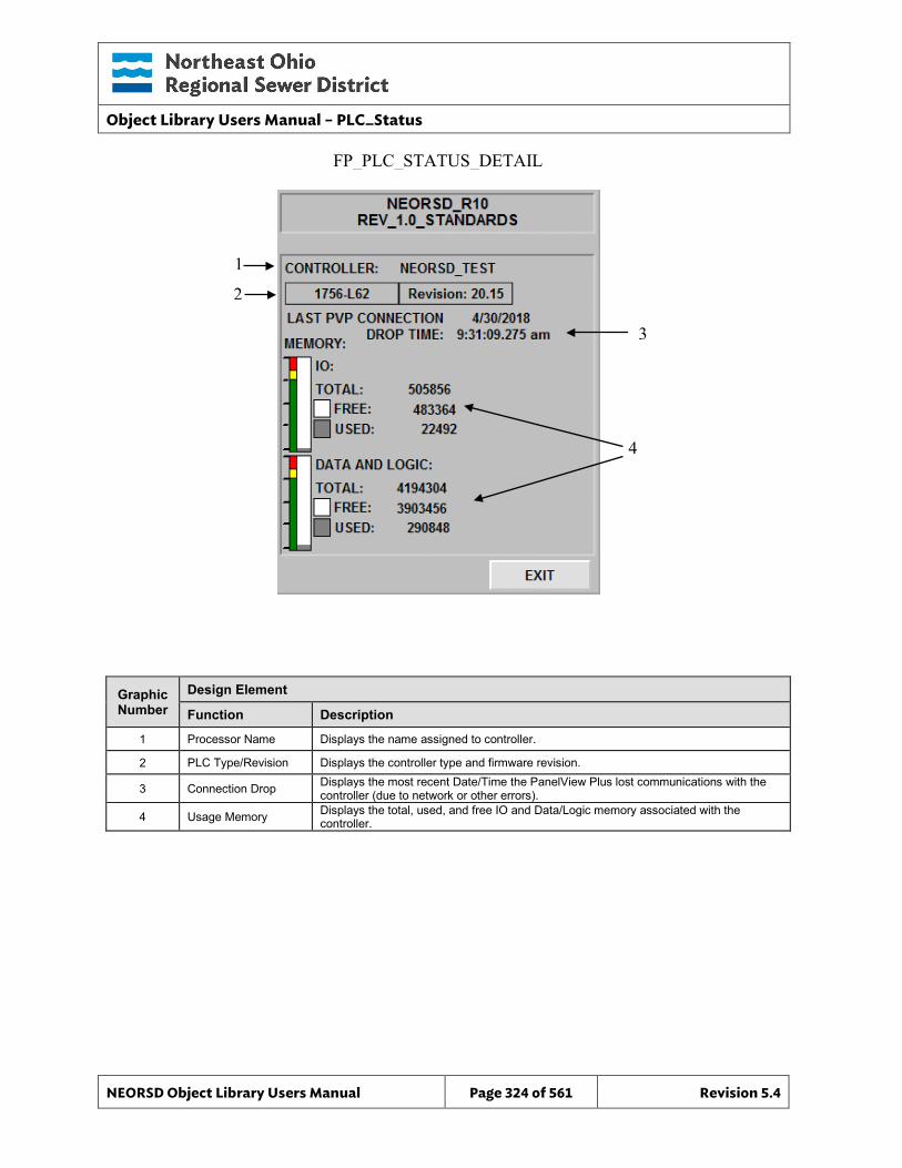
Object Library Users Manual – PLC_Status
NEORSD Object Library Users Manual Page 324 of 561 Revision 5.4
FP_PLC_STATUS_DETAIL
Graphic Number
Design Element
Function Description
1 Processor Name Displays the name assigned to controller.
2 PLC Type/Revision Displays the controller type and firmware revision.
3 Connection Drop Displays the most recent Date/Time the PanelView Plus lost communications with the controller (due to network or other errors).
4 Usage Memory Displays the total, used, and free IO and Data/Logic memory associated with the controller.
1
2
3
4
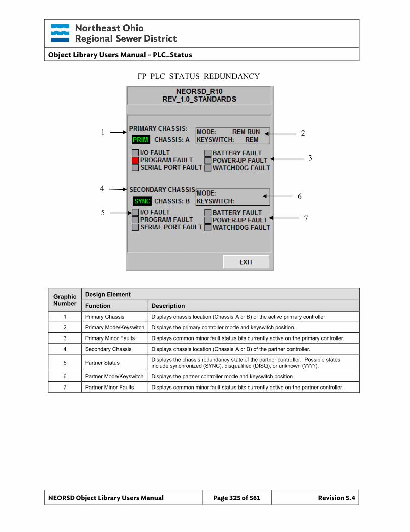
Object Library Users Manual – PLC_Status
NEORSD Object Library Users Manual Page 325 of 561 Revision 5.4
FP_PLC_STATUS_REDUNDANCY
Graphic Number
Design Element
Function Description
1 Primary Chassis Displays chassis location (Chassis A or B) of the active primary controller
2 Primary Mode/Keyswitch Displays the primary controller mode and keyswitch position.
3 Primary Minor Faults Displays common minor fault status bits currently active on the primary controller.
4 Secondary Chassis Displays chassis location (Chassis A or B) of the partner controller.
5 Partner Status Displays the chassis redundancy state of the partner controller. Possible states include synchronized (SYNC), disqualified (DISQ), or unknown (????).
6 Partner Mode/Keyswitch Displays the partner controller mode and keyswitch position.
7 Partner Minor Faults Displays common minor fault status bits currently active on the partner controller.
1
4
2
3
5
6
7
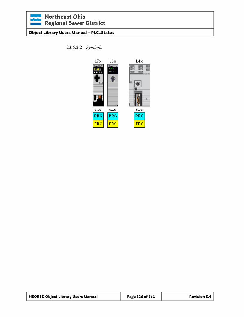
Object Library Users Manual – PLC_Status
NEORSD Object Library Users Manual Page 326 of 561 Revision 5.4
23.6.2.2 Symbols

Object Library Users Manual – PLC_Status
NEORSD Object Library Users Manual Page 327 of 561 Revision 5.4
This page left blank intentionally.
Object Library Users Manual – Restart_Inhibit
NEORSD Object Library Users Manual Page 328 of 561 Revision 5.4
24.0 Restart_Inhibit
24.1 Introduction The Restart Inhibit template provides a standard method of protecting large motors and other equipment from repeated/cycling starts within the NEORSD control systems. Use the Restart Inhibit template if the below statement is true:
• If trying to monitor and prevent a motor from starting too many times in a given time period.
Do not use the Restart Inhibit template if the below is true:
• If trying to prevent a motor from starting due to other interlock conditions. The Motor_VFD and Motor_Discrete objects contain inputs for interlocking, overtemperature, overload, etc, it is recommended to use these built-in functions instead.
24.2 Object Features
24.2.1 Status Indications This object will display whether the motor is ready to start or currently inhibited. If inhibited, the object will display the required remaining wait time (in minutes and seconds) before the motor will be ‘ready’ to attempt another start.
24.2.2 Control This object provides no direct control, but is used to prevent equipment from being started. The “Ready” output is used as in interlock to a corresponding motor object.
24.2.3 Alarms This object does not support alarming.
24.2.4 Simulation This object does not support simulation mode.
24.2.5 Trouble This object does not support hardware trouble indication.
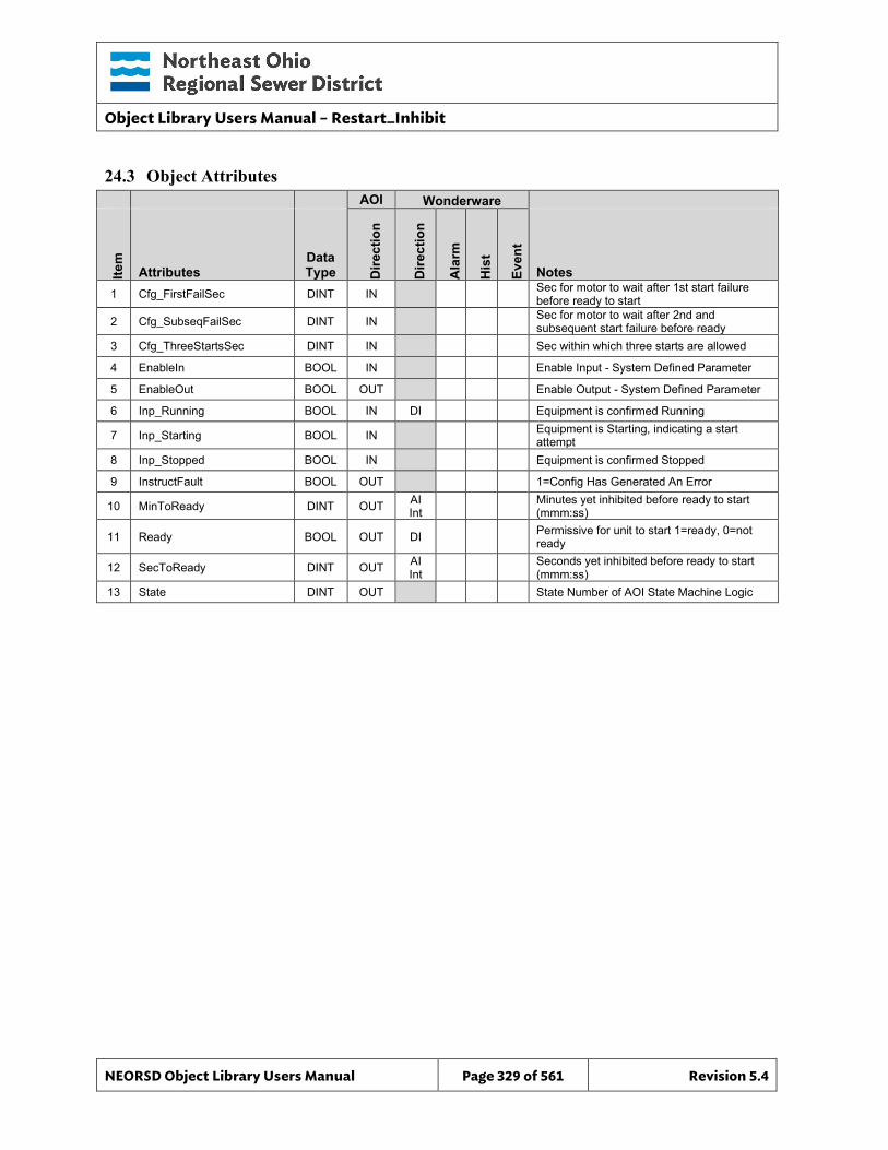
Object Library Users Manual – Restart_Inhibit
NEORSD Object Library Users Manual Page 329 of 561 Revision 5.4
24.3 Object Attributes
AOI Wonderware
Item
Attributes Data Type D
irect
ion
Dire
ctio
n
Ala
rm
His
t
Even
t
Notes 1 Cfg_FirstFailSec DINT IN Sec for motor to wait after 1st start failure
before ready to start
2 Cfg_SubseqFailSec DINT IN Sec for motor to wait after 2nd and subsequent start failure before ready
3 Cfg_ThreeStartsSec DINT IN Sec within which three starts are allowed
4 EnableIn BOOL IN Enable Input - System Defined Parameter
5 EnableOut BOOL OUT Enable Output - System Defined Parameter
6 Inp_Running BOOL IN DI Equipment is confirmed Running
7 Inp_Starting BOOL IN Equipment is Starting, indicating a start attempt
8 Inp_Stopped BOOL IN Equipment is confirmed Stopped
9 InstructFault BOOL OUT 1=Config Has Generated An Error
10 MinToReady DINT OUT AI Int Minutes yet inhibited before ready to start
(mmm:ss)
11 Ready BOOL OUT DI Permissive for unit to start 1=ready, 0=not ready
12 SecToReady DINT OUT AI Int Seconds yet inhibited before ready to start
(mmm:ss) 13 State DINT OUT State Number of AOI State Machine Logic
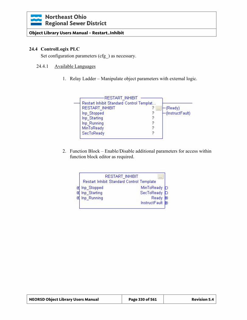
Object Library Users Manual – Restart_Inhibit
NEORSD Object Library Users Manual Page 330 of 561 Revision 5.4
24.4 ControlLogix PLC Set configuration parameters (cfg_) as necessary.
24.4.1 Available Languages
1. Relay Ladder – Manipulate object parameters with external logic.
2. Function Block – Enable/Disable additional parameters for access within function block editor as required.
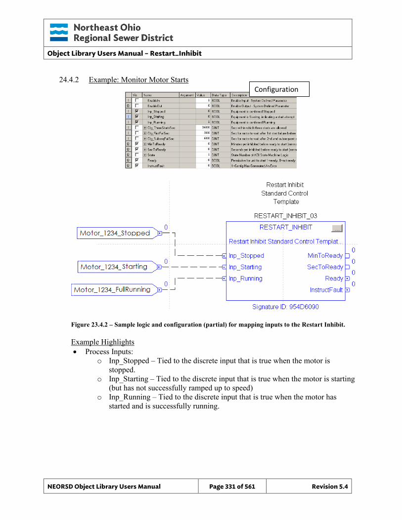
Object Library Users Manual – Restart_Inhibit
NEORSD Object Library Users Manual Page 331 of 561 Revision 5.4
24.4.2 Example: Monitor Motor Starts
Figure 23.4.2 – Sample logic and configuration (partial) for mapping inputs to the Restart Inhibit.
Example Highlights • Process Inputs:
o Inp_Stopped – Tied to the discrete input that is true when the motor is stopped.
o Inp_Starting – Tied to the discrete input that is true when the motor is starting (but has not successfully ramped up to speed)
o Inp_Running – Tied to the discrete input that is true when the motor has started and is successfully running.
Configuration
Object Library Users Manual – Restart_Inhibit
NEORSD Object Library Users Manual Page 332 of 561 Revision 5.4
• AOI Configuration: o Cfg_ThreeStartsSec – Seconds within which three starts are allowed. The
block operates in terms of three-start sets. o Cfg_FirstFailSec – Seconds after a starting failure before setting Ready to
true. o Cfg_SubseqFailSec – Seconds after two failures that the block will wait
before allowing a third start attempt (setting Ready to true). • Block Outputs for use in External Logic:
o MinToReady – Minutes before the Ready signal will turn true. o SecToReady – Seconds before the Ready signal will turn true. o Ready – True when the internal block logic believes that the motor is ready to
start. This is sent to the interlock of a motor object to prevent it from starting when ready is not true.
24.4.3 Additional Attribute Notes
24.4.3.1 Inputs o No additional notes.
24.4.3.2 Internal Configuration o No additional notes.
24.4.3.3 Outputs o No additional notes.
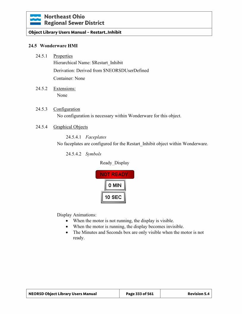
Object Library Users Manual – Restart_Inhibit
NEORSD Object Library Users Manual Page 333 of 561 Revision 5.4
24.5 Wonderware HMI
24.5.1 Properties Hierarchical Name: $Restart_Inhibit Derivation: Derived from $NEORSDUserDefined Container: None
24.5.2 Extensions: None
24.5.3 Configuration No configuration is necessary within Wonderware for this object.
24.5.4 Graphical Objects
24.5.4.1 Faceplates No faceplates are configured for the Restart_Inhibit object within Wonderware.
24.5.4.2 Symbols
Display Animations: • When the motor is not running, the display is visible. • When the motor is running, the display becomes invisible. • The Minutes and Seconds box are only visible when the motor is not
ready.
Ready_Display
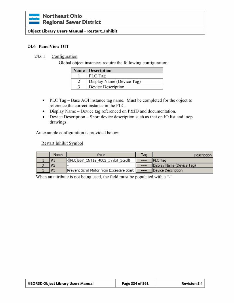
Object Library Users Manual – Restart_Inhibit
NEORSD Object Library Users Manual Page 334 of 561 Revision 5.4
24.6 PanelView OIT
24.6.1 Configuration Global object instances require the following configuration:
Name Description 1 PLC Tag 2 Display Name (Device Tag) 3 Device Description
• PLC Tag – Base AOI instance tag name. Must be completed for the object to reference the correct instance in the PLC.
• Display Name – Device tag referenced on P&ID and documentation. • Device Description – Short device description such as that on IO list and loop
drawings.
An example configuration is provided below: Restart Inhibit Symbol
When an attribute is not being used, the field must be populated with a “-“.
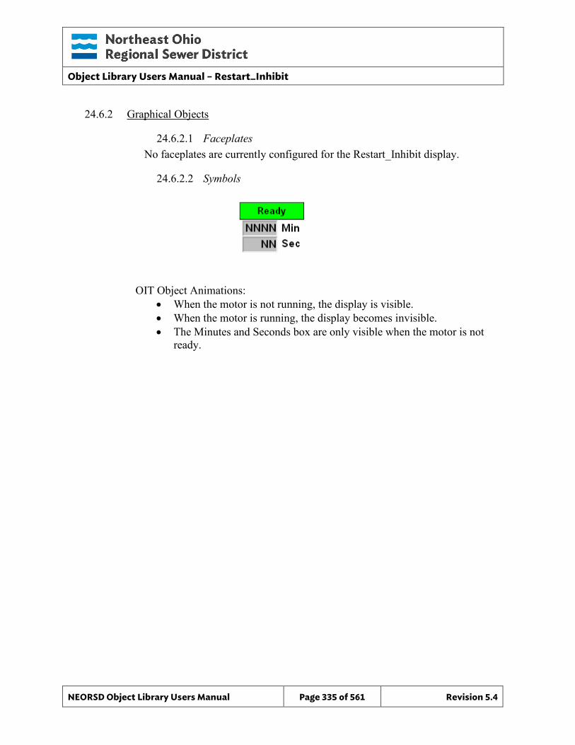
Object Library Users Manual – Restart_Inhibit
NEORSD Object Library Users Manual Page 335 of 561 Revision 5.4
24.6.2 Graphical Objects
24.6.2.1 Faceplates No faceplates are currently configured for the Restart_Inhibit display.
24.6.2.2 Symbols
OIT Object Animations:
• When the motor is not running, the display is visible. • When the motor is running, the display becomes invisible. • The Minutes and Seconds box are only visible when the motor is not
ready.
Object Library Users Manual – Runtime
NEORSD Object Library Users Manual Page 336 of 561 Revision 5.4
25.0 Runtime
25.1 Introduction The Runtime template provides a standard representation of equipment runtime throughout the NEORSD control systems. It uses a running/starting command signal output and a running feedback (if available) to totalize the runtime of a piece of equipment and the start attempts made over various time periods. Use the Runtime template if either of the statements below are true:
• If a piece of equipment has running feedback available at the PLC, and you wish to totalize the run hours.
• If a piece of equipment has a starter output from the PLC, and you wish to count the number of times the equipment has been commanded to start.
25.2 Object Features
25.2.1 Status Indications This object calculates the following values from its inputs:
• Total accumulated runtime, in tenths of an hour • Current day (24-hour) accumulated runtime, in tenths of an hour • Previous day (24-hour) accumulated runtime, in tenths of an hour • Total number of starts • Current day (24-hour) number of starts • Previous day (24-hour) number of starts • Current cycle runtime, in tenths of an hour • Previous cycle runtime, in tenths of an hour
25.2.2 Alarming This object does not have any alarming functions.
25.2.3 Simulation This object does not support a simulation mode.
25.2.4 Trouble This object does not support a trouble indication.
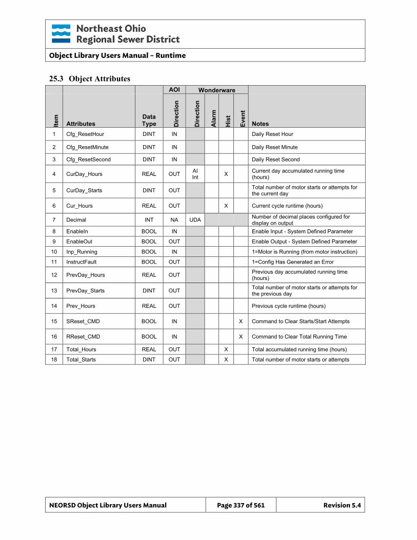
Object Library Users Manual – Runtime
NEORSD Object Library Users Manual Page 337 of 561 Revision 5.4
25.3 Object Attributes
AOI Wonderware
Item
Attributes Data Type D
irect
ion
Dire
ctio
n
Ala
rm
His
t
Even
t
Notes 1 Cfg_ResetHour DINT IN Daily Reset Hour
2 Cfg_ResetMinute DINT IN Daily Reset Minute
3 Cfg_ResetSecond DINT IN Daily Reset Second
4 CurDay_Hours REAL OUT AI Int X Current day accumulated running time
(hours)
5 CurDay_Starts DINT OUT Total number of motor starts or attempts for the current day
6 Cur_Hours REAL OUT X Current cycle runtime (hours)
7 Decimal INT NA UDA Number of decimal places configured for display on output
8 EnableIn BOOL IN Enable Input - System Defined Parameter
9 EnableOut BOOL OUT Enable Output - System Defined Parameter
10 Inp_Running BOOL IN 1=Motor is Running (from motor instruction)
11 InstructFault BOOL OUT 1=Config Has Generated an Error
12 PrevDay_Hours REAL OUT Previous day accumulated running time (hours)
13 PrevDay_Starts DINT OUT Total number of motor starts or attempts for the previous day
14 Prev_Hours REAL OUT Previous cycle runtime (hours)
15 SReset_CMD BOOL IN X Command to Clear Starts/Start Attempts
16 RReset_CMD BOOL IN X Command to Clear Total Running Time
17 Total_Hours REAL OUT X Total accumulated running time (hours)
18 Total_Starts DINT OUT X Total number of motor starts or attempts
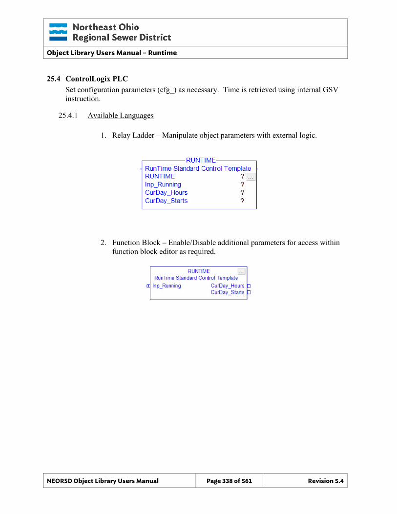
Object Library Users Manual – Runtime
NEORSD Object Library Users Manual Page 338 of 561 Revision 5.4
25.4 ControlLogix PLC Set configuration parameters (cfg_) as necessary. Time is retrieved using internal GSV instruction.
25.4.1 Available Languages
1. Relay Ladder – Manipulate object parameters with external logic.
2. Function Block – Enable/Disable additional parameters for access within
function block editor as required.
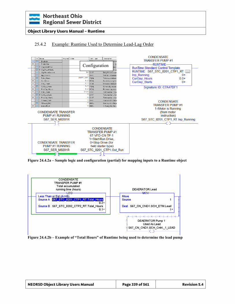
Object Library Users Manual – Runtime
NEORSD Object Library Users Manual Page 339 of 561 Revision 5.4
25.4.2 Example: Runtime Used to Determine Lead-Lag Order
Figure 24.4.2a – Sample logic and configuration (partial) for mapping inputs to a Runtime object
Figure 24.4.2b – Example of “Total Hours” of Runtime being used to determine the lead pump
Configuration
Object Library Users Manual – Runtime
NEORSD Object Library Users Manual Page 340 of 561 Revision 5.4
Example Highlights • Process Inputs
o Inp_Running – Tie this to the running feedback for the equipment. This can also be tied to the motor object output to track start attempts.
• AOI Configuration: o Cfg_ResetHour – The daily counters will reset at the hour defined here, and
current day values will be passed into previous day registers. Default “23”. o Cfg_ResetMinute – The daily counters will reset at the minute defined here,
and current day values will be passed into previous day registers. Default “59”.
o Cfg_ResetSecond – The daily counters will reset at the second defined here, and current day values will be passed into previous day registers. Default “50”.
• Block Outputs for Use in External Logic: o Total_Hours – Total number of hours the equipment has run o Cur_Hours – Hours running since last startup o Prev_Ho urs – Previous running time
25.4.3 Additional Attribute Notes
25.4.3.1 Inputs o All inputs are covered in the above example.
25.4.3.2 Internal Configuration: o All configuration is covered in the above example.
25.4.3.3 Outputs o CurDay_Hours – Hours running during the current day o CurDay_Starts – Number of times the equipment has been started for
the current day o PrevDay_Hours – Hours running during the previous day o PrevDay_Starts – Number of times the equipment started the previous
day o Total_Starts – Total number of starts for the piece of equipment
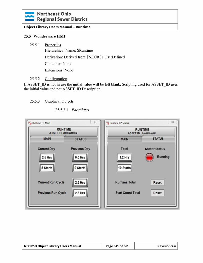
Object Library Users Manual – Runtime
NEORSD Object Library Users Manual Page 341 of 561 Revision 5.4
25.5 Wonderware HMI
25.5.1 Properties Hierarchical Name: $Runtime Derivation: Derived from $NEORSDUserDefined Container: None Extensions: None
25.5.2 Configuration If ASSET_ID is not in use the initial value will be left blank. Scripting used for ASSET_ID uses the initial value and not ASSET_ID.Description
25.5.3 Graphical Objects
25.5.3.1 Faceplates
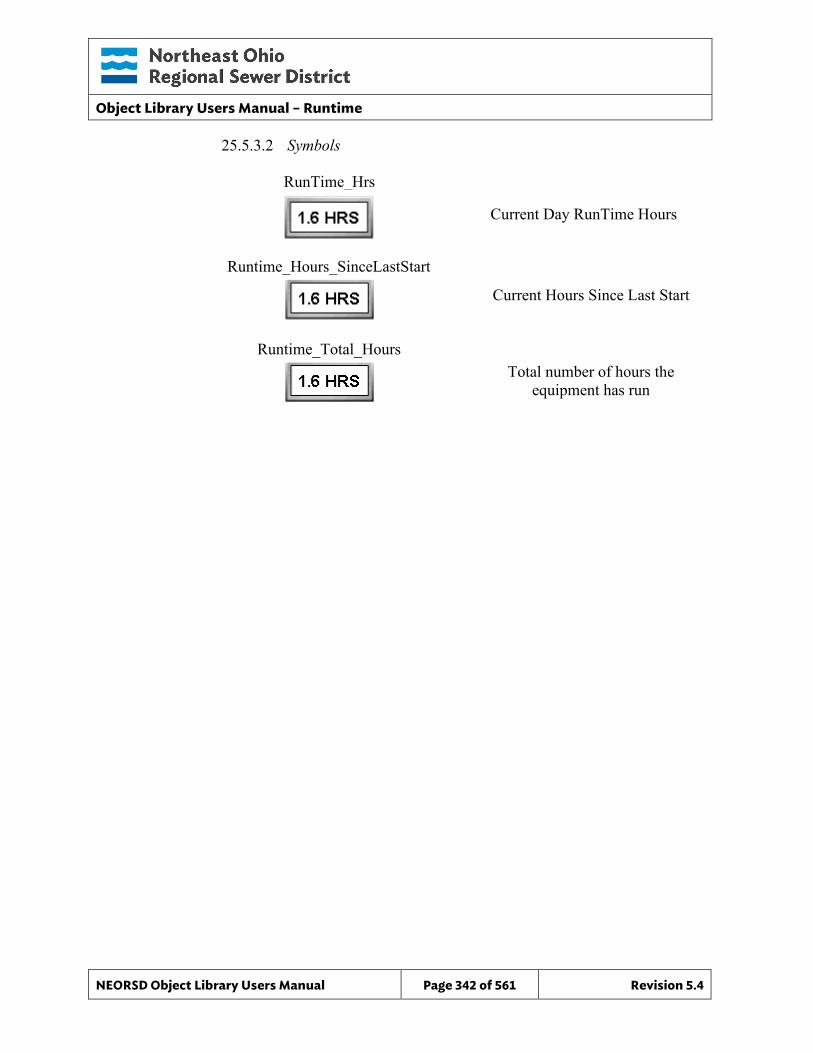
Object Library Users Manual – Runtime
NEORSD Object Library Users Manual Page 342 of 561 Revision 5.4
25.5.3.2 Symbols
RunTime_Hrs
Current Day RunTime Hours
Current Hours Since Last Start
Runtime_Hours_SinceLastStart
Total number of hours the equipment has run
Runtime_Total_Hours
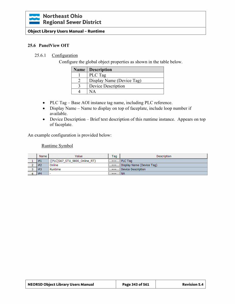
Object Library Users Manual – Runtime
NEORSD Object Library Users Manual Page 343 of 561 Revision 5.4
25.6 PanelView OIT
25.6.1 Configuration Configure the global object properties as shown in the table below.
Name Description 1 PLC Tag 2 Display Name (Device Tag) 3 Device Description 4 NA
• PLC Tag – Base AOI instance tag name, including PLC reference. • Display Name – Name to display on top of faceplate, include loop number if
available. • Device Description – Brief text description of this runtime instance. Appears on top
of faceplate. An example configuration is provided below: Runtime Symbol
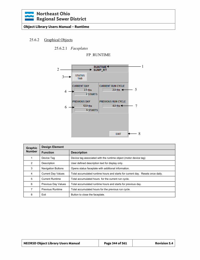
Object Library Users Manual – Runtime
NEORSD Object Library Users Manual Page 344 of 561 Revision 5.4
25.6.2 Graphical Objects
25.6.2.1 Faceplates
Graphic Number
Design Element
Function Description
1 Device Tag Device tag associated with the runtime object (motor device tag)
2 Description User defined description text for display only.
3 Navigation Buttons Opens status faceplate with additional information.
4 Current Day Values Total accumulated runtime hours and starts for current day. Resets once daily.
5 Current Runtime Total accumulated hours for the current run cycle.
6 Previous Day Values Total accumulated runtime hours and starts for previous day.
7 Previous Runtime Total accumulated hours for the previous run cycle.
8 Exit Button to close the faceplate.
FP_RUNTIME
1 2
4
6
8
3
5
7
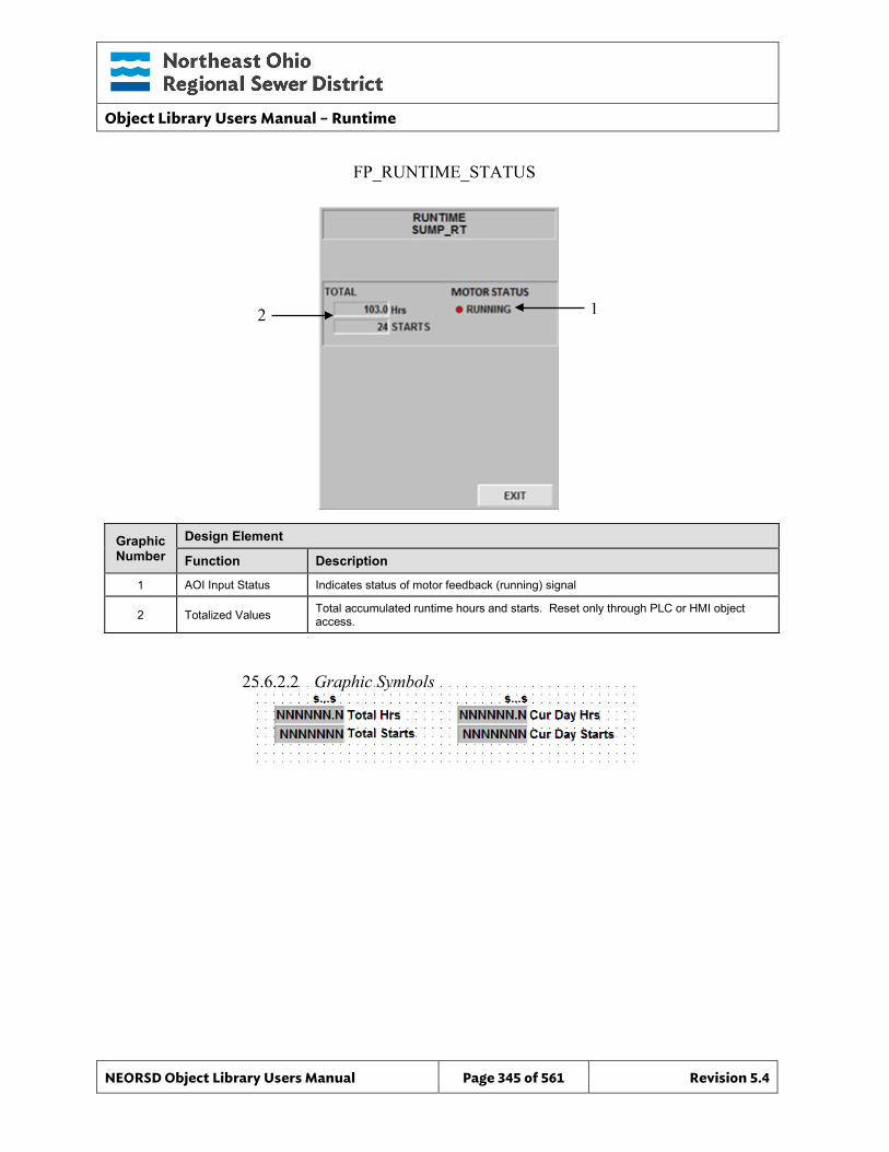
Object Library Users Manual – Runtime
NEORSD Object Library Users Manual Page 345 of 561 Revision 5.4
Graphic Number
Design Element
Function Description
1 AOI Input Status Indicates status of motor feedback (running) signal
2 Totalized Values Total accumulated runtime hours and starts. Reset only through PLC or HMI object access.
25.6.2.2 Graphic Symbols
FP_RUNTIME_STATUS
1 2
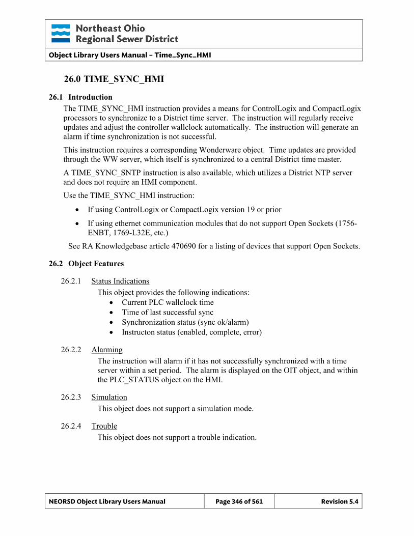
Object Library Users Manual – Time_Sync_HMI
NEORSD Object Library Users Manual Page 346 of 561 Revision 5.4
26.0 TIME_SYNC_HMI
26.1 Introduction The TIME_SYNC_HMI instruction provides a means for ControlLogix and CompactLogix processors to synchronize to a District time server. The instruction will regularly receive updates and adjust the controller wallclock automatically. The instruction will generate an alarm if time synchronization is not successful. This instruction requires a corresponding Wonderware object. Time updates are provided through the WW server, which itself is synchronized to a central District time master. A TIME_SYNC_SNTP instruction is also available, which utilizes a District NTP server and does not require an HMI component. Use the TIME_SYNC_HMI instruction:
• If using ControlLogix or CompactLogix version 19 or prior
• If using ethernet communication modules that do not support Open Sockets (1756-ENBT, 1769-L32E, etc.)
See RA Knowledgebase article 470690 for a listing of devices that support Open Sockets.
26.2 Object Features
26.2.1 Status Indications This object provides the following indications:
• Current PLC wallclock time • Time of last successful sync • Synchronization status (sync ok/alarm) • Instructon status (enabled, complete, error)
26.2.2 Alarming The instruction will alarm if it has not successfully synchronized with a time server within a set period. The alarm is displayed on the OIT object, and within the PLC_STATUS object on the HMI.
26.2.3 Simulation This object does not support a simulation mode.
26.2.4 Trouble This object does not support a trouble indication.
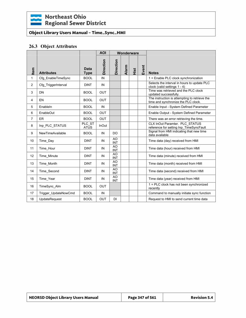
Object Library Users Manual – Time_Sync_HMI
NEORSD Object Library Users Manual Page 347 of 561 Revision 5.4
26.3 Object Attributes
AOI Wonderware
Item
Attributes Data Type D
irect
ion
Dire
ctio
n
Ala
rm
His
t
Even
t
Notes 1 Cfg_EnableTimeSync BOOL IN 1 = Enable PLC clock synchronization
2 Cfg_TriggerInterval DINT IN Selects the interval in hours to update PLC clock (valid settings 1 - 4)
3 DN BOOL OUT Time was retrieved and the PLC clock updated successfully.
4 EN BOOL OUT The instruction is attempting to retrieve the time and synchronize the PLC clock.
5 EnableIn BOOL IN Enable Input - System Defined Parameter
6 EnableOut BOOL OUT Enable Output - System Defined Parameter
7 ER BOOL OUT There was an error retrieving the time.
8 Inp_PLC_STATUS PLC_STATUS InOut CLX InOut Paramter. PLC_STATUS
reference for setting Inp_TimeSyncFault
9 NewTimeAvailable BOOL IN DO Signal from HMI indicating that new time data available
10 Time_Day DINT IN AO INT Time data (day) received from HMI
11 Time_Hour DINT IN AO INT Time data (hour) received from HMI
12 Time_Minute DINT IN AO INT Time data (minute) received from HMI
13 Time_Month DINT IN AO INT Time data (month) received from HMI
14 Time_Second DINT IN AO INT Time data (second) received from HMI
15 Time_Year DINT IN AO INT Time data (year) received from HMI
16 TimeSync_Alm BOOL OUT 1 = PLC clock has not been synchronized recently
17 Trigger_UpdateNowCmd BOOL IN Command to manually initiate sync function
18 UpdateRequest BOOL OUT DI Request to HMI to send current time data
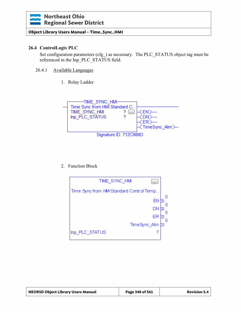
Object Library Users Manual – Time_Sync_HMI
NEORSD Object Library Users Manual Page 348 of 561 Revision 5.4
26.4 ControlLogix PLC Set configuration parameters (cfg_) as necessary. The PLC_STATUS object tag must be referenced in the Inp_PLC_STATUS field.
26.4.1 Available Languages
1. Relay Ladder
2. Function Block
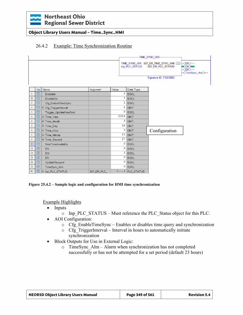
Object Library Users Manual – Time_Sync_HMI
NEORSD Object Library Users Manual Page 349 of 561 Revision 5.4
26.4.2 Example: Time Synchronization Routine
Figure 25.4.2 – Sample logic and configuration for HMI time synchronization
Example Highlights • Inputs
o Inp_PLC_STATUS – Must reference the PLC_Status object for this PLC. • AOI Configuration:
o Cfg_EnableTimeSync – Enables or disables time query and synchronization o Cfg_TriggerInterval – Interval in hours to automatically initiate
synchronization • Block Outputs for Use in External Logic:
o TimeSync_Alm – Alarm when synchronization has not completed successfully or has not be attempted for a set period (default 23 hours)
Configuration
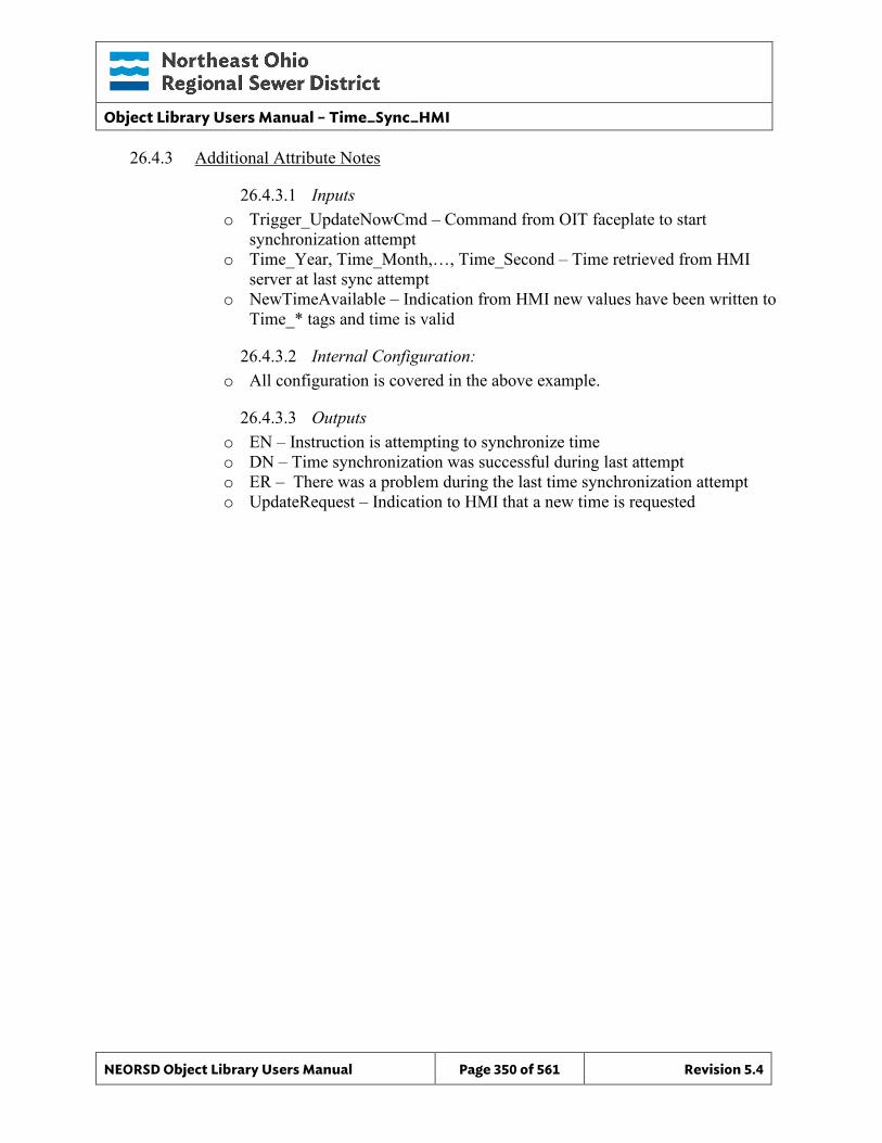
Object Library Users Manual – Time_Sync_HMI
NEORSD Object Library Users Manual Page 350 of 561 Revision 5.4
26.4.3 Additional Attribute Notes
26.4.3.1 Inputs o Trigger_UpdateNowCmd – Command from OIT faceplate to start
synchronization attempt o Time_Year, Time_Month,…, Time_Second – Time retrieved from HMI
server at last sync attempt o NewTimeAvailable – Indication from HMI new values have been written to
Time_* tags and time is valid
26.4.3.2 Internal Configuration: o All configuration is covered in the above example.
26.4.3.3 Outputs o EN – Instruction is attempting to synchronize time o DN – Time synchronization was successful during last attempt o ER – There was a problem during the last time synchronization attempt o UpdateRequest – Indication to HMI that a new time is requested
Object Library Users Manual – Time_Sync_HMI
NEORSD Object Library Users Manual Page 351 of 561 Revision 5.4
26.5 Wonderware HMI Time synchronization alarms generated by this object are alarmed at the HMI through the PLC_STATUS object. Refer to the PLC_STATUS object for more information.
26.5.1 Properties Hierarchical Name: $TIME_SYNC_HMI Derivation: Derived from $NEORSDUserDefined Container: None Extensions: None
26.5.2 Configuration None
26.5.3 Graphical Objects None
26.6 PanelView OIT
26.6.1 Configuration The following is required in the FTView ME project:
• TIME_SYNC_HMI library components files (gfx and ggfx)
• PLC_STATUS library component files (gfx and ggfx) from one of the following versions
o PVP 1250 version 1.2 or greater o PVP 700 version 1.2 or greater o PVP 1500 version 1.1 or greater
• A configured instance of the PLC_STATUS object A standalone TIME_SYNC_HMI object has not been created. Instead, OIT faceplates have been incorporated into the PLC_STATUS faceplate. Refer to the PLC_STATUS object for more information.
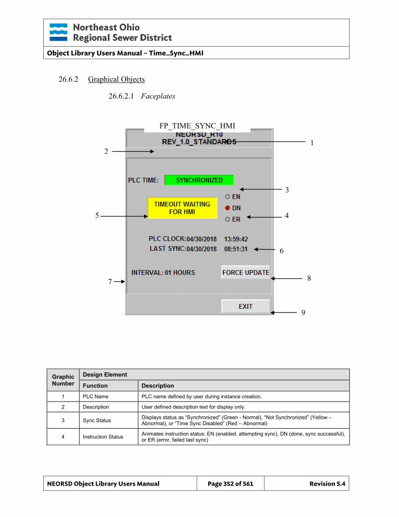
Object Library Users Manual – Time_Sync_HMI
NEORSD Object Library Users Manual Page 352 of 561 Revision 5.4
26.6.2 Graphical Objects
26.6.2.1 Faceplates
Graphic Number
Design Element
Function Description
1 PLC Name PLC name defined by user during instance creation.
2 Description User defined description text for display only.
3 Sync Status Displays status as “Synchronized” (Green - Normal), “Not Synchronized” (Yellow – Abnormal), or “Time Sync Disabled” (Red – Abnormal)
4 Instruction Status Animates instruction status: EN (enabled, attempting sync), DN (done, sync successful), or ER (error, failed last sync)
FP_TIME_SYNC_HMI
2
5
7
6
3
4
8
9
1
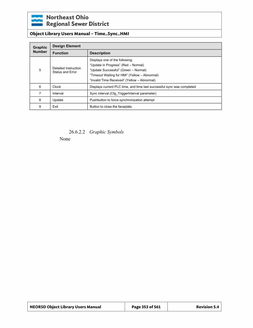
Object Library Users Manual – Time_Sync_HMI
NEORSD Object Library Users Manual Page 353 of 561 Revision 5.4
Graphic Number
Design Element
Function Description
5 Detailed Instruction Status and Error
Displays one of the following: “Update in Progress” (Red – Normal) “Update Successful” (Green – Normal) “Timeout Waiting for HMI” (Yellow – Abnormal) “Invalid Time Received” (Yellow – Abnormal)
6 Clock Displays current PLC time, and time last successful sync was completed
7 Interval Sync interval (Cfg_TriggerInterval parameter)
8 Update Pushbutton to force synchronization attempt
9 Exit Button to close the faceplate.
26.6.2.2 Graphic Symbols None
Object Library Users Manual – Time_Sync_SNTP
NEORSD Object Library Users Manual Page 354 of 561 Revision 5.4
27.0 TIME_SYNC_SNTP
27.1 Introduction The TIME_SYNC_SNTP instruction will automatically poll and synchronize ControlLogix and CompactLogix processors to a District NTP server. The instruction will generate an alarm if time synchronization is not successful. No configuration of the HMI or time server is required. Use of the T_DST or similar instruction is required to adjust for daylight savings time. A TIME_SYNC_HMI instruction is also available, which utilizes the Wonderware HMI application for time updates. This instruction is available if TIME_SYNC_SNTP instruction is not supported. Use the TIME_SYNC_SNTP instruction:
• If using ControlLogix or CompactLogix version 20 and newer
• If using ethernet communication modules that support Open Sockets (1756-EN2T, 1769-L30ER, etc.)
See RA Knowledgebase article 470690 for a listing of devices that support Open Sockets.
27.2 Object Features
27.2.1 Status Indications This object provides the following indications:
• Current PLC wallclock time • Time of last successful sync • Synchronization status (sync ok/alarm) • Instructon status (enabled, complete, error)
27.2.2 Alarming The instruction will alarm if it has not successfully synchronized with a time server within a set period. The alarm is displayed on the OIT object, and within the PLC_STATUS object on the HMI.
27.2.3 Simulation This object does not support a simulation mode.
27.2.4 Trouble This object does not support a trouble indication.
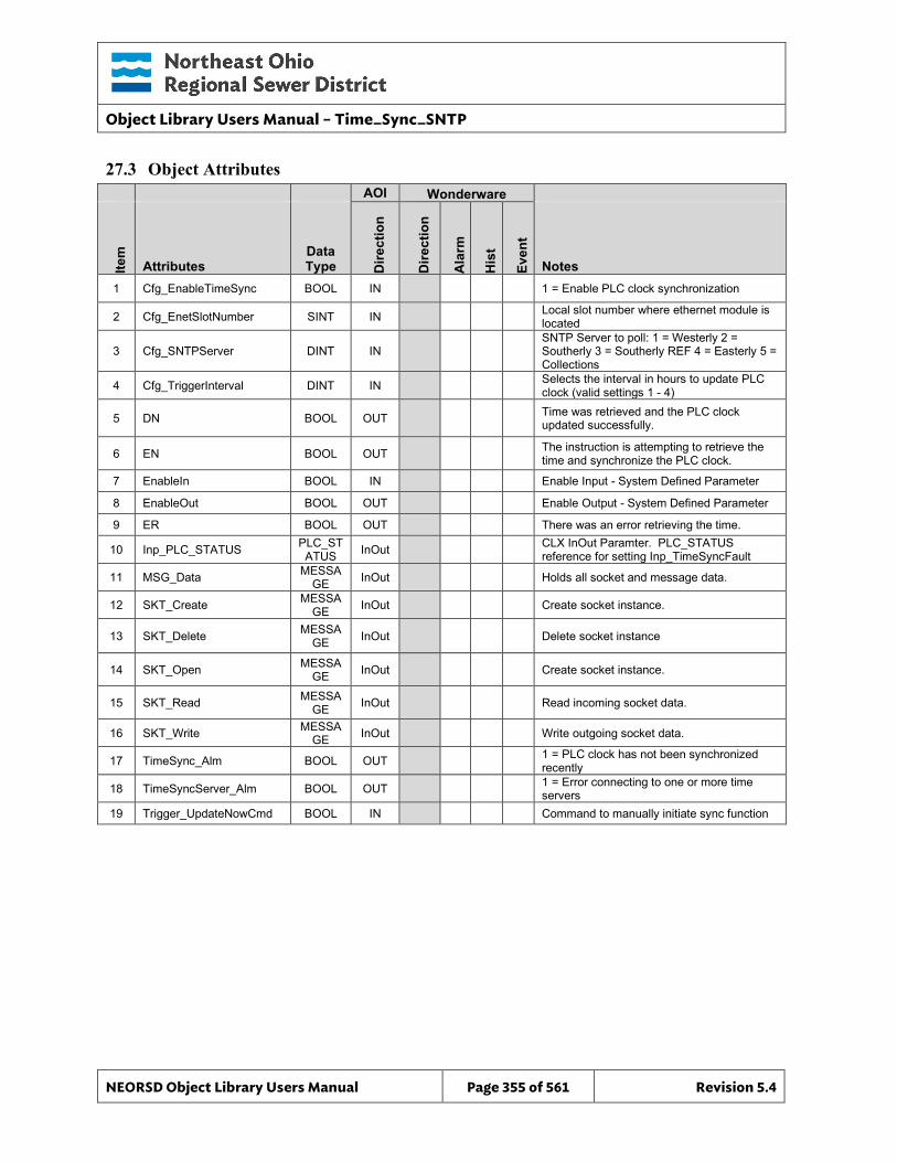
Object Library Users Manual – Time_Sync_SNTP
NEORSD Object Library Users Manual Page 355 of 561 Revision 5.4
27.3 Object Attributes
AOI Wonderware
Item
Attributes Data Type D
irect
ion
Dire
ctio
n
Ala
rm
His
t
Even
t
Notes 1 Cfg_EnableTimeSync BOOL IN 1 = Enable PLC clock synchronization
2 Cfg_EnetSlotNumber SINT IN Local slot number where ethernet module is located
3 Cfg_SNTPServer DINT IN SNTP Server to poll: 1 = Westerly 2 = Southerly 3 = Southerly REF 4 = Easterly 5 = Collections
4 Cfg_TriggerInterval DINT IN Selects the interval in hours to update PLC clock (valid settings 1 - 4)
5 DN BOOL OUT Time was retrieved and the PLC clock updated successfully.
6 EN BOOL OUT The instruction is attempting to retrieve the time and synchronize the PLC clock.
7 EnableIn BOOL IN Enable Input - System Defined Parameter
8 EnableOut BOOL OUT Enable Output - System Defined Parameter
9 ER BOOL OUT There was an error retrieving the time.
10 Inp_PLC_STATUS PLC_STATUS InOut CLX InOut Paramter. PLC_STATUS
reference for setting Inp_TimeSyncFault
11 MSG_Data MESSAGE InOut Holds all socket and message data.
12 SKT_Create MESSAGE InOut Create socket instance.
13 SKT_Delete MESSAGE InOut Delete socket instance
14 SKT_Open MESSAGE InOut Create socket instance.
15 SKT_Read MESSAGE InOut Read incoming socket data.
16 SKT_Write MESSAGE InOut Write outgoing socket data.
17 TimeSync_Alm BOOL OUT 1 = PLC clock has not been synchronized recently
18 TimeSyncServer_Alm BOOL OUT 1 = Error connecting to one or more time servers
19 Trigger_UpdateNowCmd BOOL IN Command to manually initiate sync function
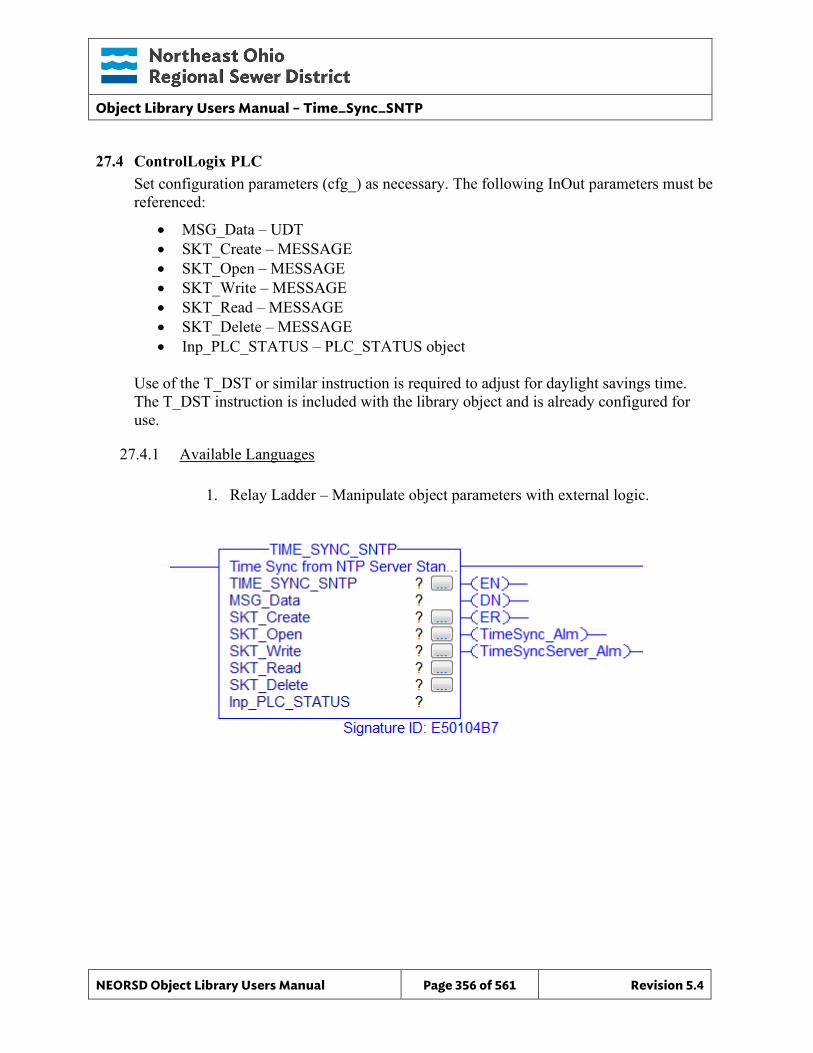
Object Library Users Manual – Time_Sync_SNTP
NEORSD Object Library Users Manual Page 356 of 561 Revision 5.4
27.4 ControlLogix PLC Set configuration parameters (cfg_) as necessary. The following InOut parameters must be referenced:
• MSG_Data – UDT • SKT_Create – MESSAGE • SKT_Open – MESSAGE • SKT_Write – MESSAGE • SKT_Read – MESSAGE • SKT_Delete – MESSAGE • Inp_PLC_STATUS – PLC_STATUS object
Use of the T_DST or similar instruction is required to adjust for daylight savings time. The T_DST instruction is included with the library object and is already configured for use.
27.4.1 Available Languages
1. Relay Ladder – Manipulate object parameters with external logic.
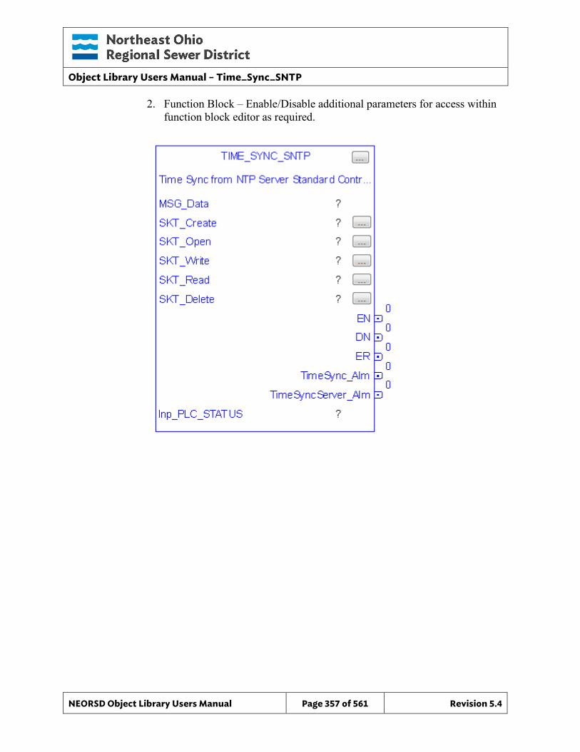
Object Library Users Manual – Time_Sync_SNTP
NEORSD Object Library Users Manual Page 357 of 561 Revision 5.4
2. Function Block – Enable/Disable additional parameters for access within function block editor as required.
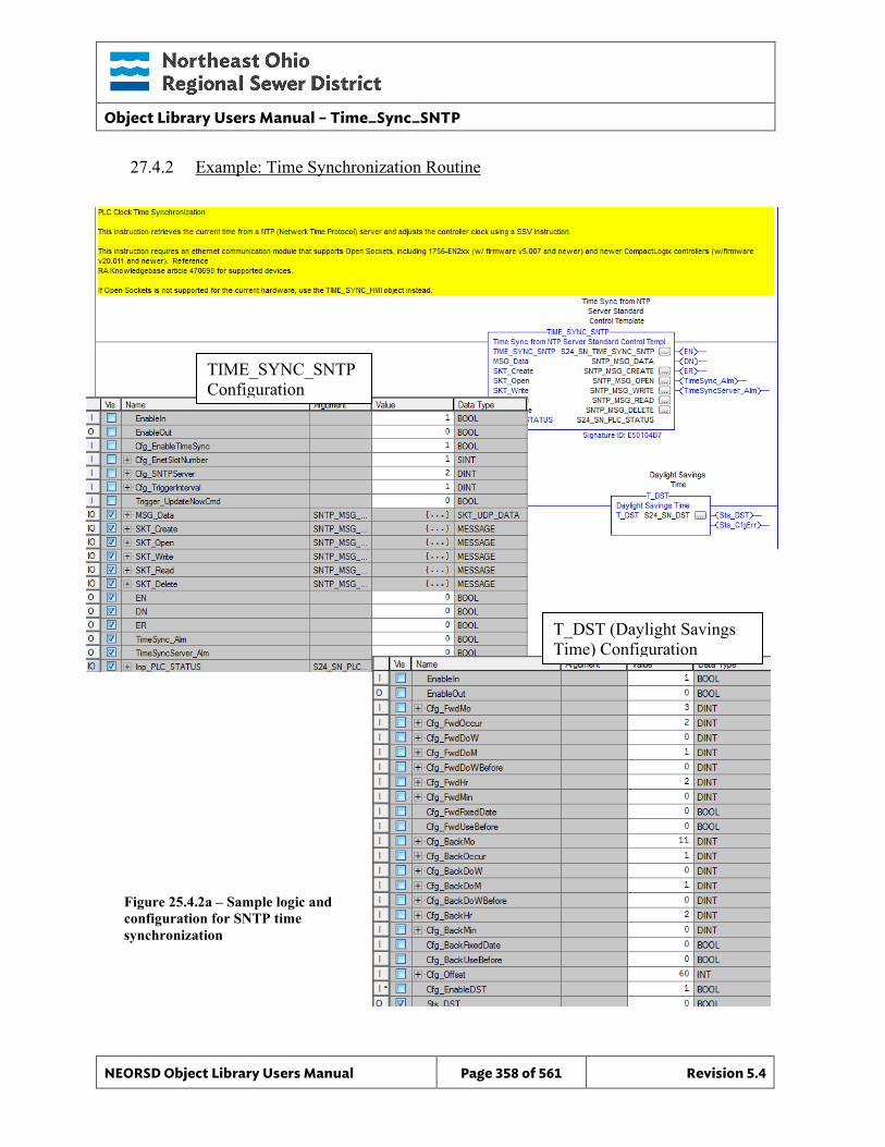
Object Library Users Manual – Time_Sync_SNTP
NEORSD Object Library Users Manual Page 358 of 561 Revision 5.4
27.4.2 Example: Time Synchronization Routine
TIME_SYNC_SNTP Configuration
T_DST (Daylight Savings Time) Configuration
Figure 25.4.2a – Sample logic and configuration for SNTP time synchronization
Object Library Users Manual – Time_Sync_SNTP
NEORSD Object Library Users Manual Page 359 of 561 Revision 5.4
NOTE
• The library object contains a routine import file that creates the logic above. By using the routine import, the TIME_SYNC_SNTP and T_DST instruction instances are created, along with associated MESSAGE tags.
• It is IMPORTANT that the MESSAGE tag configurations are not altered.
Example Highlights TIME_SYNC_SNTP • Inputs
o Inp_PLC_STATUS – Must reference the PLC_Status object for this PLC. o MSG_DATA, SKT_* - References UDT and MESSAGE tags external to
the AOI. These are created from the routine import, and do not need to be altered
• AOI Configuration: o Cfg_EnableTimeSync – Enables or disables time query and synchronization o Cfg_EnetSlotNumber – Select local slot number where ethernet card that
connects to plant network resides. Select controller slot number for controller’s with built in ethernet ports.
o Cfg_SNTPServer – Select an integer value 1-5 to select plant server: 1 = Westerly 2 = Southerly 3 = Southerly REF 4 = Easterly 5 = Collections The instruction uses this setting to select the appropriate IP address for the site’s NTP server
o Cfg_TriggerInterval – Interval in hours to automatically initiate synchronization
• Block Outputs for Use in External Logic: o TimeSync_Alm – Alarm when synchronization has not completed
successfully or has not be attempted for a set period (default 23 hours)
T_DST • Inputs
o None • AOI Configuration:
o Cfg_Fwd*, Cfg_Back*, Cfg_Offset – Configuration of daylight savings rules, default as observed by US.
o Cfg_EnableDST– Enables or disables daylights savings time adjustment. Must be enabled (=1).
• Block Outputs for Use in External Logic: o None
Object Library Users Manual – Time_Sync_SNTP
NEORSD Object Library Users Manual Page 360 of 561 Revision 5.4
27.4.3 Additional Attribute Notes
27.4.3.1 Inputs o All inputs are covered in the above example.
27.4.3.2 Internal Configuration: o All configuration is covered in the above example.
27.4.3.3 Outputs o EN – Instruction is attempting to synchronize time o DN – Time synchronization was successful during last attempt o ER – There was a problem during the last time synchronization attempt o TimeSyncServer_Alm – Indicates an error with the primary NTP server
27.5 Wonderware HMI Time synchronization alarms generated by this object are alarmed at the HMI through the PLC_STATUS object. Refer to the PLC_STATUS object for more information. A TIME_SYNC_SNTP object has not been created.
27.6 PanelView OIT
27.6.1 Configuration The following is required in the FTView ME project:
• TIME_SYNC_SNTP library components files (gfx and ggfx)
• PLC_STATUS library component files (gfx and ggfx) from one of the following versions
o PVP 1250 version 1.2 or greater o PVP 700 version 1.2 or greater o PVP 1500 version 1.1 or greater
• A configured instance of the PLC_STATUS object A standalone TIME_SYNC_SNTP object has not been created. Instead, OIT faceplates have been incorporated into the PLC_STATUS faceplate. Refer to the PLC_STATUS object for more information.
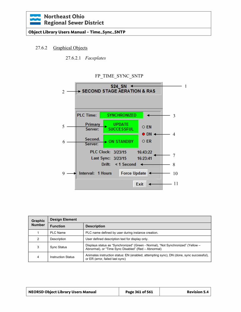
Object Library Users Manual – Time_Sync_SNTP
NEORSD Object Library Users Manual Page 361 of 561 Revision 5.4
27.6.2 Graphical Objects
27.6.2.1 Faceplates
Graphic Number
Design Element
Function Description
1 PLC Name PLC name defined by user during instance creation.
2 Description User defined description text for display only.
3 Sync Status Displays status as “Synchronized” (Green - Normal), “Not Synchronized” (Yellow – Abnormal), or “Time Sync Disabled” (Red – Abnormal)
4 Instruction Status Animates instruction status: EN (enabled, attempting sync), DN (done, sync successful), or ER (error, failed last sync)
FP_TIME_SYNC_SNTP
1 2
5
6
7
3
4
8
9 10
11
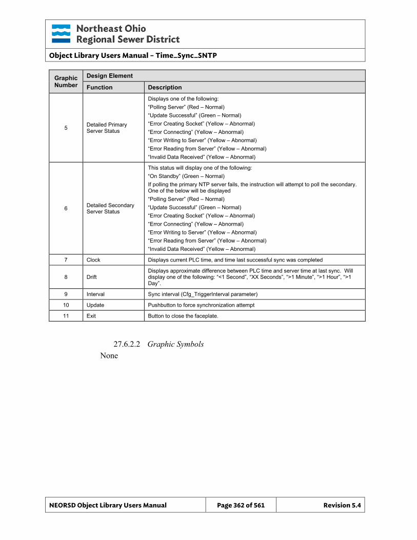
Object Library Users Manual – Time_Sync_SNTP
NEORSD Object Library Users Manual Page 362 of 561 Revision 5.4
Graphic Number
Design Element
Function Description
5 Detailed Primary Server Status
Displays one of the following: “Polling Server” (Red – Normal) “Update Successful” (Green – Normal) “Error Creating Socket” (Yellow – Abnormal) “Error Connecting” (Yellow – Abnormal) “Error Writing to Server” (Yellow – Abnormal) “Error Reading from Server” (Yellow – Abnormal) “Invalid Data Received” (Yellow – Abnormal)
6 Detailed Secondary Server Status
This status will display one of the following: “On Standby” (Green – Normal) If polling the primary NTP server fails, the instruction will attempt to poll the secondary. One of the below will be displayed “Polling Server” (Red – Normal) “Update Successful” (Green – Normal) “Error Creating Socket” (Yellow – Abnormal) “Error Connecting” (Yellow – Abnormal) “Error Writing to Server” (Yellow – Abnormal) “Error Reading from Server” (Yellow – Abnormal) “Invalid Data Received” (Yellow – Abnormal)
7 Clock Displays current PLC time, and time last successful sync was completed
8 Drift Displays approximate difference between PLC time and server time at last sync. Will display one of the following: “<1 Second”, “XX Seconds”, “>1 Minute”, “>1 Hour”, “>1 Day”.
9 Interval Sync interval (Cfg_TriggerInterval parameter)
10 Update Pushbutton to force synchronization attempt
11 Exit Button to close the faceplate.
27.6.2.2 Graphic Symbols None

Object Library Users Manual – Time_Sync_SNTP
NEORSD Object Library Users Manual Page 363 of 561 Revision 5.4
This page left blank intentionally.
Object Library Users Manual – Valve_Actuator
NEORSD Object Library Users Manual Page 364 of 561 Revision 5.4
28.0 Valve_Actuator
28.1 Introduction The Valve_Actuator template provides a standard representation for control, operation, indication, and alarming of actuated (open/close/stop) valves and gates that have position feedback (%) throughout the NEORSD control systems. Use the Valve_Actuator template if the below statement is true:
• If trying to represent a valve or gate with analog position feedback that is controlled via discrete commands (open/close/stop) instead of a modulated position setpoint.
Do not use the Valve_Actuator template:
• If the valve has position setpoint (%) commands, and no open/close/stop commands. If this is the case, use Valve_Analog or Valve_Actuator_SP instead.
• If the valve has no control. If representing a valve with position feedback but no control, use Valve_Analog_Indicator.
• If the valve is not variable position. If the valve is a two-state valve, use Valve_Discrete instead.
28.2 Object Features
28.2.1 Status Indications This object provides the following indications for the valve/gate:
• Opened/closed limit switch feedback • Analog position feedback • Auto/Manual mode indication • Remote/Local mode feedback • In-Service/Out-Of-Service mode indication
28.2.2 Alarming This object supports the following alarms:
• Alarm if the valve is neither opened nor closed for a set period of time • Alarm if the valve is commanded to fully-open and does not in a set period
of time • Alarm if the valve is commanded to fully-close and does not in a set
period of time • Alarm if the object loses feedback from failsafe limit switches • Alarm if an externally generated fault condition is true
When a fault condition occurs, the valve will remain at its current position and the object will enter manual mode.
Object Library Users Manual – Valve_Actuator
NEORSD Object Library Users Manual Page 365 of 561 Revision 5.4
28.2.3 Control This object supports the following control for the valve:
• Open, Close, and Stop Commands • Auto/Manual mode toggle • Resettable alarms • Out-of-Service/In-Service mode toggle • Interlocking to prevent operation
28.2.4 Simulation This object supports simulation of the running feedback.
28.2.5 Trouble This object supports hardware trouble indication.
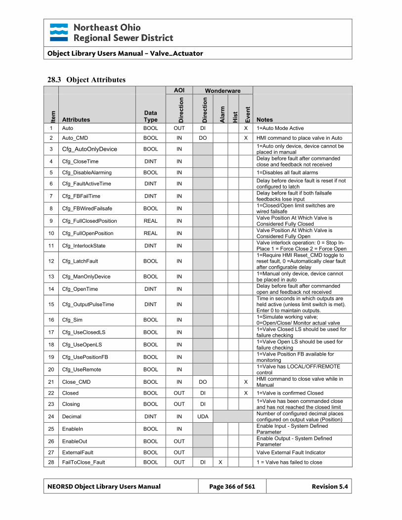
Object Library Users Manual – Valve_Actuator
NEORSD Object Library Users Manual Page 366 of 561 Revision 5.4
28.3 Object Attributes
AOI Wonderware
Item
Attributes Data Type D
irect
ion
Dire
ctio
n
Ala
rm
His
t
Even
t
Notes 1 Auto BOOL OUT DI X 1=Auto Mode Active
2 Auto_CMD BOOL IN DO X HMI command to place valve in Auto
3 Cfg_AutoOnlyDevice BOOL IN 1=Auto only device, device cannot be placed in manual
4 Cfg_CloseTime DINT IN Delay before fault after commanded close and feedback not received
5 Cfg_DisableAlarming BOOL IN 1=Disables all fault alarms
6 Cfg_FaultActiveTime DINT IN Delay before device fault is reset if not configured to latch
7 Cfg_FBFailTime DINT IN Delay before fault if both failsafe feedbacks lose input
8 Cfg_FBWiredFailsafe BOOL IN 1=Closed/Open limit switches are wired failsafe
9 Cfg_FullClosedPosition REAL IN Valve Position At Which Valve is Considered Fully Closed
10 Cfg_FullOpenPosition REAL IN Valve Position At Which Valve is Considered Fully Open
11 Cfg_InterlockState DINT IN Valve interlock operation: 0 = Stop In-Place 1 = Force Close 2 = Force Open
12 Cfg_LatchFault BOOL IN 1=Require HMI Reset_CMD toggle to reset fault, 0 =Automatically clear fault after configurable delay
13 Cfg_ManOnlyDevice BOOL IN 1=Manual only device, device cannot be placed in auto
14 Cfg_OpenTime DINT IN Delay before fault after commanded open and feedback not received
15 Cfg_OutputPulseTime DINT IN Time in seconds in which outputs are held active (unless limit switch is met). Enter 0 to maintain outputs.
16 Cfg_Sim BOOL IN 1=Simulate working valve; 0=Open/Close/ Monitor actual valve
17 Cfg_UseClosedLS BOOL IN 1=Valve Closed LS should be used for failure checking
18 Cfg_UseOpenLS BOOL IN 1=Valve Open LS should be used for failure checking
19 Cfg_UsePositionFB BOOL IN 1=Valve Position FB available for monitoring
20 Cfg_UseRemote BOOL IN 1=Valve has LOCAL/OFF/REMOTE control
21 Close_CMD BOOL IN DO X HMI command to close valve while in Manual
22 Closed BOOL OUT DI X 1=Valve is confirmed Closed
23 Closing BOOL OUT DI 1=Valve has been commanded close and has not reached the closed limit
24 Decimal DINT IN UDA Number of configured decimal places configured on output value (Position)
25 EnableIn BOOL IN Enable Input - System Defined Parameter
26 EnableOut BOOL OUT Enable Output - System Defined Parameter
27 ExternalFault BOOL OUT Valve External Fault Indicator
28 FailToClose_Fault BOOL OUT DI X 1 = Valve has failed to close
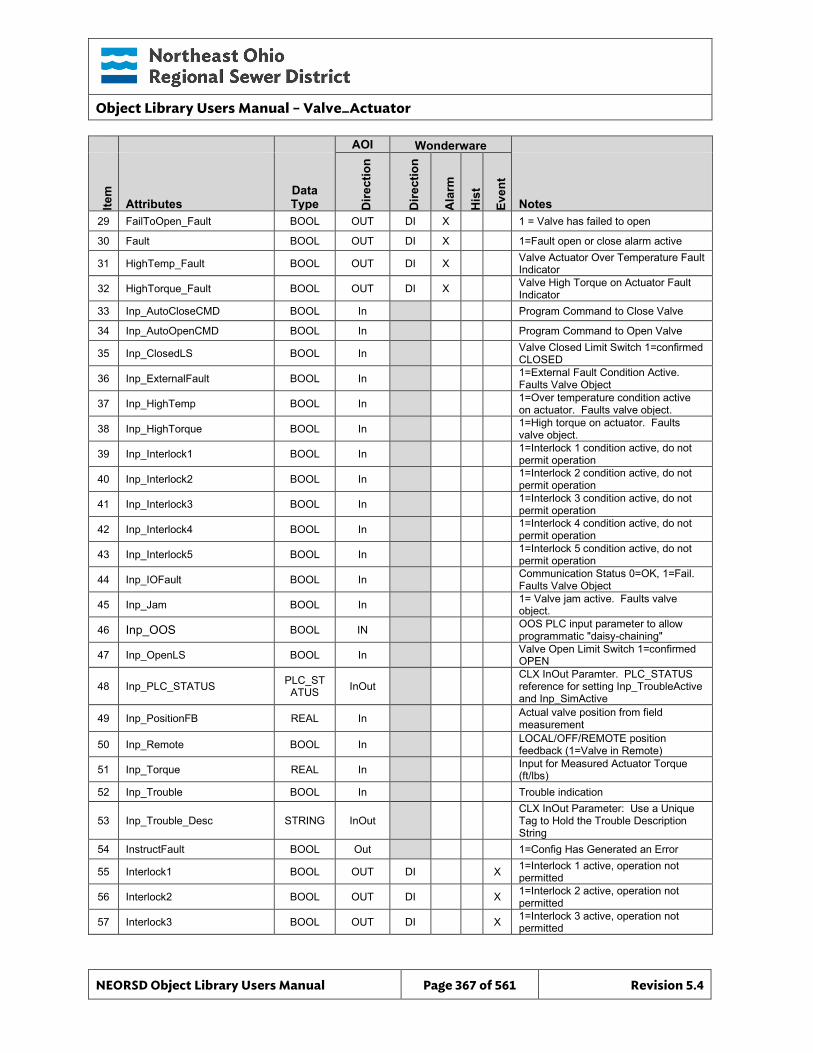
Object Library Users Manual – Valve_Actuator
NEORSD Object Library Users Manual Page 367 of 561 Revision 5.4
AOI Wonderware
Item
Attributes Data Type D
irect
ion
Dire
ctio
n
Ala
rm
His
t
Even
t
Notes 29 FailToOpen_Fault BOOL OUT DI X 1 = Valve has failed to open
30 Fault BOOL OUT DI X 1=Fault open or close alarm active
31 HighTemp_Fault BOOL OUT DI X Valve Actuator Over Temperature Fault Indicator
32 HighTorque_Fault BOOL OUT DI X Valve High Torque on Actuator Fault Indicator
33 Inp_AutoCloseCMD BOOL In Program Command to Close Valve
34 Inp_AutoOpenCMD BOOL In Program Command to Open Valve
35 Inp_ClosedLS BOOL In Valve Closed Limit Switch 1=confirmed CLOSED
36 Inp_ExternalFault BOOL In 1=External Fault Condition Active. Faults Valve Object
37 Inp_HighTemp BOOL In 1=Over temperature condition active on actuator. Faults valve object.
38 Inp_HighTorque BOOL In 1=High torque on actuator. Faults valve object.
39 Inp_Interlock1 BOOL In 1=Interlock 1 condition active, do not permit operation
40 Inp_Interlock2 BOOL In 1=Interlock 2 condition active, do not permit operation
41 Inp_Interlock3 BOOL In 1=Interlock 3 condition active, do not permit operation
42 Inp_Interlock4 BOOL In 1=Interlock 4 condition active, do not permit operation
43 Inp_Interlock5 BOOL In 1=Interlock 5 condition active, do not permit operation
44 Inp_IOFault BOOL In Communication Status 0=OK, 1=Fail. Faults Valve Object
45 Inp_Jam BOOL In 1= Valve jam active. Faults valve object.
46 Inp_OOS BOOL IN OOS PLC input parameter to allow programmatic "daisy-chaining"
47 Inp_OpenLS BOOL In Valve Open Limit Switch 1=confirmed OPEN
48 Inp_PLC_STATUS PLC_STATUS InOut
CLX InOut Paramter. PLC_STATUS reference for setting Inp_TroubleActive and Inp_SimActive
49 Inp_PositionFB REAL In Actual valve position from field measurement
50 Inp_Remote BOOL In LOCAL/OFF/REMOTE position feedback (1=Valve in Remote)
51 Inp_Torque REAL In Input for Measured Actuator Torque (ft/lbs)
52 Inp_Trouble BOOL In Trouble indication
53 Inp_Trouble_Desc STRING InOut CLX InOut Parameter: Use a Unique Tag to Hold the Trouble Description String
54 InstructFault BOOL Out 1=Config Has Generated an Error
55 Interlock1 BOOL OUT DI X 1=Interlock 1 active, operation not permitted
56 Interlock2 BOOL OUT DI X 1=Interlock 2 active, operation not permitted
57 Interlock3 BOOL OUT DI X 1=Interlock 3 active, operation not permitted
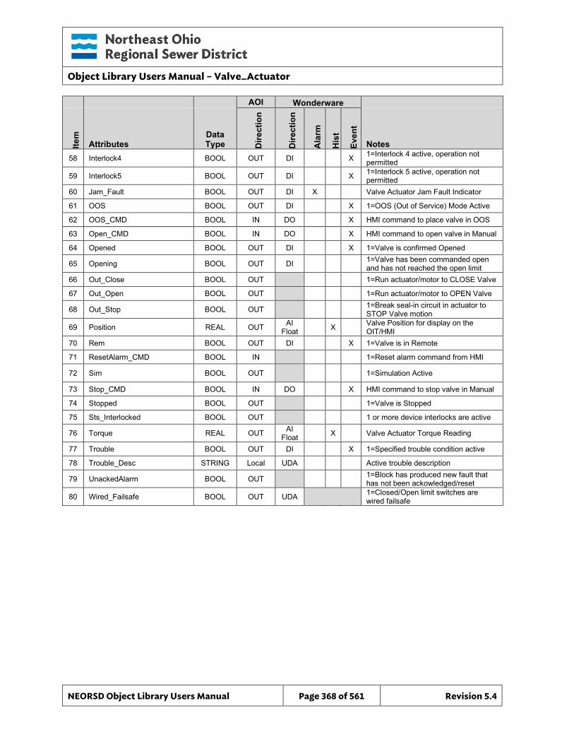
Object Library Users Manual – Valve_Actuator
NEORSD Object Library Users Manual Page 368 of 561 Revision 5.4
AOI Wonderware
Item
Attributes Data Type D
irect
ion
Dire
ctio
n
Ala
rm
His
t
Even
t
Notes 58 Interlock4 BOOL OUT DI X 1=Interlock 4 active, operation not
permitted
59 Interlock5 BOOL OUT DI X 1=Interlock 5 active, operation not permitted
60 Jam_Fault BOOL OUT DI X Valve Actuator Jam Fault Indicator
61 OOS BOOL OUT DI X 1=OOS (Out of Service) Mode Active
62 OOS_CMD BOOL IN DO X HMI command to place valve in OOS
63 Open_CMD BOOL IN DO X HMI command to open valve in Manual
64 Opened BOOL OUT DI X 1=Valve is confirmed Opened
65 Opening BOOL OUT DI 1=Valve has been commanded open and has not reached the open limit
66 Out_Close BOOL OUT 1=Run actuator/motor to CLOSE Valve
67 Out_Open BOOL OUT 1=Run actuator/motor to OPEN Valve
68 Out_Stop BOOL OUT 1=Break seal-in circuit in actuator to STOP Valve motion
69 Position REAL OUT AI Float X Valve Position for display on the
OIT/HMI 70 Rem BOOL OUT DI X 1=Valve is in Remote
71 ResetAlarm_CMD BOOL IN 1=Reset alarm command from HMI
72 Sim BOOL OUT 1=Simulation Active
73 Stop_CMD BOOL IN DO X HMI command to stop valve in Manual
74 Stopped BOOL OUT 1=Valve is Stopped
75 Sts_Interlocked BOOL OUT 1 or more device interlocks are active
76 Torque REAL OUT AI Float X Valve Actuator Torque Reading
77 Trouble BOOL OUT DI X 1=Specified trouble condition active
78 Trouble_Desc STRING Local UDA Active trouble description
79 UnackedAlarm BOOL OUT 1=Block has produced new fault that has not been ackowledged/reset
80 Wired_Failsafe BOOL OUT UDA 1=Closed/Open limit switches are wired failsafe
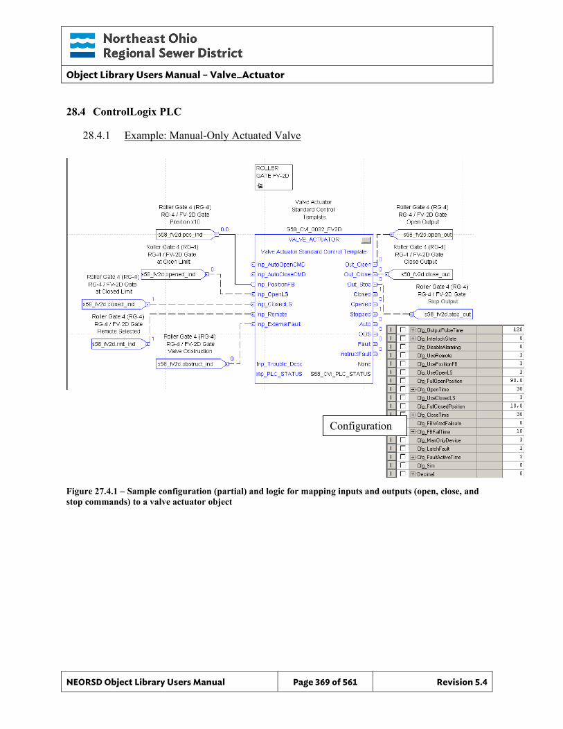
Object Library Users Manual – Valve_Actuator
NEORSD Object Library Users Manual Page 369 of 561 Revision 5.4
28.4 ControlLogix PLC
28.4.1 Example: Manual-Only Actuated Valve
Figure 27.4.1 – Sample configuration (partial) and logic for mapping inputs and outputs (open, close, and stop commands) to a valve actuator object
Configuration
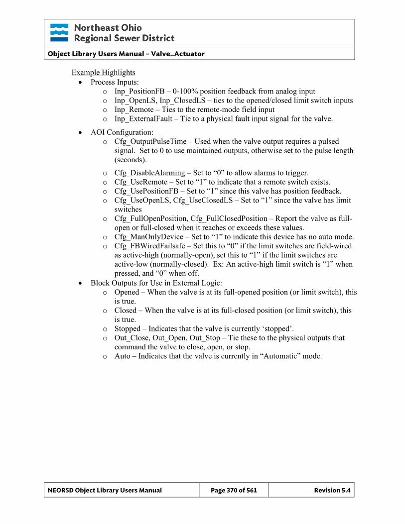
Object Library Users Manual – Valve_Actuator
NEORSD Object Library Users Manual Page 370 of 561 Revision 5.4
Example Highlights • Process Inputs:
o Inp_PositionFB – 0-100% position feedback from analog input o Inp_OpenLS, Inp_ClosedLS – ties to the opened/closed limit switch inputs o Inp_Remote – Ties to the remote-mode field input o Inp_ExternalFault – Tie to a physical fault input signal for the valve.
• AOI Configuration: o Cfg_OutputPulseTime – Used when the valve output requires a pulsed
signal. Set to 0 to use maintained outputs, otherwise set to the pulse length (seconds).
o Cfg_DisableAlarming – Set to “0” to allow alarms to trigger. o Cfg_UseRemote – Set to “1” to indicate that a remote switch exists. o Cfg_UsePositionFB – Set to “1” since this valve has position feedback. o Cfg_UseOpenLS, Cfg_UseClosedLS – Set to “1” since the valve has limit
switches o Cfg_FullOpenPosition, Cfg_FullClosedPosition – Report the valve as full-
open or full-closed when it reaches or exceeds these values. o Cfg_ManOnlyDevice – Set to “1” to indicate this device has no auto mode. o Cfg_FBWiredFailsafe – Set this to “0” if the limit switches are field-wired
as active-high (normally-open), set this to “1” if the limit switches are active-low (normally-closed). Ex: An active-high limit switch is “1” when pressed, and “0” when off.
• Block Outputs for Use in External Logic: o Opened – When the valve is at its full-opened position (or limit switch), this
is true. o Closed – When the valve is at its full-closed position (or limit switch), this
is true. o Stopped – Indicates that the valve is currently ‘stopped’. o Out_Close, Out_Open, Out_Stop – Tie these to the physical outputs that
command the valve to close, open, or stop. o Auto – Indicates that the valve is currently in “Automatic” mode.
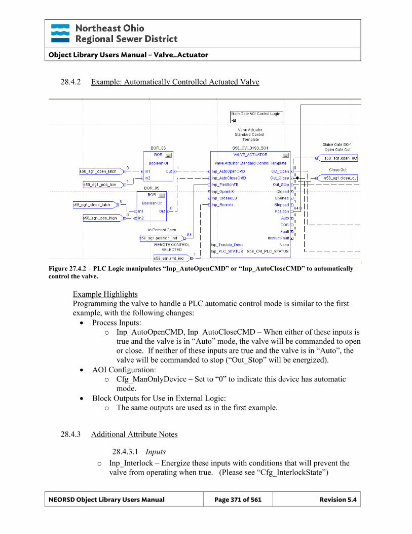
Object Library Users Manual – Valve_Actuator
NEORSD Object Library Users Manual Page 371 of 561 Revision 5.4
28.4.2 Example: Automatically Controlled Actuated Valve
Figure 27.4.2 – PLC Logic manipulates “Inp_AutoOpenCMD” or “Inp_AutoCloseCMD” to automatically control the valve.
Example Highlights Programming the valve to handle a PLC automatic control mode is similar to the first example, with the following changes: • Process Inputs:
o Inp_AutoOpenCMD, Inp_AutoCloseCMD – When either of these inputs is true and the valve is in “Auto” mode, the valve will be commanded to open or close. If neither of these inputs are true and the valve is in “Auto”, the valve will be commanded to stop (“Out_Stop” will be energized).
• AOI Configuration: o Cfg_ManOnlyDevice – Set to “0” to indicate this device has automatic
mode. • Block Outputs for Use in External Logic:
o The same outputs are used as in the first example.
28.4.3 Additional Attribute Notes
28.4.3.1 Inputs o Inp_Interlock – Energize these inputs with conditions that will prevent the
valve from operating when true. (Please see “Cfg_InterlockState”)
Object Library Users Manual – Valve_Actuator
NEORSD Object Library Users Manual Page 372 of 561 Revision 5.4
o Inp_ExternalFault – Tie to a physical fault input signal for the valve, if available.
o Inp_IOFault – Fault bit input representing a card/communication error, if available.
o INP_PLC_STATUS - Must reference the PLC_Status object for this PLC. o Inp_OOS - Programmatically set this attribute to “1” to enable Out of Service.
28.4.3.2 Internal Configuration o Cfg_LatchFault – Set to “1” if faults must be reset at the HMI/OIT. Use if: District staff should physically inspect a device before resuming operation
after a fault. o Cfg_FaultActiveTime –If “Cfg_LatchFault” = 0, the block will automatically
clear a fault in the time specified by this parameter. If the fault input condition must be removed; the block will not clear an active fault.
o Cfg_InterlockState – If an interlock input is true, the valve will move to the position defined by this attribute. Available options are “Stop-in-Place”, “Force-Close”, or “Force-Open”.
o Cfg_OpenTime – Delay before triggering an alarm if the valve was commanded to open fully and has not opened.
o Cfg_CloseTime – Delay before triggering an alarm if the valve was commanded to close fully and has not closed.
o Cfg_FBFailTime - Seconds before triggering an alarm if the limit switches are defined as failsafe and both go to an ‘off’ state.
o Cfg_OutputPulseTime – Used when the valve output requires a pulsed signal. Set to 0 to use maintained outputs, otherwise set to the pulse length (seconds).
o Cfg_Sim – Set to “1” to enable simulation mode for this block. The limit switch and position input will be ignored and when the block is commanded to open/close the valve state will react accordingly.
o Decimal – Number of decimal places to display for the valve position (%) o Cfg_AutoOnlyDevice – Set to “1” to prevent the device from operating in
remote manual mode. Cfg_ManOnlyDevice must be set to “0”.
28.4.3.3 Outputs o Sts_Interlocked – Indicates that this instance cannot operate as an interlock
condition is not satisfied. o OOS – Indicates that this instance is out-of-service
Object Library Users Manual – Valve_Actuator
NEORSD Object Library Users Manual Page 373 of 561 Revision 5.4
o Auto – Indicates that the valve is in automatic control mode o Fault – Indicates that any fault condition is active on the valve. This includes
internally generated alarms (time-to-open/close, etc) and the external alarm, if used. When the valve faults, it will remain in its current position and enter
manual mode.
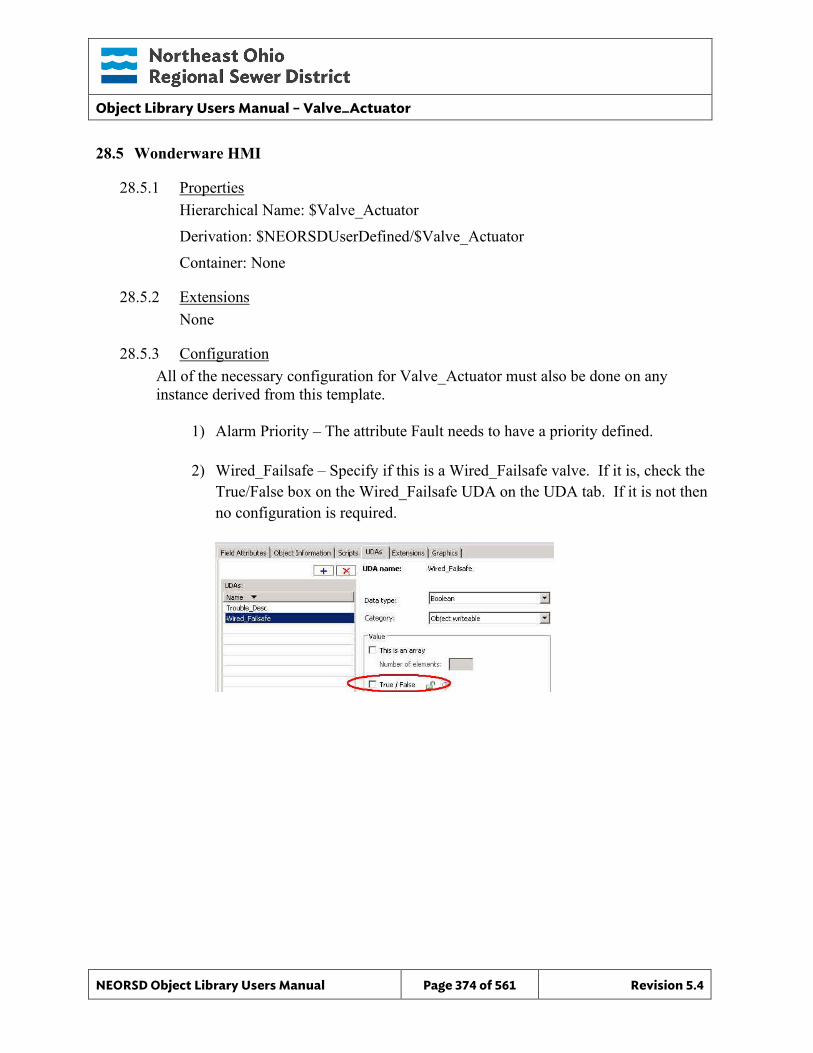
Object Library Users Manual – Valve_Actuator
NEORSD Object Library Users Manual Page 374 of 561 Revision 5.4
28.5 Wonderware HMI
28.5.1 Properties Hierarchical Name: $Valve_Actuator Derivation: $NEORSDUserDefined/$Valve_Actuator Container: None
28.5.2 Extensions None
28.5.3 Configuration All of the necessary configuration for Valve_Actuator must also be done on any instance derived from this template.
1) Alarm Priority – The attribute Fault needs to have a priority defined.
2) Wired_Failsafe – Specify if this is a Wired_Failsafe valve. If it is, check the True/False box on the Wired_Failsafe UDA on the UDA tab. If it is not then no configuration is required.
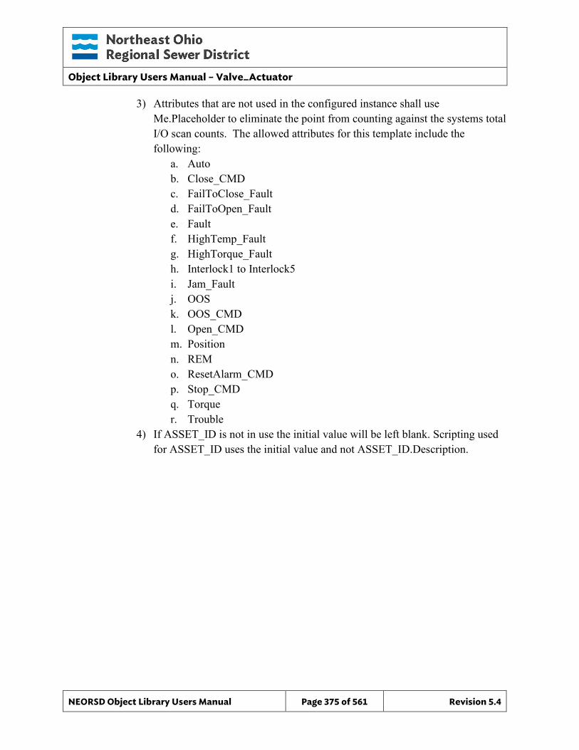
Object Library Users Manual – Valve_Actuator
NEORSD Object Library Users Manual Page 375 of 561 Revision 5.4
3) Attributes that are not used in the configured instance shall use Me.Placeholder to eliminate the point from counting against the systems total I/O scan counts. The allowed attributes for this template include the following:
a. Auto b. Close_CMD c. FailToClose_Fault d. FailToOpen_Fault e. Fault f. HighTemp_Fault g. HighTorque_Fault h. Interlock1 to Interlock5 i. Jam_Fault j. OOS k. OOS_CMD l. Open_CMD m. Position n. REM o. ResetAlarm_CMD p. Stop_CMD q. Torque r. Trouble
4) If ASSET_ID is not in use the initial value will be left blank. Scripting used for ASSET_ID uses the initial value and not ASSET_ID.Description.
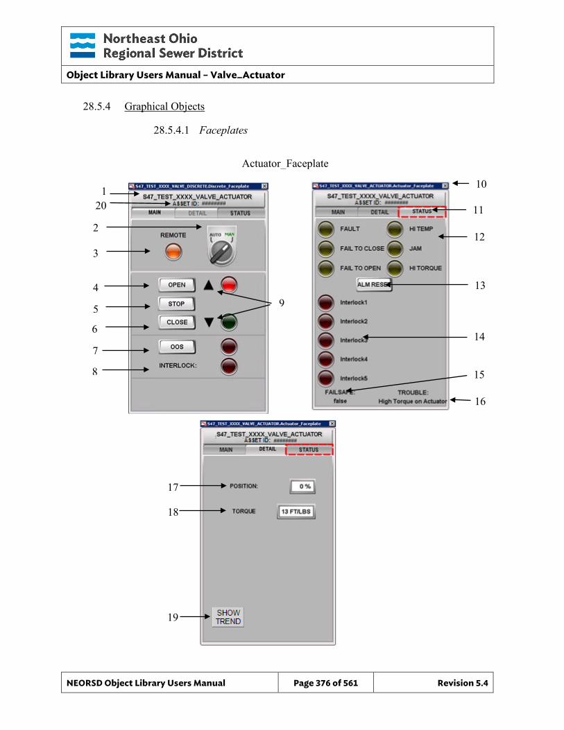
Object Library Users Manual – Valve_Actuator
NEORSD Object Library Users Manual Page 376 of 561 Revision 5.4
Actuator_Faceplate
28.5.4 Graphical Objects
28.5.4.1 Faceplates
19
10
11
12
14
1
3
2
7
8
6
4
15
13
5
9
17
18
16
20
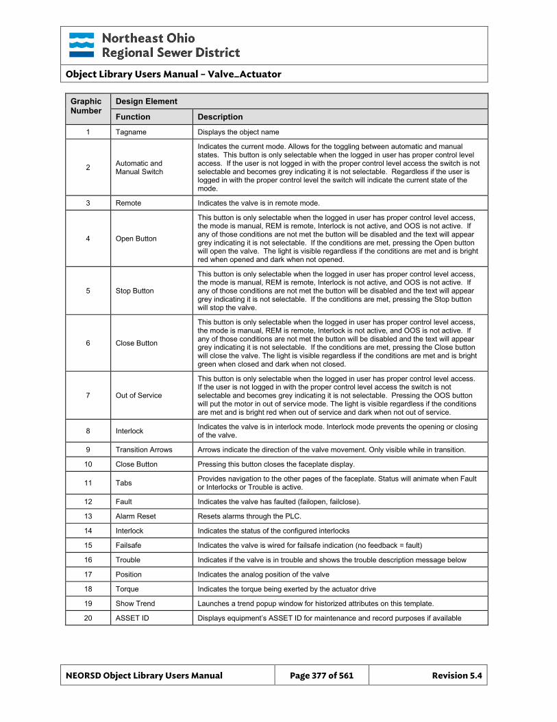
Object Library Users Manual – Valve_Actuator
NEORSD Object Library Users Manual Page 377 of 561 Revision 5.4
Graphic Number
Design Element
Function Description
1 Tagname Displays the object name
2 Automatic and Manual Switch
Indicates the current mode. Allows for the toggling between automatic and manual states. This button is only selectable when the logged in user has proper control level access. If the user is not logged in with the proper control level access the switch is not selectable and becomes grey indicating it is not selectable. Regardless if the user is logged in with the proper control level the switch will indicate the current state of the mode.
3 Remote Indicates the valve is in remote mode.
4 Open Button
This button is only selectable when the logged in user has proper control level access, the mode is manual, REM is remote, Interlock is not active, and OOS is not active. If any of those conditions are not met the button will be disabled and the text will appear grey indicating it is not selectable. If the conditions are met, pressing the Open button will open the valve. The light is visible regardless if the conditions are met and is bright red when opened and dark when not opened.
5 Stop Button
This button is only selectable when the logged in user has proper control level access, the mode is manual, REM is remote, Interlock is not active, and OOS is not active. If any of those conditions are not met the button will be disabled and the text will appear grey indicating it is not selectable. If the conditions are met, pressing the Stop button will stop the valve.
6 Close Button
This button is only selectable when the logged in user has proper control level access, the mode is manual, REM is remote, Interlock is not active, and OOS is not active. If any of those conditions are not met the button will be disabled and the text will appear grey indicating it is not selectable. If the conditions are met, pressing the Close button will close the valve. The light is visible regardless if the conditions are met and is bright green when closed and dark when not closed.
7 Out of Service
This button is only selectable when the logged in user has proper control level access. If the user is not logged in with the proper control level access the switch is not selectable and becomes grey indicating it is not selectable. Pressing the OOS button will put the motor in out of service mode. The light is visible regardless if the conditions are met and is bright red when out of service and dark when not out of service.
8 Interlock Indicates the valve is in interlock mode. Interlock mode prevents the opening or closing of the valve.
9 Transition Arrows Arrows indicate the direction of the valve movement. Only visible while in transition.
10 Close Button Pressing this button closes the faceplate display.
11 Tabs Provides navigation to the other pages of the faceplate. Status will animate when Fault or Interlocks or Trouble is active.
12 Fault Indicates the valve has faulted (failopen, failclose).
13 Alarm Reset Resets alarms through the PLC.
14 Interlock Indicates the status of the configured interlocks
15 Failsafe Indicates the valve is wired for failsafe indication (no feedback = fault)
16 Trouble Indicates if the valve is in trouble and shows the trouble description message below
17 Position Indicates the analog position of the valve
18 Torque Indicates the torque being exerted by the actuator drive
19 Show Trend Launches a trend popup window for historized attributes on this template.
20 ASSET ID Displays equipment’s ASSET ID for maintenance and record purposes if available
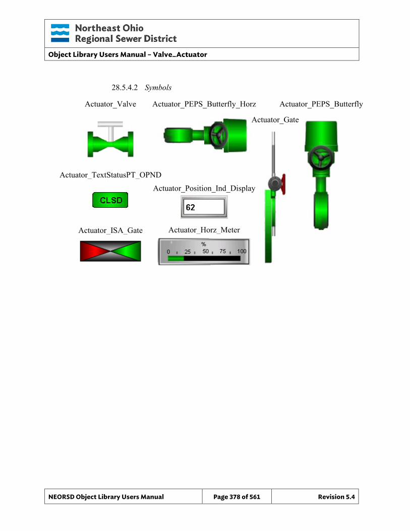
Object Library Users Manual – Valve_Actuator
NEORSD Object Library Users Manual Page 378 of 561 Revision 5.4
28.5.4.2 Symbols
Actuator_Valve Actuator_PEPS_Butterfly_Horz Actuator_PEPS_Butterfly
Actuator_TextStatusPT_OPND
Actuator_Gate
Actuator_ISA_Gate
Actuator_Position_Ind_Display
Actuator_Horz_Meter
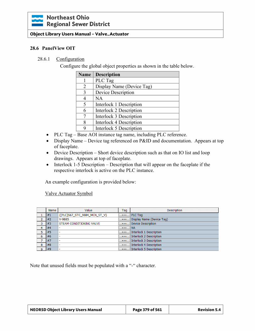
Object Library Users Manual – Valve_Actuator
NEORSD Object Library Users Manual Page 379 of 561 Revision 5.4
28.6 PanelView OIT
28.6.1 Configuration Configure the global object properties as shown in the table below.
Name Description 1 PLC Tag 2 Display Name (Device Tag) 3 Device Description 4 NA 5 Interlock 1 Description 6 Interlock 2 Description 7 Interlock 3 Description 8 Interlock 4 Description 9 Interlock 5 Description
• PLC Tag – Base AOI instance tag name, including PLC reference. • Display Name – Device tag referenced on P&ID and documentation. Appears at top
of faceplate. • Device Description – Short device description such as that on IO list and loop
drawings. Appears at top of faceplate. • Interlock 1-5 Description – Description that will appear on the faceplate if the
respective interlock is active on the PLC instance.
An example configuration is provided below: Valve Actuator Symbol
Note that unused fields must be populated with a “-“ character.
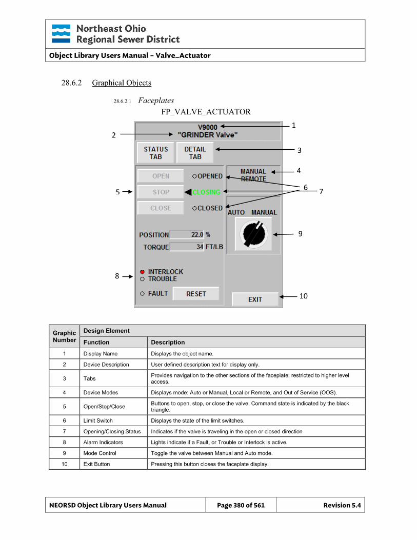
Object Library Users Manual – Valve_Actuator
NEORSD Object Library Users Manual Page 380 of 561 Revision 5.4
FP_VALVE_ACTUATOR 1
10
6
3
4
7
9
28.6.2 Graphical Objects
28.6.2.1 Faceplates
Graphic Number
Design Element
Function Description
1 Display Name Displays the object name.
2 Device Description User defined description text for display only.
3 Tabs Provides navigation to the other sections of the faceplate; restricted to higher level access.
4 Device Modes Displays mode: Auto or Manual, Local or Remote, and Out of Service (OOS).
5 Open/Stop/Close Buttons to open, stop, or close the valve. Command state is indicated by the black triangle.
6 Limit Switch Displays the state of the limit switches.
7 Opening/Closing Status Indicates if the valve is traveling in the open or closed direction
8 Alarm Indicators Lights indicate if a Fault, or Trouble or Interlock is active.
9 Mode Control Toggle the valve between Manual and Auto mode.
10 Exit Button Pressing this button closes the faceplate display.
2
8
5
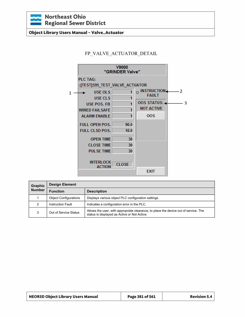
Object Library Users Manual – Valve_Actuator
NEORSD Object Library Users Manual Page 381 of 561 Revision 5.4
FP_VALVE_ACTUATOR_DETAIL
2
3
Graphic Number
Design Element
Function Description
1 Object Configurations Displays various object PLC configuration settings.
2 Instruction Fault Indicates a configuration error in the PLC.
3 Out of Service Status Allows the user, with appropriate clearance, to place the device out of service. The status is displayed as Active or Not Active.
1
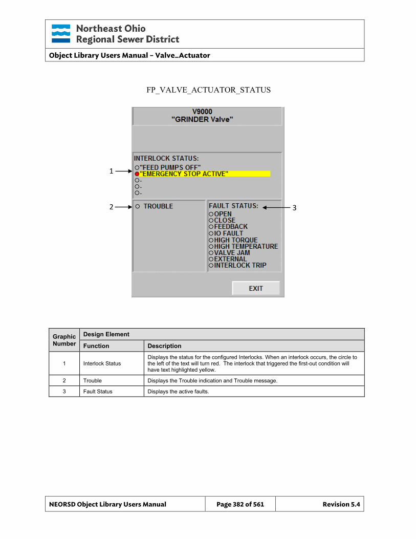
Object Library Users Manual – Valve_Actuator
NEORSD Object Library Users Manual Page 382 of 561 Revision 5.4
FP_VALVE_ACTUATOR_STATUS
3
Graphic Number
Design Element
Function Description
1 Interlock Status Displays the status for the configured Interlocks. When an interlock occurs, the circle to the left of the text will turn red. The interlock that triggered the first-out condition will have text highlighted yellow.
2 Trouble Displays the Trouble indication and Trouble message.
3 Fault Status Displays the active faults.
1
2
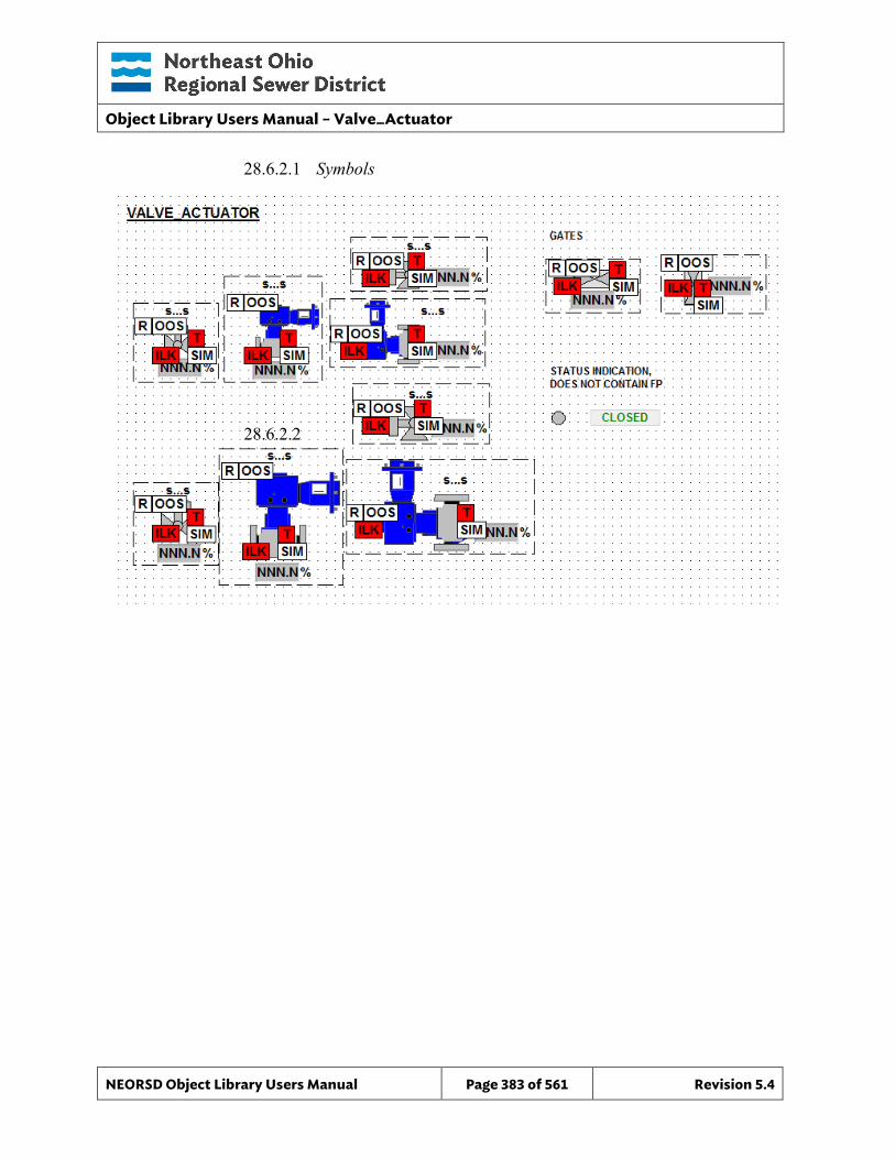
Object Library Users Manual – Valve_Actuator
NEORSD Object Library Users Manual Page 383 of 561 Revision 5.4
28.6.2.1 Symbols
28.6.2.2
Object Library Users Manual – Valve_Actuator_SP
NEORSD Object Library Users Manual Page 384 of 561 Revision 5.4
29.0 Valve_Actuator_SP
29.1 Introduction The Valve_Actuator_SP template provides a standard representation for control, operation, indication, and alarming of actuated (open/close/stop) valves and gates that have position feedback (%). A analog setpoint is provided for reference in the PLC logic, for manual operation. This object was created to replicate functionality in the Cimplicity system, but can be used elsewhere if logic is written to support the parameters. This template does not have an associated ControlLogix AOI, but can be used with a custom UDT if desired. Use the Valve_Actuator_SP template if the below statement is true:
• If trying to represent a valve or gate with analog position feedback that is controlled manually via analog command (position) as well as a discrete open/close/stop commands.
Do not use the Valve_Actuator template:
• If the valve has discrete setpoint (open/close/stop) commands, and no analog position command. If this is the case, use Valve_Actuator instead.
• If the valve has no control. If representing a valve with position feedback but no control, use Valve_Analog_Indicator.
• If the valve is not variable position. If the valve is a two-state valve, use Valve_Discrete instead.
29.2 Object Features
29.2.1 Status Indications This object provides the following indications for the valve/gate:
• Opened/closed limit switch feedback • Analog position feedback • Auto/Manual mode indication • Remote/Local mode feedback • In-Service/Out-Of-Service mode indication
29.2.2 Alarming This object supports the following alarms:
• Alarm if the valve is neither opened nor closed for a set period of time • Alarm if the valve is commanded to fully-open and does not in a set period
of time • Alarm if the valve is commanded to fully-close and does not in a set
period of time
Object Library Users Manual – Valve_Actuator_SP
NEORSD Object Library Users Manual Page 385 of 561 Revision 5.4
• Alarm if the object loses feedback from failsafe limit switches • Alarm if an externally generated fault condition is true
When a fault condition occurs, the valve will remain at its current position and the object will enter manual mode.
29.2.3 Control This object supports the following control for the valve:
• Analog Position Commands (manual) • Auto/Manual mode toggle • Resettable alarms • Out-of-Service/In-Service mode toggle • Interlocking to prevent operation
29.2.4 Simulation This object supports simulation of the running feedback.
29.2.5 Trouble This object supports hardware trouble indication.
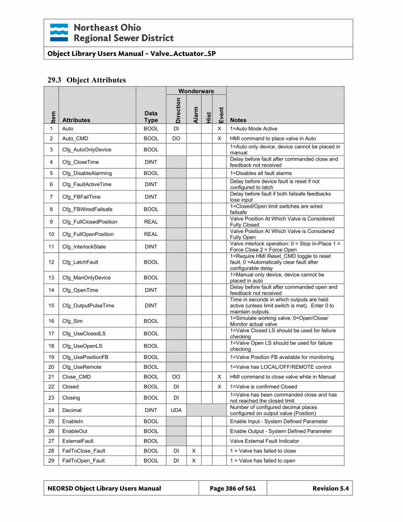
Object Library Users Manual – Valve_Actuator_SP
NEORSD Object Library Users Manual Page 386 of 561 Revision 5.4
29.3 Object Attributes
Wonderware
Item
Attributes Data Type D
irect
ion
Ala
rm
His
t
Even
t
Notes 1 Auto BOOL DI X 1=Auto Mode Active
2 Auto_CMD BOOL DO X HMI command to place valve in Auto
3 Cfg_AutoOnlyDevice BOOL 1=Auto only device, device cannot be placed in manual
4 Cfg_CloseTime DINT Delay before fault after commanded close and feedback not received
5 Cfg_DisableAlarming BOOL 1=Disables all fault alarms
6 Cfg_FaultActiveTime DINT Delay before device fault is reset if not configured to latch
7 Cfg_FBFailTime DINT Delay before fault if both failsafe feedbacks lose input
8 Cfg_FBWiredFailsafe BOOL 1=Closed/Open limit switches are wired failsafe
9 Cfg_FullClosedPosition REAL Valve Position At Which Valve is Considered Fully Closed
10 Cfg_FullOpenPosition REAL Valve Position At Which Valve is Considered Fully Open
11 Cfg_InterlockState DINT Valve interlock operation: 0 = Stop In-Place 1 = Force Close 2 = Force Open
12 Cfg_LatchFault BOOL 1=Require HMI Reset_CMD toggle to reset fault, 0 =Automatically clear fault after configurable delay
13 Cfg_ManOnlyDevice BOOL 1=Manual only device, device cannot be placed in auto
14 Cfg_OpenTime DINT Delay before fault after commanded open and feedback not received
15 Cfg_OutputPulseTime DINT Time in seconds in which outputs are held active (unless limit switch is met). Enter 0 to maintain outputs.
16 Cfg_Sim BOOL 1=Simulate working valve; 0=Open/Close/ Monitor actual valve
17 Cfg_UseClosedLS BOOL 1=Valve Closed LS should be used for failure checking
18 Cfg_UseOpenLS BOOL 1=Valve Open LS should be used for failure checking
19 Cfg_UsePositionFB BOOL 1=Valve Position FB available for monitoring
20 Cfg_UseRemote BOOL 1=Valve has LOCAL/OFF/REMOTE control
21 Close_CMD BOOL DO X HMI command to close valve while in Manual
22 Closed BOOL DI X 1=Valve is confirmed Closed
23 Closing BOOL DI 1=Valve has been commanded close and has not reached the closed limit
24 Decimal DINT UDA Number of configured decimal places configured on output value (Position)
25 EnableIn BOOL Enable Input - System Defined Parameter
26 EnableOut BOOL Enable Output - System Defined Parameter
27 ExternalFault BOOL Valve External Fault Indicator
28 FailToClose_Fault BOOL DI X 1 = Valve has failed to close
29 FailToOpen_Fault BOOL DI X 1 = Valve has failed to open
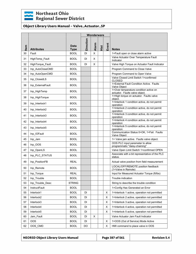
Object Library Users Manual – Valve_Actuator_SP
NEORSD Object Library Users Manual Page 387 of 561 Revision 5.4
Wonderware
Item
Attributes Data Type D
irect
ion
Ala
rm
His
t
Even
t
Notes 30 Fault BOOL DI X 1=Fault open or close alarm active
31 HighTemp_Fault BOOL DI X Valve Actuator Over Temperature Fault Indicator
32 HighTorque_Fault BOOL DI X Valve High Torque on Actuator Fault Indicator
33 Inp_AutoCloseCMD BOOL Program Command to Close Valve
34 Inp_AutoOpenCMD BOOL Program Command to Open Valve
35 Inp_ClosedLS BOOL Valve Closed Limit Switch 1=confirmed CLOSED
36 Inp_ExternalFault BOOL 1=External Fault Condition Active. Faults Valve Object
37 Inp_HighTemp BOOL 1=Over temperature condition active on actuator. Faults valve object.
38 Inp_HighTorque BOOL 1=High torque on actuator. Faults valve object.
39 Inp_Interlock1 BOOL 1=Interlock 1 condition active, do not permit operation
40 Inp_Interlock2 BOOL 1=Interlock 2 condition active, do not permit operation
41 Inp_Interlock3 BOOL 1=Interlock 3 condition active, do not permit operation
42 Inp_Interlock4 BOOL 1=Interlock 4 condition active, do not permit operation
43 Inp_Interlock5 BOOL 1=Interlock 5 condition active, do not permit operation
44 Inp_IOFault BOOL Communication Status 0=OK, 1=Fail. Faults Valve Object
45 Inp_Jam BOOL 1= Valve jam active. Faults valve object.
46 Inp_OOS BOOL OOS PLC input parameter to allow programmatic "daisy-chaining"
47 Inp_OpenLS BOOL Valve Open Limit Switch 1=confirmed OPEN
48 Inp_PLC_STATUS BOOL Associate with a bit representative of the PLC status.
49 Inp_PositionFB REAL Actual valve position from field measurement
50 Inp_Remote BOOL LOCAL/OFF/REMOTE position feedback (1=Valve in Remote)
51 Inp_Torque REAL Input for Measured Actuator Torque (ft/lbs)
52 Inp_Trouble BOOL Trouble indication
53 Inp_Trouble_Desc STRING String to describe the trouble condition
54 InstructFault BOOL 1=Config Has Generated an Error
55 Interlock1 BOOL DI X 1=Interlock 1 active, operation not permitted
56 Interlock2 BOOL DI X 1=Interlock 2 active, operation not permitted
57 Interlock3 BOOL DI X 1=Interlock 3 active, operation not permitted
58 Interlock4 BOOL DI X 1=Interlock 4 active, operation not permitted
59 Interlock5 BOOL DI X 1=Interlock 5 active, operation not permitted
60 Jam_Fault BOOL DI X Valve Actuator Jam Fault Indicator
61 OOS BOOL DI X 1=OOS (Out of Service) Mode Active
62 OOS_CMD BOOL DO X HMI command to place valve in OOS
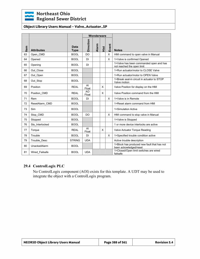
Object Library Users Manual – Valve_Actuator_SP
NEORSD Object Library Users Manual Page 388 of 561 Revision 5.4
Wonderware
Item
Attributes Data Type D
irect
ion
Ala
rm
His
t
Even
t
Notes 63 Open_CMD BOOL DO X HMI command to open valve in Manual
64 Opened BOOL DI X 1=Valve is confirmed Opened
65 Opening BOOL DI 1=Valve has been commanded open and has not reached the open limit
66 Out_Close BOOL 1=Run actuator/motor to CLOSE Valve
67 Out_Open BOOL 1=Run actuator/motor to OPEN Valve
68 Out_Stop BOOL 1=Break seal-in circuit in actuator to STOP Valve motion
69 Position REAL AI Float X Valve Position for display on the HMI
70 Position_CMD REAL AO Float X Valve Position command from the HMI
71 Rem BOOL DI X 1=Valve is in Remote
72 ResetAlarm_CMD BOOL 1=Reset alarm command from HMI
73 Sim BOOL 1=Simulation Active
74 Stop_CMD BOOL DO X HMI command to stop valve in Manual
75 Stopped BOOL 1=Valve is Stopped
76 Sts_Interlocked BOOL 1 or more device interlocks are active
77 Torque REAL AI Float X Valve Actuator Torque Reading
78 Trouble BOOL DI X 1=Specified trouble condition active
79 Trouble_Desc STRING UDA Active trouble description
80 UnackedAlarm BOOL 1=Block has produced new fault that has not been ackowledged/reset
81 Wired_Failsafe BOOL UDA 1=Closed/Open limit switches are wired failsafe
29.4 ControlLogix PLC No ControlLogix component (AOI) exists for this template. A UDT may be used to integrate the object with a ControlLogix program.
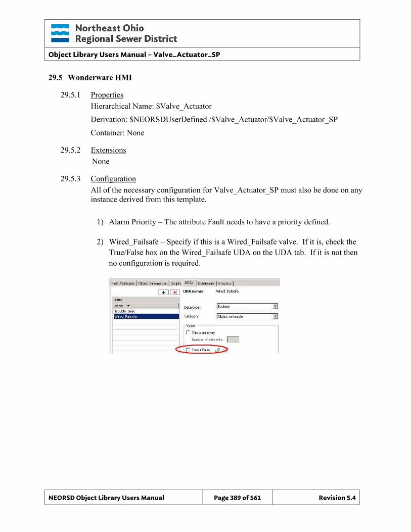
Object Library Users Manual – Valve_Actuator_SP
NEORSD Object Library Users Manual Page 389 of 561 Revision 5.4
29.5 Wonderware HMI
29.5.1 Properties Hierarchical Name: $Valve_Actuator Derivation: $NEORSDUserDefined /$Valve_Actuator/$Valve_Actuator_SP Container: None
29.5.2 Extensions None
29.5.3 Configuration All of the necessary configuration for Valve_Actuator_SP must also be done on any instance derived from this template.
1) Alarm Priority – The attribute Fault needs to have a priority defined.
2) Wired_Failsafe – Specify if this is a Wired_Failsafe valve. If it is, check the
True/False box on the Wired_Failsafe UDA on the UDA tab. If it is not then no configuration is required.

Object Library Users Manual – Valve_Actuator_SP
NEORSD Object Library Users Manual Page 390 of 561 Revision 5.4
3) Attributes that are not used in the configured instance shall use Me.Placeholder to eliminate the point from counting against the systems total I/O scan counts. The allowed attributes for this template include the following:
a. Auto b. Close_CMD c. FailToClose_Fault d. FailToOpen_Fault e. Fault f. HighTemp_Fault g. HighTorque_Fault h. Interlock1 to Interlock5 i. Jam_Fault j. OOS k. OOS_CMD l. Open_CMD m. Position n. REM o. ResetAlarm_CMD p. Stop_CMD q. Torque r. Trouble
4) If ASSET_ID is not in use the initial value will be left blank. Scripting used for ASSET_ID uses the initial value and not ASSET_ID.Description.
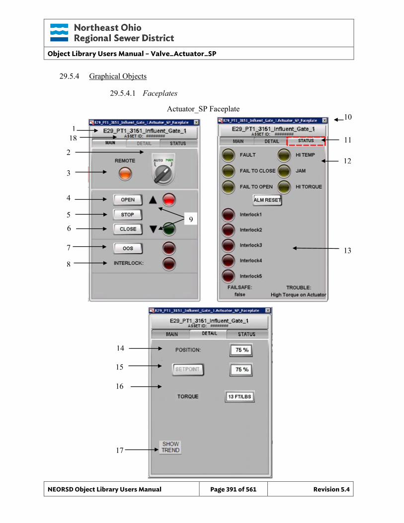
Object Library Users Manual – Valve_Actuator_SP
NEORSD Object Library Users Manual Page 391 of 561 Revision 5.4
Actuator_SP Faceplate
29.5.4 Graphical Objects
29.5.4.1 Faceplates
10
11
12
1
3
2
7
8
6
4
13
5 9
14
15
16
17
18
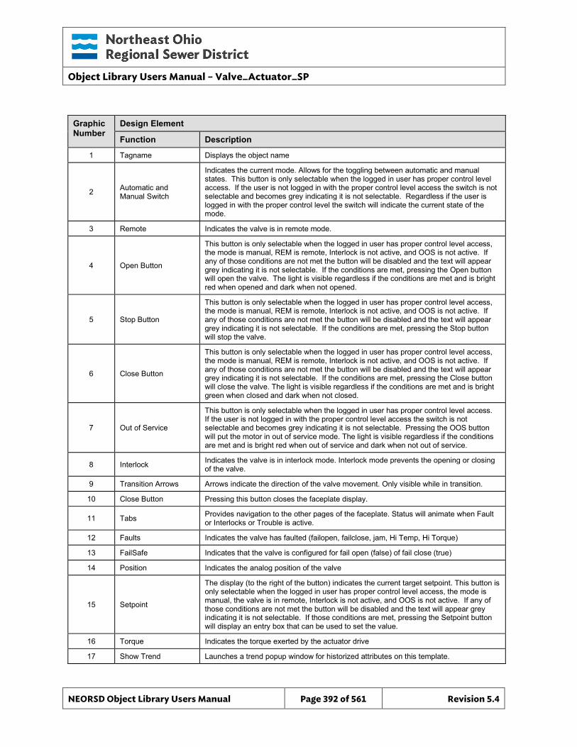
Object Library Users Manual – Valve_Actuator_SP
NEORSD Object Library Users Manual Page 392 of 561 Revision 5.4
Graphic Number
Design Element
Function Description
1 Tagname Displays the object name
2 Automatic and Manual Switch
Indicates the current mode. Allows for the toggling between automatic and manual states. This button is only selectable when the logged in user has proper control level access. If the user is not logged in with the proper control level access the switch is not selectable and becomes grey indicating it is not selectable. Regardless if the user is logged in with the proper control level the switch will indicate the current state of the mode.
3 Remote Indicates the valve is in remote mode.
4 Open Button
This button is only selectable when the logged in user has proper control level access, the mode is manual, REM is remote, Interlock is not active, and OOS is not active. If any of those conditions are not met the button will be disabled and the text will appear grey indicating it is not selectable. If the conditions are met, pressing the Open button will open the valve. The light is visible regardless if the conditions are met and is bright red when opened and dark when not opened.
5 Stop Button
This button is only selectable when the logged in user has proper control level access, the mode is manual, REM is remote, Interlock is not active, and OOS is not active. If any of those conditions are not met the button will be disabled and the text will appear grey indicating it is not selectable. If the conditions are met, pressing the Stop button will stop the valve.
6 Close Button
This button is only selectable when the logged in user has proper control level access, the mode is manual, REM is remote, Interlock is not active, and OOS is not active. If any of those conditions are not met the button will be disabled and the text will appear grey indicating it is not selectable. If the conditions are met, pressing the Close button will close the valve. The light is visible regardless if the conditions are met and is bright green when closed and dark when not closed.
7 Out of Service
This button is only selectable when the logged in user has proper control level access. If the user is not logged in with the proper control level access the switch is not selectable and becomes grey indicating it is not selectable. Pressing the OOS button will put the motor in out of service mode. The light is visible regardless if the conditions are met and is bright red when out of service and dark when not out of service.
8 Interlock Indicates the valve is in interlock mode. Interlock mode prevents the opening or closing of the valve.
9 Transition Arrows Arrows indicate the direction of the valve movement. Only visible while in transition.
10 Close Button Pressing this button closes the faceplate display.
11 Tabs Provides navigation to the other pages of the faceplate. Status will animate when Fault or Interlocks or Trouble is active.
12 Faults Indicates the valve has faulted (failopen, failclose, jam, Hi Temp, Hi Torque)
13 FailSafe Indicates that the valve is configured for fail open (false) of fail close (true)
14 Position Indicates the analog position of the valve
15 Setpoint
The display (to the right of the button) indicates the current target setpoint. This button is only selectable when the logged in user has proper control level access, the mode is manual, the valve is in remote, Interlock is not active, and OOS is not active. If any of those conditions are not met the button will be disabled and the text will appear grey indicating it is not selectable. If those conditions are met, pressing the Setpoint button will display an entry box that can be used to set the value.
16 Torque Indicates the torque exerted by the actuator drive
17 Show Trend Launches a trend popup window for historized attributes on this template.
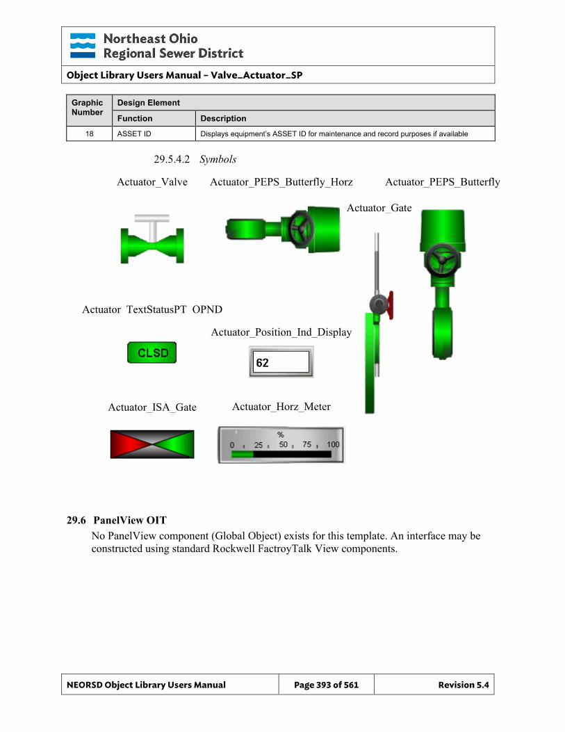
Object Library Users Manual – Valve_Actuator_SP
NEORSD Object Library Users Manual Page 393 of 561 Revision 5.4
Graphic Number
Design Element
Function Description
18 ASSET ID Displays equipment’s ASSET ID for maintenance and record purposes if available
29.5.4.2 Symbols
29.6 PanelView OIT No PanelView component (Global Object) exists for this template. An interface may be constructed using standard Rockwell FactroyTalk View components.
Actuator_Valve Actuator_PEPS_Butterfly_Horz Actuator_PEPS_Butterfly
Actuator_TextStatusPT_OPND
Actuator_Gate
Actuator_ISA_Gate
Actuator_Position_Ind_Display
Actuator_Horz_Meter
Object Library Users Manual – Valve_Analog
NEORSD Object Library Users Manual Page 394 of 561 Revision 5.4
30.0 Valve_Analog
30.1 Introduction The Valve_Analog template provides a standard representation for the control, operation, indication, and alarming of variable position (analog) valves and gates throughout the NEORSD control systems. Use the Valve_Analog template if the below statement is true:
• If trying to represent a valve or gate with variable position feedback and control.
Do not use the Valve_Analog template:
• If the valve has a position feedback (%) but also requires “Open/Close” or “Stop” commands. If “Open/Close” or “Stop” commands are required, use Valve_Actuator.
• If the valve has no control. If representing a valve with position feedback but no control, use Valve_Analog_Indicator.
• If the valve is not variable position. If the valve is a two-state valve, use Valve_Discrete instead.
30.2 Object Features
30.2.1 Status Indications This object provides the following indications for the valve/gate:
• Opened/closed limit switch feedback • Analog position feedback • Auto/Manual mode indication • Remote/Local mode feedback • In-Service/Out-Of-Service mode indication
30.2.2 Alarming This object supports the following alarms:
• Alarm if the valve is neither opened nor closed for a set period of time • Alarm if the valve is commanded to a position and does not reach it in a
set period of time • Alarm if the valve is commanded to fully-open and does not in a set period
of time • Alarm if the valve is commanded to fully-close and does not in a set
period of time • Alarm if the object loses feedback from failsafe limit switches • Alarm if an externally generated fault condition is true
When a fault condition occurs, the valve will remain at its current position and the object will enter manual mode.
Object Library Users Manual – Valve_Analog
NEORSD Object Library Users Manual Page 395 of 561 Revision 5.4
30.2.3 Control This object supports the following control for the valve:
• Command to a position setpoint • Auto/Manual mode toggle • Resettable alarms • Out-of-Service/In-Service mode toggle • Interlocking to prevent operation
30.2.4 Simulation This object supports simulation of the running feedback.
30.2.5 Trouble This object supports hardware trouble indication.

Object Library Users Manual – Valve_Analog
NEORSD Object Library Users Manual Page 396 of 561 Revision 5.4
30.3 Object Attributes
AOI Wonderware
Item
Attributes Data Type D
irect
ion
Dire
ctio
n
Ala
rm
His
t
Even
t
Notes 1 Auto BOOL OUT DI X 1=Auto Mode Active
2 Auto_CMD BOOL IN DO X HMI command to place valve in Auto
3 Auto_Reset_Pulse FLOAT IN UDA The counter used in script with PulseTime for setpoint unlatch.
4 Cfg_AutoOnlyDevice BOOL IN 1=Auto only device, device cannot be placed in manual
5 Cfg_CloseTime DINT IN Delay before fault after commanded fully close and limit switch feedback not received
6 Cfg_DisableAlarming BOOL IN 1=Disables all fault alarms
7 Cfg_FaultActiveTime DINT IN Delay before device fault is reset if not configured to latch
8 Cfg_FBFailTime DINT IN Delay before fault if both failsafe feedbacks lose input
9 Cfg_FBWiredFailsafe BOOL IN 1=Closed/Open limit switches are wired failsafe
10 Cfg_FullClosedPosition REAL IN Valve Position At Which Valve is Considered Fully Closed
11 Cfg_FullOpenPosition REAL IN Valve Position At Which Valve is Considered Fully Open
12 Cfg_LatchFault BOOL IN 1=Require HMI Reset_CMD toggle to reset fault, 0 =Automatically clear fault after configurable delay
13 Cfg_ManOnlyDevice BOOL IN 1=Manual only device, device cannot be placed in auto
14 Cfg_MaxPositionCommand REAL IN High limit of commanded output
15 Cfg_MinPositionCommand REAL IN Low limit of commanded output
16 Cfg_OpenTime DINT IN Delay before fault after commanded fully open and feedback not received
17 Cfg_PartialOpenDeadband REAL IN Deadband around Fully Closed/Open Position Settings to prevent false Partial Open Faults
18 Cfg_PartialOpenTime DINT IN Delay before fault after commanded partial open and feedback not received
19 Cfg_PosFBDeadband REAL IN Deadband in evaluating whether position feedback matches the valve command
20 Cfg_PositionCheckTime DINT IN Delay before fault after commanded position feedback is not reached within deadband
21 Cfg_ReverseActing BOOL IN 1=Reverse acting (fail open), 0=Normal (fail close)
22 Cfg_Sim BOOL IN 1=Simulate working valve; 0=Open/Close/ Monitor actual valve
23 Cfg_UseClosedLS BOOL IN 1=Valve Closed LS should be used for failure checking. Default = 0
24 Cfg_UseOpenLS BOOL IN 1=Valve Open LS should be used for failure checking. Default = 0
25 Cfg_UsePositionFB BOOL IN 1=Valve Position FB should be used for failure checking. Default = 0
26 Cfg_UseRemote BOOL IN 1=Valve has LOCAL/OFF/REMOTE control
27 Closed BOOL OUT DI X 1=Valve is confirmed fully Closed
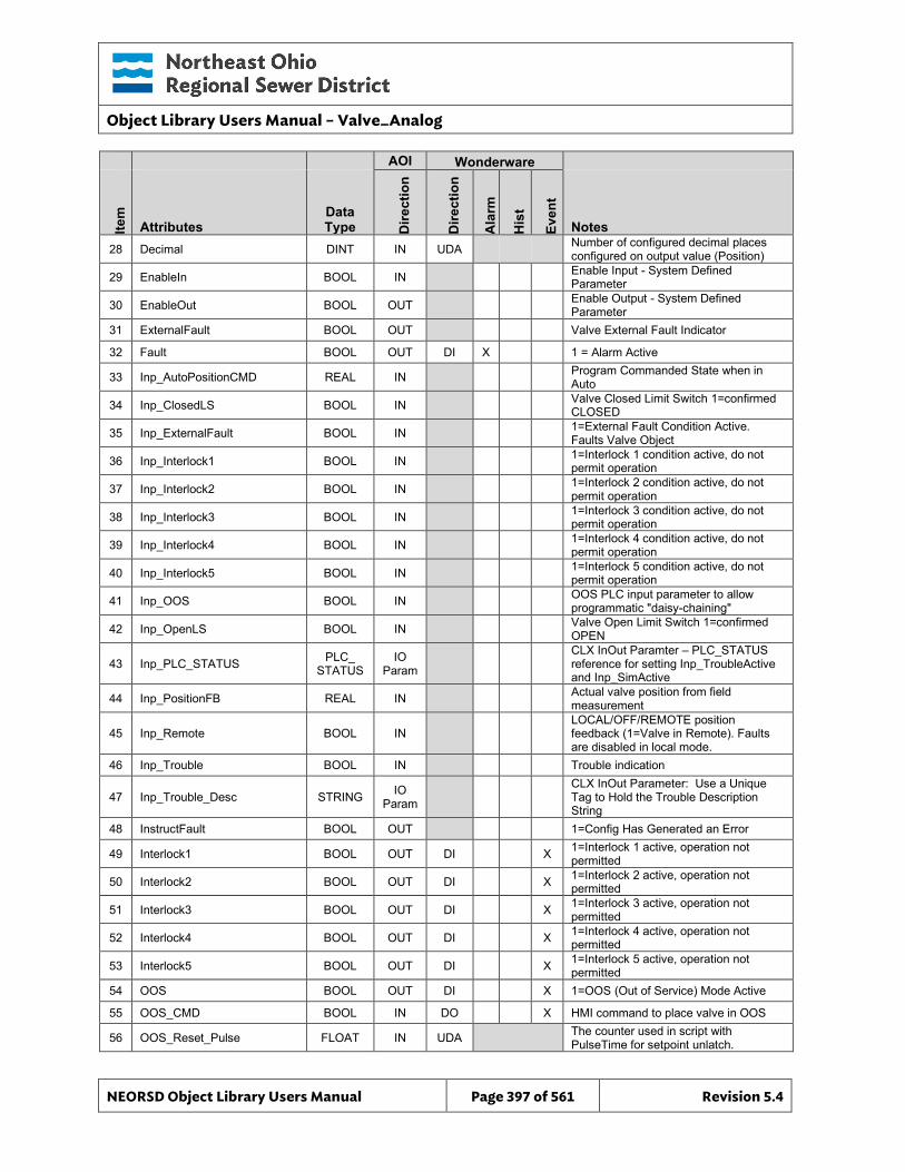
Object Library Users Manual – Valve_Analog
NEORSD Object Library Users Manual Page 397 of 561 Revision 5.4
AOI Wonderware
Item
Attributes Data Type D
irect
ion
Dire
ctio
n
Ala
rm
His
t
Even
t
Notes 28 Decimal DINT IN UDA Number of configured decimal places
configured on output value (Position)
29 EnableIn BOOL IN Enable Input - System Defined Parameter
30 EnableOut BOOL OUT Enable Output - System Defined Parameter
31 ExternalFault BOOL OUT Valve External Fault Indicator
32 Fault BOOL OUT DI X 1 = Alarm Active
33 Inp_AutoPositionCMD REAL IN Program Commanded State when in Auto
34 Inp_ClosedLS BOOL IN Valve Closed Limit Switch 1=confirmed CLOSED
35 Inp_ExternalFault BOOL IN 1=External Fault Condition Active. Faults Valve Object
36 Inp_Interlock1 BOOL IN 1=Interlock 1 condition active, do not permit operation
37 Inp_Interlock2 BOOL IN 1=Interlock 2 condition active, do not permit operation
38 Inp_Interlock3 BOOL IN 1=Interlock 3 condition active, do not permit operation
39 Inp_Interlock4 BOOL IN 1=Interlock 4 condition active, do not permit operation
40 Inp_Interlock5 BOOL IN 1=Interlock 5 condition active, do not permit operation
41 Inp_OOS BOOL IN OOS PLC input parameter to allow programmatic "daisy-chaining"
42 Inp_OpenLS BOOL IN Valve Open Limit Switch 1=confirmed OPEN
43 Inp_PLC_STATUS PLC_ STATUS
IO Param
CLX InOut Paramter – PLC_STATUS reference for setting Inp_TroubleActive and Inp_SimActive
44 Inp_PositionFB REAL IN Actual valve position from field measurement
45 Inp_Remote BOOL IN LOCAL/OFF/REMOTE position feedback (1=Valve in Remote). Faults are disabled in local mode.
46 Inp_Trouble BOOL IN Trouble indication
47 Inp_Trouble_Desc STRING IO Param
CLX InOut Parameter: Use a Unique Tag to Hold the Trouble Description String
48 InstructFault BOOL OUT 1=Config Has Generated an Error
49 Interlock1 BOOL OUT DI X 1=Interlock 1 active, operation not permitted
50 Interlock2 BOOL OUT DI X 1=Interlock 2 active, operation not permitted
51 Interlock3 BOOL OUT DI X 1=Interlock 3 active, operation not permitted
52 Interlock4 BOOL OUT DI X 1=Interlock 4 active, operation not permitted
53 Interlock5 BOOL OUT DI X 1=Interlock 5 active, operation not permitted
54 OOS BOOL OUT DI X 1=OOS (Out of Service) Mode Active
55 OOS_CMD BOOL IN DO X HMI command to place valve in OOS
56 OOS_Reset_Pulse FLOAT IN UDA The counter used in script with PulseTime for setpoint unlatch.
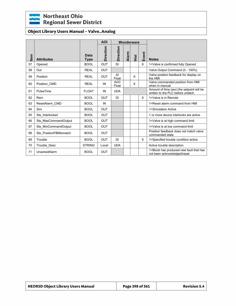
Object Library Users Manual – Valve_Analog
NEORSD Object Library Users Manual Page 398 of 561 Revision 5.4
AOI Wonderware
Item
Attributes Data Type D
irect
ion
Dire
ctio
n
Ala
rm
His
t
Even
t
Notes 57 Opened BOOL OUT DI X 1=Valve is confirmed fully Opened
58 Out REAL OUT Valve Output Command (0 - 100%)
59 Position REAL OUT AI Float X Valve position feedback for display on
the HMI
60 Position_CMD REAL IN AI/O Float X Valve commanded position from HMI
when in manual
61 PulseTime FLOAT IN UDA Amount of time (sec) the setpoint will be written to the PLC before unlatch.
62 Rem BOOL OUT DI X 1=Valve is in Remote
63 ResetAlarm_CMD BOOL IN 1=Reset alarm command from HMI
64 Sim BOOL OUT 1=Simulation Active
65 Sts_Interlocked BOOL OUT 1 or more device interlocks are active
66 Sts_MaxCommandOutput BOOL OUT 1=Valve is at high command limit
67 Sts_MinCommandOutput BOOL OUT 1=Valve is at low command limit
68 Sts_PositionFBMismatch BOOL OUT Position feedback does not match valve commanded state
69 Trouble BOOL OUT DI X 1=Specified trouble condition active
70 Trouble_Desc STRING Local UDA Active trouble description
71 UnackedAlarm BOOL OUT 1=Block has produced new fault that has not been acknowledged/reset
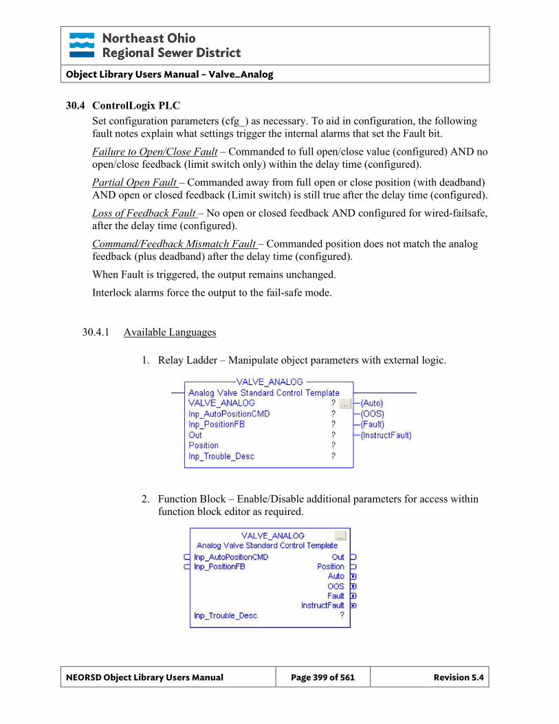
Object Library Users Manual – Valve_Analog
NEORSD Object Library Users Manual Page 399 of 561 Revision 5.4
30.4 ControlLogix PLC Set configuration parameters (cfg_) as necessary. To aid in configuration, the following fault notes explain what settings trigger the internal alarms that set the Fault bit. Failure to Open/Close Fault – Commanded to full open/close value (configured) AND no open/close feedback (limit switch only) within the delay time (configured). Partial Open Fault – Commanded away from full open or close position (with deadband) AND open or closed feedback (Limit switch) is still true after the delay time (configured). Loss of Feedback Fault – No open or closed feedback AND configured for wired-failsafe, after the delay time (configured). Command/Feedback Mismatch Fault – Commanded position does not match the analog feedback (plus deadband) after the delay time (configured). When Fault is triggered, the output remains unchanged. Interlock alarms force the output to the fail-safe mode.
30.4.1 Available Languages
1. Relay Ladder – Manipulate object parameters with external logic.
2. Function Block – Enable/Disable additional parameters for access within function block editor as required.
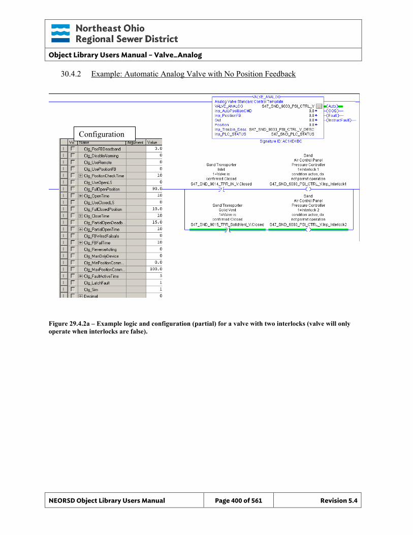
Object Library Users Manual – Valve_Analog
NEORSD Object Library Users Manual Page 400 of 561 Revision 5.4
30.4.2 Example: Automatic Analog Valve with No Position Feedback
Figure 29.4.2a – Example logic and configuration (partial) for a valve with two interlocks (valve will only operate when interlocks are false).
Configuration
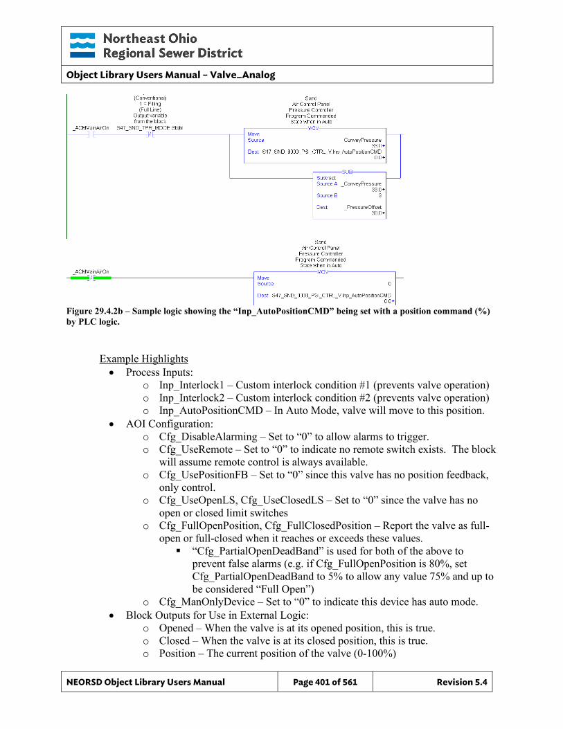
Object Library Users Manual – Valve_Analog
NEORSD Object Library Users Manual Page 401 of 561 Revision 5.4
Figure 29.4.2b – Sample logic showing the “Inp_AutoPositionCMD” being set with a position command (%) by PLC logic.
Example Highlights • Process Inputs:
o Inp_Interlock1 – Custom interlock condition #1 (prevents valve operation) o Inp_Interlock2 – Custom interlock condition #2 (prevents valve operation) o Inp_AutoPositionCMD – In Auto Mode, valve will move to this position.
• AOI Configuration: o Cfg_DisableAlarming – Set to “0” to allow alarms to trigger. o Cfg_UseRemote – Set to “0” to indicate no remote switch exists. The block
will assume remote control is always available. o Cfg_UsePositionFB – Set to “0” since this valve has no position feedback,
only control. o Cfg_UseOpenLS, Cfg_UseClosedLS – Set to “0” since the valve has no
open or closed limit switches o Cfg_FullOpenPosition, Cfg_FullClosedPosition – Report the valve as full-
open or full-closed when it reaches or exceeds these values. “Cfg_PartialOpenDeadBand” is used for both of the above to
prevent false alarms (e.g. if Cfg_FullOpenPosition is 80%, set Cfg_PartialOpenDeadBand to 5% to allow any value 75% and up to be considered “Full Open”)
o Cfg_ManOnlyDevice – Set to “0” to indicate this device has auto mode. • Block Outputs for Use in External Logic:
o Opened – When the valve is at its opened position, this is true. o Closed – When the valve is at its closed position, this is true. o Position – The current position of the valve (0-100%)
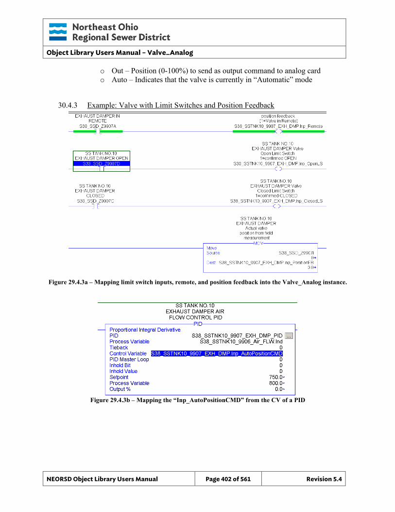
Object Library Users Manual – Valve_Analog
NEORSD Object Library Users Manual Page 402 of 561 Revision 5.4
o Out – Position (0-100%) to send as output command to analog card o Auto – Indicates that the valve is currently in “Automatic” mode
30.4.3 Example: Valve with Limit Switches and Position Feedback
Figure 29.4.3a – Mapping limit switch inputs, remote, and position feedback into the Valve_Analog instance.
Figure 29.4.3b – Mapping the “Inp_AutoPositionCMD” from the CV of a PID
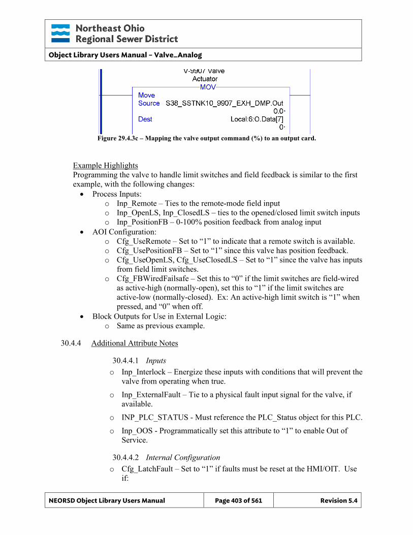
Object Library Users Manual – Valve_Analog
NEORSD Object Library Users Manual Page 403 of 561 Revision 5.4
Figure 29.4.3c – Mapping the valve output command (%) to an output card.
Example Highlights Programming the valve to handle limit switches and field feedback is similar to the first example, with the following changes: • Process Inputs:
o Inp_Remote – Ties to the remote-mode field input o Inp_OpenLS, Inp_ClosedLS – ties to the opened/closed limit switch inputs o Inp_PositionFB – 0-100% position feedback from analog input
• AOI Configuration: o Cfg_UseRemote – Set to “1” to indicate that a remote switch is available. o Cfg_UsePositionFB – Set to “1” since this valve has position feedback. o Cfg_UseOpenLS, Cfg_UseClosedLS – Set to “1” since the valve has inputs
from field limit switches. o Cfg_FBWiredFailsafe – Set this to “0” if the limit switches are field-wired
as active-high (normally-open), set this to “1” if the limit switches are active-low (normally-closed). Ex: An active-high limit switch is “1” when pressed, and “0” when off.
• Block Outputs for Use in External Logic: o Same as previous example.
30.4.4 Additional Attribute Notes
30.4.4.1 Inputs o Inp_Interlock – Energize these inputs with conditions that will prevent the
valve from operating when true. o Inp_ExternalFault – Tie to a physical fault input signal for the valve, if
available. o INP_PLC_STATUS - Must reference the PLC_Status object for this PLC. o Inp_OOS - Programmatically set this attribute to “1” to enable Out of
Service.
30.4.4.2 Internal Configuration o Cfg_LatchFault – Set to “1” if faults must be reset at the HMI/OIT. Use
if:
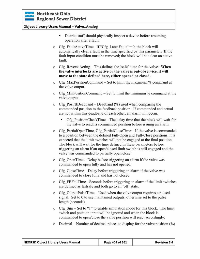
Object Library Users Manual – Valve_Analog
NEORSD Object Library Users Manual Page 404 of 561 Revision 5.4
District staff should physically inspect a device before resuming operation after a fault.
o Cfg_FaultActiveTime –If “Cfg_LatchFault” = 0, the block will automatically clear a fault in the time specified by this parameter. If the fault input condition must be removed; the block will not clear an active fault.
o Cfg_ReverseActing – This defines the ‘safe’ state for the valve. When the valve interlocks are active or the valve is out-of-service, it will move to the state defined here, either opened or closed.
o Cfg_MaxPositionCommand – Set to limit the maximum % command at the valve output.
o Cfg_MinPositionCommand – Set to limit the minimum % command at the valve output.
o Cfg_PosFBDeadband – Deadband (%) used when comparing the commanded position to the feedback position. If commanded and actual are not within this deadband of each other, an alarm will occur. Cfg_PositionCheckTime – The delay time that the block will wait for
the valve to reach a commanded position before issuing an alarm. o Cfg_PartialOpenTime, Cfg_PartialCloseTime – If the valve is commanded
to a position between the defined Full-Open and Full-Close positions, it is expected that the limit switches will not be engaged at the final position. The block will wait for the time defined in these parameters before triggering an alarm if an open/closed limit switch is still engaged and the valve was commanded to partially open/close.
o Cfg_OpenTime – Delay before triggering an alarm if the valve was commanded to open fully and has not opened.
o Cfg_CloseTime – Delay before triggering an alarm if the valve was commanded to close fully and has not closed.
o Cfg_FBFailTime - Seconds before triggering an alarm if the limit switches are defined as failsafe and both go to an ‘off’ state.
o Cfg_OutputPulseTime – Used when the valve output requires a pulsed signal. Set to 0 to use maintained outputs, otherwise set to the pulse length (seconds).
o Cfg_Sim – Set to “1” to enable simulation mode for this block. The limit switch and position input will be ignored and when the block is commanded to open/close the valve position will react accordingly.
o Decimal – Number of decimal places to display for the valve position (%)
Object Library Users Manual – Valve_Analog
NEORSD Object Library Users Manual Page 405 of 561 Revision 5.4
o Cfg_AutoOnlyDevice – Set to “1” to prevent the device from operating in remote manual mode. Cfg_ManOnlyDevice must be set to “0”.
30.4.4.3 Outputs o Sts_Interlocked – Indicates that this instance cannot operate as an
interlock condition is not satisfied. o OOS – Indicates that this instance is out-of-service o Auto – Indicates that the valve is in automatic control mode o Fault – Indicates that any fault condition is active on the valve. This
includes internally generated alarms (time-to-open/close, etc) and the external alarm, if used. When the valve faults, it will remain in its current position and enter
manual mode.
30.5 Wonderware HMI
30.5.1 Properties Hierarchical Name: $Valve_Analog Derivation: Derived from $NEORSDUserDefined /$Valve_Analog_Indicator Container: None
30.5.2 Extensions: None
30.5.3 Configuration All of the necessary configuration for Valve_Analog must also be done on any instance derived from this template.
1) Alarm Priority – The attribute Fault needs to have a priority defined.
2) Decimal – Defined as how many decimal points are shown. The default value
is 0 and need to be specified on the instance.
3) Attributes that are not used in the configured instance shall use Me.Placeholder to eliminate the point from counting against the systems total I/O scan counts. The allowed attributes for this template include the following:
a. Interlock1 to Interlock5 b. OOS c. OOS_CMD
Object Library Users Manual – Valve_Analog
NEORSD Object Library Users Manual Page 406 of 561 Revision 5.4
d. Fault e. Auto f. REM g. Position_CMD h. Trouble
4) If ASSET_ID is not in use the initial value will be left blank. Scripting used for ASSET_ID uses the initial value and not ASSET_ID.Description.
Note: The default Engineering Units for Position is %. This can be changed but is not required.
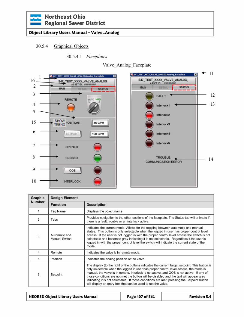
Object Library Users Manual – Valve_Analog
NEORSD Object Library Users Manual Page 407 of 561 Revision 5.4
30.5.4 Graphical Objects
30.5.4.1 Faceplates
Graphic Number
Design Element
Function Description
1 Tag Name Displays the object name
2 Tabs Provides navigation to the other sections of the faceplate. The Status tab will animate if there is a fault, trouble or an interlock active.
3 Automatic and Manual Switch
Indicates the current mode. Allows for the toggling between automatic and manual states. This button is only selectable when the logged in user has proper control level access. If the user is not logged in with the proper control level access the switch is not selectable and becomes grey indicating it is not selectable. Regardless if the user is logged in with the proper control level the switch will indicate the current state of the mode.
4 Remote Indicates the valve is in remote mode.
5 Position Indicates the analog position of the valve
6 Setpoint
The display (to the right of the button) indicates the current target setpoint. This button is only selectable when the logged in user has proper control level access, the mode is manual, the valve is in remote, Interlock is not active, and OOS is not active. If any of those conditions are not met the button will be disabled and the text will appear grey indicating it is not selectable. If those conditions are met, pressing the Setpoint button will display an entry box that can be used to set the value.
Valve_Analog_Faceplate
11 1
3
4
6
8
5
7
12
14
2
13
10
9
15
16
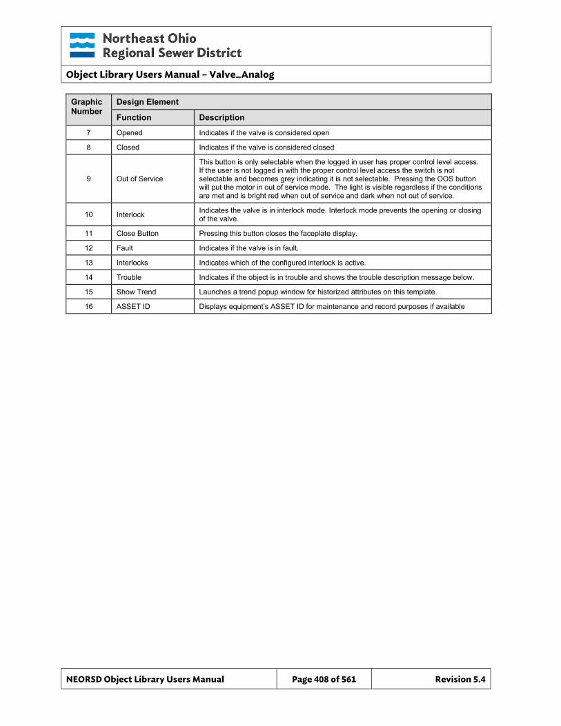
Object Library Users Manual – Valve_Analog
NEORSD Object Library Users Manual Page 408 of 561 Revision 5.4
Graphic Number
Design Element
Function Description
7 Opened Indicates if the valve is considered open
8 Closed Indicates if the valve is considered closed
9 Out of Service
This button is only selectable when the logged in user has proper control level access. If the user is not logged in with the proper control level access the switch is not selectable and becomes grey indicating it is not selectable. Pressing the OOS button will put the motor in out of service mode. The light is visible regardless if the conditions are met and is bright red when out of service and dark when not out of service.
10 Interlock Indicates the valve is in interlock mode. Interlock mode prevents the opening or closing of the valve.
11 Close Button Pressing this button closes the faceplate display.
12 Fault Indicates if the valve is in fault.
13 Interlocks Indicates which of the configured interlock is active.
14 Trouble Indicates if the object is in trouble and shows the trouble description message below.
15 Show Trend Launches a trend popup window for historized attributes on this template.
16 ASSET ID Displays equipment’s ASSET ID for maintenance and record purposes if available
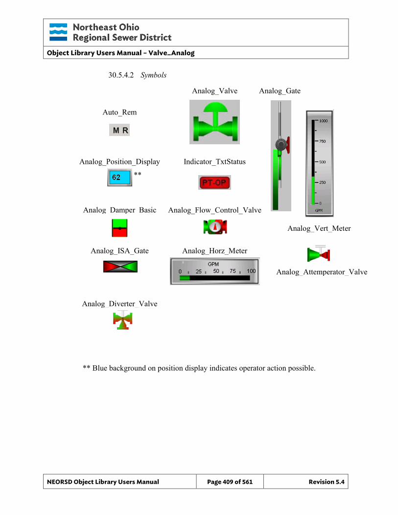
Object Library Users Manual – Valve_Analog
NEORSD Object Library Users Manual Page 409 of 561 Revision 5.4
Analog_Vert_Meter
Analog_Horz_Meter
Analog_Attemperator_Valve
30.5.4.2 Symbols
**
** Blue background on position display indicates operator action possible.
Auto_Rem
Analog_Valve Analog_Gate
Analog_Position_Display Indicator_TxtStatus
Analog_Damper_Basic Analog_Flow_Control_Valve
Analog_ISA_Gate
Analog_Diverter_Valve
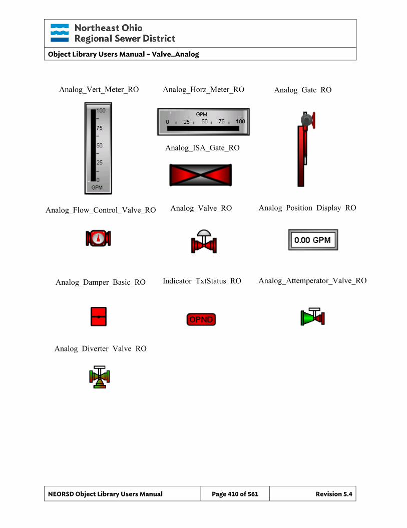
Object Library Users Manual – Valve_Analog
NEORSD Object Library Users Manual Page 410 of 561 Revision 5.4
Analog_Vert_Meter_RO Analog_Horz_Meter_RO
Analog_Gate_RO
Analog_ISA_Gate_RO
Analog_Flow_Control_Valve_RO Analog_Valve_RO
Analog_Damper_Basic_RO Indicator_TxtStatus_RO
Analog_Position_Display_RO
Analog_Attemperator_Valve_RO
Analog_Diverter_Valve_RO
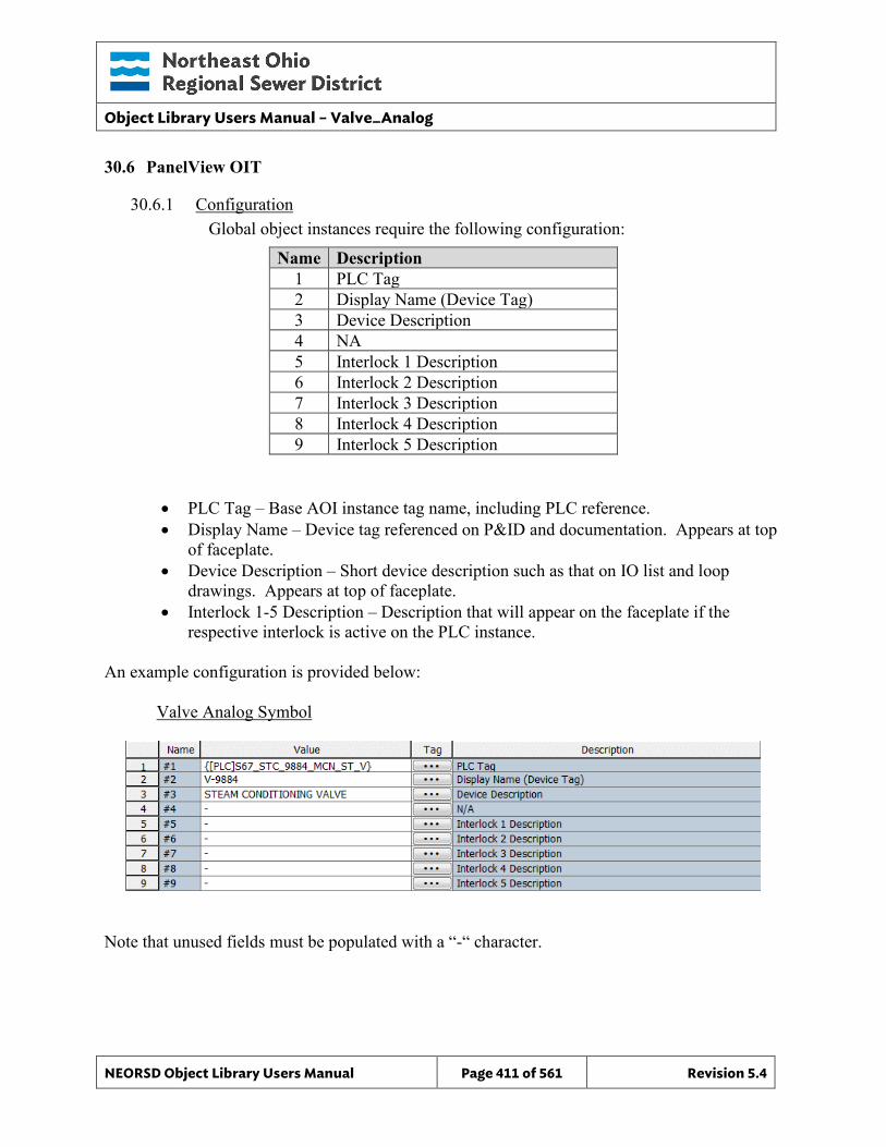
Object Library Users Manual – Valve_Analog
NEORSD Object Library Users Manual Page 411 of 561 Revision 5.4
30.6 PanelView OIT
30.6.1 Configuration Global object instances require the following configuration:
Name Description 1 PLC Tag 2 Display Name (Device Tag) 3 Device Description 4 NA 5 Interlock 1 Description 6 Interlock 2 Description 7 Interlock 3 Description 8 Interlock 4 Description 9 Interlock 5 Description
• PLC Tag – Base AOI instance tag name, including PLC reference. • Display Name – Device tag referenced on P&ID and documentation. Appears at top
of faceplate. • Device Description – Short device description such as that on IO list and loop
drawings. Appears at top of faceplate. • Interlock 1-5 Description – Description that will appear on the faceplate if the
respective interlock is active on the PLC instance.
An example configuration is provided below: Valve Analog Symbol
Note that unused fields must be populated with a “-“ character.
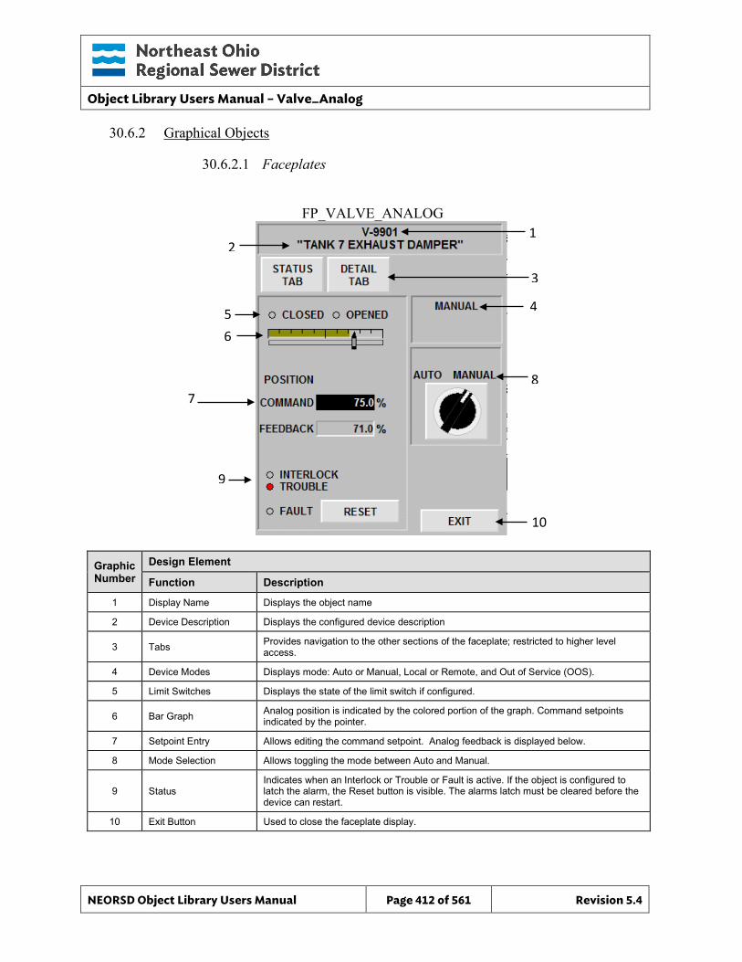
Object Library Users Manual – Valve_Analog
NEORSD Object Library Users Manual Page 412 of 561 Revision 5.4
FP_VALVE_ANALOG 1
3
10
8
4
30.6.2 Graphical Objects
30.6.2.1 Faceplates
Graphic Number
Design Element
Function Description
1 Display Name Displays the object name
2 Device Description Displays the configured device description
3 Tabs Provides navigation to the other sections of the faceplate; restricted to higher level access.
4 Device Modes Displays mode: Auto or Manual, Local or Remote, and Out of Service (OOS).
5 Limit Switches Displays the state of the limit switch if configured.
6 Bar Graph Analog position is indicated by the colored portion of the graph. Command setpoints indicated by the pointer.
7 Setpoint Entry Allows editing the command setpoint. Analog feedback is displayed below.
8 Mode Selection Allows toggling the mode between Auto and Manual.
9 Status Indicates when an Interlock or Trouble or Fault is active. If the object is configured to latch the alarm, the Reset button is visible. The alarms latch must be cleared before the device can restart.
10 Exit Button Used to close the faceplate display.
2
5
7
9
6
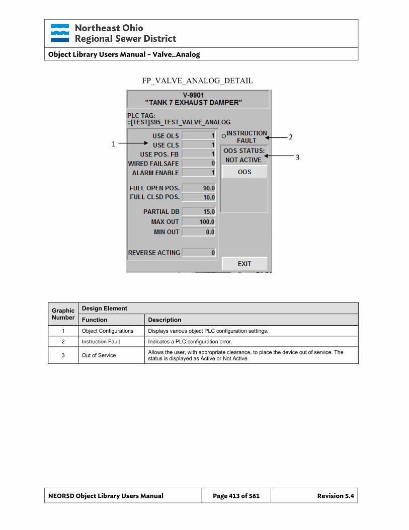
Object Library Users Manual – Valve_Analog
NEORSD Object Library Users Manual Page 413 of 561 Revision 5.4
FP_VALVE_ANALOG_DETAIL
2
3
Graphic Number
Design Element
Function Description
1 Object Configurations Displays various object PLC configuration settings.
2 Instruction Fault Indicates a PLC configuration error.
3 Out of Service Allows the user, with appropriate clearance, to place the device out of service. The status is displayed as Active or Not Active.
1
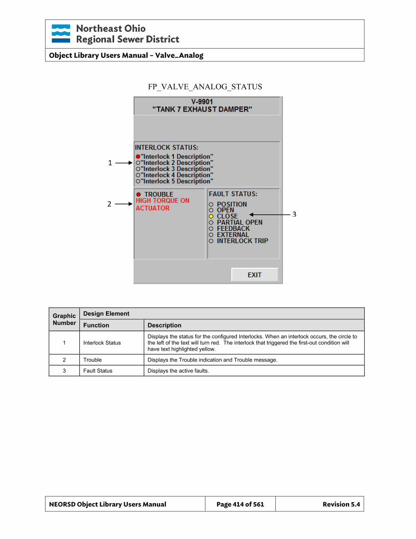
Object Library Users Manual – Valve_Analog
NEORSD Object Library Users Manual Page 414 of 561 Revision 5.4
FP_VALVE_ANALOG_STATUS
3
Graphic Number
Design Element
Function Description
1 Interlock Status Displays the status for the configured Interlocks. When an interlock occurs, the circle to the left of the text will turn red. The interlock that triggered the first-out condition will have text highlighted yellow.
2 Trouble Displays the Trouble indication and Trouble message.
3 Fault Status Displays the active faults.
1
2
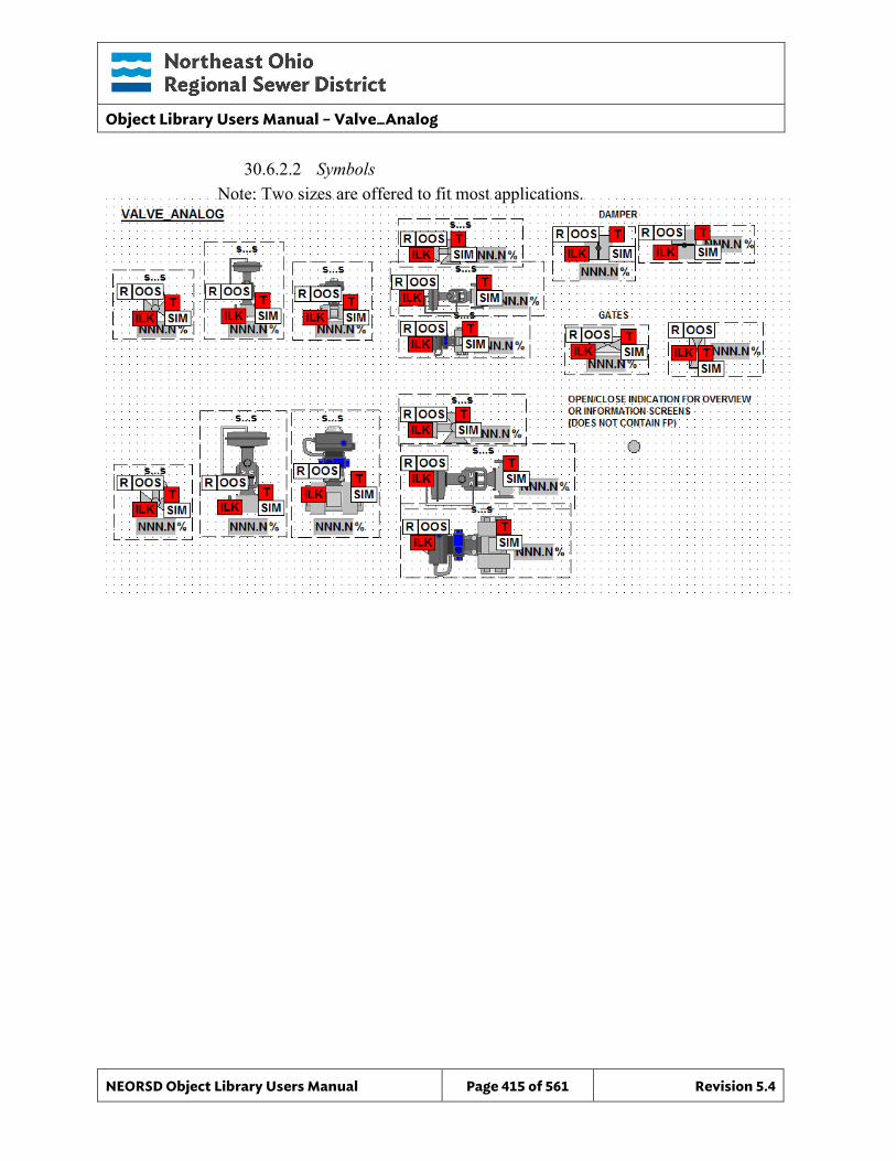
Object Library Users Manual – Valve_Analog
NEORSD Object Library Users Manual Page 415 of 561 Revision 5.4
30.6.2.2 Symbols Note: Two sizes are offered to fit most applications.
Object Library Users Manual – Valve_Analog_Indicator
NEORSD Object Library Users Manual Page 416 of 561 Revision 5.4
31.0 Valve_Analog_Indicator
31.1 Introduction The Valve_Analog_Indicator template provides a standard representation for the indication and alarming of a locally controlled (no remote operation) variable position (analog) valve or gate within the NEORSD control systems. Use the Valve_Analog_Indicator template if the below statement is true:
• If trying to represent a valve or gate with variable position feedback but no control.
Do not use the Valve_Analog_Indicator template:
• If the valve is remotely controllable (from HMI/OIT). If representing a valve with position feedback and position (%) control, use Valve_Analog instead.
• If the valve is not variable position. If the valve is a two-state valve, use Valve_Discrete_Indicator instead.
31.2 Object Features
31.2.1 Status Indications This object provides the following indications for the valve/gate:
• Opened/closed limit switch feedback • Analog position feedback • In-Service/Out-Of-Service mode indication
31.2.2 Alarming This object supports the following alarms:
• Alarm if the valve is neither opened nor closed for a set period of time • Alarm if the object loses feedback from failsafe limit switches • Alarm if an externally generated fault condition is true
31.2.3 Control This object supports the following control for the valve:
• Out-of-Service/In-Service mode toggle
31.2.4 Simulation This object supports simulation of the running feedback.
31.2.5 Trouble This object supports hardware trouble indication.
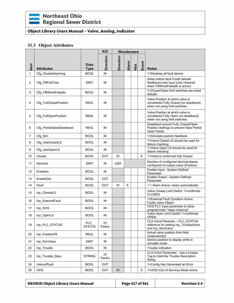
Object Library Users Manual – Valve_Analog_Indicator
NEORSD Object Library Users Manual Page 417 of 561 Revision 5.4
31.3 Object Attributes
AOI Wonderware
Item
Attributes Data Type D
irect
ion
Dire
ctio
n
Ala
rm
His
t
Even
t
Notes 1 Cfg_DisableAlarming BOOL IN 1=Disables all fault alarms
2 Cfg_FBFailTime DINT IN Delay before fault if both failsafe feedbacks lose input (only checked when FBWiredFailsafe is active)
3 Cfg_FBWiredFailsafe BOOL IN 1=Closed/Open limit switches are wired failsafe
4 Cfg_FullClosedPosition REAL IN Valve Position at which valve is considered Fully Closed (no deadband) when not using limit switches.
5 Cfg_FullOpenPosition REAL IN Valve Position at which valve is considered Fully Open (no deadband) when not using limit switches.
6 Cfg_PartialOpenDeadband REAL IN Deadband around Fully Closed/Open Position Settings to prevent false Partial Open Faults
7 Cfg_Sim BOOL IN 1=Simulate position feedback
8 Cfg_UseClosedLS BOOL IN 1=Valve Closed LS should be used for failure checking
9 Cfg_UseOpenLS BOOL IN 1=Valve Open LS should be used for failure checking
10 Closed BOOL OUT DI X 1=Valve is confirmed fully Closed
11 Decimal DINT IN UDA Number of configured decimal places configured on output value (Position)
12 EnableIn BOOL IN Enable Input - System Defined Parameter
13 EnableOut BOOL OUT Enable Output - System Defined Parameter
14 Fault BOOL OUT DI X 1 = Alarm Active; clears automatically
15 Inp_ClosedLS BOOL IN Valve Closed Limit Switch 1=confirmed CLOSED
16 Inp_ExternalFault BOOL IN 1=External Fault Condition Active. Faults Valve Object
17 Inp_OOS BOOL IN OOS PLC input parameter to allow programmatic "daisy-chaining"
18 Inp_OpenLS BOOL IN Valve Open Limit Switch 1=confirmed OPEN
19 Inp_PLC_STATUS PLC_ STATUS
IO Param
CLX InOut Paramter – PLC_STATUS reference for setting Inp_TroubleActive and Inp_SimActive
20 Inp_PositionFB REAL IN Actual valve position from field measurement
21 Inp_SimValue DINT IN Device position to display while in simulate mode
22 Inp_Trouble BOOL IN Trouble indication
23 Inp_Trouble_Desc STRING IO Param
CLX InOut Parameter: Use a Unique Tag to Hold the Trouble Description String
24 InstructFault BOOL OUT 1=Config Has Generated an Error
25 OOS BOOL OUT DI X 1=OOS (Out of Service) Mode Active
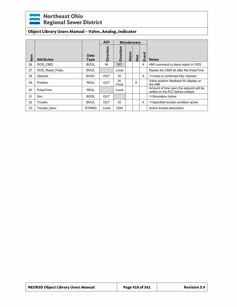
Object Library Users Manual – Valve_Analog_Indicator
NEORSD Object Library Users Manual Page 418 of 561 Revision 5.4
AOI Wonderware
Item
Attributes Data Type D
irect
ion
Dire
ctio
n
Ala
rm
His
t
Even
t
Notes 26 OOS_CMD BOOL IN DO X HMI command to place object in OOS
27 OOS_Reset_Pulse BOOL Local Resets the CMD bit after Me.PulseTime
28 Opened BOOL OUT DI X 1=Valve is confirmed fully Opened
29 Position REAL OUT AI Float X Valve position feedback for display on
the HMI
30 PulseTime REAL Local Amount of time (sec) the setpoint will be written to the PLC before unlatch
31 Sim BOOL OUT 1=Simulation Active
32 Trouble BOOL OUT DI X 1=Specified trouble condition active
33 Trouble_Desc STRING Local UDA Active trouble description
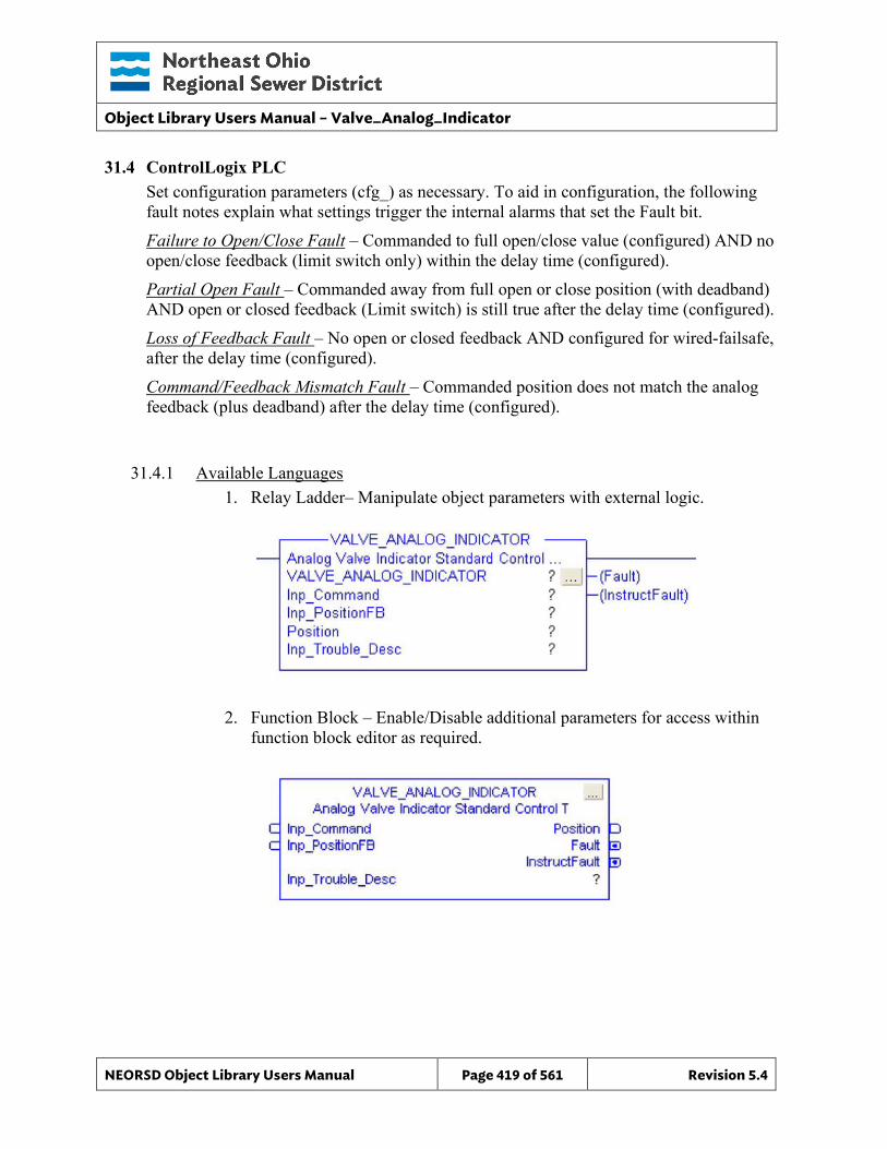
Object Library Users Manual – Valve_Analog_Indicator
NEORSD Object Library Users Manual Page 419 of 561 Revision 5.4
31.4 ControlLogix PLC Set configuration parameters (cfg_) as necessary. To aid in configuration, the following fault notes explain what settings trigger the internal alarms that set the Fault bit. Failure to Open/Close Fault – Commanded to full open/close value (configured) AND no open/close feedback (limit switch only) within the delay time (configured). Partial Open Fault – Commanded away from full open or close position (with deadband) AND open or closed feedback (Limit switch) is still true after the delay time (configured). Loss of Feedback Fault – No open or closed feedback AND configured for wired-failsafe, after the delay time (configured). Command/Feedback Mismatch Fault – Commanded position does not match the analog feedback (plus deadband) after the delay time (configured).
31.4.1 Available Languages 1. Relay Ladder– Manipulate object parameters with external logic.
2. Function Block – Enable/Disable additional parameters for access within function block editor as required.
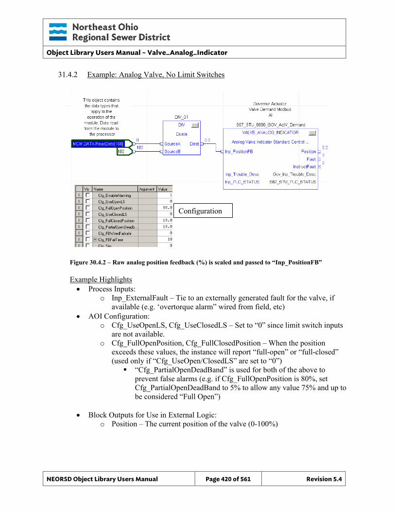
Object Library Users Manual – Valve_Analog_Indicator
NEORSD Object Library Users Manual Page 420 of 561 Revision 5.4
31.4.2 Example: Analog Valve, No Limit Switches
Figure 30.4.2 – Raw analog position feedback (%) is scaled and passed to “Inp_PositionFB”
Example Highlights • Process Inputs:
o Inp_ExternalFault – Tie to an externally generated fault for the valve, if available (e.g. ‘overtorque alarm” wired from field, etc)
• AOI Configuration: o Cfg_UseOpenLS, Cfg_UseClosedLS – Set to “0” since limit switch inputs
are not available. o Cfg_FullOpenPosition, Cfg_FullClosedPosition – When the position
exceeds these values, the instance will report “full-open” or “full-closed” (used only if “Cfg_UseOpen/ClosedLS” are set to “0”) “Cfg_PartialOpenDeadBand” is used for both of the above to
prevent false alarms (e.g. if Cfg_FullOpenPosition is 80%, set Cfg_PartialOpenDeadBand to 5% to allow any value 75% and up to be considered “Full Open”)
• Block Outputs for Use in External Logic:
o Position – The current position of the valve (0-100%)
Configuration
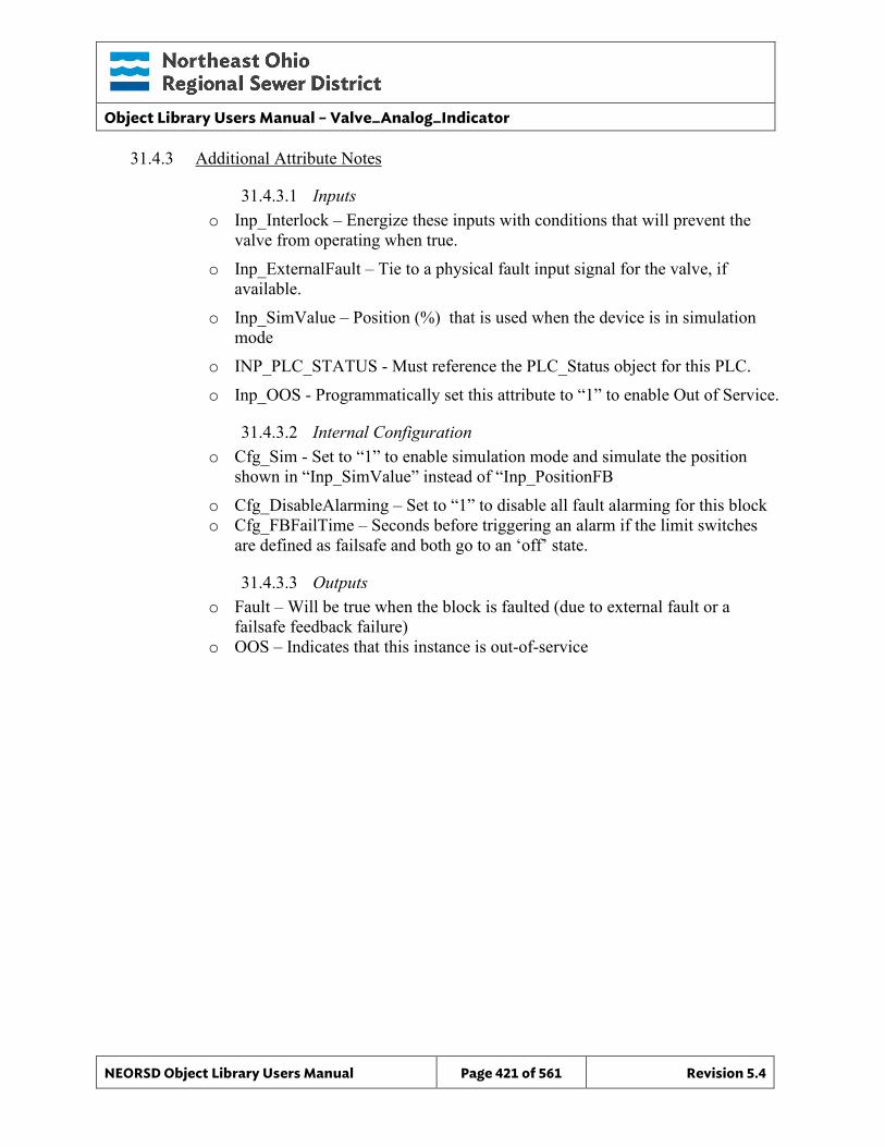
Object Library Users Manual – Valve_Analog_Indicator
NEORSD Object Library Users Manual Page 421 of 561 Revision 5.4
31.4.3 Additional Attribute Notes
31.4.3.1 Inputs o Inp_Interlock – Energize these inputs with conditions that will prevent the
valve from operating when true. o Inp_ExternalFault – Tie to a physical fault input signal for the valve, if
available. o Inp_SimValue – Position (%) that is used when the device is in simulation
mode o INP_PLC_STATUS - Must reference the PLC_Status object for this PLC. o Inp_OOS - Programmatically set this attribute to “1” to enable Out of Service.
31.4.3.2 Internal Configuration o Cfg_Sim - Set to “1” to enable simulation mode and simulate the position
shown in “Inp_SimValue” instead of “Inp_PositionFB o Cfg_DisableAlarming – Set to “1” to disable all fault alarming for this block o Cfg_FBFailTime – Seconds before triggering an alarm if the limit switches
are defined as failsafe and both go to an ‘off’ state.
31.4.3.3 Outputs o Fault – Will be true when the block is faulted (due to external fault or a
failsafe feedback failure) o OOS – Indicates that this instance is out-of-service
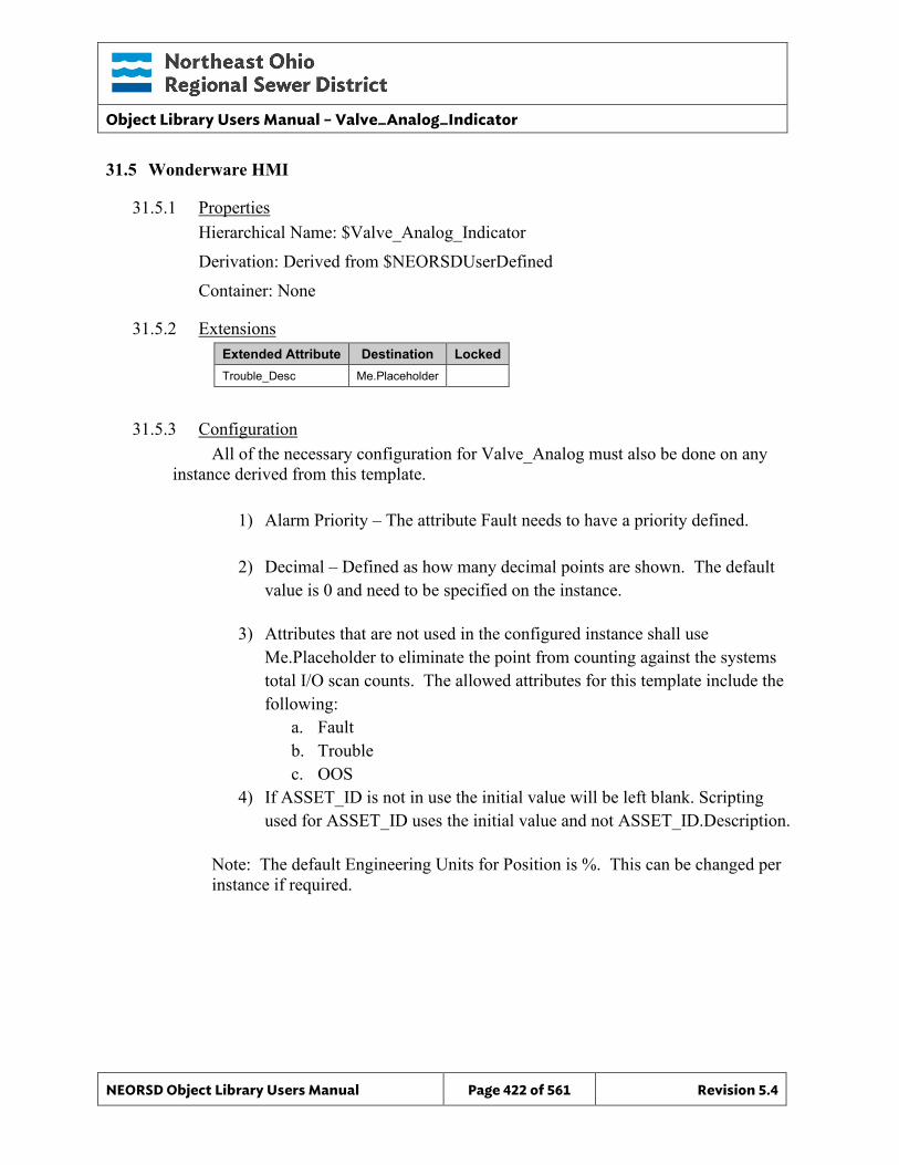
Object Library Users Manual – Valve_Analog_Indicator
NEORSD Object Library Users Manual Page 422 of 561 Revision 5.4
31.5 Wonderware HMI
31.5.1 Properties Hierarchical Name: $Valve_Analog_Indicator Derivation: Derived from $NEORSDUserDefined Container: None
31.5.2 Extensions Extended Attribute Destination Locked Trouble_Desc Me.Placeholder
31.5.3 Configuration All of the necessary configuration for Valve_Analog must also be done on any
instance derived from this template.
1) Alarm Priority – The attribute Fault needs to have a priority defined. 2) Decimal – Defined as how many decimal points are shown. The default
value is 0 and need to be specified on the instance.
3) Attributes that are not used in the configured instance shall use Me.Placeholder to eliminate the point from counting against the systems total I/O scan counts. The allowed attributes for this template include the following:
a. Fault b. Trouble c. OOS
4) If ASSET_ID is not in use the initial value will be left blank. Scripting used for ASSET_ID uses the initial value and not ASSET_ID.Description.
Note: The default Engineering Units for Position is %. This can be changed per instance if required.
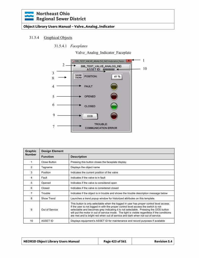
Object Library Users Manual – Valve_Analog_Indicator
NEORSD Object Library Users Manual Page 423 of 561 Revision 5.4
31.5.4 Graphical Objects
31.5.4.1 Faceplates
Graphic Number
Design Element
Function Description
1 Close Button Pressing this button closes the faceplate display.
2 Tagname Displays the object name
3 Position Indicates the current position of the valve
4 Fault Indicates if the valve is in fault
5 Opened Indicates if the valve is considered open
6 Closed Indicates if the valve is considered closed
7 Trouble Indicates if the object is in trouble and shows the trouble description message below
8 Show Trend Launches a trend popup window for historized attributes on this template.
9 Out of Service
This button is only selectable when the logged in user has proper control level access. If the user is not logged in with the proper control level access the switch is not selectable and becomes grey indicating it is not selectable. Pressing the OOS button will put the motor in out of service mode. The light is visible regardless if the conditions are met and is bright red when out of service and dark when not out of service.
10 ASSET ID Displays equipment’s ASSET ID for maintenance and record purposes if available
Valve_Analog_Indicator_Faceplate
2 1
3
4 5 6
7
8
9
10

Object Library Users Manual – Valve_Analog_Indicator
NEORSD Object Library Users Manual Page 424 of 561 Revision 5.4
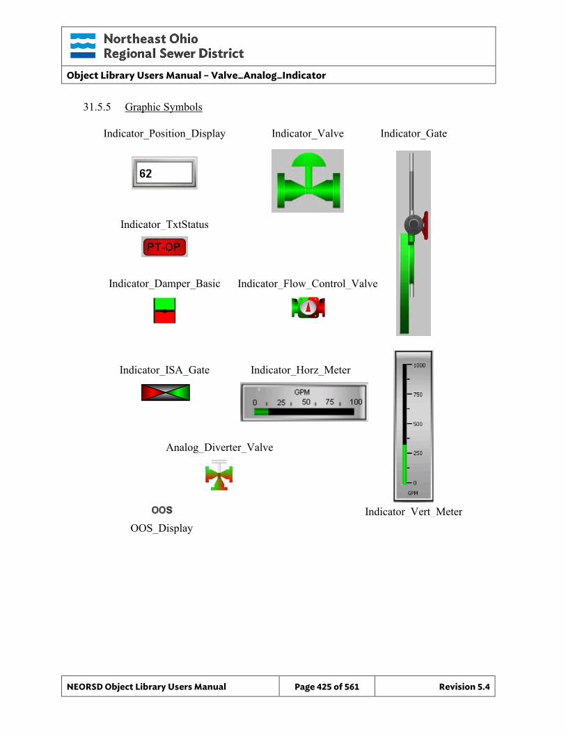
Object Library Users Manual – Valve_Analog_Indicator
NEORSD Object Library Users Manual Page 425 of 561 Revision 5.4
Indicator_Horz_Meter
Indicator_Vert_Meter
31.5.5 Graphic Symbols
Indicator_Position_Display Indicator_Valve Indicator_Gate
Indicator_TxtStatus
Indicator_Damper_Basic Indicator_Flow_Control_Valve
Indicator_ISA_Gate
Analog_Diverter_Valve
OOS_Display
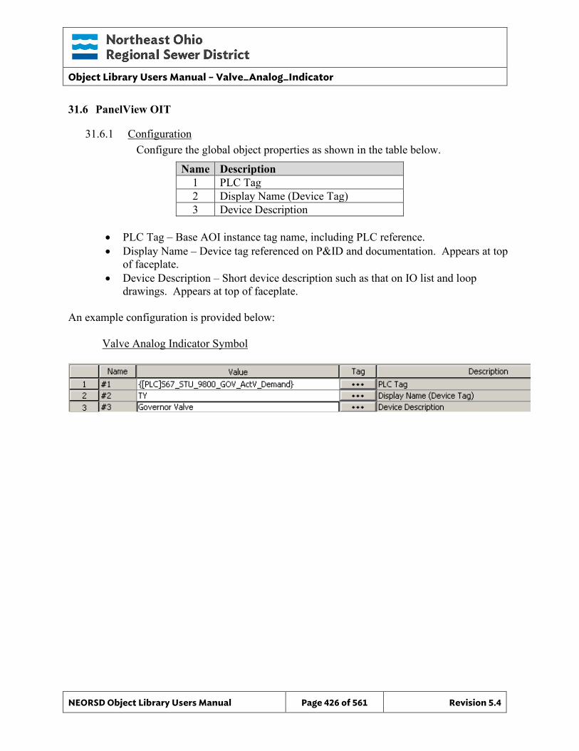
Object Library Users Manual – Valve_Analog_Indicator
NEORSD Object Library Users Manual Page 426 of 561 Revision 5.4
31.6 PanelView OIT
31.6.1 Configuration Configure the global object properties as shown in the table below.
Name Description 1 PLC Tag 2 Display Name (Device Tag) 3 Device Description
• PLC Tag – Base AOI instance tag name, including PLC reference. • Display Name – Device tag referenced on P&ID and documentation. Appears at top
of faceplate. • Device Description – Short device description such as that on IO list and loop
drawings. Appears at top of faceplate.
An example configuration is provided below: Valve Analog Indicator Symbol
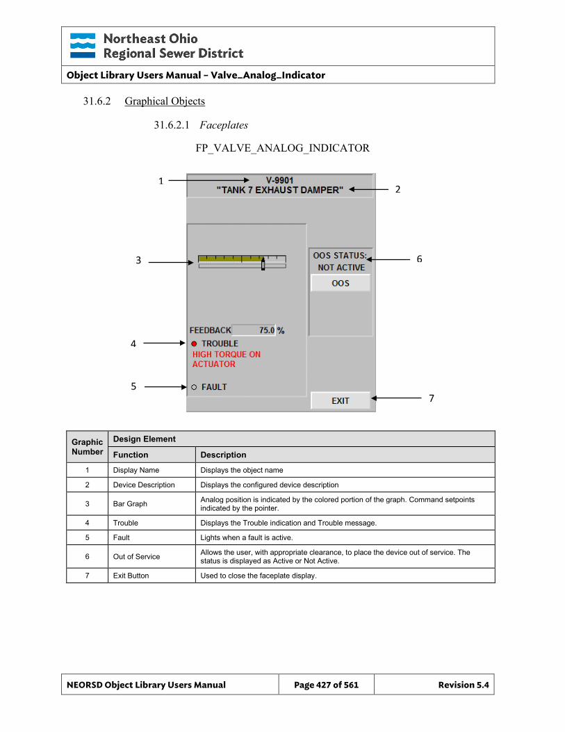
Object Library Users Manual – Valve_Analog_Indicator
NEORSD Object Library Users Manual Page 427 of 561 Revision 5.4
FP_VALVE_ANALOG_INDICATOR FP_VALVE_ANALOG_INDICATOR
31.6.2 Graphical Objects
31.6.2.1 Faceplates
Graphic Number
Design Element
Function Description
1 Display Name Displays the object name
2 Device Description Displays the configured device description
3 Bar Graph Analog position is indicated by the colored portion of the graph. Command setpoints indicated by the pointer.
4 Trouble Displays the Trouble indication and Trouble message.
5 Fault Lights when a fault is active.
6 Out of Service Allows the user, with appropriate clearance, to place the device out of service. The status is displayed as Active or Not Active.
7 Exit Button Used to close the faceplate display.
1 2
3
4
5
6
7
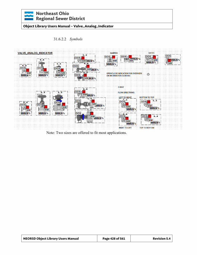
Object Library Users Manual – Valve_Analog_Indicator
NEORSD Object Library Users Manual Page 428 of 561 Revision 5.4
31.6.2.2 Symbols
Note: Two sizes are offered to fit most applications.

Object Library Users Manual – Valve_Analog_Indicator
NEORSD Object Library Users Manual Page 429 of 561 Revision 5.4
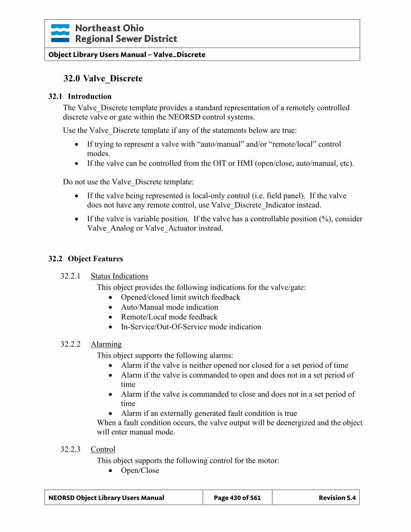
Object Library Users Manual – Valve_Discrete
NEORSD Object Library Users Manual Page 430 of 561 Revision 5.4
32.0 Valve_Discrete
32.1 Introduction The Valve_Discrete template provides a standard representation of a remotely controlled discrete valve or gate within the NEORSD control systems. Use the Valve_Discrete template if any of the statements below are true:
• If trying to represent a valve with “auto/manual” and/or “remote/local” control modes.
• If the valve can be controlled from the OIT or HMI (open/close, auto/manual, etc).
Do not use the Valve_Discrete template:
• If the valve being represented is local-only control (i.e. field panel). If the valve does not have any remote control, use Valve_Discrete_Indicator instead.
• If the valve is variable position. If the valve has a controllable position (%), consider Valve_Analog or Valve_Actuator instead.
32.2 Object Features
32.2.1 Status Indications This object provides the following indications for the valve/gate:
• Opened/closed limit switch feedback • Auto/Manual mode indication • Remote/Local mode feedback • In-Service/Out-Of-Service mode indication
32.2.2 Alarming This object supports the following alarms:
• Alarm if the valve is neither opened nor closed for a set period of time • Alarm if the valve is commanded to open and does not in a set period of
time • Alarm if the valve is commanded to close and does not in a set period of
time • Alarm if an externally generated fault condition is true
When a fault condition occurs, the valve output will be deenergized and the object will enter manual mode.
32.2.3 Control This object supports the following control for the motor:
• Open/Close
Object Library Users Manual – Valve_Discrete
NEORSD Object Library Users Manual Page 431 of 561 Revision 5.4
• Auto/Manual mode toggle • Resettable alarms • Out-of-Service/In-Service mode toggle • Interlocking to prevent operation
32.2.4 Simulation This object supports simulation of the running feedback.
32.2.5 Trouble This object supports hardware trouble indication.
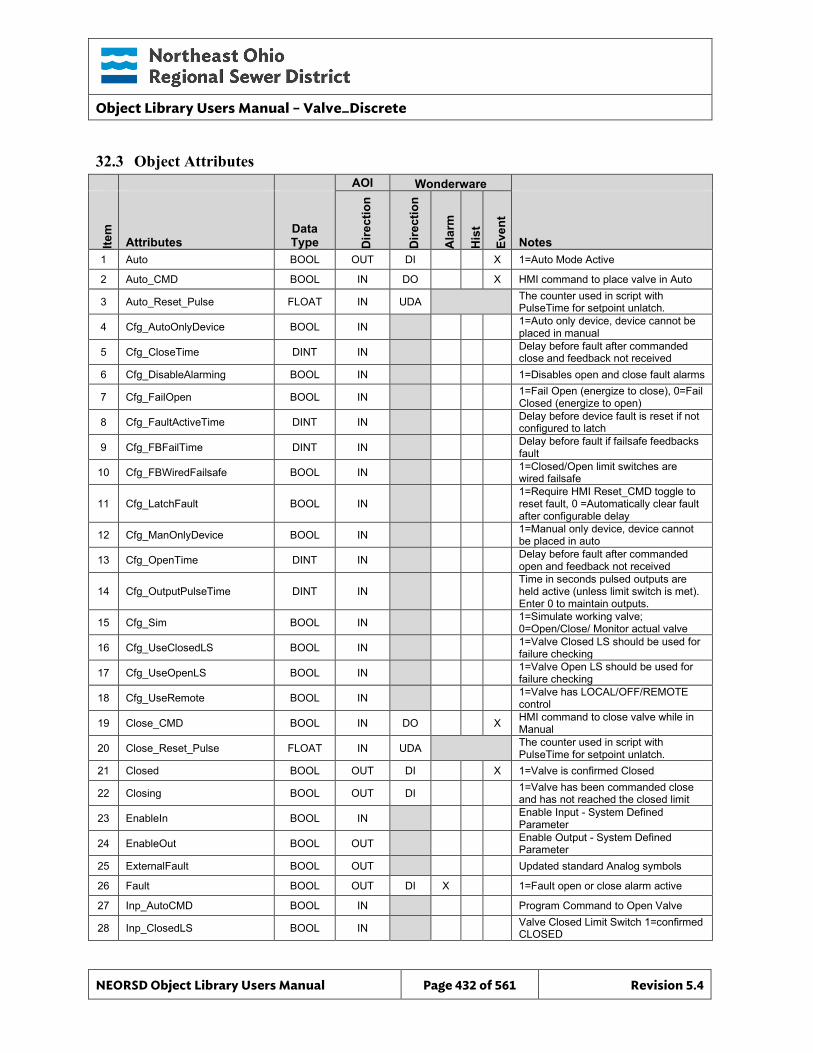
Object Library Users Manual – Valve_Discrete
NEORSD Object Library Users Manual Page 432 of 561 Revision 5.4
32.3 Object Attributes
AOI Wonderware
Item
Attributes Data Type D
irect
ion
Dire
ctio
n
Ala
rm
His
t
Even
t
Notes 1 Auto BOOL OUT DI X 1=Auto Mode Active
2 Auto_CMD BOOL IN DO X HMI command to place valve in Auto
3 Auto_Reset_Pulse FLOAT IN UDA The counter used in script with PulseTime for setpoint unlatch.
4 Cfg_AutoOnlyDevice BOOL IN 1=Auto only device, device cannot be placed in manual
5 Cfg_CloseTime DINT IN Delay before fault after commanded close and feedback not received
6 Cfg_DisableAlarming BOOL IN 1=Disables open and close fault alarms
7 Cfg_FailOpen BOOL IN 1=Fail Open (energize to close), 0=Fail Closed (energize to open)
8 Cfg_FaultActiveTime DINT IN Delay before device fault is reset if not configured to latch
9 Cfg_FBFailTime DINT IN Delay before fault if failsafe feedbacks fault
10 Cfg_FBWiredFailsafe BOOL IN 1=Closed/Open limit switches are wired failsafe
11 Cfg_LatchFault BOOL IN 1=Require HMI Reset_CMD toggle to reset fault, 0 =Automatically clear fault after configurable delay
12 Cfg_ManOnlyDevice BOOL IN 1=Manual only device, device cannot be placed in auto
13 Cfg_OpenTime DINT IN Delay before fault after commanded open and feedback not received
14 Cfg_OutputPulseTime DINT IN Time in seconds pulsed outputs are held active (unless limit switch is met). Enter 0 to maintain outputs.
15 Cfg_Sim BOOL IN 1=Simulate working valve; 0=Open/Close/ Monitor actual valve
16 Cfg_UseClosedLS BOOL IN 1=Valve Closed LS should be used for failure checking
17 Cfg_UseOpenLS BOOL IN 1=Valve Open LS should be used for failure checking
18 Cfg_UseRemote BOOL IN 1=Valve has LOCAL/OFF/REMOTE control
19 Close_CMD BOOL IN DO X HMI command to close valve while in Manual
20 Close_Reset_Pulse FLOAT IN UDA The counter used in script with PulseTime for setpoint unlatch.
21 Closed BOOL OUT DI X 1=Valve is confirmed Closed
22 Closing BOOL OUT DI 1=Valve has been commanded close and has not reached the closed limit
23 EnableIn BOOL IN Enable Input - System Defined Parameter
24 EnableOut BOOL OUT Enable Output - System Defined Parameter
25 ExternalFault BOOL OUT Updated standard Analog symbols
26 Fault BOOL OUT DI X 1=Fault open or close alarm active
27 Inp_AutoCMD BOOL IN Program Command to Open Valve
28 Inp_ClosedLS BOOL IN Valve Closed Limit Switch 1=confirmed CLOSED
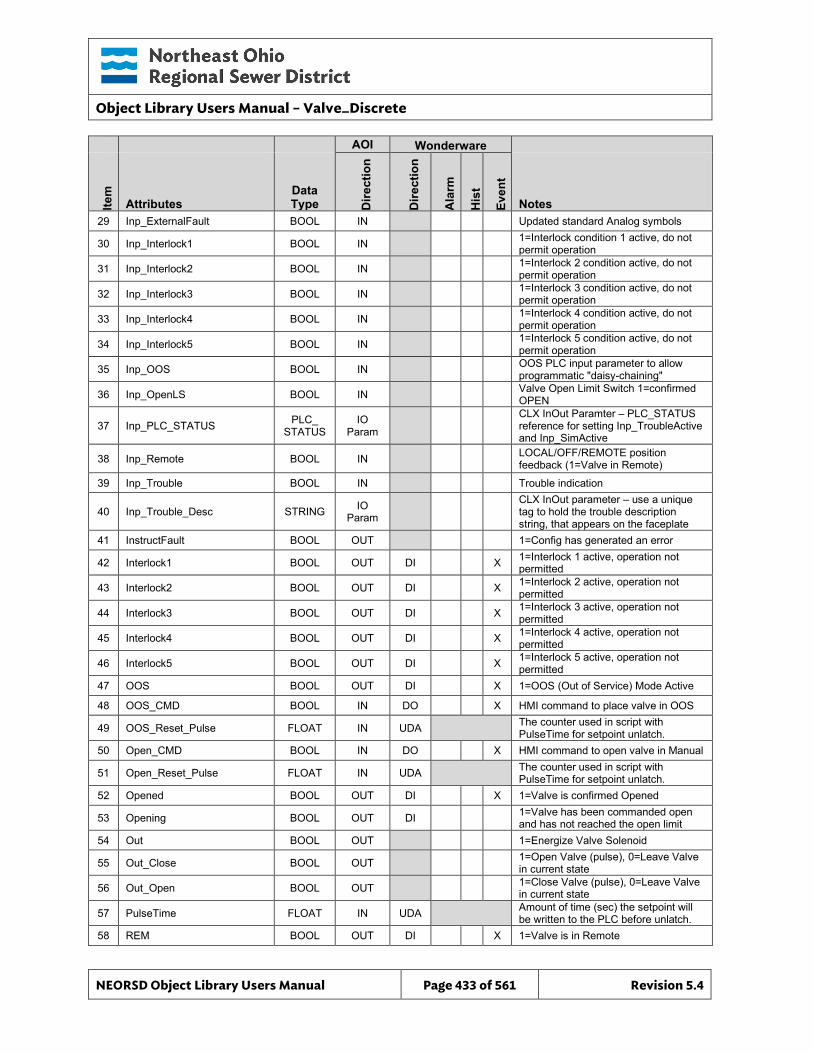
Object Library Users Manual – Valve_Discrete
NEORSD Object Library Users Manual Page 433 of 561 Revision 5.4
AOI Wonderware
Item
Attributes Data Type D
irect
ion
Dire
ctio
n
Ala
rm
His
t
Even
t
Notes 29 Inp_ExternalFault BOOL IN Updated standard Analog symbols
30 Inp_Interlock1 BOOL IN 1=Interlock condition 1 active, do not permit operation
31 Inp_Interlock2 BOOL IN 1=Interlock 2 condition active, do not permit operation
32 Inp_Interlock3 BOOL IN 1=Interlock 3 condition active, do not permit operation
33 Inp_Interlock4 BOOL IN 1=Interlock 4 condition active, do not permit operation
34 Inp_Interlock5 BOOL IN 1=Interlock 5 condition active, do not permit operation
35 Inp_OOS BOOL IN OOS PLC input parameter to allow programmatic "daisy-chaining"
36 Inp_OpenLS BOOL IN Valve Open Limit Switch 1=confirmed OPEN
37 Inp_PLC_STATUS PLC_ STATUS
IO Param
CLX InOut Paramter – PLC_STATUS reference for setting Inp_TroubleActive and Inp_SimActive
38 Inp_Remote BOOL IN LOCAL/OFF/REMOTE position feedback (1=Valve in Remote)
39 Inp_Trouble BOOL IN Trouble indication
40 Inp_Trouble_Desc STRING IO Param
CLX InOut parameter – use a unique tag to hold the trouble description string, that appears on the faceplate
41 InstructFault BOOL OUT 1=Config has generated an error
42 Interlock1 BOOL OUT DI X 1=Interlock 1 active, operation not permitted
43 Interlock2 BOOL OUT DI X 1=Interlock 2 active, operation not permitted
44 Interlock3 BOOL OUT DI X 1=Interlock 3 active, operation not permitted
45 Interlock4 BOOL OUT DI X 1=Interlock 4 active, operation not permitted
46 Interlock5 BOOL OUT DI X 1=Interlock 5 active, operation not permitted
47 OOS BOOL OUT DI X 1=OOS (Out of Service) Mode Active
48 OOS_CMD BOOL IN DO X HMI command to place valve in OOS
49 OOS_Reset_Pulse FLOAT IN UDA The counter used in script with PulseTime for setpoint unlatch.
50 Open_CMD BOOL IN DO X HMI command to open valve in Manual
51 Open_Reset_Pulse FLOAT IN UDA The counter used in script with PulseTime for setpoint unlatch.
52 Opened BOOL OUT DI X 1=Valve is confirmed Opened
53 Opening BOOL OUT DI 1=Valve has been commanded open and has not reached the open limit
54 Out BOOL OUT 1=Energize Valve Solenoid
55 Out_Close BOOL OUT 1=Open Valve (pulse), 0=Leave Valve in current state
56 Out_Open BOOL OUT 1=Close Valve (pulse), 0=Leave Valve in current state
57 PulseTime FLOAT IN UDA Amount of time (sec) the setpoint will be written to the PLC before unlatch.
58 REM BOOL OUT DI X 1=Valve is in Remote
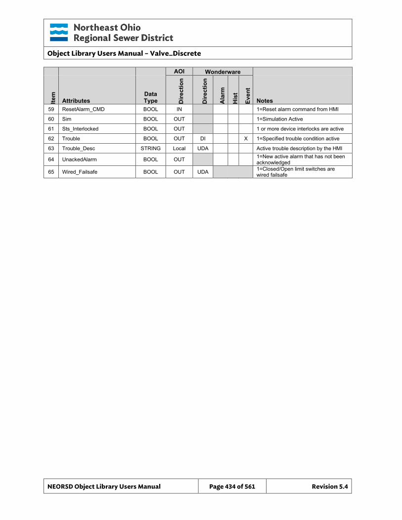
Object Library Users Manual – Valve_Discrete
NEORSD Object Library Users Manual Page 434 of 561 Revision 5.4
AOI Wonderware
Item
Attributes Data Type D
irect
ion
Dire
ctio
n
Ala
rm
His
t
Even
t
Notes 59 ResetAlarm_CMD BOOL IN 1=Reset alarm command from HMI
60 Sim BOOL OUT 1=Simulation Active
61 Sts_Interlocked BOOL OUT 1 or more device interlocks are active
62 Trouble BOOL OUT DI X 1=Specified trouble condition active
63 Trouble_Desc STRING Local UDA Active trouble description by the HMI
64 UnackedAlarm BOOL OUT 1=New active alarm that has not been acknowledged
65 Wired_Failsafe BOOL OUT UDA 1=Closed/Open limit switches are wired failsafe
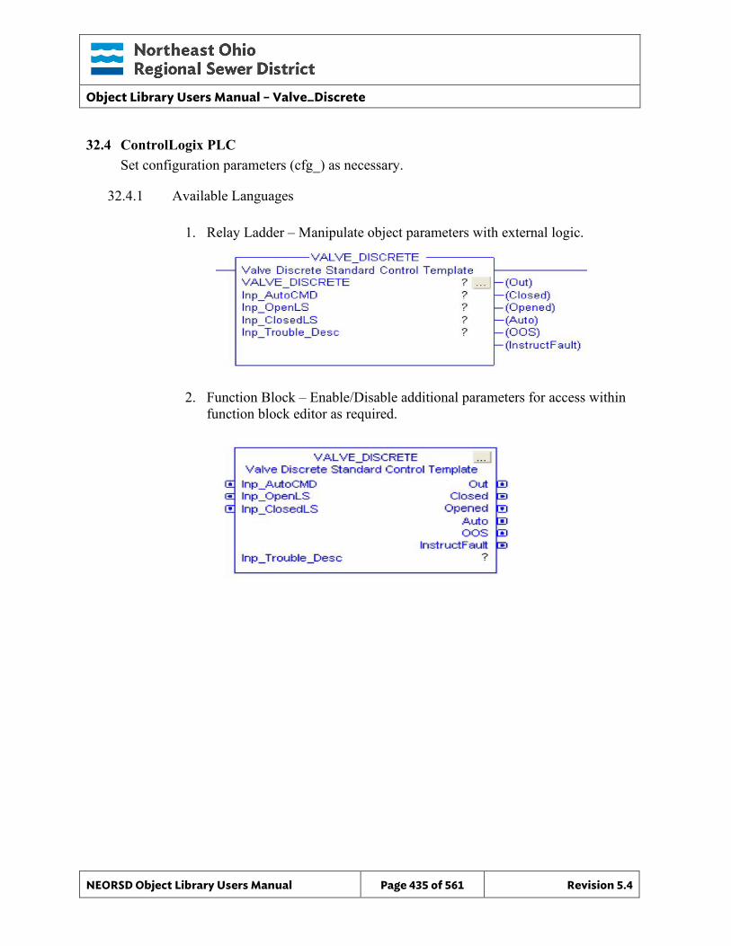
Object Library Users Manual – Valve_Discrete
NEORSD Object Library Users Manual Page 435 of 561 Revision 5.4
32.4 ControlLogix PLC Set configuration parameters (cfg_) as necessary.
32.4.1 Available Languages
1. Relay Ladder – Manipulate object parameters with external logic.
2. Function Block – Enable/Disable additional parameters for access within function block editor as required.
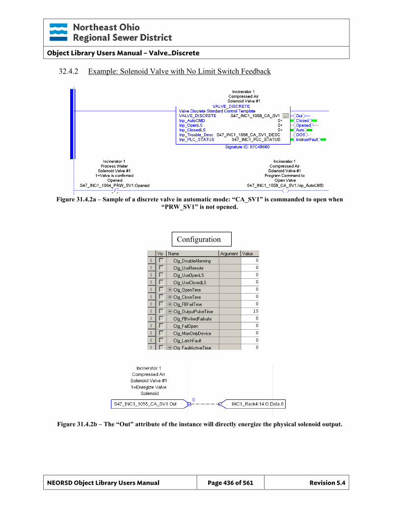
Object Library Users Manual – Valve_Discrete
NEORSD Object Library Users Manual Page 436 of 561 Revision 5.4
32.4.2 Example: Solenoid Valve with No Limit Switch Feedback
Figure 31.4.2a – Sample of a discrete valve in automatic mode: “CA_SV1” is commanded to open when
“PRW_SV1” is not opened.
Figure 31.4.2b – The “Out” attribute of the instance will directly energize the physical solenoid output.
Configuration
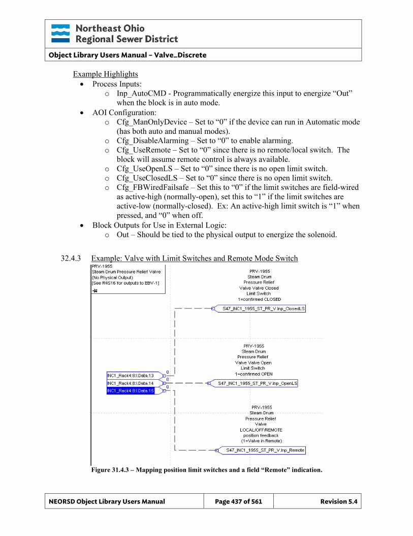
Object Library Users Manual – Valve_Discrete
NEORSD Object Library Users Manual Page 437 of 561 Revision 5.4
Example Highlights • Process Inputs:
o Inp_AutoCMD - Programmatically energize this input to energize “Out” when the block is in auto mode.
• AOI Configuration: o Cfg_ManOnlyDevice – Set to “0” if the device can run in Automatic mode
(has both auto and manual modes). o Cfg_DisableAlarming – Set to “0” to enable alarming. o Cfg_UseRemote – Set to “0” since there is no remote/local switch. The
block will assume remote control is always available. o Cfg_UseOpenLS – Set to “0” since there is no open limit switch. o Cfg_UseClosedLS – Set to “0” since there is no open limit switch. o Cfg_FBWiredFailsafe – Set this to “0” if the limit switches are field-wired
as active-high (normally-open), set this to “1” if the limit switches are active-low (normally-closed). Ex: An active-high limit switch is “1” when pressed, and “0” when off.
• Block Outputs for Use in External Logic: o Out – Should be tied to the physical output to energize the solenoid.
32.4.3 Example: Valve with Limit Switches and Remote Mode Switch
Figure 31.4.3 – Mapping position limit switches and a field “Remote” indication.
Object Library Users Manual – Valve_Discrete
NEORSD Object Library Users Manual Page 438 of 561 Revision 5.4
Example Highlights Programming the valve to look at limit switches and a Remote/Local switch is similar to the first example, with the following changes: • Process Inputs:
o Inp_OpenLS – Opened limit switch input o Inp_ClosedLS – Closed limit switch input o Inp_Remote – Valve is confirmed in remote (from field input)
When this is absent, valve is assumed always in remote. • AOI Configuration:
o Cfg_UseOpenLS, ClosedLS– Set to “1” to pick up the LS inputs. o Cfg_UseRemote – Set to “1” to pick up the Remote input.
• Block Outputs for Use in External Logic: o Same as first example (Out)
32.4.4 Additional Attribute Notes
32.4.4.1 Inputs o Inp_Interlock – Energize these inputs with conditions that will prevent the
valve from operating when true. o Inp_ExternalFault – Tie to a physical fault input signal for the valve, if
available. o INP_PLC_STATUS - Must reference the PLC_Status object for this PLC. o Inp_OOS - Programmatically set this attribute to “1” to enable Out of Service.
32.4.4.2 Internal Configuration o Cfg_LatchFault – Set to “1” if faults must be reset at the HMI/OIT. Use if: District staff should physically inspect a device before resuming operation
after a fault. o Cfg_FaultActiveTime –If “Cfg_LatchFault” = 0, the block will automatically
clear a fault in the time specified by this parameter. If the fault input condition must be removed; the block will not clear an active fault.
o Cfg_OutputPulseTime – Used when the motor starter requires a pulsed signal. Set to 0 to use maintained outputs, otherwise set to the pulse length (seconds).
o Cfg_Sim – Set to “1” to enable simulation mode for this block. The limit switch input will be ignored and when the block is commanded to open/close the valve “Out” output will react accordingly.
o Cfg_OpenTime – Delay before triggering an alarm if the valve was commanded to open and has not opened.
o Cfg_CloseTime – Delay before triggering an alarm if the valve was commanded to close and has not closed.
Object Library Users Manual – Valve_Discrete
NEORSD Object Library Users Manual Page 439 of 561 Revision 5.4
o Cfg_FBFailTime - Seconds before faulting if the valve is neither opened nor closed.
o Cfg_FailOpen – “1” will command the valve to open if a failure occurs. o Cfg_AutoOnlyDevice – Set to “1” to prevent the device from operating in
remote manual mode. Cfg_ManOnlyDevice must be set to “0”.
32.4.4.3 Outputs o Sts_Interlocked – Indicates that this instance cannot operate as an interlock
condition is not satisfied. o OOS – Indicates that this instance is out-of-service o Out_Open, Out_Close – Use instead of “Out” if separate open/close command
signals are required o Auto – Indicates that the valve is in automatic control mode o Fault – Indicates that any fault condition is active on the valve. This includes
internally generated alarms (time-to-open/close, etc) and the external alarm, if used. When the valve faults, it will be commanded to the state defined by
“Cfg_FailOpen” and will enter manual mode.
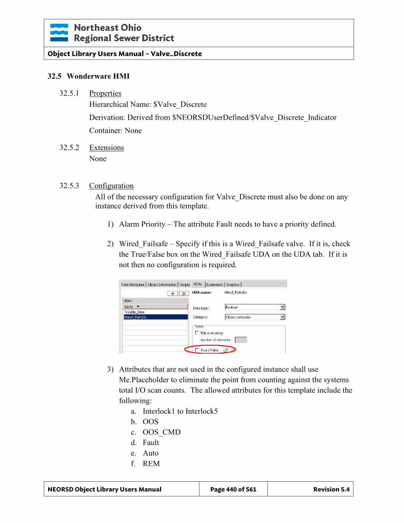
Object Library Users Manual – Valve_Discrete
NEORSD Object Library Users Manual Page 440 of 561 Revision 5.4
32.5 Wonderware HMI
32.5.1 Properties Hierarchical Name: $Valve_Discrete Derivation: Derived from $NEORSDUserDefined/$Valve_Discrete_Indicator Container: None
32.5.2 Extensions None
32.5.3 Configuration All of the necessary configuration for Valve_Discrete must also be done on any instance derived from this template.
1) Alarm Priority – The attribute Fault needs to have a priority defined.
2) Wired_Failsafe – Specify if this is a Wired_Failsafe valve. If it is, check
the True/False box on the Wired_Failsafe UDA on the UDA tab. If it is not then no configuration is required.
3) Attributes that are not used in the configured instance shall use Me.Placeholder to eliminate the point from counting against the systems total I/O scan counts. The allowed attributes for this template include the following:
a. Interlock1 to Interlock5 b. OOS c. OOS_CMD d. Fault e. Auto f. REM
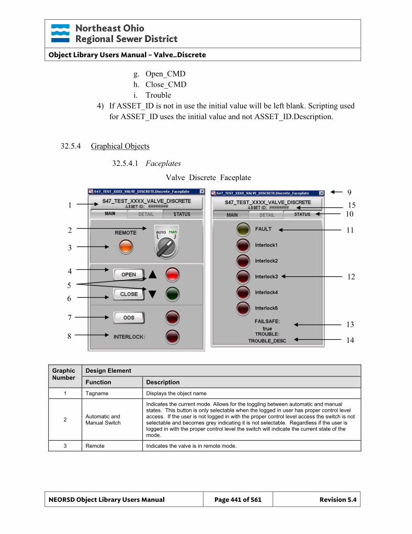
Object Library Users Manual – Valve_Discrete
NEORSD Object Library Users Manual Page 441 of 561 Revision 5.4
Valve_Discrete_Faceplate
g. Open_CMD h. Close_CMD i. Trouble
4) If ASSET_ID is not in use the initial value will be left blank. Scripting used for ASSET_ID uses the initial value and not ASSET_ID.Description.
32.5.4 Graphical Objects
32.5.4.1 Faceplates
Graphic Number
Design Element
Function Description
1 Tagname Displays the object name
2 Automatic and Manual Switch
Indicates the current mode. Allows for the toggling between automatic and manual states. This button is only selectable when the logged in user has proper control level access. If the user is not logged in with the proper control level access the switch is not selectable and becomes grey indicating it is not selectable. Regardless if the user is logged in with the proper control level the switch will indicate the current state of the mode.
3 Remote Indicates the valve is in remote mode.
9
10
11
13
1
3
2
7
8
6
4
14
12 5
15
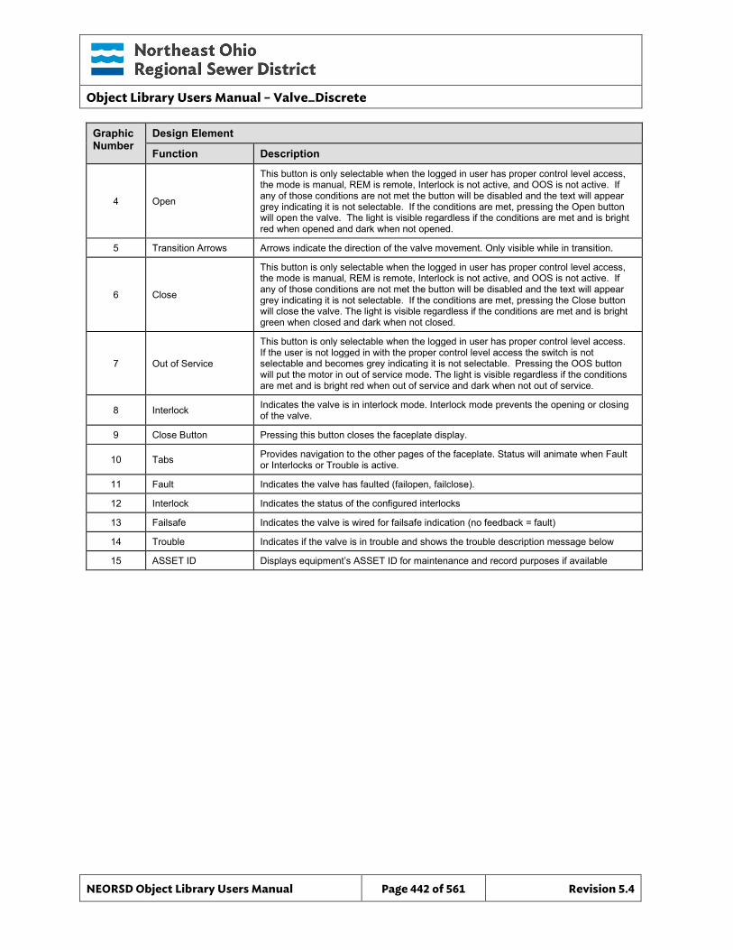
Object Library Users Manual – Valve_Discrete
NEORSD Object Library Users Manual Page 442 of 561 Revision 5.4
Graphic Number
Design Element
Function Description
4 Open
This button is only selectable when the logged in user has proper control level access, the mode is manual, REM is remote, Interlock is not active, and OOS is not active. If any of those conditions are not met the button will be disabled and the text will appear grey indicating it is not selectable. If the conditions are met, pressing the Open button will open the valve. The light is visible regardless if the conditions are met and is bright red when opened and dark when not opened.
5 Transition Arrows Arrows indicate the direction of the valve movement. Only visible while in transition.
6 Close
This button is only selectable when the logged in user has proper control level access, the mode is manual, REM is remote, Interlock is not active, and OOS is not active. If any of those conditions are not met the button will be disabled and the text will appear grey indicating it is not selectable. If the conditions are met, pressing the Close button will close the valve. The light is visible regardless if the conditions are met and is bright green when closed and dark when not closed.
7 Out of Service
This button is only selectable when the logged in user has proper control level access. If the user is not logged in with the proper control level access the switch is not selectable and becomes grey indicating it is not selectable. Pressing the OOS button will put the motor in out of service mode. The light is visible regardless if the conditions are met and is bright red when out of service and dark when not out of service.
8 Interlock Indicates the valve is in interlock mode. Interlock mode prevents the opening or closing of the valve.
9 Close Button Pressing this button closes the faceplate display.
10 Tabs Provides navigation to the other pages of the faceplate. Status will animate when Fault or Interlocks or Trouble is active.
11 Fault Indicates the valve has faulted (failopen, failclose).
12 Interlock Indicates the status of the configured interlocks
13 Failsafe Indicates the valve is wired for failsafe indication (no feedback = fault)
14 Trouble Indicates if the valve is in trouble and shows the trouble description message below
15 ASSET ID Displays equipment’s ASSET ID for maintenance and record purposes if available
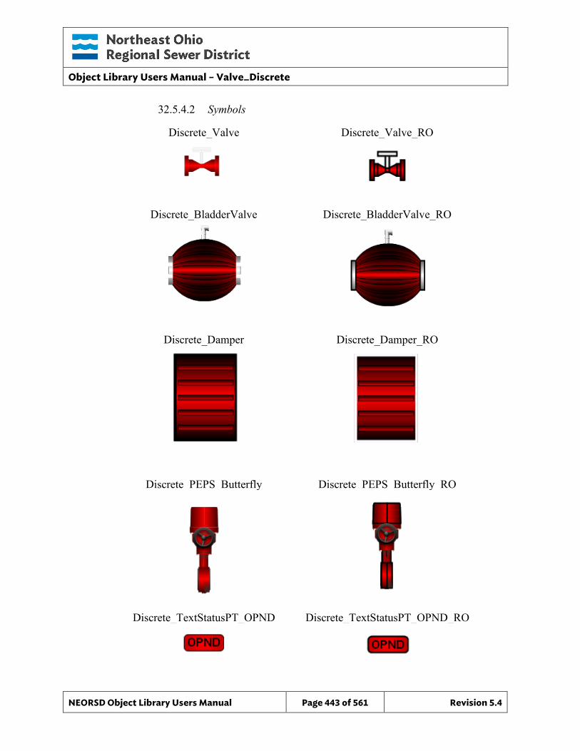
Object Library Users Manual – Valve_Discrete
NEORSD Object Library Users Manual Page 443 of 561 Revision 5.4
32.5.4.2 Symbols
Discrete_Valve
Discrete_PEPS_Butterfly
Discrete_TextStatusPT_OPND
Discrete_Damper
Discrete_BladderValve
Discrete_Damper_RO
Discrete_BladderValve_RO
Discrete_PEPS_Butterfly_RO
Discrete_Valve_RO
Discrete_TextStatusPT_OPND_RO
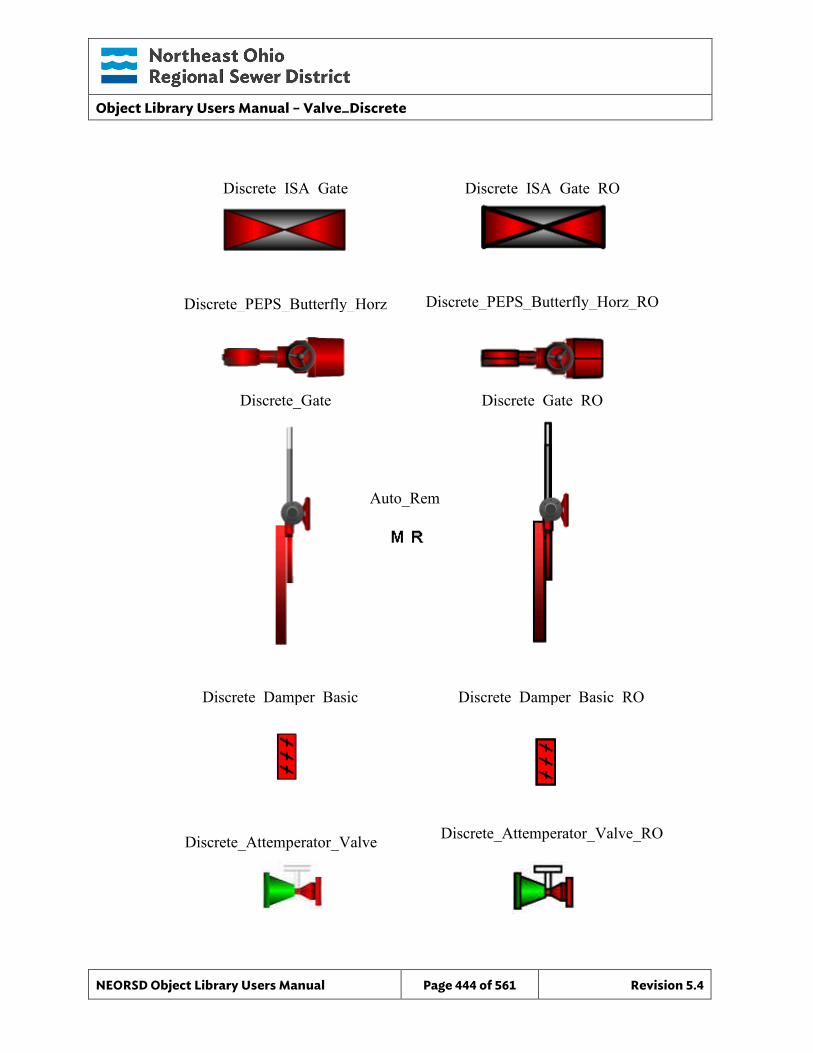
Object Library Users Manual – Valve_Discrete
NEORSD Object Library Users Manual Page 444 of 561 Revision 5.4
Auto_Rem
Discrete_PEPS_Butterfly_Horz
Discrete_Gate
Discrete_Damper_Basic
Discrete_ISA_Gate
Discrete Gate RO
Discrete_PEPS_Butterfly_Horz_RO
Discrete_ISA_Gate_RO
Discrete_Damper_Basic_RO
Discrete_Attemperator_Valve Discrete_Attemperator_Valve_RO
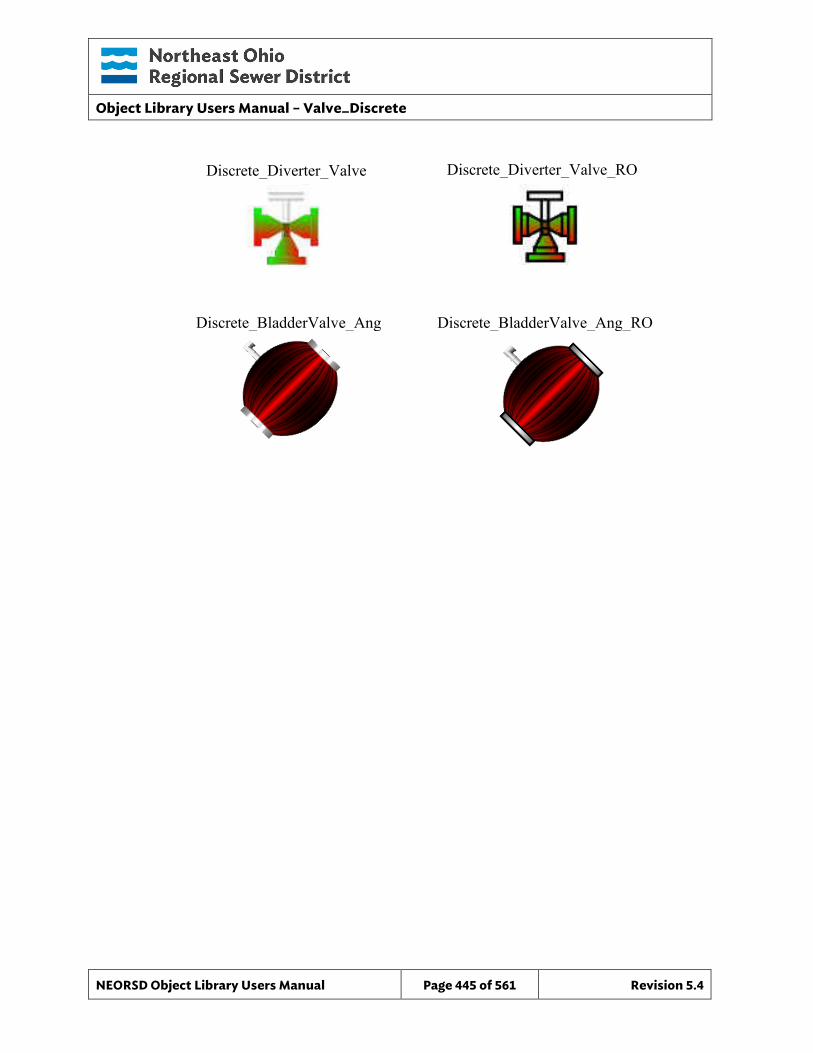
Object Library Users Manual – Valve_Discrete
NEORSD Object Library Users Manual Page 445 of 561 Revision 5.4
Discrete_BladderValve_Ang Discrete_BladderValve_Ang_RO
Discrete_Diverter_Valve Discrete_Diverter_Valve_RO
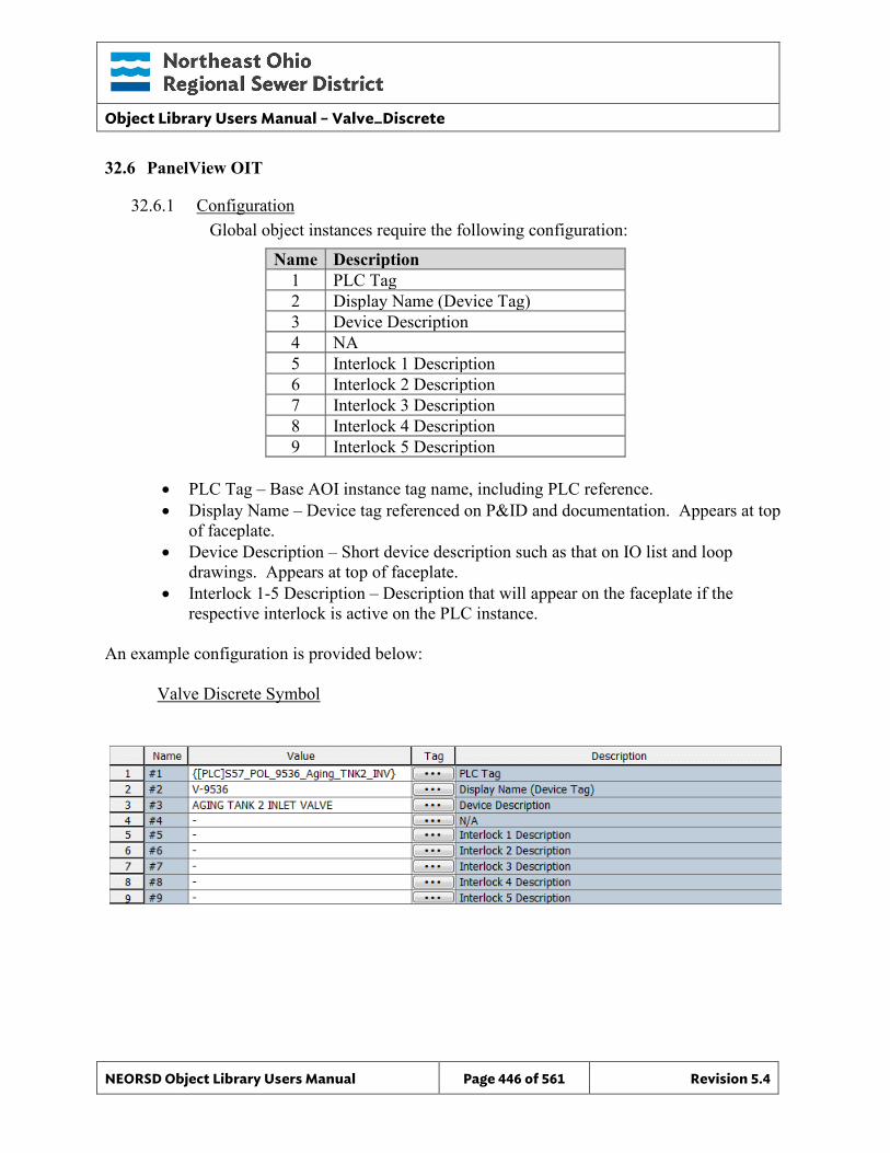
Object Library Users Manual – Valve_Discrete
NEORSD Object Library Users Manual Page 446 of 561 Revision 5.4
32.6 PanelView OIT
32.6.1 Configuration Global object instances require the following configuration:
Name Description 1 PLC Tag 2 Display Name (Device Tag) 3 Device Description 4 NA 5 Interlock 1 Description 6 Interlock 2 Description 7 Interlock 3 Description 8 Interlock 4 Description 9 Interlock 5 Description
• PLC Tag – Base AOI instance tag name, including PLC reference. • Display Name – Device tag referenced on P&ID and documentation. Appears at top
of faceplate. • Device Description – Short device description such as that on IO list and loop
drawings. Appears at top of faceplate. • Interlock 1-5 Description – Description that will appear on the faceplate if the
respective interlock is active on the PLC instance. An example configuration is provided below: Valve Discrete Symbol
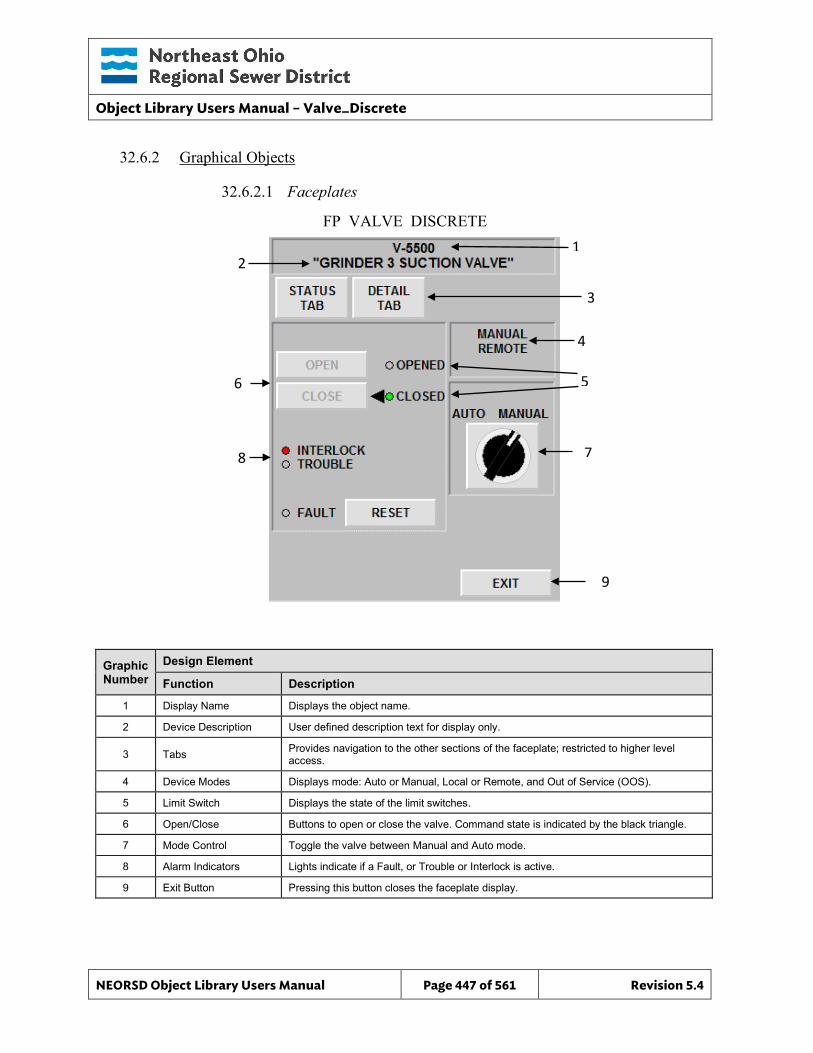
Object Library Users Manual – Valve_Discrete
NEORSD Object Library Users Manual Page 447 of 561 Revision 5.4
9
7
FP_VALVE_DISCRETE 1
5
3
4
32.6.2 Graphical Objects
32.6.2.1 Faceplates
Graphic Number
Design Element
Function Description
1 Display Name Displays the object name.
2 Device Description User defined description text for display only.
3 Tabs Provides navigation to the other sections of the faceplate; restricted to higher level access.
4 Device Modes Displays mode: Auto or Manual, Local or Remote, and Out of Service (OOS).
5 Limit Switch Displays the state of the limit switches.
6 Open/Close Buttons to open or close the valve. Command state is indicated by the black triangle.
7 Mode Control Toggle the valve between Manual and Auto mode.
8 Alarm Indicators Lights indicate if a Fault, or Trouble or Interlock is active.
9 Exit Button Pressing this button closes the faceplate display.
8
2
6
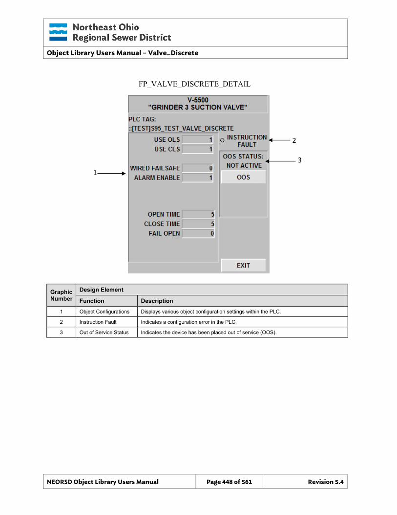
Object Library Users Manual – Valve_Discrete
NEORSD Object Library Users Manual Page 448 of 561 Revision 5.4
FP_VALVE_DISCRETE_DETAIL
2
3
Graphic Number
Design Element
Function Description
1 Object Configurations Displays various object configuration settings within the PLC.
2 Instruction Fault Indicates a configuration error in the PLC.
3 Out of Service Status Indicates the device has been placed out of service (OOS).
1
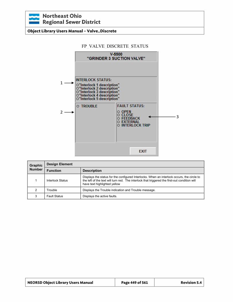
Object Library Users Manual – Valve_Discrete
NEORSD Object Library Users Manual Page 449 of 561 Revision 5.4
FP_VALVE_DISCRETE_STATUS
3
Graphic Number
Design Element
Function Description
1 Interlock Status Displays the status for the configured Interlocks. When an interlock occurs, the circle to the left of the text will turn red. The interlock that triggered the first-out condition will have text highlighted yellow
2 Trouble Displays the Trouble indication and Trouble message.
3 Fault Status Displays the active faults.
1
2
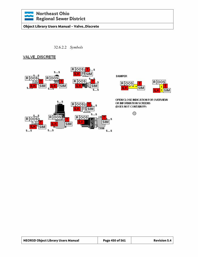
Object Library Users Manual – Valve_Discrete
NEORSD Object Library Users Manual Page 450 of 561 Revision 5.4
32.6.2.2 Symbols

Object Library Users Manual – Valve_Discrete
NEORSD Object Library Users Manual Page 451 of 561 Revision 5.4
This page left blank intentionally.
Object Library Users Manual – Valve_Discrete_Indicator
NEORSD Object Library Users Manual Page 452 of 561 Revision 5.4
33.0 Valve_Discrete_Indicator
33.1 Introduction The Valve_Discrete_Indicator template provides a standard representation of a locally controlled (no remote operation) discrete (2-state) valve or gate within the NEORSD control systems. Use the Valve_Discrete_Indicator template if both of the statements below are true:
• If trying to represent monitoring-only information (opened/closed, fault) for a valve. • If the valve has no “remote” mode of operation (only field/local operation)
Do not use the Valve_Discrete_Indicator template:
• If the valve being represented has remote-control from the HMI. If the valve has any remote control (or a “remote/local” switch), use Valve_Discrete instead.
• If the valve is variable position. If the valve has a controllable position (%), consider Valve_Analog or Valve_Actuator instead.
33.2 Object Features
33.2.1 Opened/Closed Indication This object provides opened/closed feedback from the limit switches for use with downstream logic in the PLC and for display on the HMI/OIT.
33.2.2 Status Indication This object provides the following indications for the valve:
• In-Service/Out-Of-Service mode indication
33.2.3 Alarming This object supports the following alarms:
• Alarm if the valve is neither opened nor closed for a set period of time • Alarm if the valve is commanded to open and does not in a set period of
time • Alarm if the valve is commanded to close and does not in a set period of
time
33.2.4 Control This object supports the following control for the valve:
• Out-of-Service/In-Service mode toggle
Object Library Users Manual – Valve_Discrete_Indicator
NEORSD Object Library Users Manual Page 453 of 561 Revision 5.4
33.2.5 Simulation This object supports simulation of the opened feedback.
33.2.6 Trouble This object supports hardware trouble indication.
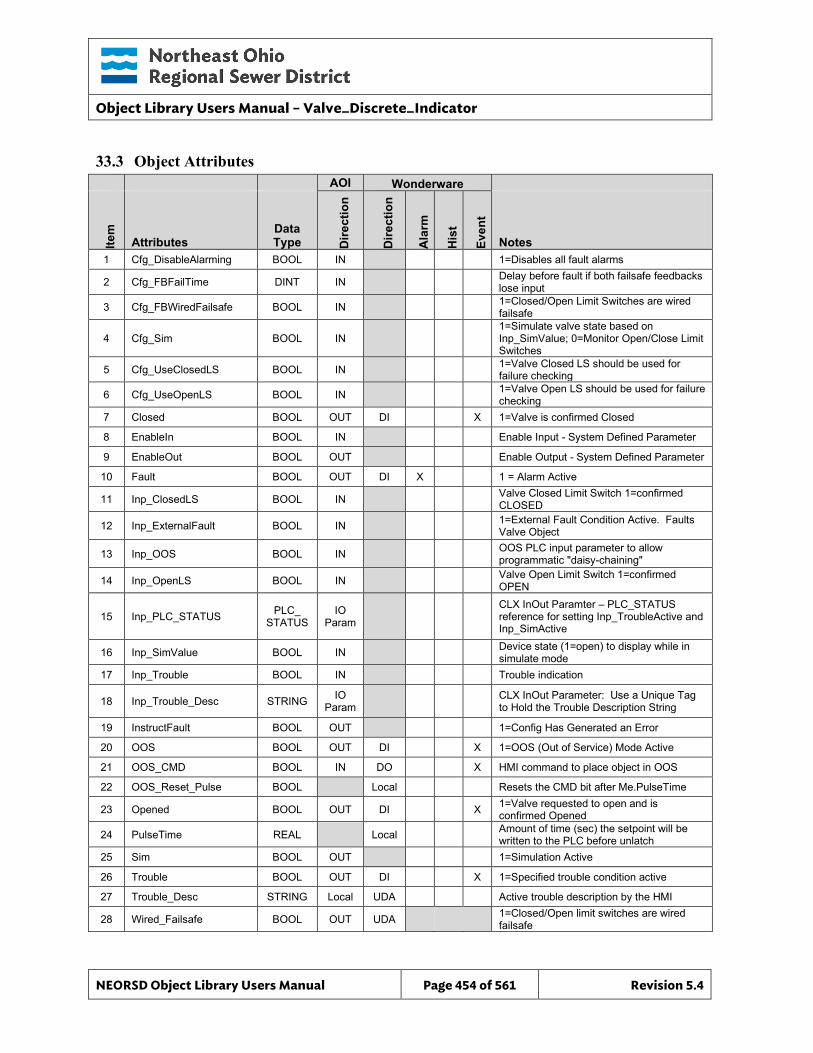
Object Library Users Manual – Valve_Discrete_Indicator
NEORSD Object Library Users Manual Page 454 of 561 Revision 5.4
33.3 Object Attributes
AOI Wonderware
Item
Attributes Data Type D
irect
ion
Dire
ctio
n
Ala
rm
His
t
Even
t
Notes 1 Cfg_DisableAlarming BOOL IN 1=Disables all fault alarms
2 Cfg_FBFailTime DINT IN Delay before fault if both failsafe feedbacks lose input
3 Cfg_FBWiredFailsafe BOOL IN 1=Closed/Open Limit Switches are wired failsafe
4 Cfg_Sim BOOL IN 1=Simulate valve state based on Inp_SimValue; 0=Monitor Open/Close Limit Switches
5 Cfg_UseClosedLS BOOL IN 1=Valve Closed LS should be used for failure checking
6 Cfg_UseOpenLS BOOL IN 1=Valve Open LS should be used for failure checking
7 Closed BOOL OUT DI X 1=Valve is confirmed Closed
8 EnableIn BOOL IN Enable Input - System Defined Parameter
9 EnableOut BOOL OUT Enable Output - System Defined Parameter
10 Fault BOOL OUT DI X 1 = Alarm Active
11 Inp_ClosedLS BOOL IN Valve Closed Limit Switch 1=confirmed CLOSED
12 Inp_ExternalFault BOOL IN 1=External Fault Condition Active. Faults Valve Object
13 Inp_OOS BOOL IN OOS PLC input parameter to allow programmatic "daisy-chaining"
14 Inp_OpenLS BOOL IN Valve Open Limit Switch 1=confirmed OPEN
15 Inp_PLC_STATUS PLC_ STATUS
IO Param
CLX InOut Paramter – PLC_STATUS reference for setting Inp_TroubleActive and Inp_SimActive
16 Inp_SimValue BOOL IN Device state (1=open) to display while in simulate mode
17 Inp_Trouble BOOL IN Trouble indication
18 Inp_Trouble_Desc STRING IO Param CLX InOut Parameter: Use a Unique Tag
to Hold the Trouble Description String
19 InstructFault BOOL OUT 1=Config Has Generated an Error
20 OOS BOOL OUT DI X 1=OOS (Out of Service) Mode Active
21 OOS_CMD BOOL IN DO X HMI command to place object in OOS
22 OOS_Reset_Pulse BOOL Local Resets the CMD bit after Me.PulseTime
23 Opened BOOL OUT DI X 1=Valve requested to open and is confirmed Opened
24 PulseTime REAL Local Amount of time (sec) the setpoint will be written to the PLC before unlatch
25 Sim BOOL OUT 1=Simulation Active
26 Trouble BOOL OUT DI X 1=Specified trouble condition active
27 Trouble_Desc STRING Local UDA Active trouble description by the HMI
28 Wired_Failsafe BOOL OUT UDA 1=Closed/Open limit switches are wired failsafe
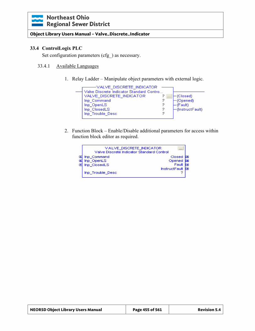
Object Library Users Manual – Valve_Discrete_Indicator
NEORSD Object Library Users Manual Page 455 of 561 Revision 5.4
33.4 ControlLogix PLC Set configuration parameters (cfg_) as necessary.
33.4.1 Available Languages
1. Relay Ladder – Manipulate object parameters with external logic.
2. Function Block – Enable/Disable additional parameters for access within function block editor as required.
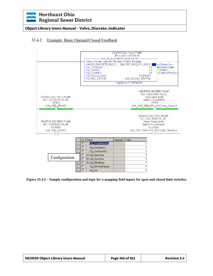
Object Library Users Manual – Valve_Discrete_Indicator
NEORSD Object Library Users Manual Page 456 of 561 Revision 5.4
33.4.2 Example: Basic Opened/Closed Feedback
Figure 32.4.2 – Sample configuration and logic for a mapping field inputs for open and closed limit switches.
Configuration
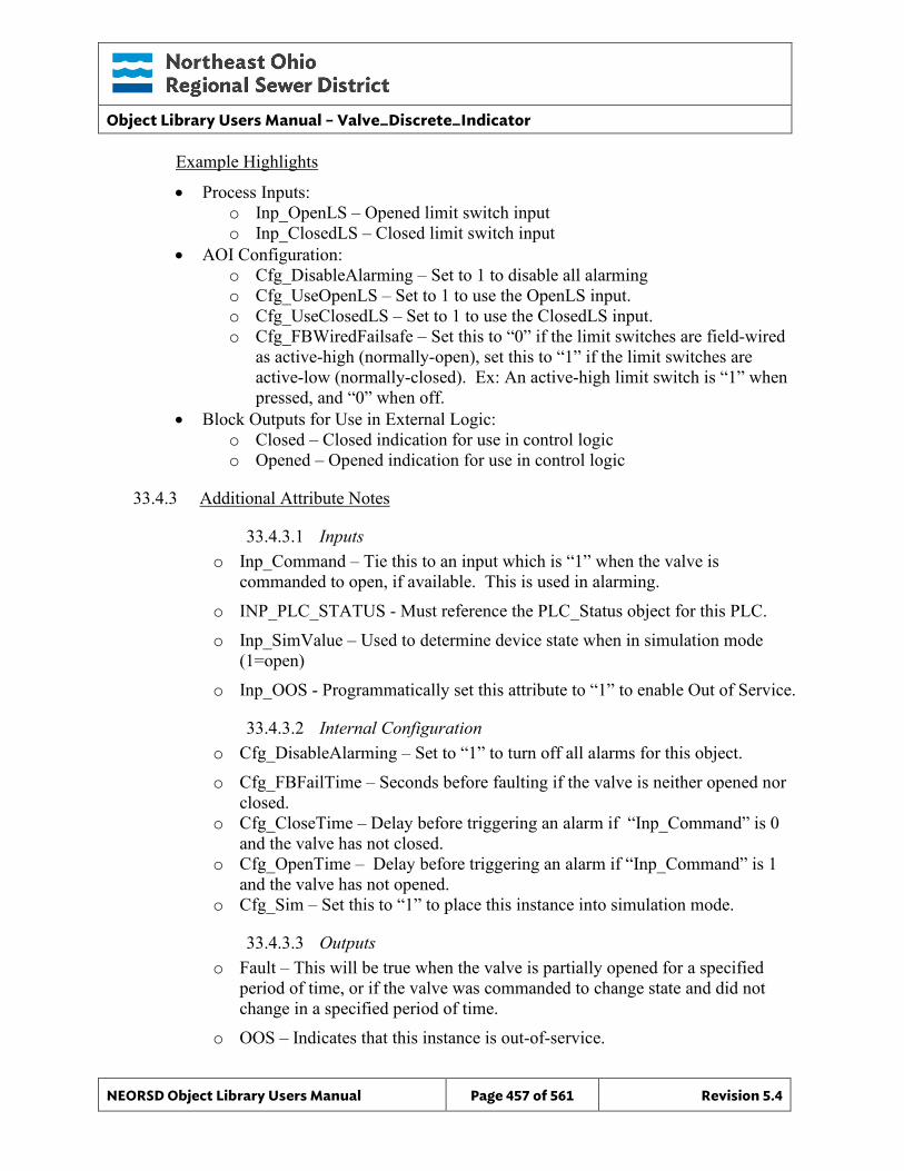
Object Library Users Manual – Valve_Discrete_Indicator
NEORSD Object Library Users Manual Page 457 of 561 Revision 5.4
Example Highlights
• Process Inputs: o Inp_OpenLS – Opened limit switch input o Inp_ClosedLS – Closed limit switch input
• AOI Configuration: o Cfg_DisableAlarming – Set to 1 to disable all alarming o Cfg_UseOpenLS – Set to 1 to use the OpenLS input. o Cfg_UseClosedLS – Set to 1 to use the ClosedLS input. o Cfg_FBWiredFailsafe – Set this to “0” if the limit switches are field-wired
as active-high (normally-open), set this to “1” if the limit switches are active-low (normally-closed). Ex: An active-high limit switch is “1” when pressed, and “0” when off.
• Block Outputs for Use in External Logic: o Closed – Closed indication for use in control logic o Opened – Opened indication for use in control logic
33.4.3 Additional Attribute Notes
33.4.3.1 Inputs o Inp_Command – Tie this to an input which is “1” when the valve is
commanded to open, if available. This is used in alarming. o INP_PLC_STATUS - Must reference the PLC_Status object for this PLC. o Inp_SimValue – Used to determine device state when in simulation mode
(1=open) o Inp_OOS - Programmatically set this attribute to “1” to enable Out of Service.
33.4.3.2 Internal Configuration o Cfg_DisableAlarming – Set to “1” to turn off all alarms for this object. o Cfg_FBFailTime – Seconds before faulting if the valve is neither opened nor
closed. o Cfg_CloseTime – Delay before triggering an alarm if “Inp_Command” is 0
and the valve has not closed. o Cfg_OpenTime – Delay before triggering an alarm if “Inp_Command” is 1
and the valve has not opened. o Cfg_Sim – Set this to “1” to place this instance into simulation mode.
33.4.3.3 Outputs o Fault – This will be true when the valve is partially opened for a specified
period of time, or if the valve was commanded to change state and did not change in a specified period of time.
o OOS – Indicates that this instance is out-of-service.
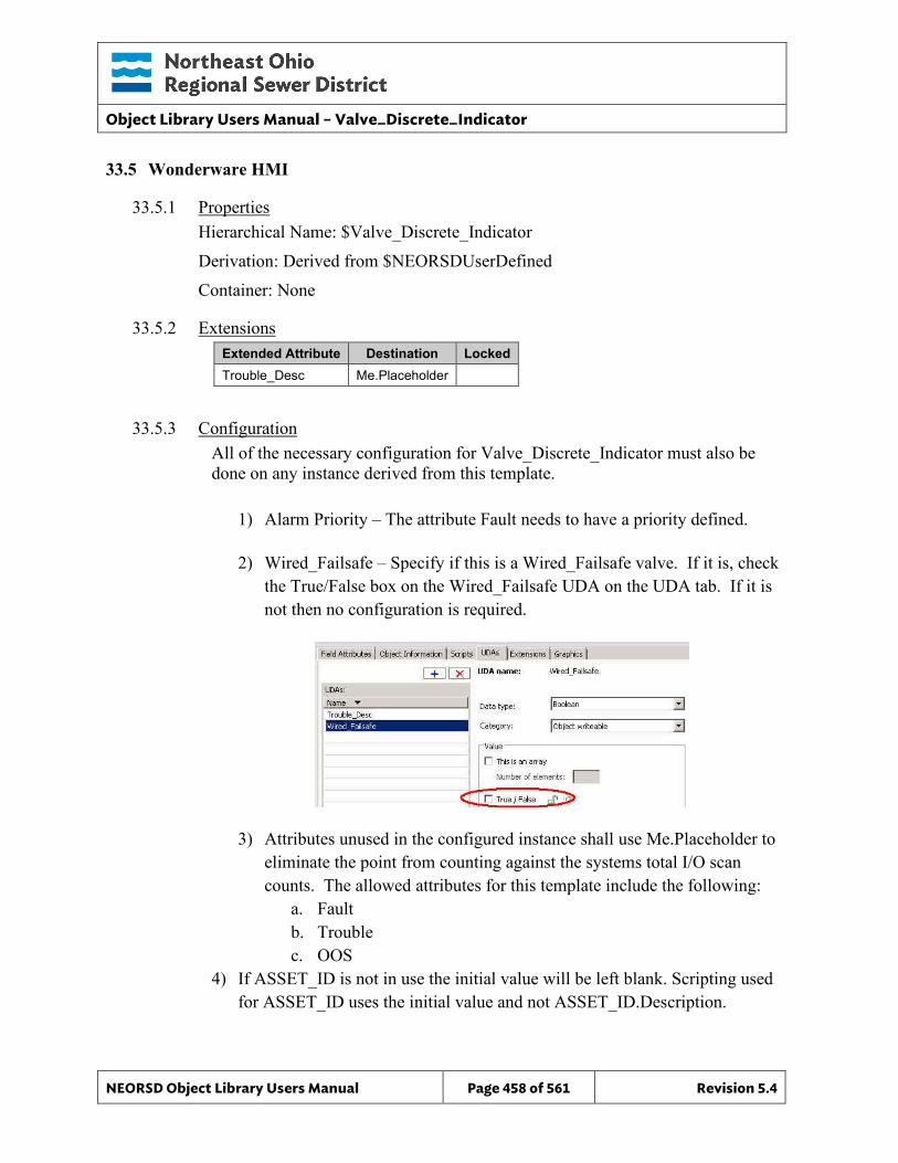
Object Library Users Manual – Valve_Discrete_Indicator
NEORSD Object Library Users Manual Page 458 of 561 Revision 5.4
33.5 Wonderware HMI
33.5.1 Properties Hierarchical Name: $Valve_Discrete_Indicator Derivation: Derived from $NEORSDUserDefined Container: None
33.5.2 Extensions Extended Attribute Destination Locked Trouble_Desc Me.Placeholder
33.5.3 Configuration All of the necessary configuration for Valve_Discrete_Indicator must also be done on any instance derived from this template.
1) Alarm Priority – The attribute Fault needs to have a priority defined.
2) Wired_Failsafe – Specify if this is a Wired_Failsafe valve. If it is, check the True/False box on the Wired_Failsafe UDA on the UDA tab. If it is not then no configuration is required.
3) Attributes unused in the configured instance shall use Me.Placeholder to eliminate the point from counting against the systems total I/O scan counts. The allowed attributes for this template include the following:
a. Fault b. Trouble c. OOS
4) If ASSET_ID is not in use the initial value will be left blank. Scripting used for ASSET_ID uses the initial value and not ASSET_ID.Description.
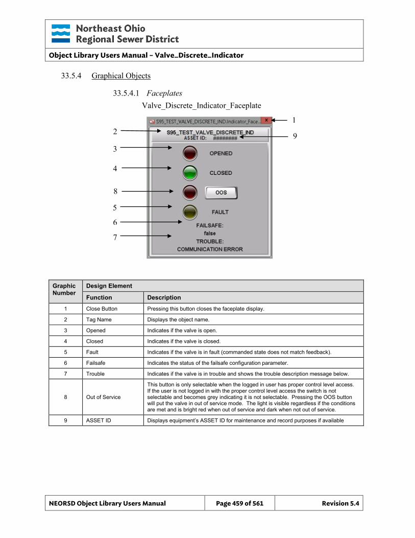
Object Library Users Manual – Valve_Discrete_Indicator
NEORSD Object Library Users Manual Page 459 of 561 Revision 5.4
33.5.4 Graphical Objects
33.5.4.1 Faceplates
Graphic Number
Design Element
Function Description
1 Close Button Pressing this button closes the faceplate display.
2 Tag Name Displays the object name.
3 Opened Indicates if the valve is open.
4 Closed Indicates if the valve is closed.
5 Fault Indicates if the valve is in fault (commanded state does not match feedback).
6 Failsafe Indicates the status of the failsafe configuration parameter.
7 Trouble Indicates if the valve is in trouble and shows the trouble description message below.
8 Out of Service
This button is only selectable when the logged in user has proper control level access. If the user is not logged in with the proper control level access the switch is not selectable and becomes grey indicating it is not selectable. Pressing the OOS button will put the valve in out of service mode. The light is visible regardless if the conditions are met and is bright red when out of service and dark when not out of service.
9 ASSET ID Displays equipment’s ASSET ID for maintenance and record purposes if available
Valve_Discrete_Indicator_Faceplate
2 1
3
4
5
6
7
8
9
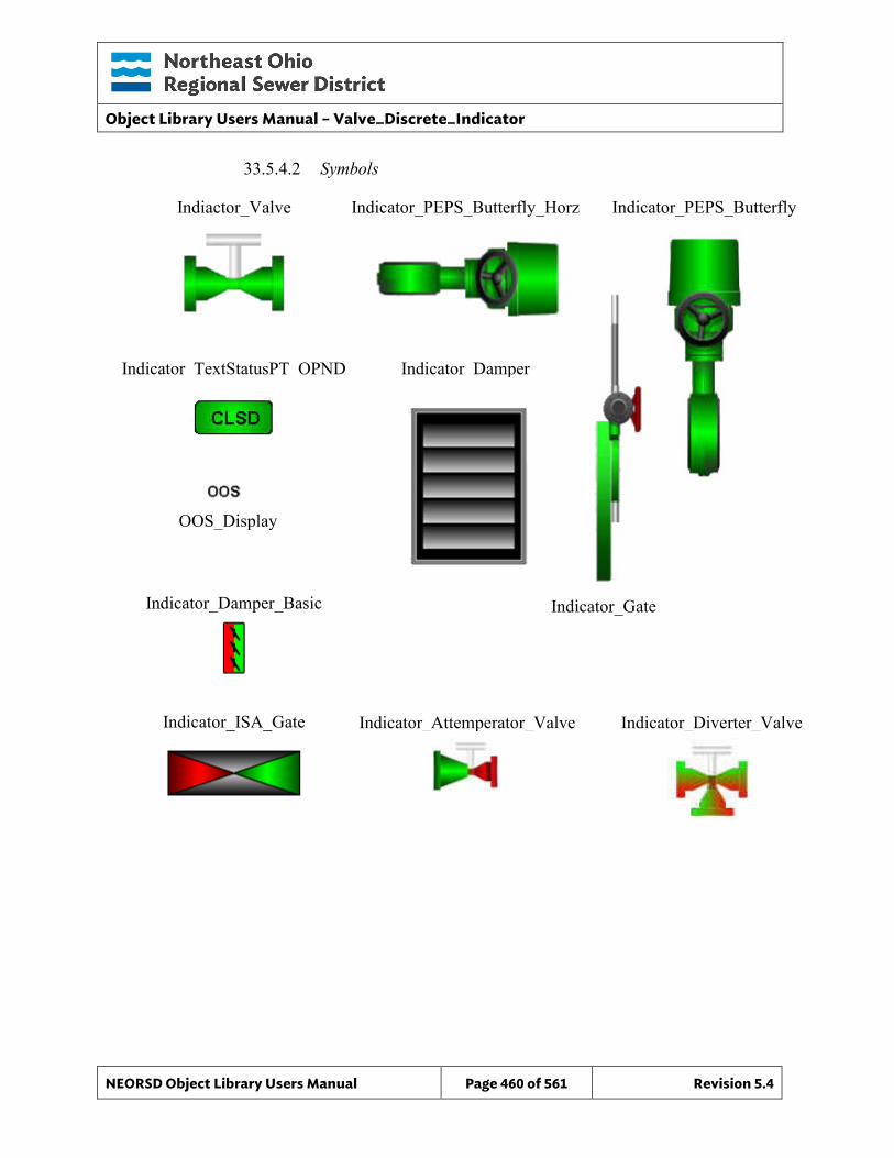
Object Library Users Manual – Valve_Discrete_Indicator
NEORSD Object Library Users Manual Page 460 of 561 Revision 5.4
33.5.4.2 Symbols
Indiactor_Valve Indicator_PEPS_Butterfly_Horz Indicator_PEPS_Butterfly
Indicator_TextStatusPT_OPND Indicator_Damper
Indicator_Gate Indicator_Damper_Basic
Indicator_ISA_Gate Indicator_Attemperator_Valve Indicator_Diverter_Valve
OOS_Display
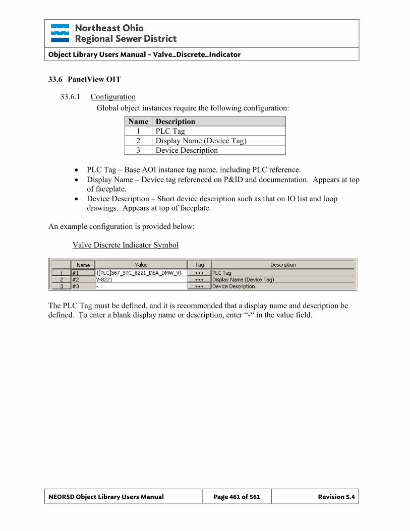
Object Library Users Manual – Valve_Discrete_Indicator
NEORSD Object Library Users Manual Page 461 of 561 Revision 5.4
33.6 PanelView OIT
33.6.1 Configuration Global object instances require the following configuration:
Name Description 1 PLC Tag 2 Display Name (Device Tag) 3 Device Description
• PLC Tag – Base AOI instance tag name, including PLC reference. • Display Name – Device tag referenced on P&ID and documentation. Appears at top
of faceplate. • Device Description – Short device description such as that on IO list and loop
drawings. Appears at top of faceplate. An example configuration is provided below: Valve Discrete Indicator Symbol
The PLC Tag must be defined, and it is recommended that a display name and description be defined. To enter a blank display name or description, enter “-“ in the value field.
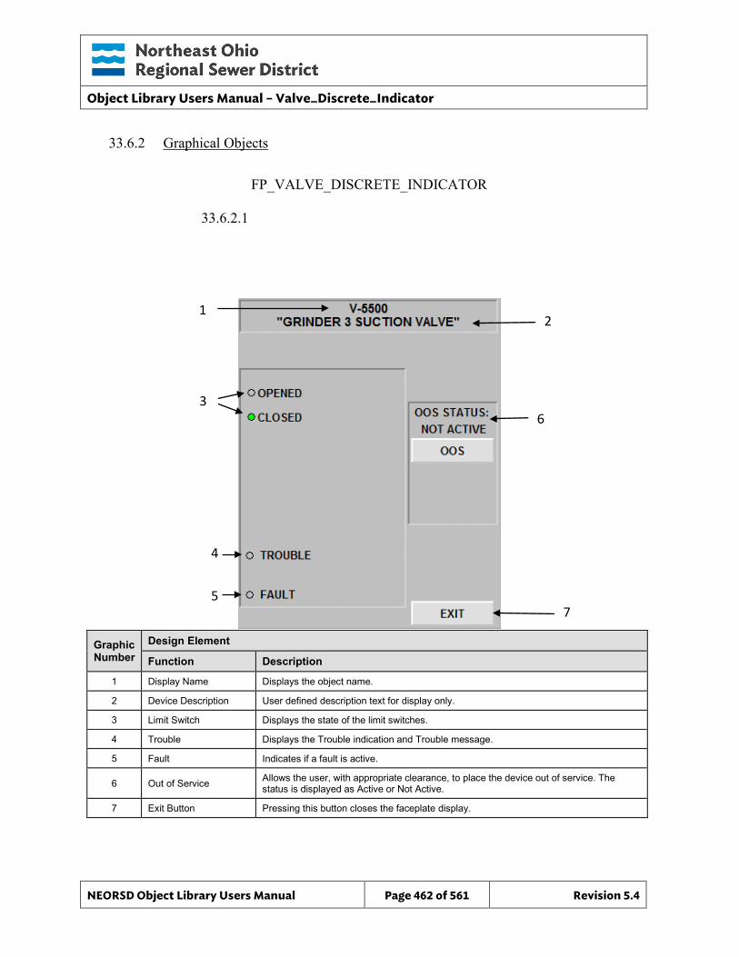
Object Library Users Manual – Valve_Discrete_Indicator
NEORSD Object Library Users Manual Page 462 of 561 Revision 5.4
FP_VALVE_DISCRETE_INDICATOR
33.6.2 Graphical Objects
33.6.2.1
Graphic Number
Design Element
Function Description
1 Display Name Displays the object name.
2 Device Description User defined description text for display only.
3 Limit Switch Displays the state of the limit switches.
4 Trouble Displays the Trouble indication and Trouble message.
5 Fault Indicates if a fault is active.
6 Out of Service Allows the user, with appropriate clearance, to place the device out of service. The status is displayed as Active or Not Active.
7 Exit Button Pressing this button closes the faceplate display.
1 2
3
4
5
6
7
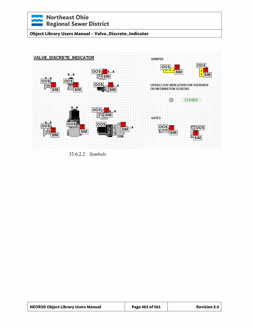
Object Library Users Manual – Valve_Discrete_Indicator
NEORSD Object Library Users Manual Page 463 of 561 Revision 5.4
33.6.2.2 Symbols
Object Library Users Manual – Breaker_52
NEORSD Object Library Users Manual Page 464 of 561 Revision 5.4
34.0 Breaker_52
34.1 Introduction The Breaker_52 template provides a standard representation for displaying the status of a power circuit breaker within the NEORSD control systems. This template is status-only, and provides no means for control or operation of the breaker. Use the Breaker_52 template if:
• Trying to represent the status of a “52” or “27” circuit breaker, either standalone or connected as one of many breakers to a relay control device (such as transformer protection relay).
34.2 Object Features
34.2.1 Value Indications This object provides breaker status information including:
• Closed/Opened Indication • Breaker Tripped • Breaker Withdrawn
34.2.2 Alarming This object will alarm when the breaker “Tripped” status is true.
34.2.3 Simulation This object does not support simulation.
34.2.4 Trouble This object does not support a trouble indication.
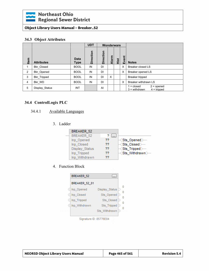
Object Library Users Manual – Breaker_52
NEORSD Object Library Users Manual Page 465 of 561 Revision 5.4
34.3 Object Attributes
UDT Wonderware
Item
Attributes Data Type D
irect
ion
Dire
ctio
n
Ala
rm
His
t
Even
t
Notes 1 Bkr_Closed BOOL IN DI X Breaker closed LS
2 Bkr_Opened BOOL IN DI X Breaker opened LS
3 Bkr_Tripped BOOL IN DI X Breaker tripped
4 Bkr_WD BOOL IN DI X Breaker withdrawn LS
5 Display_Status INT AI 1 = closed 2 = opened 3 = withdrawn 4 = tripped
34.4 ControlLogix PLC
34.4.1 Available Languages
3. Ladder
4. Function Block
Object Library Users Manual – Breaker_52
NEORSD Object Library Users Manual Page 466 of 561 Revision 5.4
34.4.3 Additional Attribute Notes
34.4.3.1 Inputs o Inp_Opened – Input indicating that the breaker is open. o Inp_Closed – Input indicating that the breaker is closed. o Inp_Tripped – Input indicating that the breaker is tripped. o Inp_Withdrawn – Input indicating that the breaker is withdrawn.
34.4.3.2 Internal Configuration o None
34.4.3.3 Outputs o Display Status – Indicates the status of the breaker that should be
displayed. o Sts_Opened – Indicates that the breaker is opened. o Sts_Closed – Indicates that the breaker is closed. o Sts_Tripped – Indicates that the breaker is tripped. o Sts_Withdrawn – Indicates that the breaker is withdrawn.
Object Library Users Manual – Breaker_52
NEORSD Object Library Users Manual Page 467 of 561 Revision 5.4
34.5 Wonderware HMI
34.5.1 Properties Hierarchical Name: $Breaker_Indicator Derivation: Derived from $NEORSDUserDefined Container: None
34.5.2 Extensions None
34.5.3 Configuration All of the necessary configuration for Breaker_Indicator must also be done on any instance derived from this template.
1) Attributes that are not used in the configured instance shall use
Me.Placeholder to eliminate the point from counting against the systems total I/O scan counts.
2) If ASSET_ID is not in use the initial value will be left blank. Scripting used for ASSET_ID uses the initial value and not ASSET_ID.Description.
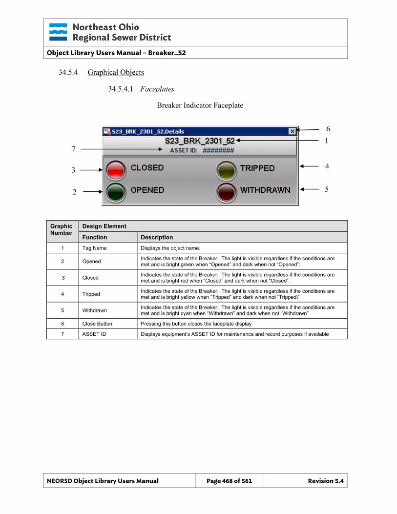
Object Library Users Manual – Breaker_52
NEORSD Object Library Users Manual Page 468 of 561 Revision 5.4
34.5.4 Graphical Objects
34.5.4.1 Faceplates
Graphic Number
Design Element
Function Description
1 Tag Name Displays the object name.
2 Opened Indicates the state of the Breaker. The light is visible regardless if the conditions are met and is bright green when “Opened” and dark when not “Opened”.
3 Closed Indicates the state of the Breaker. The light is visible regardless if the conditions are met and is bright red when “Closed” and dark when not “Closed”.
4 Tripped Indicates the state of the Breaker. The light is visible regardless if the conditions are met and is bright yellow when “Tripped” and dark when not “Tripped\”
5 Withdrawn Indicates the state of the Breaker. The light is visible regardless if the conditions are met and is bright cyan when “Withdrawn” and dark when not “Withdrawn”
6 Close Button Pressing this button closes the faceplate display.
7 ASSET ID Displays equipment’s ASSET ID for maintenance and record purposes if available
Breaker Indicator Faceplate
6 1
4
5
3
2
7
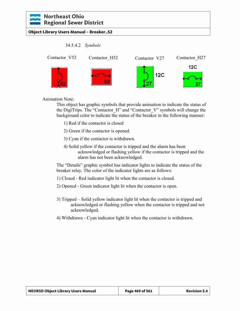
Object Library Users Manual – Breaker_52
NEORSD Object Library Users Manual Page 469 of 561 Revision 5.4
34.5.4.2 Symbols
Animation Note:
This object has graphic symbols that provide animation to indicate the status of the DigiTrips. The “Contactor_H” and “Contactor_V” symbols will change the background color to indicate the status of the breaker in the following manner:
1) Red if the contactor is closed 2) Green if the contactor is opened. 3) Cyan if the contactor is withdrawn. 4) Solid yellow if the contactor is tripped and the alarm has been
acknowledged or flashing yellow if the contactor is tripped and the alarm has not been acknowledged.
The “Details” graphic symbol has indicator lights to indicate the status of the breaker relay. The color of the indicator lights are as follows: 1) Closed - Red indicator light lit when the contactor is closed. 2) Opened - Green indicator light lit when the contactor is open. 3) Tripped – Solid yellow indicator light lit when the contactor is tripped and
acknowledged or flashing yellow when the contactor is tripped and not acknowledged.
4) Withdrawn - Cyan indicator light lit when the contactor is withdrawn.
Contactor_V52 Contactor_H52 Contactor_H27 Contactor V27
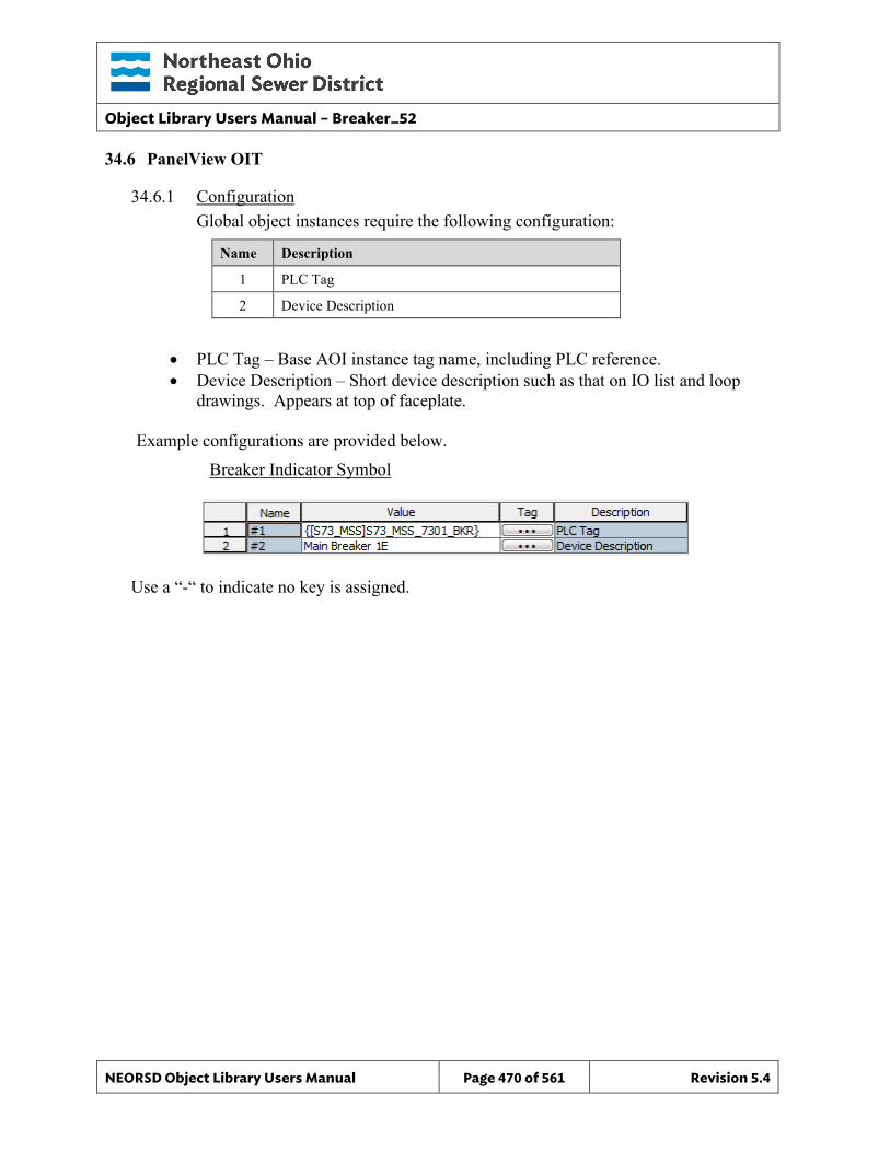
Object Library Users Manual – Breaker_52
NEORSD Object Library Users Manual Page 470 of 561 Revision 5.4
34.6 PanelView OIT
34.6.1 Configuration Global object instances require the following configuration:
Name Description
1 PLC Tag
2 Device Description
• PLC Tag – Base AOI instance tag name, including PLC reference. • Device Description – Short device description such as that on IO list and loop
drawings. Appears at top of faceplate.
Example configurations are provided below. Breaker Indicator Symbol
Use a “-“ to indicate no key is assigned.
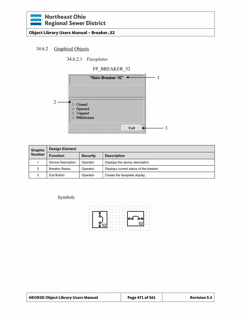
Object Library Users Manual – Breaker_52
NEORSD Object Library Users Manual Page 471 of 561 Revision 5.4
1
3
34.6.2 Graphical Objects
34.6.2.1 Faceplates
Graphic Number
Design Element
Function Security Description
1 Device Description Operator Displays the device description
2 Breaker Status Operator Displays current status of the breaker
3 Exit Button Operator Closes the faceplate display.
Symbols
FP_BREAKER_52
2
Object Library Users Manual – Differential_Protection_Relay
NEORSD Object Library Users Manual Page 472 of 561 Revision 5.4
35.0 Differential_Protection_Relay (SEL_587Z_DPR)
35.1 Introduction The SEL_587Z_DPR template provides a standard representation for displaying analog and status information associated with an SEL-587Z Differential Protection Relay, throughout the NEORSD control system. Use the SEL_587Z_DPR template if:
• Trying to represent the status of and data provided by a feeder protection relay. Do not use the SEL_587_DPR template if:
• The device you are modelling is a power monitoring device not tied with a relay. Consider the AB_Power_Monitor_3000 template instead.
35.2 Object Features
35.2.1 Value Indications In addition to phase current, this object provides breaker status information including:
• 50, 51, and 87 Trip LEDs • Enable LED • Ground Fault LED • Phase A,B,C Fault LEDs
35.2.2 Alarming This object will not trigger any alarms at present.
35.2.3 Simulation This object does not support simulation.
35.2.4 Trouble This object does not support a trouble indication.
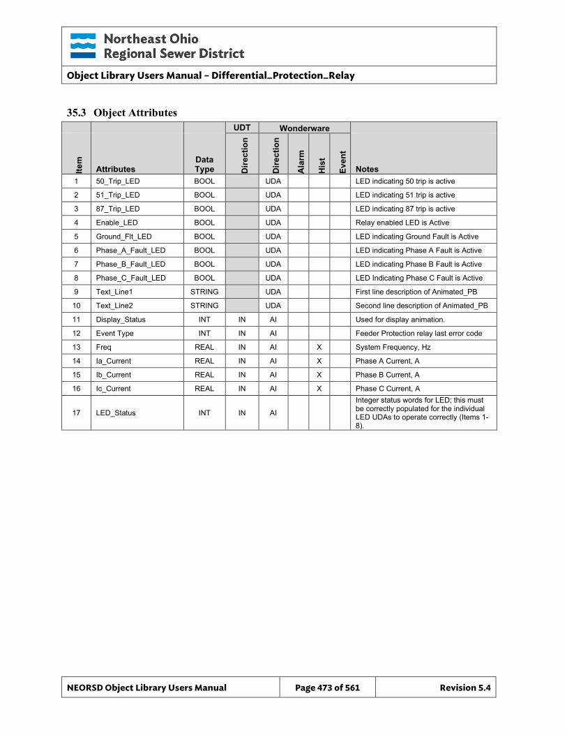
Object Library Users Manual – Differential_Protection_Relay
NEORSD Object Library Users Manual Page 473 of 561 Revision 5.4
35.3 Object Attributes
UDT Wonderware
Item
Attributes Data Type D
irect
ion
Dire
ctio
n
Ala
rm
His
t
Even
t
Notes 1 50_Trip_LED BOOL UDA LED indicating 50 trip is active
2 51_Trip_LED BOOL UDA LED indicating 51 trip is active
3 87_Trip_LED BOOL UDA LED indicating 87 trip is active
4 Enable_LED BOOL UDA Relay enabled LED is Active
5 Ground_Flt_LED BOOL UDA LED indicating Ground Fault is Active
6 Phase_A_Fault_LED BOOL UDA LED indicating Phase A Fault is Active
7 Phase_B_Fault_LED BOOL UDA LED indicating Phase B Fault is Active
8 Phase_C_Fault_LED BOOL UDA LED Indicating Phase C Fault is Active
9 Text_Line1 STRING UDA First line description of Animated_PB
10 Text_Line2 STRING UDA Second line description of Animated_PB
11 Display_Status INT IN AI Used for display animation.
12 Event Type INT IN AI Feeder Protection relay last error code
13 Freq REAL IN AI X System Frequency, Hz
14 Ia_Current REAL IN AI X Phase A Current, A
15 Ib_Current REAL IN AI X Phase B Current, A
16 Ic_Current REAL IN AI X Phase C Current, A
17 LED_Status INT IN AI
Integer status words for LED; this must be correctly populated for the individual LED UDAs to operate correctly (Items 1-8).
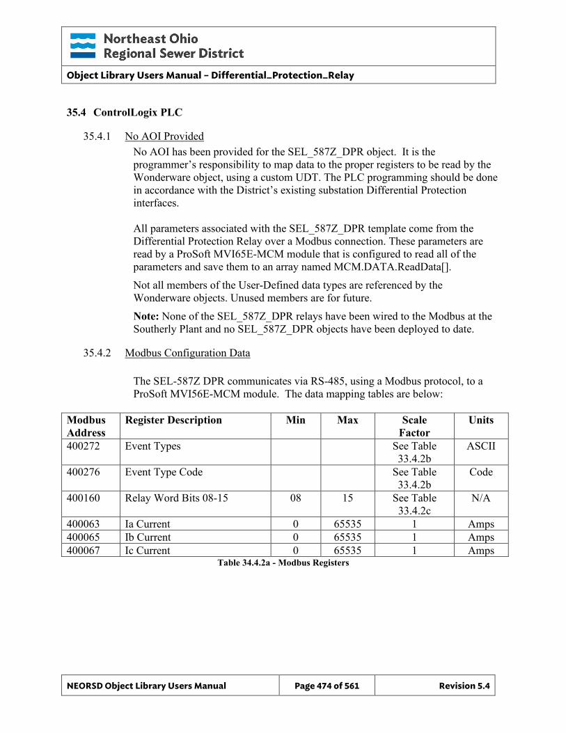
Object Library Users Manual – Differential_Protection_Relay
NEORSD Object Library Users Manual Page 474 of 561 Revision 5.4
35.4 ControlLogix PLC
35.4.1 No AOI Provided No AOI has been provided for the SEL_587Z_DPR object. It is the programmer’s responsibility to map data to the proper registers to be read by the Wonderware object, using a custom UDT. The PLC programming should be done in accordance with the District’s existing substation Differential Protection interfaces. All parameters associated with the SEL_587Z_DPR template come from the Differential Protection Relay over a Modbus connection. These parameters are read by a ProSoft MVI65E-MCM module that is configured to read all of the parameters and save them to an array named MCM.DATA.ReadData[]. Not all members of the User-Defined data types are referenced by the Wonderware objects. Unused members are for future. Note: None of the SEL_587Z_DPR relays have been wired to the Modbus at the Southerly Plant and no SEL_587Z_DPR objects have been deployed to date.
35.4.2 Modbus Configuration Data
The SEL-587Z DPR communicates via RS-485, using a Modbus protocol, to a ProSoft MVI56E-MCM module. The data mapping tables are below:
Modbus Address
Register Description Min Max Scale Factor
Units
400272 Event Types See Table 33.4.2b
ASCII
400276 Event Type Code See Table 33.4.2b
Code
400160 Relay Word Bits 08-15 08 15 See Table 33.4.2c
N/A
400063 Ia Current 0 65535 1 Amps 400065 Ib Current 0 65535 1 Amps 400067 Ic Current 0 65535 1 Amps
Table 34.4.2a - Modbus Registers
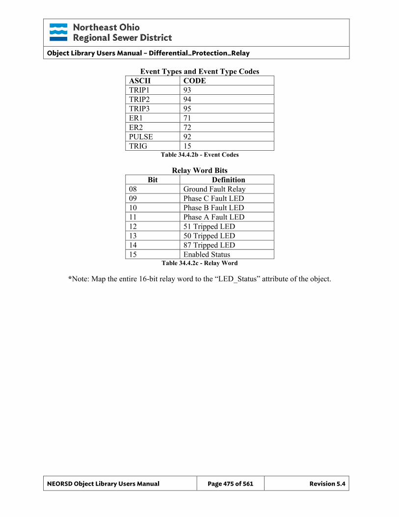
Object Library Users Manual – Differential_Protection_Relay
NEORSD Object Library Users Manual Page 475 of 561 Revision 5.4
Event Types and Event Type Codes ASCII CODE TRIP1 93 TRIP2 94 TRIP3 95 ER1 71 ER2 72 PULSE 92 TRIG 15
Table 34.4.2b - Event Codes
Relay Word Bits Bit Definition
08 Ground Fault Relay 09 Phase C Fault LED 10 Phase B Fault LED 11 Phase A Fault LED 12 51 Tripped LED 13 50 Tripped LED 14 87 Tripped LED 15 Enabled Status
Table 34.4.2c - Relay Word
*Note: Map the entire 16-bit relay word to the “LED_Status” attribute of the object.
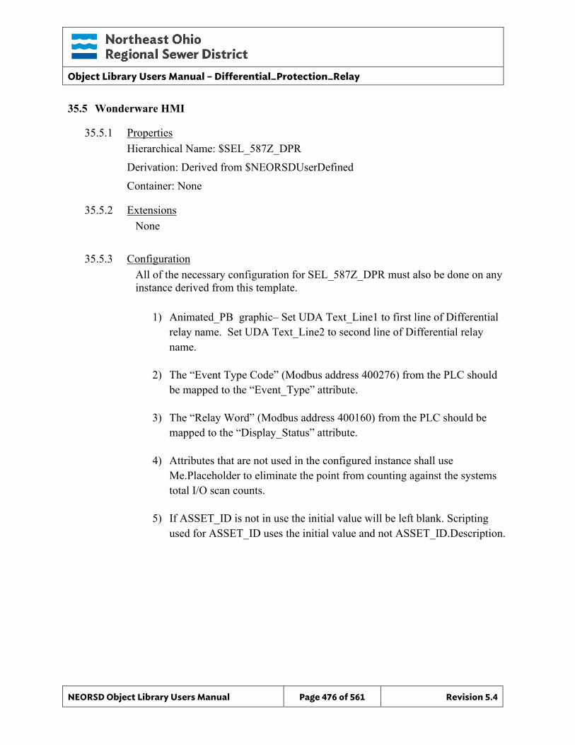
Object Library Users Manual – Differential_Protection_Relay
NEORSD Object Library Users Manual Page 476 of 561 Revision 5.4
35.5 Wonderware HMI
35.5.1 Properties Hierarchical Name: $SEL_587Z_DPR Derivation: Derived from $NEORSDUserDefined Container: None
35.5.2 Extensions None
35.5.3 Configuration All of the necessary configuration for SEL_587Z_DPR must also be done on any instance derived from this template.
1) Animated_PB graphic– Set UDA Text_Line1 to first line of Differential relay name. Set UDA Text_Line2 to second line of Differential relay name.
2) The “Event Type Code” (Modbus address 400276) from the PLC should
be mapped to the “Event_Type” attribute.
3) The “Relay Word” (Modbus address 400160) from the PLC should be mapped to the “Display_Status” attribute.
4) Attributes that are not used in the configured instance shall use
Me.Placeholder to eliminate the point from counting against the systems total I/O scan counts.
5) If ASSET_ID is not in use the initial value will be left blank. Scripting
used for ASSET_ID uses the initial value and not ASSET_ID.Description.
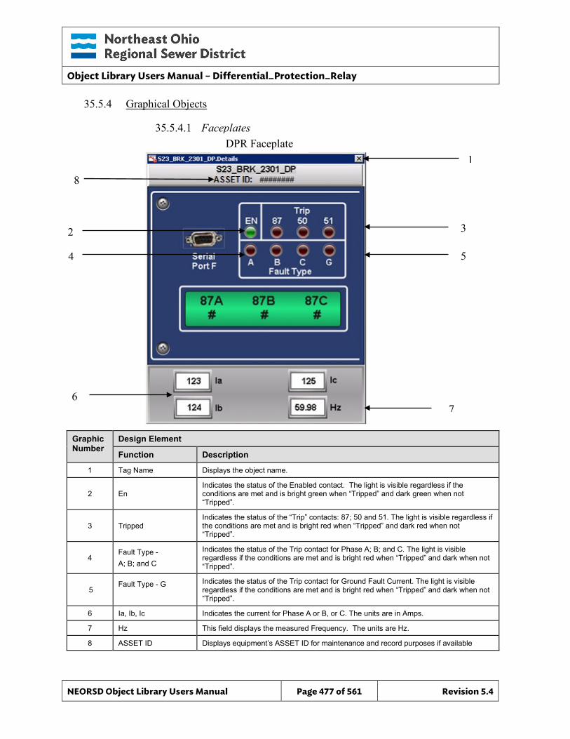
Object Library Users Manual – Differential_Protection_Relay
NEORSD Object Library Users Manual Page 477 of 561 Revision 5.4
35.5.4 Graphical Objects
35.5.4.1 Faceplates
Graphic Number
Design Element
Function Description
1 Tag Name Displays the object name.
2 En Indicates the status of the Enabled contact. The light is visible regardless if the conditions are met and is bright green when “Tripped” and dark green when not “Tripped”.
3 Tripped Indicates the status of the “Trip” contacts: 87; 50 and 51. The light is visible regardless if the conditions are met and is bright red when “Tripped” and dark red when not “Tripped”.
4 Fault Type - A; B; and C
Indicates the status of the Trip contact for Phase A; B; and C. The light is visible regardless if the conditions are met and is bright red when “Tripped” and dark when not “Tripped”.
5 Fault Type - G
Indicates the status of the Trip contact for Ground Fault Current. The light is visible regardless if the conditions are met and is bright red when “Tripped” and dark when not “Tripped”.
6 Ia, Ib, Ic Indicates the current for Phase A or B, or C. The units are in Amps.
7 Hz This field displays the measured Frequency. The units are Hz.
8 ASSET ID Displays equipment’s ASSET ID for maintenance and record purposes if available
DPR Faceplate 1
3 2 4 5
7
6
8
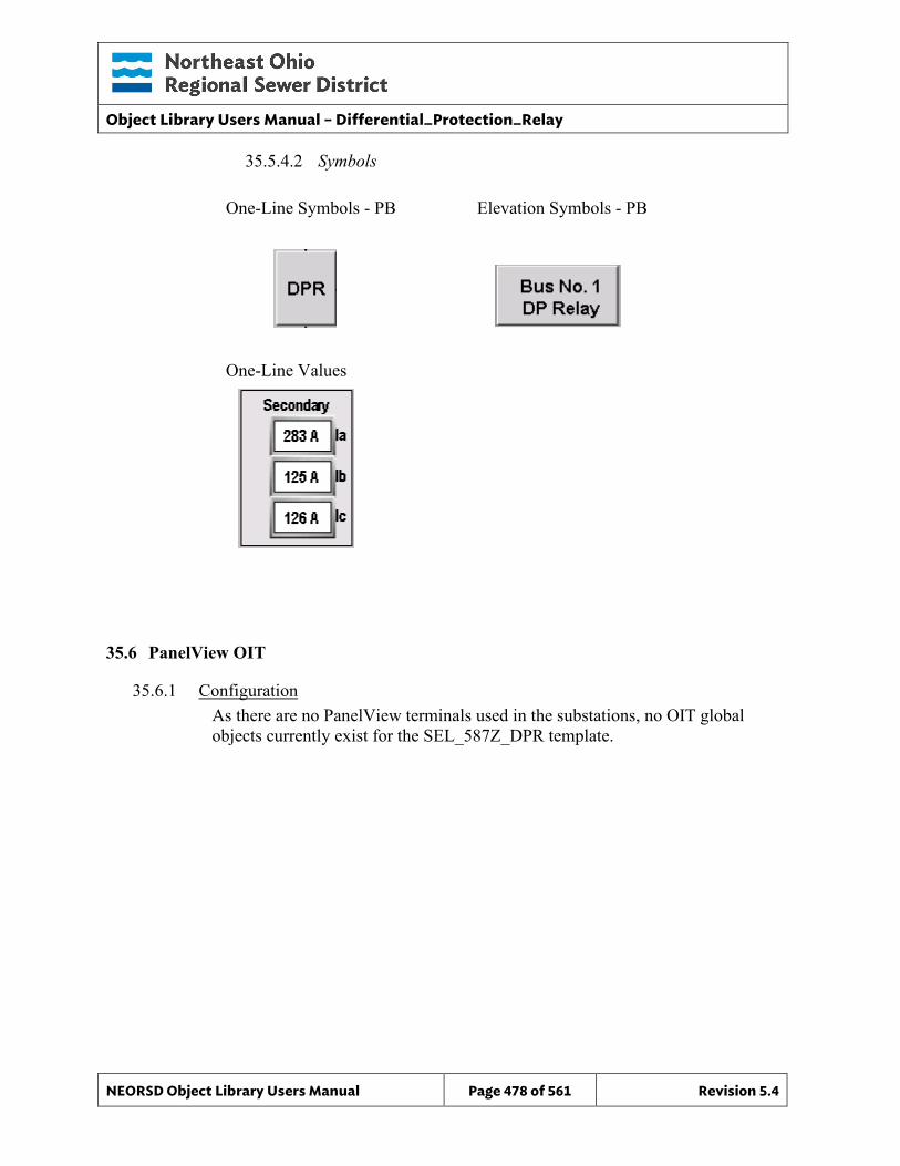
Object Library Users Manual – Differential_Protection_Relay
NEORSD Object Library Users Manual Page 478 of 561 Revision 5.4
35.5.4.2 Symbols
One-Line Symbols - PB Elevation Symbols - PB
One-Line Values
35.6 PanelView OIT
35.6.1 Configuration As there are no PanelView terminals used in the substations, no OIT global objects currently exist for the SEL_587Z_DPR template.

Object Library Users Manual – Differential_Protection_Relay
NEORSD Object Library Users Manual Page 479 of 561 Revision 5.4
This page left blank intentionally.
Object Library Users Manual – DigiTrip_520MC
NEORSD Object Library Users Manual Page 480 of 561 Revision 5.4
36.0 DigiTrip_520MC_CB
36.1 Introduction
The DigiTrip 520MC circuit breaker template provides a standard representation for breaker subsystems that provide the protective functions of a circuit breaker. The template provides indication of discrete status and alarming, as well as display of analog data associated with the DigiTrip 520MC, throughout the NEORSD control systems. Use the DigiTrip_520MC_CB template if:
• Trying to represent the status of and data provided by a DigiTrip protective module.
Do not use the DigiTrip_520MC_CB template if: • The device you are modeling is not a DigiTrip.
36.2 Object Features
36.2.1 Value Indications In addition to phase current and status codes, the object provides breaker status including:
• Display_Status – LED Status Word • Bkr_Closed • Bkr_Opened • Bkr_Tripped (with status words to indicate the reason for the trip) • Bkr_WD • Bkr_MM – Available on devices that have maintenance mode enabled
36.2.2 Alarming An alarm is generated when the object receives a “Bkr_Tripped” or “Bkr_MM” input.
36.2.3 Simulation This object does not support simulation.
36.2.4 Trouble This object does not support a trouble indication.
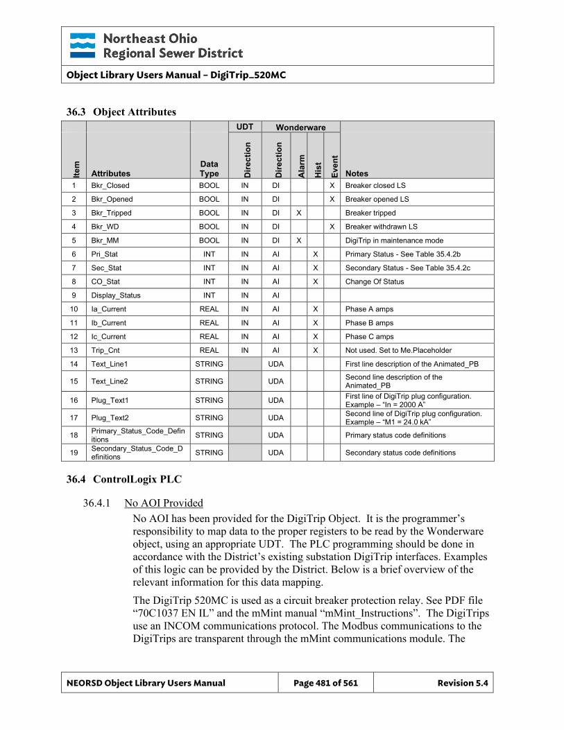
Object Library Users Manual – DigiTrip_520MC
NEORSD Object Library Users Manual Page 481 of 561 Revision 5.4
36.3 Object Attributes
UDT Wonderware
Item
Attributes Data Type D
irect
ion
Dire
ctio
n
Ala
rm
His
t
Even
t
Notes 1 Bkr_Closed BOOL IN DI X Breaker closed LS
2 Bkr_Opened BOOL IN DI X Breaker opened LS
3 Bkr_Tripped BOOL IN DI X Breaker tripped
4 Bkr_WD BOOL IN DI X Breaker withdrawn LS
5 Bkr_MM BOOL IN DI X DigiTrip in maintenance mode
6 Pri_Stat INT IN AI X Primary Status - See Table 35.4.2b
7 Sec_Stat INT IN AI X Secondary Status - See Table 35.4.2c
8 CO_Stat INT IN AI X Change Of Status
9 Display_Status INT IN AI
10 Ia_Current REAL IN AI X Phase A amps
11 Ib_Current REAL IN AI X Phase B amps
12 Ic_Current REAL IN AI X Phase C amps
13 Trip_Cnt REAL IN AI X Not used. Set to Me.Placeholder
14 Text_Line1 STRING UDA First line description of the Animated_PB
15 Text_Line2 STRING UDA Second line description of the Animated_PB
16 Plug_Text1 STRING UDA First line of DigiTrip plug configuration. Example – “In = 2000 A”
17 Plug_Text2 STRING UDA Second line of DigiTrip plug configuration. Example – “M1 = 24.0 kA”
18 Primary_Status_Code_Definitions STRING UDA Primary status code definitions
19 Secondary_Status_Code_Definitions STRING UDA Secondary status code definitions
36.4 ControlLogix PLC
36.4.1 No AOI Provided No AOI has been provided for the DigiTrip Object. It is the programmer’s responsibility to map data to the proper registers to be read by the Wonderware object, using an appropriate UDT. The PLC programming should be done in accordance with the District’s existing substation DigiTrip interfaces. Examples of this logic can be provided by the District. Below is a brief overview of the relevant information for this data mapping. The DigiTrip 520MC is used as a circuit breaker protection relay. See PDF file “70C1037 EN IL” and the mMint manual “mMint_Instructions”. The DigiTrips use an INCOM communications protocol. The Modbus communications to the DigiTrips are transparent through the mMint communications module. The
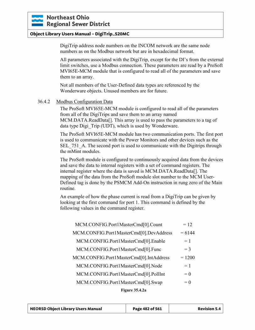
Object Library Users Manual – DigiTrip_520MC
NEORSD Object Library Users Manual Page 482 of 561 Revision 5.4
DigiTrip address node numbers on the INCOM network are the same node numbers as on the Modbus network but are in hexadecimal format. All parameters associated with the DigiTrip, except for the DI’s from the external limit switches, use a Modbus connection. These parameters are read by a ProSoft MVI65E-MCM module that is configured to read all of the parameters and save them to an array. Not all members of the User-Defined data types are referenced by the Wonderware objects. Unused members are for future.
36.4.2 Modbus Configuration Data The ProSoft MVI65E-MCM module is configured to read all of the parameters from all of the DigiTrips and save them to an array named MCM.DATA.ReadData[]. This array is used to pass the parameters to a tag of data type Digi_Trip (UDT), which is used by Wonderware. The ProSoft MVI65E-MCM module has two communication ports. The first port is used to communicate with the Power Monitors and other devices such as the SEL_751_A. The second port is used to communicate with the Digitrips through the mMint modules. The ProSoft module is configured to continuously acquired data from the devices and save the data to internal registers with a set of command registers. The internal register where the data is saved is MCM.DATA.ReadData[]. The mapping of the data from the ProSoft module slot number to the MCM User-Defined tag is done by the PSMCM Add-On instruction in rung zero of the Main routine. An example of how the phase current is read from a DigiTrip can be given by looking at the first command for port 1. This command is defined by the following values in the command register.
MCM.CONFIG.Port1MasterCmd[0].Count = 12 MCM.CONFIG.Port1MasterCmd[0].DevAddress = 6144
MCM.CONFIG.Port1MasterCmd[0].Enable = 1 MCM.CONFIG.Port1MasterCmd[0].Func = 3
MCM.CONFIG.Port1MasterCmd[0].IntAddress = 1200 MCM.CONFIG.Port1MasterCmd[0].Node = 1 MCM.CONFIG.Port1MasterCmd[0].PollInt = 0 MCM.CONFIG.Port1MasterCmd[0].Swap = 0
Figure 35.4.2a
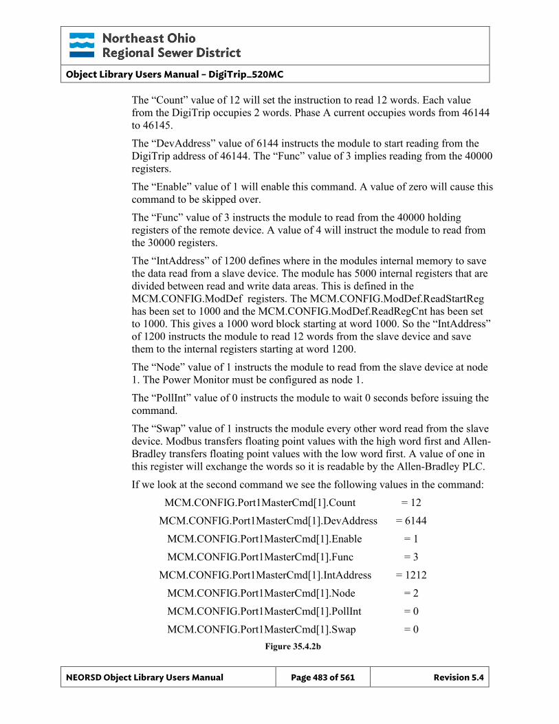
Object Library Users Manual – DigiTrip_520MC
NEORSD Object Library Users Manual Page 483 of 561 Revision 5.4
The “Count” value of 12 will set the instruction to read 12 words. Each value from the DigiTrip occupies 2 words. Phase A current occupies words from 46144 to 46145. The “DevAddress” value of 6144 instructs the module to start reading from the DigiTrip address of 46144. The “Func” value of 3 implies reading from the 40000 registers. The “Enable” value of 1 will enable this command. A value of zero will cause this command to be skipped over. The “Func” value of 3 instructs the module to read from the 40000 holding registers of the remote device. A value of 4 will instruct the module to read from the 30000 registers. The “IntAddress” of 1200 defines where in the modules internal memory to save the data read from a slave device. The module has 5000 internal registers that are divided between read and write data areas. This is defined in the MCM.CONFIG.ModDef registers. The MCM.CONFIG.ModDef.ReadStartReg has been set to 1000 and the MCM.CONFIG.ModDef.ReadRegCnt has been set to 1000. This gives a 1000 word block starting at word 1000. So the “IntAddress” of 1200 instructs the module to read 12 words from the slave device and save them to the internal registers starting at word 1200. The “Node” value of 1 instructs the module to read from the slave device at node 1. The Power Monitor must be configured as node 1. The “PollInt” value of 0 instructs the module to wait 0 seconds before issuing the command. The “Swap” value of 1 instructs the module every other word read from the slave device. Modbus transfers floating point values with the high word first and Allen-Bradley transfers floating point values with the low word first. A value of one in this register will exchange the words so it is readable by the Allen-Bradley PLC. If we look at the second command we see the following values in the command:
MCM.CONFIG.Port1MasterCmd[1].Count = 12 MCM.CONFIG.Port1MasterCmd[1].DevAddress = 6144
MCM.CONFIG.Port1MasterCmd[1].Enable = 1 MCM.CONFIG.Port1MasterCmd[1].Func = 3
MCM.CONFIG.Port1MasterCmd[1].IntAddress = 1212 MCM.CONFIG.Port1MasterCmd[1].Node = 2 MCM.CONFIG.Port1MasterCmd[1].PollInt = 0 MCM.CONFIG.Port1MasterCmd[1].Swap = 0
Figure 35.4.2b
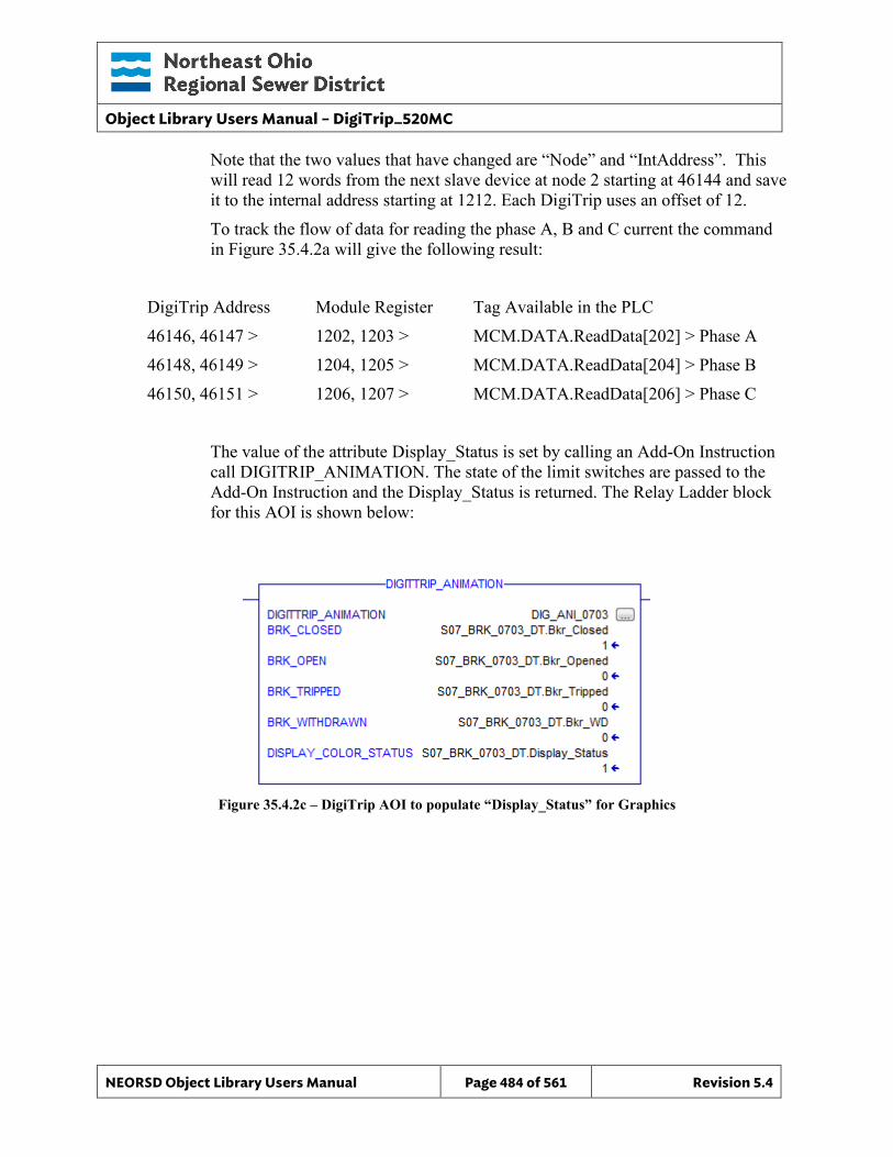
Object Library Users Manual – DigiTrip_520MC
NEORSD Object Library Users Manual Page 484 of 561 Revision 5.4
Note that the two values that have changed are “Node” and “IntAddress”. This will read 12 words from the next slave device at node 2 starting at 46144 and save it to the internal address starting at 1212. Each DigiTrip uses an offset of 12. To track the flow of data for reading the phase A, B and C current the command in Figure 35.4.2a will give the following result:
DigiTrip Address Module Register Tag Available in the PLC 46146, 46147 > 1202, 1203 > MCM.DATA.ReadData[202] > Phase A 46148, 46149 > 1204, 1205 > MCM.DATA.ReadData[204] > Phase B 46150, 46151 > 1206, 1207 > MCM.DATA.ReadData[206] > Phase C
The value of the attribute Display_Status is set by calling an Add-On Instruction call DIGITRIP_ANIMATION. The state of the limit switches are passed to the Add-On Instruction and the Display_Status is returned. The Relay Ladder block for this AOI is shown below:
Figure 35.4.2c – DigiTrip AOI to populate “Display_Status” for Graphics
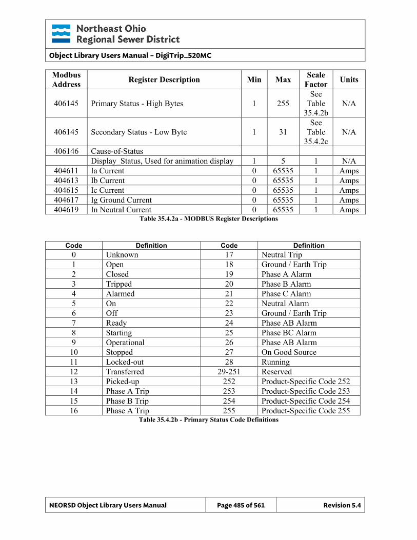
Object Library Users Manual – DigiTrip_520MC
NEORSD Object Library Users Manual Page 485 of 561 Revision 5.4
Modbus Address Register Description Min Max Scale
Factor Units
406145 Primary Status - High Bytes 1 255 See
Table 35.4.2b
N/A
406145 Secondary Status - Low Byte 1 31 See
Table 35.4.2c
N/A
406146 Cause-of-Status Display_Status, Used for animation display 1 5 1 N/A
404611 Ia Current 0 65535 1 Amps 404613 Ib Current 0 65535 1 Amps 404615 Ic Current 0 65535 1 Amps 404617 Ig Ground Current 0 65535 1 Amps 404619 In Neutral Current 0 65535 1 Amps
Table 35.4.2a - MODBUS Register Descriptions
Code Definition Code Definition 0 Unknown 17 Neutral Trip 1 Open 18 Ground / Earth Trip 2 Closed 19 Phase A Alarm 3 Tripped 20 Phase B Alarm 4 Alarmed 21 Phase C Alarm 5 On 22 Neutral Alarm 6 Off 23 Ground / Earth Trip 7 Ready 24 Phase AB Alarm 8 Starting 25 Phase BC Alarm 9 Operational 26 Phase AB Alarm 10 Stopped 27 On Good Source 11 Locked-out 28 Running 12 Transferred 29-251 Reserved 13 Picked-up 252 Product-Specific Code 252 14 Phase A Trip 253 Product-Specific Code 253 15 Phase B Trip 254 Product-Specific Code 254 16 Phase A Trip 255 Product-Specific Code 255
Table 35.4.2b - Primary Status Code Definitions
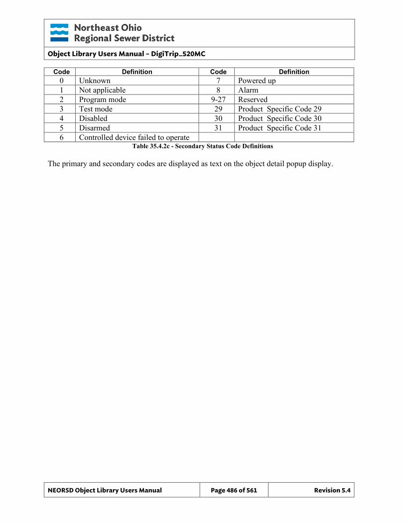
Object Library Users Manual – DigiTrip_520MC
NEORSD Object Library Users Manual Page 486 of 561 Revision 5.4
Code Definition Code Definition 0 Unknown 7 Powered up 1 Not applicable 8 Alarm 2 Program mode 9-27 Reserved 3 Test mode 29 Product Specific Code 29 4 Disabled 30 Product Specific Code 30 5 Disarmed 31 Product Specific Code 31 6 Controlled device failed to operate
Table 35.4.2c - Secondary Status Code Definitions The primary and secondary codes are displayed as text on the object detail popup display.

Object Library Users Manual – DigiTrip_520MC
NEORSD Object Library Users Manual Page 487 of 561 Revision 5.4
36.5 Wonderware HMI
36.5.1 Properties Hierarchical Name: $DigiTrip_520MC_CB Derivation: Derived from $NEORSDUserDefined Container: None
36.5.2 Extensions None
36.5.3 Configuration All of the necessary configuration for SEL_751_FPR must also be done on any instance derived from this template.
1) Animated_PB and Animated_750_PB Graphic – Set UDA Text_Line1 to
first line of DigiTrip name. Set UDA Text_Line2 to second line of DigiTrip name.
2) Attributes that are not used in the configured instance shall use
Me.Placeholder to eliminate the point from counting against the systems total I/O scan counts. These shall include values not available on delta configured systems when installed on a delta system.
3) If ASSET_ID is not in use the initial value will be left blank. Scripting
used for ASSET_ID uses the initial value and not ASSET_ID.Description.
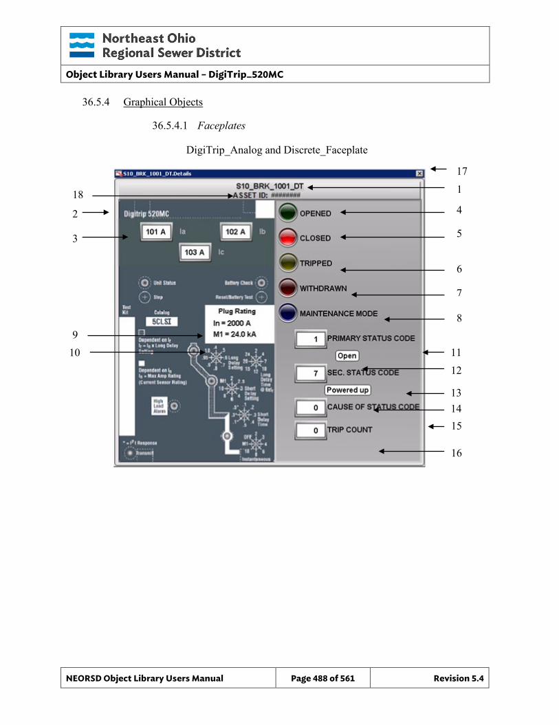
Object Library Users Manual – DigiTrip_520MC
NEORSD Object Library Users Manual Page 488 of 561 Revision 5.4
36.5.4 Graphical Objects
36.5.4.1 Faceplates
DigiTrip_Analog and Discrete_Faceplate
4
1
2
3 5
6 7 8 9
10
11 12
13 14 15
16
17
18
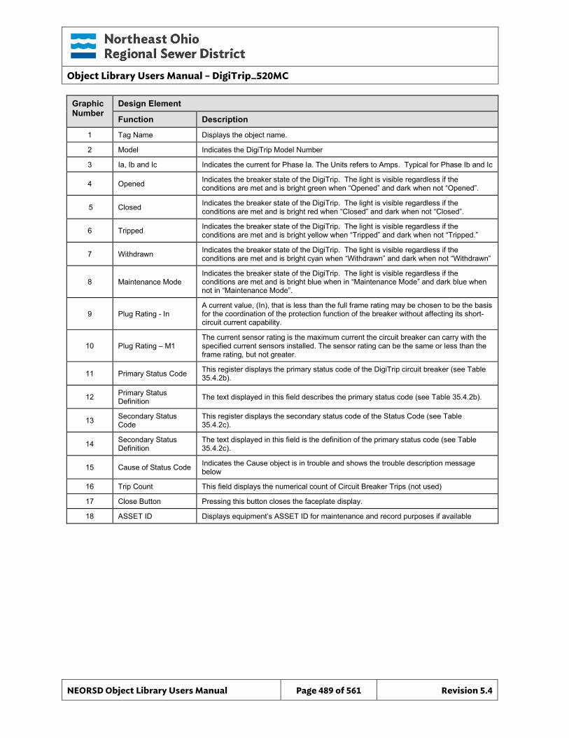
Object Library Users Manual – DigiTrip_520MC
NEORSD Object Library Users Manual Page 489 of 561 Revision 5.4
Graphic Number
Design Element
Function Description
1 Tag Name Displays the object name.
2 Model Indicates the DigiTrip Model Number
3 Ia, Ib and Ic Indicates the current for Phase Ia. The Units refers to Amps. Typical for Phase Ib and Ic
4 Opened Indicates the breaker state of the DigiTrip. The light is visible regardless if the conditions are met and is bright green when “Opened” and dark when not “Opened”.
5 Closed Indicates the breaker state of the DigiTrip. The light is visible regardless if the conditions are met and is bright red when “Closed” and dark when not “Closed”.
6 Tripped Indicates the breaker state of the DigiTrip. The light is visible regardless if the conditions are met and is bright yellow when “Tripped” and dark when not “Tripped.”
7 Withdrawn Indicates the breaker state of the DigiTrip. The light is visible regardless if the conditions are met and is bright cyan when “Withdrawn” and dark when not “Withdrawn”
8 Maintenance Mode Indicates the breaker state of the DigiTrip. The light is visible regardless if the conditions are met and is bright blue when in “Maintenance Mode” and dark blue when not in “Maintenance Mode”.
9 Plug Rating - In A current value, (In), that is less than the full frame rating may be chosen to be the basis for the coordination of the protection function of the breaker without affecting its short-circuit current capability.
10 Plug Rating – M1 The current sensor rating is the maximum current the circuit breaker can carry with the specified current sensors installed. The sensor rating can be the same or less than the frame rating, but not greater.
11 Primary Status Code This register displays the primary status code of the DigiTrip circuit breaker (see Table 35.4.2b).
12 Primary Status Definition The text displayed in this field describes the primary status code (see Table 35.4.2b).
13 Secondary Status Code
This register displays the secondary status code of the Status Code (see Table 35.4.2c).
14 Secondary Status Definition
The text displayed in this field is the definition of the primary status code (see Table 35.4.2c).
15 Cause of Status Code Indicates the Cause object is in trouble and shows the trouble description message below
16 Trip Count This field displays the numerical count of Circuit Breaker Trips (not used)
17 Close Button Pressing this button closes the faceplate display.
18 ASSET ID Displays equipment’s ASSET ID for maintenance and record purposes if available
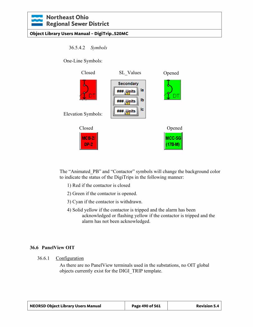
Object Library Users Manual – DigiTrip_520MC
NEORSD Object Library Users Manual Page 490 of 561 Revision 5.4
36.5.4.2 Symbols
One-Line Symbols:
Elevation Symbols:
The “Animated_PB” and “Contactor” symbols will change the background color to indicate the status of the DigiTrips in the following manner:
1) Red if the contactor is closed 2) Green if the contactor is opened. 3) Cyan if the contactor is withdrawn. 4) Solid yellow if the contactor is tripped and the alarm has been
acknowledged or flashing yellow if the contactor is tripped and the alarm has not been acknowledged.
36.6 PanelView OIT
36.6.1 Configuration As there are no PanelView terminals used in the substations, no OIT global objects currently exist for the DIGI_TRIP template.
Closed Opened
Opened Closed
SL_Values

Object Library Users Manual – DigiTrip_520MC
NEORSD Object Library Users Manual Page 491 of 561 Revision 5.4
This page left blank intentionally.
Object Library Users Manual – Feeder_Protection_Relay
NEORSD Object Library Users Manual Page 492 of 561 Revision 5.4
37.0 Feeder_Protection_Relay (SEL_751A_FPR)
37.1 Introduction The Feeder Protection Relay template provides a standard representation for displaying discrete operational and alarm status of a SEL-751A (or GE 750) feeder protection relay for status monitoring. Use the SEL_751_FPR template if:
• Trying to represent the status of and data provided by a feeder protection relay. Do not use the SEL_787_FPR template if:
• The device you are modeling is a power monitoring device with no relay functions. Consider the AB_Power_Monitor_3000 template instead.
The SEL-787 unit upon which this template is based provides programmable protective functions for power distribution systems. The protection of the power distribution system, by the SEL-751A, is provided by an interface through an external relay such as a 52 relay. The SEL-751A can also be programmed for a Maintenance Mode that provides the same function as the Maintenance Mode used on the DigiTrips. This option can be enabled by setting UDA MM_Mode to True at the instance level. The SEL_751A_FPR also includes a faceplate to mimic the GE 750 Feeder Management Relay. The same ControLogix UDT is used. The GE_750_FPR_FacePlate_Panel graphic is associated with the 750_Contactor_H and the 750_Contactor_V push buttons.
37.2 Object Features
37.2.1 Value Indications In addition to power data, this object provides breaker status information including:
• Display_Status – LED Status Word (SEL_751A faceplate only) • Bkr_Closed - (GE-750 faceplate only) • Bkr_Opened – (GE-750 faceplate only) • Bkr_Tripped – (GE-750 faceplate only) • Bkr_WD – (GE-750 faceplate only) • Bkr_MM – Available on FPRs that have maintenance mode enabled
37.2.2 Alarming This object has no alarm capability.
37.2.3 Simulation This object does not support simulation.
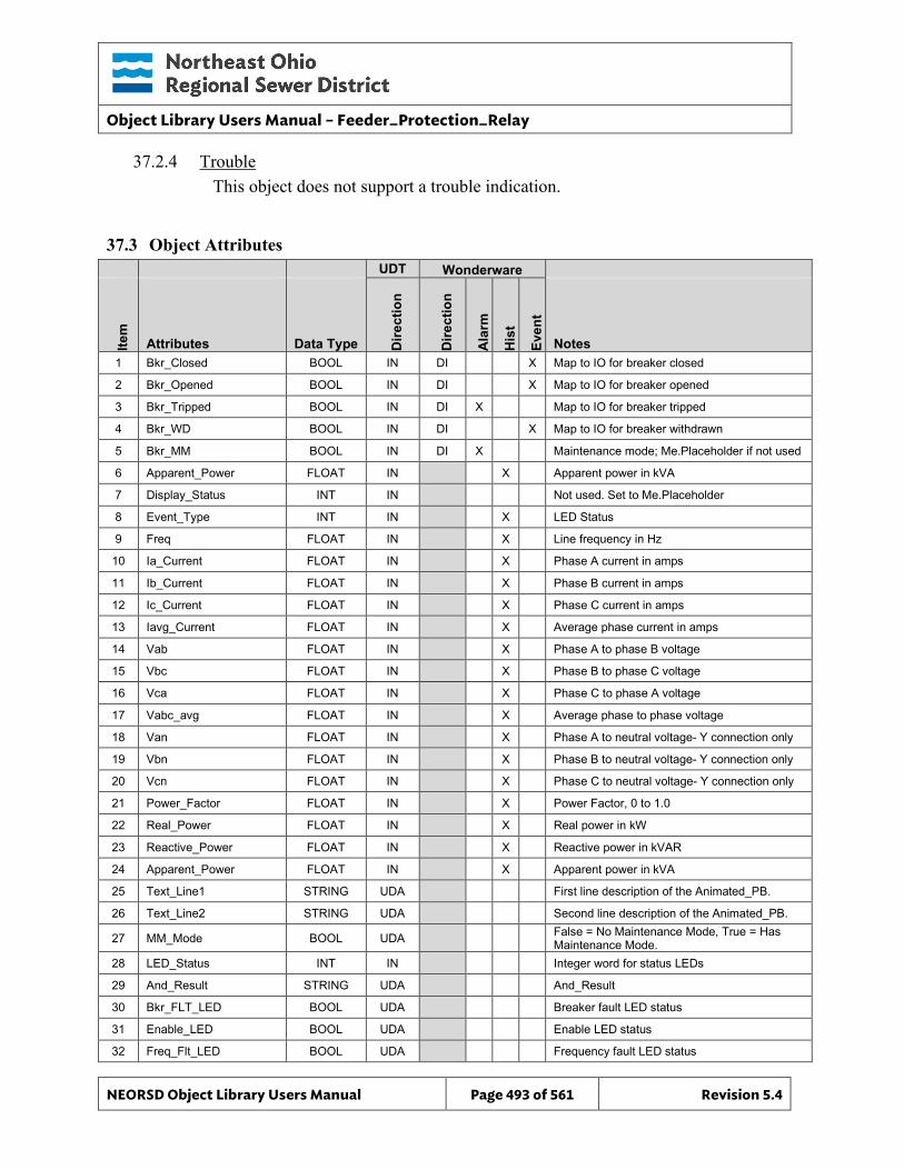
Object Library Users Manual – Feeder_Protection_Relay
NEORSD Object Library Users Manual Page 493 of 561 Revision 5.4
37.2.4 Trouble This object does not support a trouble indication.
37.3 Object Attributes
UDT Wonderware
Item
Attributes Data Type Dire
ctio
n
Dire
ctio
n
Ala
rm
His
t
Even
t
Notes 1 Bkr_Closed BOOL IN DI X Map to IO for breaker closed
2 Bkr_Opened BOOL IN DI X Map to IO for breaker opened
3 Bkr_Tripped BOOL IN DI X Map to IO for breaker tripped
4 Bkr_WD BOOL IN DI X Map to IO for breaker withdrawn
5 Bkr_MM BOOL IN DI X Maintenance mode; Me.Placeholder if not used
6 Apparent_Power FLOAT IN X Apparent power in kVA
7 Display_Status INT IN Not used. Set to Me.Placeholder
8 Event_Type INT IN X LED Status
9 Freq FLOAT IN X Line frequency in Hz
10 Ia_Current FLOAT IN X Phase A current in amps
11 Ib_Current FLOAT IN X Phase B current in amps
12 Ic_Current FLOAT IN X Phase C current in amps
13 Iavg_Current FLOAT IN X Average phase current in amps
14 Vab FLOAT IN X Phase A to phase B voltage
15 Vbc FLOAT IN X Phase B to phase C voltage
16 Vca FLOAT IN X Phase C to phase A voltage
17 Vabc_avg FLOAT IN X Average phase to phase voltage
18 Van FLOAT IN X Phase A to neutral voltage- Y connection only
19 Vbn FLOAT IN X Phase B to neutral voltage- Y connection only
20 Vcn FLOAT IN X Phase C to neutral voltage- Y connection only
21 Power_Factor FLOAT IN X Power Factor, 0 to 1.0
22 Real_Power FLOAT IN X Real power in kW
23 Reactive_Power FLOAT IN X Reactive power in kVAR
24 Apparent_Power FLOAT IN X Apparent power in kVA
25 Text_Line1 STRING UDA First line description of the Animated_PB.
26 Text_Line2 STRING UDA Second line description of the Animated_PB.
27 MM_Mode BOOL UDA False = No Maintenance Mode, True = Has Maintenance Mode.
28 LED_Status INT IN Integer word for status LEDs
29 And_Result STRING UDA And_Result
30 Bkr_FLT_LED BOOL UDA Breaker fault LED status
31 Enable_LED BOOL UDA Enable LED status
32 Freq_Flt_LED BOOL UDA Frequency fault LED status
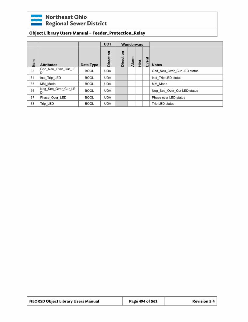
Object Library Users Manual – Feeder_Protection_Relay
NEORSD Object Library Users Manual Page 494 of 561 Revision 5.4
UDT Wonderware
Item
Attributes Data Type Dire
ctio
n
Dire
ctio
n
Ala
rm
His
t
Even
t
Notes 33 Gnd_Neu_Over_Cur_LE
D BOOL UDA Gnd_Neu_Over_Cur LED status
34 Inst_Trip_LED BOOL UDA Inst_Trip LED status
35 MM_Mode BOOL UDA MM_Mode
36 Neg_Seq_Over_Cur_LED BOOL UDA Neg_Seq_Over_Cur LED status
37 Phase_Over_LED BOOL UDA Phase over LED status
38 Trip_LED BOOL UDA Trip LED status
Object Library Users Manual – Feeder_Protection_Relay
NEORSD Object Library Users Manual Page 495 of 561 Revision 5.4
37.4 ControlLogix PLC
37.4.1 No AOI Provided No AOI has been provided for the SEL_751A_FPR object. It is the programmer’s responsibility to map data to the proper registers to be read by the Wonderware object. Use of a UDT is advised. The PLC programming should be done in accordance with the District’s existing substation Feeder Protection interfaces. Examples of this logic can be provided by the District. Below is a brief overview of the technique. Not all members of the User-Defined data types are referenced by the Wonderware objects. Unused members are for future.
37.4.2 Logic Overview All parameters associated with the SEL-751A, except for the discrete used for the Maintenance Mode, come from the SEL-751A over a Modbus connection. These parameters are read by a ProSoft MVI65E-MCM module that is configured to read all of the parameters and save them to an array named MCM.DATA.ReadData[]. The ProSoft MVI65E-MCM module has two ports. The first port is used to communicate with the Power Monitors and other devices such as the SEL_751_A. The second port is used to communicate with the Digitrips through the mMint modules. The ProSoft module is configured to continuously acquired data from the devices and save the data to internal registers with a set of command registers. The internal register where the data is saved is MCM.DATA.ReadData[]. The mapping of the data from the ProSoft module slot number to the MCM User-Defined tag is done by the PSMCM Add-On instruction in rung zero of the Main routine. An example of how the phase current is read from a SEL 751A can be given by looking at the 14th command for port 1 in the PLC program for substation 11. The data is read from the feeder protection relay from the user defined table in the relay. This table starts at address 30126. This command is defined by the following values in the command register.
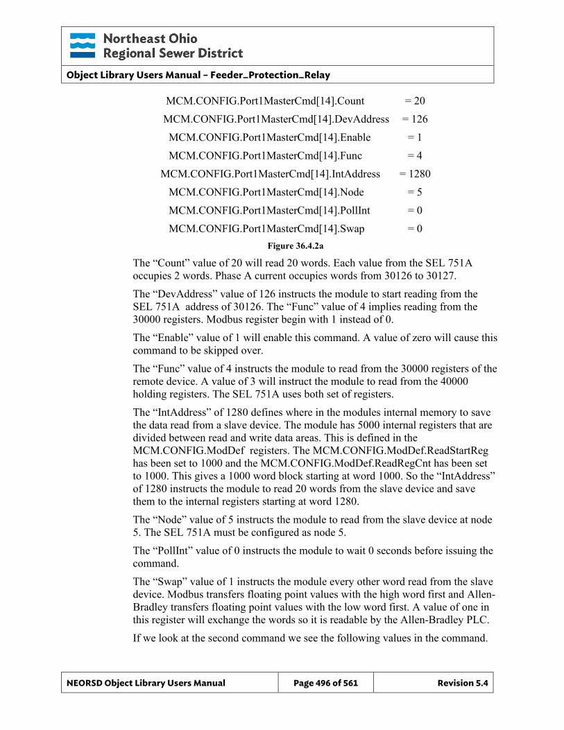
Object Library Users Manual – Feeder_Protection_Relay
NEORSD Object Library Users Manual Page 496 of 561 Revision 5.4
MCM.CONFIG.Port1MasterCmd[14].Count = 20 MCM.CONFIG.Port1MasterCmd[14].DevAddress = 126 MCM.CONFIG.Port1MasterCmd[14].Enable = 1 MCM.CONFIG.Port1MasterCmd[14].Func = 4
MCM.CONFIG.Port1MasterCmd[14].IntAddress = 1280 MCM.CONFIG.Port1MasterCmd[14].Node = 5 MCM.CONFIG.Port1MasterCmd[14].PollInt = 0 MCM.CONFIG.Port1MasterCmd[14].Swap = 0
Figure 36.4.2a
The “Count” value of 20 will read 20 words. Each value from the SEL 751A occupies 2 words. Phase A current occupies words from 30126 to 30127. The “DevAddress” value of 126 instructs the module to start reading from the SEL 751A address of 30126. The “Func” value of 4 implies reading from the 30000 registers. Modbus register begin with 1 instead of 0. The “Enable” value of 1 will enable this command. A value of zero will cause this command to be skipped over. The “Func” value of 4 instructs the module to read from the 30000 registers of the remote device. A value of 3 will instruct the module to read from the 40000 holding registers. The SEL 751A uses both set of registers. The “IntAddress” of 1280 defines where in the modules internal memory to save the data read from a slave device. The module has 5000 internal registers that are divided between read and write data areas. This is defined in the MCM.CONFIG.ModDef registers. The MCM.CONFIG.ModDef.ReadStartReg has been set to 1000 and the MCM.CONFIG.ModDef.ReadRegCnt has been set to 1000. This gives a 1000 word block starting at word 1000. So the “IntAddress” of 1280 instructs the module to read 20 words from the slave device and save them to the internal registers starting at word 1280. The “Node” value of 5 instructs the module to read from the slave device at node 5. The SEL 751A must be configured as node 5. The “PollInt” value of 0 instructs the module to wait 0 seconds before issuing the command. The “Swap” value of 1 instructs the module every other word read from the slave device. Modbus transfers floating point values with the high word first and Allen-Bradley transfers floating point values with the low word first. A value of one in this register will exchange the words so it is readable by the Allen-Bradley PLC. If we look at the second command we see the following values in the command.
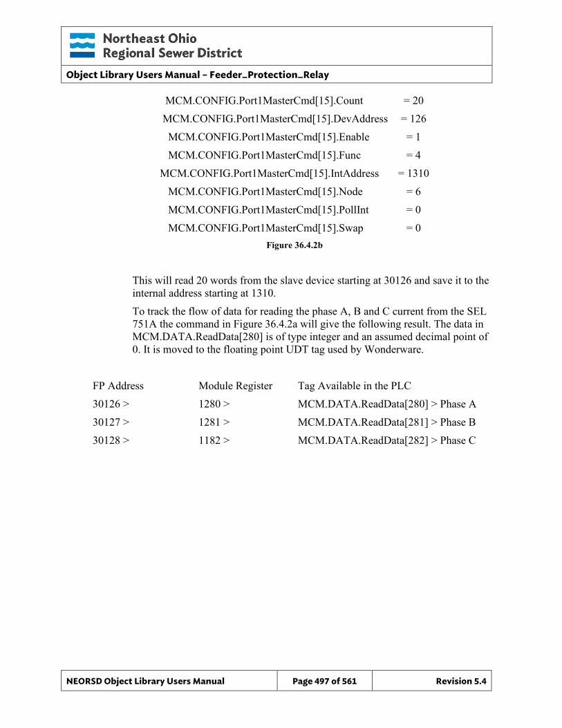
Object Library Users Manual – Feeder_Protection_Relay
NEORSD Object Library Users Manual Page 497 of 561 Revision 5.4
MCM.CONFIG.Port1MasterCmd[15].Count = 20 MCM.CONFIG.Port1MasterCmd[15].DevAddress = 126 MCM.CONFIG.Port1MasterCmd[15].Enable = 1 MCM.CONFIG.Port1MasterCmd[15].Func = 4
MCM.CONFIG.Port1MasterCmd[15].IntAddress = 1310 MCM.CONFIG.Port1MasterCmd[15].Node = 6 MCM.CONFIG.Port1MasterCmd[15].PollInt = 0 MCM.CONFIG.Port1MasterCmd[15].Swap = 0
Figure 36.4.2b
This will read 20 words from the slave device starting at 30126 and save it to the internal address starting at 1310. To track the flow of data for reading the phase A, B and C current from the SEL 751A the command in Figure 36.4.2a will give the following result. The data in MCM.DATA.ReadData[280] is of type integer and an assumed decimal point of 0. It is moved to the floating point UDT tag used by Wonderware.
FP Address Module Register Tag Available in the PLC 30126 > 1280 > MCM.DATA.ReadData[280] > Phase A 30127 > 1281 > MCM.DATA.ReadData[281] > Phase B 30128 > 1182 > MCM.DATA.ReadData[282] > Phase C
Object Library Users Manual – Feeder_Protection_Relay
NEORSD Object Library Users Manual Page 498 of 561 Revision 5.4
37.5 Wonderware HMI
37.5.1 Properties Hierarchical Name: $SEL_751A_FPR Derivation: Derived from $NEORSDUserDefined Container: None
37.5.2 Extensions None
37.5.3 Configuration All of the necessary configuration for SEL_751_FPR must also be done on any instance derived from this template.
1) Animated_PB and Animated_750_PB Graphic – Set UDA Text_Line1 to first line of DigiTrip name. Set UDA Text_Line2 to second line of DigiTrip name.
2) Details graphic – Set MM_Mode to False if the Feeder Protection Relay has not been programmed for a Maintenance Mode. Set MM_Mode to True if the Feeder Protection Relay has been programmed for a Maintenance Mode.
3) Attributes that are not used in the configured instance shall use Me.Placeholder to eliminate the point from counting against the systems total I/O scan counts. These shall include values not available on delta configured systems when installed on a delta system.
4) If ASSET_ID is not in use the initial value will be left blank. Scripting used for ASSET_ID uses the initial value and not ASSET_ID.Description.
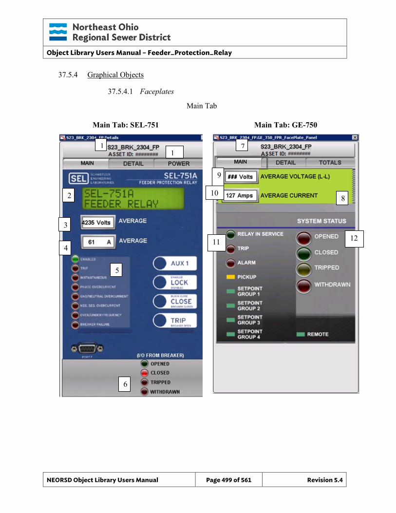
Object Library Users Manual – Feeder_Protection_Relay
NEORSD Object Library Users Manual Page 499 of 561 Revision 5.4
37.5.4 Graphical Objects
37.5.4.1 Faceplates
Main Tab: SEL-751 Main Tab: GE-750
Main Tab
4
1
3
5
6
2
7
8
9
10
11 12
1
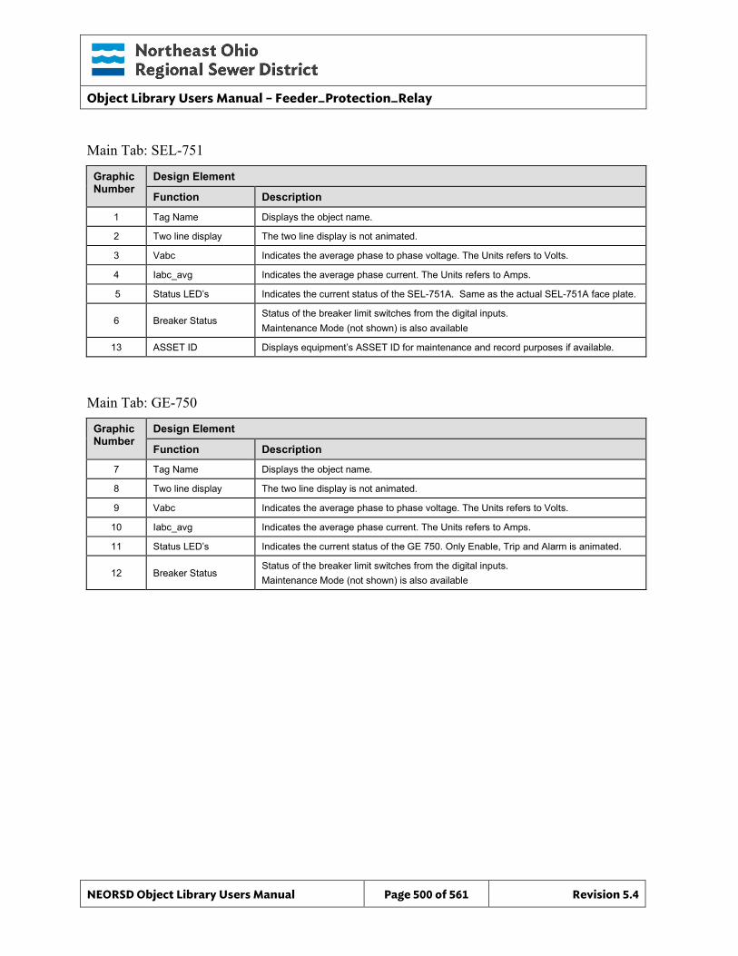
Object Library Users Manual – Feeder_Protection_Relay
NEORSD Object Library Users Manual Page 500 of 561 Revision 5.4
Main Tab: SEL-751
Graphic Number
Design Element
Function Description
1 Tag Name Displays the object name.
2 Two line display The two line display is not animated.
3 Vabc Indicates the average phase to phase voltage. The Units refers to Volts.
4 Iabc_avg Indicates the average phase current. The Units refers to Amps.
5 Status LED’s Indicates the current status of the SEL-751A. Same as the actual SEL-751A face plate.
6 Breaker Status Status of the breaker limit switches from the digital inputs. Maintenance Mode (not shown) is also available
13 ASSET ID Displays equipment’s ASSET ID for maintenance and record purposes if available.
Main Tab: GE-750
Graphic Number
Design Element
Function Description
7 Tag Name Displays the object name.
8 Two line display The two line display is not animated.
9 Vabc Indicates the average phase to phase voltage. The Units refers to Volts.
10 Iabc_avg Indicates the average phase current. The Units refers to Amps.
11 Status LED’s Indicates the current status of the GE 750. Only Enable, Trip and Alarm is animated.
12 Breaker Status Status of the breaker limit switches from the digital inputs. Maintenance Mode (not shown) is also available
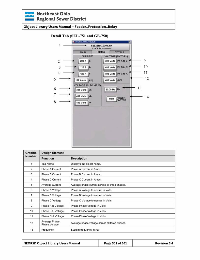
Object Library Users Manual – Feeder_Protection_Relay
NEORSD Object Library Users Manual Page 501 of 561 Revision 5.4
Detail Tab (SEL-751 and GE-750)
Graphic Number
Design Element
Function Description
1 Tag Name Displays the object name.
2 Phase A Current Phase A Current in Amps.
3 Phase B Current Phase B Current in Amps.
4 Phase C Current Phase C Current in Amps.
5 Average Current Average phase current across all three phases.
6 Phase A Voltage Phase A Voltage to neutral in Volts.
7 Phase B Voltage Phase B Voltage to neutral in Volts.
8 Phase C Voltage Phase C Voltage to neutral in Volts.
9 Phase A-B Voltage Phase-Phase Voltage in Volts.
10 Phase B-C Voltage Phase-Phase Voltage in Volts.
11 Phase C-A Voltage Phase-Phase Voltage in Volts.
12 Average Phase-Phase Voltage Average phase voltage across all three phases.
13 Frequency System frequency in Hz.
1
2 3 4
5
6 7
8
9 10 11 12
13
14
Object Library Users Manual – Feeder_Protection_Relay
NEORSD Object Library Users Manual Page 502 of 561 Revision 5.4
Graphic Number
Design Element
Function Description
14 Power Factor System Power Factor, unitless.
SEL-751A & GE 750, Totals
Graphic Number
Design Element
Function Description
1 Tag Name Displays the object name.
2 Real Power System real power (running total since last reset).
3 Reactive Power System reactive power (running total since last reset).
4 Apparent Power System apparent power (running total since last reset).
2
3 4
1
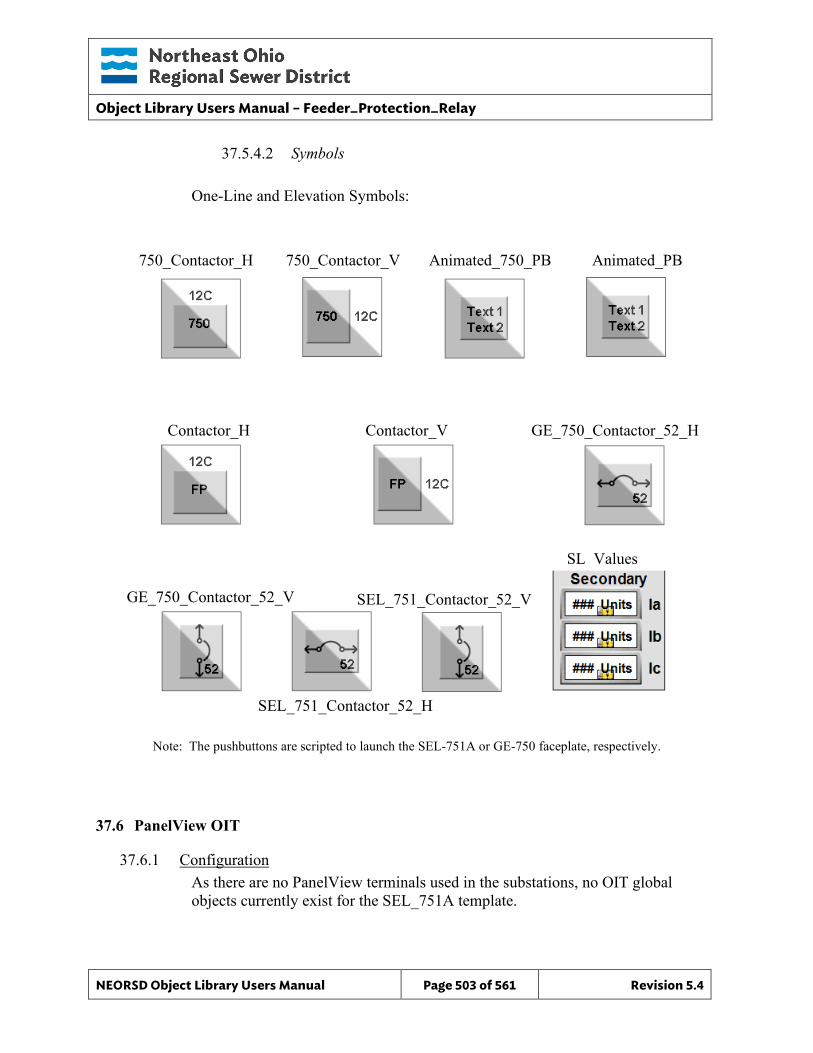
Object Library Users Manual – Feeder_Protection_Relay
NEORSD Object Library Users Manual Page 503 of 561 Revision 5.4
37.5.4.2 Symbols
One-Line and Elevation Symbols:
Note: The pushbuttons are scripted to launch the SEL-751A or GE-750 faceplate, respectively.
37.6 PanelView OIT
37.6.1 Configuration As there are no PanelView terminals used in the substations, no OIT global objects currently exist for the SEL_751A template.
750_Contactor_H 750_Contactor_V Animated_750_PB Animated_PB
Contactor_H Contactor_V GE_750_Contactor_52_H
SEL_751_Contactor_52_H
SL Values
GE_750_Contactor_52_V SEL_751_Contactor_52_V
Object Library Users Manual – AB_Power_Monitor_3000
NEORSD Object Library Users Manual Page 504 of 561 Revision 5.4
38.0 Power_Monitor (AB_Power_Monitor_3000)
38.1 Introduction The Power Monitor template provides a standard representation for the indication of values from a Rockwell Power Monitor 3000 (or similar power monitoring device), for display of pertinent power data. This template can and should be used to represent similar devices by other vendors. Use the PM_3000 template if:
• Trying to represent a device that monitors detailed power information (phase current/voltage, phase angle, real/reactive power, etc)
Do not use the PM_3000 template if: • The device you are modeling is a protection relay. Consider the SEL_587Z_DPR,
SEL_751A_FPR, or SEL_787_TPR instead. • The device can be represented by a PM_5000.
The Power Monitor 3000 unit upon which this template is based is a microprocessor-based electrical power and energy measuring device. It is connected to the three-phase ac power system through instrument transformers (PTs and CTs). It converts instantaneous voltage and current values to digital values, and uses the resulting digital values in calculations of parameters such as voltage, current, power, real power, reactive power, apparent power etc. The Power Monitor 3000 communicates via RS-485, using a Modbus protocol, to a ProSoft MVI56E-MCM module. The Power Monitors have a decimal format address node on the Modbus network.
38.2 Object Features
38.2.1 Value Indications This object provides the following indications for the monitoring device:
• Assorted power details; see attribute list
38.2.2 Alarming There are no digital alarm objects provided by the Power Monitor 3000 for discrete alarm indication.
38.2.3 Simulation This object does not support simulation.
38.2.4 Trouble This object does not support hardware trouble indication.
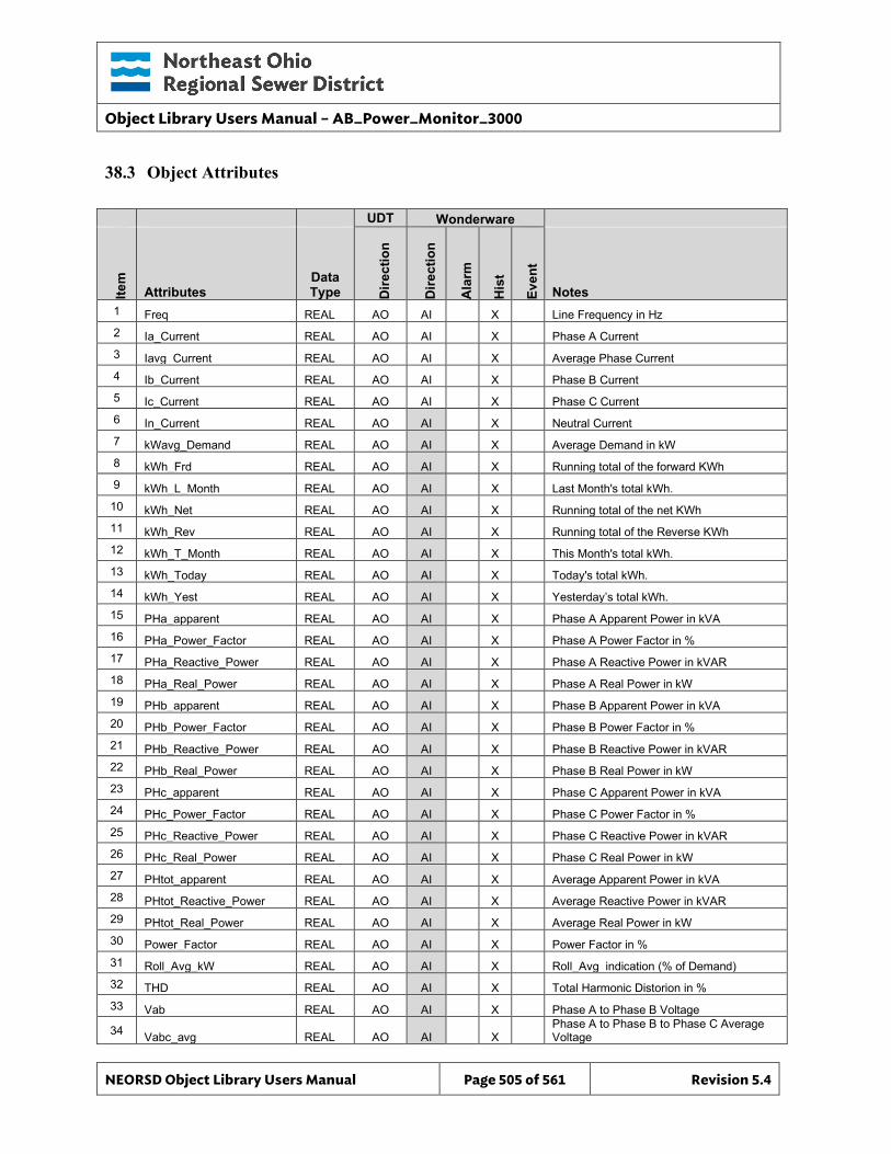
Object Library Users Manual – AB_Power_Monitor_3000
NEORSD Object Library Users Manual Page 505 of 561 Revision 5.4
38.3 Object Attributes
UDT Wonderware
Item
Attributes Data Type D
irect
ion
Dire
ctio
n
Ala
rm
His
t
Even
t
Notes 1 Freq REAL AO AI X Line Frequency in Hz 2 Ia_Current REAL AO AI X Phase A Current 3 Iavg_Current REAL AO AI X Average Phase Current 4 Ib_Current REAL AO AI X Phase B Current 5 Ic_Current REAL AO AI X Phase C Current 6 In_Current REAL AO AI X Neutral Current 7 kWavg_Demand REAL AO AI X Average Demand in kW 8 kWh_Frd REAL AO AI X Running total of the forward KWh 9 kWh_L_Month REAL AO AI X Last Month's total kWh.
10 kWh_Net REAL AO AI X Running total of the net KWh 11 kWh_Rev REAL AO AI X Running total of the Reverse KWh 12 kWh_T_Month REAL AO AI X This Month's total kWh. 13 kWh_Today REAL AO AI X Today's total kWh. 14 kWh_Yest REAL AO AI X Yesterday’s total kWh. 15 PHa_apparent REAL AO AI X Phase A Apparent Power in kVA 16 PHa_Power_Factor REAL AO AI X Phase A Power Factor in % 17 PHa_Reactive_Power REAL AO AI X Phase A Reactive Power in kVAR 18 PHa_Real_Power REAL AO AI X Phase A Real Power in kW 19 PHb_apparent REAL AO AI X Phase B Apparent Power in kVA 20 PHb_Power_Factor REAL AO AI X Phase B Power Factor in % 21 PHb_Reactive_Power REAL AO AI X Phase B Reactive Power in kVAR 22 PHb_Real_Power REAL AO AI X Phase B Real Power in kW 23 PHc_apparent REAL AO AI X Phase C Apparent Power in kVA 24 PHc_Power_Factor REAL AO AI X Phase C Power Factor in % 25 PHc_Reactive_Power REAL AO AI X Phase C Reactive Power in kVAR 26 PHc_Real_Power REAL AO AI X Phase C Real Power in kW 27 PHtot_apparent REAL AO AI X Average Apparent Power in kVA 28 PHtot_Reactive_Power REAL AO AI X Average Reactive Power in kVAR 29 PHtot_Real_Power REAL AO AI X Average Real Power in kW 30 Power_Factor REAL AO AI X Power Factor in % 31 Roll_Avg_kW REAL AO AI X Roll_Avg indication (% of Demand) 32 THD REAL AO AI X Total Harmonic Distorion in % 33 Vab REAL AO AI X Phase A to Phase B Voltage
34 Vabc_avg REAL AO AI X Phase A to Phase B to Phase C Average Voltage
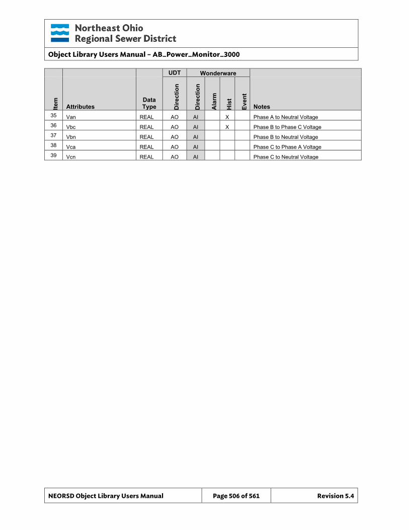
Object Library Users Manual – AB_Power_Monitor_3000
NEORSD Object Library Users Manual Page 506 of 561 Revision 5.4
UDT Wonderware
Item
Attributes Data Type D
irect
ion
Dire
ctio
n
Ala
rm
His
t
Even
t
Notes 35 Van REAL AO AI X Phase A to Neutral Voltage 36 Vbc REAL AO AI X Phase B to Phase C Voltage 37 Vbn REAL AO AI Phase B to Neutral Voltage 38 Vca REAL AO AI Phase C to Phase A Voltage 39 Vcn REAL AO AI Phase C to Neutral Voltage
Object Library Users Manual – AB_Power_Monitor_3000
NEORSD Object Library Users Manual Page 507 of 561 Revision 5.4
38.4 ControlLogix PLC
38.4.1 No AOI Provided No AOI has been provided for the AB_Power_Monitor_3000 object. It is the programmer’s responsibility to map data to the proper registers to be read by the Wonderware object, using a UDT of data type “Power_Monitor”. The PLC programming should be done in accordance with the District’s existing substation Power Monitor interfaces. Examples of this logic can be provided by the District. Below is a brief overview of the technique. Not all members of the User-Defined Data Types are referenced by the Wonderware objects; unused members are reserved for future use.
38.4.2 Logic Overview All parameters associated with the Power Monitor device come from the Power Monitor over a Modbus connection. These parameters are read by a ProSoft MVI65E-MCM module that is configured to read all of the parameters and save them to an array named “MCM.DATA.ReadData[]”. This array passes the parameters to a tag of data type Power_Monitor (UDT), which is used by Wonderware. The ProSoft MVI65E-MCM module has two ports. The first port is used to communicate with the Power Monitors and other devices such as the SEL_751_A. The second port is used to communicate with the Digitrips through the Eaton mMint Modbus translator modules. The ProSoft module is configured to continuously acquire data from the devices and save the data to internal registers with a set of command registers. The internal register where the data is saved within the Prosoft module is accessible through “MCM.DATA.ReadData[]”. The mapping of the data from the ProSoft module slot number to the MCM User-Defined tag is done by the PSMCM Add-On instruction in rung zero of the Main routine (see an existing Power_Monitor implementation for example). An example of how the phase current is read from a Power Monitor 3000 can be given by looking at the first command for port 1. This command is defined by the following values in the command register.
Object Library Users Manual – AB_Power_Monitor_3000
NEORSD Object Library Users Manual Page 508 of 561 Revision 5.4
MCM.CONFIG.Port1MasterCmd[0].Count = 26 MCM.CONFIG.Port1MasterCmd[0].DevAddress = 100 MCM.CONFIG.Port1MasterCmd[0].Enable = 1 MCM.CONFIG.Port1MasterCmd[0].Func = 4
MCM.CONFIG.Port1MasterCmd[0].IntAddress = 1000 MCM.CONFIG.Port1MasterCmd[0].Node = 1 MCM.CONFIG.Port1MasterCmd[0].PollInt = 0 MCM.CONFIG.Port1MasterCmd[0].Swap = 1
Figure 37.4.2a
The “Count” value of 26 will read 26 words. Each value from the Power Monitor 3000 occupies 2 words. Phase A current occupies words from 30101 to 30102. The “DevAddress” value of 100 instructs the module to start reading from the Power Monitor address of 30101. The “Enable” value of 1 will enable this command. A value of zero will cause this command to be skipped over. The “Func” value of 4 instructs the module to read from the 30000 registers of the remote device. A value of 3 will instruct the module to read from the 40000 holding registers. The Power Monitor uses both set of registers. Modbus register addresses begin with 1 instead of 0. The “IntAddress” of 1000 defines where in the modules internal memory to save the data read from a slave device. The module has 5000 internal registers that are divided between read and write data areas. This is defined in the MCM.CONFIG.ModDef registers. The MCM.CONFIG.ModDef.ReadStartReg has been set to 1000 and the MCM.CONFIG.ModDef.ReadRegCnt has been set to 1000. This gives a 1000 word block starting at word 1000. So the “IntAddress” of 1000 instructs the module to read 26 words from the slave device and save them to the internal registers starting at word 1000. The “Node” value of 1 instructs the module to read from the slave device at node 1. The Power Monitor must be configured as node 1. The “PollInt” value of 0 instructs the module to wait 0 seconds between data polling command requests. The “Swap” value of 1 instructs the module every other word read from the slave device. Modbus transfers floating point values with the high word first and Allen-Bradley transfers floating point values with the low word first. A value of one in this register will exchange the words so it is readable by the Allen-Bradley PLC. If we look at the second command we see the following values in the command.
MCM.CONFIG.Port1MasterCmd[1].Count = 24
Object Library Users Manual – AB_Power_Monitor_3000
NEORSD Object Library Users Manual Page 509 of 561 Revision 5.4
MCM.CONFIG.Port1MasterCmd[1].DevAddress = 300 MCM.CONFIG.Port1MasterCmd[1].Enable = 1 MCM.CONFIG.Port1MasterCmd[1].Func = 4
MCM.CONFIG.Port1MasterCmd[1].IntAddress = 1026 MCM.CONFIG.Port1MasterCmd[1].Node = 1 MCM.CONFIG.Port1MasterCmd[1].PollInt = 0 MCM.CONFIG.Port1MasterCmd[1].Swap = 1
Figure 37.4.2b
This will read 24 words from the slave device starting at 30301 and save it to the internal address starting at 1026. To track the flow of data for reading the phase A, B and C current from the Power Monitor 3000 the command in Figure 37.4.2a will give the following result.
PM Address Module Register Tag Available in the PLC 30101, 30102 > 1000, 1001 > MCM.DATA.ReadData[0] > Phase A 30103, 30104 > 1002, 1003 > MCM.DATA.ReadData[2] > Phase B 30105, 30106 > 1004, 1005 > MCM.DATA.ReadData[4] > Phase C
Object Library Users Manual – AB_Power_Monitor_3000
NEORSD Object Library Users Manual Page 510 of 561 Revision 5.4
38.5 Wonderware HMI
38.5.1 Properties Hierarchical Name: $AB_Power_Monitor_3000 Derivation: Derived from $NEORSDUserDefined Container: None
38.5.2 Extensions None
38.5.3 Configuration All of the necessary configuration for AB_Power_Monitor_3000 must also be done on any instance derived from this template.
1) Animated_PB Graphic – Set UDA Text_Line1 to first line of Power Monitor name. Set UDA Text_Line2 to second line of Power Monitor name.
2) The substations are wired in either a Delta or Wye configuration. Delta
configurations do not provide neutral current or phase to neutral voltages. On Delta configured substations, configure a value of “Me.Placeholder” for object attributes that will not be polled.
3) If ASSET_ID is not in use the initial value will be left blank. Scripting
used for ASSET_ID uses the initial value and not ASSET_ID.Description.
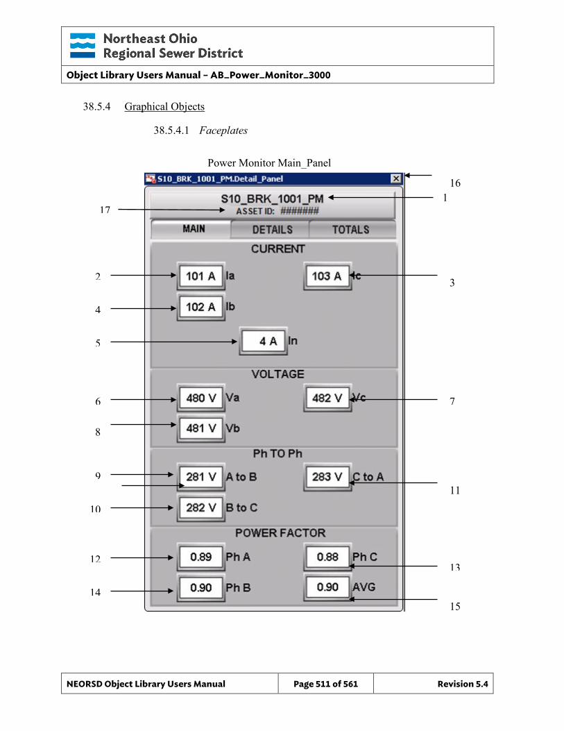
Object Library Users Manual – AB_Power_Monitor_3000
NEORSD Object Library Users Manual Page 511 of 561 Revision 5.4
38.5.4 Graphical Objects
38.5.4.1 Faceplates
Power Monitor Main_Panel
4
8
6
5
7
1
3
9
13
2
10
12
14 15
11
16
17
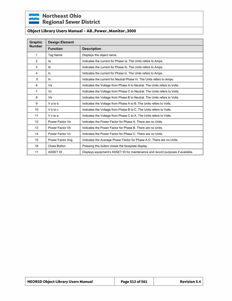
Object Library Users Manual – AB_Power_Monitor_3000
NEORSD Object Library Users Manual Page 512 of 561 Revision 5.4
Graphic Number
Design Element
Function Description
1 Tag Name Displays the object name.
2 Ia Indicates the current for Phase Ia. The Units refers to Amps.
3 Ib Indicates the current for Phase Ib. The Units refers to Amps.
4 Ic Indicates the current for Phase Ic. The Units refers to Amps.
5 In Indicates the current for Neutral Phase In. The Units refers to Amps.
6 Va Indicates the Voltage from Phase A to Neutral. The Units refers to Volts.
7 Vc Indicates the Voltage from Phase C to Neutral. The Units refers to Volts.
8 Vb Indicates the Voltage from Phase B to Neutral. The Units refers to Volts.
9 V a to b Indicates the Voltage from Phase A to B. The Units refers to Volts.
10 V b to c Indicates the Voltage from Phase B to C. The Units refers to Volts.
11 V c to a Indicates the Voltage from Phase C to A. The Units refers to Volts.
12 Power Factor Va Indicates the Power Factor for Phase A. There are no Units.
13 Power Factor Vb Indicates the Power Factor for Phase B. There are no Units.
14 Power Factor Vc Indicates the Power Factor for Phase C. There are no Units.
15 Power Factor Avg. Indicates the Average Power Factor for Phase A-C. There are no Units.
16 Close Button Pressing this button closes the faceplate display.
17 ASSET ID Displays equipment’s ASSET ID for maintenance and record purposes if available.
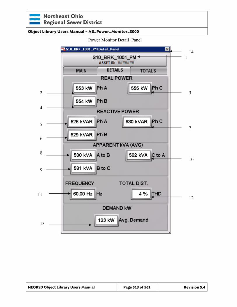
Object Library Users Manual – AB_Power_Monitor_3000
NEORSD Object Library Users Manual Page 513 of 561 Revision 5.4
4
8
6
5 7
1
3
9
12
2
11
13
10
14
Power Monitor Detail_Panel
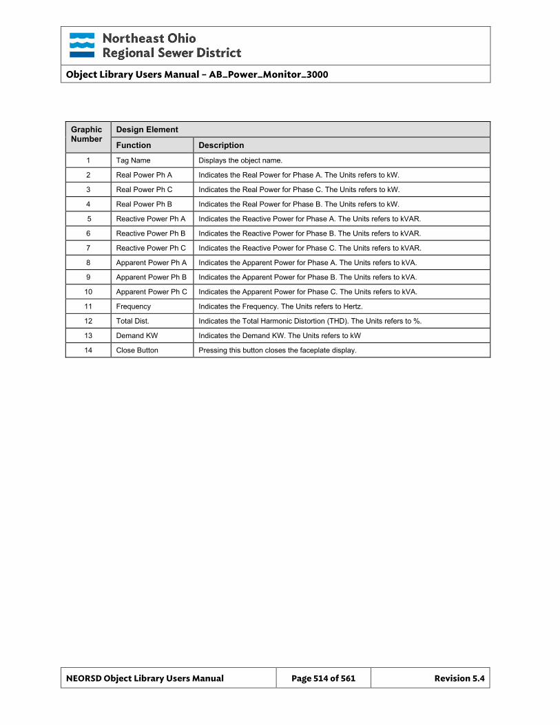
Object Library Users Manual – AB_Power_Monitor_3000
NEORSD Object Library Users Manual Page 514 of 561 Revision 5.4
Graphic Number
Design Element
Function Description
1 Tag Name Displays the object name.
2 Real Power Ph A Indicates the Real Power for Phase A. The Units refers to kW.
3 Real Power Ph C Indicates the Real Power for Phase C. The Units refers to kW.
4 Real Power Ph B Indicates the Real Power for Phase B. The Units refers to kW.
5 Reactive Power Ph A Indicates the Reactive Power for Phase A. The Units refers to kVAR.
6 Reactive Power Ph B Indicates the Reactive Power for Phase B. The Units refers to kVAR.
7 Reactive Power Ph C Indicates the Reactive Power for Phase C. The Units refers to kVAR.
8 Apparent Power Ph A Indicates the Apparent Power for Phase A. The Units refers to kVA.
9 Apparent Power Ph B Indicates the Apparent Power for Phase B. The Units refers to kVA.
10 Apparent Power Ph C Indicates the Apparent Power for Phase C. The Units refers to kVA.
11 Frequency Indicates the Frequency. The Units refers to Hertz.
12 Total Dist. Indicates the Total Harmonic Distortion (THD). The Units refers to %.
13 Demand KW Indicates the Demand KW. The Units refers to kW
14 Close Button Pressing this button closes the faceplate display.
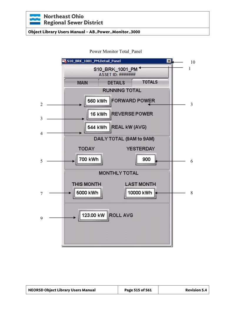
Object Library Users Manual – AB_Power_Monitor_3000
NEORSD Object Library Users Manual Page 515 of 561 Revision 5.4
3
8
5
4
6
1
3
7
2
9
10
Power Monitor Total_Panel
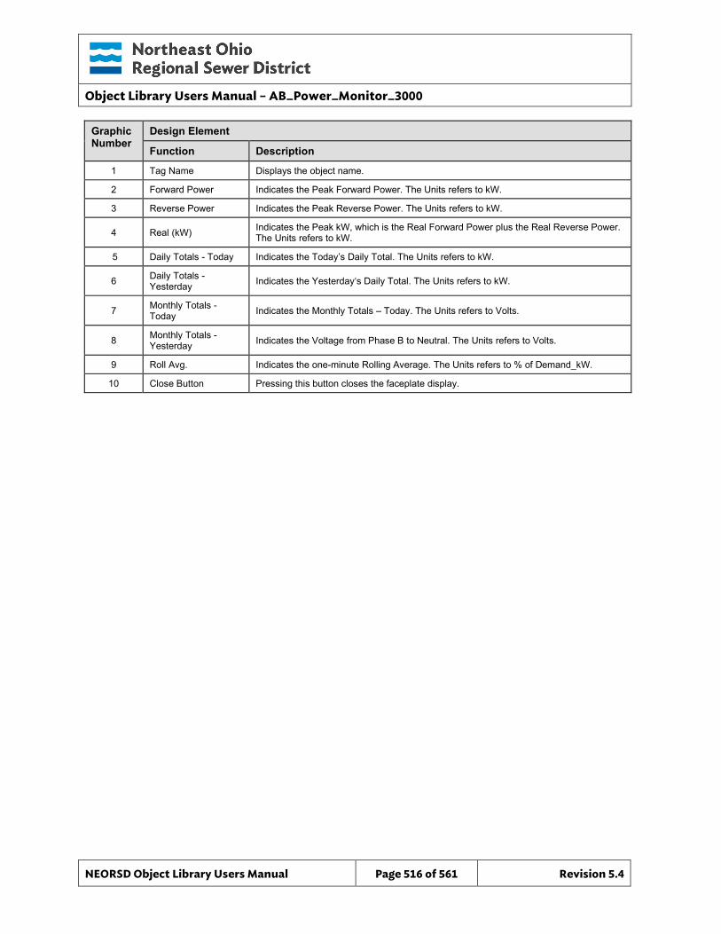
Object Library Users Manual – AB_Power_Monitor_3000
NEORSD Object Library Users Manual Page 516 of 561 Revision 5.4
Graphic Number
Design Element
Function Description
1 Tag Name Displays the object name.
2 Forward Power Indicates the Peak Forward Power. The Units refers to kW.
3 Reverse Power Indicates the Peak Reverse Power. The Units refers to kW.
4 Real (kW) Indicates the Peak kW, which is the Real Forward Power plus the Real Reverse Power. The Units refers to kW.
5 Daily Totals - Today Indicates the Today’s Daily Total. The Units refers to kW.
6 Daily Totals - Yesterday Indicates the Yesterday‘s Daily Total. The Units refers to kW.
7 Monthly Totals - Today Indicates the Monthly Totals – Today. The Units refers to Volts.
8 Monthly Totals - Yesterday Indicates the Voltage from Phase B to Neutral. The Units refers to Volts.
9 Roll Avg. Indicates the one-minute Rolling Average. The Units refers to % of Demand_kW.
10 Close Button Pressing this button closes the faceplate display.
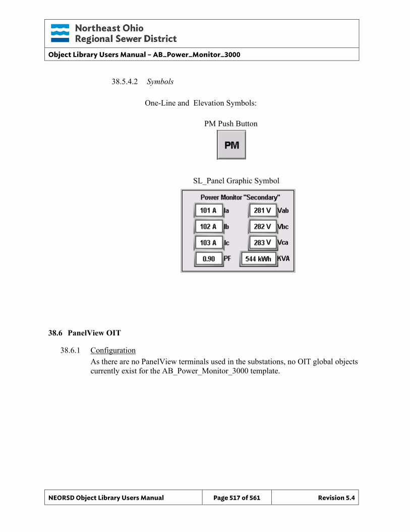
Object Library Users Manual – AB_Power_Monitor_3000
NEORSD Object Library Users Manual Page 517 of 561 Revision 5.4
38.5.4.2 Symbols
One-Line and Elevation Symbols:
SL_Panel Graphic Symbol
38.6 PanelView OIT
38.6.1 Configuration As there are no PanelView terminals used in the substations, no OIT global objects currently exist for the AB_Power_Monitor_3000 template.
PM Push Button
Object Library Users Manual – PM5000
NEORSD Object Library Users Manual Page 518 of 561 Revision 5.4
39.0 Power_Monitor_5000 (PM5000)
39.1 Introduction The Power Monitor 5000 template provides a standard representation for the indication of values from a Rockwell Power Monitor 5000 (or similar power monitoring device), for display of pertinent power data. This template can and should be used to represent similar devices by other vendors. Use the PM_5000 template if:
• Trying to represent a device that monitors detailed power information (phase current/voltage, phase angle, real/reactive power, etc)
Do not use the PM_5000 template if: • The device you are modeling is a protection relay. Consider the SEL_587Z_DPR,
SEL_751A_FPR, or SEL_787_TPR instead.
The Power Monitor 5000 unit upon which this template is based is a microprocessor-based electrical power and energy measuring device. It is connected to the three-phase ac power system through instrument transformers (PTs and CTs). It converts instantaneous voltage and current values to digital values, and uses the resulting digital values in calculations of parameters such as voltage, current, power, real power, reactive power, apparent power etc.
39.2 Object Features
39.2.1 Value Indications This object provides the following indications for the monitoring device:
• Assorted power details; see attribute list
39.2.2 Alarming There are no digital alarm objects provided by the Power Monitor 5000 for discrete alarm indication.
39.2.3 Simulation This object does not support simulation.
39.2.4 Trouble This object does not support hardware trouble indication.
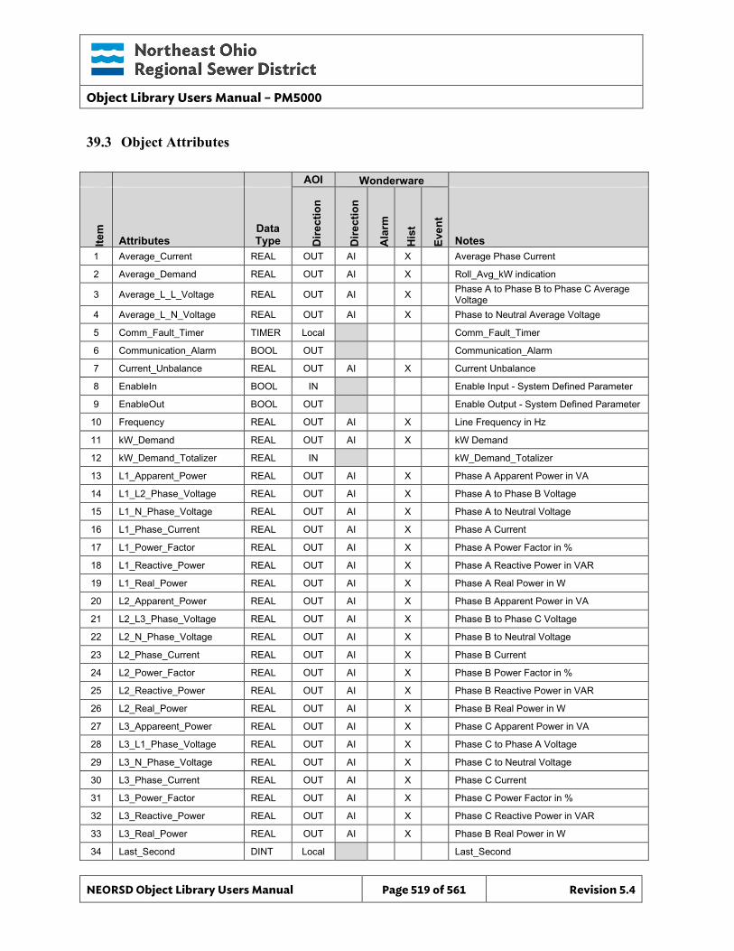
Object Library Users Manual – PM5000
NEORSD Object Library Users Manual Page 519 of 561 Revision 5.4
39.3 Object Attributes
AOI Wonderware
Item
Attributes Data Type D
irect
ion
Dire
ctio
n
Ala
rm
His
t
Even
t
Notes 1 Average_Current REAL OUT AI X Average Phase Current
2 Average_Demand REAL OUT AI X Roll_Avg_kW indication
3 Average_L_L_Voltage REAL OUT AI X Phase A to Phase B to Phase C Average Voltage
4 Average_L_N_Voltage REAL OUT AI X Phase to Neutral Average Voltage
5 Comm_Fault_Timer TIMER Local Comm_Fault_Timer
6 Communication_Alarm BOOL OUT Communication_Alarm
7 Current_Unbalance REAL OUT AI X Current Unbalance
8 EnableIn BOOL IN Enable Input - System Defined Parameter
9 EnableOut BOOL OUT Enable Output - System Defined Parameter
10 Frequency REAL OUT AI X Line Frequency in Hz
11 kW_Demand REAL OUT AI X kW Demand
12 kW_Demand_Totalizer REAL IN kW_Demand_Totalizer
13 L1_Apparent_Power REAL OUT AI X Phase A Apparent Power in VA
14 L1_L2_Phase_Voltage REAL OUT AI X Phase A to Phase B Voltage
15 L1_N_Phase_Voltage REAL OUT AI X Phase A to Neutral Voltage
16 L1_Phase_Current REAL OUT AI X Phase A Current
17 L1_Power_Factor REAL OUT AI X Phase A Power Factor in %
18 L1_Reactive_Power REAL OUT AI X Phase A Reactive Power in VAR
19 L1_Real_Power REAL OUT AI X Phase A Real Power in W
20 L2_Apparent_Power REAL OUT AI X Phase B Apparent Power in VA
21 L2_L3_Phase_Voltage REAL OUT AI X Phase B to Phase C Voltage
22 L2_N_Phase_Voltage REAL OUT AI X Phase B to Neutral Voltage
23 L2_Phase_Current REAL OUT AI X Phase B Current
24 L2_Power_Factor REAL OUT AI X Phase B Power Factor in %
25 L2_Reactive_Power REAL OUT AI X Phase B Reactive Power in VAR
26 L2_Real_Power REAL OUT AI X Phase B Real Power in W
27 L3_Appareent_Power REAL OUT AI X Phase C Apparent Power in VA
28 L3_L1_Phase_Voltage REAL OUT AI X Phase C to Phase A Voltage
29 L3_N_Phase_Voltage REAL OUT AI X Phase C to Neutral Voltage
30 L3_Phase_Current REAL OUT AI X Phase C Current
31 L3_Power_Factor REAL OUT AI X Phase C Power Factor in %
32 L3_Reactive_Power REAL OUT AI X Phase C Reactive Power in VAR
33 L3_Real_Power REAL OUT AI X Phase B Real Power in W
34 Last_Second DINT Local Last_Second
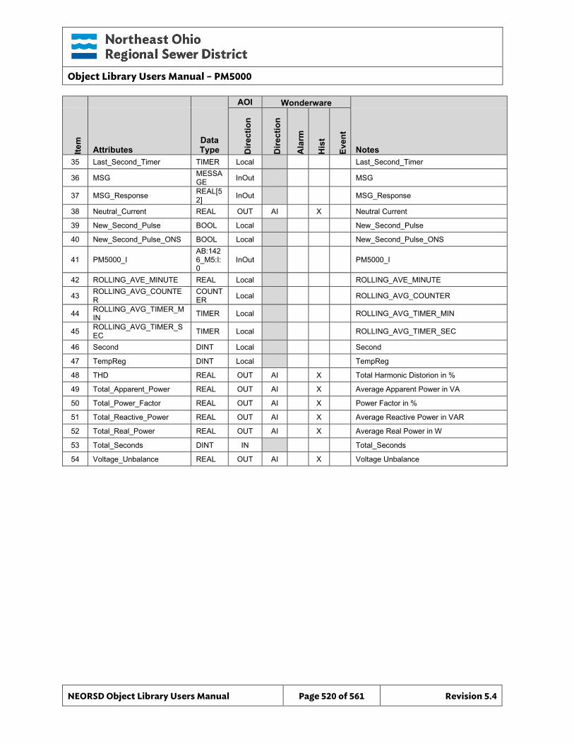
Object Library Users Manual – PM5000
NEORSD Object Library Users Manual Page 520 of 561 Revision 5.4
AOI Wonderware
Item
Attributes Data Type D
irect
ion
Dire
ctio
n
Ala
rm
His
t
Even
t
Notes 35 Last_Second_Timer TIMER Local Last_Second_Timer
36 MSG MESSAGE InOut MSG
37 MSG_Response REAL[52] InOut MSG_Response
38 Neutral_Current REAL OUT AI X Neutral Current
39 New_Second_Pulse BOOL Local New_Second_Pulse
40 New_Second_Pulse_ONS BOOL Local New_Second_Pulse_ONS
41 PM5000_I AB:1426_M5:I:0
InOut PM5000_I
42 ROLLING_AVE_MINUTE REAL Local ROLLING_AVE_MINUTE
43 ROLLING_AVG_COUNTER
COUNTER Local ROLLING_AVG_COUNTER
44 ROLLING_AVG_TIMER_MIN TIMER Local ROLLING_AVG_TIMER_MIN
45 ROLLING_AVG_TIMER_SEC TIMER Local ROLLING_AVG_TIMER_SEC
46 Second DINT Local Second
47 TempReg DINT Local TempReg
48 THD REAL OUT AI X Total Harmonic Distorion in %
49 Total_Apparent_Power REAL OUT AI X Average Apparent Power in VA
50 Total_Power_Factor REAL OUT AI X Power Factor in %
51 Total_Reactive_Power REAL OUT AI X Average Reactive Power in VAR
52 Total_Real_Power REAL OUT AI X Average Real Power in W
53 Total_Seconds DINT IN Total_Seconds
54 Voltage_Unbalance REAL OUT AI X Voltage Unbalance
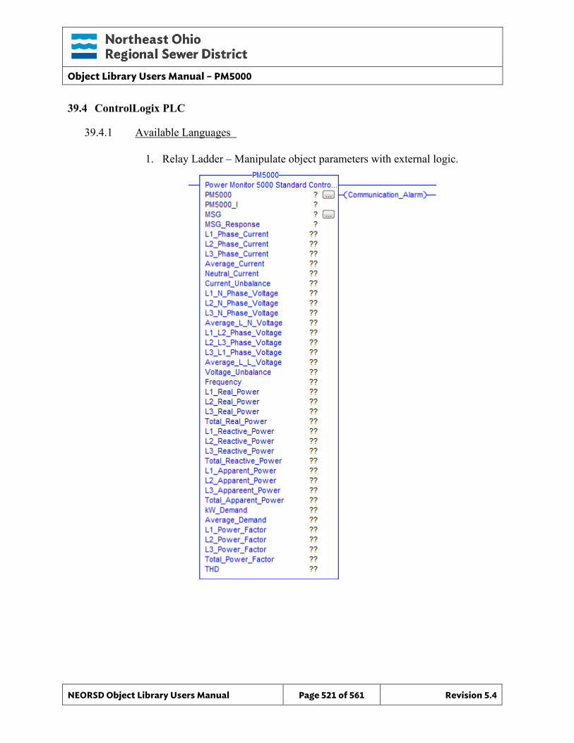
Object Library Users Manual – PM5000
NEORSD Object Library Users Manual Page 521 of 561 Revision 5.4
39.4 ControlLogix PLC
39.4.1 Available Languages
1. Relay Ladder – Manipulate object parameters with external logic.
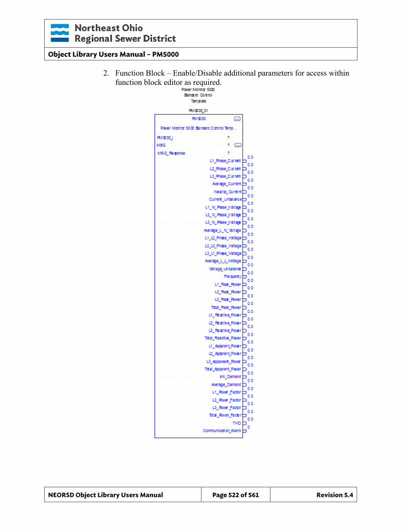
Object Library Users Manual – PM5000
NEORSD Object Library Users Manual Page 522 of 561 Revision 5.4
2. Function Block – Enable/Disable additional parameters for access within function block editor as required.
Object Library Users Manual – PM5000
NEORSD Object Library Users Manual Page 523 of 561 Revision 5.4
39.5 Wonderware HMI
39.5.1 Properties Hierarchical Name: $PM5000 Derivation: Derived from $NEORSDUserDefined Container: None
39.5.2 Extensions None
39.5.3 Configuration All of the necessary configuration for AB_Power_Monitor_5000 must also be done on any instance derived from this template.
1) The substations are wired in either a Delta or Wye configuration. Delta
configurations do not provide neutral current or phase to neutral voltages. On Delta configured substations, configure a value of “Me.Placeholder” for object attributes that will not be polled.
2) If ASSET_ID is not in use the initial value will be left blank. Scripting used for ASSET_ID uses the initial value and not ASSET_ID.Description.
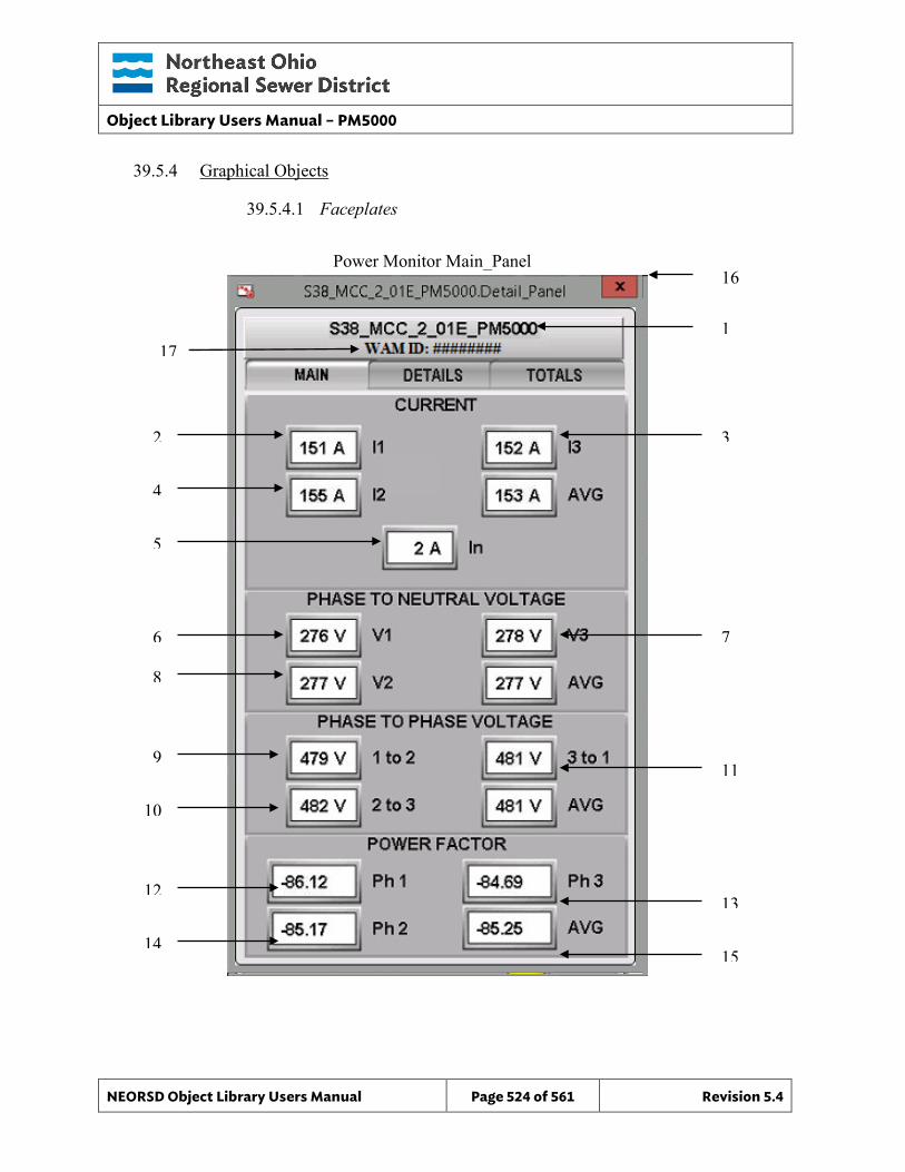
Object Library Users Manual – PM5000
NEORSD Object Library Users Manual Page 524 of 561 Revision 5.4
39.5.4 Graphical Objects
39.5.4.1 Faceplates
Power Monitor Main_Panel
4
8
6
5
7
1
3
9
13
2
10
12
14 15
11
16
17
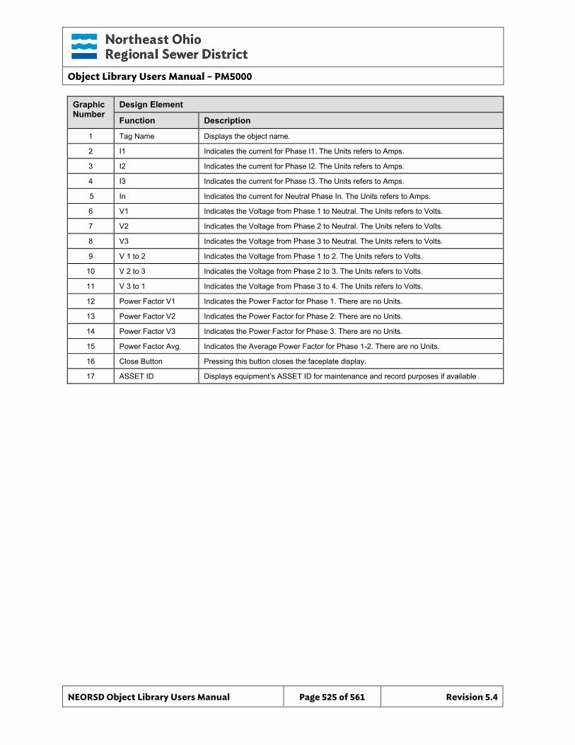
Object Library Users Manual – PM5000
NEORSD Object Library Users Manual Page 525 of 561 Revision 5.4
Graphic Number
Design Element
Function Description
1 Tag Name Displays the object name.
2 I1 Indicates the current for Phase I1. The Units refers to Amps.
3 I2 Indicates the current for Phase I2. The Units refers to Amps.
4 I3 Indicates the current for Phase I3. The Units refers to Amps.
5 In Indicates the current for Neutral Phase In. The Units refers to Amps.
6 V1 Indicates the Voltage from Phase 1 to Neutral. The Units refers to Volts.
7 V2 Indicates the Voltage from Phase 2 to Neutral. The Units refers to Volts.
8 V3 Indicates the Voltage from Phase 3 to Neutral. The Units refers to Volts.
9 V 1 to 2 Indicates the Voltage from Phase 1 to 2. The Units refers to Volts.
10 V 2 to 3 Indicates the Voltage from Phase 2 to 3. The Units refers to Volts.
11 V 3 to 1 Indicates the Voltage from Phase 3 to 4. The Units refers to Volts.
12 Power Factor V1 Indicates the Power Factor for Phase 1. There are no Units.
13 Power Factor V2 Indicates the Power Factor for Phase 2. There are no Units.
14 Power Factor V3 Indicates the Power Factor for Phase 3. There are no Units.
15 Power Factor Avg. Indicates the Average Power Factor for Phase 1-2. There are no Units.
16 Close Button Pressing this button closes the faceplate display.
17 ASSET ID Displays equipment’s ASSET ID for maintenance and record purposes if available
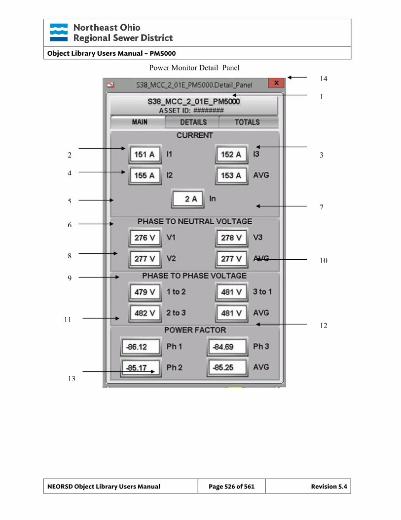
Object Library Users Manual – PM5000
NEORSD Object Library Users Manual Page 526 of 561 Revision 5.4
4
8
6
5 7
1
3
9
12
2
11
13
10
14 Power Monitor Detail_Panel

Object Library Users Manual – PM5000
NEORSD Object Library Users Manual Page 527 of 561 Revision 5.4
Graphic Number
Design Element
Function Description
1 Tag Name Displays the object name.
2 Real Power Ph 1 Indicates the Real Power for Phase 1. The Units refers to W.
3 Real Power Ph 2 Indicates the Real Power for Phase 2. The Units refers to W.
4 Real Power Ph 3 Indicates the Real Power for Phase 3. The Units refers to W.
5 Reactive Power Ph 1 Indicates the Reactive Power for Phase 1. The Units refers to VAR.
6 Reactive Power Ph 2 Indicates the Reactive Power for Phase 2. The Units refers to VAR.
7 Reactive Power Ph 3 Indicates the Reactive Power for Phase 3. The Units refers to VAR.
8 Apparent Power Ph 1 Indicates the Apparent Power for Phase 1. The Units refers to VA.
9 Apparent Power Ph 2 Indicates the Apparent Power for Phase 2. The Units refers to VA.
10 Apparent Power Ph 3 Indicates the Apparent Power for Phase 3. The Units refers to VA.
11 Frequency Indicates the Frequency. The Units refers to Hertz.
12 Total Dist. Indicates the Total Harmonic Distortion (THD). The Units refers to %.
13 Demand KW Indicates the Demand kW. The Units refers to kW
14 Close Button Pressing this button closes the faceplate display.
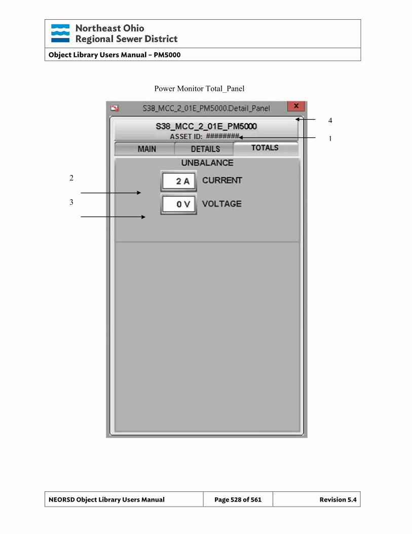
Object Library Users Manual – PM5000
NEORSD Object Library Users Manual Page 528 of 561 Revision 5.4
3
1
2
4
Power Monitor Total_Panel
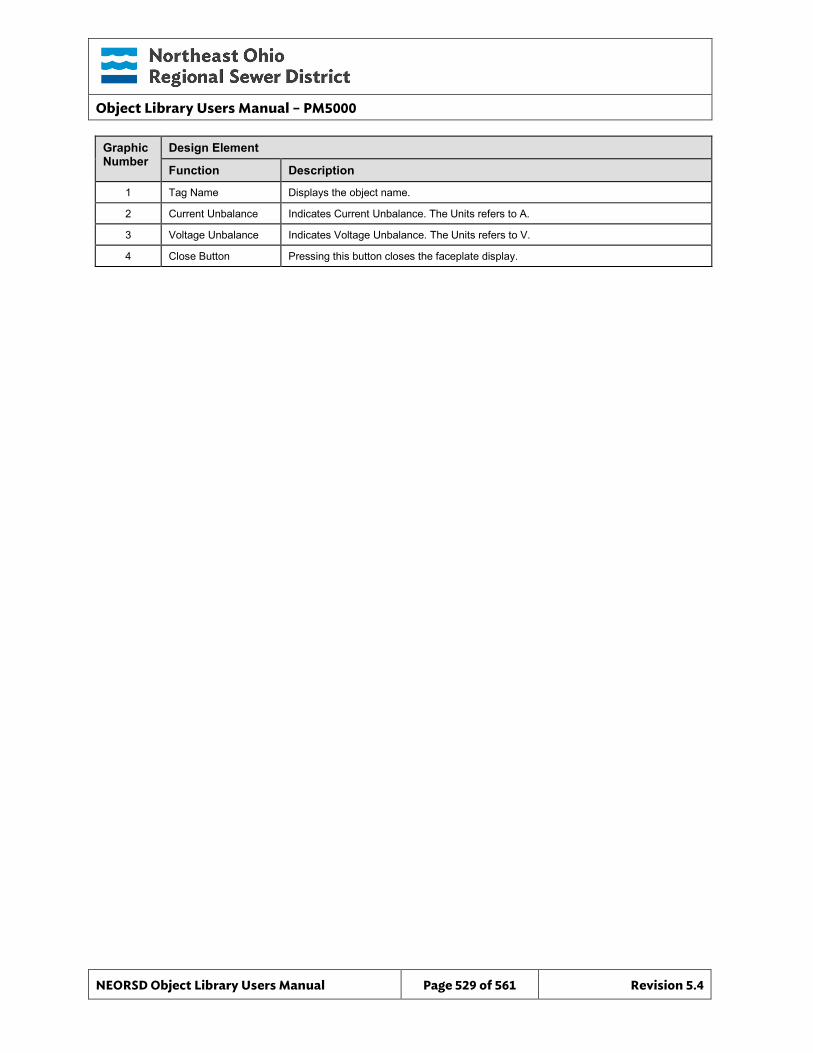
Object Library Users Manual – PM5000
NEORSD Object Library Users Manual Page 529 of 561 Revision 5.4
Graphic Number
Design Element
Function Description
1 Tag Name Displays the object name.
2 Current Unbalance Indicates Current Unbalance. The Units refers to A.
3 Voltage Unbalance Indicates Voltage Unbalance. The Units refers to V.
4 Close Button Pressing this button closes the faceplate display.
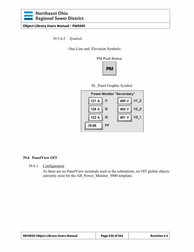
Object Library Users Manual – PM5000
NEORSD Object Library Users Manual Page 530 of 561 Revision 5.4
39.5.4.2 Symbols
One-Line and Elevation Symbols:
SL_Panel Graphic Symbol
39.6 PanelView OIT
39.6.1 Configuration As there are no PanelView terminals used in the substations, no OIT global objects currently exist for the AB_Power_Monitor_5000 template.
PM Push Button

Object Library Users Manual – PM5000
NEORSD Object Library Users Manual Page 531 of 561 Revision 5.4
This page left blank intentionally.
Object Library Users Manual – Transformer Protection Relay
NEORSD Object Library Users Manual Page 532 of 561 Revision 5.4
40.0 Transformer_Protection_Relay (SEL_787_TPR)
40.1 Introduction The Transformer Protection Relay template provides a standard representation for displaying discrete operational and alarm status of a SEL-787 transformer protection relay (or similar TPR device), for status monitoring. This template can and should be used to represent similar devices by other vendors. Use the SEL_787_TPR template if:
• Trying to represent the status of and data provided by a transformer protection relay.
Do not use the SEL_787_TPR template if: • The device you are modeling is a power monitoring device with no relay functions.
Consider the AB_Power_Monitor_3000 template instead.
The SEL-787 unit upon which this template is based provides programmable protective functions for power transformers in power distribution systems. The protection of the transformer, by the SEL-787, is provided by an interface through an external relay such as a 52 relay.
40.2 Object Features
40.2.1 Value Indications This object provides the following indications for the TPR:
• State of the relay based on “LED_Status” • Phase/line currents • Phase/line voltages • Real/reactive power • Frequency • Power Factor
40.2.2 Alarming This object supports the following alarms:
• Instantaneous and time-delayed overcurrent • Over/undervoltage • Over/underfrequency • High/Low Voltage • High/Low Frequency • Tripped and differential alarms
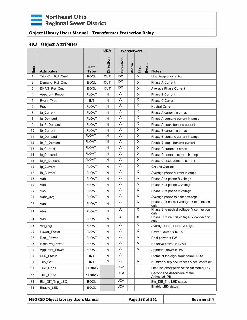
Object Library Users Manual – Transformer Protection Relay
NEORSD Object Library Users Manual Page 533 of 561 Revision 5.4
40.3 Object Attributes
UDA Wonderware
Item
Attributes Data Type D
irect
ion
Dire
ctio
n
Ala
rm
His
t
Even
t
Notes 1 Trip_Cnt_Rst_Cmd BOOL OUT DO X Line Frequency in Hz
2 Demand_Rst_Cmd BOOL OUT DO X Phase A Current
3 ENRG_Rst_Cmd BOOL OUT DO X Average Phase Current
4 Apparent_Power FLOAT IN AI X Phase B Current
5 Event_Type INT IN AI X Phase C Current
6 Freq FLOAT IN AI X Neutral Current
7 Ia_Current FLOAT IN AI X Phase A current in amps
8 Ia_Demand FLOAT IN AI X Phase A demand current in amps
9 Ia_P_Demand FLOAT IN AI X Phase A peak demand current
10 Ib_Current FLOAT IN AI X Phase B current in amps
11 Ib_Demand FLOAT IN AI X Phase B demand current in amps
12 Ib_P_Demand FLOAT IN AI X Phase B peak demand current
13 Ic_Current FLOAT IN AI X Phase C current in amps
14 Ic_Demand FLOAT IN AI X Phase C demand current in amps
15 Ic_P_Demand FLOAT IN AI X Phase C peak demand current
16 Ig_Current FLOAT IN AI X Ground Current
17 In_Current FLOAT IN AI X Average phase current in amps
18 Vab FLOAT IN AI X Phase A to phase B voltage
19 Vbc FLOAT IN AI X Phase B to phase C voltage
20 Vca FLOAT IN AI X Phase C to phase A voltage
21 Vabc_avg FLOAT IN AI X Average phase to phase voltage
22 Van FLOAT IN AI X Phase A to neutral voltage- Y connection only
23 Vbn FLOAT IN AI X Phase B to neutral voltage- Y connection only
24 Vcn FLOAT IN AI X Phase C to neutral voltage- Y connection only
25 Vln_avg FLOAT IN AI X Average Line-to-Line Voltage
26 Power_Factor FLOAT IN AI X Power Factor, 0 to 1.0
27 Real_Power FLOAT IN AI X Real power in kW
28 Reactive_Power FLOAT IN AI X Reactive power in kVAR
29 Apparent_Power FLOAT IN AI X Apparent power in kVA
30 LED_Status INT IN AI Status of the eight front panel LED’s
31 Trip_Cnt INT IN AI X Number of trip occurences since last reset
31 Text_Line1 STRING UDA First line description of the Animated_PB
32 Text_Line2 STRING UDA Second line description of the Animated_PB
33 Bkr_Diff_Trip_LED BOOL UDA Bkr_Diff_Trip LED status
34 Enable_LED BOOL UDA Enable LED status
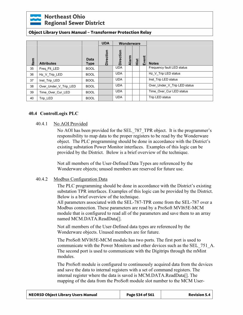
Object Library Users Manual – Transformer Protection Relay
NEORSD Object Library Users Manual Page 534 of 561 Revision 5.4
UDA Wonderware
Item
Attributes Data Type D
irect
ion
Dire
ctio
n
Ala
rm
His
t
Even
t
Notes 35 Freq_Flt_LED BOOL UDA Frequency fault LED status
36 Hz_V_Trip_LED BOOL UDA Hz_V_Trip LED status
37 Inst_Trip_LED BOOL UDA Inst_Trip LED status
38 Over_Under_V_Trip_LED BOOL UDA Over_Under_V_Trip LED status
39 Time_Over_Cur_LED BOOL UDA Time_Over_Cur LED status
40 Trip_LED BOOL UDA Trip LED status
40.4 ControlLogix PLC
40.4.1 No AOI Provided No AOI has been provided for the SEL_787_TPR object. It is the programmer’s responsibility to map data to the proper registers to be read by the Wonderware object. The PLC programming should be done in accordance with the District’s existing substation Power Monitor interfaces. Examples of this logic can be provided by the District. Below is a brief overview of the technique.
Not all members of the User-Defined Data Types are referenced by the Wonderware objects; unused members are reserved for future use.
40.4.2 Modbus Configuration Data The PLC programming should be done in accordance with the District’s existing substation TPR interfaces. Examples of this logic can be provided by the District. Below is a brief overview of the technique. All parameters associated with the SEL-787-TPR come from the SEL-787 over a Modbus connection. These parameters are read by a ProSoft MVI65E-MCM module that is configured to read all of the parameters and save them to an array named MCM.DATA.ReadData[]. Not all members of the User-Defined data types are referenced by the Wonderware objects. Unused members are for future. The ProSoft MVI65E-MCM module has two ports. The first port is used to communicate with the Power Monitors and other devices such as the SEL_751_A. The second port is used to communicate with the Digitrips through the mMint modules. The ProSoft module is configured to continuously acquired data from the devices and save the data to internal registers with a set of command registers. The internal register where the data is saved is MCM.DATA.ReadData[]. The mapping of the data from the ProSoft module slot number to the MCM User-
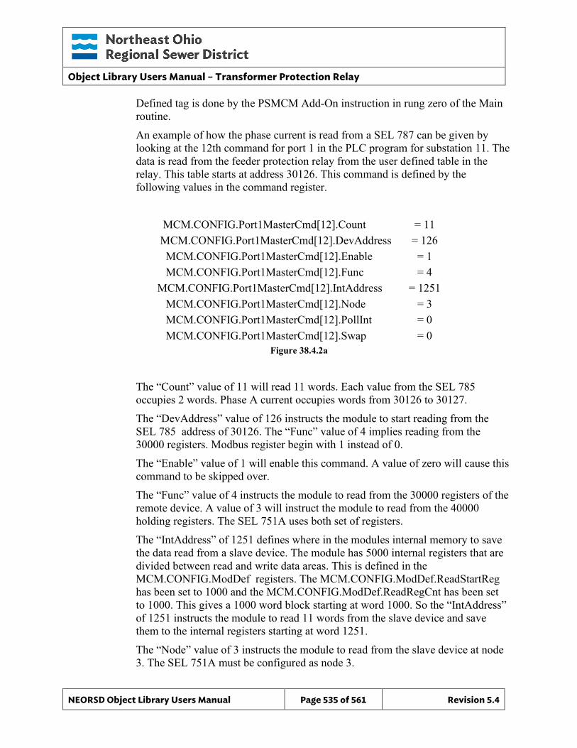
Object Library Users Manual – Transformer Protection Relay
NEORSD Object Library Users Manual Page 535 of 561 Revision 5.4
Defined tag is done by the PSMCM Add-On instruction in rung zero of the Main routine. An example of how the phase current is read from a SEL 787 can be given by looking at the 12th command for port 1 in the PLC program for substation 11. The data is read from the feeder protection relay from the user defined table in the relay. This table starts at address 30126. This command is defined by the following values in the command register.
MCM.CONFIG.Port1MasterCmd[12].Count = 11 MCM.CONFIG.Port1MasterCmd[12].DevAddress = 126 MCM.CONFIG.Port1MasterCmd[12].Enable = 1 MCM.CONFIG.Port1MasterCmd[12].Func = 4
MCM.CONFIG.Port1MasterCmd[12].IntAddress = 1251 MCM.CONFIG.Port1MasterCmd[12].Node = 3 MCM.CONFIG.Port1MasterCmd[12].PollInt = 0 MCM.CONFIG.Port1MasterCmd[12].Swap = 0
Figure 38.4.2a
The “Count” value of 11 will read 11 words. Each value from the SEL 785 occupies 2 words. Phase A current occupies words from 30126 to 30127. The “DevAddress” value of 126 instructs the module to start reading from the SEL 785 address of 30126. The “Func” value of 4 implies reading from the 30000 registers. Modbus register begin with 1 instead of 0. The “Enable” value of 1 will enable this command. A value of zero will cause this command to be skipped over. The “Func” value of 4 instructs the module to read from the 30000 registers of the remote device. A value of 3 will instruct the module to read from the 40000 holding registers. The SEL 751A uses both set of registers. The “IntAddress” of 1251 defines where in the modules internal memory to save the data read from a slave device. The module has 5000 internal registers that are divided between read and write data areas. This is defined in the MCM.CONFIG.ModDef registers. The MCM.CONFIG.ModDef.ReadStartReg has been set to 1000 and the MCM.CONFIG.ModDef.ReadRegCnt has been set to 1000. This gives a 1000 word block starting at word 1000. So the “IntAddress” of 1251 instructs the module to read 11 words from the slave device and save them to the internal registers starting at word 1251. The “Node” value of 3 instructs the module to read from the slave device at node 3. The SEL 751A must be configured as node 3.
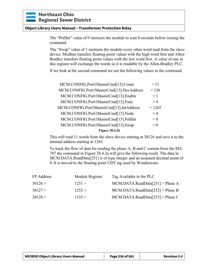
Object Library Users Manual – Transformer Protection Relay
NEORSD Object Library Users Manual Page 536 of 561 Revision 5.4
The “PollInt” value of 0 instructs the module to wait 0 seconds before issuing the command. The “Swap” value of 1 instructs the module every other word read from the slave device. Modbus transfers floating point values with the high word first and Allen-Bradley transfers floating point values with the low word first. A value of one in this register will exchange the words so it is readable by the Allen-Bradley PLC. If we look at the second command we see the following values in the command.
MCM.CONFIG.Port1MasterCmd[13].Count = 11
MCM.CONFIG.Port1MasterCmd[13].DevAddress = 126 MCM.CONFIG.Port1MasterCmd[13].Enable = 1 MCM.CONFIG.Port1MasterCmd[13].Func = 4
MCM.CONFIG.Port1MasterCmd[13].IntAddress = 1265 MCM.CONFIG.Port1MasterCmd[13].Node = 4 MCM.CONFIG.Port1MasterCmd[13].PollInt = 0 MCM.CONFIG.Port1MasterCmd[13].Swap = 0
Figure 38.4.2b
This will read 11 words from the slave device starting at 30126 and save it to the internal address starting at 1265. To track the flow of data for reading the phase A, B and C current from the SEL 787 the command in Figure 38.4.2a will give the following result. The data in MCM.DATA.ReadData[251] is of type integer and an assumed decimal point of 0. It is moved to the floating point UDT tag used by Wonderware.
FP Address Module Register Tag Available in the PLC 30126 > 1251 > MCM.DATA.ReadData[251] > Phase A 30127 > 1252 > MCM.DATA.ReadData[252] > Phase B 30128 > 1153 > MCM.DATA.ReadData[253] > Phase C
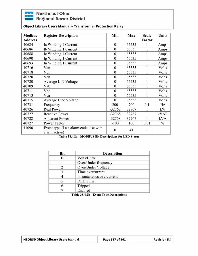
Object Library Users Manual – Transformer Protection Relay
NEORSD Object Library Users Manual Page 537 of 561 Revision 5.4
Modbus Address
Register Description Min Max Scale Factor
Units
40684 Ia Winding 1 Current 0 65535 1 Amps 40686 Ib Winding 1 Current 0 65535 1 Amps 40688 Ic Winding 1 Current 0 65535 1 Amps 40690 Ig Winding 1 Current 0 65535 1 Amps 40693 In Winding 1 Current 0 65535 1 Amps 40716 Van 0 65535 1 Volts 40718 Vbn 0 65535 1 Volts 40720 Vcn 0 65535 1 Volts 40720 Average L-N Voltage 0 65535 1 Volts 40709 Vab 0 65535 1 Volts 40711 Vbc 0 65535 1 Volts 40713 Vca 0 65535 1 Volts 40715 Average Line Voltage 0 65535 1 Volts 40731 Frequency 200 700 0.1 Hz 40726 Real Power -32768 32767 1 kW 40727 Reactive Power -32768 32767 1 kVAR 40728 Apparent Power -32768 32767 1 kVA 40727 Power Factor -100 100 0.01 % 41090 Event type (Last alarm code, use with
alarm active) 0 41 1 Table 38.4.2a - MODBUS Bit Descriptions for LED Status
Bit Description 0 Volts/Hertz 1 Over/Under frequency 2 Over/Under Voltage 3 Time overcurrent 4 Instantaneous overcurrent 5 Differential 6 Tripped 7 Enabled
Table 38.4.2b - Event Type Descriptions
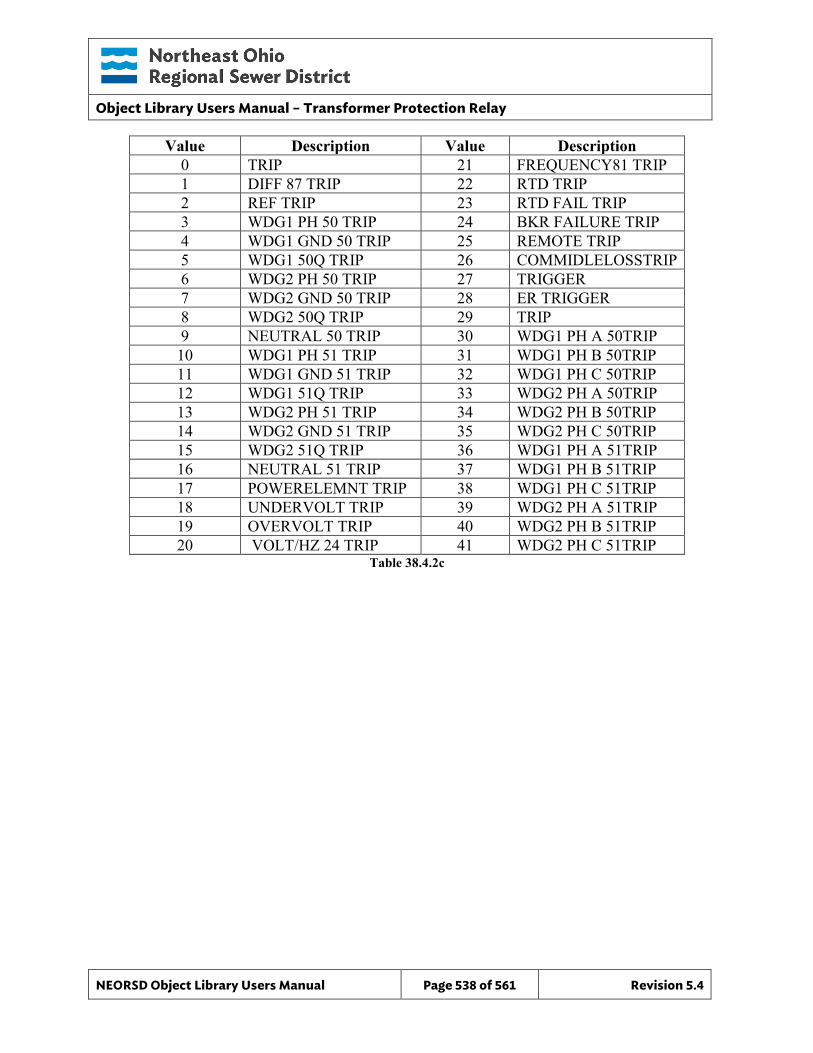
Object Library Users Manual – Transformer Protection Relay
NEORSD Object Library Users Manual Page 538 of 561 Revision 5.4
Value Description Value Description 0 TRIP 21 FREQUENCY81 TRIP 1 DIFF 87 TRIP 22 RTD TRIP 2 REF TRIP 23 RTD FAIL TRIP 3 WDG1 PH 50 TRIP 24 BKR FAILURE TRIP 4 WDG1 GND 50 TRIP 25 REMOTE TRIP 5 WDG1 50Q TRIP 26 COMMIDLELOSSTRIP 6 WDG2 PH 50 TRIP 27 TRIGGER 7 WDG2 GND 50 TRIP 28 ER TRIGGER 8 WDG2 50Q TRIP 29 TRIP 9 NEUTRAL 50 TRIP 30 WDG1 PH A 50TRIP 10 WDG1 PH 51 TRIP 31 WDG1 PH B 50TRIP 11 WDG1 GND 51 TRIP 32 WDG1 PH C 50TRIP 12 WDG1 51Q TRIP 33 WDG2 PH A 50TRIP 13 WDG2 PH 51 TRIP 34 WDG2 PH B 50TRIP 14 WDG2 GND 51 TRIP 35 WDG2 PH C 50TRIP 15 WDG2 51Q TRIP 36 WDG1 PH A 51TRIP 16 NEUTRAL 51 TRIP 37 WDG1 PH B 51TRIP 17 POWERELEMNT TRIP 38 WDG1 PH C 51TRIP 18 UNDERVOLT TRIP 39 WDG2 PH A 51TRIP 19 OVERVOLT TRIP 40 WDG2 PH B 51TRIP 20 VOLT/HZ 24 TRIP 41 WDG2 PH C 51TRIP
Table 38.4.2c
Object Library Users Manual – Transformer Protection Relay
NEORSD Object Library Users Manual Page 539 of 561 Revision 5.4
40.5 Wonderware HMI
40.5.1 Properties Hierarchical Name: $SEL_787_TPR Derivation: Derived from $NEORSDUserDefined Container: None
40.5.2 Extensions None
40.5.3 Configuration All of the necessary configuration for SEL_787_TPR must also be done on any instance derived from this template.
1) Animated_PB Graphic – Set UDA Text_Line1 to first line of TPR name. Set UDA Text_Line2 to second line of TPR name.
2) Attributes that are not used in the configured instance shall use
Me.Placeholder to eliminate the point from counting against the systems total I/O scan counts. These shall include values not available on delta configured systems when installed on a delta system.
3) If ASSET_ID is not in use the initial value will be left blank. Scripting
used for ASSET_ID uses the initial value and not ASSET_ID.Description
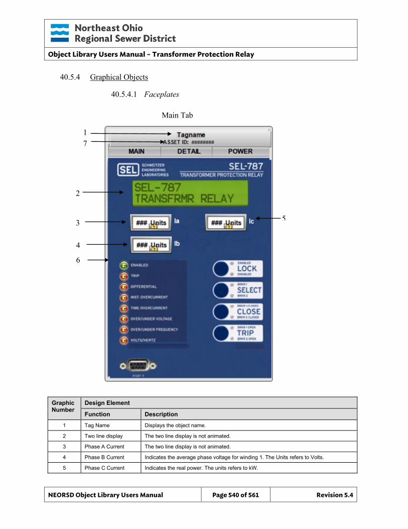
Object Library Users Manual – Transformer Protection Relay
NEORSD Object Library Users Manual Page 540 of 561 Revision 5.4
40.5.4 Graphical Objects
40.5.4.1 Faceplates
Graphic Number
Design Element
Function Description
1 Tag Name Displays the object name.
2 Two line display The two line display is not animated.
3 Phase A Current The two line display is not animated.
4 Phase B Current Indicates the average phase voltage for winding 1. The Units refers to Volts.
5 Phase C Current Indicates the real power. The units refers to kW.
5
1
2
6
Main Tab
3
4
7
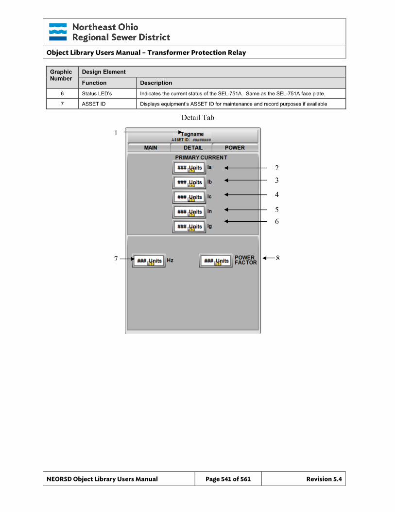
Object Library Users Manual – Transformer Protection Relay
NEORSD Object Library Users Manual Page 541 of 561 Revision 5.4
Graphic Number
Design Element
Function Description
6 Status LED’s Indicates the current status of the SEL-751A. Same as the SEL-751A face plate.
7 ASSET ID Displays equipment’s ASSET ID for maintenance and record purposes if available
Detail Tab
2 3 4 5 6
1
7
8
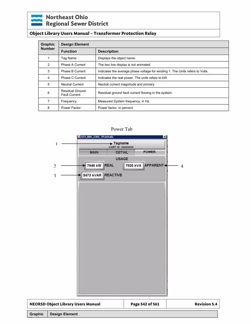
Object Library Users Manual – Transformer Protection Relay
NEORSD Object Library Users Manual Page 542 of 561 Revision 5.4
Graphic Number
Design Element
Function Description
1 Tag Name Displays the object name.
2 Phase A Current The two line display is not animated.
3 Phase B Current Indicates the average phase voltage for winding 1. The Units refers to Volts.
4 Phase C Current Indicates the real power. The units refers to kW.
5 Neutral Current Neutral current magnitude and primary.
6 Residual Ground Fault Current Residual ground fault current flowing in the system.
7 Frequency Measured System frequency, in Hz.
8 Power Factor Power factor, in percent.
Graphic N b
Design Element
2 3
4
1
Power Tab
Object Library Users Manual – Transformer Protection Relay
NEORSD Object Library Users Manual Page 543 of 561 Revision 5.4
*All parameters are displayed in the units indicated within the data field.
Function Description
1 Tag Name Displays the object name.
2 Real Power System real power in kW.
3 Reactive Power System reactive power in kW.
4 Apparent Power System apparent power in kVA.
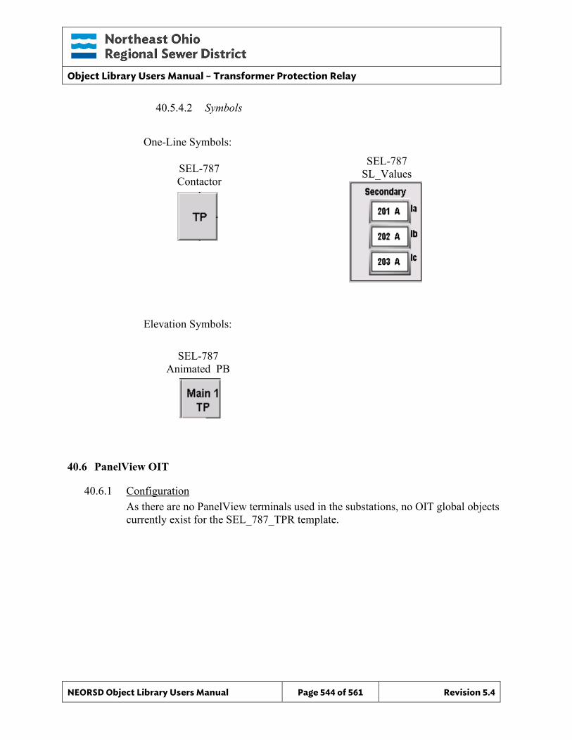
Object Library Users Manual – Transformer Protection Relay
NEORSD Object Library Users Manual Page 544 of 561 Revision 5.4
40.5.4.2 Symbols
One-Line Symbols:
Elevation Symbols:
40.6 PanelView OIT
40.6.1 Configuration As there are no PanelView terminals used in the substations, no OIT global objects currently exist for the SEL_787_TPR template.
SEL-787 Contactor
SEL-787 SL_Values
SEL-787 Animated PB
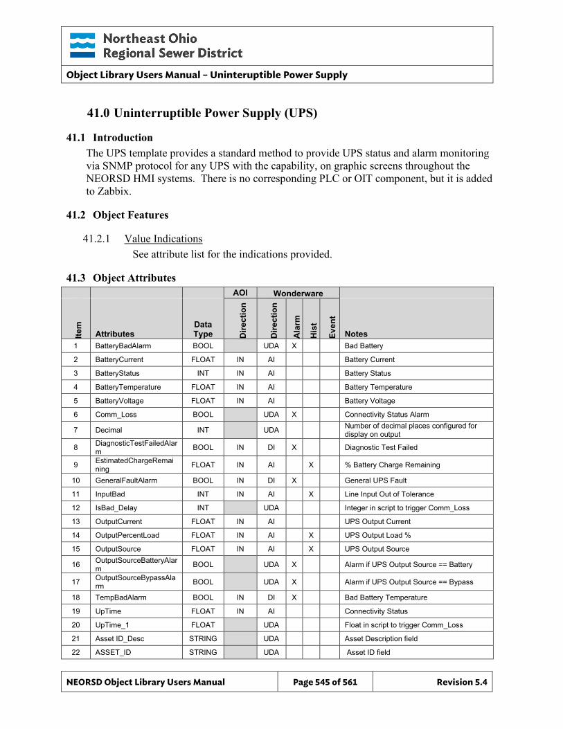
Object Library Users Manual – Uninteruptible Power Supply
NEORSD Object Library Users Manual Page 545 of 561 Revision 5.4
41.0 Uninterruptible Power Supply (UPS)
41.1 Introduction The UPS template provides a standard method to provide UPS status and alarm monitoring via SNMP protocol for any UPS with the capability, on graphic screens throughout the NEORSD HMI systems. There is no corresponding PLC or OIT component, but it is added to Zabbix.
41.2 Object Features
41.2.1 Value Indications See attribute list for the indications provided.
41.3 Object Attributes
AOI Wonderware
Item
Attributes Data Type D
irect
ion
Dire
ctio
n
Ala
rm
His
t
Even
t Notes
1 BatteryBadAlarm BOOL UDA X Bad Battery
2 BatteryCurrent FLOAT IN AI Battery Current
3 BatteryStatus INT IN AI Battery Status
4 BatteryTemperature FLOAT IN AI Battery Temperature
5 BatteryVoltage FLOAT IN AI Battery Voltage
6 Comm_Loss BOOL UDA X Connectivity Status Alarm
7 Decimal INT UDA Number of decimal places configured for display on output
8 DiagnosticTestFailedAlarm BOOL IN DI X Diagnostic Test Failed
9 EstimatedChargeRemaining FLOAT IN AI X % Battery Charge Remaining
10 GeneralFaultAlarm BOOL IN DI X General UPS Fault
11 InputBad INT IN AI X Line Input Out of Tolerance
12 IsBad_Delay INT UDA Integer in script to trigger Comm_Loss
13 OutputCurrent FLOAT IN AI UPS Output Current
14 OutputPercentLoad FLOAT IN AI X UPS Output Load %
15 OutputSource FLOAT IN AI X UPS Output Source
16 OutputSourceBatteryAlarm BOOL UDA X Alarm if UPS Output Source == Battery
17 OutputSourceBypassAlarm BOOL UDA X Alarm if UPS Output Source == Bypass
18 TempBadAlarm BOOL IN DI X Bad Battery Temperature
19 UpTime FLOAT IN AI Connectivity Status
20 UpTime_1 FLOAT UDA Float in script to trigger Comm_Loss
21 Asset ID_Desc STRING UDA Asset Description field
22 ASSET_ID STRING UDA Asset ID field
Object Library Users Manual – Uninteruptible Power Supply
NEORSD Object Library Users Manual Page 546 of 561 Revision 5.4
41.4 ControlLogix PLC No ControlLogix component (AOI) exists for this template.
41.5 Wonderware HMI
41.5.1 Properties Hierarchical Name: $UPS Derivation: Derived from $NEORSDUserDefined Container: None
41.5.2 Extensions None
41.5.3 Configuration All of the necessary configuration for UPS must be done on any instance derived from this template. 1) Attributes that are not used in the configured instance shall use
Me.Placeholder to eliminate the point from counting against the systems total I/O scan counts. Attributes that are available but default to Me.Placeholder in a new instance shall not use Me.Placeholder. Consult UPS manufacturer data to confirm available points. The allowed attributes for this template include the following:
a. BatteryCurrent (default = Me.Placeholder) b. BatteryStatus c. BatteryTemperature (default = Me.Placeholder) d. BatteryVoltage e. DiagnosticTestFailedAlarm (default = Me.Placeholder) f. EstimatedChargeRemaining g. GeneralFaultAlarm (default = Me.Placeholder) h. InputBad (default = Me.Placeholder) i. OutputCurrent j. OutputPercentLoad k. OutputSource l. TempBadAlarm (default = Me.Placeholder) m. UpTime
Object Library Users Manual – Uninteruptible Power Supply
NEORSD Object Library Users Manual Page 547 of 561 Revision 5.4
2) If ASSET_ID is not in use the initial value will be left blank. Scripting used for ASSET_ID uses the initial value and not ASSET_ID.Description.
3) The ASSET_ID Description field is written within the UDA
“ASSET_ID.Description”. The programmer shall obtain the ASSET ID attribute strings from the District.
4) The ASSET ID field is written within the UDA “ASSET_ID” and is displayed on a faceplate that is launched from a symbol. The programmer shall obtain the ASSET_ID attribute strings from the District.
5) The UPS object uses the Wonderware OI SNMP driver which requires
SuiteLink mapping. Note the Item References are SNMP OIDs that may be specific to the UPS manufacturer/model. See below for an example of SuiteLink mapping from UPS object S07_UPS_SUB19:
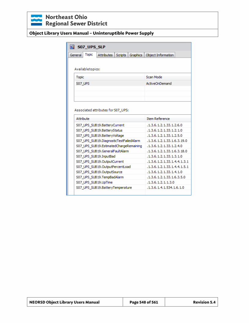
Object Library Users Manual – Uninteruptible Power Supply
NEORSD Object Library Users Manual Page 548 of 561 Revision 5.4
Object Library Users Manual – Uninteruptible Power Supply
NEORSD Object Library Users Manual Page 549 of 561 Revision 5.4
41.5.4 Graphical Objects
41.5.4.1 Faceplates
UPS_Faceplate
1
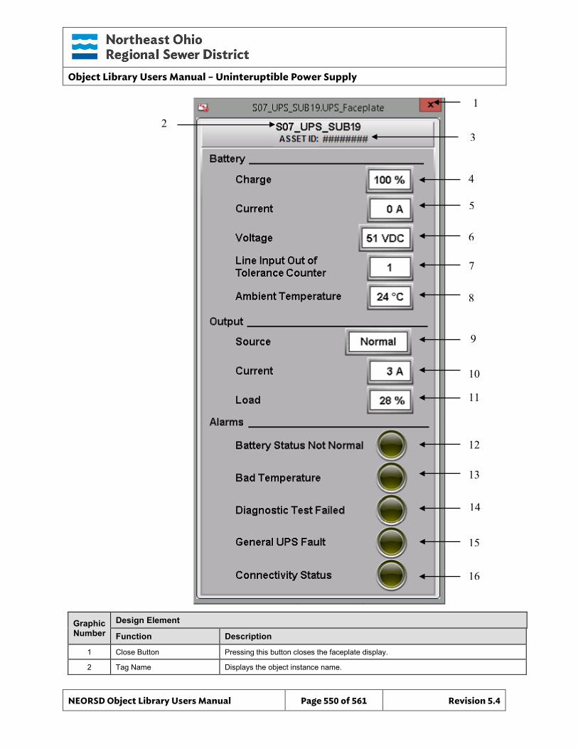
Object Library Users Manual – Uninteruptible Power Supply
NEORSD Object Library Users Manual Page 550 of 561 Revision 5.4
Graphic Number
Design Element
Function Description
1 Close Button Pressing this button closes the faceplate display.
2 Tag Name Displays the object instance name.
2 3
4
5
6
7
8
9
10
11
12
13
14
15
16
1
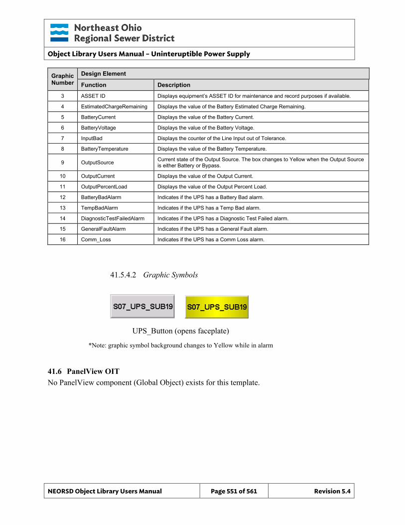
Object Library Users Manual – Uninteruptible Power Supply
NEORSD Object Library Users Manual Page 551 of 561 Revision 5.4
Graphic Number
Design Element
Function Description
3 ASSET ID Displays equipment’s ASSET ID for maintenance and record purposes if available.
4 EstimatedChargeRemaining Displays the value of the Battery Estimated Charge Remaining.
5 BatteryCurrent Displays the value of the Battery Current.
6 BatteryVoltage Displays the value of the Battery Voltage.
7 InputBad Displays the counter of the Line Input out of Tolerance.
8 BatteryTemperature Displays the value of the Battery Temperature.
9 OutputSource Current state of the Output Source. The box changes to Yellow when the Output Source is either Battery or Bypass.
10 OutputCurrent Displays the value of the Output Current.
11 OutputPercentLoad Displays the value of the Output Percent Load.
12 BatteryBadAlarm Indicates if the UPS has a Battery Bad alarm.
13 TempBadAlarm Indicates if the UPS has a Temp Bad alarm.
14 DiagnosticTestFailedAlarm Indicates if the UPS has a Diagnostic Test Failed alarm.
15 GeneralFaultAlarm Indicates if the UPS has a General Fault alarm.
16 Comm_Loss Indicates if the UPS has a Comm Loss alarm.
41.5.4.2 Graphic Symbols
41.6 PanelView OIT No PanelView component (Global Object) exists for this template.
UPS_Button (opens faceplate)
*Note: graphic symbol background changes to Yellow while in alarm
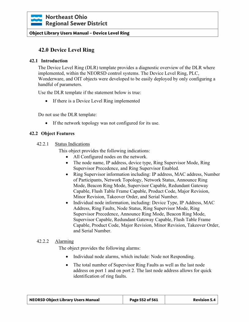
Object Library Users Manual – Device Level Ring
NEORSD Object Library Users Manual Page 552 of 561 Revision 5.4
42.0 Device Level Ring
42.1 Introduction The Device Level Ring (DLR) template provides a diagnostic overview of the DLR where implemented, within the NEORSD control systems. The Device Level Ring, PLC, Wonderware, and OIT objects were developed to be easily deployed by only configuring a handful of parameters. Use the DLR template if the statement below is true:
• If there is a Device Level Ring implemented Do not use the DLR template:
• If the network topology was not configured for its use.
42.2 Object Features
42.2.1 Status Indications This object provides the following indications:
• All Configured nodes on the network. • The node name, IP address, device type, Ring Supervisor Mode, Ring
Supervisor Precedence, and Ring Supervisor Enabled. • Ring Supervisor information including: IP address, MAC address, Number
of Participants, Network Topology, Network Status, Announce Ring Mode, Beacon Ring Mode, Supervisor Capable, Redundant Gateway Capable, Flush Table Frame Capable, Product Code, Major Revision, Minor Revision, Takeover Order, and Serial Number.
• Individual node information, including: Device Type, IP Address, MAC Address, Ring Faults, Node Status, Ring Supervisor Mode, Ring Supervisor Precedence, Announce Ring Mode, Beacon Ring Mode, Supervisor Capable, Redundant Gateway Capable, Flush Table Frame Capable, Product Code, Major Revision, Minor Revision, Takeover Order, and Serial Number.
42.2.2 Alarming The object provides the following alarms:
• Individual node alarms, which include: Node not Responding.
• The total number of Supervisor Ring Faults as well as the last node address on port 1 and on port 2. The last node address allows for quick identification of ring faults.
Object Library Users Manual – Device Level Ring
NEORSD Object Library Users Manual Page 553 of 561 Revision 5.4
42.2.3 Simulation This object does not support a simulation mode.
42.2.4 Trouble This object does not support a trouble indication.
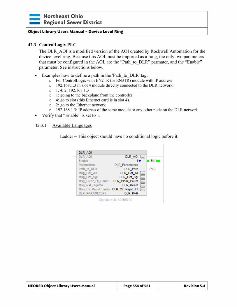
Object Library Users Manual – Device Level Ring
NEORSD Object Library Users Manual Page 554 of 561 Revision 5.4
42.3 ControlLogix PLC The DLR_AOI is a modified version of the AOI created by Rockwell Automation for the device level ring. Because this AOI must be imported as a rung, the only two parameters that must be configured in the AOI, are the “Path_to_DLR” parmater, and the “Enable” parameter. See instructions below.
• Examples how to define a path in the 'Path_to_DLR' tag: o For ControlLogix with EN2TR (or EN3TR) module with IP address o 192.168.1.3 in slot 4 module directly connected to the DLR network: o 1, 4, 2, 192.168.1.3 o 1: going to the backplane from the controller o 4: go to slot (this Ethernet card is in slot 4). o 2: go to the Ethernet network o 192.168.1.3: IP address of the same module or any other node on the DLR network
• Verify that “Enable” is set to 1.
42.3.1 Available Languages
Ladder – This object should have no conditional logic before it.
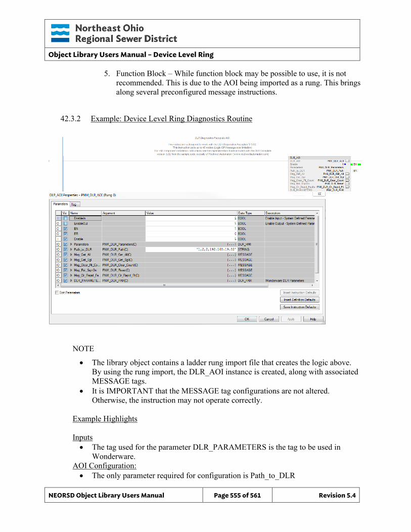
Object Library Users Manual – Device Level Ring
NEORSD Object Library Users Manual Page 555 of 561 Revision 5.4
5. Function Block – While function block may be possible to use, it is not recommended. This is due to the AOI being imported as a rung. This brings along several preconfigured message instructions.
42.3.2 Example: Device Level Ring Diagnostics Routine
NOTE
• The library object contains a ladder rung import file that creates the logic above. By using the rung import, the DLR_AOI instance is created, along with associated MESSAGE tags.
• It is IMPORTANT that the MESSAGE tag configurations are not altered. Otherwise, the instruction may not operate correctly.
Example Highlights Inputs • The tag used for the parameter DLR_PARAMETERS is the tag to be used in
Wonderware. AOI Configuration: • The only parameter required for configuration is Path_to_DLR
Object Library Users Manual – Device Level Ring
NEORSD Object Library Users Manual Page 556 of 561 Revision 5.4
• The following DLR alarms are available:
Ring Faults Node not responding
42.4 Wonderware HMI
42.4.1 Properties Hierarchical Name: $ DLR Derivation: Derived from $NEORSDUserDefined Container: None
42.4.2 Configuration All of the necessary configuration must also be done on any instance derived from this template.
1) NODE_0.NAME - The node device tag descriptions must be entered into this String for graphic display. This must be done for each active node. NODE_X.NAME (0 > X > 45)
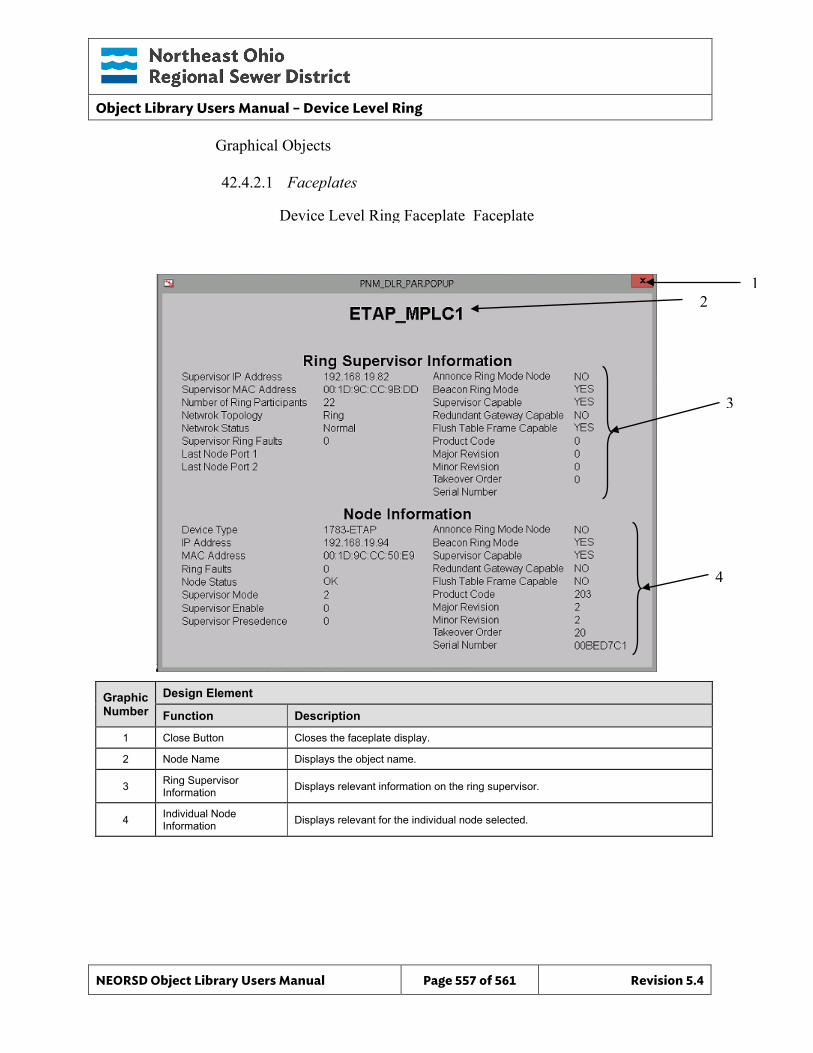
Object Library Users Manual – Device Level Ring
NEORSD Object Library Users Manual Page 557 of 561 Revision 5.4
Graphical Objects
42.4.2.1 Faceplates
Graphic Number
Design Element
Function Description
1 Close Button Closes the faceplate display.
2 Node Name Displays the object name.
3 Ring Supervisor Information Displays relevant information on the ring supervisor.
4 Individual Node Information Displays relevant for the individual node selected.
Device Level Ring Faceplate_Faceplate
3
4
2 1
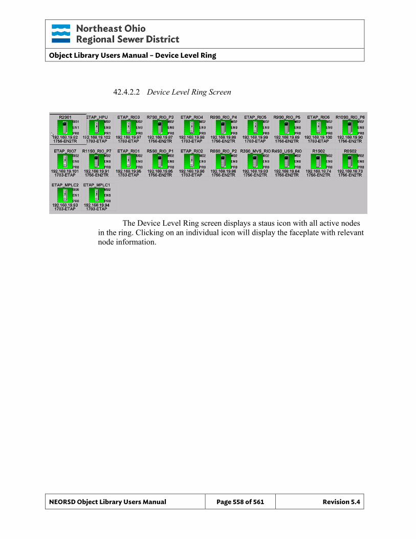
Object Library Users Manual – Device Level Ring
NEORSD Object Library Users Manual Page 558 of 561 Revision 5.4
42.4.2.2 Device Level Ring Screen
The Device Level Ring screen displays a staus icon with all active nodes
in the ring. Clicking on an individual icon will display the faceplate with relevant node information.
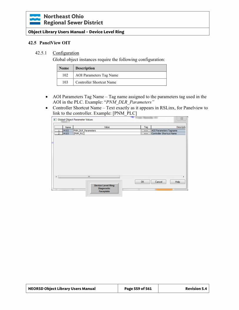
Object Library Users Manual – Device Level Ring
NEORSD Object Library Users Manual Page 559 of 561 Revision 5.4
42.5 PanelView OIT
42.5.1 Configuration Global object instances require the following configuration:
Name Description
102 AOI Parameters Tag Name
103 Controller Shortcut Name
• AOI Parameters Tag Name – Tag name assigned to the parameters tag used in the AOI in the PLC. Example: “PNM_DLR_Parameters”
• Controller Shortcut Name – Text exactly as it appears in RSLinx, for Panelview to link to the controller. Example: [PNM_PLC]
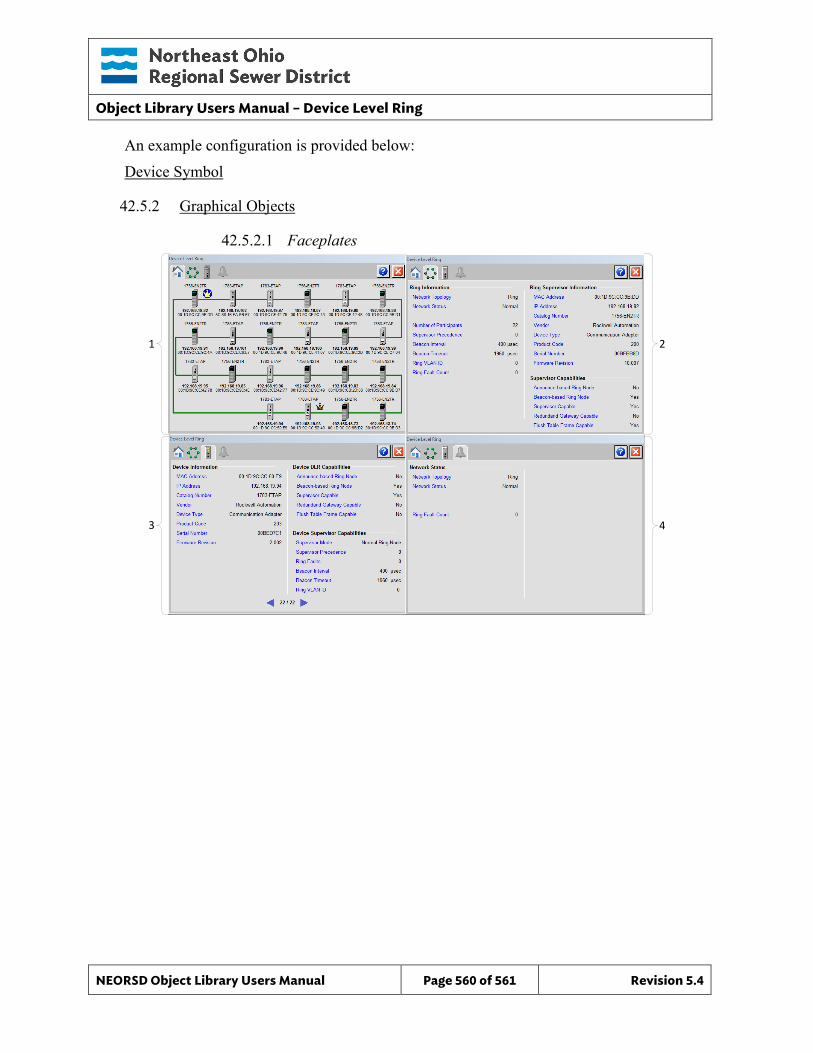
Object Library Users Manual – Device Level Ring
NEORSD Object Library Users Manual Page 560 of 561 Revision 5.4
An example configuration is provided below: Device Symbol
42.5.2 Graphical Objects
42.5.2.1 Faceplates
21
43
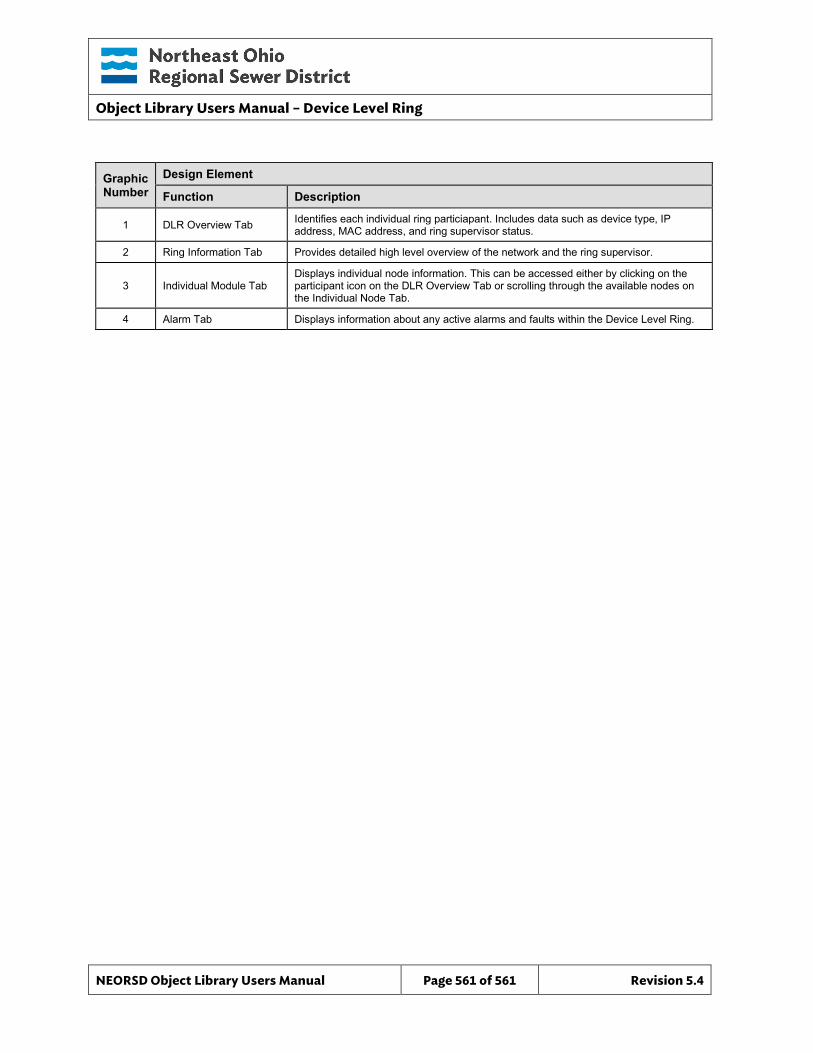
Object Library Users Manual – Device Level Ring
NEORSD Object Library Users Manual Page 561 of 561 Revision 5.4
Graphic Number
Design Element
Function Description
1 DLR Overview Tab Identifies each individual ring particiapant. Includes data such as device type, IP address, MAC address, and ring supervisor status.
2 Ring Information Tab Provides detailed high level overview of the network and the ring supervisor.
3 Individual Module Tab Displays individual node information. This can be accessed either by clicking on the participant icon on the DLR Overview Tab or scrolling through the available nodes on the Individual Node Tab.
4 Alarm Tab Displays information about any active alarms and faults within the Device Level Ring.


![LCD TV - Error: [object Object]](https://img.pdfslide.net/doc/110x75/63262933cedd78c2b50cf241/lcd-tv-error-object-object.jpg)

