Embed Size (px)
Citation preview
USERS MANUAL µVGA PICASO MD1
Tiny VGA Graphics Controller QVGA, VGA, SVGA
Revision 1.2
4D Systems
www.4dsystems.com.au µVGA-PICASO-MD1
2
PROPRIETORY INFORMATION The information contained in this document is the property of 4D Systems Pty. Ltd., and may be the subject of patents pending or granted, and must not be copied or disclosed with out prior written permission. It should not be used for commercial purposes without prior agreement in writing. 4D Systems Pty. Ltd. Endeavours to ensure that the information in this document is correct and fairly stated but does not accept liability for any error or omission. The development of 4D Systems products and services is continuous and published information may not be up to date. It is important to check the current position with 4D Systems. Contact details are available from the company web site at www.4dsystems.com.au All trademarks recognised and acknowledged. Copyright 4D Systems Pty. Ltd. 2000-2007
DISCLAIMER OF WARRANTIES & LIMITATION OF LIABILITY
4D Systems Pty. Ltd. makes no warranty, either express or implied with respect to any product, and specifically disclaims all other warranties, including, without limitation, warranties for merchantability, non-infringement and fitness for any particular purpose. 4d systems' sole obligation and liability for product defects shall be, at 4d systems' option, to replace such defective product or refund to buyer the amount paid by buyer therefore. In no event shall 4D Systems' liability exceed the buyer's purchase price.
The foregoing remedy shall be subject to buyer's written notification of defect and return of the defective product within ninety (90) days of purchase. The foregoing remedy does not apply to products that have been subjected to misuse (including without limitation static discharge), neglect, accident or modification, or to products that have been soldered or altered during assembly, or are otherwise not capable of being tested, or if damage occurs as a result of the failure of buyer to follow specific instructions.
In no event shall 4D Systems be liable to the buyer or to any third party for any indirect, incidental, special, consequential, punitive or exemplary damages (including without limitation lost profits, lost savings, or loss of business opportunity) arising out of or relating to any product or service provided or to be provided by 4D Systems, or the use or inability to use the same, even if 4D Systems has been advised of the possibility of such damages.
www.4dsystems.com.au µVGA-PICASO-MD1
3
Table of contents
1. Introduction 4 2. Features 5 3. Pin Description 6 4. Reference Designs 7 5. Personality Module Micro Code (PmmC) 9 6. Graphics Command Set (Serial) 10
6.1 General Command Set 11 7. Serial Interface (TTL Level) 39 8. Using the µVGA-PICASOMD1-UB 40 9. USB Interface 41 10. Specifications 42 11. Mechanical Details 43 12. Colour Organisation 44 13. Power-Up Reset 45 14. Related Products 46 15. Appendix 47
15.1 Help and Other Information 47
www.4dsystems.com.au µVGA-PICASO-MD1
4
1 Introduction
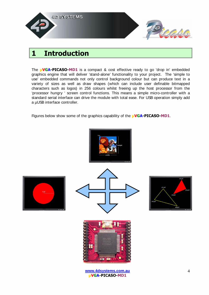
The µVGA-PICASO-MD1 is a compact & cost effective ready to go 'drop in' embedded graphics engine that will deliver ‘stand-alone’ functionality to your project. The ‘simple to use’ embedded commands not only control background colour but can produce text in a variety of sizes as well as draw shapes (which can include user definable bitmapped characters such as logos) in 256 colours whilst freeing up the host processor from the ‘processor hungry ‘ screen control functions. This means a simple micro-controller with a standard serial interface can drive the module with total ease. For USB operation simply add a µUSB interface controller.
Figures below show some of the graphics capability of the µVGA-PICASO-MD1.
www.4dsystems.com.au µVGA-PICASO-MD1
5
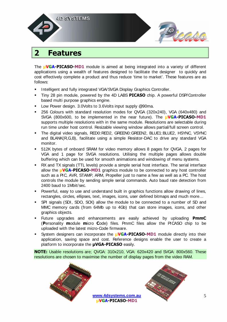
2 Features The µVGA-PICASO-MD1 module is aimed at being integrated into a variety of different applications using a wealth of features designed to facilitate the designer to quickly and cost effectively complete a product and thus reduce ‘time to market’. These features are as follows:
Intelligent and fully integrated VGA/SVGA Display Graphics Controller. Tiny 28 pin module, powered by the 4D LABS PICASO chip. A powerful DSP/Controller
based multi purpose graphics engine. Low Power design. 3.0Volts to 3.6Volts input supply @90ma. 256 Colours with standard resolution modes for QVGA (320x240), VGA (640x480) and
SVGA (800x600, to be implemented in the near future). The µVGA-PICASO-MD1 supports multiple resolutions with in the same module. Resolutions are selectable during run time under host control. Resizable viewing window allows partial/full screen control.
The digital video signals, RED0:RED2, GREEN0:GREEN2, BLUE1:BLUE2, HSYNC, VSYNC and BLANK(R,G,B), facilitate using a simple Resistor-DAC to drive any standard VGA monitor.
512K bytes of onboard SRAM for video memory allows 8 pages for QVGA, 2 pages for VGA and 1 page for SVGA resolutions. Utilising the multiple pages allows double buffering which can be used for smooth animations and windowing of menu systems.
RX and TX signals (TTL levels) provide a simple serial host interface. The serial interface allow the µVGA-PICASO-MD1 graphics module to be connected to any host controller such as a PIC, AVR, STAMP, ARM, Propeller just to name a few as well as a PC. The host controls the module by sending simple serial commands. Auto baud rate detection from 2400 baud to 1Mbit/sec.
Powerful, easy to use and understand built in graphics functions allow drawing of lines, rectangles, circles, ellipses, text, images, icons, user defined bitmaps and much more…
SPI signals (SDI, SDO, SCK) allow the module to be connected to a number of SD and MMC memory cards (from 64Mb up to 4Gb) that can store images, icons, and other graphics objects.
Future upgrades and enhancements are easily achieved by uploading PmmC (Personality module micro Code) files. PmmC files allow the PICASO chip to be uploaded with the latest micro-Code firmware.
System designers can incorporate the µVGA-PICASO-MD1 module directly into their application, saving space and cost. Reference designs enable the user to create a platform to incorporate the µVGA-PICASO easily.
NOTE: Usable resolutions are; QVGA: 310x210, VGA: 620x420 and SVGA: 800x560. These resolutions are chosen to maximise the number of display pages from the video RAM.
www.4dsystems.com.au µVGA-PICASO-MD1
6
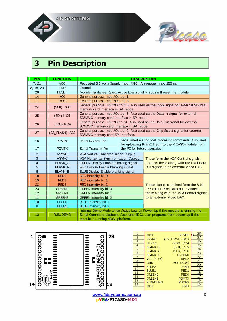
3 Pin Description
PIN FUNCTION DESCRIPTION 7, 21 VCC Regulated 3.3 Volts Supply Input @90mA average, max. 150ma
8, 15, 20 GND Ground 28 RESET Module Hardware Reset. Active Low signal > 20us will reset the module 14 I/O1 General purpose Input/Output 1 1 I/O3 General purpose Input/Output 3
24 (SCK) I/O6 General purpose Input/Output 6. Also used as the Clock signal for external SD/MMC memory card interface in SPI mode.
25 (SDI) I/O5 General purpose Input/Output 5. Also used as the Data In signal for external SD/MMC memory card interface in SPI mode.
26 (SDO) I/O4 General purpose Input/Output4. Also used as the Data Out signal for external SD/MMC memory card interface in SPI mode.
27 (CS_FLASH) I/O2 General purpose Input/Output 2. Also used as the Chip Select signal for external SD/MMC memory card SPI interface.
16 PGMRX Serial Receive Pin
17 PGMTX Serial Transmit Pin
Serial interface for host processor commands. Also used for uploading PmmC files into the PICASO module from the PC for future upgrades.
2 VSYNC VGA Vertical Synchronisation Output. 3 HSYNC VGA Horizontal Synchronisation Output. 4 BLANK_G GREEN Display Enable blanking signal. 5 BLANK_R RED Display Enable blanking signal. 6 BLANK_B BLUE Display Enable blanking signal.
These form the VGA Control signals. Connect these along with the Pixel Data Bus signals to an external Video DAC.
18 RED0 RED intensity bit 0 19 RED1 RED intensity bit 1 22 RED2 RED intensity bit 2 23 GREEN0 GREEN intensity bit 0 12 GREEN1 GREEN intensity bit 1 11 GREEN2 GREEN intensity bit 2 10 BLUE0 BLUE intensity bit 1 9 BLUE1 BLUE intensity bit 2
These signals combined form the 8 bit 256 colour Pixel Data bus. Connect these along with the VGA Control signals to an external Video DAC.
13 RUN/DEMO Internal Demo Mode when Active Low on Power-Up if the module is running the Serial Command platform. Also runs 4DGL user programs from power-up if the module is running 4DGL platform.
www.4dsystems.com.au µVGA-PICASO-MD1
7
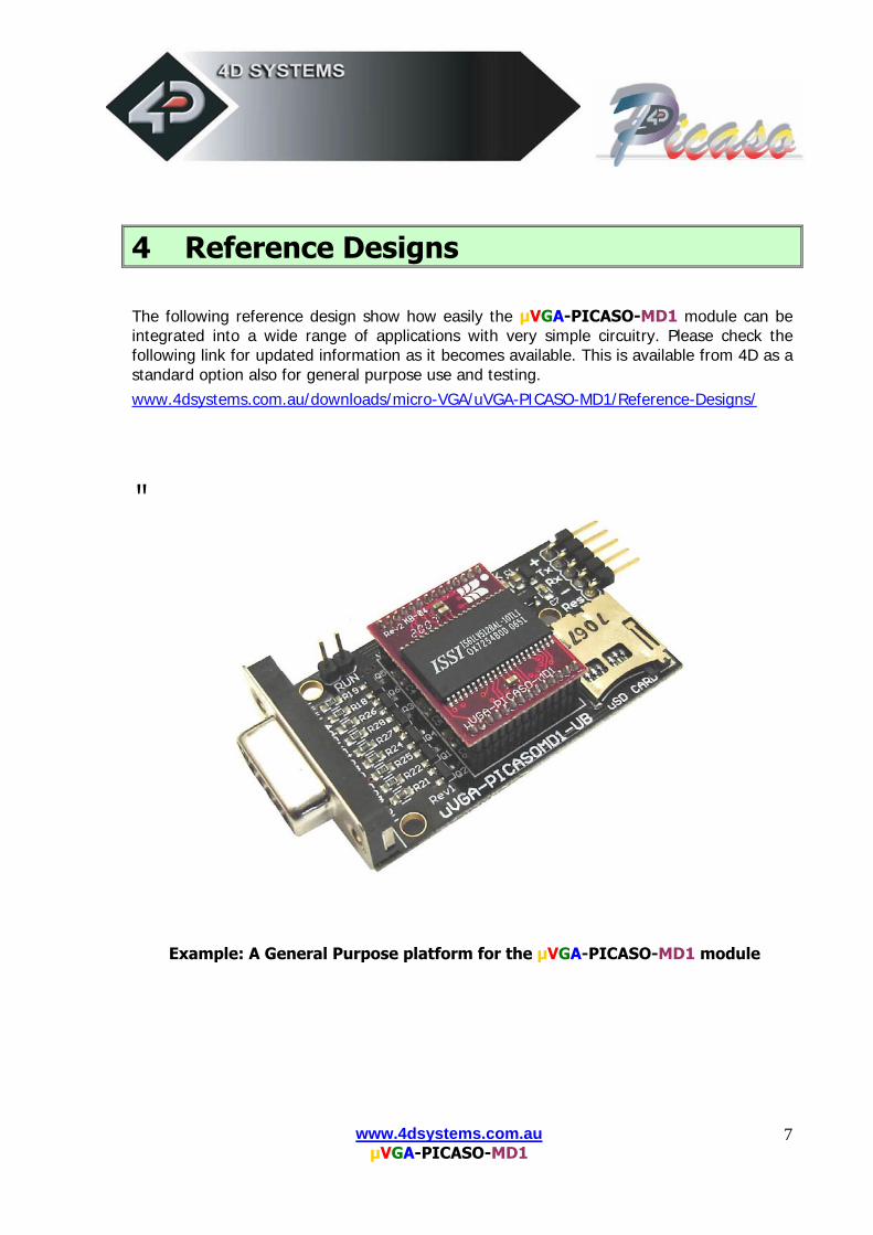
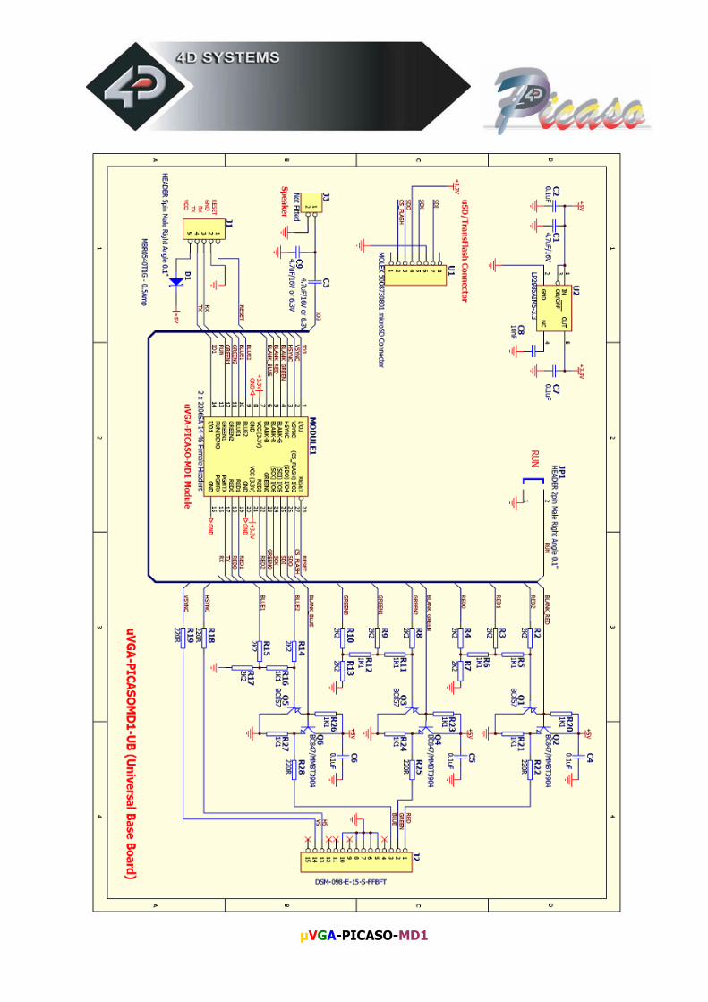
4 Reference Designs The following reference design show how easily the µVGA-PICASO-MD1 module can be integrated into a wide range of applications with very simple circuitry. Please check the following link for updated information as it becomes available. This is available from 4D as a standard option also for general purpose use and testing. www.4dsystems.com.au/downloads/micro-VGA/uVGA-PICASO-MD1/Reference-Designs/
�
Example: A General Purpose platform for the µVGA-PICASO-MD1 module
www.4dsystems.com.au µVGA-PICASO-MD1
8
www.4dsystems.com.au µVGA-PICASO-MD1
9
5 Personality Module Micro Code (PmmC) One of the important features of the µVGA-PICASO module is the ability to upload its onboard PICASO processor with a micro-Code firmware which allows the module to take on a new personality. This is referred to as Personality Module Micro Code (PmmC). The benefits of this are as follows:
• Allows the module to be easily upgraded by the user at any time with specific PmmC files as further enhancements are made in the future. This allows the user to benefit from those latest features.
• Allows the user to upload a new Operating System for example to change the device from a serial command driven platform into a high level language platform such as 4DGL (4D Graphics Language). A built-in higher level language such as 4DGL allows user programs to be run directly within the PICASO processor where the graphics operations can be performed much faster than sending the commands serially. This avoids serial bottle necks for those graphics intensive applications as well as allows the user to take complete control of all of the internal resources of the module.
The latest PmmC system file for the µVGA-PICASO-MD1 can be downloaded from: www.4dsystems.com.au/downloads/micro-VGA/uVGA-PICASO-MD1/PmmC/
The latest version of PmmCLoader.exe the PC software tool can be downloaded from: www.4dsystems.com.au/downloads/PmmC-Loader/Software/Windows/ and the User Guide can be found here: www.4dsystems.com.au/downloads/PmmC-Loader/Docs/Pdf/
www.4dsystems.com.au µVGA-PICASO-MD1
10
6 Graphics Command Set (Serial) The heart of the µVGA-PICASO-MD1 module is its rich graphics oriented command set. This comprises of powerful instructions that can draw lines, circles, rectangles, text, images, etc. to provide a full graphical user interface. The commands can be either sent via the serial link or called as functions from the built-in library if the platform is running a higher level language such as 4DGL. The command set is divided into 2 groups:
• General Command Set o These commands are generic and are standard commands that apply across
all applications.
• Extended Command Set o The µVGA-PICASO-MD1 module supports an external micro-SD (µSD)
memory card. This feature is not implemented yet, but when it becomes available the revised firmware will be available for download to re-program the module via PmmC operation. This Extended Command set will be documented fully when it is implemented. Check the 4D website for details.
The General Command set is described in detail in the following section with its syntax. Please note that all command examples listed below are in hex (00hex). Due to the high resolution nature of the µVGA-PICASO-MD1, a pixel horizontal and vertical address coordinates (x, y) will not fit into a single byte, which can only hold a maximum value of 255. Therefore each of the x and y pixel address data are represented as a 2 byte value, x(msb:lsb) and y(msb:lsb). The most significant byte (msb) is transmitted first followed by the least significant byte (lsb). This format is called the big endian. So for a 2 byte coordinate value of 013Fhex the byte order can be shown as (01hex),(3Fhex).
NOTE: When transmitting the command and data bytes to the µVGA, do not include any separators such as commas ‘,’ or spaces ‘ ‘ or brackets ‘(‘ ‘)’ between the bytes. The examples show these separators purely for legibility; these must not be included when transmitting data to the µVGA. When a command is sent, the µVGA will reply back with a single acknowledge byte called the ACK (06hex). This tells the host that the command was understood and the operation is completed. It will take the µVGA anywhere between 1 to several milliseconds to reply back with an ACK, depending on the command and the operation the µVGA has to perform. If the µVGA receives a command that it does not understand it will reply back with a negative acknowledge called the NAK (15hex).
If a command that has 5 bytes but only 4 bytes are sent, the command will not be executed and the µVGA will wait until another byte is sent before trying to execute the command. There is no timeout on the µVGA when incomplete commands are sent. The µVGA will reply back with a NAK for each invalid command it receives. For correct operation make sure the command bytes are sent in the correct sequence.
www.4dsystems.com.au µVGA-PICASO-MD1
11
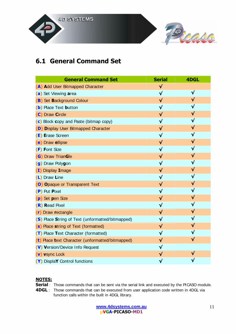
6.1 General Command Set
NOTES: Serial : Those commands that can be sent via the serial link and executed by the PICASO module. 4DGL : Those commands that can be executed from user application code written in 4DGL via
function calls within the built in 4DGL library.
General Command Set Serial 4DGL (A) Add User Bitmapped Character √
(a) Set Viewing area √ √
(B) Set Background Colour √ √
(b) Place Text button √ √
(C) Draw Circle √ √
(c) Block copy and Paste (bitmap copy) √ √
(D) Display User Bitmapped Character √ √
(E) Erase Screen √ √
(e) Draw ellipse √ √
(F) Font Size √ √
(G) Draw TrianGle √ √
(g) Draw Polygon √ √
(I) Display Image √ √
(L) Draw Line √ √
(O) Opaque or Transparent Text √ √
(P) Put Pixel √ √
(p) Set pen Size √ √
(R) Read Pixel √ √
(r) Draw rectangle √ √
(S) Place String of Text (unformatted/bitmapped) √ √
(s) Place string of Text (formatted) √ √
(T) Place Text Character (formatted) √ √
(t) Place text Character (unformatted/bitmapped) √ √
(V) Version/Device Info Request √
(v) vsync Lock √ √
(Y) DisplaY Control functions √ √
www.4dsystems.com.au µVGA-PICASO-MD1
12
6.1.1 Add User Bitmapped Character (A)
Serial Syntax : cmd, group, numb, data1, data2, …….., dataN
4DGL Syntax : N/A cmd : 41hex, Aascii
group : selects the appropriate bitmap format 00hex selects the 8x8 bitmap format 01hex selects the 16x16 bitmap format 02hex selects the 32x32 bitmap format numb : bitmap character number to add to memory:
0 to 63 (00h to 3Fh), 64 characters of 8x8 format when group = 00hex 0 to 15 (00h to 0Fh), 16 characters of 16x16 format when group = 01hex 0 to 7 (00h to 07h), 8 characters of 32x32 format when group = 02hex
data1 to dataN : number of data bytes that make up the composition and format of
the bitmapped character. The 8x8 bitmap composition is 1 byte wide (8bits) by 8 bytes deep which makes N = 1x8 = 8. The 16x16 bitmap composition is 2 bytes wide (16bits) by 16 bytes deep which makes N = 2x16 = 32. The 32x32 bitmap composition is 4 bytes wide (32bits) by 32 bytes deep hence N = 4x32 = 128.
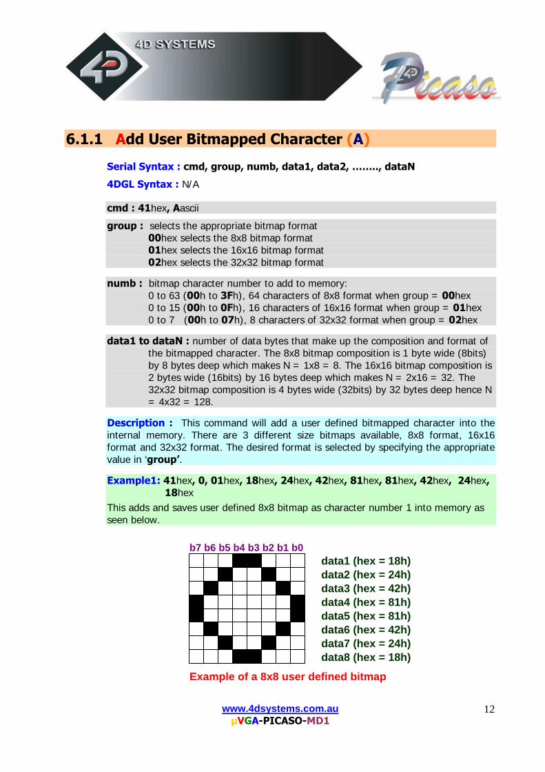
Description : This command will add a user defined bitmapped character into the internal memory. There are 3 different size bitmaps available, 8x8 format, 16x16 format and 32x32 format. The desired format is selected by specifying the appropriate value in ‘group’. Example1: 41hex, 0, 01hex, 18hex, 24hex, 42hex, 81hex, 81hex, 42hex, 24hex,
18hex This adds and saves user defined 8x8 bitmap as character number 1 into memory as seen below.
b7 b6 b5 b4 b3 b2 b1 b0 data1 (hex = 18h) data2 (hex = 24h) data3 (hex = 42h) data4 (hex = 81h) data5 (hex = 81h) data6 (hex = 42h) data7 (hex = 24h) data8 (hex = 18h)
Example of a 8x8 user defined bitmap
www.4dsystems.com.au µVGA-PICASO-MD1
13
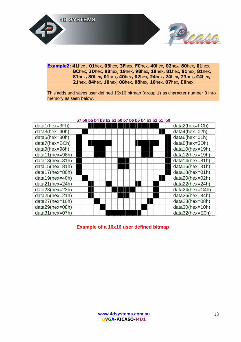
Example2: 41hex , 01hex, 03hex, 3Fhex, FChex, 40hex, 02hex, 80hex, 01hex, BChex, 3Dhex, 98hex, 19hex, 98hex, 19hex, 81hex, 81hex, 81hex, 81hex, 80hex, 01hex, 40hex, 02hex, 24hex, 24hex, 23hex, C4hex, 21hex, 84hex, 10hex, 08hex, 08hex, 10hex, 07hex, E0hex
This adds and saves user defined 16x16 bitmap (group 1) as character number 3 into memory as seen below.
b7 b6 b5 b4 b3 b2 b1 b0 b7 b6 b5 b4 b3 b2 b1 b0
data1(hex=3Fh) data2(hex=FCh) data3(hex=40h) data4(hex=02h) data5(hex=80h) data6(hex=01h) data7(hex=BCh) data8(hex=3Dh) data9(hex=98h) data10(hex=19h) data11(hex=98h) data12(hex=19h) data13(hex=81h) data14(hex=81h) data15(hex=81h) data16(hex=81h) data17(hex=80h) data18(hex=01h) data19(hex=40h) data20(hex=02h) data21(hex=24h) data22(hex=24h) data23(hex=23h) data24(hex=C4h) data25(hex=21h) data26(hex=84h) data27(hex=10h) data28(hex=08h) data29(hex=08h) data30(hex=10h) data31(hex=07h) data32(hex=E0h)
Example of a 16x16 user defined bitmap
www.4dsystems.com.au µVGA-PICASO-MD1
14
6.1.2 Set viewing area (a)
Serial Syntax : cmd, lineStart(msb:lsb), lineEnd(msb:lsb)
4DGL Syntax : (refer to 4DGL programmers manual) cmd : 61hex, a ascii lineStart: specify line start position. 2 bytes.
lineEnd: specify line stop position. 2 bytes.
Description : This command sets the current screen viewing area. The PICASO chip allocates its resources to its internal graphics engine as well as its processor to execute user commands. For those applications that require fast graphics processing and do not require full screen area, setting a smaller viewing area will allow the PICASO chip to allocate more resources for processing the commands. Success is followed by ACK return. If operation not successful, a NACK is returned. Power-up or Reset default is full screen size.
www.4dsystems.com.au µVGA-PICASO-MD1
15
6.1.3 Set Background Colour (B)
Serial Syntax : cmd, colour
4DGL Syntax : (refer to 4DGL programmers manual) cmd : 42hex, Bascii colour : pixel colour value: 1 byte 256 colours to choose from
Black = 00hex, 0dec White = FFhex, 255dec, 11111111bin
Description : This command sets the current background colour. Once this command is sent, only the background colour will change. Any other object on the screen with a different colour value will not be affected.
Example : 42hex, FFhex Set the background colour to value 256 (white).
www.4dsystems.com.au µVGA-PICASO-MD1
16
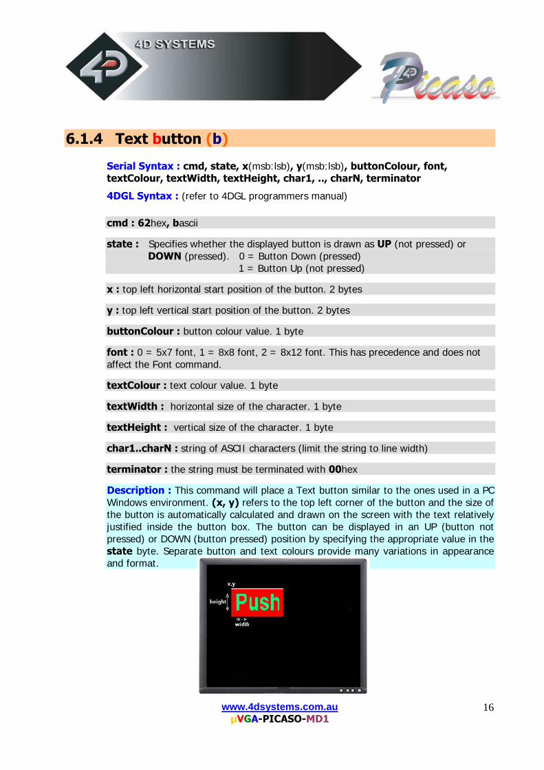
6.1.4 Text button (b)
Serial Syntax : cmd, state, x(msb:lsb), y(msb:lsb), buttonColour, font, textColour, textWidth, textHeight, char1, .., charN, terminator
4DGL Syntax : (refer to 4DGL programmers manual) cmd : 62hex, bascii state : Specifies whether the displayed button is drawn as UP (not pressed) or
DOWN (pressed). 0 = Button Down (pressed) 1 = Button Up (not pressed)
x : top left horizontal start position of the button. 2 bytes y : top left vertical start position of the button. 2 bytes buttonColour : button colour value. 1 byte
font : 0 = 5x7 font, 1 = 8x8 font, 2 = 8x12 font. This has precedence and does not affect the Font command.
textColour : text colour value. 1 byte
textWidth : horizontal size of the character. 1 byte
textHeight : vertical size of the character. 1 byte
char1..charN : string of ASCII characters (limit the string to line width) terminator : the string must be terminated with 00hex
Description : This command will place a Text button similar to the ones used in a PC Windows environment. (x, y) refers to the top left corner of the button and the size of the button is automatically calculated and drawn on the screen with the text relatively justified inside the button box. The button can be displayed in an UP (button not pressed) or DOWN (button pressed) position by specifying the appropriate value in the state byte. Separate button and text colours provide many variations in appearance and format.
www.4dsystems.com.au µVGA-PICASO-MD1
17
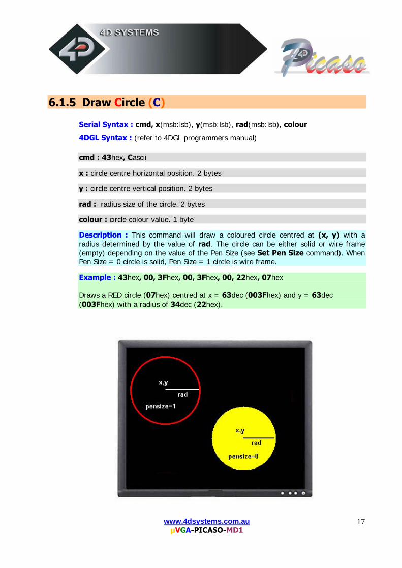
6.1.5 Draw Circle (C)
Serial Syntax : cmd, x(msb:lsb), y(msb:lsb), rad(msb:lsb), colour
4DGL Syntax : (refer to 4DGL programmers manual) cmd : 43hex, Cascii x : circle centre horizontal position. 2 bytes y : circle centre vertical position. 2 bytes rad : radius size of the circle. 2 bytes
colour : circle colour value. 1 byte
Description : This command will draw a coloured circle centred at (x, y) with a radius determined by the value of rad. The circle can be either solid or wire frame (empty) depending on the value of the Pen Size (see Set Pen Size command). When Pen Size = 0 circle is solid, Pen Size = 1 circle is wire frame. Example : 43hex, 00, 3Fhex, 00, 3Fhex, 00, 22hex, 07hex Draws a RED circle (07hex) centred at x = 63dec (003Fhex) and y = 63dec (003Fhex) with a radius of 34dec (22hex).
www.4dsystems.com.au µVGA-PICASO-MD1
18
6.1.6 Block copy & Paste (Screen Bitmap Copy) (c)
Serial Syntax : cmd, xs(msb:lsb), ys(msb:lsb), xd(msb:lsb), yd(msb:lsb),
width(msb:lsb), height(msb:lsb), src_page, dest_page
4DGL Syntax : (refer to 4DGL programmers manual)
cmd : 63hex, c ascii xs: top left horizontal start position of block to be copied (source). 2 bytes. ys: top left vertical start position of block to be copied (source). 2 bytes. xd: top left horizontal start position of where copied block is to be pasted (destination). 2 bytes. yd: top left vertical start position of where the copied block is to be pasted (destination). 2 bytes. width: width of block to be copied (source). 2 bytes. height: height of block to be copied (source). 2 bytes. src_page: source page, QVGA:8pages, VGA:2 pages, SVGA:1page. dest_page: destination page, QVGA:8pages, VGA:2 pages, SVGA:1page. Description : This command copies an area of a bitmap block of specified size. The start location of the block to be copied is represented by xs, ys (top left corner) and the size of the area to be copied is represented by width and height parameters. The start location of where the block is to be pasted (destination) is represented by xd, yd (top left corner). There are 8 pages for QVGA, 2 pages for VGA and 1 memory page for SVGA resolutions available. This is a very powerful feature for animating objects, smooth scrolling, implementing a windowing system or copying patterns across the screen to make borders or tiles.
www.4dsystems.com.au µVGA-PICASO-MD1
19
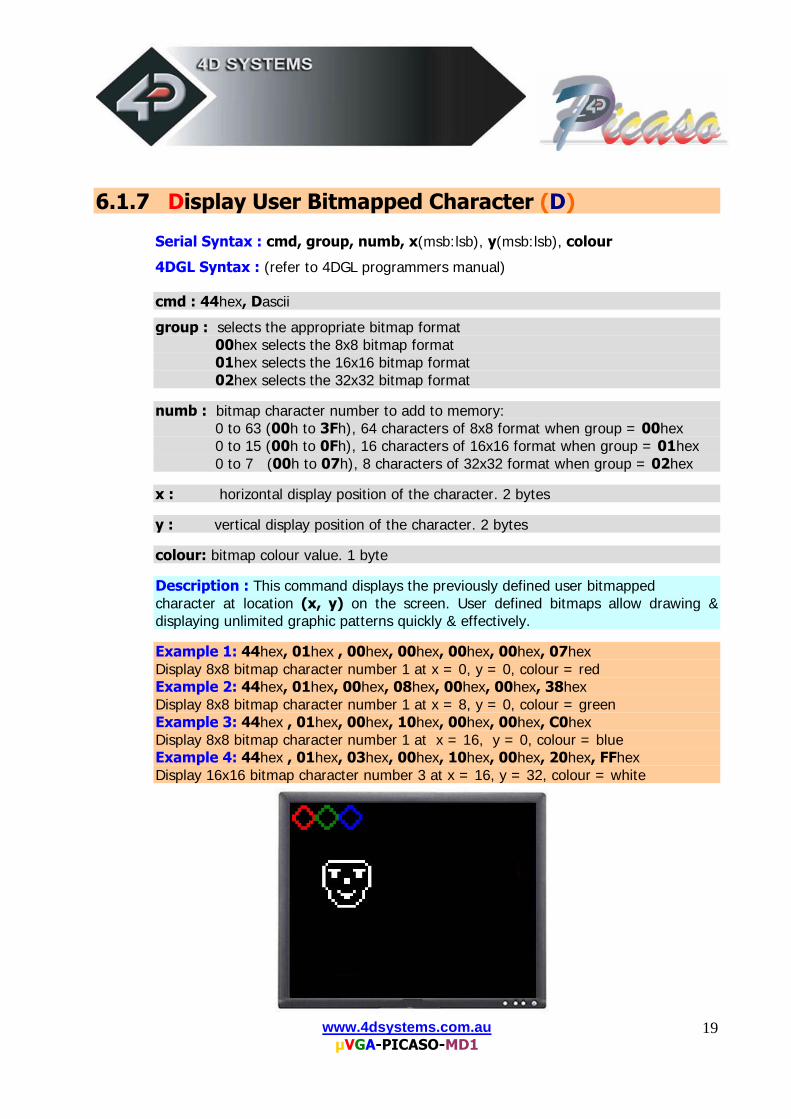
6.1.7 Display User Bitmapped Character (D)
Serial Syntax : cmd, group, numb, x(msb:lsb), y(msb:lsb), colour
4DGL Syntax : (refer to 4DGL programmers manual) cmd : 44hex, Dascii
group : selects the appropriate bitmap format 00hex selects the 8x8 bitmap format 01hex selects the 16x16 bitmap format 02hex selects the 32x32 bitmap format numb : bitmap character number to add to memory:
0 to 63 (00h to 3Fh), 64 characters of 8x8 format when group = 00hex 0 to 15 (00h to 0Fh), 16 characters of 16x16 format when group = 01hex 0 to 7 (00h to 07h), 8 characters of 32x32 format when group = 02hex
x : horizontal display position of the character. 2 bytes y : vertical display position of the character. 2 bytes colour: bitmap colour value. 1 byte Description : This command displays the previously defined user bitmapped character at location (x, y) on the screen. User defined bitmaps allow drawing & displaying unlimited graphic patterns quickly & effectively. Example 1: 44hex, 01hex , 00hex, 00hex, 00hex, 00hex, 07hex Display 8x8 bitmap character number 1 at x = 0, y = 0, colour = red Example 2: 44hex, 01hex, 00hex, 08hex, 00hex, 00hex, 38hex Display 8x8 bitmap character number 1 at x = 8, y = 0, colour = green Example 3: 44hex , 01hex, 00hex, 10hex, 00hex, 00hex, C0hex Display 8x8 bitmap character number 1 at x = 16, y = 0, colour = blue Example 4: 44hex , 01hex, 03hex, 00hex, 10hex, 00hex, 20hex, FFhex Display 16x16 bitmap character number 3 at x = 16, y = 32, colour = white
www.4dsystems.com.au µVGA-PICASO-MD1
20
6.1.8 Erase Screen (E)
Serial Syntax : cmd
4DGL Syntax : (refer to 4DGL programmers manual) cmd : 45hex, Eascii
Description : This command clears the entire screen using the current background colour. The screen erase execution starts at the beginning of the next Vsync cycle and completes by the end of the frame.
Example : 45hex Clear the screen.
www.4dsystems.com.au µVGA-PICASO-MD1
21
6.1.9 Draw Ellipse (e)
Serial Syntax : cmd, x(msb:lsb), y(msb:lsb), xrad(msb:lsb), yrad(msb:lsb), colour
4DGL Syntax : (refer to 4DGL programmers manual) cmd : 65hex, eascii x : Ellipse centre horizontal position. 2 bytes. y : Ellipse centre vertical position. 2 bytes. xrad : x (horizontal) radius size of the ellipse. 2 bytes.
yrad : y (vertical) radius size of the ellipse. 2 bytes.
colour : Ellipse colour value.
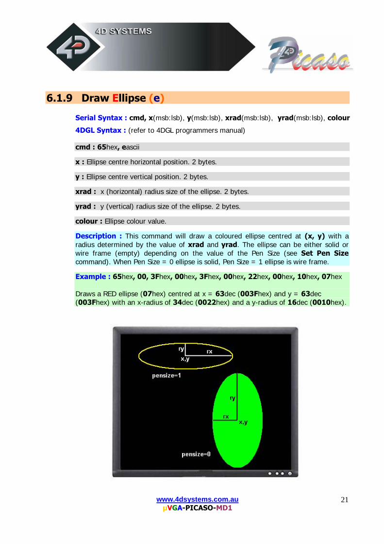
Description : This command will draw a coloured ellipse centred at (x, y) with a radius determined by the value of xrad and yrad. The ellipse can be either solid or wire frame (empty) depending on the value of the Pen Size (see Set Pen Size command). When Pen Size = 0 ellipse is solid, Pen Size = 1 ellipse is wire frame. Example : 65hex, 00, 3Fhex, 00hex, 3Fhex, 00hex, 22hex, 00hex, 10hex, 07hex Draws a RED ellipse (07hex) centred at x = 63dec (003Fhex) and y = 63dec (003Fhex) with an x-radius of 34dec (0022hex) and a y-radius of 16dec (0010hex).
www.4dsystems.com.au µVGA-PICASO-MD1
22
6.1.10 Set Font Size (F)
Serial Syntax : cmd, size
4DGL Syntax : (refer to 4DGL programmers manual) cmd : 46hex, Fascii
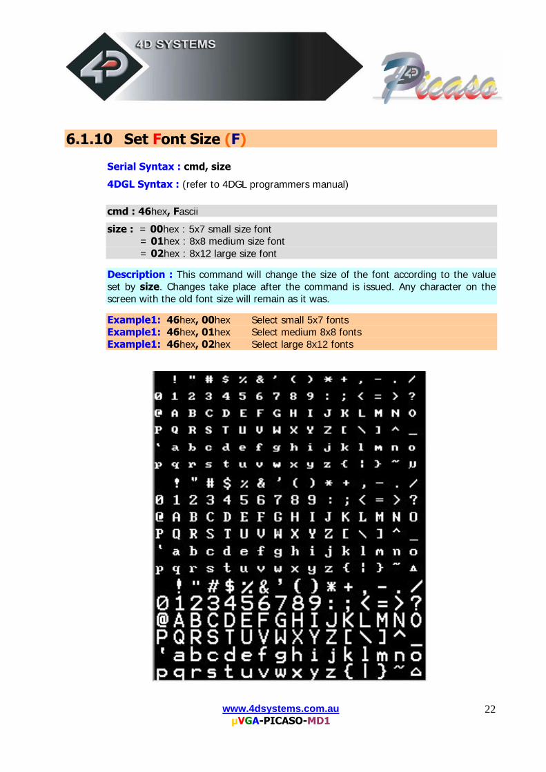
size : = 00hex : 5x7 small size font = 01hex : 8x8 medium size font = 02hex : 8x12 large size font
Description : This command will change the size of the font according to the value set by size. Changes take place after the command is issued. Any character on the screen with the old font size will remain as it was. Example1: 46hex, 00hex Select small 5x7 fonts Example1: 46hex, 01hex Select medium 8x8 fonts Example1: 46hex, 02hex Select large 8x12 fonts
www.4dsystems.com.au µVGA-PICASO-MD1
23
6.1.11 Draw TrianGle (G)
Serial Syntax : cmd, x1(msb:lsb), y1(msb:lsb), x2(msb:lsb), y2(msb:lsb),
x3(msb:lsb), y3(msb:lsb),colour
4DGL Syntax : (refer to 4DGL programmers manual) cmd : 47hex, Gascii x1, y1, x2, y2, x3, y3 : 3 vertices of the triangle. These must be specified in an anti-
clockwise fashion. All 2 byte values. colour : triangle colour value. 1 byte.
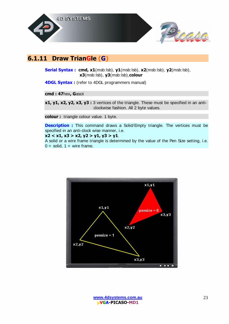
Description : This command draws a Solid/Empty triangle. The vertices must be specified in an anti-clock wise manner, i.e. x2 < x1, x3 > x2, y2 > y1, y3 > y1. A solid or a wire frame triangle is determined by the value of the Pen Size setting, i.e. 0 = solid, 1 = wire frame.
www.4dsystems.com.au µVGA-PICASO-MD1
24
6.1.12 Draw Polygon (g)
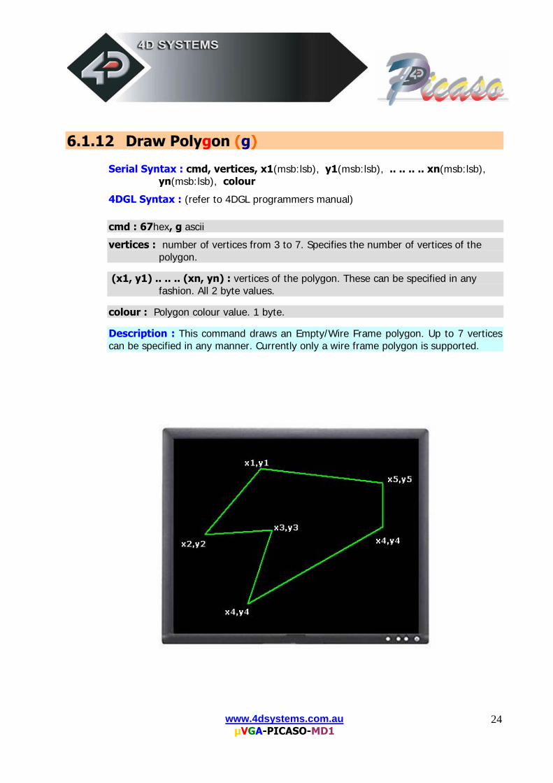
Serial Syntax : cmd, vertices, x1(msb:lsb), y1(msb:lsb), .. .. .. .. xn(msb:lsb),
yn(msb:lsb), colour
4DGL Syntax : (refer to 4DGL programmers manual) cmd : 67hex, g ascii
vertices : number of vertices from 3 to 7. Specifies the number of vertices of the polygon.
(x1, y1) .. .. .. (xn, yn) : vertices of the polygon. These can be specified in any
fashion. All 2 byte values. colour : Polygon colour value. 1 byte.
Description : This command draws an Empty/Wire Frame polygon. Up to 7 vertices can be specified in any manner. Currently only a wire frame polygon is supported.
www.4dsystems.com.au µVGA-PICASO-MD1
25
6.1.13 Display Image (I)
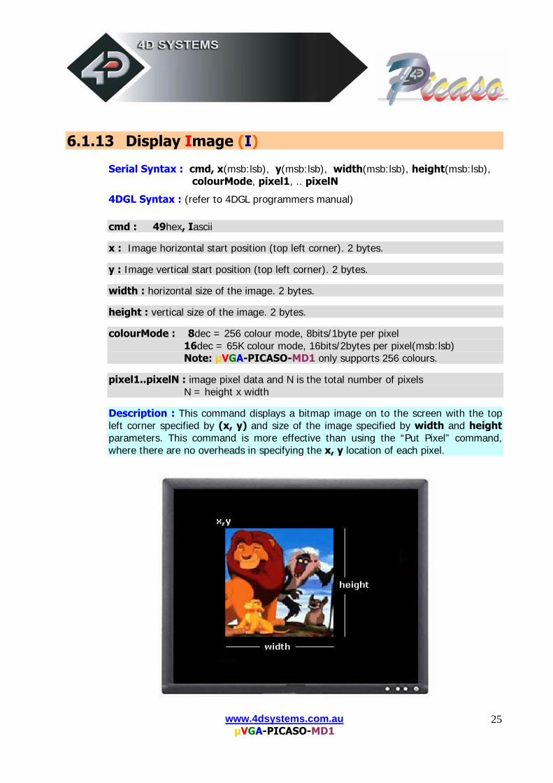
Serial Syntax : cmd, x(msb:lsb), y(msb:lsb), width(msb:lsb), height(msb:lsb),
colourMode, pixel1, .. pixelN
4DGL Syntax : (refer to 4DGL programmers manual) cmd : 49hex, Iascii x : Image horizontal start position (top left corner). 2 bytes. y : Image vertical start position (top left corner). 2 bytes. width : horizontal size of the image. 2 bytes. height : vertical size of the image. 2 bytes. colourMode : 8dec = 256 colour mode, 8bits/1byte per pixel
16dec = 65K colour mode, 16bits/2bytes per pixel(msb:lsb) Note: µVGA-PICASO-MD1 only supports 256 colours.
pixel1..pixelN : image pixel data and N is the total number of pixels N = height x width
Description : This command displays a bitmap image on to the screen with the top left corner specified by (x, y) and size of the image specified by width and height parameters. This command is more effective than using the “Put Pixel” command, where there are no overheads in specifying the x, y location of each pixel.
www.4dsystems.com.au µVGA-PICASO-MD1
26
6.1.14 Draw Line (L)
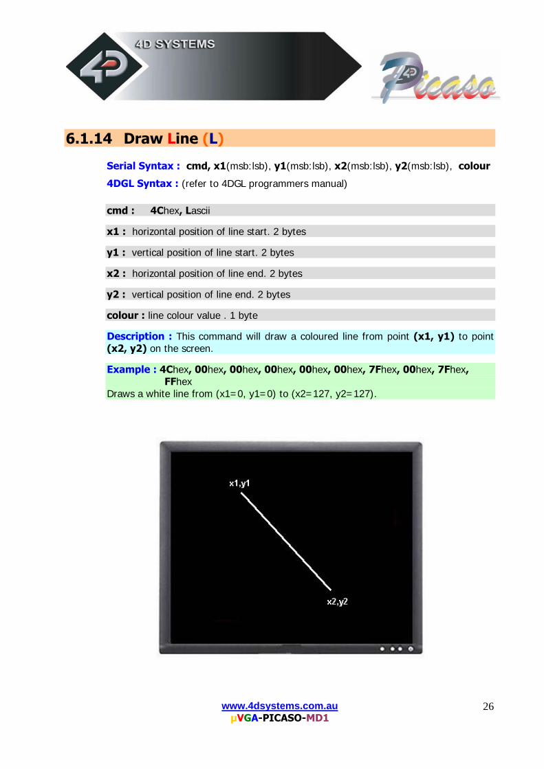
Serial Syntax : cmd, x1(msb:lsb), y1(msb:lsb), x2(msb:lsb), y2(msb:lsb), colour
4DGL Syntax : (refer to 4DGL programmers manual) cmd : 4Chex, Lascii x1 : horizontal position of line start. 2 bytes y1 : vertical position of line start. 2 bytes x2 : horizontal position of line end. 2 bytes y2 : vertical position of line end. 2 bytes colour : line colour value . 1 byte
Description : This command will draw a coloured line from point (x1, y1) to point (x2, y2) on the screen. Example : 4Chex, 00hex, 00hex, 00hex, 00hex, 00hex, 7Fhex, 00hex, 7Fhex,
FFhex Draws a white line from (x1=0, y1=0) to (x2=127, y2=127).
www.4dsystems.com.au µVGA-PICASO-MD1
27
6.1.15 Opaque / Transparent Text (O)
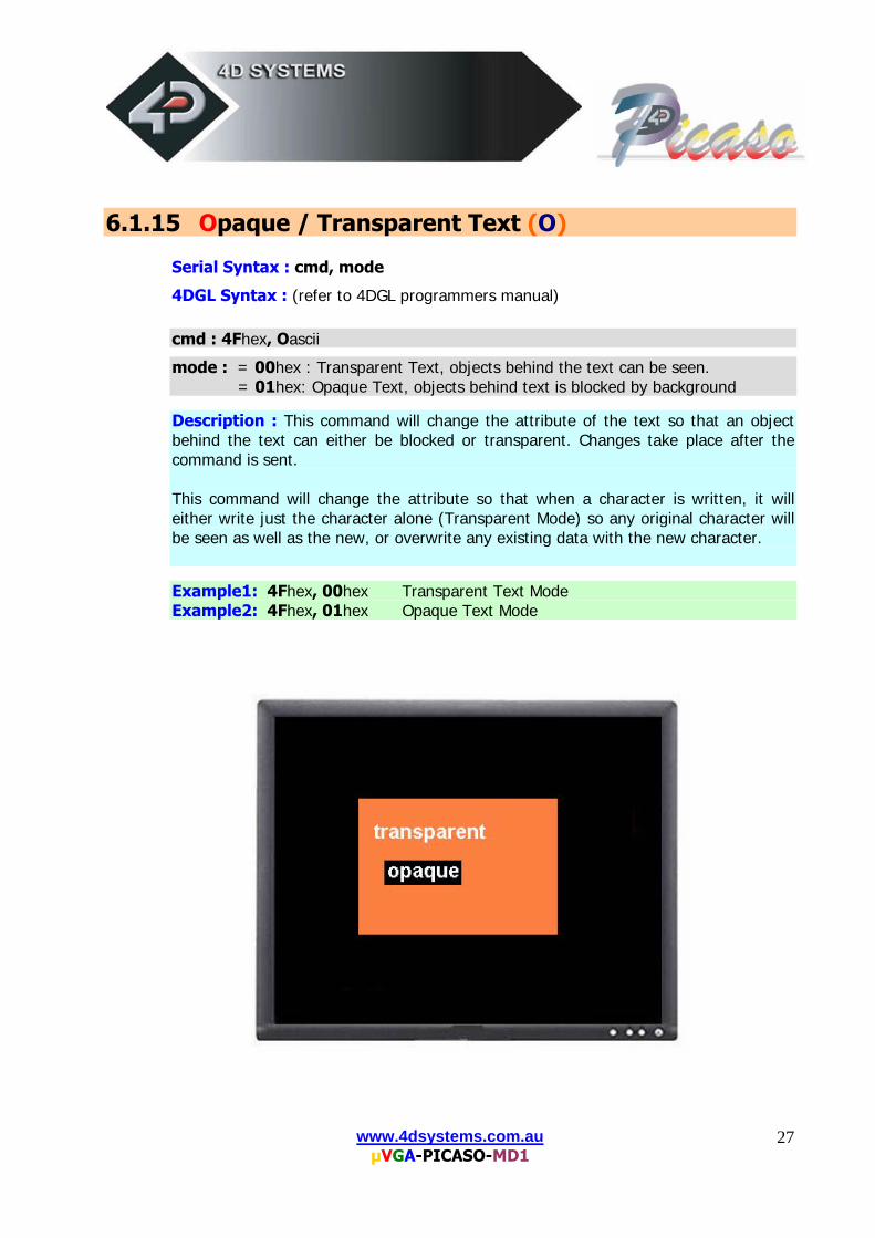
Serial Syntax : cmd, mode
4DGL Syntax : (refer to 4DGL programmers manual) cmd : 4Fhex, Oascii
mode : = 00hex : Transparent Text, objects behind the text can be seen. = 01hex: Opaque Text, objects behind text is blocked by background
Description : This command will change the attribute of the text so that an object behind the text can either be blocked or transparent. Changes take place after the command is sent. This command will change the attribute so that when a character is written, it will either write just the character alone (Transparent Mode) so any original character will be seen as well as the new, or overwrite any existing data with the new character. Example1: 4Fhex, 00hex Transparent Text Mode Example2: 4Fhex, 01hex Opaque Text Mode
www.4dsystems.com.au µVGA-PICASO-MD1
28
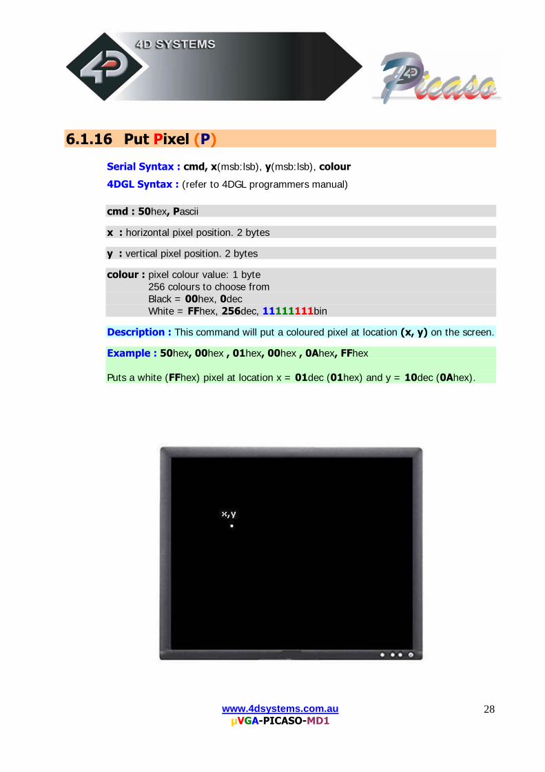
6.1.16 Put Pixel (P)
Serial Syntax : cmd, x(msb:lsb), y(msb:lsb), colour
4DGL Syntax : (refer to 4DGL programmers manual) cmd : 50hex, Pascii x : horizontal pixel position. 2 bytes y : vertical pixel position. 2 bytes colour : pixel colour value: 1 byte 256 colours to choose from Black = 00hex, 0dec White = FFhex, 256dec, 11111111bin
Description : This command will put a coloured pixel at location (x, y) on the screen.
Example : 50hex, 00hex , 01hex, 00hex , 0Ahex, FFhex Puts a white (FFhex) pixel at location x = 01dec (01hex) and y = 10dec (0Ahex).
www.4dsystems.com.au µVGA-PICASO-MD1
29
6.1.17 Set pen Size (p)
Serial Syntax : cmd, size
4DGL Syntax : (refer to 4DGL programmers manual) cmd : 70hex, p ascii
size : = 00hex : All objects such as circles, rectangles, triangles, etc are solid = 01hex : All objects are wire frame (empty)
Description : This command determines if certain graphics objects are drawn in solid or wire frame fashion. Example1: 70hex, 00hex All objects will be drawn solid Example1: 70hex, 01hex All objects will be drawn wire frame.
www.4dsystems.com.au µVGA-PICASO-MD1
30
6.1.18 Read Pixel (R)
Serial Syntax : cmd, x(msb:lsb), y(msb:lsb)
4DGL Syntax : (refer to 4DGL programmers manual) cmd : 52hex, Rascii x : horizontal pixel position. 2 bytes y : vertical pixel position. 2 bytes. Description : This command will read the colour value of pixel at location (x, y) on the screen and return it to the host. This is a useful command when for example a white pointer is moved across the screen and the host can read the colour on the screen and switch the colour of the pointer when it’s on top of a light coloured area. Example : 52hex, 00hex, 01hex, 00hex, 01hex PICASO reply : C0hex Reads a blue (C0hex) pixel at location x = 1dec (01hex) and y = 1dec (01hex).
www.4dsystems.com.au µVGA-PICASO-MD1
31
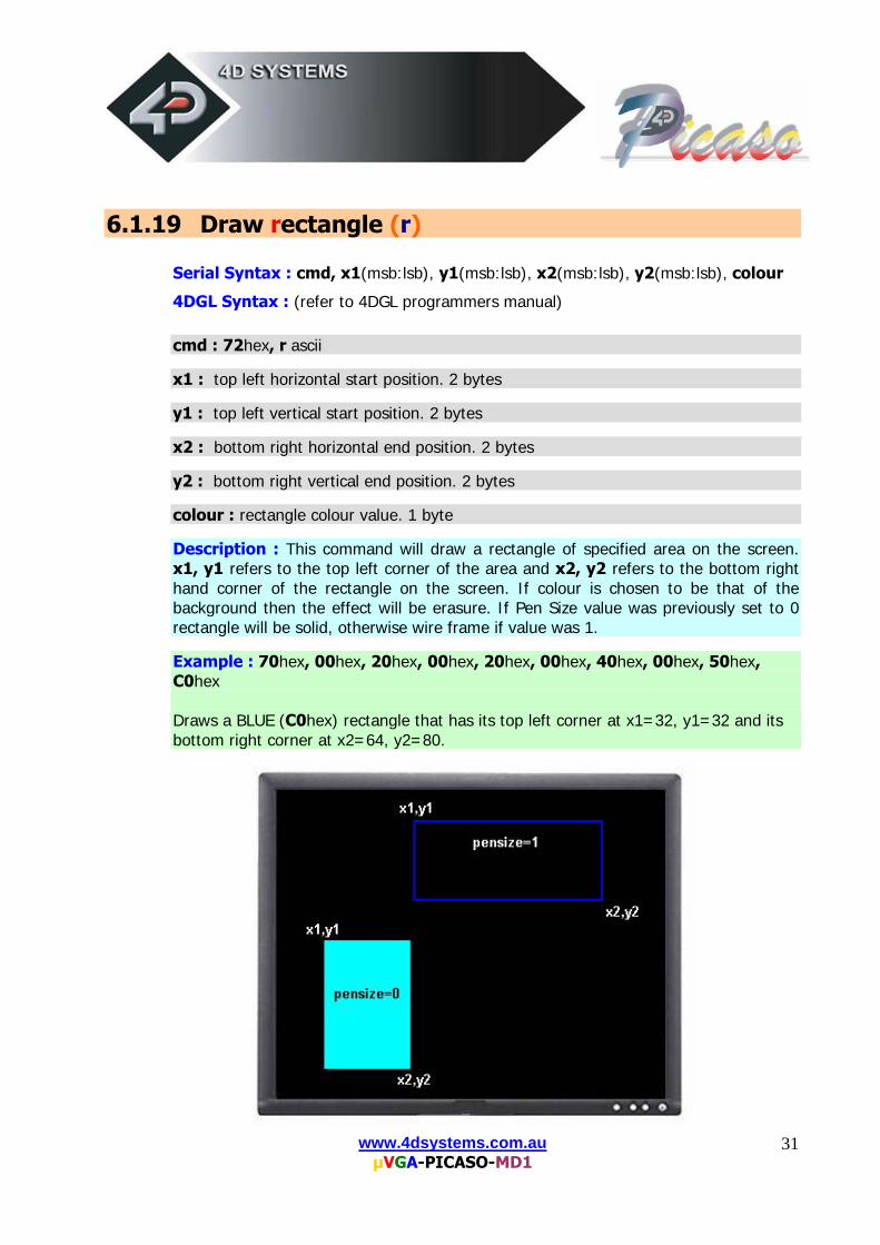
6.1.19 Draw rectangle (r)
Serial Syntax : cmd, x1(msb:lsb), y1(msb:lsb), x2(msb:lsb), y2(msb:lsb), colour
4DGL Syntax : (refer to 4DGL programmers manual) cmd : 72hex, r ascii x1 : top left horizontal start position. 2 bytes y1 : top left vertical start position. 2 bytes x2 : bottom right horizontal end position. 2 bytes y2 : bottom right vertical end position. 2 bytes colour : rectangle colour value. 1 byte
Description : This command will draw a rectangle of specified area on the screen. x1, y1 refers to the top left corner of the area and x2, y2 refers to the bottom right hand corner of the rectangle on the screen. If colour is chosen to be that of the background then the effect will be erasure. If Pen Size value was previously set to 0 rectangle will be solid, otherwise wire frame if value was 1. Example : 70hex, 00hex, 20hex, 00hex, 20hex, 00hex, 40hex, 00hex, 50hex, C0hex Draws a BLUE (C0hex) rectangle that has its top left corner at x1=32, y1=32 and its bottom right corner at x2=64, y2=80.

www.4dsystems.com.au µVGA-PICASO-MD1
32
6.1.20 Place String of Ascii Text (unformatted) (S)
Serial Syntax : cmd, x(msb:lsb), y(msb:lsb), font, colour, width, height, char1,
.., charN, terminator
4DGL Syntax : (refer to 4DGL programmers manual) cmd : 53hex, Sascii x : the horizontal start position of string (in pixels). 2 bytes.
y : the vertical start position of string (in pixels). 2 bytes.
font : 0 = 5x7 font, 1 = 8x8 font, 2 = 8x12 font. This has precedence over the Font command but does not effect the global font setting.
colour : colour value of the string. 1 byte.
width : horizontal size of the string characters, n x normal size. 1 byte.
height : vertical size of the string characters, m x normal size. 1 byte.
char1..charN : string of ASCII characters (max 256 characters) terminator : the string must be terminated with 00hex
Description : This command allows the display of a string of bitmapped (unformatted) ASCII characters. The horizontal start position of the string is specified by x and the vertical position is specified by y. The string must be terminated with 00hex. The sizes of the characters are determined by the width and height parameters. If the length of the string is longer than the maximum number of characters per line then, a wrap around will occur on to the next line. Maximum string length is 256 bytes.
www.4dsystems.com.au µVGA-PICASO-MD1
33
6.1.21 Place string of Ascii Text (formatted) (s)
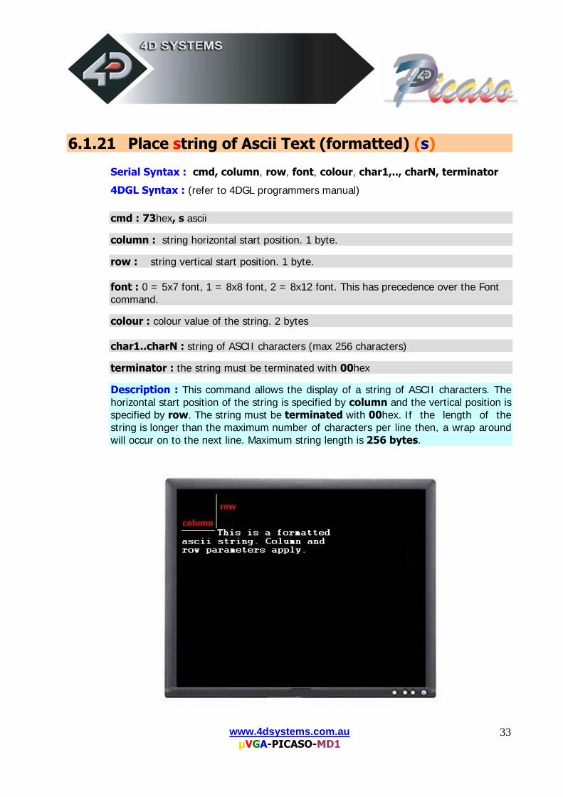
Serial Syntax : cmd, column, row, font, colour, char1,.., charN, terminator
4DGL Syntax : (refer to 4DGL programmers manual) cmd : 73hex, s ascii column : string horizontal start position. 1 byte.
row : string vertical start position. 1 byte.
font : 0 = 5x7 font, 1 = 8x8 font, 2 = 8x12 font. This has precedence over the Font command.
colour : colour value of the string. 2 bytes
char1..charN : string of ASCII characters (max 256 characters) terminator : the string must be terminated with 00hex
Description : This command allows the display of a string of ASCII characters. The horizontal start position of the string is specified by column and the vertical position is specified by row. The string must be terminated with 00hex. If the length of the string is longer than the maximum number of characters per line then, a wrap around will occur on to the next line. Maximum string length is 256 bytes.
www.4dsystems.com.au µVGA-PICASO-MD1
34
6.1.22 Place Text Character (formatted) (T)
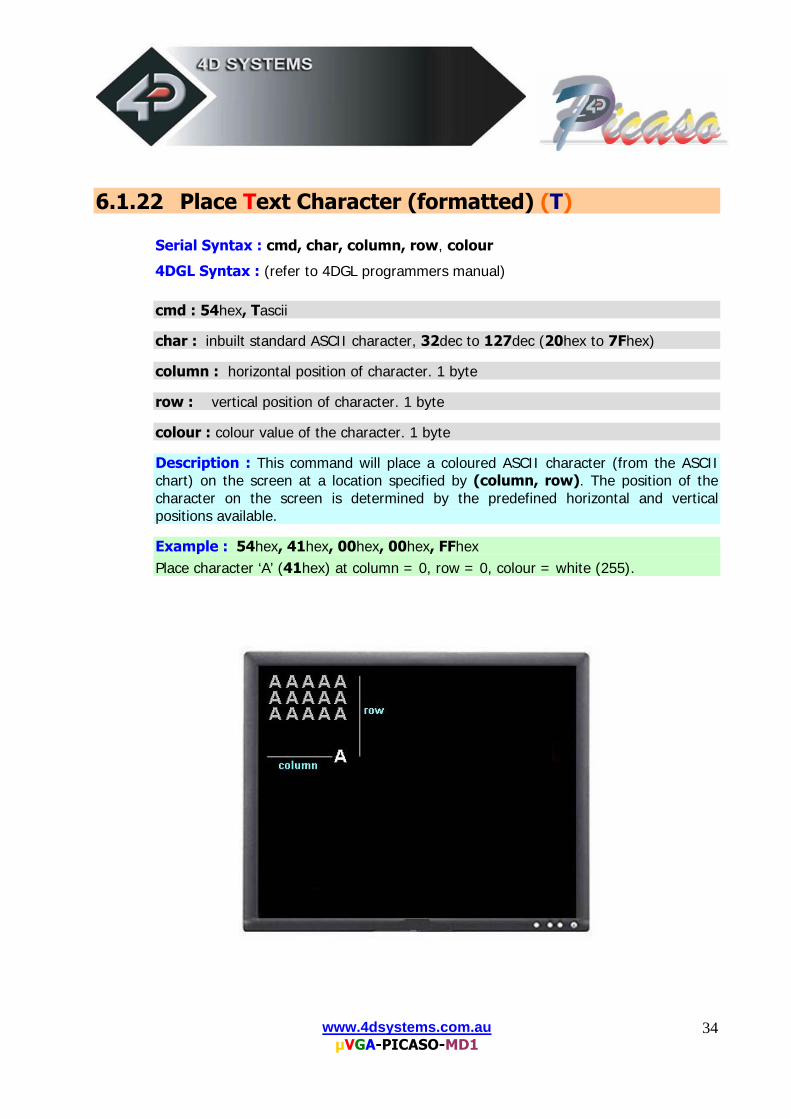
Serial Syntax : cmd, char, column, row, colour
4DGL Syntax : (refer to 4DGL programmers manual) cmd : 54hex, Tascii char : inbuilt standard ASCII character, 32dec to 127dec (20hex to 7Fhex) column : horizontal position of character. 1 byte
row : vertical position of character. 1 byte colour : colour value of the character. 1 byte
Description : This command will place a coloured ASCII character (from the ASCII chart) on the screen at a location specified by (column, row). The position of the character on the screen is determined by the predefined horizontal and vertical positions available. Example : 54hex, 41hex, 00hex, 00hex, FFhex Place character ‘A’ (41hex) at column = 0, row = 0, colour = white (255).
www.4dsystems.com.au µVGA-PICASO-MD1
35
6.1.23 Place text Character (unformatted) (t)
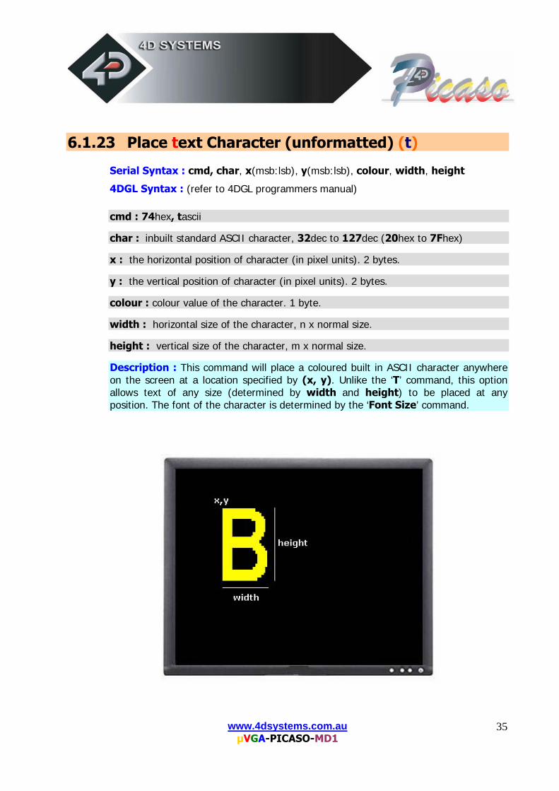
Serial Syntax : cmd, char, x(msb:lsb), y(msb:lsb), colour, width, height
4DGL Syntax : (refer to 4DGL programmers manual) cmd : 74hex, tascii char : inbuilt standard ASCII character, 32dec to 127dec (20hex to 7Fhex) x : the horizontal position of character (in pixel units). 2 bytes.
y : the vertical position of character (in pixel units). 2 bytes.
colour : colour value of the character. 1 byte.
width : horizontal size of the character, n x normal size.
height : vertical size of the character, m x normal size.
Description : This command will place a coloured built in ASCII character anywhere on the screen at a location specified by (x, y). Unlike the ‘T’ command, this option allows text of any size (determined by width and height) to be placed at any position. The font of the character is determined by the ‘Font Size’ command.
www.4dsystems.com.au µVGA-PICASO-MD1
36
6.1.24 Version/Device Info Request (V)
Serial Syntax : cmd, output Response : device_type, hardware_rev, firmware_rev, horizontal_res,
vertical_res
4DGL Syntax : N/A cmd : 56hex, Vascii output : 00hex : outputs the version and device info to the serial port only. 01hex : outputs the version and device info to the serial port as well as to
the screen. device_type : this response indicates the device type. 00hex = micro-OLED. 01hex = micro-LCD. 02hex = micro-VGA. hardware_rev : this response indicates the device hardware version. firmware_rev : this response indicates the device firmware version. horizontal_res : this response indicates the horizontal resolution of the display. 21hex : 210 pixels 22hex : 220 pixels 28hex : 128 pixels 31hex : 310 pixels 32hex : 320 pixels 60hex : 160 pixels 62hex : 620 pixels 64hex : 64 pixels 76hex : 176 pixels 96hex : 96 pixels vertical_res : this response indicates the vertical resolution of the display. See
horizontal_res above for resolution options.
Description : This command requests all the necessary information from the module about its characteristics and capability.
www.4dsystems.com.au µVGA-PICASO-MD1
37
6.1.25 vsync Lock (v)
Syntax : cmd cmd : 76hex, v ascii
response : 06hex (ACK) The µVGA will respond with the ACK byte once it encounters the next internal Vertical Sync signal.
Description : This command allows the host to lock onto the start of the next video frame. This is a very useful command when moving/animating objects on the screen where the object needs to be displayed and then erased so it can be redisplayed at a different location to give the effect of movement. Unless the host locks onto the start of frame, undesired blinking and tearing of the displayed object will occur. When the host sends this command it should wait for an ‘ACK’ from the µVGA and once the ACK is received the host can then start issuing display commands. Use this command for dynamically displayed objects such as a bouncing ball, etc. For static objects that don’t move or that do not need continuos display updates, this command is not necessary. Example of a moving object is given below: while() { send_cmd_uVGA(“v”); // send the Vsync Lock command wait_uVGA_ACK(); // µVGA will respond at start of frame send_cmd_uVGA(‘D’, 1, x, y, BLACK); // erase object at old loc. send_cmd_uVGA (‘D’, 1, ++x, ++y, RED); // display at new loc. } // loop around while loop Note: A word of caution: If the serial link is slow, that is, less than 115Kbaud, the response from the µVGA will be too slow for this command to be effective. Try and make the serial link as fast as possible.
www.4dsystems.com.au µVGA-PICASO-MD1
38
6.1.26 DisplaY Video Ram Settings (Y)
Serial Syntax : cmd, mode, parameter
4DGL Syntax : (refer to 4DGL programmers manual) cmd : 59hex, Yascii mode : 00hex : Display Page Select
parameter = 00hex to 07hex for QVGA page0 to page7. parameter = 00hex or 01hex for VGA page0 or page1. parameter = XXhex don’t care for SVGA, only page0 is available. Selects the page that is currently to be displayed on the screen. Default = page0
mode : 01hex : Read Page Select. parameter = 00hex to 07hex for QVGA page0 to page7. parameter = 00hex or 01hex for VGA page0 or page1. parameter = XXhex don’t care for SVGA, only page0 is available. Selects the page that all video memory read operations are performed from. Default = page0
mode : 02hex : Write Page Select. parameter = 00hex to 07hex for QVGA page0 to page7. parameter = 00hex or 01hex for VGA page0 or page1. parameter = XXhex don’t care for SVGA, only page0 is available. Selects the page that all video memory write operations are performed to. Default = page0
mode : 03hex : Change Resolution. parameter = 00hex : QVGA (320x240) mode, power-up/reset default. parameter = 01hex : VGA (640x480) mode. parameter = 02hex : SVGA (800x600) mode (not implemented yet).
This command allows the resolution to be changed on the fly. The Power-Up default is mode = 0 (QVGA). When it is desired to change the resolution and this command is executed, it must be followed by the Auto Baud (‘U’) command. A resolution change changes the internal clock of the µVGA which also affects the Baud Rate of the Serial Port hence the reason for resending the Auto Baud command.
NOTE: Usable pixels are; QVGA: 310x210, VGA: 620x420 and SVGA:
800x560. These resolutions are chosen to maximise the number of display pages from the video RAM.
www.4dsystems.com.au µVGA-PICASO-MD1
39
7 Serial Interface (TTL Level)
The µVGA-PICASO-MD1 module communicates with the outside world via its serial link. The serial link is always used as a means to upload a PmmC file for a new platform change or to update the module with enhancements. If the module is running the “Serial Command” platform, it can be used by a host processor to send serial commands to the module so that characters and graphics can be displayed on the screen. If the module is running the “4DGL High Level Language” platform then user application code is downloaded into the PICASO processor via the same serial link. Note: The serial connection (RX/TX) is at TTL levels (0 – 3.3V) and the logic levels are “high” = 1 = 3.3V, “low” = 0 = 0V. If interfacing to a host system running at voltage levels greater than 3.6V, then a 1K series resistor must be inserted between the Host TX and the µVGA-PICASO RX signal. Auto Baud Detect: The µVGA-PICASO-MD1 has an auto-baud detect function which can operate from 2400 baud to 1M baud. Prior to any graphical formatting and commands being sent, it must first be initialized by sending the ASCII character ‘U’ (55h) after power-up. This will allow the module to determine and lock on to the baud rate of the host automatically without needing any further setup. This must be done every time the module is powered up or reset. If the module needs its baud rate changed, then it must be powered down and powered back up again or go through a reset. The “U” command cannot be used to change the baud rate during the middle of normal usage. Serial Command Timing: Each serial command is made up of a sequence of data bytes. Some commands are a single byte and others are multiple bytes. When a command is sent to the module and the operation is completed, it will reply back with a single acknowledge byte called the ACK (06h). This tells the host that the command was understood and the operation is completed. It will take anywhere between 1 to several milliseconds to reply back with an ACK, depending on the command and the operation the µVGA-PICASO-MD1 has to perform. If it receives a command that it does not understand it will reply back with a negative acknowledge called the NAK (15h).
For example, if a command has 5 bytes but only 4 bytes are sent, the command will not be executed and when the next following command bytes are sent the module will reply back with a NAK for each and every byte it receives. For correct operation make sure the command bytes are sent in the correct sequence. Note: No termination character is to be sent at the end of the command sequence. i.e. don’t send any CR, or Null, or any other end of command bytes.
www.4dsystems.com.au µVGA-PICASO-MD1
40
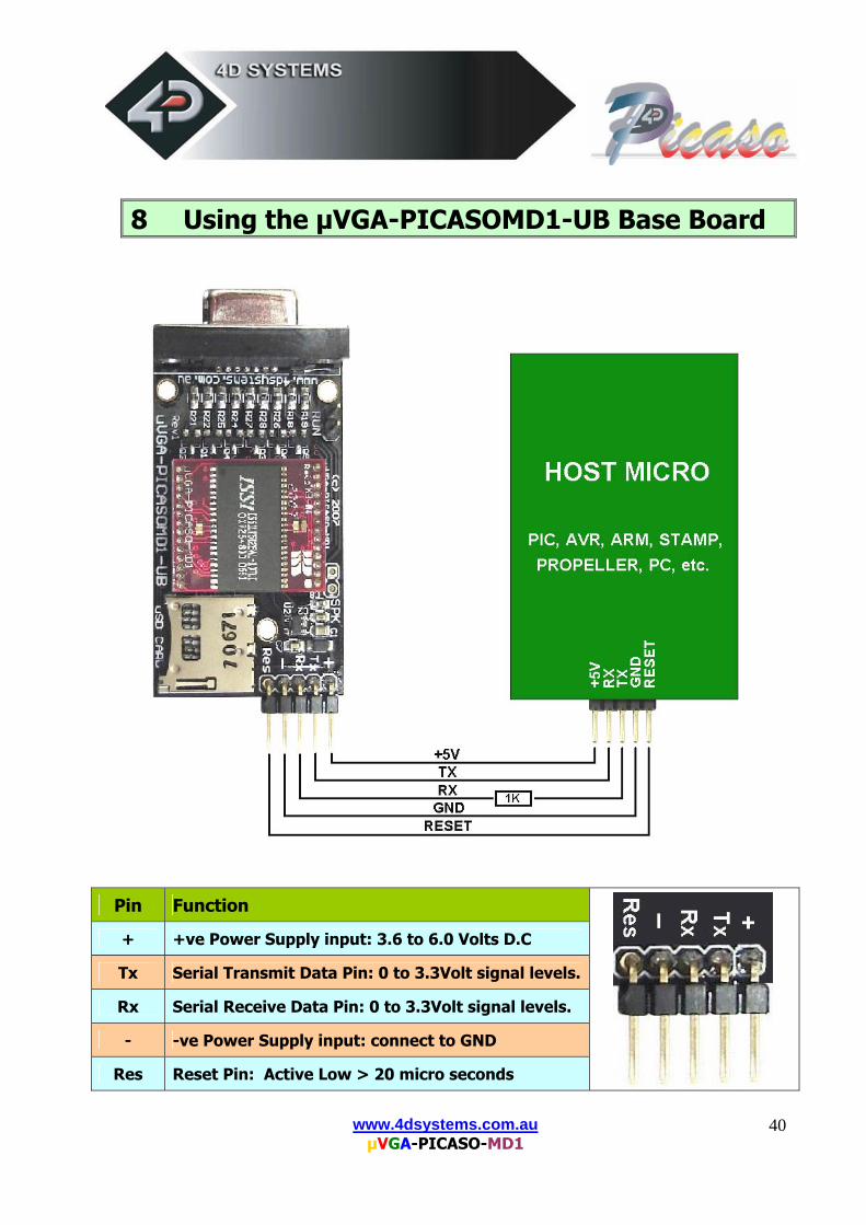
8 Using the µVGA-PICASOMD1-UB Base Board
Pin Function
+ +ve Power Supply input: 3.6 to 6.0 Volts D.C
Tx Serial Transmit Data Pin: 0 to 3.3Volt signal levels.
Rx Serial Receive Data Pin: 0 to 3.3Volt signal levels.
- -ve Power Supply input: connect to GND
Res Reset Pin: Active Low > 20 micro seconds
www.4dsystems.com.au µVGA-PICASO-MD1
41
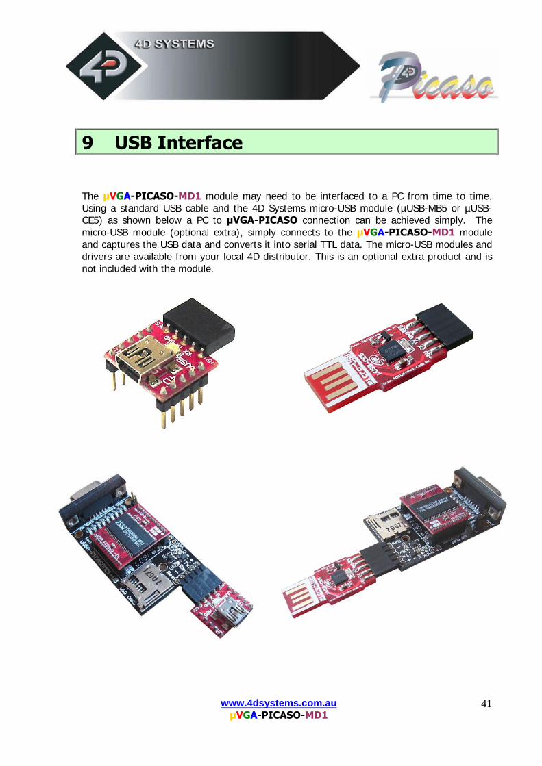
9 USB Interface
The µVGA-PICASO-MD1 module may need to be interfaced to a PC from time to time. Using a standard USB cable and the 4D Systems micro-USB module (µUSB-MB5 or µUSB-CE5) as shown below a PC to µVGA-PICASO connection can be achieved simply. The micro-USB module (optional extra), simply connects to the µVGA-PICASO-MD1 module and captures the USB data and converts it into serial TTL data. The micro-USB modules and drivers are available from your local 4D distributor. This is an optional extra product and is not included with the module.
www.4dsystems.com.au µVGA-PICASO-MD1
42
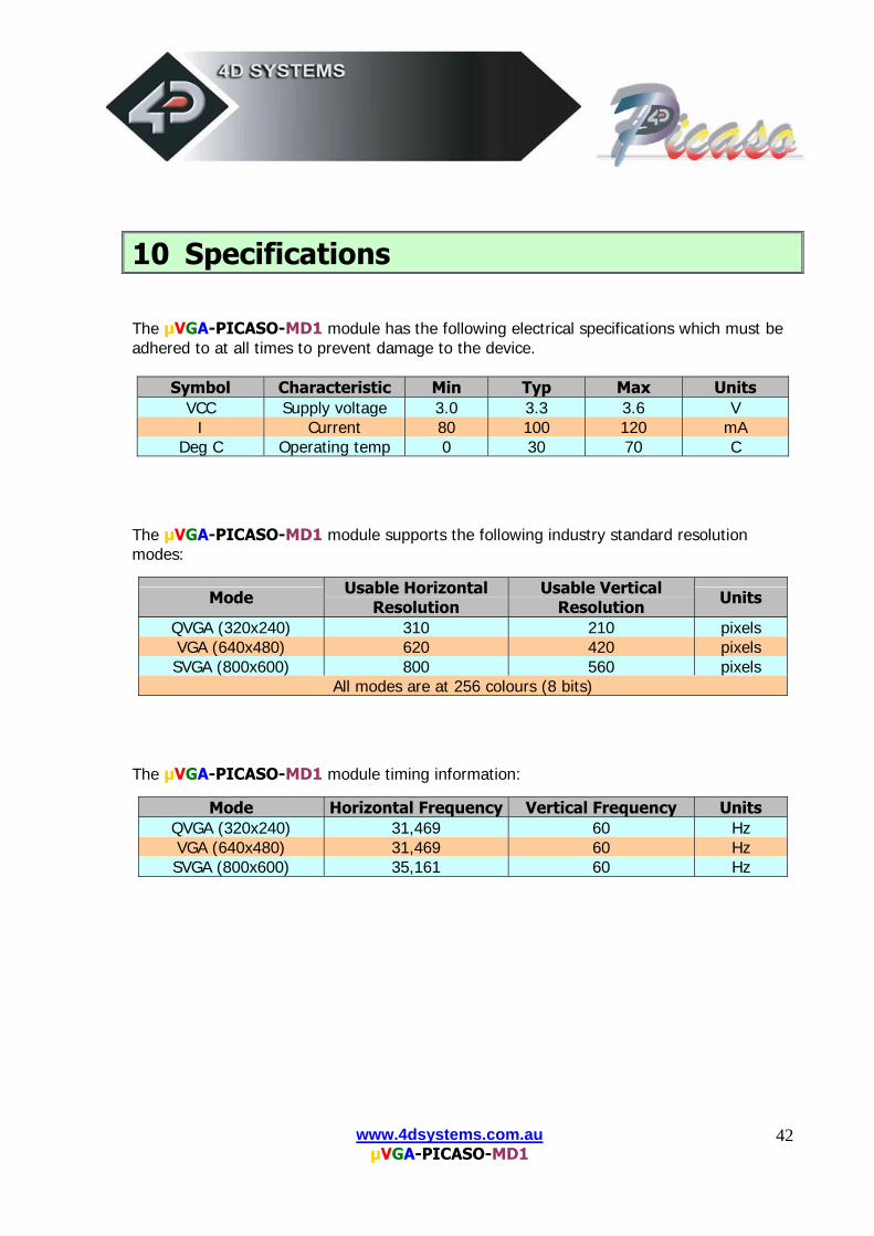
10 Specifications
The µVGA-PICASO-MD1 module has the following electrical specifications which must be adhered to at all times to prevent damage to the device.
Symbol Characteristic Min Typ Max Units VCC Supply voltage 3.0 3.3 3.6 V
I Current 80 100 120 mA Deg C Operating temp 0 30 70 C
The µVGA-PICASO-MD1 module supports the following industry standard resolution modes:
Mode Usable Horizontal Resolution
Usable Vertical Resolution Units
QVGA (320x240) 310 210 pixels VGA (640x480) 620 420 pixels SVGA (800x600) 800 560 pixels
All modes are at 256 colours (8 bits) The µVGA-PICASO-MD1 module timing information:
Mode Horizontal Frequency Vertical Frequency Units QVGA (320x240) 31,469 60 Hz VGA (640x480) 31,469 60 Hz SVGA (800x600) 35,161 60 Hz
www.4dsystems.com.au µVGA-PICASO-MD1
43
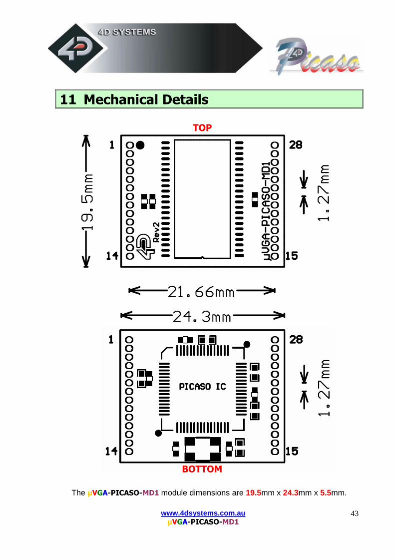
11 Mechanical Details TOP BOTTOM
The µVGA-PICASO-MD1 module dimensions are 19.5mm x 24.3mm x 5.5mm.
www.4dsystems.com.au µVGA-PICASO-MD1
44
12 Colour Organisation 256 Colour Bitmap Organisation
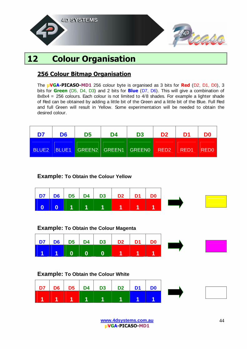
The µVGA-PICASO-MD1 256 colour byte is organised as 3 bits for Red (D2, D1, D0), 3 bits for Green (D5, D4, D3) and 2 bits for Blue (D7, D6). This will give a combination of 8x8x4 = 256 colours. Each colour is not limited to 4/8 shades. For example a lighter shade of Red can be obtained by adding a little bit of the Green and a little bit of the Blue. Full Red and full Green will result in Yellow. Some experimentation will be needed to obtain the desired colour.
D7 D6 D5 D4 D3 D2 D1 D0
BLUE2 BLUE1 GREEN2 GREEN1 GREEN0 RED2 RED1 RED0
Example: To Obtain the Colour Yellow
Example: To Obtain the Colour Magenta
Example: To Obtain the Colour White
D7 D6 D5 D4 D3 D2 D1 D0
0 0 1 1 1 1 1 1
D7 D6 D5 D4 D3 D2 D1 D0
1 1 0 0 0 1 1 1
D7 D6 D5 D4 D3 D2 D1 D0
1 1 1 1 1 1 1 1
www.4dsystems.com.au µVGA-PICASO-MD1
45
13 Power-Up Reset When the µVGA-PICASO-MD1 comes out of a power up reset it initialises the Video Graphics RAM and the internal Display registers. Allow up to 500ms before attempting to communicate with the module. The power up sequence of events should be as follows:
Allow 500ms after power-up for module to settle. Do not attempt to communicate with the module during this period. The µVGA-PICASO-MD1 may send garbage on its Tx Data line during this period, the host should disable its Rx Data reception.
Within 100ms of powering up, the host should make sure it has its Tx line pulled HIGH. If the host Tx (µVGA-PICASO-MD1 Rx) is LOW or floating after the 100ms period, the module may misinterpret this as the START bit and lock onto some undesired Baud Rate. If the host has a slow wake up time, i.e. less than 100ms, its Tx line maybe floating. This can be easily resolved by adding a pull up resistor on the host Tx line which will ensure the module does not encounter a false START bit. The pull up resistor can be any value within 10K to 100K.
The host must transmit the ASCII ‘U’ (capital U, 55hex) as the first command so the module can lock onto the host’s serial baud rate. This is called “Auto Bauding”. The module will respond with an ‘ACK’ (06h). See section 7.
The module is now ready to accept screen function commands from the host.
www.4dsystems.com.au µVGA-PICASO-MD1
46
14 Related Products
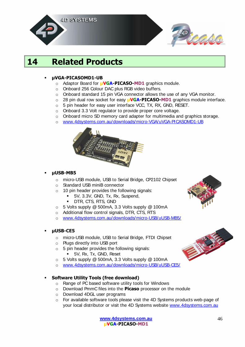
µVGA-PICASOMD1-UB o Adaptor Board for µVGA-PICASO-MD1 graphics module. o Onboard 256 Colour DAC plus RGB video buffers. o Onboard standard 15 pin VGA connector allows the use of any VGA monitor. o 28 pin dual row socket for easy µVGA-PICASO-MD1 graphics module interface. o 5 pin header for easy user interface VCC, TX, RX, GND, RESET. o Onboard 3.3 Volt regulator to provide proper core voltage. o Onboard micro SD memory card adapter for multimedia and graphics storage. o www.4dsystems.com.au/downloads/micro-VGA/uVGA-PICASOMD1-UB
µUSB-MB5 o micro-USB module, USB to Serial Bridge, CP2102 Chipset o Standard USB miniB connector o 10 pin header provides the following signals:
5V, 3.3V, GND, Tx, Rx, Suspend, DTR, CTS, RTS, GND
o 5 Volts supply @ 500mA, 3.3 Volts supply @ 100mA o Additional flow control signals, DTR, CTS, RTS o www.4dsystems.com.au/downloads/micro-USB/uUSB-MB5/
µUSB-CE5 o micro-USB module, USB to Serial Bridge, FTDI Chipset o Plugs directly into USB port o 5 pin header provides the following signals:
5V, Rx, Tx, GND, Reset o 5 Volts supply @ 500mA, 3.3 Volts supply @ 100mA o www.4dsystems.com.au/downloads/micro-USB/uUSB-CE5/
Software Utility Tools (free download) o Range of PC based software utility tools for Windows o Download PmmC files into the Picaso processor on the module o Download 4DGL user programs o For available software tools please visit the 4D Systems products web-page of
your local distributor or visit the 4D Systems website www.4dsystems.com.au
www.4dsystems.com.au µVGA-PICASO-MD1
47
15 Appendix 15.1 Help and Other Information:
Assistance with latest information and downloads visit the 4D Systems products web-page of your local distributor or visit the 4D Systems website.
Questions and technical support please visit the discussion forum at 4D website www.4dsystems.com.au
All related product information can be downloaded from www.4dsystems.com.au/downloads/micro-VGA/uVGA-PICASO-MD1