Embed Size (px)
Citation preview
IEEE TRANSACTIONS ON SIGNAL PROCESSING, VOL. 45, NO. 9, SEPTEMBER 1997 2175
On -Channel Linear Phase FIR Filter Banksand Application in Image Compression
Trac Duy Tran and Truong Q. Nguyen,Senior Member, IEEE
Abstract—This paper investigates the theory and structure of alarge subclass ofM -channel linear-phase perfect-reconstructionFIR filter banks—systems with analysis and synthesis filters oflength Li = KiM +�, where� is an arbitrary interger, 0 � � <M , andKi is any positive interger. For this subclass of systems,we first investigate the necessary conditions for the existenceof linear-phase perfect-reconstruction filter banks (LPPRFB’s).Next, we develop a complete and minimal factorization for alleven-channel linear-phase paraunitary systems (the most generallapped orthogonal transforms to date). Finally, several designexamples as well as comparisons with previous generalized lappedorthogonal transforms (GenLOT’s) in image compression arepresented to confirm the validity of the theory.
I. INTRODUCTION
I N various speech, image, and communications applications,digital filter banks have been used extensively. In this
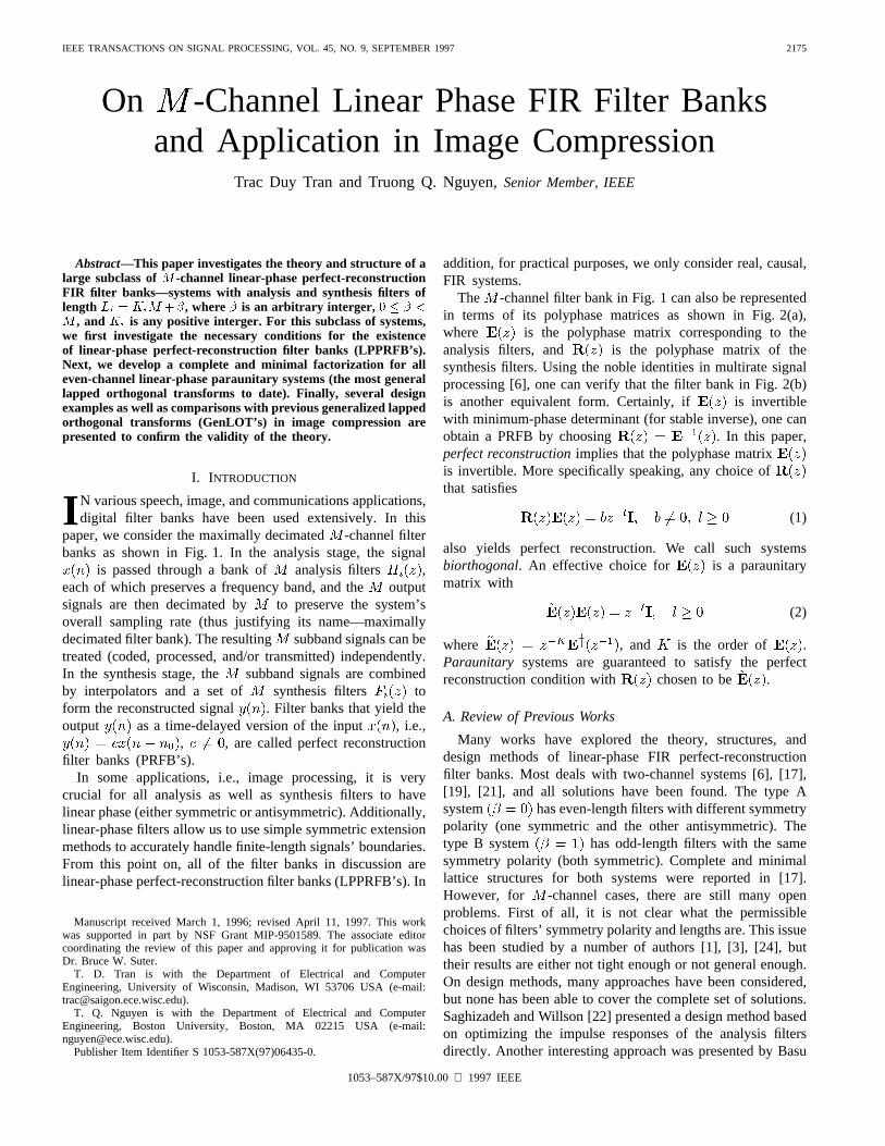
paper, we consider the maximally decimated-channel filterbanks as shown in Fig. 1. In the analysis stage, the signal
is passed through a bank of analysis filters ,each of which preserves a frequency band, and theoutputsignals are then decimated by to preserve the system’soverall sampling rate (thus justifying its name—maximallydecimated filter bank). The resulting subband signals can betreated (coded, processed, and/or transmitted) independently.In the synthesis stage, the subband signals are combinedby interpolators and a set of synthesis filters toform the reconstructed signal . Filter banks that yield theoutput as a time-delayed version of the input , i.e.,
, , are called perfect reconstructionfilter banks (PRFB’s).
In some applications, i.e., image processing, it is verycrucial for all analysis as well as synthesis filters to havelinear phase (either symmetric or antisymmetric). Additionally,linear-phase filters allow us to use simple symmetric extensionmethods to accurately handle finite-length signals’ boundaries.From this point on, all of the filter banks in discussion arelinear-phase perfect-reconstruction filter banks (LPPRFB’s). In
Manuscript received March 1, 1996; revised April 11, 1997. This workwas supported in part by NSF Grant MIP-9501589. The associate editorcoordinating the review of this paper and approving it for publication wasDr. Bruce W. Suter.
T. D. Tran is with the Department of Electrical and ComputerEngineering, University of Wisconsin, Madison, WI 53706 USA (e-mail:[email protected]).
T. Q. Nguyen is with the Department of Electrical and ComputerEngineering, Boston University, Boston, MA 02215 USA (e-mail:[email protected]).
Publisher Item Identifier S 1053-587X(97)06435-0.
addition, for practical purposes, we only consider real, causal,FIR systems.
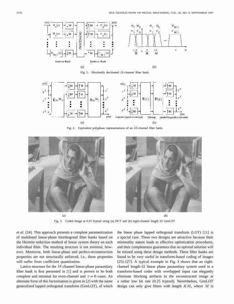
The -channel filter bank in Fig. 1 can also be representedin terms of its polyphase matrices as shown in Fig. 2(a),where is the polyphase matrix corresponding to theanalysis filters, and is the polyphase matrix of thesynthesis filters. Using the noble identities in multirate signalprocessing [6], one can verify that the filter bank in Fig. 2(b)is another equivalent form. Certainly, if is invertiblewith minimum-phase determinant (for stable inverse), one canobtain a PRFB by choosing . In this paper,perfect reconstructionimplies that the polyphase matrixis invertible. More specifically speaking, any choice ofthat satisfies
(1)
also yields perfect reconstruction. We call such systemsbiorthogonal. An effective choice for is a paraunitarymatrix with
(2)
where , and is the order of .Paraunitary systems are guaranteed to satisfy the perfectreconstruction condition with chosen to be .
A. Review of Previous Works
Many works have explored the theory, structures, anddesign methods of linear-phase FIR perfect-reconstructionfilter banks. Most deals with two-channel systems [6], [17],[19], [21], and all solutions have been found. The type Asystem has even-length filters with different symmetrypolarity (one symmetric and the other antisymmetric). Thetype B system has odd-length filters with the samesymmetry polarity (both symmetric). Complete and minimallattice structures for both systems were reported in [17].However, for -channel cases, there are still many openproblems. First of all, it is not clear what the permissiblechoices of filters’ symmetry polarity and lengths are. This issuehas been studied by a number of authors [1], [3], [24], buttheir results are either not tight enough or not general enough.On design methods, many approaches have been considered,but none has been able to cover the complete set of solutions.Saghizadeh and Willson [22] presented a design method basedon optimizing the impulse responses of the analysis filtersdirectly. Another interesting approach was presented by Basu
1053–587X/97$10.00 1997 IEEE
2176 IEEE TRANSACTIONS ON SIGNAL PROCESSING, VOL. 45, NO. 9, SEPTEMBER 1997
(a) (b)
Fig. 1. Maximally decimatedM -channel filter bank.
(a) (b)
Fig. 2. Equivalent polyphase representations of anM -channel filter bank.
(a) (b)
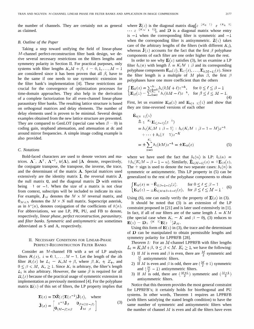
Fig. 3. Coded image at 0.25 b/pixel using (a) DCT and (b) eight-channel length 32 GenLOT.
et al. [24]. This approach presents a complete parametrizationof multiband linear-phase biorthogonal filter banks based onthe Hermite reduction method of linear system theory on eachindividual filter. The resulting structure is not minimal, how-ever. Moreover, both linear-phase and perfect-reconstructionproperties are not structurally enforced, i.e., these propertieswill suffer from coefficient quantization.
Lattice structure for the -channel linear-phase paraunitaryfilter bank is first presented in [1] and is proven to be bothcomplete and minimal for even-channel and cases. Analternate form of this factorization is given in [2] with the namegeneralized lapped orthogonal transform (GenLOT), of which
the linear phase lapped orthogonal transform (LOT) [11] isa special case. These two designs are attractive because theirminimality nature leads to effective optimization procedures,and their completeness guarantees that no optimal solution willbe missed using these design methods. These filter banks arefound to be very useful in transform-based coding of images[25]–[27]. A typical example in Fig. 3 shows that an eight-channel length-32 linear phase paraunitary system used in atransform-based coder with overlapped input can elegantlyeliminate blocking artifacts in the reconstructed image ata rather low bit rate (0.25 b/pixel). Nevertheless, GenLOTdesign can only give filters with length , where is
TRAN AND NGUYEN: -CHANNEL LINEAR PHASE FIR FILTER BANKS AND APPLICATION IN IMAGE COMPRESSION 2177
the number of channels. They are certainly not as generalas claimed.
B. Outline of the Paper
Taking a step toward unifying the field of linear-phase-channel perfect-reconstruction filter bank design, we de-
rive several necessary restrictions on the filters lengths andsymmetry polarity in Section II. For practical purposes, onlysystems with filter lengthsare considered since it has been proven that allhave tobe the same if one needs to use symmetric extension inthe filter bank’s implementation [4]. These restrictions arecrucial for the convergence of optimization processes fortime-domain approaches. They also help in the derivationof a complete factorization for all even-channel linear-phaseparaunitary filter banks. The resulting lattice structure is basedon orthogonal matrices and delay elements. The number ofdelay elements used is proven to be minimal. Several designexamples obtained from the new lattice structure are presented.They are compared to GenLOT (special case when ) incoding gain, stopband attenuation, and attenuation at dc andaround mirror frequencies. A simple image coding example isalso provided.
C. Notations
Bold-faced characters are used to denote vectors and ma-trices. tr , and denote, respectively,the conjugate transpose, the transpose, the inverse, the trace,and the determinant of the matrix . Special matrices usedextensively are the identity matrix, the reversal matrix ,the null matrix , and the diagonal matrix with entriesbeing or . When the size of a matrix is not clearfrom context, subscripts will be included to indicate its size.For example, denotes the reversal matrix, and
denotes the null matrix. Superscript asterisk,as in , denotes conjugation of the coefficients of .For abbreviations, we use LP, PR, PU, and FB to denote,respectively,linear phase, perfect reconstruction, paraunitary,and filter banks. Symmetricand antisymmetricare sometimesabbreviated as S and A, respectively.
II. NECESSARYCONDITIONS FOR LINEAR-PHASE
PERFECT-RECONSTRUCTIONFILTER BANKS
Consider an -channel FB with a set of LP analysisfilters . Let the length of thethfilter be , where , and
. Since is arbitrary, the filter’s lengthis also arbitrary. However, the sameis required for all
because of the practical usage of symmetric extension inimplementation as previously mentioned [4]. For the polyphasematrix of this set of filters, the LP property implies that
where(3)
where is the diagonal matrix diag, and is a diagonal matrix whose entry
is when the corresponding filter is symmetric andwhen the corresponding filter is antisymmetric. takescare of the arbitrary lengths of the filters (with different),whereas accounts for the fact that the first polyphasecomponents of each filter are one order higher than the rest.
In order to see why satisfies (3), let us examine a LPfilter with length and its correspondingpolyphase components . Sincethe filter length is a multiple of plus , the firstpolyphases have one more coefficient than the others
forfor .
(4)First, let us examine and and show thatthey are time-reversed versions of each other
(5)
where we have used the fact that is LP:. Similarly,
The sign is used to denote the two separate cases: issymmetric or antisymmetric. This LP property in (5) can begeneralized to the rest of the polyphase components to obtain
forfor
(6)
Using (6), one can easily verify the property of in (3).It should be noted that (3) is an extension of the LP
constraint proposed in [21] and is later used extensively in [1].In fact, if all of our filters are of the same length(the special case when and ), (3) reduces to
Using this form of in (3), the trace and the determinantof can be manipulated to obtain permissible lengths andsymmetry polarity for LPPRFB [28].
Theorem 1: For an -channel LPPRFB with filter lengths, we have the following:
1) If is even and is even, there are symmetric andantisymmetric filters.
2) If is even and is odd, there are symmetricand antisymmetric filters.
3) If is odd, there are symmetric andantisymmetric filters.
Notice that this theorem provides the most general constraintfor LPPRFB’s; it certainly holds for biorthogonal and PUsystems. In other words, Theorem 1 requires an LPPRFB(with filters satisfying the stated length condition) to have thesame number of symmetric and antisymmetric filters whenthe number of channel is even and all the filters have even
2178 IEEE TRANSACTIONS ON SIGNAL PROCESSING, VOL. 45, NO. 9, SEPTEMBER 1997
lengths. If is even but all the filters are now odd length,then the system must have two more symmetric filters. Forodd-channel systems, the number of symmetric filters alwaysexceeds the number of antisymmetric filters by one. This is auseful and powerful result. It allows the designers of FB’s tonarrow down the search for possible solutions. It also helpsto explain partially why only certain solutions exist. Beforepresenting the formal proof of the theorem, let us first gothrough a couple of useful lemmas that appear persistentlythroughout.
Lemma 1:
tr
if is even and is evenif is even and is oddif is odd and is evenif is odd and is odd.
(7)
Proof:
tr tr
There are four cases to consider. Whenis even and iseven, is also even, and all of the diagonal elementsof the matrix are all zeros. Thus, its trace is 0. Whenis even and is odd, is odd. Hence, we now pickup two nonzero elements on the diagonal of and .When is odd, and cannot be both odd or botheven. Therefore, in this case, only one nonzero element canbe picked up: either 1 or .
Lemma 2:
if is evenif is odd.
(8)
Proof: Notice that is a square block-diagonal ma-trix; thus, its determinant can be factorized as [9]
With the factorization above, coupled with the fact thatand ,
where is any positive integer, one can verify that Lemma2 holds by considering four possible cases:
andWith the help of Lemma 1, proving Theorem 1 is a trivial
task.Proof of Theorem 1:Since is invertible, and, (3) can be rewritten as
(9)
Taking the trace of both sides and using the fact that trtr , one can obtain
tr tr
tr
tr is a constant, and therefore, its value can be obtainedby evaluating the right-hand side of the above equation at aspecific value of the variable. Since
we have
tr tr tr(10)
Again, there are four possible cases. Recall thatis adiagonal matrix whose entry is when the correspondingfilter is symmetric and when the corresponding filter isantisymmetric. When both and are even, Lemma 1 yieldstr tr . Hence, the system must havean equal number of symmetric and antisymmetric filters tosatisfy the LP and PR properties. When is even and isodd, tr . Thus, we need two moresymmetric filters in this case. The results from the remainingtwo odd- cases can be trivially obtained in a similar manner.
In time-domain FB designs [22], [23], the filters’ symmetrypolarity is not a narrow enough requirement. The filters’lengths are also very important for PR. If the designer chooseswrong filters’ lengths, his optimization routine will not con-verge. Therefore, besides the necessary LP PR condition forthe filters’ symmetry polarity as stated in Theorem 1, we alsohave to obtain the necessary LP PR condition for the filters’lengths (more precisely speaking, the necessary condition forthe sum of their lengths).
Theorem 2: For an -channel LPPRFB with filter lengths, we have the following.
1) If is even and is even, is even.2) If is even and is odd, is odd.3) If is odd and is even, is odd.4) If is odd and is odd, is even.
The proof of Theorem 2 based on Lemma 2 is presented inAppendix A. An interesting corollary can be derived on thebehavior of the total lengths of all the filters in a LPPRFB.
Corollary 1: For an -channel LPPRFB with filter lengths, and is a positive
interger, if is even, , and if is odd,.
Proof: SinceIf is even and is also even, Theorem
2 requires to be even. Hence, iseven. If is now odd, then has to be odd; therefore,
is even. For odd values of , using a similarargument, we arrive at the conclusion that the total length ofall the filters is an odd multiple of .
The results from Theorem 1, Theorem 2, and Corollary 1are summarized in Table I. S stands for symmetric filters, andA stands for antisymmetric filters. Note that these results holdtrue for both sets of analysis and synthesis filters of any LPPR system satisfying (3). Similar results are also developedindependently (but without proof) by Basuet al. in [24].
It is no surprise that the solutions for the well-studied two-channel LPPRFB agree with our result. There are two systemsfor two-channel LPFB’s. The type A system has even-lengthfilters with different symmetry polarity, whereas the Type Bsystem has odd-length filters with the same symmetry. Thiscan be confirmed using Table I. The type A system belongsto the first row and . Therefore, there mustbe one symmetric and one antisymmetric filter. Since they
TRAN AND NGUYEN: -CHANNEL LINEAR PHASE FIR FILTER BANKS AND APPLICATION IN IMAGE COMPRESSION 2179
TABLE IPOSSIBLE SOLUTIONS FORM -CHANNEL LPPRFB WITH FILTERS OF ARBITRARY LENGTHSLi = KiM + �
both have even length (and is even), the sum ofthe filter lengths is a multiple of 4. Similarly, the type Bsystem satisfies all constraints in the second row of the table (itbelongs to the even- , odd- case with and )[17]. Moreover, all of the -channel solutions reported sofar also follow the results in our two theorems. For example,the three-channel LPPRFB in [3] has two symmetric filtersand one antisymmetric filter. They have lengths 56, 53, and56 . The sum of the corresponding(18, 17, and 18) is odd. In addition, the total length is anodd multiple of 3. Another three-channel solution reportedin [22] has two symmetric and one antisymmetric filter withlengths 53, 44, and 44, respectively. This system belongs tothe case of odd and even . Therefore, the number ofsymmetric filters must exceed the number of antisymmetricones by one. Moreover, the sum of (17, 14, 14) is odd,which is consistent with the result in Theorem 2. Several LPcosine-modulated PR FB’s with filter lengths not equal tohave been reported recently in [14]. All of these FB lengthsand polarity symmetry also fall within our constraints (thezero-value coefficients resulted from the optimization processneed to be counted as well).
III. L ATTICE STRUCTURE FOREVEN-CHANNEL LPPUFB’S
In this section, a complete and minimal factorization foreven-channel LPPUFBs will be presented. Lattice structuresfor even-channel systems with have been reported in[1] and [2]. However, these structures impose a very strictrestriction on both analysis and synthesis filters. They musthave the same length, which is a multiple of the number ofchannels, i.e., . This restriction does not allow muchflexibility in both of the system’s design and implementation.Extending the filters’ length from to providesmore degrees of freedom in fine-tuning the filters to meetcertain specifications, i.e., stopband attenuation. In [1] and[2], the step size in increasing the filters’ length is at least
. This is not so convenient when the number of channelsis large (say, 16 or 32). From a design point of view,
a large increase in length means a much higher nonlinearparameter space to be searched, and the optimization programtends to be more easily trapped in local minima. From animplementation point of view, a large increase in filter length
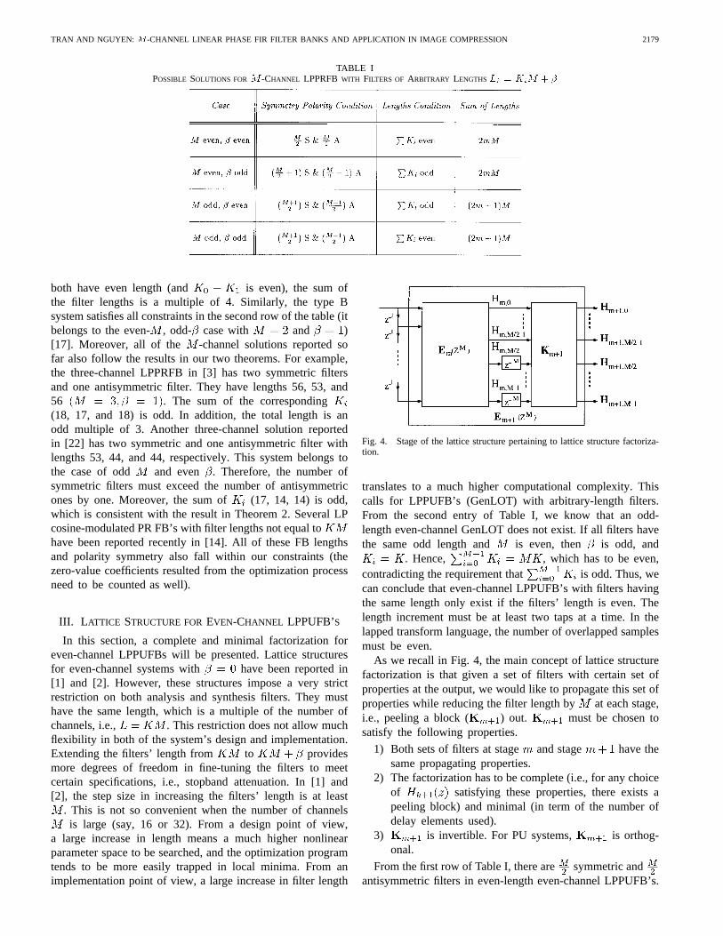
Fig. 4. Stage of the lattice structure pertaining to lattice structure factoriza-tion.
translates to a much higher computational complexity. Thiscalls for LPPUFB’s (GenLOT) with arbitrary-length filters.From the second entry of Table I, we know that an odd-length even-channel GenLOT does not exist. If all filters havethe same odd length and is even, then is odd, and
. Hence, , which has to be even,contradicting the requirement that is odd. Thus, wecan conclude that even-channel LPPUFB’s with filters havingthe same length only exist if the filters’ length is even. Thelength increment must be at least two taps at a time. In thelapped transform language, the number of overlapped samplesmust be even.
As we recall in Fig. 4, the main concept of lattice structurefactorization is that given a set of filters with certain set ofproperties at the output, we would like to propagate this set ofproperties while reducing the filter length by at each stage,i.e., peeling a block ( ) out. must be chosen tosatisfy the following properties.
1) Both sets of filters at stage and stage have thesame propagating properties.
2) The factorization has to be complete (i.e., for any choiceof satisfying these properties, there exists apeeling block) and minimal (in term of the number ofdelay elements used).
3) is invertible. For PU systems, is orthog-onal.
From the first row of Table I, there are symmetric andantisymmetric filters in even-length even-channel LPPUFB’s.
2180 IEEE TRANSACTIONS ON SIGNAL PROCESSING, VOL. 45, NO. 9, SEPTEMBER 1997
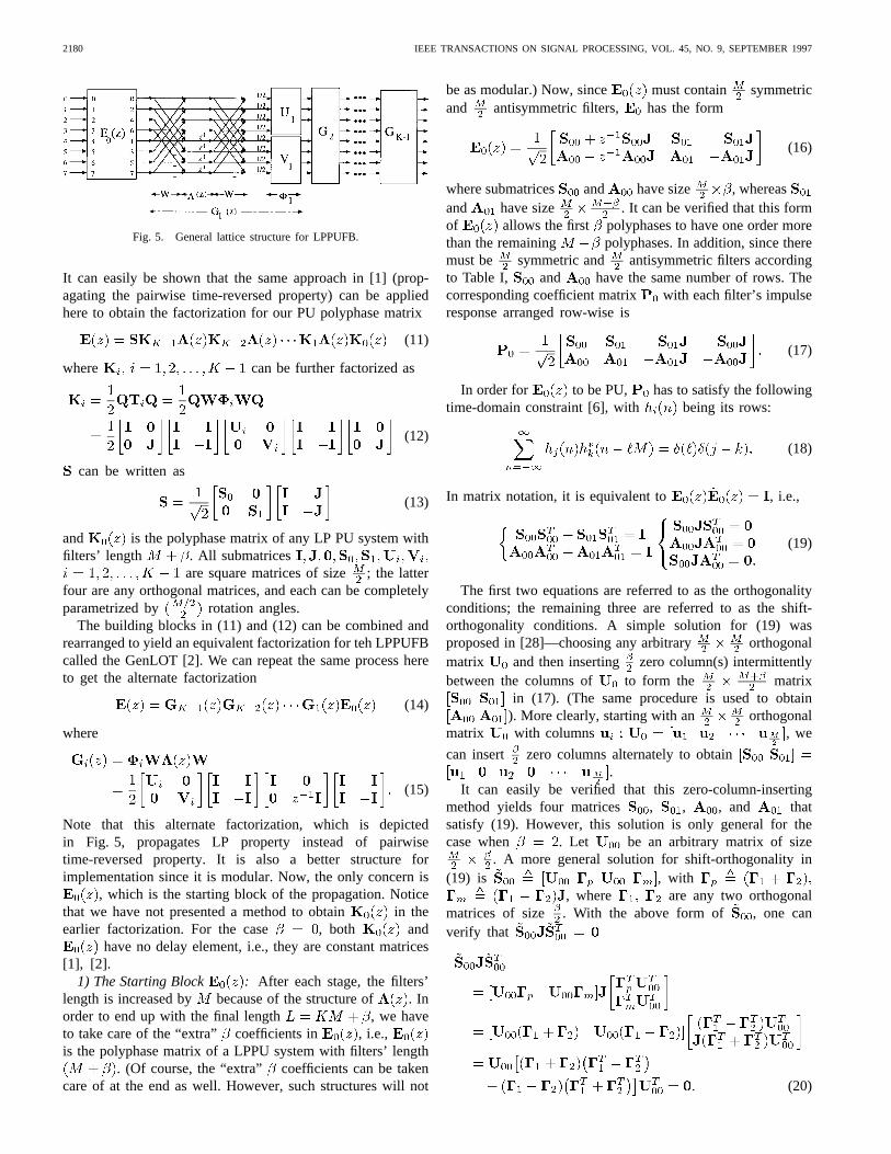
Fig. 5. General lattice structure for LPPUFB.
It can easily be shown that the same approach in [1] (prop-agating the pairwise time-reversed property) can be appliedhere to obtain the factorization for our PU polyphase matrix
(11)
where can be further factorized as
(12)
can be written as
(13)
and is the polyphase matrix of any LP PU system withfilters’ length . All submatrices
are square matrices of size ; the latterfour are any orthogonal matrices, and each can be completelyparametrized by rotation angles.
The building blocks in (11) and (12) can be combined andrearranged to yield an equivalent factorization for teh LPPUFBcalled the GenLOT [2]. We can repeat the same process hereto get the alternate factorization
(14)
where
(15)
Note that this alternate factorization, which is depictedin Fig. 5, propagates LP property instead of pairwisetime-reversed property. It is also a better structure forimplementation since it is modular. Now, the only concern is
, which is the starting block of the propagation. Noticethat we have not presented a method to obtain in theearlier factorization. For the case , both and
have no delay element, i.e., they are constant matrices[1], [2].
1) The Starting Block : After each stage, the filters’length is increased by because of the structure of . Inorder to end up with the final length , we haveto take care of the “extra” coefficients in , i.e.,is the polyphase matrix of a LPPU system with filters’ length
. (Of course, the “extra” coefficients can be takencare of at the end as well. However, such structures will not
be as modular.) Now, since must contain symmetricand antisymmetric filters, has the form
(16)
where submatrices and have size , whereasand have size . It can be verified that this formof allows the first polyphases to have one order morethan the remaining polyphases. In addition, since theremust be symmetric and antisymmetric filters accordingto Table I, and have the same number of rows. Thecorresponding coefficient matrix with each filter’s impulseresponse arranged row-wise is
(17)
In order for to be PU, has to satisfy the followingtime-domain constraint [6], with being its rows:
(18)
In matrix notation, it is equivalent to , i.e.,
(19)
The first two equations are referred to as the orthogonalityconditions; the remaining three are referred to as the shift-orthogonality conditions. A simple solution for (19) wasproposed in [28]—choosing any arbitrary orthogonalmatrix and then inserting zero column(s) intermittentlybetween the columns of to form the matrix
in (17). (The same procedure is used to obtain). More clearly, starting with an orthogonal
matrix with columns , we
can insert zero columns alternately to obtain.
It can easily be verified that this zero-column-insertingmethod yields four matrices , , , and thatsatisfy (19). However, this solution is only general for thecase when . Let be an arbitrary matrix of size
. A more general solution for shift-orthogonality in(19) is , with
, where are any two orthogonalmatrices of size . With the above form of , one canverify that
(20)
TRAN AND NGUYEN: -CHANNEL LINEAR PHASE FIR FILTER BANKS AND APPLICATION IN IMAGE COMPRESSION 2181
The remaining shift-orthogonality conditions can be verifiedsimilarly. For any arbitrary matrix and anyarbitrary matrix (these matrix sizes guaranteethe first polyphase components to have an extra order), usingthe above solutions of shift-orthogonality, we can simplify andfactorize as in (21), shown at the bottom of the page,with .
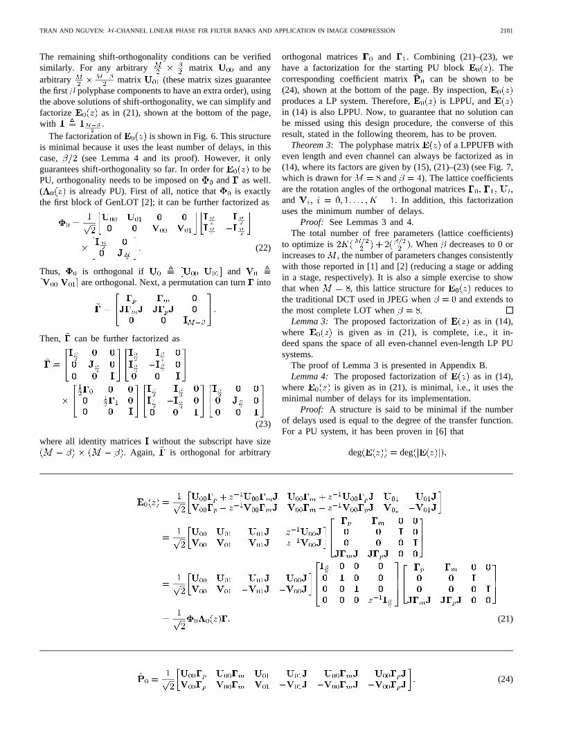
The factorization of is shown in Fig. 6. This structureis minimal because it uses the least number of delays, in thiscase, (see Lemma 4 and its proof). However, it onlyguarantees shift-orthogonality so far. In order for to bePU, orthogonality needs to be imposed on and as well.( is already PU). First of all, notice that is exactlythe first block of GenLOT [2]; it can be further factorized as
(22)
Thus, is orthogonal if andare orthogonal. Next, a permutation can turninto
Then, can be further factorized as
(23)
where all identity matrices without the subscript have size. Again, is orthogonal for arbitrary
orthogonal matrices and . Combining (21)–(23), wehave a factorization for the starting PU block . Thecorresponding coefficient matrix can be shown to be(24), shown at the bottom of the page. By inspection,produces a LP system. Therefore, is LPPU, andin (14) is also LPPU. Now, to guarantee that no solution canbe missed using this design procedure, the converse of thisresult, stated in the following theorem, has to be proven.
Theorem 3: The polyphase matrix of a LPPUFB witheven length and even channel can always be factorized as in(14), where its factors are given by (15), (21)–(23) (see Fig. 7,which is drawn for and ). The lattice coefficientsare the rotation angles of the orthogonal matrices ,and In addition, this factorizationuses the minimum number of delays.
Proof: See Lemmas 3 and 4.The total number of free parameters (lattice coefficients)
to optimize is . When decreases to 0 orincreases to , the number of parameters changes consistentlywith those reported in [1] and [2] (reducing a stage or addingin a stage, respectively). It is also a simple exercise to showthat when , this lattice structure for reduces tothe traditional DCT used in JPEG when and extends tothe most complete LOT when .
Lemma 3: The proposed factorization of as in (14),where is given as in (21), is complete, i.e., it in-deed spans the space of all even-channel even-length LP PUsystems.
The proof of Lemma 3 is presented in Appendix B.Lemma 4: The proposed factorization of as in (14),
where is given as in (21), is minimal, i.e., it uses theminimal number of delays for its implementation.
Proof: A structure is said to be minimal if the numberof delays used is equal to the degree of the transfer function.For a PU system, it has been proven in [6] that
deg deg
(21)
(24)
2182 IEEE TRANSACTIONS ON SIGNAL PROCESSING, VOL. 45, NO. 9, SEPTEMBER 1997
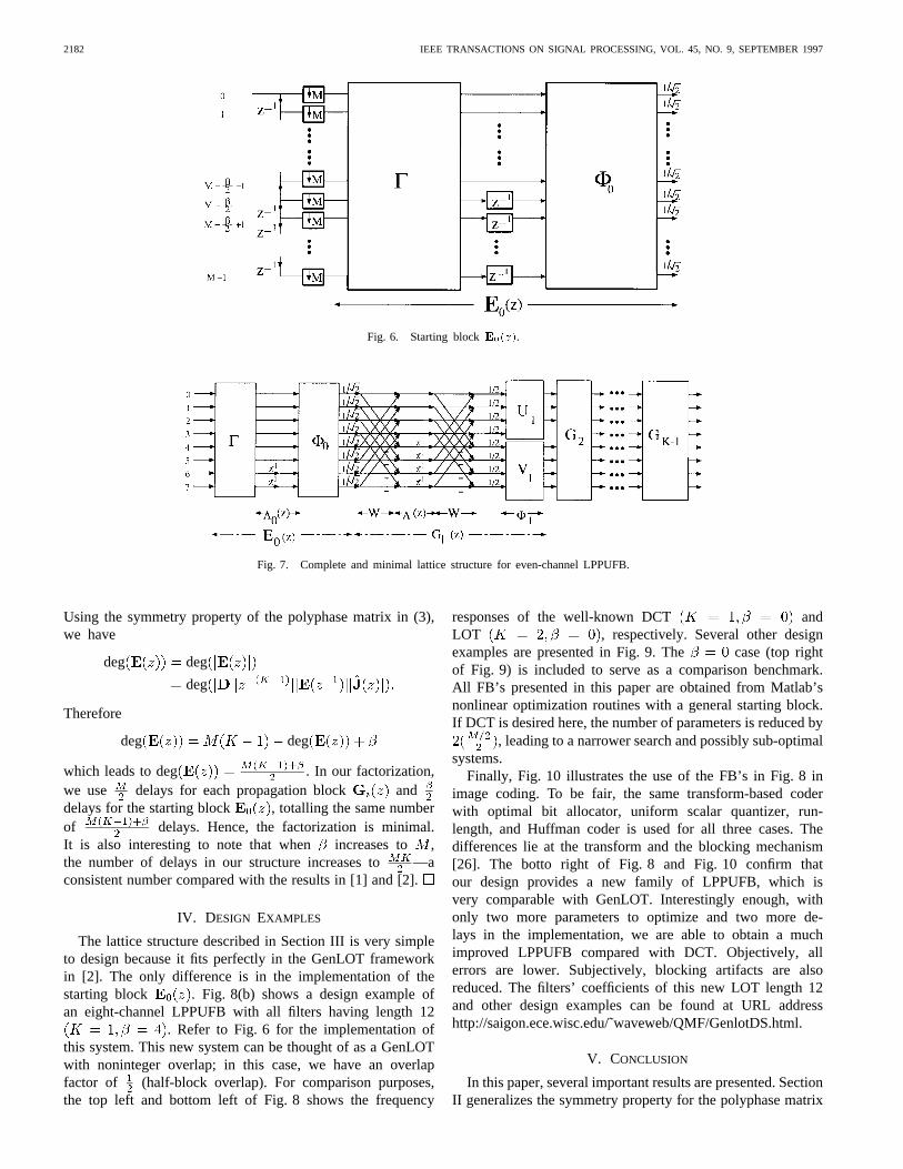
Fig. 6. Starting blockE0(z).
Fig. 7. Complete and minimal lattice structure for even-channel LPPUFB.
Using the symmetry property of the polyphase matrix in (3),we have
deg deg
deg
Therefore
deg deg
which leads to deg . In our factorization,we use delays for each propagation block anddelays for the starting block , totalling the same numberof delays. Hence, the factorization is minimal.It is also interesting to note that when increases to ,the number of delays in our structure increases to —aconsistent number compared with the results in [1] and [2].
IV. DESIGN EXAMPLES
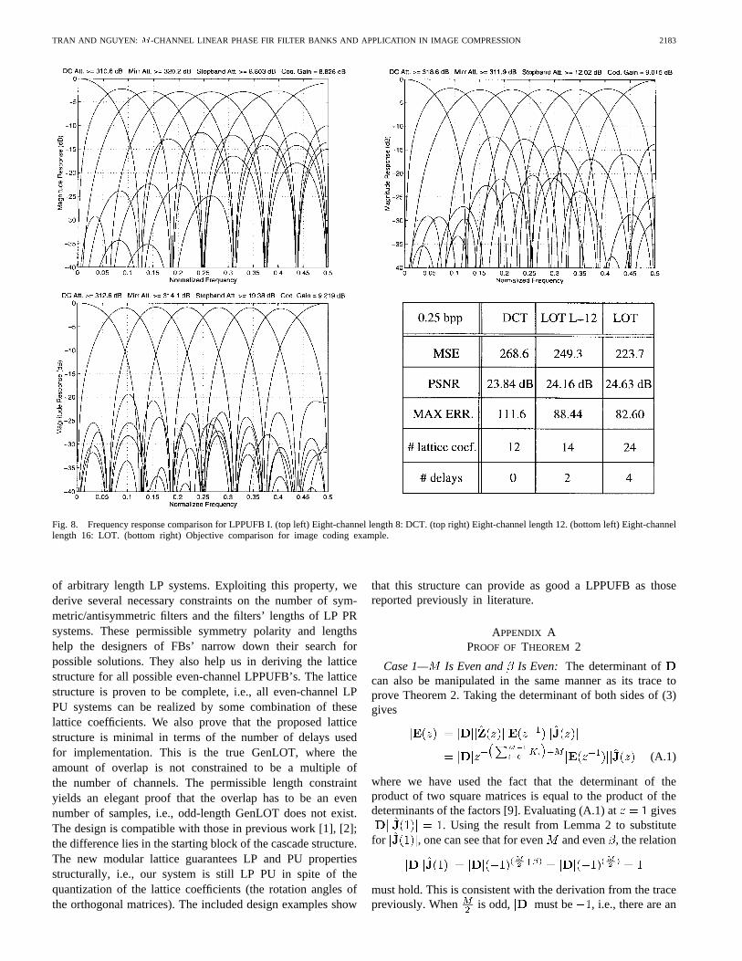
The lattice structure described in Section III is very simpleto design because it fits perfectly in the GenLOT frameworkin [2]. The only difference is in the implementation of thestarting block . Fig. 8(b) shows a design example ofan eight-channel LPPUFB with all filters having length 12
. Refer to Fig. 6 for the implementation ofthis system. This new system can be thought of as a GenLOTwith noninteger overlap; in this case, we have an overlapfactor of (half-block overlap). For comparison purposes,the top left and bottom left of Fig. 8 shows the frequency
responses of the well-known DCT andLOT , respectively. Several other designexamples are presented in Fig. 9. The case (top rightof Fig. 9) is included to serve as a comparison benchmark.All FB’s presented in this paper are obtained from Matlab’snonlinear optimization routines with a general starting block.If DCT is desired here, the number of parameters is reduced by
, leading to a narrower search and possibly sub-optimalsystems.
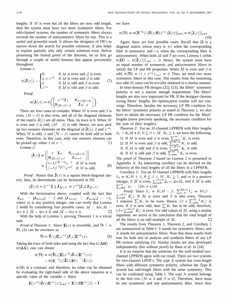
Finally, Fig. 10 illustrates the use of the FB’s in Fig. 8 inimage coding. To be fair, the same transform-based coderwith optimal bit allocator, uniform scalar quantizer, run-length, and Huffman coder is used for all three cases. Thedifferences lie at the transform and the blocking mechanism[26]. The botto right of Fig. 8 and Fig. 10 confirm thatour design provides a new family of LPPUFB, which isvery comparable with GenLOT. Interestingly enough, withonly two more parameters to optimize and two more de-lays in the implementation, we are able to obtain a muchimproved LPPUFB compared with DCT. Objectively, allerrors are lower. Subjectively, blocking artifacts are alsoreduced. The filters’ coefficients of this new LOT length 12and other design examples can be found at URL addresshttp://saigon.ece.wisc.edu/˜waveweb/QMF/GenlotDS.html.
V. CONCLUSION
In this paper, several important results are presented. SectionII generalizes the symmetry property for the polyphase matrix
TRAN AND NGUYEN: -CHANNEL LINEAR PHASE FIR FILTER BANKS AND APPLICATION IN IMAGE COMPRESSION 2183
Fig. 8. Frequency response comparison for LPPUFB I. (top left) Eight-channel length 8: DCT. (top right) Eight-channel length 12. (bottom left) Eight-channellength 16: LOT. (bottom right) Objective comparison for image coding example.
of arbitrary length LP systems. Exploiting this property, wederive several necessary constraints on the number of sym-metric/antisymmetric filters and the filters’ lengths of LP PRsystems. These permissible symmetry polarity and lengthshelp the designers of FBs’ narrow down their search forpossible solutions. They also help us in deriving the latticestructure for all possible even-channel LPPUFB’s. The latticestructure is proven to be complete, i.e., all even-channel LPPU systems can be realized by some combination of theselattice coefficients. We also prove that the proposed latticestructure is minimal in terms of the number of delays usedfor implementation. This is the true GenLOT, where theamount of overlap is not constrained to be a multiple ofthe number of channels. The permissible length constraintyields an elegant proof that the overlap has to be an evennumber of samples, i.e., odd-length GenLOT does not exist.The design is compatible with those in previous work [1], [2];the difference lies in the starting block of the cascade structure.The new modular lattice guarantees LP and PU propertiesstructurally, i.e., our system is still LP PU in spite of thequantization of the lattice coefficients (the rotation angles ofthe orthogonal matrices). The included design examples show
that this structure can provide as good a LPPUFB as thosereported previously in literature.
APPENDIX APROOF OF THEOREM 2
Case 1— Is Even and Is Even: The determinant ofcan also be manipulated in the same manner as its trace toprove Theorem 2. Taking the determinant of both sides of (3)gives
(A.1)
where we have used the fact that the determinant of theproduct of two square matrices is equal to the product of thedeterminants of the factors [9]. Evaluating (A.1) at gives
. Using the result from Lemma 2 to substitutefor , one can see that for even and even , the relation
must hold. This is consistent with the derivation from the tracepreviously. When is odd, must be , i.e., there are an
2184 IEEE TRANSACTIONS ON SIGNAL PROCESSING, VOL. 45, NO. 9, SEPTEMBER 1997
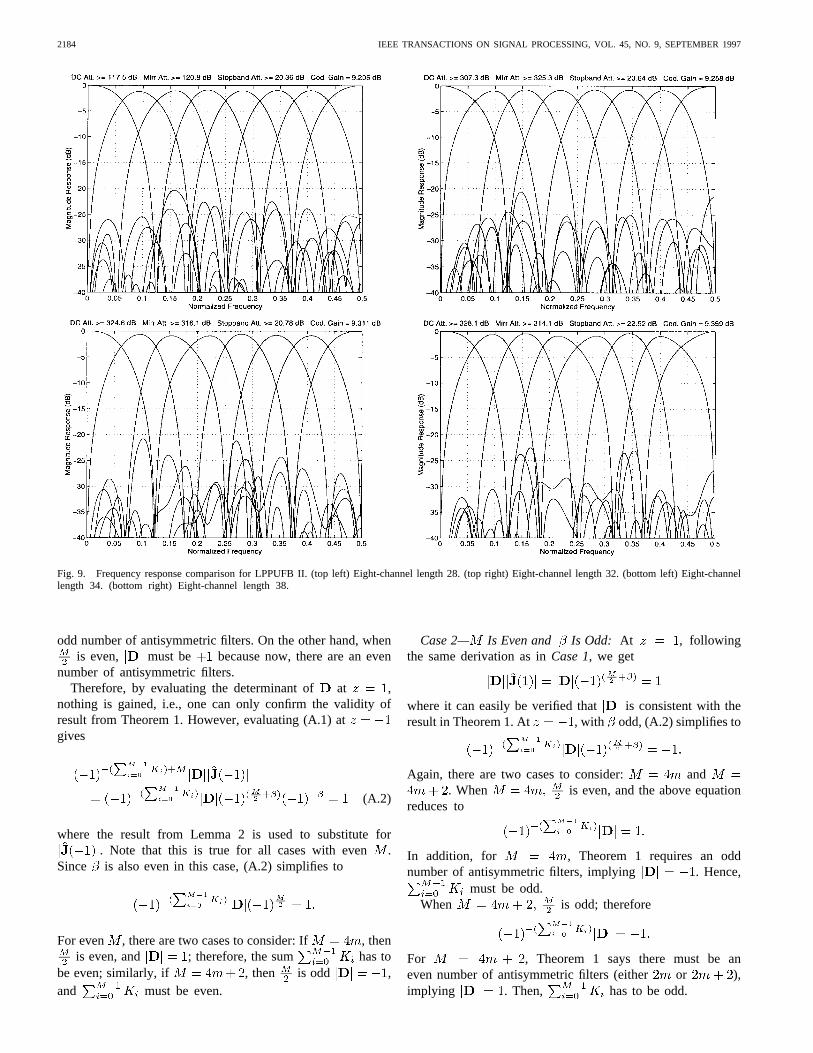
Fig. 9. Frequency response comparison for LPPUFB II. (top left) Eight-channel length 28. (top right) Eight-channel length 32. (bottom left) Eight-channellength 34. (bottom right) Eight-channel length 38.
odd number of antisymmetric filters. On the other hand, whenis even, must be because now, there are an even
number of antisymmetric filters.Therefore, by evaluating the determinant of at ,
nothing is gained, i.e., one can only confirm the validity ofresult from Theorem 1. However, evaluating (A.1) atgives
(A.2)
where the result from Lemma 2 is used to substitute for. Note that this is true for all cases with even.
Since is also even in this case, (A.2) simplifies to
For even , there are two cases to consider: If , thenis even, and ; therefore, the sum has to
be even; similarly, if , then is odd ,and must be even.
Case 2— Is Even and Is Odd: At , followingthe same derivation as inCase 1, we get
where it can easily be verified that is consistent with theresult in Theorem 1. At , with odd, (A.2) simplifies to
Again, there are two cases to consider: and. When is even, and the above equation
reduces to
In addition, for , Theorem 1 requires an oddnumber of antisymmetric filters, implying . Hence,
must be odd.When is odd; therefore
For , Theorem 1 says there must be aneven number of antisymmetric filters (either or ),implying . Then, has to be odd.
TRAN AND NGUYEN: -CHANNEL LINEAR PHASE FIR FILTER BANKS AND APPLICATION IN IMAGE COMPRESSION 2185
(a) (b)
(c) (d)
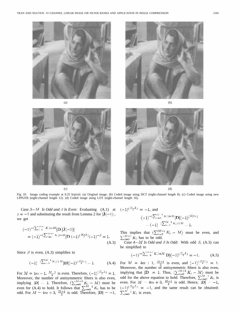
Fig. 10. Image coding example at 0.25 b/pixel: (a) Original image. (b) Coded image using DCT (eight-channel length 8). (c) Coded image using newLPPUFB (eight-channel length 12). (d) Coded image using LOT (eight-channel length 16).
Case 3— Is Odd and Is Even: Evaluating (A.1) atand substituting the result from Lemma 2 for ,
we get
(A.3)
Since is even, (A.3) simplifies to
(A.4)
For , is even. Therefore, .Moreover, the number of antisymmetric filters is also even,implying . Therefore, must beeven for (A.4) to hold. It follows that has to beodd. For , is odd. Therefore, ,
, and
This implies that must be even, andhas to be odd.
Case 4— Is Odd and Is Odd: With odd , (A.3) canbe simplified to
(A.5)
For , is even, and .Moreover, the number of antisymmetric filters is also even,implying that . Thus, must beodd for the above equation to hold. Therefore, iseven. For , is odd. Hence, ,
, and the same result can be obtained:is even.
2186 IEEE TRANSACTIONS ON SIGNAL PROCESSING, VOL. 45, NO. 9, SEPTEMBER 1997
APPENDIX BPROOF OF LEMMA 3
This lemma can be rephrased as follows: Suppose thereexists an arbitrary FIR LP PU matrix , satisfying (3);then can always be factored as in (14), whereascan always be factored as in (21).
The former is achieved by performing theorder reduc-tion process in a similar procedure as presented in [1]. Thefactorization in (11) was proven complete, i.e., there existslattice structure in the proposed from which we retain thepairwise time-reversed property, the PU property, and thecausal property such that the order of is reduced by1 after each stage. The alternate modular factorization in (14)is a rearrangement of the building blocks in (11); therefore,it is also complete [2], i.e., there exists lattice structure asin (14), which retains the LP property, the PU property, andthe causal property such that the order of is reduced by1 after each stage. Given a polyphase matrix with filters oflength , after reduction steps performedby , , the remainder is the LP PUsystem as shown in (16). Now, all what is left to proveis the latter part of the lemma: can always be factoredas in (21).
Given a starting block as in (16), (17) shows thatthe corresponding coefficient matrix will take the formin (17), where , , , and must satisfy the shift-orthogonality and orthogonality condition in (19), respectively.On the other hand, from the proposed factorization of ,the corresponding coefficient matrix takes the form in (24).
Now, we have to prove that there exists orthogonal matricesof size , and
of size such that
and similarly
The proof for existence of and is not difficult. Byimposing the PU constraint on in (16)
, it can be shown that the columns of must beorthonormal, i.e., . Since includes
columns of an arbitrary orthogonal matrix ,surely spans the space of all possible . A similar argumentcan be constructed for and .
The proof for existence of the remaining building blocksis a little more tricky. We have to show that
spans the space of all possible .Since , has rank ,
i.e., the matrix has independent columns out of itscolumns. Moreover, shift-orthogonality must also be satisfied,i.e., . This means that the columns of liein the nullspace of . However, rank( rankrank dimension of the nullspace of . Since for any
matrix
dimension of column space dimension of nullspace
The dimension of column space of must be , or in otherwords, must have independent columns. As a result,all columns of must be independent. This agreeswith our result. Recall that is anorthogonal matrix with containing the first columnsand containing the last columns. Since the columnsof any orthogonal matrix are independent,
rank rank
or spans the space of all possible . Similarly, sincerank
rank rank
leading to the same conclusion thatspans the space of all possible . The same proof can
be conducted for , , and .
ACKNOWLEDGMENT
The authors would like to thank S. Trautmann for his helpon implementing the optimization program and generatingthe image coding examples, L. Chen for his comments andsuggestions, and the reviewers for their helpful reviews.
REFERENCES
[1] A. K. Soman, P. P. Vaidyanathan, and T. Q. Nguyen, “Linear-phasePU filter banks: Theory, factorizations and applications,”IEEE Trans.Signal Processing, vol. 41, Dec. 1993.
[2] R. de Queiroz, T. Q. Nguyen, and K. Rao, “Generalized linear-phaselapped orthogonal transforms,” inProc. IEEE ISCAS, London, U.K.,1994.
[3] T. Q. Nguyen and P. P. Vaidyanathan, “Structures forM -channelperfect-reconstruction FIR QMF banks which yield linear-phase analysisfilters,” IEEE Trans. Acoust., Speech, Signal Processing, vol. 38, pp.433–446, Mar. 1990.
[4] L. Chen, T. Q. Nguyen, and K. P. Chan, “Symmetric extension methodsfor M -channel linear-phase perfect-reconstruction filter banks,”IEEETrans. Signal Processing, vol. 43, pp. 2505–2511, Nov. 1995.
[5] H. Kiya, K. Nishikawa, and M. Iwahashi, “A development of symmetricextension method for subband image coding,”IEEE Trans. ImageProcessing, vol. 3, pp. 78–81, Jan. 1994.
[6] P. P. Vaidyanathan,Multirate Systems and Filter Banks. EnglewoodCliffs, NJ: Prentice-Hall, 1993.
[7] G. Strang and T. Q. Nguyen,Wavelets and Filter Banks. Cambridge,U.K.: Cambridge Univ. Press, 1996.
[8] M. Vetterli and J. Kovacevic,Wavelets and Subband Coding. Engle-wood Cliffs, NJ: Prentice-Hall, 1995.
[9] F. R. Gantmacher,The Theory of Matrices. New York: Chelsea, 1977.[10] H. S. Malvar,Signal Processing with Lapped Transforms. Norwood,
MA: Artech House, 1992.[11] H. S. Malvar and D. Staelin, “The LOT: Transform coding without
blocking effects,”IEEE Trans. Acoust., Speech, Signal Processing, Apr.1989, pp. 553–559.
[12] M. J. T. Smith and T. P. Barnwell, “Exact reconstruction techniques fortree-structured subband coders,”IEEE Trans. Acoust., Speech, SignalProcessing, vol. ASSP-34, pp. 434–441, 1986.
[13] P. P. Vaidyanathan, “Theory and design ofM -channel maximallydecimated quadrature mirror filter with arbitraryM , having perfect-reconstruction property,”IEEE Trans. Acoust., Speech, Signal Process-ing, vol. ASSP-35, pp. 476–492, Apr. 1987.
[14] Y. P. Lin and P. P. Vaidyanathan, “Linear phase cosine modulated max-imally decimated filter banks with PR,”IEEE Trans. Signal Processing,vol. 43, pp. 2525–2539, Nov. 1995.
[15] Z. Doganata, P. P. Vaidyanathan, and T. Q. Nguyen, “General synthesisprocedures for FIR lossless transfer matrices for perfect reconstructionmultirate filter bank application,”IEEE Trans. Acoust., Speech, SignalProcessing, vol. 37, pp. 1561–1574, Oct. 1988.
TRAN AND NGUYEN: -CHANNEL LINEAR PHASE FIR FILTER BANKS AND APPLICATION IN IMAGE COMPRESSION 2187
[16] P. P. Vaidyanathan, T. Q. Nguyen, Z. Doganata, and T. Saramaki,“Improved technique for design of perfect reconstruction FIR QMFbanks with lossless polyphase matrices,”IEEE Trans. Acoust., Speech,Signal Processing, vol. 38, pp. 1042–1056, July 1989.
[17] T. Q. Nguyen and P. P. Vaidyanathan, “Two channel perfect-reconstruction FIR QMF structures which yield linear-phase analysisand synthesis filters,”IEEE Trans. Acoust., Speech, Signal Processing,vol. 38, pp. 676–690, May 1989.
[18] C. Brislawn, “A simple architecture for even-order LPPRFB,”TFTS,pp. 124–127, 1994.
[19] H. Kiya, M. Yae, and M. Iwahashi, “A linear-phase two-channel filterbank allowing perfect reconstruction,” inProc. ISCAS, May 1992, pp.951–954.
[20] M. Vetterli, “Filter banks allowing perfect reconstruction,”SignalProcess., vol. 10, pp. 219–244, 1986.
[21] M. Vetterli and D. Le Gall, “Perfect-reconstruction filter banks: Someproperties and factorizations,”IEEE Trans. Acoust., Speech, SignalProcessing, vol. 38, pp. 1057–1071, July 1989.
[22] P. Saghizadeh and A. N. Willson, “A new approach to the design ofthree-channel perfect-reconstruction linear phase FIR filter banks,” inProc. ICASSP, Apr. 1994, pp. 157–160.
[23] K. Nayebi, T. Barnwell, and M. Smith, “Time-domain filter bankanalysis: A new design theory,”IEEE Trans. Signal Processing, vol.40, 1992.
[24] S. Basu and H. M. Choi, “Hermite-like reduction method for linearphase perfect reconstruction filter bank design,” inProc. ICASSP, May1995, pp. 1512–1515.
[25] S. Trautmann and T. Q. Nguyen, “Comparison of linear phase perfectreconstruction in wavelet transform based image compression,”CISS,Washington, DC, Mar. 1995.
[26] , “GenLOT—Design and application for transform-based imagecoding,” in Proc. Asilomar Conf., Monterey, CA, Nov. 1995.
[27] P. Heller, T. Q. Nguyen, and K. Carey, “Linear-phase M-band waveletswith application to image coding,” inProc. ICASSP, May 1995.
[28] T. D. Tran and T. Q. Nguyen, “On arbitrary-lengthM -channel linear-phase FIR filter banks,” inProc. Asilomar Conf., Monterey, CA, Nov.1995.
Trac Duy Tran was born in Long Dien, Vietnam,on September 28, 1969. He received the B.S. andM.S. degrees in electrical engineering from theMassachusetts Institute of Technology, Cambridge,in 1994. He is currently pursuing the Ph.D. degreeat the University of Wisconsin, Madison.
His research interests are in the field of digitalsignal processing, particularly the theory, design,and implementation of multirate filter banks, andtheir application in image compression and imageprocessing.
Truong Q. Nguyen (S’85–M’90–SM’95) received the B.S., M.S., and Ph.D.degrees in electrical engineering from the California Institute of Technology,Pasadena, in 1985, 1986 and 1989, respectively.
He was with the Lincoln Laboratory, Massachusetts Institute of Technology(MIT), Lexington, MA, from June 1989 to July 1994 as a member of technicalstaff. During the academic year 1993 to 1994, he was a visiting lecturer atMIT and an adjunct professor at Northeastern University, Boston, MA. FromAugust 1994 to July 1996, he was an assistant professor at the Universityof Wisconsin, Madison. He is now with Boston University, Boston, MA.His research interests are in digital and image processing, multirate systems,wavelets and applications, filter design, and biomedical signal processing.
Prof. Nguyen was a recipient of a fellowship from Aerojet Dynamics for ad-vanced studies. He received the IEEE Transactions on Signal Processing PaperAward (Image and Multidimensional Processing area) for the paper he co-authored with Prof. P. P. Vaidyanathan on linear-phase perfect-reconstructionfilter banks (March 1990). He received the NSF Career Award in 1995.He is currently an Associate Editor for the IEEE TRANSACTIONS ON SIGNAL
PROCESSINGand IEEE TRANSACTIONS ON CIRCUITS AND SYSTEMS II and hasserved in the DSP Technical Committee for the CAS society. He is a memberof Tau Beta Pi and Eta Kappa Nu.


