Embed Size (px)
Citation preview
822 IEEE TRANSACTIONS ON INDUSTRY APPLICATIONS, VOL. 34, NO. 4, JULY/AUGUST 1998
On the Energy Optimized Control of Standardand High-Efficiency Induction Motors
in CT and HVAC ApplicationsFlemming Abrahamsen, Frede Blaabjerg,Senior Member, IEEE, John K. Pedersen,Member, IEEE,
Pawel Z. Grabowski,Student Member, IEEE, and Paul Thøgersen,Member, IEEE
Abstract—This paper contains an analysis of how the choiceof energy optimal control of induction motors is influenced bymotor construction, standard versus high-efficiency motor, andby application, constant torque (CT) and heating, ventilation,and air conditioning (HVAC) (interpreted as vector and scalarmotor drives). The analysis is made with a 2.2-kW voltage-source-inverter-fed squirrel-cage motor drive as an example throughoutthe paper, but through statistics on the use of motors and theirefficiencies, the conclusions are widened to a broader range(0–50 kW). Energy optimal control strategies are reviewed andcos(') control, a model-based control, and a search control areimplemented in the laboratory in a vector and a scalar motordrive. The convergence speed for the strategies and their abilityto reject disturbances are investigated by experiments. It is alsoshown experimentally that, for both standard and high-efficiencymotors, motor energy-efficiency improvement is achievable byenergy optimal control below 60% load torque. The energysavings using energy optimal control strategies are measured ona pump system with a certain load cycle. Model-based control isrecommended for CT applications andcos(') control for HVACapplications.
Index Terms—Efficiency, energy optimization, induction mo-tor.
I. INTRODUCTION
ELECTRICAL motors consume around 56% of the totalconsumed electrical energy and, thereof, integral horse-
power induction motors account for 96% of the energy con-sumption [1, p. 156]. This shows that around 54% of the totalelectrical energy is consumed by integral horsepower inductionmotors. In recent years, three trends have emerged in order toimprove the efficiency of induction motor drives.
1) The first is the use of high-efficiency (premium effi-ciency) motors, instead of standard motors. In the U.S.,the efficiency levels for new motors are mandated by
Paper IPCSD 98–24, presented at the 1997 Industry Applications SocietyAnnual Meeting, New Orleans, LA, October 5–9, and approved for publicationin the IEEE TRANSACTIONS ON INDUSTRY APPLICATIONS by the IndustrialDrives Committee of the IEEE Industry Applications Society. This work wassupported by the Danish Energy Agency under the project “Energy OptimalControl Strategies for Electromotors,” Journal No. 1253/95-0001. Manuscriptreleased for publication March 11, 1998.
F. Abrahamsen, F. Blaabjerg, and J. K. Pedersen are with the Institute ofEnergy Technology, Aalborg University, DK-9220 Aalborg East, Denmark.
P. Z. Grabowski is with the Institute of Control and Industrial Electronics,Warsaw University of Technology, 00-662 Warsaw, Poland.
P. Thøgersen is with the Transmission Division, Danfoss Drives A/S, DK-6300 Graasten, Denmark.
Publisher Item Identifier S 0093-9994(98)05190-1.
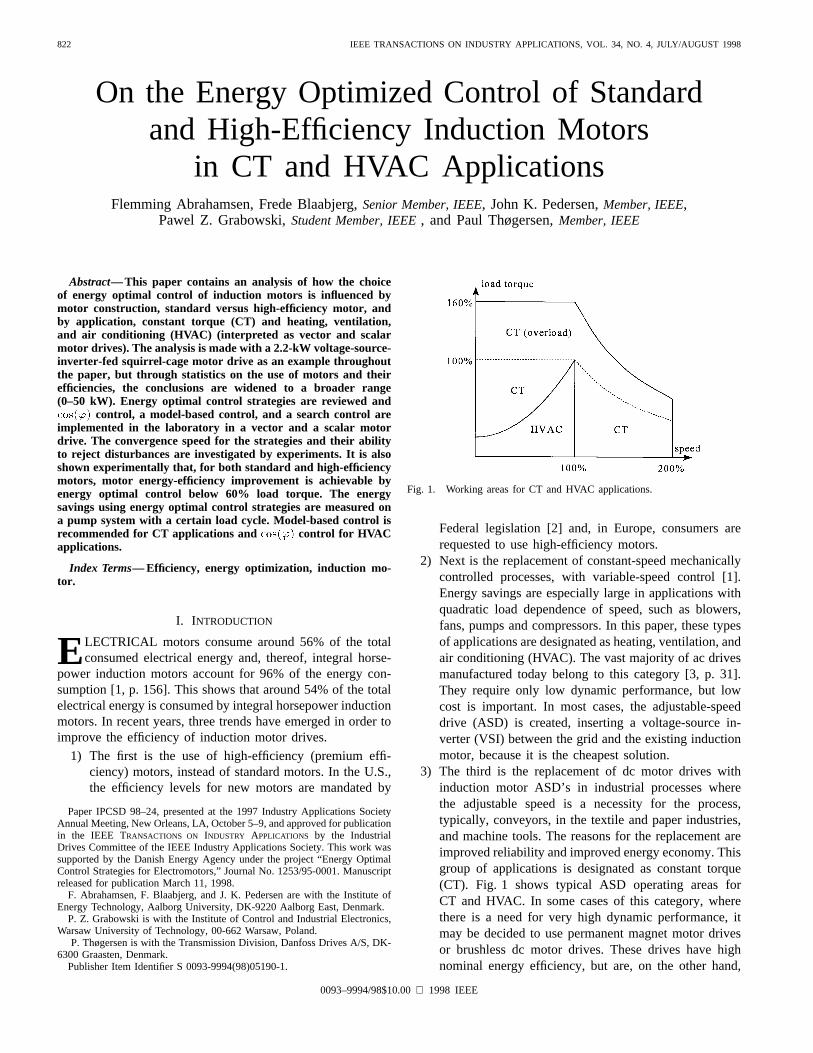
Fig. 1. Working areas for CT and HVAC applications.
Federal legislation [2] and, in Europe, consumers arerequested to use high-efficiency motors.
2) Next is the replacement of constant-speed mechanicallycontrolled processes, with variable-speed control [1].Energy savings are especially large in applications withquadratic load dependence of speed, such as blowers,fans, pumps and compressors. In this paper, these typesof applications are designated as heating, ventilation, andair conditioning (HVAC). The vast majority of ac drivesmanufactured today belong to this category [3, p. 31].They require only low dynamic performance, but lowcost is important. In most cases, the adjustable-speeddrive (ASD) is created, inserting a voltage-source in-verter (VSI) between the grid and the existing inductionmotor, because it is the cheapest solution.
3) The third is the replacement of dc motor drives withinduction motor ASD’s in industrial processes wherethe adjustable speed is a necessity for the process,typically, conveyors, in the textile and paper industries,and machine tools. The reasons for the replacement areimproved reliability and improved energy economy. Thisgroup of applications is designated as constant torque(CT). Fig. 1 shows typical ASD operating areas forCT and HVAC. In some cases of this category, wherethere is a need for very high dynamic performance, itmay be decided to use permanent magnet motor drivesor brushless dc motor drives. These drives have highnominal energy efficiency, but are, on the other hand,
0093–9994/98$10.00 1998 IEEE
ABRAHAMSEN et al.: ENERGY OPTIMIZED CONTROL OF INDUCTION MOTORS 823
more expensive than induction motor drives. In lessdemanding cases, the adjustable-speed induction motordrive will be used.
Although the induction motor has some more advanced andbetter performing competitors (involving permanent magnets),there is no doubt that, because it is cheap, rugged, andmaintenance free, it will remain the major energy consumer formany years to come. We must not forget the very importantfact that the induction motor is used in almost all electricaldrive installations today and that it will take quite a few yearsfor customers to become familiar with and start to use modernpermanent magnet motor types.
When using induction motor ASD’s, there is a furtherpossibility of reducing the drive losses by adjusting the motormagnetization level according to the motor load; this is calledenergy optimal control. Results in this area have been reportedduring the last 20 years, and a review of these was given in [4].Whereas most papers on the topic of energy optimal controlhave concentrated on one or two strategies, and optimizedthese for a given motor in a given application, the contributionof this paper is an analysis of how the choice of energyoptimized control strategy is influenced by the motor type(standard and high efficiency) and by application (CT andHVAC).
The following simplifications are made for the comparativestudy.
• Distinction is only made between a standard motor anda high-efficiency motor.
• Two types of applications are considered: 1) CT appli-cations using a vector-controlled drive and 2) HVACapplications using an open-loop scalar drive.
Statistical material on the use of induction motors is pre-sented. A brief review of energy optimal control strategiesis given, and it is then discussed which demands CT andHVAC respectively make to energy optimal control. Threecontrol strategies are selected, and the dynamics of each areinvestigated experimentally. The application of energy optimalcontrol to standard and high-efficiency motors is analyzed bothby steady-state efficiency measurements and by calculation onmotor models. The comparison of control strategies is finalizedby measuring the energy consumption with a typical HVACload cycle. Throughout the paper, results are based on a 2.2-kW induction motor drive of the standard motor. Data of thestandard motor are listed in the Appendix.
II. STATISTICS ON INDUCTION MOTORS
The work with energy savings in motor drives implies ananalysis of the use of induction motors. The intention is toconcentrate the work in a field of motor drives where most ofthe energy is used and, more importantly, where it is wasted.
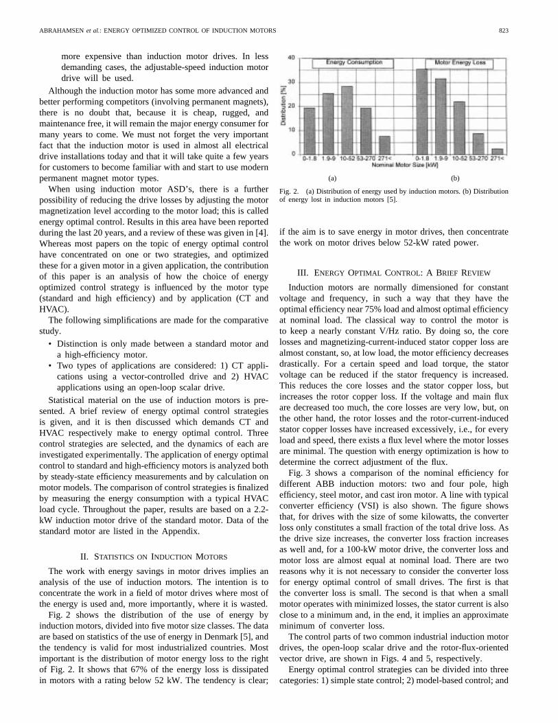
Fig. 2 shows the distribution of the use of energy byinduction motors, divided into five motor size classes. The dataare based on statistics of the use of energy in Denmark [5], andthe tendency is valid for most industrialized countries. Mostimportant is the distribution of motor energy loss to the rightof Fig. 2. It shows that 67% of the energy loss is dissipatedin motors with a rating below 52 kW. The tendency is clear;
(a) (b)
Fig. 2. (a) Distribution of energy used by induction motors. (b) Distributionof energy lost in induction motors [5].
if the aim is to save energy in motor drives, then concentratethe work on motor drives below 52-kW rated power.
III. ENERGY OPTIMAL CONTROL: A BRIEF REVIEW
Induction motors are normally dimensioned for constantvoltage and frequency, in such a way that they have theoptimal efficiency near 75% load and almost optimal efficiencyat nominal load. The classical way to control the motor isto keep a nearly constant V/Hz ratio. By doing so, the corelosses and magnetizing-current-induced stator copper loss arealmost constant, so, at low load, the motor efficiency decreasesdrastically. For a certain speed and load torque, the statorvoltage can be reduced if the stator frequency is increased.This reduces the core losses and the stator copper loss, butincreases the rotor copper loss. If the voltage and main fluxare decreased too much, the core losses are very low, but, onthe other hand, the rotor losses and the rotor-current-inducedstator copper losses have increased excessively, i.e., for everyload and speed, there exists a flux level where the motor lossesare minimal. The question with energy optimization is how todetermine the correct adjustment of the flux.
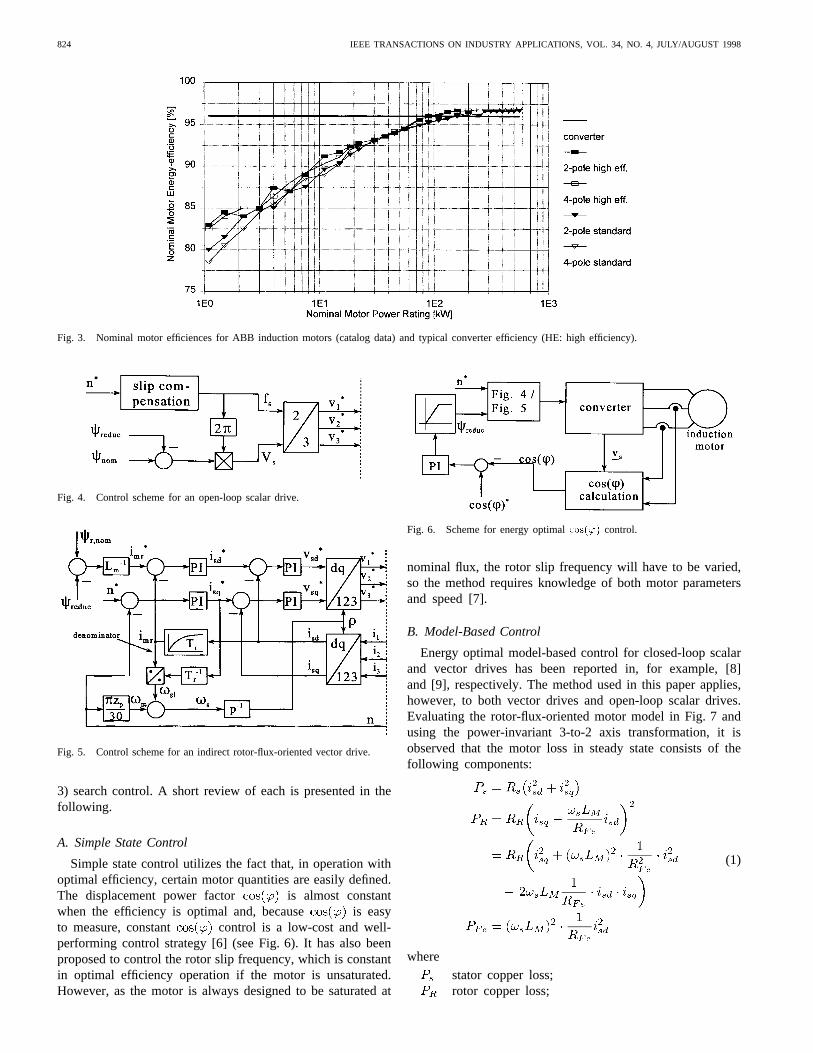
Fig. 3 shows a comparison of the nominal efficiency fordifferent ABB induction motors: two and four pole, highefficiency, steel motor, and cast iron motor. A line with typicalconverter efficiency (VSI) is also shown. The figure showsthat, for drives with the size of some kilowatts, the converterloss only constitutes a small fraction of the total drive loss. Asthe drive size increases, the converter loss fraction increasesas well and, for a 100-kW motor drive, the converter loss andmotor loss are almost equal at nominal load. There are tworeasons why it is not necessary to consider the converter lossfor energy optimal control of small drives. The first is thatthe converter loss is small. The second is that when a smallmotor operates with minimized losses, the stator current is alsoclose to a minimum and, in the end, it implies an approximateminimum of converter loss.
The control parts of two common industrial induction motordrives, the open-loop scalar drive and the rotor-flux-orientedvector drive, are shown in Figs. 4 and 5, respectively.
Energy optimal control strategies can be divided into threecategories: 1) simple state control; 2) model-based control; and
824 IEEE TRANSACTIONS ON INDUSTRY APPLICATIONS, VOL. 34, NO. 4, JULY/AUGUST 1998
Fig. 3. Nominal motor efficiences for ABB induction motors (catalog data) and typical converter efficiency (HE: high efficiency).
Fig. 4. Control scheme for an open-loop scalar drive.
Fig. 5. Control scheme for an indirect rotor-flux-oriented vector drive.
3) search control. A short review of each is presented in thefollowing.
A. Simple State Control
Simple state control utilizes the fact that, in operation withoptimal efficiency, certain motor quantities are easily defined.The displacement power factor is almost constantwhen the efficiency is optimal and, because is easyto measure, constant control is a low-cost and well-performing control strategy [6] (see Fig. 6). It has also beenproposed to control the rotor slip frequency, which is constantin optimal efficiency operation if the motor is unsaturated.However, as the motor is always designed to be saturated at
Fig. 6. Scheme for energy optimalcos(') control.
nominal flux, the rotor slip frequency will have to be varied,so the method requires knowledge of both motor parametersand speed [7].
B. Model-Based Control
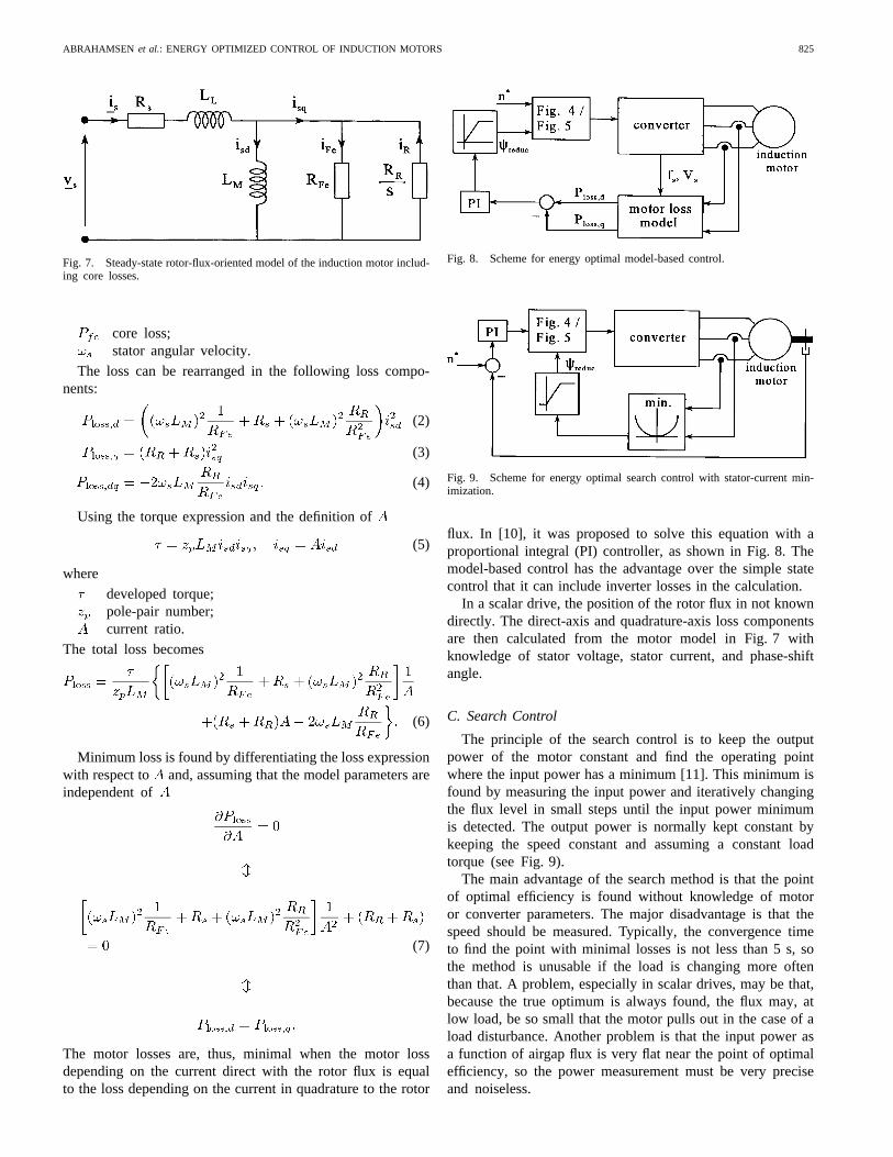
Energy optimal model-based control for closed-loop scalarand vector drives has been reported in, for example, [8]and [9], respectively. The method used in this paper applies,however, to both vector drives and open-loop scalar drives.Evaluating the rotor-flux-oriented motor model in Fig. 7 andusing the power-invariant 3-to-2 axis transformation, it isobserved that the motor loss in steady state consists of thefollowing components:
(1)
where
stator copper loss;rotor copper loss;
ABRAHAMSEN et al.: ENERGY OPTIMIZED CONTROL OF INDUCTION MOTORS 825
Fig. 7. Steady-state rotor-flux-oriented model of the induction motor includ-ing core losses.
core loss;stator angular velocity.
The loss can be rearranged in the following loss compo-nents:
(2)
(3)
(4)
Using the torque expression and the definition of
(5)
where
developed torque;pole-pair number;current ratio.
The total loss becomes
(6)
Minimum loss is found by differentiating the loss expressionwith respect to and, assuming that the model parameters areindependent of
(7)
The motor losses are, thus, minimal when the motor lossdepending on the current direct with the rotor flux is equalto the loss depending on the current in quadrature to the rotor
Fig. 8. Scheme for energy optimal model-based control.
Fig. 9. Scheme for energy optimal search control with stator-current min-imization.
flux. In [10], it was proposed to solve this equation with aproportional integral (PI) controller, as shown in Fig. 8. Themodel-based control has the advantage over the simple statecontrol that it can include inverter losses in the calculation.
In a scalar drive, the position of the rotor flux in not knowndirectly. The direct-axis and quadrature-axis loss componentsare then calculated from the motor model in Fig. 7 withknowledge of stator voltage, stator current, and phase-shiftangle.
C. Search Control
The principle of the search control is to keep the outputpower of the motor constant and find the operating pointwhere the input power has a minimum [11]. This minimum isfound by measuring the input power and iteratively changingthe flux level in small steps until the input power minimumis detected. The output power is normally kept constant bykeeping the speed constant and assuming a constant loadtorque (see Fig. 9).
The main advantage of the search method is that the pointof optimal efficiency is found without knowledge of motoror converter parameters. The major disadvantage is that thespeed should be measured. Typically, the convergence timeto find the point with minimal losses is not less than 5 s, sothe method is unusable if the load is changing more oftenthan that. A problem, especially in scalar drives, may be that,because the true optimum is always found, the flux may, atlow load, be so small that the motor pulls out in the case of aload disturbance. Another problem is that the input power asa function of airgap flux is very flat near the point of optimalefficiency, so the power measurement must be very preciseand noiseless.
826 IEEE TRANSACTIONS ON INDUSTRY APPLICATIONS, VOL. 34, NO. 4, JULY/AUGUST 1998
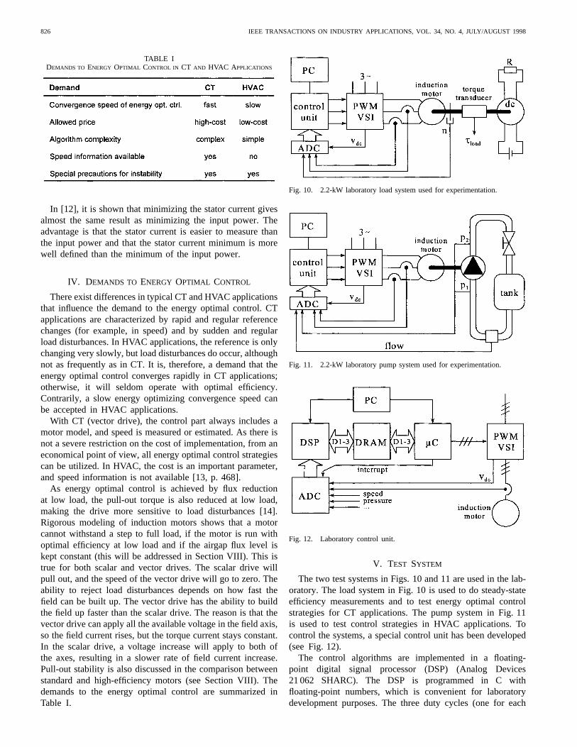
TABLE IDEMANDS TO ENERGY OPTIMAL CONTROL IN CT AND HVAC A PPLICATIONS
In [12], it is shown that minimizing the stator current givesalmost the same result as minimizing the input power. Theadvantage is that the stator current is easier to measure thanthe input power and that the stator current minimum is morewell defined than the minimum of the input power.
IV. DEMANDS TO ENERGY OPTIMAL CONTROL
There exist differences in typical CT and HVAC applicationsthat influence the demand to the energy optimal control. CTapplications are characterized by rapid and regular referencechanges (for example, in speed) and by sudden and regularload disturbances. In HVAC applications, the reference is onlychanging very slowly, but load disturbances do occur, althoughnot as frequently as in CT. It is, therefore, a demand that theenergy optimal control converges rapidly in CT applications;otherwise, it will seldom operate with optimal efficiency.Contrarily, a slow energy optimizing convergence speed canbe accepted in HVAC applications.
With CT (vector drive), the control part always includes amotor model, and speed is measured or estimated. As there isnot a severe restriction on the cost of implementation, from aneconomical point of view, all energy optimal control strategiescan be utilized. In HVAC, the cost is an important parameter,and speed information is not available [13, p. 468].
As energy optimal control is achieved by flux reductionat low load, the pull-out torque is also reduced at low load,making the drive more sensitive to load disturbances [14].Rigorous modeling of induction motors shows that a motorcannot withstand a step to full load, if the motor is run withoptimal efficiency at low load and if the airgap flux level iskept constant (this will be addressed in Section VIII). This istrue for both scalar and vector drives. The scalar drive willpull out, and the speed of the vector drive will go to zero. Theability to reject load disturbances depends on how fast thefield can be built up. The vector drive has the ability to buildthe field up faster than the scalar drive. The reason is that thevector drive can apply all the available voltage in the field axis,so the field current rises, but the torque current stays constant.In the scalar drive, a voltage increase will apply to both ofthe axes, resulting in a slower rate of field current increase.Pull-out stability is also discussed in the comparison betweenstandard and high-efficiency motors (see Section VIII). Thedemands to the energy optimal control are summarized inTable I.
Fig. 10. 2.2-kW laboratory load system used for experimentation.
Fig. 11. 2.2-kW laboratory pump system used for experimentation.
Fig. 12. Laboratory control unit.
V. TEST SYSTEM
The two test systems in Figs. 10 and 11 are used in the lab-oratory. The load system in Fig. 10 is used to do steady-stateefficiency measurements and to test energy optimal controlstrategies for CT applications. The pump system in Fig. 11is used to test control strategies in HVAC applications. Tocontrol the systems, a special control unit has been developed(see Fig. 12).
The control algorithms are implemented in a floating-point digital signal processor (DSP) (Analog Devices21 062 SHARC). The DSP is programmed in C withfloating-point numbers, which is convenient for laboratorydevelopment purposes. The three duty cycles (one for each
ABRAHAMSEN et al.: ENERGY OPTIMIZED CONTROL OF INDUCTION MOTORS 827
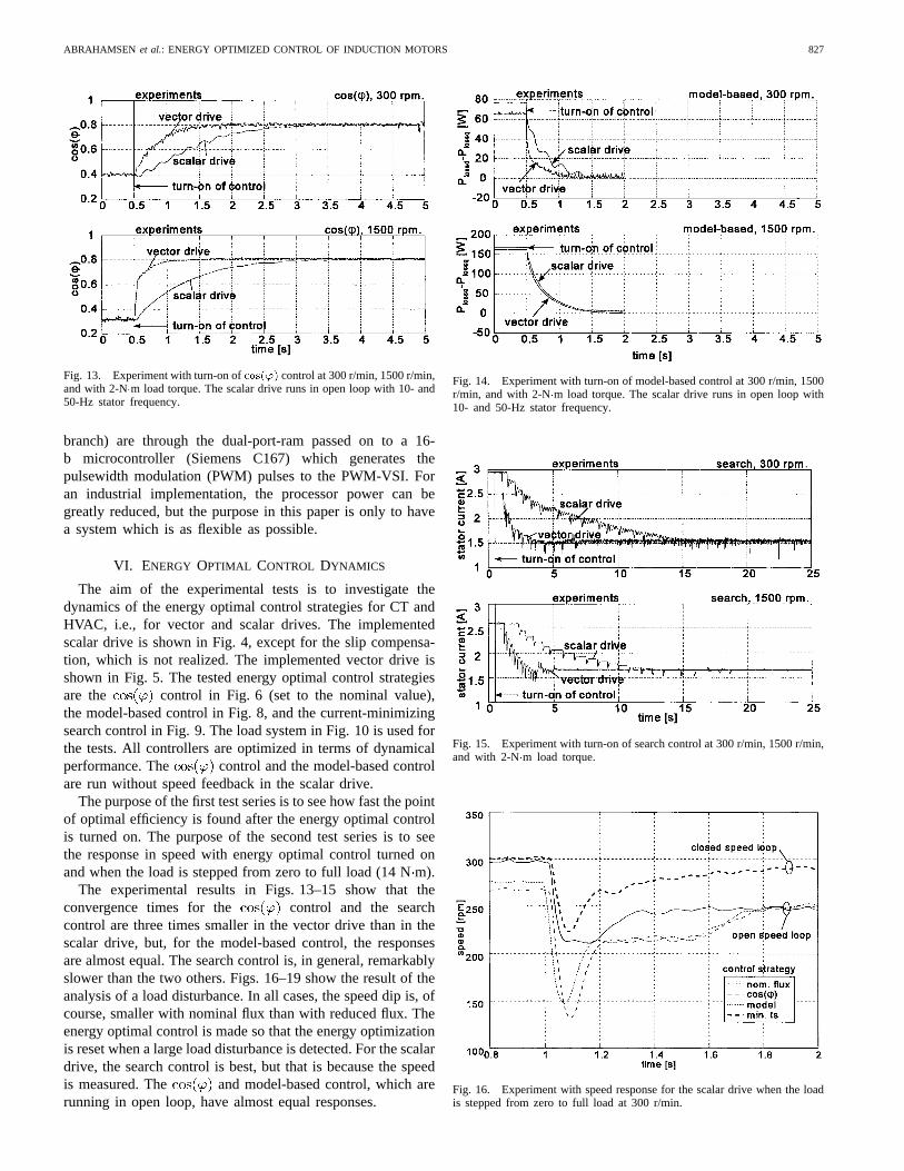
Fig. 13. Experiment with turn-on ofcos(') control at 300 r/min, 1500 r/min,and with 2-N�m load torque. The scalar drive runs in open loop with 10- and50-Hz stator frequency.
branch) are through the dual-port-ram passed on to a 16-b microcontroller (Siemens C167) which generates thepulsewidth modulation (PWM) pulses to the PWM-VSI. Foran industrial implementation, the processor power can begreatly reduced, but the purpose in this paper is only to havea system which is as flexible as possible.
VI. ENERGY OPTIMAL CONTROL DYNAMICS
The aim of the experimental tests is to investigate thedynamics of the energy optimal control strategies for CT andHVAC, i.e., for vector and scalar drives. The implementedscalar drive is shown in Fig. 4, except for the slip compensa-tion, which is not realized. The implemented vector drive isshown in Fig. 5. The tested energy optimal control strategiesare the control in Fig. 6 (set to the nominal value),the model-based control in Fig. 8, and the current-minimizingsearch control in Fig. 9. The load system in Fig. 10 is used forthe tests. All controllers are optimized in terms of dynamicalperformance. The control and the model-based controlare run without speed feedback in the scalar drive.
The purpose of the first test series is to see how fast the pointof optimal efficiency is found after the energy optimal controlis turned on. The purpose of the second test series is to seethe response in speed with energy optimal control turned onand when the load is stepped from zero to full load (14 Nm).
The experimental results in Figs. 13–15 show that theconvergence times for the control and the searchcontrol are three times smaller in the vector drive than in thescalar drive, but, for the model-based control, the responsesare almost equal. The search control is, in general, remarkablyslower than the two others. Figs. 16–19 show the result of theanalysis of a load disturbance. In all cases, the speed dip is, ofcourse, smaller with nominal flux than with reduced flux. Theenergy optimal control is made so that the energy optimizationis reset when a large load disturbance is detected. For the scalardrive, the search control is best, but that is because the speedis measured. The and model-based control, which arerunning in open loop, have almost equal responses.
Fig. 14. Experiment with turn-on of model-based control at 300 r/min, 1500r/min, and with 2-N�m load torque. The scalar drive runs in open loop with10- and 50-Hz stator frequency.
Fig. 15. Experiment with turn-on of search control at 300 r/min, 1500 r/min,and with 2-N�m load torque.
Fig. 16. Experiment with speed response for the scalar drive when the loadis stepped from zero to full load at 300 r/min.
828 IEEE TRANSACTIONS ON INDUSTRY APPLICATIONS, VOL. 34, NO. 4, JULY/AUGUST 1998
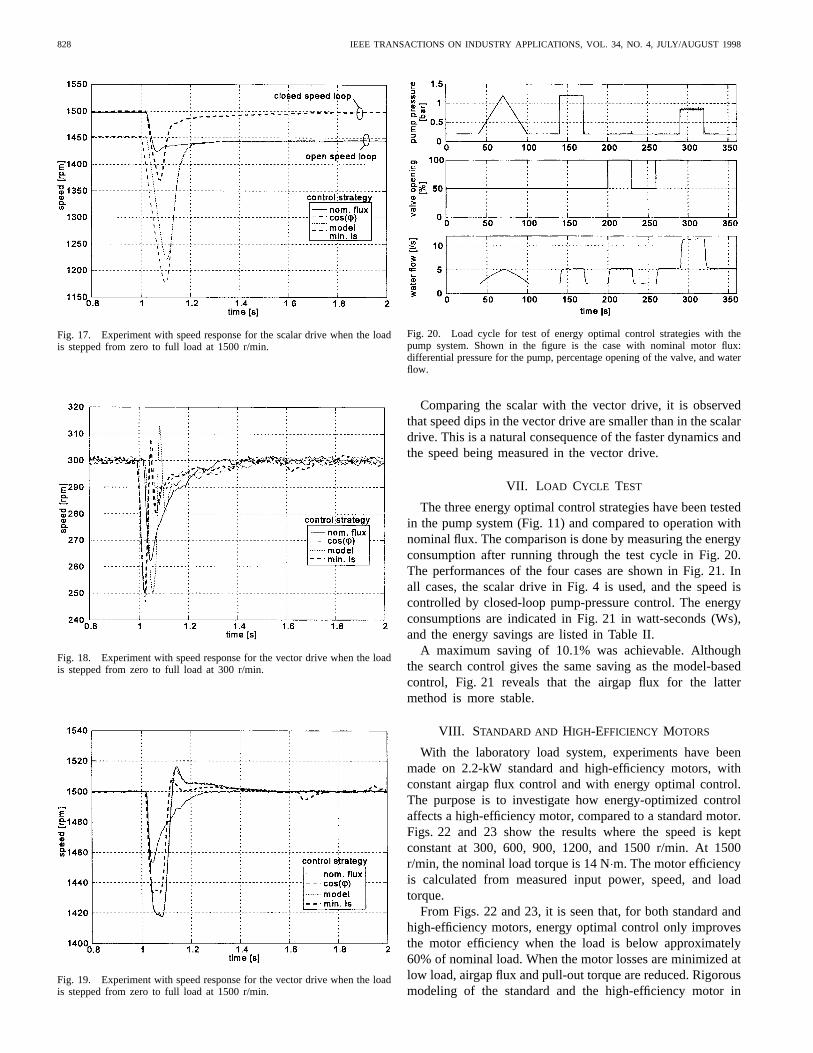
Fig. 17. Experiment with speed response for the scalar drive when the loadis stepped from zero to full load at 1500 r/min.
Fig. 18. Experiment with speed response for the vector drive when the loadis stepped from zero to full load at 300 r/min.
Fig. 19. Experiment with speed response for the vector drive when the loadis stepped from zero to full load at 1500 r/min.
Fig. 20. Load cycle for test of energy optimal control strategies with thepump system. Shown in the figure is the case with nominal motor flux:differential pressure for the pump, percentage opening of the valve, and waterflow.
Comparing the scalar with the vector drive, it is observedthat speed dips in the vector drive are smaller than in the scalardrive. This is a natural consequence of the faster dynamics andthe speed being measured in the vector drive.
VII. L OAD CYCLE TEST
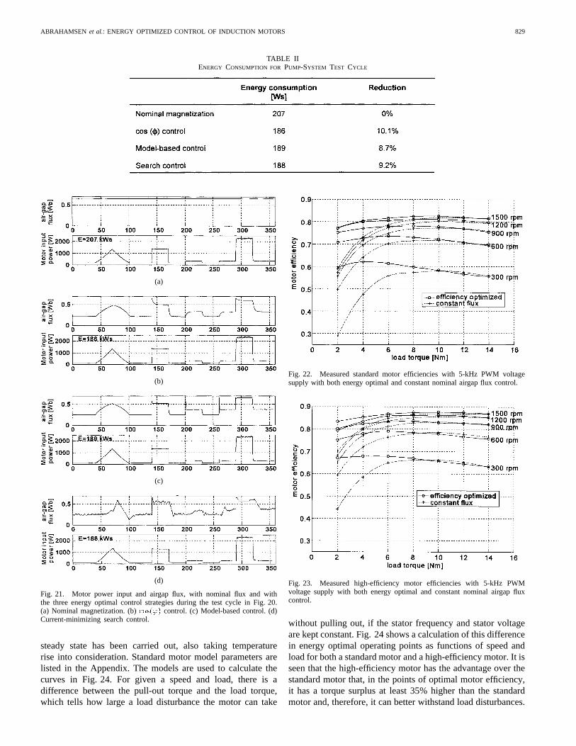
The three energy optimal control strategies have been testedin the pump system (Fig. 11) and compared to operation withnominal flux. The comparison is done by measuring the energyconsumption after running through the test cycle in Fig. 20.The performances of the four cases are shown in Fig. 21. Inall cases, the scalar drive in Fig. 4 is used, and the speed iscontrolled by closed-loop pump-pressure control. The energyconsumptions are indicated in Fig. 21 in watt-seconds (Ws),and the energy savings are listed in Table II.
A maximum saving of 10.1% was achievable. Althoughthe search control gives the same saving as the model-basedcontrol, Fig. 21 reveals that the airgap flux for the lattermethod is more stable.
VIII. STANDARD AND HIGH-EFFICIENCY MOTORS
With the laboratory load system, experiments have beenmade on 2.2-kW standard and high-efficiency motors, withconstant airgap flux control and with energy optimal control.The purpose is to investigate how energy-optimized controlaffects a high-efficiency motor, compared to a standard motor.Figs. 22 and 23 show the results where the speed is keptconstant at 300, 600, 900, 1200, and 1500 r/min. At 1500r/min, the nominal load torque is 14 Nm. The motor efficiencyis calculated from measured input power, speed, and loadtorque.
From Figs. 22 and 23, it is seen that, for both standard andhigh-efficiency motors, energy optimal control only improvesthe motor efficiency when the load is below approximately60% of nominal load. When the motor losses are minimized atlow load, airgap flux and pull-out torque are reduced. Rigorousmodeling of the standard and the high-efficiency motor in
ABRAHAMSEN et al.: ENERGY OPTIMIZED CONTROL OF INDUCTION MOTORS 829
TABLE IIENERGY CONSUMPTION FOR PUMP-SYSTEM TEST CYCLE
(a)
(b)
(c)
(d)
Fig. 21. Motor power input and airgap flux, with nominal flux and withthe three energy optimal control strategies during the test cycle in Fig. 20.(a) Nominal magnetization. (b)cos(') control. (c) Model-based control. (d)Current-minimizing search control.
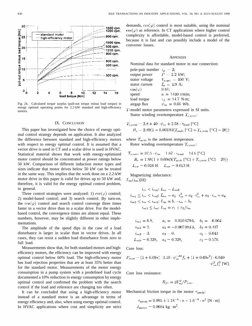
steady state has been carried out, also taking temperaturerise into consideration. Standard motor model parameters arelisted in the Appendix. The models are used to calculate thecurves in Fig. 24. For given a speed and load, there is adifference between the pull-out torque and the load torque,which tells how large a load disturbance the motor can take
Fig. 22. Measured standard motor efficiencies with 5-kHz PWM voltagesupply with both energy optimal and constant nominal airgap flux control.
Fig. 23. Measured high-efficiency motor efficiencies with 5-kHz PWMvoltage supply with both energy optimal and constant nominal airgap fluxcontrol.
without pulling out, if the stator frequency and stator voltageare kept constant. Fig. 24 shows a calculation of this differencein energy optimal operating points as functions of speed andload for both a standard motor and a high-efficiency motor. It isseen that the high-efficiency motor has the advantage over thestandard motor that, in the points of optimal motor efficiency,it has a torque surplus at least 35% higher than the standardmotor and, therefore, it can better withstand load disturbances.
830 IEEE TRANSACTIONS ON INDUSTRY APPLICATIONS, VOL. 34, NO. 4, JULY/AUGUST 1998
Fig. 24. Calculated torque surplus (pull-out torque minus load torque) inenergy optimal operating points for 2.2-kW standard and high-efficiencymotors.
IX. CONCLUSION
This paper has investigated how the choice of energy opti-mal control strategy depends on application. It also analyzedthe difference between standard and high-efficiency motorswith respect to energy optimal control. It is assumed that avector drive is used in CT and a scalar drive is used in HVAC.Statistical material shows that work with energy-optimizedmotor control should be concentrated at power ratings below50 kW. Comparison of different induction motor types andsizes indicate that motor drives below 50 kW can be treatedin the same way. This implies that the work done on a 2.2-kWmotor drive in this paper is valid for drives up to 50 kW and,therefore, it is valid for the energy optimal control problem,in general.
Three control strategies were analyzed: 1) control;2) model-based control; and 3) search control. By turn-on,the control and search control converge three timesfaster in a vector drive than in a scalar drive. For the model-based control, the convergence times are almost equal. Thesenumbers, however, may be slightly different in other imple-mentations.
The amplitude of the speed dips in the case of a loaddisturbance is larger in scalar than in vector drives. In allcases, they can resist a sudden load disturbance from zero tofull load.
Measurements show that, for both standard motors and high-efficiency motors, the efficiency can be improved with energyoptimal control below 60% load. The high-efficiency motorhas load rejection properties that are at least 35% better thanfor the standard motor. Measurements of the motor energyconsumption in a pump system with a predefined load cycledocumented a 10% reduction in energy consumption by energyoptimal control and confirmed the problem with the searchcontrol if the load and reference are changing too often.
It can be concluded that using a high-efficiency motorinstead of a standard motor is an advantage in terms ofenergy efficiency and, also, when using energy optimal control.In HVAC applications where cost and simplicity are strict
demands, control is most suitable, using the nominalas reference. In CT applications where higher control
complexity is affordable, model-based control is preferred,because it is fast and can possibly include a model of theconverter losses.
APPENDIX
Nominal data for standard motor in star connection:
pole-pair number ;output power kW;stator voltage V;stator current A;
;speed r/min;load torque N m;airgap flux Wb.
-model motor parameters expressed in SI units.Stator winding overtemperature :
[ C]
[ C] [ C]
where is the ambient temperature.Rotor winding overtemperature :
[ C]
[ C] [ C]
H H
Magnetizing inductance:[H]
Core loss:
[W].
Core loss resistance:
Mechanical friction torque in the motor :
[N m]
kg m
ABRAHAMSEN et al.: ENERGY OPTIMIZED CONTROL OF INDUCTION MOTORS 831
REFERENCES
[1] S. Nadel, M. Shepard, S. Greenberg, G. Katz, and A. T. de Almeida,Energy-Efficient Motor Systems, American Council for an Energy-Efficient Economy, Washington, DC, 1992, pp. 164–165.
[2] R. J. Lawrie, “Premium-efficiency motors: Soon they’ll be law,”Elect.Construction Maintenance, vol. 95, no. 7, pp. 32–38, July 1996.
[3] D. W. Novotny and T. A. Lipo,Vector Control and Dynamics of ACDrives. Oxford, U.K.: Clarendon, 1996.
[4] F. Abrahamsen, J. K. Pedersen, and F. Blaabjerg, “State-of-the-art ofoptimal efficiency control of low-cost induction motor drives,” inProc.PEMC’96, Budapest, Hungary, Sept. 1996, vol. 2, pp. 2/163–2/170.
[5] “Technical report 352,” DEFU, Lyngby, Denmark, 1995.[6] H. R. Andersen and J. K. Pedersen, “Low cost optimized control
strategy for a variable speed three phase induction motor,” inConf.Rec. PESC’96, 1996, vol. 1, pp. 920–924.
[7] H. G. Kim, S. K. Sul, and M. H. Park, “Optimal efficiency drive ofa current source inverter fed induction motor by flux control,”IEEETrans. Ind. Applicat., vol. IA-20, pp. 1453–1459, Nov./Dec. 1984.
[8] A. Kusko and D. Galler, “Control means for minimization of losses inAC and DC motor drives,”IEEE Trans. Ind. Applicat., vol. IA-19, pp.561–570, July/Aug. 1983.
[9] G. O. Garcia, J. C. Mendes Lu´ıs, R. M. Stephan, and E. H. Watanabe,“An efficient controller for an adjustable speed induction motor drive,”IEEE Trans. Ind. Electron., vol. 41, pp. 533–539, Oct. 1994.
[10] K. S. Rasmussen and P. Thøgersen, “Model based energy optimizer forvector controlled induction motor drives,” inProc. EPE’97, Trondheim,Norway, Sept. 1997, pp. 3.711–3.716.
[11] D. S. Kirschen, D. W. Novotny, and T. A. Lipo, “On-line efficiencyoptimization of a variable frequency induction motor drive,”IEEETrans. Ind. Applicat., vol. IA-21, pp. 610–616, May/June 1985.
[12] I. Kioskeridis and N. Margaris, “Loss minimization in scalar-controlledinduction motor drives with search controllers,”IEEE Trans. PowerElectron., vol. 11, pp. 213–220, Mar. 1996.
[13] M. P. Kazmierkowski and H. Tunia,Automatic Control of Converter-FedDrives. Amsterdam, The Netherlands: Elsevier, 1994.
[14] F. Abrahamsen, F. Blaabjerg, and J. K. Pedersen, “Analysis of sta-bility in low-cost energy optimal controlled PWM-VSI fed inductionmotor drive,” in Proc. EPE’97, Trondheim, Norway, Sept. 1997, pp.3.717–3.723.
Flemming Abrahamsen was born in Nexoe, Den-mark, in 1969. He received the M.Sc.E.E. degree in1994 from Aalborg University, Aalborg, Denmark,where he is currently working towards the Ph.D.degree in energy optimal control of electrical ma-chines.
He was with Electricit́e de France, Paris, France,for a short period in 1995. In 1995, he became aTeaching Assistant at Aalborg University, where,later that year, he became a Research Assistant. Hisresearch areas include power electronics and control
of electrical motors and converters connected to a grid.
Frede Blaabjerg (S’86–M’88–SM’97) was bornin Erslev, Denmark, in 1963. He received theM.Sc.E.E. degree from Aalborg University,Aalborg, Denmark, in 1987 and the Ph.D. degreefrom the Institute of Energy Technology, AalborgUniversity, in 1995.
He was with ABB-Scandia, Randers, Denmark,from 1987 to 1988. In 1992, he became an AssistantProfessor at Aalborg University, where, in 1996, hebecame an Associate Professor. His research areasinclude power electronics, static power converters,
ac drives, switched reluctance drives, modeling, characterization of powersemiconductor devices, and simulation. He is a member of the board of theDanish Technical Research Council.
Dr. Blaabjerg is a member of the European Power Electronics andDrives Association and the Industrial Drives and Industrial Power ConverterCommittees of the IEEE Industry Applications Society. He received the 1995Angelos Award for his contribution in the areas of modulation techniqueand control of electric drives and the Annual Teacher Prize from AalborgUniversity.
John K. Pedersen(M’92) was born in Holstebro,Denmark, in 1959. He received the B.Sc.E.E. degreefrom Aalborg University, Aalborg, Denmark.
He joined the Institute of Energy Technology,Aalborg University, as a Teaching Assistant in 1983.He was an Assistant Professor from 1984 to 1989and has been an Associate Professor since 1989.He is currently the Head of the Institute of En-ergy Technology. His research areas include powerelectronics, power converters, and electrical drivesystems, including modeling, simulation, and de-
sign, with a focus on optimized efficiency.Mr. Pedersen received the 1992 Angelos Award for his contribution in the
area of control of induction machines.
Pawel Z. Grabowski (S’94) was born in Warsaw,Poland, in 1970. He received the M.Sc.E.E. degreein 1994 from Warsaw University of Technology,Warsaw, Poland, where he is currently workingtowards the Ph.D. degree.
His research areas are control systems, intelligentcontrol methods, DSP implementations, power elec-tronics, ac drives, and simulation.
Mr. Grabowski is a Student Member of the IEEEIndustry Applications Society. He received the 1994SEP Award for his M.Sc.E.E. thesis.
Paul Thøgersen(M’92) was born in Thy, Denmark,in 1959. He received the M.Sc.E.E. degree fromAalborg University, Aalborg, Denmark, in 1984and the Ph.D. degree from the Institute of EnergyTechnology, Aalborg University, in 1989.
He was an Assistant Professor at Aalborg Uni-versity from 1988 to 1991. Since 1991, he has beenwith the Transmission Division, Danfoss DrivesA/S, Graasten, Denmark, as a Research and Devel-opment Engineer. His research areas include fre-quency converters and control and simulation of acdrives.
Dr. Thøgersen is a member of the European Power Electronics and DrivesAssociation and the IEEE Industry Applications, IEEE Power Electronics,and IEEE Industrial Electronics Societies.


