Embed Size (px)
Citation preview
ONNYX ATCS SOLUTION
Technical Description of the proposed system along with System Architecture, Design, Frontend and Backend applications, Database, Reporting tools, Monitoring and Diagnostics functions of the proposed Solution
We are Technology partner of CDAC (A scientific Society of the Ministry of Communications and Information Technology Government of India) for Vehicle Actuated Wireless Traffic Control System (WiTrac),Traffic Signal Monitoring and Management Software (TraMM), WiTraC compatible Adaptive Traffic Control System (CoSiCoSt-W) Developed under the funding from Ministry of Electronics & Information Technology (MeitY) Govt. of India. We are proposing the same for implementation of Adaptive Traffic Signal System to be installed.
Vehicle Actuated Traffic Control System,
composite signal control strategy Software –CoSiCoSt-W
Traffic Signal Monitoring & Management Software TraMM
Area Traffic Control System is an indigenous solution for Indian Road Traffic, which optimizes traffic signal, covering a set of roads for an area in a city. It is an intelligent traffic signal control system that use data from vehicle detectors and optimize traffic signal settings in an area to reduce vehicle delays and stops. The control system operates in real time with a capacity to calculate optimal cycle time, and feeds input to traffic signal controllers with a different set of stage timings. The timing plan of traffic controllers changed automatically to reduce stoppage time, which in turn reduces overall journey time. The road traffic controllers can be connected to ATCS server thru’ network. Thus traffic monitoring over an area can be made possible from a central location. The system facilitates storing of traffic data for individual junctions over a period of days, including traffic pattern during peak hours, which enables traffic engineers to view and analyzing the same. The original technology on ATCS was developed by Centre for Development of Advanced Computing (CDAC, Thiruvananthapuram), ONNYX is manufacturing the same and have supplied more than 200 controllers all over INDIA. The system supplied so far is working satisfactorily at different environmental condition and hence filed proven.
ATCS overview The Major building blocks of the Area Traffic Control System are following:- • Traffic Signal Controller (WiTraC Master & Slave) • Vehicle Detectors (Virtual-Camera Based) • Communication Network through lease lines. • Central Control System • ATCS application software (CoSiCoSt-W & TraMM) Traffic Signal Controllers (Master & Slave) are the electronic equipment kept at the junction to control duration of traffic signals. The controllers are designed using microprocessor based control circuits, and can be operated with Fixed Time mode, Demand Actuated Mode, Forced Flash Mode etc. The function of the Vehicle Detector is to identify the presence or passage of vehicles and provide input for traffic actuated signal control systems. Different type of vehicle detectors such as ultrasonic, microwave radar, magnetometer detector etc. is currently available. The most popular is Virtual Camera based. The communication network is the intermediate part which helps to communicate between the central control station and remote end junction controller. After analyzing the overall traffic flow in a corridor or a in a city the central control station updates the time plan to each and every junction controller through this Suitable Internet Protocol based network communication link. The Central control system (ICOMC) consists of ATCS Server, Operator Consoles, external storage device, projection system etc. All traffic signal controllers are connected to the ICOMC over line network at 1mbps. The Network Control Strategy Almost all the network solutions available for the ATCS are mathematical models. ATCS use a composite signal control strategy, CoSiCoSt, which is a hybrid of heuristic and mathematical approach.
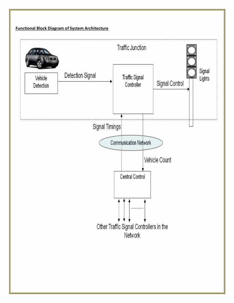
Functional Block Diagram of System Architecture
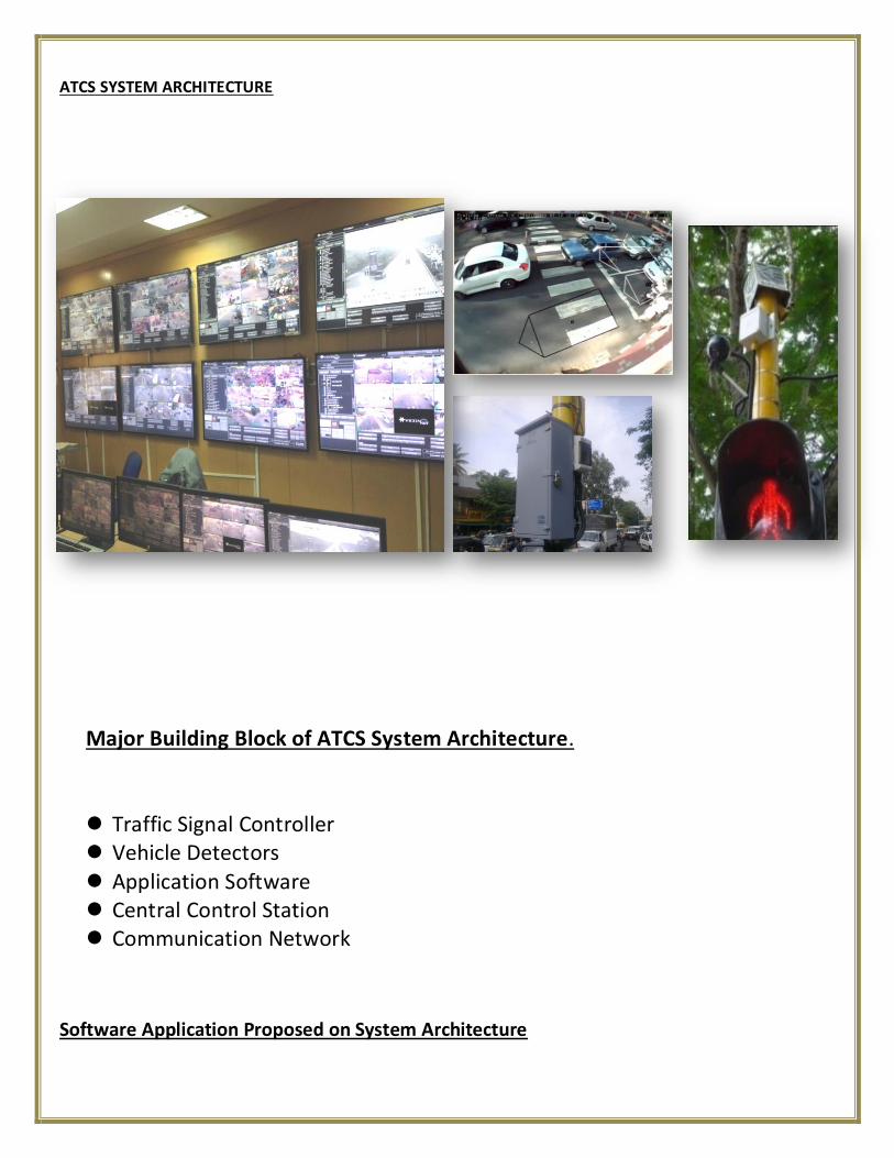
ATCS SYSTEM ARCHITECTURE
Major Building Block of ATCS System Architecture.
Traffic Signal Controller Vehicle Detectors
Application Software Central Control Station Communication Network
Software Application Proposed on System Architecture
Traffic Signal Monitoring and Management Software
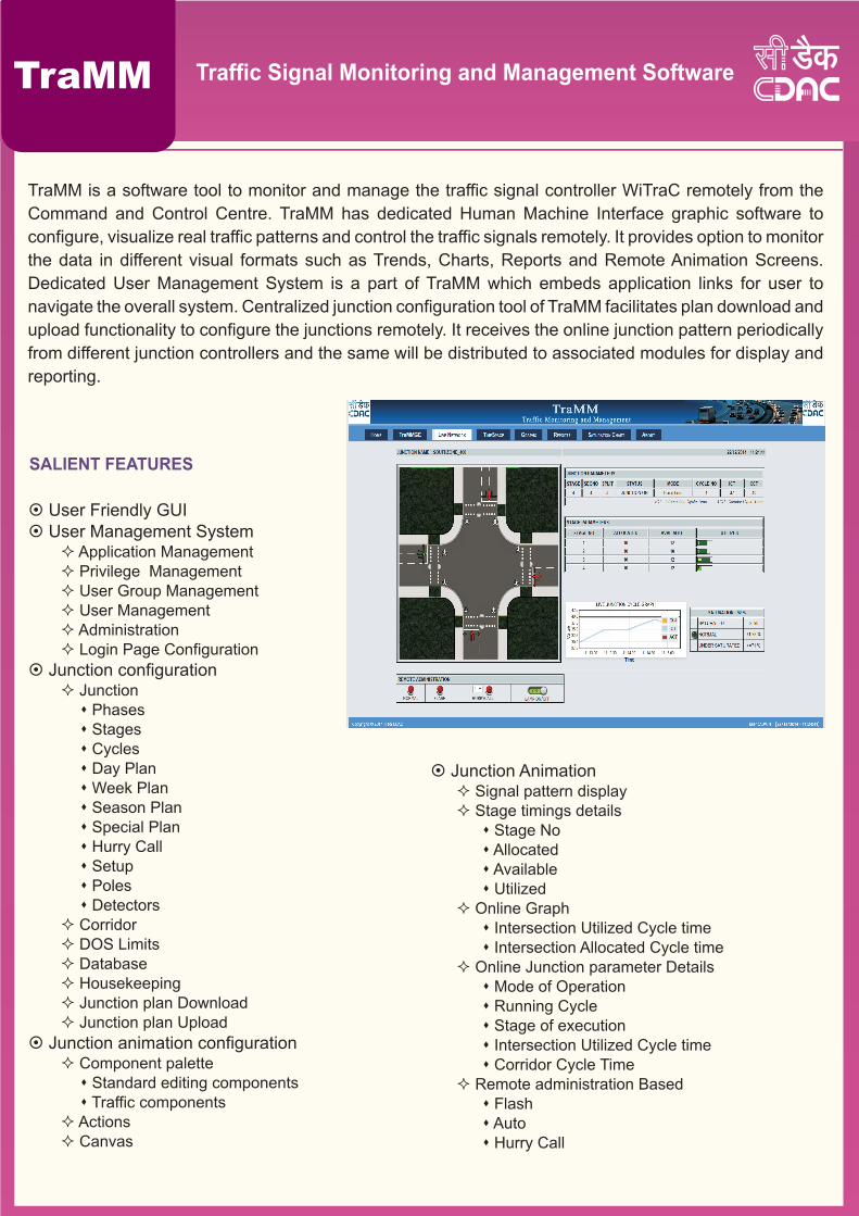
TraMM is a software tool to monitor and manage the traffic signal controller WiTraC remotely from the
Command and Control Centre. TraMM has dedicated Human Machine Interface graphic software to
configure, visualize real traffic patterns and control the traffic signals remotely. It provides option to monitor
the data in different visual formats such as Trends, Charts, Reports and Remote Animation Screens.
Dedicated User Management System is a part of TraMM which embeds application links for user to
navigate the overall system. Centralized junction configuration tool of TraMM facilitates plan download and
upload functionality to configure the junctions remotely. It receives the online junction pattern periodically
from different junction controllers and the same will be distributed to associated modules for display and
reporting.
TraMM
SALIENT FEATURES
¤ User Friendly GUI¤ User Management System
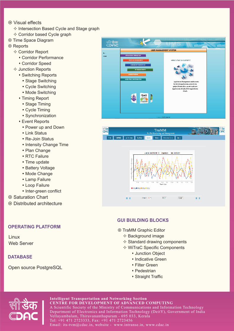
² Application Management ² Privilege Management ² User Group Management ² User Management ² Administration² Login Page Configuration
¤ Junction configuration ² Junctions Phasess Stagess Cycless Day Plans Week Plans Season Plans Special Plans Hurry Calls Setups Poless Detectors
² Corridor² DOS Limits² Database² Housekeeping ² Junction plan Download² Junction plan Upload
¤ Junction animation configuration ² Component palette s Standard editing componentss Traffic components
² Actions² Canvas
¤ Junction Animation ² Signal pattern display² Stage timings detailss Stage Nos Allocated s Available s Utilized
² Online Graphs Intersection Utilized Cycle time s Intersection Allocated Cycle time
² Online Junction parameter Details s Mode of Operations Running Cycles Stage of executions Intersection Utilized Cycle times Corridor Cycle Time
² Remote administration Based s Flash s Auto s Hurry Call
Intelligent Transportation and Networking SectionCENTRE FOR DEVELOPMENT OF ADVANCED COMPUTINGA Scientific Society of the Ministry of Communications and Information TechnologyDepartment of Electronics and Information Technology (DeitY), Government of IndiaVellayambalam, Thiruvananthapuram - 695 033, KeralaTel: +91 471 2723333, Fax: +91 471 2723456Email: [email protected], website - www.intranse.in, www.cdac.in
¤ Visual effects
² Intersection Based Cycle and Stage graph
² Corridor based Cycle graph
¤ Time Space Diagram
¤ Reports
² Corridor Report
s Corridor Performance
s Corridor Speed
² Junction Reports
s Switching Reports
? Stage Switching
? Cycle Switching
? Mode Switching
s Timing Report
? Stage Timing
? Cycle Timing
? Synchronization
s Event Reports
? Power up and Down
? Link Status
? Re-Join Status
? Intensity Change Time
? Plan Change
? RTC Failure
? Time update
? Battery Voltage
? Mode Change
? Lamp Failure
? Loop Failure
? Inter-green conflict
¤ Saturation Chart
¤ Distributed architecture
OPERATING PLATFORM
DATABASE
GUI BUILDING BLOCKS
¤ TraMM Graphic Editor
² Background image
² Standard drawing components
² WiTraC Specific Components
s Junction Object
s Indicative Green
s Filter Green
s Pedestrian
s Straight Traffic
Linux
Web Server
Open source PostgreSQL
WiTraC Compatible Adaptive Traffic Control System
Adaptive traffic control systems (ATCS) that respond to changes in traffic patterns in real-time belong to the
latest generation of signalized intersection control. They continuously detect vehicular traffic volume,
compute "optimal" signal timings based on this detected volume and simultaneously implement them at the
traffic junctions. Reacting to these volume variations generally results in reduced delays, shorter queues
and decreased travel times. In Adaptive Traffic Control Systems, the traffic signals in a particular area are
coordinated in such a way that an objective function is optimized. The Composite Signal Control Strategy
(CoSiCoSt) developed by CDAC Thiruvananthapuram optimizes a weighted combination of delay and
number of stops in real-time. CoSiCoSt is designed to cater to the typical Indian driving and traffic
conditions such as poor lane discipline and high heterogeneity. CoSiCoSt bears an Indian Patent (No:
239258 Title: A Method for Synchronizing Heterogeneous Road Traffic and System thereof) jointly owned
by the Department of Electronics and Information Technology (DeitY) and CDAC.
WiTraC is a state-of-the-art Vehicle Actuated
Wireless Traffic Control System developed by
CDAC under the DeitY funded ITS Program.
CoSiCoSt-W has custom interface to the WiTraC
and has many improved features for real-time
signal coordination in vehicle actuated mode of
signal operation.
CoSiCoSt-W
SALIENT FEATURES
BENEFITS
¤ Distributed system
² High Scalability
² Isolated VA – Coordinated - ATCS
¤ Good Congestion Management
¤ Fallback Mode
² Vehicle Actuated
¤ Model based
² Time generated
¤ Signal time computation
² Queue Exhaustion Method
¤ Subtract Mode Transition
² Quick Offset Correction
¤ Plan transition and breakpoints
² Based on degree of saturation
¤ Automatic swapping of reference junction
¤ Easy Configuration
¤ Self calibrating
¤ Exhaustive logs and reports
¤ Increase
² Lane carrying capacity
² Travel speeds
¤ Reduction
² Delay, Stops, Queue
² Fuel consumption and emissions
² Accident rate
¤ Traffic Management
² Signal Prioritizing
² Green Wave Routes
¤ Special events
² Diversions
² Incident Detection
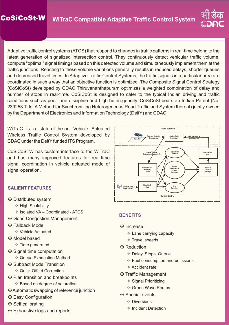
Detector
Traffic Junction
Central Control
Average DetectorOccupancy
New Timings &Preferences
Online SplitOptimizer
Stage Timing,Saturation, Speed info
TranslationPlan
Current CoSiCoStTimings
Split TimeModifier
RouteSelection &
OffesetOptimizer
PerformanceIndex (PI)/
Offset
Weights &BiasPreferences
ObservationsArea
Optimizer
Intelligent Transportation and Networking SectionCENTRE FOR DEVELOPMENT OF ADVANCED COMPUTINGA Scientific Society of the Ministry of Communications and Information TechnologyDepartment of Electronics and Information Technology (DeitY), Government of IndiaVellayambalam, Thiruvananthapuram - 695 033, KeralaTel: +91 471 2723333, Fax: +91 471 2723456Email: [email protected], website - www.intranse.in, www.cdac.in
CoSiCoSt-W OPERATION
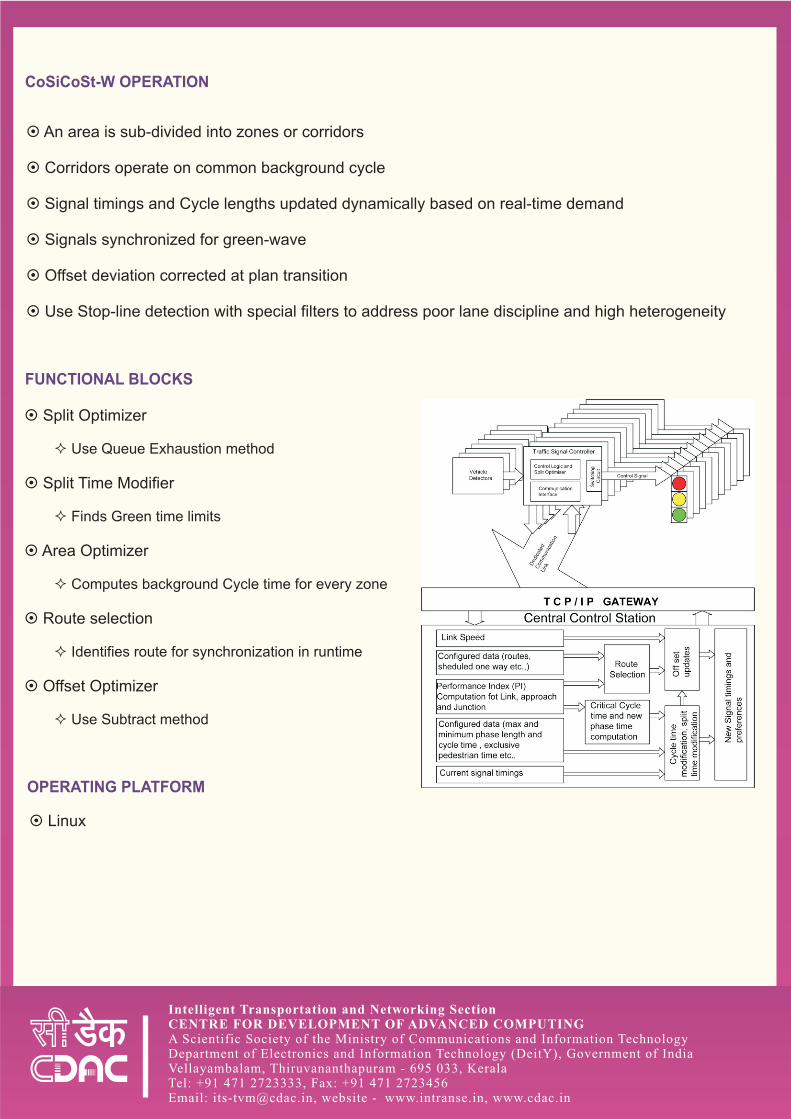
FUNCTIONAL BLOCKS
OPERATING PLATFORM
¤ An area is sub-divided into zones or corridors
¤ Corridors operate on common background cycle
¤ Signal timings and Cycle lengths updated dynamically based on real-time demand
¤ Signals synchronized for green-wave
¤ Offset deviation corrected at plan transition
¤ Use Stop-line detection with special filters to address poor lane discipline and high heterogeneity
¤ Split Optimizer
² Use Queue Exhaustion method
¤ Split Time Modifier
² Finds Green time limits
¤ Area Optimizer
² Computes background Cycle time for every zone
¤ Route selection
² Identifies route for synchronization in runtime
¤ Offset Optimizer
² Use Subtract method
¤ Linux
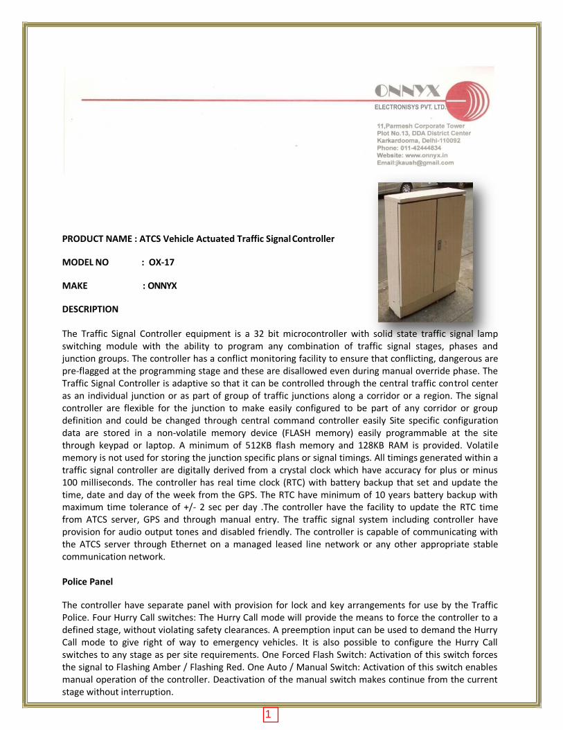
PRODUCT NAME : ATCS Vehicle Actuated Traffic Signal Controller
MODEL NO : OX-17
MAKE : ONNYX
DESCRIPTION
The Traffic Signal Controller equipment is a 32 bit microcontroller with solid state traffic signal lamp switching module with the ability to program any combination of traffic signal stages, phases and junction groups. The controller has a conflict monitoring facility to ensure that conflicting, dangerous are pre-flagged at the programming stage and these are disallowed even during manual override phase. The Traffic Signal Controller is adaptive so that it can be controlled through the central traffic control center as an individual junction or as part of group of traffic junctions along a corridor or a region. The signal controller are flexible for the junction to make easily configured to be part of any corridor or group definition and could be changed through central command controller easily Site specific configuration data are stored in a non-volatile memory device (FLASH memory) easily programmable at the site through keypad or laptop. A minimum of 512KB flash memory and 128KB RAM is provided. Volatile memory is not used for storing the junction specific plans or signal timings. All timings generated within a traffic signal controller are digitally derived from a crystal clock which have accuracy for plus or minus 100 milliseconds. The controller has real time clock (RTC) with battery backup that set and update the time, date and day of the week from the GPS. The RTC have minimum of 10 years battery backup with maximum time tolerance of +/- 2 sec per day .The controller have the facility to update the RTC time from ATCS server, GPS and through manual entry. The traffic signal system including controller have provision for audio output tones and disabled friendly. The controller is capable of communicating with the ATCS server through Ethernet on a managed leased line network or any other appropriate stable communication network.
Police Panel
The controller have separate panel with provision for lock and key arrangements for use by the Traffic Police. Four Hurry Call switches: The Hurry Call mode will provide the means to force the controller to a defined stage, without violating safety clearances. A preemption input can be used to demand the Hurry Call mode to give right of way to emergency vehicles. It is also possible to configure the Hurry Call switches to any stage as per site requirements. One Forced Flash Switch: Activation of this switch forces the signal to Flashing Amber / Flashing Red. One Auto / Manual Switch: Activation of this switch enables manual operation of the controller. Deactivation of the manual switch makes continue from the current stage without interruption.
1
One Manual Advance Pushbutton Switch: In manual operation mode, the stages appear in the sequence specified in the signal plan timetable. Activating the pushbutton switch terminates the currently running stage and start the next, without violating safety clearances. One Junction OFF Switch: Activating this switch puts OFF all signal lamps. On deactivation of the switch the traffic signal controller resumes its normal operation without violating any safety clearances.
Modes of Operation
The traffic signal controller has the following modes of operation Fixed Time: In fixed time (pre-timed) mode the traffic signal controller executes stage timings according to the site specific time-table maintained in the traffic signal controller FLASH memory. Inputs from vehicle detectors are ignored in this mode and no preemption are made on Any stage. Cycle time remains constant in every cycle execution for a given time period. Vehicle Actuation with All Stages Preemption: In the vehicle actuation with all stages preemption mode, the traffic signal controller can execute stage timings as per demand from vehicle detectors within the constraints of Minimum Green, Maximum Green running period for the stage and Cycle time stored in the traffic signal controller FLASH memory. Preemption can be possible for all demand actuated stages. Cycle time may vary in every cycle execution Semi-Actuation: In the semi-actuation mode, the traffic signal controller can execute stage timings in the vehicle actuated stages as per demand from vehicle detectors within the constraints of Minimum Green, Maximum Green running period for the stage and Cycle time stored in the traffic signal controller FLASH memory. All other stages can execute the Maximum green time configured for the stage. Preemption can be possible for all demand actuated stages. Cycle time can be vary in every cycle execution. Stage Skipping: The traffic signal controller cannot execute the stage enabled for skipping when there is no vehicle demand registered for the stage till clearance amber time of the previous stage. Transit Signal Priority (TSP) for BRT buses: The traffic signal controller can provide transit signal priority for buses in dedicated lane to ensure minimum stop delay at the intersection, without violating safety clearances. Vehicle Actuation with Fixed Cycle length: In vehicle actuation with fixed cycle length mode, the traffic signal controller executes stage timings as per demand from vehicle detectors within the constraints of Minimum Green, Maximum Green running period for the stage and Cycle time can be maintained constant during a given timeslot. Preemption for all demand actuated stages except for Priority Stage can be possible. Full ATCS (FATCS): In FATCS mode, the traffic signal controller can execute stage timings as per demand within the constraints of Minimum Green, Maximum Green running period for the stage and Cycle time specified by the Central Computer during every cycle switching. Preemption for all demand actuated stages except Priority Stage can be possible in this mode. The traffic signal controller identifies a communication failure with the central computer within a specified time period. In such an event the signal plan timings shall be executed from the local timetable stored in the traffic signal controller FLASH memory. Fallback mode of the traffic signal controller can be vehicle actuated. On restoration of the communication with central computer the traffic signal controller can automatically resort to FATCS mode. The traffic signal controller accepts the commands for remote selection / de-selection of the following from the Central Computer at Interim ICCC/ICCC. Hurry Call Flashing Amber / Flashing Red Junction Off If not reverted to the normal operation within the time period listed below, the traffic signal controllers can timeout the commands and operate normally Hurry Call – 5 Minutes Flashing Amber / Flashing Red – 30 Minutes Junction Off – 30 Minutes The traffic signal controller shall report the following to the Central Computer through the communication network every cycle or on an event as appropriate. Green time actually exercised for each approach (stage preemption timing) against the Green running period set for the approach by the Central Computer Mode of Operation Lamp failure, if any Output short circuit, if any Detector failure, if any
2
Traffic Signal Controller Operating Parameters
Phases - The controller have facility to configure 32 Phases either for vehicular movement, filter green, indicative green, pedestrian movement or a combination thereof. It shall be possible to operate the filter green (turning right signal) along with a vehicular phase. The filter green signal shall flash for a time period equal to the clearance amber period at timeout when operated with a vehicular phase. The pedestrian phase signal can be configured for flashing red or flashing green aspect during pedestrian clearance. It shall be possible to configure any phase to the given lamp numbers at the site. Stages – The controller have facility to configure 32 Stages Cycle Plans – The controller has facility to configure 24 Cycle Plans and the Amber Flashing / Red Flashing plan. It shall be possible to define different stage switching sequences in different cycle plans. The controller has the capability for a minimum of 32 cycle-switching per day in fixed mode of operation. Day Plans – The controller have facility to configure each day of the week with different day plans. It is also be possible to set any of the day plans to any day of the week. The controller has the capability to configure 20 day plans. Special Day Plans – The controller have facility to configure a minimum of 20 days as special days in a calendar year. Starting Amber – During power up the controller initially execute the Flashing Amber / Flashing Red plan for a time period of 3 Seconds to 10 Seconds. The default value of this Starting Amber is 5 Seconds. Facility is available to configure the time period of Starting Amber within the given limits at the site. Inter-green – Normally the inter-green period formed by the clearance Amber and Red extension period will be common for all stages. However, the controller has a facility to program individual inter- green period from 3 Seconds to 10 Seconds. Minimum Green – The controller allow programming the Minimum Green period from 5 Seconds to 10 Seconds without violating the safety clearances. It cannot preempt the Minimum Green once the stage start commencing execution. All Red – Immediately after the Starting Amber all the approaches should be given red signal for a few seconds before allowing any right of way, as a safety measure. The controller has programmability of 3 Seconds to 10 Seconds for All Red signal. Signal lamps monitoring – The controller have inbuilt circuitry to monitor the lamp status Green – Green Conflict Monitoring – The controller shall have a facility to list all conflicting phases at an intersection. The controller cannot allow programming of these conflicting phases in a Stage. A hardware failure leading to a conflict condition (due to faulty devices or short circuit in the output) forces the signal into Flashing Amber / Flashing Red. Cable less Synchronization – It shall be possible to synchronize the traffic signal controllers installed in a corridor in the following modes of operation, without physically linking them and without communication network. GPS enabled RTC have the reference for the cable less synchronization. Fixed Time mode with fixed offsets Vehicle Actuated mode with fixed offset
Input and Output facilities Lamp Switching: The controller has maximum 64 individual output for signal lamp switching, configurable from 16 to 32 lamps. The signal lamps operating on appropriate DC/AC voltage of applicable rating Detector Interface: A minimum of 16 vehicle detector inputs are available in the controller. All detector inputs are optically isolated and provided with LED indication for detection of vehicle. Communication Interface: The traffic signal controller supports Ethernet interface to communicate with the ATCS server Power Saving: The traffic signal controller have a facility to regulate the intensity of signal lamps during different ambient light conditions thereby saving energy. Real-time Clock (RTC): The GPS receiver for updating time, date and day of the week information of the traffic signal controller should be an integral part of the traffic signal controller. The traffic signal controller always updates the date, time and day of the week automatically from GPS during power ON and at scheduled intervals. Manual entry for date, time and day of week can be provisioned for setting the traffic signal controller RTC (Real Time Clock). It can set the RTC from the Central Server when networked Keypad (optional): The traffic signal controller have a custom made keypad or should have provision for plan upload and download using PC/laptop/Central Server Operator Display (optional): The traffic signal controller optionally have a LED backlit Liquid Crystal Display (LCD) as the operator interface.
3
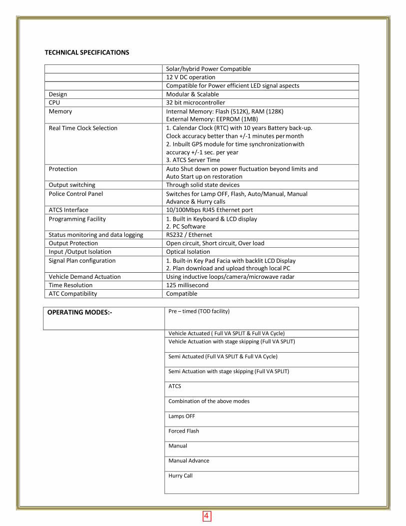
TECHNICAL SPECIFICATIONS
Solar/hybrid Power Compatible 12 V DC operation Compatible for Power efficient LED signal aspects
Design Modular & Scalable CPU 32 bit microcontroller
Memory Internal Memory: Flash (512K), RAM (128K) External Memory: EEPROM (1MB)
Real Time Clock Selection 1. Calendar Clock (RTC) with 10 years Battery back-up. Clock accuracy better than +/-1 minutes per month 2. Inbuilt GPS module for time synchronization with accuracy +/-1 sec. per year 3. ATCS Server Time
Protection Auto Shut down on power fluctuation beyond limits and Auto Start up on restoration
Output switching Through solid state devices
Police Control Panel Switches for Lamp OFF, Flash, Auto/Manual, Manual Advance & Hurry calls
ATCS Interface 10/100Mbps RJ45 Ethernet port
Programming Facility 1. Built in Keyboard & LCD display 2. PC Software
Status monitoring and data logging RS232 / Ethernet
Output Protection Open circuit, Short circuit, Over load
Input /Output Isolation Optical Isolation
Signal Plan configuration 1. Built-in Key Pad Facia with backlit LCD Display 2. Plan download and upload through local PC
Vehicle Demand Actuation Using inductive loops/camera/microwave radar
Time Resolution 125 millisecond
ATC Compatibility Compatible
OPERATING MODES:- Pre – timed (TOD facility)
Vehicle Actuated ( Full VA SPLIT & Full VA Cycle)
Vehicle Actuation with stage skipping (Full VA SPLIT)
Semi Actuated (Full VA SPLIT & Full VA Cycle)
Semi Actuation with stage skipping (Full VA SPLIT)
ATCS
Combination of the above modes
Lamps OFF
Forced Flash
Manual
Manual Advance
Hurry Call
4
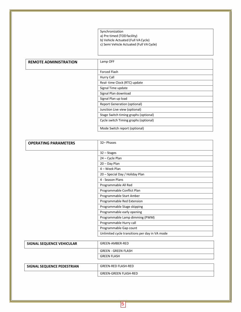
REMOTE ADMINISTRATION Lamp OFF
Forced Flash
Hurry Call
Real- time Clock (RTC) update
Signal Time update
Signal Plan download
Signal Plan up load
Report Generation (optional)
Junction Live view (optional)
Stage Switch timing graphs (optional)
Cycle switch Timing graphs (optional)
Mode Switch report (optional)
OPERATING PARAMETERS 32– Phases
32 – Stages
24 – Cycle Plan
20 – Day Plan
4 – Week Plan
20 – Special Day / Holiday Plan
4 - Season Plans
Programmable All Red
Programmable Conflict Plan
Programmable Start Amber
Programmable Red Extension
Programmable Stage skipping
Programmable early opening
Programmable Lamp dimming (PWM)
Programmable Hurry call
Programmable Gap count
Unlimited cycle transitions per day in VA mode
SIGNAL SEQUENCE VEHICULAR GREEN-AMBER-RED
GREEN - GREEN FLASH
GREEN FLASH
SIGNAL SEQUENCE PEDESTRIAN GREEN-RED FLASH-RED
GREEN-GREEN FLASH-RED
5
Synchronization a) Pre timed (TOD facility) b) Vehicle Actuated (Full VA Cycle) c) Semi Vehicle Actuated (Full VA Cycle)
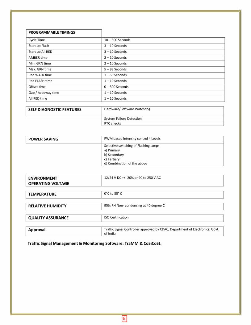
PROGRAMMABLE TIMINGS
Cycle Time 10 – 300 Seconds
Start up Flash 3 – 10 Seconds
Start up All RED 3 – 10 Seconds
AMBER time 2 – 10 Seconds
Min. GRN time 2 – 10 Seconds
Max. GRN time 5 – 99 Seconds
Ped WALK time 1 – 50 Seconds
Ped FLASH time 1 – 10 Seconds
Offset time 0 – 300 Seconds
Gap / headway time 1 – 10 Seconds
All RED time 1 – 10 Seconds
SELF DIAGNOSTIC FEATURES Hardware/Software Watchdog
System Failure Detection
RTC checks
POWER SAVING PWM based intensity control 4 Levels
Selective switching of Flashing lamps a) Primary b) Secondary c) Tertiary d) Combination of the above
ENVIRONMENT OPERATING VOLTAGE
12/24 V DC +/- 20% or 90 to 250 V AC
TEMPERATURE 0°C to 55° C
RELATIVE HUMIDITY 95% RH Non- condensing at 40 degree C
QUALITY ASSURANCE ISO Certification
Approval Traffic Signal Controller approved by CDAC, Department of Electronics, Govt. of India
Traffic Signal Management & Monitoring Software: TraMM & CoSiCoSt.
6
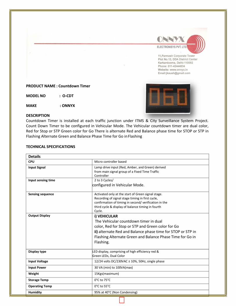
PRODUCT NAME : Countdown Timer
MODEL NO : O-CDT
MAKE : ONNYX
DESCRIPTION Countdown Timer is installed at each traffic junction under ITMS & City Surveillance System Project. Count Down Timer to be configured in Vehicular Mode. The Vehicular countdown timer are dual color, Red for Stop or STP Green color for Go There is alternate Red and Balance phase time for STOP or STP in Flashing Alternate Green and Balance Phase Time for Go in Flashing
TECHNICAL SPECIFICATIONS
Details CPU Micro controller based
Input Signal Lamp drive input (Red, Amber, and Green) derived from main signal group of a Fixed Time Traffic Controller
Input sensing time 2 to 3 Cycles/
configured in Vehicular Mode.
Sensing sequence Activated only at the start of Green signal stage. Recording of signal stage timing in first cycle, confirmation of timing in second/ verification in the third cycle & display of balance timing in fourth Cycle.
Output Display i) VEHICULAR The Vehicular countdown timer in dual
color, Red for Stop or STP and Green color for Go ii) alternate Red and Balance phase time for STOP or STP in Flashing Alternate Green and Balance Phase Time for Go in Flashing.
Display type LED display, comprising of high efficiency red & Green LEDs, Dual Color
Input Voltage 12/24 volts DC/230VAC ± 10%, 50Hz, single phase
Input Power 30 VA (min) to 100VA(max)
Weight 15Kgs(maximum)
Storage Temp 0°C to 75°C
Operating Temp 0°C to 55°C
Humidity 95% at 40°C (Non Condensing)
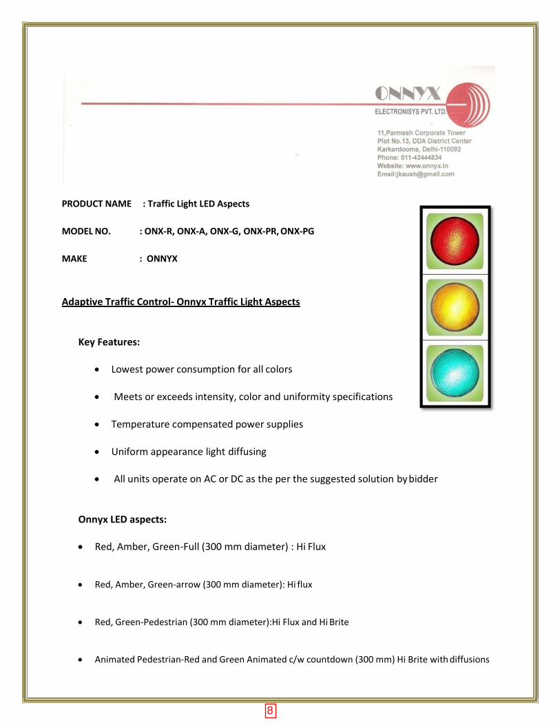
PRODUCT NAME : Traffic Light LED Aspects
MODEL NO. : ONX-R, ONX-A, ONX-G, ONX-PR, ONX-PG
MAKE : ONNYX
Adaptive Traffic Control- Onnyx Traffic Light Aspects
Key Features:
Lowest power consumption for all colors
Meets or exceeds intensity, color and uniformity specifications
Temperature compensated power supplies
Uniform appearance light diffusing
All units operate on AC or DC as the per the suggested solution by bidder
Onnyx LED aspects:
Red, Amber, Green-Full (300 mm diameter) : Hi Flux
Red, Amber, Green-arrow (300 mm diameter): Hi flux
Red, Green-Pedestrian (300 mm diameter):Hi Flux and Hi Brite
Animated Pedestrian-Red and Green Animated c/w countdown (300 mm) Hi Brite with diffusions
8
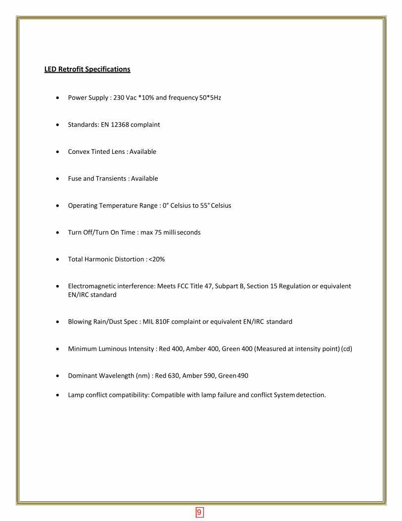
LED Retrofit Specifications
Power Supply : 230 Vac *10% and frequency 50*5Hz
Standards: EN 12368 complaint
Convex Tinted Lens : Available
Fuse and Transients : Available
Operating Temperature Range : 0° Celsius to 55° Celsius
Turn Off/Turn On Time : max 75 milli seconds
Total Harmonic Distortion : <20%
Electromagnetic interference: Meets FCC Title 47, Subpart B, Section 15 Regulation or equivalent EN/IRC standard
Blowing Rain/Dust Spec : MIL 810F complaint or equivalent EN/IRC standard
Minimum Luminous Intensity : Red 400, Amber 400, Green 400 (Measured at intensity point) (cd)
Dominant Wavelength (nm) : Red 630, Amber 590, Green 490
Lamp conflict compatibility: Compatible with lamp failure and conflict System detection.
9
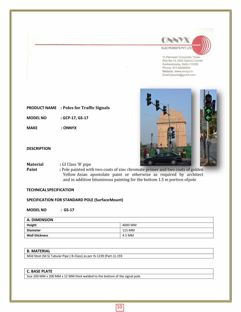
PRODUCT NAME : Poles for Traffic Signals
MODEL NO : GCP-17, GS-17
MAKE : ONNYX
DESCRIPTION
Material : GI Class ‘B’ pipe Paint : Pole painted with two coats of zinc chromate primer and two coats of golden
Yellow Asian apostolate paint or otherwise as required by architect and in addition bituminous painting for the bottom 1.5 m portion of pole
TECHNICAL SPECIFICATION
SPECIFICATION FOR STANDARD POLE (Surface Mount)
MODEL NO : GS-17
A. DIMENSION Height 4000 MM
Diameter 115 MM
Wall thickness 4.5 MM
B. MATERIAL Mild Steel (M.S) Tubular Pipe ( B-Class) as per IS-1239 (Part-1)-193
C. BASE PLATE Size 200 MM x 200 MM x 12 MM thick welded to the bottom of the signal pole
10
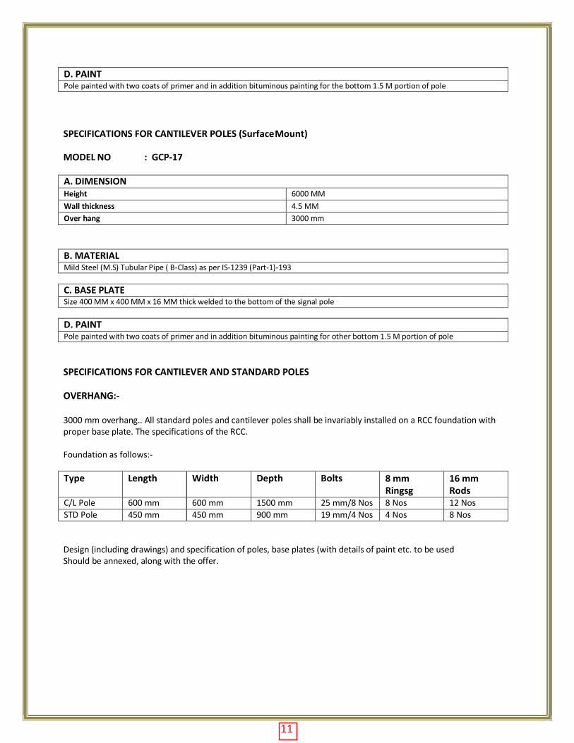
D. PAINT Pole painted with two coats of primer and in addition bituminous painting for the bottom 1.5 M portion of pole
SPECIFICATIONS FOR CANTILEVER POLES (Surface Mount)
MODEL NO : GCP-17
A. DIMENSION Height 6000 MM
Wall thickness 4.5 MM
Over hang 3000 mm
B. MATERIAL Mild Steel (M.S) Tubular Pipe ( B-Class) as per IS-1239 (Part-1)-193
C. BASE PLATE Size 400 MM x 400 MM x 16 MM thick welded to the bottom of the signal pole
D. PAINT Pole painted with two coats of primer and in addition bituminous painting for other bottom 1.5 M portion of pole
SPECIFICATIONS FOR CANTILEVER AND STANDARD POLES
OVERHANG:-
3000 mm overhang.. All standard poles and cantilever poles shall be invariably installed on a RCC foundation with proper base plate. The specifications of the RCC.
Foundation as follows:-
Type Length Width Depth Bolts 8 mm Ringsg
16 mm Rods
C/L Pole 600 mm 600 mm 1500 mm 25 mm/8 Nos 8 Nos 12 Nos
STD Pole 450 mm 450 mm 900 mm 19 mm/4 Nos 4 Nos 8 Nos
Design (including drawings) and specification of poles, base plates (with details of paint etc. to be used Should be annexed, along with the offer.
11
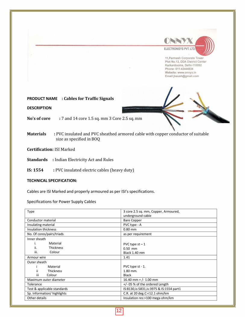
PRODUCT NAME : Cables for Traffic Signals
DESCRIPTION
No’s of core : 7 and 14 core 1.5 sq. mm 3 Core 2.5 sq. mm
Materials : PVC insulated and PVC sheathed armored cable with copper conductor of suitable size as specified in BOQ
Certification: ISI Marked
Standards : Indian Electricity Act and Rules
IS: 1554 : PVC insulated electric cables (heavy duty)
TECHNICAL SPECIFICATION:
Cables are ISI Marked and properly armoured as per ISI’s specifications.
Specifications for Power Supply Cables
Type 3 core 2.5 sq. mm, Copper, Armoured, underground cable
Conductor material Bare Copper Insulating material PVC type - A
Insulation thickness 0.80 mm
No. Of cores/pairs/triads as per requirement
Inner sheath i. Material ii. Thickness iii. Colour
PVC type st – 1 0.50 mm Black 1.40 mm
Armour wire 1.41
Outer sheath i Material ii Thickness iii Colour
PVC type st - 1. 1.80 mm. Black
Maximum outer diameter 16.40 mm + /- 1.00 mm Tolerance +/- 05 % of the ordered Length
Test & applicable standards IS:8130,is:5831,is:3975 & IS:1554 part1 Sp. Information/ highlights C.R. at 20 deg.C:<12.1 ohm/km
Other details Insulation res:>100 mega ohm/km
12
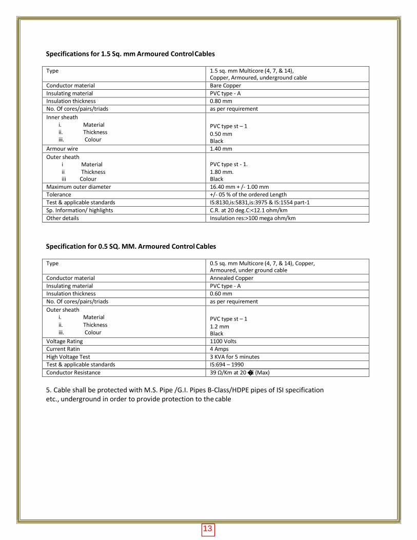
Specifications for 1.5 Sq. mm Armoured Control Cables
Type 1.5 sq. mm Multicore (4, 7, & 14), Copper, Armoured, underground cable
Conductor material Bare Copper
Insulating material PVC type - A Insulation thickness 0.80 mm No. Of cores/pairs/triads as per requirement
Inner sheath i. Material ii. Thickness iii. Colour
PVC type st – 1
0.50 mm Black
Armour wire 1.40 mm
Outer sheath i Material ii Thickness iii Colour
PVC type st - 1. 1.80 mm. Black
Maximum outer diameter 16.40 mm + /- 1.00 mm Tolerance +/- 05 % of the ordered Length
Test & applicable standards IS:8130,is:5831,is:3975 & IS:1554 part-1
Sp. Information/ highlights C.R. at 20 deg.C:<12.1 ohm/km
Other details Insulation res:>100 mega ohm/km
Specification for 0.5 SQ. MM. Armoured Control Cables
Type 0.5 sq. mm Multicore (4, 7, & 14), Copper,
Armoured, under ground cable
Conductor material Annealed Copper
Insulating material PVC type - A Insulation thickness 0.60 mm
No. Of cores/pairs/triads as per requirement
Outer sheath i. Material ii. Thickness iii. Colour
PVC type st – 1 1.2 mm Black
Voltage Rating 1100 Volts Current Ratin 4 Amps
High Voltage Test 3 KVA for 5 minutes Test & applicable standards IS:694 – 1990
Conductor Resistance 39 Ω/Km at 20 �C (Max)
5. Cable shall be protected with M.S. Pipe /G.I. Pipes B-Class/HDPE pipes of ISI specification etc., underground in order to provide protection to the cable
13