Embed Size (px)
Citation preview
24th International Conference & Exhibition on Electricity Distribution (CIRED)
12-15 June 2017
Session 3: Operation, control and protection
Open or closed ring networks?
ISSN 2515-0855doi: 10.1049/oap-cired.2017.0019
www.ietdl.org
Henri Grasset ✉
Schneider Electric, Expert team, Montpellier, France
✉ E-mail: [email protected]
Abstract: Open ring networks have been commonly used; they have been protected with either phase and earth simple ordirectional overcurrent protection relays. The biggest drawback of open ring electrical power networks is that a line/cablefault will disconnect the customers that are connected downstream from that fault location until manual or automaticreconfiguration of the network is done. How could we improve the system average interruption frequency index andthe system average interruption duration index? That is how to reduce the number and duration of powerinterruptions? What if, we create a closed ring electrical power network? Is there any impact of distributed generation?Are there some protection principles that could help? Note: this study focuses on: the IEC world (three-phase balancednetworks) and, on medium size ring networks such as for sensitive buildings, data centres, heavy industries (mainlycable based), microgrid not connected to utility (yet). This study does not fit for utility networks and isolated neutralearthing networks.
1 Introduction
1.1 Protection principles
1.1.1 Directional over current protection blocking schemebasics: Directional over current protection blocking schemes arebased on, measurement of currents and voltages (fed fromwell-sized instrument transformers), time discrimination principleand on the exchange of blocking signals via dedicatedcommunication links. Thanks to the voltage, the direction of thepower flow can be known. When an overcurrent is detected in theprotected area, it instantaneously sends a blocking signal to theupstream protection (or ‘behind’ * it), then after a certain time, ifnot blocked by the downstream protection (or ‘in front of’ *), tripsits breaker. Directional over current protection may have somelimitation for some specific cases.
*: ‘upstream’ and ‘downstream’ do not exist in closed ring.For this paper, the below definitions are used:A directional protection is drawn as ◁ or △ or ▷ or with ▽:[Protected area (downstream or ‘in front of’ *)] ◁ [Blocked area
(upstream or ‘behind’ *)].
1.2 Differential protection basics
A differential protection scheme is based on measurement of currentonly (fed from well-sized current transformers) and on the exchangeof these measurements via dedicated communication links.Differential protections calculate the difference between thecurrents entering and leaving the protected zone. The protectionsoperate when this difference exceeds a set threshold, whichdepends on the flow of the current (biased characteristic).
Usually:
† The bias current is the sum of the current measured on each enddivided by 2, even for ‘multi-ended’ lines (more than two ends).† The differential current is the difference of the current measuredon each end (not divided by 2).† Until twice the nominal current, the tripping area is the zone abovethe first slope.† That slope starts from a minimum threshold, typically 20% of thenominal.
CIRED, Open Access Proc. J., 2017, Vol. 2017, Iss. 1, pp. 1347–1354This is an open access article published by the IET under the CreativeAttribution License (http://creativecommons.org/licenses/by/3.0/)
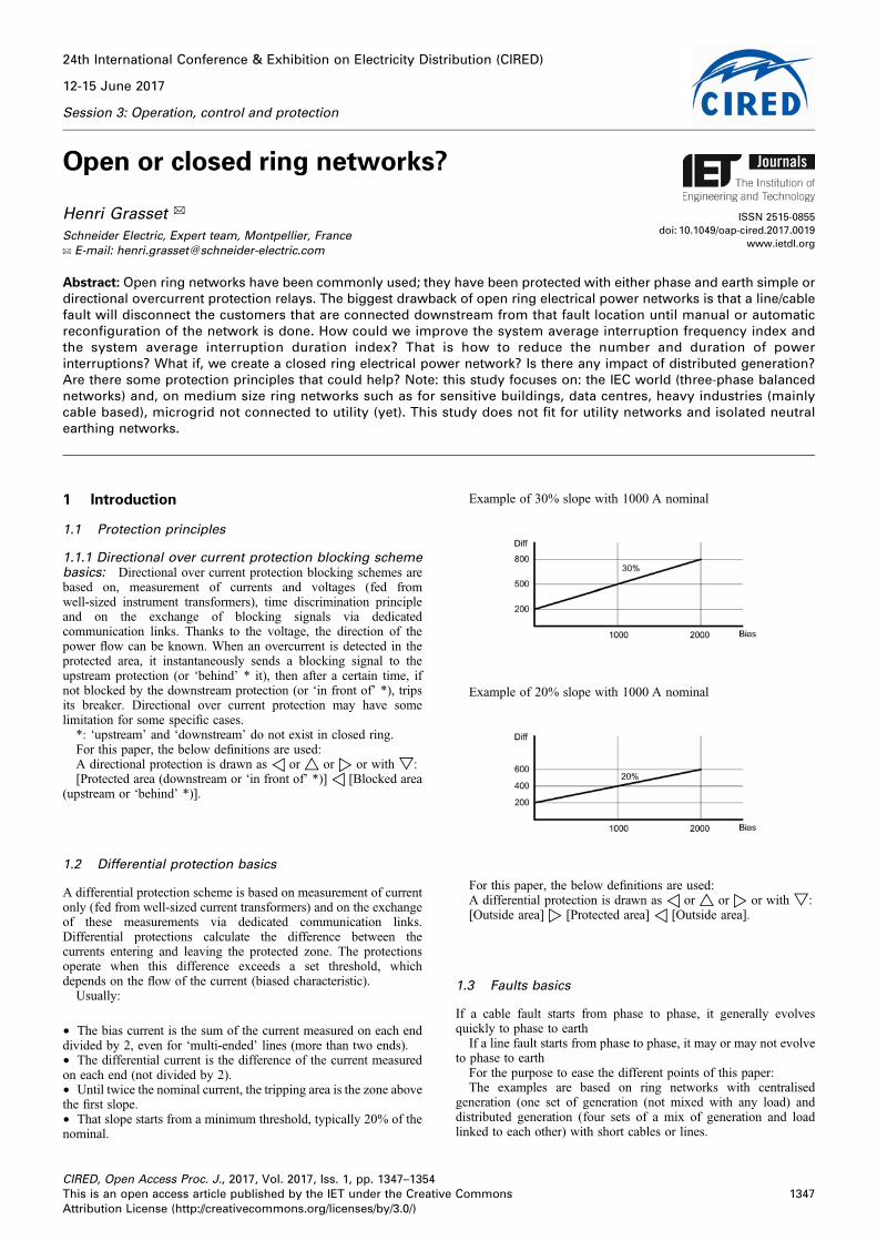
Example of 30% slope with 1000 A nominal
Example of 20% slope with 1000 A nominal
For this paper, the below definitions are used:A differential protection is drawn as ◁ or △ or ▷ or with ▽:[Outside area] ▷ [Protected area] ◁ [Outside area].
1.3 Faults basics
If a cable fault starts from phase to phase, it generally evolvesquickly to phase to earth
If a line fault starts from phase to phase, it may or may not evolveto phase to earth
For the purpose to ease the different points of this paper:The examples are based on ring networks with centralised
generation (one set of generation (not mixed with any load) anddistributed generation (four sets of a mix of generation and loadlinked to each other) with short cables or lines.
1347Commons
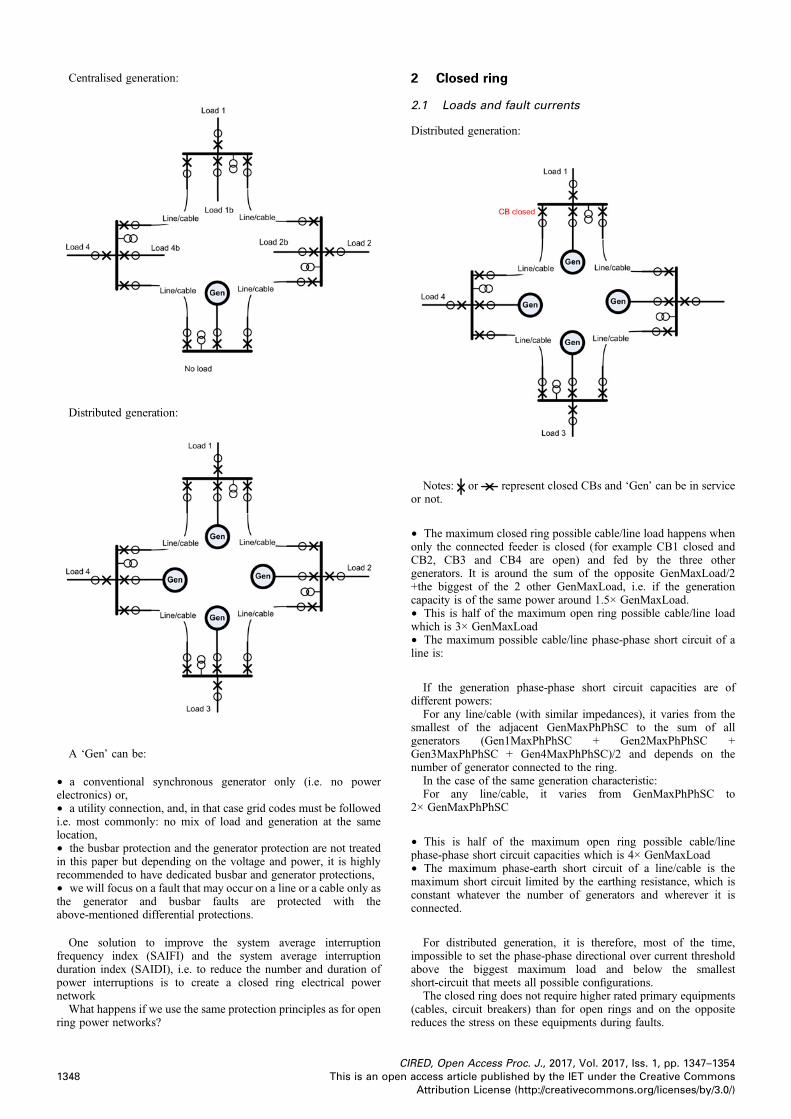
Centralised generation:
Distributed generation:
A ‘Gen’ can be:
† a conventional synchronous generator only (i.e. no powerelectronics) or,† a utility connection, and, in that case grid codes must be followedi.e. most commonly: no mix of load and generation at the samelocation,† the busbar protection and the generator protection are not treatedin this paper but depending on the voltage and power, it is highlyrecommended to have dedicated busbar and generator protections,† we will focus on a fault that may occur on a line or a cable only asthe generator and busbar faults are protected with theabove-mentioned differential protections.
One solution to improve the system average interruptionfrequency index (SAIFI) and the system average interruptionduration index (SAIDI), i.e. to reduce the number and duration ofpower interruptions is to create a closed ring electrical powernetwork
What happens if we use the same protection principles as for openring power networks?
CI
1348 This is an open
2 Closed ring
2.1 Loads and fault currents
Distributed generation:
Notes: or represent closed CBs and ‘Gen’ can be in serviceor not.
† The maximum closed ring possible cable/line load happens whenonly the connected feeder is closed (for example CB1 closed andCB2, CB3 and CB4 are open) and fed by the three othergenerators. It is around the sum of the opposite GenMaxLoad/2+the biggest of the 2 other GenMaxLoad, i.e. if the generationcapacity is of the same power around 1.5× GenMaxLoad.† This is half of the maximum open ring possible cable/line loadwhich is 3× GenMaxLoad† The maximum possible cable/line phase-phase short circuit of aline is:
If the generation phase-phase short circuit capacities are ofdifferent powers:
For any line/cable (with similar impedances), it varies from thesmallest of the adjacent GenMaxPhPhSC to the sum of allgenerators (Gen1MaxPhPhSC + Gen2MaxPhPhSC +Gen3MaxPhPhSC + Gen4MaxPhPhSC)/2 and depends on thenumber of generator connected to the ring.
In the case of the same generation characteristic:For any line/cable, it varies from GenMaxPhPhSC to
2× GenMaxPhPhSC
† This is half of the maximum open ring possible cable/linephase-phase short circuit capacities which is 4× GenMaxLoad† The maximum phase-earth short circuit of a line/cable is themaximum short circuit limited by the earthing resistance, which isconstant whatever the number of generators and wherever it isconnected.
For distributed generation, it is therefore, most of the time,impossible to set the phase-phase directional over current thresholdabove the biggest maximum load and below the smallestshort-circuit that meets all possible configurations.
The closed ring does not require higher rated primary equipments(cables, circuit breakers) than for open rings and on the oppositereduces the stress on these equipments during faults.
RED, Open Access Proc. J., 2017, Vol. 2017, Iss. 1, pp. 1347–1354access article published by the IET under the Creative CommonsAttribution License (http://creativecommons.org/licenses/by/3.0/)
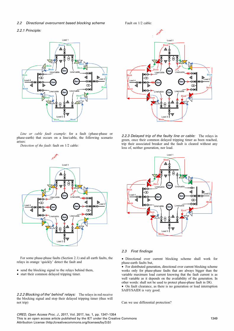
2.2 Directional overcurrent based blocking scheme
2.2.1 Principle:
Line or cable fault example: for a fault (phase-phase orphase-earth) that occurs on a line/cable, the following scenarioarises:
Detection of the fault: fault on 1/2 cable:
For some phase-phase faults (Section 2.1) and all earth faults, therelays in orange ‘quickly’ detect the fault and
† send the blocking signal to the relays behind them,† start their common delayed tripping timer.
2.2.2 Blocking of the ‘behind’ relays: The relays in red receivethe blocking signal and stop their delayed tripping timer (thus willnot trip)
CIRED, Open Access Proc. J., 2017, Vol. 2017, Iss. 1, pp. 1347–1354This is an open access article published by the IET under the CreativeAttribution License (http://creativecommons.org/licenses/by/3.0/)
Fault on 1/2 cable:
2.2.3 Delayed trip of the faulty line or cable: The relays ingreen, once their common delayed tripping timer as been reached,trip their associated breaker and the fault is cleared without anyloss of, neither generation, nor load.
2.3 First findings
† Directional over current blocking scheme shall work forphase-earth faults but,† For distributed generation, directional over current blocking schemeworks only for phase-phase faults that are always bigger than thevariable maximum load current knowing that the fault current is aswell variable as it depends on the availability of the generation. Inother words: shall not be used to protect phase-phase fault in DG.† On fault clearance, as there is no generation or load interruptionSAIFI/SAIDI is very good.
Can we use differential protection?
1349Commons
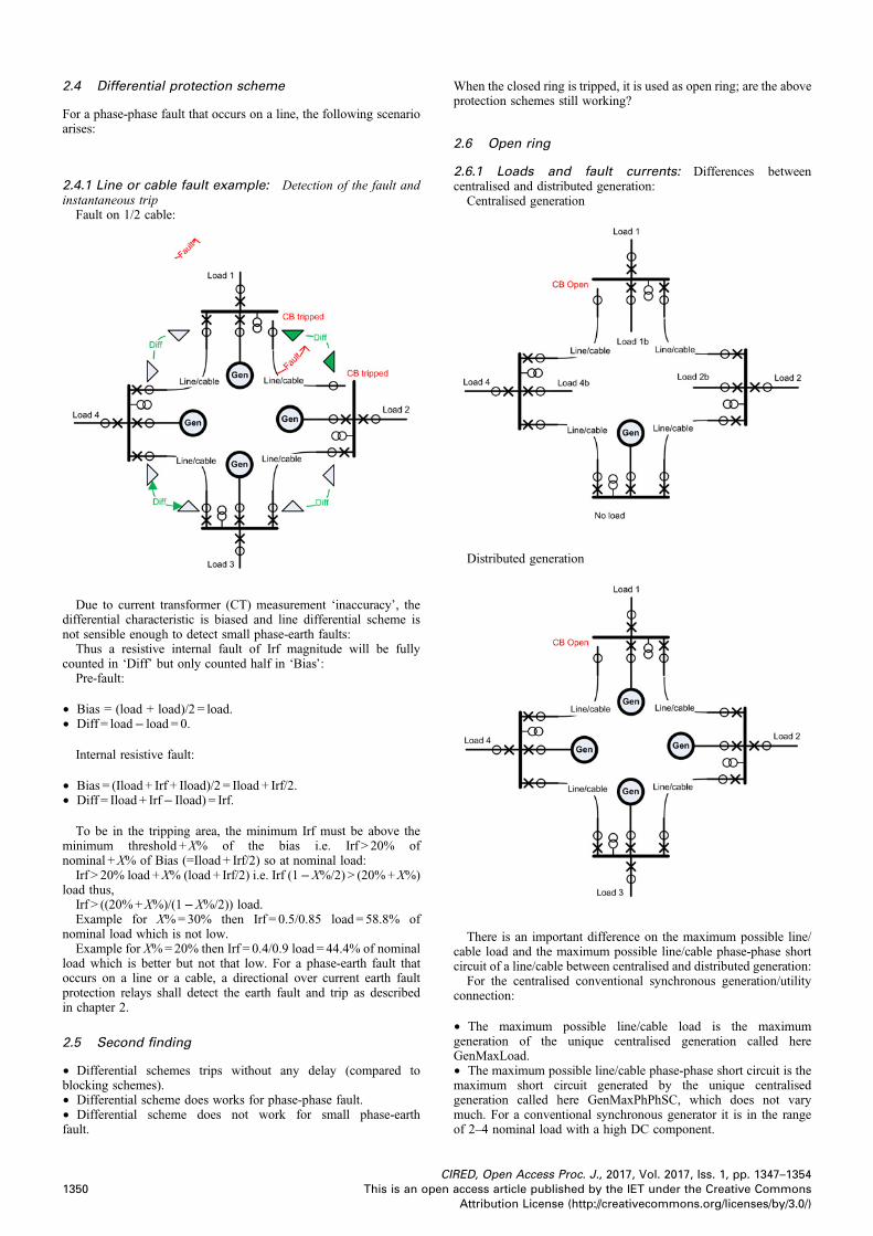
2.4 Differential protection scheme
For a phase-phase fault that occurs on a line, the following scenarioarises:
2.4.1 Line or cable fault example: Detection of the fault andinstantaneous trip
Fault on 1/2 cable:
Due to current transformer (CT) measurement ‘inaccuracy’, thedifferential characteristic is biased and line differential scheme isnot sensible enough to detect small phase-earth faults:
Thus a resistive internal fault of Irf magnitude will be fullycounted in ‘Diff’ but only counted half in ‘Bias’:
Pre-fault:
† Bias = (load + load)/2 = load.† Diff = load− load = 0.
Internal resistive fault:
† Bias = (Iload + Irf + Iload)/2 = Iload + Irf/2.† Diff = Iload + Irf− Iload) = Irf.
To be in the tripping area, the minimum Irf must be above theminimum threshold +X% of the bias i.e. Irf > 20% ofnominal +X% of Bias (=Iload + Irf/2) so at nominal load:
Irf > 20% load +X% (load + Irf/2) i.e. Irf (1−X%/2) > (20%+X%)load thus,
Irf > ((20%+X%)/(1−X%/2)) load.Example for X%=30% then Irf = 0.5/0.85 load = 58.8% of
nominal load which is not low.Example for X%=20% then Irf = 0.4/0.9 load = 44.4% of nominal
load which is better but not that low. For a phase-earth fault thatoccurs on a line or a cable, a directional over current earth faultprotection relays shall detect the earth fault and trip as describedin chapter 2.
2.5 Second finding
† Differential schemes trips without any delay (compared toblocking schemes).† Differential scheme does works for phase-phase fault.† Differential scheme does not work for small phase-earthfault.
CI
1350 This is an open
When the closed ring is tripped, it is used as open ring; are the aboveprotection schemes still working?
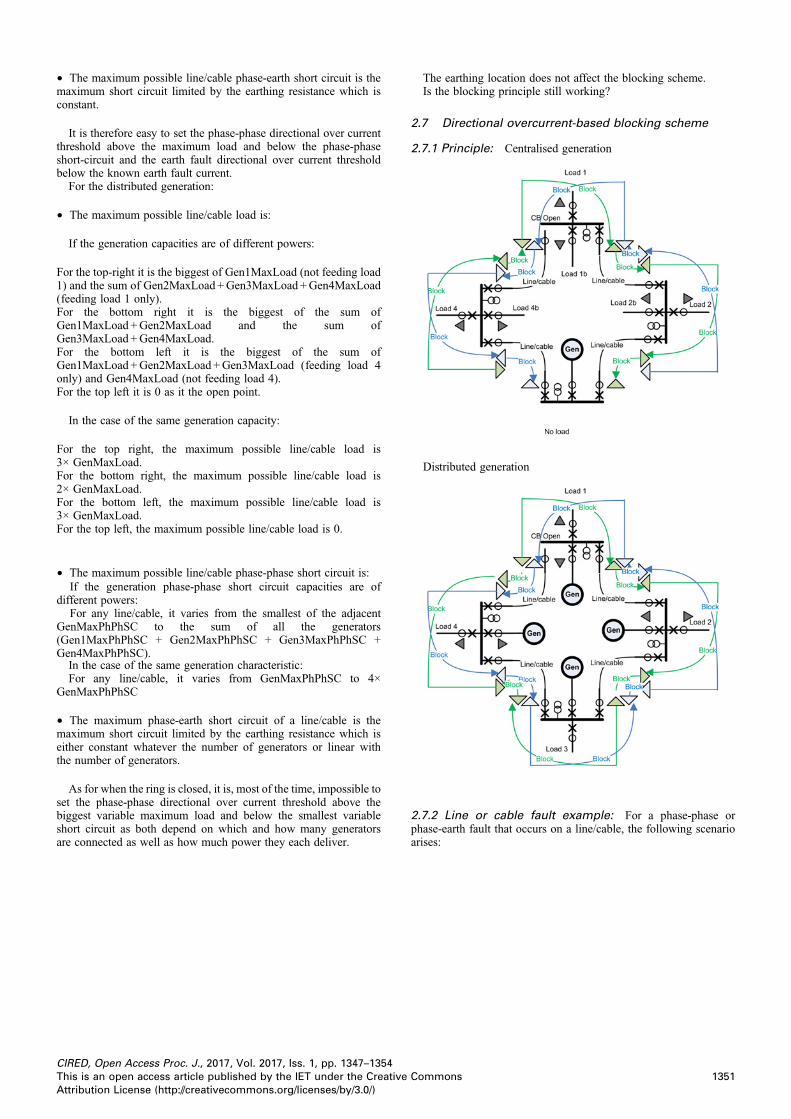
2.6 Open ring
2.6.1 Loads and fault currents: Differences betweencentralised and distributed generation:
Centralised generation
Distributed generation
There is an important difference on the maximum possible line/cable load and the maximum possible line/cable phase-phase shortcircuit of a line/cable between centralised and distributed generation:
For the centralised conventional synchronous generation/utilityconnection:
† The maximum possible line/cable load is the maximumgeneration of the unique centralised generation called hereGenMaxLoad.† The maximum possible line/cable phase-phase short circuit is themaximum short circuit generated by the unique centralisedgeneration called here GenMaxPhPhSC, which does not varymuch. For a conventional synchronous generator it is in the rangeof 2–4 nominal load with a high DC component.
RED, Open Access Proc. J., 2017, Vol. 2017, Iss. 1, pp. 1347–1354access article published by the IET under the Creative CommonsAttribution License (http://creativecommons.org/licenses/by/3.0/)
† The maximum possible line/cable phase-earth short circuit is themaximum short circuit limited by the earthing resistance which isconstant.
It is therefore easy to set the phase-phase directional over currentthreshold above the maximum load and below the phase-phaseshort-circuit and the earth fault directional over current thresholdbelow the known earth fault current.
For the distributed generation:
† The maximum possible line/cable load is:
If the generation capacities are of different powers:
For the top-right it is the biggest of Gen1MaxLoad (not feeding load1) and the sum of Gen2MaxLoad +Gen3MaxLoad +Gen4MaxLoad(feeding load 1 only).For the bottom right it is the biggest of the sum ofGen1MaxLoad +Gen2MaxLoad and the sum ofGen3MaxLoad +Gen4MaxLoad.For the bottom left it is the biggest of the sum ofGen1MaxLoad +Gen2MaxLoad +Gen3MaxLoad (feeding load 4only) and Gen4MaxLoad (not feeding load 4).For the top left it is 0 as it the open point.
In the case of the same generation capacity:
For the top right, the maximum possible line/cable load is3× GenMaxLoad.For the bottom right, the maximum possible line/cable load is2× GenMaxLoad.For the bottom left, the maximum possible line/cable load is3× GenMaxLoad.For the top left, the maximum possible line/cable load is 0.
† The maximum possible line/cable phase-phase short circuit is:If the generation phase-phase short circuit capacities are of
different powers:For any line/cable, it varies from the smallest of the adjacent
GenMaxPhPhSC to the sum of all the generators(Gen1MaxPhPhSC + Gen2MaxPhPhSC + Gen3MaxPhPhSC +Gen4MaxPhPhSC).
In the case of the same generation characteristic:For any line/cable, it varies from GenMaxPhPhSC to 4×
GenMaxPhPhSC
† The maximum phase-earth short circuit of a line/cable is themaximum short circuit limited by the earthing resistance which iseither constant whatever the number of generators or linear withthe number of generators.
As for when the ring is closed, it is, most of the time, impossible toset the phase-phase directional over current threshold above thebiggest variable maximum load and below the smallest variableshort circuit as both depend on which and how many generatorsare connected as well as how much power they each deliver.
CIRED, Open Access Proc. J., 2017, Vol. 2017, Iss. 1, pp. 1347–1354This is an open access article published by the IET under the CreativeAttribution License (http://creativecommons.org/licenses/by/3.0/)
The earthing location does not affect the blocking scheme.Is the blocking principle still working?
2.7 Directional overcurrent-based blocking scheme
2.7.1 Principle: Centralised generation
Distributed generation
2.7.2 Line or cable fault example: For a phase-phase orphase-earth fault that occurs on a line/cable, the following scenarioarises:
1351Commons
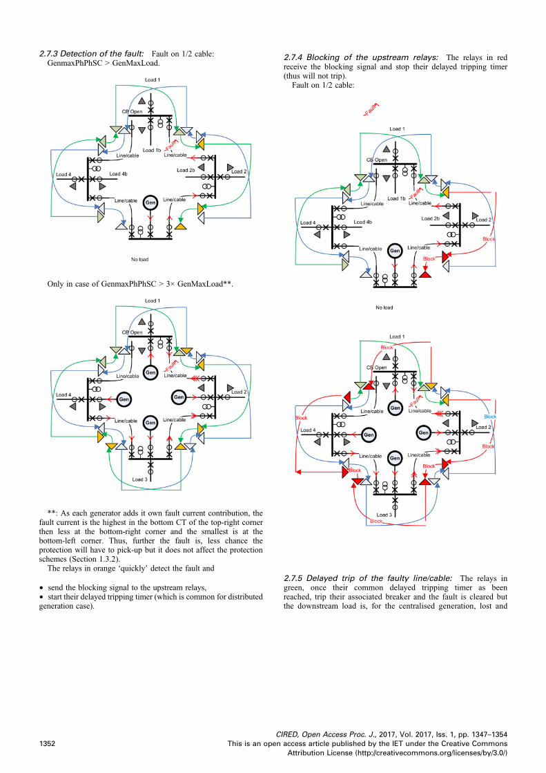
2.7.3 Detection of the fault: Fault on 1/2 cable:GenmaxPhPhSC > GenMaxLoad.
Only in case of GenmaxPhPhSC > 3× GenMaxLoad**.
**: As each generator adds it own fault current contribution, thefault current is the highest in the bottom CT of the top-right cornerthen less at the bottom-right corner and the smallest is at thebottom-left corner. Thus, further the fault is, less chance theprotection will have to pick-up but it does not affect the protectionschemes (Section 1.3.2).
The relays in orange ‘quickly’ detect the fault and
† send the blocking signal to the upstream relays,† start their delayed tripping timer (which is common for distributedgeneration case).
CI
1352 This is an open
2.7.4 Blocking of the upstream relays: The relays in redreceive the blocking signal and stop their delayed tripping timer(thus will not trip).
Fault on 1/2 cable:
2.7.5 Delayed trip of the faulty line/cable: The relays ingreen, once their common delayed tripping timer as beenreached, trip their associated breaker and the fault is cleared butthe downstream load is, for the centralised generation, lost and
RED, Open Access Proc. J., 2017, Vol. 2017, Iss. 1, pp. 1347–1354access article published by the IET under the Creative CommonsAttribution License (http://creativecommons.org/licenses/by/3.0/)
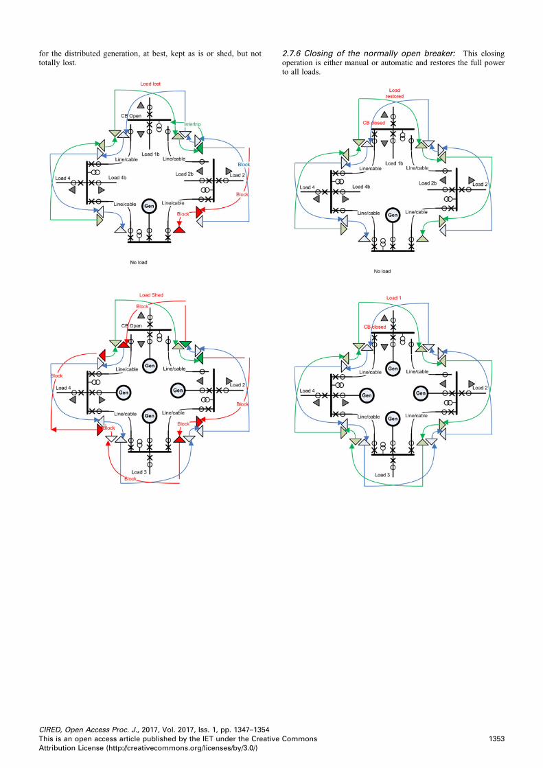
for the distributed generation, at best, kept as is or shed, but nottotally lost.
CIRED, Open Access Proc. J., 2017, Vol. 2017, Iss. 1, pp. 1347–1354This is an open access article published by the IET under the CreativeAttribution License (http://creativecommons.org/licenses/by/3.0/)
2.7.6 Closing of the normally open breaker: This closingoperation is either manual or automatic and restores the full powerto all loads.
1353Commons
2.8 Third findings
† The closed ring protection schemes still work for open ring:Line/cable phase-earth faults are still detected for both kinds of
generations.Line/cable phase-phase faults are still detected in centralised
generation but only in some cases for distributed generation. Inthat case, non-tripping would result in damage of primaryequipments that would strongly degrades further the SAIFI/SAIDI.† Fault clearance is slowed down by the delayed tripping timer(s).† On fault clearance a load maybe lost or shed and thus degrades theSAIFI/SAIDI.
3 Conclusions
On the electrical power network:
† For closed ring centralised generation (and when grid code allowsit) and distributed generation:
The biggest benefit of closed rings is to continue to providenominal power in case of a line or cable fault and thus a line orcable fault will not degrade the SAIFI/SAIDI.
The closed ring does not require higher rated primary equipments(cables and circuit breakers) than for open ring and on the oppositereduces the stress on these equipments as load and fault will bedivided by around 2. Consequently, circuit breakers such as thoseused in secondary distribution [1, 2], are perfectly adapted to thisclosed ring scheme.
Both current transformers and voltage transformers shall be usedby the below protection scheme.† When used as open ring:
CI
1354 This is an open
Some loads can be lost or shed and SAIFI/SAIDI will be affectedby line or cable faults.
On the protection schemes:
† For closed ring distributed generation networks:Phase–phase directional overcurrent does not always work and
differential schemes shall be used instead.Differential scheme does not work for small phase-earth fault and
phase-earth directional over current shall be used instead.When used as open ring, the closed ring protection scheme still
works.† Differential relays detect phase-phase faults and trip faster thandirectional overcurrent relays, which is important to save theprimary equipments or for safety reasons but do not detect ‘small’earth faults.† Directional earth fault relays react with some delay on small faultcurrents; that may be good enough as primary equipments may notbe too much stressed for such faults.† Most of line differential numerical relays embed directional earthfault protection that uses the same communication channel.
The optimum is to operate sensitive power networks as closed ringprotected by a scheme based on line differential relays embeddingearth directional overcurrent blocking schemes that will still workwhen used as open ring.
4 References
1 Ma, C.: ‘Innovative MV switchgear for today’s applications’. CICED 2012 PaperFP0112, 2012
2 Biasse, J.M.: ‘Circuit-breaker RMU improves MV/LV transformer protection’.CIRED 2009 Paper 0320, 2009
RED, Open Access Proc. J., 2017, Vol. 2017, Iss. 1, pp. 1347–1354access article published by the IET under the Creative CommonsAttribution License (http://creativecommons.org/licenses/by/3.0/)