Embed Size (px)
Citation preview
Open Source SCADA Systems for Small Renewable PowerGeneration
by
©Lawrence Oriaghe Aghenta
A Thesis submitted to the School of Graduate Studies in partial fulfillment of therequirements for the degree of
Master of Engineering
Faculty of Engineering and Applied ScienceMemorial University of Newfoundland
May 2020
St. John’s Newfoundland and Labrador Canada
Abstract
Low cost monitoring and control is essential for small renewable power systems. While
large renewable power systems can use existing commercial technology for monitoring and
control, that is not cost-effective for small renewable generation. Such small assets re-
quire cost-effective, flexible, secure, and reliable real-time coordinated data monitoring and
control systems. Supervisory control and data acquisition (SCADA) is the perfect tech-
nology for this task. The available commercial SCADA solutions are mostly pricey and
economically unjustifiable for smaller applications. They also pose interoperability issues
with the existing components which are often from multiple vendors. Therefore, an open
source SCADA system represents the most flexible and the most cost-effective SCADA so-
lution. This thesis has been done in two phases. The first phase demonstrates the design
and dynamic simulation of a small hybrid power system with a renewable power genera-
tion system as a case study. In the second phase, after an extensive study of the proven
commercial SCADA solutions and some open source SCADA packages, three different se-
cure, reliable, low-cost open source SCADA options are developed using the most recent
SCADA architecture, the Internet of Things. The implemented prototypes of the three open
source SCADA systems were tested extensively with a small renewable power system (a
solar PV system). The results show that the developed open source SCADA systems per-
form optimally and accurately, and could serve as viable options for smaller applications
such as renewable generation that cannot afford commercial SCADA solutions.
ii
Acknowledgements
First and foremost, I thank God for His grace and favors throughout this masters program.
Next, my heartfelt gratitude goes to my thesis supervisor, Prof. M. Tariq Iqbal, for
his patience and guidance in this thesis. I have benefited immensely from your wealth
of knowledge and expertise in the fields of instrumentation and control, renewable energy
systems, hybrid power systems and power electronics. To you, I say a very big thank you
for always making yourself available to answer my questions and to steer me in the right
directions.
I would like to thank my cousin Engr. Emmanuel A. Aghenta, whose invaluable support
made it possible for me to come to this country and to embark on my studies. Thank you!
I like to thank the School of Graduate Studies, Faculty of Engineering and Applied Sci-
ence, Memorial University and the Natural Sciences and Engineering Research Council of
Canada (NSERC) Energy Storage Technology Network (NESTNet) for providing graduate
student funding and the conducive environment to carry out this research.
Finally, I would like to acknowledge the technical, moral and emotional supports of my
colleagues, friends, families and Amen throughout the period of carrying out this research
work. Thank you all!!!
iii
Table of Contents
Abstract ii
Acknowledgments iii
List of Tables ix
List of Figures xii
List of Abbreviations and Symbols xiii
1 Introduction and Literature Review 1
1.1 Introduction . . . . . . . . . . . . . . . . . . . . . . . . . . . . . . . . . . 1
1.2 Background . . . . . . . . . . . . . . . . . . . . . . . . . . . . . . . . . . 4
1.2.1 Why is SCADA Needed? . . . . . . . . . . . . . . . . . . . . . . . 7
1.2.2 Elements/Levels of SCADA Systems . . . . . . . . . . . . . . . . 8
1.2.3 Applications of SCADA . . . . . . . . . . . . . . . . . . . . . . . 9
1.2.4 Desired Characteristics in a SCADA System . . . . . . . . . . . . 9
1.2.5 SCADA System Security . . . . . . . . . . . . . . . . . . . . . . . 11
1.2.6 Classes of SCADA Systems . . . . . . . . . . . . . . . . . . . . . 14
1.3 Literature Review . . . . . . . . . . . . . . . . . . . . . . . . . . . . . . . 16
1.3.1 Open Source Hardware . . . . . . . . . . . . . . . . . . . . . . . . 16
iv

1.3.2 Open Source SCADA Software Solutions . . . . . . . . . . . . . . 20
1.3.3 Open Source Server Options . . . . . . . . . . . . . . . . . . . . . 21
1.3.4 Internet of Things (IoT) Based SCADA Systems . . . . . . . . . . 22
1.4 Problem Statements/Motivations . . . . . . . . . . . . . . . . . . . . . . . 24
1.5 Research Objectives . . . . . . . . . . . . . . . . . . . . . . . . . . . . . . 25
1.6 Research Contributions/Problem Solutions . . . . . . . . . . . . . . . . . . 26
1.7 Thesis Organization/Summary . . . . . . . . . . . . . . . . . . . . . . . . 27
Bibliography . . . . . . . . . . . . . . . . . . . . . . . . . . . . . . . . . . . . 29
Co-authorship Statement 34
2 Design and Simulation of a Hybrid Power System for a House in Nigeria 35
2.1 Introduction . . . . . . . . . . . . . . . . . . . . . . . . . . . . . . . . . . 36
2.2 Literature Review . . . . . . . . . . . . . . . . . . . . . . . . . . . . . . . 38
2.3 Thermal Modelling of the House in BEOPT . . . . . . . . . . . . . . . . . 41
2.4 Optimum Hybrid Power System Design with
HOMER PRO . . . . . . . . . . . . . . . . . . . . . . . . . . . . . . . . . 43
2.5 The Proposed PV System Components . . . . . . . . . . . . . . . . . . . . 44
2.5.1 PV Arrays . . . . . . . . . . . . . . . . . . . . . . . . . . . . . . . 45
2.5.2 DC - DC Boost Converter . . . . . . . . . . . . . . . . . . . . . . 48
2.5.3 MPPT Controller . . . . . . . . . . . . . . . . . . . . . . . . . . . 48
2.5.4 Battery Energy Storage System . . . . . . . . . . . . . . . . . . . 50
2.5.5 DC - AC Converter (Inverter) . . . . . . . . . . . . . . . . . . . . 51
2.5.6 Inverter Voltage Mode Controller . . . . . . . . . . . . . . . . . . 51
2.5.7 Single Phase Step-up Transformer . . . . . . . . . . . . . . . . . . 52
2.6 Proposed PV System Dynamic Simulation with
MATLAB/SIMULINK . . . . . . . . . . . . . . . . . . . . . . . . . . . . 53
v
2.6.1 Dynamic Simulation Results . . . . . . . . . . . . . . . . . . . . . 53
2.7 Future Works . . . . . . . . . . . . . . . . . . . . . . . . . . . . . . . . . 57
2.8 Conclusions . . . . . . . . . . . . . . . . . . . . . . . . . . . . . . . . . . 57
Bibliography . . . . . . . . . . . . . . . . . . . . . . . . . . . . . . . . . . . . 59
3 Low-Cost, IoT-Based Open Source SCADA System using Emoncms, Arduino
Uno, Raspberry Pi and Node-Red 62
3.1 Introduction . . . . . . . . . . . . . . . . . . . . . . . . . . . . . . . . . . 64
3.2 Literature Review . . . . . . . . . . . . . . . . . . . . . . . . . . . . . . . 65
3.3 The Proposed SCADA System Design . . . . . . . . . . . . . . . . . . . . 67
3.3.1 Sensors . . . . . . . . . . . . . . . . . . . . . . . . . . . . . . . . 68
3.3.2 Arduino Uno Board . . . . . . . . . . . . . . . . . . . . . . . . . . 69
3.3.3 Raspberry Pi Board . . . . . . . . . . . . . . . . . . . . . . . . . . 70
3.3.4 EMONCMS Local Server IoT Platform . . . . . . . . . . . . . . . 71
3.3.5 MUN ECE Laboratory PV System Overview . . . . . . . . . . . . 72
3.4 Experimental Setup of the Proposed SCADA System . . . . . . . . . . . . 72
3.5 Testing, Results and Discussions . . . . . . . . . . . . . . . . . . . . . . . 74
3.5.1 Results . . . . . . . . . . . . . . . . . . . . . . . . . . . . . . . . 74
3.5.2 Discussions . . . . . . . . . . . . . . . . . . . . . . . . . . . . . . 75
3.6 Conclusions . . . . . . . . . . . . . . . . . . . . . . . . . . . . . . . . . . 77
Bibliography . . . . . . . . . . . . . . . . . . . . . . . . . . . . . . . . . . . . 78
4 Low-Cost, IoT-Based Open Source SCADA System using Thinger.IO and ESP32
Thing 80
4.1 Introduction . . . . . . . . . . . . . . . . . . . . . . . . . . . . . . . . . . 82
4.2 Literature Review . . . . . . . . . . . . . . . . . . . . . . . . . . . . . . . 85
4.3 System Description . . . . . . . . . . . . . . . . . . . . . . . . . . . . . . 90
vi
4.4 Components of the Proposed SCADA System . . . . . . . . . . . . . . . . 92
4.4.1 Sensors . . . . . . . . . . . . . . . . . . . . . . . . . . . . . . . . 92
4.4.2 ESP32 Thing Micro-Controller (RTU) . . . . . . . . . . . . . . . . 95
4.4.3 Raspberry Pi Micro-Controller . . . . . . . . . . . . . . . . . . . . 96
4.4.4 Thinger.IO Local Server IoT Platform . . . . . . . . . . . . . . . . 98
4.4.5 MUN ECE Laboratory PV System Overview . . . . . . . . . . . . 101
4.5 Implementation Methodology . . . . . . . . . . . . . . . . . . . . . . . . 102
4.6 Prototype Design . . . . . . . . . . . . . . . . . . . . . . . . . . . . . . . 103
4.7 Experimental Setup of the Proposed SCADA System . . . . . . . . . . . . 105
4.8 Testing and Results . . . . . . . . . . . . . . . . . . . . . . . . . . . . . . 105
4.9 Discussion . . . . . . . . . . . . . . . . . . . . . . . . . . . . . . . . . . . 109
4.10 Conclusions . . . . . . . . . . . . . . . . . . . . . . . . . . . . . . . . . . 114
4.11 Future Work . . . . . . . . . . . . . . . . . . . . . . . . . . . . . . . . . . 116
Bibliography . . . . . . . . . . . . . . . . . . . . . . . . . . . . . . . . . . . . 117
5 Low-Cost, IoT-Based Open Source SCADA system using ESP32 with OLED,
ThingsBoard and MQTT Protocol 125
5.1 Introduction . . . . . . . . . . . . . . . . . . . . . . . . . . . . . . . . . . 127
5.2 Related Works . . . . . . . . . . . . . . . . . . . . . . . . . . . . . . . . . 132
5.3 Overview of Technologies . . . . . . . . . . . . . . . . . . . . . . . . . . 136
5.4 Proposed SCADA System Architecture . . . . . . . . . . . . . . . . . . . 142
5.5 Proposed SCADA System Components . . . . . . . . . . . . . . . . . . . 143
5.5.1 Sensors (Field Instrumentation Devices) . . . . . . . . . . . . . . . 144
5.5.2 TTGO ESP32 LoRa32 OLED Micro-controller (RTU) . . . . . . . 147
5.5.3 Raspberry Pi Single-board Computer . . . . . . . . . . . . . . . . 150
5.5.4 Wi-Fi Router (TCP/IP Wi-Fi Connection) . . . . . . . . . . . . . . 151
5.5.5 ThingsBoard Local Server IoT Platform . . . . . . . . . . . . . . . 152
vii
5.5.6 MUN ECE Laboratory PV System Overview . . . . . . . . . . . . 158
5.6 Implementation Methodology . . . . . . . . . . . . . . . . . . . . . . . . 160
5.7 Prototype Design . . . . . . . . . . . . . . . . . . . . . . . . . . . . . . . 162
5.8 Experimental Setup of the Proposed SCADA System . . . . . . . . . . . . 162
5.9 Testing and Results . . . . . . . . . . . . . . . . . . . . . . . . . . . . . . 164
5.9.1 Results . . . . . . . . . . . . . . . . . . . . . . . . . . . . . . . . 164
5.10 Discussion . . . . . . . . . . . . . . . . . . . . . . . . . . . . . . . . . . . 166
5.11 Conclusions . . . . . . . . . . . . . . . . . . . . . . . . . . . . . . . . . . 172
5.12 Future Work . . . . . . . . . . . . . . . . . . . . . . . . . . . . . . . . . . 174
Bibliography . . . . . . . . . . . . . . . . . . . . . . . . . . . . . . . . . . . . 175
6 Conclusions and Future Works 182
6.1 Conclusions . . . . . . . . . . . . . . . . . . . . . . . . . . . . . . . . . . 182
6.2 Future Works . . . . . . . . . . . . . . . . . . . . . . . . . . . . . . . . . 185
6.3 List of Publications . . . . . . . . . . . . . . . . . . . . . . . . . . . . . . 186
A Supporting Information for Chapter 3 189
B Supporting Information for Chapter 4 194
C Supporting Information for Chapter 5 199
viii
List of Tables
4.1 Bill of Materials. . . . . . . . . . . . . . . . . . . . . . . . . . . . . . . . 112
4.2 Power consumption of hardware components. . . . . . . . . . . . . . . . . 112
5.1 Bill of Materials. . . . . . . . . . . . . . . . . . . . . . . . . . . . . . . . 171
5.2 Power Consumption of Hardware Components. . . . . . . . . . . . . . . . 172
6.1 Comparison Between The Three IoT-Based Open Source SCADA Systems. 185
A.1 Bill of Materials. . . . . . . . . . . . . . . . . . . . . . . . . . . . . . . . 189
A.2 Power consumption of hardware components. . . . . . . . . . . . . . . . . 190
ix
List of Figures
1.1 First Generation - Monolithic SCADA [5]. . . . . . . . . . . . . . . . . . . 5
1.2 Second Generation - Distributed SCADA [5]. . . . . . . . . . . . . . . . . 5
1.3 Third Generation - Networked SCADA [5]. . . . . . . . . . . . . . . . . . 6
1.4 Fourth Generation - Internet of Things (IoT) based SCADA [5]. . . . . . . 7
2.1 House Side View. . . . . . . . . . . . . . . . . . . . . . . . . . . . . . . . 42
2.2 BEOpt Software House Design. . . . . . . . . . . . . . . . . . . . . . . . 42
2.3 House Annual Energy Consumption from BEOpt Simulation. . . . . . . . . 42
2.4 Daily, Monthly and Annual Load Profile of the House from BEOpt Simu-
lation. . . . . . . . . . . . . . . . . . . . . . . . . . . . . . . . . . . . . . 43
2.5 HOMER Optimized Hybrid Power System Configuration. . . . . . . . . . . 45
2.6 Downloaded Solar Irradiance of the House Location. . . . . . . . . . . . . 45
2.7 HOMER Optimized Results and Parameters. . . . . . . . . . . . . . . . . . 46
2.8 Proposed PV System Block Diagram. . . . . . . . . . . . . . . . . . . . . 46
2.9 Diode Model of a PV Module [16]. . . . . . . . . . . . . . . . . . . . . . . 47
2.10 I-V and P-V Characteristics of Jinko Solar JMK300M-72 PV Array. . . . . 47
2.11 DC - DC Boost Converter Circuit Diagram [19]. . . . . . . . . . . . . . . . 48
2.12 MPPT Process [4]. . . . . . . . . . . . . . . . . . . . . . . . . . . . . . . 49
2.13 Incremental Conductance MPPT Flow Chart [4]. . . . . . . . . . . . . . . 50
2.14 The Full Bridge IGBT based Single-Phase Inverter [20]. . . . . . . . . . . 51
x
2.15 Inverter Voltage Mode Controller Block [17]. . . . . . . . . . . . . . . . . 52
2.16 MATLAB/SIMULINK Model of the Proposed PV System. . . . . . . . . . 54
2.17 PV Array Voltage and Current. . . . . . . . . . . . . . . . . . . . . . . . . 55
2.18 Solar Irradiance, Temperature and Generated Power. . . . . . . . . . . . . 55
2.19 Battery Current, State of Charge and Voltage. . . . . . . . . . . . . . . . . 55
2.20 DC-DC Boost Converter Output Voltage. . . . . . . . . . . . . . . . . . . 56
2.21 Inverter Output Voltage. . . . . . . . . . . . . . . . . . . . . . . . . . . . . 56
2.22 Single Phase Step-up Transformer Output Voltage/Load Voltage. . . . . . . 56
3.1 Block Diagram of the Proposed IoT-based SCADA System. . . . . . . . . . 68
3.2 Node-RED Flow for EmonCMS Data Logging. . . . . . . . . . . . . . . . 71
3.3 Experimental Setup of The Proposed SCADA System. . . . . . . . . . . . 73
3.4 Flow Chat of the Proposed SCADA System Data Acquisition. . . . . . . . 74
3.5 Created EmonCMS Dashboard showing Real-time Data Visualization. . . . 76
3.6 Created EmonCMS Dashboard showing Raw Data Visualization. . . . . . . 76
4.1 The first configuration (A) of the proposed Supervisory Control and Data
Acquisition (SCADA) system. . . . . . . . . . . . . . . . . . . . . . . . . 91
4.2 The second configuration (B) of the proposed SCADA system. . . . . . . . 91
4.3 ACS712 step-down resistors connection. . . . . . . . . . . . . . . . . . . . 94
4.4 Image of the SparkFun ESP32 Thing board [37]. . . . . . . . . . . . . . . 95
4.5 Hardware and peripherals specification summary of the ESP32 Thing [37]. . 96
4.6 Thinger.IO Cloud Console. . . . . . . . . . . . . . . . . . . . . . . . . . . 101
4.7 Thinger.IO Console Dashboard. . . . . . . . . . . . . . . . . . . . . . . . 102
4.8 Thinger.IO received data page. . . . . . . . . . . . . . . . . . . . . . . . . 104
4.9 Hardware implementation of the proposed SCADA system. . . . . . . . . . 105
4.10 Experimental setup of the proposed SCADA system. . . . . . . . . . . . . 106
xi
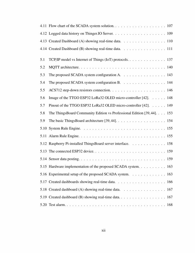
4.11 Flow chart of the SCADA system solution. . . . . . . . . . . . . . . . . . . 107
4.12 Logged data history on Thinger.IO Server. . . . . . . . . . . . . . . . . . . 109
4.13 Created Dashboard (A) showing real-time data. . . . . . . . . . . . . . . . 110
4.14 Created Dashboard (B) showing real-time data. . . . . . . . . . . . . . . . 111
5.1 TCP/IP model vs Internet of Things (IoT) protocols. . . . . . . . . . . . . . 137
5.2 MQTT architecture. . . . . . . . . . . . . . . . . . . . . . . . . . . . . . . 140
5.3 The proposed SCADA system configuration A. . . . . . . . . . . . . . . . 143
5.4 The proposed SCADA system configuration B. . . . . . . . . . . . . . . . 144
5.5 ACS712 step-down resistors connection. . . . . . . . . . . . . . . . . . . . 146
5.6 Image of the TTGO ESP32 LoRa32 OLED micro-controller [42]. . . . . . 148
5.7 Pinout of the TTGO ESP32 LoRa32 OLED micro-controller [42]. . . . . . 149
5.8 The ThingsBoard Community Edition vs Professional Edition [39, 44]. . . . 153
5.9 The basic ThingsBoard architecture [39, 44]. . . . . . . . . . . . . . . . . . 154
5.10 System Rule Engine. . . . . . . . . . . . . . . . . . . . . . . . . . . . . . 155
5.11 Alarm Rule Engine. . . . . . . . . . . . . . . . . . . . . . . . . . . . . . . 155
5.12 Raspberry Pi-installed ThingsBoard server interface. . . . . . . . . . . . . 158
5.13 The connected ESP32 device. . . . . . . . . . . . . . . . . . . . . . . . . . 159
5.14 Sensor data posting. . . . . . . . . . . . . . . . . . . . . . . . . . . . . . . 159
5.15 Hardware implementation of the proposed SCADA system. . . . . . . . . . 163
5.16 Experimental setup of the proposed SCADA system. . . . . . . . . . . . . 163
5.17 Created dashboards showing real-time data. . . . . . . . . . . . . . . . . . 166
5.18 Created dashboard (A) showing real-time data. . . . . . . . . . . . . . . . 167
5.19 Created dashboard (B) showing real-time data. . . . . . . . . . . . . . . . . 167
5.20 Test alarm. . . . . . . . . . . . . . . . . . . . . . . . . . . . . . . . . . . . 168
xii
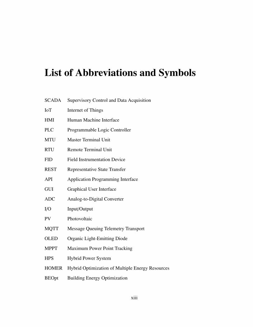
List of Abbreviations and Symbols
SCADA Supervisory Control and Data Acquisition
IoT Internet of Things
HMI Human Machine Interface
PLC Programmable Logic Controller
MTU Master Terminal Unit
RTU Remote Terminal Unit
FID Field Instrumentation Device
REST Representative State Transfer
API Application Programming Interface
GUI Graphical User Interface
ADC Analog-to-Digital Converter
I/O Input/Output
PV Photovoltaic
MQTT Message Queuing Telemetry Transport
OLED Organic Light-Emitting Diode
MPPT Maximum Power Point Tracking
HPS Hybrid Power System
HOMER Hybrid Optimization of Multiple Energy Resources
BEOpt Building Energy Optimization
xiii
Chapter 1
Introduction and Literature Review
1.1 Introduction
Electricity has become one of the basic amenities of man due to its wide usage in various
aspects of life. With the recent quest for a greener environment, there is an extended use
of more renewable energy and less fossil fuel for power generation. Thus, more renewable
generation sources such as solar photovoltaic and wind turbines are continuously being in-
jected into today’s power systems to form hybrid power systems, and to provide electricity
for mankind. This trend is expected to continue in the coming decades [1]. However, an in-
creased ratio of renewable generation sources may cause several issues in the power grid. To
reduce these issues, energy storage systems are often incorporated into the renewable gen-
eration systems. Examples of such issues include the following. First, difficulty in system
frequency control due to fluctuations in the outputs of renewable generation sources. By
convention, frequency control is mostly managed by the output change capability of ther-
mal generators and this implies inefficient operation as thermal generators are not operated
to full capacity when used for frequency control purposes [1]. This is so because renewable
generating units themselves only supply a negative margin in most cases, thus with greater
1
penetration of renewable generation, there is a further decrease in the efficiency of thermal
generators as they try to increase the output margins. Energy storage systems can mitigate
this output fluctuations in renewable generation systems, which will lead to a reduction in
the margins of thermal generators, and thus lead to higher efficiency in their operations.
Secondly, renewable energy is affected by weather conditions and since weather conditions
are largely unpredictable, the output is undependable. This makes connecting them to the
grid difficult. Although some measures are available to cope with these challenges such
as increasing the amount of renewable generation installed (overcapacity), and spreading
renewable generators over a wider geographical area to take advantage of varying weather
conditions from place to place and of smoothing effects expected from the complementary
wind and solar generators, energy storage systems represent the most cost-effective and
reliable measure considering the cost of extra renewable generation and the challenges of
constructing new transmission facilities [1].
Furthermore, it is important to ensure the correct balance between electricity supply
and demand as an imbalance will damage the stability and quality (voltage and frequency)
of the power supply. Due to the need for a continuous and flexible supply in the power
system to avoid these issues, generating plants are usually equipped with two essential
functions, in addition to their basic generating function. First, a “kilowatt function”, to
generate enough power (KW) when necessary. Secondly, a frequency control function, fine-
tuning the output to follow the continuous fluctuations in demand, using extra power from
the “kilowatt function” when necessary. However, renewable energy facilities such as solar
and wind do not posses both a KW function and a frequency control function unless they
are suitably modified. Such modifications could be in decreasing power (negative power
margin) or a phase shift inverter. Energy storage systems in renewable energy facilities help
to compensate for such difficulties with a KW function and a frequency control function.
Also, in the event of failures in the power network, energy storage systems help in the
2
continuous supply of power to consumers [1, 2]
From the discussions above, the importance of renewable power generation systems,
as well as their interconnected energy storage systems cannot be overemphasized. Thus,
there is a need to implement a safe, timely, reliable and sophisticated means of managing
the operations of the entire generation system. While it may be necessary to have local
means of implementing this management, it is equally important to have a coordinated
control either as a standalone system or with other components in the grid when grid-
wide applications are desired. In most cases, power electronic converters provide a means
of connecting the renewable generation and energy storage systems to the grid. Power
electronic systems also help in the synchronization of the various generating systems to the
utility grid, including the converter which modulates the waveforms of current and voltage
to a level that can be directly fed into or taken from the grid. Sometimes, the converter could
be connected to a transformer to provide the required voltage before the grid connection,
thus increasing the efficiency of the entire system [1]. The converter is managed by a
controller which defines the set points and parameters of the renewable generation and
energy storage systems, including the magnitude of active and reactive power, and state
of charge (SOC) of the storage system. In many applications, the energy storage systems,
the power electronic converters and other devices connected to the grid are from multiple
manufacturers and vendors, and so compatibility and interoperability of the systems in
terms of communications and electrical connections are imperative. Furthermore, because
these components are usually distributed over large geographical areas, sometimes in harsh
environments, such as deep offshore and swamps, the control strategy is even more critical.
Thus, due to this complex nature of the entire system and control strategies, local workforce
may not be cost-effective, hence, there is the need for a reliable system for managing the
entire power generation system remotely [1, 2]. In this thesis, Supervisory Control and
Data Acquisition (SCADA) system is proposed for the remote monitoring and control of the
3
renewable power generation systems. In the proposed SCADA system, key parameters from
the power generation system such as Current, Voltage, and Power are measured, processed,
and transmitted to the control platform, and based on the real-time parameters, and the
perceived conditions of the entire network, the control platform, which is an element of
the proposed SCADA system, is able to manage the power generation system for optimum
operation.
1.2 Background
SCADA is an acronym formed from the first letters of the term “Supervisory Control and
Data Acquisition”. It is a technology that enables a user to collect data from one or more
distant facilities and/or send limited control instructions to those facilities. The major func-
tion of SCADA is for acquiring data from remote devices such as batteries, valves, pumps,
transmitters, etc. and providing overall control remotely from a SCADA Host software
platform [3, 4, 6]. SCADA makes it unnecessary for an operator to be assigned to stay at
or frequently visit these remote locations when the facilities are operating normally. First
developed in the 1950s, SCADA has evolved from its use in telephone relay systems and
minicomputers [3]. The first “SCADA” systems utilized data acquisition by means of pan-
els of meters, lights and strip chart recorders. Supervisory control was exercised by the
operator manually operating various control knobs. These devices were and are still used
to do supervisory control and data acquisition on plants, factories and power generating
facilities [3–8]. Below is an overview of the generations of SCADA Architectures [5]:
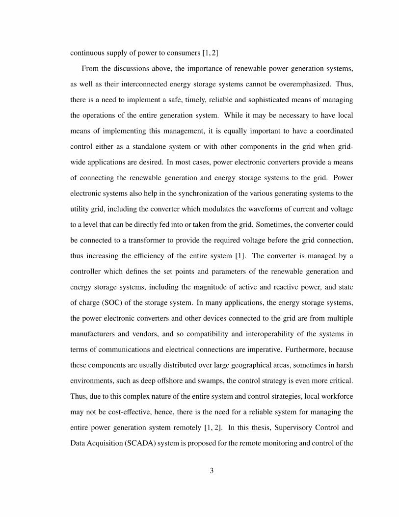
• First Generation - Monolithic SCADA: The original SCADA system was created
during a time when networks did not exist. It involved standalone systems with vir-
tually no connectivity to other systems. It was implemented using two identically
equipped mainframe systems where Wide Area Networks (WANs) communicated
4
with only Remote Terminal Units (RTUs). The system used mostly proprietary soft-
ware, and redundancy was achieved by the connection of a back-up mainframe to all
the RTUs. The Monolithic SCADA architecture is shown in Figure 1.1.
Figure 1.1: First Generation - Monolithic SCADA [5].
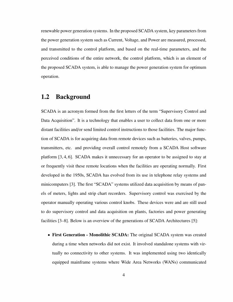
• Second Generation - Distributed SCADA: The second generation of SCADA took
advantage of LAN technology for distribution of system functions and processes
across multiple systems. The systems were cheaper and more miniaturized than its
predecessor. In almost real-time, information was shared across stations that each had
their own tasks. Distribution increased the processing power, reliability and redun-
dancy of the system, but it was not capable of reaching beyond the limits of the local
environment, and the LAN Protocols used were mostly proprietary. The Distributed
SCADA architecture is shown in Figure 1.2.
Figure 1.2: Second Generation - Distributed SCADA [5].
5
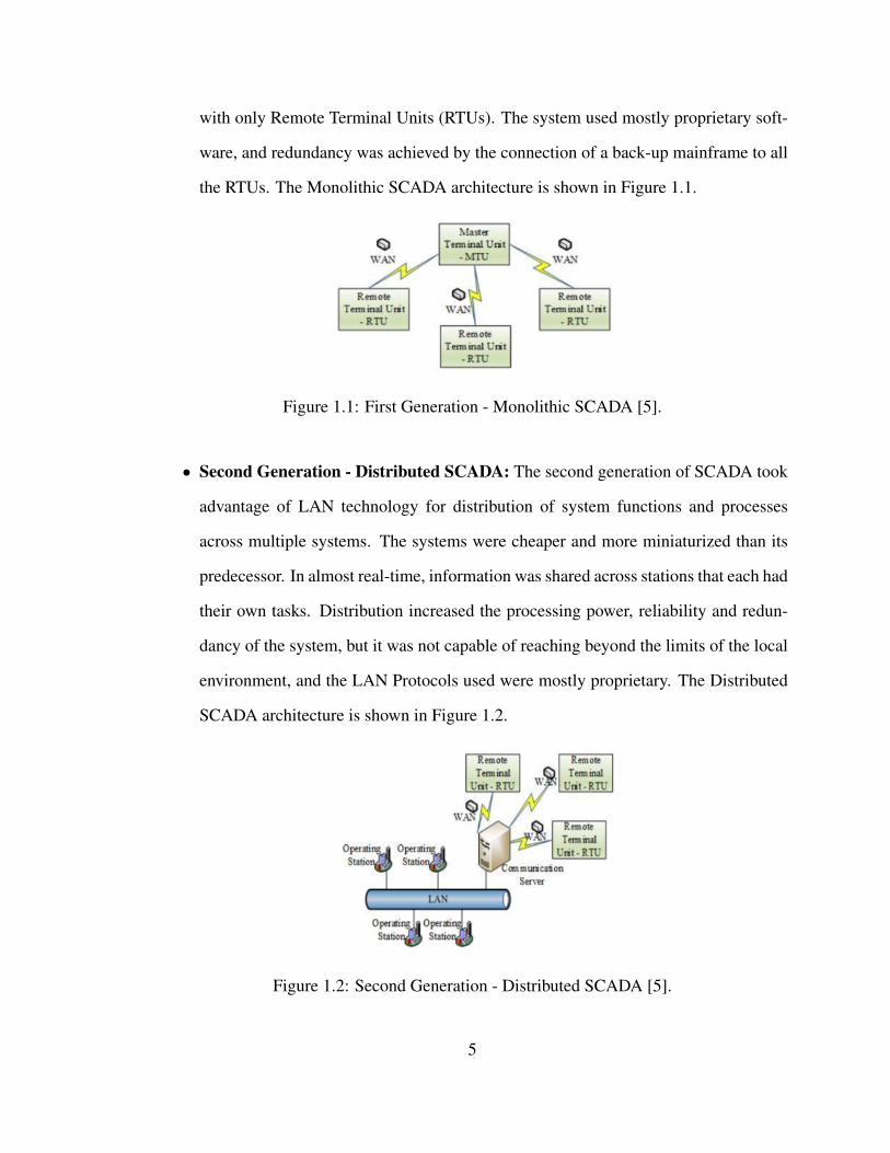
• Third Generation - Networked SCADA: This generation of SCADA involved open
system architecture with multiple networked systems communicating over WANs,
sharing master station functions and utilizing PLCs for monitoring purposes. With
distributed SCADA functionality across a WAN, this generation was much like the
2nd generation. However, unlike the 2nd generation, it was able to connect to the
internet and third-party peripherals using Internet Protocol (IP). This SCADA archi-
tecture is still in use today. However, due to technological advancements, SCADA
systems have now developed using advanced software, high performance micropro-
cessors and wireless, cloud and Internet of Things (IoT) technologies, leading to the
fourth generation SCADA. The Networked SCADA architecture is shown in Figure
1.3.
Figure 1.3: Third Generation - Networked SCADA [5].
• Fourth Generation - Internet of Things (IoT) based SCADA: Combining the con-
ventional SCADA with the cloud, IoT provides SCADA systems with an alternative
to PLCs and involves the use of data modelling and complex algorithms, thereby
resulting in increased data accessibility, flexibility, availability, scalability, and cost
efficiency. The proposed open source SCADA systems in this thesis will be built
under this IoT-based architecture as will be seen later in this work. The Internet of
Things SCADA architecture is shown in Figure 1.4.
6
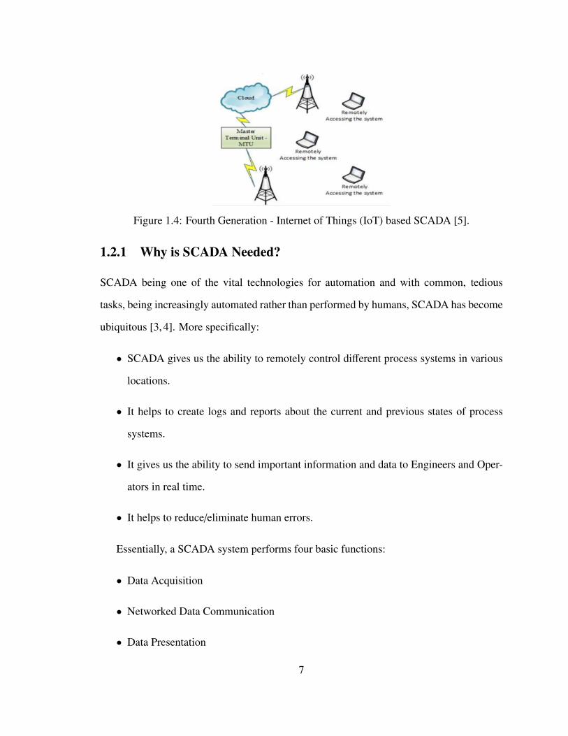
Figure 1.4: Fourth Generation - Internet of Things (IoT) based SCADA [5].
1.2.1 Why is SCADA Needed?
SCADA being one of the vital technologies for automation and with common, tedious
tasks, being increasingly automated rather than performed by humans, SCADA has become
ubiquitous [3, 4]. More specifically:
• SCADA gives us the ability to remotely control different process systems in various
locations.
• It helps to create logs and reports about the current and previous states of process
systems.
• It gives us the ability to send important information and data to Engineers and Oper-
ators in real time.
• It helps to reduce/eliminate human errors.
Essentially, a SCADA system performs four basic functions:
• Data Acquisition
• Networked Data Communication
• Data Presentation
7
• Monitoring and Control
1.2.2 Elements/Levels of SCADA Systems
There are four basic elements or levels of a SCADA system which allow it to perform the
various functions outlined in Section 1.2.1 [3, 4]. They are summarized below:
• Field Instrumentation Devices (FIDs): Like Tom DeMarco rightly said, “you can-
not control what you cannot measure”, meaning that instrumentation is a key com-
ponent of a safe and optimized control system. These devices include Sensors, Ac-
tuators, Transmitters, and so on, which are directly connected to the process systems
being managed, and they help to measure the various control parameters such as cur-
rent, voltage, power, temperature, pressure, state of charge, etc.
• Remote Terminal Units (RTUs): These are small computerized units, micro-controllers,
micro-processors (such as Programmable Logic Controllers (PLCs)), etc. deployed
in the field at specific sites and locations, and they help to collect the control informa-
tion locally from the field instrumentation devices, process the information and parse
them on to the master station for human machine interactions.
• Master Terminal Units (MTUs)/SCADA Host Platforms: These are larger com-
puter consoles or servers that serve as the central processor for the SCADA system.
At the heart of this unit is the device that issues all the commands, gathers all the data,
stores the necessary information, parses other information to the associated systems,
interfaces with the various operators of the process facilities and provides a human
machine interface (HMI) to the administrator where the system can automatically be
monitored and managed in response to the FID (sensor) inputs.
• Communication Networks: These help to connect and transmit data from the field-
based RTUs/PLCs to the SCADA Host Platform usually located remotely at the
8

field office or central control centre using various communication protocols such as
TCP/IP, Ethernet, Wi-Fi, Fieldbus, Modbus, Distributed Network Protocol (DNP),
Profibus, DirectNet, and so on.
1.2.3 Applications of SCADA
SCADA finds applications in various fields, including [3]:
• Electric Power Generation, Transmission and Distribution
• Oil and Gas Production Facilities
• Buildings, Facilities and Environments.
• Mass Transit
• Water and Sewage
• Traffic Signals
1.2.4 Desired Characteristics in a SCADA System
In order for a SCADA system to effectively perform the enumerated functions above, some
important characteristics are necessary in the SCADA system. They include the following
[9]:
• Dynamism: This means that SCADA nodes are not static, but flexible to allow the
connection of new nodes and disconnection of existing nodes.
• Retrofit: SCADA solutions should allow upgrading/updating and the addition of new
technologies/features to the existing installations.
9
• Ease of Installation/Use: : SCADA systems should be easy to deploy and to use.
For instance, sensors should not need a separate energy source and the system should
have wireless capabilities to reduce the cost of installing a monitoring network.
• Redundancy: There should be redundancy in nodes to increase the reliability of the
SCADA system.
• Low Power Consumption: Since a SCADA system is required to operate 24/7 so
as to effectively monitor the process facility being managed, it is important that the
power consumption is as minimal as possible. This will help to keep the operating
cost of the system within a reasonable range.
• Reliability and Availability: A SCADA system for a renewable power generation
system, as well as its associated energy storage systems must be highly reliable as
a failure in such a SCADA system could affect the overall power system stability
since the renewable generation system and the energy storage systems are important
components of a hybrid power system and play a key role in ensuring the stability of
the entire system. SCADA failures are said to occur in such systems when an oper-
ator is unable to retrieve data from or issue control commands to the primary plants
associated with one or more busses [10]. A. G Bruce [10] presented a method of
evaluating SCADA system reliability using aggregate assessment of system reliabil-
ity which can define reliability in terms of absolute cost. In another development, H.
Guozhen et al. [11] proposed possible solutions for SCADA system communication
reliability using PV power plants as a case study. In their work, the authors believed
that the reliability of a SCADA system is mainly affected by communication security
and device failure.
• Security: This is discussed in Section 1.2.5 below:
10
1.2.5 SCADA System Security
Security in a SCADA system is a serious issue both from the operational point of view and
economic point of view as the resultant unavailability of the critical infrastructure being
managed in the events of attacks can disrupt the related operations which could cost a huge
amount of money. Conventional SCADA systems already lack proper security measures;
however, with the integration of complex new architectures for the new Internet based on
the concepts of IoT, cloud computing, mobile wireless sensor networks, and so on, there
are more issues at stakes in the security and deployment of these classical systems [5]. It
is a general belief that the conventional SCADA system was not originally built to oper-
ate within the enterprise environment. Many therefore believe that the interconnection of
SCADA and business systems across the enterprise network pose the greatest threats to
SCADA as the SCADA components are conventionally unable to deal with the exposure
to viruses, worms, and malware that are commonly found today within the enterprise net-
work [12]. Even though the convergence of SCADA systems and control networks into
conventional IT systems has widened the SCADA security vulnerability spectrum, the ben-
efits of interconnecting SCADA and enterprise network are numerous, especially with the
new IoT-based architecture, and so tackling the related security challenges is the right step
to take. Many literatures have reviewed the security threats in a SCADA system, each
proposing various solutions. S. D. Antón et al. [13] have presented the security challenges
in the classical SCADA system. In their work, they highlighted the common attacks at the
various levels of the SCADA system. These are summarized below:
• Attacks on RTUs/PLCs: In contrast with office IT systems which mostly handle
data, PLCs/RTUs control cyber-physical systems such that they operate and interact
with devices in the real world. Therefore, attacks on these devices have an impact on
both physical entities and the entire operations. Attacks on PLCs/RTUs include unau-
11
thorized execution of malicious remote or local codes, unauthorized data extraction,
partial or full degradation of the availability of a service or resource, and maliciously
obtaining higher privileges on the system.
• Attacks on Communication Network/Fieldbus Level: Industrial networks sup-
port a vast landscape of fieldbus communication protocols both proprietary and open
source, including Modbus, Profibus, CAN, Ethernet, Local Interconnect Network,
Media Oriented System Transport, FlexRay, Powerlink, etc. Each of these protocols
has its security flaws. Such attacks include Man in the Middle (MitM) and DoS. Au-
thentication and Encryption are some possible solutions to these kinds of attacks but
even so, they are not 100% efficient [13].
• Attacks on Wireless Systems: Some wireless communication protocols used in in-
dustrial environments for SCADA systems include Bluetooth Low Energy, ZigBee,
Z-Wave, Radio Frequency Identifier, Long Range Wide Area Network (LoRa), and
Wireless Local Area Network. Since there is no physical access control to the wire-
less channel, an adversary within the range of the wireless signal can listen to the
communication and explore its vulnerabilities to deploy various attacks such as MitM
and DoS [13].
• Physical or Hardware Attacks: These are among the most difficult forms of attacks
to handle as an adversary with physical access to a device or system could easily
inflict damage on the device, rendering it unusable and creating a DoS. These also
include attacks on embedded devices such as PLCs, where input and sensor values are
falsified, leading to undesired system behaviours [13]. An example of such attacks is
Ghost in the PLC attacks [13]. There are also other attacks associated with office IT
infrastructures such as phishing and spear phishing.
Elsewhere, S. Rautmare in literature [14] classified security threats associated with SCADA
12
systems more generally into Application exploits, Backdoor attacks, Operating system (OS)
exploits, Authorized user exploits, Configuration change exploits, and Tampering. Accord-
ing to the author, some of the hard SCADA system security challenges include [14]: (1)
Disruption of process through acquiring control of SCADA network, (2) Difficulty in de-
tecting illegal configuration changes in real time, (3) Insider threat, (4) Integration, (5)
Performance and cost of the chosen security solution, (6) Security threats from open, un-
bounded and interconnected networks, (7) Network latency and response of control system
network to the security solution. In addition to these security challenges stated above which
classical SCADA systems face, literature [5] presented some of the security challenges in-
volved in the new IoT-based SCADA systems. These security challenges include [5]: (1)
Data on the cloud is only separated internally since the same cloud can be accessed by other
clients, (2) Difficulty in keeping track of data logging in the cloud-based system, (3) The
lack of proper authentication and encryption mechanisms for IoT-based SCADA systems,
(4) Difficulty in implementing proper solutions for protecting the embedded devices at the
core of industrial IoT-based SCADA systems, (5) SCADA system applications running on
the cloud can be easily searched and abused by attackers, (6) Security threats from other
web applications in the cloud, (7) The SCADA system integrated into the cloud will have
all the same risks as a typical cloud infrastructure, such as vulnerabilities from the cloud
and external individual service providers, (8) System commands and information can be
modified, sniffed, lost, or spoofed during communication as the reliance on cloud commu-
nication makes the SCADA systems more open.
Furthermore, the author in [14] proposed some recommendations to improve upon the
conventional SCADA system security, including the following: (1) Implementation of a se-
curity policy, (2) Enabling inherent security features of SCADA components, (3) Disabling
unused ports and services, (4) Implementing audits at regular intervals, (5) Defining infor-
mation security roles and responsibilities, (6) Evaluating information security risk profile,
13
(7) Establishment of change and configuration management process, (8) Deploying an ef-
fective intrusion detection system/intrusion prevention system, (9) Ensuring restricted inter-
net access in critical process control area and associated machines, (10) Isolating business
traffic from process control network, (11) Ensuring that only process control applications
are running over SCADA servers, (12) Ensuring secured communication tunnels, (13) Use
of multi-factor authentications, and (14) Identifying unguarded access points. In addition
to these classical SCADA system security recommendations, literature [5] presented more
recommendations to specifically tackle the security challenges in the IoT-based SCADA
systems. They include: (1) Network segregation, (2) Continuous monitoring and analysis,
(3) Log analysis, (4) Network traffic monitoring, (5) Memory dump and file integrity anal-
ysis, (6) Regular update and patching, etc. In this thesis, some of these recommendations
are considered in developing the IoT-based open source SCADA system solutions.
1.2.6 Classes of SCADA Systems
Generally, there are two classes of SCADA hardware and software; Proprietary (Commer-
cial) and Open Source.
• Proprietary (Commercial) SCADA: A Proprietary system is one in which all ma-
jor components are from one manufacturer and the standards are often specific to
that system and developed by the manufacturer [6]. Companies develop Proprietary
SCADA Hardware and Software systems which they sell as turnkey solutions. With a
Proprietary SCADA system, the responsibility for system reliability and security rests
solely with the manufacturer, which leaves the user vulnerable to a single manufac-
turer/supplier as the manufacturer/supplier could be slow to respond to technological
changes in a subsystem of the SCADA system. The customer is also at risk if the
manufacturer/supplier goes out of business. This solution is largely expensive since
the manufacturer/supplier is not under the same competitive pressure to keep prices
14
down after the initial sale [6]. There is also the problem of flexibility with the already
existing devices and network. For example, in a large Electrical Utility system, the
devices in the SCADA system are required to communicate with all other devices
connected to the network, and if such devices are from different vendors, then the
SCADA must support each vendor’s protocol and the implementation of such a sys-
tem increases costs and requires more engineering time. Known proprietary SCADA
manufacturers/suppliers include Siemens, Allen Bradley, General Electric, Emerson,
Schneider Electric, Modicon, Mitsubishi, Omron, and so on.
• Open Source SCADA: An Open Source system allows a user to "mix and match"
components and choose the most appropriate from several suppliers [6]. The user en-
joys greater flexibility as the user is not beholden to a single supplier. This means that
with an Open Source system, no one supplier is responsible for overall system perfor-
mance. In an Open Source SCADA system, the major components adhere to certain
standards which allow them to be interchanged with similar components manufac-
tured by others to the same standards. These standards govern the interconnections
between major system components such as Instrumentation and Remote Terminal
Units (RTU) (covering connection types, contact ratings, isolation, current levels,
voltage levels, etc.); RTU and communications bearer (covering impedance, com-
munication protocols, signalling techniques and frequencies); and communications
bearer to Master Station [6]. There are a few open source SCADA systems available
on the market today, each with its strengths and weaknesses. In this thesis, taking
some of the security recommendations presented earlier into consideration, various
low-cost, open source SCADA systems are designed, developed and implemented.
The proposed SCADA systems are based on the Internet of Things (IoT) SCADA
architecture as will be seen later in this work.
15
1.3 Literature Review
The research communities all over the world have been working assiduously to solve the
problems associated with proprietary SCADA systems, and to offer various open source
remote monitoring and control solutions using a combination of open source hardware,
servers, software and IoT platforms. However, each of these solutions has its flaws, some
of which tend to outweigh the accrued benefits of the resulting SCADA system. The related
works under the various open source elements or categories are presented below:
1.3.1 Open Source Hardware
Some of the available open source hardware include PLCs, PIC micro-controllers, and PCs.
Their related SCADA solutions in literatures are presented below:
1.3.1.1 PLC-Based Systems
W. Xibin et al. [15] presented a PLC-based SCADA system for oil storage and related ap-
plications. The structure of the developed SCADA which the authors called Ring Road
SCADA comprised of PLC of AB company to serve as a controller and a special network
ControlNet for data exchange. In addition, the control system comprised of two CPU mod-
ules of the same specifications and two heat standby System Redundancy Modules (SRM)
to realize the heat standby data of a dual-CPU, and a special ControlNet formed commu-
nication network consisting of four ControlNet Bridge Redundant (CNBR) modules and
a Communication Interface Card (PCIC card) to exchange data between operation station
and down PLC, and to complete the control order sending and data uploading. Some of
the identified features of the developed PLC-based SCADA included data collection by the
data modules, real-time monitoring and management, local and remote-control capabilities,
high reliability, flexible configuration and ease of expansion, as well as low-cost.
16
However, although PLC-based SCADA systems are robust, the systems are very com-
plex, and thus less reliable, and they rely heavily on highly developed electronic companies
to produce sophisticated PLCs. In addition, they are generally expensive, they usually have
software and hardware restrictions, they require different operating skills such as system
analysts and programmers, the operator can see only as far as the PLCs, and with thousands
of Inputs and Outputs (I/O) and sensors involved, there is a lot of wire to deal with [12].
1.3.1.2 PIC Micro-controller-Based Systems
To address some of the drawbacks associated with PLC-based SCADA systems and to
further reduce SCADA costs, S. Sahin et al. [16] presented an open source, economical
peripheral interface circuit (PIC) micro-controller based SCADA system using various ex-
perimental setups to illustrate the implementations of their proposed system. Some of the
components used in their proposed solution include the PIC16F877 micro-controller to-
gether with a large RAM and an internal EEPROM, an eight-channel, 10-bit A/D con-
verter for real time monitoring applications, RS232 connection for data transfer to and
from a standard parallel port available in most computers, LEDs, high-voltage outputs and
inputs embedded into the control cards, LabVIEW commercial software for the SCADA
front panel GUI and block diagrams which held the data flow and graphical source codes.
One disadvantage pointed out in this system was the lack of the combination of internet-
based communication technologies which is an important part of a distributed system like
SCADA [16]. Elsewhere, M. Zahran et al. [12] proposed a PIC micro-controller based
SCADA system using Atmel (AT328) micro-controllers as the RTUs, a client Laptop PC
with an open source SCADA software to serve as the MTU where HMIs were created, and
an Ethernet controller to serve as system server.
In general, although PIC micro-controllers are cheap and portable, it is more difficult to
handle PIC micro-controllers compared to other more advanced micro-controllers such as
17
an Arduino. For example, it is challenging to interface devices with PIC compared to an
Arduino.
1.3.1.3 PC-Based Systems
In a PC-to-PC (PtP) SCADA, standard PC configurations are placed on both the MTU and
RTU sides of the communication link. The PC-based RTU will usually have custom soft-
ware and is usually in charge of communication with the PC-based MTU, direct control
of parameters, intelligent decision making and data storage [17]. E. Babovic et al. [17]
presented a PC-to-PC SCADA solution using cheap and open source components, includ-
ing PC-based MTU with user friendly HMI, mobile communication devices (such as GPS)
and channels, and one or more PC-based RTU stations with simple hardware controller de-
vices using a modified Spiral Model for the development of their work. In their experiment
using Microsoft Visual Basic 6.0, two PCs were connected over simple LAN connection,
and the MTU and RTU software modules which they developed with C++ maintained the
connections using Winsock control and helped to ensure that commands from the MTU
were executed by the hardware controller modules. Elsewhere, S. U. Abdi et al. [18] pre-
sented the design and implementation of PC-based SCADA training system for the natural
gas transmission and distribution industry. The architecture of their proposed PC-based
SCADA training system included a central monitoring and control station connected to
PC-based RTUs via Industrial Ethernet, and Winsock control in Visual Basic 6.0 used to
connect multiple terminals to each other and to provide easy access to network services.
Their VB-based HMI design allowed real-time monitoring of pressure, temperature, level,
light, humidity, security switches, AC input, A/D and D/A conversion values. Although
PC-based SCADA systems are platform/protocol independent, low cost, simple to imple-
ment, easy to maintain, ensure ease of expansion and further development, they are less
reliable than the conventional SCADA systems. Hence, the reason why PLCs are generally
18
preferred to PCs for automation systems.
1.3.1.4 ESP8266-Based Systems/Web-based Wireless Sensor Solutions
T. Turc et al. [19] have proposed a web-based wireless SCADA using low cost ESP8266
module. In their work, the authors presented two methods of implementing the proposed
SCADA solution. In the first method called Periodic Unidirectional Transfer, data flowed
from the data acquisition system towards a centralized Web Server. The data acquisition
system (DAS), which was a PLC, bridged the gap between the sensors and the communica-
tion channel, collected data from sensors and periodically sent the data to the Web Server
without expecting any acknowledgement of successful receipt. On the other hand, the Web
Server continuously listened on the channel and whenever it received commands, it pro-
cessed the received commands and stored the processed sensor parameters in a database,
and then the database was made available to the Web Clients such that the web clients were
not in direct communication with the DAS. The ESP8266 module, a low-cost module with
TCP/IP Wi-Fi capabilities was used to implement the wireless network communication and
the sender made use of a hardware device called Access Point (AP) guarded by a security
key (SK) to connect to the wireless network. According to the authors, even though this first
method was simple, it was unreliable as it couldn’t prevent data from being occasionally
lost since the recipient had no means of acknowledging information receipt [19]. To address
this drawback and to ensure that the monitoring system was able to track important param-
eter changes in the process of data transfer, the authors proposed an alternative method of
implementing the web-based wireless sensor SCADA called on-demand bidirectional data
transfer using the same ESP8266 module. In this case, the Web Client transmitted update
requests to the DAS in one direction, and the DAS replied with the requested information
in the opposite direction. However, while this second method of implementation was more
responsive, it made the system more complex [19].
19
ESP8266 Wi-Fi modules can serve both as a server and as a client and they continue to
gain popularity due to their low cost, flexible design, enhanced functions, and IoT archi-
tecture but they are mostly proven in home automation domains and they still need a lot of
improvements for robust applications and high reliability [20, 21].
1.3.1.5 Arduino-Based Systems
In [22], an open source, low-cost SCADA to monitor and control a Water Pumping Sta-
tion was developed using Arduino micro-controller board as the Remote Terminal Unit
(RTU). The Arduino board was used to implement a standalone data acquisition and con-
trol unit which monitored and controlled equipment in the field as the field equipment were
connected to the Arduino board while the Arduino was in turn connected to the MTU for
remote control, and a Tablet for local control in the field. In their application, the Arduino
board was programmed with C++ to measure the Ultrasonic sensor inputs and send the val-
ues through USB to the HMI, while at the same time listening to the incoming commands,
such as turn on the pump. Although Arduino based systems are simple to implement and
support a wide array of sensors, including third party sensors, using them as standalone sys-
tems require a lot of efforts to accomplish some tasks such as scheduling and database stor-
age [23]. Furthermore, even though Arduino and ESP8266 web-based systems are much
more superior compared to PIC based systems, novel Arduino plus IoT based systems play
much more superior roles compared to the web-based system [21].
1.3.2 Open Source SCADA Software Solutions
Various open source SCADA software solutions exist on the market. Examples of such so-
lutions include Rapid SCADA, Tango SCADA, PV Browser, Mango, PySCADA, FreeSCADA,
IntegraXor, and so on. A. M. Grilo et al. [9] presented an integrated Wireless Sensor and
Actuator Networks (WSAN) and SCADA solution for monitoring critical infrastructures
20
using an Internet Protocol (IP) (Gateway), and Web-based services together with the open
source and web-based Mango SCADA which provided an integrated platform accessible
from the internet. The authors demonstrated this solution by using it to monitor and control
an electrical power grid. They also addressed some of the challenges faced in developing
a typical SCADA system, including Real-time Communications, Quality of Service (QoS),
Management Support, and Security. The main disadvantage of using a standard SCADA
software like Mango and Rapid SCADA is that they communicate using several protocols,
and it is difficult to customize the protocols without a specific training on the system [21].
These open source SCADA software solutions are also not 100% free.
1.3.3 Open Source Server Options
Just like the open source SCADA software solutions, there are also open source SCADA
server solutions available today. Examples of such servers include LabView, KingView, and
Simulink-based systems. Some of the related works in this domain are presented below:
M. Regula et al. [24] presented an open source SCADA system for power quality mon-
itoring and control in a smart micro-grid using LabView. The system operated with nine
measured and remotely managed nodes, each node containing ON/OFF button, which could
be used to control power switching element of universal measuring block. This block of
network each time sent a file with analog measured parameters and their average values
were displayed on the main window of LabView SCADA system for monitoring. Else-
where, X. Zhaoxia et al. [25] presented an open source SCADA system to monitor an
Islanded DC micro-grid, including wind turbine, photovoltaics, and battery units, based on
KingView 6.55. The SCADA system established data communication between the host and
the slave computers through intelligent modules and different communication techniques.
The developed SCADA system was able to monitor real-time parameters such as voltages,
currents, or powers, and store the important parameters into an SQL database. In their
21
solution, the host computer (server) was a KingView configuration software installed on a
Windows PC with RS 232C Communication capability, and many intelligent modules were
connected to this host computer through a cable in one case (Modbus TCP/IP) and through
an RS-232/485 converter in another case (Modbus TCP/IP) while remote monitoring was
established using GPRS service platform.
In yet another development, R. M. J. Rathnayaka et al. [26] presented a scalable open
source SCADA server solution together with a cost-effective communication media for
multi-protocol smart grid devices. In their solution, an OPC Server was designed with Mat-
Lab/Simulink to bridge windows-based software applications and process control hardware,
as well as to serve as a middleware to establish communications in the multi-protocol envi-
ronment. Furthermore, they used the low-cost cellular (GPRS/3G) communication protocol
to transfer the data between the Simulink-based OPC SCADA central server and the field
installed devices (RTUs).
Even though it is quite straightforward to implement LabView/KingView, and Simulink-
based systems, they are expensive compared to other low-cost technologies [21].
1.3.4 Internet of Things (IoT) Based SCADA Systems
The Internet of Things (IoT) based SCADA domain involves the use of one or more IoT
platforms as the Master Terminal Unit, or SCADA Host Server. Examples of open source
IoT platforms include Ubidots, Thingspeak, SiteWhere, OpenIoT, DeviceHive, KaaIoT,
Blynk, Emoncms, Thinger.IO, ThingsBoard, Freeboard, etc [27]. A few researchers have
proposed some solutions to implement IoT-based SCADA systems using IoT platforms.
For example, R. J. Tom et al. [28] proposed an IoT-based SCADA system integrated with
Fog Router and Cloud for power distribution automation to monitor and control consumer
utilization, power outage, power quality, and pole transformer health. They implemented
their proposed solution by dividing the distribution automation sensing area into three seg-
22
ments; (1) Smart metering for monitoring and controlling the home supply, (2) Line sensors
for monitoring the voltage and the current supply in the lines, and (3) Intelligent Electronic
Devices (IEDs) to monitor the parameters like temperature, loading, voltage, current and
supplied power. Also, for monitoring the Transformers, Power lines and Smart meters, Fog
Router was placed in between the Pole Transformer and the Consumer side. The smart sen-
sors and meters used the IP based communication built upon the IEEE 802.15.4, known as
IPv6 Low-power wireless Personal Area Network (6LoWPAN) to collect and send voltage,
current and power consumption data from homes to the Fog Routers. The IEDs fixed on the
Pole Transformers also used 6LoWPAN communication to reach the Fog Routers. The Fog
Routers thus acted as the 6LoWPAN gateway, where the data from smart meters, line sen-
sors, and IEDs were collected in real-time for analytics while using backbone network like
3G/4G for communicating with the IoT-Cloud platform such that the acquired data were
available to numerous operators with predetermined access keys.
Elsewhere, S. Blanch-Torné et al. [29] proposed an agent-based DCS in the form of an
IoT-based SCADA architecture. In their solution, they showed how Public Key Infrastruc-
ture (PKI) functionalities built with distributed features can be integrated into the DCS of
an industrial control system to act as a multi-agent based IoT SCADA since the main differ-
ence between a SCADA and a DCS is the centralization of the monitoring and control over
the field instruments in the SCADA. Their architecture comprised of a DCS with multiple
agents embedded in it to act like processes in a system, and a cloud storage. The agents
included Interface agent, host agent, agent controller, process agent, and instrument agent,
all connected to the naming service, PKI service and permanent storage. Each of these
agents played various roles found in a typical SCADA system to implement their proposed
solution. The agents also formed a kind of P2P network and they communicated with each
other in a Handshake process within a secure channel to address the main security threats
in such a system.
23
In another development, my predecessor, S. L. Jayasinghe [21], developed an open
source low-cost SCADA system for the monitoring and control of a grid-tied inverter con-
nected to an Energy Storage System by using ThingSpeak Local Server and Python. In
implementing his proposed solution, he developed Python-based program which allowed
a user to obtain data from the serial port and post the data to the ThingSpeak local server
platform where the user could view and download data from the ThingSpeak server plat-
form. Furthermore, he also developed a graphical user interface (GUI) to interact with the
SCADA system, and to show the current data values, as well as allow the user to set the
controlling variables. The developed system was tested with an Inverter at the University of
New Brunswick and it gave a satisfactory performance. However, as noted in his work, one
main drawback of using the ThingSpeak Local Server was that it consumed a lot of power,
about 52 W, which is high and not suitable for small-scale energy storage systems [21].
Also, the ThingsSpeak server is mainly built for Linux Operating Systems which makes
installing it in the more flexible Windows Operating Systems, or systems with less power
demands difficult [21].
In this thesis, three different low-cost, low-power, reliable and secure open source
SCADA system solutions are designed and implemented using various open source hard-
ware, software and IoT platforms.
1.4 Problem Statements/Motivations
With increasing number of small renewable generation systems, low cost monitoring and
control is necessary to ensure proper operation and maintenance. Small renewable power
systems are usually distributed over large geographical areas, sometimes in harsh envi-
ronments. While it may be necessary to have local means of managing the operations of
such systems, it is equally important to have a reliable, timely, flexible, cost-effective and
24
sophisticated coordinated monitoring and control solution. A SCADA system is the per-
fect solution for this task. However, the available proprietary SCADA systems are largely
pricey, and therefore economically unjustifiable for smaller applications. With the pro-
prietary SCADA systems, there are also the problems of interoperability and high power
consumption, as well as the need to use expensive standard communication systems as these
components are usually from multiple manufacturers and vendors. Therefore, this research
aims to investigate and study the available proven proprietary (commercial) SCADA sys-
tems to ascertain their components and functionalities, as well as the available open source
SCADA packages, and subsequently design and implement open source SCADA options
with similar functionalities as the proprietary SCADA systems on the market, and finally
test each of the developed open source SCADA options using a small photovoltaic system.
1.5 Research Objectives
The problem statements and motivations mentioned in Section 1.4 led to the formulation of
the key objectives of this research work. These are summarized below:
1. To design, dynamically model and simulate a small hybrid power system made up of
a small renewable generation system and energy storage systems as a case study to
show the needs and importance of such systems, the distributed nature of the power
generation components, and to show that these components are usually from multi-
ple manufacturers, hence the need for open source SCADA systems to manage the
operations of the entire system.
2. To study the available proprietary SCADA systems, and design some reliable, low-
cost, low-power and secure open source SCADA options with similar functionalities
as the studied proprietary SCADA systems.
25
3. To study and test the available open source Internet of Things (IoT) platforms and
choose the best options to develop the proposed IoT-based open source SCADA op-
tions.
4. To test each of the developed IoT-based open source SCADA systems with an ac-
tual renewable power generation system together with energy storage systems to ac-
quire important parameters like Current, Voltage and Power, remotely monitor them
and initiate supervisory control actions using the developed human machine interface
(dashboards, alarms, etc.) on the chosen IoT platforms.
1.6 Research Contributions/Problem Solutions
The contributions of this research work to solve the enumerated problems in Section 1.4
are summarized as follows:
1. A house in Nigeria has been chosen for the small hybrid power system design, dy-
namic modelling and simulation. Thermal modelling of the house has been carried
out to ascertain the energy needs. Having known the energy needs, the determina-
tion of the optimal renewable energy mix and sizing of the energy storage systems
and other power generation sources and components have been carried out to meet
Objective 1 stated in Section 1.5.
2. Taking some of the SCADA system security and reliability recommendations in liter-
ature into considerations, the main data cloud server in each of the designed/proposed
IoT-based open source SCADA systems is locally installed on own machines, and
self-hosted on own (MUN) network to ensure data integrity and data security, system
availability, and hence system reliability.
26
3. Selection and testing of each of the elements of the proposed IoT-based open source
SCADA system options to achieve the low-power objective mentioned in Section 1.5.
1.7 Thesis Organization/Summary
This research has been done as a part of the NSERC Energy Storage Technology Network
(NESTNet) project. NSERC Energy Storage Technology Network (NESTnet) is a network
of 15 Universities, representing 8 Provinces in Canada, and 26 industry and government
partners set up to drive progress in energy storage technologies with the aim to create more
reliable, environmentally friendly and efficient electric power systems in the country [30].
The research is carried out under four major Themes. Theme 2 investigates Power Elec-
tronic Converters for energy storage systems. The projects documented in this thesis fall
under Theme 2.4 which has to do with SCADA interface for energy storage systems.
A manuscript style format has been adopted in the preparation of this thesis. A summary
of the thesis and each of the chapters is presented as follows:
Chapter 2 presents the design and dynamic simulation of a hybrid power system made
up of a small renewable energy generation system and energy storage systems. The research
work in this chapter has been done as a case study to demonstrate the importance of such
systems and to show that the components of such power generation systems are usually
from multiple manufacturers, and geographically distributed in nature, hence the need for
open source SCADA systems to remotely monitor and manage their operations. The work
in this chapter helps to meet Objective 1 of this thesis stated in Section 1.5. This paper
has been published in the INTERNATIONAL JOURNAL OF PHOTOENERGY, Special
Issues on Advanced Solar Technologies in Buildings, Volume 2019, Article ID 6501785,
13 pages, https://doi.org/10.1155/2019/6501785.
Chapter 3 presents one of the designed low-cost, low-power, secure and reliable IoT-
27
based open source SCADA systems using a locally installed and self-hosted Emoncms
IoT Server platform, Arduino Uno micro-controller, Raspberry Pi single-board computer,
Ethernet and Node-RED data transfer tool. The work in this chapter serves as a part of
Objectives 2 and 3 stated in Section 1.5. This paper has been peer-reviewed, accepted and
presented in the conference proceedings of the 2019 IEEE Canadian Conference of Elec-
trical and Computer Engineering (CCECE), Edmonton, AB, Canada. The paper has also
been published on IEEE Xplore Database as a part of the IEEE CCECE 2019 conference
proceedings (doi: 10.1109/CCECE.2019.8861827).
Chapter 4 presents a second designed low-cost, low-power, secure and reliable IoT-
based open source SCADA system using a locally installed and self-hosted Thinger.IO
IoT Server platform, ESP32 Thing micro-controller and Wi-Fi. The work in this chapter
also serves as a part of Objectives 2 and 3 stated in Section 1.5. This paper has been
published in the ELECTRONICS JOURNAL, Special Issue on Modern Mechatronics and
Automation—An Open-Source Approach.
Electronics 2019, 8(8), 822; https://doi.org/10.3390/electronics8080822.
Chapter 5 presents a third and final designed low-cost, low-power, secure and reliable
IoT-based open source SCADA system using a locally installed and self-hosted Things-
Board IoT Server platform, ESP32 micro-controller with OLED display, Wi-Fi, and the
lightweight IoT-domain MQTT data transfer protocol. The work in this chapter also serves
as a part of Objectives 2 and 3 stated in Section 1.5. This paper has been published in the
AIMS ELECTRONICS AND ELECTRICAL ENGINEERING JOURNAL, Topical Sec-
tion on Intelligent Systems, Automation and Control. AIMS Electronics and Electrical
Engineering, 2020, 4(1): 57-86. doi: 10.3934/ElectrEng.2020.1.57. Also, a short and mod-
ified version of the work in this chapter has been presented in the conference proceedings of
the 28th Annual Newfoundland Electrical and Computer Engineering Conference (NECEC
2019), St. John’s, NL, Canada.
28
The designed IoT-based open source SCADA systems in Chapters 3, 4 and 5 have been
tested with a Small Renewable Power Generation System (Solar Photovoltaic (PV) System
with MPPT and Battery Energy Storage System) to meet the fourth and final objective of
this research work as stated in Section 1.5.
Chapter 6 presents the conclusions and recommended future works of the thesis.
The Appendices present the supporting documentations of Chapters 3 to 5 that would
otherwise clutter the thesis.
Appendix A presents the Bill of Materials and Power Consumption analysis of the de-
signed SCADA system in Chapter 3 which weren’t included in the CCECE 2019 paper due
to page limitations. This Appendix also presents the JavaScript Codes used in the realiza-
tion of the Emoncms-Node-RED flows used in the data transfer phase of the project, and
the Arduino Codes used in the Data Acquisition and Logging Phase of the project.
Appendix B presents the Arduino-ESP32 Codes used in the Data Acquisition and Data
Logging Phase of the designed SCADA system in Chapter 4.
Appendix C presents the Arduino-ESP32-ThingsBoard-MQTT Codes used in the Data
Subscription and Data Publishing Phase of the designed SCADA system in Chapter 5.
Bibliography
[1] IEC White Paper, "Electrical Energy Storage." Internet:
https://www.iec.ch/whitepaper/pdf/iecWP-energystorage-LR-en.pdf. [Accessed
on 27 August 2019].
[2] A. Mercurio, A. Di Giorgio and P. Cioci, "Open-Source Implementation of Moni-
toring and Controlling Services for EMS/SCADA Systems by Means of Web Ser-
vices— IEC 61850 and IEC 61970 Standards," IEEE Transactions on Power Deliv-
ery, vol. 24, no. 3, pp. 1148-1153, July 2009. doi: 10.1109/TPWRD.2008.2008461
29
[3] K. Stouffer, J. Falco and K. Kent, “Guide to Supervisory Control and Data Acquisi-
tion (SCADA) and Industrial Control Systems Security—Recommendations of the
National Institute of Standards and Technology,” Special Publication 800-82, Initial
Public Draft, Sept. 2006.
[4] White paper on SCADA Systems Overview, "Telemetry & Remote SCADA
Solutions." Available Online: www.schneider-electric.com. Document Number
TBUL00001-31, March 2012. [Accessed on 2 September 2019]
[5] A. Sajid, H. Abbas and K. Saleem, "Cloud-Assisted IoT-Based SCADA Systems
Security: A Review of the State of the Art and Future Challenges,". IEEE Access,
vol. 4, pp. 1375-1384, 2016. doi: 10.1109/ACCESS.2016.2549047.
[6] L. Abbey, "Telemetry / SCADA Open Systems vs Proprietary Systems,"
Available Online: https://www.abbey.co.nz/telemetry–scada-open-vs-proprietary-
systems-2003.html [Accessed on 4 September 2019]
[7] IDC Technologies, "Fundamentals of Instrumentation, Process Control, PLCs and
SCADA for Plant Operators and Other Non-Instrument Personnel," Available On-
line: https://books.idc-online.com/book-categories/instrumentation/
[8] Mader Electric, "Automation & Controls,". Available Online:
https://www.maderelectricinc.com/automation-electrical-controls [Accessed on
2 September 2019]
[9] A. M. Grilo, J. Chen, M. Díaz, D. Garrido and A. Casaca, "An Integrated WSAN
and SCADA System for Monitoring a Critical Infrastructure," in IEEE Transac-
tions on Industrial Informatics, vol. 10, no. 3, pp. 1755-1764, Aug. 2014. doi:
10.1109/TII.2014.2322818
30
[10] A. G. Bruce, "Reliability analysis of electric utility SCADA systems," IEEE
Transactions on Power Systems, vol. 13, no. 3, pp. 844-849, Aug. 1998. doi:
10.1109/59.708711
[11] H. Guozhen, C. Tao, C. Changsong and D. Shanxu, "Solutions for SCADA sys-
tem communication reliability in photovoltaic power plants," 2009 IEEE 6th Inter-
national Power Electronics and Motion Control Conference, Wuhan, 2009, pp. 2482-
2485. doi: 10.1109/IPEMC.2009.5157821
[12] M. Zahran, Y. Atia and A. Abulmagd, “Reliable, Cheaper,
and Modular New SCADA System,” ResearchGate publication:
https://www.researchgate.net/publication/263374945], July 2011.
[13] S. D. Antón, D. Fraunholz, C. Lipps, F. Pohl, M. Zimmermann and H. D. Schotten,
"Two decades of SCADA exploitation: A brief history," 2017 IEEE Conference on
Application, Information and Network Security (AINS), Miri, 2017, pp. 98-104. doi:
10.1109/AINS.2017.8270432
[14] S. Rautmare, "SCADA system security: Challenges and recommendations," 2011
Annual IEEE India Conference, Hyderabad, 2011, pp. 1-4. doi: 10.1109/IND-
CON.2011.6139567
[15] W. Xibin, Li Guohong and W. Xuejie, "PLC-based SCADA system for oil storage
and application," 2011 International Conference on Electric Information and Control
Engineering, Wuhan, 2011, pp. 1539-1541. doi: 10.1109/ICEICE.2011.5777205
[16] S. Sahin, M. Ölmez and Y. Isler, "Microcontroller-Based Experimental Setup and
Experiments for SCADA Education," IEEE Transactions on Education, vol. 53, no.
3, pp. 437-444, Aug. 2010. doi: 10.1109/TE.2009.2026739
31
[17] E. Babovic and J. Velagic, "Lowering SCADA development and implementation
costs using PtP concept," 2009 XXII International Symposium on Information, Com-
munication and Automation Technologies, Bosnia, 2009, pp. 1-7. doi: 10.1109/I-
CAT.2009.5348454
[18] S. U. Abdi, K. Iqbal and J. Ahmed, "Development of PC-based SCADA training sys-
tem," 2016 IEEE International Conference on Industrial Technology (ICIT), Taipei,
2016, pp. 1192-1197. doi: 10.1109/ICIT.2016.7474923
[19] T. Turc, A. Gligor and C. D Dumitru, "Web-based Wireless Sensor Sys-
tem for SCADA Environment," Procedia Engineering 181 (2017) 546 – 551.
https://doi.org/10.1016/j.proeng.2017.02.432
[20] "ESP8266 Community Forum". Available Online: https://www.esp8266.com.
[21] S. L. Jayasinghe, “SCADA System for Remote Control and Monitoring of Grid Con-
nected Inverters”, Master of Engineering Thesis, Memorial University of Newfound-
land, Canada, May 2018.
[22] M. Jafar, "SCADA Control of a Water Pumping Station,". Available Online:
https://www.hackster.io/muntadharjafar/scada-control-of-a-water-pumping-station-
f4cdd4.
[23] "Arduino Project Hub," Available Online: https://create.arduino.cc/projecthub
[24] M. Regula, A. Otcenasova, M. Roch, R. Bodnar and M. Repak, "SCADA system
with power quality monitoring in Smart Grid model," 2016 IEEE 16th International
Conference on Environment and Electrical Engineering (EEEIC), Florence, 2016,
pp. 1-5. doi: 10.1109/EEEIC.2016.7555577
32
[25] X. Zhaoxia, G. Zhijun, J. M. Guerrero and F. Hongwei, "SCADA system for islanded
DC microgrids," IECON 2017 - 43rd Annual Conference of the IEEE Industrial Elec-
tronics Society, Beijing, 2017, pp. 2669-2674. doi: 10.1109/IECON.2017.8216449
[26] R. M. J. Rathnayaka and K. Hemapala, "Developing of scalable SCADA in view
of acquiring multi-protocol smart grid devices," 2016 2nd International Confer-
ence on Advances in Electrical, Electronics, Information, Communication and
Bio-Informatics (AEEICB), Chennai, 2016, pp. 182-187. doi: 10.1109/AEE-
ICB.2016.7538269
[27] A Publication of ThingsCloud Technologies PVT Ltd, "Ultimate List of 50 IoT
Platforms of 2019,". Available Online: https://ebooks.thingsai.io/ultimate-list-of-iot-
platforms
[28] R. J. Tom and S. Sankaranarayanan, "IoT based SCADA integrated with
Fog for power distribution automation," 2017 12th Iberian Conference on In-
formation Systems and Technologies (CISTI), Lisbon, 2017, pp. 1-4. doi:
10.23919/CISTI.2017.7975732
[29] S. Blanch-Torné, F. Cores and R. M. Chiral, "Agent-based PKI for Distributed Con-
trol System," 2015 World Congress on Industrial Control Systems Security (WCI-
CSS), London, 2015, pp. 28-35. doi: 10.1109/WCICSS.2015.7420319
[30] Ryerson University, Centre for Urban Energy, "NSERC Energy Storage Technology
Network,". Available Online: https://www.ryerson.ca/nestnet/
33
Co-authorship Statement
I am the principal author in all the research papers used in the preparation of this thesis,
and my thesis supervisor, Dr. M. Tariq Iqbal, is the Co-author in all the papers. As the
principal author, I carried out most of the research work, performed the literature reviews,
carried out the designs, hardware implementations, experimental setups and analysis of the
results in each of the manuscripts. I also prepared the original manuscripts and subsequently
revised each of them based on the feed-backs from the Co-author and the peer reviewers
throughout the peer-review processes. The Co-author, Dr. M. Tariq Iqbal, supervised the
entire research work, reviewed and corrected each of the manuscripts, acquired the research
funding, provided the research components and contributed research ideas throughout the
research and in the actualization of each of the manuscripts.
34
Chapter 2
Design and Simulation of a Hybrid
Power System for a House in Nigeria*
Preface
A version of this manuscript has been published in the International Journal of Photoen-
ergy, Special Issues on Advanced Solar Technologies in Buildings, Volume 2019. Article
ID 6501785. I am the primary author, and I carried out most of the research work, per-
formed the literature reviews, carried out the system design, modelling, and simulations,
and analyzed the results. I also prepared the first draft of the manuscript and subsequently
revised the final manuscript based on the feedback from the co-author and the peer review
process. The Co-author, Dr. M. Tariq Iqbal, supervised the research, acquired and made
available the research funding, provided the research components, reviewed and corrected
the manuscript, and contributed research ideas in the actualization of the manuscript.
*This chapter is a version of “Design and Dynamic Modelling of a Hybrid Power System for a Housein Nigeria”, L. O. Aghenta and M. T. Iqbal, International Journal of Photoenergy Vol. 2019, Article ID6501785, 13 pages (2019).
35
Abstract
This paper presents the design and dynamic modelling of a hybrid power system for a
house in Nigeria. Thermal modelling of the house under consideration is carried out using
BEOpt software to accurately study the heat loss through the walls, windows, doors and
roof of the house. The analysis of this thermal model is used to determine hourly load
data. Design of an optimum hybrid power system for the house is done with HOMER Pro
software. The hybrid power system is made up of a diesel generator and a standalone PV
system. The proposed PV system consists of PV arrays, DC – DC Boost Converter, Bat-
tery Energy Storage System, MPPT Controller, Single Phase Full Bridge Inverter, Inverter
Voltage Mode Controller (PI Controller), and Single Phase Step-up Transformer. Dynamic
simulation of the proposed PV system component of the hybrid power system is carried out
in MATLAB/SIMULINK environment to study the power quality, harmonics, load impact,
voltage transients etc. of the system, and the simulation results are presented in the paper.
Index Terms: Renewable Energy, Thermal Modelling, BEOpt, HOMER Pro, Solar
PV, MPPT, Modelling and Simulation.
2.1 Introduction
Electricity is one of the basic amenities of man because of its wide usage in various aspects
of life. Thus, the need for a reliable source of power supply cannot be over emphasized.
Unfortunately, electrical power supply in developing countries like Nigeria is unreliable,
thereby making life difficult. Nigeria is a federal republic in West Africa, bordering Benin
in the west, Chad and Cameroon in the east, and Niger in the north. Its coast in the south
lies on the Gulf of Guinea in the Atlantic Ocean. It comprises 36 states and the Federal
Capital Territory, where the capital, Abuja is located [1]. Nigeria is often referred to as the
"Giant of Africa", owing to its large population and economy. With 186 million inhabitants,
36
Nigeria is the most populous country in Africa and the seventh most populous country in the
World [1]. Nigeria is the 12th largest producer of petroleum in the world and the 8th largest
exporter, and has the 10th largest proven reserves. Apart from petroleum, Nigeria is also
blessed with other natural resources, including natural gas, tin, iron ore, coal, limestone,
niobium, lead, zinc and arable land. Despite these abundant natural resources, the coun-
try is unable to generate enough electricity to support the national population. Presently,
the amount of generated power is about 9% of the required power needed to completely
electrify the country (about 80,000 MW capacity is required but barely 7,445 MW is in-
stalled) [2]; thus, the country continues to experience extreme electricity shortage and pro-
longed periods of power outages such that a typical Nigerian household has electric power
supply for 5 hours a day on the average. Over the years, households have had to rely mostly
on private power generators to meet their electricity needs. However, the growing price of
petroleum products to power these generators is a major concern for the average household.
Also, the noise and fumes from these generators are having significant impacts on the envi-
ronment as the fumes continue to contribute to the carbon footprints of the houses. To avoid
these negative environmental impacts of fossil fuels usage, it is important to find ways to
economically utilize clean and sustainable sources of energy such as wind, solar energy,
etc. to meet the electricity needs of the house. Various literatures presented in [5] have re-
ported abundant solar resource potential of between 3.5 kWh/m2/day and 7.0 kWh/m2/day
across Nigeria and average sunshine duration of 6.25 hours per day. This is corroborated
by the April 2018 weekly Agro-meteorological Data for the Dekad bulletin of the Nigerian
Meteorological Agency (NiMet) [6], which shows an average solar irradiation for a North-
ern city like Zaria to be 23.4 MJ/m2/day (6.5 kWh/m2/day) and that for a Southern city like
Benin City to be 17.3 MJ/m2/day (4.81 KWh/m2/day). Despite these large solar resources,
Nigeria is yet to fully integrate solar energy into its energy generation mix.
37
2.2 Literature Review
Individuals and researchers across Nigeria have over the years taken advantage of the avail-
ability of abundant solar resources, and its ease of use to design PV systems to meet their
private energy needs. Y.N. Udoakah et al. [8] designed a 1 KVA PV System for Electrical
Laboratory in the Faculty of Engineering at the University of Uyo to solve the problem of
sudden power failures during laboratory sessions. The major components of their off-grid
PV system design included two 150 W Solar Panels connected in parallel (PV module),
an inverter unit, one 12 V, 100 AH deep cycle battery, charge controller unit, and an au-
tomatic control unit to automatically switch from the inverter to the public power supply
whenever the public power was available and vice versa. Elsewhere, C. O. Okoye et al. [5]
proposed a standalone solar PV system design solution and cost model analysis using both
intuitive and numerical methods. The authors considered constant electrical load demands
of a house each in three different major cities in Nigeria; Onitsha, located in the South-East
region, Kano, located in North-West region, and Lagos, located in the South-West region
as case studies using the 2016 meteorological solar radiation data sets for these cities in
their analysis. In their solution, they used intuitive and numerical methods to calculate the
required PV area and capacity, the number of PV modules, the corresponding capacities
of the battery, the inverter, and the charge controller while using Life Cycle Cost Analysis
model to investigate the optimal cost solution for the PV system design which takes into
account the initial capital investment, the present cost of the battery, the inverter, the charge
controller, and the balance of system cost to estimate the net present value of the PV system
as well as the estimated future value of the system using appropriate discount rates for each
of the components of the PV system. D. O. Akinyele et al. [9] proposed an off-grid PV Sys-
tem design solution to solve electrical power problems in two rural households in Nigeria
using HOMER software for the modelling and analysis of the PV system and cost. In their
38
research, they considered energy consumption scenarios of two households in Agwandodo
settlement in Gwagwalada, Abuja with moderate loads. Considering the average loads and
operating hours of the domestic appliances for each of these houses, they used both MAT-
LAB and HOMER tools to obtain the daily load profiles for the two houses. They then used
HOMER software to obtain the optimized component sizes of the stand-alone PV systems
for the houses and costs.
In yet another development, M. S. Adaramola et al. [10] presented the feasibility analy-
sis of hybrid PV solar-diesel power system application for the remote areas in the Northern
part of Nigeria using Jos and its environs in Plateau State as a case study. In their solu-
tion, electrical energy of 1.5 MWh/day with daily peak load of 236 KW was simulated for
rural areas with a population of about 1500 households and with the assumption that each
household consumed 1 kWh of energy per day. The values were then used to determine the
ratings of the other components of the proposed hybrid PV solar-diesel system including
PV modules, diesel generator, battery and power converter.
In most of the above mentioned papers, the energy requirements for their hybrid/PV
system design have been estimated by calculating the power requirement of each device in
the house and estimating the approximate number of hours each device would utilize power
in a day. The problem with this method of estimating energy needs for PV system design
is that it does not consider the type and size of the locations of electrical appliances, the
building materials, orientation and dimensions of the house, as well as heat loss through the
walls, windows, doors and roofs of the house. Also, the Intuitive and Numerical methods
of estimating energy requirements presented in the other papers above have some draw-
backs. Although the intuitive methodology is relatively simple to compute compared to
the numerical method, it has the drawback of often over sizing or under sizing the entire
system due to not modelling the interactions among the subsystem components [5]. The
numerical method, on the other hand, is a complex solution prone to errors as it involves a
39
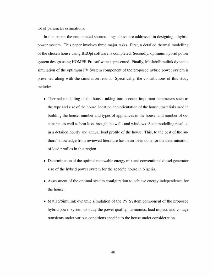
lot of parameter estimations.
In this paper, the enumerated shortcomings above are addressed in designing a hybrid
power system. This paper involves three major tasks. First, a detailed thermal modelling
of the chosen house using BEOpt software is completed. Secondly, optimum hybrid power
system design using HOMER Pro software is presented. Finally, Matlab/Simulink dynamic
simulation of the optimum PV System component of the proposed hybrid power system is
presented along with the simulation results. Specifically, the contributions of this study
include:
• Thermal modelling of the house, taking into account important parameters such as
the type and size of the house, location and orientation of the house, materials used in
building the house, number and types of appliances in the house, and number of oc-
cupants, as well as heat loss through the walls and windows. Such modelling resulted
in a detailed hourly and annual load profile of the house. This, to the best of the au-
thors’ knowledge from reviewed literature has never been done for the determination
of load profiles in that region.
• Determination of the optimal renewable energy mix and conventional diesel generator
size of the hybrid power system for the specific house in Nigeria.
• Assessment of the optimal system configuration to achieve energy independence for
the house.
• Matlab/Simulink dynamic simulation of the PV System component of the proposed
hybrid power system to study the power quality, harmonics, load impact, and voltage
transients under various conditions specific to the house under consideration.
40
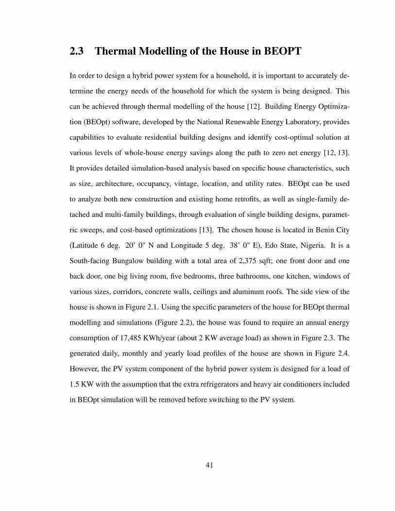
2.3 Thermal Modelling of the House in BEOPT
In order to design a hybrid power system for a household, it is important to accurately de-
termine the energy needs of the household for which the system is being designed. This
can be achieved through thermal modelling of the house [12]. Building Energy Optimiza-
tion (BEOpt) software, developed by the National Renewable Energy Laboratory, provides
capabilities to evaluate residential building designs and identify cost-optimal solution at
various levels of whole-house energy savings along the path to zero net energy [12, 13].
It provides detailed simulation-based analysis based on specific house characteristics, such
as size, architecture, occupancy, vintage, location, and utility rates. BEOpt can be used
to analyze both new construction and existing home retrofits, as well as single-family de-
tached and multi-family buildings, through evaluation of single building designs, paramet-
ric sweeps, and cost-based optimizations [13]. The chosen house is located in Benin City
(Latitude 6 deg. 20’ 0" N and Longitude 5 deg. 38’ 0" E), Edo State, Nigeria. It is a
South-facing Bungalow building with a total area of 2,375 sqft; one front door and one
back door, one big living room, five bedrooms, three bathrooms, one kitchen, windows of
various sizes, corridors, concrete walls, ceilings and aluminum roofs. The side view of the
house is shown in Figure 2.1. Using the specific parameters of the house for BEOpt thermal
modelling and simulations (Figure 2.2), the house was found to require an annual energy
consumption of 17,485 KWh/year (about 2 KW average load) as shown in Figure 2.3. The
generated daily, monthly and yearly load profiles of the house are shown in Figure 2.4.
However, the PV system component of the hybrid power system is designed for a load of
1.5 KW with the assumption that the extra refrigerators and heavy air conditioners included
in BEOpt simulation will be removed before switching to the PV system.
41
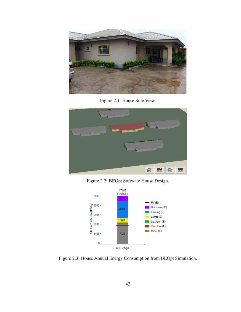
Figure 2.1: House Side View.
Figure 2.2: BEOpt Software House Design.
Figure 2.3: House Annual Energy Consumption from BEOpt Simulation.
42
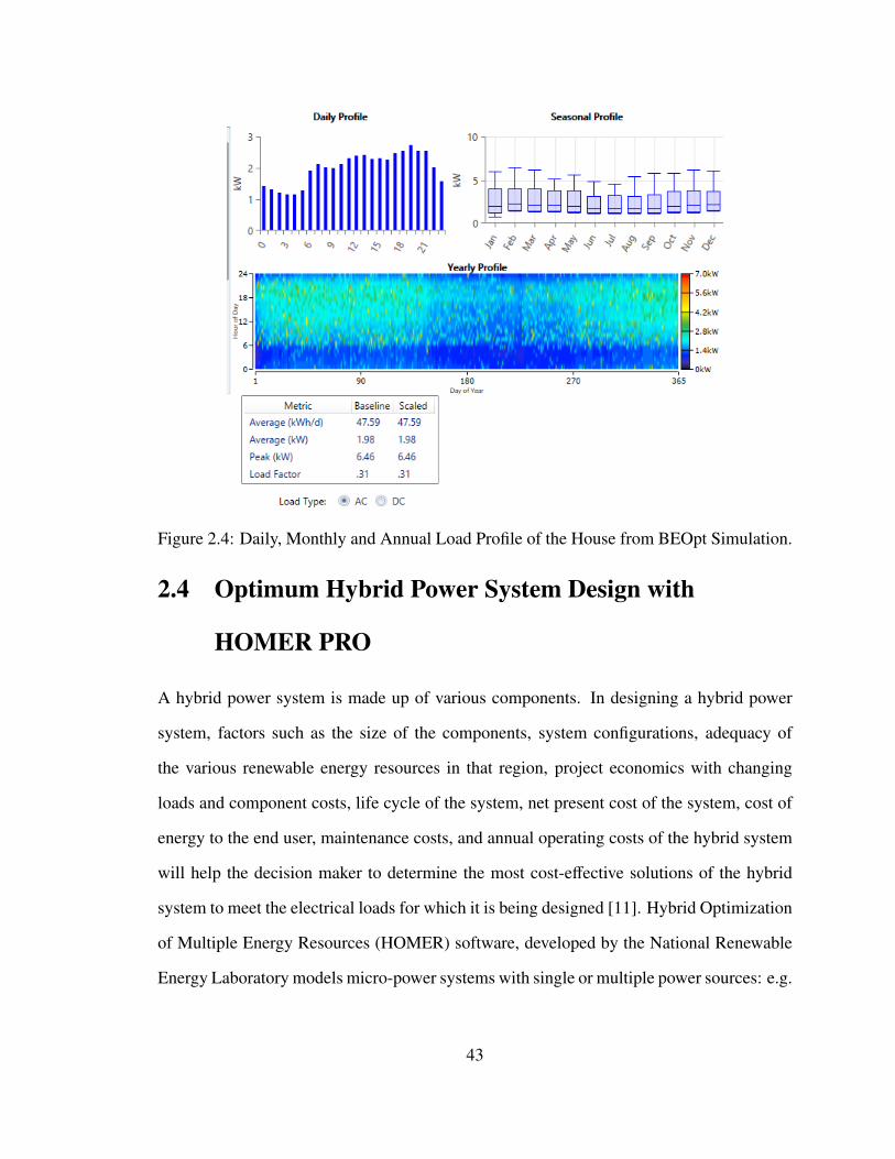
Figure 2.4: Daily, Monthly and Annual Load Profile of the House from BEOpt Simulation.
2.4 Optimum Hybrid Power System Design with
HOMER PRO
A hybrid power system is made up of various components. In designing a hybrid power
system, factors such as the size of the components, system configurations, adequacy of
the various renewable energy resources in that region, project economics with changing
loads and component costs, life cycle of the system, net present cost of the system, cost of
energy to the end user, maintenance costs, and annual operating costs of the hybrid system
will help the decision maker to determine the most cost-effective solutions of the hybrid
system to meet the electrical loads for which it is being designed [11]. Hybrid Optimization
of Multiple Energy Resources (HOMER) software, developed by the National Renewable
Energy Laboratory models micro-power systems with single or multiple power sources: e.g.
43
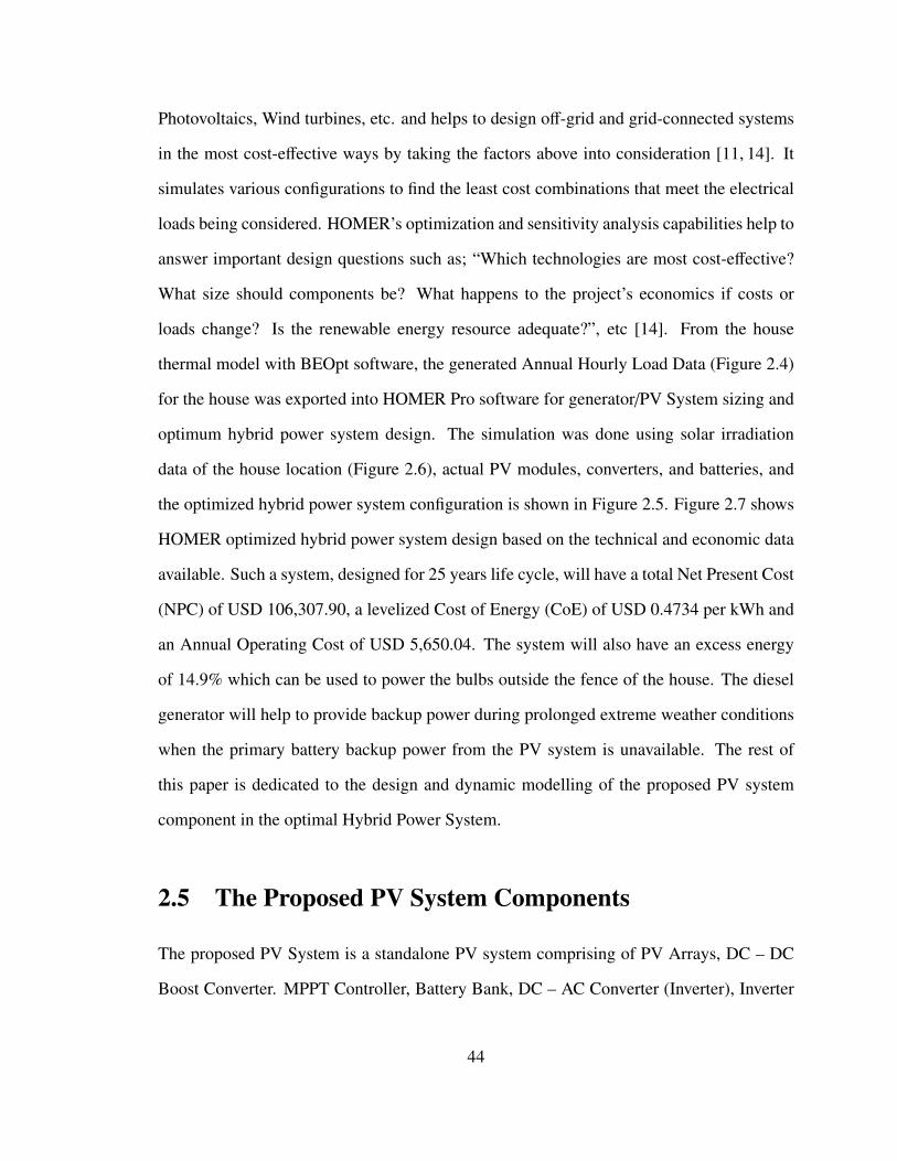
Photovoltaics, Wind turbines, etc. and helps to design off-grid and grid-connected systems
in the most cost-effective ways by taking the factors above into consideration [11, 14]. It
simulates various configurations to find the least cost combinations that meet the electrical
loads being considered. HOMER’s optimization and sensitivity analysis capabilities help to
answer important design questions such as; “Which technologies are most cost-effective?
What size should components be? What happens to the project’s economics if costs or
loads change? Is the renewable energy resource adequate?”, etc [14]. From the house
thermal model with BEOpt software, the generated Annual Hourly Load Data (Figure 2.4)
for the house was exported into HOMER Pro software for generator/PV System sizing and
optimum hybrid power system design. The simulation was done using solar irradiation
data of the house location (Figure 2.6), actual PV modules, converters, and batteries, and
the optimized hybrid power system configuration is shown in Figure 2.5. Figure 2.7 shows
HOMER optimized hybrid power system design based on the technical and economic data
available. Such a system, designed for 25 years life cycle, will have a total Net Present Cost
(NPC) of USD 106,307.90, a levelized Cost of Energy (CoE) of USD 0.4734 per kWh and
an Annual Operating Cost of USD 5,650.04. The system will also have an excess energy
of 14.9% which can be used to power the bulbs outside the fence of the house. The diesel
generator will help to provide backup power during prolonged extreme weather conditions
when the primary battery backup power from the PV system is unavailable. The rest of
this paper is dedicated to the design and dynamic modelling of the proposed PV system
component in the optimal Hybrid Power System.
2.5 The Proposed PV System Components
The proposed PV System is a standalone PV system comprising of PV Arrays, DC – DC
Boost Converter. MPPT Controller, Battery Bank, DC – AC Converter (Inverter), Inverter
44
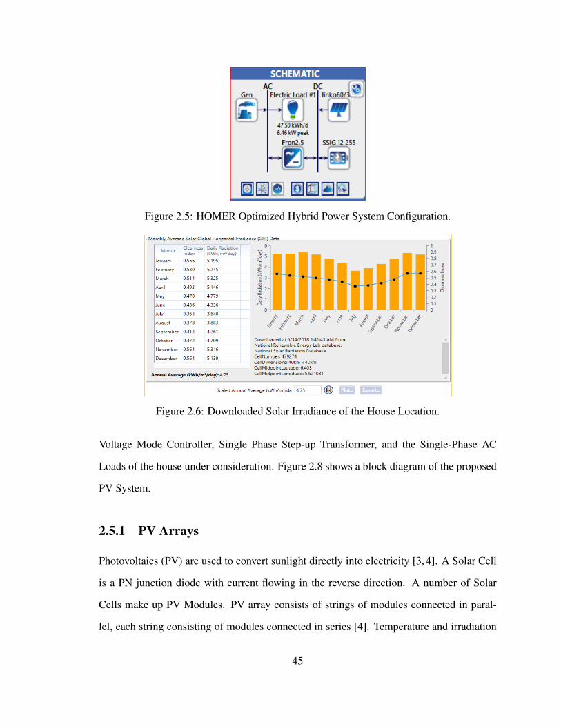
Figure 2.5: HOMER Optimized Hybrid Power System Configuration.
Figure 2.6: Downloaded Solar Irradiance of the House Location.
Voltage Mode Controller, Single Phase Step-up Transformer, and the Single-Phase AC
Loads of the house under consideration. Figure 2.8 shows a block diagram of the proposed
PV System.
2.5.1 PV Arrays
Photovoltaics (PV) are used to convert sunlight directly into electricity [3, 4]. A Solar Cell
is a PN junction diode with current flowing in the reverse direction. A number of Solar
Cells make up PV Modules. PV array consists of strings of modules connected in paral-
lel, each string consisting of modules connected in series [4]. Temperature and irradiation
45
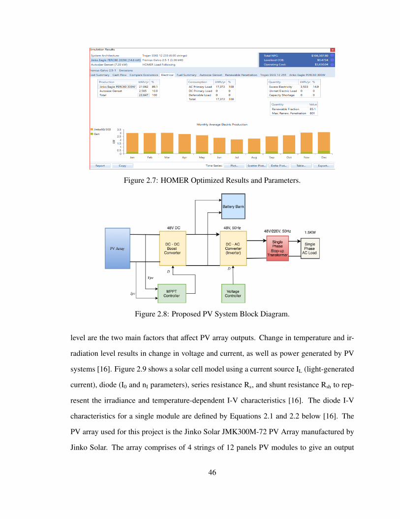
Figure 2.7: HOMER Optimized Results and Parameters.
Figure 2.8: Proposed PV System Block Diagram.
level are the two main factors that affect PV array outputs. Change in temperature and ir-
radiation level results in change in voltage and current, as well as power generated by PV
systems [16]. Figure 2.9 shows a solar cell model using a current source IL (light-generated
current), diode (I0 and nI parameters), series resistance Rs, and shunt resistance Rsh to rep-
resent the irradiance and temperature-dependent I-V characteristics [16]. The diode I-V
characteristics for a single module are defined by Equations 2.1 and 2.2 below [16]. The
PV array used for this project is the Jinko Solar JMK300M-72 PV Array manufactured by
Jinko Solar. The array comprises of 4 strings of 12 panels PV modules to give an output
46
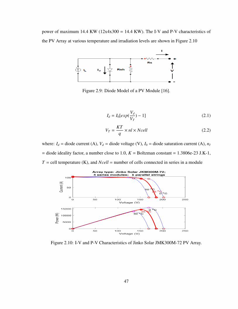
power of maximum 14.4 KW (12x4x300 = 14.4 KW). The I-V and P-V characteristics of
the PV Array at various temperature and irradiation levels are shown in Figure 2.10
Figure 2.9: Diode Model of a PV Module [16].
Id = I0[exp(Vd
VT) − 1] (2.1)
VT =KTq× nl × Ncell (2.2)
where: Id = diode current (A), Vd = diode voltage (V), I0 = diode saturation current (A), nI
= diode ideality factor, a number close to 1.0, K = Boltzman constant = 1.3806e-23 J.K-1,
T = cell temperature (K), and Ncell = number of cells connected in series in a module
Figure 2.10: I-V and P-V Characteristics of Jinko Solar JMK300M-72 PV Array.
47
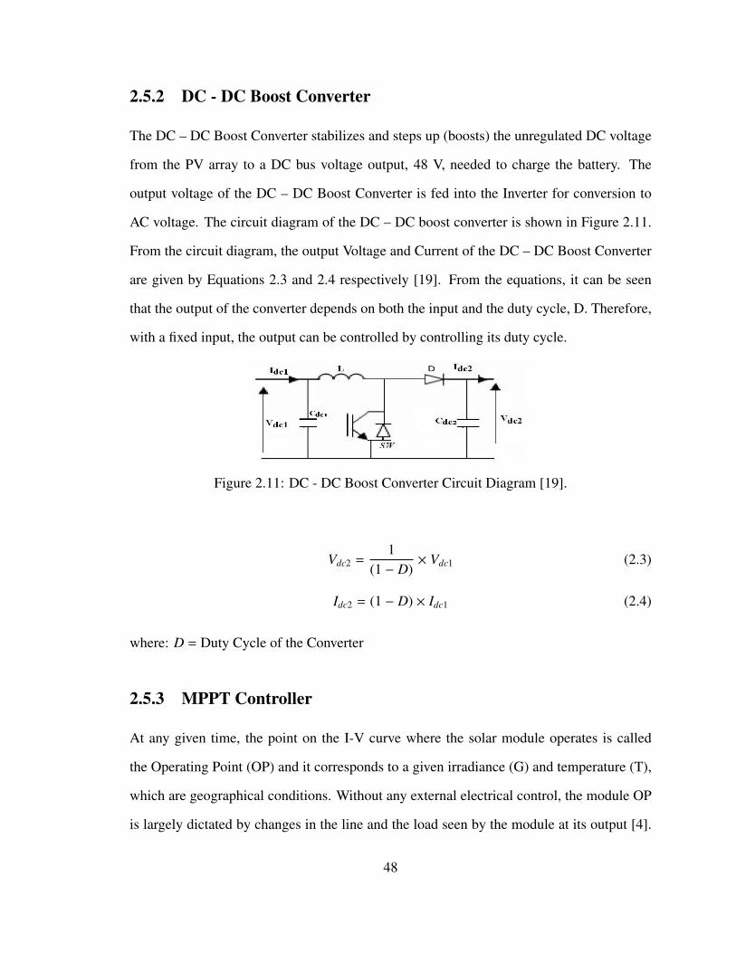
2.5.2 DC - DC Boost Converter
The DC – DC Boost Converter stabilizes and steps up (boosts) the unregulated DC voltage
from the PV array to a DC bus voltage output, 48 V, needed to charge the battery. The
output voltage of the DC – DC Boost Converter is fed into the Inverter for conversion to
AC voltage. The circuit diagram of the DC – DC boost converter is shown in Figure 2.11.
From the circuit diagram, the output Voltage and Current of the DC – DC Boost Converter
are given by Equations 2.3 and 2.4 respectively [19]. From the equations, it can be seen
that the output of the converter depends on both the input and the duty cycle, D. Therefore,
with a fixed input, the output can be controlled by controlling its duty cycle.
Figure 2.11: DC - DC Boost Converter Circuit Diagram [19].
Vdc2 =1
(1 − D)× Vdc1 (2.3)
Idc2 = (1 − D) × Idc1 (2.4)
where: D = Duty Cycle of the Converter
2.5.3 MPPT Controller
At any given time, the point on the I-V curve where the solar module operates is called
the Operating Point (OP) and it corresponds to a given irradiance (G) and temperature (T),
which are geographical conditions. Without any external electrical control, the module OP
is largely dictated by changes in the line and the load seen by the module at its output [4].
48
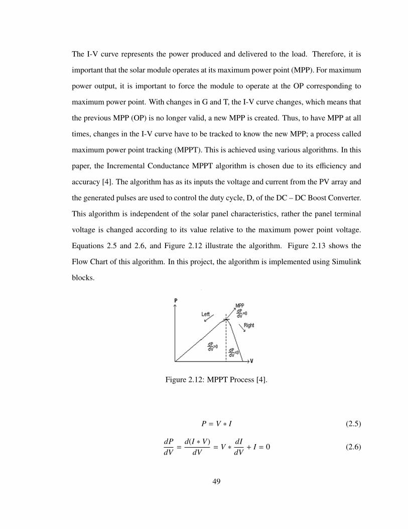
The I-V curve represents the power produced and delivered to the load. Therefore, it is
important that the solar module operates at its maximum power point (MPP). For maximum
power output, it is important to force the module to operate at the OP corresponding to
maximum power point. With changes in G and T, the I-V curve changes, which means that
the previous MPP (OP) is no longer valid, a new MPP is created. Thus, to have MPP at all
times, changes in the I-V curve have to be tracked to know the new MPP; a process called
maximum power point tracking (MPPT). This is achieved using various algorithms. In this
paper, the Incremental Conductance MPPT algorithm is chosen due to its efficiency and
accuracy [4]. The algorithm has as its inputs the voltage and current from the PV array and
the generated pulses are used to control the duty cycle, D, of the DC – DC Boost Converter.
This algorithm is independent of the solar panel characteristics, rather the panel terminal
voltage is changed according to its value relative to the maximum power point voltage.
Equations 2.5 and 2.6, and Figure 2.12 illustrate the algorithm. Figure 2.13 shows the
Flow Chart of this algorithm. In this project, the algorithm is implemented using Simulink
blocks.
Figure 2.12: MPPT Process [4].
P = V ∗ I (2.5)
dPdV
=d(I ∗ V)
dV= V ∗
dIdV
+ I = 0 (2.6)
49
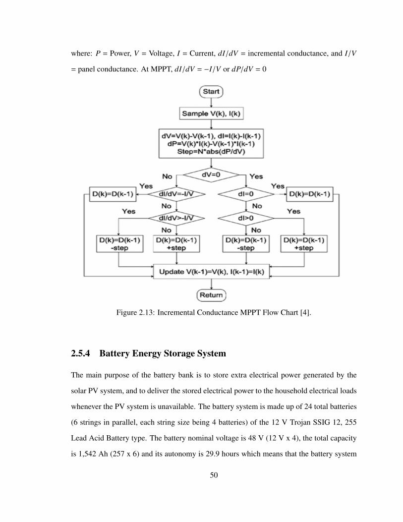
where: P = Power, V = Voltage, I = Current, dI/dV = incremental conductance, and I/V
= panel conductance. At MPPT, dI/dV = −I/V or dP/dV = 0
Figure 2.13: Incremental Conductance MPPT Flow Chart [4].
2.5.4 Battery Energy Storage System
The main purpose of the battery bank is to store extra electrical power generated by the
solar PV system, and to deliver the stored electrical power to the household electrical loads
whenever the PV system is unavailable. The battery system is made up of 24 total batteries
(6 strings in parallel, each string size being 4 batteries) of the 12 V Trojan SSIG 12, 255
Lead Acid Battery type. The battery nominal voltage is 48 V (12 V x 4), the total capacity
is 1,542 Ah (257 x 6) and its autonomy is 29.9 hours which means that the battery system
50
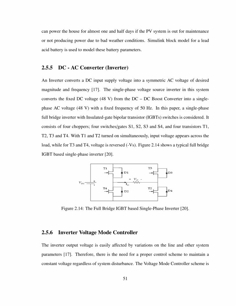
can power the house for almost one and half days if the PV system is out for maintenance
or not producing power due to bad weather conditions. Simulink block model for a lead
acid battery is used to model these battery parameters.
2.5.5 DC - AC Converter (Inverter)
An Inverter converts a DC input supply voltage into a symmetric AC voltage of desired
magnitude and frequency [17]. The single-phase voltage source inverter in this system
converts the fixed DC voltage (48 V) from the DC – DC Boost Converter into a single-
phase AC voltage (48 V) with a fixed frequency of 50 Hz. In this paper, a single-phase
full bridge inverter with Insulated-gate bipolar transistor (IGBTs) switches is considered. It
consists of four choppers; four switches/gates S1, S2, S3 and S4, and four transistors T1,
T2, T3 and T4. With T1 and T2 turned on simultaneously, input voltage appears across the
load, while for T3 and T4, voltage is reversed (-Vs). Figure 2.14 shows a typical full bridge
IGBT based single-phase inverter [20].
Figure 2.14: The Full Bridge IGBT based Single-Phase Inverter [20].
2.5.6 Inverter Voltage Mode Controller
The inverter output voltage is easily affected by variations on the line and other system
parameters [17]. Therefore, there is the need for a proper control scheme to maintain a
constant voltage regardless of system disturbance. The Voltage Mode Controller scheme is
51
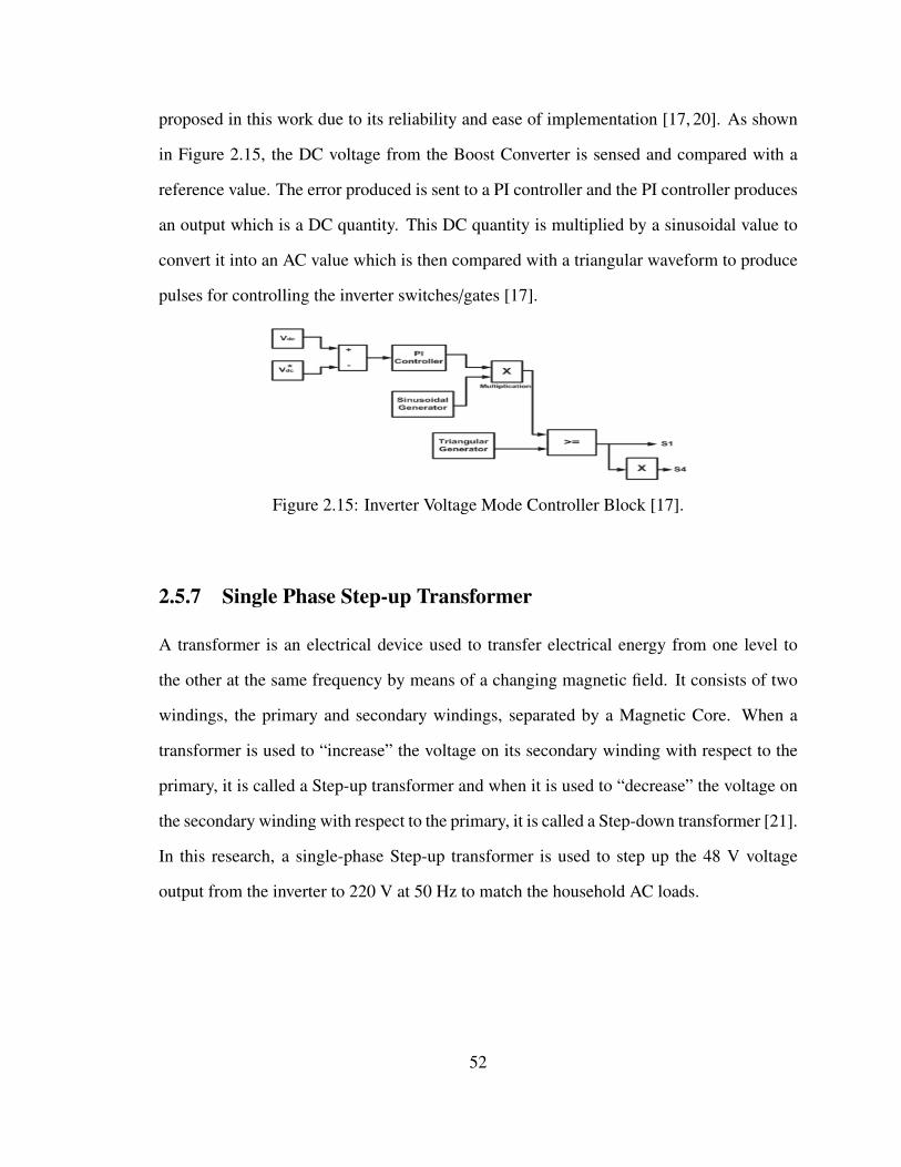
proposed in this work due to its reliability and ease of implementation [17, 20]. As shown
in Figure 2.15, the DC voltage from the Boost Converter is sensed and compared with a
reference value. The error produced is sent to a PI controller and the PI controller produces
an output which is a DC quantity. This DC quantity is multiplied by a sinusoidal value to
convert it into an AC value which is then compared with a triangular waveform to produce
pulses for controlling the inverter switches/gates [17].
Figure 2.15: Inverter Voltage Mode Controller Block [17].
2.5.7 Single Phase Step-up Transformer
A transformer is an electrical device used to transfer electrical energy from one level to
the other at the same frequency by means of a changing magnetic field. It consists of two
windings, the primary and secondary windings, separated by a Magnetic Core. When a
transformer is used to “increase” the voltage on its secondary winding with respect to the
primary, it is called a Step-up transformer and when it is used to “decrease” the voltage on
the secondary winding with respect to the primary, it is called a Step-down transformer [21].
In this research, a single-phase Step-up transformer is used to step up the 48 V voltage
output from the inverter to 220 V at 50 Hz to match the household AC loads.
52
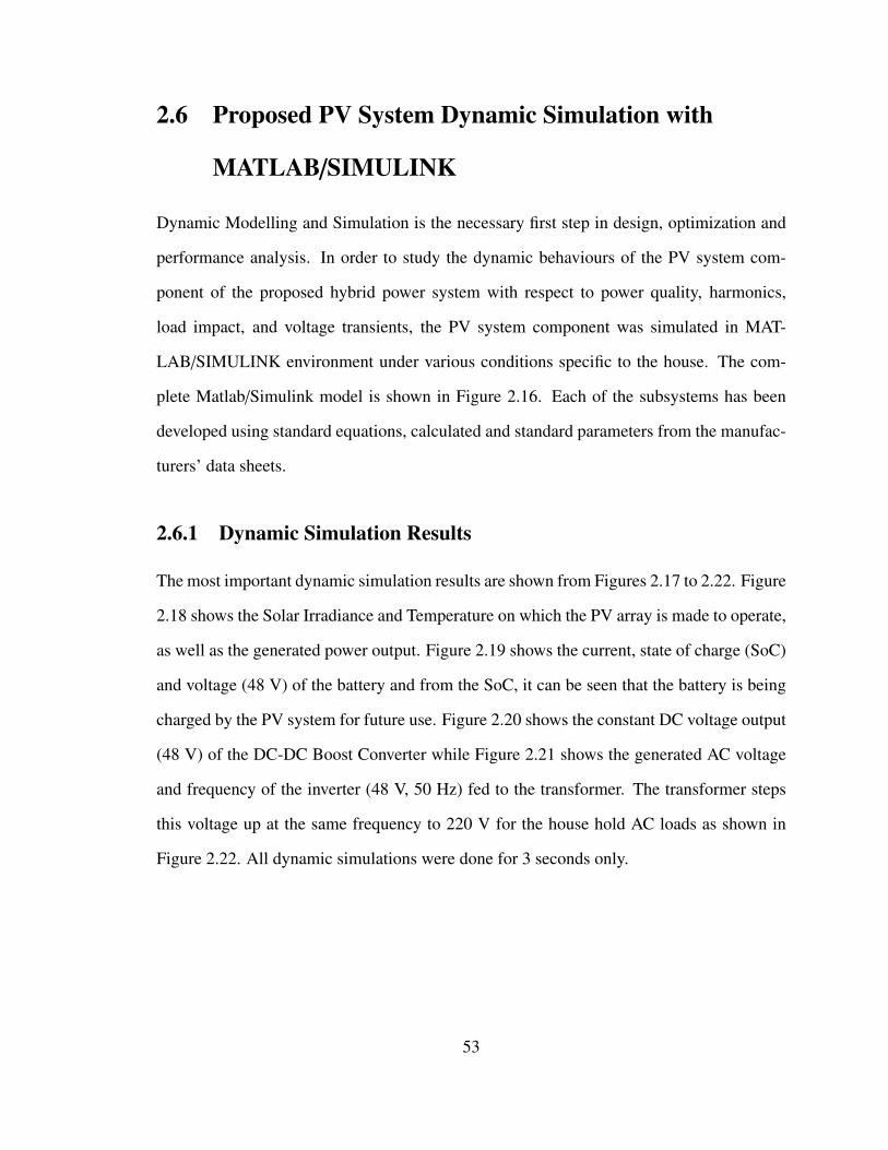
2.6 Proposed PV System Dynamic Simulation with
MATLAB/SIMULINK
Dynamic Modelling and Simulation is the necessary first step in design, optimization and
performance analysis. In order to study the dynamic behaviours of the PV system com-
ponent of the proposed hybrid power system with respect to power quality, harmonics,
load impact, and voltage transients, the PV system component was simulated in MAT-
LAB/SIMULINK environment under various conditions specific to the house. The com-
plete Matlab/Simulink model is shown in Figure 2.16. Each of the subsystems has been
developed using standard equations, calculated and standard parameters from the manufac-
turers’ data sheets.
2.6.1 Dynamic Simulation Results
The most important dynamic simulation results are shown from Figures 2.17 to 2.22. Figure
2.18 shows the Solar Irradiance and Temperature on which the PV array is made to operate,
as well as the generated power output. Figure 2.19 shows the current, state of charge (SoC)
and voltage (48 V) of the battery and from the SoC, it can be seen that the battery is being
charged by the PV system for future use. Figure 2.20 shows the constant DC voltage output
(48 V) of the DC-DC Boost Converter while Figure 2.21 shows the generated AC voltage
and frequency of the inverter (48 V, 50 Hz) fed to the transformer. The transformer steps
this voltage up at the same frequency to 220 V for the house hold AC loads as shown in
Figure 2.22. All dynamic simulations were done for 3 seconds only.
53
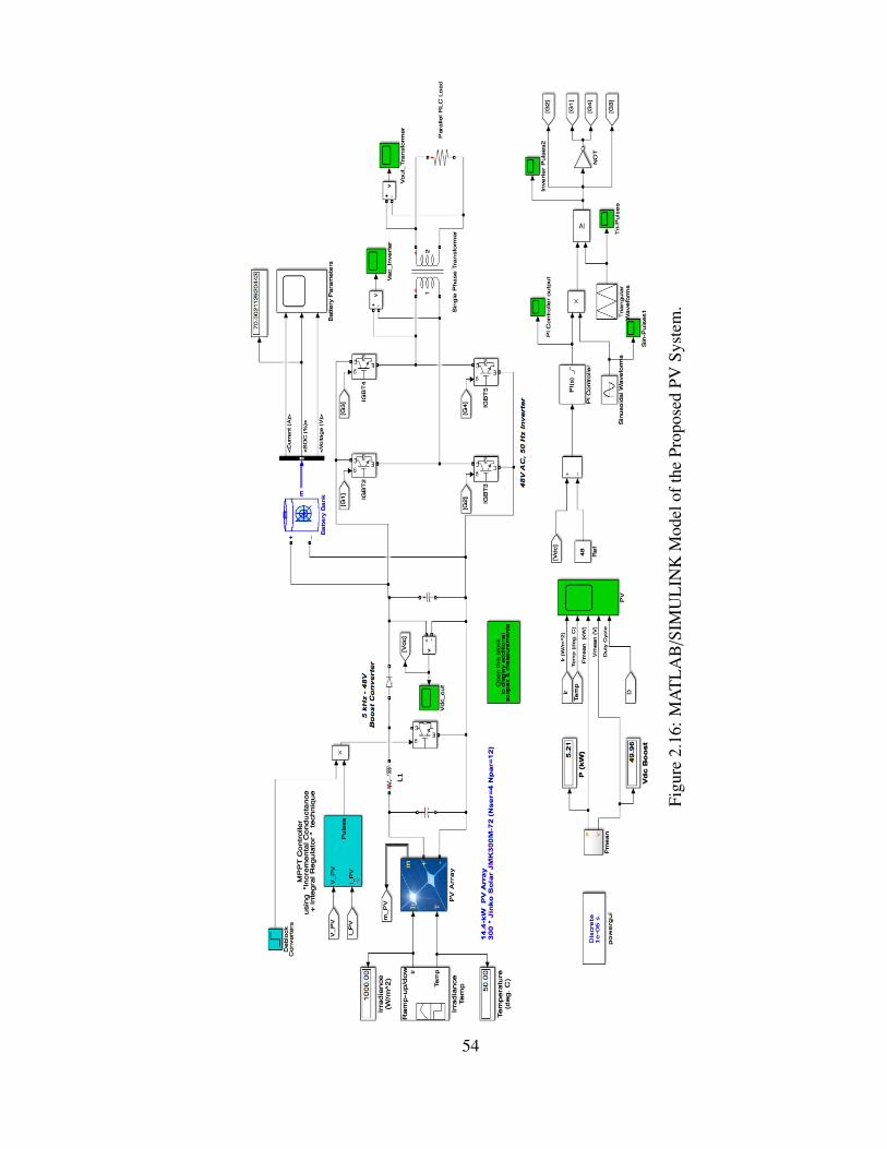
Figu
re2.
16:M
AT
LA
B/S
IMU
LIN
KM
odel
ofth
ePr
opos
edPV
Syst
em.
54
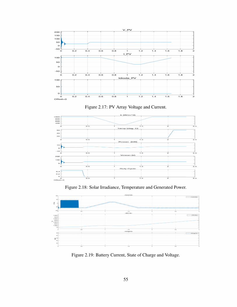
Figure 2.17: PV Array Voltage and Current.
Figure 2.18: Solar Irradiance, Temperature and Generated Power.
Figure 2.19: Battery Current, State of Charge and Voltage.
55
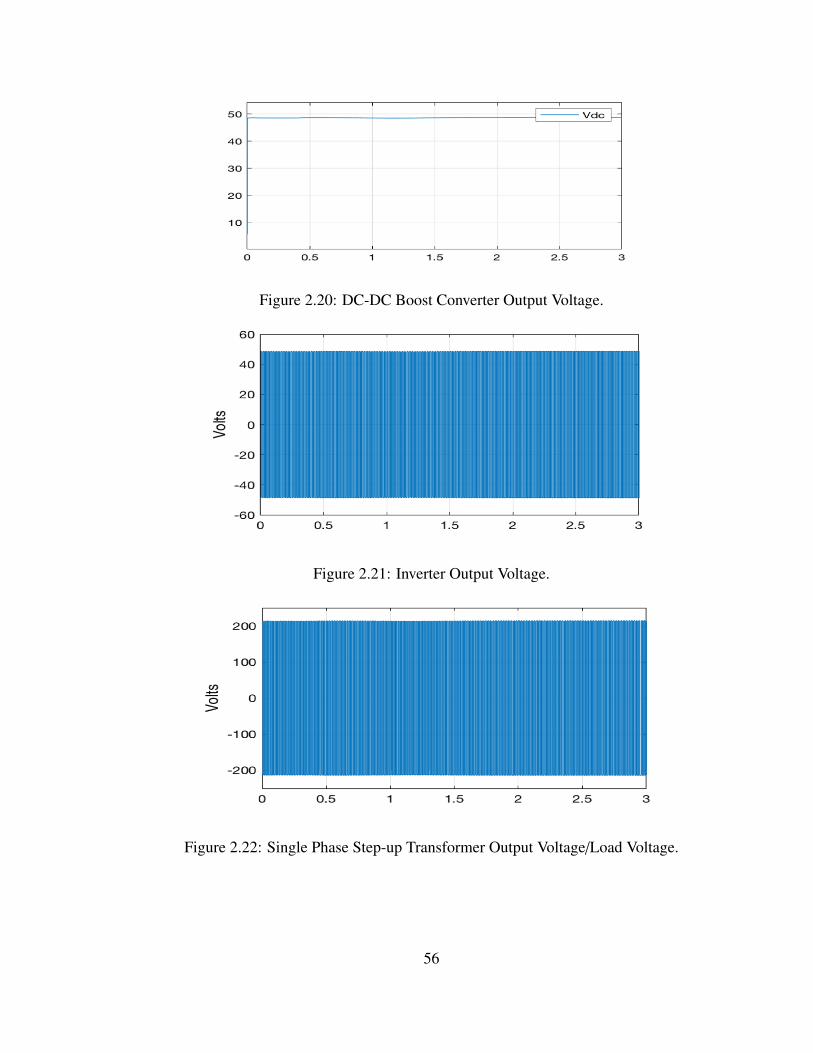
Figure 2.20: DC-DC Boost Converter Output Voltage.
Figure 2.21: Inverter Output Voltage.
Figure 2.22: Single Phase Step-up Transformer Output Voltage/Load Voltage.
56
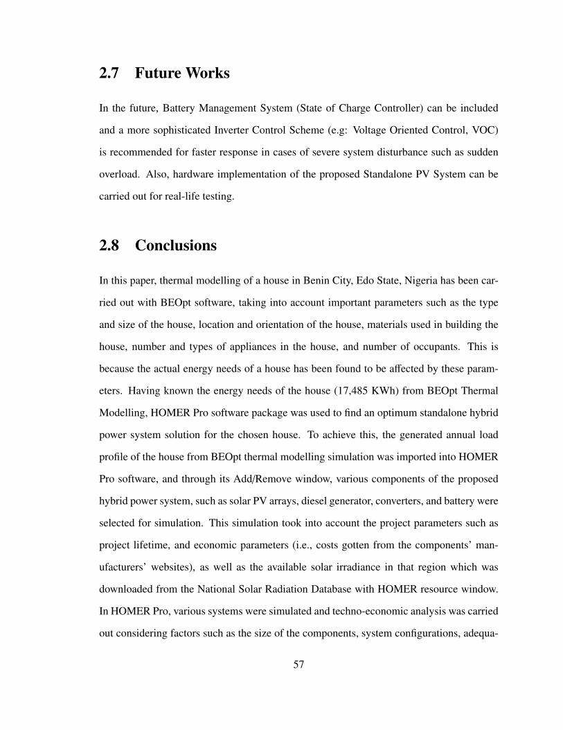
2.7 Future Works
In the future, Battery Management System (State of Charge Controller) can be included
and a more sophisticated Inverter Control Scheme (e.g: Voltage Oriented Control, VOC)
is recommended for faster response in cases of severe system disturbance such as sudden
overload. Also, hardware implementation of the proposed Standalone PV System can be
carried out for real-life testing.
2.8 Conclusions
In this paper, thermal modelling of a house in Benin City, Edo State, Nigeria has been car-
ried out with BEOpt software, taking into account important parameters such as the type
and size of the house, location and orientation of the house, materials used in building the
house, number and types of appliances in the house, and number of occupants. This is
because the actual energy needs of a house has been found to be affected by these param-
eters. Having known the energy needs of the house (17,485 KWh) from BEOpt Thermal
Modelling, HOMER Pro software package was used to find an optimum standalone hybrid
power system solution for the chosen house. To achieve this, the generated annual load
profile of the house from BEOpt thermal modelling simulation was imported into HOMER
Pro software, and through its Add/Remove window, various components of the proposed
hybrid power system, such as solar PV arrays, diesel generator, converters, and battery were
selected for simulation. This simulation took into account the project parameters such as
project lifetime, and economic parameters (i.e., costs gotten from the components’ man-
ufacturers’ websites), as well as the available solar irradiance in that region which was
downloaded from the National Solar Radiation Database with HOMER resource window.
In HOMER Pro, various systems were simulated and techno-economic analysis was carried
out considering factors such as the size of the components, system configurations, adequa-
57
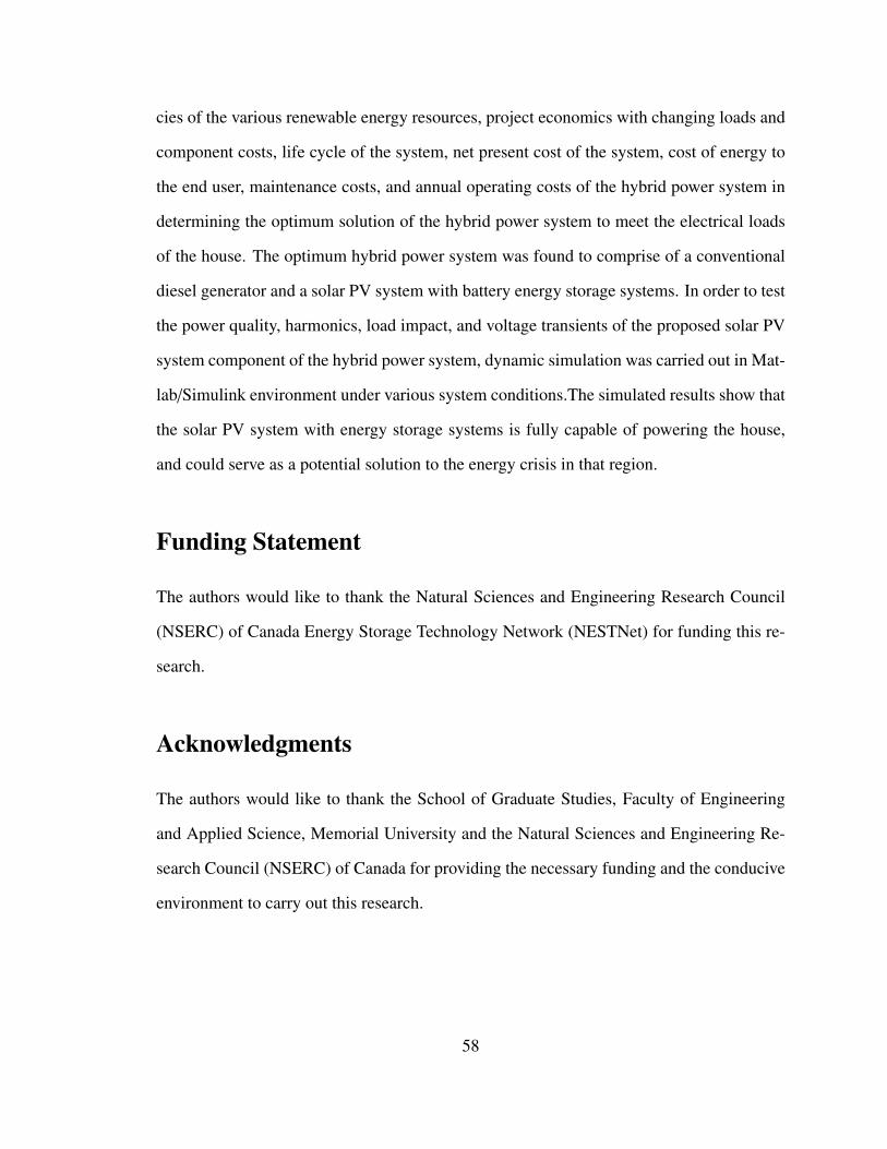
cies of the various renewable energy resources, project economics with changing loads and
component costs, life cycle of the system, net present cost of the system, cost of energy to
the end user, maintenance costs, and annual operating costs of the hybrid power system in
determining the optimum solution of the hybrid power system to meet the electrical loads
of the house. The optimum hybrid power system was found to comprise of a conventional
diesel generator and a solar PV system with battery energy storage systems. In order to test
the power quality, harmonics, load impact, and voltage transients of the proposed solar PV
system component of the hybrid power system, dynamic simulation was carried out in Mat-
lab/Simulink environment under various system conditions.The simulated results show that
the solar PV system with energy storage systems is fully capable of powering the house,
and could serve as a potential solution to the energy crisis in that region.
Funding Statement
The authors would like to thank the Natural Sciences and Engineering Research Council
(NSERC) of Canada Energy Storage Technology Network (NESTNet) for funding this re-
search.
Acknowledgments
The authors would like to thank the School of Graduate Studies, Faculty of Engineering
and Applied Science, Memorial University and the Natural Sciences and Engineering Re-
search Council (NSERC) of Canada for providing the necessary funding and the conducive
environment to carry out this research.
58
Bibliography
[1] "Nigeria," Available online: https://en.wikipedia.org/wiki/Nigeria
[2] "List of power stations in Nigeria," Available online:
https://en.wikipedia.org/wiki/List of power stations in Nigeria.
[3] "Solar Energy," Available online: http://www.pveducation.org/pvcdrom/introduction/solar-
energy
[4] "Renewable Energy: power for sustainable future," edited by Stephen Peake, 4th edi-
tion, Oxford university press 2018.
[5] C. O. Okoye, O. Taylan and D. K. Baker, “Solar energy potentials in strate-
gically located cities in Nigeria: Review, Resource Assessment and PV Sys-
tem design," Renewable and Sustainable Energy Reviews, 55(2016), pp. 550–566.
https://doi.org/10.1016/j.rser.2015.10.154.
[6] "Nigerian Meteorological Agency (NiMet)," Agrometeorological Bulletin No.10,
DEKAD 2 APRIL (11-20) 2018, Available online: http://www.nimet.gov.ng/.
[7] F. Trieb O. LangniB and KlaiBH, “Solar electricity generation - a comparative
view of technologies, costs and environmental impact,” Sol Energy 1997; 59:89–99.
http://dx.doi.org/10.1016/S0038- 092X(97)80946-2.
[8] Y. N. Udoakah, E. E. Nta, I. E. Okon and U. E. Akpabio, "Design of a 1 kva PV system
for electrical laboratory in faculty of engineering, University of Uyo, Nigeria," IEEE
Global Humanitarian Technology Conference (GHTC 2014), San Jose, CA, 2014, pp.
1-5. doi: 10.1109/GHTC.2014.6970252.
[9] D. O. Akinyele and R. K. Rayudu, "Distributed photovoltaic power generation for
energy-poor households: The Nigerian perspective," 2013 IEEE PES Asia-Pacific
59
Power and Energy Engineering Conference (APPEEC), Kowloon, 2013, pp. 1-6. doi:
10.1109/APPEEC.2013.6837165.
[10] M. S. Adaramola, S. S. Paul and O. M. Oyewola, “Assessment of de-
centralized hybrid PV solar-diesel power system for applications in Northern
part of Nigeria," Energy for Sustainable Development, 19(2014), pp. 72–82.
https://doi.org/10.1016/j.esd.2013.12.007.
[11] G. Alamri and T. Iqbal, "Sizing of a hybrid power system for a house in Libya,"
2016 IEEE 7th Annual Information Technology, Electronics and Mobile Communi-
cation Conference (IEMCON), Vancouver, BC, 2016, pp. 1-6. doi: 10.1109/IEM-
CON.2016.7746365.
[12] T. A. Jeshaa and M. T. Iqbal, “Thermal simulation and energy consumption analysis
of two houses in St. John’s, Newfoundland,” Procedia Engineering, 105(2015), pp.
607 – 612. https://doi.org/10.1016/j.proeng.2015.05.038.
[13] "BEopt," Available online: https://beopt.nrel.gov
[14] "HOMER Energy," Available online: https://www.homerenergy.com
[15] M. Jain and N. Tiwari, “Optimization and Simulation of Solar Photovoltaic cell using
HOMER: A Case Study of a Residential Building,” International Journal of Science
and Research (IJSR), ISSN (Online), Volume 3, Issue 7 (2014), pp. 2319-7064.
[16] "PV Array," Available online: https://www.mathworks.com/help/physmod/sps/powersys/
ref/pvarray.html
[17] K. Dubey and M. T. Shah, "Design and simulation of Solar PV system," 2016 In-
ternational Conference on Automatic Control and Dynamic Optimization Techniques
(ICACDOT), India, 2016, pp. 568-573. doi: 10.1109/ICACDOT.2016.7877649.
60
[18] M. Abdelmoula, S. Moughamir and B. Robert, "Design and modeling of a stand-alone
photovoltaic system," 2014 15th International Conference on Sciences and Techniques
of Automatic Control and Computer Engineering (STA), Hammamet, 2014, pp. 825-
834. doi: 10.1109/STA.2014.7086746.
[19] S. S. Mohammed and D. Devaraj, "Simulation and analysis of stand-alone photo-
voltaic system with boost converter using MATLAB/Simulink," 2014 International
Conference on Circuits, Power and Computing Technologies [ICCPCT-2014], Nager-
coil, 2014, pp. 814-821. doi: 10.1109/ICCPCT.2014.7054991.
[20] S. M. Cherati, N. A. Azli, S. M. Ayob and A. Mortezaei, "Design of a current
mode PI controller for a single-phase PWM inverter," 2011 IEEE Applied Power
Electronics Colloquium (IAPEC), Johor Bahru, 2011, pp. 180-184. doi: 10.1109/I-
APEC.2011.5779864.
[21] "Electronics Tutorial", Transformer Basics, Available online:
urlhttps://www.electronics-tutorials.ws/transformer/transformer-basics.html.
61
Chapter 3
Low-Cost, IoT-Based Open Source
SCADA System using Emoncms,
Arduino Uno, Raspberry Pi and
Node-Red*
Preface
A version of this manuscript has been peer-reviewed, accepted and presented in the con-
ference proceedings of the 2019 IEEE Canadian Conference of Electrical and Computer
Engineering (CCECE), Edmonton, AB, Canada. The paper has also been published on
IEEE Xplore Database as a part of the IEEE CCECE 2019 conference proceedings (doi:
10.1109/CCECE.2019.8861827). I am the primary author, and I carried out most of the
research work, performed the literature reviews, carried out the system design, hardware
implementations, experimental setups and analysis of the results. I also prepared the first
*This chapter is a version of “Development of an IoT Based Open Source SCADA System for PV SystemMonitoring”, L. O. Aghenta and M. T. Iqbal, CCECE 2019, doi: 10.1109/CCECE.2019.8861827).
62
draft of the manuscript and subsequently revised the final manuscript based on the feed-
back from the co-author and the peer review process. The Co-author, Dr. M. Tariq Iqbal,
supervised the research, acquired and made available the research funding, provided the
research components, reviewed and corrected the manuscript, and contributed research
ideas in the actualization of the manuscript.
Abstract
This paper presents the development of a low cost, open source Supervisory Control and
Data Acquisition (SCADA) system for solar photovoltaic (PV) system monitoring and
remote control. The proposed SCADA system is based on the Internet of Things (IoT)
SCADA architecture which incorporates web services with the conventional SCADA for a
robust supervisory control and monitoring. It comprises of analog Current and Voltage sen-
sors for acquiring the desired data from the solar PV system, Arduino Uno micro-controller
which serves as a Remote Terminal Unit to receive the acquired sensor data, Raspberry Pi
with a Node-RED programming tool for parsing the acquired data (Communication Chan-
nel), and Emoncms Local Server IoT Platform for data storage, monitoring and remote
control (Master Terminal Unit). The developed SCADA system was set up to monitor and
control a 260 W, 12 V solar PV panel in the Electrical and Computer Engineering Labora-
tory at Memorial University, and some of the created Dashboards and Charts showing the
acquired data on Emoncms server where an operator can monitor the data in the cloud using
both a computer with internet access, and Emoncms mobile app are presented in the paper.
Index Terms: Low Cost, Open Source SCADA, EMONCMS, Arduino Uno, Rasp-
berry Pi, Node-RED, Instrumentation and Control.
63
3.1 Introduction
SCADA is an acronym formed from the first letters of the term “Supervisory Control and
Data Acquisition”. It is a technology that enables a user to collect data from one or more
distant facilities and/or send limited control instructions to those facilities. The major func-
tion of SCADA is for acquiring data from remote devices such as batteries, valves, pumps,
transmitters, etc. and providing overall monitoring and control remotely from a SCADA
host software platform [2, 12]. As in the energy industry across the globe, power system
assets, such as inverters are usually distributed over large geographical areas, sometimes
in harsh environments. While it may be necessary to have local means of managing the
operations of these assets, it is equally important to have a reliable, flexible, cost effective
and sophisticated coordinated control. SCADA system is the perfect solution for this task.
SCADA makes it unnecessary for an operator to be assigned to stay at or frequently visit
these remote locations when the facilities are operating normally. Essentially, a SCADA
system performs four basic functions; data acquisition, networked data communication,
data presentation, and remote monitoring and supervisory control.
SCADA performs these essential functions using its four basic elements; Field Instru-
mentation Devices (FIDs) such as sensors and actuators connected to the systems being
managed, Remote Terminal Units (RTUs) such as single board computers for acquiring
remote data from field instrumentation devices, Master Terminal Units (MTUs) for han-
dling data processing and human machine interactions, and lastly SCADA Communication
channels for connecting the RTUs to the MTUs [2].
Generally, there are two classes of SCADA hardware and software; Proprietary and
Open Source. In a proprietary system, all major components are from a single manufac-
turer and the standards are often specific to that system, and developed by the manufacturer.
With a proprietary SCADA system, the responsibility for system reliability and security
64
rests solely with the manufacturer, which leaves the user vulnerable to a single manufactur-
er/supplier as the manufacturer/supplier could be slow to respond to technological changes
in a subsystem of the SCADA system. The customer is also at risk if the manufacturer/sup-
plier goes out of business, and the solution is largely expensive. There is also the problem
of flexibility with the already existing devices and network. An Open source system allows
a user to "mix and match" components and choose the most appropriate from several sup-
pliers. This means that with an open source system, no single supplier is responsible for
overall system performance. An open source solution also represents the most cost effective
solution as the user is not beholden to a single supplier. In an open source SCADA system,
the major components adhere to certain standards which allow them to be interchanged
with similar components manufactured by others to the same standards [12]. Therefore, in
this paper, an open source SCADA system solution is proposed.
3.2 Literature Review
There are four generations of SCADA system architecture and they include; the first gener-
ation (Monolithic), the second generation (Distributed), the third generation (Networked),
and the fourth generation (Internet of Things based SCADA architecture) [12]. The Internet
of Things concept has to do with connecting physical objects with embedded electronics,
software, sensors and connectivity to enable data interchange between these devices and an
operator over a common network or the web [1, 3–5].
Various researchers across the globe have in the past designed SCADA systems based
on the IoT architecture. In [4], a form of IoT based SCADA system is implemented using
Raspberry Pi3 as the sensor gateway, DHTII temperature and humidity sensors to acquire
the desired data, and IBM Bluemix cloud platform to receive, visualize and manage the
acquired sensor data over the web while using Node-Red and Web Socket Protocol for
65
data exchange and communication between the cloud platform and the Raspberry Pi con-
nected sensors. [3] presented an IoT-based urban climate monitoring system using Arduino
Nano, Raspberry Pi2 and Adafruit IO IoT web server. Elsewhere, [6] presented the im-
plementation of a web-based monitoring and control system for real-time electrical data
measurement in a hybrid wind/PV/battery system using web-based InTouch for graphical
user interface. In [5], the proposed IoT-based SCADA system uses Raspberry Pi3 along
with Intel Edison board for sensor inputs, and the acquired sensor data are sent to Ama-
zon Web Services (AWS) IoT platform using MQTT brokers in Node-Red. At the AWS
IoT platform, various monitoring and control schemes are initiated using Amazon’s Voice
Service called Alexa. In another development, [2] developed a low cost SCADA system
for CO2 Enhanced Oil Recovery based on the IoT SCADA architecture using sensors and
actuators connected to wellheads, Arduino Yun, Ubiquiti NanoStation wireless Ethernet/IP
addressable radios physically connected to the Arduino Yun, and a web enabled central
server running MySQL DBMS database for Graphical User Interface. In a recent develop-
ment, [1] presented the design of an IoT-based sensing and solar house monitoring and au-
tomation system using NodeMCU combined with ESP8266 micro-controller as the sensor
gateway for communication and data acquisition, and a combination of Blynk and Emon-
CMS web server for collecting and visualizing the acquired data, and for remote control of
home appliances and devices. Also, authors in [7–10] have implemented various forms of
IoT-based SCADA systems.
In most of the above mentioned papers, the IoT platform, like the Amazon Web Services
presented in [5], the IBM Bluemix in [4], Adafruit IO in [2], and EmonCMS web server
in [1], for data storage, monitoring and control is hosted in the cloud, which leaves the
stored data vulnerable to web attacks. However, security in a SCADA system is a serious
issue both from the operational and economic points of view as the resultant unavailability
of the critical infrastructure being monitored in the events of attacks can disrupt the re-
66
lated operations which could cause a huge loss. Therefore, in this paper, local EmonCMS
server is used as the IoT platform for data acquisition, storage, monitoring and control. The
hardware is installed on a private Linux-based machine and is managed by the user. The
local EmonCMS server has all the functionalities of the web-based EmonCMS server, with
additional data security as the user is able to manage the server locally [11]. The local
EmonCMS server solution is also less expensive as the user only buys the hardware on a
one-off basis while the user on the web-based EmonCMS server continuously pays for data
storage [11]. Also, the power consumption of the local EmonCMS server is minimal [11].
Furthermore, the data communication modes between the sensor gateways and the IoT plat-
forms presented in some of the literatures are complex and require advanced programming
skills, like in the case of Python Script in [2]. To address this shortcoming, the simple, se-
cure Node-Red sensor wiring is proposed for data transfer from the gateway to EmonCMS
server.
The remaining part of this paper is dedicated to the design, experimental setup and
testing of the proposed IoT-based SCADA system.
3.3 The Proposed SCADA System Design
The proposed low cost, open source SCADA system is based on the Internet of Things
(IoT) SCADA architecture. The schematics of the system design configuration is shown in
Figure 3.1. The system is made up of analog Voltage and Current sensors, Arduino Uno
micro-controller, Raspberry Pi2 single-board computer with Node-Red programming tool
for data transmission, and EmonCMS local server IoT Platform for sensor data monitoring
and remote control.
67
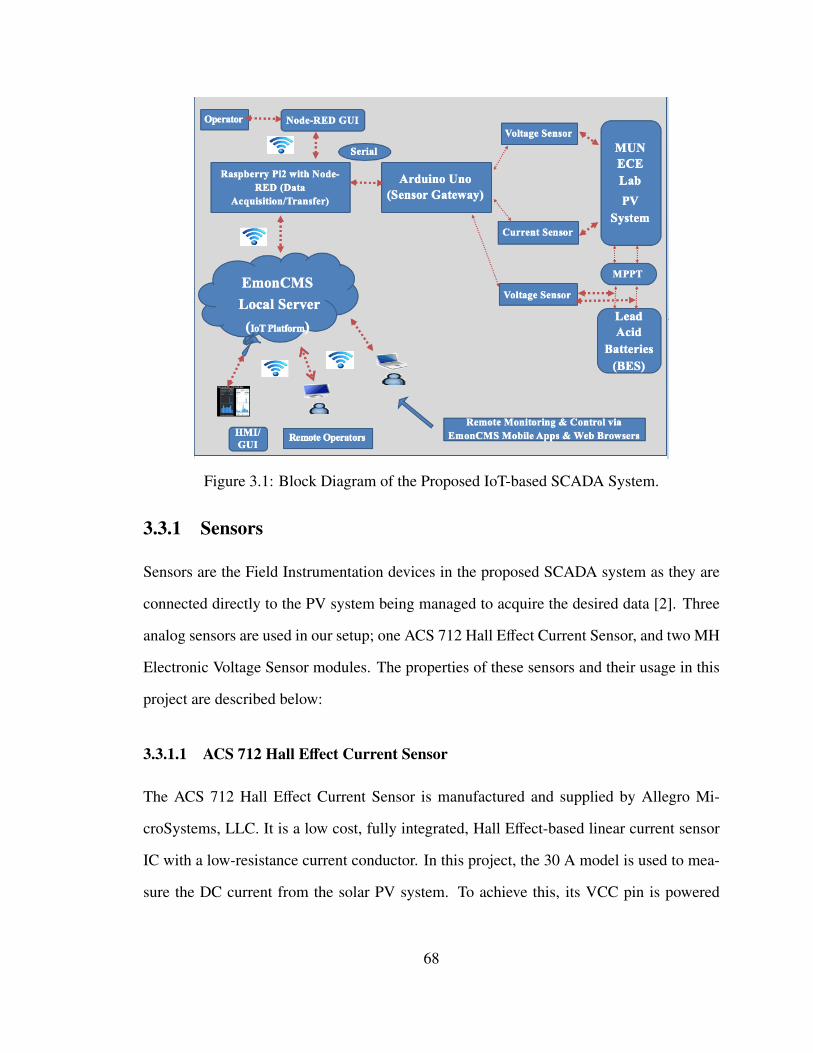
Figure 3.1: Block Diagram of the Proposed IoT-based SCADA System.
3.3.1 Sensors
Sensors are the Field Instrumentation devices in the proposed SCADA system as they are
connected directly to the PV system being managed to acquire the desired data [2]. Three
analog sensors are used in our setup; one ACS 712 Hall Effect Current Sensor, and two MH
Electronic Voltage Sensor modules. The properties of these sensors and their usage in this
project are described below:
3.3.1.1 ACS 712 Hall Effect Current Sensor
The ACS 712 Hall Effect Current Sensor is manufactured and supplied by Allegro Mi-
croSystems, LLC. It is a low cost, fully integrated, Hall Effect-based linear current sensor
IC with a low-resistance current conductor. In this project, the 30 A model is used to mea-
sure the DC current from the solar PV system. To achieve this, its VCC pin is powered
68
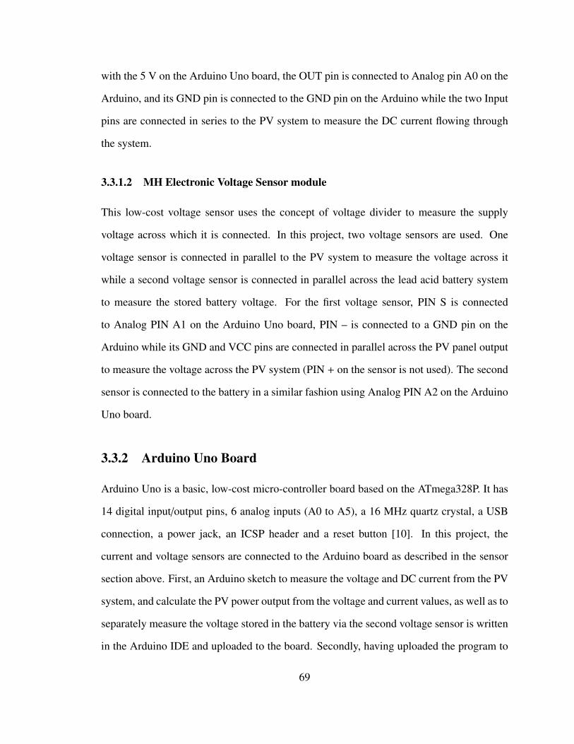
with the 5 V on the Arduino Uno board, the OUT pin is connected to Analog pin A0 on the
Arduino, and its GND pin is connected to the GND pin on the Arduino while the two Input
pins are connected in series to the PV system to measure the DC current flowing through
the system.
3.3.1.2 MH Electronic Voltage Sensor module
This low-cost voltage sensor uses the concept of voltage divider to measure the supply
voltage across which it is connected. In this project, two voltage sensors are used. One
voltage sensor is connected in parallel to the PV system to measure the voltage across it
while a second voltage sensor is connected in parallel across the lead acid battery system
to measure the stored battery voltage. For the first voltage sensor, PIN S is connected
to Analog PIN A1 on the Arduino Uno board, PIN – is connected to a GND pin on the
Arduino while its GND and VCC pins are connected in parallel across the PV panel output
to measure the voltage across the PV system (PIN + on the sensor is not used). The second
sensor is connected to the battery in a similar fashion using Analog PIN A2 on the Arduino
Uno board.
3.3.2 Arduino Uno Board
Arduino Uno is a basic, low-cost micro-controller board based on the ATmega328P. It has
14 digital input/output pins, 6 analog inputs (A0 to A5), a 16 MHz quartz crystal, a USB
connection, a power jack, an ICSP header and a reset button [10]. In this project, the
current and voltage sensors are connected to the Arduino board as described in the sensor
section above. First, an Arduino sketch to measure the voltage and DC current from the PV
system, and calculate the PV power output from the voltage and current values, as well as to
separately measure the voltage stored in the battery via the second voltage sensor is written
in the Arduino IDE and uploaded to the board. Secondly, having uploaded the program to
69
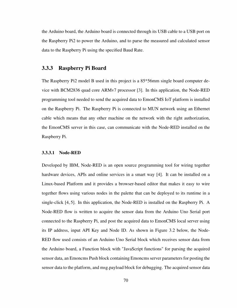
the Arduino board, the Arduino board is connected through its USB cable to a USB port on
the Raspberry Pi2 to power the Arduino, and to parse the measured and calculated sensor
data to the Raspberry Pi using the specified Baud Rate.
3.3.3 Raspberry Pi Board
The Raspberry Pi2 model B used in this project is a 85*56mm single board computer de-
vice with BCM2836 quad core ARMv7 processor [3]. In this application, the Node-RED
programming tool needed to send the acquired data to EmonCMS IoT platform is installed
on the Raspberry Pi. The Raspberry Pi is connected to MUN network using an Ethernet
cable which means that any other machine on the network with the right authorization,
the EmonCMS server in this case, can communicate with the Node-RED installed on the
Raspberry Pi.
3.3.3.1 Node-RED
Developed by IBM, Node-RED is an open source programming tool for wiring together
hardware devices, APIs and online services in a smart way [4]. It can be installed on a
Linux-based Platform and it provides a browser-based editor that makes it easy to wire
together flows using various nodes in the palette that can be deployed to its runtime in a
single-click [4, 5]. In this application, the Node-RED is installed on the Raspberry Pi. A
Node-RED flow is written to acquire the sensor data from the Arduino Uno Serial port
connected to the Raspberry Pi, and post the acquired data to EmonCMS local server using
its IP address, input API Key and Node ID. As shown in Figure 3.2 below, the Node-
RED flow used consists of an Arduino Uno Serial block which receives sensor data from
the Arduino board, a Function block with "JavaScript functions" for parsing the acquired
sensor data, an Emoncms Push block containing Emoncms server parameters for posting the
sensor data to the platform, and msg.payload block for debugging. The acquired sensor data
70
being posted to Emoncms IoT platform are displayed on the Node-RED display window as
shown in the Figure (right hand side).
Figure 3.2: Node-RED Flow for EmonCMS Data Logging.
3.3.4 EMONCMS Local Server IoT Platform
EMONCMS is a powerful open-source web-app for processing, logging and visualizing en-
ergy, temperature and other physical/environmental data [11]. It is a low-cost IoT platform
(under $500 CAD), highly flexible, and it is a part of the OpenEnergyMonitor.org project.
It has a Local Server option where a user purchases (one-off) the hardware and installs it
on a standalone or networked Windows or Linux based machine for proper management.
It also has a web-based server option which can be accessed using its URL just like every
other web application. Both the web-based and local server options have IoT capability as
the data stored in them can be accessed remotely with an internet enabled computer or with
an internet enabled phone via EMonCMS mobile app or phone browser [11]. However, the
local server EmonCMS option is more secured as the user has a better control of the server
71
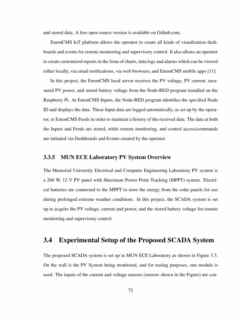
and stored data. A free open source version is available on Github.com.
EmonCMS IoT platform allows the operator to create all kinds of visualization dash-
boards and events for remote monitoring and supervisory control. It also allows an operator
to create customized reports in the form of charts, data logs and alarms which can be viewed
either locally, via email notifications, via web browsers, and EmonCMS mobile apps [11].
In this project, the EmonCMS local server receives the PV voltage, PV current, mea-
sured PV power, and stored battery voltage from the Node-RED program installed on the
Raspberry Pi. At EmonCMS Inputs, the Node-RED program identifies the specified Node
ID and displays the data. These Input data are logged automatically, as set up by the opera-
tor, to EmonCMS Feeds in order to maintain a history of the received data. The data at both
the Inputs and Feeds are stored, while remote monitoring, and control access/commands
are initiated via Dashboards and Events created by the operator.
3.3.5 MUN ECE Laboratory PV System Overview
The Memorial University Electrical and Computer Engineering Laboratory PV system is
a 260 W, 12 V PV panel with Maximum Power Point Tracking (MPPT) system. Electri-
cal batteries are connected to the MPPT to store the energy from the solar panels for use
during prolonged extreme weather conditions. In this project, the SCADA system is set
up to acquire the PV voltage, current and power, and the stored battery voltage for remote
monitoring and supervisory control.
3.4 Experimental Setup of the Proposed SCADA System
The proposed SCADA system is set up in MUN ECE Laboratory as shown in Figure 3.3.
On the wall is the PV System being monitored, and for testing purposes, one module is
used. The inputs of the current and voltage sensors (sensors shown in the Figure) are con-
72
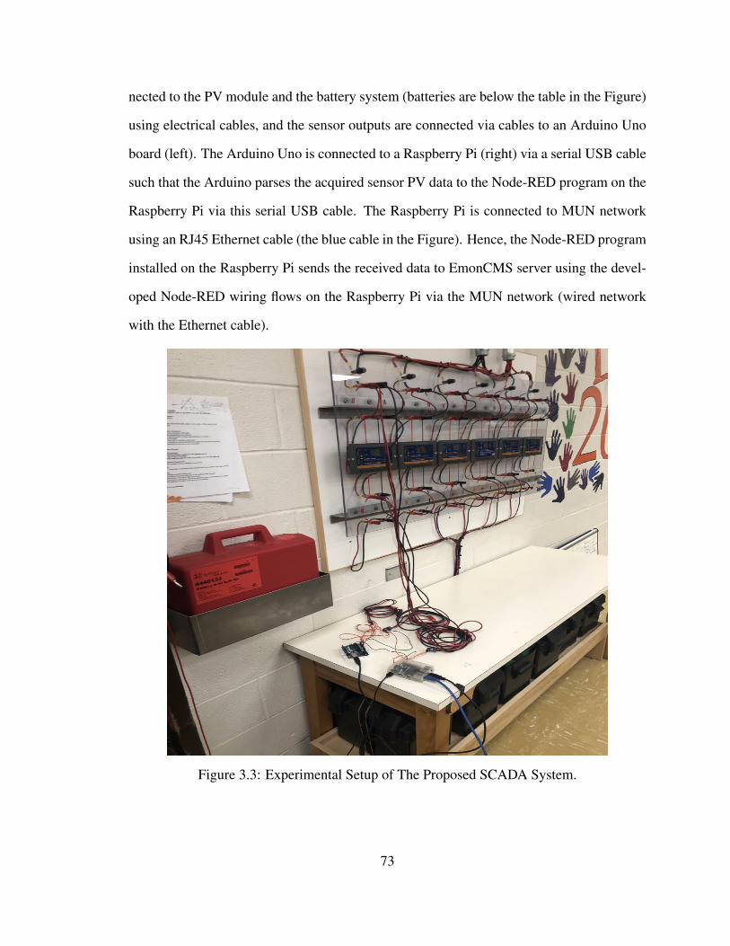
nected to the PV module and the battery system (batteries are below the table in the Figure)
using electrical cables, and the sensor outputs are connected via cables to an Arduino Uno
board (left). The Arduino Uno is connected to a Raspberry Pi (right) via a serial USB cable
such that the Arduino parses the acquired sensor PV data to the Node-RED program on the
Raspberry Pi via this serial USB cable. The Raspberry Pi is connected to MUN network
using an RJ45 Ethernet cable (the blue cable in the Figure). Hence, the Node-RED program
installed on the Raspberry Pi sends the received data to EmonCMS server using the devel-
oped Node-RED wiring flows on the Raspberry Pi via the MUN network (wired network
with the Ethernet cable).
Figure 3.3: Experimental Setup of The Proposed SCADA System.
73
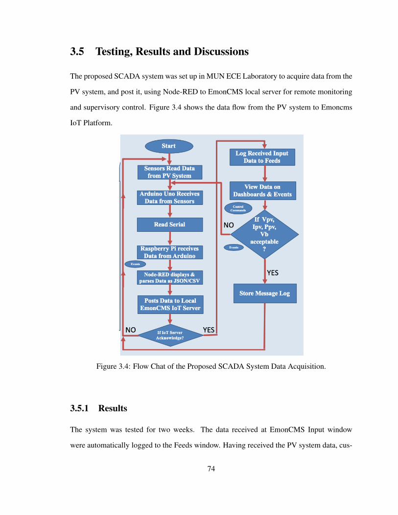
3.5 Testing, Results and Discussions
The proposed SCADA system was set up in MUN ECE Laboratory to acquire data from the
PV system, and post it, using Node-RED to EmonCMS local server for remote monitoring
and supervisory control. Figure 3.4 shows the data flow from the PV system to Emoncms
IoT Platform.
Figure 3.4: Flow Chat of the Proposed SCADA System Data Acquisition.
3.5.1 Results
The system was tested for two weeks. The data received at EmonCMS Input window
were automatically logged to the Feeds window. Having received the PV system data, cus-
74
tomized dashboards and reports in the form of charts, data logs and alarms were created on
EmonCMS IoT Platform. These dashboards, events and reports which could be viewed ei-
ther locally, through email notifications, web browsers, and EmonCMS mobile apps help an
operator to monitor the stored data, view trends in the stored data, and initiate supervisory
controls remotely. Figures 3.5 and 3.6 show two of the created dashboards for real-time
data visualization and raw-data visualization respectively. In Figure 3.5, real-time values
of PV Voltage, Current, and Power, and Battery Voltage are being visualized respectively,
and the time intervals and time stamps for each data received are displayed. In Figure 3.6,
raw values for PV Voltage, Current, and Power, and Battery Voltage are being visualized
respectively at various time intervals shown in the Figure. The vibrations of the raw data
show the changes in the values of the received data due to the fluctuating environmental
conditions affecting the PV System. Although the recorded voltage and current values are
low at this time due to the snow conditions in St. John’s at this time of the year, the voltage
and current sensors are capable of measuring up to 25 V and 30 A respectively. However,
the acquired sensor data match the values measured locally using conventional current and
voltage digital multimeters. Aside Figures 3.5 and 3.6 shown, EmonCMS Mobile App
was also connected to EmonCMS local server IoT Platform by scanning the barcode of the
platform using the Mobile App for a more flexible remote monitoring. Other Scheduling
and Visualization features such as bargraphs, histgraphs, and timecompare are available on
EmonCMS IoT Platform [11].
3.5.2 Discussions
Some of the key features of the developed IoT based SCADA system are enumerated below:
• Internet of Things based SCADA System: It is based on the Internet of Things
SCADA architecture and it has the four basic elements of a SCADA system listed
earlier in this paper.
75
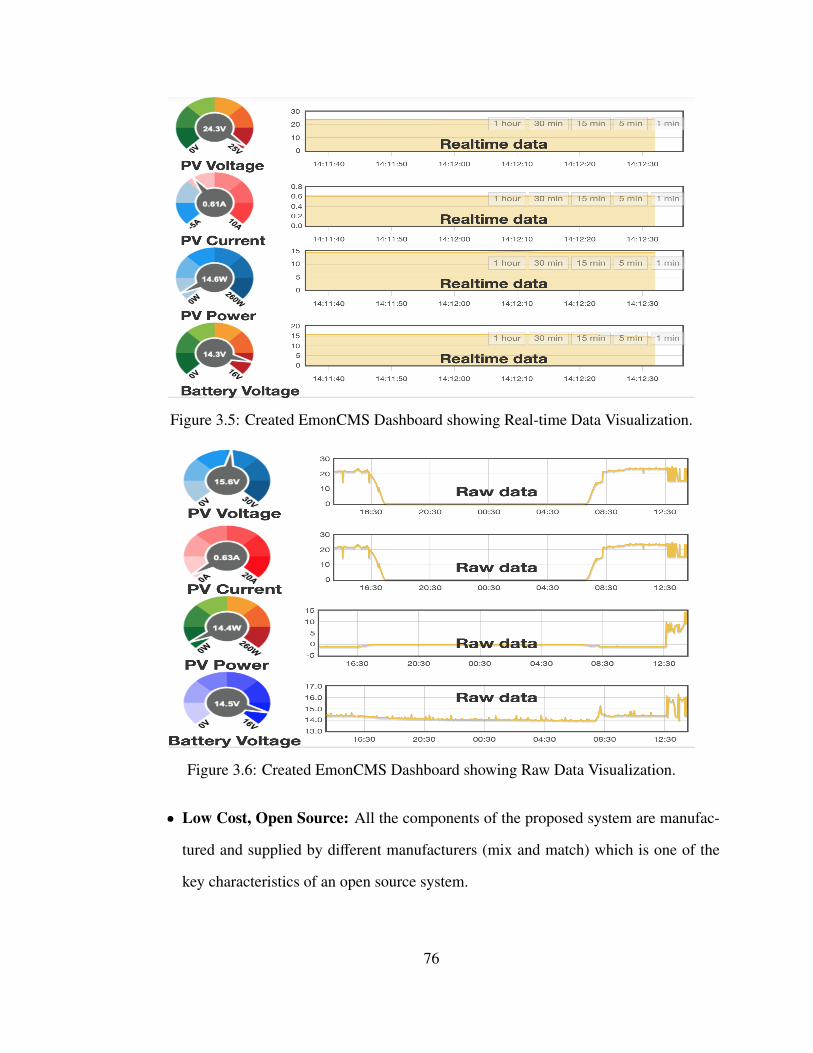
Figure 3.5: Created EmonCMS Dashboard showing Real-time Data Visualization.
Figure 3.6: Created EmonCMS Dashboard showing Raw Data Visualization.
• Low Cost, Open Source: All the components of the proposed system are manufac-
tured and supplied by different manufacturers (mix and match) which is one of the
key characteristics of an open source system.
76
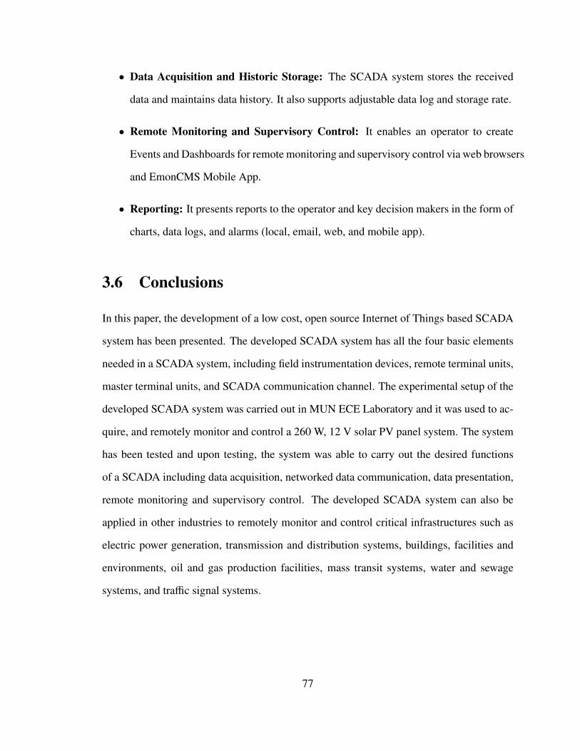
• Data Acquisition and Historic Storage: The SCADA system stores the received
data and maintains data history. It also supports adjustable data log and storage rate.
• Remote Monitoring and Supervisory Control: It enables an operator to create
Events and Dashboards for remote monitoring and supervisory control via web browsers
and EmonCMS Mobile App.
• Reporting: It presents reports to the operator and key decision makers in the form of
charts, data logs, and alarms (local, email, web, and mobile app).
3.6 Conclusions
In this paper, the development of a low cost, open source Internet of Things based SCADA
system has been presented. The developed SCADA system has all the four basic elements
needed in a SCADA system, including field instrumentation devices, remote terminal units,
master terminal units, and SCADA communication channel. The experimental setup of the
developed SCADA system was carried out in MUN ECE Laboratory and it was used to ac-
quire, and remotely monitor and control a 260 W, 12 V solar PV panel system. The system
has been tested and upon testing, the system was able to carry out the desired functions
of a SCADA including data acquisition, networked data communication, data presentation,
remote monitoring and supervisory control. The developed SCADA system can also be
applied in other industries to remotely monitor and control critical infrastructures such as
electric power generation, transmission and distribution systems, buildings, facilities and
environments, oil and gas production facilities, mass transit systems, water and sewage
systems, and traffic signal systems.
77
Acknowledgements
The authors would like to thank the Natural Sciences and Engineering Research Council
of Canada (NSERC) Energy Storage Technology Network (NESTNet) for funding this re-
search.
Bibliography
[1] M. Al-Kuwari, A. Ramadan, Y. Ismael, L. Al-Sughair, A. Gastli and M. Benammar,
"Smart-home automation using IoT-based sensing and monitoring platform," 2018
IEEE 12th International Conference on Compatibility, Power Electronics and Power
Engineering (CPE-POWERENG 2018), Doha, 2018, pp. 1-6.
[2] X. Lu, "Supervisory Control and Data Acquisition System Design for CO2 Enhanced
Oil Recovery," Technical Report No. UCB/EECS-2014-123. Master of Engineering
Thesis, EECS Department, University of California, Berkeley, CA, USA, 21 May
2014.
[3] R. Shete and S. Agrawal, "IoT based urban climate monitoring using Raspberry Pi,"
2016 International Conference on Communication and Signal Processing (ICCSP),
Melmaruvathur, 2016, pp. 2008-2012.
[4] M. Lekic and G. Gardaševic, "IoT sensor integration to Node-RED platform," 2018
17th International Symposium INFOTEH-JAHORINA (INFOTEH), East Sarajevo,
2018, pp. 1-5.
[5] A. Rajalakshmi and H. Shahnasser, "Internet of Things using Node-Red and alexa,"
2017 17th International Symposium on Communications and Information Technolo-
gies (ISCIT), Cairns, QLD, 2017, pp. 1-4.
78
[6] L. Wang and K. Liu, "Implementation of a Web-Based Real-Time Monitoring and
Control System for a Hybrid Wind-PV-Battery Renewable Energy System," 2007 In-
ternational Conference on Intelligent Systems Applications to Power Systems, Toki
Messe, Niigata, 2007, pp. 1-6.
[7] N. P. Kumar and R. K. Jatoth, "Development of cloud based light intensity monitoring
system using raspberry Pi," 2015 International Conference on Industrial Instrumenta-
tion and Control (ICIC), India, 2015, pp. 1356-1361.
[8] V. Sandeep, K. L. Gopal, S. Naveen, A. Amudhan and L. S. Kumar, "Globally ac-
cessible machine automation using Raspberry pi based on Internet of Things," 2015
International Conference on Advances in Computing, Communications and Informat-
ics (ICACCI), Kochi, 2015, pp. 1144-1147.
[9] S. Chanthakit and C. Rattanapoka, "MQTT Based Air Quality Monitoring System
using Node MCU and Node-RED," 2018 Seventh ICT International Student Project
Conference (ICT-ISPC), Nakhonpathom, 2018, pp. 1-5.
[10] J. C. B. Lopez and H. M. Villaruz, "Low-cost weather monitoring system with online
logging and data visualization," 2015 International Conference on Humanoid, Nan-
otechnology, Information Technology,Communication and Control, Environment and
Management (HNICEM), Cebu City, 2015, pp. 1-6.
[11] "Emoncms," Available online: https://emoncms.org/ (accessed 5 January 2019).
[12] "Supervisory Control and Data Acquisition," Available online: https://www.
abbey.co.nz/papers.html (accessed 5 January 2019).
79
Chapter 4
Low-Cost, IoT-Based Open Source
SCADA System using Thinger.IO and
ESP32 Thing*
Preface
A version of this manuscript has been published in the Electronics Journal, Special Issue
on Modern Mechatronics and Automation — An Open-Source Approach. Electronics
2019, 8(8), 822; https://doi.org/10.3390/electronics8080822. I am the primary author, and
I carried out most of the research work, performed the literature reviews, carried out the
system design, hardware implementations, experimental setups and analysis of the results. I
also prepared the first draft of the manuscript and subsequently revised the final manuscript
based on the feedback from the co-author and the peer review process. The Co-author, Dr.
M. Tariq Iqbal, supervised the research, acquired and made available the research funding,
*This chapter is a version of “Low-Cost, Open Source IoT-Based SCADA System Design UsingThinger.IO and ESP32 Thing”, L. O. Aghenta and M. T. Iqbal, Electronics Vol.8, No. 8, p. 822, elec-tronics8080822 (2019).
80
provided the research components, reviewed and corrected the manuscript, and contributed
research ideas in the actualization of the manuscript.
Abstract
Supervisory Control and Data Acquisition (SCADA) is a technology for monitoring and
controlling distributed processes. SCADA provides real-time data exchange between a con-
trol/monitoring centre and field devices connected to the distributed processes. A SCADA
system performs these functions using its four basic elements: Field Instrumentation De-
vices (FIDs) such as sensors and actuators which are connected to the distributed process
plants being managed, Remote Terminal Units (RTUs) such as single board computers for
receiving, processing and sending the remote data from the field instrumentation devices,
Master Terminal Units (MTUs) for handling data processing and human machine interac-
tions, and lastly SCADA Communication Channels for connecting the RTUs to the MTUs,
and for parsing the acquired data. Generally, there are two classes of SCADA hardware and
software; Proprietary (Commercial) and Open Source. In this paper, we present the design
and implementation of a low-cost, Open Source SCADA system by using Thinger.IO local
server IoT platform as the MTU and ESP32 Thing micro-controller as the RTU. SCADA
architectures have evolved over the years from monolithic (stand-alone) through distributed
and networked architectures to the latest Internet of Things (IoT) architecture. The SCADA
system proposed in this work is based on the Internet of Things SCADA architecture which
incorporates web services with the conventional (traditional) SCADA for a more robust su-
pervisory control and monitoring. It comprises of analog Current and Voltage Sensors, the
low-power ESP32 Thing micro-controller, a Raspberry Pi micro-controller, and a local Wi-
Fi Router. In its implementation, the current and voltage sensors acquire the desired data
from the process plant, the ESP32 micro-controller receives, processes and sends the ac-
81
quired sensor data via a Wi-Fi network to the Thinger.IO local server IoT platform for data
storage, real-time monitoring and remote control. The Thinger.IO server is locally hosted
by the Raspberry Pi micro-controller, while the Wi-Fi network which forms the SCADA
communication channel is created using the Wi-Fi Router. In order to test the proposed
SCADA system solution, the designed hardware was set up to remotely monitor the Pho-
tovoltaic (PV) voltage, current, and power, as well as the storage battery voltage of a 260
W, 12 V Solar PV System. Some of the created Human Machine Interfaces (HMIs) on
Thinger.IO Server where an operator can remotely monitor the data in the cloud, as well as
initiate supervisory control activities if the acquired data are not in the expected range, us-
ing both a computer connected to the network, and Thinger.IO Mobile Apps are presented
in the paper.
Index Terms: open source; SCADA; Thinger.IO; Internet of Things; ESP32 Thing;
Raspberry Pi; automation; instrumentation and control
4.1 Introduction
The acronym, SCADA, stands for Supervisory Control And Data Acquisition. A SCADA
system is a collection of both software and hardware components that allows for the su-
pervision and control of plants and industrial processes both locally and remotely. The
system involves the examination, collection, and processing of data in real time, as well as
data logging for historical purposes. The architectural design of a standard SCADA sys-
tem starts with Remote Terminal Units (RTUs), and/or Programmable Logic Controllers
(PLCs). These RTUs and PLCs are micro-controllers or microprocessors that communicate
and interact with Field Instrumentation Devices (FIDs) such as sensors, actuators, valves,
pumps and transmitters. These communication data are routed from the controllers or pro-
cessors via a SCADA Communication Channel to the SCADA computers known as Master
82
Terminal Units (MTUs) where the data are interpreted and displayed on a Human Machine
Interface (HMI) allowing operators and important decision makers to analyze and react to
process events [1–5].
SCADA technology has evolved over the past 30 years as a method of monitoring and
controlling distributed processes [5]. Before the emergence of SCADA, plant personnel
had to monitor and control industrial processes via selector switches, push buttons, and
dials (for analog signals), which meant that plants needed to maintain a good number of
personnel on site during production to be able to carry out these manual monitoring and
control tasks. As industrial processes grew and sites became more remote in nature, relays
and timers were used to assist in the supervision and control of processes, which meant
that fewer number of personnel were required on site to oversee their operations. While
relays and timers provided a decent level of automation, they required more resources to
manage their operations. The need to automate more processes, which coupled with the
difficulties associated with the previous monitoring and control solutions gave birth to the
first generation SCADA systems in the 1970s called Monolithic SCADA, and they were
stand-alone units. With the advent of Local Area Network (LAN) and HMI softwares in
the 1980s and 1990s, and with computer systems getting smaller and smarter, it became
possible to connect SCADA systems to related systems which gave rise to the second gen-
eration SCADA called Distributed SCADA. Unfortunately then, the communications were
typically proprietary which meant that the connections outside of the vendors of a particular
SCADA system were not possible [2–4].
Later in the 1990s and 2000s, SCADA began to implement open system architectures
with communication protocols that were no longer vendor specific, leading to more con-
nection capabilities in the form of a wide area network. This resulted in a more improved
SCADA system called Networked SCADA system (3rd generation). With computer tech-
nologies growing rapidly, this SCADA was quickly out of date as other technologies were
83
becoming more efficient and more in tune with the latest Information Technology (IT) de-
velopments. SCADA manufacturers had to rise to the challenge to come up with a SCADA
architecture with great advantages over older SCADA systems. This is the Internet of
Things SCADA architecture (4th generation) which incorporates cloud services with the
conventional SCADA system for more robust monitoring and control [6]. This SCADA al-
lows for real-time plant information to be accessed from anywhere around the world using
various operating systems and platforms [2, 3, 7]. The Internet of Things (IoT) concept has
to do with the connection of physical objects with embedded electronics, software, sensors
and connectivity to enable data interchange between these devices and an operator over a
common platform or the web [6–10].
Presently, as in the past, automation companies such as Emerson, Siemens, Schnei-
der Electric, and Allen Bradley develop various forms of SCADA hardware and software
which they sell as turnkey solutions to end users. Examples of such solutions include Ova-
tion SCADA communication server (Emerson), Simatic WinCC (Siemens), Clear SCADA
server (Schneider Electric), and Micro SCADA (Allen Bradley) [3, 11]. Currently, these
systems come with various IoT-based MTUs for data visualization and process management
such as the Totally Integrated Automation (TIA) portal in Siemens’ Simatic WinCC [11].
In addition to the huge initial capital costs of buying these SCADA systems, which are in
thousands of dollars, the end user is made to pay for annual maintenance and support fees to
use the SCADA system solutions. For very large companies, like most companies in the Oil
and Gas sectors, the costs of owning these commercial SCADA systems might be justifiable
or affordable. However, for smaller companies with no enormous financial resources, but
with the need to deploy SCADA solutions to monitor and control their distributed facilities,
such as companies in the power sector or renewable generation systems, these commercial
SCADA solutions do not represent a profitable choice. With the commercial systems, there
is also the problem of interoperability with the existing infrastructures, for example power
84
electronic converters in a power system [12]. Seamless communication among devices in
modern power systems is the key to successful SCADA implementation [13,14]. Therefore,
a low-cost, open source SCADA solution represents the most viable solution [4, 7, 12].
In this work, we propose a low-cost, open source SCADA system based on the most re-
cent SCADA architecture, which is the Internet of Things [6,10,15]. Our proposed SCADA
system uses reliable and commonly available components to achieve the four basic func-
tions of a SCADA system which the available commercial SCADA systems also perform:
Data acquisition, networked data communication, data presentation, and remote monitoring
and supervisory control [1, 9].
The remainder of this paper is organized as follows. In Section 4.2, we present the
related works, problem statements, and the proposed SCADA system as a solution to the
identified problems. In Section 4.3, we present system descriptions, including the proposed
SCADA system design configurations. In Section 4.4, we present the components of the
proposed SCADA system and the detailed description of each of the components. Section
4.5 presents the implementation methodology, Section 4.6 presents the prototype design,
Section 4.7 presents the experimental setup of the proposed SCADA system, and Section
4.8 presents the testing carried out and the results. In Section 4.9, the key features of the
designed SCADA system are discussed, including the system cost and power consumption
analysis. The paper is concluded in Section 4.10, and future work presented in Section
4.11.
4.2 Literature Review
The research communities all over the world have tried to solve the problems associated
with commercial SCADA systems (high costs and compatibility issues) by developing var-
ious open source SCADA solutions, each with varying costs and functionalities. Rajku-
85
mar et al. [16] have proposed a low-cost, open source SCADA system using Arduino Uno
micro-controller as the sensor gateway, and ZigBee Radio Modules for data transmission
from their field instrumentation devices such as flow sensors, temperature sensors, level
sensors, control valves, and pumps to a data processing software, which they created with
Java, where reports on the state of the process facility are generated and visualized. In [17],
a form of low-cost web-based SCADA solution is proposed. In this solution, Radio Fre-
quency (RF) Receivers connected to a controller circuitry collect plant data, and the data
are made available to the controller which, in turn parses the data to a driver circuitry for set
point verification before the data get transmitted via the internet to a web-based SCADA
server for visualization. The proposed solution here is complex as it involves the use of
a mathematical model for data verification in the controller and driver circuitries before
transmission to the web-based SCADA server.
Elsewhere, Merchan et al. [18] implemented an open source SCADA system by using
the general purpose programming platform, Python. Their proposed system is made up of
three layers: a Device Layer, which is the process plant being managed, a Controller Layer,
which comprises of two PLCs, and lastly, a Supervision Layer comprising of HMI SCADA
client, and Python Open Platform Communications Unified Architecture (OPC-UA) Server
with Structured Query Language (MySQL) Database, both installed in a Raspberry Pi3.
Here, communication between the control devices is via Ethernet. This solution uses a lot
of components which means more power consumption and less reliability of the resultant
SCADA system. The authors in [19] have implemented a form of open source SCADA
system for the monitoring of the level and flow rate of water in a container by using the
open source SCADA platform called OpenSCADA where HMIs are created for data visu-
alization. The major issues here are that the OpenSCADA software is not entirely free as
it requires user subscriptions, and the proposed solution involves a large amount of logical
programming for accurate data acquisition and visualization in the OpenSCADA platform.
86
Similar to [19], Avhad et al. [20] have proposed a form of open source automation
system using Vijeo Citect SCADA software as the MTU, AtMEGA 2560 micro-controller
as the RTU for sensor data collection, and ModBus protocol as the communication channel
between the MTU and the RTU. In another development, Mononen et al. [21] proposed a
low-cost open source SCADA system comprising of sensor network for data collection, and
a microprocessor for data processing and transmission via UDP Ethernet frame to a cloud
environment. The cloud environment is composed of virtual machines running user-defined
algorithms in the cloud for accurate data processing and handling. Just like [21], the authors
in [7] have developed a low-cost SCADA system based on IoT technology where the RTU
is connected to the field devices through TCP/IP and supported on a NoSQL database.
The functionalities of their developed system were evaluated using a traffic management
process. The major problem with these systems is that they are complex systems which
will be difficult for an ordinary end-user to use. Furthermore, the solution in [21] is prone
to errors as it requires a great deal of user-defined algorithms in the cloud.
In this paper, we present the detailed design of a SCADA system using very few low-
cost, low-power, and completely open source components. In our proposed SCADA solu-
tion, a locally installed Thinger.IO Server IoT Platform serves as the Master Terminal Unit
where HMIs are created for data visualization and processing, and the versatile Sparkfun
ESP32 Thing micro-controller serves as the Remote Terminal Unit for receiving and send-
ing the sensor data from the Field Instrumentation Devices (sensors), while a local Wi-Fi
Network provides the Communication Channel between the MTU and the RTU, resulting
in a form of industrial network as implemented by the commercial SCADA vendors all over
the world [3, 9, 11].
The authors in [22–24] have used Thinger.IO to implement their respective remote
monitoring and automation systems. In their systems, the acquired sensor data are sent
to Thinger.IO cloud platform where HMI dashboards are created for data visualization.
87
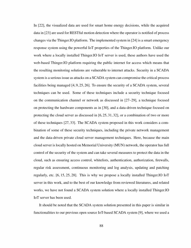
In [22], the visualized data are used for smart home energy decisions, while the acquired
data in [23] are used for RESTful motion detection where the operator is notified of process
changes via the Thinger.IO platform. The implemented system in [24] is a smart emergency
response system using the powerful IoT properties of the Thinger.IO platform. Unlike our
work where a locally installed Thinger.IO IoT server is used, these authors have used the
web-based Thinger.IO platform requiring the public internet for access which means that
the resulting monitoring solutions are vulnerable to internet attacks. Security in a SCADA
system is a serious issue as attacks on a SCADA system can compromise the critical process
facilities being managed [4, 9, 25, 26]. To ensure the security of a SCADA system, several
techniques can be used. Some of these techniques include a security technique focused
on the communication channel or network as discussed in [27–29], a technique focused
on protecting the hardware components as in [30], and a data-driven technique focused on
protecting the cloud server as discussed in [6, 25, 31, 32], or a combination of two or more
of these techniques [27, 33]. The SCADA system proposed in this work considers a com-
bination of some of these security techniques, including the private network management
and the data-driven private cloud server management techniques. Here, because the main
cloud server is locally hosted on Memorial University (MUN) network, the operator has full
control of the security of the system and can take several measures to protect the data in the
cloud, such as ensuring access control, whitelists, authentication, authorization, firewalls,
regular risk assessment, continuous monitoring and log analysis, updating and patching
regularly, etc. [6, 15, 25, 28]. This is why we propose a locally installed Thinger.IO IoT
server in this work, and to the best of our knowledge from reviewed literatures, and related
works, we have not found a SCADA system solution where a locally installed Thinger.IO
IoT server has been used.
It should be noted that the SCADA system solution presented in this paper is similar in
functionalities to our previous open source IoT-based SCADA system [9], where we used a
88
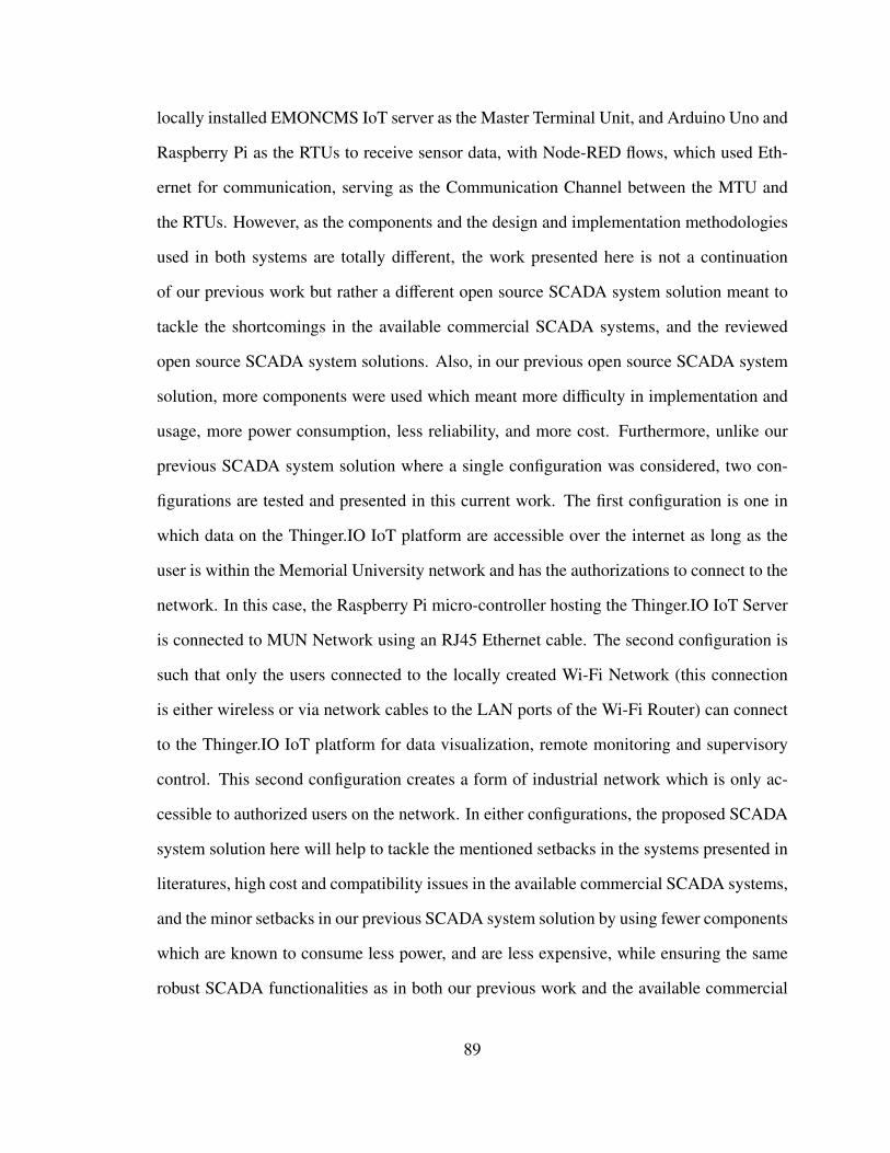
locally installed EMONCMS IoT server as the Master Terminal Unit, and Arduino Uno and
Raspberry Pi as the RTUs to receive sensor data, with Node-RED flows, which used Eth-
ernet for communication, serving as the Communication Channel between the MTU and
the RTUs. However, as the components and the design and implementation methodologies
used in both systems are totally different, the work presented here is not a continuation
of our previous work but rather a different open source SCADA system solution meant to
tackle the shortcomings in the available commercial SCADA systems, and the reviewed
open source SCADA system solutions. Also, in our previous open source SCADA system
solution, more components were used which meant more difficulty in implementation and
usage, more power consumption, less reliability, and more cost. Furthermore, unlike our
previous SCADA system solution where a single configuration was considered, two con-
figurations are tested and presented in this current work. The first configuration is one in
which data on the Thinger.IO IoT platform are accessible over the internet as long as the
user is within the Memorial University network and has the authorizations to connect to the
network. In this case, the Raspberry Pi micro-controller hosting the Thinger.IO IoT Server
is connected to MUN Network using an RJ45 Ethernet cable. The second configuration is
such that only the users connected to the locally created Wi-Fi Network (this connection
is either wireless or via network cables to the LAN ports of the Wi-Fi Router) can connect
to the Thinger.IO IoT platform for data visualization, remote monitoring and supervisory
control. This second configuration creates a form of industrial network which is only ac-
cessible to authorized users on the network. In either configurations, the proposed SCADA
system solution here will help to tackle the mentioned setbacks in the systems presented in
literatures, high cost and compatibility issues in the available commercial SCADA systems,
and the minor setbacks in our previous SCADA system solution by using fewer components
which are known to consume less power, and are less expensive, while ensuring the same
robust SCADA functionalities as in both our previous work and the available commercial
89
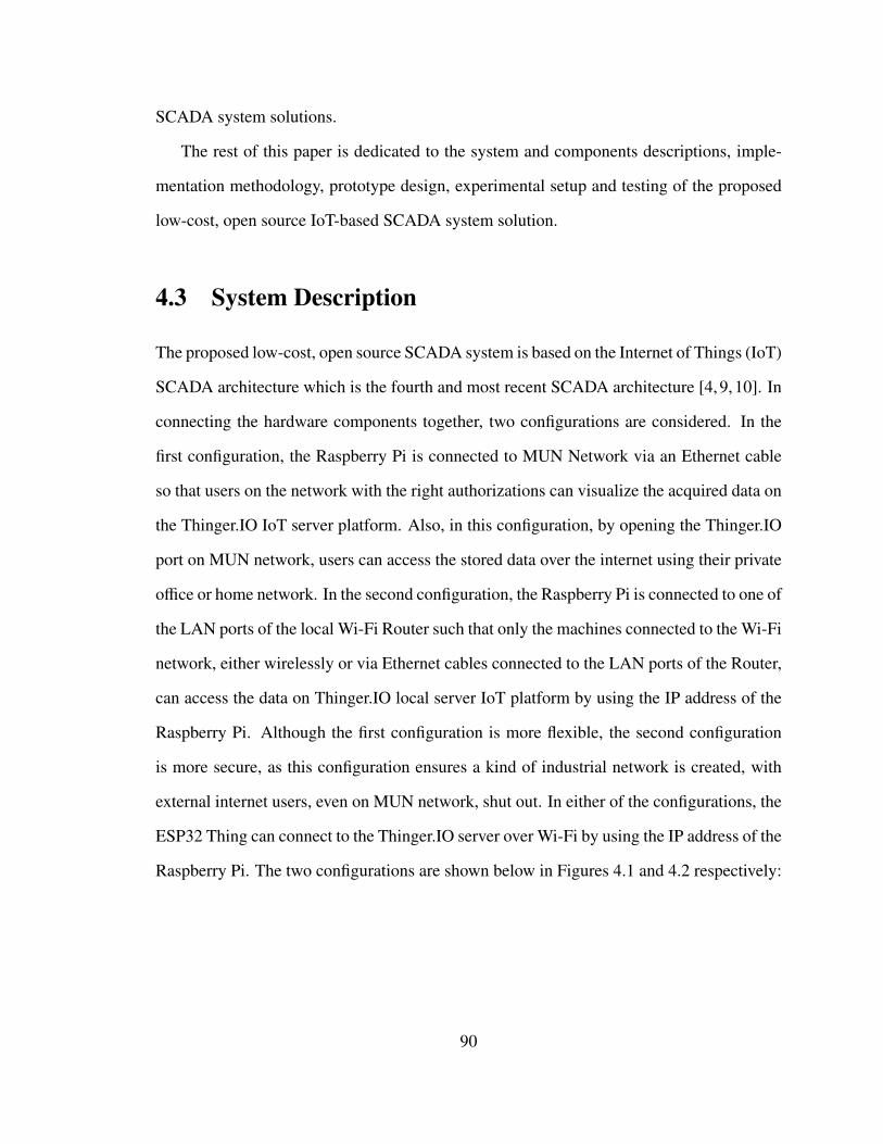
SCADA system solutions.
The rest of this paper is dedicated to the system and components descriptions, imple-
mentation methodology, prototype design, experimental setup and testing of the proposed
low-cost, open source IoT-based SCADA system solution.
4.3 System Description
The proposed low-cost, open source SCADA system is based on the Internet of Things (IoT)
SCADA architecture which is the fourth and most recent SCADA architecture [4,9,10]. In
connecting the hardware components together, two configurations are considered. In the
first configuration, the Raspberry Pi is connected to MUN Network via an Ethernet cable
so that users on the network with the right authorizations can visualize the acquired data on
the Thinger.IO IoT server platform. Also, in this configuration, by opening the Thinger.IO
port on MUN network, users can access the stored data over the internet using their private
office or home network. In the second configuration, the Raspberry Pi is connected to one of
the LAN ports of the local Wi-Fi Router such that only the machines connected to the Wi-Fi
network, either wirelessly or via Ethernet cables connected to the LAN ports of the Router,
can access the data on Thinger.IO local server IoT platform by using the IP address of the
Raspberry Pi. Although the first configuration is more flexible, the second configuration
is more secure, as this configuration ensures a kind of industrial network is created, with
external internet users, even on MUN network, shut out. In either of the configurations, the
ESP32 Thing can connect to the Thinger.IO server over Wi-Fi by using the IP address of the
Raspberry Pi. The two configurations are shown below in Figures 4.1 and 4.2 respectively:
90
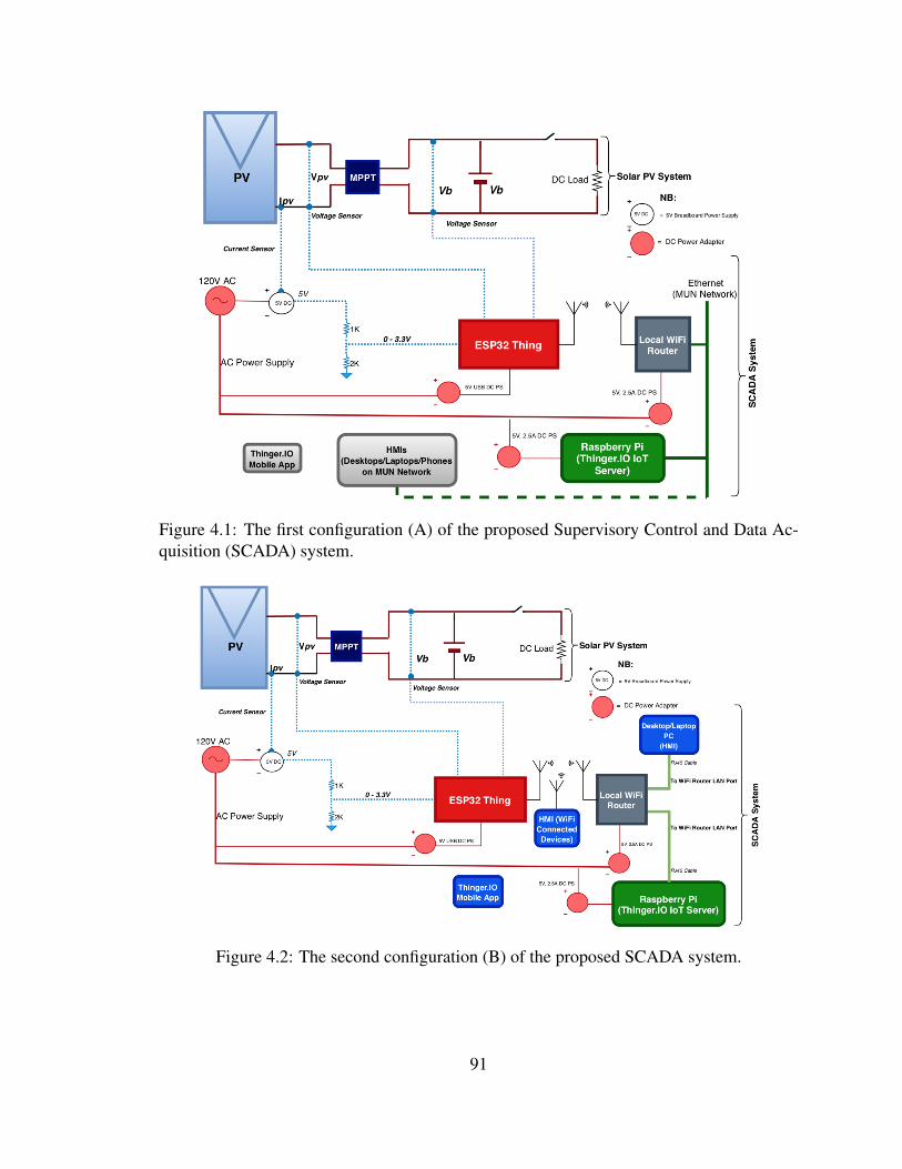
Figure 4.1: The first configuration (A) of the proposed Supervisory Control and Data Ac-quisition (SCADA) system.
Figure 4.2: The second configuration (B) of the proposed SCADA system.
91
4.4 Components of the Proposed SCADA System
The SCADA system proposed in this work is made up of analog voltage and current sensors
for data acquisition, SparkFun ESP32 Thing micro-controller for receiving, processing and
parsing the sensor data, Wi-Fi Router for local Wi-Fi network creation (communication
channel), and Thinger.IO local IoT server with graphical user interface (dashboards) created
for remote sensor data monitoring and supervisory control. Each of these components is
described in details below:
4.4.1 Sensors
Sensors are the Field Instrumentation Devices in the proposed SCADA system as they are
connected directly to the PV system being managed to acquire the desired data [1, 34].
Three analog sensors are used in our setup; one ACS 712 Hall Effect Current Sensor, and
two MH Electronic Voltage Sensor modules. The operating signal voltage (VCC) of the
current sensor is 5 V single supply, and that of voltage sensor is between 3.3 V to 5 V,
while that of the ESP32 Thing micro-controller is 0 V to 3.3 V. This means that the current
sensor is not suitable for direct connection to the analog-to-digital converter (ADC) Pins of
the ESP32 Thing. Therefore, in order to ensure that the sensor matches the 3.3 V signal
voltage of the ESP32 Thing, some level shifting is carried out by using a pull-down or
step-down resistor arrangement (Figure 4.3). This will ensure the accuracy of the measured
sensor value. The properties of these sensors and their usage in this work are described
below:
4.4.1.1 ACS 712 Hall Effect Current Sensor
The ACS 712 Hall Effect Current Sensor, manufactured and supplied by Allegro MicroSys-
tems, LLC. is a low-cost, fully integrated, Hall Effect-based linear current sensor IC with
92
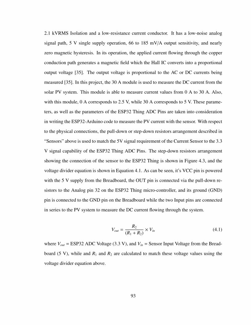
2.1 kVRMS Isolation and a low-resistance current conductor. It has a low-noise analog
signal path, 5 V single supply operation, 66 to 185 mV/A output sensitivity, and nearly
zero magnetic hysteresis. In its operation, the applied current flowing through the copper
conduction path generates a magnetic field which the Hall IC converts into a proportional
output voltage [35]. The output voltage is proportional to the AC or DC currents being
measured [35]. In this project, the 30 A module is used to measure the DC current from the
solar PV system. This module is able to measure current values from 0 A to 30 A. Also,
with this module, 0 A corresponds to 2.5 V, while 30 A corresponds to 5 V. These parame-
ters, as well as the parameters of the ESP32 Thing ADC Pins are taken into consideration
in writing the ESP32-Arduino code to measure the PV current with the sensor. With respect
to the physical connections, the pull-down or step-down resistors arrangement described in
“Sensors” above is used to match the 5V signal requirement of the Current Sensor to the 3.3
V signal capability of the ESP32 Thing ADC Pins. The step-down resistors arrangement
showing the connection of the sensor to the ESP32 Thing is shown in Figure 4.3, and the
voltage divider equation is shown in Equation 4.1. As can be seen, it’s VCC pin is powered
with the 5 V supply from the Breadboard, the OUT pin is connected via the pull-down re-
sistors to the Analog pin 32 on the ESP32 Thing micro-controller, and its ground (GND)
pin is connected to the GND pin on the Breadboard while the two Input pins are connected
in series to the PV system to measure the DC current flowing through the system.
Vout =R2
(R1 + R2)× Vin (4.1)
where Vout = ESP32 ADC Voltage (3.3 V), and Vin = Sensor Input Voltage from the Bread-
board (5 V), while and R1 and R2 are calculated to match these voltage values using the
voltage divider equation above.
93
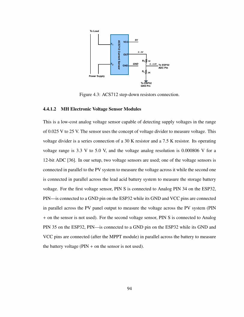
Figure 4.3: ACS712 step-down resistors connection.
4.4.1.2 MH Electronic Voltage Sensor Modules
This is a low-cost analog voltage sensor capable of detecting supply voltages in the range
of 0.025 V to 25 V. The sensor uses the concept of voltage divider to measure voltage. This
voltage divider is a series connection of a 30 K resistor and a 7.5 K resistor. Its operating
voltage range is 3.3 V to 5.0 V, and the voltage analog resolution is 0.000806 V for a
12-bit ADC [36]. In our setup, two voltage sensors are used; one of the voltage sensors is
connected in parallel to the PV system to measure the voltage across it while the second one
is connected in parallel across the lead acid battery system to measure the storage battery
voltage. For the first voltage sensor, PIN S is connected to Analog PIN 34 on the ESP32,
PIN—is connected to a GND pin on the ESP32 while its GND and VCC pins are connected
in parallel across the PV panel output to measure the voltage across the PV system (PIN
+ on the sensor is not used). For the second voltage sensor, PIN S is connected to Analog
PIN 35 on the ESP32, PIN—is connected to a GND pin on the ESP32 while its GND and
VCC pins are connected (after the MPPT module) in parallel across the battery to measure
the battery voltage (PIN + on the sensor is not used).
94
4.4.2 ESP32 Thing Micro-Controller (RTU)
The ESP32 Thing, manufactured and supplied by SparkFun Electronics, is a comprehensive
development platform. It is a Wi-Fi compatible micro-controller, it supports Bluetooth
Low-Energy (i.e., BLE, BT4.0, Bluetooth Smart), and it has nearly 30 Input/Output (I/O)
pins [37]. According to the manufacturer, it is called the “Thing” because it is the perfect
foundation for Internet of Things projects [37]. It is one of the most unique low-cost (about
$20 CAD), low-power (about 0.5 W) micro-controllers available on the market today. The
board can be powered with either a 5 V USB power supply or with a single-cell lithium-
polymer (LiPo) battery, and its operating signal voltage range is 2.2 V to 3.6 V. The I/O
pins of the ESP32 Thing board are only 3.3 V tolerant, hence the need for the level shifting
of the connected 5 V current sensor explained earlier. Figure 4.4 shows a picture of the
SparkFun ESP32 board while Figure 4.5 shows a summary of the hardware specifications
of the board [37].
Figure 4.4: Image of the SparkFun ESP32 Thing board [37].
The ESP32 Thing micro-controller is programmed with an Arduino software integrated
development environment (IDE). The Arduino IDE allows one to write the desired pro-
grams and upload them to the board via a USB cable. Arduino programs are called Sketches,
and its language is merely a set of C/C++ functions [37]. In this project, the ESP32 Thing
is hooked to a Breadboard, and the current and voltage sensors are connected to it as de-
scribed in the “Sensors” section above. First, an Arduino sketch to measure the voltage and
95
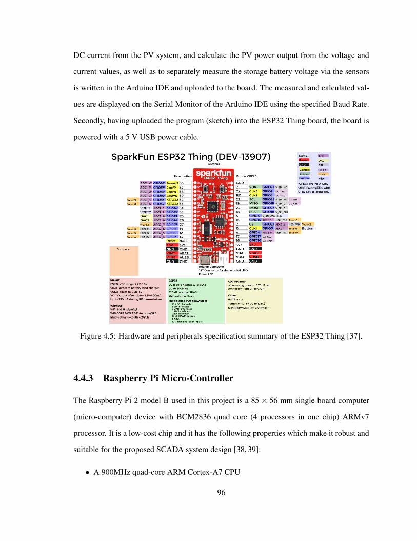
DC current from the PV system, and calculate the PV power output from the voltage and
current values, as well as to separately measure the storage battery voltage via the sensors
is written in the Arduino IDE and uploaded to the board. The measured and calculated val-
ues are displayed on the Serial Monitor of the Arduino IDE using the specified Baud Rate.
Secondly, having uploaded the program (sketch) into the ESP32 Thing board, the board is
powered with a 5 V USB power cable.
Figure 4.5: Hardware and peripherals specification summary of the ESP32 Thing [37].
4.4.3 Raspberry Pi Micro-Controller
The Raspberry Pi 2 model B used in this project is a 85 × 56 mm single board computer
(micro-computer) device with BCM2836 quad core (4 processors in one chip) ARMv7
processor. It is a low-cost chip and it has the following properties which make it robust and
suitable for the proposed SCADA system design [38, 39]:
• A 900MHz quad-core ARM Cortex-A7 CPU
96
• 1GB RAM
• One hundred Base Ethernet
• Four USB ports
• Forty GPIO pins
• Full HDMI port
• Combined 3.5 mm audio jack and composite video
• Camera interface (CSI)
• Display interface (DSI)
• Micro SD card slot
• VideoCore IV 3D graphics core.
In this work, the Thinger.IO IoT Server is installed and configured on the Raspberry Pi
and the Raspberry Pi is connected to the other components in either of the two configura-
tions described earlier.
Wi-Fi Router (Communication Channel)
In the proposed SCADA system, Wi-Fi serves as the communication channel between the
ESP32 Thing (RTU), and the Thinger.IO IoT Server (MTU). This local Wi-Fi network is
created using a D-Link Router (DI-524 Airplus G). It is a high speed router with 54 Mbps
data transfer rate, 802.11b/g wireless protocol, and it is IEEE 802.11 standards compliant.
The router has one WAN port and four LAN ports, and its operating frequency band is
2.4 GHz. Since the ESP32 Thing can implement TCP/IP, full 802.11b/g/e/i WLAN MAC
protocol and Wi-Fi direct, the router is configured to setup the needed local Wi-Fi network
97
for transmitting the sensor data from the ESP32 Thing to the Thinger.IO IoT Server by using
the server IP address to identify the platform. For the Wi-Fi access control and security
purposes, the ESP32 Thing connects to the router using the Wi-Fi network name (SSID)
and the assigned password.
4.4.4 Thinger.IO Local Server IoT Platform
Thinger.IO is a powerful open source platform for the Internet of Things (IoT). It sup-
ports Representational State Transfer (REST) Application Programming Interface (API)
which enables controlling and reading of smart devices [40]. Representational State Trans-
fer (REST) is an architecture based on web standards which uses HTTP protocol for com-
munication. This protocol enables interoperability among the different machines on the
internet by treating each and every component as a resource, such that each resource can be
accessed by a common interface utilizing the general HTTP methods like OPTIONS, GET,
PUT, POST, and DELETE, etc., [22–24,40]. The specific response of each resource is got-
ten in JSON/XML format [40]. Some of the important features of the protocol which make
it possible to connect and manage IoT devices are automatic discovery of API, and band-
width savings [24]. Thinger.IO is wholly supported by GitHub (the popular open source
development platform) [40].
Thinger.IO IoT platform supports the integration of Arduino compatible hardware (any
board that can be programmed with Arduino IDE, such as Arduino + Ethernet, Arduino
+ Wi-Fi, ESP32/8266/13, NodeMCU, TC CC320, etc.), Linux-powered devices like the
Raspberry Pi, Intel Edison or any other Linux computer running Ubuntu or MacOS, and
the ARM Mbed platform and compatible devices. The IoT platform has a Cloud Console
with a beautifully designed front-end where a user can manage the connected devices and
visualize the device information in the cloud [40]. To start an IoT project in Thinger.IO,
the first step is to create devices by adding the device parameters which will grant access
98
to connect the devices to the Thinger.IO account. Any device on the platform must be
registered to have access to the cloud, and each device is identified by its unique identifier
and credentials, such that an infinite number of devices can be added to the cloud platform
without one device interfering with the other (Figure 4.7). Once a user creates an account
on the Thinger.IO cloud, access token is obtained from the user’s Username and Password,
and this access token grants authorization access to the account resources of the connected
devices. On the Cloud Console is a Statistics section where a user can see some basic
information about the account such as the number of connected devices, endpoints, data
buckets, statistics about device consumption in terms of sent and received data, as well as
a Google Map of the approximate current locations of the connected devices (Figure 4.12).
In the Cloud Console, an operator can add or remove devices, create real-time dashboards,
access the device API, and perform other device and data management operations [22–24,
40]. Also, the left side of the Statistics screen has a main menu with all the platform features
needed to build IoT projects (Figure 4.6) [40].
One unique feature of the Thinger.IO IoT platform is that it allows an operator to dis-
cover the resources defined in the connected devices. A resource, in this case, can be a
sensor reading like current, voltage, temperature, humidity, pressure, or any actionable el-
ement like a light, a relay, a motor, etc. Once a device is connected to an account, an
operator can access its resources and explore the API REST endpoints using the API Ex-
plorer which is accessible over the Device Dashboard by clicking on a small blue button
called Device API (Figure 4.6). Essentially, any device resource is like a callback function
that can be called (on demand) through a REST API. On the Thinger.IO platform, four
different types of resources can be defined, one for input (sending data to the device), one
for output (sending data or information from the device), one for input/output (sending and
receiving information in one call), and lastly, a callback resource which can be executed
without sending or receiving information [40]. From the API perspective, the input and
99
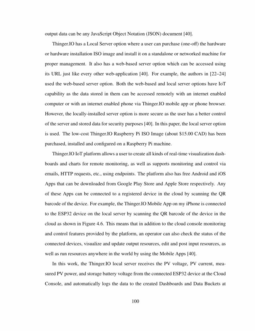
output data can be any JavaScript Object Notation (JSON) document [40].
Thinger.IO has a Local Server option where a user can purchase (one-off) the hardware
or hardware installation ISO image and install it on a standalone or networked machine for
proper management. It also has a web-based server option which can be accessed using
its URL just like every other web-application [40]. For example, the authors in [22–24]
used the web-based server option. Both the web-based and local server options have IoT
capability as the data stored in them can be accessed remotely with an internet enabled
computer or with an internet enabled phone via Thinger.IO mobile app or phone browser.
However, the locally-installed server option is more secure as the user has a better control
of the server and stored data for security purposes [40]. In this paper, the local server option
is used. The low-cost Thinger.IO Raspberry Pi ISO Image (about $15.00 CAD) has been
purchased, installed and configured on a Raspberry Pi machine.
Thinger.IO IoT platform allows a user to create all kinds of real-time visualization dash-
boards and charts for remote monitoring, as well as supports monitoring and control via
emails, HTTP requests, etc., using endpoints. The platform also has free Android and iOS
Apps that can be downloaded from Google Play Store and Apple Store respectively. Any
of these Apps can be connected to a registered device in the cloud by scanning the QR
barcode of the device. For example, the Thinger.IO Mobile App on my iPhone is connected
to the ESP32 device on the local server by scanning the QR barcode of the device in the
cloud as shown in Figure 4.6. This means that in addition to the cloud console monitoring
and control features provided by the platform, an operator can also check the status of the
connected devices, visualize and update output resources, edit and post input resources, as
well as run resources anywhere in the world by using the Mobile Apps [40].
In this work, the Thinger.IO local server receives the PV voltage, PV current, mea-
sured PV power, and storage battery voltage from the connected ESP32 device at the Cloud
Console, and automatically logs the data to the created Dashboards and Data Buckets at
100
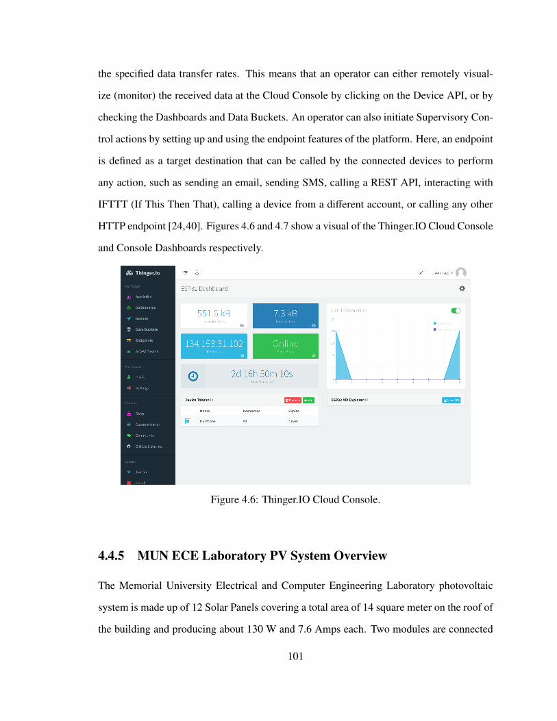
the specified data transfer rates. This means that an operator can either remotely visual-
ize (monitor) the received data at the Cloud Console by clicking on the Device API, or by
checking the Dashboards and Data Buckets. An operator can also initiate Supervisory Con-
trol actions by setting up and using the endpoint features of the platform. Here, an endpoint
is defined as a target destination that can be called by the connected devices to perform
any action, such as sending an email, sending SMS, calling a REST API, interacting with
IFTTT (If This Then That), calling a device from a different account, or calling any other
HTTP endpoint [24,40]. Figures 4.6 and 4.7 show a visual of the Thinger.IO Cloud Console
and Console Dashboards respectively.
Figure 4.6: Thinger.IO Cloud Console.
4.4.5 MUN ECE Laboratory PV System Overview
The Memorial University Electrical and Computer Engineering Laboratory photovoltaic
system is made up of 12 Solar Panels covering a total area of 14 square meter on the roof of
the building and producing about 130 W and 7.6 Amps each. Two modules are connected
101
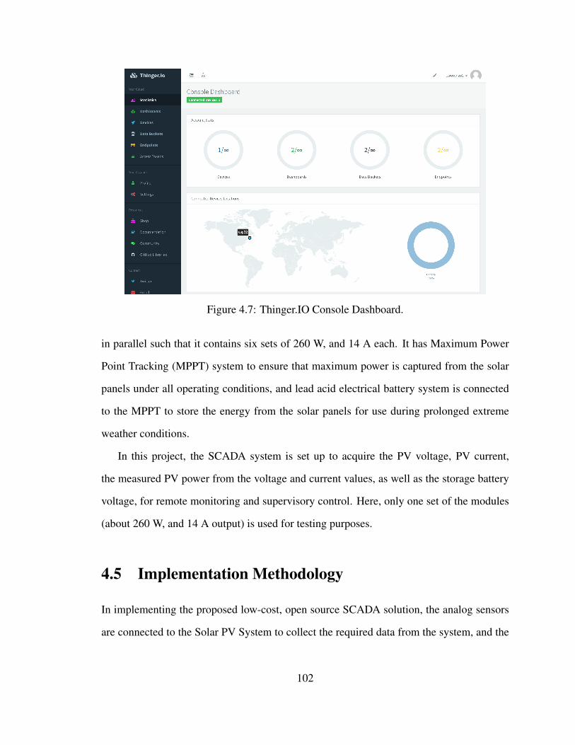
Figure 4.7: Thinger.IO Console Dashboard.
in parallel such that it contains six sets of 260 W, and 14 A each. It has Maximum Power
Point Tracking (MPPT) system to ensure that maximum power is captured from the solar
panels under all operating conditions, and lead acid electrical battery system is connected
to the MPPT to store the energy from the solar panels for use during prolonged extreme
weather conditions.
In this project, the SCADA system is set up to acquire the PV voltage, PV current,
the measured PV power from the voltage and current values, as well as the storage battery
voltage, for remote monitoring and supervisory control. Here, only one set of the modules
(about 260 W, and 14 A output) is used for testing purposes.
4.5 Implementation Methodology
In implementing the proposed low-cost, open source SCADA solution, the analog sensors
are connected to the Solar PV System to collect the required data from the system, and the
102
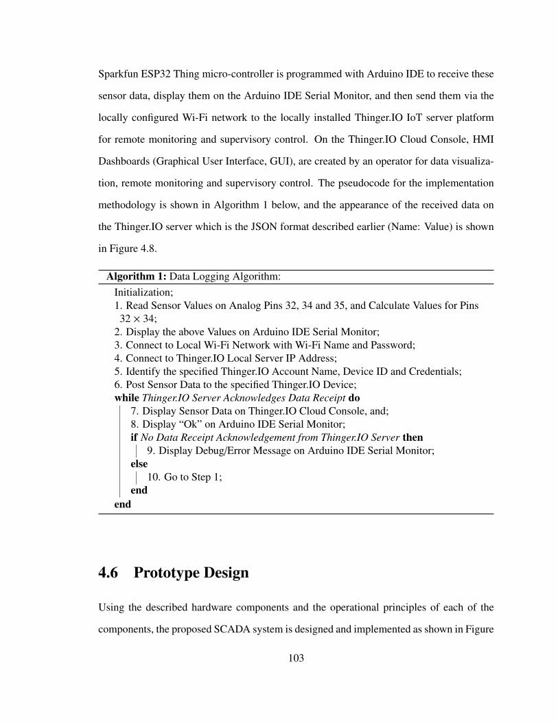
Sparkfun ESP32 Thing micro-controller is programmed with Arduino IDE to receive these
sensor data, display them on the Arduino IDE Serial Monitor, and then send them via the
locally configured Wi-Fi network to the locally installed Thinger.IO IoT server platform
for remote monitoring and supervisory control. On the Thinger.IO Cloud Console, HMI
Dashboards (Graphical User Interface, GUI), are created by an operator for data visualiza-
tion, remote monitoring and supervisory control. The pseudocode for the implementation
methodology is shown in Algorithm 1 below, and the appearance of the received data on
the Thinger.IO server which is the JSON format described earlier (Name: Value) is shown
in Figure 4.8.
Algorithm 1: Data Logging Algorithm:Initialization;1. Read Sensor Values on Analog Pins 32, 34 and 35, and Calculate Values for Pins32 × 34;
2. Display the above Values on Arduino IDE Serial Monitor;3. Connect to Local Wi-Fi Network with Wi-Fi Name and Password;4. Connect to Thinger.IO Local Server IP Address;5. Identify the specified Thinger.IO Account Name, Device ID and Credentials;6. Post Sensor Data to the specified Thinger.IO Device;while Thinger.IO Server Acknowledges Data Receipt do
7. Display Sensor Data on Thinger.IO Cloud Console, and;8. Display “Ok” on Arduino IDE Serial Monitor;if No Data Receipt Acknowledgement from Thinger.IO Server then
9. Display Debug/Error Message on Arduino IDE Serial Monitor;else
10. Go to Step 1;end
end
4.6 Prototype Design
Using the described hardware components and the operational principles of each of the
components, the proposed SCADA system is designed and implemented as shown in Figure
103
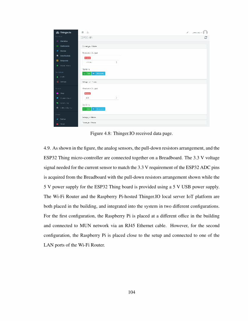
Figure 4.8: Thinger.IO received data page.
4.9. As shown in the figure, the analog sensors, the pull-down resistors arrangement, and the
ESP32 Thing micro-controller are connected together on a Breadboard. The 3.3 V voltage
signal needed for the current sensor to match the 3.3 V requirement of the ESP32 ADC pins
is acquired from the Breadboard with the pull-down resistors arrangement shown while the
5 V power supply for the ESP32 Thing board is provided using a 5 V USB power supply.
The Wi-Fi Router and the Raspberry Pi-hosted Thinger.IO local server IoT platform are
both placed in the building, and integrated into the system in two different configurations.
For the first configuration, the Raspberry Pi is placed at a different office in the building
and connected to MUN network via an RJ45 Ethernet cable. However, for the second
configuration, the Raspberry Pi is placed close to the setup and connected to one of the
LAN ports of the Wi-Fi Router.
104
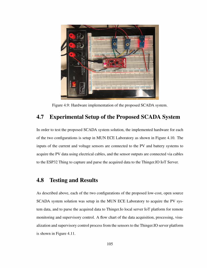
Figure 4.9: Hardware implementation of the proposed SCADA system.
4.7 Experimental Setup of the Proposed SCADA System
In order to test the proposed SCADA system solution, the implemented hardware for each
of the two configurations is setup in MUN ECE Laboratory as shown in Figure 4.10. The
inputs of the current and voltage sensors are connected to the PV and battery systems to
acquire the PV data using electrical cables, and the sensor outputs are connected via cables
to the ESP32 Thing to capture and parse the acquired data to the Thinger.IO IoT Server.
4.8 Testing and Results
As described above, each of the two configurations of the proposed low-cost, open source
SCADA system solution was setup in the MUN ECE Laboratory to acquire the PV sys-
tem data, and to parse the acquired data to Thinger.Io local server IoT platform for remote
monitoring and supervisory control. A flow chart of the data acquisition, processing, visu-
alization and supervisory control process from the sensors to the Thinger.IO server platform
is shown in Figure 4.11.
105
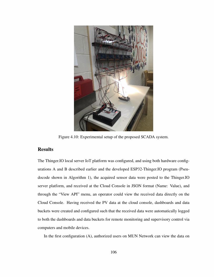
Figure 4.10: Experimental setup of the proposed SCADA system.
Results
The Thinger.IO local server IoT platform was configured, and using both hardware config-
urations A and B described earlier and the developed ESP32-Thinger.IO program (Pseu-
docode shown in Algorithm 1), the acquired sensor data were posted to the Thinger.IO
server platform, and received at the Cloud Console in JSON format (Name: Value), and
through the “View API” menu, an operator could view the received data directly on the
Cloud Console. Having received the PV data at the cloud console, dashboards and data
buckets were created and configured such that the received data were automatically logged
to both the dashboards and data buckets for remote monitoring and supervisory control via
computers and mobile devices.
In the first configuration (A), authorized users on MUN Network can view the data on
106
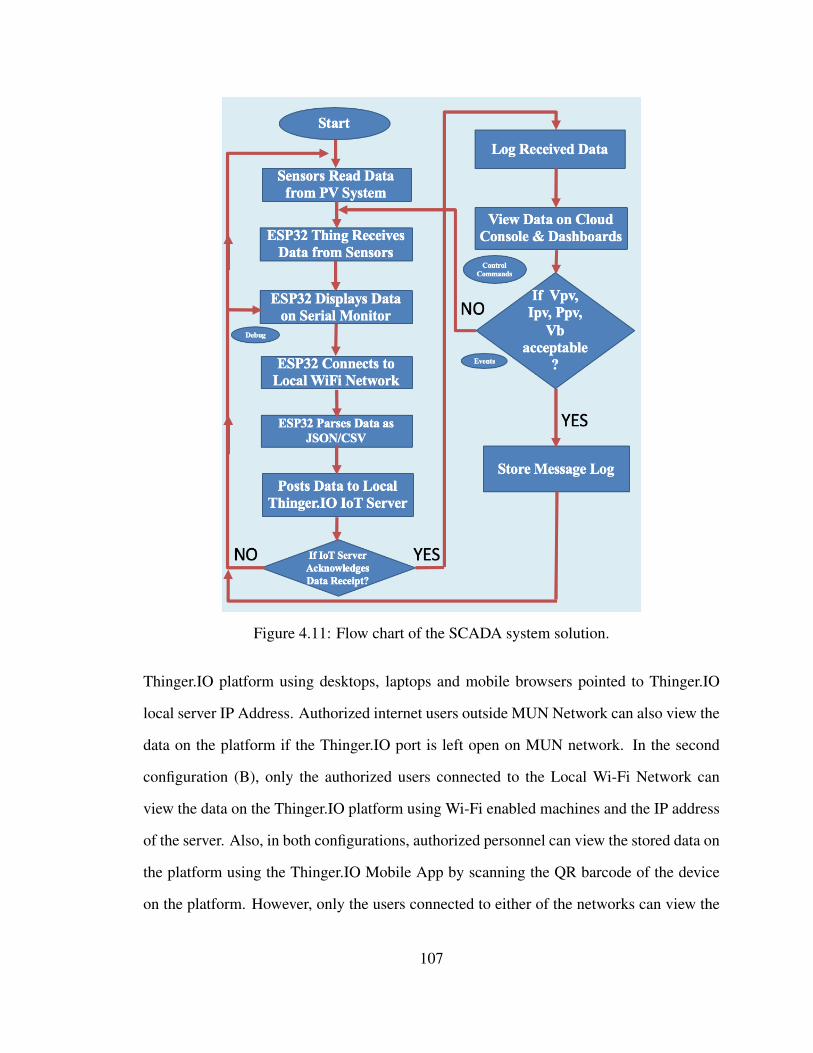
Figure 4.11: Flow chart of the SCADA system solution.
Thinger.IO platform using desktops, laptops and mobile browsers pointed to Thinger.IO
local server IP Address. Authorized internet users outside MUN Network can also view the
data on the platform if the Thinger.IO port is left open on MUN network. In the second
configuration (B), only the authorized users connected to the Local Wi-Fi Network can
view the data on the Thinger.IO platform using Wi-Fi enabled machines and the IP address
of the server. Also, in both configurations, authorized personnel can view the stored data on
the platform using the Thinger.IO Mobile App by scanning the QR barcode of the device
on the platform. However, only the users connected to either of the networks can view the
107
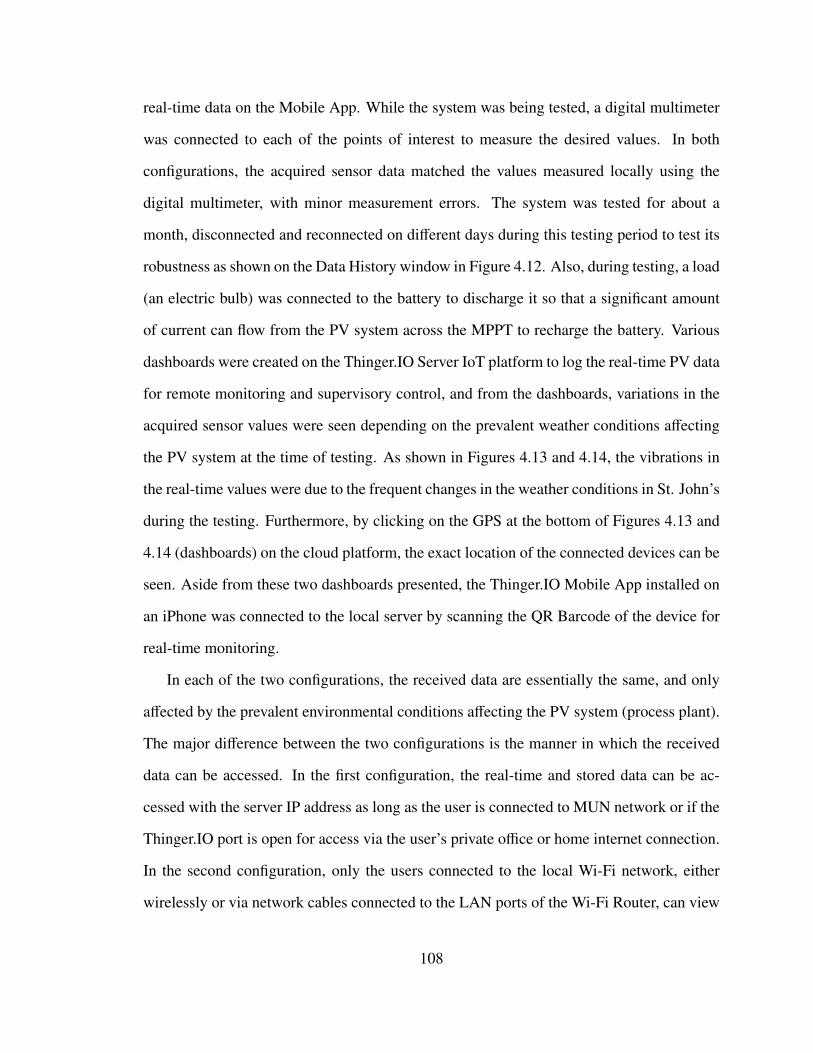
real-time data on the Mobile App. While the system was being tested, a digital multimeter
was connected to each of the points of interest to measure the desired values. In both
configurations, the acquired sensor data matched the values measured locally using the
digital multimeter, with minor measurement errors. The system was tested for about a
month, disconnected and reconnected on different days during this testing period to test its
robustness as shown on the Data History window in Figure 4.12. Also, during testing, a load
(an electric bulb) was connected to the battery to discharge it so that a significant amount
of current can flow from the PV system across the MPPT to recharge the battery. Various
dashboards were created on the Thinger.IO Server IoT platform to log the real-time PV data
for remote monitoring and supervisory control, and from the dashboards, variations in the
acquired sensor values were seen depending on the prevalent weather conditions affecting
the PV system at the time of testing. As shown in Figures 4.13 and 4.14, the vibrations in
the real-time values were due to the frequent changes in the weather conditions in St. John’s
during the testing. Furthermore, by clicking on the GPS at the bottom of Figures 4.13 and
4.14 (dashboards) on the cloud platform, the exact location of the connected devices can be
seen. Aside from these two dashboards presented, the Thinger.IO Mobile App installed on
an iPhone was connected to the local server by scanning the QR Barcode of the device for
real-time monitoring.
In each of the two configurations, the received data are essentially the same, and only
affected by the prevalent environmental conditions affecting the PV system (process plant).
The major difference between the two configurations is the manner in which the received
data can be accessed. In the first configuration, the real-time and stored data can be ac-
cessed with the server IP address as long as the user is connected to MUN network or if the
Thinger.IO port is open for access via the user’s private office or home internet connection.
In the second configuration, only the users connected to the local Wi-Fi network, either
wirelessly or via network cables connected to the LAN ports of the Wi-Fi Router, can view
108
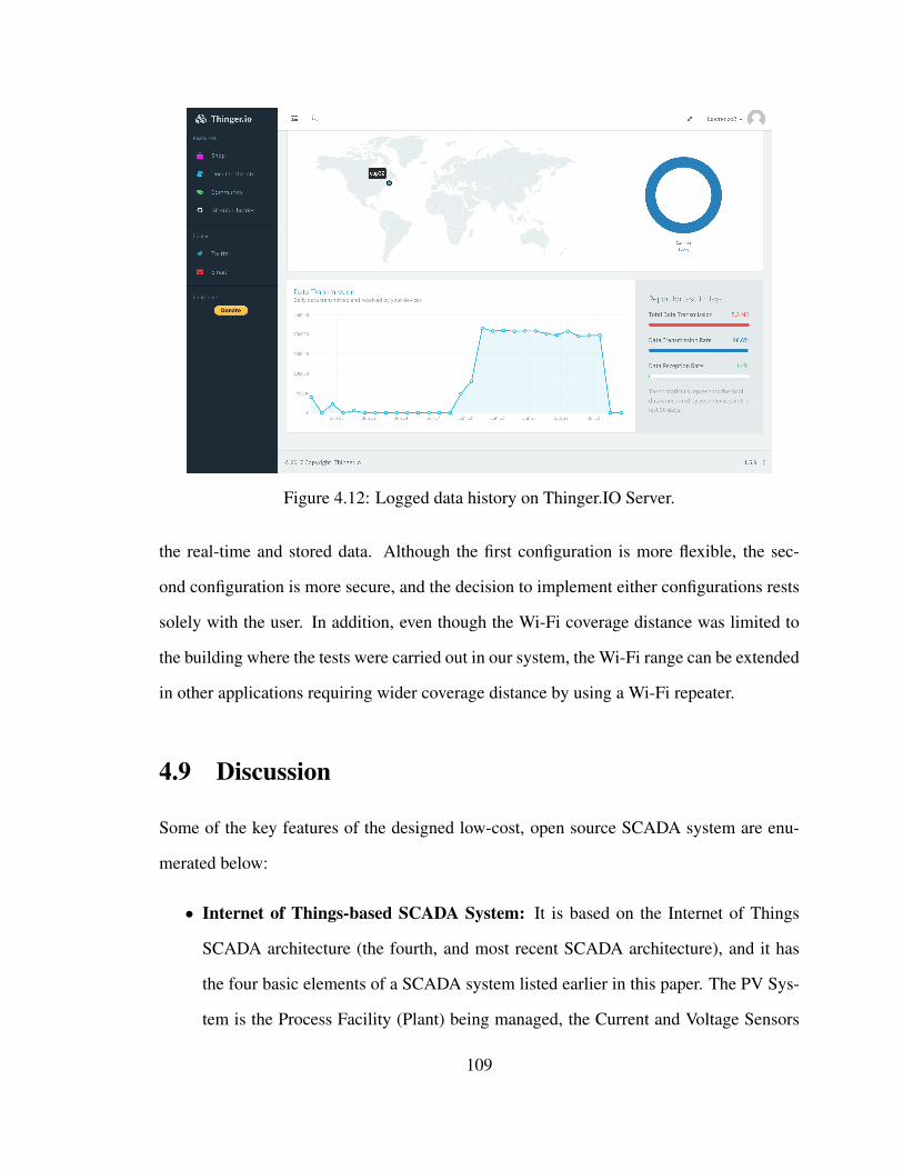
Figure 4.12: Logged data history on Thinger.IO Server.
the real-time and stored data. Although the first configuration is more flexible, the sec-
ond configuration is more secure, and the decision to implement either configurations rests
solely with the user. In addition, even though the Wi-Fi coverage distance was limited to
the building where the tests were carried out in our system, the Wi-Fi range can be extended
in other applications requiring wider coverage distance by using a Wi-Fi repeater.
4.9 Discussion
Some of the key features of the designed low-cost, open source SCADA system are enu-
merated below:
• Internet of Things-based SCADA System: It is based on the Internet of Things
SCADA architecture (the fourth, and most recent SCADA architecture), and it has
the four basic elements of a SCADA system listed earlier in this paper. The PV Sys-
tem is the Process Facility (Plant) being managed, the Current and Voltage Sensors
109
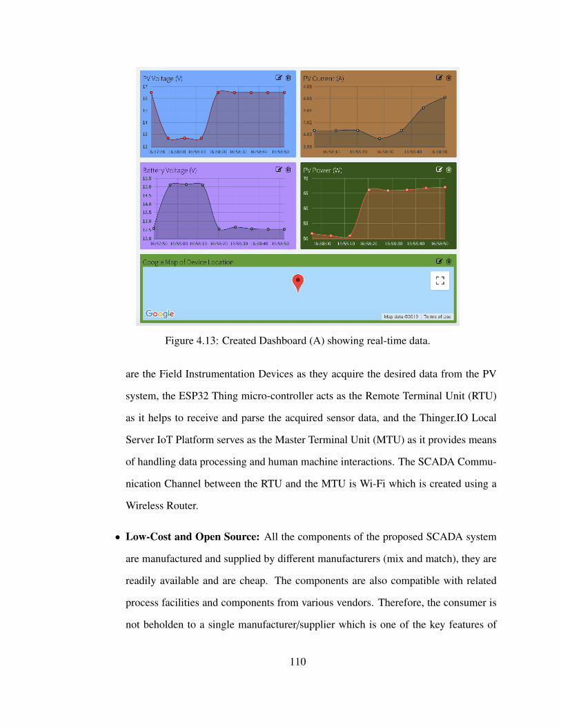
Figure 4.13: Created Dashboard (A) showing real-time data.
are the Field Instrumentation Devices as they acquire the desired data from the PV
system, the ESP32 Thing micro-controller acts as the Remote Terminal Unit (RTU)
as it helps to receive and parse the acquired sensor data, and the Thinger.IO Local
Server IoT Platform serves as the Master Terminal Unit (MTU) as it provides means
of handling data processing and human machine interactions. The SCADA Commu-
nication Channel between the RTU and the MTU is Wi-Fi which is created using a
Wireless Router.
• Low-Cost and Open Source: All the components of the proposed SCADA system
are manufactured and supplied by different manufacturers (mix and match), they are
readily available and are cheap. The components are also compatible with related
process facilities and components from various vendors. Therefore, the consumer is
not beholden to a single manufacturer/supplier which is one of the key features of
110
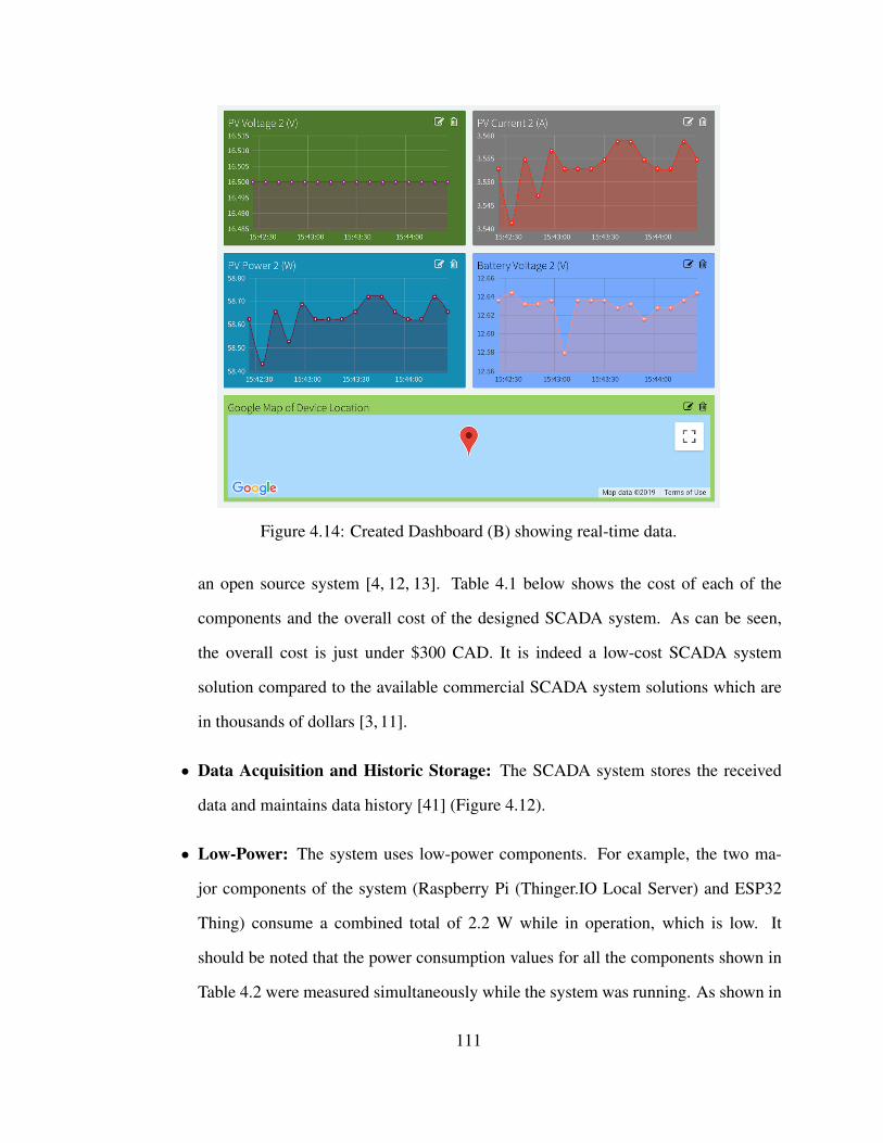
Figure 4.14: Created Dashboard (B) showing real-time data.
an open source system [4, 12, 13]. Table 4.1 below shows the cost of each of the
components and the overall cost of the designed SCADA system. As can be seen,
the overall cost is just under $300 CAD. It is indeed a low-cost SCADA system
solution compared to the available commercial SCADA system solutions which are
in thousands of dollars [3, 11].
• Data Acquisition and Historic Storage: The SCADA system stores the received
data and maintains data history [41] (Figure 4.12).
• Low-Power: The system uses low-power components. For example, the two ma-
jor components of the system (Raspberry Pi (Thinger.IO Local Server) and ESP32
Thing) consume a combined total of 2.2 W while in operation, which is low. It
should be noted that the power consumption values for all the components shown in
Table 4.2 were measured simultaneously while the system was running. As shown in
111
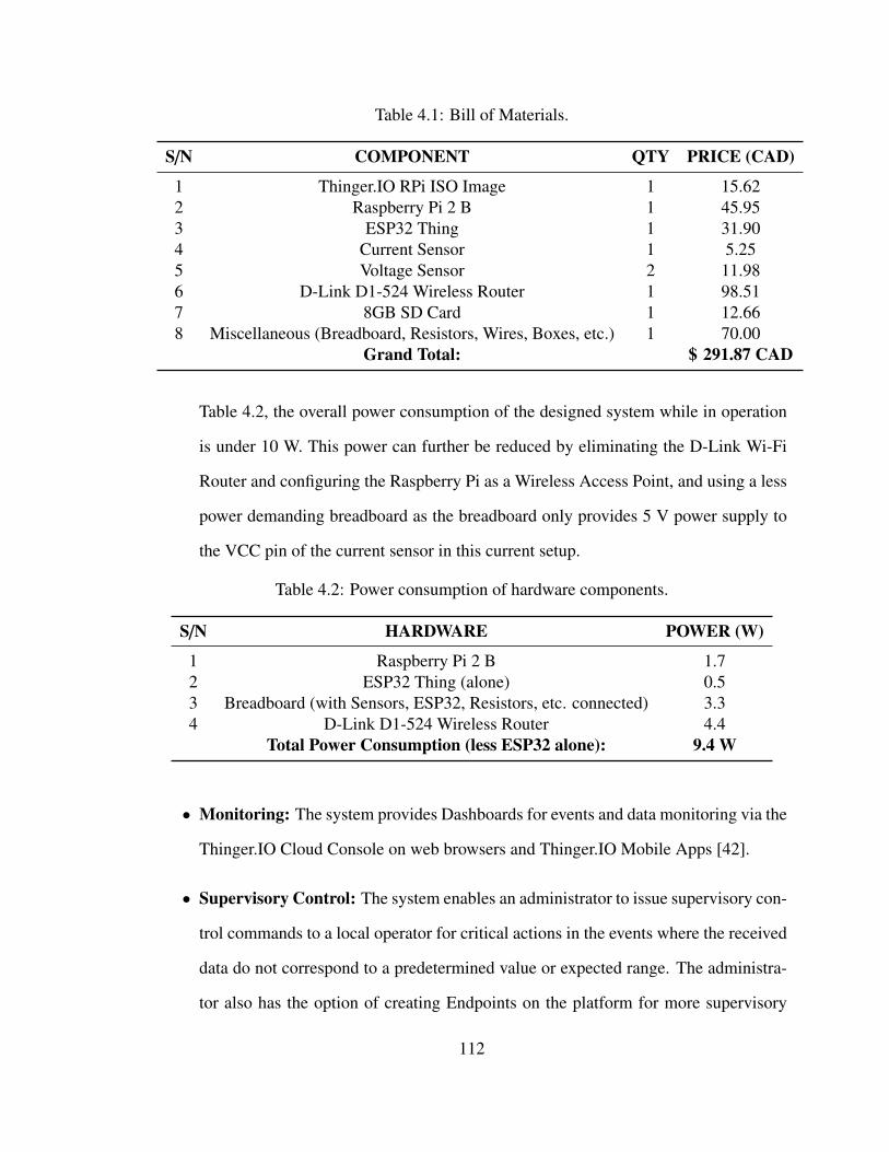
Table 4.1: Bill of Materials.
S/N COMPONENT QTY PRICE (CAD)
1 Thinger.IO RPi ISO Image 1 15.622 Raspberry Pi 2 B 1 45.953 ESP32 Thing 1 31.904 Current Sensor 1 5.255 Voltage Sensor 2 11.986 D-Link D1-524 Wireless Router 1 98.517 8GB SD Card 1 12.668 Miscellaneous (Breadboard, Resistors, Wires, Boxes, etc.) 1 70.00
Grand Total: $ 291.87 CAD
Table 4.2, the overall power consumption of the designed system while in operation
is under 10 W. This power can further be reduced by eliminating the D-Link Wi-Fi
Router and configuring the Raspberry Pi as a Wireless Access Point, and using a less
power demanding breadboard as the breadboard only provides 5 V power supply to
the VCC pin of the current sensor in this current setup.
Table 4.2: Power consumption of hardware components.
S/N HARDWARE POWER (W)
1 Raspberry Pi 2 B 1.72 ESP32 Thing (alone) 0.53 Breadboard (with Sensors, ESP32, Resistors, etc. connected) 3.34 D-Link D1-524 Wireless Router 4.4
Total Power Consumption (less ESP32 alone): 9.4 W
• Monitoring: The system provides Dashboards for events and data monitoring via the
Thinger.IO Cloud Console on web browsers and Thinger.IO Mobile Apps [42].
• Supervisory Control: The system enables an administrator to issue supervisory con-
trol commands to a local operator for critical actions in the events where the received
data do not correspond to a predetermined value or expected range. The administra-
tor also has the option of creating Endpoints on the platform for more supervisory
112
control options.
• Reporting: The system presents reports to the administrator and key decision makers
in the form of charts, data logs, and alarms (local, email, web, and mobile app).
• Security: Because the proposed solution here involves the use of a locally hosted
cloud server on MUN network, data integrity and security measures such as access
control, whitelists, authentication, authorization, firewalls, regular risk assessment,
continuous monitoring and log analysis, updating and patching regularly, etc., can
easily be taken by the administrator. Also, for more critical infrastructure monitoring
and control such as traffic light system or oil and gas facilities monitoring applica-
tions, additional security measures such as hardware protection and data encryption
on the SCADA communication channel might be necessary [29, 30, 43].
• Reliability and Availability: Although system reliability calculation is beyond the
scope of this work, research has shown that SCADA system reliability and availabil-
ity are affected by delayed or wrong operator decisions [31]. In this project, because
the components are completely open source and readily available, and the fact that
the main cloud server is locally installed and self-managed, it is easy for an operator
or administrator to manage the system to ensure its continuous reliability and avail-
ability. However, this might not be the case in a proprietary SCADA system where
the customer is beholden to a single vendor, and as such there could be time-lags in
responding to customer’s complaints since having a trained operator on stand-by 24/7
on the customer’s site might not be feasible.
• Ease of Use: The designed SCADA system solution is easy to use as the Thinger.IO
IoT Platform is very user-friendly.
113
4.10 Conclusions
In most industries all over the world, like the energy industry, critical assets are distributed
over large geographical areas, sometimes in harsh environments such as deep offshore and
swamps. While it may be necessary to have local means of managing the operations of
these critical assets, it is equally important to have a reliable, flexible, cost-effective and
sophisticated coordinated monitoring and control. Although SCADA systems have revolu-
tionized the way these critical, complex and geographically distributed industrial systems
are monitored and controlled, SCADA system designs and implementations have largely
remained proprietary. However in many applications, for example in power systems, the
energy storage systems such as inverters and batteries, power electronic converters, and
other devices connected to the grid are from various manufacturers or vendors, which of-
ten result in compatibility issues between these existing infrastructures and the proprietary
SCADA system solutions. Therefore, an open source SCADA system solution represents
the most flexible SCADA solution as it allows a user to “mix and match” components and
choose the most appropriate from several manufacturers and suppliers. Furthermore, pro-
prietary SCADA system solutions are largely expensive, and while it may be affordable for
big companies like most oil and gas producing companies, it is pricey for smaller com-
panies with no enormous financial resources like most small power companies, especially
power companies into renewable generation systems. Therefore, an open source SCADA
solution represents the most cost effective solution as the user is not beholden to a single
vendor.
In this paper, a low-cost, open source SCADA system solution based on the Internet of
Things (IoT) SCADA architecture, which is the most recent SCADA architecture, has been
presented. The hardware design of the proposed SCADA system solution has been carried
out, and the implemented system has the four basic elements needed in a SCADA system,
114
including Field Instrumentation Devices (Current and Voltage Sensors), Remote Terminal
Units (ESP32 Thing micro-controller), Master Terminal Units (Thinger.IO IoT Server Plat-
form), and SCADA Communication Channel (Local Wi-Fi Network). In order to validate
the functionalities of the designed SCADA system, it was setup and tested at the Memorial
University Electrical and Computer Engineering Laboratory to acquire and remotely moni-
tor a 260 W, 12 V Solar PV System data, as well as to initiate supervisory control activities
whenever necessary. From the tests, the system was found to be capable of carrying out the
desired functions of a SCADA system which include Data Acquisition, Networked Data
Communication, Data Presentation, and Remote Monitoring and Supervisory Control. The
power consumption of each of the components was measured while the system was in op-
eration and the entire system was found to require low power for operation, less than 10 W.
The overall cost of the system was also found to be below $300 CAD which is extremely
low for such a critical solution. Furthermore, the acquired real-time PV data visualized
at the Thinger.IO IoT Server Cloud Console and Dashboards were found to be within the
same range as the data locally measured using the conventional digital multimeter. From
information security and system reliability points of view, because the main cloud server is
privately hosted and self-managed on own network, data security measures such as access
control, authorization, authentication, whitelisting, firewalls, log analysis, etc., are easily
implemented, and since the system is self-managed, it means that the operator or adminis-
trator is readily available to carry out these tasks, thereby ensuring the security, reliability
and availability of the proposed system.
Although a PV system has been used as the process plant for testing purposes in this
work, the designed SCADA system can also be applied in other industries and fields to
remotely monitor and control critical infrastructures such as electric power generation,
transmission and distribution systems, buildings, facilities and environments, oil and gas
production facilities, mass transit systems, water and sewage systems, and traffic signal
115
systems. However, it should be noted that the designed system for this particular appli-
cation is not a plug and play turnkey solution or a one-size-fits-all system for the above
possible applications as further measures will need to be taken to customize the system
for any chosen application in order to guarantee its functionalities, reliability and security,
which might increase the overall cost and power consumption presented in this application.
For example, for outdoor deployment of the proposed SCADA system, options for boxes
and shields will have to be considered for the electronic components to prevent damage due
to moisture and wild animals. Also, to increase the security of the proposed SCADA system
for very critical applications like oil and gas facilities monitoring and traffic signal control,
additional security measures such as data encryption algorithms can be implemented on the
ESP32 micro-controller side to encrypt the acquired sensor data before sending them to the
Thinger.IO server, and at the server side, data decryption and further security measures can
be carried out. These could relatively increase the overall cost and power consumption of
the system.
4.11 Future Work
In the future, endpoints can be created on Thinger.IO platform to carry out more supervisory
control events like sending an email, sending an SMS, calling a REST API, interacting with
IFTTT (If This Then That), calling a device from a different account, or calling any other
HTTP endpoint directly from the server to complement the current supervisory control
strategy where an administrator has to notify a local operator of any abnormal variations in
the received data for necessary actions. Also, to further reduce the overall power consump-
tion which is already low, the D-Link Wi-Fi Router can be eliminated, and the Raspberry Pi
configured as a Wireless Access Point to provide the Wi-Fi connection needed for commu-
nication between the ESP32 Thing and the Thinger.IO Server. Furthermore, to increase the
116
security of the proposed SCADA system, especially when the system is deployed in very
critical applications like oil and gas facilities monitoring and traffic signal control, data en-
cryption algorithms can be implemented on the ESP32 micro-controller side to encrypt the
acquired sensor data before sending them to the Thinger.IO server, and on the server side,
data decryption and further security measures can be carried out.
Funding
This research was funded by the Natural Sciences and Engineering Research Council of
Canada (NSERC) Energy Storage Technology Network (NESTNet).
Acknowledgments
The authors would like to thank the School of Graduate Studies, Faculty of Engineering
and Applied Science, Memorial University and the Natural Sciences and Engineering Re-
search Council of Canada (NSERC) Energy Storage Technology Network (NESTNet) for
providing the necessary funds and the conducive environment to carry out this research.
The authors would also like to acknowledge the technical and emotional supports of friends
and families during the difficult period of carrying out this research work.
Bibliography
[1] X. Lu, "Supervisory Control and Data Acquisition System Design for CO2 Enhanced
Oil Recovery," Technical Report No. UCB/EECS-2014-123. Master of Engineering
Thesis, EECS Department, University of California, Berkeley, CA, USA, 21 May
2014.
117
[2] M. Anderson, "Supervisory Control and Data Acquisition," Available online:
https://realpars.com/scada/ (accessed on 3 June 2019).
[3] "Industrial Automation and Control," Available online:
https://www.schneider-electric.com/en/work/products/
industrial-automation-control/ (accessed on 10 June 2019).
[4] L. Abbey, "Telemetry/SCADA Open Systems vs Proprietary
Systems," Available online: https://www.abbey.co.nz/
telemetry--scada-open-vs-proprietary-systems-2003.html (accessed
on 21 June 2019).
[5] S.A. Boyer, "SCADA: Supervisory Control and Data Acquisition," 4th ed.;
International Society of Automation: Research Triangle Park, NC, USA,
2009. Available online: https://automation.isa.org/files/chapters/
SCADA-Supervisory-Control-and-Data-Acquisition-Fourth-Edition-Chapter-10.
pdf (accessed on 9 July 2019).
[6] Z. Sheng, C. Mahapatra, C. Zhu and V.C.M. Leung, "Recent Advances in Industrial
Wireless Sensor Networks Toward Efficient Management in IoT," IEEE Access 2015,
3, 622–637, doi:10.1109/ACCESS.2015.2435000.
[7] K. Medrano, D. Altuve, K. Belloso and C. Bran, "Development of SCADA using
a RTU based on IoT controller," In Proceedings of the 2018 IEEE International
Conference on Automation/XXIII Congress of the Chilean Association of Auto-
matic Control (ICA-ACCA), Concepcion, Chile, 17–19 October 2018; pp. 1–6,
doi:10.1109/ICA-ACCA.2018.8609700.
[8] M. Al-Kuwari, A. Ramadan, Y. Ismael, L. Al-Sughair, A. Gastli and M. Benammar,
"Smart-home automation using IoT-based sensing and monitoring platform," In Pro-
118
ceedings of the 2018 IEEE 12th International Conference on Compatibility, Power
Electronics and Power Engineering (CPE-POWERENG 2018), Doha, Qatar, 10–12
April 2018; pp. 1–6, doi:10.1109/CPE.2018.8372548.
[9] L. O. Aghenta and M. T. Iqbal, "Development of an IoT Based Open Source SCADA
System for PV System Monitoring," Presented at the 32nd IEEE Canadian Con-
ference on Electrical and Computer Engineering (CCECE 2019), Edmonton, AB,
Canada, 5–8 May 2019.
[10] G. Fortino, C. Savaglio and M. Zhou, "Toward opportunistic services for the in-
dustrial Internet of Things," In Proceedings of the 2017 13th IEEE Conference on
Automation Science and Engineering (CASE), Xi’an, China, 20–23 Auguest 2017;
pp. 825–830, doi:10.1109/COASE.2017.8256205.
[11] "Unique Automation Portfolio," Available online: https://new.siemens.com/
ca/en/products/automation.html (accessed on 10 June 2019).
[12] M.S. Almas, L. Vanfretti, S. Løvlund and J. O. Gjerde, "Open source SCADA
implementation and PMU integration for power system monitoring and control
applications," In Proceedings of the 2014 IEEE PES General Meeting/ Confer-
ence and Exposition, National Harbor, MD, USA, 27–31 July 2014; pp. 1–5,
doi:10.1109/PESGM.2014.6938840.
[13] M.S. Thomas and J. D. McDonald, "Power System SCADA and Smart Grids,"
CRC Press: Boca Raton, FL, USA, 19 December 2017. [On-line]. Available on-
line: https://books.google.ca/books?id=bAhEDwAAQBAJ (accessed on 23
June 2019).
[14] H. Shabani, M. M. Ahmed, S. Khan, S. A. Hameed, M. H. Habaebi and A. Zyoud,
"Novel IEEE802.15.4 Protocol for Modern SCADA communication systems," In
119
Proceedings of the 2014 IEEE 8th International Power Engineering and Optimization
Conference (PEOCO2014), Langkawi, Malaysia, 24–25 March 2014; pp. 597–601,
doi:10.1109/PEOCO.2014.6814498.
[15] A. Sajid, H. Abbas and K. Saleem, "Cloud-Assisted IoT-Based SCADA Systems
Security: A Review of the State of the Art and Future Challenges," IEEE Access
2016, 4, 1375–1384, doi:10.1109/ACCESS.2016.2549047.
[16] R.I. Rajkumar, T. J. Alexander and P. Devi, "ZigBee based design of low
cost SCADA system for industrial process applications," In Proceedings of the
2016 IEEE International Conference on Computational Intelligence and Com-
puting Research (ICCIC), Chennai, India, 15–17 December 2016; pp. 1–4,
doi:10.1109/ICCIC.2016.7919696.
[17] M. D. Unde and P. S. Kurhe, "Web based control and data acquisition sys-
tem for industrial application monitoring," In Proceedings of the 2017 In-
ternational Conference on Energy, Communication, Data Analytics and Soft
Computing (ICECDS), Chennai, India, 1–2 August 2017; pp. 246–249,
doi:10.1109/ICECDS.2017.8389884.
[18] D. F. Merchán, J. A. Peralta, A. Vazquez-Rodas, L. I. Minchala and D. Astudillo-
Salinas, "Open Source SCADA System for Advanced Monitoring of Industrial Pro-
cesses," In Proceedings of the 2017 International Conference on Information Sys-
tems and Computer Science (INCISCOS), Quito, Ecuador, 23–25 November 2017;
pp. 160–165, doi:10.1109/INCISCOS.2017.9.
[19] A. S. Prokhorov, M. A. Chudinov and S. E. Bondarev, "Control systems software
implementation using open source SCADA-system OpenSCADA," In Proceedings
of the 2018 IEEE Conference of Russian Young Researchers in Electrical and Elec-
120
tronic Engineering (EIConRus), Moscow, Russia, 29 January–1 February 2018; pp.
220–222, doi:10.1109/EIConRus.2018.8317069.
[20] M. Avhad, V. Divekar, H. Golatkar and S. Joshi, "Microcontroller based automa-
tion system using industry standard SCADA," In Proceedings of the 2013 Annual
IEEE India Conference (INDICON), Mumbai, India, 13–15 December 2013; pp.
1–6, doi:10.1109/INDCON.2013.6726082.
[21] T. Mononen and J. A. Mattila, "low-cost cloud-extended sensor network for supervi-
sory control," In Proceedings of the 2017 IEEE International Conference on Cyber-
netics and Intelligent Systems (CIS) and IEEE Conference on Robotics, Automation
and Mechatronics (RAM), Ningbo, China, 19–21 November 2017; pp. 502–507,
doi:10.1109/ICCIS.2017.8274827.
[22] R. K. Kodali and S. Yerroju, "Energy Efficient Home Automation Using IoT," In
Proceedings of the 2018 International Conference on Communication, Computing
and Internet of Things (IC3IoT), Chennai, India, 15–17 February 2018; pp. 151–
154, doi:10.1109/IC3IoT.2018.8668155.
[23] R. K. Kodali and V. S. K. Gorantla, "RESTful Motion Detection and Notification
using IoT," In Proceedings of the 2018 International Conference on Computer Com-
munication and Informatics (ICCCI), Coimbatore, India, 4–6 January 2018; pp. 1–5,
doi:10.1109/ICCCI.2018.8441423.
[24] R. K. Kodali and K. S. Mahesh, "Smart emergency response system," In Proceedings
of the TENCON 2017—2017 IEEE Region 10 Conference, Penang, Malaysia, 5–8
November 2017; pp. 712–717, doi:10.1109/TENCON.2017.8227953.
[25] R. S. H. Piggin, "Securing SCADA in the cloud: Managing the risks to
avoid the perfect storm," In Proceedings of the IET and ISA 60th International
121
Instrumentation Symposium 2014, London, UK, 24–26 June 2014; pp. 1–6,
doi:10.1049/cp.2014.0535.
[26] Y. Mo, R. Chabukswar and B. Sinopoli, "Detecting Integrity Attacks on
SCADA Systems," IEEE Trans. Control Syst. Technol. 2014, 22, 1396–1407,
doi:10.1109/TCST.2013.2280899.
[27] Y. Yang, H. Xu, L. Gao, Y. Yuan, K. McLaughlin and S. Sezer, "Multidimensional
Intrusion Detection System for IEC 61850-Based SCADA Networks," IEEE Trans.
Power Deliv. 2017, 32, 1068–1078, doi:10.1109/TPWRD.2016.2603339.
[28] L. Rosa, M. Freitas, S. Mazo, E. Monteiro, T. Cruz and P. Simões, "A Comprehensive
Security Analysis of a SCADA Protocol: From OSINT to Mitigation," IEEE Access
2019, 7, 42156–42168, doi:10.1109/ACCESS.2019.2906926.
[29] A. Iqbal and M. T. Iqbal, "Low-Cost and Secure Communication System for SCADA
System of Remote Microgrids," J. Electr. Comput. Eng. 2019, 2019, 1986325,
doi:10.1155/2019/1986325.
[30] T. Alves, R. Das and T. Morris, "Embedding Encryption and Machine Learning In-
trusion Prevention Systems on Programmable Logic Controllers," IEEE Embed. Syst.
Lett. 2018, 10, 99–102, doi:10.1109/LES.2018.2823906.
[31] P. M. Nasr and A. Yazdian-Varjani, "Toward Operator Access Management in
SCADA System: Deontological Threat Mitigation," IEEE Trans. Ind. Inform. 2018,
14, 3314–3324, doi:10.1109/TII.2017.2781285.
[32] G. Falco, C. Caldera and H. Shrobe, "IIoT Cybersecurity Risk Mod-
elling for SCADA Systems," IEEE Internet Things J. 2018, 5, 4486–4495,
doi:10.1109/JIOT.2018.2822842.
122
[33] Y. Yang, K. McLaughlin, S. Sezer, T. Littler, E. G. Im, B. Pranggono
and H. F. Wang, "Multiattribute SCADA-Specific Intrusion Detection Sys-
tem for Power Networks," IEEE Trans. Power Deliv. 2014, 29, 1092–1102,
doi:10.1109/TPWRD.2014.2300099.
[34] M. Endi, y. z. Elhalwagy and A. Hashad, "Three-layer PLC/SCADA system Archi-
tecture in process automation and data monitoring," In Proceedings of the 2010 the
2nd International Conference on Computer and Automation Engineering (ICCAE),
Singapore, 26–28 February 2010; pp. 774–779, doi:10.1109/ICCAE.2010.5451799.
[35] "Current Sensor ICs," Available online: https://www.
allegromicro.com/en/Products/Current-Sensor-ICs/
Zero-To-Fifty-Amp-Integrated-Conductor-Sensor-ICs.aspx (accessed
on 24 June 2019).
[36] "25V Voltage Sensor Module," Available online: https://hobbycomponents.
com/sensors/389-25v-voltage-sensor-module (accessed on 24 June 2019).
[37] Jimblom, "ESP32 Thing Hookup Guide," Available online: https://learn.
sparkfun.com/tutorials/esp32-thing-hookup-guide (accessed on 31 May
2019).
[38] R. Shete and S. Agrawal, "IoT based urban climate monitoring using Raspberry Pi,"
In Proceedings of the 2016 International Conference on Communication and Sig-
nal Processing (ICCSP), Melmaruvathur, India, 6–8 April 2016; pp. 2008–2012,
doi:10.1109/ICCSP.2016.7754526.
[39] "Raspberry Pi 2 Model B," Available online: https://www.raspberrypi.org/
products/raspberry-pi-2-model-b/ (accessed on 3 June 2019).
123
[40] "Thinger.io—Documentation," Available online: http://docs.thinger.io (ac-
cessed on 27 June 2019).
[41] A. Bagri, R. Netto and D. Jhaveri, "Supervisory Control ad Data Acquisition," Int. J.
Comput. Appl. 2014, 102, 1–5.
[42] J. Tautz-Weinert and S. J. Watson, "Using SCADA data for wind turbine con-
dition monitoring—A review," IET Renew. Power Gener. 2017, 11, 382–394,
doi:10.1049/iet-rpg.2016.0248.
[43] A. M. Grilo, J. Chen, M. Díaz, D. Garrido and A. Casaca, "An Integrated WSAN and
SCADA System for Monitoring a Critical Infrastructure," IEEE Trans. Ind. Inform.
2014, 10, 1755–1764, doi:10.1109/TII.2014.2322818.
124
Chapter 5
Low-Cost, IoT-Based Open Source
SCADA system using ESP32 with
OLED, ThingsBoard and MQTT
Protocol*
Preface
A version of this manuscript has been published in the AIMS Electronics and Electrical
Engineering Journal, Topical Section on Intelligent Systems, Automation and Control.
AIMS Electronics and Electrical Engineering, 2020, 4(1): 57-86. doi: 10.3934/Elec-
trEng.2020.1.57. A short and modified version of this chapter has also been presented in
the conference proceedings of the 28th Annual Newfoundland Electrical and Computer
Engineering Conference (NECEC 2019), St. John’s, NL, Canada. I am the primary au-
*This chapter is a modified version of “Design and implementation of a low-cost, open source IoT-basedSCADA system using ESP32 with OLED, ThingsBoard and MQTT protocol”, L. O. Aghenta and M. T. Iqbal,AIMS Electronics and Electrical Engineering, 2020, 4(1):,57-86. doi: 10.3934/ElectrEng.2020.1.57.
125
thor, and I carried out most of the research work, performed the literature reviews, carried
out the system designs, hardware implementations, experimental setups and analysis of the
results. I also prepared the first drafts of the manuscripts and subsequently revised the final
manuscripts based on the feedback from the co-author and the peer-review process. The
Co-author, Dr. M. Tariq Iqbal, supervised the research, acquired and made available the re-
search funding, provided the research components, reviewed and corrected the manuscript,
and contributed research ideas in the actualization of the manuscripts.
Abstract
Distributed assets, such as hybrid power system components, require reliable, timely, and
secure coordinated data monitoring and control systems. Supervisory Control and Data
Acquisition (SCADA) is a technology for the coordinated monitoring and control of such
assets. However, SCADA system designs and implementations have largely been propri-
etary, mostly pricey and therefore economically unjustifiable for smaller applications. With
proprietary SCADA systems, there is also the problem of interoperability with the existing
components such as power electronic converters, energy storage systems, and communica-
tion systems since these components are usually from multiple vendors. Therefore, an open
source SCADA system represents the most flexible and most cost-effective SCADA option
for such assets. In this paper, we present the design and implementation of a low-cost,
open source SCADA system based on the most recent SCADA architecture, the Internet
of Things (IoT). The proposed SCADA system consists of current and voltage sensors for
data collection, an ESP32 micro-controller with organic light-emitting diode (OLED) dis-
play, for receiving and processing the sensor data, and ThingsBoard IoT server for historic
data storage and human machine interactions. For the sensor data transfer from the ESP32
to the ThingsBoard IoT server, Message Queuing Telemetry Transport (MQTT) protocol is
126
implemented for data transfer over a local Wi-Fi connection with the MQTT Client config-
ured on the ESP32, and the ThingsBoard server node serving as the MQTT Broker. The
ThingsBoard IoT server is locally installed with PostgreSQL database on a Raspberry Pi
single-board computer and hosted locally on MUN Network for data integrity and security.
To test the performance of the developed open source SCADA system solution, it was setup
to acquire and process the current, voltage and power of a standalone solar photovoltaic sys-
tem for remote monitoring and supervisory control. The overall system design procedures
and testing, as well as the created dashboards and alarms on the ThingsBoard IoT server
platform are presented in the paper.
Index Terms: Open Source; SCADA; ThingsBoard; Internet of Things; ESP32 with
OLED; Raspberry Pi; MQTT, Automation; Instrumentation and Control.
5.1 Introduction
Energy shortage and Global Warming are some of the major challenges facing the world
today, especially with the recent rapid industrial development across the globe. As such,
world leaders in collaboration with energy experts continue to search for alternative sources
of energy, such as clean and renewable energy, to meet the growing global demand for en-
ergy and to save the environment from further degradation, caused by the use of the con-
ventional sources of energy such as fossil fuels over the years. As energy experts continue
to capture clean and renewable energy sources for the benefit of mankind, these sources
are continuously being injected into today’s power systems. These clean and renewable
sources are incorporated with the conventional energy generation systems to form Hybrid
Power Systems (HPS) [1]. However, due to the intermittent nature of these sustainable
(renewable) energy sources such as solar and wind as they are hugely affected by the preva-
lent environmental conditions, energy storage systems are usually required in the resulting
127
hybrid power systems for system, power grid and supply stability. Energy storage systems
help to mitigate supply output fluctuations, as well as help to ensure frequency control and
load balancing, amongst other important functions. These hybrid power systems, which are
usually made up of the conventional energy generation sources such as fossil fuels, and one
or more renewable generation sources such as wind and solar, together with the energy stor-
age systems, power electronic converters such as inverters, as well as other power system
devices such as communication systems needed for their successful operations are usually
spread over large geographical areas, sometimes in harsh environments such as offshore
and swamps. As a result of this distributed nature, the interconnection of these systems to
generate and supply energy presents numerous challenges, such as power quality issues,
voltage tolerances, frequency control, grid synchronization and metering, data exchange
and communications between components, as well as the safety and security of both assets
and personnel [2].
In order to overcome these challenges and to ensure seamless power system operations,
diverse sensors, micro-controllers, micro-processors (e.g programmable logic controllers),
actuators, valves, pumps, etc. are usually connected to various points of interest in the entire
HPS to acquire important data such as current, voltage, power, and so on. and for real-time
data monitoring, remote and co-ordinated controls. Supervisory Control and Data Acqui-
sition (SCADA) is the perfect solution for these tasks. Since these hybrid power systems
and their associated components are located remotely, a SCADA system is needed for their
remote monitoring, coordinated control, and data acquisition from the various sensors, ac-
tuators, and other field instrumentation devices connected to the various points of interest.
The SCADA system would help in the efficient collection of data from these variously dis-
tributed sensors, actuators and controllers, real-time remote control of the system, remote
monitoring, and maintenance of the produced current, voltage, and power [3].
SCADA refers to the combination of telemetry and data acquisition. It encompasses
128
the collection of information (data) from distributed process facilities, the transfer of these
data to a central location, analysis of these data to know the current states of the distributed
process facilities, supervisory control of the process facilities, displaying these data on a
number of operator screens or displays (Human Machine Interface), and conveying the
necessary control actions back to these distributed process facilities for the local operator’s
actions [4, 5]. It is a closed loop control system. The major functions of a SCADA system
include the following [4]:
• Data acquisition
• Data presentation
• Supervisory control
• Networked data communication
• Alarm processing
• Historic data storage, data trending and reporting
• Remote monitoring
The architectural design of a SCADA system is made up of four basic elements; field instru-
mentation devices such as sensors which collect data from the distributed process facilities
being managed, Remote Terminal Units (RTUs) such as single-board computers (PLCs,
micro-controllers, etc.) for acquiring, processing and parsing these sensor data, Master Ter-
minal Units (MTUs) such as IoT servers and platforms for data processing and human ma-
chine interactions, and finally SCADA communication channels for connecting the RTUs
to the MTUs, and for data transfer [6].
SCADA architectures have evolved over the years, starting from the very first gener-
ation SCADA systems in the 70s called Monolithic SCADA, through the second genera-
tion SCADA systems called distributed SCADA (80s and 90s), and the third generation
129
SCADA systems called Networked SCADA systems (90s and early 2000s), to the most
recent SCADA architecture called the Internet of Things (IoT) SCADA architecture (4th
generation) [7]. The SCADA system proposed in this work is based on the Internet of
Things SCADA architecture. The Internet of Things concept refers to the interconnec-
tion of physical objects, embedded electronics, software and sensors, and so on, to enable
real-time data exchange and communication between these devices and an operator over
a common network or the web [8, 9]. The IoT-based SCADA system incorporates web or
cloud services with the conventional SCADA system for a more robust remote monitoring
and control [7].
In general, there are two classes of SCADA systems, and they include Proprietary
(Commercial), and Open Source SCADA systems [10]. Automation companies like Siemens
and Schneider Electric design and develop proprietary SCADA systems such as Simatic
WinCC (Siemens), ClearSCADA (Schneider Electric), Ovation SCADA (Emerson), Micro
SCADA (Allen Bradley), etc. and they sell these systems as turn-key solutions to the end
users while providing regular or scheduled operational and technical supports both remotely
and on site (locally). Aside the high initial capital cost of purchasing these SCADA sys-
tems, there are usually some additional subscription charges for maintenance and supports
which could be billed monthly or quarterly. Thus, these proprietary SCADA solutions are
largely expensive and mostly economically unjustifiable for smaller power system applica-
tions. In addition to the cost implications of these commercial SCADA system solutions,
there is the problem of interoperability with the existing power system infrastructures. This
is because the electromechanical components of the hybrid power system, as well as the
energy storage systems, power electric converters, and other interconnected devices and the
grid integration devices are usually from multiple manufacturers. Seamless integration of a
SCADA system into existing infrastructures and communications facilities is of great im-
portance to avoid incurring additional costs due to modifications and redesigns. For these
130
reasons, an open source SCADA system represents the most flexible SCADA solution [10].
Furthermore, in addition to the cost savings of not having to redesign the communication
facilities in integrating an open source SCADA system into the existing infrastructures, an
open source system allows an end user to "mix and match" components and choose the
most appropriate from various vendors, and as such the end user is not beholden to a single
vendor [10]. Therefore, an open source SCADA system represents the most flexible and
most cost-effective SCADA system solution.
In this paper, we present the design, development and implementation of a low-cost,
open source SCADA system based on the Internet of Things (IoT) SCADA architecture.
The SCADA system proposed uses low-cost, low-power, reliable and readily available com-
ponents to realize the desired functions of a SCADA system. We show that the proposed
SCADA system works well by testing it extensively using a standalone renewable power
generation source, solar photovoltaic (PV) system, made up of solar panels and battery
energy storage system similar to the arrangements in a small hybrid power system.
The organization of the remaining part of this paper is as follows. In Section 5.2, we
present the related works, including problem statements, and the proposed SCADA system
as a solution to the identified problems. In Section 5.3, we present brief overviews of the
major technologies employed in our proposed solution, including Internet of Things (IoT)
and Message Queuing Telemetry Transport (MQTT). The proposed SCADA system archi-
tectures are presented in Section 5.4, the components of the proposed SCADA system and
descriptions of each of the components are presented in Section 5.5, and the implemen-
tation methodology used in the data collection, logging and remote monitoring presented
in Section 5.6. In Section 5.7, we present the hardware implementation, and we present
the experimental setup of the proposed SCADA system in Section 5.8. The testing proce-
dures and the realized results are presented in Section 5.9, and in Section 5.10, we present
brief discussions of the key features of the developed SCADA system solution, including
131
cost and power consumption analyses. The paper is concluded in Section 5.11, and future
directions of the research presented in Section 5.12.
5.2 Related Works
Numerous attempts have been made to reduce the over-dependence on proprietary (com-
mercial) SCADA systems by designing various forms of low-cost, and open source SCADA
systems for different industries and applications. For power system applications for exam-
ple, a few attempts have been made to develop alternative SCADA systems for critical
assets monitoring and remote control. J. Lee et al. [3] have proposed an IoT-based open
source SCADA system for the remote monitoring, power control, and distributed data pro-
cessing of a standalone offshore wave-wind hybrid power generation system based on the
IEC61850 standard. In particular, their proposed SCADA system comprised of two control
devices; a PLC and an industrial VPN router, and the data acquisition, network communi-
cation function, PLC management, and data visualization functions are carried out by the
router device. Their proposed solution was tested in a simulation-based testing environment
with the power transmission system’s operator generating commands. In a similar power
system application, S. A. Alavi et al. [11] presented an IoT-based open source data collec-
tion and visualization system. In their proposed system, two ESP-12E network modules
were configured to acquire the desired micro-grid data, and to parse the data using MQTT
protocol over Wi-Fi in one setup, and MQTT protocol over GPRS in another setup, depend-
ing on the desired coverage range. The acquired data were transmitted to the web-based
ThingsBoard server where dashboards were created for situational-awareness (SA), data
visualization and micro-grid management.
Elsewhere, K. Kao et al. [12] developed an IoT-based SCADA system for inverter mon-
itoring and remote control. In their implementation, they divided their solution into four
132
different levels which they called monitor; server; cloud; and client tiers. The monitor tier
comprised of sensors, a Wi-Fi data acquisition device, an inverter, and a wireless router.
A PC server served as the server tier, a database served as the cloud tier, and a laptop, a
tablet, and a smart phone served as the client tier. The inverter data such as voltage and fre-
quency were transmitted via a Wireless Sensor Network (WSN) to the database in the cloud,
and Asynchronous JavaScript and XML (AJAX) and Responsive Web Design (RWD) tools
were used to develop the human machine interface (HMI) for inverter data visualization.
Remote control of the voltage and frequency of the inverter was also implemented via RS-
485 connection and Modbus protocol. In another development, authors in [13] proposed a
cloud-based SCADA system by integrating JustIoT framework with the conventional open
source SCADA architecture. In their solution, the JustIoT structure was bridged to the con-
ventional SCADA for cloud capabilities using Modbus TCP and OPC client. The JustIoT
structure comprised of Raspberry Pi3 and Arduino Uno micro-controllers for data transfer
via MQTT to an intelligent server consisting of Firebase cloud system, and a cloud-based
real-time database where PC and mobile devices could visualize the stored data. Their
designed system was applied in offshore wind power monitoring, and for smart house mon-
itoring.
Although there are some studies on the design of SCADA systems in general for stan-
dalone or grid connected hybrid power systems, most IoT-based remote monitoring and
control systems, especially using the lightweight data transfer protocol for the Internet of
Things called MQTT, have focused on other sectors and their related applications such as
smart healthcare applications [14–16], home automation applications [17–21], intelligent
voting systems [22], infrastructure and transport applications [23–27], industrial manufac-
turing environments [28, 29], and so on.
The major issue with most of the reviewed IoT-based open source SCADA systems
above is that the solutions are rather cumbersome as they involve a lot of technologies,
133
tools and programming. Although remote monitoring and control is a complex issue, it
is important for the solutions to be as simple as possible, especially for an open source
system where the deployed system might have to be operated by the facilities’ owners
independently of the system designer. This is important because the facilities’ owners might
not have the advanced technological and programming knowledge needed to safely and
successfully manage a complex system. In addition to the complex nature of the reviewed
solutions, most of the authors either used a web-based IoT platform for data visualization,
storage, and other human machine interactions such as the AWS used in [22], and the
web-based ThingsBoard platforms implemented in [11,30], or designed a web platform for
data visualization and human machine interactions using multiple web technologies like the
AJAX and RWD technologies utilized in [12], and the Google Chrome based application
in [17, 24]. The major problem with using web-based platforms for data management in
a critical SCADA system is that the stored data are highly susceptible to internet attacks
since the web-based platforms require the public internet for data access just like every
other website out there. However, the importance of data security in a SCADA system
cannot be overemphasized. This is because attacks on a SCADA system can compromise
the critical infrastructures being managed, which could result in devastating economic and
operational setbacks. Data integrity in a SCADA system can be ensured by using several
techniques, including securing the data communication channel or network such as data
encryption, securing the hardware components, or securing the cloud server where the data
are stored [4, 7, 31–33].
In this paper, we implement a combination of private network management and pri-
vate cloud server management strategies to ensure the security of the proposed IoT-based
SCADA system. To achieve this, the ThingsBoard IoT Server for data management, storage
and human machine interaction is locally hosted on a Raspberry Pi machine, and a private
Wi-Fi network is created with a Wi-Fi router while data transfer is made possible using the
134
MQTT data transfer protocol over the Wi-Fi network, such that only the users with the right
authorizations can have access to the stored data. This also means that the SCADA system
operator has full control of the security of the system, unlike when it is being managed
over the public internet. On this private network, the operator can take multiple measures
to protect the data in the cloud. Such measures include ensuring access control, whitelists,
authentication, authorization, firewalls, regular risk assessment, continuous monitoring and
log analysis, updating and patching regularly, etc. In addition to taking these measures to
ensure the security of the proposed SCADA system, we implement the lightweight ISO
standard data transfer protocol for the Internet of Things, the Message Queueing Teleme-
try Transport (MQTT) protocol, for the sensor data transfer from the MQTT client (ESP32
device) to the Raspberry Pi-installed ThingsBoard IoT Server platform which serves as the
MQTT broker.
In our proposed SCADA system design solution, very low-cost, low-power, and com-
pletely open source components are used as the elements of the SCADA system. A locally
installed ThingsBoard IoT server on a Raspberry Pi machine serves as the Master Ter-
minal Unit (MTU) for data storage, data visualization and human machine interactions;
ESP32 micro-controller, with OLED display, serves as the Remote Terminal Unit (RTU)
for receiving and parsing the sensor data from the Field Instrumentation Devices (Current
and Voltage Sensors); and a local Wi-Fi network created with a Wi-Fi router serves as the
SCADA Communication Channel between the MTU and the RTU, and over which MQTT
data transfer protocol is used for data transfer from the RTU (client) to the MTU (broker).
The entire system forms a kind of secure industrial network as implemented by the com-
mercial SCADA manufacturers in various industrial domains all over the world [34]. To
the best of our knowledge, we have not found a single literature where a locally installed
ThingsBoard IoT Server has been used as the MTU in an IoT-based SCADA system de-
sign. Furthermore, with the organic light-emitting diode (OLED) display of the ESP32
135
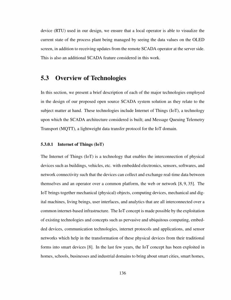
device (RTU) used in our design, we ensure that a local operator is able to visualize the
current state of the process plant being managed by seeing the data values on the OLED
screen, in addition to receiving updates from the remote SCADA operator at the server side.
This is also an additional SCADA feature considered in this work.
5.3 Overview of Technologies
In this section, we present a brief description of each of the major technologies employed
in the design of our proposed open source SCADA system solution as they relate to the
subject matter at hand. These technologies include Internet of Things (IoT), a technology
upon which the SCADA architecture considered is built; and Message Queuing Telemetry
Transport (MQTT), a lightweight data transfer protocol for the IoT domain.
5.3.0.1 Internet of Things (IoT)
The Internet of Things (IoT) is a technology that enables the interconnection of physical
devices such as buildings, vehicles, etc. with embedded electronics, sensors, softwares, and
network connectivity such that the devices can collect and exchange real-time data between
themselves and an operator over a common platform, the web or network [8, 9, 35]. The
IoT brings together mechanical (physical) objects, computing devices, mechanical and dig-
ital machines, living beings, user interfaces, and analytics that are all interconnected over a
common internet-based infrastructure. The IoT concept is made possible by the exploitation
of existing technologies and concepts such as pervasive and ubiquitous computing, embed-
ded devices, communication technologies, internet protocols and applications, and sensor
networks which help in the transformation of these physical devices from their traditional
forms into smart devices [8]. In the last few years, the IoT concept has been exploited in
homes, schools, businesses and industrial domains to bring about smart cities, smart homes,
136
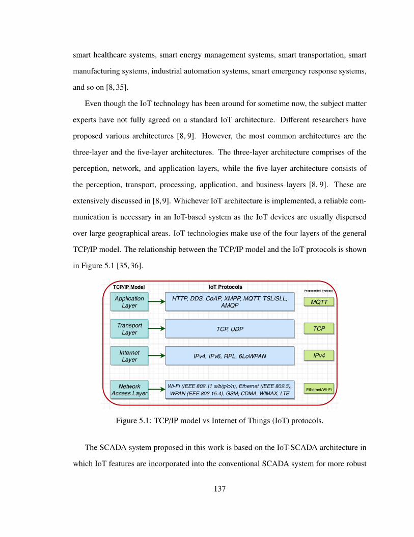
smart healthcare systems, smart energy management systems, smart transportation, smart
manufacturing systems, industrial automation systems, smart emergency response systems,
and so on [8, 35].
Even though the IoT technology has been around for sometime now, the subject matter
experts have not fully agreed on a standard IoT architecture. Different researchers have
proposed various architectures [8, 9]. However, the most common architectures are the
three-layer and the five-layer architectures. The three-layer architecture comprises of the
perception, network, and application layers, while the five-layer architecture consists of
the perception, transport, processing, application, and business layers [8, 9]. These are
extensively discussed in [8,9]. Whichever IoT architecture is implemented, a reliable com-
munication is necessary in an IoT-based system as the IoT devices are usually dispersed
over large geographical areas. IoT technologies make use of the four layers of the general
TCP/IP model. The relationship between the TCP/IP model and the IoT protocols is shown
in Figure 5.1 [35, 36].
Figure 5.1: TCP/IP model vs Internet of Things (IoT) protocols.
The SCADA system proposed in this work is based on the IoT-SCADA architecture in
which IoT features are incorporated into the conventional SCADA system for more robust
137
data acquisition, remote monitoring and supervisory control. This means that IoT proto-
cols are involved in the IoT-based SCADA system design. Research has shown that the
most critical design alternatives for developing IoT-based real-time applications such as
SCADA, are communication protocols, message encoding format, and the web or IoT plat-
form [35,36]. Therefore, in each of the IoT protocol layers shown in Figure 5.1, it is critical
to pick the right protocol for a particular IoT-based application. For instance, in the Appli-
cation Layer, one has to make the hard choice between HTTP, MQTT, CoAP, and so on, as
well as pick the right protocol in the Transport, Internet, and Network Access Layers. The
properties, advantages and disadvantages of the different Application Layer IoT protocols
such as MQTT, CoAP, HTTP, and AMQP are extensively discussed in [8, 35, 37]. In this
work, after so much research, testing and consultations, we have chosen to go with MQTT,
TCP, IPv4, and IEEE 802.11 (Wi-Fi)/Ethernet in the respective Layers. In our proposed
system, MQTT data transfer protocol is implemented over TCP/IP Wireless connectivity.
ThingsBoard has also been chosen as the preferred IoT platform after researching the al-
ternatives [38], and for security reasons, the ThingsBoard IoT server platform is locally
installed and hosted on own private machine (Raspberry Pi), and own network (Memorial
University (MUN) Network) rather than using the ThingsBoard web platform as is com-
monly implemented in literatures. One of the reasons for choosing ThingsBoard is that it
supports MQTT protocol over wireless connectivity. When implemented, the ThingsBoard
server API serves as MQTT Broker [39]. MQTT is discussed in the next section.
5.3.0.2 Message Queuing Telemetry Transport (MQTT) protocol
Message Queuing Telemetry Transport (MQTT) is a lightweight machine-to-machine data
communication protocol [8]. The MQTT, with a 2 byte fixed header, is especially suited for
IoT applications as it supports applications with limited resources such as low bandwidths,
low computational power, low memory, battery, etc. which is typical in an IoT domain [17,
138
22, 24]. MQTT runs on TCP/IP connection, and can be implemented on various networks
such as Wired (Ethernet) and Wireless Local Area Networks [26, 40]. Originally invented
in 1999 by Andy Stanford-Clark of IBM, and Arlen Nipper of Arcom (now Eurotech),
MQTT is now recognized as an open standard by the Organization for the Advancement of
Structured Information Standards (OASIS) [27].
Figure 5.2 shows the general architecture of the MQTT protocol. Essentially, MQTT
uses a Publish-Subscribe messaging mechanism, and it is made up of a Broker (Server),
and Clients. The MQTT Broker is usually a server running in the cloud or on the internet,
and is responsible for storing the published data based on different Topics, and releasing
the message (data) to the rightful Subscribers. The MQTT Client is any piece of hardware,
software, or a combination of both hardware and software, which connects to the Broker for
the purpose of exchanging data. When a connected device or Client downloads data from
the Broker (server), the process is called Subscribing, and that particular Client is known as
a Subscriber. On the other hand, when a connected device (Client) sends data to a Broker
(server), the Client is referred to as the Publisher, and the process is called Publishing.
Hence, the term, "Publish-Subscribe" mechanism upon which the MQTT protocol is based.
It is worth noting that a Broker can serve several Subscribers and Publishers, depending on
the capability of the machine running the Broker. A Client can also act as both a Publisher
and a Subscriber. When a Client publishes data, it assigns a specific Topic to the data,
with each Topic separated by a forward slash. For each Topic, there is a Topic name, and
Topic level associated with it, and wildcard characters are used to match multiple levels to
a Topic [8, 17, 26].
MQTT protocol uses three levels of Quality of Service (QoS) for message delivery:
QoS 0, QoS 1, and QoS 2. In QoS 0, the receiver does not acknowledge message receipt,
and the sender does not re-transmit the message. Here, message delivery is based on the
guarantee that there is a reliable connection between the Client(s) and the Broker (server).
139
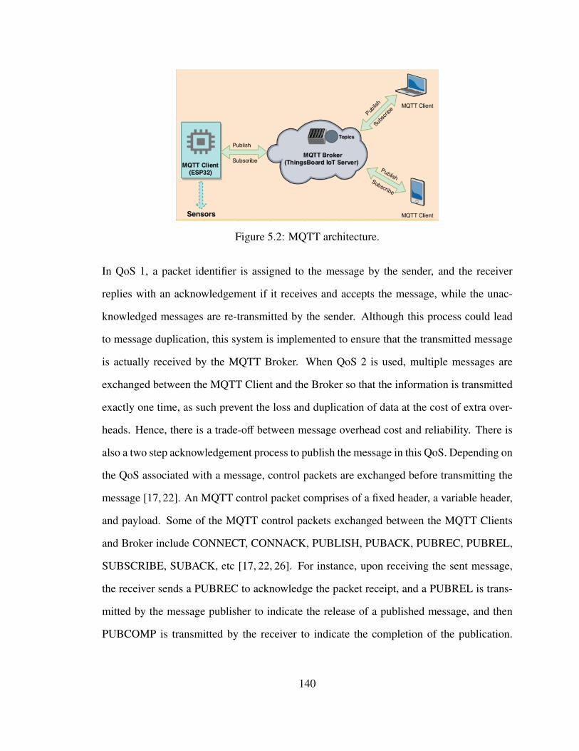
Figure 5.2: MQTT architecture.
In QoS 1, a packet identifier is assigned to the message by the sender, and the receiver
replies with an acknowledgement if it receives and accepts the message, while the unac-
knowledged messages are re-transmitted by the sender. Although this process could lead
to message duplication, this system is implemented to ensure that the transmitted message
is actually received by the MQTT Broker. When QoS 2 is used, multiple messages are
exchanged between the MQTT Client and the Broker so that the information is transmitted
exactly one time, as such prevent the loss and duplication of data at the cost of extra over-
heads. Hence, there is a trade-off between message overhead cost and reliability. There is
also a two step acknowledgement process to publish the message in this QoS. Depending on
the QoS associated with a message, control packets are exchanged before transmitting the
message [17, 22]. An MQTT control packet comprises of a fixed header, a variable header,
and payload. Some of the MQTT control packets exchanged between the MQTT Clients
and Broker include CONNECT, CONNACK, PUBLISH, PUBACK, PUBREC, PUBREL,
SUBSCRIBE, SUBACK, etc [17, 22, 26]. For instance, upon receiving the sent message,
the receiver sends a PUBREC to acknowledge the packet receipt, and a PUBREL is trans-
mitted by the message publisher to indicate the release of a published message, and then
PUBCOMP is transmitted by the receiver to indicate the completion of the publication.
140
Furthermore, MQTT has a queuing system where the Broker buffers all the messages if
the Client is offline, and delivers them to the Client when the Client is back online. In this
case, the Client and the Broker store the current state of the session, and the Broker deliv-
ers the queued messages once the Client has an active session. Thus, MQTT protocol is
reliable and suitable for IoT applications where there are usually limited resources such as
low bandwidth, low memory, low power, etc [8,17,22,26]. This is why MQTT is preferred
to other data transfer protocols like CoAP, HTTP, REST API, etc [8, 35]. MQTT also runs
on TCP/IP connection unlike CoAP which runs on UDP [8,35]. The detailed advantages of
MQTT over other data transport protocols are presented in literatures [8, 35, 37]. Because
of these valuable features of the MQTT protocol, numerous applications already use it. For
example, Facebook messaging, smart home monitoring, healthcare, transport, energy me-
tering, parking, industrial robots, manufacturing, and intelligent monitoring systems have
been implemented with MQTT protocols over various TCP/IP connections [14–29].
In this project, MQTT protocol is implemented for PV data transfer from the MQTT
Client (ESP32 micro-controller) to the MQTT Broker (ThingsBoard IoT server), while
personal computers and mobile devices can subscribe to visualize the published data on the
server. ThingsBoard server node acts as an MQTT Broker, and it supports QoS levels 0 (at
most once) and 1 (at least once), and a set of predefined Topics [39]. This ThingsBoard IoT
server together with PostgresSQL Database is built on a Raspberry Pi 2 micro-controller,
and the MQTT Client Library (Arduino PubSubClient) is implemented with Arduino IDE
Software on an ESP32 OLED micro-controller board to collect the sensor data and publish
them to the ThingsBoard IoT server (MQTT Broker).
141
5.4 Proposed SCADA System Architecture
In this section, we describe the hardware and network structures of the proposed IoT-based
open source SCADA system solution. In configuration A (Figure 5.3), the Raspberry Pi 2
micro-controller hosting the ThingsBoard IoT server (MQTT Broker) where the received
PV data are processed and stored is connected through an Ethernet cable to MUN network.
As a result of this connection, authorized users on MUN network can access the stored
PV data and visualize the created dashboards and alarms on the ThingsBoard IoT server.
In addition, authorized personnel can also have access to the stored data via the internet
by using their private home or office network as long as the ThingsBoard IoT server port
is opened only on the MUN network. Although this configuration presents a great deal of
flexibility as it provides many options for the stored data access, it poses security risks to the
stored data since external internet users can access the stored data remotely. In configuration
B (Figure 5.4), the public internet is not used, and the Wi-Fi Router is used to create a form
of industrial network such that only the authorized users nearby can access the stored PV
data on the ThingsBoard IoT server platform. This is done by connecting the Raspberry Pi
machine hosting the ThingsBoard IoT server to one of the LAN ports of the Wi-Fi Router.
In this configuration, only the connected and authorized users on the local Wi-Fi network
created with the Router can access the data on the ThingsBoard IoT server by pointing to
the IP address of the Raspberry Pi on their browsers. This configuration also ensures that
even the users on the general MUN network cannot access the stored data in the cloud,
thereby guaranteeing the security of the stored data. Firewall, and authentications are setup
on the Router to guarantee the security of the system. In both configurations, the MQTT
Client (ESP32 OLED device) processes and publishes the sensor data to the MQTT Broker
(ThingsBoard server) using MQTT protocol on the TCP/IP Wi-Fi connection established
with the Router.
142
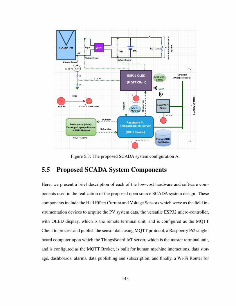
Figure 5.3: The proposed SCADA system configuration A.
5.5 Proposed SCADA System Components
Here, we present a brief description of each of the low-cost hardware and software com-
ponents used in the realization of the proposed open source SCADA system design. These
components include the Hall Effect Current and Voltage Sensors which serve as the field in-
strumentation devices to acquire the PV system data, the versatile ESP32 micro-controller,
with OLED display, which is the remote terminal unit, and is configured as the MQTT
Client to process and publish the sensor data using MQTT protocol, a Raspberry Pi2 single-
board computer upon which the ThingsBoard IoT server, which is the master terminal unit,
and is configured as the MQTT Broker, is built for human machine interactions, data stor-
age, dashboards, alarms, data publishing and subscription, and finally, a Wi-Fi Router for
143
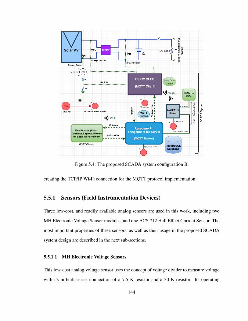
Figure 5.4: The proposed SCADA system configuration B.
creating the TCP/IP Wi-Fi connection for the MQTT protocol implementation.
5.5.1 Sensors (Field Instrumentation Devices)
Three low-cost, and readily available analog sensors are used in this work, including two
MH Electronic Voltage Sensor modules, and one ACS 712 Hall Effect Current Sensor. The
most important properties of these sensors, as well as their usage in the proposed SCADA
system design are described in the next sub-sections.
5.5.1.1 MH Electronic Voltage Sensors
This low-cost analog voltage sensor uses the concept of voltage divider to measure voltage
with its in-built series connection of a 7.5 K resistor and a 30 K resistor. Its operating
144
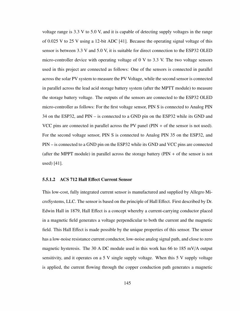
voltage range is 3.3 V to 5.0 V, and it is capable of detecting supply voltages in the range
of 0.025 V to 25 V using a 12-bit ADC [41]. Because the operating signal voltage of this
sensor is between 3.3 V and 5.0 V, it is suitable for direct connection to the ESP32 OLED
micro-controller device with operating voltage of 0 V to 3.3 V. The two voltage sensors
used in this project are connected as follows: One of the sensors is connected in parallel
across the solar PV system to measure the PV Voltage, while the second sensor is connected
in parallel across the lead acid storage battery system (after the MPTT module) to measure
the storage battery voltage. The outputs of the sensors are connected to the ESP32 OLED
micro-controller as follows: For the first voltage sensor, PIN S is connected to Analog PIN
34 on the ESP32, and PIN – is connected to a GND pin on the ESP32 while its GND and
VCC pins are connected in parallel across the PV panel (PIN + of the sensor is not used).
For the second voltage sensor, PIN S is connected to Analog PIN 35 on the ESP32, and
PIN – is connected to a GND pin on the ESP32 while its GND and VCC pins are connected
(after the MPPT module) in parallel across the storage battery (PIN + of the sensor is not
used) [41].
5.5.1.2 ACS 712 Hall Effect Current Sensor
This low-cost, fully integrated current sensor is manufactured and supplied by Allegro Mi-
croSystems, LLC. The sensor is based on the principle of Hall Effect. First described by Dr.
Edwin Hall in 1879, Hall Effect is a concept whereby a current-carrying conductor placed
in a magnetic field generates a voltage perpendicular to both the current and the magnetic
field. This Hall Effect is made possible by the unique properties of this sensor. The sensor
has a low-noise resistance current conductor, low-noise analog signal path, and close to zero
magnetic hysteresis. The 30 A DC module used in this work has 66 to 185 mV/A output
sensitivity, and it operates on a 5 V single supply voltage. When this 5 V supply voltage
is applied, the current flowing through the copper conduction path generates a magnetic
145
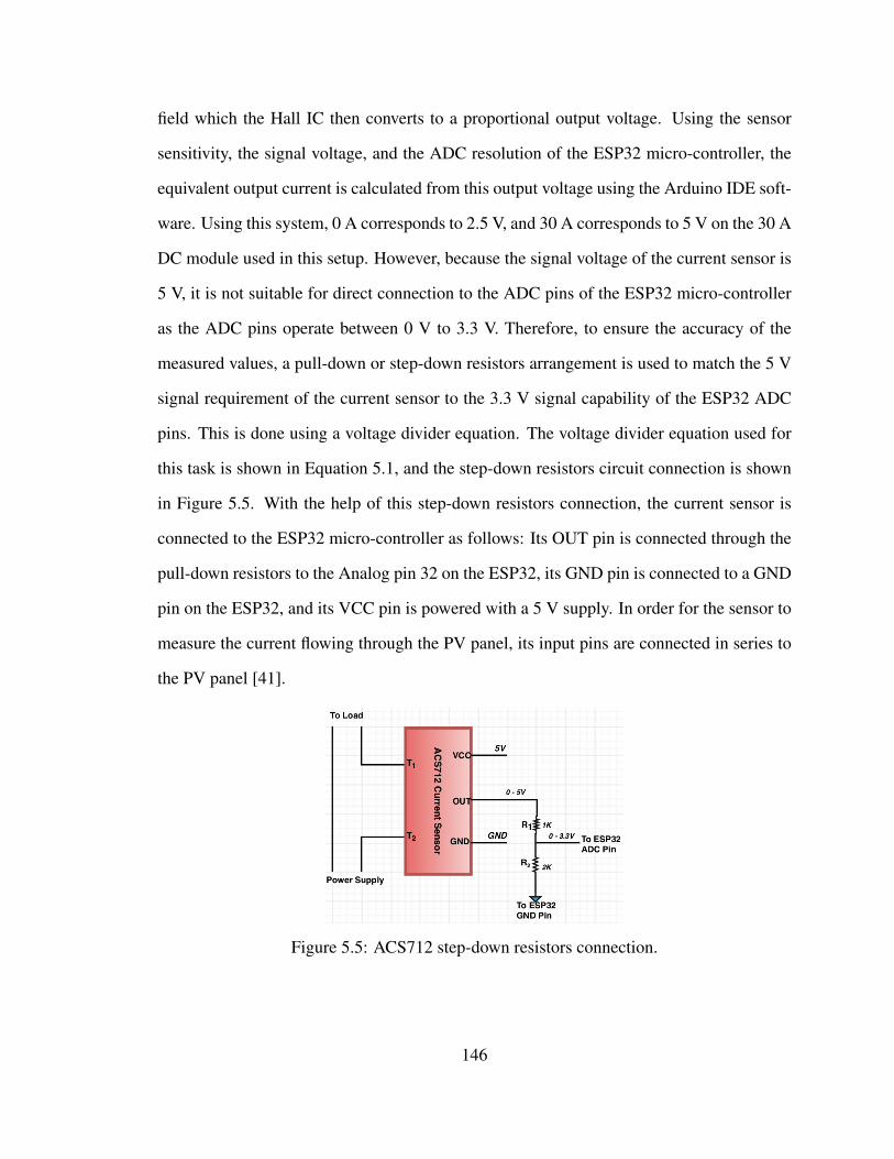
field which the Hall IC then converts to a proportional output voltage. Using the sensor
sensitivity, the signal voltage, and the ADC resolution of the ESP32 micro-controller, the
equivalent output current is calculated from this output voltage using the Arduino IDE soft-
ware. Using this system, 0 A corresponds to 2.5 V, and 30 A corresponds to 5 V on the 30 A
DC module used in this setup. However, because the signal voltage of the current sensor is
5 V, it is not suitable for direct connection to the ADC pins of the ESP32 micro-controller
as the ADC pins operate between 0 V to 3.3 V. Therefore, to ensure the accuracy of the
measured values, a pull-down or step-down resistors arrangement is used to match the 5 V
signal requirement of the current sensor to the 3.3 V signal capability of the ESP32 ADC
pins. This is done using a voltage divider equation. The voltage divider equation used for
this task is shown in Equation 5.1, and the step-down resistors circuit connection is shown
in Figure 5.5. With the help of this step-down resistors connection, the current sensor is
connected to the ESP32 micro-controller as follows: Its OUT pin is connected through the
pull-down resistors to the Analog pin 32 on the ESP32, its GND pin is connected to a GND
pin on the ESP32, and its VCC pin is powered with a 5 V supply. In order for the sensor to
measure the current flowing through the PV panel, its input pins are connected in series to
the PV panel [41].
Figure 5.5: ACS712 step-down resistors connection.
146
Vout =R2
(R1 + R2)× Vin (5.1)
where; Vout = ESP32 ADC Voltage (3.3 V), and Vin = Sensor Input Voltage (5 V), while R1
and R2 are calculated to match these voltage values using the voltage divider equation.
5.5.2 TTGO ESP32 LoRa32 OLED Micro-controller (RTU)
The TTGO ESP32 LoRa32 micro-controller board with 0.96 inch organic light-emitting
diode (OLED) display used in this work is a low-cost (about $20 CAD), low-power ((about
0.9 W), and completely open source ESP32 development board. Its physical construction
is based on the ESP32-DOWDQ6 ESP chip, and it has a built-in heat sink at the back. The
most important specifications of the board include the following [42];
• IEEE 802.11 b/g/n Standards HT40 Wi-Fi Transceiver.
• Dual Core Processor, clocked at 240 MHZ.
• 520 KB Static RAM (SRAM).
• Baseband and Lightweight TCP/IP (LwIP) stack.
• Bluetooth dual mode integrated traditional and BLE low-power Bluetooth support.
• 4 MB on-board Flash, and Wi-Fi and Bluetooth Antenna.
• 18 ADC pins and over 30 GPIO pins (I/O Pins).
• 0.96 inch white OLED display.
• 5 V single power supply, and support for a single-cell lithium-polymer (LiPo) battery.
• Support for CP2102 USB to Serial (UART) chip.
147
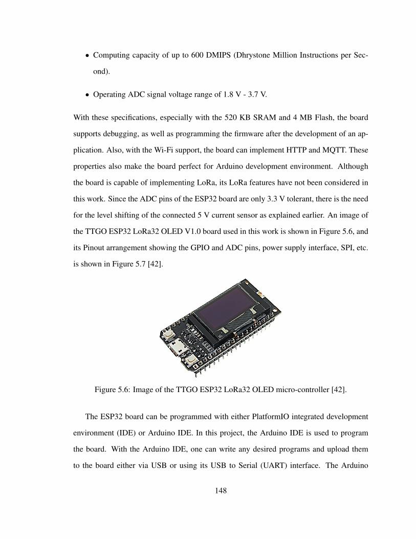
• Computing capacity of up to 600 DMIPS (Dhrystone Million Instructions per Sec-
ond).
• Operating ADC signal voltage range of 1.8 V - 3.7 V.
With these specifications, especially with the 520 KB SRAM and 4 MB Flash, the board
supports debugging, as well as programming the firmware after the development of an ap-
plication. Also, with the Wi-Fi support, the board can implement HTTP and MQTT. These
properties also make the board perfect for Arduino development environment. Although
the board is capable of implementing LoRa, its LoRa features have not been considered in
this work. Since the ADC pins of the ESP32 board are only 3.3 V tolerant, there is the need
for the level shifting of the connected 5 V current sensor as explained earlier. An image of
the TTGO ESP32 LoRa32 OLED V1.0 board used in this work is shown in Figure 5.6, and
its Pinout arrangement showing the GPIO and ADC pins, power supply interface, SPI, etc.
is shown in Figure 5.7 [42].
Figure 5.6: Image of the TTGO ESP32 LoRa32 OLED micro-controller [42].
The ESP32 board can be programmed with either PlatformIO integrated development
environment (IDE) or Arduino IDE. In this project, the Arduino IDE is used to program
the board. With the Arduino IDE, one can write any desired programs and upload them
to the board either via USB or using its USB to Serial (UART) interface. The Arduino
148
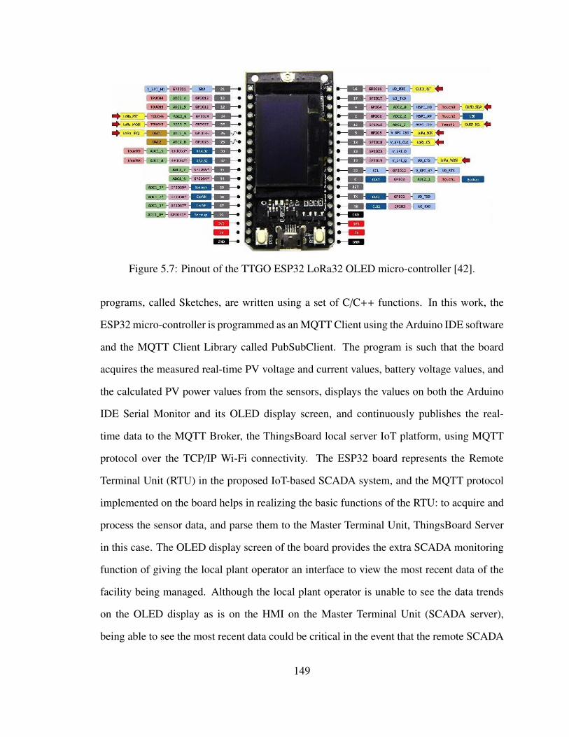
Figure 5.7: Pinout of the TTGO ESP32 LoRa32 OLED micro-controller [42].
programs, called Sketches, are written using a set of C/C++ functions. In this work, the
ESP32 micro-controller is programmed as an MQTT Client using the Arduino IDE software
and the MQTT Client Library called PubSubClient. The program is such that the board
acquires the measured real-time PV voltage and current values, battery voltage values, and
the calculated PV power values from the sensors, displays the values on both the Arduino
IDE Serial Monitor and its OLED display screen, and continuously publishes the real-
time data to the MQTT Broker, the ThingsBoard local server IoT platform, using MQTT
protocol over the TCP/IP Wi-Fi connectivity. The ESP32 board represents the Remote
Terminal Unit (RTU) in the proposed IoT-based SCADA system, and the MQTT protocol
implemented on the board helps in realizing the basic functions of the RTU: to acquire and
process the sensor data, and parse them to the Master Terminal Unit, ThingsBoard Server
in this case. The OLED display screen of the board provides the extra SCADA monitoring
function of giving the local plant operator an interface to view the most recent data of the
facility being managed. Although the local plant operator is unable to see the data trends
on the OLED display as is on the HMI on the Master Terminal Unit (SCADA server),
being able to see the most recent data could be critical in the event that the remote SCADA
149
operator is unavailable to provide supervisory control actions. This extra SCADA feature
implemented in this work is one of the contributions of this work as we have not found any
IoT-based open source SCADA system design solution where such extra plant monitoring
feature is implemented.
5.5.3 Raspberry Pi Single-board Computer
The Raspberry Pi 2 model B device used in this work is a low-cost, single-board computer
developed in the United Kingdom by the Raspberry Pi Foundation [43]. It is a portable
credit card-sized single-board computer (about 85*56 mm) featuring the BCM2836 quad
core (4 processors in one chip) ARMv7 processor, and it is completely open source. The
Raspberry Pi machine primarily runs on Raspbian operating system (OS) which is a Debian-
based Linux distribution specifically for the Raspberry Pi [43]. The most important hard-
ware specifications of the specific Raspberry Pi 2 model B used in this project include the
following [43];
• 32-bit 900 MHz quad-core ARM Cortex-A7 CPU
• 1 GB RAM
• 100 Base Ethernet support
• 4 USB ports
• 40 GPIO pins
• Full HDMI port
• Combined 3.5 mm audio jack and composite video
• Camera interface (CSI)
150
• Display interface (DSI)
• Micro SD card slot.
• VideoCore IV 3D graphics core.
In the proposed SCADA system design, the ThingsBoard IoT server which is the MQTT
Broker, as well as the Master Terminal Unit for human machine interactions and data pro-
cessing, is installed on the Raspberry Pi computer. This is done by building the Things-
Board server alongside the required third-party components and services on the Raspberry
Pi operating system. To realize this, the Raspbian Buster OS was installed on a micro-
SD card and inserted into the Raspberry Pi’s micro-SD card slot. Following the available
ThingsBoard installation documentation [44], and the open source ThingsBoard server
repository on GitHub, several installation codes were run on the Raspberry Pi Terminal
to download and install the ThingsBoard version 2.4 server and its services on the Rasp-
berry Pi computer. The open source PostgreSQL Database was also installed alongside the
ThingsBoard server to store the acquired data. After the installation and configuration of
the ThingsBoard server and the PostgreSQL Database on the Raspberry Pi, the Raspberry
Pi was then connected to the other components of the proposed SCADA system in two
different configurations as described earlier, and each configuration was tested.
5.5.4 Wi-Fi Router (TCP/IP Wi-Fi Connection)
The D-Link Router (DI-524 Airplus G) is used to create the TCP/IP Wireless network
connectivity over which the MQTT protocol is implemented for data transfer from the
MQTT Client (ESP32) to the MQTT Broker (ThingsBoard IoT server). The major speci-
fications of the router include 1 WAN port and 4 LAN ports, 2.4 GHz operating frequency
band, high speed with 54 Mbps data transfer rate, 802.11 b/g wireless protocol support and
IEEE 802.11 standards-compliant, and access control capabilities [41]. Because the ESP32
151
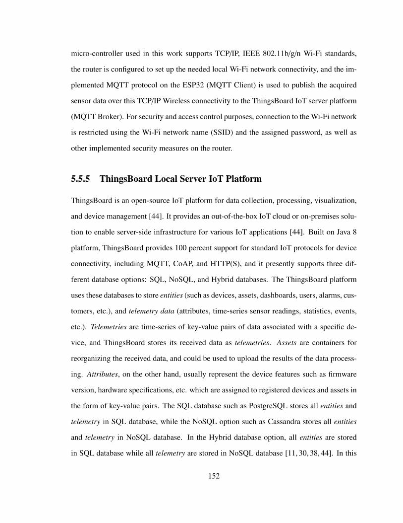
micro-controller used in this work supports TCP/IP, IEEE 802.11b/g/n Wi-Fi standards,
the router is configured to set up the needed local Wi-Fi network connectivity, and the im-
plemented MQTT protocol on the ESP32 (MQTT Client) is used to publish the acquired
sensor data over this TCP/IP Wireless connectivity to the ThingsBoard IoT server platform
(MQTT Broker). For security and access control purposes, connection to the Wi-Fi network
is restricted using the Wi-Fi network name (SSID) and the assigned password, as well as
other implemented security measures on the router.
5.5.5 ThingsBoard Local Server IoT Platform
ThingsBoard is an open-source IoT platform for data collection, processing, visualization,
and device management [44]. It provides an out-of-the-box IoT cloud or on-premises solu-
tion to enable server-side infrastructure for various IoT applications [44]. Built on Java 8
platform, ThingsBoard provides 100 percent support for standard IoT protocols for device
connectivity, including MQTT, CoAP, and HTTP(S), and it presently supports three dif-
ferent database options: SQL, NoSQL, and Hybrid databases. The ThingsBoard platform
uses these databases to store entities (such as devices, assets, dashboards, users, alarms, cus-
tomers, etc.), and telemetry data (attributes, time-series sensor readings, statistics, events,
etc.). Telemetries are time-series of key-value pairs of data associated with a specific de-
vice, and ThingsBoard stores its received data as telemetries. Assets are containers for
reorganizing the received data, and could be used to upload the results of the data process-
ing. Attributes, on the other hand, usually represent the device features such as firmware
version, hardware specifications, etc. which are assigned to registered devices and assets in
the form of key-value pairs. The SQL database such as PostgreSQL stores all entities and
telemetry in SQL database, while the NoSQL option such as Cassandra stores all entities
and telemetry in NoSQL database. In the Hybrid database option, all entities are stored
in SQL database while all telemetry are stored in NoSQL database [11, 30, 38, 44]. In this
152
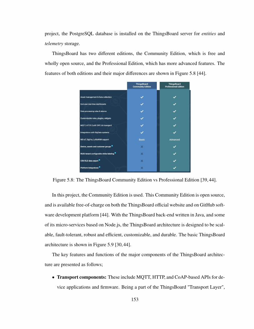
project, the PostgreSQL database is installed on the ThingsBoard server for entities and
telemetry storage.
ThingsBoard has two different editions, the Community Edition, which is free and
wholly open source, and the Professional Edition, which has more advanced features. The
features of both editions and their major differences are shown in Figure 5.8 [44].
Figure 5.8: The ThingsBoard Community Edition vs Professional Edition [39, 44].
In this project, the Community Edition is used. This Community Edition is open source,
and is available free-of-charge on both the ThingsBoard official website and on GitHub soft-
ware development platform [44]. With the ThingsBoard back-end written in Java, and some
of its micro-services based on Node.js, the ThingsBoard architecture is designed to be scal-
able, fault-tolerant, robust and efficient, customizable, and durable. The basic ThingsBoard
architecture is shown in Figure 5.9 [30, 44].
The key features and functions of the major components of the ThingsBoard architec-
ture are presented as follows;
• Transport components: These include MQTT, HTTP, and CoAP-based APIs for de-
vice applications and firmware. Being a part of the ThingsBoard "Transport Layer",
153
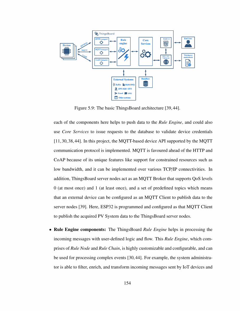
Figure 5.9: The basic ThingsBoard architecture [39, 44].
each of the components here helps to push data to the Rule Engine, and could also
use Core Services to issue requests to the database to validate device credentials
[11,30,38,44]. In this project, the MQTT-based device API supported by the MQTT
communication protocol is implemented. MQTT is favoured ahead of the HTTP and
CoAP because of its unique features like support for constrained resources such as
low bandwidth, and it can be implemented over various TCP/IP connectivities. In
addition, ThingsBoard server nodes act as an MQTT Broker that supports QoS levels
0 (at most once) and 1 (at least once), and a set of predefined topics which means
that an external device can be configured as an MQTT Client to publish data to the
server nodes [39]. Here, ESP32 is programmed and configured as that MQTT Client
to publish the acquired PV System data to the ThingsBoard server nodes.
• Rule Engine components: The ThingsBoard Rule Engine helps in processing the
incoming messages with user-defined logic and flow. This Rule Engine, which com-
prises of Rule Node and Rule Chain, is highly customizable and configurable, and can
be used for processing complex events [30, 44]. For example, the system administra-
tor is able to filter, enrich, and transform incoming messages sent by IoT devices and
154
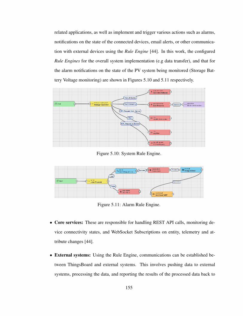
related applications, as well as implement and trigger various actions such as alarms,
notifications on the state of the connected devices, email alerts, or other communica-
tion with external devices using the Rule Engine [44]. In this work, the configured
Rule Engines for the overall system implementation (e.g data transfer), and that for
the alarm notifications on the state of the PV system being monitored (Storage Bat-
tery Voltage monitoring) are shown in Figures 5.10 and 5.11 respectively.
Figure 5.10: System Rule Engine.
Figure 5.11: Alarm Rule Engine.
• Core services: These are responsible for handling REST API calls, monitoring de-
vice connectivity states, and WebSocket Subscriptions on entity, telemetry and at-
tribute changes [44].
• External systems: Using the Rule Engine, communications can be established be-
tween ThingsBoard and external systems. This involves pushing data to external
systems, processing the data, and reporting the results of the processed data back to
155
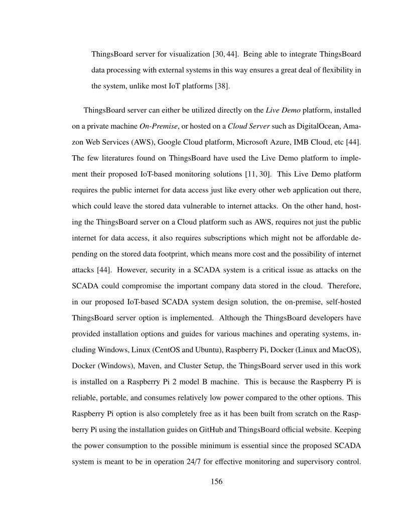
ThingsBoard server for visualization [30, 44]. Being able to integrate ThingsBoard
data processing with external systems in this way ensures a great deal of flexibility in
the system, unlike most IoT platforms [38].
ThingsBoard server can either be utilized directly on the Live Demo platform, installed
on a private machine On-Premise, or hosted on a Cloud Server such as DigitalOcean, Ama-
zon Web Services (AWS), Google Cloud platform, Microsoft Azure, IMB Cloud, etc [44].
The few literatures found on ThingsBoard have used the Live Demo platform to imple-
ment their proposed IoT-based monitoring solutions [11, 30]. This Live Demo platform
requires the public internet for data access just like every other web application out there,
which could leave the stored data vulnerable to internet attacks. On the other hand, host-
ing the ThingsBoard server on a Cloud platform such as AWS, requires not just the public
internet for data access, it also requires subscriptions which might not be affordable de-
pending on the stored data footprint, which means more cost and the possibility of internet
attacks [44]. However, security in a SCADA system is a critical issue as attacks on the
SCADA could compromise the important company data stored in the cloud. Therefore,
in our proposed IoT-based SCADA system design solution, the on-premise, self-hosted
ThingsBoard server option is implemented. Although the ThingsBoard developers have
provided installation options and guides for various machines and operating systems, in-
cluding Windows, Linux (CentOS and Ubuntu), Raspberry Pi, Docker (Linux and MacOS),
Docker (Windows), Maven, and Cluster Setup, the ThingsBoard server used in this work
is installed on a Raspberry Pi 2 model B machine. This is because the Raspberry Pi is
reliable, portable, and consumes relatively low power compared to the other options. This
Raspberry Pi option is also completely free as it has been built from scratch on the Rasp-
berry Pi using the installation guides on GitHub and ThingsBoard official website. Keeping
the power consumption to the possible minimum is essential since the proposed SCADA
system is meant to be in operation 24/7 for effective monitoring and supervisory control.
156
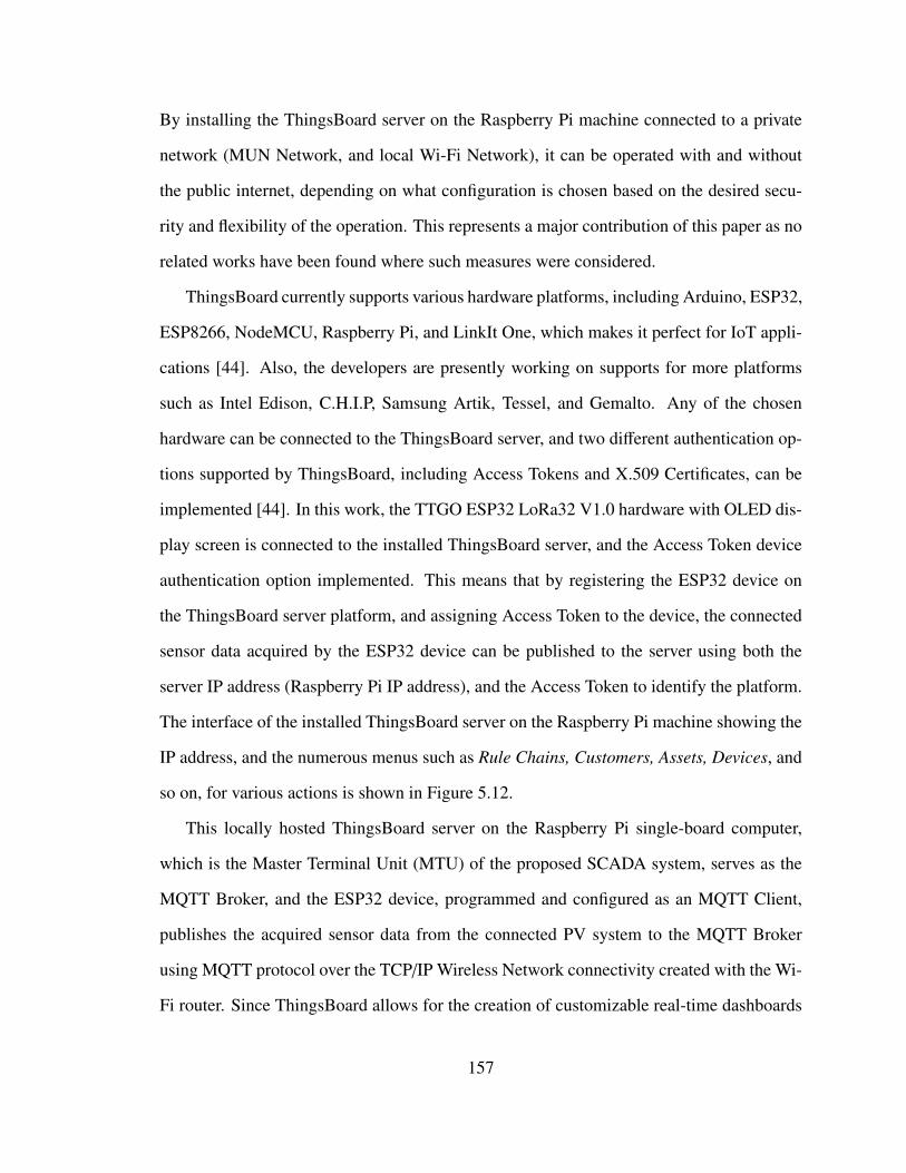
By installing the ThingsBoard server on the Raspberry Pi machine connected to a private
network (MUN Network, and local Wi-Fi Network), it can be operated with and without
the public internet, depending on what configuration is chosen based on the desired secu-
rity and flexibility of the operation. This represents a major contribution of this paper as no
related works have been found where such measures were considered.
ThingsBoard currently supports various hardware platforms, including Arduino, ESP32,
ESP8266, NodeMCU, Raspberry Pi, and LinkIt One, which makes it perfect for IoT appli-
cations [44]. Also, the developers are presently working on supports for more platforms
such as Intel Edison, C.H.I.P, Samsung Artik, Tessel, and Gemalto. Any of the chosen
hardware can be connected to the ThingsBoard server, and two different authentication op-
tions supported by ThingsBoard, including Access Tokens and X.509 Certificates, can be
implemented [44]. In this work, the TTGO ESP32 LoRa32 V1.0 hardware with OLED dis-
play screen is connected to the installed ThingsBoard server, and the Access Token device
authentication option implemented. This means that by registering the ESP32 device on
the ThingsBoard server platform, and assigning Access Token to the device, the connected
sensor data acquired by the ESP32 device can be published to the server using both the
server IP address (Raspberry Pi IP address), and the Access Token to identify the platform.
The interface of the installed ThingsBoard server on the Raspberry Pi machine showing the
IP address, and the numerous menus such as Rule Chains, Customers, Assets, Devices, and
so on, for various actions is shown in Figure 5.12.
This locally hosted ThingsBoard server on the Raspberry Pi single-board computer,
which is the Master Terminal Unit (MTU) of the proposed SCADA system, serves as the
MQTT Broker, and the ESP32 device, programmed and configured as an MQTT Client,
publishes the acquired sensor data from the connected PV system to the MQTT Broker
using MQTT protocol over the TCP/IP Wireless Network connectivity created with the Wi-
Fi router. Since ThingsBoard allows for the creation of customizable real-time dashboards
157
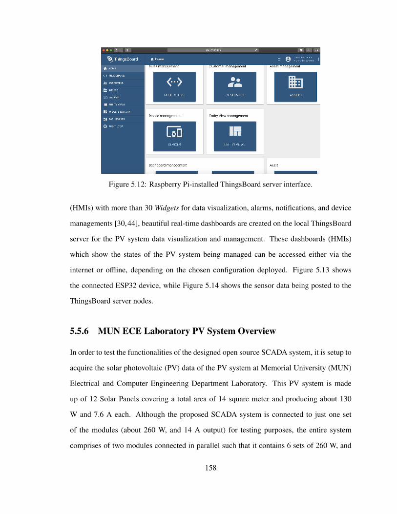
Figure 5.12: Raspberry Pi-installed ThingsBoard server interface.
(HMIs) with more than 30 Widgets for data visualization, alarms, notifications, and device
managements [30,44], beautiful real-time dashboards are created on the local ThingsBoard
server for the PV system data visualization and management. These dashboards (HMIs)
which show the states of the PV system being managed can be accessed either via the
internet or offline, depending on the chosen configuration deployed. Figure 5.13 shows
the connected ESP32 device, while Figure 5.14 shows the sensor data being posted to the
ThingsBoard server nodes.
5.5.6 MUN ECE Laboratory PV System Overview
In order to test the functionalities of the designed open source SCADA system, it is setup to
acquire the solar photovoltaic (PV) data of the PV system at Memorial University (MUN)
Electrical and Computer Engineering Department Laboratory. This PV system is made
up of 12 Solar Panels covering a total area of 14 square meter and producing about 130
W and 7.6 A each. Although the proposed SCADA system is connected to just one set
of the modules (about 260 W, and 14 A output) for testing purposes, the entire system
comprises of two modules connected in parallel such that it contains 6 sets of 260 W, and
158
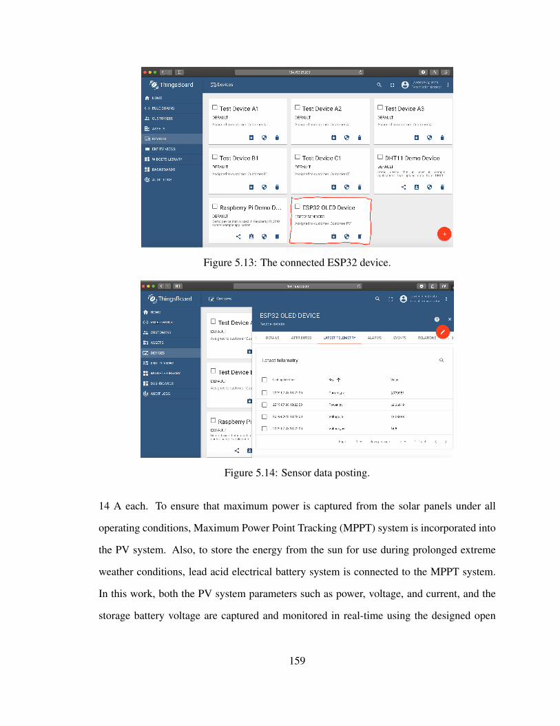
Figure 5.13: The connected ESP32 device.
Figure 5.14: Sensor data posting.
14 A each. To ensure that maximum power is captured from the solar panels under all
operating conditions, Maximum Power Point Tracking (MPPT) system is incorporated into
the PV system. Also, to store the energy from the sun for use during prolonged extreme
weather conditions, lead acid electrical battery system is connected to the MPPT system.
In this work, both the PV system parameters such as power, voltage, and current, and the
storage battery voltage are captured and monitored in real-time using the designed open
159
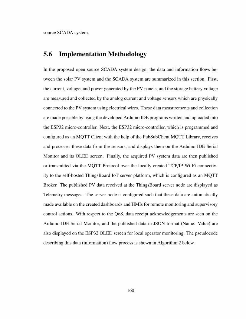
source SCADA system.
5.6 Implementation Methodology
In the proposed open source SCADA system design, the data and information flows be-
tween the solar PV system and the SCADA system are summarized in this section. First,
the current, voltage, and power generated by the PV panels, and the storage battery voltage
are measured and collected by the analog current and voltage sensors which are physically
connected to the PV system using electrical wires. These data measurements and collection
are made possible by using the developed Arduino IDE programs written and uploaded into
the ESP32 micro-controller. Next, the ESP32 micro-controller, which is programmed and
configured as an MQTT Client with the help of the PubSubClient MQTT Library, receives
and processes these data from the sensors, and displays them on the Arduino IDE Serial
Monitor and its OLED screen. Finally, the acquired PV system data are then published
or transmitted via the MQTT Protocol over the locally created TCP/IP Wi-Fi connectiv-
ity to the self-hosted ThingsBoard IoT server platform, which is configured as an MQTT
Broker. The published PV data received at the ThingsBoard server node are displayed as
Telemetry messages. The server node is configured such that these data are automatically
made available on the created dashboards and HMIs for remote monitoring and supervisory
control actions. With respect to the QoS, data receipt acknowledgements are seen on the
Arduino IDE Serial Monitor, and the published data in JSON format (Name: Value) are
also displayed on the ESP32 OLED screen for local operator monitoring. The pseudocode
describing this data (information) flow process is shown in Algorithm 2 below.
160
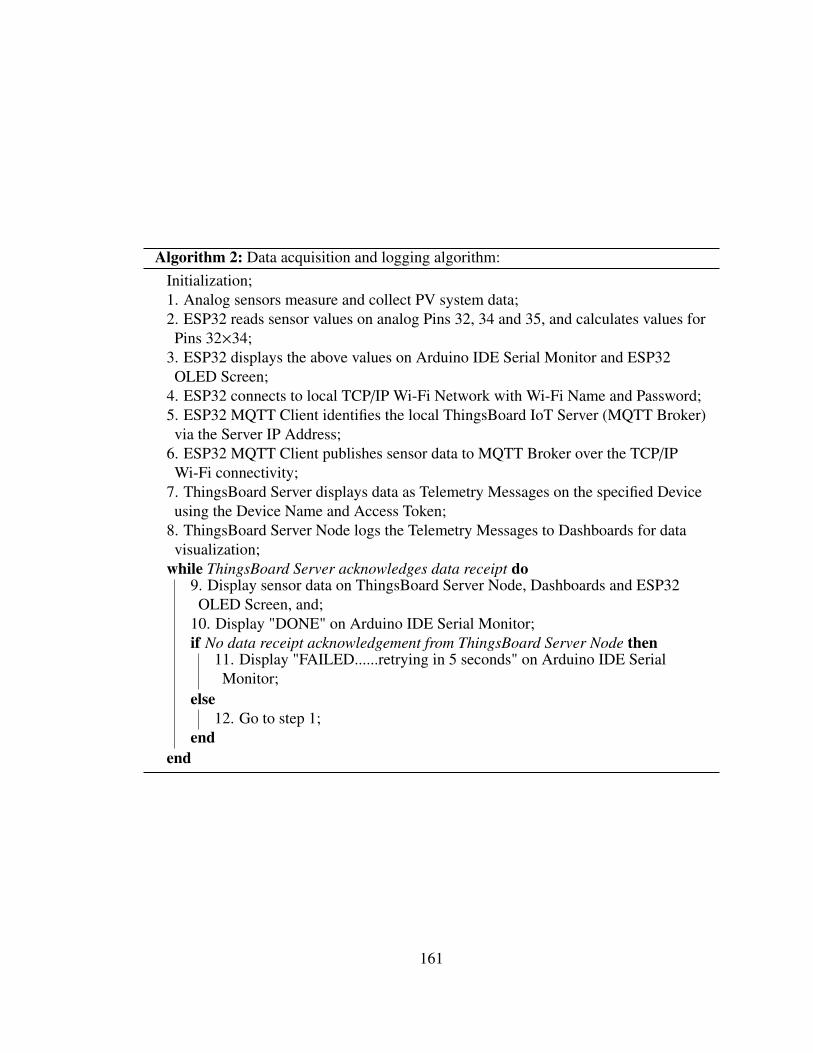
Algorithm 2: Data acquisition and logging algorithm:Initialization;1. Analog sensors measure and collect PV system data;2. ESP32 reads sensor values on analog Pins 32, 34 and 35, and calculates values forPins 32×34;
3. ESP32 displays the above values on Arduino IDE Serial Monitor and ESP32OLED Screen;
4. ESP32 connects to local TCP/IP Wi-Fi Network with Wi-Fi Name and Password;5. ESP32 MQTT Client identifies the local ThingsBoard IoT Server (MQTT Broker)via the Server IP Address;
6. ESP32 MQTT Client publishes sensor data to MQTT Broker over the TCP/IPWi-Fi connectivity;
7. ThingsBoard Server displays data as Telemetry Messages on the specified Deviceusing the Device Name and Access Token;
8. ThingsBoard Server Node logs the Telemetry Messages to Dashboards for datavisualization;
while ThingsBoard Server acknowledges data receipt do9. Display sensor data on ThingsBoard Server Node, Dashboards and ESP32OLED Screen, and;
10. Display "DONE" on Arduino IDE Serial Monitor;if No data receipt acknowledgement from ThingsBoard Server Node then
11. Display "FAILED......retrying in 5 seconds" on Arduino IDE SerialMonitor;
else12. Go to step 1;
endend
161
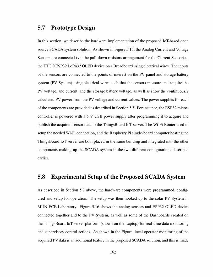
5.7 Prototype Design
In this section, we describe the hardware implementation of the proposed IoT-based open
source SCADA system solution. As shown in Figure 5.15, the Analog Current and Voltage
Sensors are connected (via the pull-down resistors arrangement for the Current Sensor) to
the TTGO ESP32 LoRa32 OLED device on a Breadboard using electrical wires. The inputs
of the sensors are connected to the points of interest on the PV panel and storage battery
system (PV System) using electrical wires such that the sensors measure and acquire the
PV voltage, and current, and the storage battery voltage, as well as show the continuously
calculated PV power from the PV voltage and current values. The power supplies for each
of the components are provided as described in Section 5.5. For instance, the ESP32 micro-
controller is powered with a 5 V USB power supply after programming it to acquire and
publish the acquired sensor data to the ThingsBoard IoT server. The Wi-Fi Router used to
setup the needed Wi-Fi connection, and the Raspberry Pi single-board computer hosting the
ThingsBoard IoT server are both placed in the same building and integrated into the other
components making up the SCADA system in the two different configurations described
earlier.
5.8 Experimental Setup of the Proposed SCADA System
As described in Section 5.7 above, the hardware components were programmed, config-
ured and setup for operation. The setup was then hooked up to the solar PV System in
MUN ECE Laboratory. Figure 5.16 shows the analog sensors and ESP32 OLED device
connected together and to the PV System, as well as some of the Dashboards created on
the ThingsBoard IoT server platform (shown on the Laptop) for real-time data monitoring
and supervisory control actions. As shown in the Figure, local operator monitoring of the
acquired PV data is an additional feature in the proposed SCADA solution, and this is made
162
Figure 5.15: Hardware implementation of the proposed SCADA system.
possible using the ESP32 OLED Screen shown.
Figure 5.16: Experimental setup of the proposed SCADA system.
163
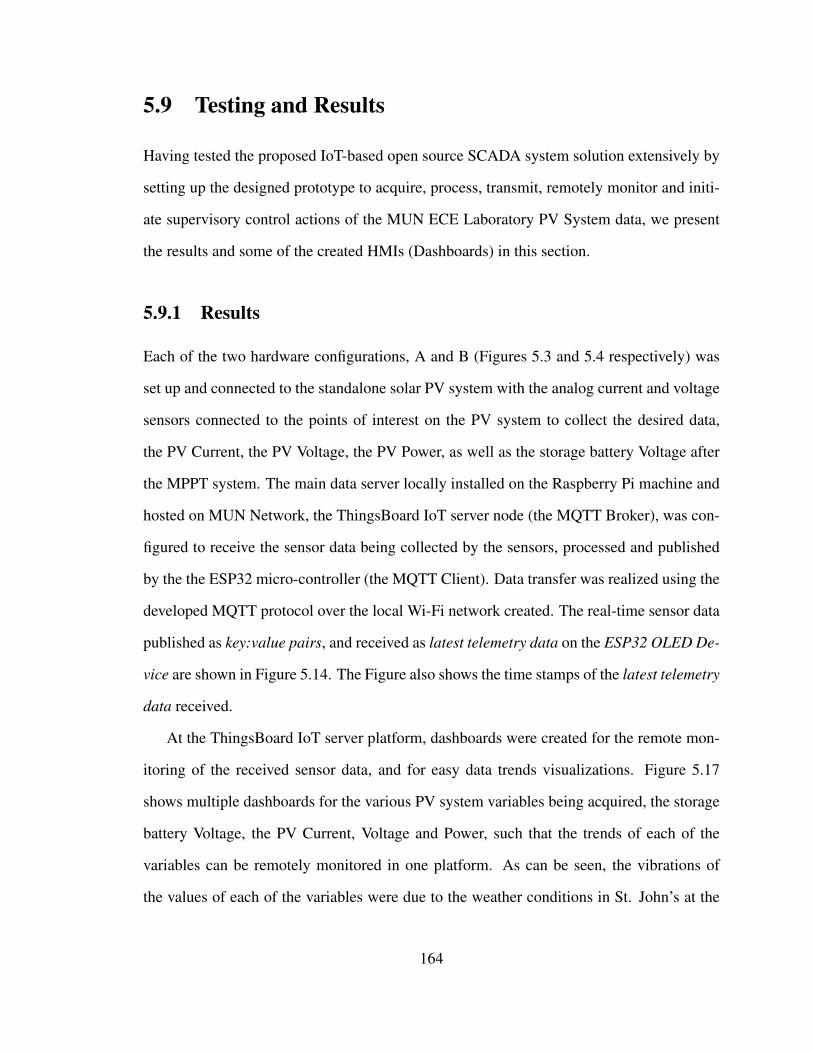
5.9 Testing and Results
Having tested the proposed IoT-based open source SCADA system solution extensively by
setting up the designed prototype to acquire, process, transmit, remotely monitor and initi-
ate supervisory control actions of the MUN ECE Laboratory PV System data, we present
the results and some of the created HMIs (Dashboards) in this section.
5.9.1 Results
Each of the two hardware configurations, A and B (Figures 5.3 and 5.4 respectively) was
set up and connected to the standalone solar PV system with the analog current and voltage
sensors connected to the points of interest on the PV system to collect the desired data,
the PV Current, the PV Voltage, the PV Power, as well as the storage battery Voltage after
the MPPT system. The main data server locally installed on the Raspberry Pi machine and
hosted on MUN Network, the ThingsBoard IoT server node (the MQTT Broker), was con-
figured to receive the sensor data being collected by the sensors, processed and published
by the the ESP32 micro-controller (the MQTT Client). Data transfer was realized using the
developed MQTT protocol over the local Wi-Fi network created. The real-time sensor data
published as key:value pairs, and received as latest telemetry data on the ESP32 OLED De-
vice are shown in Figure 5.14. The Figure also shows the time stamps of the latest telemetry
data received.
At the ThingsBoard IoT server platform, dashboards were created for the remote mon-
itoring of the received sensor data, and for easy data trends visualizations. Figure 5.17
shows multiple dashboards for the various PV system variables being acquired, the storage
battery Voltage, the PV Current, Voltage and Power, such that the trends of each of the
variables can be remotely monitored in one platform. As can be seen, the vibrations of
the values of each of the variables were due to the weather conditions in St. John’s at the
164
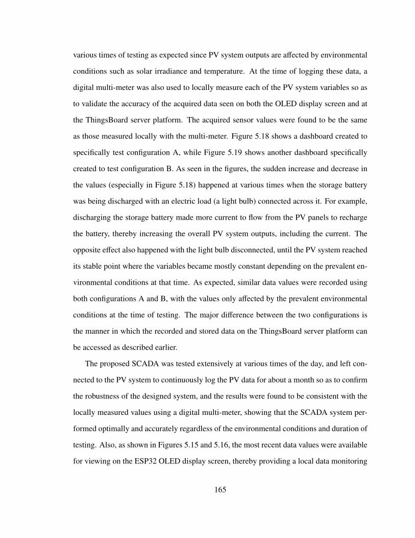
various times of testing as expected since PV system outputs are affected by environmental
conditions such as solar irradiance and temperature. At the time of logging these data, a
digital multi-meter was also used to locally measure each of the PV system variables so as
to validate the accuracy of the acquired data seen on both the OLED display screen and at
the ThingsBoard server platform. The acquired sensor values were found to be the same
as those measured locally with the multi-meter. Figure 5.18 shows a dashboard created to
specifically test configuration A, while Figure 5.19 shows another dashboard specifically
created to test configuration B. As seen in the figures, the sudden increase and decrease in
the values (especially in Figure 5.18) happened at various times when the storage battery
was being discharged with an electric load (a light bulb) connected across it. For example,
discharging the storage battery made more current to flow from the PV panels to recharge
the battery, thereby increasing the overall PV system outputs, including the current. The
opposite effect also happened with the light bulb disconnected, until the PV system reached
its stable point where the variables became mostly constant depending on the prevalent en-
vironmental conditions at that time. As expected, similar data values were recorded using
both configurations A and B, with the values only affected by the prevalent environmental
conditions at the time of testing. The major difference between the two configurations is
the manner in which the recorded and stored data on the ThingsBoard server platform can
be accessed as described earlier.
The proposed SCADA was tested extensively at various times of the day, and left con-
nected to the PV system to continuously log the PV data for about a month so as to confirm
the robustness of the designed system, and the results were found to be consistent with the
locally measured values using a digital multi-meter, showing that the SCADA system per-
formed optimally and accurately regardless of the environmental conditions and duration of
testing. Also, as shown in Figures 5.15 and 5.16, the most recent data values were available
for viewing on the ESP32 OLED display screen, thereby providing a local data monitoring
165
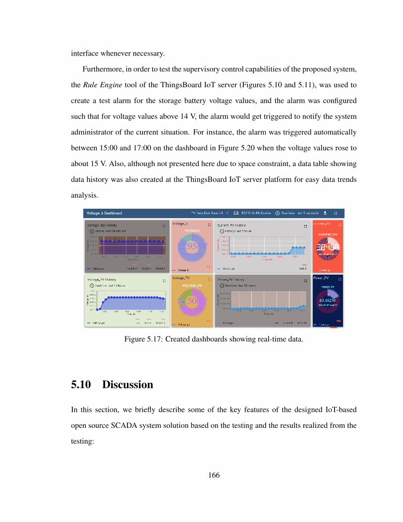
interface whenever necessary.
Furthermore, in order to test the supervisory control capabilities of the proposed system,
the Rule Engine tool of the ThingsBoard IoT server (Figures 5.10 and 5.11), was used to
create a test alarm for the storage battery voltage values, and the alarm was configured
such that for voltage values above 14 V, the alarm would get triggered to notify the system
administrator of the current situation. For instance, the alarm was triggered automatically
between 15:00 and 17:00 on the dashboard in Figure 5.20 when the voltage values rose to
about 15 V. Also, although not presented here due to space constraint, a data table showing
data history was also created at the ThingsBoard IoT server platform for easy data trends
analysis.
Figure 5.17: Created dashboards showing real-time data.
5.10 Discussion
In this section, we briefly describe some of the key features of the designed IoT-based
open source SCADA system solution based on the testing and the results realized from the
testing:
166
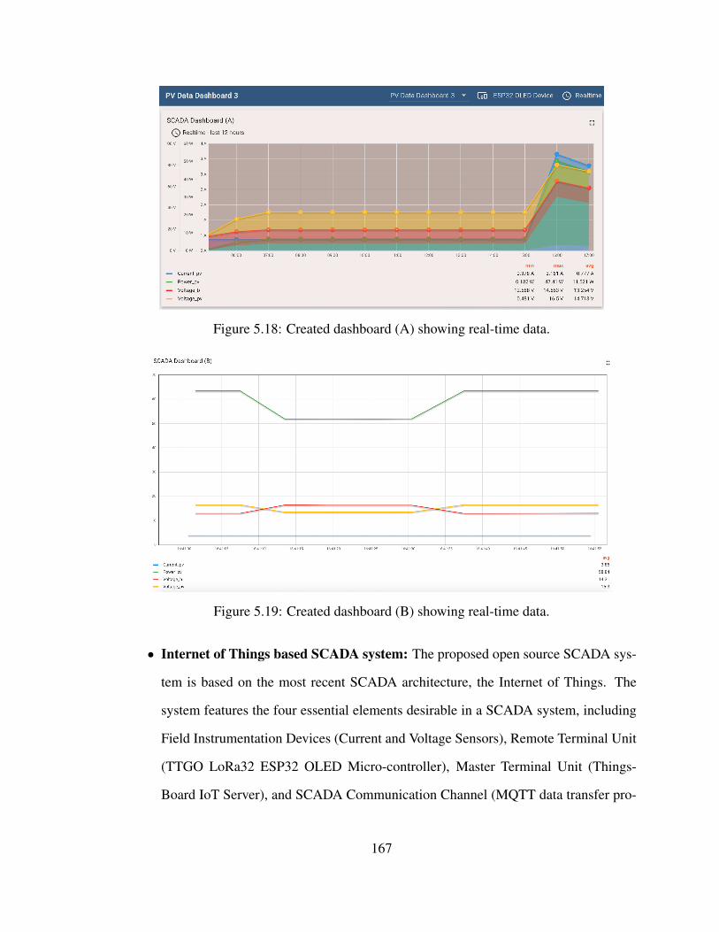
Figure 5.18: Created dashboard (A) showing real-time data.
Figure 5.19: Created dashboard (B) showing real-time data.
• Internet of Things based SCADA system: The proposed open source SCADA sys-
tem is based on the most recent SCADA architecture, the Internet of Things. The
system features the four essential elements desirable in a SCADA system, including
Field Instrumentation Devices (Current and Voltage Sensors), Remote Terminal Unit
(TTGO LoRa32 ESP32 OLED Micro-controller), Master Terminal Unit (Things-
Board IoT Server), and SCADA Communication Channel (MQTT data transfer pro-
167
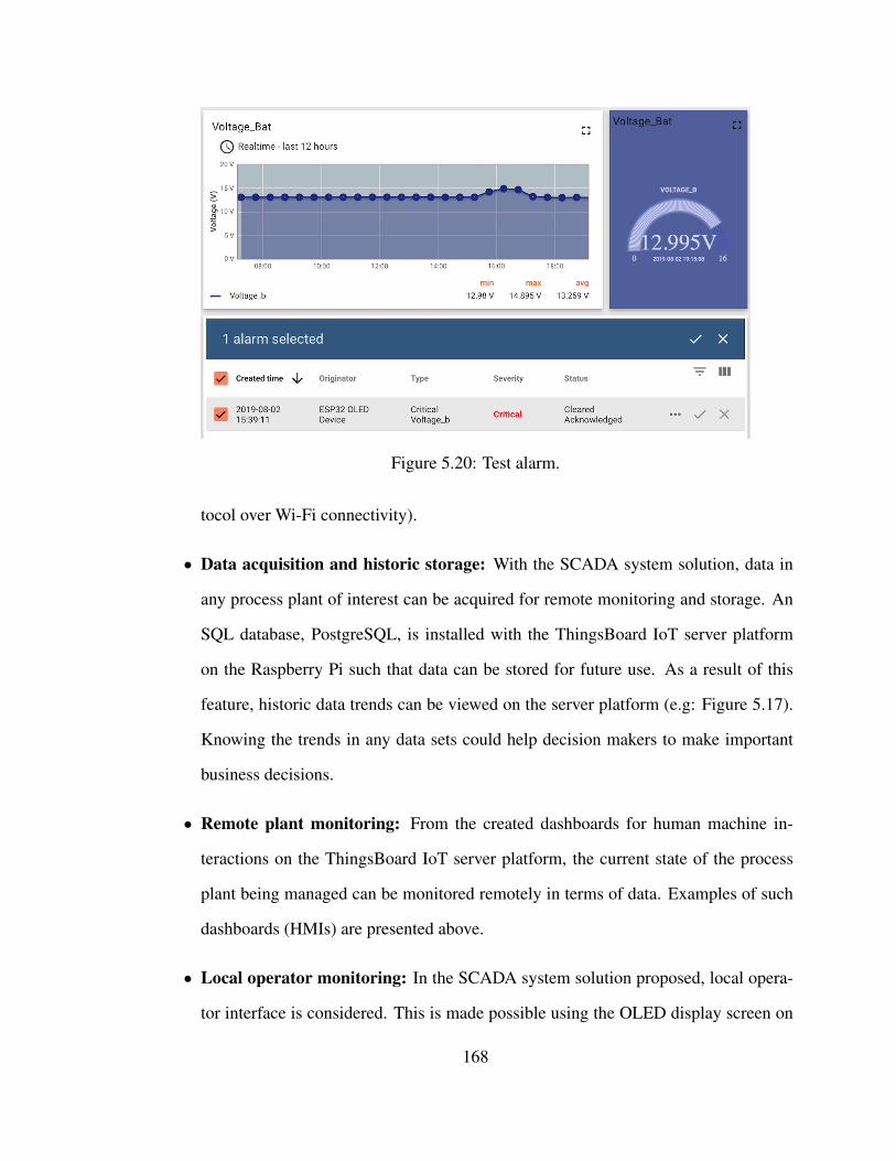
Figure 5.20: Test alarm.
tocol over Wi-Fi connectivity).
• Data acquisition and historic storage: With the SCADA system solution, data in
any process plant of interest can be acquired for remote monitoring and storage. An
SQL database, PostgreSQL, is installed with the ThingsBoard IoT server platform
on the Raspberry Pi such that data can be stored for future use. As a result of this
feature, historic data trends can be viewed on the server platform (e.g: Figure 5.17).
Knowing the trends in any data sets could help decision makers to make important
business decisions.
• Remote plant monitoring: From the created dashboards for human machine in-
teractions on the ThingsBoard IoT server platform, the current state of the process
plant being managed can be monitored remotely in terms of data. Examples of such
dashboards (HMIs) are presented above.
• Local operator monitoring: In the SCADA system solution proposed, local opera-
tor interface is considered. This is made possible using the OLED display screen on
168
the ESP32 micro-controller where a local operator can view the most recent sensor
data at the plant site simply by looking at the OLED screen. This could be particu-
larly important in the events that the overall system administrator at the server end
isn’t available to provide system updates.
• Reporting: From the data logs, charts, alarms and data trends, reports on the state of
the process plant can be generated for critical business decisions. In addition, reports
on the states of the created alarms can be sent automatically to Device Customers and
System Administrator either with instant messaging notifications or via emails.
• Security: The proposed SCADA system solution is such that the main data server,
the ThingsBoard IoT server platform, is locally hosted on MUN network. As such,
security measures can be taken by the system administrator to ensure data integrity.
Such security measures include access control, firewalls, authorization, regular risk
assessment, whitelists, continuous monitoring and log analysis, updating and patch-
ing regularly, authentication, and so on.
• Reliability and availability: Even though system reliability calculation is outside
the scope of this paper, studies have shown that SCADA system reliability and avail-
ability are affected by delayed or wrong operator decisions [45]. In the proposed
open source SCADA system solution, all the components are open source and read-
ily available. Also, the main cloud server for data processing is locally installed on
MUN Network (hosted), and self-managed. Therefore, the system administrator is
always available to continuously manage and maintain the system in order to ensure
its continuous reliability and availability. However, this is almost impossible in a
commercial (proprietary) SCADA system where the customer is beholden to a single
vendor, and as such has to contact the vendor in the events of the SCADA system
failures which could lead to downtime.
169
• Supervisory control: In the proposed SCADA system solution, by remotely moni-
toring the data sets of the desired variables in the process plant, the system admin-
istrator can send supervisory control commands via emails, alarms or instant mes-
saging notifications to the local operator informing the operator of the problems and
requesting immediate actions to correct the problems.
• Ease of use: The main data server, ThingsBoard IoT server platform, where data pro-
cessing and human machine interactions are carried out by the system owner is simple
and user-friendly, meaning that it requires less customer training for continuous use.
This is usually not the case in most commercial SCADA system solutions as their
MTU platforms are complicated, requiring a great deal of training and experience for
operation.
• Open source, and low cost: In the proposed SCADA system solution, all the com-
ponents are manufactured and supplied by multiple vendors (mix and match), and are
readily available under open source license. The components can easily be intercon-
nected with related components from several vendors. As such, the consumer is not
beholden to a single vendor. This is one of the key features of an open source system.
In Table 5.1, it can be seen that despite the fact that the proposed SCADA system
performs all the basic functions desired in a SCADA system, it is a low-cost solution
compared to the available commercial SCADA systems which are in thousands of
dollars. The overall system cost is just about $280 CAD. From the Table, it can be
seen that the main data server, the ThingsBoard IoT server installed on the Raspberry
Pi, and the database software, PostgreSQL, cost nothing. This is because the server
was built from the source code alongside the database using the developers’ guides.
The MQTT Client Library (PubSubClient) on Arduino IDE is also free.
• Low power: For an IoT-based system designed to operate 24/7, power consump-
170
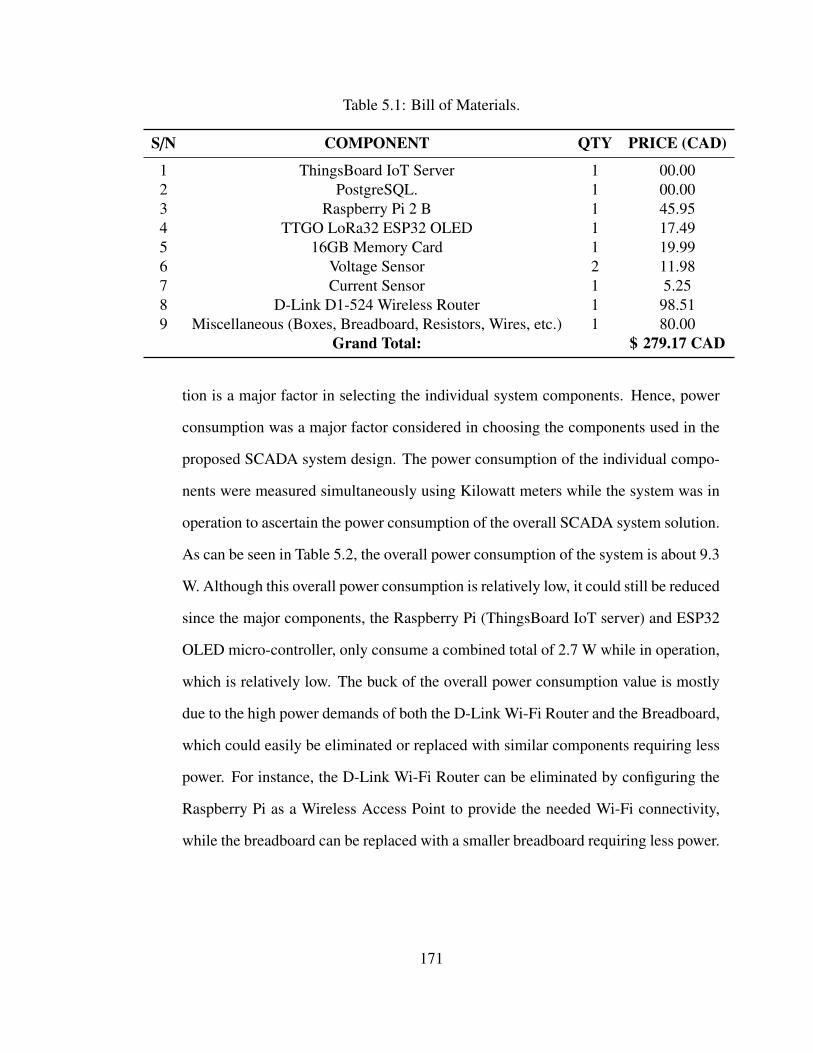
Table 5.1: Bill of Materials.
S/N COMPONENT QTY PRICE (CAD)
1 ThingsBoard IoT Server 1 00.002 PostgreSQL. 1 00.003 Raspberry Pi 2 B 1 45.954 TTGO LoRa32 ESP32 OLED 1 17.495 16GB Memory Card 1 19.996 Voltage Sensor 2 11.987 Current Sensor 1 5.258 D-Link D1-524 Wireless Router 1 98.519 Miscellaneous (Boxes, Breadboard, Resistors, Wires, etc.) 1 80.00
Grand Total: $ 279.17 CAD
tion is a major factor in selecting the individual system components. Hence, power
consumption was a major factor considered in choosing the components used in the
proposed SCADA system design. The power consumption of the individual compo-
nents were measured simultaneously using Kilowatt meters while the system was in
operation to ascertain the power consumption of the overall SCADA system solution.
As can be seen in Table 5.2, the overall power consumption of the system is about 9.3
W. Although this overall power consumption is relatively low, it could still be reduced
since the major components, the Raspberry Pi (ThingsBoard IoT server) and ESP32
OLED micro-controller, only consume a combined total of 2.7 W while in operation,
which is relatively low. The buck of the overall power consumption value is mostly
due to the high power demands of both the D-Link Wi-Fi Router and the Breadboard,
which could easily be eliminated or replaced with similar components requiring less
power. For instance, the D-Link Wi-Fi Router can be eliminated by configuring the
Raspberry Pi as a Wireless Access Point to provide the needed Wi-Fi connectivity,
while the breadboard can be replaced with a smaller breadboard requiring less power.
171
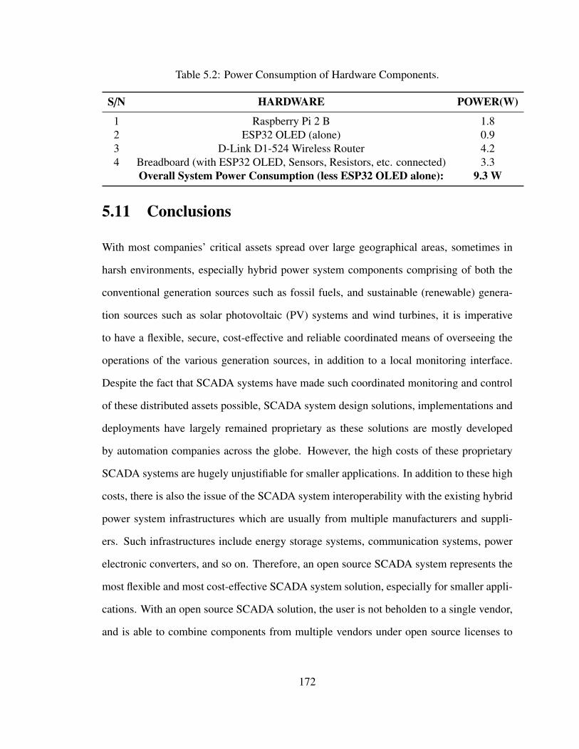
Table 5.2: Power Consumption of Hardware Components.
S/N HARDWARE POWER(W)
1 Raspberry Pi 2 B 1.82 ESP32 OLED (alone) 0.93 D-Link D1-524 Wireless Router 4.24 Breadboard (with ESP32 OLED, Sensors, Resistors, etc. connected) 3.3
Overall System Power Consumption (less ESP32 OLED alone): 9.3 W
5.11 Conclusions
With most companies’ critical assets spread over large geographical areas, sometimes in
harsh environments, especially hybrid power system components comprising of both the
conventional generation sources such as fossil fuels, and sustainable (renewable) genera-
tion sources such as solar photovoltaic (PV) systems and wind turbines, it is imperative
to have a flexible, secure, cost-effective and reliable coordinated means of overseeing the
operations of the various generation sources, in addition to a local monitoring interface.
Despite the fact that SCADA systems have made such coordinated monitoring and control
of these distributed assets possible, SCADA system design solutions, implementations and
deployments have largely remained proprietary as these solutions are mostly developed
by automation companies across the globe. However, the high costs of these proprietary
SCADA systems are hugely unjustifiable for smaller applications. In addition to these high
costs, there is also the issue of the SCADA system interoperability with the existing hybrid
power system infrastructures which are usually from multiple manufacturers and suppli-
ers. Such infrastructures include energy storage systems, communication systems, power
electronic converters, and so on. Therefore, an open source SCADA system represents the
most flexible and most cost-effective SCADA system solution, especially for smaller appli-
cations. With an open source SCADA solution, the user is not beholden to a single vendor,
and is able to combine components from multiple vendors under open source licenses to
172
ensure the system interoperability with existing infrastructures and reduction in the overall
system cost.
In this paper, we proposed a low-cost open source SCADA system based on the most
recent SCADA architecture, the Internet of Things (IoT). We also demonstrated the hard-
ware implementation of our proposed SCADA system solution using very few low-cost,
low-power, open source and readily available components as the essential elements of the
SCADA system. In designing our proposed open source SCADA system solution, data
security, data integrity, and system reliability were taken into consideration since security
in a SCADA system is a critical issue. These considerations were implemented by locally
installing the main data server, the ThingsBoard IoT server, on a Raspberry Pi single-board
machine. Thus, the data server was locally hosted and self-managed on MUN Network such
that data security and data integrity measures like authentication, authorization, access con-
trol, whitelisting, log analysis, and firewalls are self-managed by the system administrator
to ensure data security, data integrity, and system availability, and thus making sure that the
system is reliable. Also, we showed the use of the lightweight IoT application protocol,
MQTT protocol, for data transmission in such applications. The overall SCADA system
cost was found to be extremely low, about $280 CAD, and the overall power consump-
tion while in operation was found to be minimal, about 9.3 W. We also demonstrated the
performance of our proposed open source SCADA solution by setting it up to collect, log,
process, and remotely monitor the current, voltage and power of a standalone 260 W, 12
V solar photovoltaic (PV) system. Supervisory control actions were also considered with
alarms created to trigger notifications in the events that the storage battery voltage was
above a certain set point. From our testings and results, we showed that the proposed open
source SCADA system operates properly and accurately. With the OLED display screen
of the ESP32 micro-controller board used, a local real-time data monitoring interface was
also incorporated into the proposed SCADA system solution.
173
Even though the proposed open source SCADA system has only been tested with a
standalone solar PV system in this work, the system can also be customized for use in
other applications requiring real-time data acquisition, remote monitoring and supervisory
control such as traffic signal systems, power transmission and distribution systems, mass
transit systems, home energy management systems, and so on.
5.12 Future Work
ThingsBoard IoT server supports other important alarm types. For example, alarms can
be configured to notify the system administrator when the process plant being monitored
is offline, and alarm notifications can be sent via emails directly to the customers assigned
to that particular device and the system administrator. As a future work, we will look at
incorporating these alarm types into the system to increase the functionalities of the system.
Furthermore, data encryption can be implemented on the communication channel and data
transfer protocol for better security.
Acknowledgments
The authors would like to thank the School of Graduate Studies, Faculty of Engineering and
Applied Science, Memorial University and the Natural Sciences and Engineering Research
Council of Canada (NSERC) Energy Storage Technology Network (NESTNet) for provid-
ing the necessary funds and the conducive environment to carry out this research work. The
authors would also like to acknowledge the technical and emotional supports of friends and
families throughout the difficult period of carrying out this research.
174
Funding
This research was funded by the Natural Sciences and Engineering Research Council of
Canada (NSERC) Energy Storage Technology Network (NESTNet).
Bibliography
[1] L. O. Aghenta and M. T. Iqbal, “Design and Dynamic Modelling of a Hybrid Power
System for a House in Nigeria,” International Journal of Photoenergy, vol. 2019,
Article ID 6501785, 13 pages, 2019. https://doi.org/10.1155/2019/6501785.
[2] IEC White Paper, "Electrical Energy Storage." Internet:
https://www.iec.ch/whitepaper/pdf/iecWP-energystorage-LR-en.pdf. [Accessed
on 27 August 2019].
[3] J. Lee, S. Lee, H. Cho, K. S. Ham and J. Hong, "Supervisory Con-
trol and Data Acquisition for Standalone Hybrid Power Generation Sys-
tems," Sustainable Computing: Informatics and Systems, Volume 20, 2018,
Pages 141-154, ISSN 2210-5379, https://doi.org/10.1016/j.suscom.2017.11.003.
(http://www.sciencedirect.com/science/article/pii/S2210537917303062).
[4] K. Stouffer, J. Falco and K. Kent, “Guide to Supervisory Control and Data Acquisi-
tion (SCADA) and Industrial Control Systems Security—Recommendations of the
National Institute of Standards and Technology,” Special Publication 800-82, Initial
Public Draft, Sept. 2006.
[5] D. Jiao and J. Sun, “Real-Time Visualization of Geo-Sensor Data Based on the
Protocol-Coupling Symbol Construction Method,” ISPRS International Journal of
Geo-Information, vol. 7, no. 12, p. 460, Nov. 2018.
175
[6] X. Lu, "Supervisory Control and Data Acquisition System Design for CO2 Enhanced
Oil Recovery," Technical Report No. UCB/EECS-2014-123. Master of Engineering
Thesis, EECS Department, University of California, Berkeley, CA, USA, 21 May
2014.
[7] A. Sajid, H. Abbas and K. Saleem, "Cloud-Assisted IoT-Based SCADA Systems
Security: A Review of the State of the Art and Future Challenges,". IEEE Access,
vol. 4, pp. 1375-1384, 2016. doi: 10.1109/ACCESS.2016.2549047.
[8] A. Al-Fuqaha, M. Guizani, M. Mohammadi, M. Aledhari and M. Ayyash, "Internet
of Things: A Survey on Enabling Technologies, Protocols, and Applications,". IEEE
Communications Surveys and Tutorials, vol. 17, no. 4, pp. 2347-2376, Fourthquarter
2015. doi: 10.1109/COMST.2015.2444095.
[9] P. Sethi and S. R. Sarangi, “Internet of Things: Architectures, Protocols, and Ap-
plications,” Journal of Electrical and Computer Engineering, vol. 2017, Article ID
9324035, 25 pages, 2017. https://doi.org/10.1155/2017/9324035.
[10] M. Nicola, C. Nicola, M. Dut, a and D. Sacerdot,ianu, "SCADA Systems Architecture
Based on OPC and Web Servers and Integration of Applications for Industrial Pro-
cess Control," International Journal of Control Science and Engineering, Vol. 8 No.
1, 2018, pp. 13-21. doi: 10.5923/j.control.20180801.02.
[11] S. Amir Alavi, A. Rahimian, K. Mehran and J. Mehr Ardestani, "An IoT-Based
Data Collection Platform for Situational Awareness-Centric Microgrids," 2018 IEEE
Canadian Conference on Electrical and Computer Engineering (CCECE), Quebec
City, QC, 2018, pp. 1-4. doi: 10.1109/CCECE.2018.8447718
[12] K. Kao, W. Chieng and S. Jeng, "Design and development of an IoT-based web
application for an intelligent remote SCADA system," 2018 IOP Conference Se-
176
ries: Materials Science and Engineering, vol. 323, pp. 012025. doi: 10.1088/1757-
899X/323/1/012025.
[13] W. Li, J. Wang, C. Yen, Y. Lin and S. Tung, "Cloud supervisory control system based
on JustIoT," 2018 IEEE International Conference on Smart Manufacturing, Indus-
trial and Logistics Engineering (SMILE), Hsinchu, 2018, pp. 17-20. doi: 10.1109/S-
MILE.2018.8353974
[14] B. S. Sarierao and A. Prakasarao, "Smart Healthcare Monitoring System Using
MQTT Protocol," 2018 3rd International Conference for Convergence in Technol-
ogy (I2CT), Pune, 2018, pp. 1-5. doi: 10.1109/I2CT.2018.8529764
[15] F. Wu, T. Wu, and M. Yuce, “An Internet-of-Things (IoT) Network System for Con-
nected Safety and Health Monitoring Applications,” Sensors, vol. 19, no. 1, p. 21,
Dec. 2018. https://doi.org/10.3390/s19010021
[16] D. Yi, F. Binwen, K. Xiaoming and M. Qianqian, "Design and implementation of
mobile health monitoring system based on MQTT protocol," 2016 IEEE Advanced
Information Management, Communicates, Electronic and Automation Control Con-
ference (IMCEC), Xi’an, 2016, pp. 1679-1682. doi: 10.1109/IMCEC.2016.7867503
[17] R. K. Kodali and S. Soratkal, "MQTT based home automation system using
ESP8266," 2016 IEEE Region 10 Humanitarian Technology Conference (R10-
HTC), Agra, 2016, pp. 1-5. doi: 10.1109/R10-HTC.2016.7906845
[18] M. Bassoli, V. Bianchi, and I. Munari, “A Plug and Play IoT Wi-Fi Smart Home
System for Human Monitoring,” Electronics, vol. 7, no. 9, p. 200, Sep. 2018.
https://doi.org/10.3390/electronics7090200
177
[19] C. Y. Chang, C.-H. Kuo, J.-C. Chen, and T.-C. Wang, “Design and Implementa-
tion of an IoT Access Point for Smart Home,” Applied Sciences, vol. 5, no. 4, pp.
1882–1903, Dec. 2015. https://doi.org/10.3390/app5041882
[20] Y. Lee, W. Hsiao, C. Huang and S. T. Chou, "An integrated cloud-based smart home
management system with community hierarchy," in IEEE Transactions on Consumer
Electronics, vol. 62, no. 1, pp. 1-9, February 2016. doi: 10.1109/TCE.2016.7448556
[21] S. Pirbhulal, H. Zhang, M. E Alahi, H. Ghayvat, S. Mukhopadhyay, Y.-T. Zhang,
and W. Wu, “Erratum: Sandeep P., et al. A Novel Secure IoT-Based Smart Home
Automation System Using a Wireless Sensor Network. Sensors 2017, 17, 69,” Sen-
sors, vol. 17, no. 3, p. 606, Mar. 2017. https://doi.org/10.3390/s17030606
[22] A. Sahadevan, D. Mathew, J. Mookathana and B. A. Jose, "An Offline Online Strat-
egy for IoT Using MQTT," 2017 IEEE 4th International Conference on Cyber Se-
curity and Cloud Computing (CSCloud), New York, NY, 2017, pp. 369-373. doi:
10.1109/CSCloud.2017.34
[23] B. Mishra, "TMCAS: An MQTT based Collision Avoidance System for Railway net-
works," 2018 18th International Conference on Computational Science and Applica-
tions (ICCSA), Melbourne, VIC, 2018, pp. 1-6. doi: 10.1109/ICCSA.2018.8439562
[24] R. K. Kodali, "An implementation of MQTT using CC3200," 2016 Interna-
tional Conference on Control, Instrumentation, Communication and Computational
Technologies (ICCICCT), Kumaracoil, 2016, pp. 582-587. doi: 10.1109/ICCI-
CCT.2016.7988017
[25] C. Dow, S. Cheng and S. Hwang, "A MQTT-based guide and notification ser-
vice system," 2016 IEEE 7th Annual Information Technology, Electronics and Mo-
178
bile Communication Conference (IEMCON), Vancouver, BC, 2016, pp. 1-4. doi:
10.1109/IEMCON.2016.7746240
[26] R. Bryce, T. Shaw and G. Srivastava, "MQTT-G: A Publish/Subscribe Protocol with
Geolocation," 2018 41st International Conference on Telecommunications and Sig-
nal Processing (TSP), Athens, 2018, pp. 1-4. doi: 10.1109/TSP.2018.8441479
[27] P. Dhar and P. Gupta, "Intelligent parking Cloud services based on IoT using MQTT
protocol," 2016 International Conference on Automatic Control and Dynamic Op-
timization Techniques (ICACDOT), Pune, 2016, pp. 30-34. doi: 10.1109/ICAC-
DOT.2016.7877546
[28] M. Muladi, S. Sendari and T. Widiyaningtyas, "Outdoor Air Quality Monitor Using
MQTT Protocol on Smart Campus Network," 2018 International Conference on Sus-
tainable Information Engineering and Technology (SIET), Malang, Indonesia, 2018,
pp. 216-219. doi: 10.1109/SIET.2018.8693154
[29] R. A. Atmoko and D. Yang, "Online Monitoring and Controlling Industrial Arm
Robot Using MQTT Protocol," 2018 IEEE International Conference on Robotics,
Biomimetics, and Intelligent Computational Systems (Robionetics ), Bandung, In-
donesia, 2018, pp. 12-16. doi: 10.1109/ROBIONETICS.2018.8674672
[30] L. T. De Paolis, V. De Luca and R. Paiano, "Sensor data collection and analytics
with thingsboard and spark streaming," 2018 IEEE Workshop on Environmental,
Energy, and Structural Monitoring Systems (EESMS), Salerno, 2018, pp. 1-6. doi:
10.1109/EESMS.2018.8405822
[31] A. Pesch and P. Scavelli, “Condition Monitoring of Active Magnetic Bear-
ings on the Internet of Things,” Actuators, vol. 8, no. 1, p. 17, Feb. 2019.
https://doi.org/10.3390/act8010017
179
[32] B. Reaves and T. Morris, "An open virtual testbed for industrial control system secu-
rity research," International Journal of Information Security, August 2012, Volume
11, Issue 4, pp 215–229. https://doi.org/10.1007/s10207-012-0164-7
[33] D. Hadžiosmanovic, D. Bolzoni and P.H Hartel, "A log mining approach for process
monitoring in SCADA," International Journal of Information Security, August 2012,
Volume 11, Issue 4, pp 231–251. https://doi.org/10.1007/s10207-012-0163-8
[34] "Unique Automation Portfolio," Available online: https://new.siemens.com/
ca/en/products/automation.html (accessed on 29 August 2019).
[35] T. Sultana and K. A. Wahid, "Choice of Application Layer Protocols for Next Gener-
ation Video Surveillance Using Internet of Video Things," IEEE Access, vol. 7, pp.
41607-41624, 2019. doi: 10.1109/ACCESS.2019.2907525
[36] N. Moustafa, B. Turnbull and K. R. Choo, "An Ensemble Intrusion Detection Tech-
nique Based on Proposed Statistical Flow Features for Protecting Network Traffic of
Internet of Things," IEEE Internet of Things Journal, vol. 6, no. 3, pp. 4815-4830,
June 2019. doi: 10.1109/JIOT.2018.2871719
[37] Z. B. Babovic, J. Protic and V. Milutinovic, "Web Performance Evaluation for In-
ternet of Things Applications," IEEE Access, vol. 4, pp. 6974-6992, 2016. doi:
10.1109/ACCESS.2016.2615181
[38] A. A. Ismail, H. S. Hamza and A. M. Kotb, "Performance Evaluation of Open Source
IoT Platforms," 2018 IEEE Global Conference on Internet of Things (GCIoT),
Alexandria, Egypt, 2018, pp. 1-5. doi: 10.1109/GCIoT.2018.8620130
[39] "ThingsBoard API Reference," Available online: https://thingsboard.io/
docs/reference/mqtt-api/ (accessed on 29 August 2019)
180
[40] S. Nuratch, "Applying the MQTT Protocol on Embedded System for Smart
Sensors/Actuators and IoT Applications," 2018 15th International Conference on
Electrical Engineering/Electronics, Computer, Telecommunications and Informa-
tion Technology (ECTI-CON), Chiang Rai, Thailand, 2018, pp. 628-631. doi:
10.1109/ECTICon.2018.8619981
[41] L. O. Aghenta and M. T. Iqbal, “Low-Cost, Open Source IoT-Based SCADA System
Design Using Thinger.IO and ESP32 Thing,” Electronics, vol. 8, no. 8, p. 822, Jul.
2019. https://doi.org/10.3390/electronics8080822
[42] "ESP32 TTGO," Available online: http://esp32-ttgo.blogspot.com (ac-
cessed on 5 August 2019)
[43] X. Zhong and Y. Liang, “Raspberry Pi: An Effective Vehicle in Teaching the Internet
of Things in Computer Science and Engineering,” Electronics, vol. 5, no. 4, p. 56,
Sep. 2016. https://doi.org/10.3390/electronics5030056
[44] "ThingsBoard Documentation," Available online: https://thingsboard.io/
docs/ (accessed on 20 September 2019)
[45] P. M. Nasr and A. Yazdian-Varjani, "Toward Operator Access Management
in SCADA System: Deontological Threat Mitigation," IEEE Transactions
on Industrial Informatics, vol. 14, no. 8, pp. 3314-3324, Aug. 2018. doi:
10.1109/TII.2017.2781285
181
Chapter 6
Conclusions and Future Works
6.1 Conclusions
Small renewable power generation systems are becoming increasingly important in today’s
power systems, especially with the recent increasing quest for a greener environment. With
such systems, as well as the energy storage systems, communication systems, power elec-
tronic converters and other power system components, spread over large geographical areas,
sometimes in harsh environments, it is imperative to have a sophisticated means of moni-
toring and controlling their operations. Supervisory control and data acquisition (SCADA)
system has made this coordinated monitoring and control possible.
However, most of the available SCADA system solutions for these tasks are propri-
etary (commercial), and they are largely pricey as they require continuous maintenance and
support charges in addition to their huge initial purchasing and installation fees. Further-
more, because the renewable power generation components such as energy storage systems,
communication systems, power electronic converters and other critical components of the
power system are very often from multiple manufacturers, there is also the problem of
interoperability of these systems with proprietary SCADA systems, with the entire infras-
182
tructure sometimes requiring redesigns and modifications to accommodate the proprietary
SCADA system solutions, leading to even more costs and downtime. Thus, these propri-
etary SCADA system solutions become economically unjustifiable, especially for smaller
applications with lower budgets for SCADA system solutions. Therefore, for smaller appli-
cations, open source SCADA systems represent the most flexible and the most cost-effective
SCADA solution, especially if the open source SCADA systems can be designed to perform
similar functions as the available proprietary SCADA systems, but without the high costs
and interoperability issues associated with proprietary SCADA systems.
In this thesis, extensive studies have been done to develop various open source SCADA
system solutions for small renewable power generation systems so as to solve the problems
associated with the available proprietary SCADA system solutions. First, system design and
analysis to demonstrate the importance of such systems was shown by designing, dynami-
cally modelling and simulating a hybrid power system with a renewable generation source
and energy storage systems using a case study of a house in Nigeria. Next, having carefully
studied various proprietary (commercial) SCADA systems such as Ovation SCADA com-
munication server (Emerson), Simatic WinCC (Siemens), Clear SCADA Server (Schneider
Electric), and Micro SCADA (Allen Bradley), as well as the available open source SCADA
system solutions such as Rapid SCADA, Tango SCADA, Mango, LabView, KingView, etc.,
three different open source SCADA system options were designed and tested with a small
renewable energy generation source comprising of energy storage systems. The designed
open source SCADA options were done using the most recent SCADA architecture, the
Internet of Things (IoT). This IoT SCADA architecture incorporates IoT capabilities with
the traditional SCADA system for a more flexible and more robust monitoring and control.
The developed IoT-based open source SCADA system solutions comprised of very few
low-cost, low power and readily available components as the elements of the SCADA sys-
tems, including master terminal units (IoT server platforms), remote terminal units (micro-
183
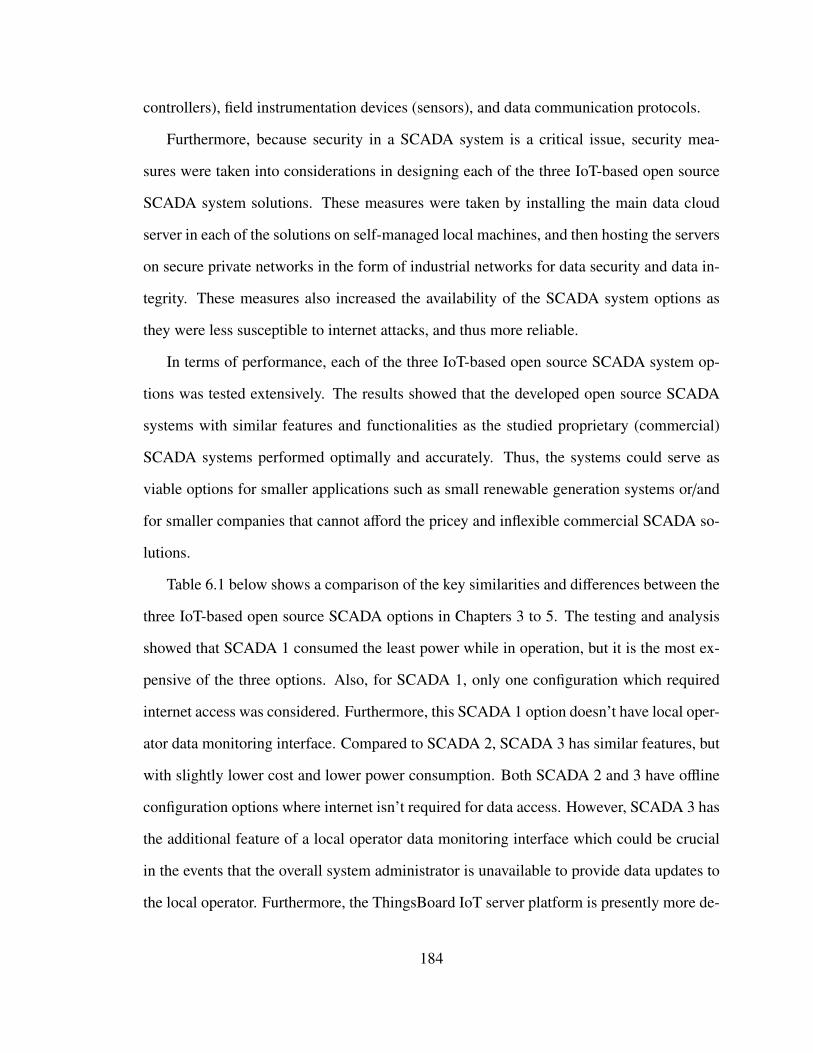
controllers), field instrumentation devices (sensors), and data communication protocols.
Furthermore, because security in a SCADA system is a critical issue, security mea-
sures were taken into considerations in designing each of the three IoT-based open source
SCADA system solutions. These measures were taken by installing the main data cloud
server in each of the solutions on self-managed local machines, and then hosting the servers
on secure private networks in the form of industrial networks for data security and data in-
tegrity. These measures also increased the availability of the SCADA system options as
they were less susceptible to internet attacks, and thus more reliable.
In terms of performance, each of the three IoT-based open source SCADA system op-
tions was tested extensively. The results showed that the developed open source SCADA
systems with similar features and functionalities as the studied proprietary (commercial)
SCADA systems performed optimally and accurately. Thus, the systems could serve as
viable options for smaller applications such as small renewable generation systems or/and
for smaller companies that cannot afford the pricey and inflexible commercial SCADA so-
lutions.
Table 6.1 below shows a comparison of the key similarities and differences between the
three IoT-based open source SCADA options in Chapters 3 to 5. The testing and analysis
showed that SCADA 1 consumed the least power while in operation, but it is the most ex-
pensive of the three options. Also, for SCADA 1, only one configuration which required
internet access was considered. Furthermore, this SCADA 1 option doesn’t have local oper-
ator data monitoring interface. Compared to SCADA 2, SCADA 3 has similar features, but
with slightly lower cost and lower power consumption. Both SCADA 2 and 3 have offline
configuration options where internet isn’t required for data access. However, SCADA 3 has
the additional feature of a local operator data monitoring interface which could be crucial
in the events that the overall system administrator is unavailable to provide data updates to
the local operator. Furthermore, the ThingsBoard IoT server platform is presently more de-
184
veloped than the Thinger.IO IoT server platform. Therefore, the ThingsBoard-based option
(SCADA 3) is favored ahead of the other two options.
Table 6.1: Comparison Between The Three IoT-Based Open Source SCADA Systems.
IoT-Based Open Source SCADA SystemsKey Properties Emoncms-
based SCADA(SCADA 1)
Thinger.IO-based SCADA(SCADA 2)
ThingsBoard-based SCADA(SCADA 3)
IoT Server (MTU) Emoncms Thinger.IO ThingsBoardRTU Arduino Un-
o/RaspberryPi
ESP32 Thing ESP32 withOLED
Communication Channel Node-RED/Ethernet
Wi-Fi/SPI MQTT/Wi-Fi
FIDs Sensors Sensors SensorsSecurity Measure Local/Self-hosted
main data serverLocal/Self-hostedmain data server
Local/Self-hostedmain data server
Reliable from Testing? Yes Yes YesAlarm & Notifications Yes Yes YesEase of Use Yes Yes YesInternet Yes Yes YesOffline Option No Yes YesLocal Operator Interface No No YesCost $404.84 CAD $291.87 CAD $279.17 CADPower Consumption 5.1 W 9.4 W 9.3 W
6.2 Future Works
The work presented in this thesis opens up new directions for research on the development
of reliable, secure, low-cost, IoT-based open source SCADA system solutions. However,
several knowledge gaps and scope of work could be further addressed. Some of the recom-
mendations for future works are summarized as follows:
• Detailed reliability calculations and analysis of each of the developed IoT-based open
source SCADA systems in Chapters 3 to 5 so that proper reliability comparison be-
185
tween the three systems can be done.
• For increased security in each of the SCADA system solutions, data encryption can
be implemented on the communication channels of each of the systems
• To further reduce the cost and power consumption of the SCADA 1 (Table 6.1), a new
open source SCADA system can be developed with the Emoncms server installed on
a more recent Linux machine, while using ESP32 Thing as the RTU, and MQTT
protocol for data transfer from the RTU to the MTU.
• The power consumption of SCADA 2 and SCADA 3 can be further reduced by con-
figuring the Raspberry Pi in each case as a Wireless Access Point to provide the
needed Wi-Fi connections, thereby eliminating the Wi-Fi Router in each case.
• The ThingsBoard IoT platform is well developed, and as such could be explored
further. In SCADA 3, the ThingsBoard MQTT API has been used for data transfer. In
the future, different open source SCADA systems can be developed using the CoAP
API and HTTP API of the ThingsBoard platform for data transfer so as to compare
their performance with the MQTT API used in SCADA 3 option (Table 6.1).
6.3 List of Publications
Refereed Journal Articles
1. Lawrence O. Aghenta and M. Tariq Iqbal, "Design and implementation of a low-cost,
open source IoT-based SCADA system using ESP32 with OLED, ThingsBoard and
MQTT protocol," AIMS Electronics and Electrical Engineering, 2020, 4(1): 57-86.
doi: 10.3934/ElectrEng.2020.1.57.
186
2. Lawrence Oriaghe Aghenta and Mohammad Tariq Iqbal, Low-Cost, "Open Source
IoT-Based SCADA System Design Using Thinger.IO and ESP32 Thing," Electronics
2019, 8(8), 822; https://doi.org/10.3390/electronics8080822.
3. Lawrence O. Aghenta and M. Tariq Iqbal, "Design and Dynamic Modelling of a
Hybrid Power System for a House in Nigeria," International Journal of Photoenergy,
Volume 2019, Article ID 6501785, 13 pages; https://doi.org/10.1155/2019/6501785.
Refereed Conference Publication
4. Lawrence O. Aghenta and M. Tariq Iqbal, "Development of an IoT-Based Open
Source SCADA System for PV System Monitoring," Presented at CCECE 2019, Ed-
monton, AB, Canada. May 5 - 8, 2019; doi: 10.1109/CCECE.2019.8861827
Regional Conference Publications
5. Lawrence O. Aghenta and M. Tariq Iqbal, "A Low-Cost, Open Source IoT-Based
SCADA System Design, and Implementation for Photovoltaics," Presented at the
28th IEEE NECEC 2019, St. John’s, NL, Canada. November 19, 2019.
6. Lawrence O. Aghenta and M. Tariq Iqbal, "Thermal Modelling and Analysis of a
House in Nigeria and PV System Design to meet its Energy needs," Presented at the
27th IEEE NECEC 2019, St. John’s, NL, Canada. November 13, 2018.
187
Poster Presentation
7. Lawrence O. Aghenta and M. Tariq Iqbal, "Internet of Things (IoT) based Reliable
Open Source SCADA System for Remote Battery Energy Storage Systems," Pre-
sented during the poster session at the NESTNet 2nd Annual Technical Conference,
Ryerson University, Toronto, ON, Canada. June 18 - 20, 2018.
188
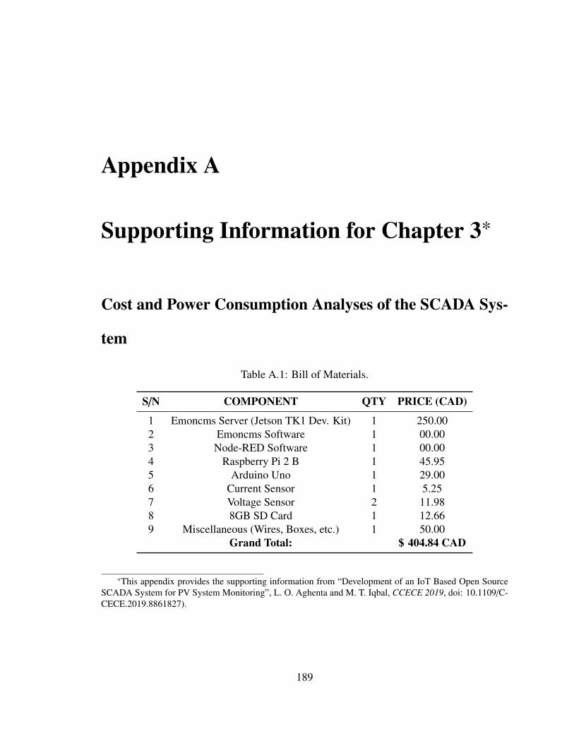
Appendix A
Supporting Information for Chapter 3*
Cost and Power Consumption Analyses of the SCADA Sys-
tem
Table A.1: Bill of Materials.
S/N COMPONENT QTY PRICE (CAD)
1 Emoncms Server (Jetson TK1 Dev. Kit) 1 250.002 Emoncms Software 1 00.003 Node-RED Software 1 00.004 Raspberry Pi 2 B 1 45.955 Arduino Uno 1 29.006 Current Sensor 1 5.257 Voltage Sensor 2 11.988 8GB SD Card 1 12.669 Miscellaneous (Wires, Boxes, etc.) 1 50.00
Grand Total: $ 404.84 CAD
*This appendix provides the supporting information from “Development of an IoT Based Open SourceSCADA System for PV System Monitoring”, L. O. Aghenta and M. T. Iqbal, CCECE 2019, doi: 10.1109/C-CECE.2019.8861827).
189
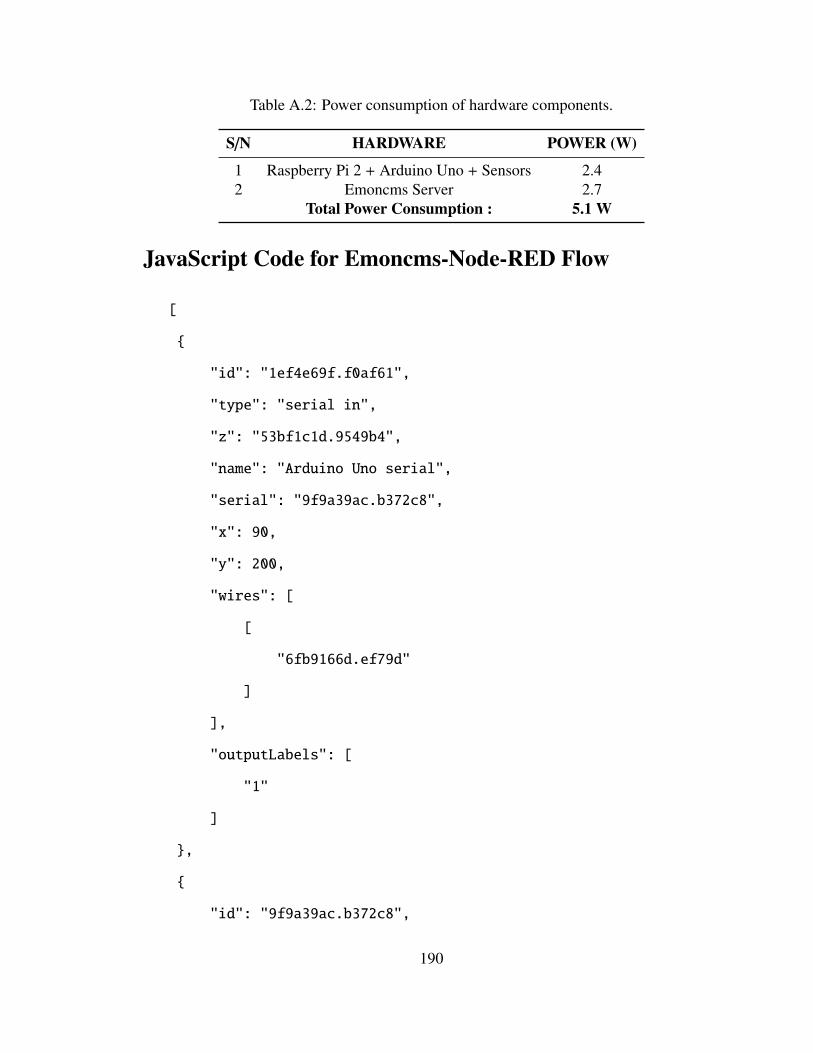
Table A.2: Power consumption of hardware components.
S/N HARDWARE POWER (W)
1 Raspberry Pi 2 + Arduino Uno + Sensors 2.42 Emoncms Server 2.7
Total Power Consumption : 5.1 W
JavaScript Code for Emoncms-Node-RED Flow
[
{
"id": "1ef4e69f.f0af61",
"type": "serial in",
"z": "53bf1c1d.9549b4",
"name": "Arduino Uno serial",
"serial": "9f9a39ac.b372c8",
"x": 90,
"y": 200,
"wires": [
[
"6fb9166d.ef79d"
]
],
"outputLabels": [
"1"
]
},
{
"id": "9f9a39ac.b372c8",
190
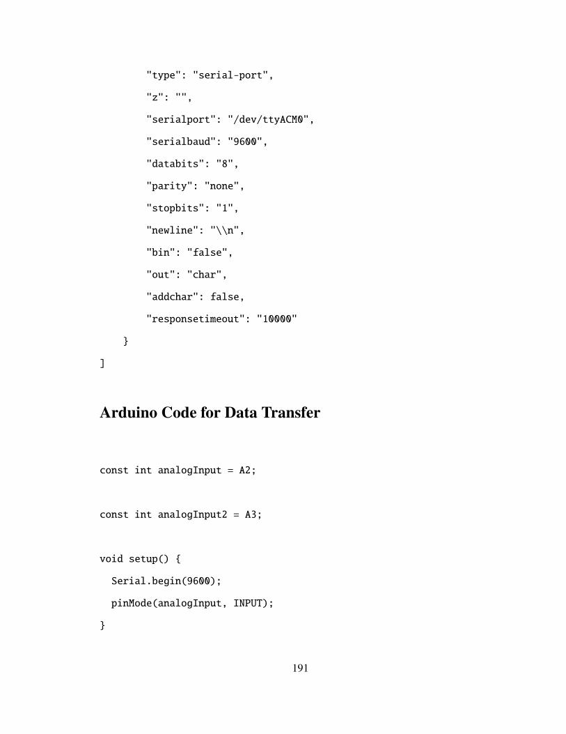
"type": "serial-port",
"z": "",
"serialport": "/dev/ttyACM0",
"serialbaud": "9600",
"databits": "8",
"parity": "none",
"stopbits": "1",
"newline": "\\n",
"bin": "false",
"out": "char",
"addchar": false,
"responsetimeout": "10000"
}
]
Arduino Code for Data Transfer
const int analogInput = A2;
const int analogInput2 = A3;
void setup() {
Serial.begin(9600);
pinMode(analogInput, INPUT);
}
191
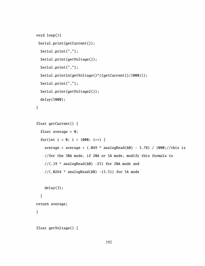
void loop(){
Serial.print(getCurrent());
Serial.print(",");
Serial.print(getVoltage());
Serial.print(",");
Serial.println(getVoltage()*((getCurrent()/1000)));
Serial.print(",");
Serial.print(getVoltage2());
delay(5000);
}
float getCurrent() {
float average = 0;
for(int i = 0; i < 1000; i++) {
average = average + (.049 * analogRead(A0) - 3.78) / 1000;//this is
//for the 30A mode, if 20A or 5A mode, modify this formula to
//(.19 * analogRead(A0) -25) for 20A mode and
//(.0264 * analogRead(A0) -13.51) for 5A mode
delay(3);
}
return average;
}
float getVoltage() {
192
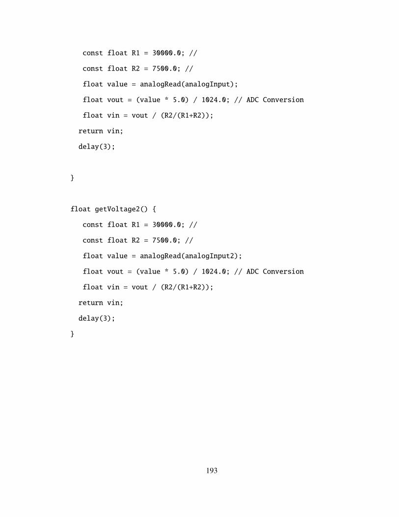
const float R1 = 30000.0; //
const float R2 = 7500.0; //
float value = analogRead(analogInput);
float vout = (value * 5.0) / 1024.0; // ADC Conversion
float vin = vout / (R2/(R1+R2));
return vin;
delay(3);
}
float getVoltage2() {
const float R1 = 30000.0; //
const float R2 = 7500.0; //
float value = analogRead(analogInput2);
float vout = (value * 5.0) / 1024.0; // ADC Conversion
float vin = vout / (R2/(R1+R2));
return vin;
delay(3);
}
193
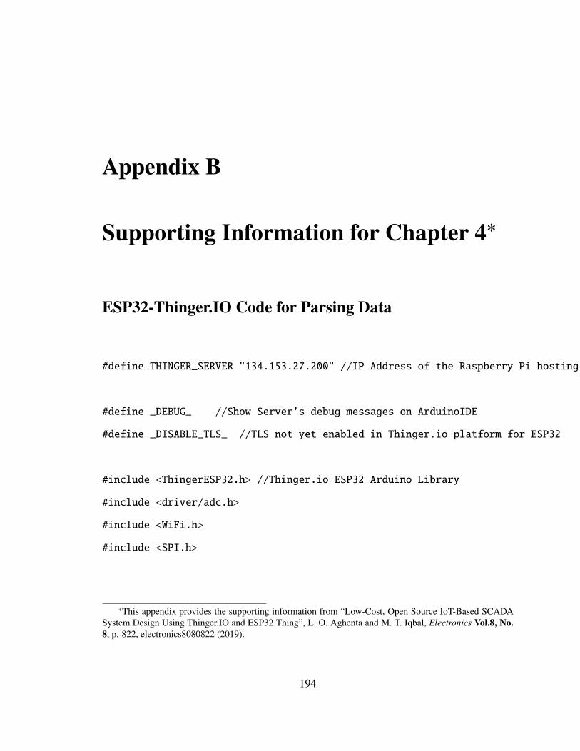
Appendix B
Supporting Information for Chapter 4*
ESP32-Thinger.IO Code for Parsing Data
#define THINGER_SERVER "134.153.27.200" //IP Address of the Raspberry Pi hosting Thinger.io Server
#define _DEBUG_ //Show Server’s debug messages on ArduinoIDE
#define _DISABLE_TLS_ //TLS not yet enabled in Thinger.io platform for ESP32
#include <ThingerESP32.h> //Thinger.io ESP32 Arduino Library
#include <driver/adc.h>
#include <WiFi.h>
#include <SPI.h>
*This appendix provides the supporting information from “Low-Cost, Open Source IoT-Based SCADASystem Design Using Thinger.IO and ESP32 Thing”, L. O. Aghenta and M. T. Iqbal, Electronics Vol.8, No.8, p. 822, electronics8080822 (2019).
194
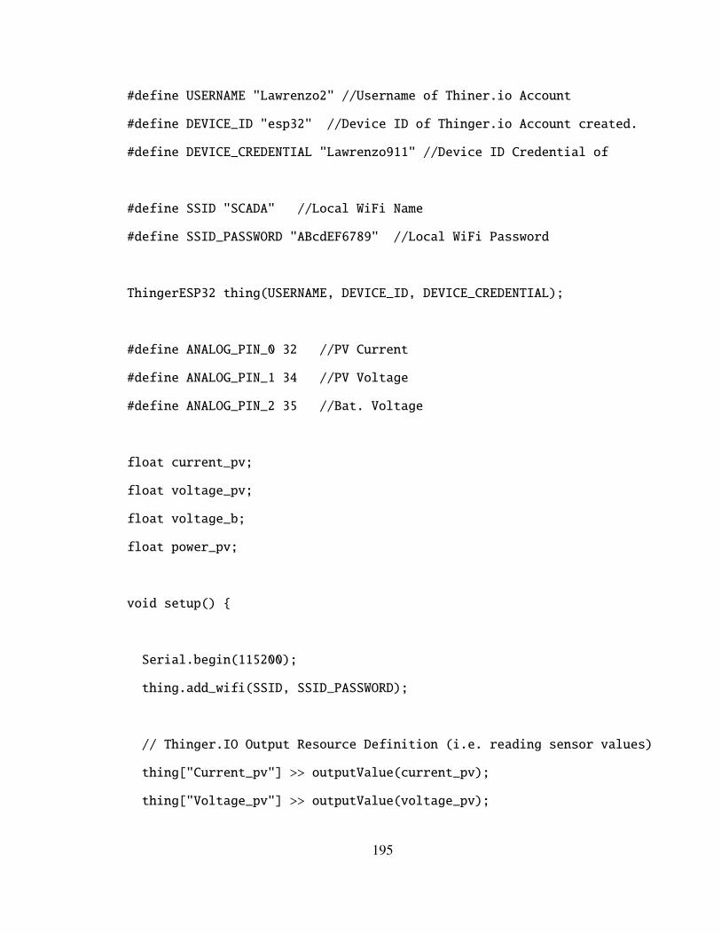
#define USERNAME "Lawrenzo2" //Username of Thiner.io Account
#define DEVICE_ID "esp32" //Device ID of Thinger.io Account created.
#define DEVICE_CREDENTIAL "Lawrenzo911" //Device ID Credential of //Thinger.io Account created.
#define SSID "SCADA" //Local WiFi Name
#define SSID_PASSWORD "ABcdEF6789" //Local WiFi Password
ThingerESP32 thing(USERNAME, DEVICE_ID, DEVICE_CREDENTIAL);
#define ANALOG_PIN_0 32 //PV Current
#define ANALOG_PIN_1 34 //PV Voltage
#define ANALOG_PIN_2 35 //Bat. Voltage
float current_pv;
float voltage_pv;
float voltage_b;
float power_pv;
void setup() {
Serial.begin(115200);
thing.add_wifi(SSID, SSID_PASSWORD);
// Thinger.IO Output Resource Definition (i.e. reading sensor values)
thing["Current_pv"] >> outputValue(current_pv);
thing["Voltage_pv"] >> outputValue(voltage_pv);
195
thing["Voltage_b"] >> outputValue(voltage_b);
thing["Power_pv"] >> outputValue(power_pv);
adc1_config_width(ADC_WIDTH_BIT_12);
adc1_config_channel_atten(ADC1_CHANNEL_4, ADC_ATTEN_DB_11);
adc1_config_channel_atten(ADC1_CHANNEL_6, ADC_ATTEN_DB_11);
adc1_config_channel_atten(ADC1_CHANNEL_7, ADC_ATTEN_DB_11);
}
void loop() {
Serial.println(" ");
current_pv = getCurrent();
voltage_pv = getVoltage();
voltage_b = getVoltage2();
power_pv = (voltage_pv * ((current_pv)));
Serial.print(current_pv);
Serial.print(" ");
Serial.print("Amps");
Serial.print(",");
Serial.print(voltage_pv);
Serial.print(" ");
Serial.print("Volts");
196
Serial.print(",");
Serial.println(voltage_pv * ((current_pv)));
Serial.print(" ");
Serial.print("Watts");
Serial.print(",");
Serial.print(voltage_b);
Serial.print(" ");
Serial.print("Volts");
thing.handle();
Serial.print("Current_pv: "); Serial.println(current_pv);
Serial.print("Voltage_pv: "); Serial.println(voltage_pv);
Serial.print("Voltage_b: "); Serial.println(voltage_b);
Serial.print("Power_pv: "); Serial.println(power_pv);
delay(5000);
}
float getCurrent() {
float average = 0;
float Amps = 0;
for (int i = 0; i < 1000; i++) { // sample 1000 times by 1 ms
average = ((analogRead(ANALOG_PIN_0)* 3.3)/(4095)); //ESP32 ADC Resolution
Amps = (average - 2.5)/66; //Current Sensor Sensitivity
delay(3);
}
197
return Amps;
}
float getVoltage() {
const float R1 = 30000.0; //R1 of Voltage Sensor 1
const float R2 = 7500.0; //R2 of Voltage Sensor 1
float value = analogRead(ANALOG_PIN_1);
float vout = ((value * 3.3)/(4095)); // Resolution of ESP32 ADC
float vin = vout / (R2 / (R1 + R2)); //Voltage Divider for Voltage Sensor 1
return vin;
delay(3);
}
float getVoltage2() {
const float R1 = 30000.0; // R1 of Voltage Sensor 2
const float R2 = 7500.0; // R2 of Voltage Sensor 2
float value = analogRead(ANALOG_PIN_2);
float vout = ((value * 3.3)/(4095)); // Resolution of ESP32 ADC
float vin = vout / (R2 / (R1 + R2)); //Voltage Divider for Voltage Sensor 2
return vin;
delay(3);
}
198
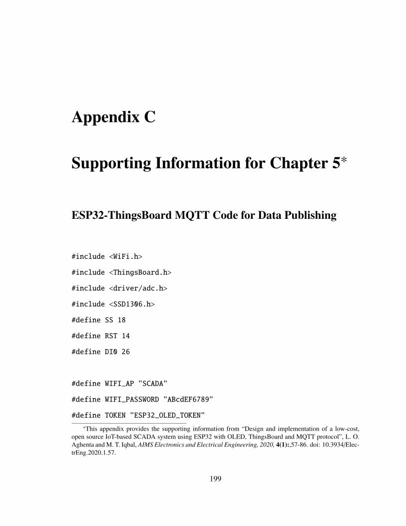
Appendix C
Supporting Information for Chapter 5*
ESP32-ThingsBoard MQTT Code for Data Publishing
#include <WiFi.h>
#include <ThingsBoard.h>
#include <driver/adc.h>
#include <SSD1306.h>
#define SS 18
#define RST 14
#define DI0 26
#define WIFI_AP "SCADA"
#define WIFI_PASSWORD "ABcdEF6789"
#define TOKEN "ESP32_OLED_TOKEN"
*This appendix provides the supporting information from “Design and implementation of a low-cost,open source IoT-based SCADA system using ESP32 with OLED, ThingsBoard and MQTT protocol”, L. O.Aghenta and M. T. Iqbal, AIMS Electronics and Electrical Engineering, 2020, 4(1):,57-86. doi: 10.3934/Elec-trEng.2020.1.57.
199
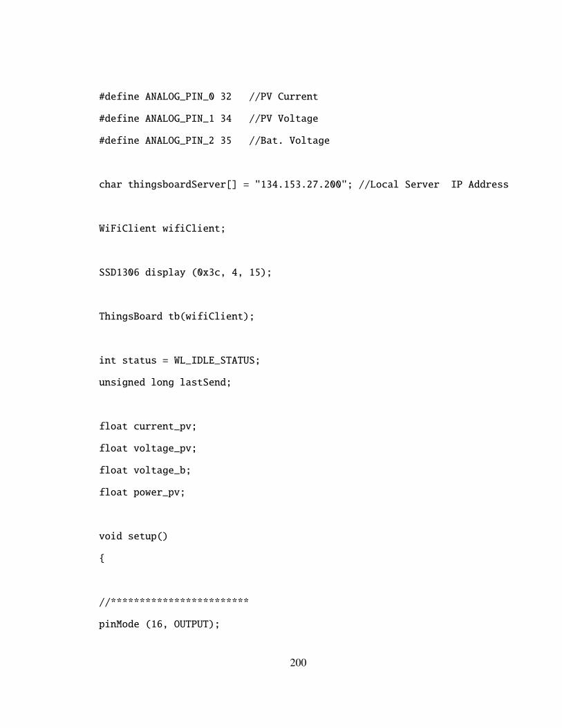
#define ANALOG_PIN_0 32 //PV Current
#define ANALOG_PIN_1 34 //PV Voltage
#define ANALOG_PIN_2 35 //Bat. Voltage
char thingsboardServer[] = "134.153.27.200"; //Local Server IP Address
WiFiClient wifiClient;
SSD1306 display (0x3c, 4, 15);
ThingsBoard tb(wifiClient);
int status = WL_IDLE_STATUS;
unsigned long lastSend;
float current_pv;
float voltage_pv;
float voltage_b;
float power_pv;
void setup()
{
//************************
pinMode (16, OUTPUT);
200
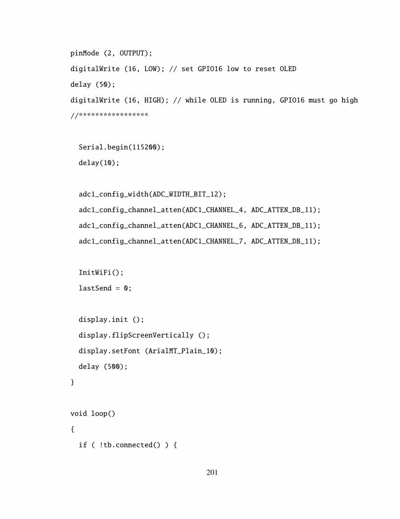
pinMode (2, OUTPUT);
digitalWrite (16, LOW); // set GPIO16 low to reset OLED
delay (50);
digitalWrite (16, HIGH); // while OLED is running, GPIO16 must go high
//*****************
Serial.begin(115200);
delay(10);
adc1_config_width(ADC_WIDTH_BIT_12);
adc1_config_channel_atten(ADC1_CHANNEL_4, ADC_ATTEN_DB_11);
adc1_config_channel_atten(ADC1_CHANNEL_6, ADC_ATTEN_DB_11);
adc1_config_channel_atten(ADC1_CHANNEL_7, ADC_ATTEN_DB_11);
InitWiFi();
lastSend = 0;
display.init ();
display.flipScreenVertically ();
display.setFont (ArialMT_Plain_10);
delay (500);
}
void loop()
{
if ( !tb.connected() ) {
201
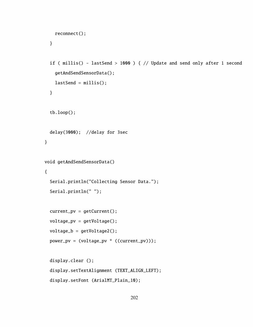
reconnect();
}
if ( millis() - lastSend > 1000 ) { // Update and send only after 1 second
getAndSendSensorData();
lastSend = millis();
}
tb.loop();
delay(3000); //delay for 3sec
}
void getAndSendSensorData()
{
Serial.println("Collecting Sensor Data.");
Serial.println(" ");
current_pv = getCurrent();
voltage_pv = getVoltage();
voltage_b = getVoltage2();
power_pv = (voltage_pv * ((current_pv)));
display.clear ();
display.setTextAlignment (TEXT_ALIGN_LEFT);
display.setFont (ArialMT_Plain_10);
202
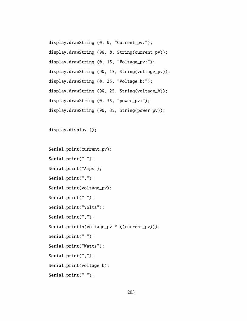
display.drawString (0, 0, "Current_pv:");
display.drawString (90, 0, String(current_pv));
display.drawString (0, 15, "Voltage_pv:");
display.drawString (90, 15, String(voltage_pv));
display.drawString (0, 25, "Voltage_b:");
display.drawString (90, 25, String(voltage_b));
display.drawString (0, 35, "power_pv:");
display.drawString (90, 35, String(power_pv));
display.display ();
Serial.print(current_pv);
Serial.print(" ");
Serial.print("Amps");
Serial.print(",");
Serial.print(voltage_pv);
Serial.print(" ");
Serial.print("Volts");
Serial.print(",");
Serial.println(voltage_pv * ((current_pv)));
Serial.print(" ");
Serial.print("Watts");
Serial.print(",");
Serial.print(voltage_b);
Serial.print(" ");
203
Serial.print("Volts");
Serial.println(" ");
Serial.print("Current_pv: "); Serial.println(current_pv);
Serial.print("Voltage_pv: "); Serial.println(voltage_pv);
Serial.print("Voltage_b: "); Serial.println(voltage_b);
Serial.print("Power_pv: "); Serial.println(power_pv);
tb.sendTelemetryFloat("Current_pv", current_pv);
tb.sendTelemetryFloat("Voltage_pv", voltage_pv);
tb.sendTelemetryFloat("Voltage_b", voltage_b);
tb.sendTelemetryFloat("Power_pv", power_pv);
}
void InitWiFi()
{
Serial.println("Connecting to AP ...");
// Attempt to connect to WiFi network
WiFi.begin(WIFI_AP, WIFI_PASSWORD);
while (WiFi.status() != WL_CONNECTED) {
delay(500);
Serial.print(".");
}
Serial.println("Connected to AP");
204
}
void reconnect() {
// Loop until we’re reconnected
while (!tb.connected()) {
status = WiFi.status();
if ( status != WL_CONNECTED) {
WiFi.begin(WIFI_AP, WIFI_PASSWORD);
while (WiFi.status() != WL_CONNECTED) {
delay(500);
Serial.print(".");
}
Serial.println("Connected to AP");
}
Serial.print("Connecting to ThingsBoard node ...");
if ( tb.connect(thingsboardServer, TOKEN) ) {
Serial.println( "[DONE]" );
} else {
Serial.print( "[FAILED]" );
Serial.println( " : retrying in 5 seconds]" );
// Wait 5 seconds before retrying
delay( 5000 );
}
}
}
205
float getCurrent() {
float average = 0;
float Amps = 0;
for (int i = 0; i < 1000; i++) { // sample 1000 times by 1 ms
average = ((analogRead(ANALOG_PIN_0)* 3.3)/(4095)); //ESP32 ADC Resolution
Amps = (average - 2.5)/66; //Current Sensor Sensitivity
delay(3);
}
return Amps;
}
float getVoltage() {
const float R1 = 30000.0; //R1 of Voltage Sensor 1
const float R2 = 7500.0; //R2 of Voltage Sensor 1
float value = analogRead(ANALOG_PIN_1);
float vout = ((value * 3.3)/(4095)); // Resolution of ESP32 ADC
float vin = vout / (R2 / (R1 + R2)); //Voltage Divider for Voltage Sensor 1
return vin;
delay(3);
}
float getVoltage2() {
const float R1 = 30000.0; // R1 of Voltage Sensor 2
const float R2 = 7500.0; // R2 of Voltage Sensor 2
float value = analogRead(ANALOG_PIN_2);
206
float vout = ((value * 3.3)/(4095)); // Resolution of ESP32 ADC
float vin = vout / (R2 / (R1 + R2)); //Voltage Divider for Voltage Sensor 2
return vin;
delay(3);
}
207