Embed Size (px)
Citation preview

Operating Instructions
Automatic Module Hei-VAP DistimaticAutomatic Module Hei-VAP Industrial DistimaticOperating instructions must be read before initial start-up. Please follow the safety instructions provided. Please keep for future reference.
Leading Safety Standards Superior Ease of Use Reduced Cost of Ownership
Automated 24/7 Evaporation

Contents
About this Document 5Version type ............................................................................. 5 About this manual ..................................................................... 5Purpose and target group ........................................................... 6Configurations ........................................................................... 6
Safety Instructions 7Terms and signs used ................................................................. 7Gerneral safety instructions ...................................................... 10
Device Description 18Device Description ................................................................... 18
Installation 19Scope of delivery ..................................................................... 19Storage and transport .............................................................. 21Unpacking the device ............................................................... 21Overview of the components ..................................................... 22Explanation of the components .................................................. 24Function and connection principle .............................................. 32Function principle of Distimatic .................................................. 32Connection principle of the vacuum circuit (Hei-VAP) .................... 33Connection principle of power supply (Hei-VAP) ........................... 36Connection principle of the vacuum circuit (Hei-VAP Industrial) ...... 37Connection principle of power supply (Hei-VAP Industrial) ............. 39Installation ............................................................................. 40Distimatic in general ................................................................ 41Hei-VAP Distimatic ................................................................... 51Hei-VAP Industrial Distimatic ..................................................... 61Powerbox, multiple socket and control box .................................. 74
Start-Up 77Preparatory steps .................................................................... 77Switching the control box on ..................................................... 78Operation ............................................................................... 78Operating panel ...................................................................... 79Operating states ...................................................................... 80Select operational mode ........................................................... 80Setting date and time .............................................................. 85Refill sensor ............................................................................ 86Cut-out sensor ........................................................................ 86

5
Contents About this Document
Version type
Description Version1.4 09/2014
About this manual
Please ensure that this manual is accessible for every operator.
Please read this manual carefully and in particular all safety and warning notices. Please ensure that every operator reads this manual.
For the current version of this operating manual in pdf format, please go to http://www.heidolph-instruments.com/support/operation-manuals/automatic-module-distimatic
This manual utilizes symbols which facilitate access to specific information.
The safety instructions are documented in chapter safety instructions. Specific warnings are at the beginning of every chapter.
Error Codes 88
Maintenance, Cleaning, Service 91Maintenance ........................................................................... 91Cleaning ................................................................................. 91Disassembly ........................................................................... 93Disposal ................................................................................. 94Contact / Technical Service ....................................................... 95
Attachments 96Technical data ......................................................................... 96EC Declaration ........................................................................ 99Confirmation of condition of unit ...............................................100

7
Safety InstructionsAbout this Document
6
Design of warning notices
WARNING Risk of injury due to failure to observe safety signs and safety instructions!
Dangers emerge when safety signs, located on the device, are not observed or when safety instructions are not followed.
Please note the warning notices.
DANGER The type and source of the danger are displayed here!
Here, the possible consequences are described when no measures are taken to prevent dangers occurring.
Here, the measure for risk prevention is specified.
This manual describes the function, operation and maintenance of the Automatic Module Distimatic. It is intended for use by trained and authorized personnel only.
Operate according to descriptions in this manual only. If there is something you do not understand, or certain information is missing, ask your manager or contact the manufacturer. Do not do anything without authorization.
The units are available in different configurations as documented in this manual.
Purpose and target group Terms and signs used
Configurations
Warning notices
In this manual you will find standardized terms and signs to warn you of possible dangers and avoid injury or damage. Kindly obey the signs listed below:
Signal word Meaning
DANGER
DANGER indicates a hazardous situation which, if not avoided, will result in death or irreversible injury.
WARNING
WARNING indicates a hazardous situation which, if not avoided, could result in serious injury or material damage.
CAUTIONCAUTION indicates a hazardous situation which, if not avoided, may result in a risk of minor injury or material damage.
Safety Instructions

Safety Instructions
8 9
Safety Instructions
Prohibitory signs
Other icons and symbols
Symbol Description Symbol Description
Fire, open flame and smoking prohibited
Prohibition for people with metal implants
Prohibition for persons with a pacemaker
Extinguishing with water is prohibited
Depositing or storing is prohibited
Symbol Description
Handling instructions concerning a user action
▪▪▪
List of information
a.b.c.
List of variants
The following symbols and distinctions in these operating instructions provide information on standard handling instructions:
Mandatory signs
Warning signs
Symbols
Symbol Description Symbol Description
Please observe this information Use eye protection
Please observe the additional information in this document or other documents mentioned
Use hand protection
Use protective clothing Use foot protection
Pull the power plug after usePull the power plug prior to opening the housing
Use ear protector
Symbol Description Symbol Description
Warning of a dangerous location
Warning of a risk of entanglement
Warning of a hot surface Warning of dangerous
electric voltage
Warning of hand injuries Warning of vacuum
Warning of automatic start
Warning of slippery conditions
Warning of explosive materials
Warning of explosion-risk area

Safety Instructions
10 11
Safety Instructions
The device has been constructed according to state-of-the-art technology and recognized safety regulations. However, risks may still arise during installation, operation and maintenance.
Please observe the safety instructions and warning notices.
The safety instructions provided in this chapter are supplemented by specific warning notices in the following chapters. This warning notices explains exactly how you must behave in order to protect yourself, others and objects from damage.
These operating instructions are a component of the device described here.
Please ensure the operating instructions are available at all times.
Please pass on the operating instructions to the subsequent owner.
The device may only be used under the following circumstances:
▪ The device is in full working order.
▪ The device is used according to its intended purpose.
▪ All operators of the device possess the necessary safety and risk awareness.
▪ The instructions stipulated in this instruction manual are followed.
Errors must be eradicated immediately; especially those which jeopardize safety.
Intended useThe device is suitable for the following use:
▪ Distillation
▪ Purification of media such as chemicals and liquids
▪ Processing reaction batches
▪ Solvents recycling
A suitable operating location for the device is one of the following areas:
Chemical, pharmaceutical and biological laboratories in industry and universities.
Please observe the operating instructions in order to use the device for its intended purpose.
Unauthorized use
Any use which deviates from the device‘s intended use is considered to be improper. The manufacturer does not accept liability for any damages resulting from non-permitted uses. The risk is carried by the operator alone.
It is not permitted for excess pressure to be applied to the device.
Use in potentially explosive areas
Do not use the device in potentially explosive areas. The device is not protected against explosion. There is no explosion or ATEX protection available.
Requirements to operate this unit
This product may only be operated and maintained by qualified personnel who are of legal age and have been instructed carefully. Others may only work with the unit under continuous supervision of an experienced person. Repairs may only be performed by qualified electricians.
Operating company’s obligations
Only operate the device in full and proper working order. Ensure that only qualified personnel operate the device. Ensure that the personnel have received safety instructions in order to guarantee
responsible and safe work procedures in the laboratory. Ensure that the device is positioned in a suitable location. Ensure that the device is sufficiently stable. Ensure that installation and operation of the device is only carried out in facilities
which are fitted with the appropriate laboratory equipment (e.g. with air extraction units).
Ensure that all screw connections are securely tightened.Depending on the medium used:
Ensure that the rotary evaporator is operated only in conjunction with an extractor hood (at least 10-fold air change, with error monitoring), see DIN EN 14175 and DIN 12924.
General safety instructions

Safety Instructions
12 13
Safety Instructions
Operating instructionsThese operating instructions as well as the operating instructions for the Hei-VAP or Hei-VAP Industrial must be followed, read and understood by all persons working with the device (acknowledgment of the safety instructions is particularly important).
Operating personnel’s obligations
Verify that the distillation material can be evaporated safely and that the distillation residue is not explosive.
Ensure that work which uses naked flames is not carried out in the vicinity of the device (risk of explosion).
Ensure that the flow rate when removing liquids with flammable materials remains at < 1 m/s (electrostatic charge; risk of ignition).
Ensure that gases classified in explosion group IIC are not produced by materials or during chemical reactions, e.g. hydrogen.
Ensure that no devices are operated or assembled which are emission or radiation sources (electromagnetic waves) for the frequency range (3×10¹¹ Hz to 3×10¹⁵ Hz).
Ensure that no devices are operated or assembled which constitute emission or radiation sources for ionizing radiation or in the ultrasonic range.
Ensure that no adiabatic compression or shock waves occur (shock wave combustion). Ensure that the use of materials which pose a potential risk of uncontrolled energy
release is prohibited by an associated pressure increase (exothermic reaction; spontaneous combustion of dusts).
Ensure that glass surfaces are only wiped with damp cloths. Ensure that ground joint connections are clean and sit securely attached. Please wear the appropriate protective clothing when working on the machine
(protective glasses and if necessary, safety gloves). Ensure that sufficient heat transfer media are used. Ensure that the maximum excess pressure of the coolant equals no more than 1 bar
in the condenser. Ensure that all tube connections are properly connected to ensure safe operation. Ensure that all cables and tubes are correctly laid and are located outside the
operating and danger zone. Please avoid putting pressure on the display.
Personnel qualification
Changes to the unit
The target group for this device is qualified personnel. The device may only be operated by individuals who have been instructed in its proper use by qualified personnel.
No unauthorized changes may be made to the unit. No parts may be used which have not been approved by the manufacturer. Unauthorized changes result in the CE declaration of conformity losing its validity, and the appliance may no longer be operated.
The manufacturer is not liable for any damage, danger or injuries that result from unauthorized changes or from operating the unit other than described in this manual.

Safety Instructions
14 15
Safety Instructions
Safety devices on the unit
Residual dangers
Despite all precautions taken, residual risks can emerge which may not be immediately obvious! Adhering to the safety instructions, the intended use and the operating instructions as a whole can reduce residual risks!
CAUTION Unintentionally rotating drive!Injuries to hands.
Ensure that the drive unit is switched off.
Note Description
Name plate (for example: Hei-VAP Distimatic)
Service Tel.: (+49)-9122 99207
4
Servi
ce Tel.: 0800-5 8897 08
Years Warranty
Jahre Garantie
3 Warranty seal
Note to disconnect the power connection prior to opening the device housing.
Label on connection for multiple switched socket (Hei-VAP) or multiple socket (Hei-VAP Industrial) and vacuum pump. Indicates the maximum total connected load
Ground symbol
WARNING Errors!Risk of injury.
Malfunctions or operating states that may jeopardize the safety of operating personnel require the device to be brought to a standstill by disconnecting the power supply.
Proper restoration of the machine‘s intended state is necessary.
WARNING Hazardous materials and solvents!
There are risks posed by the leakage of hazardous substances and solvents from locations that are not properly sealed.
Check whether all screw caps have been tightened properly at the threads to seal them off.
Route all PTFE tubes into the vessels intended for them and fasten them securely to the vessel.
Do not expose operating personnel to harmful vapors or gases. Extract waste air using a vapor outlet.
Ensure that the separator for the power supply is easily accessible at all times.
WARNING Hot surfaces!Risk of scalding and burns.
Allow the glass equipment to cool down. Allow media to cool down.
WARNING Risk of slipping!Risk of injury.
After operation or in the event of malfunctions, there may be liquid on the floor close to the machine.
Watch out for any wet spots and clean the floor if necessary.
WarningBefore opening the box disconnect power plug.
WarnungVor dem Öffnen des Gehäuses Netzstecker ziehen.

Safety Instructions
16 17
Safety Instructions
DANGER Danger to life due to dangerous electrical voltage!
Risk of serious injury.
Electrical residual energy remains in lines, equipment and devices after shutting down the device.
Disconnect the power plugs from the energy source in order to establish zero potential.
Only allow qualified electricians to perform work on the electrical supply system.
Check electrical wiring on the device at regular intervals and replace when damaged.
Only set up or disconnect connections when disconnected from the power supply.
DANGER Risk of injury or danger to life due to failure to observe the
safety instructions and safety clearance!
Risk of injury.
Risks arise due to failure to observe the safety instructions and the safety clearance for the device.
Follow all safety instructions and signs provided on the device and in these operating instructions. Maintain the appropriate safety clearance distance from the device.
WARNING Unauthorized access is prohibited!
Risk of injury.
Risks arise if unauthorized persons enter the danger zone of the device.
Twhe operator is responsible for ensuring that unauthorized persons (e.g. visitors) do not have access to the danger zones (service area, protected areas).
DANGER Failure to observe the danger zone, work area and service area!
Dangers are posed by electrical and mechanical energies, as well as by residual dangers.
Please ensure a safe distance of 1m around the evaporator components.
Do not place or store any objects in the work or service area. Deposit accessories, chemicals or tools in such a way that no
dangers arise for the personnel.
WARNING Imploding glass devices!
Serious injuries caused by shattering glass.
Check glass devices for damage (breakage, cracks etc.). Only use glass equipment in perfect condition.
WARNING Glass breakage!
Serious injuries due to shattering glass and glass breakage.
Check glass devices for damage (breakage, cracks etc.). Only use glass equipment in perfect condition. Monitor pressure conditions in the glass attachment. Work carefully.
DANGER
Risk of fire and explosion!Serious risk of fire and explosion.
There is a risk of fire and explosions in the vicinity of the device. Smoking, naked flames and fire are strictly forbidden in the vicinity of the device.
Do not store any flammable liquids in the danger zone of the device. A fire extinguisher must be kept in the vicinity of the device.
Avoid potential sources of ignition such as flammable atmospheres, reactions or electrostatic charges.
Avoid exothermic reactions or the spontaneous combustion of dust. Avoid adiabatic compression and shock waves. Take special care with reactions of explosion group IIC for which
hydrogen can be released.

1918
InstallationDevice Description
Device description
The device is an automatic module, which is operated in combination with a rotary evaporator. It has the following functions:
▪ Automatic distillation (permanent operation)▪ Automatic refill into the evaporator▪ Automatic discharge of condensate from the evaporator▪ Automatic drainage of residue (only on Distimatic including automatic drainage of
residue)▪ Automatic or manual termination of distillationAll the functions are available to you in automatic mode.
Scope of deliveryHei-VAP Distimatic
Additional on Distimatic including automatic drainage of residue:
Components Quantity Order number
Control box 1 11-300-004-89
Power cord 1
14-007-003-81 OR14-007-005-45 OR14-007-045-40 OR14-007-009-36(depending on your country)
Multiple switched socket 1 14-300-010-52
Wall bracket 1 11-300-006-62
Operating panel 1 11-300-004-91
Check valve for PTFE tube Ø 6 mm 1 11-300-006-66
Valve matrix 1 11-300-004-92
Multiple screw connection with flask sensor 1 11-300-004-96
Screw cap 1 23-30-01-07-38
Cut-out sensor 1 11-300-004-98
Rubber ring Ø 120 mm for cut-out sensor 1 23-30-01-06-35
PTFE tube Ø 6 mm (length 10 m) 1 23-30-01-04-28
Filter 1 11-300-003-78
Hose connector T-type 1 23-30-01-05-74
Overflow sensor for condensate vessel 1 14-300-011-41
Components Quantity Order number
Check valve for PTFE tube Ø 8 mm 1 11-300-006-67
Condenser G9 1 514-00900-00
Residue pump 1 14-300-010-40
3/2 way valve 1 11-300-004-97
PTFE tube Ø 8 mm (length 4 m) 1 23-30-01-03-15
Overflow sensor for condensate and residue vessel 1 14-300-011-42
Operation of Hei-VAP and Hei-VAP Industrial
See Hei-VAP or Hei-VAP Industrial operating instructions.
DANGER Danger when extinguishing fires!Risk of serious injury as a result of chemical reactions.
Danger of chemical absorption.
Vigorous reactions with the medium can occur if water is used to extinguish the fire.
Do NOT use water to put out the fire. Use extinguishing agents which do not react with the medium. Please observe the fire protection regulations and the fire
extinguishing instructions they provide.

Installation Installation
20 21
Storage and transport
Additional on Distimatic including automatic drainage of residue:
Components Quantity Order number
Check valve for PTFE tube Ø 8 mm 1 11-300-006-67
Distributor from glassware set AORDistributor from glassware set R
115-300-002-77OR15-300-002-76
Residue pump 1 14-300-010-40
3/2 way valve 1 11-300-004-97
PTFE tube Ø 8 mm (length 4 m) 1 23-30-01-03-15
Overflow sensor for condensate and residue vessel 1 14-300-011-42
Hei-VAP Industrial DistimaticComponents Quantity Order number
Control box 1 11-300-004-89
Power cord 1
14-007-003-81 OR14-007-005-45 OR14-007-045-40 OR14-007-009-36(depending on your country)
Powerbox for Hei-VAP Industrial and powerbox for chiller (variant 3 x 400 V – 230 V, standard)ORPowerbox for Hei-VAP Industrial and powerbox for chiller (variant 1 x 230 V – 230 V)
211-300-007-01OR11-300-007-02
Multiple socket 1 14-300-010-50
Wall bracket 1 11-300-006-62
Operating panel 1 11-300-004-91
Check valve for PTFE tube Ø 6 mm 1 11-300-006-66
Valve matrix 1 11-300-004-93
Collector attachment 1 11-300-006-98
Control box attachment 1 11-300-007-07
Multiple screw connection with flask sensor 1 11-300-004-96
Screw cap 1 23-30-01-07-38
Cut-out sensor 1 11-300-004-98
Rubber ring Ø 80 mm for cut-out sensor 1 23-30-01-06-35
PTFE tube Ø 6 mm (length 10 m) 1 23-30-01-04-28
Filter 1 11-300-003-78
Hose connector T-type 1 23-30-01-05-74
Overflow sensor for condensate vessel 1 14-300-011-41
CAUTION Damages as a result of improper transport!Damage can be caused to the device and the device mechanics in the case of improper transport.
Avoid jolting and impacts.
WARNING Hot surfaces!
Risk of scalding and burns.
Allow the glass equipment to cool down. Allow media to cool down.
WARNING Hazardous materials and solvents!
Dangers exist due to the emergence of hazardous substances and solvents from inadequately sealed areas and the escaping of hazardous substances into the atmosphere.
Ensure that no hazardous substances and solvents adhere to the device components.
Store and transport the device in the original packaging. Seal the packaging with adhesive tape. Store the device in a dry location. To carry the device, lift it from below.
Unpacking the device
CAUTION Damages as a result of improper transport!Damage can be caused to the device and the device mechanics in the case of improper transport.
Avoid jolting and impacts.
Unpack the device and if necessary, remove any protective films. Check scope of supply.
Has the device been damaged or is delivery incomplete?
Contact Heidolph Instruments.

Installation Installation
22 23
Overview of the components
Page 27
Page 28
Page 24
Page 26
Page 29
Page 30
Page 27
Page 24
Page 26
Page 31
Page 25
Page 25
Hei-VAP Distimatic
Hei-VAP Industrial Distimatic

Installation Installation
24 25
Reverse side (connections)2 Device mains plug
3Mains socket for multiple switched socket (Hei-VAP) or multiple socket (Hei-VAP Industrial)
4 Mains socket for vacuum pump
5 Not assigned
6Overflow sensor for condensate and/or residue vessel
73/2-way valve (only for Distimatic including automatic drainage of residue)
8Residue pump (only for Distimatic including automatic drainage of residue)
9 Valve matrix
10 Cut-out sensor
11 Flask sensor
12 Operating panel
Right side13 Refill sensor
14 Refill valve
Overall view1 Control box
Front
18 Condensate pump
19 Check valve for PTFE tube Ø 6 mm
Top15 Mains switch
16 Cut-out switch
17
Flask sensor button, status indicator of the flask sensor and calibration button (green = ready for operation, red = medium detected)
9
8
10
74
1115
1819
1
16
63
12
1314
17
52 20 Operating panel
21 Display
22 Arrow keys right/left
23 Arrow keys up/down
24 apply key
25 set key
26 parameter key
27 drain residue key
28 refill/drain key
29 start/stop key
30Wall bracket for installation of the control box
31 Wall bracket with control box
29 28 2527 2426
31
20
22
23
30
Explanation of the components21

Installation Installation
26 27
43 Overflow sensor
44Residue vessel (not included in scope of delivery)
45Condensate vessel (not included in scope of delivery)
46Product storage vessel (not included in scope of delivery)
47 Filter on PTFE tube Ø 6 mm
44
4546
47
43
48
5049
51
48Residue pump (only for Distimatic including automatic drainage of residue)
49 Flow direction indicator
50Check valve for PTFE tube Ø 8 mm (only on Distimatic including automatic drainage of residue)
51 PTFE tube

Installation Installation
28 29
52 Multiple screw connection
53Condenser G9 (only on Distimatic including automatic drainage of residue)
54Condenser from glassware set G3 (only on Distimatic without automatic drainage of residue)
55 Cut-out sensor
56 Hose connector T-type
573/2 way valve (only on Distimatic including automatic drainage of residue)
58 Flask sensor
59Screw cap GL32 (for use of condenser G9 without Distimatic)
60 Valve matrix
61 Evacuation valve
62 Condensate valve
63 Ventilation valve
64 Level sensor on collector
65 Collector
545352
61 62 63
64
65
55
60
58
56
59
57
66Multiple switched socket with connections for Hei-VAP, chiller and residue pump (total output = 3500 W)
67 Switch unit
66
67
Hei-VAP Distimatic
Installation Installation
30 31
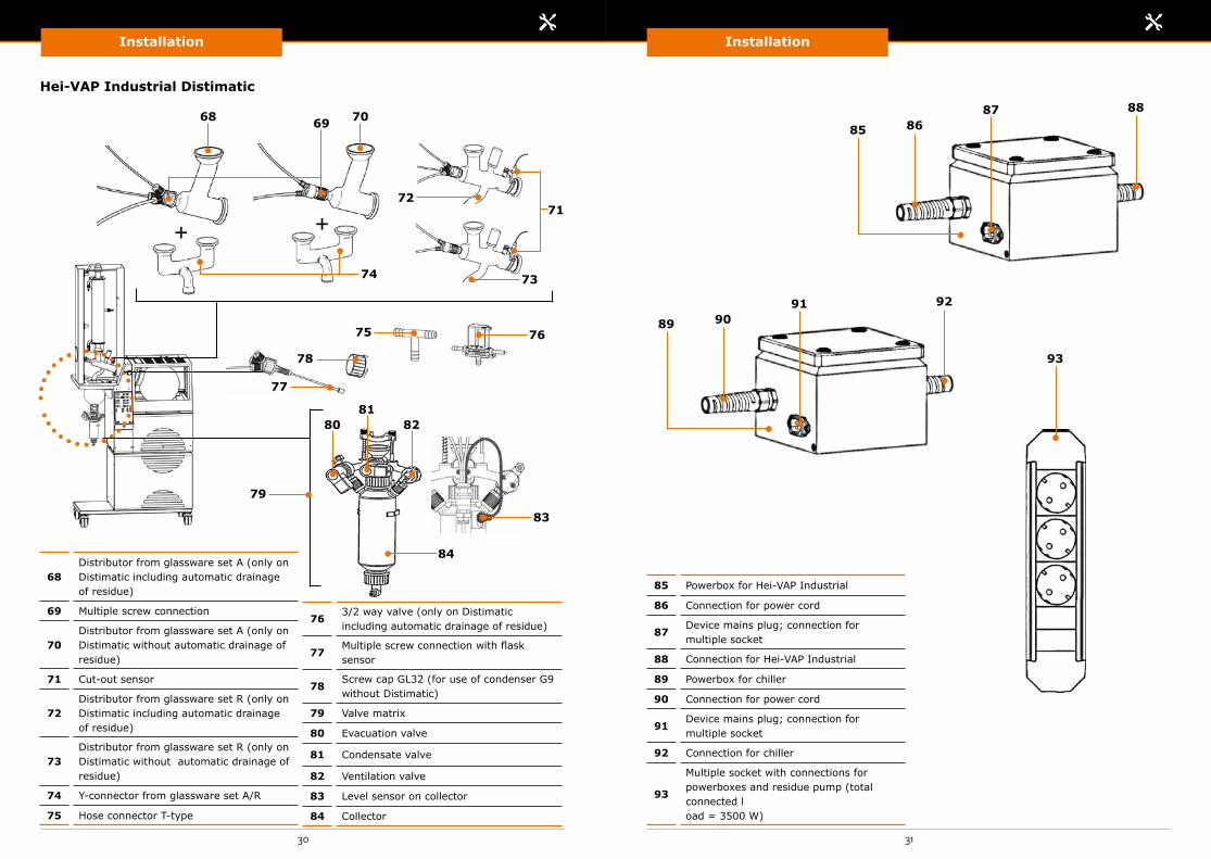
68Distributor from glassware set A (only on Distimatic including automatic drainage of residue)
69 Multiple screw connection
70Distributor from glassware set A (only on Distimatic without automatic drainage of residue)
71 Cut-out sensor
72Distributor from glassware set R (only on Distimatic including automatic drainage of residue)
73Distributor from glassware set R (only on Distimatic without automatic drainage of residue)
74 Y-connector from glassware set A/R
75 Hose connector T-type
85 Powerbox for Hei-VAP Industrial
86 Connection for power cord
87Device mains plug; connection for multiple socket
88 Connection for Hei-VAP Industrial
89 Powerbox for chiller
90 Connection for power cord
91Device mains plug; connection for multiple socket
92 Connection for chiller
93
Multiple socket with connections for powerboxes and residue pump (total connected l oad = 3500 W)
763/2 way valve (only on Distimatic including automatic drainage of residue)
77Multiple screw connection with flask sensor
78Screw cap GL32 (for use of condenser G9 without Distimatic)
79 Valve matrix
80 Evacuation valve
81 Condensate valve
82 Ventilation valve
83 Level sensor on collector
84 Collector
+ +
74
71
69 7068
76
83
75
79
78
77
72
8081
82
88
92
93
86
90
85
89
87
91
Hei-VAP Industrial Distimatic
73
84
Installation Installation
32 33
Function and connection principle Connection principle of the vacuum circuit
Function principle of Distimatic(example based on Hei-VAP Distimatic including automatic drainage of residue)
Variant 1: Hei-VAP Precision including Woulff bottle
PTFE tube
Vacuum tube
Flask sensor control cable
Vacuum tube
Control cable
Residue Condensate Product storage
Valve matrix
Distimatic
Check valve
Residue pump
Hei-VAP
3/2 way valve
Hose connector
T-type
Cut-out sensor
1 2
3 4
5
6
1 Hose connector T-type
23/2 way valve (only on Distimatic including automatic drainage of residue)
3 Woulff bottle
4Vacuum valve (not applicable when using Rotavac Vario Control, Rotavac Vario Tec)
5 Vacuum box
6
Vacuum pumpRotavac Valve ControlRotavac Valve TecRotavac Vario ControlRotavac Vario Tec

Installation Installation
34 35
Variant 2: Hei-VAP Precision without Woulff bottle
Variant 1: Hei-VAP Value/Value Digital/Advantage including Woulff bottle
Variant 2: Hei-VAP Value/Value Digital/Advantage without Woulff bottle
Vacuum tube
Control cable
7
7 Hose connector Y-type
1 Hose connector Y-type
23/2 way valve (only on Distimatic including automatic drainage of residue)
3 Vacumm pump Rotavac Vario Pumping Unit
4 Woulff bottle
Vacuum tube
12
3
4

Installation Installation
36 37
Connection principle of power supply(Hei-VAP Distimatic)
Connection principle of the vacuum circuit(Hei-VAP Industrial Distimatic)
Front
1 Control box
2 Vacuum pump
3 Multiple switched socket
4 Residue pump
5 Chiller
6 Hei-VAP
Electrical cable
5
4
3
2
1
6
1 Vacuum fitting
Vacuum tube
1

Installation Installation
38 39
Connection principle of the vacuum circuit Connection principle of power supplyReverse side
1 Vacuum fitting
Vacuum tube
1
1 Control box
2 Vacuum pump
3 Multiple socket
4 Residue pump
5 Powerbox for Hei-VAP Industrial
6 Powerbox for chiller
7 Chiller
8 Hei-VAP Industrial
Open wire ends, to be connected only by qualified personnel Electrical cable
78
5
4
3
21
6

Installation Installation
40 41
Installation
The installation is described using the example of the Hei-VAP Distimatic including automatic drainage of residue (glassware set G3 with condenser G9) and Hei-VAP Industrial Distimatic including automatic drainage of residue (glassware set R).
Please refer to the chapter on „Explanation of the components” for the differences in the glassware sets, multiple screw connection and the attaching of the cut-out sensor. You can also find a list of the glassware sets below as far as their compatibility with the respective order variant is concerned.
Installation/disassembly of Hei-VAP and Hei-VAP Industrial
See also the operating instructions of Hei-VAP or Hei-VAP Industrial.
Function principle of Distimatic
See chapter entitled „Function and connection principle” - „Distimatic in general” - „Function principle of Distimatic”.
Hei-VAP glassware sets compatibility
Hei-VAP Industrial glassware sets compatibility
Order variant Glassware set
Distimatic including automatic drainage of residue Condenser G9
Distimatic without automatic drainage of residue
G1
G3
G4
G6
Order variant Glassware set
Distimatic including automatic drainage of residue
A, A2
R
Shorty R
Distimatic without automatic drainage of residue
A, A2
R
Shorty R
Distimatic in generalWARNING Hazardous materials and solvents!
There are risks posed by the leakage of hazardous substances and solvents from locations that are not properly sealed.
Check whether all screw caps have been tightened properly at the threads to seal them off.
Check the device components for hazardous substances and solvents.
Ensure that the separator for the power supply is easily accessible at all times.
Cut off PTFE tubes, which are routed through an overflow sensor and the multiple screw connection, with a cutting knife only at an angle of approx. 45°.
When securing PTFE tubes to a connection, only cut them vertically with the HOLEX hose cutter.
If you use other cutters, there is a danger that the affected tube circuit could leak as a result of crushing the tube.
WARNINGUnpacking and installation of the Automatic Module Distimatic should be limited to and permitted only by Heidolph staff or authorized Heidolph distributors only.

Installation Installation
42 43
Place the control box on a flat, firm and dry surface with sufficient space. Also see the following sub-section „Wall bracket (optional)”.
Position control box on the suspended wall bracket.
Unscrew screw caps (5) and (6).
Control box
You can clip the wall bracket to the wall or bolt it into the wall.
Clipped:
Clip the wall bracket to a stand bar secured horizontally to the wall by means of a hanging device (1) and slide it onto a vertical stand bar by means of fixing device (2).
Route the PTFE tube coming from the product storage vessel through the brackets (3) and the cables into brackets (4).
Bolted:
Insert the hexagonal bolts Ø 6 mm through the larger borehole on hanging device (1) at the front into the back borehole and tighten until hand-tight using a socket wrench SW 10 mm.
Route the PTFE tube coming from the product storage vessel through the brackets (3) and the cables into brackets (4).
Wall bracket (optional)
Refill valve and refill sensor
2
1
3
4
5
6

Installation Installation
44 45
Connect PTFE tube Ø 6 mm to connection (7) and tighten until hand-tight. Route the PTFE tube Ø 6 mm into product storage vessel.
Connect the PTFE tube Ø 6 mm to connection (8) on filter and tighten until hand-tight and run into the product storage vessel.
Connect PTFE tube Ø 6 mm to connection (9) and tighten until hand-tight.
7
8
9
Product storage

Installation Installation
46 47
Condensate pump
Remove the screw caps (10) from connections (11) and (12). Connect PTFE tubes Ø 6 mm to connections (16) and (17) and tighten until hand-tight.
Important: Observe flow direction!
Cut off the end (18) of the PTFE tube Ø 6 mm with a cutting knife only at an angle of approx. 45° and route through the connections (20) and (19) of the overflow sensor.
Suspend overflow sensor safely on the edge (21) of the condensate vessel.
The immersion depth of the PTFE tubes in the vessel may be determined by pulling or pushing the PTFE tube (22).
Ensure that the sheathed sensor wire is not detached from the insulation during installation of the PTFE tube.
Connect PTFE tubes Ø 6 mm to connections (13) and (14) and tighten until hand-tight.
To integrate the check valve, vertically cut through the PTFE tube with the HOLEX hose cutter at about point (15) shown in the circle.
Check valve in the condensate circuit
Overflow sensor for condensate vessel
11
12
16 17
20
21
22
1918
10
13
14
15Condensate
Condensate
Condensate

Installation Installation
48 49
Residue pump (only on Distimatic including automatic drainage of residue)
Connect PTFE tubes Ø 8 mm to connections (23) and (26) and tighten until hand-tight.
Set the rotary knob (24) to the maximum flow rate (100% = MAX). To integrate the check valve, vertically cut through the PTFE tube with the HOLEX
hose cutter at about point (25) shown in the circle.
Connect power cord into connection (27) and control cable into connection (28) and tighten until hand-tight.
Residue
Residue
23
27 28
26 25
Connect PTFE tubes Ø 8 mm to connections (29) and (30) and tighten until hand-tight.
Important: Observe flow direction!
Check valve in the residue circuit (only on Distimatic including automatic drainage of residue)
Cut off the end (31) of the PTFE tube Ø 6 mm with a cutting knife only at an angle of approx. 45° and route through the connections (33) and (32) of the overflow sensor.
Overflow sensor on residue vessel
29 30
33 32
31
Attach overflow sensor safely on the edge (34) of the residue vessel.
The immersion depth of the PTFE tubes in the vessel may be determined by pulling or pushing the PTFE tube (35).
34
36
Residue

Installation Installation
50 51
Operating panel
Connect the cabling for operating panel to connection (36).
Important: The connector must click into place completely.
36
Hei-VAP Distimatic
WARNING Hazardous materials and solvents!There are risks posed by the leakage of hazardous substances and solvents from locations that are not properly sealed.
Check whether all screw caps have been tightened properly at the threads to seal them off.
Check the device components for hazardous substances and solvents.
Ensure that the separator for the power supply is easily accessible at all times.
Cut off PTFE tubes, which are routed through an overflow sensor and the multiple screw connection, with a cutting knife only at an angle of approx. 45°.
When securing PTFE tubes to a connection, only cut them vertically with the HOLEX hose cutter.
WARNING Glass breakage!Serious injuries due to shattering glass and glass breakage.
Check glass equipment for damage (breakage, cracks etc.). Only use glass equipment in perfect condition. Monitor pressure conditions in the glass attachment. Work carefully.
If you use other cutters, there is a danger that the affected tube circuit could leak as a result of crushing the tube.

Installation Installation
52 53
Remove the condenser. Mount condenser G9 and secure
it in place with the condenser attachment.
Cut-out sensor
Fix the cut-out sensor with rubber ring Ø 120 mm to the condenser.
Remove condenser attachment on the condenser.
Condenser (only on Distimatic including automatic drainage of residue)
Fix the valve matrix to the condenser with the joint clamp. Ensure that the interconnection point is evenly bolted together and does not leak.
Valve matrix

Installation Installation
54 55
Connect PTFE tube Ø 6 mm to connection (1) and tighten until hand-tight.
Route PTFE tubes and flask sensor into the evaporating flask and secure the multiple screw connection at connection (4) until hand-tight.
Multiple screw connection
Route PTFE tube Ø 8 mm through connection (2) (only on Distimatic including automatic drainage of residue) and PTFE tube Ø 6 mm through connection (3) and secure in place so it is hand-tight.
The immersion depth of the PTFE tubes and the flask sensor in the evaporating flask may be determined by loosening the respective screw cap slightly at the multiple screw connection and by pulling or pushing the PTFE tube or the flask sensor.
Re-secure the screw caps on the multiple screw connection so they are hand-tight again afterwards.
1
2
5
3
7
6
Optimization of the distillation process
Refill evaporating flask only up to one third. Position the flask sensor accordingly.
Use large evaporating flasks (3-5 liter variants) whenever possible. Use the following recommended immersion depths:
The end of the PTFE tube (5) Ø 6 mm varies. Flask sensor (6) ends just above the required maximum fill level. PTFE tube (7) Ø 8 mm (only on Distimatic including automatic drainage of residue) ends approximately 2 – 3 mm above the bottom of the evaporating flask.
This way your distillation process will become much faster.
4

Installation Installation
56 57
Screw cap GL32 (optional)
If you wish to use the Hei-VAP with condenser G9 without the Distimatic, then secure the screw cap instead of the multiple screw connection to connection (8) and tighten until hand-tight.
Remove the evaporating flask from connection (9), fill medium into the evaporating flask and then secure the evaporating flask into place again.
Connect vacuum tubes to connections (10), (11) and (12).
Connect vacuum tube to connection (13).
8
10
12
13
11
9
Hose connector T-type, 3/2 way valve and vacuum tube connections
Connection principle of the vacuum circuit See chapter entitled „Function and connection principle” - Hei-VAP Distimatic”-„Connection principle of the vacuum circuit”.

Installation Installation
58 59
Mount 3/2 way valve on stand rod (14) and secure using screws (15). Connect vacuum tube to connection (18).
Connect vacuum tube to connections (16) and (17).
Vacuum circuit in direction of vacuum pump
14
17
16
15
DANGER Danger to life due to dangerous electrical voltage!Risk of serious injury.
Electrical residual energy remains in lines, equipment and devices after shutting down the device.
Point out the power sockets to the operating personnel. Disconnect the power plugs from the energy source in order to establish zero potential.
Only allow qualified electricians to perform work on the electrical supply system.
Disconnect the device from the mains supply. Regularly check the electrical equipment (mains cables) of the device.
Replace damaged power cords. Regularly check all power cords for damages during repair and maintenance work.
Only set up or disconnect connections when discon-nected from the power supply.
Multiple switched socket and control box
18
Connection principle See chapter entitled „Function and connection principle” - Hei-VAP Distimatic”- „Connection principle of power supply”.

Installation Installation
60 61
Multiple switched socket:
Connect Hei-VAP, chiller and residue pump (only on Distimatic including automatic drainage of residue) to the connections (20) of the multiple switched socket (total output = 3500 W).
Connect power cord (22) to the mains socket. Connect the control cable (19) of the switch unit to connection (21) on the multiple
switched socket.
Control box:
Connect connector (23) belonging to the switch unit to connection (24). Connect the vacuum pump to connection (25). Connect all the control cables according to their assignments to connections (26) (see
chapter entitled „Explanation of the components” - „Distimatic in general”). Connect control box power cord to connection (27). Connect the control box to the mains socket.
19
22
23
27
25 26
24
21
20
Hei-VAP Industrial Distimatic
WARNING Hazardous materials and solvents!
There are risks posed by the leakage of hazardous substances and solvents from locations that are not properly sealed.
Check whether all screw caps have been tightened properly at the threads to seal them off.
Check the device components for hazardous substances and solvents.
Ensure that the separator for the power supply is easily accessible at all times.
Cut off PTFE tubes, which are routed through an overflow sensor and the multiple screw connection, with a cutting knife only at an angle of approx. 45°. When securing PTFE tubes to a connection, only cut them vertically with the HOLEX hose cutter.
WARNING Glass breakage!Serious injuries due to shattering glass and glass breakage.
Check glass devices for damage (breakage, cracks etc.). Only use glass equipment in perfect condition. Monitor pressure conditions in the glass attachment. Work carefully.
If you use other cutters, there is a danger that the affected tube circuit could leak as a result of crushing the tube.

Installation Installation
62 63
Remove the clamping unit (1) at the condenser.
Loosen thumb screws (2) on reverse side of protective cabinet and slide consoles (3) upwards with the condenser.
Secure thumb screws (2) so they are hand-tight in this position.
Condenser
1
3
3
2
2
3
Cover
Detach cover (4).
Remove screw connection at distributor.
Remove the clamp at the distributor.
Remove the distributor.
Distributor (only on Distimatic including automatic drainage of residue)
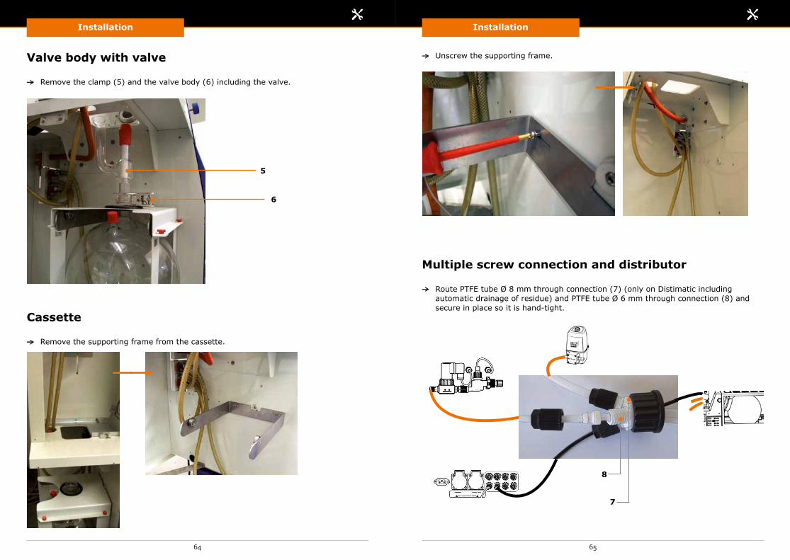
Installation Installation
64 65
Valve body with valve
Multiple screw connection and distributor
Cassette
Remove the clamp (5) and the valve body (6) including the valve.
Route PTFE tube Ø 8 mm through connection (7) (only on Distimatic including automatic drainage of residue) and PTFE tube Ø 6 mm through connection (8) and secure in place so it is hand-tight.
Remove the supporting frame from the cassette.
Unscrew the supporting frame.
5
6
8
7

Installation Installation
66 67
Connect the supplied distributor to connection (10) so it is hand-tight (only on Distimatic including automatic drainage of residue)
Route PTFE tubes and flask sensor through distributor into the evaporating flask and secure multiple screw connection at connection (9) until hand-tight.
Loosen thumb screw (11) on reverse side of protective cabinet and slide consoles (12) downwards with the condenser.
Re-secure thumb screw (11) so it is hand-tight.
12 11
9
10
11
12
Fix the distributor to connection (13) with clamping unit (14).
13
14

Installation Installation
68 69
Optimization of the distillation process Refill evaporating flask only up to one third. Position the flask sensor
accordingly. Use large evaporating flasks whenever possible. Use the following recommended immersion depths:
The end of the PTFE tube (15) Ø 6 mm varies. PTFE tube (16) Ø 8 mm (only on Distimatic including automatic drainage of residue) ends approximately 2 - 3 mm above the bottom of the evaporating flask. Flask sensor (17) ends just above the required maximum fill level.
This way your distillation process will become much faster.
The immersion depth of the PTFE tubes and the flask sensor in the evaporating flask may be adjusted by loosening the respective screw cap slightly at the multiple screw connection and by pulling or pushing the PTFE tube or the flask sensor.
Re-secure the screw caps on the multiple screw connection so they are hand-tight again.
17
15
16
Connect cut-out sensor with rubber ring Ø 80 mm to distributor (18) (for glassware set R) or condenser opening (19) (for glassware set A).
Cut-out sensor
18
19

Installation Installation
70 71
Valve matrix
Fix the valve matrix with the clamping unit to connection (20) on distributor. Ensure that the interconnection point is evenly bolted together and does not leak.
20
Clamp 3/2 way valve onto metal cladding (22) using the clamping device and secure with adjusting screws (21).
Connect vacuum tubes to connections (23), (24) and (25).
23
25
24
3/2 way valve, hose connector T-type, and vacuum tube connections
Connection principle of the vacuum circuit See chapter entitled „Function and connection principle” - Hei-VAP
Industrial Distimatic”- „Connection principle of the vacuum circuit”.
21
22

Installation Installation
72 73
Connect vacuum tube to connections (26) and (27). Connect the vacuum tube (29) to the evacuation valve of the valve matrix.
Connect vacuum tube to connection (28).
Vacuum circuit in direction of vacuum pump
26
28
30
27
29
Cover
Re-attach the cover (30).

Installation Installation
74 75
DANGER Danger to life due to dangerous electrical voltage!Risk of serious injury.
Electrical residual energy remains in lines, equipment and devices after shutting down the device.
Point out the power sockets to the operating personnel. Disconnect the power plugs from the energy source in order to establish zero potential.
Only allow qualified electricians to perform work on the electrical supply system.
Disconnect the device from the mains supply. Regularly check the electrical equipment (power cords) of the device.
Replace damaged power cords. Examine all mains cables for damages at regular intervals as part of the repair and preventive maintenance work.
Only set up or disconnect connections when disconnected from the power supply.
Powerbox, multiple socket and control box
Connection principle See chapter entitled „Function and connection principle” - Hei-VAP
Industrial Distimatic”- „Connection principle of power supply”.
Powerbox for Hei-VAP Industrial or powerbox for chiller:
Ensure that a suitable series fuse is connected in the in-house system. There is no integrated fuse in the powerbox.
Route the power cord for the Hei-VAP Industrial / chiller through the cable feed (32).
a. On variant 3 x 400 V – 230 V (standard): Connect PE cables (33), L1 (34), L2 (35), L3 (36), N (37) to connections (33) through
(37).
Fit a mains plug to suit the region on the mains supply cable (31) and connect to mains socket. You can also attach the power supply cable (31) directly to the building electrical installation.
Secure powerbox power cord in connection (38).
Multiple socket: Connect powerboxes and residue pump (only on Distimatic including automatic
drainage of residue) to connections (45) in the multiple socket (total output = 3500 W).
b. On Variant 1 x 230 V – 230 V:
Connect PE cables (33), L1 (34), N (39) to connections (33), (34) and (39).
34
36
38 37
35
33
32 31
38 39
40
33
34
32 31

Start-Up
77
Installation
76
Control box:
Connect multiple socket to connection (42). Connect the vacuum pump to connection (43). Connect all the control cables according to their assignments to connections (44) (see
chapter „Explanation of the components” - „Distimatic in general”). Connect control box power cord to connection (41). Connect the control box to the mains socket.
Switch on the rotary evaporator, vacuum pump and chiller with the respective mains switch.
If you prefer to use tap water instead of a chiller, start the water flow up during the preparation process for automatic mode (see chapter entitled „Automatic mode” – „Preparatory steps”).
41 42 4344
CAUTION The mains voltage and specification of the mains voltage on the name plate do not coincide!Damage to property as a result of overvoltage.
Please ensure that the mains voltage coincides with the voltage specified on the name plate.
DANGER Danger of electric shock or short-circuit!
Electric shock or short circuit due to damaged insulation.
Ensure that all power cords, tubes and connecting cables have been laid correctly in the area where heat is generated.
CAUTION Unintentional switch-on of the device!
Injury and burns to the hands.
Switch off the device. Unplug the mains plug after use.
Start-up
Preparatory steps
Rotary evaporator, vacuum pump, chiller See operating instructions for Hei-VAP or Hei-VAP Industrial, vacuum
pump and chiller.

Start-Up Start-Up
78 79
Switch on the control box using the mains switch (1) (the cut-out switch must not be activated).
After a few seconds, the operating state process stopped appears in the display of the operating panel. The device is ready for operation.
The device is operated via the operating panel. The operating elements are described below.
Switching the control box on Operating panel
Control elements
Automatic mode is not activated Automatic mode is not active after switching the device on.
WARNING Hot surfaces!Risk of scalding and burns.
Allow the glass devices to cool down sufficiently. Allow the media to cool down.
WARNING Hazardous materials and solvents!
There are risks posed by the leakage of hazardous substances and solvents from locations that are not properly sealed.
Check whether all screw caps have been tightened properly at the threads to seal them off.
Guide all PTFE tubes into the vessels intended for them and fasten them securely to the vessel.
Do not expose operating personnel to harmful vapors or gases. Extract waste air using a vapor outlet.
Ensure that the separator for the power supply is easily accessible at all times.
Operation
Control element Description
Display Displays the operating states, parameters and messages.
Arrow keys up/down
a. Select individual parameters (within the menu).b. Change the characters/digits of a parameter setting
(within a parameter).
Arrow keys right/left
a. Navigate to the next character/digit of a parameter setting (within a parameter).
b. Navigate between parameter settings (within a parameter with several parameter settings).
set key Select the first parameter setting (within a parameter with several parameter settings).
set and apply keys (in combination)
a. Select individual parameter settings (press „set” for at least 2 seconds) and select with the cursor (apply) (within a parameter).
b. Save changed parameter setting (press apply for at least 2 seconds and then set for at least 2 seconds; within a parameter).
parameter keya. Open menu.b. Leave menu.
drain residue key
Residues, if any, in the evaporating flask, are removed manually. The residue pump drains the residue as long as you keep the key pressed (only on Distimatic including automatic drainage of residue and if automatic mode is not activated).
refill/drain key Collector is manually emptied (if automatic mode is not activated).
start/stop key
Automatic mode is enabled or disabled.
start: If an operating pump is connected, vacuum will be applied to the system.
stop: The system will be ventilated.

Start-Up Start-Up
80 81
Operating statesOperating state Description
process stoppedAutomatic mode is disabled.
Basic condition after activation of device or end of automatic mode.
Status display Automatic mode is activated.
endprocess
Automatic mode in final process.
If the refill sensor does not detect any medium during the refill, the final process is initiated. The remaining media is distilled.
Following, the mains sockets for the rotary evaporator and the vacuum pump are deactivated at the control box. The vacuum circuit is ventilated. The condensate pump pumps out the condensate.
Parameter overview
Set parameters – Sensor-Mode
All parameters of the following table are settable. The settable criteria of a parameter (parameter settings) are marked in the following with the symbols „>…<”.
Select operational mode
After switching on the unit you can choose between two different operational modes.
Select Sensor-Mode by pressing the set key and the arrow key <. Select Time-Mode by pressing the set key and the arrow key >.
Once you selected the Sensor-Mode a S will be visible on the display. Once you selected the Time-Mode a T will be visilble on the display.
Changing modes is only possible after resetting the unit.
Parameter Description
Start/stop To gain access to the menu.
Refill to start initial filling
a. The key refill starts the pre-programmed operation. b. The key parameter allows for pre-setting all
parameters.
Time to refill >…< Time between refilling of the medium. If the preset time has expired, the flask sensor checks whether there is still any medium in the evaporating flask and triggers product refilling if needed.
Extra time until drain off The residue in the evaporating flask is drained by the residue pump if the evaporation process has stagnated for the time period set in the parameter Extra time until drain off.
Drain time cond >…< resi >…<
Cond = Drainage of condensatePlease enter the required time to drain condensate from the collectorResi = Drainage of residuePlease enter the required time to drain residue from the evaporating flask.
ENDPROCESSevaporate time >…<
Pre-program the time frame for the unit to power off all periphery after the last cycle has been executed.
ENDPROCESS drainingcond >…< resi >…<
Prior to powering off, the collector (condensate) and the evaporating flask (residue) can be drained. You have the option to allow for a final drainage (ON) or not (OFF).
Residue pump during process >…< To drain the residue this option must be set ON.
Refill to start initial filling Start the process by pressing the refill key.
Overflow Collection Vessel >…<
Activate the overflow power-off by pressing the ON key or not (OFF).
Mo 09:002006-01-27
Date and time display format. Here you can set the current date and time. Since error codes are always stamped with time, we recommend you to keep the date up to date in order to facilitate error analysis.
Drainage of condensate or residue can be performed manually by pressing the refill / drain key (condensate) and drain residue key (residue).

Start-Up Start-Up
82 83
Parameter overview
Set parameters – Time-Mode
All parameters of the following table are settable. The settable criteria of a parameter (parameter settings) are marked in the following with the symbols „>…<”.
Definition of a Step – One step consists of an evaporating flask refill along with an evaporation time period. Rule of thumb: the evaporating flask refills within approx. 20 ml / sec..
Definition of a Cycle – One cycle consists of numerous steps (to be set by operator). After every cycle residue will be drained off.
Parameter Description
Start/stop To gain access to the menu.
Refill to start initial filling
a. The key refill starts the pre-programmed operation. b. The key parameter allows for pre-setting all parameters.
Step
fill >…<
evap >…< steps >…<
Pre-program stepsfill = enter time in minutes / seconds to refill evaporating flask.evap = enter time in minutes / seconds to evaporate. In this time frame the flask is not refilled.steps = enter number of steps to the final cycle.
Process stop after >…< cycles
Enter the number of cycles for the process. After the last cycle the system will power off.
Adjust pressure for next cycle >…<
To drain residue the system will release vacuum and vent. Enter the time in minutes / seconds your process requires to reach the pre-programmed vacuum level again. After this time frame the next cycle will start.
Drain time cond >…< resi >…<
Cond = Drainage of condensatePlease enter the required time to drain condensate from the collector.Resi = Drainage of residuePlease enter the required time to drain residue from the evaporating flask.
ENDPROCESS evaporate time >…<
Pre-program the time frame for the unit to power off all periphery after the last cycle has been executed.
ENDPROCESS drain time cond >…< resi >…<
Prior to powering off, the collector (condensate) and the evaporating flask (residue) can be drained. You have the option to allow for a final drainage (ON) or not (OFF).
Residue pump during process >…<
To drain the residue this option must be set ON.
Refill to start initial filling Start the process by pressing the refill key.
Overflow Collection Vessel >…<
Activate the overflow power-off by pressing the ON key or not (OFF).
Mo 09:00 2006-01-27
Date and time display format. Here you can set the current date and time. Since error codes are always stamped with time, we recommend you to keep the date up to date in order to facilitate error analysis.
Drainage of condensate or residue can be performed manually by pressing the refill / drain key (condensate) and drain residue key (residue).

Start-Up Start-Up
84 85
All parameters of the following table are not settable and cannot be operated.
Parameter Description
AI:1: 000002: 010003: 00253
Switching state of the device inputs and outputs. Please refer to the 6 switching states in the following menu overview screen.
ESC+C.. Escape key
To open the menu, press the down arrow key.
To navigate within the menu, press the right/left arrow keys.
To leave the menu, press the up arrow key.
Changing the parameter settings
Navigating between parameter settings
Press the parameter key. The menu opens. Choose individual parameters with the up/down arrow keys. Press the set key (for at least 2 seconds). In the display, the flashing cursor
underscores the first digit/character of the parameter setting. Press the apply key. In the display, the flashing cursor highlights the complete first
digit/character in black color. Change the parameter settings using the up/down arrow keys. This applies to all parameter settings except for On or Off:
Navigate to the next digit/character with the left/right arrow keys and adjust these as described in the previous step.
In order to save the changed parameter settings, press the apply key (minimum of 2 seconds). In the display, the flashing cursor underscores the first digit/character of the parameter setting.
Press the set key (minimum of 2 seconds) until the previously flashing cursor no longer underscores the first digit/character of the parameter setting.
To exit the parameter menu, press the parameter key.
Some parameters have multiple options for settings, see, for example, the parameter endprocess parameter … with the parameter settings empty and delay. Proceed as follows to choose individual parameter settings.
Press the set key (for at least 2 seconds). Navigate between individual parameter settings with the Left/Right arrow keys. Press the apply key to highlight the first digit/character of the parameter setting
selected with the cursor.Please refer to the sub-section „Changing the parameter settings”.
Setting date and time
Date and time updateWhen the device is switched off, date and time will be automatically updated for up to 80 hours. As soon as this time period is exceeded, date and time must be set again.
An operating state or a message (except for error codes) is shown in the display.
Press the down arrow key. Date and time appear in the display. Press the set key (for at least 2 seconds). The cursor > highlights the parameter
stop. Press the down arrow key until the cursor highlights the parameter set. Press the apply key. The cursor highlights the parameter clock. Press the apply key. The cursor highlights the parameter set clock. Press the apply key. In the display the date and time display format appears. You can
now change the setting. In order to change individual parameter settings, press the up/uown arrow keys. In order to navigate between parameter settings and rows, press the left/right
arrow keys. In order to save the new date and time parameter setting, press the apply key. To exit the parameter menu again, press the set key several times until date and
time appear in the display.

Start-Up Start-Up
86 87
Adjusting the sensitivity of the sensors (optional)
Refill sensor
Cut-out sensor
You can adjust the sensitivity of the refill sensor, cut-out sensor and the level sensor.
Turn screw (1) clockwise (sensor more sensitive for non-polar media) or counterclockwise (sensor less sensitive for polar media).
You can also perform a rough adjustment of the cut-out sensor and the level sensor by decreasing or increasing the distance between the sensor and the glass surface. In the case of media with low polarity, the sensor should be positioned closer to the glass surface accordingly. In the case of media with high polarity, the sensor distance is not important.
1
1
Level sensor on collector
You can modify the height of the level sensor.
Loosen screw connection (2) and push the level sensor upwards or downwards (3). The higher the level sensor is positioned, the later the condensate will be pumped out of the collector.
Turn screw (4) clockwise (sensor more sensitive for non-polar media) or counterclockwise (sensor less sensitive for polar media).
4
3
2
Operating the cut-out switch
The cut-out switch is operated in critical cases of safety.
Operate the cut-out switch (1) to interrupt the power supply immediately. Before putting the device back into operation, clarify the cause of the fault first (see
chapter entitled „Error codes”). To put the device back into operation, turn the cut-out switch (1) to the right and
switch the device on using the mains switch. Now follow the chapter entitled „Start-up”.
1

Error Codes
8988
Error Codes
Error code Cause Consequence Measure
Error 1: Cut-out sensor
a. Cut-out sensor not connected.
The cut-out sensor triggers safe shutdown and initiates the final process (in the event of an error). The error code appears.
a. Connect the cut-out sensor.
b. Cut-out sensor not placed correctly.
b. Place the cut-out sensor as described in the chapter „Installation”.
c. The cut-out sensor is responding too sensitively to small drops that are falling down within the condenser on the wall.
c. Set the cut-out sensor to be less sensitive (see chapter „Operation” – „Adjusting the sensitivity of the sensors”).
d. The condensate has accumulated in the condenser and can no longer be discharged. Valve at the valve matrix is clogged.
d. Clean the valves at the valve matrix.
e. Cable break in the cut-out sensor.
e. Contact Technical Service.
f. The condensate has accumulated in the condenser and can no longer be discharged. The valve matrix is defective.
f. Contact Technical Service.
Error code Cause Consequence Measure
Error 2: Unable to drain collector
The condensate in the collector vessel can no longer be discharged.a. The level sensor
at the collector is not responding to a dip in the fill level possibly since there are drops of condensate in the collector or the sensor adjustment is such that it is too sensitive.
The level sensor at the collector triggers safe shutdown and initiates the final process (in the event of an error). The error code appears.
a. Set the level sensor on the collector to be less sensitive (see chapter „Operation” – „Adjusting the sensitivity of the sensors”).
b. The PTFE tube at the collector is clogged.
b. Clean the PTFE tube.
c. The condensate pump is dirty.
c. Clean the condensate pump.
d. Cable break in the level sensor at the collector.
d. Contact Technical Service.
e. The condensate pump is defective.
e. Contact Technical Service.
Error 3: Collection vessel
a. Overflow sensor for condensate and residue vessel is not connected (only on Distimatic including automatic drainage of residue).
The overflow sensor for condensate and residue vessel (only on Distimatic including automatic drainage of residue) triggers safe shutdown and initiates the final process (in the event of an error). The error code appears.
a. Connect the level sensor at the condensate or residue vessel.
b. The condensate vessel or residue vessel is full.
b. Drain the condensate vessel or residue vessel.
c. Cable break in the overflow sensor for condensate and residue vessel.
c. Contact Technical Service.
Error codes
Date and timeSince error codes are automatically stamped with date and time, we recommend you to keep the date up to date in order to facilitate error analysis.
Regularly check whether date and time are up to date (see chapter „Operation” – „Set parameters” – „Setting date and time”).

91
Maintenance, Cleaning, ServiceError Codes
90
Error code Cause Consequence Measure
Error 4: Unable to drain residue
Automatic drainage of residue active: The residue in the evaporating flask can no longer be drained.a. Suction and pressure
height of the residue pump are exceeded.
The flask sensor triggers safe shutdown and initiates the final process (in the event of an error). The error code appears.
a. Compare suction and pressure height of the residue pump with the data of the maximumsuction and pressure height given in chapter „Technical data” and adjust the heights correspondingly.
b. Flow rate of the residue pump is set too low.
b. Adjust the flow rate of the residue pump using the rotary knob to 100 %.
c. The residue pump is dirty.
c. Clean the residue pump (see chapter entitled „Cleaning” - „Circuit and flask sensor” - „Residue circuit”).
d. The viscosity of the medium is too high.
d. Adjust the viscosity of the medium for the new evapo-ration process.
e. Cable break in the flask sensor.
e. Contact Technical Service.
f. The residue pump is defective.
f. Contact Technical Service.
g. PTFE tube Ø 8 mm for the automatic drainage of residue (only on Disti-matic including automatic drainage of residue)incor-rectly positioned.
g. Correct the position of the PTFE tube Ø 8 mm for the automatic drainage of residue (see chapter „Instal-lation”).
Maintenance
Cleaning
The device is maintenance-free.
Is repair required?
Contact Heidolph Instruments. Repair must be performed by a specialist authorized by Heidolph Instruments.
Housing
Circuits and flask sensor
CAUTION Damage to property as a result of corrosive cleaning agents!Damages to the surface of the device.
To clean the housing and device surface, use a damp cloth (mild soap solution). Do not use cotton waste, scouring agents, acids, alkaline solutions, chlorine bleach, chlorine-based cleaning products or products which contain metallic components.
Servicing the Hei-VAP and Hei-VAP Industrial See also the operating instructions of Hei-VAP or Hei-VAP Industrial.
DANGER
Risk posed by electrical voltage!Risk of damage to health and to the device.
Remove mains plug before opening the housing.
WARNINGGlass breakage!Serious injuries due to shattering glass and glass breakage.
Check glass devices for damage (breakage, cracks etc.). Only use glass equipment in perfect condition. Monitor pressure conditions in the glass attachment. Work carefully.
92 93
Maintenance, Cleaning, ServiceMaintenance, Cleaning, Service
WARNING Hot surfaces!Risk of scalding and burns.
Allow the glass equipment to cool down. Allow media to cool down.
WARNING Hazardous materials and solvents!There are risks posed by the leakage of hazardous substances and solvents from locations that are not properly sealed.
Check whether all screw caps have been tightened properly at the threads to seal them off.
Route all PTFE tubes into the vessels intended for them and fasten them securely to the vessel.
Do not expose operating personnel to harmful vapors or gases. Extract waste air using a vapor outlet.
Ensure that the separator for the power supply is easily accessible at all times.
Cleaning agentsTo ensure thorough cleaning, replace contaminated cleaning agents during the process for clean cleaning agents, if necessary.
Ensure that the device is in the Sensor-Mode and in the operating state process stopped.
Allow residue pump and condensate pump to continue running for an additional 10 seconds until the residue and condensate circuits are drained.
Product storage circuit
Route the PTFE tube which leads to the product storage vessel into a vessel containing cleaning agents (e.g. solvent).
Create a vacuum. Now follow the chapters entitled Start-Up - Set parameters to convey cleaning
agent into the flask. Remove the PTFE tube from the vessel containing cleaning agents and direct into the
atmosphere. Air will be conveyed into the evaporating flask. Wait 10 seconds until the product storage circuit is emptied.
Condensate circuit
To create atmospheric pressure within the evaporator system, ventilate the rotary evaporator.
Hei-VAP: Remove the vacuum attachment or vacuum tube (glassware set G1) from the uppermost condenser opening; Hei-VAP Industrial: Remove vacuum fitting.
Then press the start/stop key. The message please preset flask-level manually appears in the display. Disregard this message.
Use the uppermost condenser opening to fill in the cleaning agent. The cleaning agent will be discharged by the condensate pump.
Wait 10 seconds until the cleaning agent has drained into the collector. To trigger the level sensor of the collector manually, position your index finger on the
level sensor (between the collector and the metal piece onto which the level sensor is fastened). The orange level sensor LED will light up and the collector will be drained.
Repeat this process until the collector is completely empty.
Wait 10 seconds until the condensate circuit is emptied.
Residue circuit
Pump cleaning agents, as outlined under „Product storage circuit” into the evaporating flask.
Route the PTFE tube which leads to the residue vessel into an empty vessel. Press the „drain residue” key. Cleaning agent will be drained by the residue pump. Wait 10 seconds until the residue circuit is emptied.
Flask sensor
Remove the flask sensor out of the evaporating flask and glassware set and clean with a cloth drenched with cleaning agent.
Disassembly
WARNING Hot surfaces!Risk of scalding and burns.
Allow the glass equipment to cool down. Allow media to cool down.
Disassembly of the Hei-VAP and Hei-VAP Industrial See also the operating instructions of Hei-VAP or Hei-VAP Industrial.

Maintenance, Cleaning, Service
94 95
Maintenance, Cleaning, Service
Disposal
Switch off the device. Disconnect all plug connections. Remove all the device components in the reverse sequence to the installation (see
chapter entitled „Installation”).
Ensure that the device is disposed of properly according to the valid national legal regulations.
Dispose of the packaging material correctly in accordance with the valid, national legal regulations.
WARNING Glass breakage!Serious injuries due to shattering glass and glass breakage.
Check glass devices for damage (breakage, cracks etc.). Only use glass equipment in perfect condition. Monitor pressure conditions in the glass attachment. Work carefully.
WARNING Hazardous materials and solvents!
There are risks posed by the leakage of hazardous substances and solvents from locations that are not properly sealed.
Check the device components for hazardous substances and solvents.
WARNING Hazardous materials and solvents!There are risks posed by the leakage of hazardous substances and solvents from locations that are not properly sealed.
Check the device components for hazardous substances and solvents.
Contact / Technical Service
If your device is not working properly:
Please inform Heidolph Instruments by using our contact information.
You have contacted Heidolph Instruments?
Copy and complete the Confirmation of condition of unit from these operating instructions.
Please repack the device appropriately for transport and send to Heidolph Instruments together with the Confirmation of condition of unit.
Our contact details
UK United Kingdom
Phone: 01799-5133-20 E-mail: [email protected] www.heidolph-instruments.co.uk
All other countries
Heidolph Instruments GmbH & Co. KG Technical Service Walpersdorfer Str. 12 91126 Schwabach Germany Phone: +49-9122-9920-74 E-mail: [email protected]

Attachments Attachments
96 97
Technical dataDistimatic in general
Permissible ambient conditions
5 - 31°C at 80 % relative humidity32 - 40 °C linear decrease up to 50% relative humidity0 - 2000 m a.s.l.Contamination level 2Overvoltage category II
Evaporation rates (L/h) ΔT* 40°Cfor Hei-VAP Distimatic (continuous operation)
Water 1.2 Ethanol 3.5 Acetone 4.4 Toluene 6.3
Airborne sound level Significantly lower than 80 dB(A)
Materials:
Collector Borosilicate glass
Ground joint parts PTFE
Laboratory screw joints PPS/PTFE
Collector valve/seal PTFE/FFKM
Evacuation valve/seal PVDF/FKM
Ventilation valve/seal PEEK/FFKM
Refill valve/seal PTFE/FFKM
Tube screw connections PVDF/FKM/PTFE
PTFE tubes PTFE; Ø 8x6 mm und Ø 6x4 mm
Check valve/seal PFA/FFKM
Filter PTFE; POR 1/G 1, nominal width of pores 100 - 160 µm
Sensor head PTFE * ΔT = Difference between heating bath temperature and boiling temperature
Control boxVoltage 230 V
Frequency 50/60 Hz
Measurements without mounted components (W x D x H)
300 x 200 x 120 mm (approx.)
Weight 5 kg (approx.)
Protection class IP54
Power input 50 VA
Connection Multiple switched socket (Hei-VAP) or multiple socket (Hei-VAP Industrial)
Vacuum pump
Overflow sensor for condensate and residue vessel (only on Distimatic including automatic drainage of residue)
3/2 way valve
Residue pump (only on Distimatic including automatic drainage of residue)
Valve matrix
Cut-out sensor
Flask sensor
Operating panel
Wall bracket
Dimensions (W x D x H) 390 x 245 x 170 mm (approx.)
Weight 1 kg (approx.)

Attachments Attachments
98 99
Attachments
Residue pump (only on Distimatic including automatic drainage of residue)
Materials:
Head parts PVDF
Diaphragm PTFE-coated
Valves FFPM
Resonating diaphragm PTFE
Condensate pumpProtection class IP00
Power input 9 VA
Flow rate at atmospheric pressure Approx. 0.6 liter/min (measured with water at 20 °C)
Maximum suction height 3 mWS
Maximum pressure height 10 mWS
Total power 3500 W
Maximum permissible medium temperature
5 - 80 °C
Materials:
Head parts PVDF
Diaphragm PTFE-coated
Valves FFPM
Resonating diaphragm PTFE
Multiple switched socket (only on Hei-VAP)Total power 3500 W
Measurements of multiple socket excluding switch unit (W x D x H)
520 mm x 84 mm x 50.5 mm (approx.)
Weight 1 kg (approx.)
Powerbox (only on Hei-VAP Industrial)Dimensions (W x D x H) 150 x 150 x 125 mm (approx.)
Weight 3 kg (approx.)
Protection class IP54
Power input 9.5 VA
Connection Hei-VAP Industrial / chiller
Multiple socket (only on Hei-VAP Industrial)Total power 3500 W
Dimensions (W x D x H) 262 mm x 59.3 mm x 43.9 mm
Weight 500 g (approx.)
Operating panelDimensions (W x D x H) 160 x 100 x 50 mm (approx.)
Weight 400 g (approx.)
Protection class IP65
Display Digital
Residue pump (only on Distimatic including automatic drainage of residue)Dimensions (W x D x H) 110 x 161 x 191 mm (approx.)
Weight 1.5 kg (approx.)
Protection class IP65
Power input 300 VA
Flow rate with atmospheric pressure Approx. 2.6 liters/min (measured with water at 20 °C)
Maximum suction height 3 mWS
Maximum pressure height 10 mWS
Maximum permissible medium temperature 5 - 80 °C

Attachments Attachments
100 101
EC Declaration of Conformity
Warranty bond
The Heidolph Instruments company provides a 3-year warranty for the products described here (excluding glass and wearing parts) if you register using the warranty card enclosed or online (www.heidolph.com). The warranty is valid from the point of registration. The serial number is also valid without registering. The warranty covers part and manufacturing defects.
EC Declaration of Conformity See attachment „EC Declaration of Conformity”.
In the case of a part or manufacturing defect, the device shall be repaired or replaced free of charge under the terms of the warranty.
Heidolph Instruments shall not assume liability for any damages incurred as a result of improper handling or transport.
Guarantee claim?
Please inform Heidolph Instruments should you wish to make a guarantee claim.
Service Tel.: (+49)-9122 99207
4
Servi
ce Tel.: 0800-5 8897 08
Years Warranty
Jahre Garantie
3
Confirmation of condition of unit
1. Details about the unit
Product number
Serial number
Reason for repair
2. Has the device been cleaned, decontaminated/sterilized?
Yes No
3. Is the unit in a condition which does not represent any health threats for the staff of our service department?
Yes No
if not, which substances has the unit come into contact with?
4. Legally binding declaration
The customer is aware of being legally liable to Heidolph Instruments for any damages arising from incomplete and incorrect information.
Date Signature
Company stamp
Please note The shipper is responsible for the return of the goods in well packed condition, suitable for the mode of transport.
Sender information
Name, first name
Company
Department, research group
Street
Zip code, city
Country
Phone
In the case of repair, copy and complete the Confirmation of condition of unit and send it to Heidolph Instruments (see chapter „Contact / Technical Service”).

M A D E I N
GERMANY
01-005-005-47-1, 23.09.2014© Heidolph Instruments GmbH & Co. KG
This is a translation of the original operating instructions. We reserve the right to make any technical modifications without prior notification. This documentation is not subject to revision; the latest versions of this documentation are found on our homepage. The copyright for all texts and images is held by Heidolph Instruments GmbH & Co. KG.


