Embed Size (px)
Citation preview
OPERATIONS AND MAINTENANCE MANUAL Groundwater Recovery and Treatment System
B&L Woodwaste Site
Milton, Washington
Prepared for:
B&L Woodwaste Site Custodial Trust Olympia, Washington
Prepared by:
AMEC Foster Wheeler Environment & Infrastructure, Inc. 600 University St., Suite 600 Seattle, WA 98101 (206) 342-1760
Revised October 2015
B&L Woodwaste Site
P:\13488 - Floyd Snider-B&L Landfill\O&M\O&M Manuals\NPDES O&M Manual\O&M Manual 2015\2015 GWTP OM Manual_Sx.docx
Operations and Maintenance Manual
Page i
Table of Contents
Table of Contents ........................................................................................................... i
Tables ............................................................................................................................. ii
Drawings ........................................................................................................................ ii
List of Appendices ....................................................................................................... iii
1.0 Introduction ......................................................................................................... 1
1.1 BACKGROUND ..................................................................................................... 1
1.2 RESPONSIBLE INDIVIDUALS .............................................................................. 1
2.0 Groundwater Treatment Plant Design Criteria and Basis ............................... 3
2.1 DESIGN CRITERIA ............................................................................................... 3
2.2 DESIGN BASIS ..................................................................................................... 4
3.0 GWTP Process Overview ................................................................................... 5
3.3 UNIT OPERATIONS.............................................................................................. 5
3.3.1 Head Tank .............................................................................................. 6
3.3.2 Oxidation Tank ........................................................................................ 6
3.3.3 Co-Precipitation Tank ............................................................................. 7
3.3.4 Clarifier Unit ............................................................................................ 8
3.3.5 pH Adjust Tank ....................................................................................... 9
3.3.6 Filter Units ............................................................................................. 10
3.3.7 Activated Alumina Adsorber Unit .......................................................... 10
3.3.8 Sludge Storage and Dewatering Unit ................................................... 11
3.3.9 Instrumentation and Controls ................................................................ 12
3.3.10 Treatment System Building ................................................................... 13
3.4 TREATMENT OBJECTIVES ............................................................................... 15
4.0 Groundwater Treatment Plant Operations and Maintenance Procedures ... 14
5.0 Groundwater Treatment Plant Maintenance ................................................... 15
5.1 MAINTENANCE PROCEDURES ........................................................................ 15
5.2 SPARE PARTS INVENTORY AND SUPPLIERS ................................................ 15
B&L Woodwaste Site
P:\13488 - Floyd Snider-B&L Landfill\O&M\O&M Manuals\NPDES O&M Manual\O&M Manual 2015\2015 GWTP OM Manual_Sx.docx
Operations and Maintenance Manual
Page ii
6.0 Health and Safety ............................................................................................. 16
7.0 Emergency Plans and Procedures .................................................................. 18
7.1 SPILL RESPONSE COORDINATOR .................................................................. 18
7.2 SPILLS AND RELEASES TO CONTAINMENT AREAS ..................................... 19
7.3 SPILLS AND RELEASES OUTSIDE CONTAINMENT AREAS .......................... 19
7.3.1 Spill Discovery and Containment .......................................................... 20
7.3.2 Spill Reporting ...................................................................................... 20
8.0 Recordkeeping .................................................................................................. 23
8.1 SAMPLE COLLECTION AND ANALYSIS DATA ................................................ 23
8.2 CONTINUOUS MONITORING DATA ................................................................. 23
8.3 CALIBRATION AND MAINTENANCE RECORDS .............................................. 24
8.4 REPORTS ........................................................................................................... 24
8.5 PERMIT APPLICATION DATA............................................................................ 25
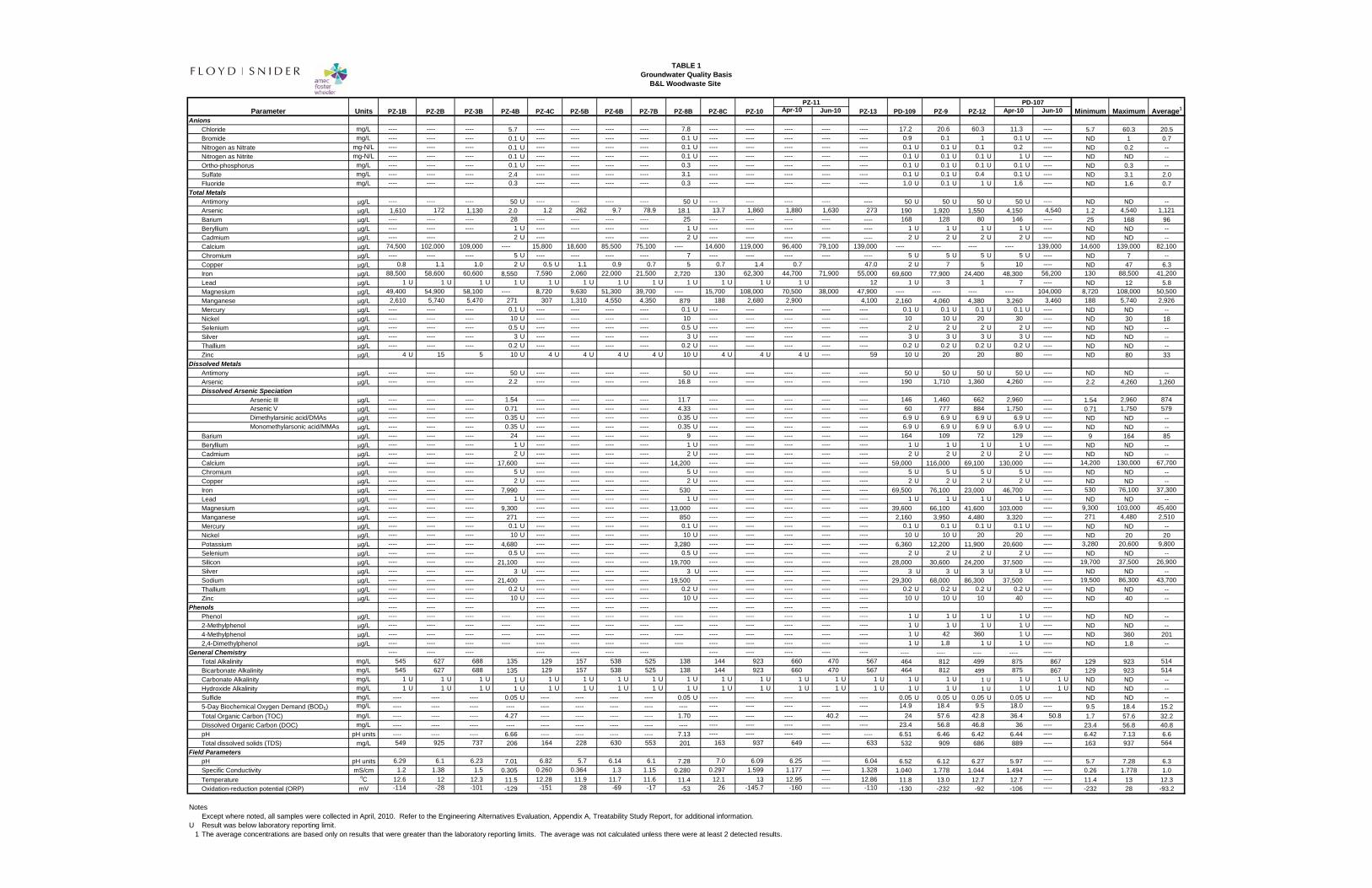
Tables Table 1 Groundwater Quality Basis
Table 2 Equipment and Chemical Contact Information
Drawings Drawing G-1 Cover Sheet
Drawing C-03 Groundwater Treatment Plant Partial Site Plan
Drawing C-04 Groundwater Recovery and Treatment Plant Piping Layout
Drawing M-01 Groundwater Treatment Plant Mechanical Layout – Floor Plan
Drawing M-02 Groundwater Treatment Plant Mechanical Layout – Mezzanine
Drawing M-03 Groundwater Treatment Plant Mechanical Layout – Section-A
Drawing M-04 Groundwater Treatment Plant Mechanical Layout – Section-B
Drawing P&ID-00 Process Flow and Instrumentation Legend
Drawing PFD-1 Process Flow Diagram
Drawing P&ID-01 Process Flow and Instrumentation Oxidation/Precipitation

B&L Woodwaste Site
P:\13488 - Floyd Snider-B&L Landfill\O&M\O&M Manuals\NPDES O&M Manual\O&M Manual 2015\2015 GWTP OM Manual_Sx.docx
Operations and Maintenance Manual
Page iii
Drawing P&ID-02 Process Flow and Instrumentation Sludge Handling
Drawing P&ID-03 Process Flow and Instrumentation Additives
Drawing P&ID-04 Process Flow and Instrumentation Effluent Polishing
Drawing P&ID-05 Process Flow and Instrumentation Extraction and Monitoring Wells
List of Appendices Appendix A: Groundwater Treatment Plant Operations and Maintenance Procedures
Appendix B: Control Narrative
Appendix C: Stormwater Pollution Prevention Plan
Appendix D: Health and Safety Plan
B&L Woodwaste Site
P:\13488 - Floyd Snider-B&L Landfill\O&M\O&M Manuals\NPDES O&M Manual\O&M Manual 2015\2015 GWTP OM Manual_Sx.docx
Operations and Maintenance Manual
Page 1
1.0 Introduction
This Operations and Maintenance Plan (O&M Plan) has been prepared to document plans and procedures and other information relevant to operation of the Groundwater Treatment Plant (GWTP) at the B&L Woodwaste Site (Site). The GWTP is a key component of the groundwater remediation remedy being implemented at the Site under the terms of Consent Decree No. 08-2-10610-7 (Consent Decree) and the 2008 Cleanup Action Plan (CAP) issued by the Washington State Department of Ecology (Ecology). Contaminated groundwater must be recovered to achieve remediation objectives described in the CAP; the recovered groundwater is treated in the GWTP for discharge to surface water, as authorized by National Pollutant Discharge Elimination System (NPDES) Permit No. WA0040321 (Permit). This O&M Plan has been prepared to document operation and maintenance procedures and to address the requirements of the Permit.
1.1 BACKGROUND
The Site is located within unincorporated Pierce County (Drawing G-01); the street address for the property on which the B&L Woodwaste Landfill is located is 1522 Fife Way East, Milton, WA. The GWTP is located in the southeast portion of the property (Drawings C-03 and C-04). Groundwater requiring treatment for removal of arsenic must be recovered from a network of recovery wells located beneath the Landfill and in the groundwater plume located outside the Landfill (Drawing C-04). The recovery wells must be operated as specified in the CAP and in compliance with regulations pursuant to the Model Toxics Control Act (MTCA). The sole source of water treated at the GWTP is from the two recovery well networks: the Landfill Network, which consists of two manifold legs collecting groundwater from the recovery wells within the barrier wall and the Outside Area Network, which recovers groundwater from high arsenic areas located outside the barrier wall. Groundwater is pumped from the wells using electrically operated pumps under automatic control. The automatic control system for the groundwater recovery wells is also used to control the GWTP, so that the wells can be controlled to maintain remediation objectives and the well pumps can be stopped as needed during GWTP upsets. This integrated system is intended to eliminate the need to bypass the GWTP and to minimize the potential for discharge of noncompliant effluent. The GWTP Permittee is the B&L Woodwaste Site Custodial Trust (Trust). The Trust is responsible for implementation of the overall remediation program at the Site, which includes operation of the GWTP.
1.2 RESPONSIBLE INDIVIDUALS
The names and phone numbers for the individuals responsible for operation, maintenance, and permit compliance are as follows:
Permittee: Dan Silver, Trustee, B&L Woodwaste Site Custodial Trust (360) 754-9343
B&L Woodwaste Site
P:\13488 - Floyd Snider-B&L Landfill\O&M\O&M Manuals\NPDES O&M Manual\O&M Manual 2015\2015 GWTP OM Manual_Sx.docx
Operations and Maintenance Manual
Page 2
Project Manager: Larry McGaughey, P.E. AMEC Environment & Infrastructure, Inc. (206) 342-1788
Process Engineer: Charles Hand, E.I.T. AMEC Environment & Infrastructure, Inc. (206) 342-1769

B&L Woodwaste Site
P:\13488 - Floyd Snider-B&L Landfill\O&M\O&M Manuals\NPDES O&M Manual\O&M Manual 2015\2015 GWTP OM Manual_Sx.docx
Operations and Maintenance Manual
Page 3
2.0 Groundwater Treatment Plant Design Criteria and Basis
The design criteria and basis provide a foundation for design of the GWTP. This section summarizes the engineering and design basis used for preparation of the plans and specifications.
2.1 DESIGN CRITERIA
Design criteria were developed for design of the GWTP. These criteria are summarized below for each component of the plant:
Provide sufficient treatment capacity and operating flexibility to support operation of the groundwater recovery system to achieve CAP objectives.
Remove site contaminants from groundwater and achieve discharge criteria that are protective of human health and the environment.
Discharge treated water to the existing surface water drainage system.
Size process equipment for the current design flow and for expected future flow reductions.
Include standby redundancy for critical process equipment to minimize process downtime.
Automate the main treatment processes to allow un-manned operation during weekends, evenings, and weekdays when an operator is not present.
Include a centralized control system that can be remotely monitored via an internet connection.
Provide sufficient storage for chemical feed solutions for at least 1 week of run time under average flow conditions.
Comply with applicable, relevant, or appropriate regulations and standards (federal, state, and local).
Conduct remediation work within wetland areas located on or adjacent to the B&L Property in accordance with applicable laws and regulations and in accordance with permits, as appropriate.
Comply with applicable, relevant, or appropriate regulations and standards (federal, state, and local) for the remedy components included in this O&M manual.
Comply with appropriate industry, professional engineering, and technical standards for the remedy components included in this O&M manual.
B&L Woodwaste Site
P:\13488 - Floyd Snider-B&L Landfill\O&M\O&M Manuals\NPDES O&M Manual\O&M Manual 2015\2015 GWTP OM Manual_Sx.docx
Operations and Maintenance Manual
Page 4
2.2 DESIGN BASIS
The general design basis for the GWTP is as follows:
Groundwater recovery within the contained area beneath the Landfill will be capable of achieving a minimum head differential across the barrier wall of 0.5 feet (ft).
The total pumping capacity for the GWTP is 150 percent of the recovery rates estimated to achieve the hydraulic control remediation objectives identified in the CAP.
The GWTP was designed for a continuous, average flow capacity of 40 gallons per minute (gpm).
The GWTP was designed to operate at a minimum continuous flow rate of 15 gpm and a maximum, short-term flow rate of 60 gpm to accommodate a range of potential recovery system operations.
The GWTP was designed to treat the maximum concentration for the groundwater quality presented in Table 1, which is considered worst-case groundwater quality that will be recovered from inside and/or outside the Landfill.
The GWTP was designed to achieve the following water quality criteria in the treated effluent as defined in the current Permit:
o Arsenic, Total < = 5 µg/L
o pH > 6.0 and < 9.0 standard units
The GWTP process design was based on the results of a pilot treatability study conducted in 2010.
The GWTP includes an automated control and data acquisition system, and was designed to operate under automatic control, with minimal direct operator attention during normal operations. The control and data acquisition system monitors groundwater levels in several piezometers and will allow remote monitoring and adjustment of operating parameters. The control and data acquisition system includes the following:
o Automatic control of the groundwater recovery well pumps for the contained area and the areas outside the Landfill.
o Automatic control of the GWTP.
o Monitoring of transducers in selected groundwater wells and piezometers.
o Remote autodialing and alarm capability.
o Data logging/recording capability.
o Remote monitoring and control capability for the groundwater recovery pumps, GWTP operations, and level monitoring instruments.
B&L Woodwaste Site
P:\13488 - Floyd Snider-B&L Landfill\O&M\O&M Manuals\NPDES O&M Manual\O&M Manual 2015\2015 GWTP OM Manual_Sx.docx
Operations and Maintenance Manual
Page 5
3.0 GWTP Process Overview
The groundwater treatment system has been designed with the primary goal of removing arsenic from contaminated groundwater recovered from the Site to achieve effluent concentrations that meet the discharge criteria summarized above. The treatment system process consists of chemical oxidation, raising pH to facilitate co-precipitation, clarification, lowering pH to improve adsorption, filtration, and adsorption. A plan view of the layout of the GWTP treatment plant and components is shown on Drawing C-03, Drawing M-01 and M-02 for the main floor and the mezzanine level respectively. A process flow diagram is presented in Drawing PFD-01. The treated groundwater will be pumped along a buried pipeline to the north pond (Drawing C-04). The solids stream from the clarification process will be stored in a sludge tank before being dewatered with a filter press; dewatering of sludge will be done periodically on a batch basis. The filter cake will be picked up and transported to an appropriate waste receiver for disposal. Treatment chemicals will be stored in tanks or transportable totes. All treatment equipment is located within the treatment building (GWTP main floor layout shown on Drawing M-01). The recovery well networks are shown on Drawing C-04. Recovered groundwater is collected in three piping manifolds that direct the recovered groundwater to the GWTP. Each line discharges to the Head Tank, located inside the GWTP Building on the mezzanine level (Drawing M-02).
3.3 UNIT OPERATIONS
The treatment process comprises of seven primary unit operations; including the Head Tank, the Oxidation Unit, the Co-Precipitation Unit, the Clarifier Unit, the pH Adjustment Unit, the Filtration Unit, and the Adsorption Unit. Ancillary units include the Sludge Management Unit (filter press for sludge dewatering) and an air compressor unit that provides air for equipment requiring compressed air. A centralized programmable logic controller (PLC) is used for data acquisition and automatic control of the entire GWTP and groundwater recovery system. Dewatered sludge from the filter press is collected in a roll-off container that will be picked up as needed for offsite disposal within a permitted commercial landfill. Treated effluent is sampled and discharged to the north pond, which overflows to an adjacent drainage ditch (Drawing C-04). The drainage ditch combines with the Surprise Lake Drain, and then flows beneath Interstate Highway 5 where it joins the Hylebos Creek, eventually discharging to the Hylebos Waterway and into Commencement Bay. The unit operations and ancillary units are described in more detail below.
Procedures are provided in Appendix A for operator guidance. A project management schedule was developed to simplify the operations and maintenance tracking for the plant (refer to Procedure P-001 in Appendix A). Alarm conditions and typical alarm set points are provided in Appendix B in the Control Narrative for the site.
B&L Woodwaste Site
P:\13488 - Floyd Snider-B&L Landfill\O&M\O&M Manuals\NPDES O&M Manual\O&M Manual 2015\2015 GWTP OM Manual_Sx.docx
Operations and Maintenance Manual
Page 6
3.3.1 Head Tank
The head tank receives pumped water from the three recovery lines shown on Drawing C-04. This unmixed tank provides flow equalization upstream of the subsequent unit operations. The tank volume is 400 gal and is an open-top tank equipped with a removable cover. Groundwater is discharged from the head tank by gravity flow through a flow meter and onto the downstream process units. The outlet includes a sample tap for the mixed influent groundwater. The head tank is equipped with a level switch to initiate emergency shutdown if a high level is detected.
3.3.2 Oxidation Tank
The oxidation tank provides mixing with potassium permanganate (KMnO4) and provides reaction time to oxidize iron and arsenic; resulting in precipitation of ferric hydroxide and co-precipitation of arsenic. Based on the 2010 treatability testing, KMnO4 was selected as the preferred oxidant. The addition of KMnO4 causes both arsenic (III) and iron (II) to be oxidized to arsenic (V) and iron (III), respectively. The higher oxidation states of arsenic and iron precipitate more readily and arsenic (V) is amenable to adsorption onto the iron hydroxide floc. The water then flows out from the oxidation tank under gravity flow.
The oxidation tank has a working volume of 1,659 gal, which provides 41 minutes of residence time at the average design flow rate (40 GPM). Mixing is provided by a top-mounted 1.0 horsepower (HP) mixer. The tank is completely mixed to ensure sufficient distribution and reaction of the KMnO4, while reducing the likelihood for short-circuiting.
During the 2010 treatability testing, the optimal dosage for KMnO4 was determined to be 145 milligrams per liter (mg/L) of groundwater. The dosage depends upon the influent concentration of permanganate-consuming constituents (i.e., iron, arsenic, manganese, and oxidizable organics). The KMnO4 feed has been designed to provide a range of dosages that can be set by the operator to support the required flexibility to accommodate changes in the groundwater chemistry and to service the full range of influent groundwater flows. The actual dosage will be adjusted as needed by the operato, based on testing the influent for arsenic, iron, and manganese and monitoring the oxidation reduction potential (ORP) in the oxidation tank to avoid over- or under-dosing.
Preparation of KMnO4 feed solution is done manually. 5 gallon pails of granular, crystalline KMnO4 are purchased from a local chemical supplier and delivered to the treatment building as needed. The pails are loaded into the KMnO4 tank by sealing the top of the pail with a fitted lid that contains a slide valve and a rubber gasket. The gasket is then connects to a vertical PVC pipe that runs from the mezzanine level down into the KMnO4 tank. The vertical pipe extends from the mezzanine level into the KMnO4 tank, below the liquid level in the tank. The pipe outlet is kept submerged during feed solution preparation to prevent fugitive dust. In addition, a constant water stream is added to the sealed lid to assist in cleaning out the pail and the piping and to prevent fugitive dust. A new batch of feed solution is typically prepared when the remaining volume of feed solution in the tank is approximately 400 gallons or less. The operator
B&L Woodwaste Site
P:\13488 - Floyd Snider-B&L Landfill\O&M\O&M Manuals\NPDES O&M Manual\O&M Manual 2015\2015 GWTP OM Manual_Sx.docx
Operations and Maintenance Manual
Page 7
will add the correct amount of water to the tank based on the volume of solution to be prepared (determined by the tank level). The operator adds sufficient KMnO4 and the correct volume of water to produce the target concentration in the make-up tank. The make-up tank has a volume of 1,800 gal, which allows for more than one weeks of continuous operation for each batch under normal flow conditions. The maximum target KMnO4 feed solution concentration is 10 grams (g) of powdered KMnO4 per liter (L) of solution (100 lb of KMnO4 per 1200 gallon batch). The feed concentration is below the published solubility of about 43 g/L water at 10oC (Lange 1999). Given the water temperature of kinetics for dissolution of the solid permanganate at the site, feed solutions higher than 10 g/L should be avoided to ensure that all of the KMnO4 dissolves. The KMnO4 feed tank is located within a secondary containment area to contain spillage in the event of tank or line failure.
The KMnO4 feed solution is fed to the oxidation tank via a chemical dosing skid that includes redundant diaphragm metering pumps to ensure accurate and continuous dosing. The solution is fed to the system at a rate that is proportional to the influent groundwater flow rate, as measured in the discharge from the head tank. The pumping rate is controlled by the PLC. Based on treatability studies and continuous monitoring of the GWTP, typical target doses range from 10-20 mg/L of KMnO4 in the recovered groundwater. The feed ratio will be adjusted by operations personnel as necessary to achieve proper treatment and to avoid overdosing (feed ratio between 500 and 1000 for 20 and 10 mg/L, respectively). Concentrations of the permanganate-consuming constituents in the untreated groundwater will be monitored to establish and control the proper KMnO4 feed rate.
An ORP sensor and transmitter is installed in the oxidation tank to monitor ORP and ensure appropriate oxidation conditions are maintained. The ORP sensor will be monitored by the PLC. A warning alarm will be initiated if the ORP is outside of the expected range to alert the operator that there is a potential problem with the KMnO4 dosing system so that corrective action can be taken.
3.3.3 Co-Precipitation Tank
Partially treated groundwater flows by gravity from the oxidation tank to the co-precipitation tank. This tank is completely mixed by a 1.0 HP, top-mounted mixer. Lime slurry is added to the co-precipitation tank under automatic control to raise the pH to a target value of 9.1-9.2 in order to induce co-precipitation of arsenic with the iron that is present in the groundwater. The ferric iron (Fe+3) formed in the Oxidation Tank will form hydroxides at the elevated pH and precipitate. Arsenic (V) will adsorb to the floc and thus will be removed with precipitated iron hydroxides. The addition of the lime also adds solids surface area and charge to aid in the co-precipitation process. The co-precipitation tank also receives sludge recycle from the clarifier to provide seed to support the formation of rapid settling solids. Coagulant is also added to the co-precipitation tank to facilitate the formation of larger and denser floc through charge destabilization and increased particle interactions. The co-precipitation tank has a working volume of 1,659 gal, which provides a 41-minute retention time at the design average flow rate. The co-precipitation tank is equipped with a pH sensor that is monitored by the PLC to
B&L Woodwaste Site
P:\13488 - Floyd Snider-B&L Landfill\O&M\O&M Manuals\NPDES O&M Manual\O&M Manual 2015\2015 GWTP OM Manual_Sx.docx
Operations and Maintenance Manual
Page 8
automatically control the pH of water in the tank through a proportional, integral, and derivative (PID) control loop.
In order to induce the pH change, a lime dose of 5.95 g of dry hydrated lime [Ca(OH)2] per gallon of groundwater was required in the treatability testing. Based on current operations, a lime dose of 1.5 g of dry hydrated lime is required per gallon of groundwater. Hydrated lime is delivered to the Site in the form of a slurry, at a concentration around 3.5 lb Ca(OH)2 per gallon of water. Delivery and feed of the lime in this manner eliminates the need for a complex and high maintenance slaking or dry chemical feeding process on site. Lime slurry will be delivered in 2,000-gal bulk loads and stored in a 5,509-gal lime storage tank. The maximum amount of lime will not exceed 4,580 gallons in the lime storage tank. Lime is then diluted to a concentration around 1.81 lb of dry hydrated lime per gallon in the lime storage tank (corresponding to a specific gravity of 1.13) to prevent system clogs from occurring resulting in periods of shutdown for maintenance of the lime feed system. The lime storage tank is located within a secondary containment area to contain any spills in the event of tank or line failure. The storage tank is continuously and completely mixed by a 5.0 HP top mounted mixer to prevent sedimentation. The lime within the lime tank is constantly recirculated in a loop via a large peristaltic pump to prevent deposition and scale formation in the lime piping. Lime is fed to the co-precipitation tank under PLC control by a small peristaltic dosing pump drawing from the discharge side of the lime recirculation line. The lime slurry feed rate is automatically controlled by the PLC to achieve the target pH in the co-precipitation tank.
At the design average groundwater flow rate (40 gpm) and a diluted concentration of 1.81 lb of dry hydrated lime per gallon, the estimated consumption of lime slurry is 60 gallons per day (gal/d). Each load of slurry (2,500 gal) would last approximately 40 days under these conditions. Lime is delivered by parking the truck at a specially designed delivery station. A concrete pad and sump was constructed along the north side of the GWTP building to contain any spills that may occur during lime delivery. Prior to delivery, the operator manually closes a valve on the spill collection sump associated with the delivery pad. Delivery hoses are connected to an Environ-Box, designed to minimize spillage during connection/disconnection. If spillage occurs during delivery, it would be contained by the curbed delivery pad and sump; spillage would be cleaned up by the operator. If no spillage occurs, the operator will reopen the sump valve, to direct stormwater runoff from the pad to normal drainage channels.
3.3.4 Clarifier Unit
Groundwater flows by gravity from the co-precipitation tank to an inclined plate clarifier unit to separate the floc from the treated water. The clarifier unit includes an integral flash mix tank and a flocculation tank, each equipped with a mixer. A polymer flocculant will be added directly to the flash mix tank under automatic control at a rate proportional to the influent groundwater flow rate. The feed rate will be determined by the process engineer.
The polymer is purchased as neat liquid in 5-gal pails, and diluted to a concentration of 0.25 percent (wt/wt) in batches to allow for the organic polymers long carbon chain to unfold. An
B&L Woodwaste Site
P:\13488 - Floyd Snider-B&L Landfill\O&M\O&M Manuals\NPDES O&M Manual\O&M Manual 2015\2015 GWTP OM Manual_Sx.docx
Operations and Maintenance Manual
Page 9
automated make down system is used to prepare the polymer feed solution as needed. The polymer feed solution is prepared and stored in a 60-gal feed tank. The small feed tank was selected to ensure short storage times for dilute polymer, which will minimize degradation and ensure that freshly prepared polymer is provided to the treatment process. The feed tank is equipped with a low-speed mixer that is operated continuously. New batches of feed polymer will be automatically prepared when the level in the polymer day tank reaches the low-level set point. A cone bottom tank is used to feed the neat polymer into the make down tank with the use of a small diaphragm pump.
The rapid-mix tank provides complete mixing of the groundwater with the dilute polymer solution and a short residence time. Based on an average design flow rate of 40 GPM and a target polymer concentration of 0.4 ppm in the wastewater based on bench scale testing, approximately 0.03 gallons of neat polymer will be dosed per day into the rapid mix tank (or a 5 gallon pail will last approximately 16 days). The slurry from the rapid-mix tank flows by gravity to the flocculation tank to provide a period of slow mixing to allow for floc formation. The flocculated groundwater then flows into the inclined plate settler, allowing the solids to settle to the sludge hopper and the clarified groundwater to overflow the effluent weir. The clarifier provides an effective settling area of 160 square feet (ft2), which provides an overflow rate of 360 gallons per day/ft2 (gpd/ft2) at average design conditions (40 gpm) , and 540 gpd/ft2 at maximum design conditions (60 gpm). Sludge from the sludge hopper is pumped to the sludge management process, which is described below.
3.3.5 pH Adjust Tank
The clarifier unit overflows by gravity to the pH adjust tank where the water pH is adjusted down to achieve effective adsorption of the remaining arsenic in the adsorption columns. Adsorbent media life in the final treatment stage is longer if the water pH is slightly acidic. The target pH for the pH adjust tank is in the range of 6.1 – 6.2. The pH is reduced by the addition of 93-98 percent sulfuric acid (H2SO4) under automatic pH control. The pH adjust tank has a working volume of 1,420 gal, providing a residence time of 35-36 minutes at the average design flow rate. The pH tank is completely mixed with a 1.0 HP, top-mounted mixer.
Acid is added to the pH adjust tank via automatic dosing pumps. Redundant duplex diaphragm metering pumps are used to feed acid to the pH adjust tank. The acid-wetted parts of the pumps and the acid feed tubing are compatible with concentrated sulfuric acid. The rate of acid addition is controlled by the PLC based on a PID control loop, using the continuous pH sensor in the pH adjust tank. The dosing rate under average flow conditions is approximately 0.14 gallons per hour (gal/hr). The Teflon acid feed line is enclosed in a protective CPVC line to contain acid if the Teflon feed line fails. The CPVC protective casing is designed to drain either to the pH adjust tank or the acid containment sump.
Concentrated acid will be delivered in 265-gal acid totes. The totes are placed on the acid containment sump upon delivery. The sump is lined with acid-resistant coating; providing secondary containment in the event of a leak or spill. Two totes are present at any time; one
B&L Woodwaste Site
P:\13488 - Floyd Snider-B&L Landfill\O&M\O&M Manuals\NPDES O&M Manual\O&M Manual 2015\2015 GWTP OM Manual_Sx.docx
Operations and Maintenance Manual
Page 10
tote is used to supply acid to the process while the second tote provides extra acid to ensure a constant supply. The level of acid in each tote is continuously monitored by the PLC to monitor inventory and identify spills of acid from the totes. There is also an optical fluid sensor in the acid dosing skid to detect any leaks in the dosing skid. If a leak is detected, an alarm will be triggered to notify the operator.
Water from the pH adjust tank is pumped to provide sufficient pressure to force the water through the filters and the adsorption columns and discharge treated water to the North Pond via Outfall #001 (Drawing C-04). The pH adjust tank is equipped with a continuous level sensor and a high level switch. The continuous level sensor is used as the control signal for the PLC to automatically regulate the speed of the discharge pump based on a PID loop for controlling tank level. A redundant discharge pump is provided in case of failure or maintenance requirements on the lead pump. Pump speed is controlled by the PLC to maintain a constant level in the pH adjust tank. The level sensor in the pH adjust tank will issue an alarm in the event the high level setpoint is detected. If the high-high level is detected, the high level switch will initiate a complete emergency shutdown of the groundwater recovery and treatment system to prevent overflow of the process units.
3.3.6 Filter Units
Following clarification, the water is filtered in a two-step process. Water is pumped from the pH adjust tank through a duplex-bag filter unit to remove suspended solids that are larger than 10 μm to prevent clogging of the downstream filter/adsorber units. Once through the duplex-bag filter unit, the water flows through a duplex-cartridge filter unit to remove remaining suspended solids down to 3 μm to prevent plugging of the adsorption unit. Two bag filter housing units are present in the duplex system; each unit was sized for a hydraulic capacity up to 220 GPM to provide extra solids loading capacity. Two cartridge filter units are present in the duplex-cartridge filter unit; each unit is capable of handling maximum design flow (up to 60 gpm). Depending on the solids loading to the filter units, one unit may be kept online, while the offline filters are fitted with fresh cartridges and a bag and placed into service when the online units are clogged, as indicated by the pressure differential measured across the units. Pressure loss across the filter unit is monitored continuously by the PLC; an alarm is issued if high pressure loss (indicating plugging of the filter) is detected. Switching of the filter units and replacement of the cartridges and bags is done manually, as needed to maintain acceptable pressure drop readings across the filter housings.
3.3.7 Activated Alumina Adsorber Unit
The final unit operation to achieve the low-level arsenic treatment target (5 μg/L or 5 ppb) is adsorption onto activated alumina in the adsorber unit. After passing through the filters, the groundwater flows to the two adsorption columns operated in a series configuration. The activated alumina requires an empty bed contact time of 5 minutes, which equates to a 200-gal (media volume, not including freeboard) adsorption column. The empty bed contact time was recommended by the media manufacturer and verified during the 2010 pilot treatability testing.
B&L Woodwaste Site
P:\13488 - Floyd Snider-B&L Landfill\O&M\O&M Manuals\NPDES O&M Manual\O&M Manual 2015\2015 GWTP OM Manual_Sx.docx
Operations and Maintenance Manual
Page 11
The media is expected to function for 4,300 bed volumes before significant breakthrough based on monitoring data. After 4,300 bed volumes of groundwater have been treated or breakthrough of arsenic is detected in samples collected after the second column, the media in both columns will be replaced. Breakthrough is defined as a concentration of 3 ppb or more as measured in the effluent side of the lag unit. The spent media will either be loaded into an onsite garbage roll-off that is picked up and transported to an appropriate waste facility for disposal or loaded directly into a vactor truck for offsite disposal at a permitted, commercial waste disposal facility. Each adsorber is equipped with a continuous differential pressure sensor so that pressure drop can be monitored by the PLC. An alarm is issued if high pressure drop is detected, indicating that the affected adsorber has become plugged and requires operator attention and backwashing.
Effluent from the second adsorber column is the final, treated effluent that is directed to the North Pond for discharge via Outfall #001. The discharge from the second adsorber flows through a pH sensor (AIT 450 on Drawing P&ID-04) where final effluent pH is monitored. An alarm will shutdown the plan if the pH drops below 6.0 SU as measured in the effluent pH sensor. The water also flows through the final effluent flow meter, FIT 490 (Drawing P&ID-04), where the total flow rate is recorded for reporting the daily discharge volume. The quality of the final treated effluent is monitored by collecting a composite sample tap located adjacent to the flow meter, inside the GWTP building. In addition, a weekly pH grab sample is collected from the effluent sample port and reported on monthly DMRs.
3.3.8 Sludge Storage and Dewatering Unit
Excess sludge generated from treatment of groundwater is collected and dewatered for disposal in a permitted, offsite landfill. Underflow from the clarifier settles to the bottom of the clarifier and pumped to the sludge storage tank with a pneumatic diaphragm pump operated on a timer control system. The sludge storage tank has a working volume of 5,850 gal and is continuously mixed by a 1.5 HP top-mounted mixer. The sludge will be accumulated in the storage tank for batch-wise dewatering by a filter press. Filter press operation requires continuous operator attention, so the sludge dewatering process will be manually initiated when an operator is on-site. The sludge storage tank is equipped with a continuous level sensor and a high level switch that are monitored by the PLC. Alarms are initiated when high inventory or high levels are detected in the sludge storage tank. Polymer flocculant can be added to the sludge storage tank by the operator to facilitate sludge dewatering.
When a sludge dewatering batch is initiated, the sludge is pumped from the sludge storage tank to the filter press by a peristaltic hose pump until a set pressure is obtained in the feed to the filter press (not to exceed 110 psi). The filtrate flows from the filter press by gravity into the head tank to ensure that all components under flow control are adjusted accordingly to account for the increased flow. At the end of each filter press cycle, as determined automatically by the mechanically built pressure at the filter press feed, the press will be opened and the sludge cake is discharged from the plates into a roll-off container located below the filter press. The roll-off container will be removed and replaced as necessary for disposal of the dewatered sludge. The
B&L Woodwaste Site
P:\13488 - Floyd Snider-B&L Landfill\O&M\O&M Manuals\NPDES O&M Manual\O&M Manual 2015\2015 GWTP OM Manual_Sx.docx
Operations and Maintenance Manual
Page 12
filter press produces dewatered sludge that meets the paint filter test and is suitable for landfill disposal.
The solids loading to the clarifier is estimated to be 144 lb dry solids per day, based on the average design flow rate. This estimate includes a 15 percent safety factor over the theoretical value, which is based on the influent water quality and treatment chemistry. It is estimated that under average flow conditions, two filter press cycles will be needed each week. The sludge storage tank will have enough capacity for 5 days of storage under average groundwater flow rates and the groundwater quality observed during the 2010 pilot treatability testing.
Approximately 960 lb of dry solids in the dewatered filter cake would be produced each week under average design flow conditions. Assuming a conservative (i.e., low) cake solids concentration of 25 percent (wt/wt), the expected total cake weight per week is 3,830 lb (wet). Based on these quantities, the roll-off container filled with filter cake will require removal for off-site disposal once approximately every 8 weeks.
An air compressor provides compressed air at approximately 120 psi for operation of the pneumatic controls and valves used by the filter press. Compressed air is necessary for operation of the sludge storage and dewater unit. The air compressor includes an accumulator vessel that feeds compressed air to the distribution lines. A pressure switch on the accumulator vessel is monitored by the PLC to initiate a low pressure alarm, indicating compressor failure.
3.3.9 Instrumentation and Controls
Instrumentation for the GWTP is depicted in the process and instrumentation diagrams (P&IDs, Drawings P&ID-00 through P&ID-05). The system has been designed to be automated to the extent practical. It is estimated that the system will require four to five visits to the site per week by the operator to ensure continuous and effective operation. The frequency for operator attention may be greater during periods of high groundwater flow, but is not expected to be less at flow rates below the design average.
The GWTP includes significant instrumentation for control and monitoring purposes. The treatment equipment and instrumentation will be automated with a single, centralized PLC. The system operations can be monitored via a human machine interface (HMI) located in the treatment building. The system also has remote monitoring and data collection capabilities through an internet interface to allow the operator to view the status of the system at any time from an offsite location. The control system also has dial-out functionality so that critical alarms will be issued by an automated call to the offsite personnel by telephone. The control system includes data logging and tracking of most process instruments, as shown on the P&IDs.
The automated control system for the GWTP includes an autodialer that is prompted to call offsite operators/responsible individuals if process or landfill alarm conditions occur, including shutdown of specific system components. Appendix B summarizes the current configuration of
B&L Woodwaste Site
P:\13488 - Floyd Snider-B&L Landfill\O&M\O&M Manuals\NPDES O&M Manual\O&M Manual 2015\2015 GWTP OM Manual_Sx.docx
Operations and Maintenance Manual
Page 13
the alarm conditions for the GWTP. These setting may be modified as approved by the Process Engineer.
3.3.10 Treatment System Building
The GWTP is located within a dedicated building to provide security, limit the generation of contaminated runoff, and to contain any spills from process equipment and tanks. Key features of the GWTP building are described below.
3.3.10.1 Building Pad
Due to the historical flooding events in the vicinity of the Site during periods of heavy rainfall, a building pad was constructed at an elevation of approximately 20 ft above sea level (ASL) to match the elevation of the existing access road around the Landfill. This elevation has been consistently above recent flood elevations and is above the elevation of the 100-year flood (MGS Engineering Consultants et al. 2004).
The floor of the building is a concrete pad providing curbing and containment for the GWTP and for lime slurry delivery to the building. A concrete pad and sump is located north of the building to contain any spills or releases of lime slurry during delivery; the concrete pad is sloped to a collection sump. This will provide spill containment in the event of an accidental release from the lime slurry truck during unloading, preventing lime from entering the surrounding wetland areas. An environmental containment enclosure is installed on the outside of the building, beneath the lime connection point, to collect any drips and spills from the hose connection during lime truck unloading.
The lime delivery sump includes a sluice gate, which when opened will allow stormwater collected on the concrete pad to flow north-east, following the normal drainage pattern. Written delivery procedures specify that the operator must close the sluice gate before a lime truck is brought on to the Site and is parked on the concrete pad. If a spill occurs, the lime will be held in the sump and on the concrete pad where it can be collected and disposed of properly. Following delivery or cleanup of any spills, the sluice gate will be reopened. A complete stormwater pollution prevention plan is included in Appendix C.
3.3.10.2 Treatment Building
The building includes two man-doors and two overhead doors (Drawing M-01). The large roll-up door provides access for moving the onsite waste and dewatered sludge roll-off bin in and out of the building. The smaller roll-up door provides access for bulk chemical deliveries and equipment. The building is electrically heated to maintain an interior temperature above a minimum of 50°F during cold weather conditions. Exhaust fans are provided to vent moisture and prevent excess heat accumulation in the summer.
The concrete floor inside the GWTP building provides containment for the GWTP process equipment. A separate containment floor that is 1 foot lower than the elevation of the main floor
B&L Woodwaste Site
P:\13488 - Floyd Snider-B&L Landfill\O&M\O&M Manuals\NPDES O&M Manual\O&M Manual 2015\2015 GWTP OM Manual_Sx.docx
Operations and Maintenance Manual
Page 14
of the building provides a drainage area for process equipment during regular operations and management and in case of spills or leaks (Drawing M-01). This lower floor is drained by a sump at the end of a collection trough that runs from the south-east side of the building near the overflow of the clarifier to the west, near the polymer make down skid. All of the treatment process equipment and vessels along with the polymer skid are located within this lower area, while the treatment process chemicals are located in separate containment areas on the north side in the GWTP building. The sump in the lower containment area is used to collect polymer dosing pump seal water, any spills, and wash water generated during equipment maintenance. Water collected in the sump is pumped to the oxidation tank or sludge tank for subsequent treatment in the treatment process. The water level in the sump is monitored continuously by the PLC to detect spills or excess accumulation of liquids in the containment area. If a high level is detected in the sump, the PLC will issue an alarm and initiate emergency shutdown of the groundwater recovery system and the GWTP. As noted on Drawing M-01, separate secondary containment is provided for the lime slurry and KMnO4 feed tanks as well as for the sulfuric acid totes. The sulfuric acid totes are placed in a separate containment area as the lime and potassium permanganate to prevent any adverse reactions from occurring from the mixture of incompatible chemicals.
A separate 8’x10’ storage shed is located west of the front of the GWTP in the gravel driveway area (Drawing C-03). The storage shed is used to store dry goods such as filters and replacement pump kits.
3.3.10.3 Building Layout
The building layout is shown in Drawings M-01 and M-02. The building includes a small laboratory area, a small office, and a restroom. The electrical room, which includes the PLC, is located on the mezzanine level. A computer used for monitoring and controlling the GWTP is located in the office. A safety shower and eye wash fountain is located on the main floor of the building, outside the lab/office area. The building layout was developed so the process equipment was in a logical sequence, optimizing piping lengths and supporting system operations and maintenance.
3.3.10.4 Security
Due to concerns over potential property damage or malicious interference, all process equipment and chemical storage tanks are housed inside the treatment building. The treatment building doors will remain locked at all times when an operator is not present. The building has protected windows to minimize the potential for vandalism or unauthorized building entry. The roll-off containers for the solids storage will be stored indoors. The groundwater recovery well heads are each contained in a locked well vault. A monitored security camera system is in place to provide continuous surveillance of the building for intruders during times when an operator is not present at the site. The building area is enclosed with a 3-stranded barbed-wire fence. One gate is present at the entrance to the site, one gate is present at the entrance to the Landfill area, and two gates are present at the north end of the fenced area. All gates are kept locked unless the area is in use by site personnel.
B&L Woodwaste Site
P:\13488 - Floyd Snider-B&L Landfill\O&M\O&M Manuals\NPDES O&M Manual\O&M Manual 2015\2015 GWTP OM Manual_Sx.docx
Operations and Maintenance Manual
Page 15
3.4 TREATMENT OBJECTIVES
The B&L Woodwaste Site GWTP is a fairly simple physical-chemical treatment system. The overall treatment objective is to reduce arsenic concentrations in the effluent so that they are below the MTCA cleanup level of 5 µg/L, while maintaining an effluent pH between 6.0 and 9.0 standard units. To achieve this, the following objectives have been established for individual unit operations:
Oxidation Tank: Achieve complete oxidation of arsenic (from As3+ to As5+ and iron (from Fe2+ to Fe3+)
Co-Precipitation Tank: Achieve a pH of 9.1-9.2 in the tank to maximize co-precipitation
pH Adjustment Tank: Achieve pH of 6.1 - 6.2 in the tank to increase adsorption media life and increase the effectiveness of arsenic adsorption onto activated alumina
B&L Woodwaste Site
1P:\13488 - Floyd Snider-B&L Landfill\O&M\O&M Manuals\NPDES O&M Manual\O&M Manual 2015\2015 GWTP OM Manual_Sx.docx
Operations and Maintenance Manual
Page 14
4.0 Groundwater Treatment Plant Operations and Maintenance Procedures
Each of the unit operations of the GWTP has Operations and Maintenance Procedures (O&M Procedures) associated with it. These procedures are presented in Appendix A. Note that these O&M Procedures are intended to be standalone documents, designed to provide operators with technical and health and safety information needed for operations tasks. As these procedures are intended to be used independently for operations tasks, each procedure has its own page numbering and the numbering does not follow page numbering in this O&M Plan. In general, specific valves and/or equipment are referenced by their number, as specified on the P&ID drawings (Drawings P&ID-00 through P&ID-05). In addition, certain process parameters must be checked on a weekly, bi-monthly, or monthly basis to ensure smooth process performance. These inspections and measurements are provided in Appendix A (Procedure P-001).
These procedures provide an overview of health and safety issues and requirements specific to the tasks addressed by the procedure. The procedures also identify any special tools or personnel protective equipment required to complete the work. The procedures also provide a step-by-step process to properly complete the task. These procedures are continuously reviewed and may be updated as needed to ensure the work is performed safely and properly. This manual will be updated as necessary when procedures are updated or if equipment is replaced.
B&L Woodwaste Site
P:\13488 - Floyd Snider-B&L Landfill\O&M\O&M Manuals\NPDES O&M Manual\O&M Manual 2015\2015 GWTP OM Manual_Sx.docx
Operations and Maintenance Manual
Page 15
5.0 Groundwater Treatment Plant Maintenance
5.1 MAINTENANCE PROCEDURES
See Appendix A for individual component maintenance procedures.
5.2 SPARE PARTS INVENTORY AND SUPPLIERS
The treatment system has several components which require regular maintenance supplies. See below for individual items which are anticipated to be needed on a fairly regular basis. An inventory list with contacts and equipment information is provided in Table 2.
B&L Woodwaste Site
P:\13488 - Floyd Snider-B&L Landfill\O&M\O&M Manuals\NPDES O&M Manual\O&M Manual 2015\2015 GWTP OM Manual_Sx.docx
Operations and Maintenance Manual
Page 16
6.0 Health and Safety
Health and safety of workers and the general public are of primary importance to operation and maintenance of the GWTP. Operation and maintenance of the Site GWTP is covered by MTCA and state and federal laws pertaining to remediation of contaminated sites. Therefore, operation of the GWTP is subject to the hazardous waste operations health and safety requirements of 29 CFR 1910, commonly referred to as HAZWOPER. A site-specific Health and Safety Plan (HASP) has been prepared to cover operations and maintenance work to be performed at the Site, which includes the GWTP. This HASP is included as Appendix D to this O&M Plan. A copy of the HASP is kept at the GWTP office; all Site workers are required to become familiar with the HASP and to sign the plan, acknowledging that they have read it and are familiar with its requirements. As noted previously, health and safety procedures and required safety equipment have been included in the task-specific O&M procedures included in this O&M Plan. All operations personnel are trained in Site hazards, handling hazardous materials used in the process, and in the safety features associated with the GWTP process and the building.
Additional health and safety considerations have been incorporated into the facilities and control system. These considerations are as follows:
A safety shower and eye-wash fountain is located outside the laboratory, and is maintained functional and available for emergency use.
In the event that either the safety shower or eye-wash fountain is used, the PLC will issue an alarm to offsite personnel that the operator has activated emergency equipment.
Emergency shutoff switches have been placed outside each man door and near the safety shower. Activation of the shut off switches causes the PLC to safely shut down the groundwater recovery wells and the GWTP and to issue an alarm to offsite personnel.
The secondary containment system for the lime and KMnO4 storage tanks includes a level sensor that will initiate an offsite alarm and a safe shutdown of the groundwater recovery system and the GWTP if liquid is detected in the containment area.
The secondary containment system for the sulfuric acid dosing skid includes an optical liquid sensor that will initiate an offsite alarm if liquid is detected in the containment area.
The secondary containment system for the GWTP includes a level sensor that will initiate an offsite alarm and a safe shutdown of the groundwater recovery system and the GWTP if a large quantity of liquid is detected in the containment area.
B&L Woodwaste Site
P:\13488 - Floyd Snider-B&L Landfill\O&M\O&M Manuals\NPDES O&M Manual\O&M Manual 2015\2015 GWTP OM Manual_Sx.docx
Operations and Maintenance Manual
Page 17
The building is equipped with smoke detectors, fire alarm, and a sprinkler system that will be activated if a fire is detected. The fire alarm system also issues an alarm to the local fire department and offsite personnel.
Local fire department officials have been notified of the hazardous materials inventory for materials that are present in the GWTP building. The building has been classified as an H-3 building. Signage is displayed on the building and tanks identifying the hazards associated with each of the process chemicals.
Manual fire extinguishers are located outside the electrical room on the mezzanine and near the two main doors.
B&L Woodwaste Site
P:\13488 - Floyd Snider-B&L Landfill\O&M\O&M Manuals\NPDES O&M Manual\O&M Manual 2015\2015 GWTP OM Manual_Sx.docx
Operations and Maintenance Manual
Page 18
7.0 Emergency Plans and Procedures
Emergencies can happen due to a variety of causes. None of the process chemicals are explosive. Sulfuric acid is a water reactive chemical that will react violently when in contact with water; the sulfuric acid handling and storage system is specifically designed to minimize the potential for contact with water, even in the event the acid containers leak and the contents are released. Therefore, emergencies are expected to be associated with spills, releases, worker exposure to process chemicals, or other worker safety issues. Emergency response to worker exposure or worker safety is addressed in the HASP. Emergency response related to process failure or spills/releases is discussed below.
As noted above, the system is designed to contain spills or releases from storage tanks and to safely shut down the groundwater recovery system and the GWTP. An emergency shutdown as discussed above may be initiated by unsafe process conditions as monitored by the control system, from the activation of a manual emergency shutdown button in the GWTP building, or when a shutdown is initiated by remote access to the control system. Three emergency shutdown buttons are readily available to workers in the building; activation of any one of the emergency shutdown buttons will initiate a safe shutdown of all groundwater recovery wells and the complete GWTP, including all chemical feed pumps. Appendix B, provides more information on how the system will be safely shut down in case of an emergency shutdown.
7.1 SPILL RESPONSE COORDINATOR
The following individual has been designated as the Spill Response Coordinator accountable for Site spills:
Spill Response Coordinator
Individual: Charles Hand, MSCE, E.I.T., Process Engineer
Phone Number: Office 206-342-1769
Mobile 509-499-8363
The following individual has been designated as the alternate Spill Response Coordinator for the Site spill response:
Alternate Spill Response Coordinator
Individual: Larry McGaughey, Ph.D., P.E., Project Manager
Phone Number: Office 206-342-1788
Mobile 206-755-1525

B&L Woodwaste Site
P:\13488 - Floyd Snider-B&L Landfill\O&M\O&M Manuals\NPDES O&M Manual\O&M Manual 2015\2015 GWTP OM Manual_Sx.docx
Operations and Maintenance Manual
Page 19
7.2 SPILLS AND RELEASES TO CONTAINMENT AREAS
Failure of tanks or piping within the GWTP building will be contained by the secondary containment; the automatic control system is designed to detect the spill and initiate a safe shutdown of the groundwater recovery wells and the GWTP. If a spill or release occurs that is contained within the containment area, the following procedure will be implemented:
1. Check the GWTP in accordance with the procedures for shutdown of the unit operations to confirm that the treatment equipment is in a safe shutdown mode.
2. Notify the Spill Response Coordinator of the failure or release. 3. Work with management and health and safety personnel as directed by the Spill
Response Coordinator and other management personnel as appropriate to retain appropriate contractors to safely clean up the release and establish safe conditions for working on the failed equipment.
4. Assess the failed equipment to ascertain the nature and cause of the failure. 5. Perform health and safety planning with the Spill Response Coordinator or other
management personnel as appropriate prior to initiating work. 6. Initiate work to repair the failure to re-establish safe working conditions. 7. After confirmation that engineering and management personnel concur that the cause(s)
of failure have been identified and addressed, return the equipment to operation and proceed with startup of the GWTP and the groundwater recovery system.
8. Prepare a report documenting the nature and cause of the failure and the actions taken to initiate repairs and prevent recurrence of the failure.
7.3 SPILLS AND RELEASES OUTSIDE CONTAINMENT AREAS
Spills and/or releases to areas outside the secondary containment facilities constitute a threat to human health and the environment. These spills must be contained and reported to appropriate authorities as soon as possible and in accordance with the procedures below. Spills of the following materials outside of the secondary containment areas will initiate emergency shutdown and response as described below:
Untreated groundwater that may contain arsenic at concentrations exceeding the cleanup level specified in the CAP (5 µg/L).
Concentrated sulfuric acid used in the GWTP.
Potassium permanganate feed solution used in the GWTP.
Solid (granular) potassium permanganate used to make feed solution used in GWTP.
Lime slurry used in the GWTP.
Other process chemicals are liquids that are used in small quantities (< 20 gallons) and are of low to moderate hazard to the environment.
B&L Woodwaste Site
P:\13488 - Floyd Snider-B&L Landfill\O&M\O&M Manuals\NPDES O&M Manual\O&M Manual 2015\2015 GWTP OM Manual_Sx.docx
Operations and Maintenance Manual
Page 20
7.3.1 Spill Discovery and Containment
Any spills extending outside the secondary containment areas within the GWTP building and/or the lime slurry delivery pad should be readily discoverable by personnel either at the Site (e.g., during delivery of lime slurry) or traveling to the Site due to alarms issued by the automatic control system (as discussed in Section 7.0). Spill containment will never take precedence over the safety of personnel. No countermeasure activities will be undertaken until conditions are safe for workers. The following general procedures should be implemented as countermeasures.
Initiate an emergency shutdown of the GWTP using an emergency shutdown button. This will automatically notify offsite personnel of emergency conditions.
Account for all onsite personnel and ensure they are aware of the spill and take appropriate safety precautions.
Identify the material spilled.
Don appropriate personal protective equipment as necessary.
Protect surface water sources such as storm drains, swales, or wetland ditches/ponds by damming potential inlets.
Attempt to seal or stop the source of the release if it can be done safely.
Notify the Site Spill Response Coordinator as described in Section 7.3.2 for assistance in reporting, spill control and spill cleanup.
In the case of a large volume spill requiring the services of an outside contractor to contain, Site personnel will take emergency containment action and initiate additional spill response conducted by a contracted spill response service. Emergency containment actions taken by Site personnel during large spills may include the placement of containment berms at the spill location or other appropriate locations around the Building to protect surface water sources or other paths of migration offsite.
The contracted spill response service will complete the cleanup activities, pump out contained spills, and place spill cleanup materials in appropriate containers as needed for offsite disposal. All spill cleanup materials and other wastes generated from the spill response will be characterized for offsite disposal in a properly permitted facility by an appropriately licensed waste contractor.
7.3.2 Spill Reporting
The Spill Response Coordinator should be prepared to relate relevant spill information when reporting the spill to the appropriate agencies. This information will include, but is not be limited to the following:
B&L Woodwaste Site
P:\13488 - Floyd Snider-B&L Landfill\O&M\O&M Manuals\NPDES O&M Manual\O&M Manual 2015\2015 GWTP OM Manual_Sx.docx
Operations and Maintenance Manual
Page 21
The address or location and phone number of the facility:
o 1522 Fife Way East, Milton, WA, (253) 926-5841
The date and time of the spill;
The type of material spilled;
Estimates of the total quantity discharged;
The source of the discharge;
A description of all affected media (soil, water, etc);
The cause of the discharge;
Any damages or injuries caused by the discharge;
Actions being used to stop, remove, and mitigate the effects of the discharge;
Whether an evacuation may be needed;
The names of other individuals and/or organizations that have been contacted regarding this spill.
In the event of a spill, personnel discovering the spill shall contact the Spill Response Coordinator or the Alternate Spill Response Coordinator at the numbers listed below:
Spill Response Coordinator
Individual: Charles Hand, MSCE, E.I.T., Process Engineer
Phone Number: Office 206-342-1769
Mobile 509-499-8363
The following individual has been designated as the Alternate Spill Prevention Coordinator for any Site spill response:
Alternate Spill Response Coordinator
Individual: Larry McGaughey, Ph.D., P.E., Project Manager
Phone Number: Office 206-342-1788
Mobile 206-755-1525
Other names and phone numbers that may need to be contacted by the Spill Response Coordinator to report a spill are listed below:
B&L Woodwaste Site
P:\13488 - Floyd Snider-B&L Landfill\O&M\O&M Manuals\NPDES O&M Manual\O&M Manual 2015\2015 GWTP OM Manual_Sx.docx
Operations and Maintenance Manual
Page 22
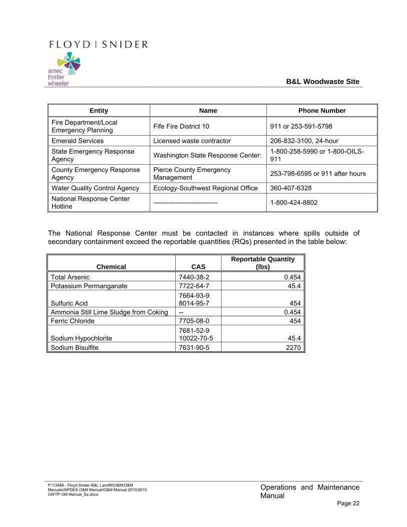
Entity Name Phone Number
Fire Department/Local Emergency Planning
Fife Fire District 10 911 or 253-591-5798
Emerald Services Licensed waste contractor 206-832-3100, 24-hour
State Emergency Response Agency
Washington State Response Center: 1-800-258-5990 or 1-800-OILS-911
County Emergency Response Agency
Pierce County Emergency Management
253-798-6595 or 911 after hours
Water Quality Control Agency Ecology-Southwest Regional Office 360-407-6328
National Response Center Hotline
----------------------------- 1-800-424-8802
The National Response Center must be contacted in instances where spills outside of secondary containment exceed the reportable quantities (RQs) presented in the table below:
Chemical CAS Reportable Quantity
(lbs)
Total Arsenic 7440-38-2 0.454 Potassium Permanganate 7722-64-7 45.4
Sulfuric Acid 7664-93-9 8014-95-7 454
Ammonia Still Lime Sludge from Coking -- 0.454 Ferric Chloride 7705-08-0 454
Sodium Hypochlorite 7681-52-9 10022-70-5 45.4
Sodium Bisulfite 7631-90-5 2270
B&L Woodwaste Site
P:\13488 - Floyd Snider-B&L Landfill\O&M\O&M Manuals\NPDES O&M Manual\O&M Manual 2015\2015 GWTP OM Manual_Sx.docx
Operations and Maintenance Manual
Page 23
8.0 Recordkeeping
Record keeping will be conducted in accordance with the most recently issued NPDES discharge permit. Electronic and/or hard copy records of all sample collection and analysis data, continuous monitoring data, calibration records, maintenance records, reports required by the Permit, and data used for the Permit application will be maintained at the GWTP Building. These records will be maintained for a minimum of three years. At the discretion of the Trust, additional copies of all records addressed in this O&M Plan may also be maintained at offsite location(s).
8.1 SAMPLE COLLECTION AND ANALYSIS DATA
The NPDES permit requires weekly grab sampling of the effluent to monitor pH and monthly composite sampling of the effluent to analyze treated water quality. The following records will be maintained regarding sample collection and analysis:
Grab sampling forms to document sample collection and analysis using the onsite bench top pH meter.
Composite sample collection forms documenting sample start time and date, sample stop time and date, and the name of the sampler.
Chain-of-custody forms for all samples provided to the laboratory for analysis.
Laboratory reports.
For any samples analyzed for pH in the GWTP laboratory, a copy of the analytical report documenting instrument calibration and sample analysis methods.
Hard copy originals of field forms (sample collection, originator chain-of-custody copy, field pH analyses) will be maintained in the GWTP Building.
8.2 CONTINUOUS MONITORING DATA
As noted above in this O&M Plan, process instrumentation is monitored and recorded by the automated monitoring and control system whenever the GWTP is in operation. The control system records readings from several process instruments to allow analysis and control of process variables. Additionally, process data are recorded for Permit compliance purposes to monitor the quality of the treated water effluent.
The following process instrumentation is monitored and recorded for process control purposes:
Influent Flow Transmitter FIT-100
Oxidation Tank ORP Transmitter AIT-110
B&L Woodwaste Site
P:\13488 - Floyd Snider-B&L Landfill\O&M\O&M Manuals\NPDES O&M Manual\O&M Manual 2015\2015 GWTP OM Manual_Sx.docx
Operations and Maintenance Manual
Page 24
Co-Precipitation Tank pH Transmitter AIT-120
pH Adjust Tank Level Transmitter LIT-420
pH Adjust Tank pH Transmitter AIT-420
Bag Filter Differential Pressure Transmitter DPIT-420
Cartridge Filter Differential Pressure Transmitter DPIT-430A and B
Adsorption Column Differential Pressure Transmitter DPIT-440A and B
Sludge Storage Tank Level Transmitter LIT-220
KMnO4 Feed Tank Level Transmitter LIT-310
Lime Slurry Tank Level Transmitter LIT-320
Polymer Feed Tank Level Transmitter LIT-330 & LIT 330B
Effluent pH Transmitter AIT-450
Data recorded from the above instruments are automatically stored in the process control database. Data from these instruments are copied to a database for process data and maintained as an electronic data file in the GWTP computer on a monthly basis no later than the 15th day of the month following data collection. These data will be simultaneously copied to a backup storage drive maintained at the GWTP Building. The electronic data files will be maintained for a minimum of three years.
8.3 CALIBRATION AND MAINTENANCE RECORDS
Written records will be prepared for calibration of process and laboratory instrumentation. These hard copy records will be maintained at the GWTP Building. Calibration records for equipment used to measure Permit parameters will also be scanned and stored electronically on the GWTP computer and on a backup storage drive maintained offsite. These records will be maintained for at least three years.
Written records confirming maintenance activities will be prepared and maintained at the GWTP Building. These records will document routine, preventive maintenance and also non-routine maintenance. Maintenance records will be placed in the equipment files that are maintained onsite for each piece of equipment. Maintenance records for all GWTP equipment will be maintained at the GWTP Building for a minimum of three years. If a piece of equipment is replaced with less than three years of use, equipment and maintenance files will be placed in an archive folder and kept onsite for a minimum of three years.
8.4 REPORTS
Several reports are required for compliance with the Permit. These include monthly DMRs, noncompliance reporting, and the other plans and reports, as specified in the Permit provisions.
B&L Woodwaste Site
P:\13488 - Floyd Snider-B&L Landfill\O&M\O&M Manuals\NPDES O&M Manual\O&M Manual 2015\2015 GWTP OM Manual_Sx.docx
Operations and Maintenance Manual
Page 25
Reports and plans prepared for compliance with the Permit will be maintained at the GWTP Building in hard copy and electronic format. These reports and plans will be maintained for a minimum of three years from the date the plan or report was prepared.
8.5 PERMIT APPLICATION DATA
A complete hard copy and electronic copy of the application for the Permit will be maintained at the GWTP Building for a minimum of three years. The application will be kept at the GWTP Building for as long as the Permit is effective. Future applications for permit renewal will also be maintained in the same manner at the GWTP Building.

B&L Woodwaste Site
Tables
Apr-10
mg/L ---- ---- ---- 5.7 ---- ---- ---- ---- 7.8 ---- ---- ---- ---- ---- 17.2 20.6 60.3 11.3 ---- 5.7 60.3 20.5mg/L ---- ---- ---- 0.1 U ---- ---- ---- ---- 0.1 U ---- ---- ---- ---- ---- 0.9 0.1 1 0.1 U ---- ND 1 0.7
mg-N/L ---- ---- ---- 0.1 U ---- ---- ---- ---- 0.1 U ---- ---- ---- ---- ---- 0.1 U 0.1 U 0.1 0.2 ---- ND 0.2 --mg-N/L ---- ---- ---- 0.1 U ---- ---- ---- ---- 0.1 U ---- ---- ---- ---- ---- 0.1 U 0.1 U 0.1 U 1 U ---- ND ND --mg/L ---- ---- ---- 0.1 U ---- ---- ---- ---- 0.3 ---- ---- ---- ---- ---- 0.1 U 0.1 U 0.1 U 0.1 U ---- ND 0.3 --mg/L ---- ---- ---- 2.4 ---- ---- ---- ---- 3.1 ---- ---- ---- ---- ---- 0.1 U 0.1 U 0.4 0.1 U ---- ND 3.1 2.0mg/L ---- ---- ---- 0.3 ---- ---- ---- ---- 0.3 ---- ---- ---- ---- ---- 1.0 U 0.1 U 1 U 1.6 ---- ND 1.6 0.7
µg/L ---- ---- ---- 50 U ---- ---- ---- ---- 50 U ---- ---- ---- ---- 50 U 50 U 50 U 50 U ---- ND ND --
µg/L 1,610 172 1,130 2.0 1.2 262 9.7 78.9 18.1 13.7 1,860 1,880 1,630 273 190 1,920 1,550 4,150 4,540 1.2 4,540 1,121
µg/L ---- ---- ---- 28 ---- ---- ---- ---- 25 ---- ---- ---- ---- 168 128 80 146 ---- 25 168 96
µg/L ---- ---- ---- 1 U ---- ---- ---- ---- 1 U ---- ---- ---- ---- 1 U 1 U 1 U 1 U ---- ND ND --
µg/L ---- ---- 2 U ---- ---- ---- 2 U ---- ---- ---- ---- 2 U 2 U 2 U 2 U ---- ND ND --
µg/L 74,500 102,000 109,000 ---- 15,800 18,600 85,500 75,100 ---- 14,600 119,000 96,400 79,100 139,000 ---- ---- ---- ---- 139,000 14,600 139,000 82,100
µg/L ---- ---- ---- 5 U ---- ---- ---- ---- 7 ---- ---- ---- ---- 5 U 5 U 5 U 5 U ---- ND 7 --
µg/L 0.8 1.1 1.0 2 U 0.5 U 1.1 0.9 0.7 5 0.7 1.4 0.7 47.0 2 U 7 5 10 ---- ND 47 6.3
µg/L 88,500 58,600 60,600 8,550 7,590 2,060 22,000 21,500 2,720 130 62,300 44,700 71,900 55,000 69,600 77,900 24,400 48,300 56,200 130 88,500 41,200
µg/L 1 U 1 U 1 U 1 U 1 U 1 U 1 U 1 U 1 U 1 U 1 U 1 U 12 1 U 3 1 7 ---- ND 12 5.8
Magnesium µg/L 49,400 54,900 58,100 ---- 8,720 9,630 51,300 39,700 ---- 15,700 108,000 70,500 38,000 47,900 ---- ---- ---- ---- 104,000 8,720 108,000 50,500
µg/L 2,610 5,740 5,470 271 307 1,310 4,550 4,350 879 188 2,680 2,900 4,100 2,160 4,060 4,380 3,260 3,460 188 5,740 2,926
µg/L ---- ---- ---- 0.1 U ---- ---- ---- ---- 0.1 U ---- ---- ---- ---- ---- 0.1 U 0.1 U 0.1 U 0.1 U ---- ND ND --
µg/L ---- ---- ---- 10 U ---- ---- ---- ---- 10 ---- ---- ---- ---- ---- 10 10 U 20 30 ---- ND 30 18
µg/L ---- ---- ---- 0.5 U ---- ---- ---- ---- 0.5 U ---- ---- ---- ---- ---- 2 U 2 U 2 U 2 U ---- ND ND --
µg/L ---- ---- ---- 3 U ---- ---- ---- ---- 3 U ---- ---- ---- ---- ---- 3 U 3 U 3 U 3 U ---- ND ND --
µg/L ---- ---- ---- 0.2 U ---- ---- ---- ---- 0.2 U ---- ---- ---- ---- ---- 0.2 U 0.2 U 0.2 U 0.2 U ---- ND ND --
µg/L 4 U 15 5 10 U 4 U 4 U 4 U 4 U 10 U 4 U 4 U 4 U ---- 59 10 U 20 20 80 ---- ND 80 33
µg/L ---- ---- ---- 50 U ---- ---- ---- ---- 50 U ---- ---- ---- ---- ---- 50 U 50 U 50 U 50 U ---- ND ND --
µg/L ---- ---- ---- 2.2 ---- ---- ---- ---- 16.8 ---- ---- ---- ---- ---- 190 1,710 1,360 4,260 ---- 2.2 4,260 1,260
Arsenic III µg/L ---- ---- ---- 1.54 ---- ---- ---- ---- 11.7 ---- ---- ---- ---- ---- 146 1,460 662 2,960 ---- 1.54 2,960 874
Arsenic V µg/L ---- ---- ---- 0.71 ---- ---- ---- ---- 4.33 ---- ---- ---- ---- ---- 60 777 884 1,750 ---- 0.71 1,750 579
Dimethylarsinic acid/DMAs µg/L ---- ---- ---- 0.35 U ---- ---- ---- ---- 0.35 U ---- ---- ---- ---- ---- 6.9 U 6.9 U 6.9 U 6.9 U ---- ND ND --Monomethylarsonic acid/MMAs µg/L ---- ---- ---- 0.35 U ---- ---- ---- ---- 0.35 U ---- ---- ---- ---- ---- 6.9 U 6.9 U 6.9 U 6.9 U ---- ND ND --
µg/L ---- ---- ---- 24 ---- ---- ---- ---- 9 ---- ---- ---- ---- ---- 164 109 72 129 ---- 9 164 85
µg/L ---- ---- ---- 1 U ---- ---- ---- ---- 1 U ---- ---- ---- ---- ---- 1 U 1 U 1 U 1 U ---- ND ND --
µg/L ---- ---- ---- 2 U ---- ---- ---- ---- 2 U ---- ---- ---- ---- ---- 2 U 2 U 2 U 2 U ---- ND ND --
µg/L ---- ---- ---- 17,600 ---- ---- ---- ---- 14,200 ---- ---- ---- ---- ---- 59,000 116,000 69,100 130,000 ---- 14,200 130,000 67,700
µg/L ---- ---- ---- 5 U ---- ---- ---- ---- 5 U ---- ---- ---- ---- ---- 5 U 5 U 5 U 5 U ---- ND ND --
µg/L ---- ---- ---- 2 U ---- ---- ---- ---- 2 U ---- ---- ---- ---- ---- 2 U 2 U 2 U 2 U ---- ND ND --
µg/L ---- ---- ---- 7,990 ---- ---- ---- ---- 530 ---- ---- ---- ---- ---- 69,500 76,100 23,000 46,700 ---- 530 76,100 37,300
µg/L ---- ---- ---- 1 U ---- ---- ---- ---- 1 U ---- ---- ---- ---- ---- 1 U 1 U 1 U 1 U ---- ND ND --
µg/L ---- ---- ---- 9,300 ---- ---- ---- ---- 13,000 ---- ---- ---- ---- ---- 39,600 66,100 41,600 103,000 ---- 9,300 103,000 45,400
µg/L ---- ---- ---- 271 ---- ---- ---- ---- 850 ---- ---- ---- ---- ---- 2,160 3,950 4,480 3,320 ---- 271 4,480 2,510
µg/L ---- ---- ---- 0.1 U ---- ---- ---- ---- 0.1 U ---- ---- ---- ---- ---- 0.1 U 0.1 U 0.1 U 0.1 U ---- ND ND --
µg/L ---- ---- ---- 10 U ---- ---- ---- ---- 10 U ---- ---- ---- ---- ---- 10 U 10 U 20 20 ---- ND 20 20
µg/L ---- ---- ---- 4,680 ---- ---- ---- ---- 3,280 ---- ---- ---- ---- ---- 6,360 12,200 11,900 20,600 ---- 3,280 20,600 9,800
µg/L ---- ---- ---- 0.5 U ---- ---- ---- ---- 0.5 U ---- ---- ---- ---- ---- 2 U 2 U 2 U 2 U ---- ND ND --
µg/L ---- ---- ---- 21,100 ---- ---- ---- ---- 19,700 ---- ---- ---- ---- ---- 28,000 30,600 24,200 37,500 ---- 19,700 37,500 26,900
µg/L ---- ---- ---- 3 U ---- ---- ---- ---- 3 U ---- ---- ---- ---- ---- 3 U 3 U 3 U 3 U ---- ND ND --
µg/L ---- ---- ---- 21,400 ---- ---- ---- ---- 19,500 ---- ---- ---- ---- ---- 29,300 68,000 86,300 37,500 ---- 19,500 86,300 43,700
µg/L ---- ---- ---- 0.2 U ---- ---- ---- ---- 0.2 U ---- ---- ---- ---- ---- 0.2 U 0.2 U 0.2 U 0.2 U ---- ND ND --
µg/L ---- ---- ---- 10 U ---- ---- ---- ---- 10 U ---- ---- ---- ---- ---- 10 U 10 U 10 40 ---- ND 40 ------ ---- ---- ---- ---- ---- ---- ---- ---- ---- ---- ---- ----
µg/L ---- ---- ---- ---- ---- ---- ---- ---- ---- ---- ---- ---- ---- ---- 1 U 1 U 1 U 1 U ---- ND ND --
µg/L ---- ---- ---- ---- ---- ---- ---- ---- ---- ---- ---- ---- ---- ---- 1 U 1 U 1 U 1 U ---- ND ND --
µg/L ---- ---- ---- ---- ---- ---- ---- ---- ---- ---- ---- ---- ---- ---- 1 U 42 360 1 U ---- ND 360 201
µg/L ---- ---- ---- ---- ---- ---- ---- ---- ---- ---- ---- ---- ---- ---- 1 U 1.8 1 U 1 U ---- ND 1.8 ------ ---- ---- ---- ---- ---- ---- ---- ---- ---- ---- ---- ----
mg/L 545 627 688 135 129 157 538 525 138 144 923 660 470 567 464 812 499 875 867 129 923 514
mg/L 545 627 688 135 129 157 538 525 138 144 923 660 470 567 464 812 499 875 867 129 923 514
mg/L 1 U 1 U 1 U 1 U 1 U 1 U 1 U 1 U 1 U 1 U 1 U 1 U 1 U 1 U 1 U 1 U 1 U 1 U 1 U ND ND --mg/L 1 U 1 U 1 U 1 U 1 U 1 U 1 U 1 U 1 U 1 U 1 U 1 U 1 U 1 U 1 U 1 U 1 U 1 U 1 U ND ND --mg/L 0.05 U 0.05 U ---- ---- ---- ---- ---- 0.05 U 0.05 U 0.05 U 0.05 U ---- ND ND --mg/L ---- ---- ---- ---- ---- 14.9 18.4 9.5 18.0 ---- 9.5 18.4 15.2
mg/L 4.27 1.70 ---- ---- ---- 40.2 ---- 24 57.6 42.8 36.4 50.8 1.7 57.6 32.2mg/L ---- ---- ---- ---- ---- 23.4 56.8 46.8 36 ---- 23.4 56.8 40.8
pH units 6.66 7.13 ---- ---- ---- ---- 6.51 6.46 6.42 6.44 ---- 6.42 7.13 6.6
mg/L 549 925 737 206 164 228 630 553 201 163 937 649 ---- 633 532 909 686 889 ---- 163 937 564
pH units 6.29 6.1 6.23 7.01 6.82 5.7 6.14 6.1 7.28 7.0 6.09 6.25 ---- 6.04 6.52 6.12 6.27 5.97 ---- 5.7 7.28 6.3
mS/cm 1.2 1.38 1.5 0.305 0.260 0.364 1.3 1.15 0.280 0.297 1.599 1.177 ---- 1.328 1.040 1.778 1.044 1.494 ---- 0.26 1.778 1.0oC 12.6 12 12.3 11.5 12.28 11.9 11.7 11.6 11.4 12.1 13 12.95 ---- 12.86 11.8 13.0 12.7 12.7 ---- 11.4 13 12.3mV -114 -28 -101 -129 -151 28 -69 -17 -53 26 -145.7 -160 ---- -110 -130 -232 -92 -106 ---- -232 28 -93.2
NotesExcept where noted, all samples were collected in April, 2010. Refer to the Engineering Alternatives Evaluation, Appendix A, Treatability Study Report, for additional information.
U Result was below laboratory reporting limit.1 The average concentrations are based only on results that were greater than the laboratory reporting limits. The average was not calculated unless there were at least 2 detected results.
Total Organic Carbon (TOC)
Dissolved Organic Carbon (DOC)
pH
Total dissolved solids (TDS)
pH
Specific Conductivity
Field Parameters
Selenium
Nickel
Iron
Chromium
Dissolved Arsenic Speciation
Barium
Silver
Dissolved Metals
Arsenic
TemperatureOxidation-reduction potential (ORP)
Carbonate Alkalinity
Hydroxide Alkalinity
Sulfide
5-Day Biochemical Oxygen Demand (BOD5)
Bicarbonate Alkalinity
Zinc
Zinc
Nickel
Potassium
Selenium
Mercury
Copper
Silicon
Silver
Sodium
Phenols
Phenol
2-Methylphenol
4-Methylphenol
2,4-Dimethylphenol
Total Alkalinity
General Chemistry
---- ---- ---- ----
Iron
Arsenic
Chloride
Bromide
PZ-3BUnits
Calcium
Barium
PZ-4B
Total Metals
Anions
Copper
Thallium
Thallium
Lead
Lead
Magnesium
Manganese
Manganese
Mercury
Beryllium
Cadmium
Calcium
Antimony
PZ-11Jun-10 PD-109 PZ-9 PZ-12
----
Apr-10PD-107
PZ-8C PZ-10 PZ-13PZ-8B Jun-10
---- ---- ---- ----
PZ-5BPZ-1B PZ-2B
----
----
----
----
--------
----
----
----
----
----
----
----
--------
----
----
----
----
----
PZ-4C
----
----
----
----
----
----
----
----
----
----
----
----
----
----
----
TABLE 1Groundwater Quality Basis
B&L Woodwaste Site
----
----
----
----
----
Nitrogen as Nitrate
Nitrogen as Nitrite
Ortho-phosphorus
Parameter PZ-6B PZ-7B Minimum Maximum Average1
Beryllium
Cadmium
Chromium
Sulfate
Fluoride
Antimony
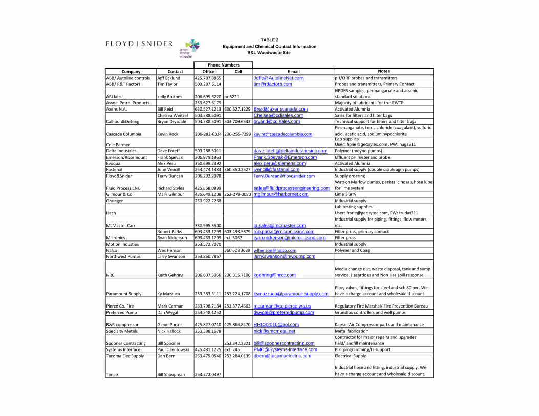
Company Contact Office Cell E‐mail Notes
ABB/ Autoline controls Jeff Ecklund 425.787.8855 [email protected] pH/ORP probes and transmittersABB/ R&T Factors Tim Taylor 503.287.6114 [email protected] Probes and transmitters, Primary Contact
ARI labs kelly Bottom 206.695.6220 or 6221NPDES samples, permanganate and arsenic standard solutions
Assoc. Petro. Products 253.627.6179 Majority of lubricants for the GWTPAxens N.A. Bill Reid 630.527.1213 630.527.1229 [email protected] Activated Alumnia
Chelsea Weitzel 503.288.5091 [email protected] Sales for filters and filter bagsBryan Drysdale 503.288.5091 503.709.6533 [email protected] Technical support for filters and filter bags
Cascade Columbia Kevin Rock 206‐282‐6334 206‐255‐7299 [email protected], ferric chloride (coagulant), sulfuric acid, acetic acid, sodium hypochlorite
Cole ParmerLab suppliesUser: [email protected], PW: hugs311
Delta Industries Dave Foteff 503.288.5011 [email protected] Polymer (moyno pumps)Emerson/Rosemount Frank Spevak 206.979.1953 [email protected] Effluent pH meter and probeEvoqua Alex Peru 360.699.7392 [email protected] Activated AlumniaFastenal John Vencill 253.474.1383 360.350.2527 [email protected] Industrial supply (double diaphragm pumps)Floyd&Snider Terry Duncan 206.292.2078 [email protected] Supply ordering
Fluid Process ENG Richard Styles 425.868.0899 [email protected] Marlow pumps, peristalic hoses, hose lube for lime system
Gilmour & Co Mark Gilmour 435.649.1208 253‐279‐0080 [email protected] Lime SlurryGrainger 253.922.2268 Industrial supply
HachLab testing supplies.User: [email protected], PW: trudat311
McMaster Carr 330.995.5500 [email protected] supply for piping, fittings, flow meters, etc.
Robert Parks 603.433.1299 603.498.5679 [email protected] Filter press, primary contactRyan Nickerson 603.433.1299 ext. 3037 [email protected] Filter press
Motion Industies 253.572.7070 Industrial supplyNalco Wes Henson 360 628 3639 [email protected] Polymer and CoagNorthwest Pumps Larry Swanson 253.850.7867 [email protected]
NRC Keith Gehring 206.607.3056 206.316.7106 [email protected] change out, waste disposal, tank and sump service, Hazardous and Non Haz spill response
Paramount Supply Ky Mazzuca 253.383.3111 253.224.1708 [email protected], valves, fittings for steel and sch 80 pvc. We have a charge account and wholesale discount.
Pierce Co. Fire Mark Carman 253.798.7184 253.377.4563 [email protected] Regulatory Fire Marshal/ Fire Prevention BureauPreferred Pump Dan Wygal 253.548.1252 [email protected] Grundfos controllers and well pumps
R&R compressor Glenn Porter 425.827.0710 425.864.8470 [email protected] Kaeser Air Compressor parts and maintenanceSpecialty Metals Nick Hallock 253.398.1678 [email protected] Metal fabrication
Spooner Contracting Bill Spooner 253.347.3321 [email protected] for major repairs and upgrades, field/landfill maintenance
Systems Interface Paul Osentowski 425.481.1225 ext. 245 [email protected] PLC programming/IT supportTacoma Elec Supply Dan Bern 253.475.0540 253.284.0139 [email protected] Electrical Supply
Timco Bill Shoopman 253.272.0397Industrial hose and fitting, industrial supply. We have a charge account and wholesale discount.
Calhoun&DeJong
Micronics
Phone Numbers
TABLE 2
Equipment and Chemical Contact Information
B&L Woodwaste Site

B&L Woodwaste Site
Drawings
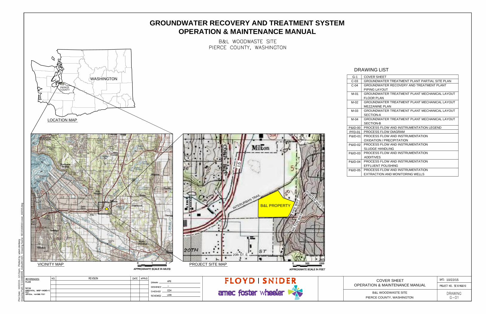
Plo
tD
ate
:1
0/2
2/1
5-
12
:21
pm
,P
lott
ed
by:
ad
am
.ste
nber
gD
raw
ing
Pa
th:
S:\
13
48
8\0
09
_A
sBu
ilt\C
AD
\,D
raw
ing
Na
me
:S
E1
01
600
10-c
over
_102
215.
dwg
10/22/15
PIERCE COUNTY, WASHINGTON
B&L WOODWASTE SITE
COVER SHEETOPERATION & MAINTENANCE MANUAL
GROUNDWATER RECOVERY AND TREATMENT SYSTEMOPERATION & MAINTENANCE MANUAL
PIERCECOUNTY
LOCATION MAP
VICINITY MAP PROJECT SITE MAP
WASHINGTON
B&L PROPERTY
20th ST. E.
I-5
FIFE
WA
Y
MIL
TON
WA
Y
INTERURBAN TRAIL
PORTERW
AY
DRAWING LISTCOVER SHEETGROUNDWATER TREATMENT PLANT PARTIAL SITE PLANGROUNDWATER RECOVERY AND TREATMENT PLANTPIPING LAYOUTGROUNDWATER TREATMENT PLANT MECHANICAL LAYOUTFLOOR PLANGROUNDWATER TREATMENT PLANT MECHANICAL LAYOUTMEZZANINE PLANGROUNDWATER TREATMENT PLANT MECHANICAL LAYOUTSECTION-AGROUNDWATER TREATMENT PLANT MECHANICAL LAYOUTSECTION-BPROCESS FLOW AND INSTRUMENTATION LEGENDPROCESS FLOW DIAGRAMPROCESS FLOW AND INSTRUMENTATIONOXIDATION / PRECIPITATIONPROCESS FLOW AND INSTRUMENTATIONSLUDGE HANDLINGPROCESS FLOW AND INSTRUMENTATIONADDITIVESPROCESS FLOW AND INSTRUMENTATIONEFFLUENT POLISHINGPROCESS FLOW AND INSTRUMENTATIONEXTRACTION AND MONITORING WELLS
G-1C-03C-04
M-01
M-02
M-03
M-04
P&ID-00PFD-01P&ID-01
P&ID-02
P&ID-03
P&ID-04
P&ID-05
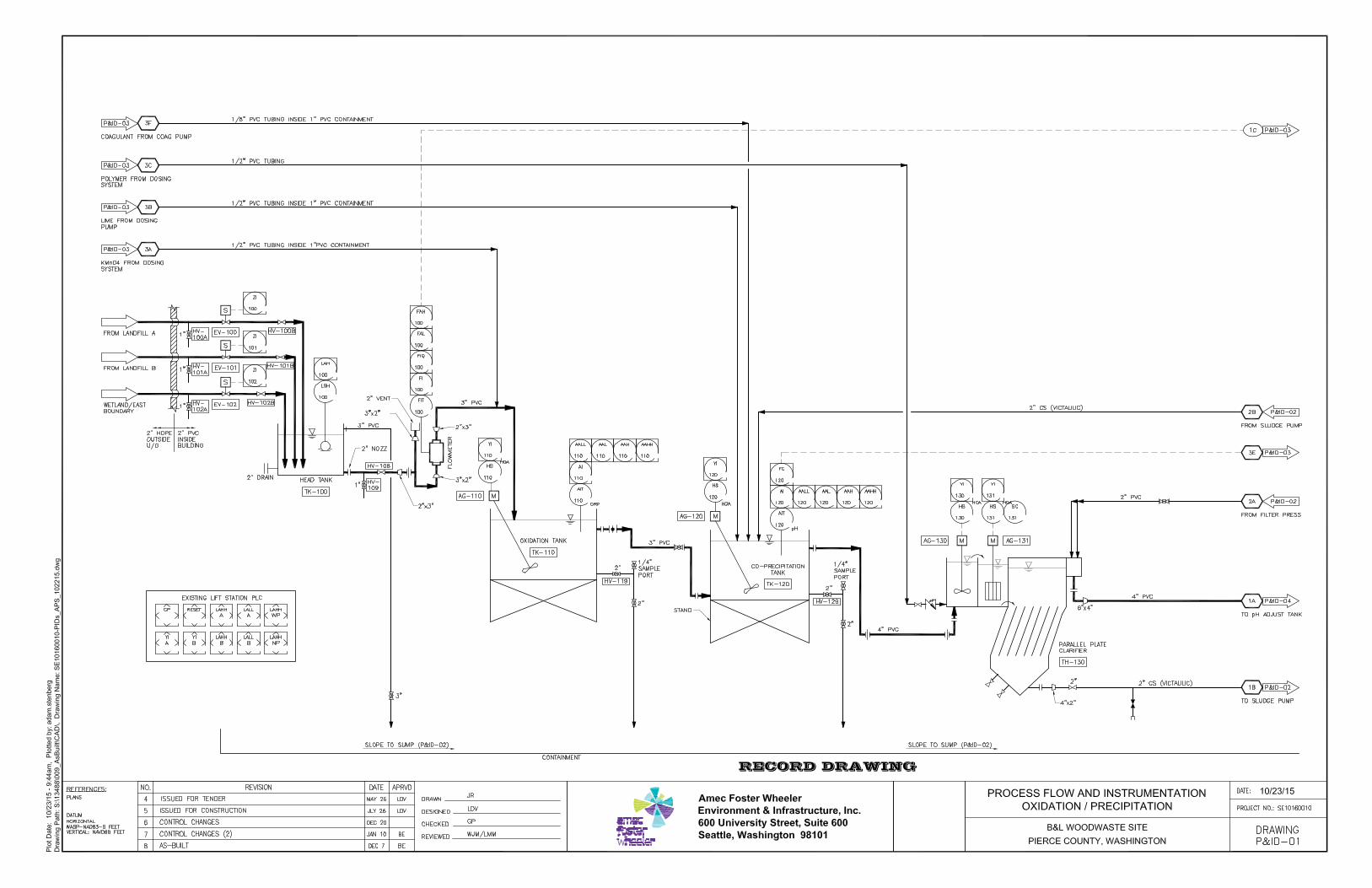
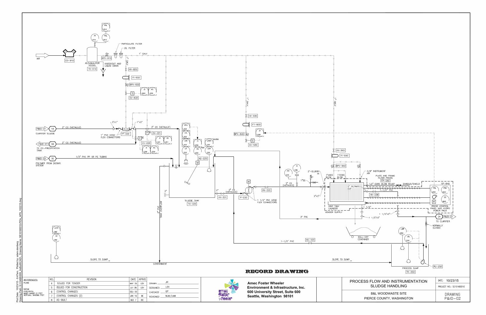
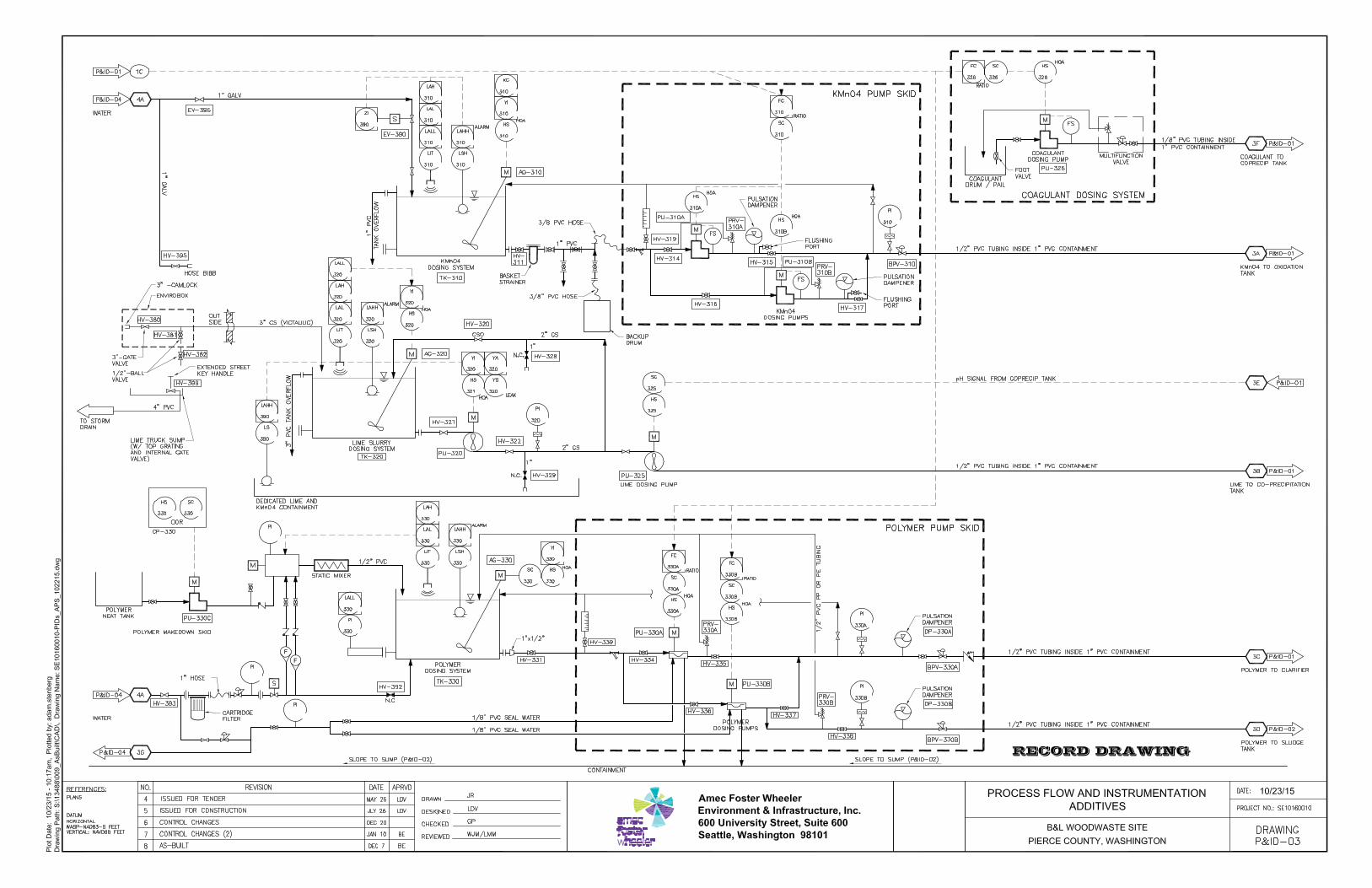
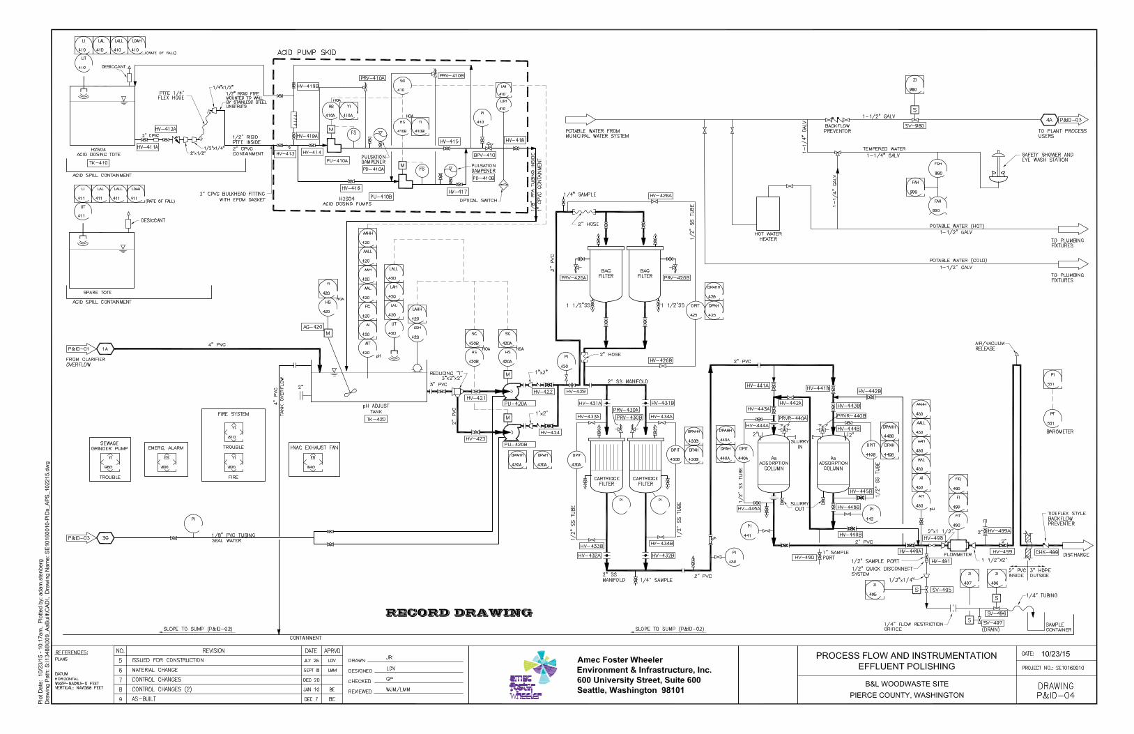
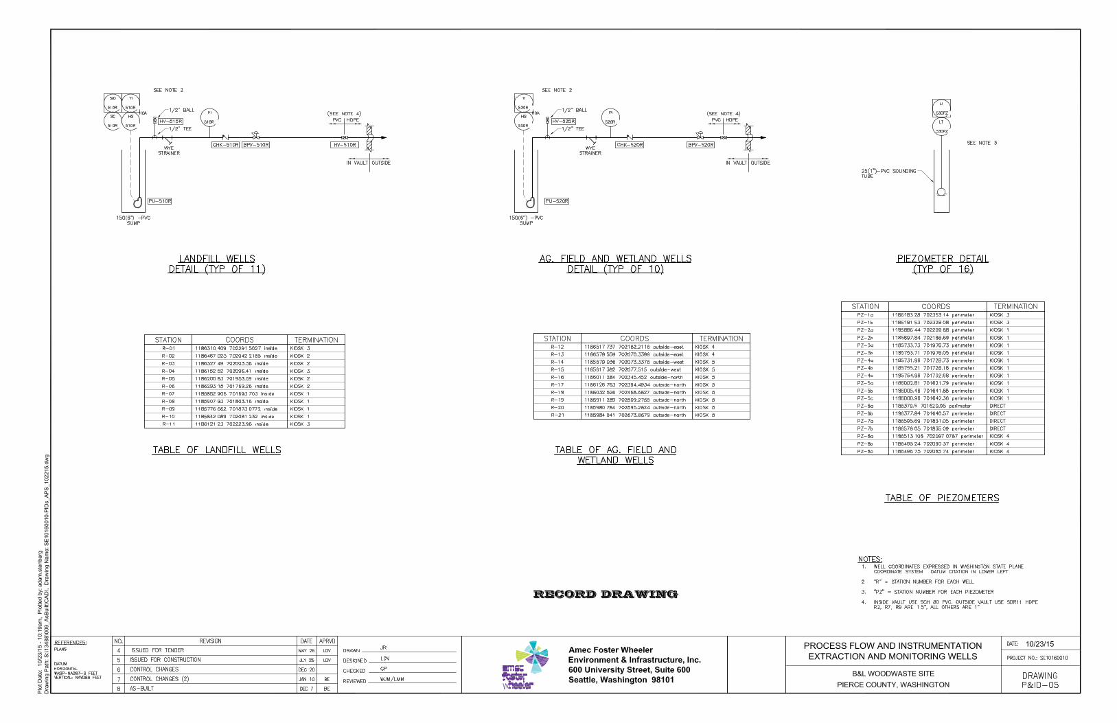


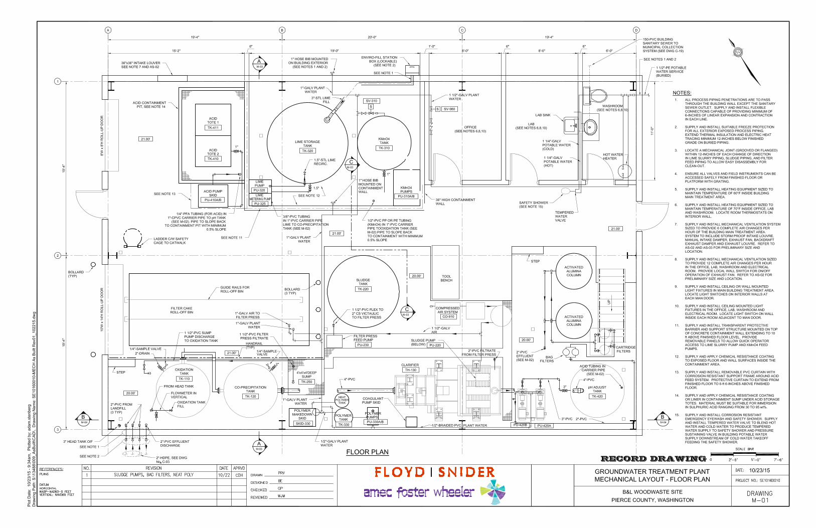
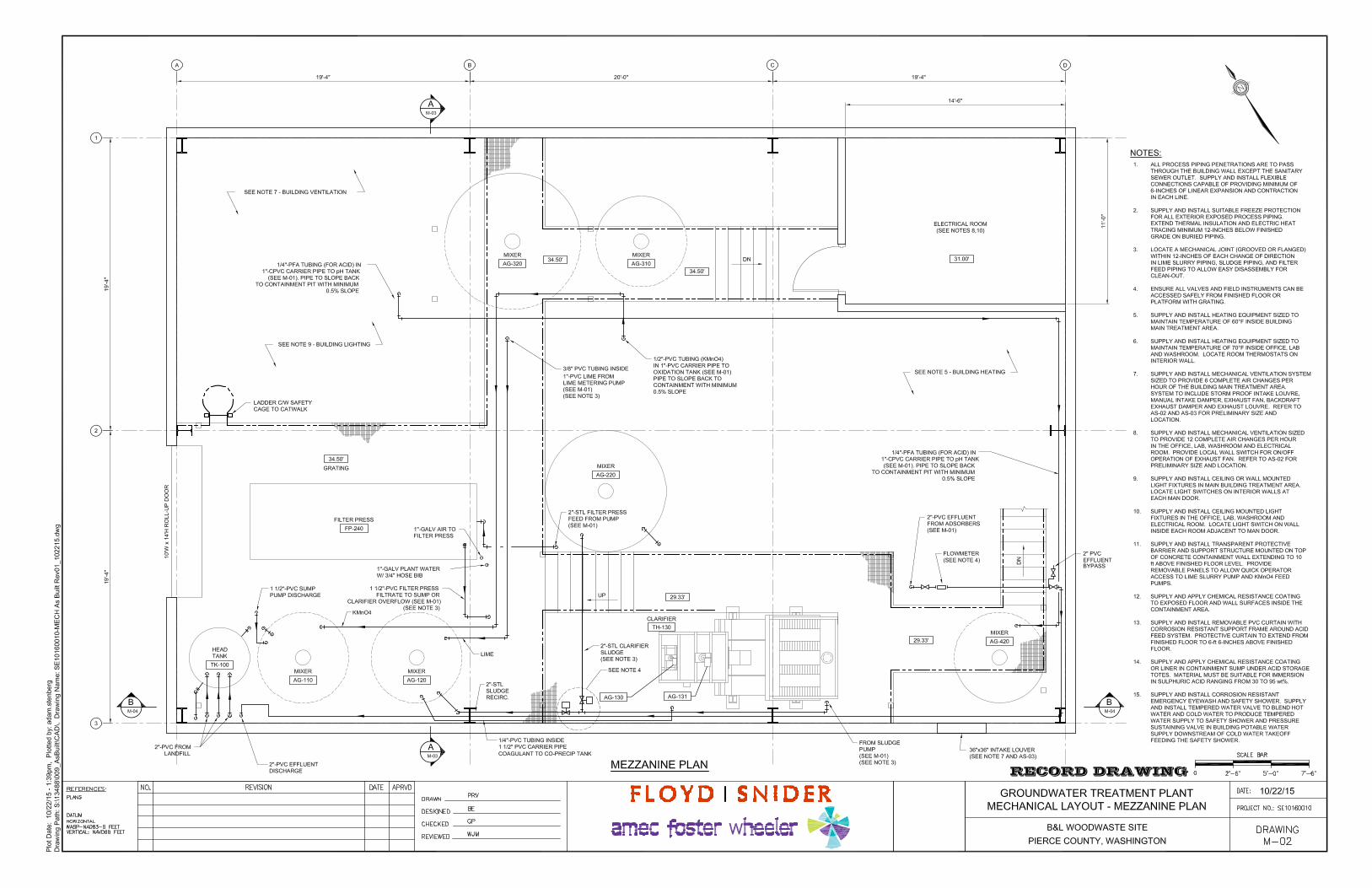
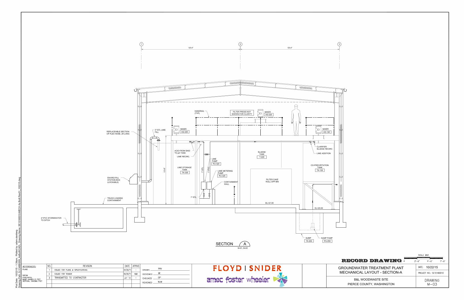
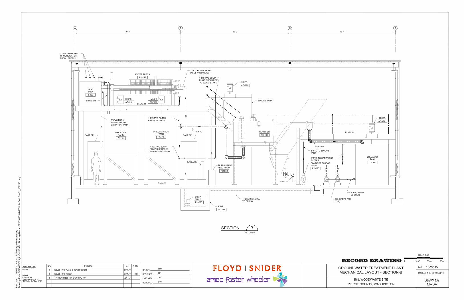
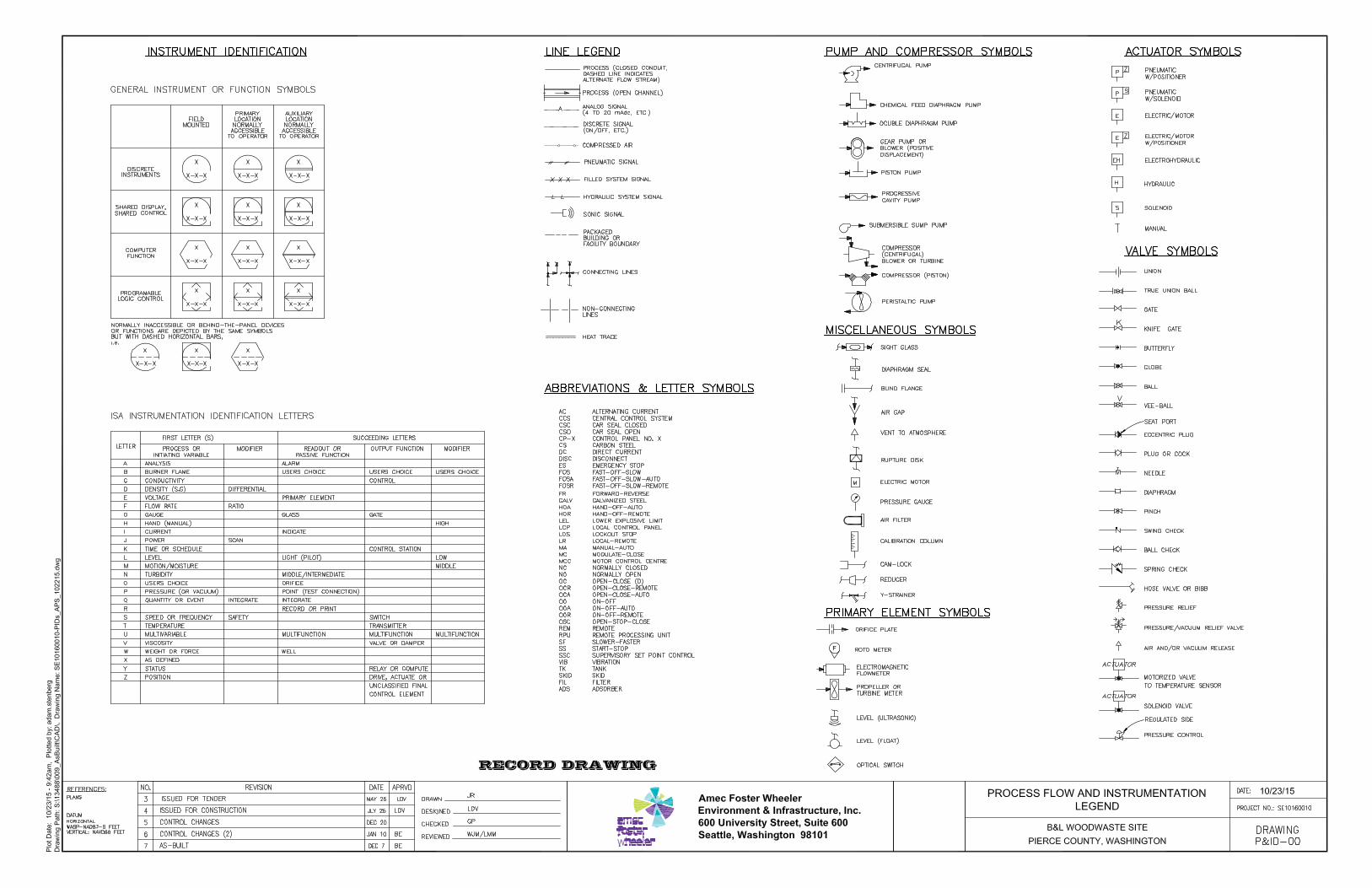
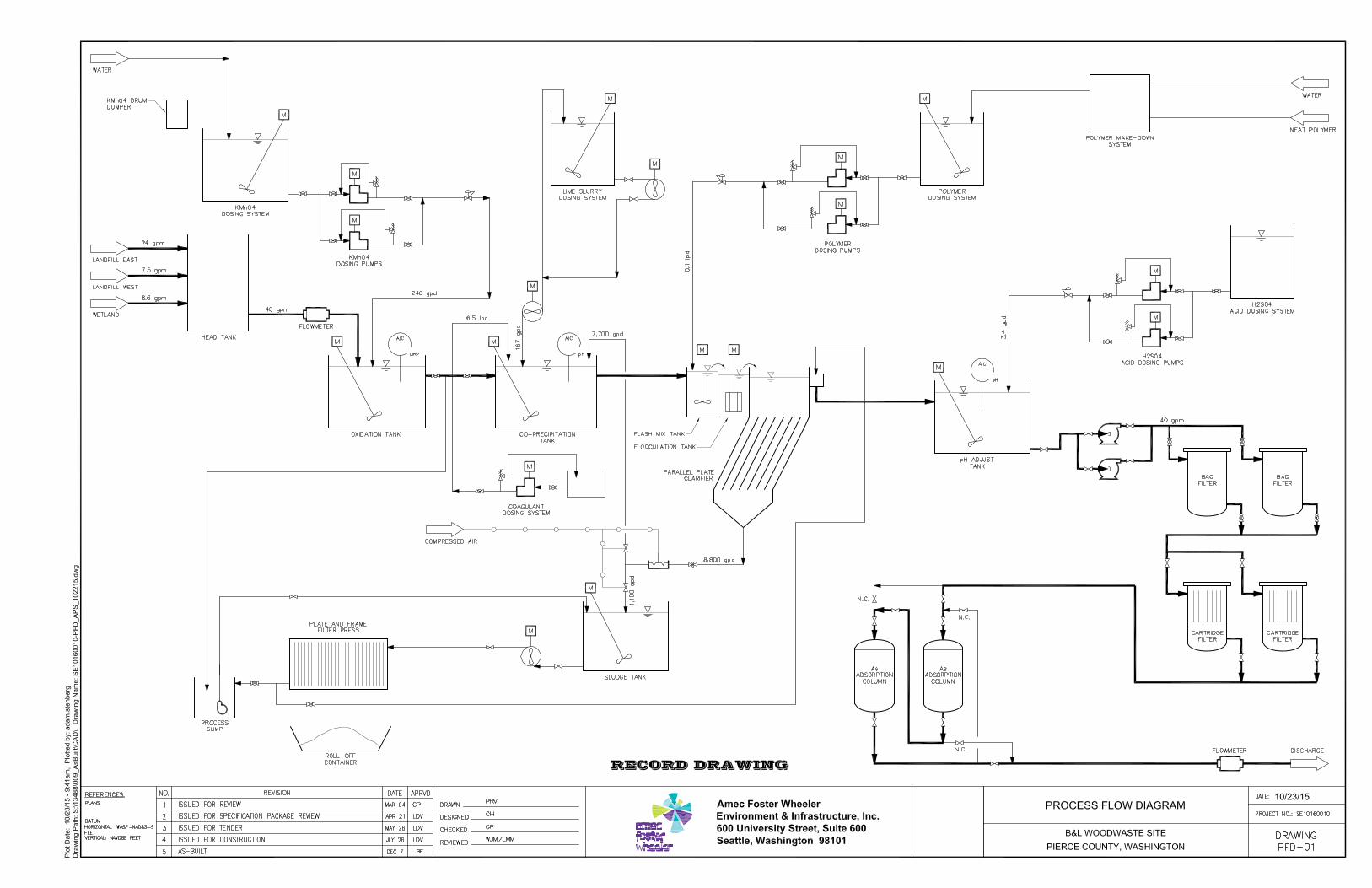
B&L Woodwaste Site
Appendix A
Groundwater Treatment Plant Operations and Maintenance Procedures
B&L Woodwaste Site
TableofContents
P-001 Documentation and Recordkeeping ......................................................... P-001
P-010 Lab Operating Procedures .......................................................................... P-010
P-020 Routine Maintenance ................................................................................... P-020
P-050 Normal Startup & Shutdown ....................................................................... P-050
P-100 Head Tank & Oxidation Tank ...................................................................... P-100
P-120 Co-Precipitation Tank .................................................................................. P-120
P-130 Clarifier System ........................................................................................... P-130
P-250 Secondary Containment System ................................................................ P-250
P-310 Permanganate Feed System ....................................................................... P-310
P-320 Lime Feed System ....................................................................................... P-320
P-326 Coagulant Feed System .............................................................................. P-326
P-330 Polymer Feed System ................................................................................. P-330
P-410 Acid Feed System ........................................................................................ P-410
P-420 pH Adjust Tank and Effluent Pumps .......................................................... P-420
P-425 Bag Filter System ........................................................................................ P-425
P-430 Cartridge Filter System ............................................................................... P-430
P-440 Adsorption Columns and Effluent pH Meter ............................................. P-440
P-910 Air Compressor System .............................................................................. P-910
P-940 Sludge Dewatering System ......................................................................... P-940
P-001-1
STANDARD OPERATION PROCEDURES: B&L WOODWASTE GROUNDWATER TREATMENT SYSTEM
PROCEDURE 001 - DOCUMENTATION AND RECORDKEEPING B&L Woodwaste Landfill
Milton, Washington
OPERATION PROCEDURES, GENERAL OVERVIEW Introduction This procedure outlines operational procedures for general documentation and
recordkeeping at the B&L Woodwaste Site. Two primary forms of records and documentation are kept at the site; compliance documentation and site operations documentation. As part of the NPDES program, any records or documents associated with submittals, sample collection, or equipment used to satisfy the NPDES Permit requirements must be maintained onsite for a minimum of three years. In order to improve system performance and to ensure equipment is operating well on a proactive basis, documents and records are maintained onsite for all operations including routine sampling for system performance and maintenance for all treatment system components.
Pre-requisites to Do This Procedure
To do this procedure you must: Be fully trained for treatment system operations or be training in the area with
someone who has been fully trained. Be fully trained for handling and management of dangerous wastes. Be familiar with all aspects of this operating procedure. Be Hazardous Waste Operations (HAZWOPER)-trained and current with
annual training updates.
In This Procedure Following is a list of topics in this Procedure:
Description See Page
1.0 Safety Considerations 2
2.0 NPDES Permit Record Keeping 3
3.0 Maintenance Records 4
4.0 Management of Change 4
5.0 PLC Data Download 5
6.0 Site Checklists 5
P-001-2
1.0 SAFETY CONSIDERATIONS Health and Safety Plan (HASP)
The most recent version of the HASP is maintained in the treatment building office and provides plans and requirements to protect the health and safety of workers involved in the operation and maintenance of the groundwater extraction and treatment system. All workers must be familiar with and sign the HASP. Specific requirements for Personal Protective Equipment (PPE) are included in the HASP. If there are any discrepancies between PPE requirements included in these procedures and PPE requirements specified in the HASP, the requirements specified in the HASP shall be followed.
Level of Hazard Low Due to the presence of dangerous waste within the closed landfill, all personnel working at the site must be fully trained in accordance with 29 CFR 1910 and WISHA regulations. Forty-hour HAZWOPER training with yearly eight hour refresher training is required for anyone performing work at the B&L Woodwaste Site.
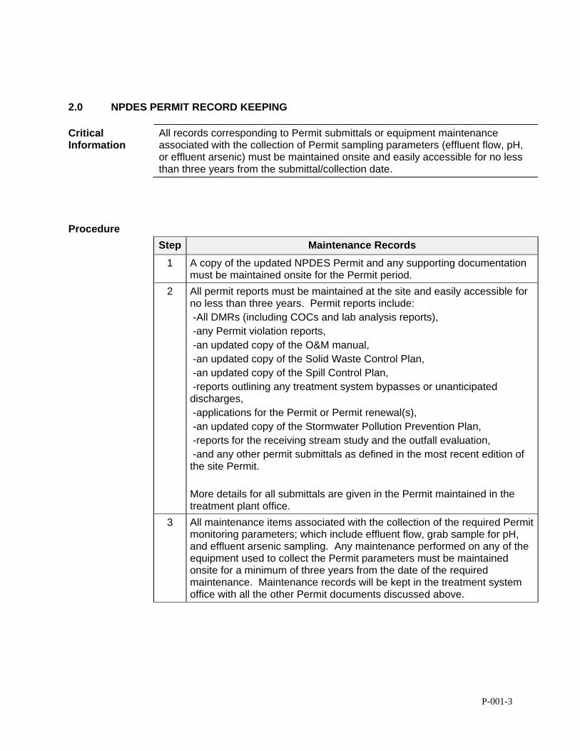
P-001-3
2.0 NPDES PERMIT RECORD KEEPING
Critical Information
All records corresponding to Permit submittals or equipment maintenance associated with the collection of Permit sampling parameters (effluent flow, pH, or effluent arsenic) must be maintained onsite and easily accessible for no less than three years from the submittal/collection date.
Procedure
Step Maintenance Records
1 A copy of the updated NPDES Permit and any supporting documentation must be maintained onsite for the Permit period.
2 All permit reports must be maintained at the site and easily accessible for no less than three years. Permit reports include: -All DMRs (including COCs and lab analysis reports), -any Permit violation reports, -an updated copy of the O&M manual, -an updated copy of the Solid Waste Control Plan, -an updated copy of the Spill Control Plan, -reports outlining any treatment system bypasses or unanticipated discharges, -applications for the Permit or Permit renewal(s), -an updated copy of the Stormwater Pollution Prevention Plan, -reports for the receiving stream study and the outfall evaluation, -and any other permit submittals as defined in the most recent edition of the site Permit. More details for all submittals are given in the Permit maintained in the treatment plant office.
3 All maintenance items associated with the collection of the required Permit monitoring parameters; which include effluent flow, grab sample for pH, and effluent arsenic sampling. Any maintenance performed on any of the equipment used to collect the Permit parameters must be maintained onsite for a minimum of three years from the date of the required maintenance. Maintenance records will be kept in the treatment system office with all the other Permit documents discussed above.
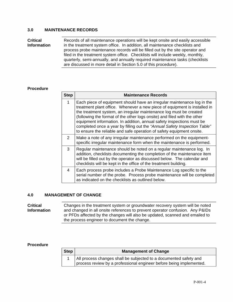
P-001-4
3.0 MAINTENANCE RECORDS
Critical Information
Records of all maintenance operations will be kept onsite and easily accessible in the treatment system office. In addition, all maintenance checklists and process probe maintenance records will be filled out by the site operator and filed in the treatment system office. Checklists will include weekly, monthly, quarterly, semi-annually, and annually required maintenance tasks (checklists are discussed in more detail in Section 5.0 of this procedure).
Procedure
Step Maintenance Records
1 Each piece of equipment should have an irregular maintenance log in the treatment plant office. Whenever a new piece of equipment is installed in the treatment system, an irregular maintenance log must be created (following the format of the other logs onsite) and filed with the other equipment information. In addition, annual safety inspections must be completed once a year by filling out the “Annual Safety Inspection Table” to ensure the reliable and safe operation of safety equipment onsite.
2 Make a note of any irregular maintenance performed on the equipment-specific irregular maintenance form when the maintenance is performed.
3 Regular maintenance should be noted on a regular maintenance log. In addition, checklists documenting the completion of the maintenance item will be filled out by the operator as discussed below. The calendar and checklists will be kept in the office of the treatment building.
4 Each process probe includes a Probe Maintenance Log specific to the serial number of the probe. Process probe maintenance will be completed as indicated on the checklists as outlined below.
4.0 MANAGEMENT OF CHANGE
Critical Information
Changes in the treatment system or groundwater recovery system will be noted and changed in all onsite references to prevent operator confusion. Any P&IDs or PFDs affected by the changes will also be updated, scanned and emailed to the process engineer to document the change.
Procedure
Step Management of Change
1 All process changes shall be subjected to a documented safety and process review by a professional engineer before being implemented.
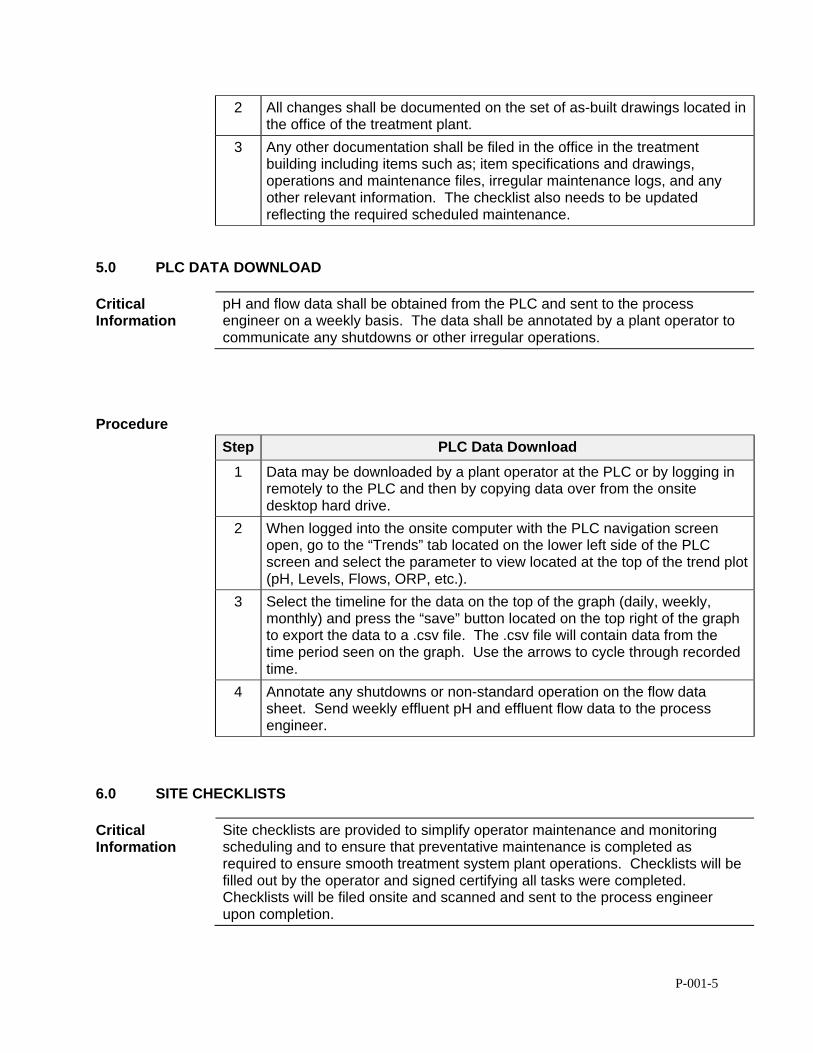
P-001-5
2 All changes shall be documented on the set of as-built drawings located in the office of the treatment plant.
3 Any other documentation shall be filed in the office in the treatment building including items such as; item specifications and drawings, operations and maintenance files, irregular maintenance logs, and any other relevant information. The checklist also needs to be updated reflecting the required scheduled maintenance.
5.0 PLC DATA DOWNLOAD
Critical Information
pH and flow data shall be obtained from the PLC and sent to the process engineer on a weekly basis. The data shall be annotated by a plant operator to communicate any shutdowns or other irregular operations.
Procedure
Step PLC Data Download
1 Data may be downloaded by a plant operator at the PLC or by logging in remotely to the PLC and then by copying data over from the onsite desktop hard drive.
2 When logged into the onsite computer with the PLC navigation screen open, go to the “Trends” tab located on the lower left side of the PLC screen and select the parameter to view located at the top of the trend plot (pH, Levels, Flows, ORP, etc.).
3 Select the timeline for the data on the top of the graph (daily, weekly, monthly) and press the “save” button located on the top right of the graph to export the data to a .csv file. The .csv file will contain data from the time period seen on the graph. Use the arrows to cycle through recorded time.
4 Annotate any shutdowns or non-standard operation on the flow data sheet. Send weekly effluent pH and effluent flow data to the process engineer.
6.0 SITE CHECKLISTS
Critical Information
Site checklists are provided to simplify operator maintenance and monitoring scheduling and to ensure that preventative maintenance is completed as required to ensure smooth treatment system plant operations. Checklists will be filled out by the operator and signed certifying all tasks were completed. Checklists will be filed onsite and scanned and sent to the process engineer upon completion.
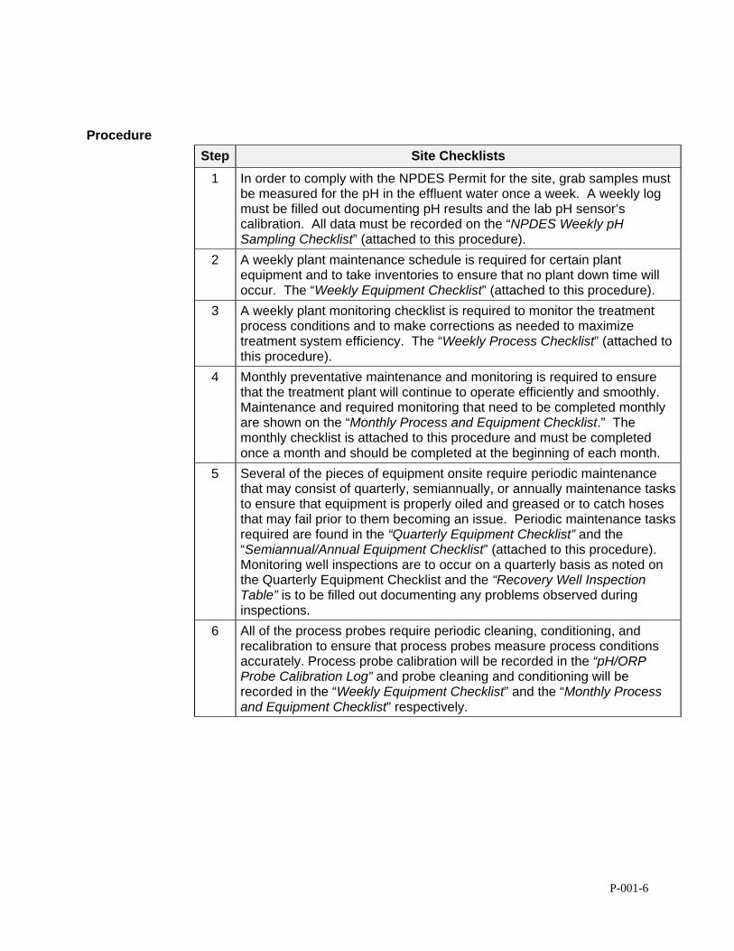
P-001-6
Procedure
Step Site Checklists
1 In order to comply with the NPDES Permit for the site, grab samples must be measured for the pH in the effluent water once a week. A weekly log must be filled out documenting pH results and the lab pH sensor’s calibration. All data must be recorded on the “NPDES Weekly pH Sampling Checklist” (attached to this procedure).
2 A weekly plant maintenance schedule is required for certain plant equipment and to take inventories to ensure that no plant down time will occur. The “Weekly Equipment Checklist” (attached to this procedure).
3 A weekly plant monitoring checklist is required to monitor the treatment process conditions and to make corrections as needed to maximize treatment system efficiency. The “Weekly Process Checklist” (attached to this procedure).
4 Monthly preventative maintenance and monitoring is required to ensure that the treatment plant will continue to operate efficiently and smoothly. Maintenance and required monitoring that need to be completed monthly are shown on the “Monthly Process and Equipment Checklist.” The monthly checklist is attached to this procedure and must be completed once a month and should be completed at the beginning of each month.
5 Several of the pieces of equipment onsite require periodic maintenance that may consist of quarterly, semiannually, or annually maintenance tasks to ensure that equipment is properly oiled and greased or to catch hoses that may fail prior to them becoming an issue. Periodic maintenance tasks required are found in the “Quarterly Equipment Checklist” and the “Semiannual/Annual Equipment Checklist” (attached to this procedure). Monitoring well inspections are to occur on a quarterly basis as noted on the Quarterly Equipment Checklist and the “Recovery Well Inspection Table” is to be filled out documenting any problems observed during inspections.
6 All of the process probes require periodic cleaning, conditioning, and recalibration to ensure that process probes measure process conditions accurately. Process probe calibration will be recorded in the “pH/ORP Probe Calibration Log” and probe cleaning and conditioning will be recorded in the “Weekly Equipment Checklist” and the “Monthly Process and Equipment Checklist” respectively.
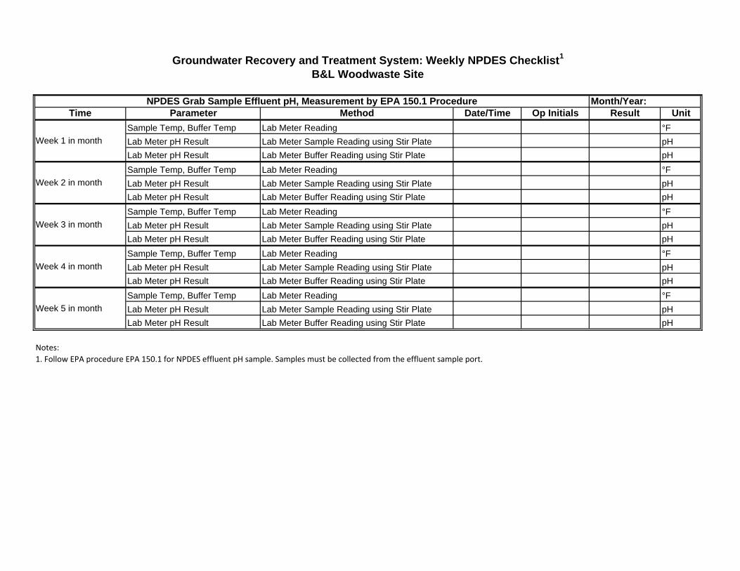
Time Parameter Method Date/Time Op Initials Result Unit
Sample Temp, Buffer Temp Lab Meter Reading °F
Lab Meter pH Result Lab Meter Sample Reading using Stir Plate pH
Lab Meter pH Result Lab Meter Buffer Reading using Stir Plate pH
Sample Temp, Buffer Temp Lab Meter Reading °F
Lab Meter pH Result Lab Meter Sample Reading using Stir Plate pH
Lab Meter pH Result Lab Meter Buffer Reading using Stir Plate pH
Sample Temp, Buffer Temp Lab Meter Reading °F
Lab Meter pH Result Lab Meter Sample Reading using Stir Plate pH
Lab Meter pH Result Lab Meter Buffer Reading using Stir Plate pH
Sample Temp, Buffer Temp Lab Meter Reading °F
Lab Meter pH Result Lab Meter Sample Reading using Stir Plate pH
Lab Meter pH Result Lab Meter Buffer Reading using Stir Plate pH
Sample Temp, Buffer Temp Lab Meter Reading °F
Lab Meter pH Result Lab Meter Sample Reading using Stir Plate pH
Lab Meter pH Result Lab Meter Buffer Reading using Stir Plate pH
Notes:1. Follow EPA procedure EPA 150.1 for NPDES effluent pH sample. Samples must be collected from the effluent sample port.
Week 3 in month
Week 4 in month
Week 5 in month
Groundwater Recovery and Treatment System: Weekly NPDES Checklist1
B&L Woodwaste Site
NPDES Grab Sample Effluent pH, Measurement by EPA 150.1 Procedure Month/Year:
Week 1 in month
Week 2 in month
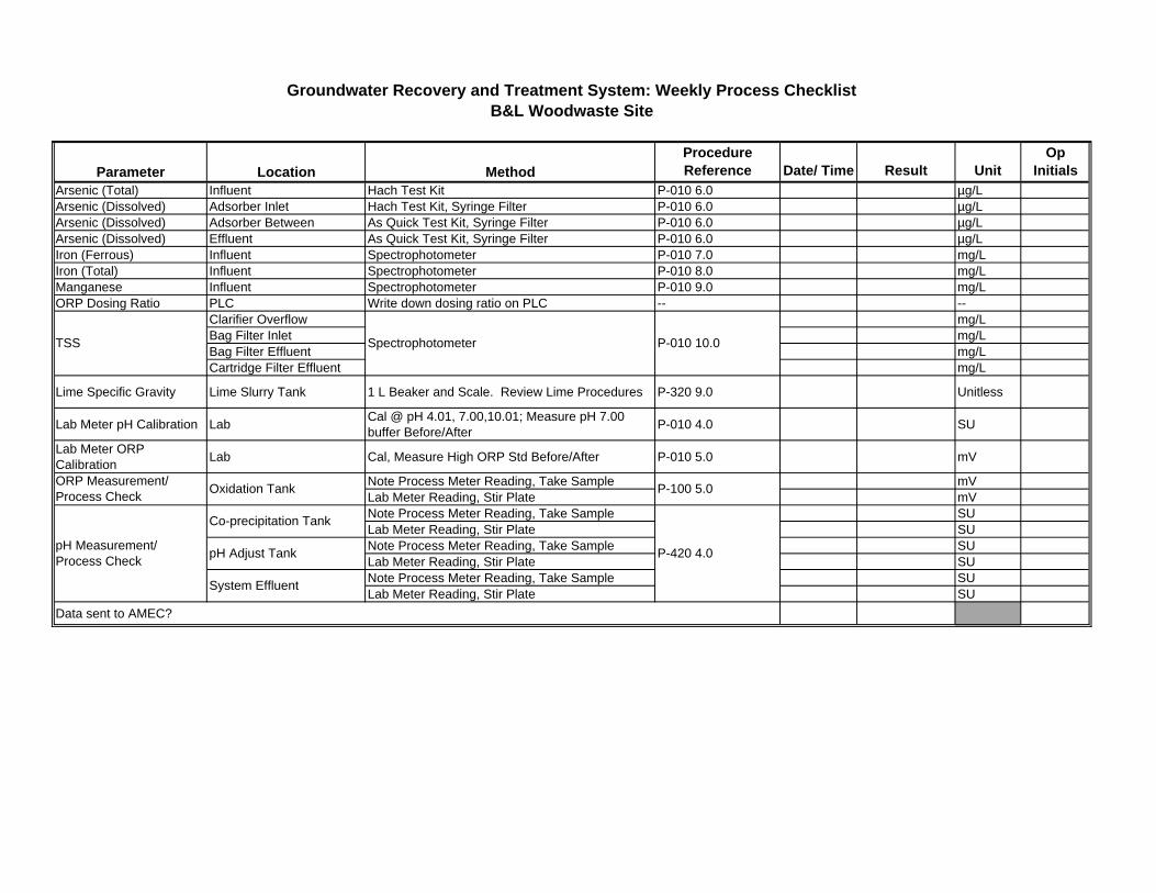
Parameter Location MethodProcedure Reference Date/ Time Result Unit
Op Initials
Arsenic (Total) Influent Hach Test Kit P-010 6.0 µg/LArsenic (Dissolved) Adsorber Inlet Hach Test Kit, Syringe Filter P-010 6.0 µg/LArsenic (Dissolved) Adsorber Between As Quick Test Kit, Syringe Filter P-010 6.0 µg/LArsenic (Dissolved) Effluent As Quick Test Kit, Syringe Filter P-010 6.0 µg/LIron (Ferrous) Influent Spectrophotometer P-010 7.0 mg/LIron (Total) Influent Spectrophotometer P-010 8.0 mg/LManganese Influent Spectrophotometer P-010 9.0 mg/LORP Dosing Ratio PLC Write down dosing ratio on PLC -- --
Clarifier Overflow mg/LBag Filter Inlet mg/LBag Filter Effluent mg/LCartridge Filter Effluent mg/L
Lime Specific Gravity Lime Slurry Tank 1 L Beaker and Scale. Review Lime Procedures P-320 9.0 Unitless
Lab Meter pH Calibration LabCal @ pH 4.01, 7.00,10.01; Measure pH 7.00 buffer Before/After
P-010 4.0 SU
Lab Meter ORP Calibration
Lab Cal, Measure High ORP Std Before/After P-010 5.0 mV
Note Process Meter Reading, Take Sample mVLab Meter Reading, Stir Plate mVNote Process Meter Reading, Take Sample SULab Meter Reading, Stir Plate SUNote Process Meter Reading, Take Sample SULab Meter Reading, Stir Plate SUNote Process Meter Reading, Take Sample SULab Meter Reading, Stir Plate SU
Data sent to AMEC?
Groundwater Recovery and Treatment System: Weekly Process ChecklistB&L Woodwaste Site
ORP Measurement/Process Check
Oxidation Tank P-100 5.0
pH Measurement/Process Check
Co-precipitation Tank
P-420 4.0pH Adjust Tank
System Effluent
Spectrophotometer P-010 10.0TSS
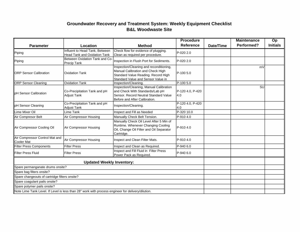
Parameter Location Method
Procedure Reference Date/Time
Maintenance Performed?
Op Initials
Piping Influent to Head Tank, Between Head Tank and Oxidation Tank
Check flow for evidence of plugging. Clean as required per procedure.
P-020 2.0
Piping Between Oxidation Tank and Co-Precip Tank
Inspection in Flush Port for Sediments. P-020 2.0
ORP Sensor Calibration Oxidation Tank
Inspection/Cleaning and reconditioning, Manual Calibration and Check High Standard Value Reading. Record High Standard Value and Sensor Value in
P-100 5.0
mV
ORP Sensor Cleaning Oxidation Tank Inspection/Cleaning. P-100 5.0
pH Sensor CalibrationCo-Precipitation Tank and pH Adjust Tank
Inspection/Cleaning, Manual Calibration and Check With Standards/Lab pH Sensor. Record Neutral Standard Value Before and After Calibration.
P-120 4.0, P-420 4.0
SU
pH Sensor CleaningCo-Precipitation Tank and pH Adjust Tank
Inspection/Cleaning.P-120 4.0, P-420 4.0
Lime Mixer Oil Lime Tank Inspect and Fill as Needed P-320 10.0
Air Compresor Belt Air Compressor Housing Manually Check Belt Tension. P-910 4.0
Air Compressor Cooling Oil Air Compressor Housing
Manually Check Oil Level After 5 Min of Runtime. Whenever Changing Cooling Oil, Change Oil Filter and Oil Separator Cartridge.
P-910 4.0
Air Compressor Control Mat and Cooler Mat
Air Compressor Housing Inspect and Clean Filter Mats. P-910 4.0
Filter Press Components Filter Press Inspect and Clean as Required. P-940 6.0
Filter Press Fluid Filter PressInspect and Fill Fluid in Filter Press Power Pack as Required.
P-940 6.0
Note Lime Tank Level. If Level is less than 28" work with process engineer for delivery/dilution.
Spare coagulant pails onsite?
Spare polymer pails onsite?
Groundwater Recovery and Treatment System: Weekly Equipment ChecklistB&L Woodwaste Site
Updated Weekly Inventory:Spare permanganate drums onsite?
Spare bag filters onsite?
Spare changeouts of cartridge filters onsite?
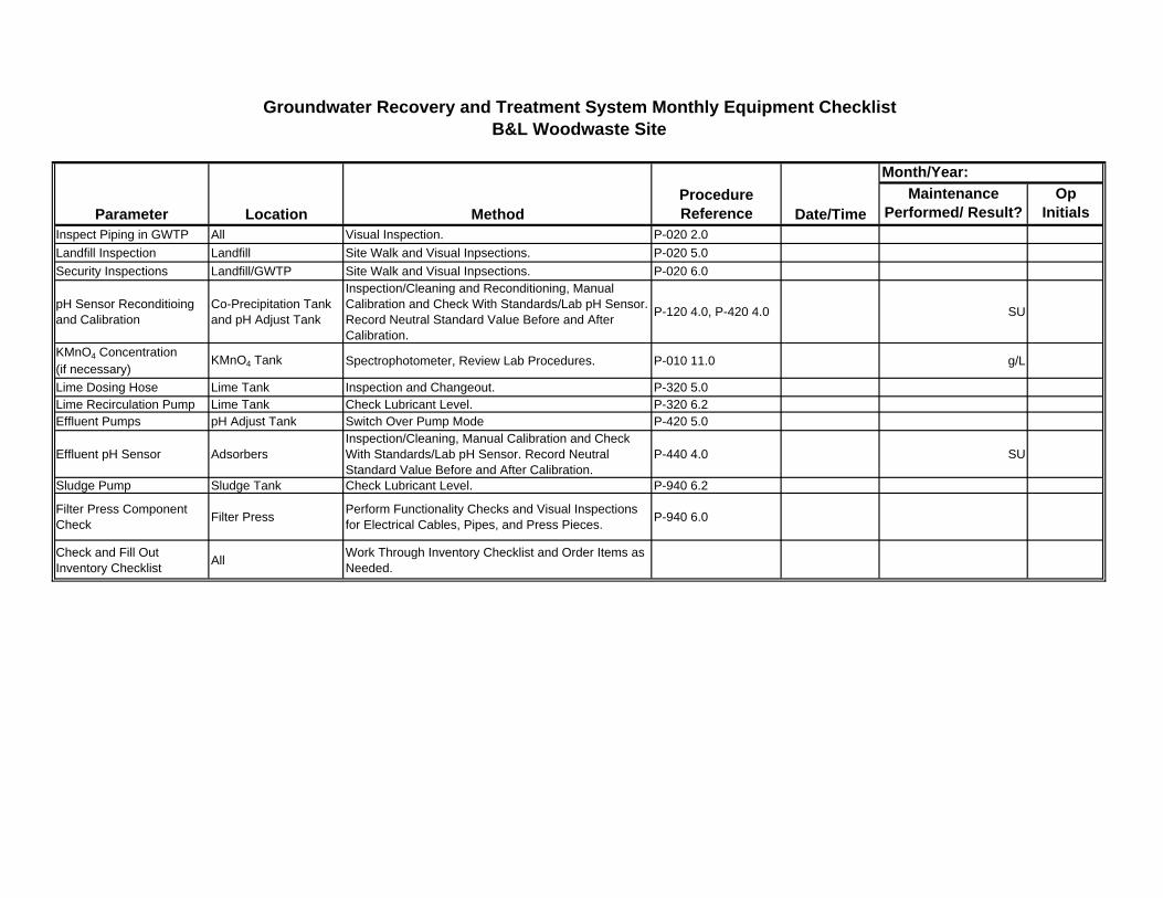
Maintenance Performed/ Result?
Op Initials
Inspect Piping in GWTP All Visual Inspection. P-020 2.0
Landfill Inspection Landfill Site Walk and Visual Inpsections. P-020 5.0
Security Inspections Landfill/GWTP Site Walk and Visual Inpsections. P-020 6.0
pH Sensor Reconditioing and Calibration
Co-Precipitation Tank and pH Adjust Tank
Inspection/Cleaning and Reconditioning, Manual Calibration and Check With Standards/Lab pH Sensor. Record Neutral Standard Value Before and After Calibration.
P-120 4.0, P-420 4.0 SU
KMnO4 Concentration (if necessary)
KMnO4 Tank Spectrophotometer, Review Lab Procedures. P-010 11.0 g/L
Lime Dosing Hose Lime Tank Inspection and Changeout. P-320 5.0Lime Recirculation Pump Lime Tank Check Lubricant Level. P-320 6.2Effluent Pumps pH Adjust Tank Switch Over Pump Mode P-420 5.0
Effluent pH Sensor AdsorbersInspection/Cleaning, Manual Calibration and Check With Standards/Lab pH Sensor. Record Neutral Standard Value Before and After Calibration.
P-440 4.0 SU
Sludge Pump Sludge Tank Check Lubricant Level. P-940 6.2
Filter Press Component Check
Filter PressPerform Functionality Checks and Visual Inspections for Electrical Cables, Pipes, and Press Pieces.
P-940 6.0
Check and Fill Out Inventory Checklist
AllWork Through Inventory Checklist and Order Items as Needed.
Groundwater Recovery and Treatment System Monthly Equipment ChecklistB&L Woodwaste Site
Parameter Location MethodProcedure Reference Date/Time
Month/Year:
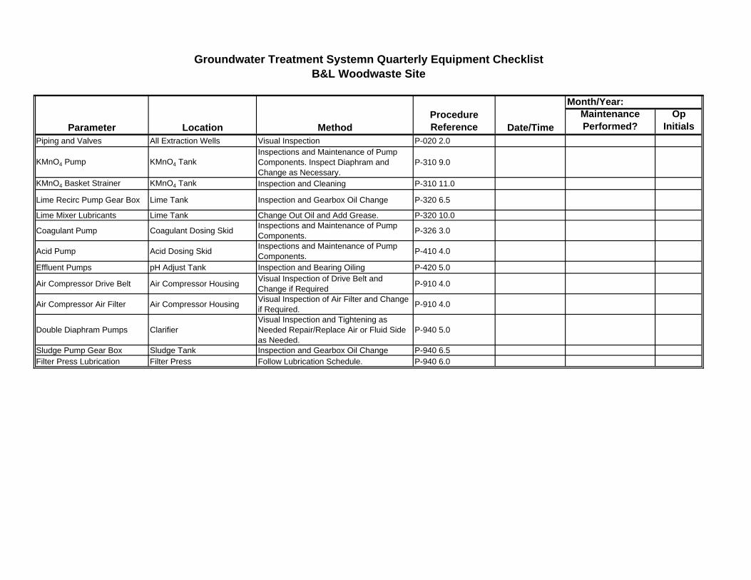
Maintenance Performed?
Op Initials
Piping and Valves All Extraction Wells Visual Inspection P-020 2.0
KMnO4 Pump KMnO4 TankInspections and Maintenance of Pump Components. Inspect Diaphram and Change as Necessary.
P-310 9.0
KMnO4 Basket Strainer KMnO4 Tank Inspection and Cleaning P-310 11.0
Lime Recirc Pump Gear Box Lime Tank Inspection and Gearbox Oil Change P-320 6.5
Lime Mixer Lubricants Lime Tank Change Out Oil and Add Grease. P-320 10.0
Coagulant Pump Coagulant Dosing SkidInspections and Maintenance of Pump Components.
P-326 3.0
Acid Pump Acid Dosing SkidInspections and Maintenance of Pump Components.
P-410 4.0
Effluent Pumps pH Adjust Tank Inspection and Bearing Oiling P-420 5.0
Air Compressor Drive Belt Air Compressor HousingVisual Inspection of Drive Belt and Change if Required
P-910 4.0
Air Compressor Air Filter Air Compressor HousingVisual Inspection of Air Filter and Change if Required.
P-910 4.0
Double Diaphram Pumps ClarifierVisual Inspection and Tightening as Needed Repair/Replace Air or Fluid Side as Needed.
P-940 5.0
Sludge Pump Gear Box Sludge Tank Inspection and Gearbox Oil Change P-940 6.5Filter Press Lubrication Filter Press Follow Lubrication Schedule. P-940 6.0
Groundwater Treatment Systemn Quarterly Equipment ChecklistB&L Woodwaste Site
Parameter Location MethodProcedure Reference Date/Time
Month/Year:
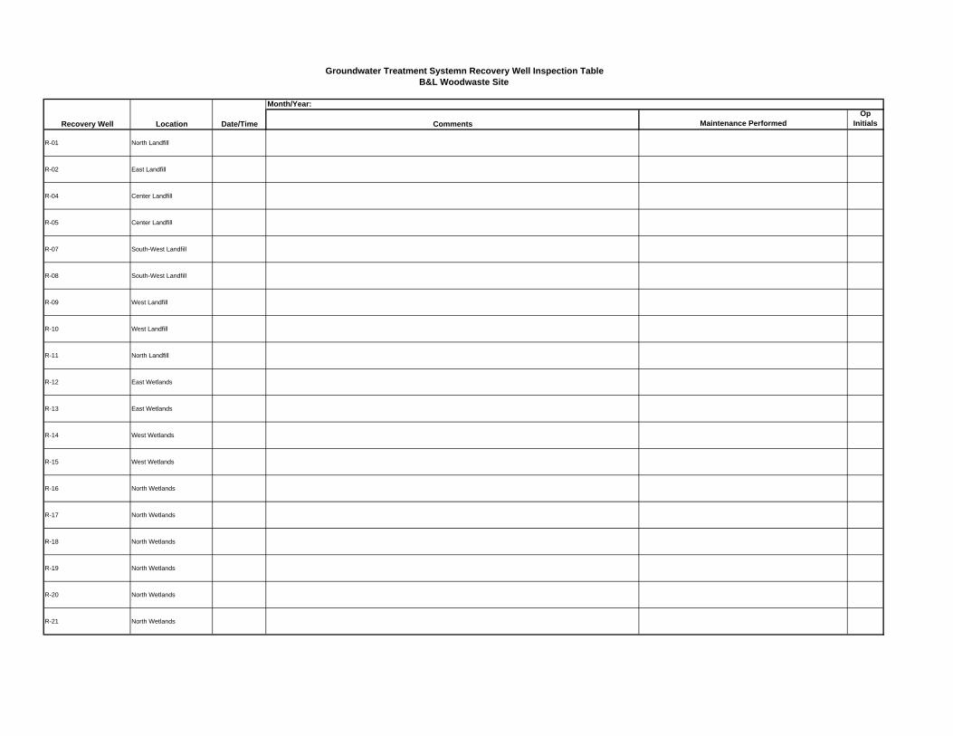
Comments Maintenance PerformedOp
Initials
R-01 North Landfill
R-02 East Landfill
R-04 Center Landfill
R-05 Center Landfill
R-07 South-West Landfill
R-08 South-West Landfill
R-09 West Landfill
R-10 West Landfill
R-11 North Landfill
R-12 East Wetlands
R-13 East Wetlands
R-14 West Wetlands
R-15 West Wetlands
R-16 North Wetlands
R-17 North Wetlands
R-18 North Wetlands
R-19 North Wetlands
R-20 North Wetlands
R-21 North Wetlands
Groundwater Treatment Systemn Recovery Well Inspection TableB&L Woodwaste Site
Recovery Well Location Date/Time
Month/Year:
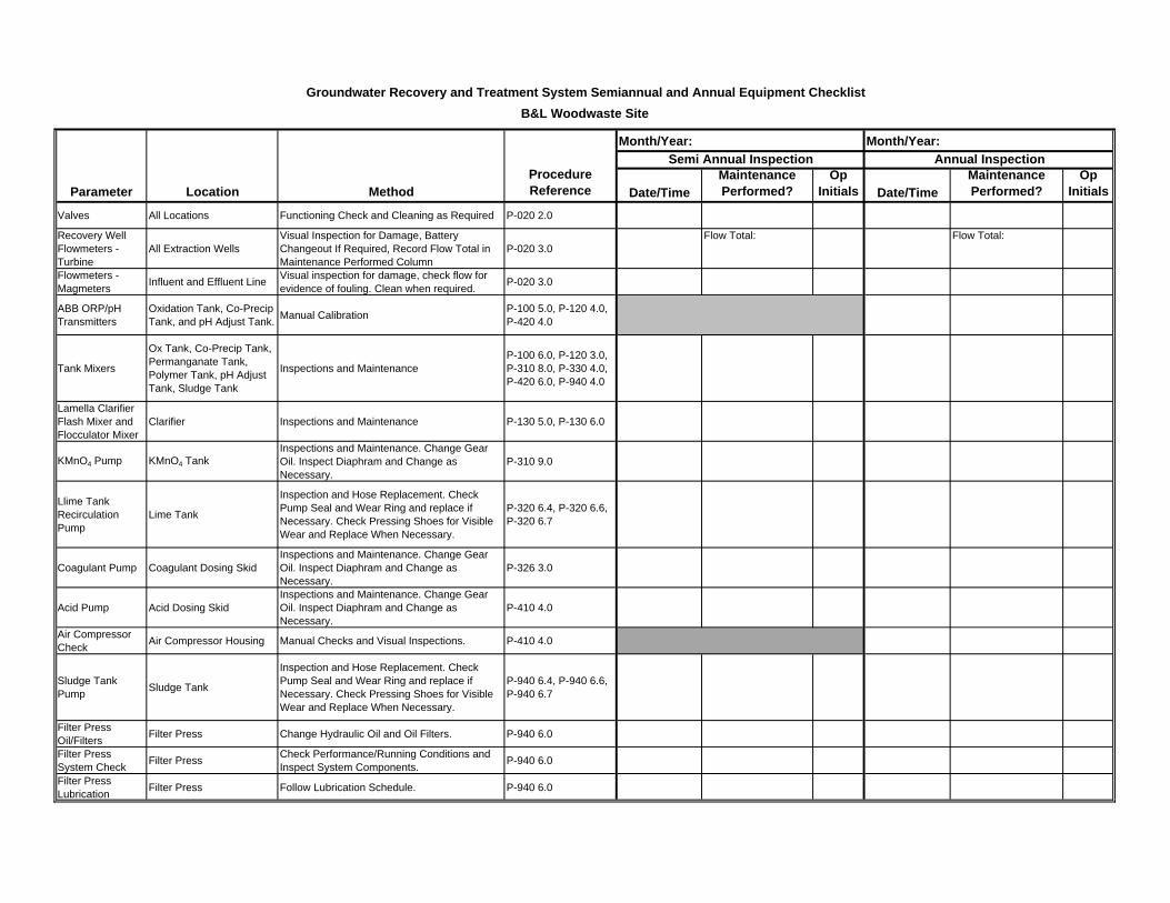
Date/TimeMaintenance Performed?
Op Initials Date/Time
Maintenance Performed?
Op Initials
Valves All Locations Functioning Check and Cleaning as Required P-020 2.0
Recovery Well Flowmeters - Turbine
All Extraction WellsVisual Inspection for Damage, Battery Changeout If Required, Record Flow Total in Maintenance Performed Column
P-020 3.0Flow Total: Flow Total:
Flowmeters - Magmeters
Influent and Effluent LineVisual inspection for damage, check flow for evidence of fouling. Clean when required.
P-020 3.0
ABB ORP/pH Transmitters
Oxidation Tank, Co-Precip Tank, and pH Adjust Tank.
Manual CalibrationP-100 5.0, P-120 4.0, P-420 4.0
Tank Mixers
Ox Tank, Co-Precip Tank, Permanganate Tank, Polymer Tank, pH Adjust Tank, Sludge Tank
Inspections and MaintenanceP-100 6.0, P-120 3.0, P-310 8.0, P-330 4.0, P-420 6.0, P-940 4.0
Lamella Clarifier Flash Mixer and Flocculator Mixer
Clarifier Inspections and Maintenance P-130 5.0, P-130 6.0
KMnO4 Pump KMnO4 TankInspections and Maintenance. Change Gear Oil. Inspect Diaphram and Change as Necessary.
P-310 9.0
Llime Tank Recirculation Pump
Lime Tank
Inspection and Hose Replacement. Check Pump Seal and Wear Ring and replace if Necessary. Check Pressing Shoes for Visible Wear and Replace When Necessary.
P-320 6.4, P-320 6.6, P-320 6.7
Coagulant Pump Coagulant Dosing SkidInspections and Maintenance. Change Gear Oil. Inspect Diaphram and Change as Necessary.
P-326 3.0
Acid Pump Acid Dosing SkidInspections and Maintenance. Change Gear Oil. Inspect Diaphram and Change as Necessary.
P-410 4.0
Air Compressor Check
Air Compressor Housing Manual Checks and Visual Inspections. P-410 4.0
Sludge Tank Pump
Sludge Tank
Inspection and Hose Replacement. Check Pump Seal and Wear Ring and replace if Necessary. Check Pressing Shoes for Visible Wear and Replace When Necessary.
P-940 6.4, P-940 6.6, P-940 6.7
Filter Press Oil/Filters
Filter Press Change Hydraulic Oil and Oil Filters. P-940 6.0
Filter Press System Check
Filter PressCheck Performance/Running Conditions and Inspect System Components.
P-940 6.0
Filter Press Lubrication
Filter Press Follow Lubrication Schedule. P-940 6.0
Groundwater Recovery and Treatment System Semiannual and Annual Equipment Checklist
B&L Woodwaste Site
Parameter Location MethodProcedure Reference
Month/Year: Month/Year:
Semi Annual Inspection Annual Inspection

Location:pH Probe Calibration Log S/N:
Date Time Buffers used Before cal After calSlope (relative to
59.16 mV) Offset (mV) Initials
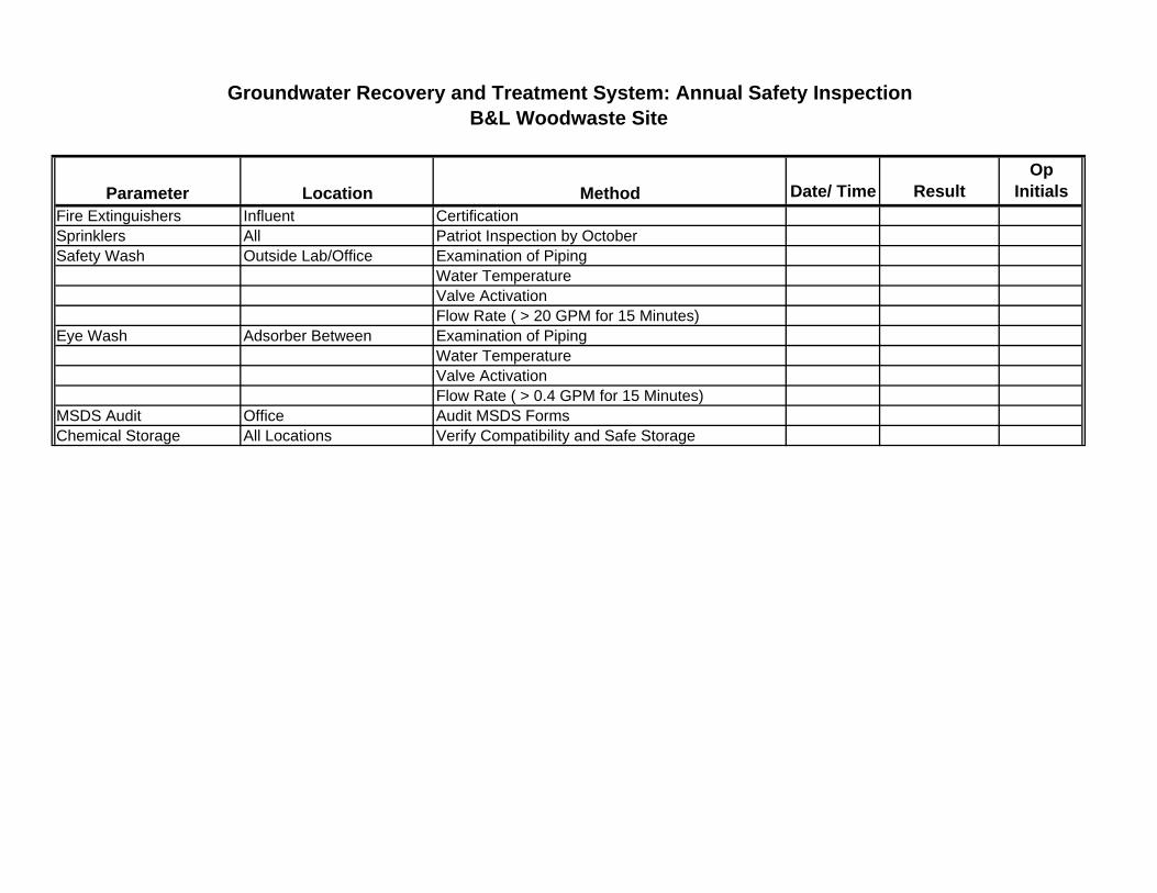
Parameter Location Method Date/ Time ResultOp
Initials
Fire Extinguishers Influent CertificationSprinklers All Patriot Inspection by OctoberSafety Wash Outside Lab/Office Examination of Piping
Water TemperatureValve ActivationFlow Rate ( > 20 GPM for 15 Minutes)
Eye Wash Adsorber Between Examination of PipingWater TemperatureValve ActivationFlow Rate ( > 0.4 GPM for 15 Minutes)
MSDS Audit Office Audit MSDS FormsChemical Storage All Locations Verify Compatibility and Safe Storage
Groundwater Recovery and Treatment System: Annual Safety InspectionB&L Woodwaste Site
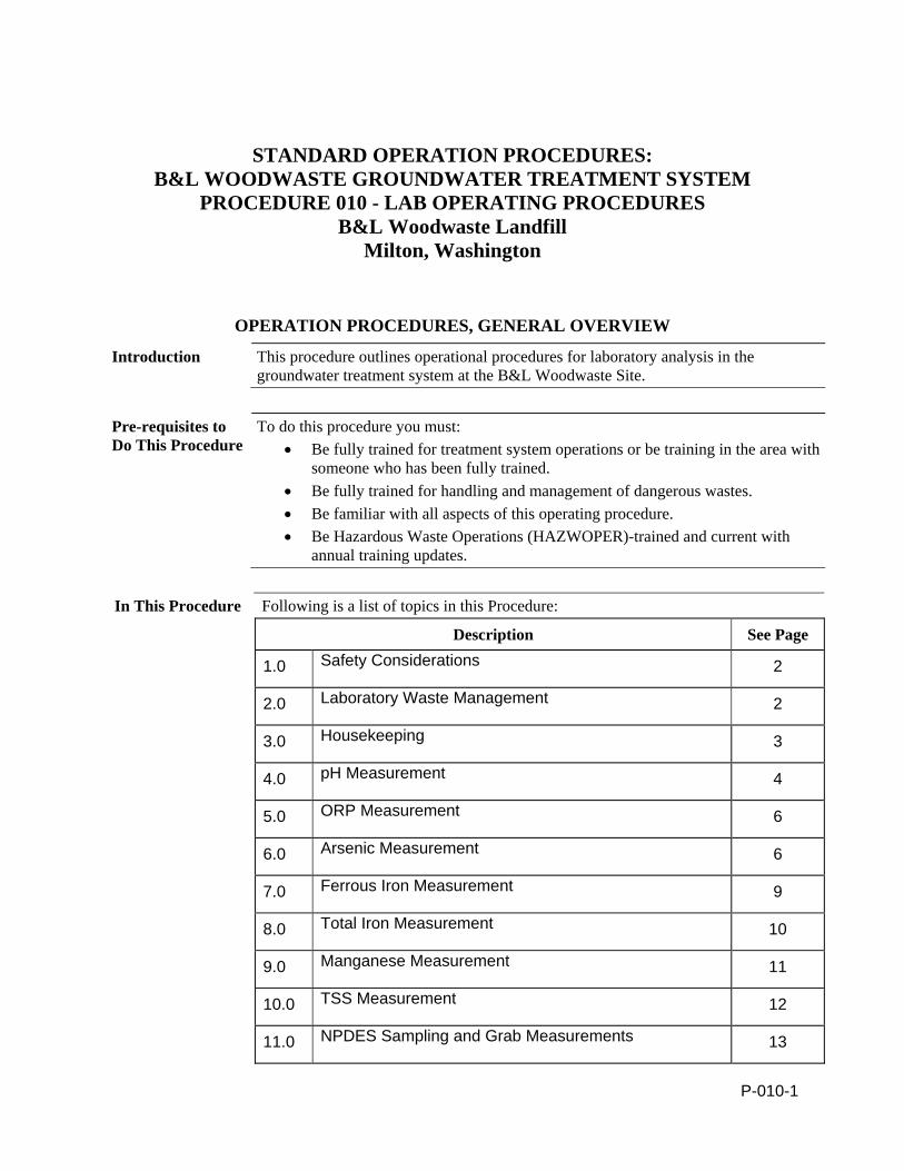
P-010-1
STANDARD OPERATION PROCEDURES: B&L WOODWASTE GROUNDWATER TREATMENT SYSTEM
PROCEDURE 010 - LAB OPERATING PROCEDURES B&L Woodwaste Landfill
Milton, Washington
OPERATION PROCEDURES, GENERAL OVERVIEW
Introduction This procedure outlines operational procedures for laboratory analysis in the groundwater treatment system at the B&L Woodwaste Site.
Pre-requisites to Do This Procedure
To do this procedure you must: Be fully trained for treatment system operations or be training in the area with
someone who has been fully trained. Be fully trained for handling and management of dangerous wastes. Be familiar with all aspects of this operating procedure. Be Hazardous Waste Operations (HAZWOPER)-trained and current with
annual training updates.
In This Procedure Following is a list of topics in this Procedure:
Description See Page
1.0 Safety Considerations 2
2.0 Laboratory Waste Management 2
3.0 Housekeeping 3
4.0 pH Measurement 4
5.0 ORP Measurement 6
6.0 Arsenic Measurement 6
7.0 Ferrous Iron Measurement 9
8.0 Total Iron Measurement 10
9.0 Manganese Measurement 11
10.0 TSS Measurement 12
11.0 NPDES Sampling and Grab Measurements 13
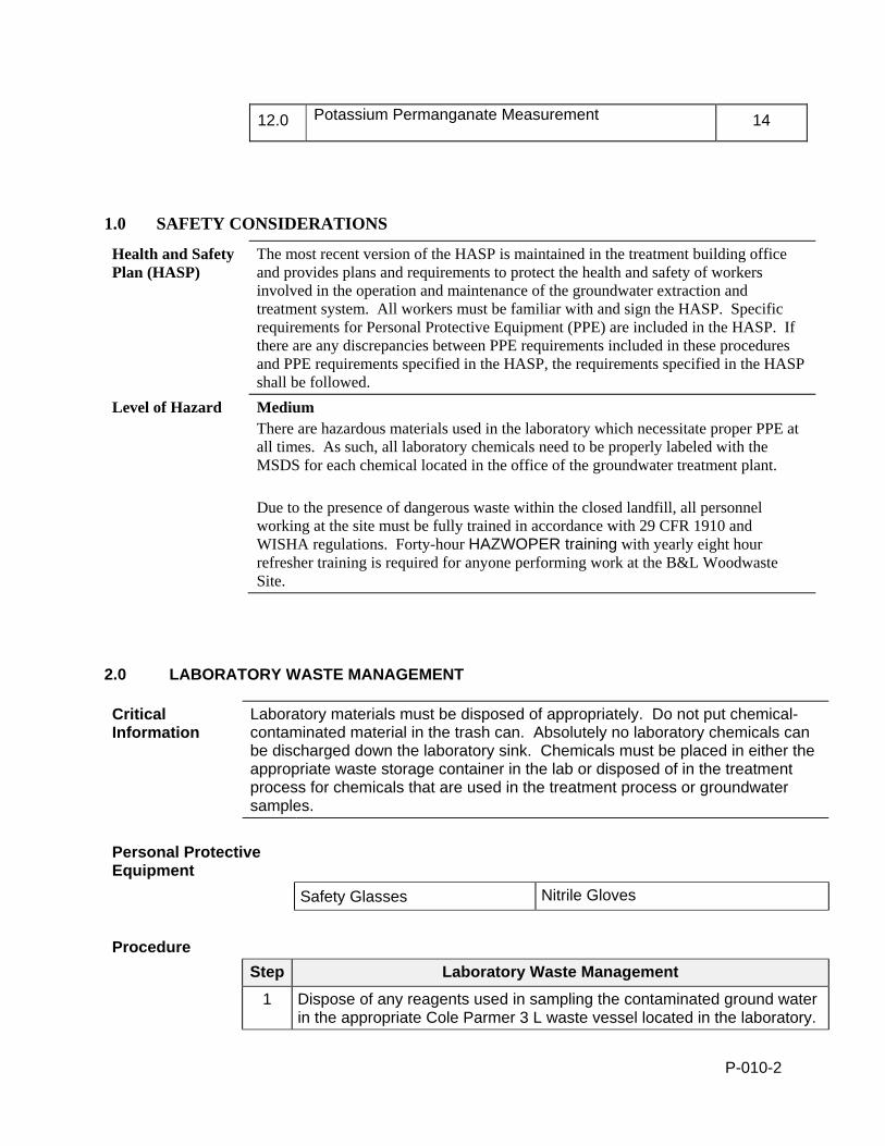
P-010-2
12.0 Potassium Permanganate Measurement 14
1.0 SAFETY CONSIDERATIONS
Health and Safety Plan (HASP)
The most recent version of the HASP is maintained in the treatment building office and provides plans and requirements to protect the health and safety of workers involved in the operation and maintenance of the groundwater extraction and treatment system. All workers must be familiar with and sign the HASP. Specific requirements for Personal Protective Equipment (PPE) are included in the HASP. If there are any discrepancies between PPE requirements included in these procedures and PPE requirements specified in the HASP, the requirements specified in the HASP shall be followed.
Level of Hazard Medium There are hazardous materials used in the laboratory which necessitate proper PPE at all times. As such, all laboratory chemicals need to be properly labeled with the MSDS for each chemical located in the office of the groundwater treatment plant. Due to the presence of dangerous waste within the closed landfill, all personnel working at the site must be fully trained in accordance with 29 CFR 1910 and WISHA regulations. Forty-hour HAZWOPER training with yearly eight hour refresher training is required for anyone performing work at the B&L Woodwaste Site.
2.0 LABORATORY WASTE MANAGEMENT
Critical Information
Laboratory materials must be disposed of appropriately. Do not put chemical-contaminated material in the trash can. Absolutely no laboratory chemicals can be discharged down the laboratory sink. Chemicals must be placed in either the appropriate waste storage container in the lab or disposed of in the treatment process for chemicals that are used in the treatment process or groundwater samples.
Personal Protective Equipment
Safety Glasses Nitrile Gloves
Procedure
Step Laboratory Waste Management
1 Dispose of any reagents used in sampling the contaminated ground water in the appropriate Cole Parmer 3 L waste vessel located in the laboratory.
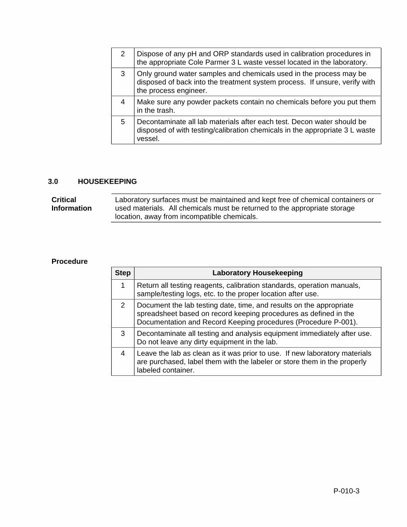
P-010-3
2 Dispose of any pH and ORP standards used in calibration procedures in the appropriate Cole Parmer 3 L waste vessel located in the laboratory.
3 Only ground water samples and chemicals used in the process may be disposed of back into the treatment system process. If unsure, verify with the process engineer.
4 Make sure any powder packets contain no chemicals before you put them in the trash.
5 Decontaminate all lab materials after each test. Decon water should be disposed of with testing/calibration chemicals in the appropriate 3 L waste vessel.
3.0 HOUSEKEEPING
Critical Information
Laboratory surfaces must be maintained and kept free of chemical containers or used materials. All chemicals must be returned to the appropriate storage location, away from incompatible chemicals.
Procedure
Step Laboratory Housekeeping
1 Return all testing reagents, calibration standards, operation manuals, sample/testing logs, etc. to the proper location after use.
2 Document the lab testing date, time, and results on the appropriate spreadsheet based on record keeping procedures as defined in the Documentation and Record Keeping procedures (Procedure P-001).
3 Decontaminate all testing and analysis equipment immediately after use. Do not leave any dirty equipment in the lab.
4 Leave the lab as clean as it was prior to use. If new laboratory materials are purchased, label them with the labeler or store them in the properly labeled container.
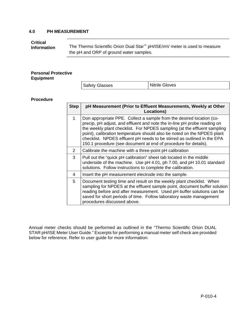
P-010-4
4.0 PH MEASUREMENT
Critical Information The Thermo Scientific Orion Dual Star™ pH/ISE/mV meter is used to measure
the pH and ORP of ground water samples.
Personal Protective Equipment
Safety Glasses Nitrile Gloves
Procedure
Step pH Measurement (Prior to Effluent Measurements, Weekly at Other Locations)
1 Don appropriate PPE. Collect a sample from the desired location (co-precip, pH adjust, and effluent and note the in-line pH probe reading on the weekly plant checklist. For NPDES sampling (at the effluent sampling point), calibration temperature should also be noted on the NPDES plant checklist. NPDES effluent pH needs to be stirred as outlined in the EPA 150.1 procedure (see document at end of procedure for details).
2 Calibrate the machine with a three-point pH calibration
3 Pull out the “quick pH calibration” sheet tab located in the middle underside of the machine. Use pH 4.01, ph 7.00, and pH 10.01 standard solutions. Follow instructions to complete the calibration.
4 Insert the pH measurement electrode into the sample.
5 Document testing time and result on the weekly plant checklist. When sampling for NPDES at the effluent sample point, document buffer solution reading before and after measurement. Used pH buffer solutions can be saved for short periods of time. Follow laboratory waste management procedures discussed above.
Annual meter checks should be performed as outlined in the “Thermo Scientific Orion DUAL STAR pH/ISE Meter User Guide.” Excerpts for performing a manual meter self check are provided below for reference. Refer to user guide for more information:
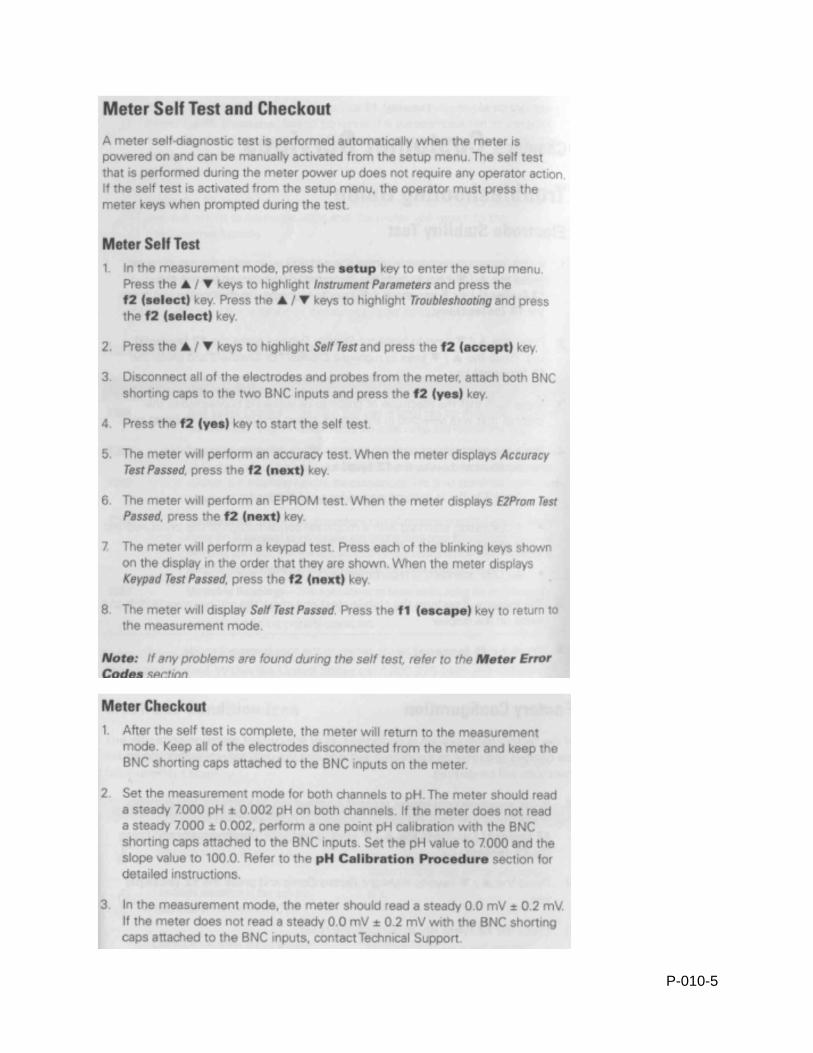
P-010-5
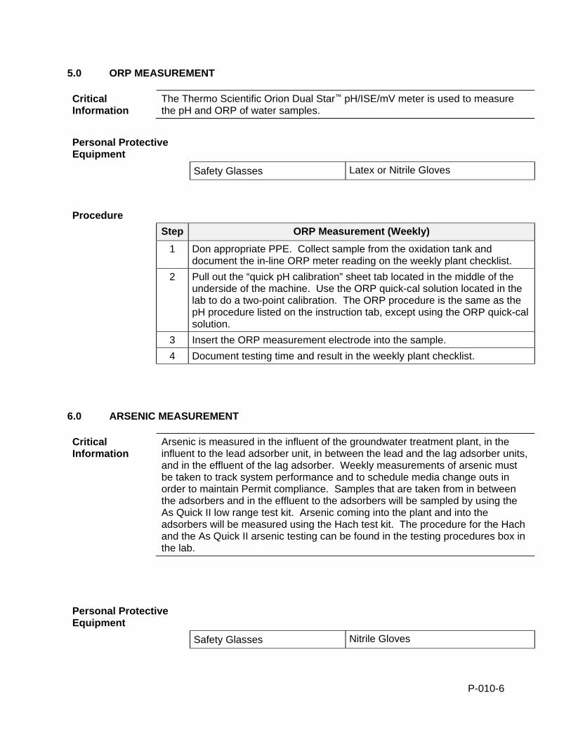
P-010-6
5.0 ORP MEASUREMENT
Critical Information
The Thermo Scientific Orion Dual Star™ pH/ISE/mV meter is used to measure the pH and ORP of water samples.
Personal Protective Equipment
Safety Glasses Latex or Nitrile Gloves
Procedure
Step ORP Measurement (Weekly)
1 Don appropriate PPE. Collect sample from the oxidation tank and document the in-line ORP meter reading on the weekly plant checklist.
2 Pull out the “quick pH calibration” sheet tab located in the middle of the underside of the machine. Use the ORP quick-cal solution located in the lab to do a two-point calibration. The ORP procedure is the same as the pH procedure listed on the instruction tab, except using the ORP quick-cal solution.
3 Insert the ORP measurement electrode into the sample.
4 Document testing time and result in the weekly plant checklist.
6.0 ARSENIC MEASUREMENT
Critical Information
Arsenic is measured in the influent of the groundwater treatment plant, in the influent to the lead adsorber unit, in between the lead and the lag adsorber units, and in the effluent of the lag adsorber. Weekly measurements of arsenic must be taken to track system performance and to schedule media change outs in order to maintain Permit compliance. Samples that are taken from in between the adsorbers and in the effluent to the adsorbers will be sampled by using the As Quick II low range test kit. Arsenic coming into the plant and into the adsorbers will be measured using the Hach test kit. The procedure for the Hach and the As Quick II arsenic testing can be found in the testing procedures box in the lab.
Personal Protective Equipment
Safety Glasses Nitrile Gloves
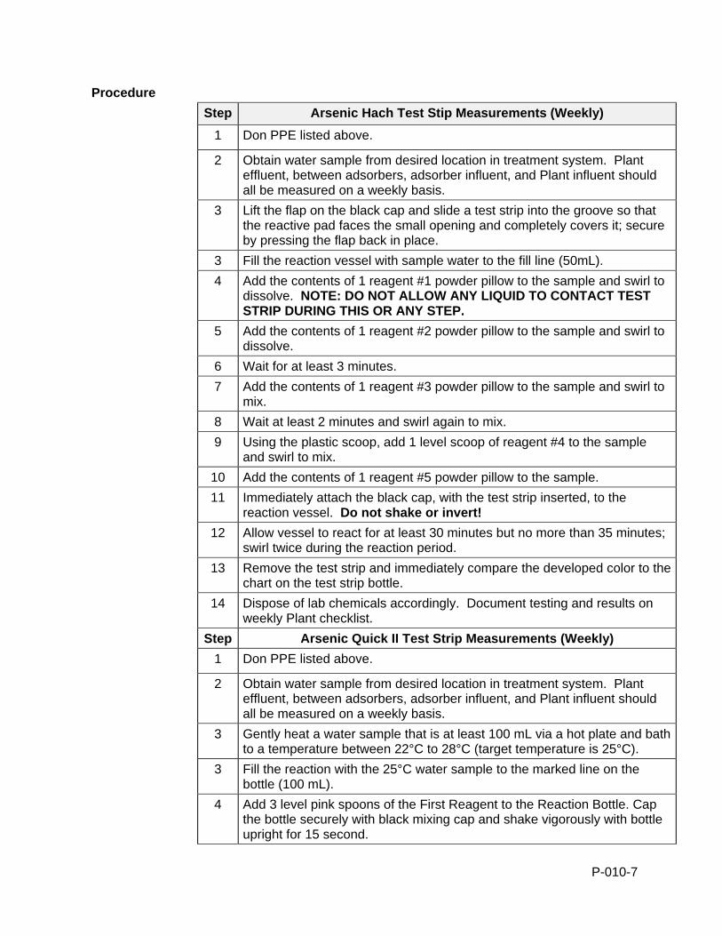
P-010-7
Procedure
Step Arsenic Hach Test Stip Measurements (Weekly)
1 Don PPE listed above.
2 Obtain water sample from desired location in treatment system. Plant effluent, between adsorbers, adsorber influent, and Plant influent should all be measured on a weekly basis.
3 Lift the flap on the black cap and slide a test strip into the groove so that the reactive pad faces the small opening and completely covers it; secure by pressing the flap back in place.
3 Fill the reaction vessel with sample water to the fill line (50mL).
4 Add the contents of 1 reagent #1 powder pillow to the sample and swirl to dissolve. NOTE: DO NOT ALLOW ANY LIQUID TO CONTACT TEST STRIP DURING THIS OR ANY STEP.
5 Add the contents of 1 reagent #2 powder pillow to the sample and swirl to dissolve.
6 Wait for at least 3 minutes.
7 Add the contents of 1 reagent #3 powder pillow to the sample and swirl to mix.
8 Wait at least 2 minutes and swirl again to mix.
9 Using the plastic scoop, add 1 level scoop of reagent #4 to the sample and swirl to mix.
10 Add the contents of 1 reagent #5 powder pillow to the sample.
11 Immediately attach the black cap, with the test strip inserted, to the reaction vessel. Do not shake or invert!
12 Allow vessel to react for at least 30 minutes but no more than 35 minutes; swirl twice during the reaction period.
13 Remove the test strip and immediately compare the developed color to the chart on the test strip bottle.
14 Dispose of lab chemicals accordingly. Document testing and results on weekly Plant checklist.
Step Arsenic Quick II Test Strip Measurements (Weekly)
1 Don PPE listed above.
2 Obtain water sample from desired location in treatment system. Plant effluent, between adsorbers, adsorber influent, and Plant influent should all be measured on a weekly basis.
3 Gently heat a water sample that is at least 100 mL via a hot plate and bath to a temperature between 22°C to 28°C (target temperature is 25°C).
3 Fill the reaction with the 25°C water sample to the marked line on the bottle (100 mL).
4 Add 3 level pink spoons of the First Reagent to the Reaction Bottle. Cap the bottle securely with black mixing cap and shake vigorously with bottle upright for 15 second.
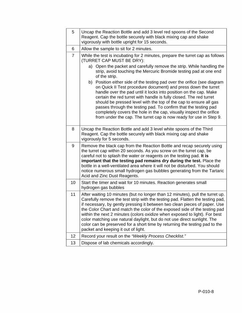
P-010-8
5 Uncap the Reaction Bottle and add 3 level red spoons of the Second Reagent. Cap the bottle securely with black mixing cap and shake vigorously with bottle upright for 15 seconds.
6 Allow the sample to sit for 2 minutes.
7 While the test is incubating for 2 minutes, prepare the turret cap as follows (TURRET CAP MUST BE DRY):
a) Open the packet and carefully remove the strip. While handling the strip, avoid touching the Mercuric Bromide testing pad at one end of the strip.
b) Position either side of the testing pad over the orifice (see diagram on Quick II Test procedure document) and press down the turret handle over the pad until it locks into position on the cap. Make certain the red turret with handle is fully closed. The red turret should be pressed level with the top of the cap to ensure all gas passes through the testing pad. To confirm that the testing pad completely covers the hole in the cap, visually inspect the orifice from under the cap. The turret cap is now ready for use in Step 9.
8 Uncap the Reaction Bottle and add 3 level white spoons of the Third Reagent. Cap the bottle securely with black mixing cap and shake vigorously for 5 seconds.
9 Remove the black cap from the Reaction Bottle and recap securely using the turret cap within 20 seconds. As you screw on the turret cap, be careful not to splash the water or reagents on the testing pad. It is important that the testing pad remains dry during the test. Place the bottle in a well-ventilated area where it will not be disturbed. You should notice numerous small hydrogen gas bubbles generating from the Tartaric Acid and Zinc Dust Reagents.
10 Start the timer and wait for 10 minutes. Reaction generates small hydrogen gas bubbles
11 After waiting 10 minutes (but no longer than 12 minutes), pull the turret up. Carefully remove the test strip with the testing pad. Flatten the testing pad, if necessary, by gently pressing it between two clean pieces of paper. Use the Color Chart and match the color of the exposed side of the testing pad within the next 2 minutes (colors oxidize when exposed to light). For best color matching use natural daylight, but do not use direct sunlight. The color can be preserved for a short time by returning the testing pad to the packet and keeping it out of light.
12 Record your result on the “Weekly Process Checklist.”
13 Dispose of lab chemicals accordingly.
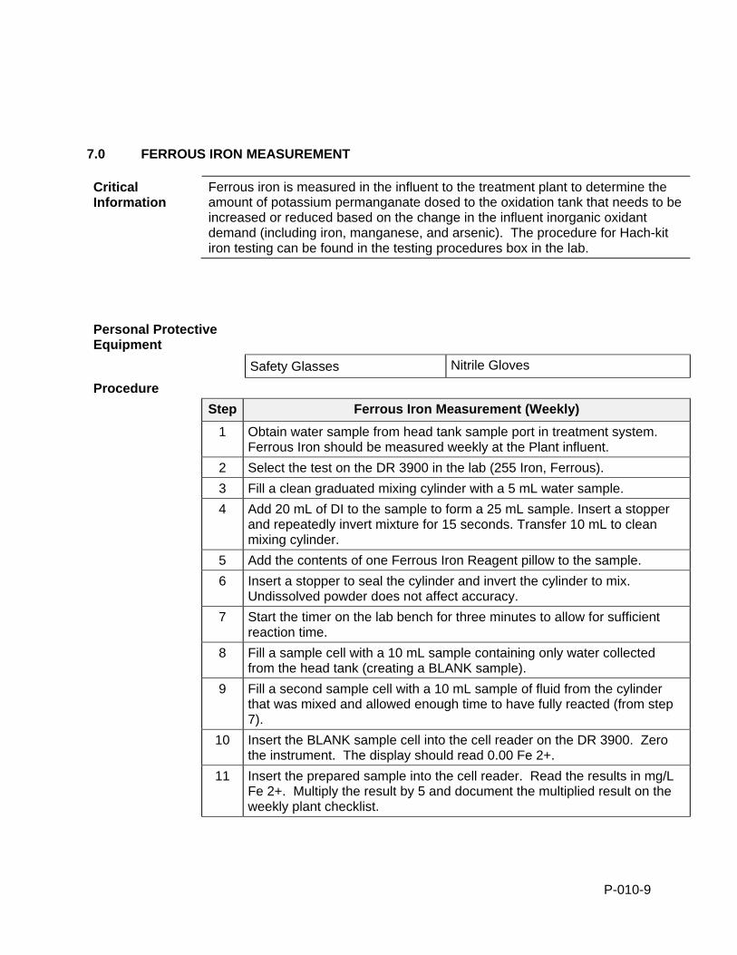
P-010-9
7.0 FERROUS IRON MEASUREMENT
Critical Information
Ferrous iron is measured in the influent to the treatment plant to determine the amount of potassium permanganate dosed to the oxidation tank that needs to be increased or reduced based on the change in the influent inorganic oxidant demand (including iron, manganese, and arsenic). The procedure for Hach-kit iron testing can be found in the testing procedures box in the lab.
Personal Protective Equipment
Safety Glasses Nitrile Gloves
Procedure
Step Ferrous Iron Measurement (Weekly)
1 Obtain water sample from head tank sample port in treatment system. Ferrous Iron should be measured weekly at the Plant influent.
2 Select the test on the DR 3900 in the lab (255 Iron, Ferrous).
3 Fill a clean graduated mixing cylinder with a 5 mL water sample.
4 Add 20 mL of DI to the sample to form a 25 mL sample. Insert a stopper and repeatedly invert mixture for 15 seconds. Transfer 10 mL to clean mixing cylinder.
5 Add the contents of one Ferrous Iron Reagent pillow to the sample.
6 Insert a stopper to seal the cylinder and invert the cylinder to mix. Undissolved powder does not affect accuracy.
7 Start the timer on the lab bench for three minutes to allow for sufficient reaction time.
8 Fill a sample cell with a 10 mL sample containing only water collected from the head tank (creating a BLANK sample).
9 Fill a second sample cell with a 10 mL sample of fluid from the cylinder that was mixed and allowed enough time to have fully reacted (from step 7).
10 Insert the BLANK sample cell into the cell reader on the DR 3900. Zero the instrument. The display should read 0.00 Fe 2+.
11 Insert the prepared sample into the cell reader. Read the results in mg/L Fe 2+. Multiply the result by 5 and document the multiplied result on the weekly plant checklist.
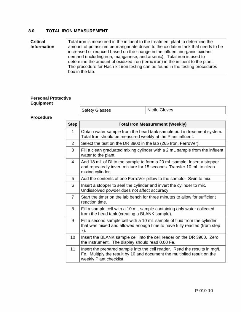
P-010-10
8.0 TOTAL IRON MEASUREMENT
Critical Information
Total iron is measured in the influent to the treatment plant to determine the amount of potassium permanganate dosed to the oxidation tank that needs to be increased or reduced based on the change in the influent inorganic oxidant demand (including iron, manganese, and arsenic). Total iron is used to determine the amount of oxidized iron (ferric iron) in the influent to the plant. The procedure for Hach-kit iron testing can be found in the testing procedures box in the lab.
Personal Protective Equipment
Safety Glasses Nitrile Gloves
Procedure
Step Total Iron Measurement (Weekly)
1 Obtain water sample from the head tank sample port in treatment system. Total Iron should be measured weekly at the Plant influent.
2 Select the test on the DR 3900 in the lab (265 Iron, FerroVer).
3 Fill a clean graduated mixing cylinder with a 2 mL sample from the influent water to the plant.
4 Add 18 mL of DI to the sample to form a 20 mL sample. Insert a stopper and repeatedly invert mixture for 15 seconds. Transfer 10 mL to clean mixing cylinder.
5 Add the contents of one FerroVer pillow to the sample. Swirl to mix.
6 Insert a stopper to seal the cylinder and invert the cylinder to mix. Undissolved powder does not affect accuracy.
7 Start the timer on the lab bench for three minutes to allow for sufficient reaction time.
8 Fill a sample cell with a 10 mL sample containing only water collected from the head tank (creating a BLANK sample).
9 Fill a second sample cell with a 10 mL sample of fluid from the cylinder that was mixed and allowed enough time to have fully reacted (from step 7).
10 Insert the BLANK sample cell into the cell reader on the DR 3900. Zero the instrument. The display should read 0.00 Fe.
11 Insert the prepared sample into the cell reader. Read the results in mg/L Fe. Multiply the result by 10 and document the multiplied result on the weekly Plant checklist.
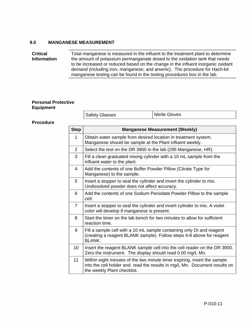
P-010-11
9.0 MANGANESE MEASUREMENT
Critical Information
Total manganese is measured in the influent to the treatment plant to determine the amount of potassium permanganate dosed to the oxidation tank that needs to be increased or reduced based on the change in the influent inorganic oxidant demand (including iron, manganese, and arsenic). The procedure for Hach-kit manganese testing can be found in the testing procedures box in the lab.
Personal Protective Equipment
Safety Glasses Nitrile Gloves
Procedure
Step Manganese Measurement (Weekly)
1 Obtain water sample from desired location in treatment system. Manganese should be sample at the Plant influent weekly.
2 Select the test on the DR 3900 in the lab (295 Manganese, HR).
3 Fill a clean graduated mixing cylinder with a 10 mL sample from the influent water to the plant.
4 Add the contents of one Buffer Powder Pillow (Citrate Type for Manganese) to the sample.
5 Insert a stopper to seal the cylinder and invert the cylinder to mix. Undissolved powder does not affect accuracy.
6 Add the contents of one Sodium Periodate Powder Pillow to the sample cell.
7 Insert a stopper to seal the cylinder and invert cylinder to mix. A violet color will develop if manganese is present.
8 Start the timer on the lab bench for two minutes to allow for sufficient reaction time.
9 Fill a sample cell with a 10 mL sample containing only DI and reagent (creating a reagent BLANK sample). Follow steps 4-8 above for reagent BLANK.
10 Insert the reagent BLANK sample cell into the cell reader on the DR 3900. Zero the instrument. The display should read 0.00 mg/L Mn.
11 Within eight minutes of the two minute timer expiring, insert the sample into the cell holder and. read the results in mg/L Mn. Document results on the weekly Plant checklist.
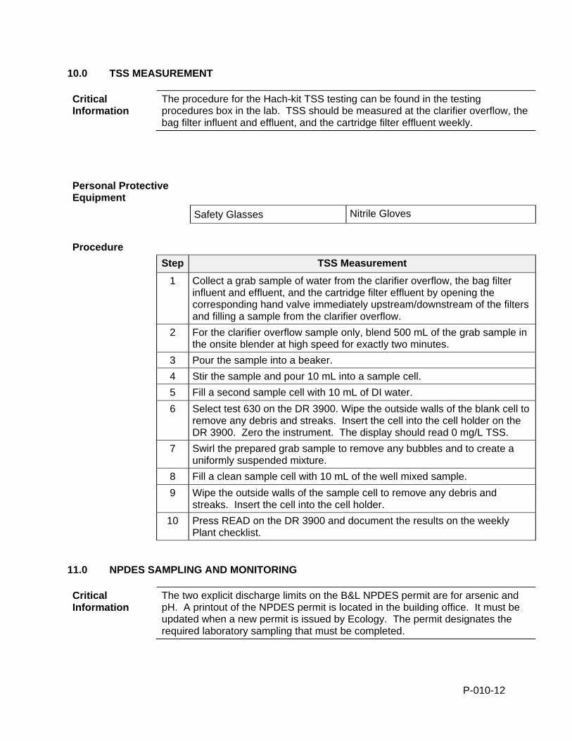
P-010-12
10.0 TSS MEASUREMENT
Critical Information
The procedure for the Hach-kit TSS testing can be found in the testing procedures box in the lab. TSS should be measured at the clarifier overflow, the bag filter influent and effluent, and the cartridge filter effluent weekly.
Personal Protective Equipment
Safety Glasses Nitrile Gloves
Procedure
Step TSS Measurement
1 Collect a grab sample of water from the clarifier overflow, the bag filter influent and effluent, and the cartridge filter effluent by opening the corresponding hand valve immediately upstream/downstream of the filters and filling a sample from the clarifier overflow.
2 For the clarifier overflow sample only, blend 500 mL of the grab sample in the onsite blender at high speed for exactly two minutes.
3 Pour the sample into a beaker.
4 Stir the sample and pour 10 mL into a sample cell.
5 Fill a second sample cell with 10 mL of DI water.
6 Select test 630 on the DR 3900. Wipe the outside walls of the blank cell to remove any debris and streaks. Insert the cell into the cell holder on the DR 3900. Zero the instrument. The display should read 0 mg/L TSS.
7 Swirl the prepared grab sample to remove any bubbles and to create a uniformly suspended mixture.
8 Fill a clean sample cell with 10 mL of the well mixed sample.
9 Wipe the outside walls of the sample cell to remove any debris and streaks. Insert the cell into the cell holder.
10 Press READ on the DR 3900 and document the results on the weekly Plant checklist.
11.0 NPDES SAMPLING AND MONITORING
Critical Information
The two explicit discharge limits on the B&L NPDES permit are for arsenic and pH. A printout of the NPDES permit is located in the building office. It must be updated when a new permit is issued by Ecology. The permit designates the required laboratory sampling that must be completed.
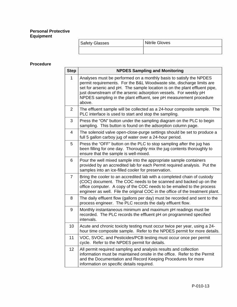
P-010-13
Personal Protective Equipment
Safety Glasses Nitrile Gloves
Procedure
Step NPDES Sampling and Monitoring
1 Analyses must be performed on a monthly basis to satisfy the NPDES permit requirements. For the B&L Woodwaste site, discharge limits are set for arsenic and pH. The sample location is on the plant effluent pipe, just downstream of the arsenic adsorption vessels. For weekly pH NPDES sampling in the plant effluent, see pH measurement procedure above.
2 The effluent sample will be collected as a 24-hour composite sample. The PLC interface is used to start and stop the sampling.
3 Press the “ON” button under the sampling diagram on the PLC to begin sampling. This button is found on the adsorption column page.
4 The solenoid valve open-close-purge settings should be set to produce a full 5 gallon carboy jug of water over a 24-hour period.
5 Press the “OFF” button on the PLC to stop sampling after the jug has been filling for one day. Thoroughly mix the jug contents thoroughly to ensure that the sample is well-mixed.
6 Pour the well mixed sample into the appropriate sample containers provided by an accredited lab for each Permit required analysis. Put the samples into an ice-filled cooler for preservation.
7 Bring the cooler to an accredited lab with a completed chain of custody (COC) document. The COC needs to be scanned and backed up on the office computer. A copy of the COC needs to be emailed to the process engineer as well. File the original COC in the office of the treatment plant.
8 The daily effluent flow (gallons per day) must be recorded and sent to the process engineer. The PLC records the daily effluent flow.
9 Monthly instantaneous minimum and maximum pH readings must be recorded. The PLC records the effluent pH on programmed specified intervals.
10 Acute and chronic toxicity testing must occur twice per year, using a 24-hour time composite sample. Refer to the NPDES permit for more details.
11 VOC, SVOC, and Pesticides/PCB testing must occur once per permit cycle. Refer to the NPDES permit for details.
12 All permit required sampling and analysis results and collection information must be maintained onsite in the office. Refer to the Permit and the Documentation and Record Keeping Procedures for more information on specific details required.
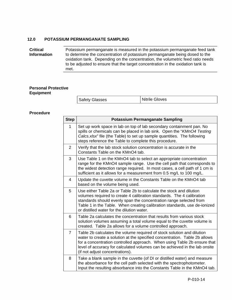
P-010-14
12.0 POTASSIUM PERMANGANATE SAMPLING
Critical Information
Potassium permanganate is measured in the potassium permanganate feed tank to determine the concentration of potassium permanganate being dosed to the oxidation tank. Depending on the concentration, the volumetric feed ratio needs to be adjusted to ensure that the target concentration in the oxidation tank is met.
Personal Protective Equipment
Safety Glasses Nitrile Gloves
Procedure
Step Potassium Permanganate Sampling
1 Set up work space in lab on top of lab secondary containment pan. No spills or chemicals can be placed in lab sink. Open the “KMnO4 Testing Calcs.xlsx” file (the Table) to set up sample quantities. The following steps reference the Table to complete this procedure.
2 Verify that the lab stock solution concentration is accurate in the Constants Table on the KMnO4 tab.
3 Use Table 1 on the KMnO4 tab to select an appropriate concentration range for the KMnO4 sample range. Use the cell path that corresponds to the widest detection range required. In most cases, a cell path of 1 cm is sufficient as it allows for a measurement from 0.5 mg/L to 100 mg/L.
4 Update the cuvette volume in the Constants Table on the KMnO4 tab based on the volume being used.
5 Use either Table 2a or Table 2b to calculate the stock and dilution volumes required to create 4 calibration standards. The 4 calibration standards should evenly span the concentration range selected from Table 1 in the Table. When creating calibration standards, use de-ionized or distilled water for the dilution water.
6 Table 2a calculates the concentration that results from various stock solution volumes assuming a total volume equal to the cuvette volume is created. Table 2a allows for a volume controlled approach.
7 Table 2b calculates the volume required of stock solution and dilution water to create a solution at the specified concentration. Table 2b allows for a concentration controlled approach. When using Table 2b ensure that level of accuracy for calculated volumes can be achieved in the lab onsite (if not adjust concentrations).
8 Take a blank sample in the cuvette (of DI or distilled water) and measure the absorbance for the cell path selected with the spectrophotometer. Input the resulting absorbance into the Constants Table in the KMnO4 tab.
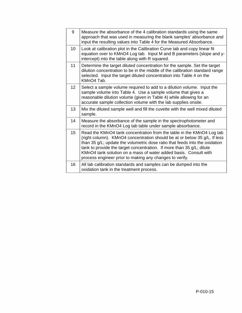
P-010-15
9 Measure the absorbance of the 4 calibration standards using the same approach that was used in measuring the blank samples' absorbance and input the resulting values into Table 4 for the Measured Absorbance.
10 Look at calibration plot in the Calibration Curve tab and copy linear fit equation over to KMnO4 Log tab. Input M and B parameters (slope and y-intercept) into the table along with R squared.
11 Determine the target diluted concentration for the sample. Set the target dilution concentration to be in the middle of the calibration standard range selected. Input the target diluted concentration into Table 4 on the KMnO4 Tab.
12 Select a sample volume required to add to a dilution volume. Input the sample volume into Table 4. Use a sample volume that gives a reasonable dilution volume (given in Table 4) while allowing for an accurate sample collection volume with the lab supplies onsite.
13 Mix the diluted sample well and fill the cuvette with the well mixed diluted sample.
14 Measure the absorbance of the sample in the spectrophotometer and record in the KMnO4 Log tab table under sample absorbance.
15 Read the KMnO4 tank concentration from the table in the KMnO4 Log tab (right column). KMnO4 concentration should be at or below 35 g/L. If less than 35 g/L; update the volumetric dose ratio that feeds into the oxidation tank to provide the target concentration. If more than 35 g/L; dilute KMnO4 tank solution on a mass of water added basis. Consult with process engineer prior to making any changes to verify.
16 All lab calibration standards and samples can be dumped into the oxidation tank in the treatment process.
29 Palms Laboratory Title: pH, EPA 150.1 47-250 Dillon Road Number : PP001 Coachella, Ca 92236 Release Date: 4/27/00 Phone: 760-398-0050 Revision Date: 11/06/01 Fax: 760-398-0028 Version: 2.0
DOCUMENT TYPE: Standard Operating Procedure TITLE: pH, EPA 150.1 INSTRUMENTATION: HACH EC10 pH Meter PREPARED BY: Marshall K. Cheung, Ph.D., Laboratory Director __________________ REVISED BY: Marshall K. Cheung, Ph.D., Laboratory Director __________________ REVIEWED BY: Anne Cheung, Laboratory Manager __________________ APPROVED BY: Marshall K. Cheung, Ph.D., Laboratory Director __________________
Table of Contents 1. Scope and Application ..................................................................................................3 2. Summary of Method .....................................................................................................3 3. Sample Handling and Preservation ...............................................................................3 4. Interferences ..................................................................................................................3 5. Apparatus ......................................................................................................................3 6. Reagents ........................................................................................................................3 7. Procedure.......................................................................................................................4 8. Calculation ....................................................................................................................6 9. Bibliography..................................................................................................................6
Page 1 of 6
29 Palms Laboratory Title: pH, EPA 150.1 47-250 Dillon Road Number : PP001 Coachella, Ca 92236 Release Date: 4/27/00 Phone: 760-398-0050 Revision Date: 11/06/01 Fax: 760-398-0028 Version: 2.0
Page 2 of 6
Document No.: PP 0001 – 015 Copy provided to: Marshall K. Cheung, Ph.D.
Title: Laboratory Director 29 Palms Laboratory 47-250 Dillon Road Coachella, CA 92236
Copy provided by: Marshall K. Cheung, Ph.D. Title: Laboratory Director Date: July 28, 2004
29 Palms Laboratory Title: pH, EPA 150.1 47-250 Dillon Road Number : PP001 Coachella, Ca 92236 Release Date: 4/27/00 Phone: 760-398-0050 Revision Date: 11/06/01 Fax: 760-398-0028 Version: 2.0 1. Scope and Application
1.1. This method is applicable to the analysis of drinking, surface and saline waters, domestic and industrial wastes and acid rain (atmospheric deposition).
1.2. It is applicable to field as well as laboratory analysis.
2. Summary of Method 2.1. Instrument setup procedure is followed. 2.2. The meter is calibrated using certified standards. 2.3. The calibration is verified with an independent certified standard (initial calibration
verification). 2.4. The pH of a sample is determined electrometrically using a combination electrode. 2.5. Continuing calibration verification is carried out using the independent certified standard.
3. Sample Handling and Preservation
3.1. Samples should be analyzed as soon as possible preferably in the field at the time of sampling. 3.2. The sample containers should be filled completely and kept sealed prior to analysis because
high-purity waters and waters not at equilibrium with the atmosphere are subject to changes when exposed to the atmosphere.
3.3. Stable pH, conductivity and temperature conditions must be demonstrated prior to groundwater sample collection (see SOP #SP002- Groundwater Sampling).
4. Interferences
4.1. The glass electrode, in general, is not subject to solution interferences from color, turbidity, colloidal matter, oxidants, reductants or high salinity.
4.2. Coatings of oily material or particulate matter can impair electrode response. Gentle wiping or detergent washing, followed by distilled water rinsing can usually remove these coatings. An additional treatment with hydrochloric acid (1 + 9) may be necessary to remove remaining film.
4.3. Variation in temperature causes pH values to differ. This interference can be controlled with instruments having temperature compensation or by calibrating the electrode-instrument system at the temperature of the samples.
4.4. If compensation or calibration at the same temperature is not possible, it should be noted by reporting both the pH and the temperature at the time of analysis.
5. Apparatus
5.1. HACH EC10 Portable pH/mV/Temperature Meter - Model 50050 5.2. HACH One Combination pH Electrode - Model 48600-22 5.3. Magnetic stirrer and Teflon-coated stirring bar (for lab analysis)
6. Reagents/Supplies
6.1. VWR pH 7.00 Buffer Solution Yellow (Cat. No. 34170-130) 6.2. VWR pH 7.00 Buffer Solution Yellow (Cat. No. 34170-130)-different lot 6.3. VWR pH 4.00 Buffer Solution Red (Cat. No. 34170-127) 6.4. VWR pH 10.00 Buffer Solution Blue (Cat. No. 34170-133) 6.5. Ricca Deionized Water (Cat. No. 9150-5) 6.6. Kimberly-Clark Kimwipes EX-L (Cat. No. 34120)
Page 3 of 6
29 Palms Laboratory Title: pH, EPA 150.1 47-250 Dillon Road Number : PP001 Coachella, Ca 92236 Release Date: 4/27/00 Phone: 760-398-0050 Revision Date: 11/06/01 Fax: 760-398-0028 Version: 2.0 7. Procedure
7.1. Instrument Setup (Refer to HACH EC10 Manual) 7.1.1. Power-up and Self-Diagnostics Checkout
7.1.1.1. Disconnect the electrode and temperature probe from the meter. 7.1.1.2. Attach BNC shorting cap to the BNC connection on the meter. 7.1.1.3. Press the I/O key to turn the instrument on. 7.1.1.4. Install new 9V battery when low battery indicator appears on the display. 7.1.1.5. Press I/O key to turn the meter off. 7.1.1.6. Press and hold the YES key while pressing the I/O key.
7.1.1.6.1. The instrument automatically performs electronic and hardware diagnostic tests, and a system countdown will display 1-8.
7.1.1.6.2. The meter will stop on test 7. 7.1.1.7. When “0” is displayed, press each key (including the I/O key) within 10 seconds to
complete this test. 7.1.1.7.1. The numeric digits will change. 7.1.1.7.2. If all keys are not pressed within 10 seconds, or if a key is not responding
properly, E-7 will appear. 7.1.1.7.3. If problems are found during self-test, the meter will display the error code
until YES is pressed. 7.1.1.7.4. If there is an error, begin Power-up and Self-Diagnostics Checkout again
(7.1.1). 7.1.1.7.5. Refer to Table 2 Error Codes on page 19 of the instrument manual.
7.1.1.8. After the keypad test (7), the meter will display test 8 and then the meter will turn off.
7.1.1.9. Make sure that the BNC shorting cap is securely attached to the BNC connection of the meter and then press the I/O key. The meter will be in the MEASURE mode as indicated on the display.
7.1.1.10. Press the MODE key until the pH mode indicator is displayed. 7.1.1.11. Press the CAL key. 7.1.1.12. When the display flashes 7.00, press the YES key. 7.1.1.13. Press the MODE key. The current slope (SLP) will be displayed. 7.1.1.14. Press the YES key. 7.1.1.15. The meter advances to MEASURE and reads a steady 7.00. 7.1.1.16. Turn meter off. 7.1.1.17. Remove the BNC shorting cap from the input connector.
7.1.2. Install the HACH One combination pH electrode. 7.1.2.1. Attach the BNC connector of the electrode to the BNC connection of the pH meter. 7.1.2.2. Attach the ATC/DIN Connector of the electrode to the ATC/DIN connection of the
pH Meter. 7.1.3. Thoroughly rinse electrode with deionized water. 7.1.4. Blot with Kimwipe. 7.1.5. Instrument is ready for calibration.
Page 4 of 6

29 Palms Laboratory Title: pH, EPA 150.1 47-250 Dillon Road Number : PP001 Coachella, Ca 92236 Release Date: 4/27/00 Phone: 760-398-0050 Revision Date: 11/06/01 Fax: 760-398-0028 Version: 2.0
7.2. Instrument Calibration 7.2.1. Allow standard pH buffer solutions to equilibrate to room temperature (20-30o C). 7.2.2. Turn the pH meter on. 7.2.3. Using the MODE key, set the meter to “pH” mode. 7.2.4. Depress the dispenser button on the electrode until a “click” is heard, then release.
7.2.4.1.Repeat until electrolyte gel emerges from the reference outlet (See Model 48600 HACH One Combination pH Electrode Instruction Manual).
7.2.4.1.1. If no gel emerges, the hole may need to be unplugged with a needle. 7.2.4.1.2. If this does not help, the gel unit may need to be replaced if low.
7.2.4.2. Rinse the electrode with deionized water and blot dry with Kimwipe. 7.2.5. Place the pH electrode into 7.00 buffer solution (Yellow).
7.2.5.1. Make sure that the electrode tip is at least 1 inch below the surface of the solution. 7.2.5.1.1. If access to magnetic stirrer is available, place clean magnetic stir rod into
buffer solution. 7.2.5.1.2. Wait for reading to stabilize while stirring on magnetic stirrer. 7.2.5.1.3. If not magnetic stirrer is used, gently agitate probe in buffer manually.
7.2.6. Press the CAL key. 7.2.7. P1 will be displayed under pH reading. 7.2.8. Wait until “ready” is displayed and then press the YES key. 7.2.9. Remove electrode, rinse with deionized water and blot dry with Kimwipe. 7.2.10. Click electrolyte pump button two (2) times. 7.2.11. Place electrode into either 4.00 or 10.00 buffer solution depending on the expected pH
range of the sample to be measured. 7.2.11.1. If expected pH range of the sample is greater than 7.00, use the 10.00 buffer
(Blue). 7.2.11.2. If the expected pH range of the sample is less than 7.00, use the 4.00 buffer (Red).
7.2.12. Make sure that the electrode tip is at least 1” below the surface of the solution. 7.2.12.1. If access to magnetic stirrer is available, place clean magnetic stir rod into buffer
solution. 7.2.12.2. Wait for reading to stabilize while stirring on magnetic stirrer. 7.2.12.3. If no magnetic stirrer is used, gently agitate probe in buffer manually.
7.2.13. Wait until “ready” is displayed and then press the YES key. 7.2.14. Slope is displayed. Record slope in HACH ph Meter Log, Logbook #30 A. 7.2.15. Remove electrode, rinse with deionized water and blot dry with Kimwipe. 7.2.16. Click electrolyte pump button two (2) times. 7.2.17. Take pH of a second standard pH 7.0 buffer as a calibration check (initial calibration
verification-ICV). 7.2.17.1. If pH is within 0.05 pH units of the expected value (acceptable precision),
calibration is verified. Proceed to 7.2.6.6. 7.2.17.2. If pH is outside this range, reread pH of calibration check standard. 7.2.17.3. If pH is within range, proceed to 7.2.6.6. 7.2.17.4. If pH is still outside range, reread fresh buffer standard. 7.2.17.5. If pH is outside range, recalibrate (7.2).
Page 5 of 6
29 Palms Laboratory Title: pH, EPA 150.1 47-250 Dillon Road Number : PP001 Coachella, Ca 92236 Release Date: 4/27/00 Phone: 760-398-0050 Revision Date: 11/06/01 Fax: 760-398-0028 Version: 2.0
Page 6 of 6
7.2.18. Retake pH of calibration standards and record reading for each in HACH pH Meter Log, Logbook #30 A.
7.2.19. Dispense gel electrolyte if the reading becomes unstable, erratic, or if stabilization takes too long (greater than two minutes).
7.3. Take sample measurements. 7.3.1. For laboratory analyses, allow samples and buffer solutions to come to room temperature
(20 – 30oC). 7.3.2. Thoroughly rinse pH electrode with deionized water and blot dry with Kimwipe. 7.3.3. Insert rinsed and dried electrode into the sample. 7.3.4. Record the pH value and the temperature of samples in appropriate bound logbook
(Surface Water Monitoring Log, Logbook #21 A, or Groundwater Monitoring Log, Logbook #13 A).
7.3.5. Analyze a calibration check standard (continuing calibration verification- CCV) with every ten samples to re-check the validity of the calibration curve.
7.3.5.1.If the CCV is within 0.05 of the expected value, continue with sample analysis. 7.3.5.2.If the CCV differs by more than 0.05, follow the steps below.
7.3.5.2.1. If the CCV does not come within 0.05 of the expected value, then the calibration check standard should first be reread.
7.3.5.2.2. If the repeat analysis result still differs by greater than 0.05, a fresh calibration check standard should be read.
7.3.5.2.3. If this calibration check standard does not meet the criteria, a new calibration must be performed and all samples analyzed since the last valid calibration must be rerun.
8. Calculation
8.1. The pH meter reads directly in pH units. Report pH to the nearest 0.01 unit and the temperature to the nearest 0.1oC.
9. Bibliography
9.1. HACH EC10 Portable pH/mV/Temperature Meter Model 50050 Manual. 9.2. Model 48600 HACH One Combination pH Electrode Instruction Manual. 9.3. EPA Method 150.1. 9.4. Standard Methods for the Examination of Water and Wastewater, 20th Edition, Method No.
4500-H+, p 4-87, (1998).
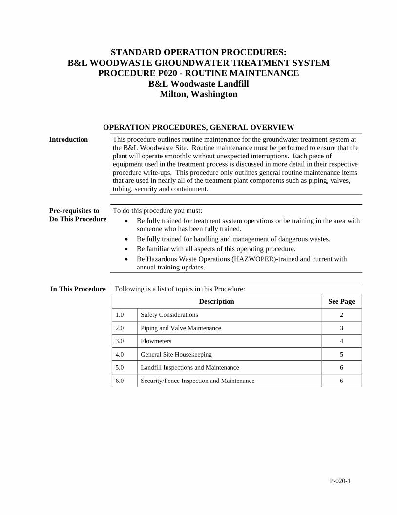
P-020-1
STANDARD OPERATION PROCEDURES: B&L WOODWASTE GROUNDWATER TREATMENT SYSTEM
PROCEDURE P020 - ROUTINE MAINTENANCE B&L Woodwaste Landfill
Milton, Washington
OPERATION PROCEDURES, GENERAL OVERVIEW Introduction This procedure outlines routine maintenance for the groundwater treatment system at
the B&L Woodwaste Site. Routine maintenance must be performed to ensure that the plant will operate smoothly without unexpected interruptions. Each piece of equipment used in the treatment process is discussed in more detail in their respective procedure write-ups. This procedure only outlines general routine maintenance items that are used in nearly all of the treatment plant components such as piping, valves, tubing, security and containment.
Pre-requisites to Do This Procedure
To do this procedure you must: Be fully trained for treatment system operations or be training in the area with
someone who has been fully trained. Be fully trained for handling and management of dangerous wastes. Be familiar with all aspects of this operating procedure. Be Hazardous Waste Operations (HAZWOPER)-trained and current with
annual training updates.
In This Procedure Following is a list of topics in this Procedure:
Description See Page
1.0 Safety Considerations 2
2.0 Piping and Valve Maintenance 3
3.0 Flowmeters 4
4.0 General Site Housekeeping 5
5.0 Landfill Inspections and Maintenance 6
6.0 Security/Fence Inspection and Maintenance 6
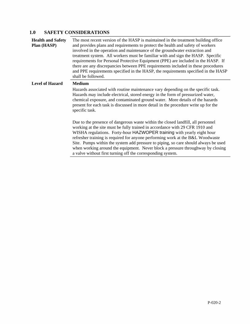
P-020-2
1.0 SAFETY CONSIDERATIONS Health and Safety Plan (HASP)
The most recent version of the HASP is maintained in the treatment building office and provides plans and requirements to protect the health and safety of workers involved in the operation and maintenance of the groundwater extraction and treatment system. All workers must be familiar with and sign the HASP. Specific requirements for Personal Protective Equipment (PPE) are included in the HASP. If there are any discrepancies between PPE requirements included in these procedures and PPE requirements specified in the HASP, the requirements specified in the HASP shall be followed.
Level of Hazard Medium Hazards associated with routine maintenance vary depending on the specific task. Hazards may include electrical, stored energy in the form of pressurized water, chemical exposure, and contaminated ground water. More details of the hazards present for each task is discussed in more detail in the procedure write up for the specific task. Due to the presence of dangerous waste within the closed landfill, all personnel working at the site must be fully trained in accordance with 29 CFR 1910 and WISHA regulations. Forty-hour HAZWOPER training with yearly eight hour refresher training is required for anyone performing work at the B&L Woodwaste Site. Pumps within the system add pressure to piping, so care should always be used when working around the equipment. Never block a pressure throughway by closing a valve without first turning off the corresponding system.
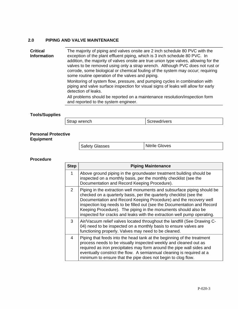
P-020-3
2.0 PIPING AND VALVE MAINTENANCE
Critical Information
The majority of piping and valves onsite are 2 inch schedule 80 PVC with the exception of the plant effluent piping, which is 3 inch schedule 80 PVC. In addition, the majority of valves onsite are true union type valves, allowing for the valves to be removed using only a strap wrench. Although PVC does not rust or corrode, some biological or chemical fouling of the system may occur; requiring some routine operation of the valves and piping. Monitoring of system flow, pressure, and pumping cycles in combination with piping and valve surface inspection for visual signs of leaks will allow for early detection of leaks. All problems should be reported on a maintenance resolution/inspection form and reported to the system engineer.
Tools/Supplies
Strap wrench Screwdrivers
Personal Protective Equipment
Safety Glasses Nitrile Gloves
Procedure
Step Piping Maintenance
1 Above ground piping in the groundwater treatment building should be inspected on a monthly basis, per the monthly checklist (see the Documentation and Record Keeping Procedure).
2 Piping in the extraction well monuments and subsurface piping should be checked on a quarterly basis, per the quarterly checklist (see the Documentation and Record Keeping Procedure) and the recovery well inspection log needs to be filled out (see the Documentation and Record Keeping Procedure). The piping in the monuments should also be inspected for cracks and leaks with the extraction well pump operating.
3 Air/Vacuum relief valves located throughout the landfill (See Drawing C-04) need to be inspected on a monthly basis to ensure valves are functioning properly. Valves may need to be cleaned.
4 Piping that feeds into the head tank at the beginning of the treatment process needs to be visually inspected weekly and cleaned out as required as iron precipitates may form around the pipe wall sides and eventually constrict the flow. A semiannual cleaning is required at a minimum to ensure that the pipe does not begin to clog flow.
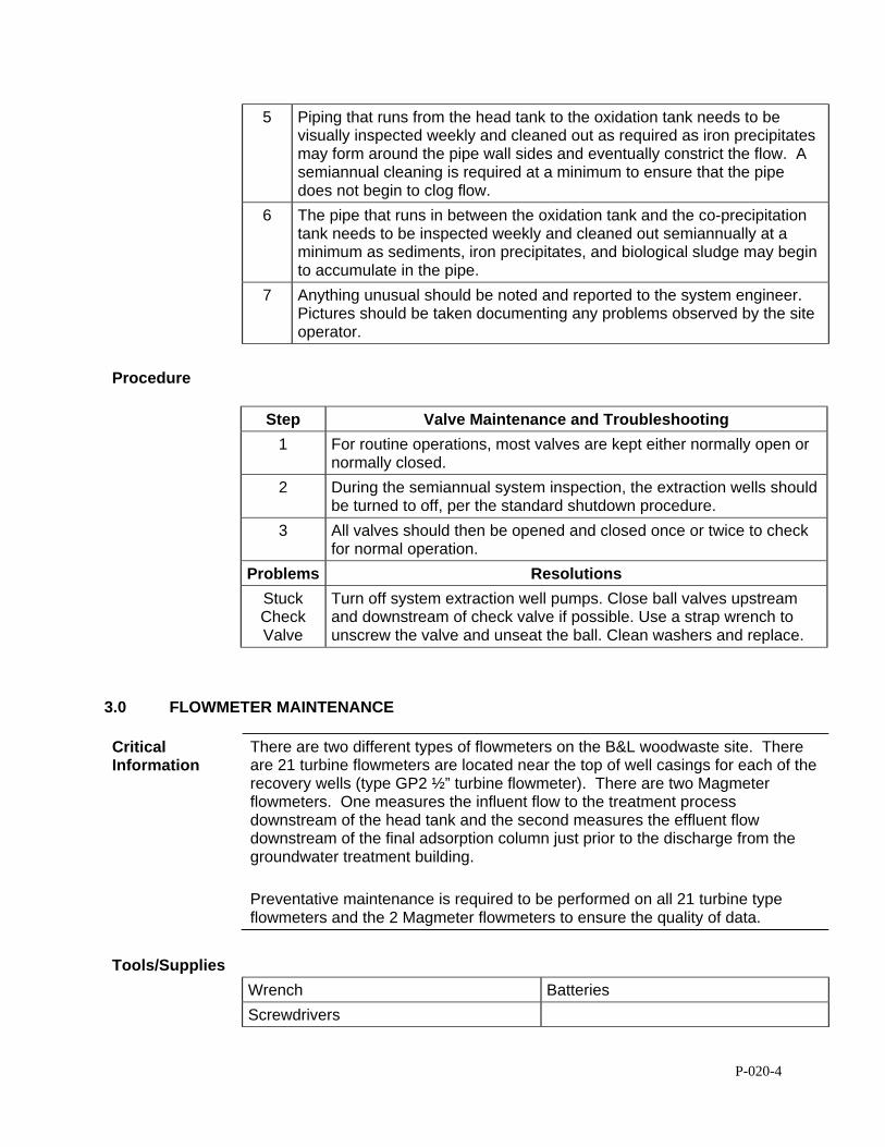
P-020-4
5 Piping that runs from the head tank to the oxidation tank needs to be visually inspected weekly and cleaned out as required as iron precipitates may form around the pipe wall sides and eventually constrict the flow. A semiannual cleaning is required at a minimum to ensure that the pipe does not begin to clog flow.
6 The pipe that runs in between the oxidation tank and the co-precipitation tank needs to be inspected weekly and cleaned out semiannually at a minimum as sediments, iron precipitates, and biological sludge may begin to accumulate in the pipe.
7 Anything unusual should be noted and reported to the system engineer. Pictures should be taken documenting any problems observed by the site operator.
Procedure
Step Valve Maintenance and Troubleshooting
1 For routine operations, most valves are kept either normally open or normally closed.
2 During the semiannual system inspection, the extraction wells should be turned to off, per the standard shutdown procedure.
3 All valves should then be opened and closed once or twice to check for normal operation.
Problems Resolutions
Stuck Check Valve
Turn off system extraction well pumps. Close ball valves upstream and downstream of check valve if possible. Use a strap wrench to unscrew the valve and unseat the ball. Clean washers and replace.
3.0 FLOWMETER MAINTENANCE
Critical Information
There are two different types of flowmeters on the B&L woodwaste site. There are 21 turbine flowmeters are located near the top of well casings for each of the recovery wells (type GP2 ½” turbine flowmeter). There are two Magmeter flowmeters. One measures the influent flow to the treatment process downstream of the head tank and the second measures the effluent flow downstream of the final adsorption column just prior to the discharge from the groundwater treatment building. Preventative maintenance is required to be performed on all 21 turbine type flowmeters and the 2 Magmeter flowmeters to ensure the quality of data.
Tools/Supplies
Wrench Batteries
Screwdrivers
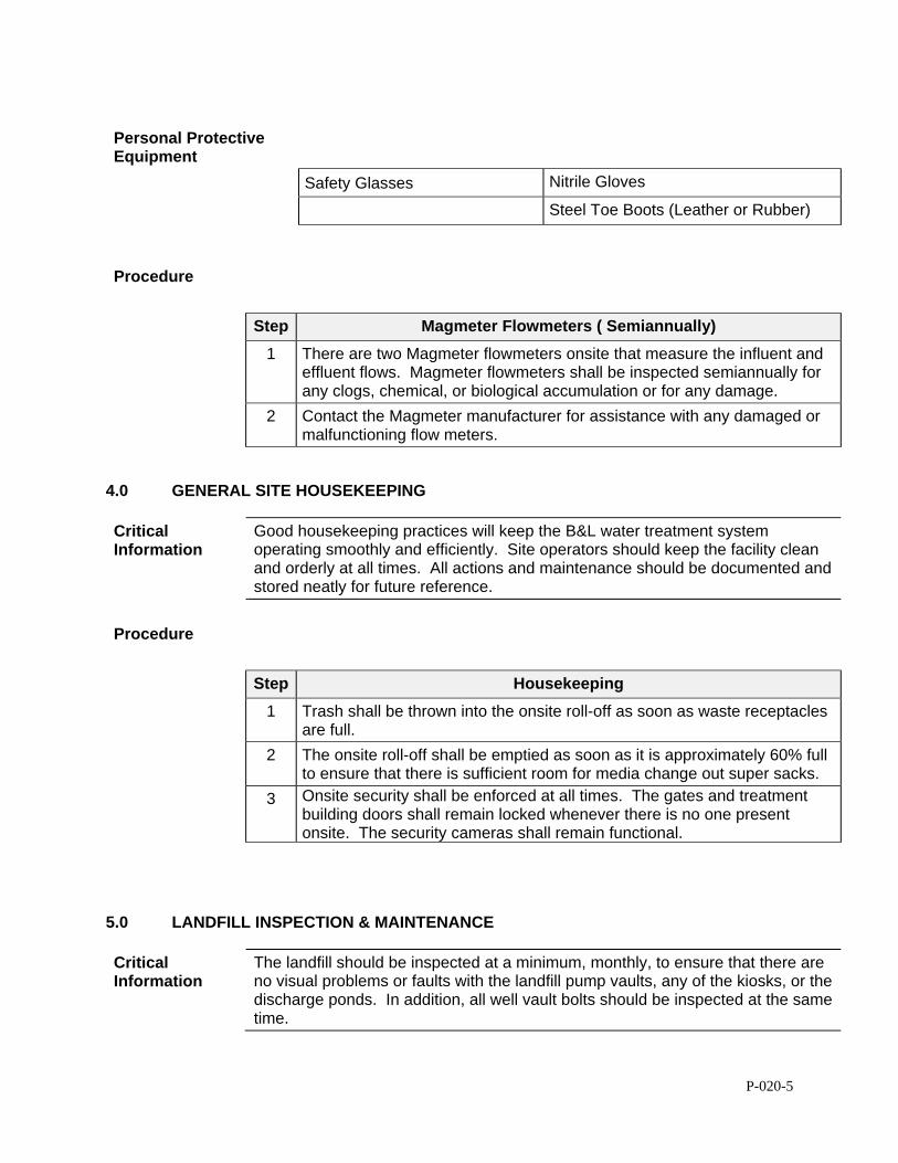
P-020-5
Personal Protective Equipment
Safety Glasses Nitrile Gloves
Steel Toe Boots (Leather or Rubber)
Procedure
Step Magmeter Flowmeters ( Semiannually)
1 There are two Magmeter flowmeters onsite that measure the influent and effluent flows. Magmeter flowmeters shall be inspected semiannually for any clogs, chemical, or biological accumulation or for any damage.
2 Contact the Magmeter manufacturer for assistance with any damaged or malfunctioning flow meters.
4.0 GENERAL SITE HOUSEKEEPING
Critical Information
Good housekeeping practices will keep the B&L water treatment system operating smoothly and efficiently. Site operators should keep the facility clean and orderly at all times. All actions and maintenance should be documented and stored neatly for future reference.
Procedure
Step Housekeeping
1 Trash shall be thrown into the onsite roll-off as soon as waste receptacles are full.
2 The onsite roll-off shall be emptied as soon as it is approximately 60% full to ensure that there is sufficient room for media change out super sacks.
3 Onsite security shall be enforced at all times. The gates and treatment building doors shall remain locked whenever there is no one present onsite. The security cameras shall remain functional.
5.0 LANDFILL INSPECTION & MAINTENANCE
Critical Information
The landfill should be inspected at a minimum, monthly, to ensure that there are no visual problems or faults with the landfill pump vaults, any of the kiosks, or the discharge ponds. In addition, all well vault bolts should be inspected at the same time.
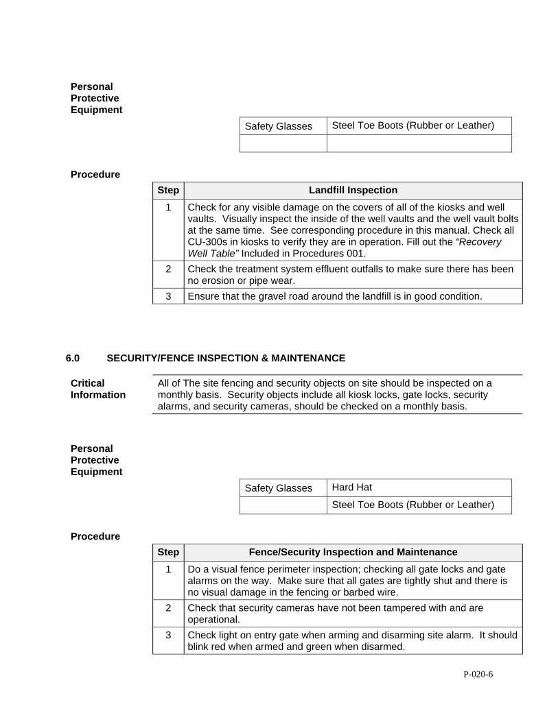
P-020-6
Personal Protective Equipment
Safety Glasses Steel Toe Boots (Rubber or Leather)
Procedure
Step Landfill Inspection
1 Check for any visible damage on the covers of all of the kiosks and well vaults. Visually inspect the inside of the well vaults and the well vault bolts at the same time. See corresponding procedure in this manual. Check all CU-300s in kiosks to verify they are in operation. Fill out the “Recovery Well Table” Included in Procedures 001.
2 Check the treatment system effluent outfalls to make sure there has been no erosion or pipe wear.
3 Ensure that the gravel road around the landfill is in good condition.
6.0 SECURITY/FENCE INSPECTION & MAINTENANCE
Critical Information
All of The site fencing and security objects on site should be inspected on a monthly basis. Security objects include all kiosk locks, gate locks, security alarms, and security cameras, should be checked on a monthly basis.
Personal Protective Equipment
Safety Glasses Hard Hat
Steel Toe Boots (Rubber or Leather)
Procedure
Step Fence/Security Inspection and Maintenance
1 Do a visual fence perimeter inspection; checking all gate locks and gate alarms on the way. Make sure that all gates are tightly shut and there is no visual damage in the fencing or barbed wire.
2 Check that security cameras have not been tampered with and are operational.
3 Check light on entry gate when arming and disarming site alarm. It should blink red when armed and green when disarmed.

P-020-7
4 Check kiosk shrouds and handles for any signs of damage. Locks should be in place inside of the metal shrouds.
5 Check well vault bolts to make sure they have not been tampered with.
P-050-1
STANDARD OPERATION PROCEDURE: B&L WOODWASTE GROUNDWATER TREATMENT SYSTEM
PROCEDURE P050 - NORMAL STARTUP AND SHUTDOWN B&L Woodwaste Landfill
Milton, Washington
OPERATION PROCEDURES, GENERAL OVERVIEW Introduction This procedure outlines operational procedures for the normal startup and shutdown
of the B&L Woodwaste groundwater treatment system. Also included in this procedure are checklists that are meant to be used as a guide for startup, shut down, and simplified troubleshooting and startup process control.
Pre-requisites to Do This Procedure
To do this procedure you must: Be fully trained for treatment system operations or be training in the area with
someone who has been fully trained. Be fully trained for handling and management of dangerous wastes. Be familiar with all aspects of this operating procedure. Be Hazardous Waste Operations (HAZWOPER)-trained and current with
annual training updates.
In This Procedure Following is a list of topics in this Procedure:
Description See Page
1.0 Safety Considerations 1
2.0 Normal Startup and Shutdown 2
1.0 SAFETY CONSIDERATIONS
Health and Safety Plan (HASP)
The HASP maintained in the treatment building provides plans and requirements to protect the health and safety of workers involved in the operation and maintenance of the groundwater extraction and treatment system. All workers must be familiar with and sign the HASP. Specific requirements for Personal Protective Equipment (PPE) are included in the HASP. If there are any discrepancies between PPE requirements included in these procedures and PPE requirements specified in the HASP, the requirements specified in the HASP shall be followed.
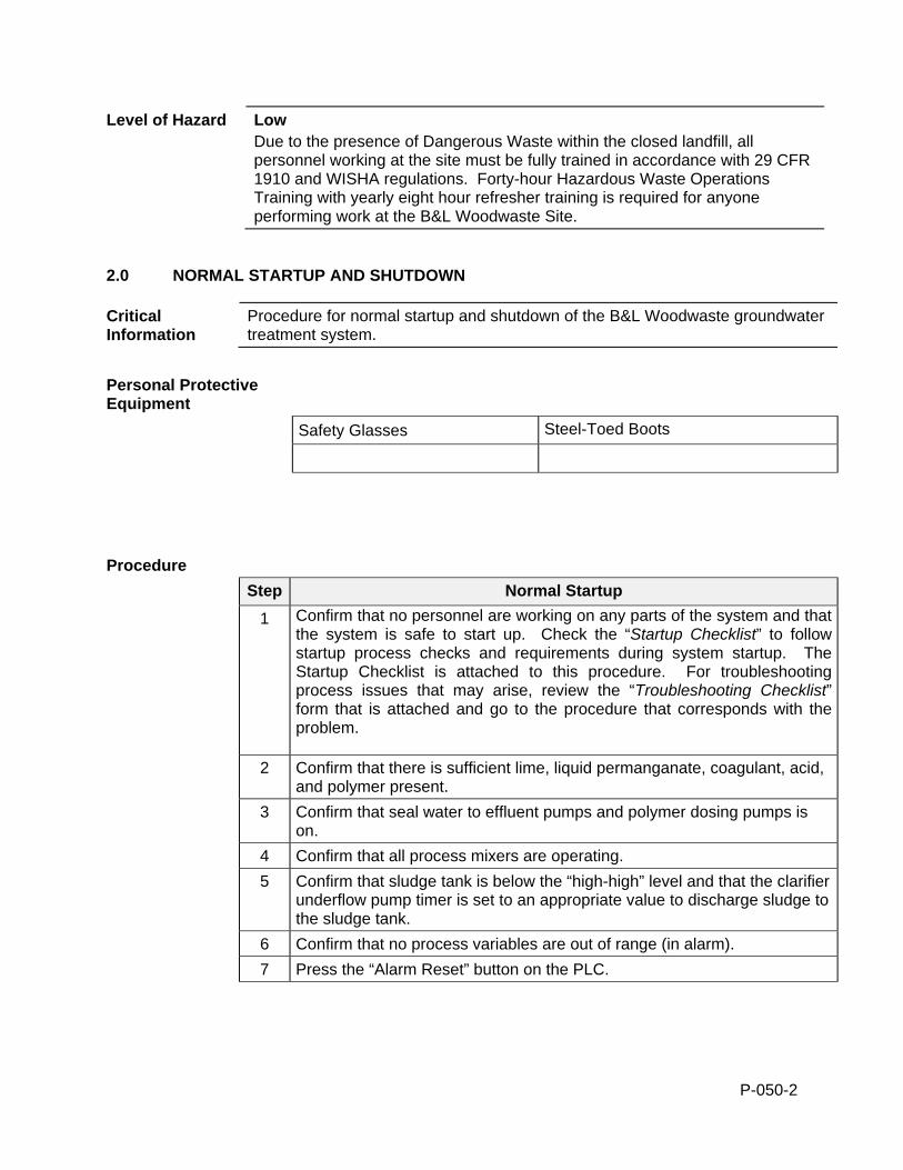
P-050-2
Level of Hazard Low Due to the presence of Dangerous Waste within the closed landfill, all personnel working at the site must be fully trained in accordance with 29 CFR 1910 and WISHA regulations. Forty-hour Hazardous Waste Operations Training with yearly eight hour refresher training is required for anyone performing work at the B&L Woodwaste Site.
2.0 NORMAL STARTUP AND SHUTDOWN
Critical Information
Procedure for normal startup and shutdown of the B&L Woodwaste groundwater treatment system.
Personal Protective Equipment
Safety Glasses Steel-Toed Boots
Procedure
Step Normal Startup
1 Confirm that no personnel are working on any parts of the system and that the system is safe to start up. Check the “Startup Checklist” to follow startup process checks and requirements during system startup. The Startup Checklist is attached to this procedure. For troubleshooting process issues that may arise, review the “Troubleshooting Checklist” form that is attached and go to the procedure that corresponds with the problem.
2 Confirm that there is sufficient lime, liquid permanganate, coagulant, acid, and polymer present.
3 Confirm that seal water to effluent pumps and polymer dosing pumps is on.
4 Confirm that all process mixers are operating.
5 Confirm that sludge tank is below the “high-high” level and that the clarifier underflow pump timer is set to an appropriate value to discharge sludge to the sludge tank.
6 Confirm that no process variables are out of range (in alarm).
7 Press the “Alarm Reset” button on the PLC.
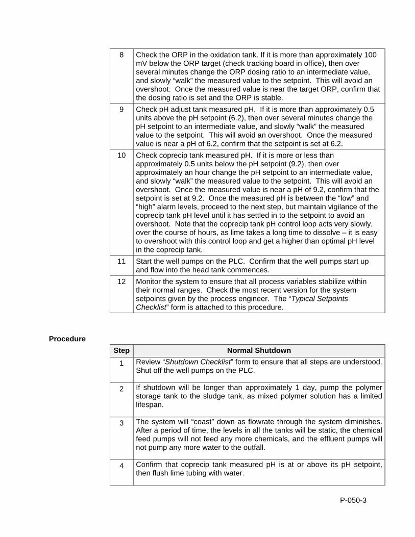
P-050-3
8 Check the ORP in the oxidation tank. If it is more than approximately 100 mV below the ORP target (check tracking board in office), then over several minutes change the ORP dosing ratio to an intermediate value, and slowly “walk” the measured value to the setpoint. This will avoid an overshoot. Once the measured value is near the target ORP, confirm that the dosing ratio is set and the ORP is stable.
9 Check pH adjust tank measured pH. If it is more than approximately 0.5 units above the pH setpoint (6.2), then over several minutes change the pH setpoint to an intermediate value, and slowly “walk” the measured value to the setpoint. This will avoid an overshoot. Once the measured value is near a pH of 6.2, confirm that the setpoint is set at 6.2.
10 Check coprecip tank measured pH. If it is more or less than approximately 0.5 units below the pH setpoint (9.2), then over approximately an hour change the pH setpoint to an intermediate value, and slowly “walk” the measured value to the setpoint. This will avoid an overshoot. Once the measured value is near a pH of 9.2, confirm that the setpoint is set at 9.2. Once the measured pH is between the “low” and “high” alarm levels, proceed to the next step, but maintain vigilance of the coprecip tank pH level until it has settled in to the setpoint to avoid an overshoot. Note that the coprecip tank pH control loop acts very slowly, over the course of hours, as lime takes a long time to dissolve – it is easy to overshoot with this control loop and get a higher than optimal pH level in the coprecip tank.
11 Start the well pumps on the PLC. Confirm that the well pumps start up and flow into the head tank commences.
12 Monitor the system to ensure that all process variables stabilize within their normal ranges. Check the most recent version for the system setpoints given by the process engineer. The “Typical Setpoints Checklist” form is attached to this procedure.
Procedure
Step Normal Shutdown
1 Review “Shutdown Checklist” form to ensure that all steps are understood. Shut off the well pumps on the PLC.
2 If shutdown will be longer than approximately 1 day, pump the polymer storage tank to the sludge tank, as mixed polymer solution has a limited lifespan.
3 The system will “coast” down as flowrate through the system diminishes. After a period of time, the levels in all the tanks will be static, the chemical feed pumps will not feed any more chemicals, and the effluent pumps will not pump any more water to the outfall.
4 Confirm that coprecip tank measured pH is at or above its pH setpoint, then flush lime tubing with water.

P-050-4
5 Shut the process water solenoid valve on the PLC to shut off pump seal water, which otherwise would be flowing into the plant sump and into the pH adjust tank.
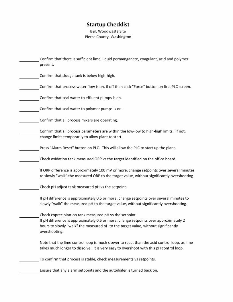
Startup ChecklistB&L Woodwaste Site
Pierce County, Washington
Confirm that sludge tank is below high‐high.
Confirm that process water flow is on, if off then click "Force" button on first PLC screen.
Confirm that seal water to effluent pumps is on.
Confirm that seal water to polymer pumps is on.
Confirm that all process mixers are operating.
Press "Alarm Reset" button on PLC. This will allow the PLC to start up the plant.
Check oxidation tank measured ORP vs the target identified on the office board.
Check pH adjust tank measured pH vs the setpoint.
Check coprecipitation tank measured pH vs the setpoint.
To confirm that process is stable, check measurements vs setpoints.
Ensure that any alarm setpoints and the autodialer is turned back on.
Confirm that there is sufficient lime, liquid permanganate, coagulant, acid and polymer present.
Confirm that all process parameters are within the low‐low to high‐high limits. If not, change limits temporarily to allow plant to start.
If pH difference is approximately 0.5 or more, change setpoints over several minutes to slowly "walk" the measured pH to the target value, without significantly overshooting.
If pH difference is approximately 0.5 or more, change setpoints over approximately 2 hours to slowly "walk" the measured pH to the target value, without significantly overshooting.
Note that the lime control loop is much slower to react than the acid control loop, as lime takes much longer to dissolve. It is very easy to overshoot with this pH control loop.
If ORP difference is approximately 100 mV or more, change setpoints over several minutes to slowly "walk" the measured ORP to the target value, without significantly overshooting.
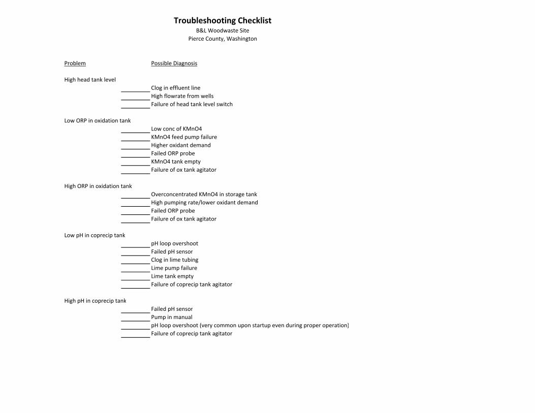
Troubleshooting ChecklistB&L Woodwaste Site
Pierce County, Washington
Problem Possible Diagnosis
High head tank levelClog in effluent lineHigh flowrate from wellsFailure of head tank level switch
Low ORP in oxidation tankLow conc of KMnO4KMnO4 feed pump failureHigher oxidant demandFailed ORP probeKMnO4 tank emptyFailure of ox tank agitator
High ORP in oxidation tankOverconcentrated KMnO4 in storage tankHigh pumping rate/lower oxidant demandFailed ORP probeFailure of ox tank agitator
Low pH in coprecip tankpH loop overshootFailed pH sensorClog in lime tubingLime pump failureLime tank emptyFailure of coprecip tank agitator
High pH in coprecip tankFailed pH sensorPump in manualpH loop overshoot (very common upon startup even during proper operation)Failure of coprecip tank agitator
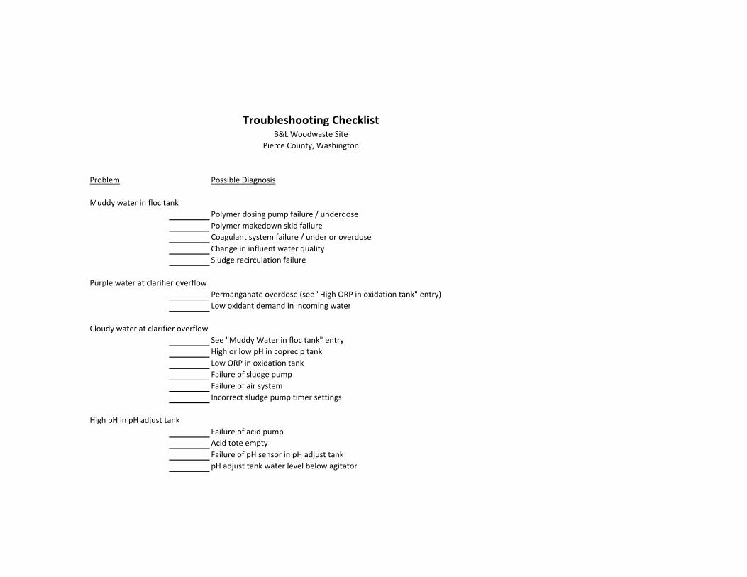
Troubleshooting ChecklistB&L Woodwaste Site
Pierce County, Washington
Problem Possible Diagnosis
Muddy water in floc tank Polymer dosing pump failure / underdosePolymer makedown skid failureCoagulant system failure / under or overdoseChange in influent water quality Sludge recirculation failure
Purple water at clarifier overflowPermanganate overdose (see "High ORP in oxidation tank" entry)Low oxidant demand in incoming water
Cloudy water at clarifier overflowSee "Muddy Water in floc tank" entryHigh or low pH in coprecip tankLow ORP in oxidation tankFailure of sludge pump Failure of air systemIncorrect sludge pump timer settings
High pH in pH adjust tankFailure of acid pumpAcid tote emptyFailure of pH sensor in pH adjust tankpH adjust tank water level below agitator
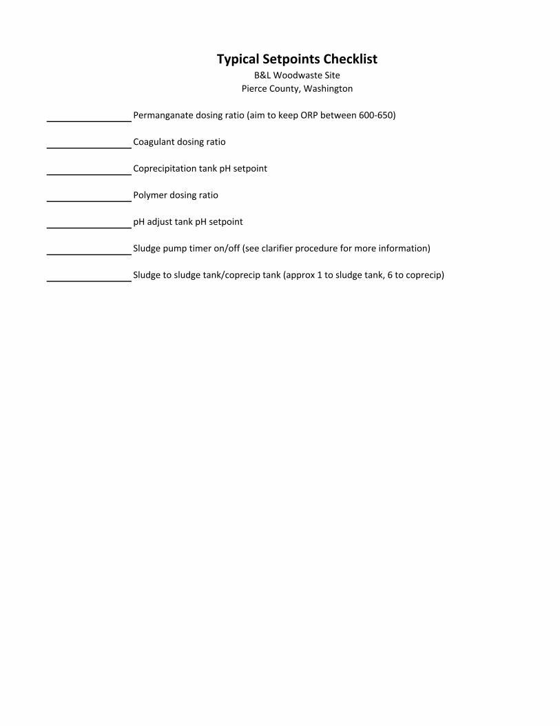
Typical Setpoints ChecklistB&L Woodwaste Site
Pierce County, Washington
Permanganate dosing ratio (aim to keep ORP between 600‐650)
Coagulant dosing ratio
Coprecipitation tank pH setpoint
Polymer dosing ratio
pH adjust tank pH setpoint
Sludge pump timer on/off (see clarifier procedure for more information)
Sludge to sludge tank/coprecip tank (approx 1 to sludge tank, 6 to coprecip)
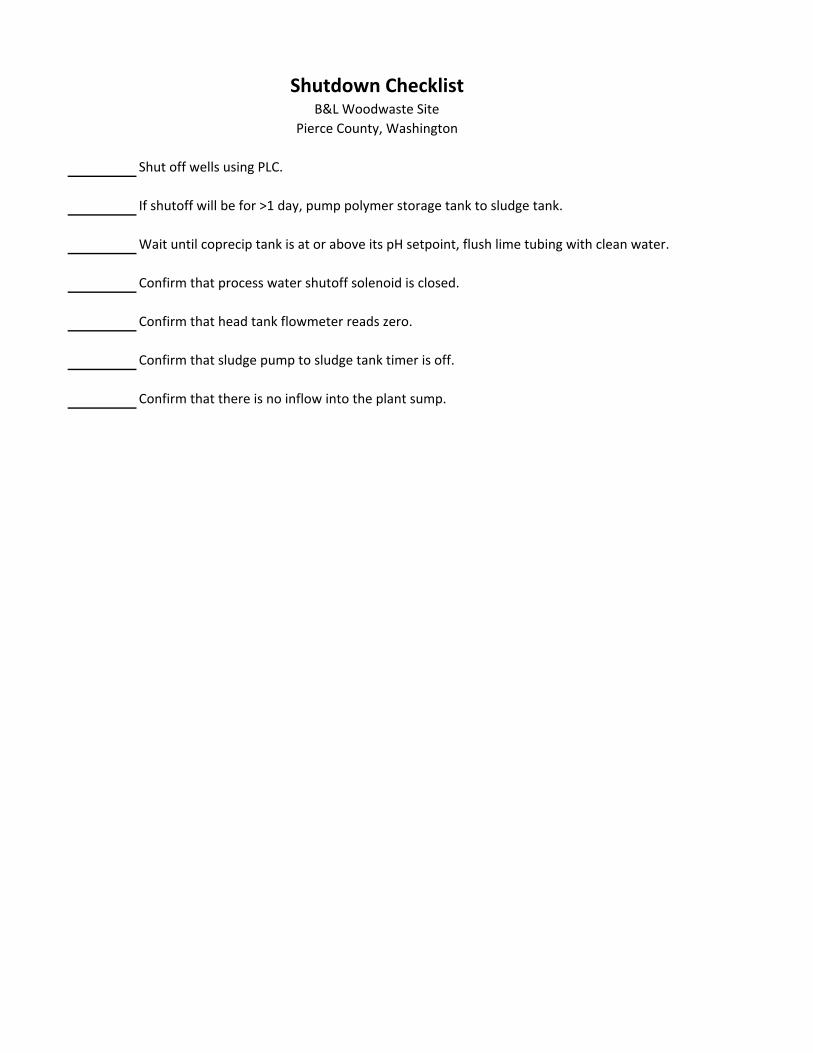
Shutdown ChecklistB&L Woodwaste Site
Pierce County, Washington
Shut off wells using PLC.
If shutoff will be for >1 day, pump polymer storage tank to sludge tank.
Wait until coprecip tank is at or above its pH setpoint, flush lime tubing with clean water.
Confirm that process water shutoff solenoid is closed.
Confirm that head tank flowmeter reads zero.
Confirm that sludge pump to sludge tank timer is off.
Confirm that there is no inflow into the plant sump.
P-100-1
STANDARD OPERATION PROCEDURE: B&L WOODWASTE GROUNDWATER TREATMENT SYSTEM
PROCEDURE P100 - HEAD TANK & OXIDATION TANK B&L Woodwaste Landfill
Milton, Washington
OPERATION PROCEDURES, GENERAL OVERVIEW Introduction This procedure outlines operational procedures for the head tank and oxidation tank in
the groundwater treatment system at the B&L Woodwaste Site. The head tank is the receiving tank for water pumped from the landfill and wetland wells. Untreated water is gravity fed from the head tank into the oxidation tank, where the water is dosed with a potassium permanganate solution, which oxidizes the iron and arsenic to aid in co-precipitation of the iron with the arsenic in the co-precipitation tank.
Pre-requisites to Do This Procedure
To do this procedure you must: Be fully trained for treatment system operations or be training in the area with
someone who has been fully trained. Be fully trained for handling and management of dangerous wastes. Be familiar with all aspects of this operating procedure. Be Hazardous Waste Operations (HAZWOPER)-trained and current with
annual training updates.
In This Procedure Following is a list of topics in this Procedure:
Description See Page
1.0 Safety Considerations 2
2.0 Head Tank Startup & Shutdown 3
3.0 Oxidation Tank Startup & Shutdown 3
4.0 Mixer Operation 4
5.0 ORP meter/sensor operation and maintenance 5
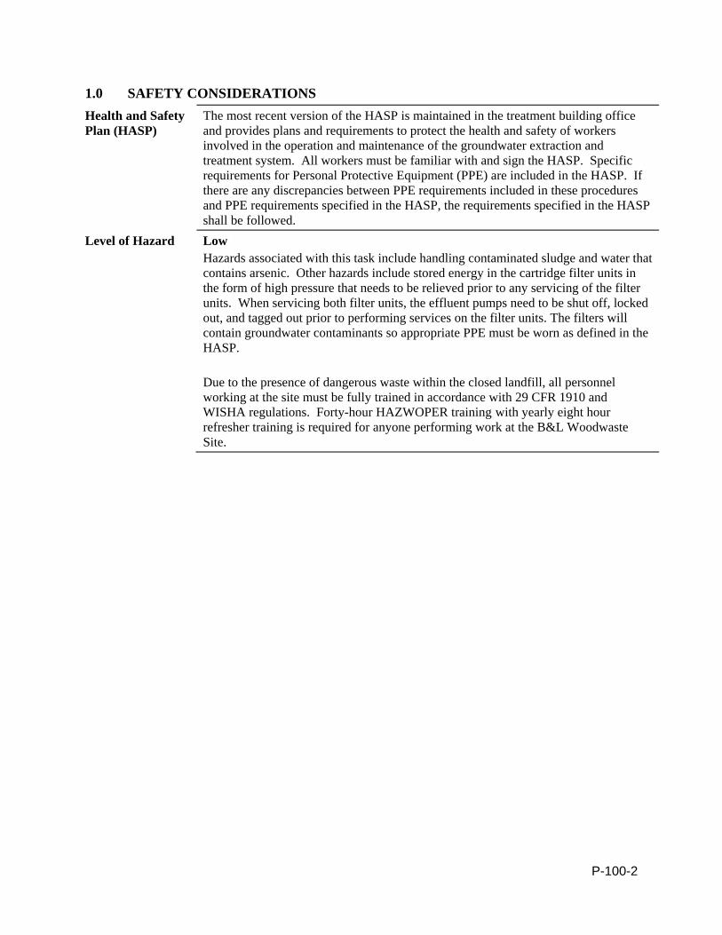
P-100-2
1.0 SAFETY CONSIDERATIONS Health and Safety Plan (HASP)
The most recent version of the HASP is maintained in the treatment building office and provides plans and requirements to protect the health and safety of workers involved in the operation and maintenance of the groundwater extraction and treatment system. All workers must be familiar with and sign the HASP. Specific requirements for Personal Protective Equipment (PPE) are included in the HASP. If there are any discrepancies between PPE requirements included in these procedures and PPE requirements specified in the HASP, the requirements specified in the HASP shall be followed.
Level of Hazard Low Hazards associated with this task include handling contaminated sludge and water that contains arsenic. Other hazards include stored energy in the cartridge filter units in the form of high pressure that needs to be relieved prior to any servicing of the filter units. When servicing both filter units, the effluent pumps need to be shut off, locked out, and tagged out prior to performing services on the filter units. The filters will contain groundwater contaminants so appropriate PPE must be worn as defined in the HASP. Due to the presence of dangerous waste within the closed landfill, all personnel working at the site must be fully trained in accordance with 29 CFR 1910 and WISHA regulations. Forty-hour HAZWOPER training with yearly eight hour refresher training is required for anyone performing work at the B&L Woodwaste Site.
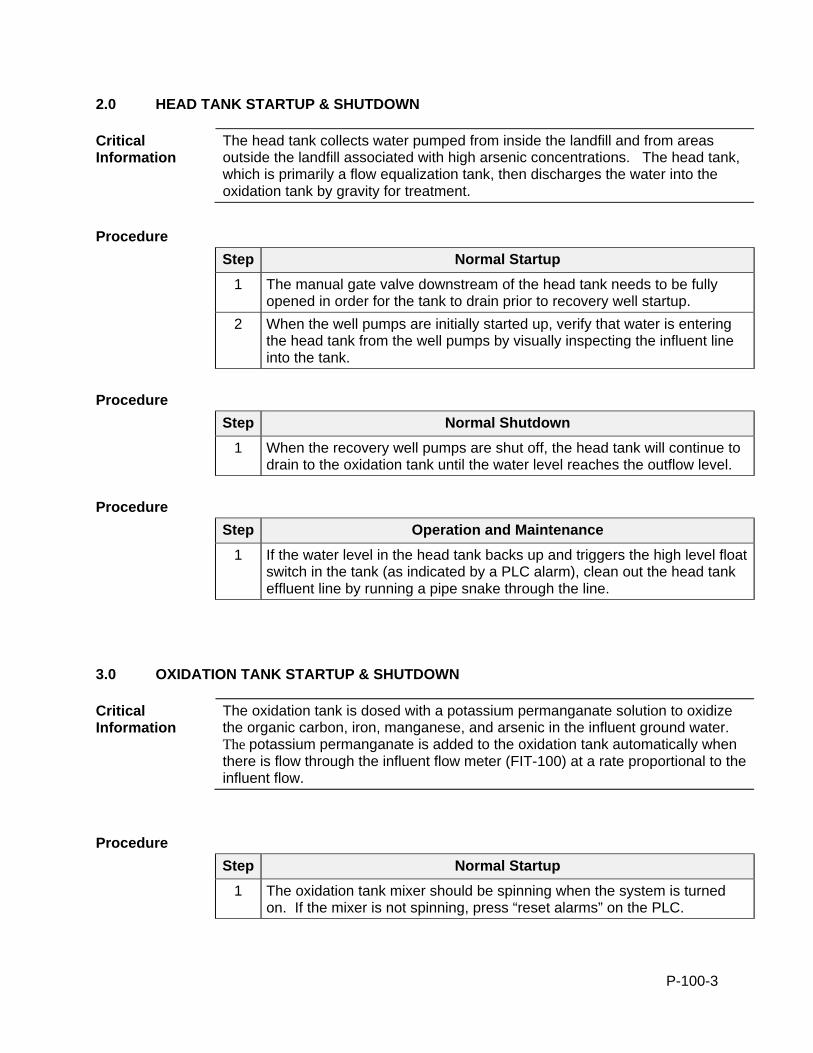
P-100-3
2.0 HEAD TANK STARTUP & SHUTDOWN
Critical Information
The head tank collects water pumped from inside the landfill and from areas outside the landfill associated with high arsenic concentrations. The head tank, which is primarily a flow equalization tank, then discharges the water into the oxidation tank by gravity for treatment.
Procedure
Step Normal Startup
1 The manual gate valve downstream of the head tank needs to be fully opened in order for the tank to drain prior to recovery well startup.
2 When the well pumps are initially started up, verify that water is entering the head tank from the well pumps by visually inspecting the influent line into the tank.
Procedure
Step Normal Shutdown
1 When the recovery well pumps are shut off, the head tank will continue to drain to the oxidation tank until the water level reaches the outflow level.
Procedure
Step Operation and Maintenance
1 If the water level in the head tank backs up and triggers the high level float switch in the tank (as indicated by a PLC alarm), clean out the head tank effluent line by running a pipe snake through the line.
3.0 OXIDATION TANK STARTUP & SHUTDOWN
Critical Information
The oxidation tank is dosed with a potassium permanganate solution to oxidize the organic carbon, iron, manganese, and arsenic in the influent ground water. The potassium permanganate is added to the oxidation tank automatically when there is flow through the influent flow meter (FIT-100) at a rate proportional to the influent flow.
Procedure
Step Normal Startup
1 The oxidation tank mixer should be spinning when the system is turned on. If the mixer is not spinning, press “reset alarms” on the PLC.
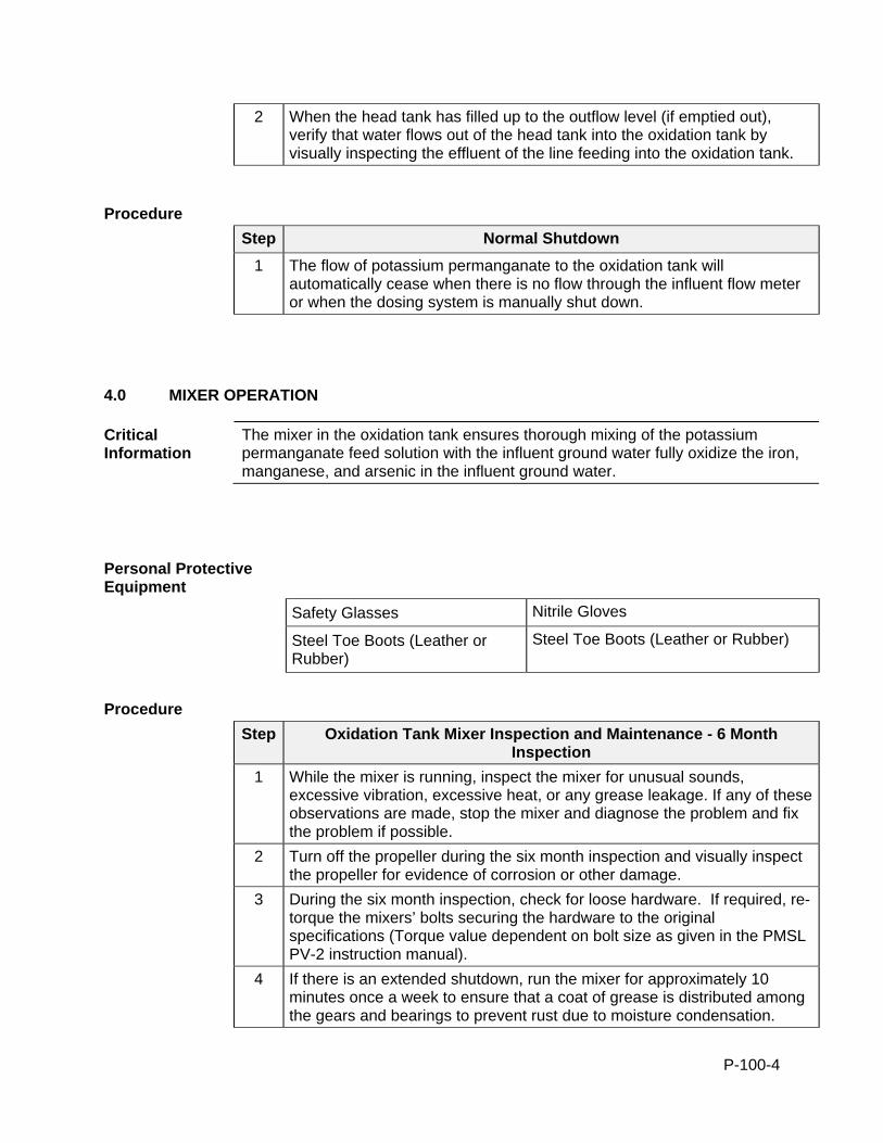
P-100-4
2 When the head tank has filled up to the outflow level (if emptied out), verify that water flows out of the head tank into the oxidation tank by visually inspecting the effluent of the line feeding into the oxidation tank.
Procedure
Step Normal Shutdown
1 The flow of potassium permanganate to the oxidation tank will automatically cease when there is no flow through the influent flow meter or when the dosing system is manually shut down.
4.0 MIXER OPERATION
Critical Information
The mixer in the oxidation tank ensures thorough mixing of the potassium permanganate feed solution with the influent ground water fully oxidize the iron, manganese, and arsenic in the influent ground water.
Personal Protective Equipment
Safety Glasses Nitrile Gloves
Steel Toe Boots (Leather or Rubber)
Steel Toe Boots (Leather or Rubber)
Procedure
Step Oxidation Tank Mixer Inspection and Maintenance - 6 Month Inspection
1 While the mixer is running, inspect the mixer for unusual sounds, excessive vibration, excessive heat, or any grease leakage. If any of these observations are made, stop the mixer and diagnose the problem and fix the problem if possible.
2 Turn off the propeller during the six month inspection and visually inspect the propeller for evidence of corrosion or other damage.
3 During the six month inspection, check for loose hardware. If required, re-torque the mixers’ bolts securing the hardware to the original specifications (Torque value dependent on bolt size as given in the PMSL PV-2 instruction manual).
4 If there is an extended shutdown, run the mixer for approximately 10 minutes once a week to ensure that a coat of grease is distributed among the gears and bearings to prevent rust due to moisture condensation.
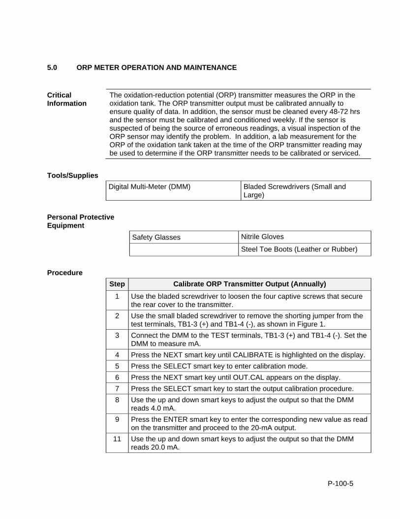
P-100-5
5.0 ORP METER OPERATION AND MAINTENANCE
Critical Information
The oxidation-reduction potential (ORP) transmitter measures the ORP in the oxidation tank. The ORP transmitter output must be calibrated annually to ensure quality of data. In addition, the sensor must be cleaned every 48-72 hrs and the sensor must be calibrated and conditioned weekly. If the sensor is suspected of being the source of erroneous readings, a visual inspection of the ORP sensor may identify the problem. In addition, a lab measurement for the ORP of the oxidation tank taken at the time of the ORP transmitter reading may be used to determine if the ORP transmitter needs to be calibrated or serviced.
Tools/Supplies
Digital Multi-Meter (DMM) Bladed Screwdrivers (Small and Large)
Personal Protective Equipment
Safety Glasses Nitrile Gloves
Steel Toe Boots (Leather or Rubber)
Procedure
Step Calibrate ORP Transmitter Output (Annually)
1 Use the bladed screwdriver to loosen the four captive screws that secure the rear cover to the transmitter.
2 Use the small bladed screwdriver to remove the shorting jumper from the test terminals, TB1-3 (+) and TB1-4 (-), as shown in Figure 1.
3 Connect the DMM to the TEST terminals, TB1-3 (+) and TB1-4 (-). Set the DMM to measure mA.
4 Press the NEXT smart key until CALIBRATE is highlighted on the display.
5 Press the SELECT smart key to enter calibration mode.
6 Press the NEXT smart key until OUT.CAL appears on the display.
7 Press the SELECT smart key to start the output calibration procedure.
8 Use the up and down smart keys to adjust the output so that the DMM reads 4.0 mA.
9 Press the ENTER smart key to enter the corresponding new value as read on the transmitter and proceed to the 20-mA output.
11 Use the up and down smart keys to adjust the output so that the DMM reads 20.0 mA.

P-100-6
12 Press the ENTER smart key to enter the new value as read on the transmitter. The transmitter then returns to the output calibrate state. NOTE: Once the output level has been permanently stored using the ENTER smart key, the output calibration procedure must be repeated to rectify a bad calibration.
13 Press the EXIT TO MEASURE smart key to return to the measure mode.
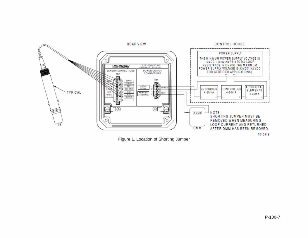
P-100-7
Figure 1. Location of Shorting Jumper
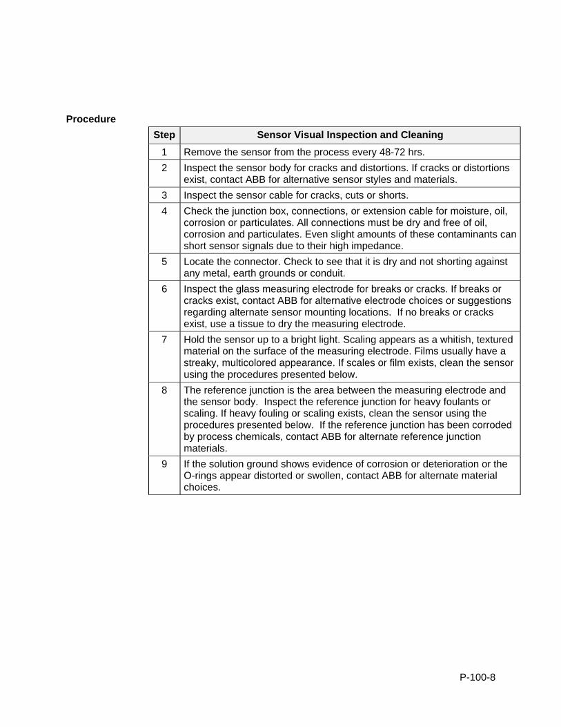
P-100-8
Procedure
Step Sensor Visual Inspection and Cleaning
1 Remove the sensor from the process every 48-72 hrs.
2 Inspect the sensor body for cracks and distortions. If cracks or distortions exist, contact ABB for alternative sensor styles and materials.
3 Inspect the sensor cable for cracks, cuts or shorts.
4 Check the junction box, connections, or extension cable for moisture, oil, corrosion or particulates. All connections must be dry and free of oil, corrosion and particulates. Even slight amounts of these contaminants can short sensor signals due to their high impedance.
5 Locate the connector. Check to see that it is dry and not shorting against any metal, earth grounds or conduit.
6 Inspect the glass measuring electrode for breaks or cracks. If breaks or cracks exist, contact ABB for alternative electrode choices or suggestions regarding alternate sensor mounting locations. If no breaks or cracks exist, use a tissue to dry the measuring electrode.
7 Hold the sensor up to a bright light. Scaling appears as a whitish, textured material on the surface of the measuring electrode. Films usually have a streaky, multicolored appearance. If scales or film exists, clean the sensor using the procedures presented below.
8 The reference junction is the area between the measuring electrode and the sensor body. Inspect the reference junction for heavy foulants or scaling. If heavy fouling or scaling exists, clean the sensor using the procedures presented below. If the reference junction has been corroded by process chemicals, contact ABB for alternate reference junction materials.
9 If the solution ground shows evidence of corrosion or deterioration or the O-rings appear distorted or swollen, contact ABB for alternate material choices.
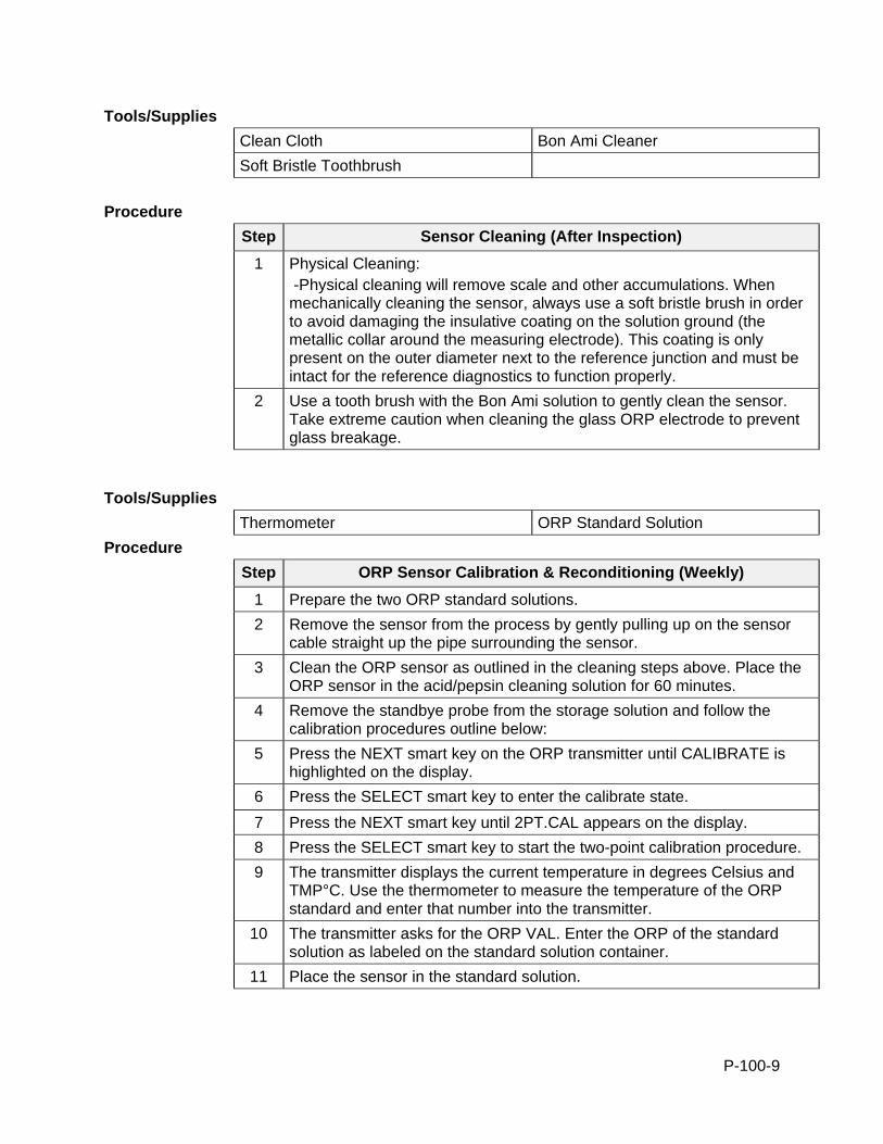
P-100-9
Tools/Supplies
Clean Cloth Bon Ami Cleaner
Soft Bristle Toothbrush
Procedure
Step Sensor Cleaning (After Inspection)
1 Physical Cleaning: -Physical cleaning will remove scale and other accumulations. When mechanically cleaning the sensor, always use a soft bristle brush in order to avoid damaging the insulative coating on the solution ground (the metallic collar around the measuring electrode). This coating is only present on the outer diameter next to the reference junction and must be intact for the reference diagnostics to function properly.
2 Use a tooth brush with the Bon Ami solution to gently clean the sensor. Take extreme caution when cleaning the glass ORP electrode to prevent glass breakage.
Tools/Supplies
Thermometer ORP Standard Solution
Procedure
Step ORP Sensor Calibration & Reconditioning (Weekly)
1 Prepare the two ORP standard solutions.
2 Remove the sensor from the process by gently pulling up on the sensor cable straight up the pipe surrounding the sensor.
3 Clean the ORP sensor as outlined in the cleaning steps above. Place the ORP sensor in the acid/pepsin cleaning solution for 60 minutes.
4 Remove the standbye probe from the storage solution and follow the calibration procedures outline below:
5 Press the NEXT smart key on the ORP transmitter until CALIBRATE is highlighted on the display.
6 Press the SELECT smart key to enter the calibrate state.
7 Press the NEXT smart key until 2PT.CAL appears on the display.
8 Press the SELECT smart key to start the two-point calibration procedure.
9 The transmitter displays the current temperature in degrees Celsius and TMP°C. Use the thermometer to measure the temperature of the ORP standard and enter that number into the transmitter.
10 The transmitter asks for the ORP VAL. Enter the ORP of the standard solution as labeled on the standard solution container.
11 Place the sensor in the standard solution.
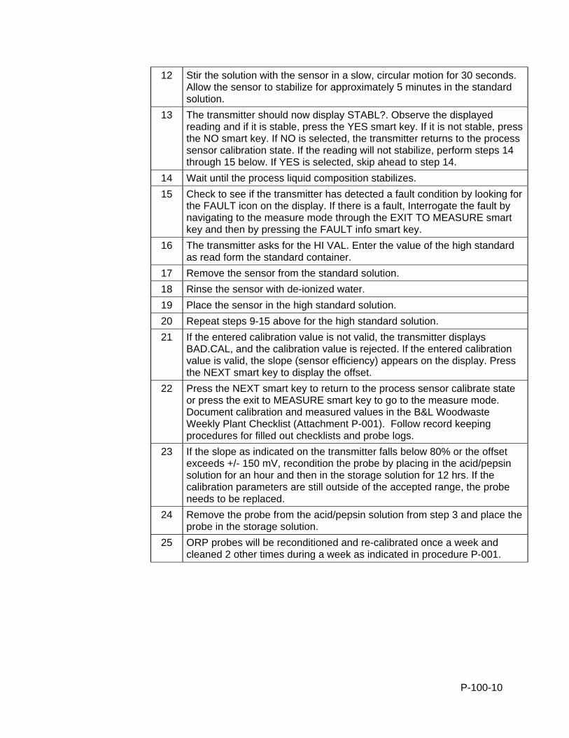
P-100-10
12 Stir the solution with the sensor in a slow, circular motion for 30 seconds. Allow the sensor to stabilize for approximately 5 minutes in the standard solution.
13 The transmitter should now display STABL?. Observe the displayed reading and if it is stable, press the YES smart key. If it is not stable, press the NO smart key. If NO is selected, the transmitter returns to the process sensor calibration state. If the reading will not stabilize, perform steps 14 through 15 below. If YES is selected, skip ahead to step 14.
14 Wait until the process liquid composition stabilizes.
15 Check to see if the transmitter has detected a fault condition by looking for the FAULT icon on the display. If there is a fault, Interrogate the fault by navigating to the measure mode through the EXIT TO MEASURE smart key and then by pressing the FAULT info smart key.
16 The transmitter asks for the HI VAL. Enter the value of the high standard as read form the standard container.
17 Remove the sensor from the standard solution.
18 Rinse the sensor with de-ionized water.
19 Place the sensor in the high standard solution.
20 Repeat steps 9-15 above for the high standard solution.
21 If the entered calibration value is not valid, the transmitter displays BAD.CAL, and the calibration value is rejected. If the entered calibration value is valid, the slope (sensor efficiency) appears on the display. Press the NEXT smart key to display the offset.
22 Press the NEXT smart key to return to the process sensor calibrate state or press the exit to MEASURE smart key to go to the measure mode. Document calibration and measured values in the B&L Woodwaste Weekly Plant Checklist (Attachment P-001). Follow record keeping procedures for filled out checklists and probe logs.
23 If the slope as indicated on the transmitter falls below 80% or the offset exceeds +/- 150 mV, recondition the probe by placing in the acid/pepsin solution for an hour and then in the storage solution for 12 hrs. If the calibration parameters are still outside of the accepted range, the probe needs to be replaced.
24 Remove the probe from the acid/pepsin solution from step 3 and place the probe in the storage solution.
25 ORP probes will be reconditioned and re-calibrated once a week and cleaned 2 other times during a week as indicated in procedure P-001.
P-120-1
STANDARD OPERATION PROCEDURE: B&L WOODWASTE GROUNDWATER TREATMENT SYSTEM
P120 - CO-PRECIPITATION TANK B&L Woodwaste Landfill
Milton, Washington
OPERATION PROCEDURES, GENERAL OVERVIEW Introduction This procedure outlines operational procedures for the co-precipitation tank in the
groundwater treatment system at the B&L Woodwaste Site. The co-precipitation tank mixes the groundwater that comes in from the oxidation tank with lime that is dosed from the lime slurry tank. The lime increases the pH of the groundwater, which facilitates the co-precipitation of the oxidized arsenic with the oxidized iron present in the groundwater. Coagulant and sludge recirculation lines also dose into the co-precipitation tank and assist with precipitation by providing more particles and charge in the groundwater to increase particle interactions and thus larger particle formation.
Pre-requisites to Do This Procedure
To do this procedure you must: Be fully trained for treatment system operations or be training in the area with
someone who has been fully trained. Be fully trained for handling and management of dangerous wastes. Be familiar with all aspects of this operating procedure. Be Hazardous Waste Operations (HAZWOPER)-trained and current with
annual training updates.
In This Procedure Following is a list of topics in this Procedure:
Description See Page
1.0 Safety Considerations 2
2.0 Normal Operation 2
3.0 Operation and Maintenance 3
4.0 pH Meter Operation and Maintenance 4
P-120-2
1.0 SAFETY CONSIDERATIONS Health and Safety Plan (HASP)
The most recent version of the HASP is maintained in the treatment building office and provides plans and requirements to protect the health and safety of workers involved in the operation and maintenance of the groundwater extraction and treatment system. All workers must be familiar with and sign the HASP. Specific requirements for Personal Protective Equipment (PPE) are included in the HASP. If there are any discrepancies between PPE requirements included in these procedures and PPE requirements specified in the HASP, the requirements specified in the HASP shall be followed.
Level of Hazard Medium Hazards associated with this task include contaminated sludge and water that contains arsenic. Other hazards include contact with the lime feed solution or the coagulant feed solution, which will cause irritation if they come into contact with skin or eyes. Thus, operators should stay alert and wear appropriate PPE when working with the co-precipitation system. There are also electrical components acting in the system which require proper lockout/tagout of all associated electrical systems prior to any maintenance performed. The co-precipitation tank will contain groundwater contaminants so appropriate PPE must be worn as defined in the HASP. Due to the presence of dangerous waste within the closed landfill, all personnel working at the site must be fully trained in accordance with 29 CFR 1910 and WISHA regulations. Forty-hour HAZWOPER training with yearly eight hour refresher training is required for anyone performing work at the B&L Woodwaste Site.
2.0 NORMAL STARTUP AND SHUTDOWN
Critical Information
Dosing into the co-precipitation tank will begin during plant startup. The oxidized groundwater flows in from the oxidation tank and is dosed with coagulant, lime and sludge via the PLC controller. The coagulant is dosed at a rate that is proportional to the groundwater influent flow (as given from the influent flow meter). The lime is dosed based on a PLC loop that targets a pH of 9.2. The sludge is dosed based on a user specified sludge recycle ratio that is fed from the clarifier underflow.
Procedure
Step Normal Startup
1 Turn on the co-precipitation tank mixer in the motor control center (MCC) by turning the hand-off-auto (HOA) switch labeled “Co-precip Tank Mixer” to “Auto.” Ensure that the co-precipitation tank mixer is spinning smoothly.
2 The pH target in the co-precip tank is 9.2. Ensure that the correct target pH is inputted into the PLC. Follow the plant start up procedures (P-050) when the pH is more than 0.5 SU off from the target.
P-120-3
3 If the PLC is reporting a value far from the target, take note and investigate. If the pH meter is jumping around or giving erroneous readings, follow the cleaning and calibration procedures for the sensor below. If the pH displayed on the PLC is displaying a sinusoidal curve that is getting larger in amplitude as time progresses, the PLC’s lime dosing loop may need to be calibrated. Contact the process engineer for more information.
Procedure
Step Normal Shutdown
1 Cut power to the co-precipitation tank mixer from the MCC by flipping the HOA switch labeled “Co-precip Tank Mixer” to “OFF”.
2 The lime dosing pump, coagulant pump, and the sludge recirculation pump will all shut off during a plant shutdown.
3.0 MIXER OPERATION
Critical Information
The mixer in the co-precipitation tank ensures thorough mixing of the feed solutions from the lime slurry tank and the coagulant dosing system with the influent from the oxidation tank and the sludge recycled from the clarifier underflow (acting as a seed for floc formation). Thorough mixing is required to provide sufficient interaction of particles and a good distribution of the additives to promote co-precipitation of the iron and arsenic.
Personal Protective Equipment
Safety Glasses Nitrile Gloves
Steel Toe Boots (Leather or Rubber)
Steel Toe Boots (Leather or Rubber)
Procedure
Step Co-Precipitation Tank Mixer Inspection and Maintenance - 6 Month Inspection
1 While the mixer is running, inspect the mixer for unusual sounds, excessive vibration, excessive heat, or any grease leakage. If any of these observations are made, stop the mixer and diagnose the problem and fix the problem if possible.
2 Turn off the propeller during the six month inspection and visually inspect the propeller for evidence of corrosion or other damage.
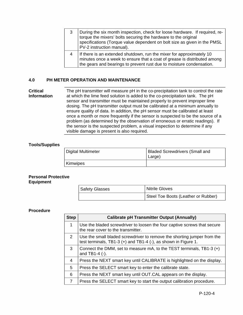
P-120-4
3 During the six month inspection, check for loose hardware. If required, re-torque the mixers’ bolts securing the hardware to the original specifications (Torque value dependent on bolt size as given in the PMSL PV-2 instruction manual).
4 If there is an extended shutdown, run the mixer for approximately 10 minutes once a week to ensure that a coat of grease is distributed among the gears and bearings to prevent rust due to moisture condensation.
4.0 PH METER OPERATION AND MAINTENANCE
Critical Information
The pH transmitter will measure pH in the co-precipitation tank to control the rate at which the lime feed solution is added to the co-precipitation tank. The pH sensor and transmitter must be maintained properly to prevent improper lime dosing. The pH transmitter output must be calibrated at a minimum annually to ensure quality of data. In addition, the pH sensor must be calibrated at least once a month or more frequently if the sensor is suspected to be the source of a problem (as determined by the observation of erroneous or erratic readings). If the sensor is the suspected problem, a visual inspection to determine if any visible damage is present is also required.
Tools/Supplies
Digital Multimeter Bladed Screwdrivers (Small and Large)
Kimwipes
Personal Protective Equipment
Safety Glasses Nitrile Gloves
Steel Toe Boots (Leather or Rubber)
Procedure
Step Calibrate pH Transmitter Output (Annually)
1 Use the bladed screwdriver to loosen the four captive screws that secure the rear cover to the transmitter.
2 Use the small bladed screwdriver to remove the shorting jumper from the test terminals, TB1-3 (+) and TB1-4 (-), as shown in Figure 1.
3 Connect the DMM, set to measure mA, to the TEST terminals, TB1-3 (+) and TB1-4 (-).
4 Press the NEXT smart key until CALIBRATE is highlighted on the display.
5 Press the SELECT smart key to enter the calibrate state.
6 Press the NEXT smart key until OUT.CAL appears on the display.
7 Press the SELECT smart key to start the output calibration procedure.
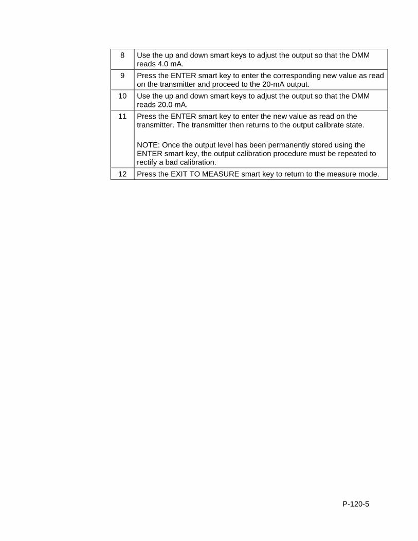
P-120-5
8 Use the up and down smart keys to adjust the output so that the DMM reads 4.0 mA.
9 Press the ENTER smart key to enter the corresponding new value as read on the transmitter and proceed to the 20-mA output.
10 Use the up and down smart keys to adjust the output so that the DMM reads 20.0 mA.
11 Press the ENTER smart key to enter the new value as read on the transmitter. The transmitter then returns to the output calibrate state. NOTE: Once the output level has been permanently stored using the ENTER smart key, the output calibration procedure must be repeated to rectify a bad calibration.
12 Press the EXIT TO MEASURE smart key to return to the measure mode.
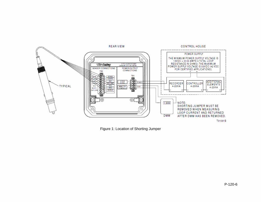
P-120-6
Figure 1: Location of Shorting Jumper
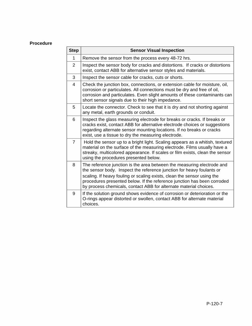
P-120-7
Procedure
Step Sensor Visual Inspection
1 Remove the sensor from the process every 48-72 hrs.
2 Inspect the sensor body for cracks and distortions. If cracks or distortions exist, contact ABB for alternative sensor styles and materials.
3 Inspect the sensor cable for cracks, cuts or shorts.
4 Check the junction box, connections, or extension cable for moisture, oil, corrosion or particulates. All connections must be dry and free of oil, corrosion and particulates. Even slight amounts of these contaminants can short sensor signals due to their high impedance.
5 Locate the connector. Check to see that it is dry and not shorting against any metal, earth grounds or conduit.
6 Inspect the glass measuring electrode for breaks or cracks. If breaks or cracks exist, contact ABB for alternative electrode choices or suggestions regarding alternate sensor mounting locations. If no breaks or cracks exist, use a tissue to dry the measuring electrode.
7 Hold the sensor up to a bright light. Scaling appears as a whitish, textured material on the surface of the measuring electrode. Films usually have a streaky, multicolored appearance. If scales or film exists, clean the sensor using the procedures presented below.
8 The reference junction is the area between the measuring electrode and the sensor body. Inspect the reference junction for heavy foulants or scaling. If heavy fouling or scaling exists, clean the sensor using the procedures presented below. If the reference junction has been corroded by process chemicals, contact ABB for alternate material choices.
9 If the solution ground shows evidence of corrosion or deterioration or the O-rings appear distorted or swollen, contact ABB for alternate material choices.
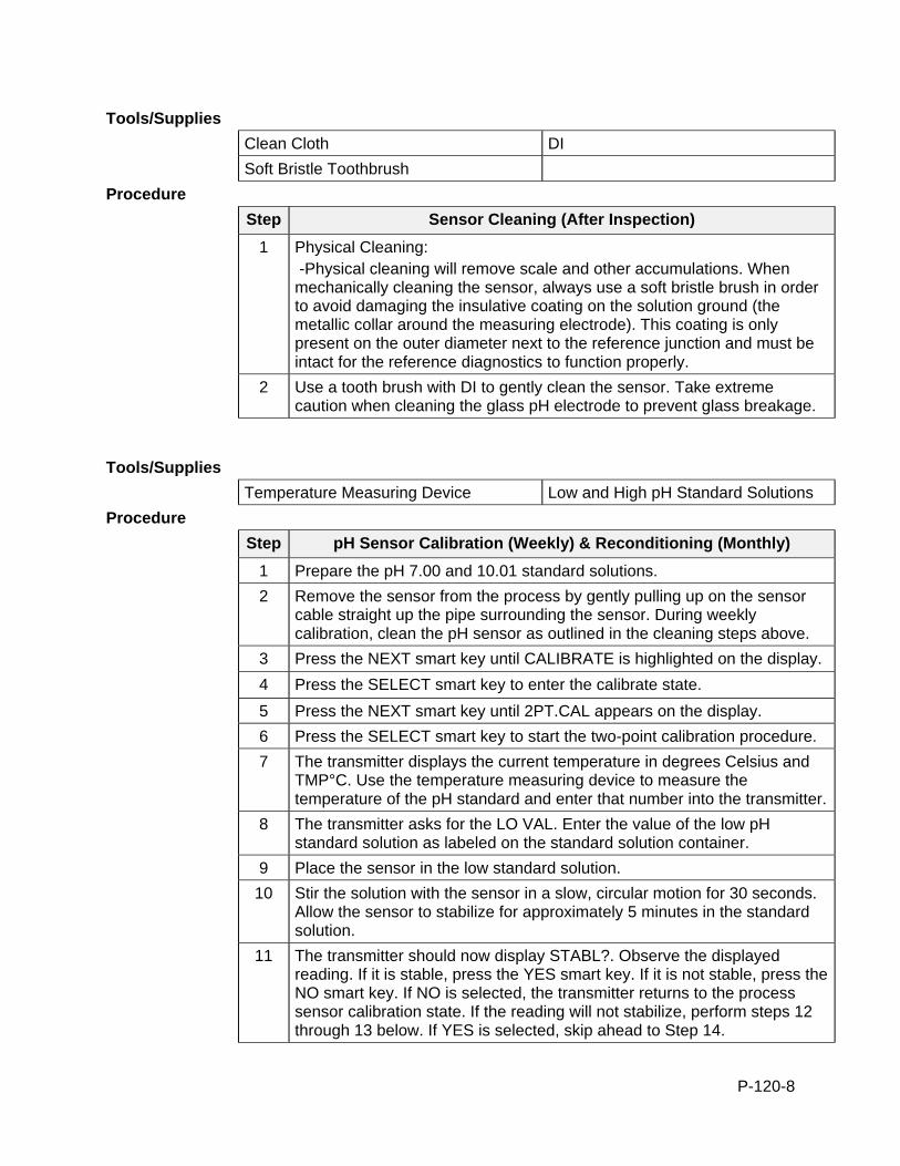
P-120-8
Tools/Supplies
Clean Cloth DI
Soft Bristle Toothbrush
Procedure
Step Sensor Cleaning (After Inspection)
1 Physical Cleaning: -Physical cleaning will remove scale and other accumulations. When mechanically cleaning the sensor, always use a soft bristle brush in order to avoid damaging the insulative coating on the solution ground (the metallic collar around the measuring electrode). This coating is only present on the outer diameter next to the reference junction and must be intact for the reference diagnostics to function properly.
2 Use a tooth brush with DI to gently clean the sensor. Take extreme caution when cleaning the glass pH electrode to prevent glass breakage.
Tools/Supplies
Temperature Measuring Device Low and High pH Standard Solutions
Procedure
Step pH Sensor Calibration (Weekly) & Reconditioning (Monthly)
1 Prepare the pH 7.00 and 10.01 standard solutions.
2 Remove the sensor from the process by gently pulling up on the sensor cable straight up the pipe surrounding the sensor. During weekly calibration, clean the pH sensor as outlined in the cleaning steps above.
3 Press the NEXT smart key until CALIBRATE is highlighted on the display.
4 Press the SELECT smart key to enter the calibrate state.
5 Press the NEXT smart key until 2PT.CAL appears on the display.
6 Press the SELECT smart key to start the two-point calibration procedure.
7 The transmitter displays the current temperature in degrees Celsius and TMP°C. Use the temperature measuring device to measure the temperature of the pH standard and enter that number into the transmitter.
8 The transmitter asks for the LO VAL. Enter the value of the low pH standard solution as labeled on the standard solution container.
9 Place the sensor in the low standard solution.
10 Stir the solution with the sensor in a slow, circular motion for 30 seconds. Allow the sensor to stabilize for approximately 5 minutes in the standard solution.
11 The transmitter should now display STABL?. Observe the displayed reading. If it is stable, press the YES smart key. If it is not stable, press the NO smart key. If NO is selected, the transmitter returns to the process sensor calibration state. If the reading will not stabilize, perform steps 12 through 13 below. If YES is selected, skip ahead to Step 14.
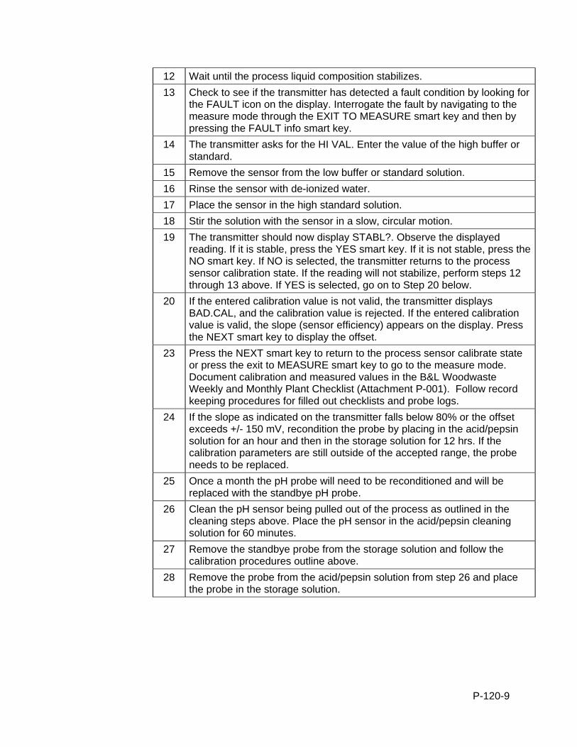
P-120-9
12 Wait until the process liquid composition stabilizes.
13 Check to see if the transmitter has detected a fault condition by looking for the FAULT icon on the display. Interrogate the fault by navigating to the measure mode through the EXIT TO MEASURE smart key and then by pressing the FAULT info smart key.
14 The transmitter asks for the HI VAL. Enter the value of the high buffer or standard.
15 Remove the sensor from the low buffer or standard solution.
16 Rinse the sensor with de-ionized water.
17 Place the sensor in the high standard solution.
18 Stir the solution with the sensor in a slow, circular motion.
19 The transmitter should now display STABL?. Observe the displayed reading. If it is stable, press the YES smart key. If it is not stable, press the NO smart key. If NO is selected, the transmitter returns to the process sensor calibration state. If the reading will not stabilize, perform steps 12 through 13 above. If YES is selected, go on to Step 20 below.
20 If the entered calibration value is not valid, the transmitter displays BAD.CAL, and the calibration value is rejected. If the entered calibration value is valid, the slope (sensor efficiency) appears on the display. Press the NEXT smart key to display the offset.
23 Press the NEXT smart key to return to the process sensor calibrate state or press the exit to MEASURE smart key to go to the measure mode. Document calibration and measured values in the B&L Woodwaste Weekly and Monthly Plant Checklist (Attachment P-001). Follow record keeping procedures for filled out checklists and probe logs.
24 If the slope as indicated on the transmitter falls below 80% or the offset exceeds +/- 150 mV, recondition the probe by placing in the acid/pepsin solution for an hour and then in the storage solution for 12 hrs. If the calibration parameters are still outside of the accepted range, the probe needs to be replaced.
25 Once a month the pH probe will need to be reconditioned and will be replaced with the standbye pH probe.
26 Clean the pH sensor being pulled out of the process as outlined in the cleaning steps above. Place the pH sensor in the acid/pepsin cleaning solution for 60 minutes.
27 Remove the standbye probe from the storage solution and follow the calibration procedures outline above.
28 Remove the probe from the acid/pepsin solution from step 26 and place the probe in the storage solution.
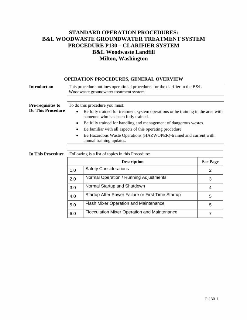
P-130-1
STANDARD OPERATION PROCEDURES: B&L WOODWASTE GROUNDWATER TREATMENT SYSTEM
PROCEDURE P130 – CLARIFIER SYSTEM B&L Woodwaste Landfill
Milton, Washington
OPERATION PROCEDURES, GENERAL OVERVIEW Introduction This procedure outlines operational procedures for the clarifier in the B&L
Woodwaste groundwater treatment system.
Pre-requisites to Do This Procedure
To do this procedure you must: Be fully trained for treatment system operations or be training in the area with
someone who has been fully trained. Be fully trained for handling and management of dangerous wastes. Be familiar with all aspects of this operating procedure. Be Hazardous Waste Operations (HAZWOPER)-trained and current with
annual training updates.
In This Procedure Following is a list of topics in this Procedure:
Description See Page
1.0 Safety Considerations 2
2.0 Normal Operation / Running Adjustments 3
3.0 Normal Startup and Shutdown 4
4.0 Startup After Power Failure or First Time Startup 5
5.0 Flash Mixer Operation and Maintenance 5
6.0 Flocculation Mixer Operation and Maintenance 7
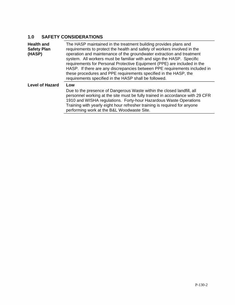
P-130-2
1.0 SAFETY CONSIDERATIONS
Health and Safety Plan (HASP)
The HASP maintained in the treatment building provides plans and requirements to protect the health and safety of workers involved in the operation and maintenance of the groundwater extraction and treatment system. All workers must be familiar with and sign the HASP. Specific requirements for Personal Protective Equipment (PPE) are included in the HASP. If there are any discrepancies between PPE requirements included in these procedures and PPE requirements specified in the HASP, the requirements specified in the HASP shall be followed.
Level of Hazard Low Due to the presence of Dangerous Waste within the closed landfill, all personnel working at the site must be fully trained in accordance with 29 CFR 1910 and WISHA regulations. Forty-hour Hazardous Waste Operations Training with yearly eight hour refresher training is required for anyone performing work at the B&L Woodwaste Site.
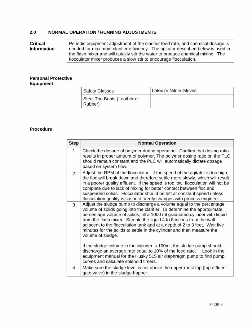
P-130-3
2.0 NORMAL OPERATION / RUNNING ADJUSTMENTS
Critical Information
Periodic equipment adjustment of the clarifier feed rate, and chemical dosage is needed for maximum clarifier efficiency. The agitator described below is used in the flash mixer and will quickly stir the water to produce chemical mixing. The flocculator mixer produces a slow stir to encourage flocculation.
Personal Protective Equipment
Safety Glasses Latex or Nitrile Gloves
Steel Toe Boots (Leather or Rubber)
Procedure
Step Normal Operation
1 Check the dosage of polymer during operation. Confirm that dosing ratio results in proper amount of polymer. The polymer dosing ratio on the PLC should remain constant and the PLC will automatically dictate dosage based on system flow.
2 Adjust the RPM of the flocculator. If the speed of the agitator is too high, the floc will break down and therefore settle more slowly, which will result in a poorer quality effluent. If the speed is too low, flocculation will not be complete due to lack of mixing for better contact between floc and suspended solids. Flocculator should be left at constant speed unless flocculation quality is suspect. Verify changes with process engineer.
3 Adjust the sludge pump to discharge a volume equal to the percentage volume of solids going into the clarifier. To determine the approximate percentage volume of solids, fill a 1000 ml graduated cylinder with liquid from the flash mixer. Sample the liquid 4 to 8 inches from the wall adjacent to the flocculation tank and at a depth of 2 to 3 feet. Wait five minutes for the solids to settle in the cylinder and then measure the volume of sludge. If the sludge volume in the cylinder is 100ml, the sludge pump should discharge an average rate equal to 10% of the feed rate. Look in the equipment manual for the Husky 515 air diaphragm pump to find pump curves and calculate solenoid timers.
4 Make sure the sludge level is not above the upper-most tap (top effluent gate valve) in the sludge hopper.
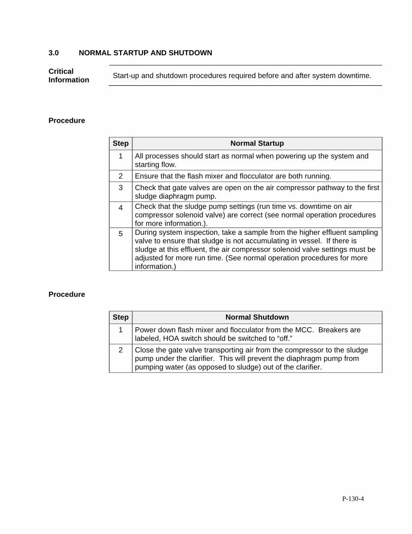
P-130-4
3.0 NORMAL STARTUP AND SHUTDOWN
Critical Information
Start-up and shutdown procedures required before and after system downtime.
Procedure
Step Normal Startup
1 All processes should start as normal when powering up the system and starting flow.
2 Ensure that the flash mixer and flocculator are both running.
3 Check that gate valves are open on the air compressor pathway to the first sludge diaphragm pump.
4 Check that the sludge pump settings (run time vs. downtime on air compressor solenoid valve) are correct (see normal operation procedures for more information.).
5 During system inspection, take a sample from the higher effluent sampling valve to ensure that sludge is not accumulating in vessel. If there is sludge at this effluent, the air compressor solenoid valve settings must be adjusted for more run time. (See normal operation procedures for more information.)
Procedure
Step Normal Shutdown
1 Power down flash mixer and flocculator from the MCC. Breakers are labeled, HOA switch should be switched to “off.”
2 Close the gate valve transporting air from the compressor to the sludge pump under the clarifier. This will prevent the diaphragm pump from pumping water (as opposed to sludge) out of the clarifier.
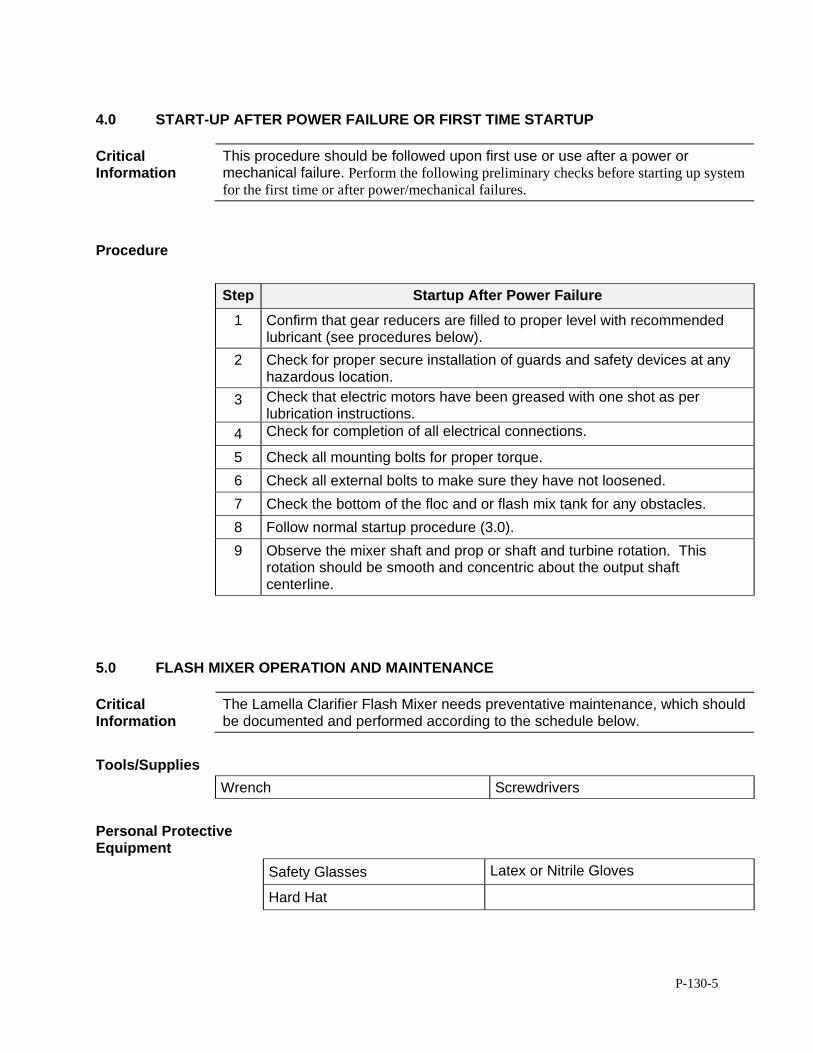
P-130-5
4.0 START-UP AFTER POWER FAILURE OR FIRST TIME STARTUP
Critical Information
This procedure should be followed upon first use or use after a power or mechanical failure. Perform the following preliminary checks before starting up system for the first time or after power/mechanical failures.
Procedure
Step Startup After Power Failure
1 Confirm that gear reducers are filled to proper level with recommended lubricant (see procedures below).
2 Check for proper secure installation of guards and safety devices at any hazardous location.
3 Check that electric motors have been greased with one shot as per lubrication instructions.
4 Check for completion of all electrical connections.
5 Check all mounting bolts for proper torque.
6 Check all external bolts to make sure they have not loosened.
7 Check the bottom of the floc and or flash mix tank for any obstacles.
8 Follow normal startup procedure (3.0).
9 Observe the mixer shaft and prop or shaft and turbine rotation. This rotation should be smooth and concentric about the output shaft centerline.
5.0 FLASH MIXER OPERATION AND MAINTENANCE
Critical Information
The Lamella Clarifier Flash Mixer needs preventative maintenance, which should be documented and performed according to the schedule below.
Tools/Supplies
Wrench Screwdrivers
Personal Protective Equipment
Safety Glasses Latex or Nitrile Gloves
Hard Hat
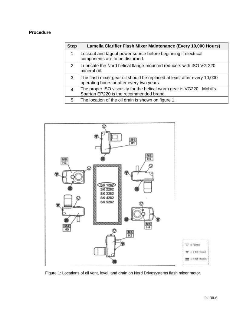
P-130-6
Procedure
Step Lamella Clarifier Flash Mixer Maintenance (Every 10,000 Hours)
1 Lockout and tagout power source before beginning if electrical components are to be disturbed.
2 Lubricate the Nord helical flange-mounted reducers with ISO VG 220 mineral oil.
3 The flash mixer gear oil should be replaced at least after every 10,000 operating hours or after every two years.
4 The proper ISO viscosity for the helical-worm gear is VG220. Mobil’s Spartan EP220 is the recommended brand.
5 The location of the oil drain is shown on figure 1.
Figure 1: Locations of oil vent, level, and drain on Nord Drivesystems flash mixer motor.
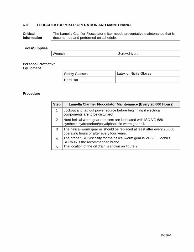
P-130-7
6.0 FLOCCULATOR MIXER OPERATION AND MAINTENANCE
Critical Information
The Lamella Clarifier Flocculator mixer needs preventative maintenance that is documented and performed on schedule.
Tools/Supplies
Wrench Screwdrivers
Personal Protective Equipment
Safety Glasses Latex or Nitrile Gloves
Hard Hat
Procedure
Step Lamella Clarifier Flocculator Maintenance (Every 20,000 Hours)
1 Lockout and tag out power source before beginning if electrical components are to be disturbed.
2 Nord helical worm gear reducers are lubricated with ISO VG 680 synthetic-hydrocarbon/polyalphaolefin worm gear oil.
3 The helical-worm gear oil should be replaced at least after every 20,000 operating hours or after every four years.
4 The proper ISO viscosity for the helical-worm gear is VG680. Mobil’s SHC636 is the recommended brand.
5 The location of the oil drain is shown on figure 2.
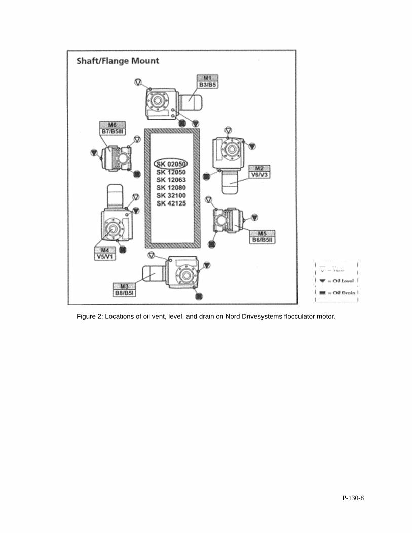
P-130-8
Figure 2: Locations of oil vent, level, and drain on Nord Drivesystems flocculator motor.
P-250-1
STANDARD OPERATION PROCEDURES: B&L WOODWASTE GROUNDWATER TREATMENT SYSTEM
P250 - SECONDARY CONTAINMENT SYSTEM B&L Woodwaste Landfill
Milton, Washington
OPERATION PROCEDURES, GENERAL OVERVIEW Introduction This procedure outlines operational procedures for the secondary containment system
in the B&L Woodwaste groundwater treatment system.
Pre-requisites to Do This Procedure
To do this procedure you must: Be fully trained for treatment system operations or be training in the area with
someone who has been fully trained. Be fully trained for handling and management of dangerous wastes. Be familiar with all aspects of this operating procedure. Be Hazardous Waste Operations (HAZWOPER)-trained and current with
annual training updates.
In This Procedure Following is a list of topics in this Procedure:
Description See Page
1.0 Safety Considerations 2
2.0 Setup and normal operation 3
3.0 Sump pump operation and maintenance 3

P-250-2
1.0 SAFETY CONSIDERATIONS
Health and Safety Plan (HASP)
The HASP maintained in the treatment building provides plans and requirements to protect the health and safety of workers involved in the operation and maintenance of the groundwater extraction and treatment system. All workers must be familiar with and sign the HASP. Specific requirements for Personal Protective Equipment (PPE) are included in the HASP. If there are any discrepancies between PPE requirements included in these procedures and PPE requirements specified in the HASP, the requirements specified in the HASP shall be followed.
Level of Hazard Medium The secondary containment area will prevent leakage of contaminated water to the environment. Operators should don appropriate PPE before investigating secondary containment fluids, which will contain contaminated water. Lockout secondary containment sump if taking off secondary containment grate. Due to the presence of Dangerous Waste within the closed landfill, all personnel working at the site must be fully trained in accordance with 29 CFR 1910 and WISHA regulations. Forty-hour Hazardous Waste Operations Training with yearly eight hour refresher training is required for anyone performing work at the B&L Woodwaste Site.
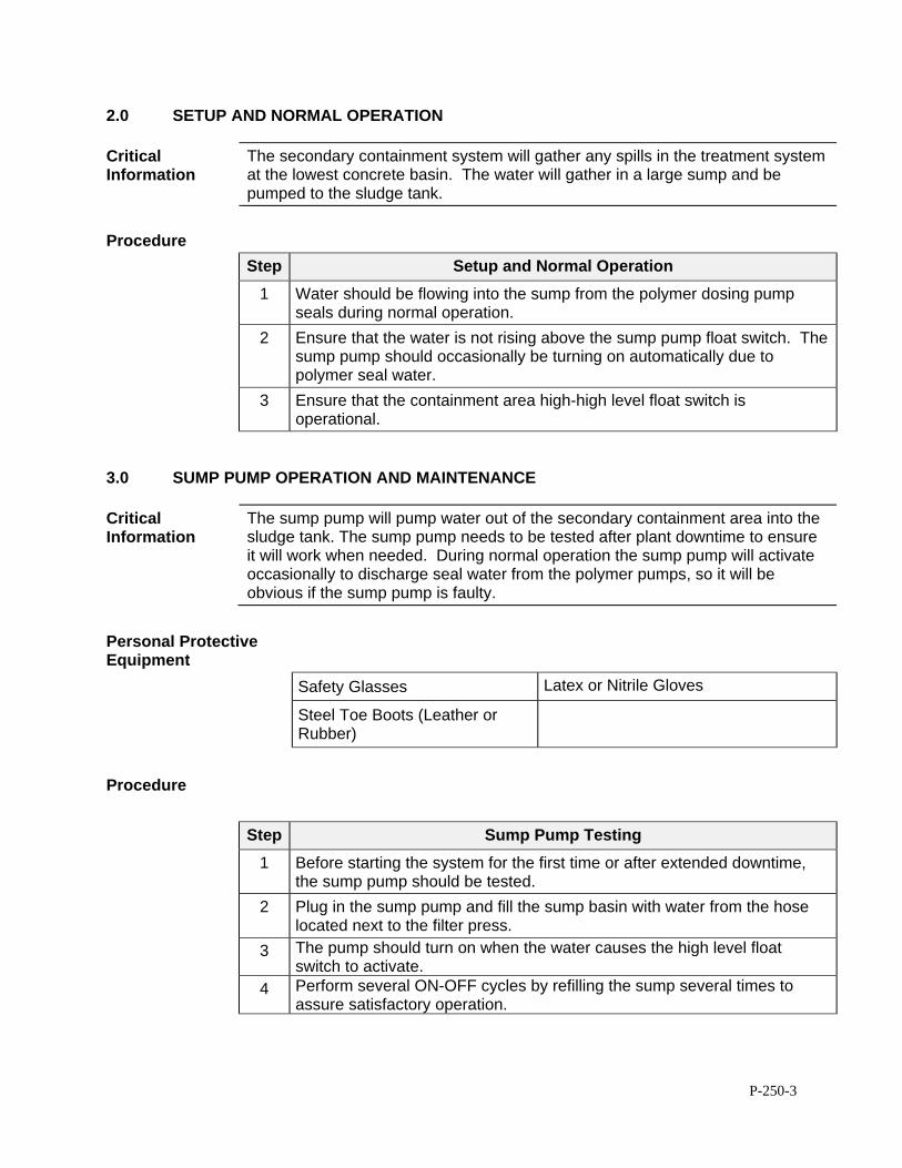
P-250-3
2.0 SETUP AND NORMAL OPERATION
Critical Information
The secondary containment system will gather any spills in the treatment system at the lowest concrete basin. The water will gather in a large sump and be pumped to the sludge tank.
Procedure
Step Setup and Normal Operation
1 Water should be flowing into the sump from the polymer dosing pump seals during normal operation.
2 Ensure that the water is not rising above the sump pump float switch. The sump pump should occasionally be turning on automatically due to polymer seal water.
3 Ensure that the containment area high-high level float switch is operational.
3.0 SUMP PUMP OPERATION AND MAINTENANCE
Critical Information
The sump pump will pump water out of the secondary containment area into the sludge tank. The sump pump needs to be tested after plant downtime to ensure it will work when needed. During normal operation the sump pump will activate occasionally to discharge seal water from the polymer pumps, so it will be obvious if the sump pump is faulty.
Personal Protective Equipment
Safety Glasses Latex or Nitrile Gloves
Steel Toe Boots (Leather or Rubber)
Procedure
Step Sump Pump Testing
1 Before starting the system for the first time or after extended downtime, the sump pump should be tested.
2 Plug in the sump pump and fill the sump basin with water from the hose located next to the filter press.
3 The pump should turn on when the water causes the high level float switch to activate.
4 Perform several ON-OFF cycles by refilling the sump several times to assure satisfactory operation.
P-310-1
STANDARD OPERATION PROCEDURE: B&L WOODWASTE GROUNDWATER TREATMENT SYSTEM
P310 - PERMANGANATE FEED SYSTEM B&L Woodwaste Landfill
Milton, Washington
OPERATION PROCEDURES, GENERAL OVERVIEW Introduction This procedure outlines operational procedures for the permanganate feed system in
the groundwater treatment system at the B&L Woodwaste Site. The potassium permanganate feed system feeds a prepared dilute potassium permanganate solution to the oxidation tank to oxidize the influent organic carbon, iron, manganese, and arsenic.
Pre-requisites to Do This Procedure
To do this procedure you must: Be fully trained for treatment system operations or be training in the area with
someone who has been fully trained. Be fully trained for handling and management of dangerous wastes. Be familiar with all aspects of this operating procedure. Be Hazardous Waste Operations (HAZWOPER)-trained and current with
annual training updates.
In This Procedure Following is a list of topics in this Procedure:
Description See Page
1.0 Safety Considerations 2
2.0 Receiving Permanganate Delivery 3
3.0 Feed Solution Preparation 4
4.0 Permanganate System Startup and Normal Operation 6
5.0 Mixer Maintenance and Operation 7
6.0 Dosing Pump Operation and Maintenance 8
7.0 Spill Response and Cleanup 13
8.0 Checking Permanganate Basket Strainer 15
P-310-2
1.0 SAFETY CONSIDERATIONS Health and Safety Plan (HASP)
The most recent version of the HASP is maintained in the treatment building office and provides plans and requirements to protect the health and safety of workers involved in the operation and maintenance of the groundwater extraction and treatment system. All workers must be familiar with and sign the HASP. Specific requirements for Personal Protective Equipment (PPE) are included in the HASP. If there are any discrepancies between PPE requirements included in these procedures and PPE requirements specified in the HASP, the requirements specified in the HASP shall be followed.
Level of Hazard High Hazards associated with this task include contact with the solid crystalline or liquid potassium permanganate (permanganate), which is a strong oxidizer and may be corrosive to skin and eyes. Inhalation of dust from the solid is highly dangerous and may irritate or damage the respiratory tract or the gastro-intestinal tract. A respirator is required whenever handing solid permanganate in addition to the other PPE as discussed in the Site HASP. Due to the presence of dangerous waste within the closed landfill, all personnel working at the site must be fully trained in accordance with 29 CFR 1910 and WISHA regulations. Forty-hour HAZWOPER training with yearly eight hour refresher training is required for anyone performing work at the B&L Woodwaste Site.
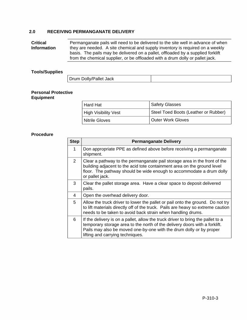
P-310-3
2.0 RECEIVING PERMANGANATE DELIVERY
Critical Information
Permanganate pails will need to be delivered to the site well in advance of when they are needed. A site chemical and supply inventory is required on a weekly basis. The pails may be delivered on a pallet, offloaded by a supplied forklift from the chemical supplier, or be offloaded with a drum dolly or pallet jack.
Tools/Supplies
Drum Dolly/Pallet Jack
Personal Protective Equipment
Hard Hat Safety Glasses
High Visibility Vest Steel Toed Boots (Leather or Rubber)
Nitrile Gloves Outer Work Gloves
Procedure
Step Permanganate Delivery
1 Don appropriate PPE as defined above before receiving a permanganate shipment.
2 Clear a pathway to the permanganate pail storage area in the front of the building adjacent to the acid tote containment area on the ground level floor. The pathway should be wide enough to accommodate a drum dolly or pallet jack.
3 Clear the pallet storage area. Have a clear space to deposit delivered pails.
4 Open the overhead delivery door.
5 Allow the truck driver to lower the pallet or pail onto the ground. Do not try to lift materials directly off of the truck. Pails are heavy so extreme caution needs to be taken to avoid back strain when handling drums.
6 If the delivery is on a pallet, allow the truck driver to bring the pallet to a temporary storage area to the north of the delivery doors with a forklift. Pails may also be moved one-by-one with the drum dolly or by proper lifting and carrying techniques.
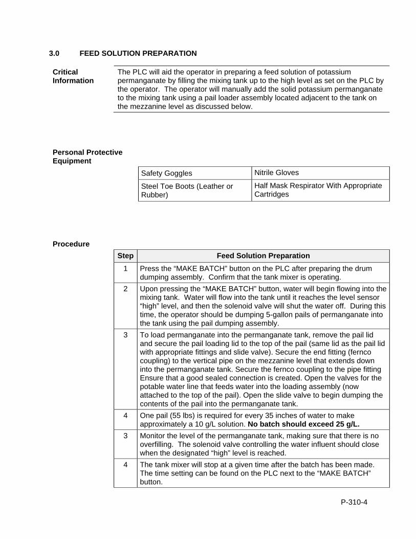
P-310-4
3.0 FEED SOLUTION PREPARATION
Critical Information
The PLC will aid the operator in preparing a feed solution of potassium permanganate by filling the mixing tank up to the high level as set on the PLC by the operator. The operator will manually add the solid potassium permanganate to the mixing tank using a pail loader assembly located adjacent to the tank on the mezzanine level as discussed below.
Personal Protective Equipment
Safety Goggles Nitrile Gloves
Steel Toe Boots (Leather or Rubber)
Half Mask Respirator With Appropriate Cartridges
Procedure
Step Feed Solution Preparation
1 Press the “MAKE BATCH” button on the PLC after preparing the drum dumping assembly. Confirm that the tank mixer is operating.
2 Upon pressing the “MAKE BATCH” button, water will begin flowing into the mixing tank. Water will flow into the tank until it reaches the level sensor “high” level, and then the solenoid valve will shut the water off. During this time, the operator should be dumping 5-gallon pails of permanganate into the tank using the pail dumping assembly.
3 To load permanganate into the permanganate tank, remove the pail lid and secure the pail loading lid to the top of the pail (same lid as the pail lid with appropriate fittings and slide valve). Secure the end fitting (fernco coupling) to the vertical pipe on the mezzanine level that extends down into the permanganate tank. Secure the fernco coupling to the pipe fitting Ensure that a good sealed connection is created. Open the valves for the potable water line that feeds water into the loading assembly (now attached to the top of the pail). Open the slide valve to begin dumping the contents of the pail into the permanganate tank.
4 One pail (55 lbs) is required for every 35 inches of water to make approximately a 10 g/L solution. No batch should exceed 25 g/L.
3 Monitor the level of the permanganate tank, making sure that there is no overfilling. The solenoid valve controlling the water influent should close when the designated “high” level is reached.
4 The tank mixer will stop at a given time after the batch has been made. The time setting can be found on the PLC next to the “MAKE BATCH” button.
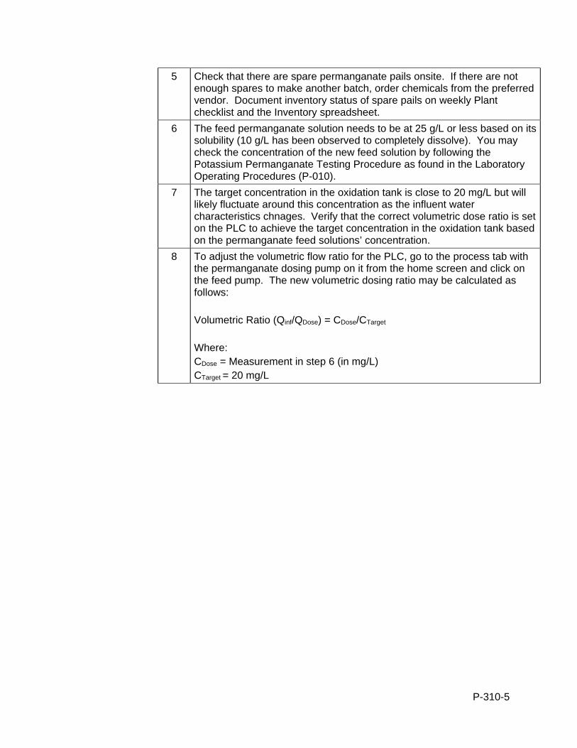
P-310-5
5 Check that there are spare permanganate pails onsite. If there are not enough spares to make another batch, order chemicals from the preferred vendor. Document inventory status of spare pails on weekly Plant checklist and the Inventory spreadsheet.
6 The feed permanganate solution needs to be at 25 g/L or less based on its solubility (10 g/L has been observed to completely dissolve). You may check the concentration of the new feed solution by following the Potassium Permanganate Testing Procedure as found in the Laboratory Operating Procedures (P-010).
7 The target concentration in the oxidation tank is close to 20 mg/L but will likely fluctuate around this concentration as the influent water characteristics chnages. Verify that the correct volumetric dose ratio is set on the PLC to achieve the target concentration in the oxidation tank based on the permanganate feed solutions’ concentration.
8 To adjust the volumetric flow ratio for the PLC, go to the process tab with the permanganate dosing pump on it from the home screen and click on the feed pump. The new volumetric dosing ratio may be calculated as follows: Volumetric Ratio (Qinf/QDose) = CDose/CTarget
Where: CDose = Measurement in step 6 (in mg/L)
CTarget = 20 mg/L
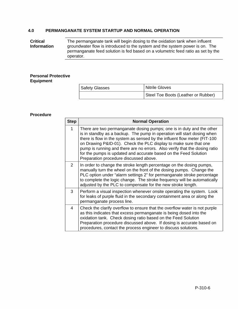
P-310-6
4.0 PERMANGANATE SYSTEM STARTUP AND NORMAL OPERATION
Critical Information
The permanganate tank will begin dosing to the oxidation tank when influent groundwater flow is introduced to the system and the system power is on. The permanganate feed solution is fed based on a volumetric feed ratio as set by the operator.
Personal Protective Equipment
Safety Glasses Nitrile Gloves
Steel Toe Boots (Leather or Rubber)
Procedure
Step Normal Operation
1 There are two permanganate dosing pumps; one is in duty and the other is in standby as a backup. The pump in operation will start dosing when there is flow in the system as sensed by the influent flow meter (FIT-100 on Drawing P&ID-01). Check the PLC display to make sure that one pump is running and there are no errors. Also verify that the dosing ratio for the pumps is updated and accurate based on the Feed Solution Preparation procedure discussed above.
2 In order to change the stroke length percentage on the dosing pumps, manually turn the wheel on the front of the dosing pumps. Change the PLC option under “alarm settings 2” for permanganate stroke percentage to complete the logic change. The stroke frequency will be automatically adjusted by the PLC to compensate for the new stroke length.
3 Perform a visual inspection whenever onsite operating the system. Look for leaks of purple fluid in the secondary containment area or along the permanganate process line.
4 Check the clarify overflow to ensure that the overflow water is not purple as this indicates that excess permanganate is being dosed into the oxidation tank. Check dosing ratio based on the Feed Solution Preparation procedure discussed above. If dosing is accurate based on procedures, contact the process engineer to discuss solutions.
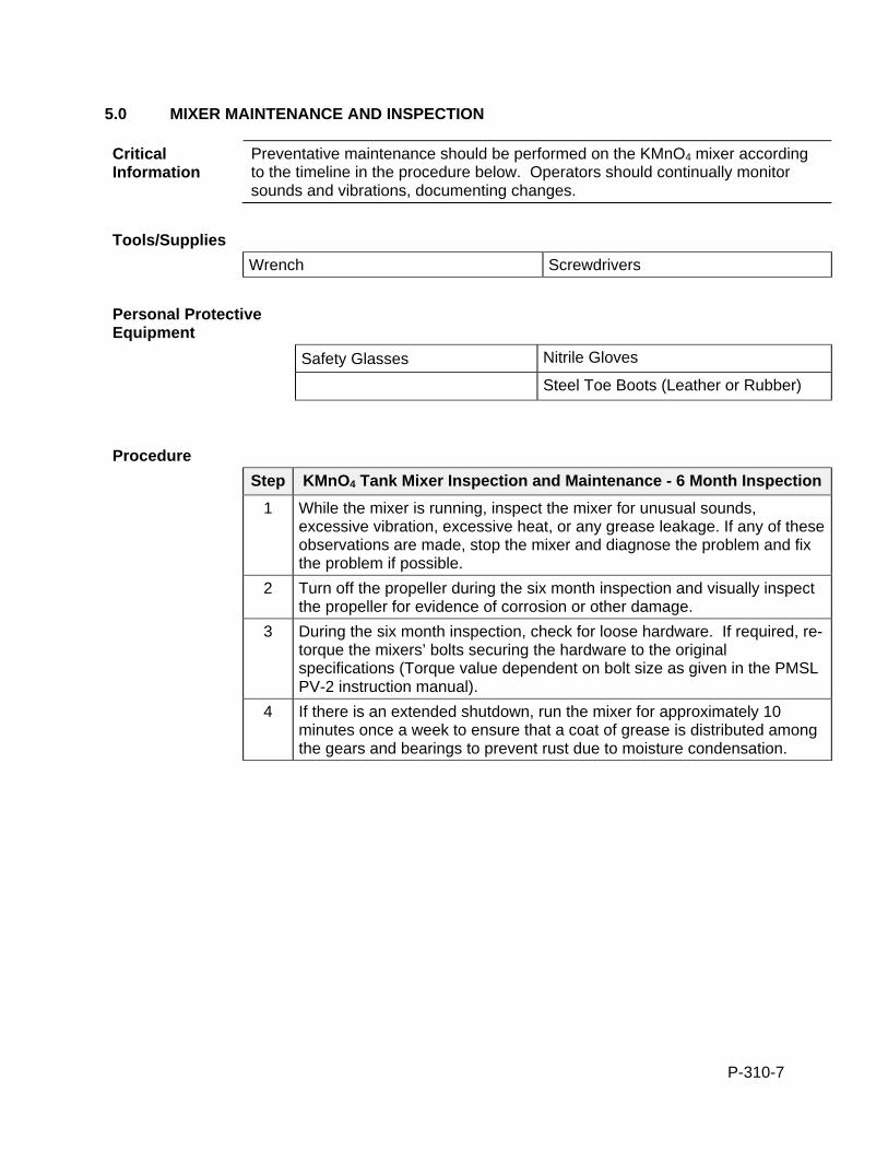
P-310-7
5.0 MIXER MAINTENANCE AND INSPECTION
Critical Information
Preventative maintenance should be performed on the KMnO4 mixer according to the timeline in the procedure below. Operators should continually monitor sounds and vibrations, documenting changes.
Tools/Supplies
Wrench Screwdrivers
Personal Protective Equipment
Safety Glasses Nitrile Gloves
Steel Toe Boots (Leather or Rubber)
Procedure
Step KMnO4 Tank Mixer Inspection and Maintenance - 6 Month Inspection
1 While the mixer is running, inspect the mixer for unusual sounds, excessive vibration, excessive heat, or any grease leakage. If any of these observations are made, stop the mixer and diagnose the problem and fix the problem if possible.
2 Turn off the propeller during the six month inspection and visually inspect the propeller for evidence of corrosion or other damage.
3 During the six month inspection, check for loose hardware. If required, re-torque the mixers’ bolts securing the hardware to the original specifications (Torque value dependent on bolt size as given in the PMSL PV-2 instruction manual).
4 If there is an extended shutdown, run the mixer for approximately 10 minutes once a week to ensure that a coat of grease is distributed among the gears and bearings to prevent rust due to moisture condensation.
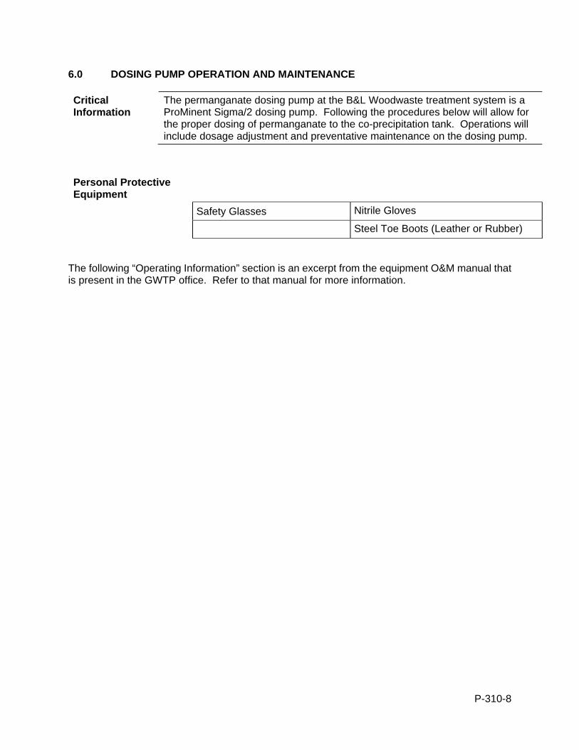
P-310-8
6.0 DOSING PUMP OPERATION AND MAINTENANCE
Critical Information
The permanganate dosing pump at the B&L Woodwaste treatment system is a ProMinent Sigma/2 dosing pump. Following the procedures below will allow for the proper dosing of permanganate to the co-precipitation tank. Operations will include dosage adjustment and preventative maintenance on the dosing pump.
Personal Protective Equipment
Safety Glasses Nitrile Gloves
Steel Toe Boots (Leather or Rubber)
The following “Operating Information” section is an excerpt from the equipment O&M manual that is present in the GWTP office. Refer to that manual for more information.
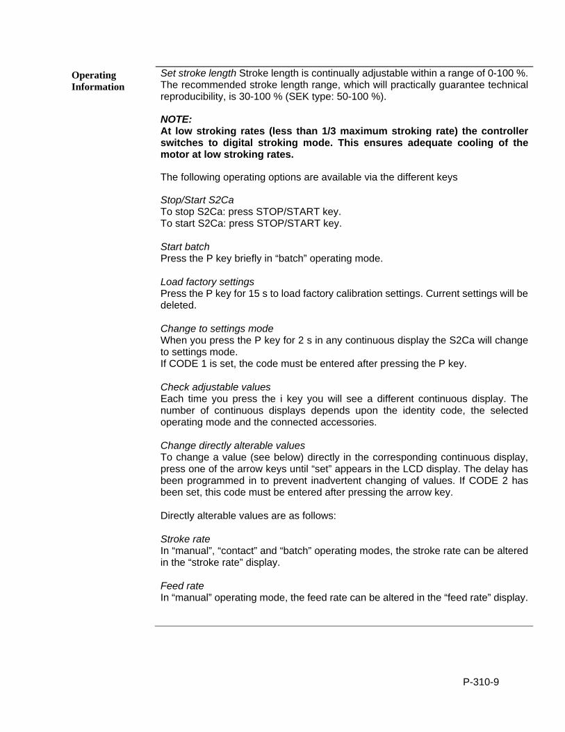
P-310-9
Operating Information
Set stroke length Stroke length is continually adjustable within a range of 0-100 %. The recommended stroke length range, which will practically guarantee technical reproducibility, is 30-100 % (SEK type: 50-100 %).
NOTE: At low stroking rates (less than 1/3 maximum stroking rate) the controller switches to digital stroking mode. This ensures adequate cooling of the motor at low stroking rates.
The following operating options are available via the different keys
Stop/Start S2Ca To stop S2Ca: press STOP/START key. To start S2Ca: press STOP/START key. Start batch Press the P key briefly in “batch” operating mode. Load factory settings Press the P key for 15 s to load factory calibration settings. Current settings will be deleted. Change to settings mode When you press the P key for 2 s in any continuous display the S2Ca will change to settings mode. If CODE 1 is set, the code must be entered after pressing the P key. Check adjustable values Each time you press the i key you will see a different continuous display. The number of continuous displays depends upon the identity code, the selected operating mode and the connected accessories. Change directly alterable values To change a value (see below) directly in the corresponding continuous display, press one of the arrow keys until “set” appears in the LCD display. The delay has been programmed in to prevent inadvertent changing of values. If CODE 2 has been set, this code must be entered after pressing the arrow key. Directly alterable values are as follows: Stroke rate In “manual”, “contact” and “batch” operating modes, the stroke rate can be altered in the “stroke rate” display. Feed rate In “manual” operating mode, the feed rate can be altered in the “feed rate” display.
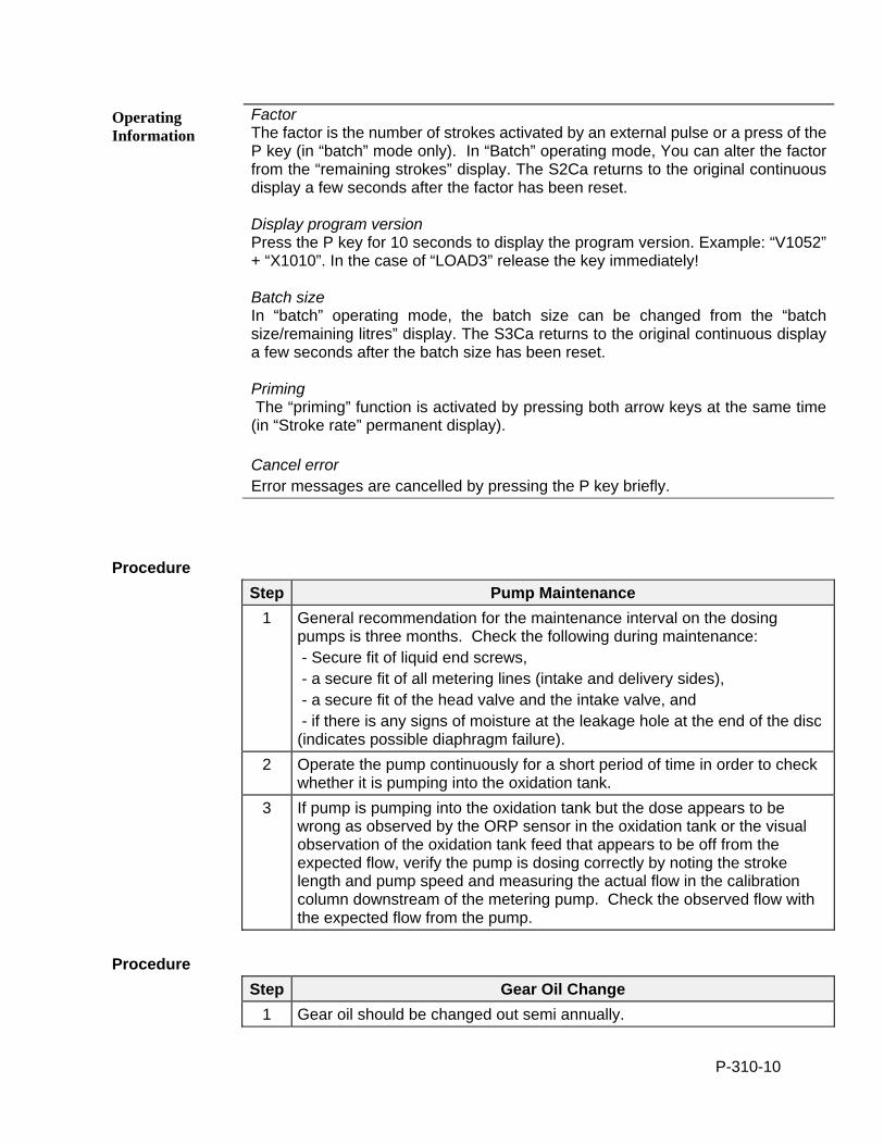
P-310-10
Operating Information
Factor The factor is the number of strokes activated by an external pulse or a press of the P key (in “batch” mode only). In “Batch” operating mode, You can alter the factor from the “remaining strokes” display. The S2Ca returns to the original continuous display a few seconds after the factor has been reset. Display program version Press the P key for 10 seconds to display the program version. Example: “V1052” + “X1010”. In the case of “LOAD3” release the key immediately! Batch size In “batch” operating mode, the batch size can be changed from the “batch size/remaining litres” display. The S3Ca returns to the original continuous display a few seconds after the batch size has been reset. Priming The “priming” function is activated by pressing both arrow keys at the same time (in “Stroke rate” permanent display). Cancel error Error messages are cancelled by pressing the P key briefly.
Procedure
Step Pump Maintenance
1 General recommendation for the maintenance interval on the dosing pumps is three months. Check the following during maintenance: - Secure fit of liquid end screws, - a secure fit of all metering lines (intake and delivery sides), - a secure fit of the head valve and the intake valve, and - if there is any signs of moisture at the leakage hole at the end of the disc (indicates possible diaphragm failure).
2 Operate the pump continuously for a short period of time in order to check whether it is pumping into the oxidation tank.
3 If pump is pumping into the oxidation tank but the dose appears to be wrong as observed by the ORP sensor in the oxidation tank or the visual observation of the oxidation tank feed that appears to be off from the expected flow, verify the pump is dosing correctly by noting the stroke length and pump speed and measuring the actual flow in the calibration column downstream of the metering pump. Check the observed flow with the expected flow from the pump.
Procedure
Step Gear Oil Change
1 Gear oil should be changed out semi annually.
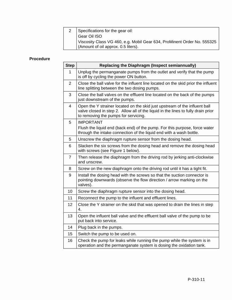
P-310-11
2 Specifications for the gear oil: Gear Oil ISO Viscosity Class VG 460, e.g. Mobil Gear 634, ProMinent Order No. 555325 (Amount of oil approx. 0.5 liters).
Procedure
Step Replacing the Diaphragm (Inspect semiannually)
1 Unplug the permanganate pumps from the outlet and verify that the pump is off by cycling the power ON button.
2 Close the ball valve for the influent line located on the skid prior the influent line splitting between the two dosing pumps.
3 Close the ball valves on the effluent line located on the back of the pumps just downstream of the pumps.
4 Open the Y strainer located on the skid just upstream of the influent ball valve closed in step 2. Allow all of the liquid in the lines to fully drain prior to removing the pumps for servicing.
5 IMPORTANT Flush the liquid end (back end) of the pump. For this purpose, force water through the intake connection of the liquid end with a wash bottle.
5 Unscrew the diaphragm rupture sensor from the dosing head.
6 Slacken the six screws from the dosing head and remove the dosing head with screws (see Figure 1 below).
7 Then release the diaphragm from the driving rod by jerking anti-clockwise and unscrew.
8 Screw on the new diaphragm onto the driving rod until it has a tight fit.
9 Install the dosing head with the screws so that the suction connector is pointing downwards (observe the flow direction / arrow marking on the valves).
10 Screw the diaphragm rupture sensor into the dosing head.
11 Reconnect the pump to the influent and effluent lines.
12 Close the Y strainer on the skid that was opened to drain the lines in step 4.
13 Open the influent ball valve and the effluent ball valve of the pump to be put back into service.
14 Plug back in the pumps.
15 Switch the pump to be used on.
16 Check the pump for leaks while running the pump while the system is in operation and the permanganate system is dosing the oxidation tank.
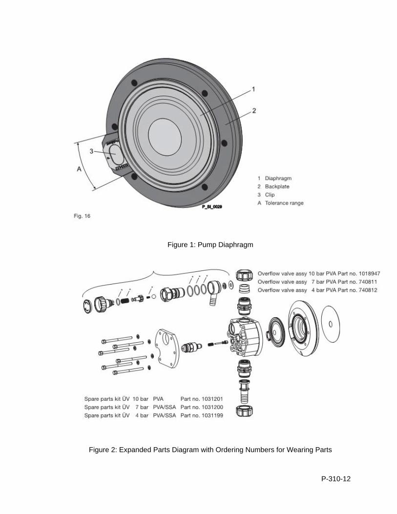
P-310-12
Figure 1: Pump Diaphragm
Figure 2: Expanded Parts Diagram with Ordering Numbers for Wearing Parts
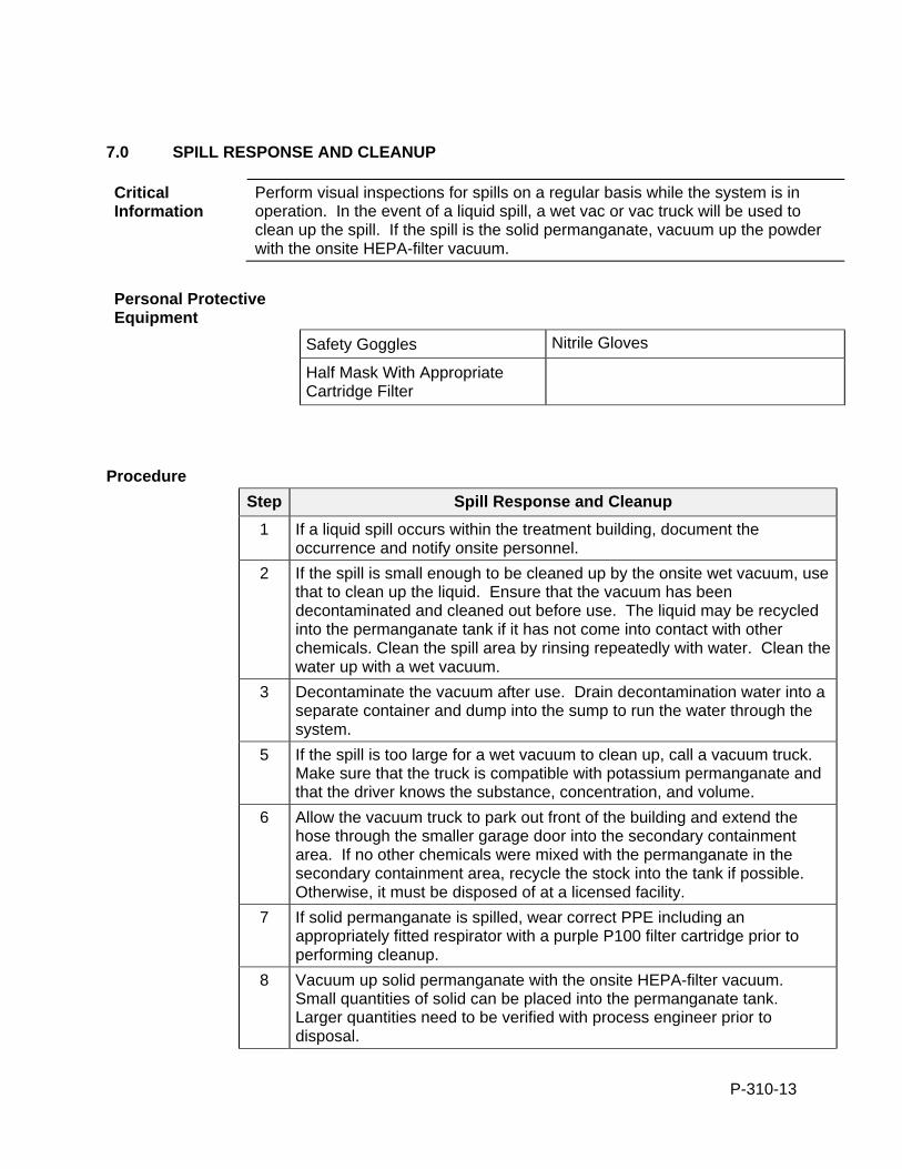
P-310-13
7.0 SPILL RESPONSE AND CLEANUP
Critical Information
Perform visual inspections for spills on a regular basis while the system is in operation. In the event of a liquid spill, a wet vac or vac truck will be used to clean up the spill. If the spill is the solid permanganate, vacuum up the powder with the onsite HEPA-filter vacuum.
Personal Protective Equipment
Safety Goggles Nitrile Gloves
Half Mask With Appropriate Cartridge Filter
Procedure
Step Spill Response and Cleanup
1 If a liquid spill occurs within the treatment building, document the occurrence and notify onsite personnel.
2 If the spill is small enough to be cleaned up by the onsite wet vacuum, use that to clean up the liquid. Ensure that the vacuum has been decontaminated and cleaned out before use. The liquid may be recycled into the permanganate tank if it has not come into contact with other chemicals. Clean the spill area by rinsing repeatedly with water. Clean the water up with a wet vacuum.
3 Decontaminate the vacuum after use. Drain decontamination water into a separate container and dump into the sump to run the water through the system.
5 If the spill is too large for a wet vacuum to clean up, call a vacuum truck. Make sure that the truck is compatible with potassium permanganate and that the driver knows the substance, concentration, and volume.
6 Allow the vacuum truck to park out front of the building and extend the hose through the smaller garage door into the secondary containment area. If no other chemicals were mixed with the permanganate in the secondary containment area, recycle the stock into the tank if possible. Otherwise, it must be disposed of at a licensed facility.
7 If solid permanganate is spilled, wear correct PPE including an appropriately fitted respirator with a purple P100 filter cartridge prior to performing cleanup.
8 Vacuum up solid permanganate with the onsite HEPA-filter vacuum. Small quantities of solid can be placed into the permanganate tank. Larger quantities need to be verified with process engineer prior to disposal.
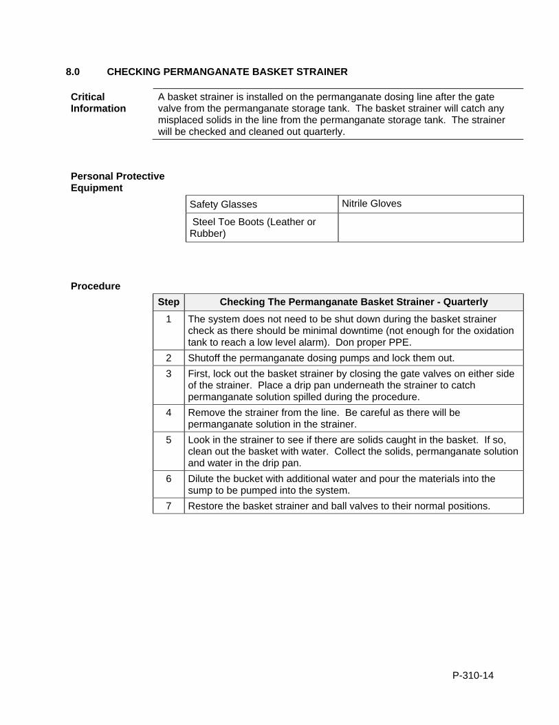
P-310-14
8.0 CHECKING PERMANGANATE BASKET STRAINER
Critical Information
A basket strainer is installed on the permanganate dosing line after the gate valve from the permanganate storage tank. The basket strainer will catch any misplaced solids in the line from the permanganate storage tank. The strainer will be checked and cleaned out quarterly.
Personal Protective Equipment
Safety Glasses Nitrile Gloves
Steel Toe Boots (Leather or Rubber)
Procedure
Step Checking The Permanganate Basket Strainer - Quarterly
1 The system does not need to be shut down during the basket strainer check as there should be minimal downtime (not enough for the oxidation tank to reach a low level alarm). Don proper PPE.
2 Shutoff the permanganate dosing pumps and lock them out.
3 First, lock out the basket strainer by closing the gate valves on either side of the strainer. Place a drip pan underneath the strainer to catch permanganate solution spilled during the procedure.
4 Remove the strainer from the line. Be careful as there will be permanganate solution in the strainer.
5 Look in the strainer to see if there are solids caught in the basket. If so, clean out the basket with water. Collect the solids, permanganate solution and water in the drip pan.
6 Dilute the bucket with additional water and pour the materials into the sump to be pumped into the system.
7 Restore the basket strainer and ball valves to their normal positions.
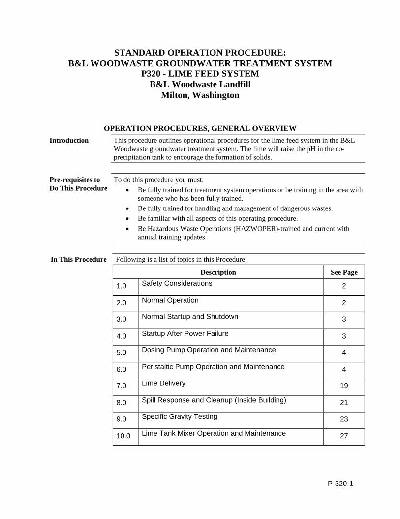
P-320-1
STANDARD OPERATION PROCEDURE: B&L WOODWASTE GROUNDWATER TREATMENT SYSTEM
P320 - LIME FEED SYSTEM B&L Woodwaste Landfill
Milton, Washington
OPERATION PROCEDURES, GENERAL OVERVIEW Introduction This procedure outlines operational procedures for the lime feed system in the B&L
Woodwaste groundwater treatment system. The lime will raise the pH in the co-precipitation tank to encourage the formation of solids.
Pre-requisites to Do This Procedure
To do this procedure you must: Be fully trained for treatment system operations or be training in the area with
someone who has been fully trained. Be fully trained for handling and management of dangerous wastes. Be familiar with all aspects of this operating procedure. Be Hazardous Waste Operations (HAZWOPER)-trained and current with
annual training updates.
In This Procedure Following is a list of topics in this Procedure:
Description See Page
1.0 Safety Considerations 2
2.0 Normal Operation 2
3.0 Normal Startup and Shutdown 3
4.0 Startup After Power Failure 3
5.0 Dosing Pump Operation and Maintenance 4
6.0 Peristaltic Pump Operation and Maintenance 4
7.0 Lime Delivery 19
8.0 Spill Response and Cleanup (Inside Building) 21
9.0 Specific Gravity Testing 23
10.0 Lime Tank Mixer Operation and Maintenance 27
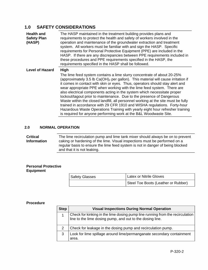
P-320-2
1.0 SAFETY CONSIDERATIONS
Health and Safety Plan (HASP)
The HASP maintained in the treatment building provides plans and requirements to protect the health and safety of workers involved in the operation and maintenance of the groundwater extraction and treatment system. All workers must be familiar with and sign the HASP. Specific requirements for Personal Protective Equipment (PPE) are included in the HASP. If there are any discrepancies between PPE requirements included in these procedures and PPE requirements specified in the HASP, the requirements specified in the HASP shall be followed.
Level of Hazard High The lime feed system contains a lime slurry concentrate of about 20-25% (approximately 3.5 lb Ca(OH)2 per gallon). This material will cause irritation if it comes in contact with skin or eyes. Thus, operators should stay alert and wear appropriate PPE when working with the lime feed system. There are also electrical components acting in the system which necessitate proper lockout/tagout prior to maintenance. Due to the presence of Dangerous Waste within the closed landfill, all personnel working at the site must be fully trained in accordance with 29 CFR 1910 and WISHA regulations. Forty-hour Hazardous Waste Operations Training with yearly eight hour refresher training is required for anyone performing work at the B&L Woodwaste Site.
2.0 NORMAL OPERATION
Critical Information
The lime recirculation pump and lime tank mixer should always be on to prevent caking or hardening of the lime. Visual inspections must be performed on a regular basis to ensure the lime feed system is not in danger of being blocked and that it is not leaking.
Personal Protective Equipment
Safety Glasses Latex or Nitrile Gloves
Steel Toe Boots (Leather or Rubber)
Procedure
Step Visual Inspections During Normal Operation
1 Check for kinking in the lime dosing pump line running from the recirculation line to the lime dosing pump, and out to the dosing line.
2 Check for leakage in the dosing pump and recirculation pump.
3 Look for lime spillage around lime/permanganate secondary containment area.
P-320-3
3.0 NORMAL STARTUP AND SHUTDOWN
Procedure
Step Normal Startup
1 The dosing pump will come online automatically when the measured pH in the coprecipitation tank is below the pH setpoint. It may be necessary to press the “reset alarms” button on the PLC if the dosing pump does not turn on automatically. The lime tank mixer and peristaltic recirculation pump should already be operational.
2 Do a visual inspection as detailed above when starting up system.
Procedure
Step Normal Shutdown
1 The lime tank mixer and peristaltic recirculation pump automatically remain on, even if groundwater pumping is stopped, unless there is a power failure.
2 The lime dosing pump will shut off on its own when the measured pH in the coprecipitation tank is at or above the pH setpoint. In addition, the pump will shut down during a plant shutdown.
4.0 STARTUP AFTER POWER FAILURE
Procedure
Step Startup After Power Failure
1 After a power failure, the lime system should automatically resume operation. First, the lime tank mixer will turn on for approximately one minute. Then the lime recirculation pump will start in reverse for approximately one minute, to flush out the lime feed line. Then the lime recirculation pump will switch to forward operation. If the lime system does not start automatically, restart the lime tank mixer and lime recirculation pump as soon as possible after power failure by turning the circuit breakers back on. Turn the circuit breakers off and on in the MCC if the mixer and pump do not restart automatically.
2 Perform a visual inspection of the secondary containment area before restarting system after a power failure.
3 After a power failure, the “reset alarms” button on the PLC will likely need to be pressed in order to restart the lime dosing pump once the groundwater pumping system is restarted.
P-320-4
5.0 DOSING PUMP OPERATION AND MAINTENANCE
Critical Information
The Watson-Marlow dosing pump will meter lime from the peristaltic pump circulation line to the co-precipitation tank. The pump must be properly maintained to achieve pH target levels in the treatment system.
Personal Protective Equipment
Safety Glasses Latex or Nitrile Gloves
Steel Toe Boots (Leather or Rubber)
Procedure
Step Dosing Pump Operation and Maintenance (Monthly)
1 The flexible hose inside the pump must be changed out monthly to prevent downtime due to clogs. The hose can be flattened or kinked on the inside of the pump. Remove the plastic covering over the peristaltic rotator to remove hosing. Replace with a new stretch of hosing. The hosing is flexible and tan in color and is located in a labeled Watson-Marlow box. Ensure that the installed hose is not subject to abrasion against any concrete or other abrasive surfaces. Document the date of the hosing change out and schedule next month’s change out.
6.0 PERISTALTIC PUMP OPERATION AND MAINTENANCE
Critical Information
The SPX-40 peristaltic pump operating the lime slurry feed system will need preventative maintenance and occasional reactive maintenance. It is important to keep the pump running to avoid hardening of the lime and resulting stasis. Maintenance activities include checking the lubricant level, changing the lubricant, replacing the pump hose, and changing the gearbox oil. These should be documented for reference during troubleshooting.
In This Procedure
Following is a list of topics in this Procedure:
Description See Page
6.1 Routine Inspection 5
6.2 Checking the Lubricant Level 5
6.3 Replacing the Lubricant 6
P-320-5
6.4 Replacing the Pump Hose (6 months) 6
6.5 Changing Oil in Gearbox 9
6.6 Replacing Pump Seal and Wear Ring 10
6.7 Replacing Pressing Shoes 15
6.8 Replacing Bearings 17
Tools/Supplies
Funnel Tray Wrench
Personal Protective Equipment
Safety Glasses Latex or Nitrile Gloves
Steel Toe Boots (Rubber or Leather)
Procedure 6.1
Step Routine Inspection
1 Check the pump head for any leakage of lubricant around the cover, the flanges and the rear of the pump head.
2 Check the gearbox for any leakage.
3 Check pump for deviating temperature or strange noises.
4 When replacing the pump hose, check pressing shoes for excessive damage.
Procedure 6.2
Step Checking the Lubricant Level
1 Periodically make sure that the lubricant level is above the minimum level line in the lubricant level inspection window. If the lubricant is below the minimum level line, replace the lubricant per procedure below.
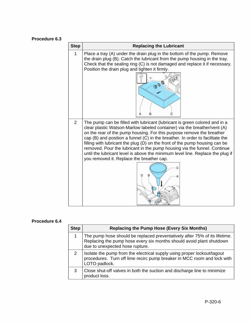
P-320-6
Procedure 6.3
Step Replacing the Lubricant
1 Place a tray (A) under the drain plug in the bottom of the pump. Remove the drain plug (B). Catch the lubricant from the pump housing in the tray. Check that the sealing ring (C) is not damaged and replace it if necessary. Position the drain plug and tighten it firmly.
2 The pump can be filled with lubricant (lubricant is green colored and in a
clear plastic Watson-Marlow labeled container) via the breather/vent (A) on the rear of the pump housing. For this purpose remove the breather cap (B) and position a funnel (C) in the breather. In order to facilitate the filling with lubricant the plug (D) on the front of the pump housing can be removed. Pour the lubricant in the pump housing via the funnel. Continue until the lubricant level is above the minimum level line. Replace the plug if you removed it. Replace the breather cap.
Procedure 6.4
Step Replacing the Pump Hose (Every Six Months)
1 The pump hose should be replaced preventatively after 75% of its lifetime. Replacing the pump hose every six months should avoid plant shutdown due to unexpected hose rupture.
2 Isolate the pump from the electrical supply using proper lockout/tagout procedures. Turn off lime recirc pump breaker in MCC room and lock with LOTO padlock.
3 Close shut-off valves in both the suction and discharge line to minimize product loss.
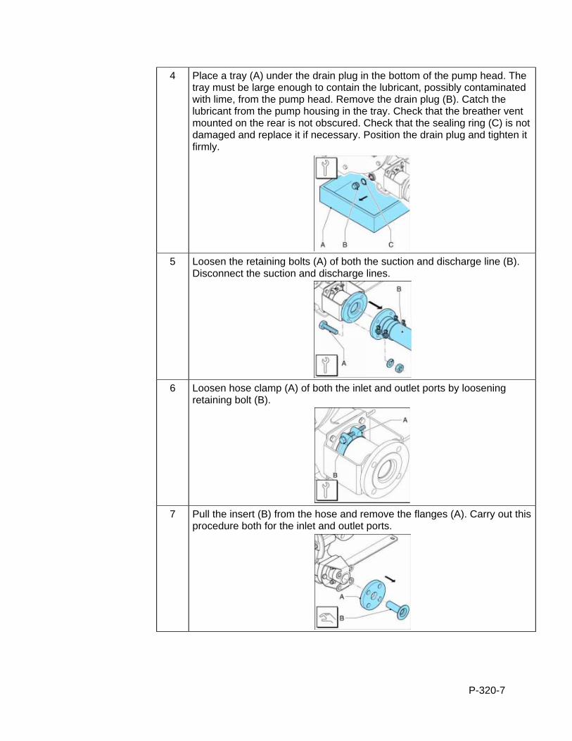
P-320-7
4 Place a tray (A) under the drain plug in the bottom of the pump head. The tray must be large enough to contain the lubricant, possibly contaminated with lime, from the pump head. Remove the drain plug (B). Catch the lubricant from the pump housing in the tray. Check that the breather vent mounted on the rear is not obscured. Check that the sealing ring (C) is not damaged and replace it if necessary. Position the drain plug and tighten it firmly.
5 Loosen the retaining bolts (A) of both the suction and discharge line (B).
Disconnect the suction and discharge lines.
6 Loosen hose clamp (A) of both the inlet and outlet ports by loosening
retaining bolt (B).
7 Pull the insert (B) from the hose and remove the flanges (A). Carry out this
procedure both for the inlet and outlet ports.
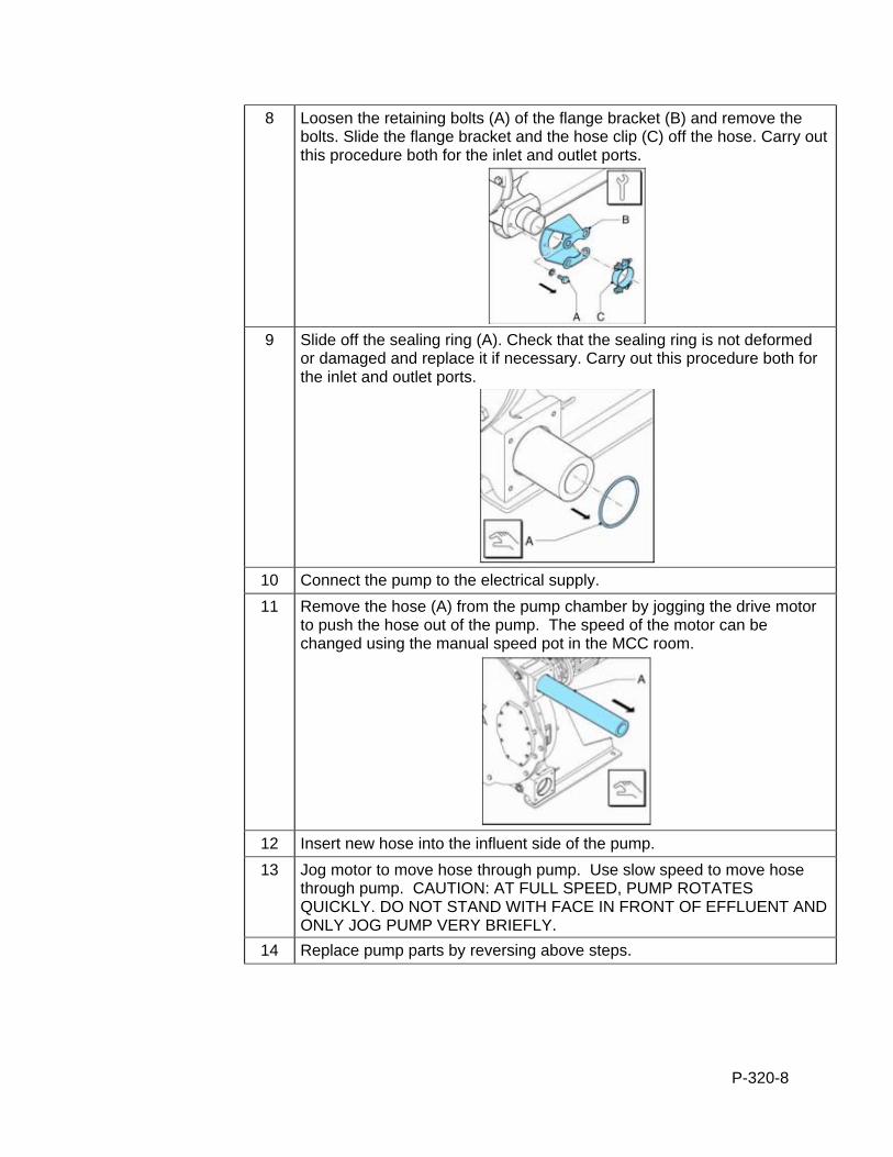
P-320-8
8 Loosen the retaining bolts (A) of the flange bracket (B) and remove the bolts. Slide the flange bracket and the hose clip (C) off the hose. Carry out this procedure both for the inlet and outlet ports.
9 Slide off the sealing ring (A). Check that the sealing ring is not deformed
or damaged and replace it if necessary. Carry out this procedure both for the inlet and outlet ports.
10 Connect the pump to the electrical supply.
11 Remove the hose (A) from the pump chamber by jogging the drive motor to push the hose out of the pump. The speed of the motor can be changed using the manual speed pot in the MCC room.
12 Insert new hose into the influent side of the pump.
13 Jog motor to move hose through pump. Use slow speed to move hose through pump. CAUTION: AT FULL SPEED, PUMP ROTATES QUICKLY. DO NOT STAND WITH FACE IN FRONT OF EFFLUENT AND ONLY JOG PUMP VERY BRIEFLY.
14 Replace pump parts by reversing above steps.
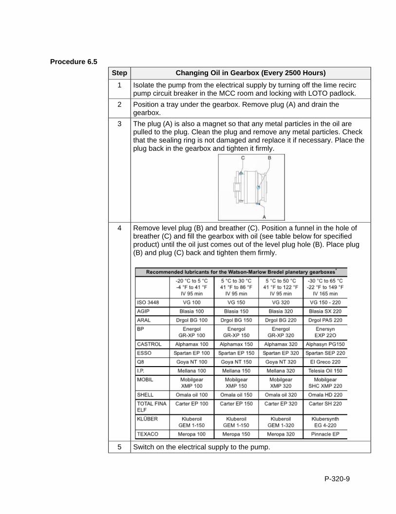
P-320-9
Procedure 6.5
Step Changing Oil in Gearbox (Every 2500 Hours)
1 Isolate the pump from the electrical supply by turning off the lime recirc pump circuit breaker in the MCC room and locking with LOTO padlock.
2 Position a tray under the gearbox. Remove plug (A) and drain the gearbox.
3 The plug (A) is also a magnet so that any metal particles in the oil are pulled to the plug. Clean the plug and remove any metal particles. Check that the sealing ring is not damaged and replace it if necessary. Place the plug back in the gearbox and tighten it firmly.
4 Remove level plug (B) and breather (C). Position a funnel in the hole of
breather (C) and fill the gearbox with oil (see table below for specified product) until the oil just comes out of the level plug hole (B). Place plug (B) and plug (C) back and tighten them firmly.
5 Switch on the electrical supply to the pump.
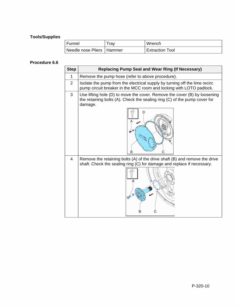
P-320-10
Tools/Supplies
Funnel Tray Wrench
Needle nose Pliers Hammer Extraction Tool
Procedure 6.6
Step Replacing Pump Seal and Wear Ring (If Necessary)
1 Remove the pump hose (refer to above procedure).
2 Isolate the pump from the electrical supply by turning off the lime recirc pump circuit breaker in the MCC room and locking with LOTO padlock.
3 Use lifting hole (D) to move the cover. Remove the cover (B) by loosening the retaining bolts (A). Check the sealing ring (C) of the pump cover for damage.
4 Remove the retaining bolts (A) of the drive shaft (B) and remove the drive
shaft. Check the sealing ring (C) for damage and replace if necessary.
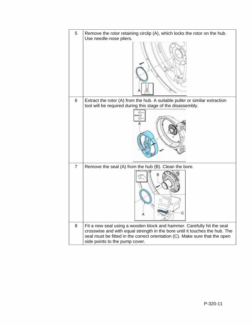
P-320-11
5 Remove the rotor retaining circlip (A), which locks the rotor on the hub. Use needle-nose pliers.
6 Extract the rotor (A) from the hub. A suitable puller or similar extraction
tool will be required during this stage of the disassembly.
7 Remove the seal (A) from the hub (B). Clean the bore.
8 Fit a new seal using a wooden block and hammer. Carefully hit the seal
crosswise and with equal strength in the bore until it touches the hub. The seal must be fitted in the correct orientation (C). Make sure that the open side points to the pump cover.
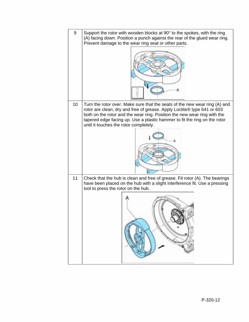
P-320-12
9 Support the rotor with wooden blocks at 90° to the spokes, with the ring (A) facing down. Position a punch against the rear of the glued wear ring. Prevent damage to the wear ring seat or other parts.
10 Turn the rotor over. Make sure that the seats of the new wear ring (A) and
rotor are clean, dry and free of grease. Apply Loctite® type 641 or 603 both on the rotor and the wear ring. Position the new wear ring with the tapered edge facing up. Use a plastic hammer to fit the ring on the rotor until it touches the rotor completely.
11 Check that the hub is clean and free of grease. Fit rotor (A). The bearings
have been placed on the hub with a slight interference fit. Use a pressing tool to press the rotor on the hub.
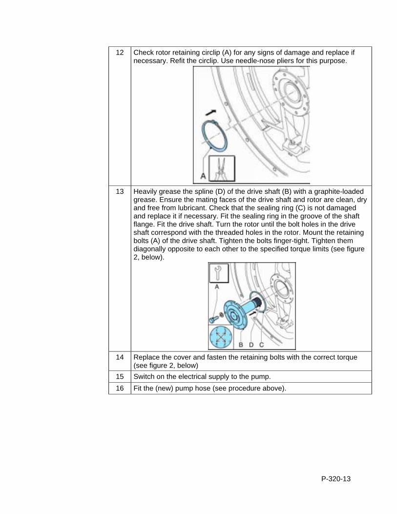
P-320-13
12 Check rotor retaining circlip (A) for any signs of damage and replace if necessary. Refit the circlip. Use needle-nose pliers for this purpose.
13 Heavily grease the spline (D) of the drive shaft (B) with a graphite-loaded
grease. Ensure the mating faces of the drive shaft and rotor are clean, dry and free from lubricant. Check that the sealing ring (C) is not damaged and replace it if necessary. Fit the sealing ring in the groove of the shaft flange. Fit the drive shaft. Turn the rotor until the bolt holes in the drive shaft correspond with the threaded holes in the rotor. Mount the retaining bolts (A) of the drive shaft. Tighten the bolts finger-tight. Tighten them diagonally opposite to each other to the specified torque limits (see figure 2, below).
14 Replace the cover and fasten the retaining bolts with the correct torque
(see figure 2, below)
15 Switch on the electrical supply to the pump.
16 Fit the (new) pump hose (see procedure above).

P-320-14
Figure 2: Specified Torque Amounts

P-320-15
Procedure 6.7
Step Replacing The Pressing Shoes (When there is visible wear on the surface)
1 Jog the motor from the MCC (requires two people) until the pressing shoe (B) is positioned in view of the inspection window (A).
2 Isolate the pump from the electrical supply by turning off the lime recirc
pump circuit breaker in the MCC room and locking with LOTO padlock
3 Place a tray (A) under the drain plug (B) in the bottom of the pump head. Remove the drain plug. Drain as much lubricant until the level has lowered just below the inspection window (D). Check that the sealing ring (C) is not damaged and replace it if necessary. Position the drain plug and tighten it firmly.
4 Loosen the retaining bolts (A) of the inspection window (B) and remove
the bolts. Remove the inspection window. Care must be taken not to damage the gasket (C).

P-320-16
5 Loosen the retaining bolt(s) (A) of pressing shoe (B) a few turns. Remove the shims (C) if present. Loosen the retaining bolt(s) (A) of pressing shoe (B) completely and remove the pressing shoe.
6 Position the (new) pressing shoe (A), check that the NordLock®-rings (B)
have been positioned correctly and tighten the retaining bolt(s) a few turns.
7 Fit the removed shims (A) again. Tighten the retaining bolt(s) (B) with the
correct torque (see figure 2).
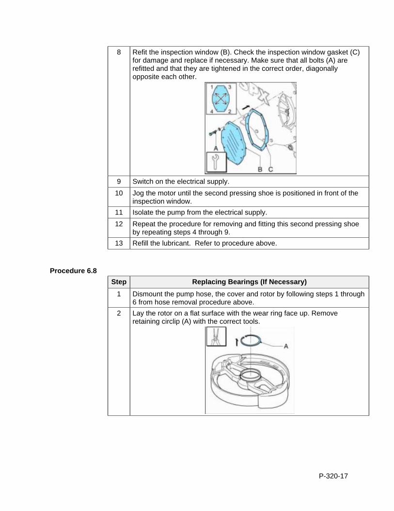
P-320-17
8 Refit the inspection window (B). Check the inspection window gasket (C) for damage and replace if necessary. Make sure that all bolts (A) are refitted and that they are tightened in the correct order, diagonally opposite each other.
9 Switch on the electrical supply.
10 Jog the motor until the second pressing shoe is positioned in front of the inspection window.
11 Isolate the pump from the electrical supply.
12 Repeat the procedure for removing and fitting this second pressing shoe by repeating steps 4 through 9.
13 Refill the lubricant. Refer to procedure above.
Procedure 6.8
Step Replacing Bearings (If Necessary)
1 Dismount the pump hose, the cover and rotor by following steps 1 through 6 from hose removal procedure above.
2 Lay the rotor on a flat surface with the wear ring face up. Remove retaining circlip (A) with the correct tools.
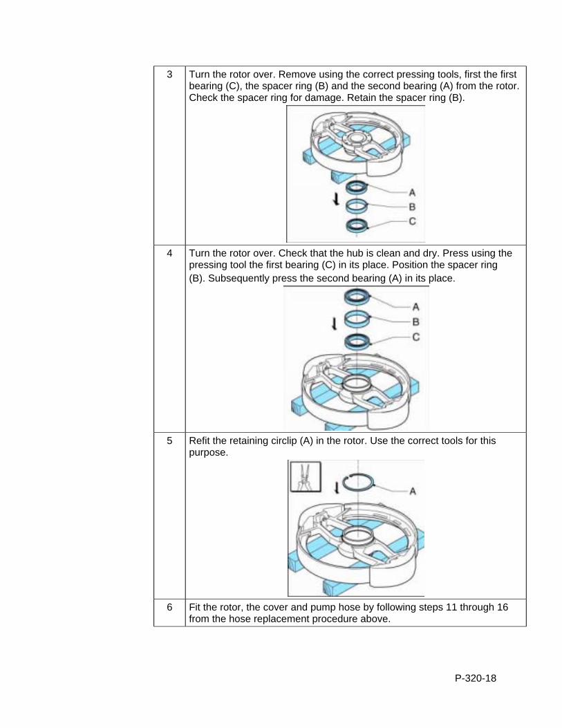
P-320-18
3 Turn the rotor over. Remove using the correct pressing tools, first the first bearing (C), the spacer ring (B) and the second bearing (A) from the rotor. Check the spacer ring for damage. Retain the spacer ring (B).
4 Turn the rotor over. Check that the hub is clean and dry. Press using the
pressing tool the first bearing (C) in its place. Position the spacer ring (B). Subsequently press the second bearing (A) in its place.
5 Refit the retaining circlip (A) in the rotor. Use the correct tools for this
purpose.
6 Fit the rotor, the cover and pump hose by following steps 11 through 16
from the hose replacement procedure above.
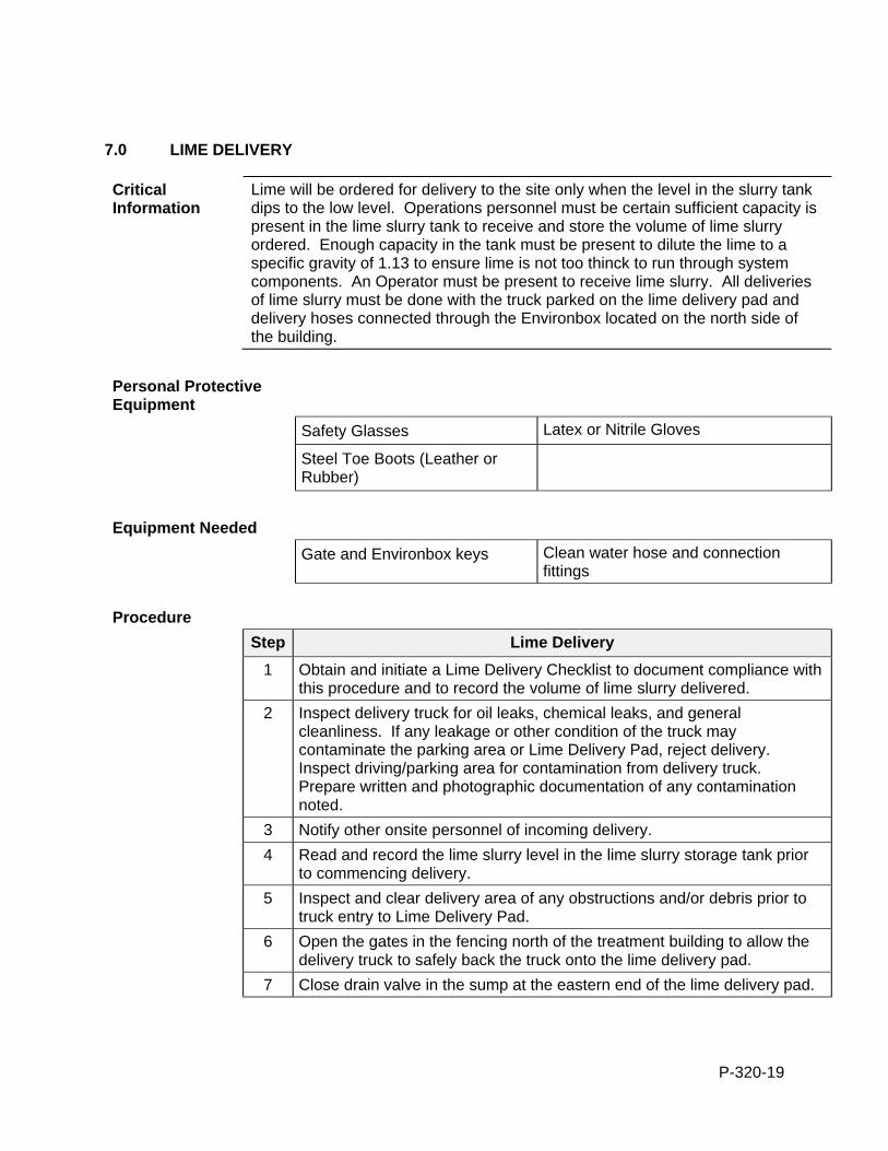
P-320-19
7.0 LIME DELIVERY
Critical Information
Lime will be ordered for delivery to the site only when the level in the slurry tank dips to the low level. Operations personnel must be certain sufficient capacity is present in the lime slurry tank to receive and store the volume of lime slurry ordered. Enough capacity in the tank must be present to dilute the lime to a specific gravity of 1.13 to ensure lime is not too thinck to run through system components. An Operator must be present to receive lime slurry. All deliveries of lime slurry must be done with the truck parked on the lime delivery pad and delivery hoses connected through the Environbox located on the north side of the building.
Personal Protective Equipment
Safety Glasses Latex or Nitrile Gloves
Steel Toe Boots (Leather or Rubber)
Equipment Needed
Gate and Environbox keys Clean water hose and connection fittings
Procedure
Step Lime Delivery
1 Obtain and initiate a Lime Delivery Checklist to document compliance with this procedure and to record the volume of lime slurry delivered.
2 Inspect delivery truck for oil leaks, chemical leaks, and general cleanliness. If any leakage or other condition of the truck may contaminate the parking area or Lime Delivery Pad, reject delivery. Inspect driving/parking area for contamination from delivery truck. Prepare written and photographic documentation of any contamination noted.
3 Notify other onsite personnel of incoming delivery.
4 Read and record the lime slurry level in the lime slurry storage tank prior to commencing delivery.
5 Inspect and clear delivery area of any obstructions and/or debris prior to truck entry to Lime Delivery Pad.
6 Open the gates in the fencing north of the treatment building to allow the delivery truck to safely back the truck onto the lime delivery pad.
7 Close drain valve in the sump at the eastern end of the lime delivery pad.
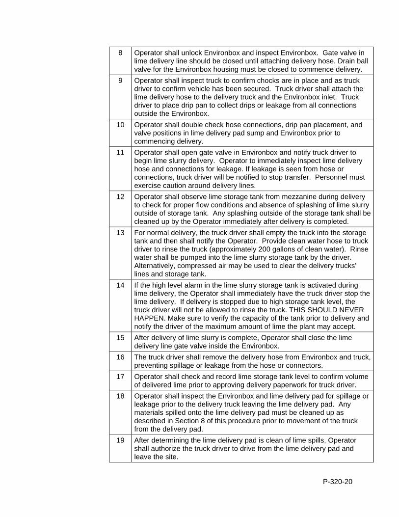
P-320-20
8 Operator shall unlock Environbox and inspect Environbox. Gate valve in lime delivery line should be closed until attaching delivery hose. Drain ball valve for the Environbox housing must be closed to commence delivery.
9 Operator shall inspect truck to confirm chocks are in place and as truck driver to confirm vehicle has been secured. Truck driver shall attach the lime delivery hose to the delivery truck and the Environbox inlet. Truck driver to place drip pan to collect drips or leakage from all connections outside the Environbox.
10 Operator shall double check hose connections, drip pan placement, and valve positions in lime delivery pad sump and Environbox prior to commencing delivery.
11 Operator shall open gate valve in Environbox and notify truck driver to begin lime slurry delivery. Operator to immediately inspect lime delivery hose and connections for leakage. If leakage is seen from hose or connections, truck driver will be notified to stop transfer. Personnel must exercise caution around delivery lines.
12 Operator shall observe lime storage tank from mezzanine during delivery to check for proper flow conditions and absence of splashing of lime slurry outside of storage tank. Any splashing outside of the storage tank shall be cleaned up by the Operator immediately after delivery is completed.
13 For normal delivery, the truck driver shall empty the truck into the storage tank and then shall notify the Operator. Provide clean water hose to truck driver to rinse the truck (approximately 200 gallons of clean water). Rinse water shall be pumped into the lime slurry storage tank by the driver. Alternatively, compressed air may be used to clear the delivery trucks’ lines and storage tank.
14 If the high level alarm in the lime slurry storage tank is activated during lime delivery, the Operator shall immediately have the truck driver stop the lime delivery. If delivery is stopped due to high storage tank level, the truck driver will not be allowed to rinse the truck. THIS SHOULD NEVER HAPPEN. Make sure to verify the capacity of the tank prior to delivery and notify the driver of the maximum amount of lime the plant may accept.
15 After delivery of lime slurry is complete, Operator shall close the lime delivery line gate valve inside the Environbox.
16 The truck driver shall remove the delivery hose from Environbox and truck, preventing spillage or leakage from the hose or connectors.
17 Operator shall check and record lime storage tank level to confirm volume of delivered lime prior to approving delivery paperwork for truck driver.
18 Operator shall inspect the Environbox and lime delivery pad for spillage or leakage prior to the delivery truck leaving the lime delivery pad. Any materials spilled onto the lime delivery pad must be cleaned up as described in Section 8 of this procedure prior to movement of the truck from the delivery pad.
19 After determining the lime delivery pad is clean of lime spills, Operator shall authorize the truck driver to drive from the lime delivery pad and leave the site.
P-320-21
20 If lime spillage has occurred inside the Environbox, Operator shall immediately clean Environbox by washing the box with clean water and a brush. Wash water shall be collected by connecting a hose to the the Environbox drain valve and collecting wash water in a plastic bucket. Wash water collected in the bucket shall be placed in the lime storage tank by the Operator.
21 Connect the clean water hose to the 3/4” ball valve inside the Environbox to flush the lime delivery pipe into the lime storage tank. Maintain the flush water at fully open flow for approximately 30 seconds. Close ¾” ball valve and disconnect clean water hose after flushing is complete.
22 After determining that the lime delivery pad and Environbox are clean of lime spills as described in Procedure 8.2, Operator shall close all Environbox valves, lock Environbox, and open the sump gate valve for the lime delivery pad to allow storm water to flow from the sump.
23 Operator shall check lime tank, recirculation system, and lime feed system for proper conditions and proper operation.
24 Complete, sign, date, and file the Lime Delivery Log (attached) to document lime delivery.
8.0 SPILL RESPONSE AND CLEANUP
Critical Information
Lime is a corrosive chemical that can cause skin and eye irritation and can cause adverse environmental impacts if released to the environment. Caution must be exercised to avoid direct contact with lime during spill response and cleanup. Actions should be taken to control or mitigate spills or releases to the environment outside the building or lime delivery pad.
Personal Protective Equipment
Safety Glasses Latex or Nitrile Gloves
Chemical/Water Resistant Boots Hard Hat
Protective coveralls
Equipment Needed
Clean water hose Sampling equipment
Brushes/brooms
Procedure 8.1
Step Spill Response and Cleanup Inside Building
1 Lime slurry will dry and solidify within about a day after it is spilled. Spills should be cleaned up immediately after a spill to simplify cleanup and minimize lime residue that may remain after cleanup.
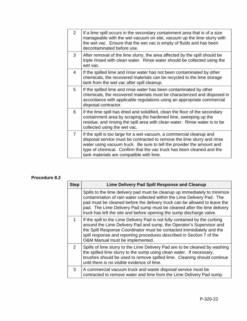
P-320-22
2 If a lime spill occurs in the secondary containment area that is of a size manageable with the wet vacuum on site, vacuum up the lime slurry with the wet vac. Ensure that the wet vac is empty of fluids and has been decontaminated before use.
3 After removal of the lime slurry, the area affected by the spill should be triple rinsed with clean water. Rinse water should be collected using the wet vac.
4 If the spilled lime and rinse water has not been contaminated by other chemicals, the recovered materials can be recycled to the lime storage tank from the wet vac after spill cleanup.
5 If the spilled lime and rinse water has been contaminated by other chemicals, the recovered materials must be characterized and disposed in accordance with applicable regulations using an appropriate commercial disposal contractor.
6 If the lime spill has dried and solidified, clean the floor of the secondary containment area by scraping the hardened lime, sweeping up the residue, and rinsing the spill area with clean water. Rinse water is to be collected using the wet vac.
7 If the spill is too large for a wet vacuum, a commercial cleanup and disposal service must be contracted to remove the lime slurry and rinse water using vacuum truck. Be sure to tell the provider the amount and type of chemical. Confirm that the vac truck has been cleaned and the tank materials are compatible with lime.
Procedure 8.2
Step Lime Delivery Pad Spill Response and Cleanup
Spills to the lime delivery pad must be cleanup up immediately to minimize contamination of rain water collected within the Lime Delivery Pad. The pad must be cleaned before the delivery truck can be allowed to leave the pad. The Lime Delivery Pad sump must be cleaned after the lime delivery truck has left the site and before opening the sump discharge valve.
1 If the spill to the Lime Delivery Pad is not fully contained by the curbing around the Lime Delivery Pad and sump, the Operator’s Supervisor and the Spill Response Coordinator must be contacted immediately and the spill response and reporting procedures described in Section 7 of the O&M Manual must be implemented.
2 Spills of lime slurry to the Lime Delivery Pad are to be cleaned by washing the spilled lime slurry to the sump using clean water. If necessary, brushes should be used to remove spilled lime. Cleaning should continue until there is no visible evidence of lime.
3 A commercial vacuum truck and waste disposal service must be contracted to remove water and lime from the Lime Delivery Pad sump.
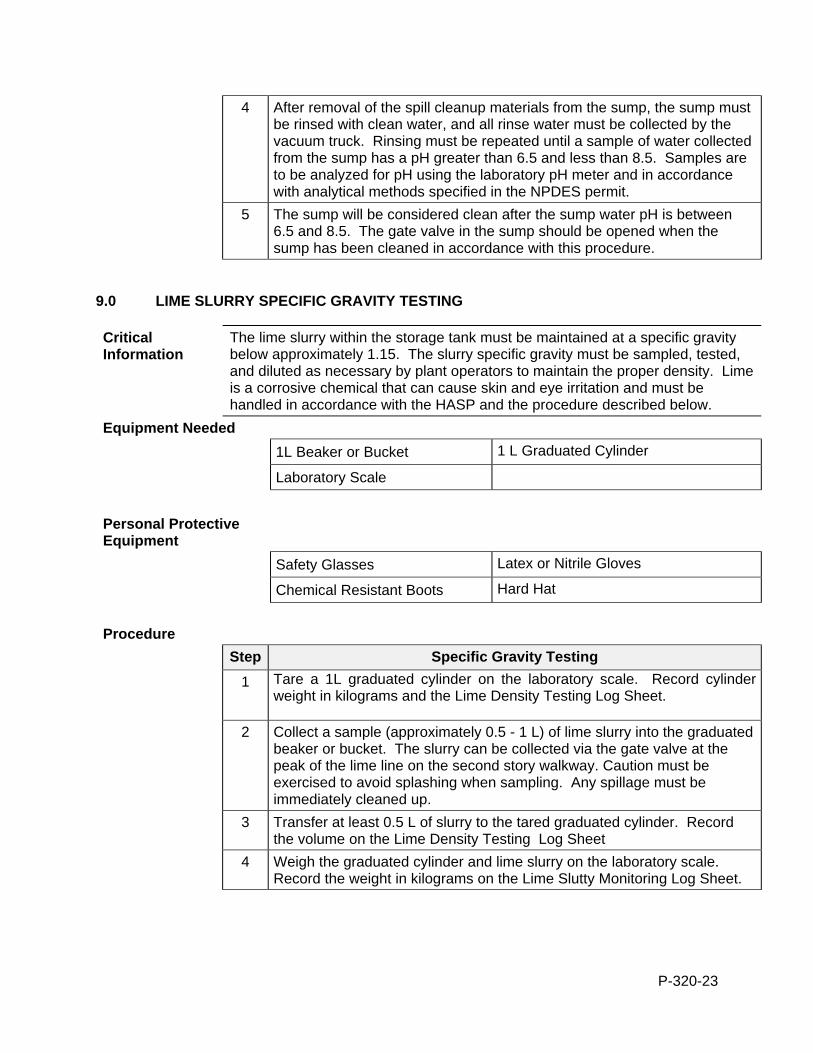
P-320-23
4 After removal of the spill cleanup materials from the sump, the sump must be rinsed with clean water, and all rinse water must be collected by the vacuum truck. Rinsing must be repeated until a sample of water collected from the sump has a pH greater than 6.5 and less than 8.5. Samples are to be analyzed for pH using the laboratory pH meter and in accordance with analytical methods specified in the NPDES permit.
5 The sump will be considered clean after the sump water pH is between 6.5 and 8.5. The gate valve in the sump should be opened when the sump has been cleaned in accordance with this procedure.
9.0 LIME SLURRY SPECIFIC GRAVITY TESTING
Critical Information
The lime slurry within the storage tank must be maintained at a specific gravity below approximately 1.15. The slurry specific gravity must be sampled, tested, and diluted as necessary by plant operators to maintain the proper density. Lime is a corrosive chemical that can cause skin and eye irritation and must be handled in accordance with the HASP and the procedure described below.
Equipment Needed
1L Beaker or Bucket 1 L Graduated Cylinder
Laboratory Scale
Personal Protective Equipment
Safety Glasses Latex or Nitrile Gloves
Chemical Resistant Boots Hard Hat
Procedure
Step Specific Gravity Testing
1 Tare a 1L graduated cylinder on the laboratory scale. Record cylinder weight in kilograms and the Lime Density Testing Log Sheet.
2 Collect a sample (approximately 0.5 - 1 L) of lime slurry into the graduated beaker or bucket. The slurry can be collected via the gate valve at the peak of the lime line on the second story walkway. Caution must be exercised to avoid splashing when sampling. Any spillage must be immediately cleaned up.
3 Transfer at least 0.5 L of slurry to the tared graduated cylinder. Record the volume on the Lime Density Testing Log Sheet
4 Weigh the graduated cylinder and lime slurry on the laboratory scale. Record the weight in kilograms on the Lime Slutty Monitoring Log Sheet.
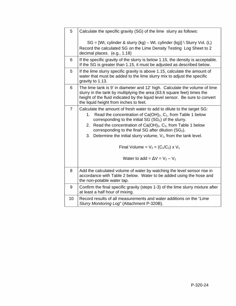
P-320-24
5 Calculate the specific gravity (SG) of the lime slurry as follows:
SG = [Wt, cylinder & slurry (kg) – Wt. cylinder (kg)] \ Slurry Vol. (L) Record the calculated SG on the Lime Density Testing Log Sheet to 2 decimal places. (e.g., 1.18)
6 If the specific gravity of the slurry is below 1.15, the density is acceptable. If the SG is greater than 1.15, it must be adjusted as described below.
5 If the lime slurry specific gravity is above 1.15, calculate the amount of water that must be added to the lime slurry mix to adjust the specific gravity to 1.13.
6 The lime tank is 9’ in diameter and 12’ high. Calculate the volume of lime slurry in the tank by multiplying the area (63.6 square feet) times the height of the fluid indicated by the liquid level sensor. Be sure to convert the liquid height from inches to feet.
7 Calculate the amount of fresh water to add to dilute to the target SG: 1. Read the concentration of Ca(OH)2, C1, from Table 1 below
corresponding to the initial SG (SG1) of the slurry. 2. Read the concentration of Ca(OH)2, C2, from Table 1 below
corresponding to the final SG after dilution (SG2). 3. Determine the initial slurry volume, V1, from the tank level.
Final Volume = V2 = (C1/C2) x V1
Water to add = ∆V = V2 – V1
8 Add the calculated volume of water by watching the level sensor rise in accordance with Table 2 below. Water to be added using the hose and the non-potable water tap.
9 Confirm the final specific gravity (steps 1-3) of the lime slurry mixture after at least a half hour of mixing.
10 Record results of all measurements and water additions on the “Lime Slurry Monitoring Log” (Attachment P-320B).
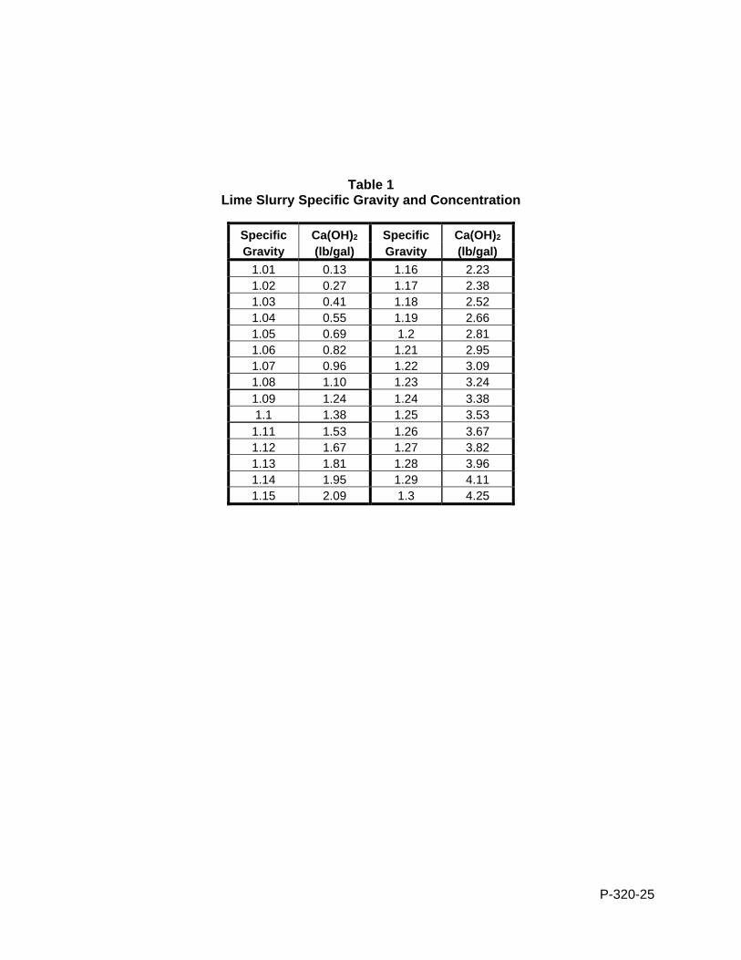
P-320-25
Table 1 Lime Slurry Specific Gravity and Concentration
Specific Ca(OH)2 Specific Ca(OH)2 Gravity (lb/gal) Gravity (lb/gal)
1.01 0.13 1.16 2.23 1.02 0.27 1.17 2.38 1.03 0.41 1.18 2.52 1.04 0.55 1.19 2.66 1.05 0.69 1.2 2.81 1.06 0.82 1.21 2.95 1.07 0.96 1.22 3.09 1.08 1.10 1.23 3.24 1.09 1.24 1.24 3.38 1.1 1.38 1.25 3.53 1.11 1.53 1.26 3.67 1.12 1.67 1.27 3.82 1.13 1.81 1.28 3.96 1.14 1.95 1.29 4.11 1.15 2.09 1.3 4.25
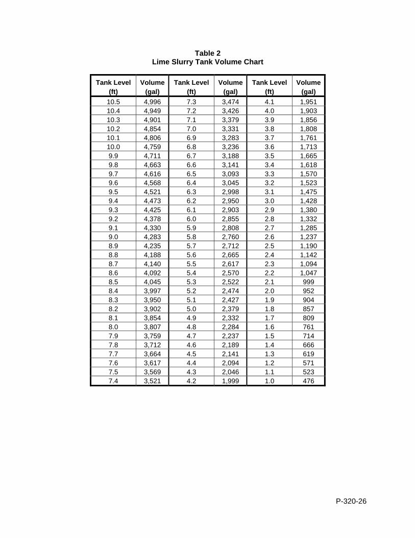
P-320-26
Table 2 Lime Slurry Tank Volume Chart
Tank Level Volume Tank Level Volume Tank Level Volume (ft) (gal) (ft) (gal) (ft) (gal)
10.5 4,996 7.3 3,474 4.1 1,951 10.4 4,949 7.2 3,426 4.0 1,903 10.3 4,901 7.1 3,379 3.9 1,856 10.2 4,854 7.0 3,331 3.8 1,808 10.1 4,806 6.9 3,283 3.7 1,761 10.0 4,759 6.8 3,236 3.6 1,713 9.9 4,711 6.7 3,188 3.5 1,665 9.8 4,663 6.6 3,141 3.4 1,618 9.7 4,616 6.5 3,093 3.3 1,570 9.6 4,568 6.4 3,045 3.2 1,523 9.5 4,521 6.3 2,998 3.1 1,475 9.4 4,473 6.2 2,950 3.0 1,428 9.3 4,425 6.1 2,903 2.9 1,380 9.2 4,378 6.0 2,855 2.8 1,332 9.1 4,330 5.9 2,808 2.7 1,285 9.0 4,283 5.8 2,760 2.6 1,237 8.9 4,235 5.7 2,712 2.5 1,190 8.8 4,188 5.6 2,665 2.4 1,142 8.7 4,140 5.5 2,617 2.3 1,094 8.6 4,092 5.4 2,570 2.2 1,047 8.5 4,045 5.3 2,522 2.1 999 8.4 3,997 5.2 2,474 2.0 952 8.3 3,950 5.1 2,427 1.9 904 8.2 3,902 5.0 2,379 1.8 857 8.1 3,854 4.9 2,332 1.7 809 8.0 3,807 4.8 2,284 1.6 761 7.9 3,759 4.7 2,237 1.5 714 7.8 3,712 4.6 2,189 1.4 666 7.7 3,664 4.5 2,141 1.3 619 7.6 3,617 4.4 2,094 1.2 571 7.5 3,569 4.3 2,046 1.1 523 7.4 3,521 4.2 1,999 1.0 476
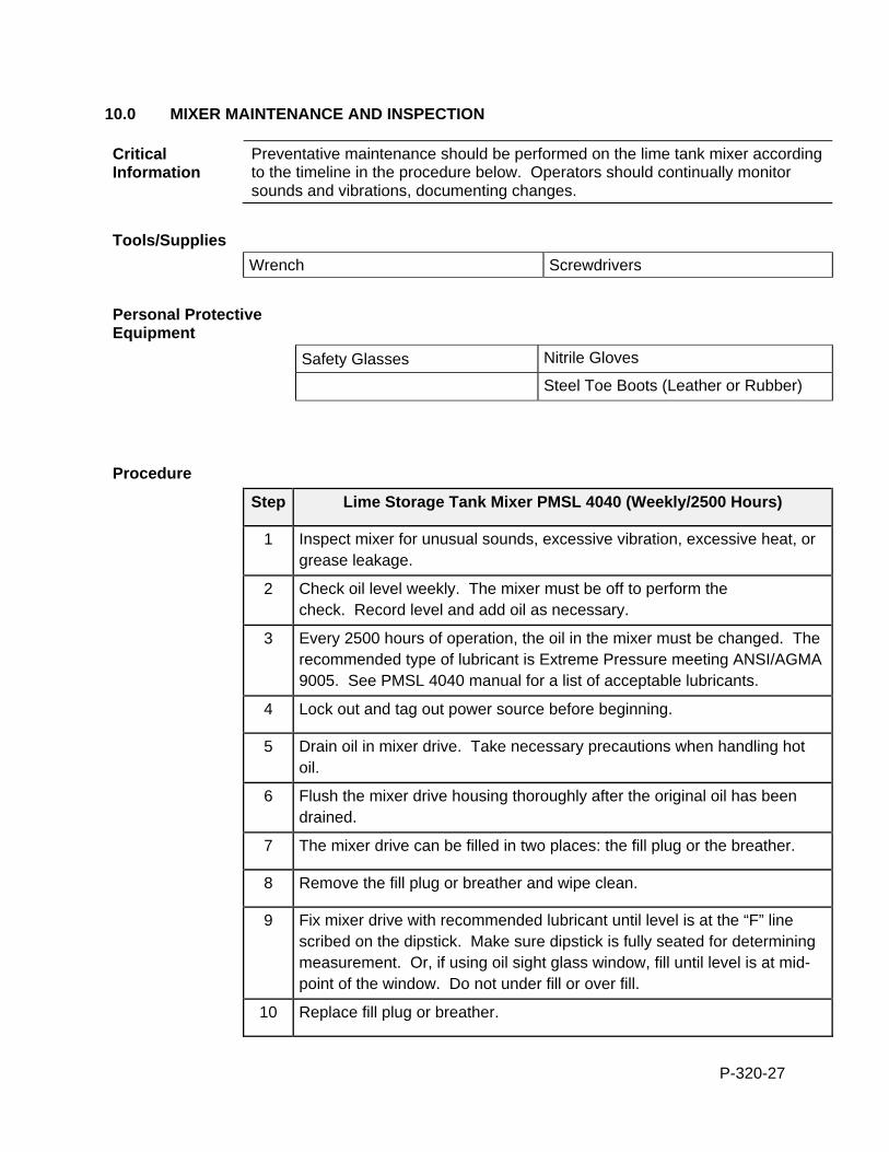
P-320-27
10.0 MIXER MAINTENANCE AND INSPECTION
Critical Information
Preventative maintenance should be performed on the lime tank mixer according to the timeline in the procedure below. Operators should continually monitor sounds and vibrations, documenting changes.
Tools/Supplies
Wrench Screwdrivers
Personal Protective Equipment
Safety Glasses Nitrile Gloves
Steel Toe Boots (Leather or Rubber)
Procedure
Step Lime Storage Tank Mixer PMSL 4040 (Weekly/2500 Hours)
1 Inspect mixer for unusual sounds, excessive vibration, excessive heat, or grease leakage.
2 Check oil level weekly. The mixer must be off to perform the check. Record level and add oil as necessary.
3 Every 2500 hours of operation, the oil in the mixer must be changed. The
recommended type of lubricant is Extreme Pressure meeting ANSI/AGMA 9005. See PMSL 4040 manual for a list of acceptable lubricants.
4 Lock out and tag out power source before beginning.
5 Drain oil in mixer drive. Take necessary precautions when handling hot oil.
6 Flush the mixer drive housing thoroughly after the original oil has been drained.
7 The mixer drive can be filled in two places: the fill plug or the breather.
8 Remove the fill plug or breather and wipe clean.
9 Fix mixer drive with recommended lubricant until level is at the “F” line scribed on the dipstick. Make sure dipstick is fully seated for determining measurement. Or, if using oil sight glass window, fill until level is at mid-point of the window. Do not under fill or over fill.
10 Replace fill plug or breather.

P-320-28
11 Add grease to all bearings, couplings, and seals.
12 Inspect impeller for evidence of erosion or corrosion.
13 Check hardware tightness. Re-torque mixer to original specifications. See PMSL 4040 manual for torque values.
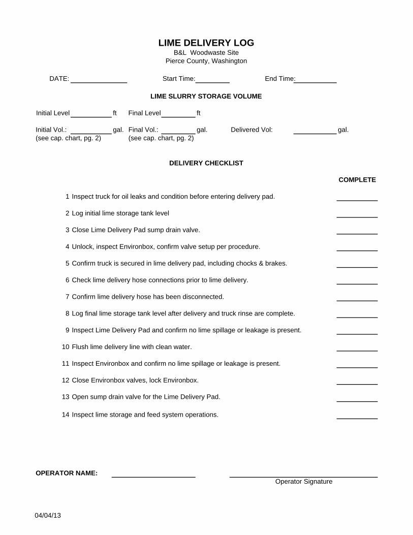
DATE: Start Time: End Time:
Initial Level ft Final Level ft
Initial Vol.: gal. Final Vol.: gal. Delivered Vol: gal.
COMPLETE
1 Inspect truck for oil leaks and condition before entering delivery pad.
2 Log initial lime storage tank level
3 Close Lime Delivery Pad sump drain valve.
4 Unlock, inspect Environbox, confirm valve setup per procedure.
5 Confirm truck is secured in lime delivery pad, including chocks & brakes.
6 Check lime delivery hose connections prior to lime delivery.
7 Confirm lime delivery hose has been disconnected.
8 Log final lime storage tank level after delivery and truck rinse are complete.
9 Inspect Lime Delivery Pad and confirm no lime spillage or leakage is present.
10 Flush lime delivery line with clean water.
11 Inspect Environbox and confirm no lime spillage or leakage is present.
12 Close Environbox valves, lock Environbox.
13 Open sump drain valve for the Lime Delivery Pad.
14 Inspect lime storage and feed system operations.
OPERATOR NAME:
LIME SLURRY STORAGE VOLUME
DELIVERY CHECKLIST
Operator Signature
(see cap. chart, pg. 2) (see cap. chart, pg. 2)
LIME DELIVERY LOGB&L Woodwaste Site
Pierce County, Washington
04/04/13
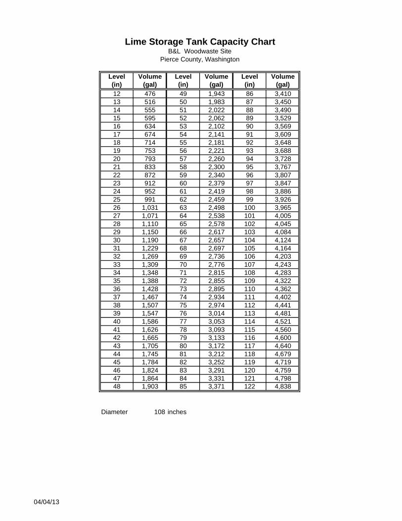
Level Volume Level Volume Level Volume(in) (gal) (in) (gal) (in) (gal)
12 476 49 1,943 86 3,41013 516 50 1,983 87 3,45014 555 51 2,022 88 3,49015 595 52 2,062 89 3,52916 634 53 2,102 90 3,56917 674 54 2,141 91 3,60918 714 55 2,181 92 3,64819 753 56 2,221 93 3,68820 793 57 2,260 94 3,72821 833 58 2,300 95 3,76722 872 59 2,340 96 3,80723 912 60 2,379 97 3,84724 952 61 2,419 98 3,88625 991 62 2,459 99 3,92626 1,031 63 2,498 100 3,96527 1,071 64 2,538 101 4,00528 1,110 65 2,578 102 4,04529 1,150 66 2,617 103 4,08430 1,190 67 2,657 104 4,12431 1,229 68 2,697 105 4,16432 1,269 69 2,736 106 4,20333 1,309 70 2,776 107 4,24334 1,348 71 2,815 108 4,28335 1,388 72 2,855 109 4,32236 1,428 73 2,895 110 4,36237 1,467 74 2,934 111 4,40238 1,507 75 2,974 112 4,44139 1,547 76 3,014 113 4,48140 1,586 77 3,053 114 4,52141 1,626 78 3,093 115 4,56042 1,665 79 3,133 116 4,60043 1,705 80 3,172 117 4,64044 1,745 81 3,212 118 4,67945 1,784 82 3,252 119 4,71946 1,824 83 3,291 120 4,75947 1,864 84 3,331 121 4,79848 1,903 85 3,371 122 4,838
Diameter 108 inches
Lime Storage Tank Capacity ChartB&L Woodwaste Site
Pierce County, Washington
04/04/13
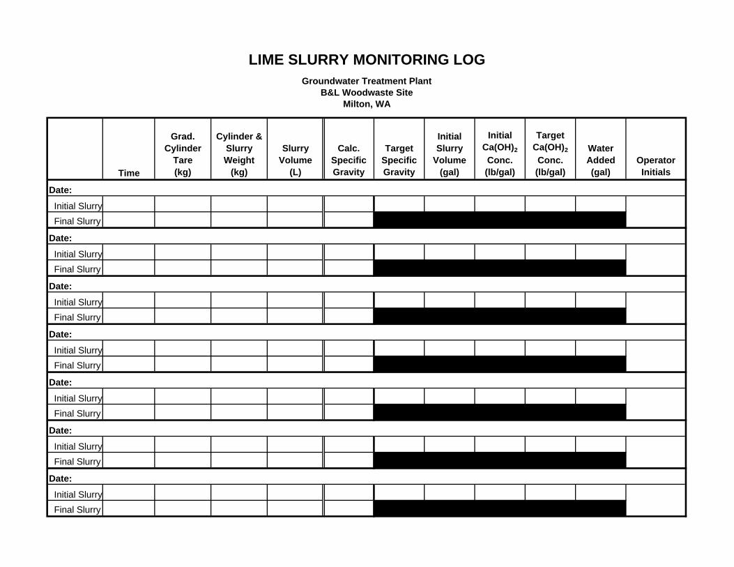
Time
Grad. Cylinder
Tare (kg)
Cylinder & Slurry Weight
(kg)
Slurry Volume
(L)
Calc. Specific Gravity
Target Specific Gravity
Initial Slurry
Volume (gal)
Initial Ca(OH)2
Conc. (lb/gal)
Target Ca(OH)2
Conc. (lb/gal)
Water Added(gal)
Operator Initials
Date:
Initial Slurry
Final Slurry
Date:
Initial Slurry
Final Slurry
Date:
Initial Slurry
Final Slurry
Date:
Initial Slurry
Final Slurry
Date:
Initial Slurry
Final Slurry
Date:
Initial Slurry
Final Slurry
Date:
Initial Slurry
Final Slurry
LIME SLURRY MONITORING LOGGroundwater Treatment Plant
B&L Woodwaste SiteMilton, WA
P-326-1
STANDARD OPERATION PROCEDURES: B&L WOODWASTE GROUNDWATER TREATMENT SYSTEM
PROCEDURE 326 – COAGULANT FEED SYSTEM B&L Woodwaste Landfill
Milton, Washington
In This Procedure Following is a list of topics in this Procedure:
Description See Page
1.0 Safety Considerations 1
2.0 Normal Operation 2
3.0 Dosing Pumps Operation and Maintenance 2
1.0 SAFETY CONSIDERATIONS Health and Safety Plan (HASP)
The HASP maintained in the treatment building provides plans and requirements to protect the health and safety of workers involved in the operation and maintenance of the groundwater extraction and treatment system. All workers must be familiar with and sign the HASP. Specific requirements for Personal Protective Equipment (PPE) are included in the HASP. If there are any discrepancies between PPE requirements included in these procedures and PPE requirements specified in the HASP, the requirements specified in the HASP shall be followed.
Level of Hazard Medium Coagulant will cause irritation if it comes in contact with skin. Caution should be maintained and proper PPE donned before working with the coagulant feed system.. There are also electrical components acting in the system which necessitate proper lockout/tagout prior to maintenance. Due to the presence of dangerous waste within the closed landfill, all personnel working at the site must be fully trained in accordance with 29 CFR 1910 and WISHA regulations. Forty-hour Hazardous Waste Operations Training with yearly eight hour refresher training is required for anyone performing work at the B&L Woodwaste Site.
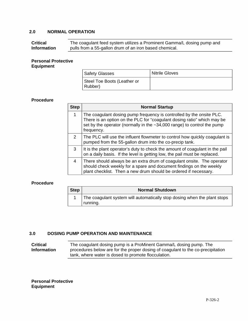
P-326-2
2.0 NORMAL OPERATION
Critical Information
The coagulant feed system utilizes a Prominent Gamma/L dosing pump and pulls from a 55-gallon drum of an iron based chemical.
Personal Protective Equipment
Safety Glasses Nitrile Gloves
Steel Toe Boots (Leather or Rubber)
Procedure
Step Normal Startup
1 The coagulant dosing pump frequency is controlled by the onsite PLC. There is an option on the PLC for “coagulant dosing ratio” which may be set by the operator (normally in the ~34,000 range) to control the pump frequency.
2 The PLC will use the influent flowmeter to control how quickly coagulant is pumped from the 55-gallon drum into the co-precip tank.
3 It is the plant operator’s duty to check the amount of coagulant in the pail on a daily basis. If the level is getting low, the pail must be replaced.
4 There should always be an extra drum of coagulant onsite. The operator should check weekly for a spare and document findings on the weekly plant checklist. Then a new drum should be ordered if necessary.
Procedure
Step Normal Shutdown
1 The coagulant system will automatically stop dosing when the plant stops running.
3.0 DOSING PUMP OPERATION AND MAINTENANCE
Critical Information
The coagulant dosing pump is a ProMinent Gamma/L dosing pump. The procedures below are for the proper dosing of coagulant to the co-precipitation tank, where water is dosed to promote flocculation.
Personal Protective Equipment
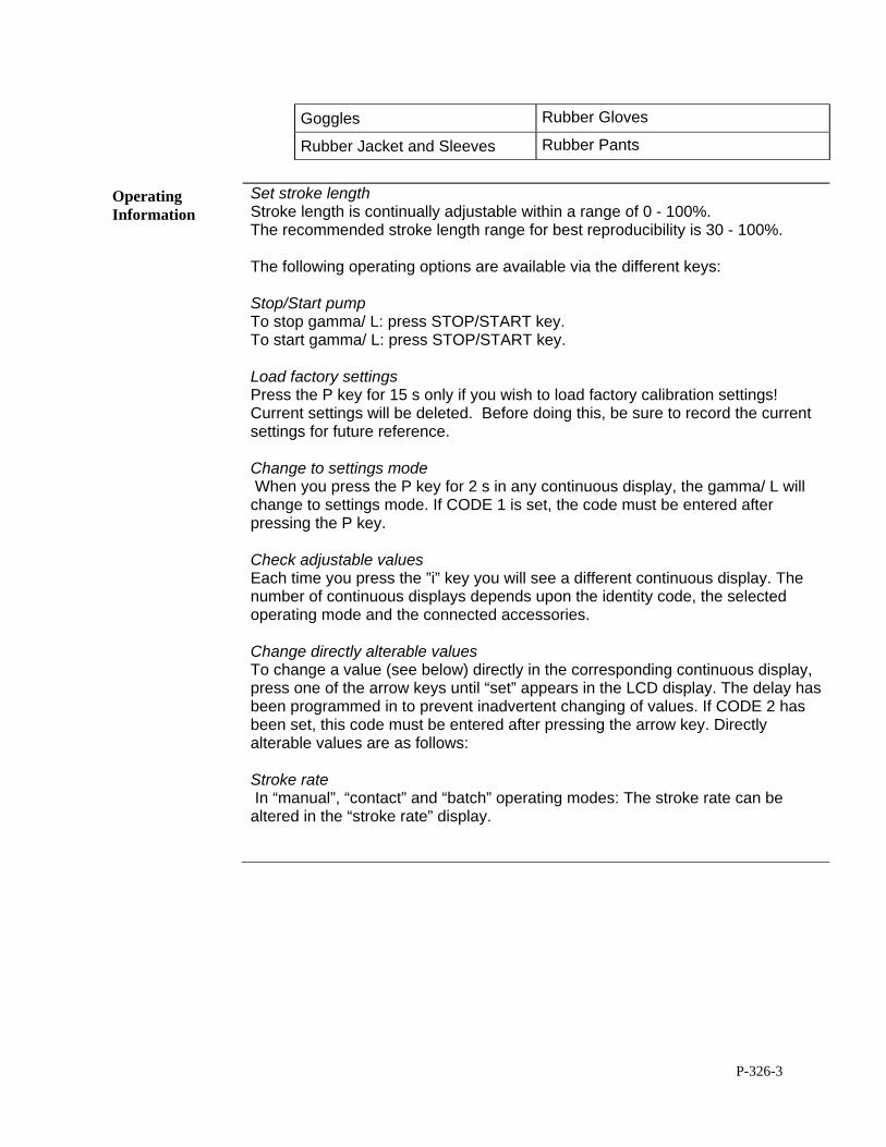
P-326-3
Goggles Rubber Gloves
Rubber Jacket and Sleeves Rubber Pants
Operating Information
Set stroke length Stroke length is continually adjustable within a range of 0 - 100%. The recommended stroke length range for best reproducibility is 30 - 100%. The following operating options are available via the different keys: Stop/Start pump To stop gamma/ L: press STOP/START key. To start gamma/ L: press STOP/START key. Load factory settings Press the P key for 15 s only if you wish to load factory calibration settings! Current settings will be deleted. Before doing this, be sure to record the current settings for future reference. Change to settings mode When you press the P key for 2 s in any continuous display, the gamma/ L will change to settings mode. If CODE 1 is set, the code must be entered after pressing the P key. Check adjustable values Each time you press the ”i” key you will see a different continuous display. The number of continuous displays depends upon the identity code, the selected operating mode and the connected accessories. Change directly alterable values To change a value (see below) directly in the corresponding continuous display, press one of the arrow keys until “set” appears in the LCD display. The delay has been programmed in to prevent inadvertent changing of values. If CODE 2 has been set, this code must be entered after pressing the arrow key. Directly alterable values are as follows: Stroke rate In “manual”, “contact” and “batch” operating modes: The stroke rate can be altered in the “stroke rate” display.
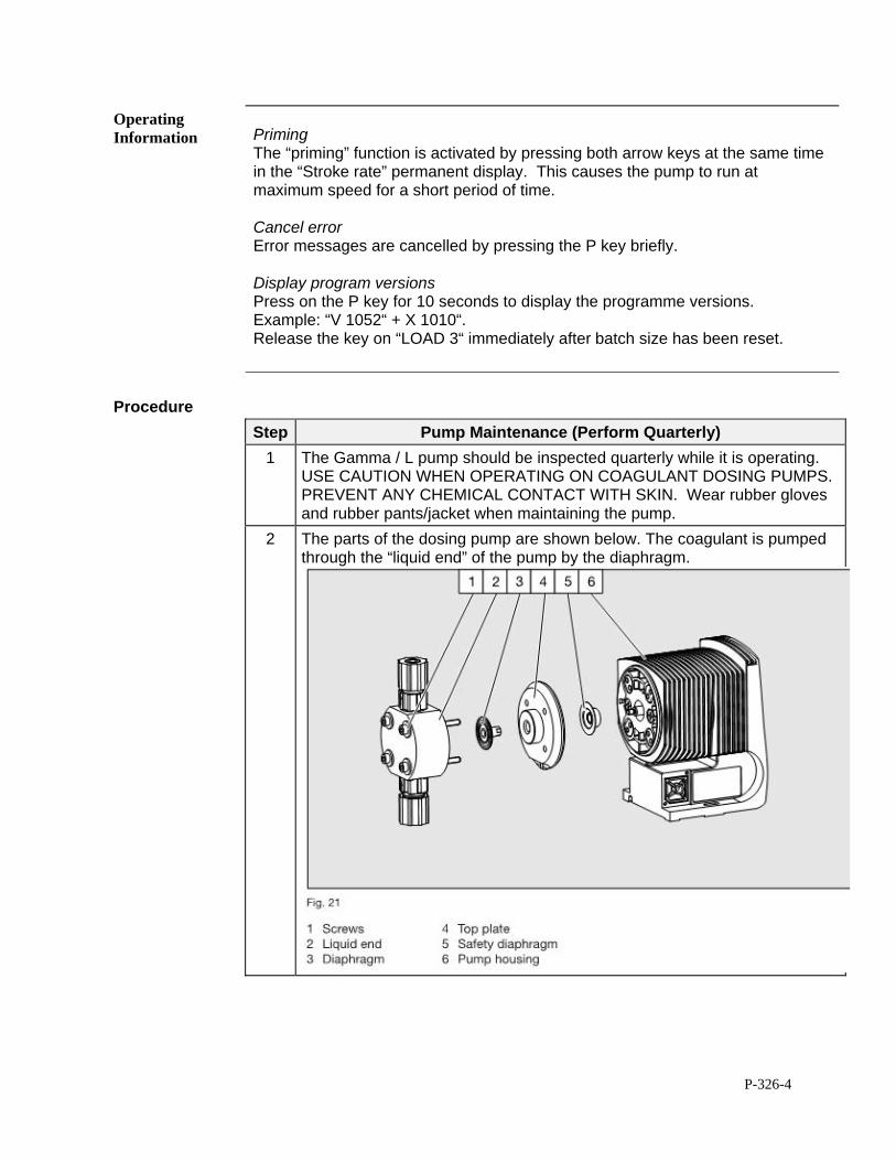
P-326-4
Operating Information
Priming The “priming” function is activated by pressing both arrow keys at the same time in the “Stroke rate” permanent display. This causes the pump to run at maximum speed for a short period of time. Cancel error Error messages are cancelled by pressing the P key briefly. Display program versions Press on the P key for 10 seconds to display the programme versions. Example: “V 1052“ + X 1010“. Release the key on “LOAD 3“ immediately after batch size has been reset.
Procedure
Step Pump Maintenance (Perform Quarterly)
1 The Gamma / L pump should be inspected quarterly while it is operating. USE CAUTION WHEN OPERATING ON COAGULANT DOSING PUMPS. PREVENT ANY CHEMICAL CONTACT WITH SKIN. Wear rubber gloves and rubber pants/jacket when maintaining the pump.
2 The parts of the dosing pump are shown below. The coagulant is pumped through the “liquid end” of the pump by the diaphragm.
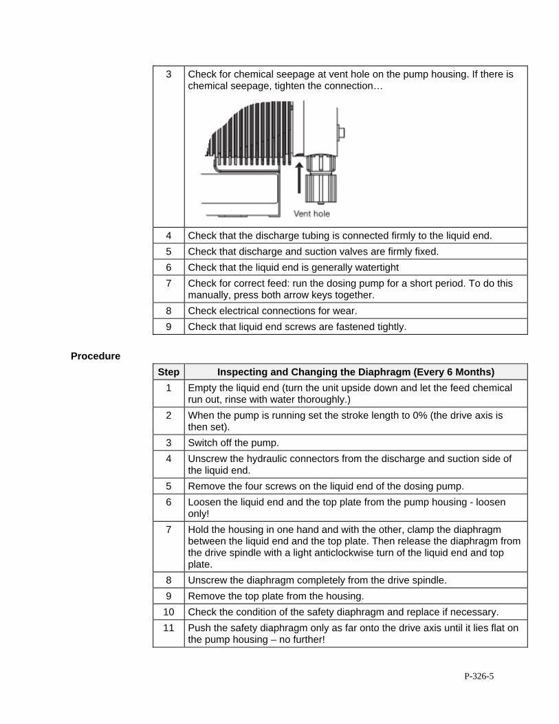
P-326-5
3 Check for chemical seepage at vent hole on the pump housing. If there is chemical seepage, tighten the connection…
4 Check that the discharge tubing is connected firmly to the liquid end.
5 Check that discharge and suction valves are firmly fixed.
6 Check that the liquid end is generally watertight
7 Check for correct feed: run the dosing pump for a short period. To do this manually, press both arrow keys together.
8 Check electrical connections for wear.
9 Check that liquid end screws are fastened tightly.
Procedure
Step Inspecting and Changing the Diaphragm (Every 6 Months)
1 Empty the liquid end (turn the unit upside down and let the feed chemical run out, rinse with water thoroughly.)
2 When the pump is running set the stroke length to 0% (the drive axis is then set).
3 Switch off the pump.
4 Unscrew the hydraulic connectors from the discharge and suction side of the liquid end.
5 Remove the four screws on the liquid end of the dosing pump.
6 Loosen the liquid end and the top plate from the pump housing - loosen only!
7 Hold the housing in one hand and with the other, clamp the diaphragm between the liquid end and the top plate. Then release the diaphragm from the drive spindle with a light anticlockwise turn of the liquid end and top plate.
8 Unscrew the diaphragm completely from the drive spindle.
9 Remove the top plate from the housing.
10 Check the condition of the safety diaphragm and replace if necessary.
11 Push the safety diaphragm only as far onto the drive axis until it lies flat on the pump housing – no further!
P-326-6
12 Screw the new diaphragm carefully up to the stop on the drive axis – this must be exact to ensure correct metering!
13 Screw the diaphragm tight once more.
14 Position the top plate on the pump housing. CAUTION - The leakage hole must point downwards when the pump is fully assembled.. Also, do not distort the top plate on the pump housing, otherwise the safety diaphragm will not fit.
15 Lay the diaphragm into the top plate.
16 Hold the top plate and screw the diaphragm in a clockwise direction until it is firmly in position (you will feel the resistance of the return spring). CAUTION - Do not overtighten the diaphragm. Also, the top plate must remain in position to prevent the safety diaphragm from distorting.
17 Place the liquid end with the screws on the diaphragm and the top plate (the priming connector must point downwards once the pump is fully assembled).
18 Screw on screws lightly and tighten
P-330-1
STANDARD OPERATION PROCEDURE: B&L WOODWASTE GROUNDWATER TREATMENT SYSTEM
P330 - POLYMER FEED SYSTEM B&L Woodwaste Landfill
Milton, Washington
OPERATION PROCEDURES, GENERAL OVERVIEW Introduction This procedure outlines operational procedures for the polymer feed system in the
groundwater treatment system at the B&L Woodwaste Site. The system includes a neat polymer holding tank; a polymer makedown skid, where the polymer is diluted and mixed with water; a day tank where the dilute solution is mixed and held until dosing to the system; and two dosing pumps that supply polymer to the flash mixing tank and the sludge tank. Proper polymer dosing promotes better floc formation.
Pre-requisites to Do This Procedure
To do this procedure you must: Be fully trained for treatment system operations or be training in the area with
someone who has been fully trained. Be fully trained for handling and management of dangerous wastes. Be familiar with all aspects of this operating procedure. Be Hazardous Waste Operations (HAZWOPER)-trained and current with
annual training updates.
In This Procedure Following is a list of topics in this Procedure:
Description See Page
1.0 Safety Considerations 2
2.0 Normal Operation 2
3.0 Makedown Skid Operation 3
4.0 Mixer Operation and Maintenance 4
5.0 Dosing Pumps Operation and Maintenance 4
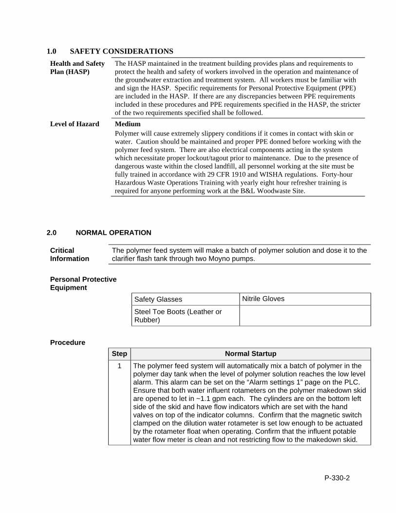
P-330-2
1.0 SAFETY CONSIDERATIONS Health and Safety Plan (HASP)
The HASP maintained in the treatment building provides plans and requirements to protect the health and safety of workers involved in the operation and maintenance of the groundwater extraction and treatment system. All workers must be familiar with and sign the HASP. Specific requirements for Personal Protective Equipment (PPE) are included in the HASP. If there are any discrepancies between PPE requirements included in these procedures and PPE requirements specified in the HASP, the stricter of the two requirements specified shall be followed.
Level of Hazard Medium Polymer will cause extremely slippery conditions if it comes in contact with skin or water. Caution should be maintained and proper PPE donned before working with the polymer feed system. There are also electrical components acting in the system which necessitate proper lockout/tagout prior to maintenance. Due to the presence of dangerous waste within the closed landfill, all personnel working at the site must be fully trained in accordance with 29 CFR 1910 and WISHA regulations. Forty-hour Hazardous Waste Operations Training with yearly eight hour refresher training is required for anyone performing work at the B&L Woodwaste Site.
2.0 NORMAL OPERATION
Critical Information
The polymer feed system will make a batch of polymer solution and dose it to the clarifier flash tank through two Moyno pumps.
Personal Protective Equipment
Safety Glasses Nitrile Gloves
Steel Toe Boots (Leather or Rubber)
Procedure
Step Normal Startup
1 The polymer feed system will automatically mix a batch of polymer in the polymer day tank when the level of polymer solution reaches the low level alarm. This alarm can be set on the “Alarm settings 1” page on the PLC. Ensure that both water influent rotameters on the polymer makedown skid are opened to let in ~1.1 gpm each. The cylinders are on the bottom left side of the skid and have flow indicators which are set with the hand valves on top of the indicator columns. Confirm that the magnetic switch clamped on the dilution water rotameter is set low enough to be actuated by the rotameter float when operating. Confirm that the influent potable water flow meter is clean and not restricting flow to the makedown skid.
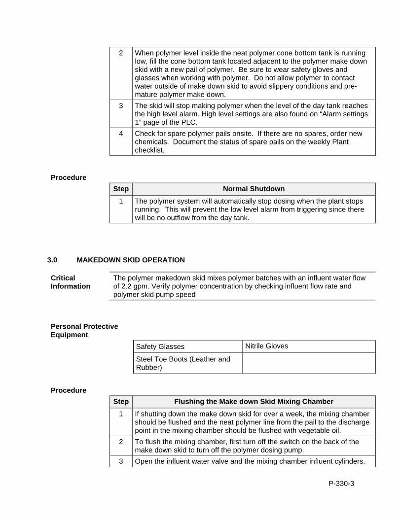
P-330-3
2 When polymer level inside the neat polymer cone bottom tank is running low, fill the cone bottom tank located adjacent to the polymer make down skid with a new pail of polymer. Be sure to wear safety gloves and glasses when working with polymer. Do not allow polymer to contact water outside of make down skid to avoid slippery conditions and pre-mature polymer make down.
3 The skid will stop making polymer when the level of the day tank reaches the high level alarm. High level settings are also found on “Alarm settings 1” page of the PLC.
4 Check for spare polymer pails onsite. If there are no spares, order new chemicals. Document the status of spare pails on the weekly Plant checklist.
Procedure
Step Normal Shutdown
1 The polymer system will automatically stop dosing when the plant stops running. This will prevent the low level alarm from triggering since there will be no outflow from the day tank.
3.0 MAKEDOWN SKID OPERATION
Critical Information
The polymer makedown skid mixes polymer batches with an influent water flow of 2.2 gpm. Verify polymer concentration by checking influent flow rate and polymer skid pump speed
Personal Protective Equipment
Safety Glasses Nitrile Gloves
Steel Toe Boots (Leather and Rubber)
Procedure
Step Flushing the Make down Skid Mixing Chamber
1 If shutting down the make down skid for over a week, the mixing chamber should be flushed and the neat polymer line from the pail to the discharge point in the mixing chamber should be flushed with vegetable oil.
2 To flush the mixing chamber, first turn off the switch on the back of the make down skid to turn off the polymer dosing pump.
3 Open the influent water valve and the mixing chamber influent cylinders.
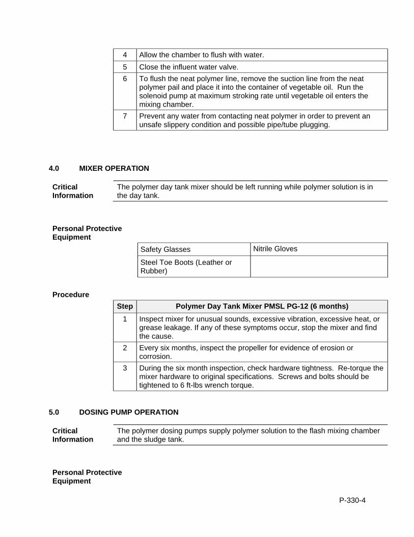
P-330-4
4 Allow the chamber to flush with water.
5 Close the influent water valve.
6 To flush the neat polymer line, remove the suction line from the neat polymer pail and place it into the container of vegetable oil. Run the solenoid pump at maximum stroking rate until vegetable oil enters the mixing chamber.
7 Prevent any water from contacting neat polymer in order to prevent an unsafe slippery condition and possible pipe/tube plugging.
4.0 MIXER OPERATION
Critical Information
The polymer day tank mixer should be left running while polymer solution is in the day tank.
Personal Protective Equipment
Safety Glasses Nitrile Gloves
Steel Toe Boots (Leather or Rubber)
Procedure
Step Polymer Day Tank Mixer PMSL PG-12 (6 months)
1 Inspect mixer for unusual sounds, excessive vibration, excessive heat, or grease leakage. If any of these symptoms occur, stop the mixer and find the cause.
2 Every six months, inspect the propeller for evidence of erosion or corrosion.
3 During the six month inspection, check hardware tightness. Re-torque the mixer hardware to original specifications. Screws and bolts should be tightened to 6 ft-lbs wrench torque.
5.0 DOSING PUMP OPERATION
Critical Information
The polymer dosing pumps supply polymer solution to the flash mixing chamber and the sludge tank.
Personal Protective Equipment
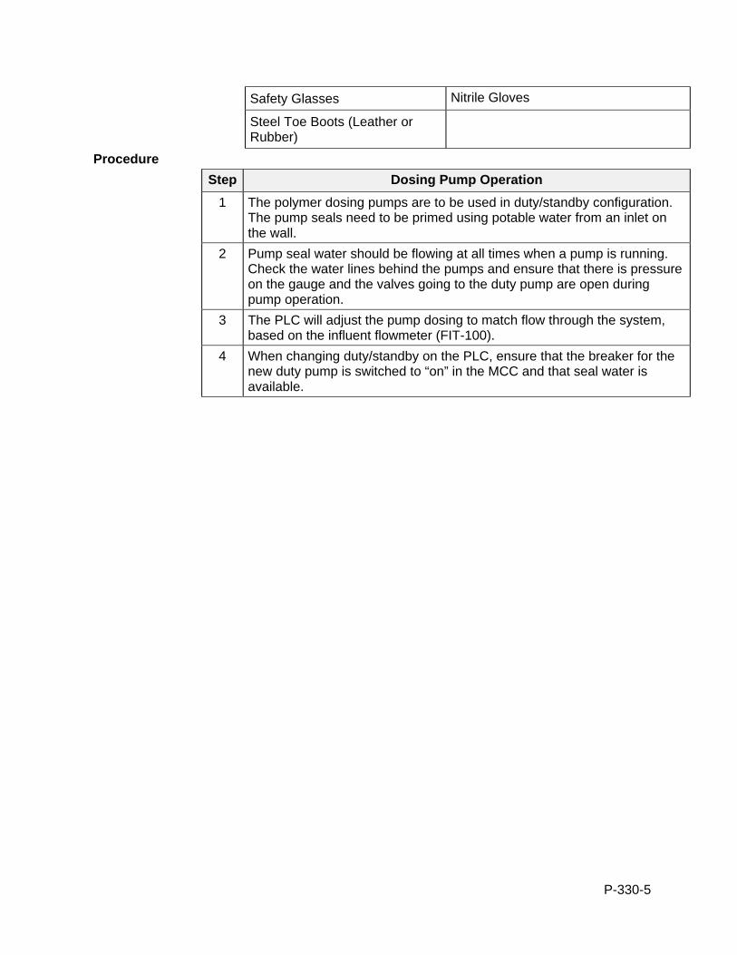
P-330-5
Safety Glasses Nitrile Gloves
Steel Toe Boots (Leather or Rubber)
Procedure
Step Dosing Pump Operation
1 The polymer dosing pumps are to be used in duty/standby configuration. The pump seals need to be primed using potable water from an inlet on the wall.
2 Pump seal water should be flowing at all times when a pump is running. Check the water lines behind the pumps and ensure that there is pressure on the gauge and the valves going to the duty pump are open during pump operation.
3 The PLC will adjust the pump dosing to match flow through the system, based on the influent flowmeter (FIT-100).
4 When changing duty/standby on the PLC, ensure that the breaker for the new duty pump is switched to “on” in the MCC and that seal water is available.
P-410-1
STANDARD OPERATION PROCEDURES: B&L WOODWASTE GROUNDWATER TREATMENT SYSTEM
PROCEDURE P410 - ACID FEED SYSTEM B&L Woodwaste Landfill
Milton, Washington
OPERATION PROCEDURES, GENERAL OVERVIEW Introduction This procedure outlines operational procedures for the acid feed system in the
groundwater treatment system at the B&L Woodwaste Site.
Pre-requisites to Do This Procedure
To do this procedure you must: Be fully trained for treatment system operations or be training in the area with
someone who has been fully trained. Be fully trained for handling and management of dangerous wastes. Be familiar with all aspects of this operating procedure. Be Hazardous Waste Operations (HAZWOPER)-trained and current with
annual training updates.
In This Procedure Following is a list of topics in this Procedure:
Description See Page
1.0 Safety Considerations 2
2.0 Acid Delivery & System Setup 3
3.0 Normal operation, startup and shutdown 4
4.0 Dosing pump operation and maintenance 5
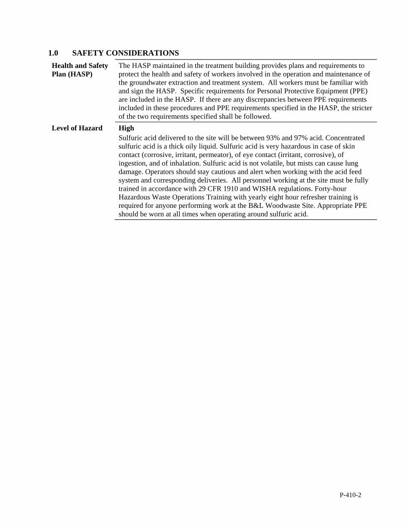
P-410-2
1.0 SAFETY CONSIDERATIONS Health and Safety Plan (HASP)
The HASP maintained in the treatment building provides plans and requirements to protect the health and safety of workers involved in the operation and maintenance of the groundwater extraction and treatment system. All workers must be familiar with and sign the HASP. Specific requirements for Personal Protective Equipment (PPE) are included in the HASP. If there are any discrepancies between PPE requirements included in these procedures and PPE requirements specified in the HASP, the stricter of the two requirements specified shall be followed.
Level of Hazard High Sulfuric acid delivered to the site will be between 93% and 97% acid. Concentrated sulfuric acid is a thick oily liquid. Sulfuric acid is very hazardous in case of skin contact (corrosive, irritant, permeator), of eye contact (irritant, corrosive), of ingestion, and of inhalation. Sulfuric acid is not volatile, but mists can cause lung damage. Operators should stay cautious and alert when working with the acid feed system and corresponding deliveries. All personnel working at the site must be fully trained in accordance with 29 CFR 1910 and WISHA regulations. Forty-hour Hazardous Waste Operations Training with yearly eight hour refresher training is required for anyone performing work at the B&L Woodwaste Site. Appropriate PPE should be worn at all times when operating around sulfuric acid.
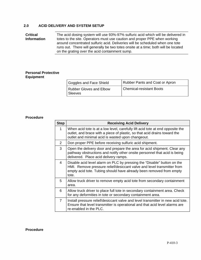
P-410-3
2.0 ACID DELIVERY AND SYSTEM SETUP
Critical Information
The acid dosing system will use 93%-97% sulfuric acid which will be delivered in totes to the site. Operators must use caution and proper PPE when working around concentrated sulfuric acid. Deliveries will be scheduled when one tote runs out. There will generally be two totes onsite at a time; both will be located on the grating over the acid containment sump.
Personal Protective Equipment
Goggles and Face Shield Rubber Pants and Coat or Apron
Rubber Gloves and Elbow Sleeves
Chemical-resistant Boots
Procedure
Step Receiving Acid Delivery
1 When acid tote is at a low level, carefully lift acid tote at end opposite the outlet, and brace with a piece of plastic, so that acid drains toward the outlet and minimal acid is wasted upon changeout.
2 Don proper PPE before receiving sulfuric acid shipment.
3 Open the delivery door and prepare the area for acid shipment. Clear any pathway obstructions and notify other onsite personnel that acid is being delivered. Place acid delivery ramps.
4 Disable acid level alarm on PLC by pressing the “Disable” button on the HMI. Remove pressure relief/desiccant valve and level transmitter from empty acid tote. Tubing should have already been removed from empty tote.
5 Allow truck driver to remove empty acid tote from secondary containment area.
6 Allow truck driver to place full tote in secondary containment area. Check for any deformities in tote or secondary containment area.
7 Install pressure relief/desiccant valve and level transmitter in new acid tote. Ensure that level transmitter is operational and that acid level alarms are re-enabled in the PLC.
Procedure
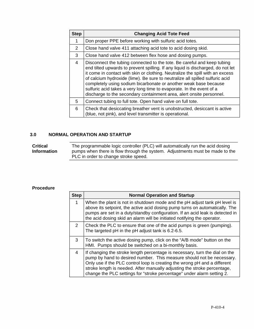
P-410-4
Step Changing Acid Tote Feed
1 Don proper PPE before working with sulfuric acid totes.
2 Close hand valve 411 attaching acid tote to acid dosing skid.
3 Close hand valve 412 between flex hose and dosing pumps.
4 Disconnect the tubing connected to the tote. Be careful and keep tubing end tilted upwards to prevent spilling. If any liquid is discharged, do not let it come in contact with skin or clothing. Neutralize the spill with an excess of calcium hydroxide (lime). Be sure to neutralize all spilled sulfuric acid completely using sodium bicarbonate or another weak base because sulfuric acid takes a very long time to evaporate. In the event of a discharge to the secondary containment area, alert onsite personnel.
5 Connect tubing to full tote. Open hand valve on full tote.
6 Check that desiccating breather vent is unobstructed, desiccant is active (blue, not pink), and level transmitter is operational.
3.0 NORMAL OPERATION AND STARTUP
Critical Information
The programmable logic controller (PLC) will automatically run the acid dosing pumps when there is flow through the system. Adjustments must be made to the PLC in order to change stroke speed.
Procedure
Step Normal Operation and Startup
1 When the plant is not in shutdown mode and the pH adjust tank pH level is above its setpoint, the active acid dosing pump turns on automatically. The pumps are set in a duty/standby configuration. If an acid leak is detected in the acid dosing skid an alarm will be initiated notifying the operator.
2 Check the PLC to ensure that one of the acid pumps is green (pumping). The targeted pH in the pH adjust tank is 6.2-6.5.
3 To switch the active dosing pump, click on the “A/B mode” button on the HMI. Pumps should be switched on a bi-monthly basis.
4 If changing the stroke length percentage is necessary, turn the dial on the pump by hand to desired number. This measure should not be necessary. Only use if the PLC control loop is creating the wrong pH and a different stroke length is needed. After manually adjusting the stroke percentage, change the PLC settings for “stroke percentage” under alarm setting 2.
P-410-5
4.0 DOSING PUMP OPERATION AND MAINTENANCE
Critical Information
The acid dosing pump is a ProMinent Gamma/L dosing pump. The procedures below are for the proper dosing of sulfuric acid to the pH adjust tank, where water is acidified to an acceptable pH range prior to the adsorbers. Operations include dosage adjustment and preventative maintenance on the dosing pump.
Personal Protective Equipment
Face Shield and Goggles Rubber Gloves
Rubber Jacket and Elbow Sleeves
Rubber Pants and Chemical Resistant Boots
P-410-6
Operating Information
Set stroke length Stroke length is continually adjustable within a range of 0 - 100%. The recommended stroke length range for best reproducibility is 30 - 100%. The following operating options are available via the different keys: Stop/Start pump To stop gamma/ L: press STOP/START key. To start gamma/ L: press STOP/START key. Load factory settings Press the P key for 15 s only if you wish to load factory calibration settings! Current settings will be deleted. Before doing this, be sure to record the current settings for future reference. Change to settings mode When you press the P key for 2 s in any continuous display, the gamma/ L will change to settings mode. If CODE 1 is set, the code must be entered after pressing the P key. Check adjustable values Each time you press the ”i” key you will see a different continuous display. The number of continuous displays depends upon the identity code, the selected operating mode and the connected accessories. Change directly alterable values To change a value (see below) directly in the corresponding continuous display, press one of the arrow keys until “set” appears in the LCD display. The delay has been programmed in to prevent inadvertent changing of values. If CODE 2 has been set, this code must be entered after pressing the arrow key. Directly alterable values are as follows: Stroke rate In “manual”, “contact” and “batch” operating modes: The stroke rate can be altered in the “stroke rate” display.
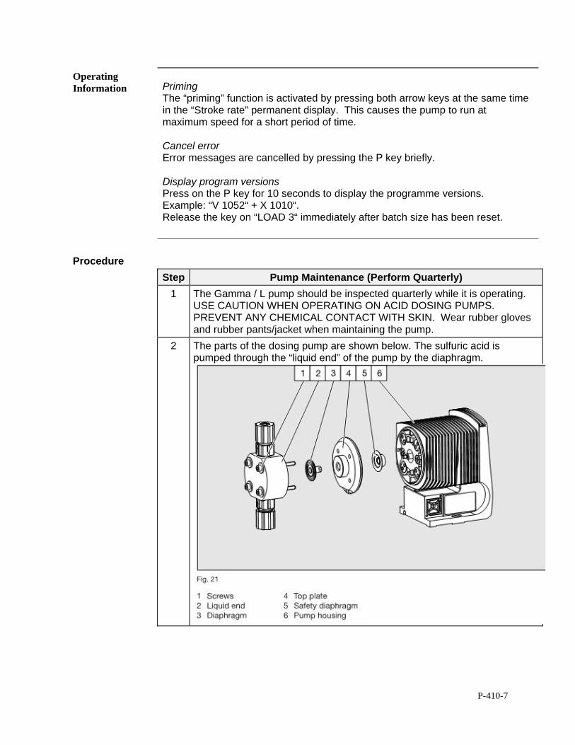
P-410-7
Operating Information
Priming The “priming” function is activated by pressing both arrow keys at the same time in the “Stroke rate” permanent display. This causes the pump to run at maximum speed for a short period of time. Cancel error Error messages are cancelled by pressing the P key briefly. Display program versions Press on the P key for 10 seconds to display the programme versions. Example: “V 1052“ + X 1010“. Release the key on “LOAD 3“ immediately after batch size has been reset.
Procedure
Step Pump Maintenance (Perform Quarterly)
1 The Gamma / L pump should be inspected quarterly while it is operating. USE CAUTION WHEN OPERATING ON ACID DOSING PUMPS. PREVENT ANY CHEMICAL CONTACT WITH SKIN. Wear rubber gloves and rubber pants/jacket when maintaining the pump.
2 The parts of the dosing pump are shown below. The sulfuric acid is pumped through the “liquid end” of the pump by the diaphragm.
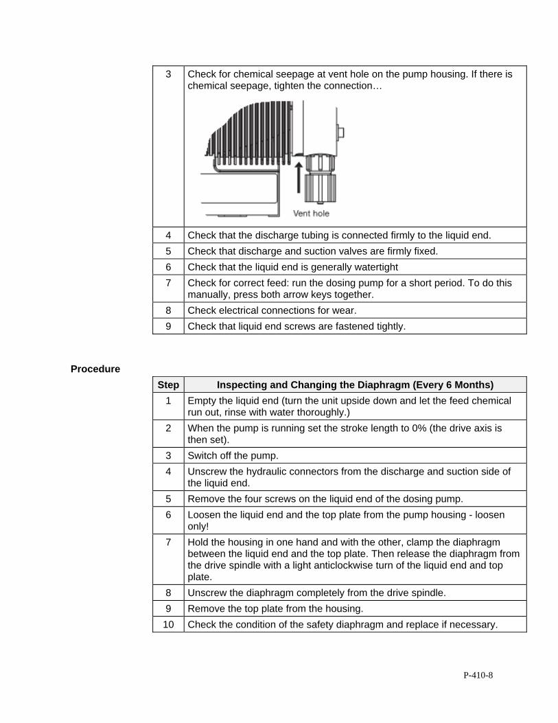
P-410-8
3 Check for chemical seepage at vent hole on the pump housing. If there is chemical seepage, tighten the connection…
4 Check that the discharge tubing is connected firmly to the liquid end.
5 Check that discharge and suction valves are firmly fixed.
6 Check that the liquid end is generally watertight
7 Check for correct feed: run the dosing pump for a short period. To do this manually, press both arrow keys together.
8 Check electrical connections for wear.
9 Check that liquid end screws are fastened tightly.
Procedure
Step Inspecting and Changing the Diaphragm (Every 6 Months)
1 Empty the liquid end (turn the unit upside down and let the feed chemical run out, rinse with water thoroughly.)
2 When the pump is running set the stroke length to 0% (the drive axis is then set).
3 Switch off the pump.
4 Unscrew the hydraulic connectors from the discharge and suction side of the liquid end.
5 Remove the four screws on the liquid end of the dosing pump.
6 Loosen the liquid end and the top plate from the pump housing - loosen only!
7 Hold the housing in one hand and with the other, clamp the diaphragm between the liquid end and the top plate. Then release the diaphragm from the drive spindle with a light anticlockwise turn of the liquid end and top plate.
8 Unscrew the diaphragm completely from the drive spindle.
9 Remove the top plate from the housing.
10 Check the condition of the safety diaphragm and replace if necessary.
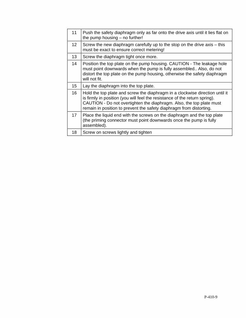
P-410-9
11 Push the safety diaphragm only as far onto the drive axis until it lies flat on the pump housing – no further!
12 Screw the new diaphragm carefully up to the stop on the drive axis – this must be exact to ensure correct metering!
13 Screw the diaphragm tight once more.
14 Position the top plate on the pump housing. CAUTION - The leakage hole must point downwards when the pump is fully assembled.. Also, do not distort the top plate on the pump housing, otherwise the safety diaphragm will not fit.
15 Lay the diaphragm into the top plate.
16 Hold the top plate and screw the diaphragm in a clockwise direction until it is firmly in position (you will feel the resistance of the return spring). CAUTION - Do not overtighten the diaphragm. Also, the top plate must remain in position to prevent the safety diaphragm from distorting.
17 Place the liquid end with the screws on the diaphragm and the top plate (the priming connector must point downwards once the pump is fully assembled).
18 Screw on screws lightly and tighten
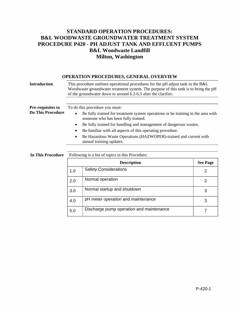
P-420-1
STANDARD OPERATION PROCEDURES: B&L WOODWASTE GROUNDWATER TREATMENT SYSTEM
PROCEDURE P420 - PH ADJUST TANK AND EFFLUENT PUMPS B&L Woodwaste Landfill
Milton, Washington
OPERATION PROCEDURES, GENERAL OVERVIEW Introduction This procedure outlines operational procedures for the pH adjust tank in the B&L
Woodwaste groundwater treatment system. The purpose of this tank is to bring the pH of the groundwater down to around 6.2-6.5 after the clarifier.
Pre-requisites to Do This Procedure
To do this procedure you must: Be fully trained for treatment system operations or be training in the area with
someone who has been fully trained. Be fully trained for handling and management of dangerous wastes. Be familiar with all aspects of this operating procedure. Be Hazardous Waste Operations (HAZWOPER)-trained and current with
annual training updates.
In This Procedure Following is a list of topics in this Procedure:
Description See Page
1.0 Safety Considerations 2
2.0 Normal operation 2
3.0 Normal startup and shutdown 3
4.0 pH meter operation and maintenance 3
5.0 Discharge pump operation and maintenance 7
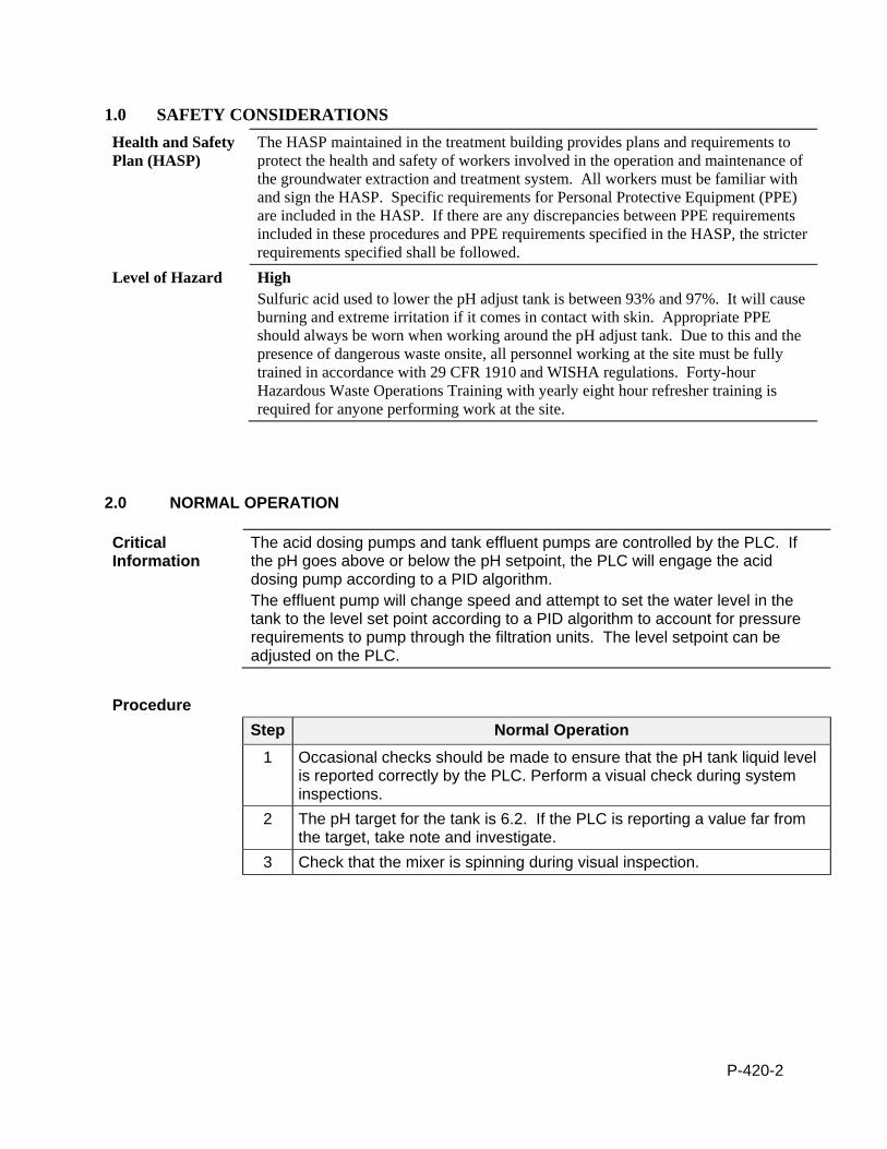
P-420-2
1.0 SAFETY CONSIDERATIONS Health and Safety Plan (HASP)
The HASP maintained in the treatment building provides plans and requirements to protect the health and safety of workers involved in the operation and maintenance of the groundwater extraction and treatment system. All workers must be familiar with and sign the HASP. Specific requirements for Personal Protective Equipment (PPE) are included in the HASP. If there are any discrepancies between PPE requirements included in these procedures and PPE requirements specified in the HASP, the stricter requirements specified shall be followed.
Level of Hazard High Sulfuric acid used to lower the pH adjust tank is between 93% and 97%. It will cause burning and extreme irritation if it comes in contact with skin. Appropriate PPE should always be worn when working around the pH adjust tank. Due to this and the presence of dangerous waste onsite, all personnel working at the site must be fully trained in accordance with 29 CFR 1910 and WISHA regulations. Forty-hour Hazardous Waste Operations Training with yearly eight hour refresher training is required for anyone performing work at the site.
2.0 NORMAL OPERATION
Critical Information
The acid dosing pumps and tank effluent pumps are controlled by the PLC. If the pH goes above or below the pH setpoint, the PLC will engage the acid dosing pump according to a PID algorithm. The effluent pump will change speed and attempt to set the water level in the tank to the level set point according to a PID algorithm to account for pressure requirements to pump through the filtration units. The level setpoint can be adjusted on the PLC.
Procedure
Step Normal Operation
1 Occasional checks should be made to ensure that the pH tank liquid level is reported correctly by the PLC. Perform a visual check during system inspections.
2 The pH target for the tank is 6.2. If the PLC is reporting a value far from the target, take note and investigate.
3 Check that the mixer is spinning during visual inspection.
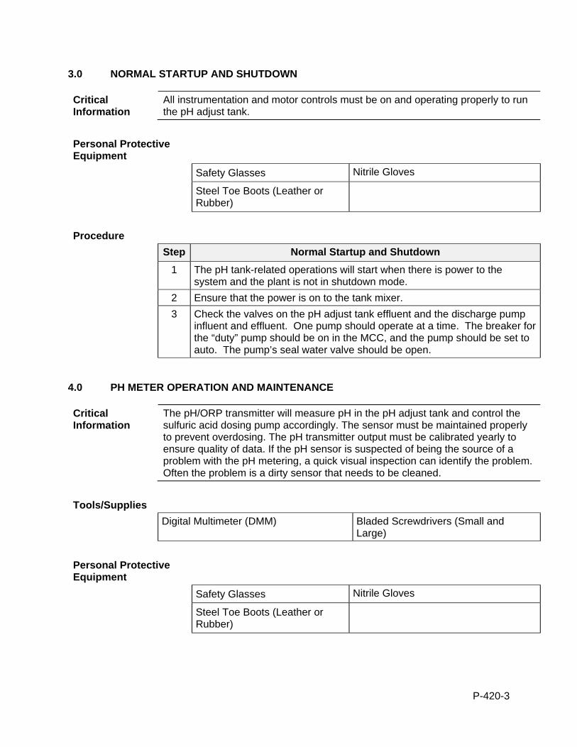
P-420-3
3.0 NORMAL STARTUP AND SHUTDOWN
Critical Information
All instrumentation and motor controls must be on and operating properly to run the pH adjust tank.
Personal Protective Equipment
Safety Glasses Nitrile Gloves
Steel Toe Boots (Leather or Rubber)
Procedure
Step Normal Startup and Shutdown
1 The pH tank-related operations will start when there is power to the system and the plant is not in shutdown mode.
2 Ensure that the power is on to the tank mixer.
3 Check the valves on the pH adjust tank effluent and the discharge pump influent and effluent. One pump should operate at a time. The breaker for the “duty” pump should be on in the MCC, and the pump should be set to auto. The pump’s seal water valve should be open.
4.0 PH METER OPERATION AND MAINTENANCE
Critical Information
The pH/ORP transmitter will measure pH in the pH adjust tank and control the sulfuric acid dosing pump accordingly. The sensor must be maintained properly to prevent overdosing. The pH transmitter output must be calibrated yearly to ensure quality of data. If the pH sensor is suspected of being the source of a problem with the pH metering, a quick visual inspection can identify the problem. Often the problem is a dirty sensor that needs to be cleaned.
Tools/Supplies
Digital Multimeter (DMM) Bladed Screwdrivers (Small and Large)
Personal Protective Equipment
Safety Glasses Nitrile Gloves
Steel Toe Boots (Leather or Rubber)
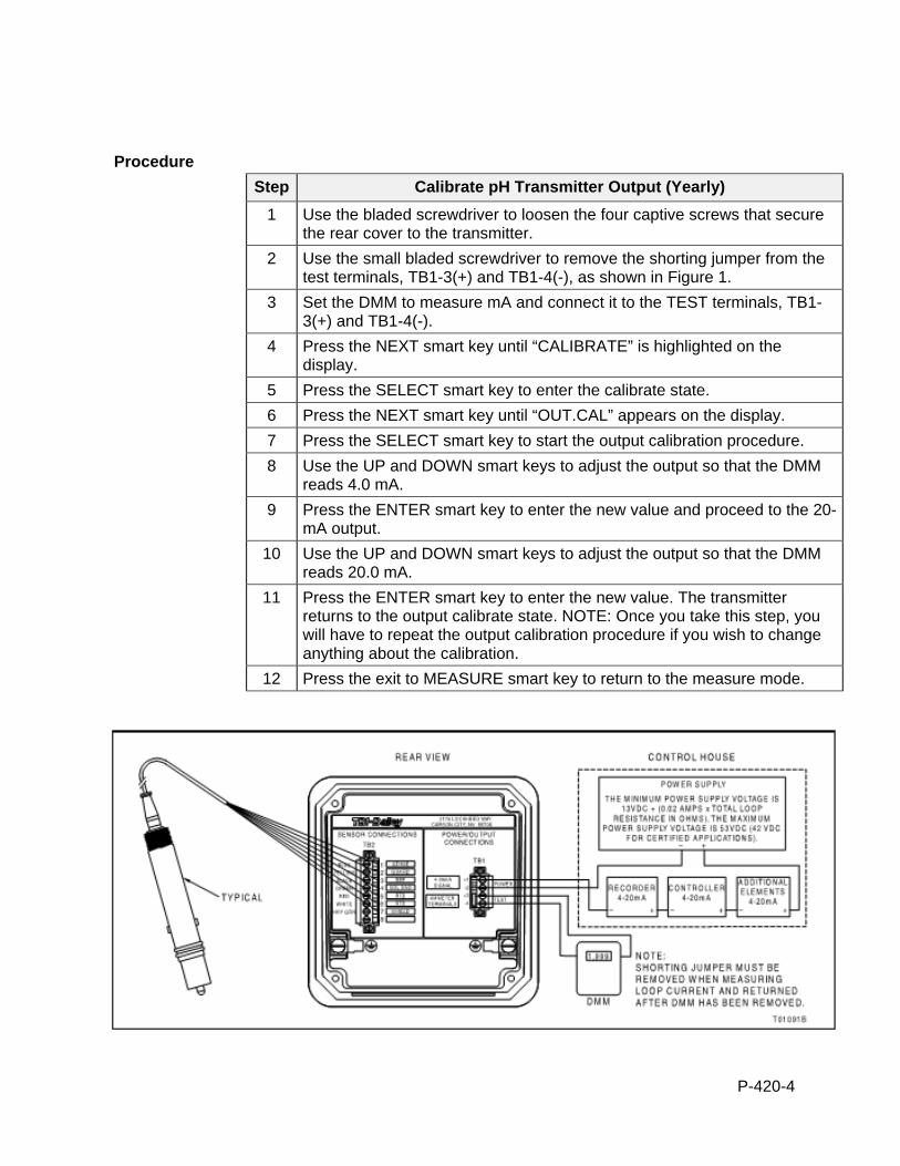
P-420-4
Procedure
Step Calibrate pH Transmitter Output (Yearly)
1 Use the bladed screwdriver to loosen the four captive screws that secure the rear cover to the transmitter.
2 Use the small bladed screwdriver to remove the shorting jumper from the test terminals, TB1-3(+) and TB1-4(-), as shown in Figure 1.
3 Set the DMM to measure mA and connect it to the TEST terminals, TB1-3(+) and TB1-4(-).
4 Press the NEXT smart key until “CALIBRATE” is highlighted on the display.
5 Press the SELECT smart key to enter the calibrate state.
6 Press the NEXT smart key until “OUT.CAL” appears on the display.
7 Press the SELECT smart key to start the output calibration procedure.
8 Use the UP and DOWN smart keys to adjust the output so that the DMM reads 4.0 mA.
9 Press the ENTER smart key to enter the new value and proceed to the 20-mA output.
10 Use the UP and DOWN smart keys to adjust the output so that the DMM reads 20.0 mA.
11 Press the ENTER smart key to enter the new value. The transmitter returns to the output calibrate state. NOTE: Once you take this step, you will have to repeat the output calibration procedure if you wish to change anything about the calibration.
12 Press the exit to MEASURE smart key to return to the measure mode.
P-420-5
Figure 1. Location of shorting jumper.
Tools/Supplies
Clean Cloth DI
Soft Bristle Toothbrush
Procedure
Step Sensor Cleaning (After Inspection)
1 Physical Cleaning: -Physical cleaning will remove scale and other accumulations. When mechanically cleaning the sensor, always use a soft bristle brush in order to avoid damaging the insulative coating on the solution ground (the metallic collar around the measuring electrode). This coating is only present on the outer diameter next to the reference junction and must be intact for the reference diagnostics to function properly.
2 Use a tooth brush with DI to gently clean the sensor. Take extreme caution when cleaning the glass pH electrode to prevent glass breakage.
Tools/Supplies
Temperature Measuring Device Low and High pH Standard Solutions
Procedure
Step pH Sensor Calibration (Weekly) & Reconditioning (Monthly)
1 Prepare the pH 7.00 and 10.01 standard solutions.
2 Remove the sensor from the process by gently pulling up on the sensor cable straight up the pipe surrounding the sensor. During weekly calibration, clean the pH sensor as outlined in the cleaning steps above.
3 Press the NEXT smart key until CALIBRATE is highlighted on the display.
4 Press the SELECT smart key to enter the calibrate state.
5 Press the NEXT smart key until 2PT.CAL appears on the display.
6 Press the SELECT smart key to start the two-point calibration procedure.
7 The transmitter displays the current temperature in degrees Celsius and TMP°C. Use the temperature measuring device to measure the temperature of the pH standard and enter that number into the transmitter.
8 The transmitter asks for the LO VAL. Enter the value of the low pH standard solution as labeled on the standard solution container.
9 Place the sensor in the low standard solution.
10 Stir the solution with the sensor in a slow, circular motion for 30 seconds. Allow the sensor to stabilize for approximately 5 minutes in the standard solution.
P-420-6
11 The transmitter should now display STABL?. Observe the displayed reading. If it is stable, press the YES smart key. If it is not stable, press the NO smart key. If NO is selected, the transmitter returns to the process sensor calibration state. If the reading will not stabilize, perform steps 12 through 13 below. If YES is selected, skip ahead to Step 14.
12 Wait until the process liquid composition stabilizes.
13 Check to see if the transmitter has detected a fault condition by looking for the FAULT icon on the display. Interrogate the fault by navigating to the measure mode through the EXIT TO MEASURE smart key and then by pressing the FAULT info smart key.
14 The transmitter asks for the HI VAL. Enter the value of the high buffer or standard.
15 Remove the sensor from the low buffer or standard solution.
16 Rinse the sensor with de-ionized water.
17 Place the sensor in the high standard solution.
18 Stir the solution with the sensor in a slow, circular motion.
19 The transmitter should now display STABL?. Observe the displayed reading. If it is stable, press the YES smart key. If it is not stable, press the NO smart key. If NO is selected, the transmitter returns to the process sensor calibration state. If the reading will not stabilize, perform steps 12 through 13 above. If YES is selected, go on to Step 20 below.
20 If the entered calibration value is not valid, the transmitter displays BAD.CAL, and the calibration value is rejected. If the entered calibration value is valid, the slope (sensor efficiency) appears on the display. Press the NEXT smart key to display the offset.
23 Press the NEXT smart key to return to the process sensor calibrate state or press the exit to MEASURE smart key to go to the measure mode. Document calibration and measured values in the B&L Woodwaste Weekly and Monthly Plant Checklist (Attachment P-001). Follow record keeping procedures for filled out checklists and probe logs.
24 If the slope as indicated on the transmitter falls below 80% or the offset exceeds +/- 150 mV, recondition the probe by placing in the acid/pepsin solution for an hour and then in the storage solution for 12 hrs. If the calibration parameters are still outside of the accepted range, the probe needs to be replaced.
25 Once a month the pH probe will need to be reconditioned and will be replaced with the standbye pH probe.
26 Clean the pH sensor being pulled out of the process as outlined in the cleaning steps above. Place the pH sensor in the acid/pepsin cleaning solution for 60 minutes.
27 Remove the standbye probe from the storage solution and follow the calibration procedures outline above.
28 Remove the probe from the acid/pepsin solution from step 26 and place the probe in the storage solution.
P-420-7
5.0 DISCHARGE PUMP OPERATION AND MAINTENANCE
Personal Protective Equipment
Safety Glasses Nitrile Gloves
Steel Toe Boots (Leather or Rubber)
Procedure
Step Normal Operation
1 The discharge pumps will start when the tank liquid level is above its set value, which can be changed on the PLC. Simply enter a different level in the box next to the pH adjust tank and press enter.
2 The effluent pumps are in duty/standby mode. When the PLC reads “A Mode,” only pump A will operate. Switch to B mode when pump A needs to rest. This should be done bimonthly or during individual pump maintenance.
3 The pumps will shut off when the water level in the pH adjust tank reaches the “low” level. This setting is found under alarm settings 1 on the PLC.
4 Ensure seal water is on when pump is running. Seal water line can be seen on wall behind effluent pumps and should have pressure on the gauge when water is flowing to pump seal.
Procedure
Step Changing Oil
1 The bearing oil should be replaced every 2000 operating hours or every 3 months. Lock out the pump by closing influent and effluent ball valves and turning the circuit breaker in the MCC room to “OFF.” Place a lockout/tagout padlock on the breaker.
2 Remove the fill plug located on top of the bearing casing,
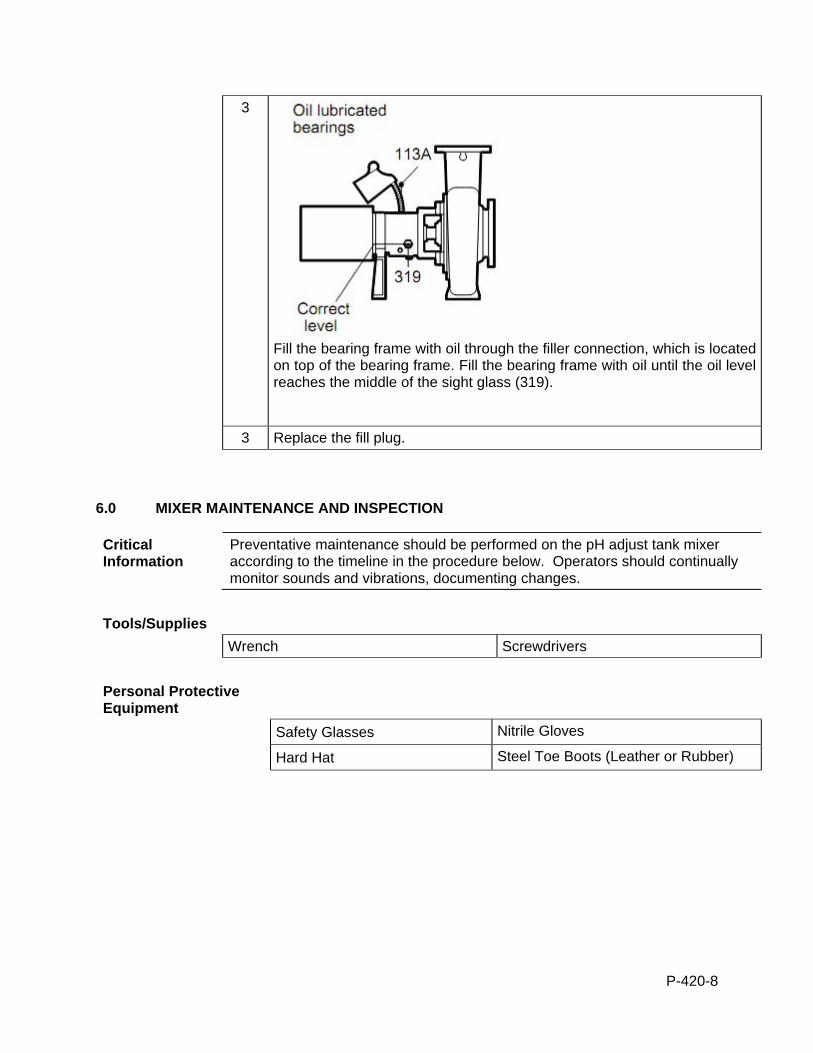
P-420-8
3
Fill the bearing frame with oil through the filler connection, which is located on top of the bearing frame. Fill the bearing frame with oil until the oil level reaches the middle of the sight glass (319).
3 Replace the fill plug.
6.0 MIXER MAINTENANCE AND INSPECTION
Critical Information
Preventative maintenance should be performed on the pH adjust tank mixer according to the timeline in the procedure below. Operators should continually monitor sounds and vibrations, documenting changes.
Tools/Supplies
Wrench Screwdrivers
Personal Protective Equipment
Safety Glasses Nitrile Gloves
Hard Hat Steel Toe Boots (Leather or Rubber)
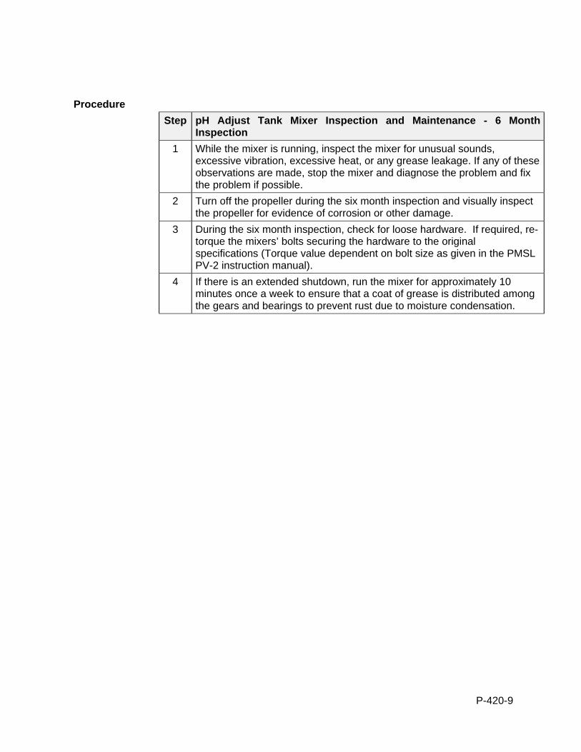
P-420-9
Procedure
Step pH Adjust Tank Mixer Inspection and Maintenance - 6 Month Inspection
1 While the mixer is running, inspect the mixer for unusual sounds, excessive vibration, excessive heat, or any grease leakage. If any of these observations are made, stop the mixer and diagnose the problem and fix the problem if possible.
2 Turn off the propeller during the six month inspection and visually inspect the propeller for evidence of corrosion or other damage.
3 During the six month inspection, check for loose hardware. If required, re-torque the mixers’ bolts securing the hardware to the original specifications (Torque value dependent on bolt size as given in the PMSL PV-2 instruction manual).
4 If there is an extended shutdown, run the mixer for approximately 10 minutes once a week to ensure that a coat of grease is distributed among the gears and bearings to prevent rust due to moisture condensation.

P-425-1
STANDARD OPERATION PROCEDURES: B&L WOODWASTE GROUNDWATER TREATMENT SYSTEM
PROCEDURE P425 - BAG FILTER SYSTEM B&L Woodwaste Landfill
Milton, Washington
OPERATION PROCEDURES, GENERAL OVERVIEW Introduction This procedure outlines operational procedures for the bag filters in the B&L
Woodwaste groundwater treatment system. The bag filters are used to separate additional suspended solids material from the wastewater before the cartridge filtration step and the final arsenic adsorption column step.
Pre-requisites to Do This Procedure
To do this procedure you must: Be fully trained for treatment system operations or be training in the area with
someone who has been fully trained. Be fully trained for handling and management of dangerous wastes. Be familiar with all aspects of this operating procedure. Be Hazardous Waste Operations (HAZWOPER)-trained and current with
annual training updates.
In This Procedure Following is a list of topics in this Procedure:
Description See Page
1.0 Safety Considerations 1
2.0 Normal Operation 2
3.0 Operation and Maintenance 3
1.0 SAFETY CONSIDERATIONS
Health and Safety Plan (HASP)
The most recent version of the HASP is maintained in the treatment building office and provides plans and requirements to protect the health and safety of workers involved in the operation and maintenance of the groundwater extraction and treatment system. All workers must be familiar with and sign the HASP. Specific requirements for Personal Protective Equipment (PPE) are included in the HASP. If there are any discrepancies between PPE requirements included in these procedures and PPE requirements specified in the HASP, the stricter requirements specified shall be followed.
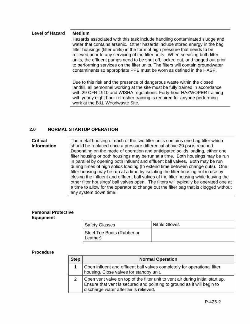
P-425-2
Level of Hazard Medium Hazards associated with this task include handling contaminated sludge and water that contains arsenic. Other hazards include stored energy in the bag filter housings (filter units) in the form of high pressure that needs to be relieved prior to any servicing of the filter units. When servicing both filter units, the effluent pumps need to be shut off, locked out, and tagged out prior to performing services on the filter units. The filters will contain groundwater contaminants so appropriate PPE must be worn as defined in the HASP. Due to this risk and the presence of dangerous waste within the closed landfill, all personnel working at the site must be fully trained in accordance with 29 CFR 1910 and WISHA regulations. Forty-hour HAZWOPER training with yearly eight hour refresher training is required for anyone performing work at the B&L Woodwaste Site.
2.0 NORMAL STARTUP OPERATION
Critical Information
The metal housing of each of the two filter units contains one bag filter which should be replaced once a pressure differential above 20 psi is reached. Depending on the mode of operation and anticipated solids loading, either one filter housing or both housings may be run at a time. Both housings may be run in parallel by opening both influent and effluent ball valves. Both may be run during times of high solids loading (to extend time between change outs). One filter housing may be run at a time by isolating the filter housing not in use by closing the influent and effluent ball valves of the filter housing while leaving the other filter housings’ ball valves open. The filters will typically be operated one at a time to allow for the operator to change out the filter bag that is clogged without any system down time.
Personal Protective Equipment
Safety Glasses Nitrile Gloves
Steel Toe Boots (Rubber or Leather)
Procedure
Step Normal Operation
1 Open influent and effluent ball valves completely for operational filter housing. Close valves for standby unit.
2 Open vent valve on top of the filter unit to vent air during initial start up. Ensure that vent is secured and pointing to ground as it will begin to discharge water after air is relieved.
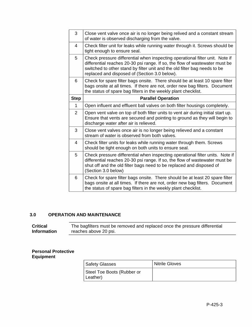
P-425-3
3 Close vent valve once air is no longer being relived and a constant stream of water is observed discharging from the valve.
4 Check filter unit for leaks while running water through it. Screws should be tight enough to ensure seal.
5 Check pressure differential when inspecting operational filter unit. Note if differential reaches 20-30 psi range. If so, the flow of wastewater must be switched to other stand by filter unit and the old filter bag needs to be replaced and disposed of (Section 3.0 below).
6 Check for spare filter bags onsite. There should be at least 10 spare filter bags onsite at all times. If there are not, order new bag filters. Document the status of spare bag filters in the weekly plant checklist.
Step Parallel Operation
1 Open influent and effluent ball valves on both filter housings completely.
2 Open vent valve on top of both filter units to vent air during initial start up. Ensure that vents are secured and pointing to ground as they will begin to discharge water after air is relieved.
3 Close vent valves once air is no longer being relieved and a constant stream of water is observed from both valves.
4 Check filter units for leaks while running water through them. Screws should be tight enough on both units to ensure seal.
5 Check pressure differential when inspecting operational filter units. Note if differential reaches 20-30 psi range. If so, the flow of wastewater must be shut off and the old filter bags need to be replaced and disposed of (Section 3.0 below)
6 Check for spare filter bags onsite. There should be at least 20 spare filter bags onsite at all times. If there are not, order new bag filters. Document the status of spare bag filters in the weekly plant checklist.
3.0 OPERATION AND MAINTENANCE
Critical Information
The bagfilters must be removed and replaced once the pressure differential reaches above 20 psi.
Personal Protective Equipment
Safety Glasses Nitrile Gloves
Steel Toe Boots (Rubber or Leather)
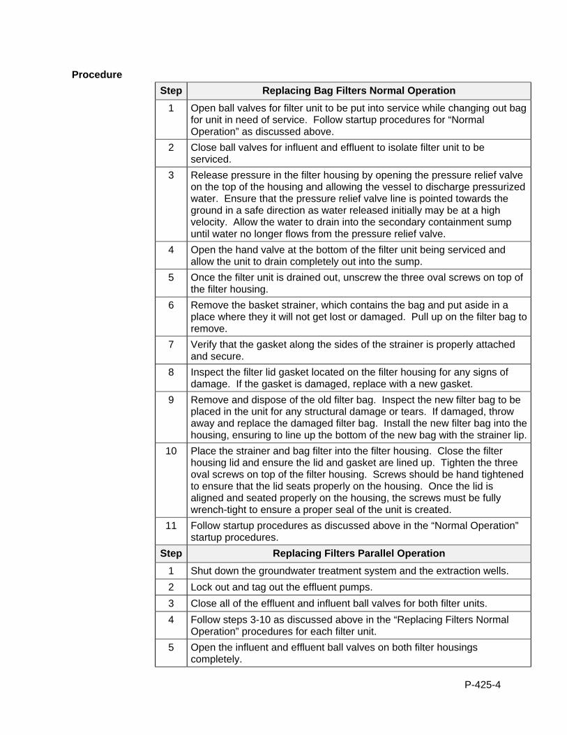
P-425-4
Procedure
Step Replacing Bag Filters Normal Operation
1 Open ball valves for filter unit to be put into service while changing out bag for unit in need of service. Follow startup procedures for “Normal Operation” as discussed above.
2 Close ball valves for influent and effluent to isolate filter unit to be serviced.
3 Release pressure in the filter housing by opening the pressure relief valve on the top of the housing and allowing the vessel to discharge pressurized water. Ensure that the pressure relief valve line is pointed towards the ground in a safe direction as water released initially may be at a high velocity. Allow the water to drain into the secondary containment sump until water no longer flows from the pressure relief valve.
4 Open the hand valve at the bottom of the filter unit being serviced and allow the unit to drain completely out into the sump.
5 Once the filter unit is drained out, unscrew the three oval screws on top of the filter housing.
6 Remove the basket strainer, which contains the bag and put aside in a place where they it will not get lost or damaged. Pull up on the filter bag to remove.
7 Verify that the gasket along the sides of the strainer is properly attached and secure.
8 Inspect the filter lid gasket located on the filter housing for any signs of damage. If the gasket is damaged, replace with a new gasket.
9 Remove and dispose of the old filter bag. Inspect the new filter bag to be placed in the unit for any structural damage or tears. If damaged, throw away and replace the damaged filter bag. Install the new filter bag into the housing, ensuring to line up the bottom of the new bag with the strainer lip.
10 Place the strainer and bag filter into the filter housing. Close the filter housing lid and ensure the lid and gasket are lined up. Tighten the three oval screws on top of the filter housing. Screws should be hand tightened to ensure that the lid seats properly on the housing. Once the lid is aligned and seated properly on the housing, the screws must be fully wrench-tight to ensure a proper seal of the unit is created.
11 Follow startup procedures as discussed above in the “Normal Operation” startup procedures.
Step Replacing Filters Parallel Operation
1 Shut down the groundwater treatment system and the extraction wells.
2 Lock out and tag out the effluent pumps.
3 Close all of the effluent and influent ball valves for both filter units.
4 Follow steps 3-10 as discussed above in the “Replacing Filters Normal Operation” procedures for each filter unit.
5 Open the influent and effluent ball valves on both filter housings completely.
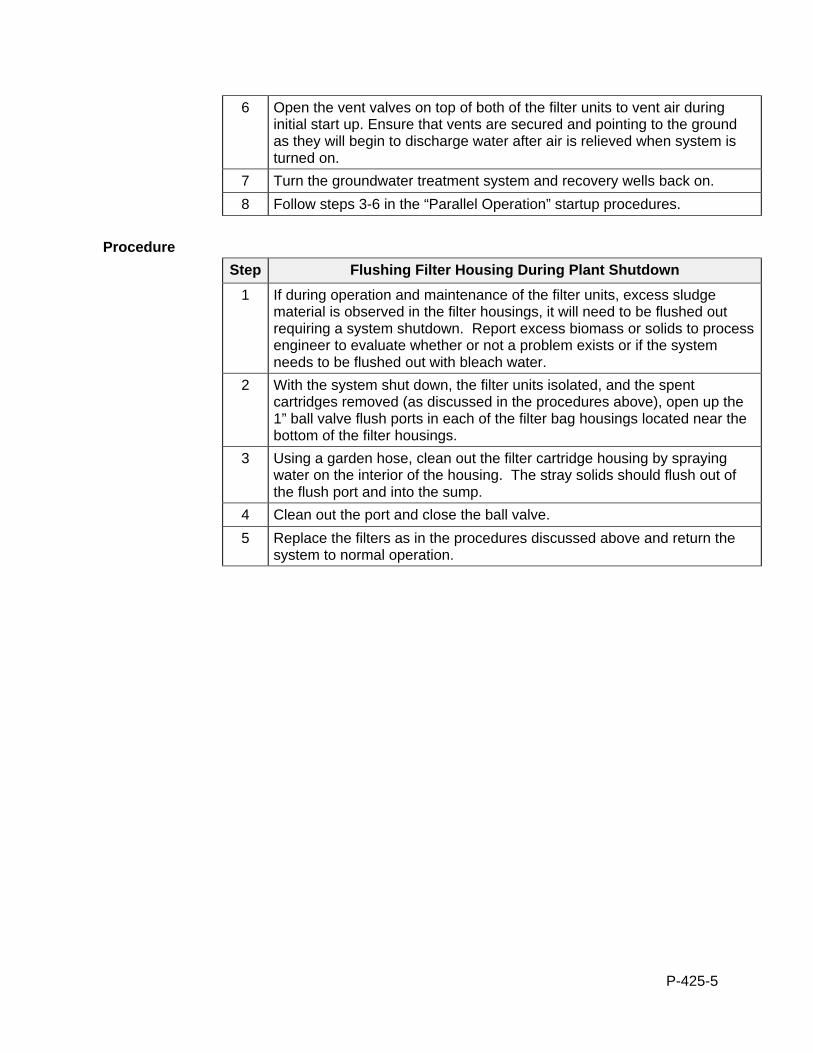
P-425-5
6 Open the vent valves on top of both of the filter units to vent air during initial start up. Ensure that vents are secured and pointing to the ground as they will begin to discharge water after air is relieved when system is turned on.
7 Turn the groundwater treatment system and recovery wells back on.
8 Follow steps 3-6 in the “Parallel Operation” startup procedures.
Procedure
Step Flushing Filter Housing During Plant Shutdown
1 If during operation and maintenance of the filter units, excess sludge material is observed in the filter housings, it will need to be flushed out requiring a system shutdown. Report excess biomass or solids to process engineer to evaluate whether or not a problem exists or if the system needs to be flushed out with bleach water.
2 With the system shut down, the filter units isolated, and the spent cartridges removed (as discussed in the procedures above), open up the 1” ball valve flush ports in each of the filter bag housings located near the bottom of the filter housings.
3 Using a garden hose, clean out the filter cartridge housing by spraying water on the interior of the housing. The stray solids should flush out of the flush port and into the sump.
4 Clean out the port and close the ball valve.
5 Replace the filters as in the procedures discussed above and return the system to normal operation.
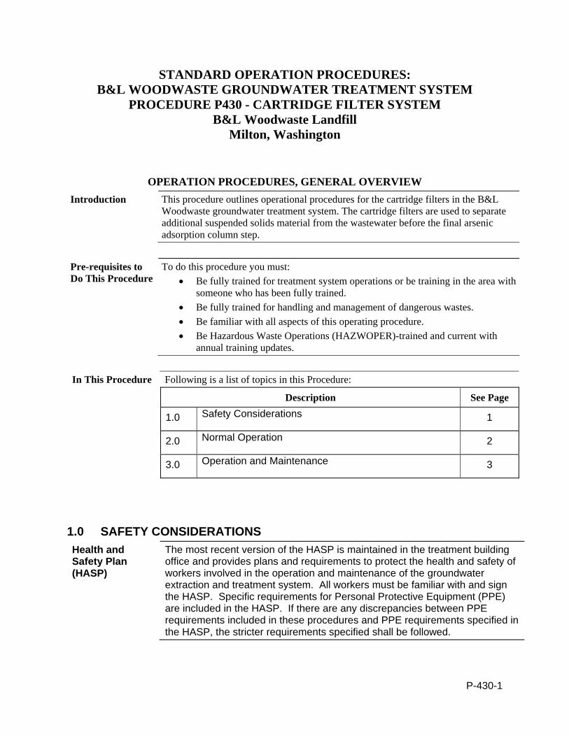
P-430-1
STANDARD OPERATION PROCEDURES: B&L WOODWASTE GROUNDWATER TREATMENT SYSTEM
PROCEDURE P430 - CARTRIDGE FILTER SYSTEM B&L Woodwaste Landfill
Milton, Washington
OPERATION PROCEDURES, GENERAL OVERVIEW Introduction This procedure outlines operational procedures for the cartridge filters in the B&L
Woodwaste groundwater treatment system. The cartridge filters are used to separate additional suspended solids material from the wastewater before the final arsenic adsorption column step.
Pre-requisites to Do This Procedure
To do this procedure you must: Be fully trained for treatment system operations or be training in the area with
someone who has been fully trained. Be fully trained for handling and management of dangerous wastes. Be familiar with all aspects of this operating procedure. Be Hazardous Waste Operations (HAZWOPER)-trained and current with
annual training updates.
In This Procedure Following is a list of topics in this Procedure:
Description See Page
1.0 Safety Considerations 1
2.0 Normal Operation 2
3.0 Operation and Maintenance 3
1.0 SAFETY CONSIDERATIONS
Health and Safety Plan (HASP)
The most recent version of the HASP is maintained in the treatment building office and provides plans and requirements to protect the health and safety of workers involved in the operation and maintenance of the groundwater extraction and treatment system. All workers must be familiar with and sign the HASP. Specific requirements for Personal Protective Equipment (PPE) are included in the HASP. If there are any discrepancies between PPE requirements included in these procedures and PPE requirements specified in the HASP, the stricter requirements specified shall be followed.
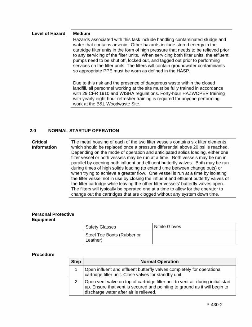
P-430-2
Level of Hazard Medium Hazards associated with this task include handling contaminated sludge and water that contains arsenic. Other hazards include stored energy in the cartridge filter units in the form of high pressure that needs to be relieved prior to any servicing of the filter units. When servicing both filter units, the effluent pumps need to be shut off, locked out, and tagged out prior to performing services on the filter units. The filters will contain groundwater contaminants so appropriate PPE must be worn as defined in the HASP. Due to this risk and the presence of dangerous waste within the closed landfill, all personnel working at the site must be fully trained in accordance with 29 CFR 1910 and WISHA regulations. Forty-hour HAZWOPER training with yearly eight hour refresher training is required for anyone performing work at the B&L Woodwaste Site.
2.0 NORMAL STARTUP OPERATION
Critical Information
The metal housing of each of the two filter vessels contains six filter elements which should be replaced once a pressure differential above 20 psi is reached. Depending on the mode of operation and anticipated solids loading, either one filter vessel or both vessels may be run at a time. Both vessels may be run in parallel by opening both influent and effluent butterfly valves. Both may be run during times of high solids loading (to extend time between change outs) or when trying to achieve a greater flow. One vessel is run at a time by isolating the filter vessel not in use by closing the influent and effluent butterfly valves of the filter cartridge while leaving the other filter vessels’ butterfly valves open. The filters will typically be operated one at a time to allow for the operator to change out the cartridges that are clogged without any system down time.
Personal Protective Equipment
Safety Glasses Nitrile Gloves
Steel Toe Boots (Rubber or Leather)
Procedure
Step Normal Operation
1 Open influent and effluent butterfly valves completely for operational cartridge filter unit. Close valves for standby unit.
2 Open vent valve on top of cartridge filter unit to vent air during initial start up. Ensure that vent is secured and pointing to ground as it will begin to discharge water after air is relieved.
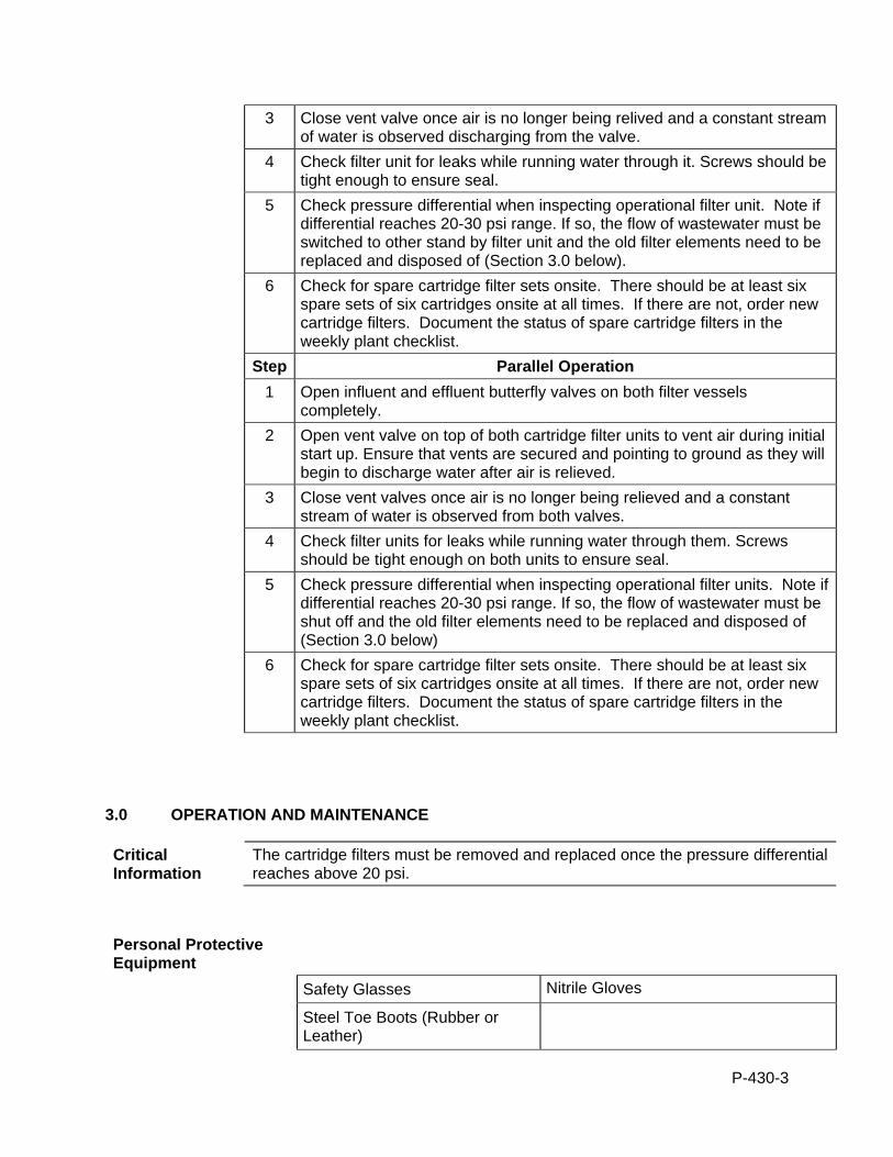
P-430-3
3 Close vent valve once air is no longer being relived and a constant stream of water is observed discharging from the valve.
4 Check filter unit for leaks while running water through it. Screws should be tight enough to ensure seal.
5 Check pressure differential when inspecting operational filter unit. Note if differential reaches 20-30 psi range. If so, the flow of wastewater must be switched to other stand by filter unit and the old filter elements need to be replaced and disposed of (Section 3.0 below).
6 Check for spare cartridge filter sets onsite. There should be at least six spare sets of six cartridges onsite at all times. If there are not, order new cartridge filters. Document the status of spare cartridge filters in the weekly plant checklist.
Step Parallel Operation
1 Open influent and effluent butterfly valves on both filter vessels completely.
2 Open vent valve on top of both cartridge filter units to vent air during initial start up. Ensure that vents are secured and pointing to ground as they will begin to discharge water after air is relieved.
3 Close vent valves once air is no longer being relieved and a constant stream of water is observed from both valves.
4 Check filter units for leaks while running water through them. Screws should be tight enough on both units to ensure seal.
5 Check pressure differential when inspecting operational filter units. Note if differential reaches 20-30 psi range. If so, the flow of wastewater must be shut off and the old filter elements need to be replaced and disposed of (Section 3.0 below)
6 Check for spare cartridge filter sets onsite. There should be at least six spare sets of six cartridges onsite at all times. If there are not, order new cartridge filters. Document the status of spare cartridge filters in the weekly plant checklist.
3.0 OPERATION AND MAINTENANCE
Critical Information
The cartridge filters must be removed and replaced once the pressure differential reaches above 20 psi.
Personal Protective Equipment
Safety Glasses Nitrile Gloves
Steel Toe Boots (Rubber or Leather)
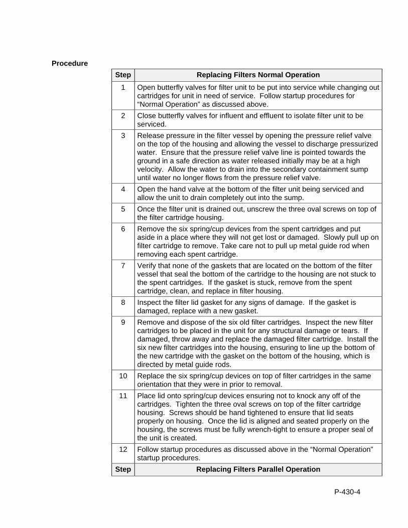
P-430-4
Procedure
Step Replacing Filters Normal Operation
1 Open butterfly valves for filter unit to be put into service while changing out cartridges for unit in need of service. Follow startup procedures for “Normal Operation” as discussed above.
2 Close butterfly valves for influent and effluent to isolate filter unit to be serviced.
3 Release pressure in the filter vessel by opening the pressure relief valve on the top of the housing and allowing the vessel to discharge pressurized water. Ensure that the pressure relief valve line is pointed towards the ground in a safe direction as water released initially may be at a high velocity. Allow the water to drain into the secondary containment sump until water no longer flows from the pressure relief valve.
4 Open the hand valve at the bottom of the filter unit being serviced and allow the unit to drain completely out into the sump.
5 Once the filter unit is drained out, unscrew the three oval screws on top of the filter cartridge housing.
6 Remove the six spring/cup devices from the spent cartridges and put aside in a place where they will not get lost or damaged. Slowly pull up on filter cartridge to remove. Take care not to pull up metal guide rod when removing each spent cartridge.
7 Verify that none of the gaskets that are located on the bottom of the filter vessel that seal the bottom of the cartridge to the housing are not stuck to the spent cartridges. If the gasket is stuck, remove from the spent cartridge, clean, and replace in filter housing.
8 Inspect the filter lid gasket for any signs of damage. If the gasket is damaged, replace with a new gasket.
9 Remove and dispose of the six old filter cartridges. Inspect the new filter cartridges to be placed in the unit for any structural damage or tears. If damaged, throw away and replace the damaged filter cartridge. Install the six new filter cartridges into the housing, ensuring to line up the bottom of the new cartridge with the gasket on the bottom of the housing, which is directed by metal guide rods.
10 Replace the six spring/cup devices on top of filter cartridges in the same orientation that they were in prior to removal.
11 Place lid onto spring/cup devices ensuring not to knock any off of the cartridges. Tighten the three oval screws on top of the filter cartridge housing. Screws should be hand tightened to ensure that lid seats properly on housing. Once the lid is aligned and seated properly on the housing, the screws must be fully wrench-tight to ensure a proper seal of the unit is created.
12 Follow startup procedures as discussed above in the “Normal Operation” startup procedures.
Step Replacing Filters Parallel Operation
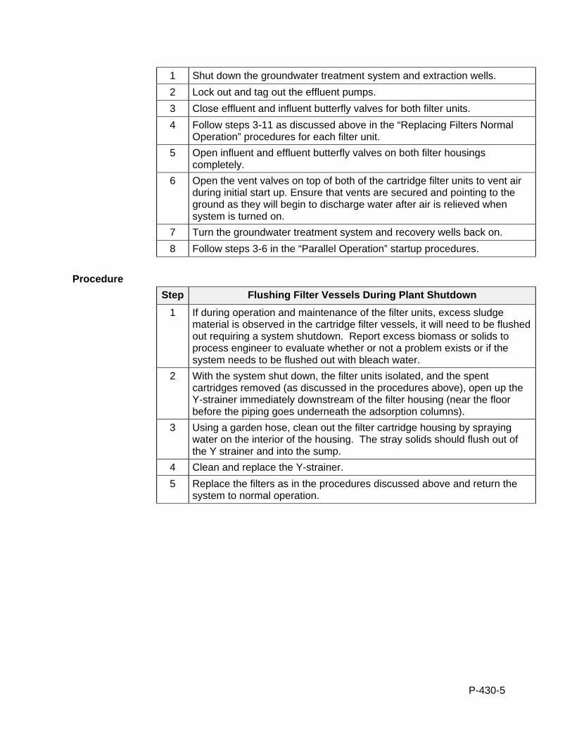
P-430-5
1 Shut down the groundwater treatment system and extraction wells.
2 Lock out and tag out the effluent pumps.
3 Close effluent and influent butterfly valves for both filter units.
4 Follow steps 3-11 as discussed above in the “Replacing Filters Normal Operation” procedures for each filter unit.
5 Open influent and effluent butterfly valves on both filter housings completely.
6 Open the vent valves on top of both of the cartridge filter units to vent air during initial start up. Ensure that vents are secured and pointing to the ground as they will begin to discharge water after air is relieved when system is turned on.
7 Turn the groundwater treatment system and recovery wells back on.
8 Follow steps 3-6 in the “Parallel Operation” startup procedures.
Procedure
Step Flushing Filter Vessels During Plant Shutdown
1 If during operation and maintenance of the filter units, excess sludge material is observed in the cartridge filter vessels, it will need to be flushed out requiring a system shutdown. Report excess biomass or solids to process engineer to evaluate whether or not a problem exists or if the system needs to be flushed out with bleach water.
2 With the system shut down, the filter units isolated, and the spent cartridges removed (as discussed in the procedures above), open up the Y-strainer immediately downstream of the filter housing (near the floor before the piping goes underneath the adsorption columns).
3 Using a garden hose, clean out the filter cartridge housing by spraying water on the interior of the housing. The stray solids should flush out of the Y strainer and into the sump.
4 Clean and replace the Y-strainer.
5 Replace the filters as in the procedures discussed above and return the system to normal operation.
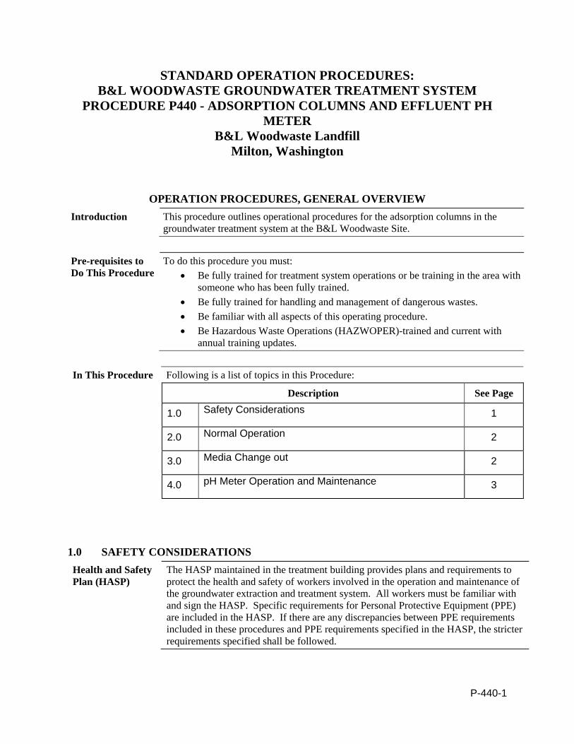
P-440-1
STANDARD OPERATION PROCEDURES: B&L WOODWASTE GROUNDWATER TREATMENT SYSTEM
PROCEDURE P440 - ADSORPTION COLUMNS AND EFFLUENT PH METER
B&L Woodwaste Landfill Milton, Washington
OPERATION PROCEDURES, GENERAL OVERVIEW Introduction This procedure outlines operational procedures for the adsorption columns in the
groundwater treatment system at the B&L Woodwaste Site.
Pre-requisites to Do This Procedure
To do this procedure you must: Be fully trained for treatment system operations or be training in the area with
someone who has been fully trained. Be fully trained for handling and management of dangerous wastes. Be familiar with all aspects of this operating procedure. Be Hazardous Waste Operations (HAZWOPER)-trained and current with
annual training updates.
In This Procedure Following is a list of topics in this Procedure:
Description See Page
1.0 Safety Considerations 1
2.0 Normal Operation 2
3.0 Media Change out 2
4.0 pH Meter Operation and Maintenance 3
1.0 SAFETY CONSIDERATIONS Health and Safety Plan (HASP)
The HASP maintained in the treatment building provides plans and requirements to protect the health and safety of workers involved in the operation and maintenance of the groundwater extraction and treatment system. All workers must be familiar with and sign the HASP. Specific requirements for Personal Protective Equipment (PPE) are included in the HASP. If there are any discrepancies between PPE requirements included in these procedures and PPE requirements specified in the HASP, the stricter requirements specified shall be followed.
P-440-2
Level of Hazard Low Make sure there is no pressure across columns when opening up for media change. Due to the presence of dangerous waste within the closed landfill, all personnel working at the site must be fully trained in accordance with 29 CFR 1910 and WISHA regulations. Forty-hour Hazardous Waste Operations Training with yearly eight hour refresher training is required for anyone performing work at the B&L Woodwaste Site.
2.0 NORMAL OPERATION
Critical Information
The adsorption columns contain an alumina-based media which is the last “polishing” filter for arsenic. The adsorption columns must be valved the correct way for correct operations.
Personal Protective Equipment
Safety Glasses Nitrile Gloves
Steel Toe Boots (Leather or Rubber)
Procedure
Step Normal Operation
1 Before treatment plant startup, check that the valve path will create a lead and lag column configuration (columns are in series, not parallel). Check each valve against the proper valving diagram in the P&ID or on the valve reference guidance hanging by the adsorbers.
2 The differential pressure indicators should read (nominally) 0 when there is no flow. The PLC will monitor differential pressure level during operation.
3.0 MEDIA CHANGEOUT
Critical Information
Media changeout is necessary when arsenic begins to break through the adsorption columns. Arsenic testing should catch this before arsenic concentrations exceed the NPDES permit limit. NRC or Mar Vac will normally do the media changeout, using a vacuum truck to remove the spent media and assist in filling the adsorbers with new media.
Personal Protective Equipment
P-440-3
Safety Glasses Nitrile Gloves
Steel Toe Boots (Leather or Rubber)
Procedure
Step Media Changeout
1 Confirm that there is a clear path from the rollup door to the media vessels, and surrounding the vessels, to allow for vacuum truck hose access.
2 The spent media will be removed and replaced with new media.
3 The adsorption columns must be filled approximately 2/3 of the way full with potable water to facilitate proper loading of the media.
4 Connect the flange and piping to the top of the adsorber being loaded. The other end of the piping has a funnel and will be located on the mezzanine level to prevent having to lean over the rail to have to load the media.
5 Media will be delivered either in 1 cubic foot sacks or 2,000 super sacks. If media is delivered in 1 cu ft sacks, each sack will need to be carried to the mezzanine level and loaded into the funnel. Each column will require 40 sacks. If a super sack is delivered, a 5 gallon bucket will need to be filled where the super sack is placed (adjacent to the roll off container) and carried to the funnel and loaded into the column. If the 5 gallon buckets are full, it will take 60 filled buckets per column. Once the first adsorber is filled, remove the flange from the second column and place ontop of the second adsorber and repeat the process.
6 When both columns are filled, replace the flange top on each adsorber and verify the valves are in the correct position.
4.0 EFFLUENT pH METER OPERATION AND MAINTENANCE
Critical Information
The pH/ORP transmitter will measure pH after the adsorption columns to act as the compliance monitoring point. The sensor must be maintained properly to correctly monitor the pH. The retractable insertion-type sensor is installed through a ball valve to enable calibration and maintenance while the process is operational. As the pipe is under pressure during operation, it is very important that when removing the sensor, the proper procedures be followed such that the ball valve is closed before the sensor is fully removed and unscrewed.
Tools/Supplies
P-440-4
Crescent Wrenches pH Buffer Solutions (pH 4 and 7), approximately a 1” level in individual beakers
Kimwipes
Personal Protective Equipment
Safety Glasses Latex or Nitrile Gloves
Hard Hat
Procedures
The following is an excerpt from the equipment O&M manual, including maintenance, sensor removal from the process, sensor cleaning and calibration. The manual is present in the GWTP office. Refer to that manual for more information.
4.1 Maintenance. The Model 385+ Sensor is a disposal type sensor and therefore requires only periodic cleaning and calibration. If the sensor has failed, it should be discarded and replaced.
4.2 Sensor Removal. Please refer to the appropriate paragraph for instructions regarding removal of the sensor for periodic maintenance.
1. Be certain system pressure at the sensor is below 64 psig (442 kPa) before proceeding with the retraction.
2. Push in on the sensor using the top of the J-box and slowly loosen the hex nut (B) of the process end male connector (A).
3. When the hex nut is loose enough, slowly ease the sensor back completely until the retraction stop collar is reached.
4. Close the ball valve slowly. If there is resistance, the valve may be hitting the sensor. Double check that the sensor has been retracted to the retraction stop collar.
5. The Male Connector Body (A) may now be completely unthreaded from the reducing coupling and the sensor removed for servicing.
4.3 pH Electrode Cleaning. If the electrode is coated or dirty, it may be cleaned as follows:
1. Remove the sensor from process as instructed in Section 4.2.
2. Wipe the glass bulb with a soft, clean, lint free cloth or tissue. If this does not remove the dirt or coating, proceed to step 3. If the sensor appears to be clean, go to step 5.
P-440-5
3. Wash the glass bulb in a strong detergent solution and thoroughly rinse with tap water. If the bulb still appears to have a coating, proceed to step 4.
4. Following the caution above, wash the glass bulb in dilute 5% hydrochloric acid solution and then rinse it thoroughly in tap water. Replace the sensor if it cannot be cleaned. If the glass bulb appears clean, proceed to step 5.
5. Buffer calibrate the sensor. If the sensor appears to respond sluggishly to pH change, soaking it overnight in a weak acid solution (5% hydrochloric acid) may improve its response. Be sure to rinse the sensor’s tip thoroughly with tap water. If the sensor will not calibrate, it must be replaced.
4.4 Platinum Electrode Cleaning. Remove any film or dirt by wiping the electrodes platinum band with a clean, lint free, cloth. If needed, a strong detergent should be used to remove any remaining dirt or film. Platinum electrodes can become poisoned by cyanide or sulfide compounds. However, processes involving these compounds (such as cyanide destruction) will destroy all the cyanides or sulfides before they can react with the platinum. Should poisoning occur, the electrode can be restored to normal operation by polishing the platinum (metallic) surface with moistened baking soda (after a strong detergent wash to remove any film on the platinum surface).
4.5 pH CALIBRATION (Once per month)
4.5.1 DESCRIPTION
New sensors must be calibrated before use. Regular recalibration is also necessary. Use auto calibration instead of manual calibration. Auto calibration avoids common pitfalls and reduces errors. The analyzer recognizes the buffers and uses temperature-corrected pH values in the calibration. Once the Model 1056 successfully completes the calibration, it calculates and displays the calibration slope and offset. The slope is reported as the slope at 25°C.
THIS SECTION DESCRIBES HOW TO CALIBRATE THE MODEL 1056 WITH A pH SENSOR. THE FOLLOWING CALIBRATION ROUTINES ARE COVERED.
Measure Sec. Menu function: default Description
pH Auto Calibration - pH 2 point buffer calibration with auto buffer recognition
Manual Calibration - pH 2 point buffer calibration with manual buffer value entry
Entering A Known Slope Value - pH Slope calibration with manual entry of known slope value
Standardization - pH 1 point buffer calibration with manual buffer value entry
A detailed flow diagram is provided at the end of this section to guide you through the calibration routines.
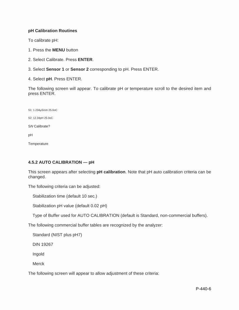
P-440-6
pH Calibration Routines
To calibrate pH:
1. Press the MENU button
2. Select Calibrate. Press ENTER.
3. Select Sensor 1 or Sensor 2 corresponding to pH. Press ENTER.
4. Select pH. Press ENTER.
The following screen will appear. To calibrate pH or temperature scroll to the desired item and press ENTER.
S1: 1.234μS/cm 25.0oC
S2: 12.34pH 25.0oC
SN Calibrate?
pH
Temperature
4.5.2 AUTO CALIBRATION — pH
This screen appears after selecting pH calibration. Note that pH auto calibration criteria can be changed.
The following criteria can be adjusted:
� Stabilization time (default 10 sec.)
� Stabilization pH value (default 0.02 pH)
� Type of Buffer used for AUTO CALIBRATION (default is Standard, non-commercial buffers).
The following commercial buffer tables are recognized by the analyzer:
� Standard (NIST plus pH7)
� DIN 19267
� Ingold
� Merck
The following screen will appear to allow adjustment of these criteria:

P-440-7
S1: 1.234μS/cm 25.0oC
S2: 12.34pH 25.0oC
SN pH Cal
Buffer Cal
Standardize
Slope: 59.16mV/pH
Offset: 600 mV
S1: 1.234μS/cm 25.0oC
S2: 12.34pH 25.0oC
SN Setup
Stable Time: 10 sec
Stable Delta: 0.02 pH
Buffer: Standard
The following sub-sections show the initial display screen that appears for each calibration routine. Use the flow diagram for pH calibration and the live screen prompts to complete calibration.
MODEL 1056 CALIBRATION
The following screen will appear if the auto cal is successful. The screen will return to the pH Buffer Cal Menu.
S1: 1.234μS/cm 25.0oC
S2: 12.34pH 25.0oC
SN pH Auto Cal
Slope: 59.16 mV/pH
Offset: 60 mV
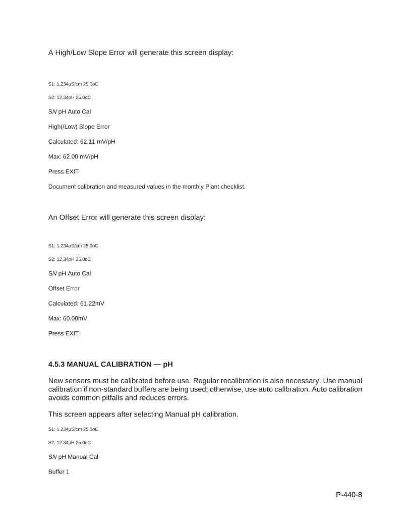
P-440-8
A High/Low Slope Error will generate this screen display:
S1: 1.234μS/cm 25.0oC
S2: 12.34pH 25.0oC
SN pH Auto Cal
High(/Low) Slope Error
Calculated: 62.11 mV/pH
Max: 62.00 mV/pH
Press EXIT
Document calibration and measured values in the monthly Plant checklist.
An Offset Error will generate this screen display:
S1: 1.234μS/cm 25.0oC
S2: 12.34pH 25.0oC
SN pH Auto Cal
Offset Error
Calculated: 61.22mV
Max: 60.00mV
Press EXIT
4.5.3 MANUAL CALIBRATION — pH
New sensors must be calibrated before use. Regular recalibration is also necessary. Use manual calibration if non-standard buffers are being used; otherwise, use auto calibration. Auto calibration avoids common pitfalls and reduces errors.
This screen appears after selecting Manual pH calibration.
S1: 1.234μS/cm 25.0oC
S2: 12.34pH 25.0oC
SN pH Manual Cal
Buffer 1
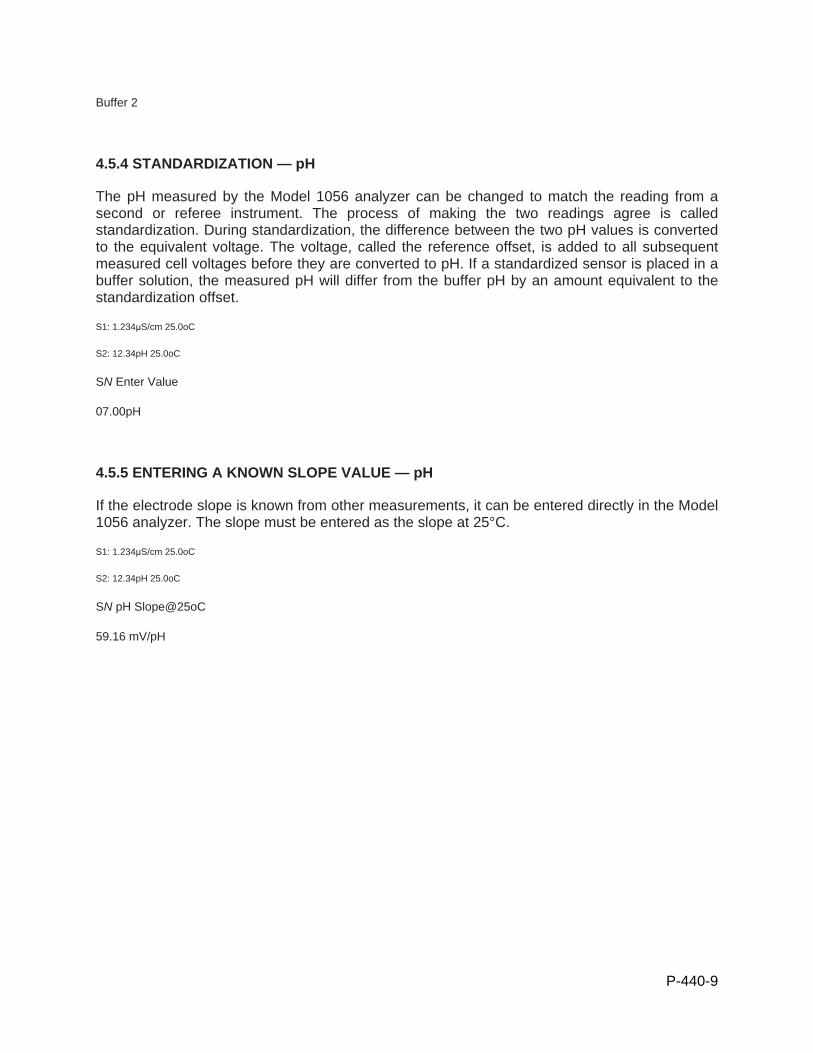
P-440-9
Buffer 2
4.5.4 STANDARDIZATION — pH
The pH measured by the Model 1056 analyzer can be changed to match the reading from a second or referee instrument. The process of making the two readings agree is called standardization. During standardization, the difference between the two pH values is converted to the equivalent voltage. The voltage, called the reference offset, is added to all subsequent measured cell voltages before they are converted to pH. If a standardized sensor is placed in a buffer solution, the measured pH will differ from the buffer pH by an amount equivalent to the standardization offset.
S1: 1.234μS/cm 25.0oC
S2: 12.34pH 25.0oC
SN Enter Value
07.00pH
4.5.5 ENTERING A KNOWN SLOPE VALUE — pH
If the electrode slope is known from other measurements, it can be entered directly in the Model 1056 analyzer. The slope must be entered as the slope at 25°C.
S1: 1.234μS/cm 25.0oC
S2: 12.34pH 25.0oC
SN pH Slope@25oC
59.16 mV/pH
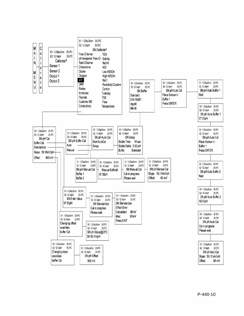
P-440-10
P-910-1
STANDARD OPERATION PROCEDURES: B&L WOODWASTE GROUNDWATER TREATMENT SYSTEM
PROCEDURE P910 - AIR COMPRESSOR SYSTEM B&L Woodwaste Landfill
Milton, Washington
OPERATION PROCEDURES, GENERAL OVERVIEW Introduction This procedure outlines operational procedures for the air compressor in the B&L
Woodwaste groundwater treatment system. The air compressor is used to supply air for the air operated diaphragm pumps, including the clarifier underflow pump. In addition, the filter press itself uses air for several of its operational modes.
Pre-requisites to Do This Procedure
To do this procedure you must: Be fully trained for treatment system operations or be training in the area with
someone who has been fully trained. Be fully trained for handling and management of dangerous wastes. Be familiar with all aspects of this operating procedure. Be Hazardous Waste Operations (HAZWOPER)-trained and current with
annual training updates.
In This Procedure Following is a list of topics in this Procedure:
Description See Page
1.0 Safety Considerations 2
2.0 Normal Startup and Shutdown 3
3.0 Startup and Shutdown After Power Failure 4
4.0 Operation and Maintenance 4
1.0 SAFETY CONSIDERATIONS
Health and Safety Plan (HASP)
The HASP maintained in the treatment building provides plans and requirements to protect the health and safety of workers involved in the operation and maintenance of the groundwater extraction and treatment system. All workers must be familiar with and sign the HASP. Specific requirements for Personal Protective Equipment (PPE) are included in the HASP. If there are any discrepancies between PPE requirements included in these procedures and PPE requirements specified in the HASP, the stricter requirements specified shall be followed.
P-910-2
Level of Hazard Medium Use caution when performing maintenance on the air compressor unit. Utilize proper lockout/tagout procedures and ensure that there is no mechanical movement of the compressor during maintenance and troubleshooting. Due to the presence of dangerous waste within the closed landfill, all personnel working at the site must be fully trained in accordance with 29 CFR 1910 and WISHA regulations. Forty-hour Hazardous Waste Operations Training with yearly eight hour refresher training is required for anyone performing work at the B&L Woodwaste Site.
2.0 NORMAL STARTUP AND SHUTDOWN
Critical Information
Procedure for normal startup and shutdown of the Kaeser SK air compressor.
Personal Protective Equipment
Safety Glasses Nitrile Gloves
Steel Toe Boots (Leather or Rubber)
P-910-3
Procedure
Step Normal Startup
1 Ensure that no personnel are working on the machine and that all access doors and panels are closed and secure.
2 Switch on the power supply disconnecting device. After the controller has performed a self-test, the green POWER ON LED lights continuously.
3 Press the «ON» key. The green Machine ON LED lights continuously. NOTE: If a power failure occurs, the machine is not prevented from automatic re-starting. It can start automatically again as soon as power is restored.
Procedure
Step Normal Shutdown
1 Press the «OFF» key. If the machine is running, there will be a rundown time of approximately 15 seconds after pressing the OFF key. If the machine is already in IDLE mode, it will shut off immediately after pressing the OFF key. The machine can be started again as soon as the Machine ON LED is extinguished.
2 Switch off and lock out the power supply disconnecting device. The machine is switched off and isolated from the power supply. The Controller Power LED extinguishes.
3 NOTE: To shut down the compressor immediately in the event of an emergency, press the red EMERGENCY STOP button. The button stays locked and prevents the machine from restarting automatically.
3.0 STARTUP AFTER POWER FAILURE
Critical Information
Procedure for startup of the Kaeser SK air compressor after power failure.
Personal Protective Equipment
Safety Glasses Nitrile Gloves
P-910-4
Hearing Protection (only for annual relief valve testing)
Steel Toe Boots (Leather or Rubber)
Procedure
Step Normal Startup
1 The machine will restart on its own as soon as power is restored to the system.
2 CAUTION: Do not work on air compressor parts during a power outage without first locking out the machine at the power source (breaker in MCC).
4.0 PREVENTATIVE MAINTENANCE
Critical Information
Preventative maintenance for the Kaeser SK air compressor.
Tools & Equipment
Lukewarm Water Household Laundry Detergent
Crescent Wrench Multimeter
Lockout Padlock
Procedure
Step Weekly Maintenance
1 The following maintenance activities should be performed on a weekly basis.
2 Check the belt tension as shown in step 3.
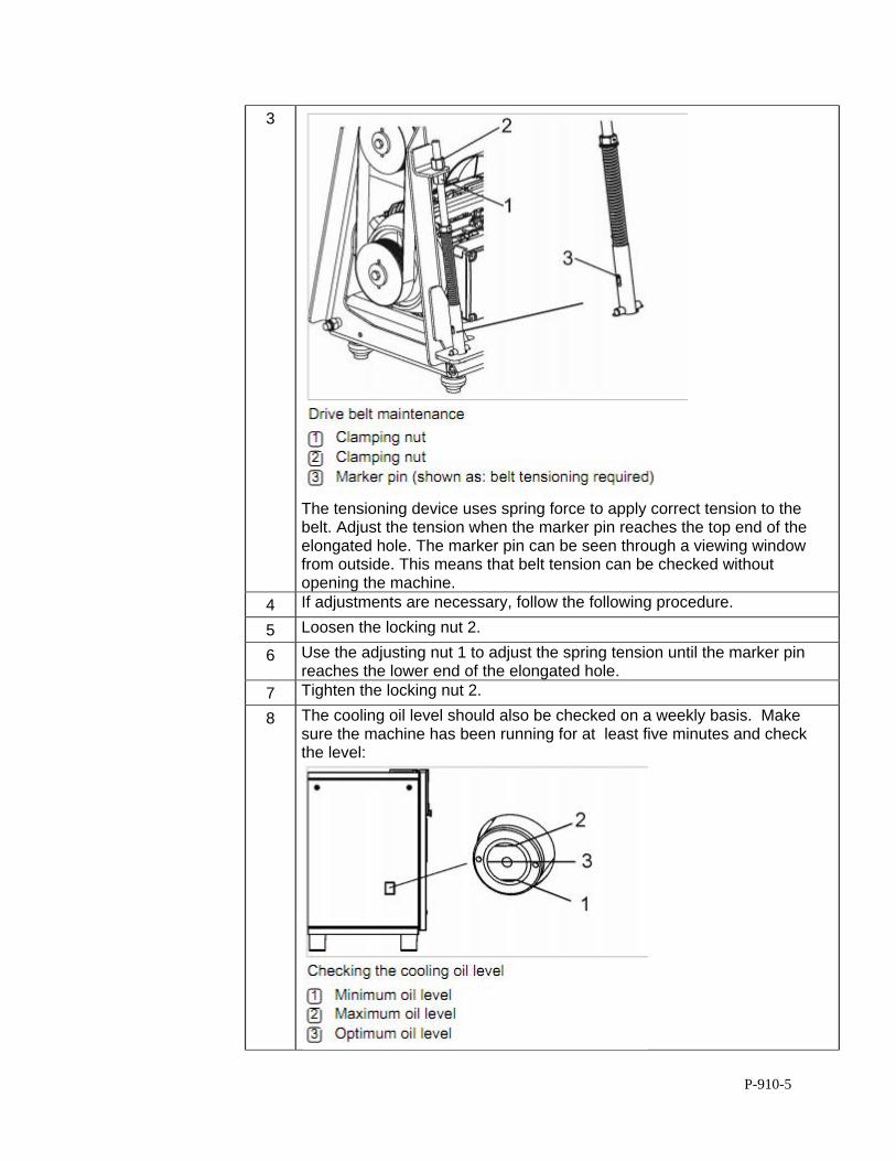
P-910-5
3
The tensioning device uses spring force to apply correct tension to the belt. Adjust the tension when the marker pin reaches the top end of the elongated hole. The marker pin can be seen through a viewing window from outside. This means that belt tension can be checked without opening the machine.
4 If adjustments are necessary, follow the following procedure.
5 Loosen the locking nut 2.
6 Use the adjusting nut 1 to adjust the spring tension until the marker pin reaches the lower end of the elongated hole.
7 Tighten the locking nut 2.
8 The cooling oil level should also be checked on a weekly basis. Make sure the machine has been running for at least five minutes and check the level:
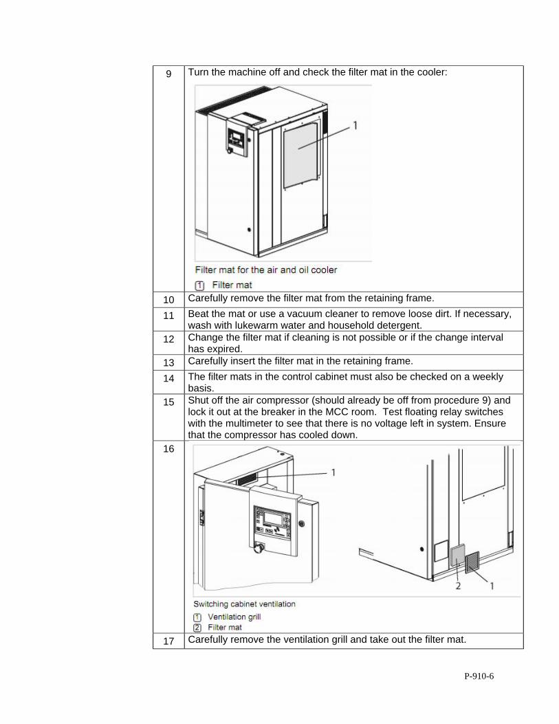
P-910-6
9 Turn the machine off and check the filter mat in the cooler:
10 Carefully remove the filter mat from the retaining frame.
11 Beat the mat or use a vacuum cleaner to remove loose dirt. If necessary, wash with lukewarm water and household detergent.
12 Change the filter mat if cleaning is not possible or if the change interval has expired.
13 Carefully insert the filter mat in the retaining frame.
14 The filter mats in the control cabinet must also be checked on a weekly basis.
15 Shut off the air compressor (should already be off from procedure 9) and lock it out at the breaker in the MCC room. Test floating relay switches with the multimeter to see that there is no voltage left in system. Ensure that the compressor has cooled down.
16
17 Carefully remove the ventilation grill and take out the filter mat.

P-910-7
18 Beat the mat or use a vacuum cleaner to remove loose dirt. If necessary, wash with lukewarm water and household detergent.
19 Change the filter mat if cleaning is not possible or if the change interval has expired.
20 Insert the filter mat in the frame and latch in the ventilation grill.
21 Remove lockout device and return breaker to “ON.”
Procedure
Step 1,000 Hour Maintenance
1 The following maintenance activities should be performed approximately every 1,000 hours of operating time.
2 Power off and lockout the machine at the breaker in the MCC room. Test floating relay switches with the multimeter to see that there is no voltage left in system. Ensure that the machine has cooled down. Check the drive belt.
3
4 Visually check the drive belt for damages. Turn the pulley by hand so that
all of the belt can be inspected. 5 If damage exists, replace the drive belt (following procedure).
6 Check the air filter:
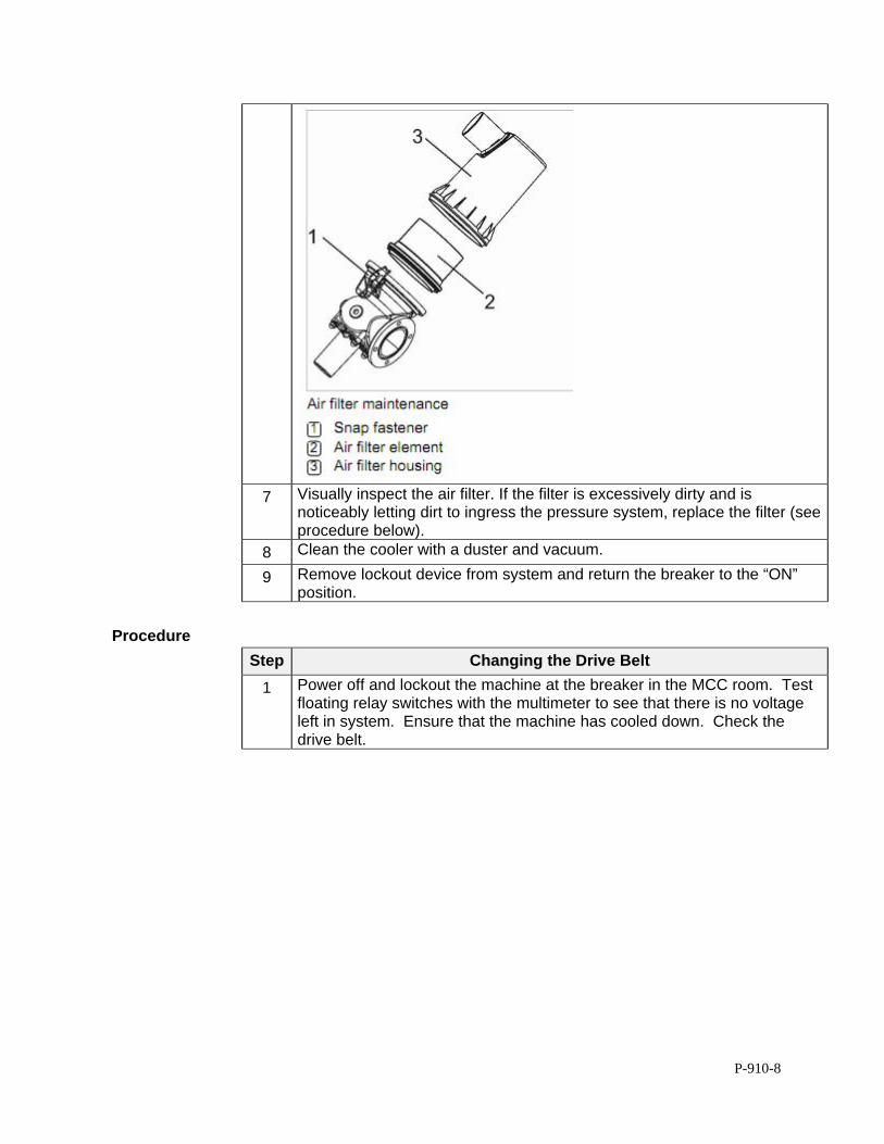
P-910-8
7 Visually inspect the air filter. If the filter is excessively dirty and is noticeably letting dirt to ingress the pressure system, replace the filter (see procedure below).
8 Clean the cooler with a duster and vacuum.
9 Remove lockout device from system and return the breaker to the “ON” position.
Procedure
Step Changing the Drive Belt
1 Power off and lockout the machine at the breaker in the MCC room. Test floating relay switches with the multimeter to see that there is no voltage left in system. Ensure that the machine has cooled down. Check the drive belt.
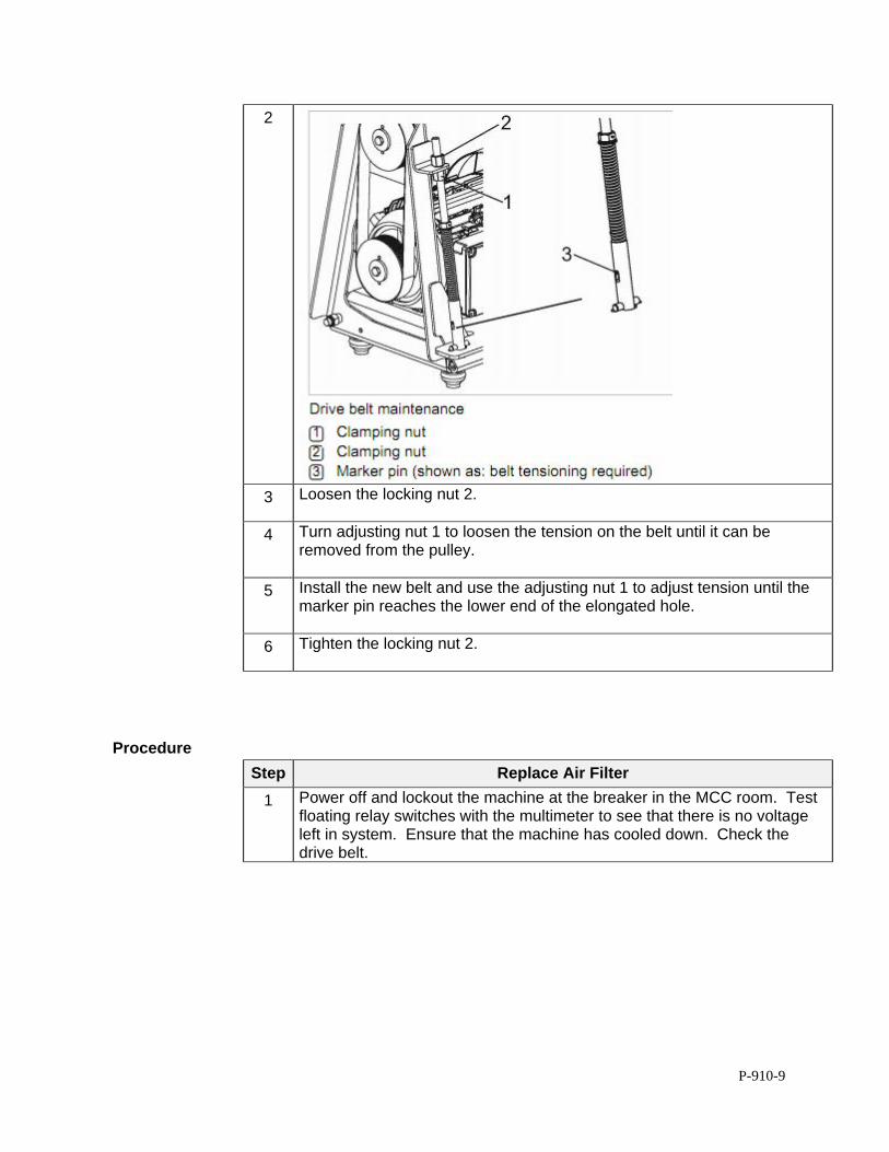
P-910-9
2
3 Loosen the locking nut 2.
4 Turn adjusting nut 1 to loosen the tension on the belt until it can be
removed from the pulley.
5 Install the new belt and use the adjusting nut 1 to adjust tension until the marker pin reaches the lower end of the elongated hole.
6 Tighten the locking nut 2.
Procedure
Step Replace Air Filter
1 Power off and lockout the machine at the breaker in the MCC room. Test floating relay switches with the multimeter to see that there is no voltage left in system. Ensure that the machine has cooled down. Check the drive belt.
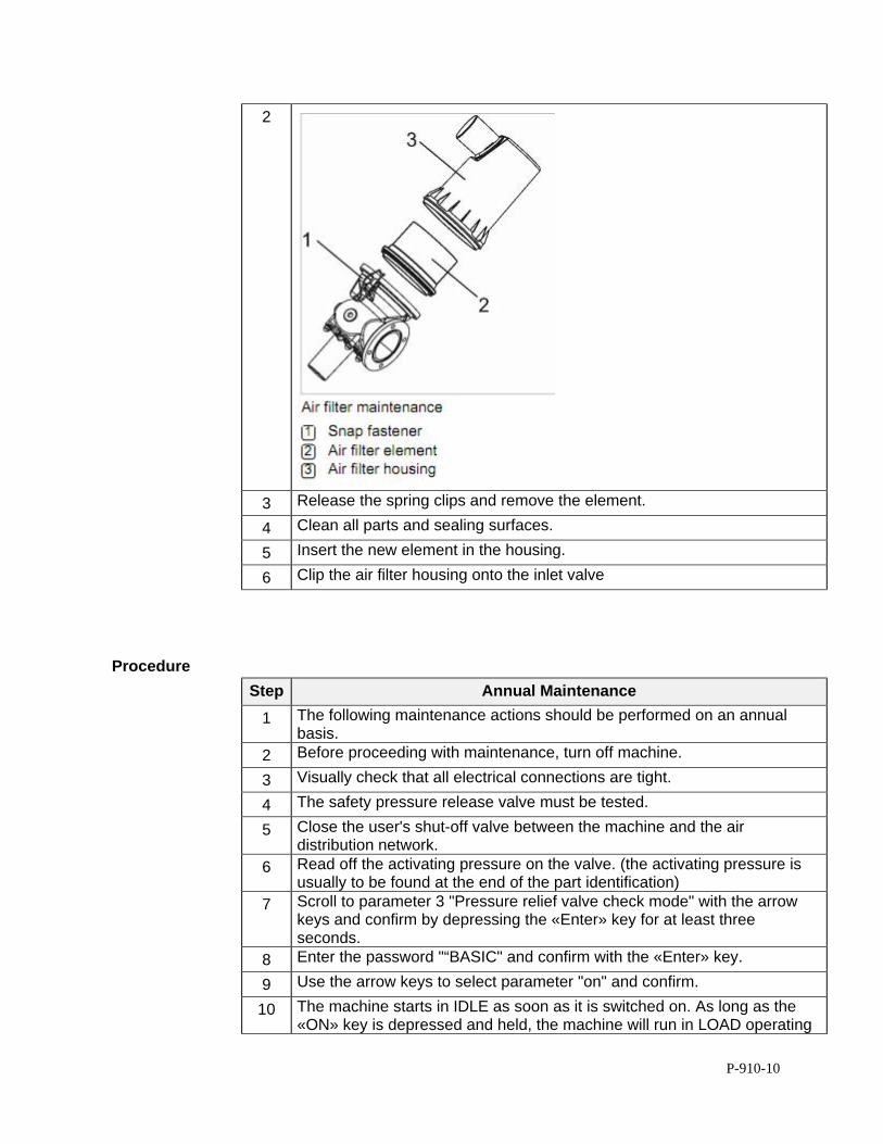
P-910-10
2
3 Release the spring clips and remove the element.
4 Clean all parts and sealing surfaces.
5 Insert the new element in the housing.
6 Clip the air filter housing onto the inlet valve
Procedure
Step Annual Maintenance
1 The following maintenance actions should be performed on an annual basis.
2 Before proceeding with maintenance, turn off machine.
3 Visually check that all electrical connections are tight.
4 The safety pressure release valve must be tested.
5 Close the user's shut-off valve between the machine and the air distribution network.
6 Read off the activating pressure on the valve. (the activating pressure is usually to be found at the end of the part identification)
7 Scroll to parameter 3 "Pressure relief valve check mode" with the arrow keys and confirm by depressing the «Enter» key for at least three seconds.
8 Enter the password "“BASIC" and confirm with the «Enter» key.
9 Use the arrow keys to select parameter "on" and confirm.
10 The machine starts in IDLE as soon as it is switched on. As long as the «ON» key is depressed and held, the machine will run in LOAD operating
P-910-11
mode and pressure builds up in the oil separator tank. As soon as the «ON» key is released, the machine switches back to IDLE and switches automatically to STANDSTILL when the idling period has elapsed.
11 The safety relief valve may blow off at any time! Excessive noise is caused when the safety relief valve blows off! There is danger of scalding from hot oil. There is danger of injury from bursting components and compressed air! ➤ Close all access doors and replace and secure all removable panels. ➤ Wear ear and eye protection. ➤ Abort the test if the working pressure reaches 10 % above the blowoff pressure of the valve.
12 Press the «ON» key for short time. The machine starts in IDLE.
13 Observe the pressure indication on the SIGMA CONTROL BASIC keep the «ON» key pressed.
14 Stop the test as soon as the safety relief valve blows off or working pressure rises to 10 % above the activating pressure of the safety relief valve.
15 If necessary, vent the machine and replace the defective safety relief valve.
16 Call up the edit mode again and enter the password "BASIC".
17 Use the arrow keys to set the parameter to "off" and confirm with the enter key.
18 Open the user's shut-off valve between the machine and the air distribution network.
19 Check the cooler for leaks.
Procedure
Step Changing Cooling Oil
1 Always change the oil filter and oil separator cartridge when changing the cooling oil (see separate procedures bellow).
2
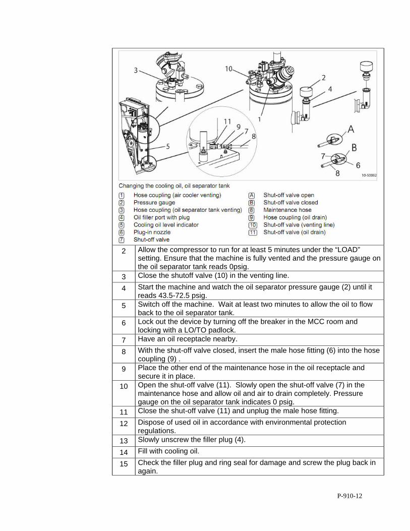
P-910-12
2 Allow the compressor to run for at least 5 minutes under the “LOAD” setting. Ensure that the machine is fully vented and the pressure gauge on the oil separator tank reads 0psig.
3 Close the shutoff valve (10) in the venting line.
4 Start the machine and watch the oil separator pressure gauge (2) until it reads 43.5-72.5 psig.
5 Switch off the machine. Wait at least two minutes to allow the oil to flow back to the oil separator tank.
6 Lock out the device by turning off the breaker in the MCC room and locking with a LO/TO padlock.
7 Have an oil receptacle nearby.
8 With the shut-off valve closed, insert the male hose fitting (6) into the hose coupling (9) .
9 Place the other end of the maintenance hose in the oil receptacle and secure it in place.
10 Open the shut-off valve (11). Slowly open the shut-off valve (7) in the maintenance hose and allow oil and air to drain completely. Pressure gauge on the oil separator tank indicates 0 psig.
11 Close the shut-off valve (11) and unplug the male hose fitting.
12 Dispose of used oil in accordance with environmental protection regulations.
13 Slowly unscrew the filler plug (4).
14 Fill with cooling oil.
15 Check the filler plug and ring seal for damage and screw the plug back in again.
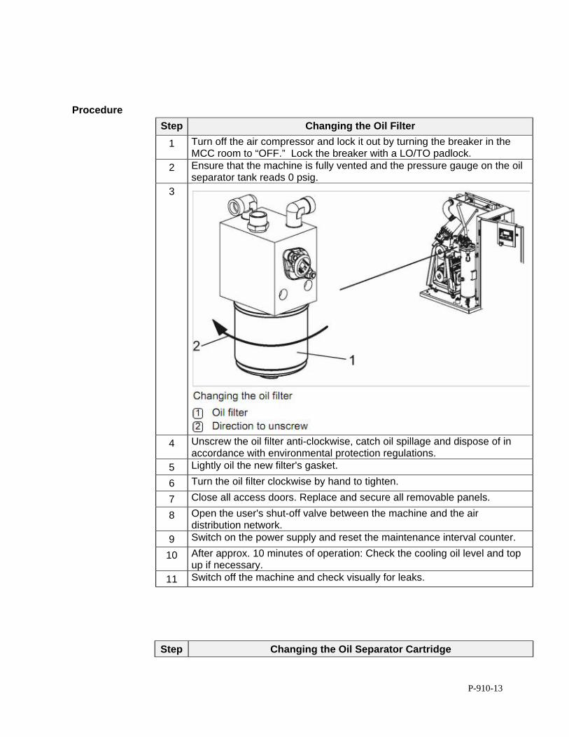
P-910-13
Procedure
Step Changing the Oil Filter
1 Turn off the air compressor and lock it out by turning the breaker in the MCC room to “OFF.” Lock the breaker with a LO/TO padlock.
2 Ensure that the machine is fully vented and the pressure gauge on the oil separator tank reads 0 psig.
3
4 Unscrew the oil filter anti-clockwise, catch oil spillage and dispose of in accordance with environmental protection regulations.
5 Lightly oil the new filter's gasket.
6 Turn the oil filter clockwise by hand to tighten.
7 Close all access doors. Replace and secure all removable panels.
8 Open the user's shut-off valve between the machine and the air distribution network.
9 Switch on the power supply and reset the maintenance interval counter.
10 After approx. 10 minutes of operation: Check the cooling oil level and top up if necessary.
11 Switch off the machine and check visually for leaks.
Step Changing the Oil Separator Cartridge
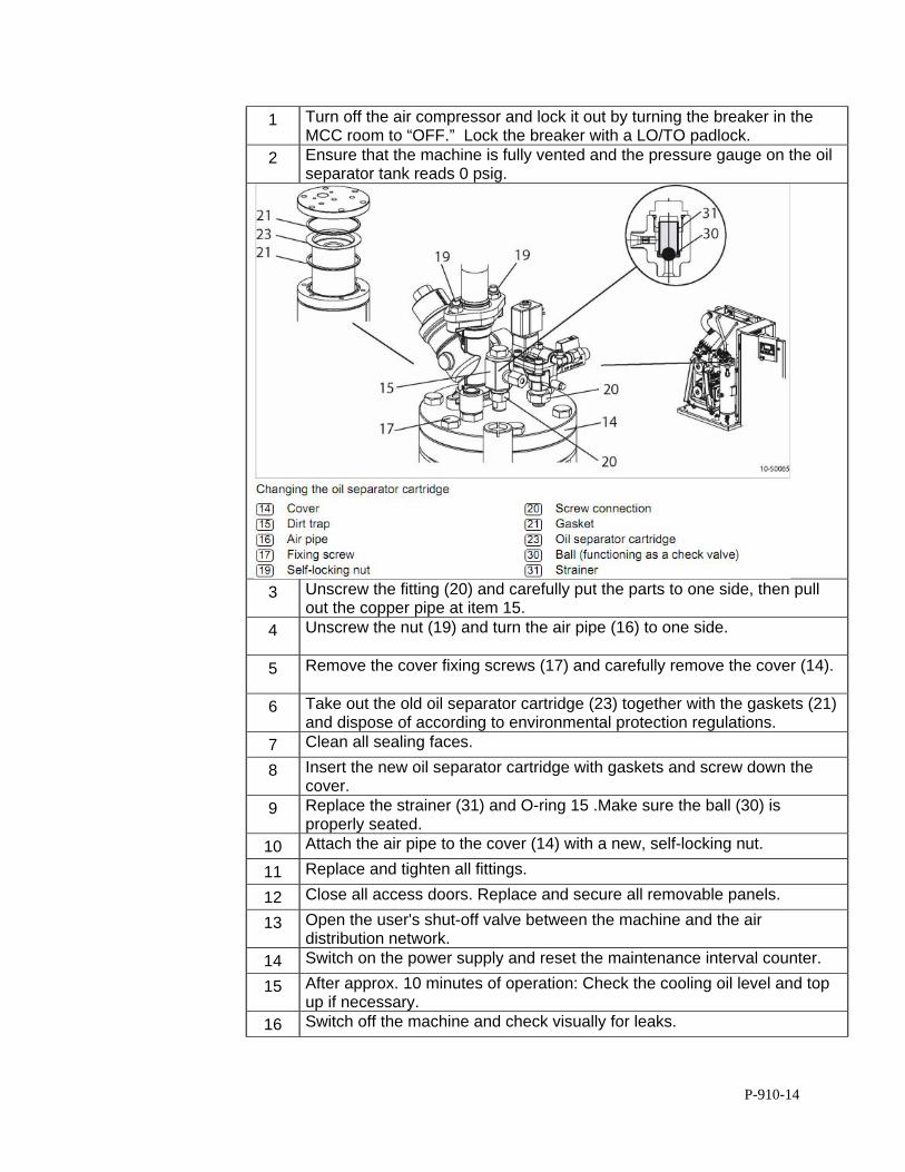
P-910-14
1 Turn off the air compressor and lock it out by turning the breaker in the MCC room to “OFF.” Lock the breaker with a LO/TO padlock.
2 Ensure that the machine is fully vented and the pressure gauge on the oil separator tank reads 0 psig.
3 Unscrew the fitting (20) and carefully put the parts to one side, then pull out the copper pipe at item 15.
4 Unscrew the nut (19) and turn the air pipe (16) to one side.
5 Remove the cover fixing screws (17) and carefully remove the cover (14).
6 Take out the old oil separator cartridge (23) together with the gaskets (21) and dispose of according to environmental protection regulations.
7 Clean all sealing faces.
8 Insert the new oil separator cartridge with gaskets and screw down the cover.
9 Replace the strainer (31) and O-ring 15 .Make sure the ball (30) is properly seated.
10 Attach the air pipe to the cover (14) with a new, self-locking nut.
11 Replace and tighten all fittings.
12 Close all access doors. Replace and secure all removable panels.
13 Open the user's shut-off valve between the machine and the air distribution network.
14 Switch on the power supply and reset the maintenance interval counter.
15 After approx. 10 minutes of operation: Check the cooling oil level and top up if necessary.
16 Switch off the machine and check visually for leaks.
P-940-1
STANDARD OPERATION PROCEDURES: B&L WOODWASTE GROUNDWATER TREATMENT SYSTEM
PROCEDURE P940 - SLUDGE DEWATERING SYSTEM B&L Woodwaste Landfill
Milton, Washington
OPERATION PROCEDURES, GENERAL OVERVIEW Introduction This procedure outlines operational procedures for the sludge dewatering system in
the B&L Woodwaste groundwater treatment system.
Pre-requisites to Do This Procedure
To do this procedure you must: Be fully trained for treatment system operations or be training in the area with
someone who has been fully trained. Be fully trained for handling and management of dangerous wastes. Be familiar with all aspects of this operating procedure. Be Hazardous Waste Operations (HAZWOPER)-trained and current with
annual training updates.
In This Procedure Following is a list of topics in this Procedure:
Description See Page
1.0 Safety Considerations 2
2.0 Normal Sludge Transfer Operation 2
3.0 Filter Press Operation 3
4.0 Mixer Operation 4
5.0 Peristaltic Pump Operation and Maintenance 5
6.0 Peristaltic Pump Operation and Maintenance 8
7.0 Instrumentation Operation and Maintenance 23
P-940-2
1.0 SAFETY CONSIDERATIONS Health and Safety Plan (HASP)
The HASP maintained in the treatment building provides plans and requirements to protect the health and safety of workers involved in the operation and maintenance of the groundwater extraction and treatment system. All workers must be familiar with and sign the HASP. Specific requirements for Personal Protective Equipment (PPE) are included in the HASP. If there are any discrepancies between PPE requirements included in these procedures and PPE requirements specified in the HASP, the requirements specified in the HASP shall be followed.
Level of Hazard Medium The sludge dewatering system utilizes large moving machinery. Operators must be cautious and wear appropriate PPE when controlling the system. Due to the presence of Dangerous Waste within the closed landfill, all personnel working at the site must be fully trained in accordance with 29 CFR 1910 and WISHA regulations. Forty-hour Hazardous Waste Operations Training with yearly eight hour refresher training is required for anyone performing work at the B&L Woodwaste Site.
2.0 NORMAL SLUDGE TRANSFER OPERATION
Critical Information
Sludge will be transferred from the bottom of the clarifier to either the sludge tank or the co-precipitation tank by an air diaphragm pump. The pathway of the sludge is controlled by the PLC via a solenoid valve and timer.
Tools/Supplies
Sampling Container (Beaker)
Personal Protective Equipment
Safety Glasses Nitrile Gloves
Steel Toe Boots (Leather or Rubber)
Procedure
Step Sludge Transfer
1 The PLC contains time settings for the solenoid valves which control sludge transfer from the bottom of the clarifier to the co-precipitation tank and the sludge tank.
2 Set the solenoid timers on the sludge handling screen to discharge a volume equal to the sludge flowing into the clarifier. See the clarifier “Normal Operations” procedure for information on finding this volume.
P-940-3
3 The “BYPASS” box next to the clarifier sludge pump should be set to open one third of the total time sludge is being pumped. When the bypass valve is open, sludge will flow into the sludge tank. Otherwise, sludge will run into the co-precipitation tank. As an example, if the solenoid valve controlling the air diaphragm pump is set on a 30 second cycle (10 on, 20 off), then the sludge bypass should be set to 30 seconds and the sludge bypass off set to 60 seconds. This way, 1/3 of the total pumped sludge will travel to the sludge tank and 2/3 will go to the co-precipitation tank.
4 As described in the clarifier procedure, adjust the pumping rate from the clarifier base after testing the top and bottom effluent taps for sludge. The adjustment will be made on the PLC by increasing time when the solenoid valve carrying air to the first air diaphragm pump is open. This testing should be performed once a week.
5 The second air diaphragm pump will only pump sludge from the sludge tank to the filter press when an auto cycle has begun.
3.0 FILTER PRESS OPERATION
Critical Information
The filter press should be run weekly (or as needed) by an onsite operator. The full cycle will take around four hours to complete, and the operator must be onsite at the finish of the auto cycle to scrape the filter cake off of the filter cloths.
Tools/Supplies
Scraper
Personal Protective Equipment
Safety Glasses Nitrile Gloves
Steel Toe Boots (Leather or Rubber)
Procedure
Step Filter Press Operation
1 Push the “AUTO CYCLE START” button on the filter press to begin the sludge disposal process. The filter press must be in auto mode for the button to activate the cycle. If filter is in manual mode, simply press the “AUTO MODE” button on the main screen.
2 The filter press will close the ram and drip tray and open the necessary valves to begin sludge flow. The treatment system PLC will receive a signal and turn on the peristaltic pump between the sludge tank and the filter press, which will start sludge flow.
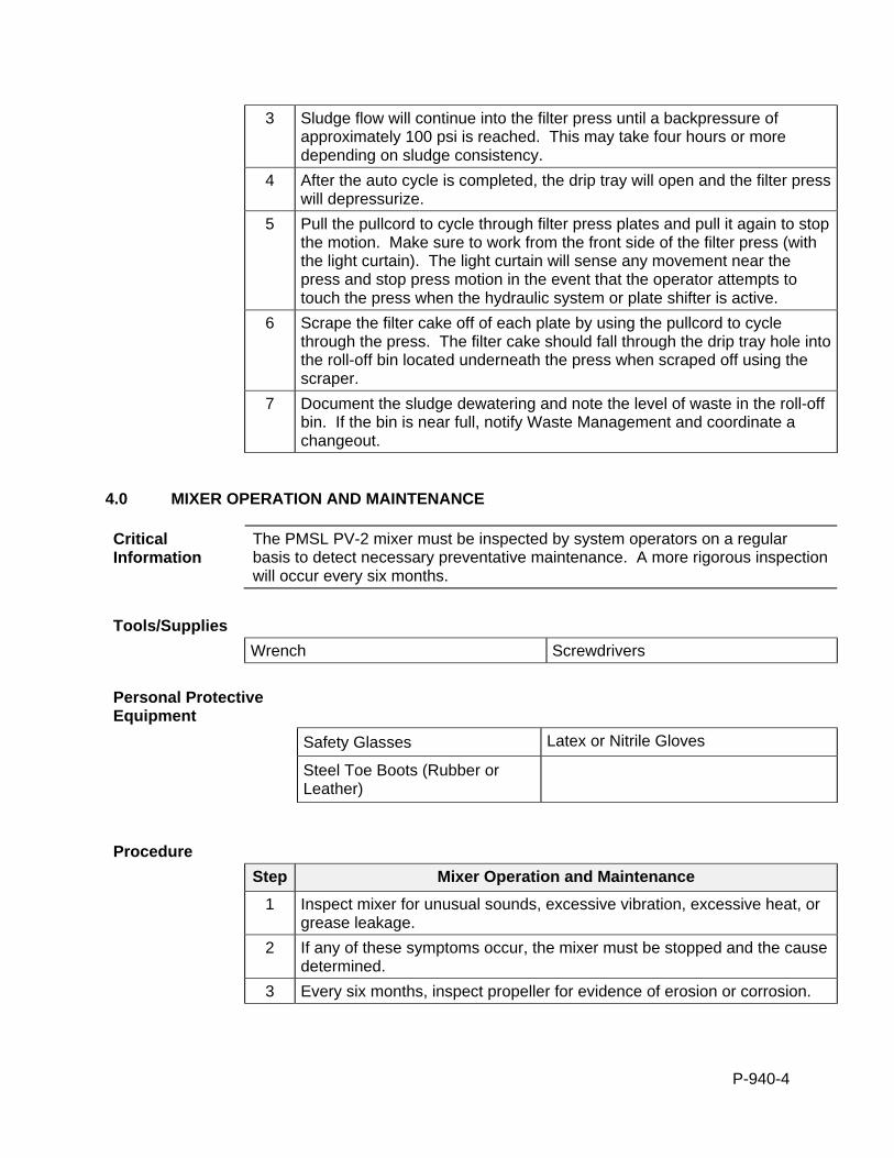
P-940-4
3 Sludge flow will continue into the filter press until a backpressure of approximately 100 psi is reached. This may take four hours or more depending on sludge consistency.
4 After the auto cycle is completed, the drip tray will open and the filter press will depressurize.
5 Pull the pullcord to cycle through filter press plates and pull it again to stop the motion. Make sure to work from the front side of the filter press (with the light curtain). The light curtain will sense any movement near the press and stop press motion in the event that the operator attempts to touch the press when the hydraulic system or plate shifter is active.
6 Scrape the filter cake off of each plate by using the pullcord to cycle through the press. The filter cake should fall through the drip tray hole into the roll-off bin located underneath the press when scraped off using the scraper.
7 Document the sludge dewatering and note the level of waste in the roll-off bin. If the bin is near full, notify Waste Management and coordinate a changeout.
4.0 MIXER OPERATION AND MAINTENANCE
Critical Information
The PMSL PV-2 mixer must be inspected by system operators on a regular basis to detect necessary preventative maintenance. A more rigorous inspection will occur every six months.
Tools/Supplies
Wrench Screwdrivers
Personal Protective Equipment
Safety Glasses Latex or Nitrile Gloves
Steel Toe Boots (Rubber or Leather)
Procedure
Step Mixer Operation and Maintenance
1 Inspect mixer for unusual sounds, excessive vibration, excessive heat, or grease leakage.
2 If any of these symptoms occur, the mixer must be stopped and the cause determined.
3 Every six months, inspect propeller for evidence of erosion or corrosion.
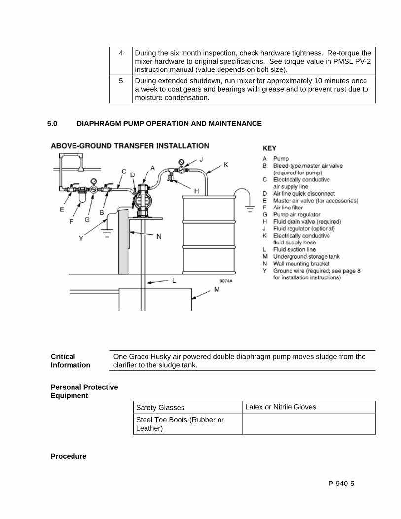
P-940-5
4 During the six month inspection, check hardware tightness. Re-torque the mixer hardware to original specifications. See torque value in PMSL PV-2 instruction manual (value depends on bolt size).
5 During extended shutdown, run mixer for approximately 10 minutes once a week to coat gears and bearings with grease and to prevent rust due to moisture condensation.
5.0 DIAPHRAGM PUMP OPERATION AND MAINTENANCE
Critical Information
One Graco Husky air-powered double diaphragm pump moves sludge from the clarifier to the sludge tank.
Personal Protective Equipment
Safety Glasses Latex or Nitrile Gloves
Steel Toe Boots (Rubber or Leather)
Procedure
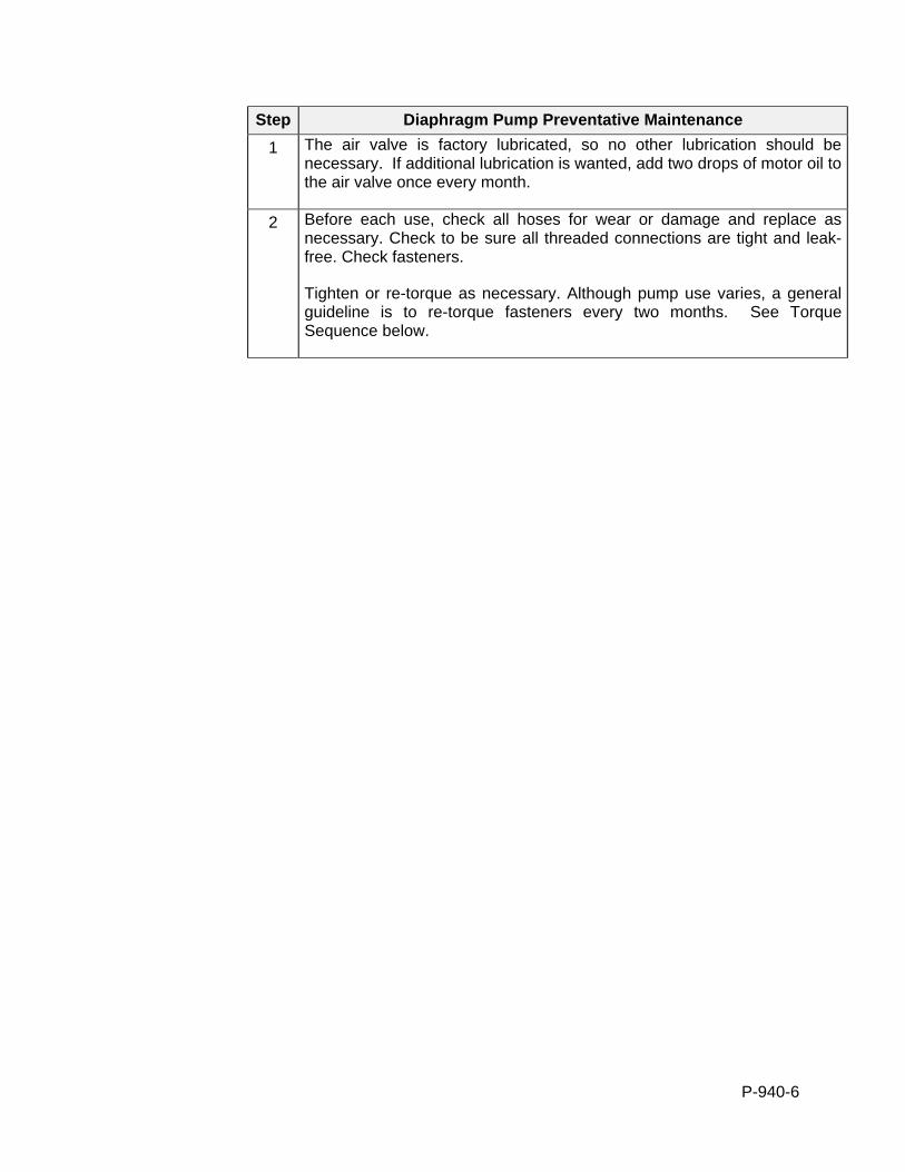
P-940-6
Step Diaphragm Pump Preventative Maintenance
1 The air valve is factory lubricated, so no other lubrication should be necessary. If additional lubrication is wanted, add two drops of motor oil to the air valve once every month.
2 Before each use, check all hoses for wear or damage and replace as necessary. Check to be sure all threaded connections are tight and leak-free. Check fasteners.
Tighten or re-torque as necessary. Although pump use varies, a general guideline is to re-torque fasteners every two months. See Torque Sequence below.
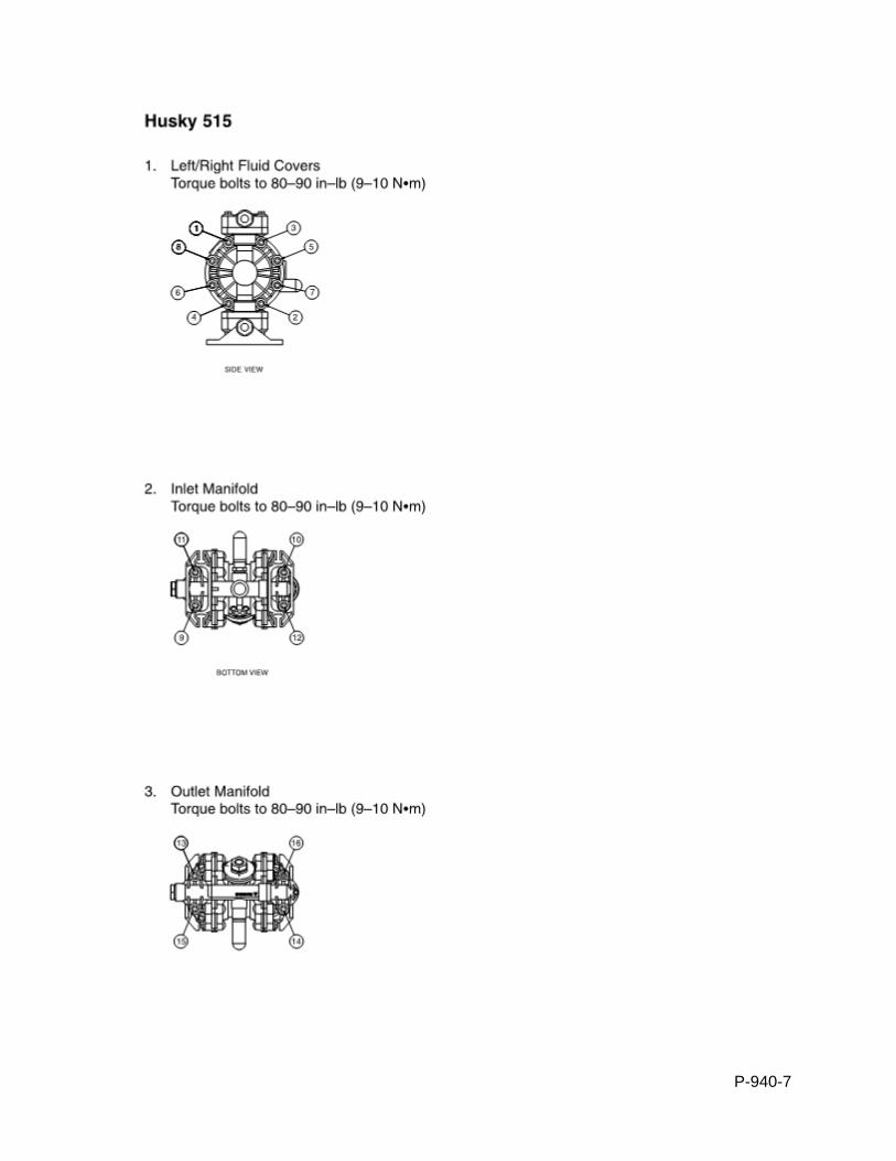
P-940-7
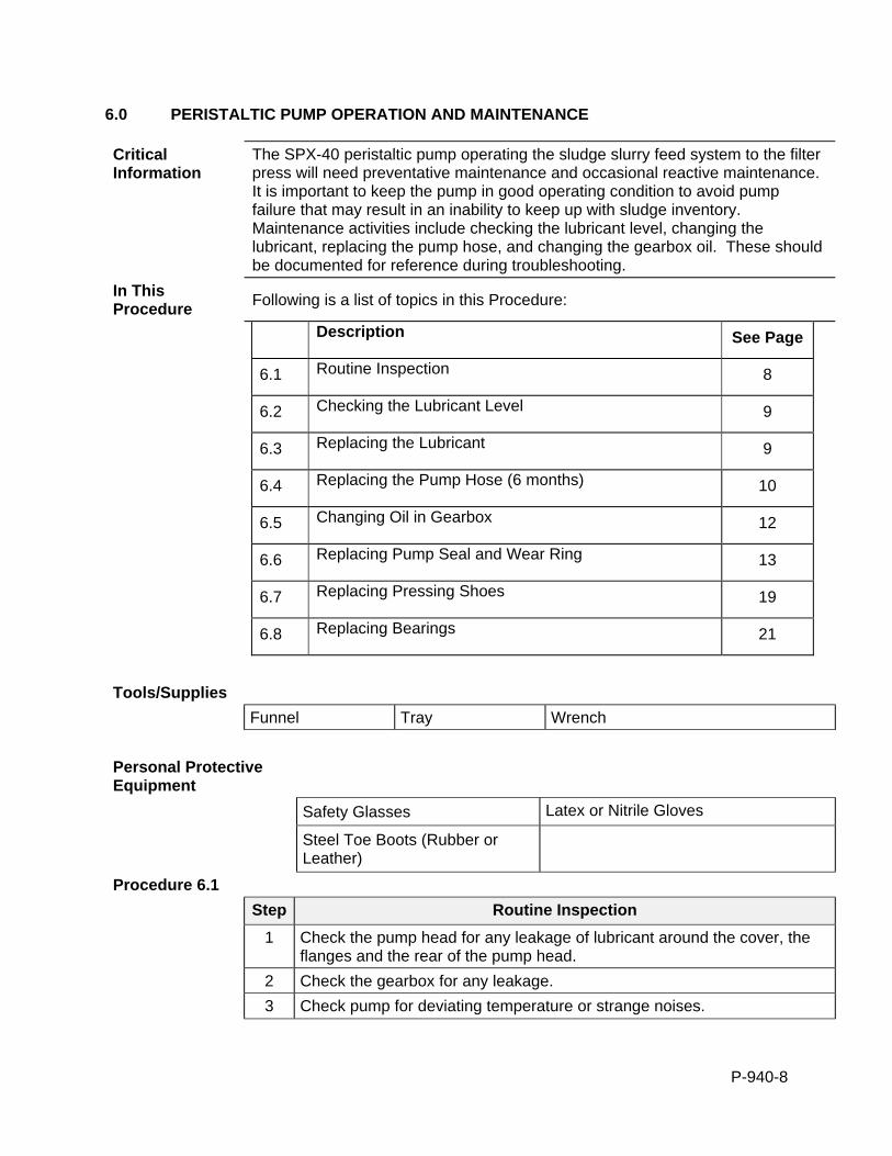
P-940-8
6.0 PERISTALTIC PUMP OPERATION AND MAINTENANCE
Critical Information
The SPX-40 peristaltic pump operating the sludge slurry feed system to the filter press will need preventative maintenance and occasional reactive maintenance. It is important to keep the pump in good operating condition to avoid pump failure that may result in an inability to keep up with sludge inventory. Maintenance activities include checking the lubricant level, changing the lubricant, replacing the pump hose, and changing the gearbox oil. These should be documented for reference during troubleshooting.
In This Procedure
Following is a list of topics in this Procedure:
Description See Page
6.1 Routine Inspection 8
6.2 Checking the Lubricant Level 9
6.3 Replacing the Lubricant 9
6.4 Replacing the Pump Hose (6 months) 10
6.5 Changing Oil in Gearbox 12
6.6 Replacing Pump Seal and Wear Ring 13
6.7 Replacing Pressing Shoes 19
6.8 Replacing Bearings 21
Tools/Supplies
Funnel Tray Wrench
Personal Protective Equipment
Safety Glasses Latex or Nitrile Gloves
Steel Toe Boots (Rubber or Leather)
Procedure 6.1
Step Routine Inspection
1 Check the pump head for any leakage of lubricant around the cover, the flanges and the rear of the pump head.
2 Check the gearbox for any leakage.
3 Check pump for deviating temperature or strange noises.
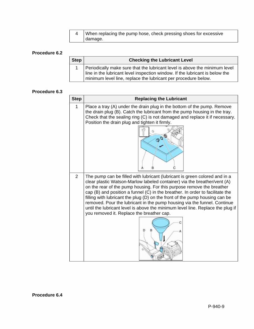
P-940-9
4 When replacing the pump hose, check pressing shoes for excessive damage.
Procedure 6.2
Step Checking the Lubricant Level
1 Periodically make sure that the lubricant level is above the minimum level line in the lubricant level inspection window. If the lubricant is below the minimum level line, replace the lubricant per procedure below.
Procedure 6.3
Step Replacing the Lubricant
1 Place a tray (A) under the drain plug in the bottom of the pump. Remove the drain plug (B). Catch the lubricant from the pump housing in the tray. Check that the sealing ring (C) is not damaged and replace it if necessary. Position the drain plug and tighten it firmly.
2 The pump can be filled with lubricant (lubricant is green colored and in a
clear plastic Watson-Marlow labeled container) via the breather/vent (A) on the rear of the pump housing. For this purpose remove the breather cap (B) and position a funnel (C) in the breather. In order to facilitate the filling with lubricant the plug (D) on the front of the pump housing can be removed. Pour the lubricant in the pump housing via the funnel. Continue until the lubricant level is above the minimum level line. Replace the plug if you removed it. Replace the breather cap.
Procedure 6.4
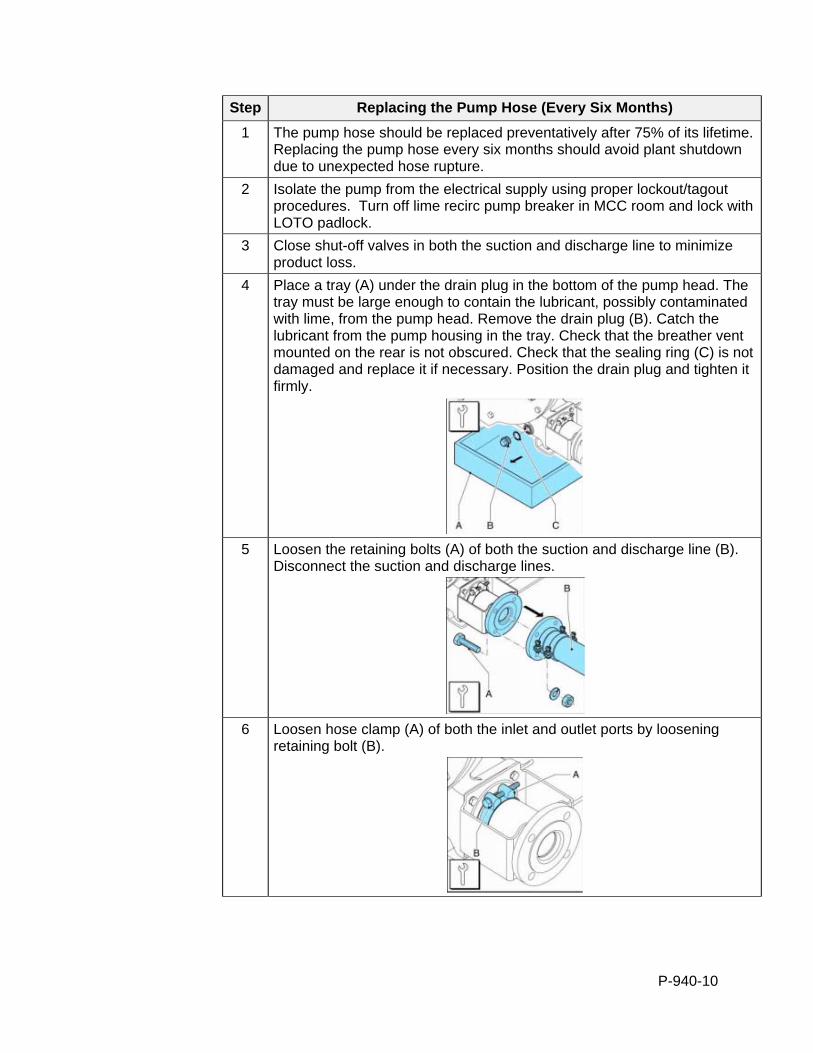
P-940-10
Step Replacing the Pump Hose (Every Six Months)
1 The pump hose should be replaced preventatively after 75% of its lifetime. Replacing the pump hose every six months should avoid plant shutdown due to unexpected hose rupture.
2 Isolate the pump from the electrical supply using proper lockout/tagout procedures. Turn off lime recirc pump breaker in MCC room and lock with LOTO padlock.
3 Close shut-off valves in both the suction and discharge line to minimize product loss.
4 Place a tray (A) under the drain plug in the bottom of the pump head. The tray must be large enough to contain the lubricant, possibly contaminated with lime, from the pump head. Remove the drain plug (B). Catch the lubricant from the pump housing in the tray. Check that the breather vent mounted on the rear is not obscured. Check that the sealing ring (C) is not damaged and replace it if necessary. Position the drain plug and tighten it firmly.
5 Loosen the retaining bolts (A) of both the suction and discharge line (B).
Disconnect the suction and discharge lines.
6 Loosen hose clamp (A) of both the inlet and outlet ports by loosening
retaining bolt (B).
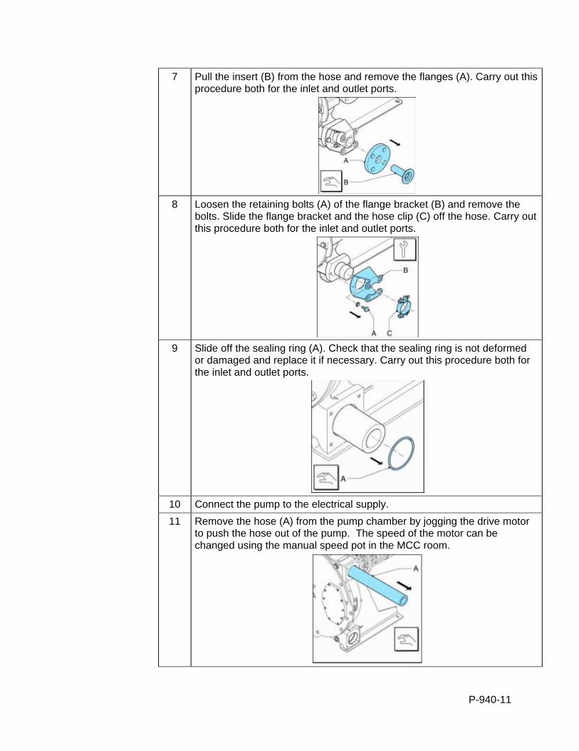
P-940-11
7 Pull the insert (B) from the hose and remove the flanges (A). Carry out this procedure both for the inlet and outlet ports.
8 Loosen the retaining bolts (A) of the flange bracket (B) and remove the
bolts. Slide the flange bracket and the hose clip (C) off the hose. Carry out this procedure both for the inlet and outlet ports.
9 Slide off the sealing ring (A). Check that the sealing ring is not deformed
or damaged and replace it if necessary. Carry out this procedure both for the inlet and outlet ports.
10 Connect the pump to the electrical supply.
11 Remove the hose (A) from the pump chamber by jogging the drive motor to push the hose out of the pump. The speed of the motor can be changed using the manual speed pot in the MCC room.
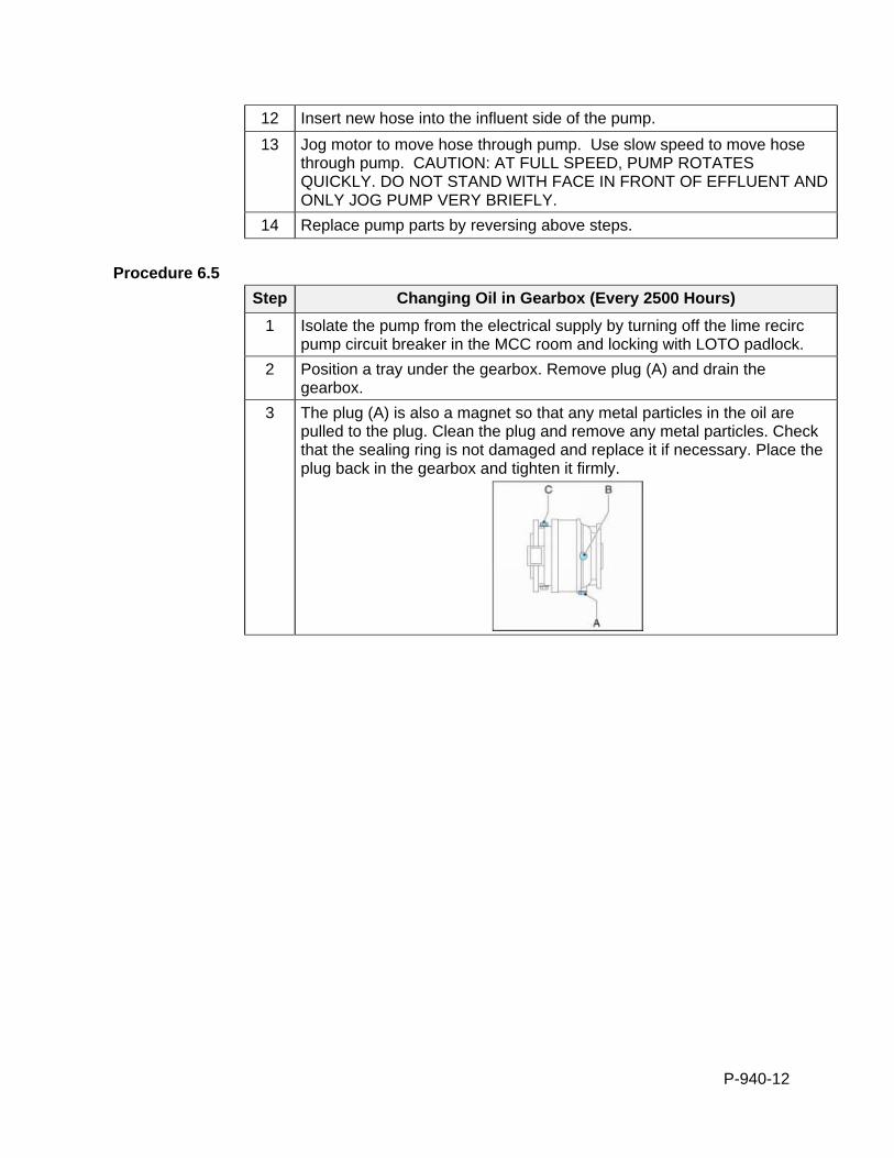
P-940-12
12 Insert new hose into the influent side of the pump.
13 Jog motor to move hose through pump. Use slow speed to move hose through pump. CAUTION: AT FULL SPEED, PUMP ROTATES QUICKLY. DO NOT STAND WITH FACE IN FRONT OF EFFLUENT AND ONLY JOG PUMP VERY BRIEFLY.
14 Replace pump parts by reversing above steps.
Procedure 6.5
Step Changing Oil in Gearbox (Every 2500 Hours)
1 Isolate the pump from the electrical supply by turning off the lime recirc pump circuit breaker in the MCC room and locking with LOTO padlock.
2 Position a tray under the gearbox. Remove plug (A) and drain the gearbox.
3 The plug (A) is also a magnet so that any metal particles in the oil are pulled to the plug. Clean the plug and remove any metal particles. Check that the sealing ring is not damaged and replace it if necessary. Place the plug back in the gearbox and tighten it firmly.
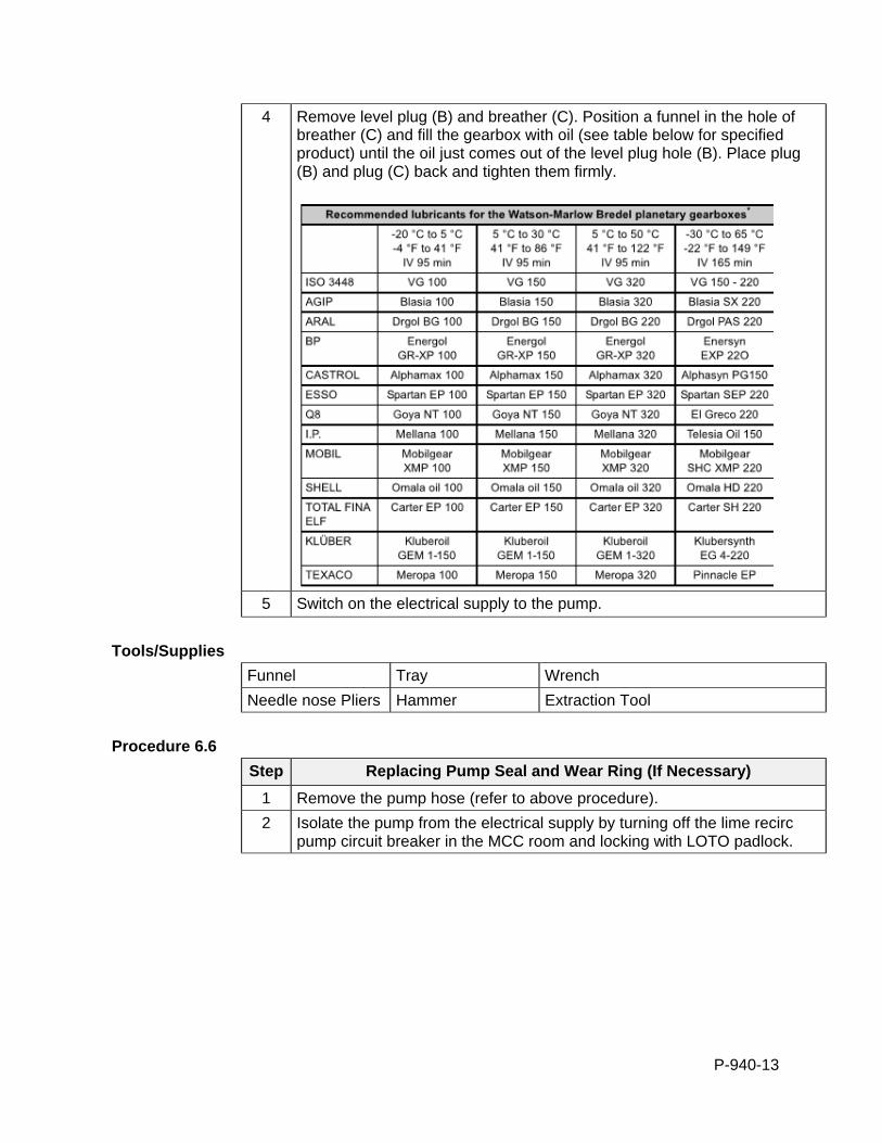
P-940-13
4 Remove level plug (B) and breather (C). Position a funnel in the hole of breather (C) and fill the gearbox with oil (see table below for specified product) until the oil just comes out of the level plug hole (B). Place plug (B) and plug (C) back and tighten them firmly.
5 Switch on the electrical supply to the pump.
Tools/Supplies
Funnel Tray Wrench
Needle nose Pliers Hammer Extraction Tool
Procedure 6.6
Step Replacing Pump Seal and Wear Ring (If Necessary)
1 Remove the pump hose (refer to above procedure).
2 Isolate the pump from the electrical supply by turning off the lime recirc pump circuit breaker in the MCC room and locking with LOTO padlock.
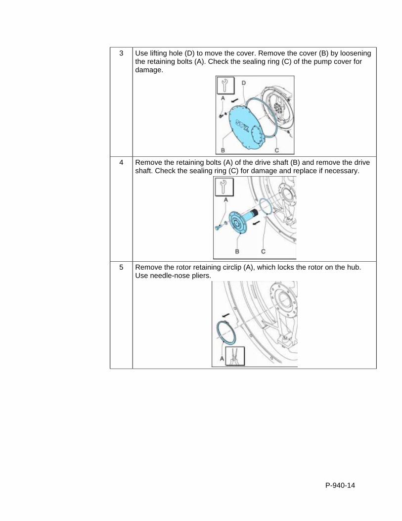
P-940-14
3 Use lifting hole (D) to move the cover. Remove the cover (B) by loosening the retaining bolts (A). Check the sealing ring (C) of the pump cover for damage.
4 Remove the retaining bolts (A) of the drive shaft (B) and remove the drive
shaft. Check the sealing ring (C) for damage and replace if necessary.
5 Remove the rotor retaining circlip (A), which locks the rotor on the hub.
Use needle-nose pliers.
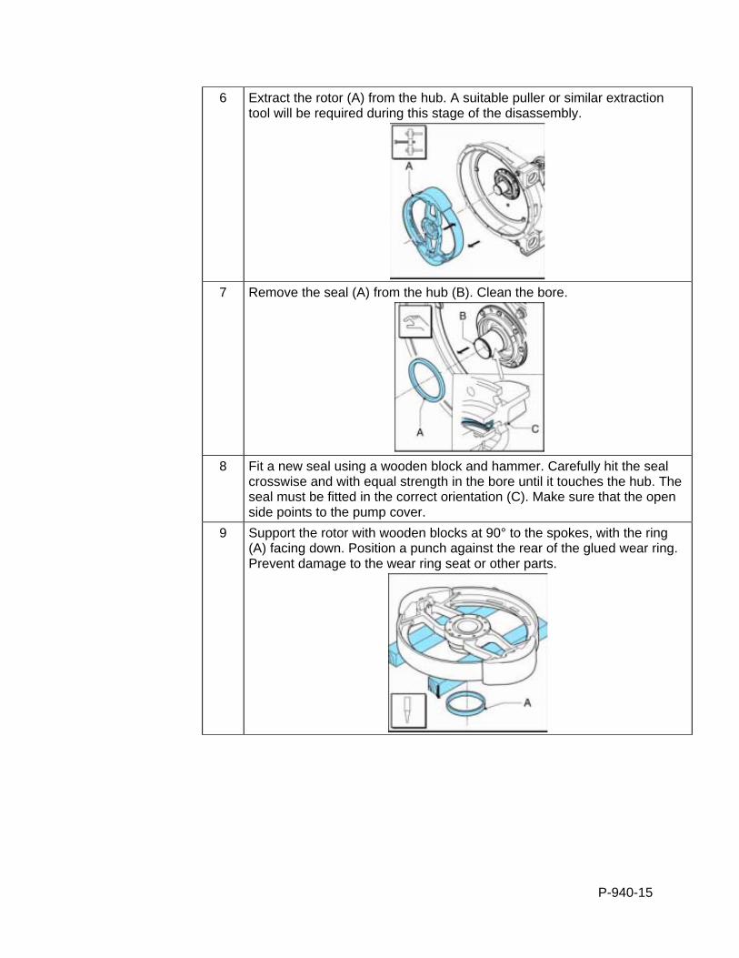
P-940-15
6 Extract the rotor (A) from the hub. A suitable puller or similar extraction tool will be required during this stage of the disassembly.
7 Remove the seal (A) from the hub (B). Clean the bore.
8 Fit a new seal using a wooden block and hammer. Carefully hit the seal
crosswise and with equal strength in the bore until it touches the hub. The seal must be fitted in the correct orientation (C). Make sure that the open side points to the pump cover.
9 Support the rotor with wooden blocks at 90° to the spokes, with the ring (A) facing down. Position a punch against the rear of the glued wear ring. Prevent damage to the wear ring seat or other parts.
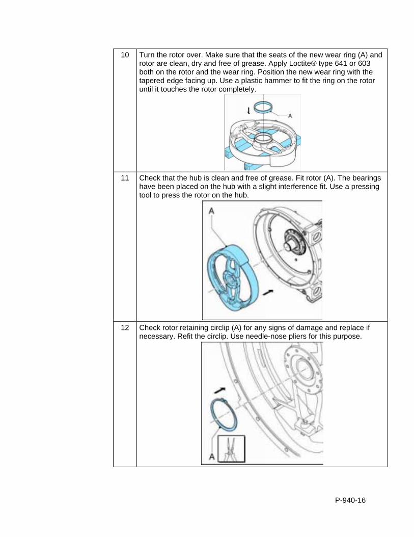
P-940-16
10 Turn the rotor over. Make sure that the seats of the new wear ring (A) and rotor are clean, dry and free of grease. Apply Loctite® type 641 or 603 both on the rotor and the wear ring. Position the new wear ring with the tapered edge facing up. Use a plastic hammer to fit the ring on the rotor until it touches the rotor completely.
11 Check that the hub is clean and free of grease. Fit rotor (A). The bearings
have been placed on the hub with a slight interference fit. Use a pressing tool to press the rotor on the hub.
12 Check rotor retaining circlip (A) for any signs of damage and replace if
necessary. Refit the circlip. Use needle-nose pliers for this purpose.
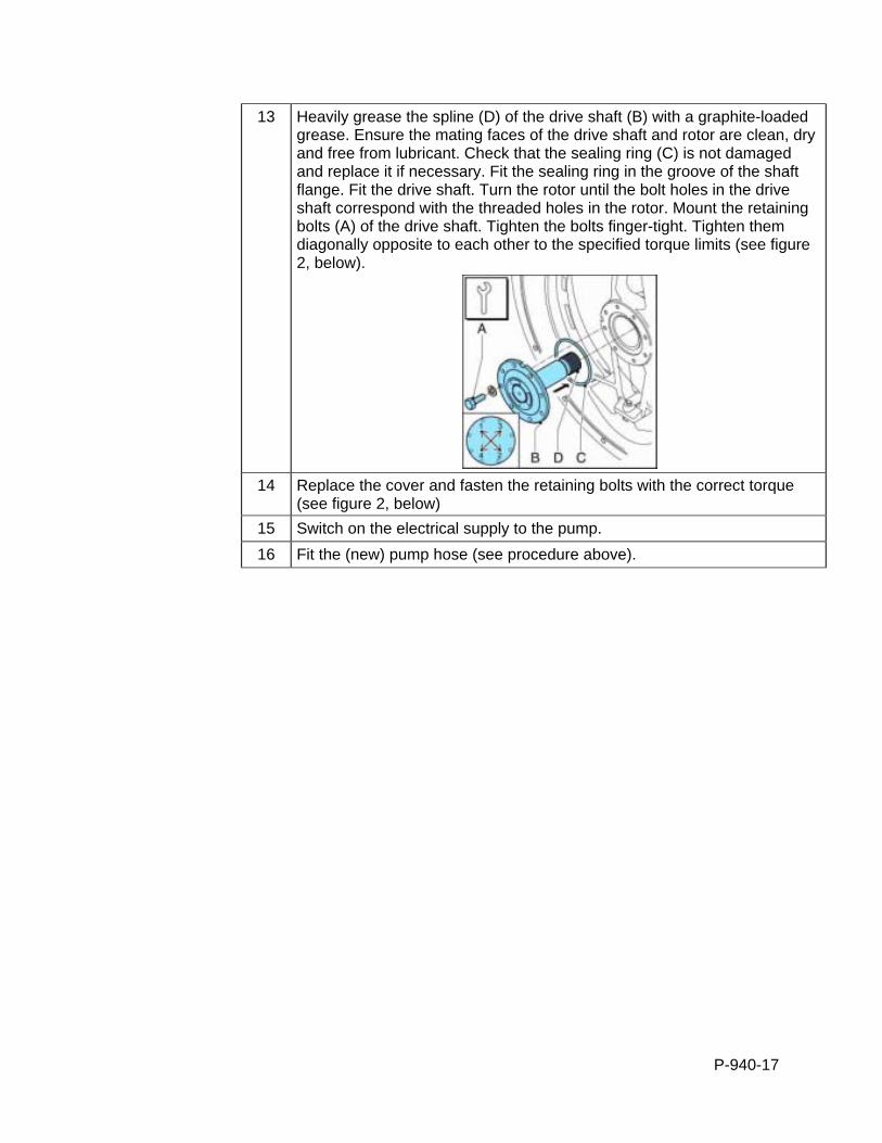
P-940-17
13 Heavily grease the spline (D) of the drive shaft (B) with a graphite-loaded grease. Ensure the mating faces of the drive shaft and rotor are clean, dry and free from lubricant. Check that the sealing ring (C) is not damaged and replace it if necessary. Fit the sealing ring in the groove of the shaft flange. Fit the drive shaft. Turn the rotor until the bolt holes in the drive shaft correspond with the threaded holes in the rotor. Mount the retaining bolts (A) of the drive shaft. Tighten the bolts finger-tight. Tighten them diagonally opposite to each other to the specified torque limits (see figure 2, below).
14 Replace the cover and fasten the retaining bolts with the correct torque
(see figure 2, below)
15 Switch on the electrical supply to the pump.
16 Fit the (new) pump hose (see procedure above).
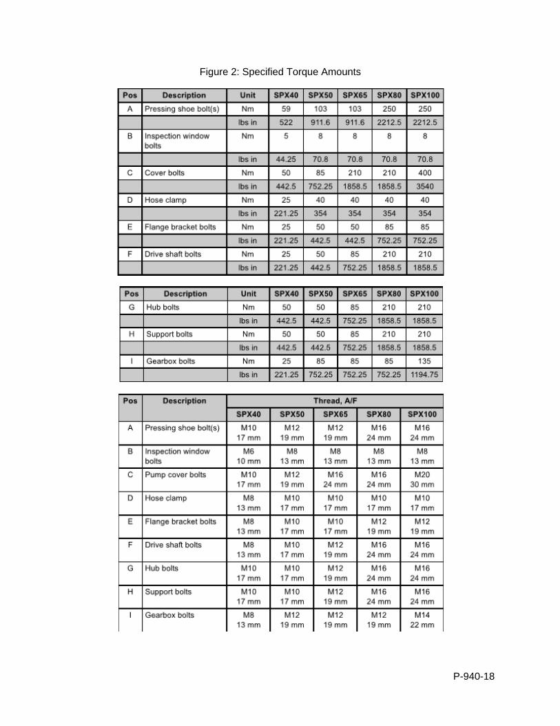
P-940-18
Figure 2: Specified Torque Amounts
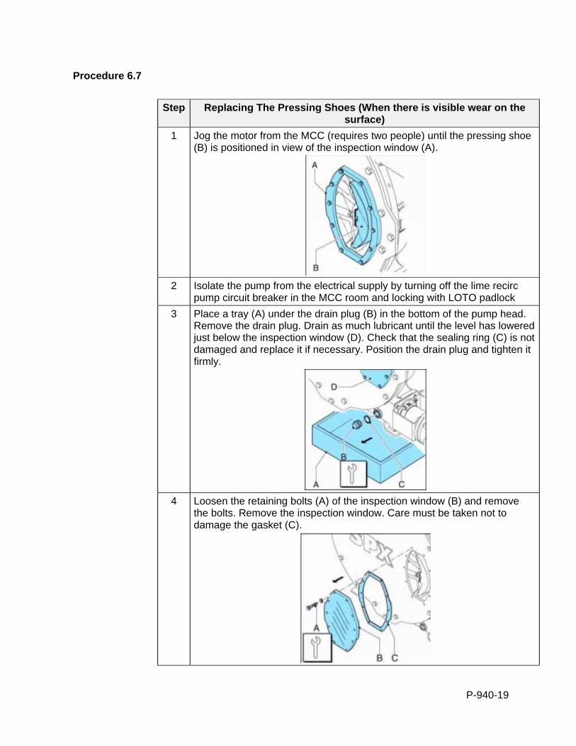
P-940-19
Procedure 6.7
Step Replacing The Pressing Shoes (When there is visible wear on the surface)
1 Jog the motor from the MCC (requires two people) until the pressing shoe (B) is positioned in view of the inspection window (A).
2 Isolate the pump from the electrical supply by turning off the lime recirc
pump circuit breaker in the MCC room and locking with LOTO padlock
3 Place a tray (A) under the drain plug (B) in the bottom of the pump head. Remove the drain plug. Drain as much lubricant until the level has lowered just below the inspection window (D). Check that the sealing ring (C) is not damaged and replace it if necessary. Position the drain plug and tighten it firmly.
4 Loosen the retaining bolts (A) of the inspection window (B) and remove
the bolts. Remove the inspection window. Care must be taken not to damage the gasket (C).
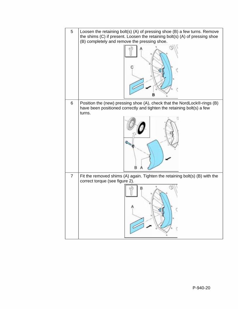
P-940-20
5 Loosen the retaining bolt(s) (A) of pressing shoe (B) a few turns. Remove the shims (C) if present. Loosen the retaining bolt(s) (A) of pressing shoe (B) completely and remove the pressing shoe.
6 Position the (new) pressing shoe (A), check that the NordLock®-rings (B)
have been positioned correctly and tighten the retaining bolt(s) a few turns.
7 Fit the removed shims (A) again. Tighten the retaining bolt(s) (B) with the
correct torque (see figure 2).
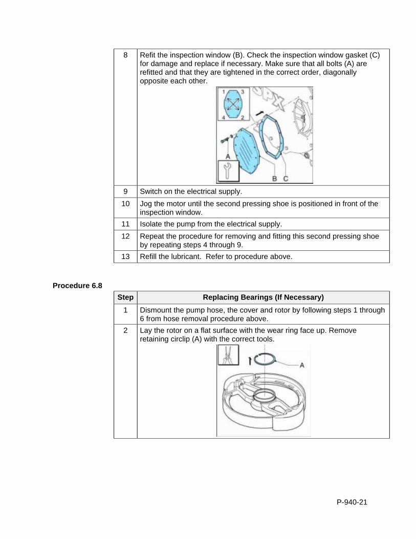
P-940-21
8 Refit the inspection window (B). Check the inspection window gasket (C) for damage and replace if necessary. Make sure that all bolts (A) are refitted and that they are tightened in the correct order, diagonally opposite each other.
9 Switch on the electrical supply.
10 Jog the motor until the second pressing shoe is positioned in front of the inspection window.
11 Isolate the pump from the electrical supply.
12 Repeat the procedure for removing and fitting this second pressing shoe by repeating steps 4 through 9.
13 Refill the lubricant. Refer to procedure above.
Procedure 6.8
Step Replacing Bearings (If Necessary)
1 Dismount the pump hose, the cover and rotor by following steps 1 through 6 from hose removal procedure above.
2 Lay the rotor on a flat surface with the wear ring face up. Remove retaining circlip (A) with the correct tools.

P-940-22
3 Turn the rotor over. Remove using the correct pressing tools, first the first bearing (C), the spacer ring (B) and the second bearing (A) from the rotor. Check the spacer ring for damage. Retain the spacer ring (B).
4 Turn the rotor over. Check that the hub is clean and dry. Press using the
pressing tool the first bearing (C) in its place. Position the spacer ring (B). Subsequently press the second bearing (A) in its place.
5 Refit the retaining circlip (A) in the rotor. Use the correct tools for this
purpose.
6 Fit the rotor, the cover and pump hose by following steps 11 through 16
from the hose replacement procedure above.
P-940-23
7.0 INSTRUMENTATION OPERATION AND MAINTENANCE
Critical Information
The filter press should be inspected by operators whenever onsite. The daily, weekly, monthly and annual service intervals listed below are suggested by Micronics and generally refer to a filter press that is used more often than weekly.
Personal Protective Equipment
Safety Glasses Latex or Nitrile Gloves
Steel Toe Boots (Rubber or Leather)
Procedure
Step Filter Press Weekly Checks
1 Hydraulic cylinders rod is clean and free from score marks and pitting.
2 Filter cloths are clean relative to the process and last wash cycle.
3 Filter cloths are not ripped, torn, or creased.
4 Plate shifter carriage tracks are clean and free from obstruction.
5 Tension of all mechanized plate shifter chains are in good order.
6 Plate shifter carriage functions in the correct manner and there is no excessive wear.
7 There are no unwanted hydraulic leaks.
8 Fluid level in the power pack is correct (look in sight window on side of HPUI reservoir).
Procedure
Step Filter Press Monthly Checks
1 All emergency stop buttons function correctly and reset accordingly.
2 No chafed, pinched or cut electrical cables.
3 No chafed, pinched or cut flexible pipes.
4 Filter plates are undamaged.
5 Press frame is undamaged.
6 Bearings and bushings are in good condition.
7 Pressure gauges are functioning and zeroing.
P-940-24
Procedure
Step Filter Press Annual Service
1 Renew hydraulic oil with the recommended lubricant (see lubrication schedule). Always renew oil filters at this time.
2 Check the performance and running conditions of the whole system. Inspect strainers, locking of relief valves, tank cover and solenoid covers etc. Check fluid temperature and pressure.
Procedure
Step Filter Press Lubrication Schedule
1 The “Fully Mechanized Filter Press Lubrication Table (Modified)” is attached and should be kept onsite and updated as applicable (also found on pages 183-187 of the filter press instructions manual located onsite).
2 Service engineers must perform maintenance according to the lubrication schedule. Be sure to document work performed by checking the respective box and noting in the field book.
3 Preferred lubricant can be found in the pdf file on page four. The locations where lubricant is necessary are on page five.
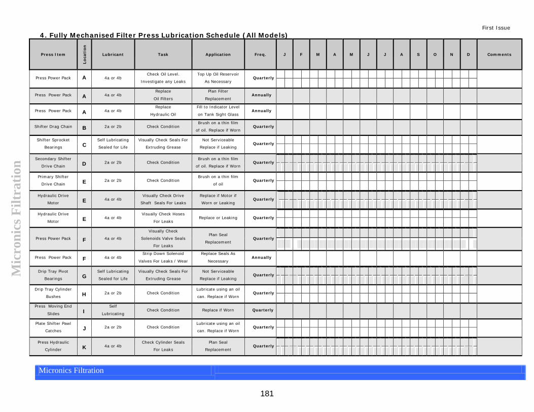
First Issue 4. Fully Mechanised Filter Press Lubrication Schedule (All Models)
181
Mic
roni
cs F
iltra
tion
Press Item
Lo
cati
on
Lubricant
Task
Application
Freq.
J
F
M
A
M
J
J
A
S
O
N
D
Comments
Press Power Pack
A 4a or 4b Check Oil Level.
Investigate any Leaks Top Up Oil Reservoir
As Necessary Quarterly
Press Power Pack
A
4a or 4b Replace
Oil Filters Plan Filter
Replacement
Annually
Press Power Pack A
4a or 4b Replace
Hydraulic Oil Fill to Indicator Level
on Tank Sight Glass
Annually
Shifter Drag Chain B
2a or 2b
Check Condition Brush on a thin film
of oil. Replace if WornQuarterly
Shifter Sprocket
Bearings
C Self Lubricating
Sealed for Life Visually Check Seals For
Extruding Grease Not Serviceable
Replace if Leaking Quarterly
Secondary Shifter
Drive Chain
D
2a or 2b Check Condition Brush on a thin film
of oil. Replace if WornQuarterly
Primary Shifter
Drive Chain
E
2a or 2b Check Condition Brush on a thin film
of oil Quarterly
Hydraulic Drive
Motor
E
4a or 4b Visually Check Drive
Shaft Seals For Leaks Replace if Motor if
Worn or Leaking Quarterly
Hydraulic Drive
Motor
E
4a or 4b Visually Check Hoses
For Leaks Replace or Leaking Quarterly
Press Power Pack
F
4a or 4b Visually Check
Solenoids Valve Seals
For Leaks
Plan Seal
Replacement Quarterly
Press Power Pack F
4a or 4b Strip Down Solenoid
Valves For Leaks / Wear
Replace Seals As
Necessary
Annually
Drip Tray Pivot
Bearings
G Self Lubricating
Sealed for Life Visually Check Seals For
Extruding Grease Not Serviceable
Replace if Leaking Quarterly
Drip Tray Cylinder
Bushes
H
2a or 2b Check Condition Lubricate using an oil
can. Replace if Worn Quarterly
Press Moving End
Slides
I Self
Lubricating
Check Condition Replace if Worn
Quarterly
Plate Shifter Pawl
Catches
J
2a or 2b Check Condition Lubricate using an oil
can. Replace if Worn Quarterly
Press Hydraulic
Cylinder
K
4a or 4b Check Cylinder Seals
For Leaks Plan Seal
Replacement Quarterly
Micronics Filtration
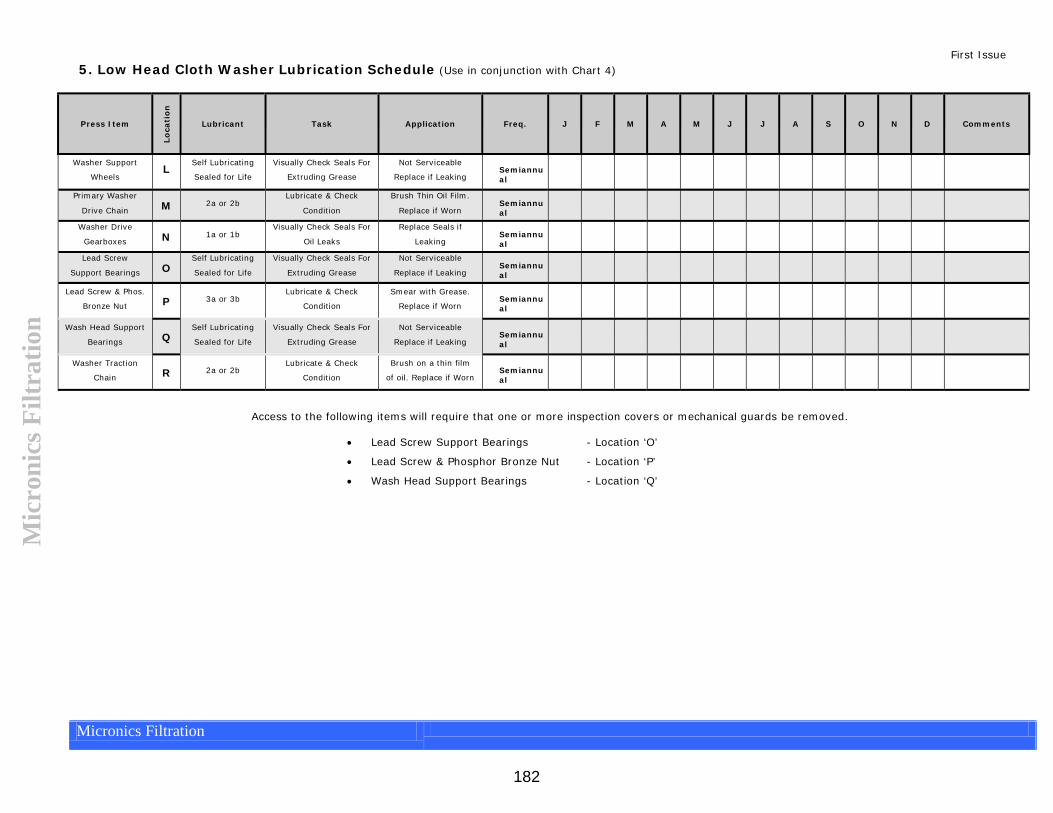
182
First Issue 5. Low Head Cloth Washer Lubrication Schedule (Use in conjunction with Chart 4)
Mic
roni
cs F
iltra
tion
Press Item
Lo
cati
on
Lubricant
Task
Application
Freq.
J
F
M
A
M
J
J
A
S
O
N
D
Comments
Washer Support
Wheels
L Self Lubricating
Sealed for Life Visually Check Seals For
Extruding Grease Not Serviceable
Replace if Leaking Semiannual
Primary Washer
Drive Chain
M
2a or 2b Lubricate & Check
Condition Brush Thin Oil Film.
Replace if Worn
Semiannual
Washer Drive
Gearboxes
N
1a or 1b Visually Check Seals For
Oil Leaks Replace Seals if
Leaking
Semiannual
Lead Screw
Support Bearings
O Self Lubricating
Sealed for Life Visually Check Seals For
Extruding Grease Not Serviceable
Replace if Leaking
Semiannual
Lead Screw & Phos.
Bronze Nut
P
3a or 3b Lubricate & Check
Condition Smear with Grease.
Replace if Worn Semiannual
Wash Head Support
Bearings
Q Self Lubricating
Sealed for Life Visually Check Seals For
Extruding Grease Not Serviceable
Replace if Leaking Semiannual
Washer Traction
Chain
R
2a or 2b Lubricate & Check
Condition Brush on a thin film
of oil. Replace if WornSemiannual
Access to the following items will require that one or more inspection covers or mechanical guards be removed.
Lead Screw Support Bearings - Location ‘O’ Lead Screw & Phosphor Bronze Nut - Location ‘P’
Wash Head Support Bearings - Location ‘Q’
Micronics Filtration
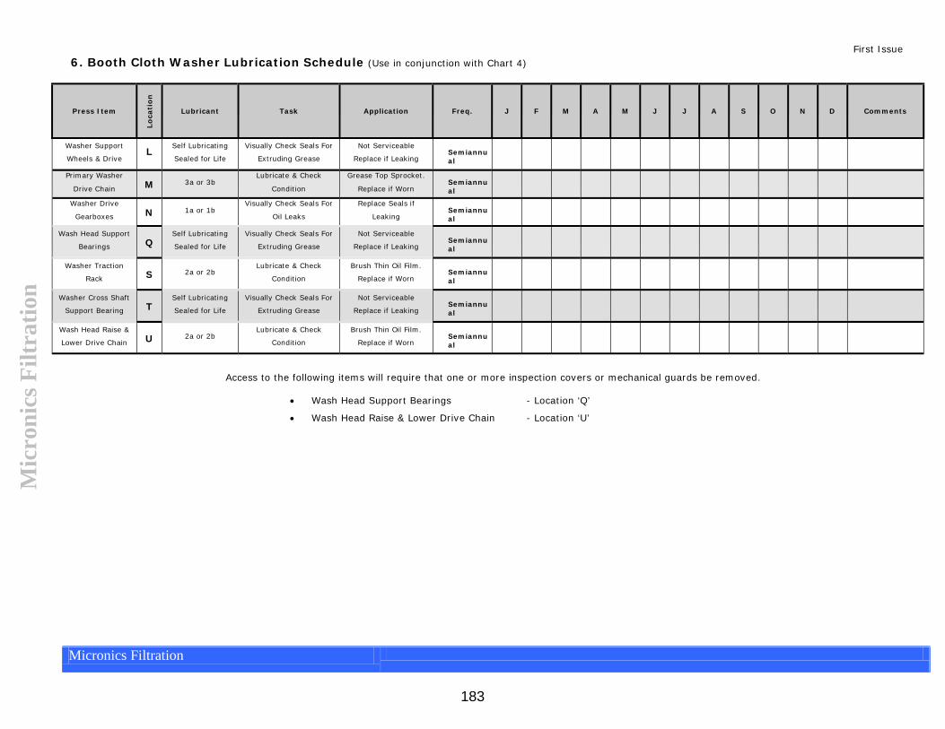
183
First Issue 6. Booth Cloth Washer Lubrication Schedule (Use in conjunction with Chart 4)
Mic
roni
cs F
iltra
tion
Press Item
Lo
cati
on
Lubricant
Task
Application
Freq.
J
F
M
A
M
J
J
A
S
O
N
D
Comments
Washer Support
Wheels & Drive
L Self Lubricating
Sealed for Life Visually Check Seals For
Extruding Grease Not Serviceable
Replace if Leaking Semiannual
Primary Washer
Drive Chain
M
3a or 3b Lubricate & Check
Condition Grease Top Sprocket.
Replace if Worn
Semiannual
Washer Drive
Gearboxes
N
1a or 1b Visually Check Seals For
Oil Leaks Replace Seals if
Leaking
Semiannual
Wash Head Support
Bearings
Q Self Lubricating
Sealed for Life Visually Check Seals For
Extruding Grease Not Serviceable
Replace if Leaking Semiannual
Washer Traction
Rack
S
2a or 2b Lubricate & Check
Condition Brush Thin Oil Film.
Replace if Worn Semiannual
Washer Cross Shaft
Support Bearing
T Self Lubricating
Sealed for Life Visually Check Seals For
Extruding Grease Not Serviceable
Replace if Leaking Semiannual
Wash Head Raise &
Lower Drive Chain
U
2a or 2b Lubricate & Check
Condition Brush Thin Oil Film.
Replace if Worn Semiannual
Access to the following items will require that one or more inspection covers or mechanical guards be removed.
Wash Head Support Bearings - Location ‘Q’ Wash Head Raise & Lower Drive Chain - Location ‘U’
Micronics Filtration
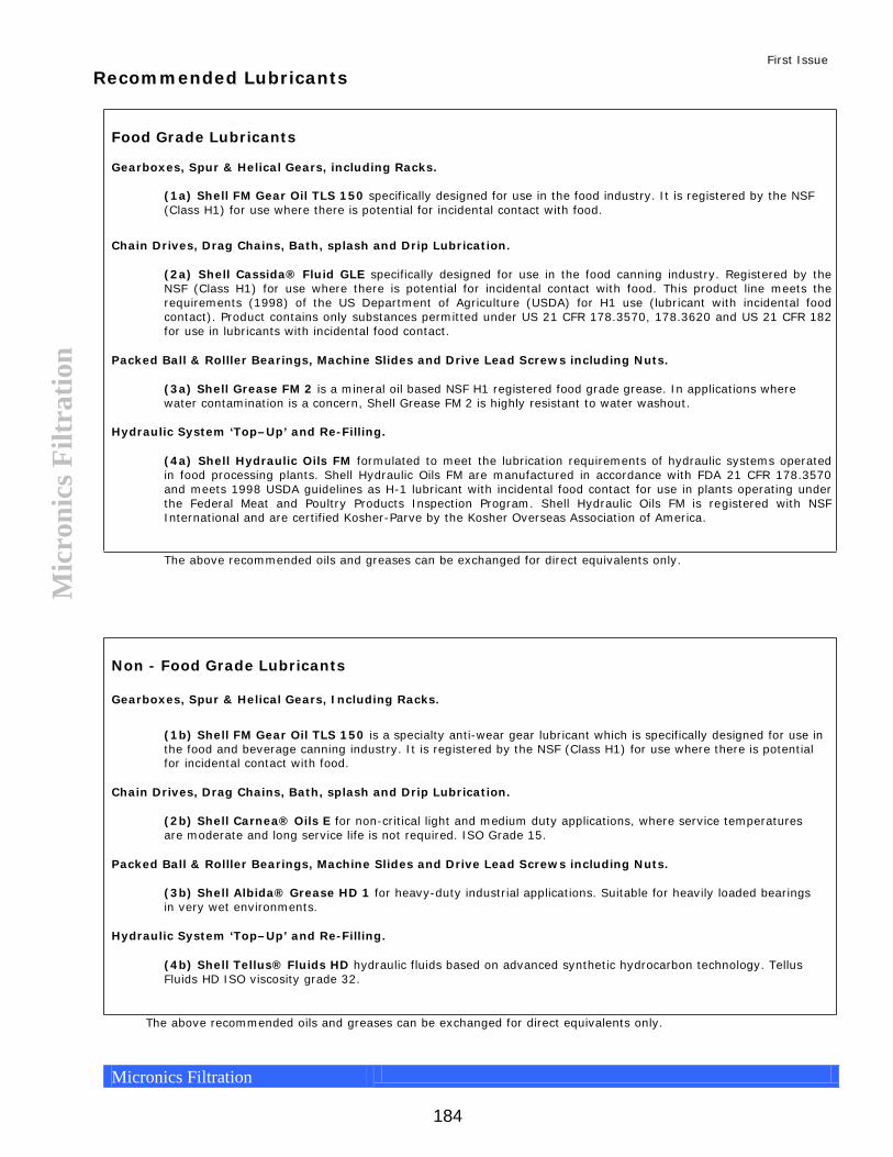
Mic
roni
cs F
iltra
tion
Recommended Lubricants
Food Grade Lubricants
Gearboxes, Spur & Helical Gears, including Racks.
First Issue
(1a) Shell FM Gear Oil TLS 150 specifically designed for use in the food industry. It is registered by the NSF (Class H1) for use where there is potential for incidental contact with food.
Chain Drives, Drag Chains, Bath, splash and Drip Lubrication.
(2a) Shell Cassida® Fluid GLE specifically designed for use in the food canning industry. Registered by the NSF (Class H1) for use where there is potential for incidental contact with food. This product line meets the requirements (1998) of the US Department of Agriculture (USDA) for H1 use (lubricant with incidental food contact). Product contains only substances permitted under US 21 CFR 178.3570, 178.3620 and US 21 CFR 182 for use in lubricants with incidental food contact.
Packed Ball & Rolller Bearings, Machine Slides and Drive Lead Screws including Nuts.
(3a) Shell Grease FM 2 is a mineral oil based NSF H1 registered food grade grease. In applications where water contamination is a concern, Shell Grease FM 2 is highly resistant to water washout.
Hydraulic System ‘Top–Up’ and Re-Filling.
(4a) Shell Hydraulic Oils FM formulated to meet the lubrication requirements of hydraulic systems operated in food processing plants. Shell Hydraulic Oils FM are manufactured in accordance with FDA 21 CFR 178.3570 and meets 1998 USDA guidelines as H-1 lubricant with incidental food contact for use in plants operating under the Federal Meat and Poultry Products Inspection Program. Shell Hydraulic Oils FM is registered with NSF International and are certified Kosher-Parve by the Kosher Overseas Association of America.
The above recommended oils and greases can be exchanged for direct equivalents only.
Non - Food Grade Lubricants
Gearboxes, Spur & Helical Gears, Including Racks.
(1b) Shell FM Gear Oil TLS 150 is a specialty anti-wear gear lubricant which is specifically designed for use in the food and beverage canning industry. It is registered by the NSF (Class H1) for use where there is potential for incidental contact with food.
Chain Drives, Drag Chains, Bath, splash and Drip Lubrication.
(2b) Shell Carnea® Oils E for non-critical light and medium duty applications, where service temperatures are moderate and long service life is not required. ISO Grade 15.
Packed Ball & Rolller Bearings, Machine Slides and Drive Lead Screws including Nuts.
(3b) Shell Albida® Grease HD 1 for heavy-duty industrial applications. Suitable for heavily loaded bearings in very wet environments.
Hydraulic System ‘Top–Up’ and Re-Filling.
(4b) Shell Tellus® Fluids HD hydraulic fluids based on advanced synthetic hydrocarbon technology. Tellus Fluids HD ISO viscosity grade 32.
The above recommended oils and greases can be exchanged for direct equivalents only.
Micronics Filtration
184

B&L Woodwaste Site
Appendix B
Control Narrative
B&L Woodwaste Site
2015 B&L Wood Waste Annual O&M Report
10/27/15 2015 Annual O&M ReportPage i
Contents
Contents .......................................................................................................................... i
List of Tables ................................................................................................................. ii
1.0 GLOSSARY OF ACRONYMS .............................................................................. 1
1.1 GENERAL PHILOSOPHY OF ALARMS AND WARNINGS .................................. 1
1.2 GENERAL PHILOSOPHY OF SYSTEM SHUTDOWN ......................................... 2
2.0 WELL PUMPS AND ANCILLARY UNITS ............................................................ 3
2.1 PROCESS DESCRIPTION ................................................................................... 3
2.2 CONTROL NARRATIVE ....................................................................................... 4
2.2.1 General ................................................................................................... 4
2.2.2 Well Pumps ............................................................................................. 5
2.2.4 Sanitary Sewer Lift Station...................................................................... 7
2.3 ALARMS ................................................................................................................ 7
3.0 CHEMICAL OXIDATION SYSTEM ...................................................................... 8
3.1 CONTROL NARRATIVE ....................................................................................... 8
3.1.1 Inlet Piping .............................................................................................. 8
3.1.2 Head Tank .............................................................................................. 8
3.1.3 Dosing System ........................................................................................ 8
3.1.4 Oxidation Tank ........................................................................................ 9
3.2 ALARMS ................................................................................................................ 9
4.0 CO-PRECIPITATION SYSTEM .......................................................................... 10
4.1 CONTROL NARRATIVE ..................................................................................... 10
4.1.1 Co-Precipitation Tank ........................................................................... 10
4.1.2 Lime Slurry Dosing ............................................................................... 10
4.1.3 Coagulant Dosing ................................................................................. 11
4.2 ALARM ................................................................................................................ 11
5.0 SETTLING SYSTEM .......................................................................................... 12
5.1 CONTROL NARRATIVE ..................................................................................... 12
5.1.1 Clarifier Skid ......................................................................................... 12
5.1.2 Polymer Dosing .................................................................................... 12
B&L Woodwaste Site
2015 B&L Wood Waste Annual O&M Report
10/27/15 2015 Annual O&M ReportPage ii
5.2 ALARMS .............................................................................................................. 13
6.0 PH ADJUST SYSTEM ........................................................................................ 14
6.1 CONTROL NARRATIVE ..................................................................................... 14
6.1.1 pH Adjust Tank ..................................................................................... 14
6.2.2 Acid Dosing ........................................................................................... 14
6.2 ALARMS .............................................................................................................. 15
7.0 FILTRATION AND ADSORPTION SYSTEM ..................................................... 16
7.1 CONTROL NARRATIVE ..................................................................................... 16
7.1.1 Bag Filters ............................................................................................. 16
7.1.2 Cartridge Filters .................................................................................... 16
7.1.3 Adsorption Columns ............................................................................. 16
7.2 ALARMS .............................................................................................................. 17
8.0 SLUDGE MANAGEMENT SYSTEM .................................................................. 18
8.1 CONTROL NARRATIVE ..................................................................................... 18
8.1.1 Sludge Tank .......................................................................................... 18
8.1.2 Filter Press ............................................................................................ 18
8.1.3 Process Sump ...................................................................................... 19
8.2 ALARMS .............................................................................................................. 19
9.0 SAFETY ............................................................................................................. 20
List of Tables
Table 2.1 Groundwater Recovery System Drawing Reference
Table 2.2 Groundwater Recovery System Equipment
Table 2.3 Groundwater Recovery System Alarms
Table 3.1 Chemical Oxidation System Drawing Reference
Table 3.2 Chemical Oxidation System Equipment
Table 3.3 Chemical Oxidation System Alarms
Table 4.1 Co-precipitation System Drawing Reference
Table 4.2 Co-precipitation System Equipment

B&L Woodwaste Site
2015 B&L Wood Waste Annual O&M Report
10/27/15 2015 Annual O&M ReportPage iii
Table 4.3 Co-precipitation System Alarms Table 5.1 Settling System Drawing Reference
Table 5.2 Settling System Equipment
Table 5.3 Settling System Alarms
Table 6.1 pH adjust System Drawing Reference
Table 6.2 pH adjust System Equipment
Table 6.3 pH adjust System Alarms
Table 7.1 Filtration and Adsorption System Drawing Reference
Table 7.2 Filtration and Adsorption System Equipment
Table 7.3 Filtration and Adsorption System Alarms
Table 8.1 Sludge Management System Drawing Reference
Table 8.2 Sludge Management System Equipment
Table 8.3 Sludge Management System Alarms
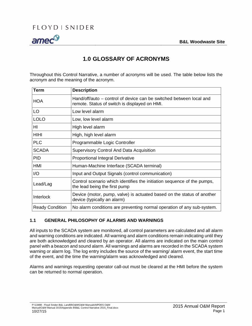
B&L Woodwaste Site
P:\13488 - Floyd Snider-B&L Landfill\O&M\O&M Manuals\NPDES O&M Manual\O&M Manual 2015\Appendix B\B&L Control Narrative 2015_Final.docx
10/27/15 2015 Annual O&M Report
Page 1
1.0 GLOSSARY OF ACRONYMS
Throughout this Control Narrative, a number of acronyms will be used. The table below lists the acronym and the meaning of the acronym.
Term Description HOA Hand/off/auto – control of device can be switched between local and
remote. Status of switch is displayed on HMI. LO Low level alarm LOLO Low, low level alarm HI High level alarm HIHI High, high level alarm PLC Programmable Logic Controller SCADA Supervisory Control And Data Acquisition PID Proportional Integral Derivative HMI Human-Machine Interface (SCADA terminal) I/O Input and Output Signals (control communication)
Lead/Lag Control scenario which identifies the initiation sequence of the pumps,
the lead being the first pump Interlock Device (motor, pump, valve) is actuated based on the status of another
device (typically an alarm) Ready Condition No alarm conditions are preventing normal operation of any sub-system.
1.1 GENERAL PHILOSOPHY OF ALARMS AND WARNINGS
All inputs to the SCADA system are monitored, all control parameters are calculated and all alarm and warning conditions are indicated. All warning and alarm conditions remain indicating until they are both acknowledged and cleared by an operator. All alarms are indicated on the main control panel with a beacon and sound alarm. All warnings and alarms are recorded in the SCADA system warning or alarm log. The log entry includes the source of the warning/ alarm event, the start time of the event, and the time the warning/alarm was acknowledged and cleared.
Alarms and warnings requesting operator call-out must be cleared at the HMI before the system can be returned to normal operation.
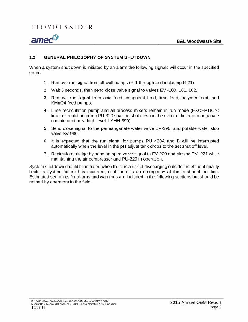
B&L Woodwaste Site
P:\13488 - Floyd Snider-B&L Landfill\O&M\O&M Manuals\NPDES O&M Manual\O&M Manual 2015\Appendix B\B&L Control Narrative 2015_Final.docx
10/27/15 2015 Annual O&M Report
Page 2
1.2 GENERAL PHILOSOPHY OF SYSTEM SHUTDOWN
When a system shut down is initiated by an alarm the following signals will occur in the specified order:
1. Remove run signal from all well pumps (R-1 through and including R-21)
2. Wait 5 seconds, then send close valve signal to valves EV -100, 101, 102.
3. Remove run signal from acid feed, coagulant feed, lime feed, polymer feed, and KMnO4 feed pumps.
4. Lime recirculation pump and all process mixers remain in run mode (EXCEPTION: lime recirculation pump PU-320 shall be shut down in the event of lime/permanganate containment area high level, LAHH-390).
5. Send close signal to the permanganate water valve EV-390, and potable water stop valve SV-980.
6. It is expected that the run signal for pumps PU 420A and B will be interrupted automatically when the level in the pH adjust tank drops to the set shut off level.
7. Recirculate sludge by sending open valve signal to EV-229 and closing EV -221 while maintaining the air compressor and PU-220 in operation.
System shutdown should be initiated when there is a risk of discharging outside the effluent quality limits, a system failure has occurred, or if there is an emergency at the treatment building. Estimated set points for alarms and warnings are included in the following sections but should be refined by operators in the field.
B&L Woodwaste Site
P:\13488 - Floyd Snider-B&L Landfill\O&M\O&M Manuals\NPDES O&M Manual\O&M Manual 2015\Appendix B\B&L Control Narrative 2015_Final.docx
10/27/15 2015 Annual O&M Report
Page 3
2.0 WELL PUMPS AND ANCILLARY UNITS
2.1 PROCESS DESCRIPTION
There are 10 constant speed well pumps in the recovery wells located outside the landfill area (Wells R-12 – R-21). These will have their flow rates set manually by means of a back pressure valve on the pump discharge in each local well vault and either the local flow meter or a portable ultrasonic flow meter reading. It is expected that the flow rates will range between 0 and 3 gallons per minute (gpm), with existing flow settings as follows:
Well Flow (gpm)
Well
Flow (gpm)
R-12 2.1 R-17 1 R-13 1.6 R-18 1 R-14 1.6 R-19 1 R-15 1.6 R-20 1 R-16 1 R-21 1
Flow rates for the above wells will be set manually, based on manual field measurements in nearby wells and piezometers. The objective for operation of these wells is to establish and maintain a capture zone adjacent to the wells. In general, these wells are expected to operate continuously. Periodic shutdown may be required during flooding conditions or other conditions affecting performance of the treatment process.
Within the landfill, groundwater elevations are monitored continuously by transducers placed within a series of 19 piezometers distributed around the boundary of the landfill. These piezometers consist of 16 paired piezometers (the pairs designated with an “a” or “b”) that are located on either side of the subsurface barrier wall. These 8 piezometer pairs are used to determine the groundwater gradient across the barrier wall. At three locations, a third piezometer completed in the lower sand aquifer is present (designated “c”). The “c” piezometers are used to determine the upward gradient at these locations. The deeper piezometers are compared to the shallow piezometers to determine the vertical gradient. Inward gradients are determined by subtracting the inside groundwater level (“b” piezometers from the outside level (“a” piezometers) and the upward gradient is determined by subtracting the “b” piezometer reading from the “c” piezometer reading.
The 11 recovery wells (Wells R-1 through R-11) completed beneath the landfill are each equipped with a variable speed well pump. These wells will be under automatic control (speed and on/off) to establish and maintain inward and upward groundwater gradients as determined by the piezometer network. The existing average flow for these wells to achieve the control objective are as follows:
B&L Woodwaste Site
P:\13488 - Floyd Snider-B&L Landfill\O&M\O&M Manuals\NPDES O&M Manual\O&M Manual 2015\Appendix B\B&L Control Narrative 2015_Final.docx
10/27/15 2015 Annual O&M Report
Page 4
Well Flow Rate
(gpm)
Well Flow Rate
(gpm) R-1 2 R-7 8 R-2 3 R-8 1 R-3 0 R-9 8 R-4 2 R-10 3 R-5 1 R-11 0.25 R-6 0
2.2 CONTROL NARRATIVE
2.2.1 General
The principal process control requirements are to:
1. Maintain an inward gradient of at least 6 inches (0.5 feet); i.e. maintain the pump flows within the landfill zone such that the water level beneath the landfill cap is at least six inches below that outside the landfill, and the groundwater tends to enter the landfill area from the outside as a result. This gradient will be measured by the “a” and “b” piezometers. This criterion is a legally enforceable requirement that must be achieved continuously by the groundwater recovery system.
2. Maintain an upward gradient as determined by the “b” and “c” piezometers. No legally enforceable numeric criterion has been established for the upward gradient
The general control strategy for groundwater recovery shall be as follows:
1. Outside Area Recovery Wells (R-12 – R-21)
a. The PLC shall poll the 10 recovery well pumps to monitor status, and alarm if a pump is turned off.
b. The PLC shall allow remote control of well pumps, with associated activation/deactivation of pump alarm actuation. If a pump is manually turned off its alarm will also be deactivated until the pump is turned on again.
2. Landfill Recovery Wells (R-1 – R-11)
a. The PLC shall poll the 19 pressure transducers in the piezometers at an operator-defined frequency, verifying proper operation of each transducer and recording the level measurement. Each transducer will require calibration to convert the reading into a level measurement. The protocol must allow for re- calibration by the operator. Water levels in each piezometer are to be recorded at the polling frequency.
B&L Woodwaste Site
P:\13488 - Floyd Snider-B&L Landfill\O&M\O&M Manuals\NPDES O&M Manual\O&M Manual 2015\Appendix B\B&L Control Narrative 2015_Final.docx
10/27/15 2015 Annual O&M Report
Page 5
b. Cross wall differential head shall be calculated and recorded at the polling frequency for each of the 8 shallow piezometer pairs, (xx-b and xx-a). This applies to all 8 measurement nodes.
c. Upward differential head shall be calculated and recorded at the polling frequency for the each of the 3 piezometer clusters (xx-b and xx-c).
d. The cross wall differential head will be used for primary control of pumping rates from the landfill recovery wells, with control actions taken at an interval input to the PLC by the operator.
e. The upward gradient will be used for trim control of landfill recovery wells, with control actions taken at an interval input to the PLC by the operator.
f. Total flow will be monitored by the PLC, with total flow readings available for remote monitoring by operators.
2.2.2 Well Pumps
Pump control will be done as described below.
1. Outside Area Recovery Wells (R-12 – R-21)
a. Well operation will be manual or automatic on/off, with automatic operation determined by operator input, trim control for total flow, or automatic system shutdown.
2. Landfill Area Recovery Wells (R-1 – R-11)
a. Primary Flow Control
i. Primary control actions for the PLC will be taken at a time interval to be input by the operator. It is anticipated that control actions will be on the order of once every 8 -12 hours, but the time interval may be longer or shorter.
ii. Based on groundwater modeling results, the cross wall piezometers have been grouped based on predicted behavior. The PLC will utilize cross wall differential heads in the following manner:
Head Differential Control Basis
PZ-1a/b Use calculated head differential for control
PZ-2a/b & PZ-3a/b Determine minimum head differential and use the
minimum for control
PZ-4a/b Use calculated head differential for control
PZ-5a/b Use calculated head differential for control
B&L Woodwaste Site
P:\13488 - Floyd Snider-B&L Landfill\O&M\O&M Manuals\NPDES O&M Manual\O&M Manual 2015\Appendix B\B&L Control Narrative 2015_Final.docx
10/27/15 2015 Annual O&M Report
Page 6
PZ-6a/b & PZ-7a/b Determine minimum head differential and use the
minimum for control
PZ-8a/b Use calculated head differential for control
PZ-4b/c & PZ-5b/c Determine minimum head differential and use the
minimum for control
PZ-8b/c Use calculated head differential for control
iii. For each of the 6 cross-wall differential gradients identified above for control, the PLC must provide for 4 action levels to be used for control purposes. The action levels will be input to a lookup table by the operator either locally or remotely. The lookup table will contain cross wall gradient values that will initiate a control action for pumping wells.
iv. For each action level associated with each of the 6 cross wall differentials to be used for control, the PLC will select pumping speeds for recovery wells from a lookup table. The PLC will provide for operator input to associate up to 3 wells with each of the 6 head differentials. The PLC will also provide for operator input of pumping speeds into a lookup table of control setpoints for up to 3 wells associated with each of the 6 head differentials. The speed setpoint lookup table for each head differential would accept 4 speed setpoints for each well to correspond with the 4 action levels described above.
v. The PLC will implement flow control for each of the 11 landfill recovery wells based on the flow control lookup tables for cross wall differential head measured at the 6 head differentials used for control. The operator inputs will associate specific pumping wells with each control head differential, and will be done such that duplicate flow setpoints settings will not be issued for any well (i.e., specific wells will be associated with each control head differential, and no well will be associated with more than one head differential).
b. Trim Control
i. Trim control of the recovery wells will be based upon the upward differential heads determined at the 2 vertical head differentials to be used for control, as identified above (i.e., the head differentials calculated from the xx-c piezometer pairs). For each of the 2 upward control differentials, the PLC will provide for 3 action levels that will be used to implement control actions. The PLC must allow operator input of the action levels for each of the 2 control differentials.
ii. For each of the 2 upward differential head pairs, the PLC will have the capability to implement a control action (i.e., to alter the pumping set point) in wells to be associated with the control differential. The PLC must accept

B&L Woodwaste Site
P:\13488 - Floyd Snider-B&L Landfill\O&M\O&M Manuals\NPDES O&M Manual\O&M Manual 2015\Appendix B\B&L Control Narrative 2015_Final.docx
10/27/15 2015 Annual O&M Report
Page 7
operator input to associate up to 3 of the 11 landfill recovery wells with either control head differential.
iii. Based on the head differential action levels, the PLC will increment the primary flow setpoints for the associated recovery wells. The PLC will provide the capability for the operator to input the magnitude of the setpoint increments. Three setpoint increment values will be input, to be associated with the three different head differential action levels. The same setpoint increment will be used for the two upward head differentials used for control.
The PLC will also compare the total flow rate for the GWTP (as measured by FIT-100) to an operator-inputted value after each recovery well control action. If the total flow exceeds the input criterion, the PLC will issue an alarm. The purpose of the alarm is to notify remote personnel of high flow conditions that may require operator attention. It is anticipated that the high flow input will be a value between the design average flow rate of 40 gpm and the maximum hydraulic capacity of 60 gpm.
2.2.4 Sanitary Sewer Lift Station
There is a grinder pump and sump for sanitary waste leaving the building. The lift station has a local controller and alarms. The operating status and any alarm conditions from the lift station must be displayed locally and be tied to the PLC for remote logging and reporting purposes.
2.3 ALARMS
Groundwater recovery system reference drawings and system equipment are summarized in Tables 2.1 and 2.2 respectively. Table 2.3 summarizes the alarm conditions and interlocks for the 8 piezometer pairs located around the landfill.
B&L Woodwaste Site
P:\13488 - Floyd Snider-B&L Landfill\O&M\O&M Manuals\NPDES O&M Manual\O&M Manual 2015\Appendix B\B&L Control Narrative 2015_Final.docx
10/27/15 2015 Annual O&M Report
Page 8
3.0 CHEMICAL OXIDATION SYSTEM
3.1 CONTROL NARRATIVE
3.1.1 Inlet Piping
Pumping of groundwater will be controlled at the PLC (refer to Section 3 for well field controls). Wells in the Landfill A, Landfill B and Wetland/East Boundary areas are piped to the treatment building and into the head tank in three separate lines. The lines can each be shut off/on locally via a manual gate valve and remotely via a solenoid valve. The position of the solenoid valve is both displayed on the HMI and can be manipulated by the operator at the HMI. The solenoid valves and well pumps are also interlocked to the high level switch in the head tank and are shut off when the HI level alarm is triggered by a float valve.
3.1.2 Head Tank
The water level in the head tank is determined by the inflow from the wells and outflow from the tank. A high level float switch (LSH-100) located in the head tank is triggered when the water level reaches a near overflow state. At this level the solenoid valves EV-100, EV-101, and EV-102 are triggered to shut and all 21 well pumps are triggered to shut off and an alarm is sounded at the PLC and a call out to warn the operator. Water flows out of the head tank to the oxidation tank by gravity and can be shut off/on locally via a gate valve. Normally this valve will be in the open position. A flow meter located between the head and oxidation tank continuously measures the flow from the head tank and displays this value both locally and on the HMI. Flow is displayed as it is measured in real time and as a total flow on the HMI. Total flow is calculated by the PLC based on the pulse output from the flowmeter. An alarm on the HMI is triggered when the flow is either above a set HI value or below a set LO value. The flow measurement is used to control the KMnO4 dosing pumps.
3.1.3 Dosing System
The KMnO4 feed solution will be prepared manually by the operator. The KMnO4 is stirred in the dosing tank (TK-310) by a mixer on a batch basis. The mixer is a constant speed mixer and can be shut on/off locally via an HOA switch. The status of the mixer (on/off) is displayed on the PLC. The mixer needs to operate only when a new batch of solution is being mixed; once the solid permanganate is fully dissolved the mixer will be shut off. This mixer shutoff will be via an operator-adjustable timer. KMnO4 solution is mixed in the tank on a manually controlled batch basis.
Granular, crystalline KMnO4 is loaded into the dosing tank manually by an operator by dumping 5 gallon pails into the dosing tank. Clean water is also added to the dosing tank to achieve the target KMnO4 concentration as specified in the current addition of the O&M Manual and is determined by the water level in the tank. The solenoid valve (EV-390) on the water line will be manually opened by selecting the begin batch button and automatically closed by the PLC when the level sensor reaches the HI level. A hand valve on the water line allows the water to be shut
B&L Woodwaste Site
P:\13488 - Floyd Snider-B&L Landfill\O&M\O&M Manuals\NPDES O&M Manual\O&M Manual 2015\Appendix B\B&L Control Narrative 2015_Final.docx
10/27/15 2015 Annual O&M Report
Page 9
on/off manually in case of solenoid valve failure. Normally the water line valves will be closed and will only be switched open when a batch is being mixed.
The solution level in the tank is monitored by an ultrasonic level meter and is displayed both locally and on the HMI. When the water level measured reaches the LO or HI level a warning alarm is triggered by the PLC and displayed on the HMI. At the low level a new batch should be made. At the high level the water line solenoid valve (EV-390) is closed. The dosing tank is equipped with a float switch which triggers at the HIHI level, indicating the tank level is nearing overflow. When the switch reaches the HIHI water level an alarm is triggered on the PLC and a callout is sent to the operator. Both the level switch and level sensor trigger alarms at the high water level as a safety measure in case either device fails.
Outflow from the dosing tank is pumped via one of two diaphragm metering pumps on the dosing skid to the oxidation tank. Only one pump will normally operate, as the second pump is an installed spare. Control of the pumps is via HOA switches. The status of the pump (on, off) is displayed on the PLC. Isolation valves for pump servicing are located upstream and downstream of each pump and can be manually manipulated. In the event that a pump is operating against a closed isolation valve, or other downstream blockage (automatic block valve failure, back pressure valve failure) each pump discharge is equipped with a pressure relief valve that discharges back to the KMnO4 tank. The pumps are variable speed and will dose automatically proportional to the flow of wastewater into the oxidation tank based on a ratio input by the operator. This ratio will need to be adjusted as necessary by the operator given the concentration of oxidizable constituents in the groundwater. In addition, the pump stroke length can be manually adjusted by the operator. Pressure in the pump discharge line is measured and displayed locally.
3.1.4 Oxidation Tank
ORP is analyzed in the oxidation tank via a probe and displayed locally and on the HMI. The target ORP level is 600 mV. Alarms are triggered on the HMI when the ORP reaches a LO or HI level resulting in a callout alarm alerting the operator to a possible failure in the KMnO4 dosing pumps, valve, lines etc. If the ORP level reaches the HIHI or LOLO set point another alarm is triggered and a call out is sent to the operator and a system shutdown occurs. The LOLO level indicates the treatment plant may not meet discharge requirements and therefore the treatment system is shut down. The HIHI level indicates the treatment plant may be discharging permanganate to the north pond and therefore the system is shut down.
Flow is discharged from the oxidation tank by gravity when the water level in the tank reaches the outlet pipe near the top of the tank. The oxidation tank is continuously stirred by a constant speed mixer which is controlled via an HOA switch. The status of the mixer (on, off) is displayed on the HMI.
3.2 ALARMS
Oxidation system reference drawings and system equipment are summarized in Tables 3.1 and 3.2 respectively. Table 3.3 summarizes the alarm conditions and interlocks associated with the oxidation system.
B&L Woodwaste Site
P:\13488 - Floyd Snider-B&L Landfill\O&M\O&M Manuals\NPDES O&M Manual\O&M Manual 2015\Appendix B\B&L Control Narrative 2015_Final.docx
10/27/15 2015 Annual O&M Report
Page 10
4.0 CO-PRECIPITATION SYSTEM
4.1 CONTROL NARRATIVE
4.1.1 Co-Precipitation Tank
Wastewater flows by gravity from the oxidation tank into the co-precipitation tank (TK-120) where lime and coagulant are added. Flow from the sludge sump can be recirculated into the co-precipitation tank as needed (see Section 8 Sludge Management). The lime slurry piping to the co- precipitation tank is flushed periodically with clean water to prevent clogging. The co-precipitation tank is continuously mixed at a constant speed manually set by the operator and the status (on, off, speed) is displayed on the HMI. Control of the mixer is via a HOA switch.
pH is monitored in the co-precipitation tank and displayed locally and on the HMI. The pH in the co-precipitation tank is controlled through the use of a PID loop that controls the pump speed for the lime dosing pump, PU-325 (see Section 4.1.2). Lime flow will always be maintained in the recirculation lime pump loop, with the exception that if there is a high level in the lime/permanganate containment area, the lime recirculation pump (PU-320) will shut down. If the pH is low more lime is directed to the co-precipitation tank by increasing the pump speed for the lime dosing pump. An alarm is triggered on the HMI if the pH reaches a set LO or HI and a call out is made warning the operator that the pH is outside operating limits and a failure may have occurred (piping, dosing pump etc.). At a LOLO or HIHI pH, an alarm is triggered, a call out is sent to the operator, and the shutdown sequence is initiated. The pH will be maintained above an operator defined level to ensure iron and arsenic are precipitated.
4.1.2 Lime Slurry Dosing
Lime slurry is delivered to the treatment building in bulk via a truck. The truck pumps the slurry into the storage tank through an outside connection. Flow in this line is isolated by a manual gate valve which the operator will open during tank fill up. An ultrasonic level sensor in the lime storage tank measures the water level and displays the value locally and on the HMI. The PLC will signal an alarm when the sensor detects either a low or high lime slurry level. If the low level alarm is triggered the operator is warned that the storage tanks needs to be refilled. If the high level alarm is triggered the slurry level is above operating limits. This alarm should only occur during lime slurry addition or dilution when an operator will be on site to manually shut off the flow of lime slurry or potable water. The tank is also equipped with a level switch which triggers an alarm on the HMI and sends a call out to the operator at the HIHI level when the tank is nearing overflow. The level sensor and level switch both alarm at a high slurry level as a safety measure in the event of the failure of either device.
The lime slurry tank is mixed at a constant speed and controlled HOA. The status of the mixer (on, off) is displayed on the HMI. The mixer can be shut off for servicing and maintenance but normally is run continuously.
B&L Woodwaste Site
P:\13488 - Floyd Snider-B&L Landfill\O&M\O&M Manuals\NPDES O&M Manual\O&M Manual 2015\Appendix B\B&L Control Narrative 2015_Final.docx
10/27/15 2015 Annual O&M Report
Page 11
Lime slurry is pumped in and out of the tank to reduce sedimentation effects via a peristaltic pump (PU-320). This pump is a constant speed pump and controlled HOA. The status of the pump (on, off) is displayed on the HMI. Isolation valves located directly upstream and downstream of the pump can be manually shut off to allow for pump servicing but normally these valves will be open. A pressure indicator located downstream of the pump is displayed locally. The pump also has indication of a hose break. Flow from the lime recirculation pump is connected to a small peristaltic pump (PU-325) where the lime is pumped into the co-precipitation pump as controlled by the PID loop. In the event of a controlled plant shutdown, the lime dosing pump will be shut off to avoid lime being overdosed to the co-precipitation tank.
The lime slurry dosing system and KMnO4 dosing system are located inside a dedicated containment area. A float switch in the containment area will trigger an alarm and will call out to the operator when the level in the containment reaches the HIHI level, warning the operator via the PLC that the containment is near overflow. In that case, the lime recirculation pump (PU-320) will shut down.
4.1.3 Coagulant Dosing
Coagulant is delivered to the site in 55 gallon drums. The drums are placed adjacent to the polymer dosing skid and a small diaphragm pump (PU-326) is hooked up to the new drum to dose into the co-precipitation tank. The coagulant dosing pump doses into the co-precipitation tank at a flow rate proportional to the influent flow into the plant (dosing ratio). The dosing ratio is set by the operator on the HMI and the PLC controls the pump speed to adjust the flow to match the dosing ratio based on the influent flow rate. The coagulant dosing pump may be run in HOA as indicated locally. The pump speed will be indicated on the HMI adjacent to the dosing ratio.
Isolation valves located directly upstream and downstream of the pump can be manually shut off to allow for pump servicing but normally these valves will be open. A pressure indicator located downstream of the pump is displayed locally.
4.2 ALARM
Co-precipitation system reference drawings and system equipment are summarized in Tables 4.1 and 4.2 respectively. Table 4.3 summarizes the alarm conditions and interlocks associated with the co-precipitation system.
B&L Woodwaste Site
P:\13488 - Floyd Snider-B&L Landfill\O&M\O&M Manuals\NPDES O&M Manual\O&M Manual 2015\Appendix B\B&L Control Narrative 2015_Final.docx
10/27/15 2015 Annual O&M Report
Page 12
5.0 SETTLING SYSTEM
5.1 CONTROL NARRATIVE
5.1.1 Clarifier Skid
Water flows by gravity from the co-precipitation tank up into the flash mix tank. The water level in the flash mix tank, flocculation tank and clarifier is constant, as slurry in each case is discharged over a weir into the next tank. From the clarifier the effluent is discharged to the pH adjust tank by gravity. Solids from the clarifier are pumped into the sludge tank. Sludge can also be recirculated to the co-precipitation tank as described in Section 8. The flash mix tank and flocculation tank are each stirred by a mixer. The flash mixer is constant speed, the flocculation tank mixer is variable speed controlled at the MCC. The mixers are controlled via an HOA switch and the status of both mixers (on, off) is displayed on the HMI.
5.1.2 Polymer Dosing
Polymer is delivered as neat polymer in pails which are loaded into a cone bottom tank that is connected to the polymer make down skid by the operator. The polymer make down skid automatically dilutes the neat polymer to an operator adjusted strength and stores it in the polymer dosing tank. The capacity of the polymer dosing tank is 60 gallons. A signal is sent by the PLC to the polymer make-down skid when the level sensor detects a set low level, indicating a new batch of polymer is needed. The polymer make-down skid will automatically add the correct amount of neat polymer and clean water to achieve the correct dilution in the dosing tank. The neat polymer dose is adjusted manually on the polymer skid diaphragm pump by adjusting the pump speed. The clean water flow is adjusted by adjusted hand valves and measuring the resulting flow on two rotometers located on the polymer dosing skid.
The level sensor installed in the storage tank is displayed locally and on the HMI. When the sensor detects a LO signal, the PLC sends a digital signal to the polymer makedown skid to make a new batch of polymer. When the sensor detects a HI signal, the PLC triggers an alarm warning the operator of a possible failure. A pressure transducer is installed in the polymer storage tank, the transducer level is displayed on the HMI and when the pressure transducer detects a LOLO level in the polymer storage tank as input by an operator in the HMI, the PLC initiates an alarm and the shutdown sequence for the plant is initiated. A level switch is installed in the storage tank which triggers an alarm at the HIHI. The alarm is displayed on the HMI and a call out is sent to the operator.
The storage tank is continuously stirred via a variable speed mixer. The mixer is controlled HOA and the status of the mixer (on, off, speed) is displayed on the HMI. The speed on the mixer can only be adjusted manually at the tank. Once the optimal speed is determined the mixer will normally operate at this constant speed.
Dilute polymer solution is pumped out of this tank to the clarifier and sludge tank via two Moyno (progressive cavity) pumps on the dosing skid. Isolation valves for pump servicing are located
B&L Woodwaste Site
P:\13488 - Floyd Snider-B&L Landfill\O&M\O&M Manuals\NPDES O&M Manual\O&M Manual 2015\Appendix B\B&L Control Narrative 2015_Final.docx
10/27/15 2015 Annual O&M Report
Page 13
upstream and downstream of each pump and can be manually manipulated. In the event that a pump is operating against a closed isolation valve or other downstream blockage (automatic block valve failure, back pressure valve failure), each pump discharge is equipped with a pressure relief valve that discharges back to the storage tank. Flow from the storage tank can be divided between the two pumps which allows for flexibility in the system. When polymer is only needed in the clarifier, one pump will be operational while the second acts as an online spare. When polymer is needed in the sludge tank, one pump (PU-330 A or B) can be directed to the sludge line by manipulation of the manual valves and adjustment of the pump speed. In the event of a failure of the first pump, polymer can be directed to the clarifier via the second pump. The speed of the dosing pumps can be adjusted locally, or by the PLC to keep pace with the influent flowrate (FIT-100). It is set based on the incoming groundwater flow at a volumetric rate of polymer to groundwater flow. This proportion can be adjusted manually by operators as required based on treatment system performance. The speed of each pump can be controlled independently HOA, with the status displayed on the HMI. Pressure in the pump discharge lines is measured and displayed locally via a pressure gauge.
5.2 ALARMS
The settling system reference drawings and system equipment are summarized in Tables 5.1 and 5.2 respectively. Table 5.3 summarizes the alarm conditions and interlocks associated with the settling system.
B&L Woodwaste Site
P:\13488 - Floyd Snider-B&L Landfill\O&M\O&M Manuals\NPDES O&M Manual\O&M Manual 2015\Appendix B\B&L Control Narrative 2015_Final.docx
10/27/15 2015 Annual O&M Report
Page 14
6.0 PH ADJUST SYSTEM
6.1 CONTROL NARRATIVE
6.1.1 pH Adjust Tank
Water flows by gravity into the pH adjust tank where it is mixed with sulfuric acid. The tank is equipped with a mixer, pH sensor, ultrasonic level sensor and level switch. The mixer is a constant speed mixer which runs continuously and can be shut off/on via a HOA switch. The status of the mixer (on, off) is displayed on the HMI.
pH is monitored in the pH adjust tank with the real time reading displayed both locally and on the HMI. The pH is used to control the speed of the acid dosing pumps to maintain the pH in the tank to an operator defined value. An alarm is signaled by the PLC when the pH reaches a LO level resulting in an operator call out. When a LOLO is reached in the pH adjust tank, a system shutdown is initiated.
The water level in the tank measured by the ultrasonic level sensor is displayed locally and on the HMI. When the level sensor detects a set LOLO, LO, or HI level the PLC triggers an alarm on the HMI. At the LOLO level, the mixers are shut off. At the LO level set point the discharge pumps (PU 420 A and B) are shut off. At the HI level set point the inlet valves and well pumps are shut off. A float level switch in the pH adjust tank triggers an alarm on the HMI and triggers the autodialer when the water level reaches the HIHI and is near to overflowing, warning the operator of a failure and the system shutdown sequence is initiated. The level sensor and level switch both signal alarms via the PLC when the water level is high, as a safety measure in case either device fails.
6.2.2 Acid Dosing
Sulfuric acid at 93-97% concentration by weight is delivered to the site in totes. The tote is connected to the acid dosing pump skid by the operator. A level sensor is installed in the tote which displays the level on the HMI. When the level in the tote reaches a set low level, the PLC triggers an alarm on the HMI. An alarm and a call out to the operator are triggered if the level drops to the LOLO level. These alarms signal the operator to exchange the tote with the spare and/or order a new tote. An alarm is also triggered on the HMI when the level in the tote decreases rapidly, indicating there may be a leak in the tote resulting in a shutdown sequence for the plant. There is also an alarm if a leak is detected in the dosing skid as indicated by an optical leak detection switch (LS-410).
The dosing pump skid transfers acid from the tote to the pH adjust tank via one of two diaphragm pumps, one pump being an installed spare. Isolation valves for pump servicing are located upstream and downstream of each pump and can be manually manipulated. The pumps can be shut off or on via a HOA switch and the speed is automatically controlled based on the pH reading in the adjust tank. The pump stroke length is manually adjustable by the operator. The acid dose to pH relationship is based on a single point control PID loop. In the event that a pump is operating
B&L Woodwaste Site
P:\13488 - Floyd Snider-B&L Landfill\O&M\O&M Manuals\NPDES O&M Manual\O&M Manual 2015\Appendix B\B&L Control Narrative 2015_Final.docx
10/27/15 2015 Annual O&M Report
Page 15
against a closed isolation valve, or other downstream blockage (automatic block valve failure, back pressure valve failure) each pump discharge is equipped with a pressure relief valve that discharges back to the storage tank. The status of the pump (on/off) is displayed on the HMI. Pressure in the pump discharge lines is measured and displayed locally.
6.2 ALARMS
The pH adjust system reference drawings and system equipment are summarized in Tables 6.1 and 6.2 respectively. Table 6.3 summarizes the alarm conditions and interlocks associated with the pH adjust system.
B&L Woodwaste Site
P:\13488 - Floyd Snider-B&L Landfill\O&M\O&M Manuals\NPDES O&M Manual\O&M Manual 2015\Appendix B\B&L Control Narrative 2015_Final.docx
10/27/15 2015 Annual O&M Report
Page 16
7.0 FILTRATION AND ADSORPTION SYSTEM
7.1 CONTROL NARRATIVE
7.1.1 Bag Filters
The level in the pH adjust tank is used to control the speed of the centrifugal pumps (PU-420A and 420B). The speed is set via a PID algorithm to be proportional to the water level which is maintained at initially 70% and manipulated to satisfy the level control. Two pumps are installed, one as an installed spare. In the event of a LO level alarm the pumps are shut off and in the event of a HI level alarm the inlet valves and well pumps are shut off. Manual isolation valves located upstream and downstream of the pumps allow for the pumps to be removed for servicing. Normally only one pump will be in operation. A pressure gauge located on the downstream end of the combined pump flow displays the pressure entering the bag filters locally. The pumps can be shut off/on HOA.
Water pumped from the pH adjust tank flows through the two bag filters installed in parallel with manual valves. The pressure differential across both filters is monitored by a pressure sensor and is displayed locally and on the HMI. When the pressure difference reaches the HI or HIHI level the PLC triggers an alarm on the HMI and a callout is sent to the operator warning the operator that the bag filters need to be changed. Pressure in the combined outlet piping is monitored via a pressure gauge and displayed locally.
7.1.2 Cartridge Filters
Water pumped from the pH adjust tank flows through the bag filters and into one of two cartridge filters installed in parallel with manual valves (one is an installed spare). A pressure gauge located on the downstream end of the bag filters displays the pressure entering the cartridge filters locally. The pressure differential across each filter is monitored by a pressure sensor and is displayed locally and on the HMI. When the pressure difference reaches the HI or HIHI level the PLC triggers an alarm on the HMI and a callout is sent to the operator warning the operator that the filter cartridges need to be changed. Pressure in the combined outlet piping is monitored via a pressure gauge and displayed locally.
7.1.3 Adsorption Columns
From the filters, the groundwater flows to the two adsorption columns in series which follow a lead/lag operation. Manual valves located upstream and downstream of each column allow for each column to be isolated for servicing or maintenance. Water samples manually collected downstream of the first adsorption column will indicate to the operator when breakthrough has occurred. The columns will also be monitored on a pressure differential basis via pressure sensors located directly upstream and downstream of each column. The differential pressure across each column will be displayed locally and on the HMI. When the pressure differential reaches a HI or HIHI level the PLC triggers an alarm on the HMI warning the operator that the adsorption media
B&L Woodwaste Site
P:\13488 - Floyd Snider-B&L Landfill\O&M\O&M Manuals\NPDES O&M Manual\O&M Manual 2015\Appendix B\B&L Control Narrative 2015_Final.docx
10/27/15 2015 Annual O&M Report
Page 17
needs to be replaced. In addition, a callout is sent to the operator at the HIHI level. Local pressure gauges are located downstream of the each column.
pH in the treated effluent is monitored (AIT-450) in the effluent pipe with the real time reading displayed both locally and on the HMI. The pH is used for compliance monitoring and reporting. The transmitter does not control any equipment, however, an alarm is signaled by the PLC when the pH reaches a LO or HI level. In addition, an alarm is signaled by the PLC, the operator is called, and the system shuts down upon a LOLO or a HIHI level.
Flow rate is measured via a magnetic flow meter (FIT-490) on the downstream end of the columns before it reaches the discharge outlet. The real time flow is displayed both locally and on the HMI. Additionally, the total flow, calculated by the PLC from the flow meter pulse output, is displayed on the HMI.
7.2 ALARMS
The filtration and adsorption system reference drawings and system equipment are summarized in Tables 7.1 and 7.2 respectively. Table 7.3 summarizes the alarm conditions and interlocks associated with the filtration and adsorption system.
B&L Woodwaste Site
P:\13488 - Floyd Snider-B&L Landfill\O&M\O&M Manuals\NPDES O&M Manual\O&M Manual 2015\Appendix B\B&L Control Narrative 2015_Final.docx
10/27/15 2015 Annual O&M Report
Page 18
8.0 SLUDGE MANAGEMENT SYSTEM
8.1 CONTROL NARRATIVE
8.1.1 Sludge Tank
Clarifier underflow is pumped to the sludge tank via a pneumatic diaphragm pump (P-220). Compressed air from the compressor (CO-910) flows through an accumulator vessel (TK-910). A pressure gauge on the vessel is displayed locally, and a pressure switch low will alarm to the PLC. Air from the accumulator vessel is divided between the first and second diaphragm pumps and the filter press. Air flow to the diaphragm pumps is controlled by solenoid valves
(EV-920 and EV-930) which are set on timers. The position of the valve is displayed on the HMI.
Sludge flow from the clarifier can be isolated manually via a pinch valve and diverted to either the sludge tank or back to the co-precipitation tank. Sludge flow from the clarifier to sludge tank and to the co-precipitation tank are controlled via the solenoid valve (EV-221) and (EV-229) respectively. Flow will normally be diverted to the co-precipitation tank to achieve a target TSS concentration into the clarifier. These valves therefore will be set to open and close by the PLC based on an operator input time interval. In the event that the clarifier is not working effectively and reprocessing is required, all flow can be diverted back to the co-precipitation tank.
In the event that the sludge in the tank is not of sufficient quality for dewatering prior to processing in the filter press, polymer can be added in the sludge tank. The operator will manually open/close the correct valves and adjust the polymer dosing pump speed as needed (see Section 5 Settling).
The sludge tank is equipped with a level sensor and level switch as a safety measure in case either device fails. The level sensor continuously measures the sludge level and displays the value both locally and on the HMI. When the level sensor detects a HI, LO or LOLO level the
PLC triggers an alarm warning the operator. A LO level indicates the tank is nearing empty and there is not enough sludge to run a batch in the filter press. A LOLO level also switches off the tank mixer to avoid running dry. A HI level indicates the tank is above operating level and a batch should be processed in the filter press. If the level continues to rise to the HIHI level, near overflow, the float switch is triggered and the PLC signals an alarm on the HMI, sends a callout to the operator and initiates the system shutdown sequence.
The sludge tank is stirred continuously by a constant speed mixer. The mixer can be shut on/off HOA and the status of the mixer (on, off) is displayed on the HMI.
8.1.2 Filter Press
The operator manually processes batches of sludge using the filter press as needed. The operator switches on the diaphragm pump and filter press on the filter press control panel (CP-840). The majority of the press functions are controlled locally at the control panel. The PLC monitors
B&L Woodwaste Site
P:\13488 - Floyd Snider-B&L Landfill\O&M\O&M Manuals\NPDES O&M Manual\O&M Manual 2015\Appendix B\B&L Control Narrative 2015_Final.docx
10/27/15 2015 Annual O&M Report
Page 19
pressure at a pressure transducer adjacent to the press inlet to ensure that high pressure setting is not exceeded by the press feed pump.
Filtrate from the press flows by gravity to the head tank. Excess filtrate is collected in the drip launder and is directed into the process sump by gravity. When the filter press cycle is complete the operator shuts off the diaphragm pump via the control panel and opens the press. The cake solids fall into a roll-off bin where they are collected until full and the bin is removed for offsite disposal. The operator will need to shut off the filter press and pump and close the valves. In the event of a malfunction, the filter press is equipped with an emergency stop which immediately shuts off power to the press. Pressure in the line between the pump and press is measured and displayed locally for the operator to observe while the press is in operation.
8.1.3 Process Sump
Flow from the treatment system containment area enter the process sump by gravity. If liquid levels in the containment area reach a HIHI level, a level float switch is activated which triggers an alarm on the HMI and sends a callout to the operator. In total there is one level switch in the containment area and one level switch in the dedicated KMnO4 and lime containment area (see Section 4). Water is pumped out of the sump to the sludge tank via a submersible pump controlled by two level float switches which signal the pump to turn on at the HI level and off at the LO level. This sump pump is only active when filter pressing operations are in progress, otherwise it is manually turned off.
8.2 ALARMS
The sludge management system reference drawings and system equipment are summarized in Tables 8.1 and 8.2 respectively. Table 8.3 summarizes the alarm conditions and interlocks associated with the sludge management system.
B&L Woodwaste Site
P:\13488 - Floyd Snider-B&L Landfill\O&M\O&M Manuals\NPDES O&M Manual\O&M Manual 2015\Appendix B\B&L Control Narrative 2015_Final.docx
10/27/15 2015 Annual O&M Report
Page 20
9.0 SAFETY
1. Flow switch FSH-990 will actuate when the safety shower and eyewash station is operated. This will actuate a local warning light and alarm horn, and call out to the operator response list. The local and remote alarms should be tested whenever the station is tested.
2. Flow alarms (local and remote) will activate and call out when the flow to the fire sprinkler system is active, and should be reported and logged at the PLC.
3. The Smoke alarm will activate and call out when any of the smoke alarm(s) are active, and should be reported and logged by the PLC.
4. HVAC system exhaust fan pushbutton emergency stop (ES-840) shall be tied into the PLC so that e-stop can be monitored remotely.
5. The manual shutdown pushbutton (ES-800) shall initiate a plant shutdown and shall call out to the operator.
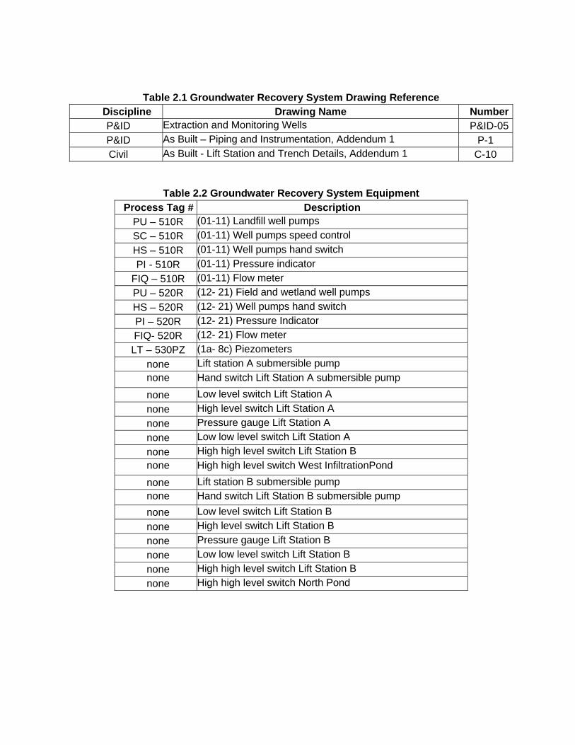
Table 2.1 Groundwater Recovery System Drawing Reference
Discipline Drawing Name NumberP&ID Extraction and Monitoring Wells P&ID-05P&ID As Built – Piping and Instrumentation, Addendum 1 P-1 Civil As Built - Lift Station and Trench Details, Addendum 1 C-10
Table 2.2 Groundwater Recovery System Equipment
Process Tag # Description PU – 510R (01-11) Landfill well pumps
SC – 510R (01-11) Well pumps speed control
HS – 510R (01-11) Well pumps hand switch
PI - 510R (01-11) Pressure indicator
FIQ – 510R (01-11) Flow meter
PU – 520R (12- 21) Field and wetland well pumps
HS – 520R (12- 21) Well pumps hand switch
PI – 520R (12- 21) Pressure Indicator
FIQ- 520R (12- 21) Flow meter
LT – 530PZ (1a- 8c) Piezometers
none Lift station A submersible pump none Hand switch Lift Station A submersible pump
none Low level switch Lift Station A
none High level switch Lift Station A
none Pressure gauge Lift Station A
none Low low level switch Lift Station A
none High high level switch Lift Station B none High high level switch West InfiltrationPond
none Lift station B submersible pump none Hand switch Lift Station B submersible pump
none Low level switch Lift Station B
none High level switch Lift Station B
none Pressure gauge Lift Station B
none Low low level switch Lift Station B
none High high level switch Lift Station B
none High high level switch North Pond
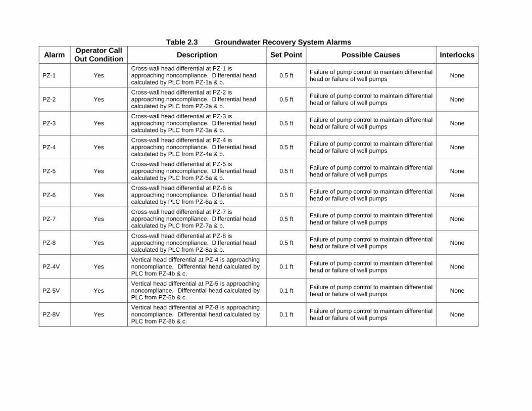
Table 2.3 Groundwater Recovery System Alarms
Alarm Operator Call Out Condition
Description Set Point Possible Causes Interlocks
PZ-1
Yes
Cross-wall head differential at PZ-1 is approaching noncompliance. Differential head calculated by PLC from PZ-1a & b.
0.5 ft Failure of pump control to maintain differential head or failure of well pumps None
PZ-2
Yes
Cross-wall head differential at PZ-2 is approaching noncompliance. Differential head calculated by PLC from PZ-2a & b.
0.5 ft Failure of pump control to maintain differential head or failure of well pumps None
PZ-3
Yes
Cross-wall head differential at PZ-3 is approaching noncompliance. Differential head calculated by PLC from PZ-3a & b.
0.5 ft Failure of pump control to maintain differential head or failure of well pumps None
PZ-4
Yes
Cross-wall head differential at PZ-4 is approaching noncompliance. Differential head calculated by PLC from PZ-4a & b.
0.5 ft Failure of pump control to maintain differential head or failure of well pumps None
PZ-5
Yes
Cross-wall head differential at PZ-5 is approaching noncompliance. Differential head calculated by PLC from PZ-5a & b.
0.5 ft Failure of pump control to maintain differential head or failure of well pumps None
PZ-6
Yes
Cross-wall head differential at PZ-6 is approaching noncompliance. Differential head calculated by PLC from PZ-6a & b.
0.5 ft Failure of pump control to maintain differential head or failure of well pumps None
PZ-7
Yes
Cross-wall head differential at PZ-7 is approaching noncompliance. Differential head calculated by PLC from PZ-7a & b.
0.5 ft Failure of pump control to maintain differential head or failure of well pumps None
PZ-8
Yes
Cross-wall head differential at PZ-8 is approaching noncompliance. Differential head calculated by PLC from PZ-8a & b.
0.5 ft Failure of pump control to maintain differential head or failure of well pumps None
PZ-4V
Yes
Vertical head differential at PZ-4 is approaching noncompliance. Differential head calculated by PLC from PZ-4b & c.
0.1 ft Failure of pump control to maintain differential head or failure of well pumps None
PZ-5V
Yes
Vertical head differential at PZ-5 is approaching noncompliance. Differential head calculated by PLC from PZ-5b & c.
0.1 ft Failure of pump control to maintain differential head or failure of well pumps None
PZ-8V
Yes
Vertical head differential at PZ-8 is approaching noncompliance. Differential head calculated by PLC from PZ-8b & c.
0.1 ft Failure of pump control to maintain differential head or failure of well pumps None
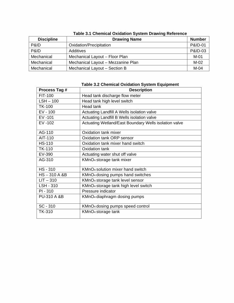
Table 3.1 Chemical Oxidation System Drawing Reference
Discipline Drawing Name Number P&ID Oxidation/Precipitation P&ID-01 P&ID Additives P&ID-03 Mechanical Mechanical Layout – Floor Plan M-01 Mechanical Mechanical Layout – Mezzanine Plan M-02 Mechanical Mechanical Layout – Section B M-04
Table 3.2 Chemical Oxidation System Equipment
Process Tag # Description FIT-100 Head tank discharge flow meter LSH – 100 Head tank high level switch TK-100 Head tank EV - 100 Actuating Landfill A Wells isolation valve EV -101 Actuating Landfill B Wells isolation valve EV -102 Actuating Wetland/East Boundary Wells isolation valve
AG-110 Oxidation tank mixer AIT-110 Oxidation tank ORP sensor HS-110 Oxidation tank mixer hand switch TK-110 Oxidation tank EV-390 Actuating water shut off valve AG-310 KMnO4 storage tank mixer
HS - 310 KMnO4 solution mixer hand switch HS – 310 A &B KMnO4 dosing pumps hand switches LIT – 310 KMnO4 storage tank level sensor LSH - 310 KMnO4 storage tank high level switch PI - 310 Pressure indicator PU-310 A &B KMnO4 diaphragm dosing pumps
SC - 310 KMnO4 dosing pumps speed control TK-310 KMnO4 storage tank
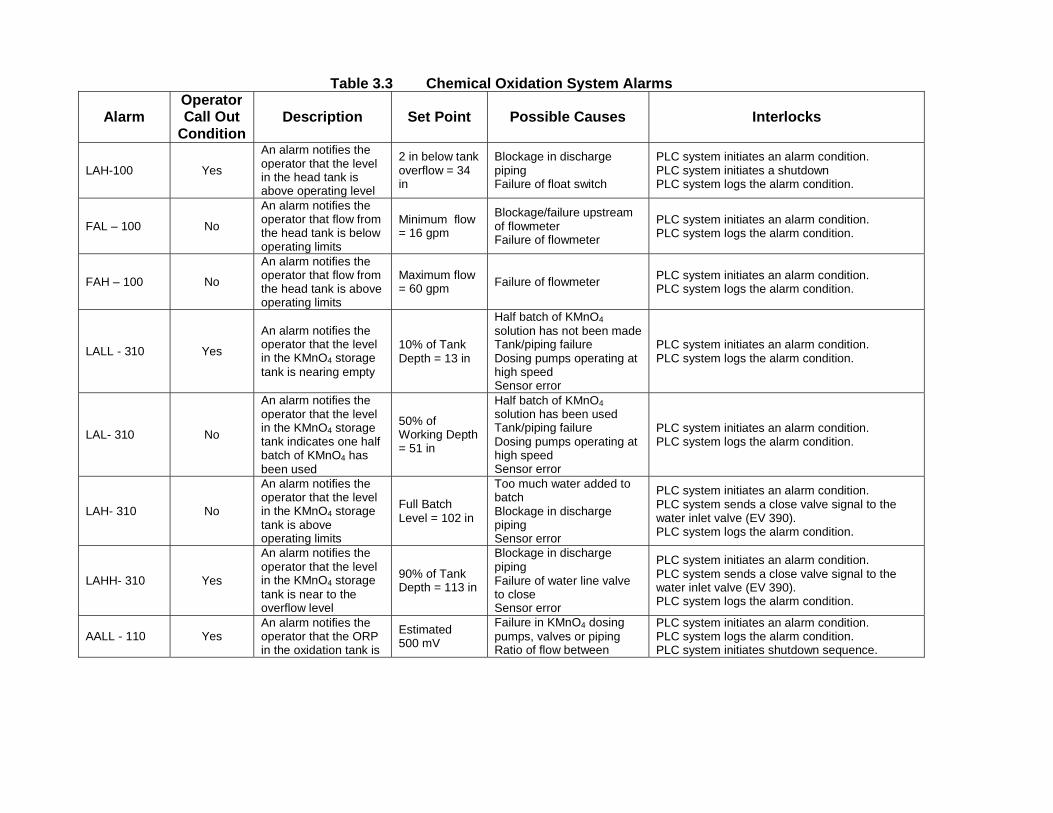
Table 3.3 Chemical Oxidation System Alarms
Alarm Operator Call Out
Condition
Description Set Point Possible Causes
Interlocks
LAH-100
Yes
An alarm notifies the operator that the level in the head tank is above operating level
2 in below tank overflow = 34 in
Blockage in discharge piping Failure of float switch
PLC system initiates an alarm condition. PLC system initiates a shutdown PLC system logs the alarm condition.
FAL – 100
No
An alarm notifies the operator that flow from the head tank is below operating limits
Minimum flow = 16 gpm
Blockage/failure upstream of flowmeter Failure of flowmeter
PLC system initiates an alarm condition. PLC system logs the alarm condition.
FAH – 100
No
An alarm notifies the operator that flow from the head tank is above operating limits
Maximum flow = 60 gpm
Failure of flowmeter
PLC system initiates an alarm condition. PLC system logs the alarm condition.
LALL - 310
Yes
An alarm notifies the operator that the level in the KMnO4 storage tank is nearing empty
10% of Tank Depth = 13 in
Half batch of KMnO4
solution has not been made Tank/piping failure Dosing pumps operating at high speed Sensor error
PLC system initiates an alarm condition. PLC system logs the alarm condition.
LAL- 310
No
An alarm notifies the operator that the level in the KMnO4 storage tank indicates one half batch of KMnO4 has been used
50% of Working Depth = 51 in
Half batch of KMnO4
solution has been used Tank/piping failure Dosing pumps operating at high speed Sensor error
PLC system initiates an alarm condition. PLC system logs the alarm condition.
LAH- 310
No
An alarm notifies the operator that the level in the KMnO4 storage tank is above operating limits
Full Batch Level = 102 in
Too much water added to batch Blockage in discharge piping Sensor error
PLC system initiates an alarm condition. PLC system sends a close valve signal to the water inlet valve (EV 390). PLC system logs the alarm condition.
LAHH- 310
Yes
An alarm notifies the operator that the level in the KMnO4 storage tank is near to the overflow level
90% of Tank Depth = 113 in
Blockage in discharge piping Failure of water line valve to close Sensor error
PLC system initiates an alarm condition. PLC system sends a close valve signal to the water inlet valve (EV 390). PLC system logs the alarm condition.
AALL - 110
Yes
An alarm notifies the operator that the ORP in the oxidation tank is
Estimated 500 mV
Failure in KMnO4 dosing pumps, valves or piping Ratio of flow between
PLC system initiates an alarm condition. PLC system logs the alarm condition. PLC system initiates shutdown sequence.
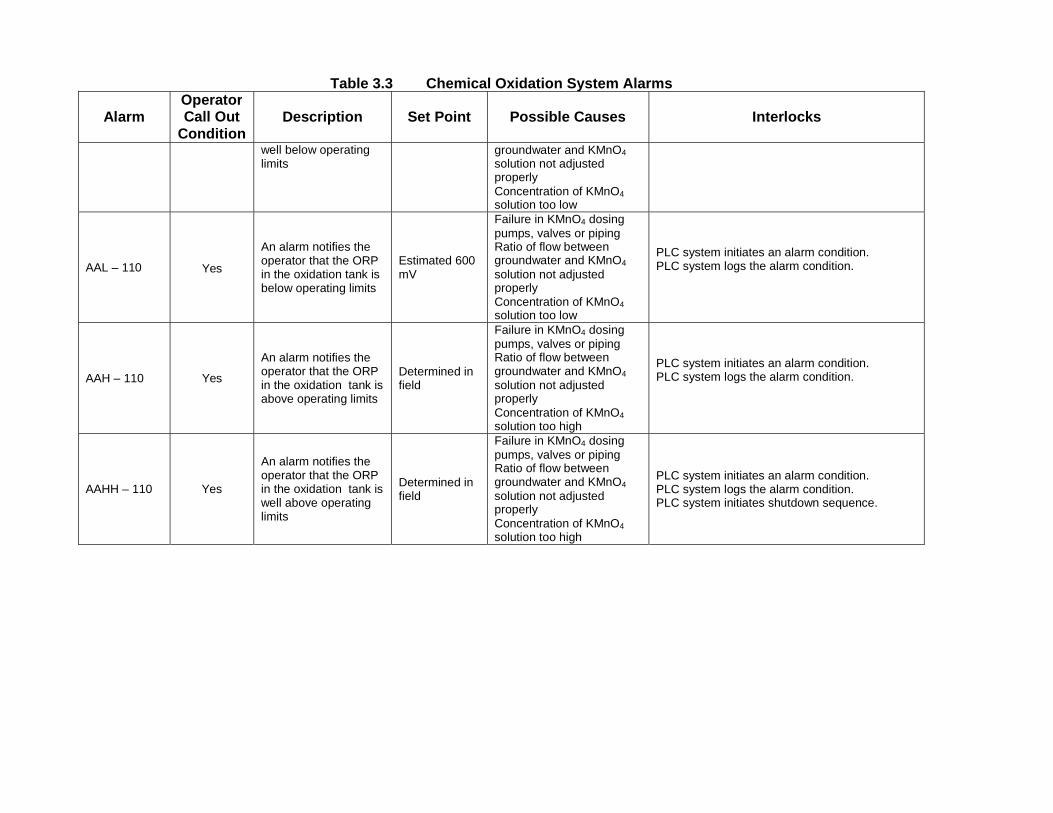
Table 3.3 Chemical Oxidation System Alarms
Alarm Operator Call Out
Condition
Description Set Point Possible Causes
Interlocks
well below operating limits groundwater and KMnO4
solution not adjusted properly Concentration of KMnO4
solution too low
AAL – 110
Yes
An alarm notifies the operator that the ORP in the oxidation tank is below operating limits
Estimated 600 mV
Failure in KMnO4 dosing pumps, valves or piping Ratio of flow between groundwater and KMnO4
solution not adjusted properly Concentration of KMnO4
solution too low
PLC system initiates an alarm condition. PLC system logs the alarm condition.
AAH – 110
Yes
An alarm notifies the operator that the ORP in the oxidation tank is above operating limits
Determined in field
Failure in KMnO4 dosing pumps, valves or piping Ratio of flow between groundwater and KMnO4
solution not adjusted properly Concentration of KMnO4
solution too high
PLC system initiates an alarm condition. PLC system logs the alarm condition.
AAHH – 110
Yes
An alarm notifies the operator that the ORP in the oxidation tank is well above operating limits
Determined in field
Failure in KMnO4 dosing pumps, valves or piping Ratio of flow between groundwater and KMnO4
solution not adjusted properly Concentration of KMnO4
solution too high
PLC system initiates an alarm condition. PLC system logs the alarm condition. PLC system initiates shutdown sequence.
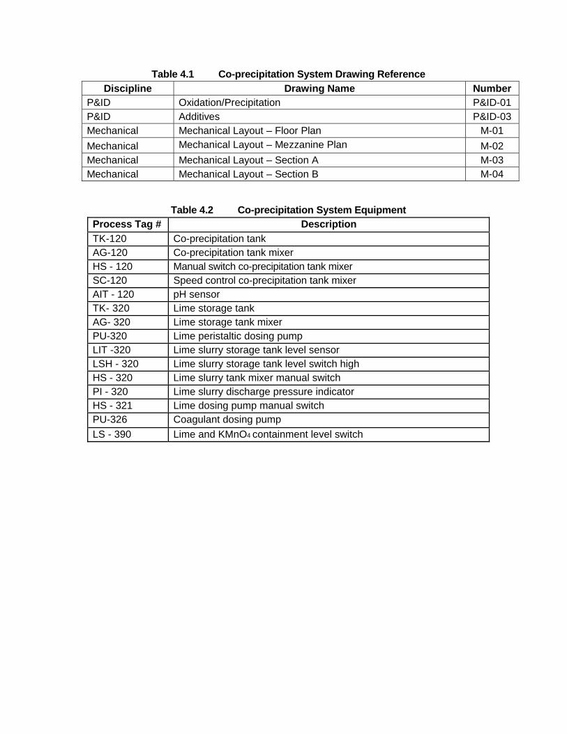
Table 4.1 Co-precipitation System Drawing Reference
Discipline Drawing Name Number P&ID Oxidation/Precipitation P&ID-01 P&ID Additives P&ID-03 Mechanical Mechanical Layout – Floor Plan M-01 Mechanical Mechanical Layout – Mezzanine Plan M-02 Mechanical Mechanical Layout – Section A M-03 Mechanical Mechanical Layout – Section B M-04
Table 4.2 Co-precipitation System Equipment
Process Tag # Description
TK-120 Co-precipitation tank AG-120 Co-precipitation tank mixer HS - 120 Manual switch co-precipitation tank mixer SC-120 Speed control co-precipitation tank mixer AIT - 120 pH sensor TK- 320 Lime storage tank AG- 320 Lime storage tank mixer PU-320 Lime peristaltic dosing pump LIT -320 Lime slurry storage tank level sensor LSH - 320 Lime slurry storage tank level switch high HS - 320 Lime slurry tank mixer manual switch PI - 320 Lime slurry discharge pressure indicator HS - 321 Lime dosing pump manual switch PU-326 Coagulant dosing pump
LS - 390 Lime and KMnO4 containment level switch
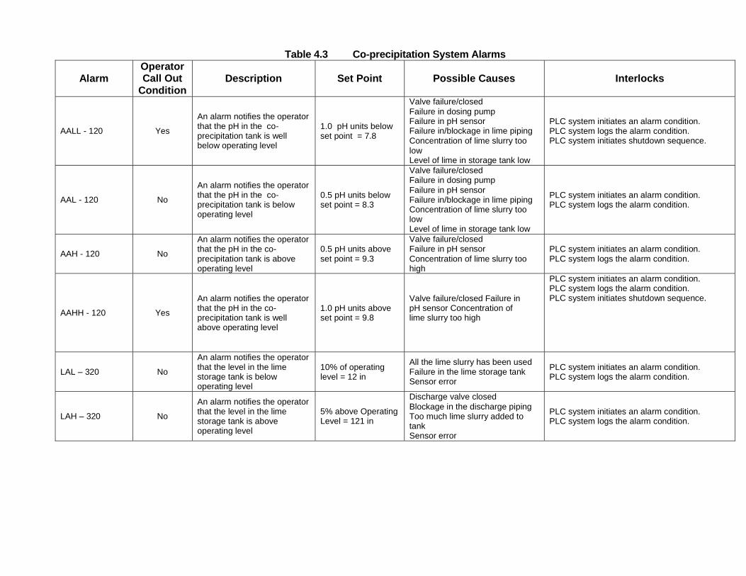
Table 4.3 Co-precipitation System Alarms
Alarm Operator Call Out
Condition
Description Set Point Possible Causes Interlocks
AALL - 120
Yes
An alarm notifies the operator that the pH in the co- precipitation tank is well below operating level
1.0 pH units below set point = 7.8
Valve failure/closed Failure in dosing pump Failure in pH sensor Failure in/blockage in lime piping Concentration of lime slurry too low Level of lime in storage tank low
PLC system initiates an alarm condition. PLC system logs the alarm condition. PLC system initiates shutdown sequence.
AAL - 120
No
An alarm notifies the operator that the pH in the co- precipitation tank is below operating level
0.5 pH units below set point = 8.3
Valve failure/closed Failure in dosing pump Failure in pH sensor Failure in/blockage in lime piping Concentration of lime slurry too low Level of lime in storage tank low
PLC system initiates an alarm condition. PLC system logs the alarm condition.
AAH - 120
No
An alarm notifies the operator that the pH in the co- precipitation tank is above operating level
0.5 pH units above set point = 9.3
Valve failure/closed Failure in pH sensor Concentration of lime slurry too high
PLC system initiates an alarm condition. PLC system logs the alarm condition.
AAHH - 120
Yes
An alarm notifies the operator that the pH in the co- precipitation tank is well above operating level
1.0 pH units above set point = 9.8
Valve failure/closed Failure in pH sensor Concentration of lime slurry too high
PLC system initiates an alarm condition. PLC system logs the alarm condition. PLC system initiates shutdown sequence.
LAL – 320
No
An alarm notifies the operator that the level in the lime storage tank is below operating level
10% of operating level = 12 in
All the lime slurry has been used Failure in the lime storage tank Sensor error
PLC system initiates an alarm condition. PLC system logs the alarm condition.
LAH – 320
No
An alarm notifies the operator that the level in the lime storage tank is above operating level
5% above Operating Level = 121 in
Discharge valve closed Blockage in the discharge piping Too much lime slurry added to tank Sensor error
PLC system initiates an alarm condition. PLC system logs the alarm condition.
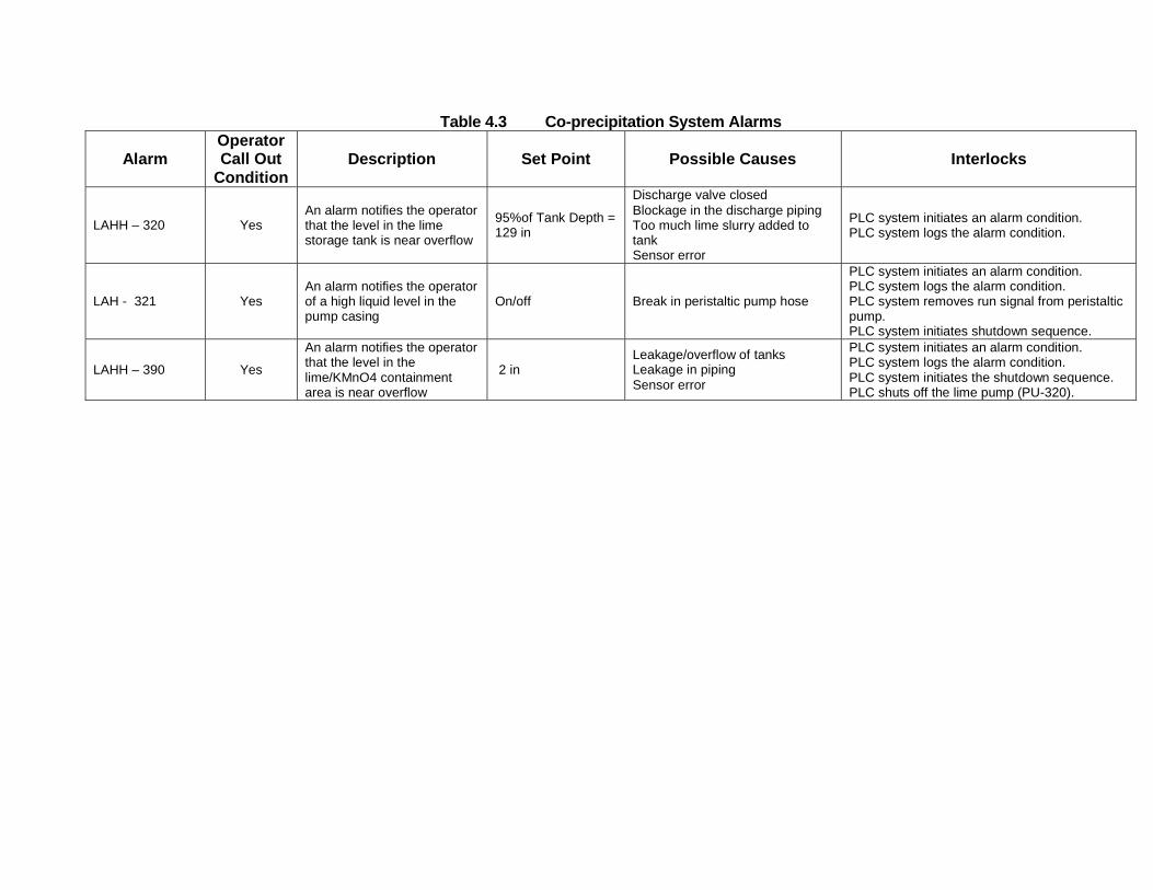
Table 4.3 Co-precipitation System Alarms
Alarm Operator Call Out
Condition
Description Set Point Possible Causes Interlocks
LAHH – 320
Yes
An alarm notifies the operator that the level in the lime storage tank is near overflow
95%of Tank Depth = 129 in
Discharge valve closed Blockage in the discharge piping Too much lime slurry added to tank Sensor error
PLC system initiates an alarm condition. PLC system logs the alarm condition.
LAH - 321
Yes
An alarm notifies the operator of a high liquid level in the pump casing
On/off
Break in peristaltic pump hose
PLC system initiates an alarm condition. PLC system logs the alarm condition. PLC system removes run signal from peristaltic pump. PLC system initiates shutdown sequence.
LAHH – 390
Yes
An alarm notifies the operator that the level in the lime/KMnO4 containment area is near overflow
2 in
Leakage/overflow of tanks Leakage in piping Sensor error
PLC system initiates an alarm condition. PLC system logs the alarm condition. PLC system initiates the shutdown sequence. PLC shuts off the lime pump (PU-320).
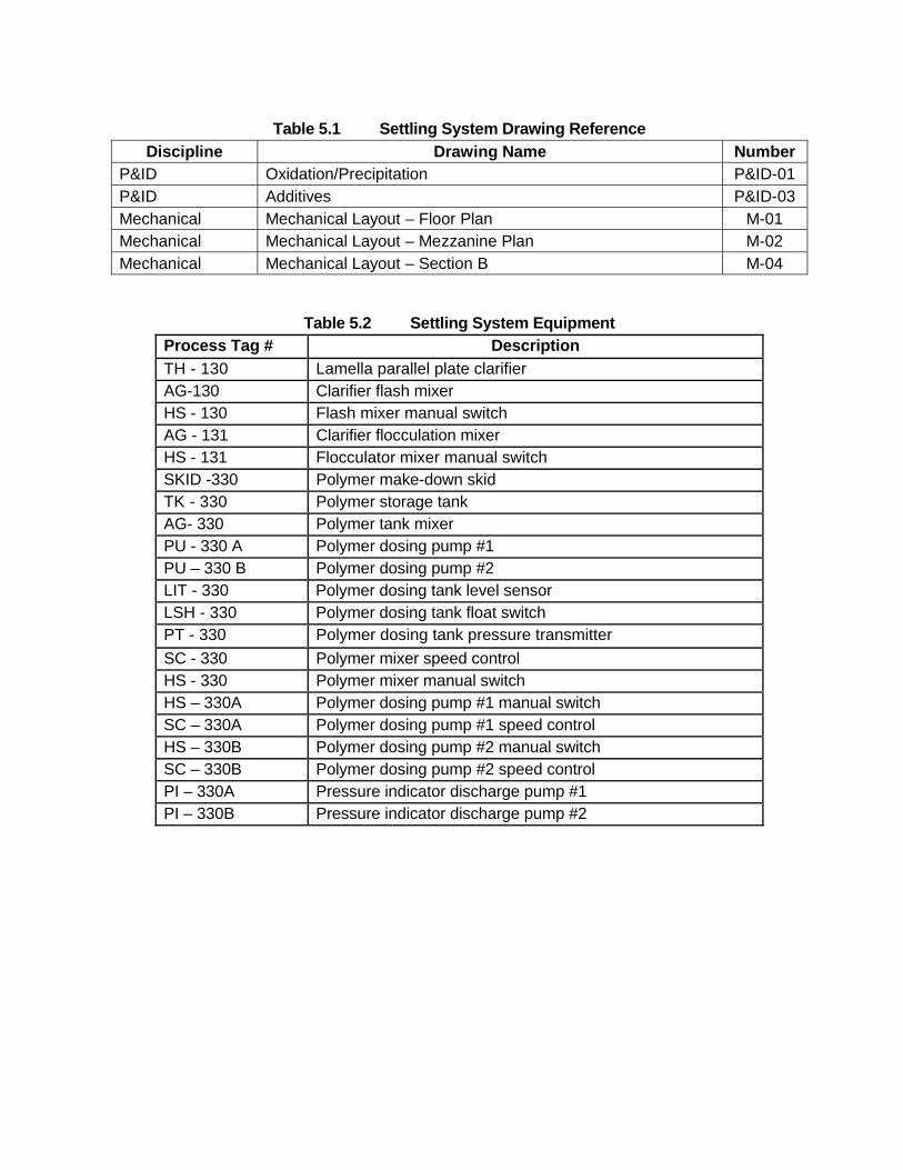
Table 5.1 Settling System Drawing Reference
Discipline Drawing Name Number P&ID Oxidation/Precipitation P&ID-01 P&ID Additives P&ID-03 Mechanical Mechanical Layout – Floor Plan M-01 Mechanical Mechanical Layout – Mezzanine Plan M-02 Mechanical Mechanical Layout – Section B M-04
Table 5.2 Settling System Equipment
Process Tag # Description
TH - 130 Lamella parallel plate clarifier AG-130 Clarifier flash mixer HS - 130 Flash mixer manual switch AG - 131 Clarifier flocculation mixer HS - 131 Flocculator mixer manual switch SKID -330 Polymer make-down skid TK - 330 Polymer storage tank AG- 330 Polymer tank mixer PU - 330 A Polymer dosing pump #1 PU – 330 B Polymer dosing pump #2 LIT - 330 Polymer dosing tank level sensor LSH - 330 Polymer dosing tank float switch PT - 330 Polymer dosing tank pressure transmitter
SC - 330 Polymer mixer speed control HS - 330 Polymer mixer manual switch HS – 330A Polymer dosing pump #1 manual switch SC – 330A Polymer dosing pump #1 speed control HS – 330B Polymer dosing pump #2 manual switch SC – 330B Polymer dosing pump #2 speed control PI – 330A Pressure indicator discharge pump #1 PI – 330B Pressure indicator discharge pump #2
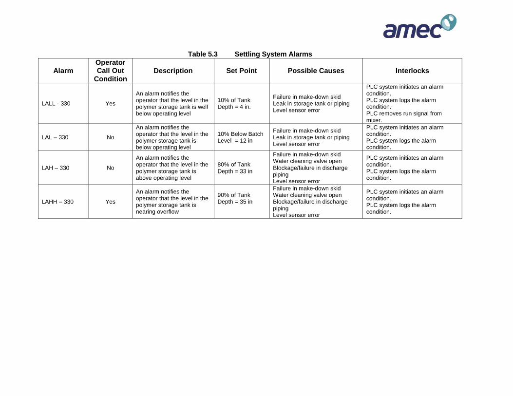
Table 5.3 Settling System Alarms
Alarm Operator Call Out
Condition
Description Set Point Possible Causes Interlocks
LALL - 330
Yes
An alarm notifies the operator that the level in the polymer storage tank is well below operating level
10% of Tank Depth = 4 in.
Failure in make-down skid Leak in storage tank or piping Level sensor error
PLC system initiates an alarm condition. PLC system logs the alarm condition. PLC removes run signal from mixer.
LAL – 330
No
An alarm notifies the operator that the level in the polymer storage tank is below operating level
10% Below Batch Level = 12 in
Failure in make-down skid Leak in storage tank or piping Level sensor error
PLC system initiates an alarm condition. PLC system logs the alarm condition.
LAH – 330
No
An alarm notifies the operator that the level in the polymer storage tank is above operating level
80% of Tank Depth = 33 in
Failure in make-down skid Water cleaning valve open Blockage/failure in discharge piping Level sensor error
PLC system initiates an alarm condition. PLC system logs the alarm condition.
LAHH – 330
Yes
An alarm notifies the operator that the level in the polymer storage tank is nearing overflow
90% of Tank Depth = 35 in
Failure in make-down skid Water cleaning valve open Blockage/failure in discharge piping Level sensor error
PLC system initiates an alarm condition. PLC system logs the alarm condition.
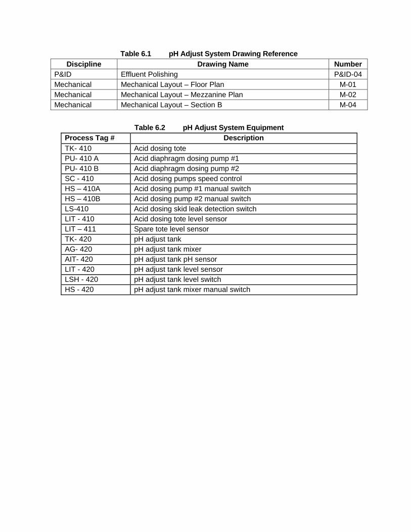
Table 6.1 pH Adjust System Drawing Reference
Discipline Drawing Name Number P&ID Effluent Polishing P&ID-04 Mechanical Mechanical Layout – Floor Plan M-01 Mechanical Mechanical Layout – Mezzanine Plan M-02 Mechanical Mechanical Layout – Section B M-04
Table 6.2 pH Adjust System Equipment
Process Tag # Description
TK- 410 Acid dosing tote PU- 410 A Acid diaphragm dosing pump #1 PU- 410 B Acid diaphragm dosing pump #2 SC - 410 Acid dosing pumps speed control HS – 410A Acid dosing pump #1 manual switch HS – 410B Acid dosing pump #2 manual switch LS-410 Acid dosing skid leak detection switch LIT - 410 Acid dosing tote level sensor LIT – 411 Spare tote level sensor TK- 420 pH adjust tank AG- 420 pH adjust tank mixer AIT- 420 pH adjust tank pH sensor LIT - 420 pH adjust tank level sensor LSH - 420 pH adjust tank level switch HS - 420 pH adjust tank mixer manual switch
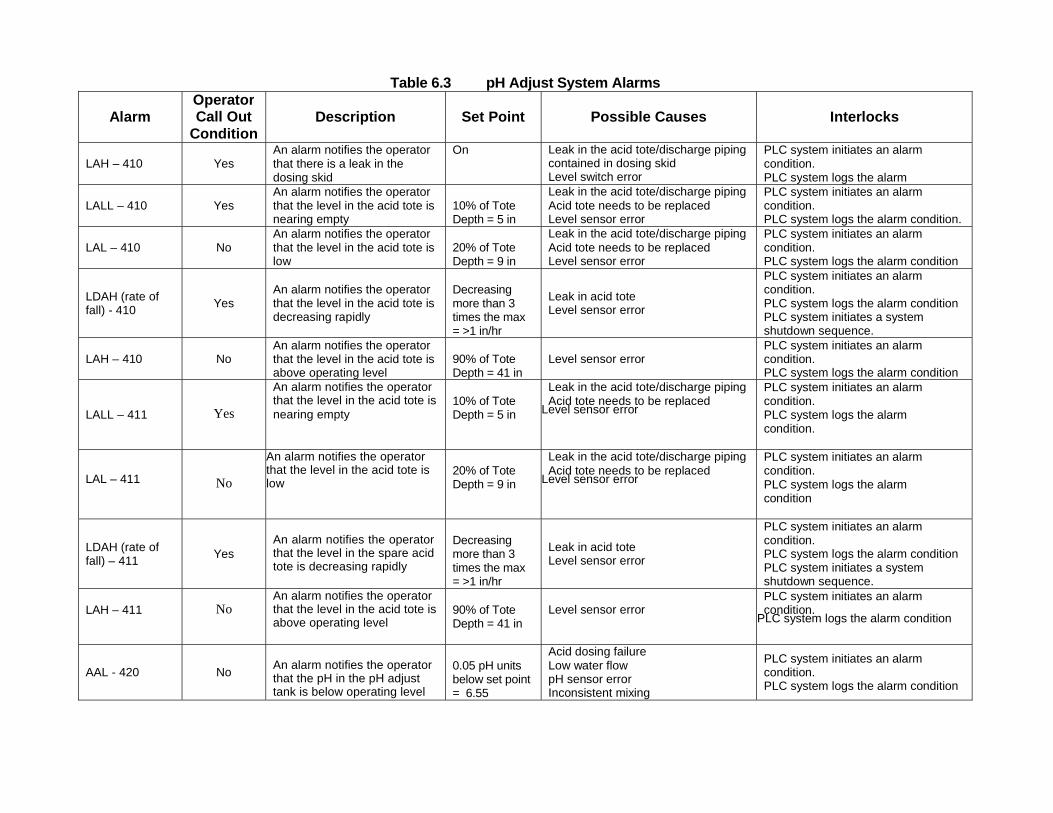
Table 6.3 pH Adjust System Alarms
Alarm Operator Call Out
Condition
Description Set Point Possible Causes Interlocks
LAH – 410
Yes
An alarm notifies the operator that there is a leak in the dosing skid
On Leak in the acid tote/discharge piping contained in dosing skid Level switch error
PLC system initiates an alarm condition. PLC system logs the alarm
LALL – 410
Yes
An alarm notifies the operator that the level in the acid tote is nearing empty
10% of Tote Depth = 5 in
Leak in the acid tote/discharge piping Acid tote needs to be replaced Level sensor error
PLC system initiates an alarm condition. PLC system logs the alarm condition.
LAL – 410
No
An alarm notifies the operator that the level in the acid tote is low
20% of Tote Depth = 9 in
Leak in the acid tote/discharge piping Acid tote needs to be replaced Level sensor error
PLC system initiates an alarm condition. PLC system logs the alarm condition
LDAH (rate of fall) - 410
Yes
An alarm notifies the operator that the level in the acid tote is decreasing rapidly
Decreasing more than 3 times the max = >1 in/hr
Leak in acid tote Level sensor error
PLC system initiates an alarm condition. PLC system logs the alarm condition PLC system initiates a system shutdown sequence.
LAH – 410
No
An alarm notifies the operator that the level in the acid tote is above operating level
90% of Tote Depth = 41 in
Level sensor error PLC system initiates an alarm condition. PLC system logs the alarm condition
LALL – 411
Yes
An alarm notifies the operator that the level in the acid tote is
nearing empty
10% of Tote Depth = 5 in
Leak in the acid tote/discharge piping Acid tote needs to be replaced
Level sensor error
PLC system initiates an alarm condition. PLC system logs the alarm condition.
LAL – 411
No
An alarm notifies the operator that the level in the acid tote is low
20% of Tote Depth = 9 in
Leak in the acid tote/discharge piping Acid tote needs to be replaced
Level sensor error
PLC system initiates an alarm condition. PLC system logs the alarm condition
LDAH (rate of fall) – 411
Yes
An alarm notifies the operator that the level in the spare acid tote is decreasing rapidly
Decreasing more than 3 times the max = >1 in/hr
Leak in acid tote Level sensor error
PLC system initiates an alarm condition. PLC system logs the alarm condition PLC system initiates a system shutdown sequence.
LAH – 411
No
An alarm notifies the operator that the level in the acid tote is above operating level
90% of Tote Depth = 41 in
Level sensor error PLC system initiates an alarm condition.
PLC system logs the alarm condition
AAL - 420
No
An alarm notifies the operator that the pH in the pH adjust tank is below operating level
0.05 pH units below set point = 6.55
Acid dosing failure Low water flow pH sensor error Inconsistent mixing
PLC system initiates an alarm condition. PLC system logs the alarm condition
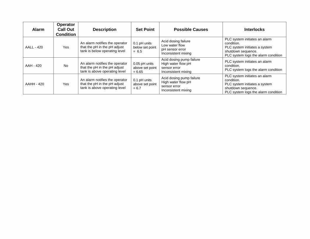
Alarm
Operator Call Out
Condition
Description Set Point Possible Causes Interlocks
AALL - 420
Yes
An alarm notifies the operator that the pH in the pH adjust tank is below operating level
0.1 pH units below set point = 6.5
Acid dosing failure Low water flow pH sensor error Inconsistent mixing
PLC system initiates an alarm condition. PLC system initiates a system shutdown sequence. PLC system logs the alarm condition
AAH - 420
No
An alarm notifies the operator that the pH in the pH adjust tank is above operating level
0.05 pH units above set point = 6.65
Acid dosing pump failure High water flow pH sensor error Inconsistent mixing
PLC system initiates an alarm condition. PLC system logs the alarm condition
AAHH - 420
Yes
An alarm notifies the operator that the pH in the pH adjust tank is above operating level
0.1 pH units above set point = 6.7
Acid dosing pump failure High water flow pH sensor error Inconsistent mixing
PLC system initiates an alarm condition. PLC system initiates a system shutdown sequence. PLC system logs the alarm condition
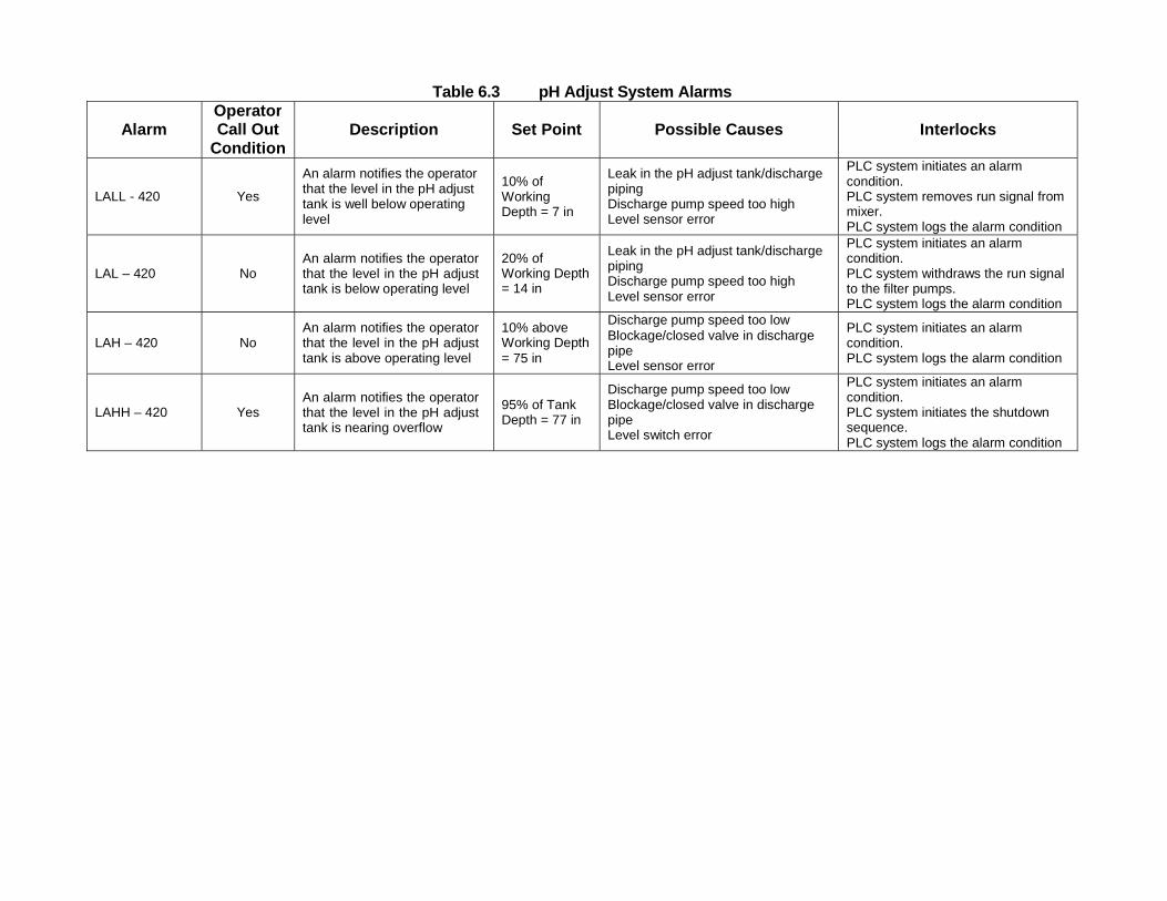
Table 6.3 pH Adjust System Alarms
Alarm Operator Call Out
Condition
Description Set Point Possible Causes Interlocks
LALL - 420
Yes
An alarm notifies the operator that the level in the pH adjust tank is well below operating level
10% of Working Depth = 7 in
Leak in the pH adjust tank/discharge piping Discharge pump speed too high Level sensor error
PLC system initiates an alarm condition. PLC system removes run signal from mixer. PLC system logs the alarm condition
LAL – 420
No
An alarm notifies the operator that the level in the pH adjust tank is below operating level
20% of Working Depth = 14 in
Leak in the pH adjust tank/discharge piping Discharge pump speed too high Level sensor error
PLC system initiates an alarm condition. PLC system withdraws the run signal to the filter pumps. PLC system logs the alarm condition
LAH – 420
No
An alarm notifies the operator that the level in the pH adjust tank is above operating level
10% above Working Depth = 75 in
Discharge pump speed too low Blockage/closed valve in discharge pipe Level sensor error
PLC system initiates an alarm condition. PLC system logs the alarm condition
LAHH – 420
Yes
An alarm notifies the operator that the level in the pH adjust tank is nearing overflow
95% of Tank Depth = 77 in
Discharge pump speed too low Blockage/closed valve in discharge pipe Level switch error
PLC system initiates an alarm condition. PLC system initiates the shutdown sequence. PLC system logs the alarm condition
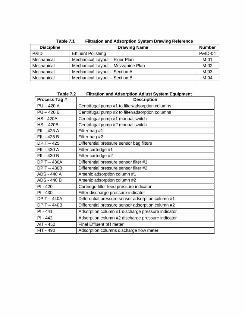
Table 7.1 Filtration and Adsorption System Drawing Reference
Discipline Drawing Name Number P&ID Effluent Polishing P&ID-04 Mechanical Mechanical Layout – Floor Plan M-01 Mechanical Mechanical Layout – Mezzanine Plan M-02 Mechanical Mechanical Layout – Section A M-03 Mechanical Mechanical Layout – Section B M-04
Table 7.2 Filtration and Adsorption Adjust System Equipment
Process Tag # Description
PU – 420 A Centrifugal pump #1 to filter/adsorption columns
PU – 420 B Centrifugal pump #2 to filter/adsorption columns
HS - 420A Centrifugal pump #1 manual switch HS – 420B Centrifugal pump #2 manual switch FIL - 425 A Filter bag #1 FIL - 425 B Filter bag #2
DPIT – 425 Differential pressure sensor bag filters
FIL - 430 A Filter cartridge #1 FIL - 430 B Filter cartridge #2
DPIT – 430A Differential pressure sensor filter #1 DPIT – 430B Differential pressure sensor filter #2 ADS - 440 A Arsenic adsorption column #1 ADS - 440 B Arsenic adsorption column #2
PI - 420 Cartridge filter feed pressure indicator PI - 430 Filter discharge pressure indicator DPIT – 440A Differential pressure sensor adsorption column #1
DPIT – 440B Differential pressure sensor adsorption column #2
PI - 441 Adsorption column #1 discharge pressure indicator
PI - 442 Adsorption column #2 discharge pressure indicator
AIT - 450 Final Effluent pH meter FIT - 490 Adsorption columns discharge flow meter

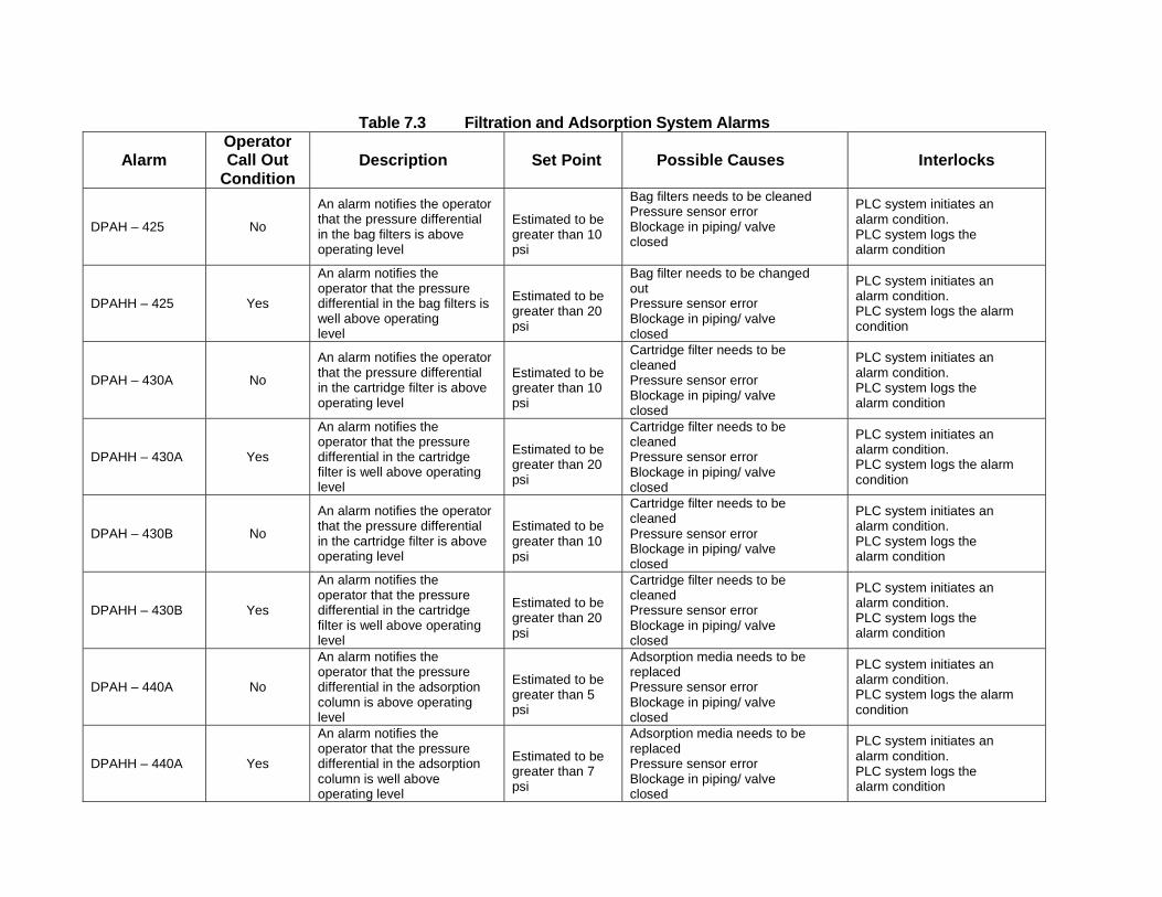
Table 7.3 Filtration and Adsorption System Alarms
Alarm Operator Call Out
Condition
Description Set Point Possible Causes Interlocks
DPAH – 425
No
An alarm notifies the operator that the pressure differential in the bag filters is above operating level
Estimated to be greater than 10 psi
Bag filters needs to be cleaned Pressure sensor error Blockage in piping/ valve closed
PLC system initiates an alarm condition. PLC system logs the alarm condition
DPAHH – 425
Yes
An alarm notifies the operator that the pressure differential in the bag filters is well above operating level
Estimated to be greater than 20 psi
Bag filter needs to be changed out Pressure sensor error Blockage in piping/ valve closed
PLC system initiates an alarm condition. PLC system logs the alarm condition
DPAH – 430A
No
An alarm notifies the operator that the pressure differential in the cartridge filter is above operating level
Estimated to be greater than 10 psi
Cartridge filter needs to be cleaned Pressure sensor error Blockage in piping/ valve closed
PLC system initiates an alarm condition. PLC system logs the alarm condition
DPAHH – 430A
Yes
An alarm notifies the operator that the pressure differential in the cartridge filter is well above operating level
Estimated to be greater than 20 psi
Cartridge filter needs to be cleaned Pressure sensor error Blockage in piping/ valve closed
PLC system initiates an alarm condition. PLC system logs the alarm condition
DPAH – 430B
No
An alarm notifies the operator that the pressure differential in the cartridge filter is above operating level
Estimated to be greater than 10 psi
Cartridge filter needs to be cleaned Pressure sensor error Blockage in piping/ valve closed
PLC system initiates an alarm condition. PLC system logs the alarm condition
DPAHH – 430B
Yes
An alarm notifies the operator that the pressure differential in the cartridge filter is well above operating level
Estimated to be greater than 20 psi
Cartridge filter needs to be cleaned Pressure sensor error Blockage in piping/ valve closed
PLC system initiates an alarm condition. PLC system logs the alarm condition
DPAH – 440A
No
An alarm notifies the operator that the pressure differential in the adsorption column is above operating level
Estimated to be greater than 5 psi
Adsorption media needs to be replaced Pressure sensor error Blockage in piping/ valve closed
PLC system initiates an alarm condition. PLC system logs the alarm condition
DPAHH – 440A
Yes
An alarm notifies the operator that the pressure differential in the adsorption column is well above operating level
Estimated to be greater than 7 psi
Adsorption media needs to be replaced Pressure sensor error Blockage in piping/ valve closed
PLC system initiates an alarm condition. PLC system logs the alarm condition
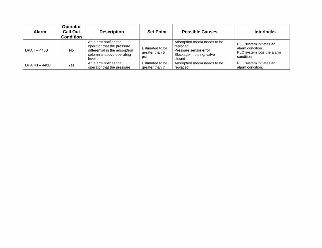
Alarm
Operator Call Out
Condition
Description Set Point Possible Causes Interlocks
DPAH – 440B
No
An alarm notifies the operator that the pressure differential in the adsorption column is above operating level
Estimated to be greater than 5 psi
Adsorption media needs to be replaced Pressure sensor error Blockage in piping/ valve closed
PLC system initiates an alarm condition. PLC system logs the alarm condition
DPAHH – 440B
Yes An alarm notifies the operator that the pressure
Estimated to be greater than 7
Adsorption media needs to be replaced
PLC system initiates an alarm condition.
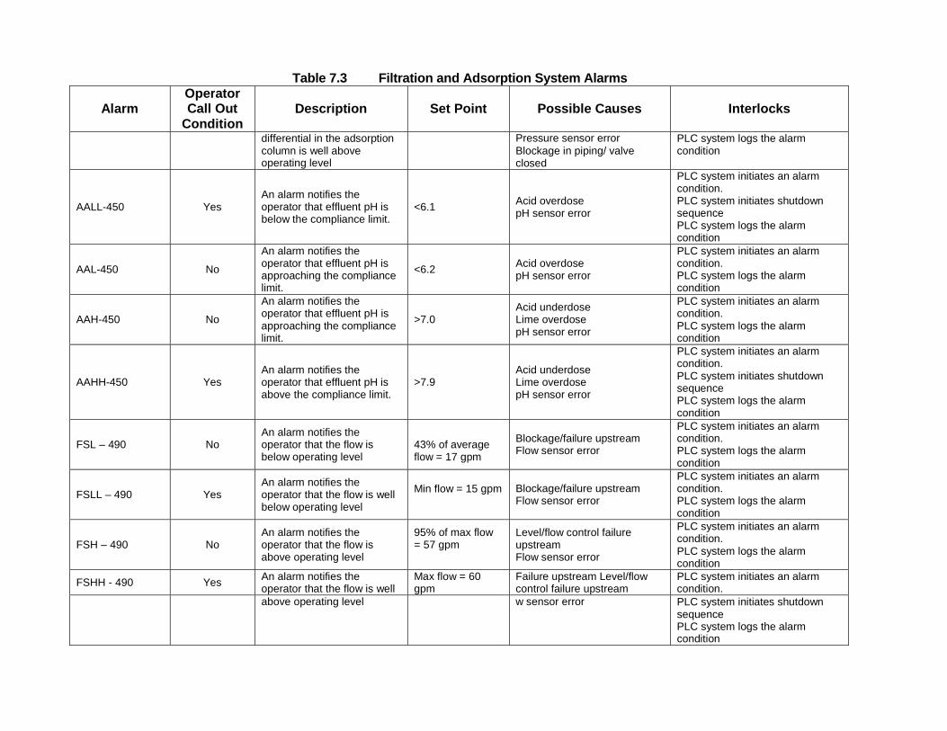
Table 7.3 Filtration and Adsorption System Alarms
Alarm Operator Call Out
Condition
Description Set Point Possible Causes Interlocks
differential in the adsorption column is well above operating level
Pressure sensor error Blockage in piping/ valve closed
PLC system logs the alarm condition
AALL-450
Yes
An alarm notifies the operator that effluent pH is below the compliance limit.
<6.1 Acid overdose pH sensor error
PLC system initiates an alarm condition. PLC system initiates shutdown sequence PLC system logs the alarm condition
AAL-450
No
An alarm notifies the operator that effluent pH is approaching the compliance limit.
<6.2 Acid overdose
pH sensor error
PLC system initiates an alarm condition. PLC system logs the alarm condition
AAH-450
No
An alarm notifies the operator that effluent pH is approaching the compliance limit.
>7.0
Acid underdose Lime overdose pH sensor error
PLC system initiates an alarm condition. PLC system logs the alarm condition
AAHH-450
Yes
An alarm notifies the operator that effluent pH is above the compliance limit.
>7.9
Acid underdose Lime overdose pH sensor error
PLC system initiates an alarm condition. PLC system initiates shutdown sequence PLC system logs the alarm condition
FSL – 490
No
An alarm notifies the operator that the flow is below operating level
43% of average flow = 17 gpm
Blockage/failure upstream Flow sensor error
PLC system initiates an alarm condition. PLC system logs the alarm condition
FSLL – 490
Yes
An alarm notifies the operator that the flow is well below operating level
Min flow = 15 gpm
Blockage/failure upstream Flow sensor error
PLC system initiates an alarm condition. PLC system logs the alarm condition
FSH – 490
No
An alarm notifies the operator that the flow is above operating level
95% of max flow = 57 gpm
Level/flow control failure upstream Flow sensor error
PLC system initiates an alarm condition. PLC system logs the alarm condition
FSHH - 490
Yes An alarm notifies the operator that the flow is well
Max flow = 60 gpm
Failure upstream Level/flow control failure upstream
PLC system initiates an alarm condition.
above operating level w sensor error PLC system initiates shutdown sequence PLC system logs the alarm condition
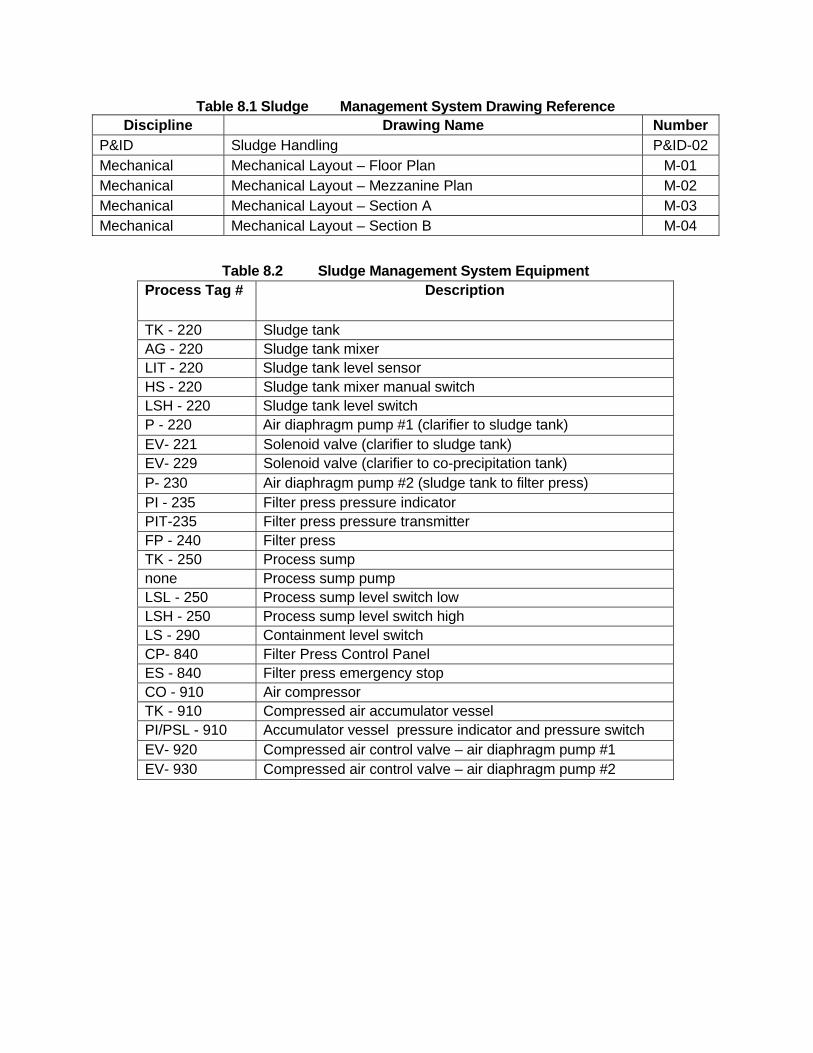
Table 8.1 Sludge Management System Drawing Reference Discipline Drawing Name Number
P&ID Sludge Handling P&ID-02 Mechanical Mechanical Layout – Floor Plan M-01 Mechanical Mechanical Layout – Mezzanine Plan M-02 Mechanical Mechanical Layout – Section A M-03 Mechanical Mechanical Layout – Section B M-04
Table 8.2 Sludge Management System Equipment
Process Tag # Description
TK - 220 Sludge tank AG - 220 Sludge tank mixer LIT - 220 Sludge tank level sensor HS - 220 Sludge tank mixer manual switch LSH - 220 Sludge tank level switch P - 220 Air diaphragm pump #1 (clarifier to sludge tank) EV- 221 Solenoid valve (clarifier to sludge tank) EV- 229 Solenoid valve (clarifier to co-precipitation tank) P- 230 Air diaphragm pump #2 (sludge tank to filter press) PI - 235 Filter press pressure indicator PIT-235 Filter press pressure transmitter FP - 240 Filter press TK - 250 Process sump none Process sump pump LSL - 250 Process sump level switch low LSH - 250 Process sump level switch high LS - 290 Containment level switch CP- 840 Filter Press Control Panel ES - 840 Filter press emergency stop CO - 910 Air compressor TK - 910 Compressed air accumulator vessel PI/PSL - 910 Accumulator vessel pressure indicator and pressure switch EV- 920 Compressed air control valve – air diaphragm pump #1 EV- 930 Compressed air control valve – air diaphragm pump #2
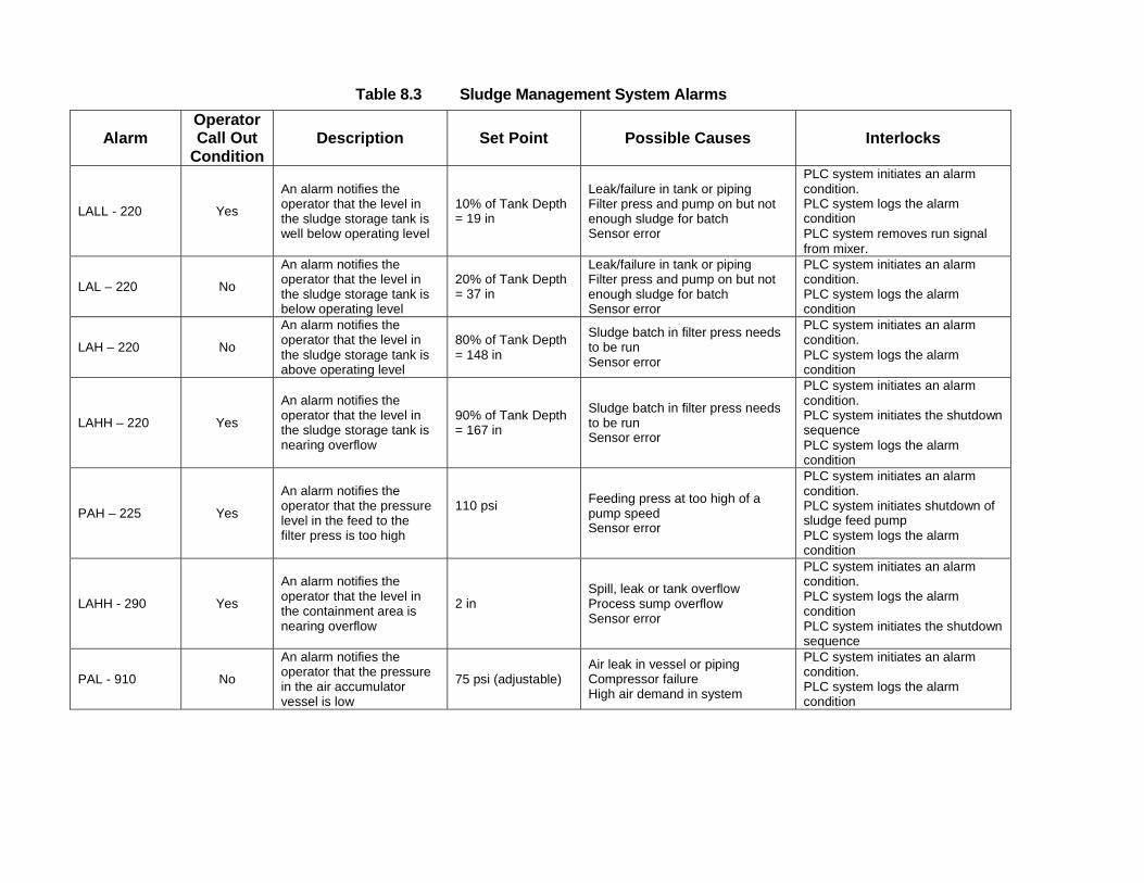
Table 8.3 Sludge Management System Alarms
Alarm Operator Call Out
Condition
Description Set Point Possible Causes Interlocks
LALL - 220
Yes
An alarm notifies the operator that the level in the sludge storage tank is well below operating level
10% of Tank Depth = 19 in
Leak/failure in tank or piping Filter press and pump on but not enough sludge for batch Sensor error
PLC system initiates an alarm condition. PLC system logs the alarm condition PLC system removes run signal from mixer.
LAL – 220
No
An alarm notifies the operator that the level in the sludge storage tank is below operating level
20% of Tank Depth = 37 in
Leak/failure in tank or piping Filter press and pump on but not enough sludge for batch Sensor error
PLC system initiates an alarm condition. PLC system logs the alarm condition
LAH – 220
No
An alarm notifies the operator that the level in the sludge storage tank is above operating level
80% of Tank Depth = 148 in
Sludge batch in filter press needs to be run Sensor error
PLC system initiates an alarm condition. PLC system logs the alarm condition
LAHH – 220
Yes
An alarm notifies the operator that the level in the sludge storage tank is nearing overflow
90% of Tank Depth = 167 in
Sludge batch in filter press needs to be run Sensor error
PLC system initiates an alarm condition. PLC system initiates the shutdown sequence PLC system logs the alarm condition
PAH – 225
Yes
An alarm notifies the operator that the pressure level in the feed to the filter press is too high
110 psi
Feeding press at too high of a pump speed Sensor error
PLC system initiates an alarm condition. PLC system initiates shutdown of sludge feed pump PLC system logs the alarm condition
LAHH - 290
Yes
An alarm notifies the operator that the level in the containment area is nearing overflow
2 in
Spill, leak or tank overflow Process sump overflow Sensor error
PLC system initiates an alarm condition. PLC system logs the alarm condition PLC system initiates the shutdown sequence
PAL - 910
No
An alarm notifies the operator that the pressure in the air accumulator vessel is low
75 psi (adjustable)
Air leak in vessel or piping Compressor failure High air demand in system
PLC system initiates an alarm condition. PLC system logs the alarm condition

B&L Woodwaste Site
Appendix C
Stormwater Pollution Prevention Plan
B&L Woodwaste Site Pierce County, Washington
Stormwater Pollution Prevention Plan (SWPPP)
Groundwater Recovery and
Treatment System
Prepared for B&L Woodwaste Custodial Trust
606 Columbia Street NW, Suite 212 Olympia, Washington 98501
Prepared by AMEC Environment & Infrastructure
600 University St, Suite 600 Seattle, Washington 98101
F L O Y D | S N I D E R 601 Union Street, Suite 600 Seattle, Washington 98101
November 2013
P:\13488 - Floyd Snider-B&L Landfill\O&M\O&M Manuals\NPDES O&M Manual\O&M Manual 2015\Appendix D\SWPPP text.docx
April 2013
Page 1 SWPPP
Table of Contents
Table of Contents ........................................................................................................... i
List of Attachments ............................................................... Error! Bookmark not defined.
1.0 Introduction ......................................................................................................... 1
2.0 Project Background and Work Area Description ............................................. 4
2.1 PROJECT BACKGROUND ................................................................................... 4
2.2 EXISTING CONDITIONS ...................................................................................... 5
2.3 OPERATION AND MAINTENANCE ACTIVITIES ................................................. 6
3.0 Lime Delivery Pad BMPs .................................................................................... 9
3.1. LIME DELIVERY PAD DESIGN ............................................................................ 9
3.2 LIME DELIVERY PROCEDURES ......................................................................... 9
3.3 LIME DELIVERY PAD CLEANUP PROCEDURES ............................................. 10
4.0 Well and Piezometer Maintenance BMPs ....................................................... 13
5.0 Pollution Prevention Team .............................................................................. 15
5.1 ROLES AND RESPONSIBILITIES ...................................................................... 15
5.2 TEAM MEMBERS ............................................................................................... 15
6.0 Reporting and Recordkeeping ........................................................................ 17
6.1 RECORDKEEPING ............................................................................................. 17
6.2 UPDATING THE SWPPP .................................................................................... 17
6.3 NOTIFICATION OF DISCHARGE ....................................................................... 17
7.0 References ........................................................................................................ 19
Figures
Figure 1: Groundwater Recovery and Treatment Plant Piping Layout
Figure 2: SWPPP Site Plan
Figure 3: Lime Delivery Pad Plan View
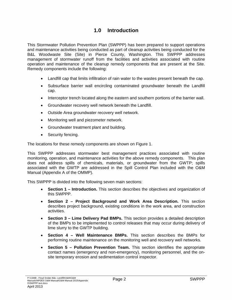
P:\13488 - Floyd Snider-B&L Landfill\O&M\O&M Manuals\NPDES O&M Manual\O&M Manual 2015\Appendix D\SWPPP text.docx
April 2013
Page 2 SWPPP
1.0 Introduction
This Stormwater Pollution Prevention Plan (SWPPP) has been prepared to support operations and maintenance activities being conducted as part of cleanup activities being conducted for the B&L Woodwaste Site (Site) in Pierce County, Washington. This SWPPP addresses management of stormwater runoff from the facilities and activities associated with routine operation and maintenance of the cleanup remedy components that are present at the Site. Remedy components include the following:
Landfill cap that limits infiltration of rain water to the wastes present beneath the cap.
Subsurface barrier wall encircling contaminated groundwater beneath the Landfill cap.
Interceptor trench located along the eastern and southern portions of the barrier wall.
Groundwater recovery well network beneath the Landfill.
Outside Area groundwater recovery well network.
Monitoring well and piezometer network.
Groundwater treatment plant and building.
Security fencing.
The locations for these remedy components are shown on Figure 1.
This SWPPP addresses stormwater best management practices associated with routine monitoring, operation, and maintenance activities for the above remedy components. This plan does not address spills of chemicals, materials, or groundwater from the GWTP; spills associated with the GWTP are addressed in the Spill Control Plan included with the O&M Manual (Appendix A of the OMMP).
This SWPPP is divided into the following seven main sections:
Section 1 – Introduction. This section describes the objectives and organization of this SWPPP.
Section 2 – Project Background and Work Area Description. This section describes project background, existing conditions in the work area, and construction activities.
Section 3 – Lime Delivery Pad BMPs. This section provides a detailed description of the BMPs to be implemented to control releases that may occur during delivery of lime slurry to the GWTP building.
Section 4 – Well Maintenance BMPs. This section describes the BMPs for performing routine maintenance on the monitoring well and recovery well networks.
Section 5 – Pollution Prevention Team. This section identifies the appropriate contact names (emergency and non-emergency), monitoring personnel, and the on-site temporary erosion and sedimentation control inspector.

P:\13488 - Floyd Snider-B&L Landfill\O&M\O&M Manuals\NPDES O&M Manual\O&M Manual 2015\Appendix D\SWPPP text.docx
April 2013
Page 3 SWPPP
Section 6 – Reporting and Recordkeeping. This section describes the requirements for documentation of BMP implementation and changes, if any, that are made to the BMPs described in this SWPPP.
Supporting documentation and forms are provided in the Attachments.
P:\13488 - Floyd Snider-B&L Landfill\O&M\O&M Manuals\NPDES O&M Manual\O&M Manual 2015\Appendix D\SWPPP text.docx
April 2013
Page 4 SWPPP
2.0 Project Background and Work Area Description
2.1 PROJECT BACKGROUND
The Site is located in unincorporated Pierce County, Washington, in Township 20 North, Range 4 East, Section 5, Willamette Meridian. The Site consists of the B&L Property (Property), which includes the B&L Woodwaste Landfill (Landfill), and adjacent areas that have been affected by releases from the Landfill. The Property occupies about 18.5 acres of undeveloped land approximately 0.25 mile east of Interstate 5 and 5 miles east of Tacoma. Within the Property, the pentagonal-shaped Landfill encompasses roughly 11.5 acres and rises to an elevation of approximately 53 feet (NAVD88). Farmland borders the western and southwestern edges of the Property, the Autumn Village Apartment complex adjoins the southeastern border, and Fife Way defines the eastern boundary. A private property is located to the northeast. Puget Power Access Road, which was converted to a bicycle trail and is now known as the Interurban Trail, borders the north side of the property. Former farmland that has re-established itself as a grassy wetland lies to the north of the Interurban Trail.
Beginning in the 1970s, the Property was operated as a disposal site for deck debris from log sort yards operating in the Tacoma Tideflats area. Log sort yard operators used Asarco slag as roadway and yard ballast. The slag was mixed with the bark and dirt that was periodically cleaned from the log sort yards and transported to the Property for disposal. During the 1980s, Ecology discovered that the slag within the waste was leaching arsenic at concentrations in exceedance of surface water standards. The waste was identified as a source of metal contamination to Hylebos Waterway and the Commencement Nearshore/Tideflats CERCLA site by the U.S. Environmental Protection Agency. Remediation and monitoring activities at the Site began in the late 1980s and have continued through the present day. In response to an order from Ecology, the waste was consolidated and a landfill cap was placed over the consolidated waste in 1992 to limit generation of leachate due to infiltration of stormwater. A phased construction program was conducted from 2008 through 2012 to implement the additional cleanup actions specified in the 2008 CAP; this work included:
Construction of a subsurface barrier wall to enclose contaminated groundwater beneath the Landfill (2009-2010);
Construction of an interceptor trench to facilitate groundwater flow around the barrier wall (2009);
Implementation of in situ treatment for downgradient groundwater (2009 – 2011);
Construction of a contaminated groundwater recovery and treatment system (2011 – 2012); and
Excavation and disposal of contaminated ditch sediments (2012).
Remediation activities at the Site include operation and maintenance of the interceptor trench, groundwater recovery system, groundwater treatment plant, and the in situ treatment program. Groundwater monitoring and monitoring well maintenance is also conducted in a network of monitoring wells distributed over the Site.
P:\13488 - Floyd Snider-B&L Landfill\O&M\O&M Manuals\NPDES O&M Manual\O&M Manual 2015\Appendix D\SWPPP text.docx
April 2013
Page 5 SWPPP
2.2 EXISTING CONDITIONS
The Site includes the B&L Property (which included the Landfill) and several adjacent properties that have been affected by the groundwater plume or affected sediment. The ground surface on the Property is mostly vegetated with grass. A curbed concrete pad extends approximately 12 ft. from the groundwater treatment plant building. The adjacent properties are primarily wetland areas and agricultural fields. Driving and parking areas on the Property are surfaced with gravel. Farming structures and an apartment complex exist on an adjacent property. The Property topography is characterized by a mound in the middle (i.e., the Landfill), a perimeter access road around the Landfill at a lower elevation, and decreasing elevations around the perimeter. The Landfill cap slopes towards the access road from the topographical high in the middle. The access road is higher than the perimeter ground surface by approximately 4 to 5 feet. An earthen pad is present beneath the groundwater treatment building; the pad elevation is approximately the same as the perimeter road around the Landfill. Agricultural ditches that collect surface runoff from agricultural farmlands are located along the southern, western, and northern boundaries of the Property. The agricultural ditches join with flow from the Surprise Lake Drain and ultimately discharge to Hylebos Creek.
The Landfill is covered by an engineered, multi-layer cap comprised of surface grass, an impermeable liner, and drainage layers; the cap limits rainfall infiltration into the Landfill wastes. Stormwater runoff and drainage from the Landfill cap drains to the perimeter stormwater collection ditch around the Landfill. The ditch conveys the runoff from south to north and discharges to the stormwater detention pond immediately north of the Landfill through three culverts. An overflow pipe in the detention pond discharges into the agricultural ditch along the northern boundary of the Property. The detention pond also receives the treated water discharged by the groundwater treatment plant. Stormwater runoff from the perimeter road either drains inward to the stormwater ditch or drains outward to the agricultural ditches. Stormwater runoff from topographically low area on the east side of the Landfill drains via a culvert to the agricultural ditch.
An organic silt and peat unit lies beneath the Landfill and forms the near-surface soils beneath much of the area surrounding the Landfill. These deposits are 4- to 7-feet thick and correspond to the pre-landfill ground surface. A thin layer of fill material from the 1993 remedy covers much of the Property ground surface surrounding the Landfill. Saturated alluvial deposits (primarily sands) directly underlie the organic silt and peat unit and comprise the Upper Sand Aquifer. The soils beneath the area upgradient of the Landfill consist of a silty, gravelly colluvium deposit with generally low permeability.
Several distinct wetlands areas, are located near or within the project area, located both on and off the Landfill Property, as shown on Figure 1. All of the wetlands are ultimately connected to Hylebos Creek through a series of smaller surface drainages and the Surprise Lake Drain. Wetland A covers approximately 0.2 acres on the southeast side of Property. As described by the Ecology rating system, Wetland A is a Category IV wetland. Wetland B is a Category III wetland, and occupies approximately 0.7 acres on the northeast portion of the Property. Wetland C covers at least 59 acres north of the Interurban Trail and is classified as a Category I wetland. Wetland F, approximately 1 acre in size, is a Category IV wetland located in the agricultural field, adjacent the northwest corner of the Property (AMEC 2011). Wetland E is located on the property to the northeast of the Landfill Property; this wetland area is not affected by stormwater runoff from the project area.
P:\13488 - Floyd Snider-B&L Landfill\O&M\O&M Manuals\NPDES O&M Manual\O&M Manual 2015\Appendix D\SWPPP text.docx
April 2013
Page 6 SWPPP
2.3 OPERATION AND MAINTENANCE ACTIVITIES
This SWPPP addresses routine operation and maintenance activities conducted to ensure the active remedy components attain cleanup objectives specified in the 2008 CAP and to comply with post-closure care requirements specified in applicable regulations for the Landfill. These routine activities will include operation and maintenance of the groundwater recovery wells, operation and maintenance of the groundwater treatment process located inside the building, monitoring and maintenance injections for in situ treatment of the groundwater plume, monitoring of groundwater and surface water, and Landfill cap inspection and surface maintenance. These routine activities will not require disturbance of surface soils. Non-routine operation and maintenance activities are not specifically addressed by this SWPPP. Work plans will be prepared for non-routine work that may disturb surface soils or otherwise potentially affect stormwater runoff from the Site. The project-specific work plans will include BMPs or, if earth disturbance is sufficiently large, a construction stormwater permit to properly manage stormwater runoff from the non-routine work.
Operation and maintenance activities associated with the GWTP will mostly be conducted inside the building housing the process equipment. Figure 2 shows the GWTP building and adjacent areas. The building significantly reduces the potential for process operations to affect stormwater runoff. The treatment system includes secondary containment and fail-safe protections that should prevent releases of chemical or untreated water from the building area. Wastes generated by the process and stored inside the building. Chemicals used in the process are stored inside the building. Standard operating procedures for the treatment process include housekeeping requirements to keep walkways clean and limit the potential for tracking process materials outside the building. Chemicals other than lime used in the treatment process are delivered in containers and transferred from delivery trucks directly to the building. Lime is delivered as a slurry in bulk tank trucks at a delivery pad designed to limit the potential for any leakage to be released to the environment; specific BMPs have been established to address stormwater management from the lime delivery area, as described below.
The groundwater recovery system includes a network of recovery wells and 19 piezometers used to monitor groundwater level around the perimeter of the Landfill (Figure 1). The groundwater recovery wells are distributed over the Landfill and the areas northwest, north, and east of the Landfill. During normal operation, the 19 submerged well pumps discharge to a sealed, underground line that directs recovered groundwater to the inside of the GWTP building. Routine maintenance may require removal of pumps from recovery wells, opening or replacement of equipment at the well heads, or removal of transducers within piezometers. BMPs have been established to address stormwater management during routine maintenance work.
A network of monitoring wells is used to collect groundwater samples to demonstrate compliance with the cleanup standard specified in the 2008 CAP. The Compliance Monitoring Plan (CMP) and the Sampling and Analysis Plan (SAP), both of which are appended to the OMMP, describe procedures used to collect samples and to prevent release of groundwater to surface soils. These procedures effectively limit the potential for groundwater sampling to impact stormwater runoff. Routine maintenance of monitoring wells is limited to replacement of well caps and maintaining well identification information on the wells. These maintenance activities have minimal potential for affecting stormwater runoff. No additional BMPs are needed to manage stormwater runoff from the area adjacent to groundwater monitoring wells during routine sampling and maintenance. Project-specific work plans that will include BMPs for

P:\13488 - Floyd Snider-B&L Landfill\O&M\O&M Manuals\NPDES O&M Manual\O&M Manual 2015\Appendix D\SWPPP text.docx
April 2013
Page 7 SWPPP
stormwater management will be prepared if more invasive maintenance (e.g., replacing the well monument) is needed.

P:\13488 - Floyd Snider-B&L Landfill\O&M\O&M Manuals\NPDES O&M Manual\O&M Manual 2015\Appendix D\SWPPP text.docx
April 2013
Page 8 SWPPP
This page intentionally left blank.
P:\13488 - Floyd Snider-B&L Landfill\O&M\O&M Manuals\NPDES O&M Manual\O&M Manual 2015\Appendix D\SWPPP text.docx
April 2013
Page 9 SWPPP
3.0 Lime Delivery Pad BMPs
Deliveries of lime slurry are made only at the Lime Delivery Pad. The location and design of the Lime Delivery Pad are shown on Figures 2 and 3. The Pad provides an impervious surface that will contain spills, if any during delivery of lime slurry. A specially designed enclosure around the delivery connection piping will collect and contain drippage that may occur during hose connection and/or disconnection. The enclosure will prevent these incidental drips from contacting the concrete pad. This Pad includes BMPs that support stormwater management and will limit the potential for releases of lime slurry to the environment during delivery of lime slurry. The design and BMPs are described in more detail below.
3.1. LIME DELIVERY PAD DESIGN
The Lime Delivery Pad is located on the north side of the building (Figure 2). The Pad is a concrete slab (12 ft X 35 ft) oriented NW to SE and completely surrounded by concrete curbing extending up to 1 ft above the slab. A concrete sump (9.5 ft X 4 ft X 4 ft) covered by a steel grate is located at the southeastern end of the slab. The slab is sloped at 3% from a high at the NW end to a low at the SE end so that any liquids on the slab will drain toward the sump. The sump is equipped with an outlet gate valve that is manually operated. An extension to the valve handle allows the drain valve to be opened and closed from grade level. The curbed area and sump provide a total containment capacity of approximately 2,350 gallons; the maximum volume of lime slurry that will be delivered is 2,500 gallons. It is highly unlikely that the entire contents of the lime slurry truck would be released to the containment area, as the truck operator will be present at the truck during delivery and the truck will be actively pumping lime slurry to the storage tank inside the building during delivery. The Lime Delivery Pad is capable of containing up to a 10 inch rain event. The Lime Delivery Pad is accessed directly from the gravel parking area around the GWTP building.
An Environ-Box™ is installed on the wall of the building at the Lime Delivery Pad to provide a safe and environmentally sound means to connect the truck to the lime slurry storage tank during delivery. The Environ-Box™ is specially designed to provide containment for any leakage that may occur when connecting or disconnecting the delivery hose to the lime slurry delivery line. The box will contain nominal amounts of drippage or leakage during connections and disconnections, preventing contact of the leaks with the concrete pad. A side connection to the lime delivery line allows the delivery line to be flushed with water from a water hose. A drain valve for the box allows any leaked lime slurry to be removed from the Environ-Box™ and collected into a bucket. The Environ-Box™ is kept closed and locked when it is not being used for delivery or being cleaned.
3.2 LIME DELIVERY PROCEDURES
The lime delivery procedures are documented in the O&M Manual, Operation Procedure P-320, Lime Feed System Operations. These procedures are summarized below. These operating procedures are followed for routine activities associated with the GWTP. Lime is delivered to the GWTP only when ordered. An order is placed for the lime only when there is sufficient capacity in the lime slurry storage tank to accept a load.
Delivery of lime slurry requires that the GWTP Operator be present at the facility. Prior to allowing the delivery truck to drive onto the Lime Delivery Pad, the truck and trailer are
P:\13488 - Floyd Snider-B&L Landfill\O&M\O&M Manuals\NPDES O&M Manual\O&M Manual 2015\Appendix D\SWPPP text.docx
April 2013
Page 10 SWPPP
inspected for oil and/or chemical leaks. If leaks are noted the truck is not allowed to unload and the trucking company is contacted to initiate cleanup of the parking area and entry driveway.
After the truck is approved for delivery, the Operator directs the truck driver to park the truck on the Lime Delivery Pad to commence transfer of lime slurry from the tank truck to the storage tank located inside the building. Prior to connecting the lime slurry delivery lines to the truck or to the GWTP lines, the Operator manually closes the gate valve in the spill containment sump located in the Lime Delivery Pad. When closed, this valve, prevents the contents of the sump from release to the environment. Upon authorization from the Operator, The truck driver connects the lime slurry delivery hose to the truck outlet connection and the Environ-Box™ camlock fitting. After double checking the connections, the truck driver opens the delivery gate valve in the Environ-Box™, which allows the lime slurry to flow to the storage tank inside the building. The driver then pumps lime slurry from the truck through the lime delivery piping and into the lime storage tank. When the lime has been delivered, the truck driver then rinses his truck using the water hose located nearby. He then pumps that rinsate water into the lime tank; this also rinses the lime delivery piping. After completing rinsing, the truck driver then closes the delivery gate valve in the Environ-Box™, disconnects the hoses, inspects the pad for spills, and leaves the site is there are no lime spills. After the lime delivery truck leaves the site the operator flushes the lime delivery piping with clean water using the ¾” ball valve present in the Environ-Box™. The delivery pad, sump, and Environ-Box™ are then checked visually to confirm that no lime has spilled. If no spills are noted, the containment sump gate valve is opened again, allowing for uncontaminated stormwater from the concrete pad to flow to the environment. If spillage has occurred, the Lime Delivery Pad, sump, and/or Environ-Box™ are cleaned, as described in the Procedure P-320 and as summarized below.
3.3 LIME DELIVERY PAD CLEANUP PROCEDURES
The cleanup procedures for the Lime Delivery Pad, are delineated in Procedure 320, Lime Feed System. The cleanup procedures are summarized here.
If lime is spilled onto the Lime Delivery Pad, the truck is not allowed to drive from the pad until cleanup of the pad has been completed. Initially, the size of the spill is assessed by the Operator. If it is small, the spill can be cleaned up using the onsite wet vacuum, a steel brush, and rinsing the concrete surface using a clean water spray from a hose. Rinse water from cleanup will collect within the sump. Cleaning will continue until the area shows no visible evidence of lime. The truck will also be inspected and any lime found on the truck will be washed off using clean water and brushes, as appropriate to remove visible traces of lime from the truck. The truck will not be allowed to leave the Lime Delivery Pad until cleanup of the pad surface and the has been completed. The water and lime collected in the sump will be removed and the sump cleaned as outlined below. Lime from cleanup will be reused in the treatment process if it is of sufficient quality. If contamination or debris is mixed with the lime it will be allowed to dry and disposed with the sludge from the groundwater treatment process.
For a moderate spill, the Operator must evaluate the spill and determine an appropriate way to proceed with cleanup. Cleanup options include removal of lime slurry using a shovel plastic bucket, washing the lime to the sump using a clean water hose, and brushes, or removal using a vacuum truck followed by clean water and brush wash. If any lime is present on the truck tires or chassis, the affected area will be washed with clean water and brushed as appropriate to remove lime. If the recovered lime slurry is of adequate quality, it will be placed into the lime storage tank for use in the treatment process. If the lime contains debris or is contaminated, it would need to be disposed by a commercial disposal firm in accordance with applicable

P:\13488 - Floyd Snider-B&L Landfill\O&M\O&M Manuals\NPDES O&M Manual\O&M Manual 2015\Appendix D\SWPPP text.docx
April 2013
Page 11 SWPPP
regulations. The truck will be allowed to leave the Lime Delivery Pad after cleanup of the surface has been completed. Water and lime collected in the sump will be removed and the sump cleaned as described below.
For a large spill, such as loss of the entire contents of the lime delivery truck to the Lime Delivery Pad, a commercial cleanup contractor will be dispatched to the site to remove the spilled lime, clean the truck, clean the Lime Delivery Pad, and to clean the Lime Delivery Pad sump. Any spill which results in the discharge of lime outside the Lime Delivery Pad and sump will be immediately reported in accordance with the Spill Response Plan presented in Section 7 of the O&M Manual.
Spills contained within the Environ-Box™ will be immediately cleanup up after the truck has left the Lime Delivery Pad. The Operator will remove lime to the extent possible using trowels or spoons. Lime residue will be flushed to a bucket via a plastic hose connected to the Environ-Box™ drain valve. Brushes will be used as appropriate. Cleanup will continue until there is no visual evidence of residual lime in the Environ-Box™.
The Lime Delivery Pad sump will be emptied and cleaned as described in Procedure P-320 after cleanup of any spills to the Pad. Water and lime in the sump will be removed by vacuum truck. Following removal of the lime and water, the sump will be rinsed using the clean water hose. Rinse water will be tested for pH by the Operator. Rinsing will continue until testing shows that the rinse water pH within the range of 6.5 to 8.5. Rinse water not within this pH range will be removed from the sump by the vacuum truck. Removed sump water will be disposed in accordance with applicable regulations by the commercial vacuum truck company. As only lime will be handled in the Lime Delivery Pad, the sump water pH will not be sufficiently high to designate the water as a characteristic Dangerous Waste.

P:\13488 - Floyd Snider-B&L Landfill\O&M\O&M Manuals\NPDES O&M Manual\O&M Manual 2015\Appendix D\SWPPP text.docx
April 2013
Page 12 SWPPP
This page intentionally left blank.
P:\13488 - Floyd Snider-B&L Landfill\O&M\O&M Manuals\NPDES O&M Manual\O&M Manual 2015\Appendix D\SWPPP text.docx
April 2013
Page 13 SWPPP
4.0 Well and Piezometer Maintenance BMPs
Maintenance of extraction wells and piezometer transducers may be required occasionally. It is important that groundwater from the subsurface is not spilled onto the ground surface.
As a piezometer transducer consists only of the transducer and an electrical cable, when a transducer is removed from the ground it should simply be placed into a 5-gallon bucket. It can then be decontaminated using a detergent such as Alconox and a rag or paper towels.
If an extraction well pump needs to be removed for maintenance, the operator should place a layer of plastic sheeting (Visqueen or similar) on the ground to contain any drips or spillage. When the tubing and pump are removed, care should be taken to direct the water which may be present in the tube into a 5-gallon bucket. After the conclusion of the pump maintenance, the contents of that bucket must be dumped into the sump, head tank, or oxidation tank inside the GWTP building. The plastic sheeting must be decontaminated using Alconox and a rag or paper towels, and then disposed of in the roll off bin onsite.

P:\13488 - Floyd Snider-B&L Landfill\O&M\O&M Manuals\NPDES O&M Manual\O&M Manual 2015\Appendix D\SWPPP text.docx
April 2013
Page 14 SWPPP
This page intentionally left blank.
P:\13488 - Floyd Snider-B&L Landfill\O&M\O&M Manuals\NPDES O&M Manual\O&M Manual 2015\Appendix D\SWPPP text.docx
April 2013
Page 15 SWPPP
5.0 Pollution Prevention Team
5.1 ROLES AND RESPONSIBILITIES
The pollution prevention team consists of personnel responsible for implementation of the SWPPP, including the following:
Process Operator-responsible for performing the work described in this SWPPP in conformance with the BMPs and applicable O&M procedures and for conducting inspections described in this SWPPP.
Process Operations Supervisor-responsible for general supervision of the Process Operator and reviewing work performed by the Process Operator to ensure the procedures described in this SWPPP are properly implemented.
Process Engineer-responsible for overall review of operations and maintenance of the Site. Responsible for initiating procedure, BMP, or facility modifications needed to properly manage stormwater at the Site.
Emergency Ecology Contact—NPDES permit manager at Ecology to be contacted in the event of a stormwater emergency. This contact is in addition to the Ecology contacts identified in the Spill Control Plan.
Non-Emergency Ecology Contact—Site manager at Ecology that can be contacted as appropriate for non-emergency issues.
Owner Contact—individual that is the Owner or representative of the Owner to be contacted in the case of an emergency or other issue.
5.2 TEAM MEMBERS
Names and contact information for those identified as members of the pollution prevention team are provided in Table 1. The personnel designated in Table 1 will be responsible for assigning their project responsibilities to a qualified and competent person during times they may be unavailable. This table will be reviewed and revised at least annually to ensure the names and phone numbers are accurate.

P:\13488 - Floyd Snider-B&L Landfill\O&M\O&M Manuals\NPDES O&M Manual\O&M Manual 2015\Appendix D\SWPPP text.docx
April 2013
Page 16 SWPPP
This page intentionally left blank.
P:\13488 - Floyd Snider-B&L Landfill\O&M\O&M Manuals\NPDES O&M Manual\O&M Manual 2015\Appendix D\SWPPP text.docx
April 2013
Page 17 SWPPP
6.0 Reporting and Recordkeeping
6.1 RECORDKEEPING
A site log book will be maintained for all on-site construction activities including a record of the implementation of the SWPPP.
The site log book, the SWPPP, and any other relevant documentation will be retained during the life of the construction project and for a minimum of 3 years after construction.
The SWPPP and site log book will be retained on-site or within reasonable access to the construction site, and will be made immediately available upon request to Ecology or to representatives of local jurisdictions. A copy of this SWPPP will be provided to Ecology within 14 days of receipt of a written request for the SWPPP from Ecology. A copy of the SWPPP or access to the SWPPP will be provided to the public within a reasonable amount of time when requested in writing.
6.2 UPDATING THE SWPPP
This SWPPP will be modified if it is determined to be ineffective in eliminating or significantly minimizing pollutants in stormwater discharges from the work areas, or if there has been a change in design, construction, operation, or maintenance at the Site that has a significant effect on the discharge, or potential for discharge, of pollutants to the waters of the State. The SWPPP will be modified within seven (7) days of a determination by a CESCL, based on inspection(s), that additional or modified BMPs are necessary to correct problems identified, and an updated timeline for BMP implementation will be prepared.
6.3 NOTIFICATION OF DISCHARGE
If there is a stormwater discharge from the work area and it causes a potential threat to human health or the environment, the following steps will be taken:
1. Ecology will be immediately notified.
2. Immediate action will be taken to sample and control the discharge and to correct the problem. If applicable, sampling and analysis results will be submitted to Ecology within 5 days of the initial discharge.
3. A detailed written report describing the discharge will be submitted to Ecology within 5 days, unless requested otherwise by Ecology.
Chemical spills to areas outside the building or Lime Delivery Pad will be addressed as described in Section 7 of the O&M Manual.

P:\13488 - Floyd Snider-B&L Landfill\O&M\O&M Manuals\NPDES O&M Manual\O&M Manual 2015\Appendix D\SWPPP text.docx
April 2013
Page 18 SWPPP
This page intentionally left blank.
P:\13488 - Floyd Snider-B&L Landfill\O&M\O&M Manuals\NPDES O&M Manual\O&M Manual 2015\Appendix D\SWPPP text.docx
April 2013
Page 19 SWPPP
7.0 References
AMEC Earth and Environmental, Inc. (AMEC). 2011. Wetland Determination and Delineation, B&L Woodwaste Site Remediation. Prepared for Floyd|Snider. May.
Washington State Department of Ecology (Ecology). 2005. Stormwater Management Manual for Western Washington, Publication Numbers 05-10-029 through 05-10-033: Washington State Department of Ecology, Water Quality Program. Olympia, Washington. February.
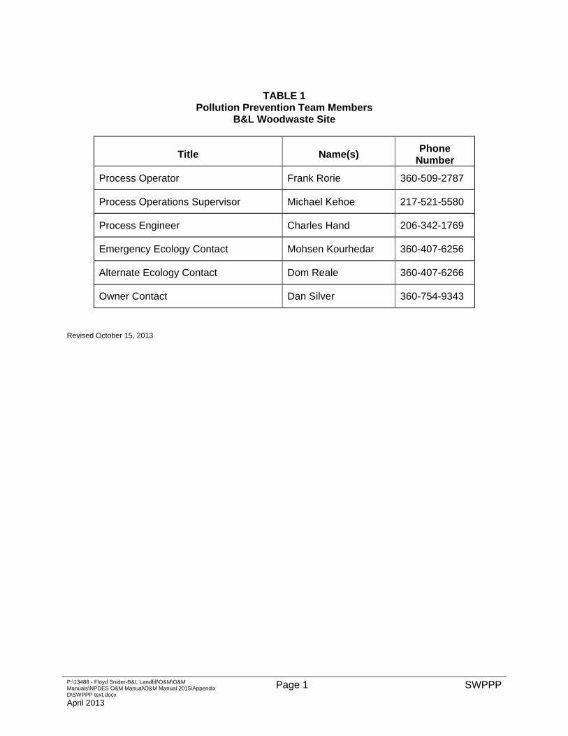
P:\13488 - Floyd Snider-B&L Landfill\O&M\O&M Manuals\NPDES O&M Manual\O&M Manual 2015\Appendix D\SWPPP text.docx
April 2013
Page 1 SWPPP
TABLE 1 Pollution Prevention Team Members
B&L Woodwaste Site
Title Name(s) Phone
Number
Process Operator Frank Rorie 360-509-2787
Process Operations Supervisor Michael Kehoe 217-521-5580
Process Engineer Charles Hand 206-342-1769
Emergency Ecology Contact Mohsen Kourhedar 360-407-6256
Alternate Ecology Contact Dom Reale 360-407-6266
Owner Contact Dan Silver 360-754-9343
Revised October 15, 2013


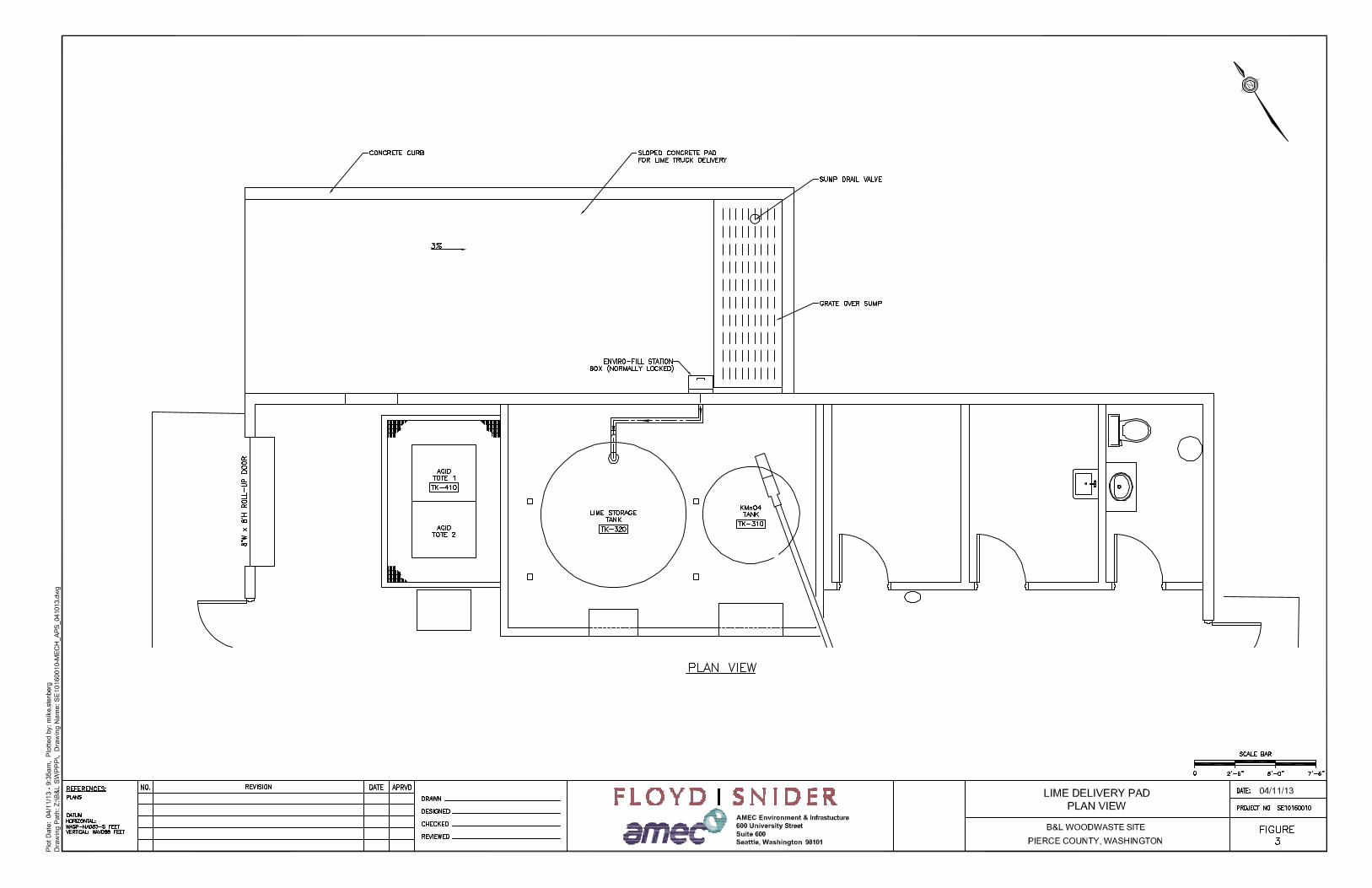

B&L Woodwaste Site
Appendix D
Health and Safety Plan
Site-Specific Health and Safety Plan: Facility Operation and Maintenance
B&L Woodwaste Site
1522 Fife Way East
Milton, Washington 98354 Prepared for: B&L Woodwaste Custodial Trust
Prepared by:
Floyd|Snider AMEC Environment & Infrastructure, Inc. 600 Union Street, Suite 600 600 University Street, Suite 600 Seattle, Washington 98101 Seattle, Washington 98101
June 2012

B&L Woodwaste Site
Health and Safety Plan
10/27/15 Health and Safety PlanPage i
TABLE OF CONTENTS
Page
1.0 PURPOSE ...................................................................................................................... 1
2.0 SCOPE OF FIELD ACTIVITIES ...................................................................................... 3
3.0 ADMINISTRATIVE INFORMATION ................................................................................ 5
4.0 PRIMARY RESPONSIBILITIES ...................................................................................... 7 4.1 PROJECT MANAGER .............................................................................................. 7 4.2 PROJECT HEALTH AND SAFETY OFFICER ............................................................... 7 4.3 SITE SAFETY OFFICER .......................................................................................... 8 4.4 SITE SUPERVISOR ................................................................................................. 9 4.5 PROJECT PERSONNEL ........................................................................................... 9 4.6 TRAINING REQUIREMENTS ................................................................................... 10 4.7 MEDICAL SURVEILLANCE ..................................................................................... 10
5.0 HAZARD ASSESSMENT.............................................................................................. 12 5.1 POTENTIAL CHEMICAL HAZARDS AT SITE ............................................................. 12 5.2 POTENTIAL PHYSICAL HAZARDS .......................................................................... 13
5.2.1 General Electrical Hazards .................................................................... 15 5.2.2 Noise Hazards ....................................................................................... 16 5.2.3 Heat Stress Hazards ............................................................................. 16 5.2.4 Cold Stress Hazards ............................................................................. 18 5.2.5 Sunburn Hazards .................................................................................. 19 5.2.6 Confined Spaces ................................................................................... 19 5.2.7 Mechanical Hazards .............................................................................. 20 5.2.8 Heavy Equipment .................................................................................. 21 5.2.9 Traffic Hazards ...................................................................................... 21 5.2.10 Insects and Wildlife ............................................................................... 21 5.2.11 Lockout/Tag Out / Hazardous Energy ................................................... 21 5.2.12 Water Hazards ...................................................................................... 22
5.3 GENERAL HAZARDS ............................................................................................ 22
6.0 PERSONAL PROTECTIVE EQUIPMENT .................................................................... 25
7.0 ACCESS CONTROL..................................................................................................... 28 7.1 COMMUNICATIONS .............................................................................................. 28
8.0 EMERGENCY RESPONSE .......................................................................................... 30 8.1 EMERGENCY EVACUATION .................................................................................. 30 8.2 MEDICAL EMERGENCIES...................................................................................... 31 8.3 ACCIDENTAL RELEASE OF HAZARDOUS MATERIALS OR WASTES .......................... 32 8.4 GENERAL EMERGENCIES ..................................................................................... 33 8.5 EMERGENCY COMMUNICATIONS .......................................................................... 33 8.6 EMERGENCY EQUIPMENT .................................................................................... 34
9.0 APPROVALS ................................................................................................................ 36
B&L Woodwaste Site
P:\13488 - Floyd Snider-B&L Landfill\HASP\2012 HASP
10/27/15 Health and Safety PlanPage ii
TABLES
Table 1 Hazardous Substances Known or Suspected at Site Table 2 Anticipated Hazards
FIGURES
Figure 1 Partial Site Plan Figure 2 Site Location Figure 3 Route to Hospital
ATTACHMENTS
Attachment 1 Project Health & Safety Field Meeting Form Attachment 2 Material Safety Data Sheets
B&L Woodwaste Site
P:\13488 - Floyd Snider-B&L Landfill\HASP\2012 HASP
10/27/15 Health and Safety PlanPage 1
SITE-SPECIFIC HEALTH AND SAFETY PLAN: GROUNDWATER RECOVERY AND TREATMENT SYSTEMS
B&L Woodwaste Landfill Seattle, Washington
1.0 PURPOSE
This Health and Safety Plan Appendix (HASP Appendix) outlines the health and safety
procedures that shall be followed while conducting field activities related to operation and
maintenance of the groundwater recovery system, groundwater interceptor trench, the
groundwater treatment system, Landfill cap, and associated buildings and fencing. The
project site is located at 1522 Fife Way East, Milton/Fife, WA.
This HASP Appendix defines site-specific hazards and controls to prevent injury and illness for
project personnel working on remediation and monitoring conducted at the Site. The
observance and practice of the procedures in this plan are mandatory for personnel working
on the above remedy components. All contractors and visitors associated with this work shall
be made aware of the requirements of this plan; however, contractors are responsible for the
health and safety of their own employees and subcontractors they employ and for following all
applicable federal, state, and local regulations. At a minimum, any contractors associated with
this work must meet the requirements of this document.
This HASP Appendix has been reviewed jointly by the AMEC Project Manager and the AMEC
Project Health and Safety Officer. Prior to entering the project area, project personnel shall
read this plan and be familiar with health and safety procedures specific to their project
responsibilities when working at the project. A copy of the plan shall be available at the Site
project office and, for work conducted outside the B&L Property, a copy shall be readily
available at the off-property work area. The work area and Site history are described in the
main body of the Site Specific HASP.
B&L Woodwaste Site
P:\13488 - Floyd Snider-B&L Landfill\HASP\2012 HASP
10/27/15 Health and Safety PlanPage 2
This page intentionally left blank.
B&L Woodwaste Site
P:\13488 - Floyd Snider-B&L Landfill\HASP\2012 HASP
10/27/15 Health and Safety PlanPage 3
2.0 SCOPE OF FIELD ACTIVITIES
Project activities will include operation and maintenance of the groundwater interceptor trench,
the groundwater recovery and treatment system, and associated security systems and
buildings associated with the Site remedy. Tasks will include:
Operation of groundwater treatment system equipment, machinery, and controls/instruments;
Operation of groundwater recovery wells, pumps, and controls/instruments;
Collection of groundwater samples from groundwater recovery wells as needed to support operations;
Contaminated water sampling from treatment system components;
Laboratory testing and analysis using onsite test kits and instruments;
Process chemical receipt and handling;
Operation of the groundwater interceptor trench system;
Maintenance of equipment, machinery, and instruments associated with the interceptor trench, groundwater recovery system, and groundwater treatment system;
Monitoring and maintenance of systems associated with the groundwater treatment building (e.g., heating system, sewage lift station);
Inspection and maintenance of the Landfill cap, perimeter drainage system, and ponds; and
Inspection and maintenance of security fencing and surveillance systems.
The field activities involve potential exposure to contaminated groundwater, hazardous
chemicals, mechanical hazards associated with machinery and equipment, and electrical
hazards. Except for operations and maintenance activities conducted on groundwater
recovery wells located on adjacent wetlands or agricultural properties, field work addressed by
this HASP Appendix will be performed on the B&L Property.
A job safety analysis (JSA) has been completed for each routine task associated with project
work addressed by this HASP Appendix. The JSA has been built into the specific Operations
B&L Woodwaste Site
P:\13488 - Floyd Snider-B&L Landfill\HASP\2012 HASP
10/27/15 Health and Safety PlanPage 4
Procedure developed for each task. The Operations and Maintenance Procedures (O&M
Procedures) are included in the Operations, Monitoring, and Maintenance Plan (OMMP); these
detailed procedures are not reproduced in the HASP Appendix, but are included in this HASP
Appendix by reference. Project personnel are required to be familiar with and to follow the
O&M Procedures when performing project work. Material Safety Data Sheets (MSDS) for
chemicals that will be used in performing project tasks or otherwise will be present in the work
areas are provided in Attachment 2.
B&L Woodwaste Site
P:\13488 - Floyd Snider-B&L Landfill\HASP\2012 HASP
10/27/15 Health and Safety PlanPage 5
3.0 ADMINISTRATIVE INFORMATION
Project Name: B&L Woodwaste Site Groundwater Recovery & Treatment System O&M
Project Start Date: May 2012
Project Address: 1522 Fife Way East, Milton, WA
AMEC Project Manager: Larry McGaughey
Telephone No.: (206) 342-1788
AMEC Project Health & Safety Officer: Tim Reinhardt
Telephone No.: (206) 838-8464 / (425) 241-5816

B&L Woodwaste Site
P:\13488 - Floyd Snider-B&L Landfill\HASP\2012 HASP
10/27/15 Health and Safety PlanPage 6
This page intentionally left blank.
B&L Woodwaste Site
P:\13488 - Floyd Snider-B&L Landfill\HASP\2012 HASP
10/27/15 Health and Safety PlanPage 7
4.0 PRIMARY RESPONSIBILITIES
4.1 PROJECT MANAGER
The Project Manager (PM) will have overall responsibility for the success of the project,
including the successful implementation of this HASP Appendix. The PM will review health
and safety issues as needed and as consulted and will have the authority to reallocate
resources and personnel to safely accomplish the field work.
In addition the PM shall:
1. Direct all project personnel involved in the work covered by this HASP Appendix;
2. Make the Project Health and Safety Officer aware of all pertinent project develop-ments and changes or revisions to project plans;
3. Make available the resources that are necessary for a safe working environment;
4. Maintain communications with the client, as necessary; and
5. Ensure that all project personnel have received required training, are aware of the potential hazards associated with the project work, have been instructed in the work practices necessary for personal health and safety, and are familiar with the HASP Appendix and safe O&M Procedures for all scheduled activities and for dealing with emergencies.
4.2 PROJECT HEALTH AND SAFETY OFFICER
The Project Health and Safety Officer (PHSO) shall:
1. Advise PM and project personnel on all health and safety aspects of the work covered by this HASP Appendix activities conducted by project personnel in the field;
2. Specify exposure monitoring as appropriate to assess health and safety conditions in the field;
3. Review any accident/incident reports and make corrective action recommendations;
4. Modify the HASP Appendix as required based on accidents/incidents and findings regarding hazards and work practices;
5. Report all accidents/incidents and findings regarding personnel exposure, field hazards, and work practices to the PM;
B&L Woodwaste Site
P:\13488 - Floyd Snider-B&L Landfill\HASP\2012 HASP
10/27/15 Health and Safety PlanPage 8
6. Suspend field work if the PHSO believes that project personnel, including any subcontractor’s personnel, are or may be exposed to an immediate health hazard.
7. Periodically inspect/audit the project site for compliance with health and safety standards and safe practices.
4.3 SITE SAFETY OFFICER
Field work addressed by this HASP Appendix will usually be done by a single worker. Multiple
workers may be present during some maintenance or calibration work. The Site Safety Officer
(SSO) will normally be the operator assigned to the Site, and the SSO will have the
responsibilities of both the SSO and the Site Supervisor (see Section 4.4). If multiple
personnel are on site, the PM will ensure that SSO Site Supervisor responsibilities are clearly
defined; the SSO may function as the Site Supervisor, as designated by the PM. The SSO
shall:
1. Ensure that appropriate personal protective equipment is available to and used by project personnel;
2. Ensure that all AMEC personnel have received required training, are aware of the potential hazards associated with site operations, have been instructed in the work practices necessary for personal health and safety, and are familiar with the HASP Appendix’s procedures for all scheduled activities and for dealing with emergencies;
3. Suspend field work if the SSO believes that project personnel are or may be exposed to an imminent health hazard;
4. Implement the HASP Appendix and report any observed significant differences from the field conditions anticipated in the plan to the PM;
5. Review O&M Procedures before performing project tasks to ensure that safe practices are followed;
6. If directed by the PHSO, perform exposure monitoring;
7. Assume other duties as directed by the PHSO; and
8. Prepare reports of any observed accidents/incidents or inadequate work practices and communicate them to the PM and PHSO.
B&L Woodwaste Site
P:\13488 - Floyd Snider-B&L Landfill\HASP\2012 HASP
10/27/15 Health and Safety PlanPage 9
4.4 SITE SUPERVISOR
The Site Supervisor shall:
1. Maintain control of the project site and direct daily field operations to be consistent with applicable environmental and health and safety regulations, O&M Procedures, and this project HASP Appendix, and enforce safe work practices and proper utilization of personal protective equipment by all project personnel working in the field;
2. With guidance from the PHSO, observe AMEC and subcontractor’s procedures with respect to health and safety;
3. Suspend field work and, as appropriate, coordinate work suspension through the subcontractor’s site supervisor, if the SS believes that any project personnel are or may be exposed to an imminent health or safety hazard;
4. Implement the HASP Appendix and report any observed significant differences from the field conditions anticipated in the plan to the project manager;
5. Conduct field safety briefings as needed;
6. Ensure that required personal protective, monitoring, and emergency equipment is provided and maintained in effective working condition prior to performing assigned field work; and
7. Report observed accidents/incidents or inadequate work practices to the PM and the PHSO.
4.5 PROJECT PERSONNEL
Project personnel involved in project work shall:
1. Perform assigned work in accordance with the O&M Procedures and safe work practices. Project personnel shall take reasonable precautions to prevent injury to themselves and to their fellow workers;
2. Perform only those tasks that they can do safely and for which they have proper personnel protective equipment, tools, and safeguards. Immediately report accidents and/or unsafe conditions to the SSO or PHSO;
3. Follow the procedures set forth in the HASP Appendix and report to the SSO, Site Supervisor, or PHSO any observed deviations by project personnel from the procedures described in this plan; and
4. Inform the SSO and PHSO of any physical conditions that might affect their ability to perform the planned field tasks prior to performing the work.
B&L Woodwaste Site
P:\13488 - Floyd Snider-B&L Landfill\HASP\2012 HASP
10/27/15 Health and Safety PlanPage 10
4.6 TRAINING REQUIREMENTS
All project personnel must comply with applicable regulations specified in Title 29, U.S. Code
of Federal Regulations (29 CFR) Part 1910.120 and the Washington Administrative Code
(WAC) Chapter 296-843, hazardous waste operations (HAZWOPER), administered by the
Washington State Department of Labor and Industries (L&I). These include completion of a
40-hour health and safety training course for HAZWOPER, an annual 8-hour refresher
training, and participation in AMEC’s medical surveillance program and respiratory protection
program. In addition to the 40-hour course and 8-hour refreshers, the Site Supervisor (and
SSO, if performing the duties of the SS) will have completed an 8-hour course for hazardous
waste site supervisors as required by WAC 296-843-20015. Each field worker will also have a
minimum of 3 days of supervised field experience at a hazardous waste site before working in
the project area without close, direct, supervision. Documentation of all required training for
personnel assigned to the project site will be maintained at the project site by the Site
Supervisor.
Additional site-specific training that covers task-specific hazards; personal protection
equipment (PPE) requirements, use, and limitations; decontamination procedures; and
emergency response information as outlined in this HASP Appendix will be given by the PHSO
or SSO before performed project work. Site-specific training briefings should be documented
on the “Project Health and Safety Field Meeting Form,” included as Attachment 1.
4.7 MEDICAL SURVEILLANCE
All AMEC personnel assigned field duties for the project area shall participate in AMEC’s
medical surveillance program, which includes annual audiometric and physical examinations
for employees involved in HAZWOPER projects. It requires that all such personnel have
medical clearance before being issued a respirator and participating in field activities.
Frequency of medical examinations which comply with 29 CFR § 1910.120(f)(3) and WAC
296-843-21005 are:
Prior to performing field work;
At least once every 24 months (12 months if exposed to air contaminants above the permissible exposure limit [PEL]), or if working in respiratory protection more than 30 days per year);
At termination of employment;
B&L Woodwaste Site
P:\13488 - Floyd Snider-B&L Landfill\HASP\2012 HASP
10/27/15 Health and Safety PlanPage 11
Upon occurrence of possible unprotected overexposure to chemicals or harmful physical agents; and
More frequently if deemed necessary by a physician.
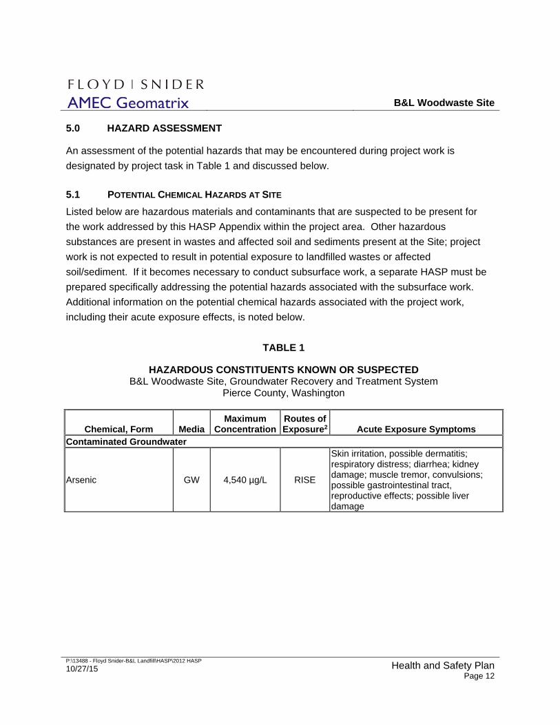
B&L Woodwaste Site
P:\13488 - Floyd Snider-B&L Landfill\HASP\2012 HASP
10/27/15 Health and Safety PlanPage 12
5.0 HAZARD ASSESSMENT
An assessment of the potential hazards that may be encountered during project work is
designated by project task in Table 1 and discussed below.
5.1 POTENTIAL CHEMICAL HAZARDS AT SITE
Listed below are hazardous materials and contaminants that are suspected to be present for
the work addressed by this HASP Appendix within the project area. Other hazardous
substances are present in wastes and affected soil and sediments present at the Site; project
work is not expected to result in potential exposure to landfilled wastes or affected
soil/sediment. If it becomes necessary to conduct subsurface work, a separate HASP must be
prepared specifically addressing the potential hazards associated with the subsurface work.
Additional information on the potential chemical hazards associated with the project work,
including their acute exposure effects, is noted below.
TABLE 1
HAZARDOUS CONSTITUENTS KNOWN OR SUSPECTED B&L Woodwaste Site, Groundwater Recovery and Treatment System
Pierce County, Washington
Chemical, Form Media Maximum
ConcentrationRoutes of Exposure2 Acute Exposure Symptoms
Contaminated Groundwater
Arsenic GW 4,540 µg/L RISE
Skin irritation, possible dermatitis; respiratory distress; diarrhea; kidney damage; muscle tremor, convulsions; possible gastrointestinal tract, reproductive effects; possible liver damage
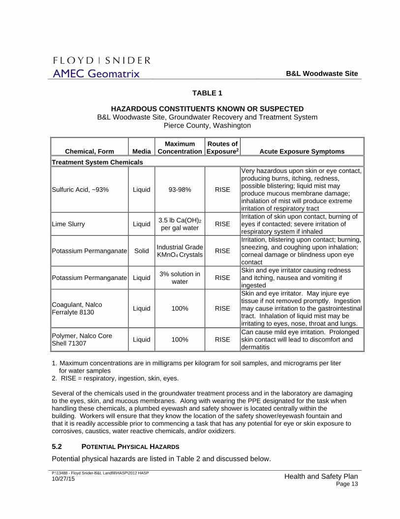
B&L Woodwaste Site
P:\13488 - Floyd Snider-B&L Landfill\HASP\2012 HASP
10/27/15 Health and Safety PlanPage 13
TABLE 1
HAZARDOUS CONSTITUENTS KNOWN OR SUSPECTED B&L Woodwaste Site, Groundwater Recovery and Treatment System
Pierce County, Washington
Chemical, Form Media Maximum
ConcentrationRoutes of Exposure2 Acute Exposure Symptoms
Treatment System Chemicals
Sulfuric Acid, ~93% Liquid
93-98%
RISE
Very hazardous upon skin or eye contact, producing burns, itching, redness, possible blistering; liquid mist may produce mucous membrane damage; inhalation of mist will produce extreme irritation of respiratory tract
Lime Slurry Liquid 3.5 lb Ca(OH)2 per gal water
RISE Irritation of skin upon contact, burning of eyes if contacted; severe irritation of respiratory system if inhaled
Potassium Permanganate
Solid Industrial Grade KMnO4 Crystals
RISE
Irritation, blistering upon contact; burning, sneezing, and coughing upon inhalation; corneal damage or blindness upon eye contact
Potassium Permanganate
Liquid 3% solution in
water RISE
Skin and eye irritator causing redness and itching, nausea and vomiting if ingested
Coagulant, Nalco Ferralyte 8130
Liquid 100% RISE
Skin and eye irritator. May injure eye tissue if not removed promptly. Ingestion may cause irritation to the gastrointestinal tract. Inhalation of liquid mist may be irritating to eyes, nose, throat and lungs.
Polymer, Nalco Core Shell 71307
Liquid 100% RISE Can cause mild eye irritation. Prolonged skin contact will lead to discomfort and dermatitis
1. Maximum concentrations are in milligrams per kilogram for soil samples, and micrograms per liter for water samples 2. RISE = respiratory, ingestion, skin, eyes. Several of the chemicals used in the groundwater treatment process and in the laboratory are damaging to the eyes, skin, and mucous membranes. Along with wearing the PPE designated for the task when handling these chemicals, a plumbed eyewash and safety shower is located centrally within the building. Workers will ensure that they know the location of the safety shower/eyewash fountain and that it is readily accessible prior to commencing a task that has any potential for eye or skin exposure to corrosives, caustics, water reactive chemicals, and/or oxidizers. 5.2 POTENTIAL PHYSICAL HAZARDS
Potential physical hazards are listed in Table 2 and discussed below.
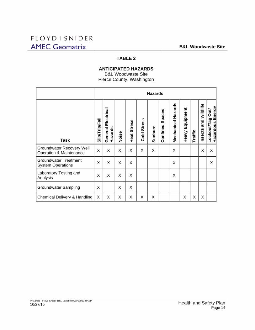
B&L Woodwaste Site
P:\13488 - Floyd Snider-B&L Landfill\HASP\2012 HASP
10/27/15 Health and Safety PlanPage 14
TABLE 2
ANTICIPATED HAZARDS B&L Woodwaste Site
Pierce County, Washington
Hazards
Task Slip
/Tri
p/F
all
Gen
eral
Ele
ctri
cal
Haz
ard
s
No
ise
Hea
t S
tres
s
Co
ld S
tres
s
Su
nb
urn
Co
nfi
ned
Sp
aces
Mec
han
ical
Haz
ard
s
Hea
vy E
qu
ipm
ent
Tra
ffic
Inse
cts
and
Wild
life
Lo
cko
ut/
Tag
Ou
t /
Haz
ard
ou
sE
ner
gy
Groundwater Recovery Well Operation & Maintenance
X X X X X X
X X X
Groundwater Treatment System Operations
X X X X
X X
Laboratory Testing and Analysis
X X X X
X
Groundwater Sampling X X X
Chemical Delivery & Handling X X X X X X X X X
B&L Woodwaste Site
P:\13488 - Floyd Snider-B&L Landfill\HASP\2012 HASP
10/27/15 Health and Safety PlanPage 15
Common safety hazards include slip/trip/fall hazards, chemical handling hazards, contaminated
media, debris and tools, and hazards associated with working around machinery, equipment,
and with hand or power tools. All project area personnel will keep materials, equipment, and
debris organized and flagged as necessary to prevent trip hazards. Project area personnel will
wear the following PPE at a minimum when entering and/or working in the groundwater
treatment building:
Sturdy work boots or shoes with steel toes and shanks;
Safety glasses; and
Hard hats.
Work conducted outside the building will require the same PPE with the exception of hard hat.
Hard hats are not required in the office, laboratory, or lavatory; and safety glasses are not
required in the office or lavatory. Additional PPE may be required for specific tasks, as
described in the O&M Procedures for the specific work task.
5.2.1 General Electrical Hazards
Electrical hazards are present throughout the GWTP Building, as much of the equipment,
instrumentation, and controls require electrical power. Prior to performing maintenance or
servicing of any process equipment, instruments, or controls, documented lockout/tag out
procedures must be followed, in accordance with the O&M Procedures. Circuits powering
equipment, instruments, and/or controls must be confirmed to be de-energized prior to removing
or opening housings to perform service or when entering confined spaces where water may be
present.
To prevent electrocution hazards caused by utilizing electrically powered tools and/or other
mobile equipment, all electrical extension cords must be rated for the combined amperage of
the equipment they power, and must be factory listed as rated SJOW or STOW (an “-A”
extension is acceptable for either) and inspected prior to each use for defects in the cord and
plugs. Any reduction or damage to the original cord jacket, gap between the strain relief, or any
evidence of overheating (cord discoloration or melting) will result in the immediate destruction of
the cord and replacement, as necessary.
The following safe work practices will also be enforced.
B&L Woodwaste Site
P:\13488 - Floyd Snider-B&L Landfill\HASP\2012 HASP
10/27/15 Health and Safety PlanPage 16
No exposed energized conductors operating above 50 volts to ground will be allowed unless properly guarded from contact by site workers.
Electrical distribution systems and electrical repairs to equipment operating above 50 volts to ground will be performed only by a qualified licensed electrician.
All portable power tools will be inspected by the user for defects before use and will be of a double-insulated design.
Any generator brought to the work area will be grounded to a suitable earth and will be equipped with overcurrent protection.
All extension cords will be protected by a ground-fault circuit interrupter, which will be tested before each use.
No extension cords will be routed through walls, ceilings, doors, or windows.
5.2.2 Noise Hazards
GWTP process equipment will operate continuously and has the potential for requiring hearing
protection. Site personnel will wear hearing protection when working in any areas designated
as requiring hearing protection. This measure is designed to prevent hearing loss that can
occur when daily 8-hour time weighted average noise exposures meet or exceed 85 decibels
(dBA) (WAC 296-817-20015).
5.2.3 Heat Stress Hazards
Heat stress is a slight hazard during the summer months in the Pacific Northwest, but becomes
a significant hazard for workers wearing protective clothing under certain conditions. Heat
stress may affect workers to varying degrees. The signs, symptoms, and treatment of these
varying degrees of heat stress are summarized below.
Heat rash may result from exposure to heat or humid air.
Heat cramps are caused by heavy sweating with inadequate electrolyte replacement. Signs and symptoms include muscle spasms and pain in the hands, feet, and abdomen. Persons experiencing these symptoms should rest in a cooler area, drink cool (not cold) liquids, and gently massage cramped muscles.
Heat exhaustion occurs from increased stress on various body organs and may include inadequate blood circulation due to cardiovascular insufficiency or dehydration. Signs and symptoms include pale, cool, moist skin; heavy sweating; dizziness; nausea; and fainting. Persons experiencing these symptoms should lie down in a cooler area, drink cool liquids with electrolytes (Gatorade, etc.), remove
B&L Woodwaste Site
P:\13488 - Floyd Snider-B&L Landfill\HASP\2012 HASP
10/27/15 Health and Safety PlanPage 17
any protective clothing, and cool body with wet compresses at forehead, back and neck, and/or armpits.
Heat stroke is the most serious form of heat stress. Temperature regulation fails and the body temperature rises to critical levels. Immediate action must be taken to cool the body before serious injury and death occur. Competent medical help must be obtained. Signs and symptoms are red, hot, usually dry skin; lack of or reduced perspiration; nausea; dizziness and confusion; strong, rapid pulse; and coma.
From May 1 to September 30, if physically demanding field work will occur in the combination of
temperatures and clothing/PPE ensembles shown in the table below, actions will be taken to
prevent heat stress among the affected workers.
WORK AREA TEMPERATURE ACTION LEVELS
Non-breathing clothes, including vapor- and chemical-resistant suits
(Levels B and A, and impermeable raingear) 52° F
Double-layer woven clothes, including coveralls, jackets, and sweatshirts 77° F
All other clothing 89° F
Site staff working outdoors will be trained in heat-related illness and in management of potential
risk factors in accordance with WAC 296-62-095. To prevent heat stress, at least one quart per
person-hour of cool potable water will be readily available via individual cups, and field
personnel will be encouraged to drink plenty of fluids and take periodic work breaks in hot
weather. The SSO will promptly consult with the PHSO, and a radial pulse monitoring method
will be implemented to ensure that adequate work-rest cycles will be established to manage
heat stress potential among the affected workers. Combined temperature and humidity
conditions that result in a heat index exceeding 100° will trigger mandatory radial pulse
monitoring and heat stress management. The following chart indicates the relative risk of heat
stress at combinations of temperature and relative humidity.
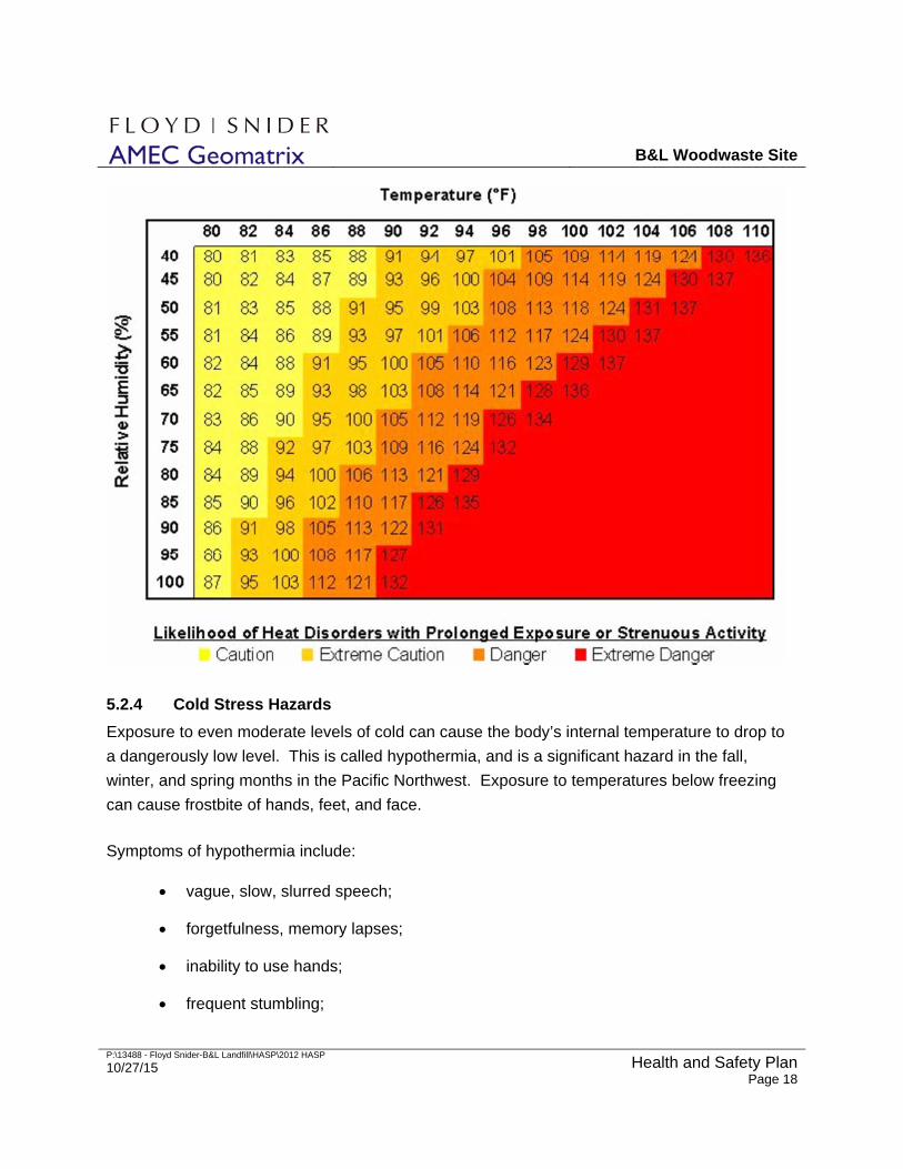
B&L Woodwaste Site
P:\13488 - Floyd Snider-B&L Landfill\HASP\2012 HASP
10/27/15 Health and Safety PlanPage 18
5.2.4 Cold Stress Hazards
Exposure to even moderate levels of cold can cause the body’s internal temperature to drop to
a dangerously low level. This is called hypothermia, and is a significant hazard in the fall,
winter, and spring months in the Pacific Northwest. Exposure to temperatures below freezing
can cause frostbite of hands, feet, and face.
Symptoms of hypothermia include:
vague, slow, slurred speech;
forgetfulness, memory lapses;
inability to use hands;
frequent stumbling;
B&L Woodwaste Site
P:\13488 - Floyd Snider-B&L Landfill\HASP\2012 HASP
10/27/15 Health and Safety PlanPage 19
drowsiness.
To prevent hypothermia, project personnel should stay dry and avoid exposure. Project
personnel are encouraged to wear sufficient clothing in layers such that outer clothing is wind-
and waterproof and inner layers retain warmth (wool or polypropylene). Project personnel
should keep hands and feet well protected at all times, especially when working in cold
conditions.
5.2.5 Sunburn Hazards
Skin exposure to ultraviolet radiation can result in sunburn. Site personnel will use long-sleeved
shirts, hats, and sunscreen to protect against sunburn when working outdoors.
5.2.6 Confined Spaces
Confined spaces and associated hazards include the following:
Confined Space Potential Hazards Lockout / Tag Out
Head Tank, TK-100 Engulfment in water, Arsenic contaminated water (wells)
Well pumps
Oxidation Tank, TK-110
Engulfment & arsenic contaminated water (TK-100), Contaminated water from process sump (TK-250), Potassium Permanganate feed (TK-310), Rotating machinery (mixer)
Permanganate dosing pump, well pumps, process sump pump, mixer
Co-Precipitation Tank, TK-120
Engulfment & arsenic contaminated water (TK-110), Lime Slurry dosing, Sludge recycle, Rotating machinery (mixer)
Lime dosing pump, sludge line to co-precipitation tank, well pumps, mixer
pH Adjust Tank, TK-420 Engulfment & arsenic contaminated water (TH-130), Sulfuric acid dosing, Rotating machinery (mixer)
Acid dosing pumps, well pumps, mixer
Potassium Permanganate Feed Tank, TK-310
KMnO4 powder addition, Engulfment (potable water line), Rotating machinery (mixer)
Permanganate conveyor, potable water line, mixer
Lime Storage Tank, TK-320 Engulfment & Lime slurry exposure, Rotating machinery (mixer)
Mixer, lime recirculation pump
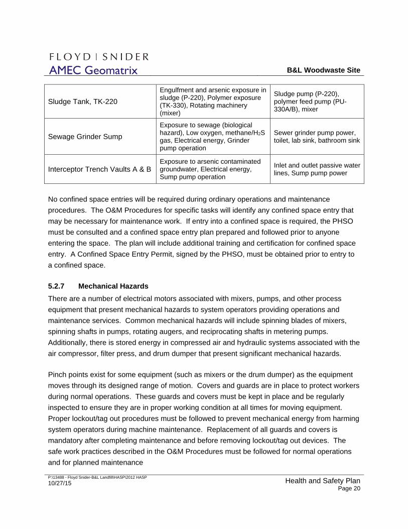
B&L Woodwaste Site
P:\13488 - Floyd Snider-B&L Landfill\HASP\2012 HASP
10/27/15 Health and Safety PlanPage 20
Sludge Tank, TK-220
Engulfment and arsenic exposure in sludge (P-220), Polymer exposure (TK-330), Rotating machinery (mixer)
Sludge pump (P-220), polymer feed pump (PU-330A/B), mixer
Sewage Grinder Sump
Exposure to sewage (biological hazard), Low oxygen, methane/H2S gas, Electrical energy, Grinder pump operation
Sewer grinder pump power, toilet, lab sink, bathroom sink
Interceptor Trench Vaults A & B Exposure to arsenic contaminated groundwater, Electrical energy, Sump pump operation
Inlet and outlet passive water lines, Sump pump power
No confined space entries will be required during ordinary operations and maintenance
procedures. The O&M Procedures for specific tasks will identify any confined space entry that
may be necessary for maintenance work. If entry into a confined space is required, the PHSO
must be consulted and a confined space entry plan prepared and followed prior to anyone
entering the space. The plan will include additional training and certification for confined space
entry. A Confined Space Entry Permit, signed by the PHSO, must be obtained prior to entry to
a confined space.
5.2.7 Mechanical Hazards
There are a number of electrical motors associated with mixers, pumps, and other process
equipment that present mechanical hazards to system operators providing operations and
maintenance services. Common mechanical hazards will include spinning blades of mixers,
spinning shafts in pumps, rotating augers, and reciprocating shafts in metering pumps.
Additionally, there is stored energy in compressed air and hydraulic systems associated with the
air compressor, filter press, and drum dumper that present significant mechanical hazards.
Pinch points exist for some equipment (such as mixers or the drum dumper) as the equipment
moves through its designed range of motion. Covers and guards are in place to protect workers
during normal operations. These guards and covers must be kept in place and be regularly
inspected to ensure they are in proper working condition at all times for moving equipment.
Proper lockout/tag out procedures must be followed to prevent mechanical energy from harming
system operators during machine maintenance. Replacement of all guards and covers is
mandatory after completing maintenance and before removing lockout/tag out devices. The
safe work practices described in the O&M Procedures must be followed for normal operations
and for planned maintenance
B&L Woodwaste Site
P:\13488 - Floyd Snider-B&L Landfill\HASP\2012 HASP
10/27/15 Health and Safety PlanPage 21
5.2.8 Heavy Equipment
Heavy equipment will not be used during normal operations. If it is necessary to use heavy
equipment for maintenance or equipment replacement, a task-specific HASP that includes
JSAs, will be prepared and implemented to document associated hazards and establish safe
work practices.
5.2.9 Traffic Hazards
Delivery truck operations in the work area may pose a hazard to site workers if working outside
the GWTP Building. Truck deliveries will be coordinated with work conducted outside the
building, and site workers will be notified of pending deliveries. High-visibility safety vests will
be worn by personnel working outside the building during truck deliveries. A speed limit of 5
miles per hour on the B&L property will be enforced. Trucks will only be approached from the
front or side of the cab, and eye contact with the operator will be made prior to entering the
strike radius of the vehicle. Loads leaving the work area will be secured and covered as
necessary to prevent loss of material on the highway. Site personnel assisting delivery vehicles
by directing the driver while backing to delivery areas will maintain a safe distance from the
vehicle and maintain visual contact with the driver.
5.2.10 Insects and Wildlife
Bees, other insects, and spiders may be encountered during site activities. Persons with
allergies to bees will make the SS and SSO aware of their allergies and will avoid areas where
bees are identified. Black widow, hobo, and brown recluse spiders are occasionally
encountered in dry, dark areas. Field personnel will maintain a safe distance from any urban
wildlife encountered, including raccoons and rodents, to preclude a bite from a sick or injured
animal. Personnel will not put ungloved hands into dark places that could contain spiders, and
will use tools to lift covers from catch basins, cleanouts, and well monuments. In order to avoid
contact with bees, wasps, spiders, and mosquitoes, field personnel will wear gloves and long
sleeved shirts as needed.
5.2.11 Lockout/Tag Out / Hazardous Energy
The groundwater treatment system poses a hazard from exposure to hazardous energy during
operation, maintenance, and repair from pressurized, contaminated groundwater, pressurized
air, hydraulic systems, and/or from electrical and mechanical energy. Written AMEC Lockout
Procedures will be followed whenever these systems must be shut down for maintenance or
repair/replacement if the unexpected energizing of the system (or release of stored energy such
B&L Woodwaste Site
P:\13488 - Floyd Snider-B&L Landfill\HASP\2012 HASP
10/27/15 Health and Safety PlanPage 22
as pressure) could cause serious injury to employees. Such activities will be implemented or
overseen only by employees named as authorized persons in AMEC’s downtown Seattle office
lockout program.
The O&M Procedures will inform the operator of lockout/tag out-requirements for normal
maintenance procedures. The operator must be lockout/tag out trained in order to complete the
maintenance procedures which require such actions. Non-standard maintenance procedures
that are not explicitly covered by existing O&M Procedures and this HASP will be performed
under a task-specific HASP (including JSAs) approved by the SSO and PM.
5.2.12 Water Hazards
Operations and maintenance of recovery wells located in wetlands areas may present water
hazards during periods of the year when these areas are flooded. Special precautions must be
taken when working in these areas during the wet season. Whenever work must be conducted
when standing water is present in these areas, the provisions for working safely specified in the
O&M Procedures must be followed. These provisions will require appropriate waders or
flotation devices and working in buddy teams. Specific health and safety precautions identified
in the appropriate O&M Procedures must be followed when working on recovery wells in the
seasonally inundated areas.
5.3 GENERAL HAZARDS
In working with or around any hazardous or potentially hazardous materials or hazardous
situations, field personnel should plan all activities before starting any task. Field personnel
shall identify health and safety hazards involved with the work planned and consult with the PM,
PHSO or SSO as to how the task can be performed in the safest manner, if he/she has any
uncertainties. Standard O&M Procedures, which identify safe work practices, must be followed
for all operations and maintenance tasks addressed by the procedures. For any tasks not
covered by the standard O&M Procedures and this HASP, a task-specific HASP(including
JSAs) must be prepared and submitted to the SSO, PM, or PHSO for approval.
Common field safety hazards include slip/trip/fall hazards, sharp or rough-surface equipment,
debris and tools, and hazards associated with working around heavy equipment. All staff who
will use portable ladders must be specifically trained in ladder safety. All operations personnel
will adhere to the following general safety rules.
B&L Woodwaste Site
P:\13488 - Floyd Snider-B&L Landfill\HASP\2012 HASP
10/27/15 Health and Safety PlanPage 23
Wear protective equipment and clothing, as specified in Section 6 of this HASP Appendix and as specified in applicable O&M Procedures.
Do not eat, drink, or use tobacco or cosmetics in restricted work areas.
Prevent splashing of contaminated groundwater and chemical solutions, and minimize emissions of dust.
Prevent back injury by never lifting or carrying a load that is heavier than you can comfortably handle. When lifting heavy objects, bend the knees and use the leg muscles, and get assistance when necessary.
Keep all heat and ignition sources away from combustible liquids, gases, or any flammable materials. When working in areas where combustible gases may be present, use only intrinsically safe (non-sparking) equipment.
Be familiar with the physical characteristics of the work area, including:
1. accessibility of other personnel, equipment, and vehicles;
2. areas of known or suspected chemicals in soil, surface water, or groundwater;
3. areas where hazardous materials are stored or used;
4. locations of the safety shower, eye wash fountain, fire extinguishers, and emergency shutdown buttons;
5. access;
6. nearest water sources; and
7. location of communication devices.
Dispose of wastes generated in accordance with the O&M Procedures.
Inspect power cords for damage such as cuts and frays. Suspend cords only with nylon rope or plastic “S” hooks.
When in doubt of your safety, it is better to overprotect.
Practice defensive driving.
Wear sturdy outer gloves when handling sharp or rough-surfaced objects.
Keep a first-aid kit in the work area and/or in a field vehicle when performing field work.

B&L Woodwaste Site
P:\13488 - Floyd Snider-B&L Landfill\HASP\2012 HASP
10/27/15 Health and Safety PlanPage 24
This page intentionally left blank
.
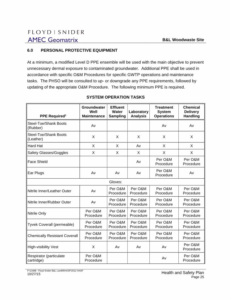
B&L Woodwaste Site
P:\13488 - Floyd Snider-B&L Landfill\HASP\2012 HASP
10/27/15 Health and Safety PlanPage 25
6.0 PERSONAL PROTECTIVE EQUIPMENT
At a minimum, a modified Level D PPE ensemble will be used with the main objective to prevent
unnecessary dermal exposure to contaminated groundwater. Additional PPE shall be used in
accordance with specific O&M Procedures for specific GWTP operations and maintenance
tasks. The PHSO will be consulted to up- or downgrade any PPE requirements, followed by
updating of the appropriate O&M Procedure. The following minimum PPE is required.
SYSTEM OPERATION TASKS
PPE Required1
Groundwater Well
Maintenance
Effluent Water
SamplingLaboratory Analysis
Treatment System
Operations
Chemical Delivery Handling
Steel-Toe/Shank Boots (Rubber)
Av Av Av
Steel-Toe/Shank Boots (Leather)
X X X X X
Hard Hat X X Av X X
Safety Glasses/Goggles X X X X X
Face Shield Av Per O&M Procedure
Per O&M Procedure
Ear Plugs Av Av Av Per O&M Procedure
Av
Gloves:
Nitrile Inner/Leather Outer Av Per O&M Procedure
Per O&M Procedure
Per O&M Procedure
Per O&M Procedure
Nitrile Inner/Rubber Outer Av Per O&M Procedure
Per O&M Procedure
Per O&M Procedure
Per O&M Procedure
Nitrile Only Per O&M Procedure
Per O&M Procedure
Per O&M Procedure
Per O&M Procedure
Per O&M Procedure
Tyvek Coverall (permeable) Per O&M Procedure
Per O&M Procedure
Per O&M Procedure
Per O&M Procedure
Per O&M Procedure
Chemically Resistant Coverall Per O&M Procedure
Per O&M Procedure
Per O&M Procedure
Per O&M Procedure
Per O&M Procedure
High-visibility Vest X Av Av Av Per O&M Procedure
Respirator (particulate cartridge)
Per O&M Procedure
Av Per O&M Procedure
B&L Woodwaste Site
P:\13488 - Floyd Snider-B&L Landfill\HASP\2012 HASP
10/27/15 Health and Safety PlanPage 26
Other Per O&M Procedure
Per O&M Procedure
Per O&M Procedure
Per O&M Procedure
Per O&M Procedure
Abbreviations Av = Have available at work site O = PPE Optional X = PPE Required

B&L Woodwaste Site
P:\13488 - Floyd Snider-B&L Landfill\HASP\2012 HASP
10/27/15 Health and Safety PlanPage 27
This page intentionally left blank.
B&L Woodwaste Site
P:\13488 - Floyd Snider-B&L Landfill\HASP\2012 HASP
10/27/15 Health and Safety PlanPage 28
7.0 ACCESS CONTROL
The purpose of access control is to minimize potential exposure to hazards, to prevent
vandalism and access by children and other unauthorized persons, and to provide secure and
safe facilities for workers. Fencing, gates, surveillance systems, and building access control will
be used to safeguard workers at the project site. Signs will be posted at each door to the
GWTP Building stating that only authorized personnel are allowed inside the building. A field
log, listing of all personnel present at the project site and listing all visitors, vendors, or
contractors is entering the project site will be maintained at the GWTP Building. Arrival and
departure times will be noted to enable an accurate roll call for onsite personnel in the event of
an emergency.
Work area controls, appropriate safety procedures, and decontamination/PPE areas will be
clearly identified to all personnel entering the project area to limit the potential for chemical
exposure associated with work activities. Access to the GWTP Building restroom and washing
facilities will be identified and provided as appropriate; sanitary facilities in the GWTP Building
will be maintained in hygienic conditions at all times.
7.1 COMMUNICATIONS
On-site communications will be by voice, hand-held radio, office phone, or cell phone.
Emergency alarms are readily available at locations within the GWTP Building. Personnel
entering the GWTP Building will be notified of the locations and use of emergency alarm
buttons, which will initiate an emergency shutdown of the GWTP and issue an alarm to offsite
and emergency personnel.

B&L Woodwaste Site
P:\13488 - Floyd Snider-B&L Landfill\HASP\2012 HASP
10/27/15 Health and Safety PlanPage 29
This page intentionally left blank.
B&L Woodwaste Site
P:\13488 - Floyd Snider-B&L Landfill\HASP\2012 HASP
10/27/15 Health and Safety PlanPage 30
8.0 EMERGENCY RESPONSE
This section defines the emergency action plan for the site. It will be rehearsed with all
personnel regularly performing project work, including maintenance subcontractors, and will be
reviewed with delivery workers and/or visitors upon their initial visit to the work area, and
whenever the plan is modified or the SS or SSO believe that field personnel are unclear about
the appropriate emergency actions.
After every emergency is resolved, the entire project team will meet and debrief on the
incident—the purpose is not to fix blame, but to improve the planning and response to future
emergencies. The debriefing will review the sequence of events, what was done well, and what
can be improved. The debriefing will be documented in a written format and communicated to
the PHSO. Modifications to the emergency plan will be approved by the PHSO.
Reasonably foreseeable emergency situations include medical emergencies, accidental release
of hazardous materials (such as potassium permanganate, lime slurry, or sulfuric acid) or
hazardous waste, and general emergencies such as fire, thunderstorm, flooding, and
earthquake. It is important that each person present understands his or her role in an
emergency, and that s/he remains calm and acts efficiently to ensure everyone’s safety.
Expected actions for each potential incident are outlined below.
8.1 EMERGENCY EVACUATION
In the event of an emergency that requires evacuation of the GWTP Building, workers inside the
building must immediately exit the building through the nearest building exit. One exit is located
on each end of the building, as shown on Figure 1. Upon exiting the building, workers shall go
to the muster point as shown on Figure 1. This muster point is located west of the building, and
should be clear from expected hazards. This location also provides alternate pathways to leave
the site, should it be necessary.
This muster point will be communicated to the field personnel and visitors. Hazardous materials
and contaminated groundwater are generally present in the GWTP Building, which provides
effective containment. Building ventilation exhausts from the roof of the building. In an
emergency, all field personnel and visitors will evacuate to the muster point for roll call. The
SSO will confirm that all personnel working at the site have evacuated the building and will
direct site personnel to take specific actions, such as calling 911 or taking steps to minimize or
mitigate dangers.
B&L Woodwaste Site
P:\13488 - Floyd Snider-B&L Landfill\HASP\2012 HASP
10/27/15 Health and Safety PlanPage 31
8.2 MEDICAL EMERGENCIES
In the event of a medical emergency, the following procedures should be used.
1. Stop any imminent hazard if you can safely do it.
2. Remove ill, injured, or exposed person(s) from immediate danger if moving them will clearly not cause them harm, and no hazards exist to the rescuers.
3. Evacuate other personnel present to a safe place in an upwind or cross-wind direction until it is safe for work to resume.
4. If serious injury or life-threatening condition exists, call:
911 – for paramedics, fire department, police
Clearly describe the location, injury, and conditions to the dispatcher. Designate a person to go to the site entrance and direct emergency equipment to the injured person(s). Provide the responders with a copy of this health and safety plan, to alert them to chemicals of potential concern.
5. Trained personnel may provide first aid/cardiopulmonary resuscitation if it is necessary and safe to do so. Remove contaminated clothing and PPE only if this can be done without endangering the injured person. Use universal precautions and required PPE (latex or nitrile gloves, barrier mask) if bodily fluid exposure is possible to prevent exposure to pathogens.
6. Call the PHSO and/or PM.
7. Immediately implement steps to prevent recurrence of the accident.
A map showing the nearest hospital location is shown at the end of this section, in Figure 3.
The address and contact information for the nearest hospital is shown below:
Tacoma General Hospital 315 Martin Luther King Jr. Way Tacoma, WA 98405-4234 (253) 403-1000
Telephone number of nearest Poison Control Center: (800) 222-1222
B&L Woodwaste Site
P:\13488 - Floyd Snider-B&L Landfill\HASP\2012 HASP
10/27/15 Health and Safety PlanPage 32
8.3 ACCIDENTAL RELEASE OF HAZARDOUS MATERIALS OR WASTES
Accidental releases of hazardous materials, contaminated groundwater, or wastes may occur to
contained areas or to the environment. Containment systems are in place for areas and
operations with the potential to have accidental releases; containment systems are designed to
prevent the release from reaching the environment outside the building or containment area.
Releases to secondary containment systems present a potential hazard to the site worker but
do not present a hazard to the environment, provided that the release is properly addressed by
site workers. Releases to areas outside containment systems represent hazards to site
workers, the general public, and to the environment.
In the event of personnel exposure to the hazardous process chemicals, including sulfuric acid,
lime slurry, or potassium permanganate solution, the affected worker should immediately
proceed to the safety shower and eye wash fountain and flush the affected area with water.
Activation of the eye wash fountain or safety shower will automatically initiate a safe shutdown
of the GWTP and issue an alarm to offsite personnel. Off site personnel will immediately report
the incident to emergency response services.
Secondary containment is provided for the areas inside the building where contaminated
groundwater or process chemicals are processed or stored. Containment is also provided for
the delivery pad and hose connector (Environbox) used to receive bulk shipments of lime slurry.
The lime slurry delivery pad provides capability to contain minor spills that may occur during
lime slurry deliveries. Releases to secondary containment areas are to be addressed in
accordance with the O&M Procedures.
In the event of accidental release of hazardous materials to areas outside the GWTP Building
and/or the lime slurry delivery pad, the following procedures must be followed.
1. Evacuate all personnel to a safe place in an upwind direction until the PHSO determines that it is safe for work to resume.
2. Contact the Tacoma Fire Department (911) and inform them of a hazardous material release.
3. Contact the Washington State Emergency Management Division (800) 258-5990 AND the National Response Center (800) 424-8802 in accordance with the procedures for spill response and reporting, as described in the O&M Procedures.
4. Contact or designate a person to contact the PHSO and PM and confirm a response from the PHSO or PM.
B&L Woodwaste Site
P:\13488 - Floyd Snider-B&L Landfill\HASP\2012 HASP
10/27/15 Health and Safety PlanPage 33
5. Contain spill in accordance with the applicable MSDS, if it is possible and if it can be done safely.
6. Initiate cleanup in accordance with the MSDS and using personnel trained in responding to the material that was released.
8.4 GENERAL EMERGENCIES
The following procedures should be followed for general emergencies.
In the event of a general process failure, the onsite operator can initiate an emergency, safe shutdown of the GWTP using any of the three emergency shutdown switches. An emergency shutdown switch is located near each of the two man doors to the building and one near the safety shower. After activating an emergency shutdown switch, the onsite operator must report the reason to offsite operations personnel and local emergency authorities, as appropriate based on the nature of the emergency shutdown.
In the case of fire, severe flooding, explosion, earthquake, or other imminent hazard, GWTP operations shall be halted using the emergency shutdown buttons and hazardous materials shall be secured. Site personnel will be immediately evacuated to a safe place. The local police/ fire department shall be notified by calling 911 if the emergency poses a hazard to the community or environment.
During the incipient phase of a fire, the available fire extinguisher(s) may be used by persons trained in putting out fires, if it is safe for them to do so. The sprinkler system is expected to extinguish significant fires.
In the event of a thunderstorm, outdoor work will be discontinued until the threat of lightning has abated.
In the event of a strong earthquake, the work area will be evacuated and secured, and personnel will quickly mobilize to high ground until it is clear that no seiche (inland tsunami) is expected.
8.5 EMERGENCY COMMUNICATIONS
The GWTP is equipped with an autodialer that will issue telephone calls to offsite personnel in
the event of emergency conditions detected by process instruments, building instruments, or the
emergency shutdown switches. The building smoke alarm and fire alarm systems will issue a
local alarm and will alarm local emergency response services if a fire or smoke is detected in
the building. Telephone service is also available from the building office that can be used in the
event of an emergency.
B&L Woodwaste Site
P:\13488 - Floyd Snider-B&L Landfill\HASP\2012 HASP
10/27/15 Health and Safety PlanPage 34
8.6 EMERGENCY EQUIPMENT
The following minimum emergency equipment will be readily available in the work area and
functional at all times:
First Aid Kit—Contents approved by the PHSO, including two blood borne pathogen barriers;
A safety shower and eye wash fountain for use if chemical exposure occurs;
Fire extinguishers and automatic sprinkler system;
Emergency shutdown buttons (three, one at each man door and one at the safety shower) to shut down the GWTP and issue an offsite alarm;
Fire alarms and smoke detectors;
Emergency lighting and exit signs;
Spill response materials in accordance with the MSDS for the hazardous materials stored onsite
Spare PPE suitable for working with the hazardous materials present in the GWTP Building; and
A copy of the current site-specific HASP Appendix.

B&L Woodwaste Site
P:\13488 - Floyd Snider-B&L Landfill\HASP\2012 HASP
10/27/15 Health and Safety PlanPage 35
This page intentionally left blank.
B&L Woodwaste Site
P:\13488 - Floyd Snider-B&L Landfill\HASP\2012 HASP
10/27/15 Health and Safety PlanPage 36
9.0 APPROVALS
Project Manager Date
Project Health & Safety Officer Date
Site Safety Officer Date

B&L Woodwaste Site
P:\13488 - Floyd Snider-B&L Landfill\HASP\2012 HASP
10/27/15 Health and Safety PlanPage 37
This page intentionally left blank.
B&L Woodwaste Site
P:\13488 - Floyd Snider-B&L Landfill\HASP\2012 HASP
10/27/15 Health and Safety PlanPage xxxviii
FIGURES


Fig
ure
1
17330-0
95/0
7
B&
LLandfill
Milto
n,W
ashin
gto
n
Vic
inity
Map
1733009-AJ.cdrEAL 05/25/07
TACOMA
SEATTLE
Commencement Bay
HylebosW
aterway
Hyle
bos
Cre
ek
West Fork
Hylebos Creek
East Fork
Hylebos Creek
Commencement
Bay
SITE
SITE
Note: Figure based on drawing from Groundwater Alternatives Evaluation Report, prepared by Floyd/Snider, January 2007.
N
Approximate Scale in Feet
0 8,000 16,000
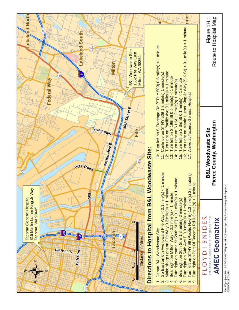
Taco
ma
Ge
nera
l Ho
spita
l31
5 M
art
in L
uth
er
Kin
g J
r W
ayTa
com
a, W
A 9
840
5
B&
L W
ood
was
te S
ite
Milt
on,
WA
983
54
Pacif
ic Hw
y E.
54th Ave E.
509
20th
Stree
t E.
POT Road
19th
Stree
tS. I Street Taco
maTa
coma
Fife
Fife
Walle
rWa
ller
Edge
wood
Edge
wood
Fede
ral W
ayFe
deral
Way
Milto
nMi
ltonLa
kelan
d Sou
thLa
kelan
d Sou
th
Puya
llup
Puya
llup
Midla
ndMi
dland
Sumn
erSu
mner
Lake
land N
orth
Lake
land N
orth
§̈ ¦5§̈ ¦70
5§̈ ¦705
UV99
UV161
UV167
UV509
UV7
UV18
UV16
. 01
20.
5 Dis
tanc
e in
Mile
s
B&L W
oodw
aste
Site
Pierc
e Cou
nty, W
ashin
gton
Fig
ure
1H.1
Rou
te to
Hos
pita
l Map
File
: F
:\pro
ject
s\B
&L
RIM
\GIS
\MX
D\F
igu
re 1
H.1
(S
tre
etm
ap
US
A R
ou
te t
o H
osp
ital M
ap
).m
xd6/
5/2
009
11
:02
AM
1. D
ep
art
B&
L W
ood
wa
ste
Site
2:
Go
Eas
t on
6th
Ave
tow
ard
Fife
Way
< 0
.1 m
ile(s
) <
1 m
inu
te
3: M
ake
sha
rp r
igh
t on
Fife
Wa
y 0
.2 m
ile(s
) <
1 m
inu
te
4: B
ear
rig
ht o
n M
ilton
Wa
y <
0.1
mile
(s)
< 1
min
ute
5:
Tu
rn r
igh
t on
Yu
ma
St (
20t
h S
t E
) <
0.1
mile
(s)
< 1
min
ute
6:
Be
ar r
igh
t on
20t
h S
t E
1.3
mile
(s)
2 m
inut
e(s)
7:
Tu
rn r
igh
t on
54t
h A
ve E
0.3
mile
(s)
< 1
min
ute
8:
Tu
rn le
ft o
n S
TH
Y 9
9 (P
acifi
c H
wy
E)
1.3
mile
(s)
2 m
inut
e(s
) 9:
Tu
rn r
igh
t on
Por
t O
f Tac
oma
Rd
0.3
mile
(s)
< 1
min
ute
10:
Tur
n le
ft o
n S
Fro
nta
ge R
d (S
TH
Y 5
09
) 0
.6 m
ile(s
) <
1 m
inu
te
11:
Co
ntin
ue o
n S
TH
Y 5
09 1
.8 m
ile(s
) 1
min
ute
(s)
12:
Tur
n r
ight
on
Pa
cific
Ave
0.1
mile
(s)
< 1
min
ute
13:
Tur
n le
ft o
n S
19
th S
t 0.5
mile
(s)
< 1
min
ute
14
: T
urn
rig
ht o
n S
I S
t 1.2
mile
(s)
1 m
inu
te(s
) 15
: T
urn
left
on
S 3
rd S
t 0.
1 m
ile(s
) <
1 m
inut
e 16
: T
urn
rig
ht o
n M
art
in L
uth
er K
ing
Jr
Wa
y (S
K S
t) <
0.1
mile
(s)
< 1
min
ute
17
: A
rriv
e a
t Ta
com
a G
ener
al H
osp
ital.
Direc
tions
to H
ospit
al fro
m B&
L Woo
dwas
te Si
te:
155
2 F
ife W
ay
Eas
t
B&L Woodwaste Site
P:\13488 - Floyd Snider-B&L Landfill\HASP\2012 HASP
10/27/15 Health and Safety PlanPage xxxix
ATTACHMENT 1
Project Health & Safety Field Meeting Form

B&L Woodwaste Site
P:\13488 - Floyd Snider-B&L Landfill\HASP\2012 HASP
10/27/15 Health and Safety PlanPage 1
PROJECT HEALTH AND SAFETY MEETING FORM Date: Time: Project No.: 13488
Project Name: B&L Woodwaste Site Groundwater Treatment
Location: 1522 Fife Way East, Milton, WA
Meeting Conducted by:
Topics Discussed: Physical Hazards:
Chemical Hazards:
Personal Protection:
Decontamination:
Other:
Emergency Information: Tacoma General Hospital 315 Martin Luther King Jr. Way
Tacoma, WA 98405-4234
Attendees
Name/Company (printed) Signature
Meeting Conducted by:
Signature
B&L Woodwaste Site
P:\13488 - Floyd Snider-B&L Landfill\HASP\2012 HASP
10/27/15 Health and Safety PlanPage 2
ATTACHMENT 2
Material Data Safety Sheets
600 University Street, Suite 1020 Seattle, WA 98101 601 Union Street, Suite 600 Seattle, WA 98101
P:\13488 - Floyd Snider-B&L Landfill\PHASE 2\Phase 2Design & Engineering\Permitting\Pierce County\PublicWorks Application\Aug 2 Info Request\Attachment 4Memo-ver-01.docxlmm 10/03/11
Page 1 of 4
Memorandum
To: Kyle Hansen, Floyd|Snider
Copies: Brett Beaulieu, Floyd|Snider
From: Larry McGaughey
Date: September 30, 2011
Re: Laboratory Testing and Reagent Overview, B&L Woodwaste Site Phase 2Remediation
The laboratory included in the groundwater treatment building will be used solely for supportingoperations of the groundwater treatment system. Testing will include pH measurement,oxidation/reduction potential (ORP) measurement, field testing for arsenic, iron, and manganesein groundwater, and for performing settling tests of groundwater to support operations of theprocess clarifier. Other operations to be conducted in the laboratory include washing oflaboratory glassware and other items (such as instrument electrodes) associated with thetreatment process. The laboratory will also be used for handling and packaging samplescollected for compliance with the NPDES permit for the treated water discharge and for samplesto be sent to a commercial laboratory for testing beyond the capabilities of the plant laboratory.
Testing of pH and ORP will be done using conventional electrochemical instruments andelectrodes. Samples of groundwater collected from the treatment process, including untreatedinfluent, water from intermediate treatment stages, and treated effluent will be manuallycollected from the treatment process and brought to the laboratory for testing. Influentgroundwater is expected to be near neutral. Process conditions for pH are expected to rangefrom about pH 6.0 to pH 8.5. The pH meter will be calibrated using commercially-availablebuffer solutions in the range of pH 6 to pH 9. Testing for ORP is expected to be conducted onsamples of untreated influent and water discharged from the oxidation tank. Electrodes will berinsed with either potable tap water or commercially-available deionized water. Samples ofgroundwater collected for pH or ORP testing will be dumped to the oxidation tank. Rinse waterand used calibration solutions will be dumped to the sink drain.
Testing for arsenic, iron, and manganese will be performed on samples of untreatedgroundwater, groundwater from intermediate treatment stages, and treated effluent. Testing willbe conducted using Hach test kits and a Hach spectrophotometer. These test kits requiremixing of packets of test chemicals into a measured aliquot of test water, allowing adequatereaction time, and reading the result either using a test strip or the spectrophotometer. Excesswater sample will be returned to the oxidation tank in the groundwater treatment system fortreatment. Solutions containing test reagent will be placed in a plastic container stored on thefloor of the laboratory for periodic offsite disposal by a properly permitted disposal firm.Reagent packaging will also be placed in a plastic container for periodic offsite disposal by a
Kyle HansenSeptember 30, 2011
P:\13488 - Floyd Snider-B&L Landfill\PHASE 2\Phase 2Design & Engineering\Permitting\Pierce County\PublicWorks Application\Aug 2 Info Request\Attachment 4Memo-ver-01.docxlmm 10/03/11
Page 2 of 4
properly permitted disposal firm. As operation of the groundwater treatment system has not yetcommenced, no disposal contracts have been established. Glassware used for testing will bewashed in the laboratory sink with potable water using a laboratory detergent such as Alconox®.Glassware will be rinsed in the sink using potable water and commercially available deionizedwater. Material Safety Data Sheets (MSDS) for the Hach test kits and Alconox are attached.
Testing will also be conducted as needed to assess coagulants/flocculants for the treatmentprocess. This testing would be conducted on intermediate process samples collected from theco-precipitation tank. Commercially-available coagulants and flocculants used commonly inwater and wastewater treatment plants would be tested for this purpose. Testing would consistof preparing coagulant/flocculant feed from the commercial product and tap water followed bydosing the test samples at different concentrations, mixing the test solutions, and observingresults. Settling tests using graduated cylinders or other glassware may also be conducted toassess settling properties. Excess samples and test solutions will be returned to thegroundwater treatment process. Glassware used for testing will be washed and rinsed in thelaboratory sink. Excess coagulant or flocculant product will be disposed offsite by a permittedcommercial disposal firm.
Reagents and laboratory materials used in the laboratory will be limited to those needed thetesting described above. These will include the following:
Hach Ferrous Iron Reagent:
Phenanthroline Sodium Bicarbonate
Hach High Range Arsenic Test Kit
Arsenic Test Strips Mercuric Bromide Saturated Paper
EZ Arsenic Reagent #1 Sulfamic Acid
Lead Acetate, 10% Acetic Acid Demineralized water Lead Acetate
EZ Arsenic Reagent #2 Zinc
Hach Low Range Arsenic Test Kit
Arsenic Test Strips Mercuric Bromide Saturated Paper
Arsenic Reagent #1 Dibasic Sodium Phosphate
Arsenic Reagent #2 Potassium peroxymonosulfate sulfate
Kyle HansenSeptember 30, 2011
P:\13488 - Floyd Snider-B&L Landfill\PHASE 2\Phase 2Design & Engineering\Permitting\Pierce County\PublicWorks Application\Aug 2 Info Request\Attachment 4Memo-ver-01.docxlmm 10/03/11
Page 3 of 4
Arsenic Reagent #3 Ethylenediaminetetracetic acid, disodium salt Ethylenediaminetetracetic acid, tetrasodium salt
Arsenic Reagent #4 Sulfamic Acid
Arsenic Reagent #5 Zinc
Hach Manganese Reagent
Buffer Powder Citrate Type Citric Acid Sodium phosphate, monobasic Sodium Sulfate
Sodium m-Periodate Buffer Solutions, pH 6.0, 7.2, and 8.0
Potassium phosphate/sodium hydroxide solutions
Commercially available polymers or polyelectrolytes used in the water and wastewatertreatment industry may also be used in performing jar tests to assess their effectiveness inseparating solid precipitates from groundwater. No other reagents are anticipated for use at thesite. If other reagents or lab materials, such as buffer solutions for different pH or ORPcalibration standards are to be used, they will be disposed in accordance with manufacturerrecommendations via placement in a plastic container and periodic offsite disposal using apermitted commercial disposal service.
The Hach reagents listed above will be received and stored in small, sealed plastic packets orsealed glass ampules. Hach test strips will be received and stored in either a box or jar. Thebuffers listed above for calibrating the pH meters will be received either in sealed packetscontaining powder or in sealed plastic bottles. All reagents will be stored as-received in aclosed storage cabinet located across the room from the laboratory sink. Storage will beconducted in accordance with supplier instructions and the MSDS information. Incompatiblereagents and/or materials will be kept separated, in accordance with supplier recommendationsand the MSDS information. Reagents removed from the chemical storage cabinet for use willbe returned after use. Cabinets located in the immediate vicinity of the sink will be used only forstorage of glassware, plastic ware, or water containers. Detergent used for washing glasswarewill be stored in the chemical storage cabinet; a small amount of detergent will be placed in abottle or jar near the sink for routine use.
Kyle HansenSeptember 30, 2011
P:\13488 - Floyd Snider-B&L Landfill\PHASE 2\Phase 2Design & Engineering\Permitting\Pierce County\PublicWorks Application\Aug 2 Info Request\Attachment 4Memo-ver-01.docxlmm 10/03/11
Page 4 of 4
Sincerely yours,
AMEC Geomatrix
Larry McGaughey, Ph.D., P.E.Project Manager
Encl.: MSDS Sheets:Arsenic Test StripsEZ Arsenic Reagent #1EZ Arsenic Reagent #2Lead Acetate, 10%Arsenic Reagent #1Arsenic Reagent #2Arsenic Reagent #3Arsenic Reagent #4Arsenic Reagent #5Ferrous Iron ReagentBuffer Powder Citrate TypeSodium PeriodateFerroVer Iron ReagentFerroVer Iron ReagentAlconox

World HeadquartersHach CompanyP.O.Box 389 MSDS No: M01892Loveland, CO USA 80539(970) 669-3050
MATERIAL SAFETY DATA SHEET_____________________________________________________________________________1. CHEMICAL PRODUCT AND COMPANY IDENTIFICATION
Product Name: Arsenic Test StripsCatalog Number: 2800150
Hach Company Emergency Telephone Numbers:P.O.Box 389 (Medical and Transportation)Loveland, CO USA 80539 (303) 623-5716 24 Hour Service(970) 669-3050 (515)232-2533 8am - 4pm CST
MSDS Number: M01892Chemical Name: Not applicableCAS No.: Not applicableChemical Formula: Not applicableChemical Family: Not applicableHazard: Highly toxic. Experimental carcinogen. Cumulative poison. Harmful if absorbed through skin.Harmful if swallowedDate of MSDS Preparation:
Day: 25Month: AugustYear: 2007
_____________________________________________________________________________2. COMPOSITION / INFORMATION ON INGREDIENTS
Mercuric Bromide Saturated PaperCAS No.: Not applicableTSCA CAS Number: Not applicablePercent Range: 100.0Percent Range Units: weight / weightLD50: None reportedLC50: None reportedTLV: Not establishedPEL: Not establishedHazard: Highly toxic. Experimental carcinogen. Cumulative poison. Harmful if absorbed through skin.Harmful if swallowed
_____________________________________________________________________________3. HAZARDS IDENTIFICATION
Emergency Overview:Appearance: White paperOdor: None
HARMFUL IF SWALLOWED OR ABSORBED THROUGH SKINPOSSIBLE BIRTH DEFECT HAZARD: MAY CAUSE BIRTH DEFECTS BASED ON ANIMAL
DATA CAN CAUSE LUNG AND KIDNEY DISEASE
HMIS:

Health: 4Flammability: 0Reactivity: 0Protective Equipment: X - See protective equipment, Section 8.
NFPA:Health: 4Flammability: 0Reactivity: 0Symbol: Not applicable
Potential Health Effects:Eye Contact: May cause irritiationSkin Contact: May cause irritiationSkin Absorption: Will be absorbed through the skin. Effects similar to those of ingestion
Target Organs: Central nervous system Liver KidneysIngestion: Highly toxic. Causes: abdominal pain nausea vomiting diarrhea metallic taste rapid pulseand respirations weakness May cause: inflammation of the mouth increased urinary output excessivesalivation liver damage kidney damage central nervous system effects collapse death
Target Organs: Central nervous system Liver KidneysInhalation: Toxic. May cause: Effects similar to those of ingestion.
Target Organs: Central nervous system Kidneys LiverMedical Conditions Aggravated: Allergies or sensitivity to mercury. Central nervous system diseasesKidney conditions Liver conditions Pre-existing: Eye conditions Skin conditions Respiratory conditionsChronic Effects: Mercury can cause personality changes such as: depression, despondency, fearfulness,restlessness, irritability, timidness, indecision and embarrassment. Mercury is a general protoplasmicpoison; it circulates in the blood and is stored in the liver, kidneys, spleen and bones. Main symptoms aresore mouth, tremors and psychic disturbances.Cancer / Reproductive Toxicity Information:
This product does NOT contain any OSHA listed carcinogens.
IARC Group 3: Non-classifiableMercury and Inorganic Mercury compoundsThis product does NOT contain any NTP listed chemicals.
Additional Cancer / Reproductive Toxicity Information: an experimental teratogen. an experimentalmutagen.
Toxicologically Synergistic Products: None reported_____________________________________________________________________________4. FIRST AID
Eye Contact: Flush eyes with water. Call physician if irritation develops.Skin Contact (First Aid): Wash skin with plenty of water. Call physician if irritation develops.Ingestion (First Aid): Give large quantities of water or milk. Induce vomiting using syrup of ipecac or bysticking finger down throat. Call physician immediately. Never give anything by mouth to an unconsciousperson.Inhalation: None required.
_____________________________________________________________________________5. FIRE FIGHTING MEASURES
Flammable Properties: Can burn in fire, releasing toxic vapors.Flash Point: Not determinedMethod: Not applicableFlammability Limits:
Lower Explosion Limits: Not applicableUpper Explosion Limits: Not applicable
Autoignition Temperature: Not determined

Hazardous Combustion Products: May vaporize to form Mercury vapor. bromidesFire / Explosion Hazards: Reacts with sodium aci-nitromethanide and acid to form explosive mercuryfulminate.
Static Discharge: None reported.Mechanical Impact: None reported
Extinguishing Media: Use media appropriate to surrounding fire conditionsFire Fighting Instruction: As in any fire, wear self-contained breathing apparatus pressure-demand and fullprotective gear. Water runoff can cause environmental damage. Dike and collect water used to fight fire.
_____________________________________________________________________________6. ACCIDENTAL RELEASE MEASURES
Spill Response Notice:Only persons properly qualified to respond to an emergency involving hazardous substances may respond to
a spill according to federal regulations (OSHA 29 CFR 1910.120(a)(v)) and per your company's emergencyresponse plan and guidelines/procedures. See Section 13, Special Instructions for disposal assistance.Containment Technique: Releases of this material may contaminate the environment. Stop spilled materialfrom being released to the environment.Clean-up Technique: Sweep up material. Dispose of all mercury contaminated material at an E.P.A.hazardous waste facility. Decontaminate the area of the spill with a soap solution.Evacuation Procedure: Evacuate as needed to perform spill clean-up. If conditions warrant, increase the sizeof the evacuation.Special Instructions (for accidental release): Product is regulated as a hazardous air pollutant. Product isregulated as RCRA hazardous waste.304 EHS RQ (40 CFR 355): Mercuric Bromide - RQ 1 lb.D.O.T. Emergency Response Guide Number: 154
_____________________________________________________________________________7. HANDLING / STORAGE
Handling: Avoid contact with skin eyes clothing Do not breathe dust. Use with adequate ventilation.Wash thoroughly after handling. Maintain general industrial hygiene practices when using this product.Storage: Keep container tightly closed when not in use.
Flammability Class: Not applicable_____________________________________________________________________________8. EXPOSURE CONTROLS / PROTECTIVE EQUIPMENT
Engineering Controls: Maintain adequate ventilation to keep vapor level below TWA for chemicals in thisproduct. Maintain general industrial hygiene practices when using this product.Personal Protective Equipment:
Eye Protection: safety glasses with top and side shieldsSkin Protection: disposable latex gloves lab coatInhalation Protection: adequate ventilation
Precautionary Measures: Avoid contact with: eyes skin clothing Do not breathe: dust Use with adequateventilation. Wash thoroughly after handling.TLV: Not establishedPEL: Not established
_____________________________________________________________________________9. PHYSICAL / CHEMICAL PROPERTIES
Appearance: White paperPhysical State: SolidMolecular Weight: Not applicableOdor: NonepH: Not applicableVapor Pressure: Not applicable

Vapor Density (air = 1): Not applicableBoiling Point: Not applicableMelting Point: Not applicableSpecific Gravity (water = 1): Not applicableEvaporation Rate (water = 1): Not applicableVolatile Organic Compounds Content: Not applicablePartition Coefficient (n-octanol / water): Not applicableSolubility:
Water: Not applicableAcid: Not applicableOther: Not applicable
Metal Corrosivity:Steel: Not applicableAluminum: Not applicable
_____________________________________________________________________________10. STABILITY / REACTIVITY
Chemical Stability: Stable when stored under proper conditions.Conditions to Avoid: Heating to decomposition.Reactivity / Incompatibility: Incompatible with: formates sulfites phosphates arsenic boron compoundscarbonates iron copper silver saltsHazardous Decomposition: Heating to decomposition releases: mercury bromidesHazardous Polymerization: Will not occur.
_____________________________________________________________________________11. TOXICOLOGICAL INFORMATION
Product Toxicological Data:LD50: None reportedLC50: None reportedDermal Toxicity Data: None reportedSkin and Eye Irritation Data: None reportedMutation Data: None reportedReproductive Effects Data: None reported
Ingredient Toxicological Data: Mercuric Bromide: Oral rat LD50 = 40 mg/kg, Dermal rat LD50 = 100 mg/kg
_____________________________________________________________________________12. ECOLOGICAL INFORMATION
Product Ecological Information: --No ecological data available for this product.
Ingredient Ecological Information: Mercury and mercury compounds: Calculated Bioconcentration factor >100. LC50/96H fish <1 mg/L
_____________________________________________________________________________13. DISPOSAL CONSIDERATIONS
EPA Waste ID Number: D009Special Instructions (Disposal): Dispose of all mercury contaminated material at an E.P.A. hazardous wastefacility.Empty Containers: Rinse three times with an appropriate solvent. Rinsate from empty containers ishazardous waste and should be disposed of at an E.P.A. approved facility. Dispose of empty container asnormal trash.
NOTICE (Disposal): These disposal guidelines are based on federal regulations and may be superseded bymore stringent state or local requirements. Please consult your local environmental regulators for moreinformation.
_____________________________________________________________________________14. TRANSPORT INFORMATION
D.O.T.:D.O.T. Proper Shipping Name: Mercury Bromides Mixture--
DOT Hazard Class: 6.1DOT Subsidiary Risk: NADOT ID Number: UN1634DOT Packing Group: II
I.C.A.O.:I.C.A.O. Proper Shipping Name: Mercury Bromides Mixture--
ICAO Hazard Class: 6.1ICAO Subsidiary Risk: NAICAO ID Number: UN1634ICAO Packing Group: II
I.M.O.:I.M.O. Proper Shipping Name: Mercury Bromides Mixture--
I.M.O. Hazard Class: 6.1I.M.O. Subsidiary Risk: NAI.M.O. ID Number: UN1634I.M.O. Packing Group: II
Additional Information: There is a possibility that this product could be contained in a reagent set or kitcomposed of various compatible dangerous goods. If the item is NOT in a set or kit, the classification givenabove applies. If the item IS part of a set or kit, the classification would change to the following: UN3316Chemical Kit, Class 9, PG II or III. If the item is not regulated, the Chemical Kit classification does not apply.
_____________________________________________________________________________15. REGULATORY INFORMATION
U.S. Federal Regulations:O.S.H.A.: This product meets the criteria for a hazardous substance as defined in the HazardCommunication Standard. (29 CFR 1910.1200)E.P.A.:
S.A.R.A. Title III Section 311/312 Categorization (40 CFR 370): Immediate (Acute) Health HazardDelayed (Chronic) Health HazardS.A.R.A. Title III Section 313 (40 CFR 372): This product contains a chemical(s) subject to thereporting requirements of Section 313 of Title III of SARA.Mercury Compounds
302 (EHS) TPQ (40 CFR 355): 500 lbs. Mercury Bromide304 CERCLA RQ (40 CFR 302.4): Not applicable304 EHS RQ (40 CFR 355): Mercuric Bromide - RQ 1 lb.Clean Water Act (40 CFR 116.4): Not applicableRCRA: Contains RCRA regulated substances. See Section 13, EPA Waste ID Number.
C.P.S.C.: Not applicableState Regulations:
California Prop. 65: WARNING - This product contains a chemical known to the State of California tocause birth defects or other reproductive harm.
Identification of Prop. 65 Ingredient(s): Mercury CompoundsCalifornia Perchlorate Rule CCR Title 22 Chap 33:
Trade Secret Registry: Not applicable
National Inventories:U.S. Inventory Status: All ingredients in this product are listed on the TSCA 8(b) Inventory (40 CFR 710).
TSCA CAS Number: Not applicable
_____________________________________________________________________________16. OTHER INFORMATION
Intended Use: Laboratory ReagentReferences: Air Contaminants, Federal Register, Vol. 54, No. 12. Thursday, January 19, 1989. pp. 2332-2983. TLV's Threshold Limit Values and Biological Exposure Indices for 1992-1993. American Conferenceof Governmental Industrial Hygienists, 1992. Sax, N. Irving. Dangerous Properties of Industrial Materials, 7thEd. New York: Van Nostrand Reinhold Co., 1989. Sax, N. Irving and Richard J. Lewis, Sr., revised by.Hawley's Condensed Chemical Dictionary, Eleventh Ed. New York: Van Nostrand Reinhold Co., 1987. TheMerck Index, 11th Ed. Rahway, New Jersey: Merck and Co., Inc., 1989. Vendor Information. Gosselin, R. E.et al. Clinical Toxicology of Commercial Products, 5th Ed. Baltimore: The Williams and Wilkins Co., 1984.CCINFO RTECS. Canadian Centre for Occupational Health and Safety. Hamilton, Ontario Canada: 30 June1993. Technical Judgment.Revision Summary: Updates in Section(s) 14,
_____________________________________________________________________________
Legend:NA - Not Applicable w/w - weight/weightND - Not Determined w/v - weight/volumeNV - Not Available v/v - volume/volume
USER RESPONSIBILITY: Each user should read and understand this information and incorporate it in individualsite safety programs in accordance with applicable hazard communication standards and regulations.
THE INFORMATION CONTAINED HEREIN IS BASED ON DATA CONSIDERED TO BE ACCURATE.HOWEVER, NO WARRANTY IS EXPRESSED OR IMPLIED REGARDING THE ACCURACY OFTHESE DATA OR THE RESULTS TO BE OBTAINED FROM THE USE THEREOF.
HACH COMPANY ©2009
World HeadquartersHach CompanyP.O.Box 389 MSDS No: M00007Loveland, CO USA 80539(970) 669-3050
MATERIAL SAFETY DATA SHEET_____________________________________________________________________________1. CHEMICAL PRODUCT AND COMPANY IDENTIFICATION
Product Name: EZ Arsenic Reagent #1Catalog Number: 2822999
Hach Company Emergency Telephone Numbers:P.O.Box 389 (Medical and Transportation)Loveland, CO USA 80539 (303) 623-5716 24 Hour Service(970) 669-3050 (515)232-2533 8am - 4pm CST
MSDS Number: M00007Chemical Name: Sulfamic AcidCAS No.: 5329-14-6Chemical Formula: H3NO3SChemical Family: Inorganic AcidHazard: Causes eye burns.Date of MSDS Preparation:
Day: 25Month: 06Year: 2010
_____________________________________________________________________________2. COMPOSITION / INFORMATION ON INGREDIENTS
Other componentCAS No.: Not applicableTSCA CAS Number: Not applicablePercent Range: < 1.0Percent Range Units: weight / weightLD50: Not applicableLC50: Not applicableTLV: Not establishedPEL: Not establishedHazard: Any ingredient(s) of this product listed as "Other component(s)" is not considered a health hazard to the user ofthis product.
Sulfamic AcidCAS No.: 5329-14-6TSCA CAS Number: 5329-14-6Percent Range: > 99.0Percent Range Units: weight / weightLD50: Oral rat LD50 = 3160 mg/kg.LC50: None reportedTLV: Not establishedPEL: Not establishedHazard: Causes eye burns.
_____________________________________________________________________________3. HAZARDS IDENTIFICATION
Emergency Overview:Appearance: White crystals
Odor: NoneCAUSES EYE BURNS CAUSES SKIN AND RESPIRATORY TRACT IRRITATION
HMIS:Health: 2Flammability: 1Reactivity: 1Protective Equipment: X - See protective equipment, Section 8.
NFPA:Health: 2Flammability: 1Reactivity: 1Symbol: Not applicable
Potential Health Effects:Eye Contact: Causes eye burns.Skin Contact: Causes severe irritationSkin Absorption: None reported
Target Organs: None reportedIngestion: May cause: irritation of the mouth and esophagus gastrointestinal irritation
Target Organs: None reportedInhalation: May cause: irritation of nose and throat
Target Organs: None reportedMedical Conditions Aggravated: Pre-existing: Eye conditions Skin conditions Respiratory conditionsChronic Effects: None reportedCancer / Reproductive Toxicity Information:
O.S.H.A. Listed: NoIARC Listed: NoNTP Listed: NoAdditional Cancer / Reproductive Toxicity Information: Not applicable
Toxicologically Synergistic Products: None reported_____________________________________________________________________________4. FIRST AID
Eye Contact: Immediately flush eyes with water for 15 minutes. Call physician.Skin Contact (First Aid): Wash skin with plenty of water for 15 minutes. Call physician immediately.Ingestion (First Aid): Do not induce vomiting. Give 1-2 glasses of water. Call physician immediately. Never giveanything by mouth to an unconscious person.Inhalation: Remove to fresh air.
_____________________________________________________________________________5. FIRE FIGHTING MEASURES
Flammable Properties: During a fire, irritating and highly toxic gases may be generated by thermal decomposition.Flash Point: Not applicableMethod: Not applicableFlammability Limits:
Lower Explosion Limits: Not applicableUpper Explosion Limits: Not applicable
Autoignition Temperature: Not applicableHazardous Combustion Products: Toxic fumes of: ammonia nitrogen oxides. sulfur oxides.Fire / Explosion Hazards: May react violently with: chlorine / chlorine compounds metal nitrates metal nitrites nitricacid
Static Discharge: None reported.Mechanical Impact: None reported
Extinguishing Media: Dry chemical. Water.Fire Fighting Instruction: As in any fire, wear self-contained breathing apparatus pressure-demand and full protectivegear.
_____________________________________________________________________________6. ACCIDENTAL RELEASE MEASURES
Spill Response Notice:

Only persons properly qualified to respond to an emergency involving hazardous substances may respond to a spillaccording to federal regulations (OSHA 29 CFR 1910.120(a)(v)) and per your company's emergency response plan andguidelines/procedures. See Section 13, Special Instructions for disposal assistance.Containment Technique: Stop spilled material from being released to the environment. Cover spilled solid material withsand or other inert material.Clean-up Technique: Scoop up spilled material into a large beaker and dissolve with water. Adjust to a pH between 6 and9 with an alkali, such as soda ash or sodium bicarbonate. Flush reacted material to the drain with a large excess of water.Decontaminate the area of the spill with a soap solution.Evacuation Procedure: Evacuate local area (15 foot radius or as directed by your facility's emergency response plan)when: a pound or more of loose powder is spilled. If conditions warrant, increase the size of the evacuation.Special Instructions (for accidental release): Product is regulated as RCRA hazardous waste in the U.S.304 EHS RQ (40 CFR 355): Not applicableD.O.T. Emergency Response Guide Number: 154
_____________________________________________________________________________7. HANDLING / STORAGE
Handling: Avoid contact with eyes skin Do not breathe dust. Maintain general industrial hygiene practices when usingthis product.Storage: Store away from: oxidizers alkalies chlorine/chlorinated metals Protect from: heat moisture
Flammability Class: Not applicable_____________________________________________________________________________8. EXPOSURE CONTROLS / PROTECTIVE EQUIPMENT
Engineering Controls: Have an eyewash station nearby. Maintain general industrial hygiene practices when using thisproduct.Personal Protective Equipment:
Eye Protection: safety glasses with top and side shieldsSkin Protection: disposable latex gloves lab coatInhalation Protection: adequate ventilation
Precautionary Measures: Avoid contact with: eyes skin Do not breathe: dust Wash thoroughly after handling. Keepaway from: alkalies metals Protect from: heat moistureTLV: Not establishedPEL: Not established
_____________________________________________________________________________9. PHYSICAL / CHEMICAL PROPERTIES
Appearance: White crystalsPhysical State: SolidMolecular Weight: 97.10Odor: NonepH: 1% soln = 1.18Vapor Pressure: Not applicableVapor Density (air = 1): Not applicableBoiling Point: Not applicableMelting Point: Product decomposes at 205 °C; 401 °FSpecific Gravity/ Relative Density (water = 1; air =1): 2.15Evaporation Rate (water = 1): Not applicableVolatile Organic Compounds Content: Not applicablePartition Coefficient (n-octanol / water): None reportedSolubility:
Water: 1:2 ratio @ 80 ° C (176 °F)Acid: SolubleOther: Slightly soluble in alcohol, methanol.
Metal Corrosivity:Steel: 0.814 in/yrAluminum: 0.212 in/yr
_____________________________________________________________________________10. STABILITY / REACTIVITY
Chemical Stability: Stable when stored under proper conditions.
Conditions to Avoid: Heating to decomposition. Excess moistureReactivity / Incompatibility: May react violently in contact with: chlorates metal nitrates metal nitrites nitric acidIncompatible with: alkalies oxidizersHazardous Decomposition: Heating to decomposition releases toxic and/or corrosive fumes of: ammonia nitrogen oxidessulfur oxidesHazardous Polymerization: Will not occur.
_____________________________________________________________________________11. TOXICOLOGICAL INFORMATION
Product Toxicological Data:LD50: Oral rat LD50 = 3160 mg/kg.LC50: None reportedDermal Toxicity Data: None reportedSkin and Eye Irritation Data: Skin Human 4%/5 days intermittent MILD, Skin rabbit 500 mg/24H SEVERE, Eyerabbit 20mg MODERATE, Eye rabbit 250µg/24H SEVERE.Mutation Data: None reportedReproductive Effects Data: None reported
Ingredient Toxicological Data: --Not applicable
_____________________________________________________________________________12. ECOLOGICAL INFORMATION
Product Ecological Information: --No ecological data available for this product.
Ingredient Ecological Information: --Not applicable
_____________________________________________________________________________13. DISPOSAL CONSIDERATIONS
EPA Waste ID Number: NoneSpecial Instructions (Disposal): Dilute to 3 to 5 times the volume with cold water. Adjust to a pH between 6 and 9 withan alkali, such as soda ash or sodium bicarbonate. Open cold water tap completely, slowly pour the reacted material to thedrain.Empty Containers: Rinse three times with an appropriate solvent. Dispose of empty container as normal trash.NOTICE (Disposal): These disposal guidelines are based on federal regulations and may be superseded by more stringentstate or local requirements. Please consult your local environmental regulators for more information.
_____________________________________________________________________________14. TRANSPORT INFORMATION
D.O.T.:D.O.T. Proper Shipping Name: Sulphamic Acid--
DOT Hazard Class: 8DOT Subsidiary Risk: NADOT ID Number: UN2967DOT Packing Group: III
I.C.A.O.:I.C.A.O. Proper Shipping Name: Sulphamic Acid--
ICAO Hazard Class: 8ICAO Subsidiary Risk: NAICAO ID Number: UN2967ICAO Packing Group: III
I.M.O.:I.M.O. Proper Shipping Name: Sulphamic Acid--
I.M.O. Hazard Class: 8I.M.O. Subsidiary Risk: NAI.M.O. ID Number: UN2967I.M.O. Packing Group: III

Additional Information: There is a possibility that this product could be contained in a reagent set or kit composed ofvarious compatible dangerous goods. If the item is NOT in a set or kit, the classification given above applies. If the item ISpart of a set or kit, the classification would change to the following: UN3316 Chemical Kit, Class 9, PG II or III. If the itemis not regulated, the Chemical Kit classification does not apply.
_____________________________________________________________________________15. REGULATORY INFORMATION
U.S. Federal Regulations:O.S.H.A.: This product meets the criteria for a hazardous substance as defined in the Hazard Communication Standard.(29 CFR 1910.1200)E.P.A.:
S.A.R.A. Title III Section 311/312 Categorization (40 CFR 370): Immediate (Acute) Health HazardS.A.R.A. Title III Section 313 (40 CFR 372): This product does NOT contain any chemical subject to the reportingrequirements of Section 313 of Title III of SARA.--
302 (EHS) TPQ (40 CFR 355): Not applicable304 CERCLA RQ (40 CFR 302.4): Not applicable304 EHS RQ (40 CFR 355): Not applicableClean Water Act (40 CFR 116.4): Not applicableRCRA: Contains no RCRA regulated substances.
C.P.S.C.: Not applicableState Regulations:
California Prop. 65: No Prop. 65 listed chemicals are present in this product.Identification of Prop. 65 Ingredient(s): Not applicable
California Perchlorate Rule CCR Title 22 Chap 33:Trade Secret Registry: Not applicableNational Inventories:
U.S. Inventory Status: TSCA Listed: YesTSCA CAS Number: 5329-14-6
_____________________________________________________________________________16. OTHER INFORMATION
Intended Use: Laboratory UseReferences: Vendor Information. NIOSH Registry of Toxic Effects of Chemical Substances, 1985-86. Cincinnati: U.S.Department of Health and Human Services, April, 1987. Gosselin, R. E. et al. Clinical Toxicology of CommercialProducts, 5th Ed. Baltimore: The Williams and Wilkins Co., 1984. Fire Protection Guide on Hazardous Materials, 10thEd. Quincy, MA: National Fire Protection Fire Protection Guide on Hazardous Materials, 10th Ed. Quincy, MA: NationalFire Protection Association, 1991. Outside Testing. Technical Judgment. The Merck Index, 11th Ed. Rahway, NewJersey: Merck and Co., Inc., 1989. Sax, N. Irving. Dangerous Properties of Industrial Materials, 7th Ed. New York: VanNostrand Reinhold Co., 1989. Air Contaminants, Federal Register, Vol. 54, No. 12. Thursday, January 19, 1989. pp.2332-2983. TLV's Threshold Limit Values and Biological Exposure Indices for 1992-1993. American Conference ofGovernmental Industrial Hygienists, 1992.Revision Summary: Updates in Section(s) 14,
_____________________________________________________________________________
Legend:NA - Not Applicable w/w - weight/weightND - Not Determined w/v - weight/volumeNV - Not Available v/v - volume/volume
USER RESPONSIBILITY: Each user should read and understand this information and incorporate it in individual site safetyprograms in accordance with applicable hazard communication standards and regulations.
THE INFORMATION CONTAINED HEREIN IS BASED ON DATA CONSIDERED TO BE ACCURATE.HOWEVER, NO WARRANTY IS EXPRESSED OR IMPLIED REGARDING THE ACCURACY OF THESE DATAOR THE RESULTS TO BE OBTAINED FROM THE USE THEREOF.
HACH COMPANY ©2010
World HeadquartersHach CompanyP.O.Box 389 MSDS No: M01157Loveland, CO USA 80539(970) 669-3050
MATERIAL SAFETY DATA SHEET_____________________________________________________________________________1. CHEMICAL PRODUCT AND COMPANY IDENTIFICATION
Product Name: EZ Arsenic Reagent #2Catalog Number: 2823099
Hach Company Emergency Telephone Numbers:P.O.Box 389 (Medical and Transportation)Loveland, CO USA 80539 (303) 623-5716 24 Hour Service(970) 669-3050 (515)232-2533 8am - 4pm CST
MSDS Number: M01157Chemical Name: ZincCAS Number: 7440-66-6Additional CAS No. (for hydrated forms): Not applicableChemical Formula: ZnChemical Family: Inorganic MetalsIntended Use: Laboratory Reagent
_____________________________________________________________________________2. HAZARDS IDENTIFICATION
GHS Classification:Hazard categories: Pyrophoric Solid: Pyr. Sol. 1 Contact with Water Emits Flammable Gases: Water-react. 1Hazardous to the Aquatic Environment: Aquatic Acute 1 Hazardous to the Aquatic Environment: Aquatic Chronic 1
GHS Label Elements:DANGER
Hazard statements: Catches fire spontaneously if exposed to air. In contact with water releases flammable gases whichmay ignite spontaneously. Very toxic to aquatic life with long lasting effects.Precautionary statements: Keep away from heat/sparks/open flames/hot surfaces. - No smoking. Wear protectivegloves / protective clothing / eye protection / face protection. Handle environmental release according to local, state,federal, provincial requirements.
HMIS:Health: 1Flammability: 3Reactivity: 1Protective Equipment: X - See protective equipment, Section 8.
NFPA:Health: 1Flammability: 3Reactivity: 1Symbol: Water Reactive
_____________________________________________________________________________3. COMPOSITION / INFORMATION ON INGREDIENTS
Hazardous Components according to GHS: Yes
Zinc
CAS Number: 7440-66-6 Chemical Formula: ZnGHS Classification: Pyr.Sol. 1, H250; Water react. 1, H260; Aq Acute 1, H400; Aq Ch. 1 H410;Percent Range: 100.0Percent Range Units: weight / weightPEL: 5 mg/m3 (ZnO)TLV: 5 mg/m3 (ZnO)
_____________________________________________________________________________4. FIRST AID MEASURE
General Information: In the event of exposure, show this Material Safety Data Sheet and label (where possible) to adoctor.Advice to doctor: Treat symptomatically.Eye Contact: Immediately flush eyes with water for 15 minutes. Call physician.Skin Contact (First Aid): Wash skin with plenty of water. Call physician if irritation develops.Inhalation: Remove to fresh air.Ingestion (First Aid): Give large quantities of water. Call physician immediately.
_____________________________________________________________________________5. FIRE FIGHTING MEASURES
Flammable Properties: During a fire, irritating and highly toxic gases may be generated by thermal decomposition.Fire Fighting Instruction: As in any fire, wear self-contained breathing apparatus pressure-demand and full protectivegear.Extinguishing Media: Sand or inert dry powderExtinguishing Media NOT To Be Used: Do NOT use water.Fire / Explosion Hazards: Finely divided dust may form a flammable or explosive mixture with air. May form explosivemixtures with: oxidizersHazardous Combustion Products: zinc oxide
_____________________________________________________________________________6. ACCIDENTAL RELEASE MEASURES
Spill Response Notice:Only persons properly qualified to respond to an emergency involving hazardous substances may respond to a spill
according to federal regulations (OSHA 29 CFR 1910.120(a)(v)) and per your company's emergency response plan andguidelines/procedures. See Section 13, Special Instructions for disposal assistance. Outside of the US, only personsproperly qualified according to state or local regulations should respond to a spill involving chemicals.Containment Technique: Stop spilled material from being released to the environment.Clean-up Technique: Sweep up material. Dispose of material in government approved hazardous waste facility.Decontaminate the area of the spill with a soap solution.Evacuation Procedure: Evacuate as needed to perform spill clean-up. If conditions warrant, increase the size of theevacuation.DOT Emergency Response Guide Number: 138
_____________________________________________________________________________7. HANDLING AND STORAGE
Handling: Avoid contact with eyes Do not breathe dust. Wash thoroughly after handling. Use with adequate ventilation.Maintain general industrial hygiene practices when using this product.Storage: Protect from: heat moistureFlammability Class: Not applicable
_____________________________________________________________________________8. EXPOSURE CONTROLS / PROTECTIVE EQUIPMENT
Engineering Controls: Maintain general industrial hygiene practices when using this product.Personal Protective Equipment:
Eye Protection: safety glasses with top and side shieldsSkin Protection: lab coatInhalation Protection: adequate ventilation
Precautionary Measures: Avoid contact with: eyes Do not breathe: dust Wash thoroughly after handling. Use withadequate ventilation. Protect from: heat moistureTLV: 5 mg/m3 (ZnO)PEL: 5 mg/m3 (ZnO)For Occupational Exposure Limits (OEL) for ingredients, see section 3 - Composition/Information on Ingredients.:
_____________________________________________________________________________9. PHYSICAL AND CHEMICAL PROPERTIES
Appearance: Bluish-gray powderPhysical State: SolidMolecular Weight: 65.37Odor: NoneOdor Threshold: OdorlesspH: Not applicableMetal Corrosivity:
Corrosivity Classification: Not classified as corrosive to metals according to GHS criteria.Steel: Not determinedAluminum: Not determined
Specific Gravity/ Relative Density (water = 1; air =1): 7.14Viscosity: Not applicableSolubility:
Water: InsolubleAcid: SolubleOther: Soluble in alkali solutions
Partition Coefficient (n-octanol / water): Not applicableCoefficient of Water / Oil: Not applicableMelting Point: 419° C (786° F)Decomposition Temperature: Not applicableBoiling Point: 907° C (1665° F)Vapor Pressure: Not applicableVapor Density (air = 1): Not applicableEvaporation Rate (water = 1): Not applicableVolatile Organic Compounds Content: Not applicableFlammable Properties: During a fire, irritating and highly toxic gases may be generated by thermal decomposition.Flash Point: Not determined
Method: Not applicableFlammability Limits:
Lower Explosion Limits: Not applicableUpper Explosion Limits: Not applicable
Autoignition Temperature: Not determinedExplosive Properties:
Not classified according to GHS criteria.Oxidizing Properties:
Not classified according to GHS criteria.Reactivity Properties:
Pyrophoric solid. In contact with water, emits flammable gases.Gas under Pressure: Not classified as gas under pressure according to GHS.
_____________________________________________________________________________10. STABILITY AND REACTIVITY
Chemical Stability: Stable when stored under proper conditions.Mechanical Impact: None reportedStatic Discharge: None reported.Reactivity / Incompatibility: Incompatible with: Barium dioxide barium nitrate cadmium carbon disulfide chlorateschlorine fluorine hydroxylamine sulfur magnesium manganese chloride potassium chloride seleniumHazardous Decomposition: Heating to decomposition releases: zinc oxideConditions to Avoid: Heating to decomposition. Avoid creating dust.
_____________________________________________________________________________11. TOXICOLOGICAL INFORMATION
Toxicokinetics, Metabolism and Distribution:
Ingestion: 10 times recommended daily allowance - no adverse effects. Excessive: may cause copper -deficiency anemia.Toxicologically Synergistic Products: None reportedAcute Toxicity: Based on classification principles, the classification criteria are not met. Route Data Given BelowInhalation human LCLo(50 min) = 124 mg/m³; TCLo (4hr) = 0.026mg/L.
Specific Target Organ Toxicity - Single Exposure (STOT-SE): Based on classification principles, the classificationcriteria are not met.Specific Target Organ Toxicity - Repeat Exposure (STOT-RE): Based on classification principles, the classificationcriteria are not met.Skin Corrosion/Irritation: Based on classification principles, the classification criteria are not met.Skin human 300 µg/3D (Intermittent) - MILD.
Eye Damage: Based on classification principles, the classification criteria are not met.Dust may cause mechanical irritation.
Sensitization: Based on classification principles, the classification criteria are not met.CMR Effects/Properties (carcinogenic, mutagenic or toxic to reproduction): Data insufficient for classification
IARC Listed: NoNTP Listed: NoO.S.H.A. Listed: No
Symptoms/Effects:Ingestion: Very large doses may cause: thirst sweating gastrointestinal tract irritation abdominal painInhalation: May cause: irritation of nose and throat coughing difficult breathing sweatingSkin Absorption: No effects anticipatedChronic Effects: None reported
Medical Conditions Aggravated: Pre-existing: Skin conditions_____________________________________________________________________________12. ECOLOGICAL INFORMATION
Product Ecological Information: Oncorhynchus mykiss 96 hr LC50 = 0.41 mg/L; Daphnia magna 48 hr EC50 = 0.139 -0.908 mg/L; Pseudokirchneriella subcapitata 96 hr EC50 = 0.11 - 0.271 mg/L.
CEPA Categorization: Persistent Not Bioaccumulative Not inherently toxic to aquatic organismsIngredient Ecological Information: --
Not applicable_____________________________________________________________________________13. DISPOSAL CONSIDERATIONS
EPA Waste ID Number: D001Special Instructions (Disposal): Dispose of material in an E.P.A. approved hazardous waste facility.Empty Containers: Rinse three times with an appropriate solvent. Dispose of empty container as normal trash.NOTICE (Disposal): These disposal guidelines are based on federal regulations and may be superseded by more stringentstate or local requirements. Please consult your local environmental regulators for more information. In Europe: Chemicaland analysis solutions must be disposed of in compliance with the respective national regulations. Product packaging mustbe disposed of in compliance with the country-specific regulations or must be passed to a packaging return system.
_____________________________________________________________________________14. TRANSPORT INFORMATION
D.O.T.:D.O.T. Proper Shipping Name: Zinc Powder--
Hazard Class: 4.3Subsidiary Risk: 4.2ID Number: UN1436Packing Group: III
T.D.G.:Proper Shipping Name: Zinc Powder--
Hazard Class: 4.3Subsidiary Risk: 4.2PIN: 1436Group: III
I.C.A.O.:I.C.A.O. Proper Shipping Name: Zinc Powder--
Hazard Class: 4.3Subsidiary Risk: 4.2ID Number: UN1436Packing Group: III
I.M.O.:I.M.O. Proper Shipping Name: Zinc Powder--
Hazard Class: 4.3Subsidiary Risk: 4.2ID Number: UN1436Packing Group: III
Additional Information: There is a possibility that this product could be contained in a reagent set or kit composed ofvarious compatible dangerous goods. If the item is NOT in a set or kit, the classification given above applies. If the item ISpart of a set or kit, the classification would change to the following: UN3316 Chemical Kit, Class 9, PG II or III. If the itemis not regulated, the Chemical Kit classification does not apply.
_____________________________________________________________________________15. REGULATORY INFORMATION
U.S. Federal Regulations:O.S.H.A.: This product meets the criteria for a hazardous substance as defined in the Hazard Communication Standard.(29 CFR 1910.1200)E.P.A.:
S.A.R.A. Title III Section 311/312 Categorization (40 CFR 370): Immediate (Acute) Health Hazard Fire HazardS.A.R.A. Title III Section 313 (40 CFR 372): This product contains a chemical(s) subject to the reportingrequirements of Section 313 of Title III of SARA.Zinc
302 (EHS) TPQ (40 CFR 355): Not applicable304 CERCLA RQ (40 CFR 302.4): Zinc 1000 lbs.304 EHS RQ (40 CFR 355): Not applicableClean Water Act (40 CFR 116.4): Not applicableRCRA: Contains no RCRA regulated substances.
State Regulations:California Prop. 65: No Prop. 65 listed chemicals are present in this product.Identification of Prop. 65 Ingredient(s): NoneCalifornia Perchlorate Rule CCR Title 22 Chap 33: Not applicableTrade Secret Registry: Not applicable
National Inventories:U.S. Inventory Status: TSCA Listed: Yes
CAS Number: 7440-66-6Canadian Inventory Status: DSL Listed: YesEEC Inventory Status: EINECS Listed: YesAustralian Inventory (AICS) Status: ListedNew Zealand Inventory (NZIoC) Status: ListedKorean Inventory (KECI) Status: ListedJapan (ENCS) Inventory Status: Some ingredients are not listed or exempt.China (PRC) Inventory (MEP) Status: Listed
_____________________________________________________________________________16. OTHER INFORMATION
References: Air Contaminants, Federal Register, Vol. 54, No. 12. Thursday, January 19, 1989. pp. 2332-2983. CCINFORTECS. Canadian Centre for Occupational Health and Safety. Hamilton, Ontario Canada: 30 June 1993. In-houseinformation. Patty, Frank A. Industrial Hygiene and Toxicology, 3rd Revised Edition. Volume 2. New York: A Wiley-Interscience Publication, 1981. Prager, Jan C. Environmental Contaminants Reference Databook, Volumes I and II. VanNostrand Reinhold Company, New York. Sax, N. Irving and Richard J. Lewis, Sr., revised by. Hawley's CondensedChemical Dictionary, Eleventh Ed. New York: Van Nostrand Reinhold Co., 1987. Sax, N. Irving. Dangerous Propertiesof Industrial Materials, 7th Ed. New York: Van Nostrand Reinhold Co., 1989. Technical Judgment. TLV's ThresholdLimit Values and Biological Exposure Indices for 1992-1993. American Conference of Governmental IndustrialHygienists, 1992. Vendor Information.Complete Text of H phrases referred to in Section 3: H250 Catches fire spontaneously if exposed to air. H260 In contactwith water releases flammable gases which may ignite spontaneously. H400 Very toxic to aquatic life. H410 Very toxic toaquatic life with long lasting effects.
Revision Summary: . Substantial revision to comply with EU Reg 1272/2008, Reg 1907/2006 and UN GHS (ST/SG/AC.10/36/Add.3).Date of MSDS Preparation:
Day: 04Month: MarchYear: 2011
MSDS Prepared: MSDS prepared by Product Compliance Department extension 3350CCOHS Evaluation Note: This product has been classified and labeled in accordance with the requirements of GHS(ST/SG/AC.10/36/Add.3). It is offered under the interim policy that was established by Health Canada permitting use ofGHS-formatted safety data sheets in Canada prior to revision of CPR to GHS. It is offered under exemption from WHMISlabeling as specified in the Controlled Products Regulation (CPR) Section 17.
_____________________________________________________________________________
Legend:NA - Not Applicable w/w - weight/weightND - Not Determined w/v - weight/volumeNV - Not Available v/v - volume/volume
USER RESPONSIBILITY: Each user should read and understand this information and incorporate it in individual site safetyprograms in accordance with applicable hazard communication standards and regulations.
THE INFORMATION CONTAINED HEREIN IS BASED ON DATA CONSIDERED TO BE ACCURATE.HOWEVER, NO WARRANTY IS EXPRESSED OR IMPLIED REGARDING THE ACCURACY OF THESE DATAOR THE RESULTS TO BE OBTAINED FROM THE USE THEREOF.
HACH COMPANY ©2011
World HeadquartersHach CompanyP.O.Box 389 MSDS No: M01120Loveland, CO USA 80539(970) 669-3050
MATERIAL SAFETY DATA SHEET_____________________________________________________________________________1. CHEMICAL PRODUCT AND COMPANY IDENTIFICATION
Product Name: Lead Acetate, 10%Catalog Number: 2823123
Hach Company Emergency Telephone Numbers:P.O.Box 389 (Medical and Transportation)Loveland, CO USA 80539 (303) 623-5716 24 Hour Service(970) 669-3050 (515)232-2533 8am - 4pm CST
MSDS Number: M01120Chemical Name: Not applicableCAS No.: Not applicableChemical Formula: Not applicableChemical Family: Not applicableHazard: Experimental carcinogen. Experimental mutagen. Experimental teratogen. Harmful if swallowedDate of MSDS Preparation:
Day: 14Month: DecemberYear: 2007
_____________________________________________________________________________2. COMPOSITION / INFORMATION ON INGREDIENTS
Acetic AcidCAS No.: 64-19-7TSCA CAS Number: 64-19-7Percent Range: 1.0 - 5.0Percent Range Units: weight / weightLD50: Oral rat LD50 = 3310 mg/kgLC50: Human TCLo = 816 ppm / 3 minutes (Irritant) ; Mouse LC50 = 5620 ppm / 1 hourTLV: 10 ppm (15 ppm STEL)PEL: 10 ppmHazard: Flammable. Causes severe burns.
Demineralized WaterCAS No.: 7732-18-5TSCA CAS Number: 7732-18-5Percent Range:Percent Range Units:LD50: None reportedLC50: None reportedTLV: Not establishedPEL: Not establishedHazard: No effects anticipated.
Lead AcetateCAS No.: 6080-56-4TSCA CAS Number: 301-04-2
Percent Range: 5.0 - 15.0Percent Range Units: weight / volumeLD50: Oral Human LDLo = 714 mg/kg; Oral Dog LDLo = 300 mg/kgLC50: None reportedTLV: 0.15 mg/m³ as PbPEL: 0.05 mg/m³ as PbHazard: Poison. Experimental carcinogen. Experimental mutagen. Experimental teratogen.
_____________________________________________________________________________3. HAZARDS IDENTIFICATION
Emergency Overview:Appearance: Clear, colorless liquidOdor: Vinegar
HARMFUL IF SWALLOWED MAY CAUSE EYE, SKIN AND RESPIRATORY TRACTIRRITATION
POSSIBLE CANCER HAZARD: MAY CAUSE CANCER BASED ON ANIMAL DATA POSSIBLEBIRTH DEFECT HAZARD: MAY CAUSE BIRTH DEFECTS
HMIS:Health: 3Flammability: 0Reactivity: 0Protective Equipment: X - See protective equipment, Section 8.
NFPA:Health: 3Flammability: 0Reactivity: 0Symbol: Not applicable
Potential Health Effects:Eye Contact: May cause irritiationSkin Contact: May cause irritiationSkin Absorption: Harmful if absorbed through the skin Effects similar to those of ingestion
Target Organs: Central nervous system BrainIngestion: May cause: gastrointestinal disturbances nausea vomiting central nervous system effectsweakness headache shock convulsions brain damage yellow jaundice kidney damage coma death
Target Organs: Brain Kidneys Peripheral nervous system Central nervous systemInhalation: Toxic. Effects similar to those of ingestion. May cause: respiratory tract irritation
Target Organs: Central nervous system BrainMedical Conditions Aggravated: Persons with pre-existing circulatory or nerve disorders may haveincreased susceptibility to lead poisoning. Pre-existing: Eye conditions Skin conditionsChronic Effects: Lead is a cumulative poison and exposure even to small amounts can raise the body'scontent to toxic levels. Small children are especially susceptible to the effects of lead poisoning.Cancer / Reproductive Toxicity Information:
This product does NOT contain any OSHA listed carcinogens.
IARC Group 2B: Experimental CarcinogenLead and Lead Compounds, InorganicNTP Listed Group 2B: Experimental CarcinogenLead AcetateAdditional Cancer / Reproductive Toxicity Information: Contains: an experimental mutagen. anexperimental teratogen.
Toxicologically Synergistic Products: None reported_____________________________________________________________________________
4. FIRST AID
Eye Contact: Immediately flush eyes with water for 15 minutes. Call physician.Skin Contact (First Aid): Wash skin with soap and plenty of water. Call physician immediately.Ingestion (First Aid): Induce vomiting using syrup of ipecac or by sticking finger down throat. Never giveanything by mouth to an unconscious person. Call physician immediately.Inhalation: Remove to fresh air.
_____________________________________________________________________________5. FIRE FIGHTING MEASURES
Flammable Properties: During a fire, this product decomposes to form toxic gases.Flash Point: Not applicableMethod: Not applicableFlammability Limits:
Lower Explosion Limits: Not applicableUpper Explosion Limits: Not applicable
Autoignition Temperature: Not applicableHazardous Combustion Products: This material will not burn.Fire / Explosion Hazards: This product will not burn or explode.
Static Discharge: None reported.Mechanical Impact: None reported
Extinguishing Media: Use media appropriate to surrounding fire conditionsFire Fighting Instruction: As in any fire, wear self-contained breathing apparatus pressure-demand and fullprotective gear. Water runoff can cause environmental damage. Dike and collect water used to fight fire.
_____________________________________________________________________________6. ACCIDENTAL RELEASE MEASURES
Spill Response Notice:Only persons properly qualified to respond to an emergency involving hazardous substances may respond to
a spill according to federal regulations (OSHA 29 CFR 1910.120(a)(v)) and per your company's emergencyresponse plan and guidelines/procedures. See Section 13, Special Instructions for disposal assistance.Containment Technique: Releases of this material may contaminate the environment. Absorb spilled liquidwith non-reactive sorbent material. Stop spilled material from being released to the environment. Dike thespill to contain material for later disposal.Clean-up Technique: Cover spilled material with an alkali, such as soda ash or sodium bicarbonate. Scoopup slurry into a large beaker. Adjust to a pH between 6 and 9 with an alkali, such as soda ash or sodiumbicarbonate. Dispose of material in an E.P.A. approved hazardous waste facility. Decontaminate the area ofthe spill with a soap solution.Evacuation Procedure: Evacuate general area (50 foot radius or as directed by your facility's emergencyresponse plan) when: any quantity is spilled.Special Instructions (for accidental release): Product is regulated as a hazardous water pollutant. Product isregulated as RCRA hazardous waste. Product is regulated as a hazardous air pollutant.304 EHS RQ (40 CFR 355): Not applicableD.O.T. Emergency Response Guide Number: None
_____________________________________________________________________________7. HANDLING / STORAGE
Handling: Avoid contact with eyes skin clothing Do not breathe mist or vapors. Wash thoroughly afterhandling. Maintain general industrial hygiene practices when using this product.Storage: Keep container tightly closed when not in use. Keep away from: oxidizers
Flammability Class: Not applicable_____________________________________________________________________________8. EXPOSURE CONTROLS / PROTECTIVE EQUIPMENT
Engineering Controls: Have an eyewash station nearby. Maintain general industrial hygiene practices whenusing this product. Use a fume hood to avoid exposure to dust, mist or vapor.Personal Protective Equipment:
Eye Protection: safety glasses with top and side shieldsSkin Protection: disposable latex glovesInhalation Protection: laboratory fume hood
Precautionary Measures: Avoid contact with: eyes clothing Do not breathe: mist/vapor Wash thoroughlyafter handling. Keep away from: oxidizersTLV: Not establishedPEL: Not established
_____________________________________________________________________________9. PHYSICAL / CHEMICAL PROPERTIES
Appearance: Clear, colorless liquidPhysical State: LiquidMolecular Weight: Not applicableOdor: VinegarpH: 3.9Vapor Pressure: Not availableVapor Density (air = 1): Not availableBoiling Point: 99.2°C; 211°FMelting Point: Not availableSpecific Gravity (water = 1): 1.067Evaporation Rate (water = 1): 0.73Volatile Organic Compounds Content: Not availablePartition Coefficient (n-octanol / water): Not applicableSolubility:
Water: MiscibleAcid: MiscibleOther: Not determined
Metal Corrosivity:Steel: Not determinedAluminum: Not determined
_____________________________________________________________________________10. STABILITY / REACTIVITY
Chemical Stability: Stable when stored under proper conditions.Conditions to Avoid: Extreme temperatures Heating to decomposition.Reactivity / Incompatibility: Incompatible with: strong acids oxidizers sulfitesHazardous Decomposition: Heating to decomposition releases: Toxic fumes of: lead carbon monoxidecarbon dioxideHazardous Polymerization: Will not occur.
_____________________________________________________________________________11. TOXICOLOGICAL INFORMATION
Product Toxicological Data:LD50: None reportedLC50: None reportedDermal Toxicity Data: Acetic Acid: Rabbit LD50 = 1060 mg/kgSkin and Eye Irritation Data: None reportedMutation Data: Lead Acetate: Cytogenetic Analysis - Human Lymphocytes 1 mmol/L/24H; CytogeneticAnalysis - Oral rat 5000 ppm; Oncogenic Transformation - Mouse Fibroblast 800 µg/L; Acetic Acid:Human sister chromatid exchange in Lymphocytes at 5 mmol/LReproductive Effects Data: Lead Acetate: Oral rat TDLo 600 µg/kg - 30 days premating - Paternalreproductive effects; Oral rat TDLo 460 mg/kg - 49 days premating - Newborn growth effects
Ingredient Toxicological Data: Lead Acetate: Oral human LDLo = 714 mg/kg; Oral dog LDLo = 300 mg/kg;Acetic Acid: Oral rat LD50 = 3310 mg/kg
_____________________________________________________________________________12. ECOLOGICAL INFORMATION
Product Ecological Information: --No ecological data available for this product.
Ingredient Ecological Information: --No ecological data available for the ingredients of this product.
_____________________________________________________________________________13. DISPOSAL CONSIDERATIONS
EPA Waste ID Number: D008Special Instructions (Disposal): Dispose of material in an E.P.A. approved hazardous waste facility.Empty Containers: Rinse three times with an appropriate solvent. Rinsate from empty containers maycontain sufficient product to require disposal as hazardous waste. Dispose of empty container as normal trash.NOTICE (Disposal): These disposal guidelines are based on federal regulations and may be superseded bymore stringent state or local requirements. Please consult your local environmental regulators for moreinformation.
_____________________________________________________________________________14. TRANSPORT INFORMATION
D.O.T.:D.O.T. Proper Shipping Name: Not Currently Regulated--
DOT Hazard Class: NADOT Subsidiary Risk: NADOT ID Number: NADOT Packing Group: NA
I.C.A.O.:I.C.A.O. Proper Shipping Name: Not Currently Regulated--
ICAO Hazard Class: NAICAO Subsidiary Risk: NAICAO ID Number: NAICAO Packing Group: NA
I.M.O.:I.M.O. Proper Shipping Name: Not Currently Regulated--
I.M.O. Hazard Class: NAI.M.O. Subsidiary Risk: NAI.M.O. ID Number: NAI.M.O. Packing Group: NA
Additional Information: There is a possibility that this product could be contained in a reagent set or kitcomposed of various compatible dangerous goods. If the item is NOT in a set or kit, the classification givenabove applies. If the item IS part of a set or kit, the classification would change to the following: UN3316Chemical Kit, Class 9, PG II or III. If the item is not regulated, the Chemical Kit classification does not apply.
_____________________________________________________________________________15. REGULATORY INFORMATION
U.S. Federal Regulations:O.S.H.A.: This product contains Lead and is regulated under 29CFR Subpart Z 1910.1025.E.P.A.:
S.A.R.A. Title III Section 311/312 Categorization (40 CFR 370): Immediate (Acute) Health HazardDelayed (Chronic) Health HazardS.A.R.A. Title III Section 313 (40 CFR 372): This product contains a chemical(s) subject to thereporting requirements of Section 313 of Title III of SARA.Lead Acetate
302 (EHS) TPQ (40 CFR 355): Not applicable304 CERCLA RQ (40 CFR 302.4): Lead Acetate: 10 lbs.304 EHS RQ (40 CFR 355): Not applicableClean Water Act (40 CFR 116.4): Lead acetate - RQ 10 lbs.RCRA: Contains RCRA regulated substances. See Section 13, EPA Waste ID Number.
C.P.S.C.: Not applicableState Regulations:
California Prop. 65: WARNING - This product contains a chemical known to the State of California tocause cancer. WARNING - This product contains a chemical known to the State of California to causebirth defects or other reproductive harm.
Identification of Prop. 65 Ingredient(s): Lead AcetateCalifornia Perchlorate Rule CCR Title 22 Chap 33:
Trade Secret Registry: Not applicableNational Inventories:
U.S. Inventory Status: All ingredients in this product are listed on the TSCA 8(b) Inventory (40 CFR 710).TSCA CAS Number: Not applicable
_____________________________________________________________________________16. OTHER INFORMATION
Intended Use: Laboratory ReagentReferences: Air Contaminants, Federal Register, Vol. 54, No. 12. Thursday, January 19, 1989. pp. 2332-2983. TLV's Threshold Limit Values and Biological Exposure Indices for 1992-1993. American Conferenceof Governmental Industrial Hygienists, 1992. In-house information. Technical Judgment. VendorInformation. 29 CFR 1900 - 1910 (Code of Federal Regulations - Labor). CCINFO RTECS. Canadian Centrefor Occupational Health and Safety. Hamilton, Ontario Canada: 30 June 1993. IARC Monographs on theEvaluation of the Carcinogenic Risks to Humans. World Health Organization (Volumes 1-42) Supplement 7.France: 1987.Revision Summary: Updates in Section(s) 14,
_____________________________________________________________________________
Legend:NA - Not Applicable w/w - weight/weightND - Not Determined w/v - weight/volumeNV - Not Available v/v - volume/volume
USER RESPONSIBILITY: Each user should read and understand this information and incorporate it in individualsite safety programs in accordance with applicable hazard communication standards and regulations.
THE INFORMATION CONTAINED HEREIN IS BASED ON DATA CONSIDERED TO BE ACCURATE.HOWEVER, NO WARRANTY IS EXPRESSED OR IMPLIED REGARDING THE ACCURACY OFTHESE DATA OR THE RESULTS TO BE OBTAINED FROM THE USE THEREOF.
HACH COMPANY ©2009
World HeadquartersHach CompanyP.O.Box 389 MSDS No: M00244Loveland, CO USA 80539(970) 669-3050
MATERIAL SAFETY DATA SHEET_____________________________________________________________________________1. CHEMICAL PRODUCT AND COMPANY IDENTIFICATION
Product Name: Arsenic Reagent #1Catalog Number: 2797899
Hach Company Emergency Telephone Numbers:P.O.Box 389 (Medical and Transportation)Loveland, CO USA 80539 (303) 623-5716 24 Hour Service(970) 669-3050 (515)232-2533 8am - 4pm CST
MSDS Number: M00244Chemical Name: Phosphoric acid, disodium saltCAS No.: 7558-79-4Chemical Formula: Na2HPO4
Chemical Family: Inorganic SaltHazard: May cause irritation.Date of MSDS Preparation:
Day: 25Month: SeptemberYear: 2007
_____________________________________________________________________________2. COMPOSITION / INFORMATION ON INGREDIENTS
Sodium Phosphate, DibasicCAS No.: 7558-79-4TSCA CAS Number: 7558-79-4Percent Range: 100.0Percent Range Units: weight / weightLD50: Oral rat LD50 = 17 g/kg.LC50: None reportedTLV: Not establishedPEL: Not establishedHazard: May cause irritation.
_____________________________________________________________________________3. HAZARDS IDENTIFICATION
Emergency Overview:Appearance: Colorless crystalsOdor: None
MAY CAUSE EYE AND RESPIRATORY TRACT IRRITATION
HMIS:Health: 1Flammability: 0
Reactivity: 0Protective Equipment: X - See protective equipment, Section 8.
NFPA:Health: 1Flammability: 0Reactivity: 0Symbol: Not applicable
Potential Health Effects:Eye Contact: May cause irritiationSkin Contact: No effects are anticipatedSkin Absorption: No effects anticipated
Target Organs: Not applicableIngestion: Very large doses may cause: fever lethargy diarrhea muscular cramps nausea vomiting
Target Organs: None reportedInhalation: May cause: respiratory tract irritation
Target Organs: None reportedMedical Conditions Aggravated: None reportedChronic Effects: None reportedCancer / Reproductive Toxicity Information:
O.S.H.A. Listed: No
IARC Listed: No
NTP Listed: No
Additional Cancer / Reproductive Toxicity Information: None reportedToxicologically Synergistic Products: None reported
_____________________________________________________________________________4. FIRST AID
Eye Contact: Immediately flush eyes with water for 15 minutes. Call physician.Skin Contact (First Aid): Wash skin with plenty of water.Ingestion (First Aid): Give large quantities of water. Call physician immediately.Inhalation: Remove to fresh air.
_____________________________________________________________________________5. FIRE FIGHTING MEASURES
Flammable Properties: During a fire, corrosive and toxic gases may be generated by thermal decomposition.Flash Point: Not applicableMethod: Not applicableFlammability Limits:
Lower Explosion Limits: Not applicableUpper Explosion Limits: Not applicable
Autoignition Temperature: Not applicableHazardous Combustion Products: Toxic fumes of: phosphorus oxidesFire / Explosion Hazards: None reported
Static Discharge: None reported.Mechanical Impact: None reported
Extinguishing Media: Dry chemical. Carbon dioxide Water.Fire Fighting Instruction: As in any fire, wear self-contained breathing apparatus pressure-demand and fullprotective gear.
_____________________________________________________________________________6. ACCIDENTAL RELEASE MEASURES
Spill Response Notice:
Only persons properly qualified to respond to an emergency involving hazardous substances may respond toa spill according to federal regulations (OSHA 29 CFR 1910.120(a)(v)) and per your company's emergencyresponse plan and guidelines/procedures. See Section 13, Special Instructions for disposal assistance.Containment Technique: Stop spilled material from being released to the environment.Clean-up Technique: Scoop up spilled material into a large beaker and dissolve with water. Adjust to a pHbetween 6 and 9 with an acid, such as sulfuric or citric. Flush reacted material to the drain with a large excessof water. Decontaminate the area of the spill with a soap solution.Evacuation Procedure: Evacuate as needed to perform spill clean-up. If conditions warrant, increase the sizeof the evacuation.Special Instructions (for accidental release): Product is regulated as a hazardous water pollutant.304 EHS RQ (40 CFR 355): Not applicableD.O.T. Emergency Response Guide Number: Not applicable
_____________________________________________________________________________7. HANDLING / STORAGE
Handling: Avoid contact with eyes Do not breathe dust. Wash thoroughly after handling. Maintain generalindustrial hygiene practices when using this product.Storage: Protect from: heat moisture
Flammability Class: Not applicable_____________________________________________________________________________8. EXPOSURE CONTROLS / PROTECTIVE EQUIPMENT
Engineering Controls: Maintain general industrial hygiene practices when using this product.Personal Protective Equipment:
Eye Protection: safety glasses with top and side shieldsSkin Protection: disposable latex gloves lab coatInhalation Protection: adequate ventilation
Precautionary Measures: Avoid contact with: eyes Do not breathe: dust Wash thoroughly after handling.Protect from: heat moistureTLV: Not establishedPEL: Not established
_____________________________________________________________________________9. PHYSICAL / CHEMICAL PROPERTIES
Appearance: Colorless crystalsPhysical State: SolidMolecular Weight: 141.96 g/molOdor: NonepH: 9.1 (1% solution)Vapor Pressure: Not applicableVapor Density (air = 1): Not applicableBoiling Point: Not applicableMelting Point: Not determinedSpecific Gravity (water = 1): 1.62Evaporation Rate (water = 1): Not applicableVolatile Organic Compounds Content: Not applicablePartition Coefficient (n-octanol / water): Not determinedSolubility:
Water: SolubleAcid: Not determinedOther: Insoluble in alcohol
Metal Corrosivity:Steel: Not determinedAluminum: Not determined
_____________________________________________________________________________10. STABILITY / REACTIVITY
Chemical Stability: Stable when stored under proper conditions.Conditions to Avoid: Extreme temperatures Excess moistureReactivity / Incompatibility: None reportedHazardous Decomposition: Toxic fumes of: phosphorus oxidesHazardous Polymerization: Will not occur.
_____________________________________________________________________________11. TOXICOLOGICAL INFORMATION
Product Toxicological Data:LD50: Oral rat LD50 = 17 g/kg.LC50: None reportedDermal Toxicity Data: None reportedSkin and Eye Irritation Data: Eye irritation rabbit: 500mg/24 hrs = MILD; Skin irritation rabbit: 500 mg/24hrs = MILD.Mutation Data: None reportedReproductive Effects Data: None reported
Ingredient Toxicological Data: --Not applicable
_____________________________________________________________________________12. ECOLOGICAL INFORMATION
Product Ecological Information: --No ecological data available for this product.
Ingredient Ecological Information: --Not applicable
_____________________________________________________________________________13. DISPOSAL CONSIDERATIONS
EPA Waste ID Number: Not applicableSpecial Instructions (Disposal): Adjust to a pH between 6 and 9 with an acid, such as sulfuric or citric. Opencold water tap completely, slowly pour the reacted material to the drain. Allow cold water to run for 5 minutesto completely flush the system.Empty Containers: Rinse three times with an appropriate solvent. Dispose of empty container as normaltrash.NOTICE (Disposal): These disposal guidelines are based on federal regulations and may be superseded bymore stringent state or local requirements. Please consult your local environmental regulators for moreinformation.
_____________________________________________________________________________14. TRANSPORT INFORMATION
D.O.T.:D.O.T. Proper Shipping Name: Not Currently Regulated--
DOT Hazard Class: NADOT Subsidiary Risk: NADOT ID Number: NADOT Packing Group: NA
I.C.A.O.:I.C.A.O. Proper Shipping Name: Not Currently Regulated--
ICAO Hazard Class: NA
ICAO Subsidiary Risk: NAICAO ID Number: NAICAO Packing Group: NA
I.M.O.:I.M.O. Proper Shipping Name: Not Currently Regulated--
I.M.O. Hazard Class: NAI.M.O. Subsidiary Risk: NAI.M.O. ID Number: NAI.M.O. Packing Group: NA
Additional Information: There is a possibility that this product could be contained in a reagent set or kitcomposed of various compatible dangerous goods. If the item is NOT in a set or kit, the classification givenabove applies. If the item IS part of a set or kit, the classification would change to the following: UN3316Chemical Kit, Class 9, PG II or III. If the item is not regulated, the Chemical Kit classification does not apply.
_____________________________________________________________________________15. REGULATORY INFORMATION
U.S. Federal Regulations:O.S.H.A.: This product meets the criteria for a hazardous substance as defined in the HazardCommunication Standard. (29 CFR 1910.1200)E.P.A.:
S.A.R.A. Title III Section 311/312 Categorization (40 CFR 370): Immediate (Acute) Health HazardS.A.R.A. Title III Section 313 (40 CFR 372): This product does NOT contain any chemical subject tothe reporting requirements of Section 313 of Title III of SARA.--
302 (EHS) TPQ (40 CFR 355): Not applicable304 CERCLA RQ (40 CFR 302.4): Sodium phosphate, dibasic 5000 lbs.304 EHS RQ (40 CFR 355): Not applicableClean Water Act (40 CFR 116.4): Sodium phosphate, dibasic - RQ 5000 lbs.RCRA: Contains no RCRA regulated substances.
C.P.S.C.: Not applicableState Regulations:
California Prop. 65: No Prop. 65 listed chemicals are present in this product.Identification of Prop. 65 Ingredient(s): None
California Perchlorate Rule CCR Title 22 Chap 33:Trade Secret Registry: Not applicableNational Inventories:
U.S. Inventory Status: TSCA Listed: YesTSCA CAS Number: 7558-79-4
_____________________________________________________________________________16. OTHER INFORMATION
Intended Use: Laboratory ReagentReferences: CCINFO MSDS/FTSS. Canadian Centre for Occupational Health and Safety. Hamilton, OntarioCanada: 30 June 1993. Vendor Information. Technical Judgment. Sax, N. Irving. Dangerous Properties ofIndustrial Materials, 7th Ed. New York: Van Nostrand Reinhold Co., 1989. The Merck Index, 11th Ed.Rahway, New Jersey: Merck and Co., Inc., 1989. TLV's Threshold Limit Values and Biological ExposureIndices for 1992-1993. American Conference of Governmental Industrial Hygienists, 1992. Air Contaminants,Federal Register, Vol. 54, No. 12. Thursday, January 19, 1989. pp. 2332-2983. 29 CFR 1900 - 1910 (Code ofFederal Regulations - Labor). CCINFO RTECS. Canadian Centre for Occupational Health and Safety.Hamilton, Ontario Canada: 30 June 1993. IARC Monographs on the Evaluation of the Carcinogenic Risks toHumans. World Health Organization (Volumes 1-42) Supplement 7. France: 1987. List of DangerousSubstances Classified in Annex I of the EEC Directive (67/548) - Classification, Packaging and Labeling of
Dangerous Substances, Amended July 1992. Sixth Annual Report on Carcinogens, 1991. U.S. Department ofHealth and Human Services. Rockville, MD: Technical Resources, Inc. 1991.Revision Summary: Updates in Section(s) 14,
_____________________________________________________________________________
Legend:NA - Not Applicable w/w - weight/weightND - Not Determined w/v - weight/volumeNV - Not Available v/v - volume/volume
USER RESPONSIBILITY: Each user should read and understand this information and incorporate it in individualsite safety programs in accordance with applicable hazard communication standards and regulations.
THE INFORMATION CONTAINED HEREIN IS BASED ON DATA CONSIDERED TO BE ACCURATE.HOWEVER, NO WARRANTY IS EXPRESSED OR IMPLIED REGARDING THE ACCURACY OFTHESE DATA OR THE RESULTS TO BE OBTAINED FROM THE USE THEREOF.
HACH COMPANY ©2009
World HeadquartersHach CompanyP.O.Box 389 MSDS No: M01887Loveland, CO USA 80539(970) 669-3050
MATERIAL SAFETY DATA SHEET_____________________________________________________________________________1. CHEMICAL PRODUCT AND COMPANY IDENTIFICATION
Product Name: Arsenic Reagent #2Catalog Number: 2797799
Hach Company Emergency Telephone Numbers:P.O.Box 389 (Medical and Transportation)Loveland, CO USA 80539 (303) 623-5716 24 Hour Service(970) 669-3050 (515)232-2533 8am - 4pm CST
MSDS Number: M01887Chemical Name: Potassium peroxymonosulfateCAS No.: 70693-62-8Chemical Formula: H3K5S4O18
Chemical Family: Oxidizing AgentsHazard: Oxidizer. Causes burns. May cause allergic reaction.Date of MSDS Preparation:
Day: 25Month: AugustYear: 2007
_____________________________________________________________________________2. COMPOSITION / INFORMATION ON INGREDIENTS
Oxone, monopersulfate compoundCAS No.: 70693-62-8TSCA CAS Number: Not ApplicablePercent Range: 100.0Percent Range Units: weight / weightLD50: Oral rat LD50 = 2000 mg/kg.LC50: Inhalation rat LC50 > 5 mg/l/4H.TLV: Not EstablishedPEL: Not EstablishedHazard: Oxidizer. Causes burns. May cause allergic reaction.
_____________________________________________________________________________3. HAZARDS IDENTIFICATION
Emergency Overview:Appearance: White powderOdor: None
CAUSES BURNS CAUSES RESPIRATORY TRACT IRRITATION MAY CAUSE ALLERGICREACTION
STRONG OXIDIZER: CONTACT WITH OTHER MATERIAL MAY CAUSE FIRE
HMIS:Health: 2
Flammability: 0Reactivity: 0Protective Equipment: X - See protective equipment, Section 8.
NFPA:Health: 2Flammability: 0Reactivity: 0Symbol: oxy
Potential Health Effects:Eye Contact: Causes eye burns.Skin Contact: Causes burns. May cause allergic reactionSkin Absorption: None reported
Target Organs: None reportedIngestion: May cause: gastrointestinal irritation
Target Organs: None reportedInhalation: Causes: irritation of nose and throat
Target Organs: None reportedMedical Conditions Aggravated: Pre-existing: Skin conditions Eye conditions Allergies or sensitivity topotassium persulfate.Chronic Effects: None reportedCancer / Reproductive Toxicity Information:
O.S.H.A. Listed: No
IARC Listed: No
NTP Listed: No
Additional Cancer / Reproductive Toxicity Information: None reportedToxicologically Synergistic Products: None reported
_____________________________________________________________________________4. FIRST AID
Eye Contact: Immediately flush eyes with water for 15 minutes. Call physician.Skin Contact (First Aid): Wash skin with plenty of water for 15 minutes. Remove contaminated clothing.Call physician immediately.Ingestion (First Aid): Do not induce vomiting. Give 1-2 glasses of water. Call physician immediately.Never give anything by mouth to an unconscious person.Inhalation: Remove to fresh air. Give artificial respiration if necessary. Call physician.
_____________________________________________________________________________5. FIRE FIGHTING MEASURES
Flammable Properties: Strong oxidizer. Contact with combustible materials may cause a fire. During a fire,this product decomposes to form toxic gases.Flash Point: Not DeterminedMethod: Not applicableFlammability Limits:
Lower Explosion Limits: Not ApplicableUpper Explosion Limits: Not Applicable
Autoignition Temperature: Not DeterminedHazardous Combustion Products: This material will not burn.Fire / Explosion Hazards: May react violently with: oxidizable materials
Static Discharge: None reported.Mechanical Impact: None reported
Extinguishing Media: Water.
Fire Fighting Instruction: As in any fire, wear self-contained breathing apparatus pressure-demand and fullprotective gear. Evacuate area and fight fire from a safe distance.
_____________________________________________________________________________6. ACCIDENTAL RELEASE MEASURES
Spill Response Notice:Only persons properly qualified to respond to an emergency involving hazardous substances may respond to
a spill according to federal regulations (OSHA 29 CFR 1910.120(a)(v)) and per your company's emergencyresponse plan and guidelines/procedures. See Section 13, Special Instructions for disposal assistance.Containment Technique: Stop spilled material from being released to the environment. Cover spilled solidmaterial with sand or other inert material.Clean-up Technique: Cover with an inert material, such as sand. Sweep up material. Work in an approvedfume hood. Working in small batches, dilute with excess water. Adjust to a pH between 6 and 9 with an alkali,such as soda ash or sodium bicarbonate. Filter to remove solids. Flush reacted material to the drain with alarge excess of water. Decontaminate the area of the spill with a soap solution.Evacuation Procedure: Evacuate local area (15 foot radius or as directed by your facility's emergencyresponse plan) when: a pound or more of loose powder is spilled. If conditions warrant, increase the size ofthe evacuation.Special Instructions (for accidental release): Product is regulated as RCRA hazardous waste.304 EHS RQ (40 CFR 355): Not applicableD.O.T. Emergency Response Guide Number: 154
_____________________________________________________________________________7. HANDLING / STORAGE
Handling: Avoid contact with eyes skin Do not breathe dust. Wash thoroughly after handling. Maintaingeneral industrial hygiene practices when using this product.Storage: Keep away from: reducers oxidizable materials Protect from: moisture heat
Flammability Class: Not applicable_____________________________________________________________________________8. EXPOSURE CONTROLS / PROTECTIVE EQUIPMENT
Engineering Controls: Have an eyewash station nearby. Use a fume hood to avoid exposure to dust, mist orvapor.Personal Protective Equipment:
Eye Protection: safety glasses with top and side shieldsSkin Protection: lab coat disposable latex glovesInhalation Protection: laboratory fume hood
Precautionary Measures: Avoid contact with: eyes skin Do not breathe: dust Wash thoroughly afterhandling. Keep away from: oxidizable materials reducersTLV: Not EstablishedPEL: Not Established
_____________________________________________________________________________9. PHYSICAL / CHEMICAL PROPERTIES
Appearance: White powderPhysical State: SolidMolecular Weight: 614.9Odor: NonepH: 1% solution = 2.3; 3% solution = 2.0Vapor Pressure: NilVapor Density (air = 1): Not DeterminedBoiling Point: Not DeterminedMelting Point: DecomposesSpecific Gravity (water = 1): 1.1 - 1.4
Evaporation Rate (water = 1): Not ApplicableVolatile Organic Compounds Content: Not ApplicablePartition Coefficient (n-octanol / water): Not ApplicableSolubility:
Water: SolubleAcid: Not DeterminedOther: Not Determined
Metal Corrosivity:Steel: Not DeterminedAluminum: Not Determined
_____________________________________________________________________________10. STABILITY / REACTIVITY
Chemical Stability: Stable when stored under proper conditions.Conditions to Avoid: Excess moisture Exposure to air. Heating to decomposition.Reactivity / Incompatibility: May react violently in contact with: oxidizable material reducersHazardous Decomposition: Heating to decomposition releases: oxygen sulfur oxidesHazardous Polymerization: Will not occur.
_____________________________________________________________________________11. TOXICOLOGICAL INFORMATION
Product Toxicological Data:LD50: Oral rat LD50 = 2000 mg/kg.LC50: Inhalation rat LC50 > 5 mg/l/4H.Dermal Toxicity Data: Skin rabbit LD50 > 11,000 mg/kg.Skin and Eye Irritation Data: None ReportedMutation Data: None ReportedReproductive Effects Data: None Reported
Ingredient Toxicological Data: Not ApplicableNot applicable
_____________________________________________________________________________12. ECOLOGICAL INFORMATION
Product Ecological Information: --No ecological data available for this product.
Ingredient Ecological Information: --Not applicable
_____________________________________________________________________________13. DISPOSAL CONSIDERATIONS
EPA Waste ID Number: NoneSpecial Instructions (Disposal): Work in an approved fume hood. Dilute material with excess water makinga weaker than 5% solution. Adjust to a pH between 6 and 9 with an alkali, such as soda ash or sodiumbicarbonate. Open cold water tap completely, slowly pour the reacted material to the drain.Empty Containers: Rinse three times with an appropriate solvent. Dispose of empty container as normaltrash. Rinsate from empty containers may contain sufficient product to require disposal as hazardous waste.NOTICE (Disposal): These disposal guidelines are based on federal regulations and may be superseded bymore stringent state or local requirements. Please consult your local environmental regulators for moreinformation.
_____________________________________________________________________________14. TRANSPORT INFORMATION
D.O.T.:D.O.T. Proper Shipping Name: Corrosive Solid, Acidic, Inorganic, N.O.S.
Potassium MonopersulfateDOT Hazard Class: 8DOT Subsidiary Risk: NADOT ID Number: UN3260DOT Packing Group: III
I.C.A.O.:I.C.A.O. Proper Shipping Name: Corrosive Solid, Acidic, Inorganic, N.O.S.Potassium Monopersulfate
ICAO Hazard Class: 8ICAO Subsidiary Risk: NAICAO ID Number: UN3260ICAO Packing Group: III
I.M.O.:I.M.O. Proper Shipping Name: Corrosive Solid, Acidic, Inorganic, N.O.S.Potassium Monopersulfate
I.M.O. Hazard Class: 8I.M.O. Subsidiary Risk: NAI.M.O. ID Number: UN3260I.M.O. Packing Group: III
Additional Information: There is a possibility that this product could be contained in a reagent set or kitcomposed of various compatible dangerous goods. If the item is NOT in a set or kit, the classification givenabove applies. If the item IS part of a set or kit, the classification would change to the following: UN3316Chemical Kit, Class 9, PG II or III. If the item is not regulated, the Chemical Kit classification does not apply.
_____________________________________________________________________________15. REGULATORY INFORMATION
U.S. Federal Regulations:O.S.H.A.: This product meets the criteria for a hazardous substance as defined in the HazardCommunication Standard. (29 CFR 1910.1200)E.P.A.:
S.A.R.A. Title III Section 311/312 Categorization (40 CFR 370): Immediate (Acute) Health HazardFire HazardS.A.R.A. Title III Section 313 (40 CFR 372): This product does NOT contain any chemical subject tothe reporting requirements of Section 313 of Title III of SARA.--
302 (EHS) TPQ (40 CFR 355): Not applicable304 CERCLA RQ (40 CFR 302.4): Not applicable304 EHS RQ (40 CFR 355): Not applicableClean Water Act (40 CFR 116.4): Not applicableRCRA: Contains RCRA regulated substances. See Section 13, EPA Waste ID Number.
C.P.S.C.: Not applicableState Regulations:
California Prop. 65: No Prop. 65 listed chemicals are present in this product.Identification of Prop. 65 Ingredient(s): Not Applicable
California Perchlorate Rule CCR Title 22 Chap 33:Trade Secret Registry: Not applicableNational Inventories:
U.S. Inventory Status: All ingredients in this product are listed on the TSCA 8(b) Inventory (40 CFR 710).TSCA CAS Number: Not Applicable
_____________________________________________________________________________16. OTHER INFORMATION
Intended Use: Laboratory Reagent
References: TLV's Threshold Limit Values and Biological Exposure Indices for 1992-1993. AmericanConference of Governmental Industrial Hygienists, 1992. The Merck Index, 11th Ed. Rahway, New Jersey:Merck and Co., Inc., 1989. Technical Judgment. Sax, N. Irving. Dangerous Properties of Industrial Materials,7th Ed. New York: Van Nostrand Reinhold Co., 1989. List of Dangerous Substances Classified in Annex I ofthe EEC Directive (67/548) - Classification, Packaging and Labeling of Dangerous Substances, Amended July1992. In-house information. Fire Protection Guide on Hazardous Materials, 10th Ed. Quincy, MA: NationalFire Protection Fire Protection Guide on Hazardous Materials, 10th Ed. Quincy, MA: National Fire ProtectionAssociation, 1991. CCINFO RTECS. Canadian Centre for Occupational Health and Safety. Hamilton,Ontario Canada: 30 June 1993. CCINFO MSDS/FTSS. Canadian Centre for Occupational Health and Safety.Hamilton, Ontario Canada: 30 June 1993. Air Contaminants, Federal Register, Vol. 54, No. 12. Thursday,January 19, 1989. pp. 2332-2983. 29 CFR 1900 - 1910 (Code of Federal Regulations - Labor).Revision Summary: Updates in Section(s) 14,
_____________________________________________________________________________
Legend:NA - Not Applicable w/w - weight/weightND - Not Determined w/v - weight/volumeNV - Not Available v/v - volume/volume
USER RESPONSIBILITY: Each user should read and understand this information and incorporate it in individualsite safety programs in accordance with applicable hazard communication standards and regulations.
THE INFORMATION CONTAINED HEREIN IS BASED ON DATA CONSIDERED TO BE ACCURATE.HOWEVER, NO WARRANTY IS EXPRESSED OR IMPLIED REGARDING THE ACCURACY OFTHESE DATA OR THE RESULTS TO BE OBTAINED FROM THE USE THEREOF.
HACH COMPANY ©2009
World HeadquartersHach CompanyP.O.Box 389 MSDS No: M01888Loveland, CO USA 80539(970) 669-3050
MATERIAL SAFETY DATA SHEET_____________________________________________________________________________1. CHEMICAL PRODUCT AND COMPANY IDENTIFICATION
Product Name: Arsenic Reagent #3Catalog Number: 2797999
Hach Company Emergency Telephone Numbers:P.O.Box 389 (Medical and Transportation)Loveland, CO USA 80539 (303) 623-5716 24 Hour Service(970) 669-3050 (515)232-2533 8am - 4pm CST
MSDS Number: M01888Chemical Name: Not applicableCAS No.: Not applicableChemical Formula: Not applicableChemical Family: Not applicableHazard: May cause irritation.Date of MSDS Preparation:
Day: 25Month: AugustYear: 2007
_____________________________________________________________________________2. COMPOSITION / INFORMATION ON INGREDIENTS
Ethylenediaminetetraacetic Acid, Disodium SaltCAS No.: 6381-92-6TSCA CAS Number: 139-33-3Percent Range: < 55Percent Range Units: weight / weightLD50: Oral rat LD50 = 2000 mg/kgLC50: None reportedTLV: Not establishedPEL: Not establishedHazard: May cause irritation.
EDTA Tetrasodium SaltCAS No.: 64-02-8TSCA CAS Number: 64-02-8Percent Range: < 55Percent Range Units: weight / weightLD50: None reportedLC50: None reportedTLV: Not establishedPEL: Not establishedHazard: May cause irritation.
_____________________________________________________________________________3. HAZARDS IDENTIFICATION
Emergency Overview:Appearance: White crystalsOdor: None
MAY CAUSE EYE, SKIN AND RESPIRATORY TRACT IRRITATION
HMIS:Health: 1Flammability: 0Reactivity: 0Protective Equipment: X - See protective equipment, Section 8.
NFPA:Health: 1Flammability: 0Reactivity: 0Symbol: Not applicable
Potential Health Effects:Eye Contact: May cause irritiationSkin Contact: May cause irritiationSkin Absorption: None reported
Target Organs: None reportedIngestion: May cause: irritation of the mouth and esophagus calcium deficiency in the bloodgastrointestinal irritation Very large doses may cause: kidney damage
Target Organs: KidneysInhalation: May cause: irritation of nose and throat
Target Organs: None reportedMedical Conditions Aggravated: None reportedChronic Effects: None reportedCancer / Reproductive Toxicity Information:
O.S.H.A. Listed: No
IARC Listed: No
NTP Listed: No
Additional Cancer / Reproductive Toxicity Information: None reportedToxicologically Synergistic Products: None reported
_____________________________________________________________________________4. FIRST AID
Eye Contact: Immediately flush eyes with water for 15 minutes. Call physician.Skin Contact (First Aid): Wash skin with soap and plenty of water. Call physician if irritation develops.Ingestion (First Aid): Give large quantities of water. Call physician immediately.Inhalation: Remove to fresh air.
_____________________________________________________________________________5. FIRE FIGHTING MEASURES
Flammable Properties: Combustion generates toxic fumes.Flash Point: Not applicableMethod: Not applicableFlammability Limits:
Lower Explosion Limits: Not applicableUpper Explosion Limits: Not applicable
Autoignition Temperature: Not determinedHazardous Combustion Products: Toxic fumes of: sodium oxides carbon monoxide, carbon dioxide.nitrogen oxides.Fire / Explosion Hazards: None reported
Static Discharge: None reported.Mechanical Impact: None reported
Extinguishing Media: Use media appropriate to surrounding fire conditionsFire Fighting Instruction: As in any fire, wear self-contained breathing apparatus pressure-demand and fullprotective gear.
_____________________________________________________________________________6. ACCIDENTAL RELEASE MEASURES
Spill Response Notice:Only persons properly qualified to respond to an emergency involving hazardous substances may respond to
a spill according to federal regulations (OSHA 29 CFR 1910.120(a)(v)) and per your company's emergencyresponse plan and guidelines/procedures. See Section 13, Special Instructions for disposal assistance.Containment Technique: Stop spilled material from being released to the environment.Clean-up Technique: Scoop up spilled material into a large beaker and dissolve with water. Adjust to a pHbetween 6 and 9. Use sulfuric or citric acid to lower pH. Use soda ash or sodium bicarbonate to increase pH.Flush reacted material to the drain with a large excess of water. Decontaminate the area of the spill with a soapsolution.Evacuation Procedure: Evacuate local area (15 foot radius or as directed by your facility's emergencyresponse plan) when: a pound or more of loose powder is spilled. If conditions warrant, increase the size ofthe evacuation.Special Instructions (for accidental release): Not applicable304 EHS RQ (40 CFR 355): Not applicableD.O.T. Emergency Response Guide Number: None
_____________________________________________________________________________7. HANDLING / STORAGE
Handling: Avoid contact with eyes skin Do not breathe dust. Wash thoroughly after handling. Maintaingeneral industrial hygiene practices when using this product.Storage: Protect from: oxidizers heat moisture
Flammability Class: Not applicable_____________________________________________________________________________8. EXPOSURE CONTROLS / PROTECTIVE EQUIPMENT
Engineering Controls: Maintain general industrial hygiene practices when using this product.Personal Protective Equipment:
Eye Protection: safety glasses with top and side shieldsSkin Protection: disposable latex gloves lab coatInhalation Protection: adequate ventilation
Precautionary Measures: Avoid contact with: eyes skin Do not breathe: dust Wash thoroughly afterhandling. Keep away from: oxidizers heat moistureTLV: Not establishedPEL: Not established
_____________________________________________________________________________9. PHYSICAL / CHEMICAL PROPERTIES
Appearance: White crystalsPhysical State: SolidMolecular Weight: Not applicableOdor: NonepH: Not determined
Vapor Pressure: Not determinedVapor Density (air = 1): Not determinedBoiling Point: Not determinedMelting Point: Not determinedSpecific Gravity (water = 1): Not determinedEvaporation Rate (water = 1): Not determinedVolatile Organic Compounds Content: Not determinedPartition Coefficient (n-octanol / water): Not determinedSolubility:
Water: SolubleAcid: SolubleOther: Not determined
Metal Corrosivity:Steel: Not determinedAluminum: Not determined
_____________________________________________________________________________10. STABILITY / REACTIVITY
Chemical Stability: Stable when stored under proper conditions.Conditions to Avoid: Extreme temperatures Excess moistureReactivity / Incompatibility: May react violently in contact with: oxidizersHazardous Decomposition: Toxic fumes of: nitrogen oxides carbon dioxide carbon monoxide sodiumoxidesHazardous Polymerization: Will not occur.
_____________________________________________________________________________11. TOXICOLOGICAL INFORMATION
Product Toxicological Data:LD50: None reportedLC50: None reportedDermal Toxicity Data: None reportedSkin and Eye Irritation Data: EDTA Tetrasodium Salt: Skin rabbit 500mg/24H, MODERATE; Eye rabbit1900µg; Eye rabbit 100mg/24H, MODERATE.Mutation Data: EDTA Disodium Salt: Cytogenetic analysis Hamster lung at 200mg/L.Reproductive Effects Data: None reported
Ingredient Toxicological Data: EDTA Disodium Salt: Oral rat LD50 = 2000 mg/kg
_____________________________________________________________________________12. ECOLOGICAL INFORMATION
Product Ecological Information: --No ecological data available for this product.
Ingredient Ecological Information: EDTA Tetrasodium Salt: BOD 0.02 g/g; COD 0.54 g/g; Fish toxicity:Bluegill LC50 = 410 mg/l for 96 hours.
_____________________________________________________________________________13. DISPOSAL CONSIDERATIONS
EPA Waste ID Number: NoneSpecial Instructions (Disposal): Dilute material with excess water making a weaker than 5% solution. Adjustto a pH between 6 and 9 with an alkali, such as soda ash or sodium bicarbonate. Open cold water tapcompletely, slowly pour the reacted material to the drain.Empty Containers: Rinse three times with an appropriate solvent. Dispose of empty container as normaltrash.
NOTICE (Disposal): These disposal guidelines are based on federal regulations and may be superseded bymore stringent state or local requirements. Please consult your local environmental regulators for moreinformation.
_____________________________________________________________________________14. TRANSPORT INFORMATION
D.O.T.:D.O.T. Proper Shipping Name: Not Currently Regulated--
DOT Hazard Class: NADOT Subsidiary Risk: NADOT ID Number: NADOT Packing Group: NA
I.C.A.O.:I.C.A.O. Proper Shipping Name: Not Currently Regulated--
ICAO Hazard Class: NAICAO Subsidiary Risk: NAICAO ID Number: NAICAO Packing Group: NA
I.M.O.:I.M.O. Proper Shipping Name: Not Currently Regulated--
I.M.O. Hazard Class: NAI.M.O. Subsidiary Risk: NAI.M.O. ID Number: NAI.M.O. Packing Group: NA
Additional Information: There is a possibility that this product could be contained in a reagent set or kitcomposed of various compatible dangerous goods. If the item is NOT in a set or kit, the classification givenabove applies. If the item IS part of a set or kit, the classification would change to the following: UN3316Chemical Kit, Class 9, PG II or III. If the item is not regulated, the Chemical Kit classification does not apply.
_____________________________________________________________________________15. REGULATORY INFORMATION
U.S. Federal Regulations:O.S.H.A.: This product meets the criteria for a hazardous substance as defined in the HazardCommunication Standard. (29 CFR 1910.1200)E.P.A.:
S.A.R.A. Title III Section 311/312 Categorization (40 CFR 370): Immediate (Acute) Health HazardS.A.R.A. Title III Section 313 (40 CFR 372): This product does NOT contain any chemical subject tothe reporting requirements of Section 313 of Title III of SARA.--
302 (EHS) TPQ (40 CFR 355): Not applicable304 CERCLA RQ (40 CFR 302.4): Not applicable304 EHS RQ (40 CFR 355): Not applicableClean Water Act (40 CFR 116.4): Not applicableRCRA: Contains no RCRA regulated substances.
C.P.S.C.: Not applicableState Regulations:
California Prop. 65: No Prop. 65 listed chemicals are present in this product.Identification of Prop. 65 Ingredient(s): None
California Perchlorate Rule CCR Title 22 Chap 33:Trade Secret Registry: Not applicableNational Inventories:
U.S. Inventory Status: All ingredients in this product are listed on the TSCA 8(b) Inventory (40 CFR 710).
TSCA CAS Number: Not applicable
_____________________________________________________________________________16. OTHER INFORMATION
Intended Use: Laboratory ReagentReferences: TLV's Threshold Limit Values and Biological Exposure Indices for 1992-1993. AmericanConference of Governmental Industrial Hygienists, 1992. The Merck Index, 11th Ed. Rahway, New Jersey:Merck and Co., Inc., 1989. Technical Judgment. Sax, N. Irving. Dangerous Properties of Industrial Materials,7th Ed. New York: Van Nostrand Reinhold Co., 1989. In-house information. Fire Protection Guide onHazardous Materials, 10th Ed. Quincy, MA: National Fire Protection Fire Protection Guide on HazardousMaterials, 10th Ed. Quincy, MA: National Fire Protection Association, 1991. CCINFO RTECS. CanadianCentre for Occupational Health and Safety. Hamilton, Ontario Canada: 30 June 1993. CCINFO MSDS/FTSS.Canadian Centre for Occupational Health and Safety. Hamilton, Ontario Canada: 30 June 1993. AirContaminants, Federal Register, Vol. 54, No. 12. Thursday, January 19, 1989. pp. 2332-2983. 29 CFR 1900 -1910 (Code of Federal Regulations - Labor).Revision Summary: Updates in Section(s) 14,
_____________________________________________________________________________
Legend:NA - Not Applicable w/w - weight/weightND - Not Determined w/v - weight/volumeNV - Not Available v/v - volume/volume
USER RESPONSIBILITY: Each user should read and understand this information and incorporate it in individualsite safety programs in accordance with applicable hazard communication standards and regulations.
THE INFORMATION CONTAINED HEREIN IS BASED ON DATA CONSIDERED TO BE ACCURATE.HOWEVER, NO WARRANTY IS EXPRESSED OR IMPLIED REGARDING THE ACCURACY OFTHESE DATA OR THE RESULTS TO BE OBTAINED FROM THE USE THEREOF.
HACH COMPANY ©2009

World HeadquartersHach CompanyP.O.Box 389 MSDS No: M00007Loveland, CO USA 80539(970) 669-3050
MATERIAL SAFETY DATA SHEET_____________________________________________________________________________1. CHEMICAL PRODUCT AND COMPANY IDENTIFICATION
Product Name: Arsenic Reagent #4Catalog Number: 45429
Hach Company Emergency Telephone Numbers:P.O.Box 389 (Medical and Transportation)Loveland, CO USA 80539 (303) 623-5716 24 Hour Service(970) 669-3050 (515)232-2533 8am - 4pm CST
MSDS Number: M00007Chemical Name: Sulfamic AcidCAS No.: 5329-14-6Chemical Formula: H3NO3SChemical Family: Inorganic AcidHazard: Causes eye burns.Date of MSDS Preparation:
Day: 25Month: 06Year: 2010
_____________________________________________________________________________2. COMPOSITION / INFORMATION ON INGREDIENTS
Other componentCAS No.: Not applicableTSCA CAS Number: Not applicablePercent Range: < 1.0Percent Range Units: weight / weightLD50: Not applicableLC50: Not applicableTLV: Not establishedPEL: Not establishedHazard: Any ingredient(s) of this product listed as "Other component(s)" is not considered a health hazard to the user ofthis product.
Sulfamic AcidCAS No.: 5329-14-6TSCA CAS Number: 5329-14-6Percent Range: > 99.0Percent Range Units: weight / weightLD50: Oral rat LD50 = 3160 mg/kg.LC50: None reportedTLV: Not establishedPEL: Not establishedHazard: Causes eye burns.
_____________________________________________________________________________3. HAZARDS IDENTIFICATION
Emergency Overview:Appearance: White crystals

Odor: NoneCAUSES EYE BURNS CAUSES SKIN AND RESPIRATORY TRACT IRRITATION
HMIS:Health: 2Flammability: 1Reactivity: 1Protective Equipment: X - See protective equipment, Section 8.
NFPA:Health: 2Flammability: 1Reactivity: 1Symbol: Not applicable
Potential Health Effects:Eye Contact: Causes eye burns.Skin Contact: Causes severe irritationSkin Absorption: None reported
Target Organs: None reportedIngestion: May cause: irritation of the mouth and esophagus gastrointestinal irritation
Target Organs: None reportedInhalation: May cause: irritation of nose and throat
Target Organs: None reportedMedical Conditions Aggravated: Pre-existing: Eye conditions Skin conditions Respiratory conditionsChronic Effects: None reportedCancer / Reproductive Toxicity Information:
O.S.H.A. Listed: NoIARC Listed: NoNTP Listed: NoAdditional Cancer / Reproductive Toxicity Information: Not applicable
Toxicologically Synergistic Products: None reported_____________________________________________________________________________4. FIRST AID
Eye Contact: Immediately flush eyes with water for 15 minutes. Call physician.Skin Contact (First Aid): Wash skin with plenty of water for 15 minutes. Call physician immediately.Ingestion (First Aid): Do not induce vomiting. Give 1-2 glasses of water. Call physician immediately. Never giveanything by mouth to an unconscious person.Inhalation: Remove to fresh air.
_____________________________________________________________________________5. FIRE FIGHTING MEASURES
Flammable Properties: During a fire, irritating and highly toxic gases may be generated by thermal decomposition.Flash Point: Not applicableMethod: Not applicableFlammability Limits:
Lower Explosion Limits: Not applicableUpper Explosion Limits: Not applicable
Autoignition Temperature: Not applicableHazardous Combustion Products: Toxic fumes of: ammonia nitrogen oxides. sulfur oxides.Fire / Explosion Hazards: May react violently with: chlorine / chlorine compounds metal nitrates metal nitrites nitricacid
Static Discharge: None reported.Mechanical Impact: None reported
Extinguishing Media: Dry chemical. Water.Fire Fighting Instruction: As in any fire, wear self-contained breathing apparatus pressure-demand and full protectivegear.
_____________________________________________________________________________6. ACCIDENTAL RELEASE MEASURES
Spill Response Notice:
Only persons properly qualified to respond to an emergency involving hazardous substances may respond to a spillaccording to federal regulations (OSHA 29 CFR 1910.120(a)(v)) and per your company's emergency response plan andguidelines/procedures. See Section 13, Special Instructions for disposal assistance.Containment Technique: Stop spilled material from being released to the environment. Cover spilled solid material withsand or other inert material.Clean-up Technique: Scoop up spilled material into a large beaker and dissolve with water. Adjust to a pH between 6 and9 with an alkali, such as soda ash or sodium bicarbonate. Flush reacted material to the drain with a large excess of water.Decontaminate the area of the spill with a soap solution.Evacuation Procedure: Evacuate local area (15 foot radius or as directed by your facility's emergency response plan)when: a pound or more of loose powder is spilled. If conditions warrant, increase the size of the evacuation.Special Instructions (for accidental release): Product is regulated as RCRA hazardous waste in the U.S.304 EHS RQ (40 CFR 355): Not applicableD.O.T. Emergency Response Guide Number: 154
_____________________________________________________________________________7. HANDLING / STORAGE
Handling: Avoid contact with eyes skin Do not breathe dust. Maintain general industrial hygiene practices when usingthis product.Storage: Store away from: oxidizers alkalies chlorine/chlorinated metals Protect from: heat moisture
Flammability Class: Not applicable_____________________________________________________________________________8. EXPOSURE CONTROLS / PROTECTIVE EQUIPMENT
Engineering Controls: Have an eyewash station nearby. Maintain general industrial hygiene practices when using thisproduct.Personal Protective Equipment:
Eye Protection: safety glasses with top and side shieldsSkin Protection: disposable latex gloves lab coatInhalation Protection: adequate ventilation
Precautionary Measures: Avoid contact with: eyes skin Do not breathe: dust Wash thoroughly after handling. Keepaway from: alkalies metals Protect from: heat moistureTLV: Not establishedPEL: Not established
_____________________________________________________________________________9. PHYSICAL / CHEMICAL PROPERTIES
Appearance: White crystalsPhysical State: SolidMolecular Weight: 97.10Odor: NonepH: 1% soln = 1.18Vapor Pressure: Not applicableVapor Density (air = 1): Not applicableBoiling Point: Not applicableMelting Point: Product decomposes at 205 °C; 401 °FSpecific Gravity/ Relative Density (water = 1; air =1): 2.15Evaporation Rate (water = 1): Not applicableVolatile Organic Compounds Content: Not applicablePartition Coefficient (n-octanol / water): None reportedSolubility:
Water: 1:2 ratio @ 80 ° C (176 °F)Acid: SolubleOther: Slightly soluble in alcohol, methanol.
Metal Corrosivity:Steel: 0.814 in/yrAluminum: 0.212 in/yr
_____________________________________________________________________________10. STABILITY / REACTIVITY
Chemical Stability: Stable when stored under proper conditions.

Conditions to Avoid: Heating to decomposition. Excess moistureReactivity / Incompatibility: May react violently in contact with: chlorates metal nitrates metal nitrites nitric acidIncompatible with: alkalies oxidizersHazardous Decomposition: Heating to decomposition releases toxic and/or corrosive fumes of: ammonia nitrogen oxidessulfur oxidesHazardous Polymerization: Will not occur.
_____________________________________________________________________________11. TOXICOLOGICAL INFORMATION
Product Toxicological Data:LD50: Oral rat LD50 = 3160 mg/kg.LC50: None reportedDermal Toxicity Data: None reportedSkin and Eye Irritation Data: Skin Human 4%/5 days intermittent MILD, Skin rabbit 500 mg/24H SEVERE, Eyerabbit 20mg MODERATE, Eye rabbit 250µg/24H SEVERE.Mutation Data: None reportedReproductive Effects Data: None reported
Ingredient Toxicological Data: --Not applicable
_____________________________________________________________________________12. ECOLOGICAL INFORMATION
Product Ecological Information: --No ecological data available for this product.
Ingredient Ecological Information: --Not applicable
_____________________________________________________________________________13. DISPOSAL CONSIDERATIONS
EPA Waste ID Number: NoneSpecial Instructions (Disposal): Dilute to 3 to 5 times the volume with cold water. Adjust to a pH between 6 and 9 withan alkali, such as soda ash or sodium bicarbonate. Open cold water tap completely, slowly pour the reacted material to thedrain.Empty Containers: Rinse three times with an appropriate solvent. Dispose of empty container as normal trash.NOTICE (Disposal): These disposal guidelines are based on federal regulations and may be superseded by more stringentstate or local requirements. Please consult your local environmental regulators for more information.
_____________________________________________________________________________14. TRANSPORT INFORMATION
D.O.T.:D.O.T. Proper Shipping Name: Sulphamic Acid--
DOT Hazard Class: 8DOT Subsidiary Risk: NADOT ID Number: UN2967DOT Packing Group: III
I.C.A.O.:I.C.A.O. Proper Shipping Name: Sulphamic Acid--
ICAO Hazard Class: 8ICAO Subsidiary Risk: NAICAO ID Number: UN2967ICAO Packing Group: III
I.M.O.:I.M.O. Proper Shipping Name: Sulphamic Acid--
I.M.O. Hazard Class: 8I.M.O. Subsidiary Risk: NAI.M.O. ID Number: UN2967I.M.O. Packing Group: III
Additional Information: There is a possibility that this product could be contained in a reagent set or kit composed ofvarious compatible dangerous goods. If the item is NOT in a set or kit, the classification given above applies. If the item ISpart of a set or kit, the classification would change to the following: UN3316 Chemical Kit, Class 9, PG II or III. If the itemis not regulated, the Chemical Kit classification does not apply.
_____________________________________________________________________________15. REGULATORY INFORMATION
U.S. Federal Regulations:O.S.H.A.: This product meets the criteria for a hazardous substance as defined in the Hazard Communication Standard.(29 CFR 1910.1200)E.P.A.:
S.A.R.A. Title III Section 311/312 Categorization (40 CFR 370): Immediate (Acute) Health HazardS.A.R.A. Title III Section 313 (40 CFR 372): This product does NOT contain any chemical subject to the reportingrequirements of Section 313 of Title III of SARA.--
302 (EHS) TPQ (40 CFR 355): Not applicable304 CERCLA RQ (40 CFR 302.4): Not applicable304 EHS RQ (40 CFR 355): Not applicableClean Water Act (40 CFR 116.4): Not applicableRCRA: Contains no RCRA regulated substances.
C.P.S.C.: Not applicableState Regulations:
California Prop. 65: No Prop. 65 listed chemicals are present in this product.Identification of Prop. 65 Ingredient(s): Not applicable
California Perchlorate Rule CCR Title 22 Chap 33:Trade Secret Registry: Not applicableNational Inventories:
U.S. Inventory Status: TSCA Listed: YesTSCA CAS Number: 5329-14-6
_____________________________________________________________________________16. OTHER INFORMATION
Intended Use: Laboratory UseReferences: Vendor Information. NIOSH Registry of Toxic Effects of Chemical Substances, 1985-86. Cincinnati: U.S.Department of Health and Human Services, April, 1987. Gosselin, R. E. et al. Clinical Toxicology of CommercialProducts, 5th Ed. Baltimore: The Williams and Wilkins Co., 1984. Fire Protection Guide on Hazardous Materials, 10thEd. Quincy, MA: National Fire Protection Fire Protection Guide on Hazardous Materials, 10th Ed. Quincy, MA: NationalFire Protection Association, 1991. Outside Testing. Technical Judgment. The Merck Index, 11th Ed. Rahway, NewJersey: Merck and Co., Inc., 1989. Sax, N. Irving. Dangerous Properties of Industrial Materials, 7th Ed. New York: VanNostrand Reinhold Co., 1989. Air Contaminants, Federal Register, Vol. 54, No. 12. Thursday, January 19, 1989. pp.2332-2983. TLV's Threshold Limit Values and Biological Exposure Indices for 1992-1993. American Conference ofGovernmental Industrial Hygienists, 1992.Revision Summary: Updates in Section(s) 14,
_____________________________________________________________________________
Legend:NA - Not Applicable w/w - weight/weightND - Not Determined w/v - weight/volumeNV - Not Available v/v - volume/volume
USER RESPONSIBILITY: Each user should read and understand this information and incorporate it in individual site safetyprograms in accordance with applicable hazard communication standards and regulations.
THE INFORMATION CONTAINED HEREIN IS BASED ON DATA CONSIDERED TO BE ACCURATE.HOWEVER, NO WARRANTY IS EXPRESSED OR IMPLIED REGARDING THE ACCURACY OF THESE DATAOR THE RESULTS TO BE OBTAINED FROM THE USE THEREOF.
HACH COMPANY ©2010
World HeadquartersHach CompanyP.O.Box 389 MSDS No: M01157Loveland, CO USA 80539(970) 669-3050
MATERIAL SAFETY DATA SHEET_____________________________________________________________________________1. CHEMICAL PRODUCT AND COMPANY IDENTIFICATION
Product Name: Arsenic Reagent #5Catalog Number: 2798199
Hach Company Emergency Telephone Numbers:P.O.Box 389 (Medical and Transportation)Loveland, CO USA 80539 (303) 623-5716 24 Hour Service(970) 669-3050 (515)232-2533 8am - 4pm CST
MSDS Number: M01157Chemical Name: ZincCAS No.: 7440-66-6Chemical Formula: ZnChemical Family: Inorganic MetalsHazard: Flammable solid. Finely divided dust may be flammable or explosive. May cause irritation.Date of MSDS Preparation:
Day: 18Month: FebruaryYear: 2009
_____________________________________________________________________________2. COMPOSITION / INFORMATION ON INGREDIENTS
ZincCAS No.: 7440-66-6TSCA CAS Number: 4770-66-6Percent Range: > 99.0Percent Range Units: weight / weightLD50: None reportedLC50: None reportedTLV: 5 mg/m3 (ZnO)PEL: 5 mg/m3 (ZnO)Hazard: Flammable solid. Finely divided dust may be flammable or explosive. May cause irritation.
ImpuritiesCAS No.: Not applicableTSCA CAS Number: Not applicablePercent Range: < 1.0Percent Range Units: weight / weightLD50: None reported.LC50: None reported.TLV: Not established.PEL: Not established.Hazard: Not applicable
_____________________________________________________________________________3. HAZARDS IDENTIFICATION
Emergency Overview:Appearance: Bluish-gray powderOdor: None
MAY CAUSE EYE, SKIN AND RESPIRATORY TRACT IRRITATION
FLAMMABLE SOLID DANGEROUS WHEN EXPOSED TO HEAT, FLAMES OR OXIDIZERS
HMIS:Health: 1Flammability: 1Reactivity: 1Protective Equipment: X - See protective equipment, Section 8.
NFPA:Health: 1Flammability: 1Reactivity: 1Symbol: Not applicable
Potential Health Effects:Eye Contact: May cause irritiationSkin Contact: Causes mild irritationSkin Absorption: No effects anticipated
Target Organs: Not applicableIngestion: Very large doses may cause: thirst sweating gastrointestinal irritation abdominal pain
Target Organs: None reportedInhalation: May cause: irritation of nose and throat coughing difficult breathing sweating
Target Organs: None reportedMedical Conditions Aggravated: Pre-existing: Skin conditionsChronic Effects: None reportedCancer / Reproductive Toxicity Information:
O.S.H.A. Listed: No
IARC Listed: No
NTP Listed: No
Additional Cancer / Reproductive Toxicity Information: None reportedToxicologically Synergistic Products: None reported
_____________________________________________________________________________4. FIRST AID
Eye Contact: Immediately flush eyes with water for 15 minutes. Call physician if irritation develops.Skin Contact (First Aid): Wash skin with plenty of water.Ingestion (First Aid): Give large quantities of water. Call physician immediately.Inhalation: Remove to fresh air.
_____________________________________________________________________________5. FIRE FIGHTING MEASURES
Flammable Properties: During a fire, irritating and highly toxic gases may be generated by thermaldecomposition.Flash Point: Not determinedMethod: Not applicableFlammability Limits:
Lower Explosion Limits: Not applicableUpper Explosion Limits: Not applicable
Autoignition Temperature: Not determinedHazardous Combustion Products: zinc oxideFire / Explosion Hazards: Finely divided dust may form a flammable or explosive mixture with air. Mayform explosive mixtures with: oxidizers
Static Discharge: None reported.Mechanical Impact: None reported
Extinguishing Media: Sand or inert dry powder Do NOT use water.Fire Fighting Instruction: As in any fire, wear self-contained breathing apparatus pressure-demand and fullprotective gear.
_____________________________________________________________________________6. ACCIDENTAL RELEASE MEASURES
Spill Response Notice:Only persons properly qualified to respond to an emergency involving hazardous substances may respond to
a spill according to federal regulations (OSHA 29 CFR 1910.120(a)(v)) and per your company's emergencyresponse plan and guidelines/procedures. See Section 13, Special Instructions for disposal assistance.Containment Technique: Stop spilled material from being released to the environment.Clean-up Technique: Sweep up material. Dispose of material in an E.P.A. approved hazardous wastefacility. Decontaminate the area of the spill with a soap solution.Evacuation Procedure: Evacuate as needed to perform spill clean-up. If conditions warrant, increase the sizeof the evacuation.Special Instructions (for accidental release): Not applicable304 EHS RQ (40 CFR 355): Not applicableD.O.T. Emergency Response Guide Number: Not applicable
_____________________________________________________________________________7. HANDLING / STORAGE
Handling: Avoid contact with eyes Do not breathe dust. Wash thoroughly after handling. Use withadequate ventilation. Maintain general industrial hygiene practices when using this product.Storage: Protect from: heat moisture
Flammability Class: Not applicable_____________________________________________________________________________8. EXPOSURE CONTROLS / PROTECTIVE EQUIPMENT
Engineering Controls: Maintain general industrial hygiene practices when using this product.Personal Protective Equipment:
Eye Protection: safety glasses with top and side shieldsSkin Protection: lab coatInhalation Protection: adequate ventilation
Precautionary Measures: Avoid contact with: eyes Do not breathe: dust Wash thoroughly after handling.Use with adequate ventilation. Protect from: heat moistureTLV: 5 mg/m3 (ZnO)PEL: 5 mg/m3 (ZnO)
_____________________________________________________________________________9. PHYSICAL / CHEMICAL PROPERTIES
Appearance: Bluish-gray powderPhysical State: SolidMolecular Weight: 65.37Odor: NonepH: Not applicableVapor Pressure: Not applicableVapor Density (air = 1): Not applicableBoiling Point: 907° C (1665° F)
Melting Point: 419° C (786° F)Specific Gravity (water = 1): 7.14Evaporation Rate (water = 1): Not applicableVolatile Organic Compounds Content: Not applicablePartition Coefficient (n-octanol / water): Not applicableSolubility:
Water: InsolubleAcid: SolubleOther: Soluble in alkali solutions
Metal Corrosivity:Steel: Not determinedAluminum: Not determined
_____________________________________________________________________________10. STABILITY / REACTIVITY
Chemical Stability: Stable when stored under proper conditions.Conditions to Avoid: Heating to decomposition. Avoid creating dust.Reactivity / Incompatibility: Incompatible with: Barium dioxide barium nitrate cadmium carbon disulfidechlorates chlorine fluorine hydroxylamine sulfur magnesium manganese chloride potassium chlorideseleniumHazardous Decomposition: Heating to decomposition releases: zinc oxideHazardous Polymerization: Will not occur.
_____________________________________________________________________________11. TOXICOLOGICAL INFORMATION
Product Toxicological Data:LD50: None reportedLC50: None reportedDermal Toxicity Data: None reportedSkin and Eye Irritation Data: Skin human 300 µg/3D (Intermittent) - MILDMutation Data: None reportedReproductive Effects Data: None reported
Ingredient Toxicological Data: --Not applicable
_____________________________________________________________________________12. ECOLOGICAL INFORMATION
Product Ecological Information: --No ecological data available for this product.
Ingredient Ecological Information: --Not applicable
_____________________________________________________________________________13. DISPOSAL CONSIDERATIONS
EPA Waste ID Number: NoneSpecial Instructions (Disposal): Dispose of material in an E.P.A. approved hazardous waste facility.Empty Containers: Rinse three times with an appropriate solvent. Dispose of empty container as normaltrash.NOTICE (Disposal): These disposal guidelines are based on federal regulations and may be superseded bymore stringent state or local requirements. Please consult your local environmental regulators for moreinformation.
_____________________________________________________________________________14. TRANSPORT INFORMATION
D.O.T.:D.O.T. Proper Shipping Name: Zinc Powder--
DOT Hazard Class: 4.3DOT Subsidiary Risk: 4.2DOT ID Number: UN1436DOT Packing Group: III
I.C.A.O.:I.C.A.O. Proper Shipping Name: Zinc Powder--
ICAO Hazard Class: 4.3ICAO Subsidiary Risk: 4.2ICAO ID Number: UN1436ICAO Packing Group: III
I.M.O.:I.M.O. Proper Shipping Name: Zinc Powder--
I.M.O. Hazard Class: 4.3I.M.O. Subsidiary Risk: 4.2I.M.O. ID Number: UN1436I.M.O. Packing Group: III
Additional Information: There is a possibility that this product could be contained in a reagent set or kitcomposed of various compatible dangerous goods. If the item is NOT in a set or kit, the classification givenabove applies. If the item IS part of a set or kit, the classification would change to the following: UN3316Chemical Kit, Class 9, PG II or III. If the item is not regulated, the Chemical Kit classification does not apply.
_____________________________________________________________________________15. REGULATORY INFORMATION
U.S. Federal Regulations:O.S.H.A.: This product meets the criteria for a hazardous substance as defined in the HazardCommunication Standard. (29 CFR 1910.1200)E.P.A.:
S.A.R.A. Title III Section 311/312 Categorization (40 CFR 370): Immediate (Acute) Health HazardFire HazardS.A.R.A. Title III Section 313 (40 CFR 372): This product contains a chemical(s) subject to thereporting requirements of Section 313 of Title III of SARA.Zinc
302 (EHS) TPQ (40 CFR 355): Not applicable304 CERCLA RQ (40 CFR 302.4): Zinc 1000 lbs.304 EHS RQ (40 CFR 355): Not applicableClean Water Act (40 CFR 116.4): Not applicableRCRA: Contains no RCRA regulated substances.
C.P.S.C.: Not applicableState Regulations:
California Prop. 65: No Prop. 65 listed chemicals are present in this product.Identification of Prop. 65 Ingredient(s): None
California Perchlorate Rule CCR Title 22 Chap 33:Trade Secret Registry: Not applicableNational Inventories:
U.S. Inventory Status: TSCA Listed: YesTSCA CAS Number: 4770-66-6
_____________________________________________________________________________16. OTHER INFORMATION
Intended Use: Laboratory ReagentReferences: Air Contaminants, Federal Register, Vol. 54, No. 12. Thursday, January 19, 1989. pp. 2332-2983. CCINFO RTECS. Canadian Centre for Occupational Health and Safety. Hamilton, Ontario Canada: 30June 1993. In-house information. Patty, Frank A. Industrial Hygiene and Toxicology, 3rd Revised Edition.Volume 2. New York: A Wiley-Interscience Publication, 1981. Prager, Jan C. Environmental ContaminantsReference Databook, Volumes I and II. Van Nostrand Reinhold Company, New York. Sax, N. Irving andRichard J. Lewis, Sr., revised by. Hawley's Condensed Chemical Dictionary, Eleventh Ed. New York: VanNostrand Reinhold Co., 1987. Sax, N. Irving. Dangerous Properties of Industrial Materials, 7th Ed. NewYork: Van Nostrand Reinhold Co., 1989. Technical Judgment. TLV's Threshold Limit Values and BiologicalExposure Indices for 1992-1993. American Conference of Governmental Industrial Hygienists, 1992. VendorInformation.Revision Summary: Updates in Section(s) 14,
_____________________________________________________________________________
Legend:NA - Not Applicable w/w - weight/weightND - Not Determined w/v - weight/volumeNV - Not Available v/v - volume/volume
USER RESPONSIBILITY: Each user should read and understand this information and incorporate it in individualsite safety programs in accordance with applicable hazard communication standards and regulations.
THE INFORMATION CONTAINED HEREIN IS BASED ON DATA CONSIDERED TO BE ACCURATE.HOWEVER, NO WARRANTY IS EXPRESSED OR IMPLIED REGARDING THE ACCURACY OFTHESE DATA OR THE RESULTS TO BE OBTAINED FROM THE USE THEREOF.
HACH COMPANY ©2009
World HeadquartersHach CompanyP.O.Box 389 MSDS No: M00024Loveland, CO USA 80539(970) 669-3050
MATERIAL SAFETY DATA SHEET_____________________________________________________________________________1. CHEMICAL PRODUCT AND COMPANY IDENTIFICATION
Product Name: Ferrous Iron ReagentCatalog Number: 103769
Hach Company Emergency Telephone Numbers:P.O.Box 389 (Medical and Transportation)Loveland, CO USA 80539 (303) 623-5716 24 Hour Service(970) 669-3050 (515)232-2533 8am - 4pm CST
MSDS Number: M00024Chemical Name: Not applicableCAS No.: Not applicableChemical Formula: Not applicableChemical Family: Not applicableHazard: May cause irritation.Date of MSDS Preparation:
Day: 05Month: OctoberYear: 2007
_____________________________________________________________________________2. COMPOSITION / INFORMATION ON INGREDIENTS
1, 10-PhenanthrolineCAS No.: 5144-89-8TSCA CAS Number: 66-71-7Percent Range: 1.0 - 10.0Percent Range Units: weight / weightLD50: Oral Rat LD50 = 132 mg/kgLC50: None reportedTLV: Not establishedPEL: Not establishedHazard: May cause irritation.
Sodium BicarbonateCAS No.: 144-55-8TSCA CAS Number: 144-55-8Percent Range: 90.0 - 100.0Percent Range Units: weight / weightLD50: Oral rat LD50 = 4220 mg/kgLC50: None reportedTLV: Not establishedPEL: Not establishedHazard: May cause irritation.
_____________________________________________________________________________3. HAZARDS IDENTIFICATION

Emergency Overview:Appearance: White powderOdor: Not determined
MAY CAUSE EYE, SKIN AND RESPIRATORY TRACT IRRITATION
HMIS:Health: 1Flammability: 0Reactivity: 0Protective Equipment: X - See protective equipment, Section 8.
NFPA:Health: 1Flammability: 0Reactivity: 0Symbol: Not applicable
Potential Health Effects:Eye Contact: May cause irritiationSkin Contact: May cause irritiationSkin Absorption: None reported
Target Organs: None reportedIngestion: Very large doses may cause: abdominal pain gastrointestinal disturbances alkalosis whichcauses abnormally high alkali reserve of the blood and other body fluids hypotension
Target Organs: None reportedInhalation: May cause: respiratory tract irritation
Target Organs: None reportedMedical Conditions Aggravated: Pre-existing: Kidney conditionsChronic Effects: None reportedCancer / Reproductive Toxicity Information:
This product does NOT contain any OSHA listed carcinogens.
This product does NOT contain any IARC listed chemicals.
This product does NOT contain any NTP listed chemicals.
Additional Cancer / Reproductive Toxicity Information: None reportedToxicologically Synergistic Products: None reported
_____________________________________________________________________________4. FIRST AID
Eye Contact: Immediately flush eyes with water for 15 minutes. Call physician.Skin Contact (First Aid): Wash skin with soap and plenty of water. Call physician if irritation develops.Ingestion (First Aid): Give large quantities of water. Call physician immediately.Inhalation: Remove to fresh air.
_____________________________________________________________________________5. FIRE FIGHTING MEASURES
Flammable Properties: Does not burn, but may melt in a fire, releasing toxic fumes.Flash Point: Not applicableMethod: Not applicableFlammability Limits:
Lower Explosion Limits: Not applicableUpper Explosion Limits: Not applicable
Autoignition Temperature: Not applicable
Hazardous Combustion Products: Toxic fumes of: sodium monoxide nitrogen oxides. carbon monoxide,carbon dioxide.Fire / Explosion Hazards: None reported
Static Discharge: None reported.Mechanical Impact: None reported
Extinguishing Media: Water. Carbon dioxide Dry chemical.Fire Fighting Instruction: As in any fire, wear self-contained breathing apparatus pressure-demand and fullprotective gear.
_____________________________________________________________________________6. ACCIDENTAL RELEASE MEASURES
Spill Response Notice:Only persons properly qualified to respond to an emergency involving hazardous substances may respond to
a spill according to federal regulations (OSHA 29 CFR 1910.120(a)(v)) and per your company's emergencyresponse plan and guidelines/procedures. See Section 13, Special Instructions for disposal assistance.Containment Technique: Stop spilled material from being released to the environment.Clean-up Technique: Scoop up spilled material into a large beaker and dissolve with water. Flush the spilledmaterial to the drain with a large excess of water. Decontaminate the area of the spill with a weak acidsolution.Evacuation Procedure: Evacuate as needed to perform spill clean-up. If conditions warrant, increase the sizeof the evacuation.Special Instructions (for accidental release): Not applicable304 EHS RQ (40 CFR 355): Not applicableD.O.T. Emergency Response Guide Number: None
_____________________________________________________________________________7. HANDLING / STORAGE
Handling: Avoid contact with eyes skin Do not breathe dust. Wash thoroughly after handling. Maintaingeneral industrial hygiene practices when using this product.Storage: Keep container tightly closed when not in use. Protect from: moisture oxidizers
Flammability Class: Not applicable_____________________________________________________________________________8. EXPOSURE CONTROLS / PROTECTIVE EQUIPMENT
Engineering Controls: Have an eyewash station nearby. Maintain general industrial hygiene practices whenusing this product.Personal Protective Equipment:
Eye Protection: safety glasses with top and side shieldsSkin Protection: disposable latex glovesInhalation Protection: adequate ventilation
Precautionary Measures: Avoid contact with: eyes skin Do not breathe: dust Wash thoroughly afterhandling. Keep away from: oxidizersTLV: Not establishedPEL: Not established
_____________________________________________________________________________9. PHYSICAL / CHEMICAL PROPERTIES
Appearance: White powderPhysical State: SolidMolecular Weight: Not applicableOdor: Not determinedpH: Not determinedVapor Pressure: Not applicableVapor Density (air = 1): Not applicable
Boiling Point: Not applicableMelting Point: Not determinedSpecific Gravity (water = 1): 2.10Evaporation Rate (water = 1): Not applicableVolatile Organic Compounds Content: Not applicablePartition Coefficient (n-octanol / water): Not applicableSolubility:
Water: Slightly solubleAcid: Slightly solubleOther: Not determined
Metal Corrosivity:Steel: Not determinedAluminum: Not determined
_____________________________________________________________________________10. STABILITY / REACTIVITY
Chemical Stability: Stable when stored under proper conditions.Conditions to Avoid: Excess moisture Heating to decomposition.Reactivity / Incompatibility: Incompatible with: oxidizersHazardous Decomposition: Toxic fumes of: nitrogen oxides sodium oxides carbon monoxide carbondioxideHazardous Polymerization: Will not occur.
_____________________________________________________________________________11. TOXICOLOGICAL INFORMATION
Product Toxicological Data:LD50: None reportedLC50: None reportedDermal Toxicity Data: None reportedSkin and Eye Irritation Data: Sodium Bicarbonate: Eye - rabbit - 100 mg/30 seconds - MILD; Skin -Human - 30 mg/3 days intermittent - MILDMutation Data: None reportedReproductive Effects Data: None reported
Ingredient Toxicological Data: Sodium Bicarbonate: Oral rat LD50 = 4220 mg/kg; 1, 10-Phenanthroline:Oral rat LD50 = 132 mg/kg
_____________________________________________________________________________12. ECOLOGICAL INFORMATION
Product Ecological Information: --No ecological data available for this product.
Ingredient Ecological Information: --No ecological data available for the ingredients of this product.
_____________________________________________________________________________13. DISPOSAL CONSIDERATIONS
EPA Waste ID Number: NoneSpecial Instructions (Disposal): Dilute material with excess water making a weaker than 5% solution. Opencold water tap completely, slowly pour the material to the drain.Empty Containers: Rinse three times with an appropriate solvent. Dispose of empty container as normaltrash.NOTICE (Disposal): These disposal guidelines are based on federal regulations and may be superseded bymore stringent state or local requirements. Please consult your local environmental regulators for moreinformation.
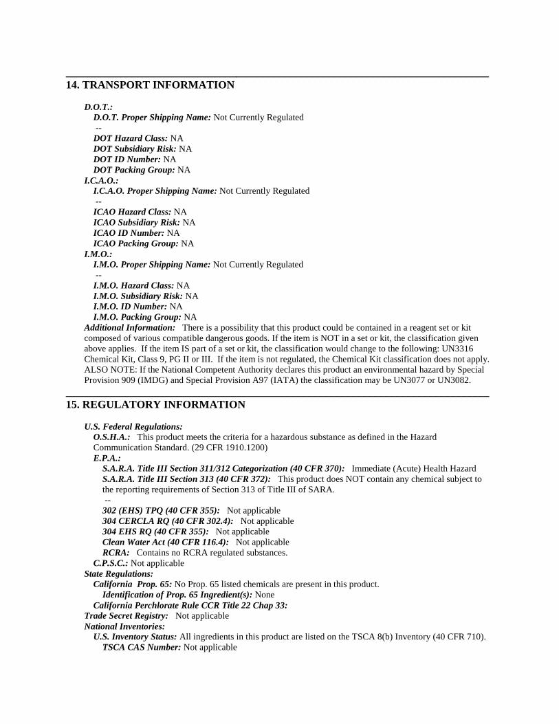
_____________________________________________________________________________14. TRANSPORT INFORMATION
D.O.T.:D.O.T. Proper Shipping Name: Not Currently Regulated--
DOT Hazard Class: NADOT Subsidiary Risk: NADOT ID Number: NADOT Packing Group: NA
I.C.A.O.:I.C.A.O. Proper Shipping Name: Not Currently Regulated--
ICAO Hazard Class: NAICAO Subsidiary Risk: NAICAO ID Number: NAICAO Packing Group: NA
I.M.O.:I.M.O. Proper Shipping Name: Not Currently Regulated--
I.M.O. Hazard Class: NAI.M.O. Subsidiary Risk: NAI.M.O. ID Number: NAI.M.O. Packing Group: NA
Additional Information: There is a possibility that this product could be contained in a reagent set or kitcomposed of various compatible dangerous goods. If the item is NOT in a set or kit, the classification givenabove applies. If the item IS part of a set or kit, the classification would change to the following: UN3316Chemical Kit, Class 9, PG II or III. If the item is not regulated, the Chemical Kit classification does not apply.ALSO NOTE: If the National Competent Authority declares this product an environmental hazard by SpecialProvision 909 (IMDG) and Special Provision A97 (IATA) the classification may be UN3077 or UN3082.
_____________________________________________________________________________15. REGULATORY INFORMATION
U.S. Federal Regulations:O.S.H.A.: This product meets the criteria for a hazardous substance as defined in the HazardCommunication Standard. (29 CFR 1910.1200)E.P.A.:
S.A.R.A. Title III Section 311/312 Categorization (40 CFR 370): Immediate (Acute) Health HazardS.A.R.A. Title III Section 313 (40 CFR 372): This product does NOT contain any chemical subject tothe reporting requirements of Section 313 of Title III of SARA.--
302 (EHS) TPQ (40 CFR 355): Not applicable304 CERCLA RQ (40 CFR 302.4): Not applicable304 EHS RQ (40 CFR 355): Not applicableClean Water Act (40 CFR 116.4): Not applicableRCRA: Contains no RCRA regulated substances.
C.P.S.C.: Not applicableState Regulations:
California Prop. 65: No Prop. 65 listed chemicals are present in this product.Identification of Prop. 65 Ingredient(s): None
California Perchlorate Rule CCR Title 22 Chap 33:Trade Secret Registry: Not applicableNational Inventories:
U.S. Inventory Status: All ingredients in this product are listed on the TSCA 8(b) Inventory (40 CFR 710).TSCA CAS Number: Not applicable
_____________________________________________________________________________16. OTHER INFORMATION
Intended Use: Iron determinationReferences: TLV's Threshold Limit Values and Biological Exposure Indices for 1992-1993. AmericanConference of Governmental Industrial Hygienists, 1992. Air Contaminants, Federal Register, Vol. 54, No. 12.Thursday, January 19, 1989. pp. 2332-2983. 29 CFR 1900 - 1910 (Code of Federal Regulations - Labor). In-house information. Technical Judgment. Fire Protection Guide on Hazardous Materials, 10th Ed. Quincy,MA: National Fire Protection Fire Protection Guide on Hazardous Materials, 10th Ed. Quincy, MA: NationalFire Protection Association, 1991.Revision Summary: Updates in Section(s) 14,
_____________________________________________________________________________
Legend:NA - Not Applicable w/w - weight/weightND - Not Determined w/v - weight/volumeNV - Not Available v/v - volume/volume
USER RESPONSIBILITY: Each user should read and understand this information and incorporate it in individualsite safety programs in accordance with applicable hazard communication standards and regulations.
THE INFORMATION CONTAINED HEREIN IS BASED ON DATA CONSIDERED TO BE ACCURATE.HOWEVER, NO WARRANTY IS EXPRESSED OR IMPLIED REGARDING THE ACCURACY OFTHESE DATA OR THE RESULTS TO BE OBTAINED FROM THE USE THEREOF.
HACH COMPANY ©2009
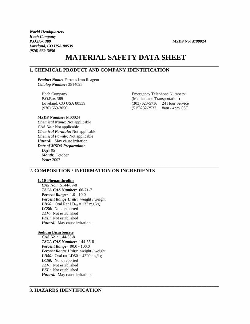
World HeadquartersHach CompanyP.O.Box 389 MSDS No: M00024Loveland, CO USA 80539(970) 669-3050
MATERIAL SAFETY DATA SHEET_____________________________________________________________________________1. CHEMICAL PRODUCT AND COMPANY IDENTIFICATION
Product Name: Ferrous Iron ReagentCatalog Number: 2514025
Hach Company Emergency Telephone Numbers:P.O.Box 389 (Medical and Transportation)Loveland, CO USA 80539 (303) 623-5716 24 Hour Service(970) 669-3050 (515)232-2533 8am - 4pm CST
MSDS Number: M00024Chemical Name: Not applicableCAS No.: Not applicableChemical Formula: Not applicableChemical Family: Not applicableHazard: May cause irritation.Date of MSDS Preparation:
Day: 05Month: OctoberYear: 2007
_____________________________________________________________________________2. COMPOSITION / INFORMATION ON INGREDIENTS
1, 10-PhenanthrolineCAS No.: 5144-89-8TSCA CAS Number: 66-71-7Percent Range: 1.0 - 10.0Percent Range Units: weight / weightLD50: Oral Rat LD50 = 132 mg/kgLC50: None reportedTLV: Not establishedPEL: Not establishedHazard: May cause irritation.
Sodium BicarbonateCAS No.: 144-55-8TSCA CAS Number: 144-55-8Percent Range: 90.0 - 100.0Percent Range Units: weight / weightLD50: Oral rat LD50 = 4220 mg/kgLC50: None reportedTLV: Not establishedPEL: Not establishedHazard: May cause irritation.
_____________________________________________________________________________3. HAZARDS IDENTIFICATION
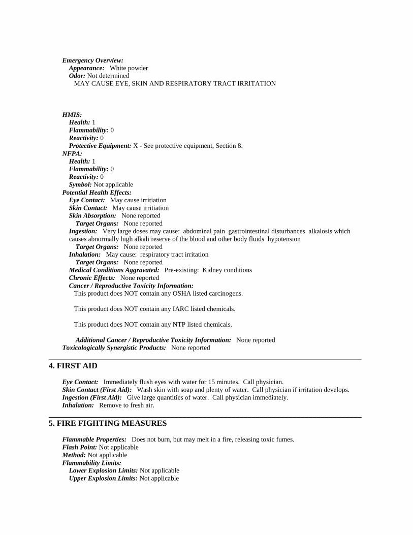
Emergency Overview:Appearance: White powderOdor: Not determined
MAY CAUSE EYE, SKIN AND RESPIRATORY TRACT IRRITATION
HMIS:Health: 1Flammability: 0Reactivity: 0Protective Equipment: X - See protective equipment, Section 8.
NFPA:Health: 1Flammability: 0Reactivity: 0Symbol: Not applicable
Potential Health Effects:Eye Contact: May cause irritiationSkin Contact: May cause irritiationSkin Absorption: None reported
Target Organs: None reportedIngestion: Very large doses may cause: abdominal pain gastrointestinal disturbances alkalosis whichcauses abnormally high alkali reserve of the blood and other body fluids hypotension
Target Organs: None reportedInhalation: May cause: respiratory tract irritation
Target Organs: None reportedMedical Conditions Aggravated: Pre-existing: Kidney conditionsChronic Effects: None reportedCancer / Reproductive Toxicity Information:
This product does NOT contain any OSHA listed carcinogens.
This product does NOT contain any IARC listed chemicals.
This product does NOT contain any NTP listed chemicals.
Additional Cancer / Reproductive Toxicity Information: None reportedToxicologically Synergistic Products: None reported
_____________________________________________________________________________4. FIRST AID
Eye Contact: Immediately flush eyes with water for 15 minutes. Call physician.Skin Contact (First Aid): Wash skin with soap and plenty of water. Call physician if irritation develops.Ingestion (First Aid): Give large quantities of water. Call physician immediately.Inhalation: Remove to fresh air.
_____________________________________________________________________________5. FIRE FIGHTING MEASURES
Flammable Properties: Does not burn, but may melt in a fire, releasing toxic fumes.Flash Point: Not applicableMethod: Not applicableFlammability Limits:
Lower Explosion Limits: Not applicableUpper Explosion Limits: Not applicable
Autoignition Temperature: Not applicableHazardous Combustion Products: Toxic fumes of: sodium monoxide nitrogen oxides. carbon monoxide,carbon dioxide.Fire / Explosion Hazards: None reported
Static Discharge: None reported.Mechanical Impact: None reported
Extinguishing Media: Water. Carbon dioxide Dry chemical.Fire Fighting Instruction: As in any fire, wear self-contained breathing apparatus pressure-demand and fullprotective gear.
_____________________________________________________________________________6. ACCIDENTAL RELEASE MEASURES
Spill Response Notice:Only persons properly qualified to respond to an emergency involving hazardous substances may respond to
a spill according to federal regulations (OSHA 29 CFR 1910.120(a)(v)) and per your company's emergencyresponse plan and guidelines/procedures. See Section 13, Special Instructions for disposal assistance.Containment Technique: Stop spilled material from being released to the environment.Clean-up Technique: Scoop up spilled material into a large beaker and dissolve with water. Flush the spilledmaterial to the drain with a large excess of water. Decontaminate the area of the spill with a weak acidsolution.Evacuation Procedure: Evacuate as needed to perform spill clean-up. If conditions warrant, increase the sizeof the evacuation.Special Instructions (for accidental release): Not applicable304 EHS RQ (40 CFR 355): Not applicableD.O.T. Emergency Response Guide Number: None
_____________________________________________________________________________7. HANDLING / STORAGE
Handling: Avoid contact with eyes skin Do not breathe dust. Wash thoroughly after handling. Maintaingeneral industrial hygiene practices when using this product.Storage: Keep container tightly closed when not in use. Protect from: moisture oxidizers
Flammability Class: Not applicable_____________________________________________________________________________8. EXPOSURE CONTROLS / PROTECTIVE EQUIPMENT
Engineering Controls: Have an eyewash station nearby. Maintain general industrial hygiene practices whenusing this product.Personal Protective Equipment:
Eye Protection: safety glasses with top and side shieldsSkin Protection: disposable latex glovesInhalation Protection: adequate ventilation
Precautionary Measures: Avoid contact with: eyes skin Do not breathe: dust Wash thoroughly afterhandling. Keep away from: oxidizersTLV: Not establishedPEL: Not established
_____________________________________________________________________________9. PHYSICAL / CHEMICAL PROPERTIES
Appearance: White powderPhysical State: SolidMolecular Weight: Not applicableOdor: Not determinedpH: Not determinedVapor Pressure: Not applicable
Vapor Density (air = 1): Not applicableBoiling Point: Not applicableMelting Point: Not determinedSpecific Gravity (water = 1): 2.10Evaporation Rate (water = 1): Not applicableVolatile Organic Compounds Content: Not applicablePartition Coefficient (n-octanol / water): Not applicableSolubility:
Water: Slightly solubleAcid: Slightly solubleOther: Not determined
Metal Corrosivity:Steel: Not determinedAluminum: Not determined
_____________________________________________________________________________10. STABILITY / REACTIVITY
Chemical Stability: Stable when stored under proper conditions.Conditions to Avoid: Excess moisture Heating to decomposition.Reactivity / Incompatibility: Incompatible with: oxidizersHazardous Decomposition: Toxic fumes of: nitrogen oxides sodium oxides carbon monoxide carbondioxideHazardous Polymerization: Will not occur.
_____________________________________________________________________________11. TOXICOLOGICAL INFORMATION
Product Toxicological Data:LD50: None reportedLC50: None reportedDermal Toxicity Data: None reportedSkin and Eye Irritation Data: Sodium Bicarbonate: Eye - rabbit - 100 mg/30 seconds - MILD; Skin -Human - 30 mg/3 days intermittent - MILDMutation Data: None reportedReproductive Effects Data: None reported
Ingredient Toxicological Data: Sodium Bicarbonate: Oral rat LD50 = 4220 mg/kg; 1, 10-Phenanthroline:Oral rat LD50 = 132 mg/kg
_____________________________________________________________________________12. ECOLOGICAL INFORMATION
Product Ecological Information: --No ecological data available for this product.
Ingredient Ecological Information: --No ecological data available for the ingredients of this product.
_____________________________________________________________________________13. DISPOSAL CONSIDERATIONS
EPA Waste ID Number: NoneSpecial Instructions (Disposal): Dilute material with excess water making a weaker than 5% solution. Opencold water tap completely, slowly pour the material to the drain.Empty Containers: Rinse three times with an appropriate solvent. Dispose of empty container as normaltrash.
NOTICE (Disposal): These disposal guidelines are based on federal regulations and may be superseded bymore stringent state or local requirements. Please consult your local environmental regulators for moreinformation.
_____________________________________________________________________________14. TRANSPORT INFORMATION
D.O.T.:D.O.T. Proper Shipping Name: Not Currently Regulated--
DOT Hazard Class: NADOT Subsidiary Risk: NADOT ID Number: NADOT Packing Group: NA
I.C.A.O.:I.C.A.O. Proper Shipping Name: Not Currently Regulated--
ICAO Hazard Class: NAICAO Subsidiary Risk: NAICAO ID Number: NAICAO Packing Group: NA
I.M.O.:I.M.O. Proper Shipping Name: Not Currently Regulated--
I.M.O. Hazard Class: NAI.M.O. Subsidiary Risk: NAI.M.O. ID Number: NAI.M.O. Packing Group: NA
Additional Information: There is a possibility that this product could be contained in a reagent set or kitcomposed of various compatible dangerous goods. If the item is NOT in a set or kit, the classification givenabove applies. If the item IS part of a set or kit, the classification would change to the following: UN3316Chemical Kit, Class 9, PG II or III. If the item is not regulated, the Chemical Kit classification does not apply.ALSO NOTE: If the National Competent Authority declares this product an environmental hazard by SpecialProvision 909 (IMDG) and Special Provision A97 (IATA) the classification may be UN3077 or UN3082.
_____________________________________________________________________________15. REGULATORY INFORMATION
U.S. Federal Regulations:O.S.H.A.: This product meets the criteria for a hazardous substance as defined in the HazardCommunication Standard. (29 CFR 1910.1200)E.P.A.:
S.A.R.A. Title III Section 311/312 Categorization (40 CFR 370): Immediate (Acute) Health HazardS.A.R.A. Title III Section 313 (40 CFR 372): This product does NOT contain any chemical subject tothe reporting requirements of Section 313 of Title III of SARA.--
302 (EHS) TPQ (40 CFR 355): Not applicable304 CERCLA RQ (40 CFR 302.4): Not applicable304 EHS RQ (40 CFR 355): Not applicableClean Water Act (40 CFR 116.4): Not applicableRCRA: Contains no RCRA regulated substances.
C.P.S.C.: Not applicableState Regulations:
California Prop. 65: No Prop. 65 listed chemicals are present in this product.Identification of Prop. 65 Ingredient(s): None
California Perchlorate Rule CCR Title 22 Chap 33:Trade Secret Registry: Not applicable
National Inventories:U.S. Inventory Status: All ingredients in this product are listed on the TSCA 8(b) Inventory (40 CFR 710).
TSCA CAS Number: Not applicable
_____________________________________________________________________________16. OTHER INFORMATION
Intended Use: Iron determinationReferences: TLV's Threshold Limit Values and Biological Exposure Indices for 1992-1993. AmericanConference of Governmental Industrial Hygienists, 1992. Air Contaminants, Federal Register, Vol. 54, No. 12.Thursday, January 19, 1989. pp. 2332-2983. 29 CFR 1900 - 1910 (Code of Federal Regulations - Labor). In-house information. Technical Judgment. Fire Protection Guide on Hazardous Materials, 10th Ed. Quincy,MA: National Fire Protection Fire Protection Guide on Hazardous Materials, 10th Ed. Quincy, MA: NationalFire Protection Association, 1991.Revision Summary: Updates in Section(s) 14,
_____________________________________________________________________________
Legend:NA - Not Applicable w/w - weight/weightND - Not Determined w/v - weight/volumeNV - Not Available v/v - volume/volume
USER RESPONSIBILITY: Each user should read and understand this information and incorporate it in individualsite safety programs in accordance with applicable hazard communication standards and regulations.
THE INFORMATION CONTAINED HEREIN IS BASED ON DATA CONSIDERED TO BE ACCURATE.HOWEVER, NO WARRANTY IS EXPRESSED OR IMPLIED REGARDING THE ACCURACY OFTHESE DATA OR THE RESULTS TO BE OBTAINED FROM THE USE THEREOF.
HACH COMPANY ©2009
World HeadquartersHach CompanyP.O.Box 389 MSDS No: M00023Loveland, CO USA 80539(970) 669-3050
MATERIAL SAFETY DATA SHEET_____________________________________________________________________________1. CHEMICAL PRODUCT AND COMPANY IDENTIFICATION
Product Name: Buffer Powder Citrate TypeCatalog Number: 2107669
Hach Company Emergency Telephone Numbers:P.O.Box 389 (Medical and Transportation)Loveland, CO USA 80539 (303) 623-5716 24 Hour Service(970) 669-3050 (515)232-2533 8am - 4pm CST
MSDS Number: M00023Chemical Name: Not applicableCAS No.: Not applicableChemical Formula: Not applicableChemical Family: Not applicableHazard: Causes moderate eye irritation.Date of MSDS Preparation:
Day: 21Month: MayYear: 2009
_____________________________________________________________________________2. COMPOSITION / INFORMATION ON INGREDIENTS
Citric AcidCAS No.: 77-92-9TSCA CAS Number: 77-92-9Percent Range: 15.0 - 25.0Percent Range Units: weight / weightLD50: Oral rat LD50 = 6730 mg/KgLC50: None reportedTLV: Not establishedPEL: Not establishedHazard: Causes severe eye irritation.
Sodium Phosphate MonobasicCAS No.: 7782-85-6TSCA CAS Number: 7558-79-4Percent Range: 45.0 - 55.0Percent Range Units: weight / weightLD50: Oral rat LD50 = 12930 mg/kg.LC50: None reportedTLV: Not establishedPEL: Not establishedHazard: May cause irritation.
Sodium SulfateCAS No.: 7757-82-6TSCA CAS Number: 7757-82-6

Percent Range: 30.0 - 40.0Percent Range Units: weight / weightLD50: Oral mouse LD50 = 5989 mg/kgLC50: None reportedTLV: Not establishedPEL: Not establishedHazard: May cause irritation.
_____________________________________________________________________________3. HAZARDS IDENTIFICATION
Emergency Overview:Appearance: White powderOdor: None
CAUSES EYE IRRITATION MAY CAUSE SKIN AND RESPIRATORY TRACT IRRITATION
HMIS:Health: 1Flammability: 0Reactivity: 0Protective Equipment: X - See protective equipment, Section 8.
NFPA:Health: 1Flammability: 0Reactivity: 0Symbol: Not applicable
Potential Health Effects:Eye Contact: Causes irritationSkin Contact: May cause irritiationSkin Absorption: No effects anticipated
Target Organs: Not applicableIngestion: Very large doses may cause: nausea vomiting diarrhea lethargy muscular cramps fever
Target Organs: None reportedInhalation: May cause: respiratory tract irritation
Target Organs: None reportedMedical Conditions Aggravated: Pre-existing: Eye conditionsChronic Effects: Citric acid chronic overexposure may cause effects due to the ability of citric acid tochelate metals, which could impair the body's ability to absorb calcium and iron.Cancer / Reproductive Toxicity Information:
This product does NOT contain any OSHA listed carcinogens.
This product does NOT contain any IARC listed chemicals.
This product does NOT contain any NTP listed chemicals.
Additional Cancer / Reproductive Toxicity Information: None reportedToxicologically Synergistic Products: None reported
_____________________________________________________________________________4. FIRST AID
Eye Contact: Immediately flush eyes with water for 15 minutes. Call physician.Skin Contact (First Aid): Wash skin with plenty of water. Call physician if irritation develops.Ingestion (First Aid): Give large quantities of water. Call physician immediately.
Inhalation: Remove to fresh air._____________________________________________________________________________5. FIRE FIGHTING MEASURES
Flammable Properties: Can burn in fire, releasing toxic vapors.Flash Point: Not applicableMethod: Not applicableFlammability Limits:
Lower Explosion Limits: Not applicableUpper Explosion Limits: Not applicable
Autoignition Temperature: Not determinedHazardous Combustion Products: Toxic fumes of: phosphorus oxides sodium monoxide sulfur oxides.carbon monoxide, carbon dioxide.Fire / Explosion Hazards: May react violently with: aluminum / aluminum compounds metal nitrates
Static Discharge: None reported.Mechanical Impact: None reported
Extinguishing Media: Water.Fire Fighting Instruction: As in any fire, wear self-contained breathing apparatus pressure-demand and fullprotective gear.
_____________________________________________________________________________6. ACCIDENTAL RELEASE MEASURES
Spill Response Notice:Only persons properly qualified to respond to an emergency involving hazardous substances may respond to
a spill according to federal regulations (OSHA 29 CFR 1910.120(a)(v)) and per your company's emergencyresponse plan and guidelines/procedures. See Section 13, Special Instructions for disposal assistance.Containment Technique: Stop spilled material from being released to the environment.Clean-up Technique: Scoop up spilled material into a large beaker and dissolve with water. Flush the spilledmaterial to the drain with a large excess of water. Decontaminate the area of the spill with a soap solution.Evacuation Procedure: Evacuate as needed to perform spill clean-up. If conditions warrant, increase the sizeof the evacuation.Special Instructions (for accidental release): Mixture contains a component which is regulated as a waterpollutant.304 EHS RQ (40 CFR 355): Not applicableD.O.T. Emergency Response Guide Number: Not applicable
_____________________________________________________________________________7. HANDLING / STORAGE
Handling: Avoid contact with eyes Do not breathe dust. Wash thoroughly after handling. Maintain generalindustrial hygiene practices when using this product.Storage: Store at 10 - 30°C. Keep container tightly closed when not in use. Protect from: moisture
Flammability Class: Not applicable_____________________________________________________________________________8. EXPOSURE CONTROLS / PROTECTIVE EQUIPMENT
Engineering Controls: Have an eyewash station nearby. Maintain general industrial hygiene practices whenusing this product.Personal Protective Equipment:
Eye Protection: safety glasses with top and side shieldsSkin Protection: disposable latex gloves lab coatInhalation Protection: adequate ventilation
Precautionary Measures: Avoid contact with: eyes Do not breathe: dust Wash thoroughly after handling.Protect from: moistureTLV: Not established
PEL: Not established_____________________________________________________________________________9. PHYSICAL / CHEMICAL PROPERTIES
Appearance: White powderPhysical State: SolidMolecular Weight: Not applicableOdor: NonepH: of 1% solution at 23 °C = 6.35Vapor Pressure: Not applicableVapor Density (air = 1): Not applicableBoiling Point: Not applicableMelting Point: 160 °C 320 °FSpecific Gravity (water = 1): 2.30Evaporation Rate (water = 1): Not applicableVolatile Organic Compounds Content: Not determinedPartition Coefficient (n-octanol / water): Not determinedSolubility:
Water: SolubleAcid: Not determinedOther: Not determined
Metal Corrosivity:Steel: Not determinedAluminum: Not determined
_____________________________________________________________________________10. STABILITY / REACTIVITY
Chemical Stability: Stable when stored under proper conditions.Conditions to Avoid: Excess moisture Heating to decomposition.Reactivity / Incompatibility: Incompatible with: metal nitrates aluminumHazardous Decomposition: Toxic fumes of: phosphorus oxides sulfur oxides carbon monoxide carbondioxideHazardous Polymerization: Will not occur.
_____________________________________________________________________________11. TOXICOLOGICAL INFORMATION
Product Toxicological Data:LD50: None reportedLC50: None reportedDermal Toxicity Data: None reportedSkin and Eye Irritation Data: Citric Acid Skin rabbit 500 mg/24 hour: MODERATE. Citric Acid Eyerabbit 750 µg/24 hour: SEVERE.Mutation Data: None reportedReproductive Effects Data: None reported
Ingredient Toxicological Data: Citric acid Oral rat LD50 = 6730 mg/kg; Sodium Sulfate Oral mouse LD50 =5989 mg/kg; Sodium Phosphate Oral rat LD50 = 17 g/kg
_____________________________________________________________________________12. ECOLOGICAL INFORMATION
Product Ecological Information: --No ecological data available for this product.
Ingredient Ecological Information: Sodium Sulfate: Aquatic Toxicity: TLm 13500 mg/L bluegill sunfish / 96hours, TLm 16500 mg/L mosquito fish / 96 hours
_____________________________________________________________________________13. DISPOSAL CONSIDERATIONS
EPA Waste ID Number: Not applicableSpecial Instructions (Disposal): Dilute to 3 to 5 times the volume with cold water. Open cold water tapcompletely, slowly pour the material to the drain. Flush system with plenty of water.Empty Containers: Rinse three times with an appropriate solvent. Dispose of empty container as normaltrash.NOTICE (Disposal): These disposal guidelines are based on federal regulations and may be superseded bymore stringent state or local requirements. Please consult your local environmental regulators for moreinformation.
_____________________________________________________________________________14. TRANSPORT INFORMATION
D.O.T.:D.O.T. Proper Shipping Name: Not Currently Regulated--
DOT Hazard Class: NADOT Subsidiary Risk: NADOT ID Number: NADOT Packing Group: NA
I.C.A.O.:I.C.A.O. Proper Shipping Name: Not Currently Regulated--
ICAO Hazard Class: NAICAO Subsidiary Risk: NAICAO ID Number: NAICAO Packing Group: NA
I.M.O.:I.M.O. Proper Shipping Name: Not Currently Regulated--
I.M.O. Hazard Class: NAI.M.O. Subsidiary Risk: NAI.M.O. ID Number: NAI.M.O. Packing Group: NA
Additional Information: There is a possibility that this product could be contained in a reagent set or kitcomposed of various compatible dangerous goods. If the item is NOT in a set or kit, the classification givenabove applies. If the item IS part of a set or kit, the classification would change to the following: UN3316Chemical Kit, Class 9, PG II or III. If the item is not regulated, the Chemical Kit classification does not apply.
_____________________________________________________________________________15. REGULATORY INFORMATION
U.S. Federal Regulations:O.S.H.A.: This product meets the criteria for a hazardous substance as defined in the HazardCommunication Standard. (29 CFR 1910.1200)E.P.A.:
S.A.R.A. Title III Section 311/312 Categorization (40 CFR 370): Immediate (Acute) Health HazardS.A.R.A. Title III Section 313 (40 CFR 372): This product does NOT contain any chemical subject tothe reporting requirements of Section 313 of Title III of SARA.--
302 (EHS) TPQ (40 CFR 355): Not applicable304 CERCLA RQ (40 CFR 302.4): Sodium phosphate, dibasic 5000 lbs.304 EHS RQ (40 CFR 355): Not applicableClean Water Act (40 CFR 116.4): Sodium phosphate, dibasic - RQ 5000 lbs.
RCRA: Contains no RCRA regulated substances.C.P.S.C.: Not applicable
State Regulations:California Prop. 65: No Prop. 65 listed chemicals are present in this product.
Identification of Prop. 65 Ingredient(s): NoneCalifornia Perchlorate Rule CCR Title 22 Chap 33:
Trade Secret Registry: Not applicableNational Inventories:
U.S. Inventory Status: All ingredients in this product are listed on the TSCA 8(b) Inventory (40 CFR 710).TSCA CAS Number: Not applicable
_____________________________________________________________________________16. OTHER INFORMATION
Intended Use: Determination of manganeseReferences: NIOSH Registry of Toxic Effects of Chemical Substances, 1985-86. Cincinnati: U.S.Department of Health and Human Services, April, 1987. CCINFO MSDS/FTSS. Canadian Centre forOccupational Health and Safety. Hamilton, Ontario Canada: 30 June 1993. The Merck Index, 11th Ed.Rahway, New Jersey: Merck and Co., Inc., 1989. Technical Judgment. In-house information. AirContaminants, Federal Register, Vol. 54, No. 12. Thursday, January 19, 1989. pp. 2332-2983. TLV'sThreshold Limit Values and Biological Exposure Indices for 1992-1993. American Conference ofGovernmental Industrial Hygienists, 1992.Revision Summary: Updates in Section(s) 14,
_____________________________________________________________________________
Legend:NA - Not Applicable w/w - weight/weightND - Not Determined w/v - weight/volumeNV - Not Available v/v - volume/volume
USER RESPONSIBILITY: Each user should read and understand this information and incorporate it in individualsite safety programs in accordance with applicable hazard communication standards and regulations.
THE INFORMATION CONTAINED HEREIN IS BASED ON DATA CONSIDERED TO BE ACCURATE.HOWEVER, NO WARRANTY IS EXPRESSED OR IMPLIED REGARDING THE ACCURACY OFTHESE DATA OR THE RESULTS TO BE OBTAINED FROM THE USE THEREOF.
HACH COMPANY ©2009
World HeadquartersHach CompanyP.O.Box 389 MSDS No: M00021Loveland, CO USA 80539(970) 669-3050
MATERIAL SAFETY DATA SHEET_____________________________________________________________________________1. CHEMICAL PRODUCT AND COMPANY IDENTIFICATION
Product Name: Sodium PeriodateCatalog Number: 2107769
Hach Company Emergency Telephone Numbers:P.O.Box 389 (Medical and Transportation)Loveland, CO USA 80539 (303) 623-5716 24 Hour Service(970) 669-3050 (515)232-2533 8am - 4pm CST
MSDS Number: M00021Chemical Name: Sodium PeriodateCAS Number: 7790-28-5Additional CAS No. (for hydrated forms): Not applicableChemical Formula: NaIO4
Chemical Family: Oxidizing AgentsIntended Use: Laboratory Use
_____________________________________________________________________________2. HAZARDS IDENTIFICATION
GHS Classification:Hazard categories: Oxidizing Solids: Ox. Sol. 2 Acute Toxicity: Acute Tox. 4-Orl
GHS Label Elements:DANGER
Hazard statements: May intensify fire; oxidiser. Harmful if swallowed.Precautionary statements: Keep/Store away from clothing/combustible materials. Keep away from heat/sparks/openflames/hot surfaces. - No smoking. In case of fire: Use dry sand, extinquishing powder, foam or water for extinction.Wear protective gloves / protective clothing / eye protection / face protection. IF SWALLOWED: Call a POISONCENTER or doctor/physician if you feel unwell. Rinse mouth.
HMIS:Health: 2Flammability: 0Reactivity: 2Protective Equipment: X - See protective equipment, Section 8.
NFPA:Health: 2Flammability: 0Reactivity: 2Symbol: oxy
_____________________________________________________________________________3. COMPOSITION / INFORMATION ON INGREDIENTS
Hazardous Components according to GHS: YesSodium m-Periodate
CAS Number: 7790-28-5Chemical Formula: NaIO4
GHS Classification: Ox. Sol. 2, H272; Acute Tox. Orl. 4, H302Percent Range: 100.0Percent Range Units: weight / weightPEL: Not establishedTLV: Not established
_____________________________________________________________________________4. FIRST AID
General Information: In the event of exposure, show this Material Safety Data Sheet and label (where possible) to adoctor.Advice to doctor: Treat symptomatically.Eye Contact: Immediately flush eyes with water for 15 minutes. Call physician.Skin Contact (First Aid): Wash skin with plenty of water for 15 minutes. Remove contaminated clothing. Call physicianimmediately.Inhalation: Remove to fresh air.Ingestion (First Aid): Give large quantities of water. Call physician immediately.
_____________________________________________________________________________5. FIRE FIGHTING MEASURES
Flammable Properties: Strong oxidizer. Contact with combustible materials may cause a fire.Fire Fighting Instruction: As in any fire, wear self-contained breathing apparatus pressure-demand and full protectivegear. Evacuate area and fight fire from a safe distance.Extinguishing Media: Water. Carbon dioxide Dry chemical.Extinguishing Media NOT To Be Used: Not applicableFire / Explosion Hazards: May react violently with: strong reducersHazardous Combustion Products: Toxic fumes of: iodine iodine compounds sodium monoxide
_____________________________________________________________________________6. ACCIDENTAL RELEASE MEASURES
Spill Response Notice:Only persons properly qualified to respond to an emergency involving hazardous substances may respond to a spill
according to federal regulations (OSHA 29 CFR 1910.120(a)(v)) and per your company's emergency response plan andguidelines/procedures. See Section 13, Special Instructions for disposal assistance. Outside of the US, only personsproperly qualified according to state or local regulations should respond to a spill involving chemicals.Containment Technique: Stop spilled material from being released to the environment. Cover spilled solid material withsand or other inert material.Clean-up Technique: Working in small batches, dilute with excess water. Adjust to a pH between 6 and 9 with an alkali,such as soda ash or sodium bicarbonate. Flush reacted material to the drain with a large excess of water. Decontaminatesite with an alkali solution.Evacuation Procedure: Evacuate general area (50 foot radius or as directed by your facility's emergency response plan)when: any quantity is spilled. If conditions warrant, increase the size of the evacuation.DOT Emergency Response Guide Number: 140
_____________________________________________________________________________7. HANDLING / STORAGE
Handling: Avoid contact with eyes skin clothing Do not breathe dust. Wash thoroughly after handling. Maintaingeneral industrial hygiene practices when using this product.Storage: Protect from: moisture oxidizable materials all sources of ignitionFlammability Class: Not applicable
_____________________________________________________________________________8. EXPOSURE CONTROLS / PROTECTIVE EQUIPMENT
Engineering Controls: Maintain general industrial hygiene practices when using this product.Personal Protective Equipment:
Eye Protection: safety glasses with top and side shields
Skin Protection: lab coat disposable latex gloves In the EU, the selected gloves must satisfy the specifications of EUDirective 89/686/EEC and standard EN 374 derived from it.Inhalation Protection: adequate ventilation
Precautionary Measures: Avoid contact with: eyes skin clothing Do not breathe: dust Wash thoroughly after handling.TLV: Not establishedPEL: Not establishedFor Occupational Exposure Limits (OEL) for ingredients, see section 3 - Composition/Information on Ingredients.:
_____________________________________________________________________________9. PHYSICAL / CHEMICAL PROPERTIES
Appearance: White powderPhysical State: SolidMolecular Weight: 214.0Odor: NoneOdor Threshold: OdorlesspH: of 5% solution = 4 - 4.5Metal Corrosivity:
Corrosivity Classification: Not classified as corrosive to metals according to GHS criteria.Steel: Not determinedAluminum: Not determined
Specific Gravity/ Relative Density (water = 1; air =1): 3.865Viscosity: Not applicableSolubility:
Water: Soluble - 14.4 g/100 g of waterAcid: SolubleOther: Not determined
Partition Coefficient (n-octanol / water): Not determinedCoefficient of Water / Oil: Not determinedMelting Point: 300°C 572°FDecomposition Temperature: > 300 °CBoiling Point: Not applicableVapor Pressure: Not applicableVapor Density (air = 1): Not applicableEvaporation Rate (water = 1): Not applicableVolatile Organic Compounds Content: Not applicableFlammable Properties: Strong oxidizer. Contact with combustible materials may cause a fire.Flash Point: Not applicable
Method: Not applicableFlammability Limits:
Lower Explosion Limits: Not applicableUpper Explosion Limits: Not applicable
Autoignition Temperature: Not determinedExplosive Properties:
Not applicable Not classified according to GHS criteria.Oxidizing Properties:
Not applicable Not classified according to GHS criteria.Reactivity Properties:
Not applicable Not classifed as self-reactive, pyrophoric, self-heating or emitting flammable gases in contact with wateraccording to GHS criteria.Gas under Pressure: Not classified as gas under pressure according to GHS. Not applicable
_____________________________________________________________________________10. STABILITY / REACTIVITY
Chemical Stability: Stable when stored under proper conditions.Mechanical Impact: None reportedStatic Discharge: None reported.Reactivity / Incompatibility: May react violently in contact with: reducers organic materialsHazardous Decomposition: Toxic fumes of: Iodine iodine compounds sodium monoxideConditions to Avoid: Excess moisture Heating to decomposition.
_____________________________________________________________________________11. TOXICOLOGICAL INFORMATION
Toxicokinetics, Metabolism and Distribution: No information availableToxicologically Synergistic Products: None reportedAcute Toxicity: Route Data Given BelowAnaloguos compound, sodium perchlorate CAS 7601-89-0, (oral rat LD50 900 - 2100 mg/kg) was classified in Annex VI
(EU Index No 017-010-00-6) as Acute Tox 4.Specific Target Organ Toxicity - Single Exposure (STOT-SE): Based on classification principles, the classificationcriteria are not met.Specific Target Organ Toxicity - Repeat Exposure (STOT-RE): Based on classification principles, the classificationcriteria are not met.Skin Corrosion/Irritation: Based on classification principles, the classification criteria are not met.Eye Damage: Based on classification principles, the classification criteria are not met.Sensitization: Based on classification principles, the classification criteria are not met.CMR Effects/Properties (carcinogenic, mutagenic or toxic to reproduction): No germ cell mutagenicity, carcinogeniictyor reproductive toxicity data found.
IARC Listed: NoNTP Listed: NoO.S.H.A. Listed: No
Symptoms/Effects:Ingestion: May cause: abdominal pain vomiting diarrheaInhalation: Causes: irritation of nose and throatSkin Absorption: None ReportedChronic Effects: None reported
Medical Conditions Aggravated: Pre-existing: Eye conditions Skin conditions_____________________________________________________________________________12. ECOLOGICAL INFORMATION
Product Ecological Information: --No ecological data available for this product.CEPA Categorization: Persistent Not Bioaccumulative Not inherently toxic to aquatic organisms
Ingredient Ecological Information: --Not applicable
_____________________________________________________________________________13. DISPOSAL CONSIDERATIONS
EPA Waste ID Number: D001Special Instructions (Disposal): Work in an approved fume hood. Working in a large container, cautiously add smallportions of the material to cold water with agitation. Adjust to a pH between 6 and 9 with an alkali, such as soda ash orsodium bicarbonate. Open cold water tap completely, slowly pour the reacted material to the drain. Allow cold water torun for 5 minutes to completely flush the system. Verification should be made that such disposal is not inconsistent withany pretreatment agreement your facility may have with the wastewater treatment facility.Empty Containers: Rinse three times with an appropriate solvent. Dispose of empty container as normal trash.NOTICE (Disposal): These disposal guidelines are based on federal regulations and may be superseded by more stringentstate or local requirements. Please consult your local environmental regulators for more information. In Europe: Chemicaland analysis solutions must be disposed of in compliance with the respective national regulations. Product packaging mustbe disposed of in compliance with the country-specific regulations or must be passed to a packaging return system.
_____________________________________________________________________________14. TRANSPORT INFORMATION
D.O.T.:D.O.T. Proper Shipping Name: Oxidizing Solid, N.O.S.(Sodium Periodate)
Hazard Class: 5.1Subsidiary Risk: NAID Number: UN1479Packing Group: II
T.D.G.:Proper Shipping Name: Oxidizing Solid, N.O.S.(Sodium Periodate)
Hazard Class: 5.1Subsidiary Risk: NA
PIN: 1479Group: II
I.C.A.O.:I.C.A.O. Proper Shipping Name: Oxidizing Solid, N.O.S.(Sodium Periodate)
Hazard Class: 5.1Subsidiary Risk: NAID Number: UN1479Packing Group: II
I.M.O.:I.M.O. Proper Shipping Name: Oxidizing Solid, N.O.S.(Sodium Periodate)
Hazard Class: 5.1Subsidiary Risk: NAID Number: UN1479Packing Group: II
Additional Information: There is a possibility that this product could be contained in a reagent set or kit composed ofvarious compatible dangerous goods. If the item is NOT in a set or kit, the classification given above applies. If the item ISpart of a set or kit, the classification would change to the following: UN3316 Chemical Kit, Class 9, PG II or III. If the itemis not regulated, the Chemical Kit classification does not apply.
_____________________________________________________________________________15. REGULATORY INFORMATION
U.S. Federal Regulations:O.S.H.A.: This product meets the criteria for a hazardous substance as defined in the Hazard Communication Standard.(29 CFR 1910.1200)E.P.A.:
S.A.R.A. Title III Section 311/312 Categorization (40 CFR 370): Immediate (Acute) Health Hazard Fire HazardS.A.R.A. Title III Section 313 (40 CFR 372): This product does NOT contain any chemical subject to the reportingrequirements of Section 313 of Title III of SARA.--
302 (EHS) TPQ (40 CFR 355): Not applicable304 CERCLA RQ (40 CFR 302.4): Not applicable304 EHS RQ (40 CFR 355): Not applicableClean Water Act (40 CFR 116.4): Not applicableRCRA: Contains RCRA regulated substances. See Section 13, EPA Waste ID Number.
State Regulations:California Prop. 65: No Prop. 65 listed chemicals are present in this product.Identification of Prop. 65 Ingredient(s): Not applicableCalifornia Perchlorate Rule CCR Title 22 Chap 33: Not applicableTrade Secret Registry: Not applicable
National Inventories:U.S. Inventory Status: TSCA Listed: Yes
CAS Number: 7790-28-5Canadian Inventory Status: DSL Listed: YesEEC Inventory Status: EINECS Listed: YesAustralian Inventory (AICS) Status: ListedNew Zealand Inventory (NZIoC) Status: ListedKorean Inventory (KECI) Status: ListedJapan (ENCS) Inventory Status: ListedChina (PRC) Inventory (MEP) Status: Listed
_____________________________________________________________________________16. OTHER INFORMATION
References: Vendor Information. TLV's Threshold Limit Values and Biological Exposure Indices for 1992-1993.American Conference of Governmental Industrial Hygienists, 1992. The Merck Index, 11th Ed. Rahway, New Jersey:Merck and Co., Inc., 1989. Technical Judgment. Sax, N. Irving. Dangerous Properties of Industrial Materials, 7th Ed.New York: Van Nostrand Reinhold Co., 1989. CCINFO RTECS. Canadian Centre for Occupational Health and Safety.Hamilton, Ontario Canada: 30 June 1993. CCINFO MSDS/FTSS. Canadian Centre for Occupational Health and Safety.Hamilton, Ontario Canada: 30 June 1993. List of Dangerous Substances Classified in Annex I of the EEC Directive(67/548) - Classification, Packaging and Labeling of Dangerous Substances, Amended July 1992. Air Contaminants,
Federal Register, Vol. 54, No. 12. Thursday, January 19, 1989. pp. 2332-2983. 29 CFR 1900 - 1910 (Code of FederalRegulations - Labor).Complete Text of H phrases referred to in Section 3: H272 May intensify fire; oxidiser. H302 Harmful if swallowed.Revision Summary: Substantial revision to comply with EU Reg 1272/2008, Reg 1907/2006 and UN GHS (ST/SG/AC.10/36/Add.3).Date of MSDS Preparation:
Day: 01Month: OctoberYear: 2010
MSDS Prepared: MSDS prepared by Product Compliance Department extension 3350CCOHS Evaluation Note: It is offered under the interim policy that was established by Health Canada permitting use ofGHS-formatted safety data sheets in Canada prior to revision of CPR to GHS. It is offered under exemption from WHMISlabeling as specified in the Controlled Products Regulation (CPR) Section 17.
_____________________________________________________________________________
Legend:NA - Not Applicable w/w - weight/weightND - Not Determined w/v - weight/volumeNV - Not Available v/v - volume/volume
USER RESPONSIBILITY: Each user should read and understand this information and incorporate it in individual site safetyprograms in accordance with applicable hazard communication standards and regulations.
THE INFORMATION CONTAINED HEREIN IS BASED ON DATA CONSIDERED TO BE ACCURATE.HOWEVER, NO WARRANTY IS EXPRESSED OR IMPLIED REGARDING THE ACCURACY OF THESE DATAOR THE RESULTS TO BE OBTAINED FROM THE USE THEREOF.
HACH COMPANY ©2010
World HeadquartersHach CompanyP.O.Box 389 MSDS No: M00135Loveland, CO USA 80539(970) 669-3050
MATERIAL SAFETY DATA SHEET_____________________________________________________________________________1. CHEMICAL PRODUCT AND COMPANY IDENTIFICATION
Product Name: FerroVer® Iron ReagentCatalog Number: 2105769
Hach Company Emergency Telephone Numbers:P.O.Box 389 (Medical and Transportation)Loveland, CO USA 80539 (303) 623-5716 24 Hour Service(970) 669-3050 (515)232-2533 8am - 4pm CST
MSDS Number: M00135Chemical Name: Not applicableCAS No.: Not applicableChemical Formula: Not applicableChemical Family: Not applicableHazard: May cause allergic reaction. May cause irritation.Date of MSDS Preparation:
Day: 15Month: OctoberYear: 2009
_____________________________________________________________________________2. COMPOSITION / INFORMATION ON INGREDIENTS
Sodium ThiosulfateCAS No.: 10102-17-7TSCA CAS Number: 7772-98-7Percent Range: 45.0 - 55.0Percent Range Units: weight / weightLD50: Oral rat LD50 > 8 gm/kgLC50: None reportedTLV: Not establishedPEL: Not establishedHazard: May cause irritation.
1,10-Phenanthroline-p-toluenesulfonic Acid SaltCAS No.: 92798-16-8TSCA CAS Number: 92798-16-8Percent Range: 1.0 - 5.0Percent Range Units: weight / weightLD50: None reportedLC50: None reportedTLV: Not establishedPEL: Not establishedHazard: May cause irritation. Toxic properties unknown.
Sodium HydrosulfiteCAS No.: 7775-14-6TSCA CAS Number: 7775-14-6Percent Range: 15.0 - 25.0Percent Range Units: weight / weightLD50: Oral rat LD50 > 500 mg/kgLC50: None reportedTLV: Not establishedPEL: Not established
Hazard: Allergen Causes moderate eye irritation. Flammable solid.
Sodium CitrateCAS No.: 68-04-2TSCA CAS Number: 68-04-2Percent Range: 1.0 - 10.0Percent Range Units: weight / weightLD50: Oral rat LD50 >8 g/KgLC50: None reportedTLV: Not establishedPEL: Not establishedHazard: May cause irritation.
Sodium MetabisulfiteCAS No.: 7681-57-4TSCA CAS Number: 7681-57-4Percent Range: 20.0 - 30.0Percent Range Units: weight / weightLD50: Oral rat LD50 = 1131 mg/kgLC50: None reportedTLV: 5 mg/m3 (ACGIH - TWA)PEL: Not establishedHazard: May cause irritation. May cause allergic reaction.
_____________________________________________________________________________3. HAZARDS IDENTIFICATION
Emergency Overview:Appearance: White to light yellow crystalsOdor: Sulfur-like
MAY CAUSE EYE AND RESPIRATORY TRACT IRRITATIONMAY CAUSE ALLERGIC RESPIRATORY REACTION IF SWALLOWED OR INHALED
HMIS:Health: 2Flammability: 0Reactivity: 1Protective Equipment: X - See protective equipment, Section 8.
NFPA:Health: 2Flammability: 0Reactivity: 1Symbol: Not applicable
Potential Health Effects:Eye Contact: May cause irritiationSkin Contact: No effects are anticipatedSkin Absorption: None reported
Target Organs: None reportedIngestion: May cause: allergic respiratory reaction gastrointestinal irritation circulatory disturbances central nervoussystem depression Very large doses may cause: abdominal pain diarrhea vomiting depression
Target Organs: None reportedInhalation: May cause: respiratory tract irritation allergic respiratory reaction difficult breathing coughing rapidpulse and respirations chest pain blood pressure changes sweating flushing hives
Target Organs: None reportedMedical Conditions Aggravated: Sulfites are strong sensitizers. Inhalation and ingestion may cause allergic respiratoryreactions in asthmatics. Persons with respiratory conditions should take special care when working with products thatcontain sulfites.Chronic Effects: Chronic overexposure may cause allergic respiratory reactionsCancer / Reproductive Toxicity Information:
This product does NOT contain any OSHA listed carcinogens.
An ingredient of this mixture is: IARC Group 3: Non-classifiableMetabisulfitesThis product does NOT contain any NTP listed chemicals.
Additional Cancer / Reproductive Toxicity Information: Contains: an experimental mutagen.Toxicologically Synergistic Products: None reported
_____________________________________________________________________________4. FIRST AID
Eye Contact: Immediately flush eyes with water for 15 minutes. Call physician.Skin Contact (First Aid): Wash skin with soap and plenty of water.Ingestion (First Aid): Give 1-2 glasses of water. Do not induce vomiting. Call physician immediately.Inhalation: Give artificial respiration if necessary. Remove to fresh air. Call physician.
_____________________________________________________________________________5. FIRE FIGHTING MEASURES
Flammable Properties: Can burn in fire, releasing toxic vapors.Flash Point: Not applicableMethod: Not applicableFlammability Limits:
Lower Explosion Limits: Not applicableUpper Explosion Limits: Not applicable
Autoignition Temperature: Not determinedHazardous Combustion Products: Toxic fumes of: sulfur oxides. sodium monoxide carbon monoxide, carbon dioxide.Fire / Explosion Hazards: May react violently with: organic materials aluminum / aluminum compounds strongoxidizers combustible materials strong acids water
Static Discharge: None reported.Mechanical Impact: None reported
Extinguishing Media: Carbon dioxide Alcohol foam. Dry chemical.Fire Fighting Instruction: As in any fire, wear self-contained breathing apparatus pressure-demand and full protectivegear.
_____________________________________________________________________________6. ACCIDENTAL RELEASE MEASURES
Spill Response Notice:Only persons properly qualified to respond to an emergency involving hazardous substances may respond to a spill
according to federal regulations (OSHA 29 CFR 1910.120(a)(v)) and per your company's emergency response plan andguidelines/procedures. See Section 13, Special Instructions for disposal assistance.Containment Technique: Stop spilled material from being released to the environment. Cover spilled solid material withsand or other inert material.Clean-up Technique: Sweep up material. Dilute with a large excess of water. Adjust to a pH between 6 and 9 with analkali, such as soda ash or sodium bicarbonate. Decontaminate the area of the spill with a soap solution.Evacuation Procedure: Evacuate local area (15 foot radius or as directed by your facility's emergency response plan)when: any quantity is spilled. If conditions warrant, increase the size of the evacuation.Special Instructions (for accidental release): Not applicable304 EHS RQ (40 CFR 355): Not applicableD.O.T. Emergency Response Guide Number: Not applicable
_____________________________________________________________________________7. HANDLING / STORAGE
Handling: Avoid contact with eyes skin clothing Do not breathe dust. Wash thoroughly after handling. Maintaingeneral industrial hygiene practices when using this product.Storage: Store between 10° and 25°C. Protect from: heat moisture light Keep away from: acids / acid fumes.combustible materials organic material oxidizers
Flammability Class: Not applicable_____________________________________________________________________________8. EXPOSURE CONTROLS / PROTECTIVE EQUIPMENT
Engineering Controls: Have an eyewash station nearby. Use general ventilation to minimize exposure to mist, vapor ordust. Maintain general industrial hygiene practices when using this product.
Personal Protective Equipment:Eye Protection: safety glasses with top and side shieldsSkin Protection: disposable latex gloves lab coatInhalation Protection: adequate ventilation and / or dust / mist mask
Precautionary Measures: Avoid contact with: eyes skin clothing Do not breathe: dust Wash thoroughly after handling.Use with adequate ventilation. Protect from: heat Keep away from: acids/acid fumes organic materials combustiblematerial oxidizers waterTLV: Not establishedPEL: Not established
_____________________________________________________________________________9. PHYSICAL / CHEMICAL PROPERTIES
Appearance: White to light yellow crystalsPhysical State: SolidMolecular Weight: Not applicableOdor: Sulfur-likepH: 5% solution = 5.29Vapor Pressure: Not applicableVapor Density (air = 1): Not applicableBoiling Point: Not applicableMelting Point: decomposes at 192° CSpecific Gravity (water = 1): 2.27Evaporation Rate (water = 1): Not applicableVolatile Organic Compounds Content: Not determinedPartition Coefficient (n-octanol / water): Not determinedSolubility:
Water: SolubleAcid: SolubleOther: Not determined
Metal Corrosivity:Steel: 0.106 in/yrAluminum: 0.003 in/yr
_____________________________________________________________________________10. STABILITY / REACTIVITY
Chemical Stability: Stable when stored under proper conditions.Conditions to Avoid: Exposure to light. Excess moisture Extreme temperaturesReactivity / Incompatibility: Incompatible with: combustible materials organic materials oxidizers aluminum acidssodium nitrite sodium chloriteHazardous Decomposition: Heating to decomposition releases toxic and/or corrosive fumes of: sulfur oxides carbonmonoxide carbon dioxideHazardous Polymerization: Will not occur.
_____________________________________________________________________________11. TOXICOLOGICAL INFORMATION
Product Toxicological Data:LD50: None reportedLC50: None reportedDermal Toxicity Data: None reportedSkin and Eye Irritation Data: Erythema at 3 minutes, 1 hour, 4 hours, 24 hours, 48 hours, 72 hours = 0. Edema at 3minutes, 1 hour, 4 hours, 24 hours, 48 hours, 72 hours = 0.Mutation Data: Sodium Metabisulfite: cytogenetic analysis hamster ovary 180 µg/l; sister chromatid exchange onhamster ovary @ 200 µg/l .Reproductive Effects Data: Sodium Metabisulfite: oral rat TDLo = 20 g/kg - effects on newborn - stillbirth; oral ratTDLo = 40 g/kg - effects on newborn - weaning or lactation index.
Ingredient Toxicological Data: Sodium Hydrosulfite Oral rat LD50 > 500 mg/kg; Sodium Thiosulfate Oral rat LD50 > 8g/kg; Sodium Citrate Oral rat LD50 > 8 g/kg
_____________________________________________________________________________12. ECOLOGICAL INFORMATION
Product Ecological Information: --No ecological data available for this product.
Ingredient Ecological Information: Sodium Metabisulfite: 120 ppm / 24, 48 & 96 hours / mosquito fish / TLm / freshwater (converting bisulfite figure to metabisulfite); Sodium Thiosulfate: Aquatic toxicity: 24,000 mg / 1 / 96 hours /mosquito-fish / TLm / turbid water at 22 ° - 24° C.
_____________________________________________________________________________13. DISPOSAL CONSIDERATIONS
EPA Waste ID Number: Not applicableSpecial Instructions (Disposal): Dilute to 3 to 5 times the volume with cold water. Adjust to a pH between 6 and 9 withan alkali, such as soda ash or sodium bicarbonate. Open cold water tap completely, slowly pour the reacted material to thedrain. Allow cold water to run for 5 minutes to completely flush the system.Empty Containers: Rinse three times with an appropriate solvent. Dispose of empty container as normal trash.NOTICE (Disposal): These disposal guidelines are based on federal regulations and may be superseded by more stringentstate or local requirements. Please consult your local environmental regulators for more information.
_____________________________________________________________________________14. TRANSPORT INFORMATION
D.O.T.:D.O.T. Proper Shipping Name: Not Currently Regulated--
DOT Hazard Class: NADOT Subsidiary Risk: NADOT ID Number: NADOT Packing Group: NA
I.C.A.O.:I.C.A.O. Proper Shipping Name: Not Currently Regulated--
ICAO Hazard Class: NAICAO Subsidiary Risk: NAICAO ID Number: NAICAO Packing Group: NA
I.M.O.:I.M.O. Proper Shipping Name: Not Currently Regulated--
I.M.O. Hazard Class: NAI.M.O. Subsidiary Risk: NAI.M.O. ID Number: NAI.M.O. Packing Group: NA
Additional Information: There is a possibility that this product could be contained in a reagent set or kit composed ofvarious compatible dangerous goods. If the item is NOT in a set or kit, the classification given above applies. If the item ISpart of a set or kit, the classification would change to the following: UN3316 Chemical Kit, Class 9, PG II or III. If the itemis not regulated, the Chemical Kit classification does not apply.
_____________________________________________________________________________15. REGULATORY INFORMATION
U.S. Federal Regulations:O.S.H.A.: This product meets the criteria for a hazardous substance as defined in the Hazard Communication Standard.(29 CFR 1910.1200)E.P.A.:
S.A.R.A. Title III Section 311/312 Categorization (40 CFR 370): Immediate (Acute) Health Hazard Delayed(Chronic) Health HazardS.A.R.A. Title III Section 313 (40 CFR 372): This product does NOT contain any chemical subject to the reportingrequirements of Section 313 of Title III of SARA.--
302 (EHS) TPQ (40 CFR 355): Not applicable304 CERCLA RQ (40 CFR 302.4): Not applicable304 EHS RQ (40 CFR 355): Not applicableClean Water Act (40 CFR 116.4): Not applicable
RCRA: Contains no RCRA regulated substances.C.P.S.C.: Not applicable
State Regulations:California Prop. 65: No Prop. 65 listed chemicals are present in this product.
Identification of Prop. 65 Ingredient(s): Not applicableCalifornia Perchlorate Rule CCR Title 22 Chap 33:
Trade Secret Registry: Not applicableNational Inventories:
U.S. Inventory Status: All ingredients in this product are listed on the TSCA 8(b) Inventory (40 CFR 710).TSCA CAS Number: Not applicable
_____________________________________________________________________________16. OTHER INFORMATION
Intended Use: Iron determinationReferences: CCINFO MSDS/FTSS. Canadian Centre for Occupational Health and Safety. Hamilton, Ontario Canada:30 June 1993. NIOSH Registry of Toxic Effects of Chemical Substances, 1985-86. Cincinnati: U.S. Department of Healthand Human Services, April, 1987. Outside Testing. Vendor Information. Gosselin, R. E. et al. Clinical Toxicology ofCommercial Products, 5th Ed. Baltimore: The Williams and Wilkins Co., 1984. Sax, N. Irving. Dangerous Properties ofIndustrial Materials, 7th Ed. New York: Van Nostrand Reinhold Co., 1989. Fire Protection Guide on HazardousMaterials, 10th Ed. Quincy, MA: National Fire Protection Fire Protection Guide on Hazardous Materials, 10th Ed.Quincy, MA: National Fire Protection Association, 1991. Technical Judgment. In-house information. TLV's ThresholdLimit Values and Biological Exposure Indices for 1992-1993. American Conference of Governmental IndustrialHygienists, 1992. Air Contaminants, Federal Register, Vol. 54, No. 12. Thursday, January 19, 1989. pp. 2332-2983.Revision Summary: Updates in Section(s) 14,
_____________________________________________________________________________
Legend:NA - Not Applicable w/w - weight/weightND - Not Determined w/v - weight/volumeNV - Not Available v/v - volume/volume
USER RESPONSIBILITY: Each user should read and understand this information and incorporate it in individual site safetyprograms in accordance with applicable hazard communication standards and regulations.
THE INFORMATION CONTAINED HEREIN IS BASED ON DATA CONSIDERED TO BE ACCURATE.HOWEVER, NO WARRANTY IS EXPRESSED OR IMPLIED REGARDING THE ACCURACY OF THESE DATAOR THE RESULTS TO BE OBTAINED FROM THE USE THEREOF.
HACH COMPANY ©2009
World HeadquartersHach CompanyP.O.Box 389 MSDS No: M00135Loveland, CO USA 80539(970) 669-3050
MATERIAL SAFETY DATA SHEET_____________________________________________________________________________1. CHEMICAL PRODUCT AND COMPANY IDENTIFICATION
Product Name: FerroVer ® Iron ReagentCatalog Number: 2507025
Hach Company Emergency Telephone Numbers:P.O.Box 389 (Medical and Transportation)Loveland, CO USA 80539 (303) 623-5716 24 Hour Service(970) 669-3050 (515)232-2533 8am - 4pm CST
MSDS Number: M00135Chemical Name: Not applicableCAS No.: Not applicableChemical Formula: Not applicableChemical Family: Not applicableHazard: May cause allergic reaction. May cause irritation.Date of MSDS Preparation:
Day: 15Month: OctoberYear: 2009
_____________________________________________________________________________2. COMPOSITION / INFORMATION ON INGREDIENTS
Sodium ThiosulfateCAS No.: 10102-17-7TSCA CAS Number: 7772-98-7Percent Range: 45.0 - 55.0Percent Range Units: weight / weightLD50: Oral rat LD50 > 8 gm/kgLC50: None reportedTLV: Not establishedPEL: Not establishedHazard: May cause irritation.
1,10-Phenanthroline-p-toluenesulfonic Acid SaltCAS No.: 92798-16-8TSCA CAS Number: 92798-16-8Percent Range: 1.0 - 5.0Percent Range Units: weight / weightLD50: None reportedLC50: None reportedTLV: Not establishedPEL: Not establishedHazard: May cause irritation. Toxic properties unknown.
Sodium HydrosulfiteCAS No.: 7775-14-6TSCA CAS Number: 7775-14-6Percent Range: 15.0 - 25.0Percent Range Units: weight / weightLD50: Oral rat LD50 > 500 mg/kgLC50: None reportedTLV: Not established
PEL: Not establishedHazard: Allergen Causes moderate eye irritation. Flammable solid.
Sodium CitrateCAS No.: 68-04-2TSCA CAS Number: 68-04-2Percent Range: 1.0 - 10.0Percent Range Units: weight / weightLD50: Oral rat LD50 >8 g/KgLC50: None reportedTLV: Not establishedPEL: Not establishedHazard: May cause irritation.
Sodium MetabisulfiteCAS No.: 7681-57-4TSCA CAS Number: 7681-57-4Percent Range: 20.0 - 30.0Percent Range Units: weight / weightLD50: Oral rat LD50 = 1131 mg/kgLC50: None reportedTLV: 5 mg/m3 (ACGIH - TWA)PEL: Not establishedHazard: May cause irritation. May cause allergic reaction.
_____________________________________________________________________________3. HAZARDS IDENTIFICATION
Emergency Overview:Appearance: White to light yellow crystalsOdor: Sulfur-like
MAY CAUSE EYE AND RESPIRATORY TRACT IRRITATIONMAY CAUSE ALLERGIC RESPIRATORY REACTION IF SWALLOWED OR INHALED
HMIS:Health: 2Flammability: 0Reactivity: 1Protective Equipment: X - See protective equipment, Section 8.
NFPA:Health: 2Flammability: 0Reactivity: 1Symbol: Not applicable
Potential Health Effects:Eye Contact: May cause irritiationSkin Contact: No effects are anticipatedSkin Absorption: None reported
Target Organs: None reportedIngestion: May cause: allergic respiratory reaction gastrointestinal irritation circulatory disturbances central nervoussystem depression Very large doses may cause: abdominal pain diarrhea vomiting depression
Target Organs: None reportedInhalation: May cause: respiratory tract irritation allergic respiratory reaction difficult breathing coughing rapidpulse and respirations chest pain blood pressure changes sweating flushing hives
Target Organs: None reportedMedical Conditions Aggravated: Sulfites are strong sensitizers. Inhalation and ingestion may cause allergic respiratoryreactions in asthmatics. Persons with respiratory conditions should take special care when working with products thatcontain sulfites.Chronic Effects: Chronic overexposure may cause allergic respiratory reactionsCancer / Reproductive Toxicity Information:
This product does NOT contain any OSHA listed carcinogens.
An ingredient of this mixture is: IARC Group 3: Non-classifiableMetabisulfitesThis product does NOT contain any NTP listed chemicals.
Additional Cancer / Reproductive Toxicity Information: Contains: an experimental mutagen.Toxicologically Synergistic Products: None reported
_____________________________________________________________________________4. FIRST AID
Eye Contact: Immediately flush eyes with water for 15 minutes. Call physician.Skin Contact (First Aid): Wash skin with soap and plenty of water.Ingestion (First Aid): Give 1-2 glasses of water. Do not induce vomiting. Call physician immediately.Inhalation: Give artificial respiration if necessary. Remove to fresh air. Call physician.
_____________________________________________________________________________5. FIRE FIGHTING MEASURES
Flammable Properties: Can burn in fire, releasing toxic vapors.Flash Point: Not applicableMethod: Not applicableFlammability Limits:
Lower Explosion Limits: Not applicableUpper Explosion Limits: Not applicable
Autoignition Temperature: Not determinedHazardous Combustion Products: Toxic fumes of: sulfur oxides. sodium monoxide carbon monoxide, carbon dioxide.Fire / Explosion Hazards: May react violently with: organic materials aluminum / aluminum compounds strongoxidizers combustible materials strong acids water
Static Discharge: None reported.Mechanical Impact: None reported
Extinguishing Media: Carbon dioxide Alcohol foam. Dry chemical.Fire Fighting Instruction: As in any fire, wear self-contained breathing apparatus pressure-demand and full protectivegear.
_____________________________________________________________________________6. ACCIDENTAL RELEASE MEASURES
Spill Response Notice:Only persons properly qualified to respond to an emergency involving hazardous substances may respond to a spill
according to federal regulations (OSHA 29 CFR 1910.120(a)(v)) and per your company's emergency response plan andguidelines/procedures. See Section 13, Special Instructions for disposal assistance.Containment Technique: Stop spilled material from being released to the environment. Cover spilled solid material withsand or other inert material.Clean-up Technique: Sweep up material. Dilute with a large excess of water. Adjust to a pH between 6 and 9 with analkali, such as soda ash or sodium bicarbonate. Decontaminate the area of the spill with a soap solution.Evacuation Procedure: Evacuate local area (15 foot radius or as directed by your facility's emergency response plan)when: any quantity is spilled. If conditions warrant, increase the size of the evacuation.Special Instructions (for accidental release): Not applicable304 EHS RQ (40 CFR 355): Not applicableD.O.T. Emergency Response Guide Number: Not applicable
_____________________________________________________________________________7. HANDLING / STORAGE
Handling: Avoid contact with eyes skin clothing Do not breathe dust. Wash thoroughly after handling. Maintaingeneral industrial hygiene practices when using this product.Storage: Store between 10° and 25°C. Protect from: heat moisture light Keep away from: acids / acid fumes.combustible materials organic material oxidizers
Flammability Class: Not applicable_____________________________________________________________________________8. EXPOSURE CONTROLS / PROTECTIVE EQUIPMENT
Engineering Controls: Have an eyewash station nearby. Use general ventilation to minimize exposure to mist, vapor ordust. Maintain general industrial hygiene practices when using this product.Personal Protective Equipment:
Eye Protection: safety glasses with top and side shieldsSkin Protection: disposable latex gloves lab coatInhalation Protection: adequate ventilation and / or dust / mist mask
Precautionary Measures: Avoid contact with: eyes skin clothing Do not breathe: dust Wash thoroughly after handling.Use with adequate ventilation. Protect from: heat Keep away from: acids/acid fumes organic materials combustiblematerial oxidizers waterTLV: Not establishedPEL: Not established
_____________________________________________________________________________9. PHYSICAL / CHEMICAL PROPERTIES
Appearance: White to light yellow crystalsPhysical State: SolidMolecular Weight: Not applicableOdor: Sulfur-likepH: 5% solution = 5.29Vapor Pressure: Not applicableVapor Density (air = 1): Not applicableBoiling Point: Not applicableMelting Point: decomposes at 192° CSpecific Gravity (water = 1): 2.27Evaporation Rate (water = 1): Not applicableVolatile Organic Compounds Content: Not determinedPartition Coefficient (n-octanol / water): Not determinedSolubility:
Water: SolubleAcid: SolubleOther: Not determined
Metal Corrosivity:Steel: 0.106 in/yrAluminum: 0.003 in/yr
_____________________________________________________________________________10. STABILITY / REACTIVITY
Chemical Stability: Stable when stored under proper conditions.Conditions to Avoid: Exposure to light. Excess moisture Extreme temperaturesReactivity / Incompatibility: Incompatible with: combustible materials organic materials oxidizers aluminum acidssodium nitrite sodium chloriteHazardous Decomposition: Heating to decomposition releases toxic and/or corrosive fumes of: sulfur oxides carbonmonoxide carbon dioxideHazardous Polymerization: Will not occur.
_____________________________________________________________________________11. TOXICOLOGICAL INFORMATION
Product Toxicological Data:LD50: None reportedLC50: None reportedDermal Toxicity Data: None reportedSkin and Eye Irritation Data: Erythema at 3 minutes, 1 hour, 4 hours, 24 hours, 48 hours, 72 hours = 0. Edema at 3minutes, 1 hour, 4 hours, 24 hours, 48 hours, 72 hours = 0.Mutation Data: Sodium Metabisulfite: cytogenetic analysis hamster ovary 180 µg/l; sister chromatid exchange onhamster ovary @ 200 µg/l .Reproductive Effects Data: Sodium Metabisulfite: oral rat TDLo = 20 g/kg - effects on newborn - stillbirth; oral ratTDLo = 40 g/kg - effects on newborn - weaning or lactation index.
Ingredient Toxicological Data: Sodium Hydrosulfite Oral rat LD50 > 500 mg/kg; Sodium Thiosulfate Oral rat LD50 > 8g/kg; Sodium Citrate Oral rat LD50 > 8 g/kg
_____________________________________________________________________________
12. ECOLOGICAL INFORMATION
Product Ecological Information: --No ecological data available for this product.
Ingredient Ecological Information: Sodium Metabisulfite: 120 ppm / 24, 48 & 96 hours / mosquito fish / TLm / freshwater (converting bisulfite figure to metabisulfite); Sodium Thiosulfate: Aquatic toxicity: 24,000 mg / 1 / 96 hours /mosquito-fish / TLm / turbid water at 22 ° - 24° C.
_____________________________________________________________________________13. DISPOSAL CONSIDERATIONS
EPA Waste ID Number: Not applicableSpecial Instructions (Disposal): Dilute to 3 to 5 times the volume with cold water. Adjust to a pH between 6 and 9 withan alkali, such as soda ash or sodium bicarbonate. Open cold water tap completely, slowly pour the reacted material to thedrain. Allow cold water to run for 5 minutes to completely flush the system.Empty Containers: Rinse three times with an appropriate solvent. Dispose of empty container as normal trash.NOTICE (Disposal): These disposal guidelines are based on federal regulations and may be superseded by more stringentstate or local requirements. Please consult your local environmental regulators for more information.
_____________________________________________________________________________14. TRANSPORT INFORMATION
D.O.T.:D.O.T. Proper Shipping Name: Not Currently Regulated--
DOT Hazard Class: NADOT Subsidiary Risk: NADOT ID Number: NADOT Packing Group: NA
I.C.A.O.:I.C.A.O. Proper Shipping Name: Not Currently Regulated--
ICAO Hazard Class: NAICAO Subsidiary Risk: NAICAO ID Number: NAICAO Packing Group: NA
I.M.O.:I.M.O. Proper Shipping Name: Not Currently Regulated--
I.M.O. Hazard Class: NAI.M.O. Subsidiary Risk: NAI.M.O. ID Number: NAI.M.O. Packing Group: NA
Additional Information: There is a possibility that this product could be contained in a reagent set or kit composed ofvarious compatible dangerous goods. If the item is NOT in a set or kit, the classification given above applies. If the item ISpart of a set or kit, the classification would change to the following: UN3316 Chemical Kit, Class 9, PG II or III. If the itemis not regulated, the Chemical Kit classification does not apply.
_____________________________________________________________________________15. REGULATORY INFORMATION
U.S. Federal Regulations:O.S.H.A.: This product meets the criteria for a hazardous substance as defined in the Hazard Communication Standard.(29 CFR 1910.1200)E.P.A.:
S.A.R.A. Title III Section 311/312 Categorization (40 CFR 370): Immediate (Acute) Health Hazard Delayed(Chronic) Health HazardS.A.R.A. Title III Section 313 (40 CFR 372): This product does NOT contain any chemical subject to the reportingrequirements of Section 313 of Title III of SARA.--
302 (EHS) TPQ (40 CFR 355): Not applicable304 CERCLA RQ (40 CFR 302.4): Not applicable304 EHS RQ (40 CFR 355): Not applicable
Clean Water Act (40 CFR 116.4): Not applicableRCRA: Contains no RCRA regulated substances.
C.P.S.C.: Not applicableState Regulations:
California Prop. 65: No Prop. 65 listed chemicals are present in this product.Identification of Prop. 65 Ingredient(s): Not applicable
California Perchlorate Rule CCR Title 22 Chap 33:Trade Secret Registry: Not applicableNational Inventories:
U.S. Inventory Status: All ingredients in this product are listed on the TSCA 8(b) Inventory (40 CFR 710).TSCA CAS Number: Not applicable
_____________________________________________________________________________16. OTHER INFORMATION
Intended Use: Iron determinationReferences: CCINFO MSDS/FTSS. Canadian Centre for Occupational Health and Safety. Hamilton, Ontario Canada:30 June 1993. NIOSH Registry of Toxic Effects of Chemical Substances, 1985-86. Cincinnati: U.S. Department of Healthand Human Services, April, 1987. Outside Testing. Vendor Information. Gosselin, R. E. et al. Clinical Toxicology ofCommercial Products, 5th Ed. Baltimore: The Williams and Wilkins Co., 1984. Sax, N. Irving. Dangerous Properties ofIndustrial Materials, 7th Ed. New York: Van Nostrand Reinhold Co., 1989. Fire Protection Guide on HazardousMaterials, 10th Ed. Quincy, MA: National Fire Protection Fire Protection Guide on Hazardous Materials, 10th Ed.Quincy, MA: National Fire Protection Association, 1991. Technical Judgment. In-house information. TLV's ThresholdLimit Values and Biological Exposure Indices for 1992-1993. American Conference of Governmental IndustrialHygienists, 1992. Air Contaminants, Federal Register, Vol. 54, No. 12. Thursday, January 19, 1989. pp. 2332-2983.Revision Summary: Updates in Section(s) 14,
_____________________________________________________________________________
Legend:NA - Not Applicable w/w - weight/weightND - Not Determined w/v - weight/volumeNV - Not Available v/v - volume/volume
USER RESPONSIBILITY: Each user should read and understand this information and incorporate it in individual site safetyprograms in accordance with applicable hazard communication standards and regulations.
THE INFORMATION CONTAINED HEREIN IS BASED ON DATA CONSIDERED TO BE ACCURATE.HOWEVER, NO WARRANTY IS EXPRESSED OR IMPLIED REGARDING THE ACCURACY OF THESE DATAOR THE RESULTS TO BE OBTAINED FROM THE USE THEREOF.
HACH COMPANY ©2009
MATERIAL SAFETY DATA SHEET ALCONOX®
May 2011 Page 1 of 7 Rev 1
Prepared to U.S. OSHA, CMA, ANSI, Canadian WHMIS, Australian WorkSafe, Japanese Industrial Standard JIS Z 7250:2000, and European Union REACH Regulations
SECTION 1 - PRODUCT AND COMPANY IDENTIFICATION PRODUCT NAME: ALCONOX® CHEMICAL FAMILY NAME: Detergent.PRODUCT USE: Critical-cleaning detergent for laboratory, healthcare and industrial applications U.N. NUMBER: Not Applicable U.N. DANGEROUS GOODS CLASS: Non-Regulated Material SUPPLIER/MANUFACTURER'S NAME: Alconox, Inc. ADDRESS: 30 Glenn St., Suite 309, White Plains, NY 10603. USA EMERGENCY PHONE: TOLL-FREE in USA/Canada 800-255-3924 International calls 813-248-0585 BUSINESS PHONE: 914-948-4040 DATE OF PREPARATION: May 2011 DATE OF LAST REVISION: February 2008
SECTION 2 - HAZARDS IDENTIFICATION
EMERGENCY OVERVIEW: This product is a white granular powder with little or no odor. Exposure can be irritating to eyes, respiratory system and skin. It is a non-flammable solid. The Environmental effects of this product have not been investigated.
US DOT SYMBOLS CANADA (WHMIS) SYMBOLS EUROPEAN and (GHS) Hazard Symbols
Non-Regulated
Signal Word: Warning!
EU LABELING AND CLASSIFICATION: Classification of the substance or mixture according to Regulation (EC) No1272/2008 Annex 1 EC# 205-633-8 This substance is not classified in the Annex I of Directive 67/548/EEC EC# 268-356-1 This substance is not classified in the Annex I of Directive 67/548/EEC EC# 231-838-7 This substance is not classified in the Annex I of Directive 67/548/EEC EC# 231-767-1 This substance is not classified in the Annex I of Directive 67/548/EEC EC# 207-638-8 Index# 011-005-00-2 EC# 205-788-1 This substance is not classified in the Annex I of Directive 67/548/EEC GHS Hazard Classification(s):
Eye Irritant Category 2A
Hazard Statement(s): Precautionary Statement(s): H319: Causes serious eye irritation
P260: Do not breath dust/fume/gas/mist/vapors/spray P264: Wash hands thoroughly after handling P271: Use only in well ventilated area. P280: Wear protective gloves/protective clothing/eye protection/face protection/
Hazard Symbol(s): [Xi] Irritant
MATERIAL SAFETY DATA SHEET ALCONOX®
May 2011 Page 2 of 7 Rev 1
Risk Phrases: R20: Harmful by inhalation R36/37/38: Irritating to eyes, respiratory system and skin
Safety Phrases: S8: Keep container dry S22: Do not breath dust S24/25: Avoid contact with skin and eyes
HEALTH HAZARDS OR RISKS FROM EXPOSURE: ACUTE: Exposure to this product may cause irritation of the eyes, respiratory system and skin. Ingestion may cause gastrointestinal
irritation including pain, vomiting or diarrhea.
CHRONIC: This product contains an ingredient which may be corrosive.
TARGET ORGANS: ACUTE: Eye, respiratory System, Skin CHRONIC: None Known
SECTION 3 - COMPOSITION and INFORMATION ON INGREDIENTS
HAZARDOUS INGREDIENTS: CAS # EINECS # ICSC # WT % HAZARD CLASSIFICATION;
RISK PHRASES
Sodium Bicarbonate 144-55-8 205-633-8 1044 33 - 43% HAZARD CLASSIFICATION: None
RISK PHRASES: None
Sodium (C10 – C16) Alkylbenzene Sulfonate
68081-81-2 268-356-1 Not Listed 10 – 20% HAZARD CLASSIFICATION: None
RISK PHRASES: None
Sodium Tripolyphosphate 7758-29-4 231-838-7 1469 5 - 15% HAZARD CLASSIFICATION: None
RISK PHRASES: None
Tetrasodium Pyrophosphate 7722-88-5 231-767-1 1140 5 - 15% HAZARD CLASSIFICATION: None
RISK PHRASES: None
Sodium Carbonate 497-19-8 207-638-8 1135 1 - 10% HAZARD CLASSIFICATION: [Xi] Irritant
RISK PHRASES: R36
Sodium Alcohol Sulfate 151-21-3 205-788-1 0502 1 – 5% HAZARD CLASSIFICATION: None
RISK PHRASES: None
Balance of other ingredients are non-hazardous or less than 1% in concentration (or 0.1% for carcinogens, reproductive toxins, or respiratory sensitizers).
NOTE:
ALL WHMIS required information is included in appropriate sections based on the ANSI Z400.1-2004 format. This product has been classified in accordance with the hazard criteria of the CPR and the MSDS contains all the information required by the CPR, EU Directives and the Japanese Industrial Standard JIS Z 7250: 2000.
SECTION 4 - FIRST-AID MEASURES Contaminated individuals of chemical exposure must be taken for medical attention if any adverse effect occurs. Rescuers should be taken for medical attention, if necessary. Take copy of label and MSDS to health professional with contaminated individual.
EYE CONTACT: If product enters the eyes, open eyes while under gentle running water for at least 15 minutes. Seek medical attention if irritation persists.
SKIN CONTACT: Wash skin thoroughly after handling. Seek medical attention if irritation develops and persists. Remove contaminated clothing. Launder before re-use.
INHALATION: If breathing becomes difficult, remove victim to fresh air. If necessary, use artificial respiration to support vital functions. Seek medical attention if breathing dificulty continues.
INGESTION: If product is swallowed, call physician or poison control center for most current information. If professional advice is not available, do not induce vomiting. Never induce vomiting or give diluents (milk or water) to someone who is unconscious, having convulsions, or who cannot swallow. Seek medical advice. Take a copy of the label and/or MSDS with the victim to the health professional.
MEDICAL CONDITIONS AGGRAVATED BY EXPOSURE: Pre-existing skin, or eye problems may be aggravated by prolonged contact.
RECOMMENDATIONS TO PHYSICIANS: Treat symptoms and reduce over-exposure.
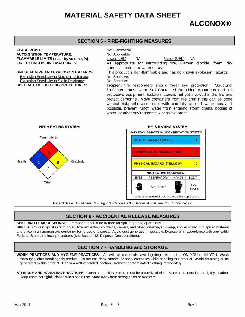
MATERIAL SAFETY DATA SHEET ALCONOX®
May 2011 Page 3 of 7 Rev 1
SECTION 5 - FIRE-FIGHTING MEASURES
FLASH POINT: Not Flammable AUTOIGNITION TEMPERATURE: Not Applicable FLAMMABLE LIMITS (in air by volume, %): Lower (LEL): NA Upper (UEL): NA FIRE EXTINGUISHING MATERIALS: As appropriate for surrounding fire. Carbon dioxide, foam, dry
chemical, halon, or water spray. UNUSUAL FIRE AND EXPLOSION HAZARDS: This product is non-flammable and has no known explosion hazards.
Explosion Sensitivity to Mechanical Impact: Not Sensitive. Explosion Sensitivity to Static Discharge: Not Sensitive
SPECIAL FIRE-FIGHTING PROCEDURES: Incipient fire responders should wear eye protection. Structural firefighters must wear Self-Contained Breathing Apparatus and full protective equipment. Isolate materials not yet involved in the fire and protect personnel. Move containers from fire area if this can be done without risk; otherwise, cool with carefully applied water spray. If possible, prevent runoff water from entering storm drains, bodies of water, or other environmentally sensitive areas.
NFPA RATING SYSTEM HMIS RATING SYSTEM
HAZARDOUS MATERIAL IDENTIFICATION SYSTEM
Flammability HEALTH HAZARD (BLUE) 1
FLAMMABILITY HAZARD (RED) 0
Health
Reactivity
PHYSICAL HAZARD (YELLOW) 0
PROTECTIVE EQUIPMENT EYES RESPIRATORY HANDS BODY
Other
See Sect 8
See Sect 8
For Routine Industrial Use and Handling Applications
Hazard Scale: 0 = Minimal 1 = Slight 2 = Moderate 3 = Serious 4 = Severe * = Chronic hazard
SECTION 6 - ACCIDENTAL RELEASE MEASURES SPILL AND LEAK RESPONSE: Personnel should be trained for spill response operations. SPILLS: Contain spill if safe to do so. Prevent entry into drains, sewers, and other waterways. Sweep, shovel or vacuum spilled material and place in an appropriate container for re-use or disposal. Avoid dust generation if possible. Dispose of in accordance with applicable Federal, State, and local procedures (see Section 13, Disposal Considerations).
SECTION 7 - HANDLING and STORAGE
WORK PRACTICES AND HYGIENE PRACTICES: As with all chemicals, avoid getting this product ON YOU or IN YOU. Wash thoroughly after handling this product. Do not eat, drink, smoke, or apply cosmetics while handling this product. Avoid breathing dusts generated by this product. Use in a well-ventilated location. Remove contaminated clothing immediately.
STORAGE AND HANDLING PRACTICES: Containers of this product must be properly labeled. Store containers in a cool, dry location. Keep container tightly closed when not in use. Store away from strong acids or oxidizers.
0
-
0
1
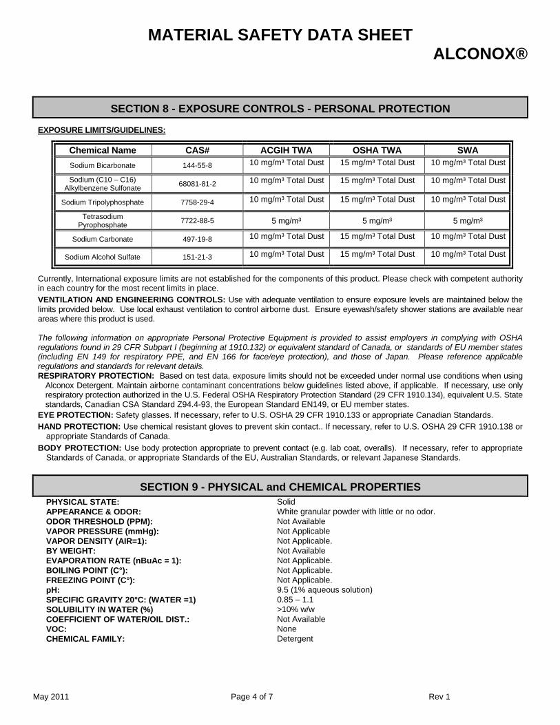
MATERIAL SAFETY DATA SHEET ALCONOX®
May 2011 Page 4 of 7 Rev 1
SECTION 8 - EXPOSURE CONTROLS - PERSONAL PROTECTION
EXPOSURE LIMITS/GUIDELINES:
Chemical Name CAS# ACGIH TWA OSHA TWA SWA
Sodium Bicarbonate 144-55-8 10 mg/m³ Total Dust 15 mg/m³ Total Dust 10 mg/m³ Total Dust
Sodium (C10 – C16) Alkylbenzene Sulfonate
68081-81-2 10 mg/m³ Total Dust 15 mg/m³ Total Dust 10 mg/m³ Total Dust
Sodium Tripolyphosphate 7758-29-4 10 mg/m³ Total Dust 15 mg/m³ Total Dust 10 mg/m³ Total Dust
Tetrasodium Pyrophosphate
7722-88-5 5 mg/m³ 5 mg/m³ 5 mg/m³
Sodium Carbonate 497-19-8 10 mg/m³ Total Dust 15 mg/m³ Total Dust 10 mg/m³ Total Dust
Sodium Alcohol Sulfate 151-21-3 10 mg/m³ Total Dust 15 mg/m³ Total Dust 10 mg/m³ Total Dust
Currently, International exposure limits are not established for the components of this product. Please check with competent authority in each country for the most recent limits in place.
VENTILATION AND ENGINEERING CONTROLS: Use with adequate ventilation to ensure exposure levels are maintained below the limits provided below. Use local exhaust ventilation to control airborne dust. Ensure eyewash/safety shower stations are available near areas where this product is used. The following information on appropriate Personal Protective Equipment is provided to assist employers in complying with OSHA regulations found in 29 CFR Subpart I (beginning at 1910.132) or equivalent standard of Canada, or standards of EU member states (including EN 149 for respiratory PPE, and EN 166 for face/eye protection), and those of Japan. Please reference applicable regulations and standards for relevant details. RESPIRATORY PROTECTION: Based on test data, exposure limits should not be exceeded under normal use conditions when using
Alconox Detergent. Maintain airborne contaminant concentrations below guidelines listed above, if applicable. If necessary, use only respiratory protection authorized in the U.S. Federal OSHA Respiratory Protection Standard (29 CFR 1910.134), equivalent U.S. State standards, Canadian CSA Standard Z94.4-93, the European Standard EN149, or EU member states.
EYE PROTECTION: Safety glasses. If necessary, refer to U.S. OSHA 29 CFR 1910.133 or appropriate Canadian Standards.
HAND PROTECTION: Use chemical resistant gloves to prevent skin contact.. If necessary, refer to U.S. OSHA 29 CFR 1910.138 or appropriate Standards of Canada.
BODY PROTECTION: Use body protection appropriate to prevent contact (e.g. lab coat, overalls). If necessary, refer to appropriate Standards of Canada, or appropriate Standards of the EU, Australian Standards, or relevant Japanese Standards.
SECTION 9 - PHYSICAL and CHEMICAL PROPERTIES PHYSICAL STATE: Solid APPEARANCE & ODOR: White granular powder with little or no odor. ODOR THRESHOLD (PPM): Not Available VAPOR PRESSURE (mmHg): Not Applicable VAPOR DENSITY (AIR=1): Not Applicable. BY WEIGHT: Not Available EVAPORATION RATE (nBuAc = 1): Not Applicable. BOILING POINT (C°): Not Applicable. FREEZING POINT (C°): Not Applicable. pH: 9.5 (1% aqueous solution) SPECIFIC GRAVITY 20°C: (WATER =1) 0.85 – 1.1 SOLUBILITY IN WATER (%) >10% w/w COEFFICIENT OF WATER/OIL DIST.: Not Available VOC: None CHEMICAL FAMILY: Detergent
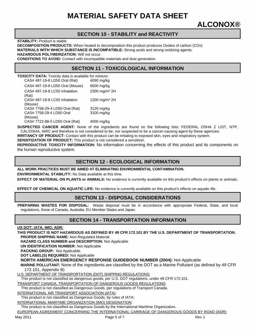
MATERIAL SAFETY DATA SHEET ALCONOX®
May 2011 Page 5 of 7 Rev 1
SECTION 10 - STABILITY and REACTIVITY STABILITY: Product is stable DECOMPOSITION PRODUCTS: When heated to decomposition this product produces Oxides of carbon (COx) MATERIALS WITH WHICH SUBSTANCE IS INCOMPATIBLE: Strong acids and strong oxidizing agents. HAZARDOUS POLYMERIZATION: Will not occur. CONDITIONS TO AVOID: Contact with incompatible materials and dust generation.
SECTION 11 - TOXICOLOGICAL INFORMATION
TOXICITY DATA: Toxicity data is available for mixture: CAS# 497-19-8 LD50 Oral (Rat) 4090 mg/kg CAS# 497-19-8 LD50 Oral (Mouse) 6600 mg/kg CAS# 497-19-8 LC50 Inhalation (Rat)
2300 mg/m³ 2H
CAS# 497-19-8 LC50 Inhalation (Mouse)
1200 mg/m³ 2H
CAS# 7758-29-4 LD50 Oral (Rat) 3120 mg/kg CAS# 7758-29-4 LD50 Oral (Mouse)
3100 mg/kg
CAS# 7722-88-5 LD50 Oral (Rat) 4000 mg/kg SUSPECTED CANCER AGENT: None of the ingredients are found on the following lists: FEDERAL OSHA Z LIST, NTP,
CAL/OSHA, IARC and therefore is not considered to be, nor suspected to be a cancer-causing agent by these agencies. IRRITANCY OF PRODUCT: Contact with this product can be irritating to exposed skin, eyes and respiratory system. SENSITIZATION OF PRODUCT: This product is not considered a sensitizer. REPRODUCTIVE TOXICITY INFORMATION: No information concerning the effects of this product and its components on the human reproductive system.
SECTION 12 - ECOLOGICAL INFORMATION ALL WORK PRACTICES MUST BE AIMED AT ELIMINATING ENVIRONMENTAL CONTAMINATION. ENVIRONMENTAL STABILITY: No Data available at this time.
EFFECT OF MATERIAL ON PLANTS or ANIMALS: No evidence is currently available on this product’s effects on plants or animals.
EFFECT OF CHEMICAL ON AQUATIC LIFE: No evidence is currently available on this product’s effects on aquatic life.
SECTION 13 - DISPOSAL CONSIDERATIONS
PREPARING WASTES FOR DISPOSAL: Waste disposal must be in accordance with appropriate Federal, State, and local regulations, those of Canada, Australia, EU Member States and Japan.
SECTION 14 - TRANSPORTATION INFORMATION
US DOT; IATA; IMO; ADR: THIS PRODUCT IS NOT HAZARDOUS AS DEFINED BY 49 CFR 172.101 BY THE U.S. DEPARTMENT OF TRANSPORTATION.
PROPER SHIPPING NAME: Non-Regulated Material HAZARD CLASS NUMBER and DESCRIPTION: Not Applicable UN IDENTIFICATION NUMBER: Not Applicable PACKING GROUP: Not Applicable. DOT LABEL(S) REQUIRED: Not Applicable NORTH AMERICAN EMERGENCY RESPONSE GUIDEBOOK NUMBER (2004): Not Applicable MARINE POLLUTANT: None of the ingredients are classified by the DOT as a Marine Pollutant (as defined by 49 CFR
172.101, Appendix B) U.S. DEPARTMENT OF TRANSPORTATION (DOT) SHIPPING REGULATIONS:
This product is not classified as dangerous goods, per U.S. DOT regulations, under 49 CFR 172.101. TRANSPORT CANADA, TRANSPORTATION OF DANGEROUS GOODS REGULATIONS:
This product is not classified as Dangerous Goods, per regulations of Transport Canada. INTERNATIONAL AIR TRANSPORT ASSOCIATION (IATA):
This product is not classified as Dangerous Goods, by rules of IATA: INTERNATIONAL MARITIME ORGANIZATION (IMO) DESIGNATION:
This product is not classified as Dangerous Goods by the International Maritime Organization. EUROPEAN AGREEMENT CONCERNING THE INTERNATIONAL CARRIAGE OF DANGEROUS GOODS BY ROAD (ADR):
MATERIAL SAFETY DATA SHEET ALCONOX®
May 2011 Page 6 of 7 Rev 1
This product is not classified by the United Nations Economic Commission for Europe to be dangerous goods.
SECTION 15 - REGULATORY INFORMATION
UNITED STATES REGULATIONS SARA REPORTING REQUIREMENTS: This product is not subject to the reporting requirements of Sections 302, 304 and 313 of
Title III of the Superfund Amendments and Reauthorization Act., as follows: None TSCA: All components in this product are listed on the US Toxic Substances Control Act (TSCA) inventory of chemicals. SARA 311/312:
Acute Health: Yes Chronic Health: No Fire: No Reactivity: No
U.S. SARA THRESHOLD PLANNING QUANTITY: There are no specific Threshold Planning Quantities for this product. The default Federal MSDS submission and inventory requirement filing threshold of 10,000 lb (4,540 kg) may apply, per 40 CFR 370.20.
U.S. CERCLA REPORTABLE QUANTITY (RQ): None CALIFORNIA SAFE DRINKING WATER AND TOXIC ENFORCEMENT ACT (PROPOSITION 65): None of the ingredients are on
the California Proposition 65 lists.
CANADIAN REGULATIONS: CANADIAN DSL/NDSL INVENTORY STATUS: All of the components of this product are on the DSL Inventory CANADIAN ENVIRONMENTAL PROTECTION ACT (CEPA) PRIORITIES SUBSTANCES LISTS: No component of this product is
on the CEPA First Priorities Substance Lists. CANADIAN WHMIS CLASSIFICATION and SYMBOLS: This product is categorized as a Controlled Product, Hazard Class D2B as
per the Controlled Product Regulations
EUROPEAN ECONOMIC COMMUNITY INFORMATION:
EU LABELING AND CLASSIFICATION: Classification of the mixture according to Regulation (EC) No1272/2008. See section 2 for details.
AUSTRALIAN INFORMATION FOR PRODUCT:
AUSTRALIAN INVENTORY OF CHEMICAL SUBSTANCES (AICS) STATUS: All components of this product are listed on the AICS. STANDARD FOR THE UNIFORM SCHEDULING OF DRUGS AND POISONS: Not applicable.
JAPANESE INFORMATION FOR PRODUCT: JAPANESE MINISTER OF INTERNATIONAL TRADE AND INDUSTRY (MITI) STATUS: The components of this product are not
listed as Class I Specified Chemical Substances, Class II Specified Chemical Substances, or Designated Chemical Substances by the Japanese MITI.
INTERNATIONAL CHEMICAL INVENTORIES:
Listing of the components on individual country Chemical Inventories is as follows: Asia-Pac: Listed
Australian Inventory of Chemical Substances (AICS): Listed
Korean Existing Chemicals List (ECL): Listed
Japanese Existing National Inventory of Chemical Substances (ENCS): Listed
Philippines Inventory if Chemicals and Chemical Substances (PICCS): Listed
Swiss Giftliste List of Toxic Substances: Listed
U.S. TSCA: Listed
SECTION 16 - OTHER INFORMATION
PREPARED BY: Paul Eigbrett Global Safety Management, 10006 Cross Creek Blvd. Suite 440, Tampa, FL 33647
MATERIAL SAFETY DATA SHEET ALCONOX®
May 2011 Page 7 of 7 Rev 1
Disclaimer: To the best of Alconox, Inc. knowledge, the information contained herein is reliable and accurate as of this date; however, accuracy, suitability or completeness is not guaranteed and no warranties of any type either express or implied are provided. The information contained herein relates only to this specific product.
ANNEX: IDENTIFIED USES OF ALCONOX® AND DIRECTIONS FOR USE Used to clean: Healthcare instruments, laboratory ware, vacuum equipment, tissue culture ware, personal protective equipment, sampling apparatus, catheters, tubing, pipes, radioactive contaminated articles, optical parts, electronic components, pharmaceutical apparatus, cosmetics manufacturing equipment, metal castings, forgings and stampings, industrial parts, tanks and reactors. Authorized by USDA for use in federally inspected meat and poultry plants. Passes inhibitory residue test for water analysis. FDA certified. Used to remove: Soil, grit, grime, buffing compound, slime, grease, oils, blood, tissue, salts, deposits, particulates, solvents, chemicals, radioisotopes, radioactive contaminations, silicon oils, mold release agents. Surfaces cleaned: Corrosion inhibited formulation recommended for glass, metal, stainless steel, porcelain, ceramic, plastic, rubber and fiberglass. Can be used on soft metals such as copper, aluminum, zinc and magnesium if rinsed promptly. Corrosion testing may be advisable. Cleaning method: Soak, brush, sponge, cloth, ultrasonic, flow through clean-inplace. Will foam—not for spray or machine use. Directions: Make a fresh 1% solution (2 1/2 Tbsp. per gal., 1 1/4 oz. per gal. or 10 grams per liter) in cold, warm, or hot water. If available use warm water. Use cold water for blood stains. For difficult soils, raise water temperature and use more detergent. Clean by soak, circulate, wipe, or ultrasonic method. Not for spray machines, will foam. For nonabrasive scouring, make paste. Use 2% solution to soak frozen stopcocks. To remove silver tarnish, soak in 1% solution in aluminum container. RINSE THOROUGHLY—preferably with running water. For critical cleaning, do final or all rinsing in distilled, deionized, or purified water. For food contact surfaces, rinse with potable water. Used on a wide range of glass, ceramic, plastic, and metal surfaces. Corrosion testing may be advisable.
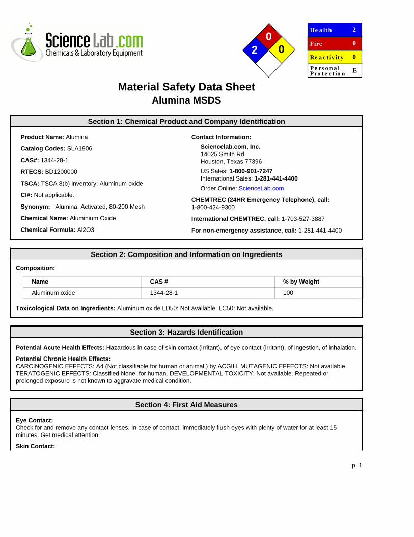
p. 1
0 2 0
He a lt h
Fire
Re a c t iv it y
Pe rs o n a lPro t e c t io n
2
0
0
E
Material Safety Data SheetAlumina MSDS
Section 1: Chemical Product and Company Identification
Product Name: Alumina
Catalog Codes: SLA1906
CAS#: 1344-28-1
RTECS: BD1200000
TSCA: TSCA 8(b) inventory: Aluminum oxide
CI#: Not applicable.
Synonym: Alumina, Activated, 80-200 Mesh
Chemical Name: Aluminium Oxide
Chemical Formula: Al2O3
Contact Information:
Sciencelab.com, Inc.14025 Smith Rd.Houston, Texas 77396
US Sales: 1-800-901-7247International Sales: 1-281-441-4400
Order Online: ScienceLab.com
CHEMTREC (24HR Emergency Telephone), call:1-800-424-9300
International CHEMTREC, call: 1-703-527-3887
For non-emergency assistance, call: 1-281-441-4400
Section 2: Composition and Information on Ingredients
Composition:
Name CAS # % by Weight
Aluminum oxide 1344-28-1 100
Toxicological Data on Ingredients: Aluminum oxide LD50: Not available. LC50: Not available.
Section 3: Hazards Identification
Potential Acute Health Effects: Hazardous in case of skin contact (irritant), of eye contact (irritant), of ingestion, of inhalation.
Potential Chronic Health Effects:CARCINOGENIC EFFECTS: A4 (Not classifiable for human or animal.) by ACGIH. MUTAGENIC EFFECTS: Not available.TERATOGENIC EFFECTS: Classified None. for human. DEVELOPMENTAL TOXICITY: Not available. Repeated orprolonged exposure is not known to aggravate medical condition.
Section 4: First Aid Measures
Eye Contact:Check for and remove any contact lenses. In case of contact, immediately flush eyes with plenty of water for at least 15minutes. Get medical attention.
Skin Contact:
p. 2
In case of contact, immediately flush skin with plenty of water. Cover the irritated skin with an emollient. Remove contaminatedclothing and shoes. Wash clothing before reuse. Thoroughly clean shoes before reuse. Get medical attention.
Serious Skin Contact:Wash with a disinfectant soap and cover the contaminated skin with an anti-bacterial cream. Seek medical attention.
Inhalation:If inhaled, remove to fresh air. If not breathing, give artificial respiration. If breathing is difficult, give oxygen. Get medicalattention.
Serious Inhalation: Not available.
Ingestion:Do NOT induce vomiting unless directed to do so by medical personnel. Never give anything by mouth to an unconsciousperson. If large quantities of this material are swallowed, call a physician immediately. Loosen tight clothing such as a collar,tie, belt or waistband.
Serious Ingestion: Not available.
Section 5: Fire and Explosion Data
Flammability of the Product: Non-flammable.
Auto-Ignition Temperature: Not applicable.
Flash Points: Not applicable.
Flammable Limits: Not applicable.
Products of Combustion: Not available.
Fire Hazards in Presence of Various Substances: Not applicable.
Explosion Hazards in Presence of Various Substances:Risks of explosion of the product in presence of mechanical impact: Not available. Risks of explosion of the product inpresence of static discharge: Not available.
Fire Fighting Media and Instructions: Not applicable.
Special Remarks on Fire Hazards: Chlorine Trifluoride reacts violently with Aluminum Oxide producing a flame.
Special Remarks on Explosion Hazards: Not available.
Section 6: Accidental Release Measures
Small Spill:Use appropriate tools to put the spilled solid in a convenient waste disposal container. Finish cleaning by spreading water onthe contaminated surface and dispose of according to local and regional authority requirements.
Large Spill:Use a shovel to put the material into a convenient waste disposal container. Finish cleaning by spreading water on thecontaminated surface and allow to evacuate through the sanitary system. Be careful that the product is not present at aconcentration level above TLV. Check TLV on the MSDS and with local authorities.
Section 7: Handling and Storage
Precautions:Do not breathe dust. Wear suitable protective clothing. In case of insufficient ventilation, wear suitable respiratory equipment. Ifyou feel unwell, seek medical attention and show the label when possible. Avoid contact with skin and eyes. Keep away fromincompatibles such as oxidizing agents, acids.
Storage: Keep container tightly closed. Keep container in a cool, well-ventilated area. Do not store above 24°C (75.2°F).
p. 3
Section 8: Exposure Controls/Personal Protection
Engineering Controls:Use process enclosures, local exhaust ventilation, or other engineering controls to keep airborne levels below recommendedexposure limits. If user operations generate dust, fume or mist, use ventilation to keep exposure to airborne contaminantsbelow the exposure limit.
Personal Protection:Splash goggles. Lab coat. Dust respirator. Be sure to use an approved/certified respirator or equivalent. Gloves.
Personal Protection in Case of a Large Spill:Splash goggles. Full suit. Dust respirator. Boots. Gloves. A self contained breathing apparatus should be used to avoidinhalation of the product. Suggested protective clothing might not be sufficient; consult a specialist BEFORE handling thisproduct.
Exposure Limits:TWA: 10 (mg/m3) from ACGIH (TLV) [United States] Inhalation Total. TWA: 10 (mg/m3) [Canada] Inhalation Total. TWA:5 (mg/m3) from OSHA (PEL) [United States] Inhalation Respirable. TWA: 15 from OSHA (PEL) [United States] InhalationTotal. TWA: 10 [United Kingdom (UK)] Inhalation Total. TWA: 4 [United Kingdom (UK)] Inhalation Respirable.Consult localauthorities for acceptable exposure limits.
Section 9: Physical and Chemical Properties
Physical state and appearance: Solid. (Solid crystalline powder.)
Odor: Odorless.
Taste: Not available.
Molecular Weight: 101.96 g/mole
Color: White.
pH (1% soln/water): Not applicable.
Boiling Point: 2980°C (5396°F)
Melting Point: 2072°C (3761.6°F)
Critical Temperature: Not available.
Specific Gravity: 4 (Water = 1)
Vapor Pressure: Not applicable.
Vapor Density: Not available.
Volatility: Not available.
Odor Threshold: Not available.
Water/Oil Dist. Coeff.: Not available.
Ionicity (in Water): Not available.
Dispersion Properties: Not available.
Solubility:Very slightly soluble in cold water. Insoluble in hot water. Practically insoluble in non-polar organic solvents. Slowly soluble inaqueous alkalie solution-forming hydroxides. Very slightly soluble in acid, alkali.
Section 10: Stability and Reactivity Data
Stability: The product is stable.
p. 4
Instability Temperature: Not available.
Conditions of Instability: Incompatible materials
Incompatibility with various substances: Reactive with oxidizing agents, acids.
Corrosivity: Non-corrosive in presence of glass.
Special Remarks on Reactivity:Chlorine Trifluoride reacts violently with Aluminum Oxide producing a flame. Ethylene oxide may polymerize violently when incontact with highly catalytic surfaces such as pure Aluminum Oxide. Reacts with hot chlorinated rubber.
Special Remarks on Corrosivity: Not available.
Polymerization: Will not occur.
Section 11: Toxicological Information
Routes of Entry: Inhalation. Ingestion.
Toxicity to Animals:LD50: Not available. LC50: Not available.
Chronic Effects on Humans:CARCINOGENIC EFFECTS: A4 (Not classifiable for human or animal.) by ACGIH. TERATOGENIC EFFECTS: ClassifiedNone. for human.
Other Toxic Effects on Humans: Hazardous in case of skin contact (irritant), of ingestion, of inhalation.
Special Remarks on Toxicity to Animals: Not available.
Special Remarks on Chronic Effects on Humans: May cause cancer (tumorigenic) according to animal data. No humandata found.
Special Remarks on other Toxic Effects on Humans:Acute Potential Health Effects: Skin: May cause skin irritation. Eyes: Nuissance Dust. Dust may cause mechanical eyeirritation. Inhalation: Nuissance Dust. Material is irritating to mucous membranes and upper respiratory tract. May causelung injury. Ingestion: May be harmful if swallowed. Ingestion of large amounts mat cause gastrointestinal tract irritation. It isexpected to be a low hazard for normal industrial handling.
Section 12: Ecological Information
Ecotoxicity: Not available.
BOD5 and COD: Not available.
Products of Biodegradation:Possibly hazardous short term degradation products are not likely. However, long term degradation products may arise.
Toxicity of the Products of Biodegradation: The product itself and its products of degradation are not toxic.
Special Remarks on the Products of Biodegradation: Not available.
Section 13: Disposal Considerations
Waste Disposal:Waste must be disposed of in accordance with federal, state and local environmental control regulations.
Section 14: Transport Information
p. 5
DOT Classification: Not a DOT controlled material (United States).
Identification: Not applicable.
Special Provisions for Transport: Not applicable.
Section 15: Other Regulatory Information
Federal and State Regulations:Illinois toxic substances disclosure to employee act: Aluminum oxide Rhode Island RTK hazardous substances: Aluminumoxide Minnesota: Aluminum oxide Massachusetts RTK: Aluminum oxide New Jersey: Aluminum oxide New Jersey spill list:Aluminum oxide California Director's list of Hazardous Substances: Aluminum oxide TSCA 8(b) inventory: Aluminum oxideSARA 313 toxic chemical notification and release reporting: Aluminum oxide
Other Regulations: EINECS: This product is on the European Inventory of Existing Commercial Chemical Substances.
Other Classifications:
WHMIS (Canada): Not controlled under WHMIS (Canada).
DSCL (EEC):R36/38- Irritating to eyes and skin. S2- Keep out of the reach of children. S46- If swallowed, seek medical advice immediatelyand show this container or label.
HMIS (U.S.A.):
Health Hazard: 2
Fire Hazard: 0
Reactivity: 0
Personal Protection: E
National Fire Protection Association (U.S.A.):
Health: 2
Flammability: 0
Reactivity: 0
Specific hazard:
Protective Equipment:Gloves. Lab coat. Dust respirator. Be sure to use an approved/certified respirator or equivalent. Splash goggles.
Section 16: Other Information
References:-Material safety data sheet emitted by: la Commission de la Santé et de la Sécurité du Travail du Québec. -The Sigma-AldrichLibrary of Chemical Safety Data, Edition II. -Hawley, G.G.. The Condensed Chemical Dictionary, 11e ed., New York N.Y., VanNostrand Reinold, 1987.
Other Special Considerations: Not available.
Created: 10/10/2005 12:47 AM
Last Updated: 05/21/2013 12:00 PM
The information above is believed to be accurate and represents the best information currently available to us. However, wemake no warranty of merchantability or any other warranty, express or implied, with respect to such information, and we assumeno liability resulting from its use. Users should make their own investigations to determine the suitability of the information for

p. 6
their particular purposes. In no event shall ScienceLab.com be liable for any claims, losses, or damages of any third party or forlost profits or any special, indirect, incidental, consequential or exemplary damages, howsoever arising, even if ScienceLab.comhas been advised of the possibility of such damages.
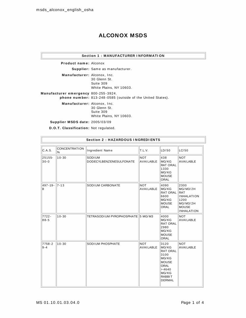
msds_alconox_english_osha
MS 01.10.01.03.04.0 Page 1 of 4
ALCONOX MSDS
Section 1 : MANUFACTURER INFORMATION
Product name: Alconox
Supplier: Same as manufacturer.
Manufacturer: Alconox, Inc. 30 Glenn St. Suite 309 White Plains, NY 10603.
Manufacturer emergency phone number:
800-255-3924. 813-248-0585 (outside of the United States).
Manufacturer: Alconox, Inc. 30 Glenn St. Suite 309 White Plains, NY 10603.
Supplier MSDS date: 2005/03/09
D.O.T. Classification: Not regulated.
Section 2 : HAZARDOUS INGREDIENTS
C.A.S. CONCENTRATION % Ingredient Name T.L.V. LD/50 LC/50
25155-30-0
10-30 SODIUM DODECYLBENZENESULFONATE
NOT AVAILABLE
438 MG/KG RAT ORAL 1330 MG/KG MOUSE ORAL
NOT AVAILABLE
497-19-8
7-13 SODIUM CARBONATE NOT AVAILABLE
4090 MG/KG RAT ORAL 6600 MG/KG MOUSE ORAL
2300 MG/M3/2H RAT INHALATION 1200 MG/M3/2H MOUSE INHALATION
7722-88-5
10-30 TETRASODIUM PYROPHOSPHATE 5 MG/M3 4000 MG/KG RAT ORAL 2980 MG/KG MOUSE ORAL
NOT AVAILABLE
7758-2 9-4
10-30 SODIUM PHOSPHATE NOT AVAILABLE
3120 MG/KG RAT ORAL 3100 MG/KG MOUSE ORAL >4640 MG/KG RABBIT DERMAL
NOT AVAILABLE
msds_alconox_english_osha
MS 01.10.01.03.04.0 Page 2 of 4
Section 2A : ADDITIONAL INGREDIENT INFORMATION
Note: (supplier). CAS# 497-19-8: LD50 4020 mg/kg - rat oral. CAS# 7758-29-4: LD50 3100 mg/kg - rat oral.
Section 3 : PHYSICAL / CHEMICAL CHARACTERISTICS
Physical state: Solid
Appearance & odor: Almost odourless. White granular powder.
Odor threshold (ppm): Not available.
Vapour pressure (mmHg):
Not applicable.
Vapour density (air=1): Not applicable.
By weight: Not available.
Evaporation rate (butyl acetate = 1):
Not applicable.
Boiling point (°C): Not applicable.
Freezing point (°C): Not applicable.
pH: (1% aqueous solution). 9.5
Specific gravity @ 20 °C: (water = 1). 0.85 - 1.10
Solubility in water (%): 100 - > 10% w/w
Coefficient of water\oil dist.:
Not available.
VOC: None
Section 4 : FIRE AND EXPLOSION HAZARD DATA
Flammability: Not flammable.
Conditions of flammability:
Surrounding fire.
Extinguishing media: Carbon dioxide, dry chemical, foam. Water Water fog.
Special procedures: Self-contained breathing apparatus required. Firefighters should wear the usual protective gear.
Auto-ignition temperature: Not available.
Flash point (°C), method:
None
Lower flammability limit (% vol): Not applicable.
Upper flammability limit (% vol):
Not applicable.
Not available.
Sensitivity to mechanical impact: Not applicable.
Hazardous combustion products:
Oxides of carbon (COx). Hydrocarbons.
Rate of burning: Not available.
Explosive power: None
msds_alconox_english_osha
MS 01.10.01.03.04.0 Page 3 of 4
Section 5 : REACTIVITY DATA
Chemical stability: Stable under normal conditions.
Conditions of instability: None known.
Hazardous polymerization:
Will not occur.
Incompatible substances:
Strong acids. Strong oxidizers.
Hazardous decomposition products:
See hazardous combustion products.
Section 6 : HEALTH HAZARD DATA
Route of entry: Skin contact, eye contact, inhalation and ingestion.
Effects of Acute Exposure
Eye contact: May cause irritation.
Skin contact: Prolonged contact may cause irritation.
Inhalation: Airborne particles may cause irritation.
Ingestion: May cause vomiting and diarrhea. May cause abdominal pain. May cause gastric distress.
Effects of chronic exposure:
Contains an ingredient which may be corrosive.
LD50 of product, species & route: > 5000 mg/kg rat oral.
LC50 of product, species & route:
Not available for mixture, see the ingredients section.
Exposure limit of material: Not available for mixture, see the ingredients section.
Sensitization to product: Not available.
Carcinogenic effects: Not listed as a carcinogen.
Reproductive effects: Not available.
Teratogenicity: Not available.
Mutagenicity: Not available.
Synergistic materials: Not available.
Medical conditions aggravated by exposure:
Not available.
First Aid
Skin contact: Remove contaminated clothing. Wash thoroughly with soap and water. Seek medical attention if irritation persists.
Eye contact: Check for and remove contact lenses. Flush eyes with clear, running water for 15 minutes while holding eyelids open: if irritation persists, consult a physician.
Inhalation: Remove victim to fresh air. Seek medical attention if symptoms persist.
Ingestion: Dilute with two glasses of water. Never give anything by mouth to an unconscious person. Do not induce vomiting, seek immediate medical attention.
msds_alconox_english_osha
MS 01.10.01.03.04.0 Page 4 of 4
Section 7 : PRECAUTIONS FOR SAFE HANDLING AND USE
Leak/Spill: Contain the spill. Recover uncontaminated material for re-use. Wear appropriate protective equipment. Contaminated material should be swept or shoveled into appropriate waste container for disposal.
Waste disposal: In accordance with municipal, provincial and federal regulations.
Handling procedures and equipment:
Protect against physical damage. Avoid breathing dust. Wash thoroughly after handling. Keep out of reach of children. Avoid contact with skin, eyes and clothing. Launder contaminated clothing prior to reuse.
Storage requirements: Keep containers closed when not in use. Store away from strong acids or oxidizers. Store in a cool, dry and well ventilated area.
Section 8 : CONTROL MEASURES
Precautionary Measures
Gloves/Type:
Neoprene or rubber gloves.
Respiratory/Type:
If exposure limit is exceeded, wear a NIOSH approved respirator.
Eye/Type:
Safety glasses with side-shields.
Footwear/Type: Safety shoes per local regulations.
Clothing/Type: As required to prevent skin contact.
Other/Type: Eye wash facility should be in close proximity. Emergency shower should be in close proximity.
Ventilation requirements:
Local exhaust at points of emission.
p. 1
0 1 0
He a lt h
Fire
Re a c t iv it y
Pe rs o n a lPro t e c t io n
2
0
0
H
Material Safety Data SheetArsenite Standard, 0.100 N Solution MSDS
Section 1: Chemical Product and Company Identification
Product Name: Arsenite Standard, 0.100 N Solution
Catalog Codes: SLA3832
CAS#: Mixture.
RTECS: Not applicable.
TSCA: TSCA 8(b) inventory: Water; Arsenic trioxide;Sodium hydroxide
CI#: Not applicable.
Synonym: Arsenite Standard, 0.100 N Solution
Chemical Name: Not applicable.
Chemical Formula: Not applicable.
Contact Information:
Sciencelab.com, Inc.14025 Smith Rd.Houston, Texas 77396
US Sales: 1-800-901-7247International Sales: 1-281-441-4400
Order Online: ScienceLab.com
CHEMTREC (24HR Emergency Telephone), call:1-800-424-9300
International CHEMTREC, call: 1-703-527-3887
For non-emergency assistance, call: 1-281-441-4400
Section 2: Composition and Information on Ingredients
Composition:
Name CAS # % by Weight
Water 7732-18-5 <100
Arsenic trioxide 1327-53-3 <0.5
Sodium hydroxide 1310-73-2 <0.3
Toxicological Data on Ingredients: Arsenic trioxide: ORAL (LD50): Acute: 14.6 mg/kg [Rat.]. 31.5 mg/kg [Mouse].
Section 3: Hazards Identification
Potential Acute Health Effects: Hazardous in case of skin contact (irritant), of eye contact (irritant), of ingestion.
Potential Chronic Health Effects:CARCINOGENIC EFFECTS: Classified A1 (Confirmed for human.) by ACGIH, 1 (Proven for human.) by IARC [Arsenictrioxide]. MUTAGENIC EFFECTS: Mutagenic for mammalian somatic cells. [Arsenic trioxide]. Mutagenic for mammaliansomatic cells. [Sodium hydroxide]. TERATOGENIC EFFECTS: Classified POSSIBLE for human [Arsenic trioxide].DEVELOPMENTAL TOXICITY: Not available. The substance may be toxic to blood, kidneys, liver, cardiovascular system,central nervous system (CNS). Repeated or prolonged exposure to the substance can produce target organs damage.
Section 4: First Aid Measures
p. 2
Eye Contact:Check for and remove any contact lenses. In case of contact, immediately flush eyes with plenty of water for at least 15minutes. Cold water may be used. Get medical attention.
Skin Contact:In case of contact, immediately flush skin with plenty of water. Cover the irritated skin with an emollient. Remove contaminatedclothing and shoes. Cold water may be used.Wash clothing before reuse. Thoroughly clean shoes before reuse. Get medicalattention.
Serious Skin Contact:Wash with a disinfectant soap and cover the contaminated skin with an anti-bacterial cream. Seek immediate medicalattention.
Inhalation:If inhaled, remove to fresh air. If not breathing, give artificial respiration. If breathing is difficult, give oxygen. Get medicalattention.
Serious Inhalation: Not available.
Ingestion:Do NOT induce vomiting unless directed to do so by medical personnel. Never give anything by mouth to an unconsciousperson. If large quantities of this material are swallowed, call a physician immediately. Loosen tight clothing such as a collar,tie, belt or waistband.
Serious Ingestion: Not available.
Section 5: Fire and Explosion Data
Flammability of the Product: Non-flammable.
Auto-Ignition Temperature: Not applicable.
Flash Points: Not applicable.
Flammable Limits: Not applicable.
Products of Combustion: Not available.
Fire Hazards in Presence of Various Substances: Not applicable.
Explosion Hazards in Presence of Various Substances: Non-explosive in presence of open flames and sparks, of shocks.
Fire Fighting Media and Instructions: Not applicable.
Special Remarks on Fire Hazards: Not available.
Special Remarks on Explosion Hazards:Arsenic trioxide + zinc will explode on heating. (Arsenic trioxide)
Section 6: Accidental Release Measures
Small Spill:Dilute with water and mop up, or absorb with an inert dry material and place in an appropriate waste disposal container.Finish cleaning by spreading water on the contaminated surface and dispose of according to local and regional authorityrequirements.
Large Spill:Absorb with an inert material and put the spilled material in an appropriate waste disposal. Finish cleaning by spreading wateron the contaminated surface and allow to evacuate through the sanitary system. Be careful that the product is not present at aconcentration level above TLV. Check TLV on the MSDS and with local authorities.
Section 7: Handling and Storage
p. 3
Precautions:Keep locked up.. Keep container dry. Do not ingest. Do not breathe gas/fumes/ vapor/spray. Never add water to this product.In case of insufficient ventilation, wear suitable respiratory equipment. If ingested, seek medical advice immediately and showthe container or the label. Avoid contact with skin and eyes.
Storage: Keep container tightly closed. Keep container in a cool, well-ventilated area. Do not store above 24°C (75.2°F).
Section 8: Exposure Controls/Personal Protection
Engineering Controls:Provide exhaust ventilation or other engineering controls to keep the airborne concentrations of vapors below their respectivethreshold limit value.
Personal Protection:Splash goggles. Lab coat. Vapor respirator. Be sure to use an approved/certified respirator or equivalent. Gloves.
Personal Protection in Case of a Large Spill:Splash goggles. Full suit. Vapor respirator. Boots. Gloves. A self contained breathing apparatus should be used to avoidinhalation of the product. Suggested protective clothing might not be sufficient; consult a specialist BEFORE handling thisproduct.
Exposure Limits:Arsenic trioxide TWA: 0.05 (mg(As)/m) [Canada] Sodium hydroxide STEL: 2 (mg/m3) from ACGIH (TLV) [United States] TWA:2 CEIL: 2 (mg/m3) from OSHA (PEL) [United States] CEIL: 2 (mg/m3) from NIOSHConsult local authorities for acceptableexposure limits.
Section 9: Physical and Chemical Properties
Physical state and appearance: Liquid.
Odor: Not available.
Taste: Not available.
Molecular Weight: Not applicable.
Color: Clear Colorless.
pH (1% soln/water): Neutral.
Boiling Point: The lowest known value is 100°C (212°F) (Water).
Melting Point: Not available.
Critical Temperature: Not available.
Specific Gravity: The only known value is 1 (Water = 1) (Water).
Vapor Pressure: The highest known value is 2.3 kPa (@ 20°C) (Water).
Vapor Density: The highest known value is 0.62 (Air = 1) (Water).
Volatility: Not available.
Odor Threshold: Not available.
Water/Oil Dist. Coeff.: Not available.
Ionicity (in Water): Not available.
Dispersion Properties: See solubility in water.
Solubility:Easily soluble in cold water, hot water. Very slightly soluble in diethyl ether.
p. 4
Section 10: Stability and Reactivity Data
Stability: The product is stable.
Instability Temperature: Not available.
Conditions of Instability: Incompatible materials
Incompatibility with various substances: Slightly reactive to reactive with oxidizing agents, metals, acids, alkalis.
Corrosivity: Non-corrosive in presence of glass.
Special Remarks on Reactivity:Dangerous when heated to decomposition. It emits toxic fumes of Arsenic. Dissolves in alkali to form arsenites. Incompatiblewith tannic acid, infusion of Chincona & other vegetable astringent infusions & decoctions, iron (in solution). Forms toxicvolatile halides in contact in contact with halide acids. Forms volatile, highly toxic Arsine when reduced in acid solution. Avigorous reaction occurs between Oxygen Difluoride, Aluminum Chloride and Arsenic Trioxide. Chlorine Trifluoride + ArsenicTrioxide produces a violent reaction without flame. Can generate Arsine, which is an extremely poisonous gas, when arseniccompounds contact acid, alkalies, or water in the presence of an active metal (zinc, aluminum, manganese, sodium, iron, etc.)(Arsenic trioxide)
Special Remarks on Corrosivity: Not available.
Polymerization: Will not occur.
Section 11: Toxicological Information
Routes of Entry: Absorbed through skin. Eye contact. Ingestion.
Toxicity to Animals:LD50: Not available. LC50: Not available.
Chronic Effects on Humans:CARCINOGENIC EFFECTS: Classified A1 (Confirmed for human.) by ACGIH, 1 (Proven for human.) by IARC [Arsenictrioxide]. MUTAGENIC EFFECTS: Mutagenic for mammalian somatic cells. [Arsenic trioxide]. Mutagenic for mammaliansomatic cells. [Sodium hydroxide]. TERATOGENIC EFFECTS: Classified POSSIBLE for human [Arsenic trioxide]. Containsmaterial which may cause damage to the following organs: blood, kidneys, liver, cardiovascular system, central nervoussystem (CNS).
Other Toxic Effects on Humans:Hazardous in case of skin contact (irritant), of ingestion, of inhalation. Slightly hazardous in case of skin contact (permeator).
Special Remarks on Toxicity to Animals: Not available.
Special Remarks on Chronic Effects on Humans:Passes through the placental barrier in human. May affect genetic material. May cause adverse reproductive (paternaland maternal effects as well as fetotoxicity or post implantation mortality) and birth defects (teratogen). May cause cancer(tumorigenic) (Arsenic trioxide)
Special Remarks on other Toxic Effects on Humans:Acute Potential Health Effects: Skin: May cause skin irritation. Eyes: May cause eye irritation. May also affect vision.Inhalation: May cause respiratory tract irritation with sore throat, coughing, shortness of breath, and delayed lung edema.Ingestion: May be fatal if swallowed. Causes severe digestive tract irritation. Symptoms may include garlic-like odor of breath,garlic taste, possible bloody diarrhea, Mee's Lines (transverse white lines on nails), abdominal pain, nausea, vomiting. Mayalso affect the liver, blood (anemia, hemolysis, pancytopenia), urinary tract (Kidneys), cardiovascular system (lowering ofblood pressure and changes in EKG), behavior/Central Nervous System, metabolsim, and brain. Chronic Potential HealthEffects:
Section 12: Ecological Information
Ecotoxicity: Not available.
p. 5
BOD5 and COD: Not available.
Products of Biodegradation:Possibly hazardous short term degradation products are not likely. However, long term degradation products may arise.
Toxicity of the Products of Biodegradation: The products of degradation are less toxic than the product itself.
Special Remarks on the Products of Biodegradation: Not available.
Section 13: Disposal Considerations
Waste Disposal:Waste must be disposed of in accordance with federal, state and local environmental control regulations.
Section 14: Transport Information
DOT Classification: Not a DOT controlled material (United States).
Identification: Not applicable.
Special Provisions for Transport: Not applicable.
Section 15: Other Regulatory Information
Federal and State Regulations:California prop. 65: This product contains the following ingredients for which the State of California has found to causecancer, birth defects or other reproductive harm, which would require a warning under the statute: Arsenic trioxide Californiaprop. 65: This product contains the following ingredients for which the State of California has found to cause birth defectswhich would require a warning under the statute: Arsenic trioxide California prop. 65: This product contains the followingingredients for which the State of California has found to cause cancer which would require a warning under the statute:Arsenic trioxide Connecticut hazardous material survey.: Arsenic trioxide Illinois toxic substances disclosure to employee act:Sodium hydroxide Illinois chemical safety act: Arsenic trioxide; Sodium hydroxide New York release reporting list: Arsenictrioxide; Sodium hydroxide Rhode Island RTK hazardous substances: Arsenic trioxide; Sodium hydroxide Pennsylvania RTK:Arsenic trioxide; Sodium hydroxide Minnesota: Sodium hydroxide Massachusetts RTK: Arsenic trioxide; Sodium hydroxideMassachusetts spill list: Arsenic trioxide New Jersey: Arsenic trioxide; Sodium hydroxide New Jersey spill list: Arsenictrioxide Louisiana RTK reporting list: Arsenic trioxide Louisiana spill reporting: Arsenic trioxide; Sodium hydroxide TSCA8(b) inventory: Water; Arsenic trioxide; Sodium hydroxide SARA 302/304/311/312 extremely hazardous substances: Arsenictrioxide
Other Regulations: OSHA: Hazardous by definition of Hazard Communication Standard (29 CFR 1910.1200).
Other Classifications:
WHMIS (Canada): Not controlled under WHMIS (Canada).
DSCL (EEC):R22- Harmful if swallowed. R45- May cause cancer. S2- Keep out of the reach of children. S46- If swallowed, seek medicaladvice immediately and show this container or label. S53- Avoid exposure - obtain special instructions before use.
HMIS (U.S.A.):
Health Hazard: 2
Fire Hazard: 0
Reactivity: 0
Personal Protection: h
National Fire Protection Association (U.S.A.):
p. 6
Health: 1
Flammability: 0
Reactivity: 0
Specific hazard:
Protective Equipment:Gloves. Lab coat. Vapor respirator. Be sure to use an approved/certified respirator or equivalent. Splash goggles.
Section 16: Other Information
References: Not available.
Other Special Considerations: Not available.
Created: 10/10/2005 12:50 AM
Last Updated: 05/21/2013 12:00 PM
The information above is believed to be accurate and represents the best information currently available to us. However, wemake no warranty of merchantability or any other warranty, express or implied, with respect to such information, and we assumeno liability resulting from its use. Users should make their own investigations to determine the suitability of the information fortheir particular purposes. In no event shall ScienceLab.com be liable for any claims, losses, or damages of any third party or forlost profits or any special, indirect, incidental, consequential or exemplary damages, howsoever arising, even if ScienceLab.comhas been advised of the possibility of such damages.
Page 1Bon Ami® Powder Cleanser RTN Number: 00004403 May 27, 2015
SAFETY DATA SHEET1. CHEMICAL PRODUCT AND COMPANY IDENTIFICATION Product Identification ______________________
Product Name: Bon Ami® Powder Cleanser Product Number: 04403, 04409, 04411, 04410, 04413,
04412, 04421, 04424, 04414, 04415, 04418 Synonyms: Bon Ami® Powder Cleanser, Bon
Ami® Kitchen & Bath Cleanser, Bon Ami Polishing Cleanser
Company Identification ______________________ Faultless Starch / Bon Ami Co. 1025 W 8th Street
Kansas City, MO 64101 USA 1-816-842-1230 (For product information) 1-800-424-9300 or 1-703-527-3887 (For emergencies)
2. HAZARDS IDENTIFICATION
NFPA Rating: Health - 1, Flammability - 0, Reactivity - 0
POTENTIAL HEALTH EFFECTS
INHALATION RISKS AND SYMPTOMS OF EXPOSURE: Not toxic according to Federal Hazardous Substance and Labeling Definition Act. Repeated or prolonged inhalation of respirable dust in excess of the PEL may cause chronic respiratory disorders.
Product Use: Hard Surface Cleaner
SKIN / EYE CONTACT RISKS AND SYMPTOMS OF EXPOSURE:Not a skin irritant. Contains Calcium Carbonate which is a mild eye irritant.
SKIN ABSORPTION RISKS AND SYMPTOMS OF EXPOSURE: None known.
Warning
Eye damage/irritation-category 1
Specific target organ toxicity-category 3
INGESTION RISKS AND SYMPTOMS OF EXPOSURE:Not toxic according to Federal Hazardous Substance and Labeling Act.HEALTH HAZARDS (ACUTE AND CHRONIC):Repeated prolonged inhalation of respirable dust in excess of the PEL may cause chronic respiratory disorders.CARCINOGENICITY INFORMATION:Not listed by IARC or NTP as a carcinogen.
MEDICAL CONDITIONS AGGRAVATED BY EXPOSURE: None known.
Bon Ami® Powder Cleanser Page 2RTN Number: 00004403 May 27, 2015____________________________________________________________________________________________________
4. FIRST AID MEASURES
EYE CONTACT FIRST AID: Hold eyelids apart and flush eyes with plenty of water for at least 15 minutes. Get medical attention if irritation persists.
INHALATION FIRST AID: If exposed to excessive levels of dust, remove to fresh air.
5. FIRE FIGHTING MEASURES
FLAMMABLE PROPERTIES COC Flash Point: N/A Autoignition Temperature: N/A
FLAMMABLE LIMITS IN AIR LEL: N/A UEL: N/A
FLAMMABLE PROPERTIES: Active ingredient is not flammable, but packaging material will burn.
EXTINGUISHING MEDIA: Water, carbon dioxide, foam or dry powder.
3. COMPOSITION/INFORMATION ON INGREDIENTS
_____________Chemical Name CALCIUM CARBONATE SODIUM CARBONATE FELDSPAR
__________CAS Number 1317-65-3 497-19-8
68476-25-5
________Amount Confidential Confidential Confidential
(See Section 8 for exposure guidelines)
(See Section 15 for regulatory information)
Bon Ami® Powder Cleanser Page 3RTN Number: 00004403 May 27, 2015____________________________________________________________________________________________________
(section 5 continued)
SPECIAL FIRE FIGHTING PROCEDURES: As in any fire, wear self-contained breathing apparatus pressure-demand MSHA/NIOSH (approved or equivalent) and full protective gear.
UNUSUAL FIRE AND EXPLOSION HAZARDS: No known unusual hazards in a fire/explosion situation.
6. ACCIDENTAL RELEASE MEASURES
ACTIONS IF MATERIAL IS RELEASED OR SPILLED: If uncontaminated, recover and reuse. Avoid causing dust in air. If contaminated, collect in suitable containers for disposal.
7. HANDLING AND STORAGE
PRECAUTIONS TO BE TAKEN IN HANDLING AND STORAGE: Avoid breathing dust. Avoid contact with eyes. Store in a cool, dry area.
OTHER PRECAUTIONS: Read and follow label CAUTIONS carefully.
8. EXPOSURE CONTROLS / PERSONAL PROTECTION
RESPIRATORY PROTECTION: Use approved NIOSH/MSHA respirator if dust exceeds PEL.
VENTILATION: Local exhaust to take dust away from user.
PROTECTIVE GLOVES: Not required.
EYE PROTECTION: Wear approved safety glasses.
OTHER PROTECTIVE CLOTHING OR EQUIPMENT: None required.
WORK / HYGIENIC PRACTICES: Observe reasonable care, cleanliness, and caution.
Bon Ami® Powder Cleanser Page 4RTN Number: 00004403 May 27, 2015____________________________________________________________________________________________________
(section 8 continued)
EXPOSURE GUIDELINES:CALCIUM CARBONATE
OSHA PEL: Total dust 15mg/m^3 / Respirable dust 5 mg/m^3ACGIH TWA: Total dust 10 mg/m^3
SODIUM CARBONATEOSHA PEL: 5 mg/m^3
FELDSPAROSHA TWA: (Respirable) 0.1 mg/m^3ACGIH TWA: (Respirable) 0.1 mg/m^3
9. PHYSICAL AND CHEMICAL PROPERTIES
FORM ..................: Powder COLOR .................: White ODOR ..................: Pleasant to non-existent odor SOLUBILITY IN WATER ...: 10% BULK DENSITY ..........: 0.9 g/ml PH ....................: ~10 for a 1% solution in water
10. STABILITY AND REACTIVITY
STABILITY:Stable.
CONDITIONS TO AVOID:Exposure to acids will generate carbon dioxide.
INCOMPATIBILITY (MATERIALS TO AVOID):Strong mineral acids.
HAZARDOUS DECOMPOSITION OR BYPRODUCTS:Reacts with acid to produce carbon dioxide or carbon monoxide.
HAZARDOUS POLYMERIZATION:Will not occur.
11. TOXICOLOGICAL INFORMATION
No information available.
12. ECOLOGICAL INFORMATION
No information available.
Bon Ami® Powder Cleanser Page 5RTN Number: 00004403 May 27, 2015____________________________________________________________________________________________________
13. DISPOSAL CONSIDERATIONS
WASTE DISPOSAL METHOD:Not a hazardous substance under the solid waste disposal act. May be disposed of in an approved land disposal facility in accordance with federal, state and local regulations.
14. TRANSPORTATION INFORMATION
PRODUCT LABEL.........: Bon Ami® Powder CleanserD.O.T. HAZARD CLASS...: Not Regulated
15. REGULATORY INFORMATION
CHEMICAL INVENTORY INFORMATION:This material or all of its components are listed on the Inventory of Existing Chemical Substances under the Toxic Substance Control Act (TSCA).
MISCELLANEOUS INFORMATION:No toxic chemical(s) subject to the reporting requirements of section 313 Title III and of 40 CFR 372 are present.
16. OTHER INFORMATION
Reason For Issue...: GHS updateApproval Date......: May 27, 2015Supercedes Date....: October 9, 2013RTN Number.........: 00004403 (Official Copy)
**********************************************************************The information accumulated herein is believed to be accurate but is not warranted to be whether originating with the company or not. Recipients are advised to confirm in advance of need that the information is current, applicable and suitable to their circumstances.
********************************************************************** END OF SDS
**********************************************************************
World HeadquartersHach CompanyP.O.Box 389 MSDS No: M01892Loveland, CO USA 80539(970) 669-3050
MATERIAL SAFETY DATA SHEET_____________________________________________________________________________1. CHEMICAL PRODUCT AND COMPANY IDENTIFICATION
Product Name: Arsenic Test StripsCatalog Number: 2800150
Hach Company Emergency Telephone Numbers:P.O.Box 389 (Medical and Transportation)Loveland, CO USA 80539 (303) 623-5716 24 Hour Service(970) 669-3050 (515)232-2533 8am - 4pm CST
MSDS Number: M01892Chemical Name: Not applicableCAS No.: Not applicableChemical Formula: Not applicableChemical Family: Not applicableHazard: Highly toxic. Experimental carcinogen. Cumulative poison. Harmful if absorbed through skin.Harmful if swallowedDate of MSDS Preparation:
Day: 25Month: AugustYear: 2007
_____________________________________________________________________________2. COMPOSITION / INFORMATION ON INGREDIENTS
Mercuric Bromide Saturated PaperCAS No.: Not applicableTSCA CAS Number: Not applicablePercent Range: 100.0Percent Range Units: weight / weightLD50: None reportedLC50: None reportedTLV: Not establishedPEL: Not establishedHazard: Highly toxic. Experimental carcinogen. Cumulative poison. Harmful if absorbed through skin.Harmful if swallowed
_____________________________________________________________________________3. HAZARDS IDENTIFICATION
Emergency Overview:Appearance: White paperOdor: None
HARMFUL IF SWALLOWED OR ABSORBED THROUGH SKINPOSSIBLE BIRTH DEFECT HAZARD: MAY CAUSE BIRTH DEFECTS BASED ON ANIMAL
DATA CAN CAUSE LUNG AND KIDNEY DISEASE
HMIS:
Health: 4Flammability: 0Reactivity: 0Protective Equipment: X - See protective equipment, Section 8.
NFPA:Health: 4Flammability: 0Reactivity: 0Symbol: Not applicable
Potential Health Effects:Eye Contact: May cause irritiationSkin Contact: May cause irritiationSkin Absorption: Will be absorbed through the skin. Effects similar to those of ingestion
Target Organs: Central nervous system Liver KidneysIngestion: Highly toxic. Causes: abdominal pain nausea vomiting diarrhea metallic taste rapid pulseand respirations weakness May cause: inflammation of the mouth increased urinary output excessivesalivation liver damage kidney damage central nervous system effects collapse death
Target Organs: Central nervous system Liver KidneysInhalation: Toxic. May cause: Effects similar to those of ingestion.
Target Organs: Central nervous system Kidneys LiverMedical Conditions Aggravated: Allergies or sensitivity to mercury. Central nervous system diseasesKidney conditions Liver conditions Pre-existing: Eye conditions Skin conditions Respiratory conditionsChronic Effects: Mercury can cause personality changes such as: depression, despondency, fearfulness,restlessness, irritability, timidness, indecision and embarrassment. Mercury is a general protoplasmicpoison; it circulates in the blood and is stored in the liver, kidneys, spleen and bones. Main symptoms aresore mouth, tremors and psychic disturbances.Cancer / Reproductive Toxicity Information:
This product does NOT contain any OSHA listed carcinogens.
IARC Group 3: Non-classifiableMercury and Inorganic Mercury compoundsThis product does NOT contain any NTP listed chemicals.
Additional Cancer / Reproductive Toxicity Information: an experimental teratogen. an experimentalmutagen.
Toxicologically Synergistic Products: None reported_____________________________________________________________________________4. FIRST AID
Eye Contact: Flush eyes with water. Call physician if irritation develops.Skin Contact (First Aid): Wash skin with plenty of water. Call physician if irritation develops.Ingestion (First Aid): Give large quantities of water or milk. Induce vomiting using syrup of ipecac or bysticking finger down throat. Call physician immediately. Never give anything by mouth to an unconsciousperson.Inhalation: None required.
_____________________________________________________________________________5. FIRE FIGHTING MEASURES
Flammable Properties: Can burn in fire, releasing toxic vapors.Flash Point: Not determinedMethod: Not applicableFlammability Limits:
Lower Explosion Limits: Not applicableUpper Explosion Limits: Not applicable
Autoignition Temperature: Not determined
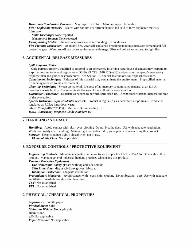
Hazardous Combustion Products: May vaporize to form Mercury vapor. bromidesFire / Explosion Hazards: Reacts with sodium aci-nitromethanide and acid to form explosive mercuryfulminate.
Static Discharge: None reported.Mechanical Impact: None reported
Extinguishing Media: Use media appropriate to surrounding fire conditionsFire Fighting Instruction: As in any fire, wear self-contained breathing apparatus pressure-demand and fullprotective gear. Water runoff can cause environmental damage. Dike and collect water used to fight fire.
_____________________________________________________________________________6. ACCIDENTAL RELEASE MEASURES
Spill Response Notice:Only persons properly qualified to respond to an emergency involving hazardous substances may respond to
a spill according to federal regulations (OSHA 29 CFR 1910.120(a)(v)) and per your company's emergencyresponse plan and guidelines/procedures. See Section 13, Special Instructions for disposal assistance.Containment Technique: Releases of this material may contaminate the environment. Stop spilled materialfrom being released to the environment.Clean-up Technique: Sweep up material. Dispose of all mercury contaminated material at an E.P.A.hazardous waste facility. Decontaminate the area of the spill with a soap solution.Evacuation Procedure: Evacuate as needed to perform spill clean-up. If conditions warrant, increase the sizeof the evacuation.Special Instructions (for accidental release): Product is regulated as a hazardous air pollutant. Product isregulated as RCRA hazardous waste.304 EHS RQ (40 CFR 355): Mercuric Bromide - RQ 1 lb.D.O.T. Emergency Response Guide Number: 154
_____________________________________________________________________________7. HANDLING / STORAGE
Handling: Avoid contact with skin eyes clothing Do not breathe dust. Use with adequate ventilation.Wash thoroughly after handling. Maintain general industrial hygiene practices when using this product.Storage: Keep container tightly closed when not in use.
Flammability Class: Not applicable_____________________________________________________________________________8. EXPOSURE CONTROLS / PROTECTIVE EQUIPMENT
Engineering Controls: Maintain adequate ventilation to keep vapor level below TWA for chemicals in thisproduct. Maintain general industrial hygiene practices when using this product.Personal Protective Equipment:
Eye Protection: safety glasses with top and side shieldsSkin Protection: disposable latex gloves lab coatInhalation Protection: adequate ventilation
Precautionary Measures: Avoid contact with: eyes skin clothing Do not breathe: dust Use with adequateventilation. Wash thoroughly after handling.TLV: Not establishedPEL: Not established
_____________________________________________________________________________9. PHYSICAL / CHEMICAL PROPERTIES
Appearance: White paperPhysical State: SolidMolecular Weight: Not applicableOdor: NonepH: Not applicableVapor Pressure: Not applicable
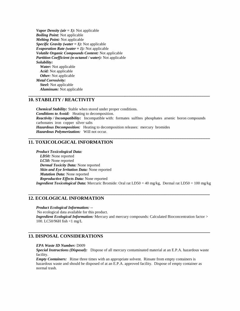
Vapor Density (air = 1): Not applicableBoiling Point: Not applicableMelting Point: Not applicableSpecific Gravity (water = 1): Not applicableEvaporation Rate (water = 1): Not applicableVolatile Organic Compounds Content: Not applicablePartition Coefficient (n-octanol / water): Not applicableSolubility:
Water: Not applicableAcid: Not applicableOther: Not applicable
Metal Corrosivity:Steel: Not applicableAluminum: Not applicable
_____________________________________________________________________________10. STABILITY / REACTIVITY
Chemical Stability: Stable when stored under proper conditions.Conditions to Avoid: Heating to decomposition.Reactivity / Incompatibility: Incompatible with: formates sulfites phosphates arsenic boron compoundscarbonates iron copper silver saltsHazardous Decomposition: Heating to decomposition releases: mercury bromidesHazardous Polymerization: Will not occur.
_____________________________________________________________________________11. TOXICOLOGICAL INFORMATION
Product Toxicological Data:LD50: None reportedLC50: None reportedDermal Toxicity Data: None reportedSkin and Eye Irritation Data: None reportedMutation Data: None reportedReproductive Effects Data: None reported
Ingredient Toxicological Data: Mercuric Bromide: Oral rat LD50 = 40 mg/kg, Dermal rat LD50 = 100 mg/kg
_____________________________________________________________________________12. ECOLOGICAL INFORMATION
Product Ecological Information: --No ecological data available for this product.
Ingredient Ecological Information: Mercury and mercury compounds: Calculated Bioconcentration factor >100. LC50/96H fish <1 mg/L
_____________________________________________________________________________13. DISPOSAL CONSIDERATIONS
EPA Waste ID Number: D009Special Instructions (Disposal): Dispose of all mercury contaminated material at an E.P.A. hazardous wastefacility.Empty Containers: Rinse three times with an appropriate solvent. Rinsate from empty containers ishazardous waste and should be disposed of at an E.P.A. approved facility. Dispose of empty container asnormal trash.

NOTICE (Disposal): These disposal guidelines are based on federal regulations and may be superseded bymore stringent state or local requirements. Please consult your local environmental regulators for moreinformation.
_____________________________________________________________________________14. TRANSPORT INFORMATION
D.O.T.:D.O.T. Proper Shipping Name: Mercury Bromides Mixture--
DOT Hazard Class: 6.1DOT Subsidiary Risk: NADOT ID Number: UN1634DOT Packing Group: II
I.C.A.O.:I.C.A.O. Proper Shipping Name: Mercury Bromides Mixture--
ICAO Hazard Class: 6.1ICAO Subsidiary Risk: NAICAO ID Number: UN1634ICAO Packing Group: II
I.M.O.:I.M.O. Proper Shipping Name: Mercury Bromides Mixture--
I.M.O. Hazard Class: 6.1I.M.O. Subsidiary Risk: NAI.M.O. ID Number: UN1634I.M.O. Packing Group: II
Additional Information: There is a possibility that this product could be contained in a reagent set or kitcomposed of various compatible dangerous goods. If the item is NOT in a set or kit, the classification givenabove applies. If the item IS part of a set or kit, the classification would change to the following: UN3316Chemical Kit, Class 9, PG II or III. If the item is not regulated, the Chemical Kit classification does not apply.
_____________________________________________________________________________15. REGULATORY INFORMATION
U.S. Federal Regulations:O.S.H.A.: This product meets the criteria for a hazardous substance as defined in the HazardCommunication Standard. (29 CFR 1910.1200)E.P.A.:
S.A.R.A. Title III Section 311/312 Categorization (40 CFR 370): Immediate (Acute) Health HazardDelayed (Chronic) Health HazardS.A.R.A. Title III Section 313 (40 CFR 372): This product contains a chemical(s) subject to thereporting requirements of Section 313 of Title III of SARA.Mercury Compounds
302 (EHS) TPQ (40 CFR 355): 500 lbs. Mercury Bromide304 CERCLA RQ (40 CFR 302.4): Not applicable304 EHS RQ (40 CFR 355): Mercuric Bromide - RQ 1 lb.Clean Water Act (40 CFR 116.4): Not applicableRCRA: Contains RCRA regulated substances. See Section 13, EPA Waste ID Number.
C.P.S.C.: Not applicableState Regulations:
California Prop. 65: WARNING - This product contains a chemical known to the State of California tocause birth defects or other reproductive harm.
Identification of Prop. 65 Ingredient(s): Mercury CompoundsCalifornia Perchlorate Rule CCR Title 22 Chap 33:
Trade Secret Registry: Not applicable
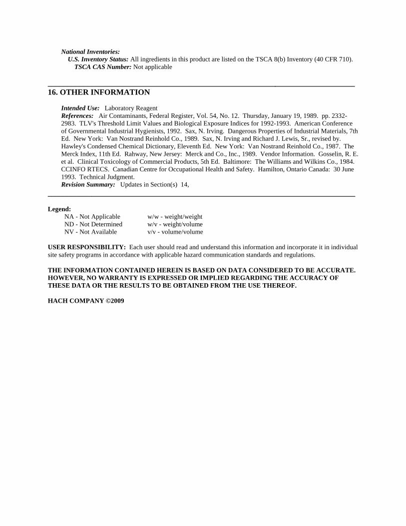
National Inventories:U.S. Inventory Status: All ingredients in this product are listed on the TSCA 8(b) Inventory (40 CFR 710).
TSCA CAS Number: Not applicable
_____________________________________________________________________________16. OTHER INFORMATION
Intended Use: Laboratory ReagentReferences: Air Contaminants, Federal Register, Vol. 54, No. 12. Thursday, January 19, 1989. pp. 2332-2983. TLV's Threshold Limit Values and Biological Exposure Indices for 1992-1993. American Conferenceof Governmental Industrial Hygienists, 1992. Sax, N. Irving. Dangerous Properties of Industrial Materials, 7thEd. New York: Van Nostrand Reinhold Co., 1989. Sax, N. Irving and Richard J. Lewis, Sr., revised by.Hawley's Condensed Chemical Dictionary, Eleventh Ed. New York: Van Nostrand Reinhold Co., 1987. TheMerck Index, 11th Ed. Rahway, New Jersey: Merck and Co., Inc., 1989. Vendor Information. Gosselin, R. E.et al. Clinical Toxicology of Commercial Products, 5th Ed. Baltimore: The Williams and Wilkins Co., 1984.CCINFO RTECS. Canadian Centre for Occupational Health and Safety. Hamilton, Ontario Canada: 30 June1993. Technical Judgment.Revision Summary: Updates in Section(s) 14,
_____________________________________________________________________________
Legend:NA - Not Applicable w/w - weight/weightND - Not Determined w/v - weight/volumeNV - Not Available v/v - volume/volume
USER RESPONSIBILITY: Each user should read and understand this information and incorporate it in individualsite safety programs in accordance with applicable hazard communication standards and regulations.
THE INFORMATION CONTAINED HEREIN IS BASED ON DATA CONSIDERED TO BE ACCURATE.HOWEVER, NO WARRANTY IS EXPRESSED OR IMPLIED REGARDING THE ACCURACY OFTHESE DATA OR THE RESULTS TO BE OBTAINED FROM THE USE THEREOF.
HACH COMPANY ©2009
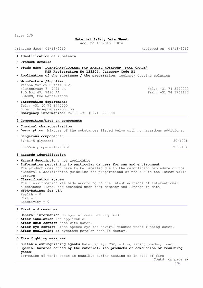
Page: 1/5Material Safety Data Sheet
acc. to ISO/DIS 11014
Printing date: 04/13/2010 Reviewed on: 04/13/2010
DR
1 Identification of substance
· Product details
· Trade name: LUBRICANT/COOLANT FOR BREDEL HOSEPUMP 'FOOD GRADE'NSF Registration No 123204, Category Code H1
· Application of the substance / the preparation: Coolant/ Cutting solution
· Manufacturer/Supplier:Watson-Marlow Bredel B.V.Sluisstraat 7, 7491 GA tel.: +31 74 3770000P.O.Box 47, 7490 AA fax.: +31 74 3761175DELDEN, the Netherlands
· Information department:Tel.: +31 (0)74 3770000E-mail: [email protected]
· Emergency information: Tel.: +31 (0)74 3770000
2 Composition/Data on components
· Chemical characterization· Description: Mixture of the substances listed below with nonhazardous additions.
· Dangerous components:56-81-5 glycerol 50-100%
57-55-6 propane-1,2-diol 2.5-10%
3 Hazards identification
· Hazard description: not applicable· Information pertaining to particular dangers for man and environmentThe product does not have to be labelled due to the calculation procedure of the"General Classification guideline for preparations of the EU" in the latest validversion.
· Classification systemThe classification was made according to the latest editions of internationalsubstances lists, and expanded upon from company and literature data.
· NFPA-Ratings for USAHealth = 0Fire = 1Reactivity = 0
4 First aid measures
· General information No special measures required.· After inhalation Not applicable.· After skin contact Wash with water.· After eye contact Rinse opened eye for several minutes under running water.· After swallowing If symptoms persist consult doctor.
5 Fire fighting measures
· Suitable extinguishing agents Water spray, CO2, extinguishing powder, foam.· Special hazards caused by the material, its products of combustion or resultinggases:Formation of toxic gases is possible during heating or in case of fire.
(Contd. on page 2) USA
Page: 2/5Material Safety Data Sheet
acc. to ISO/DIS 11014
Printing date: 04/13/2010 Reviewed on: 04/13/2010
Trade name: LUBRICANT/COOLANT FOR BREDEL HOSEPUMP 'FOOD GRADE'NSF Registration No 123204, Category Code H1
(Contd. of page 1)
DR
· Protective equipment: Wear fully protective suit.
6 Accidental release measures
· Person-related safety precautions: Not required.· Measures for environmental protection: Dilute with plenty of water.· Measures for cleaning/collecting:Absorb with liquid-binding material (sand, diatomite, acid binders, universalbinders, sawdust).Dispose of the collected material according to regulations.
7 Handling and storage
· Handling· Information for safe handling: No special measures required.· Information about protection against explosions and fires:No special measures required.
· Storage· Requirements to be met by storerooms and receptacles:Suitable material for receptacles: stainless and carbon steel and plastics.
· Information about storage in one common storage facility: Not required.· Further information about storage conditions:This product is hygroscopic.Protect from humidity and water.
8 Exposure controls and personal protection
· Components with limit values that require monitoring at the workplace:56-81-5 glycerolPEL 15*; 5** mg/m³
*Total dust **Respirable fraction
· Additional information:The lists that were valid during the creation were used as basis.
· Personal protective equipment· General protective and hygienic measuresThe usual precautionary measures for handling chemicals should be followed.
· Breathing equipment: Not required.· Protection of hands: Safety gloves recommended.· Material of glovesNeopreneNitrile rubber, NBRFluorocarbon rubber (Viton)
· Penetration time of glove materialThe determined penetration times according to EN 374 part III are not performedunder practical conditions. Therefore a maximum wearing time, which corresponds to50% of the penetration time, is recommended.
(Contd. on page 3) USA
Page: 3/5Material Safety Data Sheet
acc. to ISO/DIS 11014
Printing date: 04/13/2010 Reviewed on: 04/13/2010
Trade name: LUBRICANT/COOLANT FOR BREDEL HOSEPUMP 'FOOD GRADE'NSF Registration No 123204, Category Code H1
(Contd. of page 2)
DR
· For the permanent contact of a maximum of 15 minutes gloves made of the followingmaterials are suitable:Butyl rubber, BR
· Eye protection: Goggles recommended.
9 Physical and chemical properties
· General Information
Form: FluidColor: Clear
GreenOdor: Odorless
· Change in conditionBoiling point/Boiling range: 260°C (500°F)Solidification point: - 30°C
· Flash point: > 100°C (> 212°F) (ASTM D6450)
· Ignition temperature: ~ 370°C (~ 698°F)
· Danger of explosion: Product is not explosive. However, formation ofexplosive air/vapor mixtures are possible.
· Explosion limits:Lower: 2.6 Vol %Upper: 11.3 Vol %
· Vapor pressure at 20°C (68°F): 1.3 hPa (1 mm Hg)
· Density at 20°C (68°F): ~ 1.245 g/cm³ (ISO 2811-2)
· Solubility in / Miscibility withWater: Fully miscible
· Alcohols: Fully miscible
· pH-value: Neutral
· Viscosity:dynamic at 20°C (68°F): 600-700 mPas (ASTM D2196)
10 Stability and reactivity
· Thermal decomposition / conditions to be avoided:No decomposition if used according to specifications.
· Materials to be avoided: oxidizing agents· Dangerous products of decomposition: No dangerous decomposition products known
(Contd. on page 4) USA
Page: 4/5Material Safety Data Sheet
acc. to ISO/DIS 11014
Printing date: 04/13/2010 Reviewed on: 04/13/2010
Trade name: LUBRICANT/COOLANT FOR BREDEL HOSEPUMP 'FOOD GRADE'NSF Registration No 123204, Category Code H1
(Contd. of page 3)
DR
11 Toxicological information
· Acute toxicity:
· LD/LC50 values that are relevant for classification:· LD50 Product: oral: > 10000 mg/kg (rat, literature).
· Primary irritant effect:· on the skin: No irritant effect.· on the eye: No irritating effect.· Sensitization: No sensitizing effects known.
· Additional toxicological information:The product is not subject to classification according to internally approvedcalculation methods for preparations:When used and handled according to specifications, the product does not have anyharmful effects according to our experience and the information provided to us.
12 Ecological information
· Information about elimination (persistence and degradability):Easily biodegradableBiodegradability: > 85%.
· Acquatic toxicity:· fish toxicity: LC50: > 5000 mg/l, literature.
· Behavior in sewage processing plants:In case of judicious use the product does not cause disturbances in waterpurification plants, according to experiences made so far.
· Additional ecological information:
· General notes:Water hazard class 1 (German Regulation) (Self-assessment): slightly hazardous forwater.Do not allow undiluted product or large quantities of it to reach ground water,water course or sewage system.Classification according VwVwS dated May 1999. (German legislation)
13 Disposal considerations
· Product:· RecommendationMust not be disposed of together with household garbage. Do not allow product toreach sewage system.
· Uncleaned packagings:· Recommendation:With due observance of local regulations, for instance transport to refuseincinerator.
· Recommended cleansing agent: Water, if necessary with cleansing agents.(Contd. on page 5)
USA
Page: 5/5Material Safety Data Sheet
acc. to ISO/DIS 11014
Printing date: 04/13/2010 Reviewed on: 04/13/2010
Trade name: LUBRICANT/COOLANT FOR BREDEL HOSEPUMP 'FOOD GRADE'NSF Registration No 123204, Category Code H1
(Contd. of page 4)
DR
14 Transport information
· Transport/Additional information:Not dangerous according to the ADR/RID, IMDG, ICAO/IATA and DOT specifications.
15 Regulations
· Cancerogenity categories · EPA (Environmental Protection Agency)None of the ingredients is listed. · IARC (International Agency for Research on Cancer)None of the ingredients is listed. · NTP (National Toxicology Program)None of the ingredients is listed. · TLV (Threshold Limit Value established by ACGIH)None of the ingredients is listed. · MAK (German Maximum Workplace Concentration)None of the ingredients is listed. · NIOSH-Ca (National Institute for Occupational Safety and Health)None of the ingredients is listed. · OSHA-Ca (Occupational Safety & Health Administration)None of the ingredients is listed.
· Product related hazard informations:Observe the general safety regulations when handling chemicalsThe product is not subject to identification regulations according to directiveson hazardous materials.
· National regulations
· Water hazard class:Water hazard class 1 (Self-assessment): slightly hazardous for water.
16 Other informationDisclaimer of liability: the information in this MSDS was obtained from sourceswhich we believe are reliable. However, the information is provided without anywarranty, express or implied, regarding its correctness. The conditions or methodsof handling, storage, use or disposal of the product are beyond our control andmay be beyond our knowledge. For this and other reasons, we do not assumeresponsibility and expressly disclaim liability for loss, damage or expensearising out of or in any way connected with the handling, storage, use or disposalof the product. This MSDS was prepared and is to be used only for this product.If the product is used as a component in another product, this MSDS informationmay not be applicable.
USA
WARNING:Oil injected into the skin from high-pressure leaks can causesevere injury.Most damage occurs during the first few hours.Seek medical attention immediately.Surgical removal of oil may be necessary.Spills may create a slipping hazard.
0
1
1Health Hazard
Fire Hazard
Protective Equipment
Material Safety Data Sheet
Trade Name
Synonyms
Product Family
MSDS No.
CITGO A/W Hydraulic Oil 46
Hydraulic oil;CITGO® Material Code: 633420001
CITGO A/W Hydraulic Oil 46
Mixture.
633420001
SECTION 1. PRODUCT IDENTIFICATION
Product Number
CAS Number
633420001
Revision Date 11/4/2011
Hydraulic oil
Reactivity
HMIS
* = Chronic Health Hazard
CITGO Petroleum CorporationP.O. Box 4689Houston, TX 77210
0
1
0
Hazard Rankings
IMPORTANT: This MSDS is prepared in accordance with 29 CFR 1910.1200. Read thisMSDS before transporting, handling, storing or disposing of this product and forward thisinformation to employees, customers and users of this product.
CHEMTREC Emergency(United States Only)
(800) 424-9300
Emergency Overview
Technical Contact
Medical Emergency
NFPA
Color
Physical State Liquid.
Light amber Odor Mild petroleum odor
(800) 248-4684
(832) 486-4700
Minimum RecommendedSee Section 8 for Details
SECTION 2. COMPOSITION
Component Name(s)
Highly-refined petroleum lubricant oils Various 60 - 100Zinc and zinc compounds Proprietary <1Proprietary Ingredients Proprietary Mixture <1
CAS Registry No. Concentration (%)
SECTION 3. HAZARDS IDENTIFICATION
Also see Emergency Overview and Hazard Ratings on the top of Page 1 of this MSDS.
Signs and Symptoms of Acute Exposure
Inhalation
Eye Contact
At elevated temperatures or in enclosed spaces, product mist or vapors may irritate themucous membranes of the nose, the throat, bronchi, and lungs.
This product can cause transient mild eye irritation with short-term contact with liquid spraysor mists. Symptoms include stinging, watering, redness, and swelling.
Major Route(s) of Entry Skin contact.
Continued on Next Page Page Number: 1MSDS No. Revision Date 11/4/2011633420001
CITGO A/W Hydraulic Oil 46
Chronic Health EffectsSummary
This product contains a petroleum-based mineral oil. Prolonged or repeated skin contactcan cause mild irritation and inflammation characterized by drying, cracking, (dermatitis) oroil acne. Repeated or prolonged inhalation of petroleum-based mineral oil mists atconcentrations above applicable workplace exposure levels can cause respiratory irritation orother pulmonary effects.
Skin Contact
Ingestion
This material can cause mild skin irritation from prolonged or repeated skin contact.Injection under the skin can cause inflammation and swelling. Injection of pressurizedhydrocarbons can cause severe, permanent tissue damage. Initial symptoms may be minor.Injection of petroleum hydrocarbons requires immediate medical attention.
Target Organs May cause damage to the following organs: skin.
Carcinogenic Potential
Conditions Aggravatedby Exposure
Disorders of the following organs or organ systems that may be aggravated by significantexposure to this material or its components include: Skin
If swallowed, large volumes of material can cause generalized depression, headache,drowsiness, nausea, vomiting and diarrhea. Smaller doses can cause a laxative effect. Ifaspirated into the lungs, liquid can cause lung damage.
This product is not known to contain any components at concentrations above 0.1% whichare considered carcinogenic by OSHA, IARC or NTP.
OSHA Health Hazard Classification OSHA Physical Hazard Classification
Irritant Sensitizer
Corrosive
Toxic Highly Toxic
Carcinogenic
Combustible
Flammable
Compressed Gas
Explosive
Organic Peroxide
Water-reactive
Pyrophoric
Oxidizer
Unstable
OSHA Hazard Classification is indicated by an "X" in the box adjacent to the hazard title. If no "X" is present,the product does not exhibit the hazard as defined in the OSHA Hazard Communication Standard (29 CFR1910.1200).
Eye Contact
Skin Contact
Inhalation
Ingestion
Check for and remove contact lenses. Flush eyes with cool, clean, low-pressure water whileoccasionally lifting and lowering eyelids. Seek medical attention if excessive tearing, redness,or pain persists.
If burned by hot material, cool skin by quenching with large amounts of cool water. Forcontact with product at ambient temperatures, remove contaminated shoes and clothing.Wipe off excess material. Wash exposed skin with mild soap and water. Seek medicalattention if tissue appears damaged or if pain or irritation persists. Thoroughly cleancontaminated clothing before reuse. Clean or discard contaminated leather goods. If materialis injected under the skin, seek medical attention immediately.
Move victim to fresh air. If victim is not breathing, immediately begin rescue breathing. Ifbreathing is difficult, 100 percent humidified oxygen should be administered by a qualifiedindividual. Seek medical attention immediately. Keep the affected individual warm and atrest.
Do not induce vomiting unless directed to by a physician. Do not give anything to drink unlessdirected to by a physician. Never give anything by mouth to a person who is not fullyconscious. Seek medical attention immediately.
SECTION 4. FIRST AID MEASURES
Take proper precautions to ensure your own health and safety before attempting rescue or providing first aid.For more specific information, refer to Exposure Controls and Personal Protection in Section 8 of this MSDS.
Continued on Next Page Page Number: 2MSDS No. Revision Date 11/4/2011633420001
CITGO A/W Hydraulic Oil 46
Notes to Physician SKIN: In the event of injection in underlying tissue, immediate treatment should includeextensive incision, debridement and saline irrigation. Inadequate treatment can result inischemia and gangrene. Early symptoms may be minimal.
INGESTION: The viscosity range of the product(s) represented by this MSDS is greater than100 SUS at 100°F. Careful gastric lavage may be considered to evacuate large quantities ofmaterial.
NFPA FlammabilityClassification
AutoignitionTemperature
Hazardous CombustionProducts
Flash Point
Extinguishing Media
Lower Flammable Limit
Protection of FireFighters
Not available.
NFPA Class-IIIB combustible material.
Carbon dioxide, carbon monoxide, smoke, fumes, unburned hydrocarbons and oxides ofsulfur, phosphorus, zinc and/or nitrogen.
Open cup: 220°C (428°F) (Cleveland.).
No data.
Use dry chemical, foam, carbon dioxide or water fog. Water or foam may cause frothing.Carbon dioxide and inert gas can displace oxygen. Use caution when applying carbondioxide or inert gas in confined spaces.
Firefighters must use full bunker gear including NIOSH-approved positive pressureself-contained breathing apparatus to protect against potential hazardous combustion ordecomposition products and oxygen deficiencies.
This material can burn but will not readily ignite. This material will release vapors whenheated above the flash point temperature that can ignite when exposed to a source ofignition. In enclosed spaces, heated vapor can ignite with explosive force. Mists or spraysmay burn at temperatures below the flash point.
Special Properties
SECTION 5. FIRE FIGHTING MEASURES
Upper Flammable Limit No data.
SECTION 6. ACCIDENTAL RELEASE MEASURES
Do not touch damaged containers or spilled material unless wearing appropriate protectiveequipment. Slipping hazard; do not walk through spilled material. Stop leak if you can do sowithout risk. For small spills, absorb or cover with dry earth, sand, or other inertnon-combustible absorbent material and place into waste containers for later disposal.Contain large spills to maximize product recovery or disposal. Prevent entry into waterways orsewers. In urban area, cleanup spill as soon as possible. In natural environments, seekcleanup advice from specialists to minimize physical habitat damage. This material will floaton water. Absorbent pads and similar materials can be used. Comply with all laws andregulations.
Take proper precautions to ensure your own health and safety before attempting spill control or clean-up. Formore specific information, refer to the Emergency Overview on Page 1, Exposure Controls and PersonalProtection in Section 8 and Disposal Considerations in Section 13 of this MSDS.
Keep containers closed and do not handle or store near heat, sparks, or any other potentialignition sources. Avoid contact with oxidizing agents. Never siphon by mouth. Avoid contactwith eyes, skin, and clothing. Avoid contamination and extreme temperatures.
Empty containers may contain product residues that can ignite with explosive force. Drainand purge equipment, as necessary, to remove material residues. Follow proper entryprocedures, including compliance with 29 CFR 1910.146 prior to entering confined spacessuch as tanks or pits. Use appropriate respiratory protection when concentrations exceed any
Handling
SECTION 7. HANDLING AND STORAGE
Continued on Next Page Page Number: 3MSDS No. Revision Date 11/4/2011633420001
CITGO A/W Hydraulic Oil 46
Storage Keep container tightly closed. Store in a cool, dry, well-ventilated area. Store only inapproved containers. Do not store with strong oxidizing agents. Do not store at elevatedtemperatures. Avoid storing product in direct sunlight for extended periods of time. Storagearea must meet OSHA requirements and applicable fire codes. Consult appropriate federal,state and local authorities before reusing, reconditioning, reclaiming, recycling or disposing ofempty containers or waste residues of this product.
established occupational exposure level (See Section 8). Promptly remove contaminatedclothing. Wash exposed skin thoroughly with soap and water after handling.
Do not pressurize, cut, weld, braze solder, drill, grind or expose containers to flames, sparks,heat or other potential ignition sources. Protect containers against physical damage. Consultappropriate federal, state and local authorities before reusing, reconditioning, reclaiming,recycling or disposing of empty containers and/or waste residues of this product.
Engineering Controls
Personal ProtectiveEquipment
Provide exhaust ventilation or other engineering controls to keep the airborne concentrationsof mists and/or vapors below the recommended exposure limits (see below). An eye washstation and safety shower should be located near the work-station.
Occupational Exposure Guidelines
SECTION 8. EXPOSURE CONTROLS AND PERSONAL PROTECTION
Safety glasses equipped with side shields are recommended as minimum protection inindustrial settings. Wear goggles if splashing or spraying is anticipated. Wear goggles andface shield if material is heated above 125°F (51°C). Have suitable eye wash wateravailable.
None required for incidental contact. Use gloves constructed of chemical resistant materialssuch as heavy nitrile rubber if frequent or prolonged contact is expected. Useheat-protective gloves when handling product at elevated temperatures.
The need for respiratory protection is not anticipated under normal use conditions and withadequate ventilation. If elevated airborne concentrations above applicable workplaceexposure levels are anticipated, a NIOSH-approved organic vapor respirator equipped with adust/mist prefilter should be used. Protection factors vary depending upon the type ofrespirator used. Respirators should be used in accordance with OSHA requirements (29CFR 1910.134).
Eye Protection
Respiratory Protection
Use good personal hygiene practices. Wash hands and other exposed skin areas withplenty of mild soap and water before eating, drinking, smoking, use of toilet facilities, orleaving work. DO NOT use gasoline, kerosene, solvents or harsh abrasives as skincleaners. Since specific exposure standards/control limits have not been established for thisproduct, the "Oil Mist, Mineral" exposure limits shown below are suggested as minimumcontrol guidelines.
General Comments
Use clean protective clothing if splashing or spraying conditions are present. Protectiveclothing may include long-sleeve outer garment, apron, or lab coat. If significant contactoccurs, remove oil-contaminated clothing as soon as possible and promptly shower.Launder contaminated clothing before reuse or discard. Wear heat protective boots andprotective clothing when handling material at elevated temperatures.
Hand Protection
Body Protection
Substance Applicable Workplace Exposure Levels
Personal protective equipment should be selected based upon the conditions under whichthis material is used. A hazard assessment of the work area for PPE requirements shouldbe conducted by a qualified professional pursuant to OSHA regulations. The followingpictograms represent the minimum requirements for personal protective equipment. Forcertain operations, additional PPE may be required.
Continued on Next Page Page Number: 4MSDS No. Revision Date 11/4/2011633420001
CITGO A/W Hydraulic Oil 46
Oil, Mineral (Mist) ACGIH (United States). TWA: 5 mg/m 3
STEL: 10 mg/m 3
OSHA (United States). TWA: 5 mg/m 3
Not available.
SECTION 9. PHYSICAL AND CHEMICAL PROPERTIES (TYPICAL)
Volatility
Melting/FreezingPoint
Boiling Range
Vapor Pressure
Specific Gravity VaporDensity
Solubility inWater
Negligible volatility.
Not available.
0.87 (Water = 1) >1 (Air = 1)
<0.001 kPa (<0.01 mm Hg) (at 20°C)
Negligible solubility in cold water.
AdditionalProperties
Gravity, ºAPI (ASTM D287) = 30.4 @ 60º FDensity = 7.28 Lbs/gal.Viscosity (ASTM D2161) = 240 SUS @ 100º F
47Viscosity(cSt @ 40°C)
Physical State Liquid. Color Light amber Odor Mild petroleum odor
pH Not applicable
Flash Point Open cup: 220°C (428°F) (Cleveland.).
Conditions to Avoid
Chemical Stability
HazardousDecompositionProducts
Stable.
No additional hazardous decomposition products were identified other than the combustionproducts identified in Section 5 of this MSDS.
SECTION 10. STABILITY AND REACTIVITY
Keep away from extreme heat, sparks, open flame, and strongly oxidizing conditions.
MaterialsIncompatibility
Hazardous Polymerization Not expected to occur.
Strong oxidizers.
SECTION 11. TOXICOLOGICAL INFORMATION
For other health-related information, refer to the Emergency Overview on Page 1 and the Hazards Identificationin Section 3 of this MSDS.
Toxicity Data Highly-refined petroleum lubricant oils: ORAL (LD50): Acute: >5000 mg/kg [Rat]. DERMAL (LD50): Acute: >2000 mg/kg [Rabbit].
Mineral oil mists derived from highly refined oils are reported to have low acute and sub-acutetoxicities in animals. Effects from single and short-term repeated exposures to highconcentrations of mineral oil mists well above applicable workplace exposure levels includelung inflammatory reaction, lipoid granuloma formation and lipoid pneumonia. In acute andsub-acute studies involving exposures to lower concentrations of mineral oil mists at or nearcurrent work place exposure levels produced no significant toxicological effects. In long termstudies (up to two years) no carcinogenic effects have been reported in any animal speciestested.
Hydraulic oil:Repeated or prolonged skin contact with certain hydraulic oils can cause mild skin irritationcharacterized by drying, cracking (dermatitis) or oil acne. Injection under the skin, in muscleor into the blood stream can cause irritation, inflammation, swelling, fever, and systemic
Continued on Next Page Page Number: 5MSDS No. Revision Date 11/4/2011633420001
CITGO A/W Hydraulic Oil 46
effects, including mild central nervous system depression. Injection of pressurizedhydrocarbons can cause severe, permanent tissue damage.
SECTION 12. ECOLOGICAL INFORMATION
Biodegradability: Inherently biodegradable in aerobic conditions.
Partition Coefficient (log Kow): >6 (based on similar materials)
Photodegradation: Based on similar materials, this product will have little or no tendency topartition to air. Hydrocarbons from this product which do partition to air are expected torapidly photodegrade.
Stability in Water: Not readily susceptible to hydrolysis under aquatic conditions.
Distribution: Principally to soil and sediment. Petroleum-based (mineral) lubricating oilsnormally will float on water. In stagnant or slow-flowing waterways, an oil layer can cover alarge surface area. As a result, this oil layer might limit or eliminate natural atmosphericoxygen transport into the water. With time, if not removed, oxygen depletion in the waterwaymay be sufficient to cause a fish kill or create an anaerobic environment.
Analysis for ecological effects has not been conducted on this product. However, if spilled,this product and any contaminated soil or water may be harmful to human, animal, andaquatic life. Also, the coating action associated with petroleum and petroleum products canbe harmful or fatal to aquatic life and waterfowl.
Ecotoxicity
Environmental Fate
SECTION 13. DISPOSAL CONSIDERATIONS
Conditions of use may cause this material to become a "hazardous waste", as defined byfederal or state regulations. It is the responsibility of the user to determine if the material is a"hazardous waste" at the time of disposal. Transportation, treatment, storage, and disposalof waste material must be conducted in accordance with RCRA regulations (see 40 CFR 260through 40 CFR 271). State and/or local regulations may be more restrictive. Contact yourregional US EPA office for guidance concerning case specific disposal issues. Empty drumsand pails retain residue. DO NOT pressurize, cut, weld, braze, solder, drill, grind, or exposethis product's empty container to heat, flame, or other ignition sources. DO NOT attempt toclean it. Empty drums and pails should be drained completely, properly bunged or sealed,and promptly sent to a reconditioner.
Hazard characteristic and regulatory waste stream classification can change with product use. Accordingly, the responsibility of the user to determine the proper storage, transportation, treatment and/or disposalmethodologies for spent materials and residues at the time of disposition.
SECTION 14. TRANSPORT INFORMATION
Not regulated.
Placard(s)
Proper Shipping Name Not regulated.
Packing Group Not applicable.
A Reportable Quantity (RQ) has not been established for this material.Reportable Quantity
Hazard Class
Not regulated.UN/NA Number
US DOT Status Not regulated by the U.S. Department of Transportation as a hazardous material.
The shipping description below may not represent requirements for all modes of transportation, shippingmethods or locations outside of the United States.
Continued on Next Page Page Number: 6MSDS No. Revision Date 11/4/2011633420001
CITGO A/W Hydraulic Oil 46
MARPOL III Status
Emergency ResponseGuide No.
Not a DOT "MarinePollutant" per 49 CFR171.8.
Not applicable.
Oil: The product(s) represented by this MSDS is (are)regulated as “oil” under 49 CFR Part 130. Shipments byrail or highway in packaging having a capacity of 3500gallons or more or in a quantity greater 42,000 gallonsare subject to these requirements. In addition, mixturescontaining 10% or more of this product may be subject tothese requirements.
SECTION 15. REGULATORY INFORMATION
The Comprehensive Environmental Response, Compensation, and Liability Act of 1980(CERCLA) requires notification of the National Response Center concerning release ofquantities of "hazardous substances" equal to or greater than the reportable quantities (RQ's)listed in 40 CFR 302.4. As defined by CERCLA, the term "hazardous substance" does notinclude petroleum, including crude oil or any fraction thereof which is not otherwisespecifically designated in 40 CFR 302.4. Chemical substances present in this product orrefinery stream that may be subject to this statute are:Zinc and Zinc Compounds, Concentration: <1%
TSCA Inventory
SARA 302/304Emergency Planningand Notification
SARA 313 ToxicChemical Notificationand Release Reporting
CERCLA
CaliforniaProposition 65
This material may contain the following components which are known to the State of Californiato cause cancer, birth defects or other reproductive harm, and may be subject to therequirements of California Proposition 65 (CA Health & Safety Code Section 25249.5):Toluene: <0.001%Ethyl acrylate: <0.0005%
SARA 311/312 HazardIdentification
Additional Remarks
The Superfund Amendments and Reauthorization Act of 1986 (SARA) Title III requiresfacilities subject to this subpart to submit aggregate information on chemicals by "HazardCategory" as defined in 40 CFR 370.2. This material would be classified under the followinghazard categories:
Clean Water Act(CWA)
New JerseyRight-to-Know Label
This product and/or its components are listed on the Toxic Substances Control Act (TSCA)inventory.
No additional regulatory remarks.
Petroleum Oil (Hydraulic Oil)
No SARA 311/312 hazard categories identified.
This product contains the following components in concentrations above de minimis levelsthat are listed as toxic chemicals in 40 CFR Part 372 pursuant to the requirements of Section313 of SARA: No components were identified.
This material is classified as an oil under Section 311 of the Clean Water Act (CWA) and theOil Pollution Act of 1990 (OPA). Discharges or spills which produce a visible sheen on watersof the United States, their adjoining shorelines, or into conduits leading to surface waters mustbe reported to the EPA's National Response Center at (800) 424-8802.
The Superfund Amendments and Reauthorization Act of 1986 (SARA) Title III requiresfacilities subject to Subparts 302 and 304 to submit emergency planning and notificationinformation based on Threshold Planning Quantities (TPQs) and Reportable Quantities(RQs) for "Extremely Hazardous Substances" listed in 40 CFR 302.4 and 40 CFR 355. Nocomponents were identified.
Continued on Next Page Page Number: 7MSDS No. Revision Date 11/4/2011633420001
CITGO A/W Hydraulic Oil 46
SECTION 16. OTHER INFORMATION
Revision Date
REVISION INFORMATION
Version Number
11/4/2011
4.0
THE INFORMATION IN THIS MSDS WAS OBTAINED FROM SOURCES WHICH WE BELIEVE ARE RELIABLE.HOWEVER, THE INFORMATION IS PROVIDED WITHOUT ANY WARRANTY, EXPRESSED OR IMPLIEDREGARDING ITS CORRECTNESS. SOME INFORMATION PRESENTED AND CONCLUSIONS DRAWN HEREIN AFROM SOURCES OTHER THAN DIRECT TEST DATA ON THE SUBSTANCE ITSELF. THIS MSDS WAS PREPAREDAND IS TO BE USED ONLY FOR THIS PRODUCT. IF THE PRODUCT IS USED AS A COMPONENT IN ANOTHERPRODUCT, THIS MSDS INFORMATION MAY NOT BE APPLICABLE. USERS SHOULD MAKE THEIR OWNINVESTIGATIONS TO DETERMINE THE SUITABILITY OF THE INFORMATION OR PRODUCTS FOR THEIRPARTICULAR PURPOSE.
THE CONDITIONS OR METHODS OF HANDLING, STORAGE, USE, AND DISPOSAL OF THE PRODUCT AREBEYOND OUR CONTROL AND MAY BE BEYOND OUR KNOWLEDGE. FOR THIS AND OTHER REASONS, WE DONOT ASSUME RESPONSIBILITY AND EXPRESSLY DISCLAIM LIABILITY FOR LOSS, DAMAGE OR EXPENSEARISING OUT OF OR IN ANY WAY CONNECTED WITH HANDLING, STORAGE, USE OR DISPOSAL OF THEPRODUCT.
DISCLAIMER OF LIABILITY
ABBREVIATIONS
* * * * * END OF MSDS * * * * *
IARC: International Agency for Research on Cancer
NIOSH: National Institute of Occupational Safety and Health
Refer to the top of Page 1 for the HMIS and NFPA Hazard Ratings for this product.
NPCA: National Paint and Coating Manufacturers Association
NFPA: National Fire Protection Association
NTP: National Toxicology Program
OSHA: Occupational Safety and Health Administration
HMIS: Hazardous Materials Information System
EPA: US Environmental Protection Agency
AP: Approximately EQ: Equal >: Greater Than <: Less Than
NA: Not Applicable ND: No Data NE: Not Established
AIHA: American Industrial Hygiene Association
ACGIH: American Conference of Governmental Industrial Hygienists
p. 1
0 1 0
He a lt h
Fire
Re a c t iv it y
Pe rs o n a lPro t e c t io n
2
0
0
J
Material Safety Data SheetPotassium permanganate MSDS
Section 1: Chemical Product and Company Identification
Product Name: Potassium permanganate
Catalog Codes: SLP4912, SLP3892, SLP1075
CAS#: 7722-64-7
RTECS: SD6475000
TSCA: TSCA 8(b) inventory: Potassium permanganate
CI#: Not available.
Synonym: Potassium Permanganate, Biotech Grade
Chemical Name: Potassium Permanganate
Chemical Formula: KMnO4
Contact Information:
Sciencelab.com, Inc.14025 Smith Rd.Houston, Texas 77396
US Sales: 1-800-901-7247International Sales: 1-281-441-4400
Order Online: ScienceLab.com
CHEMTREC (24HR Emergency Telephone), call:1-800-424-9300
International CHEMTREC, call: 1-703-527-3887
For non-emergency assistance, call: 1-281-441-4400
Section 2: Composition and Information on Ingredients
Composition:
Name CAS # % by Weight
Potassium permanganate 7722-64-7 100
Toxicological Data on Ingredients: Potassium permanganate, Biotech: ORAL (LD50): Acute: 1090 mg/kg [Rat]. 2157 mg/kg[Mouse].
Section 3: Hazards Identification
Potential Acute Health Effects:Hazardous in case of skin contact (irritant), of eye contact (irritant), of ingestion, of inhalation. Slightly hazardous in case ofskin contact (permeator). Possibly corrosive to eyes and skin. The amount of tissue damage depends on length of contact.Eye contact can result in corneal damage or blindness. Skin contact can produce inflammation and blistering. Inhalation ofdust will produce irritation to gastro-intestinal or respiratory tract, characterized by burning, sneezing and coughing. Severeover-exposure can produce lung damage, choking, unconsciousness or death. Prolonged exposure may result in skin burnsand ulcerations. Over-exposure by inhalation may cause respiratory irritation.
Potential Chronic Health Effects:CARCINOGENIC EFFECTS: Not available. MUTAGENIC EFFECTS: Mutagenic for bacteria and/or yeast. TERATOGENICEFFECTS: Not available. DEVELOPMENTAL TOXICITY: Not available. The substance may be toxic to kidneys, liver, skin,central nervous system (CNS). Repeated or prolonged exposure to the substance can produce target organs damage.Repeated exposure of the eyes to a low level of dust can produce eye irritation. Repeated skin exposure can produce localskin destruction, or dermatitis. Repeated inhalation of dust can produce varying degree of respiratory irritation or lung damage.
p. 2
Section 4: First Aid Measures
Eye Contact:Check for and remove any contact lenses. In case of contact, immediately flush eyes with plenty of water for at least 15minutes. Cold water may be used. Get medical attention immediately.
Skin Contact:In case of contact, immediately flush skin with plenty of water for at least 15 minutes while removing contaminated clothingand shoes. Cover the irritated skin with an emollient. Cold water may be used.Wash clothing before reuse. Thoroughly cleanshoes before reuse. Get medical attention immediately.
Serious Skin Contact:Wash with a disinfectant soap and cover the contaminated skin with an anti-bacterial cream. Seek immediate medicalattention.
Inhalation:If inhaled, remove to fresh air. If not breathing, give artificial respiration. If breathing is difficult, give oxygen. Get medicalattention.
Serious Inhalation:Evacuate the victim to a safe area as soon as possible. Loosen tight clothing such as a collar, tie, belt or waistband. Ifbreathing is difficult, administer oxygen. If the victim is not breathing, perform mouth-to-mouth resuscitation. WARNING: It maybe hazardous to the person providing aid to give mouth-to-mouth resuscitation when the inhaled material is toxic, infectious orcorrosive. Seek immediate medical attention.
Ingestion:Do NOT induce vomiting unless directed to do so by medical personnel. Never give anything by mouth to an unconsciousperson. If large quantities of this material are swallowed, call a physician immediately. Loosen tight clothing such as a collar,tie, belt or waistband.
Serious Ingestion: Not available.
Section 5: Fire and Explosion Data
Flammability of the Product: Non-flammable.
Auto-Ignition Temperature: Not applicable.
Flash Points: Not applicable.
Flammable Limits: Not applicable.
Products of Combustion: Not available.
Fire Hazards in Presence of Various Substances: organic materials, metals, combustible materials
Explosion Hazards in Presence of Various Substances:Risks of explosion of the product in presence of mechanical impact: Not available. Risks of explosion of the product inpresence of static discharge: Not available. Explosive in presence of organic materials, of metals.
Fire Fighting Media and Instructions: Not applicable.
Special Remarks on Fire Hazards:Spontaneously flammable on contact with ethylene glycol. Potassium Permanganate being conveyed through propylene tubeignited the tube. When solid hydroxylamine is brought into contact with solid potassium permanganate, there is producedimmediately a with flame. Potassium permanganate decomposes hydrogen trisulfide so rapidly that sufficient heat is liberatedto ignite the trisulfide. When Antimony or arsenic and solid potassium permanganate are ground together, the metals ignite.
Special Remarks on Explosion Hazards:Take care in handling as explosions may occur if it is brought in contact with organic or other readily oxidizable substances,either in solution or in dry state. Explosive in contact with sulfuric acid or hydrogen peroxide. Potassium permanganate +acetic acid or acetic anhydride can explode if permanganate is not kept cold. Explosions can occur when permanganatescome on contact with benzene, carbon disulfide, diethyl ether, ethyl alcohol, petroleum, or oganic matter. Contact with glycerol
p. 3
may produce explosion. Crystals of potassium permanganate explode vigorously when ground with phosphorous. A mixtureof .5% potassium permanganate + ammonium nitrate explosive caused an explosion 7 hrs. later. Addition of Potassiumpermanganate + dimethylformamide to give a 20% solution led to an explosion after 5 min. During a preparation of chlorineby addition of the concentrated acid (Hydrochloric acid) to solid potassium permanganate, a sharp explosion occurred on oneoccasion.
Section 6: Accidental Release Measures
Small Spill: Use appropriate tools to put the spilled solid in a convenient waste disposal container.
Large Spill:Oxidizing material. Corrosive solid. Stop leak if without risk. Do not get water inside container. Avoid contact with acombustible material (wood, paper, oil, clothing...). Keep substance damp using water spray. Do not touch spilled material.Use water spray to reduce vapors. Prevent entry into sewers, basements or confined areas; dike if needed. Call for assistanceon disposal. Be careful that the product is not present at a concentration level above TLV. Check TLV on the MSDS and withlocal authorities.
Section 7: Handling and Storage
Precautions:Keep away from heat. Keep away from sources of ignition. Keep away from combustible material. Do not ingest. Do notbreathe dust. In case of insufficient ventilation, wear suitable respiratory equipment. If ingested, seek medical adviceimmediately and show the container or the label. Avoid contact with skin and eyes. Keep away from incompatibles such asorganic materials, metals, acids.
Storage:Keep container tightly closed. Keep container in a cool, well-ventilated area. Separate from acids, alkalies, reducing agentsand combustibles. See NFPA 43A, Code for the Storage of Liquid and Solid Oxidizers.
Section 8: Exposure Controls/Personal Protection
Engineering Controls:Use process enclosures, local exhaust ventilation, or other engineering controls to keep airborne levels below recommendedexposure limits. If user operations generate dust, fume or mist, use ventilation to keep exposure to airborne contaminantsbelow the exposure limit.
Personal Protection:Splash goggles. Synthetic apron. Vapor and dust respirator. Be sure to use an approved/certified respirator or equivalent.Gloves.
Personal Protection in Case of a Large Spill:Splash goggles. Full suit. Vapor and dust respirator. Boots. Gloves. A self contained breathing apparatus should be used toavoid inhalation of the product. Suggested protective clothing might not be sufficient; consult a specialist BEFORE handlingthis product.
Exposure Limits:TWA: 5 Consult local authorities for acceptable exposure limits.
Section 9: Physical and Chemical Properties
Physical state and appearance: Solid.
Odor: Odorless.
Taste: Sweetish, astringent.
Molecular Weight: 158.03 g/mole
p. 4
Color: Purple. (Dark.)
pH (1% soln/water): Not available.
Boiling Point: Not available.
Melting Point: Decomposes.
Critical Temperature: Not available.
Specific Gravity: 2.7 @ 15 C (Water = 1)
Vapor Pressure: Not applicable.
Vapor Density: Not available.
Volatility: Not available.
Odor Threshold: Not available.
Water/Oil Dist. Coeff.: Not available.
Ionicity (in Water): Not available.
Dispersion Properties: See solubility in water, methanol, acetone.
Solubility:Easily soluble in methanol, acetone. Partially soluble in cold water, hot water. Soluble in Sulfuric Acid
Section 10: Stability and Reactivity Data
Stability: The product is stable.
Instability Temperature: Not available.
Conditions of Instability: Incompatible materials
Incompatibility with various substances:Highly reactive with organic materials, metals, acids. Reactive with reducing agents, combustible materials.
Corrosivity: Not available.
Special Remarks on Reactivity:It is a powerful oxidizing agent. Incompatible with reducing agents, acids, formaldehyde, ammonium nitrate,dimethylformamide, glycerol, combustible materials, alcohols, arsenites, bromides, iodides, charcoal, organic substances,ferrous or mercurous salts, hypophosphites, hyposulfites, sulfites, peroxides, oxalates, ethylene glycol, Manganese salts in airoxidize the toxic sulfur dioxide to more toxic sulfur trioxide. Can react violently with most metal powders, ammonia, ammoniumsalts, phosphorous, many finely divided organic compounds (materials), flammable liquids, acids, sulfur.
Special Remarks on Corrosivity: Not available.
Polymerization: Will not occur.
Section 11: Toxicological Information
Routes of Entry: Absorbed through skin. Eye contact. Inhalation. Ingestion.
Toxicity to Animals:Acute oral toxicity (LD50): 1090 mg/kg [Rat]. Lowest Published Lethal Dose: LDL[Woman] - Route: Oral; Dose: 100 mg/kgLDL[Human] - Route: Oral; Dose: 143 mg/kg.
Chronic Effects on Humans:MUTAGENIC EFFECTS: Mutagenic for bacteria and/or yeast. May cause damage to the following organs: kidneys, liver, skin,central nervous system (CNS).
Other Toxic Effects on Humans:
p. 5
Hazardous in case of skin contact (irritant), of eye contact (corrosive), of ingestion, of inhalation. Slightly hazardous in case ofskin contact (permeator).
Special Remarks on Toxicity to Animals: Not available.
Special Remarks on Chronic Effects on Humans:May cause adverse reproductive effects (Male and Female fertility) based on animal data. May affect genetic material(mutagenetic) based on animal data.
Special Remarks on other Toxic Effects on Humans:
Section 12: Ecological Information
Ecotoxicity: Not available.
BOD5 and COD: Not available.
Products of Biodegradation:Possibly hazardous short term degradation products are not likely. However, long term degradation products may arise.
Toxicity of the Products of Biodegradation: The products of degradation are less toxic than the product itself.
Special Remarks on the Products of Biodegradation: Not available.
Section 13: Disposal Considerations
Waste Disposal:Waste must be disposed of in accordance with federal, state and local environmental control regulations.
Section 14: Transport Information
DOT Classification: CLASS 5.1: Oxidizing material.
Identification: : Potassium permanganate UNNA: 1490 PG: II
Special Provisions for Transport: Not available.
Section 15: Other Regulatory Information
Federal and State Regulations:Connecticut carcinogen reporting list.: Potassium permanganate Illinois toxic substances disclosure to employee act:Potassium permanganate Illinois chemical safety act: Potassium permanganate New York release reporting list: Potassiumpermanganate Rhode Island RTK hazardous substances: Potassium permanganate Pennsylvania RTK: Potassiumpermanganate Massachusetts RTK: Potassium permanganate Massachusetts spill list: Potassium permanganate New Jersey:Potassium permanganate New Jersey spill list: Potassium permanganate Louisiana spill reporting: Potassium permanganateCalifornia Director's list of Hazardous Substances: Potassium permanganate
Other Regulations:OSHA: Hazardous by definition of Hazard Communication Standard (29 CFR 1910.1200). EINECS: This product is on theEuropean Inventory of Existing Commercial Chemical Substances.
Other Classifications:
WHMIS (Canada):CLASS C: Oxidizing material. CLASS E: Corrosive solid.
DSCL (EEC):R8- Contact with combustible material may cause fire. R22- Harmful if swallowed. R50/53- Very toxic to aquatic organisms,may cause long-term adverse effects in the aquatic environment. S60- This material and its container must be disposed of ashazardous waste. S61- Avoid release to the environment. Refer to special instructions/Safety data sheets.
p. 6
HMIS (U.S.A.):
Health Hazard: 2
Fire Hazard: 0
Reactivity: 0
Personal Protection: j
National Fire Protection Association (U.S.A.):
Health: 1
Flammability: 0
Reactivity: 0
Specific hazard:
Protective Equipment:Gloves. Synthetic apron. Vapor and dust respirator. Be sure to use an approved/certified respirator or equivalent. Wearappropriate respirator when ventilation is inadequate. Splash goggles.
Section 16: Other Information
References: Not available.
Other Special Considerations: Not available.
Created: 10/10/2005 08:50 PM
Last Updated: 11/01/2010 12:00 PM
The information above is believed to be accurate and represents the best information currently available to us. However, wemake no warranty of merchantability or any other warranty, express or implied, with respect to such information, and we assumeno liability resulting from its use. Users should make their own investigations to determine the suitability of the information fortheir particular purposes. In no event shall ScienceLab.com be liable for any claims, losses, or damages of any third party or forlost profits or any special, indirect, incidental, consequential or exemplary damages, howsoever arising, even if ScienceLab.comhas been advised of the possibility of such damages.
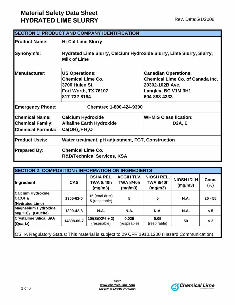
Material Safety Data SheetHYDRATED LIME SLURRY Rev. Date:5/1/2008
SECTION 1: PRODUCT AND COMPANY IDENTIFICATION
Product Name: Hi-Cal Lime Slurry
Synonym/s: Hydrated Lime Slurry, Calcium Hydroxide Slurry, Lime Slurry, Slurry, Milk of Lime
Manufacturer: US Operations: Canadian Operations:Chemical Lime Co. Chemical Lime Co. of Canada Inc.3700 Hulen St. 20302-102B Ave.Fort Worth, TX 76107 Langley, BC V1M 3H1817-732-8164 604-888-4333
Emergency Phone: Chemtrec 1-800-424-9300
Chemical Name: Calcium Hydroxide WHMIS Classification:Chemical Family: Alkaline Earth Hydroxide D2A, EChemical Formula: Ca(OH)2 + H2O
Product Use/s: Water treatment, pH adjustment, FGT, Construction
Prepared By: Chemical Lime Co.R&D/Technical Services, KSA
SECTION 2: COMPOSITION / INFORMATION ON INGREDIENTS
Ingredient CASOSHA PEL, TWA 8/40h
(mg/m3)
ACGIH TLV, TWA 8/40h
(mg/m3)
NIOSH REL, TWA 8/40h
(mg/m3)
NIOSH IDLH (mg/m3)
Conc. (%)
Calcium Hydroxide, Ca(OH)2
(Hydrated Lime)1305-62-0
15 (total dust) 5 (respirable)
5 5 N.A. 20 - 55
Magnesium Hydroxide, Mg(OH)2 (Brucite)
1309-42-8 N.A. N.A. N.A. N.A. < 5
Crystalline Silica, SiO2
(Quartz)14808-60-7
10/(SiO2% + 2) (respirable)
0.025 (respirable)
0.05 (respirable)
50 < 2
OSHA Regulatory Status: This material is subject to 29 CFR 1910.1200 (Hazard Communication).
1 of 6
Visitwww.chemicallime.com
for latest MSDS versions
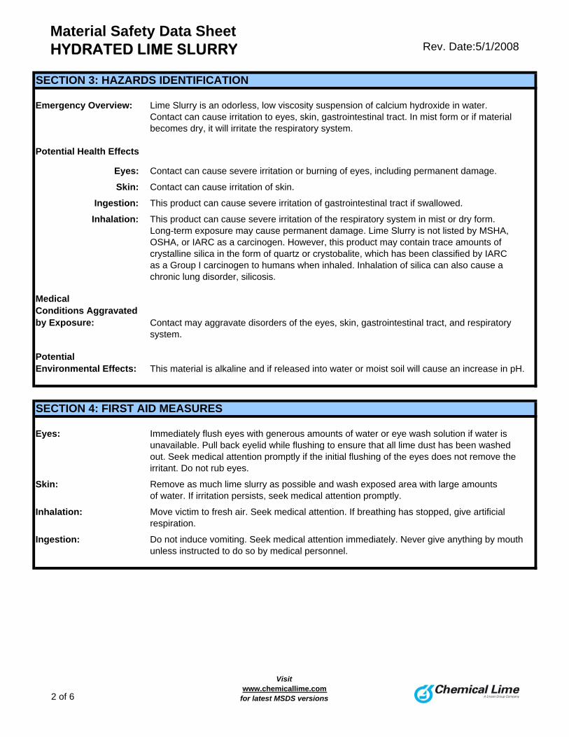
Material Safety Data SheetHYDRATED LIME SLURRY Rev. Date:5/1/2008
SECTION 3: HAZARDS IDENTIFICATION
Emergency Overview: Lime Slurry is an odorless, low viscosity suspension of calcium hydroxide in water. Contact can cause irritation to eyes, skin, gastrointestinal tract. In mist form or if material becomes dry, it will irritate the respiratory system.
Potential Health Effects
Eyes: Contact can cause severe irritation or burning of eyes, including permanent damage.
Skin: Contact can cause irritation of skin.
Ingestion: This product can cause severe irritation of gastrointestinal tract if swallowed.
Inhalation: This product can cause severe irritation of the respiratory system in mist or dry form.Long-term exposure may cause permanent damage. Lime Slurry is not listed by MSHA, OSHA, or IARC as a carcinogen. However, this product may contain trace amounts of crystalline silica in the form of quartz or crystobalite, which has been classified by IARCas a Group I carcinogen to humans when inhaled. Inhalation of silica can also cause a chronic lung disorder, silicosis.
Medical Conditions Aggravated by Exposure: Contact may aggravate disorders of the eyes, skin, gastrointestinal tract, and respiratory
system.
Potential Environmental Effects: This material is alkaline and if released into water or moist soil will cause an increase in pH.
SECTION 4: FIRST AID MEASURES
Eyes: Immediately flush eyes with generous amounts of water or eye wash solution if water isunavailable. Pull back eyelid while flushing to ensure that all lime dust has been washedout. Seek medical attention promptly if the initial flushing of the eyes does not remove the irritant. Do not rub eyes.
Skin: Remove as much lime slurry as possible and wash exposed area with large amountsof water. If irritation persists, seek medical attention promptly.
Inhalation: Move victim to fresh air. Seek medical attention. If breathing has stopped, give artificialrespiration.
Ingestion: Do not induce vomiting. Seek medical attention immediately. Never give anything by mouthunless instructed to do so by medical personnel.
2 of 6
Visitwww.chemicallime.com
for latest MSDS versions
Material Safety Data SheetHYDRATED LIME SLURRY Rev. Date:5/1/2008
SECTION 5: FIRE FIGHTING MEASURES
Fire Hazards: Lime Slurry is not combustible or flammable. However, it reacts vigorously with acids,and may release heat sufficient to ignite combustible materials in specific instances. Lime Slurry is not considered to be an explosion hazard, although reaction with acids or other incompatible materials may rupture containers.
Hazardous Combustion Products: None Extinguishing Media: Use extinguishing agent suitable for surrounding fire. Do not use water or halogenated
compounds, except that large amounts of water may be used to deluge small quantities of Lime Slurry.
Fire Fighting Instructions: Keep personnel away from and upwind of fire. Avoid skin contact or inhalation of dust. Wear
full fire-fighting turn-out gear (full Bunker gear), and respiratory protection (SCBA).
SECTION 6: ACCIDENTAL RELEASE MEASURES
Spill / Leak Procedures: Do Not use water on bulk material spills. Use proper protective equipment.
Small Spills: Use wet material containment methods. Do not clean up with compressed air. Store collected materials in sealed plastic or non-aluminum metal containers. Residue on surfaces may be water washed.
Large Spills: Use wet containment/collection techniques to collect spilled materials. If material hassufficiently dried to generate dust, evacuate area downwind of clean-up operations to minimize dust exposure. Store spilled materials in sealed plastic or non-aluminum metalcontainers.
Containment: Minimize dust generation and prevent bulk release to sewers or waterways.
Clean-up: Residual amounts of material can be flushed with large amounts of water. Equipment can be washed with either a mild vinegar and water solution, or detergent and water.
SECTION 7: HANDLING AND STORAGE
Handling: Keep in tightly closed plastic or non-aluminum metal containers. Protect containers fromphysical damage. Avoid direct skin contact with the material.
Storage: Store in a cool, dry, and well-ventilated location. Do not store near acids or otherincompatible materials. Keep away from moisture. Do not store or ship in aluminumcontainers.
3 of 6
Visitwww.chemicallime.com
for latest MSDS versions
Material Safety Data SheetHYDRATED LIME SLURRY Rev. Date:5/1/2008
SECTION 8: EXPOSURE CONTROLS / PERSONAL PROTECTION
Engineering Controls: Provide ventilation adequate to maintain PELs.
Respiratory Protection: Use NIOSH/MSHA approved respirators if airborne concentration exceeds PELs.
Skin Protection: Use appropriate gloves and footwear to prevent skin contact. Clothing should fully cover arms and legs. Should lime slurry get inside clothing or gloves, remove the clothing and the lime slurry promptly.
Eye Protection: Use safety glasses with side shields or safety goggles. Contact lenses should not be wornwhen working with lime products.
Other: Eye wash fountain/stations and emergency showers should be available.
SECTION 9: PHYSICAL AND CHEMICAL PROPERTIESAppearance: Odor: Physical State:
White or grayish-white liquid suspension
Odorless Solid
Boiling Point (°C/°F): Melting Point (°C/°F): Specific Gravity
100 / 212 dec 580 / 1076 (Apparent) g/cc: N.A.(True) g/cc: 1.2 - 1.5
Vapor Pressure (mm Hg): Vapor Density: Evaporation Rate:
N.A. N.A. N.A.Solubility in Water pH (25°C/77°F):
Material is a suspension of calcium 12.4hydroxide in water.
SECTION 10: STABILITY AND REACTIVITY
Stability: Chemically stable, but decomposes at 580°C to form calcium oxide.See also Incompatibility below.
Incompatibility/ Conditions to Avoid: Lime Slurry should not be mixed or stored with the following materials, due to the potential
for vigorous reaction and release of heat:
Acids (unless in a controlled process) Organic Acid AnhydridesReactive Fluoridated Compounds Nitro-Organic CompoundsReactive Brominated Compounds Reactive Phosphorous CompoundsReactive Powdered Metals Interhalogenated Compounds
Hazardous Decomposition Products: None
Hazardous Polymerization: None
4 of 6
Visitwww.chemicallime.com
for latest MSDS versions
Material Safety Data SheetHYDRATED LIME SLURRY Rev. Date:5/1/2008
SECTION 11: TOXICOLOGICAL INFORMATION
If product becomes dry and is in its calcium hydroxide form, the following toxicologicalcharacteristics apply:ORL-RAT LD50: 7,340 MG/KGORL-MUS LD50: 7,300 MG/KG
Lime Slurry is not listed by MSHA, OSHA, or IARC as a carcinogen, but this product may contain trace amounts of crystalline silica, which has been classified by IARC as
carcinogenic to humans when inhaled in the form of quartz or crystobalite.
SECTION 12: ECOLOGICAL INFORMATION
Ecotoxicity: Because of the high pH of this product, it would be expected to produce significant ecotoxicity upon exposure to aquatic organisms and aquatic systems in highconcentrations.
Environmental Fate: This material shows no bioaccumulation effect or food chain concentration toxicity.
SECTION 13: DISPOSAL CONSIDERATIONS
Dispose of in accordance with all applicable federal, state, and local environmentalregulations. If this product as supplied, and unmixed, becomes a waste, it will not meet
the criteria of a hazardous waste as defined under the U.S. Resource Conservation andRecovery Act (RCRA).
SECTION 14: TRANSPORTATION INFORMATION
Lime Slurry is not classified as a hazardous material by US DOT and is not regulated by
the Transportation of Dangerous Goods (TDG) when shipped by any mode of transport.
5 of 6
Visitwww.chemicallime.com
for latest MSDS versions
Material Safety Data SheetHYDRATED LIME SLURRY Rev. Date:5/1/2008
SECTION 15: REGULATORY INFORMATION
U.S. EPA Regulations: RCRA Hazardous Waste Number (40 CFR 261.33): not listed RCRA Hazardous Waste Classification (40 CFR 261): not classified
CERCLA Hazardous Substance (40 CFR 302.4) unlisted specific per RCRA, Sec. 3001; CWA, Sec. 311(b)(4); CWA, Sec. 307(a), CAA, Sec. 112CERCLA Reportable Quantity (RQ), not listedSARA 311/312 Codes: not listedSARA Toxic Chemical (40 CFR 372.65): not listedSARA EHS (Extremely Hazardous Substance) (40 CFR 355): not listed, Threshold Planning Quantity (TPQ): not listedAll chemical ingredients are listed on the USEPA TSCA Inventory List.
OSHA/MSHA Regulations: Air Contaminant (29 CRF 1910.1000, Table Z-1, Z-1-A): 5mg/M3 TWA-8
MSHA: not listedOSHA Specifically Regulated Substance (29 CFR 1910): not listed
State Regulations: Consult state and local authorities for guidance. Components found in this product maycontain trace amounts of inherent naturally occurring elements (such as, but not limited to arsenic and cadmium) that may be regulated.
Canada: WHMIS Classification: "D2A" Materials Causing Other Toxic EffectsWHMIS Classification: "E" Corrosive Materials (listed due to corrosive effect on aluminum)Canada DSL: Listed
NFPA Hazard Class: Health: 1 Flammability: 0 Reactivity: 0 HMIS Hazard Class: Health: 1 Flammability: 0 Reactivity: 0 Personal Protection: E
SECTION 16: OTHER INFORMATION
Prepared By: Chemical Lime Company, R&D/Technical Services, KSA
Chemical Lime Company provides the information contained herein in good faith but makes no representation as to its
comprehensiveness or accuracy. This document is intended only as a guide to the appropriate precautionary handling
of the material by a properly trained person. Individuals receiving this information must consult their own technical
and legal advisors and/ or exercise their own judgment in determining its appropriateness for a particular purpose.
Chemical Lime Company makes no representations or warranties, either express or implied, including without limitation
and warranties of merchantability or fitness for a particular purpose with respect to the information set forth herein
or the product(s) to which the information refers. Accordingly, Chemical Lime Company will not be responsible or
liable for any claims, losses or damages resulting from the use of or reliance upon or failure to use this information.
01 0
6 of 6
Visitwww.chemicallime.com
for latest MSDS versions
Sheet 1 OF 2 a Thermo Electron business
500 Cummings Center Beverly, MA 01915-6199 USA Telephone 978-232-6000
MATERIAL SAFETY DATA SHEET I. PRODUCT IDENTIFICATION
Product Name: Catalog No. 967961
Effective Date
ORP Standard 967901
2/16/01
Hazardous DOT IATA Shipment Labeling: None None
Title Prepared By
Quality Assurance Chemist
Title
Approved By
Director Regulatory Matters
II. HAZARDOUS INGREDIENTS (IDENTIFY INFORMATION) LDLO
Hazardous Components * Specific Chemical Identity: Common Name(s)
CAS NO.
%
OSHA PEL
ACGIH TLV
mg/Kg
Potassium Iodide (KI)
7681-11-0
40
None Listed
None Listed
120 (IVN-RAT)
Trade Secret - Chemical Identity Withheld ***Aqueous mixture of non-hazardous proprietary ingredients not found on the most recent Massachusetts substance list.
Trade Secrect
60
None Listed
None Listed
None Listed
III. PHYSICAL DATA Boiling Point 750mm Hg 106ºC
Freezing Point -6ºC
Specific Gravity (H2O=1) 1.08
Vapor Pressure @ 25ºC NA**
pH @ 25ºC
(6.98-7.02)
Solubility In Water, % by Wt @ 25ºC Miscible
Volatiles % By Wt. NA
Evaporation Rate (BUTYL, ACETATE = 1) NA
Vapor Density (AIR = 1) NA Appearance and Odor Dark Amber Solution
IV. FIRE AND EXPLOSION HAZARD DATA Flash Point (Test Method)
Autoignition Temperature
NA
NA
Flammable Limits Lower Upper in air, % by volume:
NA
NA
Extinguishing Media Dry chemical, water, foam, or CO2 Special Fire-Fighting Procedures Wear Self-contained breathing apparatus. Unusual Fire and Explosion Hazards
Toxic K2O and I2 fumes may be released during a fire. *Chemicals which are not classified as hazardous Liability is expressly disclaimed for any loss or Document No. 232162-001 per U.S. OSHA guidelines (29CFR Parts 1915.2 injury arising out of the use of this information Rev . B or 1916.2) or the Massachusetts Substance List or the use of any materials designated. Safe use (105CMR670.000 Appendix A) will not of the materials is the responsibility of the user . necessarily be listed on this form even though one or more may be a constituent of this product ** NA Not available/not applicable Printed in U.S.A. *** Non-hazardous component Form MSDS/1192
Sheet 2 OF 2 a Thermo Electron business
MATERIAL SAFETY DATA SHEET
PRODUCT NAME: ORP Standard Catalog No.: 967961, 967901
V. REACTIVITY DATA Stability: Conditions to Avoid Unstable
Stable X
None
Incompatibility (Materials to avoid) Incompatible with oxidants, metallic salts, calomel. Hazardous Decomposition Products When heated emits K2O and I- Hazardous Polymerization: Condition to Avoid May Occur
Will Not Occur X
None
VI. HEALTH HAZARD DATA Route(s) Of Entry: Inhalation? Skin? Ingestion?
No
No
Yes
Health Hazards (acute and chronic) Moderately toxic by ingestion. May irritate eyes or skin. Carcinogenicity: NTP? IARC Monographs? OSHA Regulated? Not found on these lists. Signs and Symptoms of Exposure Itching of skin, irritation of eyes if allowed to come in direct contact. Medical Conditions Generally Aggravated by Exposure Cause stinging in an open cut. Emergency And First Aid Procedures Eyes – Irrigate with water. Skin – Wash with soap and water. If ingested – dilute with large amounts of water. Get medical attention for eyes or internal exposure.
VII. PRECAUTIONS (SAFE HANDLING AND USE) Steps To be Taken In Case Material Is Released or Spilled Clean up and set aside for waste disposal. Waste Disposal Method Observe all Federal, State and local laws when disposing of this product.. Precautions To Be Taken In Handling and Storing None, product is a low hazard. NFPA rating: Scale (0-4); Health – 2, Fire - 0, Reactivity - 0, Specific - None. Other Precautions Keep closure sealed and store at room temperature to protect product integrity. This product is not affected by SARA TITLE III: Not found on CAL Prop 65. Components are listed in EPA TSCA inventory.
VIII. CONTROL MEASURES
Respiratory Protection (specify type) None
Ventilation Local Exhaust
Special
None
None
Ventilation Mechanical (General)
Other
None
None
Protective Gloves
Yes
Eye Protection
Safety glasses
Other Protective Clothing Or Equipment
None Work/Hygienic Practices
Emergency eye wash should be available. Wash off hands after working with this product.
Oakton 00654-08, 05942-61, 05942-62,
05942-64, 05942-65, 35653-03pH 10.01 Buffer
Material Safety Data Sheet
P.O. Box 5136 Vernon Hills IL 60061, USA Phone: 888-462-5866 Fax: 847-247-2984 E-mail: [email protected]
X. STABILITY AND REACTIVITY
Product is stable. Hazardous polymerization will not occur. Incompatibles: Na-K alloy, NH4H2PO4, Al, P2O5, H2SO4. Hazardous decomposition product: May emit fumes of carbon dioxides when heated to decomposition.
XI. TOXICOLOGICAL INFORMATION
Route of Exposure: Eyes, skin. Teratogen Status: None Mutagen Status: None Reproductive Toxicity: None Carcinogen Status: None
XII. ECOLOGICAL INFORMATION
None available.
XIII. DISPOSAL CONSIDERATIONS
Dispose of in a manner consistent with Federal, State and Local Regulations.
XIV. TRANSPORT INFORMATION
Product is not hazardous for transport. XV. REGULATORY INFORMATION
EUROPEAN INFORMATION:
RISK PHRASES: None SAFETY PHRASES: S24/25 Avoid contact with skin and eyes.
US/ CANADA INFORMATION
SARA/Title III: Ingredients not listed. Cal. Proposition 65: Ingredients not listed. US TSCA Inventory: Ingredients are listed. CPR Class: None. TDG Class: None. MSDS discloses elements required by the CPR.
XVI. OTHER INFORMATION
THE ABOVE INFORMATION IS BELIEVED TO BE ACCURATE AND REPRESENTS THE BEST INFORMATION CURRENTLY AVAILABLE TO US. ALL PRODUCTS ARE OFFERED IN ACCORDANCE WITH THE MANUFACTURER'S CURRENT PRODUCTION SPECIFICATIONS AND ARE INTENDED SOLELY FOR USE IN ANALYTICAL TESTING. THE MANUFACTURER SHALL IN NO EVENT BE LIABLE FOR ANY INJURY, LOSS OR DAMAGE RESULTING FROM THE HANDLING, USE OR MISUSE OF THESE PRODUCTS. MSDS prepared by Environmental, Health and Safety group. Document Number 264594-001 Rev. A Effective Date: 2/17/2010
I. PRODUCT AND COMPANY IDENTIFICATION: CATALOG NUMBERS: 00654-08, 05942-61, 05942-62, 05942-64, 05942-65, 35653-03
PRODUCT NAME: pH 10.01 Buffer
PRODUCT USE: Buffer
NFPA RATINGS: HEALTH: 1 FLAMMABILITY: 0 REACTIVITY: 0
MANUFACTURER’S NAME: Thermo Fisher Scientific, Inc
ADDRESS: 166 Cummings Center, Beverly MA 01915, USA
PHONE NUMBER FOR INFORMATION: 978-232-6000
CHEMTREC® 24 hr Emergency: US 800-424-9300; International 703-527-3887 II. COMPOSITION/INFORMATION ON INGREDIENTS
% LD50 mg/kg COMPONENT Sodium Bicarbonate (NaHCO3) CAS NO. 144-55-8 <1 4220 (ORL-RAT) COMPONENT Sodium Carbonate (Na2CO3) CAS NO. 497-19-8 <1 117 (IPR-MUS)
COMPONENT Methyl Paraben (C8H8O3) CAS NO. 99-76-3 <0.1 3000 (ORL-DOG)
COMPONENT FD&C Blue #1 (C37H34N2O9S3Na2) CAS NO. 3844-45-9 <0.01 Not available COMPONENT Deionized Water (H2O) CAS NO. 7732-18-5 99 190,000 (IPR-MUS)
III. HAZARDS IDENTIFICATION
Low hazard for normal use. May be harmful if swallowed. May cause irritation to eyes and skin. TARGET ORGANS: Eye, skin. ACUTE TOXICITY: Low hazard. CHRONIC TOXICITY: May cause irritation to skin after prolonged exposure. MEDICAL CONDITIONS AGGRAVATED BY EXPOSURE: Disease of the skin.
IV. FIRST AID MEASURES
EYE AND SKIN CONTACT: Wash off with large amounts of water. INGESTION: Give large amounts of water. Consult physician. INHALATION: Not hazardous.
V. FIRE FIGHTING MEASURES
FLASH POINT: NA AUTOIGNITION POINT: NA FLAMMABILITY LIMITS: UPPER: NA LOWER: NA EXTINGUISHING MEDIA: Water, CO2, dry chemical or foam.
VI. ACCIDENTAL RELEASE MEASURES
Take up with absorbent materials. Place in small containers for disposal. Wash spill site after material pick up is complete.
VII. HANDLING AND STORAGE
Always wear eye protection and gloves when working with this product. Avoid contact with eyes, skin or clothing. Do not ingest. Store at room temperature. Keep away from heat and keep container closed.
VIII. EXPOSURE CONTROLS/ PERSONAL PROTECTION
OSHA & ACGIH THRESHOLD LIMIT: None listed. PROTECTIVE EQUIPMENT: Safety glasses, lab coat and gloves. IX. PHYSICAL AND CHEMICAL PROPERTIES
STATE: Light blue liquid ODOR THRESHOLD: None SENSITIVITY TO MECHANICAL IMPACT: None SENSITIVITY TO STATIC DISCHARGE: None COEFFICIENT OF OIL/WATER DISTRIBUTION: None SOLUBILITY IN WATER: Soluble pH: 10.01 SPECIFIC GRAVITY: 1.0 BOILING POINT: 100ºC MELTING POINT: Not determined VAPOR DENSITY: Not determined
Oakton 00654-00, 05942-21, 05942-22,
05942-24, 05942-25, 35653-01pH 4.01 Buffer
Material Safety Data Sheet
P.O. Box 5136 Vernon Hills IL 60061, USA Phone: 888-462-5866 Fax: 847-247-2984 E-mail: [email protected]
X. STABILITY AND REACTIVITY
Product is stable. Hazardous polymerization will not occur. Incompatibles: Strong oxidizing agents, nitric acid. Hazardous decomposition product: None known.
XI. TOXICOLOGICAL INFORMATION
Route of Exposure: Eyes, skin. Teratogen Status: None Mutagen Status: None Reproductive Toxicity: None. Carcinogen Status: None.
XII. ECOLOGICAL INFORMATION
None available.
XIII. DISPOSAL CONSIDERATIONS
Dispose of in a manner consistent with Federal, State and Local Regulations.
XIV. TRANSPORT INFORMATION
Product is not hazardous for transport. XV. REGULATORY INFORMATION
EUROPEAN INFORMATION:
RISK PHRASES: None SAFETY PHRASES: S24/25 Avoid contact with skin and eyes.
US/CANADA INFORMATION
SARA/Title III: Ingredients not listed. Cal. Proposition 65: Ingredients not listed. US TSCA Inventory: Ingredients are listed CPR Class: None. TDG Class: None. MSDS discloses elements required by the CPR.
XVI. OTHER INFORMATION
THE ABOVE INFORMATION IS BELIEVED TO BE ACCURATE AND REPRE-SENTS THE BEST INFORMATION CURRENTLY AVAILABLE TO US. ALL PRODUCTS ARE OFFERED IN ACCORDANCE WITH THE MANUFACTURER'S CURRENT PRODUCTION SPECIFICATIONS AND ARE INTENDED SOLELY FOR USE IN ANALYTICAL TESTING. THE MANUFACTURER SHALL IN NO EVENT BE LIABLE FOR ANY INJURY, LOSS OR DAMAGE RESULTING FROM THE HANDLING, USE OR MISUSE OF THESE PRODUCTS. MSDS prepared by Environmental, Health and Safety group. Document Number 264586-001 Rev. A Effective Date: 2/17/2010
I. PRODUCT AND COMPANY IDENTIFICATION: CATALOG NUMBERS: 00654-00, 05942-21, 05942-22, 05942-24, 05942-25, 35653-01
PRODUCT NAME: pH 4.01 Buffer
PRODUCT USE: Buffer
NFPA RATINGS: HEALTH: 1 FLAMMABILITY: 0 REACTIVITY: 0
MANUFACTURER’S NAME: Thermo Fisher Scientific, Inc
ADDRESS: 166 Cummings Center, Beverly MA 01915, USA
PHONE NUMBER FOR INFORMATION: 978-232-6000
CHEMTREC® 24 hr Emergency: US 800-424-9300; International 703-527-3887
II. COMPOSITION/INFORMATION ON INGREDIENTS
% LD50 mg/kg COMPONENT Potassium Hydrogen Phthalate (C8H5O4K) CAS NO. 877-24-7 1 > 3,200 (ORL-RAT) COMPONENT Amaranth Red Dye (C20H11N2O10S3Na3) CAS NO. 915-67-3 <0.01 1000 (IRP-MUS) COMPONENT Deionized Water (H2O) CAS NO. 7732-18-5 99 190,000 (IPR-MUS)
III. HAZARDS IDENTIFICATION
Low hazard for normal use. Maybe harmful if swallowed. May cause irritation to eyes and skin. TARGET ORGANS: Eyes, skin. ACUTE TOXICITY: Low hazards. CHRONIC TOXICITY: May cause irritation to skin after prolonged exposure. MEDICAL CONDITIONS AGGRAVATED BY EXPOSURE: Disease of the skin.
IV. FIRST AID MEASURES
EYE AND SKIN CONTACT: Wash off with large amounts of water. INGESTION: Give large amounts of water. Consult physician. INHALATION: Not hazardous.
V. FIRE FIGHTING MEASURES
FLASH POINT: NA AUTOIGNITION POINT: NA FLAMMABILITY LIMITS: UPPER: NA LOWER: NA EXTINGUISHING MEDIA: Water, CO2, dry chemical or foam.
VI. ACCIDENTAL RELEASE MEASURES
Take up with absorbent materials. Place in small containers for disposal. Wash spill site after material pick up is complete.
VII. HANDLING AND STORAGE
Always wear eye protection and gloves when working with this product. Avoid contact with eyes, skin or clothing. Do not ingest. Store at room temperature. Keep away from heat and keep container closed.
VIII. EXPOSURE CONTROLS/ PERSONAL PROTECTION
OSHA & ACGIH THRESHOLD LIMIT: None listed. PROTECTIVE EQUIPMENT: Safety glasses, lab coat and gloves. IX. PHYSICAL AND CHEMICAL PROPERTIES
STATE: Light red liquid ODOR THRESHOLD: None SENSITIVITY TO MECHANICAL IMPACT: None SENSITIVITY TO STATIC DISCHARGE: None COEFFICIENT OF OIL/WATER DISTRIBUTION: None SOLUBILITY IN WATER: Soluble pH: 4.01 SPECIFIC GRAVITY: 1.0 BOILING POINT: 100ºC MELTING POINT: Not determined VAPOR DENSITY: Not determined
PRODUCT IDENTITY: BUFFER, Standard, pH 7.00 (Color Coded Green) CAT. NO (S): 00654-04, 05942-41, 35654-04, 05942-42, 05942-44, 05942-45, 35653-02 EFFECTIVE DATE: 3-20-2006 MSDS NUMBER 00507 Rev 3 Page 1 of 3
MATERIAL SAFETY DATA SHEET
Section 1. Chemical Product and Company Identification
Catalog Number(s)
00654-04, 35654-04, 05942-41, 05942-42, 05942-44, 05942-45, 35653-02 Product Identity
BUFFER, Standard, pH 7.00 (Color Coded Green) Manufacturer’s Name Emergency Telephone Number (24 hr)
RICCA CHEMICAL COMPANY CHEMTREC®: 800-424-9300 Address (Number, Street, City, State, and ZIP Code) Telephone Number For Information
P.O. Box 13090 817-461-5601 Date Prepared
Arlington, Texas 76094 3-8-2000
Section 2. Composition / Information on Ingredients
Percent Exposure Limits
Component CAS Registry # Concentration ACGIH TLV OSHA PEL
Sodium Phosphate, Dibasic 7558-79-4 < 1 N/A N/A
Potassium Phosphate, Monobasic 7778-77-0 < 1 N/A N/A
Preservative* Proprietary < 0.1 N/A N/A
*(No Mercury Compounds or Formaldehyde)
Inert Dye Proprietary < 0.1 N/A N/A
Water, Deionized 7732-18-5 Balance N/A N/A
Section 3. Hazards Identification
����������������������������������������������������������
EMERGENCY OVERVIEW
Non-flammable, non-toxic, non-corrosive. Does not present any significant health hazards. May cause irritation. Wash areas of contact with water
����������������������������������������������������������
POTENTIAL HEALTH EFFECTS:
TARGET ORGANS: eyes, skin. EYE CONTACT: May cause slight irritation.
INHALATION: May cause allergic respiratory reaction to those allergic to phosphates.
SKIN CONTACT: May cause slight irritation to those allergic to phosphates.
INGESTION: Large doses may cause stomach upset.
CHRONIC EFFECTS / CARCINOGENICITY:
IARC – No
NTP – No
OSHA – No TERATOLOGY (BIRTH DEFECT) INFORMATION:
No information found in “Registry of Toxic Effects of Chemical Substances” or other information sources.
REPRODUCTION INFORMATION:
No information found in “Registry of Toxic Effects of Chemical Substances” or other information sources.
PRODUCT IDENTITY: BUFFER, Standard, pH 7.00 (Color Coded Green) CAT. NO (S): 00654-04, 05942-41, 35654-04, 05942-42, 05942-44, 05942-45, 35653-02 EFFECTIVE DATE: 3-20-2006 MSDS NUMBER 00507 Rev 3 Page 2 of 3
MATERIAL SAFETY DATA SHEET
Section 4. First Aid Measures – In all cases, seek qualified evaluation.
EYE CONTACT: Irrigate immediately with large quantity of water for at least 15 minutes. Call a physician if irritation develops.
INHALATION: Remove to fresh air. Give artificial respiration if necessary. If breathing is difficult, give oxygen.
SKIN CONTACT: Flush with plenty of water for at least 15 minutes. Call a physician if irritation develops.
INGESTION: Dilute with water or milk. Call a physician if necessary.
Section 5. Fire Fighting Measures
FLAMMABLE PROPERTIES: FLASH POINT: N/A METHOD USED: N/A
FLAMMABLE LIMITS
LFL: N/A UFL: N/A
EXTINGUISHING MEDIA: Use any means suitable for extinguishing surrounding fire.
FIRE & EXPLOSION HAZARDS: Not considered to be a fire or explosion hazard.
FIRE FIGHTING INSTRUCTIONS: Use normal procedures/instructions.
FIRE FIGHTING EQUIPMENT: Use protective clothing and breathing equipment appropriate for the surrounding fire.
Section 6. Accidental Release Measures
Absorb with suitable material (vermiculite, clay, etc.) and dispose of in accordance with local regulations. Check with local agencies for the proper disposal of phosphate containing solutions.
Section 7. Handling and Storage
As with all chemicals, wash hands thoroughly after handling. Avoid contact with eyes and skin. Protect from freezing and physical damage. SAFETY STORAGE CODE: GENERAL
Section 8. Exposure Controls / Personal Protection
ENGINEERING CONTROLS: No specific controls are needed. Normal room ventilation is adequate.
RESPIRATORY PROTECTION: Normal room ventilation is adequate.
SKIN PROTECTION: Chemical resistant gloves.
EYE PROTECTION: Safety glasses or goggles.
Section 9. Physical and chemical Properties
APPEARANCE: Clear, green liquid pH: 7 ODOR: Odorless BOILING POINT (
OC): approximately 100
SOLUBILITY IN WATER: Infinite MELTING POINT (OC): approximately 0
SPECIFIC GRAVITY: approximately 1 VAPOR PRESSURE: N/A
Section 10. Stability and Reactivity
CHEMICAL STABILITY: Stable under normal conditions of use and storage.
INCOMPATIBILITY: None identified.
HAZARDOUS DECOMPOSITION PRODUCTS: Phosphorus oxides may form when heated to decomposition.
PRODUCT IDENTITY: BUFFER, Standard, pH 7.00 (Color Coded Green) CAT. NO (S): 00654-04, 05942-41, 35654-04, 05942-42, 05942-44, 05942-45, 35653-02 EFFECTIVE DATE: 3-20-2006 MSDS NUMBER 00507 Rev 3 Page 3 of 3
MATERIAL SAFETY DATA SHEET
HAZARDOUS POLYMERIZATION: Will not occur.
Section 11. Toxicological Information
LD50, Oral, Rat: (Sodium Phosphate Dibasic) 17 gm/kg; LD50, Dermal, Rabbit: (Potassium Phosphate Monobasic) >4640 mg/kg; details of toxic effects not reported other than lethal dose value.
Section 12. Ecological Information
ECOTOXICOLOGICAL INFORMATION: No information found.
CHEMICAL FATE INFORMATION: No information found.
Section 13. Disposal Considerations
Dilute with water, then flush to sewer if local regulations allow for the flushing of phosphate containing solutions. If not allowed, save for recovery or recycling in an approved waste disposal facility. Always dispose of in accordance with local, state and federal regulations.
Section 14. Transport Information (Not meant to be all inclusive)
D.O.T. SHIPPING NAME: Not regulated D.O.T. HAZARD CLASS: None
U.N. / N.A. NUMBER: None PACKING GROUP: None
D.O.T. LABEL: None
Section 15. Regulatory Information (Not meant to be all inclusive - selected regulation represented)
OSHA STATUS: The above items either do not contain any specifically hazardous material or the potentially hazardous material is present in such low concentration that the items do not present any immediate threat to health and safety. These items do not meet the OSHA Hazard Communication Standard (29 CFR 1910.1200) definition of a hazardous material.
TSCA STATUS: All components of this solution are listed on the TSCA Inventory or are mixtures (hydrates) of items listed on the TSCA Inventory. CERCLA REPORTABLE QUANTITY: Sodium Phosphate, Dibasic - 5,000 pounds. SARA TITLE III:
SECTION 302 EXTREMELY HAZARDOUS SUBSTANCES: No
SECTION 311/312 HAZARDOUS CATEGORIES: No
SECTION 313 TOXIC CHEMICALS: No
RCRA STATUS: No
CALIFORNIA PROPOSITION 65: Not listed.
PENNSYLVANIA: Sodium Phosphate Dibasic is listed as an environmental hazard on the state Hazardous Substance list.
Section 16. Other Information
NFPA Ratings: Health: 1 Flammability: 0 Reactivity: 0 Special Notice Key: None HMIS® Ratings: Health: 1 Flammability: 0 Reactivity: 0 Protective Equipment: B (Protective eyewear, gloves) Rev 1, 8-25-2000: (Section 2) corrected concentration of preservative from 1 – 2 to < 0.1%. Rev 2, 03-25-2003: Reviewed and approved, (Section 15) added CERCLA reportable quantity. Rev 3, 03-20-2006: Reviewed and approved.
When handled properly by qualified personnel, the product described herein does not present a significant health or safety hazard. Alteration of its characteristics by concentration, evaporation, addition of other substances, or other means may present hazards not specifically addressed herein and which must be evaluated by the user. The information furnished herein is believed to be accurate and represents the best data currently available to us. No warranty, expressed or implied, is made and RICCA CHEMICAL COMPANY assumes no legal responsibility or liability whatsoever resulting from its use.
SAFETY DATA SHEET PRODUCT
CORE SHELL® 71307
EMERGENCY TELEPHONE NUMBER(S) (800) 424-9300 (24 Hours) CHEMTREC
Nalco Company 1601 W. Diehl Road • Naperville, Illinois 60563-1198 • (630)305-1000
For additional copies of an MSDS visit www.nalco.com and request access. 1 / 10
1. CHEMICAL PRODUCT AND COMPANY IDENTIFICATION PRODUCT NAME : CORE SHELL® 71307 APPLICATION : FLOCCULANT COMPANY IDENTIFICATION : Nalco Company 1601 W. Diehl Road Naperville, Illinois 60563-1198 EMERGENCY TELEPHONE NUMBER(S) : (800) 424-9300 (24 Hours) CHEMTREC NFPA 704M/HMIS RATING HEALTH : 1 / 1 FLAMMABILITY : 1 / 1 INSTABILITY : 0 / 0 OTHER : 0 = Insignificant 1 = Slight 2 = Moderate 3 = High 4 = Extreme * = Chronic Health Hazard 2. COMPOSITION/INFORMATION ON INGREDIENTS Based on our hazard evaluation, none of the substances in this product are hazardous. 3. HAZARDS IDENTIFICATION
**EMERGENCY OVERVIEW**
CAUTION May cause irritation with prolonged contact. Do not get in eyes, on skin, on clothing. Do not take internally. Use with adequate ventilation. In case of contact with eyes, rinse immediately with plenty of water and seek medical advice. After contact with skin, wash immediately with plenty of water. Protect product from freezing. Wear suitable protective clothing. May evolve oxides of carbon (COx) under fire conditions. May evolve oxides of nitrogen (NOx) and sulfur (SOx) under fire conditions. Water in contact with the product will cause slippery floor conditions. PRIMARY ROUTES OF EXPOSURE : Eye, Skin HUMAN HEALTH HAZARDS - ACUTE : EYE CONTACT : Can cause mild irritation. SKIN CONTACT : Frequent or prolonged contact with product may defat and dry the skin, leading to discomfort and dermatitis. INGESTION : Not a likely route of exposure. If swallowed a jelly mass may form which in digestion may cause blockage.
SAFETY DATA SHEET PRODUCT
CORE SHELL® 71307
EMERGENCY TELEPHONE NUMBER(S) (800) 424-9300 (24 Hours) CHEMTREC
Nalco Company 1601 W. Diehl Road • Naperville, Illinois 60563-1198 • (630)305-1000
For additional copies of an MSDS visit www.nalco.com and request access. 2 / 10
INHALATION : Not a likely route of exposure. No adverse effects expected. SYMPTOMS OF EXPOSURE : Acute : A review of available data does not identify any symptoms from exposure not previously mentioned. Chronic : Frequent or prolonged contact with product may defat and dry the skin, leading to discomfort and dermatitis. AGGRAVATION OF EXISTING CONDITIONS : Skin contact may aggravate an existing dermatitis condition. HUMAN HEALTH HAZARDS - CHRONIC : No adverse effects expected other than those mentioned above. 4. FIRST AID MEASURES EYE CONTACT : Flush affected area with water. Get medical attention. SKIN CONTACT : Flush affected area with water. If symptoms develop, seek medical advice. INGESTION : Do not induce vomiting without medical advice. If conscious, washout mouth and give water to drink. Get medical attention. INHALATION : Remove to fresh air, treat symptomatically. If symptoms develop, seek medical advice. NOTE TO PHYSICIAN : Based on the individual reactions of the patient, the physician's judgement should be used to control symptoms and clinical condition. 5. FIRE FIGHTING MEASURES FLASH POINT : > 200 °F / > 93.3 °C ( PMCC ) EXTINGUISHING MEDIA : This product would not be expected to burn unless all the water is boiled away. The remaining organics may be ignitable. Use extinguishing media appropriate for surrounding fire. FIRE AND EXPLOSION HAZARD : May evolve oxides of carbon (COx) under fire conditions. May evolve oxides of nitrogen (NOx) and sulfur (SOx) under fire conditions. Water in contact with the product will cause slippery floor conditions.
SAFETY DATA SHEET PRODUCT
CORE SHELL® 71307
EMERGENCY TELEPHONE NUMBER(S) (800) 424-9300 (24 Hours) CHEMTREC
Nalco Company 1601 W. Diehl Road • Naperville, Illinois 60563-1198 • (630)305-1000
For additional copies of an MSDS visit www.nalco.com and request access. 3 / 10
SPECIAL PROTECTIVE EQUIPMENT FOR FIRE FIGHTING : In case of fire, wear a full face positive-pressure self contained breathing apparatus and protective suit. 6. ACCIDENTAL RELEASE MEASURES PERSONAL PRECAUTIONS : Notify appropriate government, occupational health and safety and environmental authorities. Do not touch spilled material. Stop or reduce any leaks if it is safe to do so. Use personal protective equipment recommended in Section 8 (Exposure Controls/Personal Protection). METHODS FOR CLEANING UP : SMALL SPILLS: Soak up spill with absorbent material. Place residues in a suitable, covered, properly labeled container. Wash affected area. Water in contact with the product will cause slippery floor conditions. LARGE SPILLS: Contain liquid using absorbent material, by digging trenches or by diking. Reclaim into recovery or salvage drums or tank truck for proper disposal. Contact an approved waste hauler for disposal of contaminated recovered material. Dispose of material in compliance with regulations indicated in Section 13 (Disposal Considerations). ENVIRONMENTAL PRECAUTIONS : This product is toxic to fish. It should not be directly discharged into lakes, ponds, streams, waterways or public water supplies. 7. HANDLING AND STORAGE HANDLING : Avoid eye and skin contact. Do not take internally. Ensure all containers are labeled. Keep the containers closed when not in use. STORAGE CONDITIONS : Protect product from freezing. Store in suitable labeled containers. Store the containers tightly closed. Store separately from oxidizers. UNSUITABLE CONSTRUCTION MATERIAL : Compatibility with Plastic Materials can vary; we therefore recommend that compatibility is tested prior to use. 8. EXPOSURE CONTROLS/PERSONAL PROTECTION OCCUPATIONAL EXPOSURE LIMITS : This product does not contain any substance that has an established exposure limit. ENGINEERING MEASURES : General ventilation is recommended. RESPIRATORY PROTECTION : Respiratory protection is not normally needed. If significant mists, vapors or aerosols are generated an approved respirator is recommended. A suitable filter material depends on the amount and type of chemicals being handled. Consider the use of filter type: Multi-contaminant cartridge. with a Particulate pre-filter. If respiratory protection is
SAFETY DATA SHEET PRODUCT
CORE SHELL® 71307
EMERGENCY TELEPHONE NUMBER(S) (800) 424-9300 (24 Hours) CHEMTREC
Nalco Company 1601 W. Diehl Road • Naperville, Illinois 60563-1198 • (630)305-1000
For additional copies of an MSDS visit www.nalco.com and request access. 4 / 10
required, institute a complete respiratory protection program including selection, fit testing, training, maintenance and inspection. In event of emergency or planned entry into unknown concentrations a positive pressure, full-facepiece SCBA should be used. HAND PROTECTION : Neoprene gloves Nitrile gloves Butyl gloves PVC gloves SKIN PROTECTION : Wear standard protective clothing. EYE PROTECTION : Wear chemical splash goggles. HYGIENE RECOMMENDATIONS : Keep an eye wash fountain available. Keep a safety shower available. If clothing is contaminated, remove clothing and thoroughly wash the affected area. Launder contaminated clothing before reuse. 9. PHYSICAL AND CHEMICAL PROPERTIES PHYSICAL STATE Emulsion APPEARANCE Opaque Off-white Light brown ODOR Hydrocarbon SPECIFIC GRAVITY 0.995 - 1.078 @ 77 °F / 25 °C DENSITY 8.30 - 9.00 lb/gal SOLUBILITY IN WATER Emulsifiable pH (100 %) 4.0 - 5.0 VISCOSITY 400 - 1,500 cps @ 72 °F / 22 °C VOC CONTENT 28.7 % Calculated Note: These physical properties are typical values for this product and are subject to change. 10. STABILITY AND REACTIVITY STABILITY : Stable under normal conditions. HAZARDOUS POLYMERIZATION : Hazardous polymerization will not occur. CONDITIONS TO AVOID : Avoid temperatures below 0 and above 93 degrees C which will cause polymer to precipitate. Avoid extremes of temperature.
SAFETY DATA SHEET PRODUCT
CORE SHELL® 71307
EMERGENCY TELEPHONE NUMBER(S) (800) 424-9300 (24 Hours) CHEMTREC
Nalco Company 1601 W. Diehl Road • Naperville, Illinois 60563-1198 • (630)305-1000
For additional copies of an MSDS visit www.nalco.com and request access. 5 / 10
MATERIALS TO AVOID : Addition of water results in gelling. Contact with strong oxidizers (e.g. chlorine, peroxides, chromates, nitric acid, perchlorate, concentrated oxygen, permanganate) may generate heat, fires, explosions and/or toxic vapors. HAZARDOUS DECOMPOSITION PRODUCTS : Under fire conditions: Oxides of carbon, Oxides of nitrogen, Oxides of sulfur 11. TOXICOLOGICAL INFORMATION No toxicity studies have been conducted on this product. SENSITIZATION : This product is not expected to be a sensitizer. CARCINOGENICITY : None of the substances in this product are listed as carcinogens by the International Agency for Research on Cancer (IARC), the National Toxicology Program (NTP) or the American Conference of Governmental Industrial Hygienists (ACGIH). HUMAN HAZARD CHARACTERIZATION : Based on our hazard characterization, the potential human hazard is: Low 12. ECOLOGICAL INFORMATION ECOTOXICOLOGICAL EFFECTS : The tests for (products or similar products) were performed in clean water as set forth by USEPA (EPA/600/4-90/027). In order to evaluate the potential toxicity mitigation, the tests for (representative polymers) were performed in environmentally relevant water with dissolved organic carbon (DOC: 4.5 mg/l). The toxicity of this product is due to an external mode of action, e.g., suffocation or immobilization. In the presence of suspended material, e.g., DOC, the polymers are bound to suspended material and the bioavailability is substantially reduced. As a result, the toxicity is expected to be lower. Under normal use and discharge conditions, the LC50 values of the representative polymers tested in the presence of DOC are expected to apply to this product. However, for large spills, the clean water data is more applicable. Acute Fish Results : Species Exposure Test Type Value Test Descriptor Zebra Danio 96 hrs LC50 1 - 10 mg/l Representative polymer tested in
water with DOC Inland Silverside 96 hrs LC50 185.14 mg/l Product Rainbow Trout 96 hrs LC50 0.51 mg/l Product ACUTE INVERTEBRATE RESULTS : Species Exposure Test Type Value Test Descriptor Daphnia magna 48 hrs LC50 10 - 100 mg/l Representative polymer tested in
water with DOC Daphnia magna 48 hrs LC50 6.09 mg/l Product Mysid Shrimp (Mysidopsis 96 hrs LC50 3.38 mg/l Product
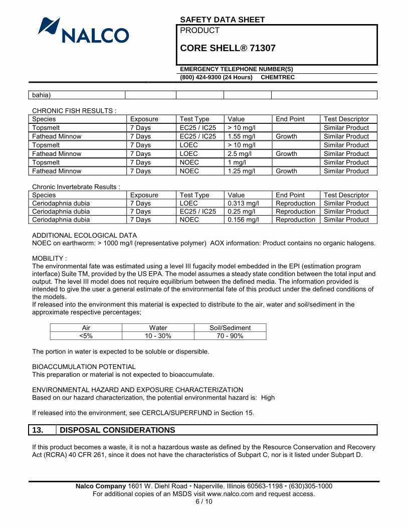
SAFETY DATA SHEET PRODUCT
CORE SHELL® 71307
EMERGENCY TELEPHONE NUMBER(S) (800) 424-9300 (24 Hours) CHEMTREC
Nalco Company 1601 W. Diehl Road • Naperville, Illinois 60563-1198 • (630)305-1000
For additional copies of an MSDS visit www.nalco.com and request access. 6 / 10
bahia) CHRONIC FISH RESULTS : Species Exposure Test Type Value End Point Test Descriptor Topsmelt 7 Days EC25 / IC25 > 10 mg/l Similar Product Fathead Minnow 7 Days EC25 / IC25 1.55 mg/l Growth Similar Product Topsmelt 7 Days LOEC > 10 mg/l Similar Product Fathead Minnow 7 Days LOEC 2.5 mg/l Growth Similar Product Topsmelt 7 Days NOEC 1 mg/l Similar Product Fathead Minnow 7 Days NOEC 1.25 mg/l Growth Similar Product Chronic Invertebrate Results : Species Exposure Test Type Value End Point Test Descriptor Ceriodaphnia dubia 7 Days LOEC 0.313 mg/l Reproduction Similar Product Ceriodaphnia dubia 7 Days EC25 / IC25 0.25 mg/l Reproduction Similar Product Ceriodaphnia dubia 7 Days NOEC 0.156 mg/l Reproduction Similar Product ADDITIONAL ECOLOGICAL DATA NOEC on earthworm: > 1000 mg/l (representative polymer) AOX information: Product contains no organic halogens. MOBILITY : The environmental fate was estimated using a level III fugacity model embedded in the EPI (estimation program interface) Suite TM, provided by the US EPA. The model assumes a steady state condition between the total input and output. The level III model does not require equilibrium between the defined media. The information provided is intended to give the user a general estimate of the environmental fate of this product under the defined conditions of the models. If released into the environment this material is expected to distribute to the air, water and soil/sediment in the approximate respective percentages;
Air Water Soil/Sediment <5% 10 - 30% 70 - 90%
The portion in water is expected to be soluble or dispersible. BIOACCUMULATION POTENTIAL This preparation or material is not expected to bioaccumulate. ENVIRONMENTAL HAZARD AND EXPOSURE CHARACTERIZATION Based on our hazard characterization, the potential environmental hazard is: High If released into the environment, see CERCLA/SUPERFUND in Section 15. 13. DISPOSAL CONSIDERATIONS If this product becomes a waste, it is not a hazardous waste as defined by the Resource Conservation and Recovery Act (RCRA) 40 CFR 261, since it does not have the characteristics of Subpart C, nor is it listed under Subpart D.
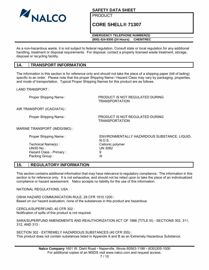
SAFETY DATA SHEET PRODUCT
CORE SHELL® 71307
EMERGENCY TELEPHONE NUMBER(S) (800) 424-9300 (24 Hours) CHEMTREC
Nalco Company 1601 W. Diehl Road • Naperville, Illinois 60563-1198 • (630)305-1000
For additional copies of an MSDS visit www.nalco.com and request access. 7 / 10
As a non-hazardous waste, it is not subject to federal regulation. Consult state or local regulation for any additional handling, treatment or disposal requirements. For disposal, contact a properly licensed waste treatment, storage, disposal or recycling facility. 14. TRANSPORT INFORMATION The information in this section is for reference only and should not take the place of a shipping paper (bill of lading) specific to an order. Please note that the proper Shipping Name / Hazard Class may vary by packaging, properties, and mode of transportation. Typical Proper Shipping Names for this product are as follows. LAND TRANSPORT :
Proper Shipping Name : PRODUCT IS NOT REGULATED DURING TRANSPORTATION
AIR TRANSPORT (ICAO/IATA) :
Proper Shipping Name : PRODUCT IS NOT REGULATED DURING TRANSPORTATION
MARINE TRANSPORT (IMDG/IMO) :
Proper Shipping Name : ENVIRONMENTALLY HAZARDOUS SUBSTANCE, LIQUID, N.O.S.
Technical Name(s) : Cationic polymer UN/ID No : UN 3082 Hazard Class - Primary : 9 Packing Group : III
15. REGULATORY INFORMATION This section contains additional information that may have relevance to regulatory compliance. The information in this section is for reference only. It is not exhaustive, and should not be relied upon to take the place of an individualized compliance or hazard assessment. Nalco accepts no liability for the use of this information. NATIONAL REGULATIONS, USA : OSHA HAZARD COMMUNICATION RULE, 29 CFR 1910.1200 : Based on our hazard evaluation, none of the substances in this product are hazardous. CERCLA/SUPERFUND, 40 CFR 302 : Notification of spills of this product is not required. SARA/SUPERFUND AMENDMENTS AND REAUTHORIZATION ACT OF 1986 (TITLE III) - SECTIONS 302, 311, 312, AND 313 : SECTION 302 - EXTREMELY HAZARDOUS SUBSTANCES (40 CFR 355) : This product does not contain substances listed in Appendix A and B as an Extremely Hazardous Substance.
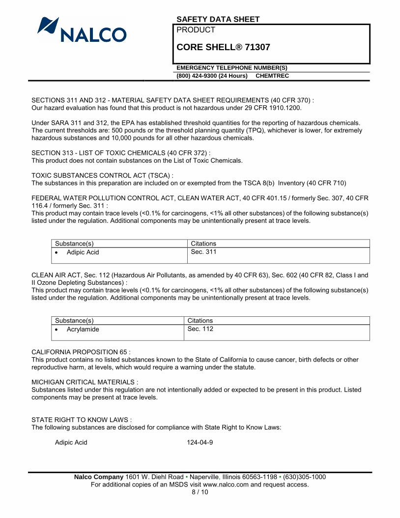
SAFETY DATA SHEET PRODUCT
CORE SHELL® 71307
EMERGENCY TELEPHONE NUMBER(S) (800) 424-9300 (24 Hours) CHEMTREC
Nalco Company 1601 W. Diehl Road • Naperville, Illinois 60563-1198 • (630)305-1000
For additional copies of an MSDS visit www.nalco.com and request access. 8 / 10
SECTIONS 311 AND 312 - MATERIAL SAFETY DATA SHEET REQUIREMENTS (40 CFR 370) : Our hazard evaluation has found that this product is not hazardous under 29 CFR 1910.1200. Under SARA 311 and 312, the EPA has established threshold quantities for the reporting of hazardous chemicals. The current thresholds are: 500 pounds or the threshold planning quantity (TPQ), whichever is lower, for extremely hazardous substances and 10,000 pounds for all other hazardous chemicals. SECTION 313 - LIST OF TOXIC CHEMICALS (40 CFR 372) : This product does not contain substances on the List of Toxic Chemicals. TOXIC SUBSTANCES CONTROL ACT (TSCA) : The substances in this preparation are included on or exempted from the TSCA 8(b) Inventory (40 CFR 710) FEDERAL WATER POLLUTION CONTROL ACT, CLEAN WATER ACT, 40 CFR 401.15 / formerly Sec. 307, 40 CFR 116.4 / formerly Sec. 311 : This product may contain trace levels (<0.1% for carcinogens, <1% all other substances) of the following substance(s) listed under the regulation. Additional components may be unintentionally present at trace levels.
Substance(s) Citations Adipic Acid
Sec. 311
CLEAN AIR ACT, Sec. 112 (Hazardous Air Pollutants, as amended by 40 CFR 63), Sec. 602 (40 CFR 82, Class I and II Ozone Depleting Substances) : This product may contain trace levels (<0.1% for carcinogens, <1% all other substances) of the following substance(s) listed under the regulation. Additional components may be unintentionally present at trace levels.
Substance(s) Citations Acrylamide
Sec. 112
CALIFORNIA PROPOSITION 65 : This product contains no listed substances known to the State of California to cause cancer, birth defects or other reproductive harm, at levels, which would require a warning under the statute. MICHIGAN CRITICAL MATERIALS : Substances listed under this regulation are not intentionally added or expected to be present in this product. Listed components may be present at trace levels. STATE RIGHT TO KNOW LAWS : The following substances are disclosed for compliance with State Right to Know Laws:
Adipic Acid 124-04-9
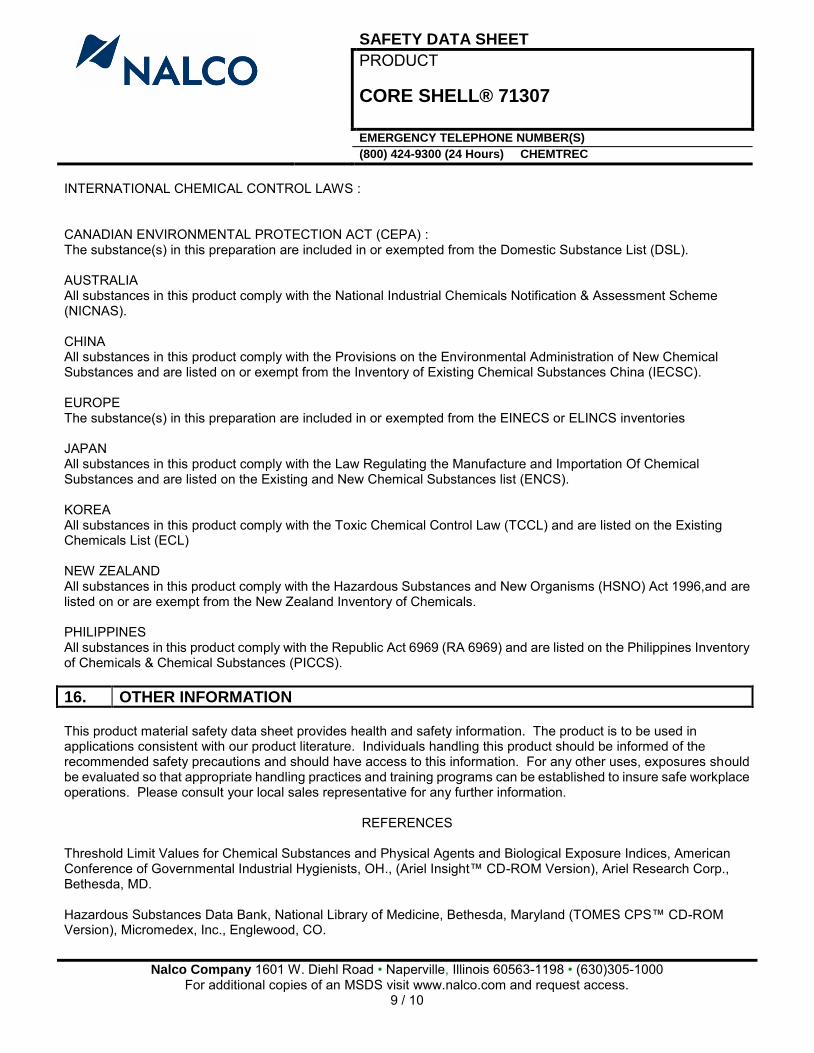
SAFETY DATA SHEET PRODUCT
CORE SHELL® 71307
EMERGENCY TELEPHONE NUMBER(S) (800) 424-9300 (24 Hours) CHEMTREC
Nalco Company 1601 W. Diehl Road • Naperville, Illinois 60563-1198 • (630)305-1000
For additional copies of an MSDS visit www.nalco.com and request access. 9 / 10
INTERNATIONAL CHEMICAL CONTROL LAWS : CANADIAN ENVIRONMENTAL PROTECTION ACT (CEPA) : The substance(s) in this preparation are included in or exempted from the Domestic Substance List (DSL). AUSTRALIA All substances in this product comply with the National Industrial Chemicals Notification & Assessment Scheme (NICNAS). CHINA All substances in this product comply with the Provisions on the Environmental Administration of New Chemical Substances and are listed on or exempt from the Inventory of Existing Chemical Substances China (IECSC). EUROPE The substance(s) in this preparation are included in or exempted from the EINECS or ELINCS inventories JAPAN All substances in this product comply with the Law Regulating the Manufacture and Importation Of Chemical Substances and are listed on the Existing and New Chemical Substances list (ENCS). KOREA All substances in this product comply with the Toxic Chemical Control Law (TCCL) and are listed on the Existing Chemicals List (ECL) NEW ZEALAND All substances in this product comply with the Hazardous Substances and New Organisms (HSNO) Act 1996,and are listed on or are exempt from the New Zealand Inventory of Chemicals. PHILIPPINES All substances in this product comply with the Republic Act 6969 (RA 6969) and are listed on the Philippines Inventory of Chemicals & Chemical Substances (PICCS). 16. OTHER INFORMATION This product material safety data sheet provides health and safety information. The product is to be used in applications consistent with our product literature. Individuals handling this product should be informed of the recommended safety precautions and should have access to this information. For any other uses, exposures should be evaluated so that appropriate handling practices and training programs can be established to insure safe workplace operations. Please consult your local sales representative for any further information.
REFERENCES Threshold Limit Values for Chemical Substances and Physical Agents and Biological Exposure Indices, American Conference of Governmental Industrial Hygienists, OH., (Ariel Insight™ CD-ROM Version), Ariel Research Corp., Bethesda, MD. Hazardous Substances Data Bank, National Library of Medicine, Bethesda, Maryland (TOMES CPS™ CD-ROM Version), Micromedex, Inc., Englewood, CO.
SAFETY DATA SHEET PRODUCT
CORE SHELL® 71307
EMERGENCY TELEPHONE NUMBER(S) (800) 424-9300 (24 Hours) CHEMTREC
Nalco Company 1601 W. Diehl Road • Naperville, Illinois 60563-1198 • (630)305-1000
For additional copies of an MSDS visit www.nalco.com and request access. 10 / 10
IARC Monographs on the Evaluation of the Carcinogenic Risk of Chemicals to Man, Geneva: World Health Organization, International Agency for Research on Cancer. Integrated Risk Information System, U.S. Environmental Protection Agency, Washington, D.C. (TOMES CPS™ CD-ROM Version), Micromedex, Inc., Englewood, CO. Annual Report on Carcinogens, National Toxicology Program, U.S. Department of Health and Human Services, Public Health Service. Title 29 Code of Federal Regulations, Part 1910, Subpart Z, Toxic and Hazardous Substances, Occupational Safety and Health Administration (OSHA), (Ariel Insight™ CD-ROM Version), Ariel Research Corp., Bethesda, MD. Registry of Toxic Effects of Chemical Substances, National Institute for Occupational Safety and Health, Cincinnati, OH, (TOMES CPS™ CD-ROM Version), Micromedex, Inc., Englewood, CO. Ariel Insight™ (An integrated guide to industrial chemicals covered under major regulatory and advisory programs), North American Module, Western European Module, Chemical Inventories Module and the Generics Module (Ariel Insight™ CD-ROM Version), Ariel Research Corp., Bethesda, MD. The Teratogen Information System, University of Washington, Seattle, WA (TOMES CPS™ CD-ROM Version), Micromedex, Inc., Englewood, CO. Prepared By : Product Safety Department Date issued : 02/15/2012 Version Number : 1.17
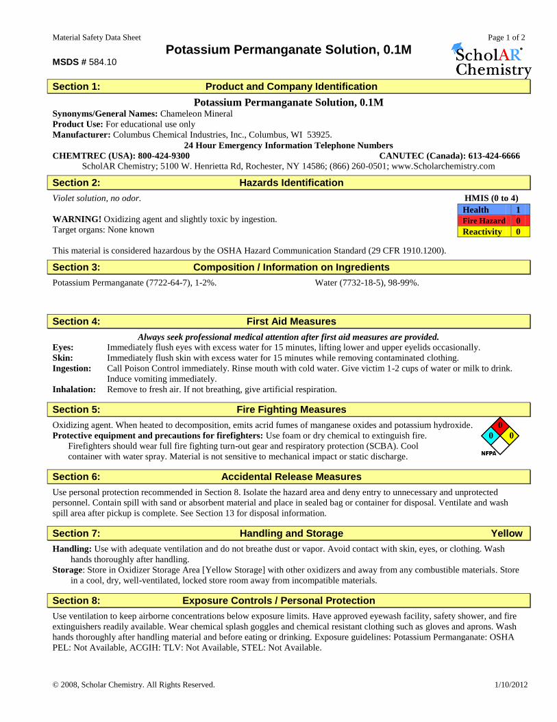
Material Safety Data Sheet Page 1 of 2
© 2008, Scholar Chemistry. All Rights Reserved. 1/10/2012
Potassium Permanganate Solution, 0.1M MSDS # 584.10
Section 1: Product and Company Identification
Potassium Permanganate Solution, 0.1M Synonyms/General Names: Chameleon Mineral
Product Use: For educational use only
Manufacturer: Columbus Chemical Industries, Inc., Columbus, WI 53925.
24 Hour Emergency Information Telephone Numbers
CHEMTREC (USA): 800-424-9300 CANUTEC (Canada): 613-424-6666
ScholAR Chemistry; 5100 W. Henrietta Rd, Rochester, NY 14586; (866) 260-0501; www.Scholarchemistry.com
Section 2: Hazards Identification
Violet solution, no odor. HMIS (0 to 4)
WARNING! Oxidizing agent and slightly toxic by ingestion.
Target organs: None known This material is considered hazardous by the OSHA Hazard Communication Standard (29 CFR 1910.1200).
Section 3: Composition / Information on Ingredients
Potassium Permanganate (7722-64-7), 1-2%. Water (7732-18-5), 98-99%.
Section 4: First Aid Measures
Always seek professional medical attention after first aid measures are provided.
Eyes: Immediately flush eyes with excess water for 15 minutes, lifting lower and upper eyelids occasionally.
Skin: Immediately flush skin with excess water for 15 minutes while removing contaminated clothing.
Ingestion: Call Poison Control immediately. Rinse mouth with cold water. Give victim 1-2 cups of water or milk to drink.
Induce vomiting immediately.
Inhalation: Remove to fresh air. If not breathing, give artificial respiration.
Section 5: Fire Fighting Measures
Oxidizing agent. When heated to decomposition, emits acrid fumes of manganese oxides and potassium hydroxide. 0
Protective equipment and precautions for firefighters: Use foam or dry chemical to extinguish fire. 0 0
Firefighters should wear full fire fighting turn-out gear and respiratory protection (SCBA). Cool
container with water spray. Material is not sensitive to mechanical impact or static discharge.
Section 6: Accidental Release Measures
Use personal protection recommended in Section 8. Isolate the hazard area and deny entry to unnecessary and unprotected
personnel. Contain spill with sand or absorbent material and place in sealed bag or container for disposal. Ventilate and wash
spill area after pickup is complete. See Section 13 for disposal information.
Section 7: Handling and Storage Yellow
Handling: Use with adequate ventilation and do not breathe dust or vapor. Avoid contact with skin, eyes, or clothing. Wash
hands thoroughly after handling.
Storage: Store in Oxidizer Storage Area [Yellow Storage] with other oxidizers and away from any combustible materials. Store
in a cool, dry, well-ventilated, locked store room away from incompatible materials.
Section 8: Exposure Controls / Personal Protection
Use ventilation to keep airborne concentrations below exposure limits. Have approved eyewash facility, safety shower, and fire
extinguishers readily available. Wear chemical splash goggles and chemical resistant clothing such as gloves and aprons. Wash
hands thoroughly after handling material and before eating or drinking. Exposure guidelines: Potassium Permanganate: OSHA
PEL: Not Available, ACGIH: TLV: Not Available, STEL: Not Available.
Health 1
Fire Hazard 0
Reactivity 0
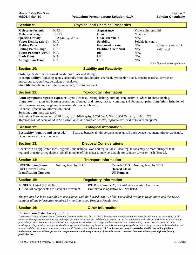
Material Safety Data Sheet Page 2 of 2
© 2008, Scholar Chemistry. All Rights Reserved. 1/10/2012
MSDS # 584.10 Potassium Permanganate Solution, 0.1M Scholar Chemistry
Section 9: Physical and Chemical Properties
Molecular formula KNO3. Appearance Violet solution solid.
Molecular weight 101.11. Odor No odor.
Specific Gravity 1.02 g/mL @ 20°C. Odor Threshold N/A.
Vapor Density (air=1) N/A. Solubility Soluble in water .
Melting Point N/A. Evaporation rate N/A. (Butyl acetate = 1).
Boiling Point/Range N/A. Partition Coefficient N/A. (log POW).
Vapor Pressure (20°C) N/A. pH N/A.
Flash Point: N/A. LEL N/A.
Autoignition Temp.: N/A. UEL N/A. N/A = Not available or applicable
Section 10: Stability and Reactivity
Stability: Stable under normal conditions of use and storage.
Incompatibility: Reducing agents, alcohols, bromides, iodides, charcoal, hydrochloric acid, organic material, ferrous or
mercurous salt, sulfites, peroxides or oxalates.
Shelf life: Indefinite shelf life, store in cool, dry environment.
Section 11: Toxicology Information
Acute Symptoms/Signs of exposure: Eyes: Redness, tearing, itching, burning, conjunctivitis. Skin: Redness, itching.
Ingestion: Irritation and burning sensations of mouth and throat, nausea, vomiting and abdominal pain. Inhalation: Irritation of
mucous membranes, coughing, wheezing, shortness of breath,
Chronic Effects: No information found.
Sensitization: none expected
Potassium Permanganate: LD50 [oral, rat]; 1090mg/kg; LC50 [rat]; N/A; LD50 Dermal [rabbit]; N/A
Material has not been found to be a carcinogen nor produce genetic, reproductive, or developmental effects.
Section 12: Ecological Information
Ecotoxicity (aquatic and terrestrial): Toxic to beneficial microorganisms (e.g. soil and sewage treatment microorganisms)..
Do not release to environment.
Section 13: Disposal Considerations
Check with all applicable local, regional, and national laws and regulations. Local regulations may be more stringent than
regional or national regulations. Small amounts of this material may be suitable for sanitary sewer or trash disposal.
Section 14: Transport Information
DOT Shipping Name: Not regulated by DOT. Canada TDG: Not regulated by TDG.
DOT Hazard Class: Hazard Class:
Identification Number: UN Number:
Section 15: Regulatory Information
EINECS: Listed (231-760-3) . WHMIS Canada: C, E: Oxidizing material, Corrosive.
TSCA: All components are listed or are exempt. California Proposition 65: Not listed.
The product has been classified in accordance with the hazard criteria of the Controlled Products Regulations and the MSDS
contains all the information required by the Controlled Products Regulations.
Section 16: Other Information
Current Issue Date: January 10, 2012 Disclaimer: Scholar Chemistry and Columbus Chemical Industries, Inc., (“S&C”) believes that the information herein is factual but is not intended to be all
inclusive. The information relates only to the specific material designated and does not relate to its use in combination with other materials or its use as to any
particular process. Because safety standards and regulations are subject to change and because S&C has no continuing control over the material, those handling, storing or using the material should satisfy themselves that they have current information regarding the particular way the material is handled, stored
or used and that the same is done in accordance with federal, state and local law. S&C makes no warranty, expressed or implied, including (without
limitation) warranties with respect to the completeness or continuing accuracy of the information contained herein or with respect to fitness for any
particular use.
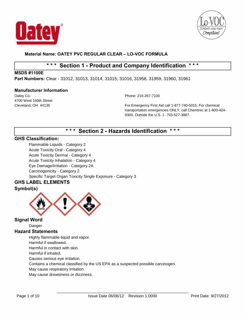
Material Name: OATEY PVC REGULAR CLEAR – LO-VOC FORMULA
____________________________________________________________ Page 1 of 10 Issue Date 06/06/12 Revision 1.0000 Print Date: 9/27/2012
* * * Section 1 - Product and Company Identification * * * MSDS #1100E Part Numbers: Clear - 31012, 31013, 31014, 31015, 31016, 31958, 31959, 31960, 31961
Manufacturer Information
Oatey Co. Phone: 216-267-7100
4700 West 160th Street
Cleveland, OH 44135 For Emergency First Aid call 1-877-740-5015. For chemical
transportation emergencies ONLY, call Chemtrec at 1-800-424-
9300. Outside the U.S. 1- 703-527-3887.
* * * Section 2 - Hazards Identification * * * GHS Classification:
Flammable Liquids - Category 2
Acute Toxicity Oral - Category 4
Acute Toxicity Dermal - Category 4
Acute Toxicity Inhalation - Category 4
Eye Damage/Irritation - Category 2A
Carcinogenicity - Category 2
Specific Target Organ Toxicity Single Exposure - Category 3
GHS LABEL ELEMENTS Symbol(s)
Signal Word Danger
Hazard Statements Highly flammable liquid and vapor.
Harmful if swallowed.
Harmful in contact with skin.
Harmful if inhaled.
Causes serious eye irritation.
Contains a chemical classified by the US EPA as a suspected possible carcinogen.
May cause respiratory irritation.
May cause drowsiness or dizziness.
Material Name: OATEY PVC REGULAR CLEAR – LO-VOC FORMULA
____________________________________________________________ Page 2 of 10 Issue Date 06/06/12 Revision 1.0000 Print Date: 9/27/2012
Precautionary Statements Prevention
Keep away from heat/sparks/open flames and hot surfaces. - No smoking.
Keep container tightly closed.
Use explosion-proof electrical/ventilating/lighting/equipment.
Use only non-sparking tools.
Take precautionary measures against static discharge.
Wear protective gloves/eye protection/face protection.
Wash thoroughly after handling.
Do not eat, drink or smoke when using this product.
Obtain special instructions before use.
Do not handle until all safety precautions have been read and understood.
Avoid breathing fume/gas/mist/vapors.
Use only outdoors or in a well-ventilated area.
Response
If on skin (or hair): Remove/Take off immediately all contaminated clothing. Rinse skin with water/shower. Wash
contaminated clothing before reuse.
If swallowed: Call a poison center or doctor/physician if you feel unwell. Rinse mouth. Do not induce vomiting.
If inhaled: Remove victim to fresh air and keep at rest in a position comfortable for breathing. Call a poison center
or doctor/physician if you feel unwell.
If in eyes: Rinse cautiously with water for several minutes. Remove contact lenses, if present and easy to do.
Continue rinsing. Immediately call a poison center or doctor/physician.
If exposed or concerned Get medical advice/attention.
In case of fire: Use dry chemical, CO2, or foam to extinguish fire.
Storage
Store in a well-ventilated place. Keep cool.
Store locked up.
Disposal Dispose of contents/container in accordance with local/regional/national/international regulations.
* * * Section 3 - Composition / Information on Ingredients * * *
CAS # Component Percent 109-99-9 Tetrahydrofuran 20-40
78-93-3 Methyl ethyl ketone 15-35
108-94-1 Cyclohexanone 10-20
67-64-1 Acetone 10-20
9002-86-2 PVC (Chloroethylene, polymer) 10-18
* * * Section 4 - First Aid Measures * * * First Aid: Eyes
If material gets into eyes or if fumes cause irritation, immediately flush eyes with plenty of water until chemical is
removed. If irritation persists, get medical attention immediately.
Material Name: OATEY PVC REGULAR CLEAR – LO-VOC FORMULA
____________________________________________________________ Page 3 of 10 Issue Date 06/06/12 Revision 1.0000 Print Date: 9/27/2012
First Aid: Skin Remove contaminated clothing immediately. Wash all exposed areas with soap and water. Get medical attention
if irritation develops. Remove dried cement with hand cleaner or baby oil.
First Aid: Ingestion DO NOT INDUCE VOMITING. Rinse mouth with water. Never give anything by mouth to a person who is
unconscious or drowsy. Get immediate medical attention by calling a Poison Control Center, or hospital
emergency room. If medical advice cannot be obtained, then take the person and product to the nearest medical
emergency treatment center or hospital.
First Aid: Inhalation
If symptoms of exposure develop, remove to fresh air. If breathing becomes difficult, administer oxygen.
Administer artificial respiration if breathing has stopped. Seek immediate medical attention.
* * * Section 5 - Fire Fighting Measures * * * General Fire Hazards
See Section 9 for Flammability Properties.
Highly flammable liquid and vapor. Keep away from heat and all sources of ignition including sparks, flames,
lighted cigarettes and pilot lights. Containers may rupture or explode in the heat of a fire. Vapors are heavier than
air and may travel to a remote ignition source and flash back. This product contains tetrahydrofuran that may form
explosive organic peroxide when exposed to air or light or with age.
Hazardous Combustion Products
Combustion will produce toxic and irritating vapors including carbon monoxide, carbon dioxide and hydrogen
chloride.
Extinguishing Media Use dry chemical, CO2, or foam to extinguish fire. Cool fire exposed container with water. Water may be
ineffective as an extinguishing agent.
Unsuitable Extinguishing Media None.
Fire Fighting Equipment/Instructions Firefighters should wear positive pressure self-contained breathing apparatus and full protective clothing for fires
in areas where chemicals are used or stored.
* * * Section 6 - Accidental Release Measures * * * Recovery and Neutralization
Stop leak if it can be done without risk.
Materials and Methods for Clean-Up Remove all sources of ignition and ventilate area. Soak up spill with an inert absorbent such as sand, earth or
other noncombusting material. Put absorbent material in covered, labeled metal containers.
Emergency Measures
Isolate area. Keep unnecessary personnel away.
Personal Precautions and Protective Equipment Personnel cleaning up the spill should wear appropriate personal protective equipment, including respirators if
vapor concentrations are high.
Environmental Precautions Prevent liquid from entering watercourses, sewers and natural waterways.
Prevention of Secondary Hazards None
Material Name: OATEY PVC REGULAR CLEAR – LO-VOC FORMULA
____________________________________________________________ Page 4 of 10 Issue Date 06/06/12 Revision 1.0000 Print Date: 9/27/2012
* * * Section 7 - Handling and Storage * * * Handling Procedures
Avoid contact with eyes, skin and clothing. Avoid breathing vapors or mists. Use with adequate ventilation
(equivalent to outdoors). Wash thoroughly after handling. Do not eat, drink or smoke in the work area. Keep
product away from heat, sparks, flames and all other sources of ignition. No smoking in storage or use areas.
Keep containers closed when not in use. Other: "Empty" containers retain product residue and can be hazardous.
Follow all SDS precautions in handling empty containers. Do not cut or weld on or near empty or full containers.
Storage Procedures Store in a cool, dry, well-ventilated area away from incompatible materials. Keep containers closed when not in
use.
Incompatibilities
Oxidizing agents, alkalis, amines, ammonia, acids, chlorine compounds, chlorinated inorganics (potassium,
calcium and sodium hypochlorite) and hydrogen peroxides. May attack plastic, resins and rubber.
* * * Section 8 - Exposure Controls / Personal Protection * * * Component Exposure Limits
Tetrahydrofuran (109-99-9) ACGIH: 50 ppm TWA
100 ppm STEL
Skin - potential significant contribution to overall exposure by the cutaneous route
OSHA: 200 ppm TWA; 590 mg/m3 TWA
NIOSH: 200 ppm TWA; 590 mg/m3 TWA
250 ppm STEL; 735 mg/m3 STEL
Methyl ethyl ketone (78-93-3) ACGIH: 200 ppm TWA
300 ppm STEL
OSHA: 200 ppm TWA; 590 mg/m3 TWA
NIOSH: 200 ppm TWA; 590 mg/m3 TWA
300 ppm STEL; 885 mg/m3 STEL
Acetone (67-64-1) ACGIH: 500 ppm TWA
750 ppm STEL
OSHA: 1000 ppm TWA; 2400 mg/m3 TWA
NIOSH: 250 ppm TWA; 590 mg/m3 TWA
Cyclohexanone (108-94-1) ACGIH: 20 ppm TWA
50 ppm STEL
Skin - potential significant contribution to overall exposure by the cutaneous route
OSHA: 50 ppm TWA; 200 mg/m3 TWA
NIOSH: 25 ppm TWA; 100 mg/m3 TWA
Potential for dermal absorption
PVC (Chloroethylene, polymer) (9002-86-2) ACGIH: 1 mg/m3 TWA (respirable fraction)
Material Name: OATEY PVC REGULAR CLEAR – LO-VOC FORMULA
____________________________________________________________ Page 5 of 10 Issue Date 06/06/12 Revision 1.0000 Print Date: 9/27/2012
Engineering Measures Open doors & windows. Provide ventilation capable of maintaining emissions at the point of use below
recommended exposure limits. If used in enclosed area, use exhaust fans. Exhaust fans should be explosion-
proof or set up in a way that flammable concentrations of solvent vapors are not exposed to electrical fixtures or
hot surfaces.
Personal Protective Equipment: Respiratory For operations where the exposure limit may be exceeded, a NIOSH approved organic vapor respirator or
supplied air respirator is recommended. Equipment selection depends on contaminant type and concentration,
select in accordance with 29 CFR 1910.134 and good industrial hygiene practice. For firefighting, use self-
contained breathing apparatus.
Personal Protective Equipment: Hands Rubber gloves are suitable for normal use of the product. For long exposures chemical resistant gloves may be
required such as 4H(tm) or Silver Shield(tm) to avoid prolonged skin contact.
Personal Protective Equipment: Eyes
Safety glasses with side shields or safety goggles.
Personal Protective Equipment: Skin and Body No additional protective equipment needed.
* * * Section 9 - Physical & Chemical Properties * * *
Appearance: Clear Odor: Ether-like
Physical State: Liquid pH: NA
Vapor Pressure: 145 mmHg @ 20°C Vapor Density: 2.5
Boiling Point: 151°F (66°C) Melting Point: NA
Solubility (H2O): Negligible Specific Gravity: 0.90 +/- 0.02 @ 20°C
Evaporation Rate: (BUAC = 1) = 5.5 - 8.0 VOC: 84-88%
Octanol/H2O Coeff.: ND Flash Point: 14-23°F (-10 to -5°C)
Flash Point Method: CCCFP Upper Flammability Limit (UFL):
11.8
Lower Flammability Limit (LFL):
1.8 Burning Rate: ND
Auto Ignition: ND
* * * Section 10 - Chemical Stability & Reactivity Information * * * Chemical Stability
This is a stable material.
Hazardous Reaction Potential Will not occur.
Conditions to Avoid Avoid heat, sparks, flames and other sources of ignition.
Incompatible Products Oxidizing agents, alkalis, amines, ammonia, acids, chlorine compounds, chlorinated inorganics (potassium,
calcium and sodium hypochlorite) and hydrogen peroxides. May attack plastic, resins and rubber.
Hazardous Decomposition Products
Combustion will produce toxic and irritating vapors including carbon monoxide, carbon dioxide and hydrogen
chloride.
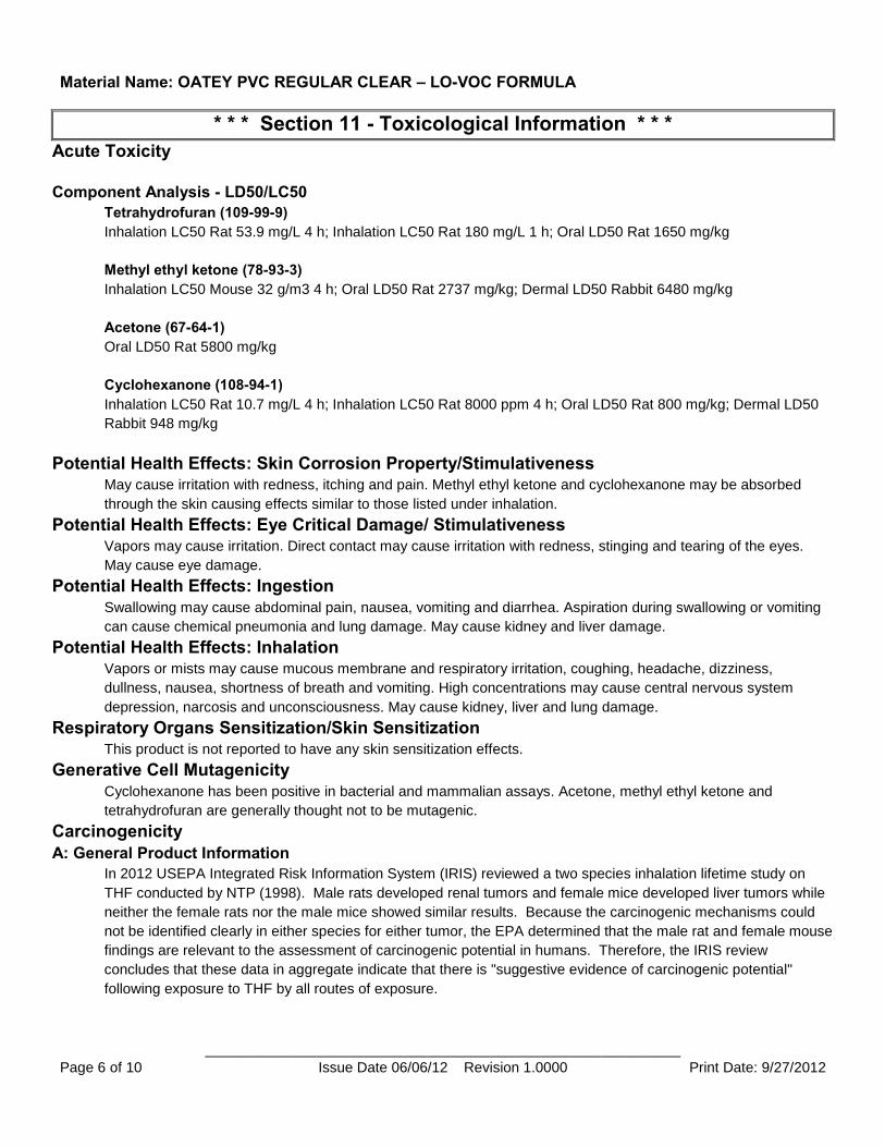
Material Name: OATEY PVC REGULAR CLEAR – LO-VOC FORMULA
____________________________________________________________ Page 6 of 10 Issue Date 06/06/12 Revision 1.0000 Print Date: 9/27/2012
* * * Section 11 - Toxicological Information * * * Acute Toxicity
Component Analysis - LD50/LC50 Tetrahydrofuran (109-99-9) Inhalation LC50 Rat 53.9 mg/L 4 h; Inhalation LC50 Rat 180 mg/L 1 h; Oral LD50 Rat 1650 mg/kg
Methyl ethyl ketone (78-93-3) Inhalation LC50 Mouse 32 g/m3 4 h; Oral LD50 Rat 2737 mg/kg; Dermal LD50 Rabbit 6480 mg/kg
Acetone (67-64-1) Oral LD50 Rat 5800 mg/kg
Cyclohexanone (108-94-1) Inhalation LC50 Rat 10.7 mg/L 4 h; Inhalation LC50 Rat 8000 ppm 4 h; Oral LD50 Rat 800 mg/kg; Dermal LD50
Rabbit 948 mg/kg
Potential Health Effects: Skin Corrosion Property/Stimulativeness May cause irritation with redness, itching and pain. Methyl ethyl ketone and cyclohexanone may be absorbed
through the skin causing effects similar to those listed under inhalation.
Potential Health Effects: Eye Critical Damage/ Stimulativeness Vapors may cause irritation. Direct contact may cause irritation with redness, stinging and tearing of the eyes.
May cause eye damage.
Potential Health Effects: Ingestion
Swallowing may cause abdominal pain, nausea, vomiting and diarrhea. Aspiration during swallowing or vomiting
can cause chemical pneumonia and lung damage. May cause kidney and liver damage.
Potential Health Effects: Inhalation Vapors or mists may cause mucous membrane and respiratory irritation, coughing, headache, dizziness,
dullness, nausea, shortness of breath and vomiting. High concentrations may cause central nervous system
depression, narcosis and unconsciousness. May cause kidney, liver and lung damage.
Respiratory Organs Sensitization/Skin Sensitization This product is not reported to have any skin sensitization effects.
Generative Cell Mutagenicity
Cyclohexanone has been positive in bacterial and mammalian assays. Acetone, methyl ethyl ketone and
tetrahydrofuran are generally thought not to be mutagenic.
Carcinogenicity
A: General Product Information
In 2012 USEPA Integrated Risk Information System (IRIS) reviewed a two species inhalation lifetime study on
THF conducted by NTP (1998). Male rats developed renal tumors and female mice developed liver tumors while
neither the female rats nor the male mice showed similar results. Because the carcinogenic mechanisms could
not be identified clearly in either species for either tumor, the EPA determined that the male rat and female mouse
findings are relevant to the assessment of carcinogenic potential in humans. Therefore, the IRIS review
concludes that these data in aggregate indicate that there is "suggestive evidence of carcinogenic potential"
following exposure to THF by all routes of exposure.
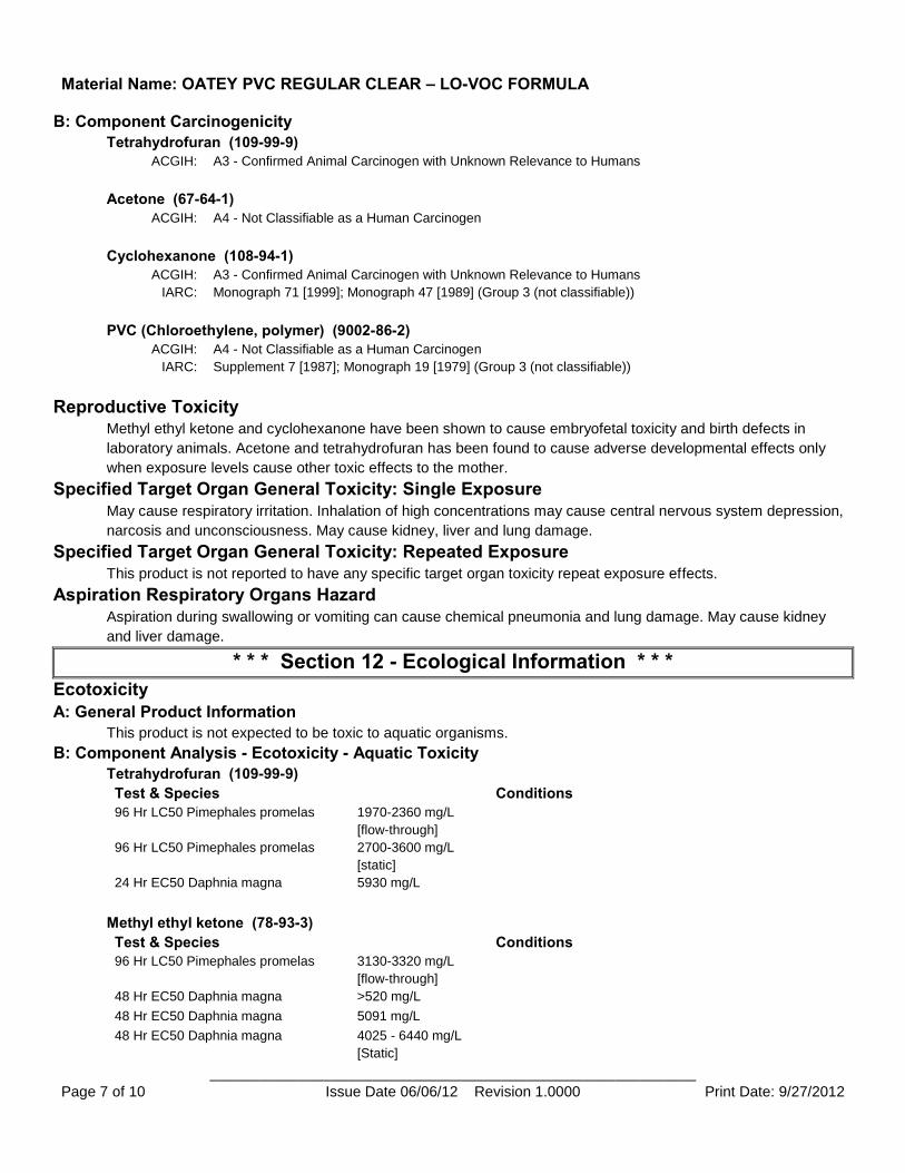
Material Name: OATEY PVC REGULAR CLEAR – LO-VOC FORMULA
____________________________________________________________ Page 7 of 10 Issue Date 06/06/12 Revision 1.0000 Print Date: 9/27/2012
B: Component Carcinogenicity Tetrahydrofuran (109-99-9)
ACGIH: A3 - Confirmed Animal Carcinogen with Unknown Relevance to Humans
Acetone (67-64-1) ACGIH: A4 - Not Classifiable as a Human Carcinogen
Cyclohexanone (108-94-1) ACGIH: A3 - Confirmed Animal Carcinogen with Unknown Relevance to Humans
IARC: Monograph 71 [1999]; Monograph 47 [1989] (Group 3 (not classifiable))
PVC (Chloroethylene, polymer) (9002-86-2) ACGIH: A4 - Not Classifiable as a Human Carcinogen
IARC: Supplement 7 [1987]; Monograph 19 [1979] (Group 3 (not classifiable))
Reproductive Toxicity Methyl ethyl ketone and cyclohexanone have been shown to cause embryofetal toxicity and birth defects in
laboratory animals. Acetone and tetrahydrofuran has been found to cause adverse developmental effects only
when exposure levels cause other toxic effects to the mother.
Specified Target Organ General Toxicity: Single Exposure
May cause respiratory irritation. Inhalation of high concentrations may cause central nervous system depression,
narcosis and unconsciousness. May cause kidney, liver and lung damage.
Specified Target Organ General Toxicity: Repeated Exposure This product is not reported to have any specific target organ toxicity repeat exposure effects.
Aspiration Respiratory Organs Hazard
Aspiration during swallowing or vomiting can cause chemical pneumonia and lung damage. May cause kidney
and liver damage.
* * * Section 12 - Ecological Information * * * Ecotoxicity
A: General Product Information
This product is not expected to be toxic to aquatic organisms.
B: Component Analysis - Ecotoxicity - Aquatic Toxicity Tetrahydrofuran (109-99-9) Test & Species Conditions
96 Hr LC50 Pimephales promelas 1970-2360 mg/L
[flow-through]
96 Hr LC50 Pimephales promelas 2700-3600 mg/L
[static]
24 Hr EC50 Daphnia magna 5930 mg/L
Methyl ethyl ketone (78-93-3) Test & Species Conditions
96 Hr LC50 Pimephales promelas 3130-3320 mg/L
[flow-through]
48 Hr EC50 Daphnia magna >520 mg/L
48 Hr EC50 Daphnia magna 5091 mg/L
48 Hr EC50 Daphnia magna 4025 - 6440 mg/L
[Static]
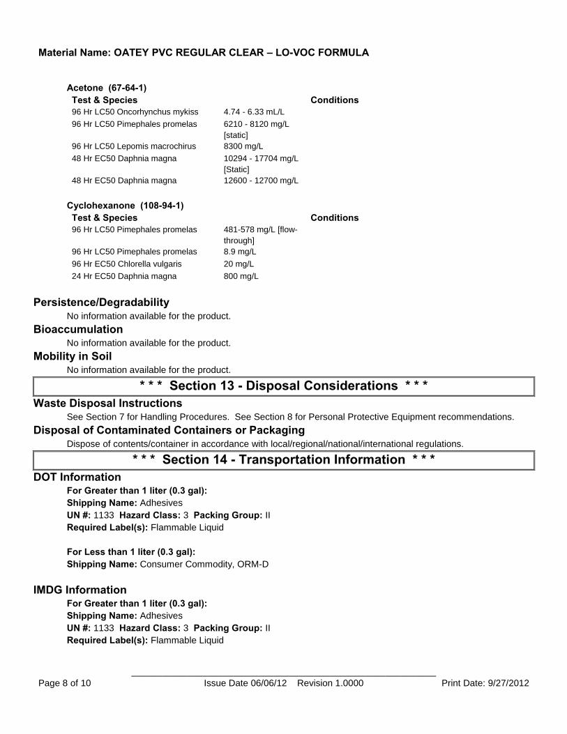
Material Name: OATEY PVC REGULAR CLEAR – LO-VOC FORMULA
____________________________________________________________ Page 8 of 10 Issue Date 06/06/12 Revision 1.0000 Print Date: 9/27/2012
Acetone (67-64-1) Test & Species Conditions
96 Hr LC50 Oncorhynchus mykiss 4.74 - 6.33 mL/L
96 Hr LC50 Pimephales promelas 6210 - 8120 mg/L
[static]
96 Hr LC50 Lepomis macrochirus 8300 mg/L
48 Hr EC50 Daphnia magna 10294 - 17704 mg/L
[Static]
48 Hr EC50 Daphnia magna 12600 - 12700 mg/L
Cyclohexanone (108-94-1) Test & Species Conditions
96 Hr LC50 Pimephales promelas 481-578 mg/L [flow-
through]
96 Hr LC50 Pimephales promelas 8.9 mg/L
96 Hr EC50 Chlorella vulgaris 20 mg/L
24 Hr EC50 Daphnia magna 800 mg/L
Persistence/Degradability
No information available for the product.
Bioaccumulation No information available for the product.
Mobility in Soil No information available for the product.
* * * Section 13 - Disposal Considerations * * * Waste Disposal Instructions
See Section 7 for Handling Procedures. See Section 8 for Personal Protective Equipment recommendations.
Disposal of Contaminated Containers or Packaging
Dispose of contents/container in accordance with local/regional/national/international regulations.
* * * Section 14 - Transportation Information * * * DOT Information
For Greater than 1 liter (0.3 gal): Shipping Name: Adhesives
UN #: 1133 Hazard Class: 3 Packing Group: II Required Label(s): Flammable Liquid
For Less than 1 liter (0.3 gal): Shipping Name: Consumer Commodity, ORM-D
IMDG Information For Greater than 1 liter (0.3 gal): Shipping Name: Adhesives
UN #: 1133 Hazard Class: 3 Packing Group: II Required Label(s): Flammable Liquid
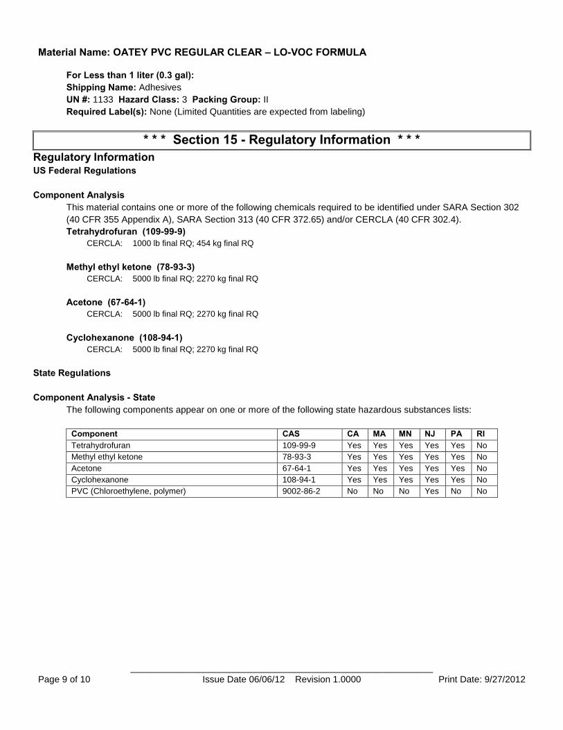
Material Name: OATEY PVC REGULAR CLEAR – LO-VOC FORMULA
____________________________________________________________ Page 9 of 10 Issue Date 06/06/12 Revision 1.0000 Print Date: 9/27/2012
For Less than 1 liter (0.3 gal): Shipping Name: Adhesives
UN #: 1133 Hazard Class: 3 Packing Group: II Required Label(s): None (Limited Quantities are expected from labeling)
* * * Section 15 - Regulatory Information * * * Regulatory Information US Federal Regulations
Component Analysis This material contains one or more of the following chemicals required to be identified under SARA Section 302
(40 CFR 355 Appendix A), SARA Section 313 (40 CFR 372.65) and/or CERCLA (40 CFR 302.4).
Tetrahydrofuran (109-99-9) CERCLA: 1000 lb final RQ; 454 kg final RQ
Methyl ethyl ketone (78-93-3) CERCLA: 5000 lb final RQ; 2270 kg final RQ
Acetone (67-64-1) CERCLA: 5000 lb final RQ; 2270 kg final RQ
Cyclohexanone (108-94-1) CERCLA: 5000 lb final RQ; 2270 kg final RQ
State Regulations
Component Analysis - State The following components appear on one or more of the following state hazardous substances lists:
Component CAS CA MA MN NJ PA RI Tetrahydrofuran 109-99-9 Yes Yes Yes Yes Yes No
Methyl ethyl ketone 78-93-3 Yes Yes Yes Yes Yes No
Acetone 67-64-1 Yes Yes Yes Yes Yes No
Cyclohexanone 108-94-1 Yes Yes Yes Yes Yes No
PVC (Chloroethylene, polymer) 9002-86-2 No No No Yes No No
Material Name: OATEY PVC REGULAR CLEAR – LO-VOC FORMULA
____________________________________________________________ Page 10 of 10 Issue Date 06/06/12 Revision 1.0000 Print Date: 9/27/2012
Component Analysis - WHMIS IDL The following components are identified under the Canadian Hazardous Products Act Ingredient Disclosure List:
Component CAS # Minimum Concentration Tetrahydrofuran 109-99-9 1 %
Methyl ethyl ketone 78-93-3 1 %
Acetone 67-64-1 1 %
Cyclohexanone 108-94-1 0.1 %
Additional Regulatory Information
A: General Product Information
This product contains trace amounts of chemicals known to the State of California to cause cancer. Under normal
use conditions, exposure to these chemicals at levels above the State of California "No Significant Risk Level"
(NSRL) are unlikely. The use of proper personal protective equipment (PPE) and ventilation guidelines noted in
Section 8 will minimize exposure to these chemicals.
B: Component Analysis - Inventory
Component CAS # TSCA CAN EEC Tetrahydrofuran 109-99-9 Yes DSL EINECS
Methyl ethyl ketone 78-93-3 Yes DSL EINECS
Acetone 67-64-1 Yes DSL EINECS
Cyclohexanone 108-94-1 Yes DSL EINECS
PVC (Chloroethylene, polymer) 9002-86-2 Yes DSL ELINCS
* * * Section 16 - Other Information * * * Key/Legend
EPA = Environmental Protection Agency; TSCA = Toxic Substance Control Act; ACGIH = American Conference
of Governmental Industrial Hygienists; IARC = International Agency for Research on Cancer; NIOSH = National
Institute for Occupational Safety and Health; NTP = National Toxicology Program; OSHA = Occupational Safety
and Health Administration., NJTSR = New Jersey Trade Secret Registry.
Literature References
None
Other Information NFPA and HMIS:
NFPA Hazard Signal: Health: 2 Flammability: 3 Reactivity: 1 Special: None
HMIS Hazard Signal: Health: 2* Flammability: 3 Reactivity: 1 PPE: G
Disclaimer:
The information herein has been compiled from sources believed to be reliable, up-to-date, and is accurate to the
best of our knowledge. However, we cannot give any guarantees regarding information from other sources, and
expressly do not make warranties, nor assume any liability for its use.
End of Sheet
Material Name: OATEY PURPLE PRIMER/CLEANER
____________________________________________________________ Page 1 of 10 Issue Date 08/02/12 Revision 1.0000 Print Date: 9/27/2012
* * * Section 1 - Product and Company Identification * * *
MSDS #1401E
Part Numbers: 30768, 30780, 30783, 30796, 30806, 31966, 31967, 31968, 31969
Manufacturer Information Oatey Co. Phone: 216-267-7100
4700 West 160th Street
Cleveland, OH 44135 For Emergency First Aid call 1-877-740-5015. For chemical
transportation emergencies ONLY, call Chemtrec at 1-800-424-
9300. Outside the U.S. 1- 703-527-3887.
* * * Section 2 - Hazards Identification * * *
GHS Classification: Flammable Liquids - Category 2
Acute Toxicity Oral - Category 4
Acute Toxicity Dermal - Category 4
Acute Toxicity Inhalation - Category 4
Eye Damage/Irritation - Category 2A
Carcinogenicity - Category 2
Specific Target Organ Toxicity Single Exposure - Category 3
GHS LABEL ELEMENTS
Symbol(s)
Signal Word Danger
Hazard Statements
Highly flammable liquid and vapor.
Harmful if swallowed.
Harmful in contact with skin.
Harmful if inhaled.
Causes serious eye irritation.
Contains a chemical classified by the US EPA as a suspected possible carcinogen.
May cause respiratory irritation.
May cause drowsiness or dizziness.
Precautionary Statements Prevention
Keep away from heat/sparks/open flames and hot surfaces. - No smoking.
Material Name: OATEY PURPLE PRIMER/CLEANER
____________________________________________________________ Page 2 of 10 Issue Date 08/02/12 Revision 1.0000 Print Date: 9/27/2012
Keep container tightly closed.
Use explosion-proof electrical/ventilating/lighting/equipment.
Use only non-sparking tools.
Take precautionary measures against static discharge.
Wear protective gloves/eye protection/face protection.
Wash thoroughly after handling.
Do not eat, drink or smoke when using this product.
Obtain special instructions before use.
Do not handle until all safety precautions have been read and understood.
Avoid breathing fume/gas/mist/vapors.
Use only outdoors or in a well-ventilated area.
Response
If on skin (or hair): Remove/Take off immediately all contaminated clothing. Rinse skin with water/shower. Wash
contaminated clothing before reuse.
If swallowed: Call a poison center or doctor/physician if you feel unwell. Rinse mouth. Do not induce vomiting.
If inhaled: Remove victim to fresh air and keep at rest in a position comfortable for breathing. Call a poison center
or doctor/physician if you feel unwell.
If in eyes: Rinse cautiously with water for several minutes. Remove contact lenses, if present and easy to do.
Continue rinsing. Immediately call a poison center or doctor/physician.
If exposed or concerned: Get medical advice/attention.
In case of fire: Use dry chemical, CO2, or foam to extinguish fire.
Storage
Store in a well-ventilated place. Keep cool.
Store locked up.
Disposal
Dispose of contents/container in accordance with local/regional/national/international regulations.
* * * Section 3 - Composition / Information on Ingredients * * *
CAS # Component Percent
67-64-1 Acetone 60-90
78-93-3 Methyl ethyl ketone 10-20
108-94-1 Cyclohexanone 3-10
109-99-9 Tetrahydrofuran 0-10
* * * Section 4 - First Aid Measures * * *
First Aid: Eyes
If material gets into eyes or if fumes cause irritation, immediately flush eyes with plenty of water until chemical is
removed. If irritation persists, get medical attention immediately.
First Aid: Skin Remove contaminated clothing immediately. Wash all exposed areas with soap and water. Get medical attention
if irritation develops. Remove dried cement with hand cleaner or baby oil.
Material Name: OATEY PURPLE PRIMER/CLEANER
____________________________________________________________ Page 3 of 10 Issue Date 08/02/12 Revision 1.0000 Print Date: 9/27/2012
First Aid: Ingestion
DO NOT INDUCE VOMITING. Rinse mouth with water. Never give anything by mouth to a person who is
unconscious or drowsy. Get immediate medical attention by calling a Poison Control Center, or hospital
emergency room. If medical advice cannot be obtained, then take the person and product to the nearest medical
emergency treatment center or hospital.
First Aid: Inhalation
If symptoms of exposure develop, remove to fresh air. If breathing becomes difficult, administer oxygen.
Administer artificial respiration if breathing has stopped. Seek immediate medical attention.
* * * Section 5 - Fire Fighting Measures * * *
General Fire Hazards
See Section 9 for Flammability Properties.
Highly flammable liquid and vapor. Keep away from heat and all sources of ignition including sparks, flames,
lighted cigarettes and pilot lights. Containers may rupture or explode in the heat of a fire. Vapors are heavier than
air and may travel to a remote ignition source and flash back. This product contains tetrahydrofuran that may form
explosive organic peroxide when exposed to air or light or with age.
Hazardous Combustion Products Combustion will produce toxic and irritating vapors including carbon monoxide, carbon dioxide and hydrogen
chloride.
Extinguishing Media
Use dry chemical, CO2, or foam to extinguish fire. Cool fire exposed container with water. Water may be
ineffective as an extinguishing agent.
Unsuitable Extinguishing Media None.
Fire Fighting Equipment/Instructions
Firefighters should wear positive pressure self-contained breathing apparatus and full protective clothing for fires
in areas where chemicals are used or stored.
* * * Section 6 - Accidental Release Measures * * *
Recovery and Neutralization
Stop leak if it can be done without risk.
Materials and Methods for Clean-Up Remove all sources of ignition and ventilate area. Soak up spill with an inert absorbent such as sand, earth or
other noncombusting material. Put absorbent material in covered, labeled metal containers.
Emergency Measures
Isolate area. Keep unnecessary personnel away.
Personal Precautions and Protective Equipment Personnel cleaning up the spill should wear appropriate personal protective equipment, including respirators if
vapor concentrations are high.
Environmental Precautions
Prevent liquid from entering watercourses, sewers and natural waterways.
Prevention of Secondary Hazards None
Material Name: OATEY PURPLE PRIMER/CLEANER
____________________________________________________________ Page 4 of 10 Issue Date 08/02/12 Revision 1.0000 Print Date: 9/27/2012
* * * Section 7 - Handling and Storage * * *
Handling Procedures Avoid contact with eyes, skin and clothing. Avoid breathing vapors or mists. Use with adequate ventilation
(equivalent to outdoors). Wash thoroughly after handling. Do not eat, drink or smoke in the work area. Keep
product away from heat, sparks, flames and all other sources of ignition. No smoking in storage or use areas.
Keep containers closed when not in use. "Empty" containers retain product residue and can be hazardous. Follow
all SDS precautions in handling empty containers. Do not cut or weld on or near empty or full containers.
Storage Procedures Store in a cool, dry, well-ventilated area away from incompatible materials. Keep containers closed when not in
use.
Incompatibilities Oxidizing agents, alkalis, amines, ammonia, acids, chlorine compounds, chlorinated inorganics (potassium,
calcium and sodium hypochlorite) and hydrogen peroxides. May attack plastic, resins and rubber.
* * * Section 8 - Exposure Controls / Personal Protection * * *
Component Exposure Limits
Acetone (67-64-1)
ACGIH: 500 ppm TWA
750 ppm STEL
OSHA: 1000 ppm TWA; 2400 mg/m3 TWA
NIOSH: 250 ppm TWA; 590 mg/m3 TWA
Methyl ethyl ketone (78-93-3)
ACGIH: 200 ppm TWA
300 ppm STEL
OSHA: 200 ppm TWA; 590 mg/m3 TWA
NIOSH: 200 ppm TWA; 590 mg/m3 TWA
300 ppm STEL; 885 mg/m3 STEL
Cyclohexanone (108-94-1)
ACGIH: 20 ppm TWA
50 ppm STEL
Skin - potential significant contribution to overall exposure by the cutaneous route
OSHA: 50 ppm TWA; 200 mg/m3 TWA
NIOSH: 25 ppm TWA; 100 mg/m3 TWA
Potential for dermal absorption
Tetrahydrofuran (109-99-9)
ACGIH: 50 ppm TWA
100 ppm STEL
Skin - potential significant contribution to overall exposure by the cutaneous route
OSHA: 200 ppm TWA; 590 mg/m3 TWA
NIOSH: 200 ppm TWA; 590 mg/m3 TWA
250 ppm STEL; 735 mg/m3 STEL
Material Name: OATEY PURPLE PRIMER/CLEANER
____________________________________________________________ Page 5 of 10 Issue Date 08/02/12 Revision 1.0000 Print Date: 9/27/2012
Engineering Measures
Open doors & windows. Provide ventilation capable of maintaining emissions at the point of use below
recommended exposure limits. If used in enclosed area, use exhaust fans. Exhaust fans should be explosion-
proof or set up in a way that flammable concentrations of solvent vapors are not exposed to electrical fixtures or
hot surfaces.
Personal Protective Equipment: Respiratory
For operations where the exposure limit may be exceeded, a NIOSH approved organic vapor respirator or
supplied air respirator is recommended. Equipment selection depends on contaminant type and concentration,
select in accordance with 29 CFR 1910.134 and good industrial hygiene practice. For firefighting, use self-
contained breathing apparatus.
Personal Protective Equipment: Hands Rubber gloves are suitable for normal use of the product. For long exposures chemical resistant gloves may be
required such as 4H(tm) or Silver Shield(tm) to avoid prolonged skin contact.
Personal Protective Equipment: Eyes Safety glasses with side shields or safety goggles.
Personal Protective Equipment: Skin and Body No additional protective equipment needed.
* * * Section 9 - Physical & Chemical Properties * * *
Appearance: Purple Odor: Ether-like
Physical State: Liquid pH: NA
Vapor Pressure: 145 mmHg @ 20°C Vapor Density: 2.5
Boiling Point: 151°F (66°C) Melting Point: NA
Solubility (H2O): Negligible Specific Gravity: 0.81 +/- 0.02 @ 20°C
Evaporation Rate: (BUAC = 1) = 5.5 - 8.0 VOC: 99.96%
Octanol/H2O Coeff.: ND Flash Point: 14-23°F (-10 to -5°C)
Flash Point Method: CCCFP Upper Flammability Limit
(UFL):
11.8
Lower Flammability Limit
(LFL):
1.8 Burning Rate: ND
Auto Ignition: ND
* * * Section 10 - Chemical Stability & Reactivity Information * * *
Chemical Stability This is a stable material.
Hazardous Reaction Potential Will not occur.
Conditions to Avoid Avoid heat, sparks, flames and other sources of ignition.
Incompatible Products
Oxidizing agents, alkalis, amines, ammonia, acids, chlorine compounds, chlorinated inorganics (potassium,
calcium and sodium hypochlorite) and hydrogen peroxides. May attack plastic, resins and rubber.
Hazardous Decomposition Products Combustion will produce toxic and irritating vapors including carbon monoxide, carbon dioxide and hydrogen
chloride.

Material Name: OATEY PURPLE PRIMER/CLEANER
____________________________________________________________ Page 6 of 10 Issue Date 08/02/12 Revision 1.0000 Print Date: 9/27/2012
* * * Section 11 - Toxicological Information * * *
Acute Toxicity
Component Analysis - LD50/LC50
Acetone (67-64-1)
Oral LD50 Rat 5800 mg/kg
Methyl ethyl ketone (78-93-3)
Inhalation LC50 Mouse 32 g/m3 4 h; Oral LD50 Rat 2737 mg/kg; Dermal LD50 Rabbit 6480 mg/kg
Cyclohexanone (108-94-1)
Inhalation LC50 Rat 10.7 mg/L 4 h; Inhalation LC50 Rat 8000 ppm 4 h; Oral LD50 Rat 800 mg/kg; Dermal LD50
Rabbit 948 mg/kg
Tetrahydrofuran (109-99-9)
Inhalation LC50 Rat 53.9 mg/L 4 h; Inhalation LC50 Rat 180 mg/L 1 h; Oral LD50 Rat 1650 mg/kg
Potential Health Effects: Skin Corrosion Property/Stimulativeness May cause irritation with redness, itching and pain. Methyl ethyl ketone and cyclohexanone may be absorbed
through the skin causing effects similar to those listed under inhalation.
Potential Health Effects: Eye Critical Damage/ Stimulativeness Vapors may cause irritation. Direct contact may cause irritation with redness, stinging and tearing of the eyes.
May cause eye damage.
Potential Health Effects: Ingestion Swallowing may cause abdominal pain, nausea, vomiting and diarrhea. Aspiration during swallowing or vomiting
can cause chemical pneumonia and lung damage. May cause kidney and liver damage.
Potential Health Effects: Inhalation Vapors or mists may cause mucous membrane and respiratory irritation, coughing, headache, dizziness,
dullness, nausea, shortness of breath and vomiting. High concentrations may cause central nervous system
depression, narcosis and unconsciousness. May cause kidney, liver and lung damage.
Respiratory Organs Sensitization/Skin Sensitization This product is not reported to have any skin sensitization effects.
Generative Cell Mutagenicity Cyclohexanone has been positive in bacterial and mammalian assays. Acetone, methyl ethyl ketone and
tetrahydrofuran are generally thought not to be mutagenic.
Carcinogenicity
A: General Product Information
In 2012 USEPA Integrated Risk Information System (IRIS) reviewed a two species inhalation lifetime study on
THF conducted by NTP (1998). Male rats developed renal tumors and female mice developed liver tumors while
neither the female rats nor the male mice showed similar results. Because the carcinogenic mechanisms could
not be identified clearly in either species for either tumor, the EPA determined that the male rat and female mouse
findings are relevant to the assessment of carcinogenic potential in humans. Therefore, the IRIS review
concludes that these data in aggregate indicate that there is "suggestive evidence of carcinogenic potential"
following exposure to THF by all routes of exposure.
Material Name: OATEY PURPLE PRIMER/CLEANER
____________________________________________________________ Page 7 of 10 Issue Date 08/02/12 Revision 1.0000 Print Date: 9/27/2012
B: Component Carcinogenicity
Acetone (67-64-1)
ACGIH: A4 - Not Classifiable as a Human Carcinogen
Cyclohexanone (108-94-1)
ACGIH: A3 - Confirmed Animal Carcinogen with Unknown Relevance to Humans
IARC: Monograph 71 [1999]; Monograph 47 [1989] (Group 3 (not classifiable))
Tetrahydrofuran (109-99-9)
ACGIH: A3 - Confirmed Animal Carcinogen with Unknown Relevance to Humans
Reproductive Toxicity Methyl ethyl ketone and cyclohexanone have been shown to cause embryofetal toxicity and birth defects in
laboratory animals. Acetone and tetrahydrofuran has been found to cause adverse developmental effects only
when exposure levels cause other toxic effects to the mother.
Specified Target Organ General Toxicity: Single Exposure
May cause respiratory irritation. Inhalation of high concentrations may cause central nervous system depression,
narcosis and unconsciousness. May cause kidney, liver and lung damage.
Specified Target Organ General Toxicity: Repeated Exposure This product is not reported to have any specific target organ toxicity repeat exposure effects.
Aspiration Respiratory Organs Hazard Aspiration during swallowing or vomiting can cause chemical pneumonia and lung damage. May cause kidney
and liver damage.
* * * Section 12 - Ecological Information * * *
Ecotoxicity
A: General Product Information
This product is not expected to be toxic to aquatic organisms.
B: Component Analysis - Ecotoxicity - Aquatic Toxicity
Acetone (67-64-1)
Test & Species Conditions
96 Hr LC50 Oncorhynchus mykiss 4.74 - 6.33 mL/L
96 Hr LC50 Pimephales promelas 6210 - 8120 mg/L
[static]
96 Hr LC50 Lepomis macrochirus 8300 mg/L
48 Hr EC50 Daphnia magna 10294 - 17704 mg/L
[Static]
48 Hr EC50 Daphnia magna 12600 - 12700 mg/L
Methyl ethyl ketone (78-93-3)
Test & Species Conditions
96 Hr LC50 Pimephales promelas 3130-3320 mg/L
[flow-through]
48 Hr EC50 Daphnia magna >520 mg/L
48 Hr EC50 Daphnia magna 5091 mg/L
48 Hr EC50 Daphnia magna 4025 - 6440 mg/L
[Static]
Material Name: OATEY PURPLE PRIMER/CLEANER
____________________________________________________________ Page 8 of 10 Issue Date 08/02/12 Revision 1.0000 Print Date: 9/27/2012
Cyclohexanone (108-94-1)
Test & Species Conditions
96 Hr LC50 Pimephales promelas 481-578 mg/L [flow-
through]
96 Hr LC50 Pimephales promelas 8.9 mg/L
96 Hr EC50 Chlorella vulgaris 20 mg/L
24 Hr EC50 Daphnia magna 800 mg/L
Tetrahydrofuran (109-99-9)
Test & Species Conditions
96 Hr LC50 Pimephales promelas 1970-2360 mg/L
[flow-through]
96 Hr LC50 Pimephales promelas 2700-3600 mg/L
[static]
24 Hr EC50 Daphnia magna 5930 mg/L
Persistence/Degradability No information available for the product.
Bioaccumulation No information available for the product.
Mobility in Soil
No information available for the product.
* * * Section 13 - Disposal Considerations * * *
Waste Disposal Instructions See Section 7 for Handling Procedures. See Section 8 for Personal Protective Equipment recommendations.
Disposal of Contaminated Containers or Packaging Dispose of contents/container in accordance with local/regional/national/international regulations.
* * * Section 14 - Transportation Information * * *
DOT Information For Greater than 1 liter (0.3 gal):
Shipping Name: Flammable Liquid, n.o.s (Methyl Ethyl Ketone, Acetone)
UN #: 1993 Hazard Class: 3 Packing Group: II
Required Label(s): Flammable Liquid
For Less than 1 liter (0.3 gal):
Shipping Name: Consumer Commodity, ORM-D
IMDG Information For Greater than 1 liter (0.3 gal):
Shipping Name: Flammable Liquid, n.o.s (Methyl Ethyl Ketone, Acetone)
UN #: 1993 Hazard Class: 3 Packing Group: II
Required Label(s): Flammable Liquid
For Less than 1 liter (0.3 gal):
Shipping Name: Flammable Liquid, n.o.s (Limited Quantity)
UN #: 1993 Hazard Class: 3 Packing Group: II
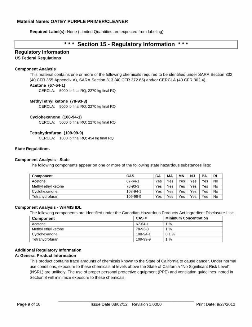
Material Name: OATEY PURPLE PRIMER/CLEANER
____________________________________________________________ Page 9 of 10 Issue Date 08/02/12 Revision 1.0000 Print Date: 9/27/2012
Required Label(s): None (Limited Quantities are expected from labeling)
* * * Section 15 - Regulatory Information * * *
Regulatory Information US Federal Regulations
Component Analysis
This material contains one or more of the following chemicals required to be identified under SARA Section 302
(40 CFR 355 Appendix A), SARA Section 313 (40 CFR 372.65) and/or CERCLA (40 CFR 302.4).
Acetone (67-64-1)
CERCLA: 5000 lb final RQ; 2270 kg final RQ
Methyl ethyl ketone (78-93-3)
CERCLA: 5000 lb final RQ; 2270 kg final RQ
Cyclohexanone (108-94-1)
CERCLA: 5000 lb final RQ; 2270 kg final RQ
Tetrahydrofuran (109-99-9)
CERCLA: 1000 lb final RQ; 454 kg final RQ
State Regulations
Component Analysis - State
The following components appear on one or more of the following state hazardous substances lists:
Component CAS CA MA MN NJ PA RI
Acetone 67-64-1 Yes Yes Yes Yes Yes No
Methyl ethyl ketone 78-93-3 Yes Yes Yes Yes Yes No
Cyclohexanone 108-94-1 Yes Yes Yes Yes Yes No
Tetrahydrofuran 109-99-9 Yes Yes Yes Yes Yes No
Component Analysis - WHMIS IDL
The following components are identified under the Canadian Hazardous Products Act Ingredient Disclosure List:
Component CAS # Minimum Concentration
Acetone 67-64-1 1 %
Methyl ethyl ketone 78-93-3 1 %
Cyclohexanone 108-94-1 0.1 %
Tetrahydrofuran 109-99-9 1 %
Additional Regulatory Information
A: General Product Information
This product contains trace amounts of chemicals known to the State of California to cause cancer. Under normal
use conditions, exposure to these chemicals at levels above the State of California "No Significant Risk Level"
(NSRL) are unlikely. The use of proper personal protective equipment (PPE) and ventilation guidelines noted in
Section 8 will minimize exposure to these chemicals.
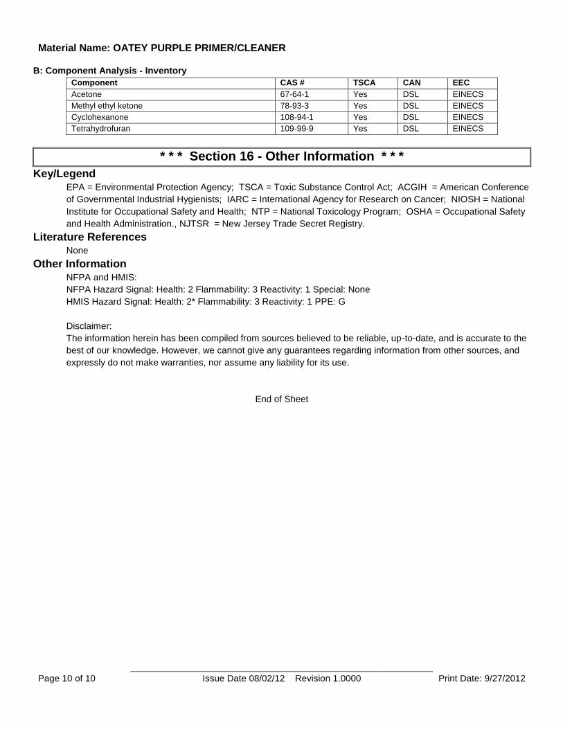
Material Name: OATEY PURPLE PRIMER/CLEANER
____________________________________________________________ Page 10 of 10 Issue Date 08/02/12 Revision 1.0000 Print Date: 9/27/2012
B: Component Analysis - Inventory
Component CAS # TSCA CAN EEC
Acetone 67-64-1 Yes DSL EINECS
Methyl ethyl ketone 78-93-3 Yes DSL EINECS
Cyclohexanone 108-94-1 Yes DSL EINECS
Tetrahydrofuran 109-99-9 Yes DSL EINECS
* * * Section 16 - Other Information * * *
Key/Legend EPA = Environmental Protection Agency; TSCA = Toxic Substance Control Act; ACGIH = American Conference
of Governmental Industrial Hygienists; IARC = International Agency for Research on Cancer; NIOSH = National
Institute for Occupational Safety and Health; NTP = National Toxicology Program; OSHA = Occupational Safety
and Health Administration., NJTSR = New Jersey Trade Secret Registry.
Literature References None
Other Information NFPA and HMIS:
NFPA Hazard Signal: Health: 2 Flammability: 3 Reactivity: 1 Special: None
HMIS Hazard Signal: Health: 2* Flammability: 3 Reactivity: 1 PPE: G
Disclaimer:
The information herein has been compiled from sources believed to be reliable, up-to-date, and is accurate to the
best of our knowledge. However, we cannot give any guarantees regarding information from other sources, and
expressly do not make warranties, nor assume any liability for its use.
End of Sheet
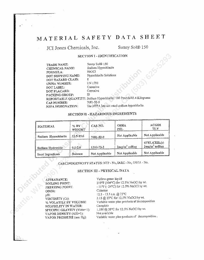
Dist
ribute
d by C
asca
de Colu
mbia
Distrib
ution
Sea
ttle,
WA (2
06) 2
82-6
334
- S
herwood, O
R (503
) 625
-529
3
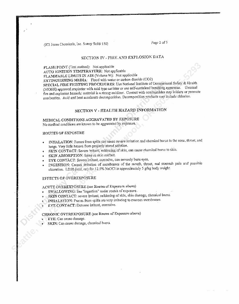
Dist
ribute
d by C
asca
de Colu
mbia
Distrib
ution
Sea
ttle,
WA (2
06) 2
82-6
334
- S
herwood, O
R (503
) 625
-529
3
Dist
ribute
d by C
asca
de Colu
mbia
Distrib
ution
Sea
ttle,
WA (2
06) 2
82-6
334
- S
herwood, O
R (503
) 625
-529
3
Dist
ribute
d by C
asca
de Colu
mbia
Distrib
ution
Sea
ttle,
WA (2
06) 2
82-6
334
- S
herwood, O
R (503
) 625
-529
3
Dist
ribute
d by C
asca
de Colu
mbia
Distrib
ution
Sea
ttle,
WA (2
06) 2
82-6
334
- S
herwood, O
R (503
) 625
-529
3
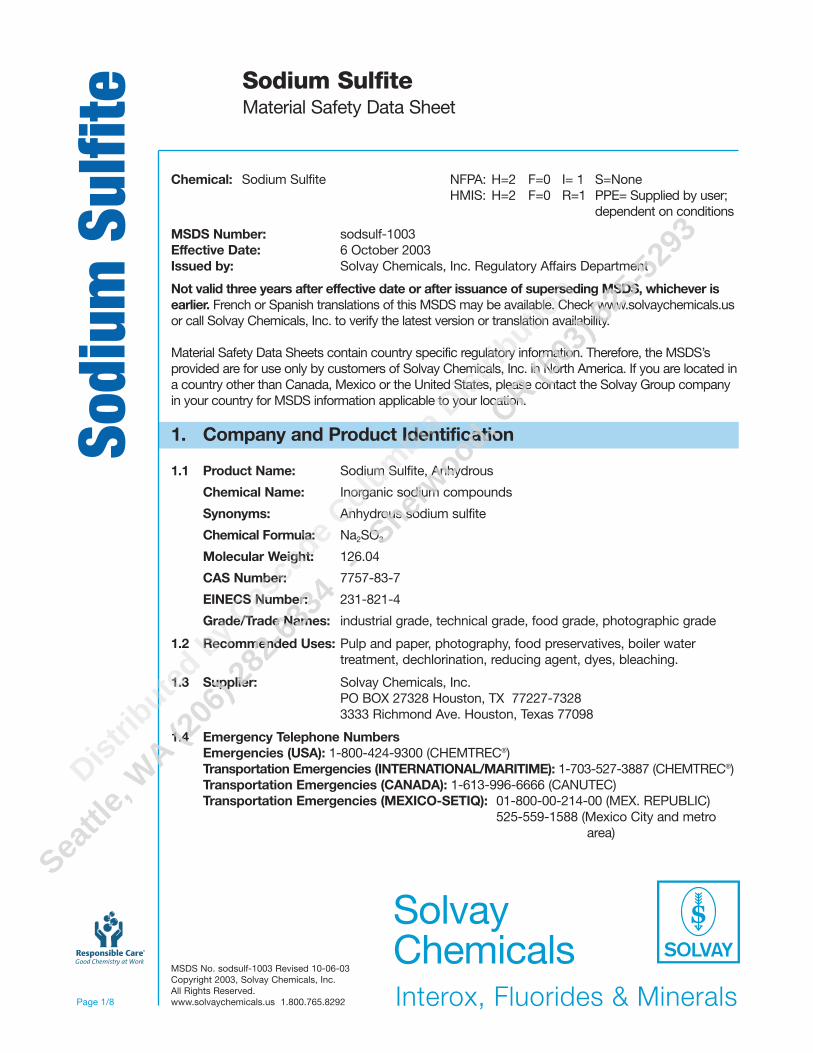
MSDS No. sodsulf-1003 Revised 10-06-03Copyright 2003, Solvay Chemicals, Inc.All Rights Reserved.www.solvaychemicals.us 1.800.765.8292
Sodi
um S
ulfit
e Sodium SulfiteMaterial Safety Data Sheet
Page 1/8
Chemical: Sodium Sulfite NFPA: H=2 F=0 I= 1 S=NoneHMIS: H=2 F=0 R=1 PPE= Supplied by user;
dependent on conditions
MSDS Number: sodsulf-1003Effective Date: 6 October 2003Issued by: Solvay Chemicals, Inc. Regulatory Affairs Department
Not valid three years after effective date or after issuance of superseding MSDS, whichever isearlier. French or Spanish translations of this MSDS may be available. Check www.solvaychemicals.usor call Solvay Chemicals, Inc. to verify the latest version or translation availability.
Material Safety Data Sheets contain country specific regulatory information. Therefore, the MSDS’sprovided are for use only by customers of Solvay Chemicals, Inc. in North America. If you are located ina country other than Canada, Mexico or the United States, please contact the Solvay Group companyin your country for MSDS information applicable to your location.
1. Company and Product Identification
1.1 Product Name: Sodium Sulfite, Anhydrous
Chemical Name: Inorganic sodium compounds
Synonyms: Anhydrous sodium sulfite
Chemical Formula: Na2SO3
Molecular Weight: 126.04
CAS Number: 7757-83-7
EINECS Number: 231-821-4
Grade/Trade Names: industrial grade, technical grade, food grade, photographic grade
1.2 Recommended Uses: Pulp and paper, photography, food preservatives, boiler water treatment, dechlorination, reducing agent, dyes, bleaching.
1.3 Supplier: Solvay Chemicals, Inc.PO BOX 27328 Houston, TX 77227-73283333 Richmond Ave. Houston, Texas 77098
1.4 Emergency Telephone NumbersEmergencies (USA): 1-800-424-9300 (CHEMTREC®)Transportation Emergencies (INTERNATIONAL/MARITIME): 1-703-527-3887 (CHEMTREC®)Transportation Emergencies (CANADA): 1-613-996-6666 (CANUTEC)Transportation Emergencies (MEXICO-SETIQ): 01-800-00-214-00 (MEX. REPUBLIC)
525-559-1588 (Mexico City and metro area)
D
istrib
uted b
y Cas
cade C
olum
bia Dist
ributio
n
Sea
ttle,
WA (2
06) 2
82-6
334
- S
herwood, O
R (503
) 625
-529
3
MSDS No. sodsulf-1003 Revised 10-06-03Copyright 2003, Solvay Chemicals, Inc.All Rights Reserved.www.solvaychemicals.us 1.800.765.8292
Sodi
um S
ulfit
e Sodium SulfiteMaterial Safety Data Sheet
Page 2/8
2. Composition/Information on IngredientsINGREDIENTS FORMULA WT. PERCENT CAS #Sodium Sulfite Na2SO3 99 7757-83-7Sodium Sulfate Na2SO4 1 7757-82-6
3. Hazards Identification
Emergency Overview: Sulfite-sensitive individuals may experience a severe allergic reaction.
3.1 Route of Entry: Inhalation: Yes Skin: Yes Ingestion: Yes
3.2 Potential Effects of exposure: May cause irritation.
Inhalation (dust): May cause mild irritation.
Eyes (dust): May cause mild irritation.
Skin contact: May cause mild irritation with prolonged exposure.
Ingestion: Oral exposure or swallowing may produce gastrointestinal upset, nausea or vomiting. Ingestion may be fatal. Sulfite sensitive individuals may experience a severe allergic reaction.
Carcinogenicity: See section 11.3
4. First-Aid Measures
4.1 Inhalation:• Remove the patient to fresh air.• If breathing has stopped or patient experiences difficulty in breathing, administer
artificial respiration.
Eyes:• Remove contact lenses. Gently flush the eyes and surrounding areas with lukewarm
water for 15 minutes.• If irritation persists, seek medical attention.
Skin:• Remove contaminated clothing.• Wipe material from the skin. Rinse the affected area with large amounts of water
for 15 minutes.• If irritation persists, seek medical attention.
Ingestion:
If the subject is completely conscious: Give 8-12 ounces of water and seek medical attention.
If the subject is unconscious: Remove any evidence of the substance from the patient's mouth. NEVER GIVE ANYTHING BY MOUTH TO AN UNCONSCIOUS PERSON.
4.2 Medical Treatment/Notes to Physician: Breathing of dust may aggravate asthma or other pulmonary diseases.
Dist
ribute
d by C
asca
de Colu
mbia
Distrib
ution
Sea
ttle,
WA (2
06) 2
82-6
334
- S
herwood, O
R (503
) 625
-529
3
MSDS No. sodsulf-1003 Revised 10-06-03Copyright 2003, Solvay Chemicals, Inc.All Rights Reserved.www.solvaychemicals.us 1.800.765.8292
Sodi
um S
ulfit
e Sodium SulfiteMaterial Safety Data Sheet
Page 3/8
5. Fire-Fighting Measures
5.1 Flash point: Non-combustible
5.2 Auto-ignition Temperature: Not applicable.
5.3 Flammability Limits: Not applicable.
5.4 Unusual Fire and Explosion Hazards: Non-combustible. Generates hazardous SO2
during decomposition.
5.5 Common Extinguishing Methods: In case of fire in close proximity, all means of extinguishing are acceptable.
5.6 Fire Fighting Procedures: Wear NIOSH-approved self-contained breathing apparatus. Use water spray to keep containers cool and to knock down fumes.
6. Accidental Release Measures
6.1 Precautions: Avoid excessive dust.
6.2 Cleanup methods:• Clean up uncontaminated material and recycle into process. • Place unusable material into a closed, labeled container compatible with the product.
6.3 Precautions for protection of the environment:• Sweep up residual material.• Do not flush to drain. • Prevent material from entering public sewer systems or any waterways. • Dispose of waste in accordance with applicable federal, state, and local environmental
laws and regulations.
7. Handling and Storage
7.1 Handling:• Avoid prolonged or repeated contact with the skin or eyes.• Do not wear contact lenses without proper eye protection when using this product.• Wash exposed areas promptly and thoroughly after skin contact from working with this
product and before eating, drinking, using tobacco products or using the rest room.• Avoid prolonged or repeated breathing of dusts.• Use vacuum or wet mop to clean up dust.
7.2 Storage:• Keep in a closed, properly labeled container in a dry area away from acids.• Protect from physical damage.
7.3 Specific Uses: See Section 1.2
7.4 Packaging:• Bulk rail car & truck.• Paper+PE.• Woven plastic material + PE coating.• Woven plastic material + PE.
Dist
ribute
d by C
asca
de Colu
mbia
Distrib
ution
Sea
ttle,
WA (2
06) 2
82-6
334
- S
herwood, O
R (503
) 625
-529
3
MSDS No. sodsulf-1003 Revised 10-06-03Copyright 2003, Solvay Chemicals, Inc.All Rights Reserved.www.solvaychemicals.us 1.800.765.8292
Sodi
um S
ulfit
e Sodium SulfiteMaterial Safety Data Sheet
Page 4/8
8. Exposure Controls/Personal Protection
8.1 Exposure Limit Values:
Exposure Limit Values TLV® ACGIH®-USA (2002) OSHA PELSodium Sulfite Not listed Nuisance Dust-5mg/m3
(Respirable Fraction), 15 mg/m3 (Total Dust).
Sulfur Dioxide Gas TWA-2 ppm STEL-5 ppm
IDLH-100ppm
ACGIH® and TLV® are registered trademarks of the American Conference of Governmental Industrial Hygienists.
8.2 Occupational Exposure Controls:
8.2.1 Ventilation: In places with the possibility for creating dust in excess of exposure limits, ventilation should be provided.
8.2.2 Respiratory protection: In case of significant or accidental dust emissions, a NIOSH/MSHA approved respirator should be worn. If SO2 is present, (see section 10), use an NIOSH-approved air supplied positive pressure respirator or acid gas canister.
8.2.3 Hand protection: Cotton gloves are adequate for routine handling of dry product. For solutions, wear acid impervious gloves.
8.2.4 Eye protection: Wear chemical safety goggles. Do not wear contact lenses without proper eye protection.
8.2.5 Skin protection: Wear boots, apron, long sleeves and other protective clothing suitable for use to prevent contact with the skin.
8.3 Other precautions: An eyewash and safety shower should be nearby and ready for use. Use good hygiene practices when handling this product including changing work clothes after use. Do not eat, drink or smoke in areas where this material is handled. Persons with allergic symptoms should seek advice from medical personnel as to whether exposure to the substance should be curtailed or eliminated.
9. Physical and Chemical Properties
9.1 Appearance: Granular solidColor: WhiteOdor: Odorless
9.2 Important Health, Safety and Environmental information:pH: 9.6-9.8 (1% solution)
Change of state:Melting point: Decomposes at approximately 600°C (1112°F)Boiling point: Not ApplicableDecompositon Temperature: Approximately 600°C (1112°F)
Dist
ribute
d by C
asca
de Colu
mbia
Distrib
ution
Sea
ttle,
WA (2
06) 2
82-6
334
- S
herwood, O
R (503
) 625
-529
3
MSDS No. sodsulf-1003 Revised 10-06-03Copyright 2003, Solvay Chemicals, Inc.All Rights Reserved.www.solvaychemicals.us 1.800.765.8292
Sodi
um S
ulfit
e Sodium SulfiteMaterial Safety Data Sheet
Page 5/8
Flash Point: Not applicable
Flammability (solid, gas): Not applicable
Explosive Properties: Not applicable
Oxidizing Properties: Decomposition releases oxides of sulfur
Vapor Pressure: No data
Relative Density:Specific gravity: 2.63 @ 20°C (68°F)(H2O=1)
Solubility:Water: 27g Sodium Sulfite in 100g water @ 20°C (68°F)Fat: Not applicable
Partition coefficient: Not applicableP (n-octanol/water)
Viscosity: No data
Vapor Density (air=1): Not applicable
Evaporation Rate: No data
Surface Tension: Not applicable
9.3 Other Information: Bulk Density: 95-100 lbs/ft3 (1522-1602 kg/m3).
10. Stability and Reactivity
Stability: Stable at ambient temperatures and atmospheric pressure.
10.1 Conditions to avoid: • High temperatures• Moisture.
10.2 Materials and substances to avoid:• Contact with strong oxidizers cause vigorous exothermic reactions.• Contact with acids will release SO2.
10.3 Hazardous decomposition products: Oxides of sulfur and sulfur dioxide gas.
10.4 Hazardous Polymerization: Not applicable
Dist
ribute
d by C
asca
de Colu
mbia
Distrib
ution
Sea
ttle,
WA (2
06) 2
82-6
334
- S
herwood, O
R (503
) 625
-529
3
MSDS No. sodsulf-1003 Revised 10-06-03Copyright 2003, Solvay Chemicals, Inc.All Rights Reserved.www.solvaychemicals.us 1.800.765.8292
Sodi
um S
ulfit
e Sodium SulfiteMaterial Safety Data Sheet
Page 6/8
11. Toxicological Information
11.1 Acute toxicity:
Oral: LD50 - 820 mg/kg species: mouse
11.2 Chronic toxicity: Can cause allergic reactions (headaches, difficulty in breathing, rapid heart rate and anaphylaxis) to susceptible individuals.
11.3 Carcinogenic Designation: None
12. Ecological Information
12.1 Acute ecotoxicity:• 96 hour LC50, Goldfish: 100 mg/l. • 24, 48, 96 hour TLm Mosquito fish: 2,600 ppm. • BOD (Biological Oxygen Demand) = 0.12 LB/LB instantaneous.
12.2 Chronic ecotoxicity: No data
12.3 Mobility: No data
12.4 Degradation
Abiotic: No data
Biotic: No data
12.5 Potential for bioaccumulation: Not expected to occur
12.6 Other adverse effects / comments: Sodium sulfite is an oxygen scavenger when introduced to water.
13. Disposal Considerations
13.1 Waste treatment: Sodium sulfite is not a listed hazardous waste under 40 CFR 261. However, state and local regulations for waste disposal may be more restrictive. Spilled product should be disposed of in an EPA approved disposal facility in accordance with applicable national, state and local environmental laws and regulations.
13.2 Packaging treatment: To avoid treatments, use dedicated containers where possible. Rinse the empty containers and treat the effluent in the same way as waste. Consult current federal, state and local regulations regarding the proper disposal of emptied containers.
13.3 RCRA Hazardous Waste: Not Listed
14. Transport Information
Mode DOT IMDG IATAProper Shipping Name Not a regulated Not a regulated Not a regulated
hazardous material hazardous material hazardous materialEmergency Info It is recommended that ERG guide # 111 be used for all non DOT regulated material.STCC # 28-123-80
Dist
ribute
d by C
asca
de Colu
mbia
Distrib
ution
Sea
ttle,
WA (2
06) 2
82-6
334
- S
herwood, O
R (503
) 625
-529
3
MSDS No. sodsulf-1003 Revised 10-06-03Copyright 2003, Solvay Chemicals, Inc.All Rights Reserved.www.solvaychemicals.us 1.800.765.8292
Sodi
um S
ulfit
e Sodium SulfiteMaterial Safety Data Sheet
Page 7/8
15. Regulatory Information
National Regulations (US)
TSCA Inventory 8(b): Yes
SARA Title III Sec. 302/303 Extremely Hazardous Substances (40 CFR355): No
SARA Title III Sec. 311/312 (40 CFR 370:Hazard: Category Acute & chronic health hazardThreshold planning quantity: 10,000 lbs
SARA Title III Sec. 313 Toxic Chemical Emissions Reporting (40 CFR 372): No
CERCLA Hazardous Substance (40CFR Part 302): No
State Component Listing: None identified
National Regulations (Canada)
Canadian NDSL/DSL Registration: DSL
WHMIS Classification: D2B - Material causing other toxic effects
This product has been classified in accordance with the hazard criteria of the Controlled Products Regulations and theMSDS contains all the information required by the Controlled Products Regulations.
Labeling according to Directive 1999/45/EC.Symbols NonePhrases R 22 Harmful if swallowed.
36/38 Irritating to eyes and skin.40 Possibility of irreversible effects.
Phrases S 22 Do not breathe dust.26 In case of contact with eyes, rinse immediately with plenty of water and
seek medical attention.36 Wear suitable protective clothing.
Dist
ribute
d by C
asca
de Colu
mbia
Distrib
ution
Sea
ttle,
WA (2
06) 2
82-6
334
- S
herwood, O
R (503
) 625
-529
3
MSDS No. sodsulf-1003 Revised 10-06-03Copyright 2003, Solvay Chemicals, Inc.All Rights Reserved.www.solvaychemicals.us 1.800.765.8292
Sodi
um S
ulfit
eSodium SulfiteMaterial Safety Data Sheet
Page 8/8
16. Other Information
The NSF International recommends that the maximum usage level is 22 mg/l for potable watertreatment, unless usage is ozone reduction. To reduce ozone, this product may be used at astoichiometric ratio of 1 to 1, or a ratio of 215 mg/l of sodium sulfite to 100 mg/l of ozone.Residual sodium sulfite levels shall not exceed 100 ppb in the finished water.
This product is not for food or drug use unless material is labeled “food grade”. For food gradeproduct, the following applies:
1. Effective August 8, 1987, the FDA has banned the use of “Sulfiting Agents” or “Sulfites”on fruits and vegetables intended to be served raw or sold raw to consumers.2. Effective January 9, 1987, the FDA is requiring when a sulfite is present in a dedtectable amount in a finished food, regardless of whether it has been directly or indirectly added viaone or more of the food ingredients, it must be declared on the label. The regulation definesa “detectable amount” of sulfite to be 10 ppm.3. Sulfiting agents or sulfites are not to be used on foods or meats recognized as a source of Vitamin B1.
16.1 Ratings:NFPA (NATIONAL FIRE PROTECTION ASSOCIATION)Health = 2 Flammability = 0 Instability = 1 Special = None
HMIS (HAZARDOUS MATERIAL INFORMATION SYSTEM)Health = 2 Fire = 0 Reactivity = 1 PPE = Supplied by User; dependent on local conditions
16.2 Other Information:
The previous information is based upon our current knowledge and experience of our product and is not exhaustive. It applies to the product as defined by the specifications. In case ofcombinations or mixtures, one must confirm that no new hazards are likely to exist. In any case,the user is not exempt from observing all legal, administrative and regulatory procedures relatingto the product, personal hygiene, and integrity of the work environment. (Unless noted to thecontrary, the technical information applies only to pure product).
To our actual knowledge, the information contained herein is accurate as of the date of thisdocument. However, neither Solvay Chemicals, Inc. nor any of its affiliates makes any warranty,express or implied, or accepts any liability in connection with this information or its use. Thisinformation is for use by technically skilled persons at their own discretion and risk and does notrelate to the use of this product in combination with any other substance or any other process.This is not a license under any patent or other proprietary right. The user alone must finallydetermine suitability of any information or material for any contemplated use, the manner of useand whether any patents are infringed.
TRADEMARKS: All trade names products referenced herein are either trademarks or registeredtrademarks of Solvay Chemicals, Inc. or affiliate unless otherwise indicated.
16.3 Reason for revision:Supersedes edition: Solvay Minerals MSDS #003 dated 06/26/03Purpose of revision: Change Company name and MSDS format
Dist
ribute
d by C
asca
de Colu
mbia
Distrib
ution
Sea
ttle,
WA (2
06) 2
82-6
334
- S
herwood, O
R (503
) 625
-529
3
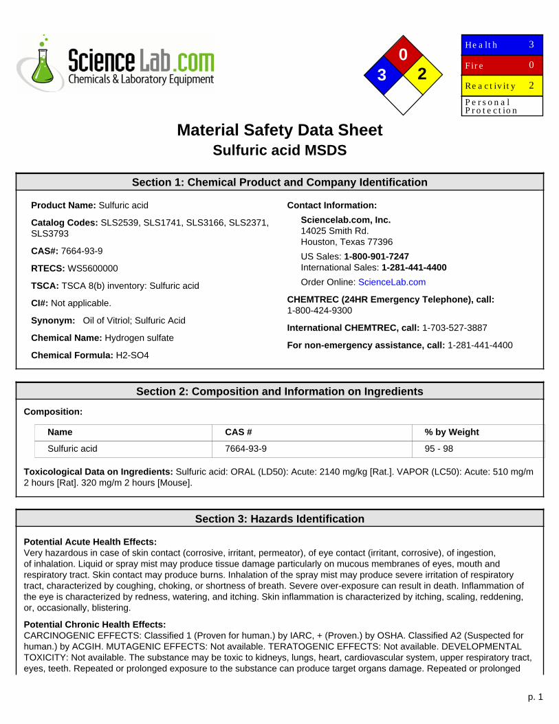
p. 1
0 3 2
He a lt h
Fir e
Re a c t iv it y
P e r s o n a lP r o t e c t io n
3
0
2
Material Safety Data SheetSulfuric acid MSDS
Section 1: Chemical Product and Company Identification
Product Name: Sulfuric acid
Catalog Codes: SLS2539, SLS1741, SLS3166, SLS2371,SLS3793
CAS#: 7664-93-9
RTECS: WS5600000
TSCA: TSCA 8(b) inventory: Sulfuric acid
CI#: Not applicable.
Synonym: Oil of Vitriol; Sulfuric Acid
Chemical Name: Hydrogen sulfate
Chemical Formula: H2-SO4
Contact Information:
Sciencelab.com, Inc.14025 Smith Rd.Houston, Texas 77396
US Sales: 1-800-901-7247International Sales: 1-281-441-4400
Order Online: ScienceLab.com
CHEMTREC (24HR Emergency Telephone), call:1-800-424-9300
International CHEMTREC, call: 1-703-527-3887
For non-emergency assistance, call: 1-281-441-4400
Section 2: Composition and Information on Ingredients
Composition:
Name CAS # % by Weight
Sulfuric acid 7664-93-9 95 - 98
Toxicological Data on Ingredients: Sulfuric acid: ORAL (LD50): Acute: 2140 mg/kg [Rat.]. VAPOR (LC50): Acute: 510 mg/m2 hours [Rat]. 320 mg/m 2 hours [Mouse].
Section 3: Hazards Identification
Potential Acute Health Effects:Very hazardous in case of skin contact (corrosive, irritant, permeator), of eye contact (irritant, corrosive), of ingestion,of inhalation. Liquid or spray mist may produce tissue damage particularly on mucous membranes of eyes, mouth andrespiratory tract. Skin contact may produce burns. Inhalation of the spray mist may produce severe irritation of respiratorytract, characterized by coughing, choking, or shortness of breath. Severe over-exposure can result in death. Inflammation ofthe eye is characterized by redness, watering, and itching. Skin inflammation is characterized by itching, scaling, reddening,or, occasionally, blistering.
Potential Chronic Health Effects:CARCINOGENIC EFFECTS: Classified 1 (Proven for human.) by IARC, + (Proven.) by OSHA. Classified A2 (Suspected forhuman.) by ACGIH. MUTAGENIC EFFECTS: Not available. TERATOGENIC EFFECTS: Not available. DEVELOPMENTALTOXICITY: Not available. The substance may be toxic to kidneys, lungs, heart, cardiovascular system, upper respiratory tract,eyes, teeth. Repeated or prolonged exposure to the substance can produce target organs damage. Repeated or prolonged
p. 2
contact with spray mist may produce chronic eye irritation and severe skin irritation. Repeated or prolonged exposure to spraymist may produce respiratory tract irritation leading to frequent attacks of bronchial infection. Repeated exposure to a highlytoxic material may produce general deterioration of health by an accumulation in one or many human organs.
Section 4: First Aid Measures
Eye Contact:Check for and remove any contact lenses. In case of contact, immediately flush eyes with plenty of water for at least 15minutes. Cold water may be used. Get medical attention immediately.
Skin Contact:In case of contact, immediately flush skin with plenty of water for at least 15 minutes while removing contaminated clothingand shoes. Cover the irritated skin with an emollient. Cold water may be used.Wash clothing before reuse. Thoroughly cleanshoes before reuse. Get medical attention immediately.
Serious Skin Contact:Wash with a disinfectant soap and cover the contaminated skin with an anti-bacterial cream. Seek immediate medicalattention.
Inhalation:If inhaled, remove to fresh air. If not breathing, give artificial respiration. If breathing is difficult, give oxygen. Get medicalattention immediately.
Serious Inhalation:Evacuate the victim to a safe area as soon as possible. Loosen tight clothing such as a collar, tie, belt or waistband. Ifbreathing is difficult, administer oxygen. If the victim is not breathing, perform mouth-to-mouth resuscitation. WARNING: It maybe hazardous to the person providing aid to give mouth-to-mouth resuscitation when the inhaled material is toxic, infectious orcorrosive. Seek immediate medical attention.
Ingestion:Do NOT induce vomiting unless directed to do so by medical personnel. Never give anything by mouth to an unconsciousperson. Loosen tight clothing such as a collar, tie, belt or waistband. Get medical attention if symptoms appear.
Serious Ingestion: Not available.
Section 5: Fire and Explosion Data
Flammability of the Product: Non-flammable.
Auto-Ignition Temperature: Not applicable.
Flash Points: Not applicable.
Flammable Limits: Not applicable.
Products of Combustion:Products of combustion are not available since material is non-flammable. However, products of decompostion include fumesof oxides of sulfur. Will react with water or steam to produce toxic and corrosive fumes. Reacts with carbonates to generatecarbon dioxide gas. Reacts with cyanides and sulfides to form poisonous hydrogen cyanide and hydrogen sulfide respectively.
Fire Hazards in Presence of Various Substances: Combustible materials
Explosion Hazards in Presence of Various Substances:Risks of explosion of the product in presence of mechanical impact: Not available. Risks of explosion of the product inpresence of static discharge: Not available. Slightly explosive in presence of oxidizing materials.
Fire Fighting Media and Instructions: Not applicable.
Special Remarks on Fire Hazards:Metal acetylides (Monocesium and Monorubidium), and carbides ignite with concentrated sulfuric acid. White Phosphorous +boiling Sulfuric acid or its vapor ignites on contact. May ignite other combustible materials. May cause fire when sulfuric acidis mixed with Cyclopentadiene, cyclopentanone oxime, nitroaryl amines, hexalithium disilicide, phorphorous (III) oxide, andoxidizing agents such as chlorates, halogens, permanganates.
p. 3
Special Remarks on Explosion Hazards:M i x t u r e s o f s u l f u r i c a c i d a n d a n y o f t h e f o l l o w i n g c a n e x p l o d e : p - n i t r o t o l u e n e , p e n t a s il v e r trihydroxydiaminophosphate, perchlorates, alcohols with strong hydrogen peroxide, ammonium tetraperoxychromate,mercuric nitrite, potassium chlorate, potassium permanganate with potassium chloride, carbides, nitro compounds, nitrates,carbides, phosphorous, iodides, picratres, fulminats, dienes, alcohols (when heated) Nitramide decomposes explosivelyon contact with concentrated sulfuric acid. 1,3,5-Trinitrosohexahydro-1,3,5-triazine + sulfuric acid causes explosivedecompositon.
Section 6: Accidental Release Measures
Small Spill:Dilute with water and mop up, or absorb with an inert dry material and place in an appropriate waste disposal container. Ifnecessary: Neutralize the residue with a dilute solution of sodium carbonate.
Large Spill:Corrosive liquid. Poisonous liquid. Stop leak if without risk. Absorb with DRY earth, sand or other non-combustible material.Do not get water inside container. Do not touch spilled material. Use water spray curtain to divert vapor drift. Use water sprayto reduce vapors. Prevent entry into sewers, basements or confined areas; dike if needed. Call for assistance on disposal.Neutralize the residue with a dilute solution of sodium carbonate. Be careful that the product is not present at a concentrationlevel above TLV. Check TLV on the MSDS and with local authorities.
Section 7: Handling and Storage
Precautions:Keep locked up.. Keep container dry. Do not ingest. Do not breathe gas/fumes/ vapor/spray. Never add water to this product.In case of insufficient ventilation, wear suitable respiratory equipment. If ingested, seek medical advice immediately and showthe container or the label. Avoid contact with skin and eyes. Keep away from incompatibles such as oxidizing agents, reducingagents, combustible materials, organic materials, metals, acids, alkalis, moisture. May corrode metallic surfaces. Store in ametallic or coated fiberboard drum using a strong polyethylene inner package.
Storage:Hygroscopic. Reacts. violently with water. Keep container tightly closed. Keep container in a cool, well-ventilated area. Do notstore above 23°C (73.4°F).
Section 8: Exposure Controls/Personal Protection
Engineering Controls:Provide exhaust ventilation or other engineering controls to keep the airborne concentrations of vapors below their respectivethreshold limit value. Ensure that eyewash stations and safety showers are proximal to the work-station location.
Personal Protection:Face shield. Full suit. Vapor respirator. Be sure to use an approved/certified respirator or equivalent. Gloves. Boots.
Personal Protection in Case of a Large Spill:Splash goggles. Full suit. Vapor respirator. Boots. Gloves. A self contained breathing apparatus should be used to avoidinhalation of the product. Suggested protective clothing might not be sufficient; consult a specialist BEFORE handling thisproduct.
Exposure Limits:TWA: 1 STEL: 3 (mg/m3) [Australia] Inhalation TWA: 1 (mg/m3) from OSHA (PEL) [United States] Inhalation TWA: 1 STEL: 3(mg/m3) from ACGIH (TLV) [United States] [1999] Inhalation TWA: 1 (mg/m3) from NIOSH [United States] Inhalation TWA: 1(mg/m3) [United Kingdom (UK)]Consult local authorities for acceptable exposure limits.
Section 9: Physical and Chemical Properties
p. 4
Physical state and appearance: Liquid. (Thick oily liquid.)
Odor: Odorless, but has a choking odor when hot.
Taste: Marked acid taste. (Strong.)
Molecular Weight: 98.08 g/mole
Color: Colorless.
pH (1% soln/water): Acidic.
Boiling Point:270°C (518°F) - 340 deg. C Decomposes at 340 deg. C
Melting Point: -35°C (-31°F) to 10.36 deg. C (93% to 100% purity)
Critical Temperature: Not available.
Specific Gravity: 1.84 (Water = 1)
Vapor Pressure: Not available.
Vapor Density: 3.4 (Air = 1)
Volatility: Not available.
Odor Threshold: Not available.
Water/Oil Dist. Coeff.: Not available.
Ionicity (in Water): Not available.
Dispersion Properties: See solubility in water.
Solubility:Easily soluble in cold water. Sulfuric is soluble in water with liberation of much heat. Soluble in ethyl alcohol.
Section 10: Stability and Reactivity Data
Stability: The product is stable.
Instability Temperature: Not available.
Conditions of Instability:Conditions to Avoid: Incompatible materials, excess heat, combustible material materials, organic materials, exposure to moistair or water, oxidizers, amines, bases. Always add the acid to water, never the reverse.
Incompatibility with various substances:Reactive with oxidizing agents, reducing agents, combustible materials, organic materials, metals, acids, alkalis, moisture.
Corrosivity:Extremely corrosive in presence of aluminum, of copper, of stainless steel(316). Highly corrosive in presence of stainlesssteel(304). Non-corrosive in presence of glass.
Special Remarks on Reactivity:Hygroscopic. Strong oxidizer. Reacts violently with water and alcohol especially when water is added to the product.Incompatible (can react explosively or dangerously) with the following: ACETIC ACID, ACRYLIC ACID, AMMONIUMHYDROXIDE, CRESOL, CUMENE, DICHLOROETHYL ETHER, ETHYLENE CYANOHYDRIN, ETHYLENEIMINE, NITRICACID, 2-NITROPROPANE, PROPYLENE OXIDE, SULFOLANE, VINYLIDENE CHLORIDE, DIETHYLENE GLYCOLMONOMETHYL ETHER, ETHYL ACETATE, ETHYLENE CYANOHYDRIN, ETHYLENE GLYCOL MONOETHYL ETHERACETATE, GLYOXAL, METHYL ETHYL KETONE, dehydrating agents, organic materials, moisture (water), Acetic anhydride,Acetone, cyanohydrin, Acetone+nitric acid, Acetone + potassium dichromate, Acetonitrile, Acrolein, Acrylonitrile, Acrylonitrile+water, Alcohols + hydrogen peroxide, ally compounds such as Allyl alcohol, and Allyl Chloride, 2-Aminoethanol, Ammoniumhydroxide, Ammonium triperchromate, Aniline, Bromate + metals, Bromine pentafluoride, n-Butyraldehyde, Carbides, Cesiumacetylene carbide, Chlorates, Cyclopentanone oxime, chlorinates, Chlorates + metals, Chlorine trifluoride, Chlorosulfonicacid, 2-cyano-4-nitrobenzenediazonium hydrogen sulfate, Cuprous nitride, p-chloronitrobenzene, 1,5-Dinitronaphthlene +
p. 5
sulfur, Diisobutylene, p-dimethylaminobenzaldehyde, 1,3-Diazidobenzene, Dimethylbenzylcarbinol + hydrogen peroxide,Epichlorohydrin, Ethyl alcohol + hydrogen peroxide, Ethylene diamine, Ethylene glycol and other glycols, , Ethylenimine,Fulminates, hydrogen peroxide, Hydrochloric acid, Hydrofluoric acid, Iodine heptafluoride, Indane + nitric acid, Iron, Isoprene,Lithium silicide, Mercuric nitride, Mesityl oxide, Mercury nitride, Metals (powdered), Nitromethane, Nitric acid + glycerides,p-Nitrotoluene, Pentasilver trihydroxydiaminophosphate, Perchlorates, Perchloric acid, Permanganates + benzene, 1-Phenyl-2-methylpropyl alcohol + hydrogen peroxide, Phosphorus, Phosphorus isocyanate, Picrates, Potassium tert-butoxide,Potassium chlorate, Potassium Permanganate and other permanganates, halogens, amines, Potassium Permanganate +Potassium chloride, Potassium Permanganate + water, Propiolactone (beta)-, Pyridine, Rubidium aceteylene carbide, Silverpermanganate, Sodium, Sodium carbonate, sodium hydroxide, Steel, styrene monomer, toluene + nitric acid, Vinyl acetate,Thalium (I) azidodithiocarbonate, Zinc chlorate, Zinc Iodide, azides, carbonates, cyanides, sulfides, sulfites, alkali hydrides,carboxylic acid anhydrides, nitriles, olefinic organics, aqueous acids, cyclopentadiene, cyano-alcohols, metal acetylides,Hydrogen gas is generated by the action of the acid on most metals (i.e. lead, copper, tin, zinc, aluminum, etc.). Concentratedsulfuric acid oxidizes, dehydrates, or sulfonates most organic compounds.
Special Remarks on Corrosivity:Non-corrosive to lead and mild steel, but dillute acid attacks most metals. Attacks many metals releasing hydrogen. Minorcorrosive effect on bronze. No corrosion data on brass or zinc.
Polymerization: Will not occur.
Section 11: Toxicological Information
Routes of Entry: Absorbed through skin. Dermal contact. Eye contact. Inhalation. Ingestion.
Toxicity to Animals:WARNING: THE LC50 VALUES HEREUNDER ARE ESTIMATED ON THE BASIS OF A 4-HOUR EXPOSURE. Acute oraltoxicity (LD50): 2140 mg/kg [Rat.]. Acute toxicity of the vapor (LC50): 320 mg/m3 2 hours [Mouse].
Chronic Effects on Humans:CARCINOGENIC EFFECTS: Classified 1 (Proven for human.) by IARC, + (Proven.) by OSHA. Classified A2 (Suspectedfor human.) by ACGIH. May cause damage to the following organs: kidneys, lungs, heart, cardiovascular system, upperrespiratory tract, eyes, teeth.
Other Toxic Effects on Humans:Extremely hazardous in case of inhalation (lung corrosive). Very hazardous in case of skin contact (corrosive, irritant,permeator), of eye contact (corrosive), of ingestion, .
Special Remarks on Toxicity to Animals: Not available.
Special Remarks on Chronic Effects on Humans:Mutagenicity: Cytogenetic Analysis: Hamster, ovary = 4mmol/L Reproductive effects: May cause adverse reproductive effectsbased on animal data. Developmental abnormalities (musculoskeletal) in rabbits at a dose of 20 mg/m3 for 7 hrs.(RTECS)Teratogenecity: neither embryotoxic, fetoxic, nor teratogenetic in mice or rabbits at inhaled doses producing some maternaltoxicity
Special Remarks on other Toxic Effects on Humans:Acute Potential Health Effects: Skin: Causes severe skin irritation and burns. Continued contact can cause tissue necrosis.Eye: Causes severe eye irritation and burns. May cause irreversible eye injury. Ingestion: Harmful if swallowed. May causepermanent damage to the digestive tract. Causes gastrointestial tract burns. May cause perforation of the stomach, GIbleeding, edema of the glottis, necrosis and scarring, and sudden circulatory collapse(similar to acute inhalation). It mayalso cause systemic toxicity with acidosis. Inhalation: May cause severe irritation of the respiratory tract and mucousmembranes with sore throat, coughing, shortness of breath, and delayed lung edema. Causes chemical burns to the repiratorytract. Inhalation may be fatal as a result of spasm, inflammation, edema of the larynx and bronchi, chemical pneumonitis,and pulmonary edema. Cause corrosive action on mucous membranes. May affect cardiovascular system (hypotension,depressed cardiac output, bradycardia). Circulatory collapse with clammy skin, weak and rapid pulse, shallow respiration, andscanty urine may follow. Circulatory shock is often the immediate cause of death. May also affect teeth(changes in teeth andsupporting structures - erosion, discoloration). Chronic Potential Health Effects: Inhalation: Prolonged or repeated inhalationmay affect behavior (muscle contraction or spasticity), urinary system (kidney damage), and cardiovascular system, heart(ischemic heart leisons), and respiratory system/lungs(pulmonary edema, lung damage), teeth (dental discoloration, erosion).Skin: Prolonged or repeated skin contact may cause dermatitis, an allergic skin reaction.
p. 6
Section 12: Ecological Information
Ecotoxicity: Ecotoxicity in water (LC50): 49 mg/l 48 hours [bluegill/sunfish].
BOD5 and COD: Not available.
Products of Biodegradation:Possibly hazardous short term degradation products are not likely. However, long term degradation products may arise.
Toxicity of the Products of Biodegradation: The products of degradation are less toxic than the product itself.
Special Remarks on the Products of Biodegradation: Not available.
Section 13: Disposal Considerations
Waste Disposal:Sulfuric acid may be placed in sealed container or absorbed in vermiculite, dry sand, earth, or a similar material. It may alsobe diluted and neutralized. Be sure to consult with local or regional authorities (waste regulators) prior to any disposal. Wastemust be disposed of in accordance with federal, state and local environmental control regulations.
Section 14: Transport Information
DOT Classification: Class 8: Corrosive material
Identification: : Sulfuric acid UNNA: 1830 PG: II
Special Provisions for Transport: Not available.
Section 15: Other Regulatory Information
Federal and State Regulations:Illinois toxic substances disclosure to employee act: Sulfuric acid New York release reporting list: Sulfuric acid RhodeIsland RTK hazardous substances: Sulfuric acid Pennsylvania RTK: Sulfuric acid Minnesota: Sulfuric acid MassachusettsRTK: Sulfuric acid New Jersey: Sulfuric acid California Director's List of Hazardous Substances (8 CCR 339): Sulfuric acidTennessee RTK: Sulfuric acid TSCA 8(b) inventory: Sulfuric acid SARA 302/304/311/312 extremely hazardous substances:Sulfuric acid SARA 313 toxic chemical notification and release reporting: Sulfuric acid CERCLA: Hazardous substances.:Sulfuric acid: 1000 lbs. (453.6 kg)
Other Regulations:OSHA: Hazardous by definition of Hazard Communication Standard (29 CFR 1910.1200). EINECS: This product is on theEuropean Inventory of Existing Commercial Chemical Substances.
Other Classifications:
WHMIS (Canada):CLASS D-1A: Material causing immediate and serious toxic effects (VERY TOXIC). CLASS E: Corrosive liquid.
DSCL (EEC):R35- Causes severe burns. S2- Keep out of the reach of children. S26- In case of contact with eyes, rinse immediately withplenty of water and seek medical advice. S30- Never add water to this product. S45- In case of accident or if you feel unwell,seek medical advice immediately (show the label where possible).
HMIS (U.S.A.):
Health Hazard: 3
Fire Hazard: 0
Reactivity: 2
p. 7
Personal Protection:
National Fire Protection Association (U.S.A.):
Health: 3
Flammability: 0
Reactivity: 2
Specific hazard:
Protective Equipment:Gloves. Full suit. Vapor respirator. Be sure to use an approved/certified respirator or equivalent. Wear appropriate respiratorwhen ventilation is inadequate. Face shield.
Section 16: Other Information
References:-Material safety data sheet emitted by: la Commission de la Santé et de la Sécurité du Travail du Québec. -The Sigma-AldrichLibrary of Chemical Safety Data, Edition II. -Hawley, G.G.. The Condensed Chemical Dictionary, 11e ed., New York N.Y., VanNostrand Reinold, 1987.
Other Special Considerations: Not available.
Created: 10/09/2005 11:58 PM
Last Updated: 11/01/2010 12:00 PM
The information above is believed to be accurate and represents the best information currently available to us. However, wemake no warranty of merchantability or any other warranty, express or implied, with respect to such information, and we assumeno liability resulting from its use. Users should make their own investigations to determine the suitability of the information fortheir particular purposes. In no event shall ScienceLab.com be liable for any claims, losses, or damages of any third party or forlost profits or any special, indirect, incidental, consequential or exemplary damages, howsoever arising, even if ScienceLab.comhas been advised of the possibility of such damages.
Page 1 of 4
Material Safety Data Sheet
1 - Chemical Product and Company Identification
Manufacturer: WD-40 Company Address: 1061 Cudahy Place (92110) P.O. Box 80607 San Diego, California, USA 92138 –0607 Telephone: Emergency only: 1-888-324-7596 (PROSAR) Information: 1-888-324-7596 Chemical Spills: 1-800-424-9300 (Chemtrec) 1-703-527-3887 (International Calls)
Chemical Name: Organic Mixture Trade Name: WD-40 Aerosol Product Use: Lubricant, Penetrant, Drives Out Moisture, Removes and Protects Surfaces From Corrosion MSDS Date Of Preparation: 3/11/10
2 – Hazards Identification
Emergency Overview: DANGER! Flammable aerosol. Contents under pressure. Harmful or fatal if swallowed. If swallowed, may be aspirated and cause lung damage. May cause eye irritation. Avoid eye contact. Use with adequate ventilation. Keep away from heat, sparks and all other sources of ignition. Symptoms of Overexposure: Inhalation: High concentrations may cause nasal and respiratory irritation and central nervous system effects such as headache, dizziness and nausea. Intentional abuse may be harmful or fatal. Skin Contact: Prolonged and/or repeated contact may produce mild irritation and defatting with possible dermatitis. Eye Contact: Contact may be irritating to eyes. May cause redness and tearing. Ingestion: This product has low oral toxicity. Swallowing may cause gastrointestinal irritation, nausea, vomiting and diarrhea. This product is an aspiration hazard. If swallowed, can enter the lungs and may cause chemical pneumonitis, severe lung damage and death. Chronic Effects: None expected. Medical Conditions Aggravated by Exposure: Preexisting eye, skin and respiratory conditions may be aggravated by exposure. Suspected Cancer Agent:
Yes No X
3 - Composition/Information on Ingredients
Ingredient CAS # Weight Percent
Aliphatic Hydrocarbon 64742-47-8 45-50
Petroleum Base Oil 64742-58-1 64742-53-6 64742-56-9 64742-65-0
<25
LVP Aliphatic Hydrocarbon 64742-47-8 12-18
Carbon Dioxide 124-38-9 2-3
Surfactant Proprietary <2
Non-Hazardous Ingredients Mixture <10
4 – First Aid Measures
Ingestion (Swallowed): Aspiration Hazard. DO NOT induce vomiting. Call physician, poison control center or the WD-40 Safety Hotline at 1-888-324-7596 immediately. Eye Contact: Flush thoroughly with water. Remove contact lenses if present after the first 5 minutes and
continue flushing for several more minutes. Get medical attention if irritation persists.
Page 2 of 4
Skin Contact: Wash with soap and water. If irritation develops and persists, get medical attention. Inhalation (Breathing): If irritation is experienced, move to fresh air. Get medical attention if irritation or other
symptoms develop and persist.
5 – Fire Fighting Measures
Extinguishing Media: Use water fog, dry chemical, carbon dioxide or foam. Do not use water jet or flooding amounts of water. Burning product will float on the surface and spread fire. Special Fire Fighting Procedures: Firefighters should always wear positive pressure self-contained breathing apparatus and full protective clothing. Cool fire-exposed containers with water. Use shielding to protect against bursting containers. Unusual Fire and Explosion Hazards: Contents under pressure. Keep away from ignition sources and open flames. Exposure of containers to extreme heat and flames can cause them to rupture often with violent force. Vapors are heavier than air and may travel along surfaces to remote ignition sources and flash back.
6 – Accidental Release Measures
Wear appropriate protective clothing (see Section 8). Eliminate all sources of ignition and ventilate area. Leaking cans should be placed in a plastic bag or open pail until the pressure has dissipated. Contain and collect liquid with an inert absorbent and place in a container for disposal. Clean spill area thoroughly. Report spills to authorities as required.
7 – Handling and Storage
Handling: Avoid contact with eyes. Avoid prolonged contact with skin. Avoid breathing vapors or aerosols. Use only with adequate ventilation. Keep away from heat, sparks, pilot lights, hot surfaces and open flames. Unplug electrical tools, motors and appliances before spraying or bringing the can near any source of electricity. Electricity can burn a hole in the can and cause contents to burst into flames. To avoid serious burn injury, do not let the can touch battery terminals, electrical connections on motors or appliances or any other source of electricity. Wash thoroughly with soap and water after handling. Keep containers closed when not in use. Keep out of the reach of children. Do not puncture, crush or incinerate containers, even when empty.
Storage: Store in a cool, well-ventilated area, away from incompatible materials Do not store above 120 F or
in direct sunlight. U.F.C (NFPA 30B) Level 3 Aerosol.
8 – Exposure Controls/Personal Protection
Chemical Occupational Exposure Limits
Aliphatic Hydrocarbon 1200 mg/m3 TWA (manufacturer recommended)
Petroleum Base Oil
5 mg/m3 TWA, 10 mg/m3 STEL ACGIH TLV 5 mg/m3 TWA OSHA PEL
LVP Aliphatic Hydrocarbon 1200 mg/m3 TWA (manufacturer recommended)
Carbon Dioxide 5000 ppm TWA (OSHA/ACGIH), 30,000 ppm STEL (ACGIH)
Surfactant None Established
Non-Hazardous Ingredients None Established
The Following Controls are Recommended for Normal Consumer Use of this Product Engineering Controls: Use in a well-ventilated area. Personal Protection: Eye Protection: Avoid eye contact. Always spray away from your face. Skin Protection: Avoid prolonged skin contact. Chemical resistant gloves recommended for operations where skin contact is likely. Respiratory Protection: None needed for normal use with adequate ventilation. For Bulk Processing or Workplace Use the Following Controls are Recommended Engineering Controls: Use adequate general and local exhaust ventilation to maintain exposure levels
below that occupational exposure limits.
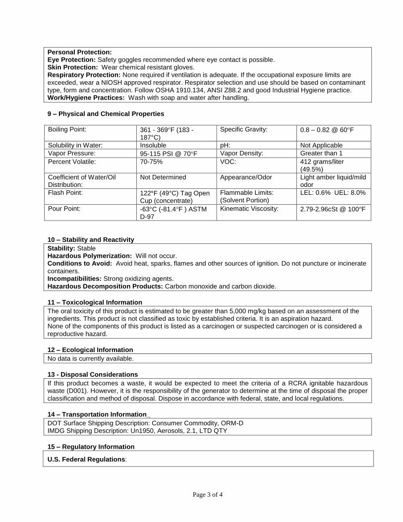
Page 3 of 4
Personal Protection: Eye Protection: Safety goggles recommended where eye contact is possible. Skin Protection: Wear chemical resistant gloves. Respiratory Protection: None required if ventilation is adequate. If the occupational exposure limits are exceeded, wear a NIOSH approved respirator. Respirator selection and use should be based on contaminant type, form and concentration. Follow OSHA 1910.134, ANSI Z88.2 and good Industrial Hygiene practice. Work/Hygiene Practices: Wash with soap and water after handling.
9 – Physical and Chemical Properties
Boiling Point: 361 - 369 F (183 - 187°C)
Specific Gravity: 0.8 – 0.82 @ 60 F
Solubility in Water: Insoluble pH: Not Applicable
Vapor Pressure: 95-115 PSI @ 70 F Vapor Density: Greater than 1
Percent Volatile: 70-75% VOC: 412 grams/liter (49.5%)
Coefficient of Water/Oil Distribution:
Not Determined Appearance/Odor Light amber liquid/mild odor
Flash Point: 122 F (49°C) Tag Open Cup (concentrate)
Flammable Limits: (Solvent Portion)
LEL: 0.6% UEL: 8.0%
Pour Point: -63 C (-81.4 F ) ASTM D-97
Kinematic Viscosity: 2.79-2.96cSt @ 100 F
10 – Stability and Reactivity
Stability: Stable Hazardous Polymerization: Will not occur. Conditions to Avoid: Avoid heat, sparks, flames and other sources of ignition. Do not puncture or incinerate containers. Incompatibilities: Strong oxidizing agents. Hazardous Decomposition Products: Carbon monoxide and carbon dioxide.
11 – Toxicological Information
The oral toxicity of this product is estimated to be greater than 5,000 mg/kg based on an assessment of the ingredients. This product is not classified as toxic by established criteria. It is an aspiration hazard. None of the components of this product is listed as a carcinogen or suspected carcinogen or is considered a reproductive hazard.
12 – Ecological Information
No data is currently available.
13 - Disposal Considerations
If this product becomes a waste, it would be expected to meet the criteria of a RCRA ignitable hazardous waste (D001). However, it is the responsibility of the generator to determine at the time of disposal the proper classification and method of disposal. Dispose in accordance with federal, state, and local regulations.
14 – Transportation Information_
DOT Surface Shipping Description: Consumer Commodity, ORM-D IMDG Shipping Description: Un1950, Aerosols, 2.1, LTD QTY
15 – Regulatory Information
U.S. Federal Regulations:
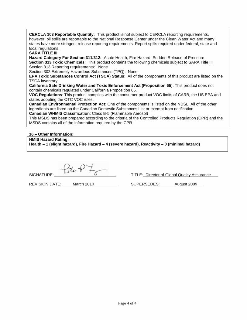
Page 4 of 4
CERCLA 103 Reportable Quantity: This product is not subject to CERCLA reporting requirements, however, oil spills are reportable to the National Response Center under the Clean Water Act and many states have more stringent release reporting requirements. Report spills required under federal, state and local regulations. SARA TITLE III: Hazard Category For Section 311/312: Acute Health, Fire Hazard, Sudden Release of Pressure Section 313 Toxic Chemicals: This product contains the following chemicals subject to SARA Title III Section 313 Reporting requirements: None Section 302 Extremely Hazardous Substances (TPQ): None EPA Toxic Substances Control Act (TSCA) Status: All of the components of this product are listed on the TSCA inventory. California Safe Drinking Water and Toxic Enforcement Act (Proposition 65): This product does not contain chemicals regulated under California Proposition 65. VOC Regulations: This product complies with the consumer product VOC limits of CARB, the US EPA and states adopting the OTC VOC rules. Canadian Environmental Protection Act: One of the components is listed on the NDSL. All of the other ingredients are listed on the Canadian Domestic Substances List or exempt from notification. Canadian WHMIS Classification: Class B-5 (Flammable Aerosol) This MSDS has been prepared according to the criteria of the Controlled Products Regulation (CPR) and the MSDS contains all of the information required by the CPR.
16 – Other Information:
HMIS Hazard Rating: Health – 1 (slight hazard), Fire Hazard – 4 (severe hazard), Reactivity – 0 (minimal hazard)
SIGNATURE: TITLE: Director of Global Quality Assurance REVISION DATE: March 2010 SUPERSEDES: August 2009
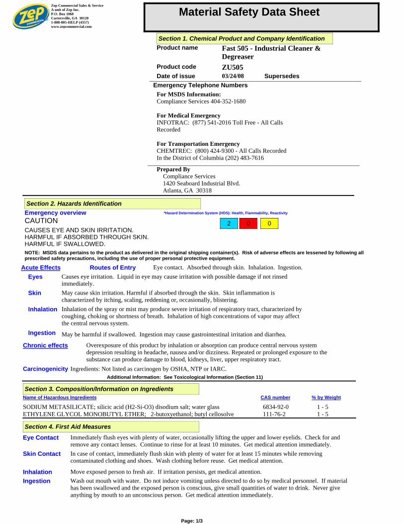
Material Safety Data Sheet
Date of issue 03/24/08
Product name Fast 505 - Industrial Cleaner &Degreaser
Product code ZU505Supersedes
Emergency Telephone Numbers
For MSDS Information:Compliance Services 404-352-1680
For Medical EmergencyINFOTRAC: (877) 541-2016 Toll Free - All CallsRecorded
For Transportation EmergencyCHEMTREC: (800) 424-9300 - All Calls RecordedIn the District of Columbia (202) 483-7616
Prepared By Compliance Services 1420 Seaboard Industrial Blvd. Atlanta, GA 30318
Zep Commercial Sales & ServiceA unit of Zep Inc.P.O. Box 1060Cartersville, GA 301201-888-805-HELP (4357)www.zepcommercial.com
Section 1. Chemical Product and Company Identification
Emergency overview
CAUTION
CAUSES EYE AND SKIN IRRITATION.HARMFUL IF ABSORBED THROUGH SKIN.HARMFUL IF SWALLOWED.
*Hazard Determination System (HDS): Health, Flammability, Reactivity
Acute Effects
Eyes
Skin
Inhalation
Ingestion
Routes of Entry Eye contact. Absorbed through skin. Inhalation. Ingestion.Causes eye irritation. Liquid in eye may cause irritation with possible damage if not rinsedimmediately.May cause skin irritation. Harmful if absorbed through the skin. Skin inflammation ischaracterized by itching, scaling, reddening or, occasionally, blistering.Inhalation of the spray or mist may produce severe irritation of respiratory tract, characterized bycoughing, choking or shortness of breath. Inhalation of high concentrations of vapor may affectthe central nervous system.
May be harmful if swallowed. Ingestion may cause gastrointestinal irritation and diarrhea.
NOTE: MSDS data pertains to the product as delivered in the original shipping container(s). Risk of adverse effects are lessened by following allprescribed safety precautions, including the use of proper personal protective equipment.
Carcinogenicity
Chronic effects
Ingredients: Not listed as carcinogen by OSHA, NTP or IARC.
Overexposure of this product by inhalation or absorption can produce central nervous systemdepression resulting in headache, nausea and/or dizziness. Repeated or prolonged exposure to thesubstance can produce damage to blood, kidneys, liver, upper respiratory tract.
Additional Information: See Toxicological Information (Section 11)
Section 2. Hazards Identification
2 0 0
Name of Hazardous Ingredients CAS number % by Weight
SODIUM METASILICATE; silicic acid (H2-Si-O3) disodium salt; water glass 6834-92-0 1 - 5ETHYLENE GLYCOL MONOBUTYL ETHER; 2-butoxyethanol; butyl cellosolve 111-76-2 1 - 5
Section 3. Composition/Information on Ingredients
Eye Contact
Skin Contact
Inhalation
Ingestion
Immediately flush eyes with plenty of water, occasionally lifting the upper and lower eyelids. Check for andremove any contact lenses. Continue to rinse for at least 10 minutes. Get medical attention immediately.In case of contact, immediately flush skin with plenty of water for at least 15 minutes while removingcontaminated clothing and shoes. Wash clothing before reuse. Get medical attention.
Move exposed person to fresh air. If irritation persists, get medical attention.Wash out mouth with water. Do not induce vomiting unless directed to do so by medical personnel. If materialhas been swallowed and the exposed person is conscious, give small quantities of water to drink. Never giveanything by mouth to an unconscious person. Get medical attention immediately.
Section 4. First Aid Measures
Page: 1/3
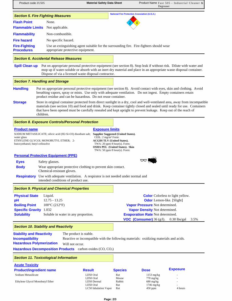
Material Safety Data Sheet Product Name Fas t 505 - Indus t r ia l Cleaner &Degreaser
Product code ZU505
None.Flash Point
Not applicable.
National Fire Protection Association (U.S.A.)
2
0
0
Flammable Limits
Flammability
Fire hazard No specific hazard.
Non-combustible.
Fire-FightingProcedures
Use an extinguishing agent suitable for the surrounding fire. Fire-fighters should wearappropriate protective equipment.
Section 5. Fire Fighting Measures
Spill Clean up Put on appropriate personal protective equipment (see section 8). Stop leak if without risk. Dilute with water andmop up if water-soluble or absorb with an inert dry material and place in an appropriate waste disposal container.Dispose of via a licensed waste disposal contractor.
Section 6. Accidental Release Measures
Handling
Storage
Put on appropriate personal protective equipment (see section 8). Avoid contact with eyes, skin and clothing. Avoidbreathing vapors, spray or mists. Use only with adequate ventilation. Do not ingest. Empty containers retainproduct residue and can be hazardous. Do not reuse container.Store in original container protected from direct sunlight in a dry, cool and well-ventilated area, away from incompatiblematerials (see section 10) and food and drink. Keep container tightly closed and sealed until ready for use. Containersthat have been opened must be carefully resealed and kept upright to prevent leakage. Keep out of the reach ofchildren.
Section 7. Handling and Storage
Personal Protective Equipment (PPE)
Eyes
Body
Respiratory
Product name Exposure limits
SODIUM METASILICATE; silicic acid (H2-Si-O3) disodium salt;water glass
Supplier Suggested (United States). CEIL: 2 mg/m³ Form:
ETHYLENE GLYCOL MONOBUTYL ETHER; 2-butoxyethanol; butyl cellosolve
ACGIH TLV (United States). TWA: 20 ppm 8 hour(s). Form:OSHA PEL (United States). Skin TWA: 50 ppm 8 hour(s). Form:
Safety glasses.Wear appropriate protective clothing to prevent skin contact.Chemical-resistant gloves.Use with adequate ventilation. A respirator is not needed under normal andintended conditions of product use.
Section 8. Exposure Controls/Personal Protection
Physical State
pH
Boiling Point
Specific Gravity
Solubility
Liquid.12.75 - 13.25100°C (212°F)1.032
Color
Odor
Vapor Pressure
Vapor Density
Evaporation Rate
VOC (Consumer)
Colorless to light yellow.Lemon-like. [Slight]Not determined.Not determined.Not determined.36 (g/l). 0.30 lbs/gal 3.5%
Soluble in water in any proportion.
Section 9. Physical and Chemical Properties
The product is stable.
Will not occur.
Stability and Reactivity
Hazardous Decomposition Products
Hazardous Polymerization
Reactive or incompatible with the following materials: oxidizing materials and acids.Incompatibility
carbon oxides (CO, CO2)
Section 10. Stability and Reactivity
Acute Toxicity
Product/ingredient name Result Species Dose Exposure
Sodium Metasilicate LD50 Oral Rat 1153 mg/kg -LD50 Oral Mouse 770 mg/kg -
Ethylene Glycol Monobutyl Ether LD50 Dermal Rabbit 680 mg/kg -LD50 Oral Rat 1746 mg/kg -LC50 Inhalation Vapor Rat 450 ppm 4 hours
Section 11. Toxicological Information
Page: 2/3
Material Safety Data Sheet Product Name Fas t 505 - Indus t r ia l Cleaner &Degreaser
Product code ZU505
Environmental Effects No applicable toxicity dataAquatic Ecotoxicity
Not available.
Section 12. Ecological Information
Waste Information
Waste Stream Code: D002Classification: - (Hazardous waste.)Origin: - (RCRA waste.)
Section 13. Disposal Considerations
Waste must be disposed of in accordance with federal, state and local environmental control regulations. Consult your local orregional authorities for additional information.
NOTE: DOT classification applies to most package sizes. For specific container size classifications or for size exceptions, refer tothe Bill of Lading with your shipment.
PG* : Packing group
Regulatory information UN number Proper shipping name Classes PG* Label
- None. Not a DOT controlledmaterial (UnitedStates).
Not available. Not available. Not available. -
Section 14. Transport Information
DOT Classification
IMDG Class
Not regulated.
TDG Classification Not regulated. - None. Not a TDG-controlled material.
-
U.S. Federal Regulations
Clean Water Act (CWA) 311: No products were found.Clean Air Act (CAA) 112 regulated toxic substances: No products were found.
State Regulations
Product name
No products were found.California Prop 65
All Components of this product are listed or exempt from listing on TSCA Inventory.
Section 15. Regulatory Information
Clean Water Act (CWA) 307: No products were found.
Ethylene Glycol Monobutyl Ether (Glycol Ethers)
SARA 313 toxic chemical notification and release reporting:
Canada
WHMIS (Canada) Class D-2B: Material causing other toxic effects (Toxic).
To the best of our knowledge, the information contained herein is accurate. However, neither the above named supplier nor any of its subsidiaries assumes anyliability whatsoever for the accuracy or completeness of the information contained herein.Final determination of suitability of any material is the sole responsibility of the user. All materials may present unknown hazards and should be used with caution.Although certain hazards are described herein, we cannot guarantee that these are the only hazards that exist.
*NOTE: Hazard Determination System (HDS) ratings are based on a 0-4 rating scale, with 0 representing minimal hazards or risks, and 4 representing significant hazards or risksAlthough these ratings are not required on MSDSs under 29 CFR 1910.1200, the preparer may choose to provide them. HDS ratings are to be used with a fully implemented program torelay the meanings of this scale.
Section 16. Other Information


