Embed Size (px)
Citation preview

AVANTI SERVICE LIFT
User’s, Maintenance and Installation Manual
Model Service Lift SWP
Original instructions
®
45540028_SIEMENS LIFT CE AECO EN 5th R9.indd 1 4/9/2018 3:51:54 PM
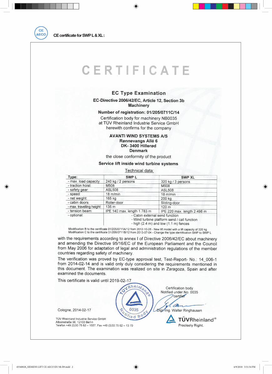
CE certificate for SWP L & XL :
45540028_SIEMENS LIFT CE AECO EN 5th R9.indd 2 4/9/2018 3:51:54 PM

AECO certificate for SWP L :
45540028_SIEMENS LIFT CE AECO EN 5th R9.indd 3 4/9/2018 3:51:55 PM

Date of publication:5th Edition: February 2015Revision 9: 27/03/2018
Manufacturer:AVANTI Wind Systems A/S Rønnevangs Allé 6 3400 Hillerød DenmarkP: +45 4824 9024F: +45 4824 9124 E: [email protected] I: www.avanti-online.com
Sales & Service:Australia Avanti Wind Systems PTY LTD P: +61 (0) 3 9585 1852 3 9585 China Avanti Wind Systems P: +86 21 5785 8811Denmark Avanti Wind Systems A/S P: +45 4824 9024Germany Avanti Wind Systems GmbH P: +49 (0) 41 21-7 88 85 – 0Spain Avanti Wind Systems SL P: +34 976 149 524UK Avanti Wind Systems Limited P: +44 0 1254 399923USA Avanti Wind Systems, Inc P: +1 (262) 641 9101India Avanti Wind Systems India (P) Ltd P: +91 95 00 173 492Brazil Avanti Brasil Sistema Eólicos LTDA P: +55 85 9 9955-0090
Manufactured Under Process Patent NO.8,499,896. ® Registered in Europe
45540028_SIEMENS LIFT CE AECO EN 5th R9.indd 4 4/9/2018 3:51:55 PM

5 User’s, Maintenance and Installation Manual
Page 1. Limited warranty . . . . . . . . . . . . . . . . . . . . . . . . . . . . . . . . . . . . . . . . . . . . . . . . . . . . 8 2. Introduction . . . . . . . . . . . . . . . . . . . . . . . . . . . . . . . . . . . . . . . . . . . . . . . . . . . . . . . . 9 2.1 Observations . . . . . . . . . . . . . . . . . . . . . . . . . . . . . . . . . . . . . . . . . . . . . . . . . . . . . . 9 2.2 Symbols . . . . . . . . . . . . . . . . . . . . . . . . . . . . . . . . . . . . . . . . . . . . . . . . . . . . . . . . . 9 2.3 Cautions . . . . . . . . . . . . . . . . . . . . . . . . . . . . . . . . . . . . . . . . . . . . . . . . . . . . . . . . 10 2.4 Terms and definitions . . . . . . . . . . . . . . . . . . . . . . . . . . . . . . . . . . . . . . . . . . . . . . . . 10 3. Description . . . . . . . . . . . . . . . . . . . . . . . . . . . . . . . . . . . . . . . . . . . . . . . . . . . . . . . . 11 3.1 Purpose . . . . . . . . . . . . . . . . . . . . . . . . . . . . . . . . . . . . . . . . . . . . . . . . . . . . . . . . 11 3.2 Scope . . . . . . . . . . . . . . . . . . . . . . . . . . . . . . . . . . . . . . . . . . . . . . . . . . . . . . . . . 11 3.3 Exclusions . . . . . . . . . . . . . . . . . . . . . . . . . . . . . . . . . . . . . . . . . . . . . . . . . . . . . . 11 3.4 Technical specifications . . . . . . . . . . . . . . . . . . . . . . . . . . . . . . . . . . . . . . . . . . . . . 11 3.5 Dimensions . . . . . . . . . . . . . . . . . . . . . . . . . . . . . . . . . . . . . . . . . . . . . . . . . . . . . 12 3.6 Components . . . . . . . . . . . . . . . . . . . . . . . . . . . . . . . . . . . . . . . . . . . . . . . . . . . . . 14 3.6.1 Components of SWP L . . . . . . . . . . . . . . . . . . . . . . . . . . . . . . . . . . . . . . . . . 14 3.6.2 Components of SWP XL . . . . . . . . . . . . . . . . . . . . . . . . . . . . . . . . . . . . . . . . 16 3.6.3 Traction system . . . . . . . . . . . . . . . . . . . . . . . . . . . . . . . . . . . . . . . . . . . . . . 17 3.6.4 Fall arrest device . . . . . . . . . . . . . . . . . . . . . . . . . . . . . . . . . . . . . . . . . . . . . 17 3.6.5 Traction, safety and guiding wire ropes . . . . . . . . . . . . . . . . . . . . . . . . . . . . . . 17 3.6.6 Main control box of SWP L and SWP XL . . . . . . . . . . . . . . . . . . . . . . . . . . . . . 18 3.6.7 Cabin control box . . . . . . . . . . . . . . . . . . . . . . . . . . . . . . . . . . . . . . . . . . . . 18 3.6.8 Platform control boxes . . . . . . . . . . . . . . . . . . . . . . . . . . . . . . . . . . . . . . . . . 18 3.6.9 Main switch . . . . . . . . . . . . . . . . . . . . . . . . . . . . . . . . . . . . . . . . . . . . . . . . . 19 3.6.10 Trapped key switch . . . . . . . . . . . . . . . . . . . . . . . . . . . . . . . . . . . . . . . . . . . 19 3.6.11 Electromagnetic motor brake . . . . . . . . . . . . . . . . . . . . . . . . . . . . . . . . . . . . . 19 3.6.12 Emergency stop button . . . . . . . . . . . . . . . . . . . . . . . . . . . . . . . . . . . . . . . . . 19 3.6.13 Overload limiter . . . . . . . . . . . . . . . . . . . . . . . . . . . . . . . . . . . . . . . . . . . . . . 19 3.6.14 Manual descent . . . . . . . . . . . . . . . . . . . . . . . . . . . . . . . . . . . . . . . . . . . . . . 19 3.6.15 Fall arrest device . . . . . . . . . . . . . . . . . . . . . . . . . . . . . . . . . . . . . . . . . . . . . 19 3.6.16 Warning lights . . . . . . . . . . . . . . . . . . . . . . . . . . . . . . . . . . . . . . . . . . . . . . . 19 3.6.17 Slack rope sensor . . . . . . . . . . . . . . . . . . . . . . . . . . . . . . . . . . . . . . . . . . . . 19 3.6.18 Obstruction switches . . . . . . . . . . . . . . . . . . . . . . . . . . . . . . . . . . . . . . . . . . 20 3.6.19 Light with emergency function . . . . . . . . . . . . . . . . . . . . . . . . . . . . . . . . . . . . 20 3.6.20 Slack rope sensor . . . . . . . . . . . . . . . . . . . . . . . . . . . . . . . . . . . . . . . . . . . . 20 3.6.21 Maintenance cover of SWP XL . . . . . . . . . . . . . . . . . . . . . . . . . . . . . . . . . . . . 20 3.6.22 Anchor points . . . . . . . . . . . . . . . . . . . . . . . . . . . . . . . . . . . . . . . . . . . . . . . 20 3.6.23 Information signs and documents . . . . . . . . . . . . . . . . . . . . . . . . . . . . . . . . . . 20 3.6.24 Guiding system for SWP L . . . . . . . . . . . . . . . . . . . . . . . . . . . . . . . . . . . . . . . 21 3.6.25 Guiding system for SWP XL . . . . . . . . . . . . . . . . . . . . . . . . . . . . . . . . . . . . . . 21 3.6.26 Guiding system for SWP XLs pulley . . . . . . . . . . . . . . . . . . . . . . . . . . . . . . . . 22 4. Installation . . . . . . . . . . . . . . . . . . . . . . . . . . . . . . . . . . . . . . . . . . . . . . . . . . . . . . . . . 23 4.1 Cautions . . . . . . . . . . . . . . . . . . . . . . . . . . . . . . . . . . . . . . . . . . . . . . . . . . . . . . . . 23 4.2 Freight kit . . . . . . . . . . . . . . . . . . . . . . . . . . . . . . . . . . . . . . . . . . . . . . . . . . . . . . . . 23 4.3 The wire ropes . . . . . . . . . . . . . . . . . . . . . . . . . . . . . . . . . . . . . . . . . . . . . . . . . . . . 23 4.3.1 Tower top . . . . . . . . . . . . . . . . . . . . . . . . . . . . . . . . . . . . . . . . . . . . . . . . . . . 24 4.3.2 Tower bottom . . . . . . . . . . . . . . . . . . . . . . . . . . . . . . . . . . . . . . . . . . . . . . . . 24 4.3.3 Securing the guide wire rope - ground level . . . . . . . . . . . . . . . . . . . . . . . . . . . . 25 4.3.3.1 Fastening the guide wire ropes Ø12mm . . . . . . . . . . . . . . . . . . . . . . . . . . 25 4.3.3.2 Tensioning the guide wire ropes Ø12mm . . . . . . . . . . . . . . . . . . . . . . . . . 26 4.3.3.3 Guiding system for SWP XLs pulley . . . . . . . . . . . . . . . . . . . . . . . . . . . . 26 4.4 Electrical connections . . . . . . . . . . . . . . . . . . . . . . . . . . . . . . . . . . . . . . . . . . . . . . . 27 4.4.1 Power supply . . . . . . . . . . . . . . . . . . . . . . . . . . . . . . . . . . . . . . . . . . . . . . . . . 27 4.4.2 Installation of main switch . . . . . . . . . . . . . . . . . . . . . . . . . . . . . . . . . . . . . . . . 27 4.4.3 Supply cable . . . . . . . . . . . . . . . . . . . . . . . . . . . . . . . . . . . . . . . . . . . . . . . . . 27 4.4.4 Power connection . . . . . . . . . . . . . . . . . . . . . . . . . . . . . . . . . . . . . . . . . . . . . 27 4.5 Installation of traction and safety wire rope in lift . . . . . . . . . . . . . . . . . . . . . . . . . . . . . . 28 4.5.1 Traction wire rope installation . . . . . . . . . . . . . . . . . . . . . . . . . . . . . . . . . . . . . . 28 4.5.2 Safety wire rope installation . . . . . . . . . . . . . . . . . . . . . . . . . . . . . . . . . . . . . . . 28
Contents
45540028_SIEMENS LIFT CE AECO EN 5th R9.indd 5 4/9/2018 3:51:55 PM

6 AVANTI Service Lift for Wind Turbines
4.6 Securing the traction and safety wire rope . . . . . . . . . . . . . . . . . . . . . . . . . . . . . . . . . . 29 4.6.1 Traction wire rope counterweight . . . . . . . . . . . . . . . . . . . . . . . . . . . . . . . . . . . 29 4.6.2 Safety wire rope push spring . . . . . . . . . . . . . . . . . . . . . . . . . . . . . . . . . . . . . . 29 4.7 Wire rope fix alignment . . . . . . . . . . . . . . . . . . . . . . . . . . . . . . . . . . . . . . . . . . . . . . . 30 4.8 Adjustment of safe-zone plates . . . . . . . . . . . . . . . . . . . . . . . . . . . . . . . . . . . . . . . . . 32 4.9 Adjustment of top obstruction device . . . . . . . . . . . . . . . . . . . . . . . . . . . . . . . . . . . . . 32 4.10 Danger zone! sticker . . . . . . . . . . . . . . . . . . . . . . . . . . . . . . . . . . . . . . . . . . . . . . . . 32 4.11 Inspection before first use . . . . . . . . . . . . . . . . . . . . . . . . . . . . . . . . . . . . . . . . . . . . 32 4.12 Disassembling . . . . . . . . . . . . . . . . . . . . . . . . . . . . . . . . . . . . . . . . . . . . . . . . . . . . 32 5. Instructions for use . . . . . . . . . . . . . . . . . . . . . . . . . . . . . . . . . . . . . . . . . . . . . . . . . . 33 5.1 Prohibited uses . . . . . . . . . . . . . . . . . . . . . . . . . . . . . . . . . . . . . . . . . . . . . . . . . . . 33 5.2 Entry and exit . . . . . . . . . . . . . . . . . . . . . . . . . . . . . . . . . . . . . . . . . . . . . . . . . . . . . 33 5.3 Stop/Emergency stop . . . . . . . . . . . . . . . . . . . . . . . . . . . . . . . . . . . . . . . . . . . . . . . 33 5.4 Operation from inside the cabin . . . . . . . . . . . . . . . . . . . . . . . . . . . . . . . . . . . . . . . . . 33 5.5 Operation from outside the cabin . . . . . . . . . . . . . . . . . . . . . . . . . . . . . . . . . . . . . . . . 33 5.6 Operation from platforms (send and call configuration) . . . . . . . . . . . . . . . . . . . . . . . . . 33 5.7 Overload limiter . . . . . . . . . . . . . . . . . . . . . . . . . . . . . . . . . . . . . . . . . . . . . . . . . . . . 34 5.8 Manual descent . . . . . . . . . . . . . . . . . . . . . . . . . . . . . . . . . . . . . . . . . . . . . . . . . . . 34 5.9 Fall arrest device . . . . . . . . . . . . . . . . . . . . . . . . . . . . . . . . . . . . . . . . . . . . . . . . . . . 34 5.10 Troubleshooting . . . . . . . . . . . . . . . . . . . . . . . . . . . . . . . . . . . . . . . . . . . . . . . . . . . 35 5.11 Out of service . . . . . . . . . . . . . . . . . . . . . . . . . . . . . . . . . . . . . . . . . . . . . . . . . . . . 37 6. Maintenance . . . . . . . . . . . . . . . . . . . . . . . . . . . . . . . . . . . . . . . . . . . . . . . . . . . . . . 38 6.1 Mandatory inspection and maintenance planning . . . . . . . . . . . . . . . . . . . . . . . . . . . . 38 6.2 Cautions . . . . . . . . . . . . . . . . . . . . . . . . . . . . . . . . . . . . . . . . . . . . . . . . . . . . . . . 38 6.3. Daily inspection by the supervisor . . . . . . . . . . . . . . . . . . . . . . . . . . . . . . . . . . . . . . . 38 6.3.1 Overall . . . . . . . . . . . . . . . . . . . . . . . . . . . . . . . . . . . . . . . . . . . . . . . . . . . . . 38 6.3.2 Travel zone . . . . . . . . . . . . . . . . . . . . . . . . . . . . . . . . . . . . . . . . . . . . . . . . . . 38 6.3.3 Control and safety devices . . . . . . . . . . . . . . . . . . . . . . . . . . . . . . . . . . . . . . . 38 6.3.3.1 Cabin control from inside the cabin . . . . . . . . . . . . . . . . . . . . . . . . . . . . 38 6.3.3.2 Cabin control from outside the cabin . . . . . . . . . . . . . . . . . . . . . . . . . . . 38 6.3.3.3 Cabin control from platform control boxes . . . . . . . . . . . . . . . . . . . . . . . . 39 6.4 Annual inspection . . . . . . . . . . . . . . . . . . . . . . . . . . . . . . . . . . . . . . . . . . . . . . . . . 40 6.4.1 Traction hoist . . . . . . . . . . . . . . . . . . . . . . . . . . . . . . . . . . . . . . . . . . . . . . . . . 40 6.4.2 Fall arrest device . . . . . . . . . . . . . . . . . . . . . . . . . . . . . . . . . . . . . . . . . . . . . . 40 6.4.3 Traction, safety and guiding wire ropes . . . . . . . . . . . . . . . . . . . . . . . . . . . . . . . 40 6.4.3.1 Cleaning . . . . . . . . . . . . . . . . . . . . . . . . . . . . . . . . . . . . . . . . . . . . . . . 41 6.4.3.2 Lubrication . . . . . . . . . . . . . . . . . . . . . . . . . . . . . . . . . . . . . . . . . . . . . 41 6.4.3.3 Measuring of the wire rope diameter . . . . . . . . . . . . . . . . . . . . . . . . . . . . 41 6.4.3.4 Discard criteria . . . . . . . . . . . . . . . . . . . . . . . . . . . . . . . . . . . . . . . . . . 42 6.4.4 Electrical cables . . . . . . . . . . . . . . . . . . . . . . . . . . . . . . . . . . . . . . . . . . . . . . 42 6.4.5 Information signs and documents . . . . . . . . . . . . . . . . . . . . . . . . . . . . . . . . . . . 42 6.5 Repairs . . . . . . . . . . . . . . . . . . . . . . . . . . . . . . . . . . . . . . . . . . . . . . . . . . . . . . . . . 42 6.6 Ordering spare parts . . . . . . . . . . . . . . . . . . . . . . . . . . . . . . . . . . . . . . . . . . . . . . . . 43 6.6.1 Wire ropes . . . . . . . . . . . . . . . . . . . . . . . . . . . . . . . . . . . . . . . . . . . . . . . . . . 43 6.6.2 Motor and brake . . . . . . . . . . . . . . . . . . . . . . . . . . . . . . . . . . . . . . . . . . . . . . 43 6.6.3 Electric control . . . . . . . . . . . . . . . . . . . . . . . . . . . . . . . . . . . . . . . . . . . . . . . 43 6.6.4 Fall arrest device . . . . . . . . . . . . . . . . . . . . . . . . . . . . . . . . . . . . . . . . . . . . . . 43 6.7 Removing wire ropes for replacement . . . . . . . . . . . . . . . . . . . . . . . . . . . . . . . . . . . . . 43 6.7.1 Parking the service lift . . . . . . . . . . . . . . . . . . . . . . . . . . . . . . . . . . . . . . . . . . . 43 6.7.2 Wire rope ends . . . . . . . . . . . . . . . . . . . . . . . . . . . . . . . . . . . . . . . . . . . . . . . 43 6.7.3 Removing the Traction wire rope . . . . . . . . . . . . . . . . . . . . . . . . . . . . . . . . . . . . 43 6.7.4 Removing the safety wire rope . . . . . . . . . . . . . . . . . . . . . . . . . . . . . . . . . . . . . 43 6.8 Replacing traction hoist . . . . . . . . . . . . . . . . . . . . . . . . . . . . . . . . . . . . . . . . . . . . . . 43 6.9 Replacing fall arrest device . . . . . . . . . . . . . . . . . . . . . . . . . . . . . . . . . . . . . . . . . . . . 43
Appendix A: Regulation of overload limiter . . . . . . . . . . . . . . . . . . . . . . . . . . . . . . . . . . . . . 44 Appendix B: Inspection Checklist . . . . . . . . . . . . . . . . . . . . . . . . . . . . . . . . . . . . . . . . . . . 45Appendix C: Inspection Log Sheet . . . . . . . . . . . . . . . . . . . . . . . . . . . . . . . . . . . . . . . . . . . 50Appendix D: AVANTI lift anchor . . . . . . . . . . . . . . . . . . . . . . . . . . . . . . . . . . . . . . . . . . . . . 53
45540028_SIEMENS LIFT CE AECO EN 5th R9.indd 6 4/9/2018 3:51:55 PM

7 User’s, Maintenance and Installation Manual
Ed.Rev Notes
05.09 Section 2.1 re-worded. Added section 2.4 Terms and definitions. Updated inspection and maintenance planning in section 6. Updated
sections 6.4.1 Traction hoist and 6.4.2. Fall arrest device. Updated Appendix D. Other minor changes.
45540028_SIEMENS LIFT CE AECO EN 5th R9.indd 7 4/9/2018 3:51:56 PM

8 AVANTI Service Lift for Wind Turbines
1) Avanti service lift (“Product”)
Avanti Wind Systems A/S warrants that com-mencing from the date of shipment to the Customer and continuing for a period of the longer of 365 days thereafter, or the period set forth in the standard AVANTI warranty, the Product1) described in this Manual will be free from defects in material and workmanship under normal use and service when installed and operated in accordance with the provisions of this Manual.
This warranty is made only to the original user of the Product. The sole and exclusive remedy and the entire liability of Avanti under this limited warranty, shall be, at the option of Avanti, a replacement of the Product (including incidental and freight charges paid by the Customer) with a similar new or reconditioned Product of equivalent value, or a refund of the purchase price if the Product is returned to Avanti, freight and insurance prepaid. The obligations of Avanti are expressly conditioned upon return of the Product in strict accordance with the return procedures of Avanti.
This warranty does not apply if the Product (i) has been altered without the authorization of Avanti or its authorized representative; (ii) has not been installed, operated, repaired, or maintained in accordance with this Manual or other instructions from Avanti; (iii) has been subjected to abuse, neglect, casualty, or negligence; (iv) has been furnished by Avanti to Customer without charge; or (v) has been sold on an “AS-IS” basis.
Except as specifically set forth in this Limited Warranty,
ALL EXPRESS OR IMPLIED CONDITIONS, REPRESENTATIONS AND WARRANTIES, INCLUDING, BUT NOT LIMITED TO, ANY IMPLIED WARRANTY OR CONDITION OF MERCHANTABILITY, FITNESS FOR A PAR-TICULAR PURPOSE, NON-INFRINGEMENT, SATISFACTORY QUALITY, COURSE OF DEAL-ING, LAW, USAGE OR TRADE PRACTICE ARE HEREBY EXCLUDED TO THE MAXIMUM EXTENT PERMITTED BY APPLICABLE LAW AND ARE EXPRESSLY DISCLAIMED BY AVANTI. IF, PURSUANT TO ANY APPLICABLE LAW, TO THE EXTENT AN IMPLIED WARRAN-TY CANNOT BE EXCLUDED AS PROVIDED IN THIS LIMITED WARRANTY, ANY IMPLIED WARRANTY IS LIMITED IN TIME TO THE SAME DURATION AS THE EXPRESS WARRANTY PERIOD SET FORTH ABOVE. BECAUSE SOME STATES DO NOT PERMIT LIMITATIONS ON THE DURATION OF IMPLIED WARRANTIES, THIS MAY NOT APPLY TO A GIVEN CUSTOM-ER. THIS LIMITED WARRANTY GIVES CUS-TOMER SPECIFIC LEGAL RIGHTS, AND CUSTOMER MAY HAVE OTHER LEGAL RIGHTS UNDER APPLICABLE LAWS.
This disclaimer shall apply even if the express warranty fails of its essential purpose.
In any cases of dispute the English original shall be taken as authoritative.
1. Limited Warranty
45540028_SIEMENS LIFT CE AECO EN 5th R9.indd 8 4/9/2018 3:51:56 PM

9 User’s, Maintenance and Installation Manual
2.2 Symbols
2.1 Observations
2. Introduction
Only trained people may use this lift.This manual must be available to staff at all times during installation, maintenance and operation.Additional copies are available from the manufacturer upon request. All measurements are indicative only and subject to change without prior notice.
The pictures and sketches in this manual may not reflect the product aesthetics, colours, arrangement precisely. This has no impact on the function or safety.!
STOP
!
�
Symbol Signal word Meaning Possible injury if not observed
Safety instructions
DANGER!IMMEDIATE orpossibly imminentdanger:
Death or severe injury!
DANGER!IMMEDIATE orpossibly imminentdanger of hazardousvoltage:
Death or severe injury!
CAUTION! Potentially hazardous
situation:Light injury or material damage.
Additional instructions
ATTENTION! Potentially dangeroussituation:
Damage to equipment or workplace
IMPORTANT!
Useful tips for optimumworking procedure
None
VERSION!
Differentiation between CE versions and AECO version.
Reference to writtenspecification/documentation
45540028_SIEMENS LIFT CE AECO EN 5th R9.indd 9 4/9/2018 3:51:57 PM

10 AVANTI Service Lift for Wind Turbines
2.3 Cautions
�
Use and daily inspection of the service lift shall only be performed by person who has gone through the relevant training associated with the Avanti service lift use and daily inspection and is in possession of a valid (non expired) certificate for the task.
Installation and maintenance of the service lift shall only be performed by certified technicians.Personnel must be at least 18 years of age. The staff must be familiar with the relevant accident preven- tion instructions and must have received proper training in these.
Personnel are obliged to read and understand this Service Manual.Personnel shall wear PFPE (safety helmet, full body harness, shock absorber, lanyard and slider) at all times, when using the lift.
A copy of the Service Manual must be handed out to the personnel involved and must always be avail-able for reference.If more than one person is entrusted with service tasks, the employer shall appoint a supervisor in charge of the operation.
Self-locking nuts must be used at all times. The screw must extend from the nut by at least half of the thread diameter. The nut may not be used once it has become possible to loosen by hand!If any damage or faults are found during operation, or if circumstances arise which may jeopardize safety: immediately interrupt the work in progress and notify the supervisor or employer!
All tests/repairs of electrical installations may only be performed by AVANTI or certified technicians.All repairs to the traction, braking and supporting systems may only be performed by AVANTI or certi- fied technicians.
If any supporting parts are repaired or replaced, the operational safety of the system must be tested and verified by AVANTI or certified technicians.Only original fault-free parts may be used.Use of non-original parts will render the manufac- turer’s warranty void and any type approval invalid.
No modification, extension or reconstruction of the service lift is allowed without AVANTI’s prior written consent.
No warranty is provided against damage resulting from reconstruction or modification of equipment or use of non-original parts which are not approved by AVANTI.
Service lift must be inspected by AVANTI or by certi- fied technician before first use.Service lift must be inspected at least once a year by AVANTI or certified technicians. In case of high operating frequency or severe conditions of use, more frequent inspection is required.
Service lift is designed for a lifetime of 20 years with an operating frequency of approximately 12.5 h/year (250 h in total).Service lift may not be used by persons who are under the influence of alcohol or drugs which may jeopardize working safety.The service lift shall not be used in case of fire in the tower.Service lift shall ONLY be used when the turbine is not generating power.
All wind farm site specific rules must be followed. Service lift shall not be used during inclement weath- er, including wind speeds over 25 m/s (55.5 mph), , electric storms, hurricanes, temperature out of lift’s operating range (-25ºC to +60ºC), and any other that jeopardize safe operation.
AECO service lift personnel shall be equipped with a wired or wireless two way communication device connected to a location staffed by personnel author- ised by AVANTI.
Avoid injury – follow all instructions!
Owner must verify the need for third party service lift inspections with the local authority and comply with the standards specified.
2.4 Terms and definitions Terms Definitions
Certified technicianPerson who has gone through the relevant training associated with the scheduled task from Avanti or from a certified trainer and is in possession of a valid (non expired) certificate for the task.
UserPerson who has gone through the relevant training associated with the Avanti service liftuse and daily inspection and is in possession of a valid (non expired) certificate for the task.
Manual descentAction performed to descend the lift at a controlled speed without power supply by manuallyopening the hoist electromagnetic brake. (Also manual no-power descent)
45540028_SIEMENS LIFT CE AECO EN 5th R9.indd 10 4/9/2018 3:51:57 PM

11 User’s, Maintenance and Installation Manual
3. Description
3.1 Purpose
The service lift described in this User’s Manual serves the following purposes:- Transportation of staff and material inside wind turbine systems, lattice towers for wind turbines, and telecommunication towers. - Transportation for mounting, inspection and repairs.
The service lift may be used to transport two persons plus their tools and equipment to the most convenient height for performing work on the tower.
The service lift is designed for permanent installation in one specific tower.
3.2 Scope
The system consists of a service lift, its guiding system along the tower, its traction and safety wire ropes made in steel, power supply system and the protective fences at landings including their interlock system 1). The system details are described along this manual. The service lift consists of a cabin made in aluminium, a traction system, a fall arrest device, a control system and safety devices. The guiding system consists of a set of guiding wire ropes made in steel, the attachments to the tower and the guides of the car. The protective fences consist of aluminium structures covered with perforated sheet of different geometries depending on the landings where they are installed. They shall comply with the relevant regulations which may include EN14122-3, OSHA 1926.502 Maximum evacuation distance from the point of emergency exit to the accessible means of evacuation shall be no more than 1,1 m. The system as whole meets the essential health and safety requirements as required by the European Machinery directive 2006/42, as well as ASME A17.7-2007/CSA B44.7-07. There are two versions: L and XL, which mainly differ in size and lifting capacity.
1)Note: Interlock system is an optional feature for AECO version.
3.3 Exclusions
The lift is not designed for use- in silos,- at drilling sites,- as a permanently installed facade lift,- as a crane lift,- in environments with explosion hazards.
3.4 Technical specificationsOperating temperature: -25ºC to +60ºC (-13ºF to +140ºF). Survival temperature: -40ºC to +80ºC (-40ºF to +176ºF) Low temperature kit is also available: Operating temperature: -30ºC to +40ºC (-22ºF to +104ºF).Survival temperature: -40ºC to +60ºC (-40ºF to +140ºF). Lifting capacity: SWP L 240 kg (max 2 persons) and SWP XL 320 kg (max 3 persons).
Weight of lift: SWP L 165 kg and SWP XL 200 kg.
Weight of the power supply cable: send/call configuration 0.5 kg/m and send only 0.2 kg/m
Door opening: 600 mm
The maximum noise level of the service lift is 80 dB(A).
45540028_SIEMENS LIFT CE AECO EN 5th R9.indd 11 4/9/2018 3:51:57 PM

12 AVANTI Service Lift for Wind Turbines
3.5 Dimensions3.5.1 Dimensions of SWP L
45540028_SIEMENS LIFT CE AECO EN 5th R9.indd 12 4/9/2018 3:51:58 PM

13 User’s, Maintenance and Installation Manual
3.5.2 Dimensions of SWP XL
45540028_SIEMENS LIFT CE AECO EN 5th R9.indd 13 4/9/2018 3:51:58 PM

14 AVANTI Service Lift for Wind Turbines
3.6 Components
3.6.1 Components of SWP L
1 Cabin2 Door3 Traction and safety wire ropes4 Guiding wire rope 5 Wire rope guides6 Bottom obstruction device 7 Top obstruction device / AECO top obstruction device8 Traveling cable pulley 1)
1) Optional feature. Mandatory for AECO versions.
5
1
2
7
3
4
5
5
4
5
8
45540028_SIEMENS LIFT CE AECO EN 5th R9.indd 14 4/9/2018 3:51:58 PM

15 User’s, Maintenance and Installation Manual
1 Traction system2 Electrical control box3 Anchor points4 Fall arrest device 5 Cabin control6 Engine room 7 Top obstruction device / AECO top obstruction device8 Traveling cable 1)
9 Slack rope sensor 1)
1) Optional feature. Mandatory for AECO versions.
3.6.1.1 Other components of SWP L
6
2
8
1
9 7
5
4
3
45540028_SIEMENS LIFT CE AECO EN 5th R9.indd 15 4/9/2018 3:51:58 PM

16 AVANTI Service Lift for Wind Turbines
1 Cabin2 Door3 Traction and safety wire ropes4 Guiding wire rope5 Wire rope guides6 Bottom obstruction device7 Top obstruction device (Optional full cover top obstruction device)8 Travelling cable (Optional feature)
3.6.2 Components of SWP XL
5
4
5
4
6
8
2
1
3
7
45540028_SIEMENS LIFT CE AECO EN 5th R9.indd 16 4/9/2018 3:51:58 PM

17 User’s, Maintenance and Installation Manual
3.6.3 Traction system
Traction system
3.6.4 Fall arrest device
Fall arrest device
3.6.5 Traction, safety and guiding wire ropes
Lift HoistLifting
capacityPower supply
Wire rope speed
EffectRated
currentTraction
wire rope Ø
Unit weight approx.
ModelType
Kg (lbs) Voltage/Frequency
m/min (ft/min)kW A mm Kg (lbs)
SWP L CE M508 500 (1100) 690V/50Hz 18 (60) 1.5 2.3 8.4 50
SWP L CE M508 500 (1100) 690V/60Hz 18 (60) 1.5 2.8 8.4 50
SWP L AECO M508 500 (1000) 400V/60Hz 21 (70) 1.8 4.9 8.4 50
SWP L AECO M508 500 (1000) 480V/60Hz 21 (70) 1.8 4.1 8.4 50
SWP L AECO M508 500 (1000) 480V/60Hz 10 (33) 1.1 3.1 8.4 50
SWP XL CE M508 600 (1320) 690V/50Hz 18 (60) 2 2.6 8.4 55
SWP XL CE M508 600 (1320) 690V/60Hz 18 (60) 2 3.2 8.4 55
Lift Fall arrest device Lifting capacityTriggering
speedSafety
wire rope Ø
Unit weight approx.
Model Type Kg (lbs) m/min (ft/min) mm Kg (lbs)
SWP L CE ASL 508 500 (1100) 30 (100) 8.4 7 (15.4)
SWP L AECO ASL 508 500 (1100) 30 (100) 8.4 7 (15.4)
SWP XL CE ASL 508 600 (1320) 30 (100) 8.4 7 (15.4)
Lift model Wire rope typeWire rope diameter
Surface Treatment
Mark/ feature
Min. break resistance
Attached with
SWP L CE & AECO M508 / ASL 508 8.4 mm, 5x19 HDG no 55 kN 2 t shackle
SWP XL CE M508 / ASL 508 8.4 mm, 5x19 HDG no 59 kN 2 t shackle
ALL Guiding wire rope 12 mm HDG no 53 kN 2 t shackle
45540028_SIEMENS LIFT CE AECO EN 5th R9.indd 17 4/9/2018 3:51:59 PM

18 AVANTI Service Lift for Wind Turbines
3.6.7 Cabin control box3.6.7.1 Cabin control box of SWP L
Hour counter
Up button
Reset button/Ready lamp
Down button
Emergency stop button
3.6.6 Main control box of SWP L and SWP XL
Trappedkey switch
Up button
ASL Engaged (red light)
Reset button/Ready lamp
Down button
Platform light (Green)
Emergency stop button
Emergency stop button
Button obstruction override switch of SWP L
Control buttons outside of the cabin (Send only configuration)
3.6.7.2 Cabin control box of SWP XL 3.6.8 Platform control boxes
1 Emergency stop button2 UP button3 Platform light (green)4 DOWN button5 Reset button / Ready lamp6 Fall arrest device engaged (red light)7 Trapped key switch8 Bottom obstruction override switch of SWP XL
1 Emergency stop button2 UP button (send function)3 Reset button / ready light (blue)4 DOWN button (call function)5 Platform light (green)
1
1
2
3
4
5
2
4
5
6
3
7
8
3SB3925-0AVInscription actuator/indicator label holder413 Rivet Nut M6 412 Electric hazard label111
09 12 012 3001Insert Han 12/0 Male11009200030301Housing bulkhead mounting-metal-gray290912012310112 Poles female insert18
45741010Backing plate label E-stop173SB35010AA510PA0Blue iluminated push button 16
45502456Withe push button UP1545502458Black push button DOWN1445502457Round metal E-stop1345502277Green holder for led12
STB153012Steel terminal box 150x300x12011ARTICLE No.DESCRIPTIONQTYPOS
A A
B B
C C
D D
E E
F F
1
1
2
2
3
3
4
4
5
5
6
6
7
7
8
8THIS
DOC
UMEN
T AN
D IT
S CO
NTEN
TS A
RE P
ROPR
IETA
RY TO
AIP
ApS
AND
PRO
TECT
ED B
Y CO
PYRI
GHT.
THEY
ARE
CON
FIDE
NTIA
L AND
MAY
CON
TAIN
LEGA
LLY
PRIV
ILEGE
D IN
FORM
ATIO
N.CO
PYIN
G, S
UBMI
TTIN
G TO
THI
RD P
ARTI
ES O
R US
E IN
ANY
FOR
M AN
D FO
R AN
Y PU
RPOS
E OT
HER
THAN
THA
T ORI
GINA
LLY
INTE
NDED
IS P
ROHI
BITE
D W
ITHOU
T TH
E EX
PRES
S PR
EVIO
US W
RITT
EN C
ONSE
NT O
F AIP
ApS
.
Denmark
Hogevej 19DK-3400 Hillerod
AIP ApS Stamp:
Edit by:Constructor:
Title:Replaced by:
Date:
Replaces:
Drw. no.
Valid from:
Rev.no.:Release Scale:
SBASBA
18/12/2013
18/12/2013 1 : 4 45108152SWP Send / CallPlatform send/call box
02
Proj: Format:A3ISO-E 1 / 1 Sheet no.
20 40
7560
4545
45
50
120
15030
0
260
110
20 20
2020
30
45540028_SIEMENS LIFT CE AECO EN 5th R9.indd 18 4/9/2018 3:52:00 PM

19 User’s, Maintenance and Installation Manual
3.6.9 Main switchPower supply is interrupted by turning the main switch of the bottom platform box to OFF position. 3.6.10 Trapped key switchAll control is interrupted by turning the Trapped key switch to OFF position. In this case the key is able to be taken out. The key allows the user to open the fence door of tower platforms. The key will remain locked until the fence door is closed. 3.6.11 Electromagnetic motor brakeThe hoist integrates an electromagnetic spring-loaded brake which engages automatically– on releasing the UP/DOWN control buttons – following a power failure. 3.6.12 Emergency stop buttonWhen a red emergency stop button is pushed in an emergency, all control is interrupted. After remedying the fault, control is reactivated by pulling the button, until it pops out again and pressing a reset button. 3.6.13 Overload limiterThe overload limiter is built into the wire rope traction system and will prevent upward travel in the event of an overload. A warning signal (buzzer) is triggered which will stop only when the cause of the overload has been removed.Possible reasons for activation of the limiter:- The service lift is overloaded or- The service lift encounters an obstacle during upward travel.Operator intervention:- Reduce the load to below the overload limit, or - Lower the lift until it is free of the obstacle and remove the obstacle before using the lift again. 3.6.14 Manual descent The hoist is delivered with a lever that allows manual release of the electromagnetic motor brake. Once the motor brake is released, the motor speed is controlled by a mechanical overspeed limiter installed between the motor shaft and the gear box. Manual descent speed is approximately 30% higher than nominal speed. During manual descent and no power supply, the bottom obstruction device is still operational by means of the emergency bottom obstruction breaker.
3.6.15 Fall arrest deviceService lift is equipped with a fall arrest device which will prevent the load from falling in case of a traction system failure or a traction wire rope breaking. The fall arrest device can be opened manually from inside the cabin. The speed of the safety wire rope passing through the device is continuously monitored, and the jaws automati-cally close in the event of sudden excessive speed.
Tightness of safety wire rope must be frequently checked, as it fully affects functionality of fall arrest device!
This protects the lift from:a) Traction wire rope breaks andb) Hoist failures
The fall arrest device can also be engaged manu-ally in an emergency by turning counterclockwise the Emergency stop lever.
3.6.16 Warning lightsWarning lights are mounted on the top and at the base of the lift. The lights are flashing when the lift is in movement.
3.6.17 Service lift doors3.6.17.1 Service lift door of SWP LThe roller door is closed by pushing the actuator in the door guard locking switch. The control is interrupted if the door is not closed properly.The roller has oval handles, push down to close the roller. Push up to unlatch and open the roller. Magnets at the bottom of the roller shutter help to keep the roller door close. The roller door is opened when the door guard locking switch is automatically unlocked when the cabin is located on a platform with the lift detection switch activated. In the user control box there is a platform light, the green light is ON when the lift is on platform. In an emergency use (for example power cut, need of evacuation, rescue) the door guard locking switch can be unlocked by pushing Door Manual Release from inside or outside the cabin.
LIFT DETECTION SWITCH
PLATFORM LIGHT (Green)
MAGNETS
DOOR GUARD LOCKING SWITCH
DOOR RELEASE FROM INSIDE OR OUTSIDE THE CABIN OF SWP L
STOP
45540028_SIEMENS LIFT CE AECO EN 5th R9.indd 19 4/9/2018 3:52:01 PM

20 AVANTI Service Lift for Wind Turbines
MANUAL RELEASE FROM INSIDE CABIN OF SWP XL
MANUAL RELEASE FROM OUTSIDE CABIN OF SWP XL
DOOR GUARD LOCKING SWITCH
3.6.17.2 Service lift door of SWP XLThe SWP XL lift features a full sliding door. It is equiped with a guardlocking switch, that can be manually released in case of emergency.
3.6.18 Obstruction switches3.6.18.1 Top obstruction switchAt the top of the cabin a top obstruction switch will stop upward travel when activated. Downward travel will still be possible after pressing the reset button. A top limit device which activates the top obstruction switch is installed below the traction wire rope attachment.
When the top obstruction switch is engaged, press the DOWN button until the top obstruction switch is released.
3.6.18.2 Emergency top limit switchThe emergency top limit switch acts a backup of the top obstruction switch. If the top obstruction switch fails to engage against the top limit device, the emergency top limit switch is triggered and interrupts control. The service lift will not be able to ascend nor descend.Manual descent is possible to disengage the top obstruction switch or to descend to bottom platform.
Do not use the service lift until the top obstruction switch fault has been rectified.
3.6.18.3 Bottom obstruction switchesSWP L features one bottom obstruction switch (S2) and SWP XL features two bottom obstruction switches (S2 and S3). These switches stop downward travel if the service lift– encounters an obstacle or– touches the ground.
After pressing the reset button, upward travel will be possible, for instance to remove the obstacle. In order to put the service lift on the ground, the bottom obstruction switches can be bypassed with the bottom obstruction override switch (located in the cabin control box).
3.6.19 Light with emergency function 1)
An emergency light can be installed to illuminate inside the lift with and without electric supply.
3.6.20 Slack rope sensor 1)
Installed on the top of the service lift, over the traction system, when engaged it will remove power from service lift. It detects slack traction wire rope.
3.6.21 Maintenance cover of SWP XLMaintenance cover allows safe and fast inspectionof traction and safety wire ropes from inside thecabin while travelling.
3.6.22 Anchor points The service lift is equipped with two anchor points in SWP L and three in SWP XL. During operation personnel should hook to the Anchor point.
3.6.23 Information signs and documentsThe following documents, signs and labels are supplied with the service lift and shall always be available.
Location Document
Inside blue bag Manual
Quick guide document
Evacuation guide
Cabin Serial number plate
Use of PPE label sign
Working load limit / Nº persons label
Manual descent label
Fall arrest deactivation label
Fall arrest activation label
Door guard locking label
Location of anchor points sticker
Emergency manual release sticker
Main control box Wiring diagram
Electrical hazard warning label
!
A
B
1) Optional feature. Mandatory for AECO versions.
45540028_SIEMENS LIFT CE AECO EN 5th R9.indd 20 4/9/2018 3:52:01 PM
21 User’s, Maintenance and Installation Manual
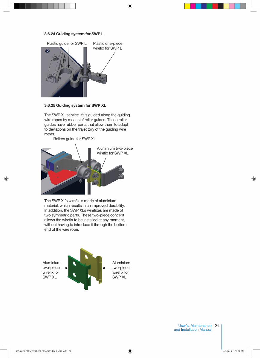
3.6.24 Guiding system for SWP L
3.6.25 Guiding system for SWP XL
The SWP XL service lift is guided along the guiding wire ropes by means of roller guides. These roller guides have rubber parts that allow them to adapt to deviations on the trajectory of the guiding wire ropes.
The SWP XLs wirefix is made of aluminium material, which results in an improved durability.In addition, the SWP XLs wirefixes are made of two symmetric parts. These two-piece concept allows the wirefix to be installed at any moment, without having to introduce it through the bottom end of the wire rope.
Plastic guide for SWP L
Rollers guide for SWP XL
Aluminium two-piece wirefix for SWP XL
Aluminium two-piece wirefix for SWP XL
Plastic one-piece wirefix for SWP L
Aluminium two-piece wirefix for SWP XL
45540028_SIEMENS LIFT CE AECO EN 5th R9.indd 21 4/9/2018 3:52:01 PM

22 AVANTI Service Lift for Wind Turbines
3.6.26 Guiding system for SWP L’s pulley and SWP XLs pulley (send and call configuration)
The SWP L’s pulley and SWP XLs pulley (send and call configuration) features a wire rope guiding system that prevents the pulley from colliding with tower internals.
45540028_SIEMENS LIFT CE AECO EN 5th R9.indd 22 4/9/2018 3:52:02 PM
23 User’s, Maintenance and Installation Manual
4 Installation 4.1 Cautions
Please familiarise yourself with these instructions and the User’s Manual before installing the service lift. Ensure that all specified parts are present before commencing installation.
No warranty is provided against damage and injury resulting from not following this “User’s, Maintenance and Installation Manual” i.e. reconstruction or modification of equipment or use of non-original parts which are not approved by the manufacturer. Prior to installation, ensure that: • Building sections involved will be able to withstand
the service lift loads. • All parts are available and fully functional. • Travel zone is protected by fences at each plat-
form.• Walking way surfaces are dry and not slippery.
The customer must define the maximum allowable wind speed ensuring safe installation.
During installation tasks, personnel shall:• Wear at least the following PPE: fall arrest
equipment if falling height is higher than 2 m, hand gloves, helmet, safety glasses, working gear.
• Use a hand winch attachable to the ladder when elevating heavy weights.
• Use a wire rope clamp or grip when lowering wire ropes, in order to avoid the risk of personnel losing the wire rope, and wire rope getting damaged or person being hit. The clamp shall be secured to a platform anchor point. The diameter of the clamps or grips shall match the diameter of the wire ropes.
• Not work at different levels if tasks involve risk of falling objects.
Electrical connection of the system must be made in accordance with EN 60204-1.
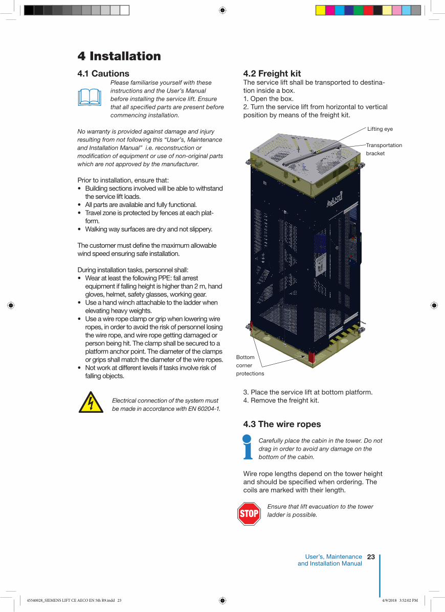
4.2 Freight kitThe service lift shall be transported to destina-tion inside a box.1. Open the box.2. Turn the service lift from horizontal to vertical position by means of the freight kit.
3. Place the service lift at bottom platform.4. Remove the freight kit.
4.3 The wire ropes
Carefully place the cabin in the tower. Do not drag in order to avoid any damage on the bottom of the cabin.
Wire rope lengths depend on the tower height and should be specified when ordering. The coils are marked with their length.
Lifting eye
Transportation
bracket
Bottom
corner
protections
�
STOPEnsure that lift evacuation to the tower ladder is possible.
45540028_SIEMENS LIFT CE AECO EN 5th R9.indd 23 4/9/2018 3:52:02 PM

24 AVANTI Service Lift for Wind Turbines
2) Uncoil wire ropes correctly (Fig. 3).
3) Feed all wire ropes to the bottom of the tower.
Fig. 3
All wire ropes are evenly uncoiled as shown in Fig 3 to prevent looping.
Ensure that no obstacles are in the way of the service lift. / Do not pull wire over edges.
Holes for
cable bin
straps
attachmentTraction wire rope
Wire rope
lock
Spacer
Space for wire rope
Plate
Safety wire rope
Guide wire hole
Guide
wire hole
Power cable hole
!
!
4.3.2 Tower bottom Holes in the bottom platform of the tower for wire rope bushing are positioned as shown in Fig. 4a SWP L and Fig. 4b SWP XL.
Fig. 4a SWP L
Fig. 1a SWP L
AISI 30445512352Roller shaft15AISI 30445512243Latch spacer roller d SharkM24 45512068Wire rope clip for 12mm13 45512063Wire rope clip for 7-8 mm22AW5754 H11145303726Top stop plate11
MATERIALARTICLE No.DESCRIPTIONQTYPOS
AISI 30445512352Roller shaft15AISI 30445512243Latch spacer roller d SharkM24 45512068Wire rope clip for 12mm13 45512063Wire rope clip for 7-8 mm22AW5754 H11145303726Top stop plate11
MATERIALARTICLE No.DESCRIPTIONQTYPOS
Fig 2b. SWP XL
Fig. 2a SWP L
The spacers must be positioned next to the wire rope locks, opposite to the plate.
Fig. 1b SWP XL
1) Fit the top limit device on the traction, safety and left guiding wire ropes (see Fig. 2a-b).
4.3.1 Tower topThe wire rope coils hang from the suspension beam.
Guiding wire Guiding wire
Safety wire
Traction wire
Top limit stop
45540028_SIEMENS LIFT CE AECO EN 5th R9.indd 24 4/9/2018 3:52:04 PM
25 User’s, Maintenance and Installation Manual
A A
B B
C C
D D
E E
F F
1
1
2
2
3
3
4
4
5
5
6
6
7
7
8
8THIS
DOC
UMEN
T AND
ITS
CONT
ENTS
ARE
PRO
PRIE
TARY
TO A
IP A
pS A
ND P
ROTE
CTED
BY
COPY
RIGH
T. TH
EY A
RE C
ONFID
ENTIA
L AND
MAY
CON
TAIN
LEGA
LLY
PRIV
ILEGE
D IN
FORM
ATIO
N.CO
PYIN
G, S
UBMI
TTIN
G TO
THIR
D PA
RTIE
S OR
USE
IN A
NY FO
RM A
ND FO
R AN
Y PU
RPOS
E OT
HER
THAN
THAT
ORI
GINA
LLY
INTE
NDED
IS P
ROHI
BITE
D W
ITHOU
T THE
EXP
RESS
PRE
VIOU
S W
RITT
EN C
ONSE
NT O
F AIP
ApS
.
Denmark
Hogevej 19DK-3400 Hillerod
AIP ApS Stamp:
Material:Dimension:
Edit by:
Edge:
Constructor:
Surface:
Title:
Revsion note:Measure tolerance:
Replaced by:
Date:
Sign:
Replaces:
Drw. no.
Valid from:
Rev.no.:Release Scale:
Weight:
ISO 2768-mK
Proj: Format:A3ISO-E
kg879,052
1 / 1 Sheet no.
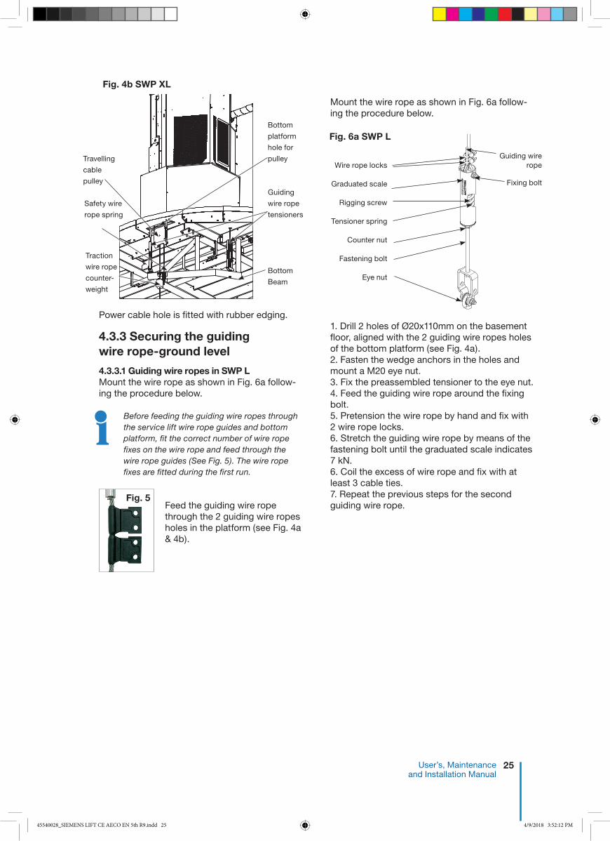
Power cable hole is fitted with rubber edging.
4.3.3 Securing the guiding wire rope-ground level
4.3.3.1 Guiding wire ropes in SWP LMount the wire rope as shown in Fig. 6a follow-ing the procedure below.
Before feeding the guiding wire ropes through the service lift wire rope guides and bottom platform, fit the correct number of wire rope fixes on the wire rope and feed through the wire rope guides (See Fig. 5). The wire rope fixes are fitted during the first run.
Feed the guiding wire rope through the 2 guiding wire ropes holes in the platform (see Fig. 4a & 4b).
Mount the wire rope as shown in Fig. 6a follow-ing the procedure below.
1. Drill 2 holes of Ø20x110mm on the basement floor, aligned with the 2 guiding wire ropes holes of the bottom platform (see Fig. 4a). 2. Fasten the wedge anchors in the holes and mount a M20 eye nut. 3. Fix the preassembled tensioner to the eye nut.4. Feed the guiding wire rope around the fixing bolt.5. Pretension the wire rope by hand and fix with 2 wire rope locks. 6. Stretch the guiding wire rope by means of the fastening bolt until the graduated scale indicates 7 kN.6. Coil the excess of wire rope and fix with at least 3 cable ties. 7. Repeat the previous steps for the second guiding wire rope.
Fig. 5
Travelling
cable
pulley
Traction
wire rope
counter-
weight
Safety wire
rope spring
Bottom
platform
hole for
pulley
Guiding
wire rope
tensioners
Bottom
Beam
Fig. 4b SWP XL
Class 8.873243220300Bolt DIN 933 8.8 FZV M20x300115Class 8.873143216110Bolt DIN 931 8.8 FZV M16x110114Class 8.873143216080Bolt DIN 931 8.8 FZV M16x80113A2-7073120999Washer DIN 125A A2 M20112A2-7073116999Washer DIN 125 A A2 M16411A2-7072116999Round washer Ø16mm A2 DIN 9021410A4-7071216999Lock nut DIN 985 A4 M1629FST70708230999Counter nut DIN 7967 FST FZV M2018C1570466220999Eye nut DIN 582 FZV M2017Steel Grade 1.710245515029Tensioner spring16S235 JRG245512419Rigging screw15S235 JRG245512398Housing14 45512068Wire rope clip for 12mm23S235 JRG245512067Galv. thimble for 12 mm wire12S355J2G345303830Link11
MATERIALARTICLE No.DESCRIPTIONQTYPOS
A A
B B
C C
D D
E E
F F
1
1
2
2
3
3
4
4
5
5
6
6
7
7
8
8THIS
DOC
UMEN
T AN
D IT
S CO
NTEN
TS A
RE P
ROPR
IETA
RY TO
AIP
ApS
AND
PRO
TECT
ED B
Y CO
PYRI
GHT.
THEY
ARE
CON
FIDE
NTIA
L AND
MAY
CON
TAIN
LEGA
LLY
PRIV
ILEGE
D IN
FORM
ATIO
N.CO
PYIN
G, S
UBMI
TTIN
G TO
THI
RD P
ARTI
ES O
R US
E IN
ANY
FOR
M AN
D FO
R AN
Y PU
RPOS
E OT
HER
THAN
THA
T ORI
GINA
LLY
INTE
NDED
IS P
ROHI
BITE
D W
ITHOU
T TH
E EX
PRES
S PR
EVIO
US W
RITT
EN C
ONSE
NT O
F AIP
ApS
.
Denmark
Rønnevangs Allé 6DK-3400 Hillerød
AIP ApS Stamp:
Edit by:Constructor:
Title:Replaced by:
Date:
Replaces:
Drw. no.
Valid from:
Rev.no.:Release Scale:
MPGMPG
2014-03-18
2014-02-11 1 : 5 35499450SWP Service LiftsLink Tensioner / Anchor Bolt
02
Proj: Format:A3ISO-E 1 / 1 Sheet no.
Wire rope locks
Graduated scale
Rigging screw
Tensioner spring
Counter nut
Fastening bolt
Eye nut
Fixing bolt
Guiding wire rope
Fig. 6a SWP L
45540028_SIEMENS LIFT CE AECO EN 5th R9.indd 25 4/9/2018 3:52:12 PM

26 AVANTI Service Lift for Wind Turbines
4.3.3.2 Guiding wire ropes in SWP XL Mount wire ropes as shown in Fig. 6b following procedure below.
1. Mount the preassembled tensioner on the bottom beam (see Fig. 4b). 2. Feed the guiding wire rope around the fixing bolt. 3. Pretension the wire rope by hand and fix with 2 wire rope locks. 4. Stretch the guiding wire rope by means of the fastening bolt until the graduated scale indicates 7 kN. 5. Coil the excess of wire rope and fix with at least 3 cable ties.6. Repeat the previous steps for the second guiding wire rope.
Check the distance between the wire ropes (1220 mm for SWP L and 1510 mm for SWP XL) so that the wire rope fix and wire ropes are in the centre of the wire rope guides.
Tighten the guiding wire ropes after the first run.
4.3.3.3 Guiding system for SWP L’s pulley and SWP XLs pulley (send and call configuration)1. Install a bracket below the bottom platform
P00.2. Install a bracket at platform P01.3. Install a bracket at the tower support T01
(between P01 and P02).4. Install a bracket at platform P02.5. Install the guiding wire ropes.6. Install the pulley.7. Adjust the guiding system.
The detailed installation instructions of the guiding system for SWP L’s pulley and SWP XLs pulley (send and call configuration) are available from AVANTI upon request.
!!
Guiding wire rope
Tensioner spring
Graduated
scale
Wire rope
locks
Fixing bolt
Counter nut
Fastening bolt
Fig. 6b SWP XL
Class 8.873243220300Bolt DIN 933 8.8 FVZ M20x30019Class 8.873143216110Bolt DIN 931 8.8 FZV M16x11018A2-7073120999Washer DIN 125A A2 M2017A2-7073116999Washer DIN 125 A A2 M1626A4-7071216999Lock nut DIN 985 A4 M1615Steel Grade 1.7102
45515029Tensioner spring14
S235 JRG245512419Rigging screw13S235 JRG245512398Housing12 35499407_P0135499407_P0111
MATERIALARTICLE No.DESCRIPTIONQTYPOS
A
45512068Wire rope clip for 12mm22S235 JRG245512067Galv. thimble for 12 mm wire11
35499407_P01MATERIALARTICLE No.DESCRIPTIONQTYPOS
A
Denmark
Rønnevangs Allé 6DK-3400 Hillerød
AIP ApS Stamp:
Edit by:Constructor:
Title:Replaced by:
Date:
Replaces:
Drw. no.
Valid from:
Rev.no.:Release Scale:
MPGMPG
2014-01-15
2014-01-15 1 : 10 35499407AD00082Set Tensioner Short
01
Proj: Format:A3ISO-E 1 / 1 Sheet no.
A A
B B
C C
D D
E E
F F
1
1
2
2
3
3
4
4
5
5
6
6
7
7
8
8THIS
DOC
UMEN
T AN
D IT
S CO
NTEN
TS A
RE P
ROPR
IETA
RY TO
AIP
ApS
AND
PRO
TECT
ED B
Y CO
PYRI
GHT.
THEY
ARE
CON
FIDE
NTIA
L AND
MAY
CON
TAIN
LEGA
LLY
PRIV
ILEGE
D IN
FORM
ATIO
N.CO
PYIN
G, S
UBMI
TTIN
G TO
THI
RD P
ARTI
ES O
R US
E IN
ANY
FOR
M AN
D FO
R AN
Y PU
RPOS
E OT
HER
THAN
THA
T ORI
GINA
LLY
INTE
NDED
IS P
ROHI
BITE
D W
ITHOU
T TH
E EX
PRES
S PR
EVIO
US W
RITT
EN C
ONSE
NT O
F AIP
ApS
.
�
45540028_SIEMENS LIFT CE AECO EN 5th R9.indd 26 4/9/2018 3:52:12 PM

27 User’s, Maintenance and Installation Manual
4.4 Electrical connections
4.4.1 Power supply
The electrical connection of the traction system must be made in accordance with EN 60204-1.
The power supply must be protected by a fuse and an earth leak circuit breaker (30mA).Disconnect the main power supply before handling power units. Verify that the rated grid and motor voltages are identical. The three-phase motor is supplied in a star connection configuration.
Check the correct phase lay after first installation and after each work at control box and/or power supply. In case the lift travels up when the down button is pushed, switch two phases on the power cable plug.
4.4.2 Installation of main switchThe main switch is installed on the bottom platform fence (Fig 7).
Mount the send and call control boxes to the platform fences and connect them to the main switch control box according to the wiring diagram supplied in the main control box of the cabin.1. Connect the power input cable to the WTG electrical cabinet.2. Connect the circuit to the plug available on the power cable coiling bin under the platform.
4.4.3 Supply cable1. The length of the cable depends on the height of the tower. The power cable is marked with its length.2. Use heavy rubber cable strips for fastening the supply cable to service lift. 3. An installed generator will have to provide at least 2.5 times the output of the traction system.
4.4.4 Power connection1. Push the EMERGENCY STOP button of the cabin operation box.2. Check that the various stop switch cables and fall arrest device cable are connected to the power cabinet according to colour code.3. If cable coiling bin is used (Fig. 8):
3.1 Hang the cable collect bin underneath the power cable hole of the bottom platform. Attach the straps on the holes shown in Fig. 4.3.2 Hang the bucket in the full length of the webbing. Keep the webbing as long as possible.3.3 Cut the transport strips and tape which hold the wire rope inside the bin.
The plug and socket connection between the lift and cable bin must be placed inside the engine room.
If traveling cable is used (Fig. 9):3.1 Install the junction box on the first platform over mid tower’s height.3.2 Cut the transport strips which hold the cable and connect the cable inlet to the junction box.3.3 Uncoil the cable to the bottom platform and guide it through the cable pulley supplied. 4. Connect the power cable outlet socket to the service lift inlet plug using cable stocking. Attach shackle to the eyebolt on the back of the service lift (Fig. 10).5. Connect the power cableplug to the grid.6. Pull the EMERGENCY STOP button to deactivate. The wiring diagram is found in the electrical control box.
Fig. 10
Fig. 7Fig. 9a
!
!
SWP L CE 690V 3 phases+gnd. 50 Hz Y I = 2.3A 1.5 kW 18m/min
SWP L CE 690V 3 phases+gnd. 60 Hz Y I = 2.8A 1.5 kW 18m/min
SWP L AECO 400V 3 phases+gnd. 60 Hz Y I = 4.9A 1.8 kW 21m/min
SWP L AECO 480V 3 phases+gnd. 60 Hz Y I = 4.1A 1.8 kW 21m/min
SWP L AECO 480V 3 phases+gnd. 60 Hz Y I = 3.1A 1.1 kW 10m/min
SWP XL CE 690V 3 phases+gnd. 50 Hz Y I = 2.6A 2 kW 18m/min
SWP XL CE 690V 3 phases+gnd. 60 Hz Y I = 3.2A 2 kW 18m/min
Control voltage: 230V
Power cable inlet plug
Counterweight traction wire
Cable collect bin
Cable collect bin suspension
straps
Spring safety wire
Power cable outlet socket
Cable stocking
Fig.8
45540028_SIEMENS LIFT CE AECO EN 5th R9.indd 27 4/9/2018 3:52:14 PM

28 AVANTI Service Lift for Wind Turbines
4.5.2 Safety wire rope installation1. Unlock the fall arrest device by pulling down the black handle. Feed the safety wire rope through the fall arrest device.2. Like the traction wire rope, continue feeding the wire rope underneath (round) the back guide wheel and over the front guide wheel. 3. Pull the safety wire rope to tighten it. 4. Feed wire rope through platform floor.5. Mount the top window on the service lift.
Fig. 13 b SWP XL
Fig. 13 a SWP L
A
AD00072_27Pulley for power cable120 AD00063_29Set Cabin Light119 AD00063_28Set Top safety stop AECO118 AD00060_26AD00060_26117 AD00060_25AD00060_25116 AD00060_22AD00060_22315 AD00060_21AD00060_21214 AD00060_19AD00060_19213 AD00060_16AD00060_16112 AD00060_15AD00060_15111 AD00060_12AD00060_12110 AD00060_10AD00060_1029 AD00060_09AD00060_0988 AD00060_06AD00060_0617 AD00063_03AD00063_0316A2-7079999562Eye nut M8 DIN582 FZV25A2-7079999507Bolt DIN 603 A2 M8x2024 45541028Lift label AVANTI logo13 45512208Top side cover12 45512207Bottom side cover11
MATERIALARTICLE No.DESCRIPTIONQTYPOS
A2-7075112035Bolt DIN 933 A2 M12x3524A2-7073112999Washer DIN 125 A A2 M1243A4-7071212999Lock Nut DIN 985 A4 M1222AISI 30445512194Anchor point11
AD00060_10MATERIALARTICLE No.DESCRIPTIONQTYPOS
A2-7076110035Bolt ISO 7380 A2 M10x3514A2-7072110999Washer DIN 9021 A2 M1013PA6 or AW5754 H11145512200Foot wedge 19 mm12Rubber45512192Female foot D70xL7011
AD00060_09MATERIALARTICLE No.DESCRIPTIONQTYPOS
Y
A2-7076106035Bolt ISO 7380 A2 M6x3516A2-7076106020Bolt ISO 7380 A2 M6x2015A2-7073106999Washer DIN 125 A A2 M644A4-7071206999Lock Nut DIN 985 A4 M623PEHD1000 or PA6G21045570006Small wheel12AW5754 H11145303386Small wheel bracket11
AD00060_22MATERIALARTICLE No.DESCRIPTIONQTYPOS
A2-7076106025Bolt ISO 7380 A2 M6x2529A2-7076105045Bolt ISO 7380 A2 M5x4528A2-7073106999Washer DIN 125 A A2 M627A2-7073105999Washer DIN 125A A2 M546A2-7072106999Washer DIN 9021 A2 M625A4-7071206999Lock Nut DIN 985 A4 M624A4-7071205999Lock Nut DIN 985 A4 M5 23 45502182Bottom stop switch12AW5754 H11145303439Bracket for S2 switch11
AD00060_12MATERIALARTICLE No.DESCRIPTIONQTYPOS
A2-7076105020Bolt ISO 7380 A2 M5x2025A2-7073105999Washer DIN 125A A2 M524A2-7072105999Washer DIN 9021 A2 M523A4-7071205999Lock Nut DIN 985 A4 M5 22 45502356Light PMARL 50 STR11
AD00060_20MATERIALARTICLE No.DESCRIPTIONQTYPOS
AA
A2-7076108016Bolt ISO 7380 A2 M8x16 24A2-7076106020Bolt ISO 7380 A2 M6x2028A2-7073112999Washer DIN 125 A A2 M1222A2-7073106999Washer DIN 125 A A2 M646A4-7071206999Lock Nut DIN 985 A4 M625PEHD1000 or PA6G21045570005Safety roller17AISI 30445512193Roller shaft13AW5754 H11145303364Safety roller support11
AD00060_19MATERIALARTICLE No.DESCRIPTIONQTYPOS
B
A
A2-7076106020Bolt ISO 7380 A2 M6x20319A2-7076104030Bolt ISO 7380 A2 M4x30218A2-7075108160Bolt DIN 933 A2 M8x160217A2-7073112999Washer DIN 125 A A2 M12216A2-7073108999Washer DIN 125 A A2 M8215A2-7073105999Washer DIN 125A A2 M5314A2-7073104999Washer DIN 125 A A2 M4413A2-7072108999Washer DIN 9021 A2 M8412A2-7072106999Washer DIN 9021 A2 M6611A4-7071208999Lock Nut DIN 985 A4 M8210A4-7071206999Lock Nut DIN 985 A4 M699A4-7071204999Lock Nut DIN 985 A4 M428AISI 30245515013BSS spring27AISI 30445512199BSS shaft26Rubber45512156Edge strip0.5 M5 45512064Wire with nylon cover D2.3mm1 M4 45512061Talurit63AW5754 H11145303493Support for switch12 45303372Bottom safety stop11
AD00060_06MATERIALARTICLE No.DESCRIPTIONQTYPOS
A2-7076104035Screw ISO 7380 A2 M4x3524A2-7073104999Washer DIN 125 A A2 M423A4-7071204999Lock Nut DIN 985 A4 M422 45502185Platform switch11
AD00060_15MATERIALARTICLE No.DESCRIPTIONQTYPOS
A
B
A2-7079999513Spring threaded bar M8416A2-7076106035Bolt ISO 7380 A2 M6x35215A2-7076104030Bolt ISO 7380 A2 M4x30214A2-7073112999Washer DIN 125 A A2 M12413A2-7073108999Washer DIN 125 A A2 M8412A2-7073106999Washer DIN 125 A A2 M6211A2-7073104999Washer DIN 125 A A2 M4410A2-7072108999Washer DIN 9021 A2 M889A4-7071208999Lock Nut DIN 985 A4 M888A4-7071206999Lock Nut DIN 985 A4 M627A4-7071204999Lock Nut DIN 985 A4 M426AISI 30445515025Top safety stop spring45AISI 30445512197Spring bushing for top bar44 45303700Top safety stop AECO13AW5754 H11145303493Support for switch12AW5754 H11145303374Top safety stop connector11
AD00063_28MATERIALARTICLE No.DESCRIPTIONQTYPOS
AC
A2-7076108030Bolt ISO 7380 A2 M8x3045A4-7071208999Lock Nut DIN 985 A4 M844A2-7073108999Washer DIN 125 A A2 M883Default45511002Large wire guide12AW5754 H11145303361Wireguide bracket11
AD00060_21MATERIALARTICLE No.DESCRIPTIONQTYPOS
A2-7079999714Eyebolt DIN 444 B A2 M6x3527 45512272Black wire handle16 45512271Red wire handle15 45512064Wire with nylon cover D2.3 mm1.4 M4 45512064Wire with nylon cover D2.3 mm1 M3AW5754 H11145512061Talurit42 35499352Roller for OSL wire21
AD00060_26MATERIALARTICLE No.DESCRIPTIONQTYPOS
A2-7076108020Bolt ISO 7380 A2 M8x2028A2-7076105016Bolt ISO 7380 A2 M5x1627A2-7073108999Washer DIN 125 A A2 M846A2-7073105999Washer DIN 125A A2 M545A4-7071208999Lock Nut DIN 985 A4 M824A4-7071205999Lock Nut DIN 985 A4 M5 23Default45502146Lift emergency light12AW5754 H11145303697Light support11
MATERIALARTICLE No.DESCRIPTIONQTYPOS
1
1
2
2
3
3
4
4
5
5
6
6
7
7
8
8
9
9
10
10
11
11
12
12
13
13
14
14
15
15
16
16
A A
B B
C C
D D
E E
F F
G G
H H
THIS
DOC
UMEN
T AN
D IT
S CO
NTEN
TS A
RE P
ROPR
IETA
RY TO
AIP
ApS
AND
PRO
TECT
ED B
Y CO
PYRI
GHT.
THEY
ARE
CON
FIDE
NTIA
L AND
MAY
CON
TAIN
LEGA
LLY
PRIV
ILEGE
D IN
FORM
ATIO
N.CO
PYIN
G, S
UBMI
TTIN
G TO
THI
RD P
ARTI
ES O
R US
E IN
ANY
FOR
M AN
D FO
R AN
Y PU
RPOS
E OT
HER
THAN
THA
T ORI
GINA
LLY
INTE
NDED
IS P
ROHI
BITE
D W
ITHOU
T TH
E EX
PRES
S PR
EVIO
US W
RITT
EN C
ONSE
NT O
F AIP
ApS
.
Denmark
Hogevej 19DK-3400 Hillerod
AIP ApS Stamp:
Edit by:Constructor:
Title:Replaced by:
Date:
Replaces:
Drw. no.
Valid from:
Rev.no.:Release Scale:
GSGS
2013-04-02
2013-04-02 - : - 02AD00063SWP Service Lift AECOCabin assembly Proj: Format:
A0ISO-E 1 / 3 Sheet no.
Traction
wire rope
Safety
wire rope
Fig. 12a SWP L Fig. 12b SWP XL
Top windowFig. 11 SWP L
Wear protective gloves when handling wire ropes.
4.5.1 Traction wire rope installation1. Remove top window from the service lift (see Fig. 11).2. Put the wire rope into the traction system’s wire rope inlet opening.3. Push the UP button on the cabin operation control (manual control from inside the cabin) and feed wire rope through until the traction system starts pulling. Ensure that the wire rope can exit without obstruction!4. Continue feeding the wire rope under-neath (round) the back guide wheel and over the front guide wheel.5. Let the traction wire rope pass through until it is slightly tightened.6. Feed wire rope through platform floor.
4.5 Installation of traction and safety wire rope in lift
45540028_SIEMENS LIFT CE AECO EN 5th R9.indd 28 4/9/2018 3:52:29 PM

29 User’s, Maintenance and Installation Manual
4.6 Securing the traction and safety wire rope The traction wire rope is fastened as described in point 4.6.1 below and the safety wire rope is fastened as shown in point 4.6.2.
4.6.1 Traction wire rope counterweight An 11kg (24,25 lb) weight is mounted approximately 200mm (7,87 in) below the cable bin, on the traction wire rope. Excess of wire rope is coiled with at least 3 strips (See Fig. 14 and Fig. 8).
4.6.2 Safety wire rope push spring1. Feed the safety wire rope through the bottom platform hole. 2. Ascend the service lift 50 cm. 3. Activate the fall arrest device. 4. Perform manual descent so that the weight of the service lift is transmitted to the safety wire rope. 5. Compress the spring to 40 mm and fix with cable ties. 6. Feed the safety wire rope through the compressed spring. 7. Pull the safety wire rope downwards by hand as much as possible. 8. Place and fasten the wire rope grip. 9. Cut the cable ties so that the spring decompress-es to 55 mm.
Before fastening the safety wire rope carry out the fall arrest device test (See User’s Manual section).
Ensure that counter-weight and wire rope coils can rotate freely.
STOP
Fig. 15
Fig. 14
45540028_SIEMENS LIFT CE AECO EN 5th R9.indd 29 4/9/2018 3:52:32 PM

30 AVANTI Service Lift for Wind Turbines
4.7 Wire rope fix alignment Having mounted the service lift, the wire ropes, and the power cable, adjust the wire rope fix alignment during the first run.
There are 2 installation windows located on the rear of the service lift. These shall only be used during installation and maintenance tasks. In order to avoid risks, turn the power supply off from the service lift before opening the 2 installation windows. Do not turn the power supply back on until the windows are closed.
4.7.1 Wire rope fix alignment for SWP LAdditional tool is needed to make the reference to right wirefix position as the guide wire rope is not reachable (for SWP L only) (see Fig. 17).
By means of the oblong holes in the wire fix fittings, adjust the fittings so that the two parts pass each other easily, when the service lift moves. Once the wirefix is properly fixed, open the tool and lift the cabin up to overtake the fixed wirefix. Then close the tool with remaining wirefixes above it and go to the next platform.
STOP
STOP
Fig. 17: Closed windows
Fig. 16 a SWP L
Fig. 16 b SWP XL
Fig. 18: Opened windows
Position
tool
Plastic guide
Plastic one-piece wirefix
Rollers guide
Aluminium two-piece wirefix
45540028_SIEMENS LIFT CE AECO EN 5th R9.indd 30 4/9/2018 3:52:33 PM

31 User’s, Maintenance and Installation Manual
4.7.2 Wire rope fix alignment for SWP XLThe final position of the wire rope fixes for SWP XL shall be adjusted with the help of an installation tool (see Fig. 19) and following the procedure below.
1. Put the installation tool inside the service lift and ascent to the first pair of wire rope fixes.2. Turn the trapped key to OFF position, and then open the 2 installation windows.3. Attach the left end of the installation tool to the left guiding wire rope (see Fig. 20).
4. Attach the right end of the installation tool to the right guiding wire rope (see Fig. 21).
5. Slide the installation tool downwards until it contacts the wire rope fixes (see Fig. 22).
6. Adjust the position of the wire rope fixes horizon-tally so that they insert in the indentations of the installation tool (see Fig. 23).
7. Tighten the bolts of the wire rope fixes.8. Slide the installation tool upwards.9. Release the right end of the installation tool from the right guiding wire rope.10. Release the left end of the installation tool from the left guiding wire rope.11. Put the installation tool inside the service lift.12. Close the 2 installation windows, and then turn the trapped key to ON position.13. Repeat the previous steps with each pair of wirefixes throughtout the travel path.
Fig. 19
Fig. 20
Fig. 21
Fig. 22
Fig. 23
45540028_SIEMENS LIFT CE AECO EN 5th R9.indd 31 4/9/2018 3:52:34 PM

32 AVANTI Service Lift for Wind Turbines
Fig. 16
4.8 Adjustment of safe-zone plates
The service lift door should be able to be opened whenever the cabin is in alignment with the platform (tolerance ± 100mm).
The safe-zone is adjusted in relation to the service lift switch in order to fulfil the above requirement (see Fig. 16).
4.9 Adjustment of top obstruction device The top obstruction device is adjusted so the top obstruction switch stops the lift in alignment with the top landing platform.
4.10 Danger zone! sticker
Mount the “Danger Zone” sticker in the tower behind the lift. Make sure the wall and platform are clean and dry before attaching the sticker.
Make sure that nobody is exposed to danger below the service lift, for instance from falling parts.
4.11 Inspection before first useA service lift inspector must carry out an inspec-tion before first use.
Inspection shall only be carried out by AVANTI, or an authorized person, following the “6.4 Annual inspection”. And filling in the “Appendix B: Inspec-tion checklist” for future possible refer-ence. The WTG owner must ensure that the results of this inspection before first use are logged in the “Appendix C: Inspec-tion Log Sheet”.
When the lift travel path is extended to the foundation when the WTG is installed over the foundation, for ex-ample in off-shore installations, the bolded points of the check list have to be checked again although they were checked during the first installation.
4.12 Disassembling Disassemble in reverse order and dispose of in accordance with local authority regulations.
STOP
�
�
�
�
45540028_SIEMENS LIFT CE AECO EN 5th R9.indd 32 4/9/2018 3:52:35 PM

33
!
STOP
User’s, Maintenance and Installation Manual
5.1 Prohibited uses The consequences of not following below prohibitions are extremely hazardous to the physical integrity of the users.
When using the service lift it is prohibited to: • Use the service lift beyond its intended purpose. • Operate the service lift without following the safety warnings and operating instructions. • Overload the service lift more than its rated load. • Try to repair machine components. Only person-nel from AVANTI or competent persons certified by AVANTI are allowed to perform service on the machine. • To manipulate switches and safeties.• To place objects on service lift roof. • To descent on service lift roof.
5.2 Entry and exitTo ensure safe entry and exit:a) Lower the service lift onto the access platform until the bottom obstruction device is activated and the cabin stops, or: bring the lift to a height corresponding to the correct level for exiting from the wind turbine’s platform.b) Open the door and exit/enter the lift through the door.
5.3 Stop/Emergency stopa) Release the Up or Down button; the service lift should stop
If it does not:b) Push the EMERGENCY STOP button, and all controls should be disabled.
5.4 Operation from inside the cabina) Close the doorb) The key switch ON/OFF should be ONc) Press the reset buttond) To go up or down, push and hold the Up or Down button.e) To place the service lift on the floor after the bottom obstruction device has stopped the lift.- Turn the override bottom obstruction device switch clockwise and hold.- Press the DOWN button until the service lift rests on the floor, then release.
5.5 Operation from outside the cabin (send only configuration)Transportation of people is forbidden if the operation is controlled from outside the cabin
Operation by means of the user control box:a) The key switch ON/OFF should be ONb) Close the door.c) Press the reset buttond) Press the UP or DOWN button respectively and the cabin starts ascending/descending.
Transportation of people is forbidden if the operation is controlled from outside the cabin
5.6 Operation from platforms (send and call configuration)Transportation of people is forbidden if the operation is controlled from the platforms.
Operation by means of the platform control box:a) Turn the trapped key switch to ON.b) Close the door of the cabin and of the platform fence.c) Press the reset button.d) Press and hold the UP or DOWN button to ascend or descend the cabin.e) When platform light (green) illuminates, cabin is aligned with a platform and can be opened.
When actuating UP or DOWN buttons, response of cabin is delayed and an acoustic signal sounds, in order to warn personnel in the surroundings that cabin is going to move.
5 . Instructions for use
45540028_SIEMENS LIFT CE AECO EN 5th R9.indd 33 4/9/2018 3:52:35 PM

34
STOP
AVANTI Service Lift for Wind Turbines
�
If a power failure or an operation fault etc. inter-rupts the hoist, a manual descent is possible from inside the cabin.
1. The lever is attached underneath the cabin top. Turn it down.2. Push the lever upwards the full way. The service lift moves downwards. The built-in me-chanical overspeed limiter limits the pace of descent. 3. To stop, simply loosen the lever.4. After manual descent, the system must be checked by an expert
During manual descent if the bottom obstruc-tion device hits an obstacle, the brake release lever is mechanically disengaged so the further descent is disabled. The system is automati-cally reset once the obstacle is removed.
To lock the fall arrest device in an emergency: • Pull down the red handle in SWP L. • Push the red lever upwards in SWP XL.If the fall arrest device engages, simply disengage itfrom inside the cabin until the fall arrest device is unlocked by:• Pulling the black handle downwards in SWP L.• Pushing the black actuator upwards in SWP XL.However, this is not possible if the safetywire rope is under tension. If this is the case:1. Remove the load on the safety wire rope bypushing the UP button taking the lift upwards afew centimetres.2. Manually open the fall arrest device until the fall arrest device is unlocked by:• Pulling the black handle downwards in SWP L.• Pushing the black lever upwards in SWP XL. In case of no power and the fall arrest device islocked with the safety wire rope under tensionevacuate the lift according to the “Evacuation guide”.
5.8 Manual descent
Brake release lever of SWP L
Brake release lever of SWP XL
PULL TO LOCK (red) in SWP L
Red locking lever of SWP XL
Black locking lever of SWP XL
PULL TO UNLOCK (Black) in SWP L
!
!
5.9 Fall arrest device
5.7 Overload limiter a) In case of an overload, the lift’s upward travel should be blocked, and a buzzer should sound in the connection cabinet.
Attempting to run in an overloaded lift is prohibited!
b) Remove enough of the load to make the buzzer stop and enable upward travel.
On entering and starting the lift, the buzzer may sound briefly. This is due to temporary load peaks occurring as the lift takes off.
The control box is designed not to activate the buzzer or stop the lift because of peak loads caused by the cabin swinging.
If the problem persists have an AVANTI expert adjust the overload limiter (see “Appendix A: Regulation of overload limiter”).
A
45540028_SIEMENS LIFT CE AECO EN 5th R9.indd 34 4/9/2018 3:52:36 PM

35
STOP
User’s, Maintenance and Installation Manual
PULL TO LOCK (red) in SWP L
Red locking lever of SWP XL
Black locking lever of SWP XL
PULL TO UNLOCK (Black) in SWP L
Breakdown Cause Solution
The service lift will neither go up nor down!
DANGER!Attempting to use the lift will jeopardize work safety
A1 The fixed EMERGENCY STOP button has been activated.
Deactivate the button in question by pulling it until it pops out.
A2 Wire rope loop on traction system. Damaged or defective wire rope or wire rope outlet causes problems.
Stop work immediately!Ask the supplier or manufacturer for help.
A3 The fall arrest device is holding the service lift on the safety wire rope.
a) Lift wire rope breakageb) Hoist failure
a) + b) Evacuate the service lift accord-ing to the “Evacuation guide”.
A4 The service lift is stuck on an obstacle.
Carefully remove the obstacle.Test the operational safety of affected building sections. Inform the supervisor.
A5 Power failurea) Control not switched on or deacti-
vated.b) Grid voltage interrupted.c) Supply between grid connection and
control interrupted.d) Phase control relay 1) tripped due to wrong phase sequence.
1) Optional for CE versions. Mandatory for AECO versions.
a) Turn EMERGENCY STOP button to the right until it is released.
b) Find the cause and wait for the power to return.
c) Test and if necessary repair the supply cable, fuses, and/or wiring from the control box.
d) Check and correct phase lay at power supply.
A6 Safety switch is triggereda) EMERGENCY top limit switch was
pressed.b) Door switch is not properly
closed or is defective.
a) Perform manual descent until the emergency top limit switch is released.b) Close the door and test the door
switch.
A7 Protection switch on overheating
a) A phase is missingb) Motor is not coolingc) Voltage too high/lowd) Magneto thermal protection 1)
tripped For AECO versions with
400V/60Hz power supply.
a) Test/repair fuses, supply and connec-tion.
b) Clean the hood.c) Measure voltage and power consump-
tion on the loaded motor. If voltage deviates from specifications, use cable with increased dimensions.
d) Turn magneto thermal switch ON.
A8 Brake does not open (no click on on/off) a) Supply, braking coil or
rectifier defective.b) Braking rotor closes.
a) Have an electrician test, repair/replace
the supply, braking coil and rectifier.b) Return traction system for repair.
5.10 Troubleshooting
1. All tests and repairs to the electronic components should be performed by certified technicians only! The wiring diagram is placed in the power cabinet.
2. Repairs to the traction hoist, the fall arrest device and to the system’s supporting components should be performed by certified technicians only!
DANGER!
Unplug the power supply before opening the power cabinet.
45540028_SIEMENS LIFT CE AECO EN 5th R9.indd 35 4/9/2018 3:52:36 PM

36
STOP
!
AVANTI Service Lift for Wind Turbines
Breakdown Cause Solution
The service lift will neither go up nor down
A9 The reset function has not been activated.
Press a reset button
A10 The key switch ON/OFF has not been activated.
Turn the key to ON
A11 The main switch is in the OFF position.
Turn the main switch ON.
A12 The product is stuck on an obstacle below it.
- Evacuate the service lift.- Inform the supervisor.- Check the bottom obstruction device connec-tion/function. Replace if necessary.- Check the slack rope sensor 1) connection/function. Replace if necessary.
1)Note: Optional feature. Mandatory for AECO
Service lift goesdown but not up
Irresponsible behaviour jeopardizes system safety!
B1 The service lift is stuck on an obstacle.
Carefully move the service lift downwards and remove the obstacle. Test the opera-tional safety of affected platform components. Inform the supervisor.
B2 Overload - Buzzer soundsin the connection cabinet.
Test and possibly reduce load until buzzer stops.
B3 Top obstruction switch:a) Top obstruction switch is defective or not connected properly.b) Top obstruction switch is activated.
a) Test the top obstruction switch connec-tion/function. Replace if necessary.
b) Move lift down until the top obstruction switch is released.
B4 Fault in UP control circuit in control box or traction system
Test and possibly repair connections, wiring and relays.
Motor hums loudlyor wire ropes squeak,but the lift can go both up and down.
C1 Wire ropes dirty
WARNING! Further use of lift may result in damage to the wire rope traction.
If possible, immediately replace the traction system and return it for test/repair at AVANTI.
DANGER!
Unplug the power supply before opening the power cabinet.
45540028_SIEMENS LIFT CE AECO EN 5th R9.indd 36 4/9/2018 3:52:36 PM

37
STOP
STOP
User’s, Maintenance and Installation Manual
Breakdown Cause Solution
Service lift will go up but not down!
Irresponsible behaviour jeopardizes system safety!
D1 The service lift has encoun-tered or is stuck on an obsta-cle.
Carefully take the service lift up and remove the obstacle.Test the operational safety of affected platform components. Inform the supervisor.
D2 The fall arrest device is hold-ing the service lift on the wire rope.
a) Excessive hoist speedb) Too low release speed on
fall arrrest device.
A defective fall arrest device will threaten the safety of the service lift! Replace immediately!
a) + b) Take the service lift upwards to relieve the safety wire rope. unlock the fall arrest device by pull down the black handle, and test its function.
Functional test when the lift is back on the ground: Replace the hoist and fall arrest device and return them for testing.
D3 Fault in down controller circuit on traction system
Insert brake lever into the traction system and lower lift manually.Test, and if necessary have connec-tions, wiring, and relays repaired.
D4 Slack rope sensor1) is engaged
1) Optional for CE version.Mandatory for AECO version.
Check the reason why it is engaged, possibly it’s an obstacle under the service lift or the bottom obstruction device is not functioning properly.
Button lampnot lit although operation is normal.
E A lamp is defective Have an electrician replace it.
Hoist goes down when up button is pressed and up when down button is pressed.
F Two phases changed in the supply
Have an electrician switch the 2 phases in the plug
Loud noise and / or smoke coming from hoist motor
G Brake closed or partially closedWARNING ! Damage of hoist brake leading to brake function lost
Stop work immediately! Call supervisor for advice and potential repair of hoist
DANGER!
Unplug the power supply before opening the power cabinet.
If these steps do not identify the cause and rectify the fault:Consult a certified technician or contact the manufacturer.
5.11 Out of service
1. Securing the service lift: Bring the service lift all the way down, until the
bottom obstruction device stops the cabin.
2. Turn off the main switch to prevent inadvertent operation of the lift:
Turn the main switch to the OFF position – power supply is now interrupted. Mark the lift “OUT OF SERVICE”. Contact the service technician for repair.
45540028_SIEMENS LIFT CE AECO EN 5th R9.indd 37 4/9/2018 3:52:36 PM

38 AVANTI Service Lift for Wind Turbines
6 Maintenance Mandatory requirements The lift must have been installed and serviced by cer-tified technicians. Operation of the lift requires user training. All the installation, inspections / maintenance operations from first use, periodical and extraordinary must be logged in the Inspection and Maintenance Log Book. All required values measured must be logged, as well as parts replaced. Annual inspections and service tasks made to the hoist and fall arrest device must be carried out by certified technicians.Ambient conditions must comply with the techni-cal specifications. Service lift misuse is prohibited, including but not limited to:• By passing overload system• Excessive use of no power descend• By passing safeties• Etc.In case the mentioned required conditions are not fully met, it is not allowed to use the lift. Put the lift out of operation and inform the site management. The site manager shall initiate the ten year inspection scope before putting the lift in use again.Before any maintenance operation, check that the service lift is properly out of service.
In case of a fault, do not use the service lift until it is solved. If required secure work-place.
The relevant maintenance instructions are provided to each person during the service training. 6.1 Mandatory inspection and maintenance planningHaving the above required conditions under control, the following inspection and maintenance planning is mandatory:
6.2 CautionsBefore any maintenance task, ensure that walking way surfaces are dry and not slippery.
During maintenance tasks, personnel shall:• Wear at least the following PPE: fall arrest equip-
ment (when falling height is more than 2 m), hand gloves, helmet, safety glasses and working gear.
• Place cabin at bottom platform and disconnect power supply.
• Use an electricity measuring tool when performing inspection of electrical components.
• Use a hand winch attachable to the ladder when handling big/ heavy loads and shall be performed at least by 2 persons.
• Panel parts shall be removed to facilitate access to confined spaces.
• Guiding rollers shall be replaced one by one.• Use a cable grip when replacing travelling cable.• Keep cabin doors closed when using a 3-step
ladder. • Dismount hatch to access the engine room.
Only certified technicians shall perform electrical installation tasks.!
Frequency Performed by Components
Daily User Overall / Travel zone
Control and safety devices
Fall arrest device
Annually Certified
technician
Overall / Travel zone
Control and safety devices
Cabin
Traction hoist
Fall arrest device
Overload limiter
Traction and safety wire ropes
Guiding system
Electrical system
Information signs and documents
Doors and hatches
Cabin control box
Safety switches
Interlock system
Platforms
Every ten years or every 125 hours of
operation (whatever occurs first)
Certified
technician
Fall arrest device (enhanced inspection)
Traction hoist (enhanced inspection)
Every 20 years or 250 hours of opera-
tion (whatever occurs first)
At Avanti
Workshop
Traction hoist (recertification)
Fall arrest device (recertification)
!
45540028_SIEMENS LIFT CE AECO EN 5th R9.indd 38 4/9/2018 3:52:37 PM

39 User’s, Maintenance and Installation Manual
6.3 Daily inspectionDaily inspection of the service lift shall only be performed by personnel authorised by AVANTI. If there is more than one user, the employer shall appoint a supervisor in charge of the daily inspection.
6.3.1 OverallVisual Inspection:a) Check that the cabin has no damages.b) Check that the top and bottom obstruction devices are free of damages.c) Check that the traction and safety wire rope ropes are correctly fed and guided. d) Record the hour meter reading on the service lift log.
6.3.2 Travel zonea) Ensure that there are no obstacles within the service lift’s operating area which may obstruct the travel of the cabin or cause the cabin to hit the ground.
6.3.3 Control and safety devices
6.3.3.1 Cabin control from inside the cabina) Close the doors. Press the EMERGENCY STOP button. The lift should remain still when the UP/DOWN button is pressed. To restart, pull the EMERGEN-CY STOP button and press the reset button.
b) Test the EMERGENCY top limit switch:During upward travel, press the switch manually, and the service lift shall stop immediately. Neither upward nor downward travel should now be possible.
c) Bottom obstruction device. Lower the lift; It shall stop before the rubber feet of the cabin reach the tower ground level.
d) Door switch:Open the door – it shall not be possible to move the lift upwards or downwards.
Place the cabin at a height no corresponding to platform – it shall not be possible to open the door. The door is only able to open by turning the emergency release lever up.
e) Key switch ON/OFF: Turn the key to OFF - it shall not be possible to move the lift upwards or downwardsf) Top obstruction device:activate device by pressing it down. The service lift shall not move up until device is released.
g) Slack rope sensor 1): Activate the slack rope sensor by manually pulling traction wire rope. The power supply to the service lift should be removed (therefore neither upward nor downward travel shall be possible).
If any faults occur during work,- stop working,- if required secure the workplace and - rectify the fault!
Make sure that nobody is exposed to danger below the service lift, for instance from falling parts.
h) Fall arrest device. Activate the fall arrest device by pulling down the red locking knob. Press and hold the DOWN button of the cabin control box. The service lift should not descend. Try to perform manual descent. The service lift should not descend. Press and hold the UP button of the cabin control box. The service lift should ascend. Unlock the fall arrest device by pulling down the black unlocking knob.
6.3.3.2 Cabin control from outside of the cabin – Send only configuration
The automatic mode function is only available from the control buttons outside of the cabin and shall be checked as follows:
a) Press the UP button on the control box. The lift should travel upwards.
b) Press the EMERGENCY STOP button on the control box. The lift stops.
c) Pull the EMERGENCY STOP button and press the DOWN button. The service lift should travel downwards until the bottom obstruction device engages.
6.3.3.3 Cabin control from platform control boxes – Send and call configuration
The automatic mode function is only available from the platform control boxes.a) Press and hold the UP button on the control box – the service lift ascends with a delayed response.
b) Press the emergency stop button on the controlbox - the service lift stops.
c) Pull the emergency stop button and press and hold the DOWN button - the service lift descends.
!STOP
45540028_SIEMENS LIFT CE AECO EN 5th R9.indd 39 4/9/2018 3:52:37 PM

40 AVANTI Service Lift for Wind Turbines
6.4 Annual inspectionHave the entire system, especially the traction system and the fall arrest device tested by certified technicians authorised by AVANTI at least once annually. However, inspect more frequently depending on use and the conditions of use.The traction system and fall arrest device must be overhauled at an AVANTI workshop and furnished with new certificate for every 250 hours of operation. The hour counter is found in the power cabinet.
A certified technician must carry out theannual inspection following the AnnualInspection Checklist detailed in Appendix B.
Owner must ensure that the results of allannual and extraordinary inspections andtests are logged in the “Appendix C:Inspection log sheet”.
6.4.1 Traction hoistThe traction hoist shall be maintainedaccording to maintenance planning (please seesection 6.1). Relevant maintenance instructionsare provided to each person during thetraining. These maintenance inspections mustbe only carried out by a certified technician.
6.4.2 Fall arrest device
The fall arrest device shall be maintainedaccording to maintenance planning (please seesection 6.1). Relevant maintenance instructionsare provided to each person during the training.These maintenance inspections must be onlycarried out by a certified technician.
If fall arrest device has engaged due to adynamic fall, a certified technician must verify the safety of the fall arrest device, the wire rope, and wire rope fastenings.
After FAD has engaged, if the FAD damper has moved downwards, the FAD unit must be replaced by a certified technician.
6.4.3 Traction, safety and guiding wire ropesPerform the following inspections and adjust if necessary: 1. Inspect all the wire ropes along their entire length. 2. Pay special attention to the wire rope ends, parts of the wire ropes running over sheaves and wire ropes under frictional wear by external components. 3. When inspecting the wire ropes, consider the following points: • type and number of wire breaks, • position and time sequence of wire breaks, • decrease of the wire rope diameter during operation, • corrosion, abrasion, deformation, • influence of heat, and • operating time. 4. Check that the traction, and safety wire ropes are fed correctly around the 2 wire rope guide wheels. 5. Check that the wire rope ends are coiled separately under the bottom platform and tied with at least 3 cable ties. 6. Check that the guiding wire rope tensioning system is correctly installed and that the wire rope locks and fixes are properly fastened. 7. Check that the compression spring on the safety wire rope is correctly installed and that the wire rope locks are fastened 8. Check that the counterweight on the traction wire rope is properly fastened. The traction wire rope coil and counterweight shall be able to rotate freely. Do not attach it to a fixed part. 9. Check that the guiding wire ropes are cor-rectly tensioned as described in the instructions of tensioning the guiding wire ropes.
Record any visible change of the condition of the wire rope on the “Appendix C: Inspection Log Sheet”, and monitor closely throughout time.
�
�
�
STOP
45540028_SIEMENS LIFT CE AECO EN 5th R9.indd 40 4/9/2018 3:52:37 PM

41 User’s, Maintenance and Installation Manual
6.4.3.1 Cleaning 1. Open the top lift hatch to access the wire ropes from inside the service lift.2. Use a cloth to wipe off the old grease from the wire ropes.3. Close the top lift hatch and ascend the service lift 1 or 2 m.4. Repeat steps 1 to 3 until the entire length of the wire ropes is clean. Always keep the traction, safety and guiding wire ropes clean and slightly greasy.Only use mechanical means to clean the dirty wire ropes, i.e. a cloth or a hand brush. Do not use solvents or other detergents.
6.4.3.2 Lubrication If the distance between platforms is more than 20 m perform the following procedure:1. Ascend the service lift 20 m.2. Open the top lift hatch.3. Through the top lift hatch and with a spray can, apply lubricant on the wire ropes.4. Close the top lift hatch and ascend the service lift 1 or 2 m.5. Repeat steps 1 to 4 until the entire length of the wire ropes is lubricated.
6. Finally, perform two complete ascends and descends in order to distribute the new lubricant evenly along the wire ropes.If the distance between platforms is equal or less than 20 m perform the following procedure:1. A first person ascends in the service lift several meters so that the wire ropes are accessible from the platform.2. From the platform and with a spray can, a second person applies lubricant on the wire ropes.3. Both persons ascend in the service lift to the next platform. 4. One person egresses to the next platform. 5. Repeat steps 1 to 4 on each platform until the entire length of the wire ropes is lubricated.6. Perform two complete ascends and descends in order to distribute the new lubricant evenly along the wire ropes.
Only use specialised wire rope lubricants. Do not use lubricants based on lithium soap grease or bitumen. Do not use disulphide-containing lubricants like Molycote ®. Apply lubricant using a spray can, brush, drip applica-tor or pressurized device.
Pay special attention to sections of the wire rope where dehydration or denaturation of the lubricant can be seen. Re-lubricate the wire ropes before they show signs of corrosion or run dry.
• A poor lubrication leads to corrosion and to a quick wear of components.
• An excessive lubrication leads to dirt agglomera-tion on the wire rope surface. As a result, this can lead to quick wear of wire rope, sheaves and drum.
• A correct lubrication keeps the efficiency factor of the wire rope, protects against corrosion, helps to elongate their lifetime significantly and ensures a safe operation.
6.4.3.3 Measuring of the wire rope diameter When measuring the diameter of the wire ropes, use a digital calliper with broad measuring faces.
! !!
!
45540028_SIEMENS LIFT CE AECO EN 5th R9.indd 41 4/9/2018 3:52:37 PM

42 AVANTI Service Lift for Wind Turbines
�
!!
Wire rope strap/loop, which cannot be unwound
Kinks resulting from counterweight of traction wire rope not being able to rotate freely.
Loop knot forming when a wire loop is pulled tight
Bends resulting from inappropriate treatment (e.g. securing the load with the wire)
Damage resulting from crushing, squeezing, running over, etc.
Wire bags
Loop formation
In general, measure the diameter of the wire rope at each WTG tower platform, and under the service lift, where the wire rope is less loaded. Specifically, if a wire rope wear is detected, measure on the affected area.
Rotate the calliper around the wire rope to measure the minimum and maximum wire rope diameter at each measurement point.
6.4.3.4 Discard criteriaThe discard criteria of the wire ropes should bebased on ISO 4309: Cranes - Wire ropes - Care and Maintenance, inspection and discard. Determine and eliminate the cause before installing a new wire rope.
AVANTI recommends to replace the traction andsafety wire ropes after 250 hours of operationcorresponding with the refurbishment of thetraction hoist and fall arrest device. Please checkwith your local author-ity regulations if it’smandatory in your case.
Check and replace the respective wire rope(s) if one of the following defects is found:
• For traction and safety wire ropes, there are more than one 4-wire strand break on a wire rope length of 250 mm.
• For guiding wire ropes, there are more than one 8-wire strand break on a wire rope length of 360 mm.
• Severe corrosion on the surface or the inside.• Heat damage, evident by the wire rope colour.• For traction and safety wire ropes, the wire
rope diameter is less than 7,6 mm.• For guiding wire ropes, the wire rope
diameter is less than 11,4 mm.• Damage on the wire rope surface (see follow-
ing figures for most common examples of wire damage).
On AECO service lifts, according to A17.1 5.11, traction and safety wire ropes must be replaced after 250 hours of operation or 5 years whichever occurs first, corresponding with the refurbishment of the traction system.
6.4.4 Electrical cables Check and replace the power supply and control cables if the cable jacket or cable connections are damaged.
6.4.5 Information signs and documentsVerify the completeness and legibility of all rating plates/information signs. Replace missing or illegible plates/signs!
45540028_SIEMENS LIFT CE AECO EN 5th R9.indd 42 4/9/2018 3:52:38 PM

43 User’s, Maintenance and Installation Manual
6.5 RepairsRepairs to traction system equipment may ONLY be performed by AVANTI, and only using original spare parts.If the gearbox oil needs to be replaced, use one of the lubricants specified below, corresponding to the temperature range in which the traction system equipment is used.• Amount required: 1,5 l• Traction system: M508• Specification: Mobil SHC 632Each oil has to be verified by AVANTI.
6.6 Ordering spare parts 6.6.1 Wire ropesIn addition to the item number and name of the spare part, always state the traction system type, wire rope diameter and production number!
6.6.2 Motor and brakeIn addition to the item number and name of the spare part, always state the motor type and the type and coil voltage of the brake!
6.6.3 Electric controlWhen ordering spare parts or making requests, always state the electricity category and wiring chart number. See the rating plate on the connection cabi-net. There is a wiring chart in the connection cabinet and in the motor terminal box.
6.6.4 Fall arrest deviceIn addition to the item number and name of the spare part, always state the fall arrest device type, the wire rope diameter and lift serial no.
6.7 Removing wires for replacement
Wear protective gloves when handling wire ropes.
6.7.1 Parking the service liftLower the lift until bottom obstruction device engages.
6.7.2 Wire rope endsBeneath the access platform:a) Loosen and uncoil all coiled and secured wire rope ends.b) Remove the weight and the tightening spring.
6.7.3 Removing the traction wire ropea) Turn the bottom obstruction override switch to the right and press the DOWN button until the cabin rests on the platform.b) After having removed the traction wire rope counter weight press the DOWN button. The wire rope now exits the traction system at the top.c) From above the traction system remove the wire rope by hand.
6.7.4 Removing the safety wire ropea) Keep the fall arrest device open and manually pull out the wire.b) Pull out the wire on top of the lift.
6.8 Replacing traction hoist
Follow maintenance cautions at all times when perform-ing replacement tasks.
It necessary to use a lifting crane in order to replace the traction hoist.
1. Remove traction wire rope. 2. Use a ladder (2 m high) to access engine room. 3. Dismount top front window and top obstruction device (if full surface top obstruction device supplied).4. Disconnect electric cables from traction hoist. 5. Dismount emergency bottom obstruction breaker. 6. Secure the traction hoist by means of lifting slings.7. Dismount traction hoist from supporting structure 8. Extract traction hoist upwards through top of the cabin using a lifting crane attached to lifting slings.9. Secure the new traction hoist by means of lifting slings and mount to supporting structure using a lifting crane.10. Mount emergency bottom obstruction breaker. 11. Connect electric cables to traction hoist. 12. Install traction wire rope. 13. Mount top front window and top obstruction device (if full surface top obstruction device supplied).14. Perform inspection before first use.
6.9 Replacing fall arrest device 1. Remove the safety wire rope. 2. Use a ladder (2 m high) to access engine room. 3. Dismount top obstruction device (if full surface top obstruction device supplied).4. Unplug electric cable of fall arrest device from the main control box. 5. Cut and remove the wire ropes of the fall arrest device actuators.6. Dismount fall arrest device from supporting struc-ture. 7. Extract fall arrest device upwards through top of the cabin. 8. Mount new fall arrest device to supporting structure. 9. Mount wire ropes of fall arrest device actuators.10. Plug electric cable of fall arrest device to the main control box. 11. Install safety wire rope. 12. Mount top obstruction device (if full surface top obstruction device supplied).13. Perform inspection before first use.
!STOP
45540028_SIEMENS LIFT CE AECO EN 5th R9.indd 43 4/9/2018 3:52:38 PM

44 AVANTI Service Lift for Wind Turbines
Appendix A: Adjustment of the overload limiter
Required tools/material: • Security Torx 40. • Test weights for applying the test load.
One turn of the tool (2) represents a change of approximately 40 kg of the triggering limit of the overload limiter
When the lift travel path is extended to the foundation in the final installation, for the adjustment of the overload limiter, the total travel distance (Wind Turbine Tower and Foundation) has to be considered.
The adjustment of the overload limiter of the service lift shall be carried out only by a certified technician.
Travel distance (m)
Setup load (1) (kg)
For SWP L For SWP XL
From 60 to 79 315 395
From 80 to 99 325 405
From 100 to 119 335 415
From 120 to 139 350 430
WLL of lift (4) (kg)
For SWP L For SWP XL
240 320
The overload limiter complies with EN 1808 8.3.5.5 1) since it will trigger before reaching a load of 1,25 times the working load limit of the hoist. In case that a third party inspector requests this test to be done, the load to be introduced in the cabin is as follows.Overload test load = WLL hoist x 1,25 – Weight of lift, counterweight, traction wire rope and power cableFor SWP L = 440 kgFor SWP XL = 530 kg
1) The EN1808 test load is only applicable to CE versions. Not applicable to AECO version.
Overload adjust-
ment tool (2)
Hole (3)
45540028_SIEMENS LIFT CE AECO EN 5th R9.indd 44 4/9/2018 3:52:39 PM

45 User’s, Maintenance and Installation Manual
Can the service lift ascend?
Can the service lift ascend?
Does the overload limiter engage during the ascent of the complete tower?
No
No
Yes
Yes
Yes
No
1. Place the service lift on the lowest travel point without touching the floor
2. Insert the setup load (1) (from the table depending on the WTG height) in the cabin
3. Press and hold the UP button
1. Remove 20 kg from the setup load (1)
2. Press and hold the UP button
1. Insert the working load limit of the lift (4) in the cabin
2. Press and hold the UP button.
1. The overload limiter is correctly set!
2. Fill in the “Appendix: Inspection log sheet”
Review the setup load (1)
that has been used
1. Insert the tool (2) through the hole (3)
2. Turn the tool (3) clockwise to increase the trigger limit of the overload limiter
3. Remove the tool (2) from the hole (3)
1. Insert the tool (2) through the hole (3)
2. Turn the tool (3) anti-clockwise to decrease the trigger limit of the overload limiter
3. Remove the tool (2) from the hole (3)
45540028_SIEMENS LIFT CE AECO EN 5th R9.indd 45 4/9/2018 3:52:39 PM

46 AVANTI Service Lift for Wind Turbines
Appendix B: Inspection Checklist
Data: Serial nº traction system:
Name of competent: Serial nº fall arrest device:
Lift nº: Tower nº: Total hours of operation: Address of installation:
1
OVERALL (More info in chapter: 6.3.1)
OK
NOT OK
ISSUE DESCRIPTION
1.1 Is the cabin assembled with all plate ends and edges touching each other?
1.2
Are the top and bottom obstruction devices without dents, cracks and disparities?
1.3
Are the traction and safety wire ropes hanging parallel equally distanced? (i.e. look out forpotential entanglement with tower internals)
1.4
Is the hour meter reading recorded on the “Inspection log sheet”?
2
CONTROL & SAFETY DEVICES (More info in chapter: 6.3.3)
OK
NOT OK
ISSUE DESCRIPTION
2.1
Are the cabin and main control boxes without dents, cracks and disparities?
2.2 Are all the internal buttons of the cabin control box fully functional?
2.3
(If provided) Are the optional external buttons of the cabin control box fully operational?(Automatic send.)
2.4 Is the bottom obstruction override key present? And is it fully functional?
2.5
Does the reset button lamp light up when activated?
2.6 Do all emergency stop buttons interrupt lift control when activated?
2.7
Does the bottom obstruction switch(es) interrupt descent when activated? (One switch forSWP L. Two for SWP XL.)
2.8 Does the emergency bottom obstruction breaker interrupt manual descent whenactivated?
2.9
Does the top obstruction switch(es) interrupt ascent when activated? (Two switches forSWP L. One for SWP XL.)
2.10 Does the emergency limit switch (S13) function properly? Is it properly adjusted at top andbottom platforms?
2.11
Does the platform light (green) light up when service lift is parked at each platform?
2.12 Is the emergency manual release button fully functional from inside and outside the cabin?
2.13
(If provided) Is the slack rope sensor switch stopping the hoist when activated? (Only forthe AECO version.)
2.14 Does the manual descent system function properly when actuated?
2.15
Are all the platform control boxes without dents, cracks and disparities? (Only ifsend / call version)
3
CABIN
OK
NOT OK
ISSUE DESCRIPTION
3.1
Is the cabin free of cracks, dents and disparities?
3.2
Is the cabin clean and in overall good condition?
3.3
Are all the assembling screws of the cabin properly mounted and tightened?
3.4
Does the bottom obstruction device compress when pushed and decompress whenreleased? Are its guiding shafts clean and lubricated?
3.5
Does the top obstruction device compress when pushed and decompress when released?Are its guiding shafts clean and lubricated?
3.6
Are the anchor points free of cracks, deformities, corrosion and other damages? Are theirscrews properly tightened?Are its guiding shafts clean and lubricated?
45540028_SIEMENS LIFT CE AECO EN 5th R9.indd 46 4/9/2018 3:52:40 PM

47 User’s, Maintenance and Installation Manual
4
GUIDING SYSTEM (More info in chapter: 6.4.3)
OK
NOT OK
ISSUE DESCRIPTION
4.1
Are the wire rope guides clean, free of cracks, wear, dents and disparities?
4.2
Are the bolts of the wire rope guides properly tightened?
4.3
Are the wire ropes free of the damages described in the manual?
4.4
Are each pair of wire rope fixes properly distanced (1220 mm for SWP L & 1510 mmfor SWP XL)? If not, use the installation tool for wire rope fixes.
4.5
Is each platform opening mounted with 2 wirefixes?
4.6
Are all the wirefixes free of cracks, dents and disparities?for SWP XL)? If not, use the instal-lation tool for wire rope fixes.
4.7 Are the bolts of wirefixes and their brackets properly tightened?
4.8
(Only for SWP XL) Are the roller guides free of damages and properly installed?
4.9 (Only for SWP XL) Are the aluminium two-piece wirefixes free of damages and
properly installed?
4.10
(Only for SWP XL) Is the guiding system of SWP XLs pulley free of damages andproperly installed?
4.11 Are the guiding wire ropes tensioned to 7KN ±10%?
4.12
(Only for SWP XL) Are the wirefixes of the travelling cable guiding system separated150 mm?
4.13
(Only when lift descents to foundation) Are the lift and travelling cable guide wireropes out of damage where they were tightened in the preassembly?
5
DOOR
OK
NOT OK
ISSUE DESCRIPTION
5.1
Is the door properly mounted and tightened to the cabin?
5.2
Does the door open and close smoothly?
5.3
Does the door lock and unlock smoothly?
6
ELECTRICAL SYSTEM
OK
NOT OK
ISSUE DESCRIPTION
6.1
Are all the electrical cables free of squeeze marks? Are their isolations present and free ofdamages?
6.2
Are the electrical cables laid and fixed with cable ties ensuring that there is no slack?
6.3 (If provided) Does the cabin light illuminate with a constant light?
6.4
(If provided) Do the warning lights flash during ascent and descent?
6.5
(If provided) Is the cable collect bin free of dents and cracks? Is it mounted according tothe manual?
6.6
(If provided) Is the cable opening of bottom platform floor properly placed? Is it mountedwith a rubber edge protection?
6.7
(If provided) Is the travelling cable pulley free of damage?
6.8
(If provided) When the lift is at bottom platform, is the pulley 100 mm below the platform floor (for CE versions)? Is the pulley 150 mm above the platform floor (for AECO version)?
6.9
Does the cable stocking(s) or cable relief prevent loading on the cable plug(s)? (1 cable stocking when bin is provided. 2 cable stockings when pulley is provided.)
6.10
(If provided) Is the travelling cable free of squeeze marks? Is the isolation of the cablepresent and free of damages?
6.11
(If provided) Is the hanging cable free of squeeze marks? Is the isolation of the cablepresent and free of damages?
6.12
Are all the electrical plugs correctly mounted and connected? Are the plugs free of dents,cracks, disparities and loose screws?
6.13
(If provided) Is the mid tower electrical cable support properly installed and tightened?
45540028_SIEMENS LIFT CE AECO EN 5th R9.indd 47 4/9/2018 3:52:40 PM

48 AVANTI Service Lift for Wind Turbines
6.14
(If provided) Is the mid tower power cable connector free of dents, cracks,disparities and loose screws?
6.15 (Only when lift descents to foundation) Is the main switch control box located in the
lift lower end of travel in the foundation?
7
TRACTION HOIST (More info in chapter: 6.4.1)
OK
NOT OK
ISSUE DESCRIPTION
7.1
Is the traction hoist clean?
7.2
Does the hour counter read less than 250 h since last overhaul? If it reads more, overhaul traction system and fall arrest device at AVANTI so that a new certificate is issued.
7.3 Does the current of electrical circuit match the current described on the service lift data
plate?
7.4
Are the 4 fixing bolts, the washers and the nuts present? Are they tightened so that thereare at least 2 threads of the bolt sticking out past the nut?
7.5 Is there no trace of “Teflon® snow/dust” beneath the wire rope pulleys?
7.6
Are the pulleys of the traction wire rope free of damage, abnormal deformation and wear?
7.7
Is there no trace of oil leak around motor and gearbox?
7.8
Is the traction hoist free of damage, dents, cracks or similar?
7.9
Is the manual descent actuator present? Can it be properly stored?
7.10 Does the traction hoist sound normal (no abnormal noises or alike) when running?
7.11 Is the electromagentic brake air gap 0.3 to 0.35 mm?
8
FALL ARREST DEVICE (More info in chapter: 6.4.2)
OK
NOT OK
ISSUE DESCRIPTION
8.1
Is the fall arrest device free of cracks, dents and disparities?
8.2
Is the fall arrest device clean?
8.3
Does the fall arrest device engage when performing overspeed “hand test”? (The safetywire rope is pulled upwards by hand from the first platform.)
8.4 Does the red locking knob engage the fall arrest device when pulled downwards? Does the
black unlocking knob release the fall arrest device when pulled downwards? (Only SWP L.)
8.5
Does the red locking lever engage the fall arrest device when pushed upwards? Does the black unlocking lever release the fall arrest device when pushed upwards? (Only SWP XL.)
8.6
Does the red light of the cabin control box light up when the fall arrest device is activated?
9
OVERLOAD LIMITER (More info in Appendix A)
OK
NOT OK
ISSUE DESCRIPTION
9.1
Was the complete overload test performed according to the “Appendix A: Adjustment ofthe overload limiter” of the manual?
9.2
Does the buzzer sound when the service lift is overloaded?
9.3 Is the service lift able to carry 240 kg to the top platform? (Only for SWP L.)
Is the service lift able to carry 320 kg to the top platform? (Only for SWP XL.)
10
TRACTION AND SAFETY WIRE ROPES (More info in chapter: 6.4.3.1)
OK
NOT OK
ISSUE DESCRIPTION
10.1
Are the traction and safety wire ropes clean and slightly greased with a standardmultipurpose grease free of disulphide?
10.2 Are the wire ropes free of deformations and squeeze marks?
10.3
Is there no severe corrosion on the surface or the inside of the wire ropes?
10.4 Are the wire ropes free of heat damages? (Evident by blue discolouration.)
10.5 Are the wire ropes´ diameters not less than 7,6 mm at any point?
10.6 Are the wire ropes free of the damages described in chapter “6.4.3.1 Traction and safety
wire ropes”?
45540028_SIEMENS LIFT CE AECO EN 5th R9.indd 48 4/9/2018 3:52:40 PM
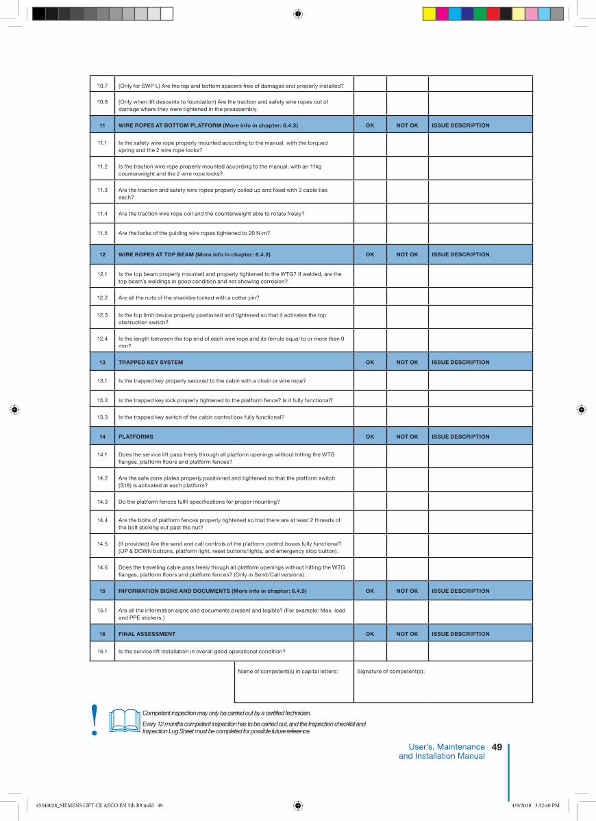
49 User’s, Maintenance and Installation Manual
Competent inspection may only be carried out by a certified technician.
Every 12 months competent inspection has to be carried out, and the Inspection checklist and Inspection Log Sheet must be completed for possible future reference.!�
10.7
(Only for SWP L) Are the top and bottom spacers free of damages and properly installed?
10.8
(Only when lift descents to foundation) Are the traction and safety wire ropes out ofdamage where they were tightened in the preassembly.
11
WIRE ROPES AT BOTTOM PLATFORM (More info in chapter: 6.4.3)
OK
NOT OK
ISSUE DESCRIPTION
11.1
Is the safety wire rope properly mounted according to the manual, with the torquedspring and the 2 wire rope locks?
11.2 Is the traction wire rope properly mounted according to the manual, with an 11kg
counterweight and the 2 wire rope locks?
11.3 Are the traction and safety wire ropes properly coiled up and fixed with 3 cable ties
each?
11.4
Are the traction wire rope coil and the counterweight able to rotate freely?
11.5
Are the locks of the guiding wire ropes tightened to 20 N·m?
12
WIRE ROPES AT TOP BEAM (More info in chapter: 6.4.3)
OK
NOT OK
ISSUE DESCRIPTION
12.1
Is the top beam properly mounted and properly tightened to the WTG? If welded, are thetop beam´s weldings in good condition and not showing corrosion?
12.2 Are all the nuts of the shackles locked with a cotter pin?
12.3 Is the top limit device properly positioned and tightened so that it activates the top
obstruction switch?
12.4
Is the length between the top end of each wire rope and its ferrule equal to or more than 0mm?
13
TRAPPED KEY SYSTEM
OK
NOT OK
ISSUE DESCRIPTION
13.1
Is the trapped key properly secured to the cabin with a chain or wire rope?
13.2
Is the trapped key lock properly tightened to the platform fence? Is it fully functional?
13.3 Is the trapped key switch of the cabin control box fully functional?
14
PLATFORMS
OK
NOT OK
ISSUE DESCRIPTION
14.1
Does the service lift pass freely through all platform openings without hitting the WTGflanges, platform floors and platform fences?
14.2
Are the safe zone plates properly positioned and tightened so that the platform switch(S18) is activated at each platform?
14.3 Do the platform fences fulfil specifications for proper mounting?
14.4
Are the bolts of platform fences properly tightened so that there are at least 2 threads ofthe bolt sticking out past the nut?
14.5
(If provided) Are the send and call controls of the platform control boxes fully functional?(UP & DOWN buttons, platform light, reset buttons/lights, and emergency stop button).
14.6 Does the travelling cable pass freely though all platform openings without hitting the WTG
flanges, platform floors and platform fences? (Only in Send/Call versions).
15
INFORMATION SIGNS AND DOCUMENTS (More info in chapter: 6.4.5)
OK
NOT OK
ISSUE DESCRIPTION
15.1 Are all the information signs and documents present and legible? (For example: Max. load
and PPE stickers.)
16
FINAL ASSESSMENT
OK
NOT OK
ISSUE DESCRIPTION
16.1 Is the service lift installation in overall good operational condition?
Name of competent(s) in capital letters:
Signature of competent(s):
45540028_SIEMENS LIFT CE AECO EN 5th R9.indd 49 4/9/2018 3:52:40 PM

50 AVANTI Service Lift for Wind Turbines
Dat
e &
tim
e
TYP
E O
F
INSP
ECTI
ON
(BEF
OR
E FI
RST
USE
,
AN
NU
AL
OR
UN
SCH
EDU
LED
)
OV
ER
AL
L R
ES
ULT
HO
UR
CO
UN
TE
RIS
SU
E D
ES
CR
IPT
ION
& C
OM
ME
NT
SN
AM
E (I
N C
AP
ITA
L LE
TT
ER
S)
& S
IGN
AT
UR
E O
F C
OM
PE
TE
NT
OK
NO
T O
K
Appendix C: Inspection Log Sheet
45540028_SIEMENS LIFT CE AECO EN 5th R9.indd 50 4/9/2018 3:52:40 PM

51 User’s, Maintenance and Installation Manual
Dat
e &
tim
e
TYP
E O
F
INSP
ECTI
ON
(BEF
OR
E FI
RST
USE
,
AN
NU
AL
OR
UN
SCH
EDU
LED
)
OV
ER
AL
L R
ES
ULT
HO
UR
CO
UN
TE
RIS
SU
E D
ES
CR
IPT
ION
& C
OM
ME
NT
SN
AM
E (I
N C
AP
ITA
L LE
TT
ER
S)
& S
IGN
AT
UR
E O
F C
OM
PE
TE
NT
OK
NO
T O
K
45540028_SIEMENS LIFT CE AECO EN 5th R9.indd 51 4/9/2018 3:52:40 PM

52 AVANTI Service Lift for Wind Turbines
Dat
e &
tim
e
TYP
E O
F
INSP
ECTI
ON
(BEF
OR
E FI
RST
USE
,
AN
NU
AL
OR
UN
SCH
EDU
LED
)
OV
ER
AL
L R
ES
ULT
HO
UR
CO
UN
TE
RIS
SU
E D
ES
CR
IPT
ION
& C
OM
ME
NT
SN
AM
E (I
N C
AP
ITA
L LE
TT
ER
S)
& S
IGN
AT
UR
E O
F C
OM
PE
TE
NT
OK
NO
T O
K
45540028_SIEMENS LIFT CE AECO EN 5th R9.indd 52 4/9/2018 3:52:40 PM

53 User’s, Maintenance and Installation Manual
Appendix D: AVANTI lift anchor
AVANTI LIFT ANCHOR is an anchor point used for protection against falls from heights intended for use with a full body harness approved according to EN 361 or Z359.1:2007 as applicable. Connection to the LIFT ANCHOR is only allowed by using self-closing connectors according to EN 362 or Z359.1:2007 as applicable.
Use in connection with other equipment than specified, may be potentially dangerous. User shall be equipped with a means of limiting the maximum dynamic forces exerted on the user during the arrest of a fall to a maximum of 6kN. In case of doubt, please contact AVANTI.
The maximum load that can be transmitted in service from the anchor device to the structure is 22.2 kN in ±15º vertical direction. The maximum deflection of the anchor point that can occur in service is 10mm.
AVANTI LIFT ANCHOR is tested and approved only tobe mounted on AVANTI lifts.Activities at height are dangerous and may lead tosevere injury or even death.
Gaining an adequate apprenticeship in appropriate techniques and methods of protection is important and is your own responsibility.
Users are obliged to read and understand this User Manual. Further they need to be proper equipped and instructed with the use of the necessary fall arrest equipment and emergency procedures in case of injury or sudden illness.
Users going to install AVANTI LIFT ANCHOR need to be familiar with the installation section of this manual. It’s essential to the safety, that the user always attach the energy absorber as high as possible above his/her position, to minimize the fall distance most possible in case of a fall.
The position of the anchor point is crucial for fall arrest – the height of the fall, elongation of lanyard and energy absorber or pendulum movement of the user should be considered in order to minimize the risk of impact in obstacles in case of a fall. It’s prohibited for the user to do many modifications or use non original Avanti components when assembling AVANTI LIFT ANCHOR.
Re-use of demounted AVANTI LIFT ANCHORS or parts is not allowed. Any changes or other uses beyond this manual are strictly forbidden.
Any changes or other uses beyond this manual are strictly forbidden. This documentation must be kept in the service lift for the purpose of subsequent examinations of the anchor device.
The AVANTI LIFT ANCHOR is for the use of one person only. It is strictly forbidden to carry out work if the person is in unfit mental or physical condition. Climbing and working under the influence of alcohol, drugs or any medication which can interfere with the safety are also much prohibited.
If there are any doubts to the safety of the AVANTI LIFT ANCHOR, or it isn’t proper fixed, deform or damaged with cracks or similar incompatible harms it may never be used – Please contact the manufacture immediately. In case of corrosion the anchor immediately needs to be removed.
Observations:Only to be used by instructed workers! Instructed workers must be aware, instructed and prepared to utilize site rescue plans.
Only to be used for preventing vertical fall!
Only to be used for fall arrest, not to hoist or hang in goods or similar!Before attaching in the ANCHOR the user needs to check it is sitting fixed and screws are sitting tight and proper.
If AVANTI LIFT ANCHOR has arrested a fall it may never be used again. Part must be removed from service imme-diately.
D.2 Danger
D.1 Caution
45540028_SIEMENS LIFT CE AECO EN 5th R9.indd 53 4/9/2018 3:52:40 PM

54 AVANTI Service Lift for Wind Turbines
The installation must be performed by a certified technician following the instructions of this manual.
AVANTI LIFT ANCHOR is tested and approved only to be installed on AVANTI lift. AVANTI LIFT ANCHOR made from AISI 304 Steel has to be screwed with two bolts DIN 933 A2-70 M12 mm, 4 washers DIN 125A A4 and self locking nuts DIN 985 A4 M12. In case of doubt, please contact AVANTI.
Before installing the AVANTI LIFT ANCHOR in heights, assure to be proper secured against fall from height by using relevant fall arrest equipment.
AVANTI LIFT ANCHOR:1. Fix the anchor point to the structure using
the supplied hardware as shown in the picture below.
2. Torque the nuts with 15 N·m (11 lb·ft).
3. Make sure the Anchor is fully seated and properly tightened.
4. Fill in “Installation form”.
5. Carry out yearly inspection by following the procedure in the section “Inspection”.
D.4 Installation
Marking on Lift Anchor plate:
After installation, marking shall be completely accessible; otherwise additional marking near the anchor device will be necessary.
D.3 Marking
Item number
European/ American standard number
Material and Capacity rating
Unique identification number
AVANTI product name
AS/NZS 1891.4:2009
Unique identification number
45540028_SIEMENS LIFT CE AECO EN 5th R9.indd 54 4/9/2018 3:52:41 PM

55 User’s, Maintenance and Installation Manual
After installation:An inspection must be carried out by a certified technician following the inspection form in this manual.
Before use:Each time using the AVANTI LIFT ANCHOR the user inspects the ANCHOR visual and manually by twisting / pulling. Check the parts are properly fixed and free of deformities, damages, cracks or similar unacceptable defects.
Periodical examination:A periodic examination at least every 12 month is essential for the safety of the AVANTI LIFT ANCHOR. The examination must be performed by a certified technician following the inspection form in this manual.
For the AVANTI LIFT ANCHOR the certified technician only needs to be trained in any metallic component covered by the European/American standard norms for fall arrest equipment.
D.6 Inspection form
D.5 Inspection
If the AVANTI LIFT ANCHOR is found not OK, it must be removed / replaced by a new AVANTI LIFT ANCHOR! The result of the periodic examination must be recorded in the Registration form of anchor.
PFPE Anchor:Manufacturer: Avanti
Type / Model: Lift Anchor
Identification no.:
Fixing structure:Lift serial no.:
Lift model:
Wind farm / WTG no.:
Installed by:
Installation company:
OK not OK
1. Lift structure does not show any deterioration.
2. Anchor locking screws are fully inserted and tightened with 15 N·m.
3. Anchor does not show cracks, deformities, corrosion or other damages.
4. Anchor installed on the lift structure according to the instructions.
5. Anchor marking is clearly readable.
Signature of competent:Name of competent in capital letters:Date:
Is the Anchor in good condition to be used? Yes No (Replace)
45540028_SIEMENS LIFT CE AECO EN 5th R9.indd 55 4/9/2018 3:52:41 PM

56 AVANTI Service Lift for Wind Turbines
Date of purchase: Date first put into service:
Periodic examination and repair history
Date Reason for entry (per. exam) OK / not OK Inspector Periodic exam next due date
Avanti lift Anchor
Identification no.: Avanti Wind Systems A/S DK-3400 Hillerød
Tel:+45 48 24 90 24 Fax: +45 48 24 91 24
www.avanti-online.com
D.7 Registration form of anchor
45540028_SIEMENS LIFT CE AECO EN 5th R9.indd 56 4/9/2018 3:52:41 PM

57 User’s, Maintenance and Installation Manual
Date of purchase: Date first put into service:
Periodic examination and repair history
Date Reason for entry (per. exam) OK / not OK Inspector Periodic exam next due date
Avanti lift Anchor
Identification no.: Avanti Wind Systems A/S DK-3400 Hillerød
Tel:+45 48 24 90 24 Fax: +45 48 24 91 24
www.avanti-online.com
D.7 Registration form of anchor
45540028_SIEMENS LIFT CE AECO EN 5th R9.indd 57 4/9/2018 3:52:41 PM

58 AVANTI Service Lift for Wind Turbines
45540028_SIEMENS LIFT CE AECO EN 5th R9.indd 58 4/9/2018 3:52:41 PM

59 User’s, Maintenance and Installation Manual
45540028_SIEMENS LIFT CE AECO EN 5th R9.indd 59 4/9/2018 3:52:41 PM

AustraliaAvanti Wind Systems PTY LTD
Unit 7 / 109 Tulip Street, Cheltenham Melbourne VIC 3192 P: +61 (0) 3 9585 1852
ChinaAvanti Wind SystemsBuilding 4, No, 518,
Gangde Road, XiaokunshanTownSongjiang District, 201614 Shanghai
P: +86 21 5785 8811 · F: +86 21 5785 8815
DenmarkAvanti Wind Systems A/S
Rønnevangs Allé 6 · DK-3400 HillerødP: +45 4824 9024 · F: +45 4824 9124
GermanyAvanti Wind Systems GmbH
Max-Planck-Str. 8 25335 ElmshornP: +49 (0) 41 21-7 88 85 – 0 · F: +49 (0) 41 21- 7 88 85-20
SpainAvanti Wind Systems SL · Poligono Industrial Centrovia
Calle Los Angeles No 88 nave 1 · 50198 La MuelaP: +34 976 149524 · F: +34 976 149508
UKAvanti Wind Systems Limited
Unit 2, Cunliffe Court Clayton-Le-Moors Accrington BB5 5JG
P: +44 (0) 1254 399923
USAAvanti Wind Systems, Inc.
11311 West Forest Home Ave. Franklin, Wisconsin 53132P: +1 (262) 641-9101 · F: +1 (262) 641-9161
IndiaAvanti Wind Systems India (P) Ltd.
Old No. 28, New No. 41,Vellala Street, AiyanambakkamChennai 600095 · Tamil Nadu
P: +91 95 00 173 492
Brazil Avanti Brasil Sistema Eólicos LTDA.
Rua João Paulo II, 131Autódromo Eusébio, Ceará
Brazil 61760-000P: +55 85 9 9955-0090
I: www.avanti-online.com · E: [email protected]
0028
SW
P S
ervi
ce L
ift M
anua
l CE
AE
CO
EN
5th
Ed
ition
: Feb
ruar
y 20
15
Rev
isio
n 9:
27/
03/2
018
45540028_SIEMENS LIFT CE AECO EN 5th R9.indd 60 4/9/2018 3:52:41 PM