Embed Size (px)
Citation preview

PARTS & ACCESSORIES

3 GH | PARTS & ACCESSORIES
OUR MAIN GOAL IS TO OFFER AN AGILE, RAPID AND QUALITY SERVICE.OUR FACILITIES, OUR STOCK AND AN EFFICIENT MANAGEMENT SYSTEM GUARANTEE THIS SERVICE.

5 GH | PARTS & ACCESSORIES
22
26 32 33
34
36 384044474850525455
56
58 59
60
62 6465
66
6869
70
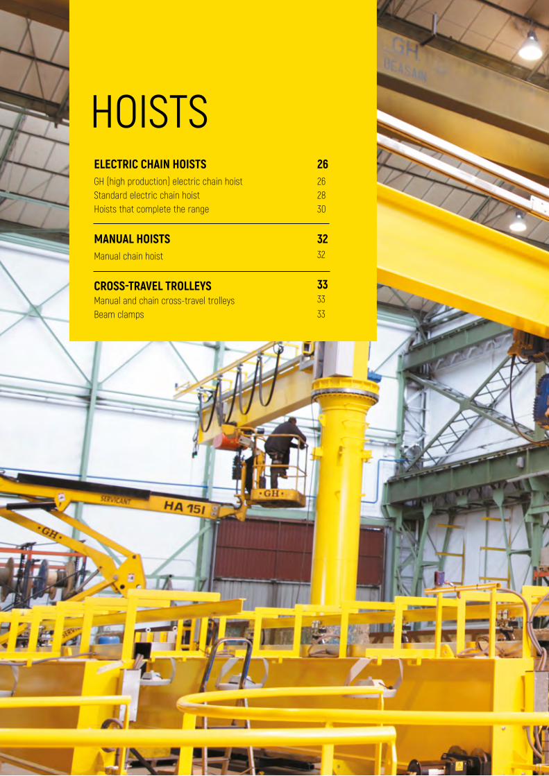
HOISTS
Electric chain hoists Manual hoists Trolleys
SUSPENSION EQUIPMENT
Weighing equipmentAMR macro displaysSpreader beamsIndustrial grippers Eye bolts and lifting pointsAutomatic hooksManual lever magnetsVacuum equipmentAlligator clampMetalworking clamps
SLINGS AND CHAINS
Slings and chain components Polyester slings
POWER SUPPLY
Radio control for bridge cranesSafety power supply lineSpring-driven cable reel
SAFETY SYSTEMS
LifelinesOther safety equipment
TECHNICAL CHARACTERISTICS
STRUCTURES
Gantry cranes Jib cranes Lightweight profiles
6
8 12 18
6-21
22-34
34-56
56-59
60-65
66-69
70-112
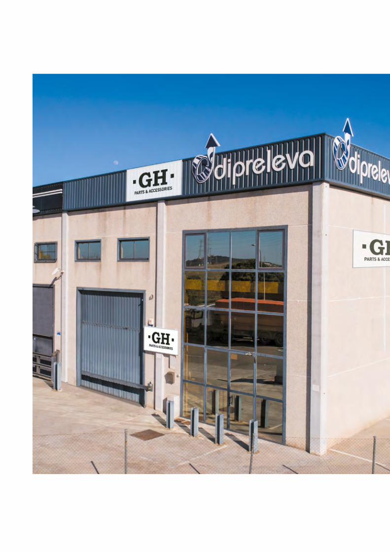
INDEX OF PRODUCTS

STRUCTURESGANTRY CRANESStandard gantry cranes Aluminium gantry cranes Motorised gantry cranes
JIB CRANESWall-mounted jib cranes Column jib cranes Special Jib cranes
LIGHTWEIGHT PROFILES
89 10 11
1214 15 16
18
7 GH | PARTS & ACCESSORIES
8 STRUCTURES
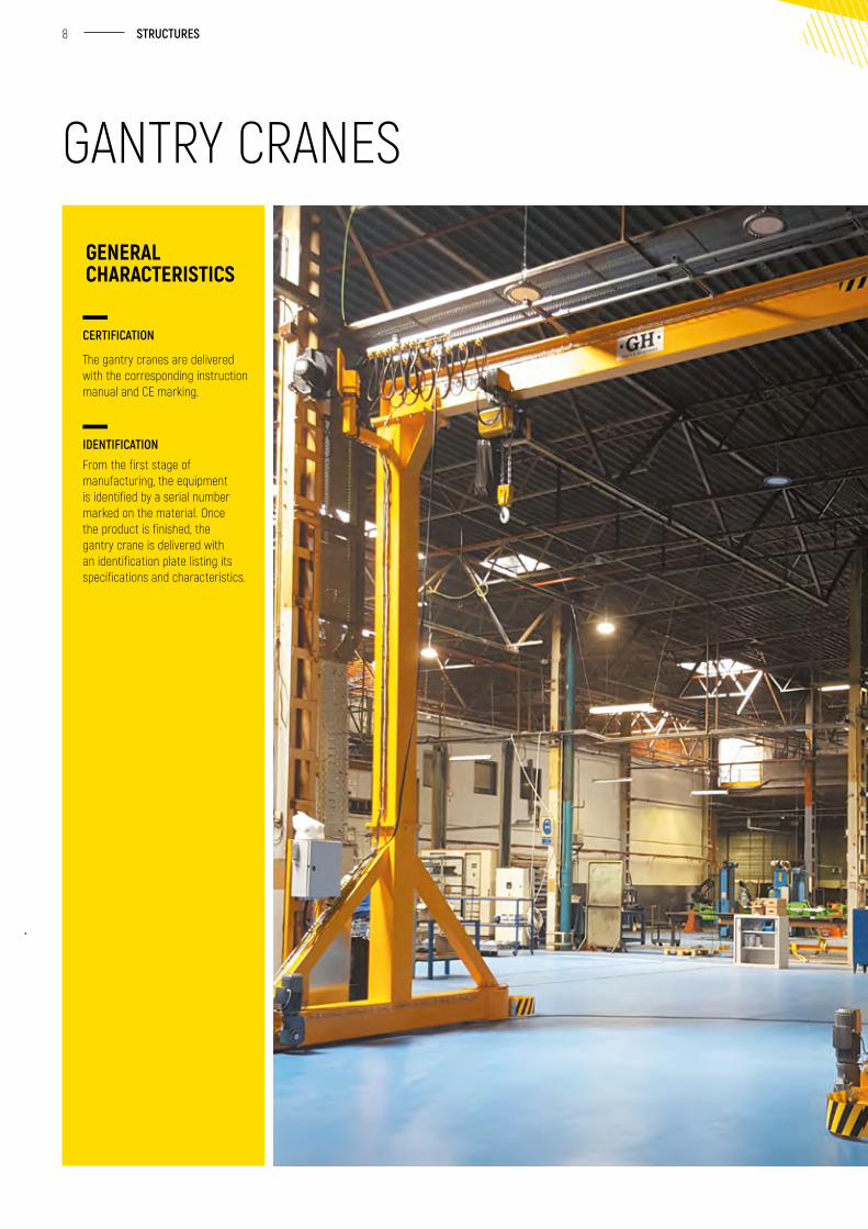
CERTIFICATION
The gantry cranes are delivered with the corresponding instruction manual and CE marking.
IDENTIFICATIONFrom the first stage of manufacturing, the equipment is identified by a serial number marked on the material. Once the product is finished, the gantry crane is delivered with an identification plate listing its specifications and characteristics.
GENERAL CHARACTERISTICS
GANTRY CRANES
9 GH | PARTS & ACCESSORIES
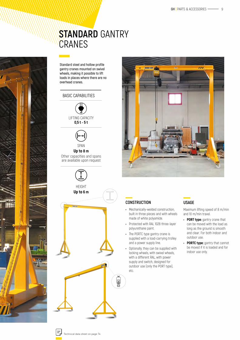
CONSTRUCTION• Mechanically-welded construction,
built in three pieces and with wheels made of white polyamide.
• Protected with RAL 1028 three-layer polyurethane paint.
• The PORTC type gantry crane is supplied with a load-carrying trolley and a power supply line.
• Optionally, they can be supplied with locking wheels, with swivel wheels, with a different RAL, with power supply and switch, designed for outdoor use (only the PORT type), etc.
Standard steel and hollow profile gantry cranes mounted on swivel wheels, making it possible to lift loads in places where there are no overhead cranes.
USAGEMaximum lifting speed of 8 m/min and 10 m/min travel.
• PORT type: gantry crane that can be moved with the load as long as the ground is smooth and clear. For both indoor and outdoor use.
• PORTC type: gantry that cannot be moved if it is loaded and for indoor use only.
BASIC CAPABILITIES
LIFTING CAPACITY0,5 t - 5 t
SPAN Up to 8 m
Other capacities and spans are available upon request
HEIGHT Up to 6 m
Technical data sheet on page 74
STANDARD GANTRY CRANES
10 STRUCTURES
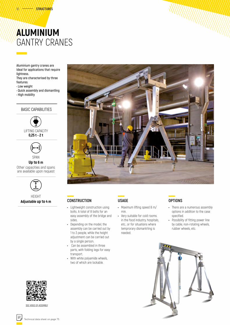
CONSTRUCTION• Lightweight construction using
bolts. A total of 8 bolts for an easy assembly of the bridge and sides.
• Depending on the model, the assembly can be carried out by 1 to 3 people, while the height adjustment can be carried out by a single person.
• Can be assembled in three parts, with folding legs for easy transport.
• With white polyamide wheels, two of which are lockable.
ALUMINIUM GANTRY CRANES
Aluminium gantry cranes are Ideal for applications that require lightness. They are characterised by three features: • Low weight • Quick assembly and dismantling • High mobility
SEE VIDEO OF ASSEMBLY
USAGE• Maximum lifting speed 8 m/
min.• Very suitable for cold rooms
in the food industry, hospitals, etc., or for situations where temprorary dismantrling is needed.
OPTIONS• There are a numerous assembly
options in addition to the case specified.
• Possibility of fitting power line by cable, non-rotating wheels, rubber wheels, etc.
BASIC CAPABILITIES
LIFTING CAPACITY 0,25 t - 2 t
SPAN Up to 6 m
Other capacities and spans are available upon request
HEIGHTAdjustable up to 4 m
Technical data sheet on page 75
11 GH | PARTS & ACCESSORIES
MOTORISED GANTRY CRANES
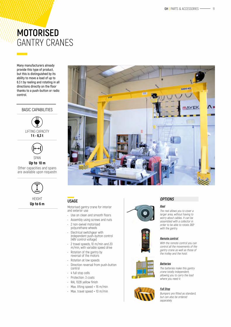
Many manufacturers already provide this type of product, but this is distinguished by its ability to move a load of up to 6.3 t by reeling and rotating in all directions directly on the floor thanks to a push-button or radio control.
USAGEMotorised gantry crane for interior and exterior use• Use on clean and smooth floors• Assembly using screws and nuts• 2 non-swivel motorised
polyurethane wheels• Electrical switchgear with
independent push-button control (48V control voltage)
• 2 travel speeds, 10 m/min and 20 m/min, with variable speed drive
• Rotation of the gantry by reversal of the motors
• Rotation at low speeds• Direction reversal from push-button
control• 4 full stop cells• Protection: 3 coats• RAL 1028 yellow finish• Max. lifting speed = 16 m/min• Max. travel speed = 10 m/min
BASIC CAPABILITIES
LIFTING CAPACITY 1 t - 6,3 t
SPAN Up to 10 m
Other capacities and spans are available upon requestn
HEIGHT Up to 6 m
OPTIONS
ReelThe reel allows you to cover a larger area, without having to worry about cables. It can be assembled with a collector in order to be able to rotate 360o with the gantry.
Remote control With the remote control you can control all the movements of the gantry crane as well as those of the trolley and the hoist.
BatteriesThe batteries make this gantry crane totally independent, allowing you to carry the load where you need it.
Full StopBumpers are fitted as standard, but can also be ordered separately.
12 STRUCTURES
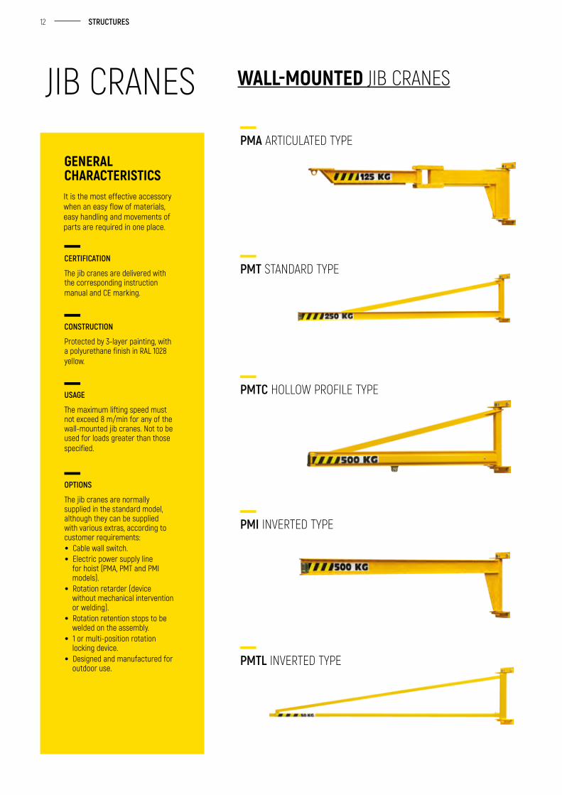
WALL-MOUNTED JIB CRANES
CERTIFICATION
The jib cranes are delivered with the corresponding instruction manual and CE marking.
CONSTRUCTION
Protected by 3-layer painting, with a polyurethane finish in RAL 1028 yellow.
USAGE
The maximum lifting speed must not exceed 8 m/min for any of the wall-mounted jib cranes. Not to be used for loads greater than those specified.
OPTIONS
The jib cranes are normally supplied in the standard model, although they can be supplied with various extras, according to customer requirements:• Cable wall switch.• Electric power supply line
for hoist (PMA, PMT and PMI models).
• Rotation retarder (device without mechanical intervention or welding).
• Rotation retention stops to be welded on the assembly.
• 1 or multi-position rotation locking device.
• Designed and manufactured for outdoor use.
It is the most effective accessory when an easy flow of materials, easy handling and movements of parts are required in one place.
GENERAL CHARACTERISTICS
PMA ARTICULATED TYPE
PMT STANDARD TYPE
PMTC HOLLOW PROFILE TYPE
PMI INVERTED TYPE
PMTL INVERTED TYPE
JIB CRANES
13 GH | PARTS & ACCESSORIES
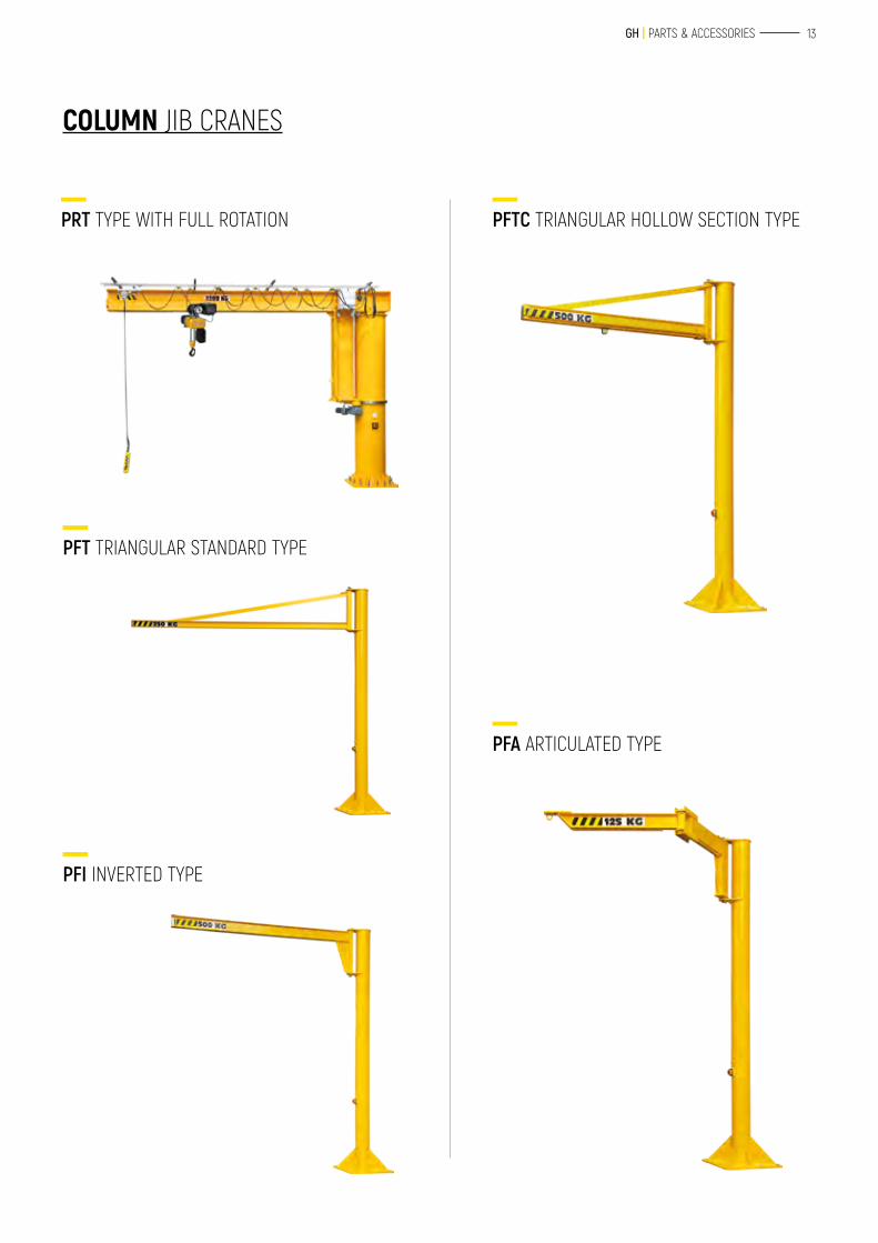
COLUMN JIB CRANES
PRT TYPE WITH FULL ROTATION PFTC TRIANGULAR HOLLOW SECTION TYPE
PFA ARTICULATED TYPE
PFT TRIANGULAR STANDARD TYPE
PFI INVERTED TYPE
14 STRUCTURES
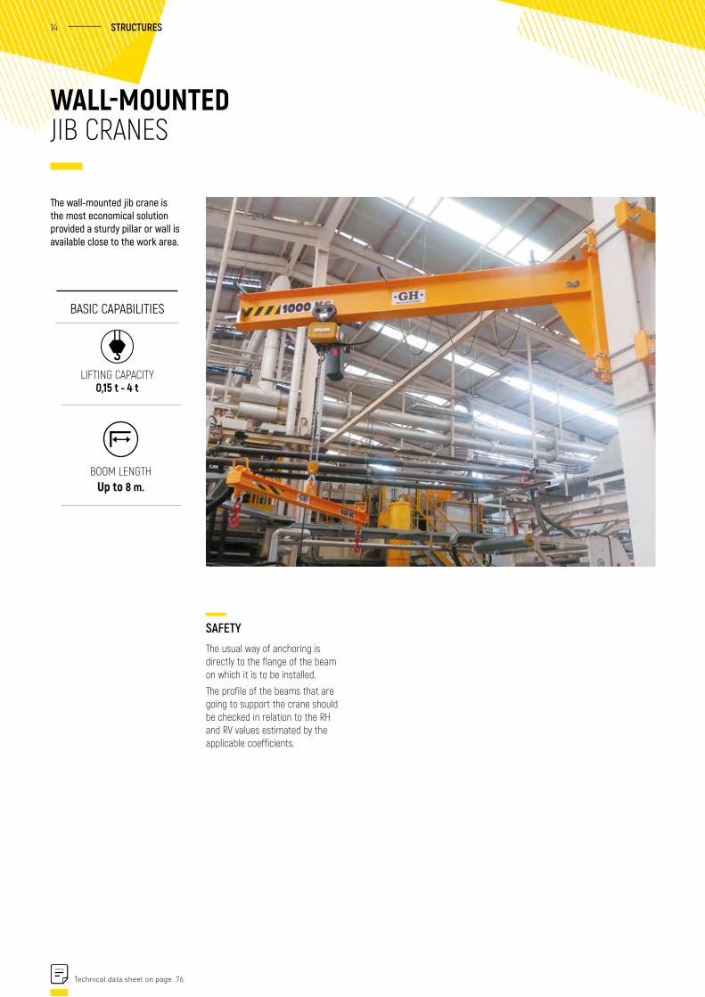
SAFETYThe usual way of anchoring is directly to the flange of the beam on which it is to be installed.
The profile of the beams that are going to support the crane should be checked in relation to the RH and RV values estimated by the applicable coefficients.
WALL-MOUNTED JIB CRANES
The wall-mounted jib crane is the most economical solution provided a sturdy pillar or wall is available close to the work area.
BASIC CAPABILITIES
LIFTING CAPACITY 0,15 t - 4 t
BOOM LENGTH Up to 8 m.
Technical data sheet on page 76
15 GH | PARTS & ACCESSORIES
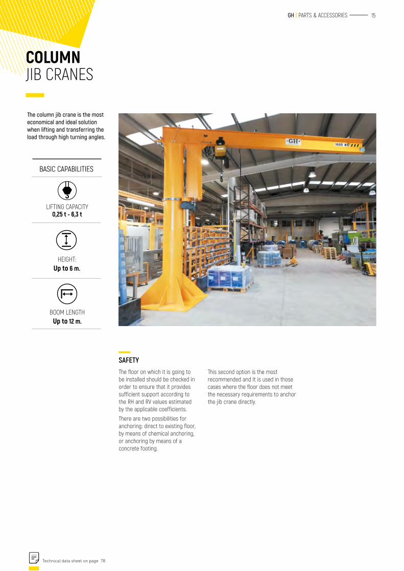
COLUMN JIB CRANES
The column jib crane is the most economical and ideal solution when lifting and transferring the load through high turning angles.
BASIC CAPABILITIES
LIFTING CAPACITY 0,25 t - 6,3 t
HEIGHT: Up to 6 m.
SAFETYThe floor on which it is going to be installed should be checked in order to ensure that it provides sufficient support according to the RH and RV values estimated by the applicable coefficients.
There are two possibilities for anchoring: direct to existing floor, by means of chemical anchoring, or anchoring by means of a concrete footing.
This second option is the most recommended and It is used in those cases where the floor does not meet the necessary requirements to anchor the jib crane directly.
BOOM LENGTH Up to 12 m.
Technical data sheet on page 78
16 STRUCTURES
1
2
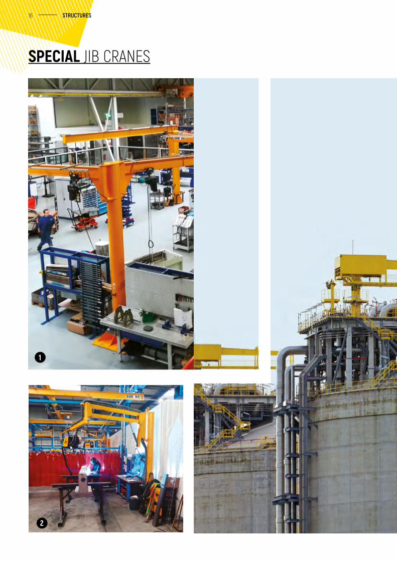
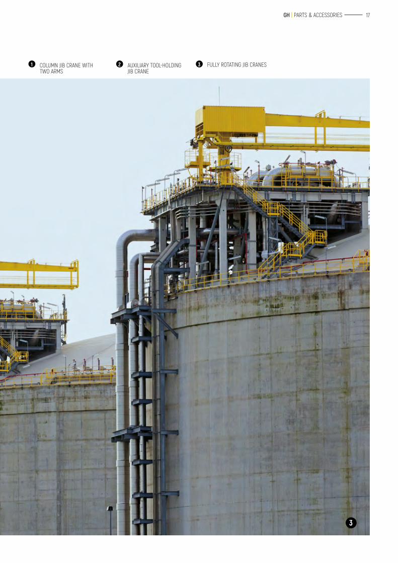
SPECIAL JIB CRANES
17 GH | PARTS & ACCESSORIES
1 COLUMN JIB CRANE WITH TWO ARMS
3
2 AUXILIARY TOOL-HOLDING JIB CRANE
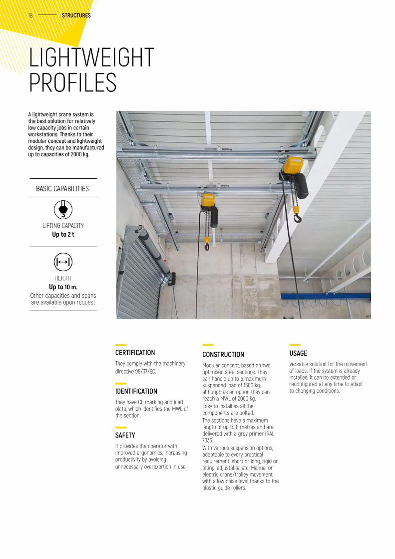
3 FULLY ROTATING JIB CRANES
18 STRUCTURES
CERTIFICATIONThey comply with the machinery directive 98/37/EC.
IDENTIFICATIONThey have CE marking and load plate, which identifies the MWL of the section.
SAFETYIt provides the operator with improved ergonomics, increasing productivity by avoiding unnecessary overexertion in use.
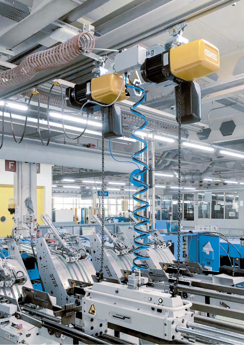
A lightweight crane system is the best solution for relatively low capacity jobs in certain workstations. Thanks to their modular concept and lightweight design, they can be manufactured up to capacities of 2000 kg.
CONSTRUCTIONModular concept, based on two optimised steel sections. They can handle up to a maximum suspended load of 1600 kg, although as an option they can reach a MWL of 2000 kg.Easy to install as all the components are bolted.The sections have a maximum length of up to 8 metres and are delivered with a grey primer (RAL 7035).With various suspension options, adaptable to every practical requirement: short or long, rigid or tilting, adjustable, etc. Manual or electric crane/trolley movement, with a low noise level thanks to the plastic guide rollers.
USAGEVersatile solution for the movement of loads. If the system is already installed, it can be extended or reconfigured at any time to adapt to changing conditions.
BASIC CAPABILITIES
LIFTING CAPACITY Up to 2 t
HEIGHT Up to 10 m.
Other capacities and spans are available upon request
LIGHTWEIGHT PROFILES
PERFILESLIGEROS
20 STRUCTURES
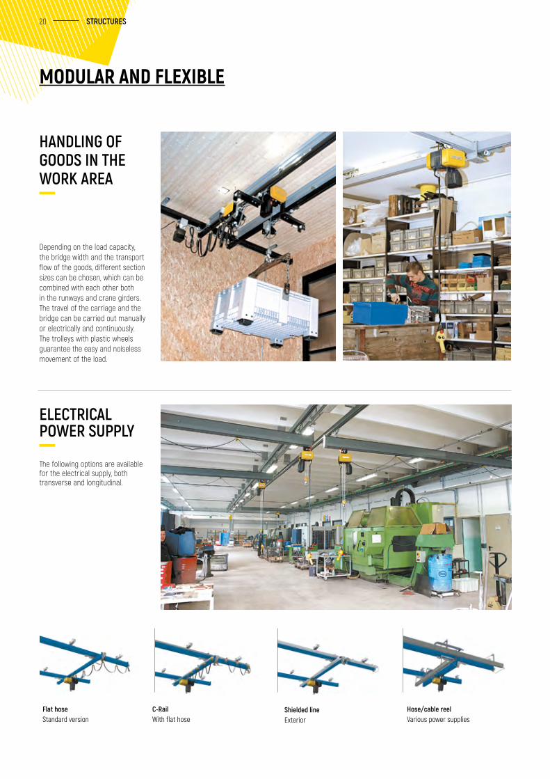
HANDLING OF GOODS IN THE WORK AREA
ELECTRICAL POWER SUPPLY
The following options are available for the electrical supply, both transverse and longitudinal.
MODULAR AND FLEXIBLE
Depending on the load capacity, the bridge width and the transport flow of the goods, different section sizes can be chosen, which can be combined with each other both in the runways and crane girders. The travel of the carriage and the bridge can be carried out manually or electrically and continuously. The trolleys with plastic wheels guarantee the easy and noiseless movement of the load.
Flat hoseStandard version
C-RailWith flat hose
Shielded lineExterior
Hose/cable reelVarious power supplies
21 GH | PARTS & ACCESSORIES
LIGHTWEIGHT PROFILES
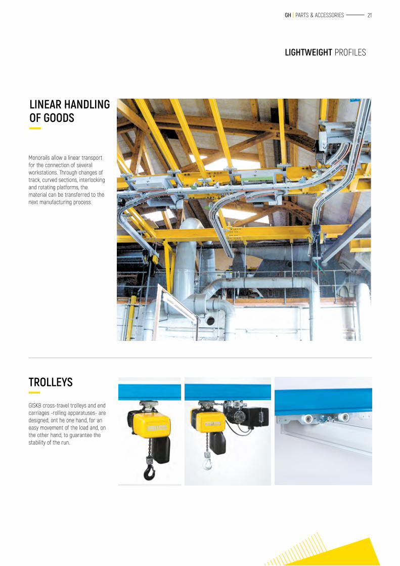
LINEAR HANDLING OF GOODS
Monorails allow a linear transport for the connection of several workstations. Through changes of track, curved sections, interlocking and rotating platforms, the material can be transferred to the next manufacturing process.
TROLLEYS
GISKB cross-travel trolleys and end carriages -rolling apparatuses- are designed, ont he one hand, for an easy movement of the load and, on the other hand, to guarantee the stability of the run.
22 STRUCTURES
HOISTSELECTRIC CHAIN HOISTSGH (high production) electric chain hoist Standard electric chain hoist Hoists that complete the range
MANUAL HOISTSManual chain hoist
CROSS-TRAVEL TROLLEYS Manual and chain cross-travel trolleys Beam clamps
2626 28 30
32 32
33 33
33
23 GH | PARTS & ACCESSORIES
Ficha técnica en pág. xx
24 HOISTS
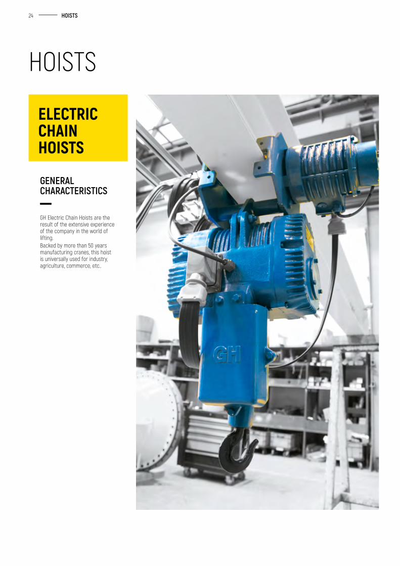
GH Electric Chain Hoists are the result of the extensive experience of the company in the world of lifting. Backed by more than 50 years manufacturing cranes, this hoist is universally used for industry, agriculture, commerce, etc..
GENERAL CHARACTERISTICS
ELECTRIC CHAIN HOISTS
HOISTS
25 GH | PARTS & ACCESSORIES
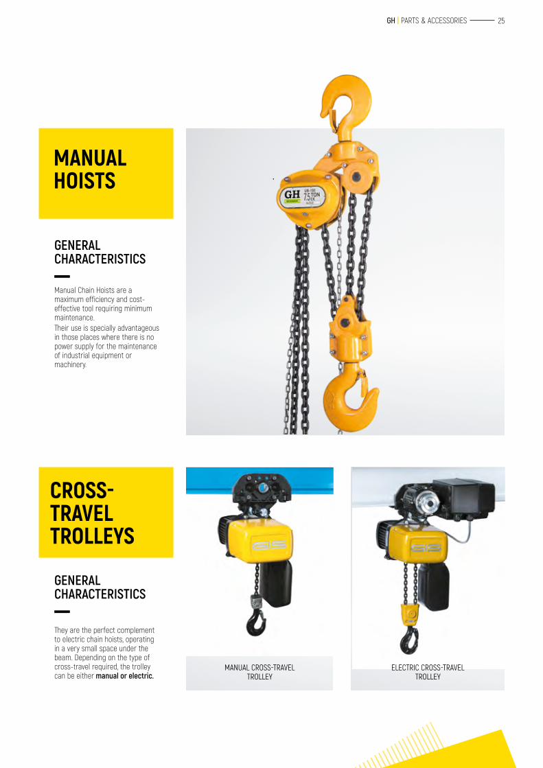
Manual Chain Hoists are a maximum efficiency and cost-effective tool requiring minimum maintenance. Their use is specially advantageous in those places where there is no power supply for the maintenance of industrial equipment or machinery.
GENERAL CHARACTERISTICS
They are the perfect complement to electric chain hoists, operating in a very small space under the beam. Depending on the type of cross-travel required, the trolley can be either manual or electric.
GENERAL CHARACTERISTICS
MANUAL CROSS-TRAVEL TROLLEY
ELECTRIC CROSS-TRAVEL TROLLEY
MANUAL HOISTS
CROSS- TRAVEL TROLLEYS
26
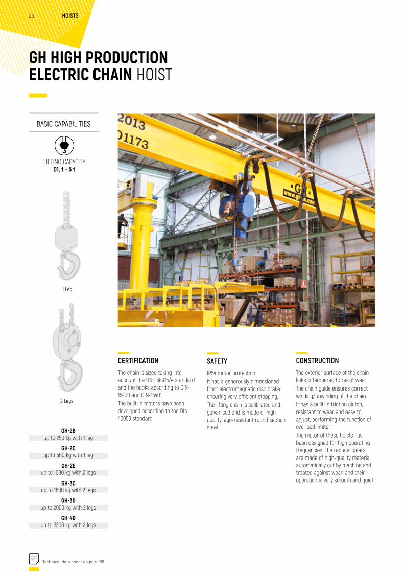
CERTIFICATIONThe chain is sized taking into account the UNE 58915/4 standard and the hooks according to DIN-15400 and DIN-15401.The built-in motors have been developed according to the DIN-40050 standard.
SAFETYIP54 motor protection.It has a generously dimensioned front electromagnetic disc brake ensuring very efficient stopping. The lifting chain is calibrated and galvanised and is made of high quality, age-resistant round section steel.
GH HIGH PRODUCTION ELECTRIC CHAIN HOIST
BASIC CAPABILITIES
LIFTING CAPACITY 01, t - 5 t
CONSTRUCTIONThe exterior surface of the chain links is tempered to resist wear.The chain guide ensures correct winding/unwinding of the chain.It has a built-in friction clutch, resistant to wear and easy to adjust, performing the function of overload limiter.The motor of these hoists has been designed for high operating frequencies. The reducer gears are made of high-quality material, automatically cut by machine and treated against wear, and their operation is very smooth and quiet.
1 Leg
2 Legs
GH-2B up to 250 kg with 1 leg
GH-2C up to 500 kg with 1 leg
GH-2E up to 1000 kg with 2 legs
GH-3C up to 1600 kg with 2 legs
GH-3D up to 2000 kg with 2 legs
GH-4D up to 3200 kg with 2 legs
Technical data sheet on page 80
HOISTS
27 GH | PARTS & ACCESSORIES
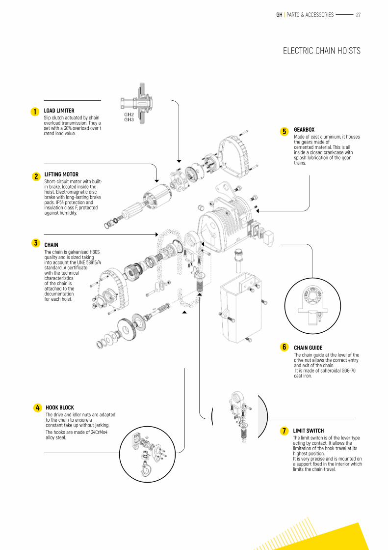
LOAD LIMITERSlip clutch actuated by chain overload transmission. They are set with a 30% overload over the rated load value.
GEARBOXMade of cast aluminium, it houses the gears made ofcemented material. This is all inside a closed crankcase with splash lubrication of the gear trains.
CHAIN GUIDEThe chain guide at the level of the drive nut allows the correct entry and exit of the chain. It is made of spheroidal GGG-70 cast iron.
LIMIT SWITCHThe limit switch is of the lever type acting by contact. It allows the limitation of the hook travel at its highest position.It is very precise and is mounted on a support fixed in the interior which limits the chain travel.
LIFTING MOTORShort-circuit motor with built-in brake, located inside the hoist. Electromagnetic disc brake with long-lasting brake pads. IP54 protection and insulation class F, protected against humidity.
CHAINThe chain is galvanised H80S quality and is sized taking into account the UNE 58915/4 standard. A certificate with the technical characteristics of the chain is attached to the documentation for each hoist.
HOOK BLOCKThe drive and idler nuts are adapted to the chain to ensure aconstant take up without jerking.The hooks are made of 34CrMo4 alloy steel.
1
2
3
4
5
6
7
ELECTRIC CHAIN HOISTS
28
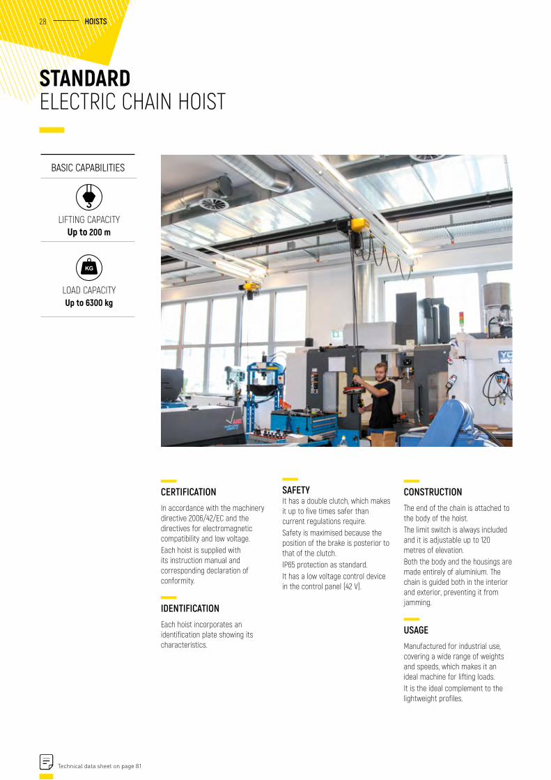
CERTIFICATIONIn accordance with the machinery directive 2006/42/EC and the directives for electromagnetic compatibility and low voltage.Each hoist is supplied with its instruction manual and corresponding declaration of conformity.
IDENTIFICATIONEach hoist incorporates an identification plate showing its characteristics.
CONSTRUCTIONThe end of the chain is attached to the body of the hoist.The limit switch is always included and it is adjustable up to 120 metres of elevation.Both the body and the housings are made entirely of aluminium. The chain is guided both in the interior and exterior, preventing it from jamming.
USAGEManufactured for industrial use, covering a wide range of weights and speeds, which makes it an ideal machine for lifting loads.It is the ideal complement to the lightweight profiles.
STANDARD ELECTRIC CHAIN HOIST
BASIC CAPABILITIES
LIFTING CAPACITY Up to 200 m
SAFETYIt has a double clutch, which makes it up to five times safer than current regulations require.Safety is maximised because the position of the brake is posterior to that of the clutch.IP65 protection as standard.It has a low voltage control device in the control panel (42 V).
LOAD CAPACITY Up to 6300 kg
Technical data sheet on page 81
HOISTS
29 GH | PARTS & ACCESSORIES
ELECTRIC CHAIN HOISTS
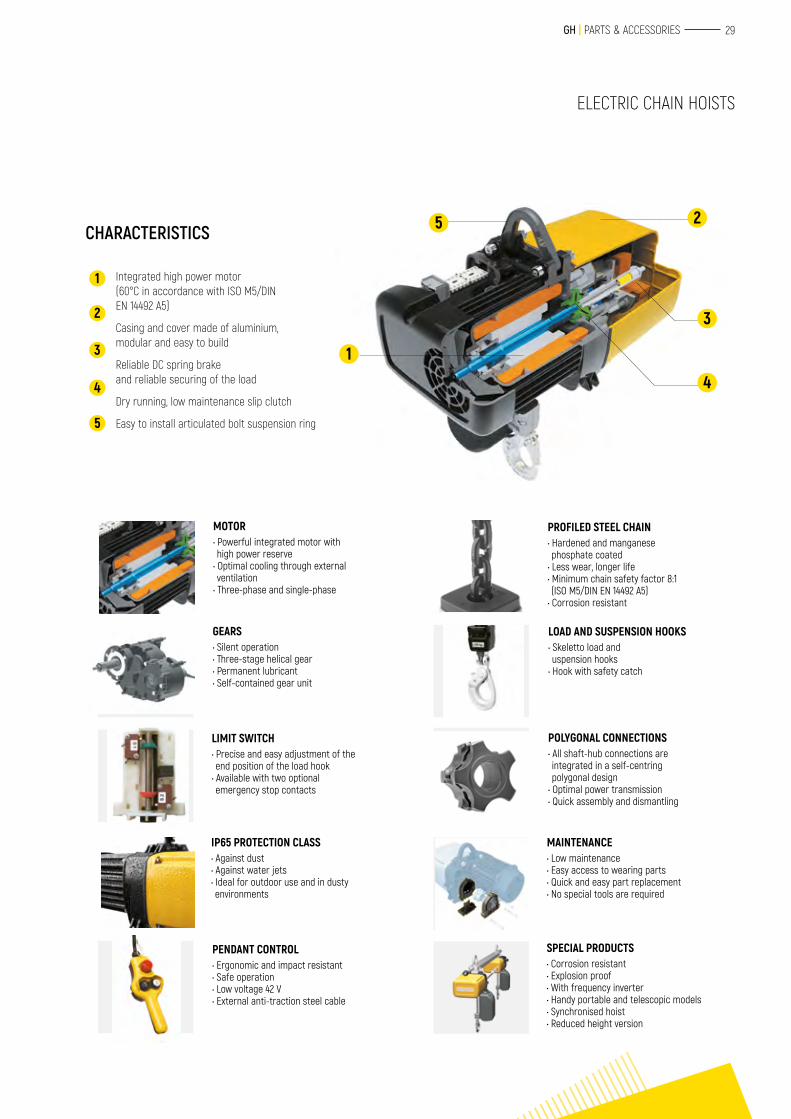
CHARACTERISTICS
1
2
3
4
5
Integrated high power motor(60°C in accordance with ISO M5/DIN EN 14492 A5)
Casing and cover made of aluminium,modular and easy to build
Reliable DC spring brakeand reliable securing of the load
Dry running, low maintenance slip clutch
Easy to install articulated bolt suspension ring
25
4
1
3
MOTOR• Powerful integrated motor with high power reserve
• Optimal cooling through external ventilation
• Three-phase and single-phase
PROFILED STEEL CHAIN• Hardened and manganese phosphate coated
• Less wear, longer life• Minimum chain safety factor 8:1 (ISO M5/DIN EN 14492 A5)
• Corrosion resistant
LOAD AND SUSPENSION HOOKS• Skeletto load and uspension hooks
• Hook with safety catch
POLYGONAL CONNECTIONS• All shaft-hub connections are integrated in a self-centring polygonal design
• Optimal power transmission• Quick assembly and dismantling
MAINTENANCE• Low maintenance• Easy access to wearing parts• Quick and easy part replacement• No special tools are required
SPECIAL PRODUCTS• Corrosion resistant• Explosion proof• With frequency inverter• Handy portable and telescopic models• Synchronised hoist• Reduced height version
GEARS• Silent operation• Three-stage helical gear• Permanent lubricant• Self-contained gear unit
LIMIT SWITCH• Precise and easy adjustment of the end position of the load hook
• Available with two optional emergency stop contacts
IP65 PROTECTION CLASS• Against dust• Against water jets• Ideal for outdoor use and in dusty environments
PENDANT CONTROL• Ergonomic and impact resistant• Safe operation• Low voltage 42 V• External anti-traction steel cable
30
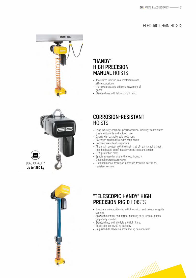
HOISTS WITH SYNCHRONISED LIFTING • Solution to optimise handling of pieces that are curved
or of special length.• Guaranteed safety of work in parallel with two or four
hooks.• Adjustable hook distance.• Modular development for use in low places.• Individually adjustable hook position with gears
operating on the limit switch.• Fully automatic installation with external control.
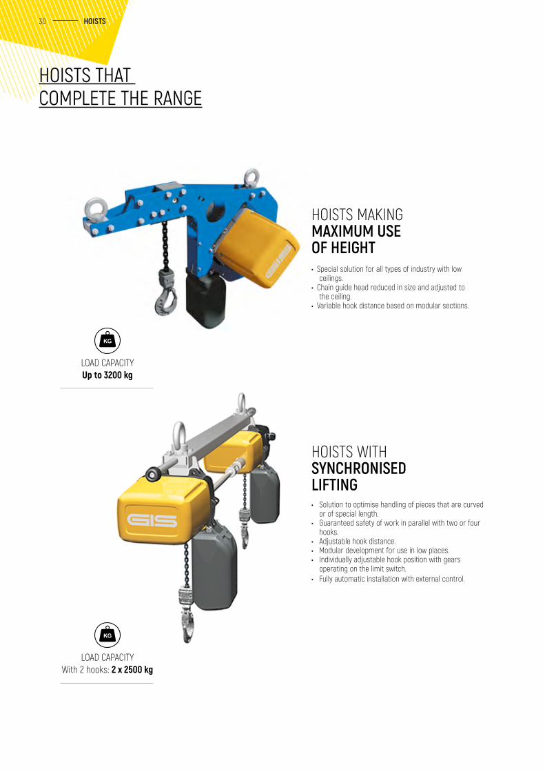
• Special solution for all types of industry with low ceilings.
• Chain guide head reduced in size and adjusted to the ceiling.
• Variable hook distance based on modular sections.
HOISTS MAKING MAXIMUM USE OF HEIGHT
HOISTS THAT COMPLETE THE RANGE
LOAD CAPACITY Up to 3200 kg
LOAD CAPACITY With 2 hooks: 2 x 2500 kg
HOISTS
31 GH | PARTS & ACCESSORIES
ELECTRIC CHAIN HOISTS
“HANDY” HIGH PRECISION MANUAL HOISTS • The switch is fitted in a comfortable and
efficient position.• It allows a fast and efficient movement of
goods.• Standard use with left and right hand.
“TELESCOPIC HANDY” HIGH PRECISION RIGID HOISTS • Exact and safe positioning with the switch and telescopic guide
system.• Allows the control and perfect handling of all kinds of goods
(especially liquids).• Standard use with the left and right hand.• Safe lifting up to 250 kg capacity.• Seguridad de elevación hasta 250 kg de capacidad.
CORROSION-RESISTANT HOISTS • Food industry, chemical, pharmaceutical industry, waste water
treatment plants and outdoor use.• Casing with cataphoresis treatment.• Corrosion-resistant rounded steel chain.• Corrosion-resistant suspension.• All parts in contact with the chain (retrofit parts such as nut,
load hooks and bolts) in a corrosion-resistant version.• IP65 protection class.• Special grease for use in the food industry.• Optional overpressure valve.• Optional manual trolley or motorised trolley in corrosion-
resistant version.LOAD CAPACITY Up to 1250 kg
32
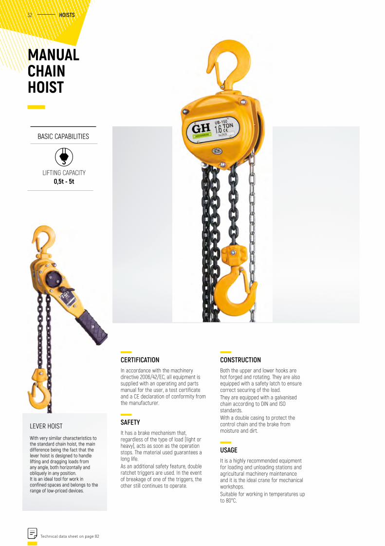
MANUAL CHAIN HOIST
CERTIFICATIONIn accordance with the machinery directive 2006/42/EC, all equipment is supplied with an operating and parts manual for the user, a test certificate and a CE declaration of conformity from the manufacturer.
SAFETYIt has a brake mechanism that, regardless of the type of load (light or heavy), acts as soon as the operation stops. The material used guarantees a long life.As an additional safety feature, double ratchet triggers are used. In the event of breakage of one of the triggers, the other still continues to operate.
BASIC CAPABILITIES
LIFTING CAPACITY 0,5t - 5t
CONSTRUCTIONBoth the upper and lower hooks are hot forged and rotating. They are also equipped with a safety latch to ensure correct securing of the load.They are equipped with a galvanised chain according to DIN and ISO standards.With a double casing to protect the control chain and the brake from moisture and dirt.
USAGEIt is a highly recommended equipment for loading and unloading stations and agricultural machinery maintenance and it is the ideal crane for mechanical workshops.Suitable for working in temperatures up to 80°C.
Technical data sheet on page 82
HOISTS
LEVER HOIST
With very similar characteristics to the standard chain hoist, the main difference being the fact that the lever hoist is designed to handle lifting and dragging loads from any angle, both horizontally and obliquely in any position.It is an ideal tool for work in confined spaces and belongs to the range of low-priced devices.
33 GH | PARTS & ACCESSORIES
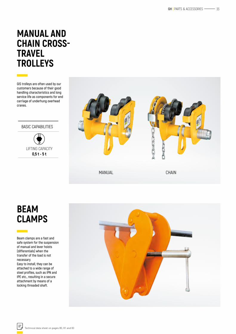
Beam clamps are a fast and safe system for the suspension of manual and lever hoists (differentials) when the transfer of the load is not necessary.Easy to install, they can be attached to a wide range of steel profiles, such as IPN and IPE etc., resulting in a secure attachment by means of a locking threaded shaft.
MANUAL AND CHAIN CROSS-TRAVEL TROLLEYS
BEAM CLAMPS
MANUAL CHAIN
GIS trolleys are often used by our customers because of their good handling characteristics and long service life as components for end carriage of underhung overhead cranes.
BASIC CAPABILITIES
LIFTING CAPACITY 0,5 t - 5 t
Technical data sheet on pages 80, 81 and 83
34 STRUCTURES
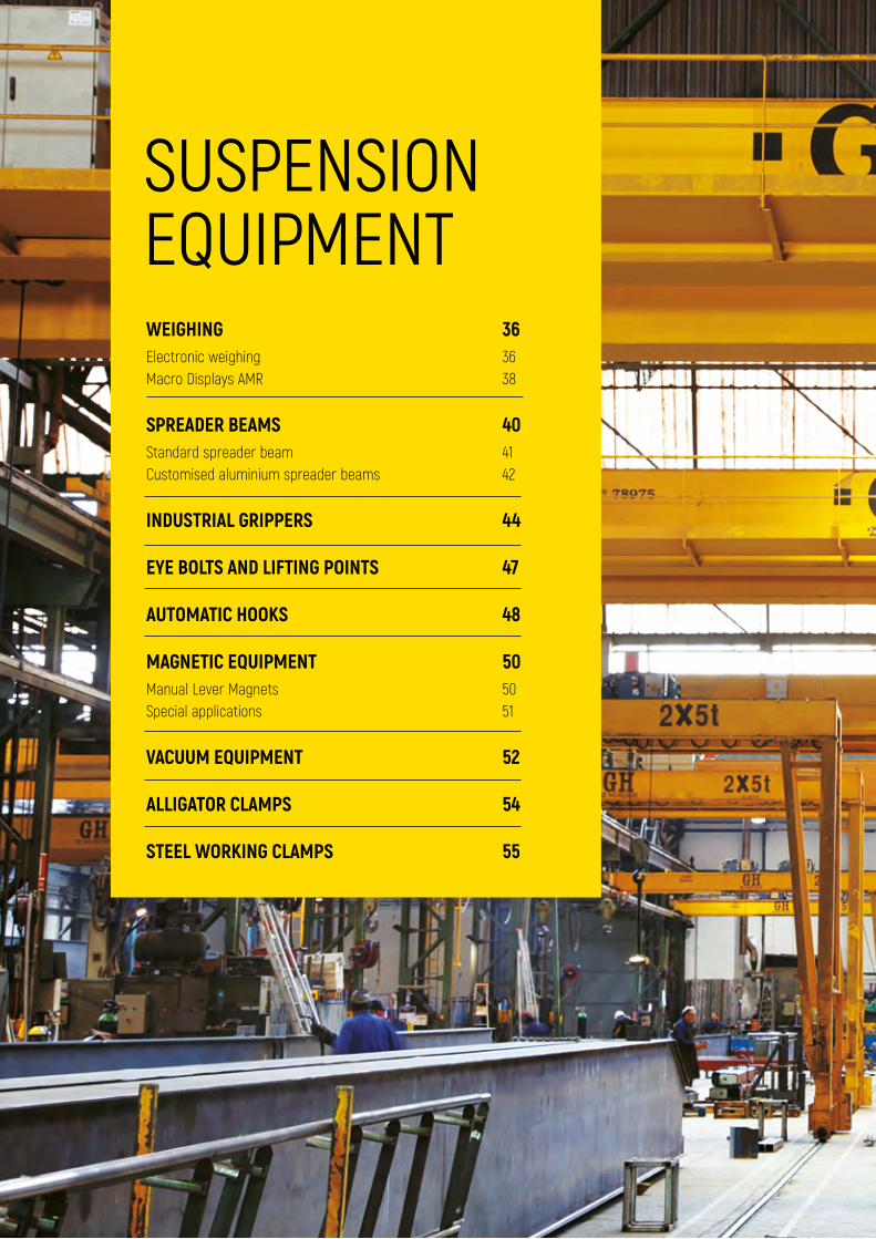
SUSPENSIONEQUIPMENTWEIGHINGElectronic weighing Macro Displays AMR
SPREADER BEAMSStandard spreader beam Customised aluminium spreader beams
INDUSTRIAL GRIPPERS
EYE BOLTS AND LIFTING POINTS
AUTOMATIC HOOKS
MAGNETIC EQUIPMENTManual Lever Magnets Special applications
VACUUM EQUIPMENT
ALLIGATOR CLAMPS
STEEL WORKING CLAMPS
3636 38
4041 42
44
47
48
5050 51
52
54
55
35 GH | PARTS & ACCESSORIES
Ficha técnica en pág. xx
36 SUSPENSION EQUIPMENT
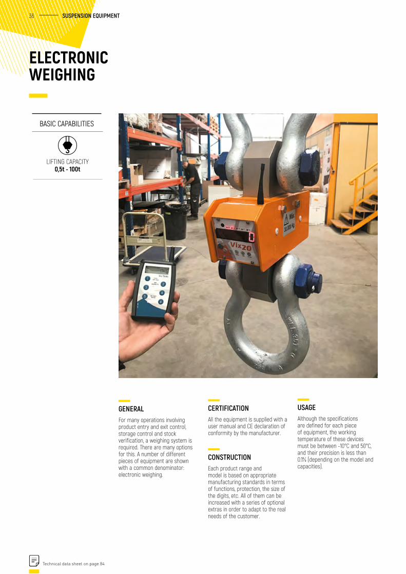
USAGEAlthough the specifications are defined for each piece of equipment, the working temperature of these devices must be between -10°C and 50°C, and their precision is less than 0.1% (depending on the model and capacities).
ELECTRONIC WEIGHING
GENERALFor many operations involving product entry and exit control, storage control and stock verification, a weighing system is required. There are many options for this. A number of different pieces of equipment are shown with a common denominator: electronic weighing.
BASIC CAPABILITIES
LIFTING CAPACITY 0,5t - 100t
CERTIFICATIONAll the equipment is supplied with a user manual and CE declaration of conformity by the manufacturer.
CONSTRUCTIONEach product range and model is based on appropriate manufacturing standards in terms of functions, protection, the size of the digits, etc. All of them can be increased with a series of optional extras in order to adapt to the real needs of the customer.
Technical data sheet on page 84
37 GH | PARTS & ACCESSORIESINDEX OF ACCESSORIES
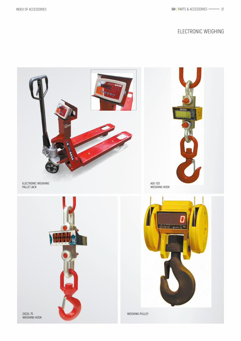
ELECTRONIC WEIGHING PALLET JACK
AGE-120 WEIGHING HOOK
EXCEL 75 WEIGHING HOOK
WEIGHING PULLEY
ELECTRONIC WEIGHING
38 SUSPENSION EQUIPMENT
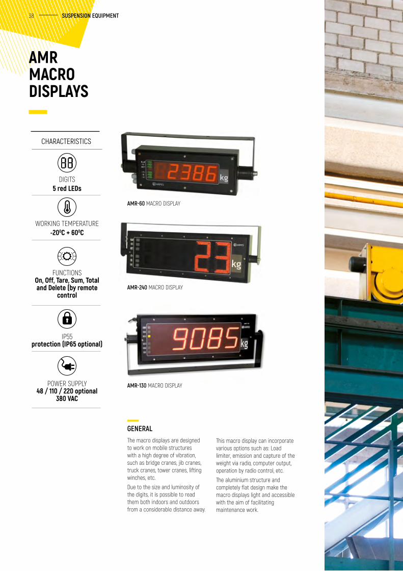
AMR MACRO DISPLAYS
GENERALThe macro displays are designed to work on mobile structures with a high degree of vibration, such as bridge cranes, jib cranes, truck cranes, tower cranes, lifting winches, etc.
Due to the size and luminosity of the digits, it is possible to read them both indoors and outdoors from a considerable distance away.
AMR-130 MACRO DISPLAY
AMR-240 MACRO DISPLAY
AMR-60 MACRO DISPLAY
This macro display can incorporate various options such as: Load limiter, emission and capture of the weight via radio, computer output, operation by radio control, etc.
The aluminium structure and completely flat design make the macro displays light and accessible with the aim of facilitating maintenance work.
CHARACTERISTICS
DIGITS5 red LEDs
WORKING TEMPERATURE -200C + 600C
FUNCTIONSOn, Off, Tare, Sum, Total and Delete (by remote
control
IP55 protection (IP65 optional)
POWER SUPPLY48 / 110 / 220 optional
380 VAC
39
SUSPENSION EQUIPMENT40
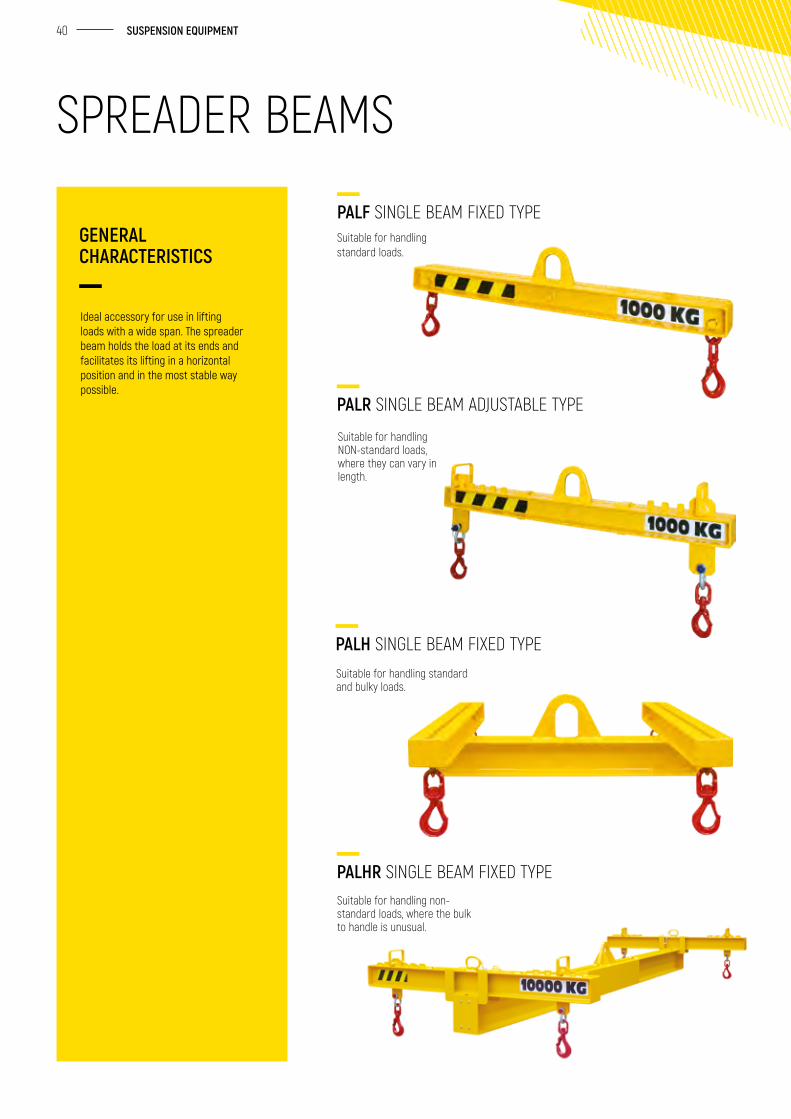
Suitable for handling standard loads.
Suitable for handling NON-standard loads, where they can vary in length.
Suitable for handling standard and bulky loads.
Suitable for handling non-standard loads, where the bulk to handle is unusual.
Ideal accessory for use in lifting loads with a wide span. The spreader beam holds the load at its ends and facilitates its lifting in a horizontal position and in the most stable way possible.
GENERAL CHARACTERISTICS
PALF SINGLE BEAM FIXED TYPE
PALR SINGLE BEAM ADJUSTABLE TYPE
PALH SINGLE BEAM FIXED TYPE
PALHR SINGLE BEAM FIXED TYPE
SPREADER BEAMS
41 GH | PARTS & ACCESSORIES
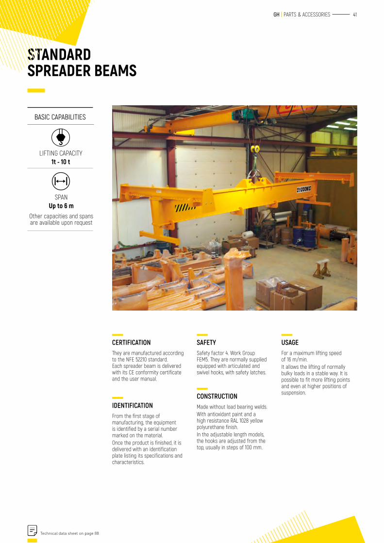
CERTIFICATIONThey are manufactured according to the NFE 52210 standard. Each spreader beam is delivered with its CE conformity certificate and the user manual.
IDENTIFICATIONFrom the first stage of manufacturing, the equipment is identified by a serial number marked on the material.Once the product is finished, it is delivered with an identification plate listing its specifications and characteristics.
SAFETYSafety factor 4. Work Group FEM5. They are normally supplied equipped with articulated and swivel hooks, with safety latches.
CONSTRUCTIONMade without load bearing welds.With antioxidant paint and a high resistance RAL 1028 yellow polyurethane finish.In the adjustable length models, the hooks are adjusted from the top, usually in steps of 100 mm.
STANDARD SPREADER BEAMS
USAGEFor a maximum lifting speed of 16 m/min.It allows the lifting of normally bulky loads in a stable way. It is possible to fit more lifting points and even at higher positions of suspension.
BASIC CAPABILITIES
LIFTING CAPACITY 1t - 10 t
SPAN Up to 6 m
Other capacities and spans are available upon request
Technical data sheet on page 88
SUSPENSION EQUIPMENT
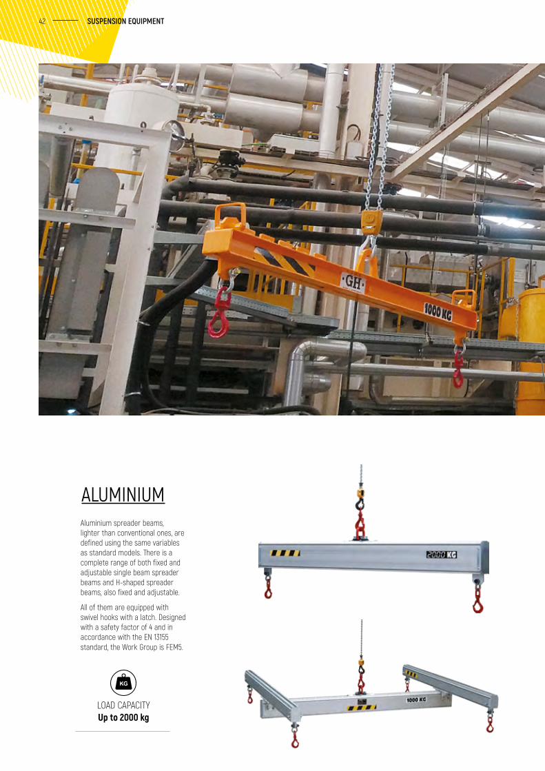
Aluminium spreader beams, lighter than conventional ones, are defined using the same variables as standard models. There is a complete range of both fixed and adjustable single beam spreader beams and H-shaped spreader beams, also fixed and adjustable.
All of them are equipped with swivel hooks with a latch. Designed with a safety factor of 4 and in accordance with the EN 13155 standard, the Work Group is FEM5.
LOAD CAPACITY Up to 2000 kg
ALUMINIUM
42
43 GH | PARTS & ACCESSORIES
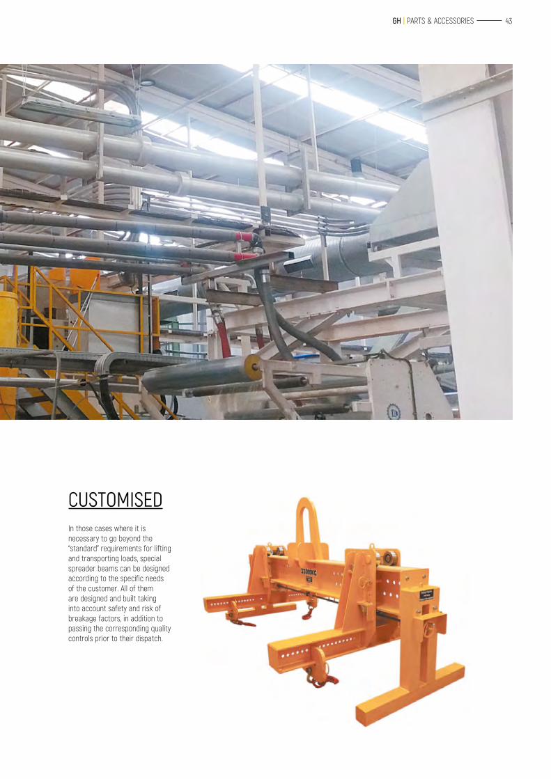
CUSTOMISEDIn those cases where it is necessary to go beyond the “standard” requirements for lifting and transporting loads, special spreader beams can be designed according to the specific needs of the customer. All of them are designed and built taking into account safety and risk of breakage factors, in addition to passing the corresponding quality controls prior to their dispatch.
44 SUSPENSION EQUIPMENT
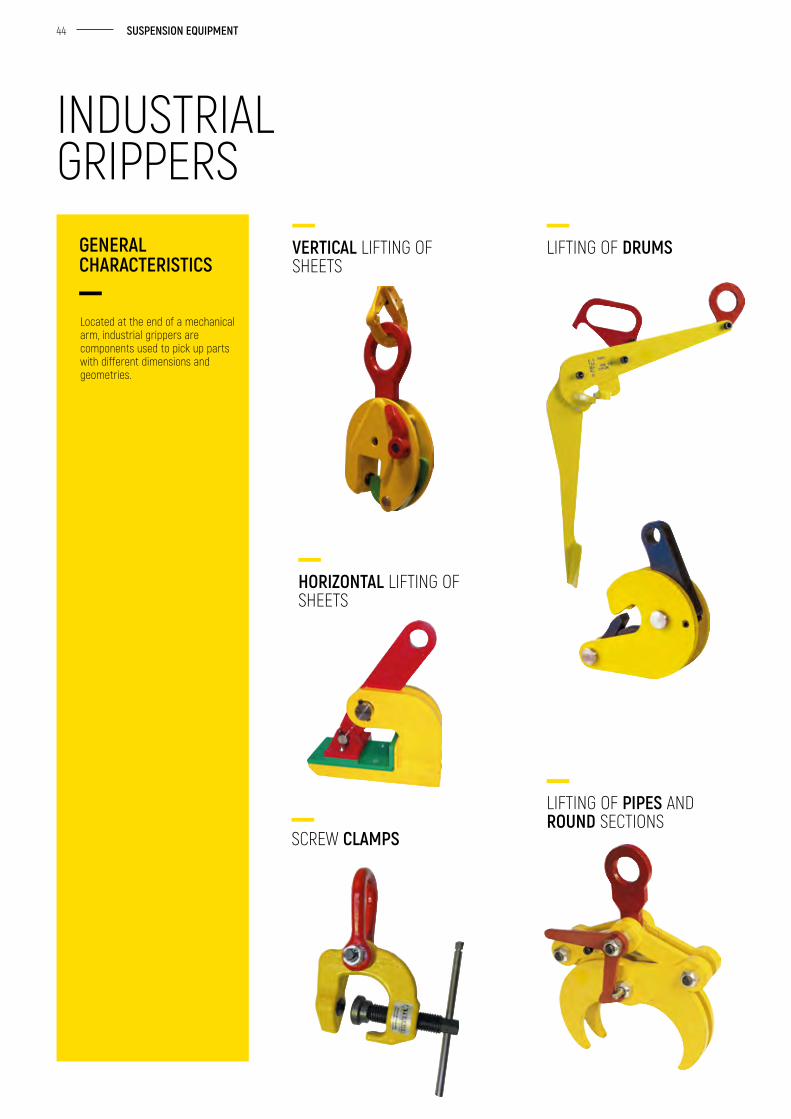
Located at the end of a mechanical arm, industrial grippers are components used to pick up parts with different dimensions and geometries.
GENERAL CHARACTERISTICS
VERTICAL LIFTING OF SHEETS
HORIZONTAL LIFTING OF SHEETS
SCREW CLAMPS
LIFTING OF DRUMS
LIFTING OF PIPES AND ROUND SECTIONS
INDUSTRIAL GRIPPERS
45 GH | PARTS & ACCESSORIES
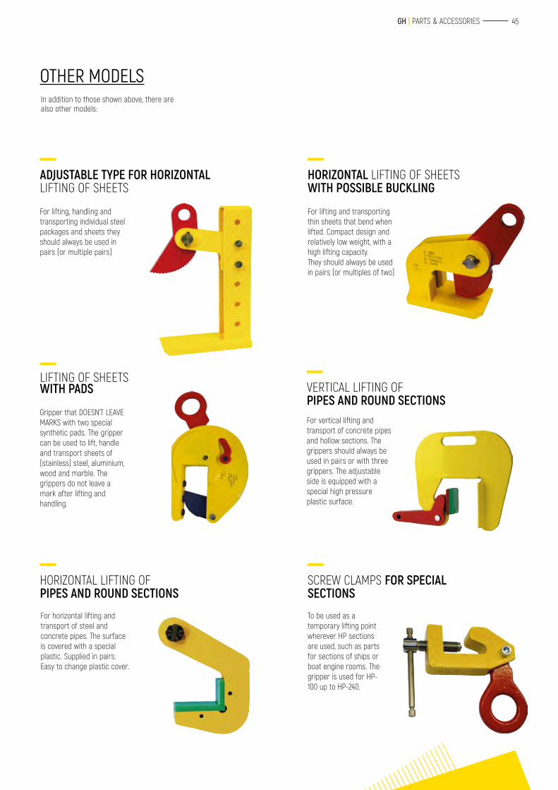
In addition to those shown above, there are also other models:
For lifting, handling and transporting individual steel packages and sheets they should always be used in pairs (or multiple pairs)
Gripper that DOESN’T LEAVE MARKS with two special synthetic pads. The gripper can be used to lift, handle and transport sheets of (stainless) steel, aluminium, wood and marble. The grippers do not leave a mark after lifting and handling.
For horizontal lifting and transport of steel and concrete pipes. The surface is covered with a special plastic. Supplied in pairs. Easy to change plastic cover.
For lifting and transporting thin sheets that bend when lifted. Compact design and relatively low weight, with a high lifting capacity.They should always be used in pairs (or multiples of two)
For vertical lifting and transport of concrete pipes and hollow sections. The grippers should always be used in pairs or with three grippers. The adjustable side is equipped with a special high pressure plastic surface.
To be used as a temporary lifting point wherever HP sections are used, such as parts for sections of ships or boat engine rooms. The gripper is used for HP-100 up to HP-240.
OTHER MODELS
ADJUSTABLE TYPE FOR HORIZONTAL LIFTING OF SHEETS
HORIZONTAL LIFTING OF SHEETS WITH POSSIBLE BUCKLING
VERTICAL LIFTING OF PIPES AND ROUND SECTIONS
SCREW CLAMPS FOR SPECIAL SECTIONS
LIFTING OF SHEETS WITH PADS
HORIZONTAL LIFTING OF PIPES AND ROUND SECTIONS
46 SUSPENSION EQUIPMENT
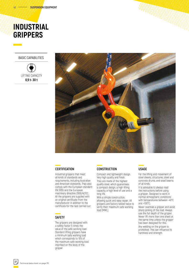
CERTIFICATIONIndustrial grippers that meet all kinds of standards and requirements, including Australian and American standards. They also comply with the European standard EN 13155 and the European machinery directive 2006/42/EC. All the grippers are supplied with an original certificate from the manufacturer in addition to the certificate for the test carried out.
SAFETYThe grippers are designed with a safety factor 5 times the value of the safe working load. Standard lifting grippers have a minimum safe working load which corresponds to 10% of the maximum safe working load inscribed on the body of the gripper.
CONSTRUCTIONCompact and lightweight design. Very high quality and finish. They are made of the highest quality steel, which guarantees a compact design, a high lifting capacity, a high level of use and a long life. With a simple construction, allowing quick and easy repair. All grippers are factory tested twice to verify their maximum safe working load (MWL).
INDUSTRIAL GRIPPERS
BASIC CAPABILITIES
LIFTING CAPACITY 0,5 t- 30 t
USAGEFor the lifting and movement of steel sheets, structures, steel and concrete drums, and steel beams of all kinds.It is advisable to always read the instructions before using a gripper. Designed to work in normal atmospheric conditions with temperatures between -40°C and +100°C.Never overload a gripper and avoid sharp jerking of the load. Always use the full depth of the gripper. Never lift more than one sheet at the same time unless the gripper has been designed for this.Any welding on the gripper is prohibited. This can influence its hardness and strength.
Technical data sheet on page 90
47 GH | PARTS & ACCESSORIES
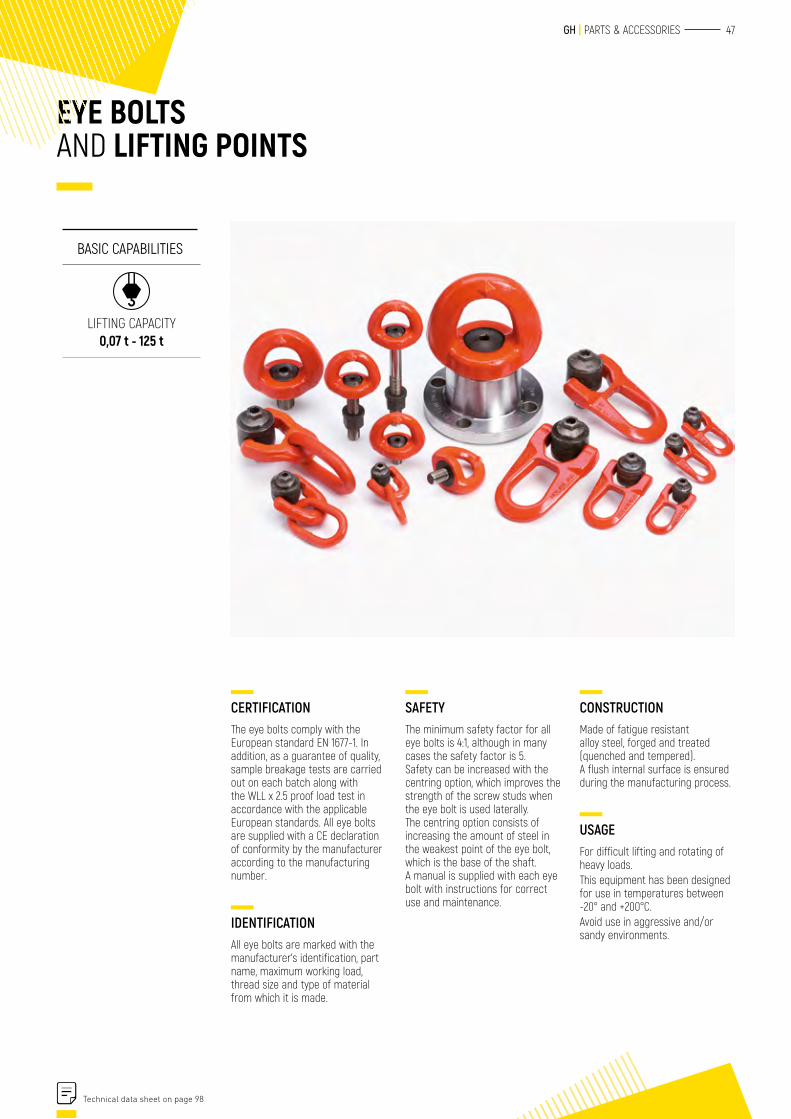
SAFETYThe minimum safety factor for all eye bolts is 4:1, although in many cases the safety factor is 5.Safety can be increased with the centring option, which improves the strength of the screw studs when the eye bolt is used laterally. The centring option consists of increasing the amount of steel in the weakest point of the eye bolt, which is the base of the shaft.A manual is supplied with each eye bolt with instructions for correct use and maintenance.
EYE BOLTS AND LIFTING POINTS
CONSTRUCTIONMade of fatigue resistant alloy steel, forged and treated (quenched and tempered).A flush internal surface is ensured during the manufacturing process.
USAGEFor difficult lifting and rotating of heavy loads.This equipment has been designed for use in temperatures between -20° and +200°C.Avoid use in aggressive and/or sandy environments.
CERTIFICATIONThe eye bolts comply with the European standard EN 1677-1. In addition, as a guarantee of quality, sample breakage tests are carried out on each batch along with the WLL x 2.5 proof load test in accordance with the applicable European standards. All eye bolts are supplied with a CE declaration of conformity by the manufacturer according to the manufacturing number.
IDENTIFICATIONAll eye bolts are marked with the manufacturer’s identification, part name, maximum working load, thread size and type of material from which it is made.
BASIC CAPABILITIES
LIFTING CAPACITY 0,07 t - 125 t
Technical data sheet on page 98
48 SUSPENSION EQUIPMENT
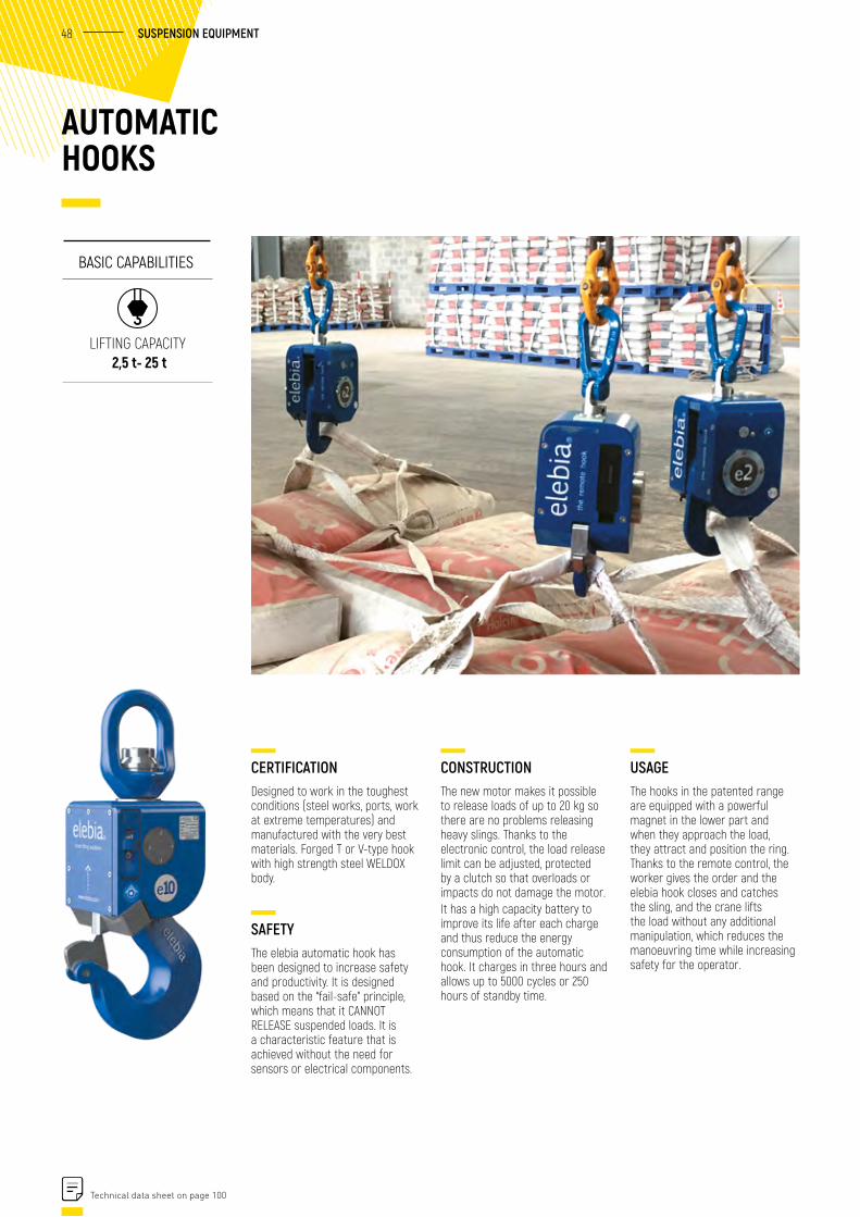
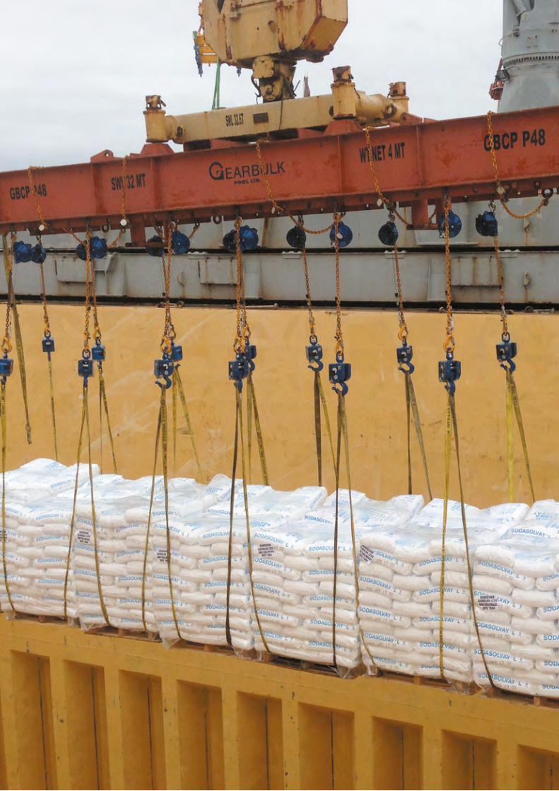
CERTIFICATIONDesigned to work in the toughest conditions (steel works, ports, work at extreme temperatures) and manufactured with the very best materials. Forged T or V-type hook with high strength steel WELDOX body.
SAFETYThe elebia automatic hook has been designed to increase safety and productivity. It is designed based on the “fail-safe” principle, which means that it CANNOT RELEASE suspended loads. It is a characteristic feature that is achieved without the need for sensors or electrical components.
CONSTRUCTIONThe new motor makes it possible to release loads of up to 20 kg so there are no problems releasing heavy slings. Thanks to the electronic control, the load release limit can be adjusted, protected by a clutch so that overloads or impacts do not damage the motor.It has a high capacity battery to improve its life after each charge and thus reduce the energy consumption of the automatic hook. It charges in three hours and allows up to 5000 cycles or 250 hours of standby time.
AUTOMATIC HOOKS
BASIC CAPABILITIES
LIFTING CAPACITY 2,5 t- 25 t
USAGEThe hooks in the patented range are equipped with a powerful magnet in the lower part and when they approach the load, they attract and position the ring. Thanks to the remote control, the worker gives the order and the elebia hook closes and catches the sling, and the crane lifts the load without any additional manipulation, which reduces the manoeuvring time while increasing safety for the operator.
Technical data sheet on page 100
49 GH | PARTS & ACCESSORIES
50 SUSPENSION EQUIPMENT
CERTIFICATIONThe magnets comply with the machinery directive 2006/42/EC and the harmonised standards UNE EN 292-1 and UNE EN 292-2. All equipment is supplied with a user manual, test certificate and CE declaration of conformity from the manufacturer.
SAFETYAll the pieces of equipment have a security lock.The separation force required when it is active is at least 3 times the rated lifting capacity. For round materials, the lifting capacity is 50% of that defined for flat materials. Avoid use in aggressive and/or sandy environments.
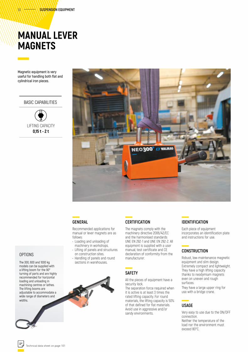
MANUAL LEVER MAGNETS
IDENTIFICATIONEach piece of equipment incorporates an identification plate and instructions for use.
CONSTRUCTIONRobust, low-maintenance magnetic equipment and slim design. Extremely compact and lightweight. They have a high lifting capacity thanks to neodymium magnets even on uneven and rough surfaces.They have a large upper ring for use with a bridge crane.
USAGEVery easy to use due to the ON/OFF connection.Neither the temperature of the load nor the environment must exceed 80°C.
GENERALRecommended applications for manual or lever magnets are as follows:• Loading and unloading of
machinery in workshops.• Lifting of panels and structures
on construction sites.• Handling of panels and round
sections in warehouses.
Magnetic equipment is very useful for handling both flat and cylindrical iron pieces.
BASIC CAPABILITIES
LIFTING CAPACITY 0,15 t - 2 t
Technical data sheet on page 101
OPTIONS
The 300, 600 and 1000 kg models can be supplied with a lifting boom for the 90° turning of parts and are highly recommended for horizontal loading and unloading in machining centres or lathes.The lifting booms are adjustable to accommodate a wide range of diameters and widths.
51 GH | PARTS & ACCESSORIES
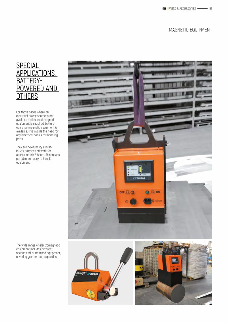
For those cases where an electrical power source is not available and manual magnetic equipment is required, battery-operated magnetic equipment is available. This avoids the need for any electrical cables for handling parts.
They are powered by a built-in 12 V battery, and work for approximately 8 hours. This means portable and easy to handle equipment.
The wide range of electromagnetic equipment includes different shapes and customised equipment, covering greater load capacities.
SPECIAL APPLICATIONS, BATTERY-POWERED AND OTHERS
MAGNETIC EQUIPMENT
52 SUSPENSION EQUIPMENT
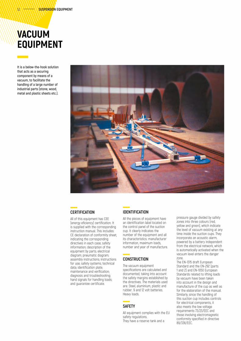
VACUUM EQUIPMENT
CERTIFICATIONAll of this equipment has CEE (energy eficiency) certification. It is supplied with the corresponding instruction manual. This includes: CE declaration of conformity sheet, indicating the corresponding directives in each case; safety information; description of the equipment by parts; electrical diagram; pneumatic diagram; assembly instructions; instructions for use; safety systems; technical data; identification plate; maintenance and verification; diagnosis and troubleshooting; hand signals for handling loads; and guarantee certificate.
IDENTIFICATIONAll the pieces of equipment have an identification label located on the control panel of the suction cup. It clearly indicates the number of the equipment and all its characteristics: manufacturer information, maximum loads, number and year of manufacture.
CONSTRUCTIONThe vacuum equipment specifications are calculated and documented, taking into account the safety margins established by the directives. The materials used are: Steel, aluminium, plastic and rubber. 9 and 12 volt batteries. Heavy loads.
SAFETYAll equipment complies with the EU safety regulations.They have a reserve tank and a
It is a below-the-hook solution that acts as a securing component by means of a vacuum, to facilitate the handling of a large number of industrial parts (stone, wood, metal and plastic sheets etc.).
pressure gauge divided by safety zones into three colours (red, yellow and green), which indicate the level of vacuum existing at any time inside the suction cups. They incorporate an acoustic alarm, powered by a battery independent from the electrical network, which is automatically activated when the vacuum level enters the danger zone.The EN-1315 draft European Standard and the EN-292 (parts 1 and 2) and EN-1050 European Standards related to lifting loads by vacuum have been taken into account in the design and manufacture of the cup as well as for the elaboration of the manual.Similarly, since the handling of this suction cup includes controls for electrical components, it also meets the low voltage requirements 73/23/EEC and those involving electromagnetic conformity specified in directive 89/336/EEC.
53 GH | PARTS & ACCESSORIES
SUCTION CUPS
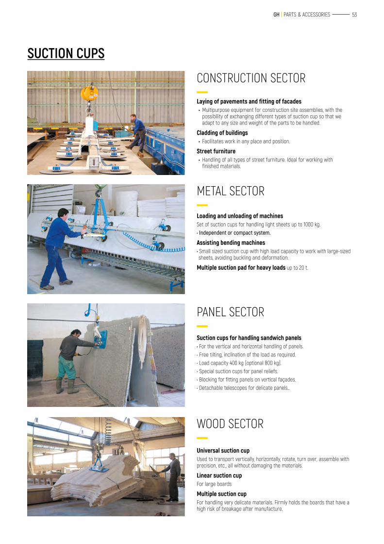
CONSTRUCTION SECTOR
Laying of pavements and fitting of facades • Multipurpose equipment for construction site assemblies, with the
possibility of exchanging different types of suction cup so that we adapt to any size and weight of the parts to be handled.
Cladding of buildings • Facilitates work in any place and position.
Street furniture • Handling of all types of street furniture. Ideal for working with
finished materials.
PANEL SECTOR
Suction cups for handling sandwich panels• For the vertical and horizontal handling of panels.• Free tilting, inclination of the load as required.• Load capacity 400 kg (optional 800 kg).• Special suction cups for panel reliefs.• Blocking for fitting panels on vertical façades.• Detachable telescopes for delicate panels..
METAL SECTOR
Loading and unloading of machines Set of suction cups for handling light sheets up to 1000 kg. • Independent or compact system.
Assisting bending machines • Small sized suction cup with high load capacity to work with large-sized sheets, avoiding buckling and deformation.
Multiple suction pad for heavy loads up to 20 t.
WOOD SECTOR
Universal suction cup Used to transport vertically, horizontally, rotate, turn over, assemble with precision, etc., all without damaging the materials.
Linear suction cup For large boards
Multiple suction cupFor handling very delicate materials. Firmly holds the boards that have a high risk of breakage after manufacture.
54 SUSPENSION EQUIPMENT
ALLIGATOR CLAMP
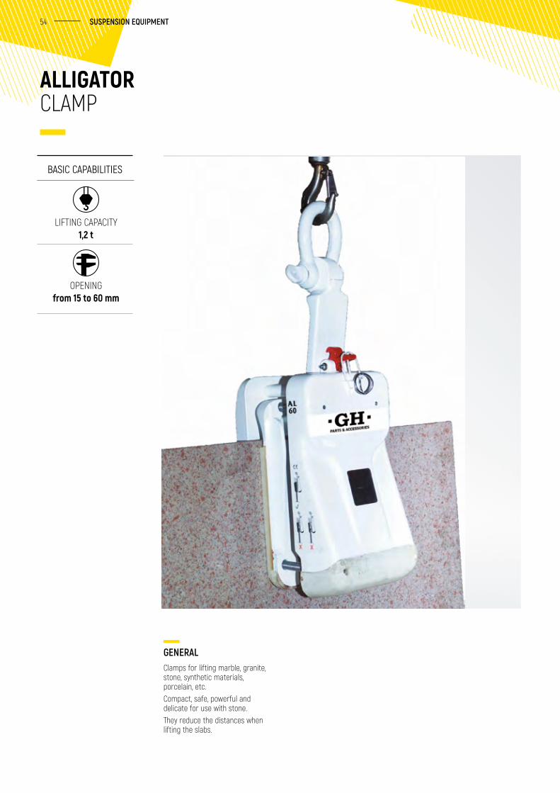
GENERALClamps for lifting marble, granite, stone, synthetic materials, porcelain, etc. Compact, safe, powerful and delicate for use with stone. They reduce the distances when lifting the slabs.
BASIC CAPABILITIES
LIFTING CAPACITY 1,2 t
OPENING from 15 to 60 mm
55 GH | PARTS & ACCESSORIES
METALWORKING CLAMPS
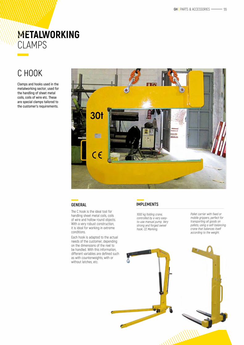
C HOOKClamps and hooks used in the metalworking sector, used for the handling of sheet metal coils, coils of wire etc. These are special clamps tailored to the customer’s requirements.
GENERALThe C hook is the ideal tool for handling sheet metal coils, coils of wire and hollow round objects. With a very robust construction, it is ideal for working in extreme conditions.Each hook is adapted to the actual needs of the customer, depending on the dimensions of the reel to be handled. With this information, different variables are defined such as with counterweights, with or without latches, etc.
1000 kg folding crane, controlled by a very easy-to-use manual pump. Very strong and forged swivel hook. CE Marking.
Pallet carrier with fixed or mobile grippers, perfect for transporting all goods on pallets, using a self-balancing crane that balances itself according to the weight.
IMPLEMENTS
STRUCTURES
SLINGS AND CHAINSSLINGS AND CHAIN COMPONENTS
POLYESTER SLINGS
58
59
57
58 SLINGS AND CHAINS
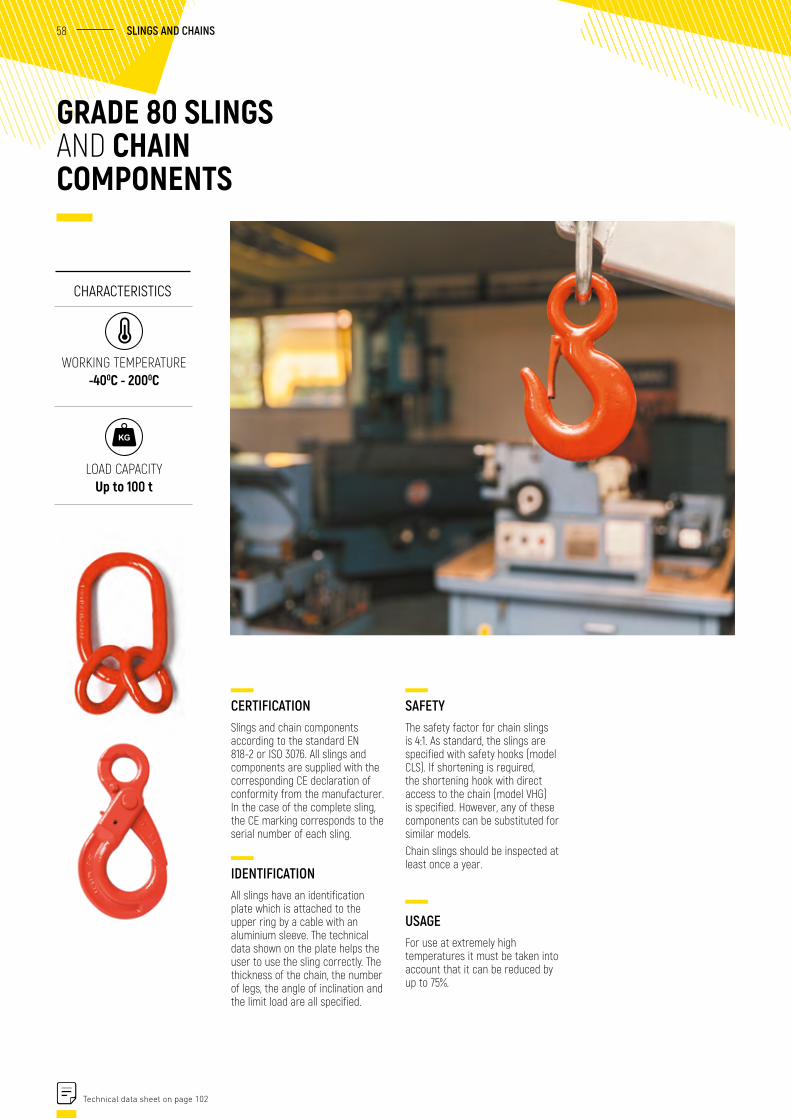
SAFETYThe safety factor for chain slings is 4:1. As standard, the slings are specified with safety hooks (model CLS). If shortening is required, the shortening hook with direct access to the chain (model VHG) is specified. However, any of these components can be substituted for similar models.Chain slings should be inspected at least once a year.
USAGEFor use at extremely high temperatures it must be taken into account that it can be reduced by up to 75%.
GRADE 80 SLINGS AND CHAIN COMPONENTS
CERTIFICATIONSlings and chain components according to the standard EN 818-2 or ISO 3076. All slings and components are supplied with the corresponding CE declaration of conformity from the manufacturer. In the case of the complete sling, the CE marking corresponds to the serial number of each sling.
IDENTIFICATIONAll slings have an identification plate which is attached to the upper ring by a cable with an aluminium sleeve. The technical data shown on the plate helps the user to use the sling correctly. The thickness of the chain, the number of legs, the angle of inclination and the limit load are all specified.
CHARACTERISTICS
WORKING TEMPERATURE -400C - 2000C
LOAD CAPACITY Up to 100 t
Technical data sheet on page 102
59 GH | PARTS & ACCESSORIES
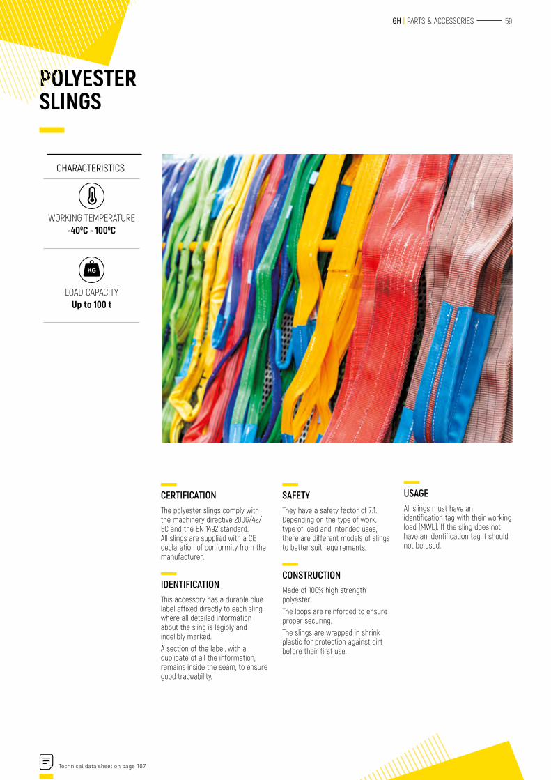
POLYESTER SLINGS
USAGEAll slings must have an identification tag with their working load (MWL). If the sling does not have an identification tag it should not be used.
CERTIFICATIONThe polyester slings comply with the machinery directive 2006/42/EC and the EN 1492 standard. All slings are supplied with a CE declaration of conformity from the manufacturer.
IDENTIFICATIONThis accessory has a durable blue label affixed directly to each sling, where all detailed information about the sling is legibly and indelibly marked.A section of the label, with a duplicate of all the information, remains inside the seam, to ensure good traceability.
SAFETYThey have a safety factor of 7:1.Depending on the type of work, type of load and intended uses, there are different models of slings to better suit requirements.
CONSTRUCTIONMade of 100% high strength polyester.The loops are reinforced to ensure proper securing.The slings are wrapped in shrink plastic for protection against dirt before their first use.
CHARACTERISTICS
WORKING TEMPERATURE -400C - 1000C
LOAD CAPACITY Up to 100 t
Technical data sheet on page 107

STRUCTURES
POWER SUPPLYELECTRICRADIO CONTROLS
SAFETY POWER SUPPLY LINE
SPRING-DRIVEN CABLE REEL
62
64
65

61
62 ELECTRIC POWER SUPPLY
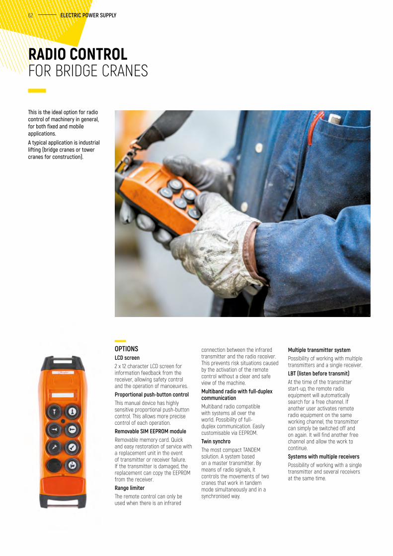
RADIO CONTROL FOR BRIDGE CRANES
connection between the infrared transmitter and the radio receiver. This prevents risk situations caused by the activation of the remote control without a clear and safe view of the machine. Multiband radio with full-duplex communicationMultiband radio compatible with systems all over the world. Possibility of full-duplex communication. Easily customisable via EEPROM. Twin synchroThe most compact TANDEM solution. A system based on a master transmitter. By means of radio signals, it controls the movements of two cranes that work in tandem mode simultaneously and in a synchronised way.
OPTIONSLCD screen2 x 12 character LCD screen for information feedback from the receiver, allowing safety control and the operation of manoeuvres.Proportional push-button controlThis manual device has highly sensitive proportional push-button control. This allows more precise control of each operation.Removable SIM EEPROM moduleRemovable memory card. Quick and easy restoration of service with a replacement unit in the event of transmitter or receiver failure. If the transmitter is damaged, the replacement can copy the EEPROM from the receiver. Range limiterThe remote control can only be used when there is an infrared
Multiple transmitter systemPossibility of working with multiple transmitters and a single receiver. LBT (listen before transmit)At the time of the transmitter start-up, the remote radio equipment will automatically search for a free channel. If another user activates remote radio equipment on the same working channel, the transmitter can simply be switched off and on again. It will find another free channel and allow the work to continue. Systems with multiple receiversPossibility of working with a single transmitter and several receivers at the same time.
This is the ideal option for radio control of machinery in general, for both fixed and mobile applications.A typical application is industrial lifting (bridge cranes or tower cranes for construction).
63 GH | PARTS & ACCESSORIES
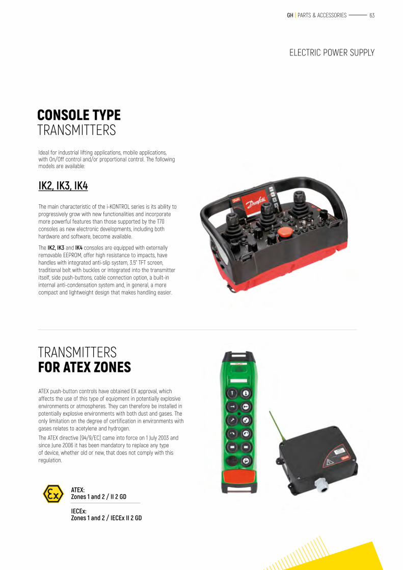
CONSOLE TYPE TRANSMITTERS
TRANSMITTERS FOR ATEX ZONES
Ideal for industrial lifting applications, mobile applications, with On/Off control and/or proportional control. The following models are available:
ATEX push-button controls have obtained EX approval, which affects the use of this type of equipment in potentially explosive environments or atmospheres. They can therefore be installed in potentially explosive environments with both dust and gases. The only limitation on the degree of certification in environments with gases relates to acetylene and hydrogen.
The ATEX directive (94/9/EC) came into force on 1 July 2003 and since June 2006 it has been mandatory to replace any type of device, whether old or new, that does not comply with this regulation.
IK2, IK3, IK4
The main characteristic of the i-KONTROL series is its ability to progressively grow with new functionalities and incorporate more powerful features than those supported by the T70 consoles as new electronic developments, including both hardware and software, become available.
The IK2, IK3 and IK4 consoles are equipped with externally removable EEPROM, offer high resistance to impacts, have handles with integrated anti-slip system, 3.5” TFT screen, traditional belt with buckles or integrated into the transmitter itself, side push-buttons, cable connection option, a built-in internal anti-condensation system and, in general, a more compact and lightweight design that makes handling easier.
ATEX: Zones 1 and 2 / II 2 GD
IECEx: Zones 1 and 2 / IECEx II 2 GD
ELECTRIC POWER SUPPLY
64 ELECTRIC POWER SUPPLY
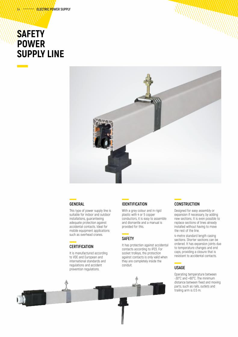
GENERALThis type of power supply line is suitable for indoor and outdoor installations, guaranteeing adequate protection against accidental contacts. Ideal for mobile equipment applications such as overhead cranes.
CERTIFICATIONIt is manufactured according to VDE and European and international standards and regulations and accident prevention regulations.
IDENTIFICATIONWith a grey colour and in rigid plastic with 4 or 5 copper conductors, it is easy to assemble and dismantle and a manual is provided for this.
SAFETYIt has protection against accidental contacts according to IP23. For socket trolleys, the protection against contacts is only valid when they are completely inside the conduit.
SAFETY POWER SUPPLY LINE
CONSTRUCTIONDesigned for easy assembly or expansion if necessary, by adding new sections. It is even possible to replace sections of lines already installed without having to move the rest of the line.4-metre standard length casing sections. Shorter sections can be ordered. It has expansion joints due to temperature changes and end caps, providing a closure that is resistant to accidental contacts.
USAGEOperating temperature between -30°C and +60°C. The minimum distance between fixed and moving parts, such as rails, outlets and trailing arm is 0.5 m.
65 GH | PARTS & ACCESSORIES
SPRING-DRIVEN CABLE REEL
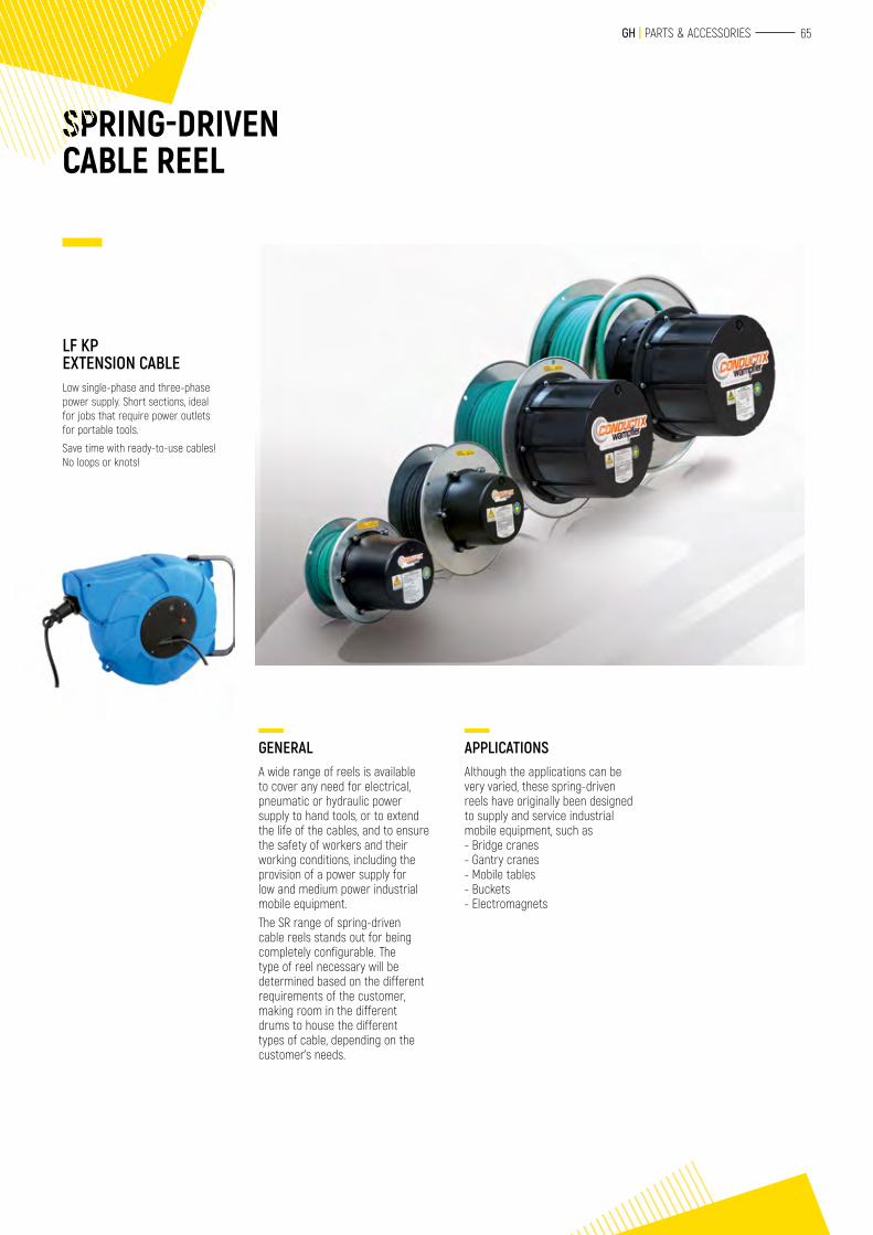
LF KP EXTENSION CABLELow single-phase and three-phase power supply. Short sections, ideal for jobs that require power outlets for portable tools.
Save time with ready-to-use cables! No loops or knots!
GENERALA wide range of reels is available to cover any need for electrical, pneumatic or hydraulic power supply to hand tools, or to extend the life of the cables, and to ensure the safety of workers and their working conditions, including the provision of a power supply for low and medium power industrial mobile equipment.The SR range of spring-driven cable reels stands out for being completely configurable. The type of reel necessary will be determined based on the different requirements of the customer, making room in the different drums to house the different types of cable, depending on the customer’s needs.
APPLICATIONSAlthough the applications can be very varied, these spring-driven reels have originally been designed to supply and service industrial mobile equipment, such as- Bridge cranes- Gantry cranes- Mobile tables- Buckets- Electromagnets
STRUCTURES
SAFETY SYSTEMSLIFELINESHorizontal and vertical
OTHER SAFETY EQUIPMENT
68
69
67
68 SAFETY SYSTEMS
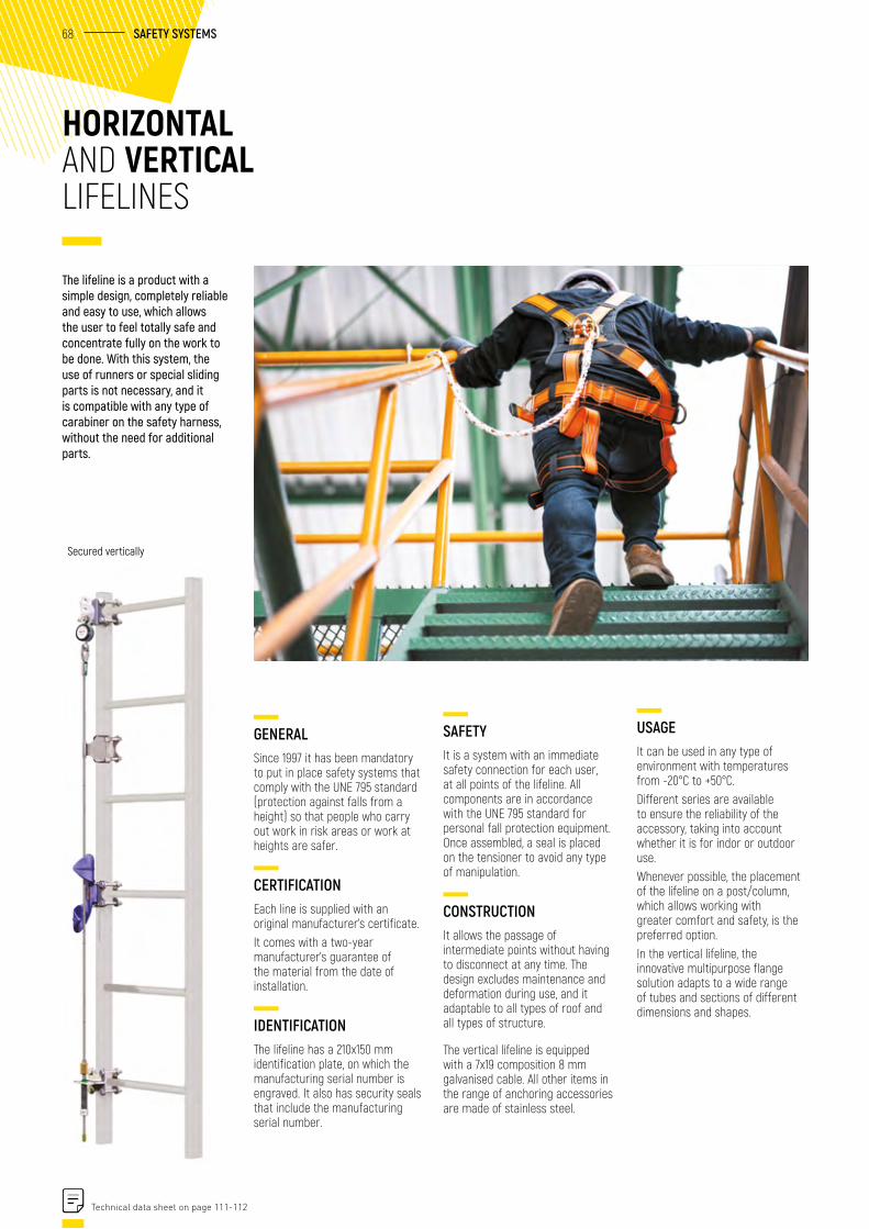
GENERALSince 1997 it has been mandatory to put in place safety systems that comply with the UNE 795 standard (protection against falls from a height) so that people who carry out work in risk areas or work at heights are safer.
CERTIFICATIONEach line is supplied with an original manufacturer’s certificate.It comes with a two-year manufacturer’s guarantee of the material from the date of installation.
IDENTIFICATIONThe lifeline has a 210x150 mm identification plate, on which the manufacturing serial number is engraved. It also has security seals that include the manufacturing serial number.
HORIZONTAL AND VERTICAL LIFELINES
SAFETYIt is a system with an immediate safety connection for each user, at all points of the lifeline. All components are in accordance with the UNE 795 standard for personal fall protection equipment. Once assembled, a seal is placed on the tensioner to avoid any type of manipulation.
CONSTRUCTIONIt allows the passage of intermediate points without having to disconnect at any time. The design excludes maintenance and deformation during use, and it adaptable to all types of roof and all types of structure.
The vertical lifeline is equipped with a 7x19 composition 8 mm galvanised cable. All other items in the range of anchoring accessories are made of stainless steel.
Secured vertically
USAGEIt can be used in any type of environment with temperatures from -20°C to +50°C.Different series are available to ensure the reliability of the accessory, taking into account whether it is for indor or outdoor use.Whenever possible, the placement of the lifeline on a post/column, which allows working with greater comfort and safety, is the preferred option.In the vertical lifeline, the innovative multipurpose flange solution adapts to a wide range of tubes and sections of different dimensions and shapes.
The lifeline is a product with a simple design, completely reliable and easy to use, which allows the user to feel totally safe and concentrate fully on the work to be done. With this system, the use of runners or special sliding parts is not necessary, and it is compatible with any type of carabiner on the safety harness, without the need for additional parts.
Technical data sheet on page 111-112
69 GH | PARTS & ACCESSORIES
PERSONNEL CAGES
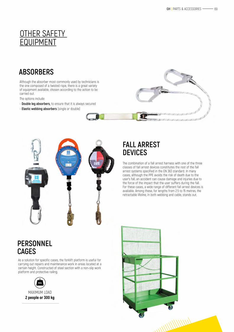
ABSORBERSAlthough the absorber most commonly used by technicians is the one composed of a twisted rope, there is a great variety of equipment available, chosen according to the action to be carried out.The options include: - Double leg absorbers, to ensure that it is always secured- Elastic webbing absorbers (single or double)
FALL ARREST DEVICESThe combination of a fall arrest harness with one of the three classes of fall arrest devices constitutes the rest of the fall arrest systems specified in the EN 363 standard. In many cases, although the PPE avoids the risk of death due to the user’s fall, an accident can cause damage and injuries due to the force of the impact that the user suffers during the fall. For these cases, a wide range of different fall arrest devices is available. Among these, for lengths from 2.5 to 15 metres, the retractable lifeline, in both webbing and cable, stands out.
As a solution for specific cases, the forklift platform is useful for carrying out repairs and maintenance work in areas located at a certain height. Constructed of steel section with a non-slip work platform and protective railing.
OTHER SAFETY EQUIPMENT
MAXIMUM LOAD 2 people or 300 kg
STRUCTURES
TECHNICAL CHARACTERISTICS
71
72 TECHNICAL CHARACTERISTICS
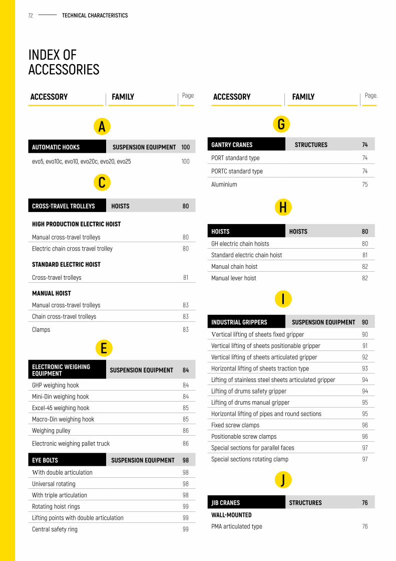
INDEX OF ACCESSORIES
ACCESSORY FAMILY Page ACCESSORY FAMILY Page.
GGANTRY CRANES STRUCTURES 74
PORT standard type 74
PORTC standard type 74
Aluminium 75
HHOISTS HOISTS 80
GH electric chain hoists 80
Standard electric chain hoist 81
Manual chain hoist 82
Manual lever hoist 82
IINDUSTRIAL GRIPPERS SUSPENSION EQUIPMENT 90
Vertical lifting of sheets fixed gripper 90
Vertical lifting of sheets positionable gripper 91
Vertical lifting of sheets articulated gripper 92
Horizontal lifting of sheets traction type 93
Lifting of stainless steel sheets articulated gripper 94
Lifting of drums safety gripper 94
Lifting of drums manual gripper 95
Horizontal lifting of pipes and round sections 95
Fixed screw clamps 96
Positionable screw clamps 96
Special sections for parallel faces 97
Special sections rotating clamp 97
JJIB CRANES STRUCTURES 76
WALL-MOUNTED
PMA articulated type 76
AAUTOMATIC HOOKS SUSPENSION EQUIPMENT 100
evo5, evo10c, evo10, evo20c, evo20, evo25 100
CCROSS-TRAVEL TROLLEYS HOISTS 80
HIGH PRODUCTION ELECTRIC HOIST
Manual cross-travel trolleys 80
Electric chain cross travel trolley 80
STANDARD ELECTRIC HOIST
Cross-travel trolleys 81
MANUAL HOIST
Manual cross-travel trolleys 83
Chain cross-travel trolleys 83
Clamps 83
EELECTRONIC WEIGHING EQUIPMENT SUSPENSION EQUIPMENT 84
GHP weighing hook 84
Mini-Din weighing hook 84
Excel-45 weighing hook 85
Macro-Din weighing hook 85
Weighing pulley 86
Electronic weighing pallet truck 86
EYE BOLTS SUSPENSION EQUIPMENT 98
With double articulation 98
Universal rotating 98
With triple articulation 98
Rotating hoist rings 99
Lifting points with double articulation 99
Central safety ring 99
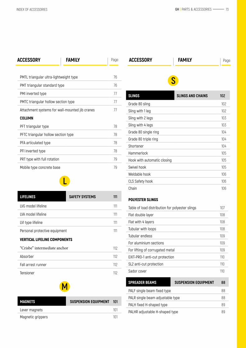
73 GH | PARTS & ACCESSORIESINDEX OF ACCESSORIES
SSLINGS SLINGS AND CHAINS 102
Grade 80 sling 102
Sling with 1 leg 102
Sling with 2 legs 103
Sling with 4 legs 103
Grade 80 single ring 104
Grade 80 triple ring 104
Shortener 104
Hammerlock 105
Hook with automatic closing 105
Swivel hook 105
Weldable hook 106
CLS Safety hook 106
Chain 106
POLYESTER SLINGS
Table of load distribution for polyester slings 107
Flat double layer 108
Flat with 4 layers 108
Tubular with loops 108
Tubular endless 109
For aluminium sections 109
For lifting of corrugated metal 109
EXIT-PRO-1 anti-cut protection 110
SL2 anti-cut protection 110
Sador cover 110
SPREADER BEAMS SUSPENSION EQUIPMENT 88
PALF single beam fixed type 88
PALR single beam adjustable type 88
PALH fixed H-shaped type 89
PALHR adjustable H-shaped type 89
ACCESSORY FAMILY PageACCESSORY FAMILY Page
PMTL triangular ultra-lightweight type 76
PMT triangular standard type 76
PMI inverted type 77
PMTC triangular hollow section type 77
Attachment systems for wall-mounted jib cranes 77
COLUMN
PFT triangular type 78
PFTC triangular hollow section type 78
PFA articulated type 78
PFI inverted type 78
PRT type with full rotation 79
Mobile type concrete base 79
LLIFELINES SAFETY SYSTEMS 111
LVG model lifeline 111
LVA model lifeline 111
LVI type lifeline 111
Personal protective equipment 111
VERTICAL LIFELINE COMPONENTS
“Crisbe” intermediate anchor 112
Absorber 112
Fall arrest runner 112
Tensioner 112
MMAGNETS SUSPENSION EQUIPMENT 101
Lever magnets 101
Magnetic grippers 101
74 TECHNICAL CHARACTERISTICS
PORT TYPE STANDARD GANTRY CRANE
PORTC TYPE STANDARD GANTRY CRANE
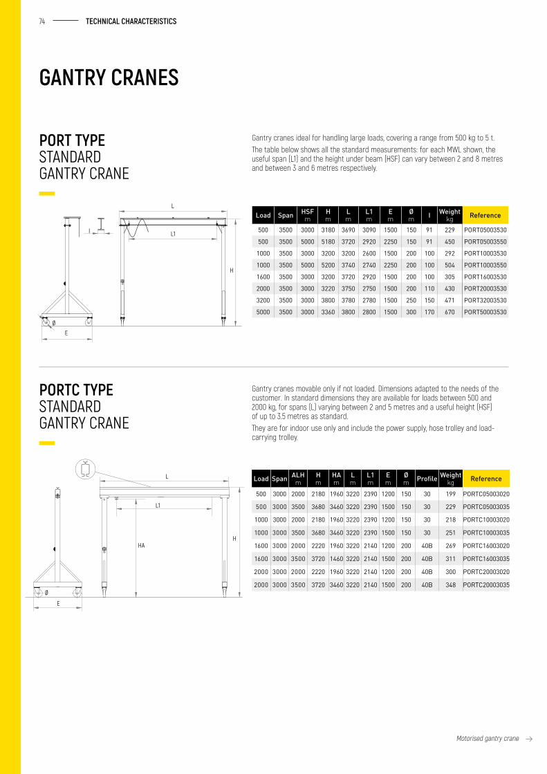
Gantry cranes ideal for handling large loads, covering a range from 500 kg to 5 t.The table below shows all the standard measurements: for each MWL shown, the useful span (L1) and the height under beam (HSF) can vary between 2 and 8 metres and between 3 and 6 metres respectively.
Gantry cranes movable only if not loaded. Dimensions adapted to the needs of the customer. In standard dimensions they are available for loads between 500 and 2000 kg, for spans (L) varying between 2 and 5 metres and a useful height (HSF) of up to 3.5 metres as standard. They are for indoor use only and include the power supply, hose trolley and load-carrying trolley.
Load Span HSF m
H m
L m
L1 m
E m
Ø m I Weight
kg Reference
500 3500 3000 3180 3690 3090 1500 150 91 229 PORT05003530
500 3500 5000 5180 3720 2920 2250 150 91 450 PORT05003550
1000 3500 3000 3200 3200 2600 1500 200 100 292 PORT10003530
1000 3500 5000 5200 3740 2740 2250 200 100 504 PORT10003550
1600 3500 3000 3200 3720 2920 1500 200 100 305 PORT16003530
2000 3500 3000 3220 3750 2750 1500 200 110 430 PORT20003530
3200 3500 3000 3800 3780 2780 1500 250 150 471 PORT32003530
5000 3500 3000 3360 3800 2800 1500 300 170 670 PORT50003530
Load Span ALH m
H m
HA m
L m
L1 m
E m
Ø m Profile Weight
kg Reference
500 3000 2000 2180 1960 3220 2390 1200 150 30 199 PORTC05003020
500 3000 3500 3680 3460 3220 2390 1500 150 30 229 PORTC05003035
1000 3000 2000 2180 1960 3220 2390 1200 150 30 218 PORTC10003020
1000 3000 3500 3680 3460 3220 2390 1500 150 30 251 PORTC10003035
1600 3000 2000 2220 1960 3220 2140 1200 200 40B 269 PORTC16003020
1600 3000 3500 3720 1460 3220 2140 1500 200 40B 311 PORTC16003035
2000 3000 2000 2220 1960 3220 2140 1200 200 40B 300 PORTC20003020
2000 3000 3500 3720 3460 3220 2140 1500 200 40B 348 PORTC20003035
GANTRY CRANES
Motorised gantry crane
E
Ø
L
H
L1I
E
Ø
L
H
L1
HA
75 GH | PARTS & ACCESSORIESINDEX OF ACCESSORIES
ALUMINIUM GANTRY CRANE
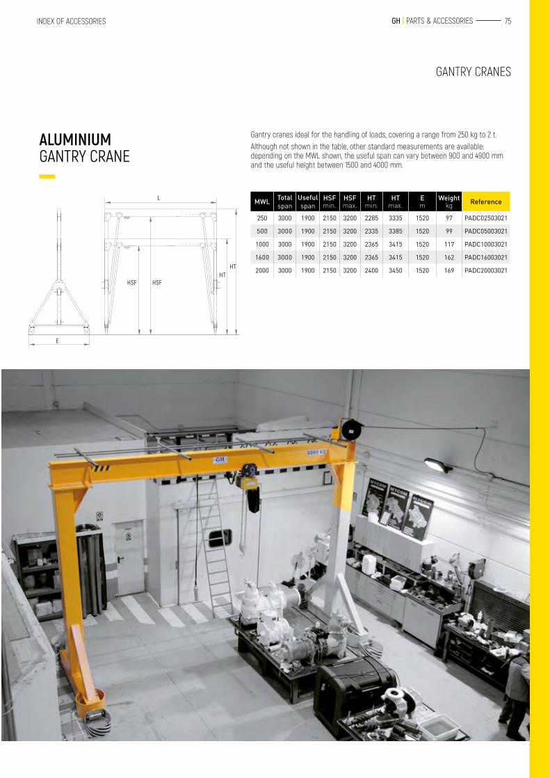
Gantry cranes ideal for the handling of loads, covering a range from 250 kg to 2 t.Although not shown in the table, other standard measurements are available: depending on the MWL shown, the useful span can vary between 900 and 4900 mm and the useful height between 1500 and 4000 mm.
MWL Total span
Useful span
HSF min.
HSF max.
HT min.
HT max.
E m
Weight kg Reference
250 3000 1900 2150 3200 2285 3335 1520 97 PADC02503021
500 3000 1900 2150 3200 2335 3385 1520 99 PADC05003021
1000 3000 1900 2150 3200 2365 3415 1520 117 PADC10003021
1600 3000 1900 2150 3200 2365 3415 1520 162 PADC16003021
2000 3000 1900 2150 3200 2400 3450 1520 169 PADC20003021
GANTRY CRANES
E
L
HTHT
HSF HSF
76 TECHNICAL CHARACTERISTICS
c
PMA ARTICULATED TYPE
PMT TRIANGULAR STANDARD TYPE
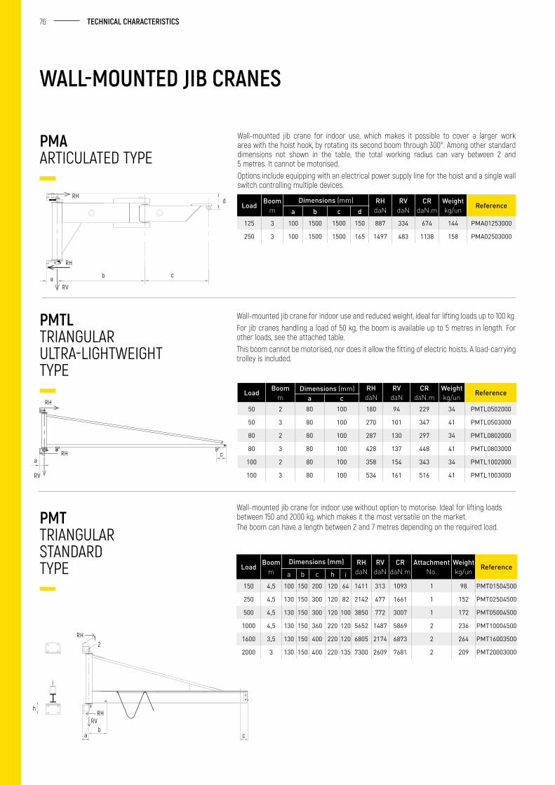
Wall-mounted jib crane for indoor use, which makes it possible to cover a larger work area with the hoist hook, by rotating its second boom through 300°. Among other standard dimensions not shown in the table, the total working radius can vary between 2 and 5 metres. It cannot be motorised.Options include equipping with an electrical power supply line for the hoist and a single wall switch controlling multiple devices.
Wall-mounted jib crane for indoor use without option to motorise. Ideal for lifting loads between 150 and 2000 kg, which makes it the most versatile on the market. The boom can have a length between 2 and 7 metres depending on the required load.
Load Boomm
Dimensions (mm) RHdaN
RVdaN
CRdaN.m
Weightkg/un Reference
a b c d125 3 100 1500 1500 150 887 334 674 144 PMA01253000
250 3 100 1500 1500 165 1497 483 1138 158 PMA02503000
Load Boomm
Dimensions (mm) RHdaN
RVdaN
CRdaN.m
Attachment No.
Weightkg/un Reference
a b c h i150 4,5 100 150 200 120 64 1411 313 1093 1 98 PMT01504500
250 4,5 130 150 300 120 82 2142 477 1661 1 152 PMT02504500
500 4,5 130 150 300 120 100 3850 772 3007 1 172 PMT05004500
1000 4,5 130 150 360 220 120 5652 1487 5869 2 236 PMT10004500
1600 3,5 130 150 400 220 120 6805 2174 6873 2 264 PMT16003500
2000 3 130 150 400 220 135 7300 2609 7681 2 209 PMT20003000
PMTL TRIANGULAR ULTRA-LIGHTWEIGHT TYPE
Wall-mounted jib crane for indoor use and reduced weight, ideal for lifting loads up to 100 kg.For jib cranes handling a load of 50 kg, the boom is available up to 5 metres in length. For other loads, see the attached table.This boom cannot be motorised, nor does it allow the fitting of electric hoists. A load-carrying trolley is included.
Load Boomm
Dimensions (mm) RHdaN
RVdaN
CRdaN.m
Weightkg/un Reference
a c50 2 80 100 180 94 229 34 PMTL0502000
50 3 80 100 270 101 347 41 PMTL0503000
80 2 80 100 287 130 297 34 PMTL0802000
80 3 80 100 428 137 448 41 PMTL0803000
100 2 80 100 358 154 343 34 PMTL1002000
100 3 80 100 534 161 516 41 PMTL1003000
WALL-MOUNTED JIB CRANES
d
cba
RH
RV
RH
ac
RH
RH
RV
RH 12
i
h
ab
RHRV
77 GH | PARTS & ACCESSORIESINDEX OF ACCESSORIES
PMI INVERTED TYPE
PMTC TRIANGULAR HOLLOW SECTION TYPE
ATTACHMENT SYSTEMS FOR WALL-MOUNTED JIB CRANES
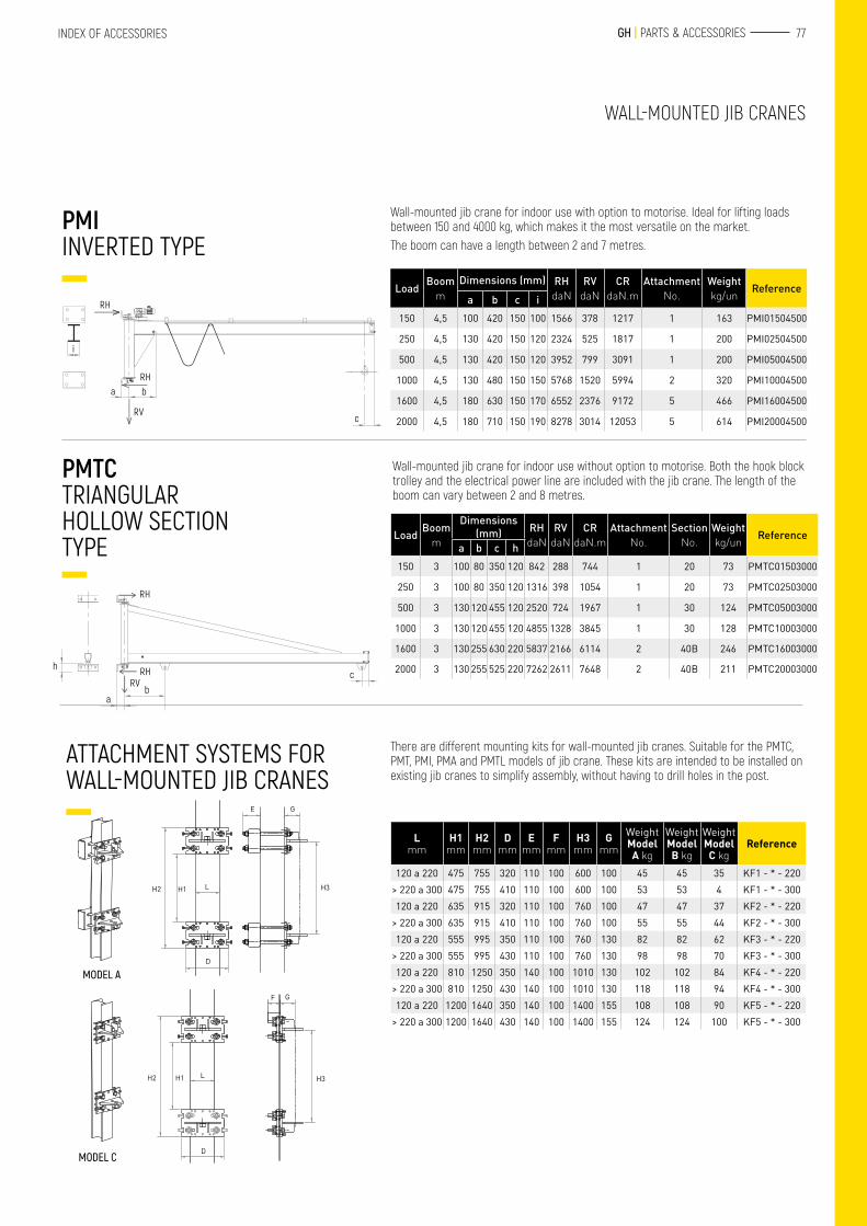
Wall-mounted jib crane for indoor use with option to motorise. Ideal for lifting loads between 150 and 4000 kg, which makes it the most versatile on the market.The boom can have a length between 2 and 7 metres.
Wall-mounted jib crane for indoor use without option to motorise. Both the hook block trolley and the electrical power line are included with the jib crane. The length of the boom can vary between 2 and 8 metres.
There are different mounting kits for wall-mounted jib cranes. Suitable for the PMTC, PMT, PMI, PMA and PMTL models of jib crane. These kits are intended to be installed on existing jib cranes to simplify assembly, without having to drill holes in the post.
L mm
H1mm
H2mm
Dmm
Emm
F mm
H3 mm
G mm
Weight Model A kg
Weight Model B kg
Weight Model C kg
Reference
120 a 220 475 755 320 110 100 600 100 45 45 35 KF1 - * - 220> 220 a 300 475 755 410 110 100 600 100 53 53 4 KF1 - * - 300120 a 220 635 915 320 110 100 760 100 47 47 37 KF2 - * - 220
> 220 a 300 635 915 410 110 100 760 100 55 55 44 KF2 - * - 300120 a 220 555 995 350 110 100 760 130 82 82 62 KF3 - * - 220
> 220 a 300 555 995 430 110 100 760 130 98 98 70 KF3 - * - 300120 a 220 810 1250 350 140 100 1010 130 102 102 84 KF4 - * - 220
> 220 a 300 810 1250 430 140 100 1010 130 118 118 94 KF4 - * - 300120 a 220 1200 1640 350 140 100 1400 155 108 108 90 KF5 - * - 220
> 220 a 300 1200 1640 430 140 100 1400 155 124 124 100 KF5 - * - 300
Load Boomm
Dimensions (mm) RHdaN
RVdaN
CRdaN.m
Attachment No.
Weightkg/un Reference
a b c i150 4,5 100 420 150 100 1566 378 1217 1 163 PMI01504500
250 4,5 130 420 150 120 2324 525 1817 1 200 PMI02504500
500 4,5 130 420 150 120 3952 799 3091 1 200 PMI05004500
1000 4,5 130 480 150 150 5768 1520 5994 2 320 PMI10004500
1600 4,5 180 630 150 170 6552 2376 9172 5 466 PMI16004500
2000 4,5 180 710 150 190 8278 3014 12053 5 614 PMI20004500
Load Boomm
Dimensions (mm) RH
daNRV
daNCR
daN.mAttachment
No.Section
No.Weightkg/un Reference
a b c h150 3 100 80 350 120 842 288 744 1 20 73 PMTC01503000
250 3 100 80 350 120 1316 398 1054 1 20 73 PMTC02503000
500 3 130 120 455 120 2520 724 1967 1 30 124 PMTC05003000
1000 3 130 120 455 120 4855 1328 3845 1 30 128 PMTC10003000
1600 3 130 255 630 220 5837 2166 6114 2 40B 246 PMTC16003000
2000 3 130 255 525 220 7262 2611 7648 2 40B 211 PMTC20003000
WALL-MOUNTED JIB CRANES
H2 H1 L H3
D
E G
MODEL A
H2 H1 L H3
F G
DMODEL C
a b
c
i
RH
RH
RV
RH
h
ab
RHRV
c
78 TECHNICAL CHARACTERISTICS
COLUMN JIB CRANES
PFT TRIANGULAR STANDARD TYPE
PFTC TRIANGULAR HOLLOW SECTION TYPE
PFA ARTICULATED TYPE
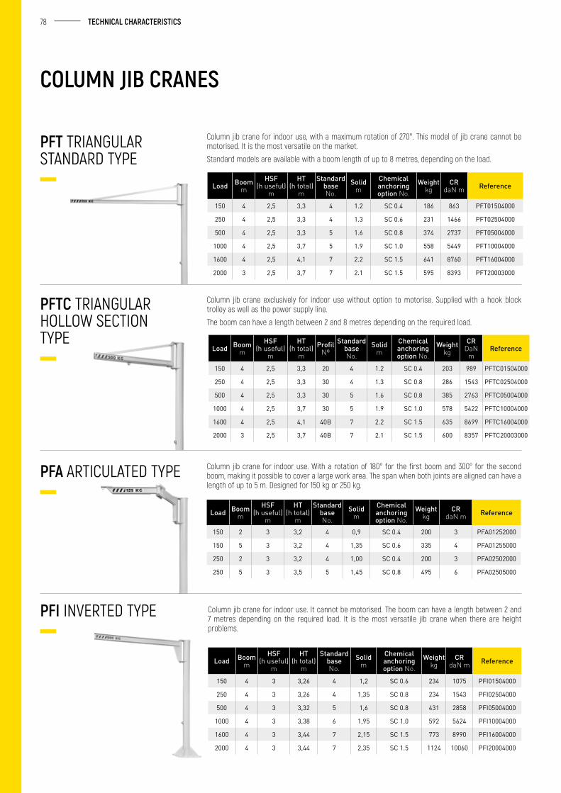
Column jib crane for indoor use, with a maximum rotation of 270°. This model of jib crane cannot be motorised. It is the most versatile on the market.
Standard models are available with a boom length of up to 8 metres, depending on the load.
Column jib crane exclusively for indoor use without option to motorise. Supplied with a hook block trolley as well as the power supply line.
The boom can have a length between 2 and 8 metres depending on the required load.
Column jib crane for indoor use. With a rotation of 180° for the first boom and 300° for the second boom, making it possible to cover a large work area. The span when both joints are aligned can have a length of up to 5 m. Designed for 150 kg or 250 kg.
Load Boomm
HSF(h useful)
m
HT(h total)
m
Standard base No.
Solidm
Chemical anchoring option No.
Weight kg
CR daN m Reference
150 4 2,5 3,3 4 1.2 SC 0.4 186 863 PFT01504000
250 4 2,5 3,3 4 1.3 SC 0.6 231 1466 PFT02504000
500 4 2,5 3,3 5 1.6 SC 0.8 374 2737 PFT05004000
1000 4 2,5 3,7 5 1.9 SC 1.0 558 5449 PFT10004000
1600 4 2,5 4,1 7 2.2 SC 1.5 641 8760 PFT16004000
2000 3 2,5 3,7 7 2.1 SC 1.5 595 8393 PFT20003000
Load Boomm
HSF(h useful)
m
HT(h total)
mProfil
NºStandard
base No.
Solidm
Chemical anchoring option No.
Weight kg
CR DaN
mReference
150 4 2,5 3,3 20 4 1.2 SC 0.4 203 989 PFTC01504000
250 4 2,5 3,3 30 4 1.3 SC 0.8 286 1543 PFTC02504000
500 4 2,5 3,3 30 5 1.6 SC 0.8 385 2763 PFTC05004000
1000 4 2,5 3,7 30 5 1.9 SC 1.0 578 5422 PFTC10004000
1600 4 2,5 4,1 40B 7 2.2 SC 1.5 635 8699 PFTC16004000
2000 3 2,5 3,7 40B 7 2.1 SC 1.5 600 8357 PFTC20003000
Load Boomm
HSF(h useful)
m
HT(h total)
m
Standard base No.
Solidm
Chemical anchoring option No.
Weight kg
CR daN m Reference
150 2 3 3,2 4 0,9 SC 0.4 200 3 PFA01252000
150 5 3 3,2 4 1,35 SC 0.6 335 4 PFA01255000
250 2 3 3,2 4 1,00 SC 0.4 200 3 PFA02502000
250 5 3 3,5 5 1,45 SC 0.8 495 6 PFA02505000
PFI INVERTED TYPE Column jib crane for indoor use. It cannot be motorised. The boom can have a length between 2 and 7 metres depending on the required load. It is the most versatile jib crane when there are height problems.
Load Boomm
HSF(h useful)
m
HT(h total)
m
Standard base No.
Solidm
Chemical anchoring option No.
Weight kg
CR daN m Reference
150 4 3 3,26 4 1,2 SC 0.6 234 1075 PFI01504000
250 4 3 3,26 4 1,35 SC 0.8 234 1543 PFI02504000
500 4 3 3,32 5 1,6 SC 0.8 431 2858 PFI05004000
1000 4 3 3,38 6 1,95 SC 1.0 592 5624 PFI10004000
1600 4 3 3,44 7 2,15 SC 1.5 773 8990 PFI16004000
2000 4 3 3,44 7 2,35 SC 1.5 1124 10060 PFI20004000
79 GH | PARTS & ACCESSORIESINDEX OF ACCESSORIES
COLUMN JIB CRANES
PRT TYPE WITH FULL ROTATION
CONCRETE BASE FOR THE MOBILE VERSION
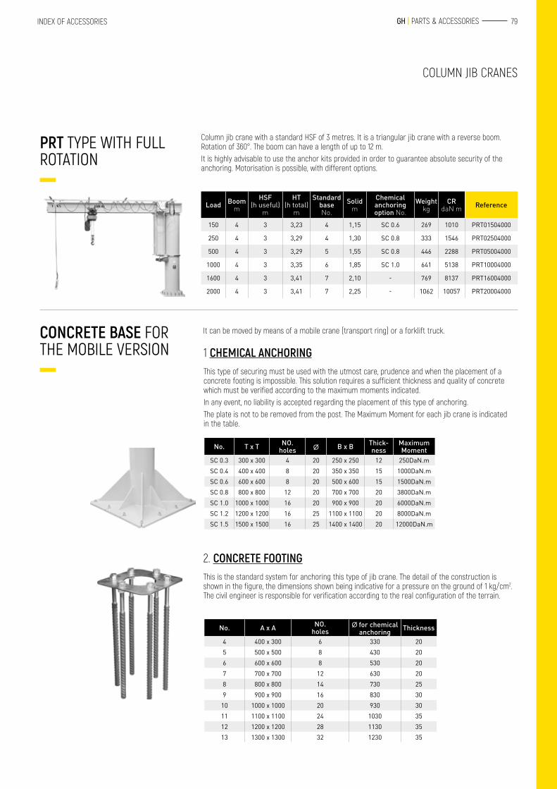
Column jib crane with a standard HSF of 3 metres. It is a triangular jib crane with a reverse boom. Rotation of 360°. The boom can have a length of up to 12 m.It is highly advisable to use the anchor kits provided in order to guarantee absolute security of the anchoring. Motorisation is possible, with different options.
It can be moved by means of a mobile crane (transport ring) or a forklift truck.
Load Boomm
HSF(h useful)
m
HT(h total)
m
Standard base No.
Solidm
Chemical anchoring option No.
Weight kg
CR daN m Reference
150 4 3 3,23 4 1,15 SC 0.6 269 1010 PRT01504000
250 4 3 3,29 4 1,30 SC 0.8 333 1546 PRT02504000
500 4 3 3,29 5 1,55 SC 0.8 446 2288 PRT05004000
1000 4 3 3,35 6 1,85 SC 1.0 641 5138 PRT10004000
1600 4 3 3,41 7 2,10 - 769 8137 PRT16004000
2000 4 3 3,41 7 2,25 - 1062 10057 PRT20004000
1 CHEMICAL ANCHORINGThis type of securing must be used with the utmost care, prudence and when the placement of a concrete footing is impossible. This solution requires a sufficient thickness and quality of concrete which must be verified according to the maximum moments indicated.In any event, no liability is accepted regarding the placement of this type of anchoring.The plate is not to be removed from the post. The Maximum Moment for each jib crane is indicated in the table.
No. T x T NO.holes ∅ B x B Thick-
nessMaximum Moment
SC 0.3 300 x 300 4 20 250 x 250 12 250DaN.mSC 0.4 400 x 400 8 20 350 x 350 15 1000DaN.mSC 0.6 600 x 600 8 20 500 x 600 15 1500DaN.mSC 0.8 800 x 800 12 20 700 x 700 20 3800DaN.mSC 1.0 1000 x 1000 16 20 900 x 900 20 6000DaN.mSC 1.2 1200 x 1200 16 25 1100 x 1100 20 8000DaN.mSC 1.5 1500 x 1500 16 25 1400 x 1400 20 12000DaN.m
2. CONCRETE FOOTINGThis is the standard system for anchoring this type of jib crane. The detail of the construction is shown in the figure, the dimensions shown being indicative for a pressure on the ground of 1 kg/cm2. The civil engineer is responsible for verification according to the real configuration of the terrain.
No. A x A NO.holes
∅ for chemical anchoring Thickness
4 400 x 300 6 330 205 500 x 500 8 430 206 600 x 600 8 530 207 700 x 700 12 630 208 800 x 800 14 730 259 900 x 900 16 830 30
10 1000 x 1000 20 930 3011 1100 x 1100 24 1030 3512 1200 x 1200 28 1130 3513 1300 x 1300 32 1230 35
80 TECHNICAL CHARACTERISTICS
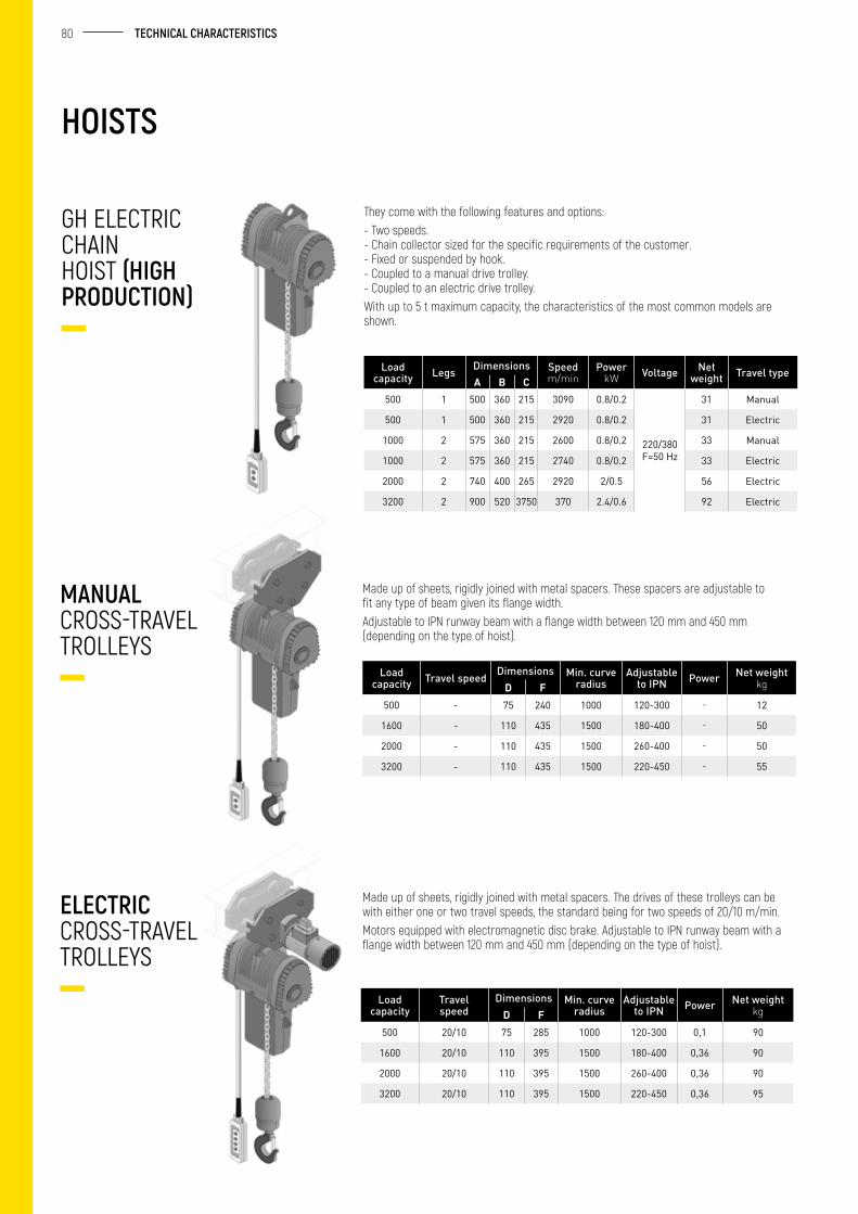
They come with the following features and options:- Two speeds. - Chain collector sized for the specific requirements of the customer. - Fixed or suspended by hook. - Coupled to a manual drive trolley. - Coupled to an electric drive trolley.With up to 5 t maximum capacity, the characteristics of the most common models are shown.
Load capacity Legs Dimensions Speed
m/minPower
kW Voltage Net weight Travel type
A B C500 1 500 360 215 3090 0.8/0.2
220/380 F=50 Hz
31 Manual
500 1 500 360 215 2920 0.8/0.2 31 Electric
1000 2 575 360 215 2600 0.8/0.2 33 Manual
1000 2 575 360 215 2740 0.8/0.2 33 Electric
2000 2 740 400 265 2920 2/0.5 56 Electric
3200 2 900 520 3750 370 2.4/0.6 92 Electric
GH ELECTRIC CHAIN HOIST (HIGH PRODUCTION)
HOISTS
Made up of sheets, rigidly joined with metal spacers. These spacers are adjustable to fit any type of beam given its flange width.Adjustable to IPN runway beam with a flange width between 120 mm and 450 mm (depending on the type of hoist).
Made up of sheets, rigidly joined with metal spacers. The drives of these trolleys can be with either one or two travel speeds, the standard being for two speeds of 20/10 m/min.Motors equipped with electromagnetic disc brake. Adjustable to IPN runway beam with a flange width between 120 mm and 450 mm (depending on the type of hoist).
Load capacity Travel speed Dimensions Min. curve
radiusAdjustable
to IPN Power Net weight kgD F
500 - 75 240 1000 120-300 - 12
1600 - 110 435 1500 180-400 - 50
2000 - 110 435 1500 260-400 - 50
3200 - 110 435 1500 220-450 - 55
Load capacity
Travel speed
Dimensions Min. curve radius
Adjustable to IPN Power Net weight
kgD F500 20/10 75 285 1000 120-300 0,1 90
1600 20/10 110 395 1500 180-400 0,36 90
2000 20/10 110 395 1500 260-400 0,36 90
3200 20/10 110 395 1500 220-450 0,36 95
MANUAL CROSS-TRAVEL TROLLEYS
ELECTRIC CROSS-TRAVEL TROLLEYS
81 GH | PARTS & ACCESSORIESINDEX OF ACCESSORIES
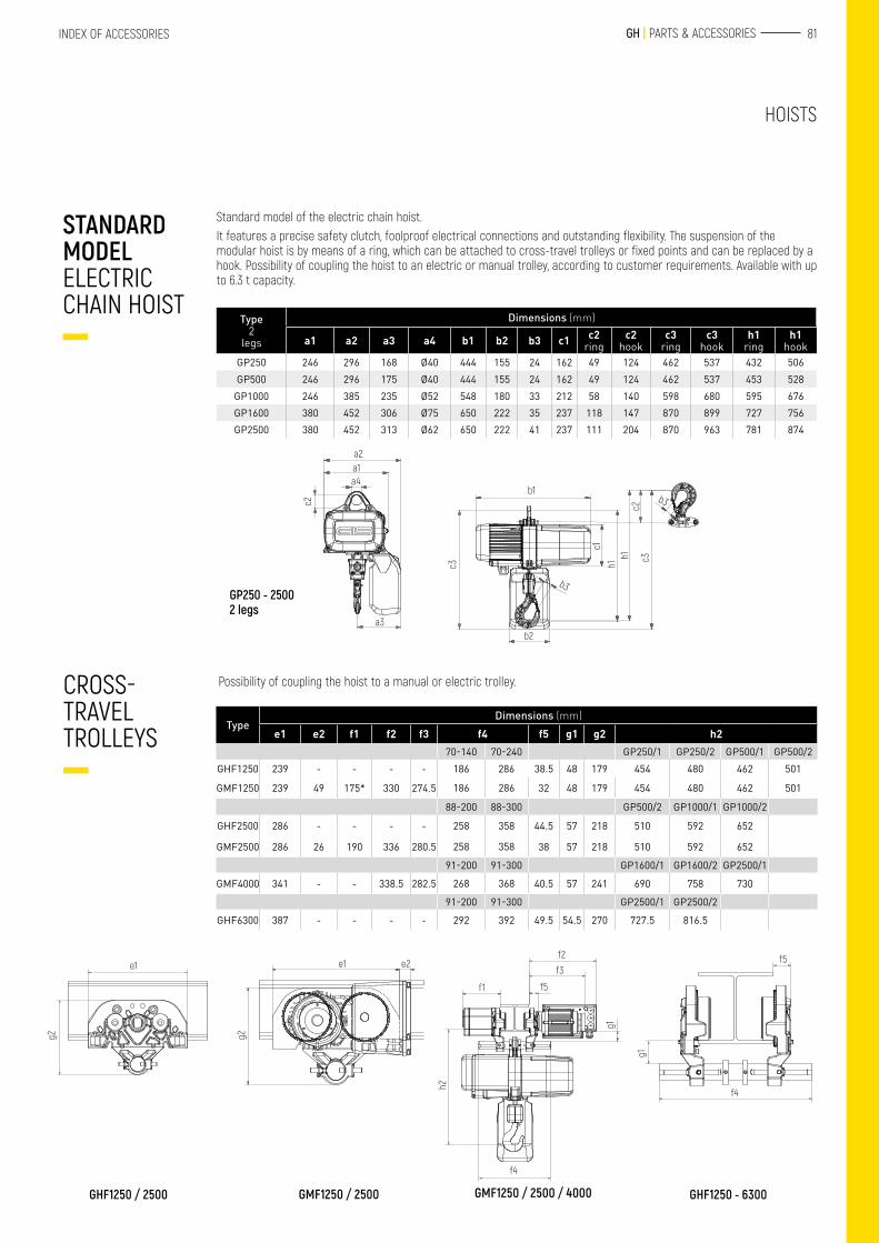
Standard model of the electric chain hoist.It features a precise safety clutch, foolproof electrical connections and outstanding flexibility. The suspension of the modular hoist is by means of a ring, which can be attached to cross-travel trolleys or fixed points and can be replaced by a hook. Possibility of coupling the hoist to an electric or manual trolley, according to customer requirements. Available with up to 6.3 t capacity.
Type 2
legs
Dimensions (mm)
a1 a2 a3 a4 b1 b2 b3 c1 c2 ring
c2 hook
c3 ring
c3 hook
h1 ring
h1 hook
GP250 246 296 168 Ø40 444 155 24 162 49 124 462 537 432 506GP500 246 296 175 Ø40 444 155 24 162 49 124 462 537 453 528
GP1000 246 385 235 Ø52 548 180 33 212 58 140 598 680 595 676GP1600 380 452 306 Ø75 650 222 35 237 118 147 870 899 727 756GP2500 380 452 313 Ø62 650 222 41 237 111 204 870 963 781 874
STANDARD MODEL ELECTRIC CHAIN HOIST
Possibility of coupling the hoist to a manual or electric trolley. CROSS-TRAVEL TROLLEYS
HOISTS
TypeDimensions (mm)
e1 e2 f1 f2 f3 f4 f5 g1 g2 h270-140 70-240 GP250/1 GP250/2 GP500/1 GP500/2
GHF1250 239 - - - - 186 286 38.5 48 179 454 480 462 501
GMF1250 239 49 175* 330 274.5 186 286 32 48 179 454 480 462 501
88-200 88-300 GP500/2 GP1000/1 GP1000/2
GHF2500 286 - - - - 258 358 44.5 57 218 510 592 652
GMF2500 286 26 190 336 280.5 258 358 38 57 218 510 592 652
91-200 91-300 GP1600/1 GP1600/2 GP2500/1
GMF4000 341 - - 338.5 282.5 268 368 40.5 57 241 690 758 730
91-200 91-300 GP2500/1 GP2500/2
GHF6300 387 - - - - 292 392 49.5 54.5 270 727.5 816.5
GP250 - 2500 2 legs
a2a1a4
c2
a3
b1
c3
c1h1
h1 c3c2
b2
b3
b3
GHF1250 / 2500 GHF1250 - 6300
e1
g2
GMF1250 / 2500
e1 e2
g2
GMF1250 / 2500 / 4000
f1
f2
f3
f5
g1
h2
f4
g1
f5
f4
82 TECHNICAL CHARACTERISTICS
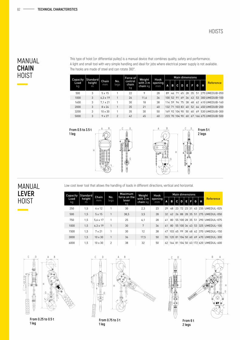
Low cost lever tool that allows the handling of loads in different directions, vertical and horizontal.MANUAL LEVER HOIST
This type of hoist (or differential pulley) is a manual device that combines quality, safety and performance.A light and small tool with very simple handling and ideal for jobs where electrical power supply is not available.The hooks are made of steel and can rotate 360°.
CapacityLoad
kg
Standard height
mChain mm
No. legs
Force of control chain
kg
Weight with 3 m chain kg
Hook opening
mm
Main dimensions
ReferenceA B C D E F G H
500 3 5 x 15 1 22 9 28 89 46 71 65 28 35 51 275 UMEDUB-0501000 3 6,3 x 19 1 26 11,6 36 100 52 91 69 36 43 53 300 UMEDUB-1001600 3 7,1 x 21 1 30 18 38 114 59 94 75 38 48 62 410 UMEDUB-1602000 3 8 x 24 1 35 21 40 132 71 103 83 40 52 64 450 UMEDUB-2003200 3 10 x 30 1 35 30 50 169 92 104 90 50 60 69 530 UMEDUB-3005000 3 9 x 27 2 42 45 60 223 70 104 90 60 67 166 675 UMEDUB-500
CapacityLoad
kg
Standard height
mChain mm
No. legs
Maximum force on the
lever kg
Weight with 3 m chain kg
Hook opening
mm
Main dimensionsReference
A B C D E F G H
250 1,5 4 x 12 1 30 2,3 23 29 48 23 72 23 31 43 235 UMEDUL-025
500 1,5 5 x 15 1 38,5 3,5 28 32 62 26 88 28 35 51 275 UMEDUL-050
750 1,5 5,6 x 17 1 25 6,1 28 41 80 55 100 28 35 51 290 UMEDUL-075
1000 1,5 6,3 x 19 1 30 7 36 41 80 55 100 36 43 53 325 UMEDUL-100
1500 1,5 7 x 21 1 30 12 38 47 103 65 99 38 48 62 370 UMEDUL-150
3000 1,5 10 x 30 1 36 17,5 50 55 120 81 104 50 60 69 470 UMEDUL-300
6000 1,5 10 x 30 2 38 32 50 62 164 81 104 50 63 172 620 UMEDUL-600
HOISTS
MANUAL CHAIN HOIST
From 0.75 to 3 t1 leg
From 6 t 2 legs
From 0.5 to 3.5 t1 leg
From 5 t2 legs
A C DB
H
FE
C D
G
A B
F
H
E
G
C D
C D
From 0.25 to 0.5 t 1 leg
A A BC C CD D DB B A
H
G
EF
H
G
EF
G
H
EF
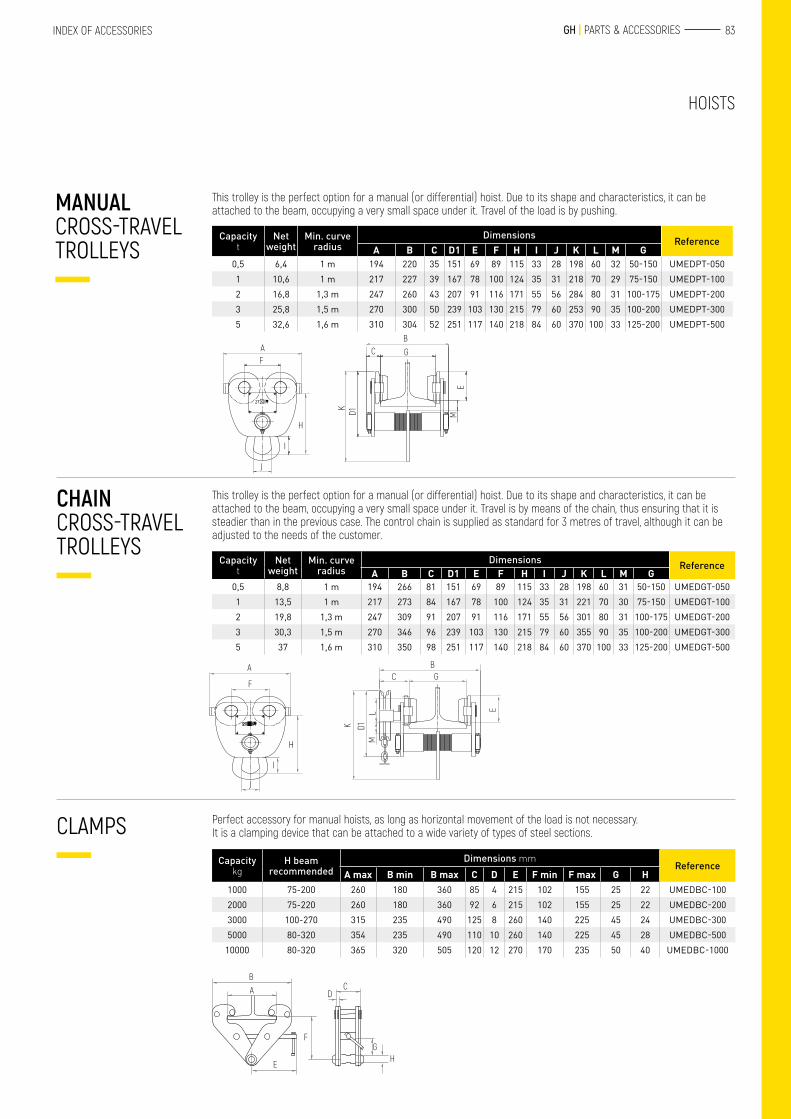
83 GH | PARTS & ACCESSORIESINDEX OF ACCESSORIES
This trolley is the perfect option for a manual (or differential) hoist. Due to its shape and characteristics, it can be attached to the beam, occupying a very small space under it. Travel of the load is by pushing.
This trolley is the perfect option for a manual (or differential) hoist. Due to its shape and characteristics, it can be attached to the beam, occupying a very small space under it. Travel is by means of the chain, thus ensuring that it is steadier than in the previous case. The control chain is supplied as standard for 3 metres of travel, although it can be adjusted to the needs of the customer.
Perfect accessory for manual hoists, as long as horizontal movement of the load is not necessary.It is a clamping device that can be attached to a wide variety of types of steel sections.
Capacityt
Net weight
Min. curve radius
Dimensions ReferenceA B C D1 E F H I J K L M G
0,5 6,4 1 m 194 220 35 151 69 89 115 33 28 198 60 32 50-150 UMEDPT-0501 10,6 1 m 217 227 39 167 78 100 124 35 31 218 70 29 75-150 UMEDPT-1002 16,8 1,3 m 247 260 43 207 91 116 171 55 56 284 80 31 100-175 UMEDPT-2003 25,8 1,5 m 270 300 50 239 103 130 215 79 60 253 90 35 100-200 UMEDPT-3005 32,6 1,6 m 310 304 52 251 117 140 218 84 60 370 100 33 125-200 UMEDPT-500
Capacityt
Net weight
Min. curve radius
Dimensions ReferenceA B C D1 E F H I J K L M G
0,5 8,8 1 m 194 266 81 151 69 89 115 33 28 198 60 31 50-150 UMEDGT-0501 13,5 1 m 217 273 84 167 78 100 124 35 31 221 70 30 75-150 UMEDGT-1002 19,8 1,3 m 247 309 91 207 91 116 171 55 56 301 80 31 100-175 UMEDGT-2003 30,3 1,5 m 270 346 96 239 103 130 215 79 60 355 90 35 100-200 UMEDGT-3005 37 1,6 m 310 350 98 251 117 140 218 84 60 370 100 33 125-200 UMEDGT-500
Capacitykg
H beam recommended
Dimensions mmReference
A max B min B max C D E F min F max G H1000 75-200 260 180 360 85 4 215 102 155 25 22 UMEDBC-1002000 75-220 260 180 360 92 6 215 102 155 25 22 UMEDBC-2003000 100-270 315 235 490 125 8 260 140 225 45 24 UMEDBC-3005000 80-320 354 235 490 110 10 260 140 225 45 28 UMEDBC-500
10000 80-320 365 320 505 120 12 270 170 235 50 40 UMEDBC-1000
MANUAL CROSS-TRAVEL TROLLEYS
CHAIN CROSS-TRAVEL TROLLEYS
CLAMPS
HOISTS
A
A
BG
F
F
I
J
K D1
C
H ML E
H
I
J
K
E
D1 M
B
GC
BA
F
E
CD
GH
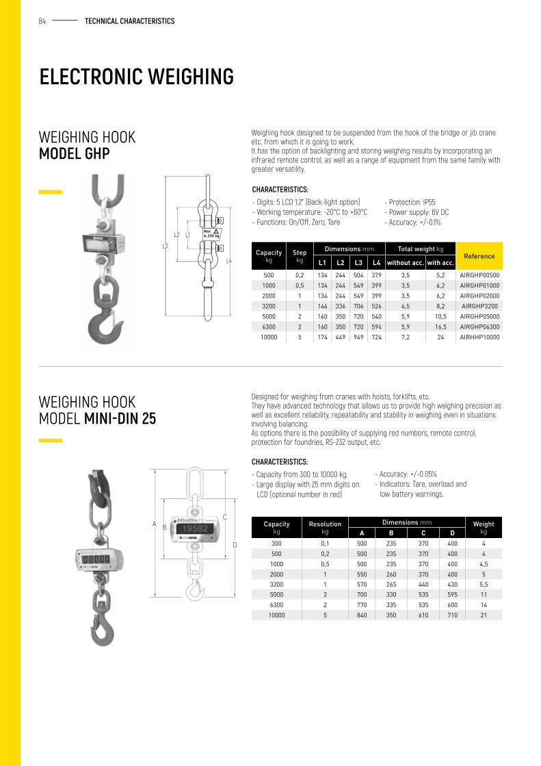
84 TECHNICAL CHARACTERISTICS
ELECTRONIC WEIGHING
Weighing hook designed to be suspended from the hook of the bridge or jib crane etc. from which it is going to work.It has the option of backlighting and storing weighing results by incorporating an infrared remote control, as well as a range of equipment from the same family with greater versatility.
Designed for weighing from cranes with hoists, forklifts, etc.They have advanced technology that allows us to provide high weighing precision as well as excellent reliability, repeatability and stability in weighing even in situations involving balancing.As options there is the possibility of supplying red numbers, remote control, protection for foundries, RS-232 output, etc.
Capacitykg
Step kg
Dimensions mm Total weight kgReference
L1 L2 L3 L4 without acc. with acc.
500 0,2 134 244 504 379 3,5 5,2 AIRGHP005001000 0,5 134 244 549 399 3,5 6,2 AIRGHP010002000 1 134 244 549 399 3,5 6,2 AIRGHP020003200 1 146 336 706 526 4,5 8,2 AIRGHP32005000 2 160 350 720 540 5,9 10,5 AIRGHP050006300 2 160 350 720 594 5,9 16,5 AIRGHP06300
10000 5 174 449 949 724 7,2 24 AIRHHP10000
Capacitykg
Resolution kg
Dimensions mm Weight kgA B C D
300 0,1 500 235 370 400 4500 0,2 500 235 370 400 4
1000 0,5 500 235 370 400 4,52000 1 550 260 370 400 53200 1 570 265 440 430 5,55000 2 700 330 535 595 116300 2 770 335 535 600 14
10000 5 840 350 610 710 21
WEIGHING HOOK MODEL GHP
WEIGHING HOOKMODEL MINI-DIN 25
CHARACTERISTICS:- Digits: 5 LCD 1.2” (Back-light option)- Working temperature: -20°C to +60°C- Functions: On/Off, Zero, Tare
CHARACTERISTICS:- Capacity from 300 to 10000 kg.- Large display with 25 mm digits on
LCD (optional number in red)
- Protection: IP55- Power supply: 6V DC- Accuracy: +/-0.1%
- Accuracy: +/-0.05%- Indicators: Tare, overload and
low battery warnings.
L4
L3
L2 L1
BAC
D
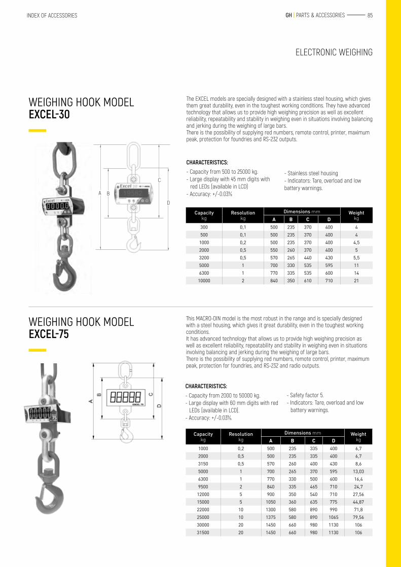
85 GH | PARTS & ACCESSORIESINDEX OF ACCESSORIES
This MACRO-DIN model is the most robust in the range and is specially designed with a steel housing, which gives it great durability, even in the toughest working conditions.It has advanced technology that allows us to provide high weighing precision as well as excellent reliability, repeatability and stability in weighing even in situations involving balancing and jerking during the weighing of large bars.There is the possibility of supplying red numbers, remote control, printer, maximum peak, protection for foundries, and RS-232 and radio outputs.
CHARACTERISTICS:- Capacity from 2000 to 50000 kg.- Large display with 60 mm digits with red
LEDs (available in LCD). - Accuracy: +/-0.03%.
WEIGHING HOOK MODEL EXCEL-75
WEIGHING HOOK MODEL EXCEL-30
ELECTRONIC WEIGHING
The EXCEL models are specially designed with a stainless steel housing, which gives them great durability, even in the toughest working conditions. They have advanced technology that allows us to provide high weighing precision as well as excellent reliability, repeatability and stability in weighing even in situations involving balancing and jerking during the weighing of large bars.There is the possibility of supplying red numbers, remote control, printer, maximum peak, protection for foundries and RS-232 outputs.
CHARACTERISTICS:- Capacity from 500 to 25000 kg.- Large display with 45 mm digits with
red LEDs (available in LCD)- Accuracy: +/-0.03%
- Stainless steel housing- Indicators: Tare, overload and low battery warnings.
- Safety factor 5.- Indicators: Tare, overload and low
battery warnings.
BA
C
D
Capacitykg
Resolution kg
Dimensions mm Weight kgA B C D
300 0,1 500 235 370 400 4500 0,1 500 235 370 400 4
1000 0,2 500 235 370 400 4,52000 0,5 550 260 370 400 53200 0,5 570 265 440 430 5,55000 1 700 330 535 595 116300 1 770 335 535 600 14
10000 2 840 350 610 710 21
Capacitykg
Resolution kg
Dimensions mm Weight kgA B C D
1000 0,2 500 235 335 400 6,72000 0,5 500 235 335 400 6,73150 0,5 570 260 400 430 8,65000 1 700 265 370 595 13,036300 1 770 330 500 600 16,49500 2 840 335 465 710 24,7
12000 5 900 350 540 710 27,5615000 5 1050 360 635 775 44,8722000 10 1300 580 890 990 71,825000 10 1375 580 890 1065 79,5630000 20 1450 660 980 1130 10631500 20 1450 660 980 1130 106
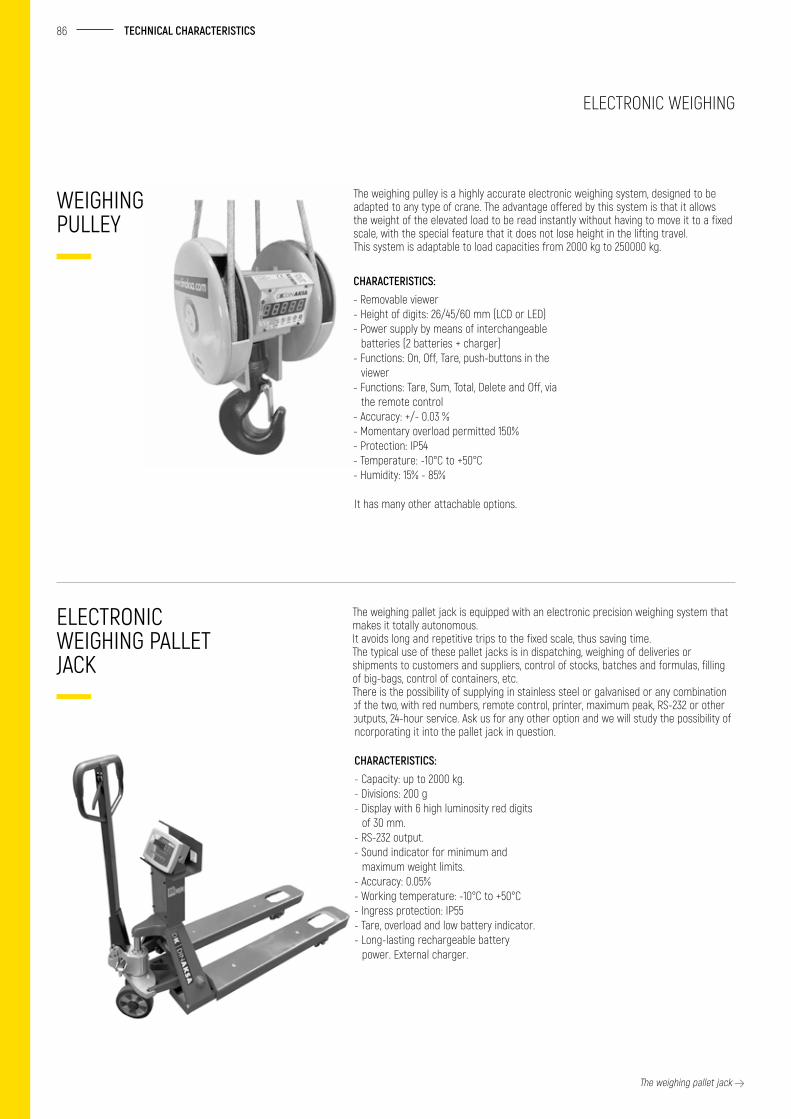
86 TECHNICAL CHARACTERISTICS
The weighing pulley is a highly accurate electronic weighing system, designed to be adapted to any type of crane. The advantage offered by this system is that it allows the weight of the elevated load to be read instantly without having to move it to a fixed scale, with the special feature that it does not lose height in the lifting travel.This system is adaptable to load capacities from 2000 kg to 250000 kg.
The weighing pallet jack is equipped with an electronic precision weighing system that makes it totally autonomous.It avoids long and repetitive trips to the fixed scale, thus saving time.The typical use of these pallet jacks is in dispatching, weighing of deliveries or shipments to customers and suppliers, control of stocks, batches and formulas, filling of big-bags, control of containers, etc.There is the possibility of supplying in stainless steel or galvanised or any combination of the two, with red numbers, remote control, printer, maximum peak, RS-232 or other outputs, 24-hour service. Ask us for any other option and we will study the possibility of incorporating it into the pallet jack in question.
CHARACTERISTICS:- Removable viewer- Height of digits: 26/45/60 mm (LCD or LED)- Power supply by means of interchangeable
batteries (2 batteries + charger)- Functions: On, Off, Tare, push-buttons in the
viewer- Functions: Tare, Sum, Total, Delete and Off, via
the remote control- Accuracy: +/- 0.03 %- Momentary overload permitted 150%- Protection: IP54- Temperature: -10°C to +50°C- Humidity: 15% - 85%
CHARACTERISTICS:- Capacity: up to 2000 kg. - Divisions: 200 g- Display with 6 high luminosity red digits
of 30 mm. - RS-232 output.- Sound indicator for minimum and
maximum weight limits. - Accuracy: 0.05%- Working temperature: -10°C to +50°C - Ingress protection: IP55- Tare, overload and low battery indicator.- Long-lasting rechargeable battery
power. External charger.
WEIGHING PULLEY
ELECTRONIC WEIGHING PALLET JACK
It has many other attachable options.
The weighing pallet jack
ELECTRONIC WEIGHING
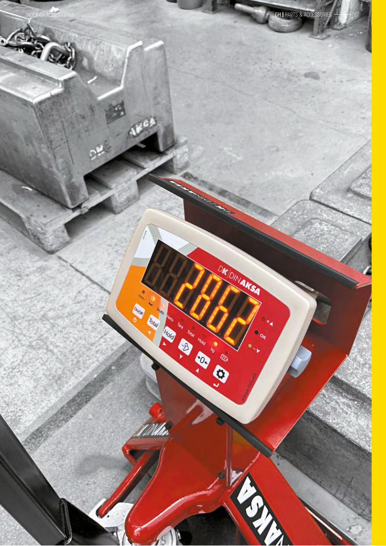
INDEX OF ACCESSORIES 87 GH | PARTS & ACCESSORIES
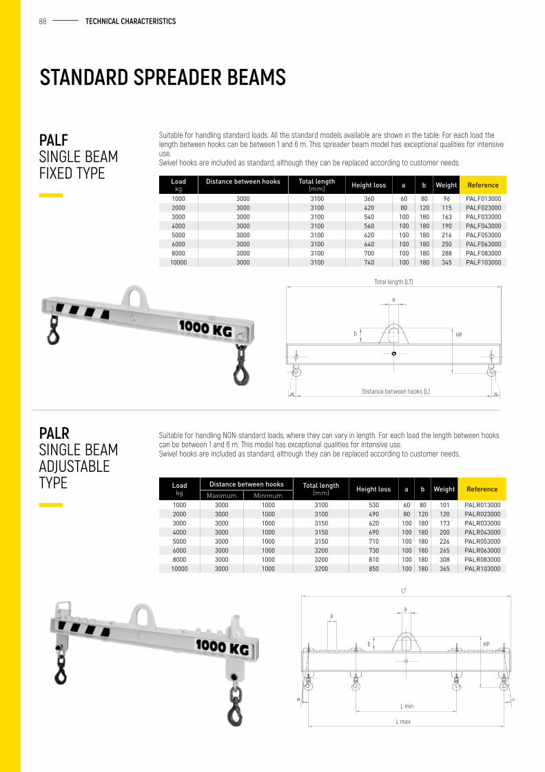
88 TECHNICAL CHARACTERISTICS
STANDARD SPREADER BEAMS
Suitable for handling standard loads. All the standard models available are shown in the table: For each load the length between hooks can be between 1 and 6 m. This spreader beam model has exceptional qualities for intensive use.Swivel hooks are included as standard, although they can be replaced according to customer needs.
Suitable for handling NON-standard loads, where they can vary in length. For each load the length between hooks can be between 1 and 6 m. This model has exceptional qualities for intensive use.Swivel hooks are included as standard, although they can be replaced according to customer needs.
Loadkg
Distance between hooks Total length (mm) Height loss a b Weight Reference
1000 3000 3100 360 60 80 96 PALF0130002000 3000 3100 420 80 120 115 PALF0230003000 3000 3100 540 100 180 163 PALF0330004000 3000 3100 560 100 180 190 PALF0430005000 3000 3100 620 100 180 216 PALF0530006000 3000 3100 640 100 180 250 PALF0630008000 3000 3100 700 100 180 288 PALF083000
10000 3000 3100 740 100 180 345 PALF103000
Loadkg
Distance between hooks Total length (mm) Height loss a b Weight Reference
Maximum Minimum1000 3000 1000 3100 530 60 80 101 PALR0130002000 3000 1000 3100 490 80 120 120 PALR0230003000 3000 1000 3150 620 100 180 173 PALR0330004000 3000 1000 3150 690 100 180 200 PALR0430005000 3000 1000 3150 710 100 180 226 PALR0530006000 3000 1000 3200 730 100 180 265 PALR0630008000 3000 1000 3200 810 100 180 308 PALR083000
10000 3000 1000 3200 850 100 180 365 PALR103000
PALF SINGLE BEAM FIXED TYPE
PALR SINGLE BEAM ADJUSTABLE TYPE
Total length (LT)
Distance between hooks (L)
a
b HP
LT
aP
b HP
L min
L max
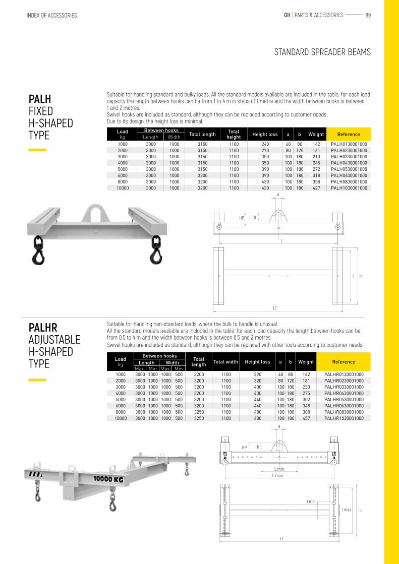
89 GH | PARTS & ACCESSORIESINDEX OF ACCESSORIES
Suitable for handling standard and bulky loads. All the standard models available are included in the table: for each load capacity the length between hooks can be from 1 to 4 m in steps of 1 metre and the width between hooks is between 1 and 2 metres.Swivel hooks are included as standard, although they can be replaced according to customer needs.Due to its design, the height loss is minimal.
Suitable for handling non-standard loads, where the bulk to handle is unusual.All the standard models available are included in the table: for each load capacity the length between hooks can be from 0.5 to 4 m and the width between hooks is between 0.5 and 2 metres.Swivel hooks are included as standard, although they can be replaced with other tools according to customer needs.
Loadkg
Between hooks Total length Total width Height loss a b Weight ReferenceLength Width
Max. Min Max. Min1000 3000 1000 1000 500 3200 1100 290 60 80 162 PALHR01300010002000 3000 1000 1000 500 3200 1100 320 80 120 181 PALHR02300010003000 3000 1000 1000 500 3200 1100 400 100 180 230 PALHR03300010004000 3000 1000 1000 500 3200 1100 400 100 180 275 PALHR04300010005000 3000 1000 1000 500 3200 1100 440 100 180 302 PALHR05300010006000 3000 1000 1000 500 3200 1100 440 100 180 348 PALHR06300010008000 3000 1000 1000 500 3250 1100 480 100 180 388 PALHR0830001000
10000 3000 1000 1000 500 3250 1100 480 100 180 457 PALHR1030001000
Loadkg
Between hooksTotal length Total
height Height loss a b Weight ReferenceLength Width1000 3000 1000 3150 1100 240 60 80 142 PALH01300010002000 3000 1000 3150 1100 270 80 120 161 PALH02300010003000 3000 1000 3150 1100 350 100 180 210 PALH03300010004000 3000 1000 3150 1100 350 100 180 245 PALH04300010005000 3000 1000 3150 1100 390 100 180 272 PALH05300010006000 3000 1000 3200 1100 390 100 180 318 PALH06300010008000 3000 1000 3200 1100 430 100 180 358 PALH0830001000
10000 3000 1000 3200 1100 430 100 180 427 PALH1030001000
PALH FIXED H-SHAPED TYPE
PALHR ADJUSTABLE H-SHAPED TYPE
STANDARD SPREADER BEAMS
a
HP b
L
LT
ltl
a
bHP
L minL max
l min
LT
l max l t
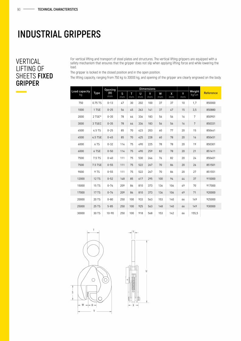
90 TECHNICAL CHARACTERISTICS
VERTICAL LIFTING OF SHEETS FIXED GRIPPER
INDUSTRIAL GRIPPERS
For vertical lifting and transport of steel plates and structures. The vertical lifting grippers are equipped with a safety mechanism that ensures that the gripper does not slip when applying lifting force and while lowering the load.The gripper is locked in the closed position and in the open position.The lifting capacity, ranging from 750 kg to 30000 kg, and opening of the gripper are clearly engraved on the body.
T
S
W R
V
X
U
Y
Load capacitykg Type
Opening (R) mm
DimensionsWeightkg/un ReferenceS
mmT
mmU
mmV
mmW
mmX
mmY
mm
750 0.75 TS 0-13 47 30 202 100 37 37 10 1,7 850000
1000 1 TSE 0-25 56 45 263 141 37 47 15 3,5 850880
2000 2 TSE* 0-35 78 64 336 183 56 56 16 7 850901
3000 3 TSEC 0-35 78 64 336 183 56 56 16 7 850331
4500 4.5 TS 0-25 85 70 423 203 60 77 20 15 850441
4500 4.5 TSE 0-45 85 70 425 228 60 78 20 16 850451
6000 6 TS 0-32 114 75 490 225 78 78 20 19 850301
6000 6 TSE 0-50 114 75 490 259 82 78 20 21 851411
7500 7.5 TS 0-40 111 75 530 246 76 82 20 24 850401
7500 7.5 TSE 0-55 111 75 522 267 70 86 20 26 851501
9000 9 TS 0-55 111 75 522 267 70 86 20 27 851551
12000 12 TS 0-52 148 85 617 295 100 94 44 37 915000
15000 15 TS 0-76 209 86 810 373 136 106 49 70 917000
17000 17 TS 0-76 209 86 810 373 136 106 49 71 920000
20000 20 TS 0-80 250 100 933 563 153 140 66 149 925000
25000 25 TS 5-85 250 100 925 563 148 140 66 149 930000
30000 30 TS 10-90 250 100 918 568 153 142 66 155,5
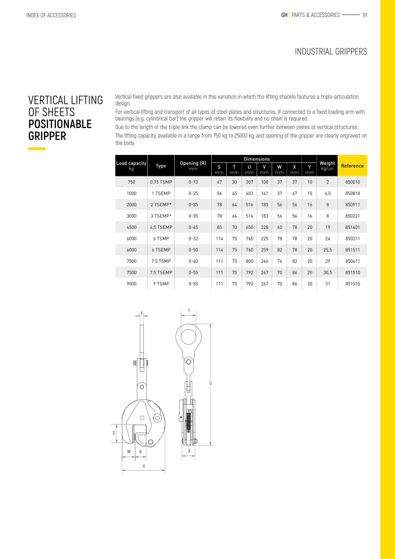
91 GH | PARTS & ACCESSORIESINDEX OF ACCESSORIES
Vertical fixed grippers are also available in this variation in which the lifting shackle features a triple-articulation design.For vertical lifting and transport of all types of steel plates and structures. If connected to a fixed loading arm with bearings (e.g. cylindrical bar) the gripper will retain its flexibility and no chain is required.Due to the length of the triple link the clamp can be lowered even further between plates or vertical structures.The lifting capacity, available in a range from 750 kg to 25000 kg, and opening of the gripper are clearly engraved on the body.
VERTICAL LIFTING OF SHEETS POSITIONABLE GRIPPER
S
W R
V
Y
X
T
U
Load capacitykg Type Opening (R)
mm
DimensionsWeightkg/un ReferenceS
mmT
mmU
mmV
mmW
mmX
mmY
mm
750 0.75 TSMP 0-13 47 30 307 100 37 37 10 2 850010
1000 1 TSEMP 0-25 56 45 403 141 37 47 15 4,5 850818
2000 2 TSEMP* 0-35 78 64 516 183 56 56 16 8 850911
3000 3 TSEMP* 0-35 78 64 516 183 56 56 16 8 850221
4500 4.5 TSEMP 0-45 85 70 650 228 60 78 20 19 851401
6000 6 TSMP 0-32 114 75 760 225 78 78 20 24 850311
6000 6 TSEMP 0-50 114 75 760 259 82 78 20 25,5 851511
7500 7.5 TSMP 0-40 111 75 800 246 76 82 20 29 850411
7500 7.5 TSEMP 0-55 111 75 792 267 70 86 20 30,5 851510
9000 9 TSMP 0-55 111 75 792 267 70 86 20 31 851515
INDUSTRIAL GRIPPERS
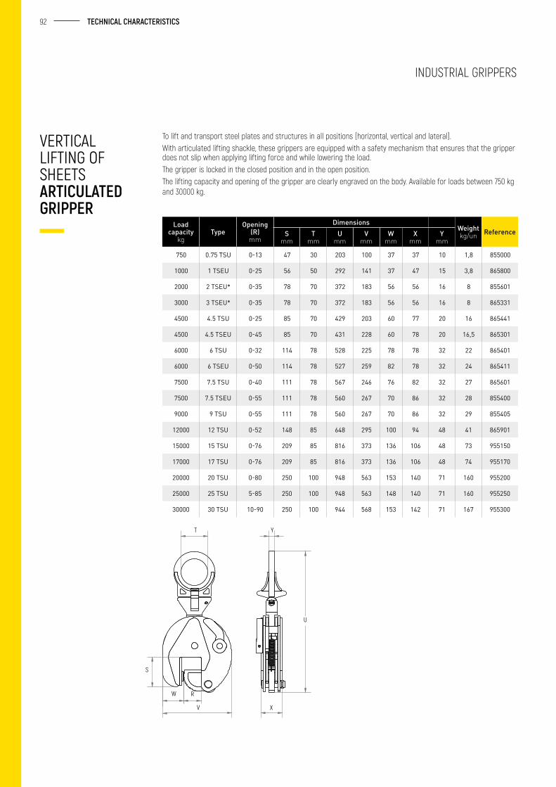
92 TECHNICAL CHARACTERISTICS
INDUSTRIAL GRIPPERS
To lift and transport steel plates and structures in all positions (horizontal, vertical and lateral).With articulated lifting shackle, these grippers are equipped with a safety mechanism that ensures that the gripper does not slip when applying lifting force and while lowering the load.The gripper is locked in the closed position and in the open position.The lifting capacity and opening of the gripper are clearly engraved on the body. Available for loads between 750 kg and 30000 kg.
VERTICAL LIFTING OF SHEETS ARTICULATED GRIPPER
Load capacity
kgType
Opening (R) mm
DimensionsWeightkg/un ReferenceS
mmT
mmU
mmV
mmW
mmX
mmY
mm
750 0.75 TSU 0-13 47 30 203 100 37 37 10 1,8 855000
1000 1 TSEU 0-25 56 50 292 141 37 47 15 3,8 865800
2000 2 TSEU* 0-35 78 70 372 183 56 56 16 8 855601
3000 3 TSEU* 0-35 78 70 372 183 56 56 16 8 865331
4500 4.5 TSU 0-25 85 70 429 203 60 77 20 16 865441
4500 4.5 TSEU 0-45 85 70 431 228 60 78 20 16,5 865301
6000 6 TSU 0-32 114 78 528 225 78 78 32 22 865401
6000 6 TSEU 0-50 114 78 527 259 82 78 32 24 865411
7500 7.5 TSU 0-40 111 78 567 246 76 82 32 27 865601
7500 7.5 TSEU 0-55 111 78 560 267 70 86 32 28 855400
9000 9 TSU 0-55 111 78 560 267 70 86 32 29 855405
12000 12 TSU 0-52 148 85 648 295 100 94 48 41 865901
15000 15 TSU 0-76 209 85 816 373 136 106 48 73 955150
17000 17 TSU 0-76 209 85 816 373 136 106 48 74 955170
20000 20 TSU 0-80 250 100 948 563 153 140 71 160 955200
25000 25 TSU 5-85 250 100 948 563 148 140 71 160 955250
30000 30 TSU 10-90 250 100 944 568 153 142 71 167 955300
T Y
S
W R
V X
U
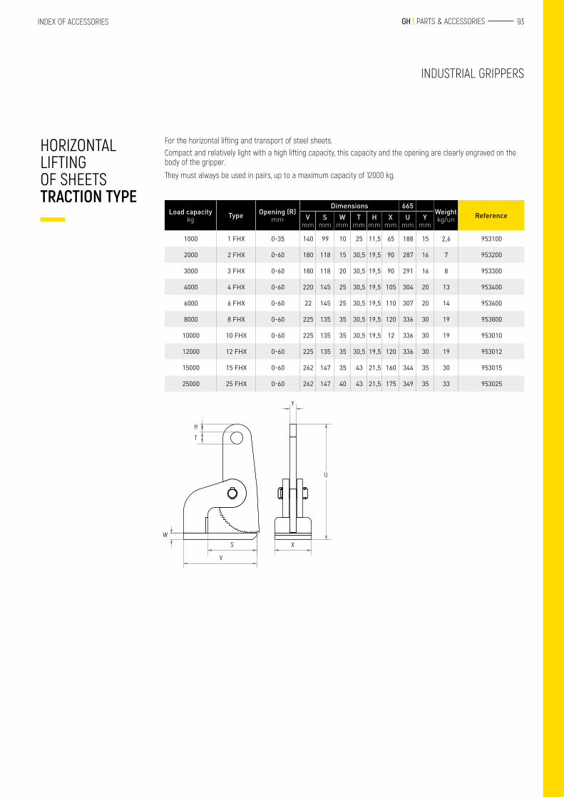
93 GH | PARTS & ACCESSORIESINDEX OF ACCESSORIES
INDUSTRIAL GRIPPERS
For the horizontal lifting and transport of steel sheets.Compact and relatively light with a high lifting capacity, this capacity and the opening are clearly engraved on the body of the gripper.
They must always be used in pairs, up to a maximum capacity of 12000 kg.
HORIZONTAL LIFTING OF SHEETS TRACTION TYPE
Load capacitykg Type Opening (R)
mm
Dimensions 665Weightkg/un ReferenceV
mmS
mmW
mmT
mmH
mmX
mmU
mmY
mm
1000 1 FHX 0-35 140 99 10 25 11,5 65 188 15 2,6 953100
2000 2 FHX 0-60 180 118 15 30,5 19,5 90 287 16 7 953200
3000 3 FHX 0-60 180 118 20 30,5 19,5 90 291 16 8 953300
4000 4 FHX 0-60 220 145 25 30,5 19,5 105 304 20 13 953400
6000 6 FHX 0-60 22 145 25 30,5 19,5 110 307 20 14 953600
8000 8 FHX 0-60 225 135 35 30,5 19,5 120 336 30 19 953800
10000 10 FHX 0-60 225 135 35 30,5 19,5 12 336 30 19 953010
12000 12 FHX 0-60 225 135 35 30,5 19,5 120 336 30 19 953012
15000 15 FHX 0-60 262 147 35 43 21,5 160 344 35 30 953015
25000 25 FHX 0-60 262 147 40 43 21,5 175 349 35 33 953025
Y
U
X
H
T
W
S
V
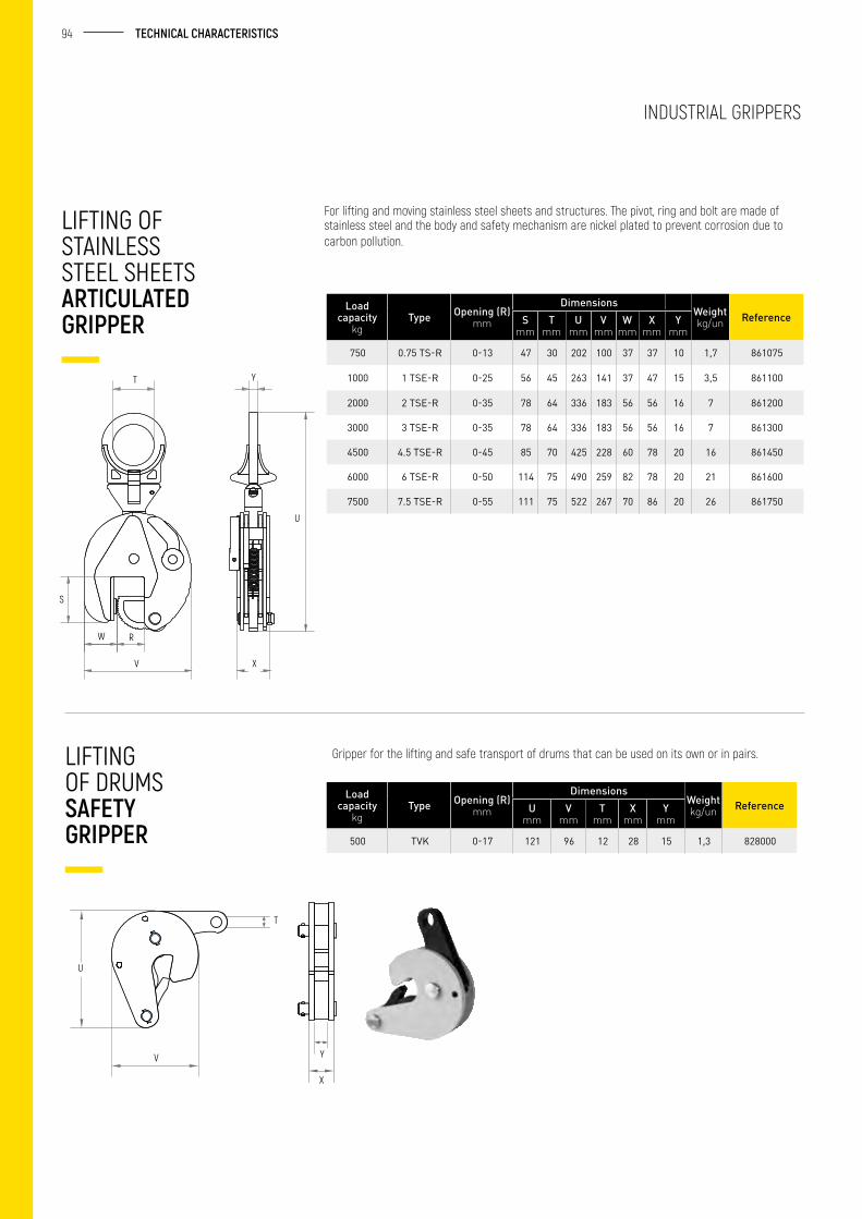
94 TECHNICAL CHARACTERISTICS
For lifting and moving stainless steel sheets and structures. The pivot, ring and bolt are made of stainless steel and the body and safety mechanism are nickel plated to prevent corrosion due to carbon pollution.
LIFTING OF STAINLESS STEEL SHEETS ARTICULATED GRIPPER
Load capacity
kgType Opening (R)
mm
DimensionsWeightkg/un ReferenceS
mmT
mmU
mmV
mmW
mmX
mmY
mm
750 0.75 TS-R 0-13 47 30 202 100 37 37 10 1,7 861075
1000 1 TSE-R 0-25 56 45 263 141 37 47 15 3,5 861100
2000 2 TSE-R 0-35 78 64 336 183 56 56 16 7 861200
3000 3 TSE-R 0-35 78 64 336 183 56 56 16 7 861300
4500 4.5 TSE-R 0-45 85 70 425 228 60 78 20 16 861450
6000 6 TSE-R 0-50 114 75 490 259 82 78 20 21 861600
7500 7.5 TSE-R 0-55 111 75 522 267 70 86 20 26 861750
Load capacity
kgType Opening (R)
mm
DimensionsWeightkg/un ReferenceU
mmV
mmT
mmX
mmY
mm
500 TVK 0-17 121 96 12 28 15 1,3 828000
Gripper for the lifting and safe transport of drums that can be used on its own or in pairs. LIFTING OF DRUMS SAFETY GRIPPER
S
T Y
W R
V X
U
INDUSTRIAL GRIPPERS
U
V
T
Y
X
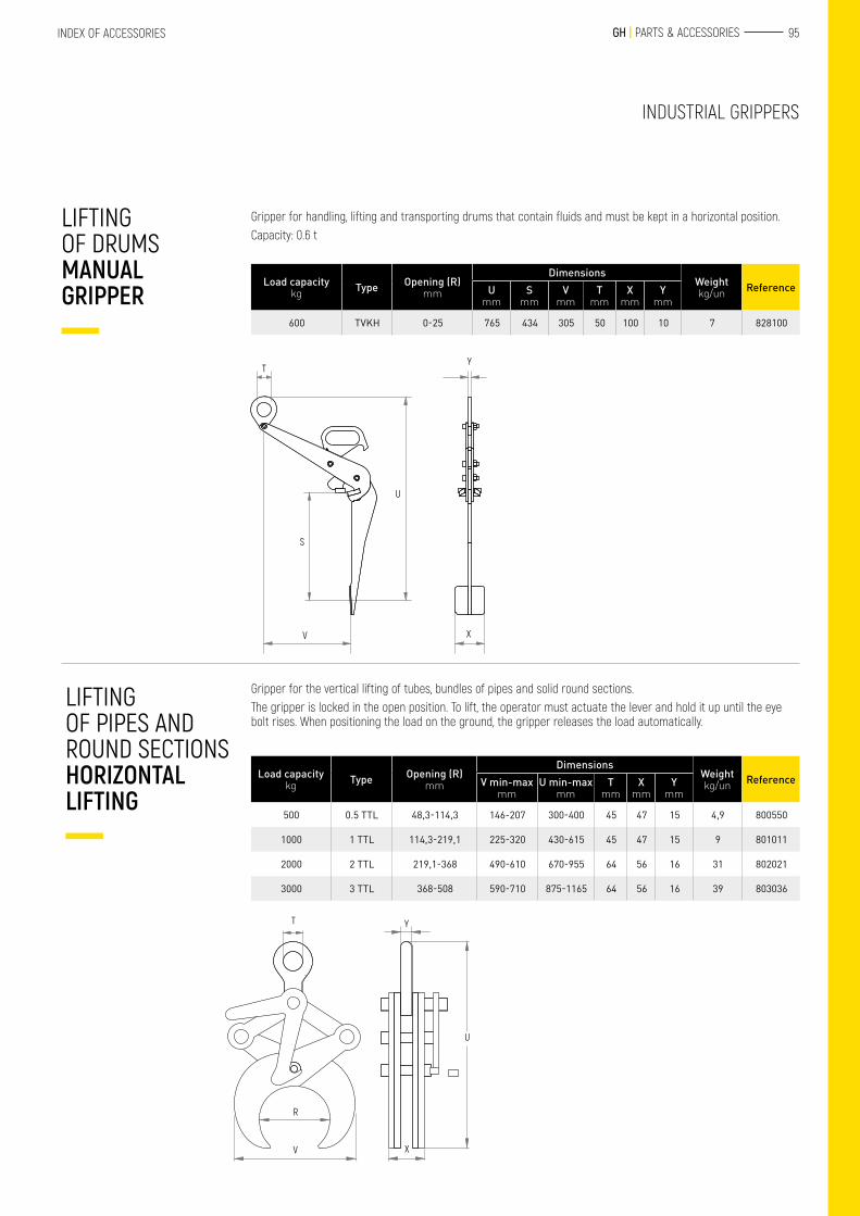
95 GH | PARTS & ACCESSORIESINDEX OF ACCESSORIES
INDUSTRIAL GRIPPERS
Gripper for handling, lifting and transporting drums that contain fluids and must be kept in a horizontal position.Capacity: 0.6 t
LIFTING OF DRUMS MANUAL GRIPPER
Load capacitykg Type Opening (R)
mm
DimensionsWeightkg/un ReferenceU
mmS
mmV
mmT
mmX
mmY
mm
600 TVKH 0-25 765 434 305 50 100 10 7 828100
Load capacitykg Type Opening (R)
mm
DimensionsWeightkg/un ReferenceV min-max
mmU min-max
mmT
mmX
mmY
mm
500 0.5 TTL 48,3-114,3 146-207 300-400 45 47 15 4,9 800550
1000 1 TTL 114,3-219,1 225-320 430-615 45 47 15 9 801011
2000 2 TTL 219,1-368 490-610 670-955 64 56 16 31 802021
3000 3 TTL 368-508 590-710 875-1165 64 56 16 39 803036
TY
U
S
V X
Gripper for the vertical lifting of tubes, bundles of pipes and solid round sections.The gripper is locked in the open position. To lift, the operator must actuate the lever and hold it up until the eye bolt rises. When positioning the load on the ground, the gripper releases the load automatically.
LIFTING OF PIPES AND ROUND SECTIONS HORIZONTAL LIFTING
T Y
U
X
R
V
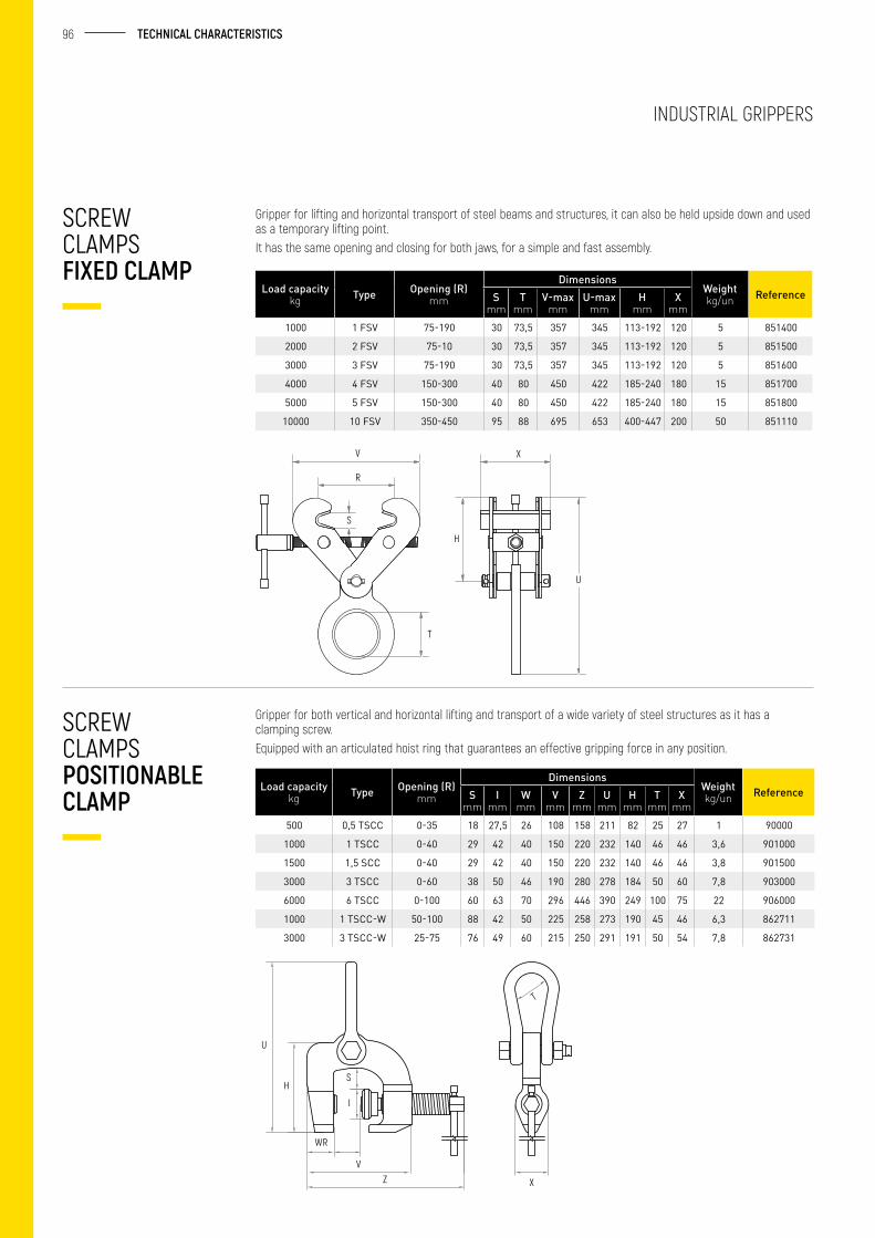
96 TECHNICAL CHARACTERISTICS
SCREW CLAMPS FIXED CLAMP
Gripper for lifting and horizontal transport of steel beams and structures, it can also be held upside down and used as a temporary lifting point.It has the same opening and closing for both jaws, for a simple and fast assembly.
INDUSTRIAL GRIPPERS
Load capacitykg Type Opening (R)
mm
DimensionsWeightkg/un ReferenceS
mmT
mmV-max
mmU-max
mmH
mmX
mm1000 1 FSV 75-190 30 73,5 357 345 113-192 120 5 851400
2000 2 FSV 75-10 30 73,5 357 345 113-192 120 5 851500
3000 3 FSV 75-190 30 73,5 357 345 113-192 120 5 851600
4000 4 FSV 150-300 40 80 450 422 185-240 180 15 851700
5000 5 FSV 150-300 40 80 450 422 185-240 180 15 851800
10000 10 FSV 350-450 95 88 695 653 400-447 200 50 851110
Gripper for both vertical and horizontal lifting and transport of a wide variety of steel structures as it has a clamping screw.Equipped with an articulated hoist ring that guarantees an effective gripping force in any position.
SCREW CLAMPS POSITIONABLE CLAMP
U
H
T
S
I
VZ
WR
X
Load capacitykg Type Opening (R)
mm
DimensionsWeightkg/un ReferenceS
mmI
mmW
mmV
mmZ
mmU
mmH
mmT
mmX
mm500 0,5 TSCC 0-35 18 27,5 26 108 158 211 82 25 27 1 90000
1000 1 TSCC 0-40 29 42 40 150 220 232 140 46 46 3,6 901000
1500 1,5 SCC 0-40 29 42 40 150 220 232 140 46 46 3,8 901500
3000 3 TSCC 0-60 38 50 46 190 280 278 184 50 60 7,8 903000
6000 6 TSCC 0-100 60 63 70 296 446 390 249 100 75 22 906000
1000 1 TSCC-W 50-100 88 42 50 225 258 273 190 45 46 6,3 862711
3000 3 TSCC-W 25-75 76 49 60 215 250 291 191 50 54 7,8 862731
V
R
S
X
H
T
U
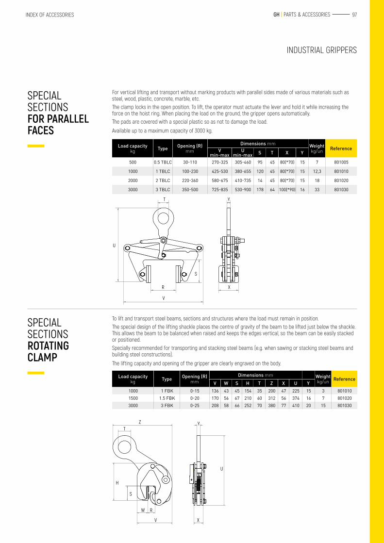
97 GH | PARTS & ACCESSORIESINDEX OF ACCESSORIES
INDUSTRIAL GRIPPERS
For vertical lifting and transport without marking products with parallel sides made of various materials such as steel, wood, plastic, concrete, marble, etc.The clamp locks in the open position. To lift, the operator must actuate the lever and hold it while increasing the force on the hoist ring. When placing the load on the ground, the gripper opens automatically.The pads are covered with a special plastic so as not to damage the load.
Available up to a maximum capacity of 3000 kg.
SPECIAL SECTIONS FOR PARALLEL FACES
U
T Y
R
V
S
X
Load capacitykg Type Opening (R)
mmDimensions mm Weight
kg/un ReferenceV min-max
U min-max S T X Y
500 0.5 TBLC 30-110 270-325 305-460 95 45 80(*70) 15 7 801005
1000 1 TBLC 100-230 425-530 380-655 120 45 80(*70) 15 12,3 801010
2000 2 TBLC 220-360 580-675 410-735 14 45 80(*70) 15 18 801020
3000 3 TBLC 350-500 725-835 530-900 178 64 100(*90) 16 33 801030
To lift and transport steel beams, sections and structures where the load must remain in position.The special design of the lifting shackle places the centre of gravity of the beam to be lifted just below the shackle. This allows the beam to be balanced when raised and keeps the edges vertical, so the beam can be easily stacked or positioned.Specially recommended for transporting and stacking steel beams (e.g. when sawing or stacking steel beams and building steel constructions).
The lifting capacity and opening of the gripper are clearly engraved on the body.
SPECIAL SECTIONS ROTATING CLAMP
ZT
H
S
W R
V
Y
U
X
Load capacitykg Type Opening (R)
mmDimensions mm Weight
kg/un ReferenceV W S H T Z X U Y
1000 1 FBK 0-15 136 43 45 154 35 200 47 225 15 3 8010101500 1.5 FBK 0-20 170 56 67 210 60 312 56 374 16 7 8010203000 3 FBK 0-25 208 58 66 252 70 380 77 410 20 15 801030
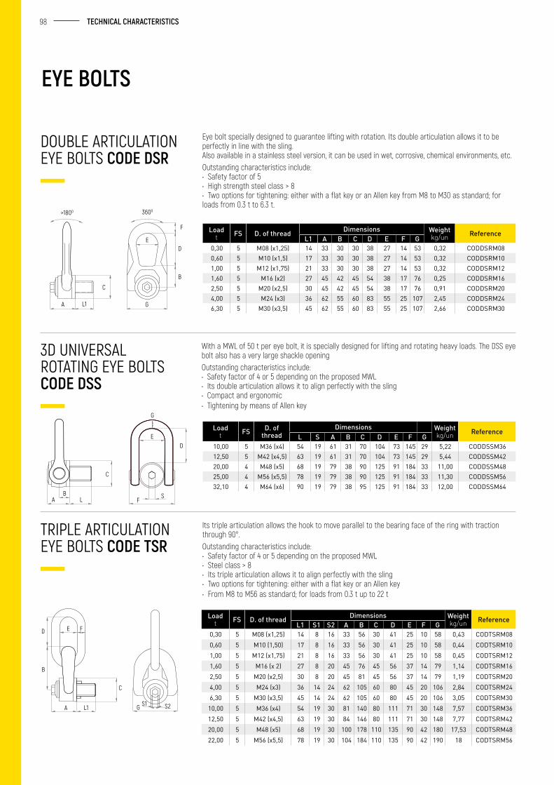
98 TECHNICAL CHARACTERISTICS
EYE BOLTS
Eye bolt specially designed to guarantee lifting with rotation. Its double articulation allows it to be perfectly in line with the sling.Also available in a stainless steel version, it can be used in wet, corrosive, chemical environments, etc. Outstanding characteristics include:• Safety factor of 5 • High strength steel class > 8 • Two options for tightening: either with a flat key or an Allen key from M8 to M30 as standard; for loads from 0.3 t to 6.3 t.
With a MWL of 50 t per eye bolt, it is specially designed for lifting and rotating heavy loads. The DSS eye bolt also has a very large shackle openingOutstanding characteristics include:• Safety factor of 4 or 5 depending on the proposed MWL • Its double articulation allows it to align perfectly with the sling • Compact and ergonomic • Tightening by means of Allen key
Its triple articulation allows the hook to move parallel to the bearing face of the ring with traction through 90°.Outstanding characteristics include:• Safety factor of 4 or 5 depending on the proposed MWL• Steel class > 8• Its triple articulation allows it to align perfectly with the sling• Two options for tightening: either with a flat key or an Allen key• From M8 to M56 as standard; for loads from 0.3 t up to 22 t
Loadt FS D. of thread Dimensions Weight
kg/un ReferenceL1 A B C D E F G
0,30 5 M08 (x1,25) 14 33 30 30 38 27 14 53 0,32 CODDSRM080,60 5 M10 (x1,5) 17 33 30 30 38 27 14 53 0,32 CODDSRM101,00 5 M12 (x1,75) 21 33 30 30 38 27 14 53 0,32 CODDSRM121,60 5 M16 (x2) 27 45 42 45 54 38 17 76 0,25 CODDSRM162,50 5 M20 (x2,5) 30 45 42 45 54 38 17 76 0,91 CODDSRM204,00 5 M24 (x3) 36 62 55 60 83 55 25 107 2,45 CODDSRM246,30 5 M30 (x3,5) 45 62 55 60 83 55 25 107 2,66 CODDSRM30
Loadt FS D. of
threadDimensions Weight
kg/un ReferenceL S A B C D E F G
10,00 5 M36 (x4) 54 19 61 31 70 104 73 145 29 5,22 CODDSSM3612,50 5 M42 (x4,5) 63 19 61 31 70 104 73 145 29 5,44 CODDSSM4220,00 4 M48 (x5) 68 19 79 38 90 125 91 184 33 11,00 CODDSSM4825,00 4 M56 (x5,5) 78 19 79 38 90 125 91 184 33 11,30 CODDSSM5632,10 4 M64 (x6) 90 19 79 38 95 125 91 184 33 12,00 CODDSSM64
Loadt FS D. of thread Dimensions Weight
kg/un ReferenceL1 S1 S2 A B C D E F G
0,30 5 M08 (x1,25) 14 8 16 33 56 30 41 25 10 58 0,43 CODTSRM080,60 5 M10 (1,50) 17 8 16 33 56 30 41 25 10 58 0,44 CODTSRM101,00 5 M12 (x1,75) 21 8 16 33 56 30 41 25 10 58 0,45 CODTSRM121,60 5 M16 (x 2) 27 8 20 45 76 45 56 37 14 79 1,14 CODTSRM162,50 5 M20 (x2,5) 30 8 20 45 81 45 56 37 14 79 1,19 CODTSRM204,00 5 M24 (x3) 36 14 24 62 105 60 80 45 20 106 2,84 CODTSRM246,30 5 M30 (x3,5) 45 14 24 62 105 60 80 45 20 106 3,05 CODTSRM30
10,00 5 M36 (x4) 54 19 30 81 140 80 111 71 30 148 7,57 CODTSRM3612,50 5 M42 (x4,5) 63 19 30 84 146 80 111 71 30 148 7,77 CODTSRM4220,00 5 M48 (x5) 68 19 30 100 178 110 135 90 42 180 17,53 CODTSRM4822,00 5 M56 (x5,5) 78 19 30 104 184 110 135 90 42 190 18 CODTSRM56
DOUBLE ARTICULATION EYE BOLTS CODE DSR
3D UNIVERSAL ROTATING EYE BOLTS CODE DSS
TRIPLE ARTICULATION EYE BOLTS CODE TSR
C
L1A
>1800 3600
F
D
B
E
G
A LB
C
G
DE
SF
S1 S2G
FED
B
A L1
C
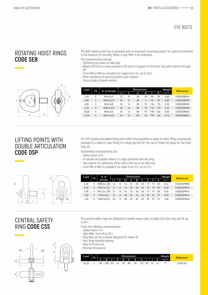
99 GH | PARTS & ACCESSORIESINDEX OF ACCESSORIES
EYE BOLTS
The SEB rotating hoist ring is equipped with an automatic reversing system for optimal orientation in the direction of the sling. Offers a high MWL in all directions. The characteristics include:• Tightening by means of Allen key• Allows the hook to move parallel to the point of support of the hoist ring with traction through
90°• From M16 to M42 as standard; for loads from 1.6 t up to 12.5 t• Other variations of securing shafts upon request• There is also a female version
The DSP double articulated lifting point offers the possibility to adapt to other lifting accessories: passage of a cable or rope, fitting of a large eye bolt for the use of hooks too large for the hoist ring, etc.
Outstanding characteristics are:• Safety factor of 5• Its double articulation allows it to align perfectly with the sling• Two options for tightening: either with a flat key or an Allen key• From M8 to M20 as standard; for loads from 0.3 t up to 2.5 t
The central safety rings are designed to handle heavy loads. A single CSS hoist ring can lift up to 55 t.It has the following characteristics:• Safety factor of 4• High MWL: from 20 to 55 t• Ring that can be screwed designed for linear lift• Very large shackle opening• Easy to fit and use• Minimal dimensions
Loadt FS D. of thread Dimensions Weight
kg/un ReferenceL1 S A B C D
1,60 5 M16 (x2) 27 8 38 45 90 78 0,80 CODSEBM162,50 5 M20 (x2,5) 30 8 38 4 90 78 0,83 CODSEBM204,00 5 M24 (x3) 36 14 58 70 134 115 2,53 CODSEBM246,30 5 M30 (x3,5) 45 14 58 70 134 115 2,62 CODSEBM30
10,00 5 M36 (x4) 54 14 88 94 190 166 8,00 CODSEBM3612,50 5 M42 (x4,5) 63 14 88 94 190 166 8,10 CODSEBM42
Loadt FS D. of
threadDimensions Weight
kg/un ReferenceL1 S1 S2 A B C E F G
0,30 5 M08 (x1,25) 14 8 16 33 56 30 19 19 58 0,32 CODDSPM080,30 5 M10 (x1,5) 17 8 16 33 56 30 19 19 58 0,33 CODDSPM101,00 5 M12 (x1,75) 21 8 16 33 56 30 19 19 58 0,34 CODDSPM121,50 5 M16 (x2) 27 8 20 45 76 45 25 27 79 0,95 CODDSPM161,60 5 M20 (x2,5) 30 8 20 45 81 45 25 27 79 1,00 CODDSPM20
Loadt FS Dimensions Weight
kg/un ReferenceA B C D E F G H I J K
32,25 4 80 330 50 62 90 88 98 132 38 76 41 17 CODCSS
ROTATING HOIST RINGS CODE SEB
LIFTING POINTS WITH DOUBLE ARTICULATION CODE DSP
CENTRAL SAFETY RING CODE CSS
C
D L1
A
B
X
X
S
C
B
A LG
E
FS1 S2
900 900
BC
D
A
K
J
HE
F G
I
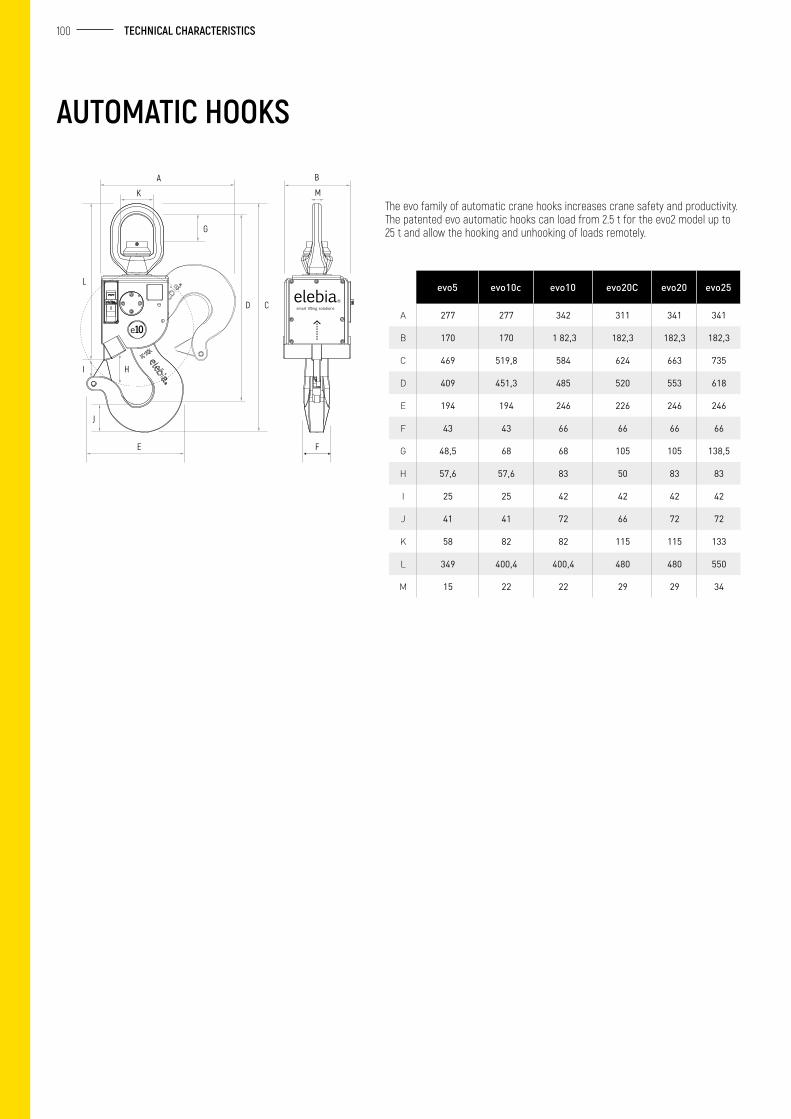
100 TECHNICAL CHARACTERISTICS
AUTOMATIC HOOKS
The evo family of automatic crane hooks increases crane safety and productivity. The patented evo automatic hooks can load from 2.5 t for the evo2 model up to 25 t and allow the hooking and unhooking of loads remotely.
A
K
G
L
I H
J
E F
D C
B
M
evo5 evo10c evo10 evo20C evo20 evo25
A 277 277 342 311 341 341
B 170 170 1 82,3 182,3 182,3 182,3
C 469 519,8 584 624 663 735
D 409 451,3 485 520 553 618
E 194 194 246 226 246 246
F 43 43 66 66 66 66
G 48,5 68 68 105 105 138,5
H 57,6 57,6 83 50 83 83
I 25 25 42 42 42 42
J 41 41 72 66 72 72
K 58 82 82 115 115 133
L 349 400,4 400,4 480 480 550
M 15 22 22 29 29 34
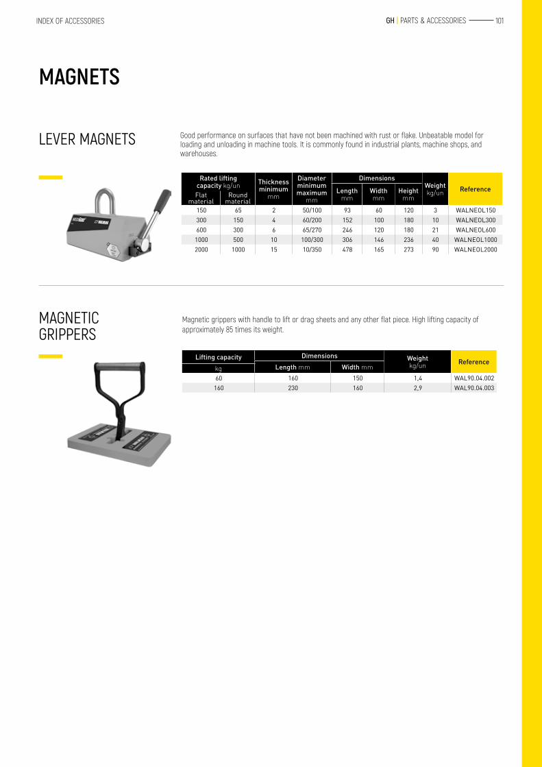
101 GH | PARTS & ACCESSORIESINDEX OF ACCESSORIES
Good performance on surfaces that have not been machined with rust or flake. Unbeatable model for loading and unloading in machine tools. It is commonly found in industrial plants, machine shops, and warehouses.
Magnetic grippers with handle to lift or drag sheets and any other flat piece. High lifting capacity of approximately 85 times its weight.
Rated lifting capacity kg/un Thickness
minimum mm
Diameterminimum maximum
mm
DimensionsWeightkg/un ReferenceLength
mmWidth mm
Height mmFlat
materialRound
material150 65 2 50/100 93 60 120 3 WALNEOL150300 150 4 60/200 152 100 180 10 WALNEOL300600 300 6 65/270 246 120 180 21 WALNEOL600
1000 500 10 100/300 306 146 236 40 WALNEOL10002000 1000 15 10/350 478 165 273 90 WALNEOL2000
Lifting capacity Dimensions Weightkg/un Reference
Length mm Width mmkg60 160 150 1,4 WAL90.04.002
160 230 160 2,9 WAL90.04.003
LEVER MAGNETS
MAGNETIC GRIPPERS
MAGNETS
evo5 evo10c evo10 evo20C evo20 evo25
A 277 277 342 311 341 341
B 170 170 1 82,3 182,3 182,3 182,3
C 469 519,8 584 624 663 735
D 409 451,3 485 520 553 618
E 194 194 246 226 246 246
F 43 43 66 66 66 66
G 48,5 68 68 105 105 138,5
H 57,6 57,6 83 50 83 83
I 25 25 42 42 42 42
J 41 41 72 66 72 72
K 58 82 82 115 115 133
L 349 400,4 400,4 480 480 550
M 15 22 22 29 29 34
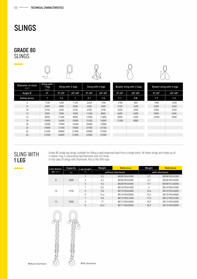
102 TECHNICAL CHARACTERISTICS
Grade 80 single leg slings, suitable for lifting a well-balanced load from a single point. All these slings are made up of 1 master ring, 2 connecting hammerlocks and CLS hook. In the case of slings with shortener, this is the VHG type.
Diameter of chainmm
Sling with 1 leg mm
Sling with 2 legs Sling with 4 legs Basket sling with 2 legs Basket sling with 4 legs
Angle B 00 00-450 450-600 00-450 450-600 00-450 450-600 00-450 450-600
Safety factor 1 1.4 1 2.1 1.5 1.1 0.8 1.7 1.2
6 1120 1600 1120 2360 1700 1180 850 1900 13208 2000 2800 2000 4250 3000 2120 1600 3350 2360
10 3150 4250 3150 6700 4750 3350 2500 5300 375013 5300 7500 5300 11200 8000 5600 4000 9000 630016 8000 11200 8000 17000 11800 8500 6300 13200 950018 10000 14000 10000 21200 15000 11200 800020 12500 17000 12500 25500 1900022 15000 21200 15000 31500 2210026 21200 30000 21200 45000 3150032 31500 45000 31500 67000 47500
Link diame-ter mm
Capacity Leg length m
Weight Reference Weight Referencekg without shortener with shortener
8 20001 3,2 BE081RSA1000 3,7 BE081RCA10003 6,2 BE081RSA3000 6,7 BE081RCA30005 9,2 BE081RSA5000 9,7 BE081R CA5000
10 31501 5,2 BE101RSA1000 6 BE101RCA10003 9,8 BE101RSA3000 10,6 BE101RCA30005 14,4 BE101RSA5000 15,2 BE101RCA5000
13 53001 9,8 BE131RSA1000 11,5 BE131RCA10003 17 BE131RSA3000 18,7 BE131RCA30005 24,2 BE111RSA5000 25,9 BE131RCA5000
GRADE 80 SLINGS
SLING WITH 1 LEG
SLINGS
B B
BB
90º
With shortenerWithout shortener
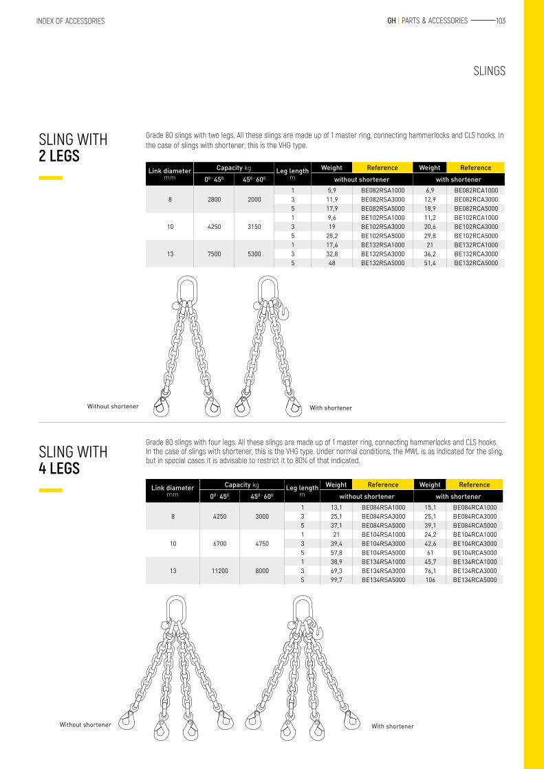
103 GH | PARTS & ACCESSORIESINDEX OF ACCESSORIES
Grade 80 slings with two legs. All these slings are made up of 1 master ring, connecting hammerlocks and CLS hooks. In the case of slings with shortener, this is the VHG type.
Grade 80 slings with four legs. All these slings are made up of 1 master ring, connecting hammerlocks and CLS hooks. In the case of slings with shortener, this is the VHG type. Under normal conditions, the MWL is as indicated for the sling, but in special cases it is advisable to restrict it to 80% of that indicated.
Link diameter mm
Capacity kg Leg length m
Weight Reference Weight Reference00 - 450 450 - 600 without shortener with shortener
8 2800 20001 5,9 BE082RSA1000 6,9 BE082RCA10003 11,9 BE082RSA3000 12,9 BE082RCA30005 17,9 BE082RSA5000 18,9 BE082RCA5000
10 4250 31501 9,6 BE102RSA1000 11,2 BE102RCA10003 19 BE102RSA3000 20,6 BE102RCA30005 28,2 BE102RSA5000 29,8 BE102RCA5000
13 7500 53001 17,6 BE132RSA1000 21 BE132RCA10003 32,8 BE132RSA3000 36,2 BE132RCA30005 48 BE132RSA5000 51,4 BE132RCA5000
Link diameter mm
Capacity kg Leg length m
Weight Reference Weight Reference00 - 450 450 - 600 without shortener with shortener
8 4250 30001 13,1 BE084RSA1000 15,1 BE084RCA10003 25,1 BE084RSA3000 25,1 BE084RCA30005 37,1 BE084RSA5000 39,1 BE084RCA5000
10 6700 47501 21 BE104RSA1000 24,2 BE104RCA10003 39,4 BE104RSA3000 42,6 BE104RCA30005 57,8 BE104RSA5000 61 BE104RCA5000
13 11200 80001 38,9 BE134RSA1000 45,7 BE134RCA10003 69,3 BE134RSA3000 76,1 BE134RCA30005 99,7 BE134RSA5000 106 BE134RCA5000
SLING WITH 2 LEGS
SLING WITH 4 LEGS
SLINGS
With shortenerWithout shortener
With shortenerWithout shortener
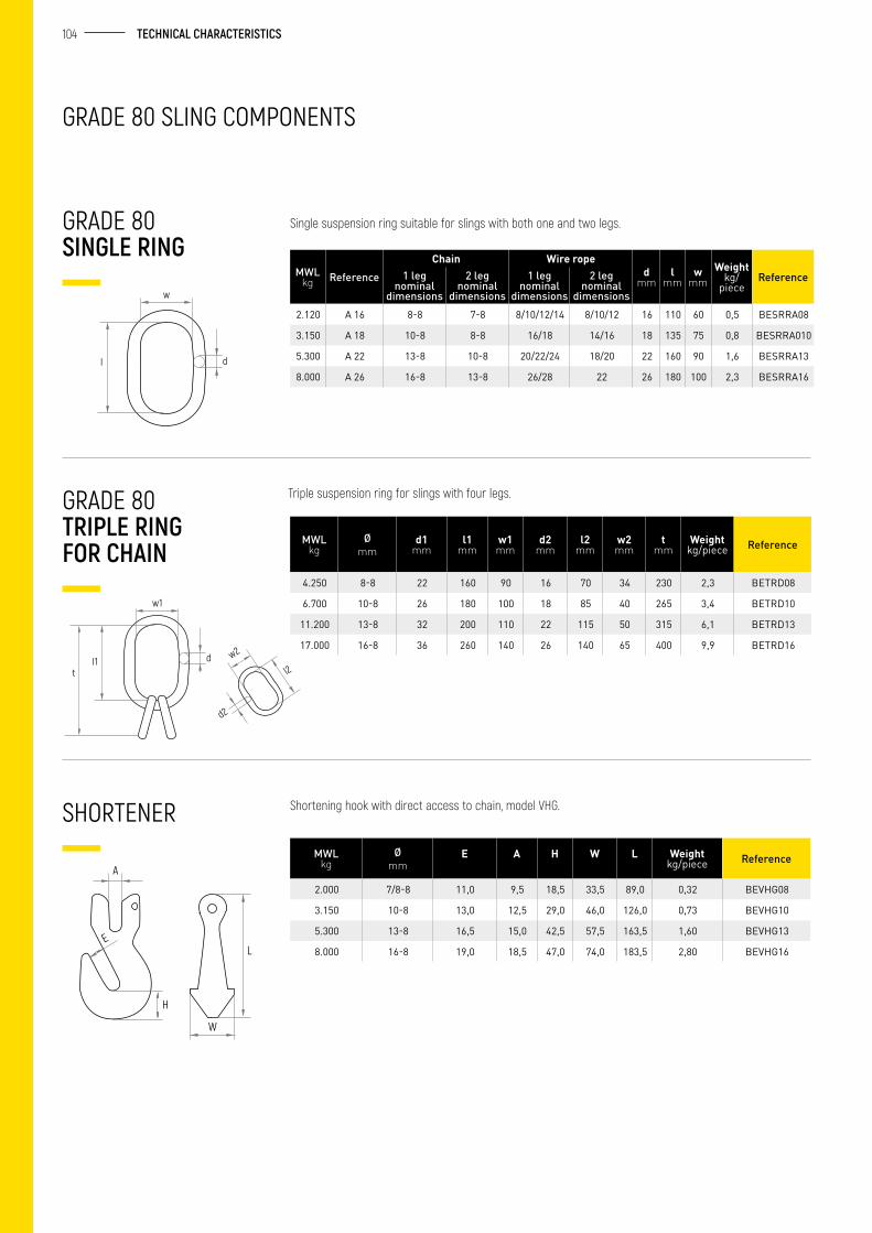
104 TECHNICAL CHARACTERISTICS
faltanimágenes
GRADE 80 SLING COMPONENTS
GRADE 80 SINGLE RING
Triple suspension ring for slings with four legs.
Shortening hook with direct access to chain, model VHG.
GRADE 80 TRIPLE RING FOR CHAIN
SHORTENER
Single suspension ring suitable for slings with both one and two legs.
MWL kg Reference
Chain Wire roped
mml
mmw
mmWeight
kg/piece
Reference1 leg nominal
dimensions
2 leg nominal
dimensions
1 leg nominal
dimensions
2 leg nominal
dimensions2.120 A 16 8-8 7-8 8/10/12/14 8/10/12 16 110 60 0,5 BESRRA08
3.150 A 18 10-8 8-8 16/18 14/16 18 135 75 0,8 BESRRA010
5.300 A 22 13-8 10-8 20/22/24 18/20 22 160 90 1,6 BESRRA13
8.000 A 26 16-8 13-8 26/28 22 26 180 100 2,3 BESRRA16
MWL kg
Ø mm
d1 mm
l1 mm
w1 mm
d2 mm
l2 mm
w2 mm
t mm
Weight kg/piece Reference
4.250 8-8 22 160 90 16 70 34 230 2,3 BETRD08
6.700 10-8 26 180 100 18 85 40 265 3,4 BETRD10
11.200 13-8 32 200 110 22 115 50 315 6,1 BETRD13
17.000 16-8 36 260 140 26 140 65 400 9,9 BETRD16
MWL kg
Ø mm
E A H W L Weight kg/piece Reference
2.000 7/8-8 11,0 9,5 18,5 33,5 89,0 0,32 BEVHG08
3.150 10-8 13,0 12,5 29,0 46,0 126,0 0,73 BEVHG10
5.300 13-8 16,5 15,0 42,5 57,5 163,5 1,60 BEVHG13
8.000 16-8 19,0 18,5 47,0 74,0 183,5 2,80 BEVHG16
I
w
d
w1
I1t
d w2
l2
d2
A
H
EL
W
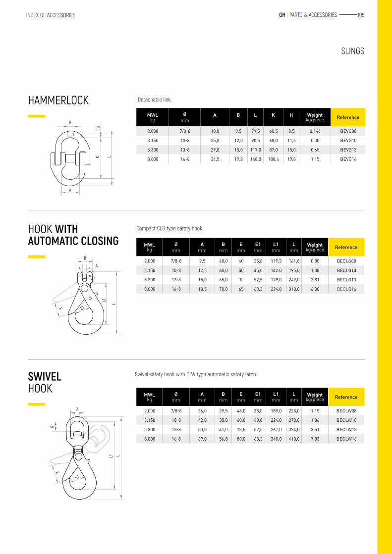
105 GH | PARTS & ACCESSORIESINDEX OF ACCESSORIES
Detachable link.HAMMERLOCK
SLINGS
H
BK L
A
MWL kg
Ø mm
A B L K H Weight kg/piece Reference
2.000 7/8-8 18,0 9,5 79,5 60,5 8,5 0,146 BEVG08
3.150 10-8 25,0 12,0 90,5 68,0 11,5 0,30 BEVG10
5.300 13-8 29,0 15,0 117,0 87,0 15,0 0,65 BEVG13
8.000 16-8 34,5 19,8 148,0 108,4 19,8 1,15 BEVG16
Compact CLG type safety hook.HOOK WITH AUTOMATIC CLOSING
L
L1
B
A
E1E
MWL kg
Ø mm
A mm
B mm
E mm
E1 mm
L1 mm
L mm
Weight kg/piece Reference
2.000 7/8-8 9,5 48,0 40 35,8 119,3 161,8 0,80 BECLG08
3.150 10-8 12,5 60,0 50 45,0 142,0 195,0 1,38 BECLG10
5.300 13-8 15,0 65,0 0 52,5 179,0 249,0 2,81 BECLG13
8.000 16-8 18,5 70,0 65 63,3 224,8 310,0 6,00 BECLG16
MWL kg
Ø mm
A mm
B mm
E mm
E1 mm
L1 mm
L mm
Weight kg/piece Reference
2.000 7/8-8 36,0 29,5 48,0 38,0 189,0 228,0 1,15 BECLW08
3.150 10-8 42,0 35,0 60,0 48,0 224,0 270,0 1,86 BECLW10
5.300 13-8 50,0 41,0 73,5 52,5 267,0 324,0 3,51 BECLW13
8.000 16-8 69,0 56,8 80,0 63,3 340,0 410,0 7,33 BECLW16
Swivel safety hook with CLW type automatic safety latch.SWIVEL HOOK
LL1
E1
E
A
B
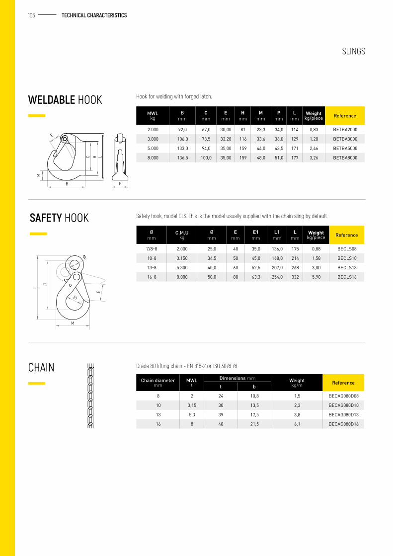
106 TECHNICAL CHARACTERISTICS
Safety hook, model CLS. This is the model usually supplied with the chain sling by default.
WELDABLE HOOK
SAFETY HOOK
Hook for welding with forged latch.
Grade 80 lifting chain - EN 818-2 or ISO 3076 76
Chain diameter mm
MWL t
Dimensions mm Weight kg/m Reference
t b
8 2 24 10,8 1,5 BECAG080D08
10 3,15 30 13,5 2,3 BECAG080D10
13 5,3 39 17,5 3,8 BECAG080D13
16 8 48 21,5 6,1 BECAG080D16
CHAIN
LHC
E
B
M
P
MWL kg
B mm
C mm
E mm
H mm
M mm
P mm
L mm
Weight kg/piece Reference
2.000 92,0 67,0 30,00 81 23,3 34,0 114 0,83 BETBA2000
3.000 106,0 73,5 33,20 116 33,6 36,0 129 1,20 BETBA3000
5.000 133,0 94,0 35,00 159 44,0 43,5 171 2,46 BETBA5000
8.000 136,5 100,0 35,00 159 48,0 51,0 177 3,26 BETBA8000
Ø mm
C.M.U kg
Ø mm
E mm
E1 mm
L1 mm
L mm
Weight kg/piece Reference
7/8-8 2.000 25,0 40 35,0 136,0 175 0,88 BECLS08
10-8 3.150 34,5 50 45,0 168,0 214 1,58 BECLS10
13-8 5.300 40,0 60 52,5 207,0 268 3,00 BECLS13
16-8 8.000 50,0 80 63,3 254,0 332 5,90 BECLS16
L L1
E
M
E1
Ø
SLINGS
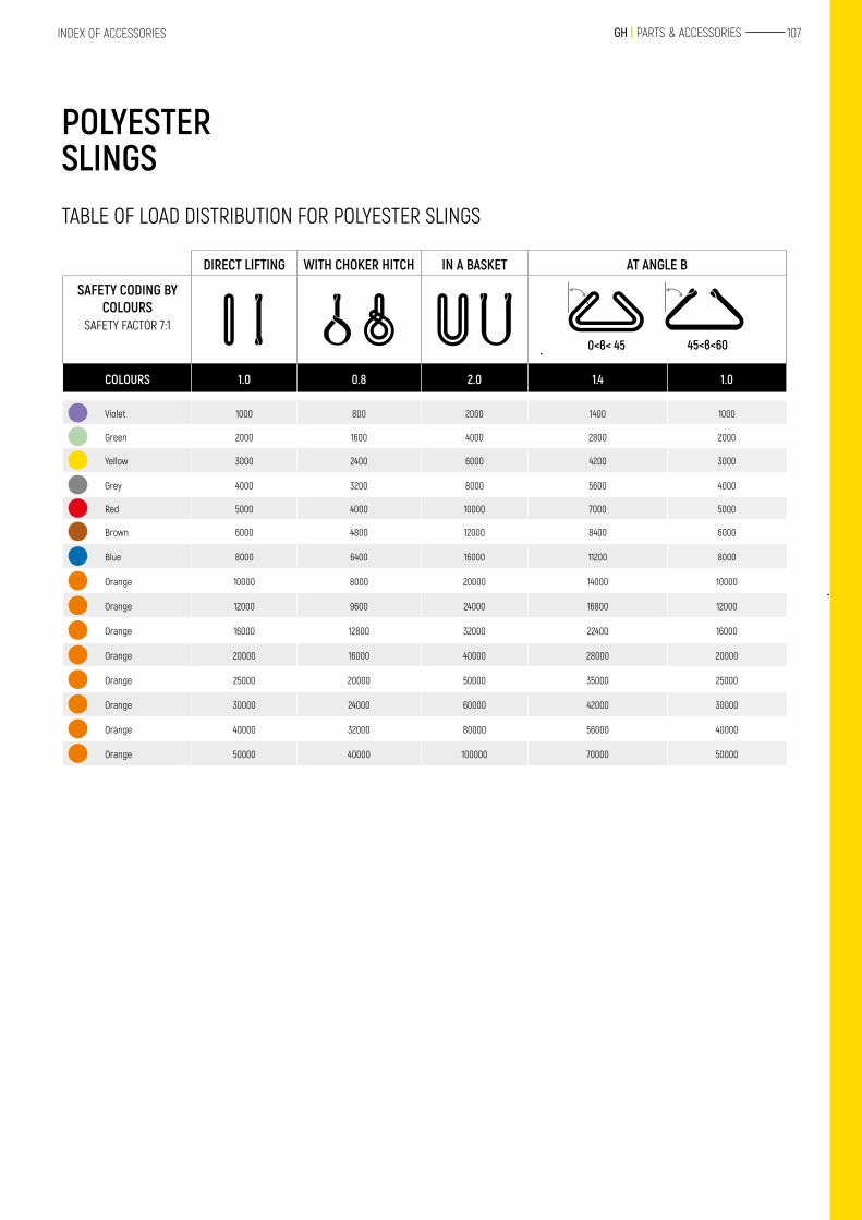
107 GH | PARTS & ACCESSORIESINDEX OF ACCESSORIES
POLYESTER SLINGS
DIRECT LIFTING WITH CHOKER HITCH IN A BASKET AT ANGLE В
SAFETY CODING BY COLOURS
SAFETY FACTOR 7:1
0<в< 45 45<в<60
COLOURS 1.0 0.8 2.0 1.4 1.0
Violet 1000 800 2000 1400 1000
Green 2000 1600 4000 2800 2000
Yellow 3000 2400 6000 4200 3000
Grey 4000 3200 8000 5600 4000
Red 5000 4000 10000 7000 5000
Brown 6000 4800 12000 8400 6000
Blue 8000 6400 16000 11200 8000
Orange 10000 8000 20000 14000 10000
Orange 12000 9600 24000 16800 12000
Orange 16000 12800 32000 22400 16000
Orange 20000 16000 40000 28000 20000
Orange 25000 20000 50000 35000 25000
Orange 30000 24000 60000 42000 30000
Orange 40000 32000 80000 56000 40000
Orange 50000 40000 100000 70000 50000
TABLE OF LOAD DISTRIBUTION FOR POLYESTER SLINGS
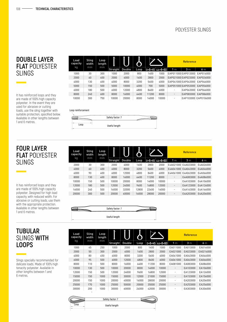
108 TECHNICAL CHARACTERISTICS
It has reinforced loops and they are made of 100% high capacity polyester. In the event they are used for abrasive or cutting loads, use the sling together with suitable protection, specified below. Available in other lengths between 1 and 6 metres.
DOUBLE LAYER FLAT POLYESTER SLINGS
Load capacity
kg
Sling width mm
Loop length
mm
Reference
Straight Double Loop 0<в<45 46<в<60 1 m 3 m 6 m1000 30 300 1000 2000 800 1400 1000 EAP011000 EAP013000 EAP0160002000 60 400 2000 4000 1600 2800 2000 EAP021000 EAP023000 EAP0260004000 130 400 4000 8000 3200 5600 4000 EAP041000 EAP043000 EAP0460005000 150 500 5000 10000 4000 700 5000 EAP051000 EAP053000 EAP0560006000 180 500 6000 12000 4800 8400 6000 - EAP063000 EAP0660008000 240 600 8000 16000 6400 11200 8000 - EAP083000 EAP086000
10000 300 750 10000 20000 8000 14000 10000 - EAP103000 EAP0106000
It has reinforced loops and they are made of 100% high capacity polyester. Designed for high load capacity, with reduced width. For abrasive or cutting loads, use them with the appropriate protection. Available in other lengths between 1 and 6 metres.
FOUR LAYER FLAT POLYESTER SLINGS
Load capacity
kg
Sling width mm
Loop length
mm
Reference
Straight Double Loop 0<в<45 46<в<60 1 m 3 m 6 m2000 30 300 2000 4000 1600 2800 2000 E4A021000 E4A023000 E4A0260004000 60 400 4000 8000 3200 5600 4000 E4A041000 E4A043000 E4A0460006000 90 400 6000 12000 4800 8400 6000 E4A061000 E4A063000 E4A0660008000 130 400 8000 16000 6400 11200 8000 - E4A083000 E4A086000
10000 150 500 10000 20000 8000 14000 10000 - E4A103000 E4A10600012000 180 500 12000 24000 9600 16800 12000 - E4A123000 E4A12600016000 240 500 16000 32000 12800 22400 16000 - E4A163000 E4A16600020000 300 500 20000 40000 16000 28000 20000 - E4A203000 E4A206000
Slings specially recommended for delicate loads. Made of 100% high tenacity polyester. Available in other lengths between 1 and 6 metres.
TUBULAR SLINGS WITH LOOPS
Load capacity
kg
Sling width mm
Loop length
mm
Reference
Straight Double Loop 0<в<45 46<в<60 1 m 3 m 6 m1000 45 250 1000 2000 800 1400 1000 EA011000 EA013000 EA0160002000 50 300 2000 4000 1600 2800 2000 EA021000 EA023000 EA02160004000 80 450 4000 8000 3200 5600 4000 EA041000 EA043000 EA0460006000 95 500 6000 12000 4800 8400 6000 EA061000 EA063000 EA0660008000 110 500 8000 16000 6400 11200 8000 EA081000 EA083000 EA086000
10000 130 500 10000 20000 8000 14000 10000 - EA103000 EA10600012000 150 500 12000 24000 9600 16800 12000 - EA123000 EA12600015000 150 1000 15000 30000 12000 21000 15000 - EA153000 EA15600020000 150 1000 20000 40000 16000 28000 20000 - EA203000 EA20600025000 170 1000 25000 50000 20000 35000 25000 - EA253000 EA25600030000 200 1000 30000 60000 24000 42000 30000 - EA303000 EA306000
POLYESTER SLINGS
Loop Useful length
Safety factor: 7
Loop reinforcement
Useful length
Safety factor: 7
Loop
Safety factor: 7
Useful length
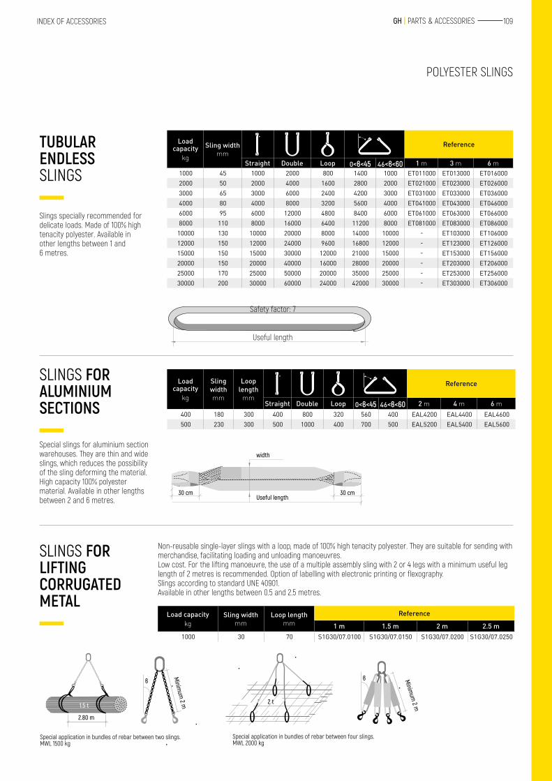
109 GH | PARTS & ACCESSORIESINDEX OF ACCESSORIES
POLYESTER SLINGS
Slings specially recommended for delicate loads. Made of 100% high tenacity polyester. Available in other lengths between 1 and 6 metres.
TUBULAR ENDLESS SLINGS
Load capacity
kg
Sling width mm
Reference
Straight Double Loop 0<в<45 46<в<60 1 m 3 m 6 m1000 45 1000 2000 800 1400 1000 ET011000 ET013000 ET0160002000 50 2000 4000 1600 2800 2000 ET021000 ET023000 ET0260003000 65 3000 6000 2400 4200 3000 ET031000 ET033000 ET0360004000 80 4000 8000 3200 5600 4000 ET041000 ET043000 ET0460006000 95 6000 12000 4800 8400 6000 ET061000 ET063000 ET0660008000 110 8000 16000 6400 11200 8000 ET081000 ET083000 ET086000
10000 130 10000 20000 8000 14000 10000 - ET103000 ET10600012000 150 12000 24000 9600 16800 12000 - ET123000 ET12600015000 150 15000 30000 12000 21000 15000 - ET153000 ET15600020000 150 20000 40000 16000 28000 20000 - ET203000 ET20600025000 170 25000 50000 20000 35000 25000 - ET253000 ET25600030000 200 30000 60000 24000 42000 30000 - ET303000 ET306000
Special slings for aluminium section warehouses. They are thin and wide slings, which reduces the possibility of the sling deforming the material. High capacity 100% polyester material. Available in other lengths between 2 and 6 metres.
SLINGS FOR ALUMINIUM SECTIONS
Load capacity
kg
Sling width mm
Loop length
mm
Reference
Straight Double Loop 0<в<45 46<в<60 2 m 4 m 6 m400 180 300 400 800 320 560 400 EAL4200 EAL4400 EAL4600500 230 300 500 1000 400 700 500 EAL5200 EAL5400 EAL5600
Non-reusable single-layer slings with a loop, made of 100% high tenacity polyester. They are suitable for sending with merchandise, facilitating loading and unloading manoeuvres. Low cost. For the lifting manoeuvre, the use of a multiple assembly sling with 2 or 4 legs with a minimum useful leg length of 2 metres is recommended. Option of labelling with electronic printing or flexography. Slings according to standard UNE 40901.Available in other lengths between 0.5 and 2.5 metres.
SLINGS FOR LIFTING CORRUGATED METAL
Load capacitykg
Sling width mm
Loop length mm
Reference
1 m 1.5 m 2 m 2.5 m1000 30 70 S1G30/07.0100 S1G30/07.0150 S1G30/07.0200 S1G30/07.0250
Useful length
Safety factor: 7
30 cm 30 cm
width
Useful length
Special application in bundles of rebar between two slings. MWL 1500 kg
Special application in bundles of rebar between four slings.MWL 2000 kg
2.80 m
1.5 t
Minim
um 2 m
в
2 t
в Minim
um 2 m
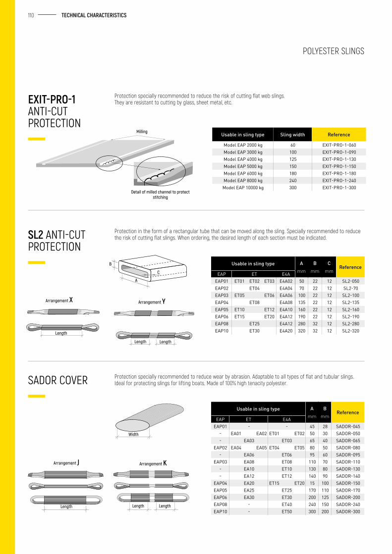
110 TECHNICAL CHARACTERISTICS
POLYESTER SLINGS
EXIT-PRO-1 ANTI-CUT PROTECTION
SL2 ANTI-CUT PROTECTION
SADOR COVER
Usable in sling type Sling width Reference
Model EAP 2000 kg 60 EXIT-PRO-1-060Model EAP 3000 kg 100 EXIT-PRO-1-090Model EAP 4000 kg 125 EXIT-PRO-1-130Model EAP 5000 kg 150 EXIT-PRO-1-150Model EAP 6000 kg 180 EXIT-PRO-1-180Model EAP 8000 kg 240 EXIT-PRO-1-240
Model EAP 10000 kg 300 EXIT-PRO-1-300
Usable in sling type Amm
Bmm
Cmm
ReferenceEAP ET E4A
EAP01 ET01 ET02 ET03 E4A02 50 22 12 SL2-050EAP02 ET04 E4A04 70 22 12 SL2-70EAP03 ET05 ET06 E4A06 100 22 12 SL2-100EAP04 ET08 E4A08 135 22 12 SL2-135EAP05 ET10 ET12 E4A10 160 22 12 SL2-160EAP06 ET15 ET20 E4A12 190 22 12 SL2-190EAP08 ET25 E4A12 280 32 12 SL2-280EAP10 ET30 E4A20 320 32 12 SL2-320
Usable in sling type Amm
Bmm
ReferenceEAP ET E4A
EAP01 - - 45 28 SADOR-045- EA01 EA02 ET01 ET02 50 30 SADOR-050- EA03 ET03 65 40 SADOR-065
EAP02 EA04 EA05 ET04 ET05 80 50 SADOR-080- EA06 ET06 95 60 SADOR-095
EAP03 EA08 ET08 110 70 SADOR-110- EA10 ET10 130 80 SADOR-130- EA12 ET12 140 90 SADOR-140
EAP04 EA20 ET15 ET20 15 100 SADOR-150EAP05 EA25 ET25 170 110 SADOR-170EAP06 EA30 ET30 200 125 SADOR-200EAP08 - ET40 240 150 SADOR-240EAP10 - ET50 300 200 SADOR-300
Protection specially recommended to reduce the risk of cutting flat web slings.They are resistant to cutting by glass, sheet metal, etc.
Protection in the form of a rectangular tube that can be moved along the sling. Specially recommended to reduce the risk of cutting flat slings. When ordering, the desired length of each section must be indicated.
Protection specially recommended to reduce wear by abrasion. Adaptable to all types of flat and tubular slings. Ideal for protecting slings for lifting boats. Made of 100% high tenacity polyester.
Detail of milled channel to protect stitching
Milling
Arrangement X Arrangement Y
Length
Length Length
C
A
B
Width
Length
Arrangement J Arrangement K
Length Length
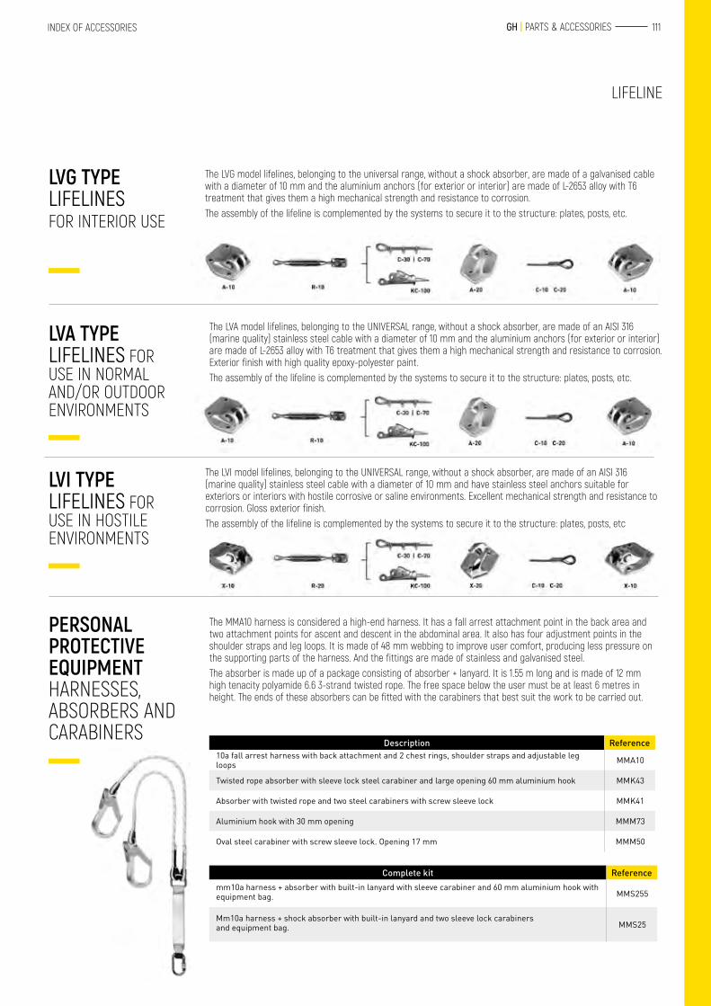
111 GH | PARTS & ACCESSORIESINDEX OF ACCESSORIES
LIFELINE
The LVG model lifelines, belonging to the universal range, without a shock absorber, are made of a galvanised cable with a diameter of 10 mm and the aluminium anchors (for exterior or interior) are made of L-2653 alloy with T6 treatment that gives them a high mechanical strength and resistance to corrosion.The assembly of the lifeline is complemented by the systems to secure it to the structure: plates, posts, etc.
The LVA model lifelines, belonging to the UNIVERSAL range, without a shock absorber, are made of an AISI 316 (marine quality) stainless steel cable with a diameter of 10 mm and the aluminium anchors (for exterior or interior) are made of L-2653 alloy with T6 treatment that gives them a high mechanical strength and resistance to corrosion. Exterior finish with high quality epoxy-polyester paint.The assembly of the lifeline is complemented by the systems to secure it to the structure: plates, posts, etc.
The LVI model lifelines, belonging to the UNIVERSAL range, without a shock absorber, are made of an AISI 316 (marine quality) stainless steel cable with a diameter of 10 mm and have stainless steel anchors suitable for exteriors or interiors with hostile corrosive or saline environments. Excellent mechanical strength and resistance to corrosion. Gloss exterior finish.The assembly of the lifeline is complemented by the systems to secure it to the structure: plates, posts, etc
The MMA10 harness is considered a high-end harness. It has a fall arrest attachment point in the back area and two attachment points for ascent and descent in the abdominal area. It also has four adjustment points in the shoulder straps and leg loops. It is made of 48 mm webbing to improve user comfort, producing less pressure on the supporting parts of the harness. And the fittings are made of stainless and galvanised steel.The absorber is made up of a package consisting of absorber + lanyard. It is 1.55 m long and is made of 12 mm high tenacity polyamide 6.6 3-strand twisted rope. The free space below the user must be at least 6 metres in height. The ends of these absorbers can be fitted with the carabiners that best suit the work to be carried out.
LVG TYPE LIFELINES FOR INTERIOR USE
LVA TYPE LIFELINES FOR USE IN NORMAL AND/OR OUTDOOR ENVIRONMENTS
LVI TYPE LIFELINES FOR USE IN HOSTILE ENVIRONMENTS
PERSONAL PROTECTIVE EQUIPMENT HARNESSES, ABSORBERS AND CARABINERS
Description Reference10a fall arrest harness with back attachment and 2 chest rings, shoulder straps and adjustable leg loops MMA10
Twisted rope absorber with sleeve lock steel carabiner and large opening 60 mm aluminium hook MMK43
Absorber with twisted rope and two steel carabiners with screw sleeve lock MMK41
Aluminium hook with 30 mm opening MMM73
Oval steel carabiner with screw sleeve lock. Opening 17 mm MMM50
Complete kit Referencemm10a harness + absorber with built-in lanyard with sleeve carabiner and 60 mm aluminium hook with equipment bag. MMS255
Mm10a harness + shock absorber with built-in lanyard and two sleeve lock carabiners and equipment bag. MMS25
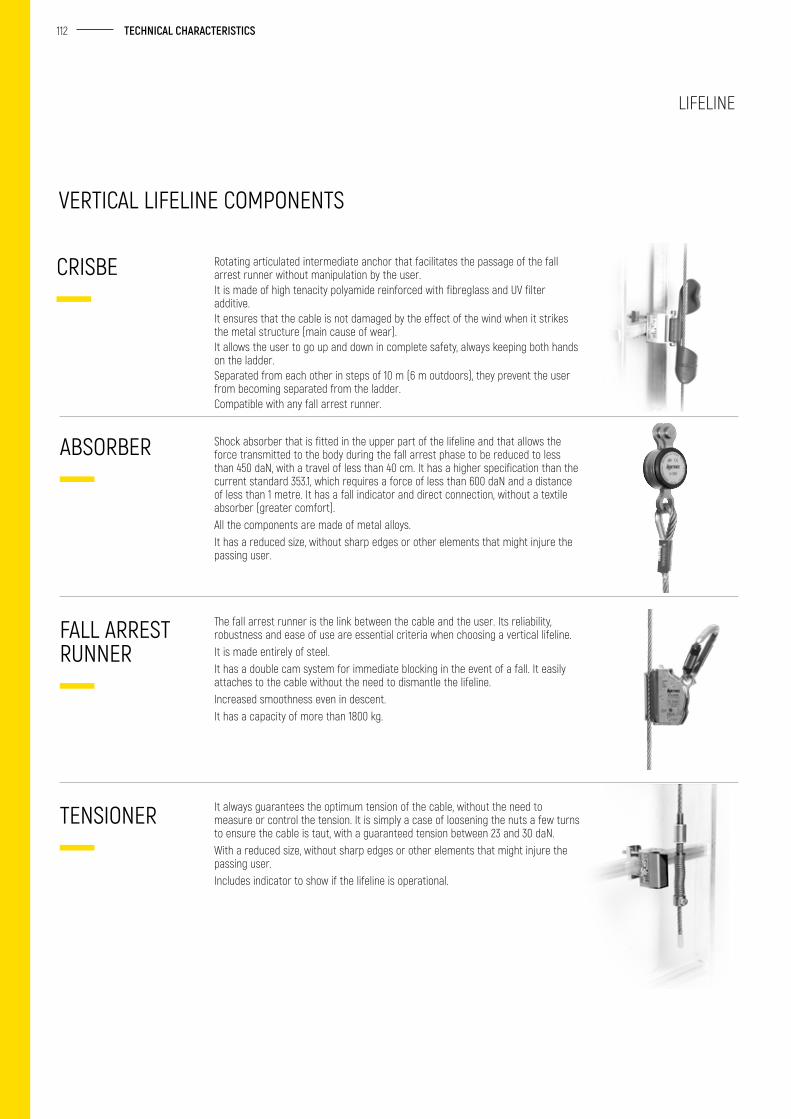
112 TECHNICAL CHARACTERISTICS
Rotating articulated intermediate anchor that facilitates the passage of the fall arrest runner without manipulation by the user.It is made of high tenacity polyamide reinforced with fibreglass and UV filter additive.It ensures that the cable is not damaged by the effect of the wind when it strikes the metal structure (main cause of wear).It allows the user to go up and down in complete safety, always keeping both hands on the ladder.Separated from each other in steps of 10 m (6 m outdoors), they prevent the user from becoming separated from the ladder.Compatible with any fall arrest runner.
Shock absorber that is fitted in the upper part of the lifeline and that allows the force transmitted to the body during the fall arrest phase to be reduced to less than 450 daN, with a travel of less than 40 cm. It has a higher specification than the current standard 353.1, which requires a force of less than 600 daN and a distance of less than 1 metre. It has a fall indicator and direct connection, without a textile absorber (greater comfort).All the components are made of metal alloys.It has a reduced size, without sharp edges or other elements that might injure the passing user.
The fall arrest runner is the link between the cable and the user. Its reliability, robustness and ease of use are essential criteria when choosing a vertical lifeline.It is made entirely of steel.It has a double cam system for immediate blocking in the event of a fall. It easily attaches to the cable without the need to dismantle the lifeline.Increased smoothness even in descent.It has a capacity of more than 1800 kg.
It always guarantees the optimum tension of the cable, without the need to measure or control the tension. It is simply a case of loosening the nuts a few turns to ensure the cable is taut, with a guaranteed tension between 23 and 30 daN.With a reduced size, without sharp edges or other elements that might injure the passing user.Includes indicator to show if the lifeline is operational.
CRISBE
ABSORBER
FALL ARREST RUNNER
TENSIONER
VERTICAL LIFELINE COMPONENTS
LIFELINE