Embed Size (px)
Citation preview
1
Overview of NASA GRC’s Efforts In SWBLI
10th Annual SWBLI Technical Interchange Meeting MaryJoLong-DavisNASAGlennResearchCenterChief,InletsandNozzlesBranchMay10-11,2017

2NASAAeronautics Research
• NASA Aeronautics Research Mission Directorate Programs and Projects
• NASA Glenn High Speed Inlet Technology• Stream-traced External Compression Inlet
(STEX)• Quiet SuperSonic Technology (QueSST)
model test in 8’x6’ SWT
• NASA Glenn SWBLI CFD Activities
• NASA Glenn SWBLI Validation Experiment
Outline

3NASAAeronautics Research
NASA Aeronautics Research Six Strategic Thrusts
Safe, Efficient Growth in Global Operations• Enable full NextGen and develop technologies to substantially
reduce aircraft safety risks
Innovation in Commercial Supersonic Aircraft• Achieve a low-boom standard
Ultra-Efficient Commercial Vehicles• Pioneer technologies for big leaps in efficiency and
environmental performance
Transition to Low-Carbon Propulsion• Characterize drop-in alternative fuels and pioneer
low-carbon propulsion technology
Real-Time System-Wide Safety Assurance• Develop an integrated prototype of a real-time safety
monitoring and assurance system
Assured Autonomy for Aviation Transformation• Develop high impact aviation autonomy applications

4NASAAeronautics Research
Aeronautics Research Mission Directorate
AdvancedAirTransportTechnology
Project(AATT)
AdvancedAirVehicles(AAVP)
AirspaceOperationsAndSafety(AOSP)
IntegratedAviationSystems(IASP)
NASA Aeronautics Program Structure
TransformativeAeronauticsConcepts(TACP)
RevolutionaryVerticalLiftTechnologyProject
(RVLT)
CommercialSupersonicTechnologyProject
(CST)
HypersonicTechnologyProject(HT)
AdvancedCompositesProject(AC)
AirspaceTechnologyDemonstrationsProject
(ATD)
SMARTNAS– TestbedforSafeTrajectoryOperationsProject
SafeAutonomousSystemOperationsProject
(SASO)
UASIntegrationintheNASProject
FlightDemonstrationandCapabilitiesProject
(FDC)
LeadingEdgeAeronauticsResearchforNASAProject
(LEARN)
TransformativeToolsandTechnologiesProject
(T3)
ConvergentAeronauticsSolutionsProject
(CAS)
--------------------------- MissionPrograms-------------------------------------- SeedlingProgram
Effective FY17AeronauticsEvaluationandTestCapabilities
Project(AETC)

5NASAAeronautics Research
What is the Advanced Air Vehicles Program (AAVP)?
Continues much of the research that was in the
Fundamental Aeronautics Program, with a new focus on research that is directly related to the newly defined strategic thrusts. It now houses the Advanced Composites Project that
was previously in the Integrated Systems Research Program. It also
includes the ground test portion of the former Aeronautics
Test Program.
Conducts fundamental research to improve aircraft performance and
minimize environmental impactsfrom subsonic air vehicles
Develops and validates tools, technologies and concepts to overcome key barriers, including
noise, efficiency, and safety for vertical lift vehicles
Explores theoretical research for potential advanced capabilities and configurations for low boom
supersonic aircraft.
Conducts research to reduce the timeline for certification of composite structures for aviation
Ensures the strategic availability, accessibility, and capability of a critical suite of aeronautics
ground test facilities to meet Agency and national aeronautics testing needs.
Advanced Air Vehicles
Program
The Fundamental Aeronautics Program, ground test capabilities, atmospheric environments related safety.
ProjectsAdvanced Air Transport Technology
Revolutionary Vertical Lift Technology
Commercial Supersonics Technology
Hypersonic Technology
Advanced Composites
Aeronautics Evaluation and Test Capabilities
6NASAAeronautics Research
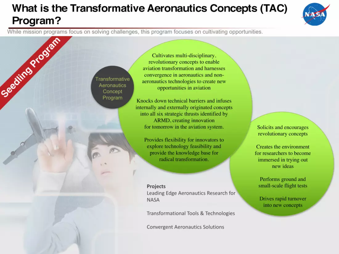
What is the Transformative Aeronautics Concepts (TAC) Program?
Solicits and encourages revolutionary concepts
Creates the environment for researchers to become
immersed in trying out new ideas
Performs ground and small-scale flight tests
Drives rapid turnover into new concepts
Cultivates multi-disciplinary, revolutionary concepts to enable
aviation transformation and harnesses convergence in aeronautics and non-
aeronautics technologies to create new opportunities in aviation
Knocks down technical barriers and infuses internally and externally originated concepts
into all six strategic thrusts identified by ARMD, creating innovation
for tomorrow in the aviation system.
Provides flexibility for innovators to explore technology feasibility and
provide the knowledge base for radical transformation.
Transformative Aeronautics
Concept Program
While mission programs focus on solving challenges, this program focuses on cultivating opportunities.
ProjectsLeadingEdgeAeronauticsResearchforNASA
TransformationalTools&Technologies
ConvergentAeronauticsSolutions

7NASAAeronautics Research
• NASA Aeronautics Research Mission Directorate Programs and Projects
• NASA Glenn High Speed Inlet Technology• Stream-traced External Compression Inlet
(STEX)• Quiet SuperSonic Technology (QueSST)
model test in 8’x6’ SWT
• NASA Glenn SWBLI CFD Activities
• NASA Glenn SWBLI Validation Experiment
Outline

8NASAAeronautics Research
Proposed 8x6 SWT Test of Inward-Turning Low-Boom Inlet
NASA Inlet Adapter Cold-Pipe Mass Flow PlugSTATUS• Continuing to work STEX design at off-design
conditions• LTO conditions ( 0.1 < M < 0.3), including aux
inlets , angle of attack, angle of sideslip• Paper on off-design performance to be
presented at ISABE in Sept 2017.• The AIP adapter (11.75” diffuser exit diam to
16” cold pipe/mass flow plug) is finished and will be shipped to the 8x6 for storage.
• Validation test article mech design complete; structural analysis underway. Preparing for fab estimate and build decision. Sketch of proposed 8x6 Inlet Test Rig
-Commercial Supersonic Technologies (CST) Project POC: Chuck Trefny and John Slater (GRC)
PROBLEMDemonstrate the performance and operability of an inward-turning, high-performance, low-boom inlet with acceptable distortion levels to enable integration with a turbine engine.
OBJECTIVES OF PROPOSED 8x6 SWT TEST(1) Validate the effects of bleed and other boundary layer control schemes (e.g.,
vortex generators) on overall inlet performance, (2) Provide better understanding of non-linear sub-critical phenomena, (3) Determine tolerance to angles of attack and yaw (4) Determine off-design Mach number performance
APPROACHPerform mechanical design, fabrication and GRC 8x6 Supersonic Wind Tunnel test of an inlet model. The model hardware will include using existing inlet adapter, cold-pipe, and mass flow plug. Existing adapter requires addition of rakes and hub to serve as Aerodynamic Interface Plane (AIP).

9NASAAeronautics Research
• NASA Aeronautics Research Mission Directorate Programs and Projects
• NASA Glenn High Speed Inlet Technology• Stream-traced External Compression Inlet
(STEX)• Quiet SuperSonic Technology (QueSST)
model test in 8’x6’ SWT
• NASA Glenn SWBLI CFD Activities
• NASA Glenn SWBLI Validation Experiment
Outline
10NASAAeronautics Research
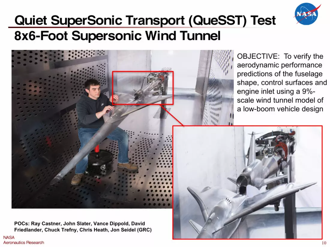
Quiet SuperSonic Transport (QueSST) Test8x6-Foot Supersonic Wind Tunnel
OBJECTIVE: To verify the aerodynamic performance predictions of the fuselage shape, control surfaces and engine inlet using a 9%-scale wind tunnel model of a low-boom vehicle design
POCs: Ray Castner, John Slater, Vance Dippold, David Friedlander, Chuck Trefny, Chris Heath, Jon Seidel (GRC)

11NASAAeronautics Research
Test Objectives
• The Quiet Supersonic Technology (QueSST) test series will occur in two phases:– Aerodynamic
• Will test a live balance installed to collect differential stability data on various control surface configurations and inlet flow-through nacelle screens.
– Propulsion• Will test with a varied inlet and nozzle in order to collect inlet performance
information.• Collect Background Oriented Schlieren (BOS) around inlet areas if
possible and schedule permits.

12NASAAeronautics Research
Model HardwareAero Configuration
• Stingmountedwith6-componentlivebalance
• Spikeextends5.1-infromnose• 8change-ablecontrolsurfaces• Totalmodellength,nose(no
spike)totail:– 106.5-in
• Totalwingspan:– 33.6-in
• Totallengthnose(nospike)tostrutLE:– 174.7-in
• TestSectionStation(nose,nospike):– TS145.3
• Totalconfigurations:– 53minor

13NASAAeronautics Research
Model HardwarePropulsion Configuration
1
• Blade-to-stingmountedwithNObalance
• Aftgeometrychanged– Notails/stabilizers
• Totalmodellength,nose(nospike)toMFPmixingcan:– 124.7-in
• Totalwingspan:– 33.6-in
• Totallengthnose(nospike)tostrutLE:– 174.7-in
• TestSectionStation(nose,nospike):– TS145.3
• Totalconfigurations:– 6minor

14NASAAeronautics Research
Model HardwarePropulsion Configuration
• Linear actuation of plug via electric motor
• AIP diameter: 3-in• MFP diameter: 3-in• Total MFP travel: 2.8-
in• Ejector only needed
when MFP pressure ratio is less than 2.0
• Ejector requirements:– 100-psig
compressed air– 0.9-lbm/sec
• Ejector supply from 450-psig air system
1

15NASAAeronautics Research
Test MatrixPropulsion Configuration
1
• Mach 0.30 – 1.6 (nom)• Varying factors:
– Inlets• Design• Alternate (fat lip)
– Vortex Generators• Baseline• Alternate 1• Alternate 2• Off
Note: primary source of propulsion data
Note: sample test matrix for a single propulsion configuration.

16NASAAeronautics Research
Propulsion Airframe Integration CFDPotential need for additional validation data and CFD tool refinements
• NASA analysis of C607.1 design was performed:
– Large differences (>5%) in NASA FUN3D vs. LM CFD++ inlet recovery and distortion.
– Differences attributed to predicted flow-field on top of vehicle.
• At GRC, the QueSST project marks the first time full vehicle aerodynamic analysis was performed using FUN3D on a mature vehicle design.
• The QueSST aircraft is unique in that it contains an aft-fuselage, top-mounted inlet installation, with complex shock-wave boundary-layer interactions that are sensitive to geometry and difficult to predict.
• Depending on the success of this first test, more investment/validation data sets likely needed to bring PAI best practices up to the same maturity level as sonic boom analysis.
92% RecoveryFun3D
97% RecoveryCFD++
Cruise Pt, Mach 1.42, AOA 1.7
Boundary Layer Growth and Shock-Induced Separation

17NASAAeronautics Research
Study of VGs on the QueSST Inlet (C606)
Objectives:• Vortex generators in current design are used to sweep the
boundary layer away from inlet.• NASA explored smaller vortex generators (VGs) aft of the
cockpit to reduce drag and shocks generated by the VGs.• Examine effect of design factors (height, length, angle).
Approach:• Use Wind-US CFD code with vortex generator model.• Simplified aircraft for structured grid to focus on VGs.• Consider effect on boundary layer at inlet entrance.
Results/Significance:• Study showed smaller VGs can effectively be used
to sweep the boundary layer away from the inlet.• Alternate VG designs were shared with Lockheed
for consideration in future configuration updates.
Inlet Lip
VG h75Configuration
VG Location

18NASAAeronautics Research
• NASA Aeronautics Research Mission Directorate Programs and Projects
• NASA Glenn High Speed Inlet Technology• Stream-traced External Compression Inlet
(STEX)• Quiet SuperSonic Technology (QueSST)
model test in 8’x6’ SWT
• NASA Glenn SWBLI CFD Activities
• NASA Glenn SWBLI Validation Experiment
Outline

19NASAAeronautics Research
Transformational Tools & Technologies ProjectLevel 2 Milestone Completion
Milestone:Evaluate advanced RANS and scale resolving simulations capability for prediction of shock-boundary layer interactions.
Exit Criteria:Quantify improvement in shock induced separation length and associated improvements in prediction of Reynolds stresses.
Due Date:03/31/2017
SWTBLIFocusregion
UFAST M2.25 SWBLI
30deg Axi Compression Corner
Transonic Diffuser
POCs: Nick Georgiadis, Julie Dudek, Manan Vyas and Jim DeBonis (GRC)

20NASAAeronautics Research
• The effect of the shear stress limiter in the Shear Stress Transport (SST) model was examined for shock separated flows
– Experimental data was used to characterize shear stress behavior– The SST model was adjusted to better replicate the experimental findings– Improved shock boundary layer predictions were obtained with the modified SST model
• Reynolds stress models (SSG/LRR & Wilcox) were evaluated for transonic diffuser and supersonic compression corner flows
– Provide enhanced physics and potential for more accurate predictions in some flows (physical representation of turbulence intensities)
– RSMs were very sensitive to the numerical scheme– RSMs did not show significant benefit boundary layer separation prediction– Need for additional research and include Algebraic Reynolds Stress models
• LES was used to simulate the UFAST shock boundary layer interaction– Digital filtering turbulent inflow generation created accurate boundary layer profiles upstream
of the shock– Separation is greatly under-predicted– Several areas are being investigated including numerical schemes, grid etc.
Summary of GRC SWBLI CFD Activities

21NASAAeronautics Research
Investigation of Shear Stress Limiter• The Menter Shear Stress Transport (SST) model is possibly the most widely
RANS used turbulence model for aerospace flows. It is a k-w model with “shear stress transport” part of the model coming from the limiter:
• The Menter BSL model is very similar to SST, but with no limiter.• Shear stress limiter sets a1 = 0.31 = -u’v’/k, using observations of Bradshaw,
Townsend, & others -- for zero pressure gradient and mild adverse gradient flows.
• Experimental data (UFAST, Smits et al, others) shows -u’v’/k exceeds 0.31 in SWTBLI flows. This quantity is known as the “structure parameter.”
• Others (Wilcox, Tan and Jin, Edwards) also have investigated values for a1greater than 0.31.
• This work:1. A range of a1 from 0.31 to 0.40 was investigated, for several cases
including SWTBLIs. (Larger values for a1 are very similar to BSL)2. Examined details of experimental turbulent measurements alongside
computations to determine appropriate value(s) for a1 in SWTBLI flows.
µt =minρkω; a1ρkΩF2
"
#$
%
&'

22NASAAeronautics Research
UFAST SWBLI Test Case 2010 AIAA SWTBLI Workshop
• Mach2.25flowapproachingSWTBLIregion.• SeveralRANSandLES(includinghybridRANS-LES)solutionssubmitted;
mostwidelyusedRANSturbulencemodelswereSSTandSA.
SWTBLIFocusregion

23NASAAeronautics Research
UFAST Results when varying “a1”Experiment Menter SSTk-w
Menter BSLk-w Menter SSTk-w, a1 =0.355
• BSL and SST models provide solutions on either side of experimental data for SWTBLIs.
• For all flows, but especially SWTBLIs, increasing a1 results in less limiting of turbulent shear stress…..smaller separations.
• a1 = 0.355 is recommended value for SWTBLI problems.• The capability to vary a1 was added to Wind-US version 4. The most recent
Wilcox k-w also uses a larger effective value for a1=0.343.

24NASAAeronautics Research
• NASA Aeronautics Research Mission Directorate Programs and Projects
• NASA Glenn High Speed Inlet Technology• Stream-traced External Compression Inlet
(STEX)• Quiet SuperSonic Technology (QueSST)
model test in 8’x6’ SWT
• NASA Glenn SWBLI CFD Activities
• NASA Glenn SWBLI Validation Experiment
Outline

25NASAAeronautics Research
TurbulenceCFDValidationExperiments(TCFDVE)
POC:DavidO.Davis(GRC)17cm Axisymmetric Supersonic Wind Tunnel
PROBLEMVery few Shock Wave/Boundary-Layer Interaction (SWBLI) experiments reported in the open literature meet the rigorous criteria required to be considered as a CFD validation dataset. This is particularly true for experiments with detailed turbulence measurements.
OBJECTIVESObtain mean and turbulence quantities through a M=2.5 SWBLI of sufficient quantity and quality to be considered as a CFD validation dataset. Initial efforts will focus on a Mach 2.5 2-D (in the mean) interaction with follow-on efforts investigating 3-D interactions. Both attached and separated interactions will be considered.
APPROACHA new M=2.5 17cm axisymmetric facility has been constructed to investigate SWBLIs. The facility is located in Test Cell W6B at NASA GRC. The SWBLI is generated by a cone-cylinder located on the centerline of the facility. The strength of the interaction is varied by changing the cone angle. The measurement region of interest is where the conical shock interacts with the naturally occurring facility boundary-layer that is highlighted by the box shown in Figure 1. The new facility will be instrumented with conventional pressure instrumentation as well as hot-wire anemometry for measurement of turbulence quantities. Non-intrusive optical techniques such as PIV will be incorporated in the future. Test are also planned with dynamic surface shear film and fast response Pressure Sensitive Paint (PSP) in collaboration with Innovative Scientific Solutions, Incorporated (ISSI).RESULTSNormal hot-wire measurements have been completed.
SIGNIFICANCEThe data to be generated has been previously unavailable. Further, development of an in-house capability to investigate SWBLIs will allow CFD code developers and turbulence modelers to have direct input into the experiment. It will also allow the ability to revisit measurements if deemed necessary.
-Transformational Tools & Technologies (T3) Project

26NASAAeronautics Research Your Title Here


