Embed Size (px)
Citation preview
OWNER’S MANUAL MODEL 230SSF/235SSF
Single Swing Fire Rated Doors
MANUAL PART #: 17A144
ASI DOORS, INC. (800) 558-7068 asidoors.com2
GENERAL INFO
RMATIO
N
GENERAL INFORMATION 3-6Safety Practices 3 Warranty Policy 5Crates and Contents 6
120-235 MANUAL INSTALLATION 7-16 Storage at Building Site 7Door Frame Measurements 7Power Operator Reinforcement 8Slip-On Frame Installation 8Welded/Knockdown Frame Install 10Door Hardware and Accessories 11Door Hardware: Wall Anchors 11Door Hardware: Gasketing 12 Door Hardware: MagLock 14Door Hardware: Manual Closers 14Power Operator Installation 15Operator Handing 16
ELECTRICAL CONTROLS 19-40 Safety Warnings & Symbols 19 Electrical Requirements 19Modes of Door Operation 20 Programming with the FCP 23 Teach-In Process, Single Swing 25 Teach-In Process, Paired Swing 28Programming Table 29Troubleshooting Codes 34Control Connections, Single 35Control Connections, Paired Primary 36Control Connections, Paired Secondary 37Electric Schematic, Single 38Electric Schematic, Paired Primary 39Electric Schematic, Paired Secondary 40
REPLACEMENT PARTS 41-46 Instructions for Ordering 41
Door Assembly, Single 42 Door Assembly, Paired 43Door Panel 44 Operator and Shroud 46
ASI DOORS, INC. (800) 558-7068 asidoors.com3
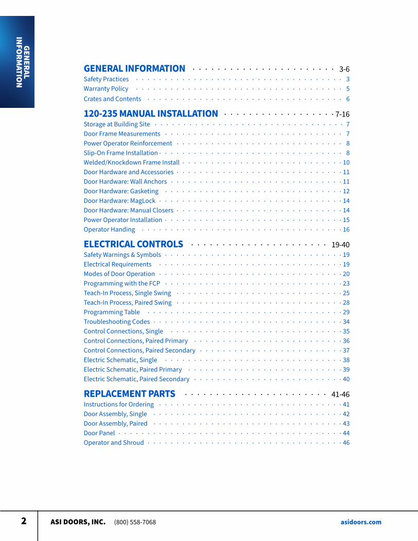
Safety Practices
This is a safety alert symbol. It is used to alert you to potential personal injury hazards. Obey all safety messages that follow this symbol to avoid possible injury or death.
WARNING indicates a potentially hazardous situation which, if not avoided, could result in death or serious injury
CAUTION indicates a potentially hazardous situation which, if not avoided, may result in minor or moderate injury
CAUTION used without a safety alert symbol indicates a potentially hazardous situation which, if not avoided, may result in property damage
NOTE explains general information
DANGER indicates an imminently hazardous situation which, if not avoided, will result in death or serious injury
NOTE
GENERAL INFO
RMATIO
N
ASI DOORS, INC. (800) 558-7068 asidoors.com4
Warning read these safety practices before installing, operating or servicing the SLIDING door Failure to follow these safety practices could result in property damage, death or
serious injury READ AND UNDERSTAND ALL WARNING LABELS AND OPERATING INSTRUCTIONS IN THIS
MANUAL BEFORE OPERATING THE SLIDING DOOR If you do not understand the instructions, ask your supervisor to teach you how to use the SLIDING door
Safety Practices (cont’d)1 Do not operate the door while under the influence of drugs or alchohol
2 Do not use the door if it looks broken or does not seem to work properly Advise your supervisor at once
3 Stay clear of the door when it is moving
4 Keep hands, feet and head clear of the door at all times
5 Do not operate the door with equipment, material or people directly inside door opening
6 Disconnect power before performing any electrical or mechanical service, cleaning or other mainte-nance on the door OSHA requires disconnect to be properly tagged and locked out during all mainte-nance or service of equipment With the power supply disconnected, always verify using a volt meter
7 All electrical troubleshooting or service must be completed by a qualified electrician or service person and must meet all applicable local, state, federal, international and other governing agency codes
8 When it is necessary to service the control box with power on, USE EXTREME CAUTION Do not place fingers or uninsulated tools inside the control box Touching wires or other parts inside the enclosure may cause electrical shock, serious injury or death
9 It is your responsibility to keep all warning labels and instructional literature legible, intact and kept with the door Replacement labels and literature are availale from ASI Doors, Inc or its representatives
10 If you have any questions, contact your supervisor or your local ASI Doors, Inc representative for assistance
11 Train all service and personnel using or near door on intended use(s) and operation of the door
12 Failure to operate the door as intended, as described, or heed any warning may result in equipment damage, property damage, serious bodily injury or death
GENERAL INFO
RMATIO
N
ASI DOORS, INC. (800) 558-7068 asidoors.com5
Warranty Policy ASI Doors (herein called “ASI”) warrants solely for the benefit of its customer that each door system manufactured by ASI (each a “Door System”) will be free from defects in material and manufacture for a period of one (1) year from the date of original shipment by ASI The following models receive a similar two (2) years from date of shipment warranty: 109, 209, 120-125, 1240-125-, 1240SS-1250SS, 1260-1270, 1260SS-1270SS, 130-135, 140-150, 160-170, 220-225, 220SS-225SS, 230-235, 230SS-235SS In all instances warranty labor is covered for a period of one (1) year from the date of original shipment
The foregoing limited warranty shall not apply to defects that result from improper installation, abuse, misuse, alteration, modification, or failure to maintain the Door System in accordance with the ASI Owner’s Manual Periodic maintenance and adjustment of the Door System as described in the ASI Owner’s Manual are the sole responsibility of the customer All claims for defects must be made to ASI within thirty (30) days after the defect is discovered or should, with reasonable care, have been discovered THE FOREGOING LIMITED WARRANTY CONSTITUTES THE EXCLUSIVE WARRANTY OF ASI WITH RESPECT TO THE DOOR SYSTEM. ASI EXPRESSLY DISCLAIMS ALL OTHER GUARANTEES OR WARRANTIES—WHETHER EXPRESSED, IMPLIED, OR STATUTORY, INCLUDING BUT NOT LIMITED TO ANY IMPLIED WARRANTY OF MERCHANTABILITY AND FITNESS FOR A PARTICULAR PURPOSE.
If a Door System does not comply with the foregoing limited warranty, and a claim is made by customer within the warranty period, ASI will, at the option of ASI, either repair or replace any defective equipment or parts free of charge and pay the reasonable labor costs to repair or replace the defective equipment or parts if within the defined warranty period The remedy of repair or replacement shall be the exclusive and sole remedy for any breach of the foregoing limited warranty
ASI SHALL NOT IN ANY EVENT BE LIABLE FOR ANY INCIDENTAL, INDIRECT, SPECIAL, EXEMPLARY OR CONSEQUENTIAL DAMAGES OF ANY KIND, INCLUDING WITHOUT LIMITATION ANY LOST PROFITS, ARISING FROM THE SALE OR USE OF THE DOOR SYSTEM, OR FROM ANY OTHER CAUSE WHATSOEVER, WHETHER THE CLAIM GIVING RISE TO SUCH DAMAGES IS BASED UPON BREACH OF WARRANTY (EXPRESSED OR IMPLIED) BREACH OF CONTRACT, TORT, STRICT LIABILITY OR ANY OTHER THEORY OF LIABILITY, EVEN IF A PARTY HAS BEEN ADVISED OF THE POSSIBILITY THEREOF, AND REGARDLESS OF ANY ADVISE OR REPRESENTATION THAT MAY HAVE BEEN RENDERED BY ASI CONCERNING THE SALE OR USE OF THE DOOR SYSTEM.
At ASI’s request, customer shall return to ASI for inspection any Door System for which a warranty claim has been made, F O B ASI’s facility with freight prepaid The customer is responsible for any removal costs
The customer shall comply with the following procedures in filing a warranty claim with ASI:
1 Notify ASI of any and all defects in writing with photographic evidence ASI will review the warranty request and issue a Returns Merchandise Authorization (RMA) form if the defective parts need to be returned to ASI for inspection and verification The RMA form must accompany any materials returned for warranty consideration
2 All replacement parts or equipment will be invoiced to the customer Upon verification by ASI that the Door System is defective, ASI will issue a full credit to customer for the replacement parts or equipment
3 If outside labor is needed to install the replacement parts or equipment, ASI requires a written estimate of the labor charges in advance so ASI may approve the labor charges and issue a purchase order ASI will not accept any labor charges unless previously approved in writing and accompanied by the ASI purchase order number
(Rev 12/21)
GENERAL INFO
RMATIO
N
ASI DOORS, INC. (800) 558-7068 asidoors.com6
Crates and Contents
GENERAL INFO
RMATIO
N
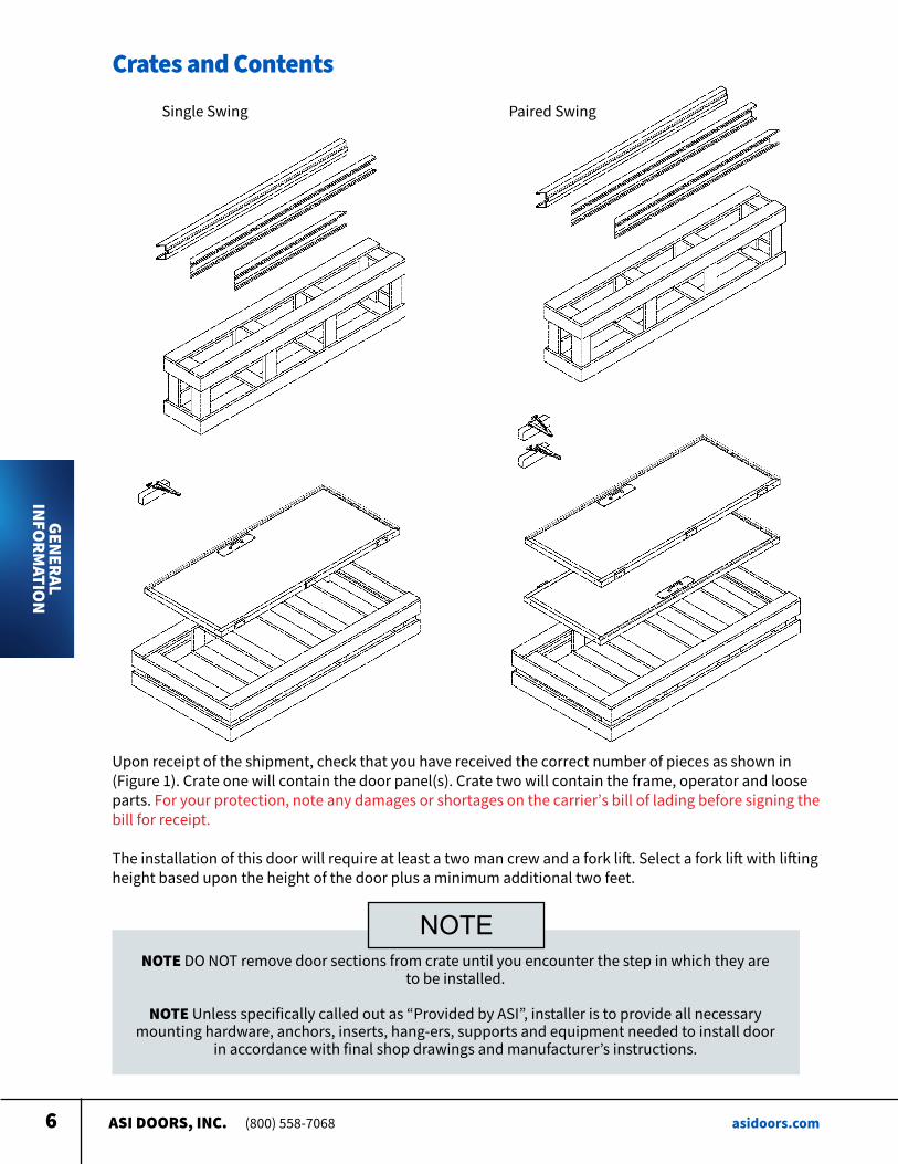
Single Swing Paired Swing
Upon receipt of the shipment, check that you have received the correct number of pieces as shown in (Figure 1) Crate one will contain the door panel(s) Crate two will contain the frame, operator and loose parts For your protection, note any damages or shortages on the carrier’s bill of lading before signing the bill for receipt
The installation of this door will require at least a two man crew and a fork lift Select a fork lift with lifting height based upon the height of the door plus a minimum additional two feet
NOTE DO NOT remove door sections from crate until you encounter the step in which they are to be installed
NOTE Unless specifically called out as “Provided by ASI”, installer is to provide all necessary
mounting hardware, anchors, inserts, hang-ers, supports and equipment needed to install door in accordance with final shop drawings and manufacturer’s instructions
NOTE
ASI DOORS, INC. (800) 558-7068 asidoors.com7
Storage at Building Site
INSTALLATION
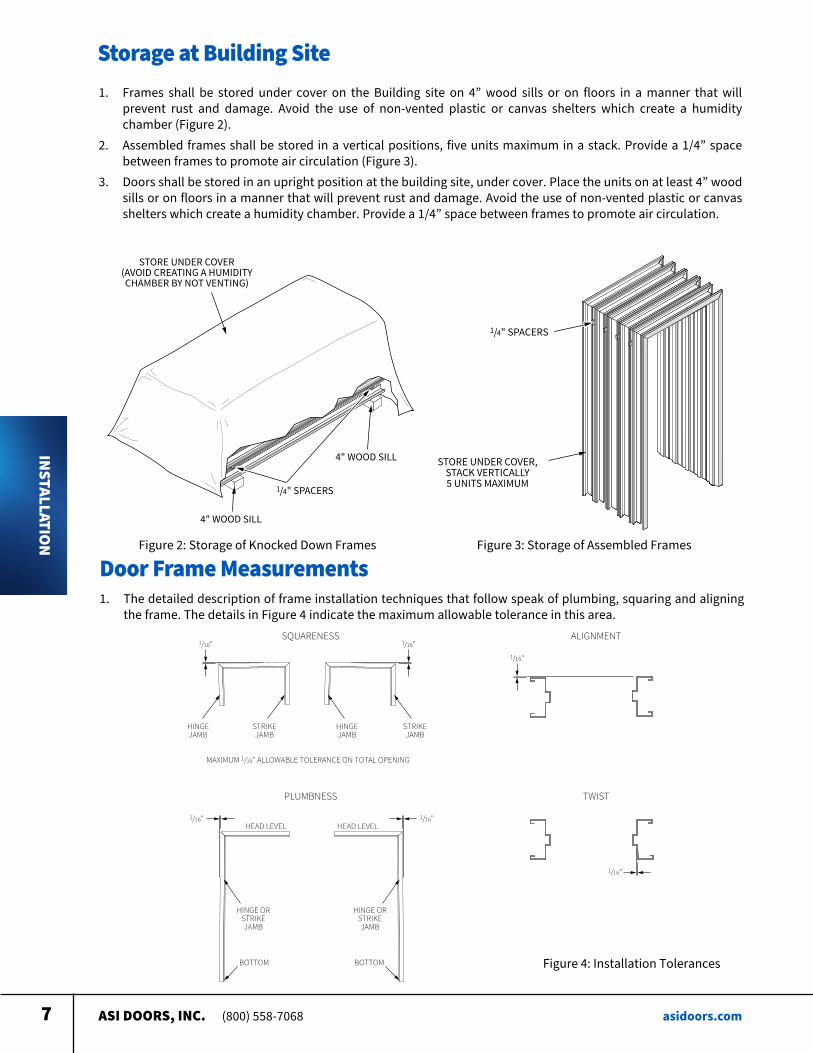
1 Frames shall be stored under cover on the Building site on 4” wood sills or on floors in a manner that will prevent rust and damage Avoid the use of non-vented plastic or canvas shelters which create a humidity chamber (Figure 2)
2 Assembled frames shall be stored in a vertical positions, five units maximum in a stack Provide a 1/4” space between frames to promote air circulation (Figure 3)
3 Doors shall be stored in an upright position at the building site, under cover Place the units on at least 4” wood sills or on floors in a manner that will prevent rust and damage Avoid the use of non-vented plastic or canvas shelters which create a humidity chamber Provide a 1/4” space between frames to promote air circulation
1/4" SPACERS
STORE UNDER COVER(AVOID CREATING A HUMIDITYCHAMBER BY NOT VENTING)
4" WOOD SILL
4" WOOD SILL
Figure 2: Storage of Knocked Down Frames
1/4" SPACERS
STORE UNDER COVER,STACK VERTICALLY5 UNITS MAXIMUM
Figure 3: Storage of Assembled Frames
Door Frame Measurements1 The detailed description of frame installation techniques that follow speak of plumbing, squaring and aligning
the frame The details in Figure 4 indicate the maximum allowable tolerance in this area
1/16"
1/16"
HINGEJAMB
HEAD LEVEL
STRIKEJAMB
MAXIMUM 1/16" ALLOWABLE TOLERANCE ON TOTAL OPENING
HINGE ORSTRIKEJAMB
BOTTOM
SQUARENESS
PLUMBNESS
ALIGNMENT
STRIKEJAMB
1/16"
TWIST
1/16"
1/16"HEAD LEVEL
HINGE ORSTRIKEJAMB
BOTTOM
1/16"
HINGEJAMB
Figure 4: Installation Tolerances
ASI DOORS, INC. (800) 558-7068 asidoors.com8
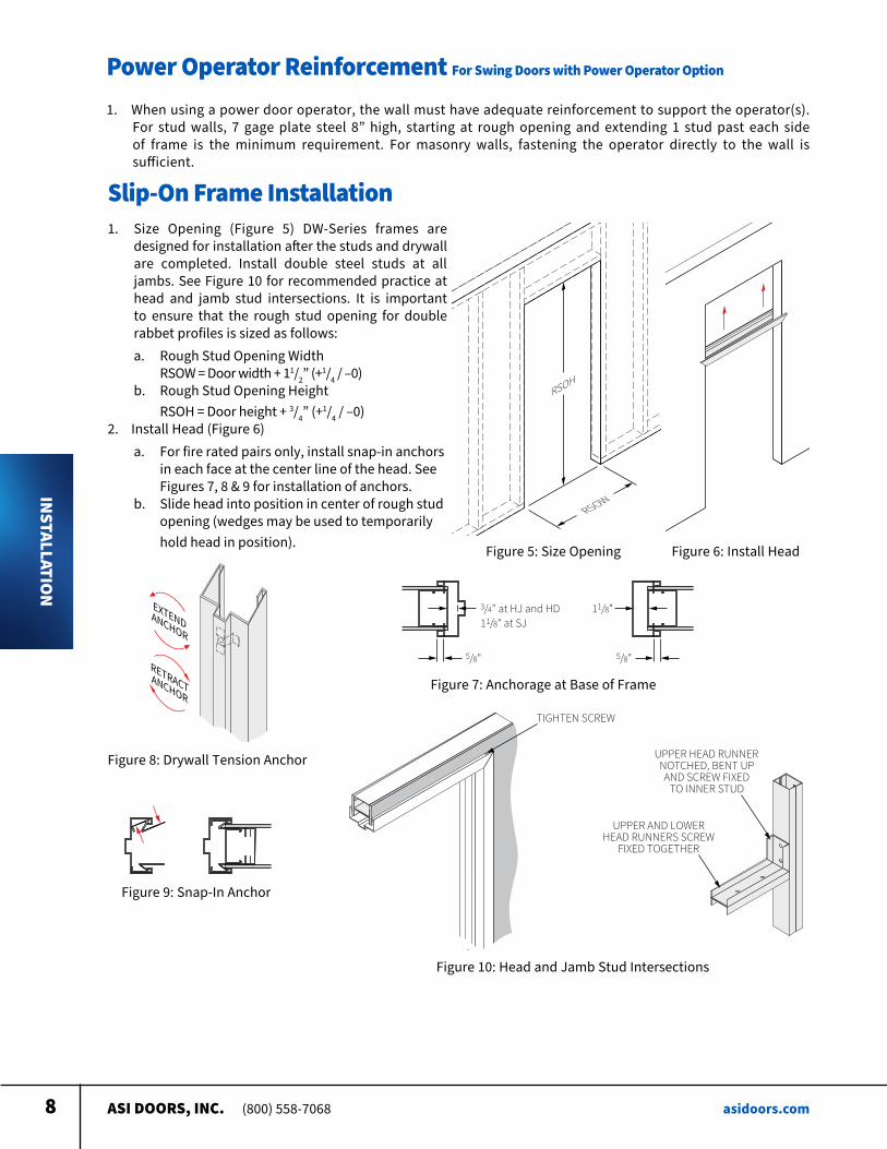
Power Operator Reinforcement For Swing Doors with Power Operator Option
INSTALLATION
1 When using a power door operator, the wall must have adequate reinforcement to support the operator(s) For stud walls, 7 gage plate steel 8” high, starting at rough opening and extending 1 stud past each side of frame is the minimum requirement For masonry walls, fastening the operator directly to the wall is sufficient
Slip-On Frame Installation
3/4" at HJ and HD11/8" at SJ
11/8"
5/8" 5/8"
Figure 7: Anchorage at Base of Frame
Figure 9: Snap-In Anchor
EXTENDANCHOR
RETRACTANCHOR
Figure 8: Drywall Tension Anchor
1 Size Opening (Figure 5) DW-Series frames are designed for installation after the studs and drywall are completed Install double steel studs at all jambs See Figure 10 for recommended practice at head and jamb stud intersections It is important to ensure that the rough stud opening for double rabbet profiles is sized as follows:a Rough Stud Opening Width
RSOW = Door width + 11/2” (+1/4 / –0)b Rough Stud Opening Height
RSOH = Door height + 3/4” (+1/4 / –0)2 Install Head (Figure 6)
a For fire rated pairs only, install snap-in anchors in each face at the center line of the head See Figures 7, 8 & 9 for installation of anchors b Slide head into position in center of rough stud opening (wedges may be used to temporarily hold head in position) Figure 6: Install Head
RSOW
RSOH
Figure 5: Size Opening
UPPER HEAD RUNNERNOTCHED, BENT UPAND SCREW FIXED
TO INNER STUD
UPPER AND LOWERHEAD RUNNERS SCREW
FIXED TOGETHER
TIGHTEN SCREW
Figure 10: Head and Jamb Stud Intersections
ASI DOORS, INC. (800) 558-7068 asidoors.com9
Slip-On Frame Installation Continued
INSTALLATION
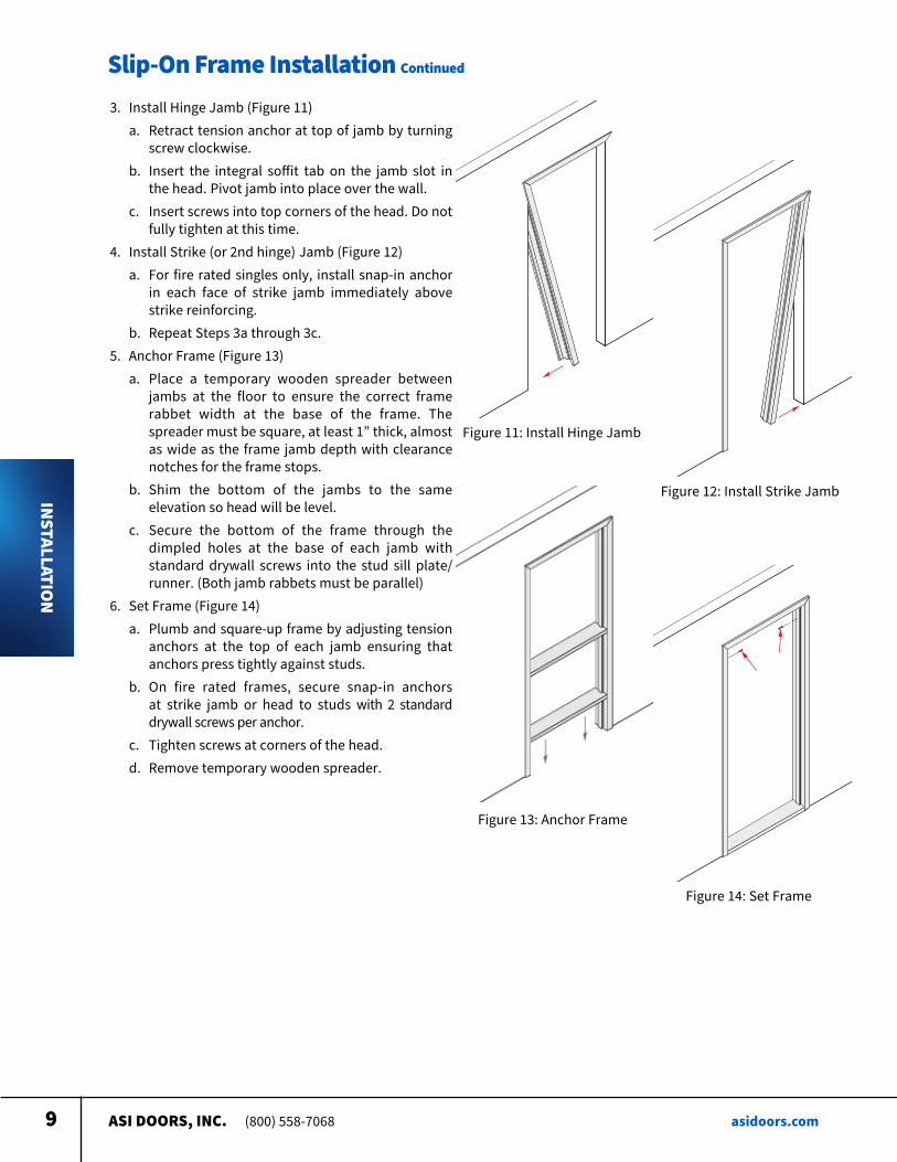
3 Install Hinge Jamb (Figure 11) a Retract tension anchor at top of jamb by turning
screw clockwise b Insert the integral soffit tab on the jamb slot in
the head Pivot jamb into place over the wall c Insert screws into top corners of the head Do not
fully tighten at this time 4 Install Strike (or 2nd hinge) Jamb (Figure 12) a For fire rated singles only, install snap-in anchor
in each face of strike jamb immediately above strike reinforcing
b Repeat Steps 3a through 3c 5 Anchor Frame (Figure 13) a Place a temporary wooden spreader between
jambs at the floor to ensure the correct frame rabbet width at the base of the frame The spreader must be square, at least 1” thick, almost as wide as the frame jamb depth with clearance notches for the frame stops
b Shim the bottom of the jambs to the same elevation so head will be level
c Secure the bottom of the frame through the dimpled holes at the base of each jamb with standard drywall screws into the stud sill plate/runner (Both jamb rabbets must be parallel)
6 Set Frame (Figure 14) a Plumb and square-up frame by adjusting tension
anchors at the top of each jamb ensuring that anchors press tightly against studs
b On fire rated frames, secure snap-in anchors at strike jamb or head to studs with 2 standard drywall screws per anchor
c Tighten screws at corners of the head d Remove temporary wooden spreader
Figure 12: Install Strike Jamb
Figure 13: Anchor Frame
Figure 14: Set Frame
Figure 11: Install Hinge Jamb
ASI DOORS, INC. (800) 558-7068 asidoors.com10
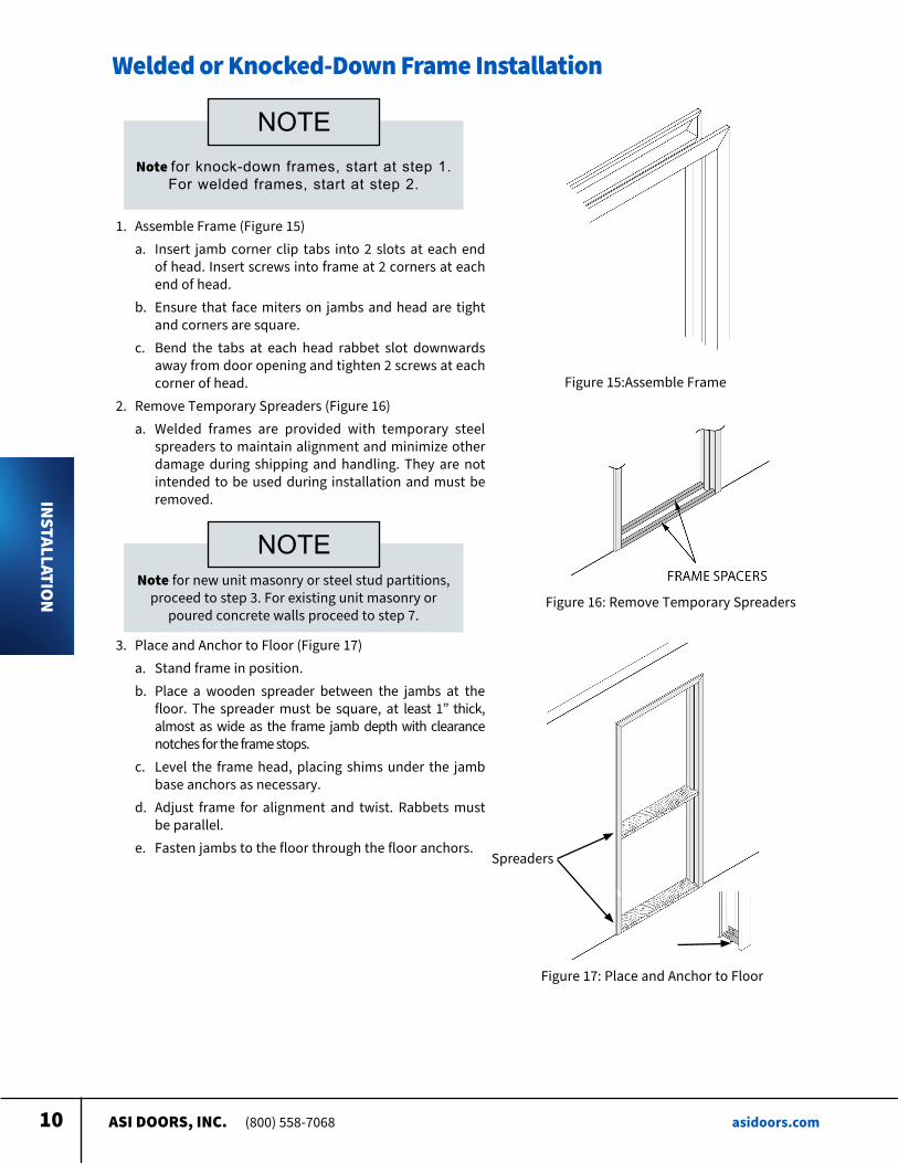
Welded or Knocked-Down Frame Installation
INSTALLATION
Note for knock-down frames, start at step 1. For welded frames, start at step 2.
NOTE
1 Assemble Frame (Figure 15) a Insert jamb corner clip tabs into 2 slots at each end
of head Insert screws into frame at 2 corners at each end of head
b Ensure that face miters on jambs and head are tight and corners are square
c Bend the tabs at each head rabbet slot downwards away from door opening and tighten 2 screws at each corner of head
2 Remove Temporary Spreaders (Figure 16) a Welded frames are provided with temporary steel
spreaders to maintain alignment and minimize other damage during shipping and handling They are not intended to be used during installation and must be removed
Figure 15: Assemble Frame
Figure 16: Remove Temporary Spreaders
Figure 17: Place and Anchor to Floor
Note for new unit masonry or steel stud partitions, proceed to step 3 For existing unit masonry or
poured concrete walls proceed to step 7
NOTE
Spreaders
3 Place and Anchor to Floor (Figure 17) a Stand frame in position b Place a wooden spreader between the jambs at the
floor The spreader must be square, at least 1” thick, almost as wide as the frame jamb depth with clearance notches for the frame stops
c Level the frame head, placing shims under the jamb base anchors as necessary
d Adjust frame for alignment and twist Rabbets must be parallel
e Fasten jambs to the floor through the floor anchors
ASI DOORS, INC. (800) 558-7068 asidoors.com11
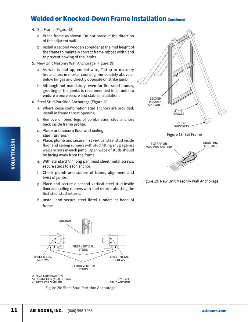
Welded or Knocked-Down Frame Installation Continued
INSTALLATION
4 Set Frame (Figure 18) a Brace frame as shown Do not brace in the direction
of the adjacent wall b Install a second wooden spreader at the mid height of
the frame to maintain correct frame rabbet width and to prevent bowing of the jambs
5 New Unit Masonry Wall Anchorage (Figure 19) a As wall is laid up, embed wire, T-stop or masonry
fire anchors in mortar coursing immediately above or below hinges and directly opposite on strike jamb
b Although not mandatory, even for fire rated frames, grouting of the jambs is recommended in all units to endure a more secure and stable installation
6 Steel Stud Partition Anchorage (Figure 20) a Where loose combination stud anchors are provided,
install in frame throat opening b Remove or bend legs of combination stud anchors
back inside frame profile c. Place and secure floor and ceiling steel runners. d Place, plumb and secure first vertical steel stud inside
floor and ceiling runners with stud fitting snug against wall anchors in each jamb Open webs of studs should be facing away from the frame
e With standard 1/2” long pan head sheet metal screws, secure studs to each anchor
f Check plumb and square of frame, alignment and twist of jambs
g Place and secure a second vertical steel stud inside floor and ceiling runners with stud returns abutting the first steel stud returns
h Install and secure steel lintel runners at head of frame
SECONDWOODEN
SPREADER
2" × 4"BRACES
2" × 4"SUPPORTS
Figure 18: Set Frame
T-STRAP ORMASONRY ANCHOR
GROUTINGTHE JAMB
Figure 19: New Unit Masonry Wall Anchorage
ANCHOR
“Z” TYPESTUD ANCHOR
FIRST VERTICALSTUDS
SHEET METALSCREWS
SHEET METALSCREWS
SECOND VERTICALSTUDS
2 PIECE COMBINATIONSTUD ANCHOR (CSA) SHOWN(1 PIECE CSA SIMILAR)
Figure 20: Steel Stud Partition Anchorage

ASI DOORS, INC. (800) 558-7068 asidoors.com12
Door Hardware and Accessories
INSTALLATION
7 Existing Masonry or Poured Concrete Wall Anchorage (Figure 21)
a Set the assembled frame centered in the completed opening
b Place wooden spreaders between the jambs at the floor and at mid height of the frame
c Level the head by placing shims under the jambs as necessary
d Adjust the frame for plumb, square, alignment and twist Rabbets must be parallel
e Mark the wall through the dimpled holes in the jamb soffits to locate the anchor points
f Drill the wall for appropriate holes at the marks g Install sleeve or expansion shell anchors in the wall
holes h Insert anchor bolts through the dimpled holes into
the wall sleeve anchors i Place shims snugly between the frame and the wall,
above each anchor bolt j Tighten bolts, checking plumb, square, alignment
and twist
EXPANSIONANCHOR
SHIM
Figure 21: Existing Masonry or Poured Concrete Wall Anchorage
HINGES FRAMECUTOUTS
Figure 22: Panel Installation
1 Door Panel: (Figure 22) a The door is shipped with all hinges mounted on door
frame b Match door panel with correct frame c Line door hinges up with frame cutouts and secure
hinges with supplied fasteners 2 Sweep Gasket: (Figure 23) a Position sweep gasket at the door bottom of desired
side such that gasket will just touch the floor through full range of door travel Positioning gasket too close to floor will wear gasket out prematurely
b Trim length as needed c Mark holes on panel and secure with supplied #6-32
screws
Figure 23: Sweep Gasket Installation
ASI DOORS, INC. (800) 558-7068 asidoors.com13
Door Hardware and Accessories Continued
INSTALLATION
HINGESIDE
GASKET
SINGLE SWINGDOOR WITH
PANEL NOT SHOWN
NON-HINGESIDE
GASKET
HEADGASKET
Figure 25: Frame Gasket Installation
ASTRAGALGASKET
SCREWS
Figure 24: Astragal Gasket Installation
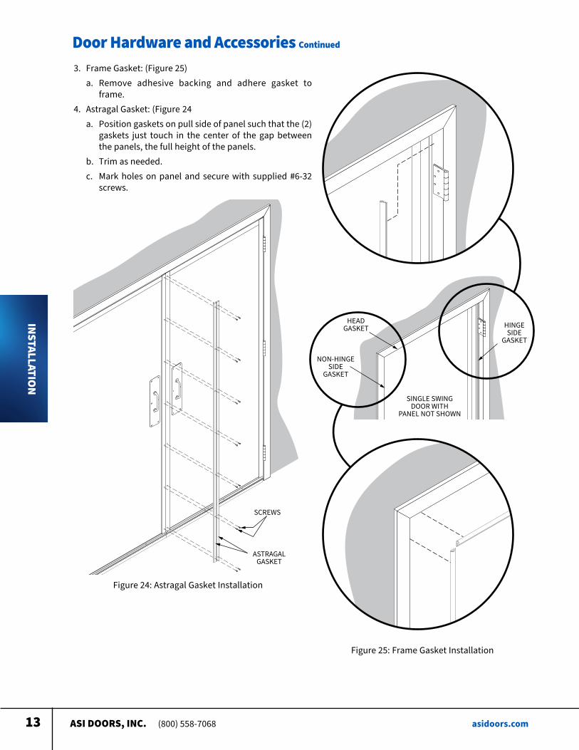
3 Frame Gasket: (Figure 25) a Remove adhesive backing and adhere gasket to
frame 4 Astragal Gasket: (Figure 24 a Position gaskets on pull side of panel such that the (2)
gaskets just touch in the center of the gap between the panels, the full height of the panels
b Trim as needed c Mark holes on panel and secure with supplied #6-32
screws
ASI DOORS, INC. (800) 558-7068 asidoors.com14
Door Hardware and Accessories Continued
INSTALLATION
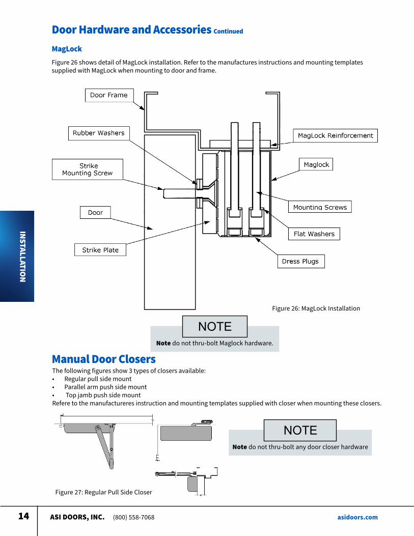
MagLockFigure 26 shows detail of MagLock installation Refer to the manufactures instructions and mounting templates supplied with MagLock when mounting to door and frame
Figure 26: MagLock Installation
Note do not thru-bolt Maglock hardware
NOTE
Manual Door ClosersThe following figures show 3 types of closers available:• Regular pull side mount• Parallel arm push side mount• Top jamb push side mountRefere to the manufactureres instruction and mounting templates supplied with closer when mounting these closers
Figure 27: Regular Pull Side Closer
Note do not thru-bolt any door closer hardware
NOTE
ASI DOORS, INC. (800) 558-7068 asidoors.com15
Door Hardware and Accessories Continued
INSTALLATION
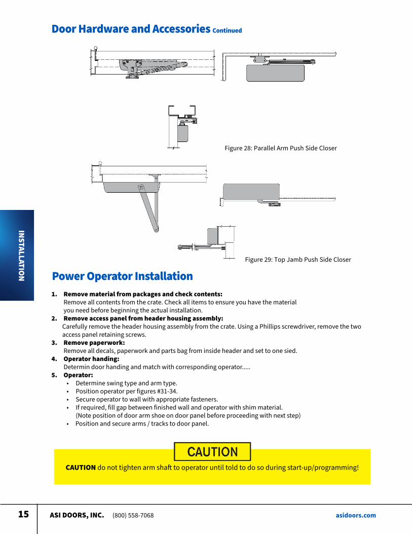
Figure 28: Parallel Arm Push Side Closer
Figure 29: Top Jamb Push Side Closer
Power Operator Installation1. Remove material from packages and check contents:
Remove all contents from the crate Check all items to ensure you have the material you need before beginning the actual installation
2. Remove access panel from header housing assembly: Carefully remove the header housing assembly from the crate Using a Phillips screwdriver, remove the two access panel retaining screws 3. Remove paperwork: Remove all decals, paperwork and parts bag from inside header and set to one sied 4. Operator handing: Determin door handing and match with corresponding operator 5. Operator:
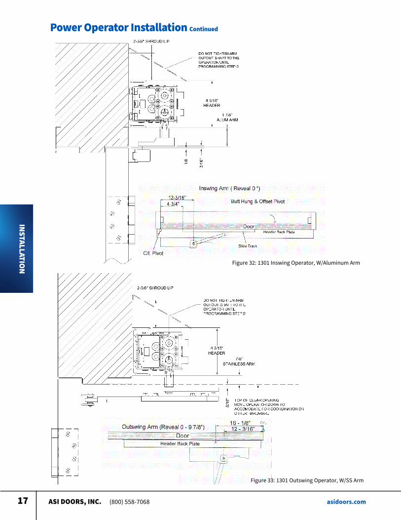
• Determine swing type and arm type • Position operator per figures #31-34 • Secure operator to wall with appropriate fasteners • If required, fill gap between finished wall and operator with shim material (Note position of door arm shoe on door panel before proceeding with next step) • Position and secure arms / tracks to door panel
CAUTION do not tighten arm shaft to operator until told to do so during start-up/programming!
ASI DOORS, INC. (800) 558-7068 asidoors.com16
Power Operator Installation Continued
INSTALLATION
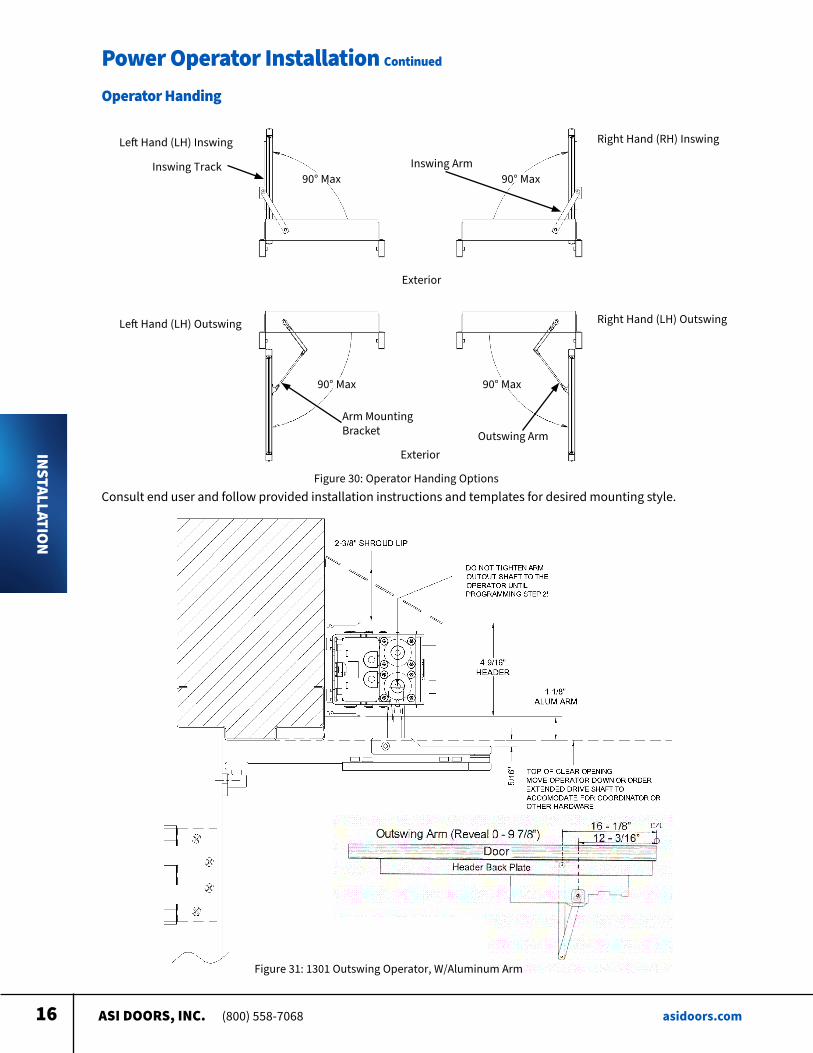
Operator Handing
Right Hand (RH) InswingLeft Hand (LH) Inswing
Exterior
Exterior
90° Max 90° Max
90° Max 90° Max
Left Hand (LH) Outswing Right Hand (LH) Outswing
Inswing Track Inswing Arm
Arm Mounting Bracket Outswing Arm
Consult end user and follow provided installation instructions and templates for desired mounting style Figure 30: Operator Handing Options
Figure 31: 1301 Outswing Operator, W/Aluminum Arm
ASI DOORS, INC. (800) 558-7068 asidoors.com17
Power Operator Installation Continued
INSTALLATION Figure 32: 1301 Inswing Operator, W/Aluminum Arm
Figure 33: 1301 Outswing Operator, W/SS Arm
ASI DOORS, INC. (800) 558-7068 asidoors.com18
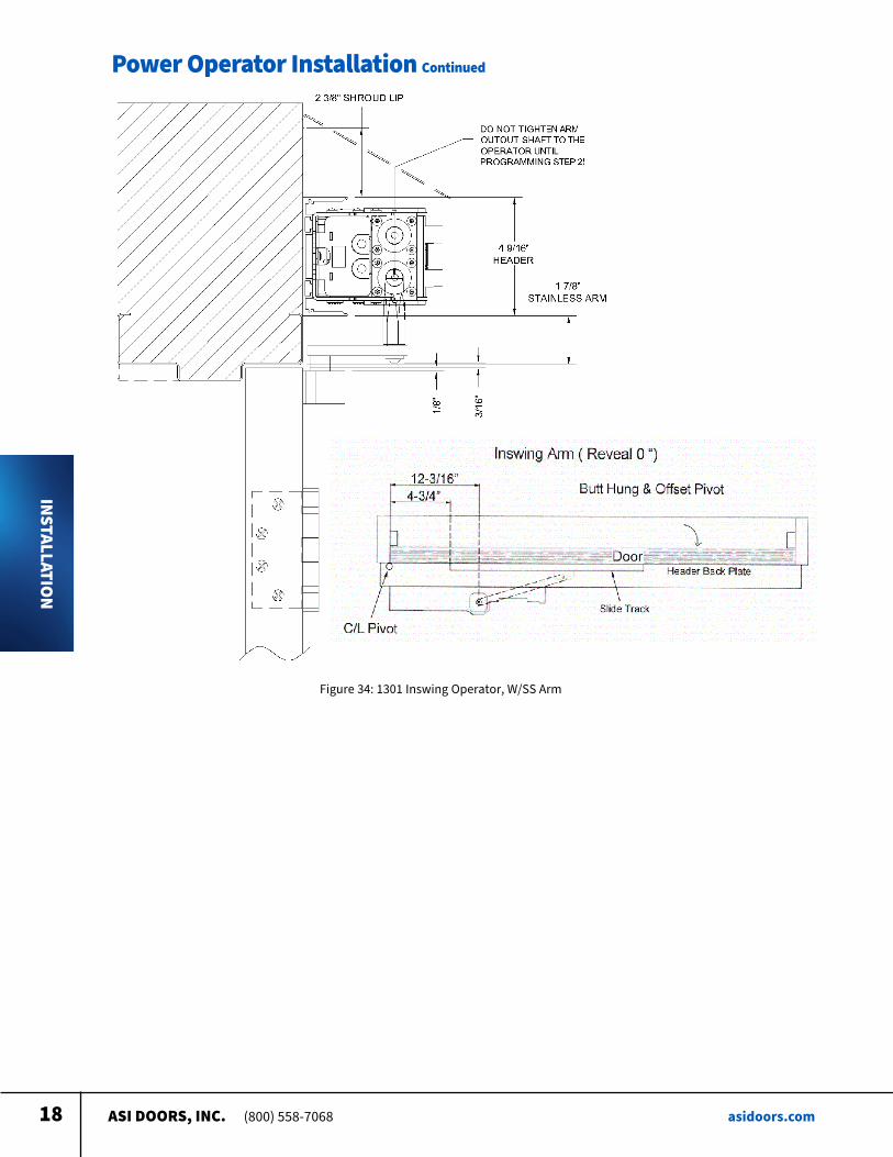
Power Operator Installation Continued
INSTALLATION
Figure 34: 1301 Inswing Operator, W/SS Arm
ASI DOORS, INC. (800) 558-7068 asidoors.com19
Electrical Controls Continued
INSTALLATION
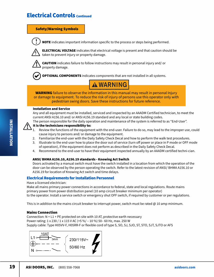
NOTE indicates important information specific to the process or steps being performed ELECTRICAL VOLTAGE indicates that electrical voltage is present and that caution should be taken to prevent injury or property damage CAUTION indicates failure to follow instructions may result in personal injury and/ or property damage
OPTIONAL COMPONENTS indicates components that are not installed in all systems
WARNING failure to observe the information in this manual may result in personal Injury or damage to equipment To reduce the risk of injury of persons use this operator only with
pedestrian swing doors Save these instructions for future reference
Installation and Service Any and all equipment must be installed, serviced and inspected by an AAADM Certified technician, to meet the current ANSI A156 10 and/ or ANSI A156 19 standard and any local or state building codes The person responsible for the daily operation and maintenance of the system is referred to as “End-User” It is the technicians responsibility to: 1 Review the functions of the equipment with the end-user Failure to do so, may lead to the improper use, could
cause injury to persons and/ or damage to the equipment 2 Familiarize the end-user with the Daily Safety Check Decal and how to perform the walk test procedures 3 Illustrate to the end-user how to place the door out of service (turn off power or place in P mode or OFF mode
of operation), if the equipment does not perform as described in the Daily Safety Check Decal 4 Recommend to the end-user to have their equipment inspected annually by an AAADM certified techni-cian
ANSI/ BHMA A156.10, A156.19 standards - Knowing Act Switch Doors activated by a manual switch must have the switch installed in a location from which the operation of the door can be observed by the person operating the switch Refer to the latest revision of ANSI/ BHMA A156 10 or A156 19 for location of Knowing Act switch and time delays
Safety/Warning Symbols
Have a licensed electrician: Make all mains primary power connections in accordance to federal, state and local regulations Route mains primary power from power distribution panel (10 amp circuit breaker minimum per operator) to the operator Install a service switch or emergency shut OFF switch, if required by customer or per regulations
This is in addition to the mains circuit breaker to interrupt power, switch must be rated @ 10 amp minimum
Mains Connection Connection: N + L1 + PE protected on site with 10 AT, protective earth necessary Power rating: 1 x 230 / 1 x 115 V AC (+5 %/ – 10 %) 50– 60 Hz, max 250 W Supply cable: Type H05VV-F, H05RR-F or flexible cord of type S, SO, SJ, SJO, ST, STO, SJT, SJTO or AFS
Electrical Requirements for Installation Personnel
ASI DOORS, INC. (800) 558-7068 asidoors.com20
Electrical Controls Continued
INSTALLATION
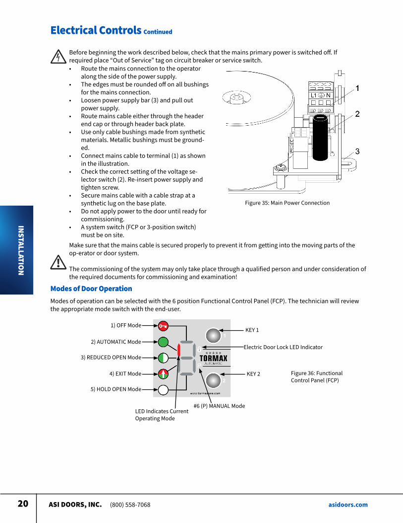
Before beginning the work described below, check that the mains primary power is switched off If required place “Out of Service” tag on circuit breaker or service switch • Route the mains connection to the operator
along the side of the power supply • The edges must be rounded off on all bushings
for the mains connection • Loosen power supply bar (3) and pull out
power supply • Route mains cable either through the header
end cap or through header back plate • Use only cable bushings made from synthetic
materials Metallic bushings must be ground-ed
• Connect mains cable to terminal (1) as shown in the illustration
• Check the correct setting of the voltage se-lector switch (2) Re-insert power supply and tighten screw
• Secure mains cable with a cable strap at a synthetic lug on the base plate
• Do not apply power to the door until ready for commissioning
• A system switch (FCP or 3-position switch) must be on site
Figure 35: Main Power Connection
Make sure that the mains cable is secured properly to prevent it from getting into the moving parts of the op-erator or door system
The commissioning of the system may only take place through a qualified person and under consideration of the required documents for commissioning and examination!
Modes of Door OperationModes of operation can be selected with the 6 position Functional Control Panel (FCP) The technician will review the appropriate mode switch with the end-user
1) OFF Mode
2) AUTOMATIC Mode
3) REDUCED OPEN Mode
4) EXIT Mode
5) HOLD OPEN Mode
KEY 1
Electric Door Lock LED Indicator
KEY 2
#6 (P) MANUAL ModeLED Indicates Current Operating Mode
Figure 36: Functional Control Panel (FCP)
ASI DOORS, INC. (800) 558-7068 asidoors.com21
Electrical Controls Continued
INSTALLATION
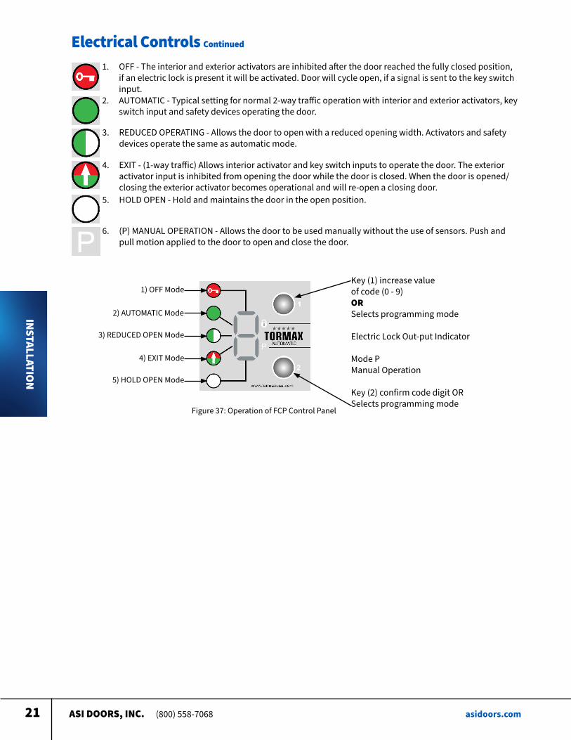
1 OFF - The interior and exterior activators are inhibited after the door reached the fully closed position, if an electric lock is present it will be activated Door will cycle open, if a signal is sent to the key switch input
2 AUTOMATIC - Typical setting for normal 2-way traffic operation with interior and exterior activators, key switch input and safety devices operating the door
3 REDUCED OPERATING - Allows the door to open with a reduced opening width Activators and safety devices operate the same as automatic mode
4 EXIT - (1-way traffic) Allows interior activator and key switch inputs to operate the door The exterior activator input is inhibited from opening the door while the door is closed When the door is opened/closing the exterior activator becomes operational and will re-open a closing door
5 HOLD OPEN - Hold and maintains the door in the open position
6 (P) MANUAL OPERATION - Allows the door to be used manually without the use of sensors Push and pull motion applied to the door to open and close the door
1) OFF Mode
2) AUTOMATIC Mode
3) REDUCED OPEN Mode
4) EXIT Mode
5) HOLD OPEN Mode
Key (1) increase value of code (0 - 9) OR Selects programming mode
Electric Lock Out-put Indicator Mode P Manual Operation
Key (2) confirm code digit OR Selects programming mode
Figure 37: Operation of FCP Control Panel
ASI DOORS, INC. (800) 558-7068 asidoors.com22
Electrical Controls Continued
INSTALLATION
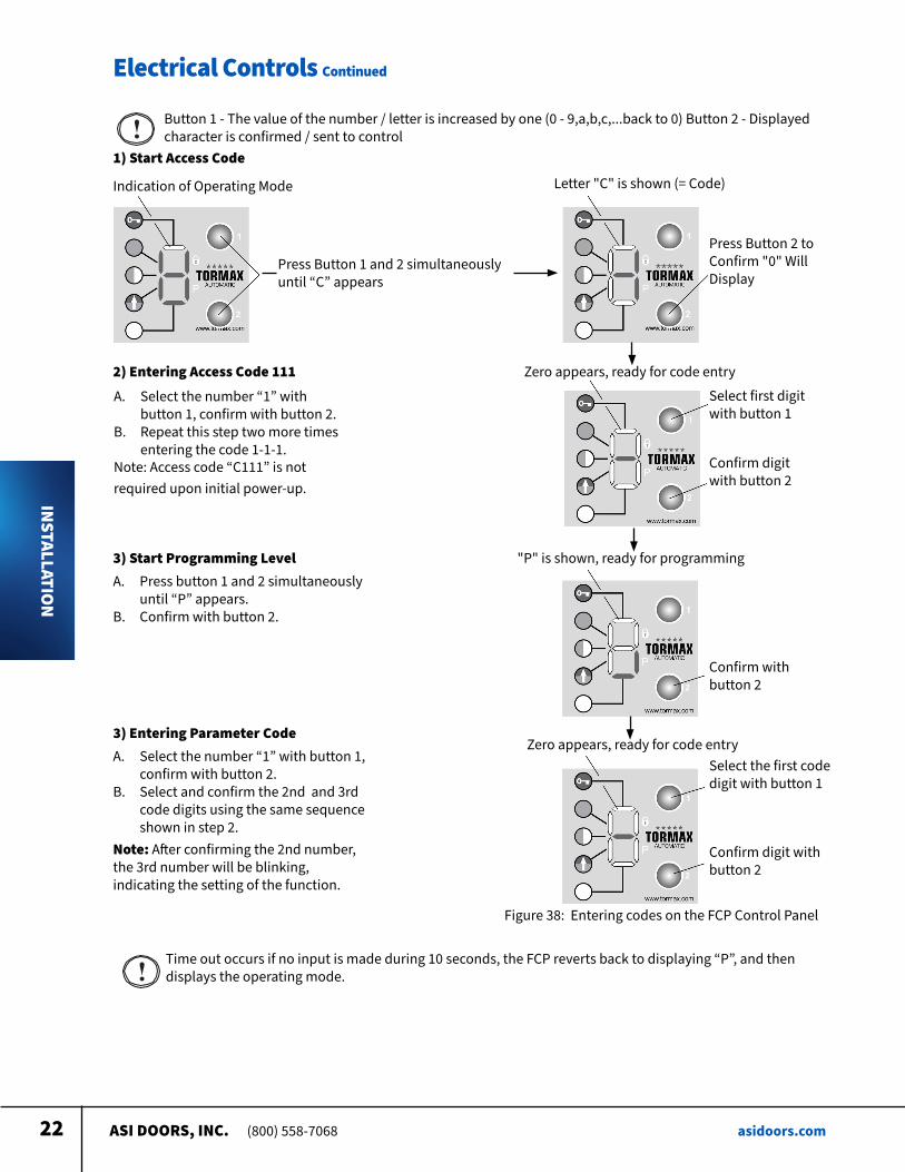
Button 1 - The value of the number / letter is increased by one (0 - 9,a,b,c, back to 0) Button 2 - Displayed character is confirmed / sent to control
1) Start Access Code
Indication of Operating Mode Letter "C" is shown (= Code)
Press Button 1 and 2 simultaneously until “C” appears
Press Button 2 to Confirm "0" Will Display
2) Entering Access Code 111
A Select the number “1” with button 1, confirm with button 2
B Repeat this step two more times entering the code 1-1-1
Note: Access code “C111” is not required upon initial power-up
Zero appears, ready for code entry Select first digit with button 1
Confirm digit with button 2
3) Start Programming LevelA Press button 1 and 2 simultaneously
until “P” appears B Confirm with button 2
"P" is shown, ready for programming
Confirm with button 2
3) Entering Parameter CodeA Select the number “1” with button 1,
confirm with button 2 B Select and confirm the 2nd and 3rd
code digits using the same sequence shown in step 2
Note: After confirming the 2nd number, the 3rd number will be blinking, indicating the setting of the function
Zero appears, ready for code entrySelect the first code digit with button 1
Confirm digit with button 2
Figure 38: Entering codes on the FCP Control Panel
Time out occurs if no input is made during 10 seconds, the FCP reverts back to displaying “P”, and then displays the operating mode
ASI DOORS, INC. (800) 558-7068 asidoors.com23
Electrical Controls Continued
INSTALLATION
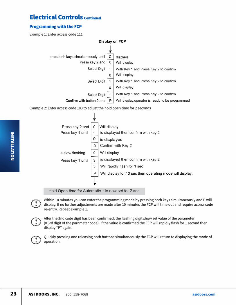
Programming with the FCPExample 1: Enter access code 111
Example 2: Enter access code 103 to adjust the hold open time for 2 seconds
Within 10 minutes you can enter the programming mode by pressing both keys simultaneously and P will display If no further adjustments are made after 10 minutes the FCP will time out and require access code re-entry Repeat example 1
After the 2nd code digit has been confirmed, the flashing digit show set value of the parameter (= 3rd digit of the parameter code) If the value is confirmed the FCP will rapidly flash for 1 second then display “P” again
Quickly pressing and releasing both buttons simultaneously the FCP will return to displaying the mode of operation
ASI DOORS, INC. (800) 558-7068 asidoors.com24
Electrical Controls Continued
INSTALLATION
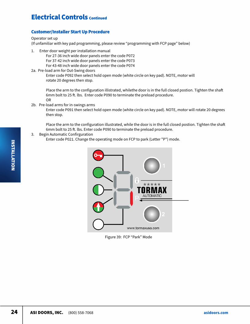
Customer/Installer Start Up ProcedureOperator set up (If unfamiliar with key pad programming, please review “programming with FCP page” below)
1 Enter door weight per installation manual For 27-36 inch wide door panels enter the code P072 For 37-42 inch wide door panels enter the code P073 For 43-48 inch wide door panels enter the code P0742a Pre-load arm for Out-Swing doors Enter code P092 then select hold open mode (white circle on key pad) NOTE, motor will rotate 20 degrees then stop
Place the arm to the configuration illistrated, whilethe door is in the full closed postion Tighten the shaft 6mm bolt to 25 ft lbs Enter code P090 to terminate the preload procedure OR2b Pre-load arms for in-swings arms Enter code P091 then select hold open mode (white circle on key pad) NOTE, motor will rotate 20 degrees then stop Place the arm to the configuration illustrated, while the door is in the full closed postion Tighten the shaft 6mm bolt to 25 ft lbs Enter code P090 to terminate the preload procedure 3 Begin Automatic Confirguration Enter code P021 Change the operating mode on FCP to park (Letter "P") mode
Figure 39: FCP “Park” Mode
ASI DOORS, INC. (800) 558-7068 asidoors.com25
Electrical Controls Continued
INSTALLATION
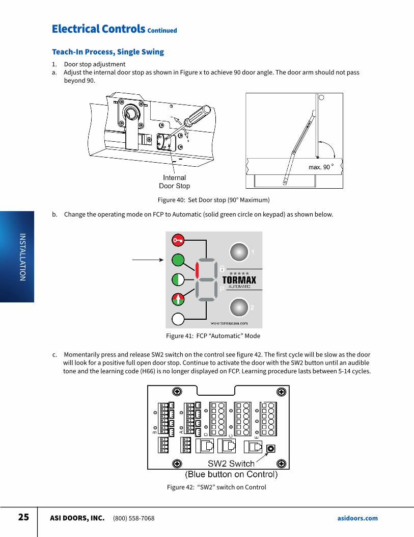
1 Door stop adjustmenta Adjust the internal door stop as shown in Figure x to achieve 90 door angle The door arm should not pass beyond 90
Teach-In Process, Single Swing
c Momentarily press and release SW2 switch on the control see figure 42 The first cycle will be slow as the door will look for a positive full open door stop Continue to activate the door with the SW2 button until an audible tone and the learning code (H66) is no longer displayed on FCP Learning procedure lasts between 5-14 cycles
Figure 40: Set Door stop (90° Maximum)
Figure 41: FCP “Automatic” Mode
Figure 42: “SW2” switch on Control
b Change the operating mode on FCP to Automatic (solid green circle on keypad) as shown below
ASI DOORS, INC. (800) 558-7068 asidoors.com26
Electrical Controls Continued
INSTALLATION
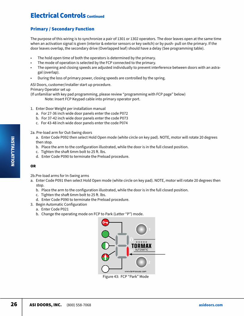
Primary / Secondary Function
The purpose of this wiring is to synchronize a pair of 1301 or 1302 operators The door leaves open at the same time when an activation signal is given (interior & exterior sensors or key switch) or by push- pull on the primary If the door leaves overlap, the secondary drive (Overlapped leaf) should have a delay (See programming table)
• The hold open time of both the operators is determined by the primary • The mode of operation is selected by the FCP connected to the primary • The opening and closing speeds are adjusted individually to prevent interference between doors with an astra-
gal (overlap) • During the loss of primary power, closing speeds are controlled by the spring
ASI Doors, customer/installer start up procedure Primary Operator set up(If unfamiliar with key pad programming, please review “programming with FCP page” below) Note: Insert FCP Keypad cable into primary operator port
1 Enter Door Weight per installation manuala For 27-36 inch wide door panels enter the code P072b For 37-42 inch wide door panels enter the code P073c For 43-48 inch wide door panels enter the code P074
2a Pre-load arm for Out-Swing doorsa Enter Code P092 then select Hold Open mode (white circle on key pad) NOTE, motor will rotate 20 degrees then stop b Place the arm to the configuration illustrated, while the door is in the full closed position c Tighten the shaft 6mm bolt to 25 ft lbs d Enter Code P090 to terminate the Preload procedure
OR
2b Pre-load arms for In-Swing armsa Enter Code P091 then select Hold Open mode (white circle on key pad) NOTE, motor will rotate 20 degrees then stop
b Place the arm to the configuration illustrated, while the door is in the full closed position c Tighten the shaft 6mm bolt to 25 ft lbs d Enter Code P090 to terminate the Preload procedure
3 Begin Automatic Configurationa Enter Code P021b Change the operating mode on FCP to Park (Letter “P”) mode
Figure 43: FCP “Park” Mode
ASI DOORS, INC. (800) 558-7068 asidoors.com27
Electrical Controls Continued
INSTALLATION
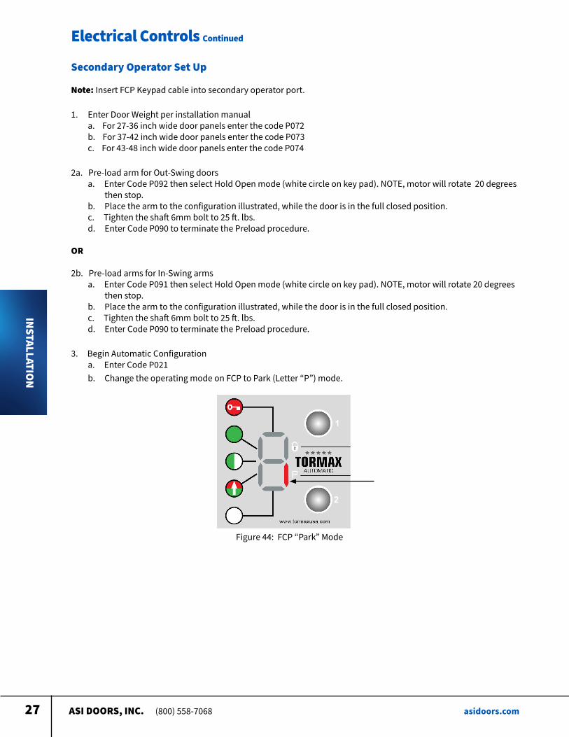
Secondary Operator Set Up
Note: Insert FCP Keypad cable into secondary operator port
1 Enter Door Weight per installation manuala For 27-36 inch wide door panels enter the code P072b For 37-42 inch wide door panels enter the code P073c For 43-48 inch wide door panels enter the code P074
2a Pre-load arm for Out-Swing doorsa Enter Code P092 then select Hold Open mode (white circle on key pad) NOTE, motor will rotate 20 degrees then stop b Place the arm to the configuration illustrated, while the door is in the full closed position c Tighten the shaft 6mm bolt to 25 ft lbs d Enter Code P090 to terminate the Preload procedure
OR
2b Pre-load arms for In-Swing armsa Enter Code P091 then select Hold Open mode (white circle on key pad) NOTE, motor will rotate 20 degrees then stop b Place the arm to the configuration illustrated, while the door is in the full closed position c Tighten the shaft 6mm bolt to 25 ft lbs d Enter Code P090 to terminate the Preload procedure
3 Begin Automatic Configurationa Enter Code P021b Change the operating mode on FCP to Park (Letter “P”) mode
Figure 44: FCP “Park” Mode
ASI DOORS, INC. (800) 558-7068 asidoors.com28
Electrical Controls Continued
INSTALLATION
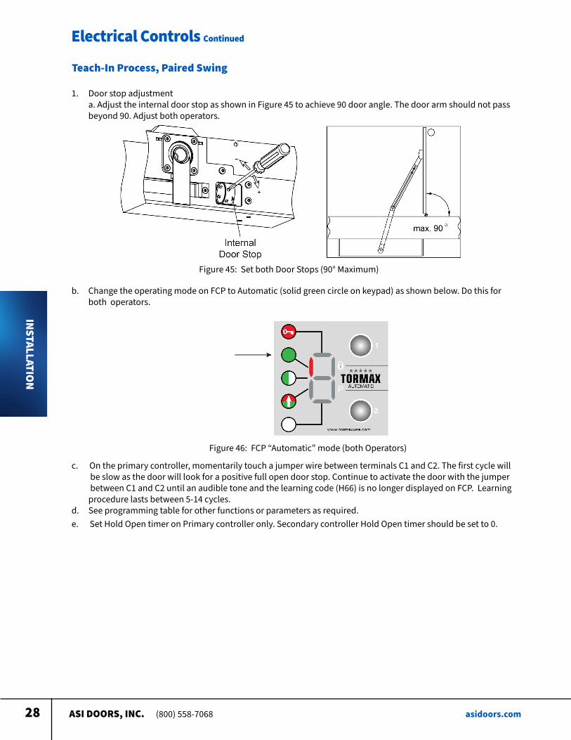
1 Door stop adjustmenta Adjust the internal door stop as shown in Figure 45 to achieve 90 door angle The door arm should not pass beyond 90 Adjust both operators
Teach-In Process, Paired Swing
b Change the operating mode on FCP to Automatic (solid green circle on keypad) as shown below Do this for both operators
c On the primary controller, momentarily touch a jumper wire between terminals C1 and C2 The first cycle will be slow as the door will look for a positive full open door stop Continue to activate the door with the jumper between C1 and C2 until an audible tone and the learning code (H66) is no longer displayed on FCP Learning procedure lasts between 5-14 cycles d See programming table for other functions or parameters as required e Set Hold Open timer on Primary controller only Secondary controller Hold Open timer should be set to 0
Figure 46: FCP “Automatic” mode (both Operators)
Figure 45: Set both Door Stops (90° Maximum)
ASI DOORS, INC. (800) 558-7068 asidoors.com29
INSTALLATION
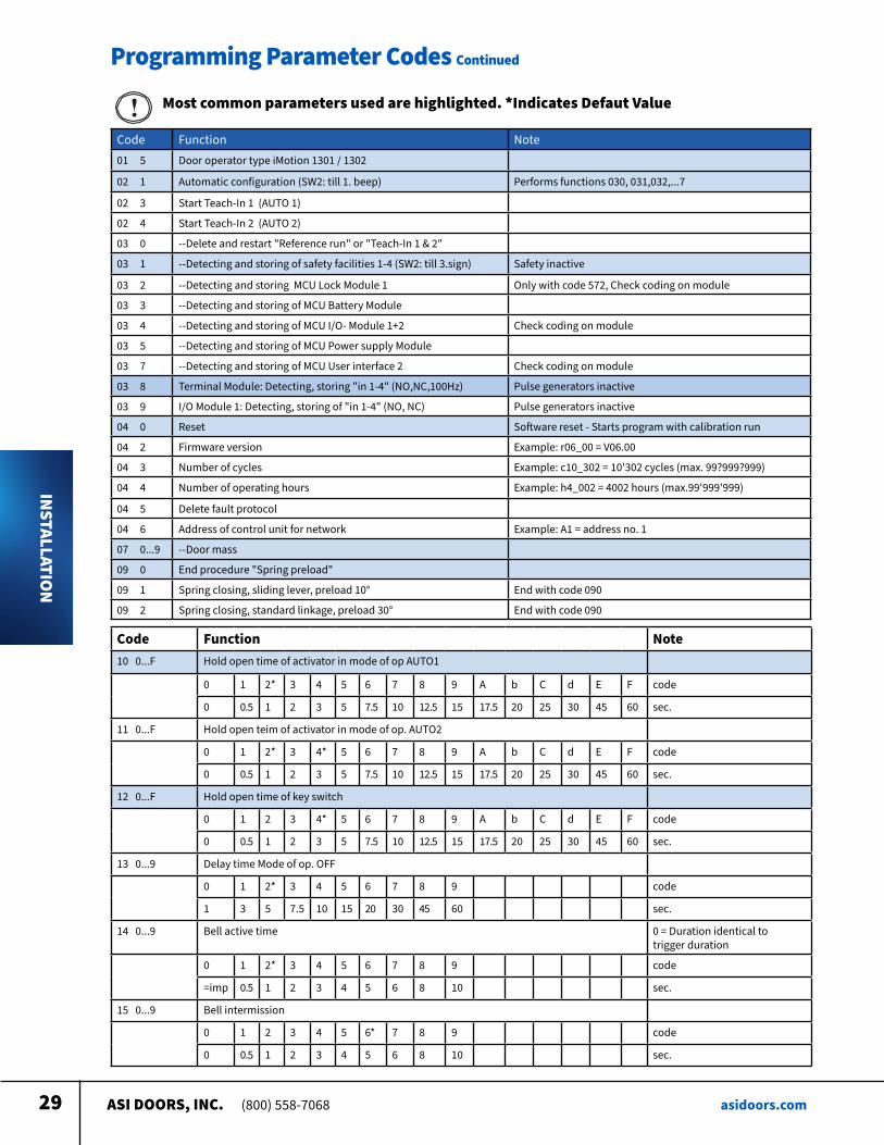
Programming Parameter Codes Continued
Code Function Note01 5 Door operator type iMotion 1301 / 1302
02 1 Automatic configuration (SW2: till 1 beep) Performs functions 030, 031,032, 7
02 3 Start Teach-In 1 (AUTO 1)
02 4 Start Teach-In 2 (AUTO 2)
03 0 --Delete and restart "Reference run" or "Teach-In 1 & 2"
03 1 --Detecting and storing of safety facilities 1-4 (SW2: till 3 sign) Safety inactive
03 2 --Detecting and storing MCU Lock Module 1 Only with code 572, Check coding on module
03 3 --Detecting and storing of MCU Battery Module
03 4 --Detecting and storing of MCU I/O- Module 1+2 Check coding on module
03 5 --Detecting and storing of MCU Power supply Module
03 7 --Detecting and storing of MCU User interface 2 Check coding on module
03 8 Terminal Module: Detecting, storing "in 1-4" (NO,NC,100Hz) Pulse generators inactive
03 9 I/O Module 1: Detecting, storing of "in 1-4" (NO, NC) Pulse generators inactive
04 0 Reset Software reset - Starts program with calibration run
04 2 Firmware version Example: r06_00 = V06 00
04 3 Number of cycles Example: c10_302 = 10'302 cycles (max 99?999?999)
04 4 Number of operating hours Example: h4_002 = 4002 hours (max 99'999'999)
04 5 Delete fault protocol
04 6 Address of control unit for network Example: A1 = address no 1
07 0 9 --Door mass
09 0 End procedure "Spring preload"
09 1 Spring closing, sliding lever, preload 10° End with code 090
09 2 Spring closing, standard linkage, preload 30° End with code 090
Code Function Note 10 0 F Hold open time of activator in mode of op AUTO1
0 1 2* 3 4 5 6 7 8 9 A b C d E F code
0 0 5 1 2 3 5 7 5 10 12 5 15 17 5 20 25 30 45 60 sec
11 0 F Hold open teim of activator in mode of op AUTO2
0 1 2* 3 4* 5 6 7 8 9 A b C d E F code
0 0 5 1 2 3 5 7 5 10 12 5 15 17 5 20 25 30 45 60 sec
12 0 F Hold open time of key switch
0 1 2 3 4* 5 6 7 8 9 A b C d E F code
0 0 5 1 2 3 5 7 5 10 12 5 15 17 5 20 25 30 45 60 sec
13 0 9 Delay time Mode of op OFF
0 1 2* 3 4 5 6 7 8 9 code
1 3 5 7 5 10 15 20 30 45 60 sec
14 0 9 Bell active time 0 = Duration identical to trigger duration
0 1 2* 3 4 5 6 7 8 9 code
=imp 0 5 1 2 3 4 5 6 8 10 sec
15 0 9 Bell intermission
0 1 2 3 4 5 6* 7 8 9 code
0 0 5 1 2 3 4 5 6 8 10 sec
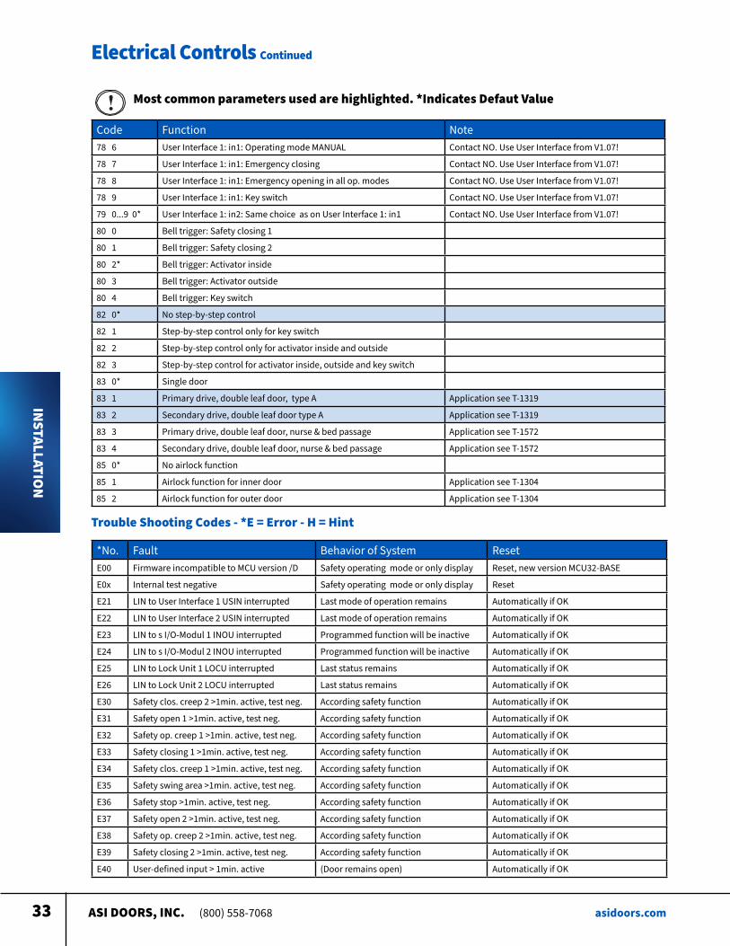
Most common parameters used are highlighted. *Indicates Defaut Value
ASI DOORS, INC. (800) 558-7068 asidoors.com30
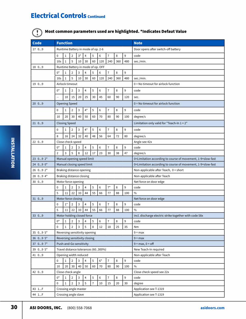
Electrical Controls Continued
INSTALLATION
Code Function Note 17 0 9 Runtime Battery in mode of op 2-6 Door opens after switch-off battery
0 1 2 3* 4 5 6 7 8 9 code
10s 1 5 10 30 60 120 240 360 480 sec /min
18 0 9 Runtime Battery in mode of op OFF
0* 1 2 3 4 5 6 7 8 9
10s 1 5 10 30 60 120 240 360 480 sec /min
19 0 9 Airlock timeout 0 = No timeout for airlock function
0* 1 2 3 4 5 6 7 8 9 code
-- 10 15 20 25 30 45 60 90 120 sec
20 0 9 Opening Speed 0 = No timeout for airlock function
0 1 2 3 4* 5 6 7 8 9 code
10 20 30 40 50 60 70 80 90 100 degree/s
21 0 9 Closing Speed Limitation only valid for "Teach-In 1 + 2"
0 1 2 3 4* 5 6 7 8 9 code
8 16 24 32 40 48 56 64 72 80 degree/s
22 0 9 Close check speed Angle see 42x
0* 1 2 3 4 5 6 7 8 9 code
2 3 5 8 12 17 23 30 38 47 degree/s
23 0 9 2* Manual opening speed limit 0=Limitation according to course of movement, 1-9=slow-fast
24 0 9 0* Manual closing speed limit 0=Limitation according to course of movement, 1-9=slow-fast
26 0 9 2* Braking distance opening Non-applicable after Teach, 0 = short
28 0 9 4* Braking distance closing Non-applicable after Teach
30 0 9 Motor force opening Net force on door edge
0 1 2 3 4 5 6 7* 8 9 code
5 11 22 33 44 55 66 77 88 100 %
31 0 9 Motor force closing Net force on door edge
0 1* 2 3 4 5 6 7 8 9 code
5 11 22 33 44 55 66 77 88 100 %
33 0 9 Motor holding closed force incl discharge electric strike together with code 58x
0* 1 2 3 4 5 6 7 8 9 code
0 1 2 3 5 8 12 18 25 35 Nm
35 0 9 5* Reversing sensitivity opening 9 = max
36 0 9 5* Reversing sensitivity closing 9 = max
37 0 9 7* Push-and-Go sensitivity 9 = max, 0 = off
39 0 9 5* Travel distance tolerances (60 300%) New Teach-In required
41 0 9 Opening width reduced Non-applicable after Teach
0 1 2 3 4 5 6* 7 8 9 code
10 20 30 40 50 60 70 80 90 100 %
42 0 9 Close check angle Close check speed see 22x
0* 1 2 3 4 5 6 7 8 9 code
0 1 2 3 5 7 10 15 20 30 degree
43 1 F Crossing angle master Application see T-1319
44 1 F Crossing angle slave Application see T-1319
Most common parameters used are highlighted. *Indicates Defaut Value
ASI DOORS, INC. (800) 558-7068 asidoors.com31
Electrical Controls Continued
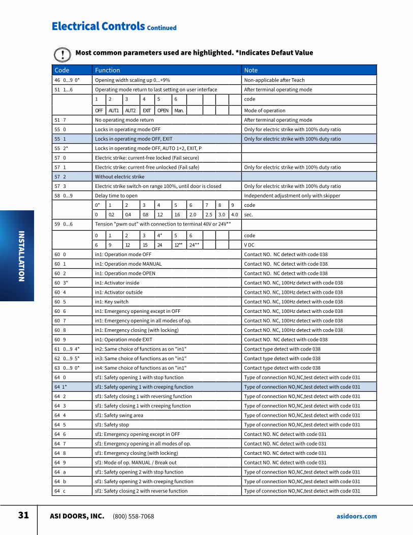
INSTALLATION
Code Function Note46 0 9 0* Opening width scaling up 0 +9% Non-applicable after Teach
51 1 6 Operating mode return to last setting on user interface After terminal operating mode
1 2 3 4 5 6 code
OFF AUT1 AUT2 EXIT OPEN Man Mode of operation
51 7 No operating mode return After terminal operating mode
55 0 Locks in operating mode OFF Only for electric strike with 100% duty ratio
55 1 Locks in operating mode OFF, EXIT Only for electric strike with 100% duty ratio
55 2* Locks in operating mode OFF, AUTO 1+2, EXIT, P
57 0 Electric strike: current-free locked (Fail secure)
57 1 Electric strike: current-free unlocked (Fail safe) Only for electric strike with 100% duty ratio
57 2 Without electric strike
57 3 Electric strike switch-on range 100%, until door is closed Only for electric strike with 100% duty ratio
58 0 9 Delay time to open Independent adjustment only with skipper
0* 1 2 3 4 5 6 7 8 9 code
0 0 2 0 4 0 8 1 2 1 6 2 0 2 5 3 0 4 0 sec
59 0 6 Tension "pwm out" with connection to terminal 40V or 24V**
0 1 2 3 4* 5 6 code
6 9 12 15 24 12** 24** V DC
60 0 in1: Operation mode OFF Contact NO NC detect with code 038
60 1 in1: Operation mode MANUAL Contact NO NC detect with code 038
60 2 in1: Operation mode OPEN Contact NO NC detect with code 038
60 3* in1: Activator inside Contact NO NC, 100Hz detect with code 038
60 4 in1: Activator outside Contact NO NC, 100Hz detect with code 038
60 5 in1: Key switch Contact NO NC, 100Hz detect with code 038
60 6 in1: Emergency opening except in OFF Contact NO NC, 100Hz detect with code 038
60 7 in1: Emergency opening in all modes of op Contact NO NC, 100Hz detect with code 038
60 8 in1: Emergency closing (with locking) Contact NO NC, 100Hz detect with code 038
60 9 in1: Operation mode EXIT Contact NO NC detect with code 038
61 0 9 4* in2: Same choice of functions as on "in1" Contact type detect with code 038
62 0 9 5* in3: Same choice of functions as on "in1" Contact type detect with code 038
63 0 9 0* in4: Same choice of functions as on "in1" Contact type detect with code 038
64 0 sf1: Safety opening 1 with stop function Type of connection NO,NC,test detect with code 031
64 1* sf1: Safety opening 1 with creeping function Type of connection NO,NC,test detect with code 031
64 2 sf1: Safety closing 1 with reversing function Type of connection NO,NC,test detect with code 031
64 3 sf1: Safety closing 1 with creeping function Type of connection NO,NC,test detect with code 031
64 4 sf1: Safety swing area Type of connection NO,NC,test detect with code 031
64 5 sf1: Safety stop Type of connection NO,NC,test detect with code 031
64 6 sf1: Emergency opening except in OFF Contact NO NC detect with code 031
64 7 sf1: Emergency opening in all modes of op Contact NO NC detect with code 031
64 8 sf1: Emergency closing (with locking) Contact NO NC detect with code 031
64 9 sf1: Mode of op MANUAL / Break out Contact NO NC detect with code 031
64 a sf1: Safety opening 2 with stop function Type of connection NO,NC,test detect with code 031
64 b sf1: Safety opening 2 with creeping function Type of connection NO,NC,test detect with code 031
64 c sf1: Safety closing 2 with reverse function Type of connection NO,NC,test detect with code 031
Most common parameters used are highlighted. *Indicates Defaut Value
ASI DOORS, INC. (800) 558-7068 asidoors.com32
Electrical Controls Continued
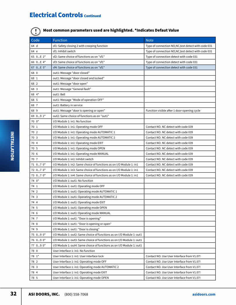
INSTALLATION
Code Function Note64 d sf1: Safety closing 2 with creeping function Type of connection NO,NC,test detect with code 031
64 e sf1: Inhibit switch Type of connection NO,NC,test detect with code 031
65 0 E 2* sf2: Same choice of functions as on "sf1" Type of connection detect with code 031
66 0 E 4* sf3: Same choice of functions as on "sf1" Type of connection detect with code 031
67 0 E 5* sf4: Same choice of functions as on "sf1" Type of connection detect with code 031
68 0 out1: Message "door closed"
68 1 out1: Message “door closed and locked”
68 2 out1: Message “door open”
68 3 out1: Message “General fault”
68 4* out1: Bell
68 5 out1: Message “Mode of operation OFF”
68 7 out1: Battery in service
68 9 out1: Message “door is opening or open” Function visible after 1 door-opening cycle
69 0 9 2* out2: Same choice of functions as on "out1"
70 0* I/O Module 1: in1: No function
70 1 I/O Module 1: in1: Operating mode OFF Contact NO NC detect with code 039
70 2 I/O Module 1: in1: Operating mode AUTOMATIC 1 Contact NO NC detect with code 039
70 3 I/O Module 1: in1: Operating mode AUTOMATIC 2 Contact NO NC detect with code 039
70 4 I/O Module 1: in1: Operating mode EXIT Contact NO NC detect with code 039
70 5 I/O Module 1: in1: Operating mode OPEN Contact NO NC detect with code 039
70 6 I/O Module 1: in1: Operating mode MANUAL Contact NO NC detect with code 039
70 7 I/O Module 1: in1: Inhibit switch Contact NO NC detect with code 039
71 0 7 0* I/O Module 1: in2: Same choice of functions as on I/O Module 1: in1 Contact NO NC detect with code 039
72 0 7 0* I/O Module 1: in3: Same choice of functions as on I/O Module 1: in1 Contact NO NC detect with code 039
73 0 7 0* I/O Module 1: in4: Same choice of functions as on I/O Module 1: in1 Contact NO NC detect with code 039
74 0* I/O Module 1: out1: No function
74 1 I/O Module 1: out1: Operating mode OFF
74 2 I/O Module 1: out1: Operating mode AUTOMATIC 1
74 3 I/O Module 1: out1: Operating mode AUTOMATIC 2
74 4 I/O Module 1: out1: Operating mode EXIT
74 5 I/O Module 1: out1: Operating mode OPEN
74 6 I/O Module 1: out1: Operating mode MANUAL
74 7 I/O Module 1: out1: "Door is opening"
74 8 I/O Module 1: out1: “Door is opening or open”
74 9 I/O Module 1: out1: "Door is closing"
75 0 9 0* I/O Module 1: out2: Same choice of functions as on I/O Module 1: out1
76 0 9 0* I/O Module 1: out3: Same choice of functions as on I/O Module 1: out1
77 0 9 0* I/O Module 1: out4: Same choice of functions as on I/O Module 1: out1
78 0 User Interface 1: in1: No function
78 1* User Interface 1: in1: User interface lock Contact NO Use User Interface from V1 07!
78 2 User Interface 1: in1: Operating mode OFF Contact NO Use User Interface from V1 07!
78 3 User Interface 1: in1: Operating mode AUTOMATIC 2 Contact NO Use User Interface from V1 07!
78 4 User Interface 1: in1: Operating mode EXIT Contact NO Use User Interface from V1 07!
78 5 User Interface 1: in1: Operating mode OPEN Contact NO Use User Interface from V1 07!
Most common parameters used are highlighted. *Indicates Defaut Value
ASI DOORS, INC. (800) 558-7068 asidoors.com33
Electrical Controls Continued
INSTALLATION
Code Function Note78 6 User Interface 1: in1: Operating mode MANUAL Contact NO Use User Interface from V1 07!
78 7 User Interface 1: in1: Emergency closing Contact NO Use User Interface from V1 07!
78 8 User Interface 1: in1: Emergency opening in all op modes Contact NO Use User Interface from V1 07!
78 9 User Interface 1: in1: Key switch Contact NO Use User Interface from V1 07!
79 0 9 0* User Interface 1: in2: Same choice as on User Interface 1: in1 Contact NO Use User Interface from V1 07!
80 0 Bell trigger: Safety closing 1
80 1 Bell trigger: Safety closing 2
80 2* Bell trigger: Activator inside
80 3 Bell trigger: Activator outside
80 4 Bell trigger: Key switch
82 0* No step-by-step control
82 1 Step-by-step control only for key switch
82 2 Step-by-step control only for activator inside and outside
82 3 Step-by-step control for activator inside, outside and key switch
83 0* Single door
83 1 Primary drive, double leaf door, type A Application see T-1319
83 2 Secondary drive, double leaf door type A Application see T-1319
83 3 Primary drive, double leaf door, nurse & bed passage Application see T-1572
83 4 Secondary drive, double leaf door, nurse & bed passage Application see T-1572
85 0* No airlock function
85 1 Airlock function for inner door Application see T-1304
85 2 Airlock function for outer door Application see T-1304
Most common parameters used are highlighted. *Indicates Defaut Value
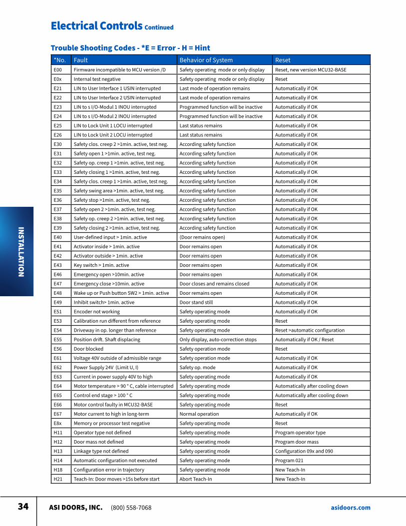
Trouble Shooting Codes - *E = Error - H = Hint
*No Fault Behavior of System ResetE00 Firmware incompatible to MCU version /D Safety operating mode or only display Reset, new version MCU32-BASE
E0x Internal test negative Safety operating mode or only display Reset
E21 LIN to User Interface 1 USIN interrupted Last mode of operation remains Automatically if OK
E22 LIN to User Interface 2 USIN interrupted Last mode of operation remains Automatically if OK
E23 LIN to s I/O-Modul 1 INOU interrupted Programmed function will be inactive Automatically if OK
E24 LIN to s I/O-Modul 2 INOU interrupted Programmed function will be inactive Automatically if OK
E25 LIN to Lock Unit 1 LOCU interrupted Last status remains Automatically if OK
E26 LIN to Lock Unit 2 LOCU interrupted Last status remains Automatically if OK
E30 Safety clos creep 2 >1min active, test neg According safety function Automatically if OK
E31 Safety open 1 >1min active, test neg According safety function Automatically if OK
E32 Safety op creep 1 >1min active, test neg According safety function Automatically if OK
E33 Safety closing 1 >1min active, test neg According safety function Automatically if OK
E34 Safety clos creep 1 >1min active, test neg According safety function Automatically if OK
E35 Safety swing area >1min active, test neg According safety function Automatically if OK
E36 Safety stop >1min active, test neg According safety function Automatically if OK
E37 Safety open 2 >1min active, test neg According safety function Automatically if OK
E38 Safety op creep 2 >1min active, test neg According safety function Automatically if OK
E39 Safety closing 2 >1min active, test neg According safety function Automatically if OK
E40 User-defined input > 1min active (Door remains open) Automatically if OK
ASI DOORS, INC. (800) 558-7068 asidoors.com34
Electrical Controls Continued
INSTALLATION
*No Fault Behavior of System ResetE00 Firmware incompatible to MCU version /D Safety operating mode or only display Reset, new version MCU32-BASE
E0x Internal test negative Safety operating mode or only display Reset
E21 LIN to User Interface 1 USIN interrupted Last mode of operation remains Automatically if OK
E22 LIN to User Interface 2 USIN interrupted Last mode of operation remains Automatically if OK
E23 LIN to s I/O-Modul 1 INOU interrupted Programmed function will be inactive Automatically if OK
E24 LIN to s I/O-Modul 2 INOU interrupted Programmed function will be inactive Automatically if OK
E25 LIN to Lock Unit 1 LOCU interrupted Last status remains Automatically if OK
E26 LIN to Lock Unit 2 LOCU interrupted Last status remains Automatically if OK
E30 Safety clos creep 2 >1min active, test neg According safety function Automatically if OK
E31 Safety open 1 >1min active, test neg According safety function Automatically if OK
E32 Safety op creep 1 >1min active, test neg According safety function Automatically if OK
E33 Safety closing 1 >1min active, test neg According safety function Automatically if OK
E34 Safety clos creep 1 >1min active, test neg According safety function Automatically if OK
E35 Safety swing area >1min active, test neg According safety function Automatically if OK
E36 Safety stop >1min active, test neg According safety function Automatically if OK
E37 Safety open 2 >1min active, test neg According safety function Automatically if OK
E38 Safety op creep 2 >1min active, test neg According safety function Automatically if OK
E39 Safety closing 2 >1min active, test neg According safety function Automatically if OK
E40 User-defined input > 1min active (Door remains open) Automatically if OK
E41 Activator inside > 1min active Door remains open Automatically if OK
E42 Activator outside > 1min active Door remains open Automatically if OK
E43 Key switch > 1min active Door remains open Automatically if OK
E46 Emergency open >10min active Door remains open Automatically if OK
E47 Emergency close >10min active Door closes and remains closed Automatically if OK
E48 Wake up or Push button SW2 > 1min active Door remains open Automatically if OK
E49 Inhibit switch> 1min active Door stand still Automatically if OK
E51 Encoder not working Safety operating mode Automatically if OK
E53 Calibration run different from reference Safety operating mode Reset
E54 Driveway in op longer than reference Safety operating mode Reset >automatic configuration
E55 Position drift Shaft displacing Only display, auto-correction stops Automatically if OK / Reset
E56 Door blocked Safety operation mode Reset
E61 Voltage 40V outside of admissible range Safety operation mode Automatically if OK
E62 Power Supply 24V (Limit U, I) Safety op mode Automatically if OK
E63 Current in power supply 40V to high Safety operating mode Automatically if OK
E64 Motor temperature > 90 ° C, cable interrupted Safety operating mode Automatically after cooling down
E65 Control end stage > 100 ° C Safety operating mode Automatically after cooling down
E66 Motor control faulty in MCU32-BASE Safety operating mode Reset
E67 Motor current to high in long-term Normal operation Automatically if OK
E8x Memory or processor test negative Safety operating mode Reset
H11 Operator type not defined Safety operating mode Program operator type
H12 Door mass not defined Safety operating mode Program door mass
H13 Linkage type not defined Safety operating mode Configuration 09x and 090
H14 Automatic configuration not executed Safety operating mode Program 021
H18 Configuration error in trajectory Safety operating mode New Teach-In
H21 Teach-In: Door moves >15s before start Abort Teach-In New Teach-In
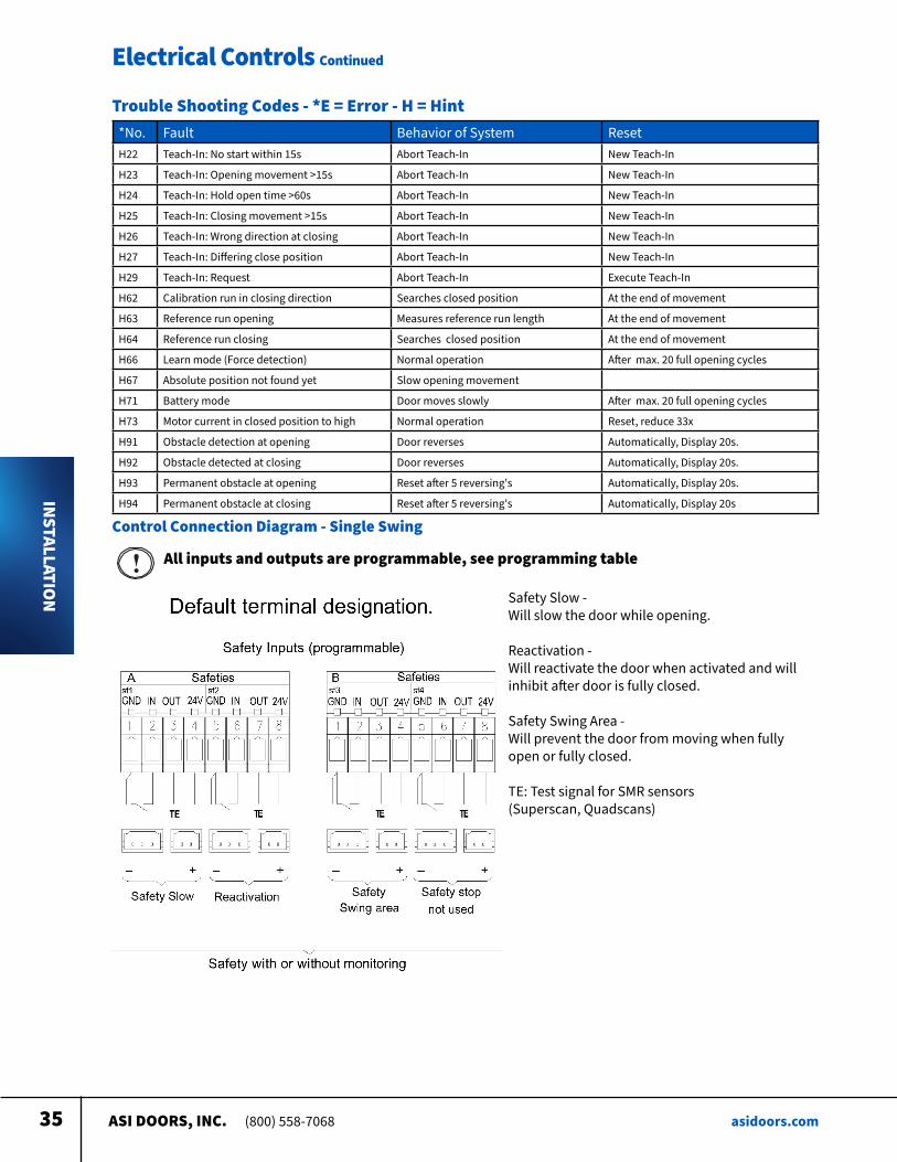
Trouble Shooting Codes - *E = Error - H = Hint
ASI DOORS, INC. (800) 558-7068 asidoors.com35
Electrical Controls Continued
INSTALLATION
*No Fault Behavior of System ResetH22 Teach-In: No start within 15s Abort Teach-In New Teach-In
H23 Teach-In: Opening movement >15s Abort Teach-In New Teach-In
H24 Teach-In: Hold open time >60s Abort Teach-In New Teach-In
H25 Teach-In: Closing movement >15s Abort Teach-In New Teach-In
H26 Teach-In: Wrong direction at closing Abort Teach-In New Teach-In
H27 Teach-In: Differing close position Abort Teach-In New Teach-In
H29 Teach-In: Request Abort Teach-In Execute Teach-In
H62 Calibration run in closing direction Searches closed position At the end of movement
H63 Reference run opening Measures reference run length At the end of movement
H64 Reference run closing Searches closed position At the end of movement
H66 Learn mode (Force detection) Normal operation After max 20 full opening cycles
H67 Absolute position not found yet Slow opening movement
H71 Battery mode Door moves slowly After max 20 full opening cycles
H73 Motor current in closed position to high Normal operation Reset, reduce 33x
H91 Obstacle detection at opening Door reverses Automatically, Display 20s
H92 Obstacle detected at closing Door reverses Automatically, Display 20s
H93 Permanent obstacle at opening Reset after 5 reversing's Automatically, Display 20s
H94 Permanent obstacle at closing Reset after 5 reversing's Automatically, Display 20s
Trouble Shooting Codes - *E = Error - H = Hint
Control Connection Diagram - Single Swing
All inputs and outputs are programmable, see programming table
Safety Slow - Will slow the door while opening
Reactivation - Will reactivate the door when activated and will inhibit after door is fully closed
Safety Swing Area - Will prevent the door from moving when fully open or fully closed
TE: Test signal for SMR sensors (Superscan, Quadscans)
ASI DOORS, INC. (800) 558-7068 asidoors.com36
Electrical Controls Continued
INSTALLATION
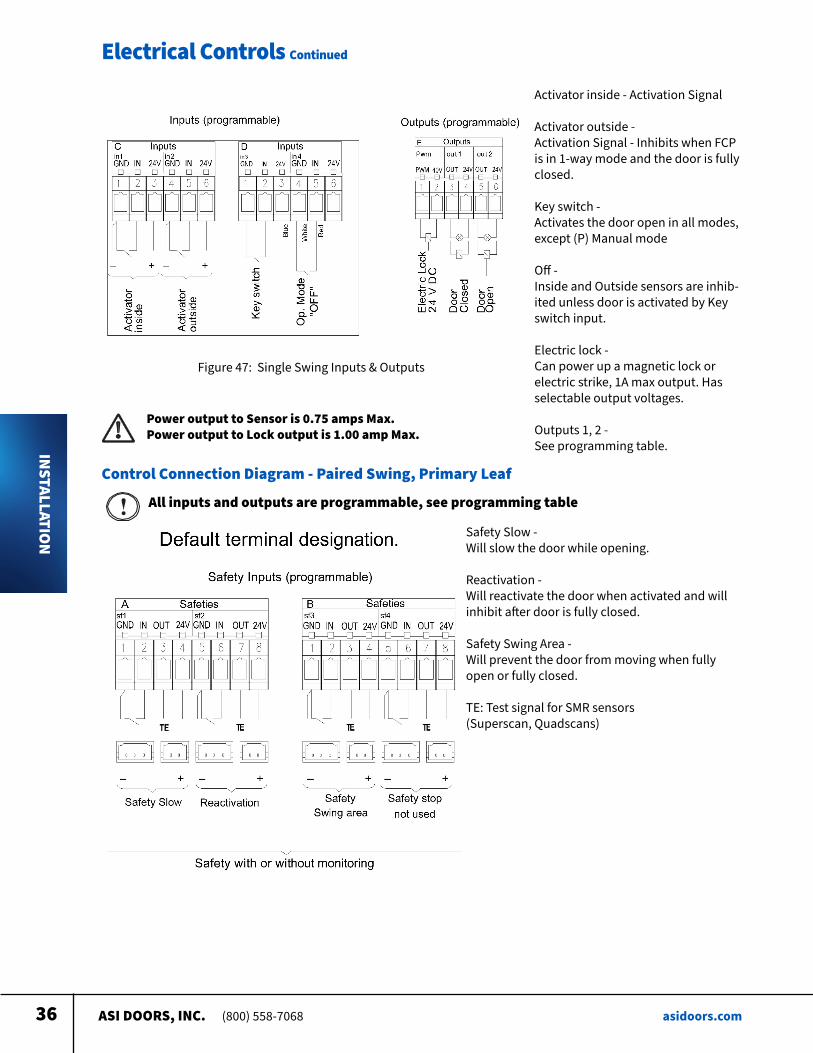
Activator inside - Activation Signal
Activator outside - Activation Signal - Inhibits when FCP is in 1-way mode and the door is fully closed
Key switch - Activates the door open in all modes, except (P) Manual mode
Off - Inside and Outside sensors are inhib-ited unless door is activated by Key switch input
Electric lock - Can power up a magnetic lock or electric strike, 1A max output Has selectable output voltages
Outputs 1, 2 - See programming table
Figure 47: Single Swing Inputs & Outputs
Power output to Sensor is 0.75 amps Max. Power output to Lock output is 1.00 amp Max.
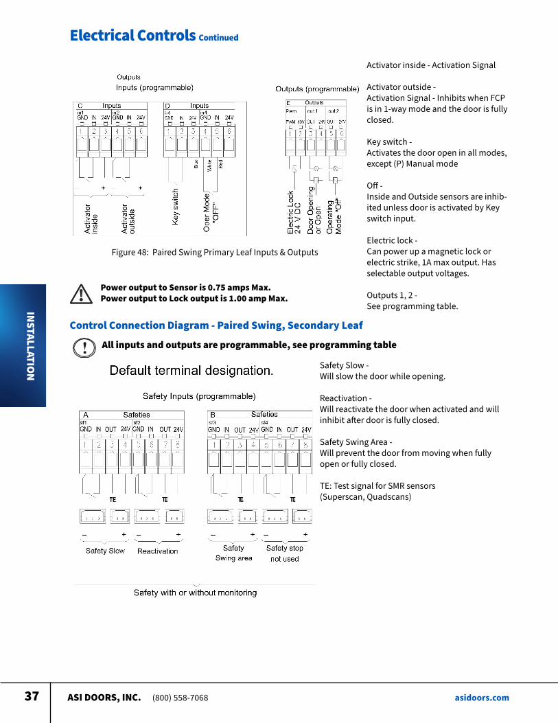
Control Connection Diagram - Paired Swing, Primary Leaf
All inputs and outputs are programmable, see programming table
Safety Slow - Will slow the door while opening
Reactivation - Will reactivate the door when activated and will inhibit after door is fully closed
Safety Swing Area - Will prevent the door from moving when fully open or fully closed
TE: Test signal for SMR sensors (Superscan, Quadscans)
ASI DOORS, INC. (800) 558-7068 asidoors.com37
Electrical Controls Continued
INSTALLATION
Activator inside - Activation Signal
Activator outside - Activation Signal - Inhibits when FCP is in 1-way mode and the door is fully closed
Key switch - Activates the door open in all modes, except (P) Manual mode
Off - Inside and Outside sensors are inhib-ited unless door is activated by Key switch input
Electric lock - Can power up a magnetic lock or electric strike, 1A max output Has selectable output voltages
Outputs 1, 2 - See programming table
Figure 48: Paired Swing Primary Leaf Inputs & Outputs
Power output to Sensor is 0.75 amps Max. Power output to Lock output is 1.00 amp Max.
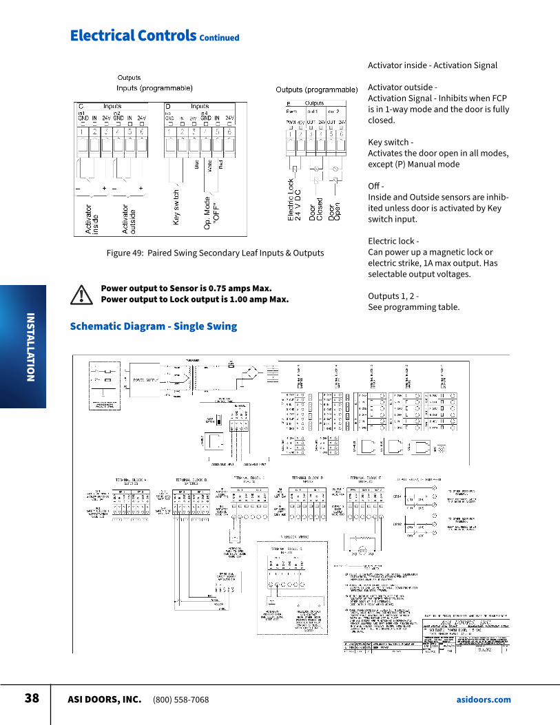
Control Connection Diagram - Paired Swing, Secondary Leaf
All inputs and outputs are programmable, see programming table
Safety Slow - Will slow the door while opening
Reactivation - Will reactivate the door when activated and will inhibit after door is fully closed
Safety Swing Area - Will prevent the door from moving when fully open or fully closed
TE: Test signal for SMR sensors (Superscan, Quadscans)
ASI DOORS, INC. (800) 558-7068 asidoors.com38
Electrical Controls Continued
INSTALLATION
Activator inside - Activation Signal
Activator outside - Activation Signal - Inhibits when FCP is in 1-way mode and the door is fully closed
Key switch - Activates the door open in all modes, except (P) Manual mode
Off - Inside and Outside sensors are inhib-ited unless door is activated by Key switch input
Electric lock - Can power up a magnetic lock or electric strike, 1A max output Has selectable output voltages
Outputs 1, 2 - See programming table
Figure 49: Paired Swing Secondary Leaf Inputs & Outputs
Power output to Sensor is 0.75 amps Max. Power output to Lock output is 1.00 amp Max.
Schematic Diagram - Single Swing
ASI DOORS, INC. (800) 558-7068 asidoors.com39
Electrical Controls Continued
INSTALLATION
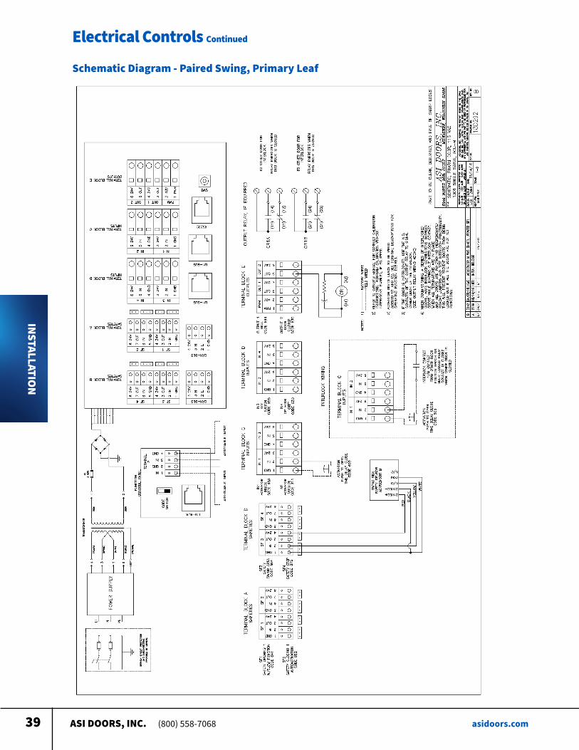
Schematic Diagram - Paired Swing, Primary Leaf
ASI DOORS, INC. (800) 558-7068 asidoors.com40
Electrical Controls Continued
INSTALLATION
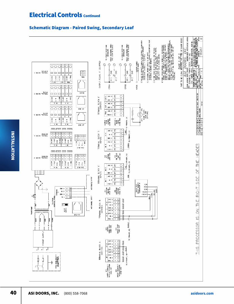
Schematic Diagram - Paired Swing, Secondary Leaf

ASI DOORS, INC. (800) 558-7068 asidoors.com41
Instructions for OrderingThis parts manual is intended to assist in the correct identification of the more commonly replaced parts; covering, generally, all models and styles offered within the marathon pharm Line The manual will also help identify obsolete parts, part design changes and current production parts For more specific parts information, please contact an authorized representative or consult the factory’s customer service or engineering departments Asi doors reserves the right to discontinue any part and make design changes without notice
Refer to the information tag on your door and record the: 1 Door model number 2 Job number 3 Door number 4 Manufacturing date Use part numbers referenced in this manual If the item is not found in the manual, the product code on the back of the item is helpful If your door has no information label, the approximate purchase date is helpful
General Instructions for Ordering Door PartsAccurate information is always necessary to serve you correctly and promptly Several
steps should be followed to determine exactly the parts that are needed
Call
1-800-558-7068or visit
asidoors.com/partsto order parts
REPLACEMEN
T PARTS
ASI DOORS, INC. (800) 558-7068 asidoors.com42
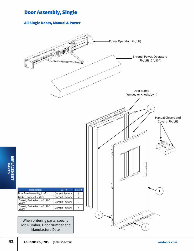
Door Assembly, Single
When ordering parts, specify Job Number, Door Number and
Manufacture Date
All Single Doors, Manual & Power
Power Operator (RH/LH)
Shroud, Power, Operators (RH/LH) (0 º, 30 º)
Door Frame (Welded or Knockdown)
1
Manual Closers and Covers (RH/LH)
1
2
4
Description PART# ITEM#Door Panel Assembly, LH/RH Consult Factory 1Gasket, Sweep (L = WIC) Consult Factory 2Gasket, Perimeter (L = 2* HIC +WIC) Consult Factory 3Gasket, Perimeter (L = 2* HIC +WIC) Consult Factory 4
REPLACEMENT
PARTS
ASI DOORS, INC. (800) 558-7068 asidoors.com43
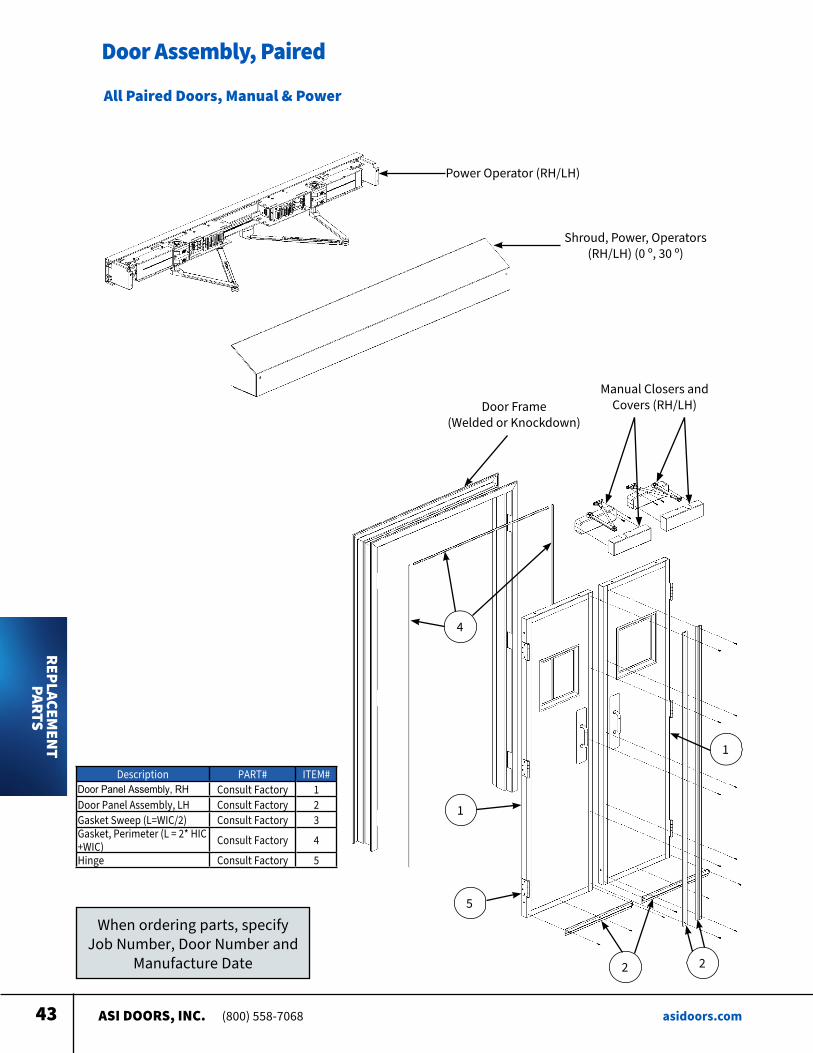
Door Assembly, Paired
When ordering parts, specify Job Number, Door Number and
Manufacture Date
All Paired Doors, Manual & Power
Power Operator (RH/LH)
Shroud, Power, Operators (RH/LH) (0 º, 30 º)
Door Frame (Welded or Knockdown)
4
Manual Closers and Covers (RH/LH)
1
2
5
Description PART# ITEM#Door Panel Assembly, RH Consult Factory 1Door Panel Assembly, LH Consult Factory 2Gasket Sweep (L=WIC/2) Consult Factory 3Gasket, Perimeter (L = 2* HIC +WIC) Consult Factory 4
Hinge Consult Factory 5
1
2
REPLACEMEN
T PARTS
ASI DOORS, INC. (800) 558-7068 asidoors.com44
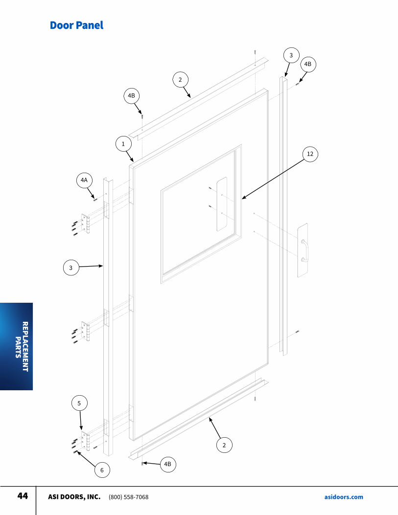
Door Panel
3
2
2
5
6
4B
1
4A
4B3
12
4B
REPLACEMENT
PARTS
ASI DOORS, INC. (800) 558-7068 asidoors.com45
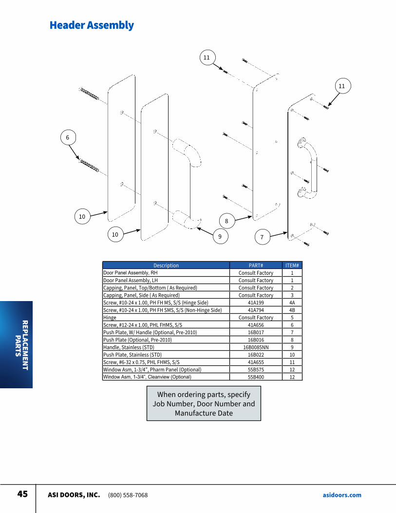
Header Assembly
Description PART# ITEM#Door Panel Assembly, RH Consult Factory 1Door Panel Assembly, LH Consult Factory 1Capping, Panel, Top/Bottom ( As Required) Consult Factory 2Capping, Panel, Side ( As Required) Consult Factory 3Screw, #10-24 x 1 00, PH FH MS, S/S (Hinge Side) 41A199 4AScrew, #10-24 x 1 00, PH FH SMS, S/S (Non-Hinge Side) 41A794 4BHinge Consult Factory 5Screw, #12-24 x 1 00, PHL FHMS, S/S 41A656 6Push Plate, W/ Handle (Optional, Pre-2010) 16B017 7Push Plate (Optional, Pre-2010) 16B016 8Handle, Stainless (STD) 16B0085NN 9Push Plate, Stainless (STD) 16B022 10Screw, #6-32 x 0 75, PHL FHMS, S/S 41A655 11Window Asm, 1-3/4”, Pharm Panel (Optional) 55B575 12Window Asm, 1-3/4”, Cleanview (Optional) 55B400 12
When ordering parts, specify Job Number, Door Number and
Manufacture Date
11
11
6
10
10 9
8
7
REPLACEMEN
T PARTS
ASI DOORS, INC. (800) 558-7068 asidoors.com46
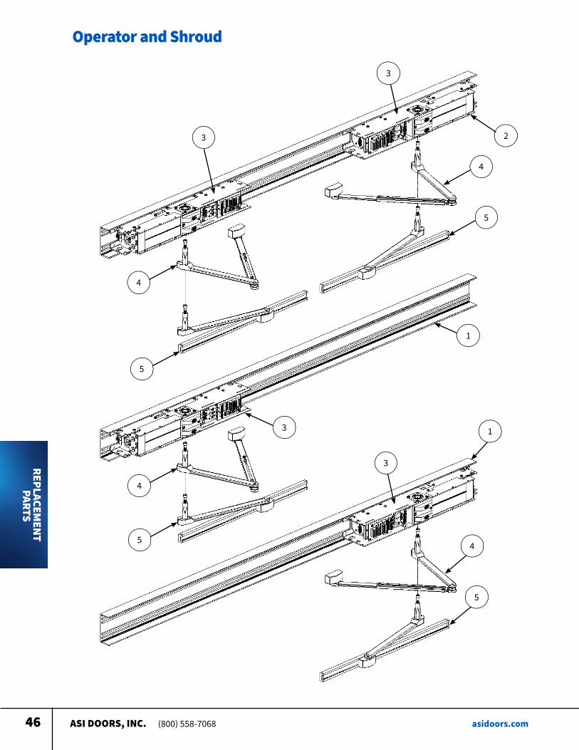
Operator and Shroud
3
3
2
4
5
4
5
4
5
3
1
3
1
4
5
REPLACEMEN
T PARTS
ASI DOORS, INC. (800) 558-7068 asidoors.com47
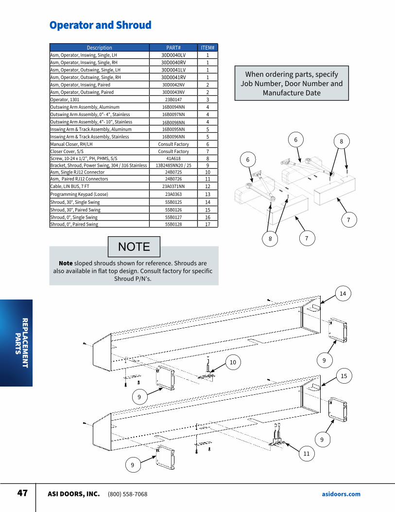
Operator and Shroud
Description PART# ITEM#Asm, Operator, Inswing, Single, LH 30D0040LV 1Asm, Operator, Inswing, Single, RH 30D0040RV 1Asm, Operator, Outswing, Single, LH 30D0041LV 1Asm, Operator, Outswing, Single, RH 30D0041RV 1Asm, Operator, Inswing, Paired 30D0042NV 2Asm, Operator, Outswing, Paired 30D0043NV 2Operator, 1301 23B0147 3Outswing Arm Assembly, Aluminum 16B0094NN 4Outswing Arm Assembly, 0"- 4", Stainless 16B0097NN 4Outswing Arm Assembly, 4"- 10", Stainless 16B0098NN 4Inswing Arm & Track Assembly, Aluminum 16B0095NN 5Inswing Arm & Track Assembly, Stainless 16B0096NN 5Manual Closer, RH/LH Consult Factory 6Closer Cover, S/S Consult Factory 7Screw, 10-24 x 1/2”, PH, PHMS, S/S 41A618 8Bracket, Shroud, Power Swing, 304 / 316 Stainless 13B2485NN20 / 25 9Asm, Single RJ12 Connector 24B0725 10Asm, Paired RJ12 Connectors 24B0726 11Cable, LIN BUS, 7 FT 23A0371NN 12Programming Keypad (Loose) 23A0363 13Shroud, 30°, Single Swing 55B0125 14Shroud, 30°, Paired Swing 55B0126 15Shroud, 0°, Single Swing 55B0127 16Shroud, 0°, Paired Swing 55B0128 17
Note sloped shrouds shown for reference Shrouds are also available in flat top design Consult factory for specific
Shroud P/N’s
NOTE
6
6
7
7
8
8
When ordering parts, specify Job Number, Door Number and
Manufacture Date
9
9
9
910
14
15
11
REPLACEMENT
PARTS

asidoors.com
ASI DOORS, INC. 5848 North 95th Court, Milwaukee, WI 53225 (800) 558-7068