Embed Size (px)
Citation preview

INSTALLATION & OPERATION INSTRUCTIONS
p70s / p70Rs Pilot Controller
© 2016 Raymarine UK Limited81365-2Document number:05-2016Date:
English (EN)

Printed Manuals
Would you prefer a printed version of this document?
Full documentation for your product is always provided as a free download on the Raymarine website, but some
customers prefer manuals in a printed format.
Raymarine provides a Print Shop service which enables you to purchase a printed manual (paperback book),
delivered to your door.
www.raymarine.com/printshop

Trademark and patents noticeRaymarine, Tacktick, Clear Pulse, Truzoom, HSB, SeaTalk, SeaTalkhs, SeaTalkng, Micronet, Raytech,Gear Up, Marine Shield, Seahawk, Autohelm, Automagic, and Visionality are registered or claimedtrademarks of Raymarine Belgium.FLIR, DownVision, SideVision, Dragonfly, Quantum, Instalert, Infrared Everywhere, and The World’sSixth Sense are registered or claimed trademarks of FLIR Systems, Inc.All other trademarks, trade names, or company names referenced herein are used for identification onlyand are the property of their respective owners.This product is protected by patents, design patents, patents pending, or design patents pending.
Fair Use StatementYou may print no more than three copies of this manual for your own use. You may not make any furthercopies or distribute or use the manual in any other way including without limitation exploiting the manualcommercially or giving or selling copies to third parties.
Software updates
Important: Check the Raymarine website for the latest software releases for your product.
www.raymarine.com/software
Product handbooksThe latest versions of all English and translated handbooks are available to download in PDF format from the websitewww.raymarine.com.Please check the website to ensure you have the latest handbooks.
Copyright ©2016 Raymarine UK Ltd. All rights reserved.
ENGLISHDocument number: 81365-2Date: 05-2016


ContentsChapter 1 Important information.......................... 7TFT Displays............................................................... 8Water ingress .............................................................. 8Disclaimer ................................................................... 8EMC installation guidelines .......................................... 8Suppression ferrites..................................................... 8Connections to other equipment ................................... 8Declaration of conformity.............................................. 8Product disposal .......................................................... 8Warranty registration.................................................... 9IMO and SOLAS.......................................................... 9Technical accuracy ...................................................... 9
Chapter 2 Document and productinformation........................................................... 112.1 Document information .......................................... 122.2 Product overview ................................................. 13
Chapter 3 Planning the installation ................... 153.1 Installation checklist ............................................. 163.2 Parts Supplied ..................................................... 163.3 Compatible autopilot systems ............................... 173.4 Software updates ................................................. 173.5 Tools ................................................................... 183.6 System protocols ................................................. 183.7 Warnings and cautions ......................................... 193.8 General location requirements .............................. 193.9 Unit dimensions ................................................... 20
Chapter 4 Cables and connections.................... 214.1 General cabling guidance ..................................... 224.2 Connections overview .......................................... 224.3 SeaTalkng® power supply ...................................... 234.4 Cable ferrite installation ........................................ 254.5 SeaTalkng® connection.......................................... 254.6 SeaTalk connection .............................................. 264.7 NMEA 2000 network connection ........................... 27
Chapter 5 Installation.......................................... 295.1 Bezel removal...................................................... 305.2 Removing the keypad........................................... 305.3 Mounting ............................................................. 315.4 Refitting the keypad ............................................. 32
Chapter 6 Getting started ................................... 336.1 Pilot controls ........................................................ 346.2 Before using your product..................................... 356.3 Powering the Pilot controller on............................. 356.4 Completing the startup wizard............................... 366.5 Pilot functions ...................................................... 366.6 Display settings.................................................... 376.7 Multiple data sources (MDS) overview................... 38
Chapter 7 Commissioning - Evolutionautopilot system.................................................. 417.1 Evolution autopilot installation ............................... 427.2 Autopilot commissioning — main differencesbetween Evolution and SPX systems .......................... 427.3 Autopilot response levels ...................................... 437.4 Initial setup and commissioning............................. 437.5 Powering the Pilot controller on............................. 447.6 Using the Set-up Wizard....................................... 457.7 Using the Dockside wizard.................................... 457.8 Adjusting the hard-over time — Evolution .............. 477.9 Compass linearization — Evolutionautopilots .................................................................. 477.10 Compass lock .................................................... 49
Chapter 8 Commissioning - SPX andSmartPilot systems ............................................. 518.1 SPX and SmartPilot autopilot installation ............... 528.2 Pilot response...................................................... 528.3 Initial setup and commissioning............................. 538.4 Powering the Pilot controller on............................. 538.5 Using the Set-up Wizard....................................... 548.6 Dockside calibration ............................................. 558.7 Dealer settings..................................................... 568.8 Adjusting the hard-over time — SmartPilot andSPX.......................................................................... 578.9 Sea trial calibration............................................... 578.10 Checking autopilot operation............................... 59
Chapter 9 Pilot modes......................................... 619.1 Auto .................................................................... 629.2 Mode menu ......................................................... 639.3 Patterns............................................................... 639.4 Track mode ......................................................... 649.5 Wind vane mode (Sailing boats only)..................... 669.6 Power steer ......................................................... 689.7 Jog steer (tiller pilots only) .................................... 699.8 Shortcut key ........................................................ 69
Chapter 10 Pilot views ........................................ 7110.1 Available pilot views ........................................... 7210.2 Graphical view ................................................... 7210.3 Large view ......................................................... 7310.4 Standard view .................................................... 7310.5 Multiple view ...................................................... 7410.6 2D View............................................................. 7410.7 Setting the pilot view........................................... 7510.8 Setting up data boxes......................................... 75
Chapter 11 Pilot controller alarms ..................... 7711.1 Alarms ............................................................... 78
Chapter 12 Set up menu options ....................... 8312.1 Set up menu ...................................................... 8412.2 Autopilot calibration menu................................... 84
5

12.3 User preferences menu ...................................... 9212.4 System set-up menu........................................... 9412.5 Diagnostics menu............................................... 95
Chapter 13 Maintenance ..................................... 9713.1 Routine equipment checks.................................. 9813.2 Product cleaning ................................................ 9813.3 Cleaning the display screen ................................ 9913.4 Cleaning the display case ................................... 9913.5 Cleaning the sun cover ..................................... 100
Chapter 14 System checks andtroubleshooting ................................................. 10114.1 Troubleshooting ............................................... 10214.2 Power up troubleshooting ................................. 10314.3 System data troubleshooting............................. 10414.4 Miscellaneous troubleshooting .......................... 10514.5 Performing a Factory Reset .............................. 106
Chapter 15 Technical specification.................. 10715.1 Technical specification ...................................... 108
Chapter 16 Technical support .......................... 10916.1 Raymarine product support and servicing ...........11016.2 Learning resources............................................111
Chapter 17 Spares and accessories................ 11317.1 Spares and Accessories ....................................11417.2 SeaTalkng® cables and accessories ....................11417.3 SeaTalkng cable kits ...........................................11617.4 SeaTalk accessories..........................................119
Appendix A Supported NMEA 2000 PGNlist ....................................................................... 121
Appendix B Software releases......................... 121
6 p70s / p70Rs

Chapter 1: Important informationWarning: Autopilot systemInstallationAs correct performance of the vessel’ssteering is critical for safety, weSTRONGLY RECOMMEND thatan Authorized Raymarine ServiceRepresentative fits this product. You willonly receive full warranty benefits if youcan show that an Authorized RaymarineService Representative has installed andcommissioned this product.
Warning: Product installation andoperation• This product must be installed andoperated in accordance with theinstructions provided. Failure to do socould result in personal injury, damageto your vessel and/or poor productperformance.
• Raymarine recommends certifiedinstallation by a Raymarine approvedinstaller. A certified installation qualifiesfor enhanced product warranty benefits.Contact your Raymarine dealer forfurther details, and refer to the separatewarranty document packed with yourproduct.
Warning: Maintain a permanentwatchAlways maintain a permanent watch, thiswill allow you to respond to situationsas they develop. Failure to maintain apermanent watch puts yourself, yourvessel and others at serious risk of harm.
Warning: Ensure safe navigationThis product is intended only as an aidto navigation and must never be usedin preference to sound navigationaljudgment. Only official governmentcharts and notices to mariners contain allthe current information needed for safenavigation, and the captain is responsiblefor their prudent use. It is the user’sresponsibility to use official governmentcharts, notices to mariners, caution andproper navigational skill when operatingthis or any other Raymarine product.
Warning: Potential ignition sourceThis product is NOT approved for use inhazardous/flammable atmospheres. DoNOT install in a hazardous/flammableatmosphere (such as in an engine roomor near fuel tanks).
Warning: Product groundingBefore applying power to this product,ensure it has been correctly grounded, inaccordance with the instructions provided.
Warning: Positive ground systemsDo not connect this unit to a system whichhas positive grounding.
Warning: Switch off power supplyEnsure the vessel’s power supply isswitched OFF before starting to install thisproduct. Do NOT connect or disconnectequipment with the power switched on,unless instructed in this document.
Warning: Power supply voltageConnecting this product to a voltagesupply greater than the specifiedmaximum rating may cause permanentdamage to the unit. Refer to the Technicalspecification section for voltage rating.
Caution: Power supply protectionWhen installing this product ensure thepower source is adequately protectedby means of a suitably-rated fuse orautomatic circuit breaker.
Caution: Sun covers• If your product is supplied with a suncover, to protect against the damagingeffects of ultraviolet (UV) light, alwaysfit the sun cover when the product isnot in use.
• Sun covers must be removed whentravelling at high speed, whether inwater or when the vessel is beingtowed.
Caution: Product cleaningWhen cleaning products:
• If your product includes a displayscreen, do NOT wipe the screen witha dry cloth, as this could scratch thescreen coating.
• Do NOT use abrasive, or acid orammonia based products.
• Do NOT use a jet wash.
Caution: Service and maintenanceThis product contains no user serviceablecomponents. Please refer all maintenanceand repair to authorized Raymarinedealers. Unauthorized repair may affectyour warranty.
Important information 7

TFT DisplaysThe colors of the display may seem to vary whenviewed against a colored background or in coloredlight. This is a perfectly normal effect that canbe seen with all color Thin Film Transistor (TFT)displays.
Water ingressWater ingress disclaimerAlthough the waterproof rating capacity of thisproduct meets the stated IPX standard (refer to theproduct’s Technical Specification), water intrusionand subsequent equipment failure may occur if theproduct is subjected to commercial high-pressurewashing. Raymarine will not warrant productssubjected to high-pressure washing.
DisclaimerRaymarine does not warrant that this product iserror-free or that it is compatible with productsmanufactured by any person or entity other thanRaymarine.Raymarine is not responsible for damages or injuriescaused by your use or inability to use the product,by the interaction of the product with productsmanufactured by others, or by errors in informationutilized by the product supplied by third parties.
EMC installation guidelinesRaymarine equipment and accessories conform tothe appropriate Electromagnetic Compatibility (EMC)regulations, to minimize electromagnetic interferencebetween equipment and minimize the effect suchinterference could have on the performance of yoursystemCorrect installation is required to ensure that EMCperformance is not compromised.
Note: In areas of extreme EMC interference,some slight interference may be noticed on theproduct. Where this occurs the product and thesource of the interference should be separated bya greater distance.
For optimum EMC performance we recommendthat wherever possible:• Raymarine equipment and cables connected toit are:– At least 1 m (3 ft) from any equipmenttransmitting or cables carrying radio signals e.g.VHF radios, cables and antennas. In the caseof SSB radios, the distance should be increasedto 7 ft (2 m).
– More than 2 m (7 ft) from the path of a radarbeam. A radar beam can normally be assumedto spread 20 degrees above and below theradiating element.
• The product is supplied from a separate batteryfrom that used for engine start. This is important to
prevent erratic behavior and data loss which canoccur if the engine start does not have a separatebattery.
• Raymarine specified cables are used.• Cables are not cut or extended, unless doing so isdetailed in the installation manual.
Note: Where constraints on the installationprevent any of the above recommendations,always ensure the maximum possible separationbetween different items of electrical equipment, toprovide the best conditions for EMC performancethroughout the installation
Suppression ferrites• Raymarine cables may be pre-fitted or suppliedwith suppression ferrites. These are important forcorrect EMC performance. If ferrites are suppliedseparately to the cables (i.e. not pre-fitted), youmust fit the supplied ferrites, using the suppliedinstructions.
• If a ferrite has to be removed for any purpose (e.g.installation or maintenance), it must be replaced inthe original position before the product is used.
• Use only ferrites of the correct type, supplied byRaymarine or its authorized dealers.
• Where an installation requires multiple ferrites tobe added to a cable, additional cable clips shouldbe used to prevent stress on the connectors dueto the extra weight of the cable.
Connections to other equipmentRequirement for ferrites on non-Raymarine cablesIf your Raymarine equipment is to be connectedto other equipment using a cable not supplied byRaymarine, a suppression ferrite MUST always beattached to the cable near the Raymarine unit.
Declaration of conformityRaymarine UK Ltd. declares that this product iscompliant with the essential requirements of EMCdirective 2004/108/EC.The original Declaration of Conformity certificatemay be viewed on the relevant product page atwww.raymarine.com.
Product disposalDispose of this product in accordance with theWEEE Directive.
The Waste Electrical and Electronic Equipment(WEEE) Directive requires the recycling of wasteelectrical and electronic equipment.
8 p70s / p70Rs
Warranty registrationTo register your Raymarine product ownership,please visit www.raymarine.com and register online.It is important that you register your product toreceive full warranty benefits. Your unit packageincludes a bar code label indicating the serial numberof the unit. You will need this serial number whenregistering your product online. You should retainthe label for future reference.
IMO and SOLASThe equipment described within this documentis intended for use on leisure marine boats andworkboats NOT covered by International MaritimeOrganization (IMO) and Safety of Life at Sea(SOLAS) Carriage Regulations.
Technical accuracyTo the best of our knowledge, the information in thisdocument was correct at the time it was produced.However, Raymarine cannot accept liability for anyinaccuracies or omissions it may contain. In addition,our policy of continuous product improvement maychange specifications without notice. As a result,Raymarine cannot accept liability for any differencesbetween the product and this document. Pleasecheck the Raymarine website (www.raymarine.com)to ensure you have the most up-to-date version(s) ofthe documentation for your product.
Important information 9

10 p70s / p70Rs

Chapter 2: Document and product information
Chapter contents• 2.1 Document information on page 12• 2.2 Product overview on page 13
Document and product information 11

2.1 Document informationThis document contains important informationrelated to the installation of your Raymarine product.The document includes information to help you:• plan your installation and ensure you have all thenecessary equipment;
• install and connect your product as part of a widersystem of connected marine electronics;
• troubleshoot problems and obtain technicalsupport if required.
This and other Raymarine product documentsare available to download in PDF format fromwww.raymarine.com.
Applicable productsThis document is applicable to the following products:
Part number Name DescriptionE70328 p70s SeaTalkng 8
button pilotcontroller(Sail)
E70329 p70Rs SeaTalkngRotary pilotcontroller(Power)
Software revisionRaymarine regularly updates product software toadd new features and improve existing functionality.This document covers Pilot controller software —LightHouse Version 3.xx, which should be used inconjunction with EV and ACU software version 2.xx.Please refer to the Software Releases section fordetails on software releases.Check the Raymarine® website to ensure you havethe latest software and user manuals:• www.raymarine.com/software• www.raymarine.com/manuals
Product documentationThe following documentation is applicable to yourproduct:Description Part numberp70s / p70Rs Installation and operationinstructions
88057 / 81365
p70s / p70Rs Mounting template 87260
Additional handbooksDescription Part numberSeaTalkng® reference manual 81300
SeaTalk to SeaTalkng® converter 87121
Document illustrationsYour product may differ slightly from that shownin the illustrations in this document, depending onproduct variant and date of manufacture.All images are provided for illustration purposes only.
12 p70s / p70Rs

2.2 Product overviewThe p70s and p70Rs are SeaTalkng pilot controllers.
D13016-2
1 2
1. p70s 8 button (sail) Pilot Controller2. p70Rs Rotary (power) Pilot ControllerThe unit has the following features:• 3.45” high brightness color LCD with wide viewingangles
• SeaTalkng, NMEA 2000 and SeaTalk compatible• All weather optically bonded LCD• Large clear characters for easy reading in anyconditions
• Easy to use LightHouseTM operating system• 12 V dc operation.• Low power consumption• Waterproof to IPx6 and IPx7
Document and product information 13

14 p70s / p70Rs

Chapter 3: Planning the installation
Chapter contents• 3.1 Installation checklist on page 16• 3.2 Parts Supplied on page 16• 3.3 Compatible autopilot systems on page 17• 3.4 Software updates on page 17• 3.5 Tools on page 18• 3.6 System protocols on page 18• 3.7 Warnings and cautions on page 19• 3.8 General location requirements on page 19• 3.9 Unit dimensions on page 20
Planning the installation 15
3.1 Installation checklistInstallation includes the following activities:
Installation Task1 Plan your system.2 Obtain all required equipment and tools.3 Site all equipment.4 Route all cables.5 Drill cable and mounting holes.6 Make all connections into equipment.7 Secure all equipment in place.8 Power on and test the system.
Schematic diagramA schematic diagram is an essential part of planningany installation. It is also useful for any futureadditions or maintenance of the system. Thediagram should include:• Location of all components.• Connectors, cable types, routes and lengths.
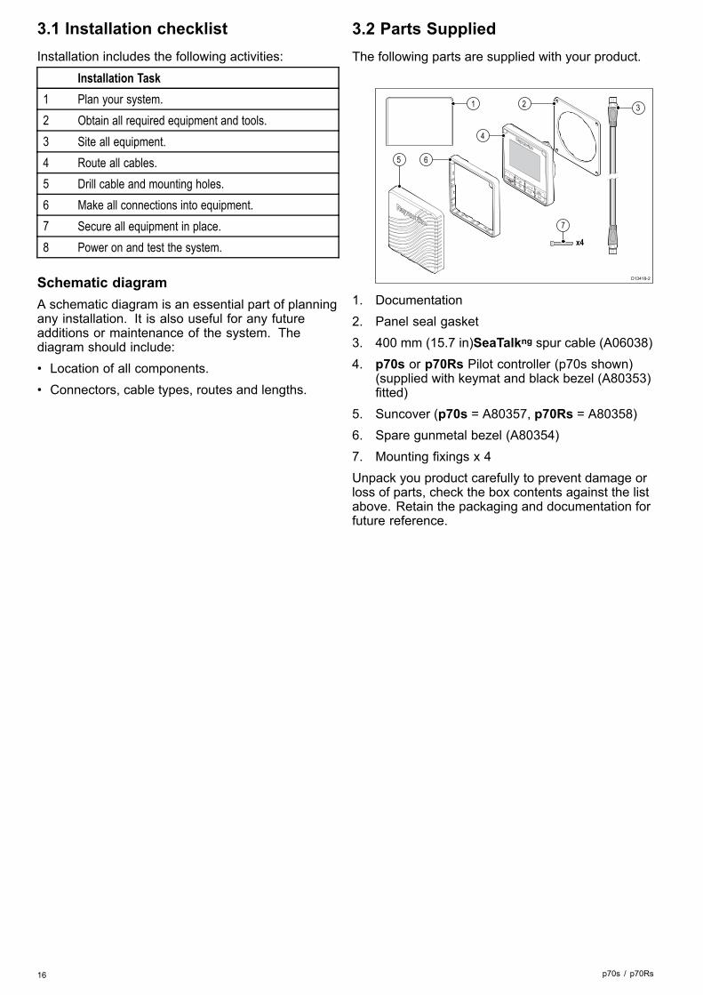
3.2 Parts SuppliedThe following parts are supplied with your product.
D13418-2
4
2
6
1 3
5
7
x4
1. Documentation2. Panel seal gasket3. 400 mm (15.7 in)SeaTalkng spur cable (A06038)4. p70s or p70Rs Pilot controller (p70s shown)
(supplied with keymat and black bezel (A80353)fitted)
5. Suncover (p70s = A80357, p70Rs = A80358)6. Spare gunmetal bezel (A80354)7. Mounting fixings x 4Unpack you product carefully to prevent damage orloss of parts, check the box contents against the listabove. Retain the packaging and documentation forfuture reference.
16 p70s / p70Rs

3.3 Compatible autopilot systemsYour product is compatible with the RaymarineAutopilot systems shown below.
Product Description Connection
��Evolutionautopilots
SeaTalkng
SMARTPILOT
SPX SmartPilot SeaTalkng
S1, S2 & S3SmartPilot
SeaTalk viaa SeaTalk toSeaTalkng adaptorcable.
3.4 Software updatesThe software running on the product can be updated.• Raymarine periodically releases software updatesto improve product performance and add newfeatures.
• You can update the software for your product usinga connected and compatible multifunction display.
• Refer to www.raymarine.com/software/ for thelatest software updates and the software updateprocedure for your product.
• If in doubt as to the correct procedure for updatingyour product software, refer to your dealer orRaymarine technical support.
Caution: Installing softwareupdatesThe software update process is carriedout at your own risk. Before initiating theupdate process ensure you have backedup any important files.Ensure that the unit has a reliable powersupply and that the update process is notinterrupted.Damage caused by incomplete updatesare not covered by Raymarine warranty.By downloading the software updatepackage, you agree to these terms.
Evolution software updatesThe components of the Evolution autopilot system(EV sensor and ACU) must be upgraded in thecorrect order.Using the System Software Update process,available on a LightHouse™ II powered MFDrunning Release 15 or greater, will ensure that theEvolution components are updated in the correctorder.If you are using another method or are updating thesystem components individually then the EV SensorMUST be updated before the ACU.
Note:• Updating in the wrong order may cause theautopilot to cease to function.
• After successful completion of the softwareupdate process the autopilot will requirere-calibration.
Planning the installation 17

3.5 ToolsTools required for installation
1 2
3 4
5 6 7
D12055-1
1. Power drill2. Jig saw3. Screwdriver4. Suitable size (10 mm to 30
mm) hole cutter5. File6. Adhesive tape7. Drill bit of appropriate size (1)
Note: (1) Drill bit size is dependent on thethickness and type of material that the unit is tobe mounted on.
3.6 System protocolsYour product can be connected to various productsand systems to share information and so improvethe functionality of the overall system. Theseconnections may be made using a number ofdifferent protocols. Fast and accurate data collectionand transfer is achieved by using a combination ofthe following data protocols:• SeaTalkng®
• NMEA 2000• SeaTalk
Note: You may find that your system does notuse all of the connection types or instrumentationdescribed in this section.
Seatalkng®
SeaTalkng (Next Generation) is an enhancedprotocol for connection of compatible marineinstruments and equipment. It replaces the olderSeaTalk and SeaTalk2 protocols.SeaTalkng utilizes a single backbone to whichcompatible instruments connect using a spur. Dataand power are carried within the backbone. Devicesthat have a low draw can be powered from thenetwork, although high current equipment will needto have a separate power connection.SeaTalkng is a proprietary extension to NMEA 2000and the proven CAN bus technology. CompatibleNMEA 2000 and SeaTalk / SeaTalk2 devices canalso be connected using the appropriate interfacesor adaptor cables as required.
NMEA 2000NMEA 2000 offers significant improvements overNMEA 0183, most notably in speed and connectivity.Up to 50 units can simultaneously transmit andreceive on a single physical bus at any one time,with each node being physically addressable. Thestandard was specifically intended to allow fora whole network of marine electronics from anymanufacturer to communicate on a common bus viastandardized message types and formats.
SeaTalkSeaTalk is a protocol which enables compatibleinstruments to connect to each other and share data.The SeaTalk cable system is used to connectcompatible instruments and equipment. The cablecarries power and data and enables connectionwithout the need for a central processor.Additional instruments and functions can be added toa SeaTalk system, simply by plugging them into thenetwork. SeaTalk equipment can also communicatewith other non-SeaTalk equipment via the NMEA0183 standard, provided a suitable interface is used.
18 p70s / p70Rs

3.7 Warnings and cautionsImportant: Before proceeding, ensure that youhave read and understood the warnings andcautions provided in the Chapter 1 Importantinformation section of this document.
3.8 General location requirementsImportant considerations when choosing a suitablelocation for your product.This product is suitable for mounting above or belowdecks.The product should be mounted where it will be:• protected from physical damage and excessivevibration.
• well ventilated and away from heat sources.• away from any potential ignition source such as anengine room, near fuel tanks or a gas locker.
When choosing a location for the product,consider the following points to ensure reliable andtrouble-free operation:• Access — there must be sufficient space toenable cable connections to the product, avoidingtight bends in the cable.
• Diagnostics — the product must be mounted ina location where the diagnostics LED is easilyvisible.
Note: Not all products include a diagnosticsLED. Refer to the Chapter 14 System checksand troubleshooting for more information.
• Electrical interference — the product should bemounted far enough away from any equipmentthat may cause interference such as motors,generators and radio transmitters / receivers.
• Magnetic compass — refer to the Compasssafe distance section in this document for adviceon maintaining a suitable distance between thisproduct and any compasses on your vessel.
• Power — to keep cable runs to a minimum, theproduct must be located as close as possible tothe vessel’s dc power supply.
• Mounting surface — ensure the product isadequately supported on a secure surface. Referto the weight information provided in the Technicalspecification for this product and ensure that theintended mounting surface is suitable for bearingthe product weight. Do NOT mount units or cutholes in places which may damage the structureof the vessel.
Planning the installation 19

Site Requirements
> 0.8m(2ft 6in)
D12031-2
Site requirements for the p70s / p70Rs Pilotcontroller are as follows:• There should be no obstacle between the userand the pilot controller.
• The pilot controller should be situated at least 0.8m from an engine, compass, high current powercables, or any magnetic device.
Viewing angle considerationsAs display contrast, color and night modeperformance are all affected by the viewing angle,Raymarine recommends you temporarily power upthe display when planning the installation, to enableyou to best judge which location gives the optimumviewing angle.
3.9 Unit dimensions
110 mm (4.33 in)14.05 mm(0.55 in) 90 mm
(3.54 in)29.8 mm(1.17 in)
115
mm
(4.5
3 in
)
17.8 mm(0.7 in)
D12103-2
20 p70s / p70Rs

Chapter 4: Cables and connections
Chapter contents• 4.1 General cabling guidance on page 22• 4.2 Connections overview on page 22• 4.3 SeaTalkng® power supply on page 23• 4.4 Cable ferrite installation on page 25• 4.5 SeaTalkng® connection on page 25• 4.6 SeaTalk connection on page 26• 4.7 NMEA 2000 network connection on page 27
Cables and connections 21

4.1 General cabling guidance
Cable types and lengthIt is important to use cables of the appropriate typeand length• Unless otherwise stated use only standard cablesof the correct type, supplied by Raymarine.
• Ensure that any non-Raymarine cables are of thecorrect quality and gauge. For example, longerpower cable runs may require larger wire gaugesto minimize voltage drop along the run.
Routing cablesCables must be routed correctly, to maximizeperformance and prolong cable life.• Do NOT bend cables excessively. Whereverpossible, ensure a minimum bend diameter of 200mm (8 in) / minimum bend radius of 100 mm (4 in).
100 mm (4 in)
200 mm (8 in)
• Protect all cables from physical damage andexposure to heat. Use trunking or conduit wherepossible. Do NOT run cables through bilges ordoorways, or close to moving or hot objects.
• Secure cables in place using tie-wraps or lacingtwine. Coil any extra cable and tie it out of the way.
• Where a cable passes through an exposedbulkhead or deckhead, use a suitable watertightfeed-through.
• Do NOT run cables near to engines or fluorescentlights.
Always route data cables as far away as possiblefrom:• other equipment and cables,• high current carrying AC and DC power lines,• antennae.
Caution: Pulling cablesDo NOT use cords or ropes, attachedto cable connectors, to pull cablesthrough restricted apertures (e.g. as inbulkheads), as this could cause damageto cables.
Strain reliefEnsure adequate strain relief is provided. Protectconnectors from strain and ensure they will not pullout under extreme sea conditions.
Cable shieldingEnsure that all data cables are properly shieldedthat the cable shielding is intact (e.g. hasn’t beenscraped off by being squeezed through a tight area).
4.2 Connections overviewUse the following information to help you identify theconnections on your product.
Connector Qty Connects to: Suitable cables1 1. SeaTalkng
backbone2. NMEA 2000
backbone3. SeaTalk
backbone
1. SeaTalkngspur cables
2. SeaTalkng toDeviceNetadaptorcable(A06045)
3. SeaTalk toSeaTalkngadaptorcable(A06073)
Connecting SeaTalkng® cables
D12615-2
1. Rotate the locking collar on the unit to theunlocked position.
2. Ensure the cable’s connector is correctly oriented.3. Fully insert the cable connector.4. Rotate locking collar clockwise (2 clicks) until it is
in the locked position.
SeaTalkng® product loadingThe number of products that can be connectedto a SeaTalkng backbone depends on the powerconsumption of each product and the physical overalllength of the backbone.SeaTalkng products have a Load EquivalencyNumber (LEN), which indicates the product’s powerconsumption. The LEN for each product can befound in the product’s Technical Specification.
22 p70s / p70Rs
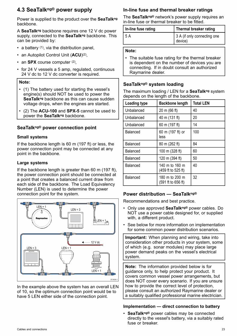
4.3 SeaTalkng® power supplyPower is supplied to the product over the SeaTalkngbackbone.A SeaTalkng backbone requires one 12 V dc powersupply, connected to the SeaTalkng backbone. Thiscan be provided by:• a battery (1), via the distribution panel,• an Autopilot Control Unit (ACU)(2),• an SPX course computer (2),• for 24 V vessels a 5 amp, regulated, continuous24 V dc to 12 V dc converter is required.
Note:• (1) The battery used for starting the vessel’sengine(s) should NOT be used to power theSeaTalkng backbone as this can cause suddenvoltage drops, when the engines are started.
• (2) The ACU-100 and SPX-5 cannot be used topower the SeaTalkng backbone.
SeaTalkng® power connection point
Small systemsIf the backbone length is 60 m (197 ft) or less, thepower connection point may be connected at anypoint in the backbone.
Large systemsIf the backbone length is greater than 60 m (197 ft),the power connection point should be connected ata point that creates a balanced current draw fromeach side of the backbone. The Load EquivalencyNumber (LEN) is used to determine the powerconnection point for the system.
��
D13424-1
LEN = 3
LEN = 3LEN = 1
LEN = 1
LEN = 1
LEN = 1
12 V dc
In the example above the system has an overall LENof 10, so the optimum connection point would be tohave 5 LEN either side of the connection point.
In-line fuse and thermal breaker ratingsThe SeaTalkng® network’s power supply requires anin-line fuse or thermal breaker to be fitted.In-line fuse rating Thermal breaker rating5 A 3 A (if only connecting one
device)
Note:• The suitable fuse rating for the thermal breakeris dependent on the number of devices you areconnecting. If in doubt consult an authorizedRaymarine dealer.
SeaTalkng® system loadingThe maximum loading / LEN for a SeaTalkng systemdepends on the length of the backbone.Loading type Backbone length Total LENUnbalanced 20 m (66 ft) 40Unbalanced 40 m (131 ft) 20Unbalanced 60 m (197 ft) 14Balanced 60 m (197 ft) or
less100
Balanced 80 m (262 ft) 84Balanced 100 m (328 ft) 60Balanced 120 m (394 ft) 50Balanced 140 m to 160 m
(459 ft to 525 ft)40
Balanced 180 m to 200 m(591 ft to 656 ft)
32
Power distribution — SeaTalkng®Recommendations and best practice.• Only use approved SeaTalkng® power cables. DoNOT use a power cable designed for, or suppliedwith, a different product.
• See below for more information on implementationfor some common power distribution scenarios.
Important: When planning and wiring, take intoconsideration other products in your system, someof which (e.g. sonar modules) may place largepower demand peaks on the vessel’s electricalsystem.
Note: The information provided below is forguidance only, to help protect your product. Itcovers common vessel power arrangements, butdoes NOT cover every scenario. If you are unsurehow to provide the correct level of protection,please consult an authorized Raymarine dealer ora suitably qualified professional marine electrician.
Implementation — direct connection to battery• SeaTalkng® power cables may be connecteddirectly to the vessel's battery, via a suitably ratedfuse or breaker.
Cables and connections 23
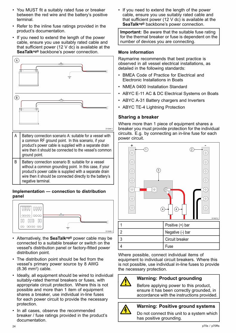
• You MUST fit a suitably rated fuse or breakerbetween the red wire and the battery’s positiveterminal.
• Refer to the inline fuse ratings provided in theproduct’s documentation.
• If you need to extend the length of the powercable, ensure you use suitably rated cable andthat sufficient power (12 V dc) is available at theSeaTalkng® backbone’s power connection.
D13344-1
A
B
A Battery connection scenario A: suitable for a vessel witha common RF ground point. In this scenario, if yourproduct’s power cable is supplied with a separate drainwire then it should be connected to the vessel’s commonground point.
B Battery connection scenario B: suitable for a vesselwithout a common grounding point. In this case, if yourproduct’s power cable is supplied with a separate drainwire then it should be connected directly to the battery’snegative terminal.
Implementation — connection to distributionpanel
D13348-1
• Alternatively, the SeaTalkng® power cable may beconnected to a suitable breaker or switch on thevessel's distribution panel or factory-fitted powerdistribution point.
• The distribution point should be fed from thevessel’s primary power source by 8 AWG(8.36 mm2) cable.
• Ideally, all equipment should be wired to individualsuitably-rated thermal breakers or fuses, withappropriate circuit protection. Where this is notpossible and more than 1 item of equipmentshares a breaker, use individual in-line fusesfor each power circuit to provide the necessaryprotection.
• In all cases, observe the recommendedbreaker / fuse ratings provided in the product’sdocumentation.
• If you need to extend the length of the powercable, ensure you use suitably rated cable andthat sufficient power (12 V dc) is available at theSeaTalkng® backbone’s power connection.
Important: Be aware that the suitable fuse ratingfor the thermal breaker or fuse is dependent on thenumber of devices you are connecting.
More informationRaymarine recommends that best practice isobserved in all vessel electrical installations, asdetailed in the following standards:• BMEA Code of Practice for Electrical andElectronic Installations in Boats
• NMEA 0400 Installation Standard• ABYC E-11 AC & DC Electrical Systems on Boats• ABYC A-31 Battery chargers and Inverters• ABYC TE-4 Lightning Protection
Sharing a breakerWhere more than 1 piece of equipment shares abreaker you must provide protection for the individualcircuits. E.g. by connecting an in-line fuse for eachpower circuit.
D11637-2
2
4 4
1
3
+ -
1 Positive (+) bar2 Negative (-) bar3 Circuit breaker4 Fuse
Where possible, connect individual items ofequipment to individual circuit breakers. Where thisis not possible, use individual in-line fuses to providethe necessary protection.
Warning: Product groundingBefore applying power to this product,ensure it has been correctly grounded, inaccordance with the instructions provided.
Warning: Positive ground systemsDo not connect this unit to a system whichhas positive grounding.
24 p70s / p70Rs

4.4 Cable ferrite installationYour product is supplied with a cable ferrite. Toensure EMC Compliance, the supplied ferrite mustbe fitted to the cable according to the followinginstructions.
SeaT
alkn
g
50 mm (1.97 in) - 100 mm (3.94 in)
SeaTalkng
Device
D13539-1
1. The ferrite must be fitted to the end of the cableclosest to the device.
2. The ferrite must be fitted at the distance specifiedin the illustration above.
3. Ensure a tight and secure fit so that the ferrite willnot move up or down the cable.
4.5 SeaTalkng® connectionThe unit connects as part of a SeaTalkng network.
Example: SeaTalkng®® system with Evolutionautopilot and iTC-5
12 V dc��SeaTalkng
SeaTalkng
D13026-2
7
1 32
4 5
6
8
9 10 11
1 ACU unit2 i70s Multifunction instrument display3 p70s / p70Rs Pilot controller (p70s shown)4 Vessel’s 12 V dc power supply5 EV unit6 SeaTalkng 5–way connector7 Rudder reference transducer8 iTC-5 converter9 Depth transducer10 Wind transducer11 Speed transducer
Note: In the above example if an ACU-100 wereused, the SeaTalkng network would require adedicated 12 V dc power supply because theACU-100 does not supply power to the SeaTalkngnetwork.
Cables and connections 25

Example: SeaTalkng® system with SPX SmartPilotand transducer pods
SeaTalkng
32
SMARTPILOT
12 V dc
SeaTalkng
SeaTalkng
D12099-3
7 8
1
4
6 6 6
5
9 10 11
Item Description1 SPX (supplying 12 V dc to the SeaTalkng network.)2 i70s Multifunction instrument displays3 p70s / p70Rs Pilot controller (p70s shown)4 Vessel’s 12 V dc power supply5 SeaTalkng 5–way connector6 Transducer pods7 Rudder reference transducer8. Fluxgate compass9 Wind transducer10 Speed transducer11 Depth transducer
4.6 SeaTalk connectionConnections to a SeaTalk network are made using aSeaTalk to SeaTalkng adaptor cable (not supplied).
12 V
D12102-3
4
5
6
7 8
9
1 2 3
Item Description1. p70s Pilot controller2. ST60+ Depth instrument3. ST60+ Speed instrument4. ST60+ Wind instrument5. Wind transducer6. SeaTalk to SeaTalkngadaptor
cable7. Depth transducer8. Speed transducer9. Course computer (supplying
12V to SeaTalk network.)
For SeaTalk cables and extensions, use SeaTalkcable accessories.
SeaTalk power protectionThe power supply must be protected by a 5 A fuseor a circuit breaker providing equivalent protection.Raymarine recommends that the power is connectedto a SeaTalk system in such a way that the currentdrawn on each side of the power connection pointis equal.
26 p70s / p70Rs

4.7 NMEA 2000 network connectionYour SeaTalkng® device can be connected to aDeviceNet / NMEA 2000 network.
D12060-3
4
2
NMEA2000
3
SeaTalkng
device
1
1. SeaTalkng® device2. SeaTalkng® to DeviceNet adaptor cable
(A06045)3. DeviceNet T-piece4. NMEA 2000 backbone
Cables and connections 27

28 p70s / p70Rs

Chapter 5: Installation
Chapter contents• 5.1 Bezel removal on page 30• 5.2 Removing the keypad on page 30• 5.3 Mounting on page 31• 5.4 Refitting the keypad on page 32
Installation 29

5.1 Bezel removal
1 2
3 4
D13435-1
Removing the bezelNote: Take care when removing the bezel. Donot use any tools to lever the bezel, doing so maycause damage.
1. Using your fingers pull the bezel away from theunit at the top and on one side.
You should hear a click as each side is released.2. Now pull the bezel away from the unit on the
opposite side.The bezel can now be pulled away from the unit.
5.2 Removing the keypadTo remove the keypad from the unit follow the stepsbelow.
• Care Point—Take care not to bend the keypad asthis may prevent the keypad from fitting correctly.
D13437-1
1. Remove the Front bezel.2. Using your fingers, grip the top edge of the
keypad and pull it down and away from the unit.
30 p70s / p70Rs

5.3 Mounting
Pre-mounting checkThe product is designed to be surface mounted.Before mounting the unit, ensure you have:• Selected a suitable location.• Identified the cable connections and route that thecables will take.
• Detached the front bezel.• Remove the keypad mat.
Mounting diagram
p70s Mounting
D12104-2
p70Rs Mounting
D12105-2
Mounting instructions1. Check the selected location for the unit, a clear,
flat area with suitable clearance behind the panelis required.
2. Fix the mounting template supplied with theproduct, to the selected location, using maskingor self adhesive tape.
3. If possible use an appropriate size hole cutter andcut out the centre hole cut out area as indicatedon the mounting template, or
4. Using a suitable drill bit, make pilot holes in eachcorner of the cut out area and using a jigsaw cutalong the inside edge of the cut out line.
5. Ensure that the unit fits into the removed areaand then file around the cut edge until smooth.
6. Drill any required holes as indicated on themounting template for the mounting fixings.
7. Peel the backing off of the supplied gasket andplace the adhesive side of the gasket onto thedisplay unit and press firmly onto the flange.
8. Connect the relevant cables to the unit.9. Slide the unit into place and secure using the
fixings provided.10.Fit keypad mat and front bezel.
Note: Drill, tap size and tightening torques aredependant upon the material type and thicknessof the mounting surface.
Note: The supplied gasket provides a sealbetween the unit and a suitably flat and stiffmounting surface or binnacle. The gasket shouldbe used in all installations. It may also benecessary to use a marine-grade sealant if themounting surface or binnacle is not entirely flat andstiff or has a rough surface finish.
Installation 31

5.4 Refitting the keypadThe keypad is held in place by tabs, located on thetop and bottom edge of the keypad. To refit thekeypad correctly all of the tabs must be engaged.
D13439-1
1. Tilt the top edge of the keypad forwards andinsert the bottom edge into the unit, ensuring thetabs line up with their respective slots.
D13438-1
2. Push the top edge of the keypad back and upinto the unit.
3. Using your fingers, apply pressure at each tablocation, ensuring that the keypad tabs are fullyengaged.
4. Refit the bezel.
32 p70s / p70Rs

Chapter 6: Getting started
Chapter contents• 6.1 Pilot controls on page 34• 6.2 Before using your product on page 35• 6.3 Powering the Pilot controller on on page 35• 6.4 Completing the startup wizard on page 36• 6.5 Pilot functions on page 36• 6.6 Display settings on page 37• 6.7 Multiple data sources (MDS) overview on page 38
Getting started 33

6.1 Pilot controlsp70s – 8 button pilot controller
D12108-3
5 6 7 8
1 2 3 4
Item Description1. LEFT SOFT BUTTON
Cancel, Back, mode selection.2. UP BUTTON / -1
Up navigation, Adjust Up, Decrease angle.3. DOWN BUTTON / +1
Down navigation, Adjust Down, Increaseangle.
4. RIGHT SOFT BUTTONMenu, Select, OK, Save.
5. STANDBY BUTTONDisengage pilot, Manual control, Power,Brightness.
6. –10 BUTTONDecrease angle.
7. +10 BUTTONIncrease angle.
8. AUTO BUTTONEngage Auto pilot.
p70Rs — rotary pilot controller
D12109-3
4
3
1
2
5
6
7
Item Description1. LEFT SOFT BUTTON
Cancel, Back, mode selection.2. STANDBY BUTTON
Disengage pilot, Manual control, Power,Brightness.
3. ROTARY CLOCKWISEDown navigation in list, Adjust Up,Increase angle (locked heading), adjustnumerical values, power steer.
4. ROTARY ANTI-CLOCKWISEUp navigation in list, Adjust Down,Decrease angle (locked heading), adjustnumerical values, power steer.
5. RIGHT SOFT BUTTONMenu, Select, OK, Save.
6. AUTO BUTTONEngage Auto pilot.
7. ROTARY END PUSH BUTTONMenu, Select, OK, Save.
The pilot controller supports the followingcombination button presses:
Combination button pressButtons ActionSTANDBY andAUTO.
Puts pilot in to Wind Vane mode.
–1 and –10or+1 and +10.
AutoTack (in wind vane mode), AutoTurn
34 p70s / p70Rs

6.2 Before using your productCommissioningBefore using your autopilot system for the first timeyou must ensure that the system has been correctlycommissioned in accordance with the supplieddocumentation.
6.3 Powering the Pilot controller on1. Press and hold the STANDBY button for one
second, until the logo appears.If the unit is being switched on for the first timeor after a factory reset the set up wizard will belaunched.
Note: The logo is not displayed if the unit is in'sleep mode'. In Sleep mode the unit may appearoff but still has power.
2. To turn the Pilot controller off press and hold theSTANDBY button. After 1 second a pop up countdown is displayed.
3. Continue to hold the STANDBY button for afurther 3 seconds to complete the power off.
Note: You cannot power off the Pilot controllerwhilst the Autopilot is engaged.
Getting started 35

6.4 Completing the startup wizardWhen you power-up the unit for the first time or aftera system reset the Startup Wizard is displayed.The setup wizard guides your through the followingbasic configuration settings:1. Language2. Boat Type3. Welcome
D13427-1
1. Using the Up and Down buttons, highlight theuser interface Language that you want to useand then press the Menu button to confirm theselection.
2. Using the Up and Down buttons, highlight theBoat Type that you want to use and then pressthe Menu button to confirm the selection.The Welcome page is displayed.
3. Select Continue.The first of a pre-defined set of Favorite pages isdisplayed.
Note: The Startup Wizard may not be displayedif these settings have already been set on thesystem that the unit is connected to.
6.5 Pilot functionsThe SmartPilot has various modes:
Standby Manual steering, activated bySTANDBY button.
Auto Autopilot engaged steeringto a heading, activated byAUTO button.
Wind vane Autopilot engaged steering tomaintain a selected apparentor true wind angle, activatedfrom the Mode menu, orby pressing AUTO andSTANDBY together.
Track Autopilot engaged steeringto a waypoint, activated fromthe Mode menu.
Pattern Autopilot engaged in fishingpattern mode, activated fromthe Mode menu.
Power steer (p70Rs rotary orjoystick only)
Autopilot engaged in powersteering mode, activated fromthe Mode menu.
Jog steer Autopilot disengaged in jogsteer mode (tiller drives andSeaTalk only), activatedwhilst in Standby mode.
36 p70s / p70Rs
6.6 Display settings
Adjusting the unit’s brightnessTo adjust the unit’s LCD brightness level, when itis not part of a Shared Brightness group follow thesteps below.1. Press the Power button.
The Display Brightness page is displayed.2. Use the Up and Down buttons to adjust the
brightness to the required level.3. Select Ok.
The Display Brightness page will time-out after 2seconds, saving the new brightness level.
Shared BrightnessYou can set up Shared Brightness groups whichenables simultaneous brightness adjustment the allunits that are part of the same group.The following products are compatible with SharedBrightness:• LightHouseTM powered MFDs• SeaTalkng® Instrument displays and Pilotcontrollers
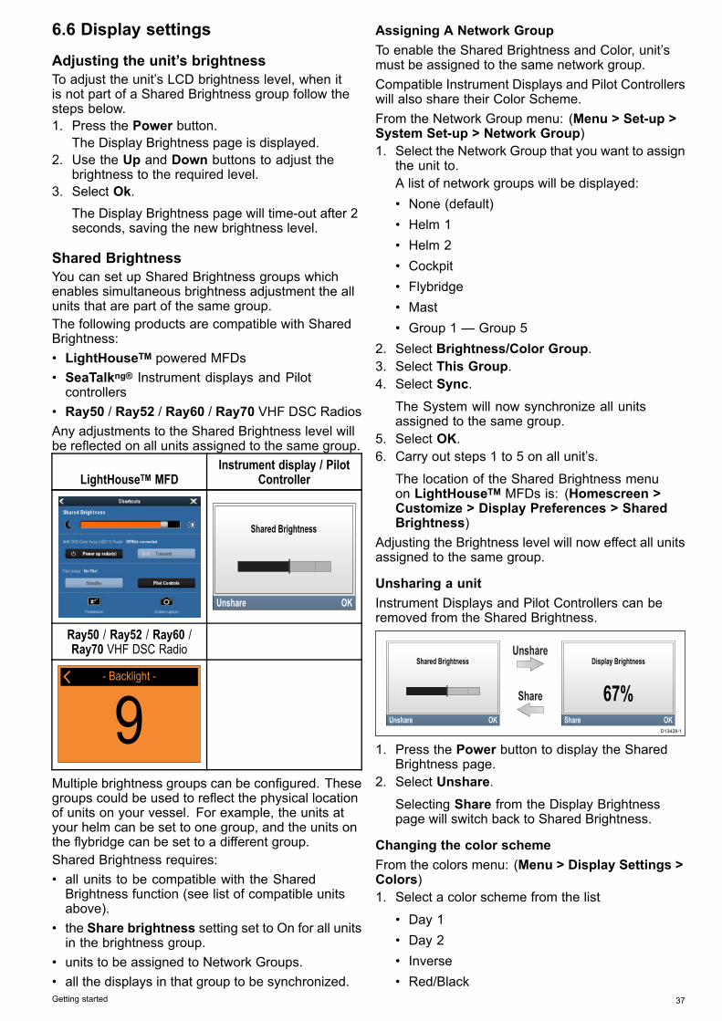
• Ray50 / Ray52 / Ray60 / Ray70 VHF DSC RadiosAny adjustments to the Shared Brightness level willbe reflected on all units assigned to the same group.
LightHouseTM MFDInstrument display / Pilot
Controller
Ray50 / Ray52 / Ray60 /Ray70 VHF DSC Radio
- Backlight -
9Multiple brightness groups can be configured. Thesegroups could be used to reflect the physical locationof units on your vessel. For example, the units atyour helm can be set to one group, and the units onthe flybridge can be set to a different group.Shared Brightness requires:• all units to be compatible with the SharedBrightness function (see list of compatible unitsabove).
• the Share brightness setting set to On for all unitsin the brightness group.
• units to be assigned to Network Groups.• all the displays in that group to be synchronized.
Assigning A Network GroupTo enable the Shared Brightness and Color, unit’smust be assigned to the same network group.Compatible Instrument Displays and Pilot Controllerswill also share their Color Scheme.From the Network Group menu: (Menu > Set-up >System Set-up > Network Group)1. Select the Network Group that you want to assign
the unit to.A list of network groups will be displayed:• None (default)• Helm 1• Helm 2• Cockpit• Flybridge• Mast• Group 1 — Group 5
2. Select Brightness/Color Group.3. Select This Group.4. Select Sync.
The System will now synchronize all unitsassigned to the same group.
5. Select OK.6. Carry out steps 1 to 5 on all unit’s.
The location of the Shared Brightness menuon LightHouseTM MFDs is: (Homescreen >Customize > Display Preferences > SharedBrightness)
Adjusting the Brightness level will now effect all unitsassigned to the same group.
Unsharing a unitInstrument Displays and Pilot Controllers can beremoved from the Shared Brightness.
D13428-1
1. Press the Power button to display the SharedBrightness page.
2. Select Unshare.Selecting Share from the Display Brightnesspage will switch back to Shared Brightness.
Changing the color schemeFrom the colors menu: (Menu > Display Settings >Colors)1. Select a color scheme from the list
• Day 1• Day 2• Inverse• Red/Black
Getting started 37
If the unit is part of a network group, the colorscheme selected will change on all units that supportcolor schemes and are part of the same group.
Display response
Setting the Display ResponseSetting the Display Response to a low value willdampen data fluctuations to provide a more stablereading. Setting the Display Response to a highvalue will reduce then damping to make readingsmore responsive.From the Display Settings menu: (Menu > DisplaySettings )1. Select Display Response.2. Select the data type:
• Speed• Depth• Wind speed• Wind angle• Heading
3. Adjust the value as required.4. Select Save.
6.7 Multiple data sources (MDS)overviewWhen a system includes multiple instances of adata source the preferred data source is selectedautomatically. The systems preferred source may notbe your preferred source, or if you are experiencing adata conflict you can manually select your preferreddata source.MDS enables you to choose a preferred source forthe following data types:• GPS Position• GPS Datum• Time & Date• Heading• Depth• Speed• WindThis exercise would usually be completed as partof the initial installation, or when new equipment isadded.For MDS to be available all products in the systemthat use the data sources listed above, must beMDS-compliant. The system will report any productsthat are NOT MDS-compliant. It may be possibleto upgrade the software for these products, tomake them compliant. Visit the Raymarine website(www.raymarine.com) to obtain the latest softwarefor your products.If MDS-compliant software is not available for theproduct and you do NOT want to use the systemspreferred data source, you must remove anynon-compliant product from the system. You shouldthen be able to select your preferred data source.
Note: Once you have completed setting up yourpreferred data sources, you may be able to addthe non-compliant products back into the system.
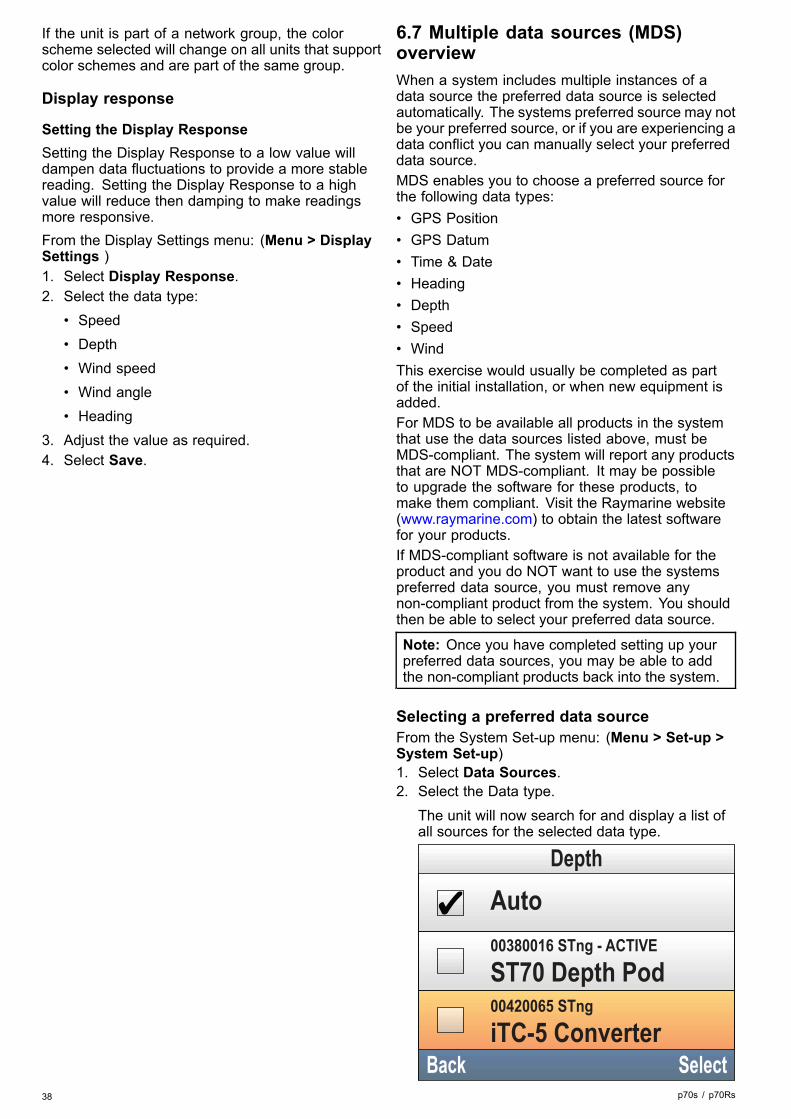
Selecting a preferred data sourceFrom the System Set-up menu: (Menu > Set-up >System Set-up)1. Select Data Sources.2. Select the Data type.
The unit will now search for and display a list ofall sources for the selected data type.
38 p70s / p70Rs

3. Select your preferred data source, or4. Select Auto to allow the system to decide.
ACTIVE is displayed next to the data source thatis the current source for the data type.
Getting started 39

40 p70s / p70Rs

Chapter 7: Commissioning - Evolution autopilot system
Chapter contents• 7.1 Evolution autopilot installation on page 42• 7.2 Autopilot commissioning — main differences between Evolution and SPX systems on page 42• 7.3 Autopilot response levels on page 43• 7.4 Initial setup and commissioning on page 43• 7.5 Powering the Pilot controller on on page 44• 7.6 Using the Set-up Wizard on page 45• 7.7 Using the Dockside wizard on page 45• 7.8 Adjusting the hard-over time — Evolution on page 47• 7.9 Compass linearization — Evolution autopilots on page 47• 7.10 Compass lock on page 49
Commissioning - Evolution autopilot system 41

7.1 Evolution autopilot installationFor information on installing and connecting anEvolution autopilot system, refer to the installationinstructions that accompany the EV-1 and EV-2units, as appropriate.
7.2 Autopilot commissioning — maindifferences between Evolution andSPX systemsThe Evolution system provides a number of featuresto improve upon the commissioning process requiredby existing SPX and some other autopilot systems.• Built-in heading and attitude sensor — noadditional fluxgate compass required.
• Automatic set-up — the rudder gain, counterrudder, manual compass calibration and autolearnsettings required for existing SPX systems are nolonger required. This results in a greatly simplifieddockside calibration process for Evolution autopilotsystems.
42 p70s / p70Rs

7.3 Autopilot response levelsThe Evolution autopilot system features a numberof different response levels to help you quicklyconfigure the system for optimum performance forthe current conditions. In Wind Vane mode, WindTrim is automatically set by your selected responselevel.The available response levels are:• Leisure— suitable for long passages where tightheading control is not critical.
• Cruising — good course-keeping withoutoverworking the pilot.
• Performance — emphasis on tight headingcontrol.
You can change the response level at any time byselecting MENU > Response Level. Then selectSave to keep the changes.
7.4 Initial setup and commissioning
Commissioning pre-requisitesBefore commissioning your system for the first time,check that the following processes have been carriedout correctly:• Autopilot system installation completed inaccordance with the Installation instructions.
• SeaTalkng network installed in accordance with theSeaTalkng Reference Manual.
• Where fitted, the GPS receiver has been installedand connected in accordance with the associatedInstallation instructions.
Check also that the commissioning engineer isfamiliar with the installation and components of theautopilot system including:• Vessel type.• Vessel steering system information.• What the autopilot will be used for.• System layout: components and connections (youshould have a schematic of the vessel’s autopilotsystem).
Initial set-upInitial set-up involves the following steps:
Important: Before proceeding with the initialset-up or commissioning of an Evolution autopilotsystem with a p70, p70s, p70R or p70Rs PilotController, ensure that the Pilot controller, EV andACU software is updated to the latest versions.Refer to http://www.raymarine.co.uk/software todownload the latest software and view instructionson how to upgrade the software of your products,using an MFD.
1. Power-up your Pilot Controller.2. Specify your preferred language and appropriate
vessel type, using the Set-up wizard.3. Complete the dockside calibration process, using
the Dockside wizard:
For vessels withouta rudder referencetransducer:
For vessels with a rudderreference transducer:
Drive Type selection Drive Type selectionAlign Rudder (rudderalignment)
Rudder Limit setting Rudder Limit settingHard Over Time (if you do notalready know your hard overtime, you should skip thisstep in the Dockside Wizardand enter the value manuallyafterwards.Rudder Drive check Rudder Drive check
4. Once the dockside wizard is complete, specifythe hard-over time (only applies to systems thatdo NOT include a rudder reference transducer).
Commissioning - Evolution autopilot system 43

5. Familiarize yourself with the importantinformation in this document related to CompassLinearization. Follow the guidelines providedto ensure that the process is completedsuccessfully.
6. Once you’ve successfully completed steps 1 to5 above, familiarize yourself with the informationrelated to theCompass Lock.
7.5 Powering the Pilot controller on1. Press and hold the STANDBY button for one
second, until the logo appears.If the unit is being switched on for the first timeor after a factory reset the set up wizard will belaunched.
Note: The logo is not displayed if the unit is in'sleep mode'. In Sleep mode the unit may appearoff but still has power.
2. To turn the Pilot controller off press and hold theSTANDBY button. After 1 second a pop up countdown is displayed.
3. Continue to hold the STANDBY button for afurther 3 seconds to complete the power off.
Note: You cannot power off the Pilot controllerwhilst the Autopilot is engaged.
44 p70s / p70Rs

7.6 Using the Set-up WizardThe set-up wizard guides you through the steps forsetting important preferences, such as preferredlanguage and correct vessel type.The Set-up Wizard contains 3 steps: LanguageSelection, Vessel Hull Type selection and WelcomeScreen. When powering the Pilot Controller for thefirst time, in an unconfigured system, the Set-upWizard is displayed automatically, and the first 3steps listed below will not be required.With the pilot in Standby mode:1. Select Menu.2. Select Set-up.3. Select Set-up Wizard.4. Select the required language.5. Select the required vessel type.
The welcome screen will now be displayed andyour choices have been saved.
6. Select OK to complete the Set-up Wizard.
Vessel hull type selectionThe vessel hull type options are designed to provideoptimum steering performance for typical vessels.It is important to complete the vessel hull typeselection as part of the initial set-up, as it forms akey part of the autopilot calibration process. You canalso access the options at any time with the pilot inStandby by selecting MENU > Set-up > AutopilotCalibration > Vessel Settings > Vessel Hull Type.Select the option that most closely matches yourvessel type and steering characteristics. The optionsare:• Power• Power (slow turn)• Power (fast turn)• Sail• Sail (Slow turn)• Sail CatamaranIt is important to be aware that steering forces (andtherefore rate-of-turn) vary significantly dependingon the combination of vessel type, steering system,and drive type. Therefore, the available vessel hulltype options are provided for guidance only. Youmay wish to experiment with the different vessel hulltype options, as it might be possible to improve thesteering performance of your vessel by selecting adifferent vessel type.When choosing a suitable vessel type, the emphasisshould be on safe and dependable steeringresponse.
7.7 Using the Dockside wizardThe dockside calibration process must be completedbefore the Evolution autopilot system can be usedfor the first time. The Dockside wizard guides youthrough the steps required for dockside calibration.The Dockside wizard contains different stepsdepending on whether you have a rudder referencetransducer fitted to your vessel:
The following Docksidewizard procedures only applyto vessels without a rudderreference transducer:
• Drive Type selection.• Rudder Limit setting.• Hard-over time setting
(Raymarine recommendsthat this informationis specified once thedockside wizard andRudder Drive check iscomplete, using the HardOver Time menu option).
• Rudder Drive check.
The following Docksidewizard procedures only applyto vessels with a rudderreference transducer:
• Drive Type selection.• Align Rudder (rudder
alignment).• Rudder Limit setting.• Rudder Drive check.
To access the wizard, ensure the pilot is in Standbymode and then:1. Select Menu.2. Select Set-up.3. Select Autopilot Calibration.4. Select Commissioning.5. Select Dockside Wizard.
Selecting a drive typeDrive Type selection is available when the pilot is instandby, from either the Dockside wizard, or from theVessel setting menu: MENU > Set-up > AutopilotCalibration > Vessel Settings .With the Drive Type menu displayed:1. Select your drive type.
Note: If your drive type is not listed, contact yourRaymarine dealer for advice.
Checking the rudder alignment (AlignRudder)This procedure establishes port and starboardrudder limits for systems using a rudder referencetransducer.The rudder check forms part of the docksidecalibration process.
The following procedure onlyapplies to vessels with arudder reference transducer.
1. Center the rudder and select OK.Commissioning - Evolution autopilot system 45

2. When prompted, turn the rudder hard to port andselect OK.
3. When prompted, turn the rudder hard to starboardand select OK.
4. When prompted, turn the rudder back to thecenter and select OK.
Note: You can cancel Dockside calibration at anytime by selecting STANDBY.
Rudder Limit settingAs part of the Dockside calibration process, thesystem will set-up the rudder limits.• For vessels with a rudder reference transducer— This procedure establishes the rudder limit.The rudder limit will be displayed with a messageconfirming that the rudder limit has been updated.This value can be changed if required.
• For vessels without a rudder referencetransducer — a default of 30 degrees isdisplayed, and can be changed as required.
Hard over timeThe hard over time setting can be specified as partof the Dockside wizard.
The following information onlyapplies to vessels without arudder reference transducer.
• If you already know the hard-over time for yourvessel’s steering system: enter this time duringthe Dockside wizard procedure.
• If you do NOT know the hard-over time for yourvessel’s steering system: skip this step during theDockside wizard procedure by selecting SAVE,then proceed to Checking the rudder drive sectionin this document to complete the Dockside wizardprocedure. Once the wizard is complete, proceedto 8.8 Adjusting the hard-over time — SmartPilotand SPX in this document for information on howto calculate and adjust the hard-over time.
Checking the rudder driveAs part of the dockside calibration process, thesystem will check the drive connection. Once it hascompleted the check successfully, a message willappear asking if it is safe for the system to take thehelm.During this procedure the autopilot will move therudder. Ensure it is safe to proceed before pressingOK.When in dockside calibration mode, with the MotorCheck page displayed:1. Centre and let go of the rudder.2. Disengage any rudder drive clutch.3. Select CONTINUE.4. Check it is safe to proceed before selecting OK.
For vessels with a rudder reference transducer,the autopilot will now automatically move therudder to port and then starboard.
5. For vessels without a rudder referencetransducer, you will be asked to confirm that therudder has turned to port by selecting YES or NO.
6. Select OK if it is safe to engage the rudder in theopposite direction.
7. You will be asked to confirm the rudder turned tostarboard by selecting YES or NO.
8. Dockside calibration is now complete, selectCONTINUE.
Note: If you confirmed a “NO” response for therudder movement to both port and starboard, thewizard will exit. It is possible that the steeringsystem did not move the rudder in any direction,and it will be necessary to check the steeringsystem before completing the Dockside wizardprocedure again.You can cancel Dockside calibration at any time bypressing STANDBY.
46 p70s / p70Rs

7.8 Adjusting the hard-over time —EvolutionOn vessels without a rudder reference transducer, itis important to set a Hard Over Time.Before attempting to follow this procedure ensureyou have read and understood the Rudder Checkwarning provided in this document.To estimate your hard over time follow the stepsbelow:1. With the autopilot in Standby, manually turn the
rudder / engine full to port. (For vessels withpower steering the engine should be runningwhen turning the rudder.)
2. Engage Auto mode.3. Press the +10 and +1 buttons at the same time
(p70/p70s) or use the Rotary (p70R/p70Rs) toalter your locked heading by 90 degrees. Use astop watch to time the movement of the rudder /engine.
4. Estimate how long it would take to move therudder from full port to full starboard. Thisestimate is your Hard Over Time.
5. Enter this estimate as your Hard Over Time. TheHard Over time setting can be accessed from theDrive Settings menu: Menu > Set-up > AutopilotCalibration > Drive Settings > Hard Over Time.
6. After setting your Hard Over Time, observe yourautopilot’s behavior and if required, make smalladjustments to the Hard Over Time value until asatisfactory result is achieved.
Warning: Rudder checkIf no rudder reference has been fitted youMUST ensure that adequate provision ismade to prevent the steering mechanismfrom impacting the end stops.
7.9 Compass linearization — EvolutionautopilotsThe EV unit’s internal compass needs to compensatefor local and the Earth’s magnetic fields. This isachieved using an automatic process known aslinearization.
Initial linearizationWhen the EV unit is first installed and powered-up (orafter a factory reset or compass restart) linearizationis required. A progress bar is displayed to indicatelinearization is required.
The linearization process will start automaticallyafter your vessel has turned approximately 100°at a speed of between 3 –15 knots. Linearizationrequires no user input, however at least a 270°turn is required before linearization can complete.The progress bar will fill to indicate progress, theprogress bar will turn Red if the process is paused orotherwise interrupted. Time it takes to complete thelinearization will vary according to the characteristicsof the vessel, the installation environment of theEV unit, and the levels of magnetic interferenceat the time of conducting the process. Sources ofsignificant magnetic interference may increase thetime required to complete the linearization process.Examples of such sources include:• Marine pontoons• Metal-hulled vessels• Underwater cablesYou can speed-up the linearization process bycompleting a full 360° turn (at a speed of 3 – 15knots). You can also restart the linearization processat any time by selecting the Restart Compass menuitem.Once the initial linearization is completed theDeviation page is displayed and the currentmaximum compass deviation is shown.
Commissioning - Evolution autopilot system 47

Compass deviationIf the reported deviation is 45° or higher, it ishighly recommended that the EV unit is movedand re-installed in a location which is subject toless magnetic interference. After the linearizationprocess has successfully completed you can checkthe current deviation value at anytime from thediagnostics pages.
Note: If “- -” is displayed as the Deviation value, itmeans that linearization has not been successfullycompleted yet.
Check the compass heading dataAs part of the autopilot system commissioningprocess, it is recommended that you check thecompass heading value displayed, against a goodknown heading source on various headings.
Note: Once the linearization process hascompleted, it is possible that the heading valuemay have a slight offset of 2 to 3 degrees. Thisis common where installation space is limited,and the EV unit cannot be properly aligned to thevessel's longitudinal axis. In this case, it is possibleto manually adjust the Compass Offset value.
Note: Do NOT rely on the reported heading untilcompass linearization and alignment is complete.
System monitoring and adaptationTo ensure optimum performance, after the initiallinearization process is complete the EV continues tomonitor and adapt the compass linearization to suitcurrent conditions.If the conditions for linearization are less than ideal,the automatic linearization process temporarilypauses until conditions improve again. The followingconditions can cause the linearization process totemporarily pause:• Boat speed < 3 knots.• Boat speed > 15 knots.• Rate-of-turn is too slow.• Significant magnetic interference is present
Accessing the compass deviation indicator1. Select MENU.
2. Select Set-up.3. Select Diagnostics.4. Select About Pilot.
The details related to the pilot diagnostics aredisplayed.
5. Scroll down to the bottom of the list to view theentry for Deviation.
Note: If “- -” is displayed as the Deviation value, itmeans that linearization has not been successfullycompleted yet.
Adjusting the Compass OffsetWith the pilot in Standby:1. From the Vessel Settings menu: (Menu >
Set-up > Autopilot Calibration > VesselSettings).
2. Select Compass Offset.3. Use the +/- 10 button (p70/p70s) or ROTARY
control (p70R/p70Rs) to adjust the compassoffset as appropriate.
The Compass Offset can be adjusted between–10° and +10°.
48 p70s / p70Rs

7.10 Compass lockOnce you are satisfied with the compass accuracy,you can lock the setting to prevent the autopilotsystem from completing a further automaticlinearization in the future.This feature is particularly useful for vessels inenvironments that are exposed to strong magneticdisturbances on a regular basis (such as offshorewind farms or very busy rivers, for example). In thesesituations it may be desirable to use the Compasslock feature to disable the continuous linearizationprocess, as the magnetic interference may build aheading error over time.
Note: The compass lock may be released at anytime, to allow the compass continuous linearizationto restart. This is particularly useful if planning along voyage. The earth’s magnetic field will changesignificantly from one geographical location toanother, and the compass can continuouslycompensate for the changes, ensuring youmaintain accurate heading data throughout thevoyage.
Locking the compassFollow the steps below to lock the compasslinearization.From the Commissioning menu: (Menu > Set-up >Autopilot Calibration > Commissioning)1. Select Compass Lock.2. Select On.The compass linearization is now locked.
Commissioning - Evolution autopilot system 49

50 p70s / p70Rs

Chapter 8: Commissioning - SPX and SmartPilot systems
Chapter contents• 8.1 SPX and SmartPilot autopilot installation on page 52• 8.2 Pilot response on page 52• 8.3 Initial setup and commissioning on page 53• 8.4 Powering the Pilot controller on on page 53• 8.5 Using the Set-up Wizard on page 54• 8.6 Dockside calibration on page 55• 8.7 Dealer settings on page 56• 8.8 Adjusting the hard-over time — SmartPilot and SPX on page 57• 8.9 Sea trial calibration on page 57• 8.10 Checking autopilot operation on page 59
Commissioning - SPX and SmartPilot systems 51

8.1 SPX and SmartPilot autopilotinstallationFor information on installing and connecting anSeaTalkng SPX autopilot system or a SeaTalkSmartPilot autopilot system, refer to the installationinstructions that accompanied your course computer.
8.2 Pilot responseThe response level controls the relationship betweencourse keeping accuracy and the amount of helm/drive activity. Range is from 1 to 9.
Making temporary changes to pilot responsePilot response is set up during commissioning ofthe SmartPilot system however you can maketemporary changes to the pilot response at any timeby accessing the Pilot response menu from;Mainmenu > Pilot Response1. From the Main menu highlight Pilot response
and press SELECT.2. Use the UP and DOWN buttons to change the
response value to the required setting.3. Press SAVE to save the response value.
Setting OptionsLevels 1 to 3 Minimize the amount of pilot
activity. This conservespower, but may compromiseshort-term course-keepingaccuracy.
Levels 4 to 6 Should give good coursekeeping with crisp, wellcontrolled turns under normaloperating conditions.
Levels 7 to 9 Gives the tightest coursekeeping and greatestrudder activity (and powerconsumption). This can leadto a rough passage in openwaters as the SPX systemmay ‘fight’ the sea.
52 p70s / p70Rs

8.3 Initial setup and commissioning
Commissioning pre-requisitesBefore commissioning your system for the first time,check that the following processes have been carriedout correctly:• Autopilot system installation completed inaccordance with the Installation instructions.
• SeaTalkng network installed in accordance with theSeaTalkng Reference Manual.
• Where fitted, the GPS receiver has been installedand connected in accordance with the associatedInstallation instructions.
Check also that the commissioning engineer isfamiliar with the installation and components of theautopilot system including:• Vessel type.• Vessel steering system information.• What the autopilot will be used for.• System layout: components and connections (youshould have a schematic of the vessel’s autopilotsystem).
Commissioning process• Check you have adhered to commissioningpre-requisites
• Initial power on and set-up• Dockside calibration (Dealer Settings on SeaTalksystems)
• Set hard over time (non-rudder reference systemsonly)
• Sea trial calibration• System checks
8.4 Powering the Pilot controller on1. Press and hold the STANDBY button for one
second, until the logo appears.If the unit is being switched on for the first timeor after a factory reset the set up wizard will belaunched.
Note: The logo is not displayed if the unit is in'sleep mode'. In Sleep mode the unit may appearoff but still has power.
2. To turn the Pilot controller off press and hold theSTANDBY button. After 1 second a pop up countdown is displayed.
3. Continue to hold the STANDBY button for afurther 3 seconds to complete the power off.
Note: You cannot power off the Pilot controllerwhilst the Autopilot is engaged.
Commissioning - SPX and SmartPilot systems 53

8.5 Using the Set-up WizardThe set-up wizard guides you through the steps forsetting important preferences, such as preferredlanguage and correct vessel type.The Set-up Wizard contains 3 steps: LanguageSelection, Vessel Hull Type selection and WelcomeScreen. When powering the Pilot Controller for thefirst time, in an unconfigured system, the Set-upWizard is displayed automatically, and the first 3steps listed below will not be required.With the pilot in Standby mode:1. Select Menu.2. Select Set-up.3. Select Set-up Wizard.4. Select the required language.5. Select the required vessel type.
The welcome screen will now be displayed andyour choices have been saved.
6. Select OK to complete the Set-up Wizard.
Vessel hull type selectionThe vessel hull type options are designed to provideoptimum steering performance for typical vessels.It is important to complete the vessel hull typeselection as part of the initial set-up wizard, as itforms a key part of the autopilot calibration process.You can also access the options at any time withthe pilot in Standby by selecting MENU > Set-up >Autopilot Calibration > Vessel Settings > VesselHull Type.As a general guide, select the option that mostclosely matches your vessel type and steeringcharacteristics. The options are:• Race Sail.• Sail Cruiser.• Catamaran.• Workboat.• RIB.• Outboard Speedboat• Inboard Speedboat• Power Cruiser 1 (<12 kts)• Power Cruiser 2 (<30 kts)• Power Cruiser 3 (>30 kts)• Sport Fishing• Pro FishingIt is important to be aware that steering forces (andtherefore rate-of-turn) vary significantly dependingon the combination of vessel type, steering system,and drive type. Therefore, the available vessel hulltype options are provided for guidance only. Youmay wish to experiment with the different vessel hulltype options, as it might be possible to improve thesteering performance of your vessel by selecting adifferent vessel type.When choosing a suitable vessel type, the emphasisshould be on safe and dependable steeringresponse.
Important: If you change the vessel type aftercompleting the Dockside calibration process (usingthe Dockside wizard), all commissioning settingswill be reset to default settings, and you will need tocomplete the Dockside calibration process again.
54 p70s / p70Rs

8.6 Dockside calibrationThe dockside calibration process must be completedbefore your SPX autopilot system can be used forthe first time. The Dockside wizard guides youthrough the steps required for dockside calibration.The Dockside wizard contains different stepsdepending on whether you have a rudder referencetransducer fitted to your vessel:
The following Docksidewizard procedures only applyto vessels without a rudderreference transducer:
• Drive Type selection.• Rudder Limit setting.• Rudder Drive check.
The following Docksidewizard procedures only applyto vessels with a rudderreference transducer:
• Drive Type selection.• Align Rudder (rudder
alignment).• Rudder Limit setting.• Rudder Drive check.
On older SeaTalk SmartPilot systems the Docksidewizard is named Dealer Settings. Please refer to 8.7Dealer settings for calibration details.
Using the Dockside wizardTo access the dockside wizard follow the stepsbelow:Ensure the pilot is in Standby.1. Select Menu.2. Select Set-up.3. Select Autopilot Calibration.4. Select Commissioning.5. Select Dockside Wizard.6. Follow the on-screen instructions.
Note: You can cancel the Dockside wizard at anytime by pressing the Standby button.
Selecting a drive typeDrive Type selection is available when the pilot is instandby, from either the Dockside wizard, or from theVessel setting menu: MENU > Set-up > AutopilotCalibration > Vessel Settings .With the Drive Type menu displayed:1. Select your drive type.
Note: If your drive type is not listed, contact yourRaymarine dealer for advice.
Checking the rudder alignment (AlignRudder)This procedure establishes port and starboardrudder limits for systems using a rudder referencetransducer.The rudder check forms part of the docksidecalibration process.
The following procedure onlyapplies to vessels with arudder reference transducer.
1. Center the rudder and select OK.2. When prompted, turn the rudder hard to port and
select OK.3. When prompted, turn the rudder hard to starboard
and select OK.4. When prompted, turn the rudder back to the
center and select OK.
Note: You can cancel Dockside calibration at anytime by selecting STANDBY.
Rudder Limit settingAs part of the Dockside calibration process, thesystem will set-up the rudder limits.• For vessels with a rudder reference transducer— This procedure establishes the rudder limit.The rudder limit will be displayed with a messageconfirming that the rudder limit has been updated.This value can be changed if required.
• For vessels without a rudder referencetransducer — a default of 30 degrees isdisplayed, and can be changed as required.
Checking the rudder driveAs part of the dockside calibration process, thesystem will check the drive connection. Once it hascompleted the check successfully, a message willappear asking if it is safe for the system to take thehelm.During this procedure the autopilot will move therudder. Ensure it is safe to proceed before pressingOK.When in dockside calibration mode, with the MotorCheck page displayed:1. Centre and let go of the rudder.2. Disengage any rudder drive clutch.3. Select CONTINUE.4. Check it is safe to proceed before selecting OK.
For vessels with a rudder reference transducer,the autopilot will now automatically move therudder to port and then starboard.
5. For vessels without a rudder referencetransducer, you will be asked to confirm that therudder has turned to port by selecting YES or NO.
6. Select OK if it is safe to engage the rudder in theopposite direction.
7. You will be asked to confirm the rudder turned tostarboard by selecting YES or NO.
8. Dockside calibration is now complete, selectCONTINUE.
Note: If you confirmed a “NO” response for therudder movement to both port and starboard, thewizard will exit. It is possible that the steeringsystem did not move the rudder in any direction,and it will be necessary to check the steeringsystem before completing the Dockside wizardprocedure again.
Commissioning - SPX and SmartPilot systems 55

You can cancel Dockside calibration at any time bypressing STANDBY.
8.7 Dealer settingsThe dockside calibration wizard is only available ona SeaTalkng system, for SeaTalk systems the Dealersettings should be set before going out on the sea.The dealer settings menu can be accessed from:Main menu > Set up > Auto pilot calibration >Dealer settings. Once entered the dealer settingsmenu will cycle through all available options.Options and limits are dependent on the coursecomputer installed.
56 p70s / p70Rs

8.8 Adjusting the hard-over time —SmartPilot and SPXOn vessels without a rudder reference transducer, itis important to set a Hard Over Time.Before attempting to follow this procedure ensureyou have read and understood the Rudder Checkwarning provided in this document.To estimate your hard over time follow the stepsbelow:1. Adjust your Rudder Gain setting to the maximum
value, making a note of the original value. TheRudder Gain setting can be accessed from theDrive Setting menu: Menu > Set-up > AutopilotCalibration > Drive Settings > Rudder Gain.
2. With the autopilot in Standby, manually turn therudder / engine full to port. (For vessels withpower steering the engine should be runningwhen turning the rudder.)
3. Engage Auto mode.4. Press the +10 and +1 buttons at the same time
(p70/p70s) or use the Rotary (p70R/p70Rs) toalter your locked heading by 90 degrees, use astop watch to time the movement of the rudder /engine.
5. Estimate how long it would take to move therudder from full port to full starboard. Thisestimate is your Hard Over Time.
6. Enter this estimate as your Hard Over Time. TheHard Over time setting can be accessed from theDrive Settings menu: Menu > Set-up > AutopilotCalibration > Drive Settings > Hard Over Time.
7. Change your Rudder Gain back to its originalvalue.
8. After setting your Hard Over Time, observe yourautopilot’s behavior and if required, make smalladjustments to the Hard Over Time value until asatisfactory result it achieved.
Warning: Rudder checkIf no rudder reference has been fitted youMUST ensure that adequate provision ismade to prevent the steering mechanismfrom impacting the end stops.
8.9 Sea trial calibrationBefore you can use the autopilot open water checksare required. The water must be calm, with lightor no wind. Leave plenty of room to manoeuvre.The Sea Trial wizard guides you through the stepsrequired for Sea trial calibration.The Sea trial wizard includes the following steps:• Swing compass• Align compass to GPS• Align compass manually• Auto Learn.You can access the Sea trial wizard at any timefrom the Commissioning menu: Menu > Set-up >Autopilot calibration > Commissioning.
Note: Sailing vessels should perform the sea trialunder engine power.
Note: The Sea trial wizard can be cancelled at anytime by pressing the Standby button.
Warning: Seatrial calibrationEnsure you have sufficient sea roomfor calibration. The seatrial calibrationmaneuvers require a clear, familiar area ofwater. Ensure you are not likely to collidewith any vessel or other obstruction duringcalibration.
Warning: Maintain sensible speedsThe autopilot may make unexpectedturns.
Compass swingYou will need to turn your vessel in slow circleswhile the system automatically makes adjustmentsto account for compass deviation. Each 360-degreecircle should take no less than two minutes, and youshould complete at least two circles.1. Start moving vessel in slow even circles, then
press START.2. Keep speed to below 2 knots. Watch the display
to ensure your turn rate is not too fast. If themessage ‘Slow Down’ is displayed reduce yourrate of turn, this can be achieved by slowingdown and / or steering in a wider circle.If a 'Slow Down' message is displayed the currentcircle will have to be repeated.
3. When the compass has been calibrated, amessage will be displayed showing the detecteddeviation. If this is more than 15 degrees you willneed to abort the calibration process and resitethe compass further away from metal items, thenrepeat the calibration process. If you still find adeviation of more than 15 degrees, contact yourRaymarine dealer for advice. If the deviation iswithin acceptable limits, press CONTINUE.
You can cancel Seatrial calibration at any time bypressing STANDBY.
Commissioning - SPX and SmartPilot systems 57

Aligning compass to GPSNote: Systems without a GPS will skip this sectionand go straight to Manual compass alignment.
If your system has a GPS connected to your datanetwork (SeaTalk, SeaTalkng or NMEA), the autopilotis tuned to the GPS heading while you steer to aknown magnetic heading. This step provides a roughalignment and minimizes the amount of compassfine tuning required.1. Steer the vessel on a steady course with minimal
tide, increase speed to more than 3 knots andpress START to align the compass to GPS.
2. Follow the on-screen instructions until theprocess completes, press the CONTINUE buttonwhen it is available to begin autolearn.
You can cancel Seatrial calibration at any time bypressing STANDBY.
Aligning compass manuallyWhere no GPS is present manual alignment of thecompass is required.1. Continue to steer on a steady course and use the
Use +1 and -1 buttons, or the ROTARY controllerto adjust the heading displayed until it matchesthe vessel’s compass reading.
2. When complete press CONTINUE to beginAutolearn.
Auto LearnYou must have significant clear water in front ofthe vessel to accommodate a series of maneuvers,which include sudden, sharp turns. There should bea clear area at least 100m wide and 500m ahead.
D12106-1
Caution: AutolearnPlease ensure sufficient free spaceahead. (Minimum 100x500m long &significantly more for a high speed vessel.
Performing Auto learnAuto learn is available from the Sea trial wizard, orfrom the Commissioning menu.Maintain a normal cruising speed (at least 3 kts)throughout the auto learn process.
1. Ensure there is sufficient free water in front of thevessel and select continue.A warning message is displayed.
2. Select Continue or press the Ok button.A warning message will be displayed lettingyou know that the vessel will zigzag and makeSudden SHARP TURNS.
3. Remove your hands from the wheel and pressAuto to begin.During this procedure the autopilot will progressthrough the required steps.
4. If ‘PASS’ is displayed then select Continue orpress the Ok button to return to manual helmcontrol.The autopilot will by placed in Standby mode. Youhave successfully completed the commissioningprocess for your SmartPilot system.
5. If ‘FAIL’ is displayed after completion of the Autolearn process then select Continue or press theOk button.The Auto learn retry message is displayed.
6. You can retry the Auto learn process by selectingYes or to cancel select No.
Note: The Sea trial wizard can be cancelled at anytime by pressing the Standby button.
Caution: System changesAny additional changes you make to yoursystem settings may require you to repeatthe calibration process.
58 p70s / p70Rs

8.10 Checking autopilot operationAfter completing calibration, check the basic autopilotoperation, as follows:1. Steer onto a compass heading and hold a steady
course at normal cruising speed. If necessary,steer the vessel manually for a short time tocheck how the vessel steers.
2. Ensure it is safe to engage the autopilot, thenpress AUTO to lock onto the current heading.The autopilot should hold a constant heading incalm sea conditions.
3. Use -1, +1, -10 and +10 or the ROTARYcontroller, to see how the SmartPilot alters thecourse to port and starboard.
4. Press STANDBY to return to manual steering.
Checking rudder gainTo determine whether the rudder gain is set correctly,carry out the following test:
D12107-1
1
2
3
Item Description1. Rudder gain too low2. Rudder gain too High3. Correct rudder gain
1. Ensure you have set the autopilot response tolevel 5.
2. Drive your vessel at a typical cruising speed inclear water.It is easier to recognize the steering response incalm sea conditions where wave action does notmask steering performance.
3. Press AUTO to enter Auto mode, then altercourse by 40°:• This course change should result in a crisp turnfollowed by an overshoot of no more than 5°, Ifthe rudder gain is adjusted correctly.
• If the course change causes a distinctovershoot (more than 5°) and/or there is adistinct ‘S’ in the course the rudder gain is toohigh.
• If the vessel’s performance is sluggish and ittakes a long time to make the 40° turn, with noovershoot the rudder gain is too low.
If necessary, adjust the rudder gain.
Checking counter rudderCounter rudder is the amount of rudder your autopilotapplies to try to prevent your vessel from oversteering. A higher counter rudder setting results inmore rudder being applied.To check the counter rudder setting:1. Ensure you have set the autopilot response to
level 5.2. Drive your vessel at a typical cruising speed in
clear water.3. Press AUTO and if necessary engage the
autopilot.4. Make a 90° course change:
• When rudder gain and counter rudder are bothset correctly, the vessel performs a smoothcontinuous turn with minimal overshoot.
• If the counter rudder is too low, the vessel willovershoot before returning slowly to the course.
• If counter rudder is too high, the vessel will‘fight’ the turn and make a series of short,sharp turns. This results in a very ‘mechanical’feel as the vessel changes course.
5. If necessary, adjust the counter rudder setting.
Counter Rudder is available from the DriveSettings menu: Menu > Set-up > AutopilotCalibration > Drive Settings > Counter Rudder.
Rudder DampingIf the autopilot is ‘hunting’ (i.e. continuously movingthe steering backwards and forwards by smallamounts) when trying to position the rudder, therudder damping setting will require adjustment tominimize this.Increasing the rudder damping value reduceshunting. The rudder damping value should beincreased 1 level at a time until the autopilot stopshunting. Always ensure the lowest acceptable valueis used.If required the Rudder Damping setting can beadjusted from the Drive Settings menu: Menu >Set-up > Autopilot Calibration > Drive Settings >Rudder Damping.
AutoTrim settingsAutoTrim determines how quickly the autopilotapplies ‘standing helm’ to correct for trim changes,caused, for example, by changes in the wind loadon the superstructure, or an imbalance of engines.Increasing the AutoTrim level reduces the time theautopilot takes to return to the correct course, butmakes the vessel less stable. If the autopilot:• Gives unstable course keeping and the vessel‘snakes’ around the desired course, decrease theAutoTrim level.
• Hangs off course for excessive periods of time,increase the AutoTrim level.
Commissioning - SPX and SmartPilot systems 59

60 p70s / p70Rs

Chapter 9: Pilot modes
Chapter contents• 9.1 Auto on page 62• 9.2 Mode menu on page 63• 9.3 Patterns on page 63• 9.4 Track mode on page 64• 9.5 Wind vane mode (Sailing boats only) on page 66• 9.6 Power steer on page 68• 9.7 Jog steer (tiller pilots only) on page 69• 9.8 Shortcut key on page 69
Pilot modes 61

9.1 Auto
Caution: Maintain a permanentwatchAutomatic course control makes it easierto steer your vessel, but it is NOT asubstitute for good seamanship. ALWAYSmaintain a permanent watch by the helm.
Automatically steering to a heading1. Steady the vessel on the required heading.2. For Wheel and Tiller drive systems see below
instructions for engaging the autopilot.• Wheel Pilot: Engage the wheel drive clutch byrotating the clutch lever clockwise (so the leverfully engages onto the locating pip).
• Tiller Pilot: Place the pushrod end over thetiller pin. If necessary, extend or retract thepushrod using the –1, +1, –10,+10 buttons orthe Rotary control.
Attention Always reach around (not through) thewheel to operate the clutch lever.
D05341-4
Wheel pilot
Tiller pilot
a
b
3. Press AUTO.The autopilot is now in AUTO mode and will steerto the chosen locked heading.
Changing course in auto modeTo change course whilst in AUTO mode:1. Use the –1 and –10 button, or turn the rotary
controller anticlockwise to change the vessel'scourse to port.Pressing –1 button will increment the course toport by 1º and –10 will increment by 10º.Turning the rotary controller 1 click anticlockwisewill increment the course to port by 1º .
2. Use the +1 and +10 buttons, or turn the rotarycontroller clockwise to change the vessel'scourse to starboard.Pressing +1 button will increment the course tostarboard by 1º and +10 will increment by 10º.
Turning the rotary controller 1 click clockwise willincrement the course to Starboard by 1º .
e.g. pressing the -1 button four times, or turning therotary 4 clicks anticlockwise will result in a 4° coursechange to port.
Disengaging the autopilot (Standby mode)The autopilot can be disengaged by following thesteps below.1. Press Standby.2. For Wheel and Tiller drive systems see below
instructions for disengaging the autopilot to returnto manual steering• Wheel Pilot: Disengage the wheel drive clutchby rotating the clutch lever anti-clockwise (sothe lever disengages fully from the locating pip.
• Tiller Pilot: Remove the drive unit from thetiller pin. If necessary, extend or retract thepushrod using the –1, +1, –10,+10 buttons orthe Rotary control.
On wheel drive systems, always make sure thatthe clutch is fully disengaged before you leave thevessel.
62 p70s / p70Rs

9.2 Mode menuPilot modes are accessed from the Mode menu. Theavailable modes are determined by the autopilotsystem and the selected Vessel Hull Type.The modes available are shown below.
Evolution SPX SmartPilotPattern Power vessel Motor and Fishing
vesselsTrack all allWind vane (2) Sailing vessel only Sailing vessel onlyPower Steer (1) p70Rs and joystick
onlyp70Rs and joystickonly
Note:• (1) Power steer mode is only available on vesselsfitted with a rudder reference transducer.
• (2) Wind vane mode is only available if there isa connect source of wind data.
The mode menu also provides a shortcut key optionthat enables a mode to be assigned to the Left Softbutton (The default option is Track).
9.3 PatternsFishing patterns are available, that can be usedwith their default settings or adjusted to your ownpreference. Fishing patterns require GPS data to beavailable on your system.
Pattern Adjustment IconDirectionCircleRadius
DirectionAngle
Zig Zag
LengthDirectionCloverleafRadius
DirectionRadius
Spiral
IncrementDirectionRadius
Circle against
DistanceDirectionFigure 8RadiusDirectionWidthHeightWidth increment
Pattern search
Height incrementDirection180 turnRadius
DirectionWidth
Box search
Height
Using a fishing pattern1. Press the RIGHT SOFT button to open the menu.2. Using the UP and DOWN buttons highlight Mode
and press SELECT.3. Using the UP and DOWN buttons highlight
Pattern and press SELECT.4. Using the UP and DOWN buttons highlight the
fishing pattern you wish you use and pressSELECT.
5. The pattern settings screen shall be displayed,showing the parameters currently set for theselected pattern. If you want to change any ofthe parameters:i. Select the parameter you want to change,
then press EDIT.ii. Use the UP and DOWN buttons to set the
value you want, then press SAVE to save
Pilot modes 63
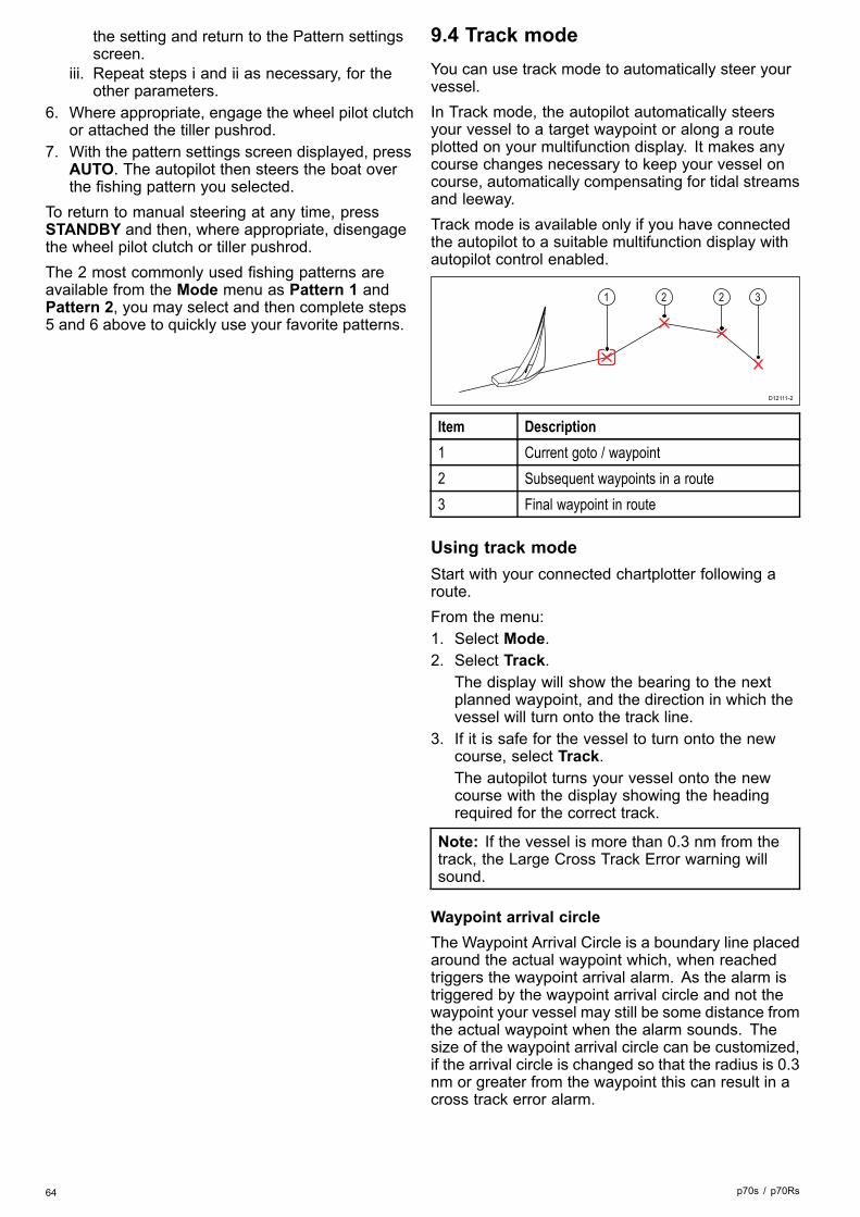
the setting and return to the Pattern settingsscreen.
iii. Repeat steps i and ii as necessary, for theother parameters.
6. Where appropriate, engage the wheel pilot clutchor attached the tiller pushrod.
7. With the pattern settings screen displayed, pressAUTO. The autopilot then steers the boat overthe fishing pattern you selected.
To return to manual steering at any time, pressSTANDBY and then, where appropriate, disengagethe wheel pilot clutch or tiller pushrod.The 2 most commonly used fishing patterns areavailable from the Mode menu as Pattern 1 andPattern 2, you may select and then complete steps5 and 6 above to quickly use your favorite patterns.
9.4 Track modeYou can use track mode to automatically steer yourvessel.In Track mode, the autopilot automatically steersyour vessel to a target waypoint or along a routeplotted on your multifunction display. It makes anycourse changes necessary to keep your vessel oncourse, automatically compensating for tidal streamsand leeway.Track mode is available only if you have connectedthe autopilot to a suitable multifunction display withautopilot control enabled.
D12111-2
1 2 2 3
Item Description1 Current goto / waypoint2 Subsequent waypoints in a route3 Final waypoint in route
Using track modeStart with your connected chartplotter following aroute.From the menu:1. Select Mode.2. Select Track.
The display will show the bearing to the nextplanned waypoint, and the direction in which thevessel will turn onto the track line.
3. If it is safe for the vessel to turn onto the newcourse, select Track.The autopilot turns your vessel onto the newcourse with the display showing the headingrequired for the correct track.
Note: If the vessel is more than 0.3 nm from thetrack, the Large Cross Track Error warning willsound.
Waypoint arrival circleThe Waypoint Arrival Circle is a boundary line placedaround the actual waypoint which, when reachedtriggers the waypoint arrival alarm. As the alarm istriggered by the waypoint arrival circle and not thewaypoint your vessel may still be some distance fromthe actual waypoint when the alarm sounds. Thesize of the waypoint arrival circle can be customized,if the arrival circle is changed so that the radius is 0.3nm or greater from the waypoint this can result in across track error alarm.
64 p70s / p70Rs

Waypoint arrival circle
D12114-2
1
2
3
4
5
Item Description1 Next waypoint2 Bearing to next waypoint3 Track line4 Cross track error5 Waypoint arrival circle
Waypoint arrivalAs the boat arrives at the target waypoint arrivalcircle the multifunction display will select the nexttarget waypoint and transmit this to the autopilot.A Waypoint Advance warning is displayed that willidentify the bearing to the next waypoint and thedirection the boat will turn to acquire the new track.
Arriving at a waypoint and waypoint advance
3 6
5
1 42
D12112-2
Item Description1 Target waypoint2 Next waypoint3 Waypoint arrival circle4 Next target waypoint5 Next waypoint arrival circle6 Previous waypoint
Waypoint advance warningThe autopilot activates the Waypoint Advancewarning in track mode whenever the target waypointname changes. This occurs when:• you select automatic acquisition by pressing Trackfrom Auto.
• you request waypoint advance by pressingTrack for 1 second in track mode (with SeaTalknavigators only).
• the boat arrives at the target and the navigatoraccepts the next waypoint.
• you activate the Man Overboard (MOB) function.When the warning sounds, the autopilot continueson its current heading but displays:• the bearing to the next waypoint.• the direction the boat will turn to take up thatbearing.
Arriving at a waypointAs you approach each waypoint, an alarm soundsand a warning is displayed:When the waypoint arrival warning is displayed:1. Check that it is safe to turn onto the new heading.2. If it is NOT safe or you do not want to advance
to the next waypoint you can:i. Select CANCEL or Auto to remain on the
same heading, orii. Select Standby to return to manual steering.
3. If it is safe select TRACK to accept the newheading and proceed to the next waypoint.
D12115-2
5
1
2
3 4
Item Description1 Next waypoint2 Track — Track to next waypoint3 Track line4 Standby (manual control)5 Auto or Cancel maintain current locked
heading
Note: If you do not press Track to accept theWaypoint Advance, the autopilot will maintainthe current heading and continue sounding thewarning.
Cross track errorCross track error (XTE) is the distance between thecurrent position and a planned track line.There are a number of reasons why you may have across track error (XTE), for example:
Pilot modes 65

• Pressing the track button at a position somedistance from the route.
• Course change to avoid an obstacle.• Waypoint arrival under certain conditions.If the cross track error is greater than 0.3 nm, theSmartPilot will sound the Large Cross Track Errorwarning and show whether you are to the port (Pt) orstarboard (Stb) of the planned track.
Example 1
D12113-2
1
2
3
Example 1 shows the course correction which willbe a turn away from the actual waypoint in order toreacquire the track line.
Item Description1. Cross track error2. Target waypoint3. Track line
Note: The cross track error alarm will continue todisplay and sound until it is reduced to less than0.3Nm.
Caution: Cross track errorcorrectionWhen returning to TRACK mode theautopilot will correct the XTE in orderto keep to the defined track leg. Thedirection of turn may not coincide with thebearing to waypoint and may be differentfrom that expected.
Route completionThe autopilot displays the Route Complete warningwhen you have reached the last waypoint on a route.
Note: The ‘Route Complete’ alarm only soundsand displays in conjunction with a multifunctiondisplay.
Leaving track modeTo leave Track mode:1. Press AUTO to return to Auto mode (autopilot
control), or.2. Press STANDBY to return to Standby mode
(manual steering).
9.5 Wind vane mode (Sailing boatsonly)When the autopilot is in Wind Vane mode it uses thewind angle as the primary heading reference. Aschanges in the true or apparent wind angle occur, itadjusts the locked heading to maintain the originalwind angle.
D12116-2
1
3
5
2
4
Item Description1 Wind direction2 Wind shift3 New wind direction4 Relative wind angle5 Vessel turns to maintain same relative
wind angle
You can only select Wind Vane mode if yourautopilot is receiving suitable SeaTalk, SeaTalkng, orNMEA 2000 wind direction data.Autopilots can maintain a course relative to either anApparent or True wind angle. The default setting isApparent wind. If required, you can change this toTrue wind from the Wind Type menu.
Using wind vane modeYou can select Wind vane mode from eitherSTANDBY or AUTO mode:1. Steady the vessel onto the required wind angle.2. Select Wind vane mode:
i. Wind vane mode can be selected by pressingthe Auto and Standby buttons together, or
ii. selecting Wind vane mode from the modesmenu: Menu > Mode > Wind vane.
This will enable Wind vane mode and lock thecurrent wind angle. The display shows the lockedheading (e.g. 128°) and the wind angle (e.g.WIND 145P indicates a wind angle of 145° toport).
3. The autopilot will then adjust the vessel’s headingto maintain the locked wind angle.
Adjusting the locked wind angle1. You can adjust the locked wind angle by using
the -1, +1, -10 and +10 buttons, or the ROTARYcontroller to change course. For example, to bearaway by 10° when the boat is on a starboard tack:i. press -10 to turn the boat 10° to port – the
locked wind angle and locked heading willboth change by 10°.
66 p70s / p70Rs

ii. the autopilot will then adjust the lockedheading as required to maintain the new windangle.
Note: Because turning the vessel affects therelationship between the true and apparent windangles, you should only use this method to makeminor adjustments to the wind angle. For majorchanges, return to STANDBY mode, steer ontothe new heading, then re-selectWind Vane mode.
Leaving wind vane modeTo leave wind vane mode:1. Press AUTO to return to Auto mode (autopilot
control), or.2. Press STANDBY to return to Standby mode
(manual steering).
Wind Shift Alarm
Evolution autopilotIf the autopilot detects a wind shift of more than 30°for 60 seconds it will trigger the Wind Shift Alarm.
SPX and SmartPilotIf the autopilot detects a wind shift of more than 15°it will trigger the Wind Shift Alarm.
Enabling and disabling the Wind Shift alarmThe Wind Shift alarm is turned on by default, you canenable and disable the Wind Shift alarm at anytime.In Wind Vane Mode:1. Select Sail Boat Settings from the Autopilot
Calibration menu: (Menu > Set-up > AutopilotCalibration > Sail Boat Settings).
2. Select Wind Shift Alarm.3. Select Off to disable the alarm or On to enable
the alarm.
Responding to the wind shift warning1. To cancel the warning, and retain the existing
wind angle and heading, press Cancel.2. Alternatively, to cancel the warning and return to
the previous heading:i. adjust the locked wind angle using the -1, +1,
-10 and +10 buttons or the Rotary controller.ii. press Standby to return to manual steering,
steer onto the required heading, and pressCancel to return to Wind Vane mode with thenew wind angle.
Using AutoTack in wind vane modeThe autopilot has a built in automatic tack facility(AutoTack) that turns your vessel "relative" to thewind angle you're currently on, and it tacks thevessel to put you on the opposite relative wind angle.
D12117-2
3
1
4
2
Item Description1 Starting position2 Tack3 Wind direction4 Final position
AutoTack is always relative to wind angle and is notadjustable.In Wind Vane mode:1. Using a p70 / p70s:
i. Press the -1 and -10 buttons at the same timeto Tack to port.
ii. Press the +1 and +10 buttons at the sametime to Tack to starboard.
2. Using a p70R or a p70Rs:i. Select Tack Port from the main menu to Tack
to port.ii. Select Tack Starboard from the main menu
to Tack to Starboard.3.When you AutoTack in wind vane mode, the boatturns through the AutoTack angle. The autopilot willthen trim the heading to mirror the locked wind anglefrom the previous tack.
Operating hints for wind vane mode• Always trim your sails carefully to minimize theamount of standing helm.
• Reef the headsail and mainsail a little early ratherthan too late.
• In Wind Vane mode the autopilot will react tolong-term wind shifts, but will not correct forshort-term changes such as gusts.
• In gusty and unsteady inshore conditions, it is bestto sail a few degrees further off the wind so thatchanges in wind direction can be tolerated.
• Avoid using Auto Tack in conditions where thewind may shift suddenly.
Caution: Allow timeAllow time for course changes
Pilot modes 67

Caution: Major course changesWhen making major course changes, thetrim on the boat may change substantially.Due to this, the autopilot may take sometime to settle accurately onto the newcourse.
Accidental gybesThe gybe inhibit feature stops the vessel from turningaway from the wind if you accidently AutoTack in thewrong direction.
Note: For the gybe inhibit feature to work, theautopilot needs suitable wind data.
With gybe inhibit set to Prevent Gybe:• you will be able to perform an AutoTack throughthe wind.
• the autopilot will prevent the boat from performingan AutoTack away from the wind.
With gybe inhibit set to Allow Gybe:• you can perform an AutoTack through or awayfrom the wind.
Note: Gybe inhibit feature can be changed fromthe Sail Boat Settings menu: Menu > Set-up >Autopilot Calibration > Sail Boat Settings >Gybe Inhibit .
9.6 Power steerPower steer mode enables you to use the rotarycontroller of the p70Rs or a connected joystick todirectly steer the vessel on manual heading.Power steer has 2 options:• Proportional— The rudder will behave in proportion to themovement of the rotary control or joystick.
• Bang Bang (Joystick only)— The rudder will move, and stay in the directionthe joystick is moved.
Engaging power steer modeTo engage Power steer mode:1. Go to the Mode menu found in Main menu >
Mode.2. Highlight Power steer and press SELECT.You can change the type of steering at any time i.e.Proportional or Bang Bang by going to the Powersteer settings in the Drive settings menu: Mainmenu > Set up > Auto pilot calibration > Drivesettings > Power steer.
Note: In order to use Bang Bang mode aconnected joystick is required, the p70Rs rotarywill only perform in Proportional mode.
68 p70s / p70Rs

9.7 Jog steer (tiller pilots only)If you have a tiller drive installed on a SeaTalknetwork, your vessel you can use the pilot controllerto operate the ram in Jog steer mode.Jog steer mode enables you to use the pilotcontrollers –1, +1, –10, +10 buttons, or the ROTARYcontroller to move the ram in and out to aidconnecting and disconnecting the ram.
Note: Jog Steer can only be used whilst yourvessel is in STANDBY.
Using jog steer (tiller drives only)1. Ensure your vessel pilot is in STANDBY mode.2. Use the –1 and –10 buttons, or turn the rotary
controller anticlockwise to retract the ram.3. Use the +1 and +10 buttons, or turn the rotary
controller clockwise to extend the ram.
9.8 Shortcut keyWhen in pilot view you can assign pilot modes tothe LEFT SOFT button as a shortcut depending onwhich vessel type has been set up.The following pilot modes can be assigned asshortcuts:• Track (default) — All vessels• Pattern — Power and fishing vessels• Power steer — All vessels (Rotary only)• Wind vane — Sailing vessels
Assigning the shortcut keyIn order to assign a pilot mode as a shortcut mappedto the LEFT SOFT button follow the steps below:1. Navigate to the Shortcut menu: Menu > Mode >
Shortcut.2. Select the required pilot mode.3. Press SAVE.
Pilot modes 69

70 p70s / p70Rs

Chapter 10: Pilot views
Chapter contents• 10.1 Available pilot views on page 72• 10.2 Graphical view on page 72• 10.3 Large view on page 73• 10.4 Standard view on page 73• 10.5 Multiple view on page 74• 10.6 2D View on page 74• 10.7 Setting the pilot view on page 75• 10.8 Setting up data boxes on page 75
Pilot views 71
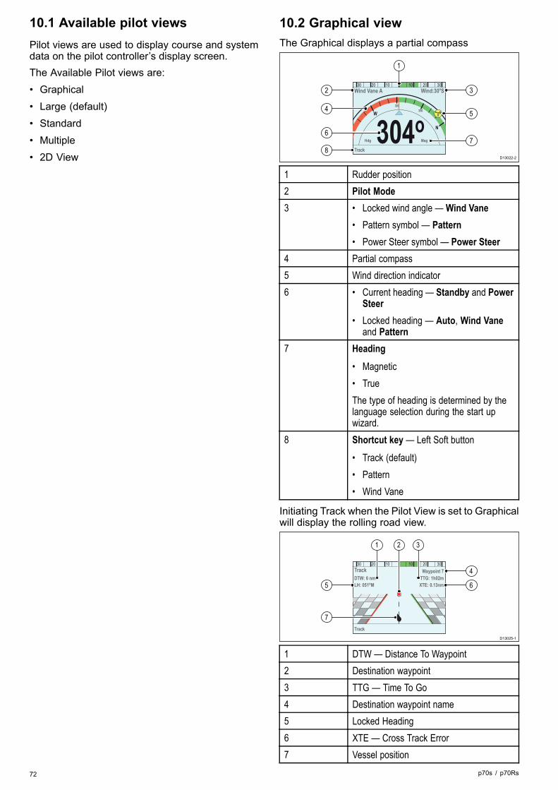
10.1 Available pilot viewsPilot views are used to display course and systemdata on the pilot controller’s display screen.The Available Pilot views are:• Graphical• Large (default)• Standard• Multiple• 2D View
10.2 Graphical viewThe Graphical displays a partial compass
304 oTrack
W
N
300
330
Hdg Mag
30 20 10 10 20 30Wind Vane A Wind:30oS
D13022-2
2
4
6
8
3
5
7
1
1 Rudder position2 Pilot Mode3 • Locked wind angle — Wind Vane
• Pattern symbol — Pattern• Power Steer symbol — Power Steer
4 Partial compass5 Wind direction indicator6 • Current heading — Standby and Power
Steer• Locked heading — Auto, Wind Vane
and Pattern7 Heading
• Magnetic• TrueThe type of heading is determined by thelanguage selection during the start upwizard.
8 Shortcut key — Left Soft button
• Track (default)• Pattern• Wind Vane
Initiating Track when the Pilot View is set to Graphicalwill display the rolling road view.
Track
30 20 10 10 20 30TrackDTW: 6 nmLH: 051oM
TTG: 1h02mWaypoint 7
XTE: 0.13nm
D13025-1
5
7
4
6
21 3
1 DTW — Distance To Waypoint2 Destination waypoint3 TTG — Time To Go4 Destination waypoint name5 Locked Heading6 XTE — Cross Track Error7 Vessel position
72 p70s / p70Rs

10.3 Large viewThe Large view has been optimized to provide thelargest possible sized text for heading data.
335 oTrack
30 20 10 10 20 30Auto Hdg 304o
Mag
D13023-1
2
4
6
3
5
1
1 Rudder position2 Pilot Mode3 • Current Heading — Auto
• Destination waypoint name — Track• Locked wind angle — Wind Vane• Pattern symbol — Pattern• Power Steer symbol — Power Steer
4 Heading
• Current Heading — Standby and PowerSteer
• Locked Heading — Auto, Track, WindVane and Pattern
5 Heading
• Magnetic• TrueThe type of heading is determined by thelanguage selection during the start upwizard.
6 Shortcut key — Left Soft button
• Track (default)• Pattern• Wind Vane
10.4 Standard viewThe Standard view provides large sized headingdata combined with data boxes which provide furtherinformation.
335 oTrack
15 69 23
30 20 10 10 20 30
Mag
TWS(Kts) Depth(ft) SOG(Kts)
Pattern
D13027-1
2
4
6
3
5
1
7
1 Rudder position2 Pilot Mode3 • Current Heading — Auto
• Destination waypoint name — Track• Locked wind angle — Wind Vane• Pattern symbol — Pattern• Power Steer symbol — Power Steer
4 Heading
• Current Heading — Standby and PowerSteer
• Locked Heading — Auto, Track, WindVane and Pattern
5 Heading
• Magnetic• TrueThe type of heading is determined by thelanguage selection during the start upwizard.
6 Shortcut key — Left Soft button
• Track (default)• Pattern• Wind Vane
7 Data Boxes x 3
• TWS (default)• Depth (default)• SOG (default)
Pilot views 73

10.5 Multiple viewThe Multiple view includes multiple data boxes fordisplaying information.
Track
30 20 10 10 20 30
Auto LH:304oM
TWS(Kts)
DTW(nm)
Depth(ft)
XTE(nm)
SOG(Kts)
Heading(M)
15
01
62
---
21
304o
D13024-1
2
5
3
1
4 4
4
1 Rudder position2 Pilot Mode3 • Current Heading — Auto
• Destination waypoint name — Track• Locked wind angle — Wind Vane• Pattern symbol — Pattern• Power Steer symbol — Power Steer
4 Data Boxes x 6
• TWS (default)• Depth (default)• SOG (default)• DTW (default)• XTE (default)• Heading (default)
5 Shortcut key — Left Soft button
• Track (default)• Pattern• Wind Vane
10.6 2D ViewThe 2D view includes a full compass dial and databoxes for displaying information.
Track
30 20 10 10 20 30TrackWaypoint 17
TWS(Kts)
Depth(ft)
SOG(Kts)
N E
W S050oM
18
73
22
D13021-1
9
3 4 51 2
8
6
7
10 11
1 Pilot Mode2 • Current Heading — Auto
• Destination waypoint name — Track• Locked wind angle — Wind Vane• Pattern symbol — Pattern• Power Steer symbol — Power Steer
3 Rudder position4 Full compass5 Destination waypoint6 Wind direction indicator7 Vessel position8 Data Boxes x 3
• TWS (default)• Depth (default)• SOG (default)
9 Shortcut key — Left Soft button
• Track (default)• Pattern• Wind Vane
10 Track line11 • Current heading — Standby and Power
Steer• Locked heading — Auto, Wind Vane,
Track and Pattern
74 p70s / p70Rs

10.7 Setting the pilot viewTo set the pilot view to your desired layout:1. Go to the Pilot view menu: Main menu > Pilot
view.2. Highlight and select View type.3. Highlight the required view:
• Graphical• Large• Standard• Multiple• 2D
4. Press SELECT to save the view as default.
10.8 Setting up data boxesThe Standard, Multiple and 2D Pilot views includedata boxes which you can customize to displaydifferent data.With your chosen Pilot view displayed:1. Select Menu.2. Select Pilot View.3. Select Data Boxes.4. Select the Data box that you want to change the
data for.A list of available data is displayed.
5. Select the relevant data type from the list.
Data boxesThe following data types are available which can bedisplayed in the data boxes:
DepthXTE Cross track errorDTW Distance to waypointBTW Bearing to waypointAWA Apparent wind angleAWS Apparent wind speedTWS True wind speedTWA True wind angleCOG Course over groundSOG Speed over groundSpeedLogTripSea temperatureTimeDateRate of turnHeading
Pilot views 75

76 p70s / p70Rs

Chapter 11: Pilot controller alarms
Chapter contents• 11.1 Alarms on page 78
Pilot controller alarms 77

11.1 AlarmsAlarms are used to alert you to a situation or hazardrequiring your attention.Some examples of alarms are:• Anchor alarm — Used when anchored, this alertsyou to a change in depth which could mean thatthe chain length requires adjusting.
• Depth and speed alarms — These alarms alertyou when your depth or speed moves outside ofspecified limits, for example a minimum depth.
• MOB (Man Overboard) alarm — Received from anMOB system.
When an alarm occurs, a message is displayed andan audible alarm may sound.
AIS textAISAISAIS textxtxtxtxt
D12080-1
You can either:• Silence the alarm, or• Silence the alarm and edit the alarm settings.
Note: With the exception of the Alarm clock,Speed and Sea temperature; SeaTalk systems willonly be able to switch alarms on and off, SeaTalkngsystems will also be able to adjust settings.
Alarm settingsMost alarms are generated locally using specifiedlimits. They are also transmitted on the SeaTalkngnetwork.Alarm name Alarm type Description ActionDetectingmagnetics
Linearizationis required.
Linearizethe internalcompass.
Magneticfieldsdetected
InitialLinearizationcomplete,furtherlinearizationwill beperformedin thebackground.
None.
Calibrationrequired
Indicates apilot that hasnot been fullycalibrated.Initiated inStandbymode, for afew secondsafter initialpower-up.
Docksideand Seatrialcalibrationneeds to beundertaken.
• Changepilot mode
• Selfcancelling
Alarm name Alarm type Description ActionOff Course Indicates
Vessel is offcourse bymore than thepre definedalarm limit.Initiated fromAuto, Track &Wind modes.
• Changepilot mode
• Changecourse
• Correctcourse
RouteComplete
Flagged bychart plotter/ navigatorwhen thelast waypointin a routehas beenreached.
• Changepilot mode
Large CrossTrack Error
Indicatescross trackerror (XTE)is greaterthan 0.3nmInitiatedduring Trackmode or onentry to Trackmode fromany othermode.
• Steer backmanuallyand entertrackagain.
• Checkautopilotsettings.
• Reset XTEon themultifunc-tion dis-play.
Loss ofWaypointdata
Indicates thesource (e.g.chartplotter)of thewaypointdata hasbeen lost
• Pilot dropsout of trackmode andinto automode andcontinueson lastlockedheading.
•Wind Shift Indicates true
wind anglehas changedby more than15 degrees.Initiated fromWind vanemode only.
• Changepilotmode.
• Changecourse.
• Reductionof changein windangle.
78 p70s / p70Rs

Alarm name Alarm type Description ActionAuto release Safety Alarm Appears
when theuser hastaken backcontrol ofthe steeringwhilst in anengagedmode (Auto,Track, etc)using thefly-by-wiresteeringwheel.
• Pilot dropsto standbyand alarmtimes outafter 10seconds.
Drivestopped
Safety Alarm Indicates arudder stallcondition haspersistedor thatthe powerhas beenremovedfrom thedrive unit.Initiated inAuto, Track &Wind modes.
• Check out-put fromSPX, driveunit andconnec-tions.
• Pilot dropsto standbyand alarmtimes outafter 10seconds.
No ControlHead
Safety Alarm The coursecomputer haslost commu-nications withthe Pilot con-troller, thisalarm is gen-erated by thecourse com-puter.
• Checkconnec-tions forshort oropen cir-cuit.
• Checksystemfor devicefault.
• Pilot dropsto standbyand alarmtimes outafter 10seconds.
No DriveDetected
Safety Alarm Communica-tion betweenthe EV unitand ACU hasbeen lost orcannot be es-tablished.
• CheckLED diag-nostics in-dicators.
• Checkoutputfrom EVand ACUunits.
• Checkphysicalconnec-tions andcable con-dition, re-place ifnecessary.
Alarm name Alarm type Description ActionSeaTalk fail Safety Alarm Total
SeaTalk datatransmissionproblem.
• Checkconnec-tions forshort oropen cir-cuit.
• Checksystemfor devicefault.
• Pilot dropsto standbyand alarmtimes outafter 10seconds.
EEPROMcorruption
Safety Alarm A corruptionof criticalconfigurationdata hasoccurred.
• Pilot dropsto standbyand alarmtimes outafter 10seconds.
No Pilot Safety Alarm The Pilot con-troller haslost commu-nications withthe coursecomputer;this alarm isgenerated bythe Pilot con-troller.
• CheckSeatalk orSeatalkngbus wiringbetweenSPXand Pilotcontroller.
• Check thatthe coursecomputeris poweredup.
NoCompass
Safety Alarm Compassis notconnected.
• Checkconnec-tions andcompasstrans-ducer.
Rate Gyrofault
Safety Alarm The gyrosensor hasfailed.
• InternalGyro fail-ure, inves-tigate faultand Con-sult a Ray-marineServiceAgent.
Pilot controller alarms 79
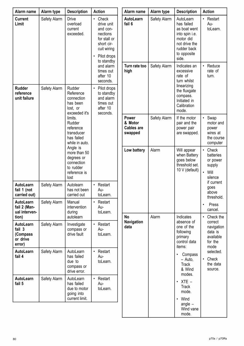
Alarm name Alarm type Description ActionCurrentLimit
Safety Alarm Driveoverloadcurrentexceeded.
• Checkdrive unitand con-nectionsfor stall orshort cir-cuit wiring
• Pilot dropsto standbyand alarmtimes outafter 10seconds.
Rudderreferenceunit failure
Safety Alarm RudderReferenceconnectionhas beenlost, orexceeded it'slimits.Rudderreferencetransducerhas failedwhile in auto.Angle ismore than 50degrees orconnectionto rudderreference islost
• Pilot dropsto standbyand alarmtimes outafter 10seconds.
AutoLearnfail 1 (notcarried out)
Safety Alarm Autolearnhas not beencarried out
• RestartAu-toLearn.
AutoLearnfail 2 (Man-ual interven-tion)
Safety Alarm Manualinterventionduringautolearn
• RestartAu-toLearn.
AutoLearnfail 3(Compassor driveerror)
Safety Alarm Investigatecompass ordrive fault
• RestartAu-toLearn.
AutoLearnfail 4
Safety Alarm AutoLearnhas faileddue tocompass ordrive error.
• RestartAu-toLearn.
AutoLearnfail 5
Safety Alarm AutoLearnhas faileddue to motorgoing intocurrent limit.
• RestartAu-toLearn.
Alarm name Alarm type Description ActionAutoLearnfail 6
Safety Alarm AutoLearnhas failedas boat wentinto spin i.e.motor didnot drive therudder backto oppositeside.
• RestartAu-toLearn.
Turn rate toohigh
Safety Alarm Indicates anexcessiverate ofturn whilstlinearizingthe fluxgatecompass.Initiated inCalibrationmode.
• Reducerate ofturn.
Power& MotorCables areswapped
Safety Alarm If the motorpair and thepower pairare swapped.
• Swapmotor andpowerwires atthe coursecomputer
Low battery Alarm Will appearwhen Batterygoes belowthreshold set.10 V (default)
• Checkbatteriesor powersupply
• Willsilenceif currentgoesabovethreshold.
• Presscancel.
NoNavigationdata
Alarm Indicatesabsence ofone of thefollowingprimarycontrol dataitems:
• Compass– Auto,Track& Windmodes.
• XTE –Trackmode.
• Windangle –Wind vanemode.
• Check thecorrectnavigationdata isavailablefor themodeselected.
• Checkthe datasource.
80 p70s / p70Rs

Alarm name Alarm type Description ActionPilot start up Alarm Will display
start up for20 secondseverytimethe pilot ispowered up
• Selfcancelling.
Waypointadvance
Alarm Indicateschange inwaypointname or IDand directionto turn to newwaypoint.Initiated inTrack mode.
• Changepilotmode.
• Acceptnewwaypointroute.
No Winddata
Alarm SmartPilot isin Wind VaneMode but hasnot receivedWind Angledata for 30seconds.
• Checkwind datasourceand con-nections.
• Pilot dropsout ofwind vanemode andrevertsto automode.
• Changepilot mode
No speeddata
Alarm Speed datahas stopped .
• CheckSeatalkconnec-tions forshort oropen cir-cuit.
• Checksystem forSeatalkdevicefault.
SeaTalk 1fail
Alarm SeaTalkchannel 1has a com-municationproblem.
• Changepilotmode.
SeaTalk 2fail
Alarm SeaTalkchannel 2has a com-municationproblem.
• Changepilotmode.
Drive short Warning Indicates ashort circuitin the driveunit
• Pilot willpowerdown
• User tofix shortcircuit
Alarm name Alarm type Description ActionClutch short Warning Indicates a
short circuitin the Clutch
• Checkclutch con-nections atSPX anddrive unit
• . Checkdrive unitclutch.
• User tofix shortcircuit
Solenoidshort
Warning Indicates ashort circuit inthe solenoid
• Pilot willpowerdown
• User tofix shortcircuit
Pilot controller alarms 81

82 p70s / p70Rs

Chapter 12: Set up menu options
Chapter contents• 12.1 Set up menu on page 84• 12.2 Autopilot calibration menu on page 84• 12.3 User preferences menu on page 92• 12.4 System set-up menu on page 94• 12.5 Diagnostics menu on page 95
Set up menu options 83

12.1 Set up menuThe set up menu provides a range of tools andsettings to configure the pilot controller.
Menu item Description OptionsAutopilotCalibration
Pilotcommissioning /calibration settings
SeaTalkng
• Vessel settings.• Drive settings.• Sailboat
settings.• Commissioning.SeaTalk
• User settings.• Dealer settings.• Seatrial
calibration.User Preferences Set user
preferences suchas: Time &Date, Units ofmeasurement,Language, Vesseltype, Vesseldetails, andVariation.
User preferencesmenu.
System Set-up Set systemgrouping, displayand system colorand brightness,Multiple datasources and aboutsystem set up.
System set upmenu.
Simulator Enables ordisables simulatormode, whichallows you topractice operatingyour instrumentdisplay withoutany data from anyother external unit.
• On• Off
Factory Reset Delete usersettings andRestore unit tofactory defaultsettings.
• Yes• No
Diagnostics Information Aboutthe display andsystem and keybeep on / offsetting.
• Yes• No
Set-up Wizard Launch the initialset-up wizard.
• Language• Vessel hull type• Welcome page
12.2 Autopilot calibration menuThe Autopilot Calibration menu options aredetermined by the connected autopilot system.
Note: Not all options are available whenCalibration Lock is turned On.
Note:• (1) — SPX and SeaTalk SmartPilots only.• (2) — Evolution autopilots only.
Menu OptionsVessel Settings • Vessel Hull Type
• Drive Type• Cruise Speed (1)
• Compass Offset• Latitude Compass Damping (1)
• Calibration LockDrive Settings • Rudder Gain (1)
• Response Level (1)
• Counter Rudder (1)
• Rudder Damping• Auto Trim (1)
• Auto Turn• Power Steer (2)
• Reverse Rudder Ref.• Off Course Alarm (1)
• Turn Rate Limit (1)
• Motor Phasing• Rudder Limit• Rudder Offset (2)
• Hard Over Time
84 p70s / p70Rs

Menu OptionsSail Boat Settings • Gybe Inhibit
• Wind Type• Wind Trim Response (1)
• Wind Shift Alarm (2)
Commissioning • Dockside Wizard• Sea Trial Wizard (1)
• Motor Phasing (1)
• Swing Compass (1)
• Auto Learn (1)
• Align Compass GPS• Align Compass (1)
• Restart Compass (2)
• Compass Lock (2)
• Pilot Factory Reset• Debug Level (2)
• ACU Debug Level (2)
Set up menu options 85

Vessel SettingsVessel settings are dependant on connected autopilot system and vessel drive type.The Vessel settings menu can be accessed from: Menu > Set-up > Autopilot Calibration > VesselSettings.
Note: When connected to a SeaTalk system the vessel settings listed below are part of the Dealersettings menu, Menu > Set-up > Autopilot Calibration > Dealer Settings.
Note: Not all options are available when Calibration Lock is turned On.
Item Description Evolution autopilotsSeaTalk and SPX SmartPilotOptions
Vessel hulltype
The vessel type options will normallygive optimum performance for typicalvessels of each type. However,you may find you can improve theperformance of your vessel byselecting an option for a differentvessel type.
• Sail.• Sail (Slow turn).• Sail Catamaran.• Power.• Power (slow turn).• Power (fast turn).
• Race sail.• Sail cruiser.• Catamaran.• Workboat.• RIB.• Outboard speed boat.• Inboard speed boat.• Power cruiser 1. — Vessel
speeds up to 12 knots.• Power cruiser 2.— Vessel
speeds up to 30 knots.• Power cruiser 3 — Vessels
speeds greater than 30 knots.• Sport fishing.• Pro fishing.
Drive type List of compatible drive types.The list is dependant upon connectedautopilot system.
Note: The drive type option is notavailable in systems comprising ofan EV-2 and an ACU-300.
• Type 1 Linear — ACU-200 andACU-400
• Type 2 Linear — ACU-400 only• Type 2 Hydraulic Linear —
ACU-400 only• Type 3 Hydraulic Linear —
ACU-400 only• I/O Stern — ACU-200 and
ACU-400• Wheel Drive — ACU-100,
ACU-200 and ACU-400• Tiller — ACU-100, ACU-200
and ACU-400• CR Solenoid— auto detected—
ACU-300 only (not selectable)• Sport Drive — ACU-200 and
ACU-400• Rotary Drive Type 1—ACU-200
and ACU-400• Rotary Drive Type 2—ACU-400
only• Hydraulic Pump Type 1 (0.5L)
— ACU-100 only• Hydraulic Pump Type 1 —
ACU-200 and ACU-400
• Type 1 linear• Type 2 linear• Type 3 linear• Hydraulic pump type 1• Hydraulic pump type 2• Hydraulic pump type 3• Rotary drive type 1• Rotary drive type 2• Rotary type 1• Rotary type 2• I/O stern• CAN• Wheel drive.• Tiller• Sport drive• Constant running pump.• Verado
86 p70s / p70Rs

Item Description Evolution autopilotsSeaTalk and SPX SmartPilotOptions
• Hydraulic Pump Type 2 —ACU-400 only
• Hydraulic Pump Type 3 —ACU-400 only
• Verado — ACU-200 andACU-400
Speed Input Select the source for speed data. InAuto the system will automaticallychoose the lowest value betweenSpeed and SOG Cruise speed allowsyou to set a static speed.
• Auto• Speed (STW)• SOG• Cruise speed
N/A
Cruise speed Set the cruise speed to the vessel’stypical cruising speed. If no speeddata is available, the SmartPilotsystem will use the cruise speedvalue you set as a default.
• 0 to 99 Kts • 0 to 99 Kts
CompassOffset
On systems without a GPS thenthe compass heading must bemanually aligned to the vesselsknown heading.
• -10° to 10° • -179° to 180°
LatitudeCompassDamping
If no valid latitude data is available,the autopilot system will use thissetting which provides the necessaryadaptation for higher latitudes.
N/A • On• Off (default)
Auto release Auto release allows you to overridethe pilot by taking hold of the wheelor tiller. When you release the wheelor tiller, the pilot will return to the lastlocked heading.
Note: Only available on S1, S2,or S3 course computers only withdrive type set to I/O stern.
N/A • Enable (default)• Disable
Calibrationlock
The calibration lock is used to lockout specific calibration settingswhich if changed may requirerecommissioning of the autopilotsystem. If your system has beendealer installed then the lock may beturned on.
• On (default)• Off
• On• Off (default)
Set up menu options 87

Drive settingsThe Drive Settings menu can be accessed from: Menu > Set-up > Autopilot Calibration > Drive Settings.
Note: Not all options are available when Calibration Lock is turned On.
Item Description Options*Rudder gain Rudder gain is a measure of how much helm the autopilot will apply to
correct course errors.A higher setting results in more rudder being applied. The rudder gainsetting is set automatically as part of the Auto Learn process.
• 1 — 9
*Counter rudder Counter rudder is the amount of rudder the autopilot system applies totry to prevent the vessel from yawing off course.A higher counter rudder setting results in more rudder being applied
• 1 — 9 Do not set to 0.
Rudder damping On autopilot systems with a rudder reference transducer, you can set therudder damping to prevent autopilot ‘hunting’.Increasing the rudder damping value reduces hunting. When adjustingthe value, increase the setting one level at a time until the autopilot stopshunting. Always use the lowest acceptable value.Rudder Damping
• 1 — 9• 3 (default)
Rudder limit If a rudder reference transducer is fitted, this screen is used to set thelimits of the rudder control just inside the mechanical end stops, andthus avoid putting the steering system under unnecessary load. Thisshould be set when commissioning the system. The limit should be setto approximately 5 degrees less than the maximum rudder angle.
Note: If no rudder reference has been fitted you MUST ensure thatadequate provision is made to prevent the steering mechanism fromimpacting the end stops.
• 10º — 40º• 30º (default)
Rudder offset This specifies the offset from amidships (zero adjustment). • -9° to 9°Reverse rudder ref This reverses the phase of the rudder reference display.
Note: This option is not available unless you have a rudder referencetransducer fitted.
Note: This option is not available on SeaTalk systems, so you wouldneed to reverse the RED and GREEN wires on the Rudder Referenceconnection to the course computer.
• Port• Starboard
*Auto Trim The Auto Trim setting determines the rate at which the autopilot systemapplies ‘standing helm’ to correct for trim changes caused by varyingwind loads on the sails or superstructure. The default Auto Trim is setas part of the Auto Learn process.If you need to change the setting, increase the Auto Trim one level at atime and use the lowest acceptable value:
• If the autopilot system gives unstable course keeping or excessivedrive activity with a change in the heel angle, decrease the AutoTrim level.
• If the autopilot system reacts slowly to a heading change due to achange in the heel angle, increase the Auto Trim level.
• If the Auto Trim level is too high, the vessel will be less stable andsnake around the desired course.
Setting
• Off• OnAdjustment
• 1 — 4 1 = Slowest, 4 =Fastest
• 1 (default)
Auto Turn This setting defines the amount of course change when performing anauto turn.
Note: This option cannot be changed when connected over SeaTalk.
Note: This option is only available on motor vessels.
• 10º — 125º• 90º (default)
88 p70s / p70Rs

Item Description OptionsResponse level This sets the default autopilot system response level setting. The
response level controls the relationship between course keepingaccuracy and the amount of helm / drive activity. You can maketemporary changes to response during normal operation.EvolutionOn Evolution autopilots the Response level setting is available from themain menu: Menu > Response LevelSeaTalk and SPX SmartPilot levels
• Level 1 — 3 Minimize the amount of pilot activity. This conservespower, but may compromise short-term course-keeping accuracy.
• Level 4 — 6 Should give good course keeping with crisp, wellcontrolled turns under normal operating conditions.
• Level 7 — 9 Gives the tightest course keeping and greatest rudderactivity (and power consumption). This can lead to a rough passagein open waters as the SPX system may ‘fight’ the sea.
Evolution
• Performance• Cruising• LeisureSeaTalk and SPX SmartPilot
• 1 — 9• 5 (default)
*Off course alarm This screen determines the angle used by the OFF COURSE alarm. TheOFF COURSE alarm operates if the pilot strays off course by more thanthe specified angle for more than 20 seconds.
• 15° to 40°• 20º (default)
*Turn rate limit This limits your vessel’s rate of turn under autopilot system control. It isonly effective if your speed is greater than 12 knots.
• 1° to 30°• 7º (default)
Power steer This screen determines the behavior of the Rotary or joystick when inpower steer mode.
Note: Power Steer mode is only available if the system includes arudder reference transducer and speed data is available
• Off• Proportional The steering will behave in proportion to the movement
of the rotary controller or joystick.• Bang Bang (Joystick only) The rudder will move, and stay in the
direction a joystick is moved.
• Off• Proportional• Bang Bang
Hard over time On vessels without a rudder reference transducer, it is of criticalimportance to set the hard over time, to ensure accurate autopilotoperation.The Default value is determined by Drive type selection.
• Value is seconds
Note: * SPX and SeaTalk SmartPilots only.
Set up menu options 89

Sail boat settingsThese settings are only available to sail boats.The Sail Boat settings menu can be accessed from: Menu > Set-up > Autopilot Calibration > SailBoat Settings.
Note: When connected to a SeaTalk system the Sail boat settings listed below are part of the Usersettings menu: Menu > Set-up > Autopilot Calibration > User Settings.
Item Description Evolution autopilots SeaTalk and SPX SmartPilotGybe inhibit With gybe inhibit set to allow, the
autopilot will allow the vessel to tackthrough / into and away from thewind. With gybe inhibit set to prevent,you can only tack through / into thewind.Gybe inhibit does not effect Auto Turn
• Allow Gybe• Prevent Gybe
• Allow Gybe• Prevent Gybe
Wind Type This option determines whether thevessel steers to apparent or true windin Wind Vane mode.
• True• Apparent
• True• Apparent
Wind TrimResponse
Wind Trim Response controls howquickly the autopilot responds tochanges in wind direction. Higherwind trim settings will result in asystem that is more responsive towind changes.
N/A • 1 to 9• 5 (default)
Wind ShiftAlarm
This option enables you to enableand disable the Wind Shift alarm.
• On (default)• Off
N/A
Note: These features are only available if wind data is available.
90 p70s / p70Rs

Commissioning menuCommissioning menu options are dependant on connected autopilot system.
Menu option Description Evolution autopilotsSeaTalk and SPXSmartPilots
Dockside Wizard Initiates the Dockside wizardprocess.
Yes Yes
Sea Trial Wizard Initiates the Sea Trial wizardprocess.
N/A Yes
Motor phasing Initiates the motor phasing(drive check) wizard
N/A Yes
Swing Compass Initiates the swing compasswizard
N/A Yes
Auto Learn Initiates the Auto Learnprocess
N/A Yes
Align Compass GPS (1) Initiates the align compass toGPS heading wizard
Yes Yes
Align Compass (1) Manual adjustment of thecompass offset
• -10° to 10° • -179° to 180°
Pilot Factory Reset Resets the autopilots coursecomputer to factory defaultsettings.
• Yes• No
• Yes• No
Restart Compass Restarts the compass • Yes• Cancel
N/A
Compass Lock Locks the compass fromperforming further automaticlinearization.
• On• Off
N/A
Debug Level (1) Sets the debug value fortroubleshooting purposes.The recommended Debugsetting is 7.
Note: The Debuglevel should only be settemporarily, usually whenrequested by TechnicalSupport as part of atroubleshooting sea trial.
• 0 — 63 N/A
ACU Debug Level (1) Sets the debug value fortroubleshooting purposes.The recommended Debugsetting is 7.
Note: The Debuglevel should only be settemporarily, usually whenrequested by TechnicalSupport as part of atroubleshooting sea trial.
• 0 — 127 N/A
Note: (1) Option not available when Calibration Lock is turned On.
User SettingsWhen connected to a SeaTalk autopilot system aUser settings menu will be available.The User settings menu can be accessed from:Main Menu > Set up > Autopilot calibration >User settings. Once entered the user settingsmenu will cycle through all available options. These
options shall be available to users when calibrationlock is turned on.
Set up menu options 91

12.3 User preferences menuThe User preferences menu enables users to customize user settings.Menu item Description OptionsTime & Date These options enable you to customize the date
and time format to your requirements. You canalso specify a local time offset from UniversalTime Constant (UTC), to compensate for anytime zone difference.
Date format:
• mm/dd/yy• dd/mm/yyTime format:
• 12hr• 24hrTime offset:
• –13 to +13 hoursUnits Enables you to specify the units used for the
following key measurements:
• Speed• Distance• Depth• Wind speed• Temperature• Flow rate• Heading• Pressure• Volume• Barometric
Speed:
• kts — knots.• mph — miles per hour.• km/h — Kilometers per hour.Distance:
• nm — Nautical miles.• sm — Statute miles.• km — Kilometers.Depth:
• ft — Feet• m — Metres• fa — FathomsWind speed:
• kts — knots.• m/s — metres per second.Temperature:
• ºC — degrees centigrade.• ºF — degrees fahrenheit.Flow Rate
• UK Gal/H — UK gallons per hour.• US Gal/H — US gallons per hour.• LPH — Liters per hour.Heading:
• Mag — magnetic.• TruePressure
• PSI — pounds per square inch.• Bar — bar.• kPa — Kilo pascals.Volume:
• UK Gallons• US Gallons
92 p70s / p70Rs

Menu item Description Options
• ltr — liter.Language Determines the language that will be used for all
on-screen text, labels, menus and options.• English (UK)• English (US)• Chinese• Croatian• Danish• Dutch• Finnish• French• German• Greek• Italian• Japanese• Korean• Norwegian• Polish• Portuguese (Brazilian)• Russian• Spanish• Swedish• Turkish
Variation Enables you to turn on and off magneticvariation, specify slave source or adjustmanually.
• Variation mode• Variation range
Variation mode:
• On• Off (default)• SlaveVariation range:
• -30º — +30ºKey Beep Enable and disable the audible beep when
pressing buttons.• On (default)• Off
Set up menu options 93

12.4 System set-up menuThe System set-up menu enables users to customize the following user settings:
Menu item Description OptionsNetwork group Allows adding multiple units together in
a group so that when the color schemeor brightness is changed on one unit thechanges are applied to all units in thegroup.
Predefined groups
• None• Helm 1• Helm 2• Cockpit• Flybridge• MastUndefined
• Group-1 — Group-5Brightness / color group Enables synchronization of the displays
brightness and color to be the same asthe other units in the same group.
Sync brightness / color
• This display• This group
Data sources Allows you to view and select preferreddata sources.
• Select data source• Data source found• Data source details
Select data source
• GPS position• GPS Datum• Time & Date• Heading• Depth• Speed• WindData source found
• model name — serial numberPort ID
Data source details
• Device name• Serial No.• Port ID• Status or No data
About system set-up Provides information about the Systemset-up menu.
94 p70s / p70Rs

12.5 Diagnostics menuYou can access diagnostics details from the Diagnostics menu: (Menu > Set-up > Diagnostics).Menu item Description OptionsAbout display Allows you to view information about the display
you are using:• Software version• Hardware version• Bootloader version• Temperature• Volts• Max. volts• Current• Max. current• Run time• Deviation (If available)
About Pilot Allows you to view information about theautopilot you are using:
Note: The About Pilot menu is onlyavailable on Pilot controllers.
• NMEA Code• Product ID• Serial number• Description• Software version• PCB Number• CAN Volts• Unit Volts• Operating hours• Deviation
About system Allows you to search the SeaTalkng network anddisplay information about the products found.
• Model number• Serial number• Software version• Hardware version• Volts
Self test The product has a built in self test which canhelp to diagnose faults.Self-Test include:
• Memory test• Button test• Display test• Buzzer test• Illumination test
N/A
Set up menu options 95

96 p70s / p70Rs

Chapter 13: Maintenance
Chapter contents• 13.1 Routine equipment checks on page 98• 13.2 Product cleaning on page 98• 13.3 Cleaning the display screen on page 99• 13.4 Cleaning the display case on page 99• 13.5 Cleaning the sun cover on page 100
Maintenance 97

13.1 Routine equipment checksRaymarine strongly recommends that you completea number of routine checks to ensure the correct andreliable operation of your equipment.Complete the following checks on a regular basis:• Examine all cables for signs of damage or wearand tear.
• Check that all cables are securely connected.
13.2 Product cleaningBest cleaning practices.
When cleaning products:• If your product includes a display screen, do NOTwipe the screen with a dry cloth, as this couldscratch the screen coating.
• Do NOT use abrasive, or acid or ammonia basedproducts.
• Do NOT use a jet wash.
98 p70s / p70Rs
13.3 Cleaning the display screenA coating is applied to the display screen. Thismakes it water repellent, and prevents glare. Toavoid damaging this coating, follow this procedure:1. Switch off the power to the display.2. Rinse the screen with fresh water to remove all
dirt particles and salt deposits.3. Allow the screen to dry naturally.4. If any smears remain, very gently wipe the screen
with a clean microfibre cleaning cloth (availablefrom an opticians).
13.4 Cleaning the display caseThe display unit is a sealed unit and does not requireregular cleaning. If it is necessary to clean the unit,follow this basic procedure:1. Switch off the power to the display.2. Wipe the display with a clean, soft cloth (a
microfibre cloth is ideal).3. If necessary, use a mild detergent to remove
grease marks.
Note: Do NOT use solvents or detergents on thescreen itself.
Note: In certain conditions, condensation mayappear inside the display screen. This will notharm the unit, and can be cleared by powering onthe display for a short time.
Maintenance 99

13.5 Cleaning the sun coverThe supplied sun cover features an adhesive surface.In certain conditions unwanted contaminants maystick to this surface. To avoid damaging the monitordisplay, clean the sun cover regularly following thisprocedure:1. Carefully remove the sun cover from the display.2. Rinse the sun cover with fresh water to remove
all dirt particles and salt deposits.3. Allow the sun cover to dry naturally.
100 p70s / p70Rs

Chapter 14: System checks and troubleshooting
Chapter contents• 14.1 Troubleshooting on page 102• 14.2 Power up troubleshooting on page 103• 14.3 System data troubleshooting on page 104• 14.4 Miscellaneous troubleshooting on page 105• 14.5 Performing a Factory Reset on page 106
System checks and troubleshooting 101

14.1 TroubleshootingThe troubleshooting information provides possiblecauses and corrective action required for commonproblems associated with marine electronicsinstallations.All Raymarine products are, prior to packing andshipping, subjected to comprehensive test andquality assurance programs. However, if youexperience problems with the operation of yourproduct this section will help you to diagnoseand correct problems in order to restore normaloperation.If after referring to this section you are still havingproblems with your unit, please contact RaymarineTechnical Support for further advice.
102 p70s / p70Rs
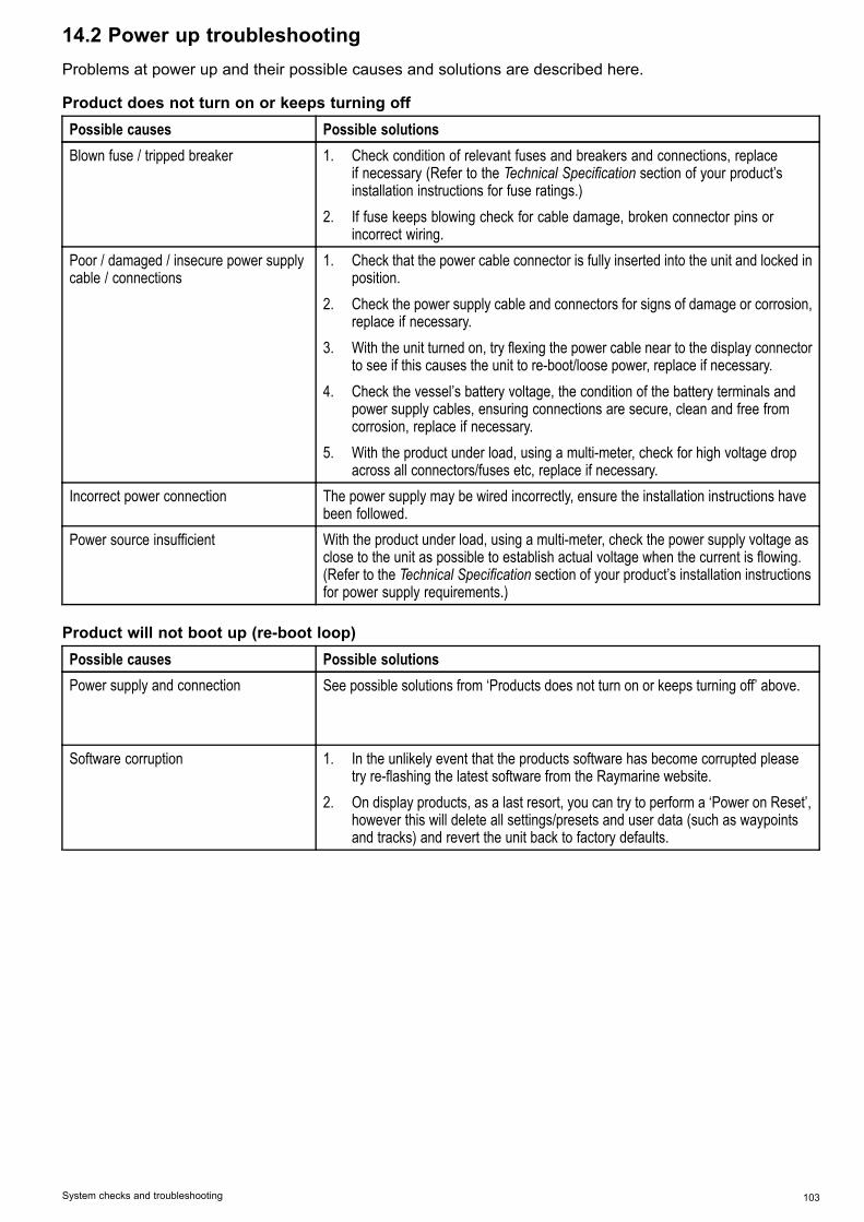
14.2 Power up troubleshootingProblems at power up and their possible causes and solutions are described here.
Product does not turn on or keeps turning offPossible causes Possible solutionsBlown fuse / tripped breaker 1. Check condition of relevant fuses and breakers and connections, replace
if necessary (Refer to the Technical Specification section of your product’sinstallation instructions for fuse ratings.)
2. If fuse keeps blowing check for cable damage, broken connector pins orincorrect wiring.
Poor / damaged / insecure power supplycable / connections
1. Check that the power cable connector is fully inserted into the unit and locked inposition.
2. Check the power supply cable and connectors for signs of damage or corrosion,replace if necessary.
3. With the unit turned on, try flexing the power cable near to the display connectorto see if this causes the unit to re-boot/loose power, replace if necessary.
4. Check the vessel’s battery voltage, the condition of the battery terminals andpower supply cables, ensuring connections are secure, clean and free fromcorrosion, replace if necessary.
5. With the product under load, using a multi-meter, check for high voltage dropacross all connectors/fuses etc, replace if necessary.
Incorrect power connection The power supply may be wired incorrectly, ensure the installation instructions havebeen followed.
Power source insufficient With the product under load, using a multi-meter, check the power supply voltage asclose to the unit as possible to establish actual voltage when the current is flowing.(Refer to the Technical Specification section of your product’s installation instructionsfor power supply requirements.)
Product will not boot up (re-boot loop)Possible causes Possible solutionsPower supply and connection See possible solutions from ‘Products does not turn on or keeps turning off’ above.
Software corruption 1. In the unlikely event that the products software has become corrupted pleasetry re-flashing the latest software from the Raymarine website.
2. On display products, as a last resort, you can try to perform a ‘Power on Reset’,however this will delete all settings/presets and user data (such as waypointsand tracks) and revert the unit back to factory defaults.
System checks and troubleshooting 103

14.3 System data troubleshootingAspects of the installation can cause problems with the data shared between connected equipment. Suchproblems, their possible causes and solutions are described here.
Problem Possible causes Possible solutionsCheck the data bus (e.g. SeaTalkng) wiring andconnections.Check the overall integrity of the data bus (e.g. SeaTalkng)wiring.
Data is not being received at thedisplay.
If available refer to the reference guide for the data bus(e.g. SeaTalkng reference manual).Check the source of the missing data (e.g. instrumentdisplay or engine interface).Check the power to the SeaTalk bus.
Data source (e.g. instrumentdisplay or engine interface) isnot operating.
Refer to the manufacturer's handbook for the equipmentin question.
Instrument, engine or othersystem data is unavailable at alldisplays.
Software mismatch betweenequipment may preventcommunication.
Contact Raymarine technical support.
Check that all required equipment is connected to thenetwork.Check the status of the Raymarine network Switch.
Network problem.
Check that SeaTalkhs / RayNet cables are free fromdamage.
Instrument or other system datais missing from some but not alldisplays.
Software mismatch betweenequipment may preventcommunication.
Contact Raymarine technical support.
Position data is not displayed onVHF radio
VHF radio NMEA 0183 input notisolated / incorrect polarity
• Check that the radio has an Isolated NMEA 0183 input.• Check polarity of NMEA 0183 wires.
104 p70s / p70Rs

14.4 Miscellaneous troubleshootingMiscellaneous problems and their possible causes and solutions are described here.
Problem Possible causes Possible solutionsCheck relevant fuses and breakers.Check that the power supply cable is sound and that allconnections are tight and free from corrosion.
Intermittent problem with powerto the display.
Check that the power source is of the correct voltage andsufficient current.
Software mismatch on system(upgrade required).
Go to www.raymarine.com and click on support for thelatest software downloads.
Display behaves erratically:
• Frequent unexpected resets.• System crashes or other
erratic behavior.
Corrupt data / other unknownissue.
Perform a factory reset.
Important: This will result in the loss of any settingsand data (such as waypoints) stored on the product.Save any important data to a memory card beforeresetting.
System checks and troubleshooting 105

14.5 Performing a Factory ResetTo reset your unit to factory default settings followthe steps below.
Note: Performing a factory reset will erase allsaved data and customized settings.
1. Press the Menu button.2. Select Set Up.3. Select Factory Reset.4. Select Yes.
Your unit will now reset itself to factory defaultsettings.
106 p70s / p70Rs

Chapter 15: Technical specification
Chapter contents• 15.1 Technical specification on page 108
Technical specification 107

15.1 Technical specificationNominal supply voltage 12 V dcOperating voltage range 9 V dc to 16 V dc (protected
up to 32 V dc)Current 131 mAPower consumption 1.57 WLEN (Refer to the SeaTalkngreference manual for furtherinformation.)
3
Operating TemperatureRange
–20°C to 55°C (–4°F to131°F)
Storage Temperature Range –30°C to 70°C (–22°F to158°F)
Relative Humidity 93% Max.Water proofing IPX6 and IPX7Display screen • 3.45” TFT LCD display
• 16bit color (64k colors)• Resolution: 320(H) x
240(V)• Brightness: 1,200 cd/m2
Data connections 1 x SeaTalkng® connectorConformance • NMEA 2000 certification
pending• Europe 2004/108/EC• Australia and New Zealand
C-Tick, compliance level 2
108 p70s / p70Rs

Chapter 16: Technical support
Chapter contents• 16.1 Raymarine product support and servicing on page 110• 16.2 Learning resources on page 111
Technical support 109

16.1 Raymarine product support andservicingRaymarine provides a comprehensive productsupport service, as well as warranty, service, andrepairs. You can access these services through theRaymarine website, telephone, and e-mail.
Product informationIf you need to request service or support, pleasehave the following information to hand:• Product name.• Product identity.• Serial number.• Software application version.• System diagrams.You can obtain this product information using themenus within your product.
Servicing and warrantyRaymarine offers dedicated service departments forwarranty, service, and repairs.Don’t forget to visit the Raymarine website toregister your product for extended warranty benefits:http://www.raymarine.co.uk/display/?id=788.Region Tele-
phoneE-mail
UnitedKingdom (UK),EMEA, andAsia Pacific
+44(0)1329246 932
United States(US)
+1 (603)324 7900
Web supportPlease visit the “Support” area of the Raymarinewebsite for:• Manuals and Documents — http://www.rayma-rine.com/manuals
• FAQ / Knowledgebase — http://www.rayma-rine.com/knowledgebase
• Technical support forum — http://forum.rayma-rine.com
• Software updates — http://www.rayma-rine.com/software
Telephone and e-mail supportRegion Tele-
phoneE-mail
United Kingdom(UK), EMEA,and Asia Pacific
+44(0)1329246 777
United States(US)
+1 (603)324 7900(Toll-free:+800 5395539)
Region Tele-phone
Australia andNew Zealand
+61 289770300
[email protected](Raymarine subsidiary)
France +33 (0)146 49 7230
[email protected](Raymarine subsidiary)
Germany +49(0)40 237808 0
[email protected](Raymarine subsidiary)
Italy +39 0299451001
[email protected](Raymarine subsidiary)
Spain +34 962965 102
[email protected](Authorized Raymarinedistributor)
Netherlands +31(0)263614 905
[email protected](Raymarine subsidiary)
Sweden +46(0)317633 670
[email protected](Raymarine subsidiary)
Finland +358(0)207619 937
[email protected](Raymarine subsidiary)
Norway +47 69264 600
[email protected](Raymarine subsidiary)
Denmark +45 437164 64
[email protected](Raymarine subsidiary)
Russia +7 495788 0508
[email protected](Authorized Raymarinedistributor)
Viewing product information1. Press the Menu button.2. Select Set-up.3. Select Diagnostics.4. Select About Display.
A range of information is displayed, including thesoftware version and Serial number.
5. Use the Up and Down buttons to cycle throughthe information.
110 p70s / p70Rs

16.2 Learning resourcesRaymarine has produced a range of learningresources to help you get the most out of yourproducts.
Video tutorialsRaymarine official channel onYouTube:
• http://www.youtube.com/u-ser/RaymarineInc
Video Gallery:
• http://www.rayma-rine.co.uk/view/?id=2679
Product Support videos:
• http://www.rayma-rine.co.uk/view/?id=4952
Note:• Viewing the videos requires a device with anInternet connection.
• Some videos are only available in English.
Training coursesRaymarine regularly runs a range of in-depth trainingcourses to help you make the most of your products.Visit the Training section of the Raymarine websitefor more information:• http://www.raymarine.co.uk/view/?id=2372
FAQs and Knowledge BaseRaymarine has produced an extensive set of FAQsand a Knowledge Base to help you find moreinformation and troubleshoot any issues.• http://www.raymarine.co.uk/knowledgebase/
Technical support forumYou can use the Technical support forum to aska technical question about a Raymarine productor to find out how other customers are usingtheir Raymarine equipment. The resource isregularly updated with contributions from Raymarinecustomers and staff:• http://forum.raymarine.com
Technical support 111

112 p70s / p70Rs

Chapter 17: Spares and accessories
Chapter contents• 17.1 Spares and Accessories on page 114• 17.2 SeaTalkng® cables and accessories on page 114• 17.3 SeaTalkng cable kits on page 116• 17.4 SeaTalk accessories on page 119
Spares and accessories 113

17.1 Spares and AccessoriesPart number DescriptionA80353 Black bezel i70s / p70s /
p70RsA80354 Gunmetal bezel i70s / p70s /
p70RsA80357 Suncover i70s / p70sA80358 Suncover p70Rs
17.2 SeaTalkng® cables andaccessoriesSeaTalkng cables and accessories for use withcompatible products.
Description Part No NotesSeaTalkng starter kit T70134 Includes:
• 1 x 5 Way connector(A06064)
• 2 x Backbone terminator(A06031)
• 1 x 3 m (9.8 ft) spurcable (A06040)
• 1 x Power cable(A06049)
SeaTalkngBackbone Kit
A25062 Includes:
• 2 x 5 m (16.4 ft)Backbone cable(A06036)
• 1 x 20 m (65.6 ft)Backbone cable(A06037)
• 4 x T-piece (A06028)• 2 x Backbone terminator
(A06031)• 1 x Power cable
(A06049)SeaTalkng 0.4 m(1.3 ft) spur
A06038
SeaTalkng 1 m(3.3 ft) spur
A06039
SeaTalkng 3 m(9.8 ft) spur
A06040
SeaTalkng 5 m(16.4 ft) spur
A06041
SeaTalkng 0.4 m(1.3 ft) elbow spur
A06042
SeaTalkng 0.4 m(1.3 ft) backbone
A06033
SeaTalkng 1 m(3.3 ft) backbone
A06034
SeaTalkng 3 m(9.8 ft) backbone
A06035
SeaTalkng 5 m(16.4 ft) backbone
A06036
SeaTalkng 9 m(29.5 ft) backbone
A06068
SeaTalkng 20 m(65.6 ft) backbone
A06037
SeaTalkng to bareends 1 m (3.3 ft)spur
A06043
114 p70s / p70Rs

Description Part No NotesSeaTalkng to bareends 3 m (9.8 ft)spur
A06044
SeaTalkng Powercable
A06049
SeaTalkngTerminator
A06031
SeaTalkng T-piece A06028 Provides 1 x spurconnection
SeaTalkng 5–wayconnector
A06064 Provides 3 x spurconnections
SeaTalkngbackbone extender
A06030
SeaTalk toSeaTalkng converterkit
E22158 Allows the connectionof SeaTalk devices to aSeaTalkng system.
SeaTalkng Inlineterminator
A80001 Provides direct connectionof a spur cable to the endof a backbone cable. NoT-piece required.
SeaTalkng Blankingplug
A06032
ACU / SPXSeaTalkng spurcable 0.3 m (1.0 ft)
R12112 Connects an SPX coursecomputer or an ACU to aSeaTalkng backbone.
SeaTalk (3 pin) toSeaTalkng adaptorcable 0.4 m (1.3 ft)
A06047
SeaTalk toSeaTalkng spur 1m (3.3 ft) spur
A22164
SeaTalk2 (5 pin) toSeaTalkng adaptorcable 0.4 m (1.3 ft)
A06048
DeviceNet adaptorcable (Female)
A06045 Allows the connection ofNMEA 2000 devices to aSeaTalkng system.
DeviceNet adaptorcable (Male)
A06046 Allows the connection ofNMEA 2000 devices to aSeaTalkng system.
DeviceNet adaptorcable (Female) tobare ends.
E05026 Allows the connection ofNMEA 2000 devices to aSeaTalkng system.
DeviceNet adaptorcable (Male) to bareends.
E05027 Allows the connection ofNMEA 2000 devices to aSeaTalkng system.
Spares and accessories 115

17.3 SeaTalkng cable kitsSeaTalkng starter kit (T70134)
Parts includedQuan-tity Connector A Cable Connector B Length
Spur cable(A06040)
1 3 m (9.8 ft)
Power cable(A06049)
1 1 m (3.3 ft)
Backboneterminator(A06031)
2 N/A N/A N/A
5–way connector(A06064). Eachconnector blockallows theconnection of upto 3 compatibledevices. Whencorrectlyterminated, aconnector blockforms a completebackbone.Multiple connectorblocks can bedaisy-chainedtogether.
1 N/A N/A N/A
SeaTalkng Backbone kit (A25062)
Parts includedQuan-tity Connector A Cable Connector B Length
Backbone cable((A06036))
2 5 m (16.4 ft)
Backbone cable((A06037))
1 20 m (65.6 ft)
Power cable(A06049)
1 1 m (3.3 ft)
116 p70s / p70Rs

Parts includedQuan-tity Connector A Cable Connector B Length
T-piece (A06028) 4 N/A N/A N/A
Backboneterminator(A06031)
2 N/A N/A N/A
SeaTalkng Evolution cable kit (R70160)
Parts includedQuan-tity Connector A Cable Connector B Length
Backbone cable((A06036))
2 5 m (16.4 ft)
Power cable(A06049)
1 1 m (3.3 ft)
Spur cable(A06040)
1 1 m (3.3 ft)
ACU / SPX powercable (R12112)(for poweringthe SeaTalkngbackbone from theautopilot system.
1 0.3 m (1.0 ft)
5–way connector(A06064). Eachconnector blockallows theconnection of upto 3 compatibledevices. Whencorrectlyterminated, aconnector blockforms a completebackbone.Multiple connectorblocks can bedaisy-chainedtogether.
1 N/A N/A N/A
Spares and accessories 117

Parts includedQuan-tity Connector A Cable Connector B Length
T-piece (A06028) 2 N/A N/A N/A
Backboneterminator(A06031)
2 N/A N/A N/A
SeaTalkng converter kit (E22158)
Parts includedQuan-tity Connector A Cable Connector B Length
Power cable(A06049)
1 1 m (3.3 ft)
Backboneterminator(A06031)
2 N/A N/A N/A
Blankingplug(A06032)
N/A N/A N/A
SeaTalk (3 pin)adapter cable(A06047)
1 0.4 m (1.3 ft)
SeaTalk toSeaTalkng con-verter(E22158).Enables the con-nection of SeaTalkdevices to aSeaTalkng sys-tem.
1 N/A N/A N/A
118 p70s / p70Rs

17.4 SeaTalk accessoriesSeaTalk cables and accessories for use withcompatible products.
Description Part No Notes3–way SeaTalkjunction box
D244
1 m (3.28 ft)SeaTalk extensioncable
D284
3m (9.8 ft) SeaTalkextension cable
D285
5 m (16.4 ft)SeaTalk extensioncable
D286
9 m (29.5 ft)SeaTalk extensioncable
D287
12 m (39.4 ft)SeaTalk extensioncable
E25051
20 m (65.6 ft)SeaTalk extensioncable
D288
Spares and accessories 119

120 p70s / p70Rs

Appendix A Supported NMEA 2000PGN list
PGN Description ReceivedTransmit-ted
59392 ISOAcknowledgment
● ●
59904 ISO Request ●
60928 ISO Address Claim ● ●
126208NMEA - Requestgroup function
● ●
126464 PGN List – Receive/ Transmit PGN’sGroup function
● ●
126992 System Time ● ●
126993 Heartbeat ● ●
126996 Product Information ● ●
127237 Heading/TrackControl
●
127245 Rudder ● ●
127250 Vessel Heading ●
127251 Rate of Turn ●
127257 Attitude ●
127258 Magnetic Variation ● ●128259 Speed ●
128267 Water Depth (belowtransducer)
●
128275 Distance Log ●
129025 Position, RapidUpdate
●
129026 COG & SOG, RapidUpdate
●
129029 GNSS Position Data ●
129033 Time & Date ●
129044 Datum ●
129283 Cross Track Error ●
129284 Navigation Data ●
129291 Set & Drift, RapidUpdate
●
130306 Wind Data ●
130310 EnvironmentalParameters
●
130311 EnvironmentalParameters
●
130576 Small Craft Status ●
130577 Direction Data ●
Appendix B Software releasesRaymarine regularly updates product softwareto introduce improvements, additional hardwaresupport and user interface features. The table belowdetails some of the important enhancements andwhich software revision they were introduced with.
Softwareversion
Applica-ble prod-uct man-ual
Pilot con-trollercompati-bility Changes
V3.05 81365–2 /88057–2 /82285–6
p70s /p70Rs /p70 / p70R
• Track acquisition& Track Keepingenhancements
• Vane mode —Wind steeringperformanceimprovements
• AdvancedCompasslinearizationbar added forEvolution
• Improved WindShift alarmincluding abilityto switch alarmoff.
V2.17 81365–1 /88057–1 /82285–5
p70s /p70Rs /p70 / p70R
• New Speed in-put selection(Auto/STW/SO-G/Cruise speed)added to Autopi-lot Calibrationmenu
• Enhanced MDSfunctionality
• Correct truncatedUI translations
• Compass Restartnow not availablewhen CalibrationLock is enabled.
V2.12 81355–1 /82285–5
p70 / p70R • Added Rudderbar indicatorto DocksideCalibration,Rudderalignment.
V2.11 81355–1 /82285–5
p70 / p70R • Add supportfor Evolutionautopilots
• Added newAbout Systemdiagnostics page
Supported NMEA 2000 PGN list 121

Softwareversion
Applica-ble prod-uct man-ual
Pilot con-trollercompati-bility Changes
V1.08 81355–1 p70 / p70R • Corrected unitreset when unit isset to Swedish
• Improvedcompatibility onmultiple controlhead systems
V1.06 81331–1 p70 / p70R • Initial Release
122 p70s / p70Rs


www.raymarine.com
Raymarine UK Limited, Marine House, Cartwright Drive, Fareham, PO15 5RJ. United Kingdom.Tel: +44 (0)1329 246 700