Embed Size (px)
Citation preview

www.wamgroup.com
Paint & Varnish ProcessingHeavy-duty tubular Screw Conveyors TP-TE
TP and TE screw conveyors are the perfect solution to:- Transfer sand from screens to storage silos;- Feed sand and other additives from silos to the weigh
hopper- Feed and transfer drymix material from the mixer to
the storage or dosing system
TP and TE Tubular Screw Feeders are manufactured in carbon steel with a suitable surface finishing. They are made up from a tubular trough that is equipped with at least one inlet and one outlet spout, a welded flange at each tube end, helicoid screw flighting welded on a centre pipe with a coupling bush at each end, two end bearing assemblies complete with self-adjusting shaft sealing unit, a number of intermediate hanger bearings depending on the overall length of the machine. Furthermore, TU Tubular Screw Feeders are equipped with a gear motor thatsuits the application.
TP / TE Tubular Screw Conveyors are used for both batch and continuous operation in applications where durability and easy replacement of those conveyor components that are subject to wear are among the main requirements.
Description
Application
Function
Benefits DS
.TP-TE
.EN.Se
ptem
ber 2
015.
R00
Ri
ghts
rese
rved
to m
odify
tech
nical
spec
ifica
tions
.
1
Modular design offers a great variety of options suitable for numerous applications; High manufacturing reliability and less maintenance frequency; High feeding accuracy; Easy maintenance Durable components for abrasive materials.

This datasheet might not show the complete range but only the models specialised for the application.
DS.TP
-TE.EN
.Sept
embe
r 201
5.R0
0
Righ
ts re
serv
ed to
mod
ify te
chnic
al sp
ecifi
catio
ns.
Paint & Varnish ProcessingHeavy-duty tubular Screw Conveyors TP-TE
www.wamgroup.com
Technical Features / Performance
Overall Dimensions
Outside Tube Ø: from 114 to 558 mm Flight in wear-resistant material and increased thickness Robust mechanical components Shoe inlet spouts Square, tapered or cylindrical inlet Optimised feed rates
TP-TE
L ±5
GQ
EC
ØB
ØA
M ±5
ØD
PF
v
T
(*) Available only as TP version Dimensions in mm
114 139 168 219 273 323 406 457 558 660
114 139 168 219 273 323 406 457 558 660
see technical catalogue
114 139 168 219 273 323 406 457 558 660
114 (*)
mm 139 (*)
mm
168 (*)
mm 219
mm
273
mm 323
mm
406
mm 457
mm
558
mm 660
mm
TYPE
OB
OA
C
OD
140 140 160 180 220 220 270 280 340 430
120 120 140 160 180 220 280 320 360 450
see technical catalogue
L + F + G
E
G
F
L
M
114 124 124 143 151 151 162 180 180
280 280 355 410 465 535 590 740 900
265 265 315 365 435 485 540 655 755
156 182 182 225 233 233 267 310 310 P
T
Q
V
see technical catalogue
114
280
265
156

www.wamgroup.com
Paint & Varnish ProcessingTubular Screw Feeders TU/TS
To feed raw material from a silo into a separate weigh hopper the TU-type Screw Feeder should be installed at a fairly flat angle. It is advisable to avoid intermediate bearings when planning the plant layout.
TU Screw Feeders are manufactured in carbon steel with a suitable surface finishing. They are made up from a tubular trough that is equipped with at least one inlet and one outlet spout, a welded flange at each tube end, helicoid screw flighting welded on a centre pipe with a coupling bush at each end, two end bearing assemblies complete with self-adjusting shaft sealing unit, a number of intermediate hanger bearings depending on the overall length of the machine. Furthermore, TU Tubular Screw Feeders are equipped with a gear motor that suits the application.
TU Tubular Screw Feeders are highly versatile and offer a variety of standard solutions for handling powdery materials. Depending on the characteristics of the material, different feeder models are available in concrete production for handling microsilica (silica fume).
Description
Application
Function
Benefits DS
.TU/T
S.EN.
Sept
embe
r 201
5.R0
0
Righ
ts re
serv
ed to
mod
ify te
chnic
al sp
ecifi
catio
ns.
2
Small diameter, great efficiency, high throughput rates; Modular design offering great variety of options suitable for numerous applications; Easy installation; Durable; Optimum price-performance ratio.

This datasheet might not show the complete range but only the models specialised for the application.
DS.TU
/TS.E
N.Se
ptem
ber 2
015.
R00
Ri
ghts
rese
rved
to m
odify
tech
nical
spec
ifica
tions
.
Paint & Varnish ProcessingTubular Screw Feeders TU/TS
www.wamgroup.com
Outside Tube Ø: 219 mm or 273 mm Angle of installation: ≤ 25° Length centre inlet – centre outlet: ≤ 7.5 m (from 4.5 m with enclosed hanger bearing, type XLY) Direct M-type drive Inlet end bearing seal c/w long-life grease lubrication (PROT 05)
Technical Features / Performance
Overall Dimensions S
Q
F
L
DA
G
E
C
N
M
TU
G
M
N
Q
on request
see WAM® - standard
L + D + F
275 330
F
L on request
180 220
D
E on request
160 180
A
C on request
40 40
Ø S 219 273

www.wamgroup.com
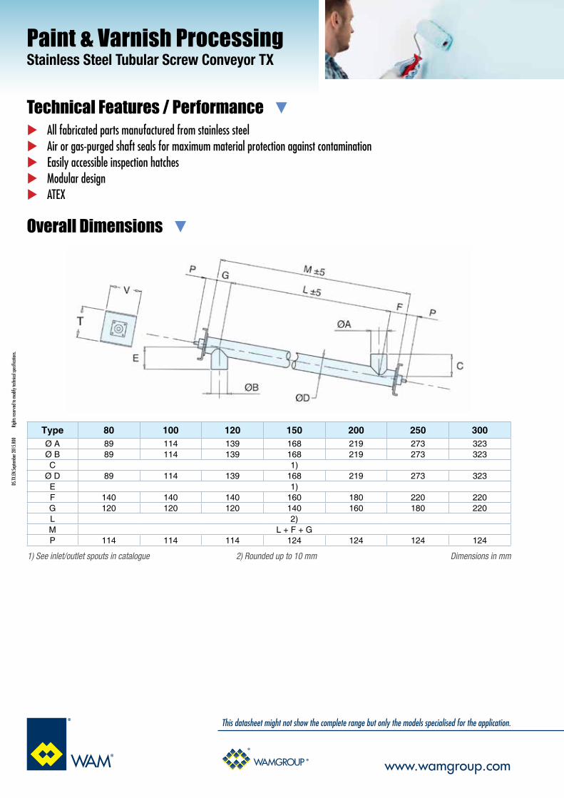
Paint & Varnish ProcessingStainless Steel Tubular Screw Conveyor TX
The application in the photograph shows a TX Screw Feeder installed over a stainless steel hopper for transfer of the material (e.g. calcium carbonate, titanium dioxide, silicate, sulphate) into the process.
TX Tubular Screw Feeders and Conveyors, which are manufactured from stainless steel with a suitable surface finishing grade appropriate for the application in Biscuit (cookies) Processing Plants, are highly versatile. Manufacture of the fabricated components is carried out on machines that guarantee a perfectly smooth surface due to which material residue is reduced to the minimum. The screw conveyors or feeders are made up from a tubular trough which is equipped with an inlet and an outlet spout, an end plate at each tube end, helicoid screw flighting continuously welded on both sides on a centre pipe with a coupling bush at each end, two end bearing assemblies complete with an air or gas-purged, adjustable shaft seal. Furthermore, the screw conveyors or feeders, which for this industry come without intermediate bearings, are equipped with a gear motor suitable for the application.
TX Tubular Screw Feeders are usually installed under a silo or FIBC (Bulk Bag) discharger to feed powdery or granular materials into a weigh hopper. They are suitable for applications in which any contamination of the material handled has to be strictly avoided.
Description
Application
Function
Benefits Comfortable cleaning and maintenance; Minimum residue; High feeding accuracy; Vast range of options and accessories; Attractive price.
DS.TX
.EN.Se
ptem
ber 2
015.
R00
Ri
ghts
rese
rved
to m
odify
tech
nical
spec
ifica
tions
.
3
Overall Dimensions
All fabricated parts manufactured from stainless steel Air or gas-purged shaft seals for maximum material protection against contamination Easily accessible inspection hatches Modular design ATEX
This datasheet might not show the complete range but only the models specialised for the application.
DS.TX
.EN.Se
ptem
ber 2
015.
R00
Ri
ghts
rese
rved
to m
odify
tech
nical
spec
ifica
tions
.
Technical Features / Performance
Paint & Varnish ProcessingStainless Steel Tubular Screw Conveyor TX
www.wamgroup.com
Dimensions in mm1) See inlet/outlet spouts in catalogue 2) Rounded up to 10 mm
Type 80 100 120 150 200 250 300Ø A 89 114 139 168 219 273 323Ø B 89 114 139 168 219 273 323C 1)
Ø D 89 114 139 168 219 273 323E 1)F 140 140 140 160 180 220 220G 120 120 120 140 160 180 220L 2)M L + F + GP 114 114 114 124 124 124 124

www.wamgroup.com
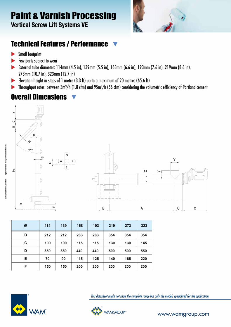
Paint & Varnish ProcessingVertical Screw Lift Systems VE
The application in the photographs shows an arrangement with FIBC discharger, a standard length horizontal screw feeder and a vertical screw conveyor. The picture on the left shows filling of a single silo, whereas the picture on the right shows an installation with a pneumatically operated diverter valve for filling of two silos.
The VE Vertical Screw Lift System consists of a Horizontal Screw Feeder and a Vertical Screw Conveyor.The Horizontal Screw Feeder, which may feed material from a silo or hopper or simply convey it being fed by an upstream feeding device, consists of a U-shape or tubular trough in carbon steel with appropriate surface finishing. In any case the outlet zone consists of a short tubular section flanged at a right angle on the bottom section of the Vertical Screw Conveyor. A flange is welded at each end of the Horizontal Screw Feeder. The trough / tube contains a rotating screw with shaft coupling bushes at each end that are connected with the shafts of the two end bearing assemblies. The Horizontal Screw Feeder is equipped with one or more intermediate hanger bearings should its overall length require any. Furthermore, it is equipped with a drive unit suitable for the application. The Vertical Screw Conveyor consists of a tubular housing complete with a tangential inlet in the bottom section which connects with the outlet of the Horizontal Screw Feeder, an inclined outlet spout in the top section, end flanges welded on each conveyor tube section, a rotating screw in one or more sections with shaft coupling bush at each end, a base bearing assembly complete with slide bush, and a number of intermediate hanger bearings should the overall height of the conveyor require any. The top-mounted drive unit with integrated end bearing assembly (from which the screw is suspended) and self-adjusting shaft sealing unit is suitable for the application. The VE Vertical Screw Lift System is available in a medium-heavy-duty version only.
The VE Vertical Screw Lift System consists of two units: a Horizontal Screw Feeder which receives material from a silo, hopper, or another feeder or conveyor, and a Vertical Screw Conveyor that lifts the material to a certain level. Material may be discharged into a weigh hopper, into one or more bins or silos, or into another conveyor or conveying system.Fabricated components, screws, and bearing assemblies have been specially designed for this system to facilitate maintenance.The VE Vertical Screw Lift System, which excels through high volumetric efficiency and excellent mechanical features, was patented in various countries in the 1980s.
Description
Application
Function
Benefits
DS.VE
.EN.Se
ptem
ber 2
015.
R00
Ri
ghts
rese
rved
to m
odify
tech
nical
spec
ifica
tions
.
4
In comparison with bucket elevators or pneumatic conveying systems, the VE Vertical Screw Lift System has the smallest overall dimensions, is easier to maintain, requires the smallest number of spare parts, and offers the best price-performance ratio.
Overall Dimensions
This datasheet might not show the complete range but only the models specialised for the application.
DS.VE
.EN.Se
ptem
ber 2
015.
R00
Ri
ghts
rese
rved
to m
odify
tech
nical
spec
ifica
tions
.
Technical Features / Performance
Paint & Varnish ProcessingVertical Screw Lift Systems VE
www.wamgroup.com
Small footprint Few parts subject to wear External tube diameter: 114mm (4.5 in), 139mm (5.5 in), 168mm (6.6 in), 193mm (7.6 in), 219mm (8.6 in), 273mm (10.7 in), 323mm (12.7 in) Elevation height in steps of 1 metre (3.3 ft) up to a maximum of 20 metres (65.6 ft) Throughput rates: between 3m³/h (1.8 cfm) and 95m³/h (56 cfm) considering the volumetric efficiency of Portland cement
W
N
E
S
Ø
45°
Hs
D
BC
Y
FE
Ø
B
AB
YØ
C X
Y
Ø 114 139 168 193 219 273 323
B 212 212 283 283 354 354 354
C 100 100 115 115 130 130 145
D 350 350 440 440 500 500 550
E 70 90 115 125 140 165 220
F 150 150 200 200 200 200 200

www.wamgroup.com
Paint & Varnish ProcessingSelf-Cleaning Modular Screw Conveyors SPA
The SPA self-cleaning modular screw conveyors are designed in Carbon Steel with a large range of finishings (RAL) and surface treatment options. It is applicable in sectors where full trough cleaning is required to handle different materials. An entire range of inlets and outlets is available for the conveying of any kind of materials. There are available drive unit for light, heavy or extra-heavy duty applications. The troughs are fully inspectable for an easy and immediate cleaning.
Thanks to the superimposed design of the two screw conveyors, the residue are also conveyed, which means that no further cleaning required. Moreover, the lower screw conveyor can be used for an accurate feeding by using particular speed configurations.
Description
Function
Benefits DS
.SPA.
EN.Se
ptem
ber 2
015.
R00
Ri
ghts
rese
rved
to m
odify
tech
nical
spec
ifica
tions
.
5
SPA is the perfect solution for paint processing due to his low powder residue.
Application
Easy maintenance; High feeding accuracy; Low residue.

This datasheet might not show the complete range but only the models specialised for the application.
DS.SP
A.EN
.Sept
embe
r 201
5.R0
0
Righ
ts re
serv
ed to
mod
ify te
chnic
al sp
ecifi
catio
ns.
Paint & Varnish ProcessingSelf-Cleaning Modular Screw Conveyors SPA
www.wamgroup.com
Compact drive unit Product-specific anti-wear screws Fully inspectable trough
Technical Features / Performance
Overall Dimensions
Model SPA
Flight diameter 200 250 300 350 400
Product group AQ=m3/h, 50Hz 46 67 84 108 145
L max. (mm)* 10,000 10,000 10,000 10,000 10,000
Product group BQ=m3/h, 50Hz 33 53 65 84 94
L max. (mm)* 10,000 10,000 10,000 10,000 10,000
Product group CQ=m3/h, 50Hz 15 24 30 42 64
L max. (mm)* 10,000 10,000 10,000 10,000 10,000
Product properties Products
Product group A flowing and little abrasive Nitrates, Carbonates, Titanium dioxide
Product group B flowing on average and abrasive on average Oxides, Kaolin, Cement, Gypsum, Lime
Product group C little flowing and abrasive Sand, Feldspar, Dolomite, Limestone
L

www.wamgroup.com
Paint & Varnish ProcessingSingle Shaft Screw Feeders SU
SU Single-shafted Screw Feeders are used for discharging poorly flowing materials from hoppers or silos with a rectangular outlet.
SU-type Single Shaft Screw Feeders are highly versatile offering numerous solutions for conveying powdery or granular materials. SU Screw Feeders are manufactured from carbon steel or stainless steel with a suitable surface finishing. The inlet section is made up from a U or V-shape trough and a tubular outlet section that is equipped with an outlet. There is an end plate at each trough end, helicoid screw flighting welded on a centre pipe with a coupling bush at each end and two end bearing assemblies complete with shaft sealing unit. Furthermore, SU Screw Feeders, which come in a medium heavy-duty design, are equipped with a gear motor that suits the application.
According to the cross section of the silo outlet, SU-type Single Shaft Screw Feeders are available with standard U-shaped or with flared V-section trough. For wet or dry sludge an extra heavy-duty version is available too.
Description
Application
Function
Benefits
DS.SU
.EN.Se
ptem
ber 2
015.
R00
Ri
ghts
rese
rved
to m
odify
tech
nical
spec
ifica
tions
.
6
Prevention of bridging, rat holing and segregation and improvement of material flow; Maintenance-free intermediate cast hanger bearings with self-lubricating slide bushes.

Overall Dimensions
This datasheet might not show the complete range but only the models specialised for the application.
DS.SU
.EN.Se
ptem
ber 2
015.
R00
Ri
ghts
rese
rved
to m
odify
tech
nical
spec
ifica
tions
.
Technical Features / Performance
Paint & Varnish ProcessingSingle Shaft Screw Feeders SU
www.wamgroup.com
Powder-coated Constant feed rates Modular design enables easy access and individual custom-design
features Sturdy design Medium-heavy-duty helicoid flighting welded on centre pipe Medium-heavy-duty trough in modular flanged sections Open trough section with drilled trough WAM® standard flange
Round outlet with drilled WAM® standard flange Robust cast iron body flanged end bearing assemblies with external
bearing units and manually adjustable packing gland seals Splined or bolted shaft couplings Drive units mounted at inlet or outlet end Direct drives in a compact version, or with coupling
transmission, or with chain or belt transmission
Trough screw conveyors and feeders are manufactured to the customer’s requirements by means of standard components available from stock, thus enabling quick delivery.
- Bare Shaft
- Overflow Hatch Flap - Direct Drive - Chain Transmission - Pulley Drive
Screwø
TroughU -V
Tubular troughO
100
120
150
200
250
300
350
400
500750
1,000
500750
1,000
500750
1,0001,250
500750
1,0001,250
500750
1,0001,250
5001,0001,2501,500
1,0001,2501,500
1,0001,2501,500
2
2
2
2
2
3
3
3
VAR.
VAR.
VAR.
VAR.
VAR.
VAR.
VAR.
VAR.
3
3
4
4
4
4
5
5
175
175
375
425
525
525
625
730
115
115
175
200
225
250
270
290
145
145
145
185
215
245
275
305
114
168
168
219
273
323
406
457
-
-
175
225
275
325
375
425
-
-
265
315
365
435
485
540
25
25
35
35
35
55
55
55
265
265
485
540
655
655
755
900
120
120
140
160
180
220
280
320
120
210
175
205
250
300
360
420
-
-
115
135
160
195
235
270
40
40
50
50
60
60
60
80
-
-
40
40
40
50
50
50
114
139
168
219
273
323
406
457
L1 E1 Ø E2 L2 A B C D F G H L M N* Q Z Z1
Dimensions mm * For cylindrical outlet (in compliance with WAM® standard)

www.wamgroup.com
Paint & Varnish ProcessingBucket Elevators EI
EIS Bucket Elevators are used for dry sand and fine aggregates having bulk density ranging from 0.8 to 2.5 kg/dm3, and particle size of up to 5mm.The material, entering through the loading hopper of the foot section, is continuously picked by appropriately shaped buckets fixed on the rubber belt, which is rotating around head and foot roller wheels. A screw tensioning system enables tensioning of the rubber belt.The buckets discharge the material through the outlet spout by centrifugal force at a constant speed of 1.5 m/s.EIS Bucket Elevators are used in dry premixed building material processing plants to fill dry sand and fine aggregates into vertical storage silos.
EIS-type Bucket Elevators are specialised for vertical elevation of dry sand and fine aggregates in dry premixed building material processing plants.
The machine consists of a head section with rubber-coated pulley, a foot section with squirrel-cage pulley and a variable number of intermediate sections. Buckets are available in reinforced mild steel or increased thickness Nylon PA6 to ensure high durability against abrasive materials handled.
Description
Application
Function
Benefits
DS.ES
.EN.Se
ptem
ber 2
015.
R00
Ri
ghts
rese
rved
to m
odify
tech
nical
spec
ifica
tions
.
7
Reliable & durable; Easy installation thanks to modular components; Low maintenance; Small footprint; Matching complementary equipment.

Overall Dimensions
This datasheet might not show the complete range but only the models specialised for the application.
DS.ES
.EN.Se
ptem
ber 2
015.
R00
Ri
ghts
rese
rved
to m
odify
tech
nical
spec
ifica
tions
.
Technical Features / Performance
Paint & Varnish ProcessingBucket Elevators EI
www.wamgroup.com
Throughput rates up to 52 m3/h Discharge heights up to 34m Anti-wear shields on inlet and outlet Plummer-block bearing with packing on head shaft Flanged-block bearing with felt on foot shaft
Rif08-09 11 20-21 29-30mm mm mm mm
A 765 950 1,172 1,276A1 823 1,026 1,224 1,422A2 345 410 460 620A3 460 580 700 740A5 548 687 812 961B 753 923 1,104 1,320
B1 814 941 1,136 1,352B2 310 384 432 490B3 370 430 550 720B9 539 604 725 891C 2,000 2,000 2,000 2,000
C1 550 674 822 922C2 211 230 264 336C3 211 250 300 386D 500-1,500N variable

www.wamgroup.com
Paint & Varnish ProcessingWAMFLO® Front Dust Collectors
WAMFLO® Front Dust Collectors are mainly used for venting of mixer for finished products and weigh hopper venting.They are equipped with a centrifugal fan with a potential air volume capacity of up to 53 m3/min.
WAMFLO® Front Dust Collectors have been specifically developed for Dry-Mix Processing Plants. They are equipped with a round stainless steel body, optionally with a large residue-free access door for filter element removal. The casing contains vertically mounted round bag-type filter elements. To keep the filter media clean an air jet cleaning system is integrated in the top cover.
WAMFLO® Front Dust Collectors are used for both venting and suction applications.Dust separated from the air flow by round bag-type filter elements drops back into the silo, bin or hopper after an integrated automatic reverse air jet cleaning system has removed it from the filter elements.
Description
Application
Function
Benefits DS
.WAM
FLO.
EN.Se
ptem
ber 2
015.
R00
Ri
ghts
rese
rved
to m
odify
tech
nical
spec
ifica
tions
.
8
Running cost reduction; Residue-free access door; Round bags available in after-market; Compliance with health and safety standards; Maintenance cost reduction; Safety for both OEM and End User.

Overall Dimensions
This datasheet might not show the complete range but only the models specialised for the application.
DS.W
AMFL
O.EN
.Sept
embe
r 201
5.R0
0
Righ
ts re
serv
ed to
mod
ify te
chnic
al sp
ecifi
catio
ns.
Technical Features / Performance
Paint & Varnish ProcessingWAMFLO® Front Dust Collectors
www.wamgroup.com
304 SS flanged cylindrical body Filter surface from 5 to 21m2 (54 to 226 sq ft) Low emission level due to B.I.A.-certified filter media Compressed air-jet cleaning system integrated in top cover High efficiency centrifugal fan
High cleaning efficiency due to “Full Immersion” solenoid valves integrated inside aluminium air tank (corrosion-resistant) for low-maintenance operation
No tools for filtering element removal required Large access door for comfortable filter element removal
C
B
A
ØL
FILTER CODEFILTER SURFACE
(m2)Ø L A B C
FNB2J05 5 603 1,666 2,221 1,809
FNB3J08 8 783 1,676 2,326 1,839
FNB3J11 11 783 2,156 2,806 2,319
FNB4J16 16 1,038 1,692 2,351 1,859
FNB4J21 21 1,038 2,172 2,831 2,339

www.wamgroup.com
Paint & Varnish ProcessingWAMAIR® Dust Collectors FP
WAMAIR® FP Dust Collectors are specially developed for de-dusting mechanical conveyors such as belt conveyors, chain conveyors and bucket elevators.
WAMAIR® FP Dust Collectors consist of a polygonal shape casing, specifically developed for de-dusting mechanical conveyors in Dry-Mix Processing Plants. The filter is equipped with horizontally inserted pocket filter elements and a reverse air jet cleaning system integrated inside the hinged access door.
WAMAIR® Dust Collectors separate dust from the air flow by means of pocket filter elements. The dust drops down after an automatic reverse air jet cleaning device inside the front inspection door has removed it from the filter elements.
Description
Application
Function
DS.W
AMAI
RO.EN
.Sept
embe
r 201
5.R0
0
Righ
ts re
serv
ed to
mod
ify te
chnic
al sp
ecifi
catio
ns.
9
Filter dimensions match conveyor shape; Compliance with health and safety standards; Filter elements available in after-market; Safety for both OEM and End User; Running cost reduction; Low energy consumption; Maintenance cost reduction.
Benefits

Overall Dimensions
This datasheet might not show the complete range but only the models specialised for the application.
DS.W
AMAI
RO.EN
.Sept
embe
r 201
5.R0
0
Righ
ts re
serv
ed to
mod
ify te
chnic
al sp
ecifi
catio
ns.
Technical Features / Performance
Paint & Varnish ProcessingWAMAIR® Dust Collectors FP
www.wamgroup.com
304 SS polygonal body Filter surface from 3 to 54m2 (32 to 581 sq ft) Low emission level due to B.I.A.-certified filter media Large access door for comfortable flter element removal High cleaning efficiency due to “Full Immersion” solenoid valves integrated in aluminium air tank (corrosion-resistant) for low-maintenance
operation High efficiency centrifugal fan Fan integrated in access door
A B
C
D
FILTER CODEFILTER SURFACE
(m2)A B C D
FPHT 1 03 3 570 700 825 1,570
FPHT 2 05 5 570 950 825 1,820
FPHT 5 09 9 570 1,700 825 2,570
FPHT D 12 12 570 1,200 1,320 2,170
FPHT E 15 15 570 1,450 1,320 2,420
FPHT F 18 18 570 1,700 1,320 2,670
FPHT M 22 22 845 1,450 1,320 2,440
FPHT R 24 24 1,065 1,200 1,320 2,190
FPHT S 30 30 1,065 1,450 1,320 2,530
FPHT T 36 36 1,065 1,700 1,320 2,813
FPHT Y 45 45 1,065 1,450 1,815 2,563
FPHT U 54 54 1,065 1,700 1,815 2,813

www.wamgroup.com
Paint & Varnish ProcessingHOPPERJET™ Weigh Hopper Venting Filters
The application in the photograph shows a HOPPERJET installed over a hopper/mixer for transfer of the material (e.g. raw material as calcium carbonate or titanium dioxide) into the process.
HOPPERJET is a polygonally shaped, small footprint venting filter for installation on intermediate storage hoppers or weigh hoppers. It can be used in various industries.
HOPPERJET is a compact venting filter for mechanically filled hoppers.Dust is separated from the air flow by a single POLYPLEAT or bag-type filter element and drops back into the hopper after an integrated automatic reverse air jet cleaning system inside the weather protection cover has removed the dust particles from the filter elements.
Description
Application
Function
Benefits
High filtration efficiency of WAM® filtering elements Low emission level due to B.I.A.-certified filter media Small Footprint: 0.11 m2 (1.2 sq ft) Corrosion-free design
DS.H
OPPE
RJET
.EN.Se
ptem
ber 2
015.
R00
Ri
ghts
rese
rved
to m
odify
tech
nical
spec
ifica
tions
.
10

Overall Dimensions
304 stainless steel body with bottom flange Compact design Compressed air jet cleaning system Quick, tool-free filter element replacement Maintenance-free air jet cleaning unit integrated in the cover High cleaning efficiency due to “Full-Immersion” solenoid valves Easy installation and retrofitting
This datasheet might not show the complete range but only the models specialised for the application.
DS.H
OPPE
RJET
.EN.Se
ptem
ber 2
015.
R00
Ri
ghts
rese
rved
to m
odify
tech
nical
spec
ifica
tions
.
Technical Features / Performance
Paint & Varnish ProcessingHOPPERJET™ Weigh Hopper Venting Filters
www.wamgroup.com
Code Nbr. Filter Elements Filter Surface Compr. air
consumptionNoisedb(A) kg
HOPT05 1 0.5 4.5 67 22

www.wamgroup.com
Paint & Varnish ProcessingBin Activators BA
Discharging of a variety of powdersUsually fitted in large numbers under material storage silos or daily buffer silos/hoppers to discharge poorly flowing powderssuch as additives.The Bin Activator outlet is usually shut off by a slide valve or butterfly valve which is connected with a mechanical feeding device or loading bellows.
The BA Bin Activator is a device of conical shape that, due to vibration, facilitates material flow from hoppers or silos. It consists of a seamless carbon steel cone manufactured on a sheet metal lathe, a seamless SINT® engineering polymer seal with integrated upper and lower flange, suspensions for connection of the Bin Activator with the silo, as well as one or two electric vibrators.
One or two electric vibrators fitted to the unit generate vibration of the Bin Activator every time the feeding device beneath the silo is started for material discharge. During operation the Bin Activator describes a gyratory movement which is transmitted to the material inside the silo. The result is smooth material flow through the Bin Activator outlet into the connected feeder.The use of this equipment ensures optimum feeding of the material causing “mass flow” inside the silo, thus avoiding bridging or rat holing phenomena.
Description
Application
Function
Benefits DS
.BA.
EN.Se
ptem
ber 2
015.
R00
Ri
ghts
rese
rved
to m
odify
tech
nical
spec
ifica
tions
.
11
High discharging performance; No waste material thanks to special seal design; Reduced maintenance thanks to long-life seal material.

Overall Dimensions
This datasheet might not show the complete range but only the models specialised for the application.
DS.B
A.EN
.Sept
embe
r 201
5.R0
0
Righ
ts re
serv
ed to
mod
ify te
chnic
al sp
ecifi
catio
ns.
Technical Features / Performance
Paint & Varnish ProcessingBin Activators BA
www.wamgroup.com
(*) Further outlet dimensions reported in Technical Catalogue Dimensions in mm
400 114
600 168
750 219
900 219
1,000 273
1,250 273
1,500 323
Size Ø A*Standard
380 427
580 519
730 609
880 684
980 734
1,230 937
1,480 1,120
B C
330 1
408 1
456 1
531 1
555 1
730 1
774 1
H Vibrators
59
80
99
134
146
290
475
kg
BA060
BA040
BA075
BA090
BA125
BA100
BA150
TYPE
Dimensions in mm
1,800 323
2,100 406
2,350 406
1,780 1,194
2,080 1,420
2,330 1,547
924 2
1,033 2
1,166 2
726
881
1,255
BA210
BA180
BA235
2,500 406
3,000 406
2,480 1,705
2,980 1,955
1,307 2
1,568 2
1,530
2,456
BA250
BA300
Diameters up to 3,000mm 304L SS available for additives Strong seamless seal
No internal residue nests Smooth internal finishing ATEX-compliant

www.wamgroup.com
Paint & Varnish ProcessingManual Bag Openers RSM
RSM Manual Bag Openers are used to transfer the raw materials contained in bags to silos for storage. The material is normally conveyed pneumatically into the silo.
The RSM Manual Bag Opener is manufactured from stainless steel and consists of a grille with a rest fitted to its front, The grille is mounted on top of a hopper which is supported by four feet. A fabricated hood with protection door fitted to its front covers the hopper and grille. RSM-310 Bag Openers are manufactured in high-finish-grade materials and come with or without integrated de-dusting filter unit. In the version with integrated dust filter the filter elements are cleaned pneumatically by reverse air jet.
The operator puts the bag on the rest and pushes it on to the grille. He then slits the bag open with a vertical cut and shakes it empty. While the bag content may be discharged through a hopper or by BINSWEEP®, a special rotary discharging device, into any type of feeder, the built-in fan operated, air jet cleaned dust collector filters the dust generated during emptying. The empty bag is dropped in the chute on the side which leads into the optional COM-type Waste Bag Compactor (see COM). Manual RSM Bag Openers are designed to minimise material residue. They satisfy a large number of applications due to their modular component design.
Description
Application
Function
Benefits DS
.RSM
.EN.Se
ptem
ber 2
015.
R00
Ri
ghts
rese
rved
to m
odify
tech
nical
spec
ifica
tions
.
12
Space-saving overall dimensions and compact user-friendly design; Built-in fan-operated, air jet-cleaned, maintenance-friendly dust collector; With optional BINSWEEP® Rotary Discharging Device (see chapter) low overall height; Favourable price-performance ratio.

Overall Dimensions
This datasheet might not show the complete range but only the models specialised for the application.
DS.R
SM.EN
.Sept
embe
r 201
5.R0
0
Righ
ts re
serv
ed to
mod
ify te
chnic
al sp
ecifi
catio
ns.
Technical Features / Performance
Paint & Varnish ProcessingManual Bag Openers RSM
www.wamgroup.com
Construction material: stainless steel Available with de-dusting filter or equipped for centralised dust suction Filter element options: cartridges, round bags, elliptical bags Filter surface from 3 to 22 m2 (32 to 237 sq ft) Collecting hoppers with different capacity volumes Support feet with possibility of height adjustment ATEX compliant
RSM 310
A 1,006
B 1,208
C* 2,166
D* 606
E* 800
F** 282
G** 458
930 760
470
30FG
A AØ 273
B
C
E
D

www.wamgroup.com
Paint & Varnish ProcessingAutomatic Bag Splitters RSA
RSA Automatic Bag Splitters are used to transfer large quantities of raw materials contained in bags to silos for storage. The material is normally conveyed pneumatically into the silo.
The RSA Automatic Bag Splitter is made up of a splitting unit consisting of a trough that encloses an extra-heavy-duty splitting screw complete with an appropriate gear motor and of a screening unit consisting of a horizontal cylindrically shaped rotating screen also complete with a drive unit. On top of the screening unit a suitable fan-operated dust collector can be integrated. Alternatively the RSA-310 is supplied with connecting spigots for a central de-dusting unit.
The RSA Automatic Bag Splitter is used for splitting and emptying single or multiple layer bags made from paper, polyethylene, or polyethylene-lined paper.The bags are loaded manually or via belt conveyor into the inlet which is covered by a dust collecting hood. The bags drop from the belt on an extra-heavy-duty shaftless screw. Thin bags will burst open just through the impact. Bags with multiple layers or those made of elastic plastic material are pulled in by the slowly turning screw and ripped open through a scissor effect between screw and trough. This effect is increased due to a replaceable panel with integrated cutters applied to the inside of the trough. As it cuts them open the screw conveys the broken bags and their content into the revolving screen. The bag contents fall through the screen mesh into a collecting device mounted on the outlet of the machine. Through rotation and a slight vibration of the screen (due to its patented design) the bags are completely emptied. Paddles applied inside the screen drum repeatedly lift up the empty bags. In this manner the bags are liberated from remaining material. The inclination of the paddles helps the bags move towards the screen outlet where they drop into the optionally built-on COM-type bag compactor (see COM).
Description
Application
Function
Benefits DS
.RSA
.EN.Se
ptem
ber 2
015.
R00
Ri
ghts
rese
rved
to m
odify
tech
nical
spec
ifica
tions
.
13
Low product retention rate; Compact machine consisting of a small number of components (only few spare parts required); Easy access to all machine parts; Low operating noise level due to use of SINT® engineering polymers; Easy and quick replacement of filter elements; Able to handle bags of different sizes without any machine adjustment; Favourable price-performance ratio.

Overall Dimensions
This datasheet might not show the complete range but only the models specialised for the application.
DS.R
SA.EN
.Sept
embe
r 201
5.R0
0
Righ
ts re
serv
ed to
mod
ify te
chnic
al sp
ecifi
catio
ns.
Technical Features / Performance
Paint & Varnish ProcessingAutomatic Bag Splitters RSA
www.wamgroup.com
Construction material: contact parts in stainless steel; Compact and robust design; Available with integrated dust collector or pre-equipped for centralised de-dusting system; Rotary vibrating screen completely in stainless steel with different size screen mesh.
www.wamgroup.com
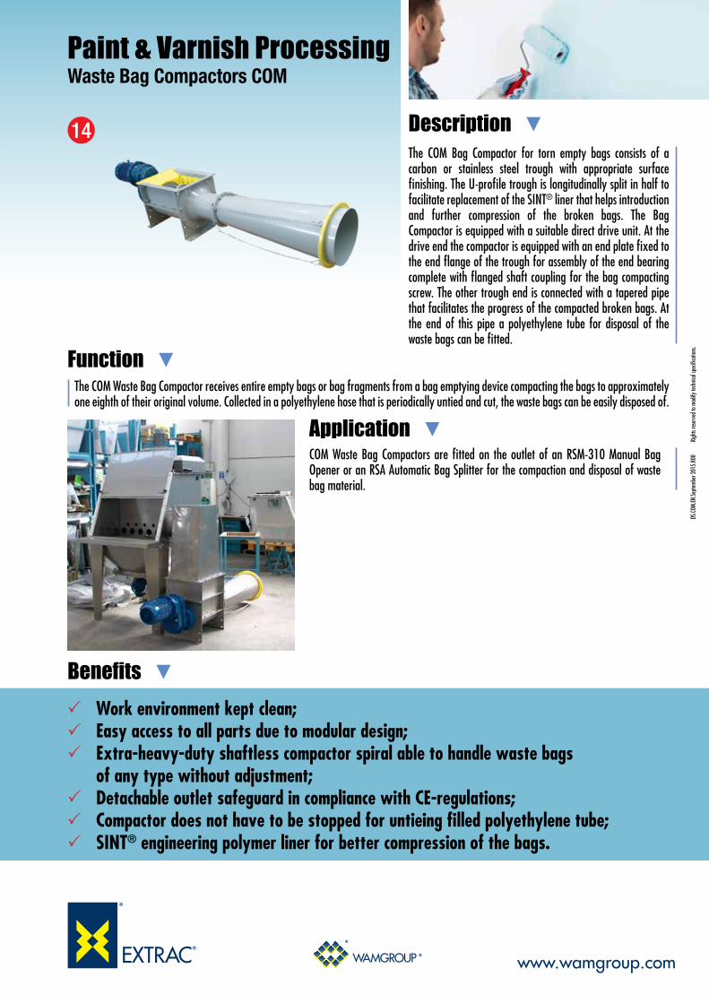
Paint & Varnish ProcessingWaste Bag Compactors COM
COM Waste Bag Compactors are fitted on the outlet of an RSM-310 Manual Bag Opener or an RSA Automatic Bag Splitter for the compaction and disposal of waste bag material.
The COM Bag Compactor for torn empty bags consists of a carbon or stainless steel trough with appropriate surface finishing. The U-profile trough is longitudinally split in half to facilitate replacement of the SINT® liner that helps introduction and further compression of the broken bags. The Bag Compactor is equipped with a suitable direct drive unit. At the drive end the compactor is equipped with an end plate fixed to the end flange of the trough for assembly of the end bearing complete with flanged shaft coupling for the bag compacting screw. The other trough end is connected with a tapered pipe that facilitates the progress of the compacted broken bags. At the end of this pipe a polyethylene tube for disposal of the waste bags can be fitted.
The COM Waste Bag Compactor receives entire empty bags or bag fragments from a bag emptying device compacting the bags to approximately one eighth of their original volume. Collected in a polyethylene hose that is periodically untied and cut, the waste bags can be easily disposed of.
Description
Application
Function
Benefits DS
.COM.
EN.Se
ptem
ber 2
015.
R00
Ri
ghts
rese
rved
to m
odify
tech
nical
spec
ifica
tions
.
14
Work environment kept clean; Easy access to all parts due to modular design; Extra-heavy-duty shaftless compactor spiral able to handle waste bags of any type without adjustment; Detachable outlet safeguard in compliance with CE-regulations; Compactor does not have to be stopped for untieing filled polyethylene tube; SINT® engineering polymer liner for better compression of the bags.

Overall Dimensions
This datasheet might not show the complete range but only the models specialised for the application.
DS.CO
M.EN
.Sept
embe
r 201
5.R0
0
Righ
ts re
serv
ed to
mod
ify te
chnic
al sp
ecifi
catio
ns.
Technical Features / Performance
Paint & Varnish ProcessingWaste Bag Compactors COM
www.wamgroup.com
Construction material: carbon steel or stainless steel; Complete with adjustable tensioning ring for polyethylene hose for disposal of waste bags; Heavy-duty shaftless compactor spiral supported at inlet end; Direct gear motor drive directly mounted at inlet end; ATEX. COM
Type
COM 040
COM 030
C D E F G H M N P
245 440
305 575
245 67
305 95
435 600
540 660
2.436
2.906
300
398
496
868
Q
1.000
1.000
640
640
L R T V Z AA AB N°W K N°Y
584 435
970 540
484 325
850 425
624 564
1.010 940
435
540
4
5
U X
218 357
218 420
128,3
100
S
136
185
3
5
AC A B
320 320
320 320
N°AD J
3 128,3
5 100

www.wamgroup.com
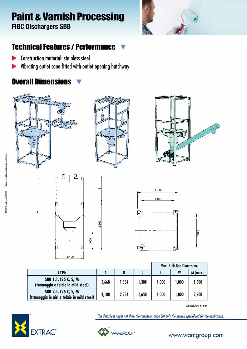
Paint & Varnish ProcessingFIBC Dischargers SBB
SBB FIBC Dischargers are used to transfer the raw materials contained in FIBCs to silos for storage. The material is normally conveyed pneumatically into the silo.
The SBB FIBC Discharger consists of a stainless steel frame complete with a material discharge hopper and an upper mobile cross bar for lifting of the filled up bag by forklift truck into the Discharger.
The SBB is a modular system for discharging Flexible Intermediate Bulk Containers (Big Bags) in different configurations depending on the application. Easy introduction of the FIBC into the support frame and dust-free discharging along with a variety of options make the SBB extremely user-friendly. The four loops of the FIBC are attached to the hooks of the detached cross bar that has previously been laid on top of the FIBC. The cross bar with the attached FIBC is then picked up by a forklift truck and introduced into the frame of the SBB Discharger. Once the FIBC has settled on the rubber seal of the discharge hopper the outlet closing rope of the FIBC can be pulled open through the inspection hatch of the discharge hopper.
Description
Application
Function
Benefits
DS.SB
B.EN
.Sept
embe
r 201
5.R0
0
Righ
ts re
serv
ed to
mod
ify te
chnic
al sp
ecifi
catio
ns.
15
Modular design; Compact shipping dimensions; Easy to install; Complete dust-free discharging from bag corners even with compressed powders.
Overall Dimensions
This datasheet might not show the complete range but only the models specialised for the application.
DS.SB
B.EN
.Sept
embe
r 201
5.R0
0
Righ
ts re
serv
ed to
mod
ify te
chnic
al sp
ecifi
catio
ns.
Technical Features / Performance
Paint & Varnish ProcessingFIBC Dischargers SBB
www.wamgroup.com
Construction material: stainless steel Vibrating outlet cone fitted with outlet opening hatchway
Max. Bulk Bag Dimensions
TYPE A B C L W M (max.)
SBB 1.1.125 C, S, M (tramoggia e telaio in mild steel) 3,668 1,884 1,308 1,000 1,000 1,800
SBB 2.1.125 C, S, M (tramoggia in aisi e telaio in mild steel) 4,108 2,234 1,658 1,000 1,000 2,200
Dimensions in mm
1.400
900
2.36
0B
A
1.410
1.160
1.160

www.wamgroup.com
Paint & Varnish ProcessingRotary Level Indicators ILT
Typically ILT Rotary Level Indicators are fitted on the vertical walls of a bin, silo or hopper at the desired maximum or minimum level. Equipped with an extension rod, they can also be mounted vertically into the roof plate.
ILT-type Bin Level Indicators have been designed for electric signalling by rotary action of minimum or maximum material level inside bins, hoppers or silos.
As long as material is present, the paddle of the ILT Bin Level Indicator does not rotate. As soon as the material level sinks below the paddle radius, rotation restarts activating other system components. The top or side-mounted indicators are commonly used for materials having a bulk density ranging between 0.5t/m³ (0.02 lb per cu in) and 2t/m³ (0.08 lb per cu in).
Description
Application
Function
Benefits
DS.IL
T.EN.
Sept
embe
r 201
5.R0
0
Righ
ts re
serv
ed to
mod
ify te
chnic
al sp
ecifi
catio
ns.
16
No product contamination due to the 304 staniless steel shaft; and measuring paddle and non-toxic plastic fittings; No product contact with the casing; ATEX; Adjustable via reset of force spring in 3 positions; Double threaded fitting ensures system compatibility; Use with different materials in one single configuration; Easy and quick installation and replacement; Compact overall dimensions; Lightweight due to casing in aluminium alloy; Maintenance-free; Cost-effective.

Overall Dimensions
This datasheet might not show the complete range but only the models specialised for the application.
DS.IL
T.EN.
Sept
embe
r 201
5.R0
0
Righ
ts re
serv
ed to
mod
ify te
chnic
al sp
ecifi
catio
ns.
Technical Features / Performance
Paint & Varnish ProcessingRotary Level Indicators ILT
www.wamgroup.com
Voltages available: 24 V – 48 V (AC), 50-60 Hz; 110 V – 230 V (AC), 50-60 Hz; 24 V (DC) Signal output: Floating microswitch AC max. 250 V, 2 A Standard connection: thread G 1½” – G 2 ½” Enclosure: IP 66 Working temperature inside vessel: - 20 °C to 80 °C (- 4° F to 178° F) Vessel maximum pressure: max. 0.8 bar (12 PSI) Threaded fittings material: Plastic Rotating shaft and measuring paddle material: 304 stainless steel Casing material: Aluminium alloy Speed of measuring paddle: 1 rpm Friction clutch protection of the gearing of impacts of the measuring paddle Self-opening double paddle for light materials Flanged connection as option Modular shaft extension up to 3 metres (10 ft) External light
L=13
3 ±5 25
0.5 1
40
149
80
98
90.5
93
72
39.5
Ø 10
G 2“ 1/2’ G 1“ 1/2’
80
15.15
2
3
1: L = 500 /1000
www.wamgroup.com
Paint & Varnish ProcessingSilo Safety System KCS
In Dry-Mix plants it is essential that each silo is equipped with the safety components described. The control panel should be installed in the central control room from where the plant operator can monitor up to 32 silos.
The KCS Silo Safety System for the safeguarding of silos consists of a central electronic monitoring and control unit which manages a series of silos and a component kit including, in the basic version one power panel for each silo, a silo pipe connection, a pinch valve, a tanker coupling with the filling pipe, a maximum level indicator, a differential pressure switch or electronic pressure meter, a pressure gauge for the venting filter, a pressure relief valve, and an audible alarm.
The KCS Silo Safety System can be used for silos which are filled by tanker with powdery materials. Damage to the silo or its accessories is most likely during the operation of tanker filling. This is due to the risk of overfilling or excess pressurisation. The KCS system, supplied in component form, prevents both overfilling and excess pressurisation, thus avoiding damage to the silo, to the venting filter or other accessories, as well as reducing the risk of dust emission into the atmosphere.
Description
Application
Function
Benefits DS
.KCS
.EN.Se
ptem
ber 2
015.
R00
Ri
ghts
rese
rved
to m
odify
tech
nical
spec
ifica
tions
.
20
Avoids harm to people and damage to the silo and its accessories; Reduces risk of air pollution; Eliminates risk of filling the wrong silo; Starts and stops filter cleaning automatically; Receives indication from electronic pressure meter whether filter may need attention.
Components
This datasheet might not show the complete range but only the models specialised for the application.
DS.K
CS.EN
.Sept
embe
r 201
5.R0
0
Righ
ts re
serv
ed to
mod
ify te
chnic
al sp
ecifi
catio
ns.
Technical Features / Performance
Paint & Varnish ProcessingSilo Safety System KCS
www.wamgroup.com
To avoid damage to silo and accessories To reduce risk of air pollution To eliminate risk of filling wrong silo To start and stop filter cleaning automatically To receive indication from pressure gauge whether filter may need attention To benefit from control panel monitoring of: • Internal pressure of any silo; • Maximum level indicator free; • Presence of compressed air to venting filter (if air jet filter is used); • Presence of compressed air to pinch valve.
Touch Control Panel
Silo Pipe Coupling
Flange
Pinch Valve Control Panel
Level Indicator
Spigot for Pressure Switch
Differential Pressure Switch
Venting Filter
Pressure Gauge
Pressure Relief Valve
Audible Alarm
Individual Power Panel

www.wamgroup.com
Paint & Varnish ProcessingPinch Valves VM / Pipe Connections KAT
VM Pinch Valves are mounted between the bottom end of the silo filling pipe and the KAT Pipe Connection for tanker filling. Should any abnormal conditions occur, such as excess pressure inside the sillo or overfilling of the latter, the VM Pinch Valve receives command for instantaneous closure, thus safeguarding the silo from any further filling or overpressurization.
The casing of the VM Pinch Valve is manufactured from aluminium alloy. Sleeves are made from fabric-reinforced NR or NBR. The sleeve support bushes are either made from aluminium alloy or 304/316 stainless steel.
VM-type Pinch Valves are used for interception of the material flow in pneumatic conveying systems, or other pipelines. They can be also installed as a locking device for silo filling pipes. In the open position the internal cross section of the valve is identical with the connecting pipe diameter. By introducing compressed air through the threaded bore into the interior of the valve, the internal flexible sleeve is reshaped in such a way as to hermetically seal the passage.
Description
Application
Function
Benefits DS
.VM.EN
.Sept
embe
r 201
5.R0
0
Righ
ts re
serv
ed to
mod
ify te
chnic
al sp
ecifi
catio
ns.
22
Full bore-through passage without any pressure loss and stagnation points; Low air consumption; Easy and quick sleeve and bush replacement; Sleeves in fabric-reinforced NR; Compact overall dimensions; Lightweight due to valve body in aluminium alloy; No maintenance required except for periodic replacement of the sleeve and the bushes.

Overall Dimensions
This datasheet might not show the complete range but only the models specialised for the application.
DS.VM
.EN.Se
ptem
ber 2
015.
R00
Ri
ghts
rese
rved
to m
odify
tech
nical
spec
ifica
tions
.
Technical Features / Performance
Paint & Varnish ProcessingPinch Valves VM / Pipe Connections KAT
www.wamgroup.com
Passage diameter 80mm or 100mm (3 or 4 in) Maximum working pressure: 3.5 bar (52 PSI) Maximum inflation pressure: 6.0 bar (90 PSI) Recommended maximum differential pressure: 2.5 bar (37 PSI) Sleeve material: NR Bush material: Aluminium alloy
ØA ØB
D
C
F E
G
J
N
ØA M
C D EQty.
F G H JØ
L MTYPE
200 M 16 4 15 270 1/4"VM080 3‘’
220 M 16 8 15 310 1/4"VM0100 4‘’
A B
80 160
100 180
N kg
294 5.40
334 7.60
180
214

www.wamgroup.com
Paint & Varnish ProcessingDrop-Through Rotary Valves RV / RVR
RV-RVR Rotary valves are fitted at the outlet of silos, bins or hoppers for feeding the discharged material with high accuracy into the downstream process.
RV Drop-Through Rotary Valves consist of a tubular cast iron or stainless steel casing, a horizontally mounted rotor with a certain number of V-shaped cross section compartments, a drive unit and a casing cover opposite the drive end.
RV Rotary Valves have been developed for maximum versatility in application. They are suitable for controlled discharging and feeding of powdery or granular materials from silos, hoppers, pneumatic conveying systems, or cyclones.
Description
Application
Function
Benefits DS
.RV-
RVR.
EN.Se
ptem
ber 2
015.
R00
Ri
ghts
rese
rved
to m
odify
tech
nical
spec
ifica
tions
.
23
Air-purged seals; Square or round flanges ensure system compatibility and match with WAM® flanges; Cast iron or SS, nickel coating, chrome-plated casing, as well as various rotor versions
available to ensure the most appropriate configuration for application requirements; Quick integration into the process thanks to easy handling; Modular design and easy maintenance thanks to few components.

Overall Dimensions
This datasheet might not show the complete range but only the models specialised for the application.
DS.R
V-RV
R.EN
.Sept
embe
r 201
5.R0
0
Righ
ts re
serv
ed to
mod
ify te
chnic
al sp
ecifi
catio
ns.
Technical Features / Performance
Paint & Varnish ProcessingDrop-Through Rotary Valves RV / RVR
www.wamgroup.com
Capacity: 2.2 ~ 19.5 litres per revolution (0.08 ~ 0.7 cu ft per revolution) Working temperature: - 20° C ~ 150° C (- 4° F ~ 300° F) Maximum differential pressure: 0.3 bar (4.4 psi) Cast iron or SS design Nickel coating or chrome-plated casing for abrasive materials available Rotor with beveled blades or replaceable tips available Sturdy compact structure Small footprint Drive unit mounted directly on shaft without further bearing assembly or coupling Square or round flanges and inlet spouts Compatibility with WAM® standard flanges on inlet and outlet
FD
H
TYPE
RV/RVR 02 30 rpm
350
0.5RV/RVR 02 20 rpm
318
RV/RVR 05 30 rpm
294
328
364
392
394
419
348
333
RV RVR
373
425
472
0.75
RV/RVR 05 20 rpm 0.5
RV/RVR 10 30 rpm 1.1
RV/RVR 10 20 rpm 0.75
RV/RVR 20 30 rpm 1.5
RV/RVR 20 20 rpm 1.1
D* F* H*
kW

www.wamgroup.com
Paint & Varnish ProcessingDrop-Through Rotary Valves RVSC
RVS Blow-Through Rotary Valves are usually fitted at the outlet of a bin, silo or hopper upstream of a pneumatic conveying duct into which the material is accurately fed.
RVS Blow-Through Rotary Valves consist of a tubular cast iron or stainless steel casing, a horizontally mounted rotor with a certain number of oblique V-shaped cross section compartments, a drive unit and a casing cover at each end.
Two compartments at a time of the continuously turning rotor are filled up with material through the inlet at the top of the Rotary Valve. After less than half a turn the material falls through the bottom opening into an air stream passing through a pneumatic conveying duct connected with the bottom part of the Rotary Valve.
Description
Application
Function
Benefits DS
.RVS
C.EN.
Sept
embe
r 201
5.R0
0
Righ
ts re
serv
ed to
mod
ify te
chnic
al sp
ecifi
catio
ns.
24
Material: cast iron, SS, coating, chromed body and various rotor versions available to offer the ideal configuration for most application requirements;
Pipe connections included simplifying unit installation and removal.

Overall Dimensions
This datasheet might not show the complete range but only the models specialised for the application.
DS.R
VSC.E
N.Se
ptem
ber 2
015.
R00
Ri
ghts
rese
rved
to m
odify
tech
nical
spec
ifica
tions
.
Technical Features / Performance
Paint & Varnish ProcessingDrop-Through Rotary Valves RVSC
www.wamgroup.com
Feed rates: 5, 9, 14, 20, 38, 80 litres per revolution (0.17, 0.3, 0.5, 0.7, 1.3, 2.8 cu ft per revolution) Working temperature: -20 °C ~ 220 °C (-4° F ~ 428° F) Maximum differential pressure: 0.8 bar (11.6 psi) Cast iron or 304 SS Nickel coating available Rotor with beveled blades or replaceable tips Chrome-plated casing for abrasive materials
Sturdy compact structure Small footprint Drive unit mounted directly on shaft without any further bearing assembly or coupling Rectangular inlet flanges Counterflanges to be welded on pneumatic conveying duct Blade scraper installed inside the inlet to ease rotor movement
Q3Q2
Q1
H
R2 R3
R1
TOREX
TYPE
RVS/C 05Q1 Q2505 342
Q3163
R1 R2550 130
R3420
H kW335 0.55
min-1
1,400
Dimensions in mm Electric Motor
RVS/C 10 572 372 200 560 140 420 339 0.75 1,400
RVS/C 15 605 390 215 588 162 426 399 1.1 1,40030 RPM
RVS/C 20 705 444 261 608 181 426 447 1.5 1,400
RVS/C 35 890 558 332 740 217 523 530 2.2 1,400
RVS/C 80 1,165 718 447 890 277 613 677 3 1,400
TYPE
RVS/C 05
Q1 Q2
505 342
Q3
163
R1 R2
550 130
R3
420
H kW
335 0.55
min-1
900
Dimensions in mm Electric Motor
RVS/C 10 572 372 200 560 140 420 339 0.55 900
RVS/C 15 605 390 215 588 162 426 399 0.75 90020 RPM
RVS/C 20 705 444 261 608 181 426 447 1.1 900
RVS/C 35 890 558 332 740 217 523 530 1.5 900
RVS/C 80 1,165 718 447 883 277 556 677 2.2 900
TYPE
RVS/C 05Q1 Q2475 342
Q3163
R1 R2517 130
R3387
H kW335 0.37
min-1
1,400
Dimensions in mm Electric Motor
RVS/C 10 542 342 200 527 140 387 339 0.37 1,400
RVS/C 15 585 370 215 572 162 410 399 0.55 1,40010 RPM
YES
Pre-Torque
YES
YES
RVS/C 20 658 397 261 591 181 410 447 0.75 1,400 YES
RVS/C 35 890 558 332 740 217 523 530 1.1 1,400 NO
RVS/C 80 1,150 703 447 832 277 555 677 1.5 1,400 NO

www.wamgroup.com
Paint & Varnish ProcessingDiverter Valves VAR
The VAR Diverter Valves are fitted directly to the pneumatic conveying ducts whenever is needed to switch the flow of material to different production lines.
The VAR Diverter Valves consist of a cast aluminium body and cover and a rotary inner drum which closes one of the two outlet pipes as required.The rotation of the inner drum is brought about by means of a pneumatic actuator. The inner sealing is ensured by pneumatically inflatable gaskets.
The VAR Diverter Valves are suitable for conveying any kind of material, both in powder and granular form.The pneumatic actuator which activates the inner rotary drum makes it possible to switch the outlet pipe and thereby divert the flow of material from one duct to another one.
Description
Application
Function
Benefits DS
.VAR.
EN.Se
ptem
ber 2
015.
R00
Ri
ghts
rese
rved
to m
odify
tech
nical
spec
ifica
tions
.
25
No contamination due to the 304 stainless steel contact parts inserts; Minimum pressure drop thanks to inflatable seal; Minimum friction during switching operations thanks to inflatable seal; ATEX-compliant pneumatic actuator and solenoid Valves; Use with different materials in a one configuration only; Quick integration into the process thanks to its light weight and easy handling; Modular design and easy maintenance thanks to small numbers of components.

Overall Dimensions
This datasheet might not show the complete range but only the models specialised for the application.
DS.VA
R.EN
.Sept
embe
r 201
5.R0
0
Righ
ts re
serv
ed to
mod
ify te
chnic
al sp
ecifi
catio
ns.
Technical Features / Performance
Paint & Varnish ProcessingDiverter Valves VAR
www.wamgroup.com
Basic structure made from cast aluminium Operating temperature: -20° C to 80° C (-4° F to 180° F) Diverter operating pressure: max. 3.5 bar (36 PSI) Inflatable seal closure pressure: max. 4 bar (58 PSI) Pneumatic actuator activation pressure: max. 8 bar (116 PSI) Range comprising diameters from 80mm to 150mm (3 to 6 in) Micro-switch box for signalling actuator position Electro-pneumatic actuator with possibility of different supply voltages 24/48/110/230 V AC
Type A B C D E F G H I kg80 80 172 154 176 352 338 106 239 488 30
100 100 198 169 218 436 338 106 265 514 40125 125 229 192 249 498 38 4 123 351 613 60150 150 260 192 278 556 384 123 383 645 78175 175 310 266 321 642 532 148 421 725 115
30˚
B C
E
D
I
H
A
F
G

www.wamgroup.com
Paint & Varnish ProcessingSlide Valves VL
VL Slide Valves are used to shut off the outlets of cement and other powdery material silos. Usually kept open during regular operation and even after work shutdown, they need to be perfectly functional for outlet cone closure when maintenance is performed on any of the downstream equipment. Due to their special design and to the engineering materials used, they represent a particularly cost-effective yet most efficient solution.
VL-type Slide Valves consist of a two-piece carbon steel frame, which is partly coated with WAM®’s unique SINT® engineering polymer composite, and a sliding blade manufactured either from the same material or from carbon steel. The use of SINT® engineering polymer composites considerably increases resistance to abrasion compared to traditional valves.
VL Slide Valves are used where flow of a bulk solid caused by gravity or transport has to be intercepted. Valves may be fitted on hopper or silo outlets, on inlets or outlets of mechanical conveyors and to the inlet of telescopic loading spouts.
Description
Application
Function
Benefits
DS.VL
.EN.Se
ptem
ber 2
015.
R00
Ri
ghts
rese
rved
to m
odify
tech
nical
spec
ifica
tions
.
26
Dust and granule-proof thanks to special component geometry; Easy integration into the process and easy handling; ATEX certified on request; Time-saving maintenance thanks to interchangeable components; Optimized performance thanks to friction-free contact design (actuator torque is not wasted
in order to win friction resistance).

Overall Dimensions
This datasheet might not show the complete range but only the models specialised for the application.
DS.VL
.EN.Se
ptem
ber 2
015.
R00
Ri
ghts
rese
rved
to m
odify
tech
nical
spec
ifica
tions
.
Technical Features / Performance
Paint & Varnish ProcessingSlide Valves VL
www.wamgroup.com
Square (VLQ) or round (VLC) inlet from 150 to 400mm (6 to 16 in) Dust and granular-proof at max. temperature of 80°C (176 F°) Carbon steel frame, SINT® polymer or carbon steel blade Absence of residue points Friction-free contact design Few components Easy part replacement Safe sealing with no additional measures due to the all-round dustproof seal lips incorporated in polymer coating
H
A B
D E E E DG
DE
EE
D C
ØF
220 275
270 325
320 375
370 425
A B
361 15.5
431 23.0
481 18.0
531 15.5
C D
110 3
128 3
89 5
100 5
E N° E
12.5 M10
12.5 M10
12.5 M10
12.5 M10
Ø F Bolts
650
765
900
1,000
G
113 22
113 30
125 40
125 46
H kg
VLQ0250..
VLQ0300..
VLQ0400..
VLQ0350..
TYPE
H
ØF
ØBØA
CD
EE
ED
GDEEED
250 265
300 315
350 365
400 415
A Ø B
361 15.5
431 23.0
481 18.0
531 15.5
Ø C D
110 3
128 3
89 5
100 5
E N° E
12.5 M10
12.5 M10
12.5 M10
12.5 M10
Ø F Bolts
650
765
900
1,000
G
113 22
113 30
125 40
125 46
H kg
VLC0250..
VLC0300..
VLC0400..
VLC0350..
TYPE
VLQ
VLC

www.wamgroup.com
Paint & Varnish ProcessingLow Profile Slide Valves VIB
Low Profile VIB Slide Valves consist of two high pressure die-cast semi-bodies manufactured from aluminium alloy, a sliding blade in carbon or stainless steel, a carbon or stainless steel frame and a pre-stressed elastomeric seal manufactured from WAM®’s unique SINT® engineering polymer composite.The use of SINT® engineering polymer composites considerably increases resistance to abrasion as compared to traditional valves. The valves are equipped with live-loaded seals which ensure extended durability and wear resistance, providing excellent sealing across the entire valve surface. Additional flange gaskets are not required.
Low Profile VIB Slide Valves are available in a variety of configurations: the VIBQ version comes with a square inlet; the VIBC-type has a circular open cross section. For the food industry a version with stainless steel blade and frame, as well as food-grade seal is available. The VIB is a gravity Slide Valve for all kinds of powdery or granular materials stored in silos or bins.
Description
Benefits DS
.VIB.
EN.Se
ptem
ber 2
015.
R00
Ri
ghts
rese
rved
to m
odify
tech
nical
spec
ifica
tions
.
27 PATENT PENDING
Minimised residue and contamination thanks to low profile design; Quick and easy maintenance; Dust, pellet and granule-proof thanks to special component geometry; Quick fitting thanks to WAM® and CEMA flange compatibility; Highly wear-resistant;
Better performance as a result of friction-free contact design (no waste of actuator torque to increase friction); Ex-stock delivery.

Overall Dimensions
PATENTED dust-proof, friction-free design; Intercepts the flow of powders, flakes, granular materials and pellets; Compatible with WAM® and CEMA flanges; Wear compensating seal system; SINT® engineering polymer for standard and food-grade applications; Replaceable sealing system in SINT® engineering polymer Interchangeable actuators: manual, pneumatic, electric gear motor.
This datasheet might not show the complete range but only the models specialised for the application.
DS.VI
B.EN
.Sept
embe
r 201
5.R0
0
Righ
ts re
serv
ed to
mod
ify te
chnic
al sp
ecifi
catio
ns.
Technical Features / Performance
Paint & Varnish ProcessingLow Profile Slide Valves VIB
www.wamgroup.com
Dimensions in mmCEMA flange available
A
G
D E E E E E
B
D
DE
EE
EE
D
C
Ø F
H
I
VIB A B C D E N° E ØF BOLTS G H I Kg150 120 175 261 15.5 115 2 12.5 M10 510 61 125 10
200 170 225 311 15.5 93,3 3 12.5 M10 610 61 122 14
250 220 275 361 15.5 110 3 12.5 M10 710 61 122 17
300 270 325 438 26.5 128,3 3 12.5 M10 840 61 122 24
350 320 375 489 22 89 5 12.5 M10 961 71 145 34
400 370 425 531 20 100 5 12.5 M10 1,058 71 145 41

www.wamgroup.com
Paint & Varnish ProcessingButterfly Valves V2FS
V.FS Butterfly Valves are used where interception of gravity-fed or pneumatically conveyed dry materials is required. They are fitted beneath hoppers, bins, silos, or screw feeder outlets. Due to their special design and to the engineering materials used, they represent a particularly cost-effective yet most efficient solution.
VFS Butterfly Valves consist of two high-pressure die-cast semi-bodies manufactured from aluminium alloy, a swivel disc in SINT® polymer composite or cast iron, and a pre-stressed elastomer seal. While V1FS has a top flange and a beaded bottom section suitable for the attachment of a flexible sleeve, the V2FS comes with an identical top and bottom flange.
For closing bins, hoppers and silos containing cement or similar materials, Butterfly Valves are among the most widely used equipment worldwide. What used to be custom-built items for specific applications, have been turned by WAM® into a mass-produced industrial product with features that allow extremely versatile use.Material flow is intercepted by activating a manual lever or a pneumatic or electric actuator turning the valve disc 90 degrees, thus closing the valve hermetically.
Description
Application
Function
Benefits
DS.VF
S.EN.
Sept
embe
r 201
5.R0
0
Righ
ts re
serv
ed to
mod
ify te
chnic
al sp
ecifi
catio
ns.
28
Dust-tight; Quick fitting, retro-fitting or replacement; Excellent resistance to wear and abrasive powders; More durable thanks to special performance features.

Overall Dimensions
This datasheet might not show the complete range but only the models specialised for the application.
DS.VF
S.EN.
Sept
embe
r 201
5.R0
0
Righ
ts re
serv
ed to
mod
ify te
chnic
al sp
ecifi
catio
ns.
Technical Features / Performance
Paint & Varnish ProcessingSlide Valves V2FS
www.wamgroup.com
95 180
150 200
200 250
250 300
300 350
350 400
400 470
Ø A Ø B
220 105
228 163
278 213
328 263
378 313
440 363
530 413
Ø C Ø D
250 115
290 115
340 115
390 115
440 115
530 123
580 123
E F
35 22x19
35 22x19
35 22x19
35 22x19
35 22x19
50 28x25
50 28x25
G Ø HDIN 5482
4 x Ø14
4 x Ø14
4 x Ø14
8 x Ø14
8 x Ø14
8 x Ø14
8 x Ø14
NDrilling
4 x Ø20
4 x Ø20
4 x Ø20
8 x Ø20
16 x Ø20
8 x Ø20
16 x Ø20
220
228
278
325
375
440
530
Ø R
22°30’ 40
22°30’ 40
22°30’ 40
11°15’ 40
5°41’ 40
10° 40
4°30’ 40
α S
80 M12
80 M12
80 M12
80 M12
80 M12
80 M12
80 M12
T U
50 M10
50 M10
50 M10
50 M10
50 M10
- -
- -
V Z
4
5
6.5
7.5
9
16
20.5
kg
V1FS 150.
V1FS 100.
V1FS 200.
V1FS 250.
V1FS 350.
V1FS 300.
V1FS 400.
TYPE P
External grooves
Dimensions in mm
95 180
150 200
200 250
250 300
300 350
350 400
400 470
Ø A Ø B
220 250
228 290
278 340
328 390
378 440
440 530
530 580
Ø C E
77 35
77 35
77 35
77 35
77 35
85 50
85 50
F G
22x19 4 x Ø14
22x19 4 x Ø14
22x19 4 x Ø14
22x19 8 x Ø14
22x19 8 x Ø14
28x25 8 x Ø14
28x25 8 x Ø14
Ø H DIN 5482
NDrilling
4 x Ø20
4 x Ø20
4 x Ø20
8 x Ø20
16 x Ø20
8 x Ø20
16 x Ø20
PExternal grooves
220 22°30’
228 22°30’
278 22°30’
325 11°15’
375 5°41’
440 10°
530 4°30’
Ø R α
80 M12
80 M12
80 M12
80 M12
80 M12
80 M12
80 M12
T U
50 M10
50 M10
50 M10
50 M10
50 M10
- -
- -
V Z
4
5
6.5
7.5
9
16
20.5
kg
V2FS 150.
V2FS 100.
V2FS 200.
V2FS 250.
V2FS 350.
V2FS 300.
V2FS 400.
TYPE
Dimensions in mm
G
ØB
ØA
ØN ØP
ØU ØZ
ØC
ØH
α
ØR
E
ØB
ØC
ØA E
ØR ØP
ØN
α
G
ØH V T
=
F S
ØD
V1FS
F
V2FS
V1FS
V2FS
V1FS with top flange and beaded bottom section suitable for fixing of flexible sleeve from 100 to 400mm (4 to 16 in) V2FS with identical top and bottom flange from 100 to 400mm (4 to 16 in) Disc in cast iron or SNT®-coated Few components Easy part replacement

www.wamgroup.com
Paint & Varnish ProcessingAluminium Diverter Valves DVA
DVA Diverter Valves are used in all types of plants where diversion of gravity flow or of conveyed dry materials is required.DVA are also installed on top of bag or bulk bag packaging lines.
DVA Diverter Valve consists of a casing in stainless steel lined with SINT® engineering polymer and a flap in SINT® engineering polymer with a steel core. The flap is activated by a manual lever, or by a pneumatic or electric actuator.
DVA is a Diverter Valve with one inlet and two outlets for the diversion of the flow of powdery or granular materials. Engineering materials used enable quick cleaning and maintenance apart from offering great resistance to abrasion.
Description
Application
Function
Benefits DS
.DVA
.EN.Se
ptem
ber 2
015.
R00
Ri
ghts
rese
rved
to m
odify
tech
nical
spec
ifica
tions
.
29
Dustproof; Elastic outline of the SINT® flap guarantees material transport without particle
breakdown, grinding or jamming; Maximum efficiency and minimum operating costs; Quick and easy maintenance; Highly wear-resistant; Attractive price.

Overall Dimensions
This datasheet might not show the complete range but only the models specialised for the application.
DS.D
VA.EN
.Sept
embe
r 201
5.R0
0
Righ
ts re
serv
ed to
mod
ify te
chnic
al sp
ecifi
catio
ns.
Technical Features / Performance
Paint & Varnish ProcessingAluminium Diverter Valves DVA
www.wamgroup.com
Range from 150mm to 300mm (6 to 12 in) Dust-proof at max. temperature of 80° C (176° F) Sturdy 304 stainless steel casing completely lined with non-stick, wear-resistant SINT®
engineering polymer Flexible casing and flap Easy part replacement
131 312 221 401 50 66 25 98 5 10 45° 12
156 358 267 472 50 66 25 114 5 10 45° 15
179 403 312 542 50 72 25 127 8 10 45° 19
217 465 358 645 50 66 25 152 8 10 45° 24
G H L M N
261 175 115 15 12.5
311 225 93.3 15 12.5
358 275 110 15 12.5
433 325 128.3 24 12.5
A B C D ØF O P Q R S T kg
200
150
250
300
TYPE

www.wamgroup.com
Paint & Varnish ProcessingSpring-loaded Pressure Relief Valves VCP
VCP Pressure Relief Valves are the last resort if abnormal pressure conditions endanger the silo structure. This is why sudden excess or suction pressure inside the silo must be dealt with instantaneously.Even though ideally a Pressure Relief Valve should never have to go into action, it must be efficient and reliable when needed.With tens of thousands of units installed worldwide, VCP Pressure Relief Valves have given evidence of being totally reliable under the most different conditions.
VCP Pressure Relief Valves consist of a cylindrical casing with a bottom flange to be connected with a spigot welded on the silo roof, a disc shape inner steel lid for negative pressure operation held in position by a central spring rod, an outside steel ring for excess pressure kept in position by three spring rods, gaskets, and a weather protection cover.
In the VCP Pressure Relief Valve, helical springs keep the valve lids closed as long as the pressure value remains within the preset limits. The three outside spring rods keep the external ring-shaped lid firmly closed as long as the force generated by the pressure inside the silo does not overcome the spring force. Once the pressure exceeds the preset value the lid is pushed up and the pressure can escape. The smaller lid covers the central circular opening of the external lid from below. It is held in the middle by a single spring rod and is pressed onto the external lid by the normal air pressure inside the silo. In the event of suction pressure, the spring is compressed and allows the lid to drop. The air entering the silo from outside ensures rapid pressure balance and pushes the central lid back up into the “closed” position.
Description
Application
Function
Benefits
DS.VC
P.EN.
Sept
embe
r 201
5.R0
0
Righ
ts re
serv
ed to
mod
ify te
chnic
al sp
ecifi
catio
ns.
30
Used with different materials in the same configuration; Easy to handle and fit thanks to lightweight design and reduced overall dimensions; Maintenance-friendly thanks to small numbers of components.

Overall Dimensions
This datasheet might not show the complete range but only the models specialised for the application.
DS.VC
P.EN.
Sept
embe
r 201
5.R0
0
Righ
ts re
serv
ed to
mod
ify te
chnic
al sp
ecifi
catio
ns.
Technical Features / Performance
Paint & Varnish ProcessingSpring-loaded Pressure Relief Valves VCP
www.wamgroup.com
Carbon steel body (VCP…1C) painted RAL 7001 Size 273mm (11 in) or 375mm (14 in) Weather protection cover in stainless steel Air volume up to 13,000 m3/h (7,650 cfm) Setting range: excess pressure from 300mm H2O (0.44psi) up to 800mm H2O (1.16 psi) Setting range: negative pressure from -50mm H2O (0.07psi) up to -100mm H2O (0.15psi) No welding seams inside Equipped for inductive signalling sensors Protective bellows for springs
A
B
CD
E
Ø F
A 400 525
B 356 468
Size 273mm
Size 375mm
C 125 175
D 120 120
E 325 400
Ø F 273 356
kg 9.5 23

www.wamgroup.com
Paint & Varnish ProcessingMembrane Pressure Relief Valves VHS-C
VHS Pressure Relief Valves are the last resort if abnormal pressure conditions endanger the silo structure. This is why sudden excess or suction pressure inside the silo must be dealt with instantaneously.Even though ideally a Pressure Relief Valve should never have to go into action, it must be efficient and reliable when needed.With thousands of units installed worldwide, VHS Pressure Relief Valves have given evidence of being totally reliable under the most different conditions.
VHS Pressure Relief Valves consist of a cylindrically shaped body with flanged connection spigot to the silo, an exhaust outlet spout for duct connection, an elastic diaphragm able to re-establish pressure balance instantaneously, a counterweight kit to keep the valve closed under normal conditions, and a weather protection cover.
The counterweight-loaded VHS-type Pressure Relief Valve has one decisive advantage over the spring-loaded type. Due to the moment of inertia of the helical springs on the latter, pressure balance is re-established extremely quickly but not instantaneously. The VHS, on the other hand, does the job in real time. Through an interplay of pressure on different surface areas on both sides of a membrane fitted inside the valve casing, perfect pressure balance is achieved. In the event of excess pressure this interaction enables air from inside the silo to flow back into the atmosphere. In case of suction pressure the air penetrates from the atmosphere into the silo.
Description
Application
Function
Benefits
DS.VH
S-C.E
N.Se
ptem
ber 2
015.
R00
Ri
ghts
rese
rved
to m
odify
tech
nical
spec
ifica
tions
.
31
Safety for people, plant and environment; Compliance with existing regulations; Maximum efficiency and minimum operating costs; Quick and easy maintenance; Attractive price.
INTERNATIONAL PATENT

Overall Dimensions
This datasheet might not show the complete range but only the models specialised for the application.
DS.VH
S-C.E
N.Se
ptem
ber 2
015.
R00
Ri
ghts
rese
rved
to m
odify
tech
nical
spec
ifica
tions
.
Technical Features / Performance
Paint & Varnish ProcessingMembrane Pressure Relief Valves VHS-C
www.wamgroup.com
C
D
A
B
VHS273 Excess Pressure Negative Pressure kg Standard-type 500 mm H2O -50 mm H2O*
8.0Option 300 ~ 1,000 mm H2O* -50 mm H2O*
A B C DØ 366 mm 557 mm Ø 273 mm Ø 140 mm

www.wamgroup.com
Paint & Varnish ProcessingEXTRABEND® and EXTRACURVE® Pipe Elbows
Short-radius EXTRABEND® and wide-radius EXTRACURVE® Pipe Elbows are inserted as a link in pneumatic silo filling pipes. Both models are manufactured from a one-piece SINTTM engineering polymer cast.Wear-resistant EXTRABEND® and EXTRACURVE® Pipe Elbows deflect incoming cement or other bulk materials minimising material degradation and elbow wear, avoiding at the same time any clogging or plugging.
The EXTRABEND® short-radius Pipe Elbow offers a substantially innovative geometry suitable to reduce wear during operation.The body cavity next to the point of diversion generates an internal material turbulence which protects the elbow from wear caused by the material travelling through the duct.The EXTRACURVE® represents the latest evolution in the development of wide angle pipe elbows. Due to its flexibility and adaptability installation has become quicker while durability is substantially increased.
Description
Function
Benefits
DS.EB
-EW.EN
.Sept
embe
r 201
5.R0
0
Righ
ts re
serv
ed to
mod
ify te
chnic
al sp
ecifi
catio
ns.
32
Long-life elbow with abrasive materials thanks to anti-wear SINTTM engineering polymer material; Reduced installation costs thanks to elastic properties (no extra work for connection on site is needed); Reduced installation and maintenance time because EB/EW are easy to handle thanks to lightweight design; Reduced costs for plant designing thanks to elastic properties (elastic elbows fit for different plant layouts); Considerable reduction of flow resistance, consequently energy saving pneumatic conveying.
EXTRABEND® and EXTRACURVE® Elbows are used as a link in silo filling pipes and in ductworks of pneumatic conveying systems. They excel through their particular resistance to wear with abrasive materials.
Application

This datasheet might not show the complete range but only the models specialised for the application.
DS.EB
-EW.EN
.Sept
embe
r 201
5.R0
0
Righ
ts re
serv
ed to
mod
ify te
chnic
al sp
ecifi
catio
ns.
Technical Features / Performance
Paint & Varnish ProcessingEXTRABEND® and EXTRACURVE® Pipe Elbows
www.wamgroup.com
EXTRACURVE®
EXTRABEND®
øF R
85 900
110 900
kg
7.3
9.6
øD E
55 1,400
83 1,400
A ød
23 52
30 80
2”
3”
EW
140 900 13.4108 1,40030 1054”
Dimensions in mm
TypeØ
Pipe B C C2 Ø D Ø D2 E F Ø G Flange Drillings kg
EB 2
EB 3
EB 4
2”
3”
4”
165
200
220
125
160
180
232
330
435
220
300
373
55
85
108
52
80
105
140
200
263
23
30
30
18
18
18
4
4
8
2
5
7
Dimension in mm
A
Overall Dimensions
SINTTM engineering polymer Range from 2” to 4” PN-type connecting flanges Up to 1.5 bar (22 PSI) in lean phase
Max temperature : 80° C (176° F) Flexible and elastic Lightweight and easy to handle Reduced noise level

www.wamgroup.com
Paint & Varnish ProcessingMicro-Batch Feeders MBF
MBF, which come in various configurations, are suitable for feeding of granules or powders. The flexible design enables feeding of a variety of additives used in Dry-Mix processing.
Typical positions within the plant are on weighing scales for loss-in-weight installations next to the mixer. Furthermore, they are fitted inside dosing stations on top of weighing scales upstream of the mixer.
The MBF Micro-Batch Feeder consists of a casing entirely manufactured from stainless steel or a steel-reinforced SINT® engineering polymer body, a horizontally mounted rotating agitator tool, a feeder screw beneath the agitator tool, a feeder pipe enclosing the protruding feeder screw, as well as one drive unit each for agitator and feeder screw.
MBF Micro-Batch Feeders are particularly suitable for poorly flowing materials which tend to clog, as well as for adhesive products. Fed through a bag opening hopper, a bulk bag discharger, or another feeding device, the agitator tool manages to keep the material flowing, reducing at the same time the possibility of formation of lumps or bridges.Poorly flowing materials with cohesion or bridging problems are homogeneously fed into the feeding zone by the blending or agitator shaft which is shaped according to the product properties.
Description
Application
Function
Benefits DS
.MBF
.EN.Se
ptem
ber 2
015.
R00
Ri
ghts
rese
rved
to m
odify
tech
nical
spec
ifica
tions
.
33
Easy integration into the plant; Feeding of different additives with the same unit thanks to component interchangeability; Small number of parts makes maintenance easy and quick; Independent drives for agitator and feeder tool leave all options open in terms of drive power and tool speed; Process reliability due to back-up by WAMGROUP® test labs ; High degree of homogeneity of fed material thanks to blending/agitating tool; Easy and quick internal cleaning thanks to quick-access inspection panel.

Overall Dimensions
This datasheet might not show the complete range but only the models specialised for the application.
DS.M
BF.EN
.Sept
embe
r 201
5.R0
0
Righ
ts re
serv
ed to
mod
ify te
chnic
al sp
ecifi
catio
ns.
Technical Features / Performance
Paint & Varnish ProcessingMicro-Batch Feeders MBF
www.wamgroup.com
Wide range of interchangeable machine components Compact design, small footprint 3 sizes available with feed rates ranging from 3 dm3/h to 4,000 dm3/h Agitator and feeder tool with independent drives Internal geometry ensures smooth feeding of particularly difficult materials No material residue Quick-access inspection panel available for stainless steel feeders Contact surfaces in SINT® engineering polymer or 304 SS (316 optional) Different types of 304 SS shaft seals

www.wamgroup.com
Paint & Varnish ProcessingElectric Vibrators MVE
MVE-type External Electric Vibrators are used for silo and hopper emptying.
The range of MVE-type External Electric Vibrators is the result of more than fifty years of experience in vibrating technology for various industrial applications worldwide.The high frequency of 3,000 rpm at 50 Hz (3,600 rpm at 60 Hz) avoids generation of dangerous resonance on the silo structure.IP 66 protection ensures operation in severe environmental conditions.Single phase models available.
MVE-type External Electric Vibrators are used in a number of different applications: as material flow aids, for screening, conveying, cleaning, detaching, compacting and sorting.
Description
Application
Function
Benefits
DS.M
VE.EN
.Sept
embe
r 201
5.R0
0
Righ
ts re
serv
ed to
mod
ify te
chnic
al sp
ecifi
catio
ns.
34
2-years-warranty including electric components; Ex-stock delivery; Maintenance-free; Excellent quality-price ratio.

Overall Dimensions
This datasheet might not show the complete range but only the models specialised for the application.
DS.M
VE.EN
.Sept
embe
r 201
5.R0
0
Righ
ts re
serv
ed to
mod
ify te
chnic
al sp
ecifi
catio
ns.
Technical Features / Performance
Paint & Varnish ProcessingElectric Vibrators MVE
www.wamgroup.com
3 Phase 1 Phase
Overall dimension
Dra
win
g
Size
c m a b Ø g
N°
Hol
es
d e f h i l nWeight
(mm
)
(inch
)
(mm
)
(inch
)
(mm
)
(inch
)
(mm
)
(inch
)
(mm
)
(inch
)
(mm
)
(inch
)
(mm
)
(inch
)
(mm
)
(inch
)
(mm
)
(inch
)
(mm
)
(inch
)
(mm
)
(inch
)
(mm
)
(inch
)
Type50 /
60Hz
U.S. Market 60 Hz
Type 50 / 60
Hz(Kg) (Lb)
MVE 60/3
MVE 160/2
MVE 60/3M
A 10 211 8.31 45 1.7762-74 2.44-
2.91 106 4.17 9 0.354 130 5.12 136 5.35 12 0.47 48 1.89 94 3.70 121 4.76 85 3.35
4.2 9.3
MVE 100/3
MVE 220/2
MVE 100/3M
33 1.30 83-102
3.27-4.02 7 0.28 4.6 10.1
MVE 200/3
MVE 440/2
MVE 200/3M
B 20 231 9.09 54 2.13 62-74 2.44-2.91 106 4.17 9 0.35 4 131 5.16 159 6.26 15 0.59 64 2.52 121 4.76 123 4.84 112 4.41 7.0 15.4
D
FH
I
AA
B B
A
A
B
E
∅G
C
LM
N
I
FD
E
H
A
B
ØG
ØN
A
C
M L
A B
MVE 3 Phase Series
MVE Single Phase Series
Type50 Hz
Type60 Hz
U.S. Market
Mechanical features Electric Features
Working moment (*) FC Power Current CapacitorClassII Div.2 II 2D
Cable typeCablegland
60 Hz
Kg*cm in*Lb Kg Lb Kw Hp A max µF
Class
U.S. Mar-ket
50Hz 60Hz 50Hz 60Hz 50Hz 60Hz 50Hz 60Hz 50 hz 60 hz 50 hz 60 hz230V 220V 115V 220V 220V 115V Temp.
ClassTemp. Class
AWG (SOW) Class
50Hz 60Hz 60Hz 50Hz 60Hz 60Hz T (°C) Temp. Class Temp. Temp.
MVE 60/3M
MVE 60/36M
MVE 160/2M 1.3 1.0 1.1 0.9 66 71 145.5 156.5 0.08 0.09 0.11 0.12 0.43 0.43 1.03 3 3 6.3
T4 1004G1.5 18-4c M16
MVE 100/3M
MVE 100/36M
MVE 220/2M 1.9 1.3 1.7 1.1 98 95 216.1 209.4 0.1 0.11 0.13 0.15 0.54 0.54 1.3 4 4 8 80°C 90°C 80°C
MVE 200/3M
MVE 200/36M
MVE 440/2M 3.7 2.6 3.2 2.3 187 189 412.3 416.7 0.18 0.21 0.24 0.28 1.14 1.14 2.62 8 8 16 T4 100
4G2.5 16-4c M20MVE
202/3MMVE
202/36MMVE
444/2M 3.7 2.6 3.2 2.3 187 189 412.3 416.7 0.18 0.21 0.24 0.28 1.14 1.14 2.62 8 8 16 T4 100
MVE 300/3M
MVE 300/36M
MVE 690/2M 6.4 4.4 5.5 3.9 321 323 707.7 712.1 0.27 0.28 0.36 0.38 1.58 1.58 3.43 12.5 12.5 25 T4 100 80°C 90°C 80°C
3 Phase
Mechanical Features Electric Features
Working moment (*) FC Power Current
Power Factor Ia/In ClassII Div.2 II 2D
Cable TypeCable GlandKg*cm in*Lb Kg Lb Kw Hp A max (Y) Type
U.S. Mar-ket
50Hz 60Hz 50Hz 60Hz 50Hz 60Hz 50Hz 60Hz 50 hz 60 hz 50 hz 60 hz
400V 460V
50Hz 60Hz 50Hz 60Hz
Temp. Class
Temp. Class
ClassTemp.
Type: AWG
(SOW) Class Temp.
Class Temp.Type
50 /60 HzU.S. Market
60 Hz 50Hz 60Hz T (°C)
MVE 60/3 MVE 160/2 1.3 0.9 1.1 0.9 66 71 145.5 156.5 0.08 0.09 0.11 0.12 0.16 0.18 0.74 0.82 3 3T4 100 4G1.5
80°C18-4c90°C
M1680°CMVE 100/3 MVE 220/2 1.9 1.3 1.7 1.1 98 95 216 209.4 0.1 0.11 0.13 0.15 0.19 0.18 0.76 0.85 3 3
MVE 200/3 MVE 440/2 3.7 2.6 3.2 2.3 187 189 412.3 416.7 0.18 0.21 0.24 0.28 0.35 0.35 0.78 0.87 3.3 3.30 T4 100
4G2.580°C
16-4c90°C
M2080°C
MVE 202/3 MVE 444/2 3.7 2.6 3.2 2.3 187 189 412.3 416.7 0.18 0.21 0.24 0.28 0.35 0.35 0.78 0.87 3.3 3.30 T4 100
MVE 300/3 MVE 690/2 6.4 4.5 5.5 3.9 321 323 708 712.1 0.27 0.28 0.36 0.38 0.52 0.45 0.84 0.89 3.60 3.50 T4 100
MVE 400/3 MVE 890/2 7.9 5.7 6.9 4.9 407 411 897 906.1 0.30 0.36 0.40 0.48 0.58 0.60 0.88 0.88 3.50 3.50 T4 100
MVE 500/3 MVE 1200/2 10.3 7.4 8.9 6.4 530 534 1168.4 1177.3 0.50 0.58 0.67 0.78 0.96 0.97 0.84 0.87 4.00 4.20T4 100
MVE 700/3 MVE 1700/2 14.9 10.6 12.9 9.2 758 765 1671.1 1686.5 0.66 0.75 0.89 1.01 1.25 1.24 0.83 0.88 4.30 5.00
MVE 800/3 MVE 1800/2 15.7 11.1 13.6 9.6 794 800 1750.5 1763.7 0.75 0.90 1.01 1.21 1.45 1.50 0.79 0.84 3.80 3.80 T4 100
Aluminium casing up to size 50 (included), cast iron from size 60 SKF bearings Operating temperature: -20° C to 40° C (-4° F to 104° F) Multiple voltages: 220-240/380-415 V, 50 Hz 750 - 1,000 - 1,500 - 3,000 R.P.M. (900 – 1,200 – 1,800 – 3,000 R.P.M.) Multiple fixing bores Motor protection: IP 66-NEMA 4
Continuous duty: S1 Insulation class: F Standard: ATEX Ex II 3D CERTIFIED Standard: ETL (UL-CSA) Class II Div.2 ATEX Exe II 2 GD increased safety range available Explosion-proof range available

www.wamgroup.com
Paint & Varnish ProcessingMARTSHOCK Pneumatic Hammers PS
In Dry-Mix plants PS-type MARTSHOCK is mainly used for cleaning the weigh hoppers while emptying into the mixer.
MARTSHOCK PS Single impact vibrator or “Hammer”, deliver high power impact that act destructively as bridge breakers. The mechanical energy released at regular intervals, at the moment of collision, is transmitted through the container wall to the stored material.The vibrating impulse leads to the complete detachment of the crusts or the collapse of a material bridge.MARTSHOCK Hammers are particularly suitable for retrofitting on silo cones or hoppers as no emptying of the bin or drilling of the wall is required.
MARTSHOCK Pneumatic Hammer impact produce a violent impact on the wall on which the unit is fitted. MARTSHOCK is suitable for all bin or hopper shapes and sizes.
Description
Application
Function
Benefits DS
.PS.E
N.Se
ptem
ber 2
015.
R00
Ri
ghts
rese
rved
to m
odify
tech
nical
spec
ifica
tions
.
35
No damage to the hopper structure; Low noise impact (with noise-abating accessories); Durable; Maintenance-friendly; Lubrication-free; Guarantee of up to 150,000 strikes.

Overall Dimensions
This datasheet might not show the complete range but only the models specialised for the application.
DS.P
S.EN.
Sept
embe
r 201
5.R0
0
Righ
ts re
serv
ed to
mod
ify te
chnic
al sp
ecifi
catio
ns.
Technical Features / Performance
Paint & Varnish ProcessingMARTSHOCK Pneumatic Hammers PS
www.wamgroup.com
Galvanised steel body Weld-on steel plate included (2 types with different thicknesses) Safety chain fixed on hopper (for assembly and dismantling) Air inlet (PS40: ”; PS63: ¼”; PS80: ¼”) Electro-pneumatic kit
Operating temperature: -20°C to 80°C (-4°F to 180°F) Operating pressure: 3 to 6 bar (44 to 88 PSI) Accessories: • IP 65 coils • Noise-abating plate (option) Timer kit for adjustment of operation setting (option)
Overall dimension
TypePS TYPE "A" ≤ 3mm hopper thickness
a b c d M mm mm mm mm mm
PS 40 160 80 302 219 16PS 63 200 95 357 259
25PS 80 250 119 430 308
Overall dimension
TypePS TYPE "B" > 3mm hopper thickness
a b c d M mm mm mm mm mm
PS 40 130 20 242 219 16PS 63 163 20 282 259
25PS 80 200 25 336 308
Features
Type
Energy Force Energy Force Air Consumption i Ø Pipe Air Nipple
J N J N Nlmm Inch GAS
3 bar 6 bar 3 bar 6 bar
PS 40 8.4 199 18.1 429 3.6 5.3 6 1/8" GAS
PS 63 28.8 589 62 1268 6.4 11.6 8 1/4" GAS
PS 80 59.2 846 153 2186 12.5 21 8 1/4" GAS
A B

www.wamgroup.com
Paint & Varnish ProcessingExternal Pneumatic Linear Vibrators K-Type
“K” External Pneumatic Linear Vibrators are used in fibre and flake processing plants where flow aids are required.A typical application are compound or masterbatch lines.“K” vibrators are fitted on:
• FIBC(BulkBag)dischargers• Storage,weighandfeedhoppers• Vibrating tables installed under FIBC filling stations (to compact the materials inside the Bulk Bag)
“K” External Pneumatic Linear Vibrators are particularly suitable for conveying, compacting and detaching of bulk solids due to perfectly linear vibrations. They reach optimum results in emptying of bins or as drives for vibrating conveyors or feeders.
“K” External Pneumatic Linear Vibrators are light and compact. Sinusoidal vibration is generated by a self-reversing piston which is freely floating on an air cushion. Frequency and amplitude can be continuously and independently adjusted. “K” External Pneumatic Linear Vibrators may operate mounted in any position. Their start/stop behaviour is optimal.
Description
Application
Function
Benefits DS
.K.EN
.Sept
embe
r 201
5.R0
0
Righ
ts re
serv
ed to
mod
ify te
chnic
al sp
ecifi
catio
ns.
36
Air-cushioned vibrator; Wide amplitude with low frequency; ATEX Zone 22 compliance – Ex II 3D T100°; Can operate in any position; Optimum start/stop behaviour; Suitable for powdery or granular materials;
No damage to bin structure; Low noise level; Low air consumption; Durable; Easy to install; Lubrication-free.

Overall Dimensions
This datasheet might not show the complete range but only the models specialised for the application.
DS.K
.EN.Se
ptem
ber 2
015.
R00
Ri
ghts
rese
rved
to m
odify
tech
nical
spec
ifica
tions
.
Technical Features / Performance
Paint & Varnish ProcessingExternal Pneumatic Linear Vibrators K-Type
www.wamgroup.com
Anodized “Anticorodal” aluminum body and cover Brass silencer Nickel-plated brass air nipple inlet Operating temperature : -20° to 130°C (-4° F to 266° F) Operating pressure : 3 to 6 bar (44 to 87 PSI)
A
G
F M
L
L
G
H
H
C
B
D
C
D
B
E
F
M
ØA
E
Fig.2
A
G
F M
L
L
G
H
H
C
B
D
C
D
B
E
F
M
ØA
E
Fig.1
TYPE FIG.A B C D E F G H Weight L M
mm in mm in mm in mm in mm in kg lb mm in mm in
K15 1 32 1.26 69 2.72 37 1.46 37 1.46 M5 1/8” M8 / / 0.17 0.37 / / 9 0.35
K22 1 45 1.77 105 4.13 56 2.2 56 2.2 1/8” 1/8” M10 / / 0.50 1.10 / / 13 0.51
K30 1 60 2.36 116 4.57 62 2.44 62 2.44 1/4” 1/4” M12 / / 1.03 2.27 / / 13 0.51
K45 2 80 3.15 151 5.94 78 3.07 78 3.07 1/4” 3/8” ø 8.5 72 2.83 2.86 6.30 90 3.54 15 0.59
K60 2 115 4.53 224 8.82 115 4.53 115 4.53 1/2” 1/2” ø 13 102 4.02 4.60 10.14 130 5.12 20 0.79
For activation a 3/2 way electrovalve and filtered compressed air are required.

www.wamgroup.com
Paint & Varnish ProcessingExternal Pneumatic Vibrators S-Type
“S” External Ball Vibrators are used in all types of powder or granular material processing plants where flow aids are required. Typical applications are compounding or masterbatch lines.They are fitted on FIBC (Bulk Bag) dischargers or storage, weigh or feeding hoppers.
“S” External Pneumatic Ball Vibrators develop frequencies of up to 35,000 r.p.m. and they are used wherever powdery materials have to be moved. “S” External Ball Vibrators are installed on bins to prevent bridging or ratholing and for the improvement of material flow on chutes, screens and vibrating tables.
“S” External Ball Vibrators consist of an anodized aluminium body inside which a steel ball rotates on a specially hardened and ground steel ring. For operation a 2/2-way-valve and filtered compressed air are required.
Description
Application
Function
Benefits DS
.S.EN
.Sept
embe
r 201
5.R0
0
Righ
ts re
serv
ed to
mod
ify te
chnic
al sp
ecifi
catio
ns.
37
High centrifugal force and low amplitude; ATEX Zone 22-compliant – Ex II 3D T100°; Suitable for powdery or granular materials; No damageto bin structure; Low air consumption; Durable; Easy to install; Maintenance-free when used with filtered/lubricated air.

Overall Dimensions
This datasheet might not show the complete range but only the models specialised for the application.
DS.S.
EN.Se
ptem
ber 2
015.
R00
Ri
ghts
rese
rved
to m
odify
tech
nical
spec
ifica
tions
.
Technical Features / Performance
Paint & Varnish ProcessingExternal Pneumatic Vibrators S-Type
www.wamgroup.com
Galvanised steel cover Brass silencer Nickel-plated brass air nipple inlet Operating temperature: -20° C to 180° C (-4° F to 356° F) Operating pressure: 3 to 6 bar (44 to 88 PSI)
TYPEVibrations F.C. max. Air Consumption
2 bar=29 psi 4 bar=58 psi 6 bar=87 psi 2 bar=29 psi 4 bar=58 psi 6 bar=87 psi 2 bar=29 psi 4 bar=58 psi 6 bar=87 psiVpm kg lb kg lb kg lb I/min CF/min I/min CF/min I/min CF/min
S8 25,500 31,000 35,000 13 29 26 57 36 79 83 2.9 145 5.1 195 6.9
S 10 22,500 28,000 34,000 25 55 47 103 71 156 92 3.2 150 5.3 200 7.1
S 13 15,000 18,500 22,500 32 70 55 121 87 191 94 3.3 158 5.6 225 7.9
S 16 13,000 17,000 19,500 45 99 80 176 110 242 122 4.3 200 7.1 280 9.9
S 20 10,500 14,500 16,500 72 158 122 268 172 378 130 4.6 230 8.1 340 12.0
S 25 9,200 12,200 14,000 93 205 157 345 205 451 160 5.7 290 10.2 425 15.0
S 30 7,800 9,700 12,500 151 332 247 543 321 706 215 7.6 375 13.2 570 20.1
S 36 7,300 9,000 10,000 206 453 315 693 405 891 260 9.2 475 16.8 675 23.8
TYPEA B C D E F X-Y
mm in mm in mm in mm in mm in mm in kg lb
S850 1.97 86 3.39 68 2.68 12 0.47 20 0.79 7 0.28 1/8’’ 0.13 0.29
S 10
S 1365 2.56 113 4.45 90 3.54 16 0.63
25 0.989 0.35 1/4’’
0.26 0.57
S 16 28 1.10 0.30 0.66
S 2080 3.15 128 5.04 104 4.09 16 0.63
33 1.309 0.35 1/4’’
0.53 1.17
S 25 38 1.50 0.63 1.39
S 30100 3.94 160 6.30 130 5.12 20 0.79
45 1.7711 0.43 3/8’’
1.13 2.49
S 36 50 1.97 1.34 2.95

www.wamgroup.com
Paint & Varnish ProcessingExternal Pneumatic Vibrators OT-Type
OT Turbine Vibrators are used in all departments of a flour mill where flow aids are required.They are fitted to FIBC discharger or storage, weigh and feed hoppers.
OT-Type External Pneumatic Turbine Vibrators develop frequencies of up to 42,000 r.p.m. and they are used wherever powdery materials have to be moved. OT-type Turbine Vibrators are installed on bins to prevent bridging or rat holing and for the improvement of material flow on chutes, screens and vibrating tables.
OT-type Turbine Vibrators consist of an anodized “anticorodal” aluminum casing inside. A turbine with integrated flyweights rotates on two oversized ball bearings. For operation a 2/2-way-valve and filtered compressed air are required.
Description
Application
Function
Benefits
DS.O
T.EN.
Sept
embe
r 201
5.R0
0
Righ
ts re
serv
ed to
mod
ify te
chnic
al sp
ecifi
catio
ns.
38
Large amplitude even with low operating pressure; ATEX 22 compliance – Ex II 3D T100°; Suitable for powdery or granular materials; Great acceleration; High centrifugal force and vibration frequency; No damage on the structure of the bin; Low noise level; Low air consumption; Durable; Easy to install; Oil-free, maintenance-free operation.
Overall Dimensions
This datasheet might not show the complete range but only the models specialised for the application.
DS.O
T.EN.
Sept
embe
r 201
5.R0
0
Righ
ts re
serv
ed to
mod
ify te
chnic
al sp
ecifi
catio
ns.
Technical Features / Performance
Paint & Varnish ProcessingExternal Pneumatic Vibrators OT-Type
www.wamgroup.com
Galvanised steel cover Brass silencer Nickel-plated brass air nipple inlet Working temperature: -20° C to 120° C (-4° F to 250° F) Working pressure: 3 to 6 bar (44 to 88 PSI)
TYPEVibrations F.C. max. Air consumption
2 bar=29 psi 4 bar=58 psi 6 bar=87 psi 2 bar=29 psi 4 bar=58 psi 6 bar=87 psi 2 bar=29 psi 4 bar=58 psi 6 bar=87 psiVpm kg lbs kg lbs kg lbs I CF I CF I CF
OT 8 34,000 38,000 42,000 110 242 205 451 292 641 45 1.6 81 2.9 110 3.9
OT 10 26,000 33,000 38,000 105 231 171 377 252 554 45 1.6 81 2.9 110 3.9
OT 10S 17,200 23,400 26,000 72 159 147 323 187 410 45 1.6 81 2.9 110 3.9
OT 13 24,500 28,500 31,000 202 444 263 579 300 659 122 4.3 204 7.2 285 10.1
OT 16 18,000 20,000 21,000 194 427 239 527 264 581 122 4.3 204 7.2 285 10.1
OT 16S 11,500 15,000 17,500 129 285 196 431 234 516 122 4.3 204 7.2 285 10.1
OT 20 14,500 19,000 23,000 251 552 404 888 526 1,157 184 6.5 318 11.2 452 16.0
OT 25 13,200 15,500 17,5000 244 537 336 740 508 1,117 184 6.5 318 11.2 452 16.0
OT 25S 9,000 11,000 13,500 214 471 335 738 483 1,063 184 6.5 318 11.2 452 16.0
OT 30 11,000 12,500 14,500 351 771 721 1,586 781 1,718 322 11.4 542 19.1 749 26.5
OT 36 8,500 11,500 12,000 341 751 698 1,536 749 1,648 322 11.4 542 19.1 749 26.5
OT 36S 6,000 7,000 8,500 406 893 706 1,554 754 1,660 322 11.4 542 19.1 749 26.5
TYPEA B C D E F X-Y
mm inch mm inch mm inch mm inch mm inch mm inch kg lbs
OT 8
50 1.97 86 3.39 68 2.68 12 0.47 33 1.30 7 0.28 1/8’’
0.250 0.55
OT 10 0.255 0.56
OT 10S 0.263 0.58
OT 13
65 2.56 113 4.45 90 3.54 16 0.63 42 1.65 9 0.35 1/4’’
0.565 1.24
OT 16 0.580 1.28
OT 16S 0.614 1.35
OT 20
80 3.15 128 5.04 104 4.09 16 0.63 56 2.20 9 0.35 1/4’’
1.090 2.40
OT 25 1.120 2.46
OT 25S 1.200 2.64
OT 30
100 3.94 160 6.30 130 5.12 20 0.79 73 2.87 11 0.43 3/8’’
2.200 4.84
OT 36 2.300 5.06
OT 36S 2.530 5.57

www.wamgroup.com
Paint & Varnish ProcessingVibrating Bin Aerators VBS-Type
Vibrating Bin Aerator types VBS combine product aeration under operating pressure reaching 4 bar (58 PSI) with an additional slight vibration on the silo wall . Due to their design damage of the silo is impossible even with abrasive materials. An additional backstop valve is not required as, due to the work pressure ranging from 0.8 to 4 bar (12-58 PSI), no material can enter the zone beneath the elastic lip. VBS-type Vibrating Bin Aerators are used for the improvement of mass flow with powders and granular materials.VBS can be used with compressed air or, in some cases, inert gases such as CO2 as a preventive measure.
Description
Benefits DS
.VBS.E
N.Se
ptem
ber 2
015.
R00
Ri
ghts
rese
rved
to m
odify
tech
nical
spec
ifica
tions
.
40
PATENTED
VBS Vibrating Bin Aerators are used in all types of powder processing plants where flow aids are required.Typical application is fluidisation of filler dust and additives in storage silos and hoppers.They are fitted on storage silos or weigh or feed hoppers, as well as fluidisers for dry bulk trailers.
Compressed air is introduced into the stored material through the silicon lip which adheres to the inside silo wall. By varying the work pressure within a range between 0.8 and 4 bar (12 to 58 PSI) the intensity of vibration of the elastic silicon lip can be changed. Due to interval operation and a maximum operation time of five seconds air consumption is very low. TRAMONTANATM disc: the Venturi style disc cavity of the VBS boosts air flow in the direction of the discharge point reducing load-out time and air consumption.
Application
Function
2 combined effects: vibration and aeration; No damage to the structure of the bin; Suitable for powdery or granular materials (non hygroscopic); Self-cleaning; Abrasion-resistant; Durable; Easy to fit; Maintenance-free; Suitable for external mounting.
Overall Dimensions
This datasheet might not show the complete range but only the models specialised for the application.
DS.VB
S.EN.
Sept
embe
r 201
5.R0
0
Righ
ts re
serv
ed to
mod
ify te
chnic
al sp
ecifi
catio
ns.
Technical Features / Performance
Paint & Varnish ProcessingVibrating Bin Aerators VBS-Type
www.wamgroup.com
Aluminum “anticorodal“ shaft (stainless steel on request – VBI-Type) Vibrating silicon membrane Continuous or discontinuous duty cycle Work temperature: -40° ~ 235°C (-40° F ~ 455° F) Work pressure: 0.8 ~ 4 bar (12 ~ 58 psi)
PRODUCT
DR
AWIN
G
MEMBRANE COLOUR STEM MATERIAL
Air consumption Working temperature
0.8 bar (11.6 psi) 2 bar (29 psi) 4 bar (58 psi) °C °F
l/min Cfm l/min Cfm l/min Cfm Min. Max. Min. Max.
VBS A White Aluminium 600 20 800 28 1150 40 -40 170 -40 338
VBSI A White Stainless steel 600 20 800 28 1150 40 -40 170 -40 338
VBE B White Nylon - - - - 1150 40 -40 80 -40 176
VBSME C White Nylon 100 3.5 150 5 - - -40 80 -40 176
VBSM D White Aluminium 100 3.5 150 5 - - -40 170 -40 338
VBSMI D White Stainless steel 100 3.5 150 5 - - -40 170 -40 338
30mm (1.2’’)
3/8
" BSP
P
A
A 29mm (1.1’’)
2" B
SPP
66
mm
(2.6
’’)
25mm (1’’) 37mm (1.5’’)
1/2"
-14
NPT
1
04m
m (4
’’)
79mm (3.1’’)
46,5 mm (1.8’’)
1/4"
-18
NPS
CØ
55m
m (2
.2’’
)
54mm (2.1’’)
1/4"
BSP
P
Ø55
mm
(2.2
’’)
1/4
" BSP
P
54mm (2.1’’)
SCREW UNI 5739 M8X25
15mm (0.6’’)
27mm (1.1’’)
10mm (0.4’’)
27.5mm (1.1’’)32mm (1.3’’)
Ø 1
10m
m (4
.3’’)
Ø 1
30m
m (5
.1’’)
Ø 1
50m
m (5
.9’’)
1/4"
BSP
P
A
C D
B


