Embed Size (px)
Citation preview

Paradox Integration Module Settings Guide

1. List of Terms used in Paradox Integration Module Settings Guide . . . . . . . . . . . . . 32. Introduction into Paradox Integration Module Settings Guide . . . . . . . . . . . . . . . 43. Configuration of the Paradox integration module . . . . . . . . . . . . . . . . . . . . . . . . 4
3.1 How to configure the Paradox integration module . . . . . . . . . . . . . . . . . . . . 43.2 Configuration of the interaction of the Intellect Server with an EVO control panel 55
3.2.1 How to configure the interaction of the Intellect Server with an EVO control panel . . . . . . . . . . . . . . . . . . . . . . . . . . . . . . . . . . . . . . . . . . . . . . . . . . . . 5
3.2.2 Configuration of the connection between the Intellect Server and the EVO control panel . . . . . . . . . . . . . . . . . . . . . . . . . . . . . . . . . . . . . . . . . . . . . . . 5
3.2.3 Reading the Digiplex EVO system configuration from the EVO control panel . 663.2.4 Synchronization of the time on the Intellect Server and the EVO control panel 63.2.5 Sending the configuration to the EVO control panel . . . . . . . . . . . . . . . . 73.2.6 Configuration of the Digiplex EVO system's users . . . . . . . . . . . . . . . . . 7
3.3 Configuration of the Digiplex EVO system's doors . . . . . . . . . . . . . . . . . . . . . 93.3.1 How to configure the Digiplex EVO system's doors . . . . . . . . . . . . . . . . 93.3.2 Identification of a door in the ACFA Intellect Software System . . . . . . . . 103.3.3 Specification of the Digiplex EVO door parameters . . . . . . . . . . . . . . . . 11
3.4 Identification of a K641R keypad in the ACFA Intellect Software System . . . . . 113.5 Configuration of the Digiplex EVO system's sections . . . . . . . . . . . . . . . . . . . 123.6 Configuration of the Digiplex EVO system's security zones . . . . . . . . . . . . . . 13
3.6.1 Configuration of a security zone's addressing . . . . . . . . . . . . . . . . . . . . 143.6.2 Specification of security zone parameters . . . . . . . . . . . . . . . . . . . . . . . 15
3.7 Configuration of a DG457 sensor . . . . . . . . . . . . . . . . . . . . . . . . . . . . . . . . 173.8 Configuration of a DG467 sensor . . . . . . . . . . . . . . . . . . . . . . . . . . . . . . . . 183.9 Configuration of a DG85 sensor . . . . . . . . . . . . . . . . . . . . . . . . . . . . . . . . . 193.10 Configuration of a DM50/DM60 sensor . . . . . . . . . . . . . . . . . . . . . . . . . . . 203.11 Configuration of a DM70 sensor . . . . . . . . . . . . . . . . . . . . . . . . . . . . . . . . 203.12 Configuration of a ZC1 sensor . . . . . . . . . . . . . . . . . . . . . . . . . . . . . . . . . 21
4. Working with the Paradox integration module . . . . . . . . . . . . . . . . . . . . . . . . . . 224.1 General Information on Working with the Paradox integration module . . . . . . 224.2 Controlling a Digiplex EVO system's sections . . . . . . . . . . . . . . . . . . . . . . . . 23

3
List of Terms used in Paradox IntegrationModule Settings GuidePIN code – the same thing as a user access code.
Access – the movement of people, vehicles, and other objects into (out of) facilities, buildings, zones, and areas.
Closed zone – a system security zone in which the alarm input (sensor) is in a normal (inactive) state. TheDigiplex EVOnormal state indicates there have been no events.
Water zone – a system zone designed to log events in the water infrastructure of a secured area, i.e. Digiplex EVO Water, , etc. (depending on the sensor used).leak Tank level
Gas zone – a system zone designed to log events in the gas infrastructure of a secured area, i.e. , Digiplex EVO Gas leak C, etc. (depending on the gas sensor used).arbon monoxide detected
Heating zone – a system zone designed to log events in the heating infrastructure of a secured area,Digiplex EVO Heatingi.e. , , etc. (depending on the temperature sensor used).Heat leak High temperature
Cool zone – a system zone designed to log events in the heating infrastructure of a secured area,Digiplex EVO Coolingi.e. , , etc. (depending on the temperature sensor used).Cooling Low temperature
User ID – a user's name in the system.Digiplex EVO
Actuating devices – turnstiles, gates, boom barriers, or doors, which are equipped with electromagnetic orelectromechanical locks.
User access card – a user's personal card for accessing secured areas and/or controlling the system.Digiplex EVO
K641R keypad – a keypad with an LCD that connects to an EVO control panel and is designed to configure and control thatpanel.
Administrator code – a code that grants access to all functions in a system; it also grants the ability to add,Digiplex EVOedit, and delete user access codes. The code is between 4 and 6 digits long.
User access code – a personal user code for accessing secured areas and/or controlling the system.Digiplex EVO
EVO control panel – a panel for monitoring and controlling a fire/security alarm system and access control devices. The Int Software System integrates the EVO48 and EVO192 panels.ellect
Digiplex EVO configuration – the sum total of all of the hardware and access parameters.Digiplex EVO
Instant arming – arming of only selected system zones (i.e., windows and doors), allowing the user to freelyDigiplex EVOoccupy other zones (i.e. residential zones). When a "instantly armed" zone is opened, the entry-delay timer is notactivated.
Normal arming – arming a section in which all zones are closed.
Open zone – a system security zone in which the alarm input (sensor) is in an active state. The active stateDigiplex EVOmeans that events are logged (i.e. , , , , etc.).Access granted Fire alarm Water leak Gas detected
Perimeter arming – arming of only selected system zones (i.e., windows and doors), allowing the user toDigiplex EVOfreely occupy other zones (i.e. residential zones). When a "perimeter armed" zone is opened, the entry-delay timer isactivated.
Digiplex EVO security zone – a logical element of a system, designed to log a specific type of events (i.e. onlyDigiplex EVOaccess control events). Events are logged based on changes to the state of the zone's alarm input (sensor). A security zoneis assigned to a section of a system based on its location.Digiplex EVO
Digiplex EVO access parameters – the sum total of all user rights, access levels, time schedules, and holidays stored inEVO control panels.
Digiplex EVO hardware parameters – the system's hardware settings.Digiplex EVO
Under-duress arming – an option that makes it possible to quickly arm open zones.
Digiplex EVO system section – a system is divided into sections by location (office, warehouse, etc.). EachDigiplex EVOsection is controlled separately by the user assigned to it, i.e. the user with the rights to execute the required controloperations).
Intellect Server - a computer configured as an Software System .Intellect Server
Serial number – an 8-digit hexadecimal number assigned to each device in a system. It serves to identify theDigiplex EVOdevice in the system.
Access control system (ACS) – a system of hardware and software designed to monitor and control access.
Readers – electronic devices designed for entering an access code using a keypad and/or reading encoded data from anaccess card.

4
1. 2. 3.
1. 2.
1. 2. 3.
1. 2. 3.
Entry-delay timer – an option that gives the user time to enter a secured area and enter a code to disarm the Digiplex EVOsystem before triggering the alarm.
Exit-delay timer – an option that gives the user time to leave an area before arming the system.Digiplex EVO
Access point – a place where access is controlled, i.e. a door in an system.Digiplex EVO
Time schedule - a set of any number of time intervals during a day (24 hours) defined for several days (1 to 366), and thetime intervals during specific dates. Time schedule defines a schedule of access to the secured object.
Introduction into Paradox IntegrationModule Settings Guide
On the page:Purpose of the documentGeneral information about the Paradoxintegration module
Purpose of the documentThis is a reference manual designed for Module configuration technicians andParadox Module Settings Guide Paradoxoperators. This module functions as part of security- and fire alarm systems and access control systems, which have beenbuilt on the Software System.ACFA Intellect
This guide presents the following materials:
General information about the integration module;ParadoxConfiguration of the integration module;ParadoxWorking with the integration module.Paradox
General information about the integration moduleParadoxThe integration module is part of / systems built on the Software System. It is designed toParadox SFA ACS ACFA Intellectperform the following functions:
Configuration of a SFA/ACS (manufactured by Paradox);Digiplex EVOInteraction between a SFA/ACS and the Software System (monitoring, control).Digiplex EVO ACFA Intellect
The integration module supports communication with the following devices:Paradox Digiplex EVO SFA/ACS
EVO48 control panel;EVO192 control panel;K641R LCD keypad.
Before configuring the integration module, the following actions must be performed:Paradox
Install the hardware on the object to be secured.Digiplex EVO SFA/ACSProgram the LCD keypad.Program the control panel using the LCD keypad or Winload software, which is freely distributed by themanufacturer of the .Digiplex EVO SFA/ACS
Configuration of the Paradox integrationmodule
Note:The integration module only supports programming a subset of the Digiplex EVO system settings.
To program the unsupported settings, you must use the resources provided by the manufacturer: keypads and/orWinload software. Detailed information about the Digiplex EVO SFA/ACS is presented in the official documentationfor that system.
Attention!Before studying this guide we recommend reviewing the documentation for the Digiplex EVO SFA/ACS.

5
1. 2.
3. 4. 5.
1. 2. 3. 4.
5. 6.
1.
How to configure the Paradox integration moduleThe integration module is installed as follows:Paradox
Configure the interaction between the Server and the EVO control panels (EVO48 and/or EVO192).IntellectConfigure the K641R keypads, which are used to configure and control the EVO control panels.
Configure the system's access points (doors).Digiplex EVOConfigure the system's sections.Digiplex EVOConfigure the system's security zones.Digiplex EVO
Configuration of the interaction of the Intellect Serverwith an EVO control panel
How to configure the interaction of the Intellect Server with anEVO control panelThe interaction between the Server and an EVO control panel is configured on the settings pane of the Intellect Paradox
object. This object is created based on a object on the tab of the dialoSFA/ACS Computer Hardware System Settingsg.
The interaction between the Server and an EVO control panel is configured as follows:Intellect
Configure the connection between the Intellect Server and the EVO control panel.Read the system configuration from the EVO control panel.Digiplex EVOIf necessary, synchronize the time on the Server and the EVO control panel.IntellectIf the system configuration has been changed in the Software System, transfer it to theDigiplex EVO ACFA IntellectEVO control panel.Configure the system's users.Digiplex EVORepeat steps 1-5 for each EVO control panel connected to the Server.Intellect
Configuration of the connection between the Intellect Server andthe EVO control panelThe Server connects to the EVO control panel through a COM port.Intellect
To configure the connection between the Server and the EVO control panel, do the following:Intellect
Note:Several keypads can be connected to a single EVO control panel.
Note:Detailed information about connecting an EVO control panel to a computer is presented in the panel's officialdocumentation.

6
1.
2.
3. 4.
1.
2. 3.
a.
b.
Go to the object's settings panel.Paradox SFA/ACS
In the field, enter the number of the COM port used to connect the Server to the EVO control panel (Port Intellect).1
In the field, enter the administrator code for the EVO control panel ( ).User code 2Click the button ( ).Apply 3
This completes the process of configuring the connection between the Intellect Server and the EVO control panel.
Reading the Digiplex EVO system configuration from the EVOcontrol panelTo read the system configuration from the EVO control panel, do the following in the SoftwareDigiplex EVO ACFA IntellectSystem:
Go to the object's settings panel.Paradox SFA/ACS
Click .Read configurationThe operation will update the following components:
Paradox module's object tree.
access parameters stored in the Software System (i.e. users and time schedules).ACFA Intellect
Components are updated in accordance with the parameters written on the EVO control panel.
This completes the process of reading the system configuration from the EVO control panel to the Digiplex EVO ACFA Software System.Intellect
Synchronization of the time on the Intellect Server and the EVO
Attention!The settings for the connection between the Intellect Server and the EVO control panel must be provided(see ).Configuration of the connection between the Intellect Server and the EVO control panel
Attention!Only "Area" and "Security zone" objects are automatically created when the configuration is read."Door" and "K641R keypad" objects must be created manually.

7
1.
2. 3.
1.
2.
1.
2.
control panelTo synchronize the time on the Server and the EVO control panel, do the following:Intellect
Go to the object's settings panel.Paradox SFA/ACS
Click .Send timeThe operation will set the Server's current time on the EVO control panel.Intellect
This completes the process of synchronizing the time on the Intellect Server and the EVO control panel.
Sending the configuration to the EVO control panelTo send the configuration from the Server to the EVO control panel, do the following:Intellect
Go to the object's settings panel.Paradox SFA/ACS
Click .Send configuration
This completes the process of sending the configuration to the EVO control panel.
Configuration of the Digiplex EVO system's usersTo configure the system's users, do the following:Digiplex EVO
Go to the object's settings panel.Paradox SFA/ACS
Attention!The settings for the connection between the Intellect Server and the EVO control panel must be provided(see ).Configuration of the connection between the Intellect Server and the EVO control panel
Attention!The settings for the connection between the Intellect Server and the EVO control panel must be provided(see ).Configuration of the connection between the Intellect Server and the EVO control panel

8
2.
3.
4.
5. a. b.
c.
6.
This will bring up the window.User settings
List 1 ( ) contains the users registered in the Software System. These users are also considered1 ACFA Intellectusers in the Digiplex EVO system. Use the mouse to select the user to be edited.Check the boxes in the group ( ) to select sections of the system to which the user will beAreas 2 Digiplex EVOassigned.
From the list ( ), select the desired role for the user in the system:Permissions level 3 Digiplex EVONo programming – the user cannot program the settings of other users in the system.Programming codes – the user can create new access codes, but only with default options; the user canalso modify user access codes and user IDs.Programming codes and settings – the user can create or change access codes and user options (seestep 7), access control options (see step 8), access card numbers, user IDs, and assign users to sections ofthe system (see step 5).
Check the boxes in the group ( ) to specify the desired user options.User settings 4
Option Function
Option enabled Option disabled
Arming only The user can arm sections of the system assigned to him or herusing an access card or code. The user cannot disarm thesesections.
The user can arm anddisarm the sectionsassigned to him or her.
Duress mode The user can arm and disarm the sections assigned to him or herwhen under duress, alerting the monitoring station of the situation.When a special duress access code is entered, the systDigiplex EVOem will be armed or disarmed and a silent alarm will besimultaneously sent to the monitoring station.
The user cannot alert themonitoring station that asection has beenarmed/disarmed underduress.
Zonedisabling
The user can disarm zones (for example, to pass through them)when the sections that contain them are armed.
The user cannot disarmzones when the sectionsthat contain them arearmed.
Instantarming
The user can use perimeter arming and instant arming to arm thesections assigned to him or her.
The user cannot useperimeter arming andinstant arming to armthe sections assigned tohim or her.
Under-duressarming
The user can use under-duress arming to arm the sections assignedto him or her.
The user cannot useunder-duress arming toarm the sectionsassigned to him or her.
Access toany areafrom thepanel
The user can gain access to every section assigned to him or her byusing the keypad, regardless of whether or not they are assigned tothe keypad.
By using the keypad theuser can only gain accessto those sections whichare assigned to him orher and the keypad.
Note:Information on identifying a Digiplex EVO system's sections in the ACFA Intellect Software System is givenin .Configuration of the Digiplex EVO system's sections

9
6.
7.
8.
a. b. c. d.
9. 10. 11.
12.
Check the boxes in the group ( ) to specify the desired user access control options.Access settings 5
Option Function
Option enabled Option disabled
Accesscard
The user can use an access card to pass through an armeddoor.
The user cannot use an access cardto pass through an armed door.The user access code remainsvalid.
Disarming The user can use an access card to unlock a door and disarman armed section. The option must be disabled.Arming only
It is dependent on the state(enabled or disabled) of the Armed
option.door access
Additionaltime
The period of time granted to the user to pass through a dooris increased by the required amount.
The user is granted the standardamount of time to pass through adoor.
The standard time and additional time for passage are specified using the K641R keypad or theWinload software.
Additionalaccess
The duration of the time schedule in which the the user canpass through a door is increased by the required amount.This time is specified using the K641R keypad or the Winloadsoftware.
The duration of the time schedule(see step 11) in which the the usercan pass through a door is notincreased.
TimeScheduleAccessonly
The user can only use his or her access codes during the timeschedule assigned to him or her (see step 11).
The user can use his or her accesscodes at any time.
Dooraccessunderprotection
The user can only use an access card to unlock a door. Todisarm a door, he or she must use an access code.
The door must be equipped with a magnetic switch andassigned to the zone for which the entry-delay timer isactivated. The and user optionsDisarming Arming onlymust be disabled.
The user can use an access card toboth unlock and disarm a door.
From the list ( ), select the desired mode to be used when arming sections using the user accessArming by card 6card:
No arming by card – the user cannot arm sections using an access card.Card for arming – the user can use an access card for normal arming of sections.Card for arming the perimeter – the user can use an access card for perimeter arming of sections.Card for duress arming – the user can use an access card for under-duress arming of sections.
From the list ( ), select the access level that should be assigned to the user.Access level 7From the list ( ), select the time schedule in which the user is authorized.Time schedule 8To save the changes and close the window, click ( ).User settings OK 9
This will save the changes to the Server's database. To send the user settings to the EVO control panel,Intellectclick on the corresponding object's settings pane (see Send configuration Paradox SFA/ACS Sending the
).configuration to the EVO control panel
This completes the process of configuring the system's users.Digiplex EVO
Configuration of the Digiplex EVO system's doors
How to configure the Digiplex EVO system's doorsIn the Software System, the system's doors correspond to a object that is a child of the ACFA Intellect Digiplex EVO Door
object on the tab of the dialog.Paradox SFA/ACS Hardware System Settings
Note:By default, all users can perform normal arming of sections.
Note:To arm a zone using instant, perimeter, or under-duress arming, the zone must be configuredappropriately (see ).Configuration of the Digiplex EVO system's security zones
Note:To close the window without saving the changes made, click the button ( ).User settings Cancel 10

10
1. 2. 3.
1.
2. 3.
4.
5.
A system's door is configured as follows:Digiplex EVO
Identify the door in the Software System.ACFA IntellectSpecify the door parameters.Repeat steps 1-2 for each door in the system.Digiplex EVO
Identification of a door in the ACFA Intellect Software SystemTo identify a door in the Software System, do the following:ACFA Intellect
Go to the object's settings panel.Door
In the field ( ), enter the address of the door in the system.Address 1 Digiplex EVOIn the field ( ), enter the door's serial number in the system. This number is enteredSerial number 2 Digiplex EVOas a hexadecimal number.
Click the button ( ).Apply 3
Note:The object must correspond to the EVO control panel to which the door is connected.Paradox SFA/ACS
Note:You can view a door's address and serial number in Winload.

11
5.
1.
2. 3.
4.
5. 6.
This will identify the door in the Software System.ACFA Intellect
This completes the process of identifying a door in the Software System.ACFA Intellect
Specification of the Digiplex EVO door parametersTo specify the door parameters, do the following:
Go to the object's settings panel.Door
From the list ( ), select the name of the section that corresponds to the area to which the door enters.Enter 1From the list ( ), select the name of the section that corresponds to the area to which the door exits.Exit 2
Check the boxes in the group ( ) to enable the correspond door options.Settings 3
Option Function
Option enabled Option disabled
Accessmode
Users assigned to at least one section assigned toa door are granted the right to access that doorand arm/disarm it.
Users assigned to all sections assigned to adoor are granted the right to access that doorand arm/disarm it.
Keyallowed
The door can be accessed using an access card oran access key instead.
The door can only be accessed using an accesscard.
Accesscard andPIN
To pass through a door a user must present his orher access card for reading and then enter anaccess code.
The door can be accessed using either anaccess card or an access key.
Delayedarming
The exit-delay timer is started when the door isarmed.
The exit-delay timer is not activated when thedoor is armed.
Delayeddisarming
The entry-delay timer is started when an armeddoor is unlocked.
The entry-delay timer is not activated when anarmed door is unlocked, immediatelytriggering the alarm.
Click the button ( ).Apply 4This will save the changes to the Server's database. To send the door parameters to the EVO control panel,Intellectclick on the corresponding object's settings pane (see Send configuration Paradox SFA/ACS Sending the
).configuration to the EVO control panel
This completes the process of specifying the door parameters.
Identification of a K641R keypad in the ACFA IntellectSoftware SystemIn the Software System, the K641R keypad corresponds to a object that is a child of the ACFA Intellect K641R keypad Pa
Note:The and settings are used to ensure the Paradox and Time and Attendance modules can runEnter Exitconcurrently.

12
1.
2.
3. 4. 5.
object on the tab of the dialog.radox SFA/ACS Hardware System Settings
To identify a K641R keypad in the Software System, do the following:ACFA Intellect
Go to the object's settings panel.K641R keypad
In the field ( ), enter the K641R keypad's serial number in the system. This numberSerial number 1 Digiplex EVOis entered as a hexadecimal number.
Click the button ( ).Apply 2This will identify the keypad in the Software System.ACFA IntellectRepeat steps 1-4 for every K641R keypad connected to the EVO panel.
This completes the process of identifying a K641R keypad in the Software System.ACFA Intellect
Configuration of the Digiplex EVO system's sections
Note: The object must correspond to the EVO control panel to which the keypad is connected.Paradox SFA/ACS
Note:You can view the K641R keypad's serial number in Winload.

13
1.
2. 3. 4. 5.
In the Software System, a section registered on the EVO control panel corresponds to an object that isACFA Intellect Areaa child of the object.Paradox SFA/ACS
Area objects are automatically registered and configured when the system configuration is read (see Digiplex EVO Reading). The system's section settings can be edited on settings panes ofthe Digiplex EVO system configuration Digiplex EVO
these objects.
To configure the system's sections, do the following:Digiplex EVO
Go to the settings pane of the object that corresponds to the desired section.Area Digiplex EVO
In the field ( ), enter the section's number in the system (between 1 and 8).Address 1 Digiplex EVOClick the button ( ).Apply 2Repeat steps 1-3 for each desired section in the system.Digiplex EVOThe changes will be saved to the Server's database. To send the section settings to the EVO control panel,Intellectclick on the corresponding object's settings pane (see Send configuration Paradox SFA/ACS Sending the
).configuration to the EVO control panel
This completes the process of configuring the system's sections.Digiplex EVO
Configuration of the Digiplex EVO system's security zonesIn the Software System, a system's security zone corresponds to a object. ThisACFA Intellect Digiplex EVO Security zone
Attention!This object has no relation to the object created on the tab.Area Programming
14
1. 2. 3. 4.
1.
2.
3.
In the Software System, a system's security zone corresponds to a object. ThisACFA Intellect Digiplex EVO Security zoneobject is a child of an object on the tab of the dialog.Area Hardware System Settings
Security zone objects are automatically registered and configured when the system configuration is readDigiplex EVO(see ). The system's security Reading the Digiplex EVO system configuration from the EVO control panel Digiplex EVOzone settings can be edited on settings panes of these objects.
A system's security zone is configured as follows:Digiplex EVO
Configure the security zone's addressing.Specify the security zone parameters.Repeat steps 1-2 for each desired security zone in the system.Digiplex EVOTo send the security zone settings to the EVO control panel, click on the corresponding Send configuration Parad
object's settings pane (see ).ox SFA/ACS Sending the configuration to the EVO control panel
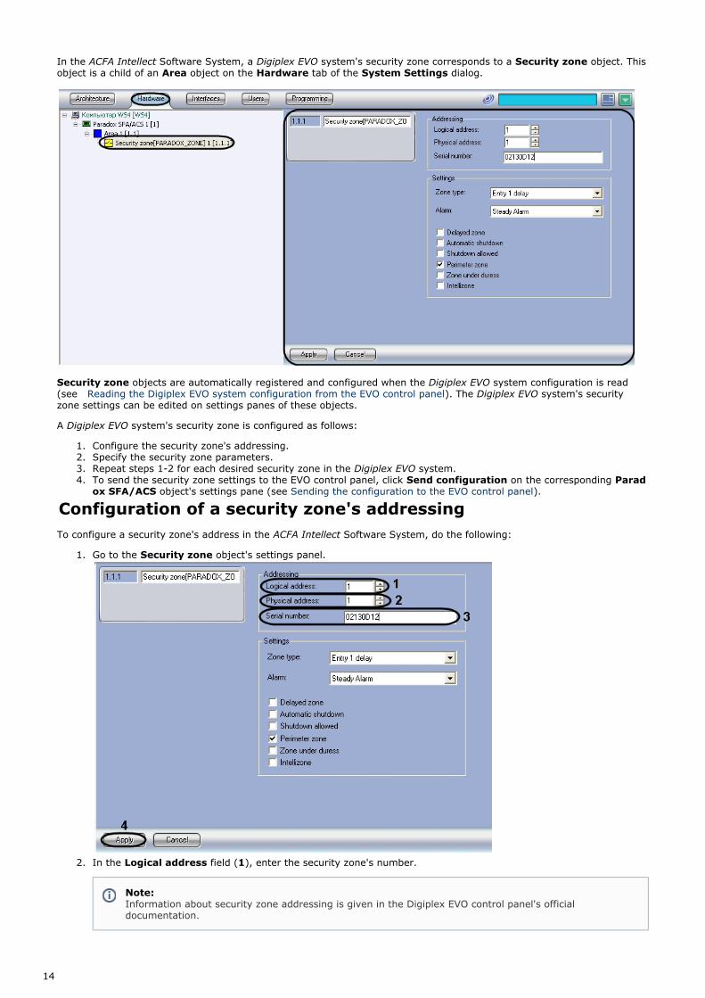
Configuration of a security zone's addressingTo configure a security zone's address in the Software System, do the following:ACFA Intellect
Go to the object's settings panel.Security zone
In the field ( ), enter the security zone's number.Logical address 1
Note:Information about security zone addressing is given in the Digiplex EVO control panel's officialdocumentation.

15
3.
4. 5.
1.
2.
In the field ( ), enter the number of the section of the EVO control panel in which the securityPhysical address 2zone is registered.
In the field ( ), enter the security zone's serial number as a hexadecimal number.Serial number 3Click the button ( ).Apply 4
This completes the process of configuring the addressing of a system's security zone in the SofDigiplex EVO ACFA Intellecttware System.
Specification of security zone parametersTo specify security zone parameters, do the following:
Go to the object's settings panel.Security zone
From the list ( ), select the required zone type.Zone type 1
Zone type Zone description
Disabled(factorydefault)
The zone is bypassed.
Entry 1delay
When this zone is opened, the entry-delay timer is activated. The length of the delay correspondsto the time of delay 1.
Entry 2delay
When this zone is opened, the second entry-delay timer is activated. The length of the delaycorresponds to the time of delay 2.
Tracking If this zone was opened after a zone with an active entry-delay timer, the EVO control panel willissue an alarm only after the entry delay has passed.
Instant If this zone is opened, the EVO control panel immediately issues an alarm signal.
24 HrBuzzer
If this zone is opened, the EVO control panel activates a buzzer on the K641R keypad for issuingan alarm signal. The control panel logs alarm events, however the buzzer cannot be disabled fromthe control panel. To disable the buzzer, the corresponding access code must be entered using thekeypad on which the buzzer has been activated.
The keypad must be assigned to the same section as the zone, otherwise the buzzer will not work.
This zone is not used for perimeter arming.
24 HrBurglaryZone
If this zone is opened, the control panel immediately issues a break-in alarm.
24 HrHold-upZone
If this zone is opened, the control panel immediately issues an alarm signal.
Note:You can view the logical (1) and physical (2) addresses in Winload.

16
2.
a. b. c.
3.
4.
24 Hr GasZone
If this zone is opened, the control panel immediately issues an alarm signal.
24 Hr HeatZone
If this zone is opened, the control panel immediately issues an alarm signal.
24 HrWaterZone
If this zone is opened, the control panel immediately issues an alarm signal.
24 Hr CoolZone
If this zone is opened, the control panel immediately issues an alarm signal.
Delayed 24Hr FireZone
A fire zone with a delayed alarm is used to prevent false alarms from smoke detectors. The alarmwill be issued only when the delay has passed and if the fire data is confirmed.
Keypad buzzers can be activated when delayed fire zones are opened. This requires the keypads tobe assigned to the same section as the fire zone.
Standard24 Hr FireZone
If a standard fire zone is opened, the control panel can perform the following actions:
Generate a record for a fire alarm;Generate a record for a fire alarm input error;Activate the fire alarm.
Inner(perimeter)Delay 1
Residential zone
When this zone is opened, the entry-delay timer is activated. The length of the delay correspondsto the time of delay 1.
Inner(perimeter)Delay 2
Residential zone
When this zone is opened, the entry-delay timer is activated. The length of the delay correspondsto the time of delay 2.
From the list ( ), select the desired alarm type for unauthorized access to the zone.Alarm 2
Alarmtype
Alarm description
SteadyAlarm
A record for the alarm is generated and a steady siren signal is issued.
PulsedAlarm
A record for the alarm is generated and a pulsed siren signal is issued.
SilentAlarm
A record for the alarm is generated; no siren signal is issued. The zone that logs the alarm must bedisarmed.
ReportAlarm
A record for the alarm is generated; no siren signal is issued. The zone that logs the alarm may bearmed or disarmed.
Check the boxes in the group ( ) to assign the desired options to the zone.Settings 3
Zone option Function
Delayed zone If a delayed zone is opened, the alarm is not sent immediately to the monitoring station, butrather upon expiration of the specified time delay. Disarming a system will result inDigiplex EVOthe deletion of any events in the zone.
Automaticshutdown
An open zone automatically closes when the specified time period has passed after it wasopened.
Shutdownallowed
The zone can be shutdown (disabled) manually.
Perimeterzone
Residential zone This zone can be disabled if the section that contains it is "perimeter armed" or"instant armed".
Note:The durations of the entry delays (1 and 2) are specified using Winload or a K641R keypad. By default,delay 1 is 30 seconds and delay 2 is 60 seconds.
Attention!The zone type must be considered when assigning options (see step 2).

17
4.
a. b. c.
5.
1.
2.
Under-duresszone
The zone can be opened if the section that contains it is armed under duress.
Intellizone This option does not work if the selected zone type is or .Standard Fire Delayed Fire
An Intellizone only generates an alarm if at least one of the following events occurs within thedelay period:
An alarm has been logged in a different Intellizone.An alarm in this zone was stopped but then resumed.An alarm in this zone hasn't stopped for the entire duration of the delay period.
The delay period in an Intellizone is specified using Winload or the K641R keypad.
Click the button ( ).Apply 4
This completes the process of specifying security zone parameters.
Configuration of a DG457 sensorIn the Software System, a DG457 sensor corresponds to a object. This object is a child of a ACFA Intellect DG457 sensor
object on the tab of the dialog.Paradox SFA/ACS Hardware System Settings
A DG457 sensor is configured as follows:
Go to the object's settings panel.DG457 sensor

18
2. 3. 4. 5. 6. 7.
1.
2. 3. 4.
5. 6. 7.
8.
In the field ( ), enter the DG457 sensor's serial number as a hexadecimal number.Serial number 1In the field, use the buttons to enter the DG457 sensor's address as a decimal number ( )Address up/down 2Check the box to increase the sensor's sensitivity ( )High sensitivity 3Check the to show the alarm indicator on the sensor ( )Alarm indicator 4Check the to monitor the sensor's body ( )Tamper detection 5To save any changes made, click the button ( ).Apply 6
This completes the process of configuring a DG457 sensor.
Configuration of a DG467 sensorIn the Software System, a DG467 sensor corresponds to a object. This object is a child of a ACFA Intellect DG467 sensor
object on the tab of the dialog.Paradox SFA/ACS Hardware System Settings
A DG467 sensor is configured as follows:
Go to the object's settings panel.DG467 sensor
In the field ( ), enter the DG467 sensor's serial number as a hexadecimal number.Serial number 1In the field, use the buttons to enter the DG467 sensor's address as a decimal number ( )Address up/down 2If the alarm should be issued when a single infrared beam is broken, check the Beam cross checking (single
box ( ).beam) 3To enable the LED on the sensor when there is an alarm, check the box ( ).Alarm indicator 4To enable the LED on the sensor when motion is detected, check the box ( ).Motion indicator 5To monitor the state of the sensor's body, check the box ( ).Tamper detection 6

19
8. 9.
10.
1.
2. 3. 4.
5. 6. 7. 8. 9.
10.
To switch to field test mode, check the ( ).Field test mode 7Use the buttons to enter the DG467 sensor's sensitivity in the field ( ).up/down Sensitivity 8To save any changes made, click the button ( ).Apply 9
This completes the process of configuring a DG467 sensor.
Configuration of a DG85 sensorIn the Software System, a DG85 sensor corresponds to a object. This object is a child of a ACFA Intellect DG85 sensor Pa
object on the tab of the dialog.radox SFA/ACS Hardware System Settings
A DG85 sensor is configured as follows:
Go to the object's settings panel.DG85 sensor
In the field ( ), enter the DG85 sensor's serial number as a hexadecimal number.Serial number 1In the field, use the buttons to enter the DG85 sensor's address as a decimal number ( )Address up/down 2If the alarm should be issued when a single infrared beam is broken, check the Beam cross checking (single
box ( ).beam) 3To enable the LED on the sensor when there is an alarm, check the box ( ).Alarm indicator 4To enable the LED on the sensor when motion is detected, check the box ( ).Motion indicator 5To monitor the state of the sensor's body, check the box ( ).Tamper detection 6To switch to field test mode, check the ( ).Field test mode 7Use the buttons to enter the DG85 sensor's sensitivity in the field ( ).up/down Sensitivity 8To save any changes made, click the button ( ).Apply 9

20
1.
2. 3.
4.
5. 6. 7. 8. 9.
10. 11.
This completes the process of configuring a DG85 sensor.
Configuration of a DM50/DM60 sensorIn the Software System, a DM50/DM60 sensor corresponds to a object. This object isACFA Intellect DM50/DM60 sensora child of a object on the tab of the dialog.Paradox SFA/ACS Hardware System Settings
A DM50/DM60 sensor is configured as follows:
Go to the object's settings panel.DM50/DM60 sensor
In the field ( ), enter the DM50/DM60 sensor's serial number as a hexadecimal number.Serial number 1In the field, use the buttons to enter the DM50/DM60 sensor's address as a decimal number (Address up/down 2)If the alarm should be issued when a single infrared beam is broken, check the Beam cross checking (single
box ( ).beam) 3To enable the LED on the sensor when there is an alarm, check the box ( ).Alarm indicator 4To enable the LED on the sensor when motion is detected, check the box ( ).Motion indicator 5To indicate other signals, check the box ( ).Other signal indicators 6To monitor the state of the sensor's body, check the box ( ).Tamper detection 7To switch to field test mode, check the ( ).Field test mode 8Use the buttons to enter the DM50/DM60 sensor's sensitivity in the field ( ).up/down Sensitivity 9To save any changes made, click the button ( ).Apply 10
This completes the process of configuring a DM50/DM60 sensor.

21
1.
2. 3. 4.
5. 6. 7. 8. 9.
10. 11.
Configuration of a DM70 sensorIn the Software System, a DM70 sensor corresponds to a object. This object is a child of a ACFA Intellect DM70 sensor Pa
object on the tab of the dialog.radox SFA/ACS Hardware System Settings
A DM70 sensor is configured as follows:
Go to the object's settings panel.DM70 sensor
In the field ( ), enter the DM70 sensor's serial number as a hexadecimal number.Serial number 1In the field, use the buttons to enter the DM70 sensor's address as a decimal number ( )Address up/down 2If the alarm should be issued when a single infrared beam is broken, check the Beam cross checking (single
box ( ).beam) 3To enable the LED on the sensor when there is an alarm, check the box ( ).Alarm indicator 4To enable the LED on the sensor when motion is detected, check the box ( ).Motion indicator 5To indicate other signals, check the box ( ).Other signal indicators 6To monitor the state of the sensor's body, check the box ( ).Tamper detection 7To switch to field test mode, check the ( ).Field test mode 8Use the buttons to enter the DM70 sensor's sensitivity in the field ( ).up/down Sensitivity 9To save any changes made, click the button ( ).Apply 10
This completes the process of configuring a DM70 sensor.
Configuration of a ZC1 sensor

22
1.
2. 3. 4.
In the Software System, a ZC1 sensor corresponds to a object. This object is a child of a ACFA Intellect ZC1 sensor Parad object on the tab of the dialog.ox SFA/ACS Hardware System Settings
A ZC1 sensor is configured as follows:
Go to the object's settings panel.ZC1 sensor
In the field ( ), enter the ZC1 sensor's serial number as a hexadecimal number.Serial number 1In the field, use the buttons to enter the ZC1 sensor's address as a decimal number ( )Address up/down 2To save any changes made, click the button ( ).Apply 3
This completes the process of configuring a ZC1 sensor.
Working with the Paradox integrationmoduleGeneral Information on Working with the Paradoxintegration moduleThe following interface objects are used to work with the integration module:Paradox

23
1. 2.
Map;Event Log.
Information on configuring the and interface objects is given in Map Event Log Intellect Software Package:.Administrator's Guide
How to work with these interface objects is described in detail in .Intellect Software Package: Operator's Guide
Controlling a Digiplex EVO system's sectionsA Digiplex EVO system's sections are controlled in the interactive window using the object's menu.Map Area
Description of the Area object's menu commands is given in the table.
Menu command Function
Disarm Disarms the section
Under-duress arming Puts the section in duress mode
Signal Issues an alarm signal
Instant arming Puts the section in "instant arming" mode
Perimeter arming Puts the section in "perimeter arming" mode
Full arming Fully arms the section
Note:To bring up an object's menu, right-click on the object's icon.
Note:Some commands may not be available based on a user's privileges (see Configuration of the Digiplex EVO
).system's users