Embed Size (px)
Citation preview
applied sciences
Article
Partially-Perforated Self-Reinforced Polyurea Foams
Sophia Do 1, Nha Uyen Huynh 1, Nathan Reed 1, Atif Mohammad Shaik 1, Somer Nacy 1,2
and George Youssef 1,*1 Experimental Mechanics Laboratory, Mechanical Engineering Department, San Diego State University,
5500 Campanile Drive, San Diego, CA 92182, USA; [email protected] (S.D.);[email protected] (N.U.H.); [email protected] (N.R.); [email protected] (A.M.S.);[email protected] (S.N.)
2 Biomedical Engineering Department, Al-Khwarizmi College of Engineering, University of Baghdad,Jaderyia, Baghdad 10070, Iraq
* Correspondence: [email protected]
Received: 27 July 2020; Accepted: 21 August 2020; Published: 25 August 2020�����������������
Abstract: This paper reports the unique microstructure of polyurea foams that combines theadvantages of open and closed cell polymeric foams, which were synthesized through a self-foamingprocess. The latter was the result of aggressive mechanical mixing of diamine curative, isocyanate,and deionized water at ambient conditions, which can be adjusted on-demand to produce variabledensity polyurea foam. The spherical, semi-closed microcellular structure has large perforations onthe cell surface resulting from the concurrent expansion of neighboring cells and small holes at thebottom surface of the cells. This resulted in a partially perforated microcellular structure of polyureafoam. As a byproduct of the manufacturing process, polyurea microspheres nucleate and depositon the inner cell walls of the foam, acting as a reinforcement. Since cell walls and the microspheresare made of polyurea, the resulting reinforcement effect overcomes the fundamental interfacial issueof different adjacent materials. The partially perforated, self-reinforced polyurea foam is comparedto the performance of traditional counterparts in biomechanical impact scenarios. An analyticalmodel was developed to explicate the stiffening effect associated with the reinforcing microspheres.The model results indicate that the reinforced microcell exhibited, on average, ~30% higher stiffnessthan its barren counterpart.
Keywords: perforated foam; self-reinforced foam; polyurea; semi-closed cell
1. Introduction
Foams are generally an essential class of materials that are ubiquitous in impact mitigationapplications, due to their inherent high-energy absorption ability. Such an ability is associated with itscellular structure through multiple deformations or failure mechanisms dependent on the classificationof the foam structure, i.e., open-cell or closed-cell. In general, the reversible or irreversible deformations(e.g., elastic deformation, bulking, and densification) dissipate the incoming impact energy throughthe strain energy resulting from the shape change during the loading scenario. Another intrinsicproperty of foams is the significant reduction of weight compared to its base materials, since the solidis either orderly or randomly arranged in the three-dimensional space during the foaming process.A sub-class of the foam family of materials is polymeric foams, which are universally used in protectivesports equipment to guard against low to moderate impacts such as those experienced by athletes.Polymeric foams strategically combine the fundamental properties of cellular solids by providingsuperior energy absorption to weight ratio, which is imperative for novel and innovative personalarmors for athletic and military applications [1]. To further improve the performance of polymeric
Appl. Sci. 2020, 10, 5869; doi:10.3390/app10175869 www.mdpi.com/journal/applsci
Appl. Sci. 2020, 10, 5869 2 of 12
foams in dynamic loading scenarios, dense polymers with superior impact mitigation have beencontinuously sought by scientists and engineers to create the cellular microstructure of foams.
The macroscale deformation response of polymeric foams is sensitive to the attributes of the loadingconditions, including the duration and amplitude of the impact, as well as the strain rate. This sensitivityis an interplay between the properties of the base or parent polymer and the cellular microstructure [2–7].At the fundamental level, the mechanical behavior of foams is hinged on the interconnectivity of thesolid forming the basic cell structure, which gives rise to different energy dissipation and shuntingmechanisms that are tunable through the geometry of the cellular microstructure. Gibson and Ashbyexhaustively treated the topic of the structure and properties of foams by generally classifying theirmicrostructures as either open-cell or closed-cell, as well as partially-open/partially-closed cells [2].The latter, if it exists, usually is a material with segregated regions of open-cells adjacent to regionsof closed-cells, due to the difficulty in strategically controlling the dispersion of the blowing orfoaming agent into the polymer melt during the manufacturing process. Open-cell foams are moredesirable for energy-absorption applications, due to their horizontal plateau behavior, while closed-cellfoams are more desirable for cushioning and load distribution applications [8–10]. Thus, combiningthe advantages of the open and closed microcellular structures would result in a foam materialwith tailorable properties explicitly designed for a target application. The material selection can befurther improved if shape memory properties are intrinsically or extrinsically induced on the foammicrostructure [11]. Recently, our group reported a manufacturing process that produced a hybridstructure foam encompassing the advantages of closed and open cells [5,6,12,13]. A byproduct of thefoaming process is the nucleation of dense microspheres, which get deposited on the inner walls ofthe cells during the final water drainage process, resulting in additional reinforcement. The latteris the focus on the research leading to this paper. It is important to note the difference betweenenhancing properties by tailoring the molecular structure through the combination of urethane andurea bonds [11], the addition of microparticles to form composite materials [3], and the approachreported here, where polyurea microspheres form during the mechanical mixing process and acta reinforcement.
A promising material for foaming is polyurea, a thermoset elastomer with superior structural andmechanical properties coupled with hygrothermal and chemical resistance that warranted widespreadattention in industrial and scientific applications [14–19]. The superior impact mitigation propertiesare driven by the underlying segmental microstructure of polyurea, which comprises of a rigid hardphase composed of aromatic moieties, dispersed in a compliant, aliphatic soft phase [20]. The ratioof these hard and soft phases is controlled by tuning the stoichiometric ratio of the isocyanate andamine constituents [21]. It is essential to differentiate between the chemical structure of the commonpolyurethane material, including its foam derivatives, and the polyurea discussed here. Generally,dense polyurea is well situated within the coating industry as a viable solution for a wide rangeof applications, e.g., water well and roof protection, given its ability to retain the majority of itsmechanical properties even after exposure to ultraviolet radiation for extended periods [22–25].It was then the motivation of this research to introduce a novel polyurea foam microstructuremanufactured through a simple and green manufacturing process that also self-reinforces the cell wallswith polyurea microspheres (a byproduct of the process), hence, creating a new polymer/polymerfoam composite [5,6,12]. The notion of ‘composite’ is motivated based on the concurrent formingof polyurea in a different form factor, i.e., the microsphere, which was shown to be stiffer than itsdense counterpart [26]. The introduction of this new class of polymeric foams will promote scientific,theoretical, and experimental investigations beyond those presented within the scope of this paper.It is important to note that other researchers concurrently investigated different variations of polyureafoams, based on the same constituents, where their results corroborate and support the notion of thisfoam having superior impact mitigation properties [26,27]. Polyurea foams can be further exploited inmany applications, including thermal insulation, filtration, and acoustic isolation, to name a few.
Appl. Sci. 2020, 10, 5869 3 of 12
Previous studies confirmed that polyurea foams inherit superior mechanical properties,including viscoelastic and impact mitigation attributes, of their dense counterpart [4–6,28–31].Different density variations were fabricated and characterized using quasi-static and impact testing.Reed et al. first performed the microstructure analysis [5]. They noted that their version of polyureafoam exhibit a hierarchical microcellular structure consisting of large perforated semi-closed sphericalcells surrounded by smaller closed spherical cells, where the mean diameters, calculated based onimage analysis of scanning electron microscope micrographs, were found to be 370 ± 162 µm and69 ± 18 µm, respectively [5]. Following the Ogden hyperfoam model, an exhaustive quasi-staticcharacterization demonstrated the hyperelastic response of polyurea foams extending from linearelasticity to the onset of densification, and the results and the experimental data were found tobe in good agreement [5]. Reed and coworkers also found that the elastic and energy-absorbingproperties of polyurea foams outperformed a benchmark, off-the-shelf, closed-cell foam (also withspherical microcellular structure) [5]. Youssef et al. then tested the same polyurea foams in response tolow-velocity impacts and confirmed the predictions of Reed et al. regarding the remarkable impactperformance [6]. Contemporary to the investigations mentioned above, Ramirez et al. also foamedpolyurea using a vacuum environment distinctively different from the polyurea foams reported hereinthat were foamed and cured in ambient conditions [4,28–31].
2. Materials and Methods
Polyurea foam sheets were fabricated using a slab molding technique, with dimensions of30.5 cm Long × 30.5 cm Wide × 1.9 cm Thick. The foam was prepared by combining Versalink® P1000(C70H124N2O16, oligomeric diamine, AirProducts & Chemicals., Allentown, PA, U.S.A.) and Isonate®
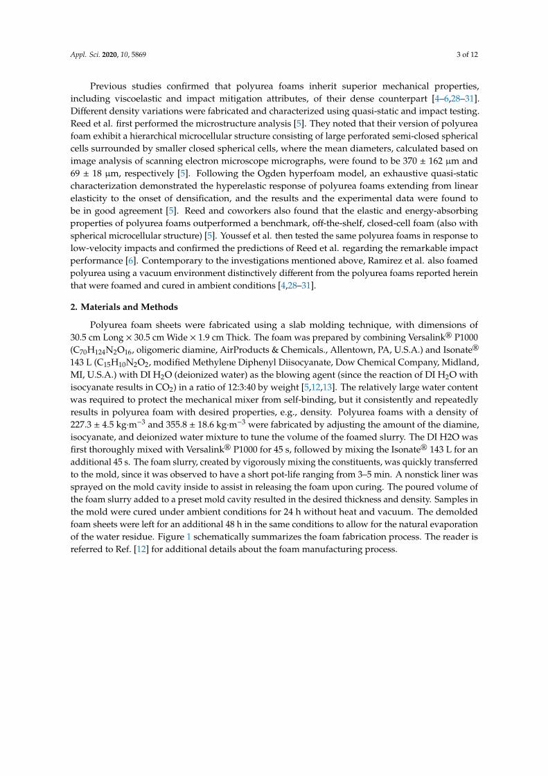
143 L (C15H10N2O2, modified Methylene Diphenyl Diisocyanate, Dow Chemical Company, Midland,MI, U.S.A.) with DI H2O (deionized water) as the blowing agent (since the reaction of DI H2O withisocyanate results in CO2) in a ratio of 12:3:40 by weight [5,12,13]. The relatively large water contentwas required to protect the mechanical mixer from self-binding, but it consistently and repeatedlyresults in polyurea foam with desired properties, e.g., density. Polyurea foams with a density of227.3 ± 4.5 kg·m−3 and 355.8 ± 18.6 kg·m−3 were fabricated by adjusting the amount of the diamine,isocyanate, and deionized water mixture to tune the volume of the foamed slurry. The DI H2O wasfirst thoroughly mixed with Versalink® P1000 for 45 s, followed by mixing the Isonate® 143 L for anadditional 45 s. The foam slurry, created by vigorously mixing the constituents, was quickly transferredto the mold, since it was observed to have a short pot-life ranging from 3–5 min. A nonstick liner wassprayed on the mold cavity inside to assist in releasing the foam upon curing. The poured volume ofthe foam slurry added to a preset mold cavity resulted in the desired thickness and density. Samples inthe mold were cured under ambient conditions for 24 h without heat and vacuum. The demoldedfoam sheets were left for an additional 48 h in the same conditions to allow for the natural evaporationof the water residue. Figure 1 schematically summarizes the foam fabrication process. The reader isreferred to Ref. [12] for additional details about the foam manufacturing process.
Appl. Sci. 2020, 10, 5869 4 of 12
Appl. Sci. 2020, 10, x FOR PEER REVIEW 3 of 11
Different density variations were fabricated and characterized using quasi-static and impact testing. Reed et al. first performed the microstructure analysis [5]. They noted that their version of polyurea foam exhibit a hierarchical microcellular structure consisting of large perforated semi-closed spherical cells surrounded by smaller closed spherical cells, where the mean diameters, calculated based on image analysis of scanning electron microscope micrographs, were found to be 370 ± 162 μm and 69 ± 18 μm, respectively [5]. Following the Ogden hyperfoam model, an exhaustive quasi-static characterization demonstrated the hyperelastic response of polyurea foams extending from linear elasticity to the onset of densification, and the results and the experimental data were found to be in good agreement [5]. Reed and coworkers also found that the elastic and energy-absorbing properties of polyurea foams outperformed a benchmark, off-the-shelf, closed-cell foam (also with spherical microcellular structure) [5]. Youssef et al. then tested the same polyurea foams in response to low-velocity impacts and confirmed the predictions of Reed et al. regarding the remarkable impact performance [6]. Contemporary to the investigations mentioned above, Ramirez et al. also foamed polyurea using a vacuum environment distinctively different from the polyurea foams reported herein that were foamed and cured in ambient conditions [4,28–31].
2. Materials and Methods
Polyurea foam sheets were fabricated using a slab molding technique, with dimensions of 30.5 cm Long × 30.5 cm Wide × 1.9 cm Thick. The foam was prepared by combining Versalink® P1000 (C70H124N2O16, oligomeric diamine, AirProducts & Chemicals., Allentown, PA, U.S.A.) and Isonate® 143 L (C15H10N2O2, modified Methylene Diphenyl Diisocyanate, Dow Chemical Company, Midland, MI, U.S.A.) with DI H2O (deionized water) as the blowing agent (since the reaction of DI H2O with isocyanate results in CO2) in a ratio of 12:3:40 by weight [5,12,13]. The relatively large water content was required to protect the mechanical mixer from self-binding, but it consistently and repeatedly results in polyurea foam with desired properties, e.g., density. Polyurea foams with a density of 227.3 ± 4.5 kg·m−3 and 355.8 ± 18.6 kg·m−3 were fabricated by adjusting the amount of the diamine, isocyanate, and deionized water mixture to tune the volume of the foamed slurry. The DI H2O was first thoroughly mixed with Versalink® P1000 for 45 s, followed by mixing the Isonate® 143 L for an additional 45 s. The foam slurry, created by vigorously mixing the constituents, was quickly transferred to the mold, since it was observed to have a short pot-life ranging from 3–5 min. A nonstick liner was sprayed on the mold cavity inside to assist in releasing the foam upon curing. The poured volume of the foam slurry added to a preset mold cavity resulted in the desired thickness and density. Samples in the mold were cured under ambient conditions for 24 h without heat and vacuum. The demolded foam sheets were left for an additional 48 h in the same conditions to allow for the natural evaporation of the water residue. Figure 1 schematically summarizes the foam fabrication process. The reader is referred to Ref. [12] for additional details about the foam manufacturing process.
Figure 1. Schematic of the mold and foam fabrication process. Figure 1. Schematic of the mold and foam fabrication process.
Upon release from the mold, several samples were extracted from the sheets, and the microstructureof the novel polyurea foam was analyzed using an electron microscope (FEI, Quanta 450) to elucidatethe underlying mechanisms responsible for the unique structure. Once SEM (scanning electronmicroscope) micrographs were obtained, the cell structure of the foam was measured using ImageJ(NIH, U.S.A.). The SEM micrographs were first calibrated within ImageJ. The circular perimeter ofindividual cells and microspheres were then measured and used to calculate their nominal diameters.The average diameter was calculated based on measurements of the cross-sectional area of exposed cellsin the SEM micrographs. Additional image analysis was performed on the same SEM micrographs toestimate the open-space in each cell, resulting in the average perforated area. In separate investigations,the mechanical properties of the foam were assessed and found to exhibit superior impact mitigationproperties suitable for integration in low-velocity sports protective gears [5,12]. The reader is referredto these references for compressive discussion about the mechanical characterizations of the polyureafoam discussed here, which were also benchmarked to an off-the-shelf foam with spherical microcellularstructure. It is worth noting that the ability to produce foams with different densities using the sameprocess prompted its investigation for density-graded foam midsoles for orthotics [1]. It is predictedthat density gradation would significantly improve the strength and energy absorption performance [1].
3. Results and Discussion
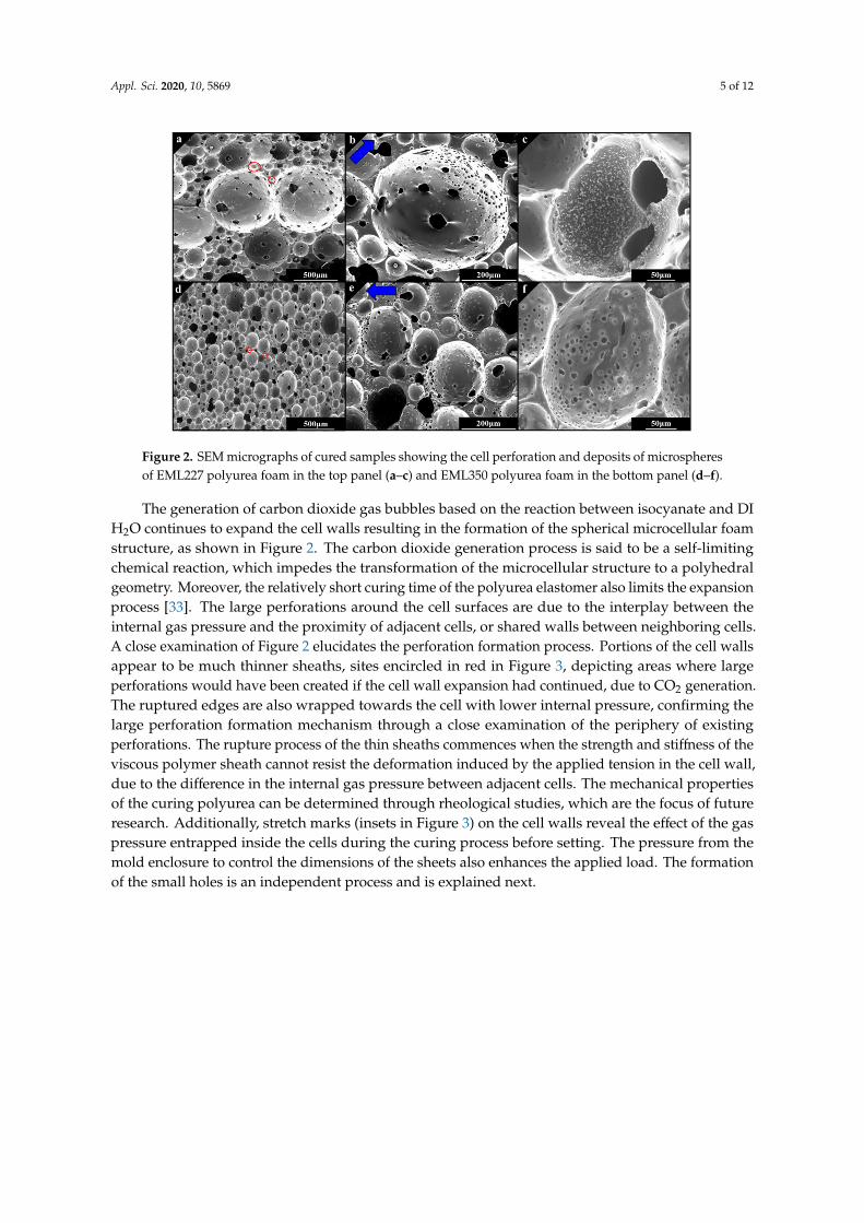
The SEM micrographs of a low-relative density of 0.21 (EML227) and high-relative density (EML350)of 0.33 polyurea foams are shown in Figure 2. The average cell diameter of the EML227 (φc,227) foamwas 134.5 ± 108.5 µm, which is nearly 48% larger the cell diameter of EML350 (φc,350 = 90.9 ± 48.9 µm)based on micrographic analysis of the SEM micrographs. The variation between the cell sizes ofEML227 and EML350 is attributed to the interplay between the desired final sheet thickness as afunction of the initial mixing ratio of the chemicals and the blowing agent. That is to say, the volumeof the foam cavity was kept constant, while adjusting the amount of the poured foam slurry—whichresulted in congregating the entrapped gas bubbles, yielding an overall smaller cell diameter. Lastly,the standard deviation of the cell size is associated with a hierarchal microcellular structure, since thecell walls separating adjacent large microcells tend to encompass cells with smaller diameters (circledin Figure 2a,d for EML227 and 350, respectively). Such a hierarchal microcellular structure plays asignificant role in the quasi-static mechanical behavior of the foam [5,6,32].
Appl. Sci. 2020, 10, 5869 5 of 12
Appl. Sci. 2020, 10, x FOR PEER REVIEW 4 of 11
Upon release from the mold, several samples were extracted from the sheets, and the microstructure of the novel polyurea foam was analyzed using an electron microscope (FEI, Quanta 450) to elucidate the underlying mechanisms responsible for the unique structure. Once SEM (scanning electron microscope) micrographs were obtained, the cell structure of the foam was measured using ImageJ (NIH, U.S.A.). The SEM micrographs were first calibrated within ImageJ. The circular perimeter of individual cells and microspheres were then measured and used to calculate their nominal diameters. The average diameter was calculated based on measurements of the cross-sectional area of exposed cells in the SEM micrographs. Additional image analysis was performed on the same SEM micrographs to estimate the open-space in each cell, resulting in the average perforated area. In separate investigations, the mechanical properties of the foam were assessed and found to exhibit superior impact mitigation properties suitable for integration in low-velocity sports protective gears [5,12]. The reader is referred to these references for compressive discussion about the mechanical characterizations of the polyurea foam discussed here, which were also benchmarked to an off-the-shelf foam with spherical microcellular structure. It is worth noting that the ability to produce foams with different densities using the same process prompted its investigation for density-graded foam midsoles for orthotics [1]. It is predicted that density gradation would significantly improve the strength and energy absorption performance [1].
3. Results and Discussion
The SEM micrographs of a low-relative density of 0.21 (EML227) and high-relative density (EML350) of 0.33 polyurea foams are shown in Figure 2. The average cell diameter of the EML227 (𝜙 , ) foam was 134.5 ± 108.5 μm, which is nearly 48% larger the cell diameter of EML350 (𝜙 , = 90.9 ± 48.9 μm) based on micrographic analysis of the SEM micrographs. The variation between the cell sizes of EML227 and EML350 is attributed to the interplay between the desired final sheet thickness as a function of the initial mixing ratio of the chemicals and the blowing agent. That is to say, the volume of the foam cavity was kept constant, while adjusting the amount of the poured foam slurry—which resulted in congregating the entrapped gas bubbles, yielding an overall smaller cell diameter. Lastly, the standard deviation of the cell size is associated with a hierarchal microcellular structure, since the cell walls separating adjacent large microcells tend to encompass cells with smaller diameters (circled in Figure 2a,d for EML227 and 350, respectively). Such a hierarchal microcellular structure plays a significant role in the quasi-static mechanical behavior of the foam [5,6,32].
Figure 2. SEM micrographs of cured samples showing the cell perforation and deposits of microspheres of EML227 polyurea foam in the top panel (a–c) and EML350 polyurea foam in the bottom panel (d–f).
Figure 2. SEM micrographs of cured samples showing the cell perforation and deposits of microspheresof EML227 polyurea foam in the top panel (a–c) and EML350 polyurea foam in the bottom panel (d–f).
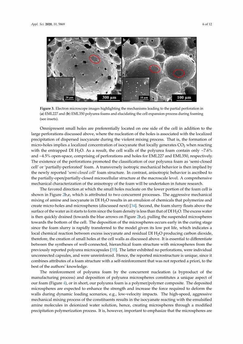
The generation of carbon dioxide gas bubbles based on the reaction between isocyanate and DIH2O continues to expand the cell walls resulting in the formation of the spherical microcellular foamstructure, as shown in Figure 2. The carbon dioxide generation process is said to be a self-limitingchemical reaction, which impedes the transformation of the microcellular structure to a polyhedralgeometry. Moreover, the relatively short curing time of the polyurea elastomer also limits the expansionprocess [33]. The large perforations around the cell surfaces are due to the interplay between theinternal gas pressure and the proximity of adjacent cells, or shared walls between neighboring cells.A close examination of Figure 2 elucidates the perforation formation process. Portions of the cell wallsappear to be much thinner sheaths, sites encircled in red in Figure 3, depicting areas where largeperforations would have been created if the cell wall expansion had continued, due to CO2 generation.The ruptured edges are also wrapped towards the cell with lower internal pressure, confirming thelarge perforation formation mechanism through a close examination of the periphery of existingperforations. The rupture process of the thin sheaths commences when the strength and stiffness of theviscous polymer sheath cannot resist the deformation induced by the applied tension in the cell wall,due to the difference in the internal gas pressure between adjacent cells. The mechanical propertiesof the curing polyurea can be determined through rheological studies, which are the focus of futureresearch. Additionally, stretch marks (insets in Figure 3) on the cell walls reveal the effect of the gaspressure entrapped inside the cells during the curing process before setting. The pressure from themold enclosure to control the dimensions of the sheets also enhances the applied load. The formationof the small holes is an independent process and is explained next.
Appl. Sci. 2020, 10, 5869 6 of 12
Appl. Sci. 2020, 10, x FOR PEER REVIEW 5 of 11
The generation of carbon dioxide gas bubbles based on the reaction between isocyanate and DI H2O continues to expand the cell walls resulting in the formation of the spherical microcellular foam structure, as shown in Figure 2. The carbon dioxide generation process is said to be a self-limiting chemical reaction, which impedes the transformation of the microcellular structure to a polyhedral geometry. Moreover, the relatively short curing time of the polyurea elastomer also limits the expansion process [33]. The large perforations around the cell surfaces are due to the interplay between the internal gas pressure and the proximity of adjacent cells, or shared walls between neighboring cells. A close examination of Figure 2 elucidates the perforation formation process. Portions of the cell walls appear to be much thinner sheaths, sites encircled in red in Figure 3, depicting areas where large perforations would have been created if the cell wall expansion had continued, due to CO2 generation. The ruptured edges are also wrapped towards the cell with lower internal pressure, confirming the large perforation formation mechanism through a close examination of the periphery of existing perforations. The rupture process of the thin sheaths commences when the strength and stiffness of the viscous polymer sheath cannot resist the deformation induced by the applied tension in the cell wall, due to the difference in the internal gas pressure between adjacent cells. The mechanical properties of the curing polyurea can be determined through rheological studies, which are the focus of future research. Additionally, stretch marks (insets in Figure 3) on the cell walls reveal the effect of the gas pressure entrapped inside the cells during the curing process before setting. The pressure from the mold enclosure to control the dimensions of the sheets also enhances the applied load. The formation of the small holes is an independent process and is explained next.
Figure 3. Electron microscope images highlighting the mechanisms leading to the partial perforation in (a) EML227 and (b) EML350 polyurea foams and elucidating the cell expansion process during foaming (see insets).
Omnipresent small holes are preferentially located on one side of the cell in addition to the large perforations discussed above, where the nucleation of the holes is associated with the localized precipitation of dispersed isocyanate during the violent mixing process. That is, the formation of micro-holes implies a localized concentration of isocyanate that locally generates CO2 when reacting with the entrapped DI H2O. As a result, the cell walls of the polyurea foam contain only ~7.6% and ~4.5% open-space, comprising of perforations and holes for EML227 and EML350, respectively. The existence of the perforations promoted the classification of our polyurea foam as ‘semi-closed cell’ or ‘partially-perforated’ foam. A transversely isotropic mechanical behavior is then implied by the newly reported ‘semi-closed cell’ foam structure. In contrast, anisotropic behavior is ascribed to the partially-open/partially-closed microcellular structure at the macroscale level. A comprehensive mechanical characterization of the anisotropy of the foam will be undertaken in future research.
The favored direction at which the small holes nucleate on the lower portion of the foam cell is shown in Figure 2b,e, which is attributed to two concurrent processes. The aggressive mechanical
Figure 3. Electron microscope images highlighting the mechanisms leading to the partial perforation in(a) EML227 and (b) EML350 polyurea foams and elucidating the cell expansion process during foaming(see insets).
Omnipresent small holes are preferentially located on one side of the cell in addition to thelarge perforations discussed above, where the nucleation of the holes is associated with the localizedprecipitation of dispersed isocyanate during the violent mixing process. That is, the formation ofmicro-holes implies a localized concentration of isocyanate that locally generates CO2 when reactingwith the entrapped DI H2O. As a result, the cell walls of the polyurea foam contain only ~7.6%and ~4.5% open-space, comprising of perforations and holes for EML227 and EML350, respectively.The existence of the perforations promoted the classification of our polyurea foam as ‘semi-closedcell’ or ‘partially-perforated’ foam. A transversely isotropic mechanical behavior is then implied bythe newly reported ‘semi-closed cell’ foam structure. In contrast, anisotropic behavior is ascribed tothe partially-open/partially-closed microcellular structure at the macroscale level. A comprehensivemechanical characterization of the anisotropy of the foam will be undertaken in future research.
The favored direction at which the small holes nucleate on the lower portion of the foam cell isshown in Figure 2b,e, which is attributed to two concurrent processes. The aggressive mechanicalmixing of amine and isocyanate in DI H2O results in an emulsion of chemicals that polymerize andcreate micro-holes and microspheres (discussed next) [34]. Second, the foam slurry floats above thesurface of the water as it starts to form since the foam density is less than that of DI H2O. The excess wateris then quickly drained (towards the blue arrows on Figure 2b,e), pulling the suspended microspherestowards the bottom of the cell. The deposition of the microspheres occurs early in the curing stagesince the foam slurry is rapidly transferred to the model given its low pot life, which indicates alocal chemical reaction between excess isocyanate and residual DI H2O producing carbon dioxide,therefore, the creation of small holes at the cell walls as discussed above. It is essential to differentiatebetween the syntheses of well-connected, hierarchical foam structure with microspheres from thepreviously reported polyurea microcapsules [35]. The latter exhibited no perforations, were individualunconnected capsules, and were unreinforced. Hence, the reported microstructure is unique, since itcombines attributes of a foam structure with a self-reinforcement that was not reported a priori, to thebest of the authors’ knowledge.
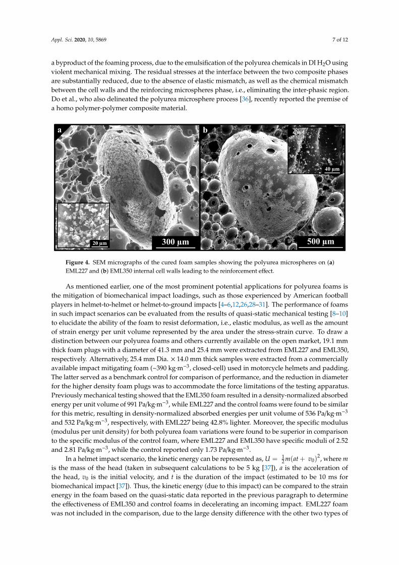
The reinforcement of polyurea foam by the concurrent nucleation (a byproduct of themanufacturing process) and deposition of polyurea microspheres constitutes a unique aspect ofour foam (Figure 4), or in short, our polyurea foam is a polymer/polymer composite. The depositedmicrospheres are expected to enhance the strength and increase the force required to deform thewalls during dynamic loading scenarios, e.g., low-velocity impacts. The high-speed, aggressivemechanical mixing process of the constituents results in the isocyanate reacting with the emulsifiedamine molecules in deionized water solution, hence, creating microspheres through a modifiedprecipitation polymerization process. It is, however, important to emphasize that the microspheres are
Appl. Sci. 2020, 10, 5869 7 of 12
a byproduct of the foaming process, due to the emulsification of the polyurea chemicals in DI H2O usingviolent mechanical mixing. The residual stresses at the interface between the two composite phasesare substantially reduced, due to the absence of elastic mismatch, as well as the chemical mismatchbetween the cell walls and the reinforcing microspheres phase, i.e., eliminating the inter-phasic region.Do et al., who also delineated the polyurea microsphere process [36], recently reported the premise ofa homo polymer-polymer composite material.
Appl. Sci. 2020, 10, x FOR PEER REVIEW 6 of 11
mixing of amine and isocyanate in DI H2O results in an emulsion of chemicals that polymerize and create micro-holes and microspheres (discussed next) [34]. Second, the foam slurry floats above the surface of the water as it starts to form since the foam density is less than that of DI H2O. The excess water is then quickly drained (towards the blue arrows on Figure 2b,e), pulling the suspended microspheres towards the bottom of the cell. The deposition of the microspheres occurs early in the curing stage since the foam slurry is rapidly transferred to the model given its low pot life, which indicates a local chemical reaction between excess isocyanate and residual DI H2O producing carbon dioxide, therefore, the creation of small holes at the cell walls as discussed above. It is essential to differentiate between the syntheses of well-connected, hierarchical foam structure with microspheres from the previously reported polyurea microcapsules [35]. The latter exhibited no perforations, were individual unconnected capsules, and were unreinforced. Hence, the reported microstructure is unique, since it combines attributes of a foam structure with a self-reinforcement that was not reported a priori, to the best of the authors’ knowledge.
The reinforcement of polyurea foam by the concurrent nucleation (a byproduct of the manufacturing process) and deposition of polyurea microspheres constitutes a unique aspect of our foam (Figure 4), or in short, our polyurea foam is a polymer/polymer composite. The deposited microspheres are expected to enhance the strength and increase the force required to deform the walls during dynamic loading scenarios, e.g., low-velocity impacts. The high-speed, aggressive mechanical mixing process of the constituents results in the isocyanate reacting with the emulsified amine molecules in deionized water solution, hence, creating microspheres through a modified precipitation polymerization process. It is, however, important to emphasize that the microspheres are a byproduct of the foaming process, due to the emulsification of the polyurea chemicals in DI H2O using violent mechanical mixing. The residual stresses at the interface between the two composite phases are substantially reduced, due to the absence of elastic mismatch, as well as the chemical mismatch between the cell walls and the reinforcing microspheres phase, i.e., eliminating the inter-phasic region. Do et al., who also delineated the polyurea microsphere process [36], recently reported the premise of a homo polymer-polymer composite material.
Figure 4. SEM micrographs of the cured foam samples showing the polyurea microspheres on (a) EML227 and (b) EML350 internal cell walls leading to the reinforcement effect.
As mentioned earlier, one of the most prominent potential applications for polyurea foams is the mitigation of biomechanical impact loadings, such as those experienced by American football players in helmet-to-helmet or helmet-to-ground impacts [4–6,12,26,28–31]. The performance of foams in such impact scenarios can be evaluated from the results of quasi-static mechanical testing [8–10] to elucidate the ability of the foam to resist deformation, i.e., elastic modulus, as well as the amount of strain energy per unit volume represented by the area under the stress-strain curve. To draw a distinction between our polyurea foams and others currently available on the open market,
Figure 4. SEM micrographs of the cured foam samples showing the polyurea microspheres on (a)EML227 and (b) EML350 internal cell walls leading to the reinforcement effect.
As mentioned earlier, one of the most prominent potential applications for polyurea foams isthe mitigation of biomechanical impact loadings, such as those experienced by American footballplayers in helmet-to-helmet or helmet-to-ground impacts [4–6,12,26,28–31]. The performance of foamsin such impact scenarios can be evaluated from the results of quasi-static mechanical testing [8–10]to elucidate the ability of the foam to resist deformation, i.e., elastic modulus, as well as the amountof strain energy per unit volume represented by the area under the stress-strain curve. To draw adistinction between our polyurea foams and others currently available on the open market, 19.1 mmthick foam plugs with a diameter of 41.3 mm and 25.4 mm were extracted from EML227 and EML350,respectively. Alternatively, 25.4 mm Dia. × 14.0 mm thick samples were extracted from a commerciallyavailable impact mitigating foam (~390 kg·m−3, closed-cell) used in motorcycle helmets and padding.The latter served as a benchmark control for comparison of performance, and the reduction in diameterfor the higher density foam plugs was to accommodate the force limitations of the testing apparatus.Previously mechanical testing showed that the EML350 foam resulted in a density-normalized absorbedenergy per unit volume of 991 Pa/kg·m−3, while EML227 and the control foams were found to be similarfor this metric, resulting in density-normalized absorbed energies per unit volume of 536 Pa/kg·m−3
and 532 Pa/kg·m−3, respectively, with EML227 being 42.8% lighter. Moreover, the specific modulus(modulus per unit density) for both polyurea foam variations were found to be superior in comparisonto the specific modulus of the control foam, where EML227 and EML350 have specific moduli of 2.52and 2.81 Pa/kg·m−3, while the control reported only 1.73 Pa/kg·m−3.
In a helmet impact scenario, the kinetic energy can be represented as, U = 12 m(at + v0)
2, where mis the mass of the head (taken in subsequent calculations to be 5 kg [37]), a is the acceleration ofthe head, v0 is the initial velocity, and t is the duration of the impact (estimated to be 10 ms forbiomechanical impact [37]). Thus, the kinetic energy (due to this impact) can be compared to the strainenergy in the foam based on the quasi-static data reported in the previous paragraph to determinethe effectiveness of EML350 and control foams in decelerating an incoming impact. EML227 foamwas not included in the comparison, due to the large density difference with the other two types of
Appl. Sci. 2020, 10, 5869 8 of 12
foams. To estimate the strain energy, the density-normalized absorbed energy per unit volume ismultiplied by the volume of the impact region and the density of the respective foam. The volumeof the impact region was calculated based on an estimated 10 cm impact diameter and the thicknessof a typical helmet foam liner (2 cm). The results show that EML350 can tolerate up to 47.6 g ofacceleration, while the control foam (with comparable density) can only sustain an acceleration of36.8 g. The estimated 29% increase in impact mitigation ability through tolerance to higher accelerationis attributed to the unique microstructure of our novel polyurea foam.
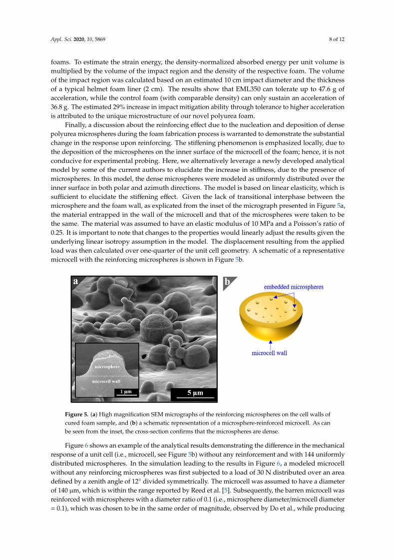
Finally, a discussion about the reinforcing effect due to the nucleation and deposition of densepolyurea microspheres during the foam fabrication process is warranted to demonstrate the substantialchange in the response upon reinforcing. The stiffening phenomenon is emphasized locally, due tothe deposition of the microspheres on the inner surface of the microcell of the foam; hence, it is notconducive for experimental probing. Here, we alternatively leverage a newly developed analyticalmodel by some of the current authors to elucidate the increase in stiffness, due to the presence ofmicrospheres. In this model, the dense microspheres were modeled as uniformly distributed over theinner surface in both polar and azimuth directions. The model is based on linear elasticity, which issufficient to elucidate the stiffening effect. Given the lack of transitional interphase between themicrosphere and the foam wall, as explicated from the inset of the micrograph presented in Figure 5a,the material entrapped in the wall of the microcell and that of the microspheres were taken to bethe same. The material was assumed to have an elastic modulus of 10 MPa and a Poisson’s ratio of0.25. It is important to note that changes to the properties would linearly adjust the results given theunderlying linear isotropy assumption in the model. The displacement resulting from the appliedload was then calculated over one-quarter of the unit cell geometry. A schematic of a representativemicrocell with the reinforcing microspheres is shown in Figure 5b.Appl. Sci. 2020, 10, x FOR PEER REVIEW 8 of 11
Figure 5. (a) High magnification SEM micrographs of the reinforcing microspheres on the cell walls of cured foam sample, and (b) a schematic representation of a microsphere-reinforced microcell. As can be seen from the inset, the cross-section confirms that the microspheres are dense.
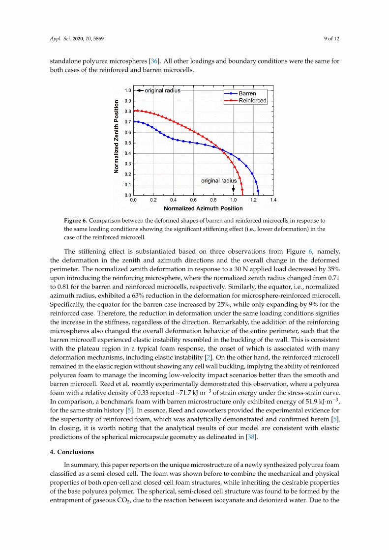
Figure 6 shows an example of the analytical results demonstrating the difference in the mechanical response of a unit cell (i.e., microcell, see Figure 5b) without any reinforcement and with 144 uniformly distributed microspheres. In the simulation leading to the results in Figure 6, a modeled microcell without any reinforcing microspheres was first subjected to a load of 30 N distributed over an area defined by a zenith angle of 12° divided symmetrically. The microcell was assumed to have a diameter of 140 μm, which is within the range reported by Reed et al. [5]. Subsequently, the barren microcell was reinforced with microspheres with a diameter ratio of 0.1 (i.e., microsphere diameter/microcell diameter = 0.1), which was chosen to be in the same order of magnitude, observed by Do et al., while producing standalone polyurea microspheres [36]. All other loadings and boundary conditions were the same for both cases of the reinforced and barren microcells.
Figure 6. Comparison between the deformed shapes of barren and reinforced microcells in response to the same loading conditions showing the significant stiffening effect (i.e., lower deformation) in the case of the reinforced microcell.
The stiffening effect is substantiated based on three observations from Figure 6, namely, the deformation in the zenith and azimuth directions and the overall change in the deformed perimeter.
Figure 5. (a) High magnification SEM micrographs of the reinforcing microspheres on the cell walls ofcured foam sample, and (b) a schematic representation of a microsphere-reinforced microcell. As canbe seen from the inset, the cross-section confirms that the microspheres are dense.
Figure 6 shows an example of the analytical results demonstrating the difference in the mechanicalresponse of a unit cell (i.e., microcell, see Figure 5b) without any reinforcement and with 144 uniformlydistributed microspheres. In the simulation leading to the results in Figure 6, a modeled microcellwithout any reinforcing microspheres was first subjected to a load of 30 N distributed over an areadefined by a zenith angle of 12◦ divided symmetrically. The microcell was assumed to have a diameterof 140 µm, which is within the range reported by Reed et al. [5]. Subsequently, the barren microcell wasreinforced with microspheres with a diameter ratio of 0.1 (i.e., microsphere diameter/microcell diameter= 0.1), which was chosen to be in the same order of magnitude, observed by Do et al., while producing
Appl. Sci. 2020, 10, 5869 9 of 12
standalone polyurea microspheres [36]. All other loadings and boundary conditions were the same forboth cases of the reinforced and barren microcells.
Appl. Sci. 2020, 10, x FOR PEER REVIEW 8 of 11
Figure 5. (a) High magnification SEM micrographs of the reinforcing microspheres on the cell walls of cured foam sample, and (b) a schematic representation of a microsphere-reinforced microcell. As can be seen from the inset, the cross-section confirms that the microspheres are dense.
Figure 6 shows an example of the analytical results demonstrating the difference in the mechanical response of a unit cell (i.e., microcell, see Figure 5b) without any reinforcement and with 144 uniformly distributed microspheres. In the simulation leading to the results in Figure 6, a modeled microcell without any reinforcing microspheres was first subjected to a load of 30 N distributed over an area defined by a zenith angle of 12° divided symmetrically. The microcell was assumed to have a diameter of 140 μm, which is within the range reported by Reed et al. [5]. Subsequently, the barren microcell was reinforced with microspheres with a diameter ratio of 0.1 (i.e., microsphere diameter/microcell diameter = 0.1), which was chosen to be in the same order of magnitude, observed by Do et al., while producing standalone polyurea microspheres [36]. All other loadings and boundary conditions were the same for both cases of the reinforced and barren microcells.
Figure 6. Comparison between the deformed shapes of barren and reinforced microcells in response to the same loading conditions showing the significant stiffening effect (i.e., lower deformation) in the case of the reinforced microcell.
The stiffening effect is substantiated based on three observations from Figure 6, namely, the deformation in the zenith and azimuth directions and the overall change in the deformed perimeter.
Figure 6. Comparison between the deformed shapes of barren and reinforced microcells in response tothe same loading conditions showing the significant stiffening effect (i.e., lower deformation) in thecase of the reinforced microcell.
The stiffening effect is substantiated based on three observations from Figure 6, namely,the deformation in the zenith and azimuth directions and the overall change in the deformedperimeter. The normalized zenith deformation in response to a 30 N applied load decreased by 35%upon introducing the reinforcing microsphere, where the normalized zenith radius changed from 0.71to 0.81 for the barren and reinforced microcells, respectively. Similarly, the equator, i.e., normalizedazimuth radius, exhibited a 63% reduction in the deformation for microsphere-reinforced microcell.Specifically, the equator for the barren case increased by 25%, while only expanding by 9% for thereinforced case. Therefore, the reduction in deformation under the same loading conditions signifiesthe increase in the stiffness, regardless of the direction. Remarkably, the addition of the reinforcingmicrospheres also changed the overall deformation behavior of the entire perimeter, such that thebarren microcell experienced elastic instability resembled in the buckling of the wall. This is consistentwith the plateau region in a typical foam response, the onset of which is associated with manydeformation mechanisms, including elastic instability [2]. On the other hand, the reinforced microcellremained in the elastic region without showing any cell wall buckling, implying the ability of reinforcedpolyurea foam to manage the incoming low-velocity impact scenarios better than the smooth andbarren microcell. Reed et al. recently experimentally demonstrated this observation, where a polyureafoam with a relative density of 0.33 reported ~71.7 kJ·m−3 of strain energy under the stress-strain curve.In comparison, a benchmark foam with barren microstructure only exhibited energy of 51.9 kJ·m−3,for the same strain history [5]. In essence, Reed and coworkers provided the experimental evidence forthe superiority of reinforced foam, which was analytically demonstrated and confirmed herein [5].In closing, it is worth noting that the analytical results of our model are consistent with elasticpredictions of the spherical microcapsule geometry as delineated in [38].
4. Conclusions
In summary, this paper reports on the unique microstructure of a newly synthesized polyurea foamclassified as a semi-closed cell. The foam was shown before to combine the mechanical and physicalproperties of both open-cell and closed-cell foam structures, while inheriting the desirable propertiesof the base polyurea polymer. The spherical, semi-closed cell structure was found to be formed by theentrapment of gaseous CO2, due to the reaction between isocyanate and deionized water. Due to the
Appl. Sci. 2020, 10, 5869 10 of 12
interaction between the expanding adjacent cells, large perforations appear on the surfaces of cell walls.The reported version of polyurea foam was shown to be self-reinforced with polyurea microspherescreating a polymer/polymer composite with a well-bonded reinforcement and matrix phases, due tothe absence of elastic and molecular structure mismatches at the interface. A companion analyticalmodel was used to elucidate the stiffening effect, due to the deposition of the dense microspheres onthe inner surface of the microcells. Future studies include the in-depth characterization of the foamstructure and its influence on the dynamic behavior, as well as the expansion of the modeling effortsto explicate the influence of the entire set of scientific variables defining the model. Polyurea foamsrecently were proposed for biomedical impact mitigation application, helmets and orthotics, but alsohave potential in other applications, such as fluid and heat management.
Author Contributions: SEM investigation, collected the data, analyzed the micrographs, and assisted in the firstdraft of the paper, S.D.; additional SEM, assisted in final draft of the paper, and helped with the modeling, N.U.H.;created the foam samples and performed the previous mechanical testing, N.R.; assisted with SEM investigationsand assisted with the first draft, A.M.S.; formulated the analytical model and assisted in the final draft, S.N.;conceived the idea, wrote the paper, assisted in analysis, helped with the model formulation, and supervised allwork, G.Y. All authors have read and agreed to the published version of the manuscript.
Funding: The research was supported by the USA. DoD grant W911NF-14-1-0039 and W911NF-18-1-0477.The authors are grateful to the guidance of Roshdy Barsoum of the Office of Naval Research. The research wasalso supported by internal funds from San Diego State University. We acknowledge the use of equipment atthe Electron Microscopy Facility acquired by NSF grant DBI-0959908 as well as the NSF support though awardNo. 1925539.
Acknowledgments: The authors are grateful to Makayla McFarland for her assistance with some image analysis.
Conflicts of Interest: The authors declare no conflict of interest.
References
1. Uddin, K.Z.; Youssef, G.; Trkov, M.; Seyyedhosseinzadeh, H.; Koohbor, B. Gradient optimization ofmulti-layered density-graded foam laminates for footwear material design. J. Biomech. 2020, 109, 109950.[CrossRef] [PubMed]
2. Gibson, L.J.; Ashby, M.F. Cellular Solids: Structure and Properties; Cambridge University Press: Cambridge,UK, 1999; ISBN 978-0-521-49911-8.
3. Weems, A.C.; Li, W.; Maitland, D.J.; Calle, L.M. Polyurethane Microparticles for Stimuli Response andReduced Oxidative Degradation in Highly Porous Shape Memory Polymers. ACS Appl. Mater. Interfaces2018, 10, 32998–33009. [CrossRef] [PubMed]
4. Ramirez, B.J.; Gupta, V. Evaluation of novel temperature-stable viscoelastic polyurea foams as helmet linermaterials. Mater. Des. 2018, 137, 298–304. [CrossRef]
5. Reed, N.; Huynh, N.U.; Rosenow, B.; Manlulu, K.; Youssef, G. Synthesis and characterization of elastomericpolyurea foam. J. Appl. Polym. Sci. 2020, 137, 48839. [CrossRef]
6. Youssef, G.; Reed, N.; Huynh, N.U.; Rosenow, B.; Manlulu, K. Experimentally-validated predictions of impactresponse of polyurea foams using viscoelasticity based on bulk properties. Mech. Mater. 2020, 148, 103432.[CrossRef]
7. Weems, A.C.; Easley, A.; Roach, S.R.; Maitland, D.J. Highly Cross-Linked Shape Memory Polymers withTunable Oxidative and Hydrolytic Degradation Rates and Selected Products Based on Succinic Acid.ACS Appl. Bio Mater. 2019, 2, 454–463. [CrossRef]
8. Rusch, K.C. Load–compression behavior of flexible foams. J. Appl. Polym. Sci. 1969, 13, 2297–2311. [CrossRef]9. Rusch, K.C. Load-compression behavior of brittle foams. J. Appl. Polym. Sci. 1970, 14, 1263–1276. [CrossRef]10. Rusch, K.C. Energy-absorbing characteristics of foamed polymers. J. Appl. Polym. Sci. 1970, 14, 1433–1447.
[CrossRef]11. Easley, A.D.; Monroe, M.B.B.; Hasan, S.M.; Weems, A.C.; Frederick, J.; Maitland, D.J. Shape memory
polyurethane-urea foams with improved toughness. J. Appl. Polym. Sci. 2019, 136, 47268. [CrossRef]
Appl. Sci. 2020, 10, 5869 11 of 12
12. Youssef, G.; Reed, N. Scalable Manufacturing Method of Property-Tailorable Polyurea Foam. U.S. PatentApplication No. 16/118,879, 5 March 2020.
13. Do, S.; Rosenow, B.; Reed, N.; Mohammed, A.; Manlulu, K.; Youssef, G. Fabrication, Characterization,and Testing of Novel Polyurea Foam. PU Magazine International, April/May 2019; 104–107.
14. Barsoum, R.G.S. Elastomeric Polymers with High Rate Sensitivity: Applications in Blast, Shockwave, and PenetrationMechanics; William Andrew: Norwich, NY, USA, 2015; ISBN 978-0-323-35434-9.
15. Jain, A.; Youssef, G.; Gupta, V. Dynamic tensile strength of polyurea-bonded steel/E-glass composite joints.J. Adhes. Sci. Technol. 2013, 27, 403–412. [CrossRef]
16. Youssef, G.; Gupta, V. Dynamic tensile strength of polyurea. J. Mater. Res. 2012, 27, 494–499. [CrossRef]17. Zhao, J.; Knauss, W.G.; Ravichandran, G. Applicability of the time–temperature superposition principle in
modeling dynamic response of a polyurea. Mech. Time-Depend. Mater. 2007, 11, 289–308. [CrossRef]18. Jiao, T.; Clifton, R.J.; Grunschel, S.E. High Strain Rate Response of an Elastomer. AIP Conf. Proc. 2006,
845, 809–812. [CrossRef]19. Grujicic, M.; Pandurangan, B.; He, T.; Cheeseman, B.A.; Yen, C.-F.; Randow, C.L. Computational investigation
of impact energy absorption capability of polyurea coatings via deformation-induced glass transition.Mater. Sci. Eng. A 2010, 527, 7741–7751. [CrossRef]
20. Grujicic, M.; Pandurangan, B. Mesoscale analysis of segmental dynamics in microphase-segregated polyurea.J. Mater. Sci. 2012, 47, 3876–3889. [CrossRef]
21. Grujicic, M.; Pandurangan, B.; King, A.E.; Runt, J.; Tarter, J.; Dillon, G. Multi-length scale modeling andanalysis of microstructure evolution and mechanical properties in polyurea. J. Mater. Sci. 2011, 46, 1767–1779.[CrossRef]
22. Whitten, I.; Youssef, G. The effect of ultraviolet radiation on ultrasonic properties of polyurea. Polym. Degrad.Stab. 2016, 123, 88–93. [CrossRef]
23. Youssef, G.; Whitten, I. Dynamic properties of ultraviolet-exposed polyurea. Mech. Time-Depend. Mater. 2017,21, 351–363. [CrossRef]
24. Youssef, G.; Brinson, J.; Whitten, I. The effect of ultraviolet radiation on the hyperelastic Behavior of polyurea.J. Polym. Environ. 2018, 26, 183–190. [CrossRef]
25. Shaik, A.M.; Huynh, N.U.; Youssef, G. Micromechanical behavior of ultraviolet-exposed polyurea.Mech. Mater. 2020, 140, 103244. [CrossRef]
26. Gupta, V.; Citron, J.K.; Youssef, G. Material for Mitigating Impact Forces with Collision Durations inNanoseconds to Milliseconds Range. U.S. Patent Application No. 13/879,616, 28 November 2013.
27. Gupta, V.; Youssef, G. Orientation-dependent impact behavior of polymer/EVA bilayer specimens at longwavelengths. Exp. Mech. 2014, 54. [CrossRef]
28. Ramirez, B.J.; Kingstedt, O.T.; Crum, R.; Gamez, C.; Gupta, V. Tailoring the rate-sensitivity of low densitypolyurea foams through cell wall aperture size. J. Appl. Phys. 2017, 121, 225107. [CrossRef]
29. Ramirez, B.J.; Misra, U.; Gupta, V. Viscoelastic foam-filled lattice for high energy absorption. Mech. Mater.2018, 127, 39–47. [CrossRef]
30. Ramirez, B.J.; Gupta, V. High tear strength polyurea foams with low compression set and shrinkage propertiesat elevated temperatures. Int. J. Mech. Sci. 2019, 150, 29–34. [CrossRef]
31. Ramirez, B.J.; Gupta, V. Energy Absorption and low velocity impact response of open-cell polyurea foams.J. Dyn. Behav. Mater. 2019, 5, 132–142. [CrossRef]
32. Xia, R.; Feng, X.-Q.; Wang, G.-F. Effective elastic properties of nanoporous materials with hierarchicalstructure. Acta Mater. 2011, 59, 6801–6808. [CrossRef]
33. Youssef, G. Dynamic Properties of Polyurea; University of California: Los Angeles, CA, USA, 2010.34. Xu, J.; Han, H.; Zhang, L.; Zhu, X.; Jiang, X.; Kong, X.Z. Preparation of highly uniform and crosslinked polyurea
microspheres through precipitation copolymerization and their property and structure characterization.RSC Adv. 2014, 4, 32134–32141. [CrossRef]
35. Hong, K.; Park, S. Preparation of polyurea microcapsules with different composition ratios: Structures andthermal properties. Mater. Sci. Eng. A 1999, 272, 418–421. [CrossRef]
36. Do, S.; Stepp, S.; Youssef, G. Quasi-static and dynamic characterization of Polyurea microspheres reinforcedpolyurea matrix composite. Mater. Today Commun. 2020, 25, 101464. [CrossRef]

Appl. Sci. 2020, 10, 5869 12 of 12
37. Berger, S.A.; Goldsmith, W.; Lewis, E.R. Introduction to Bioengineering; Oxford University Press: Oxford, UK,1996; ISBN 978-0-19-856516-1.
38. Shorter, R.; Smith, J.; Coveney, V.; Busfield, J. Axial compression of hollow elastic spheres. J. Mech. Mater.Struct. 2010, 5, 693–705. [CrossRef]
© 2020 by the authors. Licensee MDPI, Basel, Switzerland. This article is an open accessarticle distributed under the terms and conditions of the Creative Commons Attribution(CC BY) license (http://creativecommons.org/licenses/by/4.0/).


