Embed Size (px)
Citation preview
Wear 258 (2005) 434–442
Performance of WC–VC–Co thermal spray coatingsin abrasion and slurry erosion tests
C.N. Machioa,∗, G. Akdogana, M.J. Witcombb, S. Luyckxa
a School of Process and Materials Engineering, University of the Witwatersrand, Johannesburg, South Africab Electron Microscopy Unit, University of the Witwatersrand, Johannesburg, South Africa
Received 22 December 2003Available online 30 October 2004
Abstract
Thermal spray coatings based on tungsten carbide are widely used in wear applications. This paper presents results obtained from commercialWC–12 wt.%Co and WC–17 wt.%Co as well as experimental WC–10 wt.%VC–12 wt.%Co and WC–10 wt.%VC–17 wt.%Co coatings. Thecoatings have been deposited on stainless steel substrates using a high pressure high velocity oxy-fuel (HP/HVOF) Tafa® JP 5000TM thermals rry erosion.S potentialo nference,M powders( ow that theW s. In slurrye and cobalti©
K
1
fIestmo
a
idewasr-etalcon-ness.
oat-ow-
e thed inWCders
0d
praying system. They have all been tested under identical conditions in order to compare their resistance to abrasion and sluimilar tests have been carried out previously in our laboratory [H.L. de Villiers-Lovelock, S. Luyckx, Preliminary investigation on thef VC-WC-Co HP/HVOF powders and coatings, in: C.C. Berndt (Ed.), Proceedings of the First International Thermal Spray Coontreal, Canada, 8–11 May 2000, pp. 647–656] [1] but gave inconclusive results which were found due to the VC-containing
WC–VC–Co) not being optimal. The tests have now been repeated with optimized WC–VC–Co powders. The present results shC–VC–Co coatings produced with the optimized powders exhibit higher abrasion resistance then commercial WC–Co coating
rosion, the best performance of the VC-containing coatings is as good as that of the commercial WC–Co coatings. The role of VCn the wear process of the coatings is discussed.
2004 Elsevier B.V. All rights reserved.
eywords: Vanadium carbide; WC–Co; Thermal spray; Wear
. Introduction
WC-based hardmetals are widely used in industry mainlyor wear resistance due to their high hardness and toughness.nitially manufactured as cemented carbides, use has sincexpanded to coatings, applied, e.g. by thermal spraying on aubstrate. Applications of thermal sprayed coatings includehe aerospace industry[2] where weight savings are of pri-ary importance and mining applications, e.g. for protectionf slurry pumps[3].
A high hardness in cemented carbides is normally associ-ted with a high volume fraction of the carbide phase and/or
∗ Corresponding author. Tel.: +27 11 717 7543; fax: +27 11 403 1471.E-mail address:[email protected] (C.N. Machio).
a fine WC grain size[4] and the presence of harder carbphases. The introduction of the harder VC in WC–Costarted by Luyckx et al.[5–7] who have shown that the patial replacement of WC by 10 wt.% VC produces a hardmthat is harder than conventional WC–Co of equal cobalttent and tougher than conventional WC–Co of equal hardThese findings led to the introduction of VC in coatings[1].
The work of de Villiers-Lovelock and Luyckx[1] failed toshow clear advantages of VC-modified thermal spray cings in laboratory wear tests. This was attributed to the pders for the coatings being not optimal, mainly becausVC particles were large and heterogeneously distributethe powders. To better determine the effect of replacingby VC, the present investigation has used optimized pow[8].
043-1648/$ – see front matter © 2004 Elsevier B.V. All rights reserved.oi:10.1016/j.wear.2004.09.033

C.N. Machio et al. / Wear 258 (2005) 434–442 435
Table 1Nominal powder compositions
Powder Nominal composition (wt.%) Approx. equivalent (vol.%)
Commercial A-12Co 88WC–12 Co 80WC–20CoC-17Co 83WC–17Co 73WC–27Co
New (experimental) B-10VC12Co 78WC–10VC–12Co 83 (WC, VC)–17CoD-10VC17Co 73WC–10VC–17Co 77(WC, VC)–23Co
2. Experiments
2.1. Powder characterization
The chemical composition of the powders used for thisinvestigation is given inTable 1. The symbols A-12Co, B-10VC12Co, C-17Co and D-10VC17Co (Table 1) will beused throughout the paper. The composition given for theWC–VC–Co coatings refers to the powders used to manu-facture the agglomerated, spray dried and sintered thermalspray powders, hence it is called “nominal composition”. Ineffect, the phases present in the WC–VC–Co thermal spraypowders were WC, (V, W)C and Co. Since the compositionof (V, W)C is not known exactly, the composition in volumepercent is given as “approximate” inTable 1.
Powder particle size distribution was determined by theMalvern® laser diffraction technique.Fig. 1(a) shows the sizedistributions obtained. The WC grain size in the powders wasdetermined by lineal analysis. Micrographs were obtained ina scanning electron microscope (SEM) in back scattered elec-tron mode and WC grains measured using a semi-automaticclick sensitive image analyser. More than 800 grains wereanalyzed for each coating. The WC grain size distributionsobtained are shown inFig. 1(b).
The elemental components of the powders were confirmedb o int en-t rbon.X thec en-
tal powders consisted of the double carbide (V, W)C, WC andCo.
2.2. Coating deposition and characterization
A high-pressure high velocity oxy-fuel (HP/HVOF) Tafa®
JP 5000TM thermal spraying system was used to deposit thecoatings. All the coatings were deposited on stainless steelsubstrates. Before deposition, the surfaces to be coated werecleaned and roughened by shot blasting using 24 grit aluminaparticles. The surface roughness after shot blasting was 6�mRa. After deposition, the coating microstructures were exam-ined using both optical microscopy (OM) and SEM. Surfacearea analysis was used on optical micrographs to evaluateporosity levels in the coatings. The size of the WC grainsin the coatings was obtained by lineal analysis as was donefor the powders (see Section2.1). Phase compositions weredetermined using a Philips diffractometer fitted with a Motube. The Vickers macro-hardness was determined on crosssections of the coatings. The indentation load was 1 kg. Thisload is unlike what is generally used for coatings (most com-monly 300 g) and is aimed at reducing the scatter associatedwith micro-hardness tests.
2.3. Wear testing
ane t ratioo sw of 10
ders d
y energy dispersive spectroscopy (EDS) to be W and Che commercial powders and W, V, and Co in the experimal powders. The EDS system used could not detect ca-ray diffractometry (XRD) confirmed that the phases inommercial powders were WC and Co while the experim
Fig. 1. (a) Size distribution of the particles of pow
All wear tests used silica sand with particles havinglongated morphology. The particles had a mean aspecf about 1.4 and a hardness of 1020 HV 1± 50. The hardnesas obtained on polished cross-sections and as a mean
eposited; (b) WC grain size distribution in the powders.

436 C.N. Machio et al. / Wear 258 (2005) 434–442
Table 2Abrasion wear parameters
Test parameter Dry abrasion Wet abrasion
Abrasive particle flow rate 47 g/s 10 wt.% abrasive particles in waterTest loads 25 and 50 N 8 NTest time 25 min 60 minMass loss measurements 5 min intervals 5 min intervals in first 30 min, 10 min intervals thereafterNumber of test specimens per coating 3 3Dimension of specimens 70 mm× 25 mm× 5 mm 18 mm× 18 mm× 5 mmWheel speed 200 rpm 110 rpm
readings. Mass loss measurements during wear where deter-mined using an analytical mass balance with a sensitivity of0.1 mg while wear surfaces were analyzed using scanningelectron microscopy techniques in a JEOL 840 SEM and aLEO Field Emission SEM.
2.3.1. Abrasion testingBoth dry and wet conditions were used. The dry testing
was done in accordance with ASTM G65–85 which uses arubber wheel and dry sand, while wet abrasion testing useda cylindrical rubber wheel and a slurry of sand particles inwater. The test parameters are given inTable 2.
Four specimens could be tested simultaneously on the wetabrasion test rig. Every test run therefore included a test speci-men of each of the four grades of coatings. This arrangementallowed comparisons to be made run after run. Specimen
loading was via the rig’s loading arms. A pneumatic pumpcirculated the slurry and was set running for at least 2 minprior to testing in order to establish a steady flow of the slurry.
2.3.2. Slurry erosionErosion tests were carried out on a rig with a specimen
holder that could be set at various angles between the spec-imen and slurry jet. The slurry consisted of the previouslydescribed silica sand in water. An impeller circulated theslurry through a nozzle of diameter 12.5 mm. Tests wereconducted at 45 and 90◦ incidence angles on specimens ofsize 50 mm× 50 mm× 6 mm. Three specimens at each anglewere used for each grade of coating and mass loss averagesobtained. The tests lasted 30 min and mass losses were deter-mined at 5-min intervals. Before the tests were carried out,the rig was calibrated by measuring the flow rate of the slurry.
FC
ig. 2. Coating microstructures. (a) Coating A-12Co; (b) coating B-10VC12-17Co: WC (white), Co (dark). Main phases in B-10VC12Co and D-10VC1
Co; (c) coating C-17Co; (d) coating D-10VC17Co. Main phases in A-12Co and7Co: WC (white), Co (dark), (V, W)C (slightly darker than Co).

C.N. Machio et al. / Wear 258 (2005) 434–442 437
Table 3Hardness values of coatings
Coating HV (1 kg) Standard deviation
A-12Co 1101 23B-10VC12Co 1056 61C-17Co 1045 69D-10VC17Co 942 46
The effective concentration of the slurry out of the nozzle wasfound to be 5 wt.% of abrasive and the slurry jet velocity was12.6 m/s.
3. Results
3.1. Coating characteristics
3.1.1. MicrostructuresThe average thickness of all the coatings in this study
was found to be 200�m. Light optical microscopy showedthat the coatings exhibited the typical porosity of thermalspray coatings, with the porosity being of the order of 5%in D-10VC17Co and B-10VC12Co and 2% in A-12Co andC-17Co.
Fig. 2shows representative secondary electron mode mi-crographs. The main phases in A-12Co and C-17Co inFig. 2
Fig. 3. WC grain size distribution in the coatings, obtained from lineal anal-ysis. Each graph was obtained from more than 800 grains.
are WC (white) and Co (dark). The main phases in B-10VC12Co and D-10VC17Co are WC (white), Co (dark) and(V, W)C (slightly darker than Co). The black roughly spheri-cal features are pores. The WC particles appeared rounded asopposed to the prismatic morphology seen in the powders andin cemented carbides. The binder phase was shown by EDSto have W (commercial coatings) or W and V (experimentalcoatings) in solution.
Fl
ig. 4. Dry abrasive wear results. (a) Cumulative mass loss (i) and mass lososs per unit time (ii) curves for test load 50 N. Letters at end of curves refer
s per unit time (ii) curves for test load 25 N; (b) cumulative mass loss (i) andmassto symbols inTable 1.

438 C.N. Machio et al. / Wear 258 (2005) 434–442
Fig. 5. Mass loss curves in wet abrasion. (i) Cumulative mass loss curves. (ii) Mass loss per unit time curves. Letters at end of curves refer to symbols inTable 1.
3.1.2. Phase compositionXRD results showed that the thermal spraying caused
some decarburization of WC to ditungsten carbide (W2C)in some coatings, formation of eta phase and also caused theCo binder phase to acquire an amorphous structure in all thecoatings. The phases in the coatings were: in A-12Co: WCand W2C; in B-10VC12Co: WC, (V, W)C, W2C and M12Cwith M being W, V and Co; in C-17Co: WC and M12C withM being W and Co; and in D-10VC17Co: WC, (V, W)C,W2C and M12C with M being W, V and Co. The amountsof W2C and eta phase formed in the coatings were approxi-mated from their respective peak intensities in the XRD spec-tra. The W2C/WC and M12C/WC ratios were not higher than7 wt.%. The (V, W)C/WC ratio in the powders was approxi-
mately 33/55 (wt.%) for B-10VC12Co and 34/50 (wt.%) forD-10VC17Co[9]. These (V, W)C/WC ratios may be differ-ent in the coatings if the solubility of (V, W)C and WC in Co(which is not known at present) is different.
3.1.3. Hardness valuesThe new VC-containing coatings are slightly less hard
compared to the conventional coatings, as shown inTable 3where each value is an average of 10 readings.
Therefore the VC in the new coatings does not producethe expected increase in hardness as it does in the case ofcemented WC–VC–Co carbides. The lower hardness wasalso observed for one of the VC coatings in previous stud-ies [1]. It is important to note that in those studies[1], as
FD
ig. 6. Examples of wear surfaces after dry abrasion tests at 25 N load. (a)-10VC17Co.
Coating A-12Co; (b) coating B-10VC12Co; (c) coating C-17Co; and (d) coating

C.N. Machio et al. / Wear 258 (2005) 434–442 439
Fig. 7. Examples of wear surfaces in wet abrasion. (a) Coating A-12Co; (b) coating B-10VC12Co; (c) coating C-17Co; and (d) coating D-10VC17Co. Carbidechipping occurred less than in dry abrasion and carbide particles appear “polished”.
Fig. 8. Mass loss curves in slurry erosion. (a) Cumulative mass loss (i) and mass loss per unit time (ii) curves at 45◦; (b) cumulative mass loss (i) and mass lossper unit time (ii) curves at 90◦. Letters at end of curves refer to symbols inTable 1.

440 C.N. Machio et al. / Wear 258 (2005) 434–442
in most of the WC–Co coating literature, the hardness wasquoted as micro-hardness. Micro-hardness tests are how-ever characterized by a large scatter since they are unsuit-able for characterizing two phase materials. The hardness ofthe coatings is practically the same as that of the abrasiveparticles.
3.1.4. WC grain size in coatingsThe WC grain size distribution in the coatings is shown in
Fig. 3. For each coating, at least 800 grains were measured.Even though the starting powders were found to possess sim-ilar WC grain size distribution,Fig. 3shows that the new VCcontaining coatings have finer WC particles compared to theconventional coatings.
3.2. Wear performance
3.2.1. Dry and wet abrasionMass loss measurements for both test loads, 25 and 50 N,
in dry abrasion showed that the VC-containing coatings were,in general, more wear resistant and exhibited lower mass lossrates on longer testing.Fig. 4shows the cumulative mass losscurves as well as the mass loss per unit time curves. The twotypes of curves show the same relative performance of thecoatings. Measurements at the lower test load were charac-t s int ts forw t
the VC-containing coatings showed a markedly better wearresistance than the other coatings.
3.2.1.1. Wear surfaces and features in abrasion.Randomexamples of wear surfaces in dry abrasion for the test load of25 N are shown inFig. 6. Cobalt was removed during abra-sion, which accounts for the higher wear rate of the coatingswith higher cobalt content. Some carbides were cracked andchipped. Occasionally, fragments of the grains fell off thecoating surface.
The occurrence of the said features, which are typical ofthe wear process of this type of coatings, increased in inten-sity with load, carbide particle size and binder content. Thehigher testing load caused increased carbide grains fragmen-tation especially in the conventional coatings. Apart from thechipping process that left voids on the carbide grains, some ofthe bigger grains were also observed to have been “polished”.
The VC-containing coatings also suffered preferentialbinder removal and fragmentation of the carbide grains butthe WC grains exhibited less incidence of fracture because,on average, their size was finer than in the WC–Co coatings.The lower wear rate of the WC–VC–Co coatings may be alsopartly due to less binder removal than in WC–Co coatings ofequal cobalt mass fraction because the volume fraction isl re-m es byX
erized by substantial scatter brought about by vibrationhe loading arm of the rig. The mass loss measuremenet abrasion testing are shown inFig. 5 and indicate tha
Fig. 9. Wear surfaces in slurry erosion testing at 45◦. (a) Coating A-12Co; (b) c
ower in the WC–VC–Co coatings. However, the cobaltoval could not be quantified despite attempted analys-ray photoelectron spectroscopy[10].
oating B-10VC12Co; (c) coating C-17Co; and (d) coating D-10VC17Co.
C.N. Machio et al. / Wear 258 (2005) 434–442 441
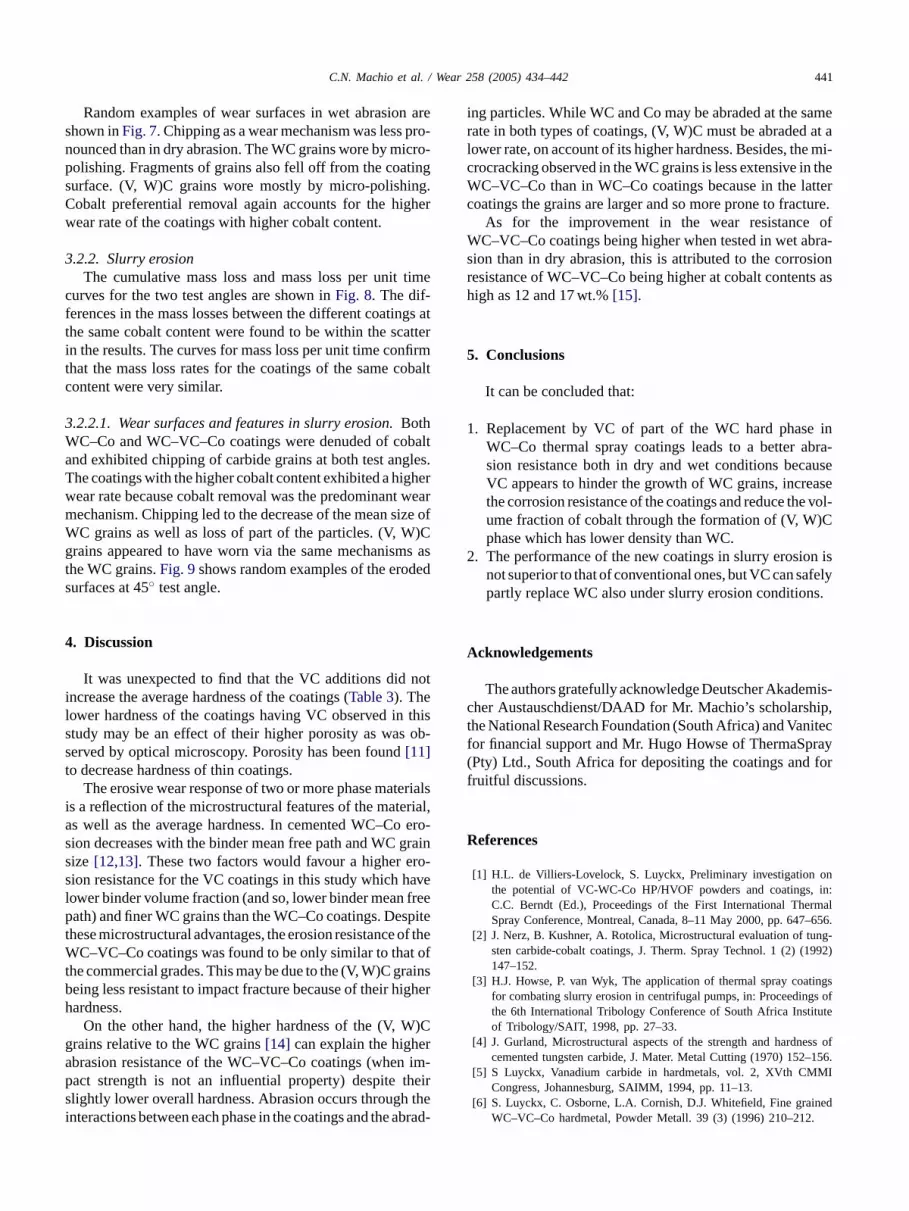
Random examples of wear surfaces in wet abrasion areshown inFig. 7. Chipping as a wear mechanism was less pro-nounced than in dry abrasion. The WC grains wore by micro-polishing. Fragments of grains also fell off from the coatingsurface. (V, W)C grains wore mostly by micro-polishing.Cobalt preferential removal again accounts for the higherwear rate of the coatings with higher cobalt content.
3.2.2. Slurry erosionThe cumulative mass loss and mass loss per unit time
curves for the two test angles are shown inFig. 8. The dif-ferences in the mass losses between the different coatings atthe same cobalt content were found to be within the scatterin the results. The curves for mass loss per unit time confirmthat the mass loss rates for the coatings of the same cobaltcontent were very similar.
3.2.2.1. Wear surfaces and features in slurry erosion.BothWC–Co and WC–VC–Co coatings were denuded of cobaltand exhibited chipping of carbide grains at both test angles.The coatings with the higher cobalt content exhibited a higherwear rate because cobalt removal was the predominant wearmechanism. Chipping led to the decrease of the mean size ofWC grains as well as loss of part of the particles. (V, W)Cgrains appeared to have worn via the same mechanisms ast deds
4
notil thiss ob-st
erialsi rial,a o ero-s grains ro-s avel freep spitet of theW t oft rainsb igherh
)Cg ra im-p heirs thei abrad
ing particles. While WC and Co may be abraded at the samerate in both types of coatings, (V, W)C must be abraded at alower rate, on account of its higher hardness. Besides, the mi-crocracking observed in the WC grains is less extensive in theWC–VC–Co than in WC–Co coatings because in the lattercoatings the grains are larger and so more prone to fracture.
As for the improvement in the wear resistance ofWC–VC–Co coatings being higher when tested in wet abra-sion than in dry abrasion, this is attributed to the corrosionresistance of WC–VC–Co being higher at cobalt contents ashigh as 12 and 17 wt.%[15].
5. Conclusions
It can be concluded that:
1. Replacement by VC of part of the WC hard phase inWC–Co thermal spray coatings leads to a better abra-sion resistance both in dry and wet conditions becauseVC appears to hinder the growth of WC grains, increasethe corrosion resistance of the coatings and reduce the vol-ume fraction of cobalt through the formation of (V, W)Cphase which has lower density than WC.
2. The performance of the new coatings in slurry erosion isfelys.
A
mis-c ip,t nitecf ray( forf
R
onin:
rmal–656.ng-992)
tingss of
tute
ss of–156.MI
ned.
he WC grains.Fig. 9shows random examples of the erourfaces at 45◦ test angle.
. Discussion
It was unexpected to find that the VC additions didncrease the average hardness of the coatings (Table 3). Theower hardness of the coatings having VC observed intudy may be an effect of their higher porosity as waserved by optical microscopy. Porosity has been found[11]o decrease hardness of thin coatings.
The erosive wear response of two or more phase mats a reflection of the microstructural features of the mates well as the average hardness. In cemented WC–Cion decreases with the binder mean free path and WCize[12,13]. These two factors would favour a higher eion resistance for the VC coatings in this study which hower binder volume fraction (and so, lower binder meanath) and finer WC grains than the WC–Co coatings. De
hese microstructural advantages, the erosion resistanceC–VC–Co coatings was found to be only similar to tha
he commercial grades. This may be due to the (V, W)C geing less resistant to impact fracture because of their hardness.
On the other hand, the higher hardness of the (V, Wrains relative to the WC grains[14] can explain the highebrasion resistance of the WC–VC–Co coatings (whenact strength is not an influential property) despite tlightly lower overall hardness. Abrasion occurs throughnteractions between each phase in the coatings and the
-not superior to that of conventional ones, but VC can sapartly replace WC also under slurry erosion condition
cknowledgements
The authors gratefully acknowledge Deutscher Akadeher Austauschdienst/DAAD for Mr. Machio’s scholarshhe National Research Foundation (South Africa) and Vaor financial support and Mr. Hugo Howse of ThermaSpPty) Ltd., South Africa for depositing the coatings andruitful discussions.
eferences
[1] H.L. de Villiers-Lovelock, S. Luyckx, Preliminary investigationthe potential of VC-WC-Co HP/HVOF powders and coatings,C.C. Berndt (Ed.), Proceedings of the First International TheSpray Conference, Montreal, Canada, 8–11 May 2000, pp. 647
[2] J. Nerz, B. Kushner, A. Rotolica, Microstructural evaluation of tusten carbide-cobalt coatings, J. Therm. Spray Technol. 1 (2) (1147–152.
[3] H.J. Howse, P. van Wyk, The application of thermal spray coafor combating slurry erosion in centrifugal pumps, in: Proceedingthe 6th International Tribology Conference of South Africa Instiof Tribology/SAIT, 1998, pp. 27–33.
[4] J. Gurland, Microstructural aspects of the strength and hardnecemented tungsten carbide, J. Mater. Metal Cutting (1970) 152
[5] S Luyckx, Vanadium carbide in hardmetals, vol. 2, XVth CMCongress, Johannesburg, SAIMM, 1994, pp. 11–13.
[6] S. Luyckx, C. Osborne, L.A. Cornish, D.J. Whitefield, Fine graiWC–VC–Co hardmetal, Powder Metall. 39 (3) (1996) 210–212

442 C.N. Machio et al. / Wear 258 (2005) 434–442
[7] D. du Randt, S. Luyckx, D. Markoulides, I.T. Northrop, D.J. White-field, A comparison between ultrafine WC-Co and fine WC-VC-Coalloys, Int. J. Mater. Prod. Technol. 15 (3–5) (2000) 270–274.
[8] C. Machio, M.J. Witcomb, S. Luyckx, Characterisation of new WC-VC-Co thermal spray powders, Proc. Microsc. Soc. Southern Afr.31 (2001) 13.
[9] S. Luyckx, D.J. Whitefield, M.J. Witcomb, L.A. Cornish, The devel-opment of WC–VC–Co hardmetal: a review of past work and newresults, Adv. Powder Metall. Part. Mater. (1998) 1-85–1-91.
[10] C. Machio, S. Luyckx, private communication, 2003.[11] P.J. Burnett, D.S. Rickerby, The mechanical properties of wear-
resistant coatings. II: Experimental studies and interpretation of hard-ness, Thin Solid Films 148 (1987) 51–65.
[12] V.A. Pugsley, C. Allen, The slurry erosion of ultrafine tungstencarbide–cobalt, in: Proceedings of the 6th International TribologyConference of South Africa Institute of Tribology/SAIT, 1998, pp.364–370.
[13] D.K. Shetty, I.G. Wright, J.T. Stropki, Slurry erosion of WC–Cocermets and ceramics, Trans. ASLE 28 (1) (1984) 123–133.
[14] J. Zinyana, S. Broccardo, S. Hamar-Thibault, L.A. Cornish, M.J.Witcomb, C.H. Allibert, S. Luyckx, Effect of composition on the(V, W)C constitution in V-W-C-Co alloys, in: Plansee Proceedings,Austria, 2001, pp. 291–298.
[15] S. Broccardo, An investigation into the corrosion resistance ofWC–VC–Co hardmetals, M.Sc. Dissertation, University of the Wit-watersrand, 2003.


