Embed Size (px)
Citation preview
PET
TECHNICAL HANDBOOK
INTRODUCTION
PET IS AN AMORPHOUS, SOLID PLASTIC SHEET, WHICH CAN BE
MANUFACTURED IN TRANSPARENT, TRANSLUCENT OR COLOURED FORM. IT
IS MADE OF A PURE PET (POLYETHYLENE TEREPHTHALATE) WHICH IS A
THERMOPLASTIC POLYESTER. THIS PLASTIC IS WIDELY KNOWN FROM ITS
USE IN FOOD PACKAGING (PET-SOFT DRINK BOTTLES), AS FIBRES USED IN
CLOTHING (TREVIRA) AND AS VIDEOTAPE (
HOSTAPHAN).
Process innovation has made it possible to extrude this material into sheets of thickness
between 1 to 6mm which combine good mechanical and optical properties. The unique
combination of properties of PET are supplemented by good fire resistance, compliance with
FDA/BGA requirements for contact with foodstuffs, and the ability of any waste sheet to be
used in existing recycling facilities for PET.
This technical handbook describes the different properties of PET, details the test methods,
and explains the results. In general, the tests are performed according to ISO methods. A
reference to the corresponding DIN and/or ASTM method is made where appropriate.
PROPERTIES OF PET
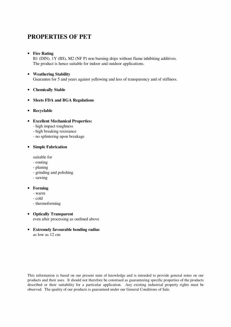
• Fire Rating
B1 (DIN), 1Y (BS), M2 (NF P) non burning drips without flame inhibiting additives.
The product is hence suitable for indoor and outdoor applications.
• Weathering Stability
Guarantee for 5 and years against yellowing and less of transparency and of stiffness.
• Chemically Stable
• Meets FDA and BGA Regulations
• Recyclable
• Excellent Mechanical Properties:
- high impact toughness
- high breaking resistance
- no splintering upon breakage
• Simple Fabrication
suitable for
- routing
- planing
- grinding and polishing
- sawing
• Forming
- warm
- cold
- thermoforming
• Optically Transparent
even after processing as outlined above
• Extremely favourable bending radius
as low as 12 cm
This information is based on our present state of knowledge and is intended to provide general notes on our
products and their uses. It should not therefore be construed as guaranteeing specific properties of the products
described or their suitability for a particular application. Any existing industrial property rights must be
observed. The quality of our products is guaranteed under our General Conditions of Sale.
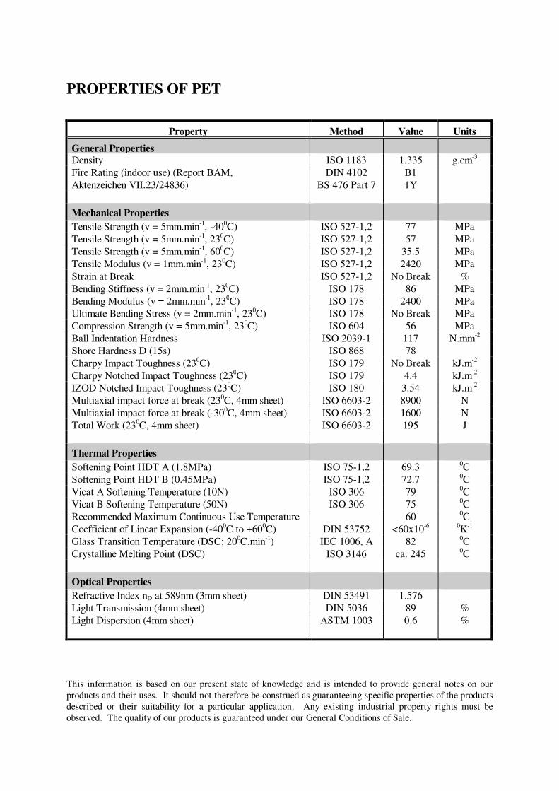
PROPERTIES OF PET
Property Method Value Units
General Properties
Density ISO 1183 1.335 g.cm-3
Fire Rating (indoor use) (Report BAM,
Aktenzeichen VII.23/24836)
DIN 4102
BS 476 Part 7
B1
1Y
Mechanical Properties
Tensile Strength (v = 5mm.min-1
, -400C) ISO 527-1,2 77 MPa
Tensile Strength (v = 5mm.min-1
, 230C) ISO 527-1,2 57 MPa
Tensile Strength (v = 5mm.min-1
, 600C) ISO 527-1,2 35.5 MPa
Tensile Modulus (v = 1mm.min-1
, 230C) ISO 527-1,2 2420 MPa
Strain at Break ISO 527-1,2 No Break %
Bending Stiffness (v = 2mm.min-1
, 230C) ISO 178 86 MPa
Bending Modulus (v = 2mm.min-1
, 230C) ISO 178 2400 MPa
Ultimate Bending Stress (v = 2mm.min-1
, 230C) ISO 178 No Break MPa
Compression Strength (v = 5mm.min-1
, 230C) ISO 604 56 MPa
Ball Indentation Hardness ISO 2039-1 117 N.mm-2
Shore Hardness D (15s) ISO 868 78
Charpy Impact Toughness (230C) ISO 179 No Break kJ.m
-2
Charpy Notched Impact Toughness (230C) ISO 179 4.4 kJ.m
-2
IZOD Notched Impact Toughness (230C) ISO 180 3.54 kJ.m
-2
Multiaxial impact force at break (230C, 4mm sheet) ISO 6603-2 8900 N
Multiaxial impact force at break (-300C, 4mm sheet) ISO 6603-2 1600 N
Total Work (230C, 4mm sheet) ISO 6603-2 195 J
Thermal Properties
Softening Point HDT A (1.8MPa) ISO 75-1,2 69.3 0C
Softening Point HDT B (0.45MPa) ISO 75-1,2 72.7 0C
Vicat A Softening Temperature (10N) ISO 306 79 0C
Vicat B Softening Temperature (50N) ISO 306 75 0C
Recommended Maximum Continuous Use Temperature 60 0C
Coefficient of Linear Expansion (-400C to +60
0C) DIN 53752 <60x10
-6
0K
-1
Glass Transition Temperature (DSC; 200C.min
-1) IEC 1006, A 82
0C
Crystalline Melting Point (DSC) ISO 3146 ca. 245 0C
Optical Properties
Refractive Index nD at 589nm (3mm sheet) DIN 53491 1.576
Light Transmission (4mm sheet) DIN 5036 89 %
Light Dispersion (4mm sheet) ASTM 1003 0.6 %
This information is based on our present state of knowledge and is intended to provide general notes on our
products and their uses. It should not therefore be construed as guaranteeing specific properties of the products
described or their suitability for a particular application. Any existing industrial property rights must be
observed. The quality of our products is guaranteed under our General Conditions of Sale.
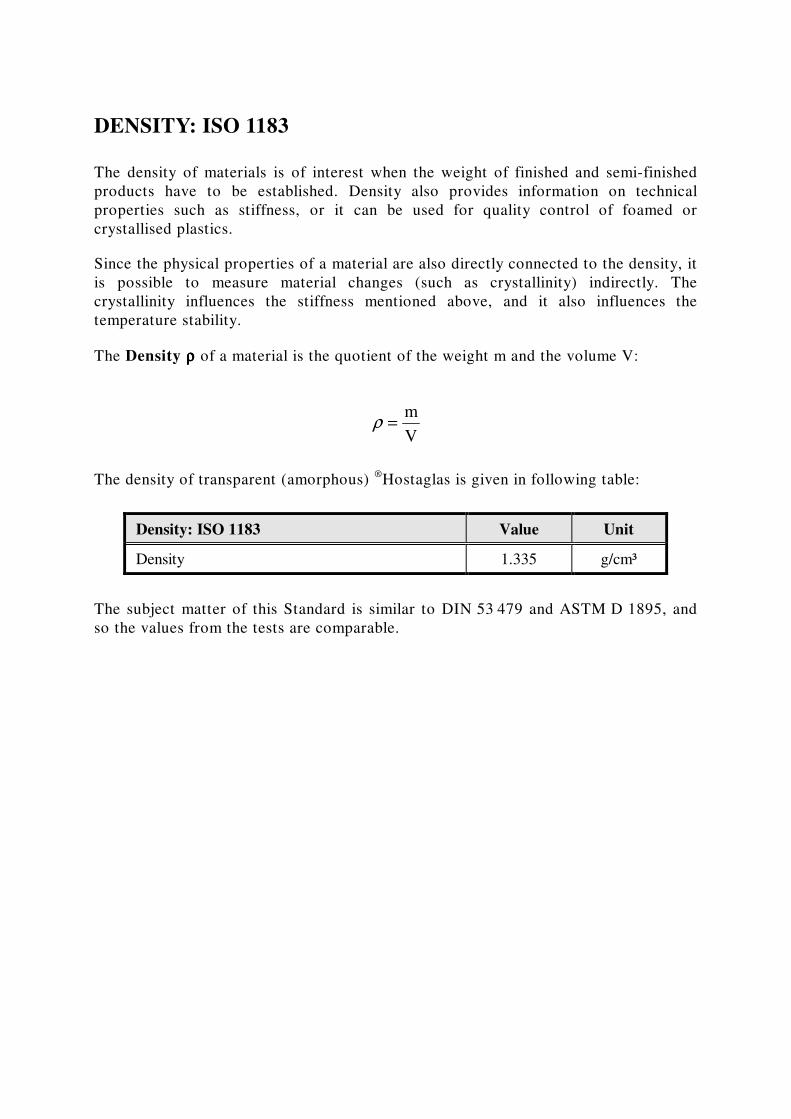
DENSITY: ISO 1183
The density of materials is of interest when the weight of finished and semi-finished
products have to be established. Density also provides information on technical
properties such as stiffness, or it can be used for quality control of foamed or
crystallised plastics.
Since the physical properties of a material are also directly connected to the density, it
is possible to measure material changes (such as crystallinity) indirectly. The
crystallinity influences the stiffness mentioned above, and it also influences the
temperature stability.
The Density ρρρρ of a material is the quotient of the weight m and the volume V:
The density of transparent (amorphous) ®
Hostaglas is given in following table:
Density: ISO 1183 Value Unit
Density 1.335 g/cm³
The subject matter of this Standard is similar to DIN 53 479 and ASTM D 1895, and
so the values from the tests are comparable.
ρ =m
V
FLAMMABILITY: DIN 4102-1
Information on the flammability of plastics is often required if they are used in
building construction. Normally, materials must comply with country-specific tests,
for instance, in Germany, France, Great-Britain and the United States. Sometimes one
country will accept the results of a test mandated by another: Ireland, for example,
accepts and uses the British tests.
In Germany, the flammability of construction materials is tested according to the
Standard DIN 4102-1. Materials are then categorised into non-flammable materials
(building material classes A1 and A2), and flammable materials (building material
classes B1, B2 and B3). Since all plastics are ignitable, they all fall into the categories
B1 to B3, whose requirements are described in the following sections:
• Building material class B1, fire-resistant:
The average of the remaining sample length must be greater than 15cm, and none
of the samples are permitted to have a length of 0cm. The exhaust temperature
must be not greater than 200°C, and the B2 requirements of the small-burner-test
have to be met.
• Building material classes B2, moderately-flammable:
Five samples have to meet the requirements of the small-burner-test. The tip of
the flame must not reach the mark within 20 seconds for any of the samples.
• Building material classes B3, flammable:
All materials fall in category class B3 when they do not comply with the
requirements of class B1 or B2.
In Great Britain plastic sheet is tested according to BS 476 Part 7. This method is
used to rate the speed of the fire propagation on the surface of the sample. The
sample is held vertically. The classification of the test material is made according to
the flame size and the propagation.
The fire rating in France is performed according to NF P92-501. Aside from the fire
rating there is a Standard NF X10-702 which tests smoke and fume behaviour. The M
classification for fire, and the F classification for smoke can then be determined.
The fire rating in the Netherlands is performed according to NEN 6065. Materials are
divided into classes 1 to 5, with 1 being the best, for the surface flame spread and the
contribution to flash-over.
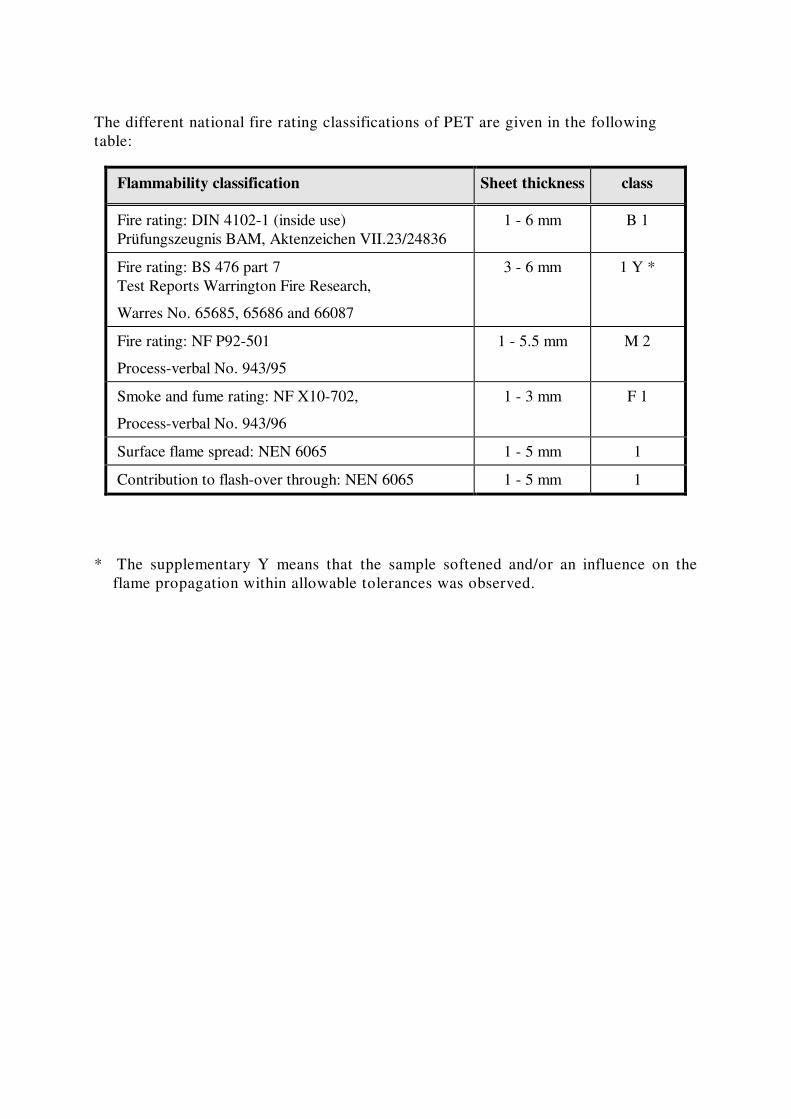
The different national fire rating classifications of PET are given in the following
table:
Flammability classification Sheet thickness class
Fire rating: DIN 4102-1 (inside use)
Prüfungszeugnis BAM, Aktenzeichen VII.23/24836
1 - 6 mm B 1
Fire rating: BS 476 part 7
Test Reports Warrington Fire Research,
Warres No. 65685, 65686 and 66087
3 - 6 mm 1 Y *
Fire rating: NF P92-501
Process-verbal No. 943/95
1 - 5.5 mm M 2
Smoke and fume rating: NF X10-702,
Process-verbal No. 943/96
1 - 3 mm F 1
Surface flame spread: NEN 6065 1 - 5 mm 1
Contribution to flash-over through: NEN 6065 1 - 5 mm 1
* The supplementary Y means that the sample softened and/or an influence on the
flame propagation within allowable tolerances was observed.
BARRIER BEHAVIOUR
Testing the barrier behaviour gives information on the gas and water vapour
permeability through plastics and characterises the barrier properties. The packaging
and container industries which make film, sheet or containers (e.g. bottles) are the
prime industries most interested in these tests.
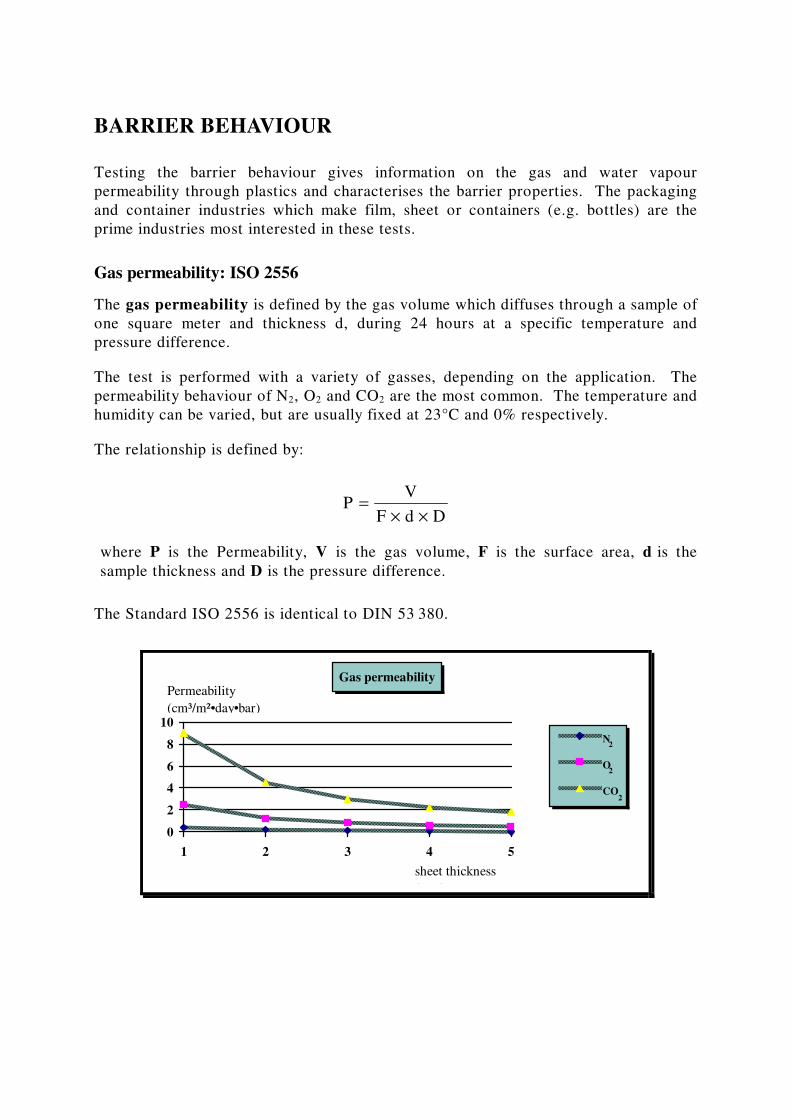
Gas permeability: ISO 2556
The gas permeability is defined by the gas volume which diffuses through a sample of
one square meter and thickness d, during 24 hours at a specific temperature and
pressure difference.
The test is performed with a variety of gasses, depending on the application. The
permeability behaviour of N2, O2 and CO2 are the most common. The temperature and
humidity can be varied, but are usually fixed at 23°C and 0% respectively.
The relationship is defined by:
PV
F d D=
× ×
where P is the Permeability, V is the gas volume, F is the surface area, d is the
sample thickness and D is the pressure difference.
The Standard ISO 2556 is identical to DIN 53 380.
Gas permeability
0
2
4
6
8
10
1 2 3 4 5
N
O
CO
Permeability
(cm³/m²•day•bar)
sheet thickness
(mm)
2
2
2
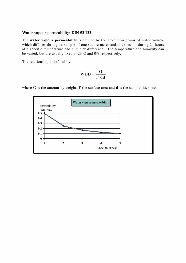
Water vapour permeability: DIN 53 122
The water vapour permeability is defined by the amount in grams of water volume
which diffuses through a sample of one square meter and thickness d, during 24 hours
at a specific temperature and humidity difference. The temperature and humidity can
be varied, but are usually fixed at 23°C and 0% respectively.
The relationship is defined by:
WDDG
F d=
×
where G is the amount by weight, F the surface area and d is the sample thickness
Water vapour permeability
0
0.1
0.2
0.3
0.4
0.5
1 2 3 4 5
Permeability
(g/m²•day)
Sheet thickness
(mm)
MECHANICAL PROPERTIES
For the design engineer, the converter, and the end user of plastics, the most
important mechanical properties are determined by stress-, bend- and pressure
experiments. These properties will allow comparison between different materials and
material qualities. It has to be kept in mind that a detailed comparison of the
behaviour of plastics is only possible when the mechanical property data are
determined under a variety of temperatures and test conditions (e.g. test speeds,
temperatures, sample preparation and preconditioning of the sample).
The experiments are performed as short term measurements on standardised test
specimens under predetermined conditions. For example, the sample pre-treatment
(preconditioning), the test climatisation (e.g. temperature, humidity) and the test
speed are standardised. The test results are dependent on the way samples are
generated, for example, by extrusion or by injection moulding. All the properties
discussed in the following sections are based on samples prepared out of PET sheet
from production.
The mechanical properties of plastics are a variable of time and temperature, since
plastics show a visco-elastic behaviour. These properties are needed for static
stability and deformation calculations of parts which have to withstand long-term
loads and stresses. Therefore the results of the short term measurements discussed in
following sections cannot be used for long term static considerations.
The visco-elastic behaviour can be described with the help of the modulus of elasticity
(or Young’s modulus), which can be determined from standardized measurements.
For instance, the modulus of elasticity is dependent on stress time or the oscillation
frequency during vibration experiments. Plastics show a different elasticity behaviour
compared to natural materials. Holding a sample in place after applying an abrupt
stress for example, shows that the tension will decrease over time. This decrease is
based on molecular relaxation processes, which means that the molecules will adapt to
the new sample shape. The elasticity modulus will therefore also decrease over time.
The modulus of elasticity and the flexural modulus of PET measured with the stress
and the bend test, show almost identical values between -40 °C to 70 °C. It is
interesting to note that only amorphous plastics with a Tg considerably higher than
room temperature behave like this.
TENSILE STRESS BEHAVIOUR - ISO 527-1,2
This test provides some insight to the dependence between longitudinal applied stress
and the deformation behaviour of plastics. Tensions are calculated from their force
and length changes. Plotting the data into a stress-strain curve visualises this
dependence.
Some properties which can be determined are tensile strength, tensile stress at
rupture, yield stress, modulus of elasticity and strain at tensile strength. These
properties are defined as:
The tensile strength is the quotient of the measured maximum force at break (in N)
and the initial cross-section of the sample (in mm²).
The tensile stress at rupture is quotient of the measured force (in N) and the initial
cross-section of the sample (in mm²).
The yield stress is the tensile strength at which the gradient angle of the stress-strain
curve becomes zero for the first time.
The strain is the change in length related to the initial measured length during any
time of the experiment. Usually the strain at rupture and the strain at tensile
strength are specified.
The modulus of elasticity or Young’s modulus is a measure for the stiffness of the
material. It is an important measure for static calculations and can be described as:
S E d³ = ×
Of which S is the stiffness, E is the modulus of elasticity and d is the thickness of the
sample.
The modulus of elasticity is usually measured at the very beginning of the tensile
stress experiment. In this part of the stress-strain curve, it is assumed that plastic
materials still show a fully elastic behaviour. PET has a high modulus of elasticity.
The material shows a distinct stretch range with a high elongation, is not brittle but
behaves in a ductile manner. To give a simple understanding of the relationship it can
be said that a material with a high modulus of elasticity only needs to be thin to
achieve a certain stiffness.
For example, one advantage of a high stretch range is that the material can easily be
thermoformed with good detail and high deformation. On the other hand, a high
modulus of elasticity allows for the use of thinner sheet when only regular
deformation is required, which results in a lower material cost.
The tensile strength and the yield stress are the same for PET. The material also does
not show any rupture between -40 to 70°C at a draw speed of 5mm/min. This means
that PET is very tough.
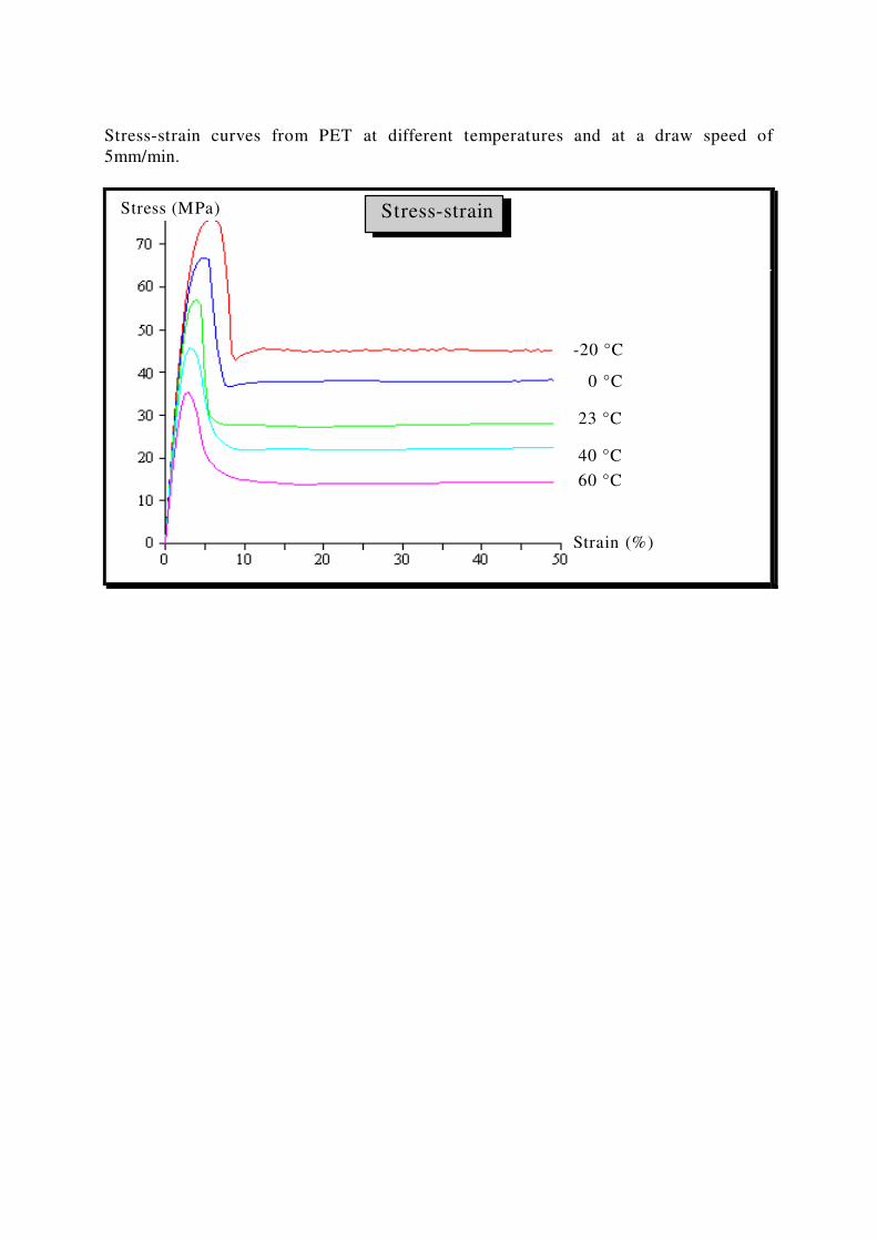
Stress-strain curves from PET at different temperatures and at a draw speed of
5mm/min.
-20 °C
0 °C
23 °C
40 °C
60 °C
Stress (MPa)
Strain (%)
Stress-strain
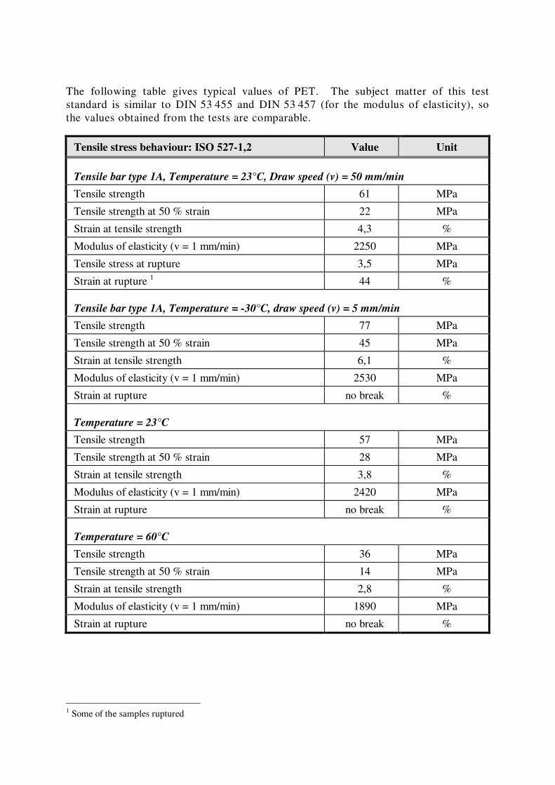
The following table gives typical values of PET. The subject matter of this test
standard is similar to DIN 53 455 and DIN 53 457 (for the modulus of elasticity), so
the values obtained from the tests are comparable.
Tensile stress behaviour: ISO 527-1,2 Value Unit
Tensile bar type 1A, Temperature = 23°C, Draw speed (v) = 50 mm/min
Tensile strength 61 MPa
Tensile strength at 50 % strain 22 MPa
Strain at tensile strength 4,3 %
Modulus of elasticity (v = 1 mm/min) 2250 MPa
Tensile stress at rupture 3,5 MPa
Strain at rupture 1 44 %
Tensile bar type 1A, Temperature = -30°C, draw speed (v) = 5 mm/min
Tensile strength 77 MPa
Tensile strength at 50 % strain 45 MPa
Strain at tensile strength 6,1 %
Modulus of elasticity (v = 1 mm/min) 2530 MPa
Strain at rupture no break %
Temperature = 23°C
Tensile strength 57 MPa
Tensile strength at 50 % strain 28 MPa
Strain at tensile strength 3,8 %
Modulus of elasticity (v = 1 mm/min) 2420 MPa
Strain at rupture no break %
Temperature = 60°C
Tensile strength 36 MPa
Tensile strength at 50 % strain 14 MPa
Strain at tensile strength 2,8 %
Modulus of elasticity (v = 1 mm/min) 1890 MPa
Strain at rupture no break %
1 Some of the samples ruptured
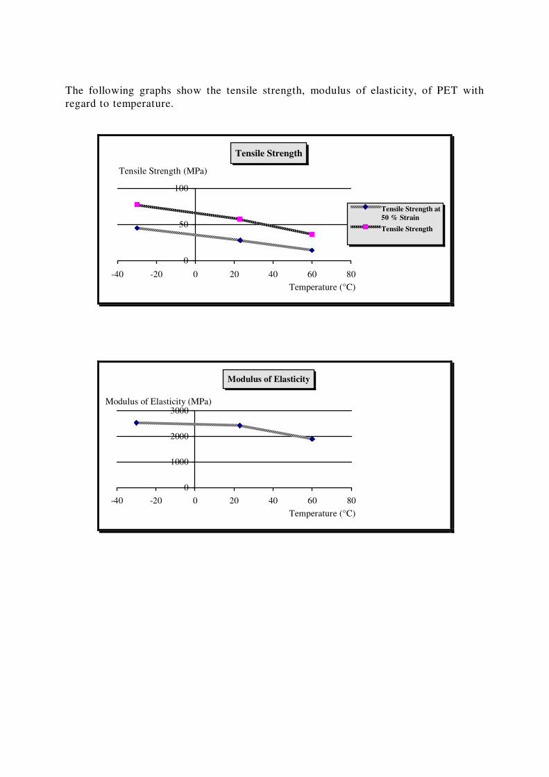
The following graphs show the tensile strength, modulus of elasticity, of PET with
regard to temperature.
Tensile Strength
0
50
100
-40 -20 0 20 40 60 80
Tensile Strength at
50 % Strain
Tensile Strength
Tensile Strength (MPa)
Temperature (°C)
Modulus of Elasticity
0
1000
2000
3000
-40 -20 0 20 40 60 80
Modulus of Elasticity (MPa)
Temperature (°C)
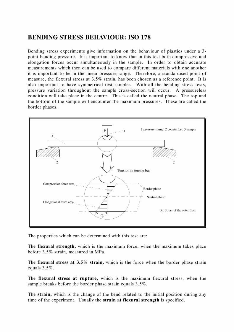
BENDING STRESS BEHAVIOUR: ISO 178
Bending stress experiments give information on the behaviour of plastics under a 3-
point bending pressure. It is important to know that in this test both compressive and
elongation forces occur simultaneously in the sample. In order to obtain accurate
measurements which then can be used to compare different materials with one another
it is important to be in the linear pressure range. Therefore, a standardised point of
measure, the flexural stress at 3.5% strain, has been chosen as a reference point. It is
also important to have symmetrical test samples. With all the bending stress tests,
pressure variation throughout the sample cross-section will occur. A pressureless
condition will take place in the centre. This is called the neutral phase. The top and
the bottom of the sample will encounter the maximum pressures. These are called the
border phases.
F 1
3
2 2
1 pressure stamp, 2 counterfort, 3 sample
σF
σF: Stress of the outer fiber
Neutral phase
Border phase
Tension in tensile bar
Compression force area
Elongational force area
The properties which can be determined with this test are:
The flexural strength, which is the maximum force, when the maximum takes place
before 3.5% strain, measured in MPa.
The flexural stress at 3.5% strain, which is the force when the border phase strain
equals 3.5%.
The flexural stress at rupture, which is the maximum flexural stress, when the
sample breaks before the border phase strain equals 3.5%.
The strain, which is the change of the bend related to the initial position during any
time of the experiment. Usually the strain at flexural strength is specified.
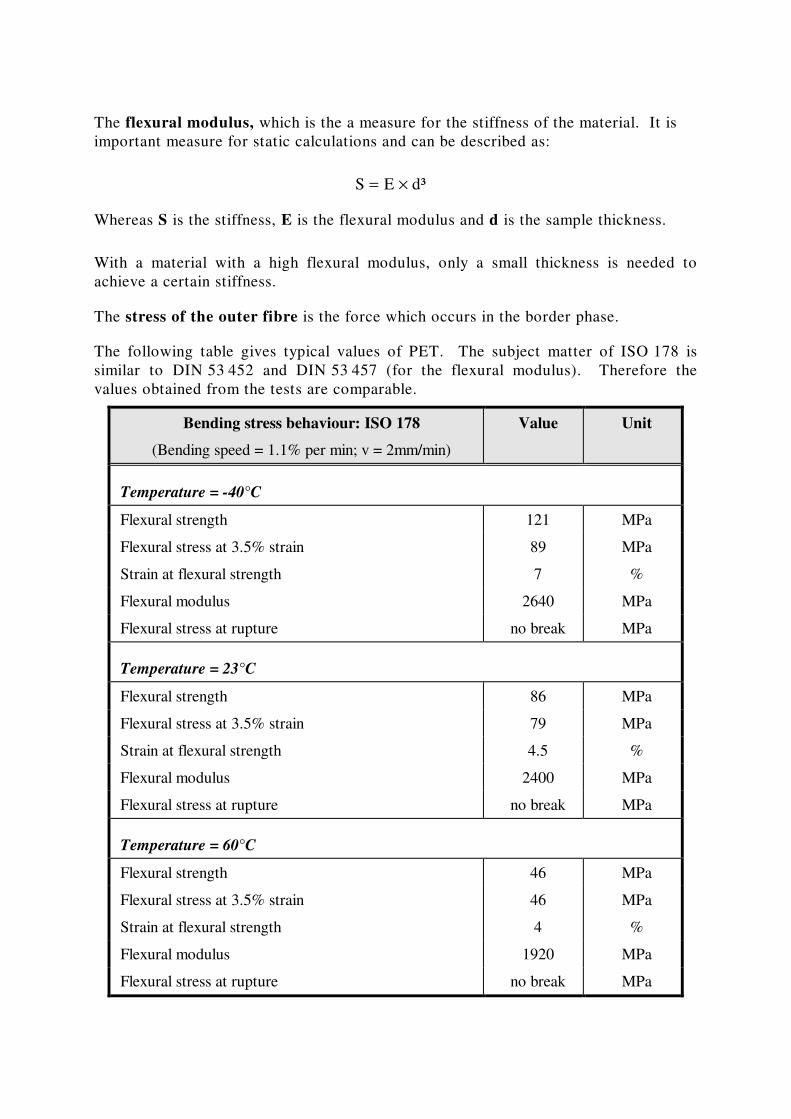
The flexural modulus, which is the a measure for the stiffness of the material. It is
important measure for static calculations and can be described as:
S E d³ = ×
Whereas S is the stiffness, E is the flexural modulus and d is the sample thickness.
With a material with a high flexural modulus, only a small thickness is needed to
achieve a certain stiffness.
The stress of the outer fibre is the force which occurs in the border phase.
The following table gives typical values of PET. The subject matter of ISO 178 is
similar to DIN 53 452 and DIN 53 457 (for the flexural modulus). Therefore the
values obtained from the tests are comparable.
Bending stress behaviour: ISO 178
(Bending speed = 1.1% per min; v = 2mm/min)
Value Unit
Temperature = -40°C
Flexural strength 121 MPa
Flexural stress at 3.5% strain 89 MPa
Strain at flexural strength 7 %
Flexural modulus 2640 MPa
Flexural stress at rupture no break MPa
Temperature = 23°C
Flexural strength 86 MPa
Flexural stress at 3.5% strain 79 MPa
Strain at flexural strength 4.5 %
Flexural modulus 2400 MPa
Flexural stress at rupture no break MPa
Temperature = 60°C
Flexural strength 46 MPa
Flexural stress at 3.5% strain 46 MPa
Strain at flexural strength 4 %
Flexural modulus 1920 MPa
Flexural stress at rupture no break MPa
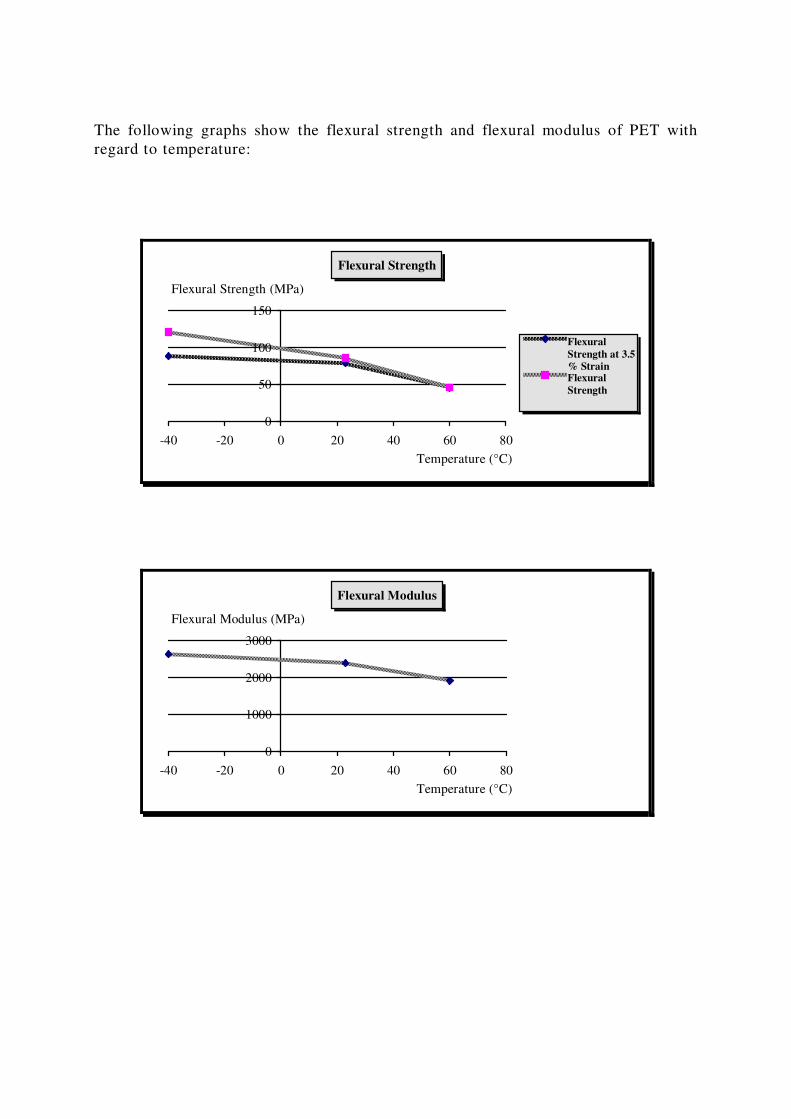
The following graphs show the flexural strength and flexural modulus of PET with
regard to temperature:
Flexural Strength
0
50
100
150
-40 -20 0 20 40 60 80
Flexural
Strength at 3.5
% StrainFlexural
Strength
Flexural Strength (MPa)
Temperature (°C)
Flexural Modulus
0
1000
2000
3000
-40 -20 0 20 40 60 80
Flexural Modulus (MPa)
Temperature (°C)
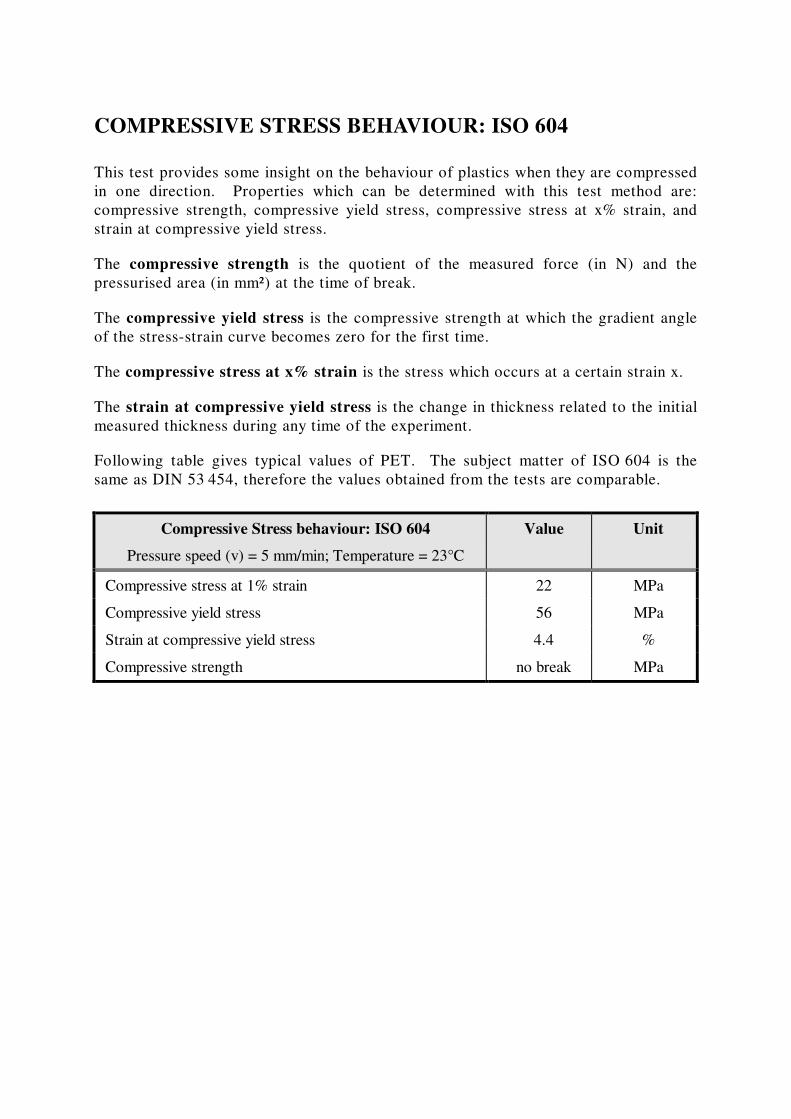
COMPRESSIVE STRESS BEHAVIOUR: ISO 604
This test provides some insight on the behaviour of plastics when they are compressed
in one direction. Properties which can be determined with this test method are:
compressive strength, compressive yield stress, compressive stress at x% strain, and
strain at compressive yield stress.
The compressive strength is the quotient of the measured force (in N) and the
pressurised area (in mm²) at the time of break.
The compressive yield stress is the compressive strength at which the gradient angle
of the stress-strain curve becomes zero for the first time.
The compressive stress at x% strain is the stress which occurs at a certain strain x.
The strain at compressive yield stress is the change in thickness related to the initial
measured thickness during any time of the experiment.
Following table gives typical values of PET. The subject matter of ISO 604 is the
same as DIN 53 454, therefore the values obtained from the tests are comparable.
Compressive Stress behaviour: ISO 604
Pressure speed (v) = 5 mm/min; Temperature = 23°C
Value Unit
Compressive stress at 1% strain 22 MPa
Compressive yield stress 56 MPa
Strain at compressive yield stress 4.4 %
Compressive strength no break MPa
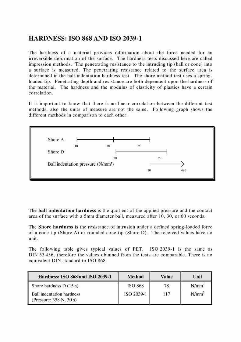
HARDNESS: ISO 868 AND ISO 2039-1
The hardness of a material provides information about the force needed for an
irreversible deformation of the surface. The hardness tests discussed here are called
impression methods. The penetrating resistance to the intruding tip (ball or cone) into
a surface is measured. The penetrating resistance related to the surface area is
determined in the ball-indentation hardness test. The shore method test uses a spring-
loaded tip. Penetrating depth and resistance are both dependent upon the hardness of
the material. The hardness and the modulus of elasticity of plastics have a certain
correlation.
It is important to know that there is no linear correlation between the different test
methods, also the units of measure are not the same. Following graph shows the
different methods in comparison to each other.
Shore A
Shore D
Ball indentation pressure (N/mm²)
10 40 90
30 90
10 480
The ball indentation hardness is the quotient of the applied pressure and the contact
area of the surface with a 5mm diameter ball, measured after 10, 30, or 60 seconds.
The Shore hardness is the resistance of intrusion under a defined spring-loaded force
of a cone tip (Shore A) or rounded cone tip (Shore D). The received values have no
unit.
The following table gives typical values of PET. ISO 2039-1 is the same as
DIN 53 456, therefore the values obtained from the tests are comparable. There is no
equivalent DIN standard to ISO 868.
Hardness: ISO 868 and ISO 2039-1 Method Value Unit
Shore hardness D (15 s) ISO 868 78 N/mm2
Ball indentation hardness
(Pressure: 358 N, 30 s)
ISO 2039-1
117
N/mm2
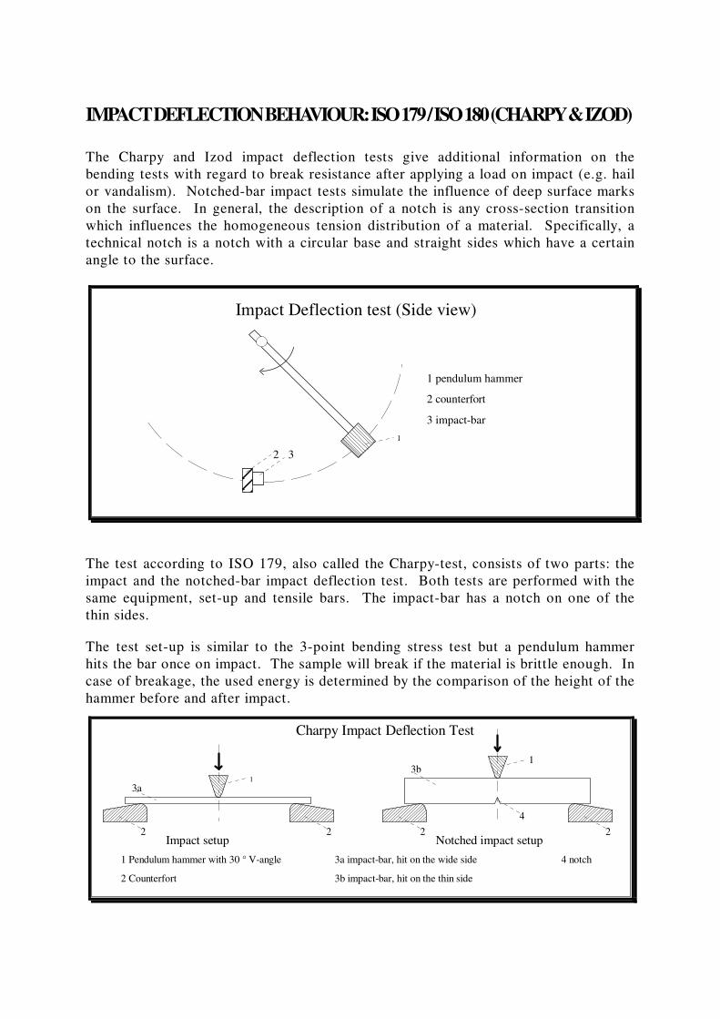
IMPACT DEFLECTION BEHAVIOUR: ISO 179 / ISO 180 (CHARPY & IZOD)
The Charpy and Izod impact deflection tests give additional information on the
bending tests with regard to break resistance after applying a load on impact (e.g. hail
or vandalism). Notched-bar impact tests simulate the influence of deep surface marks
on the surface. In general, the description of a notch is any cross-section transition
which influences the homogeneous tension distribution of a material. Specifically, a
technical notch is a notch with a circular base and straight sides which have a certain
angle to the surface.
1 pendulum hammer
2
Impact Deflection test (Side view)
3 impact-bar
3
2 counterfort
1
The test according to ISO 179, also called the Charpy-test, consists of two parts: the
impact and the notched-bar impact deflection test. Both tests are performed with the
same equipment, set-up and tensile bars. The impact-bar has a notch on one of the
thin sides.
The test set-up is similar to the 3-point bending stress test but a pendulum hammer
hits the bar once on impact. The sample will break if the material is brittle enough. In
case of breakage, the used energy is determined by the comparison of the height of the
hammer before and after impact.
1 Pendulum hammer with 30 ° V-angle
1
3a
2 2
Charpy Impact Deflection Test
3a impact-bar, hit on the wide side
13b
2 2
3b impact-bar, hit on the thin side
4 notch
4
Impact setup Notched impact setup
2 Counterfort

The test according to ISO 180, called the Izod-test, also consists of two parts, the
impact and the notched-bar impact deflection test. Both tests are performed with the
same equipment and notched-bars, but with a different set-up. The impact-bar has a
notch on one thin side, is held in place between two supports, and is once hit with a
pendulum hammer on impact. The used energy is determined by the comparison of the
height of the hammer before and after impact.
Impact Setup
Izod Impact Deflection Test
1 pendulum hammer
3
1
2
Notched Impact Setup
3
1
2 impact-bar
3 counterfort
The Charpy impact strength is the energy used after breakage of the impact-bar,
related to the initial cross-section.
The notched Charpy impact strength is the energy used after breakage of the
notched impact-bar, related to the initial cross-section at the notch.
The Izod impact strength is the energy used after breakage of the notched impact-
bar, related to the initial cross-section at the notch. The notch is directed away from
the pendulum hammer.
The notched Izod impact strength is the energy used after breakage of the notched
impact-bar, related to the initial cross-section at the notch. The notch is directed into
the direction of the pendulum hammer.
The following table gives typical values for ®
Hostaglas. The subject matter of
ISO 179 is the same as DIN 53 453, so the values obtained from the tests are
comparable. There is no comparable standard for ISO 180.
Impact deflection behaviour: ISO 179 and ISO 180 Method Value Unit
Charpy impact strength at 23°C ISO 179 no break kJ/m²
Charpy impact strength at -30°C ISO 179 73 kJ/m²
Charpy notched impact strength at 23°C ISO 179 4.4 kJ/m²
Charpy notched impact strength at -30°C ISO 179 2.4 kJ/m²
Izod notched impact strength at 23°C ISO 180 3.5 kJ/m²
BI-AXIAL IMPACT BEHAVIOUR: ISO 6603-2
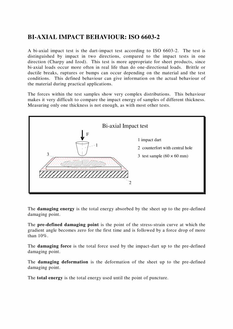
A bi-axial impact test is the dart-impact test according to ISO 6603-2. The test is
distinguished by impact in two directions, compared to the impact tests in one
direction (Charpy and Izod). This test is more appropriate for sheet products, since
bi-axial loads occur more often in real life than do one-directional loads. Brittle or
ductile breaks, ruptures or bumps can occur depending on the material and the test
conditions. This defined behaviour can give information on the actual behaviour of
the material during practical applications.
The forces within the test samples show very complex distributions. This behaviour
makes it very difficult to compare the impact energy of samples of different thickness.
Measuring only one thickness is not enough, as with most other tests.
Bi-axial Impact test
2 counterfort with central hole
3 test sample (60 × 60 mm)
1
1 impact dart
F
3
2
The damaging energy is the total energy absorbed by the sheet up to the pre-defined
damaging point.
The pre-defined damaging point is the point of the stress-strain curve at which the
gradient angle becomes zero for the first time and is followed by a force drop of more
than 10%.
The damaging force is the total force used by the impact-dart up to the pre-defined
damaging point.
The damaging deformation is the deformation of the sheet up to the pre-defined
damaging point.
The total energy is the total energy used until the point of puncture.
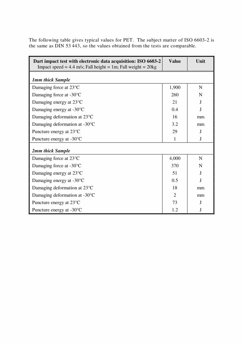
The following table gives typical values for PET. The subject matter of ISO 6603-2 is
the same as DIN 53 443, so the values obtained from the tests are comparable.
Dart impact test with electronic data acquisition: ISO 6603-2
Impact speed = 4.4 m/s; Fall height = 1m; Fall weight = 20kg
Value Unit
1mm thick Sample
Damaging force at 23°C 1,900 N
Damaging force at -30°C 260 N
Damaging energy at 23°C 21 J
Damaging energy at -30°C 0.4 J
Damaging deformation at 23°C 16 mm
Damaging deformation at -30°C 3.2 mm
Puncture energy at 23°C 29 J
Puncture energy at -30°C 1 J
2mm thick Sample
Damaging force at 23°C 4,000 N
Damaging force at -30°C 370 N
Damaging energy at 23°C 51 J
Damaging energy at -30°C 0.5 J
Damaging deformation at 23°C 18 mm
Damaging deformation at -30°C 2 mm
Puncture energy at 23°C 73 J
Puncture energy at -30°C 1.2 J
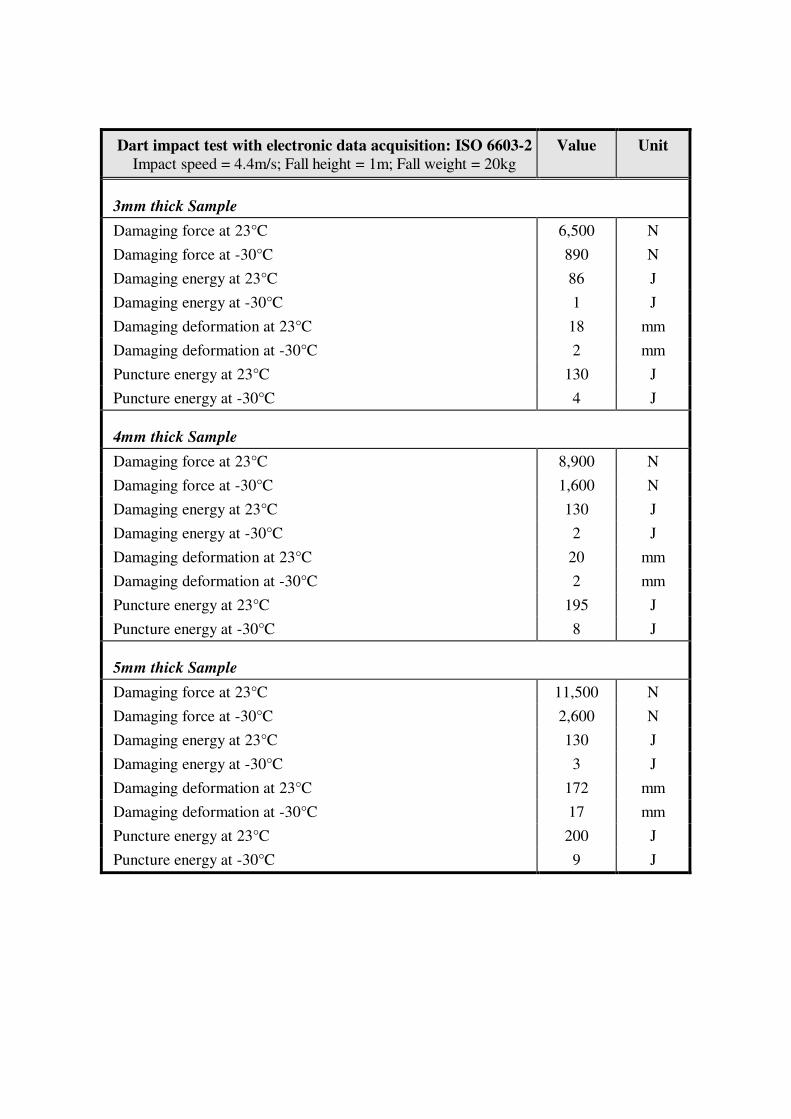
Dart impact test with electronic data acquisition: ISO 6603-2
Impact speed = 4.4m/s; Fall height = 1m; Fall weight = 20kg
Value Unit
3mm thick Sample
Damaging force at 23°C 6,500 N
Damaging force at -30°C 890 N
Damaging energy at 23°C 86 J
Damaging energy at -30°C 1 J
Damaging deformation at 23°C 18 mm
Damaging deformation at -30°C 2 mm
Puncture energy at 23°C 130 J
Puncture energy at -30°C 4 J
4mm thick Sample
Damaging force at 23°C 8,900 N
Damaging force at -30°C 1,600 N
Damaging energy at 23°C 130 J
Damaging energy at -30°C 2 J
Damaging deformation at 23°C 20 mm
Damaging deformation at -30°C 2 mm
Puncture energy at 23°C 195 J
Puncture energy at -30°C 8 J
5mm thick Sample
Damaging force at 23°C 11,500 N
Damaging force at -30°C 2,600 N
Damaging energy at 23°C 130 J
Damaging energy at -30°C 3 J
Damaging deformation at 23°C 172 mm
Damaging deformation at -30°C 17 mm
Puncture energy at 23°C 200 J
Puncture energy at -30°C 9 J
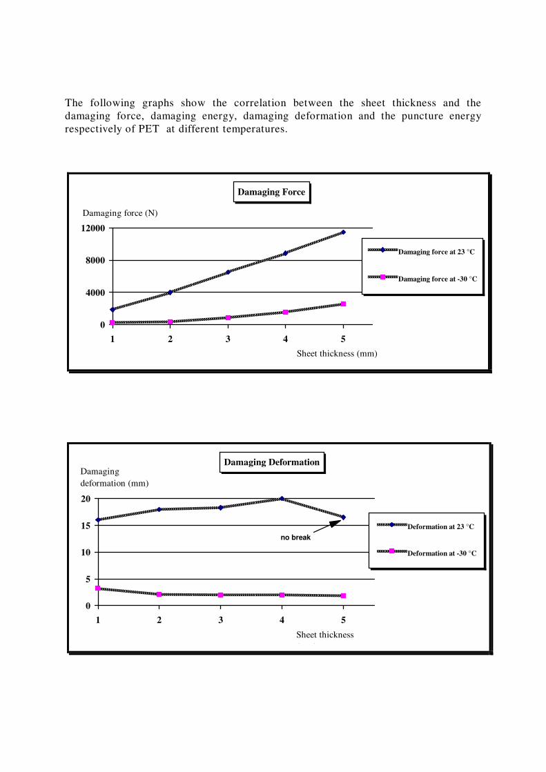
The following graphs show the correlation between the sheet thickness and the
damaging force, damaging energy, damaging deformation and the puncture energy
respectively of PET at different temperatures.
Damaging Force
0
4000
8000
12000
1 2 3 4 5
Damaging force at 23 °C
Damaging force at -30 °C
Damaging force (N)
Sheet thickness (mm)
Damaging Deformation
0
5
10
15
20
1 2 3 4 5
Deformation at 23 °C
Deformation at -30 °C
Damaging
deformation (mm)
Sheet thickness
(mm)
no break
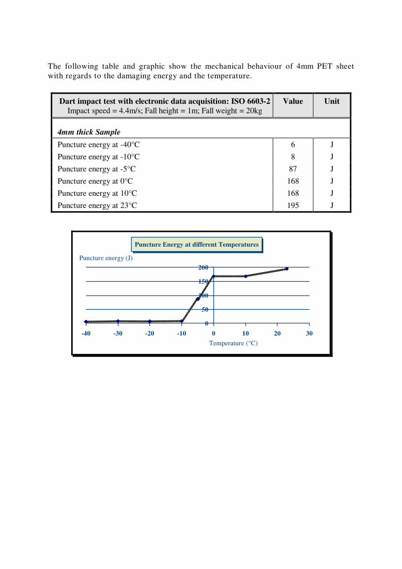
The following table and graphic show the mechanical behaviour of 4mm PET sheet
with regards to the damaging energy and the temperature.
Dart impact test with electronic data acquisition: ISO 6603-2
Impact speed = 4.4m/s; Fall height = 1m; Fall weight = 20kg
Value Unit
4mm thick Sample
Puncture energy at -40°C 6 J
Puncture energy at -10°C 8 J
Puncture energy at -5°C 87 J
Puncture energy at 0°C 168 J
Puncture energy at 10°C 168 J
Puncture energy at 23°C 195 J
Puncture Energy at different Temperatures
0
50
100
150
200
-40 -30 -20 -10 0 10 20 30
Puncture energy (J)
Temperature (°C)
OPTICAL PROPERTIES
LIGHT TRANSMISSION AND HAZE: ASTM D 1003
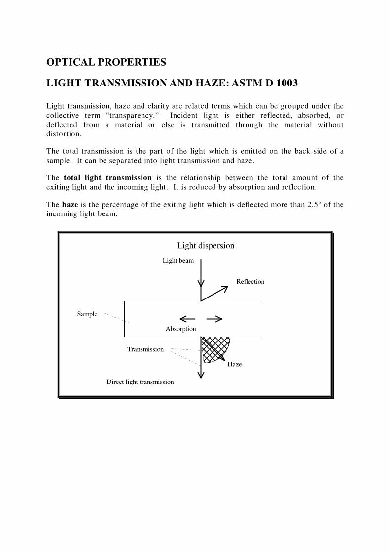
Light transmission, haze and clarity are related terms which can be grouped under the
collective term “transparency.” Incident light is either reflected, absorbed, or
deflected from a material or else is transmitted through the material without
distortion.
The total transmission is the part of the light which is emitted on the back side of a
sample. It can be separated into light transmission and haze.
The total light transmission is the relationship between the total amount of the
exiting light and the incoming light. It is reduced by absorption and reflection.
The haze is the percentage of the exiting light which is deflected more than 2.5° of the
incoming light beam.
Sample
Light beam
Absorption
Direct light transmission
Haze
Reflection
Light dispersion
Transmission
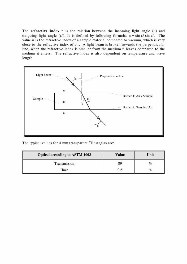
The refractive index n is the relation between the incoming light angle (ε) and
outgoing light angle (ε′). It is defined by following formula: n = sin ε/ sin ε′. The
value n is the refractive index of a sample material compared to vacuum, which is very
close to the refractive index of air. A light beam is broken towards the perpendicular
line, when the refractive index is smaller from the medium it leaves compared to the
medium it enters. The refractive index is also dependent on temperature and wave
length.
ε
ε
n
n
n'ε 'Sample
Border 1: Air / Sample
Border 2: Sample / Airε '
Perpendicular lineLight beam
The typical values for 4 mm transparent ®
Hostaglas are:
Optical according to ASTM 1003 Value Unit
Transmission 89 %
Haze 0.6 %
GLOSS: ISO 2813
Gloss plays an important role with transparent materials. A low gloss means that the
reflected light is dispersed strongly, and the depth-sharpness will be reduced
significantly. This is the case with matte surfaces (anti-reflection). The gloss is
usually measured with a reflectrometer. The reflectometer value, measured according
to DIN 67 530, is based on a black glass standard with a defined refractive index. The
value for this standard is defined as 100 units.
In this measurement, light is directed at the sheet at three different angles: 20°, 60°
and 85°. The 60 degree light angle is preferably used with medium gloss surfaces.
The measured values should be between 10 and 70 gloss units. High gloss surfaces,
which have a higher value at the 60° light angle, should be measured at 20°. Matte
surfaces, on the other hand, should be measured with 85° light. In order to obtain
good results, the surface to be measured should be flat. Special care should be taken
with transparent samples, because the background can influence the measurements.
For these samples a matte, black background is usually used.
Gloss is defined as the ratio of the reflective light intensity of the sample and the
intensity of a high quality optical mirror used as the reference.
The typical values for 4 mm transparent PET are:
Gloss: ASTM 2813 Value Unit
Gloss 20° 170 -
Gloss 60° 140 -
ISO 2813 is comparable to DIN 67 530 and ASTM D 2457.
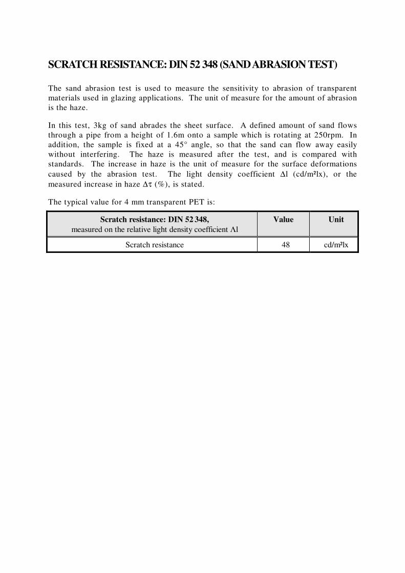
SCRATCH RESISTANCE: DIN 52 348 (SAND ABRASION TEST)
The sand abrasion test is used to measure the sensitivity to abrasion of transparent
materials used in glazing applications. The unit of measure for the amount of abrasion
is the haze.
In this test, 3kg of sand abrades the sheet surface. A defined amount of sand flows
through a pipe from a height of 1.6m onto a sample which is rotating at 250rpm. In
addition, the sample is fixed at a 45° angle, so that the sand can flow away easily
without interfering. The haze is measured after the test, and is compared with
standards. The increase in haze is the unit of measure for the surface deformations
caused by the abrasion test. The light density coefficient ∆l (cd/m²lx), or the
measured increase in haze ∆τ (%), is stated.
The typical value for 4 mm transparent PET is:
Scratch resistance: DIN 52 348,
measured on the relative light density coefficient Λl
Value Unit
Scratch resistance 48 cd/m²lx
TEMPERATURE BEHAVIOUR
Hostaglas is a transparent amorphous thermoplastic. The molecules of amorphous
thermoplastics are not arranged in a structure but are randomly distributed. The
molecules can therefore move easily when the material is heated. The flat PET sheet
can be reformed with heat and pressure into another shape, e.g., by pressure or
vacuum forming, or hot-bending, to produce a three-dimensional part.
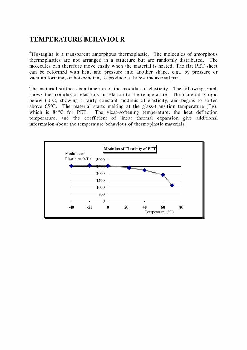
The material stiffness is a function of the modulus of elasticity. The following graph
shows the modulus of elasticity in relation to the temperature. The material is rigid
below 60°C, showing a fairly constant modulus of elasticity, and begins to soften
above 65°C. The material starts melting at the glass-transition temperature (Tg),
which is 84°C for PET. The vicat-softening temperature, the heat deflection
temperature, and the coefficient of linear thermal expansion give additional
information about the temperature behaviour of thermoplastic materials.
Modulus of Elasticity of PET
0
500
1000
1500
2000
2500
3000
-40 -20 0 20 40 60 80
Modulus of
Elasticity (MPa)
Temperature (°C)
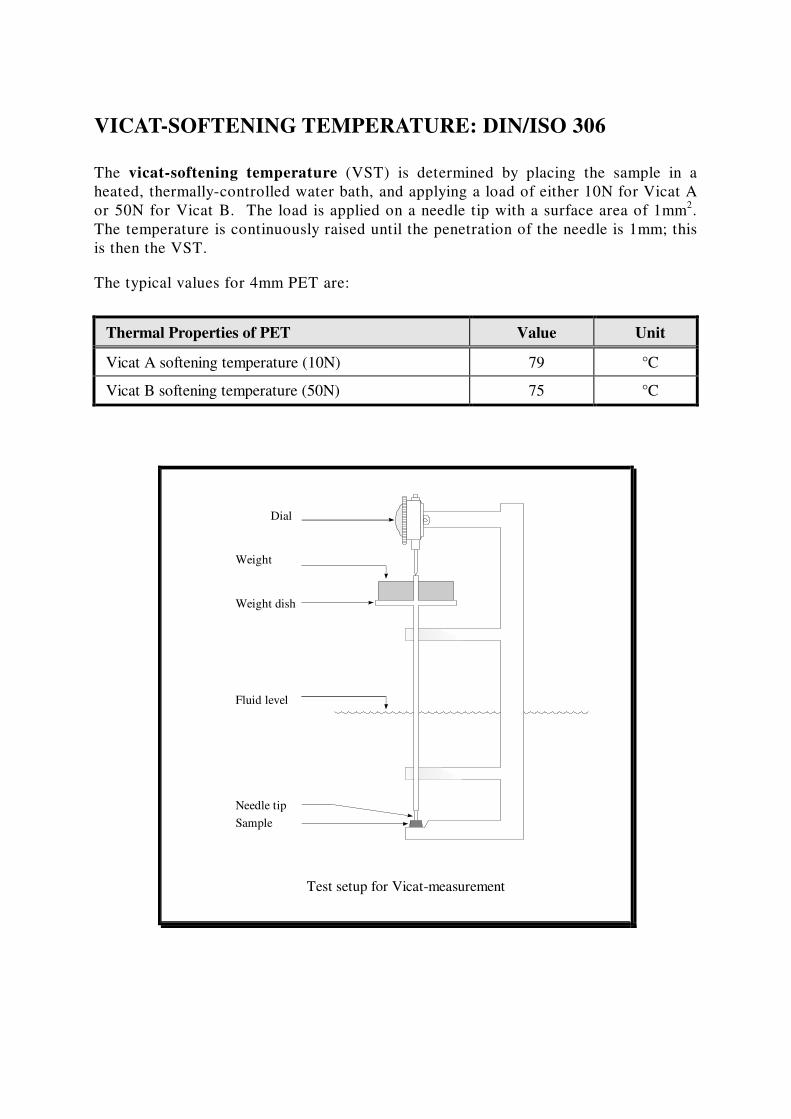
VICAT-SOFTENING TEMPERATURE: DIN/ISO 306
The vicat-softening temperature (VST) is determined by placing the sample in a
heated, thermally-controlled water bath, and applying a load of either 10N for Vicat A
or 50N for Vicat B. The load is applied on a needle tip with a surface area of 1mm2.
The temperature is continuously raised until the penetration of the needle is 1mm; this
is then the VST.
The typical values for 4mm PET are:
Thermal Properties of PET Value Unit
Vicat A softening temperature (10N) 79 °C
Vicat B softening temperature (50N) 75 °C
Sample
Needle tip
Test setup for Vicat-measurement
Fluid level
Weight dish
Weight
Dial
HEAT DEFLECTION TEMPERATURE (HDT): ISO 75-1,2
The test set-up is similar to the set-up of the vicat-softening temperature. In this case,
the sample rests on two supports while a load is applied in the centre of either 1.8MPa
for HDT A, or 0.5MPa for HDT B.
The Heat Deflection Temperature is the temperature where the strain in the border
face equals 0.2%.
Thermal Properties of PET Value Unit
HDT A (1.8MPa) 69.3 °C
HDT B (0.45MPa) 72.7 °C
ISO 75-1,2 is the same as DIN 53 461, so the values obtained from the tests are
comparable.
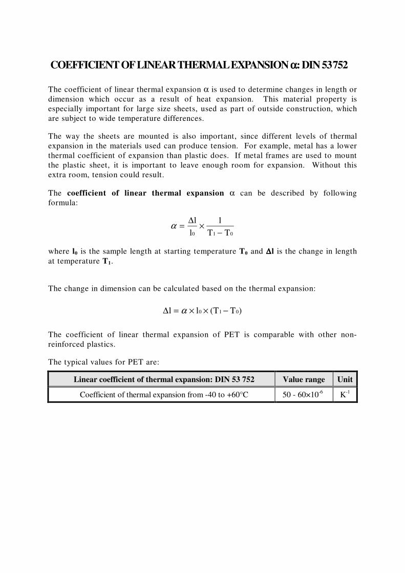
COEFFICIENT OF LINEAR THERMAL EXPANSION αααα: DIN 53 752
The coefficient of linear thermal expansion α is used to determine changes in length or
dimension which occur as a result of heat expansion. This material property is
especially important for large size sheets, used as part of outside construction, which
are subject to wide temperature differences.
The way the sheets are mounted is also important, since different levels of thermal
expansion in the materials used can produce tension. For example, metal has a lower
thermal coefficient of expansion than plastic does. If metal frames are used to mount
the plastic sheet, it is important to leave enough room for expansion. Without this
extra room, tension could result.
The coefficient of linear thermal expansion α can be described by following
formula:
where l0 is the sample length at starting temperature T0 and ∆∆∆∆l is the change in length
at temperature T1.
The change in dimension can be calculated based on the thermal expansion:
∆l l (T T )0 1 0= × × −α
The coefficient of linear thermal expansion of PET is comparable with other non-
reinforced plastics.
The typical values for PET are:
Linear coefficient of thermal expansion: DIN 53 752 Value range Unit
Coefficient of thermal expansion from -40 to +60°C 50 - 60×10-6
K-1
α = ×−
∆l
l
1
T T0 1 0
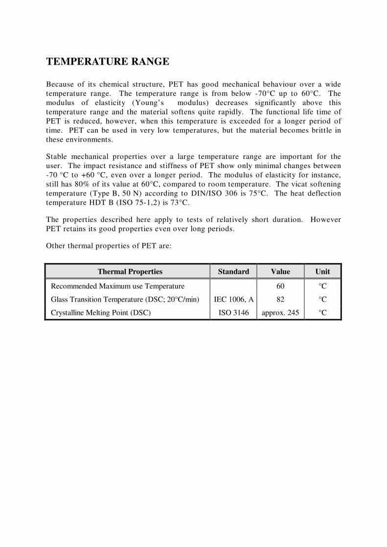
TEMPERATURE RANGE
Because of its chemical structure, PET has good mechanical behaviour over a wide
temperature range. The temperature range is from below -70°C up to 60°C. The
modulus of elasticity (Young’s modulus) decreases significantly above this
temperature range and the material softens quite rapidly. The functional life time of
PET is reduced, however, when this temperature is exceeded for a longer period of
time. PET can be used in very low temperatures, but the material becomes brittle in
these environments.
Stable mechanical properties over a large temperature range are important for the
user. The impact resistance and stiffness of PET show only minimal changes between
-70 °C to +60 °C, even over a longer period. The modulus of elasticity for instance,
still has 80% of its value at 60°C, compared to room temperature. The vicat softening
temperature (Type B, 50 N) according to DIN/ISO 306 is 75°C. The heat deflection
temperature HDT B (ISO 75-1,2) is 73°C.
The properties described here apply to tests of relatively short duration. However
PET retains its good properties even over long periods.
Other thermal properties of PET are:
Thermal Properties Standard Value Unit
Recommended Maximum use Temperature 60 °C
Glass Transition Temperature (DSC; 20°C/min) IEC 1006, A 82 °C
Crystalline Melting Point (DSC) ISO 3146 approx. 245 °C
ELECTRICAL BEHAVIOUR
In the electric and electronic industries, the electrical properties of plastics are of
great importance. Plastics are most often used in these industries because of their
excellent insulation properties. Determining the electrical behaviour of plastics is very
complex because there are so many variables. Only a selection of the most important
measurements and properties are explained here.
The methods introduced here are in general according to IEC-standards (International
Electrotechnical Commission Standards), and the corresponding DIN standards.
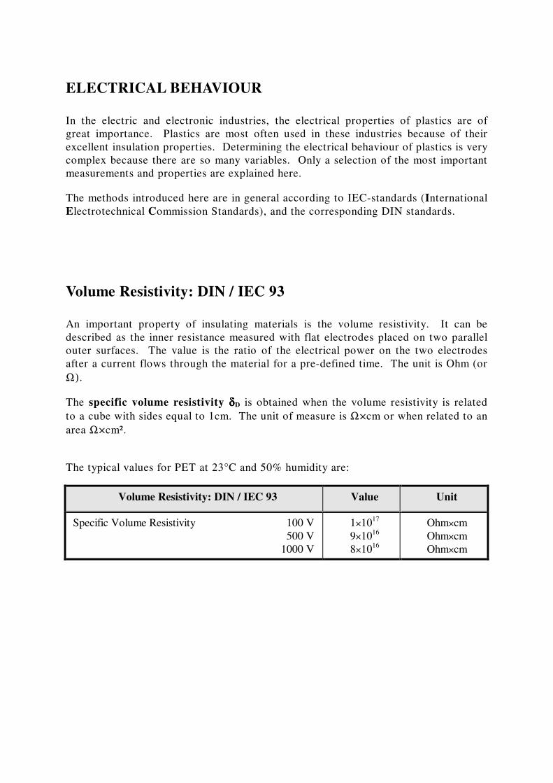
Volume Resistivity: DIN / IEC 93
An important property of insulating materials is the volume resistivity. It can be
described as the inner resistance measured with flat electrodes placed on two parallel
outer surfaces. The value is the ratio of the electrical power on the two electrodes
after a current flows through the material for a pre-defined time. The unit is Ohm (or
Ω).
The specific volume resistivity δδδδD is obtained when the volume resistivity is related
to a cube with sides equal to 1cm. The unit of measure is Ω×cm or when related to an
area Ω×cm².
The typical values for PET at 23°C and 50% humidity are:
Volume Resistivity: DIN / IEC 93 Value Unit
Specific Volume Resistivity 100 V
500 V
1000 V
1×10¹⁷
9×10¹⁶
8×10¹⁶
Ohm×cm
Ohm×cm
Ohm×cm
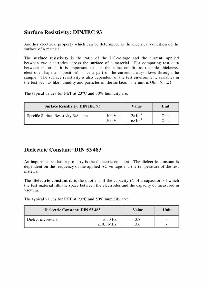
Surface Resistivity: DIN/IEC 93
Another electrical property which can be determined is the electrical condition of the
surface of a material.
The surface resistivity is the ratio of the DC-voltage and the current, applied
between two electrodes across the surface of a material. For comparing test data
between materials it is important to use the same conditions (sample thickness,
electrode shape and position), since a part of the current always flows through the
sample. The surface resistivity is also dependent of the test environment; variables in
the test such as like humidity and particles on the surface. The unit is Ohm (or Ω).
The typical values for PET at 23°C and 50% humidity are:
Surface Resistivity: DIN IEC 93 Value Unit
Specific Surface Resistivity R/Square 100 V
500 V
2×10¹⁴
6×10¹⁴
Ohm
Ohm
Dielectric Constant: DIN 53 483
An important insulation property is the dielectric constant. The dielectric constant is
dependent on the frequency of the applied AC-voltage and the temperature of the test
material.
The dielectric constant εεεεττττ is the quotient of the capacity Cx of a capacitor, of which
the test material fills the space between the electrodes and the capacity Co measured in
vacuum.
The typical values for PET at 23°C and 50% humidity are:
Dielectric Constant: DIN 53 483 Value Unit
Dielectric constant at 50 Hz
at 0.1 MHz
3.8
3.6
-
-
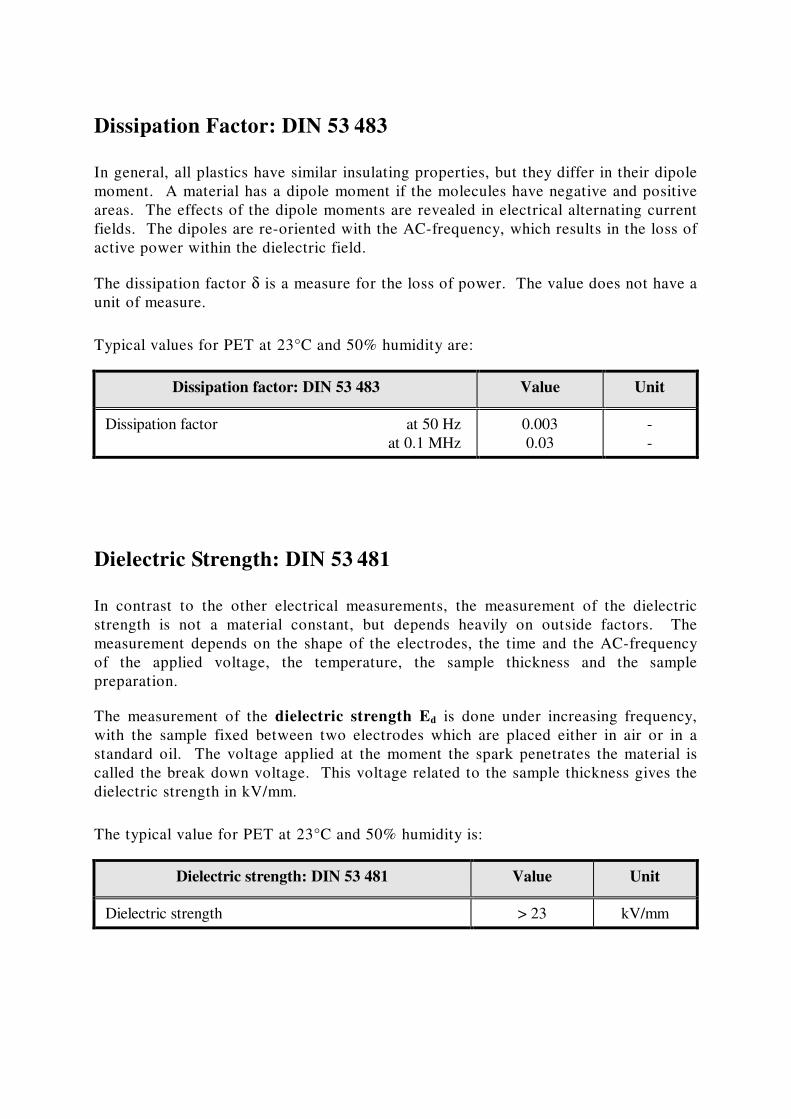
Dissipation Factor: DIN 53 483
In general, all plastics have similar insulating properties, but they differ in their dipole
moment. A material has a dipole moment if the molecules have negative and positive
areas. The effects of the dipole moments are revealed in electrical alternating current
fields. The dipoles are re-oriented with the AC-frequency, which results in the loss of
active power within the dielectric field.
The dissipation factor δ is a measure for the loss of power. The value does not have a
unit of measure.
Typical values for PET at 23°C and 50% humidity are:
Dissipation factor: DIN 53 483 Value Unit
Dissipation factor at 50 Hz
at 0.1 MHz
0.003
0.03
-
-
Dielectric Strength: DIN 53 481
In contrast to the other electrical measurements, the measurement of the dielectric
strength is not a material constant, but depends heavily on outside factors. The
measurement depends on the shape of the electrodes, the time and the AC-frequency
of the applied voltage, the temperature, the sample thickness and the sample
preparation.
The measurement of the dielectric strength Ed is done under increasing frequency,
with the sample fixed between two electrodes which are placed either in air or in a
standard oil. The voltage applied at the moment the spark penetrates the material is
called the break down voltage. This voltage related to the sample thickness gives the
dielectric strength in kV/mm.
The typical value for PET at 23°C and 50% humidity is:
Dielectric strength: DIN 53 481 Value Unit
Dielectric strength > 23 kV/mm

Comparative Tracking Index: DIN/IEC 112
The Comparative Tracking Index (CTI) is a characteristic value of resistance to
electrical leakage. The resistance to electrical leakage is the resistance of an
insulating material against a build-up of a creeping current over a distance.
The test is performed by placing two electrodes which have a electrical potential
difference on the surface of a sample. A certain number of drops of a salt solution are
then placed on the surface in between the electrodes. The Comparative Tracking
Index is defined as the highest voltage which the material can withstand without
showing any creeping current between the electrodes under exposure to 50 drops of a
standardized salt solution.
The typical value for PET at 23°C and 50% humidity is:
Comparative Tracking Index: DIN/IEC 112 Value Unit
Comparative Tracking Index (CTI) 225 -
THERMOFORMING
Thermoforming is a technique commonly employed in the plastics industry. It was originally
regarded as a simple process for producing relatively unsophisticated components, but a host
of innovative modifications have been developed to enable the manufacture of increasingly
more complex mouldings. PET is excellently suited for thermoforming. As with traditional
materials, the moulding process involves heating the sheet to above the glass transition
temperature, forming the sheet to the desired shape, cooling to below the TG and finally
demoulding. PET does not require drying or annealing.
PET sheets can be crystallised during the thermoforming process. Hence, depending upon the
extent of the thermal conditioning treatment following the forming process, it is possible to
retain the favourable property profile of the transparent amorphous sheet, or alternatively
produce crystalline components with increased thermal stability and outstanding resistance to
chemicals.
Some comments valid for the stages in the thermoforming process are given below.
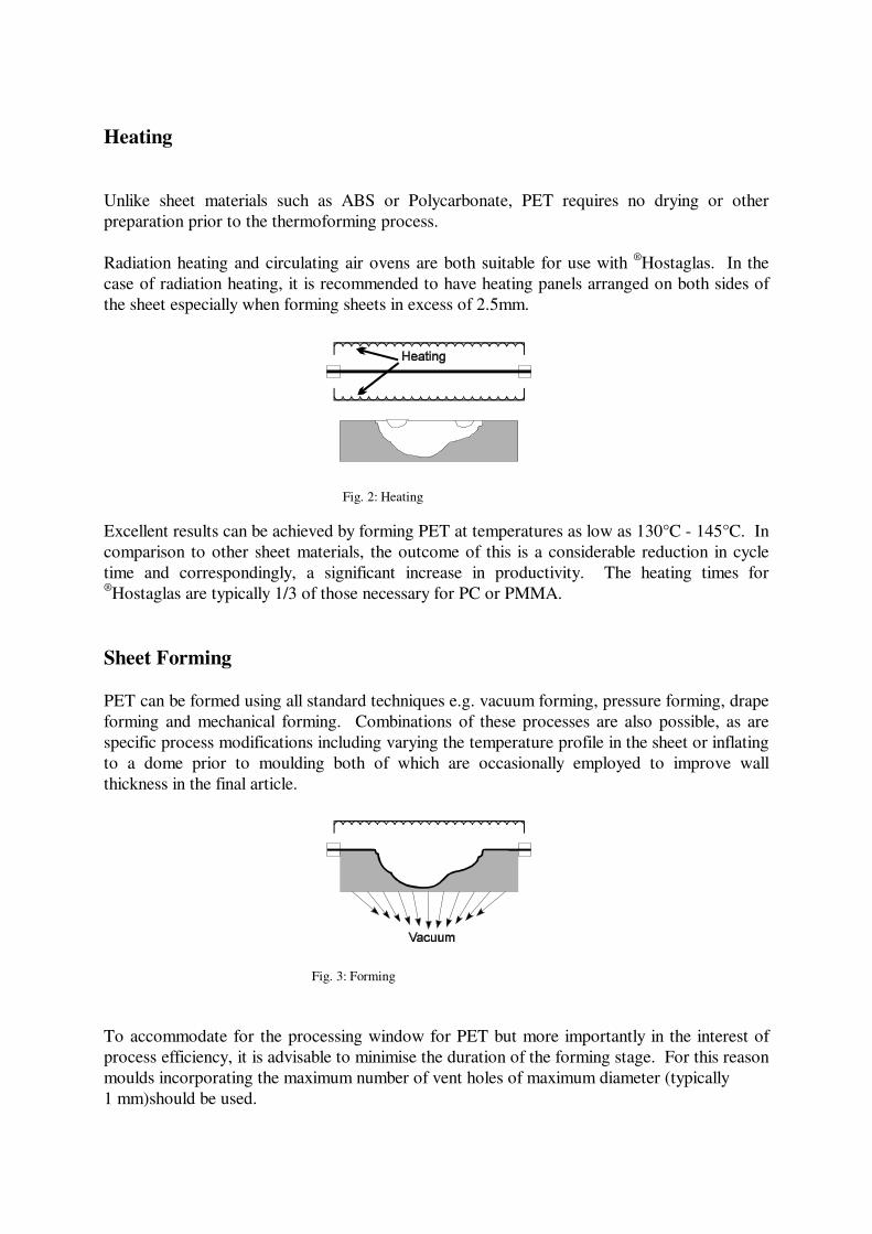
Heating
Unlike sheet materials such as ABS or Polycarbonate, PET requires no drying or other
preparation prior to the thermoforming process.
Radiation heating and circulating air ovens are both suitable for use with ®Hostaglas. In the
case of radiation heating, it is recommended to have heating panels arranged on both sides of
the sheet especially when forming sheets in excess of 2.5mm.
Fig. 2: Heating
Excellent results can be achieved by forming PET at temperatures as low as 130°C - 145°C. In
comparison to other sheet materials, the outcome of this is a considerable reduction in cycle
time and correspondingly, a significant increase in productivity. The heating times for ®Hostaglas are typically 1/3 of those necessary for PC or PMMA.
Sheet Forming
PET can be formed using all standard techniques e.g. vacuum forming, pressure forming, drape
forming and mechanical forming. Combinations of these processes are also possible, as are
specific process modifications including varying the temperature profile in the sheet or inflating
to a dome prior to moulding both of which are occasionally employed to improve wall
thickness in the final article.
Fig. 3: Forming
To accommodate for the processing window for PET but more importantly in the interest of
process efficiency, it is advisable to minimise the duration of the forming stage. For this reason
moulds incorporating the maximum number of vent holes of maximum diameter (typically
1 mm)should be used.
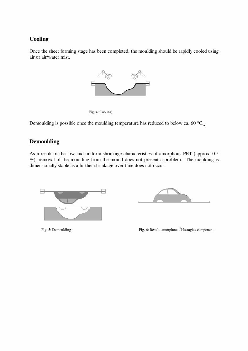
Cooling
Once the sheet forming stage has been completed, the moulding should be rapidly cooled using
air or air/water mist.
Fig. 4: Cooling
Demoulding is possible once the moulding temperature has reduced to below ca. 60 °C.
Demoulding
As a result of the low and uniform shrinkage characteristics of amorphous PET (approx. 0.5
%), removal of the moulding from the mould does not present a problem. The moulding is
dimensionally stable as a further shrinkage over time does not occur.
Fig. 5: Demoulding Fig. 6: Result, amorphous Hostaglas component
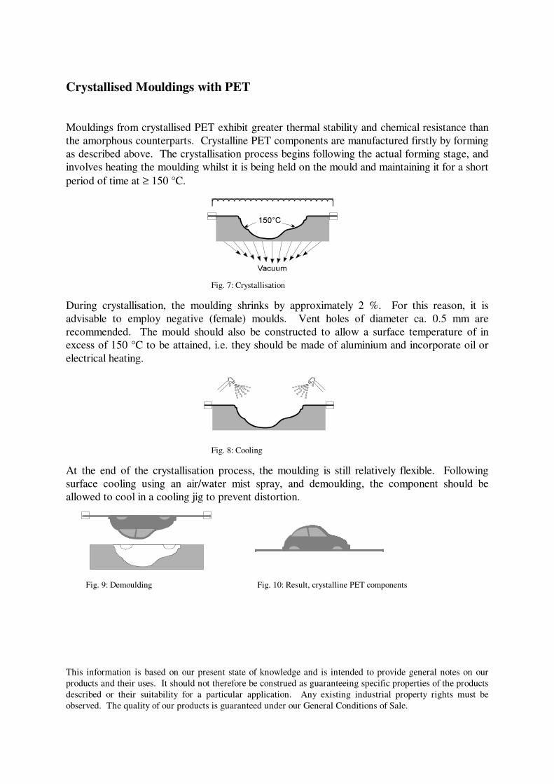
Crystallised Mouldings with PET
Mouldings from crystallised PET exhibit greater thermal stability and chemical resistance than
the amorphous counterparts. Crystalline PET components are manufactured firstly by forming
as described above. The crystallisation process begins following the actual forming stage, and
involves heating the moulding whilst it is being held on the mould and maintaining it for a short
period of time at ≥ 150 °C.
Fig. 7: Crystallisation
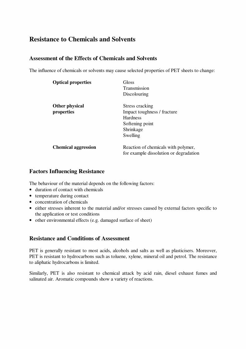
During crystallisation, the moulding shrinks by approximately 2 %. For this reason, it is
advisable to employ negative (female) moulds. Vent holes of diameter ca. 0.5 mm are
recommended. The mould should also be constructed to allow a surface temperature of in
excess of 150 °C to be attained, i.e. they should be made of aluminium and incorporate oil or
electrical heating.
Fig. 8: Cooling
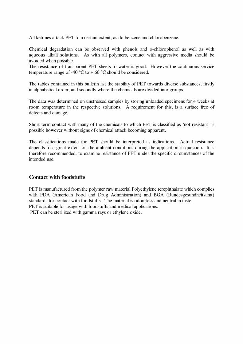
At the end of the crystallisation process, the moulding is still relatively flexible. Following
surface cooling using an air/water mist spray, and demoulding, the component should be
allowed to cool in a cooling jig to prevent distortion.
Fig. 9: Demoulding Fig. 10: Result, crystalline PET components
This information is based on our present state of knowledge and is intended to provide general notes on our
products and their uses. It should not therefore be construed as guaranteeing specific properties of the products
described or their suitability for a particular application. Any existing industrial property rights must be
observed. The quality of our products is guaranteed under our General Conditions of Sale.
Resistance to Chemicals and Solvents
Assessment of the Effects of Chemicals and Solvents
The influence of chemicals or solvents may cause selected properties of PET sheets to change:
Optical properties Gloss
Transmission
Discolouring
Other physical Stress cracking
properties Impact toughness / fracture
Hardness
Softening point
Shrinkage
Swelling
Chemical aggression Reaction of chemicals with polymer,
for example dissolution or degradation
Factors Influencing Resistance
The behaviour of the material depends on the following factors:
• duration of contact with chemicals
• temperature during contact
• concentration of chemicals
• either stresses inherent to the material and/or stresses caused by external factors specific to
the application or test conditions
• other environmental effects (e.g. damaged surface of sheet)
Resistance and Conditions of Assessment
PET is generally resistant to most acids, alcohols and salts as well as plasticisers. Moreover,
PET is resistant to hydrocarbons such as toluene, xylene, mineral oil and petrol. The resistance
to aliphatic hydrocarbons is limited.
Similarly, PET is also resistant to chemical attack by acid rain, diesel exhaust fumes and
salinated air. Aromatic compounds show a variety of reactions.
All ketones attack PET to a certain extent, as do benzene and chlorobenzene.
Chemical degradation can be observed with phenols and o-chlorophenol as well as with
aqueous alkali solutions. As with all polymers, contact with aggressive media should be
avoided when possible.
The resistance of transparent PET sheets to water is good. However the continuous service
temperature range of -40 °C to + 60 °C should be considered.
The tables contained in this bulletin list the stability of PET towards diverse substances, firstly
in alphabetical order, and secondly where the chemicals are divided into groups.
The data was determined on unstressed samples by storing unloaded specimens for 4 weeks at
room temperature in the respective solutions. A requirement for this, is a surface free of
defects and damage.
Short term contact with many of the chemicals to which PET is classified as ‘not resistant’ is
possible however without signs of chemical attack becoming apparent.
The classifications made for PET should be interpreted as indications. Actual resistance
depends to a great extent on the ambient conditions during the application in question. It is
therefore recommended, to examine resistance of PET under the specific circumstances of the
intended use.
Contact with foodstuffs
PET is manufactured from the polymer raw material Polyethylene terephthalate which complies
with FDA (American Food and Drug Administration) and BGA (Bundesgesundheitsamt)
standards for contact with foodstuffs. The material is odourless and neutral in taste.
PET is suitable for usage with foodstuffs and medical applications.
PET can be sterilized with gamma rays or ethylene oxide.
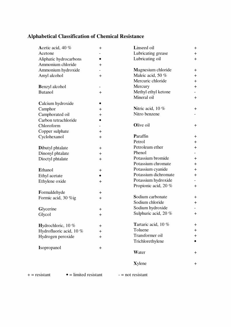
Alphabetical Classification of Chemical Resistance
Acetic acid, 40 % +
Acetone -
Aliphatic hydrocarbons •
Ammonium chloride +
Ammonium hydroxide -
Amyl alcohol +
Benzyl alcohol -
Butanol +
Calcium hydroxide •
Camphor +
Camphorated oil +
Carbon tetrachloride •
Chloroform -
Copper sulphate +
Cyclohexanol +
Dibutyl phtalate +
Dinonyl phtalate +
Dioctyl phtalate +
Ethanol +
Ethyl acetate •
Ethylene oxide +
Formaldehyde +
Formic acid, 30 %ig +
Glycerine +
Glycol +
Hydrochloric, 10 % +
Hydrofluoric acid, 10 % +
Hydrogen peroxide +
Isopropanol +
Linseed oil +
Lubricating grease +
Lubricating oil +
Magnesium chloride +
Maleic acid, 50 % +
Mercuric chloride +
Mercury +
Methyl ethyl ketone -
Mineral oil +
Nitric acid, 10 % +
Nitro benzene -
Olive oil +
Paraffin +
Petrol +
Petroleum ether +
Phenol -
Potassium bromide +
Potassium chromate +
Potassium cyanide +
Potassium dichromate +
Potassium hydroxide -
Propionic acid, 20 % +
Sodium carbonate +
Sodium chloride +
Sodium hydroxide -
Sulphuric acid, 20 % +
Tartaric acid, 10 % +
Toluene +
Transformer oil +
Trichlorethylene •
Water +
Xylene +
+ = resistant • = limited resistant - = not resistant
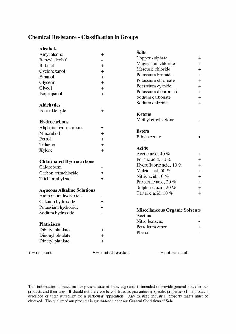
Chemical Resistance - Classification in Groups
Alcohols
Amyl alcohol +
Benzyl alcohol -
Butanol +
Cyclohexanol +
Ethanol +
Glycerin +
Glycol +
Isopropanol +
Aldehydes
Formaldehyde +
Hydrocarbons
Aliphatic hydrocarbons •
Mineral oil +
Petrol +
Toluene +
Xylene +
Chlorinated Hydrocarbons
Chloroform -
Carbon tetrachloride •
Trichlorethylene •
Aqueous Alkaline Solutions
Ammonium hydroxide -
Calcium hydroxide •
Potassium hydroxide -
Sodium hydroxide -
Platicisers
Dibutyl phtalate +
Dinonyl phtalate +
Dioctyl phtalate +
Salts
Copper sulphate +
Magnesium chloride +
Mercuric chloride +
Potassium bromide +
Potassium chromate +
Potassium cyanide +
Potassium dichromate +
Sodium carbonate +
Sodium chloride +
Ketone
Methyl ethyl ketone -
Esters
Ethyl acetate •
Acids
Acetic acid, 40 % +
Formic acid, 30 % +
Hydrofluoric acid, 10 % +
Maleic acid, 50 % +
Nitric acid, 10 % +
Propionic acid, 20 % +
Sulphuric acid, 20 % +
Tartaric acid, 10 % +
Miscellaneous Organic Solvents
Acetone -
Nitro benzene -
Petroleum ether +
Phenol -
+ = resistant • = limited resistant - = not resistant
This information is based on our present state of knowledge and is intended to provide general notes on our
products and their uses. It should not therefore be construed as guaranteeing specific properties of the products
described or their suitability for a particular application. Any existing industrial property rights must be
observed. The quality of our products is guaranteed under our General Conditions of Sale.
- 2 -
PET - STORAGE AND TRANSPORTATION
• PET should be stored and transported on stable, flat pallets. The size should be equivalent
to or slightly larger than the sheets.
• Sheets should be lifted and handled one at a time. To prevent scratching, sheets should not
be allowed to slide over each other during handling.
• Sheets should be stored indoors and protected from direct sunlight (‘magnifying-glass
effect’) and also from moisture.
• When storing in a vertical position, sheets should be supported to their full height.
This information is based on our present state of knowledge and is intended to provide general notes on our
products and their uses. It should not therefore be construed as guaranteeing specific properties of the products
described or their suitability for a particular application. Any existing industrial property rights must be
observed. The quality of our products is guaranteed under our General Conditions of Sale.
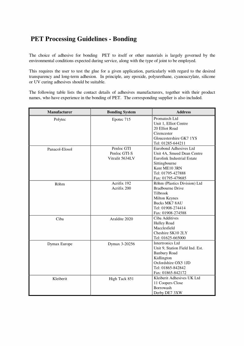
PET Processing Guidelines - Bonding
The choice of adhesive for bonding PET to itself or other materials is largely governed by the
environmental conditions expected during service, along with the type of joint to be employed.
This requires the user to test the glue for a given application, particularly with regard to the desired
transparency and long-term adhesion. In principle, any epoxide, polyurethane, cyanoacrylate, silicone
or UV curing adhesives should be suitable.
The following table lists the contact details of adhesives manufacturers, together with their product
names, who have experience in the bonding of PET. The corresponding supplier is also included.
Manufacturer Bonding System Address
Polytec Epotec 715 Promatech Ltd
Unit 1, Elliot Centre
20 Elliot Road
Cirencester
Gloucestershire GK7 1YS
Tel: 01285-644211
Panacol-Elosol Penloc GTI
Penloc GTI-S
Vitralit 5634LV
Eurobond Adhesives Ltd
Unit 4A, Smeed Dean Centre
Eurolink Industrial Estate
Sittingbourne
Kent ME10 3RN
Tel: 01795-427888
Fax: 01795-479685
Röhm Acrifix 192
Acrifix 200
Röhm (Plastics Division) Ltd
Bradbourne Drive
Tilbrook
Milton Keynes
Bucks MK7 8AU
Tel: 01908-274414
Fax: 01908-274588
Ciba Araldite 2020 Ciba Additives
Hulley Road
Macclesfield
Cheshire SK10 2LY
Tel: 01625-665000
Dymax Europe Dymax 3-20256 Intertronics Ltd
Unit 9, Station Field Ind. Est.
Banbury Road
Kidlington
Oxfordshire OX5 1JD
Tel: 01865-842842
Fax: 01865-842172
Kleiberit High Tack 851 Kleiberit Adhesives UK Ltd
11 Coopers Close
Borrowash
Derby DE7 3XW
Recommendations for adhesive bonding of PET
• The surface should be clean, dry and free from dust or loose particles.
• Degreasing: greatest adhesion is achieved by cleaning the surface with ethyl alcohol; good results
can be obtained by cleaning with a detergent solution. Cleaning with acetone is not recommended.
• Follow manufacturer useful hints in bonding
Hostaglas when using all adhesives.
• After the adhesive has been correctly applied, place the sheet substrates in contact and secure them
firmly until the adhesive has cured.
• Depending upon the instructions given by the adhesive manufacturer, coat the sheet surface with the
appropriate primer where necessary.
• Note that curing time can be as long as 24 hours in some cases.
• Use adhesives in a well ventilated room. Do not smoke in the area, and avoid skin contact.
Hoechst is not an adhesive manufacturer and is therefore unable to accept any responsibility for the
performances of adhesives used to bond PET.
This information is based on our present state of knowledge and is intended to provide general notes on our
products and their uses. It should not therefore be construed as guaranteeing specific properties of the products
described or their suitability for a particular application. Any existing industrial property rights must be
observed. The quality of our products is guaranteed under our General Conditions of Sale.
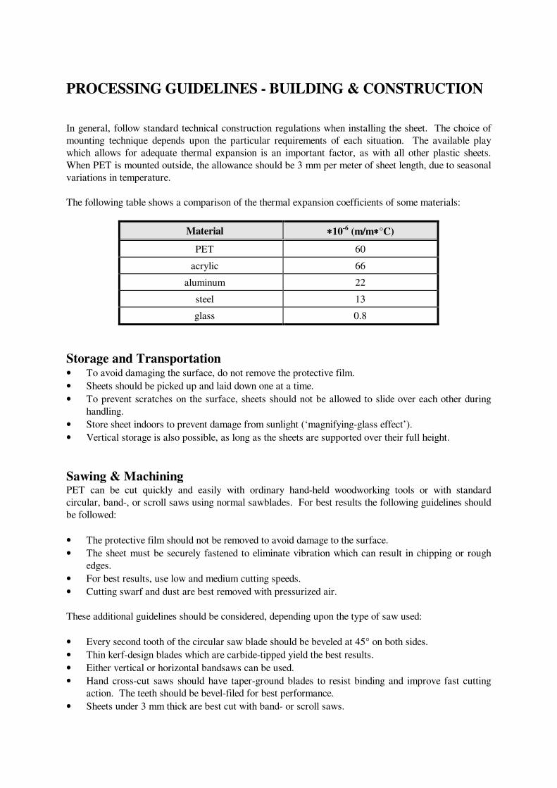
PROCESSING GUIDELINES - BUILDING & CONSTRUCTION
In general, follow standard technical construction regulations when installing the sheet. The choice of
mounting technique depends upon the particular requirements of each situation. The available play
which allows for adequate thermal expansion is an important factor, as with all other plastic sheets.
When PET is mounted outside, the allowance should be 3 mm per meter of sheet length, due to seasonal
variations in temperature.
The following table shows a comparison of the thermal expansion coefficients of some materials:
Material ∗∗∗∗10-6
(m/m∗∗∗∗°C)
PET 60
acrylic 66
aluminum 22
steel 13
glass 0.8
Storage and Transportation • To avoid damaging the surface, do not remove the protective film.
• Sheets should be picked up and laid down one at a time.
• To prevent scratches on the surface, sheets should not be allowed to slide over each other during
handling.
• Store sheet indoors to prevent damage from sunlight (‘magnifying-glass effect’).
• Vertical storage is also possible, as long as the sheets are supported over their full height.
Sawing & Machining PET can be cut quickly and easily with ordinary hand-held woodworking tools or with standard
circular, band-, or scroll saws using normal sawblades. For best results the following guidelines should
be followed:
• The protective film should not be removed to avoid damage to the surface.
• The sheet must be securely fastened to eliminate vibration which can result in chipping or rough
edges.
• For best results, use low and medium cutting speeds.
• Cutting swarf and dust are best removed with pressurized air.
These additional guidelines should be considered, depending upon the type of saw used:
• Every second tooth of the circular saw blade should be beveled at 45° on both sides.
• Thin kerf-design blades which are carbide-tipped yield the best results.
• Either vertical or horizontal bandsaws can be used.
• Hand cross-cut saws should have taper-ground blades to resist binding and improve fast cutting
action. The teeth should be bevel-filed for best performance.
• Sheets under 3 mm thick are best cut with band- or scroll saws.
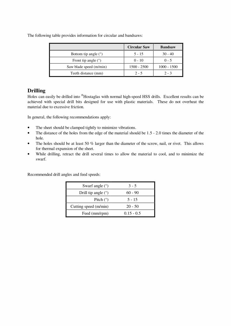
The following table provides information for circular and bandsaws:
Circular Saw Bandsaw
Bottom tip angle (°) 5 - 15 30 - 40
Front tip angle (°) 0 - 10 0 - 5
Saw blade speed (m/min) 1500 - 2500 1000 - 1500
Teeth distance (mm) 2 - 5 2 - 3
Drilling Holes can easily be drilled into
Hostaglas with normal high-speed HSS drills. Excellent results can be
achieved with special drill bits designed for use with plastic materials. These do not overheat the
material due to excessive friction.
In general, the following recommendations apply:
• The sheet should be clamped tightly to minimize vibrations.
• The distance of the holes from the edge of the material should be 1.5 - 2.0 times the diameter of the
hole.
• The holes should be at least 50 % larger than the diameter of the screw, nail, or rivet. This allows
for thermal expansion of the sheet.
• While drilling, retract the drill several times to allow the material to cool, and to minimize the
swarf.
Recommended drill angles and feed speeds:
Swarf angle (°) 3 - 5
Drill tip angle (°) 60 - 90
Pitch (°) 5 - 15
Cutting speed (m/min) 20 - 50
Feed (mm/rpm) 0.15 - 0.5
Mounting methods
Screw mounting For internal installations, the drill hole should be a minimum of 1 mm larger than the circumference of
the fixing screw to allow for thermal expansion. If the sheets are mounted flush together, a slight gap
should remain between them. Large washers should be used to distribute the force on the sheet over a
larger surface area.
In order to prevent tension it is important that the holes of the sheet are aligned with the holes in the
structure onto which it will be mounted. It is best is to drill both holes at once. The distance of the
holes to the edge of the sheet should as great as possible to reduce notch stress. The use of counter-sunk
screws is not recommended, since they leave no play for expansion. Self-tapping screws should only be
used with washers, spring-washers or clips.
Example:
• 0.8 x 1.5 m PET sheet with a 5 mm thickness
• Use 4 mm diameter screw at an interval of 40 cm
• The distance to the edges should be a minimum of 9 mm
Frame mounting When PET is mounted in a wooden, metal or plastic frame, two other factors along with thermal
expansion must be taken into account: the groove depth, and the correct sheet thickness. Once again,
the thickness depends on the size and shape of the sheet and the maximum loads it will encounter (e.g.,
wind pressure).
Other mounting methods PET can easily be mounted in standard industrial clamping systems. These clamping systems are very
practical, especially when thermal expansion is a major factor. Clear adhesive tapes like ScotchTM
200
MP or 468 MP can be also used in some transparent applications or for colored sheets.
PET sheets may also be fastened with rivets. It is recommended that washers be used to reduce
pressure during riveting. The hole in the sheet should be 1.5 to 2 times the diameter of the rivet to allow
for expansion.
This information is based on our present state of knowledge and is intended to provide general notes on our
products and their uses. It should not therefore be construed as guaranteeing specific properties of the products
described or their suitability for a particular application. Any existing industrial property rights must be
observed. The quality of our products is guaranteed under our General Conditions of Sale.
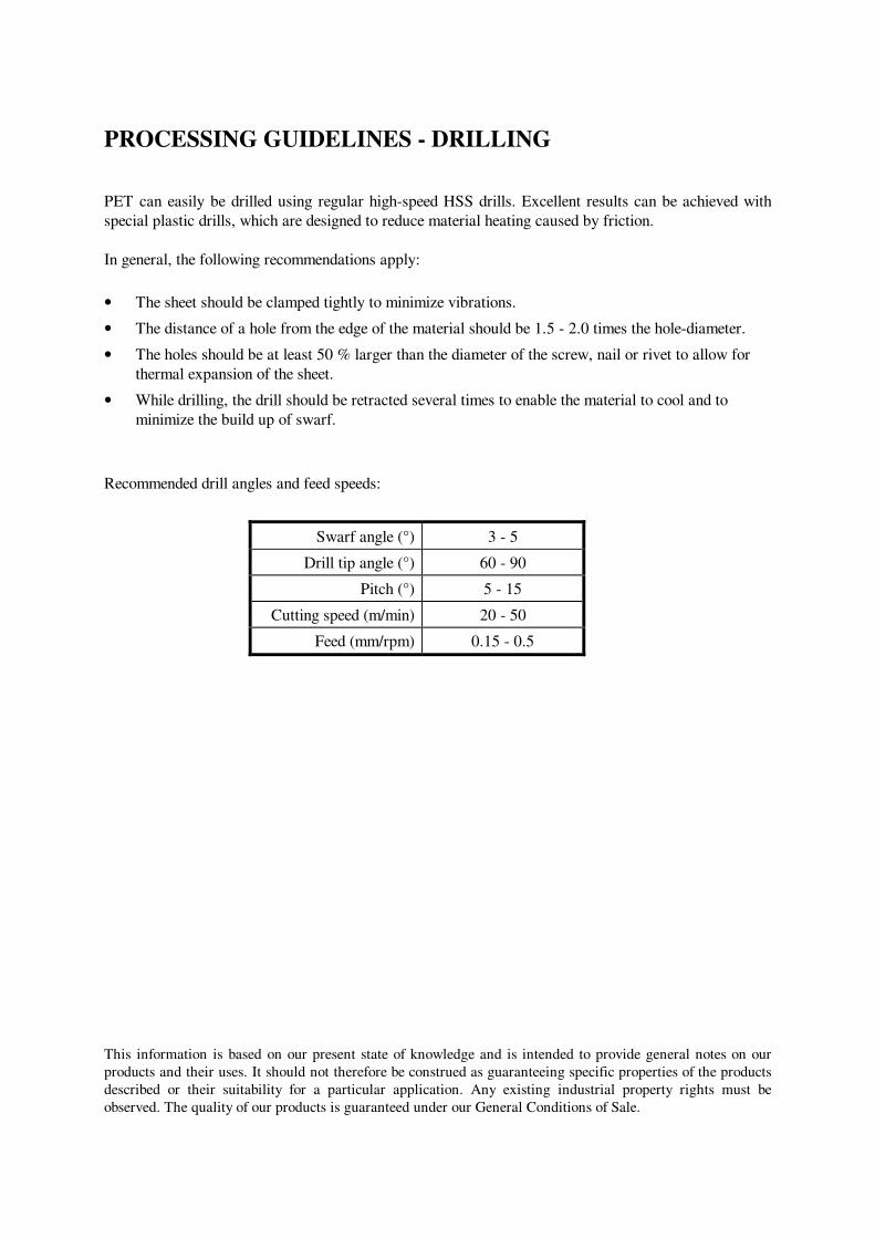
PROCESSING GUIDELINES - DRILLING
PET can easily be drilled using regular high-speed HSS drills. Excellent results can be achieved with
special plastic drills, which are designed to reduce material heating caused by friction.
In general, the following recommendations apply:
• The sheet should be clamped tightly to minimize vibrations.
• The distance of a hole from the edge of the material should be 1.5 - 2.0 times the hole-diameter.
• The holes should be at least 50 % larger than the diameter of the screw, nail or rivet to allow for
thermal expansion of the sheet.
• While drilling, the drill should be retracted several times to enable the material to cool and to
minimize the build up of swarf.
Recommended drill angles and feed speeds:
Swarf angle (°) 3 - 5
Drill tip angle (°) 60 - 90
Pitch (°) 5 - 15
Cutting speed (m/min) 20 - 50
Feed (mm/rpm) 0.15 - 0.5
This information is based on our present state of knowledge and is intended to provide general notes on our
products and their uses. It should not therefore be construed as guaranteeing specific properties of the products
described or their suitability for a particular application. Any existing industrial property rights must be
observed. The quality of our products is guaranteed under our General Conditions of Sale.
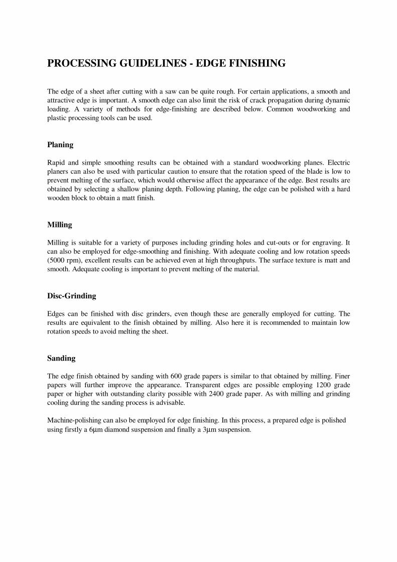
PROCESSING GUIDELINES - EDGE FINISHING
The edge of a sheet after cutting with a saw can be quite rough. For certain applications, a smooth and
attractive edge is important. A smooth edge can also limit the risk of crack propagation during dynamic
loading. A variety of methods for edge-finishing are described below. Common woodworking and
plastic processing tools can be used.
Planing
Rapid and simple smoothing results can be obtained with a standard woodworking planes. Electric
planers can also be used with particular caution to ensure that the rotation speed of the blade is low to
prevent melting of the surface, which would otherwise affect the appearance of the edge. Best results are
obtained by selecting a shallow planing depth. Following planing, the edge can be polished with a hard
wooden block to obtain a matt finish.
Milling
Milling is suitable for a variety of purposes including grinding holes and cut-outs or for engraving. It
can also be employed for edge-smoothing and finishing. With adequate cooling and low rotation speeds
(5000 rpm), excellent results can be achieved even at high throughputs. The surface texture is matt and
smooth. Adequate cooling is important to prevent melting of the material.
Disc-Grinding
Edges can be finished with disc grinders, even though these are generally employed for cutting. The
results are equivalent to the finish obtained by milling. Also here it is recommended to maintain low
rotation speeds to avoid melting the sheet.
Sanding
The edge finish obtained by sanding with 600 grade papers is similar to that obtained by milling. Finer
papers will further improve the appearance. Transparent edges are possible employing 1200 grade
paper or higher with outstanding clarity possible with 2400 grade paper. As with milling and grinding
cooling during the sanding process is advisable.
Machine-polishing can also be employed for edge finishing. In this process, a prepared edge is polished
using firstly a 6µm diamond suspension and finally a 3µm suspension.
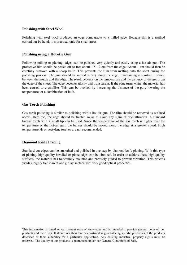
Polishing with Steel Wool
Polishing with steel wool produces an edge comparable to a milled edge. Because this is a method
carried out by hand, it is practical only for small areas.
Polishing using a Hot-Air Gun
Following milling or planing, edges can be polished very quickly and easily using a hot-air gun. The
protective film should be peeled off to free about 1.5 - 2 cm from the edge. About 1 cm should then be
carefully removed with a sharp knife. This prevents the film from melting onto the sheet during the
polishing process. The gun should be moved slowly along the edge, maintaining a constant distance
between the nozzle and the edge. The result depends on the temperature and the distance of the gun from
the edge of the sheet. The edge becomes glossy and transparent. If the edge turns white, the material has
been caused to crystallise. This can be avoided by increasing the distance of the gun, lowering the
temperature, or a combination of both.
Gas Torch Polishing
Gas torch polishing is similar to polishing with a hot-air gun. The film should be removed as outlined
above. Here too, the edge should be treated so as to avoid any signs of crystallisation. A standard
butane torch with a small tip can be used. Since the temperature of the gas torch is higher than the
temperature of the hot-air gun, the burner should be moved along the edge at a greater speed. High
temperature H2 or acetylene torches are not recommended.
Diamond Knife Planing
Standard cut edges can be smoothed and polished in one step by diamond knife planing. With this type
of planing, high quality bevelled or plane edges can be obtained. In order to achieve these high quality
surfaces, the material has to securely mounted and precisely guided to prevent vibration. This process
yields a highly transparent and glossy surface with very good optical properties.
This information is based on our present state of knowledge and is intended to provide general notes on our
products and their uses. It should not therefore be construed as guaranteeing specific properties of the products
described or their suitability for a particular application. Any existing industrial property rights must be
observed. The quality of our products is guaranteed under our General Conditions of Sale.
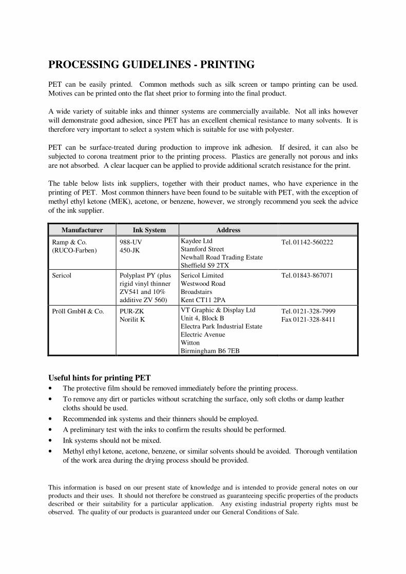
PROCESSING GUIDELINES - PRINTING
PET can be easily printed. Common methods such as silk screen or tampo printing can be used.
Motives can be printed onto the flat sheet prior to forming into the final product.
A wide variety of suitable inks and thinner systems are commercially available. Not all inks however
will demonstrate good adhesion, since PET has an excellent chemical resistance to many solvents. It is
therefore very important to select a system which is suitable for use with polyester.
PET can be surface-treated during production to improve ink adhesion. If desired, it can also be
subjected to corona treatment prior to the printing process. Plastics are generally not porous and inks
are not absorbed. A clear lacquer can be applied to provide additional scratch resistance for the print.
The table below lists ink suppliers, together with their product names, who have experience in the
printing of PET. Most common thinners have been found to be suitable with PET, with the exception of
methyl ethyl ketone (MEK), acetone, or benzene, however, we strongly recommend you seek the advice
of the ink supplier.
Manufacturer Ink System Address
Ramp & Co.
(RUCO-Farben)
988-UV
450-JK
Kaydee Ltd
Stamford Street
Newhall Road Trading Estate
Sheffield S9 2TX
Tel. 01142-560222
Sericol Polyplast PY (plus
rigid vinyl thinner
ZV541 and 10%
additive ZV 560)
Sericol Limited
Westwood Road
Broadstairs
Kent CT11 2PA
Tel. 01843-867071
Pröll GmbH & Co. PUR-ZK
Norilit K
VT Graphic & Display Ltd
Unit 4, Block B
Electra Park Industrial Estate
Electric Avenue
Witton
Birmingham B6 7EB
Tel. 0121-328-7999
Fax 0121-328-8411
Useful hints for printing PET
• The protective film should be removed immediately before the printing process.
• To remove any dirt or particles without scratching the surface, only soft cloths or damp leather
cloths should be used.
• Recommended ink systems and their thinners should be employed.
• A preliminary test with the inks to confirm the results should be performed.
• Ink systems should not be mixed.
• Methyl ethyl ketone, acetone, benzene, or similar solvents should be avoided. Thorough ventilation
of the work area during the drying process should be provided.
This information is based on our present state of knowledge and is intended to provide general notes on our
products and their uses. It should not therefore be construed as guaranteeing specific properties of the products
described or their suitability for a particular application. Any existing industrial property rights must be
observed. The quality of our products is guaranteed under our General Conditions of Sale.
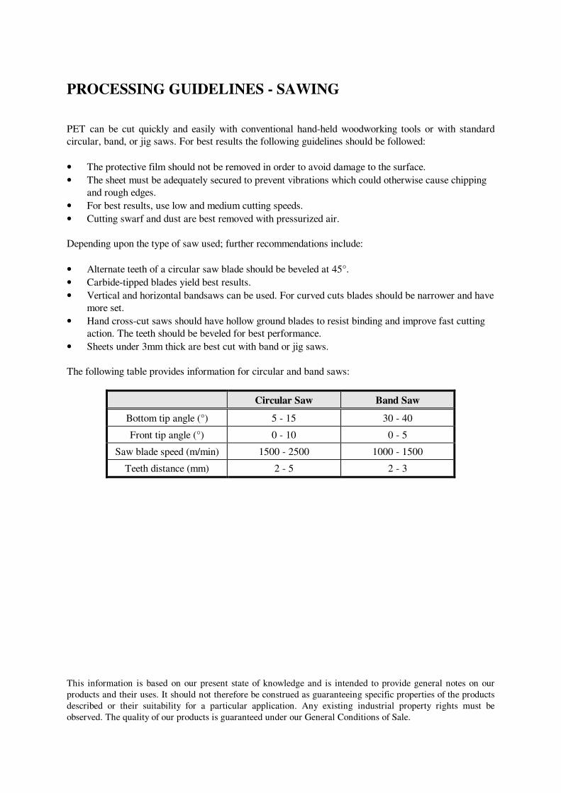
PROCESSING GUIDELINES - SAWING
PET can be cut quickly and easily with conventional hand-held woodworking tools or with standard
circular, band, or jig saws. For best results the following guidelines should be followed:
• The protective film should not be removed in order to avoid damage to the surface.
• The sheet must be adequately secured to prevent vibrations which could otherwise cause chipping
and rough edges.
• For best results, use low and medium cutting speeds.
• Cutting swarf and dust are best removed with pressurized air.
Depending upon the type of saw used; further recommendations include:
• Alternate teeth of a circular saw blade should be beveled at 45°.
• Carbide-tipped blades yield best results.
• Vertical and horizontal bandsaws can be used. For curved cuts blades should be narrower and have
more set.
• Hand cross-cut saws should have hollow ground blades to resist binding and improve fast cutting
action. The teeth should be beveled for best performance.
• Sheets under 3mm thick are best cut with band or jig saws.
The following table provides information for circular and band saws:
Circular Saw Band Saw
Bottom tip angle (°) 5 - 15 30 - 40
Front tip angle (°) 0 - 10 0 - 5
Saw blade speed (m/min) 1500 - 2500 1000 - 1500
Teeth distance (mm) 2 - 5 2 - 3
This information is based on our present state of knowledge and is intended to provide general notes on our
products and their uses. It should not therefore be construed as guaranteeing specific properties of the products
described or their suitability for a particular application. Any existing industrial property rights must be
observed. The quality of our products is guaranteed under our General Conditions of Sale.
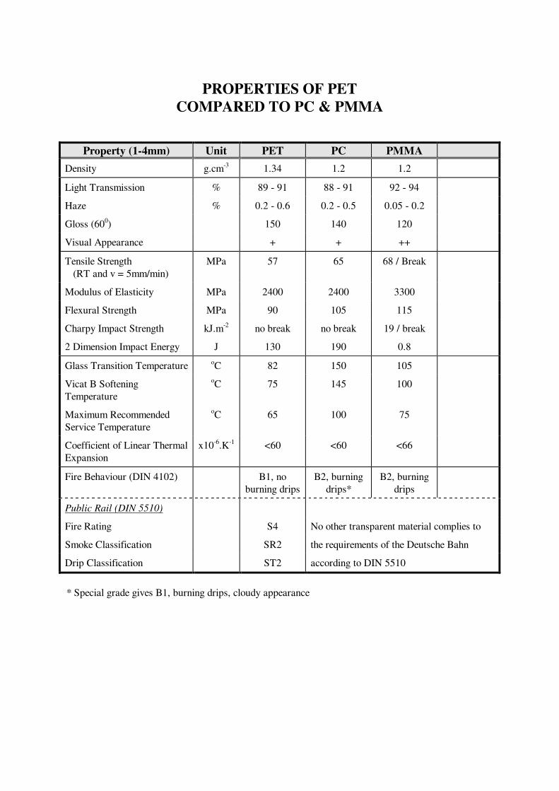
PROPERTIES OF PET
COMPARED TO PC & PMMA
Property (1-4mm) Unit PET PC PMMA
Density g.cm-3
1.34 1.2 1.2
Light Transmission % 89 - 91 88 - 91 92 - 94
Haze % 0.2 - 0.6 0.2 - 0.5 0.05 - 0.2
Gloss (600) 150 140 120
Visual Appearance + + ++
Tensile Strength
(RT and v = 5mm/min)
MPa 57 65 68 / Break
Modulus of Elasticity MPa 2400 2400 3300
Flexural Strength MPa 90 105 115
Charpy Impact Strength kJ.m-2
no break no break 19 / break
2 Dimension Impact Energy J 130 190 0.8
Glass Transition Temperature oC 82 150 105
Vicat B Softening
Temperature
oC 75 145 100
Maximum Recommended
Service Temperature
oC 65 100 75
Coefficient of Linear Thermal
Expansion
x10-6
.K-1
<60 <60 <66
Fire Behaviour (DIN 4102) B1, no
burning drips
B2, burning
drips*
B2, burning
drips
Public Rail (DIN 5510)
Fire Rating S4 No other transparent material complies to
Smoke Classification SR2 the requirements of the Deutsche Bahn
Drip Classification ST2 according to DIN 5510
* Special grade gives B1, burning drips, cloudy appearance
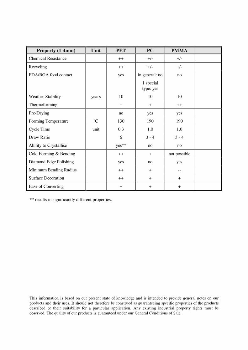
Property (1-4mm) Unit PET PC PMMA
Chemical Resistance ++ +/- +/-
Recycling ++ +/- +/-
FDA/BGA food contact yes in general: no
1 special
type: yes
no
Weather Stability years 10 10 10
Thermoforming + + ++
Pre-Drying no yes yes
Forming Temperature oC 130 190 190
Cycle Time unit 0.3 1.0 1.0
Draw Ratio 6 3 - 4 3 - 4
Ability to Crystallise yes** no no
Cold Forming & Bending ++ + not possible
Diamond Edge Polishing yes no yes
Minimum Bending Radius ++ + --
Surface Decoration ++ + +
Ease of Converting + + +
** results in significantly different properties.
This information is based on our present state of knowledge and is intended to provide general notes on our
products and their uses. It should not therefore be construed as guaranteeing specific properties of the products
described or their suitability for a particular application. Any existing industrial property rights must be
observed. The quality of our products is guaranteed under our General Conditions of Sale.