Embed Size (px)
Citation preview

1 . Introduction 2. Image formation 3. Positron electron annihilation 4. Isotopes emitting positrons 5. Basic coincidence technique 6. Positron tracers 7. Physical processes in PET 8. Temporal resolution 9. Spatial resolution factors 10. Recent detector developments 11. Tomograph design factors 12. Three dimensional images 13. Conclusions 14. References

1
Positron Emission Tomography (PET)
by Saleh Qutaishat
Physics Department Chalmers University of Technology
and Goteborg University
The principle of image formation in tomography is summarised. The principle ofpositron electron annihilation is introduced. The principle ofcoincidence techniques is illustrated. Detector development and perspectives for positron emission tomography (PET) instrumentation for medical research is presented. The physical processes in in positron annihilation, photon scattering and tomograph design are discussed.
1. Introduction
X-ray which was discovered by Rotengen marked the dawn of radiography. X-ray beams were used to image internal parts of the human body . Later on, other techniques for medical imaging using ultrasound and electromagnetic radiation were developed. The radiation used to image an internal organ must have adequate energy to penetrate that organ. since an image results from the absorption patterns. If the radiation has more energy it passes through unabsorbed. An other technique for imaging was developed by injecting a radioactive substance into the human being or animal. The distribution of the substance within a specific organ is monitored externally by the emitted radiation. Nuclear medicine originated from this procedure. An isomer of technetium 99mTc is the most widely used radionuclide for nuclear medicine. It decays with a half life of 6 hours. emitting 140 keY photons. Sodium iodide are highly efficient detectors of these photons. Other radioactive isotopes, such as 20lTI (80 ke V), 178Ta (55-65 ke V), 133Xe (80 ke V), emitting photons of lower energy than 99rnTc can be used. Multiwire proportional chambers are used as detectors for these photons. The standard imaging device in nuclear medicine is the gamma camera, a large sodium iodide crystal with photo multiplier read out [1].
2. Image formation
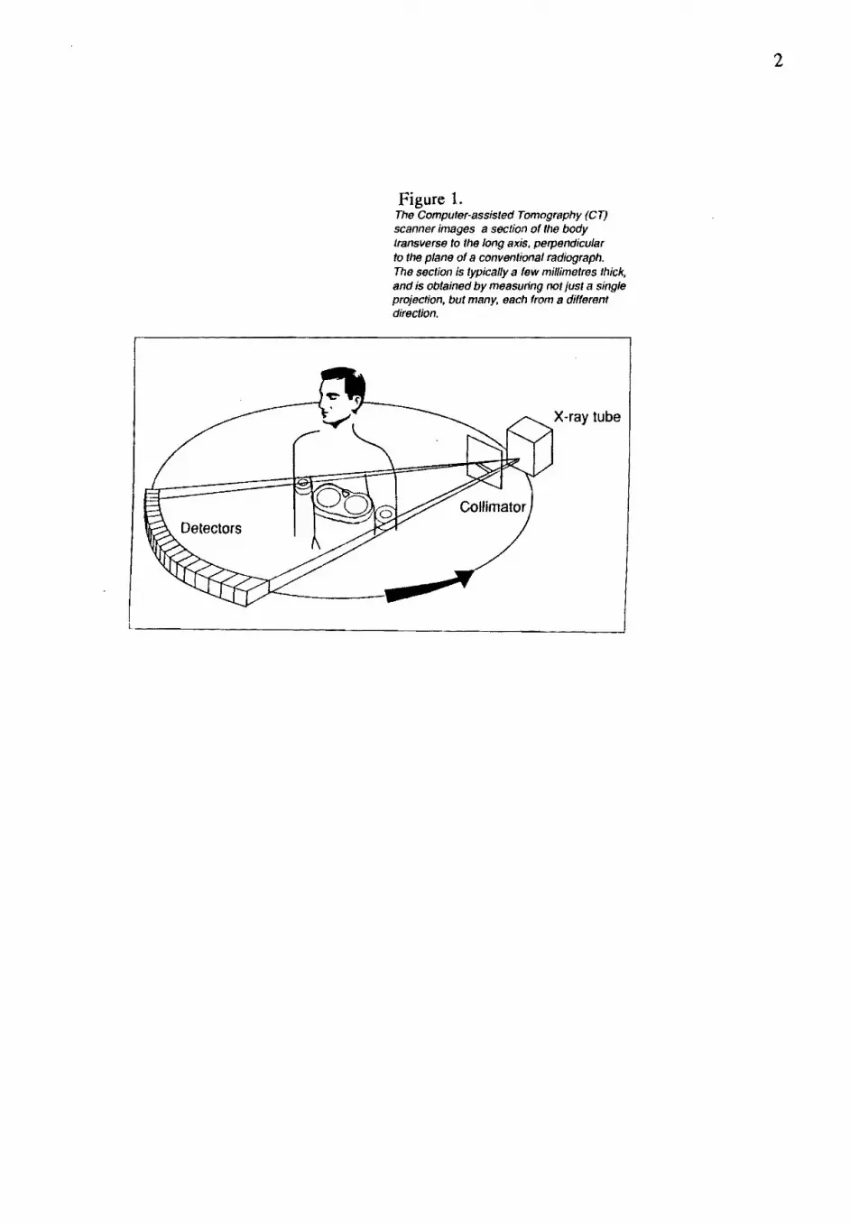
To form an image, a collimator consisting of a thick lead sheet perforated with many thousands of small holes, must be placed between the incident radiation and the crystal to eliminate oblique incident photons. Thus, only perpendicular incident radiation pass through the holes to the detector. The effective sensitivity of the sodium iodide crystal is reduced by using the collimator. The images produced are projections of a three-dimensional distribution onto a twodimensional plane. Thus depth information is missing. The invention of computer-assisted (Cf) scanner developed the type of images produced. The CT scanner images a section of the body transverse to the long axis, perpendicular to the plane of a conventional radiograph [1,2]. One-dimensional projection profiles are reconstructed into a twodimensional image of a transverse body section, as shown in figure (1).
2
Figure 1. The Computer-assisted Tomography (CT) scanner images a section of the body transverse to the long axis. perpendicular to the plane of a conventional radiograph. The section is typically a few millimetres thick. and is obtained by measuring not just a single projection. but many, each {rom a different direction.
X-ray tube

3
A useful technique for three-dimensional imaging of certain tracer distribution in the brain and heart is single photon emission computed tomography (SPECT). In this technique a gamma camera is rotated around the patient and takes a series of two-dimensional projections from different directions. Applying computer-assisted tomography (CT) reconstruction techniques, the internal distribution of thee radioactive tracer can be recovered simultaneously for parallel two-dimensional transverse sections. Sometimes radionuclides used in nuclear medicine emit photons with energies higher than 140 keY of 99mTc. In such cases, the collimators used in gamma cameras must be thick enough to stop inclined radiation. Thus the efficiency is reduced and the spatial resolution is degraded.
3. Positron electron annihilation
Beta particles are fast electrons or positrons which result from the weak-interaction decay of a neutron or a proton in nuclei which contain an excess of the respective nucleon. In neutron-rich nucleus, a neutron can transform itself into a proton via the process:
n ~ p + e + u (1) Here an electron and an antineutrino are emitted. (The proton remains bound to the nucleus). The daughter nucleus now contains one extra protons, so that its atomic number is increased by 1. Similarly, in nuclei with too many protons, the decay
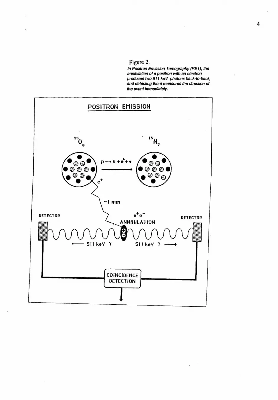
p~n+~+u m can occur, where a positron and a neutrino are now emitted and the atomic number is decreased by one [3]. An example of positron emitting nuclei is the isotope of oxygen 150 8 • This isotope decays to nitrogen 15N7 by emitting a positron and a neutrino as shown in equation (2). Among the principle elements of life only hydrogen does not offer a convenient positron-emitting isotope. If the emitted positron hits an absorbing material it annihilates with an electron from the absorber to produce two photons, each one with an energy equal to the electron mass 511 ke V. These two gamma photons are always emitted in opposite directions, in order to conserve momentum in the annihilation process. The two photons are detected by two detectors set opposite to each other. The two detectors are connected to a coincident unit to detect the coincident photons, i.e, the photons originating from a specific annihilation process [1]. The annihilation process is demonstrated in figure (2).
4. Isotopes emitting positrons
All ~rinciple elements of life offer a convenient positron-emitting isotopes except hydrogen. The Isotopes of oxygen, nitrogen and carbon are positron emitters with a short half-lives 2, ID and 20 minutes. These isotopes are useful for medical imaging. They are produced by cyclotrons.
4
Figure 2. In Positron Emission Tomography (PET), the annihlletion ofe positron with en electron produces two 51 1keV photons beck-Io-beck, and detecting them measures the direction of
the event Immediately.
POSITRON EMISSION
, DETECTOR
f. p .... n+e+"
-, mm
DETECTOR
+-- 511 keY Y 511 keY Y ---+
...._______....., COINCIDENCE DETECTION t-------..I

5
5. Basic coincidence technique
Electronic circuits are used to determine coincident photons detected by radiation detectors. Coincidence in time serves a very powerful criterion for distinguishing reactions. A simple coincidence measuring system is illustrated in figure (3) [3]. The basic technique is to convert the analog signal coming from the detector into a logic signal and then send the pulses into a coincidence module. If the two signals are, in fact, coincident, then a logic signal is produced at the output. It can be seen in figure (3) that a coincident output signal is produced if any part of the two incoming signals overlap. Thus all pulses arriving within a time equal to the sum of their widths are registered as coincident. Figure (4) shows examples of coincident and noncoincident pulses. The electrical path of each branch leading to the coincidence module should be of equal length. This can be insured by adding adjustable delay to each line as shown in figure (3).
L:::~r--::::;:::-r DISCR. -u- DEl AY
r=::::-~--I DISCR.
SCALER
I---v----I DElAY -v- COINCIDENCE ("AND")
FIR..3 A system for coincidence measuremcn:
INPUT 1
INPUT 2
COINCIDENCE FIR·4. OUTPUT Coincidence belween puhc.

6
6. Positron tracers
Positron emission tomography (PET) pennits the non-invasive, quantitative study of biological processes as they occur using minute quantities of tracer material. Biological processes in different organs can be studied by using a variety of labeled compounds as shown in table (1) [4).
Table 1- Positron tracers and the processes they measure
Heart:
ionic 82Rb myocardial perfusion lle palmitate Catty add transport, oxidation Ile or uN amino adds protein synthesis, tissue anabolism
Brain:
ionic 82Rb blood brain barrier breakdown 18F deoxyglucose glucose transport, phosphorylation 122I iodoamphetamines blood flow lS02 oxygen utilization 11i0 water blood flow lleo hemoglobin blood volume

7
7. Physical processes in PET
The following Physical processes in PET [4] are discussed a) Positron stops in a tissue " ,Positrons are emitted with a variety of energies, with a maximum energy that dep~nds on the isotope. Thus the resulting positron range i~ ,a tissue vari~s from a sm,all fractIon of a millimeter to several millimete~s[5], The ability of ~ET mstrume!1tatton t? me~sure dynamically tracer concentration IS affected by the phYSical processes myolved m pos~tron emission figure (5), detection of annihillation photons and the tomographiC reconstruction.
Positron annihilation photons
1800 ± 0.25°
XBL 953 8057
FigureS: A positron emitted by nuclear decay stops in tissue and annihilatf's with a nearby electron, producing two 511 keY photons that fly off in nearly opposite directions.
b) Scatter in a tissue A 511 keY photon travels an average of 10 cm in water before interacting by Compton scattering, The probability that both annihilation photons leave the body unscattered is 20% [6]. This results in a significant loss of events. c) Interaction with the detectors Two types of interaction occur in the detection process. One is by the photoelectric effect, whereby the entire photoenergy is transfered into a recoil electron. The other is by Compton scattering, where the photon energy is reduced by being scattered by a recoil electron which picked part of the photon energy. For successful detection both annihilation photons have to pass pulse hight requirements in the opposing detectors. The fraction of annihilation photons reaching the scintillator that produce an acceptable pulse is called the detection efficiency. d) Scintillation The recoil eJectrons produce scintiHation light via the excitation process with a certain luminous efficiency.

8
e) Light transfer to photodetectors Part of the scintillation light is collected by the photo detectors while the rest is lost via other processes. The fraction of light that reaches the photo detectors is called the light collection efficiency. f) Production of an electron pulse Collected scintillation light is converted into electric pulses that are amplified by a photo multiplier tube. g) Electronics Electronic circuits determine whenever two opposing detectors detect photons with a short time interval (5 to 20 nsec) and store the address of the crystals involved [7,8]. The differential time of arrival is also recorded for the time of flight mode [9,10]. h) Attenuation correction The patient has to be placed in the tomograph and positioned at a slice to be imaged before the administration of any radioactive isotope. i) Additional data correction The data must be corrected for accidental background events, scattered background events and the loss of events due to the dead time in the detectors and electronics. j) Reconstruction Filtering the parallel-ray projections and then back projecting to the image array is involved in tomographic reconstruction
8. Temporal resolution
The ability to measure the tracer concentration with good temporal resolution ( i.e, increase of rapid time sequence images) requires the collection of a large number of events during the study, which requires good detection efficiency, low dead time, high maximum data rates, and a maximum of detection motion.
9. Spatial resolution factors
An overall system spatial resolution with fwhm less than or equal D/2 for quantitation within regions of size D. The principle components of the system resolution are: i) Positron range Positron annihilation shows a distribution with a bright center and extensive tails. The resulting full width at half maximum is <1 mm. ii) Deviations from 1800 emission. The angular distribution of annihilation photons in water shows nearly a gaussian
distribution with a fwhm .&=0.50 [11]. This blurring factor represents the most fundamental limit to spatial resolution in PET. iii) Dr!tector aperture The geometrical component of the detector resolution is about one half of the exposed width w of a discrete crystal. iv) Linear sampling For detectors of width w, the geometrical resolution w/2 is not realized in the reconstruction image unless the tomographic sampling distance is w/4 or finer through out the image region. v) Multiple crystal interactions Compton scattering of the annihilation photons can result in mis-identification of the detector of the first interaction. This effect is reduced by coupling each scintillator to its individual photodetector or placing shielding materials between the detectors.

9
vi) Off-axis penetration Annihilation photons from off-axis sources can penetrate one or. more detectors before interacting. This results in uncertainty of the depth of interaction. vii) Reconstruction filter The reconstruction filter upper frequency roll-off should be detennined by the system resolution in order to get the best estimation of the tracer activity within regions of interest. viii) Organ motion For cardiac imaging and rapid sequence imaging for fast dynamic studies gating is used to reduce the effect of organ and tracer motion.
10. Recent detector developments
10.1 Small PMTs The development of small photomultiplier tubes (PMTs) -10 mm diameter tube) permitted the construction of positron tomographs with 3mm crystals where each crystal is coupled to onePMT. 10.2 Light division coding In this type of detectors. each PMT is coupled to two or more crystals. The crystal of interaction is determined by the ratio or difference of the PMT signals. 10.3 Anger-type coding In thi:; type of detection. a single large scintillation crystal is coupled to many PMTs and the ratio of outputs is used to determine the center of intensity. 10.4 Wire chambers An efficient scintillation detector. e.g, BaF2 that produces UV emission is used with a wire proportional chamber with a special liquid photocathode that converts the UV into an electron avalanche. A detector of BaF2 scintillators and wire chambers for 511 keY gamma-ray was developed by George Charpak (the Nobil prise winner in physics this year 1993) group at CERNin 1986. The wire chamber was filled with tetrakis (diethylamine) ethylene (TMAE) vapour and operated at a pressure of a few Torr. using different gases at various temperatures. Energr' time, and position resolution were given for BaF2 crystals with sections of lOXI0 mm and 5X5 mm2. The spatial precision with a matrix of small crystals was better than with a single large crystal. They expected that a medical PET camera based on a solid state proportional counter SSPC will have a high-rate capability and allow a dramatic improvement of the axial precision and of the acceptance [12].
11. Tomograph design factors
The aim of most tomograph designs is the accurate and rapid measurement of tracer concentration in sharply defined tissue volume elements. Thus, temporal resolution. spatial resolution, and the quantitative measurement of activity concentration are required. 11.1 Quantitative accuracy - Statistical factors Statistical accuracy in the reconstructed image depends on the number of coincident events that can be collected within the available time. This is determined by the available positron activity and the sensitivity of the tomograph which is expressed as the number of coincident events detected per second per IlCi/cm3 in a 20 cm diameter cylinder of water. The system sensitivity depends on: a) Solid angle coverage The best acceptance solid angle for annihilation photons is provided by multiple rings of detectors that encircles the patient. b) Axial coverage A higher event rate for a given amount of tracer activity is provided by multiple detector rings that cover a larger volume of tissue.

10
c) Detector material Bismuth gennanate (BGO) crystals has better stopping power than Nal for the 511 keY gamma rays, but poorer energy resolution. Thus BGO replaced NaI in non-time of flight PET instrumentation. BaF2replaced CsF for time of flight PETs. d) Single vs multiple crystal detections Multiple crystal detectors enhance the detection efficiency, but they degrade the position resolution. e) Time of flight information excellent timing resolution -0.4 ns is achieved by using BaF2 detectors. Such detectors are able to measure the arrival time difference between the two photons and determine the annihilation point.
11.2 Quantitative accuracy - systematic errors PET data are subject also to systematic errors, e.g, background events due to accidental coincidences.
12. Three dimensional images
By imaging parallel slices at different levels and processing them by computers, it is possible to combine such two dimensional images to obtain a three dimensional image. A PET scanner is shown in figure (6).
Figure 6. PET scanner assembled at CERN and operational at Geneva's UnIVerSity Hospital for the past two years, About 200 patients have been scanned,

1 1
13. Conclusions
Positron emission tomography (PET) proved to be an efficient research and diagnostic technique in medicine in spite of its complexity and cost
14. References
[1]. Townsend DW: Physics instrumentation for medical imaging. CERN courier 33-3: 1-8,1993
[2]. Dale S: Ectomography - Theory and hnplementation in Gamma Camera Imaging, Ph.D thesis, Department of Medical Engineering, Karolinska Institute, and Department of Clinical Physiology Thoracic, Karolinska Hospital, Kungl. Tekniska Hogskolan, Stockholm, Sweden, ISBN 91-7170-946-0, 1989, pp 1-44
[3]. Leo WL: Techniques for Nuclear and Particle Physics Experiments,ed SpringerVerlag, 1992, pp 2-9 & pp 302-303
[4]. Derenzo SE: Recent developments in positron emission tomography (PET) instrumentation. Phys and Eng of Computerized Multidim lmag and Process. Vol. 671: 232-242,1986
[5]. Cho ZH, Chan JK, Erikson L, et al: Positron ranges obtained from biomedocal important positron emitting radionuclides. J Nucl Med 16: 1174-1176,1975
[6]. Budinger TF, Derenzo SE, Gullberg GT, Greenberg WL, and Huesman RH: Emission computer assisted tomography with single-photon and positron annihilation photon emitter. J Comput Assist Tomogr 1: 131-145,1977
[7]. Huesman RH, Cahoon JL; Derenzo SE, et al: Crystal positron tomograph. IEEE Trans Nucl Sci NS-27: 474-478, 1980
[8]. Cahoon JL, Huesman RH, Derenzo SE, et al: The electronics for the Donner, high resolution 600-crystal positron tomograph. IEEE Trans NUcl Sci NS-33:570-574, 1986
[9]. Blaine J, Fike D, Hitchens R, et al: Data acquisition aspects of super-PETT. IEEE Trans Nucl Sci NS-29:544-547, 1982
[10]. Philippe EA, Mullani N, Hartz E, et al: Real time multi-processor image reconstructor for time of flight positron emission tomography (TOFPET). IEEE Trans Nucl Sci NS-29: 524-527, 1982
[11]. Colombino P, Fiscella B, Trossi L: Study of positronium in water and ice from 22 to -144 OC by annihilation quantum measurements. Nuovo Cimento 38: 707-723, 1965
[12]. Mine P, Charpak G, Stantiard J-C, Scigosld D, Suffert M and Tavernier S: Nucl. Inst. and Meth. A269:385-391, 1988


