Embed Size (px)
Citation preview
http://www.nyms.org/
NYMS Newsletter, September 2014
THE OPERATION OF A PORTABLE PETROGRAPHIC THIN-SECTION LABORATORY FOR FIELD STUDIES
Yuval Goren
Depar tment of Archaeology and Ancient Near Eastern Cultures, Tel Aviv University, Israel
Abstract
This article presents a procedure for petrographic and micromorphological thin-section preparation and examination in extra-laboratory and field conditions. Employing basic, frequently-improvised, off-the-shelf equipment, standard petrographic thin sections of rocks, sediments, ceramics, mortars, and plasters can be produced and examined. Use of the newly-introduced Goren portable microscope enables laboratory-grade examination and recording of such materials during field expeditions. Examples are adduced from the field of material analysis in art and archaeology.
INTRODUCTION
The use of analytical apparatus in the field has been an aspiration since the dawn of modern science. Field research in this context refers to the collection of information beyond the confines of a laboratory, library, or regular workplace. This article is focusing on aspects of microscopical work, the following discussion surveys the use of microscopes in such conditions.
In the eighteenth century, pocket-sized microscopes were devised for studying microscopic fauna and flora in ponds and on the seashore and the dissection of flowers or inspection of insects and minerals. As disciplined science and scientific methodology developed in the nineteenth century, portable analytical apparatus began increasingly to be taken to distant locations in land or sea expeditions (e.g., Herschel, 1849). Charles Darwin’s seminal work during his voyage on HMS Beagle between 1831 and 1836 (Burnett & Martin,
1992; Jardine, 2009) is one of many examples of this practice. From the mid-nineteenth century onwards, portable microscopes were introduced for medical inspections conducted at patients’ bedsides (Gruby, 1846)—a method that developed concurrently with the emergence of germ theory. This usage was then extended to field and frontline hospitals during the American Civil War (Cassedy, 1976) and after.
While we normally associate modern analytical work and apparatus with research laboratories, a large portion of modern research is in fact performed outside the laboratory. Despite being regarded as unorthodox (Watt, 1993), these situations are actually far from unusual. In many aspects of research, they constitute common practice—the diagnosis of tropical diseases, mining geology, soil analysis, forensic studies, military medicine, entomology, micropaleontology, and microbiological research being but some of a long list of examples. The broad scope and vast
THE OPERATION OF A PORTABLE PETROGRAPHIC LABORATORY
2 New York Microscopical Society Newsletter, September 2014
historical, theoretical, and methodological background of this issue make it impossible to discuss from a holistic perspective. While the method and equipment presented below are applicable to many disciplines, I shall focus on the study of materials in art and archaeology, the concluding remarks expanding this discussion to broader aspects of field research.
MICROSCOPY IN GEOARCHAEOLOGY
Geoarchaeology—A definition
Over the course of the twentieth century, archaeology has evolved from a discipline rooted in anthropology and/or cultural history into an interdisciplinary subject combining numerous academic fields of research. The field commonly referred to as “archaeological sciences” employs a broad spectrum of research methods, approaches, and professional practices—frequently borrowed from the natural or exact sciences—order to address directly archaeological issues. These include archaeozoology, archaeobotany, archaeometallurgy, ancient DNA, radiometric dating techniques, physical anthropology, residue and wear analyses of artifacts, paleoenvironmental studies, etc.
Within this framework, geoarchaeology is defined as those disciplines that adopt methods derived from the earth sciences in the broadest sense to study and interpret site stratigraphy and depositional processes, building resources, technology and the materials of inorganic archaeological artifacts, recent and ancient environments with regard to human history, archaeologically-related tectonics and earthquakes, paleomagnetic dating, archaeological coastlines, etc. A broad topic in its own right, geoarchaeology encompasses a wide-ranging spectrum of research topics, analytical methods, and applied instruments, whose common denominator is their association with geology in the broadest sense.
Several aspects of geoarchaeology require the optical microscope as their primary tool. As in geology, the instrument of preference is the polarizing—or petrographic—microscope. These
methods are commonly defined respectively as petrography and micromorphology. While borrowed from earth sciences, these two terms have developed a slightly different meaning in the archaeological context. While optical microscopes are also used in numerous other science-based fields of archaeology—such as metallography, archaeobotany, palynology, etc.—I shall not relate to these here. Before discussing field methods, let me first give a brief overview of micromorphology and petrography.
Micromorphology
Archaeological micromorphology is a soil analysis technique that contributes to our understanding of site-formation processes. Combining microscopic and macroscopic observations of physical properties of sediments with the aim of evaluating the depositional origin and integrity of archaeological strata, micromorphological samples allow the contextual analysis of archaeological materials, micro-artifacts, and waste products, microscopic faunal and plant remains being observed in situ.
Micromorphology was originally developed by Kubiena (1938, 1953, 1970) as a tool for examining soil textures and composition in thin sections under a polarizing microscope. Influential in soil sciences, this significant development became standard practice. Due to limitations I shall explain below, however, sampling techniques only became easier
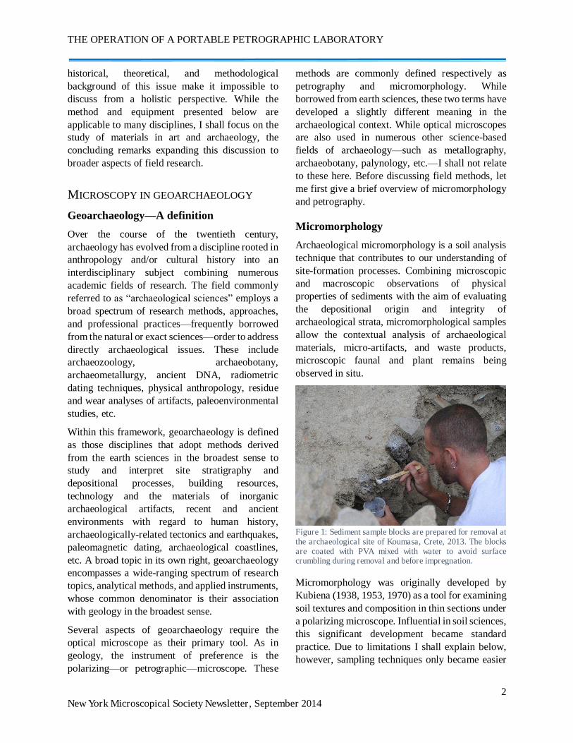
Figure 1: Sediment sample blocks are prepared for removal at the archaeological site of Koumasa, Crete, 2013. The blocks are coated with PVA mixed with water to avoid surface crumbling during removal and before impregnation.
Y. Goren
3 New York Microscopical Society Newsletter, September 2014
to implement with the improvement of synthetic resins and polymers, during the second half of the twentieth century. From the 1970s onwards, micromorphology began to be applied in archaeological research (Courty et al., 1989). Further studies (Matthews et al., 1997; Goldberg & Macphail, 2006; Goldberg & Berna, 2010) refined the potential of archaeological applications by means of micromorphological samples.
Archaeological micromorphology links the microscopic analysis of intact oriented stratigraphic soil samples in thin sections with field observations of larger units. Micromorphologic examinations of site deposits allow depositional processes and soil features to be studied in situ through the use of polarized light microscopic analysis under plane-polarized (PPL) and cross-polarized light (XPL). This method is particularly valuable because micro-artifacts and other microscopic residues of human activities can be found on floors and other surfaces even after these have been cleaned.
Micromorphology also permits the recovery and examination of a wide range of minute plant and faunal remains—such as siliceous phytoliths, charred plant tissues, microscopic bone splinters, and coprolites (fossil manure) or their inorganic remnants (such as spherulites and oxalate druzes resulting from herbivore dung). Evidence of burning can be adduced in both organic (plants, bones) and inorganic residues according to the structural changes that occur in minerals or microscopic slug and ash. Activity remnants such as the compaction of living floors, plowing, technology workshop micro-wastes, accumulation of inorganic plant cell remains in silos, etc., can be observed even after sites have been cleared on the macro scale. Post-depositional alterations—such as bioturbation, organic decay, soil formation, mineral alteration or translocation of sediments by alluviation or aeolian activities—can also be examined.
Micromorphological thin sections also provide permanent archival samples for future research, always being available for re-examination. Several case studies (Courty et al., 1989) have demonstrated the way in which micromorphology
can be incorporated into research methodologies in order to gain a better understanding of a site’s use and post-occupation history. The findings of these studies have addressed questions pertaining to the use of space over time, the nature of accumulations from different activities undertaken in living floors, the role and nature of post-depositional processes, and numerous other environmental and climatic aspects.
The primary limitation under which micromorphology suffers is related to the laboratory work it requires. Sampling procedures begin with detailed field descriptions of a given deposit, followed by the removal of unmixed blocks of sediment preserving its integrity and orientation. Samples are typically taken from a section or surface of an excavated unit, a knife or spatula being used to cut out a block of the soil, typically 10 x 10 x 20 cm in size, depending on the nature of the feature. Crumbly sediments are first coated with plaster of paris or sprayed with a polymer resin immersed in a solvent (e.g., Polyvinyl acetate [PVA] immersed in water or Paraloid B–72 in acetone), then being carefully removed with the aid of a spatula (Figure 1). More solid sediments are carved out of the section or surface, carefully packed in tissue paper, and then wrapped in several layers of masking-tape and stored to prevent breakage. Once removed and wrapped, the sample is labeled with its 3-dimensional provenance information and shipped to the lab for processing. At the lab, the samples are slowly dried in an oven at a low temperature (~50° C), after which they are placed in a vacuum chamber to allow the infusion of synthetic resin through capillary action. When the resin has hardened, the samples are cut with a diamond saw into 5 mm-thick slices. These are ground flat on one side and glued to a large—usually 7.5 x 5 cm—microscope carrying glasses. On the other side, they are ground down into standard 30μ (thirty microns, 0.03 mm) thin sections. Once ready, the thin sections are labeled and examined under the polarizing microscope.
THE OPERATION OF A PORTABLE PETROGRAPHIC LABORATORY
4 New York Microscopical Society Newsletter, September 2014
Petrography
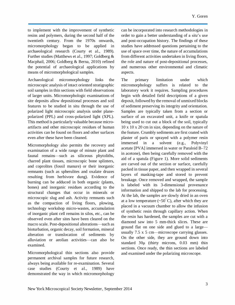
In the archaeological context, the term petrography refers to the study of non-metallic artifacts in thin sections under a polarizing microscope (Quinn, 2013). Developed in the field of geology and mineralogy, this became established from the mid-nineteenth century onwards as the standard method for the microscopical study of rocks and rock-forming minerals in thin sections. Since the 1930s, archaeologists have used it to examine archaeologically-related crystalline non-metallic materials. While it has commonly been employed in the identification of ceramic raw materials (Figure 2) it has also been applied to plasters and mortars and—not surprisingly—the identification of types of rocks in the study of statues, stone tools, and building materials.
In the case of ceramics, the petrographic study of pottery has greatly contributed to the classification of the clay and temper chosen by specific potters, estimating the firing temperature (by phase changes in minerals), the identification of material manipulation (sorting, refinement, etc.), and reconstruction of the assumed geology of the area in which the raw materials were extracted. If the latter features are sufficiently specific, petrography can also help to determine an object’s provenance—i.e., the workshop’s geographic location. The extensive ethnographic data available concerning traditional potters worldwide indicating that the vast majority employ materials from their immediate environment, a vessel can be determined as “local” to its site of discovery or produced elsewhere. Over the last century, this methodology has been employed in numerous studies to determine pottery “families” and wares, identify trade and exchange systems, and conjecture regarding interactions between cultural and political entities. From the 1990s onwards, I have employed this method to study clay cuneiform tablets from some of the major ancient Near Eastern archives (Goren et al., 2004; 2011). Petrographic studies of stone artifacts have also been conducted with respect to the exchange and transformation of prehistoric polished stone axes in the Old and New Worlds (e.g., Bradley & Edmonds, 1993).
Petrography is not the sole method employed in archaeology for such studies. From the 1960s onwards, provenance studies of archaeological artifacts have been carried out via a variety of elemental methods. These measure the elemental concentrations within the artifact, comparing them internally within given groups of artifacts or confronting them with databases of reference materials from other known sources. The most commonly-used method for non-metallic objects is Neutron Activation Analysis (NAA or INAA [Instrumental NAA]). On occasion, however, other geochemical methods are employed—such as Atomic Absorption Spectrometry (AAS), Inductively Coupled-Plasma Spectrometry (ICP), and X-Ray Florescence (XRF). In many instances, the best results have proved to be those achieved through a combination of petrography with elemental methods such as NAA. While a mineralogical method, petrography is primarily a qualitative method. Likewise, while elemental methods are fully quantitative they are rather “blind” and heavily reliant on the statistical manipulation of data.
THE PORTABLE LABORATORY
The need for portable laboratories
In practice, micromorphology and petrography both are laboratory-based methods, requiring immovable equipment for the preparation and examination of sampled specimens. While micromorphology can be explained in a certain sense as a method for excavating selected portions of a site under a microscope, the need to impregnate block samples of sediments by polymer resin and prepare oversized microscopic thin sections restricts it primarily to the laboratory. Its use as a means for gaining a detailed understanding of archaeological features is thus effectively confined to the post-field season.
Many sites are also remote from the laboratory, frequently in other countries or on other continents. In these circumstances, the laboratory can became available and the results reported to the field archaeologist only after the end of the excavation
Y. Goren
5 New York Microscopical Society Newsletter, September 2014
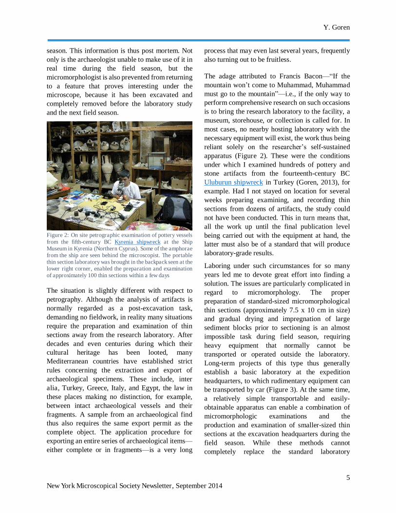
season. This information is thus post mortem. Not only is the archaeologist unable to make use of it in real time during the field season, but the micromorphologist is also prevented from returning to a feature that proves interesting under the microscope, because it has been excavated and completely removed before the laboratory study and the next field season.
Figure 2: On site petrographic examination of pottery vessels from the fifth-century BC Kyrenia shipwreck at the Ship Museum in Kyrenia (Northern Cyprus). Some of the amphorae from the ship are seen behind the microscopist. The portable thin section laboratory was brought in the backpack seen at the lower right corner, enabled the preparation and examination of approximately 100 thin sections within a few days
The situation is slightly different with respect to petrography. Although the analysis of artifacts is normally regarded as a post-excavation task, demanding no fieldwork, in reality many situations require the preparation and examination of thin sections away from the research laboratory. After decades and even centuries during which their cultural heritage has been looted, many Mediterranean countries have established strict rules concerning the extraction and export of archaeological specimens. These include, inter alia, Turkey, Greece, Italy, and Egypt, the law in these places making no distinction, for example, between intact archaeological vessels and their fragments. A sample from an archaeological find thus also requires the same export permit as the complete object. The application procedure for exporting an entire series of archaeological items—either complete or in fragments—is a very long
process that may even last several years, frequently also turning out to be fruitless.
The adage attributed to Francis Bacon—“If the mountain won’t come to Muhammad, Muhammad must go to the mountain”—i.e., if the only way to perform comprehensive research on such occasions is to bring the research laboratory to the facility, a museum, storehouse, or collection is called for. In most cases, no nearby hosting laboratory with the necessary equipment will exist, the work thus being reliant solely on the researcher’s self-sustained apparatus (Figure 2). These were the conditions under which I examined hundreds of pottery and stone artifacts from the fourteenth-century BC Uluburun shipwreck in Turkey (Goren, 2013), for example. Had I not stayed on location for several weeks preparing examining, and recording thin sections from dozens of artifacts, the study could not have been conducted. This in turn means that, all the work up until the final publication level being carried out with the equipment at hand, the latter must also be of a standard that will produce laboratory-grade results.
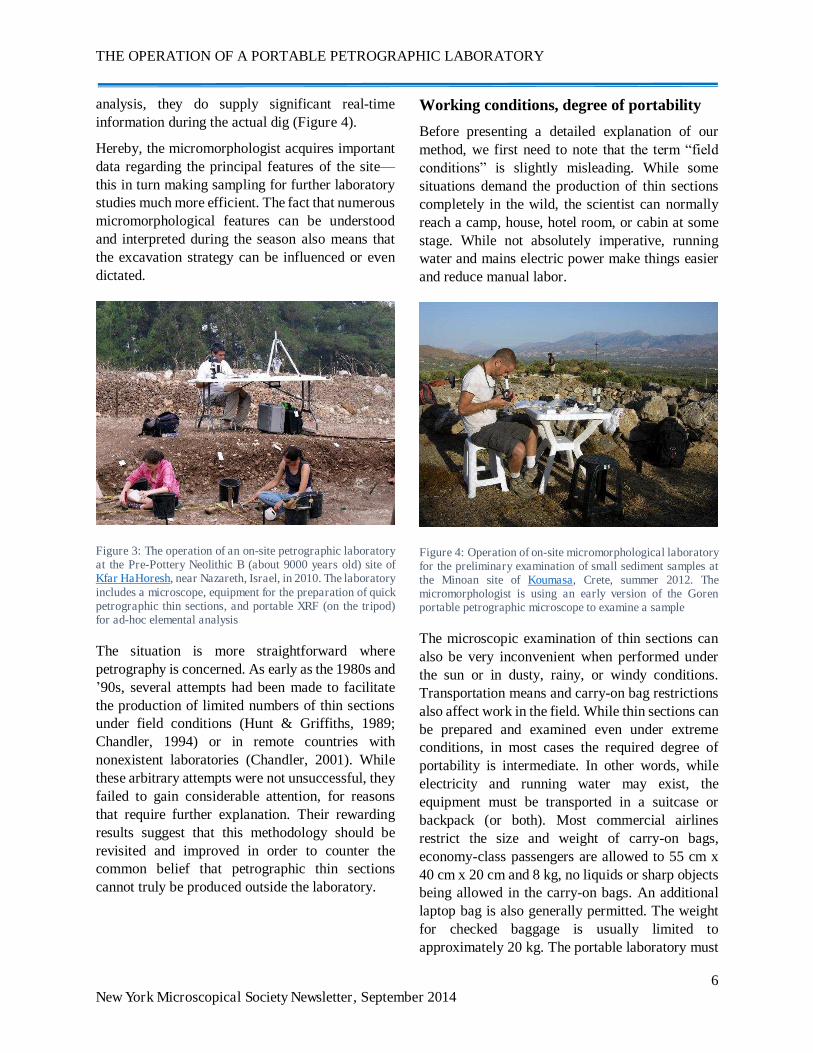
Laboring under such circumstances for so many years led me to devote great effort into finding a solution. The issues are particularly complicated in regard to micromorphology. The proper preparation of standard-sized micromorphological thin sections (approximately 7.5 x 10 cm in size) and gradual drying and impregnation of large sediment blocks prior to sectioning is an almost impossible task during field season, requiring heavy equipment that normally cannot be transported or operated outside the laboratory. Long-term projects of this type thus generally establish a basic laboratory at the expedition headquarters, to which rudimentary equipment can be transported by car (Figure 3). At the same time, a relatively simple transportable and easily-obtainable apparatus can enable a combination of micromorphologic examinations and the production and examination of smaller-sized thin sections at the excavation headquarters during the field season. While these methods cannot completely replace the standard laboratory
THE OPERATION OF A PORTABLE PETROGRAPHIC LABORATORY
6 New York Microscopical Society Newsletter, September 2014
analysis, they do supply significant real-time information during the actual dig (Figure 4).
Hereby, the micromorphologist acquires important data regarding the principal features of the site— this in turn making sampling for further laboratory studies much more efficient. The fact that numerous micromorphological features can be understood and interpreted during the season also means that the excavation strategy can be influenced or even dictated.
Figure 3: The operation of an on-site petrographic laboratory at the Pre-Pottery Neolithic B (about 9000 years old) site of Kfar HaHoresh, near Nazareth, Israel, in 2010. The laboratory includes a microscope, equipment for the preparation of quick petrographic thin sections, and portable XRF (on the tripod) for ad-hoc elemental analysis
The situation is more straightforward where petrography is concerned. As early as the 1980s and ’90s, several attempts had been made to facilitate the production of limited numbers of thin sections under field conditions (Hunt & Griffiths, 1989; Chandler, 1994) or in remote countries with nonexistent laboratories (Chandler, 2001). While these arbitrary attempts were not unsuccessful, they failed to gain considerable attention, for reasons that require further explanation. Their rewarding results suggest that this methodology should be revisited and improved in order to counter the common belief that petrographic thin sections cannot truly be produced outside the laboratory.
Working conditions, degree of portability
Before presenting a detailed explanation of our method, we first need to note that the term “field conditions” is slightly misleading. While some situations demand the production of thin sections completely in the wild, the scientist can normally reach a camp, house, hotel room, or cabin at some stage. While not absolutely imperative, running water and mains electric power make things easier and reduce manual labor.
Figure 4: Operation of on-site micromorphological laboratory for the preliminary examination of small sediment samples at the Minoan site of Koumasa, Crete, summer 2012. The micromorphologist is using an early version of the Goren portable petrographic microscope to examine a sample
The microscopic examination of thin sections can also be very inconvenient when performed under the sun or in dusty, rainy, or windy conditions. Transportation means and carry-on bag restrictions also affect work in the field. While thin sections can be prepared and examined even under extreme conditions, in most cases the required degree of portability is intermediate. In other words, while electricity and running water may exist, the equipment must be transported in a suitcase or backpack (or both). Most commercial airlines restrict the size and weight of carry-on bags, economy-class passengers are allowed to 55 cm x 40 cm x 20 cm and 8 kg, no liquids or sharp objects being allowed in the carry-on bags. An additional laptop bag is also generally permitted. The weight for checked baggage is usually limited to approximately 20 kg. The portable laboratory must
Y. Goren
7 New York Microscopical Society Newsletter, September 2014
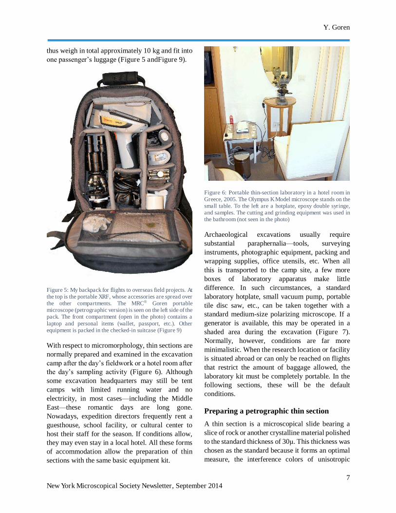
thus weigh in total approximately 10 kg and fit into one passenger’s luggage (Figure 5 andFigure 9).
Figure 5: My backpack for flights to overseas field projects. At the top is the portable XRF, whose accessories are spread over the other compartments. The MRC® Goren portable microscope (petrographic version) is seen on the left side of the pack. The front compartment (open in the photo) contains a laptop and personal items (wallet, passport, etc.). Other equipment is packed in the checked-in suitcase (Figure 9)
With respect to micromorphology, thin sections are normally prepared and examined in the excavation camp after the day’s fieldwork or a hotel room after the day’s sampling activity (Figure 6). Although some excavation headquarters may still be tent camps with limited running water and no electricity, in most cases—including the Middle East—these romantic days are long gone. Nowadays, expedition directors frequently rent a guesthouse, school facility, or cultural center to host their staff for the season. If conditions allow, they may even stay in a local hotel. All these forms of accommodation allow the preparation of thin sections with the same basic equipment kit.
Figure 6: Portable thin-section laboratory in a hotel room in Greece, 2005. The Olympus K Model microscope stands on the small table. To the left are a hotplate, epoxy double syringe, and samples. The cutting and grinding equipment was used in the bathroom (not seen in the photo)
Archaeological excavations usually require substantial paraphernalia—tools, surveying instruments, photographic equipment, packing and wrapping supplies, office utensils, etc. When all this is transported to the camp site, a few more boxes of laboratory apparatus make little difference. In such circumstances, a standard laboratory hotplate, small vacuum pump, portable tile disc saw, etc., can be taken together with a standard medium-size polarizing microscope. If a generator is available, this may be operated in a shaded area during the excavation (Figure 7). Normally, however, conditions are far more minimalistic. When the research location or facility is situated abroad or can only be reached on flights that restrict the amount of baggage allowed, the laboratory kit must be completely portable. In the following sections, these will be the default conditions.
Preparing a petrographic thin section
A thin section is a microscopical slide bearing a slice of rock or another crystalline material polished to the standard thickness of 30μ. This thickness was chosen as the standard because it forms an optimal measure, the interference colors of unisotropic
THE OPERATION OF A PORTABLE PETROGRAPHIC LABORATORY
8 New York Microscopical Society Newsletter, September 2014
mineral crystals as seen by the human eye being neither too high nor too low by spectral order. Although the idea of slicing and grinding a rock so thinly may appear a complicated operation, it is in fact quite simple, the students in our Laboratory for Comparative Microarchaeology at Tel Aviv University regularly mastering it after a few weeks of training.
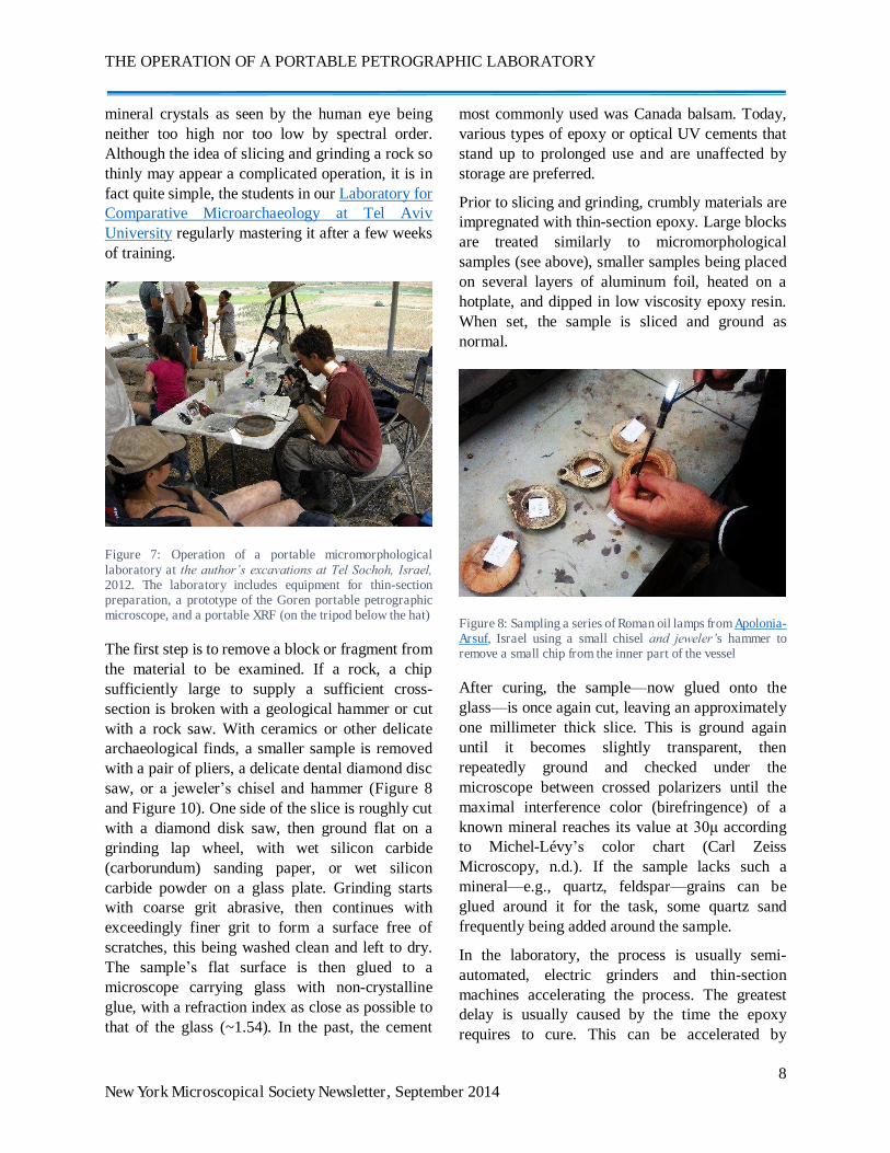
Figure 7: Operation of a portable micromorphological laboratory at the author’s excavations at Tel Sochoh, Israel, 2012. The laboratory includes equipment for thin-section preparation, a prototype of the Goren portable petrographic microscope, and a portable XRF (on the tripod below the hat)
The first step is to remove a block or fragment from the material to be examined. If a rock, a chip sufficiently large to supply a sufficient cross-section is broken with a geological hammer or cut with a rock saw. With ceramics or other delicate archaeological finds, a smaller sample is removed with a pair of pliers, a delicate dental diamond disc saw, or a jeweler’s chisel and hammer (Figure 8 and Figure 10). One side of the slice is roughly cut with a diamond disk saw, then ground flat on a grinding lap wheel, with wet silicon carbide (carborundum) sanding paper, or wet silicon carbide powder on a glass plate. Grinding starts with coarse grit abrasive, then continues with exceedingly finer grit to form a surface free of scratches, this being washed clean and left to dry. The sample’s flat surface is then glued to a microscope carrying glass with non-crystalline glue, with a refraction index as close as possible to that of the glass (~1.54). In the past, the cement
most commonly used was Canada balsam. Today, various types of epoxy or optical UV cements that stand up to prolonged use and are unaffected by storage are preferred.
Prior to slicing and grinding, crumbly materials are impregnated with thin-section epoxy. Large blocks are treated similarly to micromorphological samples (see above), smaller samples being placed on several layers of aluminum foil, heated on a hotplate, and dipped in low viscosity epoxy resin. When set, the sample is sliced and ground as normal.
Figure 8: Sampling a series of Roman oil lamps from Apolonia-Arsuf, Israel using a small chisel and jeweler’s hammer to remove a small chip from the inner part of the vessel
After curing, the sample—now glued onto the glass—is once again cut, leaving an approximately one millimeter thick slice. This is ground again until it becomes slightly transparent, then repeatedly ground and checked under the microscope between crossed polarizers until the maximal interference color (birefringence) of a known mineral reaches its value at 30μ according to Michel-Lévy’s color chart (Carl Zeiss Microscopy, n.d.). If the sample lacks such a mineral—e.g., quartz, feldspar—grains can be glued around it for the task, some quartz sand frequently being added around the sample.
In the laboratory, the process is usually semi-automated, electric grinders and thin-section machines accelerating the process. The greatest delay is usually caused by the time the epoxy requires to cure. This can be accelerated by
Y. Goren
9 New York Microscopical Society Newsletter, September 2014
controlled heating on a hotplate. Some laboratories use UV-curing adhesive rather than epoxy resins, although these also take some hours to cure. Except this delay, the process can be expedited if operated by a trained technician. Fully-equipped laboratories may have entirely automated—but inordinately expensive—thin-section machines capable of simultaneously grinding sets of slides. Set on a revolver, these stop automatically when 30μ thickness has been reached.
While such equipment is obviously restricted to the laboratory, research-grade thin sections can be prepared manually outside the laboratory using a portable kit consisting of off-the-shelf, relatively low-priced, and easily-available instruments. The following discuss the necessary equipment and sample preparation procedure.
OPERATING A PORTABLE LABORATORY
Setting
The portable laboratory (see below) is designed to be carried in a normal suitcase while leaving sufficient space and weight for other personal items. Consisting of a main box with most of the necessary equipment and several additional appliances, the latter can be housed in a permanent setting—a hotel room, camp, etc.
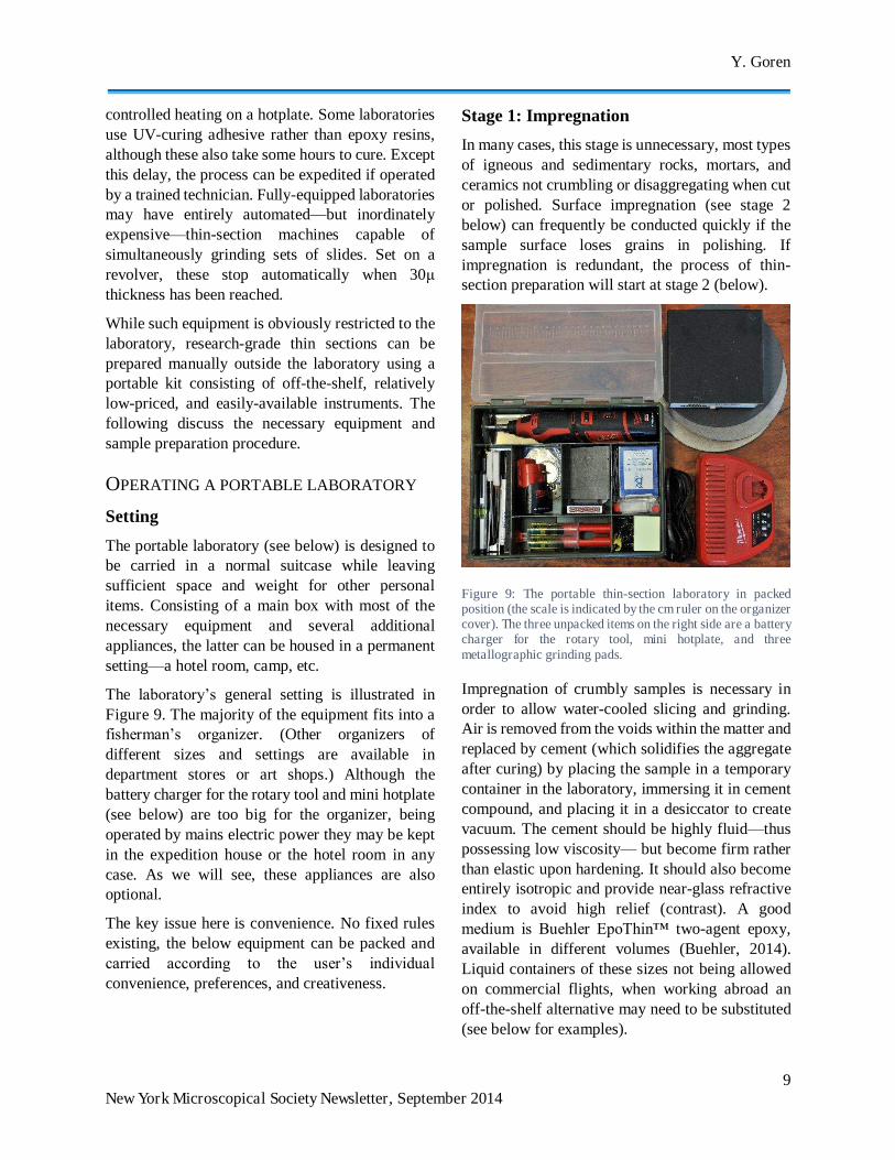
The laboratory’s general setting is illustrated in Figure 9. The majority of the equipment fits into a fisherman’s organizer. (Other organizers of different sizes and settings are available in department stores or art shops.) Although the battery charger for the rotary tool and mini hotplate (see below) are too big for the organizer, being operated by mains electric power they may be kept in the expedition house or the hotel room in any case. As we will see, these appliances are also optional.
The key issue here is convenience. No fixed rules existing, the below equipment can be packed and carried according to the user’s individual convenience, preferences, and creativeness.
Stage 1: Impregnation
In many cases, this stage is unnecessary, most types of igneous and sedimentary rocks, mortars, and ceramics not crumbling or disaggregating when cut or polished. Surface impregnation (see stage 2 below) can frequently be conducted quickly if the sample surface loses grains in polishing. If impregnation is redundant, the process of thin-section preparation will start at stage 2 (below).
Figure 9: The portable thin-section laboratory in packed position (the scale is indicated by the cm ruler on the organizer cover). The three unpacked items on the right side are a battery charger for the rotary tool, mini hotplate, and three metallographic grinding pads.
Impregnation of crumbly samples is necessary in order to allow water-cooled slicing and grinding. Air is removed from the voids within the matter and replaced by cement (which solidifies the aggregate after curing) by placing the sample in a temporary container in the laboratory, immersing it in cement compound, and placing it in a desiccator to create vacuum. The cement should be highly fluid—thus possessing low viscosity— but become firm rather than elastic upon hardening. It should also become entirely isotropic and provide near-glass refractive index to avoid high relief (contrast). A good medium is Buehler EpoThin™ two-agent epoxy, available in different volumes (Buehler, 2014). Liquid containers of these sizes not being allowed on commercial flights, when working abroad an off-the-shelf alternative may need to be substituted (see below for examples).
THE OPERATION OF A PORTABLE PETROGRAPHIC LABORATORY
10 New York Microscopical Society Newsletter, September 2014
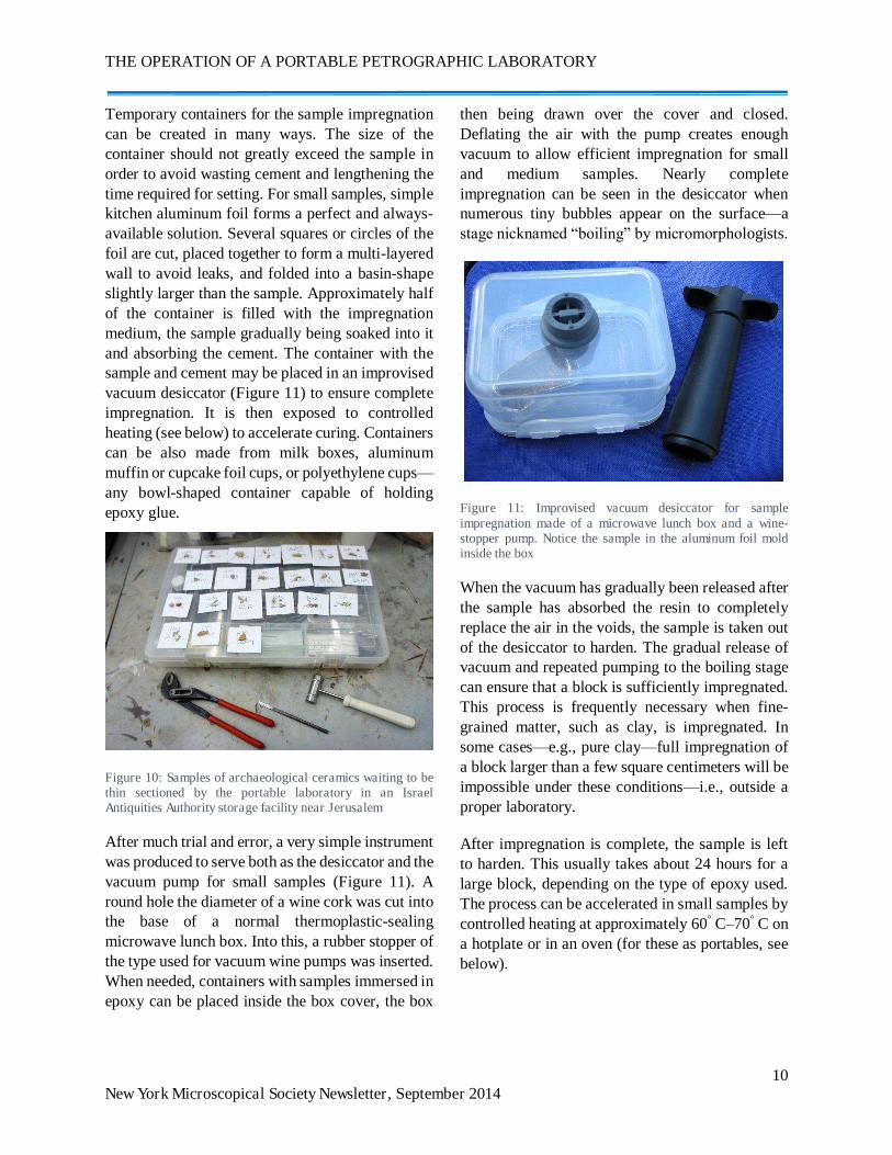
Temporary containers for the sample impregnation can be created in many ways. The size of the container should not greatly exceed the sample in order to avoid wasting cement and lengthening the time required for setting. For small samples, simple kitchen aluminum foil forms a perfect and always-available solution. Several squares or circles of the foil are cut, placed together to form a multi-layered wall to avoid leaks, and folded into a basin-shape slightly larger than the sample. Approximately half of the container is filled with the impregnation medium, the sample gradually being soaked into it and absorbing the cement. The container with the sample and cement may be placed in an improvised vacuum desiccator (Figure 11) to ensure complete impregnation. It is then exposed to controlled heating (see below) to accelerate curing. Containers can be also made from milk boxes, aluminum muffin or cupcake foil cups, or polyethylene cups—any bowl-shaped container capable of holding epoxy glue.
Figure 10: Samples of archaeological ceramics waiting to be thin sectioned by the portable laboratory in an Israel Antiquities Authority storage facility near Jerusalem
After much trial and error, a very simple instrument was produced to serve both as the desiccator and the vacuum pump for small samples (Figure 11). A round hole the diameter of a wine cork was cut into the base of a normal thermoplastic-sealing microwave lunch box. Into this, a rubber stopper of the type used for vacuum wine pumps was inserted. When needed, containers with samples immersed in epoxy can be placed inside the box cover, the box
then being drawn over the cover and closed. Deflating the air with the pump creates enough vacuum to allow efficient impregnation for small and medium samples. Nearly complete impregnation can be seen in the desiccator when numerous tiny bubbles appear on the surface—a stage nicknamed “boiling” by micromorphologists.
Figure 11: Improvised vacuum desiccator for sample impregnation made of a microwave lunch box and a wine-stopper pump. Notice the sample in the aluminum foil mold inside the box
When the vacuum has gradually been released after the sample has absorbed the resin to completely replace the air in the voids, the sample is taken out of the desiccator to harden. The gradual release of vacuum and repeated pumping to the boiling stage can ensure that a block is sufficiently impregnated. This process is frequently necessary when fine-grained matter, such as clay, is impregnated. In some cases—e.g., pure clay—full impregnation of a block larger than a few square centimeters will be impossible under these conditions—i.e., outside a proper laboratory.
After impregnation is complete, the sample is left to harden. This usually takes about 24 hours for a large block, depending on the type of epoxy used. The process can be accelerated in small samples by controlled heating at approximately 60° C–70° C on a hotplate or in an oven (for these as portables, see below).
Y. Goren
11 New York Microscopical Society Newsletter, September 2014
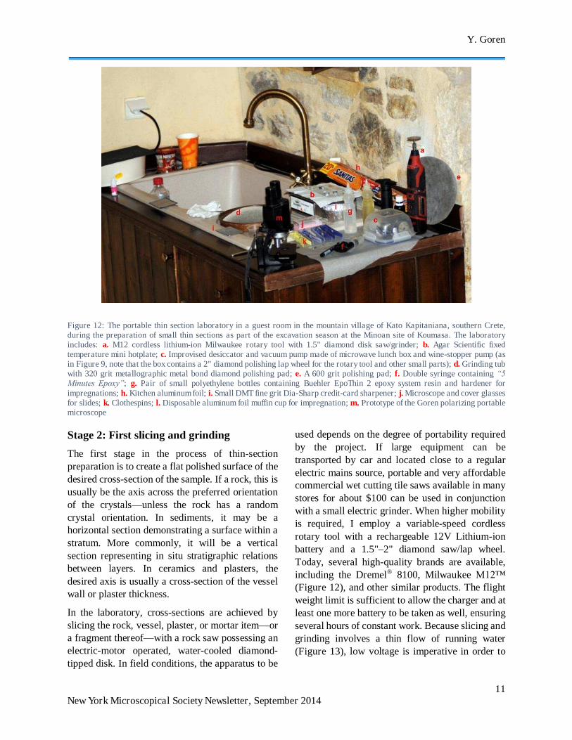
Figure 12: The portable thin section laboratory in a guest room in the mountain village of Kato Kapitaniana, southern Crete, during the preparation of small thin sections as part of the excavation season at the Minoan site of Koumasa. The laboratory includes: a. M12 cordless lithium-ion Milwaukee rotary tool with 1.5" diamond disk saw/grinder; b. Agar Scientific fixed temperature mini hotplate; c. Improvised desiccator and vacuum pump made of microwave lunch box and wine-stopper pump (as in Figure 9, note that the box contains a 2" diamond polishing lap wheel for the rotary tool and other small parts); d. Grinding tub with 320 grit metallographic metal bond diamond polishing pad; e. A 600 grit polishing pad; f. Double syringe containing “5 Minutes Epoxy”; g. Pair of small polyethylene bottles containing Buehler EpoThin 2 epoxy system resin and hardener for impregnations; h. Kitchen aluminum foil; i. Small DMT fine grit Dia-Sharp credit-card sharpener; j. Microscope and cover glasses for slides; k. Clothespins; l. Disposable aluminum foil muffin cup for impregnation; m. Prototype of the Goren polarizing portable microscope
Stage 2: First slicing and grinding
The first stage in the process of thin-section preparation is to create a flat polished surface of the desired cross-section of the sample. If a rock, this is usually be the axis across the preferred orientation of the crystals—unless the rock has a random crystal orientation. In sediments, it may be a horizontal section demonstrating a surface within a stratum. More commonly, it will be a vertical section representing in situ stratigraphic relations between layers. In ceramics and plasters, the desired axis is usually a cross-section of the vessel wall or plaster thickness.
In the laboratory, cross-sections are achieved by slicing the rock, vessel, plaster, or mortar item—or a fragment thereof—with a rock saw possessing an electric-motor operated, water-cooled diamond-tipped disk. In field conditions, the apparatus to be
used depends on the degree of portability required by the project. If large equipment can be transported by car and located close to a regular electric mains source, portable and very affordable commercial wet cutting tile saws available in many stores for about $100 can be used in conjunction with a small electric grinder. When higher mobility is required, I employ a variable-speed cordless rotary tool with a rechargeable 12V Lithium-ion battery and a 1.5"–2" diamond saw/lap wheel. Today, several high-quality brands are available, including the Dremel® 8100, Milwaukee M12™ (Figure 12), and other similar products. The flight weight limit is sufficient to allow the charger and at least one more battery to be taken as well, ensuring several hours of constant work. Because slicing and grinding involves a thin flow of running water (Figure 13), low voltage is imperative in order to
THE OPERATION OF A PORTABLE PETROGRAPHIC LABORATORY
12 New York Microscopical Society Newsletter, September 2014
prevent electric shocks. It also enables the work to be conducted in the field.
The first slicing is made by holding the rotary tool with one hand and the sample with the other under slowly running water or slightly immersed in a bucket or tub (Figure 13). The motor is operated at a low RPM to ensure that the disk revolves slowly and to avoid water splashing, the sample being brought to the disk and cut steadily. Although diamond disk saws are not sharp or denticulated, the slow rotation also precluding risk of injury, protective glasses should be worn to avoid damage to the eyes caused by shooting particles. It takes some time to find the best position to achieve a clean cut and direct the splash of water away from the operator. A tub, tap, and thin, steady flow of water are the optimal requirements. If the sample is small, it can first be ground on the lapping side of the wheel. This ensuring that the coarse sawing ridges are removed and the surface is generally flat. Further grinding in the grinding tub is usually required, however.
Figure 13: Cutting a sample from the carrying glass using a rotary tool with a 2" diamond disk saw/lap wheel under running water
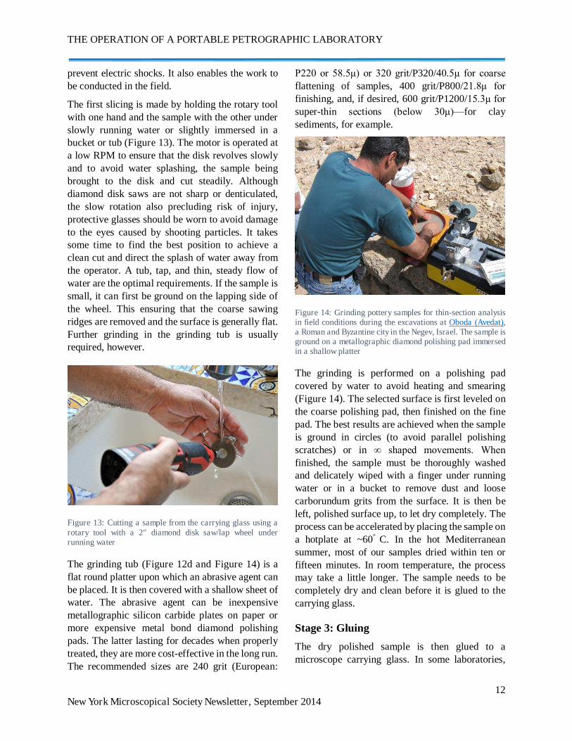
The grinding tub (Figure 12d and Figure 14) is a flat round platter upon which an abrasive agent can be placed. It is then covered with a shallow sheet of water. The abrasive agent can be inexpensive metallographic silicon carbide plates on paper or more expensive metal bond diamond polishing pads. The latter lasting for decades when properly treated, they are more cost-effective in the long run. The recommended sizes are 240 grit (European:
P220 or 58.5μ) or 320 grit/P320/40.5μ for coarse flattening of samples, 400 grit/P800/21.8μ for finishing, and, if desired, 600 grit/P1200/15.3μ for super-thin sections (below 30μ)—for clay sediments, for example.
Figure 14: Grinding pottery samples for thin-section analysis in field conditions during the excavations at Oboda (Avedat), a Roman and Byzantine city in the Negev, Israel. The sample is ground on a metallographic diamond polishing pad immersed in a shallow platter
The grinding is performed on a polishing pad covered by water to avoid heating and smearing (Figure 14). The selected surface is first leveled on the coarse polishing pad, then finished on the fine pad. The best results are achieved when the sample is ground in circles (to avoid parallel polishing scratches) or in ∞ shaped movements. When finished, the sample must be thoroughly washed and delicately wiped with a finger under running water or in a bucket to remove dust and loose carborundum grits from the surface. It is then be left, polished surface up, to let dry completely. The process can be accelerated by placing the sample on a hotplate at ~60° C. In the hot Mediterranean summer, most of our samples dried within ten or fifteen minutes. In room temperature, the process may take a little longer. The sample needs to be completely dry and clean before it is glued to the carrying glass.
Stage 3: Gluing
The dry polished sample is then glued to a microscope carrying glass. In some laboratories,
Y. Goren
13 New York Microscopical Society Newsletter, September 2014
this side of the glass is ground matt to ensure better holding of the sample. When modern epoxy glues replaced the traditional Canada balsam or Lakeside cements, however, we found that it was possible to glue the samples directly onto the unprepared glass. The glass must be free of any dust, oil, or fingerprints that may hamper proper bonding.
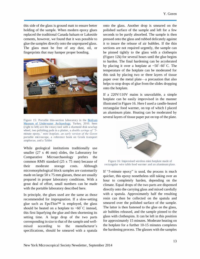
Figure 15: Portable thin-section laboratory in the Bodrum Museum of Underwater Archaeology, Turkey, 2010. Seen (right to left) are the rotary tool with a diamond disk saw/lap wheel, two polishing pads in a platter, a double syringe of “5-minute epoxy,” mini hotplate, an early version of the Goren portable microscope, a reference book on Greek transport amphorae, and a Tablet
While geological institutions traditionally use smaller (27 x 46 mm) slides, the Laboratory for Comparative Microarchaeology prefers the common RMS standard (25 x 75 mm) because of their moderate storage costs. Although micromorphological block samples are customarily made on large 50 x 75 mm glasses, these are usually prepared in proper laboratory conditions. With a great deal of effort, small numbers can be made with the portable laboratory described here.
In principle, the glues used are the same as those recommended for impregnation. If a slow-setting glue such as EpoThin™ is employed, the glass should be heated on a hotplate to ~60° C instead, this first liquefying the glue and then shortening its setting time. A large drop of the two parts corresponding in size to that of the sample and well-mixed according to the manufacturer’s specifications, should be smeared with a spatula
onto the glass. Another drop is smeared on the polished surface of the sample and left for a few seconds to be partly absorbed. The sample is then pressed onto the glass and rubbed delicately against it to insure the release of air bubbles. If the thin sections are not required urgently, the sample can be pinned tightly to the glass with a clothespin (Figure 12k) for several hours until the glue begins to harden. The final hardening can be accelerated by placing it over a hotplate at ~50°–60° C. The temperature of the hotplate can be moderated for this task by placing two or three layers of tissue paper over the metal plate—a precaution that also helps to stop drops of glue from the slides dropping onto the hotplate.
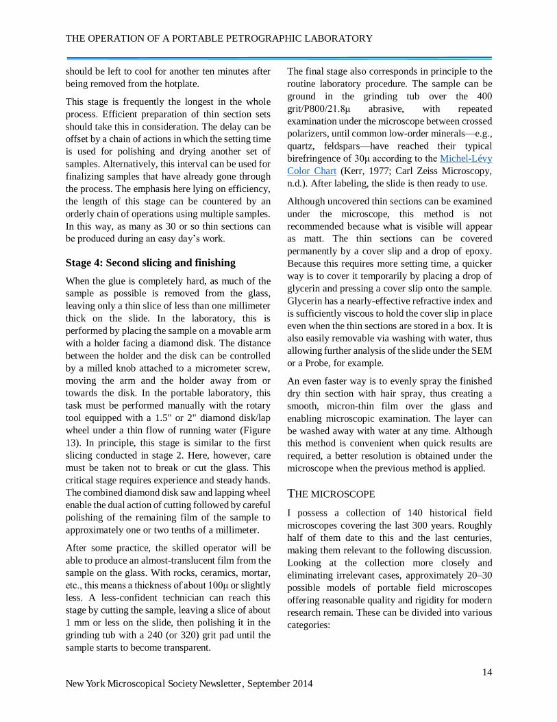
If a 220V/110V mains is unavailable, a simple hotplate can be easily improvised in the manner illustrated in Figure 16. Here I used a candle-heated rectangular food warmer, on top of which I placed an aluminum plate. Heating can be moderated by several layers of tissue paper put on top of the plate.
Figure 16: Improvised wireless mini hotplate made of
rectangular wire table food warmer and an aluminum plate.
If “5-minute epoxy” is used, the process is much quicker, this epoxy nonetheless still taking over an hour to completely harden, depending on the climate. Equal drops of the two parts are dispensed directly onto the carrying glass and mixed carefully with a spatula. Approximately half the resulting resin can then be collected on the spatula and smeared over the polished surface of the sample. The latter is then fastened to the glue on the glass, air bubbles released, and the sample pinned to the glass with clothespins. It can be left in this position for approximately 15 minutes. Moderate heating on the hotplate for a further 10-15 minutes completes the hardening process. The glasses with the samples
THE OPERATION OF A PORTABLE PETROGRAPHIC LABORATORY
14 New York Microscopical Society Newsletter, September 2014
should be left to cool for another ten minutes after being removed from the hotplate.
This stage is frequently the longest in the whole process. Efficient preparation of thin section sets should take this in consideration. The delay can be offset by a chain of actions in which the setting time is used for polishing and drying another set of samples. Alternatively, this interval can be used for finalizing samples that have already gone through the process. The emphasis here lying on efficiency, the length of this stage can be countered by an orderly chain of operations using multiple samples. In this way, as many as 30 or so thin sections can be produced during an easy day’s work.
Stage 4: Second slicing and finishing
When the glue is completely hard, as much of the sample as possible is removed from the glass, leaving only a thin slice of less than one millimeter thick on the slide. In the laboratory, this is performed by placing the sample on a movable arm with a holder facing a diamond disk. The distance between the holder and the disk can be controlled by a milled knob attached to a micrometer screw, moving the arm and the holder away from or towards the disk. In the portable laboratory, this task must be performed manually with the rotary tool equipped with a 1.5" or 2" diamond disk/lap wheel under a thin flow of running water (Figure 13). In principle, this stage is similar to the first slicing conducted in stage 2. Here, however, care must be taken not to break or cut the glass. This critical stage requires experience and steady hands. The combined diamond disk saw and lapping wheel enable the dual action of cutting followed by careful polishing of the remaining film of the sample to approximately one or two tenths of a millimeter.
After some practice, the skilled operator will be able to produce an almost-translucent film from the sample on the glass. With rocks, ceramics, mortar, etc., this means a thickness of about 100μ or slightly less. A less-confident technician can reach this stage by cutting the sample, leaving a slice of about 1 mm or less on the slide, then polishing it in the grinding tub with a 240 (or 320) grit pad until the sample starts to become transparent.
The final stage also corresponds in principle to the routine laboratory procedure. The sample can be ground in the grinding tub over the 400 grit/P800/21.8μ abrasive, with repeated examination under the microscope between crossed polarizers, until common low-order minerals—e.g., quartz, feldspars—have reached their typical birefringence of 30μ according to the Michel-Lévy Color Chart (Kerr, 1977; Carl Zeiss Microscopy, n.d.). After labeling, the slide is then ready to use.
Although uncovered thin sections can be examined under the microscope, this method is not recommended because what is visible will appear as matt. The thin sections can be covered permanently by a cover slip and a drop of epoxy. Because this requires more setting time, a quicker way is to cover it temporarily by placing a drop of glycerin and pressing a cover slip onto the sample. Glycerin has a nearly-effective refractive index and is sufficiently viscous to hold the cover slip in place even when the thin sections are stored in a box. It is also easily removable via washing with water, thus allowing further analysis of the slide under the SEM or a Probe, for example.
An even faster way is to evenly spray the finished dry thin section with hair spray, thus creating a smooth, micron-thin film over the glass and enabling microscopic examination. The layer can be washed away with water at any time. Although this method is convenient when quick results are required, a better resolution is obtained under the microscope when the previous method is applied.
THE MICROSCOPE
I possess a collection of 140 historical field microscopes covering the last 300 years. Roughly half of them date to this and the last centuries, making them relevant to the following discussion. Looking at the collection more closely and eliminating irrelevant cases, approximately 20–30 possible models of portable field microscopes offering reasonable quality and rigidity for modern research remain. These can be divided into various categories:
Y. Goren
15 New York Microscopical Society Newsletter, September 2014
1. Folded-optics microscopes: Based on an idea by McArthur (1934), this “family” of microscopes uses folded optics in the form of prisms to miniaturize the optical path, thus forming very compact instruments. A good overview of the most important models, including the most recent ones, is presented by Sobel, (n.d.), and Kreindler, (2013a; 2013b).
2. Folding microscopes: A version of desktop microscopes, these possess folding parts designed to collapse into a carry-on briefcase. They are thus more portable than their desktop equivalents. A good example is the Spencer Model 60 from the first and second quarter of the twentieth century (del Cerro, 2008).
3. Pocket microscopes: These are miniaturized microscopes that frequently possess a broad range of magnifications and high-quality optics. This concept became popular towards the late first quarter of the twentieth century, particularly in Germany. A good example of these is the Protami produced by Hensoldt from 1925 and on(Goren & Kreindler, 2011a; 2011b; Kreindler & Goren, 2011).
Very few of these models offer basic polarizing possibilities. An early example, now highly collectible and extremely rare, is the polarizing version of the superb Minor pocket microscope produced by Ernst Leitz, Wetzlar between the 1920’s and the late 1930’s (Kile, 2003, p. 31). On occasion, earlier researchers used polarizing versions of folded-optics microscopes, such as the Vickers McArthur model (Chandler, 1994) or a polarizing Swift FM-31 (Chandler, 2001). None of these or other models are binocular, however, the majority of them presenting ergonomics not permitting expanded working time without neck and eye fatigue. I thus found them all to be insufficient for the routine and prolonged microscopic work required under the circumstances detailed above.
I therefore developed a new concept of versatile portable microscope (Goren, 2013), now patented
1 http://www.mrclab.com/htmls/home.aspx.
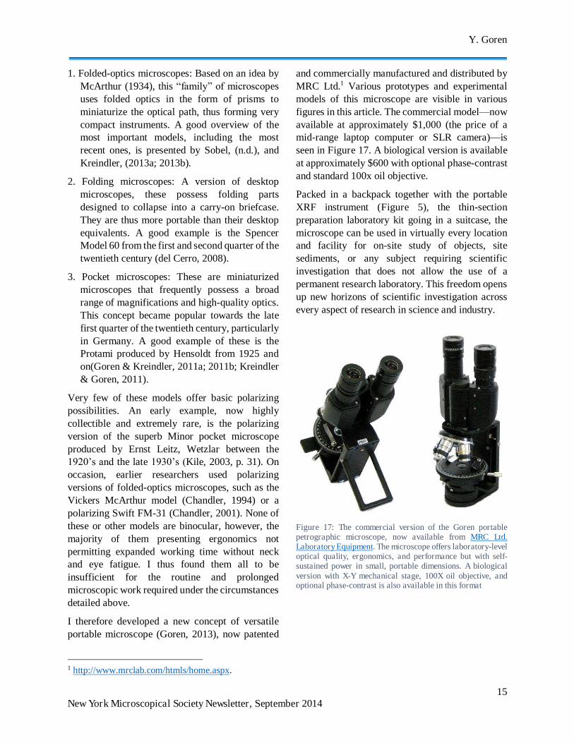
and commercially manufactured and distributed by MRC Ltd.1 Various prototypes and experimental models of this microscope are visible in various figures in this article. The commercial model—now available at approximately $1,000 (the price of a mid-range laptop computer or SLR camera)—is seen in Figure 17. A biological version is available at approximately $600 with optional phase-contrast and standard 100x oil objective.
Packed in a backpack together with the portable XRF instrument (Figure 5), the thin-section preparation laboratory kit going in a suitcase, the microscope can be used in virtually every location and facility for on-site study of objects, site sediments, or any subject requiring scientific investigation that does not allow the use of a permanent research laboratory. This freedom opens up new horizons of scientific investigation across every aspect of research in science and industry.
Figure 17: The commercial version of the Goren portable petrographic microscope, now available from MRC Ltd. Laboratory Equipment. The microscope offers laboratory-level optical quality, ergonomics, and performance but with self-sustained power in small, portable dimensions. A biological version with X-Y mechanical stage, 100X oil objective, and optional phase-contrast is also available in this format
THE OPERATION OF A PORTABLE PETROGRAPHIC LABORATORY
16 New York Microscopical Society Newsletter, September 2014
CONCLUDING REMARKS
The methodology and facilities presented here are suitable for countless applications in science and industry where optical microscopy is required outside the proper research laboratory. My aim was to demonstrate that quick sample preparation for top-level microscopic examination should not be limited to obvious and easy blood tests or biological examination of microfauna or tissues. With some basic equipment and free thinking, petrographic thin sections can be produced by portable laboratories and examined under a proper portable microscope. Needless to say, the same apparatus—with a portable reflected light microscope—can be used to prepare opaque metallographic samples, talented, creative scientists undoubtedly being capable of finding ways to adjust it to numerous other needs. All that is required is to think “outside the box”— the box here being the established research laboratory and equipment imposed on scientists by the business-driven scientific instrument producers (who refrain from entering what they conceive as “niches”, while modern science is seeking for these niches), and being biased by some unjustified preconceptions. Proper science is not reduced if it is performed with a sample prepared in a lunchbox connected to a wine-vacuum pump, and the level of scholarship is not reduced if a thin section is not made by an overly expensive Logitech thin section machine.
Together with MRC Lab Supplies Ltd., the producer of the portable microscope shown here, I am now looking into the possibility of producing commercial kits based on the thin-section portable laboratory described in this paper, to be marketed for an affordable fee as an optional companion to the Goren microscope. At the end of the day, however, this step is merely for the sake of convenience, any interested scientist being capable of assembling such a kit after some visits to the nearby shopping center.
REFERENCES
Bradley, R. & Edmonds, M., 1993. Interpreting the Axe Trade: Production and Exchange in Neolithic Britain. Cambridge: Cambridge University Press.
Buehler, 2014. EpoThin™ 2 Epoxy System.
Burnett, W. & Martin, L., 1992. Charles Darwin’s Microscopes. Microscopy, 36(8), pp. 604–627.
Carl Zeiss Microscopy, n.d. Michel-Lévy Color Chart.
Cassedy, J., 1976. The Microscope in American Medical Science, 1840-1860. Isis, 67, pp. 76-97.
Chandler, G., 1994. New Applications of Archaeological Microscopy in the Field: Ceramic Petrography and Microwear Analysis. Papers from the Institute of Archaeology, 5, pp. 39-48.
Chandler, G., 2001. Development of a Field Petrographic Analysis System and its Application to the Study of Socioeconomic Interaction Networks of the Early Harappan Northwestern Indus Valley of Pakistan. Oxford: British Archaeological Reports (Book 995).
Courty, M., Goldberg, P., & Macphail, R., 1989. Soils and Micromorphology in Archaeology. Cambridge: Cambridge University Press.
Cerro, M. del, 2008. War and its Microscopes: A Review of the Spencer 60, the Tiyoda MKH, and the AO Microscope Set. Micscape Magazine. December 2008.
Goldberg, P. & Berna, F., 2010. Micromorphology and Context. Quaternary International, 214, pp. 56–62.
Goldberg, P. & Macphail, R., 2006. Practical and Theoretical Geoarchaeology. Oxford: Wiley-Blackwell.
Goren, Y., 2013. International Exchange during the Late Second Millennium B.C.: Microarchaeological Study of Finds from the Uluburun Ship. In: J. Aruz, S. Graff, & Y. Rakic, eds., Cultures in Contact: From Mesopotamia to the Mediterranean in the Second Millennium B.C.
Y. Goren
17 New York Microscopical Society Newsletter, September 2014
(pp. 54–61). New York: Metropolitan Museum of Arts.
Goren, Y., 2013. New Design for a Versatile Field Microscope. Microscopy Today, 21(3), pp. 26–29.
Goren, Y., Finkelstein, I., & Na’aman, N., 2004. Inscribed in Clay: Provenance Study of the Amarna Tablets and Other Near Eastern Texts. Tel Aviv: Monograph Series of the Institute of Archaeology, Tel Aviv University.
Goren, Y. & Kreindler, R.J., 2011a. The Great Age of the Taschenmikroskop, Part 1. Micscape Magazine, July 2011.
Goren, Y. & Kreindler, R.J., 2011b. The Great Age of the Taschenmicroscope, Part 2. Micscape Magazine, August 2011.
Goren, Y., Mommsen, H., & Klinger, J., 2011. Nondestructive Provenance Study of Cuneiform Tablets Using Portable X-Ray Fluorescence (pXRF). Journal of Archaeological Science, 38, pp. 684–696.
Gruby, D., 1846. Description of a New Microscope, For the Use of Medical Practitioners at the Bed-side. Monthly Journal of Medical Science, pp. 1-2.
Herschel, J., ed., 1849. A Manual of Scientific Enquiry: Prepared for the Use of Her Majesty’s Navy and Adapted for Travellers in General. London: John Murray.
Hunt, P. & Griffiths, D., 1989. Optical Petrology in the Field. World Archaeology, 21(1), pp. 165–172.
Jardine, B., 2009. Between the Beagle and the Barnacle: Darwin’s Microscopy, 1837–1854. Studies in History and Philosophy of Science, 40, pp. 382–395.
Kerr, P., 1977. Optical Mineralogy. 4th ed. New York/London: McGraw-Hill.
Kile, D. E., 2003. The Petrographic Microscope: Evolution of a Mineralogical Research Instrument. Tucson Arizona: The Mineralogical Record.
Kreindler, R.J. & Goren, Y., 2011. The Great Age of the Taschenmikroskop, Part 3. Micscape Magazine, September 2011.
Kreindler, R.J., 2013a. Folded-optics microscopes 1 of 2. The Nm1 (Newton microscopes): Their heritage. Micscape Magazine, July 2013.
Kreindler, R.J., 2013b. The Nm1 (Newton Microscopes): Part 2 of 2. An in-depth examination and comparison to other folded-optics designs. Micscape Magazine, July 2013.
Kubiena, W., 1938. Micropedology. Ames, Iowa: Collegiate Press.
Kubiena, W., 1953. The Soils of Europe. London: Thomas Murbry & Co.
Kubiena, W., 1970. Micromorphological Features of Soil Geography. New Brunswick: Rutgers University Press.
Matthews, W., et al., 1997. Microstratigraphic Traces of Site Formation Processes and Human Activities. World Archaeology, 29(2), pp. 281–308.
McArthur, J., 1934. A New Type of Portable Microscope. Journal of the Royal Microscopical Society, 54, pp. 182–185.
Quinn, P., 2013. Ceramic Petrography: The Interpretation of Archaeological Pottery & Related Artefacts in Thin Sections. Oxford: Archaeopress.
Sobel, B., n.d. McArthur Type Microscopes.
Watt, I., 1993. Light Microscopes for Use in Unorthodox Situations. Microscopy and Analysis, 38, pp. 27–29.
Copyright © 2014. All rights reserved to the author. Unless otherwise indicated, all materials on these pages are copyrighted by the author. All rights reserved. No part of these pages may be used for any purpose other than personal or academic use. Therefore, reproduction, modification, storage in a retrieval system or retransmission, in any form or by any means, electronic, mechanical or otherwise, for reasons other than personal or academic use, is strictly prohibited without prior written permission by the author.


