Embed Size (px)
Citation preview

Planar Microcoil Optimization of MEMS
Electrodynamic Microspeakers Planar Microcoil
Optimization of MEMS Electrodynamic Microspeakers
I Shahosseini, E Lefeuvre, J Moulin, E Martinicic, M Woytasik, G Pillonnet,
G Lemarquand
To cite this version:
I Shahosseini, E Lefeuvre, J Moulin, E Martinicic, M Woytasik, et al.. Planar Microcoil Op-timization of MEMS Electrodynamic Microspeakers Planar Microcoil Optimization of MEMSElectrodynamic Microspeakers. IEEE Transactions on Magnetics, Institute of Electrical andElectronics Engineers (IEEE), 2013, pp.8. <hal-01103602>
HAL Id: hal-01103602
https://hal.archives-ouvertes.fr/hal-01103602
Submitted on 15 Jan 2015
HAL is a multi-disciplinary open accessarchive for the deposit and dissemination of sci-entific research documents, whether they are pub-lished or not. The documents may come fromteaching and research institutions in France orabroad, or from public or private research centers.
L’archive ouverte pluridisciplinaire HAL, estdestinee au depot et a la diffusion de documentsscientifiques de niveau recherche, publies ou non,emanant des etablissements d’enseignement et derecherche francais ou etrangers, des laboratoirespublics ou prives.

For Review O
nly
Planar Microcoil Optimization of MEMS Electrodynamic
Microspeakers
Journal: IEEE Transactions on Magnetics
Manuscript ID: Draft
Article Type: 1 Paper
Date Submitted by the Author: n/a
Complete List of Authors: Shahosseini, Iman; University of Paris Sud, Lefeuvre, Elie; University of Paris Sud, Moulin, Johan; University of Paris Sud, Martinicic, Emile; University of Paris Sud, Woytasik, Marion; University of Paris Sud, Pillonnet, Gael; Institut des Nanotechnologies de Lyon, Lemarquand, Guy; Laboratoire d'Acoustique de l'Université du Maine,
Keywords: Efficiency, Electrodynamic, Magnet, MEMS, Microspeaker, Planar coil

For Review O
nly
> FOR CONFERENCE-RELATED PAPERS, REPLACE THIS LINE WITH YOUR SESSION NUMBER, E.G., AB-02 (DOUBLE-CLICK HERE) <
1
Planar Microcoil Optimization of MEMS Electrodynamic
Microspeakers
I. Shahosseini1, E. Lefeuvre
1, J. Moulin
1, E. Martinicic
1, M. Woytasik
1, G. Pillonnet
2, G. Lemarquand
3
1Institut d'Electronique Fondamentale, Univ. Paris Sud / CNRS, 91405 Orsay, France
2Institut des Nanotechnologies de Lyon (INL) – UMR CNRS 5270, Lyon, France
3Laboratoire d'Acoustique de l'Université du Maine, Université du Maine / CNRS, 72085 Le Mans, France
A method for optimizing the planar microcoil of MEMS electrodynamic microspeakers with the aim of maximizing the
electroacoustic efficiency is presented. The poposed approach is based on a mixed-model using both analytical models and finite
element method (FEM). FEM simulation was used for computing the spatial distribution of the magnetic field created by the
permanent magnets, making thus possible to analyze any geometry of permanent magnets. Different configurations of magnets were
considered, and for each the planar copper microcoil was optimized while taking into account the technological constraints due to the
microfabrication process, the associated electronics and the targeted acoustic power emission. The results showed that the proposed
method predicts the force factor in very good agreement with experimental measurements carried out on the micromachined device.
Morover, according to the electro-mechano-acoustic model, these results showed that the optimized microcoil associated to the best
magnet configuration increases the electroacoustic efficiency by more than 200% compared to conventional microspeakers.
Index Terms—Efficiency, Electrodynamic, Magnet, MEMS, Microspeaker, Planar coil
I. INTRODUCTION
oday, microspeakers are embedded in numerous electronic
mobile devices such as cellular phones, notebooks,
cameras, camcorders and small video-game devices. The
increasing complexity and number of functions of mobile
devices induces a strong increase of their power consumption.
Progresses achieved on batteries have unfortunately not
followed the same rhythm. Consequently, the poor autonomy
of mobile devices is becoming a real problem.
In the case of mobiles phones, almost a quarter of the
battery energy is consumed by the audio system [1]. The
analysis of each element of the sound generation system
reveals that the microspeaker is the efficiency bottleneck.
Indeed, typical efficiency of conventional microspeakers is far
below 0.1% [2], whereas overall efficiency of the associated
electronics (filters, amplifiers) are usually situated above 50%
[3], [4].
Today’s microspeakers are manufactured by employing
conventional technologies, which have low dimensional
precision and propose a limited choice of materials. For
instance, polymers like poly ethylene naphthalene (PEN) or
polyacrylate compound are the typical materials used for the
diaphragm of conventional microspeakers [5], [6], [7].
Compared to materials as monocrystalline silicon, which can
be easily machined by Microelectromechanical systems
(MEMS) technologies, such polymer materials present
undesirable mechanical behavior. Indeed, the existence of
many mechanical proper modes of the diaphragm in the
audible frequency band degrades the sound quality of the
transducer [8]. Another major advantage of MEMS
technologies is the high dimensional precision, below one
micron, unachievable by conventional technologies. These
aspects help to conceive and fabricate high performance
electromechanical transducers.
With the aim of improving the energy autonomy of mobile
devices, this work studies the electromagnetic structure of a
silicon-based microspeaker, and more specifically the planar
voice coil. For this purpose, an optimization method based on
a mixed-model is presented. This model couples analytical
equations and Finite Element Method (FEM). In the proposed
approach, the use of FEM is restricted to computation of the
magnetic field created by the permanent magnets. This is
particularly interesting in case of magnetic structures for
which analytical methods are difficult to implement.
In several previous works related to electrodynamic
microspeakers, studies of the electromagnetic motor were
reported, but, to our knowledge, the optimization of the voice
coil was never clearly stated. They used either analytical or
FEM models to analyze the flux pattern of the designed
electromagnetic actuation [9], [10], [11], [12]. Some works
reported the resulted driving force through computing the
components of the magnetic field contributing to actuation [5],
[13], [14]. However, the optimization of the voice coil
dimensions was not presented. Few works, nevertheless,
studied the magnetic field as a function of the coil in-plane or
out-of-plane displacement to optimize the voice coil position
[15], [16], [17]. Je et al. [18] reported the diaphragm
displacement obtained for different coil configurations,
without seeking the optimum coil geometry.
The study presented herein aims at optimizing the planar
voice coil of a MEMS microspeaker to maximize its
electroacoustic efficiency. This paper is organized as follows:
first, the architecture of the MEMS microspeaker is presented
in section II. Then, in section III, two different configurations
of permanent magnets are examined in terms of spatial
distribution of the magnetic flux density. The optimization
method of the planar microcoil is then presented in section IV.
Theoretical predictions are finally compared to the
experimental measurements in section V, before the
T
Manuscript received October 19, 2012. Corresponding author: I.
Shahosseini (e-mail: [email protected]).
Digital Object Identifier inserted by IEEE
Page 1 of 7
123456789101112131415161718192021222324252627282930313233343536373839404142434445464748495051525354555657585960

For Review O
nly
> FOR CONFERENCE-RELATED PAPERS, REPLACE THIS LINE WITH YOUR SESSION NUMBER, E.G., AB-02 (DOUBLE-CLICK HERE) <
2
conclusion.
II. STRUCTURE OF THE MICROSPEAKER
The structure of the considered MEMS microspeaker is
depicted in Fig. 1. It is composed of a circular silicon
membrane suspended to the substrate by a set of silicon
springs. A planar microcoil is located on top of the silicon
membrane. The electrical contact is achieved by two copper
conductor tracks located on top of two of the suspension
springs. These elements and the silicon membrane define the
mobile part of the microspeaker. The magnetic field is created
by either one or two ring-shaped permanent magnets, bonded
respectively on top side or on both sides of the silicon
substrate. The spacer represented in Fig. 1 is used to adjust the
magnet-membrane distance.
What differs this structure from conventional microspeakers
is the absence of soft magnetic materials to confine the
magnetic field. Indeed, despite some works reported the
integration of such materials [18], this complicates
significantly the device microfabrication. Moreover, the
presence of soft magnetic materials introduce additional
nonlinearities in the electroacoustic response [19].
As mentioned in previous works of the authors, thanks to
the mechanical properties of silicon single-crystal and the
optimized stiffening microstructure on the backside of the
membrane, the mobile part remains light and rigid [20]. These
parameters strongly influence the sound quality and the
efficiency of the transducer. Silicon material was also used for
the suspension springs due to outstanding linearity of its
mechanical properties and very long fatigue life [21], [22].
These are necessary factors to get a high quality of sound
reproduction in audio systems.
With the presented structure, thanks to the high rigidity of
the membrane, the sound waves are generated by piston-like
movement. Such working mode is more beneficial for the
sound quality comparing to other acoustic emission principles
based on flexible diaphragms, whose proper modes degrade
the sound quality [18], [23]. As detailed in [24], to generate 80
dB sound pressure level (SPL) in 10 cm distance of the
microspeaker for the frequency bandwidth of 300 Hz to 20
kHz, which corresponds to mobile phones application, an out-
of-plane displacement up to ±300 µm is required for a 15 mm
in diameter membrane.
To supply such displacement, the electromagnetic motor
should generate the force in need. The driving force FZ, which
is the component of the Lorentz force along z axis (Fig. 2),
results from the interaction between the microcoil and the
magnetic field. It can be calculated by (1) in the case of a
circular planar microcoil [25]:
IFBRIF firi
N
iz ...2. )(
1
=∑==
π (1)
Where I is the electric current injected into the microcoil
consisting of N turns, Ri the radius of each coil turn, and Br(i)
the radial component of the magnetic field nearby each coil
turn. This relation can be also described as the product of the
electric current I through the coil and the force factor Ff which
is an intrinsic characteristic of the coil-magnet structure.
Figure 1) Cut view of the MEMS electrodynamic microspeaker with two-ring
magnets
The force factor should be as high as possible to minimize
the needed electric current. According to (1), this can be
achieved by deploying as long as possible voice-coil and a
magnetic structure providing strong Br. However, as it will be
detailed in the following sections, the voice coil mass is
another parameter to consider because of its adverse effect on
the microspeaker efficiency.
III. RADIAL MAGNETIC FLUX DENSITY
The magnetic flux density created by two different
structures of permanent magnets is analyzed here. As shown
in Fig. 2-a, the first structure uses one ring magnet located in
front side of the device, making a vertical distance of 300 µm
from the coil plane in the rest position. As discussed in part II,
this corresponds to the membrane displacement when the
microspeaker undergoes the extreme working conditions. The
cut view of Fig 2-b depicts the second structure, composed of
two ring magnets. The topside magnet remains at 300 µm
distance from the coil plane, and the bottom side magnet is
positioned in 600 µm distance from the membrane plane, in
order to enable ±300 µm out-of-plane displacement of the 300
µm thick membrane. For each configuration, an axial
magnetization field in the z-axis direction was considered for
the magnets.
The radial magnetic flux density was calculated in each case
using FEM. For this purpose, the axisymmetric geometry of
the 3D structure enabled to use 2D models for FEM
simulations. The ring magnets were simulated considering a
magnetization field of 1.5 T, an inner diameter of 16 mm, an
outer diameter of 22 mm, and a thickness of 3 mm. These
specifications correspond to available NdFeB bulk magnetic
material.
Substrate
B
Silicon Membrane
Spacer
Microcoil
Magnets
Suspension spring
Page 2 of 7
123456789101112131415161718192021222324252627282930313233343536373839404142434445464748495051525354555657585960
For Review O
nly
> FOR CONFERENCE-RELATED PAPERS, REPLACE THIS LINE WITH YOUR SESSION NUMBER, E.G., AB-02 (DOUBLE-CLICK HERE) <
3
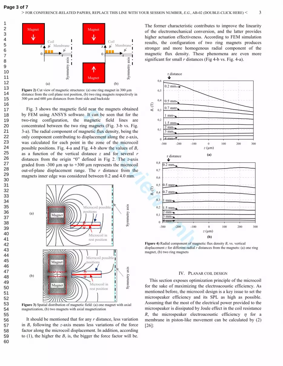
Figure 2) Cut view of magnetic structures: (a) one ring magnet in 300 µm
distance from the coil plane rest position, (b) two ring magnets respectively in
300 µm and 600 µm distances from front side and backside
Fig. 3 shows the magnetic field near the magnets obtained
by FEM using ANSYS software. It can be seen that for the
two-ring configuration, the magnetic field lines are
concentrated between the two ring magnets (Fig. 3-b vs. Fig.
3-a). The radial component of magnetic flux density, being the
only component contributing to displacement along the z-axis,
was calculated for each point in the zone of the microcoil
possible positions. Fig. 4-a and Fig. 4-b show the values of Br
as a function of the vertical distance z and for several r
distances from the origin “0” defined in Fig 2. The z-axis
graded from -300 µm up to +300 µm represents the microcoil
out-of-plane displacement range. The r distance from the
magnets inner edge was considered between 0.2 and 4.0 mm.
Figure 3) Spatial distribution of magnetic field: (a) one magnet with axial
magnetization, (b) two magnets with axial magnetization
It should be mentioned that for any r distance, less variation
in Br following the z-axis means less variations of the force
factor along the microcoil displacement. In addition, according
to (1), the higher the Br is, the bigger the force factor will be.
The former characteristic contributes to improve the linearity
of the electromechanical conversion, and the latter provides
higher actuation effectiveness. According to FEM simulation
results, the configuration of two ring magnets produces
stronger and more homogenous radial component of the
magnetic flux density. These phenomena are even more
significant for small r distances (Fig 4-b vs. Fig. 4-a).
Figure 4) Radial component of magnetic flux density Br vs. vertical
displacement z for different radial r distances from the magnets: (a) one ring
magnet, (b) two ring magnets
IV. PLANAR COIL DESIGN
This section exposes optimization principle of the microcoil
for the sake of maximizing the electroacoustic efficiency. As
mentioned before, the microcoil design is a key issue to set the
microspeaker efficiency and its SPL as high as possible.
Assuming that the most of the electrical power provided to the
microspeaker is dissipated by Joule effect in the coil resistance
R, the microspeaker electroacoustic efficiency η for a
membrane in piston-like movement can be calculated by (2)
[26]:
(b)
Magnet
Magnet
(a) Magnet
Sy
mm
etry
ax
is
Sy
mm
etry
ax
is
Microcoil in
rest position
Microcoil possible
positions
Microcoil in
rest position
Microcoil possible
positions
0
0,1
0,2
0,3
0,4
0,5
0,6
-300 -200 -100 0 100 200 300
0
0,1
0,2
0,3
0,4
0,5
0,6
0,7
0,8
-300 -200 -100 0 100 200 300
(a)
(b)
0.2 mm
0.5 mm
0.7 mm
1 mm
1.5 mm 2 mm
3 mm
4 mm
0.2 mm
0.5 mm
0.7 mm
1 mm
1.5 mm 2 mm
3 mm
4 mm
z (µm)
Br (T
) z (µm)
Br (T
)
r distance
r distance
z
r 0
Sy
mm
etry
ax
is
Membrane z
r 0
Sy
mm
etry
ax
is
Coil Coil Membrane
Magnet
Magnet
(a) (b)
Magnet
Page 3 of 7
123456789101112131415161718192021222324252627282930313233343536373839404142434445464748495051525354555657585960

For Review O
nly
> FOR CONFERENCE-RELATED PAPERS, REPLACE THIS LINE WITH YOUR SESSION NUMBER, E.G., AB-02 (DOUBLE-CLICK HERE) <
4
24
.1
.2
..
+=
membranecoil
f
MM
F
Rc
aπρη (2)
In this equation, ρ is the air density (1.2 kg/m3 at 20°C), a
the membrane radius, c the sound speed (343 m/s at 20°C),
Mcoil and Mmembrane respectively the mass of the voice coil and
the silicon membrane, Ff the force factor of the
electromagnetic motor.
Though MEMS technologies lead us to conceive preferably
a planar coil, its geometric parameters still yield a system with
high degree of freedom to optimize the efficiency. As Fig. 5
illustrates, among total seven independent parameters which
influence the microspeaker efficiency, four parameters are
related to the coil design: electric resistance, thickness, width,
and inter-space of the coil turns (Fig. 6). The fifth and the
sixth parameters concern the membrane radius and mass, and
the seventh parameter is the radial component of the magnetic
flux density created by the magnets.
Figure 5) Flowchart of the microspeaker electroacoustic efficiency and
influence of the seven independent parameters in bold blocks
Figure 6) Schematic cut view of a the planar voice coil with its geometrical
parameters
In order to obtain realistic values in this system, numerous
technological constraints in terms of microfabrication and
electroacoustic design were taken into account. Indeed, the
coil resistance was set at 10 Ω to be compatible with the
associated amplifier electronic circuit. To meet the objective
of 80 dB SPL in 10 cm beginning from 300 Hz, and to supply
a piston like motion in the microspeaker bandwidth, the
membrane radius was set at 7.5 mm and its mass at 25 mg [8].
Besides, the MEMS fabrication process used for electroplating
the copper microcoil imposes dimensional limits on the
microcoil thickness and turns inter-space. Actually, because of
the photolithography resist used in micromolding step, the
maximum achievable thickness for the microcoil was 30 µm
with minimum inter-space of 20 µm. Therefore, the only
parameters that remain undefined are the coil turns width and
the radial component of the magnetic flux density, calculated
according to each magnetic structure. For both magnet
configurations of Fig. 2, Fig. 7 depicts the variation of the Br
parameter as a function of the distance from the magnets for
null z displacement. This is indeed the position mostly taken
by the membrane, especially in medium and high working
frequencies for which the displacement amplitudes remains
below few microns. Therefore, for the rest of calculations
these values of Br were taken into account. As simulation
results stand, variations in Br with or without the presence of
the copper microcoil are negligible, even for injected current
as high as 1 A.
Figure 7) Radial component of magnetic flux density Br as a function of the
distance r for themicrocoil in rest position: (a) one magnet (Fig. 2-a), (b) two
magnets (Fig. 2-b)
To increase the force factor as much as possible, the
microcoil should be very long and ideally concentrated where
the magnetic field is maximal. However, according to (2), the
microcoil mass has a counterproductive effect on the
efficiency. Therefore, to find the optimum coil mass, the only
one undefined coil parameter, the turns width, was varied. As
shown in Fig. 8, for the configuration of two magnets, the
maximum efficiency of 0.008 %, takes place for a coil width
of 35 µm. This sets a good trade-off between the force factor
and the coil mass for the maximum efficiency. In respect of
the coil electric resistance and microfabrication constraints
previously mentioned, the optimized copper microcoil should
have 14 turns and 5.8 mg mass.
Th
icknes
s
Membrane
Voice coil Inter-space Width
Coil
resistance
Coil
thickness
Turns width
Coil turns
inter-space
Coil length
Br dl
Membrane
radius
Coil mass
Efficiency Membrane
mass
Turns number
Distance r (mm)
(b)
(a)
Br (T
)
Page 4 of 7
123456789101112131415161718192021222324252627282930313233343536373839404142434445464748495051525354555657585960

For Review O
nly
> FOR CONFERENCE-RELATED PAPERS, REPLACE THIS LINE WITH YOUR SESSION NUMBER, E.G., AB-02 (DOUBLE-CLICK HERE) <
5
Figure 8) Microspeaker efficiency as a function of coil turns width for two-ring magnet configuration, considering a coil resistance of 10 Ω, of 30 µm
turns thickness and 20 µm inter-space
By the same method, the microcoil was optimized for the
one ring magnet configuration. This resulted in 16-turn coil
with 40 µm turns width and a mass of 7.6 mg yielding the
maximum efficiency of 0.004 %.
V. CHARACTERIZATION
After setting the voice coil dimensions for the configuration
of two magnets, the microspeaker fabrication was carried out
in clean room. Then, as Fig. 9 shows, the device and two
NdFeB ring magnets of 1.5 T were assembled together with
the help of a transparent plexiglas frame. After making two
external contact points with the electroplated copper coil, the
device was installed on a test bench to measure in static mode
the membrane out-of-plane displacement as a function of the
injected current. For this purpose, Keyence LKG5000 laser
displacement sensor was used.
Figure 9) Micromachined silicon MEMS microspeaker assembled with two
front and backside ring magnets
Photos of the membrane displacement for one magnet
configuration are presented in Fig. 10-a and Fig. 10-b without
and with injected electric current respectively.
Fig. 11 shows the measured membrane displacement as a
function of the injected electric current for a device with either
one or two ring magnets. These measurements cover the
microspeaker peak-to-peak displacement, from -300 µm up to
+300 µm.
Figure 10) Membrane static displacement for one magnet configuration: (a) membrane in rest position, (b) displacement for 20 mA injected current
Figure 11) Measured membrane out-of-plane displacement as a function of
the applied electric current: (a) with configuration of Fig. 2-a, (b) with configuration of Fig. 2-b
To determine the force factor, the mechanical model of the
loudspeaker was taken into account. The vibration of the
microspeaker membrane follows a second-order system,
which can be described as [27][27]:
zFkzdt
dzR
dt
zdM =++
2
2
(3)
Where M is the mass of the mobile part, R the mechanical
resistance, k the stiffness of the suspension springs, z the
membrane displacement, and Fz the applied force defined also
by the product of the force factor and the injected current.
In static mode, the only term that compensates the applied
force is the suspension springs restoring force (Hooke’s law).
Therefore, knowing the injected current and the membrane
displacement, the force factor can be calculated for each
membrane position after measuring the springs stiffness. To
do so, Futek CSG110 force sensor was used to establish the
springs force-displacement diagram. As Fig. 12 shows, the
suspension springs behave very linearly even for
displacements bigger than 400 µm. So the suspension stiffness
k can be considered constant within the displacement range of
interest, and equivalent to 7.0 N/m.
Membrane
SOI substrate
Ring magnet
(a) (b)
Membrane
Electric current (mA)
Ou
t-o
f-p
lane
dis
pla
cem
ent
(µm
)
(a) (b)
Front side ring magnet Microcoil
Silicon membrane
Contact point
Back side ring magnet 5 mm
500 µm
Inset: electroplated microcoil
Eff
icie
ncy
(%
)
Turns width (µm)
Page 5 of 7
123456789101112131415161718192021222324252627282930313233343536373839404142434445464748495051525354555657585960

For Review O
nly
> FOR CONFERENCE-RELATED PAPERS, REPLACE THIS LINE WITH YOUR SESSION NUMBER, E.G., AB-02 (DOUBLE-CLICK HERE) <
6
Figure 12) Measured mechanical force as a function of applied membrane displacement in static mode
The force factor was consequently calculated for each
membrane position. The results for one-ring and two-ring
magnets are presented in Fig. 13. In the same figure, the force
factors calculated by the coupled FEM and analytical model
are presented for each magnet configuration. For this purpose,
the actual electroplated microcoil dimensions as well as the
turns relative position to the magnets were taken into account
for FEM simulations. The calculations also consider the actual
geometrical shape of the microcoil, which was designed to
increase the lifetime of the device. Indeed, the microcoil was
shaped in a manner to evade as much as possible the
mechanical stress in the membrane-suspension spring clamped
zone.
Figure 13) Force factor as a function of the membrane out-of-plane position: (a) one magnet with axial magnetization (Fig. 2-a), (b) two magnets with axial
magnetization (Fig. 2-b)
Comparing the force factor values for each magnetic
structure shows very good correlation between the expected
simulation results and the experimental measurements. The
one-ring and two-ring magnet configurations yield a force
factor near to 0.1 N/A and 0.2 N/A respectively when the
microcoil is positioned within ±300 µm displacement range
(Fig. 13). It should be noted that for both magnet
configurations, the resulted force factor is not completely
symmetric for upward and downward displacements. This is
due to the existence of an asymmetrical magnetic field
distribution. Neither one topside magnet nor paired magnets in
nonsymmetrical position to the microcoil rest position
provides the same Br for symmetrical displacements of the
microcoil.
In addition, comparing the resulted force factor of two-ring
magnet configuration with that of the one-ring magnet, the
force factor is raised by a factor of 2. Consequently, according
to (2), the microspeaker efficiency can be raised by a factor of
4.
The influence of other magnetic structures on the force
factor was also studied: first, the two-ring magnet
configuration with axial magnetization of 1.5 T and with an
inner and an outer diameters of 15 and 21 mm respectively,
second the same geometry of magnets, but with radial
magnetization of 1.5 T instead of axial. Finally, configuration
with only one ring magnet with radial magnetization of 1.5 T
in front side of the device was examined. For each of these
three configurations, the microcoil turns width was optimized,
taking into account the same technological constraints.
As simulations results predict, by deploying one or two
magnets with radial magnetization field, the force factor is
almost halved comparing to the configuration of two-ring
magnets with axial magnetization (Fig. 14-a vs. Fig 14-b and
Fig. 14-c). On the contrary, by decreasing coil-magnet
distance, magnets inner diameter of 15 instead of 16 mm, the
force factor rises from 0.2 to 0.35 N/A (Fig. 13-b vs. Fig 14-
a), which leads to a gain factor of 3 in efficiency. In other
words, the efficiency can reach 0.024 %, which is more than
two times higher than that of conventional microspeakers.
Figure 14) Simulated force factors as a function of the microcoil out-of-plane
position: (a) two-ring magnets with axial magnetization, (b) two-ring magnets with radial magnetization, (c) one-ring magnet with radial magnetization
VI. CONCLUSION
This work presented in the first place the structure of an
electrodynamic microspeaker based on silicon material, able
to be micromachined with the help of MEMS technology. As
the electroacoustic efficiency of the microspeaker has a
significant effect on the autonomy and the playback time of
common mobile electronic devices, a special attention was
paid to optimize the microspeaker electromagnetic motor.
For this purpose, a novel method was proposed to optimize
the planar coil dimensions. It relies on one hand on FEM
simulations to calculate the magnetic flux density created by
permanent magnets within the voice coil distance, and on the
Out-of-plane position (µm)
Fo
rce
fact
or
(N/A
)
(a)
(b)
(c)
Out-of-plane position (µm)
Fo
rce
fact
or
(N/A
)
Simulation
Measurement
Simulation
Measurement
(a)
(b)
Out-of-plane displacement (µm)
Fo
rce
(mN
)
Page 6 of 7
123456789101112131415161718192021222324252627282930313233343536373839404142434445464748495051525354555657585960

For Review O
nly
> FOR CONFERENCE-RELATED PAPERS, REPLACE THIS LINE WITH YOUR SESSION NUMBER, E.G., AB-02 (DOUBLE-CLICK HERE) <
7
other hand it uses analytical electro-mechano-acoustic models.
It was shown on a flowchart that the microspeaker efficiency
depends on the seven independent parameters. Among those,
one parameter is related to the magnetic structure, two
parameters to the microspeaker emissive surface, and four
parameters to the voice coil.
The technological constraints related to the electronic
amplifier, the acoustic power emission, and the
microfabrication process were taken into account. This
determined the membrane radius and mass, as well as the coil
resistance, the coil turns thickness, and the turns inter-space.
The spatial distribution of the magnetic flux density was set by
the chosen permanent magnet configuration. Then, the coil
turns width was varied in order to maximize the efficiency.
After carrying out the device microfabrication steps, the
microspeaker force factor was experimentally determined for
different out-of-plane positions of the microcoil. The results
showed very good correlation between theoretical predictions
and experimental results. This permitted to validate the
proposed modeling technique, and investigate in further
studies other magnetic structures with the objective of
improving the electroacoustic efficiency. Among the different
permanent magnet structures considered, the configuration of
two ring magnets with axial magnetization promises more
than 2 times higher conversion efficiency for the proposed
electroacoustic transducer comparing to the best conventional
microspeakers currently used in mobile phones.
ACKNOWLEDGMENT
This work has been financially supported by the French
National Research Agency (ANR).
REFERENCES
[1] K. Lee, Y. Cho, and N. Chang, “High-level power management of audio
power amplifiers for portable multimedia applications”, in Proc.
IEEE/ACM/IFIP Workshop on Embedded Sys. for Real Time Multimedia (2006), pp. 41-46.
[2] E. Sturtzer, G. Pillonnet, N. Abouchi, and F. Goutti, “System Approach to Avoid Audio Amplifier Oversizing in Mobile Phone Application”, in
Proc. Audio Engin. Soc. Conf. (2011).
[3] W. H. Groeneweg, “Analog signal processing for a class D audio amplifier in 65 nm CMOS technology”, in Proc. Solid-State Circ. (2008)
pp. 322-325.
[4] C. W. Lin, B. S. Hsieh, and Y. C. Lin, “Enhanced design of filterless class-D audio amplifier”, in Proc. Design, Automation & Test in Europe
Conference & Exhibition (2009) pp. 1397-1402.
[5] S. M. Hwang, H. J. Lee, K. S. Hong, B. S. Kang, and G. Y. Hwang, “New development of combined permanent-magnet type microspeakers
used for cellular phones”, IEEE Trans. on Magn. (2005) vol. 41, no. 5,
pp. 2000-2003. [6] M.R. Bai, Y. L. Ching, and L. C. Rong, "Optimization of microspeaker
diaphragm pattern using combined finite element–lumped parameter
models" IEEE Trans. on Magn.(2008) vol.44, no.8, pp. 2049-2057. [7] W. Kim, G. W. Jang, and Y. Y. Kim, “Microspeaker diaphragm
optimization for widening the operating frequency band and increasing
sound pressure level”, IEEE Trans. on Magn. (2010) vol. 46, no. 1, pp. 59-66.
[8] I. Shahosseini, E. Lefeuvre, E. Martincic, M. Woytasik, J. Moulin, S.
Megherbi, R. Ravaud, and Guy Lemarquand, “Microstructured silicon membrane with soft suspension beams for a high performance MEMS
microspeaker”, Microsyst. Technol. (2012) DOI 10.1007/s00542-012-
1477-1. [9] F. L. Ayatollahi and B. Y. Majlis, “Design and Modeling of
Micromachined Condenser MEMS Loudspeaker using Permanent
Magnet Neodymium-Iron-Boron (Nd-Fe-B)”, in Proc. ICSE (2006) pp.
160-166. [10] M. C. Cheng, W. S. Huang, and S. R. S. Huang, “A Silicon
Microspeaker for Hearing Instruments” J. Micromech. Microeng. 14
(2004) pp. 859-866. [11] T. Lin, T. Meydan, and R. Rashedin, “Design method of microactuator
with magnetic alloy iron-based amorphous plates for loudspeaker”,
IEEE Trans. on Magn. (2007) vol. 43, no. 6, pp. 2707-2709. [12] F. Neri, F. Di Fazio, R. Crescenzi, and M. Balucani, “A Novel
Micromachined Loudspeaker Topology”, in Proc. Electronic
Components and Technology (2011) pp. 1221-1227. [13] K. S. Kim, J. H. Kwon, S. M. Hwang, and G. Y. Hwang, “Performance
comparison of various magnetic circuits of integrated microspeakers and
dynamic receivers used for mobile phones”, J. Appl. Phys. (2008) 103. [14] C. M. Lee, J. H. Kwon, K. S. Kim, J. H. Park, and S. M. Hwang,
“Design and analysis of microspeaker to improve sound characterizatics
in a low frequency range”, IEEE Trans. on Magn. (2010) vol. 46, no. 6. [15] G. Y. Hwang, H. J. Lee, S. M. Hwang, B. S. Kang, and S. K. Jeung,
“Performance comparison between inner and outer permanent magnet
type microspeakers used for mobile phones”, J. Appl. Phys. (2003) vol. 93, no. 10, pp. 8519-8521.
[16] G. Lemarquand, R. Ravaud, I. Shahosseini, V. Lemarquand, J. Moulin,
and E. Lefeuvre, “MEMS electrodynamic loudspeakers for mobile phones”, Appl. Acoustics (2012) vol. 73, no. 4, pp. 379-385.
[17] Y. C. Chen, Wei-Ting Liu, Tzu-Yuan Chao, and Y. T. Cheng, “An
optimized cu-ni nanocomposite coil for low-power electromagnetic microspeaker fabrication”, in Proc. IEEE Transducers (2009) pp. 25-28.
[18] S. S. Je, F. Rivas, R. E. Diaz, J. Kwon, J. Kim, B. Bakkaloglu, S. Kiaei, and J. Chae, “A compact and low-cost MEMS loudspeaker for digital
hearing aids”, in Proc. IEEE Transactions on Biomedical Circuits and
Systems (2009) vol. 3, no. 5, pp. 348-358. [19] B. Merit, G. Lemarquand, and V. Lemarquand, “Performances and
design of ironless loudspeaker motor structures”, Appl Acoust (2010)
doi:10.1016/j.apacoust.2009.12.004. [20] I. Shahosseini, E. Lefeuvre, M. Woytasik, J. Moulin, X. Leroux, S.
Edmond, E. Dufour-Gergam, A. Bosseboeuf, G. Lemarquand, and V.
Lemarquand, “Towards High Fidelity High Efficiency MEMS Microspeakers” in Proc. IEEE Sensors (2010) pp. 2426-2430.
[21] Y. Chida, H. Katsumata, T. Fujiya, S. Kaihatsu, T. Morita, D. Hoshino,
and Y. Nishioka, “Silicon linear actuator driven by electrochemomechanical strain of polypyrrole film”, Sens. and Actu.
(2011) 169, pp. 367-37.
[22] M. Legros, O. Ferry, F. Houdellier, A. Jacques, and A. George, “Fatigue of single crystalline silicon: Mechanical behaviour and TEM
observations”, Mat. Sci. and Engin. (2008) 483, pp. 353-364.
[23] T. D. Rossing, "Handbook of Acoustics, Springer", 2007, ISBN 978-0-387-30446-5.
[24] I. Shahosseini, E. Lefeuvre, J. Moulin, E. Martincic, M. Woytasik, B.
Belier, G. Lemarquand, “Silicon-based MEMS microspeaker with large stroke electromagnetic actuation”, in Proc DTIP (2012) pp. 8-12.
[25] Y. C. Chen and Y. T. Cheng, “A low-power milliwatt electromagnetic
microspeaker using a PDMS membrane for hearing aids application”, in Proc. IEEE MEMS (2011) pp. 1213-1216.
[26] A. D. Pierce, Acoustics, Acoustical Society of America, ISBN 0-88318-
612-8, 1989. [27] W. T. Thomson and M. D. Dahleh, “Theory of Vibration with
Applications” Englewood Cliffs, NJ: Prentice-Hall (1998).
Page 7 of 7
123456789101112131415161718192021222324252627282930313233343536373839404142434445464748495051525354555657585960


