Embed Size (px)
Citation preview
Plant Engineering Policies and Procedures
Manual Owner: Shashikant Patel
REV 3.02
May 28, 2020

This Page Intentionally Blank
May 28, 2020 – Rev 3.02
Record of Revisions
Revision Number Revision Date Sections
Revised Reason for Revision
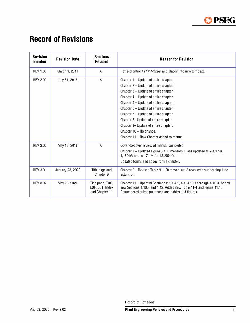
REV 1.00 March 1, 2011 All Revised entire PEPP Manual and placed into new template.
REV 2.00 July 31, 2016 All Chapter 1 – Update of entire chapter.
Chapter 2 – Update of entire chapter.
Chapter 3 – Update of entire chapter.
Chapter 4 – Update of entire chapter.
Chapter 5 – Update of entire chapter.
Chapter 6 – Update of entire chapter.
Chapter 7 – Update of entire chapter.
Chapter 8– Update of entire chapter.
Chapter 9– Update of entire chapter.
Chapter 10 – No change.
Chapter 11 – New Chapter added to manual.
REV 3.00 May 18, 2018 All Cover-to-cover review of manual completed.
Chapter 3 – Updated Figure 3.1. Dimension B was updated to 9-1/4 for 4,150 kV and to 17-1/4 for 13,200 kV.
Updated forms and added forms chapter.
REV 3.01 January 23, 2020 Title page and Chapter 9
Chapter 9 – Revised Table 9-1. Removed last 3 rows with subheading Line Extension.
REV 3.02 May 28, 2020 Title page, TOC, LOF, LOT, Index and Chapter 11
Chapter 11 – Updated Sections 2.10, 4.1, 4.4, 4.10.1 through 4.10.3. Added new Sections 4.10.4 and 4.12. Added new Table 11-1 and Figure 11.1. Renumbered subsequent sections, tables and figures.
Record of Revisions
May 28, 2020 – Rev 3.02 Plant Engineering Policies and Procedures iii

This Page Intentionally Blank
Record of Revisions
May 28, 2020 – Rev 3.02iv Plant Engineering Policies and Procedures
May 18, 2018 – Rev 3.00Go to TOC
Table of ContentsList of Figures . . . . . . . . . . . . . . . . . . . . . . . . . . . . . . . . . . . . . . . . . . . . . . . . . . . . . . . xi
List of Tables . . . . . . . . . . . . . . . . . . . . . . . . . . . . . . . . . . . . . . . . . . . . . . . . . . . . . . . xv
List of Forms . . . . . . . . . . . . . . . . . . . . . . . . . . . . . . . . . . . . . . . . . . . . . . . . . . . . . . xvii
Introduction . . . . . . . . . . . . . . . . . . . . . . . . . . . . . . . . . . . . . . . . . . . . . . . . . . . . . . . xix
1. Overview . . . . . . . . . . . . . . . . . . . . . . . . . . . . . . . . . . . . . . . . . . . . . . . . . . . . . . . . . . . . . . . . . . . . .xix
2. Safety . . . . . . . . . . . . . . . . . . . . . . . . . . . . . . . . . . . . . . . . . . . . . . . . . . . . . . . . . . . . . . . . . . . . . . .xix
3. New Format . . . . . . . . . . . . . . . . . . . . . . . . . . . . . . . . . . . . . . . . . . . . . . . . . . . . . . . . . . . . . . . . . . .xix
4. Latest Version . . . . . . . . . . . . . . . . . . . . . . . . . . . . . . . . . . . . . . . . . . . . . . . . . . . . . . . . . . . . . . . . . xx
5. Updates . . . . . . . . . . . . . . . . . . . . . . . . . . . . . . . . . . . . . . . . . . . . . . . . . . . . . . . . . . . . . . . . . . . . . . xx
6. How to Use this Manual. . . . . . . . . . . . . . . . . . . . . . . . . . . . . . . . . . . . . . . . . . . . . . . . . . . . . . . . . . xx
7. Symbols . . . . . . . . . . . . . . . . . . . . . . . . . . . . . . . . . . . . . . . . . . . . . . . . . . . . . . . . . . . . . . . . . . . . .xxi
8. What’s New . . . . . . . . . . . . . . . . . . . . . . . . . . . . . . . . . . . . . . . . . . . . . . . . . . . . . . . . . . . . . . . . . . .xxi
9. Ownership and Confidentiality . . . . . . . . . . . . . . . . . . . . . . . . . . . . . . . . . . . . . . . . . . . . . . . . . . . . xxii
Chapter 1 – Underground Services – Table of Contents . . . . . . . . . . . . . . . . . . . . . . . 1-TOC 1
Chapter 1 – Underground Services . . . . . . . . . . . . . . . . . . . . . . . . . . . . . . . . . . . . . . . . 1-1
1. Buried Underground Distribution (BUD) . . . . . . . . . . . . . . . . . . . . . . . . . . . . . . . . . . . . . . . . . . . . 1-1
2. BUD Joint Trench Work Procedures . . . . . . . . . . . . . . . . . . . . . . . . . . . . . . . . . . . . . . . . . . . . . . . 1-8
3. Underground Distribution in Overhead Zone . . . . . . . . . . . . . . . . . . . . . . . . . . . . . . . . . . . . . . . . 1-26
4. Conduit and Manhole Work Procedures . . . . . . . . . . . . . . . . . . . . . . . . . . . . . . . . . . . . . . . . . . . 1-26
5. Blanket Purchase Orders . . . . . . . . . . . . . . . . . . . . . . . . . . . . . . . . . . . . . . . . . . . . . . . . . . . . . . . 1-27
6. Contractor Job Procedures – Minor Construction . . . . . . . . . . . . . . . . . . . . . . . . . . . . . . . . . . . . 1-28
7. Contractor Job Procedures – Major Construction . . . . . . . . . . . . . . . . . . . . . . . . . . . . . . . . . . . . 1-28
8. Invoice Reconciliation and Reporting of Work Done by Contractor . . . . . . . . . . . . . . . . . . . . . . . 1-29
9. As-Built Construction Records . . . . . . . . . . . . . . . . . . . . . . . . . . . . . . . . . . . . . . . . . . . . . . . . . . 1-29
Chapter 2 – Lighting Services – Table of Contents. . . . . . . . . . . . . . . . . . . . . . . . . . . 2-TOC 1
Chapter 2 – Lighting Services . . . . . . . . . . . . . . . . . . . . . . . . . . . . . . . . . . . . . . . . . . . 2-1
1. General Specification for Lighting Services . . . . . . . . . . . . . . . . . . . . . . . . . . . . . . . . . . . . . . . . . . 2-1
2. Street Lighting . . . . . . . . . . . . . . . . . . . . . . . . . . . . . . . . . . . . . . . . . . . . . . . . . . . . . . . . . . . . . . . 2-2
3. Area Lighting . . . . . . . . . . . . . . . . . . . . . . . . . . . . . . . . . . . . . . . . . . . . . . . . . . . . . . . . . . . . . . . . . 2-4
Table of Contents
May 18, 2018 – Rev 3.00 Plant Engineering Policies and Procedures v
4. Calculation of Costs and Credits . . . . . . . . . . . . . . . . . . . . . . . . . . . . . . . . . . . . . . . . . . . . . . . . . . .2-5
Chapter 3 – Customer Equipment Requirements – Primary Service – Table of Contents. . . . . . . . . . . . . . . . . . . . . . . . . . . . . . . . . . . . . . . . .3-TOC 1
Chapter 3 – Customer Equipment Requirements – Primary Service . . . . . . . . . . . . . . . . . . 3-1
1. Specifications . . . . . . . . . . . . . . . . . . . . . . . . . . . . . . . . . . . . . . . . . . . . . . . . . . . . . . . . . . . . . . . . .3-1
2. General Information . . . . . . . . . . . . . . . . . . . . . . . . . . . . . . . . . . . . . . . . . . . . . . . . . . . . . . . . . . . .3-1
3. Review Requirement. . . . . . . . . . . . . . . . . . . . . . . . . . . . . . . . . . . . . . . . . . . . . . . . . . . . . . . . . . . .3-3
4. Revenue Metering. . . . . . . . . . . . . . . . . . . . . . . . . . . . . . . . . . . . . . . . . . . . . . . . . . . . . . . . . . . . . .3-4
5. Grounding. . . . . . . . . . . . . . . . . . . . . . . . . . . . . . . . . . . . . . . . . . . . . . . . . . . . . . . . . . . . . . . . . . . .3-5
6. Service Equipment Installations and Arrangements . . . . . . . . . . . . . . . . . . . . . . . . . . . . . . . . . . . .3-5
7. Metal-Clad or Metal-Enclosed Switchgear . . . . . . . . . . . . . . . . . . . . . . . . . . . . . . . . . . . . . . . . . . .3-7
8. Service Circuit Breaker . . . . . . . . . . . . . . . . . . . . . . . . . . . . . . . . . . . . . . . . . . . . . . . . . . . . . . . . . .3-8
9. Surge Arresters . . . . . . . . . . . . . . . . . . . . . . . . . . . . . . . . . . . . . . . . . . . . . . . . . . . . . . . . . . . . . . .3-9
10. More Than One Source. . . . . . . . . . . . . . . . . . . . . . . . . . . . . . . . . . . . . . . . . . . . . . . . . . . . . . . . . .3-9
11. Mimic Bus . . . . . . . . . . . . . . . . . . . . . . . . . . . . . . . . . . . . . . . . . . . . . . . . . . . . . . . . . . . . . . . . . . .3-9
12. Other Requirements . . . . . . . . . . . . . . . . . . . . . . . . . . . . . . . . . . . . . . . . . . . . . . . . . . . . . . . . . . . .3-9
13. Animal Deterrent. . . . . . . . . . . . . . . . . . . . . . . . . . . . . . . . . . . . . . . . . . . . . . . . . . . . . . . . . . . . . . .3-9
14. Arc Flash Hazard Calculation Study . . . . . . . . . . . . . . . . . . . . . . . . . . . . . . . . . . . . . . . . . . . . . . .3-10
15. Standard Layouts . . . . . . . . . . . . . . . . . . . . . . . . . . . . . . . . . . . . . . . . . . . . . . . . . . . . . . . . . . . . .3-11
Chapter 4 – General Specifications for a Customer-Owned 26.4 kV Outdoor Substation– Table of Contents . . . . . . . . . . . . . . . . . . . . . . . . . . . . . . . . . . . . . . .4-TOC 1
Chapter 4 – General Specifications for a Customer-Owned 26.4 kV Outdoor Substation . . . . 4-1
1. Introduction . . . . . . . . . . . . . . . . . . . . . . . . . . . . . . . . . . . . . . . . . . . . . . . . . . . . . . . . . . . . . . . . . .4-1
2. General . . . . . . . . . . . . . . . . . . . . . . . . . . . . . . . . . . . . . . . . . . . . . . . . . . . . . . . . . . . . . . . . . . . . . .4-1
3. Reviews and Approvals Required . . . . . . . . . . . . . . . . . . . . . . . . . . . . . . . . . . . . . . . . . . . . . . . . . .4-2
4. Frequency and Voltage Regulation . . . . . . . . . . . . . . . . . . . . . . . . . . . . . . . . . . . . . . . . . . . . . . . . .4-3
5. Short Circuit Duty . . . . . . . . . . . . . . . . . . . . . . . . . . . . . . . . . . . . . . . . . . . . . . . . . . . . . . . . . . . . . .4-3
6. Circuit Breakers . . . . . . . . . . . . . . . . . . . . . . . . . . . . . . . . . . . . . . . . . . . . . . . . . . . . . . . . . . . . . . .4-4
7. Fuses . . . . . . . . . . . . . . . . . . . . . . . . . . . . . . . . . . . . . . . . . . . . . . . . . . . . . . . . . . . . . . . . . . . . . . .4-4
8. Battery . . . . . . . . . . . . . . . . . . . . . . . . . . . . . . . . . . . . . . . . . . . . . . . . . . . . . . . . . . . . . . . . . . . . . .4-4
9. Relays and SCADA Interface. . . . . . . . . . . . . . . . . . . . . . . . . . . . . . . . . . . . . . . . . . . . . . . . . . . . . .4-5
10. Disconnecting Switches . . . . . . . . . . . . . . . . . . . . . . . . . . . . . . . . . . . . . . . . . . . . . . . . . . . . . . . . .4-8
Table of Contents
May 18, 2018 – Rev 3.00vi Plant Engineering Policies and Procedures
11. Revenue Metering Equipment . . . . . . . . . . . . . . . . . . . . . . . . . . . . . . . . . . . . . . . . . . . . . . . . . . . . 4-8
12. Insulators, Conductors, Connections and Clearances . . . . . . . . . . . . . . . . . . . . . . . . . . . . . . . . . 4-11
13. Transformers. . . . . . . . . . . . . . . . . . . . . . . . . . . . . . . . . . . . . . . . . . . . . . . . . . . . . . . . . . . . . . . . 4-11
14. Surge Arresters . . . . . . . . . . . . . . . . . . . . . . . . . . . . . . . . . . . . . . . . . . . . . . . . . . . . . . . . . . . . . . 4-11
15. Grounding . . . . . . . . . . . . . . . . . . . . . . . . . . . . . . . . . . . . . . . . . . . . . . . . . . . . . . . . . . . . . . . . . . 4-12
16. Location and Structural Arrangement . . . . . . . . . . . . . . . . . . . . . . . . . . . . . . . . . . . . . . . . . . . . . 4-12
17. More Than One Source . . . . . . . . . . . . . . . . . . . . . . . . . . . . . . . . . . . . . . . . . . . . . . . . . . . . . . . . 4-13
18. Mimic Bus . . . . . . . . . . . . . . . . . . . . . . . . . . . . . . . . . . . . . . . . . . . . . . . . . . . . . . . . . . . . . . . . . . 4-13
19. Operating Procedures . . . . . . . . . . . . . . . . . . . . . . . . . . . . . . . . . . . . . . . . . . . . . . . . . . . . . . . . . 4-13
20. Other Requirements . . . . . . . . . . . . . . . . . . . . . . . . . . . . . . . . . . . . . . . . . . . . . . . . . . . . . . . . . . 4-14
21. Customer Responsibilities for Testing and Commissioning . . . . . . . . . . . . . . . . . . . . . . . . . . . . 4-14
22. Construction in Flood Prone Areas . . . . . . . . . . . . . . . . . . . . . . . . . . . . . . . . . . . . . . . . . . . . . . . 4-15
23. Animal Deterrent . . . . . . . . . . . . . . . . . . . . . . . . . . . . . . . . . . . . . . . . . . . . . . . . . . . . . . . . . . . . . 4-15
24. Arc Flash Hazard Calculation Study . . . . . . . . . . . . . . . . . . . . . . . . . . . . . . . . . . . . . . . . . . . . . . . 4-15
25. Standard Layouts . . . . . . . . . . . . . . . . . . . . . . . . . . . . . . . . . . . . . . . . . . . . . . . . . . . . . . . . . . . . 4-16
Chapter 5 – General Specification for a Customer Owned 26.4 kV Substation with a Metal-Clad 26 kV Switchgear – Table of Contents . . . . . . . . . . . . . . . . . 5-TOC 1
Chapter 5 – General Specification for a Customer-Owned 26.4 kV Substation with a Metal-Clad 26 kV Switchgear . . . . . . . . . . . . . . . . . . . . . . . . . . . . . . . . . . 5-1
1. Introduction. . . . . . . . . . . . . . . . . . . . . . . . . . . . . . . . . . . . . . . . . . . . . . . . . . . . . . . . . . . . . . . . . . 5-1
2. General . . . . . . . . . . . . . . . . . . . . . . . . . . . . . . . . . . . . . . . . . . . . . . . . . . . . . . . . . . . . . . . . . . . . . 5-1
3. Review and Approvals Required . . . . . . . . . . . . . . . . . . . . . . . . . . . . . . . . . . . . . . . . . . . . . . . . . . 5-2
4. Frequency and Voltage Regulation . . . . . . . . . . . . . . . . . . . . . . . . . . . . . . . . . . . . . . . . . . . . . . . . 5-3
5. Short Circuit Duty . . . . . . . . . . . . . . . . . . . . . . . . . . . . . . . . . . . . . . . . . . . . . . . . . . . . . . . . . . . . . 5-3
6. Circuit Breakers . . . . . . . . . . . . . . . . . . . . . . . . . . . . . . . . . . . . . . . . . . . . . . . . . . . . . . . . . . . . . . . 5-4
7. Fuses . . . . . . . . . . . . . . . . . . . . . . . . . . . . . . . . . . . . . . . . . . . . . . . . . . . . . . . . . . . . . . . . . . . . . . . 5-4
8. Battery . . . . . . . . . . . . . . . . . . . . . . . . . . . . . . . . . . . . . . . . . . . . . . . . . . . . . . . . . . . . . . . . . . . . . . 5-5
9. Relays and SCADA Interface . . . . . . . . . . . . . . . . . . . . . . . . . . . . . . . . . . . . . . . . . . . . . . . . . . . . . 5-5
10. Disconnecting / Load Interrupting Switches . . . . . . . . . . . . . . . . . . . . . . . . . . . . . . . . . . . . . . . . . 5-8
11. Revenue Metering Equipment . . . . . . . . . . . . . . . . . . . . . . . . . . . . . . . . . . . . . . . . . . . . . . . . . . . . 5-9
12. Insulators, Conductors, Clearances and Connections . . . . . . . . . . . . . . . . . . . . . . . . . . . . . . . . . 5-11
13. Transformers. . . . . . . . . . . . . . . . . . . . . . . . . . . . . . . . . . . . . . . . . . . . . . . . . . . . . . . . . . . . . . . . 5-11
14. Surge Arresters . . . . . . . . . . . . . . . . . . . . . . . . . . . . . . . . . . . . . . . . . . . . . . . . . . . . . . . . . . . . . . 5-12
Table of Contents
May 18, 2018 – Rev 3.00 Plant Engineering Policies and Procedures vii
15. Grounding. . . . . . . . . . . . . . . . . . . . . . . . . . . . . . . . . . . . . . . . . . . . . . . . . . . . . . . . . . . . . . . . . . .5-12
16. Location and Structural Arrangement. . . . . . . . . . . . . . . . . . . . . . . . . . . . . . . . . . . . . . . . . . . . . .5-12
17. More Than One Source. . . . . . . . . . . . . . . . . . . . . . . . . . . . . . . . . . . . . . . . . . . . . . . . . . . . . . . . .5-13
18. Mimic Bus . . . . . . . . . . . . . . . . . . . . . . . . . . . . . . . . . . . . . . . . . . . . . . . . . . . . . . . . . . . . . . . . . .5-13
19. Operating Procedures. . . . . . . . . . . . . . . . . . . . . . . . . . . . . . . . . . . . . . . . . . . . . . . . . . . . . . . . . .5-14
20. Other Requirements . . . . . . . . . . . . . . . . . . . . . . . . . . . . . . . . . . . . . . . . . . . . . . . . . . . . . . . . . . .5-14
21. Customer Responsibilities for Testing and Commissioning . . . . . . . . . . . . . . . . . . . . . . . . . . . . .5-14
22. Construction in Flood Prone Areas . . . . . . . . . . . . . . . . . . . . . . . . . . . . . . . . . . . . . . . . . . . . . . . .5-15
23. Animal Deterrent. . . . . . . . . . . . . . . . . . . . . . . . . . . . . . . . . . . . . . . . . . . . . . . . . . . . . . . . . . . . . .5-16
24. Arc Flash Hazard Calculation Studies . . . . . . . . . . . . . . . . . . . . . . . . . . . . . . . . . . . . . . . . . . . . . .5-16
25. Standard Layouts . . . . . . . . . . . . . . . . . . . . . . . . . . . . . . . . . . . . . . . . . . . . . . . . . . . . . . . . . . . . .5-17
Chapter 6 – General Specifications for a Customer-Owned 69 kV Outdoor Substation – Table of Contents . . . . . . . . . . . . . . . . . . . . . . . . . . . . . . . . . . . . . . .6-TOC 1
Chapter 6 – General Specifications for a Customer-Owned 69 kV Outdoor Substation . . . . . . 6-1
1. Introduction . . . . . . . . . . . . . . . . . . . . . . . . . . . . . . . . . . . . . . . . . . . . . . . . . . . . . . . . . . . . . . . . . .6-1
2. General . . . . . . . . . . . . . . . . . . . . . . . . . . . . . . . . . . . . . . . . . . . . . . . . . . . . . . . . . . . . . . . . . . . . . .6-1
3. Reviews and Approvals Required . . . . . . . . . . . . . . . . . . . . . . . . . . . . . . . . . . . . . . . . . . . . . . . . . .6-2
4. Frequency and Voltage Regulation . . . . . . . . . . . . . . . . . . . . . . . . . . . . . . . . . . . . . . . . . . . . . . . . .6-3
5. Short Circuit Duty . . . . . . . . . . . . . . . . . . . . . . . . . . . . . . . . . . . . . . . . . . . . . . . . . . . . . . . . . . . . . .6-3
6. Circuit Breakers . . . . . . . . . . . . . . . . . . . . . . . . . . . . . . . . . . . . . . . . . . . . . . . . . . . . . . . . . . . . . . .6-3
7. Fuses . . . . . . . . . . . . . . . . . . . . . . . . . . . . . . . . . . . . . . . . . . . . . . . . . . . . . . . . . . . . . . . . . . . . . . .6-4
8. Battery . . . . . . . . . . . . . . . . . . . . . . . . . . . . . . . . . . . . . . . . . . . . . . . . . . . . . . . . . . . . . . . . . . . . . .6-4
9. Relays and SCADA Interface. . . . . . . . . . . . . . . . . . . . . . . . . . . . . . . . . . . . . . . . . . . . . . . . . . . . . .6-4
10. Disconnecting Switches . . . . . . . . . . . . . . . . . . . . . . . . . . . . . . . . . . . . . . . . . . . . . . . . . . . . . . . . .6-7
11. Revenue Metering Equipment. . . . . . . . . . . . . . . . . . . . . . . . . . . . . . . . . . . . . . . . . . . . . . . . . . . . .6-8
12. Insulators, Conductors, Connections and Clearances. . . . . . . . . . . . . . . . . . . . . . . . . . . . . . . . . . .6-9
13. Transformers . . . . . . . . . . . . . . . . . . . . . . . . . . . . . . . . . . . . . . . . . . . . . . . . . . . . . . . . . . . . . . . . .6-9
14. Surge Arresters . . . . . . . . . . . . . . . . . . . . . . . . . . . . . . . . . . . . . . . . . . . . . . . . . . . . . . . . . . . . . . .6-9
15. Grounding. . . . . . . . . . . . . . . . . . . . . . . . . . . . . . . . . . . . . . . . . . . . . . . . . . . . . . . . . . . . . . . . . . .6-10
16. Location and Structural Arrangement. . . . . . . . . . . . . . . . . . . . . . . . . . . . . . . . . . . . . . . . . . . . . .6-10
17. More Than One Source. . . . . . . . . . . . . . . . . . . . . . . . . . . . . . . . . . . . . . . . . . . . . . . . . . . . . . . . .6-11
18. Mimic Bus . . . . . . . . . . . . . . . . . . . . . . . . . . . . . . . . . . . . . . . . . . . . . . . . . . . . . . . . . . . . . . . . . .6-11
19. Operating Procedures. . . . . . . . . . . . . . . . . . . . . . . . . . . . . . . . . . . . . . . . . . . . . . . . . . . . . . . . . .6-12
Table of Contents
May 18, 2018 – Rev 3.00viii Plant Engineering Policies and Procedures
20. Other Requirements . . . . . . . . . . . . . . . . . . . . . . . . . . . . . . . . . . . . . . . . . . . . . . . . . . . . . . . . . . 6-12
21. Customer Responsibilities for Testing and Commissioning . . . . . . . . . . . . . . . . . . . . . . . . . . . . 6-12
22. Construction in Flood Prone Areas . . . . . . . . . . . . . . . . . . . . . . . . . . . . . . . . . . . . . . . . . . . . . . . 6-13
23. Animal Deterrent . . . . . . . . . . . . . . . . . . . . . . . . . . . . . . . . . . . . . . . . . . . . . . . . . . . . . . . . . . . . . 6-14
24. Arc Flash Hazard Calculation Studies. . . . . . . . . . . . . . . . . . . . . . . . . . . . . . . . . . . . . . . . . . . . . . 6-14
25. Standard Layouts . . . . . . . . . . . . . . . . . . . . . . . . . . . . . . . . . . . . . . . . . . . . . . . . . . . . . . . . . . . . 6-15
Chapter 7 – General Specifications for Rotating Non-Utility Generators (NUGs)– Table of Contents . . . . . . . . . . . . . . . . . . . . . . . . . . . . . . . . . . . . . . . 7-TOC 1
Chapter 7 – General Specifications for Rotating Non-Utility Generators (NUGs). . . . . . . . . . 7-1
1. Document Scope . . . . . . . . . . . . . . . . . . . . . . . . . . . . . . . . . . . . . . . . . . . . . . . . . . . . . . . . . . . . . . 7-1
2. Definitions/Acronyms . . . . . . . . . . . . . . . . . . . . . . . . . . . . . . . . . . . . . . . . . . . . . . . . . . . . . . . . . . 7-1
3. Process . . . . . . . . . . . . . . . . . . . . . . . . . . . . . . . . . . . . . . . . . . . . . . . . . . . . . . . . . . . . . . . . . . . . . 7-4
4. Applicants/Facility Requirements. . . . . . . . . . . . . . . . . . . . . . . . . . . . . . . . . . . . . . . . . . . . . . . . . 7-10
5. Revenue Metering . . . . . . . . . . . . . . . . . . . . . . . . . . . . . . . . . . . . . . . . . . . . . . . . . . . . . . . . . . . . 7-18
6. Network Service . . . . . . . . . . . . . . . . . . . . . . . . . . . . . . . . . . . . . . . . . . . . . . . . . . . . . . . . . . . . . 7-21
7. Additional Resources. . . . . . . . . . . . . . . . . . . . . . . . . . . . . . . . . . . . . . . . . . . . . . . . . . . . . . . . . . 7-25
Chapter 8 – Notifications and Permits – Table of Contents . . . . . . . . . . . . . . . . . . . . . 8-TOC 1
Chapter 8 – Notifications and Permits . . . . . . . . . . . . . . . . . . . . . . . . . . . . . . . . . . . . . . 8-1
1. Occupancy of Public and Private Land and Waterways . . . . . . . . . . . . . . . . . . . . . . . . . . . . . . . . . 8-1
2. Work on Private Property (Easements) . . . . . . . . . . . . . . . . . . . . . . . . . . . . . . . . . . . . . . . . . . . . 8-11
3. Work with Developers . . . . . . . . . . . . . . . . . . . . . . . . . . . . . . . . . . . . . . . . . . . . . . . . . . . . . . . . . 8-24
4. Hazards to Aviation . . . . . . . . . . . . . . . . . . . . . . . . . . . . . . . . . . . . . . . . . . . . . . . . . . . . . . . . . . . 8-25
5. Pole Attachments and Duct Leasing . . . . . . . . . . . . . . . . . . . . . . . . . . . . . . . . . . . . . . . . . . . . . . 8-26
6. Utility Relocations . . . . . . . . . . . . . . . . . . . . . . . . . . . . . . . . . . . . . . . . . . . . . . . . . . . . . . . . . . . . 8-29
7. Environmental . . . . . . . . . . . . . . . . . . . . . . . . . . . . . . . . . . . . . . . . . . . . . . . . . . . . . . . . . . . . . . . 8-39
8. Construction Activities Located in and Near Streams . . . . . . . . . . . . . . . . . . . . . . . . . . . . . . . . . 8-43
Chapter 9 – Costs and Estimates – Table of Contents. . . . . . . . . . . . . . . . . . . . . . . . . 9-TOC 1
Chapter 9 – Costs and Estimates. . . . . . . . . . . . . . . . . . . . . . . . . . . . . . . . . . . . . . . . . . 9-1
1. Use of Actual or Estimated Costs . . . . . . . . . . . . . . . . . . . . . . . . . . . . . . . . . . . . . . . . . . . . . . . . . 9-1
2. Distribution Estimating System . . . . . . . . . . . . . . . . . . . . . . . . . . . . . . . . . . . . . . . . . . . . . . . . . . . 9-1
3. Smart Growth Tool . . . . . . . . . . . . . . . . . . . . . . . . . . . . . . . . . . . . . . . . . . . . . . . . . . . . . . . . . . . . 9-2
Table of Contents
May 18, 2018 – Rev 3.00 Plant Engineering Policies and Procedures ix
May 28, 2020 – Rev 3.02
4. BUD Estimating Tool. . . . . . . . . . . . . . . . . . . . . . . . . . . . . . . . . . . . . . . . . . . . . . . . . . . . . . . . . . . .9-4
5. Street Light Smart Growth Tool . . . . . . . . . . . . . . . . . . . . . . . . . . . . . . . . . . . . . . . . . . . . . . . . . . .9-6
6. Work Done at the Expense of Others . . . . . . . . . . . . . . . . . . . . . . . . . . . . . . . . . . . . . . . . . . . . . . .9-7
Chapter 10 – New Business . . . . . . . . . . . . . . . . . . . . . . . . . . . . . . . . . . . . . . . . . 10-TOC 1
Chapter 11 – General Specifications for Inverter-Based Non-Utility Generators (NUGs) – Table of Contents . . . . . . . . . . . . . . . . . . . . . . . . . . . . . . . . . . . . . . 11-TOC 1
Chapter 11 – General Specifications for Inverter-Based Non-Utility Generators (NUGs) . . . 11-1
1. Document Scope . . . . . . . . . . . . . . . . . . . . . . . . . . . . . . . . . . . . . . . . . . . . . . . . . . . . . . . . . . . . .11-1
2. Definitions/Acronyms . . . . . . . . . . . . . . . . . . . . . . . . . . . . . . . . . . . . . . . . . . . . . . . . . . . . . . . . . .11-1
3. Process. . . . . . . . . . . . . . . . . . . . . . . . . . . . . . . . . . . . . . . . . . . . . . . . . . . . . . . . . . . . . . . . . . . . .11-4
4. Applicants/Facility Requirements . . . . . . . . . . . . . . . . . . . . . . . . . . . . . . . . . . . . . . . . . . . . . . . . .11-9
5. Revenue Metering. . . . . . . . . . . . . . . . . . . . . . . . . . . . . . . . . . . . . . . . . . . . . . . . . . . . . . . . . . . .11-18
6. Renewable Generation in Network Areas . . . . . . . . . . . . . . . . . . . . . . . . . . . . . . . . . . . . . . . . . .11-22
7. Additional Resources . . . . . . . . . . . . . . . . . . . . . . . . . . . . . . . . . . . . . . . . . . . . . . . . . . . . . . . . .11-27
Forms . . . . . . . . . . . . . . . . . . . . . . . . . . . . . . . . . . . . . . . . . . . . . . . . . . . . . . . . Form-1
Index . . . . . . . . . . . . . . . . . . . . . . . . . . . . . . . . . . . . . . . . . . . . . . . . . . . . . . . . . Index-1
Table of Contents
May 28, 2020 – Rev 3.02x Plant Engineering Policies and Procedures
May 18, 2018 – Rev 3.00
List of FiguresFigure 1.1: Sample of Pre-Design Meeting Checklist (page 1 of 2) (ED-DC-PEP-Form001) . . . . . . . . . . . . . . . . . . . .1-11
Figure 1.2: Sample of Pre-Design Meeting Checklist (page 2 of 2) (ED-DC-PEP-Form001) . . . . . . . . . . . . . . . . . . . .1-12
Figure 1.3: CATV Occupancy of Joint Trench – Sample Letter (page 1) . . . . . . . . . . . . . . . . . . . . . . . . . . . . . . . . . . .1-13
Figure 1.4: CATV Occupancy of Joint Trench – Sample Letter (page 2) . . . . . . . . . . . . . . . . . . . . . . . . . . . . . . . . . . .1-14
Figure 1.5: Example of Responsibility Letter (page 1). . . . . . . . . . . . . . . . . . . . . . . . . . . . . . . . . . . . . . . . . . . . . . . . .1-15
Figure 1.6: Example of Responsibility Letter (page 2). . . . . . . . . . . . . . . . . . . . . . . . . . . . . . . . . . . . . . . . . . . . . . . . .1-16
Figure 1.7: Example of Responsibility Letter (page 3). . . . . . . . . . . . . . . . . . . . . . . . . . . . . . . . . . . . . . . . . . . . . . . . .1-17
Figure 1.8: Roadway Crossing Installation . . . . . . . . . . . . . . . . . . . . . . . . . . . . . . . . . . . . . . . . . . . . . . . . . . . . . . . . .1-19
Figure 3.1: Mounting Dimensions for Current and Potential Transformers in Compartment Bar Type 75 A to 800 A 4,150 V and 13,200 V . . . . . . . . . . . . . . . . . . . . . . . . . . . . . . . . . . . . . . . . . . . . . . . .3-11
Figure 3.2: Customer’s Substation – Grounding Details . . . . . . . . . . . . . . . . . . . . . . . . . . . . . . . . . . . . . . . . . . . . . . .3-13
Figure 4.1: Sectionalizing Scheme with Breakers – Transformer >10 MVA. . . . . . . . . . . . . . . . . . . . . . . . . . . . . . . . .4-18
Figure 4.2: Sectionalizing Scheme with Motor Operated Load Break Type Disconnects – Transformer >10 MVA . . . . . . . . . . . . . . . . . . . . . . . . . . . . . . . . . . . . . . . . . . . . . . . . . . . . . . . . . . . . . . .4-19
Figure 4.3: Transfer Scheme with Breakers – Transformer >10 MVA . . . . . . . . . . . . . . . . . . . . . . . . . . . . . . . . . . . . .4-20
Figure 4.4: Transfer Scheme with Motor Operated Disconnects – Transformer >10 MVA . . . . . . . . . . . . . . . . . . . . .4-21
Figure 4.5: Dual Supply, Low Side Transfer with Motor Operated Load Break Type Disconnects – Transformers < 10 MVA . . . . . . . . . . . . . . . . . . . . . . . . . . . . . . . . . . . . . . . . . . . . . . . . . . . . . . . . . . . . . .4-22
Figure 4.6: Dual Supply – Dual Transformers with Line Breakers . . . . . . . . . . . . . . . . . . . . . . . . . . . . . . . . . . . . . . . .4-23
Figure 4.7: Multiple Supply – Multiple Transformers with Line Breakers . . . . . . . . . . . . . . . . . . . . . . . . . . . . . . . . . .4-24
Figure 4.8: Dual supply – Dual Transformers with Transformer Breakers. . . . . . . . . . . . . . . . . . . . . . . . . . . . . . . . . .4-26
Figure 4.9: Multiple Supply – Multiple Transformers with Line Breakers . . . . . . . . . . . . . . . . . . . . . . . . . . . . . . . . . .4-28
Figure 4.10: Supply to Remote Non-Utility Substation with Generation (Non-Export) . . . . . . . . . . . . . . . . . . . . . . . .4-30
Figure 4.11: Customer’s 26 kV Outdoor Metering Arrangement for Metering Transformers JKW-200 with JVT-200 . . . . . . . . . . . . . . . . . . . . . . . . . . . . . . . . . . . . . . . . . . . . . . . . . . . . . . . . . . . . . . . . . . . . .4-32
Figure 4.12: Current Transformer Dimensions – 34,500 V GE JKW-200 Outdoor Type – 25/50 to 300/600 A . . . . . .4-34
Figure 4.13: Current Transformer Dimensions – 34,500 V GE JKW-200 Outdoor Type – 400/800 to 1,500/3,000 A . . . . . . . . . . . . . . . . . . . . . . . . . . . . . . . . . . . . . . . . . . . . . . . . . . . . . . . . . . . . . . . . . .4-35
Figure 4.14: Potential Transformer Dimensions – 26,400 V General Electric Type JVT - 200 Outdoor . . . . . . . . . . . .4-36
Figure 4.15: Standard Meter Board – Single Meter Service . . . . . . . . . . . . . . . . . . . . . . . . . . . . . . . . . . . . . . . . . . . .4-37
Figure 4.16: Meter Panel – Single Metering Point. . . . . . . . . . . . . . . . . . . . . . . . . . . . . . . . . . . . . . . . . . . . . . . . . . . .4-38
Figure 4.17: Meter Panel – Indoor – Two Metering Points . . . . . . . . . . . . . . . . . . . . . . . . . . . . . . . . . . . . . . . . . . . . .4-39
Figure 4.18: Meter Panel – Outdoor – Two Metering Points . . . . . . . . . . . . . . . . . . . . . . . . . . . . . . . . . . . . . . . . . . . .4-40
Figure 4.19: Disc Insulator Assembly Dead-End on Customer’s Structure . . . . . . . . . . . . . . . . . . . . . . . . . . . . . . . . .4-42
Figure 4.20: Typical Substation Arrangement – 26 kV Rubber Cable Termination . . . . . . . . . . . . . . . . . . . . . . . . . . .4-44
Figure 4.21: Typical Customer’s Substation – Grounding Details . . . . . . . . . . . . . . . . . . . . . . . . . . . . . . . . . . . . . . . .4-46
Figure 5.1: Sectionalizing Scheme with Breakers . . . . . . . . . . . . . . . . . . . . . . . . . . . . . . . . . . . . . . . . . . . . . . . . . . . .5-18
Figure 5.2: Sectionalizing Scheme with Motor Operated Load Break Type Disconnects . . . . . . . . . . . . . . . . . . . . . . .5-19
Figure 5.3: Transfer Scheme with Breakers – Transformer >10 MVA . . . . . . . . . . . . . . . . . . . . . . . . . . . . . . . . . . . . .5-20
List of Figures
May 18, 2018 – Rev 3.00 Plant Engineering Policies and Procedures xi
Figure 5.4: Transfer Scheme with Motor Operated Disconnects – Transformer >10 MVA . . . . . . . . . . . . . . . . . . . . 5-21
Figure 5.5: Dual Supply, Low Side Transfer with Motor Operated Load Break Type Disconnects – Transformers < 10 MVA . . . . . . . . . . . . . . . . . . . . . . . . . . . . . . . . . . . . . . . . . . . . . . . . . . . . . . . . . . . . . 5-22
Figure 5.6: Dual Supply – Dual Transformers with Line Breakers . . . . . . . . . . . . . . . . . . . . . . . . . . . . . . . . . . . . . . . 5-23
Figure 5.7: Multiple Supply – Multiple Transformers with Line Breakers . . . . . . . . . . . . . . . . . . . . . . . . . . . . . . . . . 5-24
Figure 5.8: Dual supply – Dual Transformers with Transformer Breakers . . . . . . . . . . . . . . . . . . . . . . . . . . . . . . . . . 5-26
Figure 5.9: Multiple Supply – Multiple Transformers with Line and Transformer Breakers . . . . . . . . . . . . . . . . . . . . 5-28
Figure 5.10: Supply to Remote Non-Utility Substation with Generation (Non-Export) . . . . . . . . . . . . . . . . . . . . . . . 5-30
Figure 5.11: Details of ABB Metering Current Transformer KOR-20 . . . . . . . . . . . . . . . . . . . . . . . . . . . . . . . . . . . . . 5-32
Figure 5.12: Details of GE Metering Current transformer JKW-7. . . . . . . . . . . . . . . . . . . . . . . . . . . . . . . . . . . . . . . . 5-33
Figure 5.13: Details of GE Voltage Transformer JVW-7. . . . . . . . . . . . . . . . . . . . . . . . . . . . . . . . . . . . . . . . . . . . . . . 5-34
Figure 5.14: Meter Panel – Single Metering Point . . . . . . . . . . . . . . . . . . . . . . . . . . . . . . . . . . . . . . . . . . . . . . . . . . . 5-35
Figure 5.15: Meter Panel – Indoor – Two Metering Points . . . . . . . . . . . . . . . . . . . . . . . . . . . . . . . . . . . . . . . . . . . . 5-36
Figure 5.16: Meter Panel – Outdoor – Two Metering Points . . . . . . . . . . . . . . . . . . . . . . . . . . . . . . . . . . . . . . . . . . . 5-37
Figure 5.17: Typical Entrance Cubicle Arrangement using 26 kV EPR Cable . . . . . . . . . . . . . . . . . . . . . . . . . . . . . . . 5-39
Figure 5.18: Disc Insulator Assembly Dead-End on Customer's Structure . . . . . . . . . . . . . . . . . . . . . . . . . . . . . . . . 5-40
Figure 6.1: Dual Supply - Dual Transformer (69 kV Ring Bus) . . . . . . . . . . . . . . . . . . . . . . . . . . . . . . . . . . . . . . . . . 6-15
Figure 6.2: Customer’s 69 kV Outdoor Metering Arrangement for Metering Transformers JKW-350 with JVT-350 . . . . . . . . . . . . . . . . . . . . . . . . . . . . . . . . . . . . . . . . . . . . . . . . . . . . . . . . . . . . . . . . . . . . . 6-18
Figure 6.3: GE Current Transformer JKW-350 Outline Dimensions. . . . . . . . . . . . . . . . . . . . . . . . . . . . . . . . . . . . . . 6-20
Figure 6.4: GE Potential Transformer JVT-350 Outline Dimensions . . . . . . . . . . . . . . . . . . . . . . . . . . . . . . . . . . . . . 6-21
Figure 6.5: Meter Panel – Single Metering Point . . . . . . . . . . . . . . . . . . . . . . . . . . . . . . . . . . . . . . . . . . . . . . . . . . . . 6-22
Figure 6.6: Meter Panel – Indoor – Two Metering Points . . . . . . . . . . . . . . . . . . . . . . . . . . . . . . . . . . . . . . . . . . . . . 6-23
Figure 6.7: Meter Panel – Outdoor – Two Metering Points . . . . . . . . . . . . . . . . . . . . . . . . . . . . . . . . . . . . . . . . . . . . 6-24
Figure 6.8: Typical Customer’s Substation – Grounding Details . . . . . . . . . . . . . . . . . . . . . . . . . . . . . . . . . . . . . . . . 6-26
Figure 7.1: Typical Flow Chart . . . . . . . . . . . . . . . . . . . . . . . . . . . . . . . . . . . . . . . . . . . . . . . . . . . . . . . . . . . . . . . . . . . 7-5
Figure 7.2: Typical Schweitzer Metering/SCADA Enclosure for 480 V through 13 kV NUG Connections. . . . . . . . . . 7-19
Figure 7.3: Typical Schweitzer Metering/SCADA Enclosure for 26 kV, 69 kV NUG Connections and as Required . . . . . . . . . . . . . . . . . . . . . . . . . . . . . . . . . . . . . . . . . . . . . . . . . . . . . . . . . . . . . . . . . . . . . . 7-20
Figure 7.4: Area Network. . . . . . . . . . . . . . . . . . . . . . . . . . . . . . . . . . . . . . . . . . . . . . . . . . . . . . . . . . . . . . . . . . . . . . 7-22
Figure 7.5: Scheme with a Minimum Import Relay . . . . . . . . . . . . . . . . . . . . . . . . . . . . . . . . . . . . . . . . . . . . . . . . . . 7-24
Figure 8.1: Underground Work Flowchart . . . . . . . . . . . . . . . . . . . . . . . . . . . . . . . . . . . . . . . . . . . . . . . . . . . . . . . . . . 8-1
Figure 8.2: Overhead Work Flowchart . . . . . . . . . . . . . . . . . . . . . . . . . . . . . . . . . . . . . . . . . . . . . . . . . . . . . . . . . . . . . 8-3
Figure 8.3: Sample of Pole Consent Form (ED-DC-PEP-Form002) . . . . . . . . . . . . . . . . . . . . . . . . . . . . . . . . . . . . . . . 8-5
Figure 8.4: Work on State Highways . . . . . . . . . . . . . . . . . . . . . . . . . . . . . . . . . . . . . . . . . . . . . . . . . . . . . . . . . . . . . . 8-6
Figure 8.5: Process Flow for Obtaining and Executing an Easement . . . . . . . . . . . . . . . . . . . . . . . . . . . . . . . . . . . . . 8-13
Figure 8.6: Sample Easements . . . . . . . . . . . . . . . . . . . . . . . . . . . . . . . . . . . . . . . . . . . . . . . . . . . . . . . . . . . . . . . . . 8-14
Figure 8.7: Sample Easements (cont.) . . . . . . . . . . . . . . . . . . . . . . . . . . . . . . . . . . . . . . . . . . . . . . . . . . . . . . . . . . . 8-15
Figure 8.8: Sample Easements (cont.) . . . . . . . . . . . . . . . . . . . . . . . . . . . . . . . . . . . . . . . . . . . . . . . . . . . . . . . . . . . 8-16
Figure 8.9: Sample Easements (cont.) . . . . . . . . . . . . . . . . . . . . . . . . . . . . . . . . . . . . . . . . . . . . . . . . . . . . . . . . . . . 8-17
List of Figures
May 18, 2018 – Rev 3.00xii Plant Engineering Policies and Procedures
May 28, 2020 – Rev 3.02
Figure 8.10: Sample Information Request Letter to Customer (Page 1 of 2) . . . . . . . . . . . . . . . . . . . . . . . . . . . . . . .8-18
Figure 8.11: Sample Information Request Letter to Customer (Page 2 of 2) . . . . . . . . . . . . . . . . . . . . . . . . . . . . . . .8-19
Figure 8.12: Sample Transmittal to PSE&G Corporate Property Office (ED-DC-PEP-Form003) . . . . . . . . . . . . . . . . .8-20
Figure 8.13: Work Involving Railroads Flowchart . . . . . . . . . . . . . . . . . . . . . . . . . . . . . . . . . . . . . . . . . . . . . . . . . . . .8-21
Figure 8.14: Work with Developers Flowchart. . . . . . . . . . . . . . . . . . . . . . . . . . . . . . . . . . . . . . . . . . . . . . . . . . . . . . .8-25
Figure 8.15: Construction Activities In and Around Airport Flowchart . . . . . . . . . . . . . . . . . . . . . . . . . . . . . . . . . . . .8-26
Figure 8.16: Request to Attach or Lease Flowchart. . . . . . . . . . . . . . . . . . . . . . . . . . . . . . . . . . . . . . . . . . . . . . . . . . .8-27
Figure 8.17: Private Party Project Flowchart . . . . . . . . . . . . . . . . . . . . . . . . . . . . . . . . . . . . . . . . . . . . . . . . . . . . . . . .8-34
Figure 8.18: Public Improvement Project Flowchart . . . . . . . . . . . . . . . . . . . . . . . . . . . . . . . . . . . . . . . . . . . . . . . . . .8-35
Figure 8.19: Excerpt from Basis Public Utility Franchise Authority Document . . . . . . . . . . . . . . . . . . . . . . . . . . . . . .8-36
Figure 8.20: Excerpt from Sample Statutory Language Covering Utility Relocations Document. . . . . . . . . . . . . . . . .8-37
Figure 8.21: Excerpt from New Jersey Administrative Code Document . . . . . . . . . . . . . . . . . . . . . . . . . . . . . . . . . . .8-38
Figure 8.22: Management of Excavated Soils at Non-company Locations Flowchart . . . . . . . . . . . . . . . . . . . . . . . . .8-39
Figure 8.23: Details of Civil Drawings Chart . . . . . . . . . . . . . . . . . . . . . . . . . . . . . . . . . . . . . . . . . . . . . . . . . . . . . . . .8-42
Figure 8.24: Flood Hazard . . . . . . . . . . . . . . . . . . . . . . . . . . . . . . . . . . . . . . . . . . . . . . . . . . . . . . . . . . . . . . . . . . . . . .8-45
Figure 8.25: Environmental Affairs Flow Chart 1. . . . . . . . . . . . . . . . . . . . . . . . . . . . . . . . . . . . . . . . . . . . . . . . . . . . .8-46
Figure 8.26: Wetland Habitats. . . . . . . . . . . . . . . . . . . . . . . . . . . . . . . . . . . . . . . . . . . . . . . . . . . . . . . . . . . . . . . . . . .8-48
Figure 8.27: Environmental Affairs Flow Chart 2 – Construction Activities Located in and Around Wetlands . . . . . . .8-49
Figure 8.28: Environmental Affairs Flow Chart 3 – Construction Activities Located Near a River or Bay Flowchart . . . . . . . . . . . . . . . . . . . . . . . . . . . . . . . . . . . . . . . . . . . . . . . . . . . . . . . . . . . . . . . . . . . . .8-50
Figure 8.29: Sample of Request for Services Form (ED-DC-PEP-Form004) . . . . . . . . . . . . . . . . . . . . . . . . . . . . . . . .8-53
Figure 8.30: Sample of Engineering Environmental Review and Protection Process (page 1 of 3) (ED-DC-PEP-Form005). . . . . . . . . . . . . . . . . . . . . . . . . . . . . . . . . . . . . . . . . . . . . . . . . . . . . . . . . . . . . .8-54
Figure 8.31: Sample of Engineering Environmental Review and Protection Process (page 2 of 3) (ED-DC-PEP-Form005). . . . . . . . . . . . . . . . . . . . . . . . . . . . . . . . . . . . . . . . . . . . . . . . . . . . . . . . . . . . . .8-55
Figure 8.32: Sample of Engineering Environmental Review and Protection Process (page 3 of 3) (ED-DC-PEP-Form005). . . . . . . . . . . . . . . . . . . . . . . . . . . . . . . . . . . . . . . . . . . . . . . . . . . . . . . . . . . . . .8-56
Figure 8.33: Flood Hazard Field Guide (page 1 of 2) . . . . . . . . . . . . . . . . . . . . . . . . . . . . . . . . . . . . . . . . . . . . . . . . . .8-57
Figure 8.34: Flood Hazard Field Guide (page 2 of 2) . . . . . . . . . . . . . . . . . . . . . . . . . . . . . . . . . . . . . . . . . . . . . . . . . .8-58
Figure 9.1: Smart Growth Tool . . . . . . . . . . . . . . . . . . . . . . . . . . . . . . . . . . . . . . . . . . . . . . . . . . . . . . . . . . . . . . . . . . .9-3
Figure 9.2: Single Family Differential Worksheet. . . . . . . . . . . . . . . . . . . . . . . . . . . . . . . . . . . . . . . . . . . . . . . . . . . . . .9-4
Figure 9.3: Multi Family / Mixed Use BUD Differential Estimate Worksheet . . . . . . . . . . . . . . . . . . . . . . . . . . . . . . . . .9-5
Figure 9.4: Street Light Smart Growth Tool . . . . . . . . . . . . . . . . . . . . . . . . . . . . . . . . . . . . . . . . . . . . . . . . . . . . . . . . .9-6
Figure 11.1: Voltage and Reactive Power Default Settings . . . . . . . . . . . . . . . . . . . . . . . . . . . . . . . . . . . . . . . . . . . .11-14
Figure 11.2: Typical Schweitzer Metering/SCADA Enclosure for 480 V through 13 kV NUG Connections . . . . . . . .11-20
Figure 11.3: Typical Schweitzer Metering/SCADA Enclosure for 26 kV, 69 kV NUG Connections and as Required . . . . . . . . . . . . . . . . . . . . . . . . . . . . . . . . . . . . . . . . . . . . . . . . . . . . . . . . . . . . . . . . . . . . .11-21
Figure 11.4: Area Network . . . . . . . . . . . . . . . . . . . . . . . . . . . . . . . . . . . . . . . . . . . . . . . . . . . . . . . . . . . . . . . . . . . .11-23
Figure 11.5: Scheme with a Minimum Import Relay . . . . . . . . . . . . . . . . . . . . . . . . . . . . . . . . . . . . . . . . . . . . . . . . .11-26
List of Figures
May 28, 2020 – Rev 3.02 Plant Engineering Policies and Procedures xiii

This Page Intentionally Blank
List of Figures
May 28, 2020 – Rev 3.02xiv Plant Engineering Policies and Procedures
May 28, 2020 – Rev 3.02
List of TablesTable 1-1: Trench Type and Cost per Foot . . . . . . . . . . . . . . . . . . . . . . . . . . . . . . . . . . . . . . . . . . . . . . . . . . . . . . . . .1-10
Table 3-1: Minimum Requirements for Customer Circuit Breaker . . . . . . . . . . . . . . . . . . . . . . . . . . . . . . . . . . . . . . . .3-6
Table 3-2: Minimum Requirements for Customer Switches . . . . . . . . . . . . . . . . . . . . . . . . . . . . . . . . . . . . . . . . . . . . .3-6
Table 4-1: Acceptable Relay List . . . . . . . . . . . . . . . . . . . . . . . . . . . . . . . . . . . . . . . . . . . . . . . . . . . . . . . . . . . . . . . . .4-43
Table 5-1: Acceptable Relay List . . . . . . . . . . . . . . . . . . . . . . . . . . . . . . . . . . . . . . . . . . . . . . . . . . . . . . . . . . . . . . . . .5-31
Table 8-1: Redevelopment Statutes . . . . . . . . . . . . . . . . . . . . . . . . . . . . . . . . . . . . . . . . . . . . . . . . . . . . . . . . . . . . . .8-30
Table 8-2: Statutes Governing Other Public Authorities . . . . . . . . . . . . . . . . . . . . . . . . . . . . . . . . . . . . . . . . . . . . . . .8-31
Table 8-3: Statutes Governing Other Public Authorities . . . . . . . . . . . . . . . . . . . . . . . . . . . . . . . . . . . . . . . . . . . . . . .8-31
Table 9-1: Unit Fixed Charges for Installation and Removal of Temporary Services . . . . . . . . . . . . . . . . . . . . . . . . . . .9-7
Table 11-1: Voltage and Reactive Power Default Settings. . . . . . . . . . . . . . . . . . . . . . . . . . . . . . . . . . . . . . . . . . . . .11-13
List of Tables
May 28, 2020 – Rev 3.02 Plant Engineering Policies and Procedures xv

This Page Intentionally Blank
List of Tables
May 28, 2020 – Rev 3.02xvi Plant Engineering Policies and Procedures

May 18, 2018 – Rev 3.00
List of FormsED-DC-PEP-Form001 – Pre-Design Meeting Checklist (for a fillable form click here)
ED-DC-PEP-Form002 – Pole Consent Form (for a fillable form click here)
ED-DC-PEP-Form003 – Transmittal to PSE&G Corporate Property Office (for a fillable form click here)
ED-DC-PEP-Form004 – Request for Services – Licensing and Permits (for a fillable form click here)
ED-DC-PEP-Form005 – Engineering Environmental Review and Protection Process (for a fillable form click here)
List of Forms
May 18, 2018 – Rev 3.00 Plant Engineering Policies and Procedures xvii

This Page Intentionally Blank
List of Forms
May 18, 2018 – Rev 3.00xviii Plant Engineering Policies and Procedures

January 23, 2020 – Rev 3.01
Introduction
1. OverviewThe Manual Owner for the Plant Engineering Policies and Procedures (PEPP) Manual is Shashikant Patel, Manager Project Engineering. Any content questions and/or suggestions for revisions should be directed to him. The PEPP Manual has been established to provide an accessible and centralized repository for statements of policy and their interpretation and implementation, relative to Electric Distribution applications. It also provides instructions for the implementation of other procedures and for the processing of correspondence and forms where statewide uniformity is essential. It is expected that deviations from these guidelines shall have prior approval of the Director Strategic Utility Technologies so that safety and consistency are maintained.
This manual was redesigned and revised in 2020 and replaces all previous versions. It was updated and rewritten to include current practices, procedures, and technologies and to present the information in a practical format that can be easily accessed and followed by all PSE&G personnel. It is not intended that this manual is a stand-alone document but should be complemented with Original Equipment Manufacturers (OEM) documentation and other Technical Manuals (e.g., PSE&G Safety Standards and Procedures manual), as required.
2. SafetyEach Chapter of this manual incorporates worker safety in all operational procedures. All personnel working on PSE&G Plant Engineering Policy and Procedures are expected to be fully informed of all safety rules and procedures and strict adherence is mandatory.
It is not intended that these standards replace any governmental regulations, codes, or ordinances. In conforming to these standards, all company safety standards, regulations, procedures, practices and sound judgment shall be followed.
The entire manual has been updated based on the many years of experience of key Subject Matter Experts (SME’s) in Company operations and the recommendations and requirements of recognized safety associations and authorities. Additional safety procedures occasionally will be issued, either verbally or in writing, and are considered an extension of the practices contained in this manual.
Since specific safety rules cannot cover all conditions that may arise on the job, each associate has a primary responsibility to follow the instructions contained in this manual, to be alert and to use good judgment for their own safety, the safety of their fellow workers and the general public. More detailed safety information can be found in the PSE&G Safety Standards and Procedures manual at PSE&G OEM Document Warehouse.
3. New Format A new format has been created for the Technical Manuals to:
• Make them more user friendly• Have a consistent format across all Technical Manuals• Create larger graphics and drawings• Make them easier to read• Make them compatible with our electronic requirements for posting on our website• Make them easily adaptable to PDF files and therefore easier to search
Introduction
January 23, 2020 – Rev 3.01 Plant Engineering Policies and Procedures xix
May 18, 2018 – Rev 3.00
4. Latest VersionAll Technical Manuals and Procedures are available electronically and are the “latest” or “most current” version. These PDF files can be accessed 24 hours, 7 days per week at the PSE&G OEM Document Warehouse and can all be printed out. Drawings can be enlarged. They are easy to navigate through “bookmarks” on the left hand side of the page – you can click on each chapter to take you there. You can also search them for your key interests and topics by using the Search tool on the top of the menu bar.
5. UpdatesIt is recognized that updates and/or modifications to this manual will be required as new equipment, ideas and procedures are developed in PSE&G. Such updates and/or modifications or change requests shall be initiated and approved by the Manual Owner and/or Subject Matter Experts and submitted to Technical Documentation. You can also use [email protected] to inquire about possible changes that we will direct to the Manual Owners. All users are encouraged to give their feedback on this manual and its content at any time. The Technical Documentation Department of PSE&G shall implement any and all changes only upon receipt of the approval of the Manual Owner. These changes will then be effected by revising or replacing existing pages or by issuing a bulletin to ensure uniform application for appropriate associates. When new or revised pages are complete, they shall be inserted in their proper places in the manuals. Notification to all applicable personnel will also take place upon approval of the Manual Owner in a prompt and timely manner. Electronic versions online at PSE&G OEM Document Warehouse reflect our most current revisions.
The distribution of any changes is controlled by the Manual Owner and implemented by the Technical Documentation Department.
6. How to Use this ManualEach manual consists of the following components:
• Cover page – shows the Manual Owner and date of release• Record of Revisions• Table of Contents• Chapters• Tabs marking the beginning of all Chapters• List of Figures (all drawings/photographs/specifications)• List of Tables• Each page lists, in the footer, the revision date of that page (bottom left) and the Chapter/Part of the
manual to which this page refers (bottom right). Also, where a Section Letter was used previously instead of a Chapter Number, this Section and Letter are indicated at the top of each page. For example, Chapter 3 (old Section C) will be at the top.
• Each drawing is a specific Figure Number as is each Table. All references throughout the manual refer to these figures/tables.
Introduction
May 18, 2018 – Rev 3.00xx Plant Engineering Policies and Procedures
May 28, 2020 – Rev 3.02
• References will appear in the manual in two formats:
a. Internal References
Internal references are references to topics that are in other locations of the PEPP Manual. These references will list the Chapter number (if applicable) and Section number and will link to the referenced material.
b. External References
External references are references to topics that are located in other manuals. These references will appear in the following format:
Manual Title: Chapter Title; Section Title (if applicable); Sub-Section Title (if applicable)
Example:
Overhead Construction Outside Plant Manual: Cutouts, Surge Arrestors; 13 kV Loadbuster Disconnect Switch – 900 A Rating
• References will also appear in the following format and may be internal or external references.
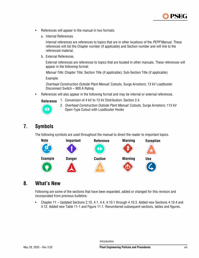
7. SymbolsThe following symbols are used throughout the manual to direct the reader to important topics.
8. What’s NewFollowing are some of the sections that have been expanded, added or changed for this revision and incorporated from previous bulletins:
• Chapter 11 – Updated Sections 2.10, 4.1, 4.4, 4.10.1 through 4.10.3. Added new Sections 4.10.4 and 4.12. Added new Table 11-1 and Figure 11.1. Renumbered subsequent sections, tables and figures.
1. Conversion of 4 kV to 13 kV Distribution: Section 2.4 2. Overhead Construction Outside Plant Manual: Cutouts, Surge Arrestors; 113 kV
Open-Type Cutout with Loadbuster Hooks
Reference
Note Important Reference
Example Danger Caution
Warning
Warning
Exception
Use
Introduction
May 28, 2020 – Rev 3.02 Plant Engineering Policies and Procedures xxi
May 18, 2018 – Rev 3.00
9. Ownership and ConfidentialityThe Plant Engineering Policies and Procedures manual is the property of PSE&G. The Manual Owner is Shashikant Patel, Manager Project Engineering. It is a confidential document for PSE&G personnel only. It is loaned to you subject to recall without prior notice, and with the distinct understanding that it is to be used only for the duration of and in connection with the performance of work for PSE&G. Reproduction in whole or in part is expressly forbidden. Should circumstances arise under which you will no longer require this manual for the specific purpose for which it is loaned to you, it must be returned promptly. Under no circumstances shall this manual be transferred, loaned or by any other means made available to any individual outside the Company, firm or corporation without the express written permission of the Manual Owner.
We welcome any comments or feedback – please contact the Technical Documentation Department at [email protected].
Introduction
May 18, 2018 – Rev 3.00xxii Plant Engineering Policies and Procedures
May 18, 2018 – Rev 3.00Go to Chapter TOC
Chapter 1 – Underground Services – Table of Contents1. Buried Underground Distribution (BUD) . . . . . . . . . . . . . . . . . . . . . . . . . . . . . . . . . . . . . . . . . . . . 1-1
1.1 Definitions . . . . . . . . . . . . . . . . . . . . . . . . . . . . . . . . . . . . . . . . . . . . . . . . . . . . . . . . . . . . . . . . . . . . . .1-1
1.2 Applicability . . . . . . . . . . . . . . . . . . . . . . . . . . . . . . . . . . . . . . . . . . . . . . . . . . . . . . . . . . . . . . . . . . . . .1-2
1.3 Smart Growth. . . . . . . . . . . . . . . . . . . . . . . . . . . . . . . . . . . . . . . . . . . . . . . . . . . . . . . . . . . . . . . . . . . .1-2
1.4 Rights-of-Way and Easements . . . . . . . . . . . . . . . . . . . . . . . . . . . . . . . . . . . . . . . . . . . . . . . . . . . . . . .1-3
1.5 Installation of Underground Distribution System . . . . . . . . . . . . . . . . . . . . . . . . . . . . . . . . . . . . . . . .1-3
1.6 Connections to Supply Systems. . . . . . . . . . . . . . . . . . . . . . . . . . . . . . . . . . . . . . . . . . . . . . . . . . . . . .1-5
1.7 Construction. . . . . . . . . . . . . . . . . . . . . . . . . . . . . . . . . . . . . . . . . . . . . . . . . . . . . . . . . . . . . . . . . . . . .1-5
1.8 Street Lighting . . . . . . . . . . . . . . . . . . . . . . . . . . . . . . . . . . . . . . . . . . . . . . . . . . . . . . . . . . . . . . . . . . .1-5
1.9 Determination of Charges to Applicant. . . . . . . . . . . . . . . . . . . . . . . . . . . . . . . . . . . . . . . . . . . . . . . . .1-6
1.10 Cooperation by Applicant . . . . . . . . . . . . . . . . . . . . . . . . . . . . . . . . . . . . . . . . . . . . . . . . . . . . . . . . . . .1-7
1.11 Special Conditions or Exemptions . . . . . . . . . . . . . . . . . . . . . . . . . . . . . . . . . . . . . . . . . . . . . . . . . . . .1-7
1.12 Compliance . . . . . . . . . . . . . . . . . . . . . . . . . . . . . . . . . . . . . . . . . . . . . . . . . . . . . . . . . . . . . . . . . . . . .1-7
1.13 Authorization . . . . . . . . . . . . . . . . . . . . . . . . . . . . . . . . . . . . . . . . . . . . . . . . . . . . . . . . . . . . . . . . . . . .1-7
2. BUD Joint Trench Work Procedures . . . . . . . . . . . . . . . . . . . . . . . . . . . . . . . . . . . . . . . . . . . . . . . 1-8
2.1 Work Initiation . . . . . . . . . . . . . . . . . . . . . . . . . . . . . . . . . . . . . . . . . . . . . . . . . . . . . . . . . . . . . . . . . . .1-8
2.2 Trench Sponsorship . . . . . . . . . . . . . . . . . . . . . . . . . . . . . . . . . . . . . . . . . . . . . . . . . . . . . . . . . . . . . .1-8
2.3 Trench Layout . . . . . . . . . . . . . . . . . . . . . . . . . . . . . . . . . . . . . . . . . . . . . . . . . . . . . . . . . . . . . . . . . . .1-8
2.4 Use of Contractors . . . . . . . . . . . . . . . . . . . . . . . . . . . . . . . . . . . . . . . . . . . . . . . . . . . . . . . . . . . . . . . .1-9
2.5 Billing Procedure . . . . . . . . . . . . . . . . . . . . . . . . . . . . . . . . . . . . . . . . . . . . . . . . . . . . . . . . . . . . . . . . .1-9
2.6 Pre-Design Meeting . . . . . . . . . . . . . . . . . . . . . . . . . . . . . . . . . . . . . . . . . . . . . . . . . . . . . . . . . . . . . . .1-9
2.7 Design Criteria . . . . . . . . . . . . . . . . . . . . . . . . . . . . . . . . . . . . . . . . . . . . . . . . . . . . . . . . . . . . . . . . . .1-18
2.8 Easement Preparation and Tracking . . . . . . . . . . . . . . . . . . . . . . . . . . . . . . . . . . . . . . . . . . . . . . . . . .1-23
2.9 Cost Estimating Procedure. . . . . . . . . . . . . . . . . . . . . . . . . . . . . . . . . . . . . . . . . . . . . . . . . . . . . . . . .1-24
2.10 Transmittal of Costs . . . . . . . . . . . . . . . . . . . . . . . . . . . . . . . . . . . . . . . . . . . . . . . . . . . . . . . . . . . . . .1-24
2.11 Pre-Construction Meeting . . . . . . . . . . . . . . . . . . . . . . . . . . . . . . . . . . . . . . . . . . . . . . . . . . . . . . . . .1-25
3. Underground Distribution in Overhead Zone . . . . . . . . . . . . . . . . . . . . . . . . . . . . . . . . . . . . . . . . 1-26
3.1 Division of Cost and Responsibilities . . . . . . . . . . . . . . . . . . . . . . . . . . . . . . . . . . . . . . . . . . . . . . . .1-26
3.2 Transmittal of Costs . . . . . . . . . . . . . . . . . . . . . . . . . . . . . . . . . . . . . . . . . . . . . . . . . . . . . . . . . . . . . .1-26
4. Conduit and Manhole Work Procedures . . . . . . . . . . . . . . . . . . . . . . . . . . . . . . . . . . . . . . . . . . . 1-26
4.1 Minor Construction – ($50,000 or less) . . . . . . . . . . . . . . . . . . . . . . . . . . . . . . . . . . . . . . . . . . . . . . .1-26
4.2 Procedures. . . . . . . . . . . . . . . . . . . . . . . . . . . . . . . . . . . . . . . . . . . . . . . . . . . . . . . . . . . . . . . . . . . . .1-27
4.3 Major Construction – (Exceeding $50,000) . . . . . . . . . . . . . . . . . . . . . . . . . . . . . . . . . . . . . . . . . . . .1-27
Chapter 1 – Underground Services – Table of Contents
May 18, 2018 – Rev 3.00 Plant Engineering Policies and Procedures 1 – TOC 1
Go to TOC
5. Blanket Purchase Orders . . . . . . . . . . . . . . . . . . . . . . . . . . . . . . . . . . . . . . . . . . . . . . . . . . . . . . .1-27
5.1 Request for Bids . . . . . . . . . . . . . . . . . . . . . . . . . . . . . . . . . . . . . . . . . . . . . . . . . . . . . . . . . . . . . . . . 1-27
5.2 Bid Evaluation. . . . . . . . . . . . . . . . . . . . . . . . . . . . . . . . . . . . . . . . . . . . . . . . . . . . . . . . . . . . . . . . . . 1-27
5.3 Requisition for Blanket Purchase Order . . . . . . . . . . . . . . . . . . . . . . . . . . . . . . . . . . . . . . . . . . . . . . 1-27
6. Contractor Job Procedures – Minor Construction . . . . . . . . . . . . . . . . . . . . . . . . . . . . . . . . . . . .1-28
6.1 Division Engineering Supervision . . . . . . . . . . . . . . . . . . . . . . . . . . . . . . . . . . . . . . . . . . . . . . . . . . . 1-28
7. Contractor Job Procedures – Major Construction . . . . . . . . . . . . . . . . . . . . . . . . . . . . . . . . . . . .1-28
7.1 Blanket Authorizations . . . . . . . . . . . . . . . . . . . . . . . . . . . . . . . . . . . . . . . . . . . . . . . . . . . . . . . . . . . 1-28
8. Invoice Reconciliation and Reporting of Work Done by Contractor . . . . . . . . . . . . . . . . . . . . . . .1-29
8.1 Contractor Man-hour Loadings. . . . . . . . . . . . . . . . . . . . . . . . . . . . . . . . . . . . . . . . . . . . . . . . . . . . . 1-29
9. As-Built Construction Records . . . . . . . . . . . . . . . . . . . . . . . . . . . . . . . . . . . . . . . . . . . . . . . . . . .1-29
9.1 Responsibilities . . . . . . . . . . . . . . . . . . . . . . . . . . . . . . . . . . . . . . . . . . . . . . . . . . . . . . . . . . . . . . . . 1-29
9.2 Procedures – Underground Construction Specialist . . . . . . . . . . . . . . . . . . . . . . . . . . . . . . . . . . . . . 1-30
Chapter 1 – Underground Services – Table of Contents
May 18, 2018 – Rev 3.001 – TOC 2 Plant Engineering Policies and Procedures
Go to TOC
May 18, 2018 – Rev 3.00
Chapter 1 – Underground Services
1. Buried Underground Distribution (BUD)Buried Underground Distribution (BUD) refers to the electric system in which the distribution lines and service conductors, with minor exceptions, are required to be buried directly in earth or in underground conduits. Requirements are governed by the New Jersey Administrative Code (N.J.A.C.) The following is a summary of the applicable regulations for extension of electric underground facilities.
(Ref. N.J.A.C. 2015 14:3-8.2, 14:3-8.4 et seq, and the PSE&G Tariff for Electric Service B.P.U.N.J. No. 15)
1.1 DefinitionsThe following words and terms when used in this section shall have the following meanings unless the context clearly indicates otherwise.
Applicant – is the individual or entity, who may or may not be the ultimate customer, requesting new, additional, temporary, or upgraded electric service from PSE&G. For BUD. this typically means the subdivider, developer, builder, or owner applying for the construction of an electric distribution system in a subdivision.
Board – the Board of Public Utilities of New Jersey.
Building – a permanent structure enclosed within exterior walls or fire walls, built, erected and framed of component structural parts and designed for single-family or duplex-family occupancy. A duplex family building may consist of either a duplex apartment with rooms on two floors and a private inner-stairway, or a duplex house with two separate family units side by side.
Company – Public Service Electric and Gas (PSE&G).
Contribution in Aid of Construction (CIAC) – a charge to a customer by Public Service toward capitalized facilities installed by Public Service; also known as a Customer Contribution.
Cost – with respect to the cost of construction of an extension, actual and/or site-specific unitized expenses incurred for materials and labor (including both internal and external labor) employed in the design, purchase, construction, and/or installation of the extension, including overhead directly attributable to the work, as well as overrides or loading factors such as those for back-up personnel for mapping, records, clerical, supervision or general office functions.
Deposit – a payment made by a customer to Public Service that is refundable under certain circumstances; also known as a Customer Advance for Construction.
Designated Growth Area – an area designated for growth as detailed in N.J.A.C. 14:3-8.2 and depicted on the New Jersey State Planning Commission State Plan Policy Map as of the date service is requested by the Applicant.
Distribution Revenue – the sum of revenue from the Service Charge and Distribution Charges, less unit and sales taxes; also known as Delivery Revenue or Non-Supply Revenue.
Existing Street – a public street, road or highway, traversing or abutting the Applicant’s subdivision, that was in existence and utilized prior to the approval and establishment of the subdivision.
Chapter 1 – Underground Services
May 18, 2018 – Rev 3.00 Plant Engineering Policies and Procedures 1 – 1
Go to Chapter TOC – Go to TOC
Extension – the construction or installation of plant and/or facilities by Public Service used to convey service from existing or new plant and/or facilities to one or more customers, and also means the plant and/or facilities themselves. An Extension includes all Public Service plant and/or facilities used for electric transmission (non-FERC jurisdictional) and/or distribution, whether located overhead or underground, on a public street or right of way, or on private property or private right of way, and includes the conductors, poles or supports, cable, conduit, rights of way, land, site restoration, handholes, manholes, vaults, line transformers, protection devices, metering equipment and other means of conveying service from existing plant and/or facilities to each unit or structure to be served. An extension does not include equipment solely used for administrative purposes, such as office equipment used for administering a billing system. For an underground extension, the extension begins at the existing infrastructure and ends at, and includes, the meter.
Mobile Home – a dwelling unit constructed for permanent occupancy, which is designed for moving along roads and highways by towing with a truck or tractor and which is installed on a permanent foundation.
Multiple-Occupancy Building – a permanent structure enclosed or within exterior walls or fire walls built, erected and framed of component structural parts and designed to contain three or more individual dwelling units and consisting of not more than four stories.
New Street – a public street, road or highway, traversing or abutting the Applicant’s subdivision, that was or will be constructed subsequent to the approval and establishment of the subdivision.
Non-Growth Area – an area not in a Designated Growth Area.
SGIIP Area – Smart Growth Infrastructure Investment Program. It is any area in a municipality that is located in Planning Area 1, and for which the municipality has obtained appropriate formal endorsement from the State Planning Commission.
Smart Growth – planned development that is intended to help protect open space and farmland, revitalize existing communities, maintain affordable housing and provide a variety of transportation choices.
Subdivision – the tract of land which is divided into lots as approved by the appropriate authorities for the construction of new residential buildings or the placement of mobile homes, or the land on which new multiple-occupancy buildings are to be erected.
1.2 ApplicabilityExtensions of electric distribution facilities necessary to furnish an electric system within new residential subdivisions having three or more building lots, or to new multiple-occupancy buildings not more than four stories in height, shall be made underground, unless a waiver has been obtained from the Board of Public Utilities (BPU), or the extension is a high capacity main line of 4 megavolt amps (MVA) or more.
Such extensions of service shall be made by the company in accordance with the provisions in this section.
1.3 Smart GrowthNew Jersey Smart Growth Policy identifies certain geographical areas of the state as “Growth” and “Non-Growth”. “Growth” areas may receive favorable treatment for residential, commercial, or industrial development, including expedited permit reviews, and economic benefits. “Non-Growth” areas may not receive such favorable treatment.
Chapter 1 – Underground Services
May 18, 2018 – Rev 3.001 – 2 Plant Engineering Policies and Procedures
Go to Chapter TOC – Go to TOC
The official source for determination of a Growth or Non-Growth Area shall be the State Planning Maps from the New Jersey Office of Smart Growth. Any additional information, such as the Company’s GIS, may be used to assist in the determination, but the final authority shall be the official state maps.
The actual location of the end-use load shall determine the applicable area, not the location of the meter, the Company facilities used to provide service, the customer’s street address, or any other determinant.
1.4 Rights-of-Way and EasementsWithin the Applicant’s subdivision, the company shall construct, operate and maintain all underground electric distribution lines along public streets, roads, and highways. On public lands and private property, the Applicant shall provide, without cost or condemnation, Right-of-Way (ROW) and easements satisfactory both as to location and legal sufficiency. These conveyances shall also include any underground extensions on properties adjacent to the boundary line of the subdivision.
ROW and easements must be furnished by the Applicant at no cost and in sufficient time to meet service requirements. The ROW or easements so granted must be cleared of trees, tree stumps and other obstructions above or below grade at no charge to the Company to a width sufficient to permit the use of machinery and equipment, and must be graded to within 6 in. of final grade by the Applicant before the utility will commence construction. Such clearance and grading must be maintained by the Applicant during construction of the electric distribution facilities.
1.5 Installation of Underground Distribution System For the installation of an underground electric distribution system in a single family residential development, the Applicant shall pay the differential cost between the construction of an underground and an equivalent overhead distribution system as determined from the company's approved Tariff for Electric Service. (See Chapter 9 – Costs and Estimates).
For multiple-occupancy buildings, duplex family buildings and mobile homes, the underground distribution system within the subdivision shall be constructed in the most economical manner, and the Applicant shall pay the differential cost according to the component unit charges. (See Chapter 9 – Costs and Estimates).
At the request of the Applicant and upon approval by the Company, components which exceed standards may be installed, provided the Applicant bears the full cost of the excess facilities requested.
1. The Company is not obligated to furnish electric service to any building in a subdivision until:
a. An application for the electric distribution system in the section of the subdivision, which has received final approval of the appropriate authorities, has been received by the responsible Electric Delivery Division, and
b. A deposit and/or contribution has been made in accordance with this Section, unless otherwise ordered by the Board.
Charges for a BUD development may not be waived or refunded unless such waiver or refund is specifically approved by the Board.
2. Subsequent to receipt of a proper application and necessary easements, and after coordination with other utilities, the Company shall install along new streets and along existing streets without overhead distribution facilities, an underground electric distribution system for the supply of electric service to the subdivision.
Chapter 1 – Underground Services
May 18, 2018 – Rev 3.00 Plant Engineering Policies and Procedures 1 – 3
Go to Chapter TOC – Go to TOC
3. The Applicant shall supply the preliminary or tentative subdivision map, submitted to and approved by the appropriate authorities, showing the subdivision of all of the Applicant’s property, together with the anticipated electric load requirements for each living unit, to facilitate planning for the ultimate supply in the form of branch circuit, main feeder and/or substation facilities required.
4. The Applicant shall also supply the final subdivision map of the section of the subdivision which has received the final approval of the appropriate authorities and which the Applicant proposes to develop in the immediate future. This submission shall also detail the planned electric load requirement that will be borne by the developer. The Applicant shall supply an estimate of the date electric service will be required initially and the time schedule for full development of the section.
5. Extensions of high capacity main line distribution facilities, not exceeding 4 MVA, solely within and for the Applicant’s subdivision shall be made underground.
6. Extensions of high capacity main line distribution facilities, exceeding 4 MVA, solely within and for the Applicant’s subdivision may be made overhead, unless otherwise ordered by the Board. The Applicant shall pay the differential cost, if any, for each extension as determined from the component unit charges. (See Chapter 9 – Costs and Estimates).
7. Extensions of high capacity main line distribution facilities, not exceeding 4 MVA, solely within the Applicant’s subdivision and also necessary to serve adjacent underground residential, commercial, or industrial loads shall be made underground. The differential cost for such extensions, if any, shall be prorated in such a manner that the Applicant shall pay only for the capacity necessary to serve the Applicant’s subdivision. The Company shall require a deposit or contribution and charge the balance differential cost to the other residential, commercial or industrial Applicants, when service is requested for such loads, on a prorated basis.
8. Extensions of high capacity main line distribution facilities exceeding 4 MVA, solely within the Applicant’s subdivision and also necessary to serve adjacent underground residential, commercial or industrial loads, may be made overhead, unless otherwise ordered by the Board.
9. Extensions of high capacity main line distribution facilities, not exceeding 4 MVA, to reach the Applicant’s subdivision, through another residential subdivision where the provisions of the Section are applicable, shall be made underground. The Applicant shall pay a prorated differential cost for such extensions only for that capacity necessary to serve the Applicant’s subdivision in addition to the charges required pursuant to this section. The Company shall require a deposit or contribution and charge the balance differential cost to the property owner or owners of the residential subdivision through which the extension is made, when such owner or owners make an application for electric service, on a prorated basis.
10. Extensions of high capacity main line distribution facilities exceeding 4 MVA to reach the Applicant’s subdivision, through another residential subdivision where the provisions of this Section are applicable, may be made overhead, unless otherwise ordered by the Board.
11. Single-family residential buildings in the subdivision facing an existing street on which overhead facilities are presently installed may be served overhead. Should such buildings be served overhead, neither the number nor the frontage of such lots shall be included in the calculation to determine the Applicant’s contribution. Multiple-occupancy buildings, duplex family buildings or mobile homes in the subdivision which abut an existing street on which overhead facilities are presently installed may be served overhead from the existing street.
12. In BUD areas any incidental secondary single phase service for non-residential use (such as swimming pools) shall be incorporated in the distribution system layout and included in the calculation of the Applicant’s contribution using the appropriate units of cost. (See Chapter 9 – Costs and Estimates).
Chapter 1 – Underground Services
May 18, 2018 – Rev 3.001 – 4 Plant Engineering Policies and Procedures
Go to Chapter TOC – Go to TOC
13. The total front footage shall be determined by measuring the street footage of all property within the subdivision (including both dimensions on the corner lots) excepting those portions of existing streets along which overhead facilities are already installed and will be used to provide overhead service.
14. The service connection to each building will be at the nearest corner of the building to the point at which the service enters the property to be served. If such service length on property served is more than 50 ft, then the Applicant shall pay the amount per foot listed in Chapter 9 – Costs and Estimates, for the length in excess of 50 ft. (The service length means the actual length of service cable between the side property line of the property being served to the meter location). It does not include that portion of the service which may be on an adjacent property.
For estimating purposes, unless the developer guarantees that all service locations will always be at the nearest building corner, the service length may be determined from the building setback and the lot width in accordance with the formula:
Service length = building setback + 1/2 lot width
Excess service length = Service length - 50 ft.
If the meter is to be located in the rear of the building, then the excess service length is increased by the distance between the front and back of the building.
15. In subdivisions where lot sizes, configurations or requirements are such that, in the Company’s judgment, underground primary conductors must be extended into the lots in the subdivision, the applicant shall pay the differential cost of such extensions determined from the unit cost. (See Chapter 9 – Costs and Estimates).
1.6 Connections to Supply SystemsThe Company shall provide a connection, using the normal method of construction, from the boundary line of the Applicant’s subdivision to the utility’s existing supply facilities. If good engineering practice dictates that the connection extension should be installed underground, such an extension should be planned and the differential cost, if any, should be borne by the Applicant.
1.7 ConstructionWhere practical, as determined by the Company, electric conductors shall be installed in the same trench with communication facilities and gas facilities. Where joint use of a trench is practical, the Company will not be obliged to commence work on the underground system until the Applicant has made all necessary arrangements with the communication and gas utility and they are ready to commence work on their underground system.
Pavement cutting and restoration, rock removal, blasting, or unusual or difficult digging conditions requiring equipment and methods not generally used by the Division’s forces may be charged to the Applicant. Such charges shall be at actual low bid differential cost on a job-by-job basis (Contractors Unit Price Proposal – Construction of Underground Conduits and Associated Work), with the Applicant having the option to have the work done by themselves or their agent. If the developer elects to do this work and is qualified, they shall provide a suitable trench, remove the rock and spoilage, and backfill in accordance with Company specifications.
1.8 Street LightingAll subdivisions to be supplied from underground electric facilities shall have incorporated in their design the requirements for street lighting in accordance with the standards in general use in the municipality. Such street lighting shall also be supplied from the underground system.
Chapter 1 – Underground Services
May 18, 2018 – Rev 3.00 Plant Engineering Policies and Procedures 1 – 5
Go to Chapter TOC – Go to TOC
Poles and fixtures shall be selected from the types and sizes adopted by the Company as standard. The Applicant’s charges for residential underground service includes a basic cost for a street lighting system with lights spaced every 200 ft. Additional charges for variations from this spacing and for the type of street lighting poles to be used are included in the appropriate cost. (See Chapter 9 – Costs and Estimates).
Buried underground supply facilities shall be installed for private area lighting in locations where the Board’s Underground Regulation applies. Such lighting facilities shall be installed by the company at the customer's expense in accordance with the tariff and based on the unit costs of construction. (See Chapter 9 – Costs and Estimates).
1.9 Determination of Charges to Applicant
1.9.1 Deposit Calculation for BUD Development
When it is necessary for the Company to construct the underground extension to serve the requirements of an Applicant, the additional cost of such an extension over and above the amount it would cost to serve those customers overhead (i.e. differential), shall constitute a nonrefundable contribution in aid of construction paid by the Applicant to the Company. The remainder of the cost of the service, that is the amount, which overhead service would have cost, shall be shared between the Applicant and the Company.
When the total cost of the underground extensions is less than or equal to $1 million, a deposit will only be required to the extent that ten times (or twenty times in a SGIIP Area) the estimated Annual Distribution Revenue is less than the cost of the underground extensions. In this case, the “excess cost”, after subtracting revenue credit and any required up-front contributions such as BUD Charges and Atypical Conditions, shall be the required deposit amount grossed up for income tax effects. The deposit requirement shall be waived for any excess cost $500 or less.
When the total cost of the underground extensions is greater than $1 million, the Company reserves the right to require a deposit up to the total cost of the underground extensions. Such determination shall be made on an individual project specific basis. The Manager of New Business and Work Management shall be contacted for any project where the total cost of the extension is in excess of $1 million.
1.9.2 Multiple Phase BUD Development – Basis for Deposit Calculations
Many BUD development plans call for multiple phase construction where the developer requests the Company to install a portion of its distribution facilities prior to the start of construction of some buildings. Where practicable and economical, the installation of Company facilities may be performed in phases or otherwise coordinated with the developer to minimize both the deposit requirements to the developer and the risk to the Company that a portion of these facilities would not be utilized to full capacity, or not utilized at all. In these cases, the deposit requirements shall be based upon the estimated cost of the facilities to be installed by the Company and the first year’s estimated Annual Distribution Revenue from the Company’s electric meters to be fed by these facilities. Only the estimated revenue anticipated from buildings where construction is substantially underway at the time of the planned installation of the Company’s distribution lines shall be considered for purposes of the calculation of the initial deposit.
Revenue from buildings where construction has not yet started, or that are only minimally under construction, at the time of the planned installation of Company distribution lines should be treated in the same way as revenue from additional unanticipated customers is handled, as specified in 3.7.2 of the Tariff for Electric Service B.P.U.N.J. No.15 Standard Terms and Conditions. In these cases, the anticipated revenue from these customers should not be considered in the calculation of the initial deposit. Refer to Section 12 of the PSE&G Tariff Policy Manual for further clarification and examples.
Chapter 1 – Underground Services
May 18, 2018 – Rev 3.001 – 6 Plant Engineering Policies and Procedures
Go to Chapter TOC – Go to TOC
1.9.3 Extensions Outside a BUD Development
The cost related to an Extension outside the confines of a BUD development should be considered as part of any initial construction or phase of the BUD development. Thus, the entire cost for these facilities should be used in the calculation of a deposit (or contribution) requirements for the initial phase of the development.
1.10 Cooperation by ApplicantThe charges specified are based on the premise that each Applicant shall agree to cooperate with the utility in accordance with this Section in an effort to keep the cost of construction and installation of the underground electric distribution system as low as possible. This includes the scheduling of construction to preclude the necessity for trenching in frozen soils, or in land fill operations before soils have become stabilized.
If unusual circumstances would unreasonably delay the Company’s ability to provide underground service, the Company may install temporary facilities in whatever manner is most practical under the circumstances. However, the Company shall replace such temporary facilities as soon as practical with permanent underground service in accordance with regulations. The cost of the installation and removal of the temporary facilities is nonrefundable and shall constitute a CIAC.
1.11 Special Conditions or ExemptionsWhen the requirement that an extension be located underground will result in hardship, inequity, or will be discriminatory to other affected parties, the Company or Applicant may request from the Board a special exemption, or approval of special conditions. The Board may require that the requesting party submit, as part of such a request, documentation that the requesting party has deposited in an escrow account an amount up to the estimated difference in cost between underground and overhead service.
1.12 ComplianceNew Jersey Administrative Code Title 14, Chapter 3, Subchapter 8 “Extensions to Provide Regulated Services” is intended to fulfill the mandate at N.J.S.A. 48:2-23 that regulated entity service be safe, adequate and proper, and furnished in a manner that tends to conserve and preserve the quality of the environment. One way in which this subchapter fulfills that mandate is through provisions that generally do not permit regulated entities to invest, in response to an application for an extension, in new infrastructure in areas that are not designated for growth.
Regulated entities, customers, applicants, developers, builders, municipal bodies and other persons shall cooperate fully in order to facilitate construction of an extension at the lowest reasonable cost consistent with system reliability and safety. This includes sharing trenches where practicable, and coordinating scheduling and other aspects of construction to minimize delays and to avoid difficult conditions such as frozen or unstable soils. A municipality shall not impose an ordinance or other requirement that conflicts with this subchapter, or which would prevent or interfere with another person’s compliance with this subchapter.
1.13 AuthorizationConstruction of buried underground distribution systems for subdivisions covered by this section shall proceed and be charged to an appropriate blanket authorization or a specific authorization, in accordance with the New Business Section of this manual. The cost of services, street lighting and transformers shall be excluded when determining the type of authorization required. However, when a specific authorization is required, the Estimate General shall include all costs generally chargeable to Utility Plant Accounts.
Chapter 1 – Underground Services
May 18, 2018 – Rev 3.00 Plant Engineering Policies and Procedures 1 – 7
Go to Chapter TOC – Go to TOC
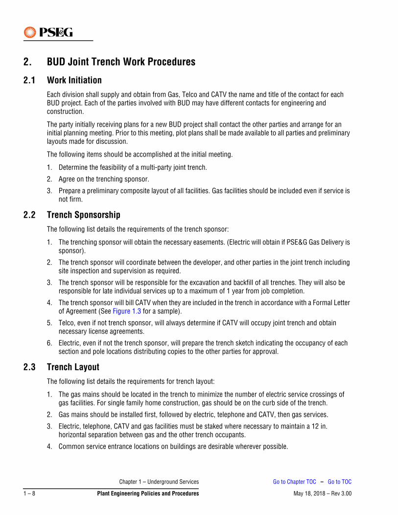
2. BUD Joint Trench Work Procedures
2.1 Work InitiationEach division shall supply and obtain from Gas, Telco and CATV the name and title of the contact for each BUD project. Each of the parties involved with BUD may have different contacts for engineering and construction.
The party initially receiving plans for a new BUD project shall contact the other parties and arrange for an initial planning meeting. Prior to this meeting, plot plans shall be made available to all parties and preliminary layouts made for discussion.
The following items should be accomplished at the initial meeting.
1. Determine the feasibility of a multi-party joint trench.
2. Agree on the trenching sponsor.
3. Prepare a preliminary composite layout of all facilities. Gas facilities should be included even if service is not firm.
2.2 Trench Sponsorship The following list details the requirements of the trench sponsor:
1. The trenching sponsor will obtain the necessary easements. (Electric will obtain if PSE&G Gas Delivery is sponsor).
2. The trench sponsor will coordinate between the developer, and other parties in the joint trench including site inspection and supervision as required.
3. The trench sponsor will be responsible for the excavation and backfill of all trenches. They will also be responsible for late individual services up to a maximum of 1 year from job completion.
4. The trench sponsor will bill CATV when they are included in the trench in accordance with a Formal Letter of Agreement (See Figure 1.3 for a sample).
5. Telco, even if not trench sponsor, will always determine if CATV will occupy joint trench and obtain necessary license agreements.
6. Electric, even if not the trench sponsor, will prepare the trench sketch indicating the occupancy of each section and pole locations distributing copies to the other parties for approval.
2.3 Trench LayoutThe following list details the requirements for trench layout:
1. The gas mains should be located in the trench to minimize the number of electric service crossings of gas facilities. For single family home construction, gas should be on the curb side of the trench.
2. Gas mains should be installed first, followed by electric, telephone and CATV, then gas services.
3. Electric, telephone, CATV and gas facilities must be staked where necessary to maintain a 12 in. horizontal separation between gas and the other trench occupants.
4. Common service entrance locations on buildings are desirable wherever possible.
Chapter 1 – Underground Services
May 18, 2018 – Rev 3.001 – 8 Plant Engineering Policies and Procedures
Go to Chapter TOC – Go to TOC
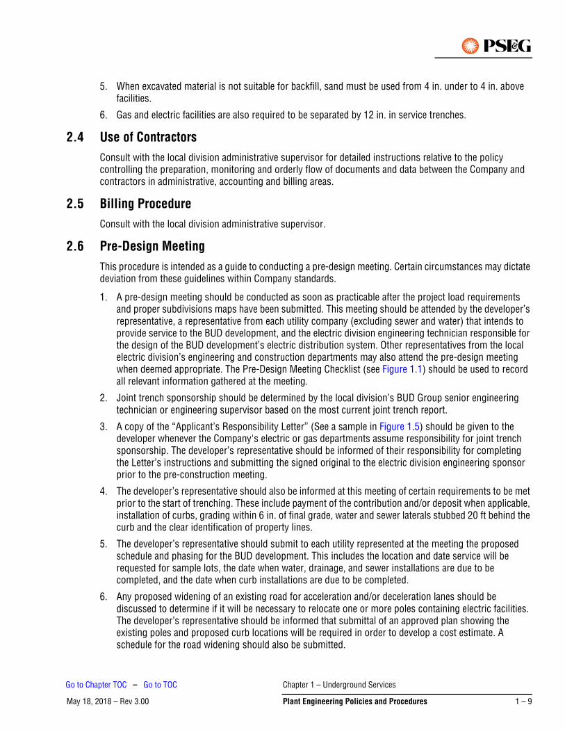
5. When excavated material is not suitable for backfill, sand must be used from 4 in. under to 4 in. above facilities.
6. Gas and electric facilities are also required to be separated by 12 in. in service trenches.
2.4 Use of ContractorsConsult with the local division administrative supervisor for detailed instructions relative to the policy controlling the preparation, monitoring and orderly flow of documents and data between the Company and contractors in administrative, accounting and billing areas.
2.5 Billing ProcedureConsult with the local division administrative supervisor.
2.6 Pre-Design MeetingThis procedure is intended as a guide to conducting a pre-design meeting. Certain circumstances may dictate deviation from these guidelines within Company standards.
1. A pre-design meeting should be conducted as soon as practicable after the project load requirements and proper subdivisions maps have been submitted. This meeting should be attended by the developer’s representative, a representative from each utility company (excluding sewer and water) that intends to provide service to the BUD development, and the electric division engineering technician responsible for the design of the BUD development’s electric distribution system. Other representatives from the local electric division’s engineering and construction departments may also attend the pre-design meeting when deemed appropriate. The Pre-Design Meeting Checklist (see Figure 1.1) should be used to record all relevant information gathered at the meeting.
2. Joint trench sponsorship should be determined by the local division’s BUD Group senior engineering technician or engineering supervisor based on the most current joint trench report.
3. A copy of the “Applicant’s Responsibility Letter” (See a sample in Figure 1.5) should be given to the developer whenever the Company's electric or gas departments assume responsibility for joint trench sponsorship. The developer’s representative should be informed of their responsibility for completing the Letter’s instructions and submitting the signed original to the electric division engineering sponsor prior to the pre-construction meeting.
4. The developer’s representative should also be informed at this meeting of certain requirements to be met prior to the start of trenching. These include payment of the contribution and/or deposit when applicable, installation of curbs, grading within 6 in. of final grade, water and sewer laterals stubbed 20 ft behind the curb and the clear identification of property lines.
5. The developer’s representative should submit to each utility represented at the meeting the proposed schedule and phasing for the BUD development. This includes the location and date service will be requested for sample lots, the date when water, drainage, and sewer installations are due to be completed, and the date when curb installations are due to be completed.
6. Any proposed widening of an existing road for acceleration and/or deceleration lanes should be discussed to determine if it will be necessary to relocate one or more poles containing electric facilities. The developer’s representative should be informed that submittal of an approved plan showing the existing poles and proposed curb locations will be required in order to develop a cost estimate. A schedule for the road widening should also be submitted.
Chapter 1 – Underground Services
May 18, 2018 – Rev 3.00 Plant Engineering Policies and Procedures 1 – 9
Go to Chapter TOC – Go to TOC
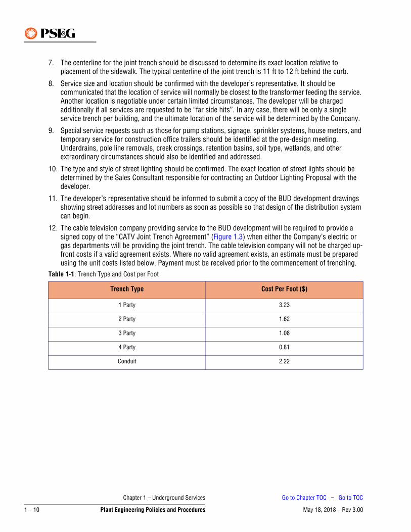
7. The centerline for the joint trench should be discussed to determine its exact location relative to placement of the sidewalk. The typical centerline of the joint trench is 11 ft to 12 ft behind the curb.
8. Service size and location should be confirmed with the developer’s representative. It should be communicated that the location of service will normally be closest to the transformer feeding the service. Another location is negotiable under certain limited circumstances. The developer will be charged additionally if all services are requested to be “far side hits”. In any case, there will be only a single service trench per building, and the ultimate location of the service will be determined by the Company.
9. Special service requests such as those for pump stations, signage, sprinkler systems, house meters, and temporary service for construction office trailers should be identified at the pre-design meeting. Underdrains, pole line removals, creek crossings, retention basins, soil type, wetlands, and other extraordinary circumstances should also be identified and addressed.
10. The type and style of street lighting should be confirmed. The exact location of street lights should be determined by the Sales Consultant responsible for contracting an Outdoor Lighting Proposal with the developer.
11. The developer’s representative should be informed to submit a copy of the BUD development drawings showing street addresses and lot numbers as soon as possible so that design of the distribution system can begin.
12. The cable television company providing service to the BUD development will be required to provide a signed copy of the “CATV Joint Trench Agreement” (Figure 1.3) when either the Company’s electric or gas departments will be providing the joint trench. The cable television company will not be charged up-front costs if a valid agreement exists. Where no valid agreement exists, an estimate must be prepared using the unit costs listed below. Payment must be received prior to the commencement of trenching.
Table 1-1: Trench Type and Cost per Foot
Trench Type Cost Per Foot ($)
1 Party 3.23
2 Party 1.62
3 Party 1.08
4 Party 0.81
Conduit 2.22
Chapter 1 – Underground Services
May 18, 2018 – Rev 3.001 – 10 Plant Engineering Policies and Procedures
Go to Chapter TOC – Go to TOC

Figure 1.1: Sample of Pre-Design Meeting Checklist (page 1 of 2) (ED-DC-PEP-Form001)
PEPP-002623-01-0309
Chapter 1 – Underground Services
May 18, 2018 – Rev 3.00 Plant Engineering Policies and Procedures 1 – 11
Go to Chapter TOC – Go to TOC
Figure 1.2: Sample of Pre-Design Meeting Checklist (page 2 of 2) (ED-DC-PEP-Form001)
PEPP-002623-01-0309
Chapter 1 – Underground Services
May 18, 2018 – Rev 3.001 – 12 Plant Engineering Policies and Procedures
Go to Chapter TOC – Go to TOC
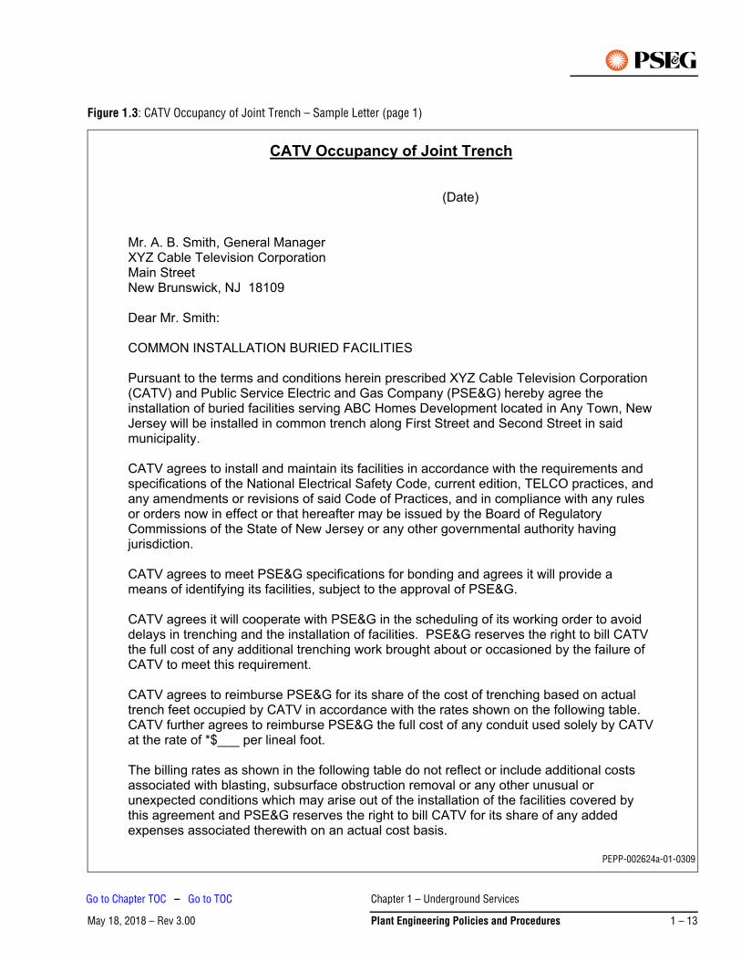
Figure 1.3: CATV Occupancy of Joint Trench – Sample Letter (page 1)
PEPP-002624a-01-0309
Chapter 1 – Underground Services
May 18, 2018 – Rev 3.00 Plant Engineering Policies and Procedures 1 – 13
Go to Chapter TOC – Go to TOC
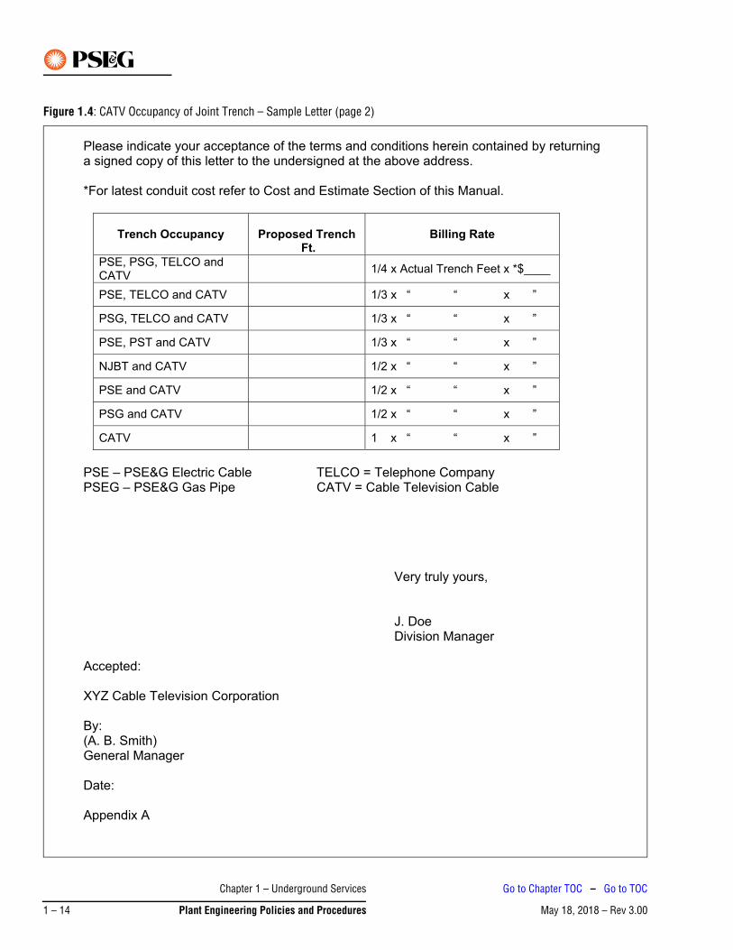
Figure 1.4: CATV Occupancy of Joint Trench – Sample Letter (page 2)
Chapter 1 – Underground Services
May 18, 2018 – Rev 3.001 – 14 Plant Engineering Policies and Procedures
Go to Chapter TOC – Go to TOC
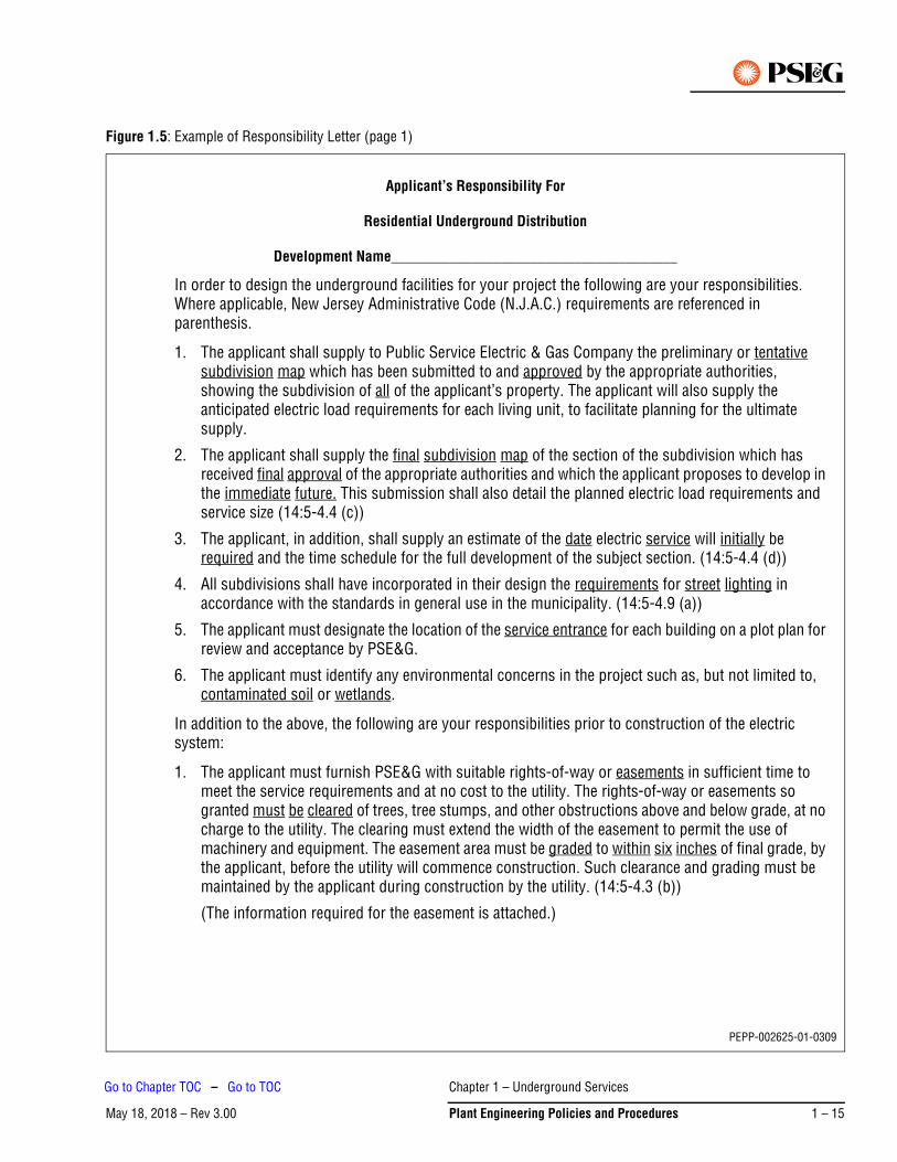
Figure 1.5: Example of Responsibility Letter (page 1)
Applicant’s Responsibility For
Residential Underground Distribution
Development Name_______________________________________
In order to design the underground facilities for your project the following are your responsibilities. Where applicable, New Jersey Administrative Code (N.J.A.C.) requirements are referenced in parenthesis.
1. The applicant shall supply to Public Service Electric & Gas Company the preliminary or tentative subdivision map which has been submitted to and approved by the appropriate authorities, showing the subdivision of all of the applicant’s property. The applicant will also supply the anticipated electric load requirements for each living unit, to facilitate planning for the ultimate supply.
2. The applicant shall supply the final subdivision map of the section of the subdivision which has received final approval of the appropriate authorities and which the applicant proposes to develop in the immediate future. This submission shall also detail the planned electric load requirements and service size (14:5-4.4 (c))
3. The applicant, in addition, shall supply an estimate of the date electric service will initially be required and the time schedule for the full development of the subject section. (14:5-4.4 (d))
4. All subdivisions shall have incorporated in their design the requirements for street lighting in accordance with the standards in general use in the municipality. (14:5-4.9 (a))
5. The applicant must designate the location of the service entrance for each building on a plot plan for review and acceptance by PSE&G.
6. The applicant must identify any environmental concerns in the project such as, but not limited to, contaminated soil or wetlands.
In addition to the above, the following are your responsibilities prior to construction of the electric system:
1. The applicant must furnish PSE&G with suitable rights-of-way or easements in sufficient time to meet the service requirements and at no cost to the utility. The rights-of-way or easements so granted must be cleared of trees, tree stumps, and other obstructions above and below grade, at no charge to the utility. The clearing must extend the width of the easement to permit the use of machinery and equipment. The easement area must be graded to within six inches of final grade, by the applicant, before the utility will commence construction. Such clearance and grading must be maintained by the applicant during construction by the utility. (14:5-4.3 (b))
(The information required for the easement is attached.)
PEPP-002625-01-0309
Chapter 1 – Underground Services
May 18, 2018 – Rev 3.00 Plant Engineering Policies and Procedures 1 – 15
Go to Chapter TOC – Go to TOC
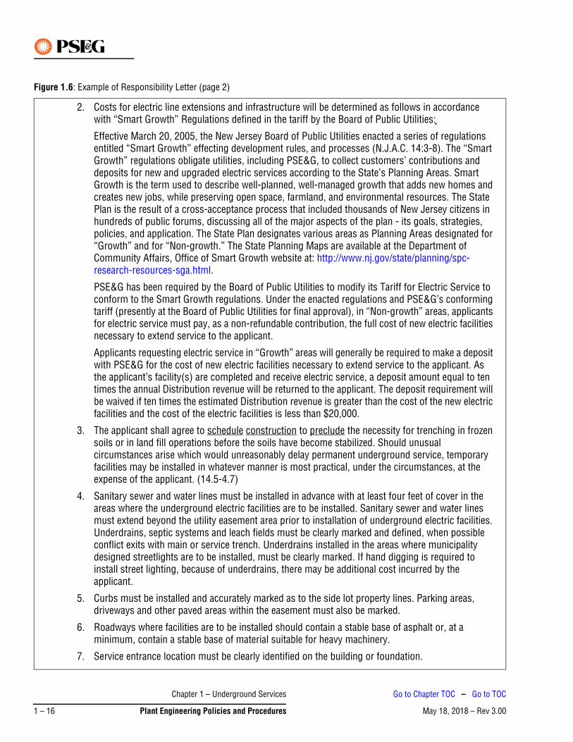
Figure 1.6: Example of Responsibility Letter (page 2)
2. Costs for electric line extensions and infrastructure will be determined as follows in accordance with “Smart Growth” Regulations defined in the tariff by the Board of Public Utilities:
Effective March 20, 2005, the New Jersey Board of Public Utilities enacted a series of regulations entitled “Smart Growth” effecting development rules, and processes (N.J.A.C. 14:3-8). The “Smart Growth” regulations obligate utilities, including PSE&G, to collect customers’ contributions and deposits for new and upgraded electric services according to the State’s Planning Areas. Smart Growth is the term used to describe well-planned, well-managed growth that adds new homes and creates new jobs, while preserving open space, farmland, and environmental resources. The State Plan is the result of a cross-acceptance process that included thousands of New Jersey citizens in hundreds of public forums, discussing all of the major aspects of the plan - its goals, strategies, policies, and application. The State Plan designates various areas as Planning Areas designated for “Growth” and for “Non-growth.” The State Planning Maps are available at the Department of Community Affairs, Office of Smart Growth website at: http://www.nj.gov/state/planning/spc-research-resources-sga.html.
PSE&G has been required by the Board of Public Utilities to modify its Tariff for Electric Service to conform to the Smart Growth regulations. Under the enacted regulations and PSE&G’s conforming tariff (presently at the Board of Public Utilities for final approval), in “Non-growth” areas, applicants for electric service must pay, as a non-refundable contribution, the full cost of new electric facilities necessary to extend service to the applicant.
Applicants requesting electric service in “Growth” areas will generally be required to make a deposit with PSE&G for the cost of new electric facilities necessary to extend service to the applicant. As the applicant’s facility(s) are completed and receive electric service, a deposit amount equal to ten times the annual Distribution revenue will be returned to the applicant. The deposit requirement will be waived if ten times the estimated Distribution revenue is greater than the cost of the new electric facilities and the cost of the electric facilities is less than $20,000.
3. The applicant shall agree to schedule construction to preclude the necessity for trenching in frozen soils or in land fill operations before the soils have become stabilized. Should unusual circumstances arise which would unreasonably delay permanent underground service, temporary facilities may be installed in whatever manner is most practical, under the circumstances, at the expense of the applicant. (14.5-4.7)
4. Sanitary sewer and water lines must be installed in advance with at least four feet of cover in the areas where the underground electric facilities are to be installed. Sanitary sewer and water lines must extend beyond the utility easement area prior to installation of underground electric facilities. Underdrains, septic systems and leach fields must be clearly marked and defined, when possible conflict exits with main or service trench. Underdrains installed in the areas where municipality designed streetlights are to be installed, must be clearly marked. If hand digging is required to install street lighting, because of underdrains, there may be additional cost incurred by the applicant.
5. Curbs must be installed and accurately marked as to the side lot property lines. Parking areas, driveways and other paved areas within the easement must also be marked.
6. Roadways where facilities are to be installed should contain a stable base of asphalt or, at a minimum, contain a stable base of material suitable for heavy machinery.
7. Service entrance location must be clearly identified on the building or foundation.
Chapter 1 – Underground Services
May 18, 2018 – Rev 3.001 – 16 Plant Engineering Policies and Procedures
Go to Chapter TOC – Go to TOC

Figure 1.7: Example of Responsibility Letter (page 3)
8. House/Apartment number must be approved by the proper authority and submitted to PSE&G. Although this will normally be accomplished as part of the original submission, written confirmation is required before construction. Each unit must be clearly identified onsite with its proper address at the time when the electric service will become energized.
Pre-design and pre-construction meetings will be convened for all parties involved as required to facilitate the installation of electric facilities.
The above responsibilities are noted in an effort to provide responsive service at the lowest possible cost consistent with sound construction practices.
If you have any questions, please call PSE&G Engineering at (XXX) XXX-XXXX.
Date__________________ Received by: _____________________________
Title: ___________________________________
Company or Corporate Name
_______________________________________
Chapter 1 – Underground Services
May 18, 2018 – Rev 3.00 Plant Engineering Policies and Procedures 1 – 17
Go to Chapter TOC – Go to TOC
2.7 Design CriteriaThis document is to serve as a general guide for designing new BUD projects and upgrading existing BUD developments for reliability improvements. Its purpose is to provide standard design practices in an effort to ensure safe, reliable and consistent electric service to new residential developments, and provide standard upgrade design and construction practices. Every effort should be made to comply with these guidelines; however, certain circumstances and conditions may make it impractical to do so. Major deviations from these guidelines which may impact reliability shall be reviewed by Asset Management Standards. Minor deviations may be made by local division BUD Group Supervisor where necessary.
2.7.1 Application
The following provides information regarding the application of design criteria:
1. New BUD developments should be designed in accordance with Section 2.7.2 – New Installations. These guidelines cover initial design and layout, and provide direction for remediation of existing installations.
2. Reliability upgrades to existing BUD areas due to poorly performing cable and or equipment should be completed in accordance with Section 2.7.3 – Existing Installations – Remediation Work. Analysis will indicate the following types of upgrades as options:
a. First two sections in from riser pole: This method should be used when there are multiple failures which occurred in these first two cable sections only. Directional boring should be used to replace these sections. This method should not be used if there is a high number of failures in other cable sections in the development.
b. Large portion of development: This method should be used in large developments that were built in sections over a long period of time and have different vintage cable in each section. Sections with poorly performing cable should be targeted and directional boring should be used to replace cable in these sections only. Padmounted transformers should also be replaced as needed.
c. Entire development: Where the entire development has experienced multiple cable failures in numerous sections throughout the development, the cable in the entire development should be replaced. Directional boring should be used to replace all the cable in the development. Padmounted transformers should also be replaced as needed.
When performing an engineering analysis for Poorest Performing Circuit (PPC) work to bring outages to zero, the division should consider replacing all the cable in the development and any transformers that are in deteriorated condition or that do not have an under oil arrestor. The division should convert any radial installations to open loop design and install elbow and standoff arrestors at all open points in the development.
2.7.2 New Installations
When designing new BUD installations, the information below provides design and construction guidelines to be used to ensure that construction meets reliability performance expectations.
Trenching
1. In general, the main trench containing all utilities should be placed approximately 11-1/2 ft behind the curb. This is negotiable depending on field conditions, but is to be at the discretion of the utility companies.
2. Trench width will be designed based on the number of utilities occupying the trench (consult the Underground Construction Outside Plant Manual). Depth should be kept to ensure a minimum of 36 in. cover for primary and 30 in. cover for services.
Chapter 1 – Underground Services
May 18, 2018 – Rev 3.001 – 18 Plant Engineering Policies and Procedures
Go to Chapter TOC – Go to TOC
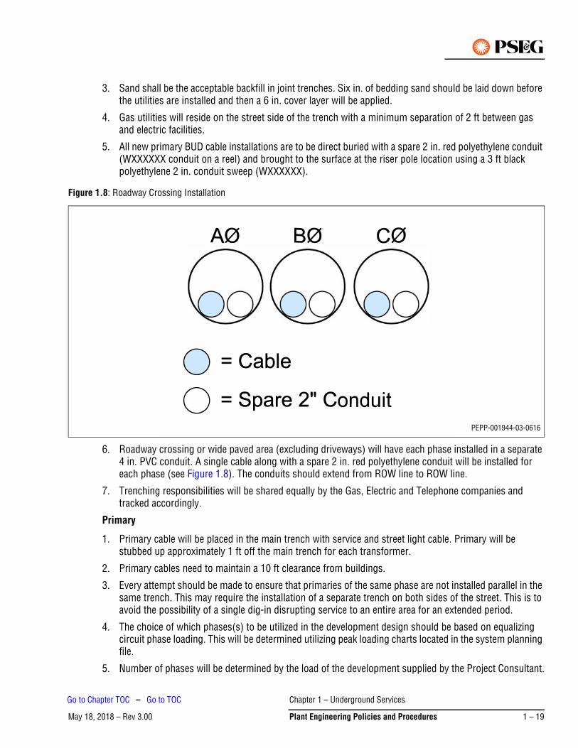
3. Sand shall be the acceptable backfill in joint trenches. Six in. of bedding sand should be laid down before the utilities are installed and then a 6 in. cover layer will be applied.
4. Gas utilities will reside on the street side of the trench with a minimum separation of 2 ft between gas and electric facilities.
5. All new primary BUD cable installations are to be direct buried with a spare 2 in. red polyethylene conduit (WXXXXXX conduit on a reel) and brought to the surface at the riser pole location using a 3 ft black polyethylene 2 in. conduit sweep (WXXXXXX).
Figure 1.8: Roadway Crossing Installation
6. Roadway crossing or wide paved area (excluding driveways) will have each phase installed in a separate 4 in. PVC conduit. A single cable along with a spare 2 in. red polyethylene conduit will be installed for each phase (see Figure 1.8). The conduits should extend from ROW line to ROW line.
7. Trenching responsibilities will be shared equally by the Gas, Electric and Telephone companies and tracked accordingly.
Primary
1. Primary cable will be placed in the main trench with service and street light cable. Primary will be stubbed up approximately 1 ft off the main trench for each transformer.
2. Primary cables need to maintain a 10 ft clearance from buildings.
3. Every attempt should be made to ensure that primaries of the same phase are not installed parallel in the same trench. This may require the installation of a separate trench on both sides of the street. This is to avoid the possibility of a single dig-in disrupting service to an entire area for an extended period.
4. The choice of which phases(s) to be utilized in the development design should be based on equalizing circuit phase loading. This will be determined utilizing peak loading charts located in the system planning file.
5. Number of phases will be determined by the load of the development supplied by the Project Consultant.
PEPP-001944-03-0616
Chapter 1 – Underground Services
May 18, 2018 – Rev 3.00 Plant Engineering Policies and Procedures 1 – 19
Go to Chapter TOC – Go to TOC
6. Consideration should be given to the total number of transformers on the loop to minimize switching complexity during normal and emergency operations.
7. Every BUD development will be designed with a loop scheme.
8. Open points shall be designed to split the total KVA of the development in half.
9. 13 kV loops shall be designed so that each half-loop is loaded at approximately 80 A primary load, or 600 kVA of connected transformer load per phase. Diversified loading calculations may be considered to allow greater loading but half-loop shall not exceed a maximum of 100 A total primary load, or 760 kVA due to 200 A elbow limitation. This will ensure that entire loop can be carried in contingency switching without overloading elbows.
10. Standard design for all new loops is to install elbow arrestors and standoff arrestors on all open points.
Services
1. Service cable will be placed in the main trench with primary and street light cable. Each individual service will run perpendicular from the main trench to hit each building following the shortest and most direct route.
2. Every attempt should be made to minimize the amount of transformers and primary wire by maximizing service length as directed by the AC Voltage Drop Tool located on the Consolidated Manager Website. Maximum service lengths shall be limited to 400 ft in general.
3. Service cable size and length shall be determined by main breaker rating and using the AC Voltage Drop Tool located on the Consolidated Manager Website based upon loads and service size supplied by the Project Consultant.
4. Services crossing roadways shall be kept to a minimum, but can be used where appropriate to decrease the amount of transformers. Such crossings shall be installed in 4 in. PVC conduit.
5. Location of service to buildings can be requested by the developer, but the ultimate service location will be determined by PSEG. Service entrances shall be located on the front of the building or on the side of the building but within 5 ft of the front of the building, and never permitted on the rear or sides beyond 5 ft from the front.
6. A maximum of eight services plus street lighting should be connected per transformer, for service cable sizes of up to 2/0 Cu. For 350 Cu, a maximum of four services per transformer plus street light wire shall be maintained.
Transformers
1. Transformer size shall be determined using the AC Voltage Drop Tool located on the Consolidated Manager Website based upon loads and service size supplied by the Project Consultant.
2. Transformers shall be placed 2 ft off property lines and 1 ft off the main trench.
3. Installation of facilities in the rear of properties shall be strongly discouraged and will require the approval of a supervisor if considered.
4. Transformers need to maintain a 10 ft clearance from buildings.
5. Transformers will always be oriented so as to open toward the street side (for access).
6. Open delta installations with two single-phase padmounted transformers shall have the pads located as close as possible. Locally available labels shall be affixed to the outside of the transformer doors identifying this installation as an open delta. All prints will have this installation clearly marked as an open delta installation.
Chapter 1 – Underground Services
May 18, 2018 – Rev 3.001 – 20 Plant Engineering Policies and Procedures
Go to Chapter TOC – Go to TOC
7. Standard installation is to install a faulted circuit indicator (FCI) with fiber optic external indication (W130942) on the load side cable on all new single phase padmounted transformers. All new single phase padmounted transformers have a pre-drilled hole in the lid for this installation.
8. Standard installation for all new single phase padmounted transformers is to install elbow arrestors and standoff arrestors on all open points.
Street Lights
1. Street light cable will be placed in the main trench with primary and service cable. Each individual street light will run perpendicular from the main trench to hit each individual light.
2. Street lights shall be placed a minimum of 18 in. behind face of curb on property lines. The location of each light must be approved by the appropriate township if it is a dedicated road, or the developer if a non-dedicated road.
3. Street light black and white cable will be used (W027683, Black #8 with White #6). If long cable length results in too much voltage drop, run #2 cable (W026811, two black #2s with a bare #4 neutral) to the base of the pole and extend the B&W cable up the street light pole.
Riser Poles
1. Riser poles should be a class 2 pole with the riser conduits installed as per the Overhead Construction Outside Plant Manual: Poles, Cross Arms, and Supports; Vertical Service Runs on Joint Pole Allocations.
2. If existing overhead facilities reside on the opposite side of the street as the proposed development the new facilities should be installed under the road to avoid exposure.
3. In general, BUD projects should be fused at 135 A, but fuse coordination and loading need to be a factor in determining fuse size.
4. Every attempt should be made to avoid installing both riser cables for the same loop on the same pole.
5. Ensure that riser pole arrestors are installed.
6. Check riser pole ground rod and connections. Ensure 25 ohms or less ground resistance using a clamp-on style tester.
Record of As-Builds
1. BUD records will be permanently drawn in a Microstation file at a scale of 50 ft = 1 in. for multifamily developments and 100 ft = 1 in. for single family developments. These records shall be made to fit on an 18 in. x 24 in. drawing. Where the development is too large to fit on one sheet, multiple sheets will be necessary.
2. These drawings will contain, at a minimum, the size and location of all conduit crossings, primary cable, secondary cable, service cable, street light cable, transformers and street lights.
3. An electrical switching diagram or switching schematic shall be drawn for all developments that do not fit on one sheet.
BUD Costs
1. Costs associated with BUD projects shall be determined by the BUD Estimating Tool located on the Consolidated Manager Web Site. The multifamily estimate on this tool is the only one that should be used.
2. Costs derived from the BUD Estimating Tool shall be inputted into the Smart Growth Tool located on the Consolidated Manager Web Site and should be in accordance with the Tariff and Smart Growth Regulations.
Chapter 1 – Underground Services
May 18, 2018 – Rev 3.00 Plant Engineering Policies and Procedures 1 – 21
Go to Chapter TOC – Go to TOC
Easements
1. Easements must be obtained from the developer prior to any installation of facilities.
2. Preparation of the easement will be the responsibility of the trench sponsor, except in the case where the gas company is the trench sponsor. In this case, the electric company will obtain the easement.
3. In general, the utility easement should include all public rights of way plus an additional 10 ft beyond the property line.
Operations/Switching
Cable failures will be repaired as soon as possible and loops should be returned to normal as soon as possible. Loops will not be left out of configuration for more than 72 hours.
2.7.3 Existing Installations – Remediation Work
When upgrading existing installations, such as for PPC work, the information below provides design and construction guidelines to be used to bring older installations up to design and reliability performance expectations.
Trenching
1. Determination to be made whether to perform conventional trenching or to utilize directional boring. Total cost including initial cost and any restoration efforts should be evaluated to determine most cost effective method.
2. All new primary BUD cable installations are to be direct buried with a spare 2 in. red conduit (WXXXXXX conduit on a reel) and brought to the surface at the riser pole location using a 3 ft black polyethylene 2 in. conduit sweep (WXXXXXX).
3. Roadway crossing or wide paved area (excluding driveways) will have each phase installed in a 4 in. PVC conduit. A single cable along with a spare 2 in. red polyethylene conduit will be installed for each phase (see Figure 1.8). The conduits should extend from ROW line to ROW line.
Primary
1. When upgrading a BUD area, the division should convert any radial installations to open loop design and install elbow and standoff arrestors at all open points in the development.
2. Open points shall be designed to split the total KVA of the development in half.3. Loops shall be designed so that each half-loop does not exceed 100 A total primary load (due to 200 A
elbow limitation).
Transformers
1. Check ground rods and connections in all transformers.
2. Standard installation is to install a faulted circuit indicator (FCI) with fiber optic external indication (W130942) on the load side cable on all new single phase padmounted transformers. All new single phase padmounted transformers have a pre-drilled hole in the lid for this installation. For older transformers without a pre-drilled installation hole, the standard installation is the FCI without the external fiber indication (W130943). If for operating reasons, the division wishes to retrofit an older transformer with the fiber optic external indication kit, a hole shall be drilled through the lid and then thoroughly primed with primer paint. A final top coat of green shall be applied to prevent rusting.
3. Standard installation for all new single phase padmounted transformers is to install elbow arrestors and standoff arrestors on all open points.
4. On poorly performing cable areas in existing developments, the division should install elbow arrestors and stand-off arrestors at open points to extend the life of the cable.
Chapter 1 – Underground Services
May 18, 2018 – Rev 3.001 – 22 Plant Engineering Policies and Procedures
Go to Chapter TOC – Go to TOC
Riser Poles
1. Ensure that riser pole arrestors are installed.
2. Check riser pole ground rod and connection. Ensure 25 ohms or less ground resistance using a clamp-on style tester.
Record of As-Builds
When upgrading existing BUD areas, drawings will be updated to conform to the following criteria:
1. BUD records will be permanently drawn in a Microstation file at a scale of 50 ft = 1 in. for multifamily developments and 100 ft = 1 in. for single family developments. These records shall be made to fit on an 18 in. x 24 in. drawing. Where the development is too large to fit on one sheet, multiple sheets will be necessary.
2. These drawings will contain, at a minimum, the size and location of all conduit crossings, primary cable, secondary cable, service cable, street light cable, transformers and street lights.
3. An electrical switching diagram or switching schematic shall be drawn for all developments that do not fit on one sheet.
Operations/Switching
1. Cable failures will be repaired as soon as possible and loops should be returned to normal as soon as possible. Loops will not be left out of configuration for more than 72 hours.
2. Loops shall be designed so that each half-loop does not exceed 100 A total primary load (due to 200 A elbow limitation).
2.8 Easement Preparation and TrackingThe engineering job sponsor will do the following:
1. Assign an easement file number and enter the appropriate information in the easement logbook.
2. Prepare the cover letter and easement document/drawing to send to the applicant.
3. Mail the cover letter, the original plus one copy of the easement document/drawing, and a self-addressed envelope to the applicant.
4. Log in the easement logbook the date the easement was mailed to the applicant, and the date on which the executed easement was received back from the applicant.
5. Review the executed easement document returned by the applicant for accuracy.
6. Forward the original executed easement document/drawing, along with the informational cover sheet, to Corporate Properties for recording and subsequent filing with the Corporate Secretary.
7. Log in the easement logbook the date on which the original executed easement document/drawing was sent to Corporate Properties, and the date on which a copy of the recorded easement was returned back from Corporate Properties.
8. Make two copies of the recorded easement document/drawing; place one copy in the engineering job folder, and give one copy to the engineering clerk.
9. Log in the easement logbook the date on which a copy of the recorded easement document/drawing was given to the engineering clerk.
Chapter 1 – Underground Services
May 18, 2018 – Rev 3.00 Plant Engineering Policies and Procedures 1 – 23
Go to Chapter TOC – Go to TOC
The engineering clerk will do the following:
1. Prepare the division easement file folder and associated file card (95-0107).
2. Place a copy of the recorded easement document/drawing in the division easement file; log accordingly in the easement logbook.
Corporate Properties (General Office) will do the following:
1. Forward the executed easement document/drawing and recording fee to the appropriate county office for recording.
2. Send one copy of the recorded easement document/drawing to the division engineering job sponsor, and one copy to the Verizon Centralized Pole Office.
3. Forward the original recorded easement document/drawing to the Corporate Secretary.
See Chapter 9 – Costs and Estimates for additional information.
2.9 Cost Estimating ProcedureThis procedure is intended as a guide for producing cost estimates. Certain circumstances may dictate deviation from these guidelines within company standards and applicable tariff requirements. Refer to Chapter 9 – Costs and Estimates for additional information.
1. All BUD estimates will be done using the Multifamily Estimating Tool located on the internal Consolidated Manager Intranet Website.
2. Underground costs will be determined by calculating the trench footage (if electric is the trench sponsor), primary cable, service cable, street light cable, conduits and terminations.
3. Overhead equivalent costs will be determined by drawing overhead equivalent design, calculating footages for pole line, primary cable, secondary cable, service cable, street light cable, and the number of transformers and entering this data into the BUD Estimating Tool.
4. Figures derived from the BUD Estimating Tool shall be inserted into the applicable fields in the Smart Growth Tool located on the Consolidated Manager Intranet Website.
5. The trenches and installations of service cables to commercial customers located within a BUD development are the responsibility of the developer. All costs associated with this work will be the responsibility of the developer if they request that such work be performed by PSE&G.
2.10 Transmittal of CostsAll costs and charges for this work will be recorded in the Delivery Work Management System (DWMS) notification. The communication of this information to the customer and subsequent billing will be performed by the project consultant.
Chapter 1 – Underground Services
May 18, 2018 – Rev 3.001 – 24 Plant Engineering Policies and Procedures
Go to Chapter TOC – Go to TOC
2.11 Pre-Construction MeetingThis procedure is intended as a guide for conducting a pre-construction meeting. Certain circumstances may dictate deviation from these guidelines within Company standards.
1. The developer’s representative should request the trench sponsor to arrange a pre-construction meeting when the project site is ready for utility construction.
2. The trench sponsor should verify, via a field check, whether the project site meets the requirements for utility construction.
3. The minimum requirements necessary to commence utility construction include the following:
a. All curbs have been installed
b. All roads have been paved, or have a suitable, stable base installed
c. All trenching areas have been graded within 6 in. of final grade
d. All property lines have been well marked on the curb with addresses on both sides of the property line marker
e. Water and sewer mains have been installed
f. Water and sewer laterals have been stubbed back at least 20 ft behind the curb
g. All costs that are the responsibility of the developer have been paid
h. Construction has been started on at least one housing unit
i. All easements have been secured
4. The trench sponsor should arrange for the pre-construction meeting to be held at the project site after all of the minimum requirements listed above have been met, and the project site has been initially field checked by the trench sponsor.
5. The pre-construction meeting should be attended by at least one representative from the telephone company, cable television company, gas company, and electric company, respectively. An underground construction supervisor from the local electric division should be invited to attend, as should a representative from the contractor where utilized.
6. The project site should be walked or driven through by all parties together in order to discuss foreseen problems and scheduling.
7. The conclusion of the pre-construction meeting should be considered as the handoff from the engineering department to the construction department. A full set of prints should be given to the underground construction supervisor. Additionally, DWMS work orders should be sent to the Gater or Project Coordinator for final review and scheduling. The developer’s representative should be informed at the close of the pre-construction meeting that the underground construction supervisor will be their primary contact for the electric portion of the project during the construction phase.
8. The developer’s representative should be informed to contact the project consultant for meter orders.
Chapter 1 – Underground Services
May 18, 2018 – Rev 3.00 Plant Engineering Policies and Procedures 1 – 25
Go to Chapter TOC – Go to TOC
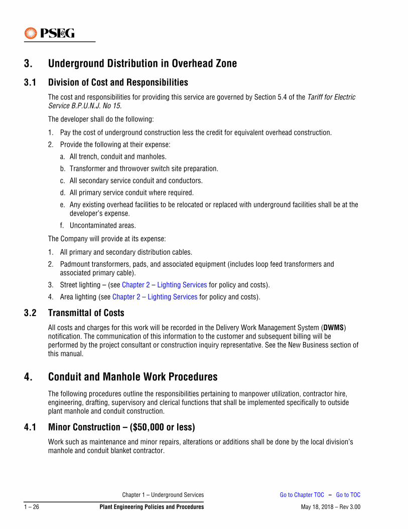
3. Underground Distribution in Overhead Zone
3.1 Division of Cost and Responsibilities The cost and responsibilities for providing this service are governed by Section 5.4 of the Tariff for Electric Service B.P.U.N.J. No 15.
The developer shall do the following:
1. Pay the cost of underground construction less the credit for equivalent overhead construction.
2. Provide the following at their expense:
a. All trench, conduit and manholes.
b. Transformer and throwover switch site preparation.
c. All secondary service conduit and conductors.
d. All primary service conduit where required.
e. Any existing overhead facilities to be relocated or replaced with underground facilities shall be at the developer’s expense.
f. Uncontaminated areas.
The Company will provide at its expense:
1. All primary and secondary distribution cables.
2. Padmount transformers, pads, and associated equipment (includes loop feed transformers and associated primary cable).
3. Street lighting – (see Chapter 2 – Lighting Services for policy and costs).
4. Area lighting (see Chapter 2 – Lighting Services for policy and costs).
3.2 Transmittal of CostsAll costs and charges for this work will be recorded in the Delivery Work Management System (DWMS) notification. The communication of this information to the customer and subsequent billing will be performed by the project consultant or construction inquiry representative. See the New Business section of this manual.
4. Conduit and Manhole Work ProceduresThe following procedures outline the responsibilities pertaining to manpower utilization, contractor hire, engineering, drafting, supervisory and clerical functions that shall be implemented specifically to outside plant manhole and conduit construction.
4.1 Minor Construction – ($50,000 or less)Work such as maintenance and minor repairs, alterations or additions shall be done by the local division’s manhole and conduit blanket contractor.
Chapter 1 – Underground Services
May 18, 2018 – Rev 3.001 – 26 Plant Engineering Policies and Procedures
Go to Chapter TOC – Go to TOC

4.2 ProceduresThe following procedures shall be followed when manhole, conduit and associated construction work is to be performed by the local division’s blanket authorization contractor.
1. Prepare construction drawings when necessary. Drawings to conform to published standards for outside plant construction.
2. Obtain all necessary materials and permits and proceed with the construction in compliance with all Company, Federal, State, County, and local municipal safety and construction standard requirements.
3. Create all necessary notifications and/or work orders.
4. Submit work packages to the contractor.
5. Order all required material.
6. Supervise the contractor’s work.
7. Obtain as-built data (see As-Built Section 9.) for revision of the underground system records including plan, detail, and Service and Cable Data Sheets (Form 95-0226).
8. Review contractor invoices for accuracy; the engineering technician first approves and forwards to the engineering supervisor for signature.
4.3 Major Construction – (Exceeding $50,000) Major repairs, alterations, additions and the installation of new lines shall be done primarily by a contractor through competitive bids.
5. Blanket Purchase OrdersThe Request for Blanket Purchase Orders shall be prepared on a 3 year basis by the local division Operations and Resources Manager in accordance with the procedures as outlined.
5.1 Request for BidsThe local division Operations and Resources Manager will prepare the necessary approved transmittal letters requesting bids along with the latest revised specifications and the compiled contract proposals, and forward same to the Procurement Department. The Procurement Department shall arrange a pre-bid meeting to be held with the prospective Contractors and the Division representatives such as the Project Coordinator, Underground Specialist and others to review the latest specifications and proposals.
5.2 Bid EvaluationUpon receipt of the bids by Procurement, an evaluation shall be made with concurrence from the Division and in accordance with the current purchase order approval process.
5.3 Requisition for Blanket Purchase OrderUpon receipt of approval to award the contract, the Operations and Resources Manager will be notified to proceed with the issuance of the Requisition for Purchase Order through the SAP System. Only one blanket purchase order per division will be issued.
The Requisition for Purchase Order shall include the name and address of the winning contractor, the effective dates of the order, and the estimated cost based on bid price for the duration of the contract.
Chapter 1 – Underground Services
May 18, 2018 – Rev 3.00 Plant Engineering Policies and Procedures 1 – 27
Go to Chapter TOC – Go to TOC

6. Contractor Job Procedures – Minor ConstructionThis work is limited to an estimated cost of $50,000. Contractor pricing and payment shall be done under the division’s blanket purchase order.
6.1 Division Engineering SupervisionNotification shall be given to the contractor. A division representative will visit the job site with the contractor to arrange a starting date. After reviewing the scope of work, the contractor shall supply the division sponsor with an estimated cost for work; such cost shall be entered in the work order by the division sponsor. All material to be supplied by the division will be placed in the work order. Prior to construction, the Work Order number(s), Purchase Order number, necessary drawings, permits and detailed specifications not covered under the purchase order shall be forwarded to the contractor. The division shall supply construction supervision, materials and contract administration. The Underground Construction Specialist will assist with these duties as needed.
7. Contractor Job Procedures – Major ConstructionAll work exceeding an estimated cost of $50,000 to be done by a contractor shall be contracted out by competitive bidding solicited through the Procurement Department under the sponsorship of the Operations and Resources Manager.
7.1 Blanket Authorizations Letter of Transmittal – Local divisions shall prepare an estimate and a letter addressed to the Manager – Procurement requesting the solicitation of competitive bids. The letter shall include: a description and location of the work, work breakdown structure (WBS) or order number(s) and the required completion date.
A sketch of the proposed work and all available utility information shall be attached and include the recommended manhole and conduit layout.
The Underground Construction Specialist will prepare and forward construction drawings, bid proposals and detailed specifications to the Procurement Department for solicitation of competitive bidding. Upon identification of successful bidder, the Operations and Resources Department will generate and approve a purchase requisition for the entire bid amount and forward to procurement for the creation of a purchase order.
Permits – The Engineering Technician assigned to the project shall acquire all necessary local, state and county permits and forward them to the underground construction specialist prior to construction. Special permits such as river crossing or private property acquisition will be requested by the engineering sponsor in accordance with the Notification and Permits section of this manual.
Construction Management – The Underground Construction Specialist will acquire all necessary materials, provide onsite supervision as required, and coordinate work schedules with the contractor.
Changes to Purchase Order – The Underground Construction Specialist will identify where project scope changes and/or field conditions require changes to the purchase order. When a Field Change Memo (FCM) is the result of a major scope change (major scope change being defined as one in which an additional 10% of materials or contractor cost is required), the approval of the Project Manager, if applicable, or the Operations and Resources Manager, is required prior to the start of the additional work.
Chapter 1 – Underground Services
May 18, 2018 – Rev 3.001 – 28 Plant Engineering Policies and Procedures
Go to Chapter TOC – Go to TOC
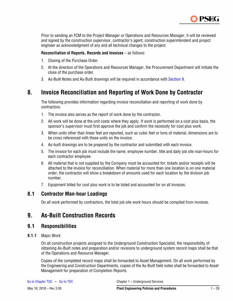
Prior to sending an FCM to the Project Manager or Operations and Resources Manager, it will be reviewed and signed by the construction supervisor, contractor’s agent, construction superintendent and project engineer as acknowledgment of any and all technical changes to the project.
Reconciliation of Reports, Records and Invoices – as follows:
1. Closing of the Purchase Order.
2. At the direction of the Operations and Resources Manager, the Procurement Department will initiate the close of the purchase order.
3. As-Built Notes and As-Built drawings will be required in accordance with Section 9.
8. Invoice Reconciliation and Reporting of Work Done by ContractorThe following provides information regarding invoice reconciliation and reporting of work done by contractors.
1. The invoice also serves as the report of work done by the contractor.
2. All work will be done at the unit costs where they apply. If work is performed on a cost plus basis, the sponsor’s supervisor must first approve the job and confirm the necessity for cost plus work.
3. When units other than linear feet are reported, such as cubic feet or tons of material, dimensions are to be cross referenced with these units on the invoice.
4. As-built drawings are to be prepared by the contractor and submitted with each invoice.
5. The invoice for each job must include the name, employee number, title and daily job site man-hours for each contractor employee.
6. All material that is not supplied by the Company must be accounted for; tickets and/or receipts will be attached to the invoice for reconciliation. When material for more than one location is on one material order, the contractor will show a breakdown of amounts used for each location by the division job number.
7. Equipment billed for cost plus work is to be listed and accounted for on all invoices.
8.1 Contractor Man-hour LoadingsOn all work performed by contractors, the total job site work hours should be compiled from invoices.
9. As-Built Construction Records
9.1 Responsibilities
9.1.1 Major Work
On all construction projects assigned to the Underground Construction Specialist, the responsibility of obtaining As-Built notes and preparation and/or revisions to underground system record maps shall be that of the Operations and Resource Manager.
Copies of the completed record maps shall be forwarded to Asset Management. On all work performed by the Engineering and Construction Departments, copies of the As-Built field notes shall be forwarded to Asset Management for preparation of Completion Reports.
Chapter 1 – Underground Services
May 18, 2018 – Rev 3.00 Plant Engineering Policies and Procedures 1 – 29
Go to Chapter TOC – Go to TOC

9.1.2 Minor Work
On minor work to be constructed by a contractor under a blanket purchase order and supervised by the Division, it shall be the engineering sponsor’s responsibility to obtain As-Built data, revise underground records, and prepare the appropriate Data Sheets.
9.2 Procedures – Underground Construction SpecialistAs-Built notes shall be obtained in accordance with the following procedures on all projects involving the installation or removal of underground facilities. These notes shall also be used for verification of contractor's invoices. The following procedures shall be followed.
9.2.1 Base Line Control
Establish base line control using existing curbing or, if no existing physical control line is available, by use of a transit to establish lines. This line should be tied in to some permanent structure and be able to be re- established.
9.2.2 Manhole Location
Locate manholes by station and offset to center line and each corner.
9.2.3 Conduit Location
Covers and offset shall be taken on conduits at 50 ft plus or minus intervals or at changes of direction, grade or configuration change.
9.2.4 Existing Utilities
Existing utilities shall be located by station, size and cover, and their proximity to the Public Service facility being installed.
9.2.5 Manhole Details
Manhole details to include: inside dimensions, manhole depth, head room, duct cable occupancy, and inside dimensions of old manhole if it is to be rebuilt.
9.2.6 Private Property
In areas of private property, rights-of-way, new street and areas where no permanent pavement exists or grade changes are proposed, elevations shall be taken at grade changes on the top of duct banks and existing grade, to determine that mount of cover.
9.2.7 Field Notes
Field notes may be detailed on a copy of the construction print. These notes shall be recorded while the work is in progress. After completion of the project, all necessary revisions to the Underground System Records shall be prepared and forwarded to the Manager – Outside Plant Engineering and Design. As-Built notes shall include: starting date, completion date, constructed by, and SAP work order number. These notes shall be included in the job folder filed under the SAP work order number and retained for future reference.
Chapter 1 – Underground Services
May 18, 2018 – Rev 3.001 – 30 Plant Engineering Policies and Procedures
Go to Chapter TOC – Go to TOC
May 18, 2018 – Rev 3.00Go to Chapter TOC
Chapter 2 – Lighting Services – Table of Contents1. General Specification for Lighting Services . . . . . . . . . . . . . . . . . . . . . . . . . . . . . . . . . . . . . . . . . . 2-1
1.1 General. . . . . . . . . . . . . . . . . . . . . . . . . . . . . . . . . . . . . . . . . . . . . . . . . . . . . . . . . . . . . . . . . . . . . . . . .2-1
1.2 Definitions . . . . . . . . . . . . . . . . . . . . . . . . . . . . . . . . . . . . . . . . . . . . . . . . . . . . . . . . . . . . . . . . . . . . . .2-1
1.3 Accessibility . . . . . . . . . . . . . . . . . . . . . . . . . . . . . . . . . . . . . . . . . . . . . . . . . . . . . . . . . . . . . . . . . . . . .2-1
1.4 Billing . . . . . . . . . . . . . . . . . . . . . . . . . . . . . . . . . . . . . . . . . . . . . . . . . . . . . . . . . . . . . . . . . . . . . . . . . .2-1
1.5 Brackets . . . . . . . . . . . . . . . . . . . . . . . . . . . . . . . . . . . . . . . . . . . . . . . . . . . . . . . . . . . . . . . . . . . . . . . .2-2
1.6 Control of Lights . . . . . . . . . . . . . . . . . . . . . . . . . . . . . . . . . . . . . . . . . . . . . . . . . . . . . . . . . . . . . . . . .2-2
1.7 Timer . . . . . . . . . . . . . . . . . . . . . . . . . . . . . . . . . . . . . . . . . . . . . . . . . . . . . . . . . . . . . . . . . . . . . . . . . .2-2
1.8 Visors/Shields . . . . . . . . . . . . . . . . . . . . . . . . . . . . . . . . . . . . . . . . . . . . . . . . . . . . . . . . . . . . . . . . . . .2-2
1.9 Vandal Resistant Shields . . . . . . . . . . . . . . . . . . . . . . . . . . . . . . . . . . . . . . . . . . . . . . . . . . . . . . . . . . .2-2
2. Street Lighting . . . . . . . . . . . . . . . . . . . . . . . . . . . . . . . . . . . . . . . . . . . . . . . . . . . . . . . . . . . . . . . 2-2
2.1 PSE&G Owned Facilities. . . . . . . . . . . . . . . . . . . . . . . . . . . . . . . . . . . . . . . . . . . . . . . . . . . . . . . . . . . .2-2
2.2 Body Politic . . . . . . . . . . . . . . . . . . . . . . . . . . . . . . . . . . . . . . . . . . . . . . . . . . . . . . . . . . . . . . . . . . . . .2-2
2.3 BUD Regulation (Street Lighting) . . . . . . . . . . . . . . . . . . . . . . . . . . . . . . . . . . . . . . . . . . . . . . . . . . . . .2-3
2.4 Publicly-Owned Facilities (POF) . . . . . . . . . . . . . . . . . . . . . . . . . . . . . . . . . . . . . . . . . . . . . . . . . . . . . .2-3
2.5 Changes in Size, Type, or Location of Street Lights . . . . . . . . . . . . . . . . . . . . . . . . . . . . . . . . . . . . . . .2-3
2.6 Police Recall, Fire Alarm Service or Unmetered Service . . . . . . . . . . . . . . . . . . . . . . . . . . . . . . . . . . .2-4
3. Area Lighting . . . . . . . . . . . . . . . . . . . . . . . . . . . . . . . . . . . . . . . . . . . . . . . . . . . . . . . . . . . . . . . . . 2-4
3.1 Body Politic . . . . . . . . . . . . . . . . . . . . . . . . . . . . . . . . . . . . . . . . . . . . . . . . . . . . . . . . . . . . . . . . . . . . .2-4
3.2 Private Customer . . . . . . . . . . . . . . . . . . . . . . . . . . . . . . . . . . . . . . . . . . . . . . . . . . . . . . . . . . . . . . . . .2-4
3.3 BUD Regulation (Area Lighting) . . . . . . . . . . . . . . . . . . . . . . . . . . . . . . . . . . . . . . . . . . . . . . . . . . . . . .2-4
3.4 Request for Sale of PSE&G Facilities . . . . . . . . . . . . . . . . . . . . . . . . . . . . . . . . . . . . . . . . . . . . . . . . . .2-5
3.5 Floodlight Aiming . . . . . . . . . . . . . . . . . . . . . . . . . . . . . . . . . . . . . . . . . . . . . . . . . . . . . . . . . . . . . . . . .2-5
4. Calculation of costs and Credits . . . . . . . . . . . . . . . . . . . . . . . . . . . . . . . . . . . . . . . . . . . . . . . . . . 2-5
4.1 General. . . . . . . . . . . . . . . . . . . . . . . . . . . . . . . . . . . . . . . . . . . . . . . . . . . . . . . . . . . . . . . . . . . . . . . . .2-5
4.2 Cost Estimating Tools . . . . . . . . . . . . . . . . . . . . . . . . . . . . . . . . . . . . . . . . . . . . . . . . . . . . . . . . . . . . .2-6
4.3 Private Street and Area Lighting (PSAL) . . . . . . . . . . . . . . . . . . . . . . . . . . . . . . . . . . . . . . . . . . . . . . .2-6
4.4 Body Politic Lighting (BPL) . . . . . . . . . . . . . . . . . . . . . . . . . . . . . . . . . . . . . . . . . . . . . . . . . . . . . . . . .2-7
4.5 BUD Lighting . . . . . . . . . . . . . . . . . . . . . . . . . . . . . . . . . . . . . . . . . . . . . . . . . . . . . . . . . . . . . . . . . . . .2-9
Chapter 2 – Lighting Services – Table of Contents
May 18, 2018 – Rev 3.00 Plant Engineering Policies and Procedures 2 – TOC 1
Go to TOC

This Page Intentionally Blank
Chapter 2 – Lighting Services – Table of Contents
May 18, 2018 – Rev 3.00 Plant Engineering Policies and Procedures 2 – TOC 2
Go to TOC
May 18, 2018 – Rev 3.00
Chapter 2 – Lighting Services
1. General Specification for Lighting Services
1.1 GeneralOutdoor Lighting service is made available to private and body politic customers as outlined in the Tariff for Electric Service B.P.U.N.J. No. 15. There are three separate lighting tariffs: Body Politic Lighting (BPL), Body Politic Lighting – Publicly Owned Facilities (BPL-POF) and Private Street and Area Lighting (PSAL). Under these tariffs, PSE&G provides street lighting and area lighting to body politic and private customers. Outdoor lighting service includes the procurement, installation, maintenance, replacement for knockdowns, and repairs, with the exception of lighting provided under the Rate Tariff, Publicly Owned Facilities.
1.2 DefinitionsStreet Lighting – Lighting requested by a Body Politic or builder/developer installed for the purpose of lighting a dedicated, or to-be dedicated, street or roadway.
Body Politic – Shall be interpreted to include: The State of New Jersey, the federal government, municipalities, counties, and school districts as well as state, county, municipal or regional authorities and districts founded by a government unit for public purposes where the whole interest belongs to the government. “Whole interest belongs to the government” means that no stock in a Body Politic is held by private investors.
Area Lighting – Lighting installed for the purpose of safety and security of areas other than dedicated, or to-be dedicated, roadways. This type of lighting is available for any customer, including a Body Politic, and will be provided only if practicable and safe from the standpoint of PSE&G. This service will not be supplied within buildings, or to light fixtures attached to the outside of buildings or where introduction of such lighting would create a hazard.
1.3 AccessibilityAll lighting will normally be supplied only to those locations that have adequate access for use of PSE&G’s aerial lift equipment (typical access would be 10 ft wide road bed). If adequate access is not available, Sales personnel shall consult with Electric Distribution personnel before any agreement is signed by the customer.
1.4 BillingBilling is provided under the three separate lighting tariffs, and is specific to the application and type of product installed. Products installed by PSE&G for body politic customers are billed under the BPL Rate Schedule found on Sheet Nos. 180 through 191 of the Tariff for Electric Service B.P.U.N.J. No. 15. Products that are purchased and installed by a body politic customer, but maintained by PSE&G are billed under the BPL-POF Rate Schedule found on Sheet Nos. 195 through 200 of the Tariff for Electric Service B.P.U.N.J. No. 15. Products installed by PSE&G for private customers are billed under the PSAL Rate Schedule found on Sheet Nos. 203 to 214 of the Tariff for Electric Service B.P.U.N.J. No. 15. Within these tariff sheets, billing and billing computations are shown for standard and specialty lighting products.
Chapter 2 – Lighting Services
May 18, 2018 – Rev 3.00 Plant Engineering Policies and Procedures 2 – 1
Go to Chapter TOC – Go to TOC
1.5 BracketsThe standard PSE&G street lighting bracket is 8 ft in length. Other bracket sizes are available for use, depending on the application and the project-specific requirements.
1.6 Control of LightsAll lights will be controlled by individual photo-electric sensors.
1.7 TimerTimers and timed photo controls are available for use in specific applications where Sales and Electric Distribution agree on their use. The customer shall still be billed for the standard amount of burning hours in accordance with the current tariff.
1.8 Visors/ShieldsVisors and shields are used to change the light pattern or direction and are available for installation. Proper selection of light fixtures to avoid glare complaints, and the decision to use visors or shields, is the responsibility of the Sales representative prior to the agreement being signed and the installation completed. Visors and shields are “one time” billable items, charges can be found in the Outdoor Lighting Database.
1.9 Vandal Resistant ShieldsProtective devices (i.e. Lexan shields) are available for use in areas where fixture damage from breakage is highly likely. Available shields can be found in the Outdoor Lighting Database. Shields are “one time” billable items.
2. Street Lighting
2.1 PSE&G Owned FacilitiesWhere PSE&G procures, finances, installs, and maintains street lighting assets for the purpose of providing adequate illumination of roadways. Street lighting service applies where a Body Politic or builder/developer has submitted a letter of request or contacted PSE&G through some other means with a request to install lighting facilities on dedicated or to be dedicated streets or roadways.
2.2 Body PoliticWhere underground street lighting is requested by a Body Politic in a designated Underground Zone, the standard 30 ft aluminum street light pole will be installed at 150 ft intervals by PSE&G at no cost. If non-standard poles and fixtures are requested, a credit will be given based upon the estimated cost of a standard pole installed at 150 ft intervals. Where underground construction is requested by a Body Politic, outside of the “underground zone” designated by PSE&G, the customer shall pay the cost of all such underground construction with no credits applied, and the customer pays the full cost of the non-standard products. Pricing for these facilities is provided in Rate Schedule BPL.
Chapter 2 – Lighting Services
May 18, 2018 – Rev 3.002 – 2 Plant Engineering Policies and Procedures
Go to Chapter TOC – Go to TOC
2.3 BUD Regulation (Street Lighting)All subdivisions to be supplied from underground electric facilities in an overhead zone shall have incorporated in their design the requirements for street lighting in accordance with the requirements of the municipality (See Section 4.4.1 for more information).
The developer charges for residential underground service include a basic cost for a street lighting system with standard lighting poles (30 ft center bored pine) spaced every 200 ft on one side of the street. Additional charges for variations from this spacing and for non-standard street lighting poles and fixtures to be used are included in the “Calculation of Cost and Credits” in Section 4.
2.3.1 Terms of Service
For all standard luminaires and standard lighting poles: 1 year and thereafter until terminated by 5 days notice.
For specialty luminaires and specialty lighting poles and miscellaneous devices: 5 years and thereafter until terminated by 5 days notice. Customers are required to make payment for all such lighting facilities removed prior to 5 years from the installation date equal to the cost of removal less salvage plus 75% of the original installed costs net of any customer contributions.
2.4 Publicly-Owned Facilities (POF)Where a body politic customer chooses to install its own lighting system and requests PSE&G to maintain the lighting fixtures. Where PSE&G has reviewed and approved the fixture to be installed, these are assets defined as Publicly-Owned Facilities. Where the customer is a Body Politic who has entered into a maintenance agreement with PSE&G, and where PSE&G has paid no part of the distribution facilities, street light fixtures and associated equipment beyond the point of connection to PSE&G lines. The point of connection is to be designated by PSE&G.
The complete lighting installation shall be acceptable to PSE&G for operation and maintenance. PSE&G will clean refractors or globes, replace lamps and photocells, locate cable faults, and make minor cable and socket repairs. Upon request, replacement of defective cable, ballasts, painting or otherwise maintaining posts or street light fixtures or any other associated equipment shall be done only at the expense of the customer.
2.4.1 Term of Service
One year for all new lamps and thereafter until terminated by 5 days notice.
2.5 Changes in Size, Type, or Location of Street LightsThe customer may be required to make a payment toward the cost of installation, removal, relocation and/or change in lamp size, or for conversion from one light source to another when the average age of the luminaires to be converted is less than 20 years. Payment shall be based upon the unamortized installation costs, plus removal costs, less any salvage value of the device.
Customers will be required to make a payment for the actual cost of the requested work for any temporary replacement. Also for relocation of an existing light to a new location and the subsequent movement of a light back to the old location.
A request to install a new light at the same location within 12 months of the removal of an existing light will be considered a replacement of the existing light.
Chapter 2 – Lighting Services
May 18, 2018 – Rev 3.00 Plant Engineering Policies and Procedures 2 – 3
Go to Chapter TOC – Go to TOC
A charge may be assessed for a lamp ordered reconnected or reinstalled within 12 months of the request to disconnect.
PSE&G reserves the right to limit the number of lamps it will upgrade in any given year to no more than 5% of the total number of units in service for a particular customer.
2.6 Police Recall, Fire Alarm Service or Unmetered Service Service to indicating lamps used for marking locations of fire and police boxes, sirens, bells, horns, fixed warning or obstruction lights, such as at airports, or similar purposes, will be furnished to a customer and billed under the appropriate Rate Schedule GLP. For removal of facilities under the BPL Tariff, customers will be charged for all specialty lighting removed prior to 5 years from the date of installation, an amount equal to the cost of removal, less salvage value, plus 75% of the original installed cost, net any customer contributions.
3. Area LightingArea lighting service applies where a customer requests lighting services for the purpose of other than street lighting. Where PSE&G procures, finances, installs, and maintains street lighting assets for the purpose of providing adequate illumination of roadways.
3.1 Body PoliticFor a Body Politic, where area lighting using overhead construction is requested, PSE&G shall furnish and install the light fixture and pole, where necessary, make necessary lamp replacements, and otherwise maintain the installation. Pricing for this service is provided in the Rate Schedule BPL. Where underground construction is desired by a body politic for area lighting, whether or not it is located in an “Underground Zone”, the customer shall pay the cost of such underground construction, and no credits are applied.
3.2 Private CustomerWhere the customer requests, and PSE&G elects to provide, this type of service, the customer pays the cost provided in the Rate Schedule PSAL for the installation of poles, brackets, and fixtures. PSE&G will furnish and install the light fixture and poles, where necessary, make necessary lamp replacements, and otherwise maintain the installation. The cost of any line extension on public highway required to provide the lighting service is an additional charge. No charge is made for utilizing other existing utility poles.
Where underground construction is requested in overhead zones, the customer pays the cost of all facilities. The cost of non-salvageable items, such as trenching, backfill and conduit shall be paid for upfront in a lump sum. Where underground construction is requested in designated underground zones, customer pays the cost of all facilities. When a non-standard installation has been designated and approved by PSE&G, a credit equal to 100 ft of conduit and streetlight wire is applied to the costs of the facilities.
3.3 BUD Regulation (Area Lighting)All lighting which is not designated as street lighting in a BUD subdivision shall be treated as area lighting.
3.3.1 Terms of service
For all standard luminaires and standard lighting poles: 1 year and thereafter until terminated by 5 days notice, unless underground construction is utilized, where the term shall be 5 years and thereafter until terminated by 5 days notice.
Chapter 2 – Lighting Services
May 18, 2018 – Rev 3.002 – 4 Plant Engineering Policies and Procedures
Go to Chapter TOC – Go to TOC
For specialty luminaires and specialty lighting poles and miscellaneous devices: 10 years and thereafter until terminated by 5 days notice. Customers are required to make payment for all such lighting facilities removed prior to 5 years from the installation date equal to the cost of removal less salvage plus 75% of the original installed costs; for facilities removed from the fifth to tenth year after installation such payment shall equal the cost of removal less salvage plus 50% of the original installed costs.
3.4 Request for Sale of PSE&G FacilitiesIt is Company policy not to sell existing outdoor lighting facilities to customers.
3.5 Floodlight AimingAs part of the job package that is compiled as the result of the sale of floodlighting equipment, a detailed sketch is created and provided to Electric Distribution by the Sales representative for use in proper aiming when the floodlights are installed.
4. Calculation of Costs and Credits
4.1 GeneralEquivalent overhead costs shall not be subtracted from the total costs to provide underground “streetscape” lighting for municipalities.
Municipal customers may be required to make a payment toward the costs of installation, removal, relocation, and/or changes in lamp size for conversion from one light source to another when the age of the luminaires to be converted is less than 20 years (See Special Provision c-1 of Sheet No.190 of the Tariff for Electric Service B.P.U.N.J. No. 15).
Where the customer has obtained permission in advance from Public Service to install trench and/or conduit for underground street lighting projects in lieu of such work being performed by Public Service, the cost Public Service would have incurred for such work shall not be considered in the derivation of any customer contribution or monthly charge associated with such work.
In no case shall the application of any credit or reduction in cost result in any form of payment or amount owed to the customer. Credit must be applied only against the cost of the work that would have been incurred by Public Service.
All measurements shall be determined along each side of the street that is to be illuminated, as measured along the curb line, rounded up to the next whole number of credit equivalents. Each side of the street shall be considered separately. A lighted street side shall be considered as portions of either side of the street having street lighting poles, where such placement is less than 300 ft apart (as measured along the curb line), or where Public Service underground electric secondary voltage distribution facilities are, or would have been, installed absent the request for street lighting. A street side with street lighting poles placed 300 ft or more apart, and where underground secondary voltage distribution would not otherwise be placed, absent the request for street lighting, is considered non-illuminated street side and, as such, no pole credits shall be provided.
Chapter 2 – Lighting Services
May 18, 2018 – Rev 3.00 Plant Engineering Policies and Procedures 2 – 5
Go to Chapter TOC – Go to TOC
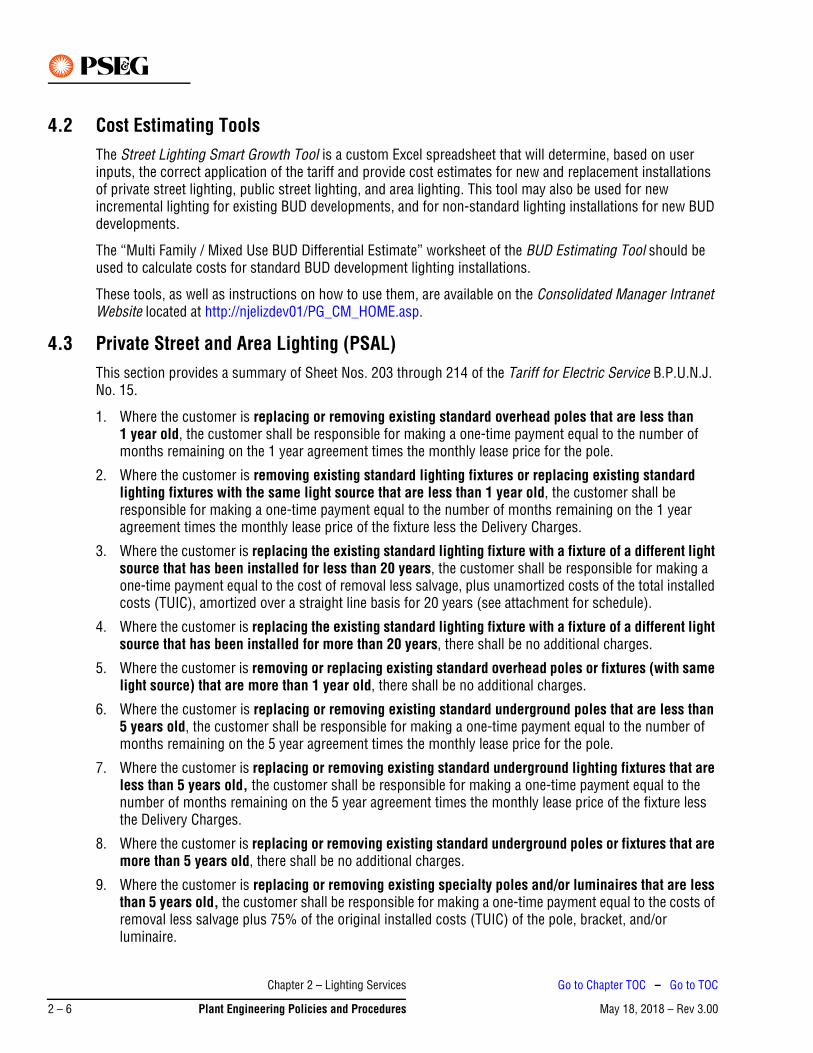
4.2 Cost Estimating ToolsThe Street Lighting Smart Growth Tool is a custom Excel spreadsheet that will determine, based on user inputs, the correct application of the tariff and provide cost estimates for new and replacement installations of private street lighting, public street lighting, and area lighting. This tool may also be used for new incremental lighting for existing BUD developments, and for non-standard lighting installations for new BUD developments.
The “Multi Family / Mixed Use BUD Differential Estimate” worksheet of the BUD Estimating Tool should be used to calculate costs for standard BUD development lighting installations.
These tools, as well as instructions on how to use them, are available on the Consolidated Manager Intranet Website located at http://njelizdev01/PG_CM_HOME.asp.
4.3 Private Street and Area Lighting (PSAL)This section provides a summary of Sheet Nos. 203 through 214 of the Tariff for Electric Service B.P.U.N.J. No. 15.
1. Where the customer is replacing or removing existing standard overhead poles that are less than 1 year old, the customer shall be responsible for making a one-time payment equal to the number of months remaining on the 1 year agreement times the monthly lease price for the pole.
2. Where the customer is removing existing standard lighting fixtures or replacing existing standard lighting fixtures with the same light source that are less than 1 year old, the customer shall be responsible for making a one-time payment equal to the number of months remaining on the 1 year agreement times the monthly lease price of the fixture less the Delivery Charges.
3. Where the customer is replacing the existing standard lighting fixture with a fixture of a different light source that has been installed for less than 20 years, the customer shall be responsible for making a one-time payment equal to the cost of removal less salvage, plus unamortized costs of the total installed costs (TUIC), amortized over a straight line basis for 20 years (see attachment for schedule).
4. Where the customer is replacing the existing standard lighting fixture with a fixture of a different light source that has been installed for more than 20 years, there shall be no additional charges.
5. Where the customer is removing or replacing existing standard overhead poles or fixtures (with same light source) that are more than 1 year old, there shall be no additional charges.
6. Where the customer is replacing or removing existing standard underground poles that are less than 5 years old, the customer shall be responsible for making a one-time payment equal to the number of months remaining on the 5 year agreement times the monthly lease price for the pole.
7. Where the customer is replacing or removing existing standard underground lighting fixtures that are less than 5 years old, the customer shall be responsible for making a one-time payment equal to the number of months remaining on the 5 year agreement times the monthly lease price of the fixture less the Delivery Charges.
8. Where the customer is replacing or removing existing standard underground poles or fixtures that are more than 5 years old, there shall be no additional charges.
9. Where the customer is replacing or removing existing specialty poles and/or luminaires that are less than 5 years old, the customer shall be responsible for making a one-time payment equal to the costs of removal less salvage plus 75% of the original installed costs (TUIC) of the pole, bracket, and/or luminaire.
Chapter 2 – Lighting Services
May 18, 2018 – Rev 3.002 – 6 Plant Engineering Policies and Procedures
Go to Chapter TOC – Go to TOC
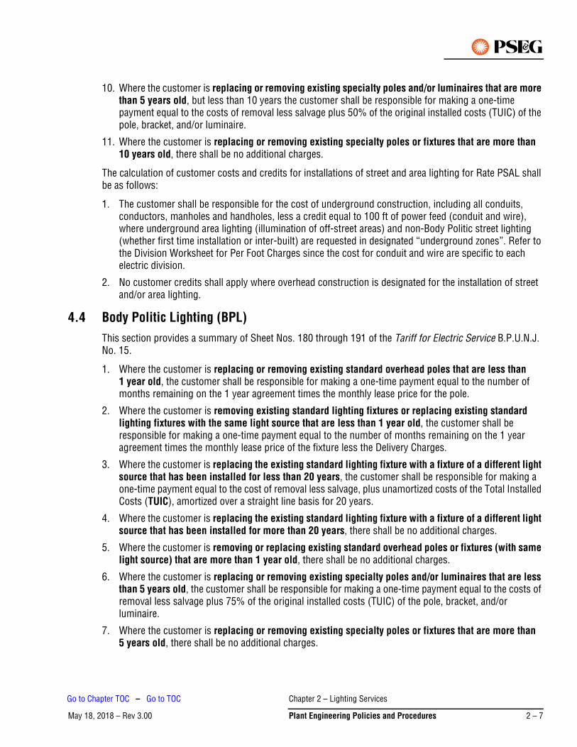
10. Where the customer is replacing or removing existing specialty poles and/or luminaires that are more than 5 years old, but less than 10 years the customer shall be responsible for making a one-time payment equal to the costs of removal less salvage plus 50% of the original installed costs (TUIC) of the pole, bracket, and/or luminaire.
11. Where the customer is replacing or removing existing specialty poles or fixtures that are more than 10 years old, there shall be no additional charges.
The calculation of customer costs and credits for installations of street and area lighting for Rate PSAL shall be as follows:
1. The customer shall be responsible for the cost of underground construction, including all conduits, conductors, manholes and handholes, less a credit equal to 100 ft of power feed (conduit and wire), where underground area lighting (illumination of off-street areas) and non-Body Politic street lighting (whether first time installation or inter-built) are requested in designated “underground zones”. Refer to the Division Worksheet for Per Foot Charges since the cost for conduit and wire are specific to each electric division.
2. No customer credits shall apply where overhead construction is designated for the installation of street and/or area lighting.
4.4 Body Politic Lighting (BPL)This section provides a summary of Sheet Nos. 180 through 191 of the Tariff for Electric Service B.P.U.N.J. No. 15.
1. Where the customer is replacing or removing existing standard overhead poles that are less than 1 year old, the customer shall be responsible for making a one-time payment equal to the number of months remaining on the 1 year agreement times the monthly lease price for the pole.
2. Where the customer is removing existing standard lighting fixtures or replacing existing standard lighting fixtures with the same light source that are less than 1 year old, the customer shall be responsible for making a one-time payment equal to the number of months remaining on the 1 year agreement times the monthly lease price of the fixture less the Delivery Charges.
3. Where the customer is replacing the existing standard lighting fixture with a fixture of a different light source that has been installed for less than 20 years, the customer shall be responsible for making a one-time payment equal to the cost of removal less salvage, plus unamortized costs of the Total Installed Costs (TUIC), amortized over a straight line basis for 20 years.
4. Where the customer is replacing the existing standard lighting fixture with a fixture of a different light source that has been installed for more than 20 years, there shall be no additional charges.
5. Where the customer is removing or replacing existing standard overhead poles or fixtures (with same light source) that are more than 1 year old, there shall be no additional charges.
6. Where the customer is replacing or removing existing specialty poles and/or luminaires that are less than 5 years old, the customer shall be responsible for making a one-time payment equal to the costs of removal less salvage plus 75% of the original installed costs (TUIC) of the pole, bracket, and/or luminaire.
7. Where the customer is replacing or removing existing specialty poles or fixtures that are more than 5 years old, there shall be no additional charges.
Chapter 2 – Lighting Services
May 18, 2018 – Rev 3.00 Plant Engineering Policies and Procedures 2 – 7
Go to Chapter TOC – Go to TOC
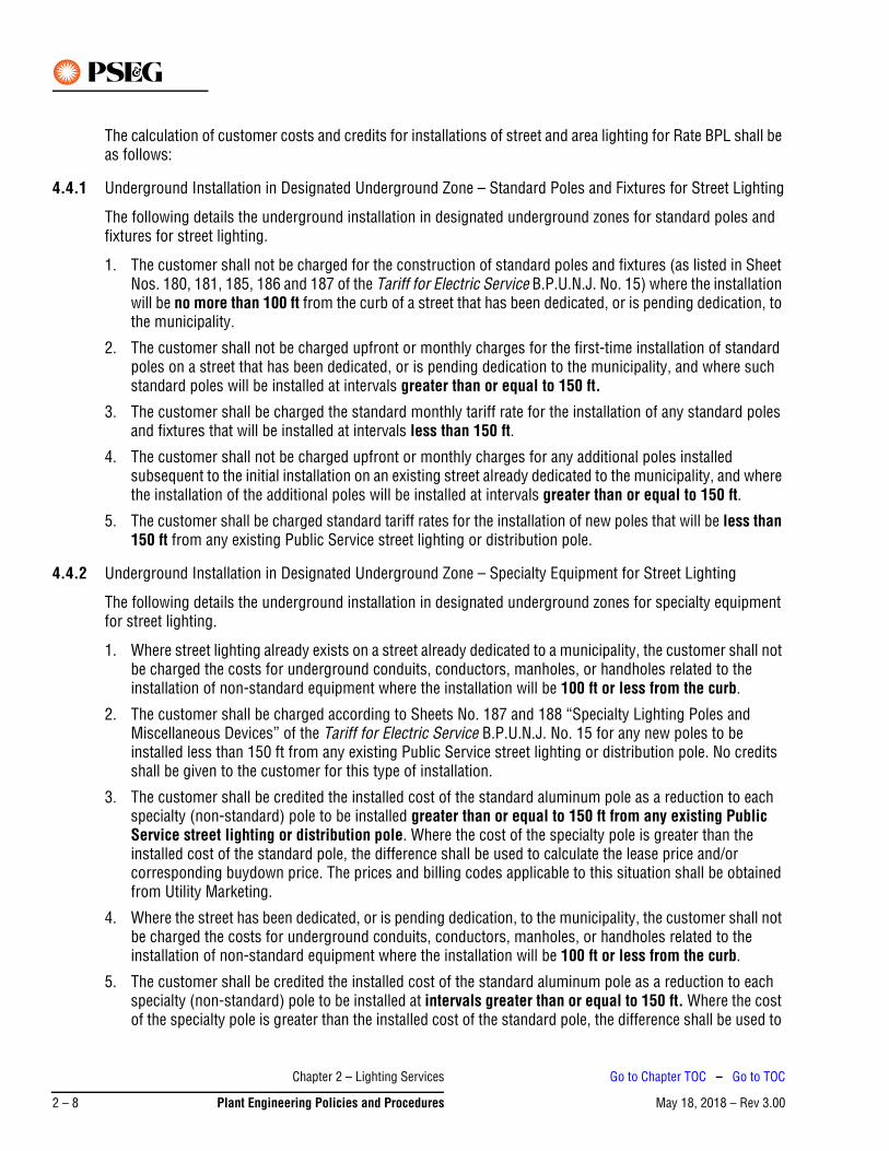
The calculation of customer costs and credits for installations of street and area lighting for Rate BPL shall be as follows:
4.4.1 Underground Installation in Designated Underground Zone – Standard Poles and Fixtures for Street Lighting
The following details the underground installation in designated underground zones for standard poles and fixtures for street lighting.
1. The customer shall not be charged for the construction of standard poles and fixtures (as listed in Sheet Nos. 180, 181, 185, 186 and 187 of the Tariff for Electric Service B.P.U.N.J. No. 15) where the installation will be no more than 100 ft from the curb of a street that has been dedicated, or is pending dedication, to the municipality.
2. The customer shall not be charged upfront or monthly charges for the first-time installation of standard poles on a street that has been dedicated, or is pending dedication to the municipality, and where such standard poles will be installed at intervals greater than or equal to 150 ft.
3. The customer shall be charged the standard monthly tariff rate for the installation of any standard poles and fixtures that will be installed at intervals less than 150 ft.
4. The customer shall not be charged upfront or monthly charges for any additional poles installed subsequent to the initial installation on an existing street already dedicated to the municipality, and where the installation of the additional poles will be installed at intervals greater than or equal to 150 ft.
5. The customer shall be charged standard tariff rates for the installation of new poles that will be less than 150 ft from any existing Public Service street lighting or distribution pole.
4.4.2 Underground Installation in Designated Underground Zone – Specialty Equipment for Street Lighting
The following details the underground installation in designated underground zones for specialty equipment for street lighting.
1. Where street lighting already exists on a street already dedicated to a municipality, the customer shall not be charged the costs for underground conduits, conductors, manholes, or handholes related to the installation of non-standard equipment where the installation will be 100 ft or less from the curb.
2. The customer shall be charged according to Sheets No. 187 and 188 “Specialty Lighting Poles and Miscellaneous Devices” of the Tariff for Electric Service B.P.U.N.J. No. 15 for any new poles to be installed less than 150 ft from any existing Public Service street lighting or distribution pole. No credits shall be given to the customer for this type of installation.
3. The customer shall be credited the installed cost of the standard aluminum pole as a reduction to each specialty (non-standard) pole to be installed greater than or equal to 150 ft from any existing Public Service street lighting or distribution pole. Where the cost of the specialty pole is greater than the installed cost of the standard pole, the difference shall be used to calculate the lease price and/or corresponding buydown price. The prices and billing codes applicable to this situation shall be obtained from Utility Marketing.
4. Where the street has been dedicated, or is pending dedication, to the municipality, the customer shall not be charged the costs for underground conduits, conductors, manholes, or handholes related to the installation of non-standard equipment where the installation will be 100 ft or less from the curb.
5. The customer shall be credited the installed cost of the standard aluminum pole as a reduction to each specialty (non-standard) pole to be installed at intervals greater than or equal to 150 ft. Where the cost of the specialty pole is greater than the installed cost of the standard pole, the difference shall be used to
Chapter 2 – Lighting Services
May 18, 2018 – Rev 3.002 – 8 Plant Engineering Policies and Procedures
Go to Chapter TOC – Go to TOC
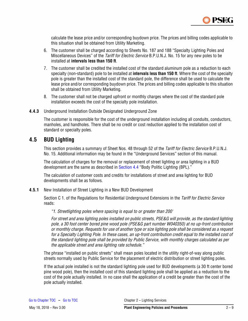
calculate the lease price and/or corresponding buydown price. The prices and billing codes applicable to this situation shall be obtained from Utility Marketing.
6. The customer shall be charged according to Sheets No. 187 and 188 “Specialty Lighting Poles and Miscellaneous Devices” of the Tariff for Electric Service B.P.U.N.J. No. 15 for any new poles to be installed at intervals less than 150 ft.
7. The customer shall be credited the installed cost of the standard aluminum pole as a reduction to each specialty (non-standard) pole to be installed at intervals less than 150 ft. Where the cost of the specialty pole is greater than the installed cost of the standard pole, the difference shall be used to calculate the lease price and/or corresponding buydown price. The prices and billing codes applicable to this situation shall be obtained from Utility Marketing.
8. The customer shall not be charged upfront or monthly charges where the cost of the standard pole installation exceeds the cost of the specialty pole installation.
4.4.3 Underground Installation Outside Designated Underground Zone
The customer is responsible for the cost of the underground installation including all conduits, conductors, manholes, and handholes. There shall be no credit or cost reduction applied to the installation cost of standard or specialty poles.
4.5 BUD LightingThis section provides a summary of Sheet Nos. 48 through 52 of the Tariff for Electric Service B.P.U.N.J. No. 15. Additional information may be found in the “Underground Services” section of this manual.
The calculation of charges for the removal or replacement of street lighting or area lighting in a BUD development are the same as described in Section 4.4 “Body Politic Lighting (BPL).”
The calculation of customer costs and credits for installations of street and area lighting for BUD developments shall be as follows.
4.5.1 New Installation of Street Lighting in a New BUD Development
Section C 1. of the Regulations for Residential Underground Extensions in the Tariff for Electric Service reads:
“1. Streetlighting poles where spacing is equal to or greater than 200'
For street and area lighting poles installed on public streets, PSE&G will provide, as the standard lighting pole, a 30 foot center bored pine wood pole (PSE&G part number W040350) at no up-front contribution or monthly charge. Requests for use of another type or size lighting pole shall be considered as a request for a Specialty Lighting Pole. In these cases, an up-front contribution credit equal to the installed cost of the standard lighting pole shall be provided by Public Service, with monthly charges calculated as per the applicable street and area lighting rate schedule.”
The phrase “installed on public streets” shall mean poles located in the utility right-of-way along public streets normally used by Public Service for the placement of electric distribution or street lighting poles.
If the actual pole installed is not the standard lighting pole used for BUD developments (a 30 ft center bored pine wood pole), then the installed cost of this standard lighting pole shall be applied as a reduction to the cost of the pole actually installed. In no case shall the application of a credit be greater than the cost of the pole actually installed.
Chapter 2 – Lighting Services
May 18, 2018 – Rev 3.00 Plant Engineering Policies and Procedures 2 – 9
Go to Chapter TOC – Go to TOC
Upon the initial request for street lighting poles along a street in a BUD development, one such pole credit equivalent shall be provided for each 200 ft of street upon which the street lighting poles are to be placed, not to exceed the number of poles to be installed. Subsequent to the initial request, one such pole credit equivalent shall be applied for customer requests for additional lighting poles that are to be 200 ft or more from any existing Public Service street lighting or distribution pole.
These measurements shall be determined for each street that is to be illuminated, as measured along the centerline of the street, rounded up to the next whole number of credit equivalents.
4.5.2 New Installation of Street Lighting in an Existing BUD Development
The following provides information regarding the new installation of street lighting in an existing BUD development.
1. The customer shall not be charged for a new standard wooden pole where the new pole will be installed 200 ft or more from any existing Public Service street lighting or distribution pole. The customer shall not be credited for a pole to be installed less than 200 ft from the nearest existing pole. The pole shall be charged at the applicable tariff rate.
2. The customer shall be credited the installed cost of the standard wooden pole as a reduction to each specialty (non-standard) pole to be installed greater than or equal to 200 ft from any existing Public Service street lighting or distribution pole. Where the cost of the specialty pole is greater than the installed cost of the standard pole, the difference shall be used to calculate the lease price and/or corresponding buydown price. The prices and billing codes applicable to this situation shall be obtained from Utility Marketing.
3. The customer shall be charged the applicable monthly PSAL tariff rate where specialty poles will be installed at intervals less than 200 ft.
4.5.3 New Installation of Area Lighting in a BUD Development
The following provides information regarding the new installation of area lighting in a BUD development.
1. The developer shall be responsible for the cost of all conduits, conductors, manholes, and handholes. All poles to be installed shall be charged at the applicable monthly PSAL tariff rate.
2. Where the customer has obtained permission in advance from Public Service to install trench and/or conduit for underground street lighting projects in lieu of such work being performed by Public Service, the cost Public Service would have incurred for such work shall not be considered in the derivation of any customer contribution or monthly charge associated with such work.
3. Where the customer elects to install street light foundations or bases, the customer’s contribution shall be reduced by $300.00 per base.
4. In no case shall the application of any credit or reduction in cost result in any form of payment or amount owed to the customer. Credit must be applied only against the cost of the work that would have been incurred by Public Service.
Chapter 2 – Lighting Services
May 18, 2018 – Rev 3.002 – 10 Plant Engineering Policies and Procedures
Go to Chapter TOC – Go to TOC

May 18, 2018 – Rev 3.00Go to Chapter TOC
Chapter 3 – Customer Equipment Requirements – Primary Service – Table of Contents
1. Specifications . . . . . . . . . . . . . . . . . . . . . . . . . . . . . . . . . . . . . . . . . . . . . . . . . . . . . . . . . . . . . . . . 3-1
2. General Information. . . . . . . . . . . . . . . . . . . . . . . . . . . . . . . . . . . . . . . . . . . . . . . . . . . . . . . . . . . . 3-1
3. Review Requirement . . . . . . . . . . . . . . . . . . . . . . . . . . . . . . . . . . . . . . . . . . . . . . . . . . . . . . . . . . . 3-3
4. Revenue Metering . . . . . . . . . . . . . . . . . . . . . . . . . . . . . . . . . . . . . . . . . . . . . . . . . . . . . . . . . . . . . 3-4
5. Grounding . . . . . . . . . . . . . . . . . . . . . . . . . . . . . . . . . . . . . . . . . . . . . . . . . . . . . . . . . . . . . . . . . . . 3-5
6. Service Equipment Installations and Arrangements. . . . . . . . . . . . . . . . . . . . . . . . . . . . . . . . . . . . 3-5
7. Metal-Clad or Metal-Enclosed Switchgear . . . . . . . . . . . . . . . . . . . . . . . . . . . . . . . . . . . . . . . . . . . 3-7
8. Service Circuit Breaker . . . . . . . . . . . . . . . . . . . . . . . . . . . . . . . . . . . . . . . . . . . . . . . . . . . . . . . . . 3-8
9. Surge Arresters . . . . . . . . . . . . . . . . . . . . . . . . . . . . . . . . . . . . . . . . . . . . . . . . . . . . . . . . . . . . . . . 3-9
10. More Than One Source . . . . . . . . . . . . . . . . . . . . . . . . . . . . . . . . . . . . . . . . . . . . . . . . . . . . . . . . . 3-9
11. Mimic Bus . . . . . . . . . . . . . . . . . . . . . . . . . . . . . . . . . . . . . . . . . . . . . . . . . . . . . . . . . . . . . . . . . . . 3-9
12. Other Requirements . . . . . . . . . . . . . . . . . . . . . . . . . . . . . . . . . . . . . . . . . . . . . . . . . . . . . . . . . . . 3-9
13. Animal Deterrent . . . . . . . . . . . . . . . . . . . . . . . . . . . . . . . . . . . . . . . . . . . . . . . . . . . . . . . . . . . . . . 3-9
14. Arc Flash Hazard Calculation Study . . . . . . . . . . . . . . . . . . . . . . . . . . . . . . . . . . . . . . . . . . . . . . . 3-10
15. Standard Layouts . . . . . . . . . . . . . . . . . . . . . . . . . . . . . . . . . . . . . . . . . . . . . . . . . . . . . . . . . . . . 3-11
Chapter 3 – Customer Equipment Requirements – Primary Service – Table of
May 18, 2018 – Rev 3.00 Plant Engineering Policies and Procedures 3 – TOC 1
Go to TOC

This Page Intentionally Blank
Chapter 3 – Customer Equipment Requirements – Primary Service – Table of
May 18, 2018 – Rev 3.003 – TOC 2 Plant Engineering Policies and Procedures
Go to TOC
May 18, 2018 – Rev 3.00
Chapter 3 – Customer Equipment Requirements – Primary Service
1. SpecificationsThe following requirements apply to specifications for primary service.
1. The local Electric Distribution Division office will provide primary service specifications to customers upon request. These specifications are for the customer’s guidance only, and outline general PSE&G requirements for the customer’s equipment. Any detailed engineering is to be performed by the customer or such agent as the customer may designate. PSE&G may be consulted with this process.
2. Billing meters shall normally be Cold Sequence, that is a disconnect device shall be located on the line side of the meters, unless otherwise requested by PSE&G.
3. The primary switchgear should be arranged so that the service enters through an incoming section that may include lightning arrestors, followed by a section containing an isolating switch and then a separate metering section, where PSE&G’s metering transformers will be mounted.
4. PSE&G’s review of major electrical equipment and approval of the final electrical plan must be secured by the customer before major equipment is purchased, or construction is started. Detailed plans shall be prepared by the customer and three copies submitted to PSE&G for review.
2. General InformationThe following is general information applicable to customer equipment requirements for primary service.
1. PSE&G’s standard service supply is alternating current with a nominal frequency of 60 Hz (cycles per second).
2. PSE&G will supply primary service from distribution circuits at nominal 2400/4160 (4 kV) volts or nominal 7620/13,200 (13 kV) volts, three-phase, four-wire, WYE. Determination of the supply voltage shall be made by PSE&G.
3. PSE&G will normally supply primary service from voltage regulated circuits. It is impractical to provide each and every customer on a distribution system with constant utilization voltage corresponding to the nameplate voltage of their devices. It is the customer’s responsibility to provide and install equipment which will operate properly within the range of standard voltage being supplied, which can vary between 107% and 95% of nominal under emergency conditions. The normal expected range is between 105% and 100%.
4. Protection of electrical equipment against harmonics, loss of voltage, under voltage, transient under voltage or over voltage, voltage unbalance, phase reversal and short circuit currents is the responsibility of the customer. This should be considered in the design of the customer's equipment and relaying.
5. It should be noted that short-term low-voltage dips occur on PSE&G’s system. It is recommended that time-delay, protective devices be installed on important motors or other critical equipment, but shall not be installed on the incoming service entrance devices.
6. It is recommended that an uninterruptible power supply or a power conditioner device be installed by the customer if continuity of service or quality service is required for critical computer or electronic equipment.
Chapter 3 – Customer Equipment Requirements – Primary Service
May 18, 2018 – Rev 3.00 Plant Engineering Policies and Procedures 3 – 1
Go to Chapter TOC – Go to TOC
7. PSE&G will normally supply up to 3,000 kVA at 4 kV primary voltage and 5,000 kVA at 13 kV.
8. In 4 kV service areas where the conversion to 13 kV distribution is anticipated, all new primary customers will be required to install 13 kV entrance equipment. Service will initially be supplied at 4 kV. PSE&G will not supply 13 kV/4 kV step down transformers or reimburse the customer for the additional costs of dual ratio 13 kV/4kV transformers or for the additional costs for 13 kV switchgear.
New Primary Voltage Customers
It will be to the long-term economic advantage of PSE&G to have new primary customers install equipment suitable for 13 kV operation rather than accept 4 kV equipment, and supply 13 kV to 4 kV step-down transformers ahead of such loads in the future.
Accordingly, effectively immediately, all new primary customers will be required to install switchgear designed for operation at 13 kV.
New primary customers will also be requested to install dual ratio 13 kV/4 kV transformers and motors that operate at either 4 kV or 13 kV since service will initially be from 4 kV sources but may be upgraded in the future. These customers shall, however, be informed of the estimated time, if known, of the area conversion to 13 kV. It is up to the customer to make the choice to:
– Install straight 4 kV end-use equipment at this time and replace it with 13 kV equipment at the time the service voltage is upgraded, or
– Install dual voltage equipment initially, or– Install straight 4 kV end-use equipment at this time and install 13 kV/4 kV step down transformers at
the time the service voltage is upgraded.
9. The customer shall provide at their expense any transformers which they require to obtain voltages other than the standard voltage supplied.
10. The following transformer requirements are for customer connections with no paralleled generation. For direct transformations from the primary service voltage supplied by PSE&G to other utilization voltages, the following neutral connections should be observed. When WYE-WYE transformers are used, the primary and secondary neutrals of the transformers should be interconnected with the neutral conductor and the customer's service equipment ground. For WYE-DELTA transformations, the primary neutrals of the transformers should be left “floating” (i.e., tied together at the transformer but not grounded or connected to a neutral conductor). DELTA-DELTA and DELTA-WYE transformations are acceptable; however, the loss of one primary phase will result in less than full voltage on the transformer secondary.
11. Customer connections with paralleled non-utility generation (NUG), inclusive of inverter based generation (solar, batteries, etc) must only install transformer type WYE-WYE for primary service. The Wye point must be grounded on the utility side. If the installation is greater than 1 MW, PSE&G will install a recloser, at the customer’s expense, upstream from the customer owned switchgear.
12. PSE&G will perform all work in the service run which involves poles, wires, cables and appurtenances up to the point of connection to the customer’s facilities, in accordance with Section 5 of its Tariff for Electric Service B.P.U.N.J. No. 15. Normally the line side of the customer’s main interrupting device or the line side of the isolating switches will be the point of connection. The customer shall furnish and install at their expense, and in accordance with the specifications of PSE&G, any conduit or manholes required in the service run.
Chapter 3 – Customer Equipment Requirements – Primary Service
May 18, 2018 – Rev 3.003 – 2 Plant Engineering Policies and Procedures
Go to Chapter TOC – Go to TOC
3. Review RequirementThe following details the review requirements for customer equipment requirements – primary service.
1. Three sets of final plans and shop drawings (three hard copies and one electronic pdf file) shall be submitted to PSE&G for review. Such review must be completed prior to the fabrication of apparatus and purchase of equipment. PSE&G will not be responsible for field revisions resulting from failure to follow this requirement.
2. Specifically, the drawings submitted should cover the following items:
a. A plot plan showing the location of the service entrance equipment.
b. A plan and elevation detail of the service entrance equipment including metering facilities and branch or sub-main interrupting devices.
c. A listing of the major service entrance equipment and materials unless these are detailed on the drawings.
d. A one-line diagram of the high-voltage (primary) electrical system. This drawing should include the metering current and potential transformers and DC schematic diagrams of the relaying scheme if applicable.
e. Conduit and manhole details.
3. PSE&G’s review of the above final plans or drawings is for general arrangement and conformity with PSE&G’s technical requirements only and does not indicate safe or faultless design. By review of the final plans or drawings, PSE&G is indicating that the design is compatible with PSE&G’s equipment and service. Responsibility for proper design, operation, maintenance and safety of the customer's installation rests solely with the customer. In addition, all work and equipment must conform to municipal and all other applicable codes and requirements, including applicable provisions of the National Electrical Code (NEC) and the National Electrical Safety Code (NESC) in effect at the time of construction.
4. PSE&G will survey the electrical service entrance equipment when notified by the customer of its installation. In addition, PSE&G will require a certificate or letter of approval for the installation from the electrical inspection authority having jurisdiction before service is introduced.
PSE&G will not be liable for damages or for injuries sustained by customers or by the equipment of customers or by reason of the condition or character of customers’ facilities or the equipment of others on customer’s premises. PSE&G will not be liable for the use, care, or handling of the electric service delivered to the customer after same passes beyond the point at which PSE&G’s service facilities connect to the customer’s facilities.
Note
Chapter 3 – Customer Equipment Requirements – Primary Service
May 18, 2018 – Rev 3.00 Plant Engineering Policies and Procedures 3 – 3
Go to Chapter TOC – Go to TOC
4. Revenue MeteringThe following details the requirements for revenue metering.
1. PSE&G will not permit the connection of customer’s ammeters, voltmeters, pilot or indicating lamps or any other current-consuming devices to the metering transformers used in conjunction with its revenue meters. No current consuming devices, other than current transformers required for automatic tripping or line sensing potential transformers for automatic transfer schemes, may be placed on the incoming line side of the metering transformers. Potential sensing lights, if operated by push buttons, may be connected to the customer’s line sensing potential transformers on duplicate service installations.
2. PSE&G will furnish three current transformers, three potential transformers, metering control cable, meter enclosures and associated equipment.
Customer shall identify and mark phases (A, B, C) in revenue metering compartment.
3. The customer’s contractor will install these transformers in the revenue metering compartment and wire the high-voltage side. The transformers shall be mounted on substantial supports, which are not used as a support for buses or cables. In metal-clad switchgear both the current and potential transformers are to be mounted in a manner so as to be accessible for inspection while energized. The primary connections of the potential transformers are to be made on the line side of the current transformers. Polarity shall be observed in the installation of the current and potential transformers. Polarity marks of current transformers shall face supply side of service.
Primary leads for the potential transformers shall be #2 AWG copper wire (minimum) connected on the line side of current transformers. If the wire is not fully insulated for the service voltage, it shall be installed on the approved insulators and/or shaped so as to provide proper clearances.
4. Mounting dimensions for revenue metering transformers are shown in Figure 3.1 (see Section 15. – Standard Layouts).
5. The conduit for the secondary control cable from the metering transformer secondaries to the meter panel shall be 2 in. threaded rigid metal conduit to be supplied and installed by the customer. Grounding bushings shall be installed on the ends of metal conduit.
6. The metering secondary control cables and wires will be furnished by PSE&G and when specified will be installed in this conduit by the customer. Secondary metering transformer connections, test switch and meter connections will be made by PSE&G.
7. The location, dimensions and mounting height of the equipment will be specified by the PSE&G Wiring Inspector. Conduit, as described in number 5 above, between the meter panel and metering transformers will be required. The customer shall install any meter mounting equipment or enclosures furnished by PSE&G in accordance with PSE&G requirements.
8. PSE&G’s Metering Department shall designate the location of the metering enclosure and associated equipment. In no case shall the secondary leads length from the metering transformers to the revenue meters exceed 100 ft. Adequate lighting shall be in the vicinity of the billing meter if indoors.
9. A minimum clearance of 36 in. shall be provided in front of any meters and not less than 36 in. of clearance from gas metering and gas piping. Meter mounting height shall be such that the top of the meter mounting equipment shall be as close as practicable to 5 ft from the floor or finished grade, but no lower than 3 ft nor higher than 6 ft. Where meters must be located next to a walkway and there is less than a 24 in. clearance from the edge of the walkway to the back of the meter mounting equipment, the height shall be 78 in. from grade to the top of meter mounting equipment.
10. The customer shall provide required conduit (as specified by PSE&G) from the telephone entrance demarcation point to the meter panel. When required PSE&G will request the telephone line and pay all monthly charges.
Chapter 3 – Customer Equipment Requirements – Primary Service
May 18, 2018 – Rev 3.003 – 4 Plant Engineering Policies and Procedures
Go to Chapter TOC – Go to TOC
5. GroundingThe customer shall provide, install and connect, in accordance with the current edition of the National Electrical Code and National Electrical Safety Code, all grounding requirements of service equipment and any required grounding of equipment furnished by PSE&G but installed by the customer.
The path to ground for circuits, equipment or enclosures shall be permanent and continuous. It shall have ample current carrying capacity to conduct safely any currents liable to be imposed on it and shall have impedance sufficiently low to limit the potential above ground and to facilitate the operation of the over-current devices.
A grounded neutral service conductor will be brought into the customer’s installation by PSE&G. This conductor shall be connected to the grounding facilities of the customer’s installation on a copper or aluminum neutral block or bus not less than 2 in. x 4 in. x 1/4 in. in size with standard NEMA drilled or tapped holes (see Section 15. – Standard Layouts, Figure 3.2: Customer’s Substation – Grounding Details). Connectors shall be provided by the customer for the metering neutral and the customer’s grounding electrode, grid system or equivalent.
In metal-clad switchgear, the ground bus must be available in the cable entrance compartment for the connection of the service neutral conductor, cable bonds and the customer's grounding conductor. The ground bus shall extend into the metering transformer compartment for grounding of the transformer bases and the primary and secondary neutral connections of the metering transformers. Ground Bus shall be a minimum of 1/4 x 2 in. copper.
Where a metal fence is used to enclose a primary installation, the fence shall be connected to the ground bus of the installation at as many points as may be necessary to provide adequate protection. All grounding electrodes at such an installation shall be interconnected (see Section 15. – Standard Layouts, Figure 3.2: Customer’s Substation – Grounding Details).
The provisions for grounding shall be shown in detail on all plans for primary service installations submitted to PSE&G for review together with a grounding study that shall be performed to ensure safe step and touch potential in accordance with the latest IEEE 80.
6. Service Equipment Installations and ArrangementsThe following details the requirements for service equipment installations and arrangements.
1. An incoming compartment dedicated specifically for line and cable termination shall be installed with hinged access doors to accommodate safe access of PSE&G workers for inspection and maintenance purposes. No less than 10 ft of unobstructed space in front of the cable termination compartment shall be maintained for installation and maintenance. (Refer to Section 9. for Surge Arrester placement).
Customer shall identify and mark phases (A, B, C) in the incoming compartment.
2. The customer shall furnish, install and maintain a service entrance interrupting device which must be specifically reviewed by PSE&G. If this device has fault interrupting ability it must be capable of coordinating with protective devices on the PSE&G system for which the local Electric Distribution Division will supply the necessary information.
Chapter 3 – Customer Equipment Requirements – Primary Service
May 18, 2018 – Rev 3.00 Plant Engineering Policies and Procedures 3 – 5
Go to Chapter TOC – Go to TOC
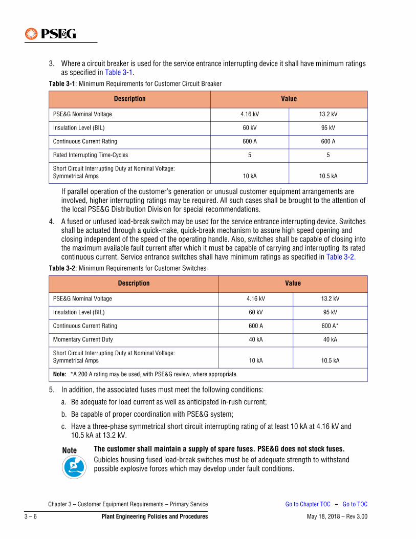
3. Where a circuit breaker is used for the service entrance interrupting device it shall have minimum ratings as specified in Table 3-1.
If parallel operation of the customer’s generation or unusual customer equipment arrangements are involved, higher interrupting ratings may be required. All such cases shall be brought to the attention of the local PSE&G Distribution Division for special recommendations.
4. A fused or unfused load-break switch may be used for the service entrance interrupting device. Switches shall be actuated through a quick-make, quick-break mechanism to assure high speed opening and closing independent of the speed of the operating handle. Also, switches shall be capable of closing into the maximum available fault current after which it must be capable of carrying and interrupting its rated continuous current. Service entrance switches shall have minimum ratings as specified in Table 3-2.
5. In addition, the associated fuses must meet the following conditions:
a. Be adequate for load current as well as anticipated in-rush current;
b. Be capable of proper coordination with PSE&G system;
c. Have a three-phase symmetrical short circuit interrupting rating of at least 10 kA at 4.16 kV and 10.5 kA at 13.2 kV.
Table 3-1: Minimum Requirements for Customer Circuit Breaker
Description Value
PSE&G Nominal Voltage 4.16 kV 13.2 kV
Insulation Level (BIL) 60 kV 95 kV
Continuous Current Rating 600 A 600 A
Rated Interrupting Time-Cycles 5 5
Short Circuit Interrupting Duty at Nominal Voltage: Symmetrical Amps 10 kA 10.5 kA
Table 3-2: Minimum Requirements for Customer Switches
Description Value
PSE&G Nominal Voltage 4.16 kV 13.2 kV
Insulation Level (BIL) 60 kV 95 kV
Continuous Current Rating 600 A 600 A*
Momentary Current Duty 40 kA 40 kA
Short Circuit Interrupting Duty at Nominal Voltage:Symmetrical Amps 10 kA 10.5 kA
Note: *A 200 A rating may be used, with PSE&G review, where appropriate.
The customer shall maintain a supply of spare fuses. PSE&G does not stock fuses.Cubicles housing fused load-break switches must be of adequate strength to withstand possible explosive forces which may develop under fault conditions.
Note
Chapter 3 – Customer Equipment Requirements – Primary Service
May 18, 2018 – Rev 3.003 – 6 Plant Engineering Policies and Procedures
Go to Chapter TOC – Go to TOC
6. The service entrance interrupting device must provide a visible break in all ungrounded conductors and isolate the metering transformers from all customer-owned equipment, including relaying and control transformers.
Generally this requirement will be met with a single gang-operated device on the load side of the revenue metering transformer (hot sequence metering) unless specified otherwise. If the visible break device is located between the PSE&G supply-side and the revenue metering transformers (cold sequence metering) then the isolating device for any control or relaying transformer connected to the main bus without a gang-operated switch must be clearly identified. Identification must be made with appropriate durable signage specified by PSE&G to alert operating personnel of a possible backfeed source.
Cold sequence metering may be approved for duplicate service when a single revenue metering installation is utilized.
If the isolating device is not rated for load break operation it must be interlocked with a load break device in such a way that the nonload break device cannot be operated when the load break device is in the closed position. Interlocks may consist of a substantial direct mechanical lock or be of the tumbler key interchange type. Electrical interlocks will require specific review.
7. Primary service cable size will be determined by PSE&G. Five inch conduit shall be installed by the customer to accept the service cables which will be installed by PSE&G. In addition, a spare conduit is recommended. Larger size conduits and/or manholes may be required due to the cable size, length of run, or number and degrees of bends in the conduit. Special provisions may be required to facilitate cable pulling. Where PSE&G elects to install direct buried cable, the customer shall provide the trench and appropriate backfill. For additional information refer to the latest PSE&G Information and Requirements for Electric Service book, Exhibit 7.
8. Stress cones or cable terminators will be necessary depending upon cable type and size. A minimum of 42 in. of vertical clearance from the end of the service conduit to the point of connection at the customer’s service entrance equipment is required to install stress cones and cable terminators. Cable supports may be required. Bottom entry cable is preferred. Bus stabs into the cable compartment may be required to permit vertical connection of cables.
9. Clearances for switchgear from walls or other obstructions shall be as required by the latest edition of the National Electrical Code.
7. Metal-Clad or Metal-Enclosed SwitchgearThe entire assembly shall conform to the latest published ANSI, NEMA, and IEEE Standards as a minimum and be tested in conformance therewith.
Refer to Section 4. for revenue metering requirements.
Operating handles shall be externally mounted, and should be non-removable in the closed position and have provisions for padlocking in both the open and closed positions. Switch position indications shall be plainly visible.
Doors giving access to power fuses and/or interrupter switches shall be mechanically or key interlocked to prevent opening the door if the switch is closed or closing the switch if the door is open.
All compartments shall be identified with an engraved plastic or metal tag on the exterior.
Remote breaker control switches should be installed to operate breakers from external location.
Chapter 3 – Customer Equipment Requirements – Primary Service
May 18, 2018 – Rev 3.00 Plant Engineering Policies and Procedures 3 – 7
Go to Chapter TOC – Go to TOC
8. Service Circuit BreakerThe service circuit breaker can function as:
1. A load disconnecting device for normal operation.
2. An automatic disconnecting device to remove from the PSE&G system any short circuits within the customer's installation, which are not satisfactorily removed by other devices.
Where a circuit breaker is used as a service entrance interrupting device, automatic tripping must be specifically reviewed by PSE&G and provided by the customer in accordance with the following:
1. For a 4 kV breaker, it is recommended that automatic tripping be provided by the use of acceptable microprocessor-based time-delay overcurrent relays with a very inverse characteristic and with an instantaneous element, which provide both time and current selection, particularly when the customer requires several steps of fault selection to the point of utilization.
2. For a 13 kV breaker, automatic tripping must be provided by using acceptable microprocessor-based time-delay overcurrent relays with an extremely inverse characteristic and with an instantaneous element.
3. Where a DC tripping scheme is used, the circuit breaker shall be equipped with a DC trip coil rated at not less than 12 V and energized from a 40 A-hour storage battery of not less than 24 V equipped with a suitable automatic charger. A 12 V tripping source with a 12 V trip coil is not permitted because of the contact voltage drop. A monthly inspection of the battery is recommended to ensure proper operation of the equipment.
4. To actuate the automatic tripping scheme, the customer’s installation must include one current transformer for each phase. Where practicable, these should be installed on the supply side of the circuit breaker. For 4 kV or 13 kV service, current transformers should be 1200/5, five tap, multi-ratio. The rating of the CT’s, as specified in ANSI/IEEE C57.13 should be appropriate for the relaying equipment used. CT’s of C-100 accuracy class are recommended.
No form of tripping device, other than those given above, shall be used unless specifically reviewed by the PSE&G.
All trip coils must be easily disconnected for test. Where a direct-trip AC device is used, test connection facilities reviewed by the PSE&G must be provided to permit tripping tests to be made with sufficient safe working distance from energized primary equipment.
No device to provide closing power for a service circuit breaker shall be connected on the line side of the metering transformers.
Also see Section 3. paragraph 1 for drawings to be submitted to PSE&G for review.
Adequate relay test facilities must be provided by means of test switches such as the ABB FT-1 switch.
The microprocessor relay type selected for use must be approved by PSE&G for each individual installation.
PSE&G will review the relay settings and will witness the initial trip checks of these relays before the service can be energized.
All relays and associated equipment shall be maintained by the Customer.
Chapter 3 – Customer Equipment Requirements – Primary Service
May 18, 2018 – Rev 3.003 – 8 Plant Engineering Policies and Procedures
Go to Chapter TOC – Go to TOC
9. Surge ArrestersSurge arresters shall be installed on customer's entrance equipment. They have to be connected to the PSE&G side of the customer's isolating switch and located in the entrance cable compartment. The primary leads from the arresters are to be terminated separately with a suitable connector such that the leads may be readily joined to or separated from the termination points to permit isolation of leads and arresters for the purpose of testing the cable. The arrester leads shall be terminated in such a position that isolation of leads and arresters can be accomplished without hazard to personnel from other equipment, which may be energized.
Surge Arresters shall be Intermediate Class and duty cycle rated 3 kV for installation on 4 kV systems and 10 kV on 13 kV systems.
10. More Than One SourceWhere the customer’s load can be supplied from more than one source, such as the customer’s own generation or duplicate service from PSE&G, barriers shall be incorporated into the switchgear design so that when a supply or service cable is de-energized by PSE&G and the customer’s isolating switch is open, there will be no energized equipment capable of being contacted in the service entrance cable compartment.
Additional requirements may be specified by PSE&G depending upon the customer’s equipment and/or arrangement.
11. Mimic BusIt is recommended that a Mimic Bus or schematic representation illustrating the arrangement of the devices and apparatus contained in the cubicles comprising the switchgear be displayed on the front panels.
12. Other Requirements“Danger High Voltage” signs shall be installed as in accordance with applicable requirements of the NEC and the NESC in effect at the time of construction.
13. Animal DeterrentIt is required to mitigate interruptions and equipment damage resulting from animal intrusion into electric power supply substation by using the means of animal deterrent recommended by the latest IEEE Guide 1264.
Chapter 3 – Customer Equipment Requirements – Primary Service
May 18, 2018 – Rev 3.00 Plant Engineering Policies and Procedures 3 – 9
Go to Chapter TOC – Go to TOC
14. Arc Flash Hazard Calculation StudyIt is required to perform Arc Flash Hazard Calculation Study in accordance with the latest IEEE STD 1584 and NFPA 70E and have it reviewed by PSE&G.
The arc-flash calculation study report should include the following information as a minimum:
1. Executive summary.
2. Narrative describing the scope and results of the study and the methodology used.
3. Description of power system modes of operation and details of the scenarios evaluated.
4. Results of short-circuit analysis listing equipment that is applied above its short-circuit current rating, and recommendations if appropriate.
5. Results and recommendations of time-current analysis, including time-current curves.
6. Arc-flash spreadsheet: A tabulated form including a listing of all equipment that had arc-flash hazard values calculated as part of the study. This listing should include the calculated three-phase bolted fault current, arcing fault current, identity of overcurrent protection device with its opening time, working distance, arc-flash protection boundary, and incident energy.
7. A tabulated form showing the worst case incident energy calculated for each bus and the associated mode of power system operation. Report may include incident energy calculated for each bus for each mode of operation.
8. Documentation of all study input data, including utility available fault currents; cable sizes, types, and lengths; motor data; breaker types and settings; fuse sizes and types; etc.
9. Up-to-date single-line diagram(s).
10. Documentation of the software manufacturer, exact version of software used, and configuration settings used to do the study.
11. List of assumptions that were made for cable lengths, CT ratios, transformer impedances, etc.
12. Additional information may be included where it enhances understanding of the electrical system and arc-flash study.
13. Advisory statements covering the impact of changes to the power system, including overcurrent protective devices or system operation and potential impact on arc-flash incident energies.
This may be a part of the arc-flash spreadsheet.Note
Chapter 3 – Customer Equipment Requirements – Primary Service
May 18, 2018 – Rev 3.003 – 10 Plant Engineering Policies and Procedures
Go to Chapter TOC – Go to TOC
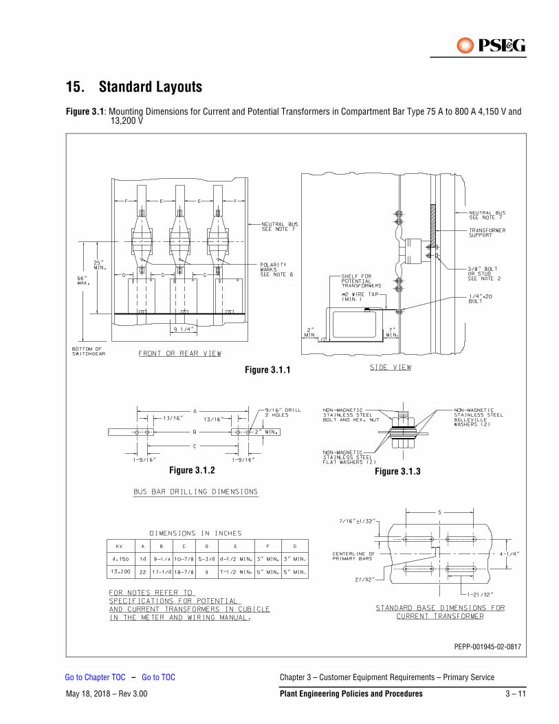
15. Standard Layouts
Figure 3.1: Mounting Dimensions for Current and Potential Transformers in Compartment Bar Type 75 A to 800 A 4,150 V and 13,200 V
Figure 3.1.1
Figure 3.1.3
PEPP-001945-02-0817
Figure 3.1.2
May 18, 2018 – Rev 3.00
Go to Chapter TOC – Go to TOC
Chapter 3 – Customer EquiPlant Engineering Policies
pment Requirements – Primary Service
and Procedures 3 – 11
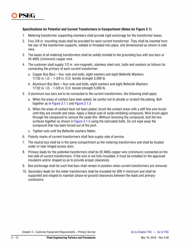
Specifications for Potential and Current Transformers in Compartment (Notes for Figure 3.1)
1. Metering transformer supporting members shall provide rigid anchorage for the transformer bases.
2. Four 3/8 in. mounting studs shall be provided for each current transformer. They shall be inserted from the rear of the transformer supports, welded or threaded into place, and dimensioned as shown in side view.
3. The bases of all metering transformers shall be solidly bonded to the grounding bus with bus bars or #4 AWG (minimum) copper wire.
4. The customer shall supply 1/2 in. non-magnetic, stainless steel nuts, bolts and washers as follows for connecting the primary of each current transformer:
a. Copper Bus Bars – four nuts and bolts, eight washers and eight Belleville Washers 17/32 in. I.D. - 1-3/8 in. O.D. tensile strength 5,000 lb.
b. Aluminum Bus Bars – four nuts and bolts, eight washers and eight Belleville Washers 17/32 in. I.D. - 1-3/8 in. O.D. tensile strength 5,000 lb.
5. If aluminum bus bars are to be connected to the current transformers, the following shall apply:
a. When the areas of contact have been plated, be careful not to abrade or scratch the plating. Bolt together as in Figure 3.1.1 and Figure 3.1.3.
b. When the areas of contact have not been plated, brush the contact areas with a stiff fine wire brush until they are smooth and clean. Apply a liberal coat of oxide-inhibiting compound. Wire brush again through the compound to remove the oxide film. Without removing the compound, bolt the two surfaces together as shown in Figure 3.1.3 using the lubricated bolts. Do not wipe away the compound that has been forced out of the joint.
c. Tighten nuts until the Belleville washers flatten.
6. Polarity marks of current transformers shall face supply side of service.
7. The neutral bus shall be in the same compartment as the metering transformers and shall be located under or near hinged access door.
8. Primary leads for the potential transformers shall be #2 AWG copper wire (minimum) connected on the line side of current transformers. If the wire is not fully insulated, it must be installed on the approved insulators and/or shaped so as to provide proper clearances.
9. Bus anchorage shall be such that bars shall remain in position when current transformers are removed.
10. Secondary leads for the meter transformers shall be insulated for 600 V minimum and shall be supported and shaped to maintain phase-to-ground clearances between the leads and primary conductors.
Chapter 3 – Customer Equipment Requirements – Primary Service
May 18, 2018 – Rev 3.003 – 12 Plant Engineering Policies and Procedures
Go to Chapter TOC – Go to TOC
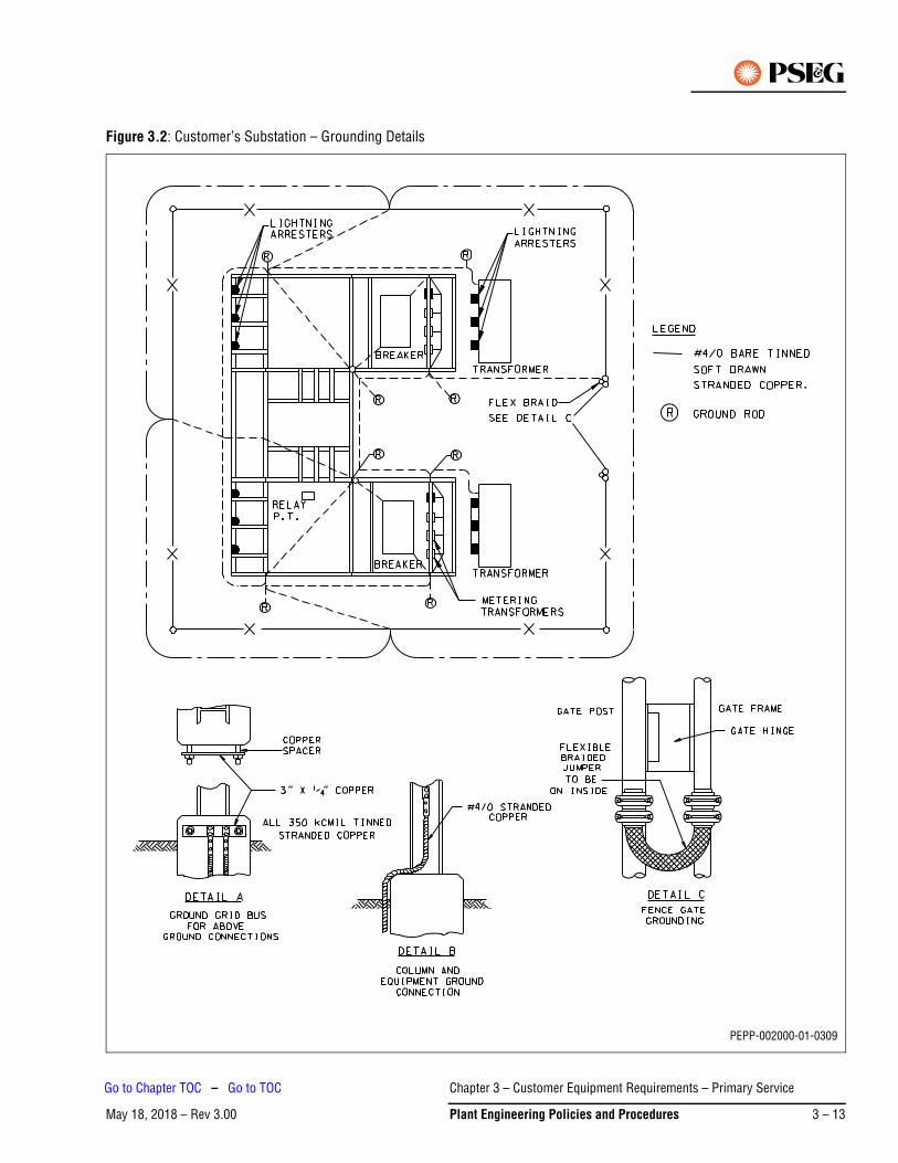
Figure 3.2: Customer’s Substation – Grounding Details
PEPP-002000-01-0309
Chapter 3 – Customer Equipment Requirements – Primary Service
May 18, 2018 – Rev 3.00 Plant Engineering Policies and Procedures 3 – 13
Go to Chapter TOC – Go to TOC
Figure 3.2 Notes:
1. The main station ground grid is to be made of # 4/0 AWG Bare Tinned Stranded Copper (minimum).
2. Connections between the ground grid bus, structure, and various pieces of apparatus are to be direct copper connections of # 4/0 AWG Stranded or 2 in. x 1/4 in. Bar (minimum).
3. Ground connectors may be of the welded, bolted or compression type. Bolted connectors must utilize at least two independent bolts or two U-Bolts.
4. Where connectors are in direct contact with structural steel members surfaces, the surface of the connectors shall be tinned.
Chapter 3 – Customer Equipment Requirements – Primary Service
May 18, 2018 – Rev 3.003 – 14 Plant Engineering Policies and Procedures
Go to Chapter TOC – Go to TOC
May 18, 2018 – Rev 3.00Go to Chapter TOC
Chapter 4 – General Specifications for a Customer-Owned 26.4 kV Outdoor Substation – Table of Contents
1. Introduction. . . . . . . . . . . . . . . . . . . . . . . . . . . . . . . . . . . . . . . . . . . . . . . . . . . . . . . . . . . . . . . . . . 4-1
2. General . . . . . . . . . . . . . . . . . . . . . . . . . . . . . . . . . . . . . . . . . . . . . . . . . . . . . . . . . . . . . . . . . . . . . 4-1
3. Reviews and Approvals Required . . . . . . . . . . . . . . . . . . . . . . . . . . . . . . . . . . . . . . . . . . . . . . . . . 4-2
4. Frequency and Voltage Regulation . . . . . . . . . . . . . . . . . . . . . . . . . . . . . . . . . . . . . . . . . . . . . . . . 4-3
5. Short Circuit Duty . . . . . . . . . . . . . . . . . . . . . . . . . . . . . . . . . . . . . . . . . . . . . . . . . . . . . . . . . . . . . 4-3
6. Circuit Breakers . . . . . . . . . . . . . . . . . . . . . . . . . . . . . . . . . . . . . . . . . . . . . . . . . . . . . . . . . . . . . . . 4-4
7. Fuses . . . . . . . . . . . . . . . . . . . . . . . . . . . . . . . . . . . . . . . . . . . . . . . . . . . . . . . . . . . . . . . . . . . . . . . 4-4
8. Battery . . . . . . . . . . . . . . . . . . . . . . . . . . . . . . . . . . . . . . . . . . . . . . . . . . . . . . . . . . . . . . . . . . . . . . 4-4
9. Relays and SCADA Interface . . . . . . . . . . . . . . . . . . . . . . . . . . . . . . . . . . . . . . . . . . . . . . . . . . . . . 4-5
10. Disconnecting Switches . . . . . . . . . . . . . . . . . . . . . . . . . . . . . . . . . . . . . . . . . . . . . . . . . . . . . . . . 4-8
11. Revenue Metering Equipment . . . . . . . . . . . . . . . . . . . . . . . . . . . . . . . . . . . . . . . . . . . . . . . . . . . . 4-8
12. Insulators, Conductors, Connections and Clearances . . . . . . . . . . . . . . . . . . . . . . . . . . . . . . . . . 4-11
13. Transformers. . . . . . . . . . . . . . . . . . . . . . . . . . . . . . . . . . . . . . . . . . . . . . . . . . . . . . . . . . . . . . . . 4-11
14. Surge Arresters . . . . . . . . . . . . . . . . . . . . . . . . . . . . . . . . . . . . . . . . . . . . . . . . . . . . . . . . . . . . . . 4-11
15. Grounding . . . . . . . . . . . . . . . . . . . . . . . . . . . . . . . . . . . . . . . . . . . . . . . . . . . . . . . . . . . . . . . . . . 4-12
16. Location and Structural Arrangement . . . . . . . . . . . . . . . . . . . . . . . . . . . . . . . . . . . . . . . . . . . . . 4-12
17. More Than One Source . . . . . . . . . . . . . . . . . . . . . . . . . . . . . . . . . . . . . . . . . . . . . . . . . . . . . . . . 4-13
18. Mimic Bus . . . . . . . . . . . . . . . . . . . . . . . . . . . . . . . . . . . . . . . . . . . . . . . . . . . . . . . . . . . . . . . . . . 4-13
19. Operating Procedures . . . . . . . . . . . . . . . . . . . . . . . . . . . . . . . . . . . . . . . . . . . . . . . . . . . . . . . . . 4-13
20. Other Requirements . . . . . . . . . . . . . . . . . . . . . . . . . . . . . . . . . . . . . . . . . . . . . . . . . . . . . . . . . . 4-14
21. Customer Responsibilities for Testing and Commissioning . . . . . . . . . . . . . . . . . . . . . . . . . . . . 4-14
22. Construction in Flood Prone Areas . . . . . . . . . . . . . . . . . . . . . . . . . . . . . . . . . . . . . . . . . . . . . . . 4-15
23. Animal Deterrent . . . . . . . . . . . . . . . . . . . . . . . . . . . . . . . . . . . . . . . . . . . . . . . . . . . . . . . . . . . . . 4-15
24. Arc Flash Hazard Calculation Study . . . . . . . . . . . . . . . . . . . . . . . . . . . . . . . . . . . . . . . . . . . . . . . 4-15
25. Standard Layouts . . . . . . . . . . . . . . . . . . . . . . . . . . . . . . . . . . . . . . . . . . . . . . . . . . . . . . . . . . . . 4-16
Chapter 4 – General Specifications for a Customer-Owned 26.4 kV Outdoor
May 18, 2018 – Rev 3.00 Plant Engineering Policies and Procedures 4 – TOC 1
Go to TOC

This Page Intentionally Blank
Chapter 4 – General Specifications for a Customer-Owned 26.4 kV Outdoor
May 18, 2018 – Rev 3.004 – TOC 2 Plant Engineering Policies and Procedures
Go to TOC
May 18, 2018 – Rev 3.00
Chapter 4 – General Specifications for a Customer-Owned 26.4 kV Outdoor Substation
1. IntroductionPSE&G is committed to providing a safe environment for our employees and safe, adequate and reliable electric service to our customers.
These General Specifications are provided to assist the customer and their agents in developing the necessary detailed substation specifications for acceptable operation on PSE&G’s 26.4 kV electrical system.
The Addendum to these General Specifications show typical one-line substation configurations (Figure 4.1 through Figure 4.11) that are acceptable for operation on PSE&G’s 26.4 kV electrical system. Not all configurations are available everywhere on the system nor is every possible configuration shown. Preliminary discussions with PSE&G are recommended to determine what is available to best serve the customer’s requirements.
In accordance with Section 5.1 of the Standard Terms and Conditions of PSE&G’s Electric Tariff B.P.U.N.J. No. 15, the customer’s 26.4 kV bus is considered part of PSE&G’s sub-transmission system for operational purposes, and system power may flow through the customer’s bus with no remuneration to the customer by PSE&G.
2. GeneralThe following general requirements apply to customer substations.
1. PSE&G requires that all customer substations supplied from the 26.4 kV electrical system shall be designed for 26.4 kV operation and that all construction and equipment be a minimum of 38 kV level classification, 200 kV BIL minimum unless otherwise specified.
2. The 26.4 kV system is resistance grounded through an 8 or 9 ohm neutral resistor that is installed in PSE&G’s switching stations. Under certain conditions this neutral resistor may be bypassed, effectively grounding the system. During single phase to ground fault events, the unfaulted phases may rise to 31 kV over ground potential. Maximum voltage as seen by switching and interrupting devices will not exceed 29.0 kV during ground faults. These effects should be considered in the design of the customer’s relaying. PSE&G requires that all outdoor customer substations supplied from the 26.4 kV resistance grounded electrical system shall be designed for 38 kV operation and that all construction and equipment shall be rated and tested at a minimum of 38 kV voltage level classification, 200 kV BIL, unless otherwise specified.
3. Prior to purchasing any equipment, PSE&G shall be contacted for details on types of equipment and relays suitable for the substation design selected by the customer.
4. Customer shall submit to the Division 26 kV Distribution Planner two copies of the conceptual one-line (electronic version in PDF format) as part of the first contact with PSE&G. The one-line shall clearly indicate all proposed relay protection (function, make and model) and all equipment ratings. One copy shall be addressed to the Division 26 kV Distribution Planner and the other to the Electric Meter Supervisor.
5. Interior and exterior lighting is required, per National Electrical Safety Code (NESC) requirements.
Chapter 4 – General Specifications for a Customer-Owned 26.4 kV Outdoor
May 18, 2018 – Rev 3.00 Plant Engineering Policies and Procedures 4 – 1
Go to Chapter TOC – Go to TOC
3. Reviews and Approvals RequiredThe following are requirements for the review and approval of the customer’s substation.
1. Five sets of the final substation plans, and an electronic version in PDF format, shall be submitted to PSE&G for its review so as to ensure that the design satisfies PSE&G’s technical requirements. PSE&G’s review must be completed prior to the fabrication of apparatus and the supporting structure.
2. Specifically, the drawings submitted should cover the following items:
a. Single-line diagram of the substation including secondary connections to the main transformers, bus and feeder breaker arrangements and connections.
b. Written procedure on how the customer substation will be operated.
c. DC and AC (three-line) schematic diagrams of the relaying and control of all 26.4 kV automatic apparatus.
d. A plot plan showing the location of the substation with regard to all structures within 100 ft thereof.
e. A manhole and conduit drawing representing incoming lines and instrument transformer secondary circuits used for revenue metering.
f. Electrical plan and elevation plan views of the substation.
g. A listing of the major equipment and materials, including their electrical characteristics and the manufacturer’s description, unless these are detailed on the drawings.
h. The location and arrangement of metering, SCADA and control panels. See Section 9. paragraph 6. for SCADA requirements and details.
i. The substation grounding plans, details and calculations.
j. System Protection relay and instrumentation single-line diagram.
3. PSE&G’s review of the above final plans and drawings is for general arrangement approval and to ensure conformity with PSE&G’s technical requirements only, and does not indicate safe or faultless design. By review of the final plans or drawings, PSE&G is indicating that the design is compatible with PSE&G’s equipment and service. Responsibility for proper design, operation, maintenance and safety of the customer’s installation rests solely with the customer. In addition, all work and equipment must conform to municipal and all other applicable codes and requirements, including applicable provisions of the National Electrical Code (NEC) and the NESC in effect at the time of construction.
4. Final acceptance by PSE&G before introducing service to the completed installation is dependent upon the customer obtaining approval from the electrical inspection authority having jurisdiction, and provision by such inspection authority to the local Electric Distribution Division Wiring Inspection Department of an original cut-in card.
5. Unless otherwise specified, PSE&G requires a minimum of 3 weeks after notification of completion of the customer’s work and its walk through or inspection of the customer’s installation, to test and set relays, breakers, meters and/or other associated equipment, including developing final cut-over
PSE&G will not be liable for damages or for injuries sustained by customers or by the equipment of customers or by reason of the condition or character of customer’s facilities or the equipment of others on customer's premises. PSE&G will not be liable for the use, care, or handling of the electric service delivered to the customer after same passes beyond the point at which PSE&G’s service facilities connect to the customer’s facilities.
Note
Chapter 4 – General Specifications for a Customer-Owned 26.4 kV Outdoor
May 18, 2018 – Rev 3.004 – 2 Plant Engineering Policies and Procedures
Go to Chapter TOC – Go to TOC
procedures or other documents or procedures required for the customer. Further, any corrective items noted by PSE&G during the final walk through or inspection of the customer’s site must be completed prior to PSE&G beginning its final commissioning work noted above.
4. Frequency and Voltage RegulationThe following are general voltage and frequency conditions on PSE&G’s system that the customer should consider in its substation design.
1. The frequency of PSE&G’s system is normally regulated at 60 Hz (cycles per second) and under usual conditions the variations are limited to 0.1 cycle above or below 60 Hz.
2. The voltage of PSE&G’s 26.4 kV system under normal conditions will be within a range of 105% to 98% of nominal voltage with a maximum variation of 6%. Under emergency conditions the voltage can be within a range of 105% to 95% of nominal voltage with a maximum variation of 8%. If this regulation is not satisfactory for the operation of the customer's plant, it is the customer’s responsibility to install suitable voltage regulation equipment. If the cost to supply service to the customer at these voltage ranges could be substantially reduced by operating outside these limits, PSE&G may render service with different limits under the terms of a special agreement with the customer.
3. It should be noted, that during fault conditions, short term voltage fluctuations may occur on PSE&G’s system which could result in abnormally low voltage and/or unbalanced voltages. This effect should be considered in the design of the customer’s relay protection system. In addition, operation of certain types of customer’s utilization equipment will adversely affect the power quality of the supply voltage. If the customer has installed critical computer or electronic equipment requiring continuity of service or exceptional service quality, it is the customer's responsibility to install any necessary uninterruptible power supply and/or a power conditioning device that may be required for this application.
4. It is also recommended that time-delay protective devices be installed on important motors and other critical equipment. This will permit the customer to avoid unnecessary outages during faults or surges on PSE&G’s system or from the customer's in-plant facilities.
5. Short Circuit DutyThe maximum available three-phase short circuit current on PSE&G’s 26.4 kV system is 31.5 kA (Short Time Symmetrical 2 Seconds) / 50 KA (Momentary 10 Cycle Asymmetrical) / 80 kA (Peak). The construction of PSE&G’s 26.4 kV system is dynamic and subject to change as required for the safe, adequate and reliable operation of the system. PSE&G recommends that the customer design its substation for the maximum short circuit current available.
Chapter 4 – General Specifications for a Customer-Owned 26.4 kV Outdoor
May 18, 2018 – Rev 3.00 Plant Engineering Policies and Procedures 4 – 3
Go to Chapter TOC – Go to TOC
6. Circuit BreakersThe following are general requirements for circuit breakers.
1. All circuit breakers on the high-voltage side of the customer’s transformers shall meet the most recent edition of the Institute of Electrical and Electronics Engineers (IEEE) Standard C37 for 38 kV maximum rated voltage equipment. Line circuit breakers shall have a minimum of 1,200 A continuous current rating. Bus tie breakers may require higher current ratings depending on the substation configuration.
2. PSE&G requires all circuit breakers on the high-voltage side of the customer’s transformers have a short circuit interrupting duty of 31.5 kA (Short Time Symmetrical 2 Seconds) / 50 kA (Momentary 10 Cycle Asymmetrical) / 80 kA (Peak).
3. The line side of the service entrance or transformer circuit breaker shall be provided with a bushing-type, five tap multi-ratio American National Standards Institute (ANSI) standard current transformer in each terminal. The current transformer shall be relay accuracy class C-400 or better on full tap, and its current rating shall be compatible to the continuous current rating of the breaker.
7. FusesPSE&G’s preference is for the use of circuit breakers but, in some cases, fuses may be utilized on the high-voltage side of the customer’s transformers in lieu of transformer primary circuit breakers. This is only allowable for transformers of up to 10 MVA rating. If fuses are used, the voltage rating shall be greater than or equal to the system line-to-line operating voltage. The fuses shall meet the following requirements.
1. The fuses shall coordinate with PSE&G’s source line(s) relaying and with the transformer secondary fuse, breaker or recloser. If the primary fuse is of the expulsion type, the minimum melting time shall be corrected for “preloading”. The selection time between primary and secondary protection for a customer’s transformers shall be a minimum of 0.5 seconds.
2. The fuses shall have an interrupting capacity equal to, or greater than the maximum asymmetrical short circuit current available on the system at the fuse location, 50 kA (Momentary 10 cycle).
3. The current rating shall be greater than or equal to the transformer manufacturer’s nominal nameplate full load emergency rating. The customer shall submit its proposed fuse type and time-current characteristics to PSE&G’s System Protection Department for approval prior to energization of the substation.
4. The fuses shall meet the requirements of the most recent editions of IEEE Standards C37.46 and C37.48.
8. BatteryA storage battery or other reliable DC source, shall be provided to supply DC voltage for automatic tripping of the circuit breaker(s). The latest editions of IEEE Standards 484 and 485 provide guidance in calculating the appropriate battery size and for installation design and procedures. IEEE Std. C37.06-2009, Table 18 provides the control voltage range required for the operation of the circuit breaker(s).
The battery shall be equipped with an automatic charger, a voltmeter and a low voltage alarm. The low voltage alarm shall be either an audible alarm that will attract a response, and a remote alarm to a manned location. Likewise, if another DC source is utilized, it shall be alarmed to indicate loss of voltage.
The battery shall be sized for minimum of an 8-hour discharge rate.
Chapter 4 – General Specifications for a Customer-Owned 26.4 kV Outdoor
May 18, 2018 – Rev 3.004 – 4 Plant Engineering Policies and Procedures
Go to Chapter TOC – Go to TOC
9. Relays and SCADA InterfaceThe following are general requirements for relaying and SCADA equipment.
1. Specific PSE&G requirements will be provided for relays and their associated equipment, as required for the operation of circuit breakers and/or motor-operated disconnecting switches. For the convenience of those customers who plan that their substations will utilize Automatic Sectionalizing or Transfer Schemes, a sample relay and control diagrams have been included (see Section 25. “Standard Layouts”, Figure 4.1 - Figure 4.4). Some other typical substation configurations are shown in Figure 4.5 - Figure 4.11. Additionally, a list of recommended relays that may be used by the customer is included in “Acceptable Relay List” (Table 4-1). In the event that the customer chooses to use alternative relays, these relays must be approved by PSE&G, and the customer will be responsible for applying the relay settings provided by PSE&G using an approved third party testing company at the customer's expense. Written relay test results must be provided to PSE&G for the initial installation, and provided every 4 years thereafter, when the settings are verified by an approved testing company.
2. All protective relays shall have provisions for isolating the relays for testing or replacement purposes while the equipment is in service. Relay isolation shall be accomplished by using test switches such as the ABB FT-1. Test switches in AC current circuits shall be equipped with test jacks for test connections.
3. The current and potential transformers supplying the protective relays shall not be used for any other purpose.
a. All CTs for relay protection shall adhere to ANSI/IEEE Standard MRCT, C400 class or better.
b. 26 kV breakers shall be equipped with two sets of three-phase CTs on both sides to provide overlapping zones of protection for incoming PSE&G lines, the customer’s 26 kV bus and 26 kV transformers, unless it is not possible to fit in two sets due to space limitations, in which case the relay and CT arrangement and accuracy class must be submitted to PSE&G for approval of the configuration.
c. Each incoming 26 kV line shall be provided with three line-side single-phase PTs, with a 26400-110 V ratio (240/1), wye-connected on both the primary and secondary sides. All PTs shall be of 34.5 kV Nominal System Voltage and be capable of operating at 173% of rated voltage for 1 minute without exceeding 175°C temperature rise.
4. It is recommended that the customer consider the installation of differential relaying for the protection of large power transformers.
If differential relaying is installed, the overcurrent relays associated with each service entrance breaker shall be connected to the bushing-type current transformers on the source side of each service entrance breaker. If CTs are not available on the source side of the entrance breaker, load side CTs may be used.
5. To facilitate maintenance and eliminate the possibility of vibration damage / inadvertent operation, caution should be observed in the placement of relays for tripping high-voltage circuit breakers. If the protective devices being used are sensitive to vibration consideration shall be given to not mounting relays in/on a compartment attached to the breaker but rather in/on a separate weatherproof enclosure or rack in the control house or control room.
Chapter 4 – General Specifications for a Customer-Owned 26.4 kV Outdoor
May 18, 2018 – Rev 3.00 Plant Engineering Policies and Procedures 4 – 5
Go to Chapter TOC – Go to TOC
6. Basic SCADA functionality is required for all customer subs. For small 26 kV customers a standard Mini SCADA box may be used. The box has only Dry contact inputs for indication enabled. Standard PSE&G prints for this Class and coded NEMA 4 Mini SCADA box are 311336, 311337, and 311338. This SCADA box is PSE&G class and coded with code W930001 and is usually kept in stock by PSE&G. Please contact PSE&G Delivery Project and Construction (DP&C) Design Group for standard prints to be used in Designing point to point diagrams and review of proposed design. PSE&G Design Group should be contacted for direction and final review of the design.
a. PSE&G shall designate, select, specify and purchase the equipment required for SCADA purposes. The applicant shall receive the devices from PSE&G and install the equipment at its facility. If necessary, PSE&G will install any other SCADA equipment required at its facilities, at the applicant’s expense. The applicant shall pay PSE&G for all costs associated with SCADA equipment.
b. PSE&G shall require approximately 48 in. x 48 in. of open wall space to install a SCADA RTU for monitoring of the station. The RTU enclosure itself is approximately 30 in. x 30 in. x 12 in.
c. 125 V DC from station battery is required for the SCADA RTU power.
d. 120 V AC is required as a back-up source of power. This is also used for the heater and AC convenience outlet.
e. This RTU takes up to 16 dry contact inputs and provides a wetting voltage to the field contact with the power supplied.
f. A standard dial-up phone line, otherwise known as Plain Old Telephone Service (POTS) line and normally ordered and maintained by the customer, is to be terminated at the location of the SCADA RTU. The customer in agreement with the operating division shall define who orders and maintains the line.
g. If a standard POTS line is not available from the telephone service provider, a fiber optic connection can be used. Customer is responsible for the cost associated with complete procurement and installation of fiber. The customer shall provide an uninterruptable power supply to the router or other interface device. The router or other interface device shall be powered in such a fashion, so that if power to the facility goes down the communications system shall be kept “live” for a minimum of at least 8 hours.
7. Recommended indications/alarms shall be as follows if available and should be wired in this order. If the specific alarm is not available, a spare input shall be left in its place. The points listed here are suggestions and of course every site will have slightly different points to be submitted and approved by the local operations and Relay groups. Specific text can be modified in the Master. As a rule of thumb, Station Alarm (as described elsewhere in the alarm bus portion of the spec.), Station Control handle in Auto, Breaker / motor operated disconnect indication, DC System trouble, Station L&P fail are the most basic. The customer must supply a dry contact and wiring to the RTU cabinet for each available point.
a. Common Station Alarm (If Available and Applicable)
b. Station Control Handle (If Available and Applicable)
c. Fire Alarm (If Available and Applicable)
d. Station Battery System Trouble (If Available and Applicable)
e. Station Light and Power Fail
f. L1 Breaker Status (Any Line Breaker MOC “A” and TOC in Series)
g. L2 Breaker Status (Any Line Breaker MOC “A” and TOC in Series)
h. SEC. 1-2 Breaker Status or Motor operated disconnects
Chapter 4 – General Specifications for a Customer-Owned 26.4 kV Outdoor
May 18, 2018 – Rev 3.004 – 6 Plant Engineering Policies and Procedures
Go to Chapter TOC – Go to TOC
i. Transfer Auto/Manual
j. SPARE
k. SPARE
l. SPARE
m. SPARE
n. SPARE
o. SPARE
p. SPARE
8. Recommended control outputs, if available, shall be as follows and should be wired in this order. The points listed here are merely the suggestions; every site may have slightly different points to be submitted and approved by the local Operations and Relay groups. Specific text can be modified in the Master.
a. Line 1 Breaker 1 Trip
b. Line 2 Breaker 1 Trip
c. Spare
d. Spare
e. Spare
f. Spare
g. Spare
9. The presence of any type of Generation running in parallel with the service may result in additional specific protection, SCADA, and ESOC RTU design requirements. The customer Engineer is required to identify any Generation and obtain direction and approval from PSE&G Design Group based on the specifics of planned installation.
10. Two copies of each relay instruction book for all line and bus relays shall be provided to PSE&G 2 months prior to the expected service date.
11. When relays are required for the protection of a sub-transmission line or a transmission line, requirements covering that application are very specific and are based on the line configuration, etc. Those requirements are not in the scope of this document. The PSE&G System Protection Group in Newark must be contacted for specific recommendations. At that time, sample AC and DC schematics will be provided by PSE&G.
12. For other applications (i.e., bus differential protection discussed in item 4 above) the same System Protection Group in Newark must be contacted for specific relay recommendations.
Chapter 4 – General Specifications for a Customer-Owned 26.4 kV Outdoor
May 18, 2018 – Rev 3.00 Plant Engineering Policies and Procedures 4 – 7
Go to Chapter TOC – Go to TOC
10. Disconnecting SwitchesThe following are guidelines for disconnecting switches.
1. Guidelines for the application, installation, operation and maintenance of disconnecting switches are described in the latest editions of IEEE NESC C2-2012, Sections 173 and 216; as well as the latest editions of IEEE C37.30, C37.32 and C37.35.
All Disconnect Switches shall be of 38 kV Class, 200 kV BIL and designed for operation at 34.5 kV unless otherwise noted.
2. The line disconnecting switches shall be horizontally mounted, three-pole, gang-operated, vertical break devices with arcing horns or with load break capability if used for switching. One three-pole, gang-operated line grounding switch shall be installed as part of each line disconnecting switch, and shall be mechanically interlocked in such a way that the line grounding switch cannot be closed when the line disconnecting switch is in the closed position, and the line disconnecting switch cannot be closed when the line grounding switch is in the closed position. The line disconnecting switches and the line grounding switches shall be so arranged that they can be padlocked in any desired position
.
3. Disconnect switches shall be 200 kV BIL, and have a minimum short circuit withstand rating of 38 kA (Short Time Symmetrical 2 Seconds) / 99 kA (Peak).
4. Line disconnecting switches and any line breaker bus disconnecting switches or bus sectionalizing switches shall be rated 1,200 A. Bus sectionalizing switches may require higher current ratings depending on the customer's substation configuration, with 1,200 A minimum (56 MVA) load break capability if used for switching and be tested and capable of at least 5 full load interruptions at an operating voltage of 29.0 kV minimum.
5. Where a circuit breaker is not used as the primary side disconnecting means for a main power transformer, then the primary side disconnecting switch shall be capable of interrupting the magnetizing current of the transformer and be rated at least 600 A load break capability and be tested and capable of at least five full load interruptions at an operating voltage of 29.0 kV minimum.
6. Any disconnecting switch mounted vertically shall be hinged at the bottom to prevent accidental closing.
11. Revenue Metering EquipmentThe information listed below pertains to Revenue Metering Equipment.
1. PSE&G will furnish two Potential transformers (PTs) and two current transformers (CTs) for revenue metering, the secondary control cable and test switches for each metering point.
2. PSE&G will not permit the connection of any customer equipment to the metering transformers used for its revenue metering. No device other than those used for automatic tripping, or those supplied or required by PSE&G, shall be placed on the line side of the billing meters.
ANSI Standards do not require ground switches to have a fault close rating since proper operating practice requires the circuit be tested de-energized before closing the ground switch. It must have a momentary rating of 50 kA.
Note
Chapter 4 – General Specifications for a Customer-Owned 26.4 kV Outdoor
May 18, 2018 – Rev 3.004 – 8 Plant Engineering Policies and Procedures
Go to Chapter TOC – Go to TOC
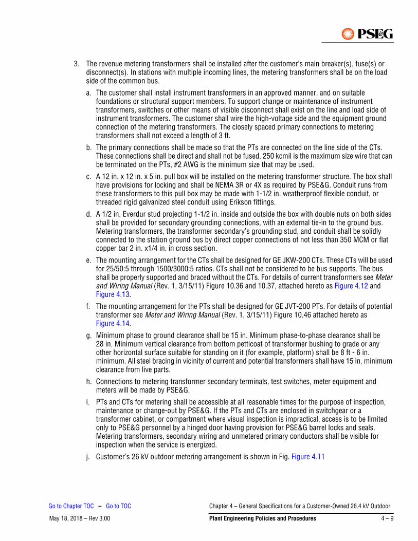
3. The revenue metering transformers shall be installed after the customer’s main breaker(s), fuse(s) or disconnect(s). In stations with multiple incoming lines, the metering transformers shall be on the load side of the common bus.
a. The customer shall install instrument transformers in an approved manner, and on suitable foundations or structural support members. To support change or maintenance of instrument transformers, switches or other means of visible disconnect shall exist on the line and load side of instrument transformers. The customer shall wire the high-voltage side and the equipment ground connection of the metering transformers. The closely spaced primary connections to metering transformers shall not exceed a length of 3 ft.
b. The primary connections shall be made so that the PTs are connected on the line side of the CTs. These connections shall be direct and shall not be fused. 250 kcmil is the maximum size wire that can be terminated on the PTs, #2 AWG is the minimum size that may be used.
c. A 12 in. x 12 in. x 5 in. pull box will be installed on the metering transformer structure. The box shall have provisions for locking and shall be NEMA 3R or 4X as required by PSE&G. Conduit runs from these transformers to this pull box may be made with 1-1/2 in. weatherproof flexible conduit, or threaded rigid galvanized steel conduit using Erikson fittings.
d. A 1/2 in. Everdur stud projecting 1-1/2 in. inside and outside the box with double nuts on both sides shall be provided for secondary grounding connections, with an external tie-in to the ground bus. Metering transformers, the transformer secondary’s grounding stud, and conduit shall be solidly connected to the station ground bus by direct copper connections of not less than 350 MCM or flat copper bar 2 in. x1/4 in. in cross section.
e. The mounting arrangement for the CTs shall be designed for GE JKW-200 CTs. These CTs will be used for 25/50:5 through 1500/3000:5 ratios. CTs shall not be considered to be bus supports. The bus shall be properly supported and braced without the CTs. For details of current transformers see Meter and Wiring Manual (Rev. 1, 3/15/11) Figure 10.36 and 10.37, attached hereto as Figure 4.12 and Figure 4.13.
f. The mounting arrangement for the PTs shall be designed for GE JVT-200 PTs. For details of potential transformer see Meter and Wiring Manual (Rev. 1, 3/15/11) Figure 10.46 attached hereto as Figure 4.14.
g. Minimum phase to ground clearance shall be 15 in. Minimum phase-to-phase clearance shall be 28 in. Minimum vertical clearance from bottom petticoat of transformer bushing to grade or any other horizontal surface suitable for standing on it (for example, platform) shall be 8 ft - 6 in. minimum. All steel bracing in vicinity of current and potential transformers shall have 15 in. minimum clearance from live parts.
h. Connections to metering transformer secondary terminals, test switches, meter equipment and meters will be made by PSE&G.
i. PTs and CTs for metering shall be accessible at all reasonable times for the purpose of inspection, maintenance or change-out by PSE&G. If the PTs and CTs are enclosed in switchgear or a transformer cabinet, or compartment where visual inspection is impractical, access is to be limited only to PSE&G personnel by a hinged door having provision for PSE&G barrel locks and seals. Metering transformers, secondary wiring and unmetered primary conductors shall be visible for inspection when the service is energized.
j. Customer’s 26 kV outdoor metering arrangement is shown in Fig. Figure 4.11
Chapter 4 – General Specifications for a Customer-Owned 26.4 kV Outdoor
May 18, 2018 – Rev 3.00 Plant Engineering Policies and Procedures 4 – 9
Go to Chapter TOC – Go to TOC
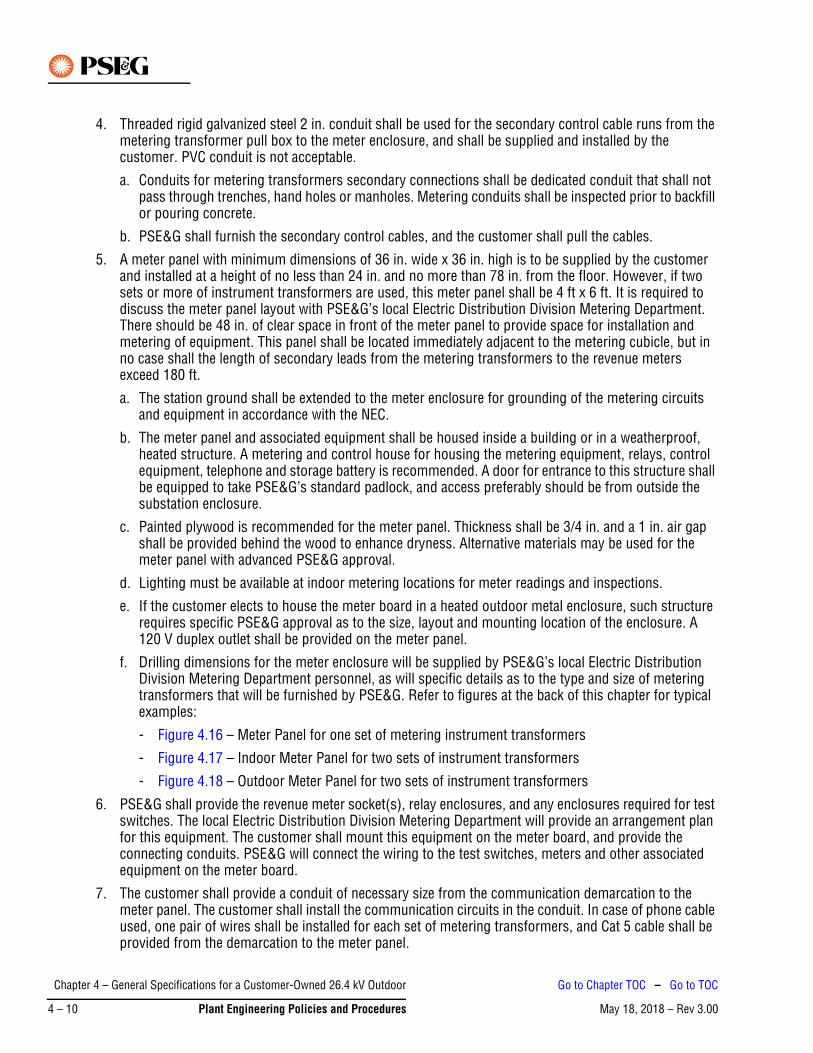
4. Threaded rigid galvanized steel 2 in. conduit shall be used for the secondary control cable runs from the metering transformer pull box to the meter enclosure, and shall be supplied and installed by the customer. PVC conduit is not acceptable.
a. Conduits for metering transformers secondary connections shall be dedicated conduit that shall not pass through trenches, hand holes or manholes. Metering conduits shall be inspected prior to backfill or pouring concrete.
b. PSE&G shall furnish the secondary control cables, and the customer shall pull the cables.
5. A meter panel with minimum dimensions of 36 in. wide x 36 in. high is to be supplied by the customer and installed at a height of no less than 24 in. and no more than 78 in. from the floor. However, if two sets or more of instrument transformers are used, this meter panel shall be 4 ft x 6 ft. It is required to discuss the meter panel layout with PSE&G’s local Electric Distribution Division Metering Department. There should be 48 in. of clear space in front of the meter panel to provide space for installation and metering of equipment. This panel shall be located immediately adjacent to the metering cubicle, but in no case shall the length of secondary leads from the metering transformers to the revenue meters exceed 180 ft.
a. The station ground shall be extended to the meter enclosure for grounding of the metering circuits and equipment in accordance with the NEC.
b. The meter panel and associated equipment shall be housed inside a building or in a weatherproof, heated structure. A metering and control house for housing the metering equipment, relays, control equipment, telephone and storage battery is recommended. A door for entrance to this structure shall be equipped to take PSE&G’s standard padlock, and access preferably should be from outside the substation enclosure.
c. Painted plywood is recommended for the meter panel. Thickness shall be 3/4 in. and a 1 in. air gap shall be provided behind the wood to enhance dryness. Alternative materials may be used for the meter panel with advanced PSE&G approval.
d. Lighting must be available at indoor metering locations for meter readings and inspections.
e. If the customer elects to house the meter board in a heated outdoor metal enclosure, such structure requires specific PSE&G approval as to the size, layout and mounting location of the enclosure. A 120 V duplex outlet shall be provided on the meter panel.
f. Drilling dimensions for the meter enclosure will be supplied by PSE&G’s local Electric Distribution Division Metering Department personnel, as will specific details as to the type and size of metering transformers that will be furnished by PSE&G. Refer to figures at the back of this chapter for typical examples:
- Figure 4.16 – Meter Panel for one set of metering instrument transformers
- Figure 4.17 – Indoor Meter Panel for two sets of instrument transformers
- Figure 4.18 – Outdoor Meter Panel for two sets of instrument transformers
6. PSE&G shall provide the revenue meter socket(s), relay enclosures, and any enclosures required for test switches. The local Electric Distribution Division Metering Department will provide an arrangement plan for this equipment. The customer shall mount this equipment on the meter board, and provide the connecting conduits. PSE&G will connect the wiring to the test switches, meters and other associated equipment on the meter board.
7. The customer shall provide a conduit of necessary size from the communication demarcation to the meter panel. The customer shall install the communication circuits in the conduit. In case of phone cable used, one pair of wires shall be installed for each set of metering transformers, and Cat 5 cable shall be provided from the demarcation to the meter panel.
Chapter 4 – General Specifications for a Customer-Owned 26.4 kV Outdoor
May 18, 2018 – Rev 3.004 – 10 Plant Engineering Policies and Procedures
Go to Chapter TOC – Go to TOC
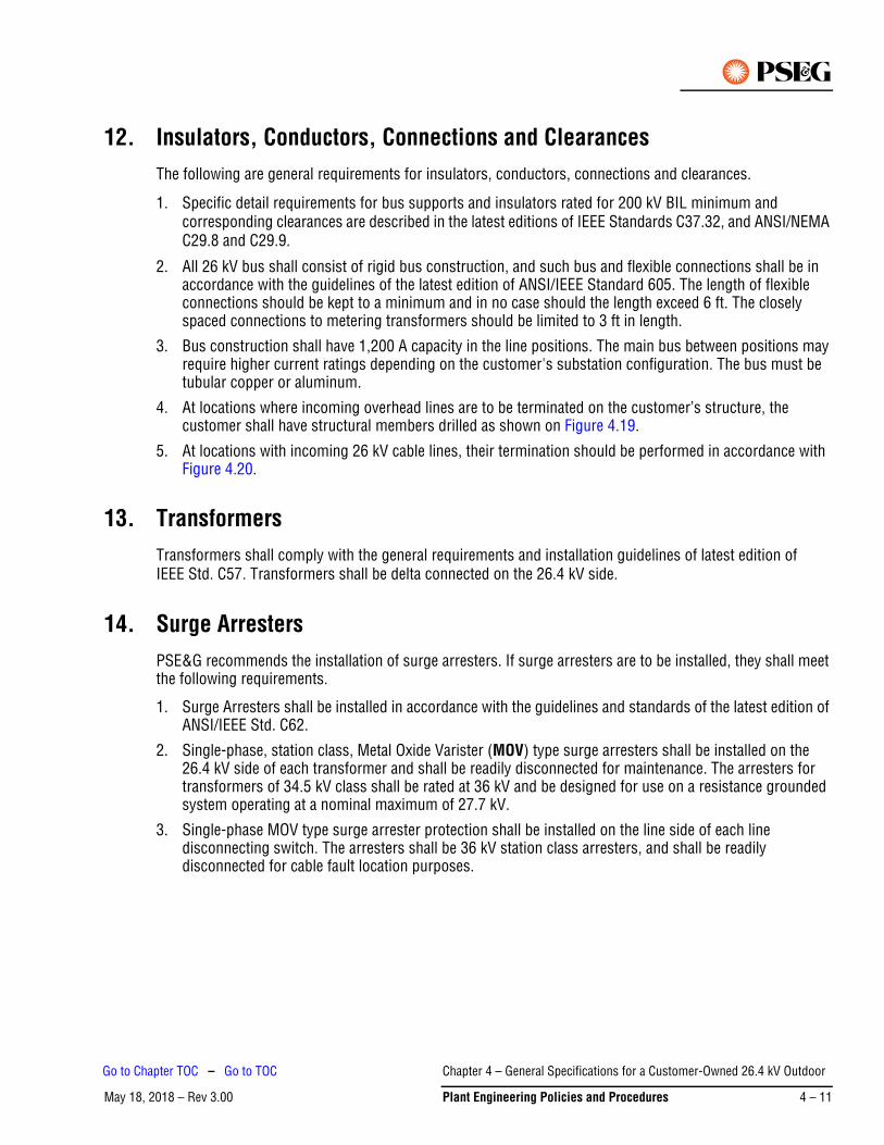
12. Insulators, Conductors, Connections and ClearancesThe following are general requirements for insulators, conductors, connections and clearances.
1. Specific detail requirements for bus supports and insulators rated for 200 kV BIL minimum and corresponding clearances are described in the latest editions of IEEE Standards C37.32, and ANSI/NEMA C29.8 and C29.9.
2. All 26 kV bus shall consist of rigid bus construction, and such bus and flexible connections shall be in accordance with the guidelines of the latest edition of ANSI/IEEE Standard 605. The length of flexible connections should be kept to a minimum and in no case should the length exceed 6 ft. The closely spaced connections to metering transformers should be limited to 3 ft in length.
3. Bus construction shall have 1,200 A capacity in the line positions. The main bus between positions may require higher current ratings depending on the customer's substation configuration. The bus must be tubular copper or aluminum.
4. At locations where incoming overhead lines are to be terminated on the customer’s structure, the customer shall have structural members drilled as shown on Figure 4.19.
5. At locations with incoming 26 kV cable lines, their termination should be performed in accordance with Figure 4.20.
13. TransformersTransformers shall comply with the general requirements and installation guidelines of latest edition of IEEE Std. C57. Transformers shall be delta connected on the 26.4 kV side.
14. Surge ArrestersPSE&G recommends the installation of surge arresters. If surge arresters are to be installed, they shall meet the following requirements.
1. Surge Arresters shall be installed in accordance with the guidelines and standards of the latest edition of ANSI/IEEE Std. C62.
2. Single-phase, station class, Metal Oxide Varister (MOV) type surge arresters shall be installed on the 26.4 kV side of each transformer and shall be readily disconnected for maintenance. The arresters for transformers of 34.5 kV class shall be rated at 36 kV and be designed for use on a resistance grounded system operating at a nominal maximum of 27.7 kV.
3. Single-phase MOV type surge arrester protection shall be installed on the line side of each line disconnecting switch. The arresters shall be 36 kV station class arresters, and shall be readily disconnected for cable fault location purposes.
Chapter 4 – General Specifications for a Customer-Owned 26.4 kV Outdoor
May 18, 2018 – Rev 3.00 Plant Engineering Policies and Procedures 4 – 11
Go to Chapter TOC – Go to TOC
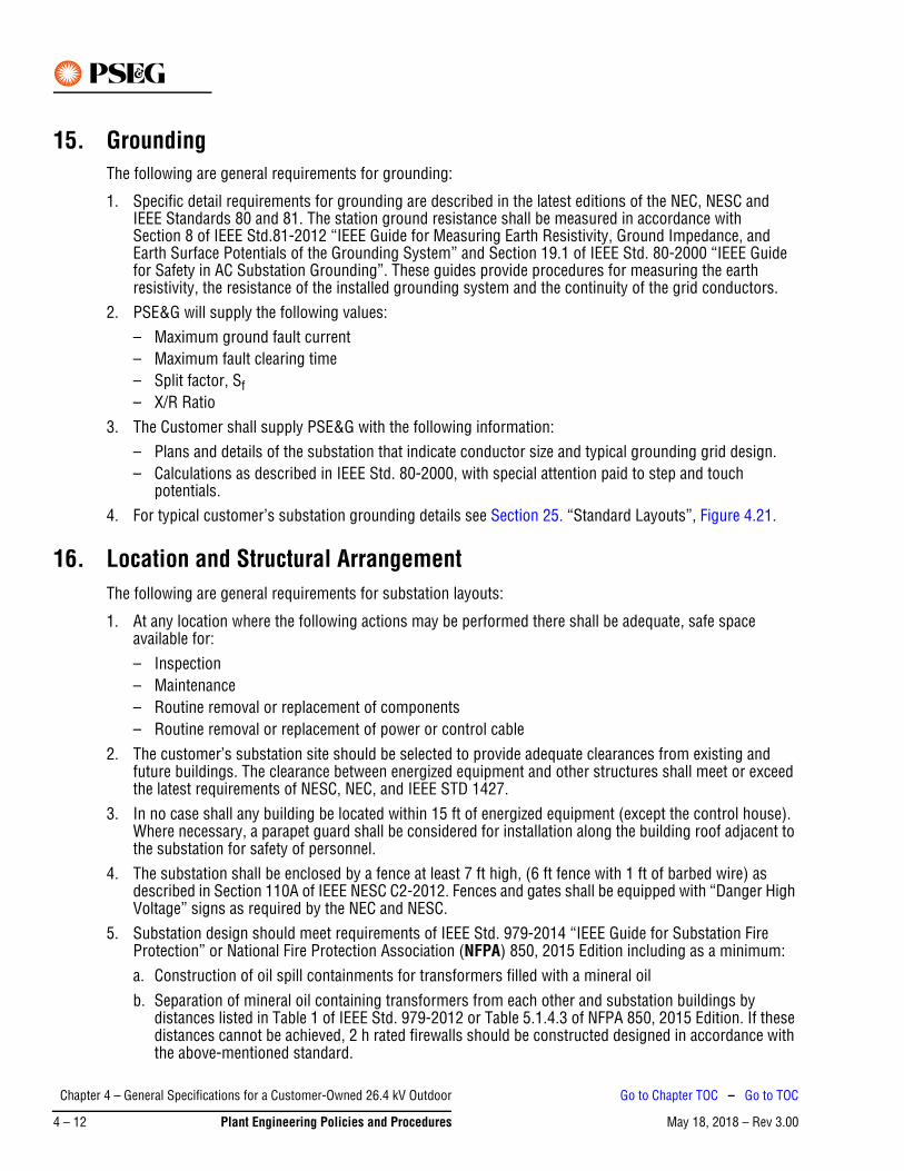
15. GroundingThe following are general requirements for grounding:
1. Specific detail requirements for grounding are described in the latest editions of the NEC, NESC and IEEE Standards 80 and 81. The station ground resistance shall be measured in accordance with Section 8 of IEEE Std.81-2012 “IEEE Guide for Measuring Earth Resistivity, Ground Impedance, and Earth Surface Potentials of the Grounding System” and Section 19.1 of IEEE Std. 80-2000 “IEEE Guide for Safety in AC Substation Grounding”. These guides provide procedures for measuring the earth resistivity, the resistance of the installed grounding system and the continuity of the grid conductors.
2. PSE&G will supply the following values:– Maximum ground fault current– Maximum fault clearing time– Split factor, Sf– X/R Ratio
3. The Customer shall supply PSE&G with the following information:– Plans and details of the substation that indicate conductor size and typical grounding grid design.– Calculations as described in IEEE Std. 80-2000, with special attention paid to step and touch
potentials.4. For typical customer’s substation grounding details see Section 25. “Standard Layouts”, Figure 4.21.
16. Location and Structural ArrangementThe following are general requirements for substation layouts:
1. At any location where the following actions may be performed there shall be adequate, safe space available for:– Inspection– Maintenance– Routine removal or replacement of components– Routine removal or replacement of power or control cable
2. The customer’s substation site should be selected to provide adequate clearances from existing and future buildings. The clearance between energized equipment and other structures shall meet or exceed the latest requirements of NESC, NEC, and IEEE STD 1427.
3. In no case shall any building be located within 15 ft of energized equipment (except the control house). Where necessary, a parapet guard shall be considered for installation along the building roof adjacent to the substation for safety of personnel.
4. The substation shall be enclosed by a fence at least 7 ft high, (6 ft fence with 1 ft of barbed wire) as described in Section 110A of IEEE NESC C2-2012. Fences and gates shall be equipped with “Danger High Voltage” signs as required by the NEC and NESC.
5. Substation design should meet requirements of IEEE Std. 979-2014 “IEEE Guide for Substation Fire Protection” or National Fire Protection Association (NFPA) 850, 2015 Edition including as a minimum:a. Construction of oil spill containments for transformers filled with a mineral oilb. Separation of mineral oil containing transformers from each other and substation buildings by
distances listed in Table 1 of IEEE Std. 979-2012 or Table 5.1.4.3 of NFPA 850, 2015 Edition. If these distances cannot be achieved, 2 h rated firewalls should be constructed designed in accordance with the above-mentioned standard.
Chapter 4 – General Specifications for a Customer-Owned 26.4 kV Outdoor
May 18, 2018 – Rev 3.004 – 12 Plant Engineering Policies and Procedures
Go to Chapter TOC – Go to TOC
6. Substation should have an adequate lightning protection in accordance with the latest revision of IEEE Std. 998 “Guide for Direct Lightning Stroke Shielding of Substations”.
7. If a building wall is used as a part of the substation enclosure, there shall be no windows, doors, fire escapes, vents, drains, down spout openings, or other foreign obstructions in or near such areas of the wall which are bounded by the projection of the substation building; and this section of the wall shall be made of a fireproof material type of construction.
8. The substation structure must be of sufficient strength and properly braced to adequately support PSE&G’s entering 26.4 kV lines, each conductor of which may have a maximum tension of 3000 lb and may deviate up to 45 degrees from a direct approach.
9. For personnel safety lighting of the substation should be provided for walkways and in operating areas as per NESC, Section 111.
10. A telephone shall be provided in the control house for the purpose of switching.
17. More Than One SourceWhere the customer’s load can be supplied from more than one source, such as the customer’s own generation or a duplicate service from PSE&G, the entrance switchgear shall be provided by the customer with a sign stating “Caution – Multiple Power Sources”.
Additional requirements may be specified by PSE&G depending upon the customer’s equipment and/or arrangement.
18. Mimic BusA Mimic Bus or schematic representation, illustrating the arrangement of the devices and apparatus contained in the cubicles comprising the switchgear, shall be displayed on the front panels of the switchgear. For equipment installed outside the switchgear, a corresponding mimic bus or schematic representation shall be displayed on circuit breaker control panels.
19. Operating ProceduresThe following are standard operating procedures for the substation:
1. To provide for security of PSE&G’s system and for the safety of PSE&G’s and the customer’s personnel, PSE&G requires operational control of the following devices at the customer’s substation:• 26.4 kV line disconnecting switches• Line grounding switches• Line circuit breakers and their bus disconnecting switches• 26.4 kV bus sectionalizing switches and breaker(s), if providedA representative of PSE&G's local Electric Distribution Division will operate these devices as directed by that Division's Service Dispatcher.
2. An authorized attendant of the customer may operate the 26.4 kV service entrance breaker(s), the breaker isolating switches and all equipment on the load side of the service entrance breaker(s) as desired. The customer's authorized attendant is never to operate the devices listed above in item 1.
3. In the event of an interruption to service, PSE&G will restore service as soon as possible without notification.
4. Specific operating instructions will be provided to the customer prior to energization.
Chapter 4 – General Specifications for a Customer-Owned 26.4 kV Outdoor
May 18, 2018 – Rev 3.00 Plant Engineering Policies and Procedures 4 – 13
Go to Chapter TOC – Go to TOC
20. Other Requirements“Danger High Voltage” signs shall be installed in accordance with applicable requirements of the NEC and the NESC in effect at the time of construction.
Approved “Lamicoid” tags shall be furnished by the customer on all switchgear compartments and board-mounted components, and all circuit breakers, transformers and disconnect switches. Tag names shall be identical to the terminology used in the customer's drawings, or as specified by PSE&G at interface points. All tags shall be attached with either stainless steel pins or stainless steel machine screws.
21. Customer Responsibilities for Testing and CommissioningNormal protocol should expect that all the work listed below is performed when commissioning customer substations. This work is the responsibility of the Customer and is normally performed by the site Electrical Contractor and a Testing Contractor. Testing and commissioning must be performed by a certified National Electrical Testing Association (NETA) company.
1. Customer shall perform the following:a. Tightening and torquing of all bolted electrical connections.
b. Verification of all external wiring.c. Complete testing of all protection and control circuits using the AC/DC schematics.d. Hi-pot, Doble and Ductor testing of all circuit breakers.e. Timing test for service entrance and bus tie circuit breakers.f. Hi-pot and Doble testing of all bus work including arrestors. Ductoring of bus work is also
recommended.g. Operational verification of each circuit breaker - electrical, mechanical, safety interlocks.h. Operational verification of each line disconnect and ground switch and keyed interlocks.i. Ratio verification of potential devices.j. “Megger” and ratio tests of all current transformers.k. Setting the ratio of all CTs as per protection requirements – Line Protection CTs shall be set by
PSE&G.l. Shortening all unused CTs and winding taps as necessary. m. Calibration of all instruments.n. Verification and adjustment of battery chargers as required - verification of set points of all battery
related alarms.o. Verification and testing of all alarms to the annunciator.p. Verification of accuracy of Mimic Bus against the One Line.q. Verification of operation of telephone circuits for SCADA and metering.r. Verification of correct taps for transformers.s. All necessary transformer tests before energizing (TTR, Doble, hi-pot, cooling system as required).
Chapter 4 – General Specifications for a Customer-Owned 26.4 kV Outdoor
May 18, 2018 – Rev 3.004 – 14 Plant Engineering Policies and Procedures
Go to Chapter TOC – Go to TOC

2. PSE&G shall:a. For service entrance and bus tie circuit breakers, perform operational checks and review results of
ductor and timing tests performed by the Customer.b. Set line relays (bus differentials and breaker failure if used), verify associated instrumentation and
perform operational / trip checks of service entry and bus tie breakers.c. Set and test the required ratio of CTs associated with the line relays.d. Verify operation of line disconnects, line grounds and keyed interlocks.e. Install and verify metering and SCADA equipment.
22. Construction in Flood Prone AreasAs part of the customer facility design process, the customer or customer's engineer shall determine if the customer site is prone to flooding by reviewing the latest Federal Emergency Management Agency (FEMA) and New Jersey Department of Environmental Protection (NJDEP) Flood Maps. If flooding is a possibility, station equipment that may be impacted by flood waters shall be installed at least 1 ft above the highest available design flood elevation as determined by:
1. FEMA 100-year Base Flood Elevation (BFE)2. NJDEP Flood Hazard Area Limit (FHAL)
This will apply to but not limited to metal clad switchgear, circuit breakers, operating mechanisms for disconnects, control panels, cooling fan motors, LTC controller and any control components of the transformers, batteries, relays, terminal blocks (especially those carry DC current) and other vulnerable electronic devices.
23. Animal DeterrentIt is required to mitigate interruptions and equipment damage resulting from animal intrusion into electric power supply substation by using the means of animal deterrent recommended by the latest IEEE Guide 1264.
24. Arc Flash Hazard Calculation StudyIt is required to perform Arc Flash Hazard Calculation Study in accordance with the latest IEEE STD 1584 and NFPA 70E and have it reviewed by PSE&G.
The arc-flash calculation study report should include the following information as a minimum:
1. Executive summary.
2. Narrative describing the scope and results of the study and the methodology used.
3. Description of power system modes of operation and details of the scenarios evaluated.
4. Results of short-circuit analysis listing equipment that is applied above its short-circuit current rating, and recommendations if appropriate.
5. Results and recommendations of time-current analysis, including time-current curves.
6. Arc-flash spreadsheet: A tabulated form including a listing of all equipment that had arc-flash hazard values calculated as part of the study. This listing should include the calculated three-phase bolted fault
Chapter 4 – General Specifications for a Customer-Owned 26.4 kV Outdoor
May 18, 2018 – Rev 3.00 Plant Engineering Policies and Procedures 4 – 15
Go to Chapter TOC – Go to TOC
current, arcing fault current, identity of overcurrent protection device with its opening time, working distance, arc-flash protection boundary, and incident energy.
7. A tabulated form showing the worst case incident energy calculated for each bus and the associated mode of power system operation. Report may include incident energy calculated for each bus for each mode of operation.
8. Documentation of all study input data, including utility available fault currents; cable sizes, types, and lengths; motor data; breaker types and settings; fuse sizes and types; etc.
9. Up-to-date single-line diagram(s).
10. Documentation of the software manufacturer, exact version of software used, and configuration settings used to do the study.
11. List of assumptions that were made for cable lengths, CT ratios, transformer impedances, etc.
12. Additional information may be included where it enhances understanding of the electrical system and arc-flash study.
13. Advisory statements covering the impact of changes to the power system, including overcurrent protective devices or system operation and potential impact on arc-flash incident energies.
25. Standard LayoutsTransfer and Sectionalizing Scheme Controls for Figure 4.1, Figure 4.2, Figure 4.3 and Figure 4.4.
1. For both Transfer and Sectionalizing Schemes, two selector switches should be provided to choose:
a. Type of Schemei. Sectionalizingii. Line 1 Preferred
iii. Line 2 Preferredb. Control Switch
i. Automatic
ii. Manual2. Selectable time, delayed over a range of 0-30 seconds.3. Transfer Scheme description:
a. Preferred line loses potential.b. *Time-delay times out.c. Preferred motor operated disconnect (or breaker) opens.
d. Alternate motor operated disconnect (or breaker) closes.e. Station restored.f. To restore station to normal, switching must be done manually.
This may be a part of the arc-flash spreadsheet.Note
Chapter 4 – General Specifications for a Customer-Owned 26.4 kV Outdoor
May 18, 2018 – Rev 3.004 – 16 Plant Engineering Policies and Procedures
Go to Chapter TOC – Go to TOC
4. Sectionalizing Scheme Description:
a. Loss of line potential.
b. *Time-delay times out.
c. Both L1 and L2 motor operated disconnects (or breakers) open.
d. Return of potential on either L1 or L2 will result in the motor operated disconnect closing into the line with potential on it.
e. Station restored.
f. To restore station to normal, switching must be done manually.
* Time delay is necessary to coordinate with line reclosing.-Note
Chapter 4 – General Specifications for a Customer-Owned 26.4 kV Outdoor
May 18, 2018 – Rev 3.00 Plant Engineering Policies and Procedures 4 – 17
Go to Chapter TOC – Go to TOC

Figure 4.1: Sectionalizing Scheme with Breakers – Transformer >10 MVA
Figure 4.1 Notes*:
If Electromechanical relays are used, one set of relays is required.
If Microprocessor relays are used, customer choice to either:
1. Use just 50/51P, 51NP and relay must trip breaker on relay failure.2. Use both 50/51P, 51NP and 50/51B, 51NB and single relay failure does not have to trip breaker.3. Fuse protection in lieu of breakers is only allowable for transformers with a maximum rating of 10 MVA
or less.
PEPP-001363-02-0616
Chapter 4 – General Specifications for a Customer-Owned 26.4 kV Outdoor
May 18, 2018 – Rev 3.004 – 18 Plant Engineering Policies and Procedures
Go to Chapter TOC – Go to TOC
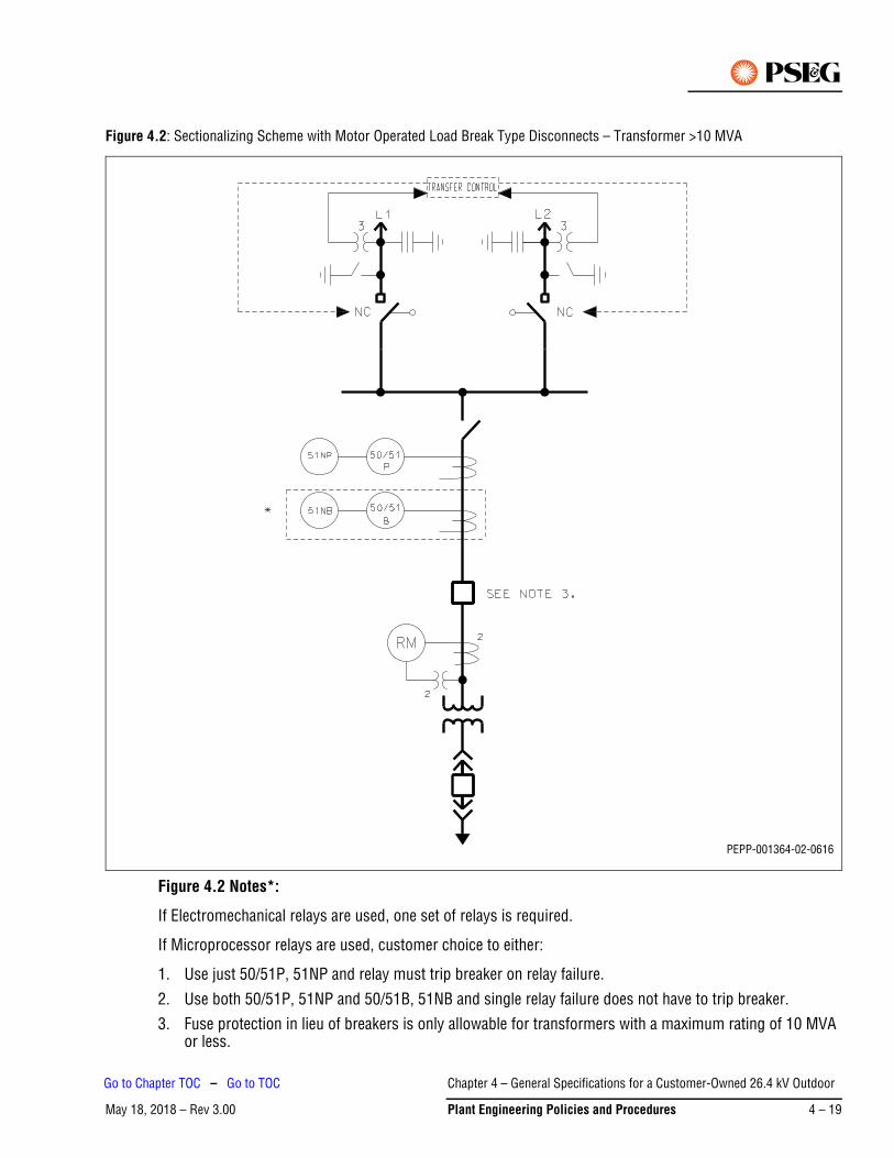
Figure 4.2: Sectionalizing Scheme with Motor Operated Load Break Type Disconnects – Transformer >10 MVA
Figure 4.2 Notes*:
If Electromechanical relays are used, one set of relays is required.
If Microprocessor relays are used, customer choice to either:
1. Use just 50/51P, 51NP and relay must trip breaker on relay failure.
2. Use both 50/51P, 51NP and 50/51B, 51NB and single relay failure does not have to trip breaker.3. Fuse protection in lieu of breakers is only allowable for transformers with a maximum rating of 10 MVA
or less.
PEPP-001364-02-0616
Chapter 4 – General Specifications for a Customer-Owned 26.4 kV Outdoor
May 18, 2018 – Rev 3.00 Plant Engineering Policies and Procedures 4 – 19
Go to Chapter TOC – Go to TOC

Figure 4.3: Transfer Scheme with Breakers – Transformer >10 MVA
Figure 4.3 Notes*:
If Electromechanical relays are used, one set of relays is required.
If Microprocessor relays are used, customer choice to either:
1. Use just 50/51P, 51NP and relay must trip breaker on relay failure.2. Use both 50/51P, 51NP and 50/51B, 51NB and single relay failure does not have to trip breaker.
3. Fuse protection in lieu of breakers is only allowable for transformers with a maximum rating of 10 MVA or less.
PEPP-001367-02-0616
Chapter 4 – General Specifications for a Customer-Owned 26.4 kV Outdoor
May 18, 2018 – Rev 3.004 – 20 Plant Engineering Policies and Procedures
Go to Chapter TOC – Go to TOC
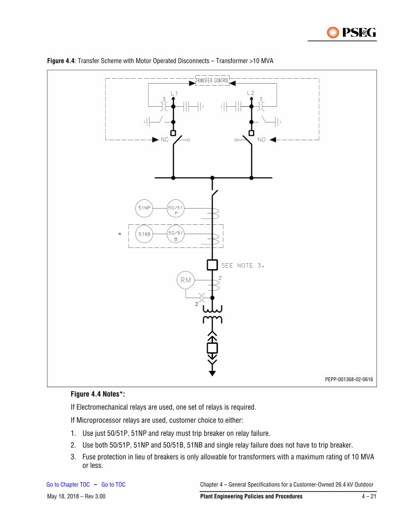
Figure 4.4: Transfer Scheme with Motor Operated Disconnects – Transformer >10 MVA
Figure 4.4 Notes*:
If Electromechanical relays are used, one set of relays is required.
If Microprocessor relays are used, customer choice to either:
1. Use just 50/51P, 51NP and relay must trip breaker on relay failure.
2. Use both 50/51P, 51NP and 50/51B, 51NB and single relay failure does not have to trip breaker.
3. Fuse protection in lieu of breakers is only allowable for transformers with a maximum rating of 10 MVA or less.
PEPP-001368-02-0616
Chapter 4 – General Specifications for a Customer-Owned 26.4 kV Outdoor
May 18, 2018 – Rev 3.00 Plant Engineering Policies and Procedures 4 – 21
Go to Chapter TOC – Go to TOC
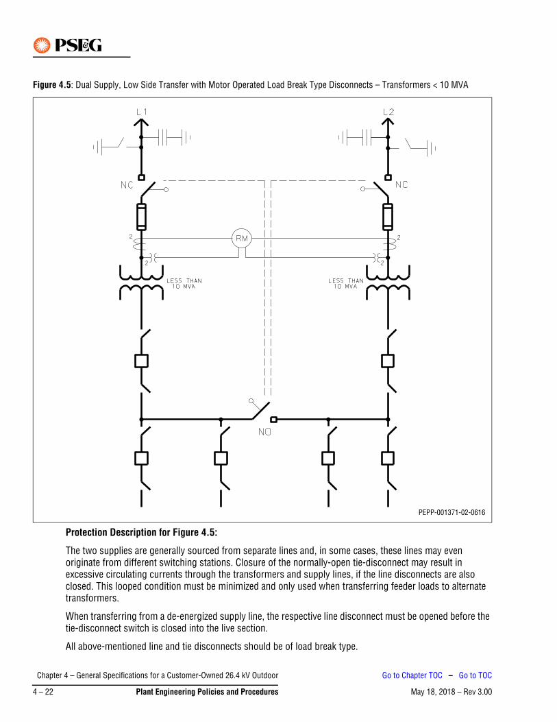
Figure 4.5: Dual Supply, Low Side Transfer with Motor Operated Load Break Type Disconnects – Transformers < 10 MVA
Protection Description for Figure 4.5:
The two supplies are generally sourced from separate lines and, in some cases, these lines may even originate from different switching stations. Closure of the normally-open tie-disconnect may result in excessive circulating currents through the transformers and supply lines, if the line disconnects are also closed. This looped condition must be minimized and only used when transferring feeder loads to alternate transformers.
When transferring from a de-energized supply line, the respective line disconnect must be opened before the tie-disconnect switch is closed into the live section.
All above-mentioned line and tie disconnects should be of load break type.
PEPP-001371-02-0616
Chapter 4 – General Specifications for a Customer-Owned 26.4 kV Outdoor
May 18, 2018 – Rev 3.004 – 22 Plant Engineering Policies and Procedures
Go to Chapter TOC – Go to TOC

Figure 4.6: Dual Supply – Dual Transformers with Line Breakers
PEPP-001372-03-0616
Chapter 4 – General Specifications for a Customer-Owned 26.4 kV Outdoor
May 18, 2018 – Rev 3.00 Plant Engineering Policies and Procedures 4 – 23
Go to Chapter TOC – Go to TOC

Figure 4.7: Multiple Supply – Multiple Transformers with Line Breakers
PEPP-001373-03-0616
Chapter 4 – General Specifications for a Customer-Owned 26.4 kV Outdoor
May 18, 2018 – Rev 3.004 – 24 Plant Engineering Policies and Procedures
Go to Chapter TOC – Go to TOC
Protection Description for Figure 4.6 and Figure 4.7:
1. Each 26 kV feeder is protected by 21-primary, 21-back-up distance relays, and a 67N directional ground overcurrent relay. The 67N ground overcurrent relay is torque controlled by overcurrent relay 50N.
2. Depending on the customer’s location within the network, and its proximity to PSE&G substations, a communications circuit and associated equipment may be required for feeder protection.
a. Each 26 kV bus section will be protected with an 87 (differential) relay. The customer's transformer may or may not be included in the differential zone. If the transformer is not included in the differential zone, time overcurrent relays 51 and 51N will be required for the transformer overcurrent protection.
b. The 50N and 67N relays are only required if the 21B or 21P devices cannot perform these functions.
Chapter 4 – General Specifications for a Customer-Owned 26.4 kV Outdoor
May 18, 2018 – Rev 3.00 Plant Engineering Policies and Procedures 4 – 25
Go to Chapter TOC – Go to TOC
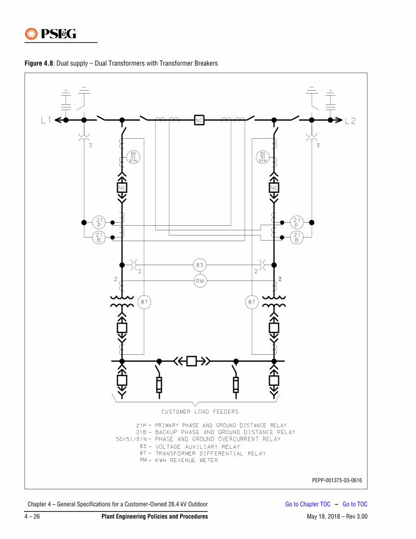
Figure 4.8: Dual supply – Dual Transformers with Transformer Breakers
PEPP-001375-03-0616
Chapter 4 – General Specifications for a Customer-Owned 26.4 kV Outdoor
May 18, 2018 – Rev 3.004 – 26 Plant Engineering Policies and Procedures
Go to Chapter TOC – Go to TOC
Protection and Operating Requirements for Figure 4.8:
Line relaying is required, and the customer should contact PSE&G for recommended relay types. The low-side bus tie breaker must be operated in a normally open position. Interlocks are required between the low-side transformer main breakers and the bus tie such that the bus tie breaker cannot be closed at the same time that both main breakers are closed. Additionally, 26 kV transformer circuit breakers are required, along with overcurrent protection. Transformer differential protection relaying is recommended as well, but not required by PSE&G. The customer may opt to select a relay capable of both overcurrent and differential functions in one microprocessor-based package. Contact PSE&G for recommended relay types. Depending on the customer’s location within the network, and proximity to substations, a communications circuit and associated equipment may be required for line protection.
Chapter 4 – General Specifications for a Customer-Owned 26.4 kV Outdoor
May 18, 2018 – Rev 3.00 Plant Engineering Policies and Procedures 4 – 27
Go to Chapter TOC – Go to TOC
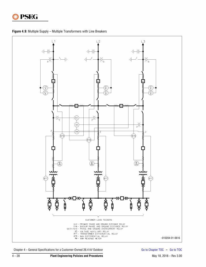
Figure 4.9: Multiple Supply – Multiple Transformers with Line Breakers
PEPP-010204-01-0616
Chapter 4 – General Specifications for a Customer-Owned 26.4 kV Outdoor
May 18, 2018 – Rev 3.004 – 28 Plant Engineering Policies and Procedures
Go to Chapter TOC – Go to TOC
Protection Description for Figure 4.9
1. Each 26 kV feeder is protected by 21-primary, 21-back-up distance relays, and a 67N directional ground overcurrent relay. The 67N ground overcurrent relay is torque controlled by overcurrent relay 50N.
2. Depending on the customer's location within the network, and its proximity to PSE&G substations, a communications circuit and associated equipment may be required for feeder protection.
3. Each 26 kV bus section will be protected with an 87B (differential) relay.
4. Each customer's transformer will be protected with a 87T (differential) relay. Time overcurrent relays 51 and 51N may be required for the transformer overcurrent protection.
5. The 50N and 67N relays are only required if the 21B or 21P devices cannot perform these functions.
Chapter 4 – General Specifications for a Customer-Owned 26.4 kV Outdoor
May 18, 2018 – Rev 3.00 Plant Engineering Policies and Procedures 4 – 29
Go to Chapter TOC – Go to TOC

Figure 4.10: Supply to Remote Non-Utility Substation with Generation (Non-Export)
PEPP-001376-03-0616
Chapter 4 – General Specifications for a Customer-Owned 26.4 kV Outdoor
May 18, 2018 – Rev 3.004 – 30 Plant Engineering Policies and Procedures
Go to Chapter TOC – Go to TOC
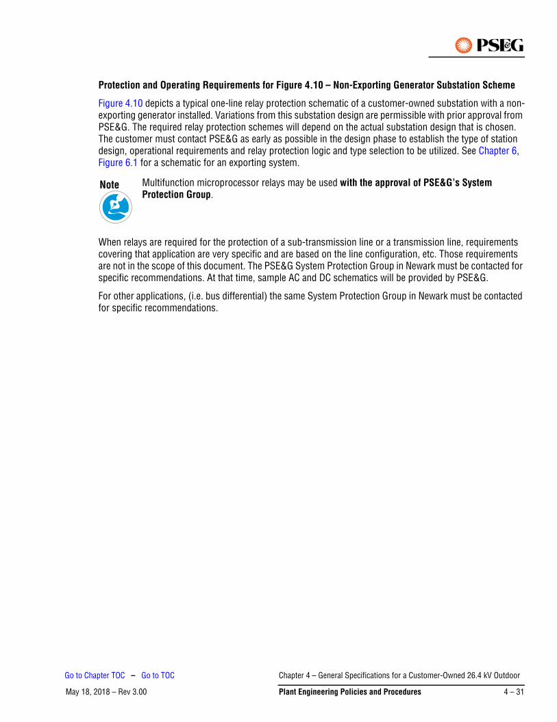
Protection and Operating Requirements for Figure 4.10 – Non-Exporting Generator Substation Scheme
Figure 4.10 depicts a typical one-line relay protection schematic of a customer-owned substation with a non-exporting generator installed. Variations from this substation design are permissible with prior approval from PSE&G. The required relay protection schemes will depend on the actual substation design that is chosen. The customer must contact PSE&G as early as possible in the design phase to establish the type of station design, operational requirements and relay protection logic and type selection to be utilized. See Chapter 6, Figure 6.1 for a schematic for an exporting system.
When relays are required for the protection of a sub-transmission line or a transmission line, requirements covering that application are very specific and are based on the line configuration, etc. Those requirements are not in the scope of this document. The PSE&G System Protection Group in Newark must be contacted for specific recommendations. At that time, sample AC and DC schematics will be provided by PSE&G.
For other applications, (i.e. bus differential) the same System Protection Group in Newark must be contacted for specific recommendations.
Multifunction microprocessor relays may be used with the approval of PSE&G’s System Protection Group.
Note
Chapter 4 – General Specifications for a Customer-Owned 26.4 kV Outdoor
May 18, 2018 – Rev 3.00 Plant Engineering Policies and Procedures 4 – 31
Go to Chapter TOC – Go to TOC
Figure 4.11: Customer’s 26 kV Outdoor Metering Arrangement for Metering Transformers JKW-200 with JVT-200
PEPP-002083-02-0616
Chapter 4 – General Specifications for a Customer-Owned 26.4 kV Outdoor
May 18, 2018 – Rev 3.004 – 32 Plant Engineering Policies and Procedures
Go to Chapter TOC – Go to TOC
Figure 4.11 Notes:
1. Minimum clearance phase-to-ground 15 in.
2. Minimum clearance phase-to-phase 28 in.
3. Minimum vertical clearance from bottom petticoat of transformer bushing to grade or any other horizontal surface suitable for standing on it (for example, platform) should be 8 ft- 6 in. minimum.
4. For detail of potential transformer see Meter and Wiring Manual Figure 10.46 (Figure 4.14).
5. For detail of current transformers see Meter and Wiring Manual Figures 10.36 and 10.37 (Figure 4.12 and Figure 4.13 respectively).
6. Transformers may be mounted to the structure as shown or may be attached to concrete pedestals, (shown as dotted lines).
7. All conduits shall be threaded galvanized rigid steel or weatherproof flexible conduit.
8. A 1/2 in. Everdur stud, projecting 1-1/2 in. inside and outside box with double nuts on both sides, shall be provided for secondary grounding connections, with external tie-in to the ground bus.
9. Metering transformers, transformer secondary grounding stud, and conduit shall be solidly connected to the station ground bus by using direct copper connections of not less than 350 MCM, or flat copper bar 2 in. x 1/4 in. in cross section.
10. All steel bracing in the vicinity of current and potential transformers shall have 15 in. minimum clearance from live parts.
11. When installing #2 PT reverse secondary connections.
12. 1-1/2 in. weatherproof flexible conduit or 1 in. rigid galvanized steel conduit minimum (if conduit, use Erikson fittings).
Chapter 4 – General Specifications for a Customer-Owned 26.4 kV Outdoor
May 18, 2018 – Rev 3.00 Plant Engineering Policies and Procedures 4 – 33
Go to Chapter TOC – Go to TOC
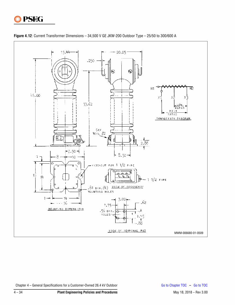
Figure 4.12: Current Transformer Dimensions – 34,500 V GE JKW-200 Outdoor Type – 25/50 to 300/600 A
MWM-006680-01-0509
Chapter 4 – General Specifications for a Customer-Owned 26.4 kV Outdoor
May 18, 2018 – Rev 3.004 – 34 Plant Engineering Policies and Procedures
Go to Chapter TOC – Go to TOC
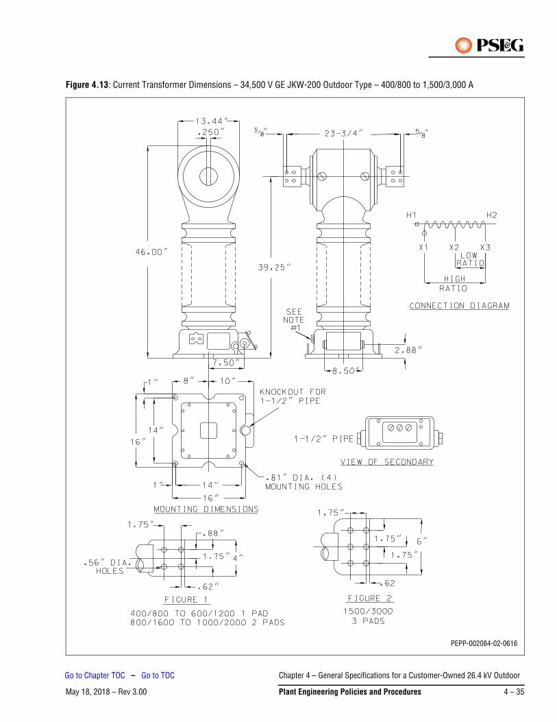
Figure 4.13: Current Transformer Dimensions – 34,500 V GE JKW-200 Outdoor Type – 400/800 to 1,500/3,000 A
PEPP-002084-02-0616
Chapter 4 – General Specifications for a Customer-Owned 26.4 kV Outdoor
May 18, 2018 – Rev 3.00 Plant Engineering Policies and Procedures 4 – 35
Go to Chapter TOC – Go to TOC
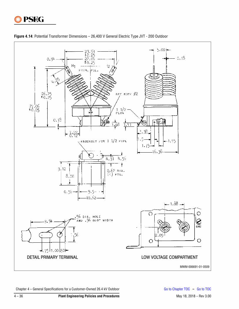
Figure 4.14: Potential Transformer Dimensions – 26,400 V General Electric Type JVT - 200 Outdoor
DETAIL PRIMARY TERMINAL LOW VOLTAGE COMPARTMENT
MWM-006691-01-0509
Chapter 4 – General Specifications for a Customer-Owned 26.4 kV Outdoor
May 18, 2018 – Rev 3.004 – 36 Plant Engineering Policies and Procedures
Go to Chapter TOC – Go to TOC
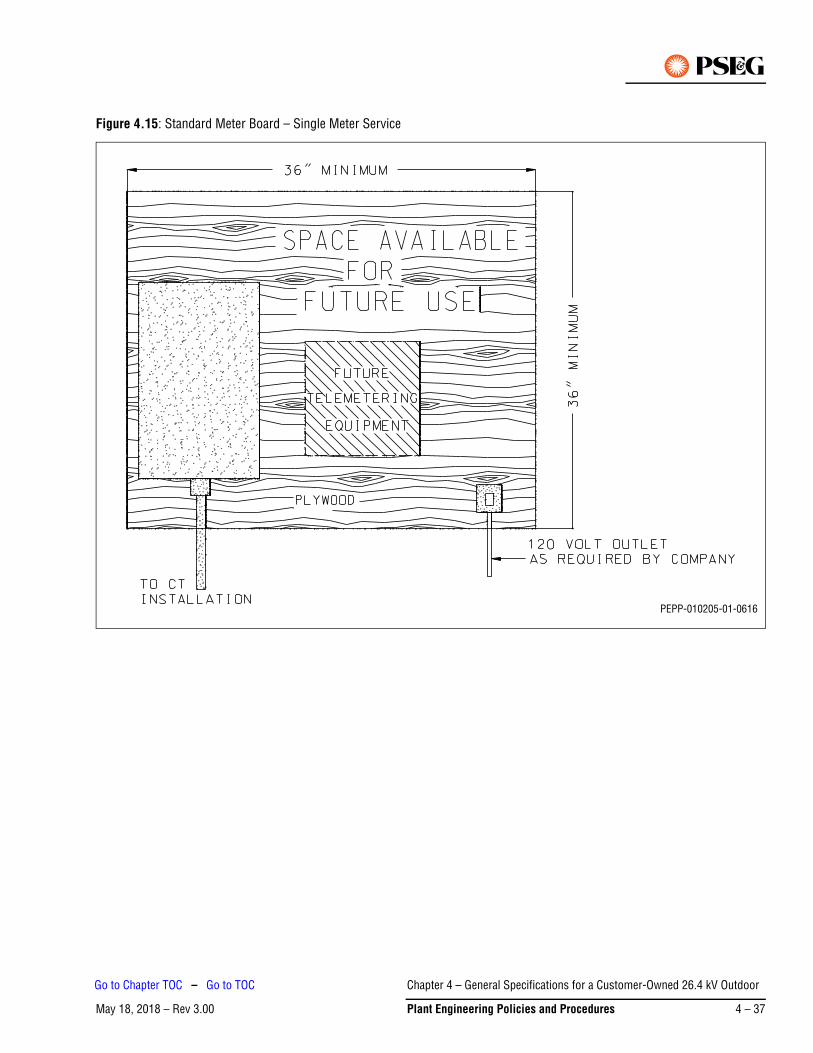
Figure 4.15: Standard Meter Board – Single Meter Service
PEPP-010205-01-0616
Chapter 4 – General Specifications for a Customer-Owned 26.4 kV Outdoor
May 18, 2018 – Rev 3.00 Plant Engineering Policies and Procedures 4 – 37
Go to Chapter TOC – Go to TOC
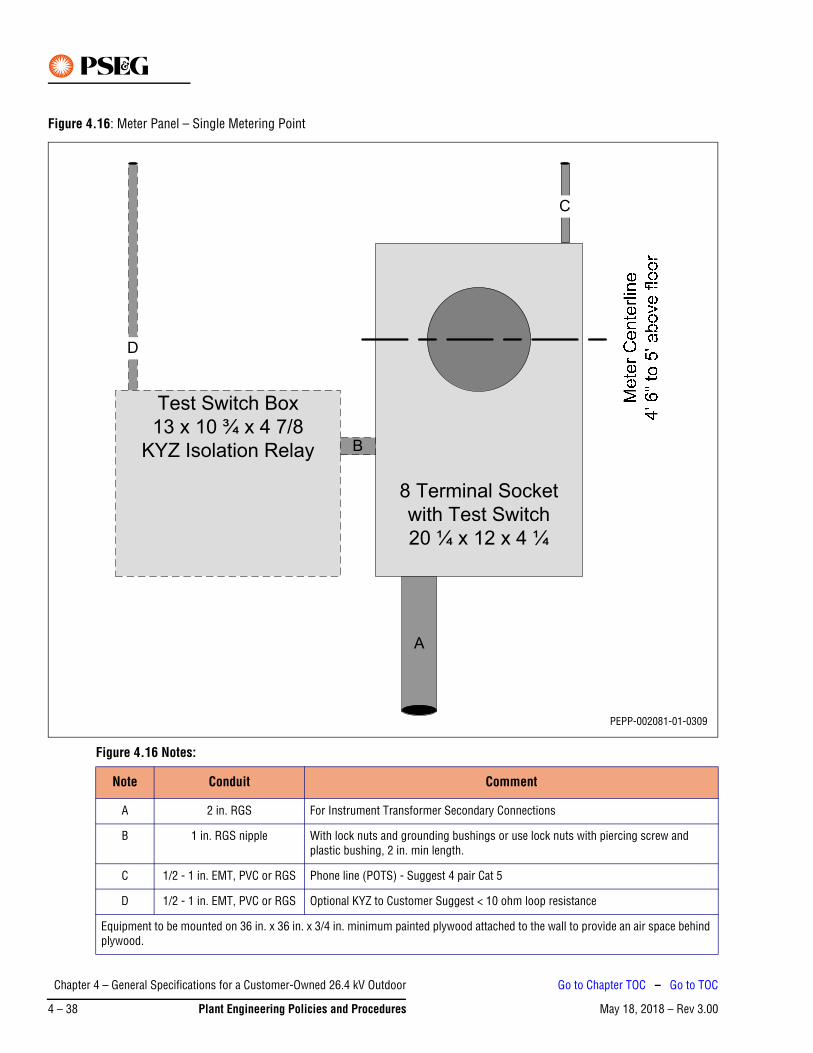
Figure 4.16: Meter Panel – Single Metering Point
Figure 4.16 Notes:
Note Conduit Comment
A 2 in. RGS For Instrument Transformer Secondary Connections
B 1 in. RGS nipple With lock nuts and grounding bushings or use lock nuts with piercing screw and plastic bushing, 2 in. min length.
C 1/2 - 1 in. EMT, PVC or RGS Phone line (POTS) - Suggest 4 pair Cat 5
D 1/2 - 1 in. EMT, PVC or RGS Optional KYZ to Customer Suggest < 10 ohm loop resistance
Equipment to be mounted on 36 in. x 36 in. x 3/4 in. minimum painted plywood attached to the wall to provide an air space behind plywood.
8 Terminal Socket
with Test Switch
20 ¼ x 12 x 4 ¼
Test Switch Box
13 x 10 ¾ x 4 7/8
KYZ Isolation Relay B
D
C
A
PEPP-002081-01-0309
Chapter 4 – General Specifications for a Customer-Owned 26.4 kV Outdoor
May 18, 2018 – Rev 3.004 – 38 Plant Engineering Policies and Procedures
Go to Chapter TOC – Go to TOC
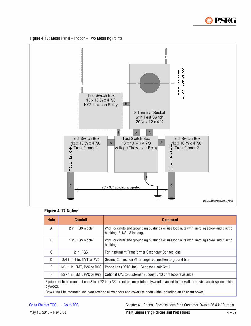
Figure 4.17: Meter Panel – Indoor – Two Metering Points
Figure 4.17 Notes:
Note Conduit Comment
A 2 in. RGS nipple With lock nuts and grounding bushings or use lock nuts with piercing screw and plastic bushing, 2-1/2 - 3 in. long.
B 1 in. RGS nipple With lock nuts and grounding bushings or use lock nuts with piercing screw and plastic bushing
C 2 in. RGS For Instrument Transformer Secondary Connections
D 3/4 in. - 1 in. EMT or PVC Ground Connection #8 or larger connection to ground bus
E 1/2 - 1 in. EMT, PVC or RGS Phone line (POTS line) - Suggest 4 pair Cat 5
F 1/2 - 1 in. EMT, PVC or RGS Optional KYZ to Customer Suggest < 10 ohm loop resistance
Equipment to be mounted on 48 in. x 72 in. x 3/4 in. minimum painted plywood attached to the wall to provide an air space behind plywood.
Boxes shall be mounted and connected to allow doors and covers to open without binding on adjacent boxes.
8 Terminal Socket
with Test Switch
20 ¼ x 12 x 4 ¼
Test Switch Box
13 x 10 ¾ x 4 7/8
Voltage Thow-over Relay
C
Test Switch Box
13 x 10 ¾ x 4 7/8
Transformer 2
A A
Test Switch Box
13 x 10 ¾ x 4 7/8
Transformer 1
AA
Test Switch Box
13 x 10 ¾ x 4 7/8
KYZ Isolation Relay B
C
F
28" - 30" Spacing suggested
B
E
D
PEPP-001369-01-0309
Chapter 4 – General Specifications for a Customer-Owned 26.4 kV Outdoor
May 18, 2018 – Rev 3.00 Plant Engineering Policies and Procedures 4 – 39
Go to Chapter TOC – Go to TOC
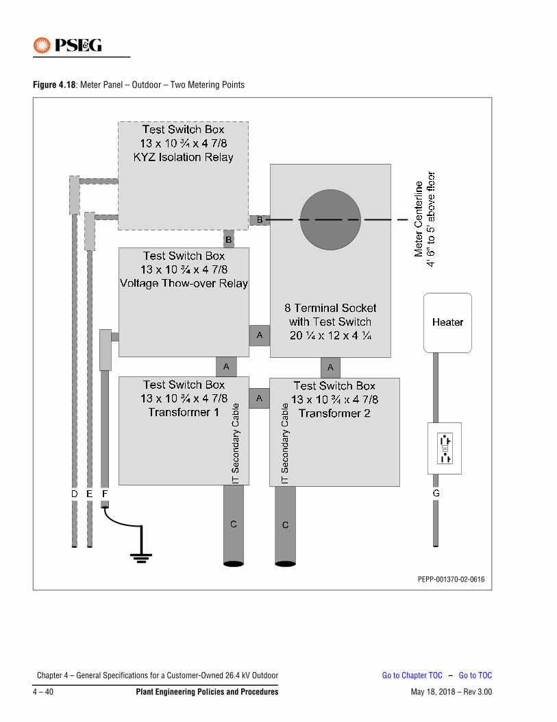
Figure 4.18: Meter Panel – Outdoor – Two Metering Points
PEPP-001370-02-0616
Chapter 4 – General Specifications for a Customer-Owned 26.4 kV Outdoor
May 18, 2018 – Rev 3.004 – 40 Plant Engineering Policies and Procedures
Go to Chapter TOC – Go to TOC
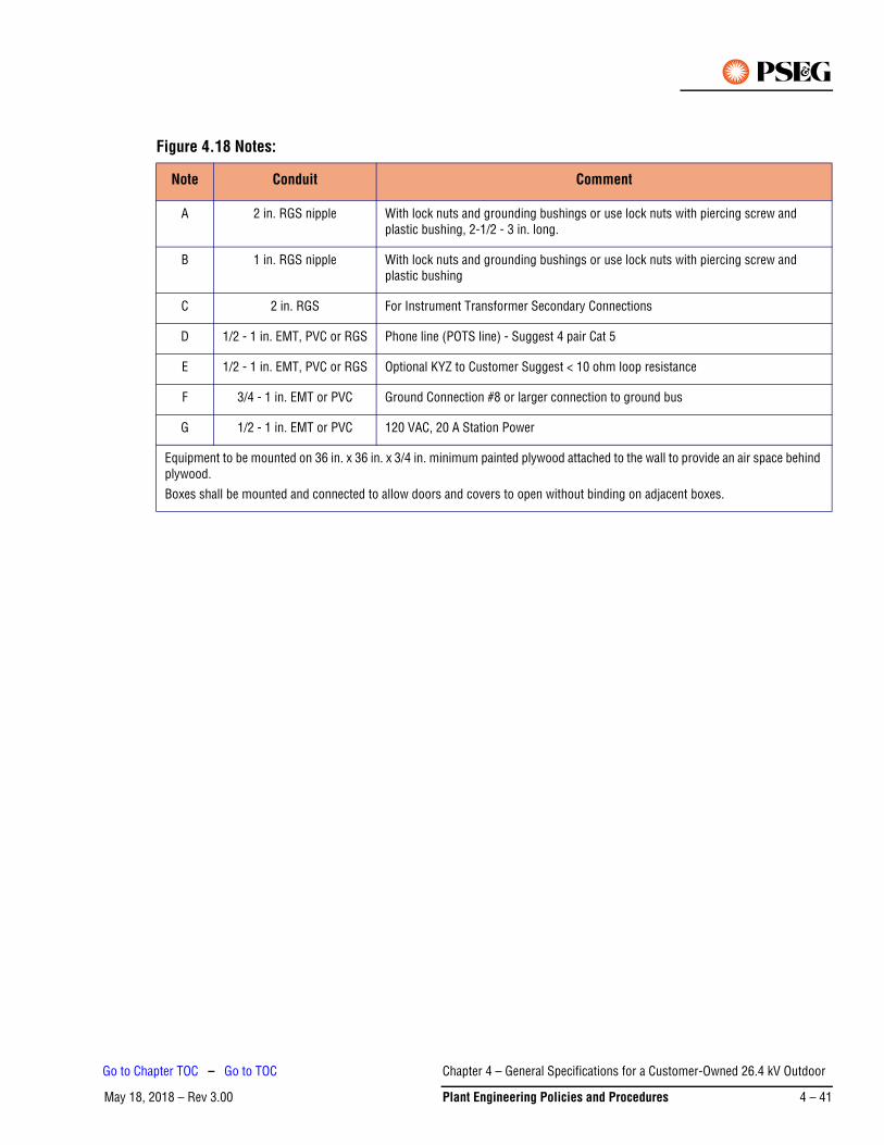
Figure 4.18 Notes:
Note Conduit Comment
A 2 in. RGS nipple With lock nuts and grounding bushings or use lock nuts with piercing screw and plastic bushing, 2-1/2 - 3 in. long.
B 1 in. RGS nipple With lock nuts and grounding bushings or use lock nuts with piercing screw and plastic bushing
C 2 in. RGS For Instrument Transformer Secondary Connections
D 1/2 - 1 in. EMT, PVC or RGS Phone line (POTS line) - Suggest 4 pair Cat 5
E 1/2 - 1 in. EMT, PVC or RGS Optional KYZ to Customer Suggest < 10 ohm loop resistance
F 3/4 - 1 in. EMT or PVC Ground Connection #8 or larger connection to ground bus
G 1/2 - 1 in. EMT or PVC 120 VAC, 20 A Station Power
Equipment to be mounted on 36 in. x 36 in. x 3/4 in. minimum painted plywood attached to the wall to provide an air space behind plywood.
Boxes shall be mounted and connected to allow doors and covers to open without binding on adjacent boxes.
Chapter 4 – General Specifications for a Customer-Owned 26.4 kV Outdoor
May 18, 2018 – Rev 3.00 Plant Engineering Policies and Procedures 4 – 41
Go to Chapter TOC – Go to TOC

Figure 4.19: Disc Insulator Assembly Dead-End on Customer’s Structure
Figure 4.19 Note:
All line termination insulators and hardware will be provided and installed by PSE&G.
PEPP-002082-03-0616
Chapter 4 – General Specifications for a Customer-Owned 26.4 kV Outdoor
May 18, 2018 – Rev 3.004 – 42 Plant Engineering Policies and Procedures
Go to Chapter TOC – Go to TOC
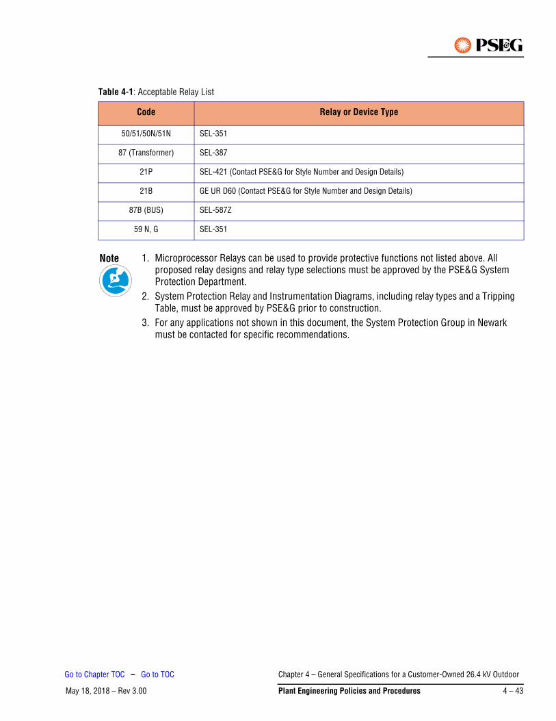
Table 4-1: Acceptable Relay List
Code Relay or Device Type
50/51/50N/51N SEL-351
87 (Transformer) SEL-387
21P SEL-421 (Contact PSE&G for Style Number and Design Details)
21B GE UR D60 (Contact PSE&G for Style Number and Design Details)
87B (BUS) SEL-587Z
59 N, G SEL-351
1. Microprocessor Relays can be used to provide protective functions not listed above. All proposed relay designs and relay type selections must be approved by the PSE&G System Protection Department.
2. System Protection Relay and Instrumentation Diagrams, including relay types and a Tripping Table, must be approved by PSE&G prior to construction.
3. For any applications not shown in this document, the System Protection Group in Newark must be contacted for specific recommendations.
Note
Chapter 4 – General Specifications for a Customer-Owned 26.4 kV Outdoor
May 18, 2018 – Rev 3.00 Plant Engineering Policies and Procedures 4 – 43
Go to Chapter TOC – Go to TOC
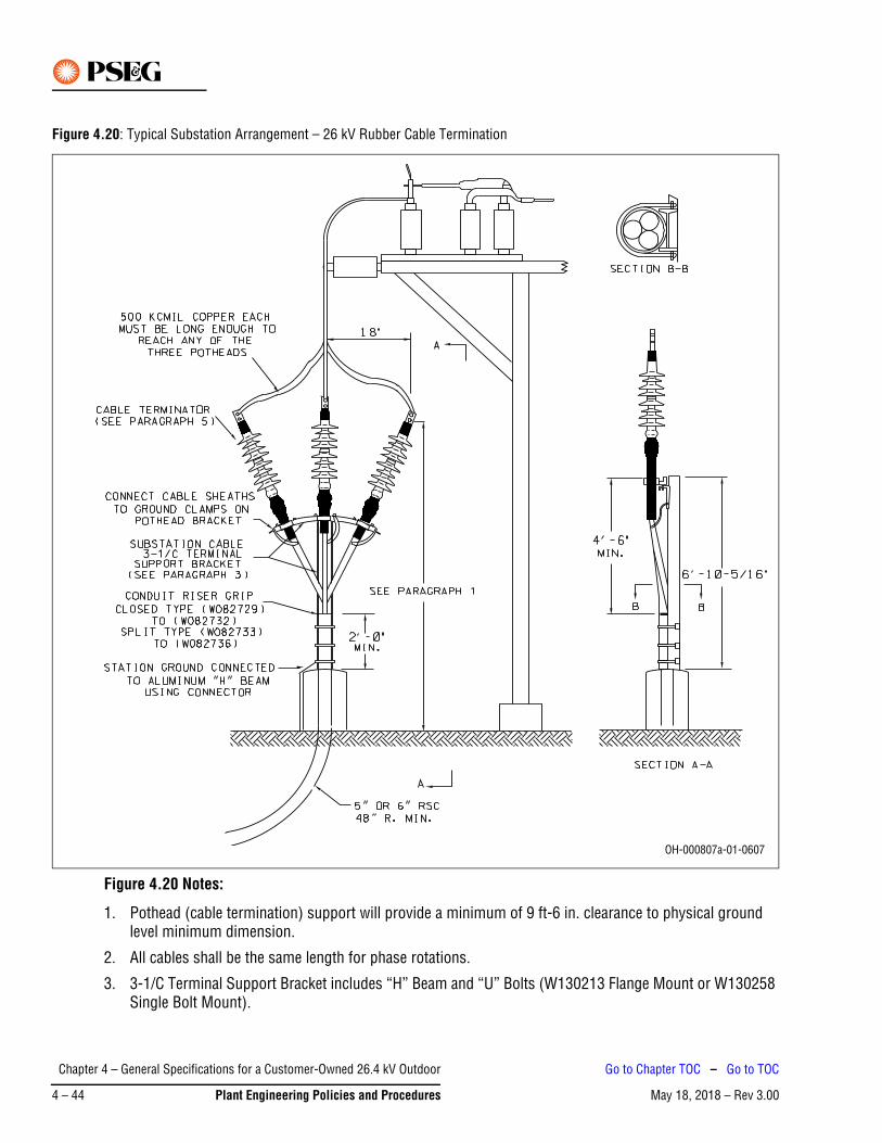
Figure 4.20: Typical Substation Arrangement – 26 kV Rubber Cable Termination
Figure 4.20 Notes:
1. Pothead (cable termination) support will provide a minimum of 9 ft-6 in. clearance to physical ground level minimum dimension.
2. All cables shall be the same length for phase rotations.
3. 3-1/C Terminal Support Bracket includes “H” Beam and “U” Bolts (W130213 Flange Mount or W130258 Single Bolt Mount).
OH-000807a-01-0607
Chapter 4 – General Specifications for a Customer-Owned 26.4 kV Outdoor
May 18, 2018 – Rev 3.004 – 44 Plant Engineering Policies and Procedures
Go to Chapter TOC – Go to TOC

4. Terminal Support Bracket may be oriented 90 degrees from position shown above to accommodate customer equipment, where applicable (i.e. potential transformers). Phasing can be accomplished by switching cable and terminators.
5. For terminator Class/Code number, installation instructions, and aerial lug, see appropriate section of the Overhead Construction Outside Plant Manual: Splices, Ties and Overhead Connections for terminator being installed.
Chapter 4 – General Specifications for a Customer-Owned 26.4 kV Outdoor
May 18, 2018 – Rev 3.00 Plant Engineering Policies and Procedures 4 – 45
Go to Chapter TOC – Go to TOC
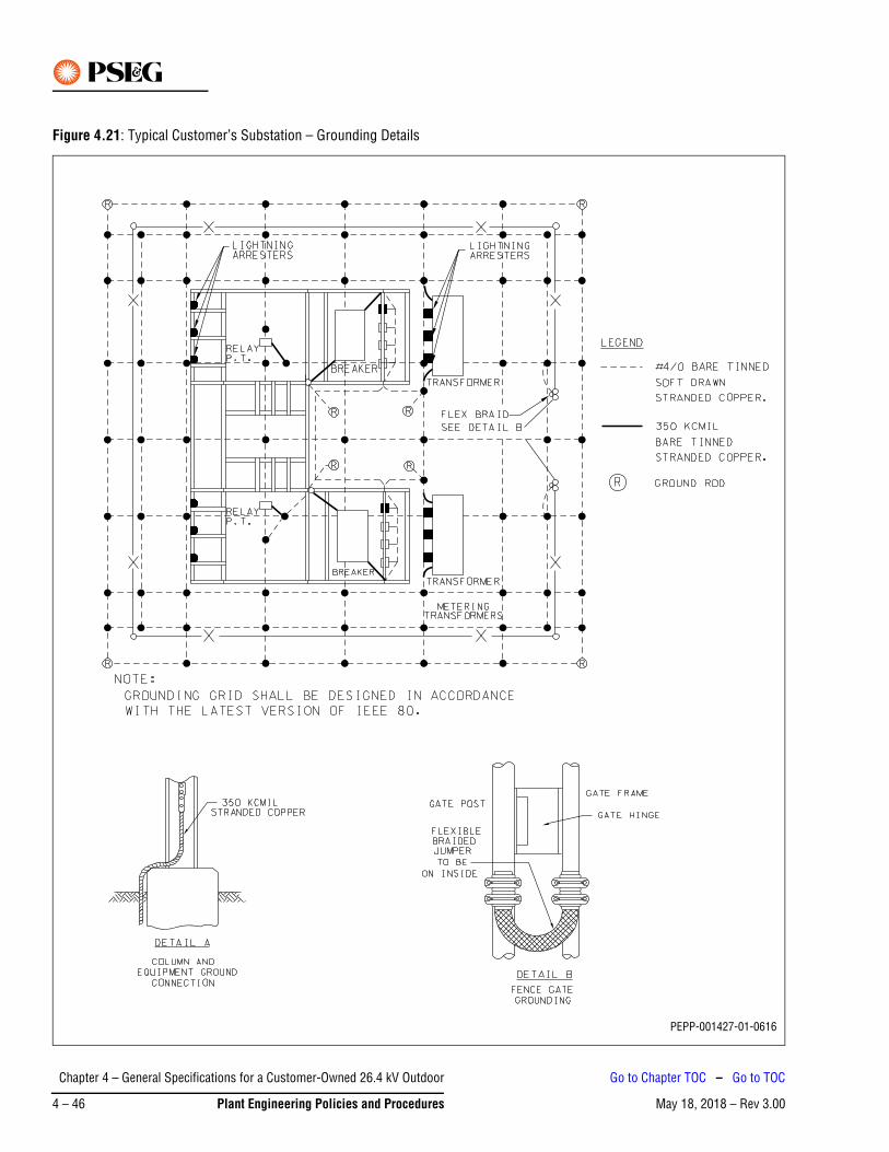
Figure 4.21: Typical Customer’s Substation – Grounding Details
PEPP-001427-01-0616
Chapter 4 – General Specifications for a Customer-Owned 26.4 kV Outdoor
May 18, 2018 – Rev 3.004 – 46 Plant Engineering Policies and Procedures
Go to Chapter TOC – Go to TOC
Figure 4.21 Notes:
1. The main station ground grid is to be made of # 4/0 AWG Bare Tinned Stranded Copper (minimum).
2. Connections between the ground grid bus, structure, and various pieces of apparatus are to be direct copper connections of # 4/0 AWG Stranded or 2 in. x 1/4 in. Bar (minimum).
3. Ground connectors may be of the welded, bolted or compression type. Bolted connectors must utilize at least two independent bolts or two U-Bolts.
4. Where connectors are in direct contact with structural steel members surfaces, the surface of the connectors shall be tinned.
Chapter 4 – General Specifications for a Customer-Owned 26.4 kV Outdoor
May 18, 2018 – Rev 3.00 Plant Engineering Policies and Procedures 4 – 47
Go to Chapter TOC – Go to TOC

This Page Intentionally Blank
Chapter 4 – General Specifications for a Customer-Owned 26.4 kV Outdoor
May 18, 2018 – Rev 3.004 – 48 Plant Engineering Policies and Procedures
Go to Chapter TOC – Go to TOC
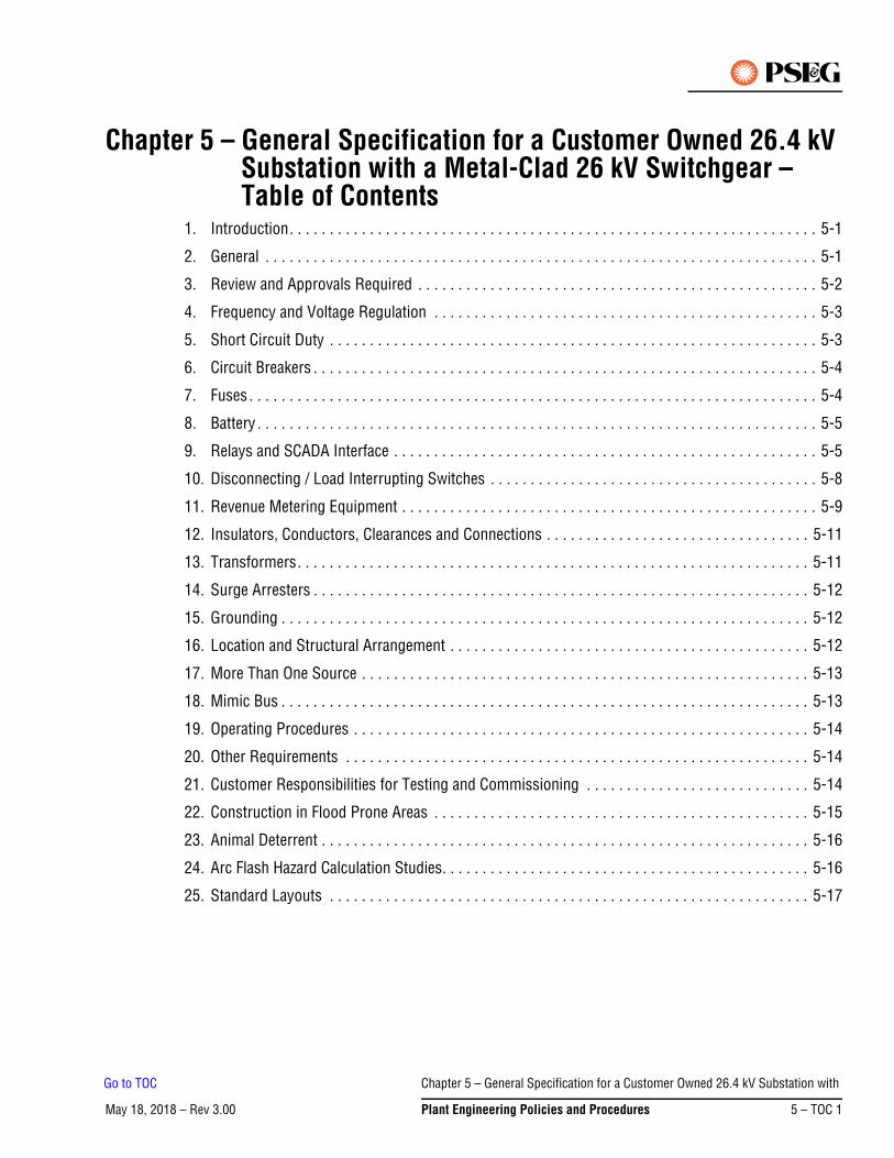
May 18, 2018 – Rev 3.00Go to Chapter TOC
Chapter 5 – General Specification for a Customer Owned 26.4 kV Substation with a Metal-Clad 26 kV Switchgear – Table of Contents
1. Introduction. . . . . . . . . . . . . . . . . . . . . . . . . . . . . . . . . . . . . . . . . . . . . . . . . . . . . . . . . . . . . . . . . . 5-1
2. General . . . . . . . . . . . . . . . . . . . . . . . . . . . . . . . . . . . . . . . . . . . . . . . . . . . . . . . . . . . . . . . . . . . . . 5-1
3. Review and Approvals Required . . . . . . . . . . . . . . . . . . . . . . . . . . . . . . . . . . . . . . . . . . . . . . . . . . 5-2
4. Frequency and Voltage Regulation . . . . . . . . . . . . . . . . . . . . . . . . . . . . . . . . . . . . . . . . . . . . . . . . 5-3
5. Short Circuit Duty . . . . . . . . . . . . . . . . . . . . . . . . . . . . . . . . . . . . . . . . . . . . . . . . . . . . . . . . . . . . . 5-3
6. Circuit Breakers . . . . . . . . . . . . . . . . . . . . . . . . . . . . . . . . . . . . . . . . . . . . . . . . . . . . . . . . . . . . . . . 5-4
7. Fuses . . . . . . . . . . . . . . . . . . . . . . . . . . . . . . . . . . . . . . . . . . . . . . . . . . . . . . . . . . . . . . . . . . . . . . . 5-4
8. Battery . . . . . . . . . . . . . . . . . . . . . . . . . . . . . . . . . . . . . . . . . . . . . . . . . . . . . . . . . . . . . . . . . . . . . . 5-5
9. Relays and SCADA Interface . . . . . . . . . . . . . . . . . . . . . . . . . . . . . . . . . . . . . . . . . . . . . . . . . . . . . 5-5
10. Disconnecting / Load Interrupting Switches . . . . . . . . . . . . . . . . . . . . . . . . . . . . . . . . . . . . . . . . . 5-8
11. Revenue Metering Equipment . . . . . . . . . . . . . . . . . . . . . . . . . . . . . . . . . . . . . . . . . . . . . . . . . . . . 5-9
12. Insulators, Conductors, Clearances and Connections . . . . . . . . . . . . . . . . . . . . . . . . . . . . . . . . . 5-11
13. Transformers. . . . . . . . . . . . . . . . . . . . . . . . . . . . . . . . . . . . . . . . . . . . . . . . . . . . . . . . . . . . . . . . 5-11
14. Surge Arresters . . . . . . . . . . . . . . . . . . . . . . . . . . . . . . . . . . . . . . . . . . . . . . . . . . . . . . . . . . . . . . 5-12
15. Grounding . . . . . . . . . . . . . . . . . . . . . . . . . . . . . . . . . . . . . . . . . . . . . . . . . . . . . . . . . . . . . . . . . . 5-12
16. Location and Structural Arrangement . . . . . . . . . . . . . . . . . . . . . . . . . . . . . . . . . . . . . . . . . . . . . 5-12
17. More Than One Source . . . . . . . . . . . . . . . . . . . . . . . . . . . . . . . . . . . . . . . . . . . . . . . . . . . . . . . . 5-13
18. Mimic Bus . . . . . . . . . . . . . . . . . . . . . . . . . . . . . . . . . . . . . . . . . . . . . . . . . . . . . . . . . . . . . . . . . . 5-13
19. Operating Procedures . . . . . . . . . . . . . . . . . . . . . . . . . . . . . . . . . . . . . . . . . . . . . . . . . . . . . . . . . 5-14
20. Other Requirements . . . . . . . . . . . . . . . . . . . . . . . . . . . . . . . . . . . . . . . . . . . . . . . . . . . . . . . . . . 5-14
21. Customer Responsibilities for Testing and Commissioning . . . . . . . . . . . . . . . . . . . . . . . . . . . . 5-14
22. Construction in Flood Prone Areas . . . . . . . . . . . . . . . . . . . . . . . . . . . . . . . . . . . . . . . . . . . . . . . 5-15
23. Animal Deterrent . . . . . . . . . . . . . . . . . . . . . . . . . . . . . . . . . . . . . . . . . . . . . . . . . . . . . . . . . . . . . 5-16
24. Arc Flash Hazard Calculation Studies. . . . . . . . . . . . . . . . . . . . . . . . . . . . . . . . . . . . . . . . . . . . . . 5-16
25. Standard Layouts . . . . . . . . . . . . . . . . . . . . . . . . . . . . . . . . . . . . . . . . . . . . . . . . . . . . . . . . . . . . 5-17
Chapter 5 – General Specification for a Customer Owned 26.4 kV Substation with
May 18, 2018 – Rev 3.00 Plant Engineering Policies and Procedures 5 – TOC 1
Go to TOC

This Page Intentionally Blank
Chapter 5 – General Specification for a Customer Owned 26.4 kV Substation with
May 18, 2018 – Rev 3.005 – TOC 2 Plant Engineering Policies and Procedures
Go to TOC
May 18, 2018 – Rev 3.00
Chapter 5 – General Specification for a Customer-Owned 26.4 kV Substation with a Metal-Clad 26 kV Switchgear
1. IntroductionPSE&G is committed to providing a safe environment for our employees and safe, adequate and reliable electric service to our customers.
These General Specifications are provided to assist the customer and their agents in developing the necessary detailed substation specifications for acceptable operation on PSE&G’s 26.4 kV electrical system.
The Addendum to these General Specifications show typical one-line substation configurations (Figure 5.1 through Figure 5.11) that are acceptable for operation on PSE&G’s 26.4 kV electrical system. Not all configurations are available everywhere on the system nor is every possible configuration shown. Preliminary discussions with PSE&G are recommended to determine what is available to best serve the customer's requirements.
In accordance with Section 5.1 of the Standard Terms and Conditions of PSE&G’s Electric Tariff B.P.U.N.J. No. 15, the customer's 26.4 kV bus is considered part of PSE&G’s distribution system for operational purposes, and system power may flow through the customer’s bus with no remuneration to the customer by PSE&G.
2. GeneralThe following general requirements apply to customer substations:
1. PSE&G requires that all customer substations supplied from the 26.4 kV impedance grounded electrical system shall be designed for 34.5 kV operation and that all construction and equipment shall be rated and tested at a minimum of 38 kV voltage level classification, 150 kV BIL, unless otherwise specified.
2. All aspects of the Metal Clad / Metal-Enclosed Switchgear associated with Customer Owned Substations shall conform with the latest versions of American National Standards Institute (ANSI) / Institute of Electrical and Electronics Engineers (IEEE) Standards C37.20.3, C37.20.4 and C37.20.2.
3. The 26.4 kV system is resistance grounded through an 8 or 9 ohm neutral resistor that is installed in PSE&G’s switching stations. Under certain conditions this neutral resistor may be bypassed, effectively grounding the system. During single phase Ground Fault events, the unfaulted phases may rise to 31 kV over ground potential. Maximum voltage as seen by switching and interrupting devices will not exceed 29.0 kV during ground faults. These effects should be considered in the design of the customer's relaying. PSE&G requires that all indoor customer substations supplied from the 26.4 kV impedance grounded electrical system shall be designed for 34.5 kV operation and that all construction and equipment shall be rated and tested at a minimum of 38 kV voltage level classification, 150 kV BIL, unless otherwise specified.
4. Prior to purchasing any equipment, PSE&G shall be contacted for details on types of equipment and relays suitable for the substation design selected by the customer.
5. Customer shall submit to the Division 26 kV Planner two copies of the conceptual one-line (electronic version in PDF format) as part of the first contact with PSE&G. The one line shall clearly indicate all proposed protection (function / make and model) and all equipment ratings. One copy shall be addressed to the Division 26 kV Planner and the other to the Electric Meter Supervisor.
Chapter 5 – General Specification for a Customer-Owned 26.4 kV Substation
May 18, 2018 – Rev 3.00 Plant Engineering Policies and Procedures 5 – 1
Go to Chapter TOC – Go to TOC
3. Review and Approvals RequiredThe following are requirements for the review and approval of the customer’s substation:
1. Five sets of the final substation plans, and an electronic version in PDF format, shall be submitted to PSE&G for its review so as to ensure that the design satisfies PSE&G’s technical requirements. Such review must be completed prior to the fabrication of apparatus and the supporting structure.
2. Specifically, the drawings submitted should cover the following items:
a. Single-line diagram of the substation including secondary connections to the main transformers, bus and feeder breaker arrangements and connections.
b. Written procedure on how the customer substation will be operated.
c. DC and AC schematic diagrams of the relaying and control of all 26.4 kV automatic apparatus.
d. A plot plan showing the location of the substation with regard to all structures within 100 ft thereof.
e. A manhole and conduit drawing representing incoming lines and instrument transformer secondary circuits used for revenue metering.
f. Switchgear plans and elevation views showing at a minimum incoming terminations and revenue instrument transformer cubicles. These drawings will confirm clearances and how instrument transformers are installed.
g. Substation plan and elevation views whether indoor or outdoor.
h. A listing of the major equipment and materials, including their electrical characteristics and the manufacturer’s description, unless these are detailed on the drawings.
i. The location and arrangement of metering, indication and control panels. See Section 9. Number 7. for SCADA requirements and details.
j. The substation grounding plans, details and calculations.
k. System protection relay and instrumentation single-line diagram.
3. PSE&G’s review of the above final plans and drawings is for general arrangement acceptance and to ensure conformity with PSE&G’s technical requirements only, and does not indicate safe or faultless design. By review of the final plans or drawings, PSE&G is indicating that the design is compatible with PSE&G’s equipment and service. Responsibility for proper design, operation, maintenance and safety of the customer’s installation rests solely with the customer. In addition, all work and equipment must conform to municipal and all other applicable codes and requirements, including applicable provisions of the National Electrical Code (NEC) and the National Electrical Safety Code (NESC) in effect at the time of construction.
4. Final acceptance by PSE&G before introducing service to the completed installation is dependent upon the customer obtaining approval from the electrical inspection authorities having jurisdiction, and provision by such inspection authority to the local Electric Distribution Division Wiring Inspection Department of an original cut-in card.
PSE&G will not be liable for damages or for injuries sustained by customers or by the equipment of customers or by reason of the condition or character of customer’s facilities or the equipment of others on customer’s premises. PSE&G will not be liable for the use, care, or handling of the electric service delivered to the customer after same passes beyond the point at which PSE&G’s service facilities connect to the customer’s facilities.
Note
Chapter 5 – General Specification for a Customer-Owned 26.4 kV Substation
May 18, 2018 – Rev 3.005 – 2 Plant Engineering Policies and Procedures
Go to Chapter TOC – Go to TOC
5. Unless otherwise specified, PSE&G requires a minimum of 3 weeks after notification of completion of the customer's work and its walk through or inspection of the customer’s installation, to test and set relays, breakers, meters and/or other associated equipment, including developing final cut-over procedures or other documents or procedures required for the customer. Further, any corrective items noted by PSE&G during the final walk through or inspection of the customer’s site must be completed prior to PSE&G beginning its final commissioning work noted above.
4. Frequency and Voltage RegulationThe following are general voltage and frequency conditions on PSE&G’s system that the customer should consider in its substation design:
1. The frequency of PSE&G’s system is normally regulated at 60 Hz (cycles per second) and under usual conditions the variations are limited to 0.1 cycle above or below 60 Hz.
2. The voltage of PSE&G’s 26.4 kV system under normal conditions will be within a range of 105% to 98% of nominal voltage with a maximum variation of 6%. Under emergency conditions the voltage can be within a range of 105% to 95% of nominal voltage with a maximum variation of 8%. If this regulation is not satisfactory for the operation of the customer's plant, it is the customer’s responsibility to install suitable voltage regulation equipment. It should be noted, that during fault conditions, short term voltage fluctuations may occur on PSE&G system which could result in abnormally low voltage and/or unbalanced voltages. In addition, operation of certain types of customer's utilization equipment will adversely affect the power quality of the supply voltage. If the customer has installed critical computer or electronic equipment requiring continuity of service or exceptional service quality, it is the customer’s responsibility to install any necessary uninterruptible power supply and/or a power conditioning device that may be required for this application. All aspects of the Metal Clad/Metal-Enclosed Switchgear associated with Customer Owned Substations shall conform with the latest versions of ANSI / IEEE Standards C37.20.3, C37.20.4and C37.20.2
3. It is also recommended that time-delay protective devices be installed on important motors and other critical equipment. This will permit the customer to avoid unnecessary outages during faults or surges on PSE&G’s system or from the customer's in-plant facilities.
5. Short Circuit DutyThe maximum available three-phase short circuit current on PSE&G’s 26.4 kV system is 31.5 kA (Short Time Symmetrical 2 Seconds) / 50 kA (Momentary 10 Cycle Asymmetrical) / 80 kA (Peak). The construction of PSE&G’s 26.4 kV system is dynamic and subject to change as required for the safe, adequate and reliable operation of the system. PSE&G requires that the customer design its substation for the maximum short circuit current available.
Chapter 5 – General Specification for a Customer-Owned 26.4 kV Substation
May 18, 2018 – Rev 3.00 Plant Engineering Policies and Procedures 5 – 3
Go to Chapter TOC – Go to TOC
6. Circuit BreakersThe following are general requirements for circuit breakers:
1. All circuit breakers on the high-voltage side of the customer’s transformers shall meet the most recent edition of ANSI Standard C-37 for 38 kV maximum rated voltage equipment. Line circuit breakers shall have a minimum of 1,200 A continuous current rating. Bus tie breakers may require higher current ratings depending on the substation configuration.
2. PSE&G requires all circuit breakers on the high-voltage side of the customer’s transformers have a minimum short circuit interrupting duty of 31.5 kA (Short Time Symmetrical 2 Seconds) / 50 kA (Momentary 10 Cycle Asymmetrical) / 80 kA (Peak). The line side of the service entrance or transformer circuit breaker shall be provided with a bushing-type, five tap multi-ratio ANSI standard current transformer in each terminal. The current transformer shall be relaying accuracy class of C-400 or better on full tap, and its current rating shall be compatible to the continuous current rating of the breaker.
3. Applications that utilize fixed circuit breakers shall employ key interlocked isolation disconnect switches. The disconnects shall be interlocked so that they can only be opened if the circuit breaker is open/ripped.
7. FusesPSE&G’s preference is for the use of circuit breakers, but in some cases fuses may be utilized on the high-voltage side of the customer’s transformers in lieu of transformer primary circuit breakers. This is only allowable for transformers of up to 10 MVA rating. If fuses are used, the fuses shall be insulated at 38 kV, 150 kV BIL. The fuses shall be able to interrupt short circuits at voltages up to 29.0 kV and withstand voltages up to 38 kV after clearing the fault, voltage rating shall be 38 kV. The fuses shall meet the following requirements:
1. The fuses must be able to coordinate with PSE&G’s source line(s) relaying and with the transformer secondary fuse, breaker or recloser. If the primary fuse is of the expulsion type, the minimum melting time shall be corrected for “preloading”. The selection time between primary and secondary protection for a customer’s transformers shall be a minimum of 0.5 seconds.
2. The fuses shall have an interrupting capacity equal to, or greater than, the maximum asymmetrical short circuit current available on the system, 50 KA.
3. The current rating of the fuse shall be greater than or equal to the transformer manufacturer’s nominal nameplate full load emergency rating. The customer shall submit its proposed fuse type to PSE&G's System Protection Department for approval prior to energization of the substation.
4. The fuses shall meet the most recent requirements of IEEE Standards C37.46 and C37.48.
Only two known types of fuses are currently available for use on the PSE&G 26 kV System in Metal-Enclosed Switchgear. The 38 kV insulated S&C “Fault Fiter” (Electronic Fuse) has a max voltage rating of 29.0 kV and a continuous current rating of up to 1,200 A. The Cooper NX rated at 38 kV has a max continuous current rating of up to 100 A.S&C SM 5 and Cutler Hammer BA fuses have max short circuit clearing capabilities of less than 17 kA asymmetrical and are not acceptable.
Note
Chapter 5 – General Specification for a Customer-Owned 26.4 kV Substation
May 18, 2018 – Rev 3.005 – 4 Plant Engineering Policies and Procedures
Go to Chapter TOC – Go to TOC
8. BatteryA storage battery, or other reliable direct current source, shall be provided to supply DC voltage for automatic tripping of the circuit breaker(s). The latest editions of IEEE Standards 484 and 485 provide guidance in calculating the appropriate battery size and for installation design and procedures. IEEE Std. C37.06 - 2009, Table 18 provides the control voltage range required at the circuit breaker(s).
The battery shall be equipped with an automatic charger, a voltmeter and a low voltage alarm. The low voltage alarm shall be either an audible alarm that will attract a response and a remote alarm to a manned location. Likewise, if another DC source is utilized, it shall be alarmed to indicate loss of voltage.
The battery shall be sized for minimum of an 8-hour discharge rate.
9. Relays and SCADA InterfaceThe following are general requirements for relaying and SCADA equipment:
1. Specific PSE&G requirements will be provided for relays and their associated equipment, as required for the operation of circuit breakers and/or motor-operated disconnecting switches. For the convenience of those customers who plan that their substations will utilize Automatic Sectionalizing or Transfer Schemes, sample relay and control diagrams have been included Section 25. “Standard Layouts” (Figure 5.1 - Figure 5.4). Some other typical substation configurations are shown in Figure 5.6 - Figure 5.11. Additionally, a list of recommended relays that may be used by the customer is included in Table 5-1. In the event that the customer chooses to use alternative relays, these relays must be approved by PSE&G, and the customer will be responsible for applying the relay settings provided by PSE&G using an approved third party testing company at the customer’s expense. Written relay test results must be provided to PSE&G for the initial installation, and every 4 years thereafter, when the settings are verified by an approved testing company.
2. All protective relays shall have provisions for isolating the relays for testing or replacement purposes while the equipment is in service. Relay isolation shall be accomplished by using switches such as the ABB FT-1. Test switches in AC current circuits shall be equipped with test jacks for test connections.
3. The current and potential transformers supplying the relays shall not be used for any other purpose.
a. All Current Transformers (CTs) for relay protection shall adhere to ANSI/IEEE Standard MRCT, C400 class or better.
b. 26 kV breakers shall be equipped with two sets of three-phase CTs on both sides to provide overlapping zones of protection for incoming PSE&G lines, and the customer’s 26 kV bus and 26 kV transformers, unless it is not possible to fit in two sets due to space limitations, in which case the relay and CT arrangement and accuracy class must be submitted to PSE&G for approval of the configuration.
c. Each incoming 26 kV line shall be provided with three line-side single phase Voltage Transformers (VTs), with a 27,600-115 V ratio (240/1), wye-connected on both the primary and secondary sides with secondary winding isolation switches. All VTs shall be of 34.5 kV Nominal System Voltage.
4. It is recommended that the customer consider the installation of differential relaying for the protection of large power transformers.
If differential relaying is installed, the over current relays associated with each service entrance breaker shall be connected to the bushing-type current transformers on the source side of each service entrance breaker. If CTs are not available on the source side of the entrance breaker, load side CTs may be used.
Chapter 5 – General Specification for a Customer-Owned 26.4 kV Substation
May 18, 2018 – Rev 3.00 Plant Engineering Policies and Procedures 5 – 5
Go to Chapter TOC – Go to TOC
5. To facilitate maintenance and eliminate the possibility of vibration damage / inadvertent operation, caution should be observed in the placement of relays for tripping high-voltage circuit breakers. If the protective devices being used are sensitive to vibration, consideration shall be given to not mounting relays in/on a compartment attached to the breaker but rather in/on a separate weatherproof enclosure or rack in the control house or control room.
6. Basic SCADA functionality should be considered for all customer subs. For small 26 kV customers a standard Mini SCADA box shall be used. The box has only dry contact inputs for indication enabled. Standard prints for this class and coded NEMA 4 Mini SCADA box are 311336, 311337, and 311338. This mini SCADA box is PSE&G class and coded with code W930001 and is usually kept in stock by PSE&G. Please contact PSE&G design group for standard prints to be used in designing point to point diagrams and review of proposed design. PSE&G Design should be contacted for direction and final review of the design.
a. PSE&G shall designate, select, specify and purchase the equipment required for SCADA purposes. The applicant shall receive the devices from PSE&G and install the equipment at its facility. If necessary, PSE&G will install any other SCADA equipment required at its facilities, at the applicant's expense. The applicant shall pay PSE&G for all costs associated with SCADA equipment.
b. PSE&G shall require approximately 48 in. x 48 in. of open wall space to install a mini SCADA RTU for monitoring of the station. The mini SCADA RTU dimension is approximately 30 in. H x 30 in. L x 12 in. D.
c. The mini SCADA RTU shall be powered from 125 V DC station batteries as primary source.
d. 120 V AC is required as a back-up source of power. This is also used for the heater and AC convenience outlet.
e. This mini SCADA RTU takes up to 16 dry contact inputs and provides a wetting voltage to the field contact with the power supplied.
f. A standard dial-up phone line, otherwise known as Plain Old Telephone Service (POTS) line and normally ordered and maintained by the customer, is to be terminated at the location of the mini SCADA RTU. The customer in agreement with the operating division shall define who orders and maintains the line.
g. If a standard dial-up POTS line is not available from the telephone service provider, then a fiber optic or T1 connection shall be provided. The customer shall provide an uninterruptable power supply to the router or other interface device. The router or other interface device shall be powered in such a fashion, so that, if power to the facility goes down, the communications system shall be kept “live” for a minimum of at least 8 hours.
7. Recommended indications/alarms shall be as follows if available and should be wired in this order. If the specific alarm is not available, a spare input shall be left in its place. The points listed here are suggestions and of course every site will have slightly different points to be submitted and approved by the local operations and Relay groups. Specific text can be modified in the Master. As a rule of thumb, Station Alarm (as described elsewhere in the alarm bus portion of the spec.), Station Control handle in Auto, Breaker/motor operated disconnect indication, DC System trouble, Station L&P fail are the most basic. The customer must supply:
a. Dry contact and wiring to the RTU cabinet for each available point.
b. Common Station Alarm (If Available and Applicable)
c. Station Control Handle (If Available and Applicable)
Chapter 5 – General Specification for a Customer-Owned 26.4 kV Substation
May 18, 2018 – Rev 3.005 – 6 Plant Engineering Policies and Procedures
Go to Chapter TOC – Go to TOC
d. Fire Alarm (If Available and Applicable)
e. Station Battery System Trouble (If Available and Applicable)
f. Station Light and Power Fail
g. L1 Breaker Status (Any Line Breaker MOC “A” and TOC in Series)
h. Breaker Status (Any Line Breaker MOC “A” and TOC in Series)
i. SEC. 1-2 Breaker Status or Motor operated disconnects
j. Transfer Auto/Manual
k. SPARE
l. SPARE
m. SPARE
n. SPARE
o. SPARE
p. SPARE
q. SPARE
8. The presence of any type of generation running in parallel with the service may result in additional specific protection, SCADA, and ESOC RTU design requirements. The customer engineer is required to identify any generation and obtain direction and approval from PSE&G Design Group based on the specifics of planned installation.
9. Two copies of each relay instruction book for all line and bus relays shall be provided to PSE&G 2 months prior to the expected service date.
10. Note that some multifunction microprocessor relays may be used in lieu of the devices listed in the Acceptable Relay List attached to this document, with the prior approval of PSE&G’s System Protection Group.
11. When relays are required for the protection of a sub-transmission line or a transmission line, requirements covering that application are very specific and are based on the line configuration, etc. Those requirements are not in the scope of this document. The PSE&G System Protection Group in Newark must be contacted for specific recommendations. At that time, sample AC and DC schematics will be provided by PSE&G.
12. For other applications (i.e. bus differential protection discussed in number 4 above) the same System Protection Group in Newark must be contacted for specific relay recommendations.
Chapter 5 – General Specification for a Customer-Owned 26.4 kV Substation
May 18, 2018 – Rev 3.00 Plant Engineering Policies and Procedures 5 – 7
Go to Chapter TOC – Go to TOC
10. Disconnecting / Load Interrupting SwitchesThe following are guidelines for Metal-Enclosed load interrupting disconnecting switches:
1. Guidelines for the application, installation, operation and maintenance of disconnecting switches are described in the latest editions of IEEE NESC C2-2012, Sections 173 and 216, as well as the latest editions of IEEE C37.20.4 and 37.22 2. All Metal-Enclosed Disconnect Switches shall be of 38 kV Class, 150 kV BIL and designed for operation at 34.5 kV unless otherwise noted.
2. The line disconnecting switches shall be three-pole gang-operated devices rated 1,200 A continuous with 1,200 A Minimum (56 MVA) load break capability if used for switching and be tested and capable of at least five full load interruptions at a minimum operating voltage of 29.0 kV. One three-pole, gang-operated line grounding switch shall be installed as a companion to each line disconnecting switch, and shall be mechanically interlocked in such a way that the line grounding switch cannot be closed when the line disconnecting switch is in the closed position, and the line disconnecting switch cannot be closed when the line grounding switch is in the closed position. The line disconnecting switches and the line grounding switches shall be so arranged that they can be padlocked in any position desired. The Ground Switch shall be of 38 kV Class, withstand 150 kV BIL in the open position and have a withstand rating of 31.5 kA (Short Time Symmetrical 2 Seconds) / 50 kA (Momentary 10 Cycle Asymmetrical) / 80 kA (Peak) and meet all applicable operational and test parameters for service in 34.5 kV systems.
3. Line Disconnect Switches and Line Grounding Switches shall be housed in separate isolated cubicles whenever possible. Each switch shall be equipped with a mechanical position indicator, clearly visible from outside of the cubicle door. Line Disconnect Closed – Red, Line Disconnect Open – Green, Ground Open – Green, and Ground Closed – Red.
4. Disconnect switches shall have a Withstand / Fault Make – Latch rating of 31.5 kA (Short Time Symmetrical 2 Seconds) / 50 kA (Momentary 10 cycle Asymmetrical) / 80 kA (Peak).
5. Line disconnecting switches and any line breaker bus disconnecting switches or bus sectionalizing switches shall be rated 1,200 A Continuous. Bus sectionalizing switches may require higher current ratings, depending on the customer’s substation configuration, with 1,200 A minimum (56 MVA) load break capability if used for switching and be tested and capable of at least 5 full load interruptions at an operating voltage of 29.0 kV minimum
6. Where a circuit breaker is not used as the primary side disconnecting means for a main power transformer, then the primary side disconnecting switch shall be capable of interrupting the magnetizing current of the transformer and be rated at least 600 A load break capability and be tested and capable of at least five full load interruptions at an operating voltage of 29.0 kV minimum.
7. Any disconnecting switch mounted vertically shall be hinged at the bottom to prevent accidental closing.
8. Any disconnect switches installed shall be oriented for front access, with the phases arranged 1-2-3 left-to-right, and not oriented as an end unit in a front-to-back configuration.
9. The incoming line compartment (cubicle with ground switch and arrestors) shall be designed to easily handle the pulling and termination of two 750 kcmil EPR type cables per phase.
ANSI Standards do not require ground switches to have a fault close rating since proper operating practice requires the circuit be tested de-energized before closing the ground switch. It must have a momentary rating of 50 kA.
Note
Chapter 5 – General Specification for a Customer-Owned 26.4 kV Substation
May 18, 2018 – Rev 3.005 – 8 Plant Engineering Policies and Procedures
Go to Chapter TOC – Go to TOC
10. Based on minimum spacing requirements outlined in Section 12. Number 5. and Figure 5.17, this incoming cable compartment shall be designed to be at least 60 in. wide and have a pad lockable hinged door to permit incoming cable access without unbolting and metal clad panels, only to PSE&G personnel.
11. Each incoming line compartment shall be equipped with a “View Port” that shall permit an operator to perform infrared scans and to visually determine the position of both disconnect devices without opening the cubicle door. The “View Port” shall be an engineered product that shall be UV, flash resistant and shatter proof. Fluke Series CLK or approved equal.
12. The incoming line compartment (cubicle with ground switch and arrestors) shall have sufficient clearance to safely permit the testing of the incoming line with a “Test Stick”.
13. The incoming line compartment (cubicle with ground switch and arrestors) shall also be equipped with three “Neon Glow Tubes” connected on the incoming line that shall be visible through the “View Ports” to give an indication of an energized line. “Neon Glow Tubes” shall be designed to permit easy replacement.
11. Revenue Metering EquipmentThe following information pertains to revenue metering equipment:
1. PSE&G will furnish two VTs and two CTs for revenue metering, the secondary control cable and test switches for each metering point.
2. PSE&G will not permit the connection of any customer equipment to the metering transformers used for revenue metering. No device other than those used for automatic tripping, or those supplied or required by PSE&G, shall be placed on the line side of the billing meters. The revenue metering transformers shall be installed after main breaker(s) or disconnect(s). In stations with multiple incoming lines, the metering transformers shall be on the load side of the common bus.
a. The customer shall install instrument transformers, wire the high-voltage side and the equipment ground connection. The instrument transformer equipment ground shall be 4/0 AWG minimum, copper wire or equivalent.
b. The primary connections shall be made so that the VTs are connected on the line side of the CTs. These connections shall be direct and shall not be fused. 250 kcmil is the maximum size wire that can be terminated on the VTs, #2 AWG is the minimum size that may be used.
c. The connections to the primary terminals of the CTs shall be designed so that either ABB KOR-20 or GE JKW-7 CTs may be bolted to the bus. (These CTs have different heights from the base plate to the primary terminal connection with the bus.). For details of current transformers see Figure 5.15 - Figure 5.16. CT primary terminals shall not be considered to be bus supports. The bus shall be designed to be properly supported and braced without the need for the CTs to be mounted in place. Polarity markings on CTs shall normally be on the line/utility side of the switchgear. Hardware which may be needed for the installation of alternative CTs shall be stored inside the instrument transformer compartment, preferably not in contact with the concrete pad.
d. The mounting arrangement for the Potential transformers (PTs) shall be designed for GE JVW-7 PTs. For details of potential transformer see Figure 5.17.
e. Connections to metering transformer secondary terminals, test switches, meter equipment and meters will be made by PSE&G.
Chapter 5 – General Specification for a Customer-Owned 26.4 kV Substation
May 18, 2018 – Rev 3.00 Plant Engineering Policies and Procedures 5 – 9
Go to Chapter TOC – Go to TOC
3. VTs and CTs for metering shall be accessible at all reasonable times for the purpose of inspection, maintenance or change-out by PSE&G. If the VTs and CTs are enclosed in switchgear or a transformer cabinet, or compartment where visual inspection is impractical, access shall be limited only to PSE&G’s personnel by a hinged door having provisions for PSE&G’s pad-locks, or barrel locks and seals. Metering transformers, secondary wiring and unmetered primary conductors shall be visible for inspection when the compartments or cabinets are opened and energized.
4. Threaded rigid galvanized steel 2 in. conduit shall be used for the secondary control cable/wires from the switchgear cubical for metering transformers to the meter panel, and shall be supplied and installed by the customer.
a. Conduits for metering transformers secondary connections shall be dedicated conduit that shall not pass through either trenches, hand holes or manholes. Metering conduits shall be inspected prior to backfill or pouring concrete.
b. PSE&G shall furnish the secondary control cables/wires, and the customer shall pull them.
5. A meter panel with minimum dimensions of 36 in. wide x 36 in. high is to be supplied by the customer and installed at a height of no less than 24 in. and no more than 78 in. from the floor. However, if two sets or more of instrument transformers are used, this meter panel shall be 4 ft x 6 ft. Please discuss the meter panel layout with PSE&G’s local Electric Distribution Division Metering Department. This panel shall be located adjacent to the metering transformers, but in no case shall the length of the secondary leads from the metering transformers to the revenue meters exceed 180 ft.
a. The station ground shall be extended to the meter enclosure for grounding of the metering circuits and equipment.
b. The meter panel and associated equipment shall be housed in a building or in a weatherproof, heated enclosure. A metering and control house for the metering equipment, relays, control equipment, telephone and storage battery is recommended. A door for entrance to this structure shall be equipped to take PSE&G’s standard padlock, and access may be from outside the substation enclosure.
c. Painted 3/4 in. thick plywood is recommended for the meter panel with a 1 in. air gap shall be provided behind the wood to enhance dryness. Alternative materials may be used for the meter panel with advanced PSE&G approval.
d. Lighting must be available at indoor metering locations for meter readings and inspections.
e. If the customer elects to house the meter panel in a heated outdoor metal enclosure, such structure requires specific PSE&G approval as to the size, layout and mounting location of the enclosure. A 120 V duplex outlet shall be provided on the meter panel.
f. Drilling dimensions for the meter enclosure will be supplied by PSE&G’s local Electric Distribution Division Metering Department personnel, as will specific details as to the type and size of metering transformers that will be furnished by PSE&G. Refer to figures at the back of this chapter for typical examples:
- Figure 5.11 – Meter Panel for one set of metering instrument transformers
- Figure 5.15 – Indoor Meter Panel for two sets of instrument transformers
- Figure 5.16 – Outdoor Meter Panel for two sets of instrument transformers
Chapter 5 – General Specification for a Customer-Owned 26.4 kV Substation
May 18, 2018 – Rev 3.005 – 10 Plant Engineering Policies and Procedures
Go to Chapter TOC – Go to TOC
g. PSE&G shall provide the revenue meter socket(s), relay enclosures, and any enclosures required for test switches. The customer shall mount this equipment on the meter panel, and provide the connecting conduits. PSE&G will connect the wiring to the test switches, meters and other associated equipment on the meter panel.
h. The customer shall provide a conduit of necessary size from the communication demarcation location to the meter panel. The customer shall install the communication circuits in the conduit. In case of phone cable used, one pair of wires shall be installed for each set of metering transformers, and Cat 5 cable shall be provided from the demarcation to the meter panel.
12. Insulators, Conductors, Clearances and ConnectionsThe following are general requirements for insulators, conductors, clearances and connections:
1. Specific detail requirements for bus supports, insulators and clearances are described in the latest editions of IEEE Standards C37.20.2, C37.20.3, and ANSI/NEMA C29.8 and C29.9.
2. All 26 kV bus shall consist of rigid bus construction, and such bus and flexible connections shall be in accordance with the guidelines of the latest edition of ANSI/IEEE Standard 605.
3. All bus construction and clearances for energized parts must be certified and tested to meet 150 kV BIL at a minimum. In general, insulated bus is preferred.
4. Bus construction shall have 1,200 A capacity in the line positions and at least that much for the main bus in between depending on the customer’s substation configuration, such as when it is designed to be a “flow-through” station.
5. The following clearances must be maintained for cable attachment points in the incoming cable compartments and the revenue instrument transformer compartment:
a. Phase-to-Phase – 12 in. to 12-1/2 in. edge to edge.
b. Phase-to-Ground – 10 in. to 12 in. edge to cubicle wall.
Spacing must be rated for 150 kV BIL, at a minimum. The cable landing bus shall be 3 in. to 4 in. wide. Minimum Incoming Cable Cubicle width shall be 60 in. minimum. Also see Figure 5.16.
6. At locations where incoming overhead lines are to be terminated on the customer’s structure, the customer shall have structural members drilled as shown on Figure 5.18.
7. For underground connections, see Figure 5.16.
13. TransformersTransformers shall comply with the general requirements and installation guidelines of ANSI C57.
Transformers shall be Delta connected on the 26.4 kV side.
Chapter 5 – General Specification for a Customer-Owned 26.4 kV Substation
May 18, 2018 – Rev 3.00 Plant Engineering Policies and Procedures 5 – 11
Go to Chapter TOC – Go to TOC
14. Surge ArrestersPSE&G recommends the installation of surge arresters. If surge arresters are to be installed, they shall meet the following requirements:
1. Surge Arresters shall be installed in accordance with the guidelines and standards of the latest edition of ANSI C62.
2. Single-phase, station class, Metal Oxide Varistor (MOV) type surge arresters shall be installed on the 26.4 kV side of each transformer and shall be readily disconnected for maintenance. The arresters for transformers of 34.5 kV class shall be rated at 36 kV and be designed for use on a resistance grounded system operating at a nominal maximum of 27.7 kV. Where dead front small transformers are used, dead front 36 kV class distribution class arresters may be used.
3. Single-phase MOV type surge arrester protection shall be installed on the line side of each line disconnecting switch. The arrestors shall be 36 kV station class arresters, and shall be readily capable of being disconnected for cable fault location purposes.
15. GroundingThe following are general requirements for grounding:
1. Specific detail requirements for grounding are described in the latest editions of the NEC, NESC and IEEE Guides 80 and 81. The station ground resistance shall be measured in accordance with Section 8 of IEEE Std.81-2012 “IEEE Guide for Measuring Earth Resistivity, Ground Impedance, and Earth Surface Potentials of the Grounding System” and Section 19.1 of IEEE Std. 80-2000 “IEEE Guide for Safety in AC Substation Grounding”. These guides provide procedures for measuring the earth resistivity, the resistance of the installed grounding system and the continuity of the grid conductors.
2. PSE&G will supply the following values:
– Maximum ground fault current– Maximum fault clearing time– Split Factor, SF– X/R Ratio
3. The Customer shall supply PSE&G with the following information:
– Plans and details of the substation that indicate conductor size and typical grounding grid design– Calculations as described in IEEE Guide 80-2000, with special attention paid to step and touch
potentials.
16. Location and Structural ArrangementThe following are general requirements for substation layouts:
1. At any location where the following actions may be performed there shall be adequate, safe space available for:
– Inspection– Maintenance
Chapter 5 – General Specification for a Customer-Owned 26.4 kV Substation
May 18, 2018 – Rev 3.005 – 12 Plant Engineering Policies and Procedures
Go to Chapter TOC – Go to TOC
– Routine removal or replacement of components– Routine removal or replacement of power or control cable
2. The customer’s substation site should be selected to provide adequate clearances from existing and future buildings. The clearance between energized equipment and other structures shall meet or exceed the latest requirements of NESC, NEC, and IEEE STD 1427.
3. In outdoor part of substation there should not be any building located within 15 ft of energized equipment (except the control house). Where necessary, a parapet guard shall be considered for installation along the building roof adjacent to the substation for safety of personnel.
4. The substation site shall be enclosed by a fence at least 7 ft high, (6 ft fence with 1 ft of barbed wire) as described in Section 110A of IEEE NESC C2-2012. Fences and gates shall be equipped with “Danger High Voltage” signs as required by the NEC and NESC.
5. Substation design should meet requirements of IEEE Std. 979-2014 “IEEE Guide for Substation Fire Protection” or National Fire Protection Association (NFPA) 850, 2015 Edition including as a minimum:
a. Construction of oil spill containments for transformers filled with a mineral oil
b. Separation of mineral oil containing transformers from each other and substation buildings by distances listed in Table 1 of IEEE Std. 979-2014 or Table 5.1.4.3 of NFPA 850, 2015 Edition. If these distances cannot be achieved, 2 h rated firewalls should be constructed designed in accordance with the above-mentioned standard.
6. Substation should have an adequate lightning protection in accordance with the latest revision of IEEE Std. 998 “Guide for Direct Lightning Stroke Shielding of Substations”
7. The switchgear shall be accessible to qualified personnel only. Any gate or doors must be provided with a means to allow independent access to PSE&G personnel.
8. For personnel safety, lighting shall be provided for walkways and operating areas as per NESC Section 111.
9. A telephone shall be provided in the area for the purpose of switching.
17. More Than One SourceWhere the customer’s load can be supplied from more than one source, such as the customer’s own generation or a duplicate service from PSE&G, the entrance switchgear shall be provided by the customer with a sign stating “Caution – Multiple Power Sources”.
Additional requirements may be specified by PSE&G depending upon the customer’s equipment and/or arrangement.
18. Mimic BusA Mimic Bus or schematic representation, illustrating the arrangement of the devices and apparatus contained in the cubicles comprising the switchgear, shall be displayed on the front panels of the switchgear.
Chapter 5 – General Specification for a Customer-Owned 26.4 kV Substation
May 18, 2018 – Rev 3.00 Plant Engineering Policies and Procedures 5 – 13
Go to Chapter TOC – Go to TOC
19. Operating ProceduresThe following are standard operating procedures for the substation:
1. To provide for security of PSE&G’s system and for the safety of PSE&G’s and the customer’s personnel, PSE&G requires operational control of the following devices at the customer's substation:
– 26.4 kV line disconnecting switches– Line grounding switches– Line circuit breakers and their bus disconnecting switches– 26.4 kV bus sectionalizing switches and breaker(s), if provided
A representative of PSE&G’s local Electric Distribution Division office will operate these devices as directed by that Division’s Service Dispatcher.
2. An authorized attendant of the customer may operate the 26.4 kV service entrance breaker(s), the breaker isolating switches and all equipment on the load side of the service entrance breaker(s) as desired. The customer’s authorized attendant is never to operate the devices listed above in number 1.
3. In the event of an interruption to service, PSE&G will restore service as soon as possible without notification.
4. Specific operating instructions shall be provided to the customer prior to energization.
20. Other Requirements“Danger High Voltage” signs shall be installed in accordance with applicable requirements of the NEC and the NESC in effect at the time of construction.
Approved “Lamicoid” (Engraved Laminated Plastic) tags shall be furnished by the customer on all switchgear compartments and panel-mounted components, and all circuit breakers, transformers and disconnect switches. Tag names shall be identical to the terminology used in the customer's drawings, or as specified by PSE&G at interface points. All tags shall be attached with either stainless steel pins or stainless steel machine screws.
21. Customer Responsibilities for Testing and CommissioningNormal protocol would expect the following when installing and commissioning customer switchgear. This work is the responsibility of the Customer and is normally performed by the site Electrical Contractor and a Testing Contractor. Testing and commissioning must be performed by a certified National Electrical Testing Association (NETA) company.
1. Customer shall perform the following:
a. Physical assembly of all shipping sections.
b. Verify the weather tightness of the completed assembly.
c. Tightening and torquing of all bolted electrical connections.
d. Tie-in of all prefabricated wiring.
e. Install and verify all external wiring.
f. Complete testing of all protection and control circuits using the AC/DC schematics.
Chapter 5 – General Specification for a Customer-Owned 26.4 kV Substation
May 18, 2018 – Rev 3.005 – 14 Plant Engineering Policies and Procedures
Go to Chapter TOC – Go to TOC
g. Hi-pot, Doble and Ductor testing of all circuit breakers.
h. Timing test for service entrance and bus tie circuit breakers.
i. Hi-pot and Doble testing of all bus work including arrestors. Ductoring of bus work is also recommended.
j. Operational verification of each circuit breaker – electrical, mechanical, safety interlocks.
k. Operational verification of each line disconnect and ground switch and keyed interlocks.
l. Operational verification of drawout fuse holders.
m. Ratio verification of potential devices.
n. “Megger” and ratio tests of all current transformers.
o. Set the ratio of all CTs as per protection requirements – Line Protection CTs shall be set by PSE&G.
p. Short all unused CTs and winding taps as necessary.
q. Calibration of all instruments.
r. Verify and adjust battery chargers as required – verify set points of all battery related alarms.
s. Verification and testing of all alarms to the annunciator.
t. Verify accuracy of Mimic Bus against the One Line.
u. Install and verify operation of telephone circuits for SCADA and metering.
v. Verify correct taps for transformers. Perform all necessary transformer tests before energizing (TTR, Doble, hi-pot, cooling system as required).
2. PSE&G shall:
a. For service entrance and bus tie circuit breakers, perform operational checks and review results of ductor and timing tests performed by the Customer.
b. Set line relays (bus differentials and breaker failure if used), verify associated instrumentation and perform operational / trip checks of service entry and bus tie breakers.
c. Set and test the required ratio of CTs associated with the line relays.
d. Verify operation of line disconnects, line grounds and keyed interlocks.
e. Install and verify metering and SCADA equipment.
22. Construction in Flood Prone AreasAs part of the customer facility design process, the customer or customers engineer shall determine if the customer site is prone to flooding by reviewing the latest Federal Emergency Management Agency (FEMA) and New Jersey Department of Environmental Protection (NJDEP) Flood Maps. If flooding is a possibility, station equipment that may be impacted by flood waters shall be installed at least 1ft above the highest available design flood elevation as determined by:
1. FEMA 100-year Base Flood Elevation (BFE)
2. NJDEP Flood Hazard Area Limit (FHAL)
This will apply to but not limited to metal clad switchgear, circuit breakers, operating mechanisms for disconnects, transformers, batteries, relays, terminal blocks (especially those carry DC current) and other vulnerable electronic devices.
Chapter 5 – General Specification for a Customer-Owned 26.4 kV Substation
May 18, 2018 – Rev 3.00 Plant Engineering Policies and Procedures 5 – 15
Go to Chapter TOC – Go to TOC

23. Animal DeterrentIt is required to mitigate interruptions and equipment damage resulting from animal intrusion into electric power supply substation by using the means of animal deterrent recommended by the latest IEEE Guide 1264.
24. Arc Flash Hazard Calculation StudiesIt is required to performed Arc Flash Hazard Calculation Study in accordance with latest IEEE STD 1584 and NFPA 70E and reviewed by PSE&G.
The arc-flash study report should include the following information as a minimum:
1. Executive summary.
2. Narrative describing the scope and results of the study and the methodology used.
3. Description of modes of operation (power system) and details of the scenarios evaluated.
4. Results of short-circuit analysis listing equipment that is applied above its short-circuit current rating, and recommendations if appropriate.
5. Results and recommendations of time-current analysis, including time-current curves.
6. Arc-flash spreadsheet: A tabulated form including a listing of all equipment that had arc-flash hazard values calculated as part of the study. This listing should include the calculated three-phase bolted fault current, arcing fault current, identity of overcurrent protection device with its opening time, working distance, arc-flash protection boundary, and incident energy.
7. A tabulated form showing the worst case incident energy calculated for each bus and the associated mode of power system operation. Report may include incident energy calculated for each bus for each mode of operation.
8. Documentation of all study input data, including utility available fault currents; cable sizes, types, and lengths; motor data; breaker types and settings; fuse sizes and types; etc.
9. Up-to-date single-line diagram(s).
10. Documentation of the software manufacturer, exact version of software used, and configuration settings used to do the study.
11. List of assumptions that were made for cable lengths, CT ratios, transformer impedances, etc.
12. Additional information may be included where it enhances understanding of the electrical system and arc-flash study.
13. Advisory statements covering the impact of changes to the power system, including overcurrent protective devices or system operation and potential impact on arc-flash incident energies.
This may be part of the arc-flash spreadsheet.Note
Chapter 5 – General Specification for a Customer-Owned 26.4 kV Substation
May 18, 2018 – Rev 3.005 – 16 Plant Engineering Policies and Procedures
Go to Chapter TOC – Go to TOC
25. Standard LayoutsTransfer and Sectionalizing Scheme Controls for Figure 5.1, Figure 5.2, Figure 5.3 and Figure 5.4.
1. For both Transfer and Sectionalizing Schemes, two selector switches should be provided to choose:
a. Type of Scheme
i. Sectionalizing
ii. Line 1 Preferred
iii. Line 2 Preferred
b. Control Switch
i. Automatic
ii. Manual
2. Selectable time, delayed over a range of 0-30 seconds.
3. Transfer Scheme description:
a. Preferred line loses potential
b. *Time-delay times out
c. Preferred motor operated disconnect (or breaker) opens
d. Alternate motor operated disconnect (or breaker) closes
e. Station restored
f. To restore station to normal, switching must be done manually
4. Sectionalizing Scheme Description:
a. Loss of line potential
b. *Time-delay times out
c. Both L1 and L2 motor operated disconnects (or breakers) open
d. Return of potential on either L1 or L2 will result in the motor operated disconnect closing into the line with potential on it
e. Station restored
f. To restore station to normal, switching must be done manually
* Time delay is necessary to coordinate with line reclosing.Note
Chapter 5 – General Specification for a Customer-Owned 26.4 kV Substation
May 18, 2018 – Rev 3.00 Plant Engineering Policies and Procedures 5 – 17
Go to Chapter TOC – Go to TOC
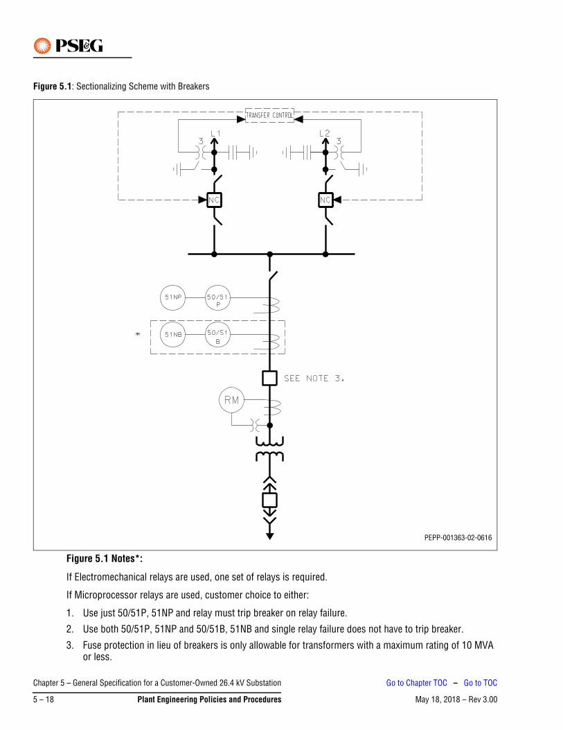
Figure 5.1: Sectionalizing Scheme with Breakers
Figure 5.1 Notes*:
If Electromechanical relays are used, one set of relays is required.
If Microprocessor relays are used, customer choice to either:
1. Use just 50/51P, 51NP and relay must trip breaker on relay failure.
2. Use both 50/51P, 51NP and 50/51B, 51NB and single relay failure does not have to trip breaker.
3. Fuse protection in lieu of breakers is only allowable for transformers with a maximum rating of 10 MVA or less.
PEPP-001363-02-0616
Chapter 5 – General Specification for a Customer-Owned 26.4 kV Substation
May 18, 2018 – Rev 3.005 – 18 Plant Engineering Policies and Procedures
Go to Chapter TOC – Go to TOC
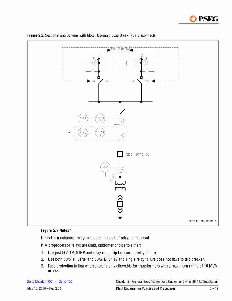
Figure 5.2: Sectionalizing Scheme with Motor Operated Load Break Type Disconnects
Figure 5.2 Notes*:
If Electro-mechanical relays are used, one set of relays is required.
If Microprocessor relays are used, customer choice to either:
1. Use just 50/51P, 51NP and relay must trip breaker on relay failure.
2. Use both 50/51P, 51NP and 50/51B, 51NB and single relay failure does not have to trip breaker.
3. Fuse protection in lieu of breakers is only allowable for transformers with a maximum rating of 10 MVA or less.
PEPP-001364-02-0616
Chapter 5 – General Specification for a Customer-Owned 26.4 kV Substation
May 18, 2018 – Rev 3.00 Plant Engineering Policies and Procedures 5 – 19
Go to Chapter TOC – Go to TOC

Figure 5.3: Transfer Scheme with Breakers – Transformer >10 MVA
Figure 5.3 Notes*:
If Electromechanical relays are used, one set of relays is required.
If Microprocessor relays are used, customer choice to either:
1. Use just 50/51P, 51NP and relay must trip breaker on relay failure.2. Use both 50/51P, 51NP and 50/51B, 51NB and single relay failure does not have to trip breaker.
3. Fuse protection in lieu of breakers is only allowable for transformers with a maximum rating of 10 MVA or less.
PEPP-001367-02-0616
Chapter 5 – General Specification for a Customer-Owned 26.4 kV Substation
May 18, 2018 – Rev 3.005 – 20 Plant Engineering Policies and Procedures
Go to Chapter TOC – Go to TOC

Figure 5.4: Transfer Scheme with Motor Operated Disconnects – Transformer >10 MVA
Figure 5.4 Notes*:
If Electromechanical relays are used, one set of relays is required.
If Microprocessor relays are used, customer choice to either:
1. Use just 50/51P, 51NP and relay must trip breaker on relay failure.
2. Use both 50/51P, 51NP and 50/51B, 51NB and single relay failure does not have to trip breaker.
3. Fuse protection in lieu of breakers is only allowable for transformers with a maximum rating of 10 MVA or less.
PEPP-001368-02-0616
Chapter 5 – General Specification for a Customer-Owned 26.4 kV Substation
May 18, 2018 – Rev 3.00 Plant Engineering Policies and Procedures 5 – 21
Go to Chapter TOC – Go to TOC
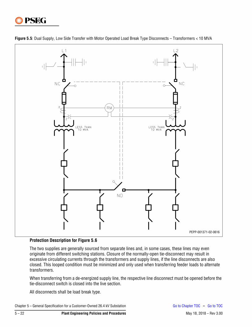
Figure 5.5: Dual Supply, Low Side Transfer with Motor Operated Load Break Type Disconnects – Transformers < 10 MVA
Protection Description for Figure 5.6
The two supplies are generally sourced from separate lines and, in some cases, these lines may even originate from different switching stations. Closure of the normally-open tie-disconnect may result in excessive circulating currents through the transformers and supply lines, if the line disconnects are also closed. This looped condition must be minimized and only used when transferring feeder loads to alternate transformers.
When transferring from a de-energized supply line, the respective line disconnect must be opened before the tie-disconnect switch is closed into the live section.
All disconnects shall be load break type.
PEPP-001371-02-0616
Chapter 5 – General Specification for a Customer-Owned 26.4 kV Substation
May 18, 2018 – Rev 3.005 – 22 Plant Engineering Policies and Procedures
Go to Chapter TOC – Go to TOC
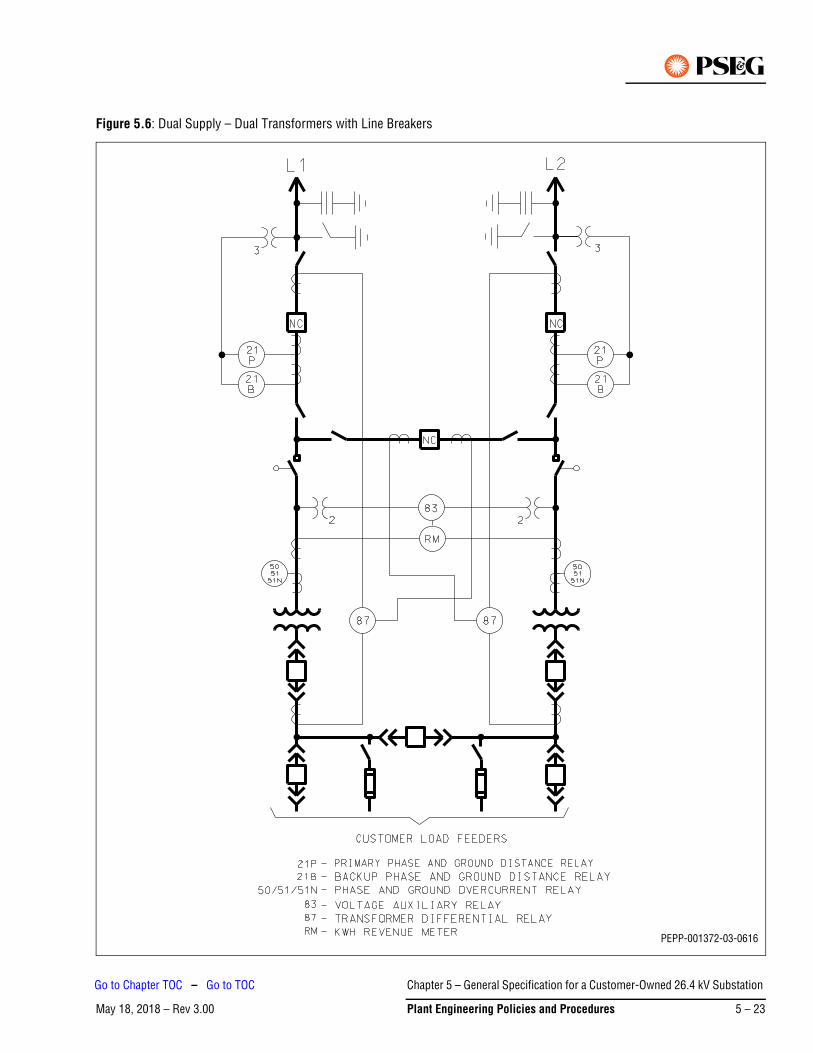
Figure 5.6: Dual Supply – Dual Transformers with Line Breakers
PEPP-001372-03-0616
Chapter 5 – General Specification for a Customer-Owned 26.4 kV Substation
May 18, 2018 – Rev 3.00 Plant Engineering Policies and Procedures 5 – 23
Go to Chapter TOC – Go to TOC
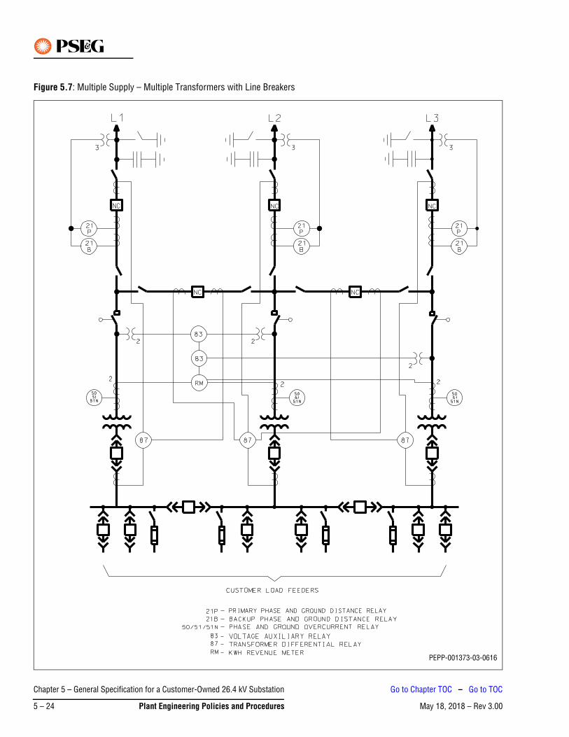
Figure 5.7: Multiple Supply – Multiple Transformers with Line Breakers
PEPP-001373-03-0616
Chapter 5 – General Specification for a Customer-Owned 26.4 kV Substation
May 18, 2018 – Rev 3.005 – 24 Plant Engineering Policies and Procedures
Go to Chapter TOC – Go to TOC
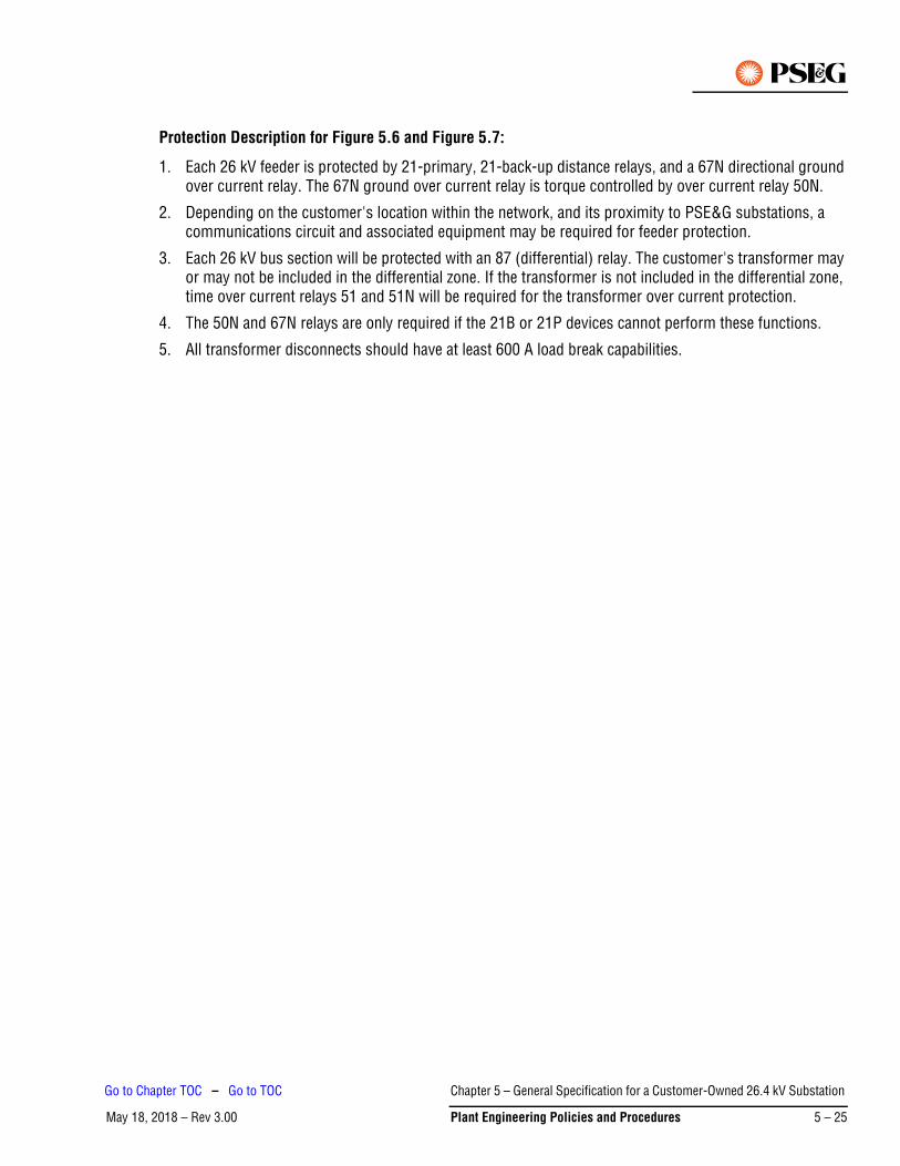
Protection Description for Figure 5.6 and Figure 5.7:
1. Each 26 kV feeder is protected by 21-primary, 21-back-up distance relays, and a 67N directional ground over current relay. The 67N ground over current relay is torque controlled by over current relay 50N.
2. Depending on the customer's location within the network, and its proximity to PSE&G substations, a communications circuit and associated equipment may be required for feeder protection.
3. Each 26 kV bus section will be protected with an 87 (differential) relay. The customer's transformer may or may not be included in the differential zone. If the transformer is not included in the differential zone, time over current relays 51 and 51N will be required for the transformer over current protection.
4. The 50N and 67N relays are only required if the 21B or 21P devices cannot perform these functions.
5. All transformer disconnects should have at least 600 A load break capabilities.
Chapter 5 – General Specification for a Customer-Owned 26.4 kV Substation
May 18, 2018 – Rev 3.00 Plant Engineering Policies and Procedures 5 – 25
Go to Chapter TOC – Go to TOC
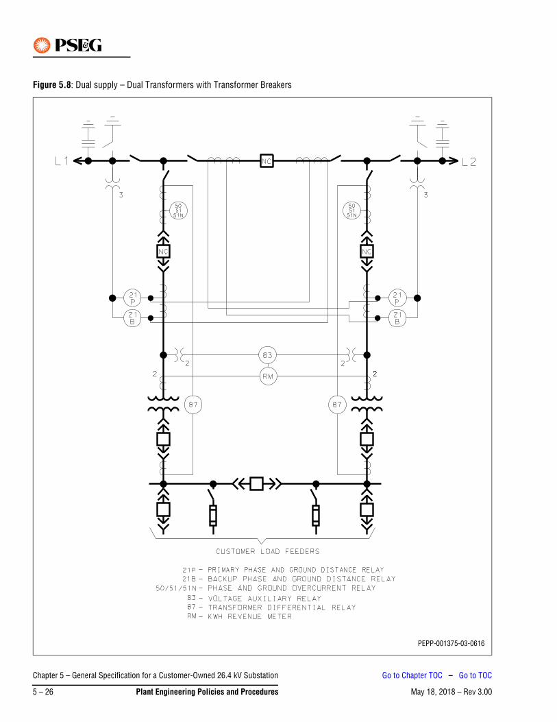
Figure 5.8: Dual supply – Dual Transformers with Transformer Breakers
PEPP-001375-03-0616
Chapter 5 – General Specification for a Customer-Owned 26.4 kV Substation
May 18, 2018 – Rev 3.005 – 26 Plant Engineering Policies and Procedures
Go to Chapter TOC – Go to TOC

Protection and Operating Requirements for Figure 5.8
Line relaying is required, and the customer should contact PSE&G for recommended relay types. The low-side bus tie breaker must be operated in a normally open position. Interlocks are required between the low-side transformer main breakers and the bus tie such that the bus tie breaker cannot be closed at the same time that both Main breakers are closed. Additionally, 26 kV transformer circuit breakers are required, along with over current protection. Transformer differential protection relaying is recommended as well, but not required by PSE&G. The customer may opt to select a relay capable of both over current and differential functions in one microprocessor-based package. Contact PSE&G for recommended relay types. Depending on the customer's location within the network, and proximity to substations, a communications circuit and associated equipment may be required for line protection.
Chapter 5 – General Specification for a Customer-Owned 26.4 kV Substation
May 18, 2018 – Rev 3.00 Plant Engineering Policies and Procedures 5 – 27
Go to Chapter TOC – Go to TOC
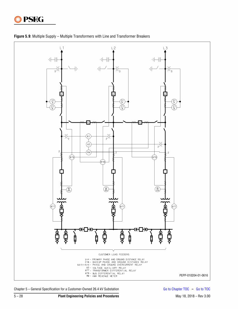
Figure 5.9: Multiple Supply – Multiple Transformers with Line and Transformer Breakers
PEPP-010204-01-0616
Chapter 5 – General Specification for a Customer-Owned 26.4 kV Substation
May 18, 2018 – Rev 3.005 – 28 Plant Engineering Policies and Procedures
Go to Chapter TOC – Go to TOC
Protection Description for Figure 5.9:
1. Each 26 kV feeder is protected by 21-primary, 21-back-up distance relays, and a 67N directional ground over current relay. The 67N ground over current relay is torque controlled by over current relay 50N.
2. Depending on the customer's location within the network, and its proximity to PSE&G substations, a communications circuit and associated equipment may be required for feeder protection.
3. Each 26 kV bus section will be protected with an 87 (differential) relay.
4. Each customer’s transformer will be protected with a 87T (differential) relay. Time overcurrent relays 51 and 51N may be required for the transformer overcurrent protection.
5. The 50N and 67N relays are only required if the 21B or 21P devices cannot perform these functions.
Chapter 5 – General Specification for a Customer-Owned 26.4 kV Substation
May 18, 2018 – Rev 3.00 Plant Engineering Policies and Procedures 5 – 29
Go to Chapter TOC – Go to TOC
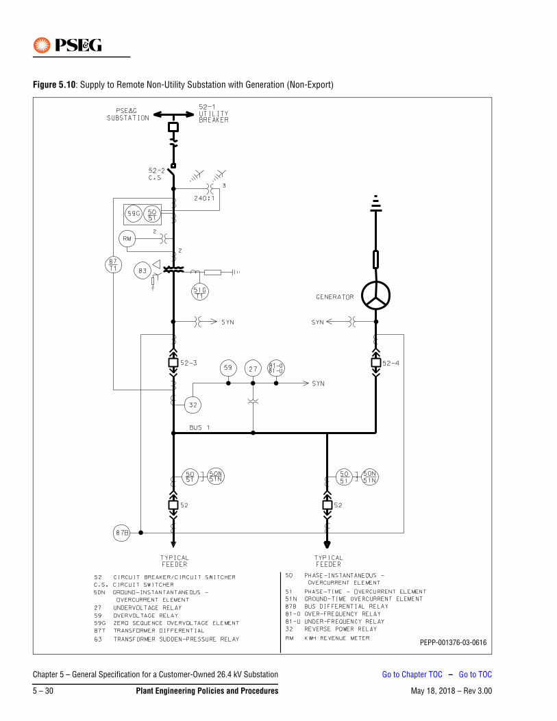
Figure 5.10: Supply to Remote Non-Utility Substation with Generation (Non-Export)
PEPP-001376-03-0616
Chapter 5 – General Specification for a Customer-Owned 26.4 kV Substation
May 18, 2018 – Rev 3.005 – 30 Plant Engineering Policies and Procedures
Go to Chapter TOC – Go to TOC
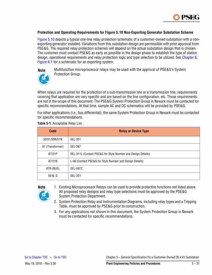
Protection and Operating Requirements for Figure 5.10 Non-Exporting Generator Substation Scheme
Figure 5.10 depicts a typical one-line relay protection schematic of a customer-owned substation with a non-exporting generator installed. Variations from this substation design are permissible with prior approval from PSE&G. The required relay protection schemes will depend on the actual substation design that is chosen. The customer must contact PSE&G as early as possible in the design phase to establish the type of station design, operational requirements and relay protection logic and type selection to be utilized. See Chapter 6, Figure 6.1 for a schematic for an exporting system.
When relays are required for the protection of a sub-transmission line or a transmission line, requirements covering that application are very specific and are based on the line configuration, etc. Those requirements are not in the scope of this document. The PSE&G System Protection Group in Newark must be contacted for specific recommendations. At that time, sample AC and DC schematics will be provided by PSE&G.
For other applications (i.e., bus differential), the same System Protection Group in Newark must be contacted for specific recommendations.
Multifunction microprocessor relays may be used with the approval of PSE&G’s System Protection Group.
Table 5-1: Acceptable Relay List
Code Relay or Device Type
50/51/50N/51N SEL-351
87 (Transformer) SEL-387
87/21P SEL-311L (Contact PSE&G for Style Number and Design Details)
87/21B L-90 (Contact PSE&G for Style Number and Design Details)
87B (BUS) SEL-587Z
59 N, G SEL-351
1. Existing Microprocessor Relays can be used to provide protective functions not listed above. All proposed relay designs and relay type selections must be approved by the PSE&G System Protection Department.
2. System Protection Relay and Instrumentation Diagrams, including relay types and a Tripping Table, must be approved by PSE&G prior to construction.
3. For any applications not shown in this document, the System Protection Group in Newark must be contacted for specific recommendations.
Note
Note
Chapter 5 – General Specification for a Customer-Owned 26.4 kV Substation
May 18, 2018 – Rev 3.00 Plant Engineering Policies and Procedures 5 – 31
Go to Chapter TOC – Go to TOC
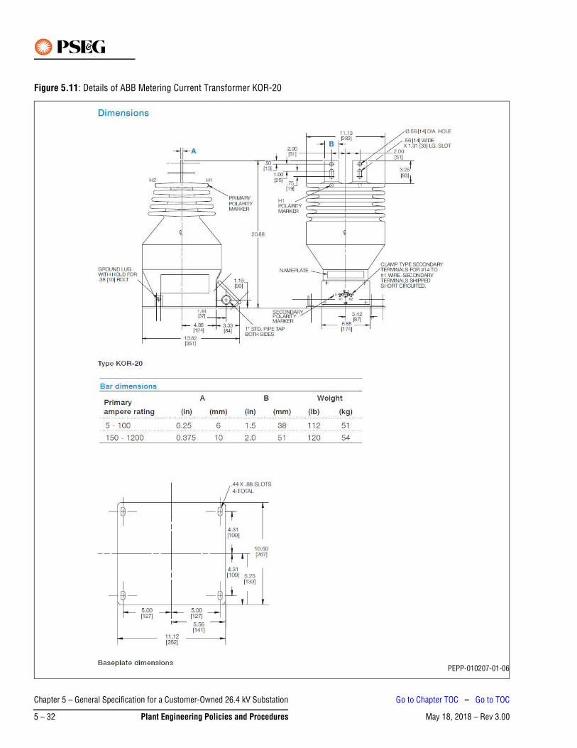
Figure 5.11: Details of ABB Metering Current Transformer KOR-20
PEPP-010207-01-06
Chapter 5 – General Specification for a Customer-Owned 26.4 kV Substation
May 18, 2018 – Rev 3.005 – 32 Plant Engineering Policies and Procedures
Go to Chapter TOC – Go to TOC
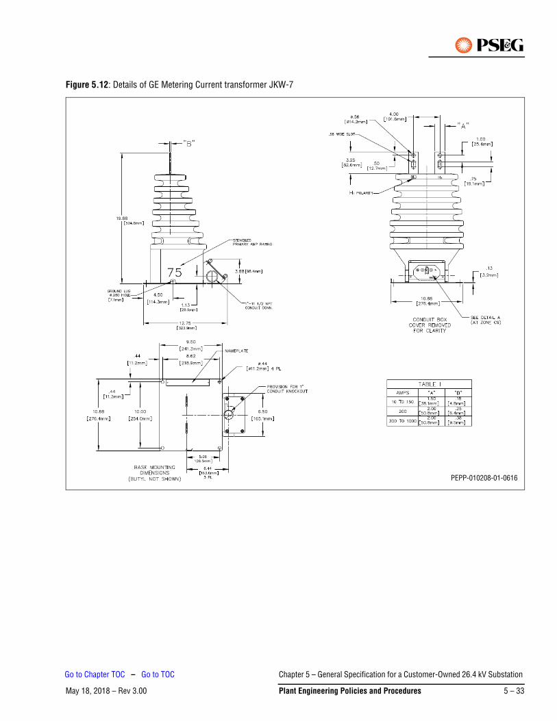
Figure 5.12: Details of GE Metering Current transformer JKW-7
PEPP-010208-01-0616
Chapter 5 – General Specification for a Customer-Owned 26.4 kV Substation
May 18, 2018 – Rev 3.00 Plant Engineering Policies and Procedures 5 – 33
Go to Chapter TOC – Go to TOC
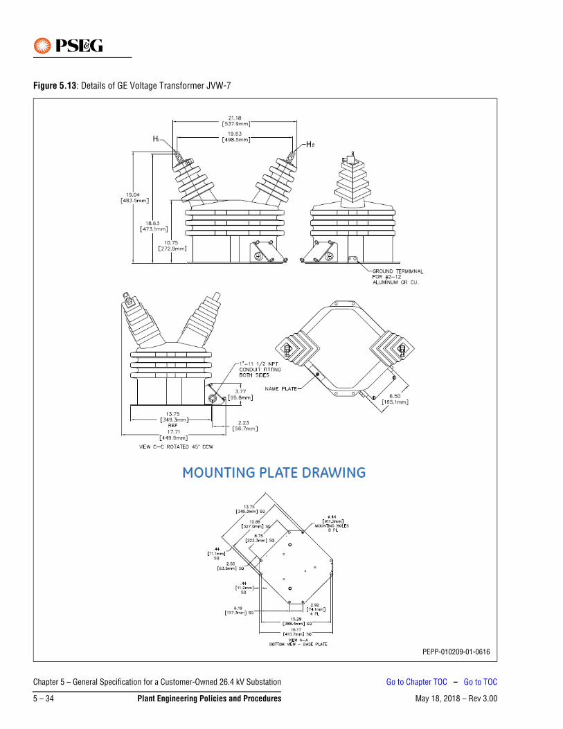
Figure 5.13: Details of GE Voltage Transformer JVW-7
PEPP-010209-01-0616
Chapter 5 – General Specification for a Customer-Owned 26.4 kV Substation
May 18, 2018 – Rev 3.005 – 34 Plant Engineering Policies and Procedures
Go to Chapter TOC – Go to TOC
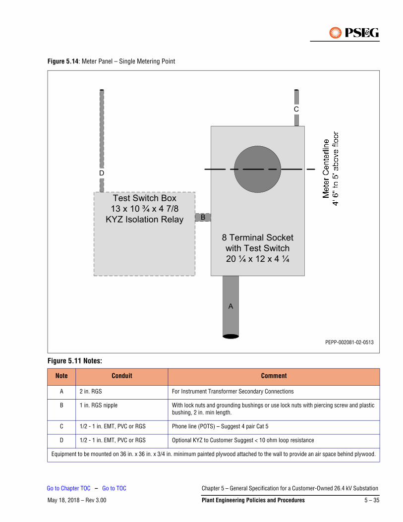
Figure 5.14: Meter Panel – Single Metering Point
Figure 5.11 Notes:
Note Conduit Comment
A 2 in. RGS For Instrument Transformer Secondary Connections
B 1 in. RGS nipple With lock nuts and grounding bushings or use lock nuts with piercing screw and plastic bushing, 2 in. min length.
C 1/2 - 1 in. EMT, PVC or RGS Phone line (POTS) – Suggest 4 pair Cat 5
D 1/2 - 1 in. EMT, PVC or RGS Optional KYZ to Customer Suggest < 10 ohm loop resistance
Equipment to be mounted on 36 in. x 36 in. x 3/4 in. minimum painted plywood attached to the wall to provide an air space behind plywood.
8 Terminal Socket
with Test Switch
20 ¼ x 12 x 4 ¼
Test Switch Box
13 x 10 ¾ x 4 7/8
KYZ Isolation Relay B
D
C
A
PEPP-002081-02-0513
Chapter 5 – General Specification for a Customer-Owned 26.4 kV Substation
May 18, 2018 – Rev 3.00 Plant Engineering Policies and Procedures 5 – 35
Go to Chapter TOC – Go to TOC
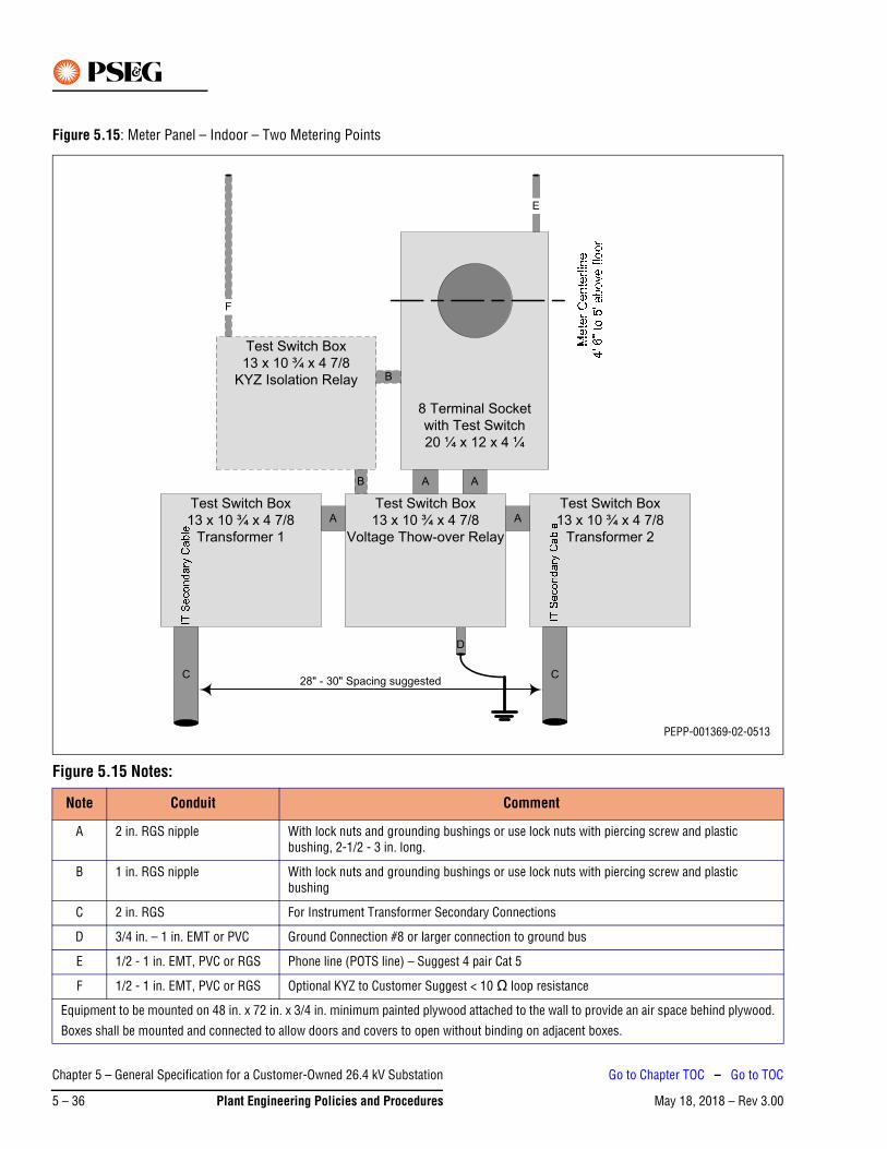
Figure 5.15: Meter Panel – Indoor – Two Metering Points
Figure 5.15 Notes:
Note Conduit Comment
A 2 in. RGS nipple With lock nuts and grounding bushings or use lock nuts with piercing screw and plastic bushing, 2-1/2 - 3 in. long.
B 1 in. RGS nipple With lock nuts and grounding bushings or use lock nuts with piercing screw and plastic bushing
C 2 in. RGS For Instrument Transformer Secondary Connections
D 3/4 in. – 1 in. EMT or PVC Ground Connection #8 or larger connection to ground bus
E 1/2 - 1 in. EMT, PVC or RGS Phone line (POTS line) – Suggest 4 pair Cat 5
F 1/2 - 1 in. EMT, PVC or RGS Optional KYZ to Customer Suggest < 10 Ω loop resistance
Equipment to be mounted on 48 in. x 72 in. x 3/4 in. minimum painted plywood attached to the wall to provide an air space behind plywood.
Boxes shall be mounted and connected to allow doors and covers to open without binding on adjacent boxes.
8 Terminal Socket
with Test Switch
20 ¼ x 12 x 4 ¼
Test Switch Box
13 x 10 ¾ x 4 7/8
Voltage Thow-over Relay
C
Test Switch Box
13 x 10 ¾ x 4 7/8
Transformer 2
A A
Test Switch Box
13 x 10 ¾ x 4 7/8
Transformer 1
AA
Test Switch Box
13 x 10 ¾ x 4 7/8
KYZ Isolation Relay B
C
F
28" - 30" Spacing suggested
B
E
D
PEPP-001369-02-0513
Chapter 5 – General Specification for a Customer-Owned 26.4 kV Substation
May 18, 2018 – Rev 3.005 – 36 Plant Engineering Policies and Procedures
Go to Chapter TOC – Go to TOC
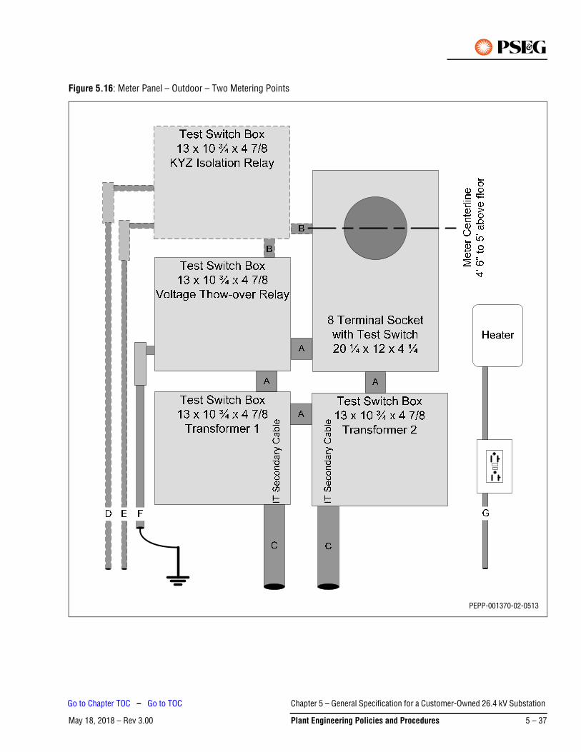
Figure 5.16: Meter Panel – Outdoor – Two Metering Points
PEPP-001370-02-0513
Chapter 5 – General Specification for a Customer-Owned 26.4 kV Substation
May 18, 2018 – Rev 3.00 Plant Engineering Policies and Procedures 5 – 37
Go to Chapter TOC – Go to TOC
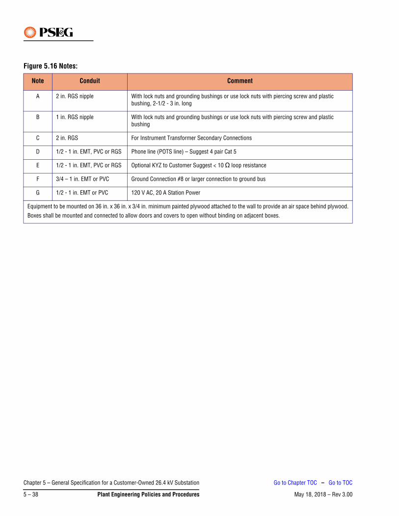
Figure 5.16 Notes:
Note Conduit Comment
A 2 in. RGS nipple With lock nuts and grounding bushings or use lock nuts with piercing screw and plastic bushing, 2-1/2 - 3 in. long
B 1 in. RGS nipple With lock nuts and grounding bushings or use lock nuts with piercing screw and plastic bushing
C 2 in. RGS For Instrument Transformer Secondary Connections
D 1/2 - 1 in. EMT, PVC or RGS Phone line (POTS line) – Suggest 4 pair Cat 5
E 1/2 - 1 in. EMT, PVC or RGS Optional KYZ to Customer Suggest < 10 Ω loop resistance
F 3/4 – 1 in. EMT or PVC Ground Connection #8 or larger connection to ground bus
G 1/2 - 1 in. EMT or PVC 120 V AC, 20 A Station Power
Equipment to be mounted on 36 in. x 36 in. x 3/4 in. minimum painted plywood attached to the wall to provide an air space behind plywood.
Boxes shall be mounted and connected to allow doors and covers to open without binding on adjacent boxes.
Chapter 5 – General Specification for a Customer-Owned 26.4 kV Substation
May 18, 2018 – Rev 3.005 – 38 Plant Engineering Policies and Procedures
Go to Chapter TOC – Go to TOC
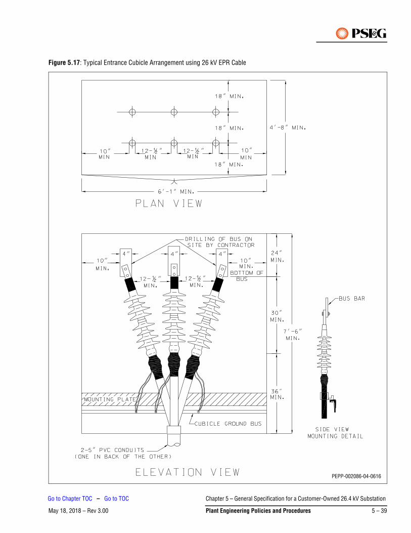
Figure 5.17: Typical Entrance Cubicle Arrangement using 26 kV EPR Cable
PEPP-002086-04-0616
Chapter 5 – General Specification for a Customer-Owned 26.4 kV Substation
May 18, 2018 – Rev 3.00 Plant Engineering Policies and Procedures 5 – 39
Go to Chapter TOC – Go to TOC
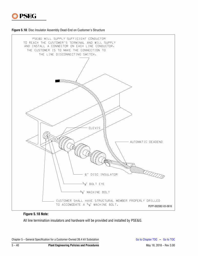
Figure 5.18: Disc Insulator Assembly Dead-End on Customer's Structure
Figure 5.18 Note:
All line termination insulators and hardware will be provided and installed by PSE&G.
PEPP-002082-03-0616
Chapter 5 – General Specification for a Customer-Owned 26.4 kV Substation
May 18, 2018 – Rev 3.005 – 40 Plant Engineering Policies and Procedures
Go to Chapter TOC – Go to TOC
May 18, 2018 – Rev 3.00Go to Chapter TOC
Chapter 6 – General Specifications for a Customer-Owned 69 kV Outdoor Substation – Table of Contents
1. Introduction. . . . . . . . . . . . . . . . . . . . . . . . . . . . . . . . . . . . . . . . . . . . . . . . . . . . . . . . . . . . . . . . . . 6-1
2. General . . . . . . . . . . . . . . . . . . . . . . . . . . . . . . . . . . . . . . . . . . . . . . . . . . . . . . . . . . . . . . . . . . . . . 6-1
3. Reviews and Approvals Required . . . . . . . . . . . . . . . . . . . . . . . . . . . . . . . . . . . . . . . . . . . . . . . . . 6-2
4. Frequency and Voltage Regulation . . . . . . . . . . . . . . . . . . . . . . . . . . . . . . . . . . . . . . . . . . . . . . . . 6-3
5. Short Circuit Duty . . . . . . . . . . . . . . . . . . . . . . . . . . . . . . . . . . . . . . . . . . . . . . . . . . . . . . . . . . . . . 6-3
6. Circuit Breakers . . . . . . . . . . . . . . . . . . . . . . . . . . . . . . . . . . . . . . . . . . . . . . . . . . . . . . . . . . . . . . . 6-3
7. Fuses . . . . . . . . . . . . . . . . . . . . . . . . . . . . . . . . . . . . . . . . . . . . . . . . . . . . . . . . . . . . . . . . . . . . . . . 6-4
8. Battery . . . . . . . . . . . . . . . . . . . . . . . . . . . . . . . . . . . . . . . . . . . . . . . . . . . . . . . . . . . . . . . . . . . . . . 6-4
9. Relays and SCADA Interface . . . . . . . . . . . . . . . . . . . . . . . . . . . . . . . . . . . . . . . . . . . . . . . . . . . . . 6-4
10. Disconnecting Switches . . . . . . . . . . . . . . . . . . . . . . . . . . . . . . . . . . . . . . . . . . . . . . . . . . . . . . . . 6-7
11. Revenue Metering Equipment . . . . . . . . . . . . . . . . . . . . . . . . . . . . . . . . . . . . . . . . . . . . . . . . . . . . 6-8
12. Insulators, Conductors, Connections and Clearances . . . . . . . . . . . . . . . . . . . . . . . . . . . . . . . . . . 6-9
13. Transformers. . . . . . . . . . . . . . . . . . . . . . . . . . . . . . . . . . . . . . . . . . . . . . . . . . . . . . . . . . . . . . . . . 6-9
14. Surge Arresters . . . . . . . . . . . . . . . . . . . . . . . . . . . . . . . . . . . . . . . . . . . . . . . . . . . . . . . . . . . . . . . 6-9
15. Grounding . . . . . . . . . . . . . . . . . . . . . . . . . . . . . . . . . . . . . . . . . . . . . . . . . . . . . . . . . . . . . . . . . . 6-10
16. Location and Structural Arrangement . . . . . . . . . . . . . . . . . . . . . . . . . . . . . . . . . . . . . . . . . . . . . 6-10
17. More Than One Source . . . . . . . . . . . . . . . . . . . . . . . . . . . . . . . . . . . . . . . . . . . . . . . . . . . . . . . . 6-11
18. Mimic Bus . . . . . . . . . . . . . . . . . . . . . . . . . . . . . . . . . . . . . . . . . . . . . . . . . . . . . . . . . . . . . . . . . . 6-11
19. Operating Procedures . . . . . . . . . . . . . . . . . . . . . . . . . . . . . . . . . . . . . . . . . . . . . . . . . . . . . . . . . 6-12
20. Other Requirements . . . . . . . . . . . . . . . . . . . . . . . . . . . . . . . . . . . . . . . . . . . . . . . . . . . . . . . . . . 6-12
21. Customer Responsibilities for Testing and Commissioning . . . . . . . . . . . . . . . . . . . . . . . . . . . . 6-12
22. Construction in Flood Prone Areas . . . . . . . . . . . . . . . . . . . . . . . . . . . . . . . . . . . . . . . . . . . . . . . 6-13
23. Animal Deterrent . . . . . . . . . . . . . . . . . . . . . . . . . . . . . . . . . . . . . . . . . . . . . . . . . . . . . . . . . . . . . 6-14
24. Arc Flash Hazard Calculation Studies. . . . . . . . . . . . . . . . . . . . . . . . . . . . . . . . . . . . . . . . . . . . . . 6-14
25. Standard Layouts . . . . . . . . . . . . . . . . . . . . . . . . . . . . . . . . . . . . . . . . . . . . . . . . . . . . . . . . . . . . 6-15
Chapter 6 – General Specifications for a Customer-Owned 69 kV Outdoor
May 18, 2018 – Rev 3.00 Plant Engineering Policies and Procedures 6 – TOC 1
Go to TOC

This Page Intentionally Blank
Chapter 6 – General Specifications for a Customer-Owned 69 kV Outdoor
May 18, 2018 – Rev 3.006 – TOC 2 Plant Engineering Policies and Procedures
Go to TOC
May 18, 2018 – Rev 3.00
Chapter 6 – General Specifications for a Customer-Owned 69 kV Outdoor Substation
1. IntroductionPSE&G is committed to providing a safe environment for our employees and safe, adequate and reliable electric service to our customers.
These General Specifications are provided to assist the customer and their agents in developing the necessary detailed substation specifications for acceptable operation on PSE&G’s 69 kV electrical system.
The Addendum to these General Specifications show typical one-line substation configuration (Figure 6.1) that is acceptable for operation on PSE&G’s 69 kV electrical system. Not all configurations are shown. Preliminary discussions with PSE&G are recommended to determine what substation configurations might best serve the customer’s requirements.
In accordance with Section 5.1 of the Standard Terms and Conditions of PSE&G’s Electric Tariff B.P.U.N.J. No. 15, the customer’s 69 kV bus is considered part of PSE&G’s distribution system for operational purposes, and system power may flow through the customer's bus with no remuneration to the customer by PSE&G.
2. GeneralThe following general requirements apply to customer substations:
1. PSE&G requires that all customer substations supplied from the 69 kV electrical system shall be designed for 69 kV operation with 350 kV BIL minimum insulation rating unless otherwise specified.
2. The 69 kV system is operated with its neutral solidly grounded at the supply station.
3. Prior to purchasing any equipment, PSE&G shall be contacted for details on types of equipment and relays suitable for the substation design selected by the customer.
4. Customer shall submit to the Division 69 kV Planner two copies of the conceptual one-line (electronic version in PDF format) as part of the first contact with PSE&G. The one line shall clearly indicate all proposed relay protection (function/make and model) and all equipment ratings. One copy shall be addressed to the Division 69 kV Planner and the other to the Electric Meter Supervisor.
5. Interior and exterior lighting is required, per National Electrical Safety Code (NESC) requirements.
Chapter 6 – General Specifications for a Customer-Owned 69 kV Outdoor
May 18, 2018 – Rev 3.00 Plant Engineering Policies and Procedures 6 – 1
Go to Chapter TOC – Go to TOC
3. Reviews and Approvals RequiredThe following are requirements for the review and approval of the customer's substation.
1. Five sets of the final substation plans, and an electronic version in PDF format, shall be submitted to PSE&G for its review so as to ensure that the design satisfies PSE&G’s technical requirements. PSE&G’s review must be completed prior to the fabrication of apparatus and the supporting structure.
2. Specifically, the drawings submitted should cover the following items:
a. Single-line diagram of the substation including secondary connections to the main transformers, bus and feeder breaker arrangements and connections.
b. Written procedure on how the customer substation will be operated.
c. DC and AC (three line) schematic diagrams of the relaying and control of all 69 kV automatic apparatus.
d. A plot plan showing the location of the substation with regard to all structures within 100 ft thereof.
e. A manhole and conduit drawing representing incoming lines and instrument transformer secondary circuits used for revenue metering and control.
f. Electrical plan and elevation plan views of the substation.
g. A listing of the major equipment and materials, including their electrical characteristics and the manufacturer's description, unless these are detailed on the drawings.
h. The location and arrangement of metering, indication and control panels. See Section 9. Number 8. for Distribution SCADA and Number 12. for ESOC interface requirements and details.
i. The substation grounding plans, details and calculations.
3. PSE&G’s review of the above final plans and drawings is for general arrangement acceptance and to ensure conformity with PSE&G’s technical requirements only, and does not indicate safe or faultless design. By review of the final plans or drawings, PSE&G is indicating that the design is compatible with PSE&G’s equipment and service. Responsibility for proper design, operation, maintenance and safety of the customer's installation rests solely with the customer. In addition, all work and equipment must conform to municipal and all other applicable codes and requirements, including applicable provisions of the National Electrical Code (NEC) and the NESC in effect at the time of construction.
4. Final acceptance by PSE&G before introducing service to the completed installation is dependent upon the customer obtaining approval from the electrical inspection authority having jurisdiction, and provision by such inspection authority to the local Electric Distribution Division Wiring Inspection Department of an original cut-in card.
5. Unless otherwise specified, PSE&G requires a minimum of 3 weeks after notification of completion of the customer's work and its walk through or inspection of the customer’s installation, to test and set relays, breakers, meters and/or other associated equipment, including developing final cut-over procedures or other documents or procedures required for the customer. Further, any corrective items noted by PSE&G during the final walk through or inspection of the customer’s site must be completed prior to PSE&G beginning its final commissioning work noted above.
PSE&G will not be liable for damages or for injuries sustained by customers or by the equipment of customers or by reason of the condition or character of customer’s facilities or the equipment of others on customer’s premises. PSE&G will not be liable for the use, care, or handling of the electric service delivered to the customer after same passes beyond the point at which PSE&G’s service facilities connect to the customer’s facilities.
Note
Chapter 6 – General Specifications for a Customer-Owned 69 kV Outdoor
May 18, 2018 – Rev 3.006 – 2 Plant Engineering Policies and Procedures
Go to Chapter TOC – Go to TOC
4. Frequency and Voltage RegulationThe following are general voltage and frequency conditions on PSE&G’s system that the customer should consider in its substation design.
1. The frequency of PSE&G’s system is normally regulated at 60 Hz (cycles per second) and under usual conditions the variations are limited to 0.1 cycle above or below 60 Hz.
2. The voltage of PSE&G’s 69 kV system under normal conditions will be within a range of 105% to 98% of nominal voltage with a maximum variation of 6%. Under emergency conditions the voltage can be within a range of 105% to 95% of nominal voltage with a maximum variation of 8%. If this regulation is not satisfactory for the operation of the customer’s plant, it is the customer’s responsibility to install suitable voltage regulation equipment. If the cost to supply service to the customer at these voltage ranges could be substantially reduced by operating outside these limits, PSE&G may render service with different limits under the terms of a special agreement with the customer.
3. It should be noted, that during fault conditions, short term voltage fluctuations of up to 0.5 seconds may occur on PSE&G’s system which could result in abnormally low voltage and/or unbalanced voltages. This effect should be considered in the design of the customer’s relaying. In addition, operation of certain types of customer’s utilization equipment will adversely affect the power quality of the supply voltage. If the customer has installed critical computer or electronic equipment requiring continuity of service or exceptional service quality, it is the customer's responsibility to install any necessary uninterruptible power supply and/or a power conditioning device that may be required for this application.
4. It is also recommended that time-delay protective devices be installed on important motors and other critical equipment. This will permit the customer to avoid unnecessary outages during faults or surges on PSE&G’s system or from the customer's in-plant facilities.
5. Short Circuit DutyThe maximum available three-phase symmetrical short circuit current on PSE&G’s 69 kV system is 40 kA (Short Time Symmetrical 2 Seconds) / 63 KA (Momentary 10 Cycle Asymmetrical) /104 kA (Peak). The construction of PSE&G’s 69 kV system is dynamic and subject to change as required for the safe, adequate and reliable operation of the system. PSE&G recommends that the customer design its substation for the maximum short circuit current available.
6. Circuit BreakersThe following are general requirements for circuit breakers:
1. All circuit breakers on the high-voltage side of the customer’s transformers shall meet the most recent edition of Electrical and Electronics Engineers (IEEE) Standard C-37 for 72.5 kV maximum rated voltage equipment. Line circuit breakers shall have a minimum of 1,200 A continuous current rating. Bus tie breakers may require higher current ratings depending on the substation configuration.
2. PSE&G requires all circuit breakers on the high-voltage side of the customer’s transformers have short circuit interrupting duty of 40 kA (Short Time Symmetrical 2 Seconds) / 63 kA (Momentary 10 Cycle Asymmetrical) / 104 kA (Peak).
3. The line side of the service entrance or transformer circuit breaker shall be provided with a bushing-type, five tap multi-ratio American National Standards Institute (ANSI)/IEEE standard current transformer in each terminal. The current transformer shall be relay accuracy class C-800 or better on full tap, and its current rating shall be compatible to the continuous current rating of the breaker.
Chapter 6 – General Specifications for a Customer-Owned 69 kV Outdoor
May 18, 2018 – Rev 3.00 Plant Engineering Policies and Procedures 6 – 3
Go to Chapter TOC – Go to TOC
7. FusesPSE&G’s preference is for the use of circuit breakers, but in some cases fuses may be utilized on the high-voltage side of the customer’s transformers in lieu of transformer primary circuit breakers. This is only allowable for transformers of up to 10 MVA rating. If fuses are used, the voltage rating shall be greater than or equal to the system line-to-line operating voltage. The fuses shall meet the following requirements:
1. The fuses shall coordinate with PSE&G’s source line(s) relaying and with the transformer secondary fuse, breaker or recloser. If the primary fuse is of the expulsion type, the minimum melting time shall be corrected for “preloading”. The selection time between primary and secondary protection for a customer’s transformers shall be a minimum of 0.5 seconds.
2. The fuses shall have an interrupting capacity equal to, or greater than, the maximum asymmetrical short circuit current available on the system at the fuse location, 40 kA.
3. The current rating shall be greater than or equal to the transformer manufacturer’s nominal nameplate full load emergency rating. The customer shall submit its proposed fuse type to PSE&G’s System Protection Department for approval prior to energization of the substation.
4. The fuses shall meet the requirements of the most recent editions of IEEE Standards C-37.46 and C-37.48.
8. BatteryA storage battery or other reliable DC source, shall be provided to supply DC voltage for automatic tripping of the circuit breaker(s). The latest editions of IEEE Standards 484 and 485 provide guidance in calculating the appropriate battery size and for installation design and procedures. IEEE Std. C37.06-2009, Table 18 provides the control voltage range required at the circuit breaker(s).
The battery shall be equipped with an automatic charger, a voltmeter and a low voltage alarm. The low voltage alarm shall be either an audible alarm that will provide a response, or a remote alarm to a manned location. Likewise, if another DC source is utilized, it shall be alarmed to indicate loss of voltage.
The battery shall be sized for minimum of an 8-hour discharge rate.
9. Relays and SCADA InterfaceThe following are general requirements for relaying and SCADA equipment:
1. Specific PSE&G requirements will be provided for relays and their associated equipment, as required for the operation of circuit breakers and/or motor-operated disconnecting switches.
2. All proposed relay designs involving the protection of the 69 kV equipment, including single line diagram, relay and instrumentation diagrams, tripping tables, etc. must be reviewed and approved by the PSE&G System Protection Group prior to purchasing the equipment. Additionally, please contact PSE&G for approved relay types prior to the design of the protection scheme. The customer will be responsible for applying certain relay settings provided by PSE&G using an approved third party testing company at the customer’s expense. Written relay test results must be provided to PSE&G for the initial installation, and provided every 4 years thereafter, when the settings are verified by an approved testing company.
Chapter 6 – General Specifications for a Customer-Owned 69 kV Outdoor
May 18, 2018 – Rev 3.006 – 4 Plant Engineering Policies and Procedures
Go to Chapter TOC – Go to TOC
3. All protective relays shall have provisions for isolating the relays for testing or replacement purposes while the equipment is in service. Relay isolation shall be accomplished by using switches such as the ABB FT-1. Test switches in AC current circuits shall be equipped with test jacks for test connections.
4. The current and potential transformers supplying the relays shall not be used for any other purpose.
a. All CTs for relay protection shall adhere to ANSI/IEEE Standard MRCT, C800 class or better.
b. 69 kV breakers shall be equipped with two sets of three-phase CTs on both sides to provide overlapping zones of protection for incoming PSE&G lines, the customer's 69 kV bus and 69 kV transformers, unless it is not possible to fit in two sets due to space limitations, in which case the relay and Current Transformer (CT) arrangement and accuracy class must be submitted to PSE&G for approval of the configuration.
c. Each incoming 69 kV line shall be provided with three line-side single phase Potential Transformers (PTs), with a 69000/ 3-69:69 V ratio, wye-connected on both the primary and secondary sides.
5. It is recommended that the customer consider the installation of differential relaying for the protection of large power transformers.
6. If differential relaying is installed, the overcurrent relays associated with each service entrance breaker shall be connected to the bushing-type current transformers on the source side of each service entrance breaker. If CTs are not available on the source side of the entrance breaker, load side CTs may be used.
7. To facilitate maintenance and eliminate the possibility of vibration damage/inadvertent operation, the relays for tripping high-voltage circuit breakers shall be installed in a separate weatherproof enclosure or on the rack in the control house or control room.
8. Basic Distribution SCADA functionality should be considered for all customer subs. For small 69 kV customers a standard Mini SCADA box may be used. The box has only dry contact inputs for indication enabled. Standard prints for this class and coded NEMA 4 Mini SCADA box are 311336, 311337, and 311338. This SCADA box is PSE&G class and coded with code W930001 and is usually kept in stock by PSE&G. Please contact PSE&G design group for standard prints to be used in designing point to point diagrams and review of proposed design. PSE&G Design should be contacted for direction and final review of the design.
a. PSE&G shall require approximately 48 in. x 48 in. of open wall space to install a distribution SCADA RTU for monitoring of the station. The RTU itself is approximately 30 in. x 30 in. x 12 in.
b. 125 V DC from station batteries is required available at the SCADA RTU for power.
c. 120 V AC is required as a back-up source of power. This is also used for the heater and AC convenience outlet.
d. This RTU takes up to 16 dry contact inputs and provides a wetting voltage to the field contact with the power supplied.
9. Recommended indications/alarms shall be as follows if available and should be wired in this order. If the specific alarm is not available, a spare input shall be left in its place. The points listed here are suggestions and of course every site will have slightly different points to be submitted and approved by the local operations and Relay groups. Specific text can be modified in the Master. As a rule of thumb, Station Alarm (as described elsewhere in the alarm bus portion of the spec.), Station Control handle in Auto, Breaker / motor operated disconnect indication, DC System trouble, Station L&P fail are the most basic. The customer must supply a dry contact and wiring to the RTU cabinet for each available point.
a. Common Station Alarm (If Available and Applicable)
b. Station Control Handle (If Available and Applicable)
c. Fire Alarm (If Available and Applicable)
Chapter 6 – General Specifications for a Customer-Owned 69 kV Outdoor
May 18, 2018 – Rev 3.00 Plant Engineering Policies and Procedures 6 – 5
Go to Chapter TOC – Go to TOC
d. Station Battery System Trouble (If Available and Applicable)
e. Station Light and Power Fail
f. L1 Breaker Status (Any Line Breaker MOC “A” and TOC in Series)
g. L2 Breaker Status (Any Line Breaker MOC “A” and TOC in Series)
h. SEC. 1-2 Breaker Status or Motor operated disconnects
i. Transfer Auto/Manual
j. SPARE
k. SPARE
l. SPARE
m. SPARE
n. SPARE
o. SPARE
p. SPARE
10. A standard dial-up phone line, otherwise known as a Plain Old Telephone Service (POTS) line and normally ordered and maintained by the customer, is to be terminated at the location of the Distribution SCADA RTUs. The customer agreement with the operating division shall define who orders and maintains the line.
11. If a standard energized POTS line is not available from the telephone service provider and a fiber optic connection is provided, the customer shall provide an uninterruptable power supply to the router or other interface device. The router or other interface device shall be powered in such a fashion, so that if power to the facility goes down the communications system shall be kept “live” for a minimum of at least 8 hours.
12. ESOC RTU needs to be installed to provide a required control, status indication and telemetering points as follows:
a. Output for transformer LTC 5% voltage reduction control (raise/lower)
b. Status indication to monitor 69 kV circuit breaker (open/close)
c. Analog input to measure three-phase line currents and voltages
13. The following requirements need to be met to support the installation of ESOC RTU:
a. PSE&G shall require approximately 48 in. x 48 in. of open wall space to install the ESOC RTU. The RTU itself is approximately 24 in. x 24 in. x 12 in.
b. 125 V DC from station batteries is required available at the ESOC RTU for power.
c. 120 V AC is required as a back-up source of power. This is also used for the heater and AC convenience outlet.
14. PSE&G shall designate, select and specify the equipment and subsequent telecommunications devices to be used for interface with ESOC by means of fiber optic cable, digital data links and/or analog signals to be installed at the facility.
15. Corresponding communication circuit to be terminated at ESOC RTU should be ordered and maintained by the customer.
Chapter 6 – General Specifications for a Customer-Owned 69 kV Outdoor
May 18, 2018 – Rev 3.006 – 6 Plant Engineering Policies and Procedures
Go to Chapter TOC – Go to TOC
16. Please contact PSE&G design group for standard prints to be used in designing point to point diagrams and review of proposed design for ESOC. PSE&G Design should be contacted for direction and final review of the design.
17. The presence of any type of generation running in parallel with the service may result in additional specific protection, SCADA, and ESOC RTU design requirements. The customer engineer is required to identify any generation and obtain direction and approval from PSE&G Design Group based on the specific planned install.
18. PSE&G shall designate, select, specify and purchase the equipment required for Distribution SCADA and ESOC purposes. The applicant shall receive the devices from PSE&G and install the equipment at its facility. If necessary, PSE&G will install any other SCADA and ESOC equipment required at its facilities, at the applicant's expense. The applicant shall pay PSE&G for all costs associated with SCADA and ESOC equipment.
19. Two copies of each relay instruction book for all line and bus relays shall be provided to PSE&G 2 months prior to the expected service date.
20. Note that some multifunction microprocessor relays may be used with the prior approval of PSE&G’s System Protection Group.
21. Relays required for the protection of a sub-transmission line or a transmission line, are very specific to the application and are based on the line configuration, impedances, etc. Those requirements are not in the scope of this document. The PSE&G System Protection Group in Newark must be contacted for specific recommendations. At that time, sample AC and DC schematics will be provided by PSE&G.
22. For other applications (i.e. bus differential protection discussed in item 5 above) the same System Protection Group in Newark must be contacted for specific relay recommendations.
10. Disconnecting SwitchesThe following are guidelines for disconnecting switches:
1. Guidelines for the application, installation, operation and maintenance of disconnecting switches are described in the latest editions of IEEE NESC C2-2012, Sections 173 and 216, as well as the latest editions of IEEE C37.30, C37.32 and C37.35.
2. The line disconnecting switches shall be horizontally mounted, three-pole, gang-operated, vertical break devices with arcing horns. One three-pole, gang-operated line grounding switch shall be installed as part of each line disconnecting switch, and shall be mechanically interlocked in such a way that the line grounding switch cannot be closed when the line disconnecting switch is in the closed position, and the line disconnecting switch cannot be closed when the line grounding switch is in the closed position. The line disconnecting switches and the line grounding switches shall be so arranged that they can be padlocked in any position desired. The Ground Switch shall be of 72.5 kV Class, withstand 350 kV BIL in the open position and have a withstand rating of 40 kA (Short Time Symmetrical 2 Seconds) / 63 kA (Momentary 10 Cycle Asymmetrical) / 104 kA (Peak) and meet all applicable operational and test parameters for service in 69 kV systems.
ANSI Standards do not require ground switches to have a fault close rating since proper operating practice requires the circuit be tested de-energized before closing the ground switch. It must have a momentary rating of 63 kA.
Note
Chapter 6 – General Specifications for a Customer-Owned 69 kV Outdoor
May 18, 2018 – Rev 3.00 Plant Engineering Policies and Procedures 6 – 7
Go to Chapter TOC – Go to TOC
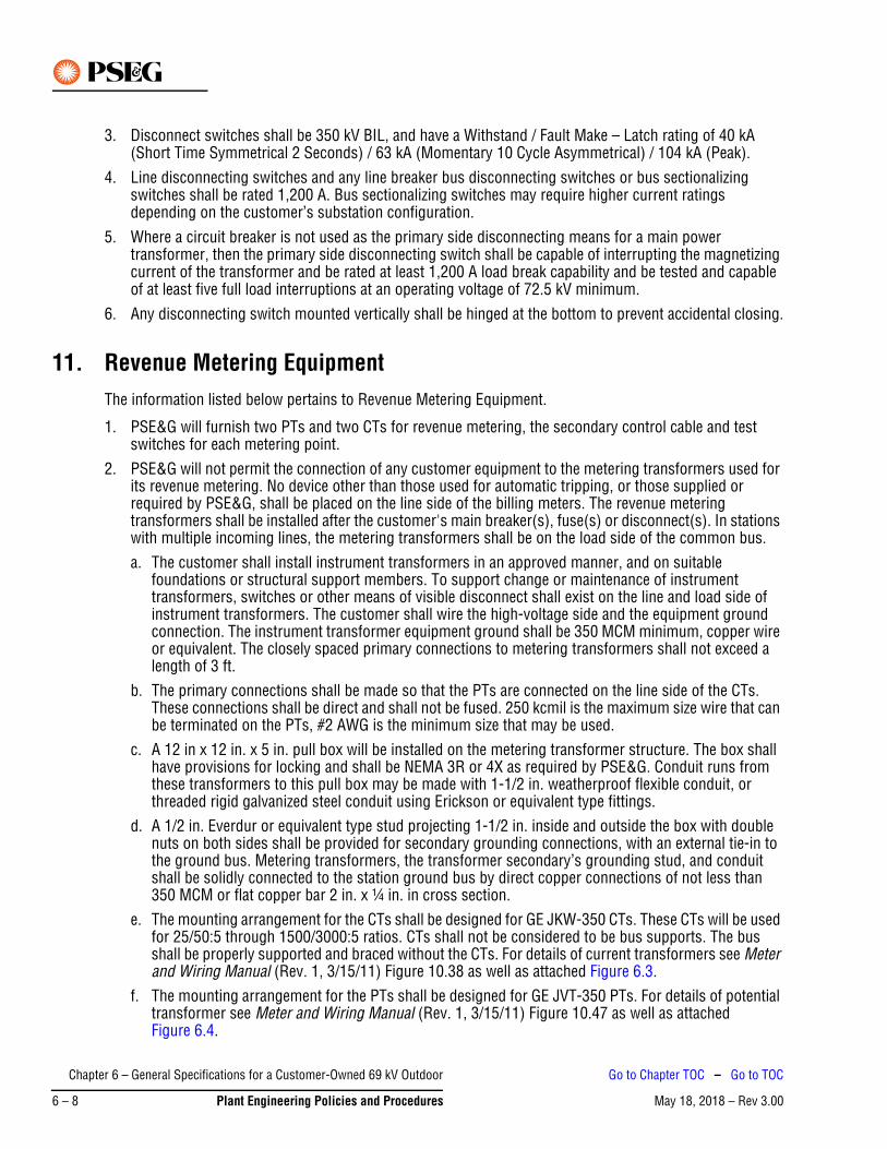
3. Disconnect switches shall be 350 kV BIL, and have a Withstand / Fault Make – Latch rating of 40 kA (Short Time Symmetrical 2 Seconds) / 63 kA (Momentary 10 Cycle Asymmetrical) / 104 kA (Peak).
4. Line disconnecting switches and any line breaker bus disconnecting switches or bus sectionalizing switches shall be rated 1,200 A. Bus sectionalizing switches may require higher current ratings depending on the customer’s substation configuration.
5. Where a circuit breaker is not used as the primary side disconnecting means for a main power transformer, then the primary side disconnecting switch shall be capable of interrupting the magnetizing current of the transformer and be rated at least 1,200 A load break capability and be tested and capable of at least five full load interruptions at an operating voltage of 72.5 kV minimum.
6. Any disconnecting switch mounted vertically shall be hinged at the bottom to prevent accidental closing.
11. Revenue Metering EquipmentThe information listed below pertains to Revenue Metering Equipment.
1. PSE&G will furnish two PTs and two CTs for revenue metering, the secondary control cable and test switches for each metering point.
2. PSE&G will not permit the connection of any customer equipment to the metering transformers used for its revenue metering. No device other than those used for automatic tripping, or those supplied or required by PSE&G, shall be placed on the line side of the billing meters. The revenue metering transformers shall be installed after the customer's main breaker(s), fuse(s) or disconnect(s). In stations with multiple incoming lines, the metering transformers shall be on the load side of the common bus.a. The customer shall install instrument transformers in an approved manner, and on suitable
foundations or structural support members. To support change or maintenance of instrument transformers, switches or other means of visible disconnect shall exist on the line and load side of instrument transformers. The customer shall wire the high-voltage side and the equipment ground connection. The instrument transformer equipment ground shall be 350 MCM minimum, copper wire or equivalent. The closely spaced primary connections to metering transformers shall not exceed a length of 3 ft.
b. The primary connections shall be made so that the PTs are connected on the line side of the CTs. These connections shall be direct and shall not be fused. 250 kcmil is the maximum size wire that can be terminated on the PTs, #2 AWG is the minimum size that may be used.
c. A 12 in x 12 in. x 5 in. pull box will be installed on the metering transformer structure. The box shall have provisions for locking and shall be NEMA 3R or 4X as required by PSE&G. Conduit runs from these transformers to this pull box may be made with 1-1/2 in. weatherproof flexible conduit, or threaded rigid galvanized steel conduit using Erickson or equivalent type fittings.
d. A 1/2 in. Everdur or equivalent type stud projecting 1-1/2 in. inside and outside the box with double nuts on both sides shall be provided for secondary grounding connections, with an external tie-in to the ground bus. Metering transformers, the transformer secondary’s grounding stud, and conduit shall be solidly connected to the station ground bus by direct copper connections of not less than 350 MCM or flat copper bar 2 in. x ¼ in. in cross section.
e. The mounting arrangement for the CTs shall be designed for GE JKW-350 CTs. These CTs will be used for 25/50:5 through 1500/3000:5 ratios. CTs shall not be considered to be bus supports. The bus shall be properly supported and braced without the CTs. For details of current transformers see Meter and Wiring Manual (Rev. 1, 3/15/11) Figure 10.38 as well as attached Figure 6.3.
f. The mounting arrangement for the PTs shall be designed for GE JVT-350 PTs. For details of potential transformer see Meter and Wiring Manual (Rev. 1, 3/15/11) Figure 10.47 as well as attached Figure 6.4.
Chapter 6 – General Specifications for a Customer-Owned 69 kV Outdoor
May 18, 2018 – Rev 3.006 – 8 Plant Engineering Policies and Procedures
Go to Chapter TOC – Go to TOC
12. Insulators, Conductors, Connections and ClearancesThe following are general requirements for insulators, conductors, connections and clearances.
1. Specific detail requirements for bus supports and insulators rated for 200 kV BIL minimum and corresponding clearances are described in the latest editions of IEEE Standards C37.32, and ANSI/NEMA C29.8 and C29.9.
2. All 69 kV bus shall consist of rigid bus construction, and such bus and flexible connections shall be in accordance with the guidelines of the latest edition of ANSI/IEEE Standard 605. The length of flexible connections should be kept to a minimum and in no case should the length exceed 6 ft. The closely spaced connections to metering transformers should be limited to 3 ft in length.
3. Bus construction shall have 1,200 A capacity in the line positions. The main bus between positions may require higher current ratings depending on the customer’s substation configuration. The bus must be tubular copper or aluminum.
13. TransformersTransformers shall comply with the general requirements and installation guidelines of latest edition of IEEE Std. C57.
Transformers shall be delta connected on the 69 kV side.
14. Surge ArrestersPSE&G recommends the installation of surge arresters. If surge arresters are to be installed, they shall meet the following requirements:
1. Surge Arresters shall be installed in accordance with the guidelines and standards of the latest edition of ANSI/IEEE Std. C62.
2. Single-phase, station class, Metal Oxide Varister (MOV) type surge arresters shall be installed on the 69 kV side of each transformer and shall be readily disconnected for maintenance. The arresters for transformers of 69 kV class shall be rated at 66 kV Station Class.
3. Single-phase MOV type surge arrester protection shall be installed on the line side of each line disconnecting switch. The arresters shall be 60 kV Station Class arresters, and shall be readily disconnected for cable fault location purposes.
Chapter 6 – General Specifications for a Customer-Owned 69 kV Outdoor
May 18, 2018 – Rev 3.00 Plant Engineering Policies and Procedures 6 – 9
Go to Chapter TOC – Go to TOC
15. GroundingThe following are general requirements for grounding:
1. Specific detail requirements for grounding are described in the latest editions of the NEC, NESC and IEEE Standards 80 and 81. The station ground resistance shall be measured in accordance with Section 8 of IEEE Std.81-2012 “IEEE Guide for Measuring Earth Resistivity, Ground Impedance, and Earth Surface Potentials of the Grounding System” and Section 19.1 of IEEE Std. 80-2000 “IEEE Guide for Safety in AC Substation Grounding”. These standards provide procedures for measuring the earth resistivity, the resistance of the installed grounding system and the continuity of the grid conductors.
2. PSE&G will supply the following values:
– Maximum ground fault current– Maximum fault clearing time– Split factor, Sf– X/R Ratio
3. The Customer shall supply PSE&G with the following information:
– Plans and details of the substation that indicate conductor size and typical grounding grid design– Calculations as described in IEEE Std. 80-2000, with special attention paid to step and touch
potentials.
4. For typical customer’s substation grounding details see Section 25. “Standard Layouts”, Figure 6.8.
16. Location and Structural ArrangementThe following are general requirements for substation layouts:
1. At any location where the following actions may be performed there shall be adequate, safe space available for:
– Inspection– Maintenance– Routine removal or replacement of components– Routine removal or replacement of power or control cable
2. The customer’s substation site should be selected to provide adequate clearances from existing and future buildings. The clearance between energized equipment and other structures shall meet or exceed the latest requirements of NESC, NEC, and IEEE STD 1427.
3. In no case shall any building be located within 15 ft of energized equipment (except the control house). Where necessary, a parapet guard shall be considered for installation along the building roof adjacent to the substation for safety of personnel.
4. The substation shall be enclosed by a fence at least 7 ft high, (6 ft fence with 1 ft of barbed wire) as described in the Section 110A of IEEE NESC C2-2012.Fences and gates shall be equipped with “Danger High Voltage” signs as required by the NEC and NESC.
Chapter 6 – General Specifications for a Customer-Owned 69 kV Outdoor
May 18, 2018 – Rev 3.006 – 10 Plant Engineering Policies and Procedures
Go to Chapter TOC – Go to TOC
5. Substation design should meet requirements of IEEE Std. 979-2014 “IEEE Guide for Substation Fire Protection” or National Fire Protection Association (NFPA) 850, 2015 Edition including as a minimum:
a. Construction of oil spill containments for transformers filled with a mineral oil
b. Separation of mineral oil containing transformers from each other and substation buildings by distances listed in Table 1 of IEEE Std. 979-2014 or Table 5.1.4.3 of NFPA 850, 2015 Edition. If these distances can't be achieved, 2 h rated firewalls should be constructed designed in accordance with the above-mentioned standard.
6. Substation should have an adequate lightning protection in accordance with the latest revision of IEEE Std. 998 “Guide for Direct Lightning Stroke Shielding of Substations”.
7. If a building wall is used as a part of the substation enclosure, there shall be no windows, doors, fire escapes, vents, drains, down spout openings, or other foreign obstructions in or near such areas of the wall which are bounded by the projection of the substation building; this section of the wall shall be made of a fireproof material type of construction.
8. The substation structure must be of sufficient strength and properly braced to adequately support PSE&G’s entering 69 kV lines, each conductor of which may have a maximum tension of 2500 lb and may deviate up to 45 degrees from a direct approach.
9. For personnel safety, lighting of the substation should be provided for walkways and in operating areas as per NESC, Section 111.
10. A telephone shall be provided in the control house for the purpose of switching.
17. More Than One SourceWhere the customer’s load can be supplied from more than one source, such as the customer’s own generation or a duplicate service from PSE&G, the entrance switchgear shall be provided by the customer with a sign stating “Caution – Multiple Power Sources”.
Additional requirements may be specified by PSE&G depending upon the customer’s equipment and/or arrangement.
18. Mimic BusA Mimic Bus or schematic representation, illustrating the arrangement of the devices and apparatus contained in the HV equipment system, shall be displayed on the front panels of the control racks.
Chapter 6 – General Specifications for a Customer-Owned 69 kV Outdoor
May 18, 2018 – Rev 3.00 Plant Engineering Policies and Procedures 6 – 11
Go to Chapter TOC – Go to TOC
19. Operating ProceduresThe following are standard operating procedures for the substation:
1. To provide for security of PSE&G’s system and for the safety of PSE&G’s and the customer’s personnel, PSE&G requires operational control of the following devices at the customer's substation:
– 69 kV line disconnecting switches– Line grounding switches– Line circuit breakers and their bus disconnecting switches– 69 kV bus sectionalizing switches and breaker(s), if provided
A representative of PSE&G’s local Electric Distribution Division will operate these devices as directed by that Division’s Service Dispatcher.
2. An authorized attendant of the customer may operate the 69 kV service entrance breaker(s), the breaker isolating switches and all equipment on the load side of the service entrance breaker(s) as desired. The customer’s authorized attendant is never to operate the devices listed above in item 1.
3. In the event of an interruption to service, PSE&G will to restore service as soon as possible without notification.
4. Specific operating instructions will be provided to the customer prior to energization.
20. Other Requirements“Danger High Voltage” signs shall be installed in accordance with applicable requirements of the NEC and the NESC in effect at the time of construction.
Approved “Lamicoid” tags shall be furnished by the customer on all switchgear compartments and board-mounted components, and all circuit breakers, transformers and disconnect switches. Tag names shall be identical to the terminology used in the customer’s drawings, or as specified by PSE&G at interface points. All tags shall be attached with either stainless steel pins or stainless steel machine screws.
21. Customer Responsibilities for Testing and CommissioningNormal protocol would expect that all the work listed below is performed when commissioning customer substations. This work is the responsibility of the Customer and is normally performed by the site Electrical Contractor and a Testing Contractor. Testing and commissioning must be performed by a certified National Electrical Testing Association (NETA) company.
1. Customer shall perform the following:
a. Tightening and torquing of all bolted electrical connections.
b. Verification of all external wiring.
c. Complete testing of all protection and control circuits using the AC/DC schematics.
d. Hi-pot, Doble and Ductor testing of all circuit breakers.
e. Timing test for service entrance and bus tie circuit breakers.
Chapter 6 – General Specifications for a Customer-Owned 69 kV Outdoor
May 18, 2018 – Rev 3.006 – 12 Plant Engineering Policies and Procedures
Go to Chapter TOC – Go to TOC
f. Hi-pot and Doble testing of all bus work including arrestors. Ductoring of bus work is also recommended.
g. Operational verification of each circuit breaker – electrical, mechanical, safety interlocks.
h. Operational verification of each line disconnect and ground switch and keyed interlocks.
i. Ratio verification of potential devices.
j. “Megger” and ratio tests of all current transformers.
k. Setting the ratio of all CTs as per protection requirements – Line Protection CTs shall be set by PSE&G.
l. Shortening all unused CTs and winding taps as necessary.
m. Calibration of all instruments.
n. Verification and adjustment of battery chargers as required – verification of set points of all battery related alarms
o. Verification and testing of all alarms to the annunciator.
p. Verification of accuracy of Mimic Bus against the One Line.
q. Verification of operation of telephone circuits for SCADA and metering.
r. Verification of correct taps for transformers.
s. All necessary transformer tests before energizing (TTR, Doble, hi-pot, cooling system as required).
2. PSE&G shall:
a. For service entrance and bus tie circuit breakers, perform operational checks and review results of Ductor and timing tests performed by the Customer.
b. Set line relays (bus differentials and breaker failure if used), verify associated instrumentation and perform operational / trip checks of service entry and bus tie breakers.
c. Set and test the required ratio of CTs associated with the line relays.
d. Verify operation of line disconnects, line grounds and keyed interlocks.
e. Install and verify metering and SCADA equipment
22. Construction in Flood Prone AreasAs part of the customer facility design process, the customer or customer’s engineer shall determine if the customer site is prone to flooding by reviewing the latest Federal Emergency Management Agency (FEMA) and New Jersey Department of Environmental Protection (NJDEP) Flood Maps. If flooding is a possibility, station equipment that may be impacted by flood waters shall be installed at least 1ft above the highest available design flood elevation as determined by:
1. FEMA 100-year Base Flood Elevation (BFE)
2. NJDEP Flood Hazard Area Limit (FHAL)
This will apply to, but not limited to, metal clad switchgear, circuit breakers, operating mechanisms for disconnects, transformers, batteries, relays, terminal blocks (especially those carry DC current) and other vulnerable electronic devices.
Chapter 6 – General Specifications for a Customer-Owned 69 kV Outdoor
May 18, 2018 – Rev 3.00 Plant Engineering Policies and Procedures 6 – 13
Go to Chapter TOC – Go to TOC
23. Animal DeterrentIt is required to mitigate interruptions and equipment damage resulting from animal intrusion into electric power supply substation by using the means of animal deterrent recommended by the latest IEEE Guide 1264.
24. Arc Flash Hazard Calculation StudiesIt is required to performed Arc Flash Hazard Calculation Study in accordance with latest IEEE STD 1584 and NFPA 70E and reviewed by PSE&G.
The arc-flash study report should include the following information as a minimum:
1. Executive summary.
2. Narrative describing the scope and results of the study and the methodology used.
3. Description of modes of operation (power system) and details of the scenarios evaluated.
4. Results of short-circuit analysis listing equipment that is applied above its short-circuit current rating, and recommendations if appropriate.
5. Results and recommendations of time-current analysis, including time-current curves.
6. Arc-flash spreadsheet: A tabulated form including a listing of all equipment that had arc-flash hazard values calculated as part of the study. This listing should include the calculated three-phase bolted fault current, arcing fault current, identity of overcurrent protection device with its opening time, working distance, arc-flash protection boundary, and incident energy.
7. A tabulated form showing the worst case incident energy calculated for each bus and the associated mode of power system operation. Report may include incident energy calculated for each bus for each mode of operation.
8. Documentation of all study input data, including utility available fault currents; cable sizes, types, and lengths; motor data; breaker types and settings; fuse sizes and types; etc.
9. Up-to-date single-line diagram(s).
10. Documentation of the software manufacturer, exact version of software used, and configuration settings used to do the study.
11. List of assumptions that were made for cable lengths, CT ratios, transformer impedances, etc.
12. Additional information may be included where it enhances understanding of the electrical system and arc-flash study.
13. Advisory statements covering the impact of changes to the power system, including overcurrent protective devices or system operation and potential impact on arc-flash incident energies.
This may be a part of the arc-flash spreadsheet.Note
Chapter 6 – General Specifications for a Customer-Owned 69 kV Outdoor
May 18, 2018 – Rev 3.006 – 14 Plant Engineering Policies and Procedures
Go to Chapter TOC – Go to TOC
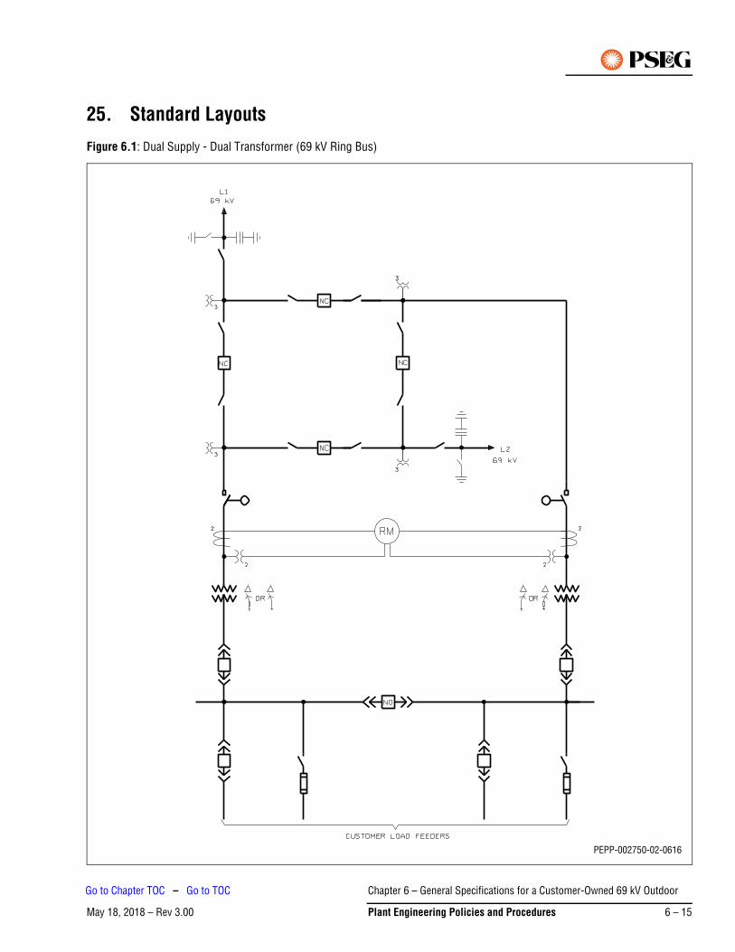
25. Standard Layouts
Figure 6.1: Dual Supply - Dual Transformer (69 kV Ring Bus)
PEPP-002750-02-0616
Chapter 6 – General Specifications for a Customer-Owned 69 kV Outdoor
May 18, 2018 – Rev 3.00 Plant Engineering Policies and Procedures 6 – 15
Go to Chapter TOC – Go to TOC
Figure 6.1: Notes:
1. Connections to metering transformer secondary terminals, test switches, meter equipment and meters will be made by PSE&G.
2. PTs and CTs for metering shall be accessible at all reasonable times for the purpose of inspection, maintenance or change-out by PSE&G. If the PTs and CTs are enclosed in switchgear or a transformer cabinet, or compartment where visual inspection is impractical, access is to be limited only to PSE&G personnel by a hinged door having provision for PSE&G barrel locks and seals. Metering transformers, secondary wiring and unmetered primary conductors shall be visible for inspection when the service is energized.
3. Threaded rigid galvanized steel 2 in. conduit shall be used for the secondary control cable runs from the metering transformer pull box to the meter enclosure, and shall be supplied and installed by the customer. PVC conduit is not acceptable.
a. Conduits for metering transformers secondary connections shall be dedicated conduit that shall not pass through either trenches, hand holes or manholes. Metering conduits shall be inspected prior to backfill or pouring concrete.
b. PSE&G shall furnish the secondary control cables, and the customer shall pull the cables
c. Connections to metering transformer secondary terminals, test switches, meter equipment and meters will be made by PSE&G.
4. A meter panel with minimum dimensions of 36 in. wide x 36 in. high is to be supplied by the customer and installed at a height of no less than 24 in. and no more than 78 in. from the floor. However, if two sets or more of instrument transformers are used, this meter panel shall be 4 ft x 6 ft. Please discuss the meter panel layout with PSE&G’s local Electric Distribution Division Metering Department. There should be 48 in of clear space in front of the meter panel to provide space for installation and metering of equipment. This panel shall be located immediately adjacent to the metering cubicle, but in no case shall the length of secondary leads from the metering transformers to the revenue meters exceed 180 ft.
a. The station ground shall be extended to the meter enclosure for grounding of the metering circuits and equipment in accordance with the NEC.
b. The meter panel and associated equipment shall be housed inside a building or in a weatherproof, heated structure. A metering and control house for housing the metering equipment, relays, control equipment, telephone and storage battery is recommended. A door for entrance to this structure shall be equipped to take PSE&G's standard padlock, and access preferably should be from outside the substation enclosure.
c. Painted plywood is recommended for the meter panel. Thickness shall be 3/4 in. and a 1 in. air gap shall be provided behind the wood to enhance dryness. Alternative materials may be used for the meter panel with advanced PSE&G approval.
d. Lighting must be available at indoor metering locations for meter readings and inspections.
e. If the customer elects to house the meter board in a heated outdoor metal enclosure, such structure requires specific PSE&G approval as to the size, layout and mounting location of the enclosure. A 120 V duplex outlet shall be provided on the meter panel.
Chapter 6 – General Specifications for a Customer-Owned 69 kV Outdoor
May 18, 2018 – Rev 3.006 – 16 Plant Engineering Policies and Procedures
Go to Chapter TOC – Go to TOC
f. Drilling dimensions for the meter enclosure will be supplied by PSE&G’s local Electric Distribution Division Metering Department personnel, as will specific details as to the type and size of metering transformers that will be furnished by PSE&G. Refer to figures at the back of this chapter for typical examples:
- Figure 6.5 – Meter Panel for one set of metering instrument transformers
- Figure 6.6 – Indoor Meter Panel for two sets of instrument transformers
- Figure 6.7 – Outdoor Meter Panel for two sets of instrument transformers
g. PSE&G shall provide the revenue meter socket(s), relay enclosures, and any enclosures required for test switches. The local Electric Distribution Division Metering Department will provide an arrangement plan for this equipment. The customer shall mount this equipment on the meter board, and provide the connecting conduits. PSE&G will connect the wiring to the test switches, meters and other associated equipment on the meter board.
Chapter 6 – General Specifications for a Customer-Owned 69 kV Outdoor
May 18, 2018 – Rev 3.00 Plant Engineering Policies and Procedures 6 – 17
Go to Chapter TOC – Go to TOC
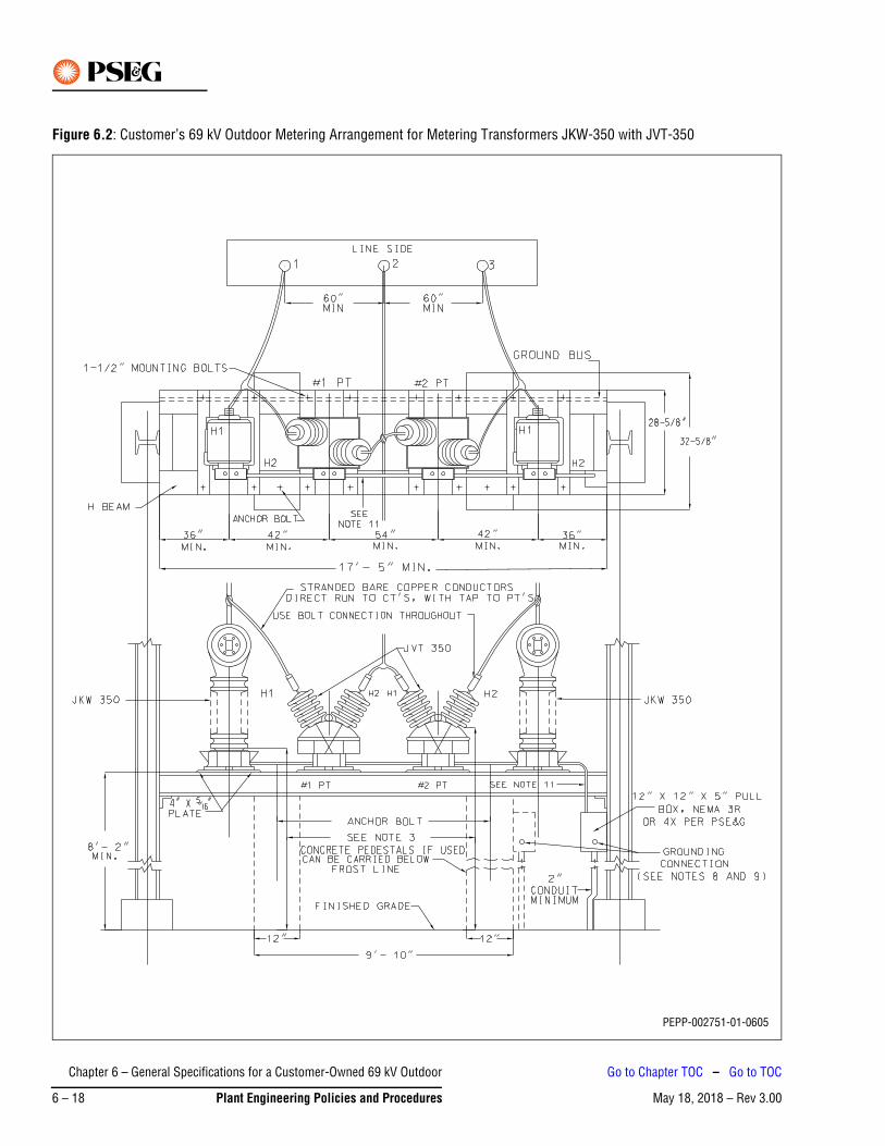
Figure 6.2: Customer’s 69 kV Outdoor Metering Arrangement for Metering Transformers JKW-350 with JVT-350
PEPP-002751-01-0605
Chapter 6 – General Specifications for a Customer-Owned 69 kV Outdoor
May 18, 2018 – Rev 3.006 – 18 Plant Engineering Policies and Procedures
Go to Chapter TOC – Go to TOC
Figure 6.2 Notes:
1. Minimum clearance phase-to-ground 27 in.
2. Minimum clearance phase-to-phase 34 in.
3. Minimum vertical clearance from bottom petticoat of transformer bushing to grade or any other horizontal surface suitable for standing on it (for example, platform) should be 8 ft-9 in. minimum.
4. For outline diagram of potential transformers see Meter and Wiring Manual Figure 10.47 and Figure 6.4.
5. For outline diagram of current transformers see Meter and Wiring Manual Figure 10.38 and Figure 6.3.
6. Transformers may be mounted to the structure as shown or may be attached to concrete pedestals, (shown as dotted lines).
7. All conduit shall be threaded galvanized rigid steel or weatherproof flexible conduit.
8. A 1/2 in. Everdur or equivalent type stud, projecting 1-1/2 in. inside and outside box with double nuts on both sides, shall be provided for grounding connections, with external tie-in to the ground bus.
9. Metering transformers, pull box grounding stud, and conduit shall be solidly connected to the station ground bus by using direct copper connections of not less than 350 MCM, or flat copper bar 2 in. x 1/4 in. in cross section.
10. All steel bracing in the vicinity of current and potential transformers shall have 27 in. minimum clearance from live parts.
11. When installing #2 PT reverse secondary connections.
12. The conduit between instrument transformer secondary terminal boxes shall be 1-1/2 in. weatherproof flexible or 1-1/2 in. rigid galvanized steel (if flexible conduit, use Erickson or equivalent type fittings).
Chapter 6 – General Specifications for a Customer-Owned 69 kV Outdoor
May 18, 2018 – Rev 3.00 Plant Engineering Policies and Procedures 6 – 19
Go to Chapter TOC – Go to TOC
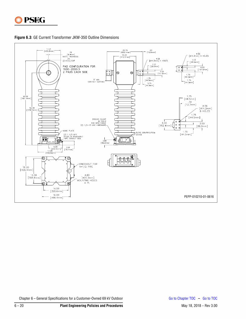
Figure 6.3: GE Current Transformer JKW-350 Outline Dimensions
PEPP-010210-01-0616
Chapter 6 – General Specifications for a Customer-Owned 69 kV Outdoor
May 18, 2018 – Rev 3.006 – 20 Plant Engineering Policies and Procedures
Go to Chapter TOC – Go to TOC
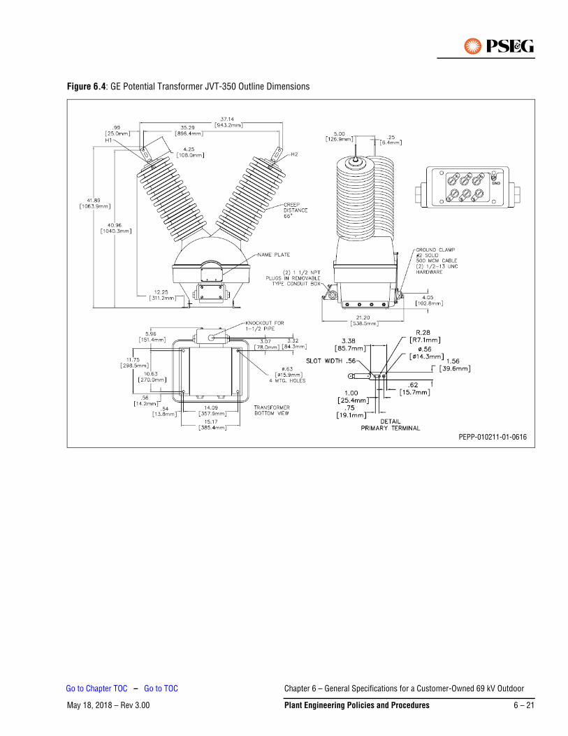
Figure 6.4: GE Potential Transformer JVT-350 Outline Dimensions
PEPP-010211-01-0616
Chapter 6 – General Specifications for a Customer-Owned 69 kV Outdoor
May 18, 2018 – Rev 3.00 Plant Engineering Policies and Procedures 6 – 21
Go to Chapter TOC – Go to TOC
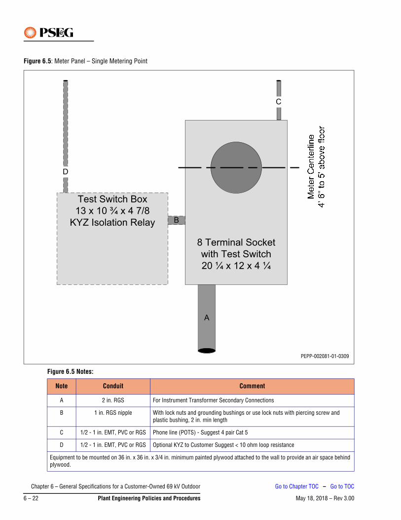
Figure 6.5: Meter Panel – Single Metering Point
Figure 6.5 Notes:
Note Conduit Comment
A 2 in. RGS For Instrument Transformer Secondary Connections
B 1 in. RGS nipple With lock nuts and grounding bushings or use lock nuts with piercing screw and plastic bushing, 2 in. min length
C 1/2 - 1 in. EMT, PVC or RGS Phone line (POTS) - Suggest 4 pair Cat 5
D 1/2 - 1 in. EMT, PVC or RGS Optional KYZ to Customer Suggest < 10 ohm loop resistance
Equipment to be mounted on 36 in. x 36 in. x 3/4 in. minimum painted plywood attached to the wall to provide an air space behind plywood.
8 Terminal Socket
with Test Switch
20 ¼ x 12 x 4 ¼
Test Switch Box
13 x 10 ¾ x 4 7/8
KYZ Isolation Relay B
D
C
A
PEPP-002081-01-0309
Chapter 6 – General Specifications for a Customer-Owned 69 kV Outdoor
May 18, 2018 – Rev 3.006 – 22 Plant Engineering Policies and Procedures
Go to Chapter TOC – Go to TOC

Figure 6.6: Meter Panel – Indoor – Two Metering Points
Figure 6.6 Notes:
Note Conduit Comment
A 2 in. RGS nipple With lock nuts and grounding bushings or use lock nuts with piercing screw and plastic bushing, 2-1/2 - 3 in. long
B 1 in. RGS nipple With lock nuts and grounding bushings or use lock nuts with piercing screw and plastic bushing
C 2 in. RGS For Instrument Transformer Secondary Connections
D 3/4 in. - 1 in. EMT or PVC Ground Connection #8 or larger connection to ground bus
E 1/2 - 1 in. EMT, PVC or RGS Phone line (POTS line) - Suggest 4 pair Cat 5
F 1/2 - 1 in. EMT, PVC or RGS Optional KYZ to Customer Suggest < 10 ohm loop resistance
Equipment to be mounted on 48 in. x 72 in. x 3/4 in. minimum painted plywood attached to the wall to provide an air space behind plywood.
Boxes shall be mounted and connected to allow doors and covers to open without binding on adjacent boxes.
8 Terminal Socket
with Test Switch
20 ¼ x 12 x 4 ¼
Test Switch Box
13 x 10 ¾ x 4 7/8
Voltage Thow-over Relay
C
Test Switch Box
13 x 10 ¾ x 4 7/8
Transformer 2
A A
Test Switch Box
13 x 10 ¾ x 4 7/8
Transformer 1
AA
Test Switch Box
13 x 10 ¾ x 4 7/8
KYZ Isolation Relay B
C
F
28" - 30" Spacing suggested
B
E
D
PEPP-001369-01-0309
Chapter 6 – General Specifications for a Customer-Owned 69 kV Outdoor
May 18, 2018 – Rev 3.00 Plant Engineering Policies and Procedures 6 – 23
Go to Chapter TOC – Go to TOC

Figure 6.7: Meter Panel – Outdoor – Two Metering Points
PEPP-001370-02-0616
Chapter 6 – General Specifications for a Customer-Owned 69 kV Outdoor
May 18, 2018 – Rev 3.006 – 24 Plant Engineering Policies and Procedures
Go to Chapter TOC – Go to TOC

Figure 6.7 Notes:
Note Conduit Comment
A 2 in. RGS nipple With lock nuts and grounding bushings or use lock nuts with piercing screw and plastic bushing, 2-1/2 - 3 in. long.
B 1 in. RGS nipple With lock nuts and grounding bushings or use lock nuts with piercing screw and plastic bushing
C 2 in. RGS For Instrument Transformer Secondary Connections
D 1/2 - 1 in. EMT, PVC or RGS Phone line (POTS line) - Suggest 4 pair Cat 5
E 1/2 - 1 in. EMT, PVC or RGS Optional KYZ to Customer Suggest < 10 ohm loop resistance
F 3/4 - 1 in. EMT or PVC Ground Connection #8 or larger connection to ground bus
G 1/2 - 1 in. EMT or PVC 120 VAC, 20 A Station Power
Equipment to be mounted on 36 in. x 36 in. x 3/4 in. minimum painted plywood attached to the wall to provide an air space behind plywood.
Boxes shall be mounted and connected to allow doors and covers to open without binding on adjacent boxes.
Chapter 6 – General Specifications for a Customer-Owned 69 kV Outdoor
May 18, 2018 – Rev 3.00 Plant Engineering Policies and Procedures 6 – 25
Go to Chapter TOC – Go to TOC
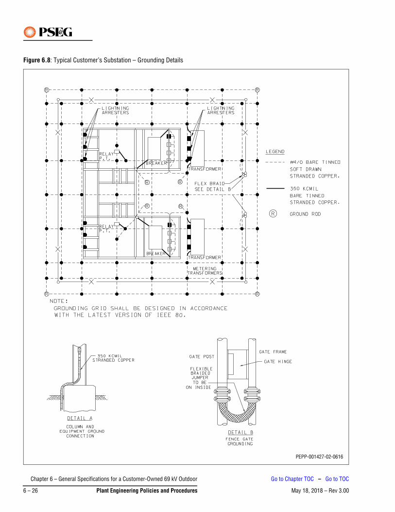
Figure 6.8: Typical Customer’s Substation – Grounding Details
PEPP-001427-02-0616
Chapter 6 – General Specifications for a Customer-Owned 69 kV Outdoor
May 18, 2018 – Rev 3.006 – 26 Plant Engineering Policies and Procedures
Go to Chapter TOC – Go to TOC

Figure 6.8 Notes:
1. The main station ground grid is to be made of # 4/0 AWG Bare Tinned Stranded Copper (minimum).
2. Connections between the ground grid bus, structure, and various pieces of apparatus are to be direct copper connections of # 350 kCMIL Stranded or 2 in. x 1/4 in. Bar (minimum).
3. Ground connectors may be of the welded, bolted or compression type. Bolted connectors must utilize at least two independent bolts or two U-Bolts.
4. Where connectors are in direct contact with structural steel members surfaces, the surface of the connectors shall be tinned.
Chapter 6 – General Specifications for a Customer-Owned 69 kV Outdoor
May 18, 2018 – Rev 3.00 Plant Engineering Policies and Procedures 6 – 27
Go to Chapter TOC – Go to TOC

This Page Intentionally Blank
Chapter 6 – General Specifications for a Customer-Owned 69 kV Outdoor
May 18, 2018 – Rev 3.006 – 28 Plant Engineering Policies and Procedures
Go to Chapter TOC – Go to TOC
May 18, 2018 – Rev 3.00Go to Chapter TOC
Chapter 7 – General Specifications for Rotating Non-Utility Generators (NUGs) – Table of Contents
1. Document Scope . . . . . . . . . . . . . . . . . . . . . . . . . . . . . . . . . . . . . . . . . . . . . . . . . . . . . . . . . . . . . . 7-1
2. Definitions/Acronyms . . . . . . . . . . . . . . . . . . . . . . . . . . . . . . . . . . . . . . . . . . . . . . . . . . . . . . . . . . 7-1
2.1 Affected System . . . . . . . . . . . . . . . . . . . . . . . . . . . . . . . . . . . . . . . . . . . . . . . . . . . . . . . . . . . . . . . . . .7-1
2.2 Aggregate Net Metering . . . . . . . . . . . . . . . . . . . . . . . . . . . . . . . . . . . . . . . . . . . . . . . . . . . . . . . . . . . .7-1
2.3 Applicant . . . . . . . . . . . . . . . . . . . . . . . . . . . . . . . . . . . . . . . . . . . . . . . . . . . . . . . . . . . . . . . . . . . . . . .7-1
2.4 Customer-Generator Facility. . . . . . . . . . . . . . . . . . . . . . . . . . . . . . . . . . . . . . . . . . . . . . . . . . . . . . . . .7-1
2.5 E1 Notification . . . . . . . . . . . . . . . . . . . . . . . . . . . . . . . . . . . . . . . . . . . . . . . . . . . . . . . . . . . . . . . . . . .7-1
2.6 EDC . . . . . . . . . . . . . . . . . . . . . . . . . . . . . . . . . . . . . . . . . . . . . . . . . . . . . . . . . . . . . . . . . . . . . . . . . . .7-1
2.7 ESOC . . . . . . . . . . . . . . . . . . . . . . . . . . . . . . . . . . . . . . . . . . . . . . . . . . . . . . . . . . . . . . . . . . . . . . . . . .7-1
2.8 IEEE 1547. . . . . . . . . . . . . . . . . . . . . . . . . . . . . . . . . . . . . . . . . . . . . . . . . . . . . . . . . . . . . . . . . . . . . . .7-2
2.9 Interconnection Application and Agreement. . . . . . . . . . . . . . . . . . . . . . . . . . . . . . . . . . . . . . . . . . . . .7-2
2.10 Interconnection Point . . . . . . . . . . . . . . . . . . . . . . . . . . . . . . . . . . . . . . . . . . . . . . . . . . . . . . . . . . . . . .7-2
2.11 Net Metering . . . . . . . . . . . . . . . . . . . . . . . . . . . . . . . . . . . . . . . . . . . . . . . . . . . . . . . . . . . . . . . . . . . .7-2
2.12 Non-Utility Generator (NUG) . . . . . . . . . . . . . . . . . . . . . . . . . . . . . . . . . . . . . . . . . . . . . . . . . . . . . . . .7-2
2.13 PEP . . . . . . . . . . . . . . . . . . . . . . . . . . . . . . . . . . . . . . . . . . . . . . . . . . . . . . . . . . . . . . . . . . . . . . . . . . .7-3
2.14 PJM . . . . . . . . . . . . . . . . . . . . . . . . . . . . . . . . . . . . . . . . . . . . . . . . . . . . . . . . . . . . . . . . . . . . . . . . . . .7-3
2.15 PSE&G System . . . . . . . . . . . . . . . . . . . . . . . . . . . . . . . . . . . . . . . . . . . . . . . . . . . . . . . . . . . . . . . . . .7-3
2.16 Renewable Energy . . . . . . . . . . . . . . . . . . . . . . . . . . . . . . . . . . . . . . . . . . . . . . . . . . . . . . . . . . . . . . . .7-3
2.17 SCADA . . . . . . . . . . . . . . . . . . . . . . . . . . . . . . . . . . . . . . . . . . . . . . . . . . . . . . . . . . . . . . . . . . . . . . . . .7-3
2.18 Studies . . . . . . . . . . . . . . . . . . . . . . . . . . . . . . . . . . . . . . . . . . . . . . . . . . . . . . . . . . . . . . . . . . . . . . . . .7-4
3. Process . . . . . . . . . . . . . . . . . . . . . . . . . . . . . . . . . . . . . . . . . . . . . . . . . . . . . . . . . . . . . . . . . . . . . 7-4
3.1 Introduction . . . . . . . . . . . . . . . . . . . . . . . . . . . . . . . . . . . . . . . . . . . . . . . . . . . . . . . . . . . . . . . . . . . . .7-4
3.2 Processing Requests from Rotating Non-Utility Generators not Utilizing Class 1 Renewable Fuels . . .7-5
3.3 Processing Requests from Rotating Non-Utility Generators Utilizing Class 1 Renewable Fuels . . . . . .7-7
3.4 Application Review. . . . . . . . . . . . . . . . . . . . . . . . . . . . . . . . . . . . . . . . . . . . . . . . . . . . . . . . . . . . . . . .7-8
3.5 Applicant Commits to Proceed with Constructing the Project . . . . . . . . . . . . . . . . . . . . . . . . . . . . . . .7-9
3.6 Coordination and Scheduling . . . . . . . . . . . . . . . . . . . . . . . . . . . . . . . . . . . . . . . . . . . . . . . . . . . . . . . .7-9
3.7 Inspection and Testing . . . . . . . . . . . . . . . . . . . . . . . . . . . . . . . . . . . . . . . . . . . . . . . . . . . . . . . . . . . . .7-9
3.8 Acceptance. . . . . . . . . . . . . . . . . . . . . . . . . . . . . . . . . . . . . . . . . . . . . . . . . . . . . . . . . . . . . . . . . . . . . .7-9
3.9 PSE&G Modifications . . . . . . . . . . . . . . . . . . . . . . . . . . . . . . . . . . . . . . . . . . . . . . . . . . . . . . . . . . . . .7-10
4. Applicants/Facility Requirements. . . . . . . . . . . . . . . . . . . . . . . . . . . . . . . . . . . . . . . . . . . . . . . . . 7-10
4.1 Drawings and Specifications . . . . . . . . . . . . . . . . . . . . . . . . . . . . . . . . . . . . . . . . . . . . . . . . . . . . . . .7-11
Chapter 7 – General Specifications for Rotating Non-Utility Generators (NUGs) –
May 18, 2018 – Rev 3.00 Plant Engineering Policies and Procedures 7 – TOC 1
Go to TOC
4.2 Trench, Conduit and Conductors . . . . . . . . . . . . . . . . . . . . . . . . . . . . . . . . . . . . . . . . . . . . . . . . . . . 7-11
4.3 Telecommunication . . . . . . . . . . . . . . . . . . . . . . . . . . . . . . . . . . . . . . . . . . . . . . . . . . . . . . . . . . . . . 7-11
4.4 Switchgear . . . . . . . . . . . . . . . . . . . . . . . . . . . . . . . . . . . . . . . . . . . . . . . . . . . . . . . . . . . . . . . . . . . . 7-11
4.5 Disconnect Switch . . . . . . . . . . . . . . . . . . . . . . . . . . . . . . . . . . . . . . . . . . . . . . . . . . . . . . . . . . . . . . 7-11
4.6 Automatic Control. . . . . . . . . . . . . . . . . . . . . . . . . . . . . . . . . . . . . . . . . . . . . . . . . . . . . . . . . . . . . . . 7-11
4.7 Breaker Control. . . . . . . . . . . . . . . . . . . . . . . . . . . . . . . . . . . . . . . . . . . . . . . . . . . . . . . . . . . . . . . . . 7-12
4.8 Isolation for Testing . . . . . . . . . . . . . . . . . . . . . . . . . . . . . . . . . . . . . . . . . . . . . . . . . . . . . . . . . . . . . 7-12
4.9 Telemetering, SCADA and Control . . . . . . . . . . . . . . . . . . . . . . . . . . . . . . . . . . . . . . . . . . . . . . . . . . 7-12
4.10 Power Factor . . . . . . . . . . . . . . . . . . . . . . . . . . . . . . . . . . . . . . . . . . . . . . . . . . . . . . . . . . . . . . . . . . 7-13
4.11 Relaying . . . . . . . . . . . . . . . . . . . . . . . . . . . . . . . . . . . . . . . . . . . . . . . . . . . . . . . . . . . . . . . . . . . . . . 7-14
4.12 Relay Requirements . . . . . . . . . . . . . . . . . . . . . . . . . . . . . . . . . . . . . . . . . . . . . . . . . . . . . . . . . . . . . 7-14
4.13 Acceptable Relays. . . . . . . . . . . . . . . . . . . . . . . . . . . . . . . . . . . . . . . . . . . . . . . . . . . . . . . . . . . . . . . 7-16
4.14 Inspection and Maintenance . . . . . . . . . . . . . . . . . . . . . . . . . . . . . . . . . . . . . . . . . . . . . . . . . . . . . . . 7-17
5. Revenue Metering. . . . . . . . . . . . . . . . . . . . . . . . . . . . . . . . . . . . . . . . . . . . . . . . . . . . . . . . . . . . .7-18
5.1 Documentation . . . . . . . . . . . . . . . . . . . . . . . . . . . . . . . . . . . . . . . . . . . . . . . . . . . . . . . . . . . . . . . . . 7-18
5.2 Instrument Transformers . . . . . . . . . . . . . . . . . . . . . . . . . . . . . . . . . . . . . . . . . . . . . . . . . . . . . . . . . 7-18
5.3 Revenue Metering Cabinet . . . . . . . . . . . . . . . . . . . . . . . . . . . . . . . . . . . . . . . . . . . . . . . . . . . . . . . . 7-18
5.4 Telemetering and Supervisory Control and Data Acquisition (SCADA) . . . . . . . . . . . . . . . . . . . . . . . 7-18
5.5 Process where an existing Net Metering Customer no longer qualifies. . . . . . . . . . . . . . . . . . . . . . . 7-18
6. Network Service . . . . . . . . . . . . . . . . . . . . . . . . . . . . . . . . . . . . . . . . . . . . . . . . . . . . . . . . . . . . . .7-21
6.1 Network Basics. . . . . . . . . . . . . . . . . . . . . . . . . . . . . . . . . . . . . . . . . . . . . . . . . . . . . . . . . . . . . . . . . 7-21
6.2 Types of Networks . . . . . . . . . . . . . . . . . . . . . . . . . . . . . . . . . . . . . . . . . . . . . . . . . . . . . . . . . . . . . . 7-21
6.3 Network Interconnection Issues . . . . . . . . . . . . . . . . . . . . . . . . . . . . . . . . . . . . . . . . . . . . . . . . . . . . 7-22
6.4 NUG – Any Power Output Level – Export . . . . . . . . . . . . . . . . . . . . . . . . . . . . . . . . . . . . . . . . . . . . . 7-23
6.5 Rotating NUG – Any Power Output Level Not Utilizing Class 1 Renewable Fuels – Non-Export . . . . 7-23
6.6 Rotating Non-Utility Generators utilizing Class 1 renewable fuels . . . . . . . . . . . . . . . . . . . . . . . . . . 7-25
7. Additional Resources . . . . . . . . . . . . . . . . . . . . . . . . . . . . . . . . . . . . . . . . . . . . . . . . . . . . . . . . . .7-25
Chapter 7 – General Specifications for Rotating Non-Utility Generators (NUGs) –
May 18, 2018 – Rev 3.007 – TOC 2 Plant Engineering Policies and Procedures
Go to TOC
May 18, 2018 – Rev 3.00
Chapter 7 – General Specifications for Rotating Non-Utility Generators (NUGs)
1. Document ScopeThe purpose of this document is to communicate the process and requirements for interconnecting a spinning generator to PSE&G’s electric distribution system. It should be used as a reference tool to help understand the different aspects involved with the process. Always consult with a qualified PSE&G associate before starting a project. This document will cover the basic elements related to:
• Definitions• Process• Applicant/Facility Requirements• Metering• Installations in Network Areas
2. Definitions/Acronyms
2.1 Affected SystemAn electric system other than the PSE&G System that may be affected by proposed NUG interconnection.
2.2 Aggregate Net MeteringA customer-generator with multiple facilities of the same rate class utilizing one of those facilities as a host site which produces more electricity than consumed at that site.
2.3 ApplicantWithin this document the applicant may be several different parties involved with the process of interconnecting. For simplicity’s sake, the applicant may be any person or designee taking ownership of and responsibility for the construction, operation, ownership and maintenance of the facility.
2.4 Customer-Generator FacilityEquipment used by a customer-generator to generate, manage and/or monitor electricity.
2.5 E1 NotificationRefers to a formal request for information concerning all customer needs that is created in PSE&G’s Distribution Work Management System (DWMS).
2.6 EDCElectric Distribution Company
2.7 ESOCPSE&G’s Electric System Operations Center
Chapter 7 – General Specifications for Rotating Non-Utility Generators
May 18, 2018 – Rev 3.00 Plant Engineering Policies and Procedures 7 – 1
Go to Chapter TOC – Go to TOC
2.8 IEEE 1547Approved series of interconnection standards developed by the Institute of Electrical and Electronics Engineers.
2.9 Interconnection Application and AgreementContractual agreement between the customer-generator and PSE&G to interconnect distributive generation to PSE&G’s distribution system.
2.10 Interconnection PointThe point(s) of physical connection of the NUG to the PSE&G System located at the point where the PSE&G System meets with and connects to the NUG’s facility. Typically, this occurs at the point where the NUG’s incoming line is terminated by PSE&G, such as at a disconnect switch or switches on the high side of a customer’s circuit breaker or other load break device. This interconnection point or points should be identified on the NUG’s single line diagram. This is also the point where certain SCADA and telemetering measurements should be effectively determined.
2.11 Net MeteringA system of metering electricity in which PSE&G:
1. Credits a Customer-generator at the full retail rate for each kilowatt-hour produced by a Class 1 renewable energy system (see Section 2.16 below), installed on the Customer-generator’s side of the electric revenue meter, up to the total amount of electricity used by that Customer during an annualized period; and
2. Compensates the Customer-generator at the end of the annualized period for any remaining credits, at a rate equal to the electric supplier’s or BGS provider’s avoided cost of wholesale power.
Net Metering rules are included in Section 15 – Net Metering Installations (including all subsections) of the Electric Standard Terms and Conditions.
2.12 Non-Utility Generator (NUG)Non-Utility Generator (also known as a cogenerator, “Distributed” or “Dispersed” Generator (DG), Distributed Resource (DR), or customer-generator) is any facility which operates an electric power generating device in parallel with the PSE&G System. Large generators that are Independent Power Producers (IPPs) or Electric Wholesale Generators (EWGs) generally are connected to the Transmission System, will have additional requirements, and come under the interconnection procedures of PJM. There are two basic types of NUGs, one which will sell power to PSE&G (or some other utility) – referred to as an “exporter” and one which will consume all power generated on their own premises – a “non-exporter”. There is a subset of exporting facilities which is called a “net metered” facility, where excess power is netted against the customer’s kilowatt-hour usage via special metering.
A rotating NUG can be any one of the following types:
• Cogeneration or Combined Heat and Power (CHP) Facility
Produces electricity and useful thermal energy from the same fuel source.
• Resource Recovery Facility
Produces electricity from fuels such as municipal waste, tires, sludge, wood chips, etc.
Chapter 7 – General Specifications for Rotating Non-Utility Generators
May 18, 2018 – Rev 3.007 – 2 Plant Engineering Policies and Procedures
Go to Chapter TOC – Go to TOC
• Biopower
Produces electricity through the use of organic materials
• Hydro Facility
Produces electricity from water resources
• Landfill Gas Facility
Produces electricity from natural gas by-products emitted from landfills
• Wave or tidal facility
Produces electricity from a generator utilizing tidal and wave energy
2.13 PEPPurchase Electric Power – Agreement to generate electric power and sell directly back to the EDC.
2.14 PJMThe PJM Regional Transmission Organization, which oversees the operation of the transmission system in the region in which PSE&G operates, also has oversight of generator interconnections where the generator is exporting power for use in the wholesale marketplace. Generally, the exporting generation facility must have an aggregate output of over 1 MW to be PJM jurisdictional, and it can be connected to either the distribution system or the transmission system.
2.15 PSE&G SystemThe electrical facilities owned, controlled and operated by PSE&G.
2.16 Renewable EnergyClass 1 Renewable:
• Biopower • Fuel Cells (Inverter based – see Chapter 11)• Stored electrical generation (Inverter based – see Chapter 11)• Solar or Photovoltaic Facility (Inverter based – see Chapter 11)• Wave or Tidal• Wind Facility (Inverter based – see Chapter 11)
Class 2 Renewable:
• Energy produced at resource recovery or hydro power facility
2.17 SCADASupervisory Control and Data Acquisition
Chapter 7 – General Specifications for Rotating Non-Utility Generators
May 18, 2018 – Rev 3.00 Plant Engineering Policies and Procedures 7 – 3
Go to Chapter TOC – Go to TOC
2.18 StudiesThe following studies may be performed by PSE&G in order to determine the capability of interconnecting the NUG facility:
• Feasibility StudyA basic assessment by PSE&G of the ability of the PSE&G System to accommodate the NUG’s interconnection, including preliminary information about what service voltage level would be utilized and costs.
• Impact StudyAn assessment by PSE&G of: a. The adequacy of the PSE&G System to accommodate the output of the NUG;
b. Whether any additional costs may be incurred in order to design, furnish, and install the interconnection; and
c. With respect to an interconnection application, an estimate of the NUG’s cost responsibility for PSE&G’s interconnection facilities.
• Facilities Study
An engineering study conducted by PSE&G (in coordination with any Affected System) to determine the required modifications to the PSE&G System, including the cost and the time required to design, furnish and install such modifications, as necessary to accommodate an interconnection application.
3. Process
3.1 IntroductionThe NUG’s primary function is to produce electric power that can be used in one of three ways:
• All used on site (Non-Exporter)• All sold (Exporter)• A combination of the above, which may include facilities that net meter their output
PSE&G has the following obligations to NUGs:
• Analyze interconnection requests received from NUGs, or PJM in the event that PJM is managing the interconnection process, and provide data and cost estimates.
• Provide access to the PSE&G System.• Provide regular Electric Tariff service if needed, and billing metering.
The first contact with PSE&G by a NUG could be received from any of several PSE&G representatives who have responsibility for customer contact. From that initial contact it is important that the NUG be channeled to the appropriate party in PSE&G. The flow chart shown in Figure 7.1 in Section 3.2, “Processing Requests from Rotating Non-Utility Generators not Utilizing Class 1 Renewable Fuels”, defines where a NUG should be directed and how various groups in the company are involved with NUGs.
NUGs that utilize Class 1 renewable fuels, qualify for treatment under New Jersey’s “Net Metering and Interconnection Standards for Class 1 Renewable Energy Systems.” Separate procedures and processes for tracking these projects have been developed, including specialized metering equipment and billing methods. This topic is covered in Section 3.3. More on Class 1 Renewable Energy interconnections may be found in Chapter 9 of Technical Manual “Information and Requirements for Electric Service Manual (Green Book), Rev. 03.00, Dated May 31, 2014.”
Chapter 7 – General Specifications for Rotating Non-Utility Generators
May 18, 2018 – Rev 3.007 – 4 Plant Engineering Policies and Procedures
Go to Chapter TOC – Go to TOC
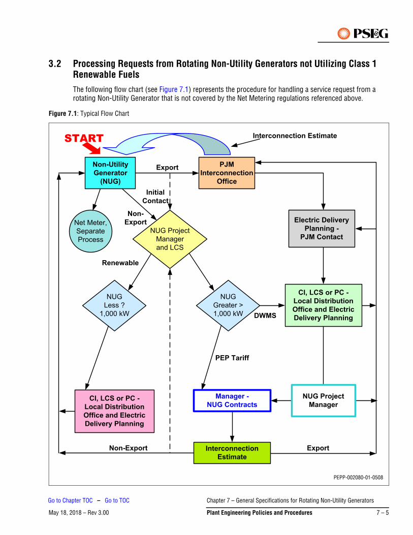
3.2 Processing Requests from Rotating Non-Utility Generators not Utilizing Class 1 Renewable FuelsThe following flow chart (see Figure 7.1) represents the procedure for handling a service request from a rotating Non-Utility Generator that is not covered by the Net Metering regulations referenced above.
Figure 7.1: Typical Flow Chart
Non-UtilityGenerator
(NUG)
PJMInterconnection
Office
NUG Project
Manager
and LCS
NUG
Less ?
1,000 kW
NUG
Greater >
1,000 kW
CI, LCS or PC -Local DistributionOffice and ElectricDelivery Planning
Electric Delivery Planning -
PJM Contact
CI, LCS or PC -Local DistributionOffice and ElectricDelivery Planning
Manager -NUG Contracts
InterconnectionEstimate
START
Export
Renewable
Non-Export
InitialContact
Interconnection Estimate
Non-Export Export
DWMS
PEP Tariff
Net Meter,
Separate
Process
NUG ProjectManager
PEPP-002080-01-0508
Chapter 7 – General Specifications for Rotating Non-Utility Generators
May 18, 2018 – Rev 3.00 Plant Engineering Policies and Procedures 7 – 5
Go to Chapter TOC – Go to TOC
1. Flowchart Terms
– Non-Utility Generator (NUG)
The owner/manager/engineer of the facility, consultant, contractor, or anyone acting or working as an agent of the owner.
– Initial Contact– All initial contacts with the NUG will be referred to the Business Process Manager in the Springfield
Office (Large Customer Support Department). Based on the size of the co-generator the following course of action will be determined:
- >2 MW – initiate and coordinate an initial meeting of all parties, unless the project will be managed by PJM.
- 2 MW send information to the local Electric Distribution Division office and Electric Delivery Planning.
– Initial Meeting of all Parties
For the NUG with greater than 2 MW capacity and that is not being managed by PJM, the Major Account Consultant will arrange a meeting of all persons who will have an interest in the project, to include any or all of the following:
i. The Non-Utility Generator
ii. Manager – NUG Contracts
iii. Manager – Transmission Planning
iv. Manager – Electric Delivery Planning
v. Major Account Consultant
vi. Operations and Resource Manager
vii. ESOC and/or Division Operations
viii. Manager – Asset Reliability
ix. NUG Project Manager
The initial meeting will be used to obtain and pass on information needed for the customer to:
2. Determine if it may be feasible to construct the facility.
a. Establish lines of communication for the project.
b. Exchange information with the NUG to establish project scope. The NUG will be informed that an Agreement for the project will need to be executed. Additionally, detailed specifications and requirements will be prepared when the project is approved and the required contribution is received.
c. Inform the NUG whether or not it should be applying for its interconnection through the PJM process.
- NUG Project Manager
Responsible for the entire project, including preparation of Investment Request (IR) and obtaining funds, within their department.
- Interconnection Estimate
Information required by involved parties to complete the project. Included will be information such as study estimates, conceptual estimates, plans, specifications, drawings for review, payment schedules, construction schedules, cut in procedures, etc.
Chapter 7 – General Specifications for Rotating Non-Utility Generators
May 18, 2018 – Rev 3.007 – 6 Plant Engineering Policies and Procedures
Go to Chapter TOC – Go to TOC
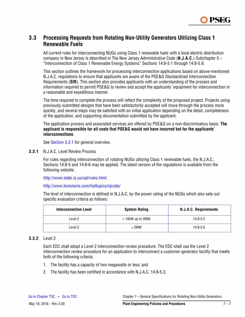
3.3 Processing Requests from Rotating Non-Utility Generators Utilizing Class 1 Renewable FuelsAll current rules for interconnecting NUGs using Class 1 renewable fuels with a local electric distribution company in New Jersey is described in The New Jersey Administrative Code (N.J.A.C.) Subchapter 5 – “Interconnection of Class 1 Renewable Energy Systems” Sections 14:8-5.1 through 14:8-5.9.
This section outlines the framework for processing interconnection applications based on above-mentioned N.J.A.C. regulations to ensure that applicants are aware of the PSE&G Standardized Interconnection Requirements (SIR). This section also provides applicants with an understanding of the process and information required to permit PSE&G to review and accept the applicants’ equipment for interconnection in a reasonable and expeditious manner.
The time required to complete the process will reflect the complexity of the proposed project. Projects using previously submitted designs that have been satisfactorily accepted will move through the process more quickly, and several steps may be satisfied with an initial application depending on the detail, completeness of the application, and supporting documentation submitted by the applicant.
The application process and associated services are offered by PSE&G on a non-discriminatory basis. The applicant is responsible for all costs that PSE&G would not have incurred but for the applicants’ interconnections.
See Section 3.3.1 for general overview.
3.3.1 N.J.A.C. Level Review Process
For rules regarding interconnection of rotating NUGs utilizing Class 1 renewable fuels, the N.J.A.C., Sections 14:8-5 and 14:8-6 may be applied. The latest version of the regulations is available from the following website:
http://www.state.nj.us/oal/rules.html
http://www.lexisnexis.com/hottopics/njcode/
The level of interconnection is defined in N.J.A.C. by the power rating of the NUGs which also sets out specific evaluation criteria as follows:
3.3.2 Level 2
Each EDC shall adopt a Level 2 interconnection review procedure. The EDC shall use the Level 2 interconnection review procedure for an application to interconnect a customer-generator facility that meets both of the following criteria:
1. The facility has a capacity of two megawatts or less; and
2. The facility has been certified in accordance with N.J.A.C. 14:8-5.3.
Interconnection Level System Rating N.J.A.C. Requirements
Level 2 > 10kW up to 2MW 14:8-5.5
Level 3 > 2MW 14:8-5.6
Chapter 7 – General Specifications for Rotating Non-Utility Generators
May 18, 2018 – Rev 3.00 Plant Engineering Policies and Procedures 7 – 7
Go to Chapter TOC – Go to TOC
3.3.3 Level 3
Each EDC shall adopt a Level 3 interconnection review procedure (which is described in N.J.A.C. 14:8-5.6). The EDC shall use the Level 3 review procedure for an application to interconnect a customer rotating generator facility that does not qualify for the Level 2 interconnection review procedures set forth at N.J.A.C. 14:8-5.5.
3.3.4 Application Documentation
The documents and application fees required from a customer vary depending on the type of interconnection being proposed. The relevant documents are outlined below:
*Application/Agreement documents and fees can be located at PSE&G’s Website, or the NJ Office of Clean Energy Website:
http://www.pseg.com/business/small_large_business/rebate/njcleanenergy.jsp
http://www.njcleanenergy.com/renewable-energy/programs/net-metering-and-interconnection
Additional documentation required, but not limited to, includes:
• Site plan including the location of proposed interconnection point• Electrical one-line including both the utility feed and customers equipment• Detailed switchgear specifications
3.4 Application ReviewA PSE&G representative will process the application for an initial review and feasibility study. This requires a basic assessment of the ability of the PSE&G System to accommodate the customer-generator’s interconnection, including preliminary information about what service voltage level would be utilized and costs. The results of this study will determine whether or not an impact study and or facilities study will be required.
The applicant will be provided with an assessment of the technical feasibility of the proposed interconnection and proposed costs that may be incurred.
If it is determined that there may or will be a significant impact to the utilities PSE&G’s distribution system, the customer will be informed that further study will be necessary. The applicant will then be required to:
• Provide PSE&G with a cost-based advance payment for the PSE&G review of the proposed generator. • Submit a detailed design package.• Confirm with PSE&G a mutually agreeable schedule for the project based on the applicant’s work plans
and the other discussions.
Additional exchanges of information between PSE&G and the applicant may be required to complete the design package according to PSE&G’s technical requirements for interconnection.
Applicant will be informed of the results of any further studies and issued an estimate for all necessary work to accommodate the customer-generator’s interconnection.
Interconnection Type Interconnection Document
Net Metering Level 2-3 Level 2-3 Interconnection Application/Agreement (with Terms and Conditions)*
PEP Tariff – Levels 1-3 Level 2-3 Interconnection Application/Agreement (with Terms and Conditions)*
PJM Tariff N/A (Requests processed through Electric Planning group)
Chapter 7 – General Specifications for Rotating Non-Utility Generators
May 18, 2018 – Rev 3.007 – 8 Plant Engineering Policies and Procedures
Go to Chapter TOC – Go to TOC
3.5 Applicant Commits to Proceed with Constructing the ProjectThe applicant will:
• Execute a standardized interconnection agreement or commit in writing to the applicable tariff requirements.
• Provide PSE&G with an advance payment for PSE&G’s estimated costs associated with system modifications, metering, and on-site verification.
• Provide a preliminary schedule of construction for the facility.
3.6 Coordination and SchedulingThe applicant will be provided with the contact information for the applicable PSE&G representative. The applicant shall contact this individual to schedule a project kick-off meeting.
At this initial meeting the applicant should be prepared to discuss:
• Scheduling• Details of related documentation and drawings submitted• Coordination• Inspection requirements• Metering requirements
3.7 Inspection and TestingPeriodic inspection will be required by our metering and inspection department. Scheduling of these site visits should be discussed at the bi-monthly meetings and will be the responsibility of the applicant. See Section 4. for further details of the inspection process.
The applicant will develop a written testing plan to be submitted to PSE&G for review and acceptance. This testing plan will be designed to verify compliance of the facility with the applicant’s PSE&G-accepted drawings and details of the interconnection. The final testing will include testing in accordance with the SIR and the site-specific requirements. The final testing will be conducted at a mutually agreeable time and PSE&G shall be given the opportunity to witness the tests. See Section 4. for further details off the testing protocol.
When applicant is ready to schedule a testing date, they should have completed the second part of the Interconnection Agreement and submitted it to PSE&G.
3.8 AcceptanceWithin a reasonable time after interconnection, PSE&G will review the results of its on-site verification and issue to the applicant a formal letter of acceptance for interconnection or Permission To Operate (PTO) as well as a copy of the fully executed agreement.
Installation of the customer-generator facility must be in compliance with the local, state and federal codes and regulations, and shall meet the requirements of IEEE Standard 1547-2003 (R2008) “Standard for Interconnecting Distributed Resources with Electric Power Systems” with the Amendment IEEE Std 1547a™-2014 and any subsequent subparts of IEEE 1547, such as IEEE 1547.1 (2005) for testing protocols. The installation shall be performed in a workmanlike manner, and shall meet or exceed industry standards of good practice. Prior to connection, PSE&G must be provided by the local Sub-code Official with a “cut-in
Chapter 7 – General Specifications for Rotating Non-Utility Generators
May 18, 2018 – Rev 3.00 Plant Engineering Policies and Procedures 7 – 9
Go to Chapter TOC – Go to TOC
card” or other evidence of the satisfactory electrical inspection by the authorized inspection agency having jurisdiction.
Upon initial parallel operation of a generating system a “Witness Test” or verification test shall be performed, or any time interface hardware or software is changed, a verification test must be performed in accordance with the applicable requirements of IEEE Std 1547.1 (2005) “Conformance Test Procedures for Equipment Interconnecting Distributed Resources with Electric Power Systems.” A New Jersey Licensed Professional Engineer or qualified individual working under the direction of a New Jersey Licensed Professional Engineer must perform verification testing in accordance with the manufacturer’s recommendations, and use licensed electricians with experience in testing protective equipment. PSE&G reserves the right to witness verification testing or require written certification that the testing was performed.
Verification testing shall be performed every 4 years. All verification tests prescribed by the manufacturer shall be performed. If wires must be removed to perform certain tests, each wire and each terminal must be clearly and permanently marked. The generator-owner shall maintain verification test reports for inspection by PSE&G.
Any system that depends upon a battery for trip power shall be checked and logged once per month for proper voltage. Once every 4 years the battery must be either replaced or a discharge test performed.
3.9 PSE&G ModificationsAll labor and material expenses incurred to provide the NUG interconnection service will be billed at actual cost.
4. Applicants/Facility RequirementsThe following are requirements for all NUGs regardless of size or intent to sell to PSE&G or elsewhere, other than those which are handled under the Net Metering program.
The information contained herein is general and not intended to cover all details and aspects of a particular project. PSE&G should be consulted in case of doubt on the current applicability of any item.
Any information contained in this document is subject to change without notification. It is the NUG’s responsibility to verify current applicability of information through written inquiry to PSE&G.
It is PSE&G’s policy to permit NUGs to operate their generating equipment in parallel with PSE&G’s electric distribution system provided there are no expected adverse effects to the reliability or quality of service currently provided to other customers, or to the safety of PSE&G’s workers or the general public.
PSE&G will not be liable for damages or for injuries sustained by customers or by the equipment of customers or by reason of the condition or character of customer’s facilities or the equipment of others on customer’s premises. PSE&G will not be liable for the use, care, or handling of the electric service delivered to the customer after same passes beyond the point at which PSE&G’s service facilities connect to the customer's facilities.
Note
Chapter 7 – General Specifications for Rotating Non-Utility Generators
May 18, 2018 – Rev 3.007 – 10 Plant Engineering Policies and Procedures
Go to Chapter TOC – Go to TOC
4.1 Drawings and SpecificationsThree sets of the following drawings must be submitted to PSE&G and/or PJM for review:
1. AC three line schematics detailing the required relaying and CT location.
2. DC schematics detailing the required relaying.
3. Instruction manuals for the protective components.
4. One line diagram showing the interconnection with the PSE&G system as well as the generator and associated breakers and protective equipment.
5. Generator data required to analyze fault contributions and load flows.
6. Transformer data including ratings and impedance. All transformers for all NUG facilities, inclusive of customer owned transformers on net metered facilities, must by wye-wye type. There must be a ground connection on the utility side of each transformer. Any deviation from this requirement must be approved by PSE&G.
7. Logic diagrams and/or tripping tables.
4.2 Trench, Conduit and ConductorsThe applicant will be responsible for all trench, conduit and secondary conductors required. Primary conductors will be provided and installed by PSE&G at the applicant’s expense. It is the applicant’s responsibility to conform to all PSE&G and NEC specification requirements for trench and conduit installation as well as coordination of all inspections required for such work.
4.3 TelecommunicationThe applicant is responsible for all telecommunication conduit and conductors. The applicant is also responsible for all coordination and communication with the telecommunication company.
4.4 SwitchgearFor NUGs directly connected to 4 kV and higher voltages the applicant is responsible for the supply and installation of all required switchgear elements. The switchgear must strictly conform to PSE&G’s specifications.
4.5 Disconnect SwitchA disconnect switch may be required depending on the size of the installation. It is recommended to be installed on both sides of PSE&G metering for most installations.
4.6 Automatic ControlThe protective equipment installed by the NUG shall provide automatic disconnection of the generator from the PSE&G System for the following conditions.
1. A fault on the NUG equipment
2. Abnormal voltage or frequency
3. De-energization of the PSE&G supply line
In addition, the NUG must submit plans explaining how their control scheme will isolate its generation from the PSE&G System when the PSE&G source is lost.
Chapter 7 – General Specifications for Rotating Non-Utility Generators
May 18, 2018 – Rev 3.00 Plant Engineering Policies and Procedures 7 – 11
Go to Chapter TOC – Go to TOC
4.7 Breaker ControlFor NUG’s supplied at voltages of 4 kV or greater, the high side breaker must be DC operated. This will require a battery and suitable charger. It has been the experience of PSE&G that a properly maintained battery provides the most reliable source of power for operating breakers. The battery shall be sized for a minimum of 8 hour duty cycle. The NUG is responsible for maintaining the battery and charger system.
4.8 Isolation for TestingAt NUG’s whose aggregate output exceeds 1 MW, all required relays shall have provisions for AC and DC isolation for testing. This will normally consist of test switches such as the ABB FT-1. The current circuits must have shorting bars to avoid open circuiting the Current Transformers (CTs).
4.9 Telemetering, SCADA and Control
4.9.1 Telemetering
Equipment shall be installed at the Project and PSE&G’s Electric System Operations Center (ESOC) in Newark, New Jersey to provide for telecommunication interfaces and to enable measurement of the following quantities when the NUGs net output into PSE&G’s System will exceed 1,000 kW:
1. Instantaneous net active electrical power output of the Facility’s generator
2. Instantaneous net reactive electrical power output of the Facility’s generator
3. Instantaneous terminal voltage of the Facility’s generator
4. Instantaneous voltage at the Substation Facility
5. Instantaneous active power flow on the Interconnection at the Substation Facility
6. Instantaneous reactive power flow on the Interconnection at the Substation Facility
7. Hourly kilowatt-hours of Net Electrical Energy received by PSE&G at the Point of Interconnection.
8. Based upon PSE&G’s review of the design of the electrical portion of the Project, PSE&G will designate the point(s) where the aforementioned electrical quantities are to be measured.
PSE&G shall designate, select and specify the equipment and subsequent telecommunications devices to be used for telemetering to the ESOC by means of fiber optic cable, digital data links and/or analog signals to be installed at the facility, to enable a measurement of the aforementioned electrical quantities. PSE&G shall purchase the telemetering and control equipment required at both the Project and the ESOC, at the NUG’s expense. The NUG shall receive from PSE&G and install the telemetering equipment required at the Project in accordance with PSE&G’s specifications. PSE&G shall own, operate and maintain the telemetering and SCADA equipment.
The NUG shall pay PSE&G for any costs associated with operating and maintaining the telemetering and SCADA equipment.
For projects 10 MW or less in size that are coordinated through PJM, PSE&G and the NUG may choose to utilize PJM’s telemetry format, which is discussed in Attachment E to PJM Manual 14A, Rev.17, effective 1/22/2015.
Chapter 7 – General Specifications for Rotating Non-Utility Generators
May 18, 2018 – Rev 3.007 – 12 Plant Engineering Policies and Procedures
Go to Chapter TOC – Go to TOC
4.9.2 Supervisory Control and Data Acquisition (SCADA)
For all NUGs with net output into PSE&G’s System above 1,000 kW PSE&G shall designate, select, specify and purchase the equipment required for SCADA purposes. The NUG shall receive the devices from PSE&G and install the equipment at its facility. If necessary, PSE&G will install any other SCADA equipment required at its facilities, at the NUGs expense. The NUG shall pay PSE&G for all costs associated with SCADA equipment. This equipment will provide some or all of the following data:
1. Entrance breaker status indication
2. Breaker low gas pressure alarm
3. Breaker control status indication (local/remote)
4. Main transformer differential relay operation alarm indication
5. Generator breaker status indication
6. SCADA equipment shall be capable of tripping the generator breaker or the entrance breaker.
Additional SCADA equipment for use by the local Electric Distribution Division office operations personnel may be required. This local-use SCADA equipment utilizes low cost equipment, but can provide some or all of the following data as needed:
1. Circuit breaker open/close indication
2. Line disconnect switch open/close indication (NO or NC)
3. RFL receive trip (for transfer trip relaying)
4. RFL trouble alarm (for transfer trip relaying)
5. Loss of potential
6. Bus voltage (three phases)
7. DC control low voltage alarm
For projects 10 MW or less in size that are coordinated through PJM, PSE&G and the NUG may choose to utilize PJM’s SCADA system, which is discussed in Attachment E to PJM Manual 14A, Rev.17, effective 1/22/2015.
4.9.3 Telecommunications
Non-Utility Generator shall lease, at its expense the appropriate communication circuits required for operation of the SCADA system.
Such equipment will be owned, operated and maintained by PSE&G. Any costs associated with the operation or maintenance of such equipment shall be paid for by the NUG within 30 days of the date of billing.
For projects 10 MW or less in size that are coordinated through PJM, PSE&G and the NUG may choose to utilize PJM’s communications system, which is discussed in Attachment E to PJM Manual 14A, Rev.17, effective 1/22/2015.
4.10 Power FactorThe power factor of the NUG must be maintained at unity at the Interconnection Point unless otherwise specified by PSE&G. The generator shall have the capability to operate between 0.95 lagging, to 0.95 leading if required by PSE&G for operational purposes. The installation of power factor correction capacitors at the NUG’s generating facility may be required if the output is below unity and cannot be corrected by the generator. The cost of such capacitors shall be borne by the NUG.
Chapter 7 – General Specifications for Rotating Non-Utility Generators
May 18, 2018 – Rev 3.00 Plant Engineering Policies and Procedures 7 – 13
Go to Chapter TOC – Go to TOC
4.11 RelayingThe Non-Utility Generator interconnection relay settings shall be set based on IEEE Standard 1547-2003 (R2008) “Standard for Interconnecting Distributed Resources with Electric Power Systems” with the Amendment IEEE STD 1547a™-2014 and any subsequent subparts of IEEE 1547. PSE&G may provide additional relay requirements superseding the ones from above-mentioned IEEE Standards. PSE&G must approve all the remaining settings for all required interconnection relays that trip breakers that affect PSE&G load flow. In addition, for NUGs whose aggregate output is greater than 1 MW, PSE&G personnel will apply the settings to the relays. However, if preferred by the NUG, or because personnel constraints prohibit PSE&G from applying the settings, this task may be contracted for by the NUG to be performed by a qualified third party acceptable to PSE&G. If a third party applies the settings, documentation showing proof of the setting application shall be provided by the NUG to PSE&G. If PSE&G applies the settings, the NUG will be charged for this service.
For NUGs whose output is greater than 1 MW, periodic maintenance of the required protective relay system may be performed by PSE&G personnel. The NUG will be charged for this service. If preferred by the NUG, or because personnel constraints prohibit PSE&G from performing the required maintenance, it may be performed by a qualified third party acceptable to PSE&G. If a third party performs the maintenance, documentation showing proof of the maintenance shall be provided by the NUG to PSE&G. The period of maintenance shall be based on the PSE&G Relay Test Manual and currently that interval is 4 years.
If the output of the NUG is 1 MW or less, the NUG must provide for periodic maintenance of the protective relay systems and submit proof of this maintenance to PSE&G. The period of this maintenance shall be 4 years or less.
PSE&G recommends that the other relays installed by the NUG also be maintained periodically. The NUG may use a qualified independent testing service or may request that PSE&G perform the testing and maintenance. The NUG will be billed for all testing and maintenance performed by PSE&G on other relay systems at their facility.
When the NUG facility is first placed in service (for a NUG whose aggregate output exceeds 1 MW) PSE&G will test all required interconnection relays and their associated circuits prior to energizing the NUG.
4.12 Relay RequirementsThe following requirements are mandated for the safety and reliability of the PSE&G System. The relay protection design of all equipment in the NUG’s facility is solely the responsibility of the NUG.
The numbers shown in parenthesis in the following paragraphs utilize the IEEE codes for the particular relay type referenced below.
4.12.1 NUG any Output Power Level – Non-export
A NUG, which does not intend to send power to the grid, shall install a relay with a directional power function (32) at the point of interconnection with PSE&G. Sufficient power must flow into the NUG’s facility such that enough current is detected by the CTs that the 32 element can operate. If power flow into the NUG is not maintained, the 32 element will open a breaker between the generator and PSE&G. This method of always importing a small amount of power is required to ensure proper operation of the directional power relay, since whenever the 32 element detects any power flows from the NUG into the PSE&G System, the 32 element will isolate the generator from PSE&G. The relay with a directional power function (32) shall be fed by three single-phase current transformers (CT) and three single-phase potential transformers (PT) located on the PSE&G side of the service entrance breaker. The PT shall be connected Wye-Wye. In order to
Chapter 7 – General Specifications for Rotating Non-Utility Generators
May 18, 2018 – Rev 3.007 – 14 Plant Engineering Policies and Procedures
Go to Chapter TOC – Go to TOC
limit unnecessary operations during faults on the PSE&G System or loss of load in the NUG’s facility, the directional power relay should be set with up to a 5 second delay (except for the case of generators connected to 4 kV or 13 kV circuits, which has to meet specific relay requirements explained in Section 4.12.5. below).
Since the PSE&G source breaker may be reclosed automatically, it is essential that the NUG generator is disconnected from the utility system when the reclose attempt occurs, or equipment damage can result.
4.12.2 NUG Aggregate Output 1 MW or Less – Export
Except for the case of generators connected to 4 kV or 13 kV circuits, which has to meet specific relay requirements explained in Section 4.12.5 below, any other type of rotating NUG whose total output is 1 MW or less and that intends to export power to the grid is required to provide the following functions in its relay protection design:
1. Undervoltage (27) function
2. Overvoltage (59) function
3. Underfrequency (81u) function
4. Overfrequency (81o) function
The relays specified in items 1-4 above are to be selected from PSE&G’s current list of acceptable microprocessor relays (see Section 4.13)
4.12.3 NUG Aggregate Output Greater Than 1 MW – Export
Except for the case of generators connected to 4 kV or 13 kV circuits, which has to meet specific relay requirements explained in Section 4.12.5. below, any other type of rotating NUG whose total output exceeds 1 MW and that intends to export power to the grid is required to provide the following functions in its relay protection design:
1. Undervoltage (27) function
2. Overvoltage (59) function
3. Underfrequency (81u) function
4. Overfrequency (81o) function
5. Voltage controlled overcurrent (51V) or generator differential (87) function
The relays specified in items 1-4 above are to be selected from PSE&G’s current list of acceptable microprocessor relays (see Section 4.13)
Relays specified in item 5 above are generator protection relays. Their settings are based on type of relay selected. These settings and relays do not need PSE&G approval.
4.12.4 Additional Equipment
In addition to the relays mentioned in the preceding paragraphs, other devices may be required for functions such as those listed below:
• Regular and Backup relay schemes• Carrier and/or transfer trip equipment• Automatic checkback for the communication equipment• Breaker failure relaying• Close into fault relaying
Chapter 7 – General Specifications for Rotating Non-Utility Generators
May 18, 2018 – Rev 3.00 Plant Engineering Policies and Procedures 7 – 15
Go to Chapter TOC – Go to TOC
4.12.5 Additional Relay Requirements for Generators Connected to 4 kV or 13 kV Overhead Circuits
The installation of any generation capable of supplying any level of fault current for a fault on the 4 kV or 13 kV PSE&G system must meet all of the requirements of the IEEE 1547 standard (as indicated in Section 3.7) and must also meet the additional requirements noted below. These requirements are in place to ensure PSE&G line worker safety. PSE&G line workers maintain wire and equipment on 4 kV and 13 kV distribution circuits while energized and, therefore, any fault that might occur while they are working must be cleared instantaneously. The customer will be required to perform the tasks noted below to demonstrate that the protection system for their generator will properly clear a fault on the PSE&G system with no intentional time delay. There are many ways this can be accomplished, and the method must be approved by the PSE&G System Protection group.
At a minimum, the following tasks must be completed prior to approval.
1. The customer must perform a simplified short circuit study that, at a minimum, will indicate the following:
a. Generator supplied fault current for a three-phase fault and for a phase to ground fault on the PSE&G system (4 kV or 13 kV). The PSE&G transformer configuration must be taken into account when performing this study.
b. Generator supplied voltages and speed of voltage decay following the fault after the loss of utility supply.
2. The customer must indicate the relay element(s) that will trip instantaneously for the events modeled above. This may be a directional overcurrent element, an undervoltage element, an instantaneous minimum power import element, or another protection function. There must be no intentional time delay for the clearing of this event. Please note that these protection constraints may result in “nuisance trips” due to disturbances on the PSE&G system throughout the life of the installation.
Additionally, if the customer is fed from a PSE&G transformer that is DELTA connected on the primary (13kV or 4kV) side, the customer must determine how the generator is going to clear ground faults on the PSE&G system (since the DELTA connection will not allow ground fault current to flow), and gain approval from the PSE&G system protection group.
3. The customer must certify that:
a. They fully understand the worker safety issue described above.
b. Generator protection designed to trip with no intentional time delay for a fault on the PSE&G system has been provided and will never be removed from service while the generator is running.
4.13 Acceptable RelaysAll Non-Utility Generator interconnection protection relays used to satisfy the above requirements, or any additional PSE&G requirements, or any relays that trip breakers that may affect PSE&G load flow must come from the PSE&G list of acceptable microprocessor relays. Contact PSE&G System Protection Department for the latest version of this list
Interconnection relay settings shall be set based on IEEE Standard 1547-2003 (R2008) “Standard for Interconnecting Distributed Resources with Electric Power Systems” with the Amendment IEEE Std 1547a™-2014 and any subsequent subparts of IEEE 1547. PSE&G may provide additional relay requirements superseding the ones from above-mentioned IEEE Standards.6.
Chapter 7 – General Specifications for Rotating Non-Utility Generators
May 18, 2018 – Rev 3.007 – 16 Plant Engineering Policies and Procedures
Go to Chapter TOC – Go to TOC
The relay AC inputs and DC outputs are to be isolated by ABB FT-1 test switches.
4.14 Inspection and MaintenancePeriodic inspection and maintenance of the equipment and facilities is necessary to assure proper operation and function. PSE&G shall be granted access for its authorized representatives during any reasonable hours to install, check and maintain its metering equipment and/or for operation of the interconnection disconnecting device.
Types of maintenance that a NUG would be responsible for at its facility consist of diagnostic testing and sampling, minor maintenance items and major maintenance items, for example:
• Diagnostic testing and sampling
Is performed either on in-service equipment or on equipment out of service but immediately available for service. Examples might be obtaining oil samples for gas-in-oil analysis and thermovision heat detection scanning.
• Minor maintenance
Would require the equipment to be out of service but available for return to service within a few hours or less. Examples might be lubrication of mechanisms, checking the proper operation of pressure switches; checking the operation and synchronism of disconnect switches, meggering, ductoring, timing checks, interrupting medium moisture tests as well as relay setting checks and operational function tests.
• Major maintenance
Would include the complete or partial disassembly of a piece of equipment, and would usually involve taking an extended outage. Examples would be the replacement of contacts in a tap changing mechanism, or the replacement of a transformer bushing.
Schedules for maintenance should be developed based on equipment manufacturer’s suggestions, the operating record, inspection results, past maintenance experience, the critical nature of the equipment and the shut-down schedule of the facility. Maintenance may be performed by the customer’s own personnel, or a qualified contractor.
As part of the interconnection agreement, specific equipment will be identified and maintained by PSE&G (at the NUG’s expense). The requirements for this type of maintenance are established by the need to maintain the integrity of the PSE&G System and prevent interference to other NUGs or customers. This maintenance must not be duplicated by the customer or their contractor. Coordination and communication between PSE&G and those doing the maintenance for the customer should be initiated.
1. When relays are required for the protection of a sub-transmission line or a transmission line, requirements covering those applications are very specific and are based on the voltage class, line configuration, etc. Such requirements are not in the scope of this document. The PSE&G System Protection Group in Newark must be contacted for specific recommendations. At that time, sample AC and DC schematics will be provided by PSE&G.
2. For other applications (i.e. bus differential protection) the same System Protection Group in Newark must be contacted for specific recommendations.
Note
Chapter 7 – General Specifications for Rotating Non-Utility Generators
May 18, 2018 – Rev 3.00 Plant Engineering Policies and Procedures 7 – 17
Go to Chapter TOC – Go to TOC
5. Revenue MeteringPSE&G shall install, own, operate and maintain the electric revenue meter(s) at the NUG facility, in order to accurately measure the quantity of electricity received from the NUG facility.
PSE&G shall designate, select, specify, own, operate and maintain all associated revenue metering equipment required to provide the metering data showing how much electricity the NUG supplies to or receives from the PSE&G System. All metering expenses will be paid by the NUG.
5.1 DocumentationThe applicant must submit the following documentation:
• Electrical one-line detailing disconnect, metering and relay locations.• Conduit drawing if applicable.• Detailed switch-gear diagrams showing the location of CTs and potential transformers (PTs), metering
and relays (if applicable).• Detailed compartment diagrams showing the dimensions of each compartment where PSE&G
equipment will reside.• Test results from meggering the bus and ground grid resistance. • Ground grid details.• Telecommunication details.
5.2 Instrument TransformersPSE&G will supply CTs, PTs and the control wire to the meter. The applicant will be responsible for the installation of that equipment. Refer to Section 7. for the appropriate specifications that are specific to your project’s voltage requirements.
5.3 Revenue Metering CabinetThe applicant will be responsible to install the metering cabinet. This cabinet will consist of a simple meter socket, a Hoffman-Type Box or a Schweitzer Enclosure. The applicant will provide and install the meter socket or Hoffman Box. PSE&G will provide the Schweitzer enclosure at the customer’s expense which will be installed by the applicant. PSE&G will designate which type will be required.
5.4 Telemetering and Supervisory Control and Data Acquisition (SCADA)For telemetering and SCADA requirements see Section 4.9.1 and Section 4.9.2. In case Schweitzer enclosure is used as a revenue metering cabinet, it may house telemetering and SCADA equipment as well. For layouts of typical Schweitzer enclosures, see Figure 7.2 and Figure 7.3.
5.5 Process Where an Existing Net Metering Customer No Longer QualifiesIn cases where a net metering customer goes out of business, the generator output no longer qualifies for net metering since the load will most likely far exceed the customer’s use. In this scenario, the customer no longer qualifies for net metering reimbursement for excess generation. If the owner of the panels wishes to sell the output to PSE&G, they must obtain Qualifying Facility status and can then sell the output through the PEP Tariff. This may involve modifications to the customer’s metering and any expenses incurred would be borne by the customer.
Chapter 7 – General Specifications for Rotating Non-Utility Generators
May 18, 2018 – Rev 3.007 – 18 Plant Engineering Policies and Procedures
Go to Chapter TOC – Go to TOC
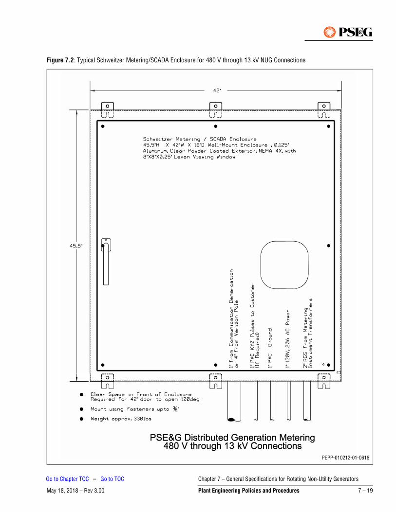
Figure 7.2: Typical Schweitzer Metering/SCADA Enclosure for 480 V through 13 kV NUG Connections
PEPP-010212-01-0616
Chapter 7 – General Specifications for Rotating Non-Utility Generators
May 18, 2018 – Rev 3.00 Plant Engineering Policies and Procedures 7 – 19
Go to Chapter TOC – Go to TOC
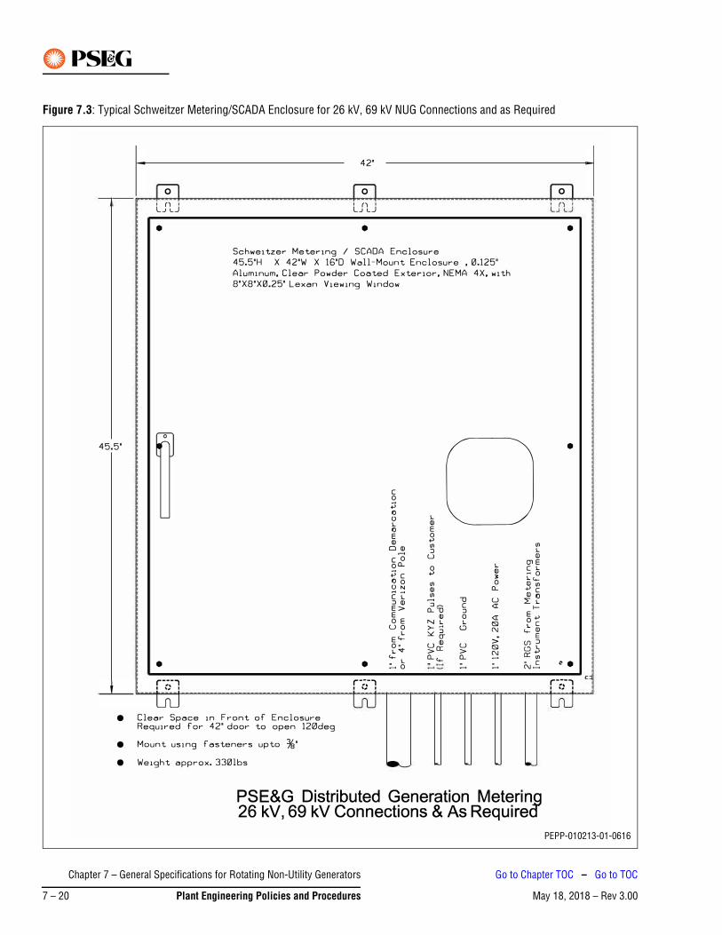
Figure 7.3: Typical Schweitzer Metering/SCADA Enclosure for 26 kV, 69 kV NUG Connections and as Required
PEPP-010213-01-0616
Chapter 7 – General Specifications for Rotating Non-Utility Generators
May 18, 2018 – Rev 3.007 – 20 Plant Engineering Policies and Procedures
Go to Chapter TOC – Go to TOC
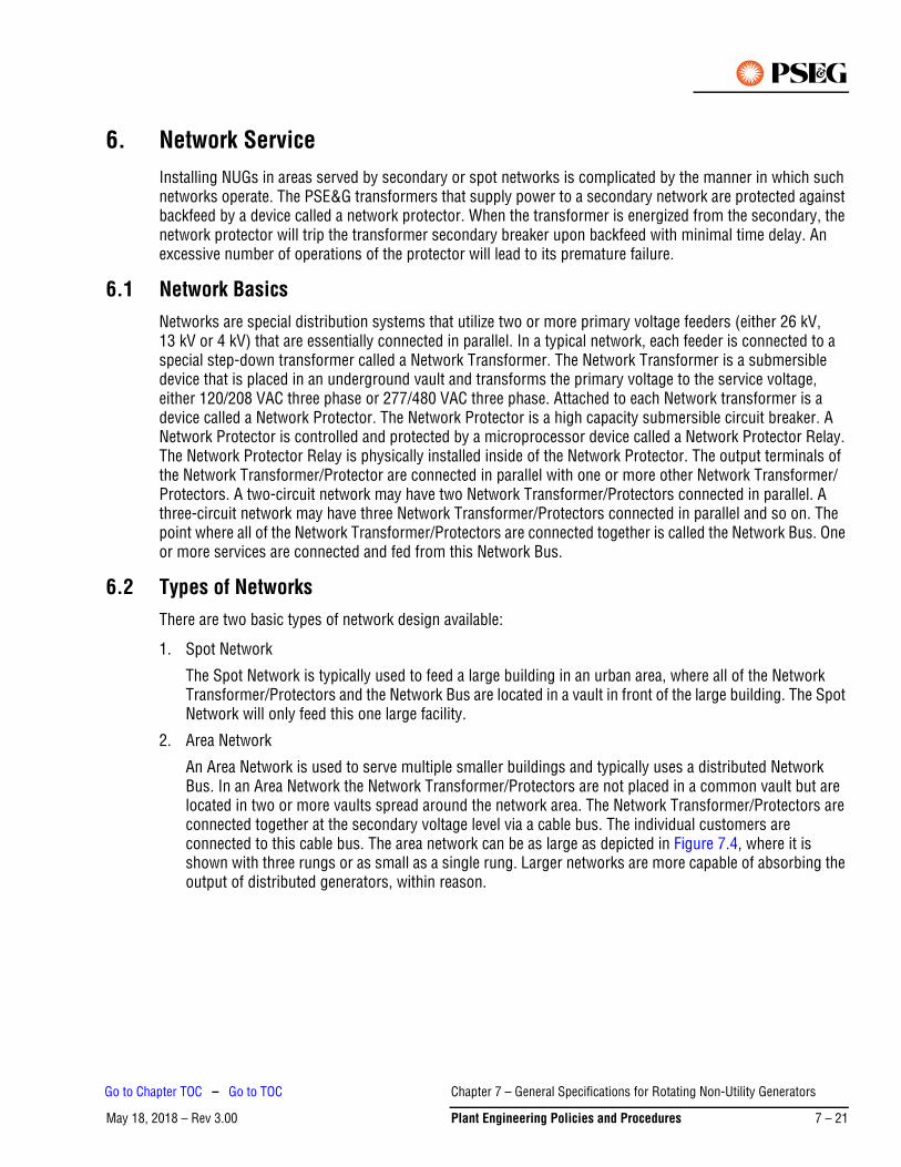
6. Network ServiceInstalling NUGs in areas served by secondary or spot networks is complicated by the manner in which such networks operate. The PSE&G transformers that supply power to a secondary network are protected against backfeed by a device called a network protector. When the transformer is energized from the secondary, the network protector will trip the transformer secondary breaker upon backfeed with minimal time delay. An excessive number of operations of the protector will lead to its premature failure.
6.1 Network BasicsNetworks are special distribution systems that utilize two or more primary voltage feeders (either 26 kV, 13 kV or 4 kV) that are essentially connected in parallel. In a typical network, each feeder is connected to a special step-down transformer called a Network Transformer. The Network Transformer is a submersible device that is placed in an underground vault and transforms the primary voltage to the service voltage, either 120/208 VAC three phase or 277/480 VAC three phase. Attached to each Network transformer is a device called a Network Protector. The Network Protector is a high capacity submersible circuit breaker. A Network Protector is controlled and protected by a microprocessor device called a Network Protector Relay. The Network Protector Relay is physically installed inside of the Network Protector. The output terminals of the Network Transformer/Protector are connected in parallel with one or more other Network Transformer/Protectors. A two-circuit network may have two Network Transformer/Protectors connected in parallel. A three-circuit network may have three Network Transformer/Protectors connected in parallel and so on. The point where all of the Network Transformer/Protectors are connected together is called the Network Bus. One or more services are connected and fed from this Network Bus.
6.2 Types of NetworksThere are two basic types of network design available:
1. Spot Network
The Spot Network is typically used to feed a large building in an urban area, where all of the Network Transformer/Protectors and the Network Bus are located in a vault in front of the large building. The Spot Network will only feed this one large facility.
2. Area Network
An Area Network is used to serve multiple smaller buildings and typically uses a distributed Network Bus. In an Area Network the Network Transformer/Protectors are not placed in a common vault but are located in two or more vaults spread around the network area. The Network Transformer/Protectors are connected together at the secondary voltage level via a cable bus. The individual customers are connected to this cable bus. The area network can be as large as depicted in Figure 7.4, where it is shown with three rungs or as small as a single rung. Larger networks are more capable of absorbing the output of distributed generators, within reason.
Chapter 7 – General Specifications for Rotating Non-Utility Generators
May 18, 2018 – Rev 3.00 Plant Engineering Policies and Procedures 7 – 21
Go to Chapter TOC – Go to TOC
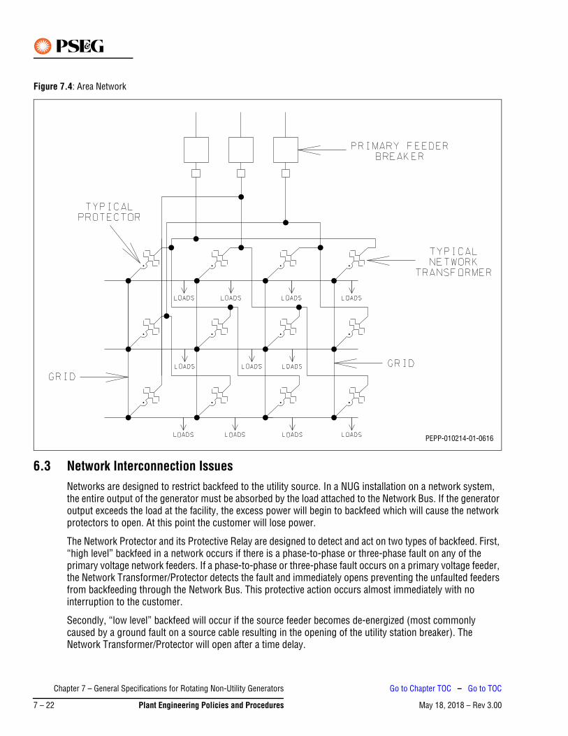
Figure 7.4: Area Network
6.3 Network Interconnection IssuesNetworks are designed to restrict backfeed to the utility source. In a NUG installation on a network system, the entire output of the generator must be absorbed by the load attached to the Network Bus. If the generator output exceeds the load at the facility, the excess power will begin to backfeed which will cause the network protectors to open. At this point the customer will lose power.
The Network Protector and its Protective Relay are designed to detect and act on two types of backfeed. First, “high level” backfeed in a network occurs if there is a phase-to-phase or three-phase fault on any of the primary voltage network feeders. If a phase-to-phase or three-phase fault occurs on a primary voltage feeder, the Network Transformer/Protector detects the fault and immediately opens preventing the unfaulted feeders from backfeeding through the Network Bus. This protective action occurs almost immediately with no interruption to the customer.
Secondly, “low level” backfeed will occur if the source feeder becomes de-energized (most commonly caused by a ground fault on a source cable resulting in the opening of the utility station breaker). The Network Transformer/Protector will open after a time delay.
PEPP-010214-01-0616
Chapter 7 – General Specifications for Rotating Non-Utility Generators
May 18, 2018 – Rev 3.007 – 22 Plant Engineering Policies and Procedures
Go to Chapter TOC – Go to TOC

In the case of a NUG installation, if the generator output meets or exceeds the load connected to, then the Network Transformer/Protector will trip due to low level backfeed.
Exported power looks like backfeed current to the Network Protection Relay. All Network Protectors connected to the common low voltage bus will see reverse current and will open, causing the facility to lose power.
6.4 NUG – Any Power Output Level – ExportSince the network protectors will operate to trip the transformer secondary breaker without delay whenever back-feeding occurs, it is typically not possible to install an exporting NUG in a secondary network. Spot networks that do not utilize network protectors, depending upon their configuration and service characteristics, may permit export in certain circumstances.
6.5 Rotating NUG – Any Power Output Level Not Utilizing Class 1 Renewable Fuels – Non-ExportFor NUGs who do not intend to export power to the grid, installation in a network area is possible. PSE&G must perform a Feasibility and/or Impact Study on the effect of adding such generation to the network, and such studies shall be performed at the cost of the NUG. Such studies will investigate the electrical loading of the network, the devices currently installed in the network, and the effects of adding such a NUG facility to the network. Upon completion of the Impact Study, the NUG will be given an office estimate of the cost of interconnecting the NUG into the network, assuming that it is possible to do so. If the NUG wishes to proceed, a Facility Study must be performed at the NUG’s expense, which will develop detailed estimates for interconnection costs and a schedule for the work.
The relay protection design for the NUG will require that it install a minimum import relay with a directional power function (32) at the point of interconnection with PSE&G (see Figure 7.5). Sufficient power must flow into the NUG such that enough current is detected by the CTs that the 32 element can operate. If power flow into the NUG is not maintained, the 32 element will open a breaker between the generator and PSE&G. This method of always importing a small amount of power is required to ensure proper operation of the directional power element, since whenever the 32 element detects any power flow from the NUG into the PSE&G System, the 32 element will isolate the generator from PSE&G. The relay with a directional power function (32) shall be fed by three single-phase CT and three single-phase PT located on the customer side of the service entrance breaker. The PT shall be connected wye-wye.
Chapter 7 – General Specifications for Rotating Non-Utility Generators
May 18, 2018 – Rev 3.00 Plant Engineering Policies and Procedures 7 – 23
Go to Chapter TOC – Go to TOC
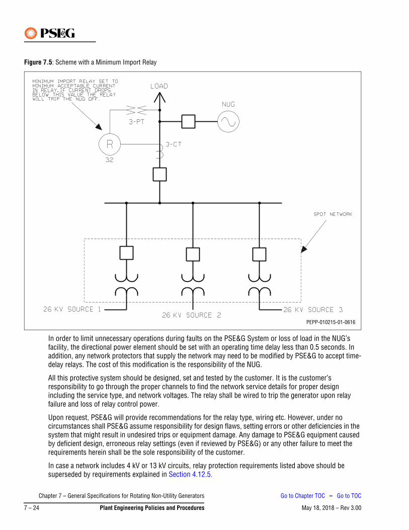
Figure 7.5: Scheme with a Minimum Import Relay
In order to limit unnecessary operations during faults on the PSE&G System or loss of load in the NUG’s facility, the directional power element should be set with an operating time delay less than 0.5 seconds. In addition, any network protectors that supply the network may need to be modified by PSE&G to accept time-delay relays. The cost of this modification is the responsibility of the NUG.
All this protective system should be designed, set and tested by the customer. It is the customer’s responsibility to go through the proper channels to find the network service details for proper design including the service type, and network voltages. The relay shall be wired to trip the generator upon relay failure and loss of relay control power.
Upon request, PSE&G will provide recommendations for the relay type, wiring etc. However, under no circumstances shall PSE&G assume responsibility for design flaws, setting errors or other deficiencies in the system that might result in undesired trips or equipment damage. Any damage to PSE&G equipment caused by deficient design, erroneous relay settings (even if reviewed by PSE&G) or any other failure to meet the requirements herein shall be the sole responsibility of the customer.
In case a network includes 4 kV or 13 kV circuits, relay protection requirements listed above should be superseded by requirements explained in Section 4.12.5.
PEPP-010215-01-0616
Chapter 7 – General Specifications for Rotating Non-Utility Generators
May 18, 2018 – Rev 3.007 – 24 Plant Engineering Policies and Procedures
Go to Chapter TOC – Go to TOC
6.6 Rotating Non-Utility Generators Utilizing Class 1 Renewable FuelsAs mentioned in Section 3.2 above, all current rules for interconnecting NUGs using Class 1 renewable fuels with a local electric distribution company in New Jersey is described in the N.J.A.C. Subchapter 5 – “Interconnection of Class 1 Renewable Energy Systems” Sections 14:8-5.1 through 14:8-5.9.
§ 14:8-5.5 Level 2 interconnection review is covering applications to connect customer-generator facilities with a power rating of two MW or less, which meet the certification requirements at N.J.A.C. 14:8-5.3. While Sections 14:8-5.5 (c) through (k) describe requirements for any interconnection with a local electric company’s distribution systems, if a rotating NUG has a proposed point of common coupling with EDC on a spot or area network, the interconnection shall meet the following additional requirements described in Section 14:8-5.5 (l) 1 and 3:
1. For a customer-generator facility that will be connected to a spot network circuit, the aggregate generation capacity connected to that spot network from customer-generator facilities, including the customer-generator facility, shall not exceed 5% of the spot network’s maximum load;
2. For a customer-generator facility that will be connected to a spot or an area network that does not utilize inverter based protective functions … the customer-generator facility shall utilize reverse power relays or other protection devices that ensure no export of power from the customer-generator facility, including inadvertent export (under fault conditions) that could adversely affect protective devices on the network.
If application to interconnect a customer-generator facility to the Network does not qualify for Level 2 interconnection review procedures set forth at N.J.A.C. 14:8-5.5, then the Developer may apply for a Level 3 interconnection review described in the N.J.A.C. Section 14:8-5.6 which will require at the customers expense to conduct the impact study of the probable impact of a customer-generator facility on the safety and reliability of the EDC’s electric distribution system as well as a load study to determine the minimum load of the network.
To fulfill requirement stated in N.J.A.C. 14:8-5.5., (l) 3 (see above) PSE&G requires the use of a minimum import/reverse power relay, described in Section 6.3 (see Figure 7.5) under all previously mentioned conditions.
7. Additional Resources• PSE&G Information and Requirements for Electric Service
https://www.pseg.com/business/builders/new_service/before/index.jsp
• Plant Engineering Policies and Procedures
https://www.pseg.com/business/builders/new_service/before/index.jsp
• Technical Support Contact
Chapter 7 – General Specifications for Rotating Non-Utility Generators
May 18, 2018 – Rev 3.00 Plant Engineering Policies and Procedures 7 – 25
Go to Chapter TOC – Go to TOC

This Page Intentionally Blank
Chapter 7 – General Specifications for Rotating Non-Utility Generators
May 18, 2018 – Rev 3.007 – 26 Plant Engineering Policies and Procedures
Go to Chapter TOC – Go to TOC
May 18, 2018 – Rev 3.00Go to Chapter TOC
Chapter 8 – Notifications and Permits – Table of Contents1. Occupancy of Public and Private Land and Waterways . . . . . . . . . . . . . . . . . . . . . . . . . . . . . . . . . 8-1
1.1 Work on County or Municipal Roads . . . . . . . . . . . . . . . . . . . . . . . . . . . . . . . . . . . . . . . . . . . . . . . . . .8-1
1.2 Obtaining County and Municipal Pole Consents. . . . . . . . . . . . . . . . . . . . . . . . . . . . . . . . . . . . . . . . . .8-4
1.3 NJ Department of Transportation (DOT) Regional Offices . . . . . . . . . . . . . . . . . . . . . . . . . . . . . . . . . .8-7
1.4 Obtaining State Highway Occupancy Permit . . . . . . . . . . . . . . . . . . . . . . . . . . . . . . . . . . . . . . . . . . . .8-8
1.5 Obtaining State Highway Opening Permit. . . . . . . . . . . . . . . . . . . . . . . . . . . . . . . . . . . . . . . . . . . . . . .8-9
1.6 Obtaining State Highway Pole Permit. . . . . . . . . . . . . . . . . . . . . . . . . . . . . . . . . . . . . . . . . . . . . . . . .8-10
1.7 Work with Highway Authorities . . . . . . . . . . . . . . . . . . . . . . . . . . . . . . . . . . . . . . . . . . . . . . . . . . . . .8-10
1.8 Work with Other Authorities . . . . . . . . . . . . . . . . . . . . . . . . . . . . . . . . . . . . . . . . . . . . . . . . . . . . . . . .8-11
2. Work on Private Property (Easements) . . . . . . . . . . . . . . . . . . . . . . . . . . . . . . . . . . . . . . . . . . . . 8-11
2.1 Procedures for Obtaining an Easement . . . . . . . . . . . . . . . . . . . . . . . . . . . . . . . . . . . . . . . . . . . . . . .8-11
2.2 Easement Formats . . . . . . . . . . . . . . . . . . . . . . . . . . . . . . . . . . . . . . . . . . . . . . . . . . . . . . . . . . . . . . .8-12
2.3 Work Involving Railroads . . . . . . . . . . . . . . . . . . . . . . . . . . . . . . . . . . . . . . . . . . . . . . . . . . . . . . . . . .8-21
2.4 Railroad Agreements, Requirements and Specifications . . . . . . . . . . . . . . . . . . . . . . . . . . . . . . . . . .8-23
3. Work with Developers . . . . . . . . . . . . . . . . . . . . . . . . . . . . . . . . . . . . . . . . . . . . . . . . . . . . . . . . . 8-24
4. Hazards to Aviation . . . . . . . . . . . . . . . . . . . . . . . . . . . . . . . . . . . . . . . . . . . . . . . . . . . . . . . . . . . 8-25
4.1 Federal Aviation Administration . . . . . . . . . . . . . . . . . . . . . . . . . . . . . . . . . . . . . . . . . . . . . . . . . . . . .8-25
5. Pole Attachments and Duct Leasing . . . . . . . . . . . . . . . . . . . . . . . . . . . . . . . . . . . . . . . . . . . . . . 8-26
5.1 General Requirements for Attachment of Holiday Decorations, Banners, and Signs to Poles . . . . . .8-28
5.2 Insurance Requirements for Attachment of Holiday Decorations, Banners, and Signs to Poles. . . . .8-28
6. Utility Relocations . . . . . . . . . . . . . . . . . . . . . . . . . . . . . . . . . . . . . . . . . . . . . . . . . . . . . . . . . . . . 8-29
6.1 Legal Authority to use Public Streets for Electric Utility Facilities. . . . . . . . . . . . . . . . . . . . . . . . . . . .8-29
6.2 Financial Responsibility for Utility Relocations to Accommodate Improvements to Public Streets8-30
6.3 Statutes Providing for Reimbursement for the Relocation of Utility Facilities . . . . . . . . . . . . . . . . . .8-30
7. Environmental . . . . . . . . . . . . . . . . . . . . . . . . . . . . . . . . . . . . . . . . . . . . . . . . . . . . . . . . . . . . . . . 8-39
7.1 Management of Excavated Soils at Non-Company Locations. . . . . . . . . . . . . . . . . . . . . . . . . . . . . . .8-39
7.2 Work Involving Environmental Affairs – Licensing and Permits Division . . . . . . . . . . . . . . . . . . . . . .8-40
7.3 Licensing Submittal and Approval Cycle . . . . . . . . . . . . . . . . . . . . . . . . . . . . . . . . . . . . . . . . . . . . . .8-41
8. Construction Activities Located in and Near Streams . . . . . . . . . . . . . . . . . . . . . . . . . . . . . . . . . 8-43
8.1 Construction Activities Located In and Around Wetlands. . . . . . . . . . . . . . . . . . . . . . . . . . . . . . . . . .8-46
8.2 Construction Activities Located Near a River or Bay . . . . . . . . . . . . . . . . . . . . . . . . . . . . . . . . . . . . .8-51
8.3 Regional Planning Districts . . . . . . . . . . . . . . . . . . . . . . . . . . . . . . . . . . . . . . . . . . . . . . . . . . . . . . . .8-51
Chapter 8 – Notifications and Permits – Table of Contents
May 18, 2018 – Rev 3.00 Plant Engineering Policies and Procedures 8 – TOC 1
Go to TOC
8.4 Disturbance of Soil . . . . . . . . . . . . . . . . . . . . . . . . . . . . . . . . . . . . . . . . . . . . . . . . . . . . . . . . . . . . . . 8-52
8.5 Licensing and Approval Cycle. . . . . . . . . . . . . . . . . . . . . . . . . . . . . . . . . . . . . . . . . . . . . . . . . . . . . . 8-52
8.6 Permit Obtainment Procedure – Request Form . . . . . . . . . . . . . . . . . . . . . . . . . . . . . . . . . . . . . . . . 8-52
Chapter 8 – Notifications and Permits – Table of Contents
May 18, 2018 – Rev 3.008 – TOC 2 Plant Engineering Policies and Procedures
Go to TOC
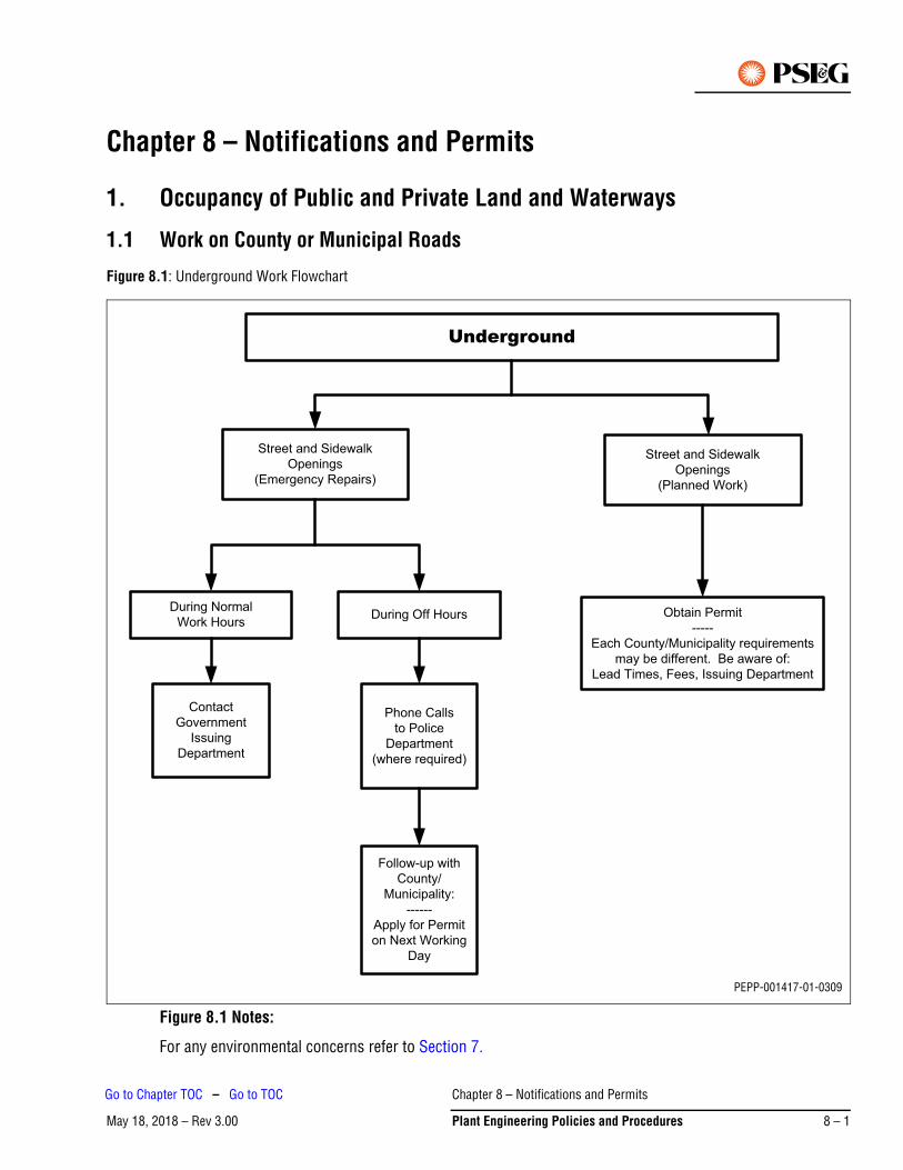
May 18, 2018 – Rev 3.00
Chapter 8 – Notifications and Permits
1. Occupancy of Public and Private Land and Waterways
1.1 Work on County or Municipal Roads
Figure 8.1: Underground Work Flowchart
Figure 8.1 Notes:
For any environmental concerns refer to Section 7.
Underground
Street and Sidewalk
Openings
(Emergency Repairs)
Street and Sidewalk
Openings
(Planned Work)
During Normal
Work HoursDuring Off Hours Obtain Permit
-----
Each County/Municipality requirements
may be different. Be aware of:
Lead Times, Fees, Issuing Department
Contact
Government
Issuing
Department
Phone Calls
to Police
Department
(where required)
Follow-up with
County/
Municipality:
------
Apply for Permit
on Next Working
Day
PEPP-001417-01-0309
Chapter 8 – Notifications and Permits
May 18, 2018 – Rev 3.00 Plant Engineering Policies and Procedures 8 – 1
Go to Chapter TOC – Go to TOC
Requirements to Obtain a Road Opening Permit:
1. Complete the Road Opening Permit Application Form.
2. Call the municipal or county office to verify fee, opening requirements, and lead time.
3. Prepare the internal Request for Check (Form 95-3790) for road opening permit application fee; have the engineering supervisor sign; submit to clerical for processing; obtain the check.
4. Prepare a permit drawing indicating the proposed opening(s); include length and width of opening, facilities to be installed, trench detail and any other pertinent information.
5. Send/deliver the application, fee, and drawing to the municipal or county office.
In general, road opening permits are not required when the governing agency is sponsoring and/or funding the project. This should be confirmed at the earliest possible time of the project.
Note
Chapter 8 – Notifications and Permits
May 18, 2018 – Rev 3.008 – 2 Plant Engineering Policies and Procedures
Go to Chapter TOC – Go to TOC
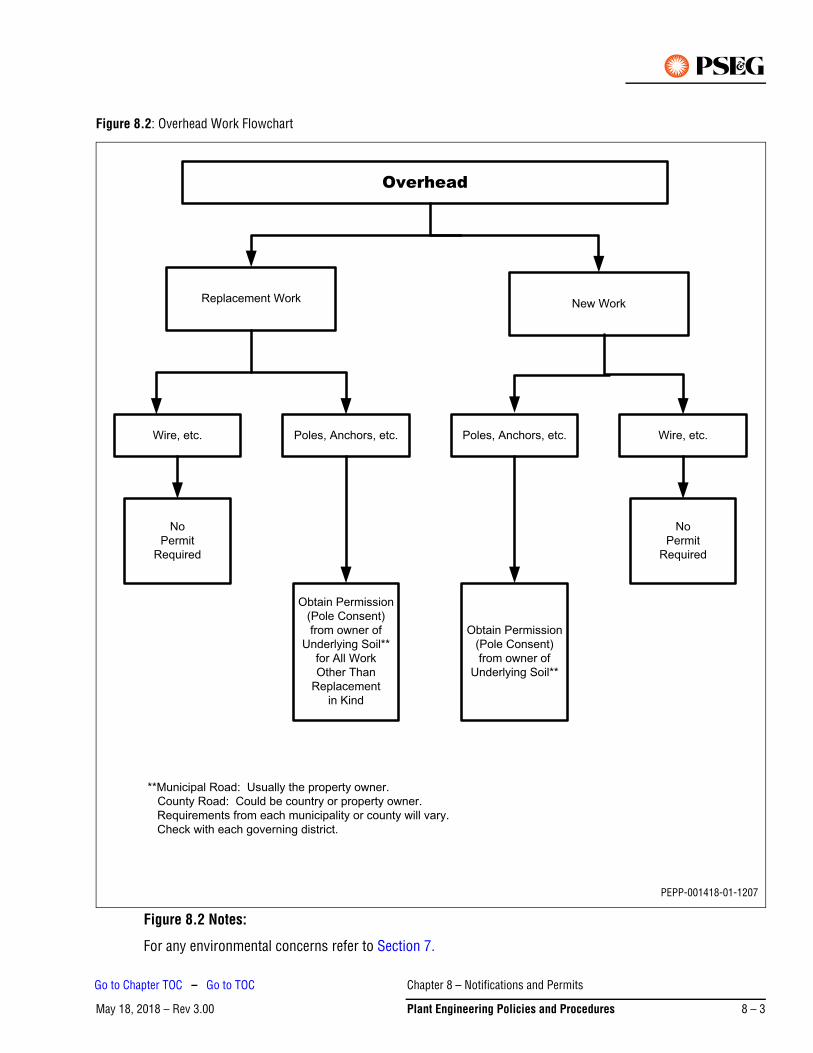
Figure 8.2: Overhead Work Flowchart
Figure 8.2 Notes:
For any environmental concerns refer to Section 7.
Overhead
Replacement Work New Work
Wire, etc. Poles, Anchors, etc.
No
Permit
Required
Obtain Permission
(Pole Consent)
from owner of
Underlying Soil**
for All Work
Other Than
Replacement
in Kind
Wire, etc.Poles, Anchors, etc.
No
Permit
Required
Obtain Permission
(Pole Consent)
from owner of
Underlying Soil**
**Municipal Road: Usually the property owner.
County Road: Could be country or property owner.
Requirements from each municipality or county will vary.
Check with each governing district.
PEPP-001418-01-1207
Chapter 8 – Notifications and Permits
May 18, 2018 – Rev 3.00 Plant Engineering Policies and Procedures 8 – 3
Go to Chapter TOC – Go to TOC
1.2 Obtaining County and Municipal Pole ConsentsPrepare consent forms – see Figure 8.3. Drawings (always required with county pole permits – may not be required for municipal pole permits) to include offset dimensions from road center line etc.
Pole permits may not be required if the county or state agency is sponsoring and/or funding the project. This should be confirmed at the earliest possible time of the project.
Note
Chapter 8 – Notifications and Permits
May 18, 2018 – Rev 3.008 – 4 Plant Engineering Policies and Procedures
Go to Chapter TOC – Go to TOC

Figure 8.3: Sample of Pole Consent Form (ED-DC-PEP-Form002)
PEPP-002194-03-0418
Chapter 8 – Notifications and Permits
May 18, 2018 – Rev 3.00 Plant Engineering Policies and Procedures 8 – 5
Go to Chapter TOC – Go to TOC
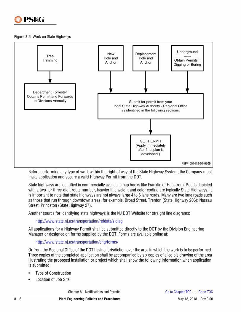
Figure 8.4: Work on State Highways
Before performing any type of work within the right of way of the State Highway System, the Company must make application and secure a valid Highway Permit from the DOT.
State highways are identified in commercially available map books like Franklin or Hagstrom. Roads depicted with a two- or three-digit route number, heavier line weight and color coding are typically State Highways. It is important to note that state highways are not always large 4 to 6 lane roads. Many are two lane roads such as those that run through downtown areas; for example, Broad Street, Trenton (State Highway 206); Nassau Street, Princeton (State Highway 27).
Another source for identifying state highways is the NJ DOT Website for straight line diagrams:
http://www.state.nj.us/transportation/refdata/sldiag
All applications for a Highway Permit shall be submitted directly to the DOT by the Division Engineering Manager or designee on forms supplied by the DOT. Forms are available online at:
http://www.state.nj.us/transportation/eng/forms/
Or from the Regional Office of the DOT having jurisdiction over the area in which the work is to be performed. Three copies of the completed application shall be accompanied by six copies of a legible drawing of the area illustrating the proposed installation or project which shall show the following information when application is submitted:
• Type of Construction• Location of Job Site
Tree
Trimming
Department Forrester
Obtains Permit and Forwards
to Divisions Annually
Underground
------
Obtain Permits if
Digging or Boring
Replacement
Pole and
Anchor
New
Pole and
Anchor
Submit for permit from your
local State Highway Authority - Regional Office
as identified in the following sections.
GET PERMIT
(Apply immediately
after final plan is
developed.)
PEPP-001419-01-0309
Chapter 8 – Notifications and Permits
May 18, 2018 – Rev 3.008 – 6 Plant Engineering Policies and Procedures
Go to Chapter TOC – Go to TOC
• Right of Way Lines• Setback and Location of Proposed Structures• Curbing and Sidewalks• Existing Utility Poles• Directional and Regulatory Signs• Location of Driveways• Traffic Control Plans (if required)
Construction work authorized under the terms of the Highway Permits must be completed within 1 year from date of issue.
Application for a Highway Permit shall be made to the applicable Regional Office of the DOT having jurisdiction over the area in which work is to be performed (see list of DOT offices on the following page). All application forms and permits, when received, are to be approved and signed by the Division Engineering Manager or their designated representative.
The fully-signed original copies of all Highway Permits will be filed in the local Division Office and are to be retained in accordance with Section 102 – Administrative Procedures Manual.
Annual Tree Trimming Permits covering tree trimming activities within the confines of State Highway rights of way will be secured by the Department Forester.
1.3 NJ Department of Transportation (DOT) Regional OfficesNJDOT Construction and Maintenance Unit offices and their areas of jurisdiction are as follows:
North Region
New Jersey Department of Transportation200 Stierli Court Mt. Arlington, NJ 07856-1322
Bergen, Essex, Hudson, Morris, Passaic, Sussex, Union counties and portions of Warren County (including Route 57 and north)
Executive Director’s Office(973) 601-6600Fax (973) 601-6603
Central Region
New Jersey Department of Transportation1035 Parkway AvenueTrenton, NJ 08625
Hunterdon, Mercer, Middlesex, Monmouth, Ocean, Somerset counties and portions of Warren County (Routes 22, 122, 173, 78 and including south of Route 57)
Executive Director’s Office(732) 625-4340Fax (732) 625-4344
Chapter 8 – Notifications and Permits
May 18, 2018 – Rev 3.00 Plant Engineering Policies and Procedures 8 – 7
Go to Chapter TOC – Go to TOC
South Region
New Jersey Department of TransportationOne Executive CampusRoute 70 WestCherry Hill, NJ 08002
Atlantic, Burlington, Camden, Cape May, Cumberland, Gloucester and Salem counties
Executive Director’s Office(856) 486-6600Fax (856) 486-6833
Source: http://www.state.nj.us/transportation/about/directory/index.shtml
1.4 Obtaining State Highway Occupancy PermitThis permit is required for any construction and maintenance activity on a designated state highway that will require 4 or more hours to complete. Any violations or failure to obtain the required permit may result in a fine and/or denial to perform work on the state highway.
It generally takes at least 1 month to obtain an occupancy permit from the DOT. Therefore, it is important to make application to occupy a state highway early in the design phase of the project. Any violations or failure to obtain the required permit may result in a fine and/or denial to perform work on the state highway.
Larger projects may require a pre-construction meeting with an engineer and/or inspector from the DOT Regional Office having jurisdiction over the work location.
The Highway Occupancy Permit will usually indicate any restrictions including permissible hours of work.
1. Discuss the conceptual plan for duct bank and manhole locations with the state (not necessary for small openings for underground services overhead zone).
2. Prepare a detailed scaled drawing for the test pits.
3. Fill out (print or online) the Application for Highway Occupancy Form MT-120A found at:
http://www.state.nj.us/transportation/eng/forms/
4. Prepare a proposed method of traffic control (Traffic Control Plan) that conforms to the NJDOT Work Zone Safety Set-Up Guide. This guide is available online at:
http://www.state.nj.us/transportation/publicat/pdf/WorkZoneSafetySetupGuide.pdf
5. Prepare the internal Request for Check (Form 95-3790) for occupancy permit application fee; have the engineering supervisor sign; submit to clerical for processing; obtain the check.
6. Send three completed copies of the occupancy permit application, six copies of all drawings, the traffic control plan, and the check for the application fee to the appropriate DOT regional office.
7. An acknowledgment notice for receipt of the permit application will be received from the DOT in approximately 2 weeks. This is not permission to perform the work.
8. In approximately 2 months, an occupancy permit form will be received for signature and permit fee. Prepare a Request for Check (Form 95-3790) for the permit fee; have the engineering supervisor sign both the Request for Check and the permit; return it, along with the drawings and traffic control plans, back to the appropriate DOT regional office.
Chapter 8 – Notifications and Permits
May 18, 2018 – Rev 3.008 – 8 Plant Engineering Policies and Procedures
Go to Chapter TOC – Go to TOC
9. In approximately 1 month, the occupancy permit will be received; the test pit work can proceed at this time.
10. Record the occupancy permit number on all construction drawings and DWMS notifications. Give copies of the permit, construction drawings, and traffic control plans to the Construction Department supervisor or contractor (the company crew or contractor crew at the location must possess these documents while performing the work).
11. After the manhole and duct bank locations have been proved by the test pits, scaled drawings for the conduit and manhole work must be prepared indicating the location and depth of PSE&G’s proposed facilities.
12. The completion notice that normally accompanies the occupancy permit must be filled out and mailed back to the DOT regional office after the work has been completed.
1.5 Obtaining State Highway Opening PermitIt generally takes at least 2 months to obtain opening permits from the DOT. Therefore, it is important to make application to occupy a state highway early in the design phase of the project. Except in certain cases where verbal approval has been received from the DOT, the project cannot be released for construction until the permit(s) has been received. Any violations or failure to obtain the required permit may result in a fine and/or denial to perform work on the state highway.
Larger projects may require a pre-construction meeting with an engineer and/or inspector from the DOT Regional Office having jurisdiction over the work location.
1. Fill out (print or online) the Application for Utility Opening Form MT-17A found at:
http://www.state.nj.us/transportation/eng/forms/
2. Prepare the internal Request for Check (Form 95-3790) for opening permit application fee; have the engineering supervisor sign; submit to clerical for processing; obtain the check.
3. Send the check for the permit application fee, three copies of the application form, and six copies of all drawings to the DOT regional office.
4. An acknowledgment of receipt of application will be received in approximately 2 weeks.
5. In approximately 2 months, an opening permit form will be received for signature and permit fee. Prepare a Request for Check (Form 95-3790) for the permit fee; have the engineering supervisor sign both the Request for Check and the permit; return it, along with the drawings and traffic control plans, back to the appropriate DOT regional office.*
6. In approximately 1 month, the permit will be received and the work can begin.
7. Record the opening permit number on all construction drawings and DWMS notifications. Give copies of the permit, construction drawings, and traffic control plans to the PSE&G contractor (the contractor crew at the location must possess these documents while performing the work).
8. The completion notice received with the permit must be sent back to the DOT regional office after completion of all work and final restoration.
*Certain projects may require payment of a DOT Inspection Fee.
Chapter 8 – Notifications and Permits
May 18, 2018 – Rev 3.00 Plant Engineering Policies and Procedures 8 – 9
Go to Chapter TOC – Go to TOC
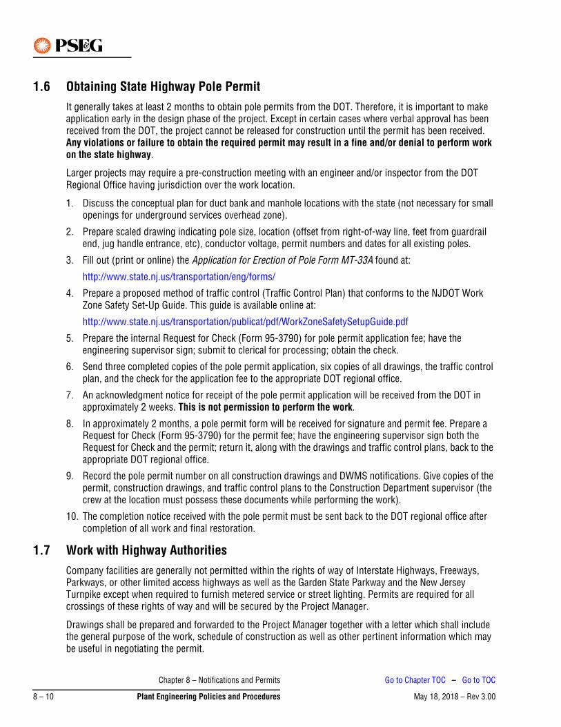
1.6 Obtaining State Highway Pole PermitIt generally takes at least 2 months to obtain pole permits from the DOT. Therefore, it is important to make application early in the design phase of the project. Except in certain cases where verbal approval has been received from the DOT, the project cannot be released for construction until the permit has been received. Any violations or failure to obtain the required permit may result in a fine and/or denial to perform work on the state highway.
Larger projects may require a pre-construction meeting with an engineer and/or inspector from the DOT Regional Office having jurisdiction over the work location.
1. Discuss the conceptual plan for duct bank and manhole locations with the state (not necessary for small openings for underground services overhead zone).
2. Prepare scaled drawing indicating pole size, location (offset from right-of-way line, feet from guardrail end, jug handle entrance, etc), conductor voltage, permit numbers and dates for all existing poles.
3. Fill out (print or online) the Application for Erection of Pole Form MT-33A found at:
http://www.state.nj.us/transportation/eng/forms/
4. Prepare a proposed method of traffic control (Traffic Control Plan) that conforms to the NJDOT Work Zone Safety Set-Up Guide. This guide is available online at:
http://www.state.nj.us/transportation/publicat/pdf/WorkZoneSafetySetupGuide.pdf
5. Prepare the internal Request for Check (Form 95-3790) for pole permit application fee; have the engineering supervisor sign; submit to clerical for processing; obtain the check.
6. Send three completed copies of the pole permit application, six copies of all drawings, the traffic control plan, and the check for the application fee to the appropriate DOT regional office.
7. An acknowledgment notice for receipt of the pole permit application will be received from the DOT in approximately 2 weeks. This is not permission to perform the work.
8. In approximately 2 months, a pole permit form will be received for signature and permit fee. Prepare a Request for Check (Form 95-3790) for the permit fee; have the engineering supervisor sign both the Request for Check and the permit; return it, along with the drawings and traffic control plans, back to the appropriate DOT regional office.
9. Record the pole permit number on all construction drawings and DWMS notifications. Give copies of the permit, construction drawings, and traffic control plans to the Construction Department supervisor (the crew at the location must possess these documents while performing the work).
10. The completion notice received with the pole permit must be sent back to the DOT regional office after completion of all work and final restoration.
1.7 Work with Highway AuthoritiesCompany facilities are generally not permitted within the rights of way of Interstate Highways, Freeways, Parkways, or other limited access highways as well as the Garden State Parkway and the New Jersey Turnpike except when required to furnish metered service or street lighting. Permits are required for all crossings of these rights of way and will be secured by the Project Manager.
Drawings shall be prepared and forwarded to the Project Manager together with a letter which shall include the general purpose of the work, schedule of construction as well as other pertinent information which may be useful in negotiating the permit.
Chapter 8 – Notifications and Permits
May 18, 2018 – Rev 3.008 – 10 Plant Engineering Policies and Procedures
Go to Chapter TOC – Go to TOC
1.8 Work with Other AuthoritiesThere may be unique authorities within our franchise service territory which may require special permits for construction of our facilities. Such authorities can include, but are not limited, to:
• Port Authority of NY and NJ• Hackensack Meadowlands Development Commission• Pinelands Commission• Delaware River Port Authority• D&R Canal
2. Work on Private Property (Easements)An easement is required when one or more of the following conditions exist:
1. There is a Buried Underground Development (BUD) regardless of whether it is commercial, residential, or industrial.
2. Service is being installed on properties that have the potential for being subdivided. Properties have the potential to be subdivided if there is a service distance of 200 ft or more on the property being served from the public right-of-way or roadway, or if there is substantial area surrounding the property for subdivision.
3. A service crosses one property to serve another property.
4. Any facility of PSE&G is located on private property and is not part of a service (i.e. poles, anchors, guy wires, and overhead or underground lines).
An easement is not required when one of the following conditions exists:
1. The facility is a service line that serves the same property it is located on and there is no possibility of a subdivision (i.e. the service line is less than 200 ft on the property being served from the public right-of-way or roadway.
2. All facilities installed are located in the public right-of-way or roadway.
2.1 Procedures for Obtaining an EasementThe following details the procedures for obtaining an easement.
1. Determine if an easement is necessary pursuant to the requirements listed in the section above.
2. If easement is necessary, then prepare an Information Request Letter in the correct format and deliver it to the property owner so that PSE&G may obtain the proper information for the easement.
3. After receiving the information letter back from the property owner, choose which type of easement you will need based on whether the owner of the property is an individual (or husband or wife), a partnership or a corporation (see list easement formats at the end of this section). Fill in the blanks in the easement and have the following people sign the easement:
a. If husband and wife own property, then both the husband and the wife must sign the easement.
b. If a corporation owns the property, then an officer of the corporation must execute the easement.
c. If the property is owned by any partnership, then the managing partner must sign the easement.
Chapter 8 – Notifications and Permits
May 18, 2018 – Rev 3.00 Plant Engineering Policies and Procedures 8 – 11
Go to Chapter TOC – Go to TOC
4. Prepare a drawing of the easement that will be attached to the document as an Exhibit. The drawing must include block and lot numbers of the subject property and adjoining properties. A north-pointing arrow must also be included. The drawing can be no more 8-1/2 in. x 14 in. and must have the drawing number on it for inclusion in the easement document. If the easement is in new construction, then it may be a good idea to have the customer’s surveyor prepare the drawing.
5. Send the easement (with the drawing) to the property owner and have them execute the easement. Also make sure they have their signatures witnessed by a third party and notarized by a Notary Public of the State of New Jersey or an Attorney at Law of the State of New Jersey.
6. Under receipt of the fully executed and notarized easement, the facilities may be installed.
7. The Engineering Sponsor who prepared the document should sign the “prepared by” section at the top of each easement document.
8. The original easement should be sent to the Manager – Corporate Properties for recording and record storage.
9. A copy of the easement must be kept in the division easement file folder.
2.2 Easement FormatsThe following documents are located on the local sharedrive in MS Word format:
• Information Request Letter• Individual Grant of Easement for Overhead and/or Underground Facilities• Individual Grant of Easement for Underground Facilities Only• Individual Grant of Easement for PSE&G and Verizon• Individual Grant of Easement with Use of Private Manholes• Individual Grant of Easement for Relocation of Facilities• Individual Grant of Easement for BUD• Corporation Grant of Easement for Overhead and/or Underground Facilities• Corporation Grant of Easement for Underground Facilities Only• Corporation Grant of Easement for PSE&G and Verizon• Corporation Grant of Easement for Use of Private Manholes• Corporation Grant of Easement for Relocation of Facilities• Corporation Grant of Easement for BUD• Partnership Grant of Easement for Overhead and/or Underground Facilities• Partnership Grant of Easement for Underground Facilities Only• Partnership Grant of Easement for PSE&G and Verizon• Partnership Grant of Easement for Use of Private Manholes• Partnership Grant of Easement for Relocation of Facilities• Partnership Grant of Easement for BUD• Corporate Properties Memo
Chapter 8 – Notifications and Permits
May 18, 2018 – Rev 3.008 – 12 Plant Engineering Policies and Procedures
Go to Chapter TOC – Go to TOC
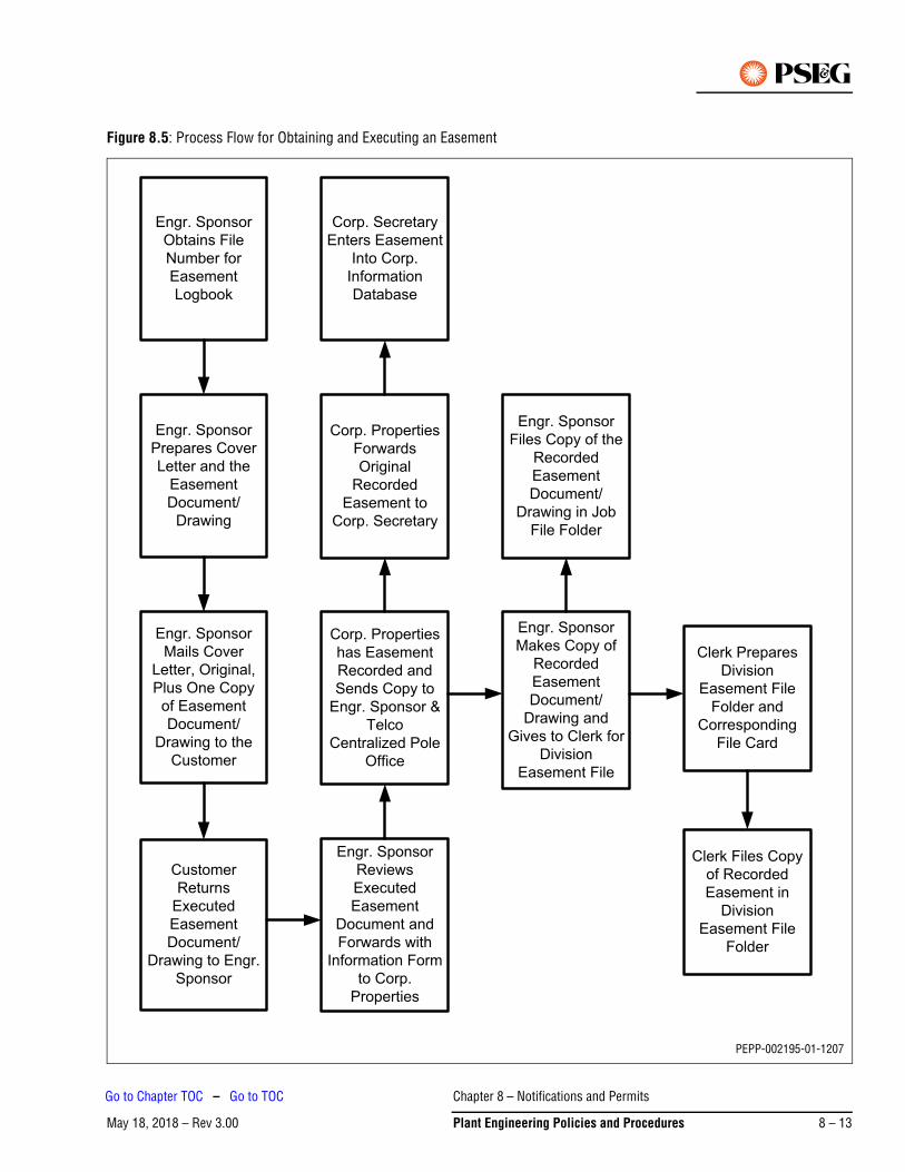
Figure 8.5: Process Flow for Obtaining and Executing an Easement
Engr. Sponsor
Obtains File
Number for
Easement
Logbook
Corp. Secretary
Enters Easement
Into Corp.
Information
Database
Engr. Sponsor
Files Copy of the
Recorded
Easement
Document/
Drawing in Job
File Folder
Clerk Prepares
Division
Easement File
Folder and
Corresponding
File Card
Customer
Returns
Executed
Easement
Document/
Drawing to Engr.
Sponsor
Engr. Sponsor
Mails Cover
Letter, Original,
Plus One Copy
of Easement
Document/
Drawing to the
Customer
Engr. Sponsor
Prepares Cover
Letter and the
Easement
Document/
Drawing
Engr. Sponsor
Reviews
Executed
Easement
Document and
Forwards with
Information Form
to Corp.
Properties
Corp. Properties
Forwards
Original
Recorded
Easement to
Corp. Secretary
Corp. Properties
has Easement
Recorded and
Sends Copy to
Engr. Sponsor &
Telco
Centralized Pole
Office
Engr. Sponsor
Makes Copy of
Recorded
Easement
Document/
Drawing and
Gives to Clerk for
Division
Easement File
Clerk Files Copy
of Recorded
Easement in
Division
Easement File
Folder
PEPP-002195-01-1207
Chapter 8 – Notifications and Permits
May 18, 2018 – Rev 3.00 Plant Engineering Policies and Procedures 8 – 13
Go to Chapter TOC – Go to TOC
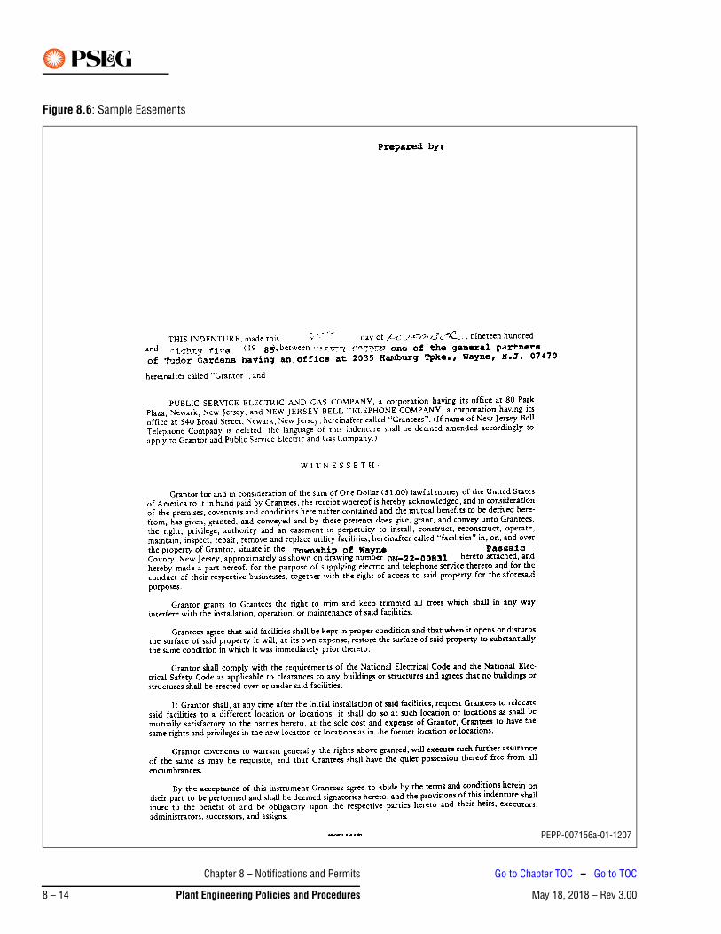
Figure 8.6: Sample Easements
PEPP-007156a-01-1207
Chapter 8 – Notifications and Permits
May 18, 2018 – Rev 3.008 – 14 Plant Engineering Policies and Procedures
Go to Chapter TOC – Go to TOC
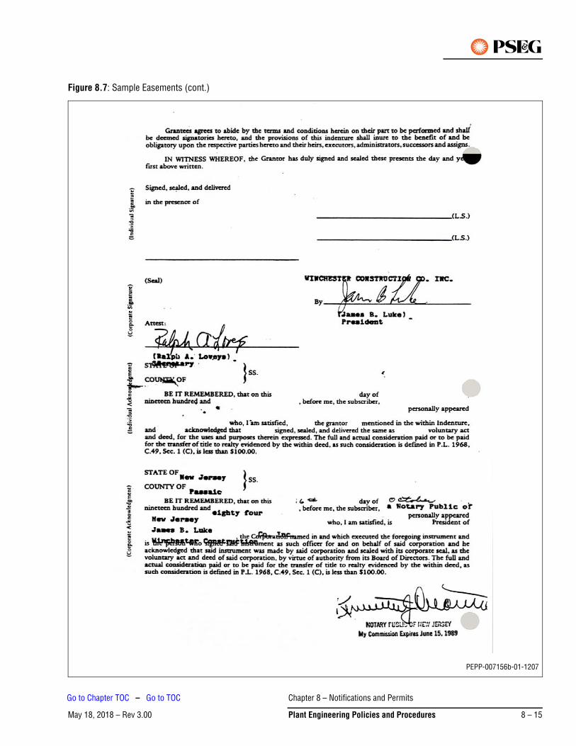
Figure 8.7: Sample Easements (cont.)
PEPP-007156b-01-1207
Chapter 8 – Notifications and Permits
May 18, 2018 – Rev 3.00 Plant Engineering Policies and Procedures 8 – 15
Go to Chapter TOC – Go to TOC
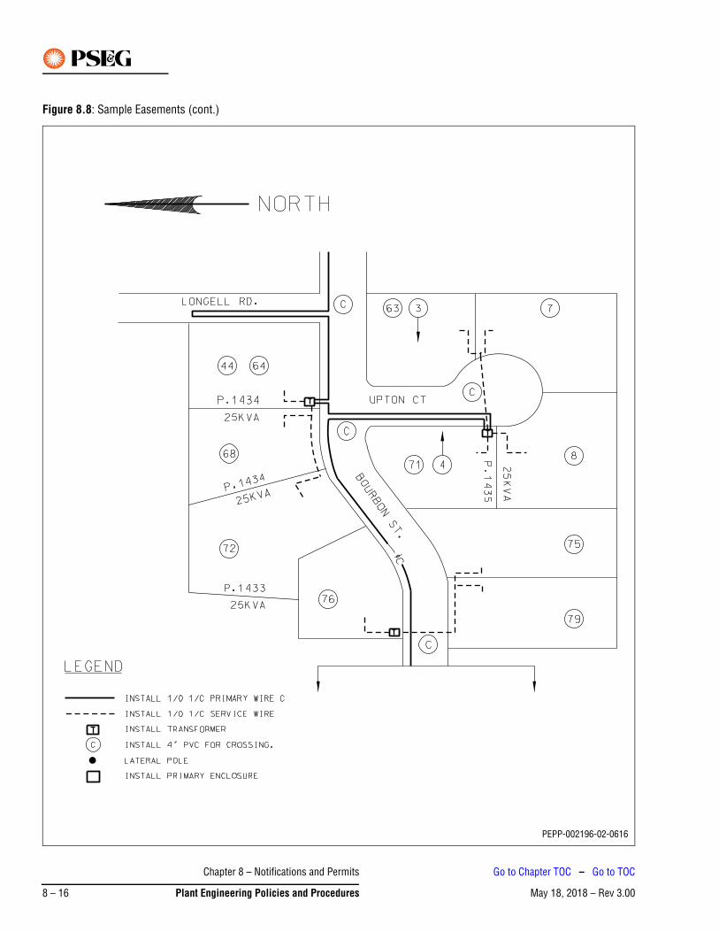
Figure 8.8: Sample Easements (cont.)
PEPP-002196-02-0616
Chapter 8 – Notifications and Permits
May 18, 2018 – Rev 3.008 – 16 Plant Engineering Policies and Procedures
Go to Chapter TOC – Go to TOC
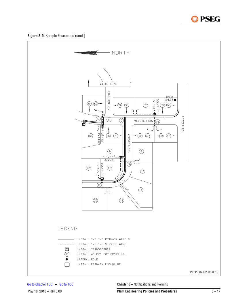
Figure 8.9: Sample Easements (cont.)
PEPP-002197-02-0616
Chapter 8 – Notifications and Permits
May 18, 2018 – Rev 3.00 Plant Engineering Policies and Procedures 8 – 17
Go to Chapter TOC – Go to TOC
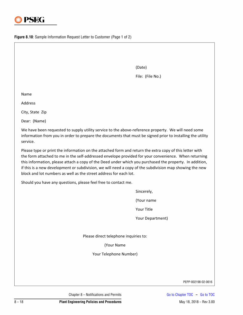
Figure 8.10: Sample Information Request Letter to Customer (Page 1 of 2)
PEPP-002198-02-0616
Chapter 8 – Notifications and Permits
May 18, 2018 – Rev 3.008 – 18 Plant Engineering Policies and Procedures
Go to Chapter TOC – Go to TOC
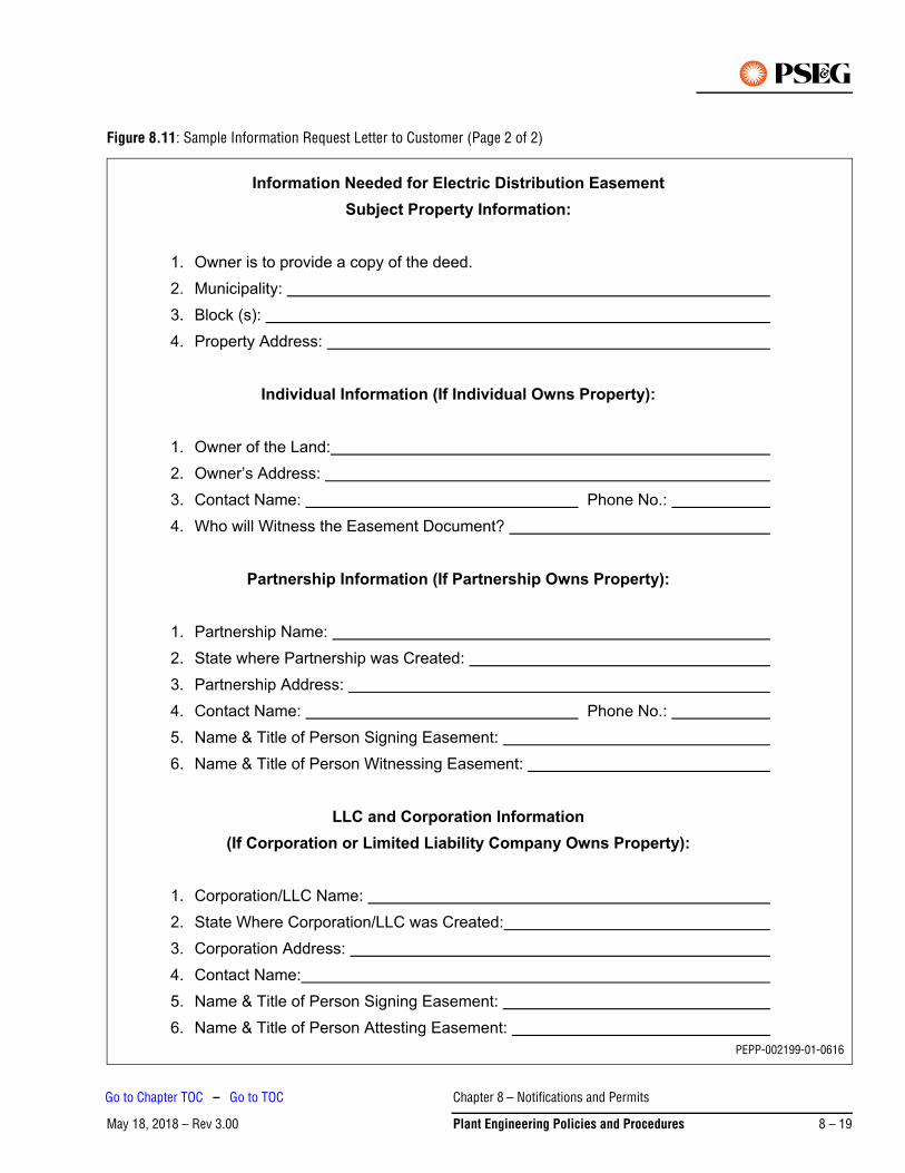
Figure 8.11: Sample Information Request Letter to Customer (Page 2 of 2)
PEPP-002199-01-0616
Chapter 8 – Notifications and Permits
May 18, 2018 – Rev 3.00 Plant Engineering Policies and Procedures 8 – 19
Go to Chapter TOC – Go to TOC
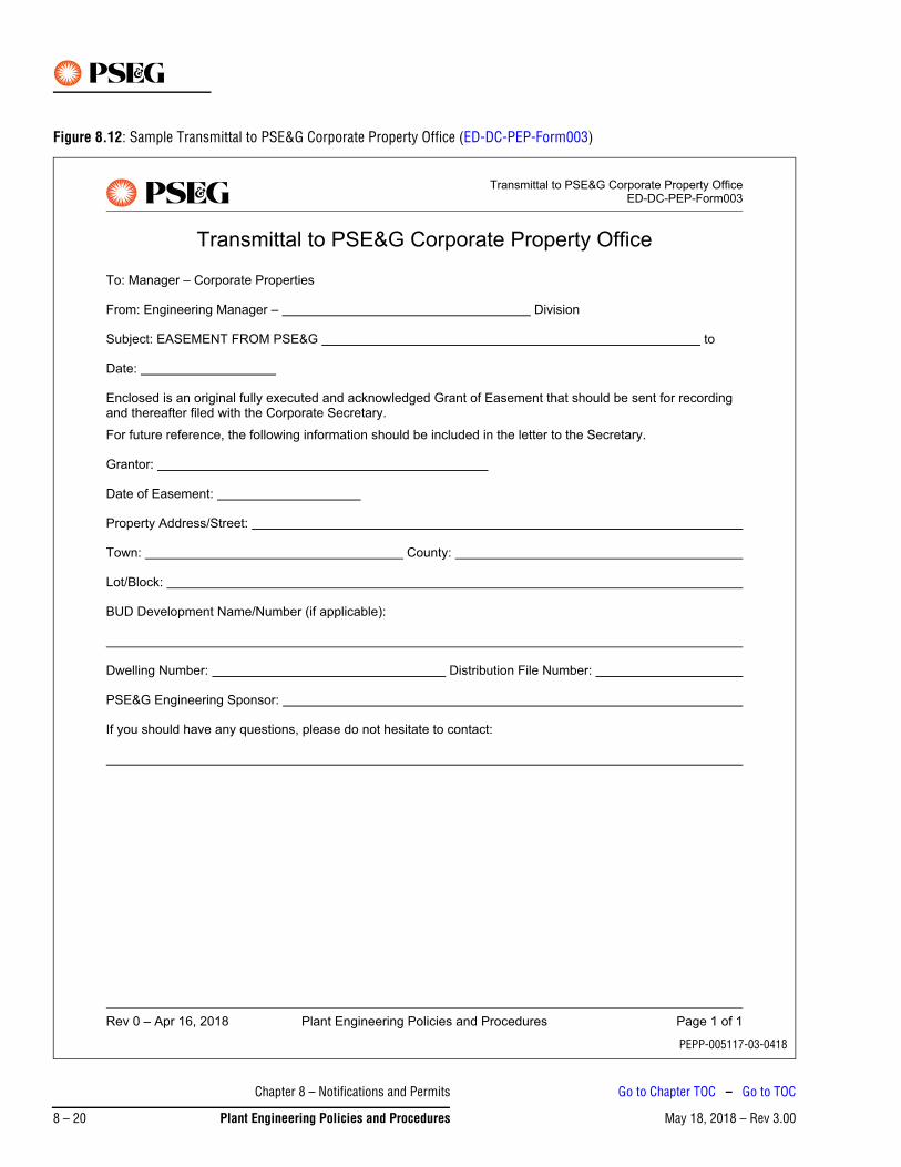
Figure 8.12: Sample Transmittal to PSE&G Corporate Property Office (ED-DC-PEP-Form003)
PEPP-005117-03-0418
Chapter 8 – Notifications and Permits
May 18, 2018 – Rev 3.008 – 20 Plant Engineering Policies and Procedures
Go to Chapter TOC – Go to TOC
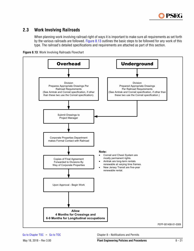
2.3 Work Involving RailroadsWhen planning work involving railroad right of ways it is important to make sure all requirements as set forth by the various railroads are followed. Figure 8.13 outlines the basic steps to be followed for any work of this type. The railroad’s detailed specifications and requirements are attached as part of this section.
Figure 8.13: Work Involving Railroads Flowchart
Overhead Underground
Division
Prepares Appropriate Drawings Per
Railroad Requirements
(See Amtrak and Conrail specification, if other
than these two use the Conrail specification).
Division
Prepared Appropriate Drawings
Per Railroad Requirements
(See Amtrak and Conrail specification, if other than
these two use the Conrail specification.)
Submit Drawings to
Project Manager
Corporate Properties Department
makes Formal Contact with Railroad
Copies of Final Agreement
Forwarded to Divisions By
Way of Corporate Properties
Upon Approval - Begin Work
Allow4 Months for Crossings and
6-9 Months for Longitudinal occupations
Note:Conrail and Chesii System are
mostly permanent rights.
Amtrak are long-term rentals
renewable at varying time frames.
New Jersey Transit are five-year
renewable rental.
PEPP-001408-01-0309
Chapter 8 – Notifications and Permits
May 18, 2018 – Rev 3.00 Plant Engineering Policies and Procedures 8 – 21
Go to Chapter TOC – Go to TOC
2.3.1 Operating Railroads in New Jersey
The following are railroads that operate in New Jersey:
• New Jersey Transit Corporation• Consolidated Rail Corporation• National Railroad Passenger Corporation, AMTRAK• Delaware River Port Authority, Port Authority Transit Corp. – PATCO• Port Authority of NY and NJ, PATH• Morristown and Erie Railway, Inc.• NY Susquehanna and Western Railway Corp.
2.3.2 Railroad Emergency Contacts
The following are emergency telephone numbers for railroads operating in New Jersey:
• New Jersey Transit CorporationChief Dispatcher: (201) 714-2781NJ Transit Emergencies: 1-800-242-0236
• Consolidated Rail CorporationConrail Emergencies: 1-800-272-0911
• National Railroad Passenger CorporationAmtrak Power Director: (212) 630-7681Amtrak Trouble Desk: (212) 630-7651Amtrak Emergencies: 1-800-331-0008
• Delaware River Port AuthorityPort Authority Transit Corp. – PATCODispatcher: (609) 963-7983
• Port Authority of NY and NJPort Authority Trans Hudson Corporation – PATHTrain Master: (201) 216-6552, 6553, 6554
• Morristown and Erie Railway, Inc.President and General Manager: (973) 267-4300Morristown and Erie Railway emergency: 1-800-274-5761
2.3.3 Railroad Contacts for Flagmen
The following are railroad contacts for flagmen for railroads operating in New Jersey:
• New Jersey Transit CorporationDirector of Special Projects(201) 714-2663
Note: You must have the Agreement # before calling
• Consolidated Rail CorporationGeneral Manager – Construction(215) 596-3644
Note: You must have the Agreement # before calling
Chapter 8 – Notifications and Permits
May 18, 2018 – Rev 3.008 – 22 Plant Engineering Policies and Procedures
Go to Chapter TOC – Go to TOC
• National Railroad Passenger CorporationDirector Engineering and Construction(215) 349-1505
• Delaware River Port AuthorityPort Authority Transit Corp. – PATCODispatcher: (609) 963-7983
• Port Authority of NY and NJPort Authority Trans Hudson Corporation – PATHTrain Master: (201) 216-6552, 6553, 6554
• Morristown and Erie Railway, Inc.President and General Manager: (201) 267-4300
2.4 Railroad Agreements, Requirements and Specifications
2.4.1 General Information
An application for occupancy right-of-way must be submitted to the appropriate railroad operator for any facilities installed over, under, across, or upon railroad property. The railroad operator must be also notified when new facilities have been, or will be, added to existing agreements.
The PSE&G Manager – Corporate Properties must be notified immediately to identify the railroad operator and obtain contact information and requirements.
The Engineering Sponsor will prepare detailed scaled drawings per the railroad operator’s requirements, and submit the drawings to Corporate Properties.
Corporate Properties will make formal contact with the railroad operator in order to obtain the agreement and arrange payment of any applicable fees.
A formal final agreement to perform work will be obtained between 4 and 9 months from the time of application.
2.4.2 Requirements for Drawings – Overhead Facilities
The following are the requirements for drawings pertaining to overhead facilities.
1. Plan view of the railroad crossing/right-of-way occupation relative to all railroad facilities
2. Elevation view showing clearances between the top of the rail and the bottom of the wire sag
3. Pole top configuration
4. Nominal voltage of electric lines
5. Number of, size, and material of electric wires
6. Height, class, and depth of poles
7. Number of, location, size of, material of anchors and all guying for poles
Double cross-arms are required on poles adjacent to the railroad track.Note
Chapter 8 – Notifications and Permits
May 18, 2018 – Rev 3.00 Plant Engineering Policies and Procedures 8 – 23
Go to Chapter TOC – Go to TOC
2.4.3 Requirements for Drawings – Underground Facilities
The following are the requirements for drawings pertaining to underground facilities.
1. Plan view of the railroad crossing/right-of-way occupation relative to all railroad facilities
2. All railroad property lines
3. Other underground facilities as determined by the applicant
4. Profile showing depth of casing pipe from ground level, tracks, and other facilities
5. Location and description of appurtenances, manholes, and other accesses
6. Size and material of casing pipe
7. Size and material of carrier conduit
8. Method of construction and installation
Primary Contact: Manager – Corporate Properties, (973) 430-5284.
3. Work with DevelopersNormally it is the responsibility of the developer to obtain all necessary approvals. Unfortunately, there are times when the developer does not consider the utility installation when applying for state, regional and federal approvals; specifically wetlands and stream encroachment approvals.
When the developer requests electric service, the division representative should inquire if the developer included the utility installation as part of any applicable approvals required for the development. For example, if a utility line is to be constructed across a stream or within wetlands the New Jersey Department of Environmental Protection (NJDEP) or Army Corp of Engineers (ACOE) approvals must include those activities with the permit conditions. Either PSE&G or the developer must obtain these approvals prior to our installation.
It is recommended that the developer’s permit approvals be checked first in order to provide a realistic date of installation and service. Figure 8.14 provides a list of potential permits that may be required by federal, state, and regional regulatory agencies.
Chapter 8 – Notifications and Permits
May 18, 2018 – Rev 3.008 – 24 Plant Engineering Policies and Procedures
Go to Chapter TOC – Go to TOC
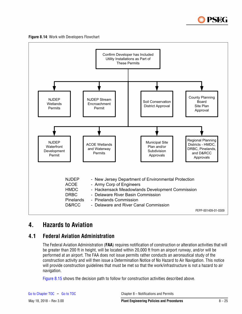
Figure 8.14: Work with Developers Flowchart
4. Hazards to Aviation
4.1 Federal Aviation Administration The Federal Aviation Administration (FAA) requires notification of construction or alteration activities that will be greater than 200 ft in height, will be located within 20,000 ft from an airport runway, and/or will be performed at an airport. The FAA does not issue permits rather conducts an aeronautical study of the construction activity and will then issue a Determination Notice of No Hazard to Air Navigation. This notice will provide construction guidelines that must be met so that the work/infrastructure is not a hazard to air navigation.
Figure 8.15 shows the decision path to follow for construction activities described above.
NJDEP - New Jersey Department of Environmental Protection
ACOE - Army Corp of Engineers
HMDC - Hackensack Meadowlands Development Commission
DRBC - Delaware River Basin Commission
Pinelands - Pinelands Commission
D&RCC - Delaware and River Canal Commission
Confirm Developer has Included
Utility Installations as Part of
These Permits
NJDEP
Wetlands
Permits
NJDEP Stream
Encroachment
Permit
NJDEP
Waterfront
Development
Permit
County Planning
Board
Site Plan
Approval
Soil Conservation
District Approval
Regional Planning
Districts - HMDC,
DRBC, Pinelands,
and D&RCC
Approvals
Municipal Site
Plan and/or
Subdivision
Approvals
ACOE Wetlands
and Waterway
Permits
PEPP-001409-01-0309
Chapter 8 – Notifications and Permits
May 18, 2018 – Rev 3.00 Plant Engineering Policies and Procedures 8 – 25
Go to Chapter TOC – Go to TOC
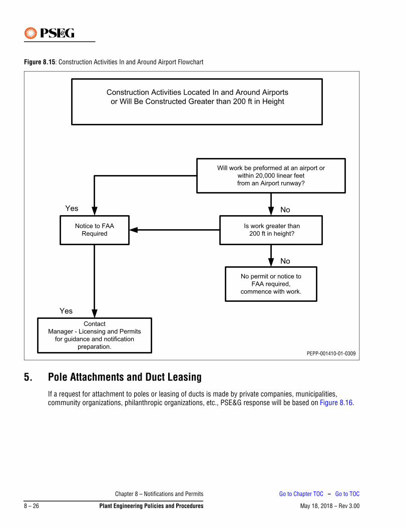
Figure 8.15: Construction Activities In and Around Airport Flowchart
5. Pole Attachments and Duct LeasingIf a request for attachment to poles or leasing of ducts is made by private companies, municipalities, community organizations, philanthropic organizations, etc., PSE&G response will be based on Figure 8.16.
Construction Activities Located In and Around Airports
or Will Be Constructed Greater than 200 in Height
Will work be preformed at an airport or
within 20,000 linear feet
from an Airport runway?
Is work greater than
200 ft in height?
No permit or notice to
FAA required,
commence with work.
Notice to FAA
Required
Contact
Manager - Licensing and Permits
for guidance and notification
preparation.
No
No
Yes
Yes
PEPP-001410-01-0309
Chapter 8 – Notifications and Permits
May 18, 2018 – Rev 3.008 – 26 Plant Engineering Policies and Procedures
Go to Chapter TOC – Go to TOC
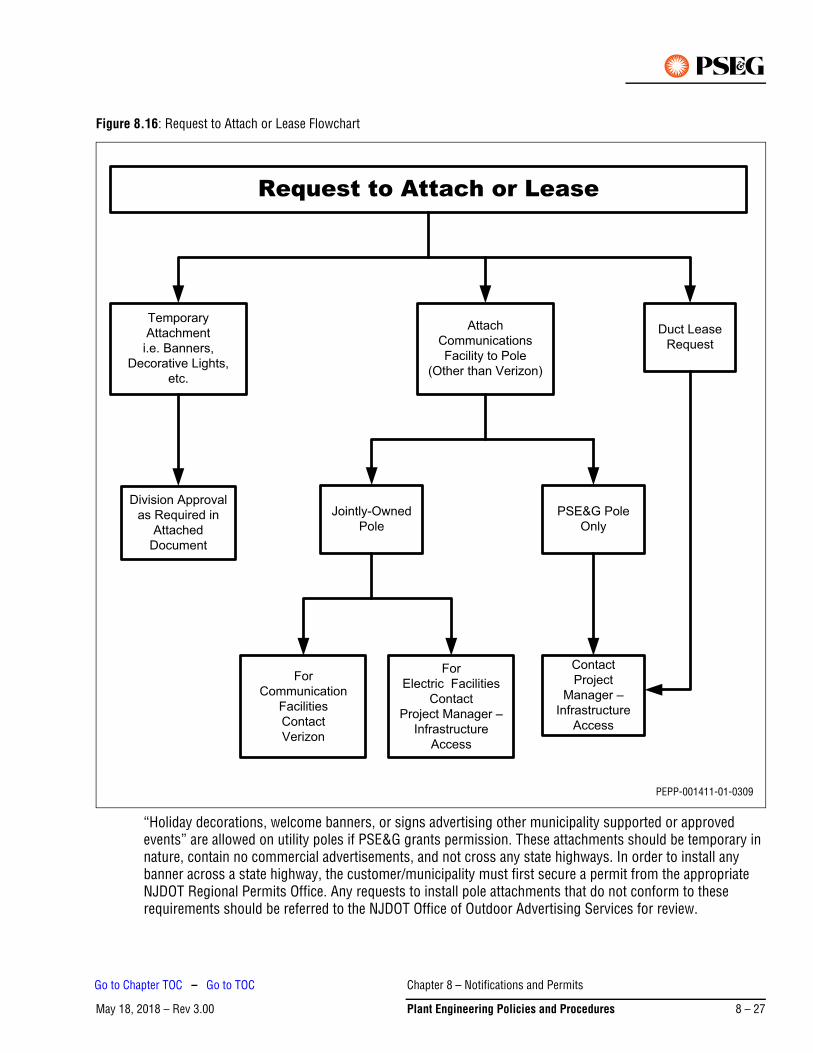
Figure 8.16: Request to Attach or Lease Flowchart
“Holiday decorations, welcome banners, or signs advertising other municipality supported or approved events” are allowed on utility poles if PSE&G grants permission. These attachments should be temporary in nature, contain no commercial advertisements, and not cross any state highways. In order to install any banner across a state highway, the customer/municipality must first secure a permit from the appropriate NJDOT Regional Permits Office. Any requests to install pole attachments that do not conform to these requirements should be referred to the NJDOT Office of Outdoor Advertising Services for review.
Request to Attach or Lease
Temporary
Attachment
i.e. Banners,
Decorative Lights,
etc.
Attach
Communications
Facility to Pole
(Other than Verizon)
Duct Lease
Request
Division Approval
as Required in
Attached
Document
Jointly-Owned
Pole
PSE&G Pole
Only
For
Communication
Facilities
Contact
Verizon
For
Electric Facilities
Contact
Project Manager –
Infrastructure
Access
Contact
Project
Manager –
Infrastructure
Access
PEPP-001411-01-0309
Chapter 8 – Notifications and Permits
May 18, 2018 – Rev 3.00 Plant Engineering Policies and Procedures 8 – 27
Go to Chapter TOC – Go to TOC
5.1 General Requirements for Attachment of Holiday Decorations, Banners, and Signs to PolesThe customer/municipality must do the following:
1. Obtain all required governmental permits.
2. Provide proof of minimum insurance as specified in PSE&G’s “Insurance Requirements for Attachment of Holiday Decorations, Banners, and Signs to Poles”.
3. Obtain PSE&G approval of locations, attachments, and method of attachment prior to installation.
4. Obtain New Jersey Bell approval (written permission) for any jointly owned poles.
5.2 Insurance Requirements for Attachment of Holiday Decorations, Banners, and Signs to PolesThe following specific insurance requirements for pole attachments are derived from PSE&G’s General Provisions for Insurance provided in the Corporate Procedures Manual.
1. Before any attachments are made, licensee should provide proof of the following minimum insurance in forms and with insurance companies acceptable to PSE&G.
a. Workers’ compensation insurance in accordance with statutory requirements and Employers’ Liability Insurance with a minimum limit of $500,000 each occurrence.
b. Comprehensive General Liability Insurance (occurrence form) including premises, contractual liability, products liability, completed operations, independent contractors, broad form property damage, damage caused by structural injury, and damage to underground utilities with the following minimum limits of liability:
- Bodily injury $1,000,000. each occurrence
- Property Damage $1,000,000. each occurrence
c. Comprehensive Automobile Liability Insurance (only required if vehicles are to be used to install attachments) including coverage for all owned, non-owned and hired automobiles used by the licensee in the performance of the work with the following minimum limits of liability:
- Bodily injury $1,000,000. each occurrence
- Property Damage $1,000,000. each occurrence
2. All liability coverages shall name PSE&G as an additional ensured to support the contractual obligations assumed by the licensee in acceptance of this contract and provide that this coverage is primary and without right of contribution from insurance carried by PSE&G.
3. Prior to the commencement of this agreement, licensee will deliver to PSE&G Certificates of Insurance evidencing this coverage is in effect and providing at least 30 days notice to PSE&G of any cancellation, termination, or material alteration of said insurance.
4. Licensee shall notify the Company’s representatives and the Claims department immediately by telephone (973) 430-7000 and in writing within 24 hours after an occurrence thereof, of all accidents arising out of work done under this contract. Such notice shall not relieve either party of any of its obligations under this agreement, nor be construed to be other than a mere notification.
5. The insurance requirements as set forth above are to fully protect PSE&G from any and all claims by third parties, including employees of the licensee or its agents, subcontractors, and invitees. Said insurance, however, is in no manner to relieve or release the licensee, its agents, sub-contractors and invitees from, or to limit their liability as to any and all obligations herein assumed.
Chapter 8 – Notifications and Permits
May 18, 2018 – Rev 3.008 – 28 Plant Engineering Policies and Procedures
Go to Chapter TOC – Go to TOC
6. Utility Relocations
6.1 Legal Authority to use Public Streets for Electric Utility FacilitiesThe franchise authority of PSE&G to provide electric service to the citizens of New Jersey is granted directly by the state and not through the grant of franchise rights by individual municipalities. The principal statute authorizing electric service by utility companies is the Electric Light, Heat and Power Company Act of 1896. This Act, codified in Chapter 7 of Title 48 of the New Jersey Statutes Annotated, granted to electric companies formed under it the right to use the public highways and streets of the state for their electric operations. It is this charter from the state, together with other applicable statutory provisions of Title 48 (Public Utilities) of the New Jersey Statutes, which constitute the electric franchise of PSE&G. This electric franchise continues indefinitely and unlike, for example, a cable TV franchise, is not subject to periodic renewal. However, the right of a public utility to utilize the public streets to provide electric utility service to members of the public is subject to reasonable regulation to assure proper roadway restoration and to protect the safety and convenience of the traveling public.
NJSA 48:7-1 and 2, governing the rights of PSE&G to install and maintain electric utility facilities in public streets are shown in full in Exhibit 10-10. Further, public streets are broadly defined at NJSA 48:3-17.2(d) as follows:
(d) “Street” means any highway, road, street, alley, lane or place dedicated to public use whether or not accepted and whether or not subsequently vacated and includes the sidewalk area and other areas between the sidelines thereof.
As set forth in NJSA 48:7-1 and 2, the use of public streets by PSE&G for electric facilities is subject to the following requirements:
1. PSE&G must secure the consent in writing of the “owner of the soil”, usually but not necessarily the abutting property owner, before installing a pole. To the extent that an executed pole consent does not provide for a later expansion of facilities or replacement by a larger pole, a new consent should be secured when such expansion or increase is undertaken.
2. PSE&G is subject to lawful street opening regulations intended to assure proper restoration of the roadways and to protect the safety and convenience of the traveling public. The payment of fees for such permits can be properly required as long as such fees defray the cost of the regulatory services rendered and are not for the purpose of raising revenue.
3. In incorporated cities and towns, but not boroughs, townships and municipalities with other forms of government, a “designation” of the streets where overhead electric facilities are to be installed must be made by the city or town. Once a designation is made, it cannot be rescinded by a subsequent governing body. This requirement had particular significance when electricity was a new technology being introduced into established municipalities. It is largely of historical interest today since New Jersey is heavily developed and no new cities or towns are being created.
A municipal or county government cannot regulate the means or method of supplying electric service and cannot dictate construction practices. The New Jersey Board of Public Utilities (BPU), formerly known at various times as the Board of Regulatory Commissioners or the Public Utility Commission, was formed in 1911 under Title 48 of the New Jersey Statutes in order to exercise broad supervisory control over all aspects of public utility operation. The regulations of the BPU require that utility plant conform to “standard practice” and be constructed in accordance with the National Electrical Code and National Electrical Safety Code in effect at the time of construction.
Chapter 8 – Notifications and Permits
May 18, 2018 – Rev 3.00 Plant Engineering Policies and Procedures 8 – 29
Go to Chapter TOC – Go to TOC
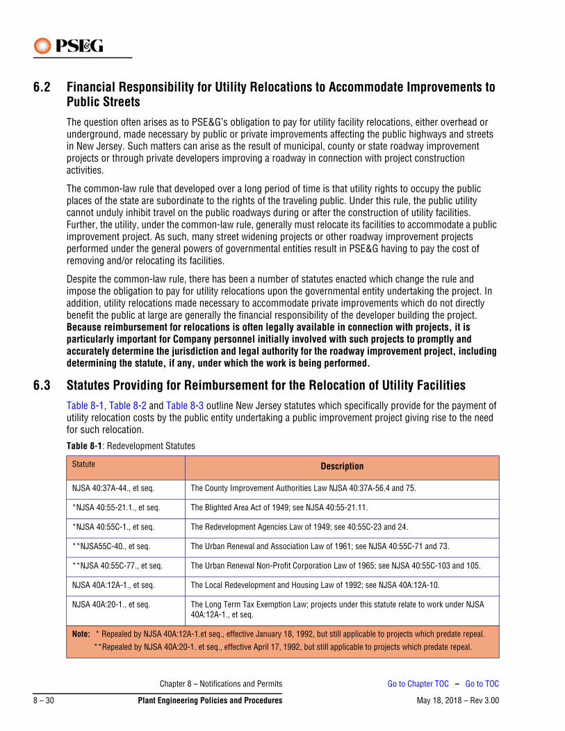
6.2 Financial Responsibility for Utility Relocations to Accommodate Improvements to Public StreetsThe question often arises as to PSE&G’s obligation to pay for utility facility relocations, either overhead or underground, made necessary by public or private improvements affecting the public highways and streets in New Jersey. Such matters can arise as the result of municipal, county or state roadway improvement projects or through private developers improving a roadway in connection with project construction activities.
The common-law rule that developed over a long period of time is that utility rights to occupy the public places of the state are subordinate to the rights of the traveling public. Under this rule, the public utility cannot unduly inhibit travel on the public roadways during or after the construction of utility facilities. Further, the utility, under the common-law rule, generally must relocate its facilities to accommodate a public improvement project. As such, many street widening projects or other roadway improvement projects performed under the general powers of governmental entities result in PSE&G having to pay the cost of removing and/or relocating its facilities.
Despite the common-law rule, there has been a number of statutes enacted which change the rule and impose the obligation to pay for utility relocations upon the governmental entity undertaking the project. In addition, utility relocations made necessary to accommodate private improvements which do not directly benefit the public at large are generally the financial responsibility of the developer building the project. Because reimbursement for relocations is often legally available in connection with projects, it is particularly important for Company personnel initially involved with such projects to promptly and accurately determine the jurisdiction and legal authority for the roadway improvement project, including determining the statute, if any, under which the work is being performed.
6.3 Statutes Providing for Reimbursement for the Relocation of Utility FacilitiesTable 8-1, Table 8-2 and Table 8-3 outline New Jersey statutes which specifically provide for the payment of utility relocation costs by the public entity undertaking a public improvement project giving rise to the need for such relocation.
Table 8-1: Redevelopment Statutes
Statute Description
NJSA 40:37A-44., et seq. The County Improvement Authorities Law NJSA 40:37A-56.4 and 75.
*NJSA 40:55-21.1., et seq. The Blighted Area Act of 1949; see NJSA 40:55-21.11.
*NJSA 40:55C-1., et seq. The Redevelopment Agencies Law of 1949; see 40:55C-23 and 24.
**NJSA55C-40., et seq. The Urban Renewal and Association Law of 1961; see NJSA 40:55C-71 and 73.
**NJSA 40:55C-77., et seq. The Urban Renewal Non-Profit Corporation Law of 1965; see NJSA 40:55C-103 and 105.
NJSA 40A:12A-1., et seq. The Local Redevelopment and Housing Law of 1992; see NJSA 40A:12A-10.
NJSA 40A:20-1., et seq. The Long Term Tax Exemption Law; projects under this statute relate to work under NJSA 40A:12A-1., et seq.
Note: * Repealed by NJSA 40A:12A-1.et seq., effective January 18, 1992, but still applicable to projects which predate repeal.
**Repealed by NJSA 40A:20-1. et seq., effective April 17, 1992, but still applicable to projects which predate repeal.
Chapter 8 – Notifications and Permits
May 18, 2018 – Rev 3.008 – 30 Plant Engineering Policies and Procedures
Go to Chapter TOC – Go to TOC
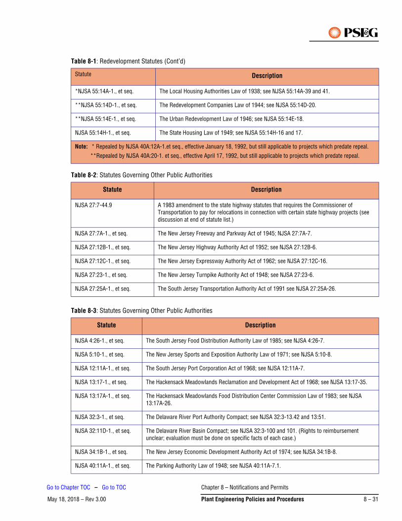
*NJSA 55:14A-1., et seq. The Local Housing Authorities Law of 1938; see NJSA 55:14A-39 and 41.
**NJSA 55:14D-1., et seq. The Redevelopment Companies Law of 1944; see NJSA 55:14D-20.
**NJSA 55:14E-1., et seq. The Urban Redevelopment Law of 1946; see NJSA 55:14E-18.
NJSA 55:14H-1., et seq. The State Housing Law of 1949; see NJSA 55:14H-16 and 17.
Table 8-2: Statutes Governing Other Public Authorities
Statute Description
NJSA 27:7-44.9 A 1983 amendment to the state highway statutes that requires the Commissioner of Transportation to pay for relocations in connection with certain state highway projects (see discussion at end of statute list.)
NJSA 27:7A-1., et seq. The New Jersey Freeway and Parkway Act of 1945; NJSA 27:7A-7.
NJSA 27:12B-1., et seq. The New Jersey Highway Authority Act of 1952; see NJSA 27:12B-6.
NJSA 27:12C-1., et seq. The New Jersey Expressway Authority Act of 1962; see NJSA 27:12C-16.
NJSA 27:23-1., et seq. The New Jersey Turnpike Authority Act of 1948; see NJSA 27:23-6.
NJSA 27:25A-1., et seq. The South Jersey Transportation Authority Act of 1991 see NJSA 27:25A-26.
Table 8-3: Statutes Governing Other Public Authorities
Statute Description
NJSA 4:26-1., et seq. The South Jersey Food Distribution Authority Law of 1985; see NJSA 4:26-7.
NJSA 5:10-1., et seq. The New Jersey Sports and Exposition Authority Law of 1971; see NJSA 5:10-8.
NJSA 12:11A-1., et seq. The South Jersey Port Corporation Act of 1968; see NJSA 12:11A-7.
NJSA 13:17-1., et seq. The Hackensack Meadowlands Reclamation and Development Act of 1968; see NJSA 13:17-35.
NJSA 13:17A-1., et seq. The Hackensack Meadowlands Food Distribution Center Commission Law of 1983; see NJSA 13:17A-26.
NJSA 32:3-1., et seq. The Delaware River Port Authority Compact; see NJSA 32:3-13.42 and 13:51.
NJSA 32:11D-1., et seq. The Delaware River Basin Compact; see NJSA 32:3-100 and 101. (Rights to reimbursement unclear; evaluation must be done on specific facts of each case.)
NJSA 34:1B-1., et seq. The New Jersey Economic Development Authority Act of 1974; see NJSA 34:1B-8.
NJSA 40:11A-1., et seq. The Parking Authority Law of 1948; see NJSA 40:11A-7.1.
Table 8-1: Redevelopment Statutes (Cont’d)
Statute Description
Note: * Repealed by NJSA 40A:12A-1.et seq., effective January 18, 1992, but still applicable to projects which predate repeal.
**Repealed by NJSA 40A:20-1. et seq., effective April 17, 1992, but still applicable to projects which predate repeal.
Chapter 8 – Notifications and Permits
May 18, 2018 – Rev 3.00 Plant Engineering Policies and Procedures 8 – 31
Go to Chapter TOC – Go to TOC
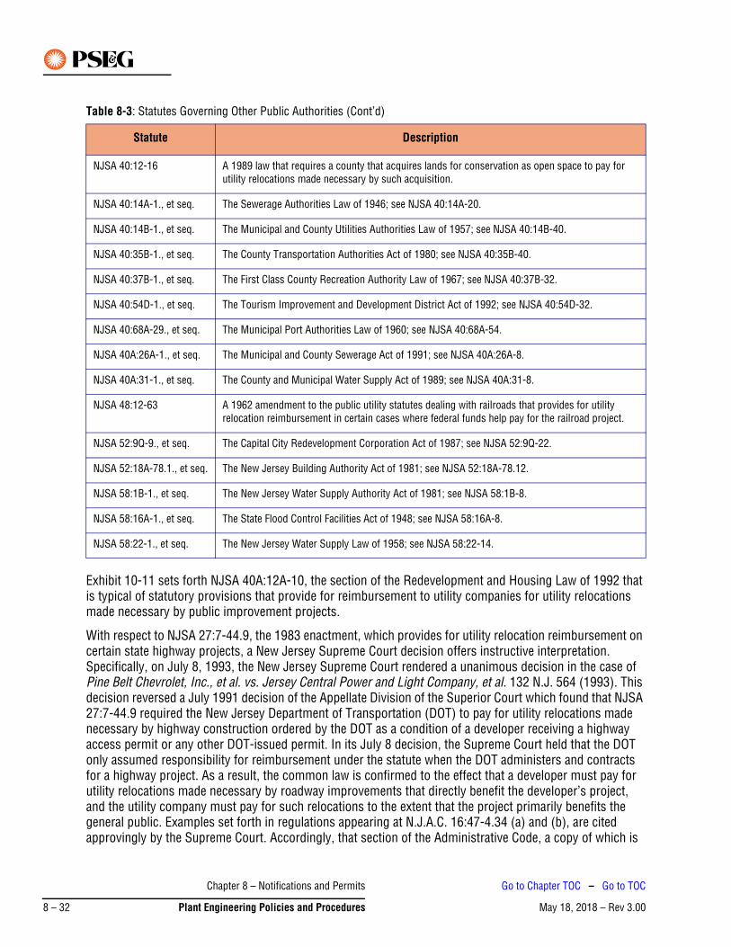
Exhibit 10-11 sets forth NJSA 40A:12A-10, the section of the Redevelopment and Housing Law of 1992 that is typical of statutory provisions that provide for reimbursement to utility companies for utility relocations made necessary by public improvement projects.
With respect to NJSA 27:7-44.9, the 1983 enactment, which provides for utility relocation reimbursement on certain state highway projects, a New Jersey Supreme Court decision offers instructive interpretation. Specifically, on July 8, 1993, the New Jersey Supreme Court rendered a unanimous decision in the case of Pine Belt Chevrolet, Inc., et al. vs. Jersey Central Power and Light Company, et al. 132 N.J. 564 (1993). This decision reversed a July 1991 decision of the Appellate Division of the Superior Court which found that NJSA 27:7-44.9 required the New Jersey Department of Transportation (DOT) to pay for utility relocations made necessary by highway construction ordered by the DOT as a condition of a developer receiving a highway access permit or any other DOT-issued permit. In its July 8 decision, the Supreme Court held that the DOT only assumed responsibility for reimbursement under the statute when the DOT administers and contracts for a highway project. As a result, the common law is confirmed to the effect that a developer must pay for utility relocations made necessary by roadway improvements that directly benefit the developer’s project, and the utility company must pay for such relocations to the extent that the project primarily benefits the general public. Examples set forth in regulations appearing at N.J.A.C. 16:47-4.34 (a) and (b), are cited approvingly by the Supreme Court. Accordingly, that section of the Administrative Code, a copy of which is
NJSA 40:12-16 A 1989 law that requires a county that acquires lands for conservation as open space to pay for utility relocations made necessary by such acquisition.
NJSA 40:14A-1., et seq. The Sewerage Authorities Law of 1946; see NJSA 40:14A-20.
NJSA 40:14B-1., et seq. The Municipal and County Utilities Authorities Law of 1957; see NJSA 40:14B-40.
NJSA 40:35B-1., et seq. The County Transportation Authorities Act of 1980; see NJSA 40:35B-40.
NJSA 40:37B-1., et seq. The First Class County Recreation Authority Law of 1967; see NJSA 40:37B-32.
NJSA 40:54D-1., et seq. The Tourism Improvement and Development District Act of 1992; see NJSA 40:54D-32.
NJSA 40:68A-29., et seq. The Municipal Port Authorities Law of 1960; see NJSA 40:68A-54.
NJSA 40A:26A-1., et seq. The Municipal and County Sewerage Act of 1991; see NJSA 40A:26A-8.
NJSA 40A:31-1., et seq. The County and Municipal Water Supply Act of 1989; see NJSA 40A:31-8.
NJSA 48:12-63 A 1962 amendment to the public utility statutes dealing with railroads that provides for utility relocation reimbursement in certain cases where federal funds help pay for the railroad project.
NJSA 52:9Q-9., et seq. The Capital City Redevelopment Corporation Act of 1987; see NJSA 52:9Q-22.
NJSA 52:18A-78.1., et seq. The New Jersey Building Authority Act of 1981; see NJSA 52:18A-78.12.
NJSA 58:1B-1., et seq. The New Jersey Water Supply Authority Act of 1981; see NJSA 58:1B-8.
NJSA 58:16A-1., et seq. The State Flood Control Facilities Act of 1948; see NJSA 58:16A-8.
NJSA 58:22-1., et seq. The New Jersey Water Supply Law of 1958; see NJSA 58:22-14.
Table 8-3: Statutes Governing Other Public Authorities (Cont’d)
Statute Description
Chapter 8 – Notifications and Permits
May 18, 2018 – Rev 3.008 – 32 Plant Engineering Policies and Procedures
Go to Chapter TOC – Go to TOC

attached as Exhibit 10-12, may offer some guidance for when relocation expenses can be properly sought from a developer. As a result of the guidelines offered by the Pine Belt decision, each applicable project must be analyzed to determine what components primarily benefit the general traveling public and what components are primarily for the benefit of the developer’s project.
For many utility relocation projects, it is important to determine some basic facts before proceeding. Figure 8.17 and Figure 8.18 outline the process to be followed in order to make a correct determination of PSE&G’s responsibility.
Chapter 8 – Notifications and Permits
May 18, 2018 – Rev 3.00 Plant Engineering Policies and Procedures 8 – 33
Go to Chapter TOC – Go to TOC
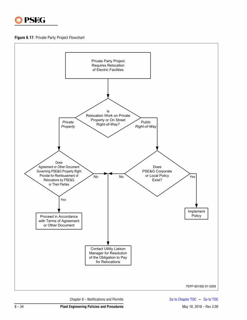
Figure 8.17: Private Party Project Flowchart
Private Party Project
Requires Relocation
of Electric Facilities
Is
Relocation Work on Private
Property or On Street
Right-of-Way?
DoesAgreement or Other Document
Governing PSE&G Property RightProvide for Reimbusement of
Relocations by PSE&Gor Their Parties
Does
PSE&G Corporate
or Local Policy
Exist?
Proceed in Accordance
with Terms of Agreement
or Other Document
Contact Utility Liaison
Manager for Resolution
of the Obligation to Pay
for Relocations
Implement
Policy
PrivateProperty
PublicRight-of-Way
No
Yes
No Yes
PEPP-001405-01-0309
Chapter 8 – Notifications and Permits
May 18, 2018 – Rev 3.008 – 34 Plant Engineering Policies and Procedures
Go to Chapter TOC – Go to TOC
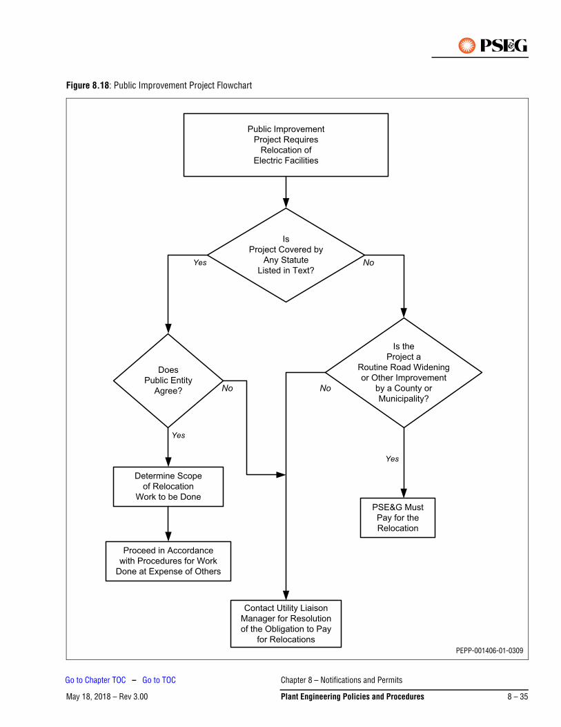
Figure 8.18: Public Improvement Project Flowchart
Public Improvement
Project Requires
Relocation of
Electric Facilities
Is
Project Covered by
Any Statute
Listed in Text?
Does
Public Entity
Agree?
Is the
Project a
Routine Road Widening
or Other Improvement
by a County or
Municipality?
Determine Scope
of Relocation
Work to be Done
Contact Utility Liaison
Manager for Resolution
of the Obligation to Pay
for Relocations
PSE&G Must
Pay for the
Relocation
No
Yes
No
Yes
Proceed in Accordance
with Procedures for Work
Done at Expense of Others
Yes
No
PEPP-001406-01-0309
Chapter 8 – Notifications and Permits
May 18, 2018 – Rev 3.00 Plant Engineering Policies and Procedures 8 – 35
Go to Chapter TOC – Go to TOC
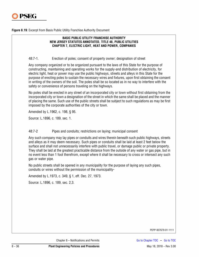
Figure 8.19: Excerpt from Basis Public Utility Franchise Authority Document
BASIC PUBLIC UTILITY FRANCHISE AUTHORITYNEW JERSEY STATUTES ANNOTATED, TITLE 48, PUBLIC UTILITIES
CHAPTER 7, ELECTRIC LIGHT, HEAT AND POWER, COMPANIES
48:7-1. Erection of poles; consent of property owner; designation of street
Any company organized or to be organized pursuant to the laws of this State for the purpose of constructing, maintaining and operating works for the supply-and distribution of electricity, for electric light, heat or power may use the public highways, streets and alleys in this State for the purpose of erecting poles to sustain the necessary wires and fixtures, upon first obtaining the consent in writing of the owners of the soil. The poles shall be so located as in no way to interfere with the safety or convenience of persons traveling on the highways.
No poles shall be erected in any street of an incorporated city or town without first obtaining from the incorporated city or town a designation of the street in which the same shall be placed and the manner of placing the same. Such use of the public streets shall be subject to such regulations as may be first imposed by the corporate authorities of the city or town.
Amended by L.1962, c. 198, § 95.
Source: L.1896, c. 189, sec. 1.
48:7-2 Pipes and conduits; restrictions on laying; municipal consent
Any such company may lay pipes or conduits and wires therein beneath such public highways, streets and alleys as it may deem necessary. Such pipes or conduits shall be laid at least 2 feet below the surface and shall not unnecessarily interfere with public travel, or damage public or private property. They shall be laid at the greatest practicable distance from the outside of any water or gas pipe, but in no event less than 1 foot therefrom, except where it shall be necessary to cross or intersect any such gas or water pipe.
No public streets shall be opened in any municipality for the purpose of laying any such pipes, conduits or wires without the permission of the municipality-
Amended by L.1973, c. 349, § 1, eff. Dec. 27, 1973.
Source: L.1896, c. 189, sec. 2,3.
PEPP-007679-01-1111
Chapter 8 – Notifications and Permits
May 18, 2018 – Rev 3.008 – 36 Plant Engineering Policies and Procedures
Go to Chapter TOC – Go to TOC
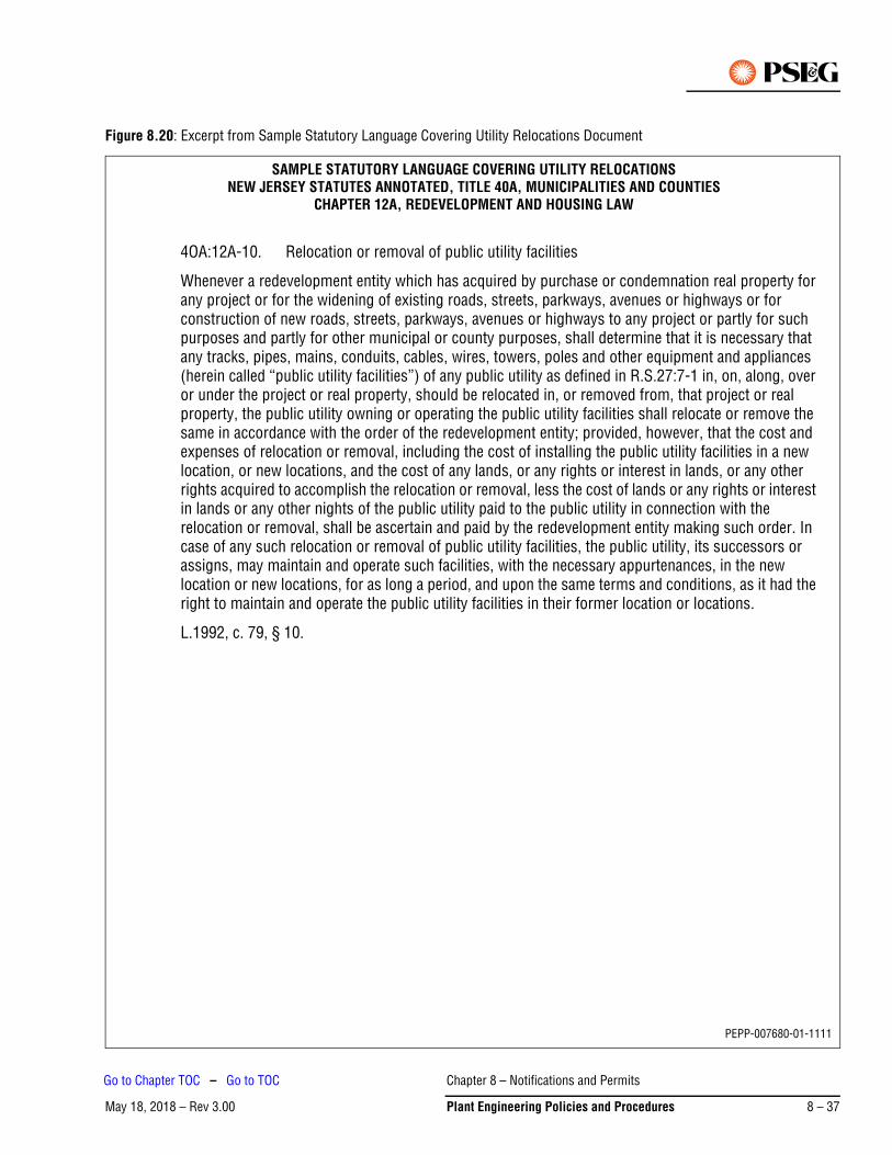
Figure 8.20: Excerpt from Sample Statutory Language Covering Utility Relocations Document
SAMPLE STATUTORY LANGUAGE COVERING UTILITY RELOCATIONSNEW JERSEY STATUTES ANNOTATED, TITLE 40A, MUNICIPALITIES AND COUNTIES
CHAPTER 12A, REDEVELOPMENT AND HOUSING LAW
4OA:12A-10. Relocation or removal of public utility facilities
Whenever a redevelopment entity which has acquired by purchase or condemnation real property for any project or for the widening of existing roads, streets, parkways, avenues or highways or for construction of new roads, streets, parkways, avenues or highways to any project or partly for such purposes and partly for other municipal or county purposes, shall determine that it is necessary that any tracks, pipes, mains, conduits, cables, wires, towers, poles and other equipment and appliances (herein called “public utility facilities”) of any public utility as defined in R.S.27:7-1 in, on, along, over or under the project or real property, should be relocated in, or removed from, that project or real property, the public utility owning or operating the public utility facilities shall relocate or remove the same in accordance with the order of the redevelopment entity; provided, however, that the cost and expenses of relocation or removal, including the cost of installing the public utility facilities in a new location, or new locations, and the cost of any lands, or any rights or interest in lands, or any other rights acquired to accomplish the relocation or removal, less the cost of lands or any rights or interest in lands or any other nights of the public utility paid to the public utility in connection with the relocation or removal, shall be ascertain and paid by the redevelopment entity making such order. In case of any such relocation or removal of public utility facilities, the public utility, its successors or assigns, may maintain and operate such facilities, with the necessary appurtenances, in the new location or new locations, for as long a period, and upon the same terms and conditions, as it had the right to maintain and operate the public utility facilities in their former location or locations.
L.1992, c. 79, § 10.
PEPP-007680-01-1111
Chapter 8 – Notifications and Permits
May 18, 2018 – Rev 3.00 Plant Engineering Policies and Procedures 8 – 37
Go to Chapter TOC – Go to TOC
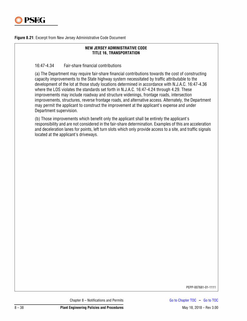
Figure 8.21: Excerpt from New Jersey Administrative Code Document
NEW JERSEY ADMINISTRATIVE CODETITLE 16, TRANSPORTATION
16:47-4.34 Fair-share financial contributions
(a) The Department may require fair-share financial contributions towards the cost of constructing capacity improvements to the State highway system necessitated by traffic attributable to the development of the lot at those study locations determined in accordance with N.J.A.C. 16:47-4.36 where the LOS violates the standards set forth in N.J.A.C. 16:47-4.24 through 4.29. These improvements may include roadway and structure widenings, frontage roads, intersection improvements, structures, reverse frontage roads, and alternative access. Alternately, the Department may permit the applicant to construct the improvement at the applicant's expense and under Department supervision.
(b) Those improvements which benefit only the applicant shall be entirely the applicant's responsibility and are not considered in the fair-share determination. Examples of this are acceleration and deceleration lanes for points, left turn slots which only provide access to a site, and traffic signals located at the applicant's driveways.
PEPP-007681-01-1111
Chapter 8 – Notifications and Permits
May 18, 2018 – Rev 3.008 – 38 Plant Engineering Policies and Procedures
Go to Chapter TOC – Go to TOC
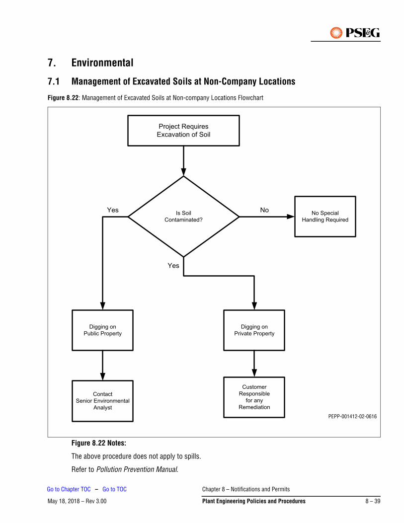
7. Environmental
7.1 Management of Excavated Soils at Non-Company Locations
Figure 8.22: Management of Excavated Soils at Non-company Locations Flowchart
Figure 8.22 Notes:
The above procedure does not apply to spills.
Refer to Pollution Prevention Manual.
PEPP-001412-02-0616
Chapter 8 – Notifications and Permits
May 18, 2018 – Rev 3.00 Plant Engineering Policies and Procedures 8 – 39
Go to Chapter TOC – Go to TOC
PSE&G is dedicated to providing safe, reliable and competitively-priced electric and gas energy to its customers, and in a responsible manner consistent with environmental laws and regulations and worker and community health and safety.
In keeping with this mandate, it is PSE&G’s policy to first minimize the amount of displaced, excess soil generated by excavation activities at non-Company locations. It is also PSE&G’s policy to recycle and/or reuse to the maximum extent possible any excess soil that is displaced by these excavation activities.
Accordingly, PSE&G employees and its contractors will make all reasonable efforts to follow the established policy for management of excavated soil at non-PSE&G locations. This policy includes at a minimum the following practices:
1. During an excavation, should evidence of major contamination be encountered, such as free product, buried drums, or overpowering fumes that may pose a potential hazard to worker or community health and safety, all excavation activity shall cease at that location, and the NJDEP Environmental Hotline (1-877-WARNDEP (1-877-927-6337)) shall be notified. Further work at this location shall occur in consultation with response personnel.
2. Under all other conditions and upon completion of the utility work, all excavated soil shall be placed back into the original excavation to the maximum extent possible. However, if there is any displaced soil or other excavated material that is unable to be backfilled, it shall be recycled and/or reused.
a. Soil that exhibits no evidence of contamination, i.e., no odor or visible discoloration, may be either given to a contractor as clean fill for construction, or sent to an authorized reuse or recycling facility.
b. However, displaced, excess soil that has come from a known or suspected area of contamination shall be sent to a recycling facility authorized to handle such contaminated soil.
7.2 Work Involving Environmental Affairs – Licensing and Permits DivisionThis section provides direction for identifying and complying with various regulatory requirements that may be encountered in minor construction or repair of electric distribution equipment. For construction projects involving substations, tower lines exceeding 69 kV, and duct lines, Environmental Affairs should be contacted to evaluate the project for necessary permits early in the planning phase. This section of the manual illustrates typical environmental situations PSE&G encounters which prompt the need for regulatory approvals. In addition, it identifies the appropriate PSE&G department and personnel who shall be responsible for various permit applications and approvals.
Prior to construction, all work locations must be evaluated for environmental sensitivity. Depending on the type of conditions and location (regional planning districts), multiple regulatory approvals may be required prior to work commencement. The following sections will discuss various regulatory paths that will determine the applicable permits and regulatory agencies responsible for the approvals.
The Licensing and Permits Division of Environmental Affairs can provide a detailed explanation of the regulatory approvals. Always contact the Environmental Affairs Department – Licensing and Permit Division for updated regulations, application requirements, and guidance.
For purpose of this policy, non-Company location refers to excavations involving street openings, trenching operations in public rights-of-way, etc.
Note
Chapter 8 – Notifications and Permits
May 18, 2018 – Rev 3.008 – 40 Plant Engineering Policies and Procedures
Go to Chapter TOC – Go to TOC
The regulatory community is constantly changing. Legislation and increased enforcement of environmental regulations make it necessary for PSE&G to ensure regulatory compliance. It is necessary for the company to be represented by associates who have a clear understanding and working knowledge of environmental regulations. The Electric Distribution Division Headquarters shall look to Environmental Affairs for guidance and direction concerning regulatory compliance when construction or repair activities are considered in questionable areas that may be environmentally sensitive.
7.3 Licensing Submittal and Approval CycleFigure 8.23 is to be used as a reference in determining estimated time durations which can be used in the planning phase of projects. Note that the Licensing and Permits Department should always be consulted prior to proceeding.
Chapter 8 – Notifications and Permits
May 18, 2018 – Rev 3.00 Plant Engineering Policies and Procedures 8 – 41
Go to Chapter TOC – Go to TOC
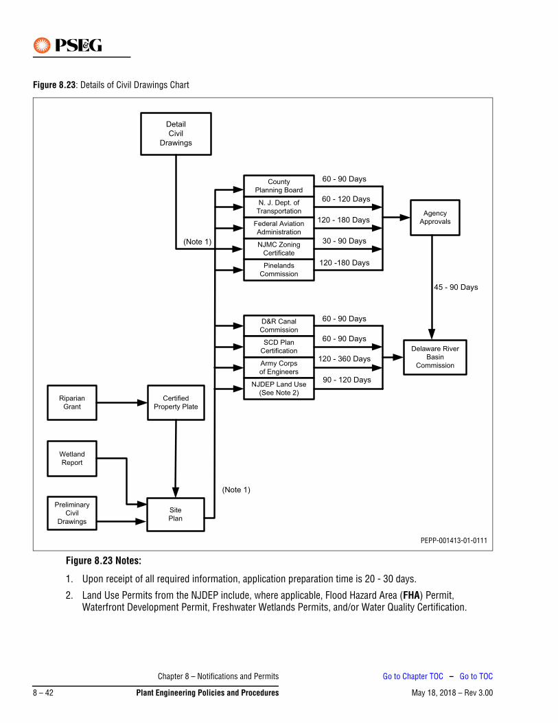
Figure 8.23: Details of Civil Drawings Chart
Figure 8.23 Notes:
1. Upon receipt of all required information, application preparation time is 20 - 30 days.
2. Land Use Permits from the NJDEP include, where applicable, Flood Hazard Area (FHA) Permit, Waterfront Development Permit, Freshwater Wetlands Permits, and/or Water Quality Certification.
Detail
Civil
Drawings
Riparian
Grant
Wetland
Report
Preliminary
Civil
Drawings
Site
Plan
Certified
Property Plate
Agency
Approvals
Delaware River
Basin
Commission
County
Planning Board
Federal Aviation
Administration
N. J. Dept. of
Transportation
Pinelands
Commission
NJMC Zoning
Certificate
D&R Canal
Commission
SCD Plan
Certification
Army Corps
of Engineers
NJDEP Land Use
(See Note 2)
45 - 90 Days
(Note 1)
(Note 1)
60 - 90 Days
60 - 120 Days
120 - 180 Days
30 - 90 Days
120 -180 Days
60 - 90 Days
60 - 90 Days
120 - 360 Days
90 - 120 Days
PEPP-001413-01-0111
Chapter 8 – Notifications and Permits
May 18, 2018 – Rev 3.008 – 42 Plant Engineering Policies and Procedures
Go to Chapter TOC – Go to TOC
8. Construction Activities Located in and Near StreamsThere are six terms referred to in this section and are defined as follows:
1. Flood Plain – The relatively flat area adjoining the channel of a natural stream which has been or may be hereafter covered by flood waters. To determine the 100 year flood plain/elevation requires review of the Federal Emergency Management Associations Federal Insurance Rate Maps.
2. Floodway – The channel of a natural stream and portions of the flood hazard area adjoining the channel which are reasonably required to carry and discharge the flood water or flood flow of any natural stream.
3. Wetland – Those areas that are inundated by surface or groundwater at a frequency and duration sufficient to support, and that under normal circumstances do support, a prevalence of vegetation typically adapted for life in saturated soil conditions.
4. Regulated Water – All waters in New Jersey are regulated except:
a. Man made canals;
b. Coastal wetland regulated under the Wetlands Act of 1970 (N.J.S.A. 13:9A-1 et seq.); and
c. Any segment of water that has a drainage area of less than 50 acres, provided one or more of the following applies:
i. The water has no discernible channel;
ii. The water is confined within a lawfully existing, man made conveyance structure or drainage feature, such as a pipe, culvert, ditch, channel or basin;
iii. The water is not connected to a regulated water by a channel or pipe, such as an isolated pond or depression that has no outlet.
5. Riparian Zone – The riparian zone includes the land and vegetation adjacent to each regulated water measured landward from the top of bank. If a discernible bank is not present along a regulated water, the portion of the riparian zone outside the regulated water is measured landward as follows:
a. Along a linear fluvial or tidal water, such as a stream, the riparian zone is measured landward of the feature’s centerline;
b. Along a non-linear fluvial water, such as a lake or pond, the riparian zone is measured landward of the normal water surface limit;
c. Along a non-linear tidal water, such as a bay or inlet, the riparian zone is measured landward of the mean high water; and
d. Along an amorphously-shaped feature, such as a wetland complex, through which a regulated water flows but which lacks a discernible channel, the riparian zone is measured landward of the feature’s centerline.
6. Navigable Water – Waters that are subject to the ebb and flow tide and/or are presently used or have been used in the past, or may be susceptible for use to transport interstate or foreign commerce.
Figure 8.24 illustrates the profile of the stream, its flood plain, and floodway. If construction or repair work is to be performed within stream flood plain refer to Figure 8.25. If there is any question as to jurisdiction of streams, Manager, Licensing and Permits Division of Environmental Affairs should be contacted.
Very few activities are not regulated under the FHA program. When work activities will cross over or under a stream, or are located within the 100 year flood plain, a FHA Permit is required. Additional approvals may also apply and are required due to the environmental sensitivity of the work location. If the work location is
Chapter 8 – Notifications and Permits
May 18, 2018 – Rev 3.00 Plant Engineering Policies and Procedures 8 – 43
Go to Chapter TOC – Go to TOC

situated in or near a stream, wetlands may be present and wetland permits will be required in addition to a FHA permit. The NJDEP will issue wetlands and FHA permits. If the stream is determined to be a navigable waterway and is within 1000 ft of tide waters, the U.S. ACOE and NJDEP have joint jurisdiction over the placement of fill and/or obstruction to the streambed. The ACOE will issue Section 404 Permits for the placement of fill and Section 10 Permits for activities that will be constructed under the stream or cause obstruction to the streambed.
Chapter 8 – Notifications and Permits
May 18, 2018 – Rev 3.008 – 44 Plant Engineering Policies and Procedures
Go to Chapter TOC – Go to TOC
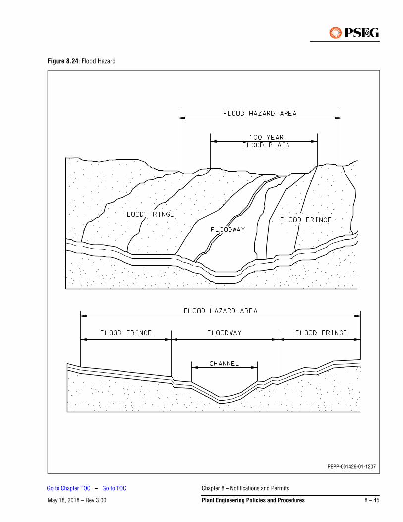
Figure 8.24: Flood Hazard
PEPP-001426-01-1207
Chapter 8 – Notifications and Permits
May 18, 2018 – Rev 3.00 Plant Engineering Policies and Procedures 8 – 45
Go to Chapter TOC – Go to TOC
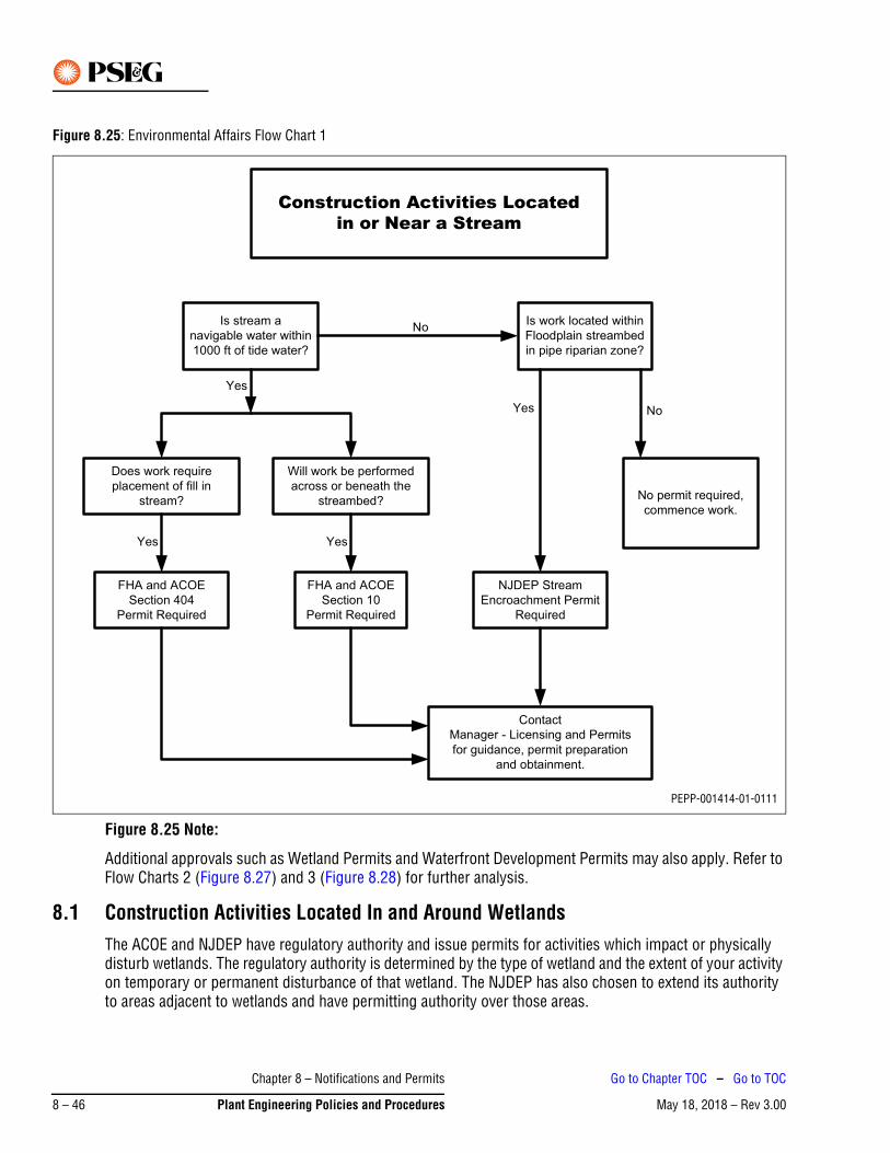
Figure 8.25: Environmental Affairs Flow Chart 1
Figure 8.25 Note:
Additional approvals such as Wetland Permits and Waterfront Development Permits may also apply. Refer to Flow Charts 2 (Figure 8.27) and 3 (Figure 8.28) for further analysis.
8.1 Construction Activities Located In and Around WetlandsThe ACOE and NJDEP have regulatory authority and issue permits for activities which impact or physically disturb wetlands. The regulatory authority is determined by the type of wetland and the extent of your activity on temporary or permanent disturbance of that wetland. The NJDEP has also chosen to extend its authority to areas adjacent to wetlands and have permitting authority over those areas.
Construction Activities Locatedin or Near a Stream
Is stream a
navigable water within
1000 ft of tide water?
Is work located within
Floodplain streambed
in pipe riparian zone?
Does work require
placement of fill in
stream?
Will work be performed
across or beneath the
streambed? No permit required,
commence work.
FHA and ACOE
Section 404
Permit Required
FHA and ACOE
Section 10
Permit Required
NJDEP Stream
Encroachment Permit
Required
Contact
Manager - Licensing and Permits
for guidance, permit preparation
and obtainment.
No
Yes
Yes
Yes
Yes
No
PEPP-001414-01-0111
Chapter 8 – Notifications and Permits
May 18, 2018 – Rev 3.008 – 46 Plant Engineering Policies and Procedures
Go to Chapter TOC – Go to TOC
Wetlands are referred to by a number of terms based on their location and characteristics. The terms addressed in this document are coastal wetlands, freshwater wetlands, and transition areas.
1. Coastal Wetland – any bank, marsh, swamp, meadow, flat or other low land subject to tidal action along the New Jersey coastline and inland waterways extending southerly from the Manasquan Inlet to Cape May Harbor or at any inlet, estuary or those areas now or formerly connected to tidal waters whose surface is at or below an elevation of 1 ft above local extreme high water, and upon which may grow or is capable of growing some, but not necessarily all, plant species listed on the New Jersey wetlands plant list for coastal areas. Coastal wetlands exclude any land or real property subject to the jurisdiction of the Hackensack Meadowlands.
2. Freshwater Wetland – an area that is inundated or saturated by surface water or ground water at a frequency and duration sufficient to support, and that under normal circumstances does support, a prevalence of vegetation typically adapted for life in saturated soil conditions; provided however that the New Jersey Department of Environmental Protection and Energy (NJDEPE), in designating a wetland, shall use the three-parameter approach (hydrology, soil, and vegetation) enumerated in the 1989 Federal Manual for Identifying and Delineating Jurisdictional Wetlands, and any subsequent amendments thereto incorporated herein by reference.
3. Transition Areas – an ecological buffer zone between uplands and freshwater wetlands which is an integral portion of the freshwater wetlands ecosystem, providing temporary refuge for freshwater wetlands fauna during high water episodes, critical habitat for animals dependent upon but not resident in freshwater wetlands, and slight variations of freshwater wetland boundaries over time due to hydrologic or climatologic effects. A transition area is also a sediment and storm water control zone to reduce the impacts of development upon freshwater wetlands and freshwater wetlands species.
The delineation of wetlands is a difficult science that requires specialized professionals to determine the presence and extent of the regulated area. They do not always appear like wetlands and no two are alike. Traditionally, wetlands were easy to identify. If there was ponding of water for a significantly long period of time or the ground was always muddy, one could say it may be a wetland. Today, the regulatory community has defined specific criteria for determining wetland areas. The U.S. ACOE utilize the 1987 manual and the NJDEP utilize the 1989 Federal Manual For Identifying and Delineating Wetlands. Figure 8.26 is a schematic diagram of different wetland habitats.
If any construction activity is to occur near or within a wetland, a state or federal approval is required; refer to Figure 8.27. If the project area is located within the Hackensack Meadowlands, the U.S. ACOE has jurisdiction and will issue a permit to proceed with the construction or repair work. All other areas are subject to the NJDEPE.
A transition area is required adjacent to freshwater wetlands within NJDEP jurisdiction. The width of a transition area “buffer” is determined by the wetland resource value classification. The NJDEP determines the resource value classification by assessing the wetlands proximity to threatened and endangered plant and animal species, trout maintenance and production streams, and EPA Priority Wetlands. Wetlands of exceptional resource value require a buffer of 150 ft. Wetlands of intermediate resource value require a buffer of 50 ft. Ordinary resource value wetlands do not require transition areas. All wetlands in highlands have a 300 ft riparian zone.
Chapter 8 – Notifications and Permits
May 18, 2018 – Rev 3.00 Plant Engineering Policies and Procedures 8 – 47
Go to Chapter TOC – Go to TOC
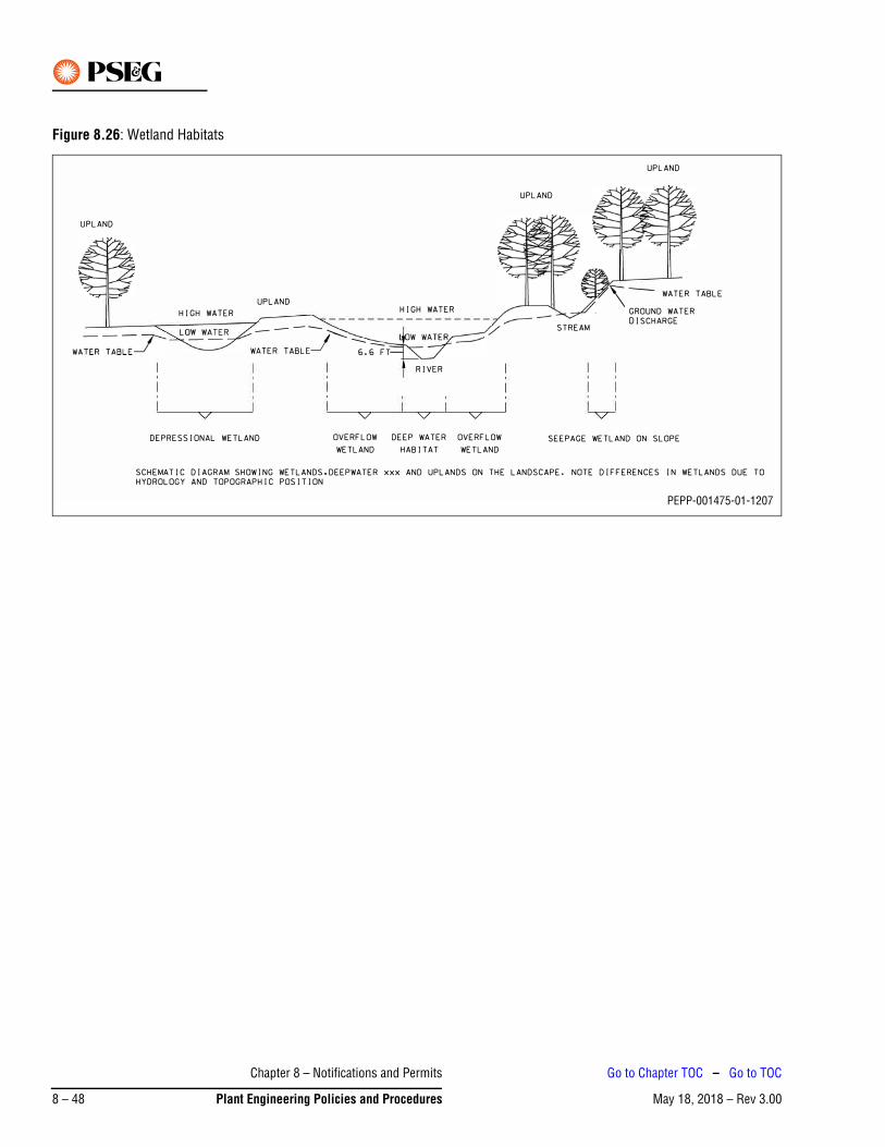
Figure 8.26: Wetland Habitats
PEPP-001475-01-1207
Chapter 8 – Notifications and Permits
May 18, 2018 – Rev 3.008 – 48 Plant Engineering Policies and Procedures
Go to Chapter TOC – Go to TOC
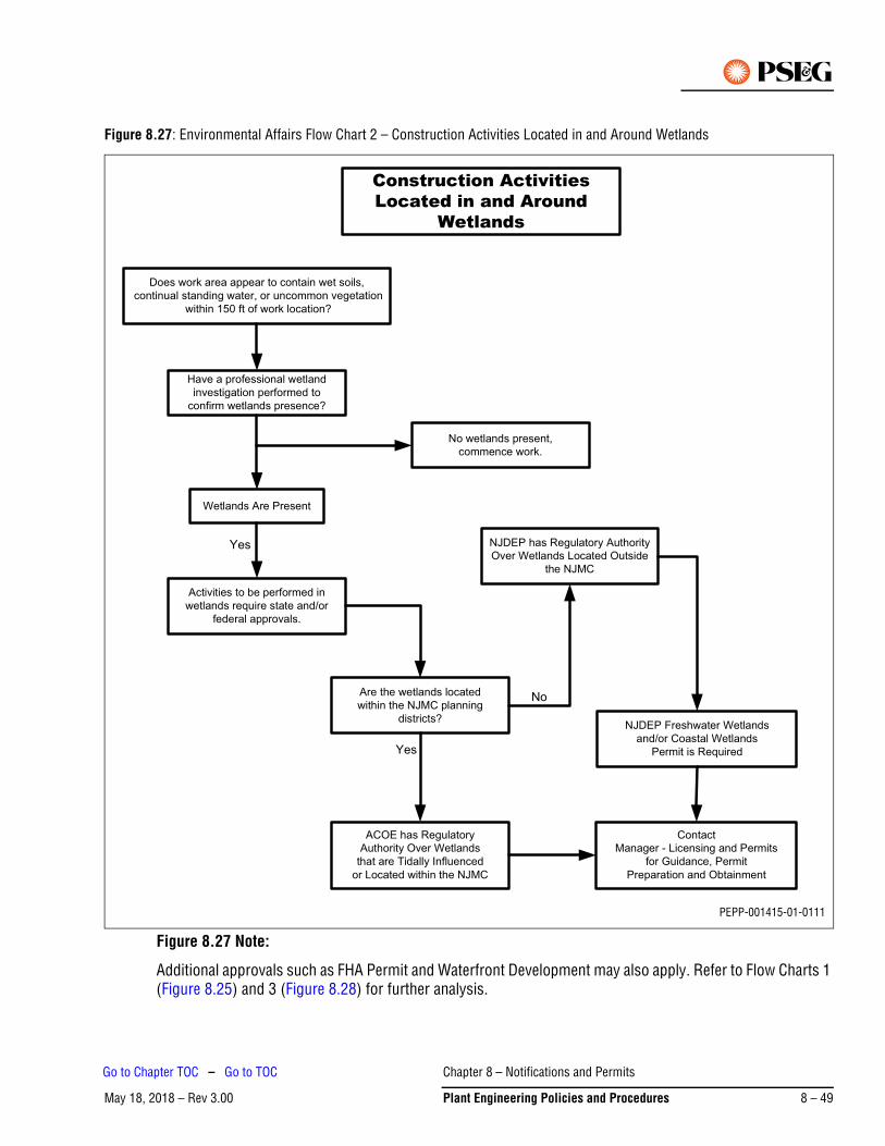
Figure 8.27: Environmental Affairs Flow Chart 2 – Construction Activities Located in and Around Wetlands
Figure 8.27 Note:
Additional approvals such as FHA Permit and Waterfront Development may also apply. Refer to Flow Charts 1 (Figure 8.25) and 3 (Figure 8.28) for further analysis.
Construction ActivitiesLocated in and Around
Wetlands
Environmental Affairs Flow Chart 2
Does work area appear to contain wet soils,
continual standing water, or uncommon vegetation
within 150 ft of work location?
Have a professional wetland
investigation performed to
confirm wetlands presence?
No wetlands present,
commence work.
Wetlands Are Present
Activities to be performed in
wetlands require state and/or
federal approvals.
Are the wetlands located
within the NJMC planning
districts?
NJDEP has Regulatory Authority
Over Wetlands Located Outside
the NJMC
NJDEP Freshwater Wetlands
and/or Coastal Wetlands
Permit is Required
ACOE has Regulatory
Authority Over Wetlands
that are Tidally Influenced
or Located within the NJMC
Contact
Manager - Licensing and Permits
for Guidance, Permit
Preparation and Obtainment
Yes
No
Yes
PEPP-001415-01-0111
Chapter 8 – Notifications and Permits
May 18, 2018 – Rev 3.00 Plant Engineering Policies and Procedures 8 – 49
Go to Chapter TOC – Go to TOC
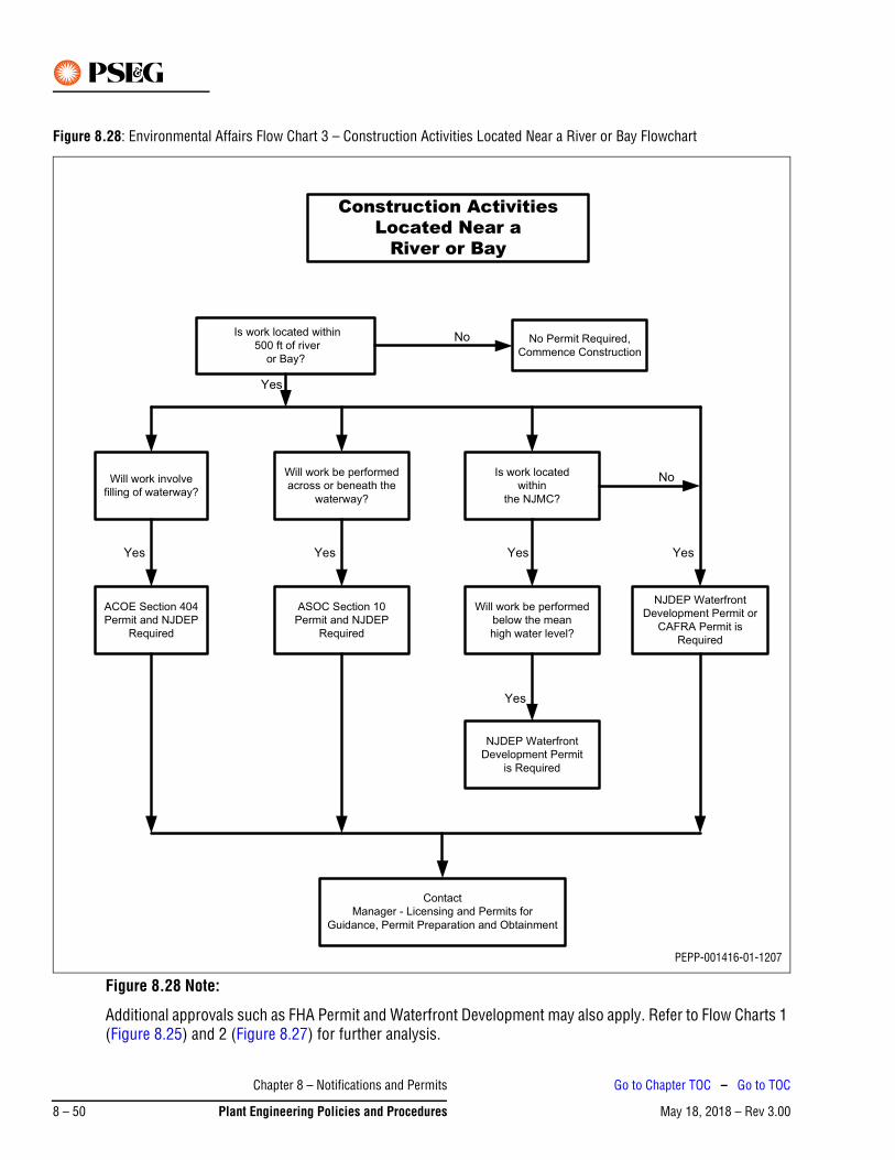
Figure 8.28: Environmental Affairs Flow Chart 3 – Construction Activities Located Near a River or Bay Flowchart
Figure 8.28 Note:
Additional approvals such as FHA Permit and Waterfront Development may also apply. Refer to Flow Charts 1 (Figure 8.25) and 2 (Figure 8.27) for further analysis.
Construction ActivitiesLocated Near a
River or Bay
Is work located within
500 ft of river
or Bay?
No Permit Required,
Commence Construction
Will work involve
filling of waterway?
NJDEP Waterfront
Development Permit or
CAFRA Permit is
Required
Will work be performed
across or beneath the
waterway?
Is work located
within
the NJMC?
ACOE Section 404
Permit and NJDEP
Required
ASOC Section 10
Permit and NJDEP
Required
Will work be performed
below the mean
high water level?
NJDEP Waterfront
Development Permit
is Required
Contact
Manager - Licensing and Permits for
Guidance, Permit Preparation and Obtainment
No
Yes
No
Yes
YesYes
Yes
Yes
PEPP-001416-01-1207
Chapter 8 – Notifications and Permits
May 18, 2018 – Rev 3.008 – 50 Plant Engineering Policies and Procedures
Go to Chapter TOC – Go to TOC
8.2 Construction Activities Located Near a River or BayThese waterways are the easiest to identify. However, the regulatory jurisdiction is determined by the type of activity and its location to regional planning areas. Figure 8.28 shows the regulatory jurisdiction based on specific types of activities and if work will be performed within the New Jersey Meadowlands Commission (NJMC).
Work activities that are located in or near a river may require multiple approvals from the NJDEP and possibly the ACOE. If the work location is within 500 ft of tidal river’s edge, a NJDEP Waterfront Development Permit is required. A FHA Permit is also required if the work activity is performed below the 100 year flood plain elevation or within the riparian zone. The ACOE permits discussed in previous section will also apply to rivers when filling, dredging or construction below the riverbed is performed.
8.3 Regional Planning DistrictsNew Jersey has two significant regional planning areas: the Pinelands and the Hackensack Meadowlands. These areas contain significant ecological and environmental value and require specific regulatory controls for development and construction activities. There are additional planning areas within New Jersey. These areas were created to manage specific areas in New Jersey with specific development controls to ensure protection of natural resources. These planning areas are the Delaware River Basin Commission and Delaware and Raritan Canal Commission. PSE&G regional electric division territories do encroach into these regional planning districts and areas. Contact the Manager, Licensing and Permits for specific regulatory requirements for each district and planning area that may apply to the electric division territory.
8.3.1 Pinelands
The New Jersey Legislature passed the Pinelands Protection Act in 1972 in order to control development within the Pinelands and to preserve its unique character and natural resources. No development may occur within the Pinelands unless the construction or work complies with the Pinelands Management Plan.
The Pinelands Commission is the regulatory authority within the Pinelands. The commission reviews applications for development and will approve, deny, or grant a waiver of the Management Plan. Waivers are granted only when it has been demonstrated that there exists an extraordinary hardship or compelling public need, that the development is consistent with the purpose of both the Pinelands Protection and Section 502 of the National Parks and Recreation Act, and that the activity will not substantially impair the resources of the area.
8.3.2 New Jersey Meadowlands
In 1968 the New Jersey Legislature passed the Hackensack Meadowlands Reclamation and Development Act in order to develop the Meadowlands in an orderly and comprehensive manner while preserving its delicate ecological balance.
The NJMC was empowered to adopt and implement the Meadowlands Master Plan and its regulations. All development and construction activities are required to be reviewed by the NJMC and receive a Zoning Certificate.
8.3.3 Delaware Raritan Canal Commission
The Delaware and Raritan State Park Law established the Delaware and Raritan Canal Park and created the Delaware and Raritan Canal Commission (D&RCC). The D&RCC’s function was to develop a master plan for the park and to establish a review zone in which both state and private activities in or near the canal would be reviewed. The Delaware and Raritan Canal was divided into two review zones: Zone A – 1,000 ft on either side of the canal and Zone B – a 400 sq mile area which encompasses the watersheds which drain into the canal.
Chapter 8 – Notifications and Permits
May 18, 2018 – Rev 3.00 Plant Engineering Policies and Procedures 8 – 51
Go to Chapter TOC – Go to TOC
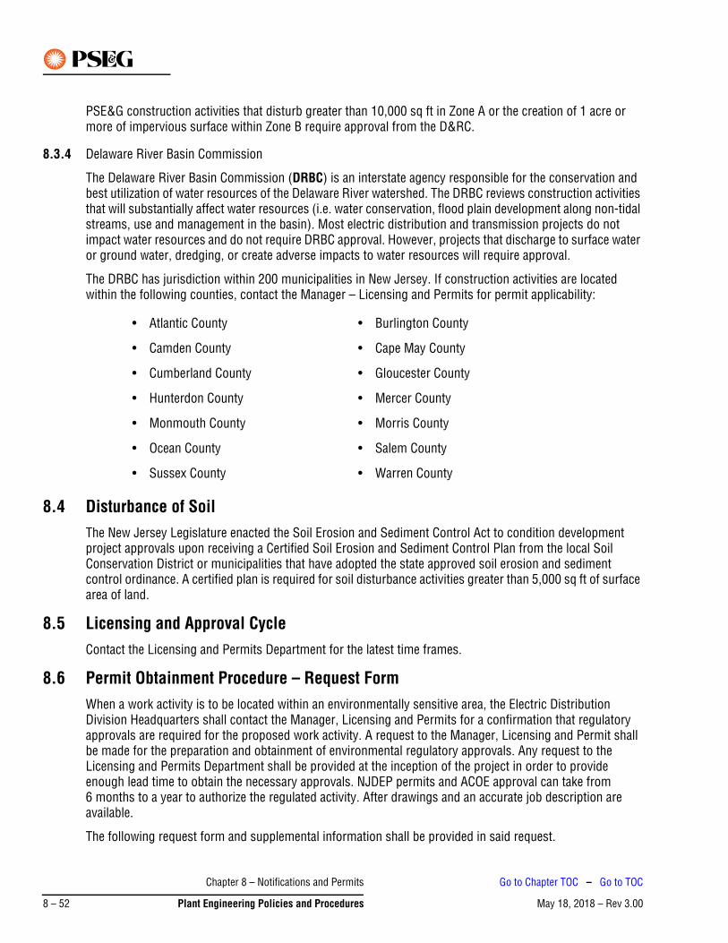
PSE&G construction activities that disturb greater than 10,000 sq ft in Zone A or the creation of 1 acre or more of impervious surface within Zone B require approval from the D&RC.
8.3.4 Delaware River Basin Commission
The Delaware River Basin Commission (DRBC) is an interstate agency responsible for the conservation and best utilization of water resources of the Delaware River watershed. The DRBC reviews construction activities that will substantially affect water resources (i.e. water conservation, flood plain development along non-tidal streams, use and management in the basin). Most electric distribution and transmission projects do not impact water resources and do not require DRBC approval. However, projects that discharge to surface water or ground water, dredging, or create adverse impacts to water resources will require approval.
The DRBC has jurisdiction within 200 municipalities in New Jersey. If construction activities are located within the following counties, contact the Manager – Licensing and Permits for permit applicability:
8.4 Disturbance of SoilThe New Jersey Legislature enacted the Soil Erosion and Sediment Control Act to condition development project approvals upon receiving a Certified Soil Erosion and Sediment Control Plan from the local Soil Conservation District or municipalities that have adopted the state approved soil erosion and sediment control ordinance. A certified plan is required for soil disturbance activities greater than 5,000 sq ft of surface area of land.
8.5 Licensing and Approval CycleContact the Licensing and Permits Department for the latest time frames.
8.6 Permit Obtainment Procedure – Request FormWhen a work activity is to be located within an environmentally sensitive area, the Electric Distribution Division Headquarters shall contact the Manager, Licensing and Permits for a confirmation that regulatory approvals are required for the proposed work activity. A request to the Manager, Licensing and Permit shall be made for the preparation and obtainment of environmental regulatory approvals. Any request to the Licensing and Permits Department shall be provided at the inception of the project in order to provide enough lead time to obtain the necessary approvals. NJDEP permits and ACOE approval can take from 6 months to a year to authorize the regulated activity. After drawings and an accurate job description are available.
The following request form and supplemental information shall be provided in said request.
• Atlantic County • Burlington County
• Camden County • Cape May County
• Cumberland County • Gloucester County
• Hunterdon County • Mercer County
• Monmouth County • Morris County
• Ocean County • Salem County
• Sussex County • Warren County
Chapter 8 – Notifications and Permits
May 18, 2018 – Rev 3.008 – 52 Plant Engineering Policies and Procedures
Go to Chapter TOC – Go to TOC
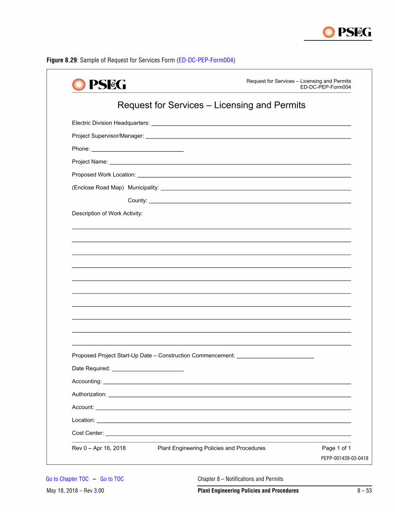
Figure 8.29: Sample of Request for Services Form (ED-DC-PEP-Form004)
PEPP-001439-03-0418
Chapter 8 – Notifications and Permits
May 18, 2018 – Rev 3.00 Plant Engineering Policies and Procedures 8 – 53
Go to Chapter TOC – Go to TOC
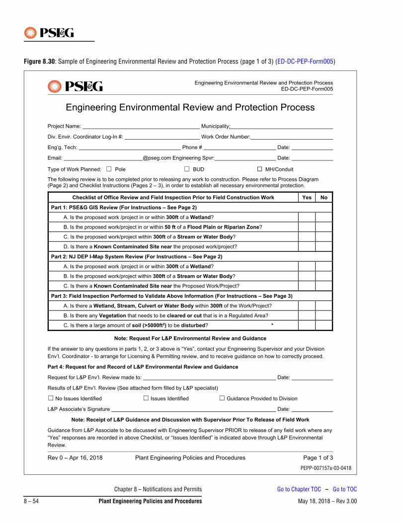
Figure 8.30: Sample of Engineering Environmental Review and Protection Process (page 1 of 3) (ED-DC-PEP-Form005)
PEPP-007157a-03-0418
Chapter 8 – Notifications and Permits
May 18, 2018 – Rev 3.008 – 54 Plant Engineering Policies and Procedures
Go to Chapter TOC – Go to TOC
Figure 8.31: Sample of Engineering Environmental Review and Protection Process (page 2 of 3) (ED-DC-PEP-Form005)
PEPP-007157b-03-0418
Chapter 8 – Notifications and Permits
May 18, 2018 – Rev 3.00 Plant Engineering Policies and Procedures 8 – 55
Go to Chapter TOC – Go to TOC
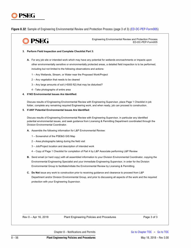
Figure 8.32: Sample of Engineering Environmental Review and Protection Process (page 3 of 3) (ED-DC-PEP-Form005)
PEPP-007157c-02-0511
Chapter 8 – Notifications and Permits
May 18, 2018 – Rev 3.008 – 56 Plant Engineering Policies and Procedures
Go to Chapter TOC – Go to TOC
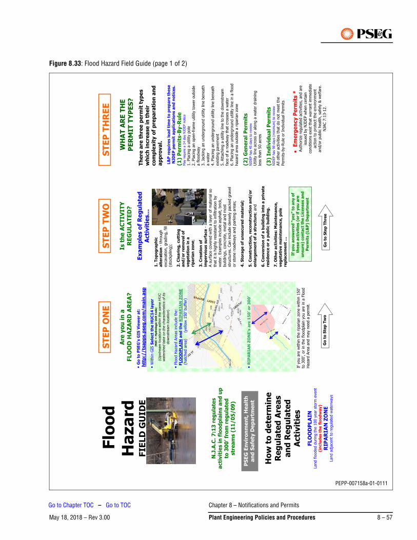
Figure 8.33: Flood Hazard Field Guide (page 1 of 2)
If y
ou
an
sw
ere
d “
ye
s” t
o a
ny o
f th
ese
acti
vit
ies (
or
if y
ou
are
un
su
re)
co
nta
ct
the
Lic
en
se
s a
nd
P
erm
its (
L&
P)
De
pa
rtm
en
t
Flo
od
Ha
za
rdFIE
LD
GU
ID
E
N.J
.A.C
. 7
:13
re
gu
late
s
acti
vit
ies i
n f
loo
dp
lain
s a
nd
up
to
30
0’ fr
om
re
gu
late
d
str
ea
ms (
11
/0
5/0
9)
Ho
w t
o d
ete
rmin
e
Re
gu
late
d A
rea
s
an
d R
eg
ula
ted
A
cti
vit
ies
FLO
OD
PLA
IN
Land
floo
ded
durin
g th
e 10
0 ye
ar s
torm
eve
nt(i
nclu
de
s t
he
flo
od
wa
y)
RIP
AR
IA
N Z
ON
E
Land
adj
acen
t to
regu
late
d w
ater
way
s
Are
yo
u i
n a
FLO
OD
HA
ZA
RD
AR
EA
?
Go
to
PS
EG
’s G
IS V
iew
er
at:
htt
p:/
/ts
ap
ps.p
se
g.c
om
/m
ain
.asp
With
in G
IS S
ele
ct
the
HU
C1
4 l
aye
r (H
UC
= H
yd
rolo
gic
Un
it C
od
e)
(Ups
tream
loca
tions
with
in th
e sa
me
HU
C
wat
ersh
ed ta
ke o
n th
e ch
arac
teris
tics
of it
s do
wns
tream
loca
tion)
Flo
od H
azar
d Ar
eas
inclu
de th
e:
FLO
OD
PLA
IN a
nd
th
e R
IPA
RIA
N Z
ON
E(h
atch
ed a
rea)
(
yello
w 1
50’ b
uffe
r)
RIP
AR
IAN
ZO
NE
’s a
re 1
50
’ o
r 3
00
’
If yo
u ar
e w
ithin
the
ripar
ian
zone
with
in 1
50’
to 3
00’,
or in
the
flood
plai
n yo
u ar
e in
a F
lood
Ha
zard
Are
a an
d m
ay n
eed
a pe
rmit.
Is t
he
AC
TIV
IT
Y
RE
GU
LA
TE
D?
Ex
am
ple
s o
f R
eg
ula
ted
A
cti
vit
ies…
1.
To
po
gra
ph
ic
alt
era
tio
n -
thro
ugh
exca
vatio
n, g
radi
ng, f
ill (s
tock
pilin
g);
2.
Cle
ari
ng
, cu
ttin
g
an
d/
or
rem
ova
l o
f v
eg
eta
tio
n i
n a
rip
ari
an
zo
ne;
3.
Cre
ati
on
of
imp
erv
iou
s s
urf
ace -
A su
rface
cov
ered
with
a la
yer o
f mat
eria
l so
that
it is
hig
hly
resis
tant
to in
filtra
tion
by
wat
er. E
xam
ples
inclu
de a
spha
lt, b
rick,
bu
ildin
gs, c
oncr
ete,
met
al a
nd m
ost
stru
ctur
es. C
an in
clude
den
sely
pac
ked
grav
el
or s
tone
road
way
s an
d pa
rkin
g ar
eas;
4.
Sto
rag
e o
f u
nse
cu
red
ma
teri
al;
5.
Co
nstr
ucti
on
, re
co
nstr
ucti
on
an
d/o
r e
nla
rge
me
nt
of
a s
tru
ctu
re; a
nd
6.
Co
nv
ers
ion
of
a b
uil
din
g i
nto
a p
riva
te
resid
en
ce
or
a p
ub
lic b
uil
din
g.
7.
Oth
er
acti
vit
ies:
Ma
inte
na
nce
, v
eg
eta
tiv
e m
ain
ten
an
ce
, p
ole
re
pla
ce
me
nt
…
WH
AT
AR
E T
HE
P
ER
MIT
TY
PE
S?
Th
ere
are
th
ree
pe
rmit
typ
es
wh
ich
in
cre
ase
in
th
eir
co
mp
lex
ity o
f p
rep
ara
tio
n a
nd
a
pp
rova
l.
L&
P r
eq
uir
es l
ea
d t
ime
to
pre
pa
re t
he
se
N
JD
EP
pe
rmit
ap
pli
ca
tio
ns a
nd
no
tice
s.
(1)
Pe
rmit
s-B
y-R
ule
M
ay re
quire
a 1
4 da
y NJ
DEP
notic
e1.
Pla
cing
a ut
ility
pole
2.
Pla
cing
an o
pen-
fram
e ut
ility
tow
er o
utsid
e a
flood
way
3.
Jac
king
an
unde
rgro
und
utilit
y lin
e be
neat
h a
wat
er
4. P
lacin
g an
und
ergr
ound
util
ity li
ne b
enea
th
exist
ing
pave
men
t 5.
Atta
chin
g a
utilit
y lin
e to
the
dow
nstre
am
face
of a
road
way
that
cro
sses
a w
ater
6.
Pla
cing
an u
nder
grou
nd u
tility
line
in a
floo
d ha
zard
are
a ou
tsid
e a
ripar
ian
zone
(2)
Ge
ne
ral
Pe
rmit
s
NJDE
P ha
s 45
day
s to
revie
wUt
ility
line
acro
ss o
r alo
ng a
wat
er d
rain
ing
less
than
50
acre
s
(3)
Ind
ivid
ua
l P
erm
its
NJDE
P ha
s 90
day
s (m
inim
um) t
o re
view
All o
ther
act
iviti
es th
at d
o no
t mee
t the
Pe
rmits
-by-
Rule
or I
ndiv
idua
l Per
mits
Em
erg
en
cy P
erm
its *
Auth
orize
regu
late
d ac
tiviti
es, a
nd a
re
issue
d by
NJD
EP w
hen
certa
in
cond
ition
s ex
ist th
at w
arra
nt im
med
iate
ac
tion
to p
rote
ct th
e en
viron
men
t an
d/or
pub
lic h
ealth
, saf
ety
& w
elfa
re.
NJAC
7:1
3-12
.
ST
EP
ON
ES
TE
P T
WO
ST
EP
TH
RE
E
PS
EG
En
vir
on
me
nt,
He
alt
h
an
d S
afe
ty D
ep
art
me
nt
Go
to
Ste
p T
wo
Go
to
Ste
p T
hre
e
PEPP-007158a-01-0111
Chapter 8 – Notifications and Permits
May 18, 2018 – Rev 3.00 Plant Engineering Policies and Procedures 8 – 57
Go to Chapter TOC – Go to TOC
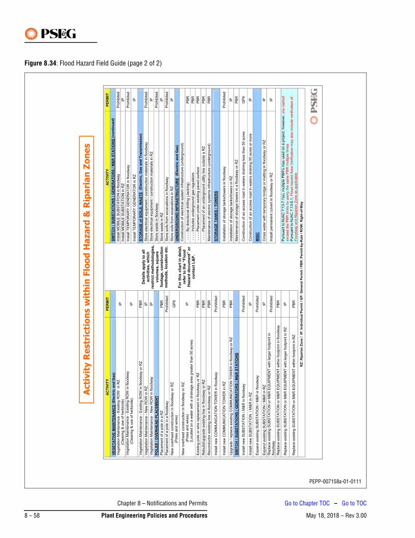
Figure 8.34: Flood Hazard Field Guide (page 2 of 2)
ACTI
VITY
PE
RM
IT
ACTI
VITY
PE
RMIT
VE
GET
ATIV
E M
AIN
TEN
ANC
E (E
lect
ric a
nd G
as)
SWIT
CH
/SU
BST
ATIO
NS
/ GEN
ERAT
OR
S / M
&R
STA
TIO
NS
(con
tinue
d)
Insta
ll M
OB
ILE
SU
BS
TA
TIO
N in f
loodw
ay
Pro
hib
ited
V
eg
eta
tion M
ain
tenance -
Exis
ting R
OW
in
RZ
(C
learing &
use o
f herb
icid
e)
IPIn
sta
ll M
OB
ILE
SU
BS
TA
TIO
N in R
Z
IP
Insta
ll T
EM
PO
RA
RY
GE
NE
RA
TO
R in flo
odw
ay
Pro
hib
ited
V
eg
eta
tion M
ain
tenance -
Exis
ting R
OW
in flo
odw
ay
(
Cle
aring
& u
se o
f herb
icid
e)
IPIn
sta
ll T
EM
PO
RA
RY
GE
NE
RA
TO
R in R
Z
IP
Veg
eta
tion M
ain
tenance -
Exis
ting R
OW
in flo
odw
ay o
r R
Z
PB
R
STO
RAG
E of
SO
ILS,
WAS
TE (
Elec
tric
, Gas
and
Tra
nsm
issi
on)
Veg
eta
tion M
ain
tenance -
New
RO
W in R
Z
IP
Sto
re e
lectr
ical equip
ment /
constr
uction m
ate
rials
in f
loodw
ay
Pro
hib
ited
Veg
eta
tion M
ain
tenance -
New
RO
W in f
loodw
ay
IP
Sto
re e
lectr
ical equip
ment /
constr
uction m
ate
rials
in R
Z
IP
POLE
S / O
VER
HEA
D P
LAC
EMEN
T
Sto
re w
aste
in flo
odw
ay
Pro
hib
ited
Pla
cem
ent of a p
ole
in a
RZ
P
BR
S
tore
waste
in R
Z
IP
Pla
cem
ent of a p
ole
in a
flo
odw
ay
Pro
hib
ited
Sto
re s
oils
fro
m e
xcavations in f
loodw
ay
Pro
hib
ited
Sto
re s
oils
fro
m e
xcavations in R
Z
IP
New
overh
ead c
onstr
uction in flo
odw
ay o
r R
Z
(P
ole
s a
nd
wire
s)
GP
8
UND
ERG
ROUN
D IN
FRAS
TRU
CTU
RE
(Ele
ctric
and
Gas
) C
onstr
uction o
f ele
ctr
ical syste
m infr
astr
uctu
re (
underg
round)
- -
- -
By d
irectional drilli
ng (
Jackin
g)
PB
R
New
overh
ead c
onstr
uction in f
loodw
ay o
r R
Z
(
Po
les a
nd
wire
s)
(
Locate
d o
n a
wate
r w
ith a
dra
inag
e a
rea g
reate
r th
an 5
0 a
cre
s)
IP
- -
- -
Inclu
des u
nderg
round g
as r
egula
tors
P
BR
Exis
ting p
ole
or
wire r
epla
cem
ent in
flo
odw
ay o
r R
Z
PB
R
- -
- -
Pla
cem
ent under
exis
ting
paved s
urf
ace
PB
R
Rebuild
/upg
rade e
xis
ting lin
e in flo
odw
ay o
r R
Z
PB
R
- -
- -
Pla
cem
ent of an u
nderg
round u
tilit
y lin
e o
uts
ide a
RZ
P
BR
Reconducto
r exis
ting
lin
e in flo
odw
ay o
r R
Z
PB
R
Ma
inte
nance o
f ele
ctr
ic s
yste
ms infr
astr
uctu
re (
underg
round)
PB
R
Insta
ll new
CO
MM
UN
ICA
TIO
N T
OW
ER
in f
loodw
ay
Pro
hib
ited
STO
RAG
E TA
NK
S / T
OW
ERS
Insta
ll new
CO
MM
UN
ICA
TIO
N T
OW
ER
in R
Z
PB
R
Deta
ils a
pply
to a
ll ac
tiviti
es, w
hich
re
stric
t met
hodo
logi
es,
volu
mes
, squ
are
foot
age,
con
stru
ctio
n m
etho
ds, l
ocat
ion
etc.
For t
his
char
t in
deta
il,
refe
r to
the
“Flo
od
Haza
rd d
ocum
ent”
or
cont
act L
&P.
Insta
llation o
f sto
rag
e tanks/tow
ers
in f
loodw
ay
Pro
hib
ited
Upg
rade / r
epla
ce e
xis
ting C
OM
MU
NIC
AT
ION
TO
WE
R in f
loodw
ay o
r R
Z
PB
R
Insta
llation o
f sto
rag
e tanks/tow
ers
in R
Z
IP
SWIT
CH /
SUBS
TATI
ONS
/ G
ENER
ATO
RS
/ M&
R S
TATI
ONS
M
ain
tenance o
f sto
rag
e tow
ers
in a
flo
odw
ay o
r R
Z
PB
R
Insta
ll new
SU
BS
TA
TIO
N / M
&R
in flo
odw
ay
Pro
hib
ited
Constr
uction o
f an a
ccess r
oad in w
ate
rs d
rain
ing less than 5
0 a
cre
s
GP
9
Insta
ll new
SU
BS
TA
TIO
N / M
&R
in R
Z
IP
Constr
uction o
f an a
ccess r
oad in w
ate
rs d
rain
ing 5
0 a
cre
s o
r m
ore
IP
Expand e
xis
ting
SU
BS
TA
TIO
N / M
&R
in f
loodw
ay
Pro
hib
ited
MIS
C
Expand e
xis
ting
SU
BS
TA
TIO
N / M
&R
in R
Z
IP
Cro
ss w
ate
r w
ith tem
pora
ry b
ridge o
r m
attin
g in f
loodw
ay o
r R
Z
IP
Repla
ce e
xis
ting
SU
BS
TA
TIO
N o
r M
&R
EQ
UIP
ME
NT
with larg
er
footp
rint in
floodw
ay
Pro
hib
ited
Insta
ll perm
anent
culv
ert
in flo
odw
ay o
r R
Z
IP
Repla
ce e
xis
ting
SU
BS
TA
TIO
N o
r M
&R
EQ
UIP
ME
NT
within
footp
rint in
flo
odw
ay
PB
R
Repla
ce e
xis
ting
SU
BS
TA
TIO
N o
r M
&R
EQ
UIP
ME
NT
with larg
er
footp
rint in
RZ
IP
P
urs
uant to
NJA
C 7
:13-7
.1(e
), m
ultip
le P
BR
's m
ay u
sed o
n a
pro
ject, h
ow
ever,
you c
annot
exceed the P
BR
lim
its b
y u
sin
g t
he s
am
e P
BR
multip
le t
imes
Repla
ce e
xis
ting
SU
BS
TA
TIO
N o
r M
&R
EQ
UIP
ME
NT
within
footp
rint in
RZ
P
BR
P
urs
uant to
NJA
C 7
:13-6
.1,
Flo
od h
azard
Are
a V
erification m
ay a
lso inclu
de v
erification o
f F
lood
way a
nd R
iparian Z
one a
s a
pplic
able
RZ:
Rip
aria
n Zo
ne /
IP: I
ndiv
idua
l Per
mit
/ GP:
Gen
eral
Per
mit
/ PB
R: P
erm
it-by
-Rul
e / R
OW
: Rig
ht-o
f-Way
A
cti
vit
y R
estr
icti
on
s w
ith
in F
loo
d H
aza
rd &
Rip
ari
an
Zo
ne
s
PEPP-007158a-01-0111
Chapter 8 – Notifications and Permits
May 18, 2018 – Rev 3.008 – 58 Plant Engineering Policies and Procedures
Go to Chapter TOC – Go to TOC
May 18, 2018 – Rev 3.00Go to Chapter TOC
Chapter 9 – Costs and Estimates – Table of Contents1. Use of Actual or Estimated Costs . . . . . . . . . . . . . . . . . . . . . . . . . . . . . . . . . . . . . . . . . . . . . . . . . 9-1
1.1 General Policy . . . . . . . . . . . . . . . . . . . . . . . . . . . . . . . . . . . . . . . . . . . . . . . . . . . . . . . . . . . . . . . . . . .9-1
1.2 Exceptions . . . . . . . . . . . . . . . . . . . . . . . . . . . . . . . . . . . . . . . . . . . . . . . . . . . . . . . . . . . . . . . . . . . . . .9-1
1.3 Time Period for True-Ups. . . . . . . . . . . . . . . . . . . . . . . . . . . . . . . . . . . . . . . . . . . . . . . . . . . . . . . . . . .9-1
2. Distribution Estimating System . . . . . . . . . . . . . . . . . . . . . . . . . . . . . . . . . . . . . . . . . . . . . . . . . . . 9-1
3. Smart Growth Tool . . . . . . . . . . . . . . . . . . . . . . . . . . . . . . . . . . . . . . . . . . . . . . . . . . . . . . . . . . . . 9-2
4. BUD Estimating Tool . . . . . . . . . . . . . . . . . . . . . . . . . . . . . . . . . . . . . . . . . . . . . . . . . . . . . . . . . . . 9-4
4.1 Single Family Differential Worksheet . . . . . . . . . . . . . . . . . . . . . . . . . . . . . . . . . . . . . . . . . . . . . . . . . .9-4
4.2 Multi Family / Mixed Use BUD Differential Estimate Worksheet . . . . . . . . . . . . . . . . . . . . . . . . . . . . . .9-5
5. Street Light Smart Growth Tool. . . . . . . . . . . . . . . . . . . . . . . . . . . . . . . . . . . . . . . . . . . . . . . . . . . 9-6
6. Work Done at the Expense of Others . . . . . . . . . . . . . . . . . . . . . . . . . . . . . . . . . . . . . . . . . . . . . . . 9-7
6.1 Estimating for Work Done at The Expense of Others . . . . . . . . . . . . . . . . . . . . . . . . . . . . . . . . . . . . . .9-7
6.2 Temporary Services . . . . . . . . . . . . . . . . . . . . . . . . . . . . . . . . . . . . . . . . . . . . . . . . . . . . . . . . . . . . . . .9-7
Chapter 9 – Costs and Estimates – Table of Contents
May 18, 2018 – Rev 3.00 Plant Engineering Policies and Procedures 9 – TOC 1
Go to TOC

This Page Intentionally Blank
Chapter 9 – Costs and Estimates – Table of Contents
May 18, 2018 – Rev 3.009 – TOC 2 Plant Engineering Policies and Procedures
Go to TOC
May 18, 2018 – Rev 3.00
Chapter 9 – Costs and Estimates
1. Use of Actual or Estimated Costs
1.1 General PolicyIn all situations, other than those exceptions specifically identified below, the cost estimated prior to actual construction shall be utilized in the determination of charges to customers. These costs are not subject to true-up after the fact.
1.2 ExceptionsIf the total cost of construction (i.e. capital projects) is expected to be less than $250,000, adjustments to specific portions of jobs utilizing estimated costs may be made in cases where a large portion of the cost is related to construction of underground facilities (such as conduit). In these cases, the written cost estimate provided to the customer shall include a statement that the costs may be higher than estimated if severe conditions, such as excessive rock or other unknown underground facilities, are found during excavation. This estimate shall include commonly incurred incremental costs on a per unit basis, such as the cost per foot of blasting through excessive rock. If incurred, these incremental costs shall be collected from the customer upon completion of the incremental work.
If the total cost of construction is expected to equal or exceed $250,000, then the estimated costs are subject to true-up to actual costs, either higher or lower.
1.3 Time Period for True-UpsAll true-ups to actual costs should be performed as soon as practicable after the completion of the job. If such true-up to actual costs cannot be completed within 6 months of the completion of the job, the customer is to be notified in writing of the expected completion date of the true-up.
2. Distribution Estimating SystemThe Distribution Estimating System for construction work is a Microsoft Access database application located on the corporate network at \\njnwkfp10\Entapps10\. (This drive is normally mapped as the “K” drive). Directions for using this system are also located on this drive as well as on the “Policy & Training Docs” Page of the Consolidated Manager Intranet Website located at http://njelizdev01/PG_CM_HOME.asp.
The system utilizes user input data, construction codes, and formulas to generate estimates. Users input the applicable construction codes and required number of units for the project. Also input are O&M dollars, cost of removal, months for escalation, salvage value, and difficulty factors. Construction codes are in standard units of 1000 ft for each, depending on the unit of work, and include folio items/prices (automatically updated by SAP) and man-hour estimates per unit. Users have the ability to update/modify construction
Refer also to the PSE&G Electric and Gas Tariff Policies (also known as the Tariff Policy Manual).Note
Chapter 9 – Costs and Estimates
May 18, 2018 – Rev 3.00 Plant Engineering Policies and Procedures 9 – 1
Go to Chapter TOC – Go to TOC
codes to reflect new materials and/or actual Division operating conditions. The system uses formulas to calculate appropriate labor and material loading and a detailed estimate of costs.
3. Smart Growth ToolThe Smart Growth Tool is a Microsoft Excel spreadsheet located in the New Business Page of the Consolidated Manager Intranet Website. The address is http://njelizdev01/PG_CM_HOME.asp.
This tool is used to input job cost and projected customer revenue in order to determine if a contribution or deposit (including gross-up) is required. All cells shaded in yellow are data input, while cells shaded in blue are labels or calculated fields not available for data input. The cells to the left of the section vertically labeled “USE DATA TO THE LEFT IN DWMS” is to be copied and pasted into the long text field of the 24ET Task of the E1 notification.
The Distribution Estimating System should be used to derive estimated costs for large relocation work (such as for the DOT), system reinforcement, Distribution Circuit Reinforcement (DCR), and other large projects that are in the early stages of planning and/or have a low probability of being completed in the near term.The estimated costs for other smaller projects (such as New Business) that have a high probability of being completed in the near term should be derived from newly created SAP work orders.
Note
Chapter 9 – Costs and Estimates
May 18, 2018 – Rev 3.009 – 2 Plant Engineering Policies and Procedures
Go to Chapter TOC – Go to TOC
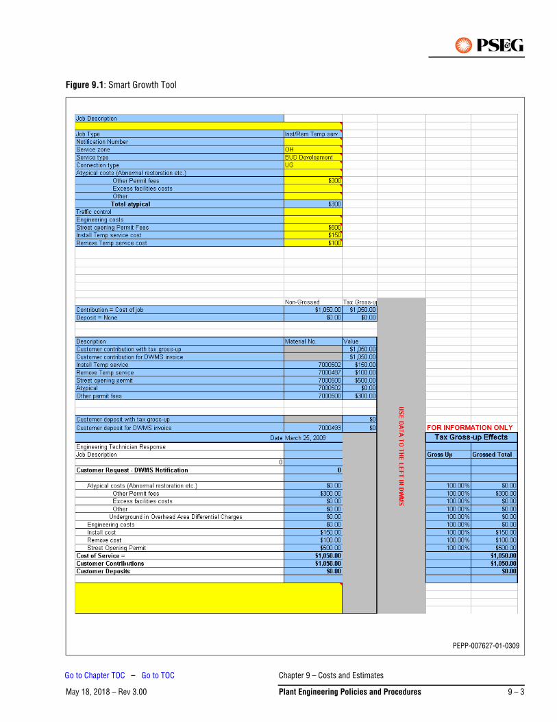
Figure 9.1: Smart Growth Tool
PEPP-007627-01-0309
Chapter 9 – Costs and Estimates
May 18, 2018 – Rev 3.00 Plant Engineering Policies and Procedures 9 – 3
Go to Chapter TOC – Go to TOC
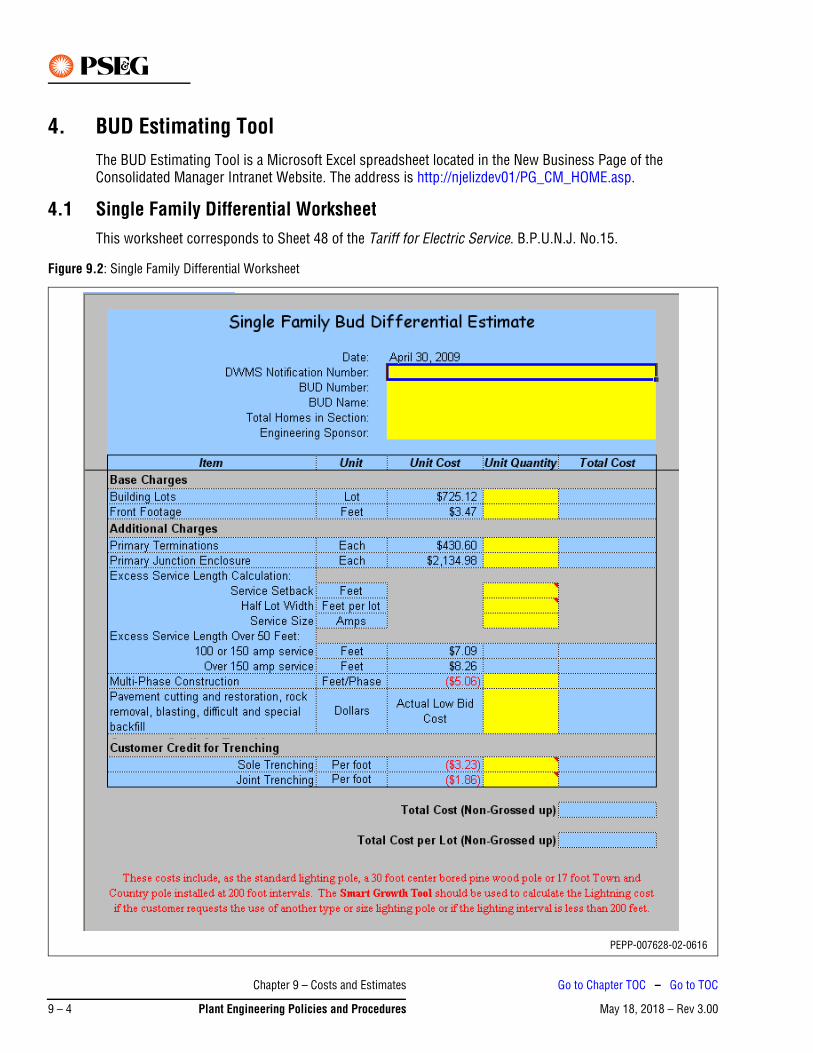
4. BUD Estimating ToolThe BUD Estimating Tool is a Microsoft Excel spreadsheet located in the New Business Page of the Consolidated Manager Intranet Website. The address is http://njelizdev01/PG_CM_HOME.asp.
4.1 Single Family Differential WorksheetThis worksheet corresponds to Sheet 48 of the Tariff for Electric Service. B.P.U.N.J. No.15.
Figure 9.2: Single Family Differential Worksheet
PEPP-007628-02-0616
Chapter 9 – Costs and Estimates
May 18, 2018 – Rev 3.009 – 4 Plant Engineering Policies and Procedures
Go to Chapter TOC – Go to TOC
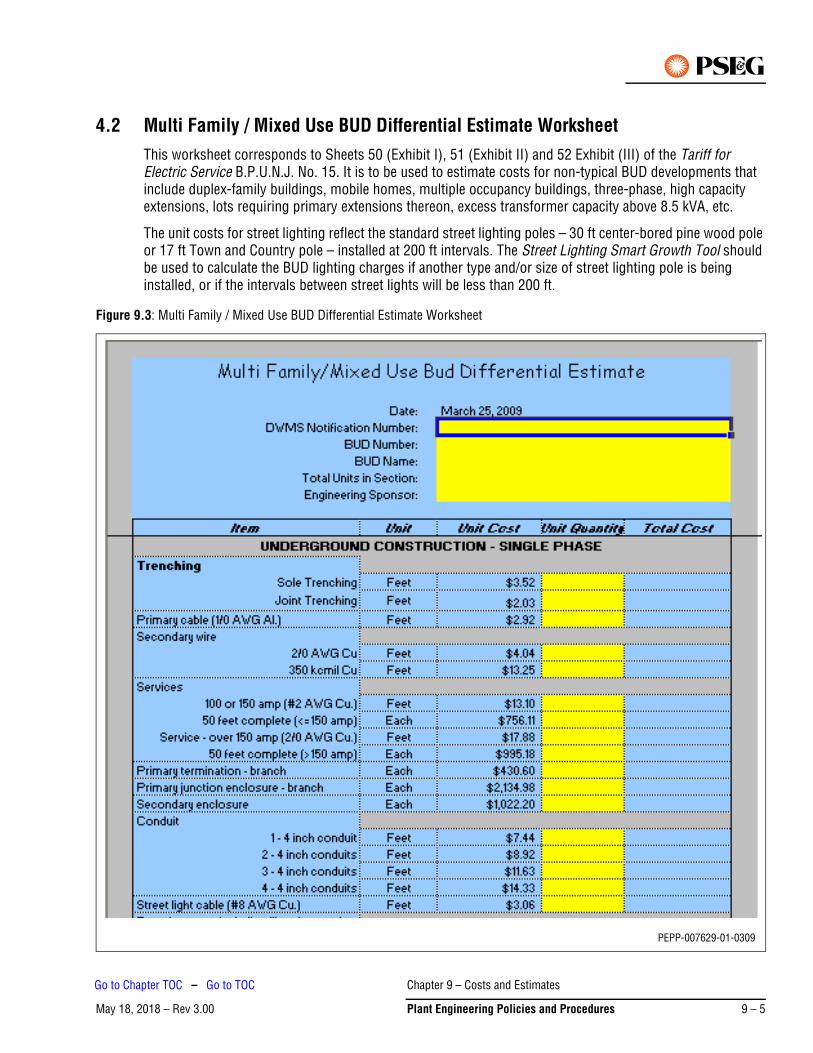
4.2 Multi Family / Mixed Use BUD Differential Estimate WorksheetThis worksheet corresponds to Sheets 50 (Exhibit I), 51 (Exhibit II) and 52 Exhibit (III) of the Tariff for Electric Service B.P.U.N.J. No. 15. It is to be used to estimate costs for non-typical BUD developments that include duplex-family buildings, mobile homes, multiple occupancy buildings, three-phase, high capacity extensions, lots requiring primary extensions thereon, excess transformer capacity above 8.5 kVA, etc.
The unit costs for street lighting reflect the standard street lighting poles – 30 ft center-bored pine wood pole or 17 ft Town and Country pole – installed at 200 ft intervals. The Street Lighting Smart Growth Tool should be used to calculate the BUD lighting charges if another type and/or size of street lighting pole is being installed, or if the intervals between street lights will be less than 200 ft.
Figure 9.3: Multi Family / Mixed Use BUD Differential Estimate Worksheet
PEPP-007629-01-0309
Chapter 9 – Costs and Estimates
May 18, 2018 – Rev 3.00 Plant Engineering Policies and Procedures 9 – 5
Go to Chapter TOC – Go to TOC
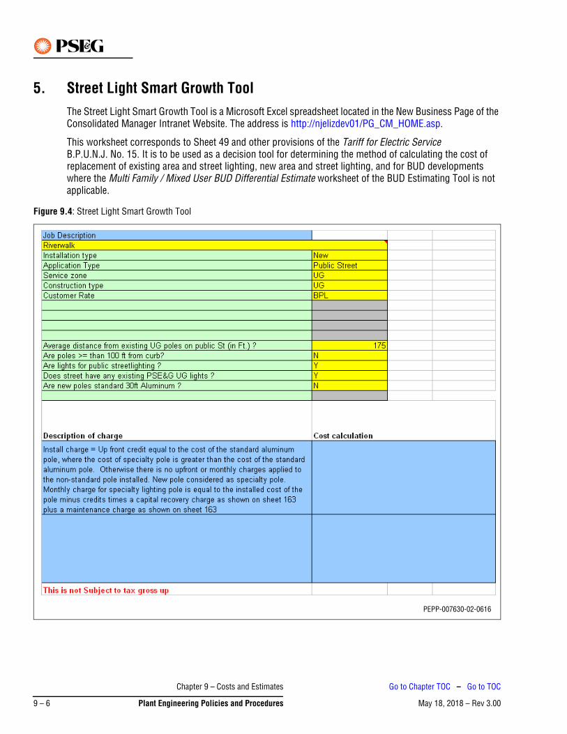
5. Street Light Smart Growth ToolThe Street Light Smart Growth Tool is a Microsoft Excel spreadsheet located in the New Business Page of the Consolidated Manager Intranet Website. The address is http://njelizdev01/PG_CM_HOME.asp.
This worksheet corresponds to Sheet 49 and other provisions of the Tariff for Electric Service B.P.U.N.J. No. 15. It is to be used as a decision tool for determining the method of calculating the cost of replacement of existing area and street lighting, new area and street lighting, and for BUD developments where the Multi Family / Mixed User BUD Differential Estimate worksheet of the BUD Estimating Tool is not applicable.
Figure 9.4: Street Light Smart Growth Tool
PEPP-007630-02-0616
Chapter 9 – Costs and Estimates
May 18, 2018 – Rev 3.009 – 6 Plant Engineering Policies and Procedures
Go to Chapter TOC – Go to TOC
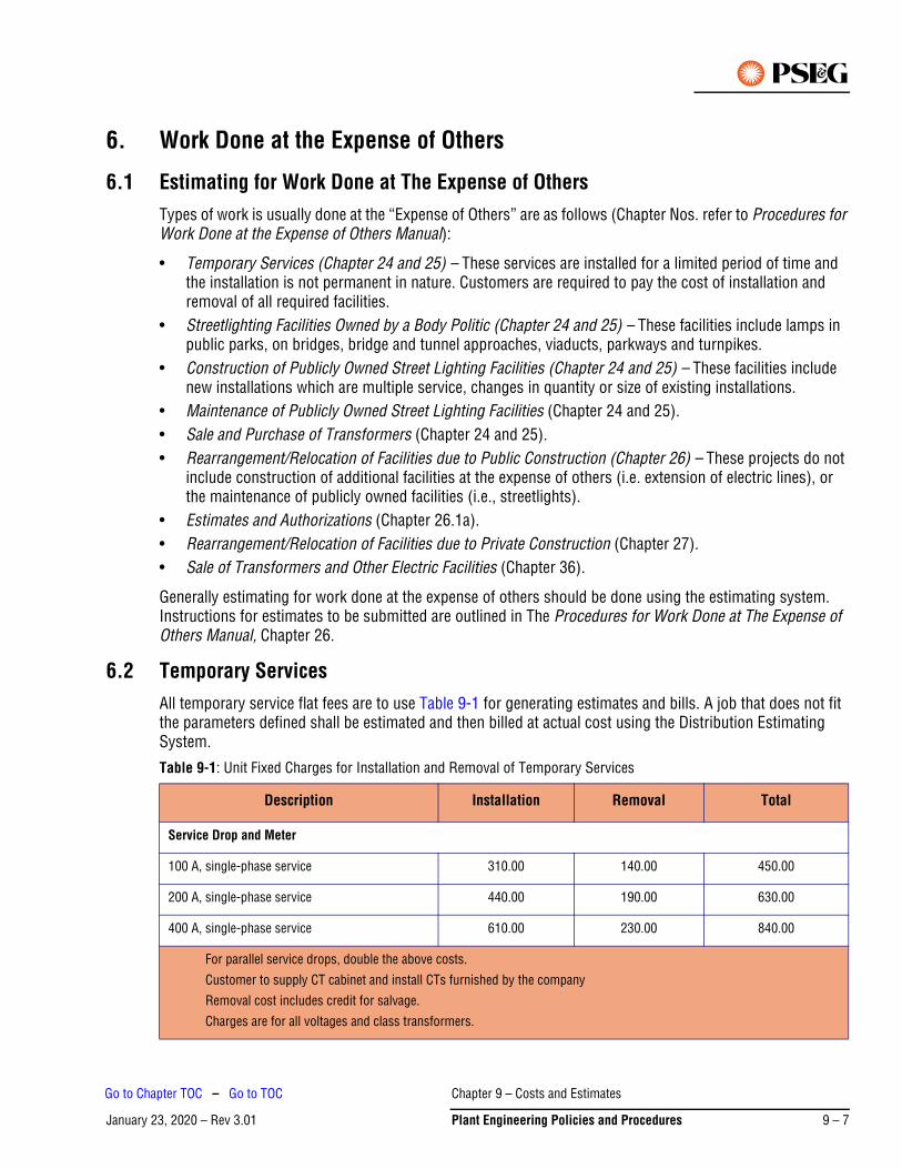
January 23, 2020 – Rev 3.01
6. Work Done at the Expense of Others
6.1 Estimating for Work Done at The Expense of OthersTypes of work is usually done at the “Expense of Others” are as follows (Chapter Nos. refer to Procedures for Work Done at the Expense of Others Manual):
• Temporary Services (Chapter 24 and 25) – These services are installed for a limited period of time and the installation is not permanent in nature. Customers are required to pay the cost of installation and removal of all required facilities.
• Streetlighting Facilities Owned by a Body Politic (Chapter 24 and 25) – These facilities include lamps in public parks, on bridges, bridge and tunnel approaches, viaducts, parkways and turnpikes.
• Construction of Publicly Owned Street Lighting Facilities (Chapter 24 and 25) – These facilities include new installations which are multiple service, changes in quantity or size of existing installations.
• Maintenance of Publicly Owned Street Lighting Facilities (Chapter 24 and 25).• Sale and Purchase of Transformers (Chapter 24 and 25).• Rearrangement/Relocation of Facilities due to Public Construction (Chapter 26) – These projects do not
include construction of additional facilities at the expense of others (i.e. extension of electric lines), or the maintenance of publicly owned facilities (i.e., streetlights).
• Estimates and Authorizations (Chapter 26.1a).• Rearrangement/Relocation of Facilities due to Private Construction (Chapter 27).• Sale of Transformers and Other Electric Facilities (Chapter 36).
Generally estimating for work done at the expense of others should be done using the estimating system. Instructions for estimates to be submitted are outlined in The Procedures for Work Done at The Expense of Others Manual, Chapter 26.
6.2 Temporary ServicesAll temporary service flat fees are to use Table 9-1 for generating estimates and bills. A job that does not fit the parameters defined shall be estimated and then billed at actual cost using the Distribution Estimating System.
Table 9-1: Unit Fixed Charges for Installation and Removal of Temporary Services
Description Installation Removal Total
Service Drop and Meter
100 A, single-phase service 310.00 140.00 450.00
200 A, single-phase service 440.00 190.00 630.00
400 A, single-phase service 610.00 230.00 840.00
For parallel service drops, double the above costs.
Customer to supply CT cabinet and install CTs furnished by the company
Removal cost includes credit for salvage.
Charges are for all voltages and class transformers.
Chapter 9 – Costs and Estimates
January 23, 2020 – Rev 3.01 Plant Engineering Policies and Procedures 9 – 7
Go to Chapter TOC – Go to TOC
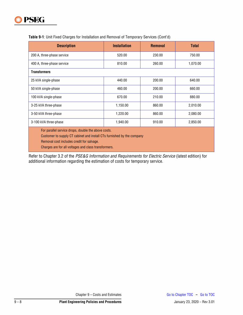
Refer to Chapter 3.2 of the PSE&G Information and Requirements for Electric Service (latest edition) for additional information regarding the estimation of costs for temporary service.
200 A, three-phase service 520.00 230.00 750.00
400 A, three-phase service 810.00 260.00 1,070.00
Transformers
25 kVA single-phase 440.00 200.00 640.00
50 kVA single-phase 460.00 200.00 660.00
100 kVA single-phase 670.00 210.00 880.00
3-25 kVA three-phase 1,150.00 860.00 2,010.00
3-50 kVA three-phase 1,220.00 860.00 2,080.00
3-100 kVA three-phase 1,940.00 910.00 2,850.00
Table 9-1: Unit Fixed Charges for Installation and Removal of Temporary Services (Cont’d)
Description Installation Removal Total
For parallel service drops, double the above costs.
Customer to supply CT cabinet and install CTs furnished by the company
Removal cost includes credit for salvage.
Charges are for all voltages and class transformers.
Chapter 9 – Costs and Estimates
January 23, 2020 – Rev 3.019 – 8 Plant Engineering Policies and Procedures
Go to Chapter TOC – Go to TOC

May 18, 2018 – Rev 3.00
Chapter 10 – New BusinessThis chapter is currently under development.
Chapter 10 – New Business
May 18, 2018 – Rev 3.00 Plant Engineering Policies and Procedures 10 – 1
Go to TOC

This Page Intentionally Blank
Chapter 10 – New Business
May 18, 2018 – Rev 3.0010 – 2 Plant Engineering Policies and Procedures
Go to TOC
May 28, 2020 – Rev 3.02Go to Chapter TOC
Chapter 11 – General Specifications for Inverter-Based Non-Utility Generators (NUGs) – Table of Contents
1. Document Scope . . . . . . . . . . . . . . . . . . . . . . . . . . . . . . . . . . . . . . . . . . . . . . . . . . . . . . . . . . . . . 11-1
2. Definitions/Acronyms . . . . . . . . . . . . . . . . . . . . . . . . . . . . . . . . . . . . . . . . . . . . . . . . . . . . . . . . . 11-1
2.1 Affected System . . . . . . . . . . . . . . . . . . . . . . . . . . . . . . . . . . . . . . . . . . . . . . . . . . . . . . . . . . . . . . . . .11-1
2.2 Aggregate Net Metering . . . . . . . . . . . . . . . . . . . . . . . . . . . . . . . . . . . . . . . . . . . . . . . . . . . . . . . . . . .11-1
2.3 Applicant . . . . . . . . . . . . . . . . . . . . . . . . . . . . . . . . . . . . . . . . . . . . . . . . . . . . . . . . . . . . . . . . . . . . . .11-1
2.4 Customer-Generator Facility. . . . . . . . . . . . . . . . . . . . . . . . . . . . . . . . . . . . . . . . . . . . . . . . . . . . . . . .11-1
2.5 E1 Notification . . . . . . . . . . . . . . . . . . . . . . . . . . . . . . . . . . . . . . . . . . . . . . . . . . . . . . . . . . . . . . . . . .11-1
2.6 EDC . . . . . . . . . . . . . . . . . . . . . . . . . . . . . . . . . . . . . . . . . . . . . . . . . . . . . . . . . . . . . . . . . . . . . . . . . .11-1
2.7 ESOC . . . . . . . . . . . . . . . . . . . . . . . . . . . . . . . . . . . . . . . . . . . . . . . . . . . . . . . . . . . . . . . . . . . . . . . . .11-2
2.8 IEEE 1547. . . . . . . . . . . . . . . . . . . . . . . . . . . . . . . . . . . . . . . . . . . . . . . . . . . . . . . . . . . . . . . . . . . . . .11-2
2.9 Interconnection Application and Agreement. . . . . . . . . . . . . . . . . . . . . . . . . . . . . . . . . . . . . . . . . . . .11-2
2.10 Point of Common Coupling (Point of Interconnection) . . . . . . . . . . . . . . . . . . . . . . . . . . . . . . . . . . .11-2
2.11 Inverter. . . . . . . . . . . . . . . . . . . . . . . . . . . . . . . . . . . . . . . . . . . . . . . . . . . . . . . . . . . . . . . . . . . . . . . .11-2
2.12 Net Metering . . . . . . . . . . . . . . . . . . . . . . . . . . . . . . . . . . . . . . . . . . . . . . . . . . . . . . . . . . . . . . . . . . .11-2
2.13 Non-Utility Generator (NUG) . . . . . . . . . . . . . . . . . . . . . . . . . . . . . . . . . . . . . . . . . . . . . . . . . . . . . . .11-2
2.14 PEP . . . . . . . . . . . . . . . . . . . . . . . . . . . . . . . . . . . . . . . . . . . . . . . . . . . . . . . . . . . . . . . . . . . . . . . . . .11-3
2.15 PJM . . . . . . . . . . . . . . . . . . . . . . . . . . . . . . . . . . . . . . . . . . . . . . . . . . . . . . . . . . . . . . . . . . . . . . . . . .11-3
2.16 PSE&G System . . . . . . . . . . . . . . . . . . . . . . . . . . . . . . . . . . . . . . . . . . . . . . . . . . . . . . . . . . . . . . . . .11-3
2.17 Renewable Energy . . . . . . . . . . . . . . . . . . . . . . . . . . . . . . . . . . . . . . . . . . . . . . . . . . . . . . . . . . . . . . .11-3
2.18 SCADA . . . . . . . . . . . . . . . . . . . . . . . . . . . . . . . . . . . . . . . . . . . . . . . . . . . . . . . . . . . . . . . . . . . . . . . .11-3
2.19 Studies . . . . . . . . . . . . . . . . . . . . . . . . . . . . . . . . . . . . . . . . . . . . . . . . . . . . . . . . . . . . . . . . . . . . . . . .11-4
3. Process . . . . . . . . . . . . . . . . . . . . . . . . . . . . . . . . . . . . . . . . . . . . . . . . . . . . . . . . . . . . . . . . . . . . 11-4
3.1 Introduction . . . . . . . . . . . . . . . . . . . . . . . . . . . . . . . . . . . . . . . . . . . . . . . . . . . . . . . . . . . . . . . . . . . .11-4
3.2 N.J.A.C. Level Review Process . . . . . . . . . . . . . . . . . . . . . . . . . . . . . . . . . . . . . . . . . . . . . . . . . . . . . .11-5
3.3 Application Documentation . . . . . . . . . . . . . . . . . . . . . . . . . . . . . . . . . . . . . . . . . . . . . . . . . . . . . . . .11-6
3.4 Application Review. . . . . . . . . . . . . . . . . . . . . . . . . . . . . . . . . . . . . . . . . . . . . . . . . . . . . . . . . . . . . . .11-7
3.5 Applicant Commits to Proceed with Constructing the Project . . . . . . . . . . . . . . . . . . . . . . . . . . . . . .11-7
3.6 Coordination and Scheduling . . . . . . . . . . . . . . . . . . . . . . . . . . . . . . . . . . . . . . . . . . . . . . . . . . . . . . .11-7
3.7 Inspection and Testing . . . . . . . . . . . . . . . . . . . . . . . . . . . . . . . . . . . . . . . . . . . . . . . . . . . . . . . . . . . .11-8
3.8 Acceptance. . . . . . . . . . . . . . . . . . . . . . . . . . . . . . . . . . . . . . . . . . . . . . . . . . . . . . . . . . . . . . . . . . . . .11-8
3.9 PSE&G Modifications. . . . . . . . . . . . . . . . . . . . . . . . . . . . . . . . . . . . . . . . . . . . . . . . . . . . . . . . . . . . .11-9
4. Applicants/Facility Requirements. . . . . . . . . . . . . . . . . . . . . . . . . . . . . . . . . . . . . . . . . . . . . . . . . 11-9
Chapter 11 – General Specifications for Inverter-Based Non-Utility Generators
May 28, 2020 – Rev 3.02 Plant Engineering Policies and Procedures 11 – TOC 1
Go to TOC
May 28, 2020 – Rev 3.02Go to Chapter TOC
4.1 Drawings and Specifications. . . . . . . . . . . . . . . . . . . . . . . . . . . . . . . . . . . . . . . . . . . . . . . . . . . . . . . 11-9
4.2 Transformer . . . . . . . . . . . . . . . . . . . . . . . . . . . . . . . . . . . . . . . . . . . . . . . . . . . . . . . . . . . . . . . . . . . 11-9
4.3 Trench, Conduit and Conductors . . . . . . . . . . . . . . . . . . . . . . . . . . . . . . . . . . . . . . . . . . . . . . . . . . 11-10
4.4 Telecommunication . . . . . . . . . . . . . . . . . . . . . . . . . . . . . . . . . . . . . . . . . . . . . . . . . . . . . . . . . . . . 11-10
4.5 Switchgear . . . . . . . . . . . . . . . . . . . . . . . . . . . . . . . . . . . . . . . . . . . . . . . . . . . . . . . . . . . . . . . . . . . 11-10
4.6 Disconnect Switch . . . . . . . . . . . . . . . . . . . . . . . . . . . . . . . . . . . . . . . . . . . . . . . . . . . . . . . . . . . . . 11-10
4.7 Automatic Control. . . . . . . . . . . . . . . . . . . . . . . . . . . . . . . . . . . . . . . . . . . . . . . . . . . . . . . . . . . . . . 11-10
4.8 Breaker Control. . . . . . . . . . . . . . . . . . . . . . . . . . . . . . . . . . . . . . . . . . . . . . . . . . . . . . . . . . . . . . . . 11-10
4.9 Isolation for Testing . . . . . . . . . . . . . . . . . . . . . . . . . . . . . . . . . . . . . . . . . . . . . . . . . . . . . . . . . . . . 11-10
4.10 Telemetering, SCADA and Control . . . . . . . . . . . . . . . . . . . . . . . . . . . . . . . . . . . . . . . . . . . . . . . . . 11-11
4.11 Power Factor . . . . . . . . . . . . . . . . . . . . . . . . . . . . . . . . . . . . . . . . . . . . . . . . . . . . . . . . . . . . . . . . . 11-12
4.12 Inverter Capabilities . . . . . . . . . . . . . . . . . . . . . . . . . . . . . . . . . . . . . . . . . . . . . . . . . . . . . . . . . . . . 11-13
4.13 Relaying . . . . . . . . . . . . . . . . . . . . . . . . . . . . . . . . . . . . . . . . . . . . . . . . . . . . . . . . . . . . . . . . . . . . . 11-15
4.14 Relay Requirements . . . . . . . . . . . . . . . . . . . . . . . . . . . . . . . . . . . . . . . . . . . . . . . . . . . . . . . . . . . . 11-15
4.15 Acceptable Relays. . . . . . . . . . . . . . . . . . . . . . . . . . . . . . . . . . . . . . . . . . . . . . . . . . . . . . . . . . . . . . 11-17
4.16 Inspection and Maintenance . . . . . . . . . . . . . . . . . . . . . . . . . . . . . . . . . . . . . . . . . . . . . . . . . . . . . . 11-17
5. Revenue Metering. . . . . . . . . . . . . . . . . . . . . . . . . . . . . . . . . . . . . . . . . . . . . . . . . . . . . . . . . . . .11-18
5.1 Documentation . . . . . . . . . . . . . . . . . . . . . . . . . . . . . . . . . . . . . . . . . . . . . . . . . . . . . . . . . . . . . . . . 11-18
5.2 Instrument Transformers . . . . . . . . . . . . . . . . . . . . . . . . . . . . . . . . . . . . . . . . . . . . . . . . . . . . . . . . 11-18
5.3 Revenue Metering Cabinet . . . . . . . . . . . . . . . . . . . . . . . . . . . . . . . . . . . . . . . . . . . . . . . . . . . . . . . 11-18
5.4 Telemetering and Supervisory Control and Data Acquisition (SCADA) . . . . . . . . . . . . . . . . . . . . . . 11-18
5.5 Process Where an Existing Net Metering Customer No Longer Qualifies . . . . . . . . . . . . . . . . . . . . 11-19
6. Renewable Generation in Network Areas . . . . . . . . . . . . . . . . . . . . . . . . . . . . . . . . . . . . . . . . . .11-22
6.1 Network Basics. . . . . . . . . . . . . . . . . . . . . . . . . . . . . . . . . . . . . . . . . . . . . . . . . . . . . . . . . . . . . . . . 11-22
6.2 Types of Networks . . . . . . . . . . . . . . . . . . . . . . . . . . . . . . . . . . . . . . . . . . . . . . . . . . . . . . . . . . . . . 11-22
6.3 Network Interconnection Issues . . . . . . . . . . . . . . . . . . . . . . . . . . . . . . . . . . . . . . . . . . . . . . . . . . . 11-23
6.4 Codes Governing Connections to Networks . . . . . . . . . . . . . . . . . . . . . . . . . . . . . . . . . . . . . . . . . . 11-24
6.5 Minimum Import / Reverse Power Relays . . . . . . . . . . . . . . . . . . . . . . . . . . . . . . . . . . . . . . . . . . . 11-25
7. Additional Resources . . . . . . . . . . . . . . . . . . . . . . . . . . . . . . . . . . . . . . . . . . . . . . . . . . . . . . . . .11-27
Chapter 11 – General Specifications for Inverter-Based Non-Utility Generators
May 28, 2020 – Rev 3.0211 – TOC 2 Plant Engineering Policies and Procedures
Go to TOC
May 28, 2020 – Rev 3.02
Chapter 11 – General Specifications for Inverter-Based Non-Utility Generators (NUGs)
1. Document ScopeThe purpose of this document is to communicate the process and requirements for interconnecting an inverter based generator to PSE&G’s electric distribution system. It should be used as a reference tool to help understand the different aspects involved with the process. Most of the document will be geared toward Level 2 and Level 3 interconnections as defined in Section 3.1, but the application process for all Levels are virtually the same. Always consult with a qualified PSE&G associate before starting a project. This document will cover the basic elements related to:
• Definitions• Process• Applicants/Facility Requirements• Metering• Installations in Network Areas
2. Definitions/Acronyms
2.1 Affected SystemAn electric system other than the PSE&G System that may be affected by the proposed customer-generator facility interconnection.
2.2 Aggregate Net MeteringA customer-generator with multiple facilities of the same rate class utilizing one of those facilities as a host site which produces more electricity than consumed at that site.
2.3 ApplicantWithin this document, the applicant may be several different parties involved with the process of interconnecting. For simplicity sake, the applicant may be any person or designee taking ownership of and responsibility for the construction, operation, ownership and maintenance of the facility.
2.4 Customer-Generator FacilityEquipment used by a customer-generator to generate, manage and/or monitor electricity.
2.5 E1 NotificationRefers to a formal request for information concerning all the customer-generator’s facility requirements which is created in PSE&G’s distribution work management system.
2.6 EDCElectric Distribution Company
Chapter 11 – General Specifications for Inverter-Based Non-Utility Generators
May 28, 2020 – Rev 3.02 Plant Engineering Policies and Procedures 11 – 1
Go to Chapter TOC – Go to TOC
May 28, 2020 – Rev 3.02
2.7 ESOCPSE&G’s Electric System Operations Center
2.8 IEEE 1547Approved series of interconnection standards developed by the Institute of Electrical and Electronics Engineers.
2.9 Interconnection Application and AgreementContractual agreement between the customer-generator and PSE&G to interconnect distributive generation to PSE&G’s distribution system.
2.10 Point of Common Coupling (Point of Interconnection)The point(s) of physical connection of the customer-generator facility to the PSE&G System located at the point where the PSE&G System meets with and connects to the customer-generator facility. Typically, this occurs at the point where the incoming line is terminated by PSE&G, such as at a disconnect switch or switches on the high side of a customer’s circuit breaker or other load break device. This interconnection point or points should be identified on the customer-generator’s facility single line diagram. This is also the point where certain SCADA and telemetering measurements should be effectively determined
2.11 InverterA device that converts Direct Current (DC) electricity into Alternating Current (AC).
2.12 Net MeteringA system of metering electricity in which PSE&G:
1. Credits a Customer-generator at the full retail rate for each kilowatt-hour produced by a Class 1 renewable energy system not to exceed 2 MW in size, installed on the Customer-generator’s side of the electric revenue meter, up to the total amount of electricity used by that Customer during an annualized period; and
2. Compensates the Customer-generator at the end of the annualized period for any remaining credits, at a rate equal to the electric supplier’s or BGS provider's avoided cost of wholesale power.
Net Metering rules are included in Section 15 – Net Metering Installations (including all subsections) of the Electric Standard Terms and Conditions.
2.13 Non-Utility Generator (NUG)Non-Utility Generator (also known as a cogenerator, “Distributed” or “Dispersed” Generator (DG), Distributed Resource (DR), or customer-generator) is any facility which operates an electric power generating device in parallel with the PSE&G System. Large generators that are Independent Power Producers (IPPs) or Electric Wholesale Generators (EWGs) generally are connected to the Transmission System, will have additional requirements, and come under the interconnection procedures of PJM. There are two basic types of NUGs, one which will sell power to PSE&G (or some other utility) – referred to as an “exporter” and one which will consume all power generated on their own premises – a “non-exporter”. There is a subset of exporting facilities which is called a “net metered” facility, where excess power is netted against the customer’s kilowatt-hour usage via special metering.
Chapter 11 – General Specifications for Inverter-Based Non-Utility
May 28, 2020 – Rev 3.0211 – 2 Plant Engineering Policies and Procedures
Go to Chapter TOC – Go to TOC
May 18, 2018 – Rev 3.00
An inverter-based NUG can be any one of the following types:
• Solar or Photovoltaic Facility
Produces electricity from solar radiation.
• Fuel Cells
Produces electricity through conversion of chemical energy from hydrogen-rich fuels into electrical power.
• Storage technologies such as batteries, supercapacitors, and superconducting magnetic energy storage
Produces electricity through conversion of stored chemical or electromagnetic energy into electrical power.
• Wind Facility
Produces electricity through conversion of wind’s kinetic energy into electric power.
2.14 PEPPurchase Electric Power
Agreement to generate electric power and sell directly back to the EDC.
2.15 PJMThe PJM Regional Transmission Organization, which oversees the operation of the transmission system in the region in which PSE&G operates, also has oversight of generator interconnections where the generator is exporting power for use in the wholesale marketplace. Generally, the exporting generation facility must have an aggregate output of over 1 MW to be PJM jurisdictional, and it can be connected to either the distribution system or the transmission system.
2.16 PSE&G SystemThe electrical facilities owned, controlled and operated by PSE&G.
2.17 Renewable EnergyClass 1 Renewable:
• Biopower (Rotating NUG – see Chapter 7)• Fuel Cells• Stored electrical generation• Solar or Photovoltaic Facility• Wave or Tidal (Rotating NUG – see Chapter 7)• Wind Facility
Class 2 Renewable:
• Energy produced at resource recovery or hydro power facility (Rotating NUG – see Chapter 7)
2.18 SCADASupervisory Control and Data Acquisition.
Chapter 11 – General Specifications for Inverter-Based Non-Utility Generators
May 18, 2018 – Rev 3.00 Plant Engineering Policies and Procedures 11 – 3
Go to Chapter TOC – Go to TOC
2.19 StudiesThe following studies may be performed by PSE&G in order to determine the capability of interconnecting the customer-generator facility:
• Feasibility Study
A basic assessment by PSE&G of the ability of the PSE&G System to accommodate the customer-generator’s interconnection, including preliminary information about what service voltage level would be utilized and costs.
• Impact Study
An assessment by PSE&G of:
a. The adequacy of the PSE&G System to accommodate the output of the customer-generator facility;
b. Whether any additional costs may be incurred in order to design, furnish, and install the interconnection; and
c. With respect to an interconnection application, an estimate of the customer-generator’s cost responsibility for PSE&G’s interconnection facilities.
• Facilities Study
An engineering study conducted by PSE&G (in coordination with any Affected System) to determine the required modifications to the PSE&G System, including the cost and the time required to design, furnish and install such modifications, as necessary to accommodate an interconnection application.
3. Process
3.1 IntroductionThe Non-Utility Generator’s (NUG’s) primary function is to produce electric power which can be used in one of three ways:
• All used on site (Non-Exporter)• All sold (Exporter)• A combination of the above, which may include facilities that net meter their output
The most common interconnection Scenarios are:
• Net Metered Scenario
The interconnection of Class 1 renewable generation, usually in the form of solar panels, either independently or through a third party behind the meter.
• Commingled Scenario
The interconnection of Class 1 renewable generation, usually in the form of solar panels, either independently or through a third party, behind-the-meter and commingling the energy with non-Class 1 generation, which is typically a fossil-fueled turbine.
• Grid Connected Scenario
The interconnection of solar panels for the sole purpose of generating and flowing that power into either the PSE&G System (PEP) or PJM.
Chapter 11 – General Specifications for Inverter-Based Non-Utility
May 18, 2018 – Rev 3.0011 – 4 Plant Engineering Policies and Procedures
Go to Chapter TOC – Go to TOC
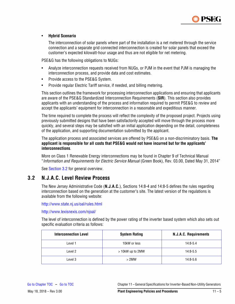
• Hybrid Scenario
The interconnection of solar panels where part of the installation is a net metered through the service connection and a separate grid connected interconnection is created for solar panels that exceed the customer’s expected kilowatt-hour usage and thus are not eligible for net metering.
PSE&G has the following obligations to NUGs:
• Analyze interconnection requests received from NUGs, or PJM in the event that PJM is managing the interconnection process, and provide data and cost estimates.
• Provide access to the PSE&G System.• Provide regular Electric Tariff service, if needed, and billing metering.
This section outlines the framework for processing interconnection applications and ensuring that applicants are aware of the PSE&G Standardized Interconnection Requirements (SIR). This section also provides applicants with an understanding of the process and information required to permit PSE&G to review and accept the applicants’ equipment for interconnection in a reasonable and expeditious manner.
The time required to complete the process will reflect the complexity of the proposed project. Projects using previously submitted designs that have been satisfactorily accepted will move through the process more quickly, and several steps may be satisfied with an initial application depending on the detail, completeness of the application, and supporting documentation submitted by the applicant.
The application process and associated services are offered by PSE&G on a non-discriminatory basis. The applicant is responsible for all costs that PSE&G would not have incurred but for the applicants’ interconnections.
More on Class 1 Renewable Energy interconnections may be found in Chapter 9 of Technical Manual “Information and Requirements for Electric Service Manual (Green Book), Rev. 03.00, Dated May 31, 2014”
See Section 3.2 for general overview.
3.2 N.J.A.C. Level Review ProcessThe New Jersey Administrative Code (N.J.A.C.), Sections 14:8-4 and 14:8-5 defines the rules regarding interconnection based on the generation at the customer’s site. The latest version of the regulations is available from the following website:
http://www.state.nj.us/oal/rules.html
http://www.lexisnexis.com/njoal/
The level of interconnection is defined by the power rating of the inverter based system which also sets out specific evaluation criteria as follows:
Interconnection Level System Rating N.J.A.C. Requirements
Level 1 10kW or less 14:8-5.4
Level 2 > 10kW up to 2MW 14:8-5.5
Level 3 > 2MW 14:8-5.6
Chapter 11 – General Specifications for Inverter-Based Non-Utility Generators
May 18, 2018 – Rev 3.00 Plant Engineering Policies and Procedures 11 – 5
Go to Chapter TOC – Go to TOC
3.2.1 Level 1
Each EDC shall adopt a Level 1 interconnection review procedure. The EDC shall use the Level 1 review procedure only for an application to interconnect a customer-generator facility that meets all of the following criteria:
1. The facility is a Class 1 renewable inverter-based generation source;
2. The facility has a capacity of 10 kW or less; and
3. The facility has been certified in accordance with N.J.A.C. 14:8-5.4.
3.2.2 Level 2
Each EDC shall adopt a Level 2 interconnection review procedure. The EDC shall use the Level 2 interconnection review procedure for an application to interconnect a customer-generator facility that meets both of the following criteria:
1. The facility has a capacity of 2 megawatts or less; and
2. The facility has been certified in accordance with N.J.A.C. 14:8-5.5.
3.2.3 Level 3
Each EDC shall adopt a Level 3 interconnection review procedure. The EDC shall use the Level 3 review procedure for an application to interconnect a customer-generator facility that does not qualify for the Level 1 or Level 2 interconnection review procedures set forth at N.J.A.C. 14:8-5.4 and 5.5.
3.3 Application DocumentationThe documents and application fees required from a customer vary depending on the type of interconnection being proposed. The relevant documents are outlined below:
*Application/Agreement documents and fees can be located at PSE&G’s Website, or the NJ Office of Clean Energy Website:
http://www.pseg.com/business/small_large_business/rebate/njcleanenergy.jsp
http://www.njcleanenergy.com/renewable-energy/programs/net-metering-and-interconnection
Additional documentation required, but not limited to include:
• Site plan including the location of proposed interconnection point• Electrical one-line including both the utility feed and customers equipment• Detailed switchgear specifications
Interconnection Type Interconnection Document
Net Metering Level 1 Level 1 Interconnection Application/Agreement (with Terms and Conditions)*
Net Metering Level 2-3 Level 2-3 Interconnection Application/Agreement (with Terms and Conditions)*
PEP Tariff – Levels 1-3 Level 2-3 Interconnection Application/Agreement (with Terms and Conditions)*
PJM Tariff N/A (Requests processed through Electric Planning group)
Chapter 11 – General Specifications for Inverter-Based Non-Utility
May 18, 2018 – Rev 3.0011 – 6 Plant Engineering Policies and Procedures
Go to Chapter TOC – Go to TOC
3.4 Application ReviewA PSE&G representative will process the application for an initial review and feasibility study. This requires a basic assessment of the ability of the PSE&G System to accommodate the customer-generator’s interconnection, including preliminary information about what service voltage level would be utilized and costs. The results of this study will determine whether or not an impact study and or facilities study will be required.
The applicant will be provided with an assessment of the technical feasibility of the proposed interconnection and proposed costs that may be incurred.
If it’s determined that there may or will be a significant impact to PSE&G’s distribution system, the customer will be informed that further study will be necessary. The applicant will then be required to:
• Provide PSE&G with a cost-based advance payment for the PSE&G review of the proposed generator. • Submit a detailed design package.• Confirm with PSE&G a mutually agreeable schedule for the project based on the applicant’s work plans
and the other discussions.
Additional exchanges of information between PSE&G and the applicant may be required to complete the design package according to PSE&G’s technical requirements for interconnection.
Applicant will be informed of the results of any further studies and issued an estimate for all necessary work to accommodate the customer-generator’s interconnection.
3.5 Applicant Commits to Proceed with Constructing the ProjectThe applicant will:
• Execute a standardized interconnection agreement or commit in writing to the applicable tariff requirements; and
• Provide PSE&G with an advance payment for PSE&G’s estimated costs associated with system modifications, metering, and on-site verification.
• Provide a preliminary schedule of construction for the facility.
3.6 Coordination and SchedulingThe applicant will be provided with the contact information for the applicable PSE&G representative. The applicant shall contact this individual to schedule a project kick-off meeting.
At this initial meeting the applicant should be prepared to discuss:
• Scheduling• Details of related documentation and drawings submitted• Coordination• Inspection requirements• Metering requirements
Chapter 11 – General Specifications for Inverter-Based Non-Utility Generators
May 18, 2018 – Rev 3.00 Plant Engineering Policies and Procedures 11 – 7
Go to Chapter TOC – Go to TOC
3.7 Inspection and TestingPeriodic inspection will be required by our metering and inspection department. Scheduling of these site visits should be discussed at the bi-monthly meetings and will be the responsibility of the applicant. See Section 4. for further details of the inspection process.
The applicant will develop a written testing plan to be submitted to PSE&G for review and acceptance. This testing plan will be designed to verify compliance of the facility with the applicant’s PSE&G-accepted drawings and details of the interconnection. The final testing will include testing in accordance with the SIR and the site-specific requirements. The final testing will be conducted at a mutually agreeable time, and PSE&G shall be given the opportunity to witness the tests. See Section 4. for further details off the testing protocol.
When applicant is ready to schedule a testing date, they should have completed the second part of the Interconnection Agreement and submitted it to PSE&G.
3.8 AcceptanceWithin a reasonable time after interconnection, PSE&G will review the results of its on-site verification and issue to the applicant a formal letter of acceptance for interconnection or Permission To Operate (PTO) as well as a copy of the fully executed agreement.
Installation of the customer-generator facility must be in compliance with the local, state and federal codes and regulations, and shall meet the requirements of IEEE Standard 1547-2003 (R2008) “Standard for Interconnecting Distributed Resources with Electric Power Systems” with the Amendment IEEE Std 1547a™-2014 and any subsequent subparts of IEEE 1547, such as IEEE 1547.1 (2005) for testing protocols. The installation shall be performed in a workmanlike manner, and shall meet or exceed industry standards of good practice. Prior to connection, PSE&G must be provided by the local Sub-code Official with a “cut-in card” or other evidence of the satisfactory electrical inspection by the authorized inspection agency having jurisdiction.
Upon initial parallel operation of a generating system a “Witness Test” or verification test shall be performed, or any time interface hardware or software is changed, a verification test must be performed in accordance with the applicable requirements of IEEE Std 1547.1 (2005) “Conformance Test Procedures for Equipment Interconnecting Distributed Resources with Electric Power Systems.” A New Jersey Licensed Professional Engineer or qualified individual working under the direction of a New Jersey Licensed Professional Engineer must perform verification testing in accordance with the manufacturer's recommendations, and use licensed electricians with experience in testing protective equipment. PSE&G reserves the right to witness verification testing or require written certification that the testing was performed.
Verification testing shall be performed every 4 years. All verification tests prescribed by the manufacturer shall be performed. If wires must be removed to perform certain tests, each wire and each terminal must be clearly and permanently marked. The generator-owner shall maintain verification test reports for inspection by PSE&G.
PSE&G will not be liable for damages or for injuries sustained by customers or by the equipment of customers or by reason of the condition or character of customer’s facilities or the equipment of others on customer’s premises. PSE&G will not be liable for the use, care, or handling of the electric service delivered to the customer after same passes beyond the point at which PSE&G’s service facilities connect to the customer's facilities.
Note
Chapter 11 – General Specifications for Inverter-Based Non-Utility
May 18, 2018 – Rev 3.0011 – 8 Plant Engineering Policies and Procedures
Go to Chapter TOC – Go to TOC
May 28, 2020 – Rev 3.02
Single-phase inverters rated 10 kW and below may be verified once per year as follows: once per year, the owner or their agent shall operate the load break Disconnect Switch and verify the power producing facility automatically shuts down and does not restart for 5 minutes after the switch is closed.
Any system that depends upon a battery for trip power shall be checked and logged once per month for proper voltage. Once every 4 years the battery must be either replaced or a discharge test performed.
3.9 PSE&G ModificationsAll labor and material expenses incurred to provide the NUG interconnection service will be billed at actual cost.
4. Applicants/Facility RequirementsThe following are requirements for all customer-generator facilities regardless of size or intent to sell to PSE&G or elsewhere.
The information contained herein is general and not intended to cover all details and aspects of a particular project. PSE&G should be consulted in case of doubt on the current applicability of any item.
Any information contained in this document is subject to change without notification. It is the customer-generator’s responsibility to verify current applicability of information through written inquiry to PSE&G.
It is PSE&G’s policy to permit customer-generator facilities to operate their generating equipment in parallel with PSE&G’s electric distribution system provided there are no expected adverse effects to the reliability or quality of service currently provided to other customers, or to the safety of PSE&G’s workers or the general public.
4.1 Drawings and SpecificationsThree sets of the following drawings must be submitted to PSE&G and/or PJM for review:
1. AC three-line schematics detailing the required relaying and Current Transformer (CT) location.
2. DC schematics detailing the required relaying.
3. Instruction manuals for the protective components.
4. One line diagram showing the interconnection with the PSE&G System as well as the generator and associated breakers and protective equipment.
5. Generator data required to analyze fault contributions and load flows.
6. Transformer data including ratings and impedance.
7. Logic diagrams and/or tripping tables.
8. The one line showing relevant wiring for SCADA communication connections (the relays connections to an RTU).
4.2 TransformerPSE&G will provide and install any transformers required on the primary side of the switch-gear at the applicant’s expense. The applicant will supply an appropriate base for PSE&G to install the Pad and Transformer on. This base must conform to PSE&G specifications and will be inspected prior to installation of the Pad.
Chapter 11 – General Specifications for Inverter-Based Non-Utility Generators
May 28, 2020 – Rev 3.02 Plant Engineering Policies and Procedures 11 – 9
Go to Chapter TOC – Go to TOC
4.3 Trench, Conduit and ConductorsThe applicant will be responsible for all trench, conduit and secondary conductors required. Primary conductors will be provided and installed by PSE&G at the applicant’s expense. It is the applicant’s responsibility to conform to all PSE&G and NEC specification requirements for trench and conduit installation as well as coordination of all inspections required for such work.
4.4 TelecommunicationThe applicant is responsible for all telecommunication conduit and conductors. PSE&G is responsible for all coordination and communication with the telecommunication company at the NUG’s expense. PSE&G will also install the uplink devices, such as 4G router, at the NUG’s expense.
4.5 SwitchgearFor solar systems directly connected a 4 kV and higher voltages the applicant is responsible for the supply and installation of all required switchgear elements. The switchgear must strictly conform to PSE&G’s specifications.
4.6 Disconnect SwitchA disconnect switch may be required depending on the size of the installation. It is recommended to be installed on both sides of PSE&G metering for most installations.
4.7 Automatic ControlThe protective equipment installed by the NUG shall provide automatic disconnection of the generator from the PSE&G System for the following conditions.
1. A fault on the NUG equipment.
2. Abnormal voltage or frequency.
3. De-energization of the PSE&G supply line.
In addition, the NUG must submit plans explaining how their control scheme will isolate its generation from the PSE&G System when the PSE&G source is lost.
4.8 Breaker ControlFor NUG’s supplied at voltages of 4 kV or greater, the high side breaker must be DC operated. This will require a battery and suitable charger. It has been the experience of PSE&G that a properly maintained battery provides the most reliable source of power for operating breakers. The battery shall be sized for a minimum of 8 hour duty cycle. The NUG is responsible for maintaining the battery and charger system.
4.9 Isolation for TestingAt NUG’s whose aggregate output exceeds 1 MW, all required relays shall have provisions for AC and DC isolation for testing. This will normally consist of test switches such as the ABB FT-1. The current circuits must have shorting bars to avoid open circuiting the CTs.
Chapter 11 – General Specifications for Inverter-Based Non-Utility
May 28, 2020 – Rev 3.0211 – 10 Plant Engineering Policies and Procedures
Go to Chapter TOC – Go to TOC
4.10 Telemetering, SCADA and Control
4.10.1 Telemetering
Equipment shall be installed at the Project and PSE&G’s Electric System Operations Center (ESOC) or Operation Control Center to provide for telecommunication interfaces and to enable measurement of the following quantities when the NUGs maximum facility output of 500 kW and above:
1. Instantaneous voltage at the point of common coupling.
2. Instantaneous active power flow on the interconnection at the point of common coupling.
3. Instantaneous reactive power flow on the interconnection at the point of common coupling.
4. Instantaneous net active electrical power output of the facility’s generator.
5. Instantaneous net reactive electrical power output of the facility’s generator.
6. Instantaneous terminal voltage of the facility’s generator.
7. Hourly kilowatt-hours of net electrical energy received by PSE&G at the point of common coupling.
Based upon PSE&G’s review of the design of the electrical portion of the Project, PSE&G will designate the point(s) where the aforementioned electrical quantities are to be measured.
PSE&G shall designate, select and specify the equipment and subsequent telecommunications devices to be used for telemetering to the ESOC or Operations Control Center by means of fiber optic cable, digital data links and/or analog signals to be installed at the facility, to enable a measurement of the aforementioned electrical quantities. PSE&G shall purchase the telemetering and control equipment required at both the Project and the ESOC or Operations Control Center, at the NUG’s expense. The NUG shall receive from PSE&G and install the telemetering equipment required at the Project in accordance with PSE&G’s specifications. PSE&G shall own, operate and maintain the telemetering and SCADA equipment.
The NUG shall pay PSE&G for any costs associated with operating and maintaining the telemetering and SCADA equipment.
For projects 10 MW or less in size that are coordinated through PJM, PSE&G and the NUG may choose to utilize PJM’s telemetry format, Jetstream, which is discussed in Section 4.1 of PJM Manual 14D, Rev.49, effective 9/26/2019.
4.10.2 Supervisory Control and Data Acquisition (SCADA)
For all NUGs with maximum facility output of 500 kW and above, PSE&G shall designate, select, specify and purchase the equipment required for SCADA purposes. The NUG shall receive the devices from PSE&G and install the equipment at its facility. If necessary, PSE&G will install any other SCADA equipment required at its facilities, at the NUG’s expense. The NUG shall pay PSE&G for all costs associated with SCADA equipment. This equipment will provide some or all of the following data:
1. Entrance breaker status indication.
2. Breaker low gas pressure alarm.
3. Breaker control status indication (local/remote).
4. Main transformer differential relay operation alarm indication.
5. Generator breaker status indication.
6. SCADA equipment shall be capable of tripping the generator breaker or the entrance breaker.
Chapter 11 – General Specifications for Inverter-Based Non-Utility Generators
May 28, 2020 – Rev 3.02 Plant Engineering Policies and Procedures 11 – 11
Go to Chapter TOC – Go to TOC
Additional SCADA equipment for use by the local Electric Distribution Division office operations personnel may be required. This local-use SCADA equipment utilizes low cost equipment, but can provide some or all of the following data as needed:
1. Circuit breaker open/close indication.
2. Line disconnect switch open/close indication (NO or NC).
3. RFL receive trip (for transfer trip relaying).
4. RFL trouble alarm (for transfer trip relaying).
5. Loss of potential.
6. Bus voltage (three phases).
7. DC control low voltage alarm.
For projects 10 MW or less in size that are coordinated through PJM, PSE&G and the NUG may choose to utilize PJM’s telemetry format, Jetstream, which is discussed in Section 4.1 of PJM Manual 14D, Rev. 49, effective 9/26/19.
4.10.3 Telecommunications
The NUG shall lease, at its expense, the appropriate communication equipment required for operation of the SCADA system.
The NUG shall be responsible for all trench, conduit, fiber optics etc. for the SCADA devices to communicate to the uplink. Such equipment will be owned, operated and maintained by PSE&G. PSE&G shall procure and install devices providing the uplink, such as a 4G router, and leasing the Communication channels at the NUG’s expense. Any costs associated with the operation or maintenance of such equipment shall be paid for by the NUG within 30 days of the date of billing.
For projects 10 MW or less in size that are coordinated through PJM, PSE&G and the NUG may choose to utilize PJM’s communications system, Jetstream, which is discussed in Section 4.1 of PJM Manual 14D, Rev. 49, effective 9/26/19.
4.10.4 Weather Stations
The applicant shall provide and install a Meteorological Monitoring (Weather) Station for the solar site. The Weather Station shall include, but not be limited to:
• Data logger with Ethernet connectivity compatible with DNP3 communications protocol.• Air temperature sensor• Relative humidity sensor• Solar radiation sensor• Baromatic pressure sensor• Precipitation gauge; heated• Ultrasonic Wind sensor
4.11 Power FactorThe power factor of the NUG must be maintained at level specified in Interconnection Agreement. The installation of power factor correction capacitors at the NUG’s generating facility may be required if the output is below specified level and cannot be corrected by the generator. The cost of such capacitors shall be borne by the NUG.
Chapter 11 – General Specifications for Inverter-Based Non-Utility
May 28, 2020 – Rev 3.0211 – 12 Plant Engineering Policies and Procedures
Go to Chapter TOC – Go to TOC
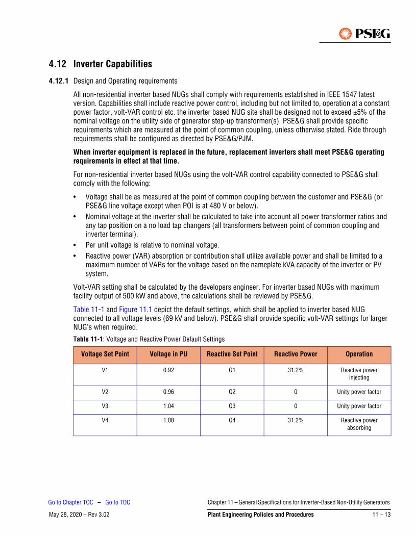
4.12 Inverter Capabilities
4.12.1 Design and Operating requirements
All non-residential inverter based NUGs shall comply with requirements established in IEEE 1547 latest version. Capabilities shall include reactive power control, including but not limited to, operation at a constant power factor, volt-VAR control etc. the inverter based NUG site shall be designed not to exceed ±5% of the nominal voltage on the utility side of generator step-up transformer(s). PSE&G shall provide specific requirements which are measured at the point of common coupling, unless otherwise stated. Ride through requirements shall be configured as directed by PSE&G/PJM.
When inverter equipment is replaced in the future, replacement inverters shall meet PSE&G operating requirements in effect at that time.
For non-residential inverter based NUGs using the volt-VAR control capability connected to PSE&G shall comply with the following:
• Voltage shall be as measured at the point of common coupling between the customer and PSE&G (or PSE&G line voltage except when POI is at 480 V or below).
• Nominal voltage at the inverter shall be calculated to take into account all power transformer ratios and any tap position on a no load tap changers (all transformers between point of common coupling and inverter terminal).
• Per unit voltage is relative to nominal voltage.• Reactive power (VAR) absorption or contribution shall utilize available power and shall be limited to a
maximum number of VARs for the voltage based on the nameplate kVA capacity of the inverter or PV system.
Volt-VAR setting shall be calculated by the developers engineer. For inverter based NUGs with maximum facility output of 500 kW and above, the calculations shall be reviewed by PSE&G.
Table 11-1 and Figure 11.1 depict the default settings, which shall be applied to inverter based NUG connected to all voltage levels (69 kV and below). PSE&G shall provide specific volt-VAR settings for larger NUG’s when required.
Table 11-1: Voltage and Reactive Power Default Settings
Voltage Set Point Voltage in PU Reactive Set Point Reactive Power Operation
V1 0.92 Q1 31.2% Reactive power injecting
V2 0.96 Q2 0 Unity power factor
V3 1.04 Q3 0 Unity power factor
V4 1.08 Q4 31.2% Reactive power absorbing
Chapter 11 – General Specifications for Inverter-Based Non-Utility Generators
May 28, 2020 – Rev 3.02 Plant Engineering Policies and Procedures 11 – 13
Go to Chapter TOC – Go to TOC
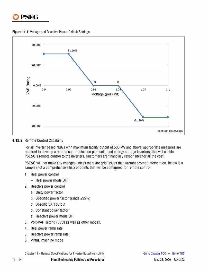
Figure 11.1: Voltage and Reactive Power Default Settings
4.12.2 Remote Control Capability
For all inverter based NUGs with maximum facility output of 500 kW and above, appropriate measures are required to develop a remote communication path solar and energy storage inverters; this will enable PSE&G's remote control to the inverters. Customers are financially responsible for all the cost.
PSE&G will not make any changes unless there are grid issues that warrant prompt intervention. Below is a sample (not a comprehensive list) of points that will be configured for remote control.
1. Real power control
– Real power mode OFF
2. Reactive power control
a. Unity power factor
b. Specified power factor (range ±95%)
c. Specific VAR output
d. Constant power factor
e. Reactive power mode OFF
3. Volt-VAR setting (VVC) as well as other modes.
4. Real power ramp rate
5. Reactive power ramp rate
6. Virtual machine mode
PEPP-011389-01-0320
Chapter 11 – General Specifications for Inverter-Based Non-Utility
May 28, 2020 – Rev 3.0211 – 14 Plant Engineering Policies and Procedures
Go to Chapter TOC – Go to TOC
4.13 RelayingThe Non-Utility Generator interconnection relay settings shall be set based on IEEE Standard 1547-2003 (R2008) “Standard for Interconnecting Distributed Resources with Electric Power Systems” with the Amendment IEEE Std 1547a™-2014 and any subsequent subparts of IEEE 1547. PSE&G may provide additional relay requirements superseding the ones from above-mentioned IEEE Standards. PSE&G must approve all the remaining settings for all required interconnection relays that trip breakers that affect PSE&G load flow. In addition, for NUGs whose aggregate output is greater than 1 MW, PSE&G personnel will apply the settings to the relays. However, if preferred by the NUG, or because personnel constraints prohibit PSE&G from applying the settings, this task may be contracted for by the NUG to be performed by a qualified third party acceptable to PSE&G. If a third party applies the settings, documentation showing proof of the setting application shall be provided by the NUG to PSE&G. If PSE&G applies the settings, the NUG will be charged for this service.
For NUGs whose output is greater than 1 MW, periodic maintenance of the required protective relay system may be performed by PSE&G personnel. The NUG will be charged for this service. If preferred by the NUG, or because personnel constraints prohibit PSE&G from performing the required maintenance, it may be performed by a qualified third party acceptable to PSE&G. If a third party performs the maintenance, documentation showing proof of the maintenance shall be provided by the NUG to PSE&G. The period of maintenance shall be based on the PSE&G Relay Test Manual and currently that interval is 4 years.
If the output of the NUG is 1 MW or less, the NUG must provide for periodic maintenance of the protective relay systems and submit proof of this maintenance to PSE&G. The period of this maintenance shall be 4 years or less.
PSE&G recommends that the other relays installed by the NUG also be maintained periodically. The NUG may use a qualified independent testing service or may request that PSE&G perform the testing and maintenance. The NUG will be billed for all testing and maintenance performed by PSE&G on other relay systems at their facility.
When the NUG facility is first placed in service (for a NUG whose aggregate output exceeds 1 MW), PSE&G will test all required interconnection relays and their associated circuits prior to energizing the NUG.
4.14 Relay RequirementsThe following requirements are mandated for the safety and reliability of the PSE&G System. The relay protection design of all equipment in the NUG’s facility is solely the responsibility of the NUG.
The numbers shown in parenthesis in the following paragraphs utilize the IEEE codes for the particular relay type referenced below.
4.14.1 NUG any Output Power Level – Non-export
A NUG, which does not intend to send power to the grid, shall install a relay with a directional power function (32) at the point of interconnection with PSE&G. Sufficient power must flow into the NUG’s facility such that enough current is detected by the CTs that the 32 element can operate. If power flow into the NUG is not maintained, the 32 element will open a breaker between the generator and PSE&G. This method of always importing a small amount of power is required to ensure proper operation of the directional power relay, since whenever the 32 element detects any power flows from the NUG into the PSE&G System, the 32 element will isolate the generator from PSE&G. The relay with a directional power function (32) shall be fed by three single-phase CT and three single-phase Potential Transformers (PT) located on the PSE&G side of the service entrance breaker. The PT shall be connected Wye-Wye. In order to limit unnecessary operations
Chapter 11 – General Specifications for Inverter-Based Non-Utility Generators
May 28, 2020 – Rev 3.02 Plant Engineering Policies and Procedures 11 – 15
Go to Chapter TOC – Go to TOC
during faults on the PSE&G System or loss of load in the NUG’s facility, the directional power relay should be set with up to a 5 second delay.
Since the PSE&G source breaker may be reclosed automatically, it is essential that the NUG generator is disconnected from the utility system when the reclose attempt occurs, or equipment damage can result.
4.14.2 NUG Aggregate Output 1 MW or Less – Export
A NUG whose total output is 1 MW or less and that intends to export power to the grid is required to provide the following functions in it’s relay protection design:
1. Undervoltage (27) function
2. Overvoltage (59) function
3. Underfrequency (81u) function
4. Overfrequency (81o) function
The relays specified in items 1-4 above are to be selected from PSE&G’s current list of acceptable microprocessor relays (see Section 4.15)
4.14.3 NUG Aggregate Output Greater Than 1 MW – Export
A NUG whose total output exceeds 1 MW and that intends to export power to the grid is required to provide the following functions in its relay protection design:
1. Undervoltage (27) function
2. Overvoltage (59) function
3. Underfrequency (81u) function
4. Overfrequency (81o) function –
5. Voltage controlled overcurrent (51 V) or generator differential (87) function
The relays specified in items 1-4 above are to be selected from PSE&G’s current list of acceptable microprocessor relays (see Section 4.15).
Relays specified in item 5 above are generator protection relays. Their settings are based on type of relay selected. These settings and relays do not need PSE&G approval.
4.14.4 Additional Equipment
In addition to the relays mentioned in the preceding paragraphs, other devices may be required for functions such as those listed below:
1. Regular and backup relay schemes.
2. Carrier and/or transfer trip equipment.
3. Automatic checkback for the communication equipment.
4. Breaker failure relaying.
5. Close into fault relaying.
Chapter 11 – General Specifications for Inverter-Based Non-Utility
May 28, 2020 – Rev 3.0211 – 16 Plant Engineering Policies and Procedures
Go to Chapter TOC – Go to TOC
4.15 Acceptable RelaysAll Non-Utility Generator interconnection protection relays used to satisfy the above requirements, or any additional PSE&G requirements, or any relays that trip breakers that may affect PSE&G load flow, must come from the PSE&G list of acceptable microprocessor relays. Contact PSE&G System Protection Department for the latest version of this list.
Interconnection relay settings shall be set based on IEEE Standard 1547-2003 (R2008) “Standard for Interconnecting Distributed Resources with Electric Power Systems” with the Amendment IEEE Std 1547a™-2014 and any subsequent subparts of IEEE 1547. PSE&G may provide additional relay requirements superseding the ones from above-mentioned IEEE Standards.
The relay AC inputs and DC outputs are to be isolated by ABB FT-1 test switches.
4.16 Inspection and MaintenancePeriodic inspection and maintenance of the equipment and facilities is necessary to assure proper operation and function. PSE&G shall be granted access for its authorized representatives during any reasonable hours to install, check and maintain metering equipment and/or for operation of the interconnection disconnecting device.
Types of maintenance that the applicant would be responsible for at its facility consist of diagnostic testing and sampling, minor maintenance items and major maintenance items, for example:
• Diagnostic testing and sampling
Is performed either on in-service equipment or on equipment out of service but immediately available for service. Example would be thermovision heat detection scanning.
• Minor maintenance
Would require the equipment to be out of service but available for return to service within a few hours or less. Examples might be lubrication of mechanisms, checking the proper operation of pressure switches; checking the operation and synchronism of disconnect switches, meggering, ductoring, timing checks, interrupting medium moisture tests as well as relay setting checks and operational function tests.
• Major maintenance
Would include the complete or partial disassembly of a piece of equipment, and would usually involve taking an extended outage. Examples would be the replacement of contacts in a load tap changing mechanism, or transformer bushing, or maybe replacement of the whole PSE&G supplied transformer.
Schedules for maintenance should be developed based on equipment manufacturer’s suggestions, the operating record, inspection results, past maintenance experience, the critical nature of the equipment and the shut-down schedule of the facility. Maintenance may be performed by the customer’s own personnel, or a qualified contractor.
1. When relays are required for the protection of a sub-transmission line or a transmission line, requirements covering those applications are very specific and are based on the voltage class, line configuration, etc. Such requirements are not in the scope of this document. The PSE&G System Protection Group in Newark must be contacted for specific recommendations. At that time, sample AC and DC schematics will be provided by PSE&G.
2. For other applications (i.e. bus differential protection) the same System Protection Group in Newark must be contacted for specific recommendations.
Note
Chapter 11 – General Specifications for Inverter-Based Non-Utility Generators
May 28, 2020 – Rev 3.02 Plant Engineering Policies and Procedures 11 – 17
Go to Chapter TOC – Go to TOC
As part of the interconnection agreement, specific equipment will be identified and maintained by PSE&G (at the NUG’s expense). The requirements for this type of maintenance are established by the need to maintain the integrity of the PSE&G System and prevent interference to other NUGs or customers. This maintenance must not be duplicated by the customer or their contractor. Coordination and communication between PSE&G and those doing the maintenance for the customer should be initiated.
5. Revenue MeteringPSE&G shall install, own, operate and maintain the electric revenue meter(s) at the NUG facility, in order to accurately measure the quantity of electricity received from the NUG facility.
PSE&G shall designate, select, specify, own, operate and maintain all associated revenue metering equipment required to provide the metering data showing how much electricity the NUG supplies to or receives from the PSE&G System. All Metering expenses will be paid by the NUG.
5.1 DocumentationThe applicant must submit the following documentation:
• Electrical one-line detailing disconnect, metering and relay locations.• Conduit drawing if applicable.• Detailed switch-gear diagrams showing the location of CTs and PTs, metering and relays (if applicable).• Detailed compartment diagrams showing the dimensions of each compartment where PSE&G
equipment will reside.• Test results from meggering the BUS and Ground Grid Resistance. • Ground grid details.• Telecommunication details.
5.2 Instrument TransformersPSE&G will supply CTs, PTs and the control wire to the meter. The applicant will be responsible for the installation of that equipment. Refer to Section 7. for the appropriate specifications that are specific to your projects voltage requirements.
5.3 Revenue Metering CabinetThe applicant will be responsible to install the metering cabinet. This cabinet will consist of a simple meter socket, a Hoffman-Type Box or a Schweitzer Enclosure. The applicant will provide and install the meter socket or Hoffman Box. PSE&G will provide the Schweitzer enclosure at the customer’s expense which will be installed by the applicant. PSE&G will designate which type will be required.
5.4 Telemetering and Supervisory Control and Data Acquisition (SCADA)For telemetering and SCADA requirements see Section 4.10.1 and Section 4.10.2.
In case Schweitzer enclosure is used as a revenue metering cabinet, it may house telemetering and SCADA equipment as well. For layouts of typical Schweitzer enclosures, see Figure 11.2 and Figure 11.3.
Chapter 11 – General Specifications for Inverter-Based Non-Utility
May 28, 2020 – Rev 3.0211 – 18 Plant Engineering Policies and Procedures
Go to Chapter TOC – Go to TOC
5.5 Process Where an Existing Net Metering Customer No Longer QualifiesIn cases where a net metering customer goes out of business, the solar output no longer qualifies for net metering since the load will most likely far exceed the customer’s use. In this scenario, the customer no longer qualifies for net metering reimbursement for excess generation. If the owner of the panels wishes to sell the output to PSE&G, they must obtain Qualifying Facility status and can then sell the output through the PEP Tariff. This may involve modifications to the customer’s metering and any expenses incurred would be borne by the customer.
Chapter 11 – General Specifications for Inverter-Based Non-Utility Generators
May 28, 2020 – Rev 3.02 Plant Engineering Policies and Procedures 11 – 19
Go to Chapter TOC – Go to TOC
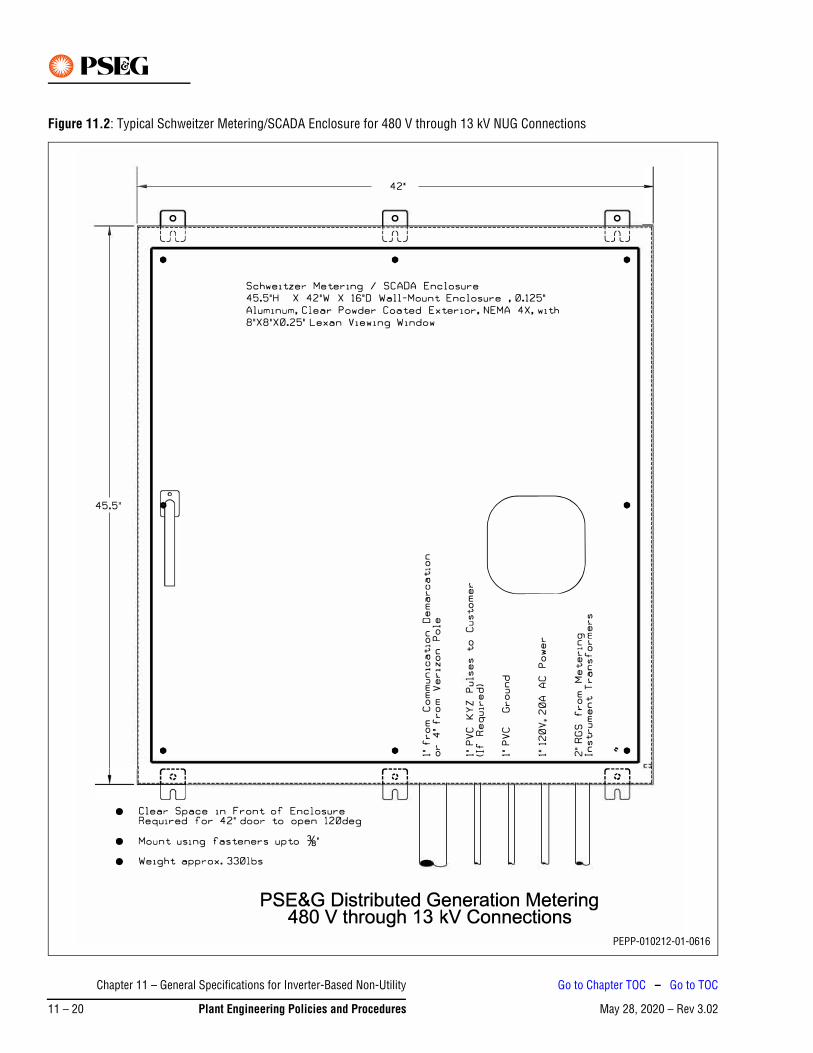
Figure 11.2: Typical Schweitzer Metering/SCADA Enclosure for 480 V through 13 kV NUG Connections
PEPP-010212-01-0616
Chapter 11 – General Specifications for Inverter-Based Non-Utility
May 28, 2020 – Rev 3.0211 – 20 Plant Engineering Policies and Procedures
Go to Chapter TOC – Go to TOC
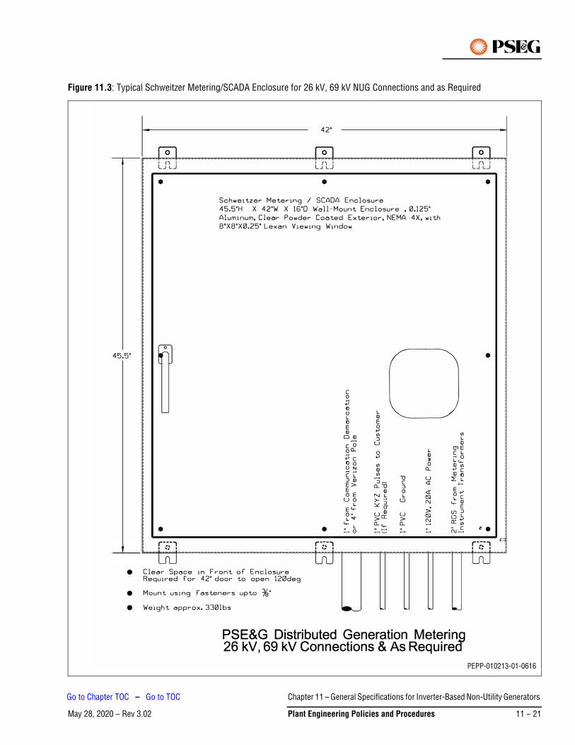
Figure 11.3: Typical Schweitzer Metering/SCADA Enclosure for 26 kV, 69 kV NUG Connections and as Required
PEPP-010213-01-0616
Chapter 11 – General Specifications for Inverter-Based Non-Utility Generators
May 28, 2020 – Rev 3.02 Plant Engineering Policies and Procedures 11 – 21
Go to Chapter TOC – Go to TOC
6. Renewable Generation in Network AreasInstalling Renewable Generation in areas served by secondary or spot networks is complicated by the manner in which such networks operate. The PSE&G transformers that supply power to a secondary network are protected against backfeed by a device called a network protector. This device is required to protect the network in the event of a fault on any circuit supplying it. Any backfeed through a transformer from the secondary will cause the network protector to trip the transformer secondary breaker with a minimal time delay, interrupting electrical service to customers on the network and causing all solar systems to go off-line due to the loss of potential. As such, any backfeed caused by an oversized solar system in a network directly impacts PSE&G’s ability to provide reliable service to customers. Besides, an excessive number of operations of the protector will lead to its premature failure.
Solar Photovoltaic System (PV System) developers need to be aware that installations in any urban city environment where underground distribution is present may involve Network Distribution Systems. Networks are high reliability distribution systems that are primarily used in PSE&G cities. If a developer scouts out a potential solar site in an urban city area and does not see overhead distribution on all of the streets in the immediate area of the prospective site, there is a very high probability that the site is in a network area.
6.1 Network BasicsNetworks are special distribution systems that utilize two or more primary voltage feeders (either 26 kV, 13 kV or 4 kV) that are essentially connected in parallel. In a typical network, each feeder is connected to a special step down transformer called a Network Transformer. The Network Transformer is a submersible device that is placed in an underground vault and transforms the primary voltage to the service voltage, either 120/208 VAC three-phase or 277/480 VAC three-phase. Attached to each Network transformer is a device called a Network Protector. The Network Protector is a high capacity submersible circuit breaker. A Network Protector is controlled and protected by a microprocessor device called a Network Protector Relay. The Network Protector Relay is physically installed inside of the Network Protector. The output terminals of the Network Transformer/Protector are connected in parallel with one or more other Network Transformer/Protectors. A two-circuit network may have two Network Transformer/Protectors connected in parallel. A three-circuit network may have three Network Transformer/Protectors connected in parallel and so on. The point where all of the Network Transformer/Protectors are connected together is called the Network Bus. One or more services are connected and fed from this Network Bus.
6.2 Types of NetworksThere are two basic types of network designs available:
1. Spot NetworkThe Spot Network is typically used to feed a large building in an urban area, where all of the Network Transformer/Protectors and the Network Bus are located in a vault in front of the large building. The Spot Network will only feed this one large facility.
2. Area NetworkAn Area Network is used to serve multiple smaller buildings and typically uses a distributed Network Bus. In an Area Network the Network Transformer/Protectors are not placed in a common vault but are located in two or more vaults spread around the network area. The Network Transformer/Protectors are connected together at the secondary voltage level via a cable bus. The individual customers are connected to this cable bus. The area network can be as large as depicted in Figure 11.4, where it is shown with three rungs or as small as a single rung. Larger networks are more capable of absorbing the output of solar systems and distributed generators, within reason.
Chapter 11 – General Specifications for Inverter-Based Non-Utility
May 28, 2020 – Rev 3.0211 – 22 Plant Engineering Policies and Procedures
Go to Chapter TOC – Go to TOC
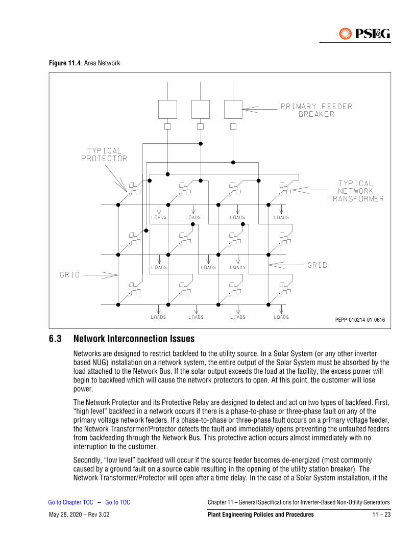
Figure 11.4: Area Network
6.3 Network Interconnection IssuesNetworks are designed to restrict backfeed to the utility source. In a Solar System (or any other inverter based NUG) installation on a network system, the entire output of the Solar System must be absorbed by the load attached to the Network Bus. If the solar output exceeds the load at the facility, the excess power will begin to backfeed which will cause the network protectors to open. At this point, the customer will lose power.
The Network Protector and its Protective Relay are designed to detect and act on two types of backfeed. First, “high level” backfeed in a network occurs if there is a phase-to-phase or three-phase fault on any of the primary voltage network feeders. If a phase-to-phase or three-phase fault occurs on a primary voltage feeder, the Network Transformer/Protector detects the fault and immediately opens preventing the unfaulted feeders from backfeeding through the Network Bus. This protective action occurs almost immediately with no interruption to the customer.
Secondly, “low level” backfeed will occur if the source feeder becomes de-energized (most commonly caused by a ground fault on a source cable resulting in the opening of the utility station breaker). The Network Transformer/Protector will open after a time delay. In the case of a Solar System installation, if the
PEPP-010214-01-0616
Chapter 11 – General Specifications for Inverter-Based Non-Utility Generators
May 28, 2020 – Rev 3.02 Plant Engineering Policies and Procedures 11 – 23
Go to Chapter TOC – Go to TOC
solar output meets or exceeds the load it is connected to, then the Network Transformer/Protector will trip due to low level backfeed.
Exported power looks like backfeed current to the Network Protection Relay. All Network Protectors connected to the common low voltage bus will see reverse current and will open, causing the facility to lose power.
6.4 Codes Governing Connections to NetworksThe New Jersey Administrative Code Subchapter 5 – Interconnection of Class 1 Renewable Energy Systems Sections 14:8-5.1 through 14:8-5.9 describe all of the current rules for interconnecting with a local electric distribution company in New Jersey.
§ 14:8-5.5 Level 2 interconnection review is covering applications to connect customer-generator facilities with a power rating of two MW or less, which meet the certification requirements at N.J.A.C. 14:8-5.3.
Sections 14:8-5.5 (c) through (k) describe requirements for any interconnection with a local electric company’s distribution systems.
Section 14:8-5.5 (l)
If a customer-generator facility’s proposed point of common coupling is on a spot or area network, the interconnection shall meet all of the following requirements that apply, in addition to the requirements in (c) through (k) above:
1. For a customer-generator facility that will be connected to a spot network circuit, the aggregate generation capacity connected to that spot network from customer-generator facilities, including the customer-generator facility, shall not exceed five percent of the spot network’s maximum load;
2. For a customer-generator facility that utilizes inverter based protective functions, which will be connected to an area network, the customer-generator facility, combined with other exporting customer-generator facilities on the load side of network protective devices, shall not exceed 10 percent of the minimum annual load on the network, or 500 kW, whichever is less. For the purposes of this paragraph, the percent of minimum load for solar electric generation customer-generator facility shall be calculated based on the minimum load occurring during an off-peak daylight period; and/or
3. For a customer-generator facility that will be connected to a spot or an area network that does not utilize inverter based protective functions, or for an inverter based customer-generator facility that does not meet the requirements of (l)1 or 2 above, the customer-generator facility shall utilize reverse power relays or other protection devices that ensure no export of power from the customer-generator facility, including inadvertent export (under fault conditions) that could adversely affect protective devices on the network.
A clarification for Sub Paragraph 3 above
The term “inverter based protective functions” in the context of Networks is that the inverter has the ability to measure the power flow into or out of the network and be able to throttle inverter output as not to export power under any circumstances. If the inverter does not have the capability to do so, then the output of the Solar System (or any other inverter based NUG) must be kept within the constraints described in Sub Paragraphs 1 and 2 above, or a Minimum Import (Reverse Power) relay and associated circuitry must be used to sense and eliminate Network backfeed by automatically tripping the Solar System.
Chapter 11 – General Specifications for Inverter-Based Non-Utility
May 28, 2020 – Rev 3.0211 – 24 Plant Engineering Policies and Procedures
Go to Chapter TOC – Go to TOC
If application to interconnect a customer-generator facility to the Network does not qualify for Level 2 interconnection review procedures set forth at N.J.A.C. 14:8-5.5, then the Developer may apply for a Level 3 interconnection review described in the N.J.A.C. Section 14:8-5.6, which will require at the customer’s expense to conduct the impact study of the probable impact of a customer-generator facility on the safety and reliability of the EDC’s electric distribution system as well as a load study to determine the minimum load of the network.
6.5 Minimum Import / Reverse Power RelaysPSE&G requires the use of a minimum import/reverse power relay on inverter-based installations that meet the criteria stated in N.J.A.C. 14:8-5.5., (l) 3 (see above).
To fulfill this requirement, the NUG shall install a relay with a directional power function (32) at the point of interconnection with PSE&G (see Figure 11.5). A minimal amount of power must always flow into the NUG such that enough current is detected by the CTs that the 32 element can operate. This minimum number will generally be determined by the minimum setting on the relay. If power flow into the NUG is not maintained, the 32 element will open a breaker between the generator and PSE&G. This method of always importing a small amount of power is required to ensure proper operation of the directional power element, since whenever the 32 element detects any power flows from the NUG into the PSE&G System, the 32 element will isolate the generator from PSE&G. The relay with a directional power function (32) shall be fed by three single-phase CT and three single-phase PT located on the customer side of the service entrance breaker. The PT shall be connected wye-wye. All this protective system should be designed, set and tested by the customer. Upon request, PSE&G will provide recommendations for the relay type, wiring etc.
In order to limit unnecessary operations during faults on the PSE&G System or loss of load in the NUG’s facility, the directional power element should be set with an operating time delay less than 0.5 seconds. In addition, any network protectors that supply the network may need to be modified by PSE&G to accept time-delay relays. The cost of this modification is the responsibility of the NUG.
In all cases, PSE&G must be contacted prior to testing and may require a witness test prior to placing the Solar System in service. PSE&G must receive a copy of all relay setting and testing results prior to placing the unit in service. The customer shall certify that the minimum import relay was tested and is working as per the requirements set forth in this section.
Chapter 11 – General Specifications for Inverter-Based Non-Utility Generators
May 28, 2020 – Rev 3.02 Plant Engineering Policies and Procedures 11 – 25
Go to Chapter TOC – Go to TOC
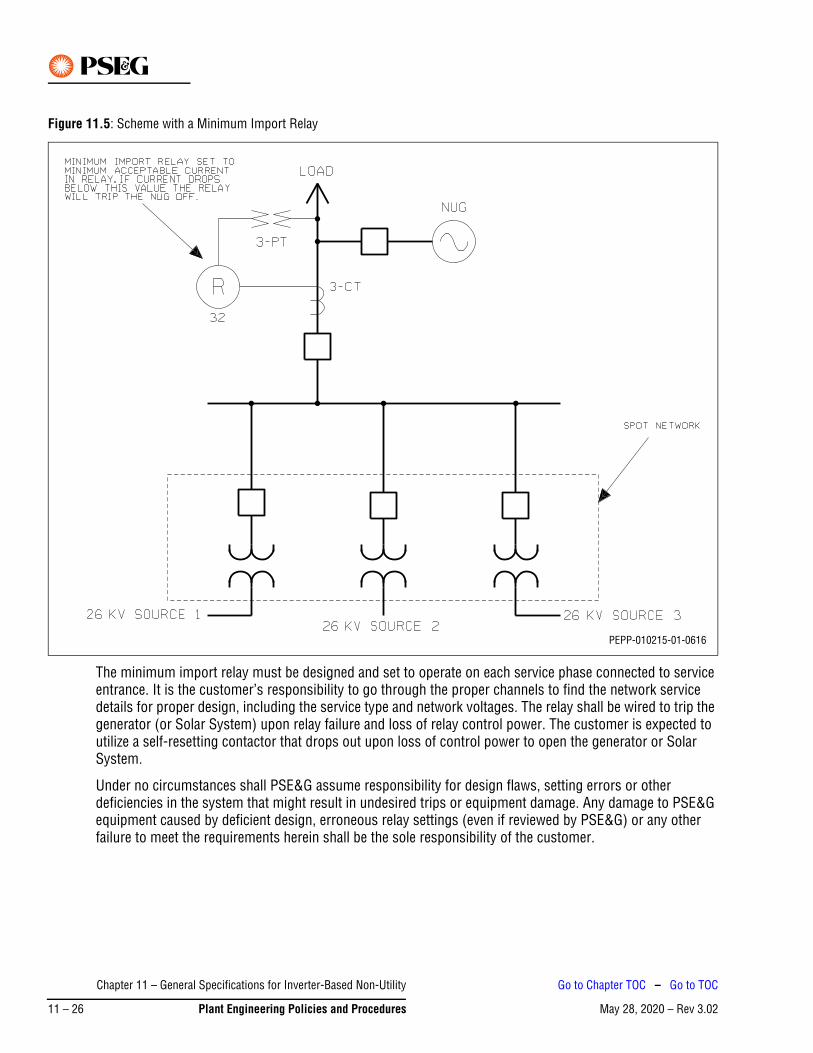
Figure 11.5: Scheme with a Minimum Import Relay
The minimum import relay must be designed and set to operate on each service phase connected to service entrance. It is the customer’s responsibility to go through the proper channels to find the network service details for proper design, including the service type and network voltages. The relay shall be wired to trip the generator (or Solar System) upon relay failure and loss of relay control power. The customer is expected to utilize a self-resetting contactor that drops out upon loss of control power to open the generator or Solar System.
Under no circumstances shall PSE&G assume responsibility for design flaws, setting errors or other deficiencies in the system that might result in undesired trips or equipment damage. Any damage to PSE&G equipment caused by deficient design, erroneous relay settings (even if reviewed by PSE&G) or any other failure to meet the requirements herein shall be the sole responsibility of the customer.
PEPP-010215-01-0616
Chapter 11 – General Specifications for Inverter-Based Non-Utility
May 28, 2020 – Rev 3.0211 – 26 Plant Engineering Policies and Procedures
Go to Chapter TOC – Go to TOC
7. Additional ResourcesAdditional resources are as follows:
• PSE&G Information and Requirements for Electric Service
https://www.pseg.com/business/builders/new_service/before/index.jsp
• Plant Engineering Policies and Procedures
https://www.pseg.com/business/builders/new_service/before/index.jsp
• Technical Support Contact
Chapter 11 – General Specifications for Inverter-Based Non-Utility Generators
May 28, 2020 – Rev 3.02 Plant Engineering Policies and Procedures 11 – 27
Go to Chapter TOC – Go to TOC

This Page Intentionally Blank
Chapter 11 – General Specifications for Inverter-Based Non-Utility
May 28, 2020 – Rev 3.0211 – 28 Plant Engineering Policies and Procedures
Go to Chapter TOC – Go to TOC

May 31, 2017 – Rev 2.00
FormsThis chapter provides a list of forms used in the Plant Engineering Policies and Procedures and links to those forms in PDF format. The PDF can be printed for hard copy use or the fillable PDF can be completed and saved. In addition, the pages following this list also contain forms that can be printed for hardcopy use.
ED-DC-PEP-Form001 – Pre-Design Meeting Checklist (for a fillable form click here)
ED-DC-PEP-Form002 – Pole Consent Form (for a fillable form click here)
ED-DC-PEP-Form003 – Transmittal to PSE&G Corporate Property Office (for a fillable form click here)
ED-DC-PEP-Form004 – Request for Services – Licensing and Permits (for a fillable form click here)
ED-DC-PEP-Form005 – Engineering Environmental Review and Protection Process (for a fillable form click here)
Forms
May 31, 2017 – Rev 2.00 Plant Engineering Policies and Procedures Form – 1
Go to TOC

This Page Intentionally Blank
Forms
May 31, 2017 – Rev 2.00Form – 2 Plant Engineering Policies and Procedures
Go to TOC

ED-DC-PEP-Form001
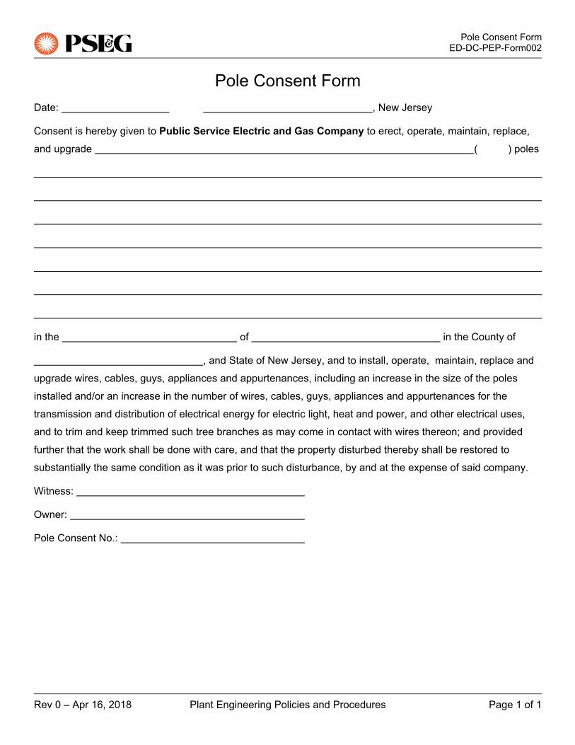
ED-DC-PEP-Form002


ED-DC-PEP-Form003


ED-DC-PEP-Form004

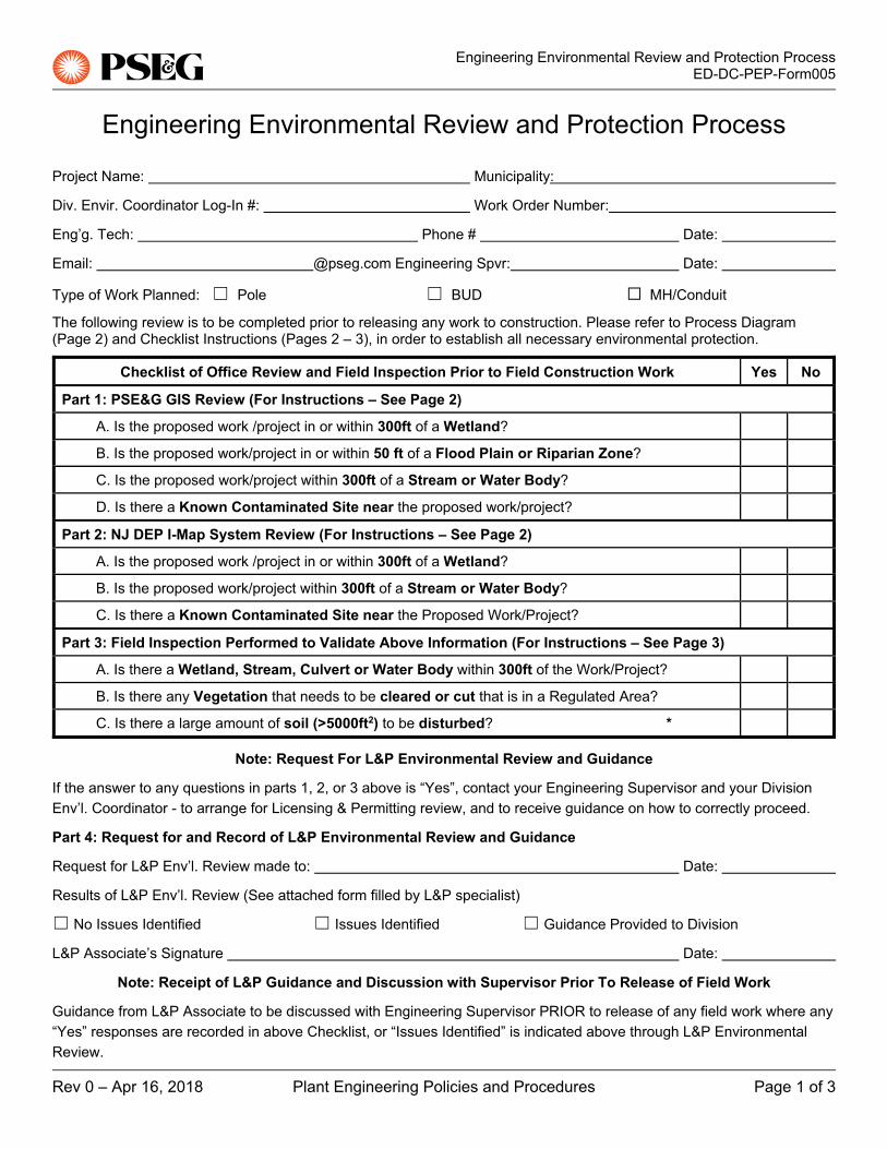
ED-DC-PEP-Form005

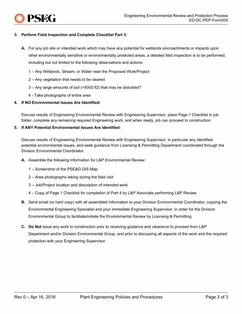

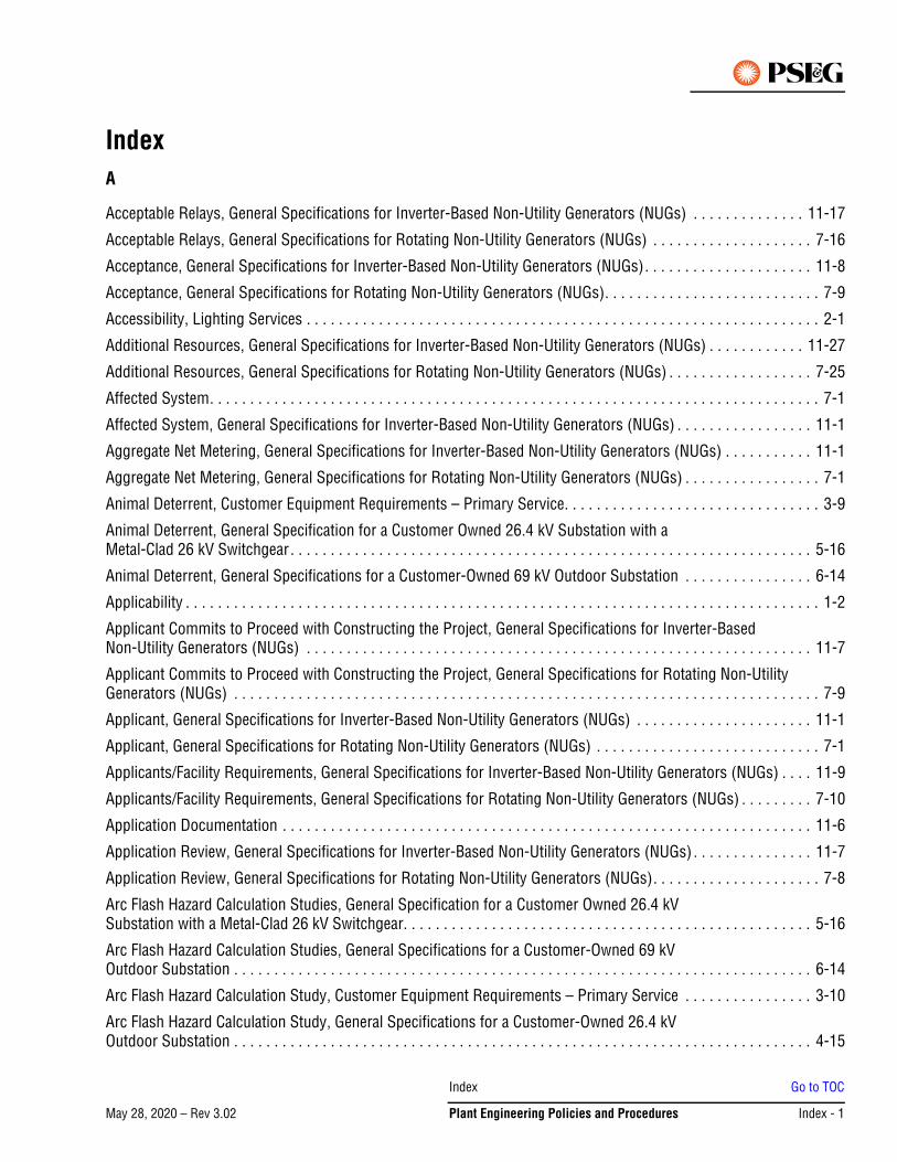
May 28, 2020 – Rev 3.02
IndexA
Acceptable Relays, General Specifications for Inverter-Based Non-Utility Generators (NUGs) . . . . . . . . . . . . . . 11-17
Acceptable Relays, General Specifications for Rotating Non-Utility Generators (NUGs) . . . . . . . . . . . . . . . . . . . . 7-16
Acceptance, General Specifications for Inverter-Based Non-Utility Generators (NUGs). . . . . . . . . . . . . . . . . . . . . 11-8
Acceptance, General Specifications for Rotating Non-Utility Generators (NUGs). . . . . . . . . . . . . . . . . . . . . . . . . . . 7-9
Accessibility, Lighting Services . . . . . . . . . . . . . . . . . . . . . . . . . . . . . . . . . . . . . . . . . . . . . . . . . . . . . . . . . . . . . . . . 2-1
Additional Resources, General Specifications for Inverter-Based Non-Utility Generators (NUGs) . . . . . . . . . . . . 11-27
Additional Resources, General Specifications for Rotating Non-Utility Generators (NUGs) . . . . . . . . . . . . . . . . . . 7-25
Affected System. . . . . . . . . . . . . . . . . . . . . . . . . . . . . . . . . . . . . . . . . . . . . . . . . . . . . . . . . . . . . . . . . . . . . . . . . . . . 7-1
Affected System, General Specifications for Inverter-Based Non-Utility Generators (NUGs) . . . . . . . . . . . . . . . . . 11-1
Aggregate Net Metering, General Specifications for Inverter-Based Non-Utility Generators (NUGs) . . . . . . . . . . . 11-1
Aggregate Net Metering, General Specifications for Rotating Non-Utility Generators (NUGs) . . . . . . . . . . . . . . . . . 7-1
Animal Deterrent, Customer Equipment Requirements – Primary Service. . . . . . . . . . . . . . . . . . . . . . . . . . . . . . . . 3-9
Animal Deterrent, General Specification for a Customer Owned 26.4 kV Substation with a Metal-Clad 26 kV Switchgear. . . . . . . . . . . . . . . . . . . . . . . . . . . . . . . . . . . . . . . . . . . . . . . . . . . . . . . . . . . . . . . . . 5-16
Animal Deterrent, General Specifications for a Customer-Owned 69 kV Outdoor Substation . . . . . . . . . . . . . . . . 6-14
Applicability . . . . . . . . . . . . . . . . . . . . . . . . . . . . . . . . . . . . . . . . . . . . . . . . . . . . . . . . . . . . . . . . . . . . . . . . . . . . . . . 1-2
Applicant Commits to Proceed with Constructing the Project, General Specifications for Inverter-Based Non-Utility Generators (NUGs) . . . . . . . . . . . . . . . . . . . . . . . . . . . . . . . . . . . . . . . . . . . . . . . . . . . . . . . . . . . . . . . 11-7
Applicant Commits to Proceed with Constructing the Project, General Specifications for Rotating Non-Utility Generators (NUGs) . . . . . . . . . . . . . . . . . . . . . . . . . . . . . . . . . . . . . . . . . . . . . . . . . . . . . . . . . . . . . . . . . . . . . . . . . 7-9
Applicant, General Specifications for Inverter-Based Non-Utility Generators (NUGs) . . . . . . . . . . . . . . . . . . . . . . 11-1
Applicant, General Specifications for Rotating Non-Utility Generators (NUGs) . . . . . . . . . . . . . . . . . . . . . . . . . . . . 7-1
Applicants/Facility Requirements, General Specifications for Inverter-Based Non-Utility Generators (NUGs) . . . . 11-9
Applicants/Facility Requirements, General Specifications for Rotating Non-Utility Generators (NUGs) . . . . . . . . . 7-10
Application Documentation . . . . . . . . . . . . . . . . . . . . . . . . . . . . . . . . . . . . . . . . . . . . . . . . . . . . . . . . . . . . . . . . . . 11-6
Application Review, General Specifications for Inverter-Based Non-Utility Generators (NUGs) . . . . . . . . . . . . . . . 11-7
Application Review, General Specifications for Rotating Non-Utility Generators (NUGs). . . . . . . . . . . . . . . . . . . . . 7-8
Arc Flash Hazard Calculation Studies, General Specification for a Customer Owned 26.4 kV Substation with a Metal-Clad 26 kV Switchgear. . . . . . . . . . . . . . . . . . . . . . . . . . . . . . . . . . . . . . . . . . . . . . . . . . . 5-16
Arc Flash Hazard Calculation Studies, General Specifications for a Customer-Owned 69 kV Outdoor Substation . . . . . . . . . . . . . . . . . . . . . . . . . . . . . . . . . . . . . . . . . . . . . . . . . . . . . . . . . . . . . . . . . . . . . . . . 6-14
Arc Flash Hazard Calculation Study, Customer Equipment Requirements – Primary Service . . . . . . . . . . . . . . . . 3-10
Arc Flash Hazard Calculation Study, General Specifications for a Customer-Owned 26.4 kV Outdoor Substation . . . . . . . . . . . . . . . . . . . . . . . . . . . . . . . . . . . . . . . . . . . . . . . . . . . . . . . . . . . . . . . . . . . . . . . . 4-15
Index Go to TOC
Plant Engineering Policies and Procedures Index - 1May 28, 2020 – Rev 3.02
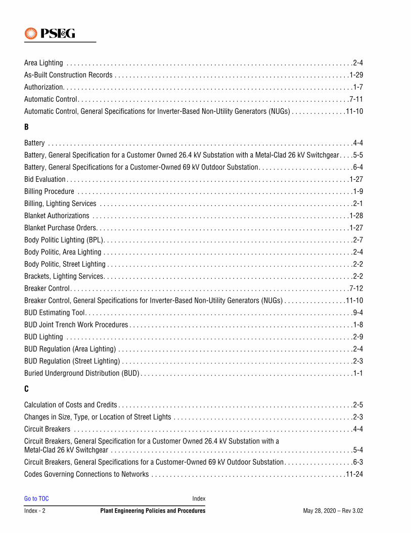
Area Lighting . . . . . . . . . . . . . . . . . . . . . . . . . . . . . . . . . . . . . . . . . . . . . . . . . . . . . . . . . . . . . . . . . . . . . . . . . . . . . .2-4
As-Built Construction Records . . . . . . . . . . . . . . . . . . . . . . . . . . . . . . . . . . . . . . . . . . . . . . . . . . . . . . . . . . . . . . . .1-29
Authorization. . . . . . . . . . . . . . . . . . . . . . . . . . . . . . . . . . . . . . . . . . . . . . . . . . . . . . . . . . . . . . . . . . . . . . . . . . . . . . .1-7
Automatic Control. . . . . . . . . . . . . . . . . . . . . . . . . . . . . . . . . . . . . . . . . . . . . . . . . . . . . . . . . . . . . . . . . . . . . . . . . .7-11
Automatic Control, General Specifications for Inverter-Based Non-Utility Generators (NUGs) . . . . . . . . . . . . . . .11-10
B
Battery . . . . . . . . . . . . . . . . . . . . . . . . . . . . . . . . . . . . . . . . . . . . . . . . . . . . . . . . . . . . . . . . . . . . . . . . . . . . . . . . . . .4-4
Battery, General Specification for a Customer Owned 26.4 kV Substation with a Metal-Clad 26 kV Switchgear. . . .5-5
Battery, General Specifications for a Customer-Owned 69 kV Outdoor Substation. . . . . . . . . . . . . . . . . . . . . . . . . .6-4
Bid Evaluation . . . . . . . . . . . . . . . . . . . . . . . . . . . . . . . . . . . . . . . . . . . . . . . . . . . . . . . . . . . . . . . . . . . . . . . . . . . . .1-27
Billing Procedure . . . . . . . . . . . . . . . . . . . . . . . . . . . . . . . . . . . . . . . . . . . . . . . . . . . . . . . . . . . . . . . . . . . . . . . . . . .1-9
Billing, Lighting Services . . . . . . . . . . . . . . . . . . . . . . . . . . . . . . . . . . . . . . . . . . . . . . . . . . . . . . . . . . . . . . . . . . . . .2-1
Blanket Authorizations . . . . . . . . . . . . . . . . . . . . . . . . . . . . . . . . . . . . . . . . . . . . . . . . . . . . . . . . . . . . . . . . . . . . . .1-28
Blanket Purchase Orders. . . . . . . . . . . . . . . . . . . . . . . . . . . . . . . . . . . . . . . . . . . . . . . . . . . . . . . . . . . . . . . . . . . . .1-27
Body Politic Lighting (BPL). . . . . . . . . . . . . . . . . . . . . . . . . . . . . . . . . . . . . . . . . . . . . . . . . . . . . . . . . . . . . . . . . . . .2-7
Body Politic, Area Lighting . . . . . . . . . . . . . . . . . . . . . . . . . . . . . . . . . . . . . . . . . . . . . . . . . . . . . . . . . . . . . . . . . . . .2-4
Body Politic, Street Lighting . . . . . . . . . . . . . . . . . . . . . . . . . . . . . . . . . . . . . . . . . . . . . . . . . . . . . . . . . . . . . . . . . . .2-2
Brackets, Lighting Services. . . . . . . . . . . . . . . . . . . . . . . . . . . . . . . . . . . . . . . . . . . . . . . . . . . . . . . . . . . . . . . . . . . .2-2
Breaker Control. . . . . . . . . . . . . . . . . . . . . . . . . . . . . . . . . . . . . . . . . . . . . . . . . . . . . . . . . . . . . . . . . . . . . . . . . . . .7-12
Breaker Control, General Specifications for Inverter-Based Non-Utility Generators (NUGs) . . . . . . . . . . . . . . . . .11-10
BUD Estimating Tool. . . . . . . . . . . . . . . . . . . . . . . . . . . . . . . . . . . . . . . . . . . . . . . . . . . . . . . . . . . . . . . . . . . . . . . . .9-4
BUD Joint Trench Work Procedures . . . . . . . . . . . . . . . . . . . . . . . . . . . . . . . . . . . . . . . . . . . . . . . . . . . . . . . . . . . . .1-8
BUD Lighting . . . . . . . . . . . . . . . . . . . . . . . . . . . . . . . . . . . . . . . . . . . . . . . . . . . . . . . . . . . . . . . . . . . . . . . . . . . . . .2-9
BUD Regulation (Area Lighting) . . . . . . . . . . . . . . . . . . . . . . . . . . . . . . . . . . . . . . . . . . . . . . . . . . . . . . . . . . . . . . . .2-4
BUD Regulation (Street Lighting) . . . . . . . . . . . . . . . . . . . . . . . . . . . . . . . . . . . . . . . . . . . . . . . . . . . . . . . . . . . . . . .2-3
Buried Underground Distribution (BUD) . . . . . . . . . . . . . . . . . . . . . . . . . . . . . . . . . . . . . . . . . . . . . . . . . . . . . . . . . .1-1
C
Calculation of Costs and Credits . . . . . . . . . . . . . . . . . . . . . . . . . . . . . . . . . . . . . . . . . . . . . . . . . . . . . . . . . . . . . . . .2-5
Changes in Size, Type, or Location of Street Lights . . . . . . . . . . . . . . . . . . . . . . . . . . . . . . . . . . . . . . . . . . . . . . . . .2-3
Circuit Breakers . . . . . . . . . . . . . . . . . . . . . . . . . . . . . . . . . . . . . . . . . . . . . . . . . . . . . . . . . . . . . . . . . . . . . . . . . . . .4-4
Circuit Breakers, General Specification for a Customer Owned 26.4 kV Substation with a Metal-Clad 26 kV Switchgear . . . . . . . . . . . . . . . . . . . . . . . . . . . . . . . . . . . . . . . . . . . . . . . . . . . . . . . . . . . . . . . . . .5-4
Circuit Breakers, General Specifications for a Customer-Owned 69 kV Outdoor Substation. . . . . . . . . . . . . . . . . . .6-3
Codes Governing Connections to Networks . . . . . . . . . . . . . . . . . . . . . . . . . . . . . . . . . . . . . . . . . . . . . . . . . . . . .11-24
Go to TOC Index
Index - 2 Plant Engineering Policies and Procedures May 28, 2020 – Rev 3.02
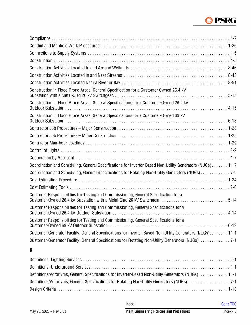
Compliance . . . . . . . . . . . . . . . . . . . . . . . . . . . . . . . . . . . . . . . . . . . . . . . . . . . . . . . . . . . . . . . . . . . . . . . . . . . . . . . 1-7
Conduit and Manhole Work Procedures . . . . . . . . . . . . . . . . . . . . . . . . . . . . . . . . . . . . . . . . . . . . . . . . . . . . . . . . 1-26
Connections to Supply Systems . . . . . . . . . . . . . . . . . . . . . . . . . . . . . . . . . . . . . . . . . . . . . . . . . . . . . . . . . . . . . . . 1-5
Construction . . . . . . . . . . . . . . . . . . . . . . . . . . . . . . . . . . . . . . . . . . . . . . . . . . . . . . . . . . . . . . . . . . . . . . . . . . . . . . 1-5
Construction Activities Located In and Around Wetlands . . . . . . . . . . . . . . . . . . . . . . . . . . . . . . . . . . . . . . . . . . . 8-46
Construction Activities Located in and Near Streams . . . . . . . . . . . . . . . . . . . . . . . . . . . . . . . . . . . . . . . . . . . . . . 8-43
Construction Activities Located Near a River or Bay . . . . . . . . . . . . . . . . . . . . . . . . . . . . . . . . . . . . . . . . . . . . . . . 8-51
Construction in Flood Prone Areas, General Specification for a Customer Owned 26.4 kV Substation with a Metal-Clad 26 kV Switchgear. . . . . . . . . . . . . . . . . . . . . . . . . . . . . . . . . . . . . . . . . . . . . . . . . . . 5-15
Construction in Flood Prone Areas, General Specifications for a Customer-Owned 26.4 kV Outdoor Substation . . . . . . . . . . . . . . . . . . . . . . . . . . . . . . . . . . . . . . . . . . . . . . . . . . . . . . . . . . . . . . . . . . . . . . . . 4-15
Construction in Flood Prone Areas, General Specifications for a Customer-Owned 69 kV Outdoor Substation . . . . . . . . . . . . . . . . . . . . . . . . . . . . . . . . . . . . . . . . . . . . . . . . . . . . . . . . . . . . . . . . . . . . . . . . 6-13
Contractor Job Procedures – Major Construction . . . . . . . . . . . . . . . . . . . . . . . . . . . . . . . . . . . . . . . . . . . . . . . . . 1-28
Contractor Job Procedures – Minor Construction . . . . . . . . . . . . . . . . . . . . . . . . . . . . . . . . . . . . . . . . . . . . . . . . . 1-28
Contractor Man-hour Loadings . . . . . . . . . . . . . . . . . . . . . . . . . . . . . . . . . . . . . . . . . . . . . . . . . . . . . . . . . . . . . . . 1-29
Control of Lights . . . . . . . . . . . . . . . . . . . . . . . . . . . . . . . . . . . . . . . . . . . . . . . . . . . . . . . . . . . . . . . . . . . . . . . . . . . 2-2
Cooperation by Applicant. . . . . . . . . . . . . . . . . . . . . . . . . . . . . . . . . . . . . . . . . . . . . . . . . . . . . . . . . . . . . . . . . . . . . 1-7
Coordination and Scheduling, General Specifications for Inverter-Based Non-Utility Generators (NUGs) . . . . . . . 11-7
Coordination and Scheduling, General Specifications for Rotating Non-Utility Generators (NUGs) . . . . . . . . . . . . . 7-9
Cost Estimating Procedure . . . . . . . . . . . . . . . . . . . . . . . . . . . . . . . . . . . . . . . . . . . . . . . . . . . . . . . . . . . . . . . . . . 1-24
Cost Estimating Tools . . . . . . . . . . . . . . . . . . . . . . . . . . . . . . . . . . . . . . . . . . . . . . . . . . . . . . . . . . . . . . . . . . . . . . . 2-6
Customer Responsibilities for Testing and Commissioning, General Specification for a Customer-Owned 26.4 kV Substation with a Metal-Clad 26 kV Switchgear . . . . . . . . . . . . . . . . . . . . . . . . . . . . . . 5-14
Customer Responsibilities for Testing and Commissioning, General Specifications for a Customer-Owned 26.4 kV Outdoor Substation . . . . . . . . . . . . . . . . . . . . . . . . . . . . . . . . . . . . . . . . . . . . . . . . . . . 4-14
Customer Responsibilities for Testing and Commissioning, General Specifications for a Customer-Owned 69 kV Outdoor Substation . . . . . . . . . . . . . . . . . . . . . . . . . . . . . . . . . . . . . . . . . . . . . . . . . . . . . 6-12
Customer-Generator Facility, General Specifications for Inverter-Based Non-Utility Generators (NUGs). . . . . . . . 11-1
Customer-Generator Facility, General Specifications for Rotating Non-Utility Generators (NUGs) . . . . . . . . . . . . . 7-1
D
Definitions, Lighting Services . . . . . . . . . . . . . . . . . . . . . . . . . . . . . . . . . . . . . . . . . . . . . . . . . . . . . . . . . . . . . . . . . 2-1
Definitions, Underground Services . . . . . . . . . . . . . . . . . . . . . . . . . . . . . . . . . . . . . . . . . . . . . . . . . . . . . . . . . . . . . 1-1
Definitions/Acronyms, General Specifications for Inverter-Based Non-Utility Generators (NUGs). . . . . . . . . . . . . 11-1
Definitions/Acronyms, General Specifications for Rotating Non-Utility Generators (NUGs). . . . . . . . . . . . . . . . . . . 7-1
Design Criteria . . . . . . . . . . . . . . . . . . . . . . . . . . . . . . . . . . . . . . . . . . . . . . . . . . . . . . . . . . . . . . . . . . . . . . . . . . . . 1-18
Index Go to TOC
Plant Engineering Policies and Procedures Index - 3May 28, 2020 – Rev 3.02
Determination of Charges to Applicant . . . . . . . . . . . . . . . . . . . . . . . . . . . . . . . . . . . . . . . . . . . . . . . . . . . . . . . . . . .1-6
Disconnect Switch . . . . . . . . . . . . . . . . . . . . . . . . . . . . . . . . . . . . . . . . . . . . . . . . . . . . . . . . . . . . . . . . . . . . . . . . .7-11
Disconnect Switch, General Specifications for Inverter-Based Non-Utility Generators (NUGs). . . . . . . . . . . . . . .11-10
Disconnecting / Load Interrupting Switches . . . . . . . . . . . . . . . . . . . . . . . . . . . . . . . . . . . . . . . . . . . . . . . . . . . . . . .5-8
Disconnecting Switches . . . . . . . . . . . . . . . . . . . . . . . . . . . . . . . . . . . . . . . . . . . . . . . . . . . . . . . . . . . . . . . . . . . . . .4-8
Disconnecting Switches, General Specifications for a Customer-Owned 69 kV Outdoor Substation . . . . . . . . . . . .6-7
Distribution Estimating System. . . . . . . . . . . . . . . . . . . . . . . . . . . . . . . . . . . . . . . . . . . . . . . . . . . . . . . . . . . . . . . . .9-1
Disturbance of Soil . . . . . . . . . . . . . . . . . . . . . . . . . . . . . . . . . . . . . . . . . . . . . . . . . . . . . . . . . . . . . . . . . . . . . . . . .8-52
Division Engineering Supervision . . . . . . . . . . . . . . . . . . . . . . . . . . . . . . . . . . . . . . . . . . . . . . . . . . . . . . . . . . . . . .1-28
Division of Cost and Responsibilities . . . . . . . . . . . . . . . . . . . . . . . . . . . . . . . . . . . . . . . . . . . . . . . . . . . . . . . . . . .1-26
Document Scope, General Specifications for Rotating Non-Utility Generators (NUGs). . . . . . . . . . . . . . . . . . . . . . .7-1
Documentation, General Specifications for Inverter-Based Non-Utility Generators (NUGs) . . . . . . . . . . . . . . . . .11-18
Documentation, General Specifications for Rotating Non-Utility Generators (NUGs) . . . . . . . . . . . . . . . . . . . . . . .7-18
Drawings and Specifications, General Specifications for Inverter-Based Non-Utility Generators (NUGs) . . . . . . . .11-9
Drawings and Specifications, General Specifications for Rotating Non-Utility Generators (NUGs) . . . . . . . . . . . . .7-11
E
E1 Notification, General Specifications for Inverter-Based Non-Utility Generators (NUGs). . . . . . . . . . . . . . . . . . .11-1
E1 Notification, General Specifications for Rotating Non-Utility Generators (NUGs). . . . . . . . . . . . . . . . . . . . . . . . .7-1
Easement Formats . . . . . . . . . . . . . . . . . . . . . . . . . . . . . . . . . . . . . . . . . . . . . . . . . . . . . . . . . . . . . . . . . . . . . . . . .8-12
Easement Preparation and Tracking . . . . . . . . . . . . . . . . . . . . . . . . . . . . . . . . . . . . . . . . . . . . . . . . . . . . . . . . . . . .1-23
EDC, General Specifications for Inverter-Based Non-Utility Generators (NUGs) . . . . . . . . . . . . . . . . . . . . . . . . . . .11-1
EDC, General Specifications for Rotating Non-Utility Generators (NUGs) . . . . . . . . . . . . . . . . . . . . . . . . . . . . . . . . .7-1
Environmental. . . . . . . . . . . . . . . . . . . . . . . . . . . . . . . . . . . . . . . . . . . . . . . . . . . . . . . . . . . . . . . . . . . . . . . . . . . . .8-39
ESOC, General Specifications for Inverter-Based Non-Utility Generators (NUGs) . . . . . . . . . . . . . . . . . . . . . . . . . .11-2
ESOC, General Specifications for Rotating Non-Utility Generators (NUGs). . . . . . . . . . . . . . . . . . . . . . . . . . . . . . . .7-1
Estimating for Work Done at The Expense of Others . . . . . . . . . . . . . . . . . . . . . . . . . . . . . . . . . . . . . . . . . . . . . . . .9-7
Exceptions, Costs and Estimates . . . . . . . . . . . . . . . . . . . . . . . . . . . . . . . . . . . . . . . . . . . . . . . . . . . . . . . . . . . . . . .9-1
F
Federal Aviation Administration . . . . . . . . . . . . . . . . . . . . . . . . . . . . . . . . . . . . . . . . . . . . . . . . . . . . . . . . . . . . . . .8-25
Financial Responsibility for Utility Relocations to Accommodate Improvements to Public Streets. . . . . . . . . . . . .8-30
Floodlight Aiming . . . . . . . . . . . . . . . . . . . . . . . . . . . . . . . . . . . . . . . . . . . . . . . . . . . . . . . . . . . . . . . . . . . . . . . . . . .2-5
Frequency and Voltage Regulation, General Specification for a Customer Owned 26.4 kV Substation with a Metal-Clad 26 kV Switchgear . . . . . . . . . . . . . . . . . . . . . . . . . . . . . . . . . . . . . . . . . . . . . . . . . . . . . . . . . . . . .5-3
Frequency and Voltage Regulation, General Specifications for a Customer-Owned 26.4 kV Outdoor Substation . . .4-3
Go to TOC Index
Index - 4 Plant Engineering Policies and Procedures May 28, 2020 – Rev 3.02
Frequency and Voltage Regulation, General Specifications for a Customer-Owned 69 kV Outdoor Substation . . . . 6-3
Fuses, General Specification for a Customer Owned 26.4 kV Substation with a Metal-Clad 26 kV Switchgear . . . . 5-4
Fuses, General Specifications for a Customer-Owned 26.4 kV Outdoor Substation. . . . . . . . . . . . . . . . . . . . . . . . . 4-4
Fuses, General Specifications for a Customer-Owned 69 kV Outdoor Substation . . . . . . . . . . . . . . . . . . . . . . . . . . 6-4
G
General Information, Customer Equipment Requirements – Primary Service . . . . . . . . . . . . . . . . . . . . . . . . . . . . . 3-1
General Policy, Costs and Estimates . . . . . . . . . . . . . . . . . . . . . . . . . . . . . . . . . . . . . . . . . . . . . . . . . . . . . . . . . . . . 9-1
General Requirements for Attachment of Holiday Decorations, Banners, and Signs to Poles . . . . . . . . . . . . . . . . 8-28
General Specification for Lighting Services . . . . . . . . . . . . . . . . . . . . . . . . . . . . . . . . . . . . . . . . . . . . . . . . . . . . . . . 2-1
General, Calculation of Costs and Credits . . . . . . . . . . . . . . . . . . . . . . . . . . . . . . . . . . . . . . . . . . . . . . . . . . . . . . . . 2-5
General, General Specification for a Customer Owned 26.4 kV Substation with a Metal-Clad 26 kV Switchgear. . . 5-1
General, General Specifications for a Customer-Owned 26.4 kV Outdoor Substation . . . . . . . . . . . . . . . . . . . . . . . 4-1
General, General Specifications for a Customer-Owned 69 kV Outdoor Substation. . . . . . . . . . . . . . . . . . . . . . . . . 6-1
General, Lighting Services . . . . . . . . . . . . . . . . . . . . . . . . . . . . . . . . . . . . . . . . . . . . . . . . . . . . . . . . . . . . . . . . . . . . 2-1
Grounding, Customer Equipment Requirements – Primary Service . . . . . . . . . . . . . . . . . . . . . . . . . . . . . . . . . . . . 3-5
Grounding, General Specification for a Customer Owned 26.4 kV Substation with a Metal-Clad 26 kV Switchgear. . . . . . . . . . . . . . . . . . . . . . . . . . . . . . . . . . . . . . . . . . . . . . . . . . . . . . . . . . . . . . . . . 5-12
Grounding, General Specifications for a Customer-Owned 26.4 kV Outdoor Substation . . . . . . . . . . . . . . . . . . . . 4-12
H
Hazards to Aviation . . . . . . . . . . . . . . . . . . . . . . . . . . . . . . . . . . . . . . . . . . . . . . . . . . . . . . . . . . . . . . . . . . . . . . . . 8-25
I
IEEE 1547, General Specifications for Inverter-Based Non-Utility Generators (NUGs). . . . . . . . . . . . . . . . . . . . . . 11-2
IEEE 1547, General Specifications for Rotating Non-Utility Generators (NUGs) . . . . . . . . . . . . . . . . . . . . . . . . . . . 7-2
Inspection and Maintenance . . . . . . . . . . . . . . . . . . . . . . . . . . . . . . . . . . . . . . . . . . . . . . . . . . . . . . . . . . . . . . . . . 7-17
Inspection and Maintenance, General Specifications for Inverter-Based Non-Utility Generators (NUGs). . . . . . . 11-17
Inspection and Testing, General Specifications for Inverter-Based Non-Utility Generators (NUGs) . . . . . . . . . . . . 11-8
Inspection and Testing, General Specifications for Rotating Non-Utility Generators (NUGs). . . . . . . . . . . . . . . . . . 7-9
Installation of Underground Distribution System. . . . . . . . . . . . . . . . . . . . . . . . . . . . . . . . . . . . . . . . . . . . . . . . . . . 1-3
Instrument Transformers, General Specifications for Inverter-Based Non-Utility Generators (NUGs) . . . . . . . . . 11-18
Instrument Transformers, General Specifications for Rotating Non-Utility Generators (NUGs). . . . . . . . . . . . . . . 7-18
Insulators, Conductors, Clearances and Connections . . . . . . . . . . . . . . . . . . . . . . . . . . . . . . . . . . . . . . . . . . . . . . 5-11
Insulators, Conductors, Connections and Clearances . . . . . . . . . . . . . . . . . . . . . . . . . . . . . . . . . . . . . . . . . . . . . . 4-11
Insulators, Conductors, Connections and Clearances, General Specifications for a Customer-Owned 69 kV Outdoor Substation . . . . . . . . . . . . . . . . . . . . . . . . . . . . . . . . . . . . . . . . . . . . . . . . . . . . . . 6-9
Index Go to TOC
Plant Engineering Policies and Procedures Index - 5May 28, 2020 – Rev 3.02
Insurance Requirements for Attachment of Holiday Decorations, Banners, and Signs to Poles . . . . . . . . . . . . . . .8-28
Interconnection Application and Agreement, General Specifications for Inverter-Based Non-Utility Generators (NUGs) . . . . . . . . . . . . . . . . . . . . . . . . . . . . . . . . . . . . . . . . . . . . . . . . . . . . . . . . . . . . . . . . . . . . . . . . .11-2
Interconnection Application and Agreement, General Specifications for Rotating Non-Utility Generators (NUGs) . . . . . . . . . . . . . . . . . . . . . . . . . . . . . . . . . . . . . . . . . . . . . . . . . . . . . . . . . . . . . . . . . . . . . . . . . .7-2
Interconnection Point, General Specifications for Rotating Non-Utility Generators (NUGs) . . . . . . . . . . . . . . . . . . .7-2
Introduction, General Specification for a Customer Owned 26.4 kV Substation with a Metal-Clad 26 kV Switchgear . . . . . . . . . . . . . . . . . . . . . . . . . . . . . . . . . . . . . . . . . . . . . . . . . . . . . . . . . . . . . . . . . .5-1
Introduction, General Specifications for a Customer-Owned 26.4 kV Outdoor Substation . . . . . . . . . . . . . . . . . . . .4-1
Introduction, General Specifications for a Customer-Owned 69 kV Outdoor Substation. . . . . . . . . . . . . . . . . . . . . .6-1
Introduction, General Specifications for Inverter-Based Non-Utility Generators (NUGs). . . . . . . . . . . . . . . . . . . . .11-4
Introduction, General Specifications for Rotating Non-Utility Generators (NUGs) . . . . . . . . . . . . . . . . . . . . . . . . . .7-4
Inverter Capabilities, General Specifications for Inverter-Based Non-Utility Generators (NUGs). . . . . . . . . . . . . .11-13
Inverter, General Specifications for Inverter-Based Non-Utility Generators (NUGs) . . . . . . . . . . . . . . . . . . . . . . . .11-2
Invoice Reconciliation and Reporting of Work Done by Contractor . . . . . . . . . . . . . . . . . . . . . . . . . . . . . . . . . . . .1-29
Isolation for Testing, General Specifications for Inverter-Based Non-Utility Generators (NUGs) . . . . . . . . . . . . .11-10
Isolation for Testing, General Specifications for Rotating Non-Utility Generators (NUGs) . . . . . . . . . . . . . . . . . . .7-12
L
Legal Authority to use Public Streets for Electric Utility Facilities . . . . . . . . . . . . . . . . . . . . . . . . . . . . . . . . . . . . . .8-29
Licensing and Approval Cycle . . . . . . . . . . . . . . . . . . . . . . . . . . . . . . . . . . . . . . . . . . . . . . . . . . . . . . . . . . . . . . . . .8-52
Licensing Submittal and Approval Cycle . . . . . . . . . . . . . . . . . . . . . . . . . . . . . . . . . . . . . . . . . . . . . . . . . . . . . . . . .8-41
Location and Structural Arrangement, General Specification for a Customer Owned 26.4 kV Substation with a Metal-Clad 26 kV Switchgear . . . . . . . . . . . . . . . . . . . . . . . . . . . . . . . . . . . . . . . . . . . . . . . . . . .5-12
Location and Structural Arrangement, General Specifications for a Customer-Owned 26.4 kV Outdoor Substation. . . . . . . . . . . . . . . . . . . . . . . . . . . . . . . . . . . . . . . . . . . . . . . . . . . . . . . . . . . . . . . . . . . . . . . . .4-12
M
Major Construction – (Exceeding $50,000) . . . . . . . . . . . . . . . . . . . . . . . . . . . . . . . . . . . . . . . . . . . . . . . . . . . . . .1-27
Management of Excavated Soils at Non-Company Locations . . . . . . . . . . . . . . . . . . . . . . . . . . . . . . . . . . . . . . . . .8-39
Metal-Clad or Metal-Enclosed Switchgear . . . . . . . . . . . . . . . . . . . . . . . . . . . . . . . . . . . . . . . . . . . . . . . . . . . . . . . .3-7
Mimic Bus, Customer Equipment Requirements – Primary Service . . . . . . . . . . . . . . . . . . . . . . . . . . . . . . . . . . . . .3-9
Mimic Bus, General Specifications for a Customer-Owned 26.4 kV Outdoor Substation . . . . . . . . . . . . . . . . . . . .4-13
Mimic Bus, General Specifications for a Customer-Owned 69 kV Outdoor Substation . . . . . . . . . . . . . . . . . . . . . .6-11
Minimum Import / Reverse Power Relays . . . . . . . . . . . . . . . . . . . . . . . . . . . . . . . . . . . . . . . . . . . . . . . . . . . . . .11-25
Minor Construction – ($50,000 or less) . . . . . . . . . . . . . . . . . . . . . . . . . . . . . . . . . . . . . . . . . . . . . . . . . . . . . . . . .1-26
More Than One Source, Customer Equipment Requirements – Primary Service . . . . . . . . . . . . . . . . . . . . . . . . . . .3-9
Go to TOC Index
Index - 6 Plant Engineering Policies and Procedures May 28, 2020 – Rev 3.02
More Than One Source, General Specifications for a Customer-Owned 26.4 kV Outdoor Substation . . . . . . . . . . 4-13
More Than One Source, General Specifications for a Customer-Owned 69 kV Outdoor Substation . . . . . . . . . . . 6-11
Multi Family / Mixed Use BUD Differential Estimate Worksheet. . . . . . . . . . . . . . . . . . . . . . . . . . . . . . . . . . . . . . . . 9-5
N
N.J.A.C. Level Review Process . . . . . . . . . . . . . . . . . . . . . . . . . . . . . . . . . . . . . . . . . . . . . . . . . . . . . . . . . . . . . . . 11-5
Net Metering, General Specifications for Inverter-Based Non-Utility Generators (NUGs) . . . . . . . . . . . . . . . . . . . 11-2
Net Metering, General Specifications for Rotating Non-Utility Generators (NUGs) . . . . . . . . . . . . . . . . . . . . . . . . . 7-2
Network Basics . . . . . . . . . . . . . . . . . . . . . . . . . . . . . . . . . . . . . . . . . . . . . . . . . . . . . . . . . . . . . . . . . . . . . . . . . . 11-22
Network Basics, General Specifications for Rotating Non-Utility Generators (NUGs) . . . . . . . . . . . . . . . . . . . . . . 7-21
Network Interconnection Issues, General Specifications for Inverter-Based Non-Utility Generators (NUGs). . . . 11-23
Network Interconnection Issues, General Specifications for Rotating Non-Utility Generators (NUGs). . . . . . . . . . 7-22
Network Service, General Specifications for Rotating Non-Utility Generators (NUGs). . . . . . . . . . . . . . . . . . . . . . 7-21
NJ Department of Transportation (DOT) Regional Offices . . . . . . . . . . . . . . . . . . . . . . . . . . . . . . . . . . . . . . . . . . . . 8-7
Non-Utility Generator (NUG), General Specifications for Inverter-Based Non-Utility Generators (NUGs) . . . . . . . 11-2
Non-Utility Generator (NUG), General Specifications for Rotating Non-Utility Generators (NUGs) . . . . . . . . . . . . . 7-2
NUG – Any Power Output Level – Export. . . . . . . . . . . . . . . . . . . . . . . . . . . . . . . . . . . . . . . . . . . . . . . . . . . . . . . . 7-23
O
Obtaining County and Municipal Pole Consents . . . . . . . . . . . . . . . . . . . . . . . . . . . . . . . . . . . . . . . . . . . . . . . . . . . 8-4
Obtaining State Highway Occupancy Permit . . . . . . . . . . . . . . . . . . . . . . . . . . . . . . . . . . . . . . . . . . . . . . . . . . . . . . 8-8
Obtaining State Highway Opening Permit . . . . . . . . . . . . . . . . . . . . . . . . . . . . . . . . . . . . . . . . . . . . . . . . . . . . . . . . 8-9
Obtaining State Highway Pole Permit . . . . . . . . . . . . . . . . . . . . . . . . . . . . . . . . . . . . . . . . . . . . . . . . . . . . . . . . . . 8-10
Occupancy of Public and Private Land and Waterways . . . . . . . . . . . . . . . . . . . . . . . . . . . . . . . . . . . . . . . . . . . . . . 8-1
Operating Procedures, General Specification for a Customer Owned 26.4 kV Substation with a Metal-Clad 26 kV Switchgear. . . . . . . . . . . . . . . . . . . . . . . . . . . . . . . . . . . . . . . . . . . . . . . . . . . . . . . . . . . . . . . . . 5-14
Operating Procedures, General Specifications for a Customer-Owned 69 kV Outdoor Substation . . . . . . . . . . . . 6-12
Other Requirements, Customer Equipment Requirements – Primary Service . . . . . . . . . . . . . . . . . . . . . . . . . . . . . 3-9
Other Requirements, General Specification for a Customer Owned 26.4 kV Substation with a Metal-Clad 26 kV Switchgear. . . . . . . . . . . . . . . . . . . . . . . . . . . . . . . . . . . . . . . . . . . . . . . . . . . . . . . . . . . . . . . . . 5-14
Other Requirements, General Specifications for a Customer-Owned 26.4 kV Outdoor Substation . . . . . . . . . . . . 4-14
Other Requirements, General Specifications for a Customer-Owned 69 kV Outdoor Substation . . . . . . . . . . . . . . 6-12
P
PEP, General Specifications for Inverter-Based Non-Utility Generators (NUGs) . . . . . . . . . . . . . . . . . . . . . . . . . . 11-3
PEP, General Specifications for Rotating Non-Utility Generators (NUGs) . . . . . . . . . . . . . . . . . . . . . . . . . . . . . . . . 7-3
Permit Obtainment Procedure – Request Form . . . . . . . . . . . . . . . . . . . . . . . . . . . . . . . . . . . . . . . . . . . . . . . . . . . 8-52
Index Go to TOC
Plant Engineering Policies and Procedures Index - 7May 28, 2020 – Rev 3.02
PJM, General Specifications for Inverter-Based Non-Utility Generators (NUGs). . . . . . . . . . . . . . . . . . . . . . . . . . .11-3
PJM, General Specifications for Rotating Non-Utility Generators (NUGs). . . . . . . . . . . . . . . . . . . . . . . . . . . . . . . . .7-3
Point of Common Coupling (Point of Interconnection), General Specifications for Inverter-Based Non-Utility Generators (NUGs) . . . . . . . . . . . . . . . . . . . . . . . . . . . . . . . . . . . . . . . . . . . . . . . . . . . . . . . . . . . . . . . .11-2
Pole Attachments and Duct Leasing . . . . . . . . . . . . . . . . . . . . . . . . . . . . . . . . . . . . . . . . . . . . . . . . . . . . . . . . . . . .8-26
Police Recall, Fire Alarm Service or Unmetered Service . . . . . . . . . . . . . . . . . . . . . . . . . . . . . . . . . . . . . . . . . . . . . .2-4
Power Factor. . . . . . . . . . . . . . . . . . . . . . . . . . . . . . . . . . . . . . . . . . . . . . . . . . . . . . . . . . . . . . . . . . . . . . . . . . . . . .7-13
Power Factor, General Specifications for Inverter-Based Non-Utility Generators (NUGs) . . . . . . . . . . . . . . . . . . .11-12
Pre-Construction Meeting. . . . . . . . . . . . . . . . . . . . . . . . . . . . . . . . . . . . . . . . . . . . . . . . . . . . . . . . . . . . . . . . . . . .1-25
Pre-Design Meeting . . . . . . . . . . . . . . . . . . . . . . . . . . . . . . . . . . . . . . . . . . . . . . . . . . . . . . . . . . . . . . . . . . . . . . . . .1-9
Private Customer . . . . . . . . . . . . . . . . . . . . . . . . . . . . . . . . . . . . . . . . . . . . . . . . . . . . . . . . . . . . . . . . . . . . . . . . . . .2-4
Private Street and Area Lighting (PSAL) . . . . . . . . . . . . . . . . . . . . . . . . . . . . . . . . . . . . . . . . . . . . . . . . . . . . . . . . . .2-6
Procedures . . . . . . . . . . . . . . . . . . . . . . . . . . . . . . . . . . . . . . . . . . . . . . . . . . . . . . . . . . . . . . . . . . . . . . . . . . . . . . .1-27
Procedures – Underground Construction Specialist . . . . . . . . . . . . . . . . . . . . . . . . . . . . . . . . . . . . . . . . . . . . . . . .1-30
Procedures for Obtaining an Easement. . . . . . . . . . . . . . . . . . . . . . . . . . . . . . . . . . . . . . . . . . . . . . . . . . . . . . . . . .8-11
Process Where an Existing Net Metering Customer No Longer Qualifies . . . . . . . . . . . . . . . . . . . . . . . . . . . . . . .11-19
Process Where an Existing Net Metering Customer No Longer Qualifies, General Specifications for Rotating Non-Utility Generators (NUGs) . . . . . . . . . . . . . . . . . . . . . . . . . . . . . . . . . . . . . . . . . . . . . . . . . . . . . .7-18
Process, General Specifications for Inverter-Based Non-Utility Generators (NUGs) . . . . . . . . . . . . . . . . . . . . . . . .11-4
Process, General Specifications for Rotating Non-Utility Generators (NUGs) . . . . . . . . . . . . . . . . . . . . . . . . . . . . . .7-4
Processing Requests from Rotating Non-Utility Generators not Utilizing Class 1 Renewable Fuels . . . . . . . . . . . . .7-5
Processing Requests from Rotating Non-Utility Generators Utilizing Class 1 Renewable Fuels . . . . . . . . . . . . . . . .7-7
PSE&G Modifications . . . . . . . . . . . . . . . . . . . . . . . . . . . . . . . . . . . . . . . . . . . . . . . . . . . . . . . . . . . . . . . . . . . . . . .7-10
PSE&G Modifications, General Specifications for Inverter-Based Non-Utility Generators (NUGs) . . . . . . . . . . . . .11-9
PSE&G Owned Facilities . . . . . . . . . . . . . . . . . . . . . . . . . . . . . . . . . . . . . . . . . . . . . . . . . . . . . . . . . . . . . . . . . . . . . .2-2
PSE&G System, General Specifications for Inverter-Based Non-Utility Generators (NUGs) . . . . . . . . . . . . . . . . . .11-3
PSE&G System, General Specifications for Rotating Non-Utility Generators (NUGs) . . . . . . . . . . . . . . . . . . . . . . . .7-3
Publicly-Owned Facilities (POF) . . . . . . . . . . . . . . . . . . . . . . . . . . . . . . . . . . . . . . . . . . . . . . . . . . . . . . . . . . . . . . . .2-3
R
Railroad Agreements, Requirements and Specifications. . . . . . . . . . . . . . . . . . . . . . . . . . . . . . . . . . . . . . . . . . . . .8-23
Regional Planning Districts. . . . . . . . . . . . . . . . . . . . . . . . . . . . . . . . . . . . . . . . . . . . . . . . . . . . . . . . . . . . . . . . . . .8-51
Relay Requirements . . . . . . . . . . . . . . . . . . . . . . . . . . . . . . . . . . . . . . . . . . . . . . . . . . . . . . . . . . . . . . . . . . . . . . . .7-14
Relay Requirements, General Specifications for Inverter-Based Non-Utility Generators (NUGs) . . . . . . . . . . . . .11-15
Relaying . . . . . . . . . . . . . . . . . . . . . . . . . . . . . . . . . . . . . . . . . . . . . . . . . . . . . . . . . . . . . . . . . . . . . . . . . . . . . . . . .7-14
Relaying, General Specifications for Inverter-Based Non-Utility Generators (NUGs) . . . . . . . . . . . . . . . . . . . . . .11-15
Go to TOC Index
Index - 8 Plant Engineering Policies and Procedures May 28, 2020 – Rev 3.02
Relays and SCADA Interface . . . . . . . . . . . . . . . . . . . . . . . . . . . . . . . . . . . . . . . . . . . . . . . . . . . . . . . . . . . . . . . . . . 4-5
Relays and SCADA Interface, General Specification for a Customer Owned 26.4 kV Substation with a Metal-Clad 26 kV Switchgear . . . . . . . . . . . . . . . . . . . . . . . . . . . . . . . . . . . . . . . . . . . . . . . . . . . . . . . . . . . . 5-5
Relays and SCADA Interface, General Specifications for a Customer-Owned 69 kV Outdoor Substation . . . . . . . . 6-4
Renewable Energy, General Specifications for Inverter-Based Non-Utility Generators (NUGs) . . . . . . . . . . . . . . . 11-3
Renewable Energy, General Specifications for Rotating Non-Utility Generators (NUGs) . . . . . . . . . . . . . . . . . . . . . 7-3
Renewable Generation in Network Areas . . . . . . . . . . . . . . . . . . . . . . . . . . . . . . . . . . . . . . . . . . . . . . . . . . . . . . . 11-22
Request for Bids . . . . . . . . . . . . . . . . . . . . . . . . . . . . . . . . . . . . . . . . . . . . . . . . . . . . . . . . . . . . . . . . . . . . . . . . . . 1-27
Request for Sale of PSE&G Facilities . . . . . . . . . . . . . . . . . . . . . . . . . . . . . . . . . . . . . . . . . . . . . . . . . . . . . . . . . . . . 2-5
Requisition for Blanket Purchase Order . . . . . . . . . . . . . . . . . . . . . . . . . . . . . . . . . . . . . . . . . . . . . . . . . . . . . . . . . 1-27
Responsibilities . . . . . . . . . . . . . . . . . . . . . . . . . . . . . . . . . . . . . . . . . . . . . . . . . . . . . . . . . . . . . . . . . . . . . . . . . . . 1-29
Revenue Metering Cabinet, General Specifications for Inverter-Based Non-Utility Generators (NUGs) . . . . . . . . 11-18
Revenue Metering Cabinet, General Specifications for Rotating Non-Utility Generators (NUGs) . . . . . . . . . . . . . . 7-18
Revenue Metering Equipment, General Specification for a Customer Owned 26.4 kV Substation with a Metal-Clad 26 kV Switchgear . . . . . . . . . . . . . . . . . . . . . . . . . . . . . . . . . . . . . . . . . . . . . . . . . . . . . . . . . . . . 5-9
Revenue Metering Equipment, General Specifications for a Customer-Owned 26.4 kV Outdoor Substation . . . . . . 4-8
Revenue Metering Equipment, General Specifications for a Customer-Owned 69 kV Outdoor Substation . . . . . . . 6-8
Revenue Metering, Customer Equipment Requirements – Primary Service. . . . . . . . . . . . . . . . . . . . . . . . . . . . . . . 3-4
Revenue Metering, General Specifications for Inverter-Based Non-Utility Generators (NUGs) . . . . . . . . . . . . . . 11-18
Revenue Metering, General Specifications for Rotating Non-Utility Generators (NUGs) . . . . . . . . . . . . . . . . . . . . 7-18
Review and Approvals Required, General Specification for a Customer Owned 26.4 kV Substation with a Metal-Clad 26 kV Switchgear . . . . . . . . . . . . . . . . . . . . . . . . . . . . . . . . . . . . . . . . . . . . . . . . . . . . . . . . . . . . 5-2
Review Requirement, Customer Equipment Requirements – Primary Service. . . . . . . . . . . . . . . . . . . . . . . . . . . . . 3-3
Reviews and Approvals Required, General Specifications for a Customer-Owned 26.4 kV Outdoor Substation . . . 4-2
Reviews and Approvals Required, General Specifications for a Customer-Owned 69 kV Outdoor Substation. . . . . 6-2
Rights-of-Way and Easements. . . . . . . . . . . . . . . . . . . . . . . . . . . . . . . . . . . . . . . . . . . . . . . . . . . . . . . . . . . . . . . . . 1-3
Rotating Non-Utility Generators Utilizing Class 1 Renewable Fuels . . . . . . . . . . . . . . . . . . . . . . . . . . . . . . . . . . . . 7-25
Rotating NUG – Any Power Output Level Not Utilizing Class 1 Renewable Fuels – Non-Export. . . . . . . . . . . . . . . 7-23
S
SCADA, General Specifications for Inverter-Based Non-Utility Generators (NUGs) . . . . . . . . . . . . . . . . . . . . . . . . 11-3
SCADA, General Specifications for Rotating Non-Utility Generators (NUGs) . . . . . . . . . . . . . . . . . . . . . . . . . . . . . . 7-3
Service Circuit Breaker. . . . . . . . . . . . . . . . . . . . . . . . . . . . . . . . . . . . . . . . . . . . . . . . . . . . . . . . . . . . . . . . . . . . . . . 3-8
Service Equipment Installations and Arrangements. . . . . . . . . . . . . . . . . . . . . . . . . . . . . . . . . . . . . . . . . . . . . . . . . 3-5
Short Circuit Duty, General Specification for a Customer Owned 26.4 kV Substation with a Metal-Clad 26 kV Switchgear. . . . . . . . . . . . . . . . . . . . . . . . . . . . . . . . . . . . . . . . . . . . . . . . . . . . . . . . . . . . . . . . . . 5-3
Index Go to TOC
Plant Engineering Policies and Procedures Index - 9May 28, 2020 – Rev 3.02
Short Circuit Duty, General Specifications for a Customer-Owned 26.4 kV Outdoor Substation. . . . . . . . . . . . . . . .4-3
Short Circuit Duty, General Specifications for a Customer-Owned 69 kV Outdoor Substation . . . . . . . . . . . . . . . . .6-3
Single Family Differential Worksheet . . . . . . . . . . . . . . . . . . . . . . . . . . . . . . . . . . . . . . . . . . . . . . . . . . . . . . . . . . . .9-4
Smart Growth . . . . . . . . . . . . . . . . . . . . . . . . . . . . . . . . . . . . . . . . . . . . . . . . . . . . . . . . . . . . . . . . . . . . . . . . . . . . . .1-2
Smart Growth Tool . . . . . . . . . . . . . . . . . . . . . . . . . . . . . . . . . . . . . . . . . . . . . . . . . . . . . . . . . . . . . . . . . . . . . . . . . .9-2
Special Conditions or Exemptions . . . . . . . . . . . . . . . . . . . . . . . . . . . . . . . . . . . . . . . . . . . . . . . . . . . . . . . . . . . . . .1-7
Specifications, Customer Equipment Requirements – Primary Service . . . . . . . . . . . . . . . . . . . . . . . . . . . . . . . . . .3-1
Standard Layouts, Customer Equipment Requirements – Primary Service. . . . . . . . . . . . . . . . . . . . . . . . . . . . . . .3-11
Standard Layouts, General Specification for a Customer Owned 26.4 kV Substation with a Metal-Clad 26 kV Switchgear . . . . . . . . . . . . . . . . . . . . . . . . . . . . . . . . . . . . . . . . . . . . . . . . . . . . . . . . . . . . . . . . .5-17
Standard Layouts, General Specifications for a Customer-Owned 26.4 kV Outdoor Substation . . . . . . . . . . . . . . .4-16
Standard Layouts, General Specifications for a Customer-Owned 69 kV Outdoor Substation . . . . . . . . . . . . . . . .6-15
Statutes Providing for Reimbursement for the Relocation of Utility Facilities . . . . . . . . . . . . . . . . . . . . . . . . . . . . .8-30
Street Light Smart Growth Tool . . . . . . . . . . . . . . . . . . . . . . . . . . . . . . . . . . . . . . . . . . . . . . . . . . . . . . . . . . . . . . . .9-6
Street Lighting, Lighting Services . . . . . . . . . . . . . . . . . . . . . . . . . . . . . . . . . . . . . . . . . . . . . . . . . . . . . . . . . . . . . . .2-2
Street Lighting, Underground Services . . . . . . . . . . . . . . . . . . . . . . . . . . . . . . . . . . . . . . . . . . . . . . . . . . . . . . . . . . .1-5
Studies, General Specifications for Inverter-Based Non-Utility Generators (NUGs) . . . . . . . . . . . . . . . . . . . . . . . .11-4
Studies, General Specifications for Rotating Non-Utility Generators (NUGs) . . . . . . . . . . . . . . . . . . . . . . . . . . . . . .7-4
Surge Arresters. . . . . . . . . . . . . . . . . . . . . . . . . . . . . . . . . . . . . . . . . . . . . . . . . . . . . . . . . . . . . . . . . . . . . . . . . . . .4-11
Surge Arresters, Customer Equipment Requirements – Primary Service . . . . . . . . . . . . . . . . . . . . . . . . . . . . . . . . .3-9
Surge Arresters, General Specification for a Customer Owned 26.4 kV Substation with a Metal-Clad 26 kV Switchgear . . . . . . . . . . . . . . . . . . . . . . . . . . . . . . . . . . . . . . . . . . . . . . . . . . . . . . . . . . . . . . . . .5-12
Switchgear, General Specifications for Inverter-Based Non-Utility Generators (NUGs) . . . . . . . . . . . . . . . . . . . .11-10
Switchgear, General Specifications for Rotating Non-Utility Generators (NUGs) . . . . . . . . . . . . . . . . . . . . . . . . . .7-11
T
Telecommunication, General Specifications for Inverter-Based Non-Utility Generators (NUGs) . . . . . . . . . . . . . .11-10
Telecommunication, General Specifications for Rotating Non-Utility Generators (NUGs). . . . . . . . . . . . . . . . . . . .7-11
Telemetering and Supervisory Control and Data Acquisition (SCADA) . . . . . . . . . . . . . . . . . . . . . . . . . . . . . . . . .11-18
Telemetering and Supervisory Control and Data Acquisition (SCADA), General Specifications for Rotating Non-Utility Generators (NUGs) . . . . . . . . . . . . . . . . . . . . . . . . . . . . . . . . . . . . . . . . . . . . . . . . . . . . . . . . .7-18
Telemetering, SCADA and Control . . . . . . . . . . . . . . . . . . . . . . . . . . . . . . . . . . . . . . . . . . . . . . . . . . . . . . . . . . . . .7-12
Telemetering, SCADA and Control, General Specifications for Inverter-Based Non-Utility Generators (NUGs). . .11-11
Temporary Services . . . . . . . . . . . . . . . . . . . . . . . . . . . . . . . . . . . . . . . . . . . . . . . . . . . . . . . . . . . . . . . . . . . . . . . . .9-7
Time Period for True-Ups . . . . . . . . . . . . . . . . . . . . . . . . . . . . . . . . . . . . . . . . . . . . . . . . . . . . . . . . . . . . . . . . . . . . .9-1
Timer, Lighting Services . . . . . . . . . . . . . . . . . . . . . . . . . . . . . . . . . . . . . . . . . . . . . . . . . . . . . . . . . . . . . . . . . . . . . .2-2
Go to TOC Index
Index - 10 Plant Engineering Policies and Procedures May 28, 2020 – Rev 3.02
Transformer, General Specifications for Inverter-Based Non-Utility Generators (NUGs) . . . . . . . . . . . . . . . . . . . . 11-9
Transformers, General Specification for a Customer Owned 26.4 kV Substation with a Metal-Clad 26 kV Switchgear. . . . . . . . . . . . . . . . . . . . . . . . . . . . . . . . . . . . . . . . . . . . . . . . . . . . . . . . . . . . . . . . . 5-11
Transformers, General Specifications for a Customer-Owned 26.4 kV Outdoor Substation . . . . . . . . . . . . . . . . . 4-11
Transformers, General Specifications for a Customer-Owned 69 kV Outdoor Substation . . . . . . . . . . . . . . . . . . . . 6-9
Transmittal of Costs, BUD Joint Trech Work Procedures . . . . . . . . . . . . . . . . . . . . . . . . . . . . . . . . . . . . . . . . . . . 1-24
Transmittal of Costs, Underground Distribution in Overhead Zones . . . . . . . . . . . . . . . . . . . . . . . . . . . . . . . . . . . 1-26
Trench Layout . . . . . . . . . . . . . . . . . . . . . . . . . . . . . . . . . . . . . . . . . . . . . . . . . . . . . . . . . . . . . . . . . . . . . . . . . . . . . 1-8
Trench Sponsorship . . . . . . . . . . . . . . . . . . . . . . . . . . . . . . . . . . . . . . . . . . . . . . . . . . . . . . . . . . . . . . . . . . . . . . . . 1-8
Trench, Conduit and Conductors . . . . . . . . . . . . . . . . . . . . . . . . . . . . . . . . . . . . . . . . . . . . . . . . . . . . . . . . . . . . . . 7-11
Trench, Conduit and Conductors, General Specifications for Inverter-Based Non-Utility Generators (NUGs) . . . 11-10
Types of Networks . . . . . . . . . . . . . . . . . . . . . . . . . . . . . . . . . . . . . . . . . . . . . . . . . . . . . . . . . . . . . . . . . . . . . . . . 11-22
Types of Networks, General Specifications for Rotating Non-Utility Generators (NUGs) . . . . . . . . . . . . . . . . . . . . 7-21
U
Underground Distribution in Overhead Zone . . . . . . . . . . . . . . . . . . . . . . . . . . . . . . . . . . . . . . . . . . . . . . . . . . . . . 1-26
Use of Actual or Estimated Costs. . . . . . . . . . . . . . . . . . . . . . . . . . . . . . . . . . . . . . . . . . . . . . . . . . . . . . . . . . . . . . . 9-1
Use of Contractors. . . . . . . . . . . . . . . . . . . . . . . . . . . . . . . . . . . . . . . . . . . . . . . . . . . . . . . . . . . . . . . . . . . . . . . . . . 1-9
Utility Relocations . . . . . . . . . . . . . . . . . . . . . . . . . . . . . . . . . . . . . . . . . . . . . . . . . . . . . . . . . . . . . . . . . . . . . . . . . 8-29
V
Vandal Resistant Shields . . . . . . . . . . . . . . . . . . . . . . . . . . . . . . . . . . . . . . . . . . . . . . . . . . . . . . . . . . . . . . . . . . . . . 2-2
Visors/Shields . . . . . . . . . . . . . . . . . . . . . . . . . . . . . . . . . . . . . . . . . . . . . . . . . . . . . . . . . . . . . . . . . . . . . . . . . . . . . 2-2
W
Work Done at the Expense of Others . . . . . . . . . . . . . . . . . . . . . . . . . . . . . . . . . . . . . . . . . . . . . . . . . . . . . . . . . . . . 9-7
Work Initiation . . . . . . . . . . . . . . . . . . . . . . . . . . . . . . . . . . . . . . . . . . . . . . . . . . . . . . . . . . . . . . . . . . . . . . . . . . . . . 1-8
Work Involving Environmental Affairs – Licensing and Permits Division. . . . . . . . . . . . . . . . . . . . . . . . . . . . . . . . 8-40
Work Involving Railroads. . . . . . . . . . . . . . . . . . . . . . . . . . . . . . . . . . . . . . . . . . . . . . . . . . . . . . . . . . . . . . . . . . . . 8-21
Work on County or Municipal Roads . . . . . . . . . . . . . . . . . . . . . . . . . . . . . . . . . . . . . . . . . . . . . . . . . . . . . . . . . . . . 8-1
Work on Private Property (Easements) . . . . . . . . . . . . . . . . . . . . . . . . . . . . . . . . . . . . . . . . . . . . . . . . . . . . . . . . . 8-11
Work with Developers . . . . . . . . . . . . . . . . . . . . . . . . . . . . . . . . . . . . . . . . . . . . . . . . . . . . . . . . . . . . . . . . . . . . . . 8-24
Work with Highway Authorities . . . . . . . . . . . . . . . . . . . . . . . . . . . . . . . . . . . . . . . . . . . . . . . . . . . . . . . . . . . . . . . 8-10
Work with Other Authorities . . . . . . . . . . . . . . . . . . . . . . . . . . . . . . . . . . . . . . . . . . . . . . . . . . . . . . . . . . . . . . . . . 8-11
Index Go to TOC
Plant Engineering Policies and Procedures Index - 11May 28, 2020 – Rev 3.02

This Page Intentionally Blank
Go to TOC Index
Index - 12 Plant Engineering Policies and Procedures May 28, 2020 – Rev 3.02

Pre-Design Meeting Checklist ED-DC-PEP-Form001
Rev 0 – Apr 16, 2018 Plant Engineering Policies and Procedures Page 1 of 2
Pre-Design Meeting ChecklistDevelopment name:
Date of pre-design meeting:
Trench sponsor (to be determined at meeting):
Developer’s responsibility letter (to be given at meeting):
Where construction will begin?
When construction will begin?
Location of sample lots:
Date water and sewer to be completed (this includes water and sewer being stubbed past the utility easement):
Where construction will begin?
Date curbs to be completed:
Will the streets be dedicated?
Required end date (first meter spin date):
Center line of trench (to be determined at meeting):
Service size:
Service location (garage, basement, opp. garage):
Can service location change (can driveways flip)?
Any road widening:
Any temporaries:
Any pump stations:
Any underdrains:
Type of street lights:
Send lot numbers and addresses:
Are street names approved by twp?
Do rocky soil conditions exist (the developer may be required to trench or pay the premium cost for trenching)?
House meters, sign lighting, pond aerators or any other special services:
Any wetlands or contaminated soil issues:
Any street tree or other types of easements within our proposed 10 ft wide utility easement:

Pre-Design Meeting Checklist ED-DC-PEP-Form001
Rev 0 – Apr 16, 2018 Plant Engineering Policies and Procedures Page 2 of 2
Notes:

Engineering Environmental Review and Protection Process ED-DC-PEP-Form005
Rev 0 – Apr 16, 2018 Plant Engineering Policies and Procedures Page 1 of 3
Engineering Environmental Review and Protection Process
Project Name: Municipality:
Div. Envir. Coordinator Log-In #: Work Order Number:
Eng’g. Tech: Phone # Date:
Email: @pseg.com Engineering Spvr: Date:
Type of Work Planned: ☐ Pole ☐ BUD ☐ MH/Conduit
The following review is to be completed prior to releasing any work to construction. Please refer to Process Diagram (Page 2) and Checklist Instructions (Pages 2 – 3), in order to establish all necessary environmental protection.
Checklist of Office Review and Field Inspection Prior to Field Construction Work Yes No
Part 1: PSE&G GIS Review (For Instructions – See Page 2)
A. Is the proposed work /project in or within 300ft of a Wetland?
B. Is the proposed work/project in or within 50 ft of a Flood Plain or Riparian Zone?
C. Is the proposed work/project within 300ft of a Stream or Water Body?
D. Is there a Known Contaminated Site near the proposed work/project?
Part 2: NJ DEP I-Map System Review (For Instructions – See Page 2)
A. Is the proposed work /project in or within 300ft of a Wetland?
B. Is the proposed work/project within 300ft of a Stream or Water Body?
C. Is there a Known Contaminated Site near the Proposed Work/Project?
Part 3: Field Inspection Performed to Validate Above Information (For Instructions – See Page 3)
A. Is there a Wetland, Stream, Culvert or Water Body within 300ft of the Work/Project?
B. Is there any Vegetation that needs to be cleared or cut that is in a Regulated Area?
C. Is there a large amount of soil (>5000ft2) to be disturbed? *
Note: Request For L&P Environmental Review and Guidance
If the answer to any questions in parts 1, 2, or 3 above is “Yes”, contact your Engineering Supervisor and your Division Env’l. Coordinator - to arrange for Licensing & Permitting review, and to receive guidance on how to correctly proceed.
Part 4: Request for and Record of L&P Environmental Review and Guidance
Request for L&P Env’l. Review made to: Date:
Results of L&P Env’l. Review (See attached form filled by L&P specialist)
☐ No Issues Identified ☐ Issues Identified ☐ Guidance Provided to Division
L&P Associate’s Signature Date:
Note: Receipt of L&P Guidance and Discussion with Supervisor Prior To Release of Field Work
Guidance from L&P Associate to be discussed with Engineering Supervisor PRIOR to release of any field work where any “Yes” responses are recorded in above Checklist, or “Issues Identified” is indicated above through L&P Environmental Review.

Engineering Environmental Review and Protection Process ED-DC-PEP-Form005
Rev 0 – Apr 16, 2018 Plant Engineering Policies and Procedures Page 2 of 3
Detailed Engineering Environmental Process and Procedures 1. Perform PSE&G GIS Review and Complete Checklist Part 1:
A. Choose Electric Delivery GIS map - Standard View
B. Select and open each of the following five Environmental and Flood Hazard Layers, and examine the GIS Map for
each layer as you consider the four questions of Checklist Part 1:
1 – Environmental Layer - Wetlands (as of 1986)
2 – Environmental Layer - Known Contaminated Sites (as of 2005)
3 – Flood Hazard Layer – Surface Water Quality Standards
4 – Flood Hazard Layer – Floodplain
5 – Flood Hazard Layer – Flood Hazard
C. Respond to the four “Yes / No” questions of Checklist Part 1 based on your review of the five Environmental and
Flood Hazard Layers above.
2. Perform NJ DEP I-Map System Review and Complete Checklist Part 2:
A. Log in to http://www.nj.gov/dep/gis/geowebsplash.htm
B. Click on “Launch GeoWeb Profile” to launch a new window with the mapping program.
C. Click on “Searches” along the top of the page to perform search by job address.
D. Select each of the five following Visible Environmental Layers [check the “square box”], along with County and
Road layers along the left side:
1 – Wetlands
2 – Streams
3 – Water Bodies
4 – Landscape Project 2.1 Emergent Wetlands
5 – Landscape Project 2.1 Forested Wetlands
After selecting needed layers – Refresh Map.
E. Respond to the four “Yes / No” questions of Checklist Part 2 based on your review of the five Visible
Environmental Layers above.
*** If you are having problems navigating this site, consult your L&P Contractor Associate***

Engineering Environmental Review and Protection Process ED-DC-PEP-Form005
Rev 0 – Apr 16, 2018 Plant Engineering Policies and Procedures Page 3 of 3
3. Perform Field Inspection and Complete Checklist Part 3:
A. For any job site or intended work which may have any potential for wetlands encroachments or impacts upon
other environmentally sensitive or environmentally protected areas, a detailed field inspection is to be performed,
including but not limited to the following observations and actions:
1 – Any Wetlands, Stream, or Water near the Proposed Work/Project
2 – Any vegetation that needs to be cleared
3 – Any large amounts of soil (>5000 ft2) that may be disturbed?
4 - Take photographs of entire area
4. If NO Environmental Issues Are Identified:
Discuss results of Engineering Environmental Review with Engineering Supervisor, place Page 1 Checklist in job folder, complete any remaining required Engineering work, and when ready, job can proceed to construction.
5. If ANY Potential Environmental Issues Are Identified:
Discuss results of Engineering Environmental Review with Engineering Supervisor, in particular any identified potential environmental issues, and seek guidance from Licensing & Permitting Department coordinated through the Division Environmental Coordinator.
A. Assemble the following information for L&P Environmental Review:
1 – Screenshot of the PSE&G GIS Map
2 – Area photographs taking during the field visit
3 – Job/Project location and description of intended work
4 – Copy of Page 1 Checklist for completion of Part 4 by L&P Associate performing L&P Review
B. Send email (or hard copy) with all assembled information to your Division Environmental Coordinator, copying the
Environmental Engineering Specialist and your immediate Engineering Supervisor, in order for the Division
Environmental Group to facilitate/initiate the Environmental Review by Licensing & Permitting.
C. Do Not issue any work to construction prior to receiving guidance and clearance to proceed from L&P
Department and/or Division Environmental Group, and prior to discussing all aspects of the work and the required
protection with your Engineering Supervisor.

Transmittal to PSE&G Corporate Property Office ED-DC-PEP-Form003
Rev 0 – Apr 16, 2018 Plant Engineering Policies and Procedures Page 1 of 1
Transmittal to PSE&G Corporate Property Office
To: Manager – Corporate Properties
From: Engineering Manager – Division
Subject: EASEMENT FROM PSE&G to
Date:
Enclosed is an original fully executed and acknowledged Grant of Easement that should be sent for recording and thereafter filed with the Corporate Secretary. For future reference, the following information should be included in the letter to the Secretary.
Grantor:
Date of Easement:
Property Address/Street:
Town: County:
Lot/Block:
BUD Development Name/Number (if applicable):
Dwelling Number: Distribution File Number:
PSE&G Engineering Sponsor:
If you should have any questions, please do not hesitate to contact:

Request for Services – Licensing and Permits ED-DC-PEP-Form004
Rev 0 – Apr 16, 2018 Plant Engineering Policies and Procedures Page 1 of 1
Request for Services – Licensing and Permits
Electric Division Headquarters:
Project Supervisor/Manager:
Phone:
Project Name:
Proposed Work Location:
(Enclose Road Map) Municipality:
County:
Description of Work Activity:
Proposed Project Start-Up Date – Construction Commencement:
Date Required:
Accounting:
Authorization:
Account:
Location:
Cost Center:

Pole Consent Form ED-DC-PEP-Form002
Rev 0 – Apr 16, 2018 Plant Engineering Policies and Procedures Page 1 of 1
Pole Consent Form Date: , New Jersey
Consent is hereby given to Public Service Electric and Gas Company to erect, operate, maintain, replace,
and upgrade ( ) poles
in the of in the County of
, and State of New Jersey, and to install, operate, maintain, replace and
upgrade wires, cables, guys, appliances and appurtenances, including an increase in the size of the poles
installed and/or an increase in the number of wires, cables, guys, appliances and appurtenances for the
transmission and distribution of electrical energy for electric light, heat and power, and other electrical uses,
and to trim and keep trimmed such tree branches as may come in contact with wires thereon; and provided
further that the work shall be done with care, and that the property disturbed thereby shall be restored to
substantially the same condition as it was prior to such disturbance, by and at the expense of said company.
Witness:
Owner:
Pole Consent No.: