Embed Size (px)
Citation preview
Original instructions
English v14C 2TLC172002M0214_C
PLUTO Safety-PLC
Programming manual

2 2TLC172002M0214_C
About this manualThis manual is divided in two parts; part 1 describing how to use the programming tool PlutoManager and part 2 describing the language rules.
Part 1 begins with the chapter “Making your first program” which leads you through the creation ofa simple example. For first time users this can be a good way to get started.
The programming language is related to the programming standard IEC 61131-3. Theprogramming can also be done in text form with a standard text editor. Before downloading to thesystem the code must be compiled to hex-format. Download of the hex-file to a PLUTO-unit andmonitoring is possible by either Pluto Manager or a standard terminal program as Hyper Terminal.
Table of contents
Part 1 .............................................................................................................................................. 5
1 Safety note ........................................................................................................................ 52 Installation ......................................................................................................................... 53 Making your first program .................................................................................................. 63.1 Creating a new project ....................................................................................................... 63.2 Name and description ........................................................................................................ 73.3 Include source file.............................................................................................................. 73.4 Saving ............................................................................................................................... 83.5 Selection of function block library ...................................................................................... 83.6 Hardware setup ................................................................................................................. 93.6.1 Instruction set 2 / instruction set 3 ................................................................................... 103.7 Configuration of I/O ......................................................................................................... 113.7.1 No Filt .............................................................................................................................. 113.7.2 Disabling of test pulses .................................................................................................... 123.8 Example of setup of I/O-options....................................................................................... 133.9 Naming of variables ......................................................................................................... 143.10 Programming the ladder logic .......................................................................................... 153.11 Adding comments and finalising the network ................................................................... 213.12 Next network ................................................................................................................... 223.13 Connecting the components ............................................................................................ 244 Projects Open, close, save, …......................................................................................... 264.1 Password protect ............................................................................................................. 274.1.1 Opening a password protected file .................................................................................. 285 Bus configuration ............................................................................................................. 295.1 Identifier IDFIX number ................................................................................................... 305.1.1 Read IDFIX number from Pluto........................................................................................ 305.2 Advanced settings ........................................................................................................... 315.3 External communication .................................................................................................. 316 I/O Options ...................................................................................................................... 327 AS-i bus functions............................................................................................................ 337.1 Initial configuration of AS-i functions ................................................................................ 337.1.1 “New Pluto”, selection of family and station number ........................................................ 337.1.2 Working mode on the AS-i bus ........................................................................................ 347.1.2.1 Variants of monitor mode:................................................................................................ 357.1.3 Page for AS-i specific setup ............................................................................................. 367.1.4 Manual configuration of slave types (profiles) .................................................................. 377.1.4.1 Undefined ........................................................................................................................ 377.1.4.2 Safe input ........................................................................................................................ 387.1.4.3 Nonsafe Standard slaves................................................................................................. 40
3 2TLC172002M0214_C
7.1.4.4 Nonsafe A/B slaves ......................................................................................................... 407.1.4.5 Combined Transaction A/B slaves ................................................................................... 407.1.4.6 Analogue input slaves ..................................................................................................... 407.1.4.7 Analogue output slaves (non-safe) .................................................................................. 417.1.4.8 Safe Output ..................................................................................................................... 417.1.4.9 Pluto as Safe Input .......................................................................................................... 427.1.5 Write parameter to slave and receive info back ............................................................... 427.2 Online configuration of AS-i bus ...................................................................................... 437.2.1 Read AS-i slaves ............................................................................................................. 437.2.1.1 Configuration in Monitor mode ......................................................................................... 447.2.2 Teach safety codes ......................................................................................................... 457.2.2.1 Set slave output ............................................................................................................... 467.3 Other online tools ............................................................................................................ 467.3.1 AS-i status ....................................................................................................................... 477.3.2 Show code table .............................................................................................................. 497.3.3 Teach code table ............................................................................................................. 497.3.4 Erase code table ............................................................................................................. 497.3.5 Change address on a slave ............................................................................................. 508 Analogue inputs Pluto D20 and D45 – Function blocks ................................................... 518.1 Application example with two sensors – Temperature measurement ............................... 539 Counter inputs Pluto D45................................................................................................. 549.1 Application with two encoders – Speed monitoring .......................................................... 569.2 Application with one encoder and one analogue value – Speed monitoring ..................... 5710 Variables ......................................................................................................................... 5910.1.1 Symbolic Name ............................................................................................................... 5910.1.2 Description ...................................................................................................................... 5910.2 Local/Global variables ..................................................................................................... 5910.2.1 Export variables ............................................................................................................... 6210.3 Remanent variables......................................................................................................... 6410.3.1 Clear Remanent variables ............................................................................................... 6510.4 Export and import variable names ................................................................................... 6611 Ladder logic programming ............................................................................................... 6711.1 Edit mode ........................................................................................................................ 6811.2 Tool bar ........................................................................................................................... 6911.3 Update / Undo ................................................................................................................. 7111.4 Expand / Collapse networks ............................................................................................ 7111.5 Drag-and-drop ................................................................................................................. 7211.6 Options ............................................................................................................................ 7411.7 Sequences ...................................................................................................................... 7612 Project setup ................................................................................................................... 7712.1 Function libraries ............................................................................................................. 7712.2 Merge projects ................................................................................................................. 7813 Compilation ..................................................................................................................... 7914 General Preferences ....................................................................................................... 8015 Online operations ............................................................................................................ 8215.1 Communication ............................................................................................................... 8215.2 Tools menu...................................................................................................................... 8215.2.1 Erase PLC Program / Change of password ..................................................................... 8215.2.2 Online info ....................................................................................................................... 8215.2.3 Copy online IDFIX to Clipboard ....................................................................................... 8215.2.4 Terminal window ............................................................................................................. 8315.2.5 Reset all Plutos ............................................................................................................... 8315.2.6 Write IDFIX ...................................................................................................................... 8415.2.7 Upload Program from Pluto ............................................................................................. 8415.2.8 Pluto System Software (Updating the Operating System files in Pluto) ............................ 86
4 2TLC172002M0214_C
15.3 Program download .......................................................................................................... 8815.4 Insertion of Pluto unit in existing project afterwards ......................................................... 8915.5 Change of baud rate, error code Er26 ............................................................................. 8915.6 Online .............................................................................................................................. 9015.7 Seal ................................................................................................................................. 93
Part 2 ............................................................................................................................................ 94
1 Bit-instructions ................................................................................................................. 941.1 Addressing of bit-operands .............................................................................................. 941.2 Register bits (Instruction set 3 only) ................................................................................ 961.3 Boolean instructions ........................................................................................................ 971.4 Edge detection ................................................................................................................ 991.4.1 Inverted edge detection (Instruction set 3 only) .............................................................. 991.5 Latch function ................................................................................................................ 1001.6 Toggle function .............................................................................................................. 1011.7 Timers ........................................................................................................................... 1022 Memories ...................................................................................................................... 1042.1 Local memories (M) ....................................................................................................... 1042.2 Global memories (GM) .................................................................................................. 1042.3 System memories (SM) ................................................................................................. 1053 Sequences .................................................................................................................... 1063.1 Addressing .................................................................................................................... 1063.2 Jump ............................................................................................................................. 1073.3 Reset sequence ............................................................................................................ 1094 Numeric operations ....................................................................................................... 1104.1 Registers ....................................................................................................................... 1104.1.1 Addressing .................................................................................................................... 1104.1.1.1 Half Double Registers .................................................................................................... 1104.1.2 Operations ..................................................................................................................... 1114.1.3 System registers ............................................................................................................ 1154.2 Use of analogue values ................................................................................................. 1175 Program declaration in text form .................................................................................... 1195.1 Identity, station number and Pluto family ....................................................................... 1195.2 Declaration of program code ......................................................................................... 1195.3 Declaration of I/O .......................................................................................................... 1205.4 Symbolic names ............................................................................................................ 1216 Program example in text form ........................................................................................ 1227 Appendix A, Compatibility for Pluto ................................................................................ 123
5 2TLC172002M0214_C
Part 1Pluto Manager
1 Safety noteNote that logic faults, like for example an emergency stop that controls the wrong output, cannot bedetected by this software tool. Programs must therefore be reviewed and the safety applicationscarefully tested before being used in applications.
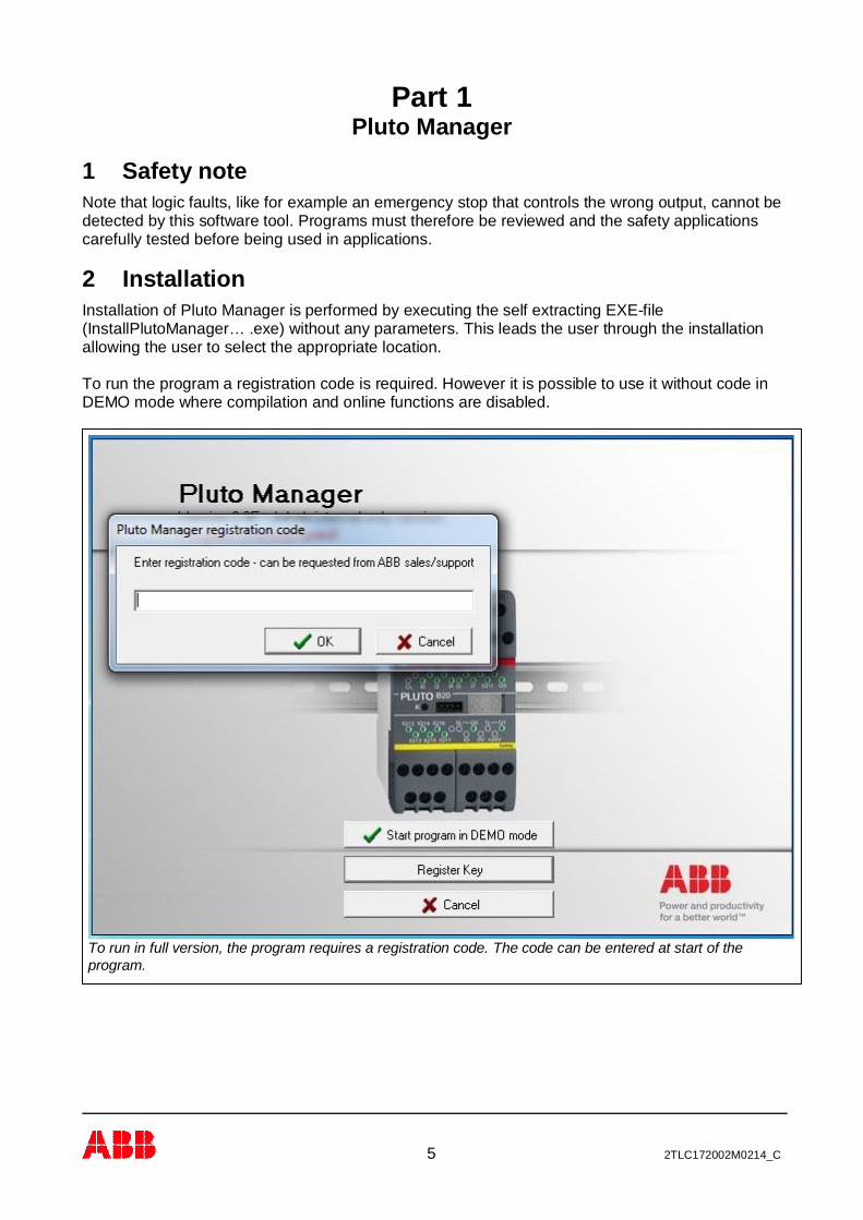
2 InstallationInstallation of Pluto Manager is performed by executing the self extracting EXE-file(InstallPlutoManager… .exe) without any parameters. This leads the user through the installationallowing the user to select the appropriate location.
To run the program a registration code is required. However it is possible to use it without code inDEMO mode where compilation and online functions are disabled.
To run in full version, the program requires a registration code. The code can be entered at start of theprogram.
6 2TLC172002M0214_C
3 Making your first programThe quickest way to introduce yourself to the Pluto Manager is to write an application. This tutorialguides you through the creation of a Pluto program.
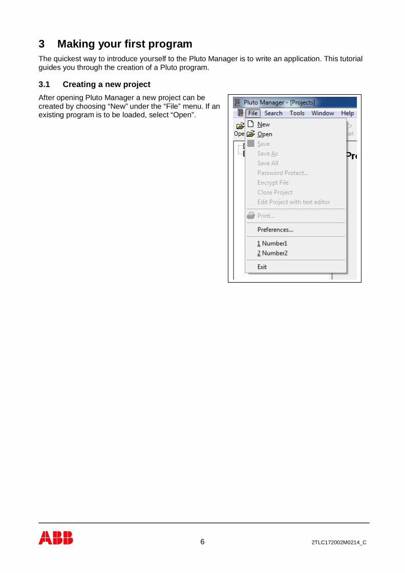
3.1 Creating a new projectAfter opening Pluto Manager a new project can becreated by choosing “New” under the “File” menu. If anexisting program is to be loaded, select “Open”.
7 2TLC172002M0214_C
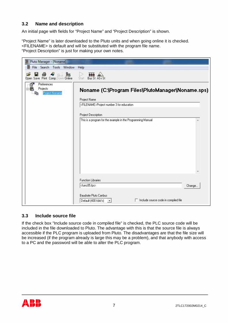
3.2 Name and descriptionAn initial page with fields for “Project Name” and “Project Description” is shown.
“Project Name” is later downloaded to the Pluto units and when going online it is checked.<FILENAME> is default and will be substituted with the program file name.“Project Description” is just for making your own notes.
3.3 Include source fileIf the check box ”Include source code in compiled file” is checked, the PLC source code will beincluded in the file downloaded to Pluto. The advantage with this is that the source file is alwaysaccessible if the PLC program is uploaded from Pluto. The disadvantages are that the file size willbe increased (if the program already is large this may be a problem), and that anybody with accessto a PC and the password will be able to alter the PLC program.

8 2TLC172002M0214_C
3.4 SavingAt this stage it can be a good idea to save for the first time. The toolbar provides quick mouseaccess to save. When the project is not saved before, Pluto Manager displays the Save As dialogbox. “Save” and “Save As” can also be found under the File menu. The source file is automaticallysaved with file extension .sps if nothing else is specified.
3.5 Selection of function block libraryThe Pluto system offers the possibility for using pre-programmed function blocks/macros fordifferent safety functions and safety devices. These function blocks are stored in separate libraryfiles. Standard libraries are included in Pluto Manager but it is also possible to make user specificlibraries.
Select “Function library”,“Change”, and then “Addstandard Library”. A list withavailable libraries is shown.
By “Add standard Library” Pluto Manager looks for the files at “..\PlutoManager\Library” where theynormally are stored by the installation program. If “Add User Library” is selected, Pluto Managerlooks for the files in the directory where the project files are stored.
9 2TLC172002M0214_C
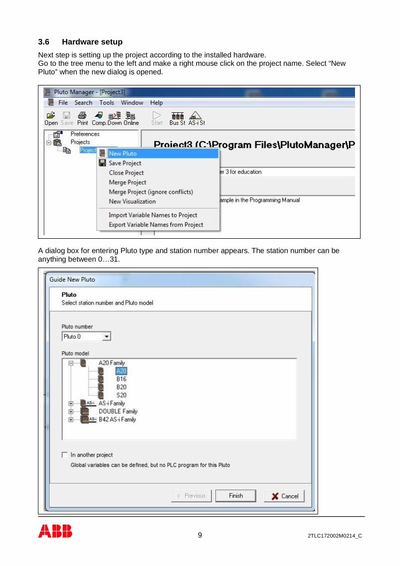
3.6 Hardware setupNext step is setting up the project according to the installed hardware.Go to the tree menu to the left and make a right mouse click on the project name. Select “NewPluto” when the new dialog is opened.
A dialog box for entering Pluto type and station number appears. The station number can beanything between 0…31.
10 2TLC172002M0214_C
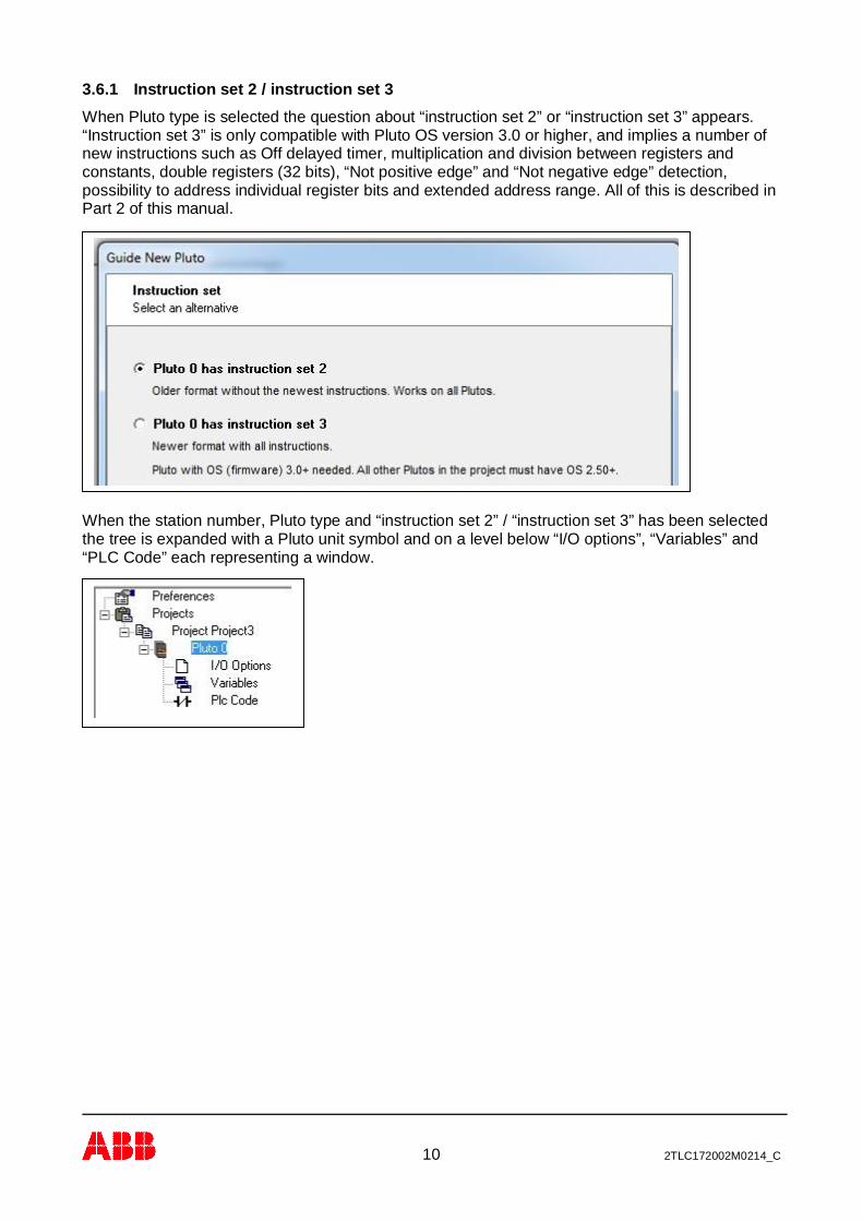
3.6.1 Instruction set 2 / instruction set 3When Pluto type is selected the question about “instruction set 2” or “instruction set 3” appears.“Instruction set 3” is only compatible with Pluto OS version 3.0 or higher, and implies a number ofnew instructions such as Off delayed timer, multiplication and division between registers andconstants, double registers (32 bits), “Not positive edge” and “Not negative edge” detection,possibility to address individual register bits and extended address range. All of this is described inPart 2 of this manual.
When the station number, Pluto type and “instruction set 2” / “instruction set 3” has been selectedthe tree is expanded with a Pluto unit symbol and on a level below “I/O options”, “Variables” and“PLC Code” each representing a window.
11 2TLC172002M0214_C
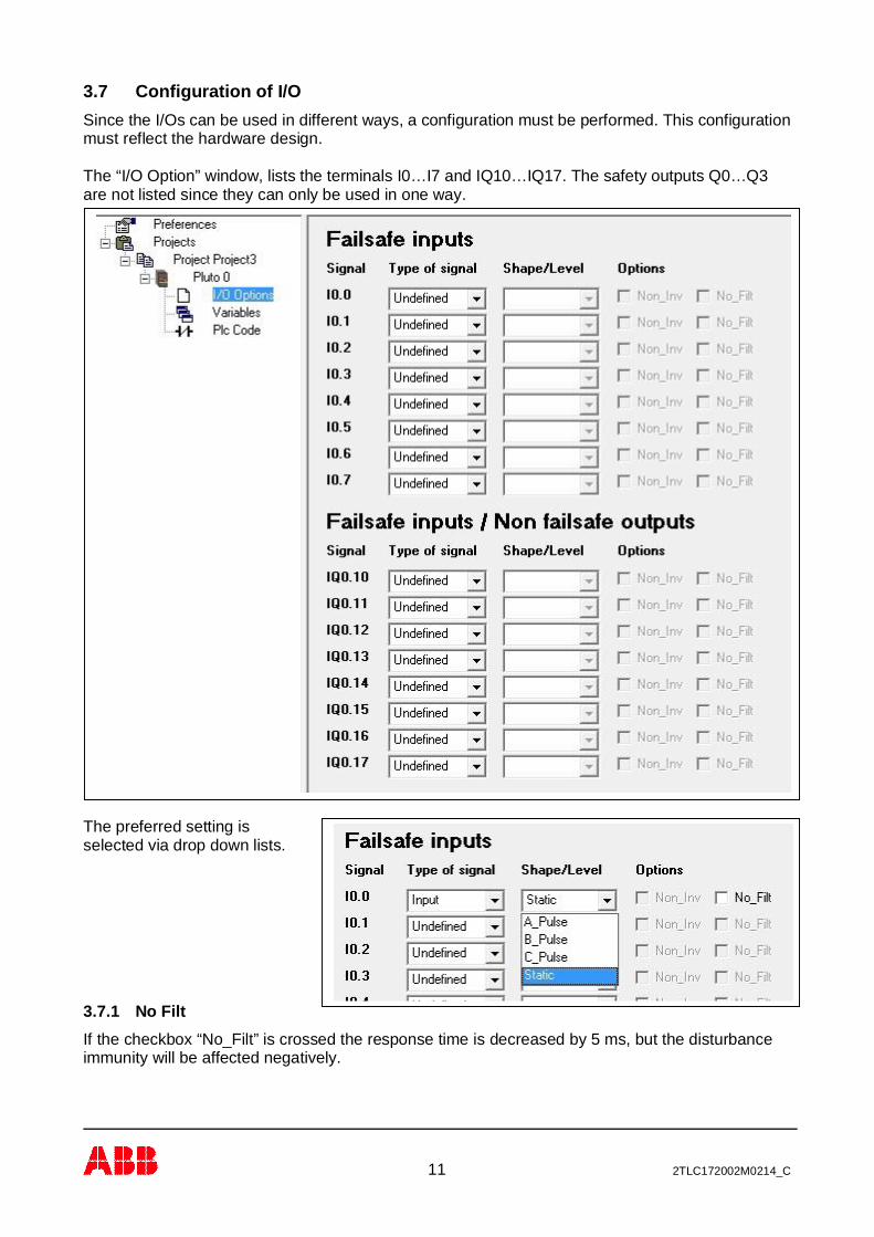
3.7 Configuration of I/OSince the I/Os can be used in different ways, a configuration must be performed. This configurationmust reflect the hardware design.
The “I/O Option” window, lists the terminals I0…I7 and IQ10…IQ17. The safety outputs Q0…Q3are not listed since they can only be used in one way.
The preferred setting isselected via drop down lists.
3.7.1 No FiltIf the checkbox “No_Filt” is crossed the response time is decreased by 5 ms, but the disturbanceimmunity will be affected negatively.
12 2TLC172002M0214_C
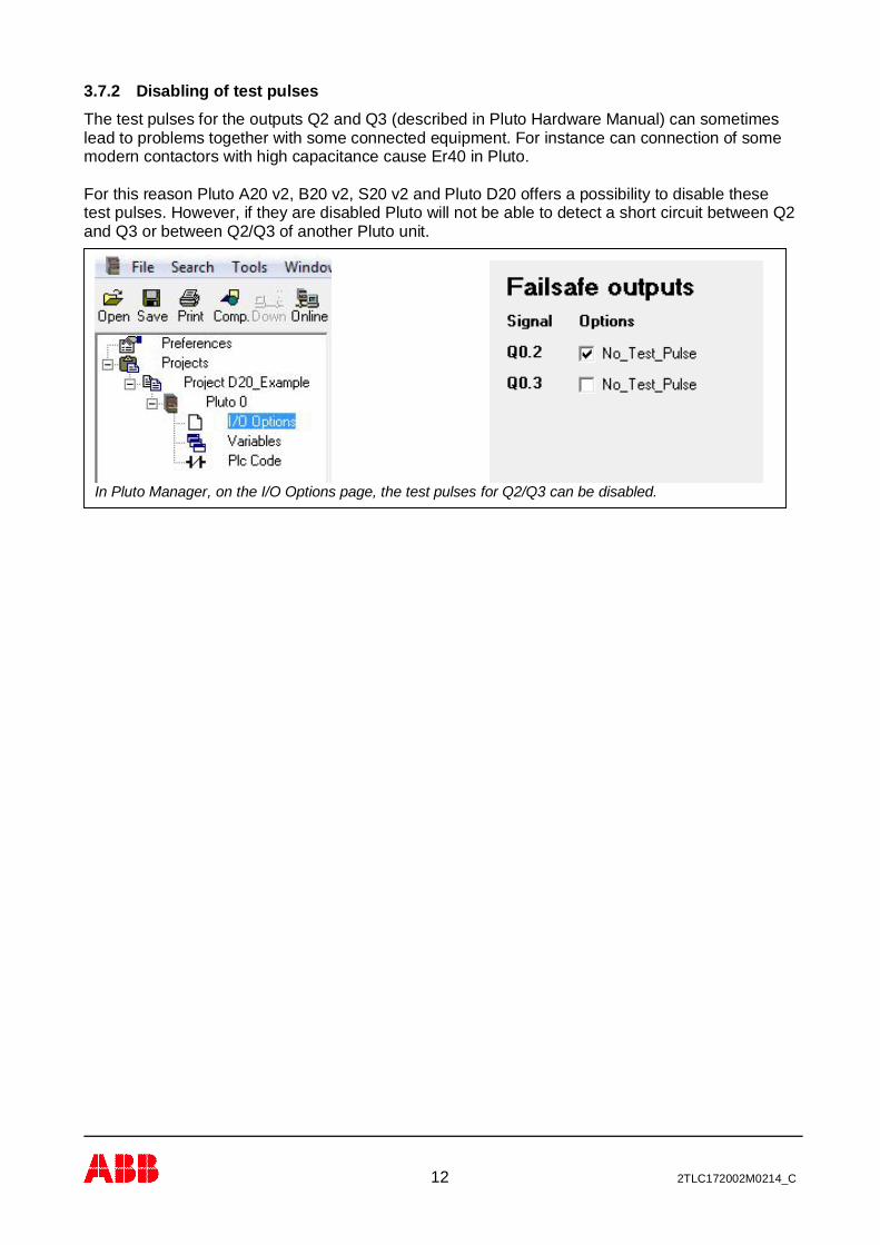
3.7.2 Disabling of test pulsesThe test pulses for the outputs Q2 and Q3 (described in Pluto Hardware Manual) can sometimeslead to problems together with some connected equipment. For instance can connection of somemodern contactors with high capacitance cause Er40 in Pluto.
For this reason Pluto A20 v2, B20 v2, S20 v2 and Pluto D20 offers a possibility to disable thesetest pulses. However, if they are disabled Pluto will not be able to detect a short circuit between Q2and Q3 or between Q2/Q3 of another Pluto unit.
In Pluto Manager, on the I/O Options page, the test pulses for Q2/Q3 can be disabled.

13 2TLC172002M0214_C
3.8 Example of setup of I/O-optionsThe pictures below show first an example of wiring, and then the corresponding configuration in the“I/O Option” window.
Note: The configuration of I/O isdependent on the hardware design. Thecorrect use of inputs, outputs, dynamicsignals etc. which is safety related, isnormally the hardware designer’sresponsibility.
14 2TLC172002M0214_C
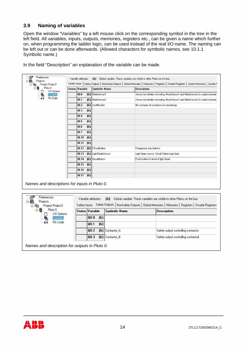
3.9 Naming of variablesOpen the window “Variables” by a left mouse click on the corresponding symbol in the tree in theleft field. All variables, inputs, outputs, memories, registers etc., can be given a name which furtheron, when programming the ladder logic, can be used instead of the real I/O name. The naming canbe left out or can be done afterwards. (Allowed characters for symbolic names, see 10.1.1Symbolic name.)
In the field “Description” an explanation of the variable can be made.
Names and descriptions for inputs in Pluto 0.
Names and description for outputs in Pluto 0.
15 2TLC172002M0214_C
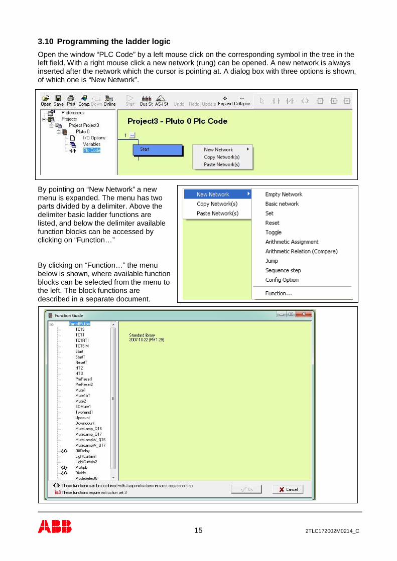
3.10 Programming the ladder logicOpen the window “PLC Code” by a left mouse click on the corresponding symbol in the tree in theleft field. With a right mouse click a new network (rung) can be opened. A new network is alwaysinserted after the network which the cursor is pointing at. A dialog box with three options is shown,of which one is “New Network”.
By pointing on “New Network” a newmenu is expanded. The menu has twoparts divided by a delimiter. Above thedelimiter basic ladder functions arelisted, and below the delimiter availablefunction blocks can be accessed byclicking on “Function…”
By clicking on “Function…” the menubelow is shown, where available functionblocks can be selected from the menu tothe left. The block functions aredescribed in a separate document.
16 2TLC172002M0214_C
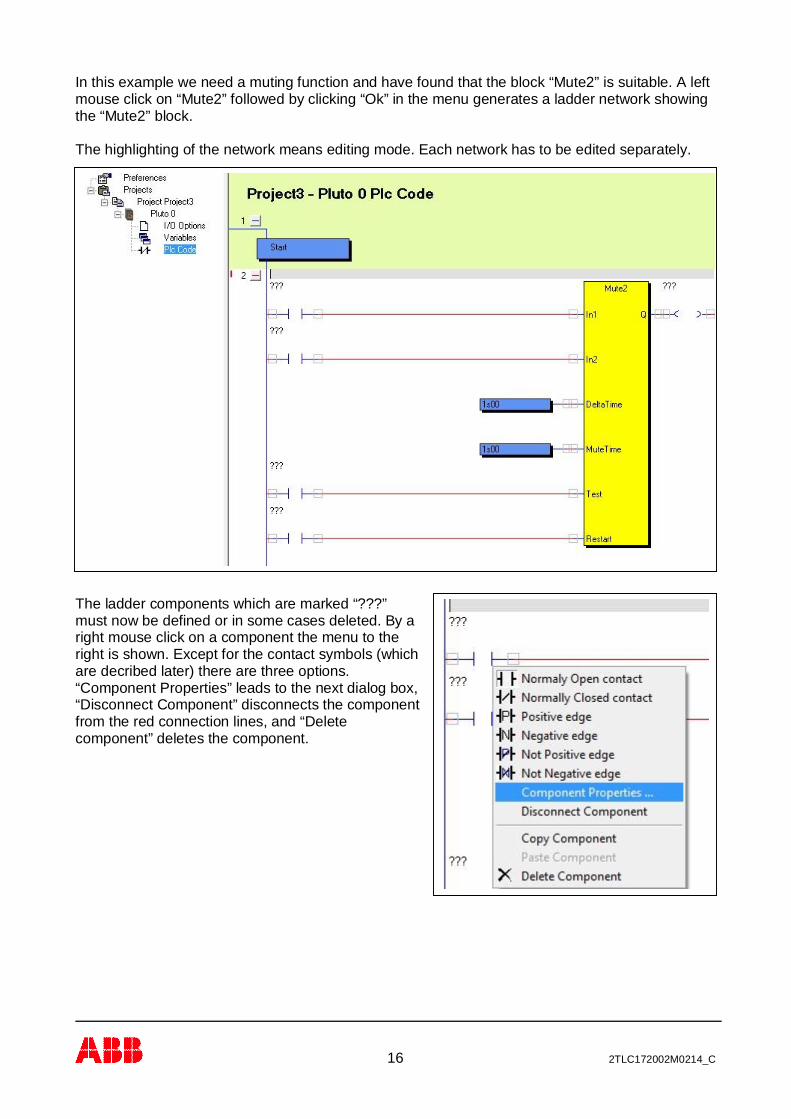
In this example we need a muting function and have found that the block “Mute2” is suitable. A leftmouse click on “Mute2” followed by clicking “Ok” in the menu generates a ladder network showingthe “Mute2” block.
The highlighting of the network means editing mode. Each network has to be edited separately.
The ladder components which are marked “???”must now be defined or in some cases deleted. By aright mouse click on a component the menu to theright is shown. Except for the contact symbols (whichare decribed later) there are three options.“Component Properties” leads to the next dialog box,“Disconnect Component” disconnects the componentfrom the red connection lines, and “Deletecomponent” deletes the component.
17 2TLC172002M0214_C
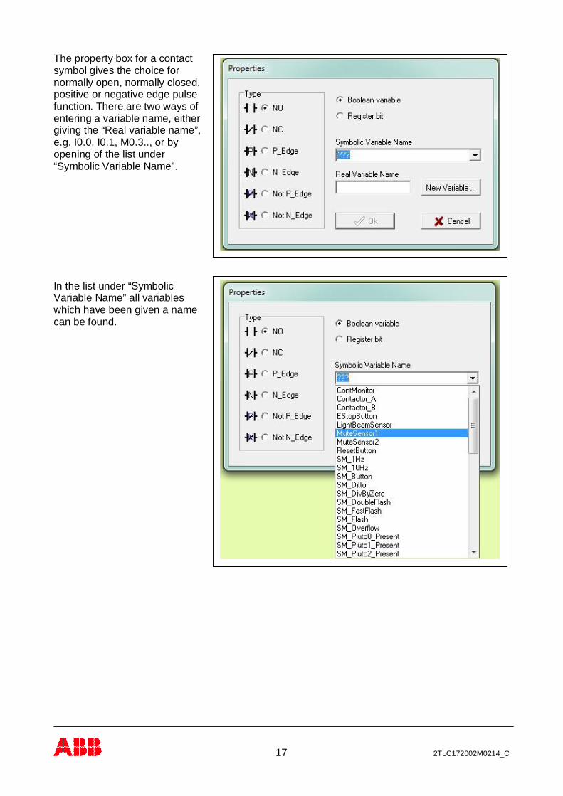
The property box for a contactsymbol gives the choice fornormally open, normally closed,positive or negative edge pulsefunction. There are two ways ofentering a variable name, eithergiving the “Real variable name”,e.g. I0.0, I0.1, M0.3.., or byopening of the list under“Symbolic Variable Name”.
In the list under “SymbolicVariable Name” all variableswhich have been given a namecan be found.
18 2TLC172002M0214_C
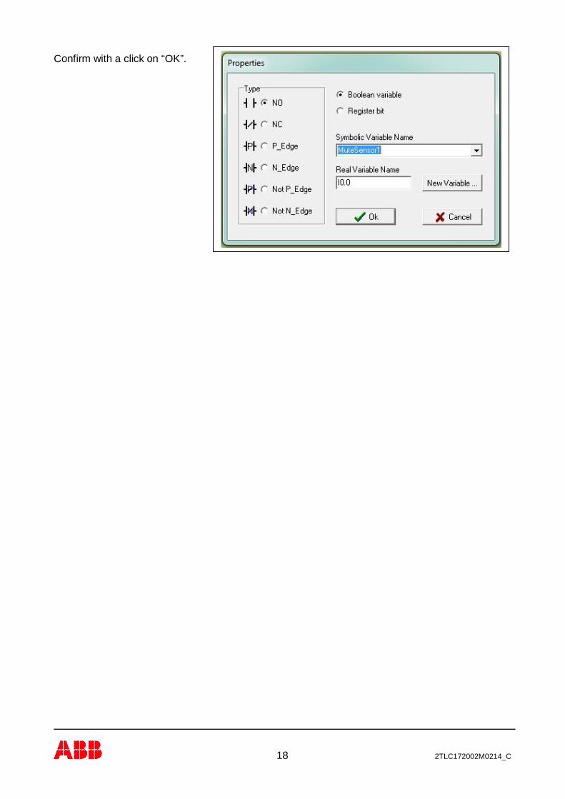
Confirm with a click on “OK”.

19 2TLC172002M0214_C
After selection, the component is labelled with both symbolic and real variable name.
The timer values can be changed in the same way, but a different dialog box is shown where thetimer value can be either specified as a constant or as the value from a register. “s” is used as thedecimal point.

20 2TLC172002M0214_C
The output from a function block can be connected directly to a physical output (Q), a memory (Mor GM) or to an input in another block, in this case a memory (M0.0).
By a double click onthe ladder componentwe get a dialog boxwith different outputfunctions.
To avoid mistakes the memories should be given a name directly by use. This can be done byopening the window “Variables” during the editing of a ladder network (except when a dialog box isshown).
The input for Test on the “Mute2” function block shall not have any input condition in this example.The component is therefore deleted.
21 2TLC172002M0214_C
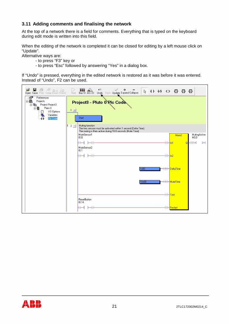
3.11 Adding comments and finalising the networkAt the top of a network there is a field for comments. Everything that is typed on the keyboardduring edit mode is written into this field.
When the editing of the network is completed it can be closed for editing by a left mouse click on“Update”.Alternative ways are:
- to press “F3” key or- to press “Esc” followed by answering “Yes” in a dialog box.
If “Undo” is pressed, everything in the edited network is restored as it was before it was entered.Instead of “Undo”, F2 can be used.
22 2TLC172002M0214_C
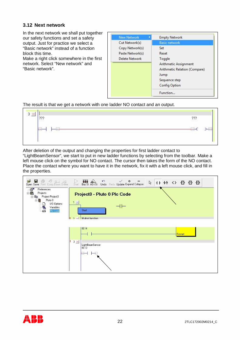
3.12 Next networkIn the next network we shall put togetherour safety functions and set a safetyoutput. Just for practice we select a“Basic network” instead of a functionblock this time.Make a right click somewhere in the firstnetwork. Select “New network” and“Basic network”.
The result is that we get a network with one ladder NO contact and an output.
After deletion of the output and changing the properties for first ladder contact to“LightBeamSensor”, we start to put in new ladder functions by selecting from the toolbar. Make aleft mouse click on the symbol for NO contact. The cursor then takes the form of the NO contact.Place the contact where you want to have it in the network, fix it with a left mouse click, and fill inthe properties.

23 2TLC172002M0214_C
In this network we need a function block called “ResetT”. This is a block with one safety inputwhich can handle monitoring of a Reset push button with an indicator. By clicking on the F symbol,the list with available function blocks is shown from where “ResetT” can be selected and inserted inthe network.
Continue selection of the other components needed in the same way. Function blocks can befound under the symbol F, Timers under “T” and arithmetic functions under “A”.

24 2TLC172002M0214_C
3.13 Connecting the componentsWhen the arrow symbol in the toolbar is highlighted it is possible to draw, delete and change linesbetween the components. In this mode it is also possible to drag components around. Theoperations “Draw a line”, “Change a line”, “Change component properties”, “Change components”and “Moving components” are described in detail in chapter 9.1 “Edit mode”.
When all components are inserted and connected, press the “Update” button or F3.Note that the function block output “IndReset” is a secondary output. This block output can be leftopen if there is no use for it. If a component (Q, M or GM) is connected to it, the right side of thiscomponent shall be left open and not be connected to the right common line.

25 2TLC172002M0214_C
After updating we continue with the last network in this program. The safety function is to controlthe two contactors A and B, connected to different outputs. We shall program contactor B to workexactly as Contactor A. Instead of making an equal network as for contactor A, we can use“Contactor_A” (Q0.2) which contains the logic result of the previous network.Open a new basic network, then open the “Properties” dialog box for the first contact. Select“Contactor_A” from the list. Finally set the properties for the output to “Contactor_B”.
Finished
26 2TLC172002M0214_C
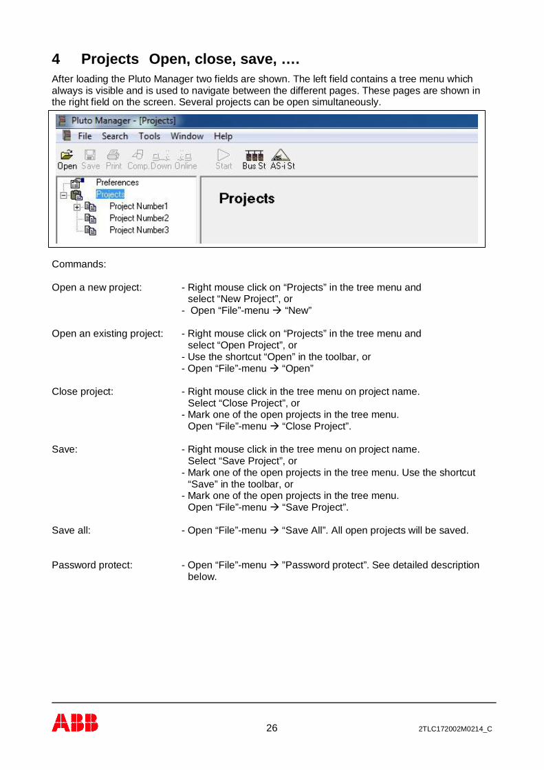
4 Projects Open, close, save, ….After loading the Pluto Manager two fields are shown. The left field contains a tree menu whichalways is visible and is used to navigate between the different pages. These pages are shown inthe right field on the screen. Several projects can be open simultaneously.
Commands:
Open a new project: - Right mouse click on “Projects” in the tree menu andselect “New Project”, or
- Open “File”-menuà “New”
Open an existing project: - Right mouse click on “Projects” in the tree menu andselect “Open Project”, or
- Use the shortcut “Open” in the toolbar, or- Open “File”-menuà “Open”
Close project: - Right mouse click in the tree menu on project name.Select “Close Project”, or
- Mark one of the open projects in the tree menu.Open “File”-menuà “Close Project”.
Save: - Right mouse click in the tree menu on project name.Select “Save Project”, or
- Mark one of the open projects in the tree menu. Use the shortcut“Save” in the toolbar, or
- Mark one of the open projects in the tree menu.Open “File”-menuà “Save Project”.
Save all: - Open “File”-menuà “Save All”. All open projects will be saved.
Password protect: - Open “File”-menuà ”Password protect”. See detailed descriptionbelow.
27 2TLC172002M0214_C
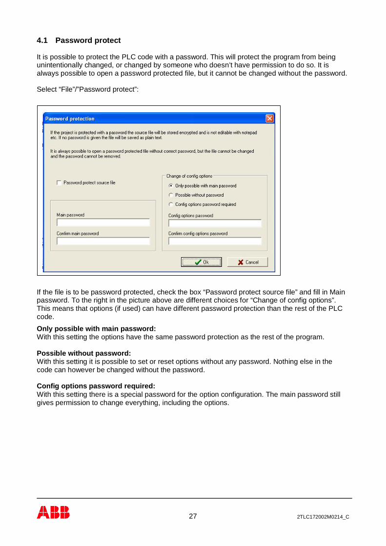
4.1 Password protect
It is possible to protect the PLC code with a password. This will protect the program from beingunintentionally changed, or changed by someone who doesn’t have permission to do so. It isalways possible to open a password protected file, but it cannot be changed without the password.
Select “File”/”Password protect”:
If the file is to be password protected, check the box “Password protect source file” and fill in Mainpassword. To the right in the picture above are different choices for “Change of config options”.This means that options (if used) can have different password protection than the rest of the PLCcode.
Only possible with main password:With this setting the options have the same password protection as the rest of the program.
Possible without password:With this setting it is possible to set or reset options without any password. Nothing else in thecode can however be changed without the password.
Config options password required:With this setting there is a special password for the option configuration. The main password stillgives permission to change everything, including the options.
28 2TLC172002M0214_C
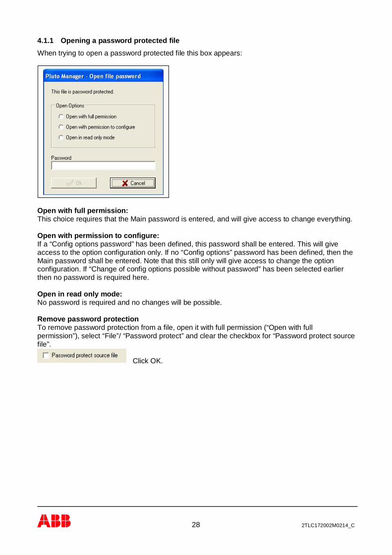
4.1.1 Opening a password protected fileWhen trying to open a password protected file this box appears:
Open with full permission:This choice requires that the Main password is entered, and will give access to change everything.
Open with permission to configure:If a “Config options password” has been defined, this password shall be entered. This will giveaccess to the option configuration only. If no “Config options” password has been defined, then theMain password shall be entered. Note that this still only will give access to change the optionconfiguration. If “Change of config options possible without password” has been selected earlierthen no password is required here.
Open in read only mode:No password is required and no changes will be possible.
Remove password protectionTo remove password protection from a file, open it with full permission (“Open with fullpermission”), select “File”/ “Password protect” and clear the checkbox for “Password protect sourcefile”.
Click OK.
29 2TLC172002M0214_C
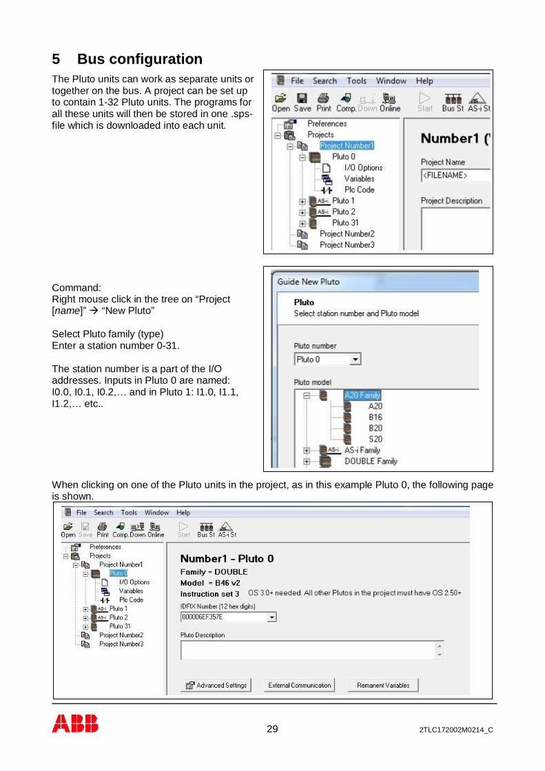
5 Bus configurationThe Pluto units can work as separate units ortogether on the bus. A project can be set upto contain 1-32 Pluto units. The programs forall these units will then be stored in one .sps-file which is downloaded into each unit.
Command:Right mouse click in the tree on “Project[name]”à “New Pluto”
Select Pluto family (type)Enter a station number 0-31.
The station number is a part of the I/Oaddresses. Inputs in Pluto 0 are named:I0.0, I0.1, I0.2,… and in Pluto 1: I1.0, I1.1,I1.2,… etc..
When clicking on one of the Pluto units in the project, as in this example Pluto 0, the following pageis shown.
30 2TLC172002M0214_C
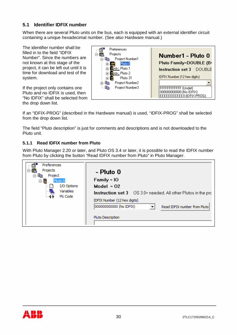
5.1 Identifier IDFIX numberWhen there are several Pluto units on the bus, each is equipped with an external identifier circuitcontaining a unique hexadecimal number. (See also Hardware manual.)
The identifier number shall befilled in to the field “IDFIXNumber”. Since the numbers arenot known at this stage of theproject, it can be left out until it istime for download and test of thesystem.
If the project only contains onePluto and no IDFIX is used, then“No IDFIX” shall be selected fromthe drop down list.
If an “IDFIX-PROG” (described in the Hardware manual) is used, “IDFIX-PROG” shall be selectedfrom the drop down list.
The field “Pluto description” is just for comments and descriptions and is not downloaded to thePluto unit.
5.1.1 Read IDFIX number from PlutoWith Pluto Manager 2.20 or later, and Pluto OS 3.4 or later, it is possible to read the IDFIX numberfrom Pluto by clicking the button “Read IDFIX number from Pluto” in Pluto Manager.
31 2TLC172002M0214_C
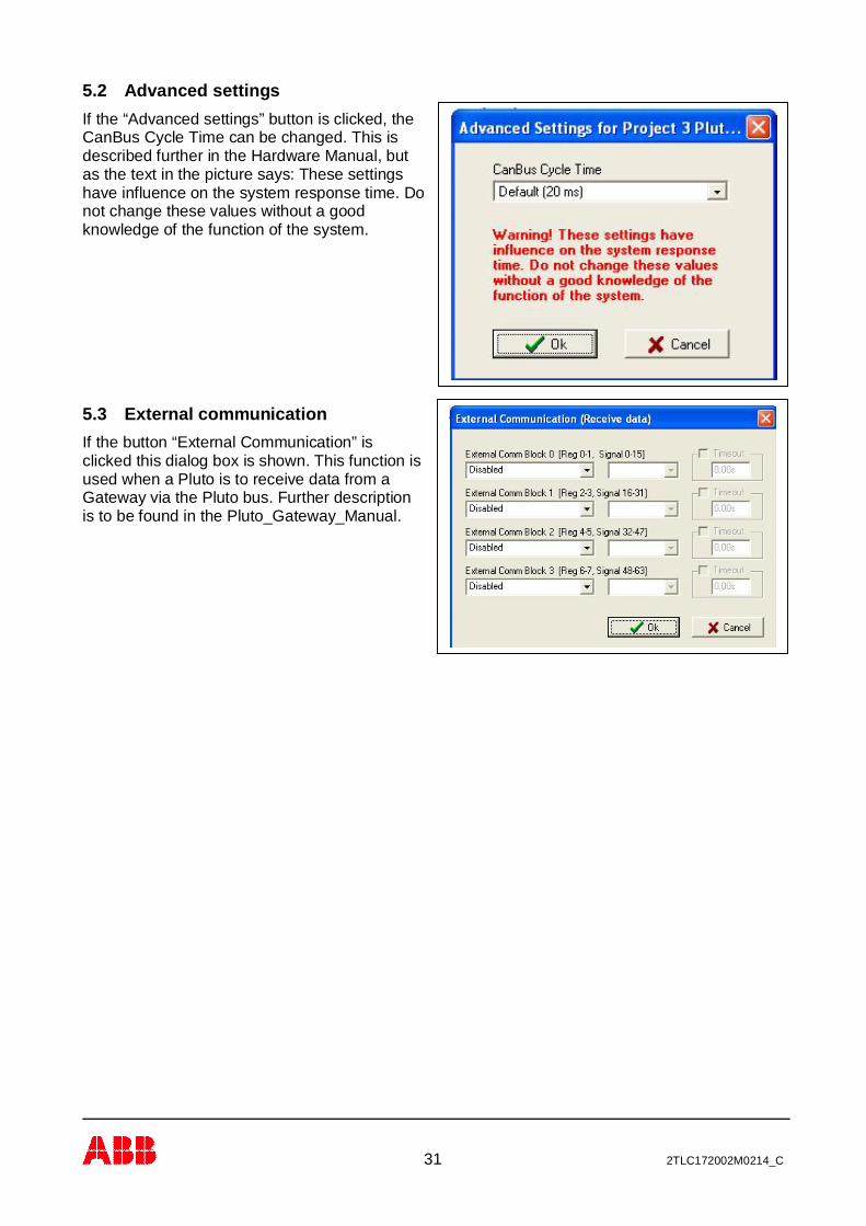
5.2 Advanced settingsIf the “Advanced settings” button is clicked, theCanBus Cycle Time can be changed. This isdescribed further in the Hardware Manual, butas the text in the picture says: These settingshave influence on the system response time. Donot change these values without a goodknowledge of the function of the system.
5.3 External communicationIf the button “External Communication” isclicked this dialog box is shown. This function isused when a Pluto is to receive data from aGateway via the Pluto bus. Further descriptionis to be found in the Pluto_Gateway_Manual.
32 2TLC172002M0214_C
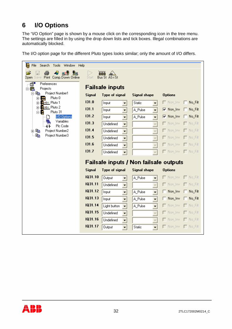
6 I/O OptionsThe “I/O Option” page is shown by a mouse click on the corresponding icon in the tree menu.The settings are filled in by using the drop down lists and tick boxes. Illegal combinations areautomatically blocked.
The I/O option page for the different Pluto types looks similar; only the amount of I/O differs.

33 2TLC172002M0214_C
7 AS-i bus functions(Only for Pluto AS-i and B42 AS-i, see also Pluto_Hardware_Manual)
7.1 Initial configuration of AS-i functionsThe following will show the steps to configure a Pluto AS-i or a B42 AS-i.
7.1.1 “New Pluto”, selection of family and station numberPut the cursor in the left side tree menu, make aright mouse click and select “New Pluto”(as described in 5).
Select Pluto “AS-i” or “B42 AS-i” from the list andselect station number on the Pluto bus.
Safetylight curtain
Bus Master /Monitor only /Monitor/slave
SafetyE-stop
1-channelSafetymodule
2-channelSafetymodul
Safetyswitch
AS-iPower
(30VDC)
External master(Optional)
Pluto AS-i
AS-i bus
Non-safestandard
slave
max4in/4out
A
Non-safe extended
slaves (A/B)
max4in/3out
B
ASi-
ASi+
0VIQ13IQ11
IQ10 IQ12
ID0V
Q0
PLUTOC L
C H
I0 I2 I3
I1 ASi+
+24V
Q1
ASi- Q3
Q2
I3
IQ 11
IQ10
IQ13 0V
IQ12
C H
PLUTOC L I0 I2
I1
Pluto
Q1
+24V0VID
Q0
Q3ASi+ ASi-
ASi-ASi+ Q2
Pluto Bus(To other Pluto units)
Pluto on AS-i bus with some examples of AS-i slave types.
(Note: For old Pluto AS-i, of version 1, extended non-safety slaves can only be handled in” Monitor only”mode)
34 2TLC172002M0214_C
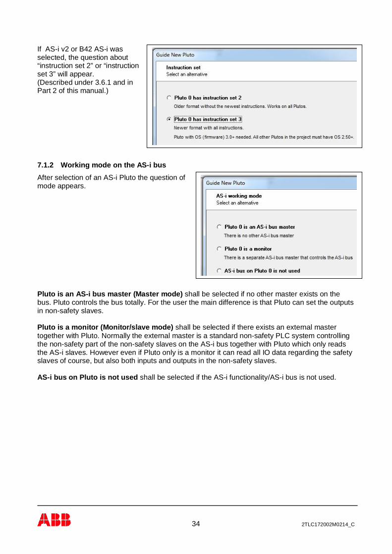
If AS-i v2 or B42 AS-i wasselected, the question about“instruction set 2” or “instructionset 3” will appear.(Described under 3.6.1 and inPart 2 of this manual.)
7.1.2 Working mode on the AS-i busAfter selection of an AS-i Pluto the question ofmode appears.
Pluto is an AS-i bus master (Master mode) shall be selected if no other master exists on thebus. Pluto controls the bus totally. For the user the main difference is that Pluto can set the outputsin non-safety slaves.
Pluto is a monitor (Monitor/slave mode) shall be selected if there exists an external mastertogether with Pluto. Normally the external master is a standard non-safety PLC system controllingthe non-safety part of the non-safety slaves on the AS-i bus together with Pluto which only readsthe AS-i slaves. However even if Pluto only is a monitor it can read all IO data regarding the safetyslaves of course, but also both inputs and outputs in the non-safety slaves.
AS-i bus on Pluto is not used shall be selected if the AS-i functionality/AS-i bus is not used.

35 2TLC172002M0214_C
7.1.2.1 Variants of monitor mode:If monitor mode is selected a new dialog with three selections appears.
Monitor only: An external master controls the bus and Pluto listens to the traffic and reads the I/Oinformation of all slaves. (Both safe inputs and non-safe input/outputs).
Monitor / Slave: Same as Monitor only but Pluto is also acting as a non-safety slave under theexternal master which means that Pluto and the external master can exchange 4 bit data in eachdirection with each other. If this mode is selected, the slave address also has to be selected.
Monitor / Slave with 3 extra slaves: Same as Monitor /Slave but with three extra dummy slaves.This mode shall be selected when there are less than 5 AS-i slaves connected to the bus. (Thereason is that if there are only a few slaves on the bus the AS-i cycle time is shorter and if it is toshort the safety slaves have not enough time to update the safety code.)

36 2TLC172002M0214_C
7.1.3 Page for AS-i specific setupBy clicking on “AS-i Options” in the tree menu to the left the special page for AS-i specific settingsis shown.
Working modes:Even if the working mode was selectedimmediately by selection of a Pluto AS-iit can be modified afterwards. As thepicture shows there are three selectionsfor Monitor mode.
Optimization “Short stop time” or “Disturbance immunity”As the picture tells Short stop time should be selected whenthere are fewer than 20 slaves on the bus.By selection of disturbance immunity the system can withstanddisturbances on the AS-i bus better, but the worst case stop timeincreases 10 ms.
37 2TLC172002M0214_C
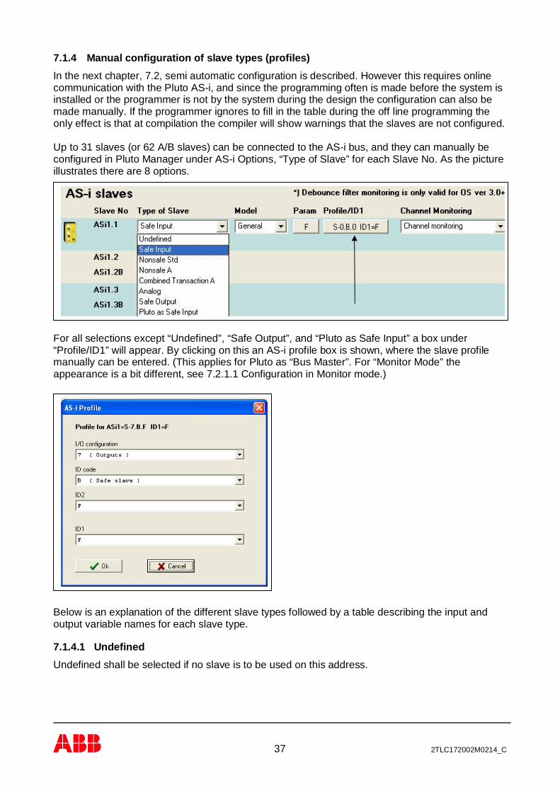
7.1.4 Manual configuration of slave types (profiles)In the next chapter, 7.2, semi automatic configuration is described. However this requires onlinecommunication with the Pluto AS-i, and since the programming often is made before the system isinstalled or the programmer is not by the system during the design the configuration can also bemade manually. If the programmer ignores to fill in the table during the off line programming theonly effect is that at compilation the compiler will show warnings that the slaves are not configured.
Up to 31 slaves (or 62 A/B slaves) can be connected to the AS-i bus, and they can manually beconfigured in Pluto Manager under AS-i Options, “Type of Slave” for each Slave No. As the pictureillustrates there are 8 options.
For all selections except “Undefined”, “Safe Output”, and “Pluto as Safe Input” a box under“Profile/ID1” will appear. By clicking on this an AS-i profile box is shown, where the slave profilemanually can be entered. (This applies for Pluto as “Bus Master”. For “Monitor Mode” theappearance is a bit different, see 7.2.1.1 Configuration in Monitor mode.)
Below is an explanation of the different slave types followed by a table describing the input andoutput variable names for each slave type.
7.1.4.1 UndefinedUndefined shall be selected if no slave is to be used on this address.

38 2TLC172002M0214_C
7.1.4.2 Safe inputA safe input slave has physically a dual channel input but in Pluto/Pluto Manager it is configured asone input. The slave can also have up to 4 non-safe outputs. For naming of variables see the tableunder 7.1.4.4 Nonsafe A/B slaves.
When Safe input is selected the following page is shown:
Under “Model” there is another drop down list where the type of safe input slave can be selected.For all slave types except Urax, select “General”. For Urax slaves, select the correct Urax model.
By clicking on “Param” the slave parameter can be set. This parameter setting dictates whichmode the slave operates in.
“Profile/ID1” is a description of the slave stating the number of inputs/outputs, if it is a non-safe orsafety slave, A/B slave, etc. Explanation of the profile codes can be found in different literature buthere are some examples:S-0.B… - Safe slaveS-7.B… - Safe slave with outputsS-7.0… - Standard non-safe slave with 4 inputs and 4 outputs.“Profile/ID1” does not have to be selected for Urax slaves, since this is done automatically byselecting the correct Urax type. For other slave types than Urax, see the manual for correct setting.
For Urax-A1R this picture is shown. For “General” this picture is shown.

39 2TLC172002M0214_C
“Channel Monitoring”Many of the safety nodes have dual channel input. The user can select different kinds of channelmonitoring for these devices.
- No channel monitoring: Both channels must be on, but nochannel monitoring. Normal settingfor single channel slaves.
- Channel monitoring: The default setting. If one channelopens, the other also has to beopened before they close again.
- Chan mon & debounce filter*: As with channel monitoring, butthere is a time from where bothchannels are on where contactbounces are allowed.The input is considered as on as soon as both channels are on, butwill shortly fall if there are contact bounces.This mode is suitable for example for doors with mechanicalswitches.
- Simultaneously: As with channel monitoring, but there is a maximum time betweenthe two channels off®on transitions.
- Simultaneously & debounce*: As simultaneously, but contact bounces are allowed within thespecified time.The input is considered as on as soon as both channels are on, butwill shortly fall if there are contact bounces.
*OS version 3.0 or later
For all URAX models except URAX-C1 the Channel Monitoring setting is inhibited. This is because(with exception for URAX-C1) the channel monitoring is handled by URAX.
“Time limit”If “Simultaneously” has been selected the desired time limit in seconds can be entered here.
Ch 1
Ch 2
No channel monitoring
Chan mon & debounce filter
Simultaneously
Simultaneously & debounce
Channel monitoring
This timing diagram example illustrates the differences between the different settings.

40 2TLC172002M0214_C
7.1.4.3 Nonsafe Standard slavesA non-safe standard slave can have up to 4 local non-safe inputs and/or up to 4 local non-safeoutputs. For naming of variables see the table below.
7.1.4.4 Nonsafe A/B slavesTwo A/B-slaves (one A-slave + one B-slave) share the same address number. This means that upto 62 A/B-slaves can be used in a net, instead of 31 which is the maximum number for other slavetypes. A non-safe A/B-slave can have up to 4 inputs and 3 outputs. Both inputs and outputs arelocal. For naming of variables see the table below.
”Type of Slave” settingSafe Input(Slave 1-15)
Safe Input(Slave 16-31)
Nonsafe Std Nonsafe A(Nonsafe B)
Global Safety Inputs ASi_.x - - -Local Safety Inputs - ASi_.x - -Local NonSafety Inputs - - ASi_.x.1
ASi_.x.2ASi_.x.3ASi_.x.4
ASi_.x.1ASi_.x.2ASi_.x.3ASi_.x.4(ASi_.xB.1)(ASi_.xB.2)(ASi_.xB.3)(ASi_.xB.4)
Local NonSafety Outputs ASq_.x.1ASq_.x.2ASq_.x.3ASq_.x.4
ASq_.x.1ASq_.x.2ASq_.x.3ASq_.x.4
ASq_.x.1ASq_.x.2ASq_.x.3ASq_.x.4
ASq_.x.1ASq_.x.2ASq_.x.3(ASq_.xB.1)(ASq_.xB.2)(ASq_.xB.3)
“_” = Pluto no, “x” = Slave no.
7.1.4.5 Combined Transaction A/B slavesPluto supports Combined Transaction slaves with 4 inputs and 4 outputs.AS-i profile: S-7.A.7
7.1.4.6 Analogue input slavesThis is a non-safe slave which reads one analogue input value per channel and then sends adigital representation of this value over the AS-i bus. The slave can have up to 4 input channelsand one special function block, “ASiAnalogInput”, is needed for each channel.
In this example the Analogue slave has number 1, and only channel 1 is used. The value is stored inregister 0.
41 2TLC172002M0214_C
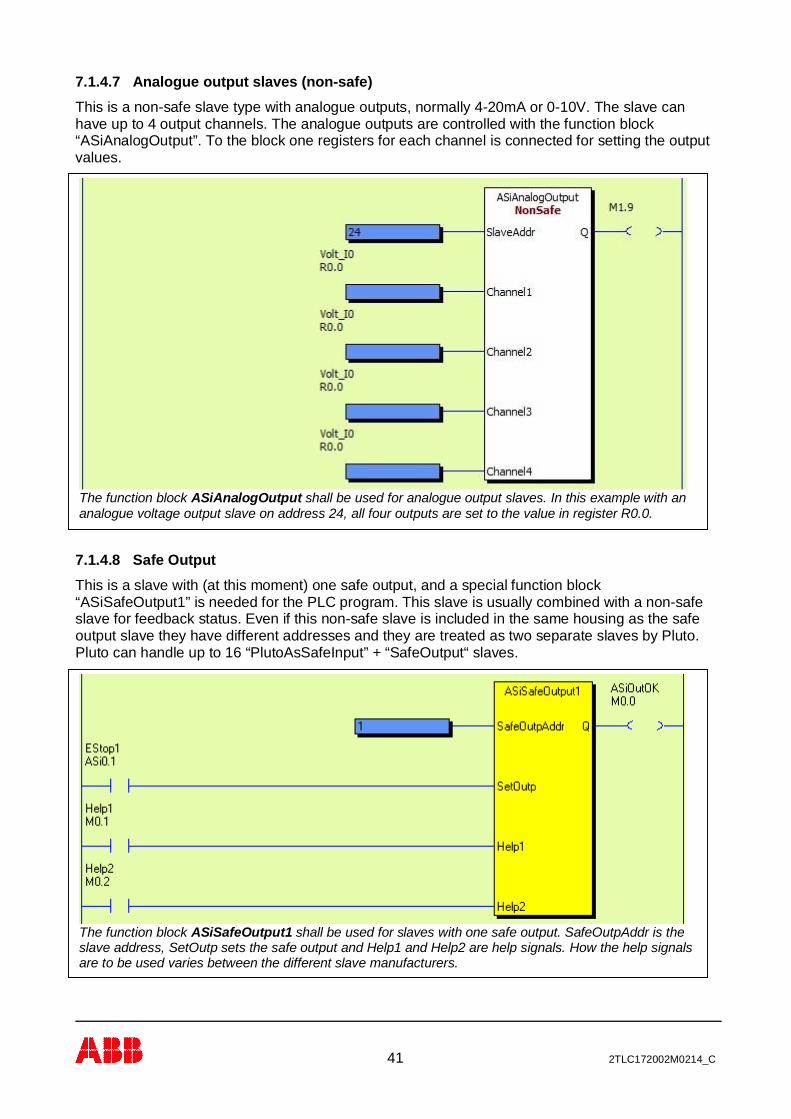
7.1.4.7 Analogue output slaves (non-safe)This is a non-safe slave type with analogue outputs, normally 4-20mA or 0-10V. The slave canhave up to 4 output channels. The analogue outputs are controlled with the function block“ASiAnalogOutput”. To the block one registers for each channel is connected for setting the outputvalues.
7.1.4.8 Safe OutputThis is a slave with (at this moment) one safe output, and a special function block“ASiSafeOutput1” is needed for the PLC program. This slave is usually combined with a non-safeslave for feedback status. Even if this non-safe slave is included in the same housing as the safeoutput slave they have different addresses and they are treated as two separate slaves by Pluto.Pluto can handle up to 16 “PlutoAsSafeInput” + “SafeOutput“ slaves.
The function block ASiSafeOutput1 shall be used for slaves with one safe output. SafeOutpAddr is theslave address, SetOutp sets the safe output and Help1 and Help2 are help signals. How the help signalsare to be used varies between the different slave manufacturers.
The function block ASiAnalogOutput shall be used for analogue output slaves. In this example with ananalogue voltage output slave on address 24, all four outputs are set to the value in register R0.0.

42 2TLC172002M0214_C
7.1.4.9 Pluto as Safe InputThis is the setting for a Pluto that is used as a safe input slave. A special function block,“PlutoAsSafeInput”, is needed for the PLC program. Configuration of the safe input and non-safeoutputs are the same as for the ordinary “Safe input” slave described in the table above. Pluto canhandle up to 16 “PlutoAsSafeInput” + “SafeOutput“ slaves.
7.1.5 Write parameter to slave and receive info backFor some AS-i slaves on the market it is possible to send a parameter to the slave and receiveinfo/data back. The function block “ASiParam” is required for this.
Example: Pluto 1 is used as “safe input slave”. The slave number is 1, and I1.0 is used as input to thefunction block.
Configuration for Pluto 0 which is a master that reads slave no 1.
Configuration for Pluto 1 which functions as a “Safe input” slave.
Example with ASiParam: Parameter 2 is written to slave no. 1. The data received back from theslave will be written to register R0.0.

43 2TLC172002M0214_C
7.2 Online configuration of AS-i busBefore the configuration below can be performed the program has to be compiled and downloadedto the Pluto unit.
The two buttons “Read AS-i slaves” and “Teach safety codes” are semi automatic functions thatreads out what kind of slaves that are connected to the AS-i bus.
7.2.1 Read AS-i slaves- Start with pressing “Read AS-i slaves”.
Pluto will scan the AS-i bus to find out what type of slaves that are connected to it. The followingpicture will be displayed. - If everything looks OK press “Save”
Menu from “Read AS-i slaves”.In this case Pluto is master on the bus. No: 1 and 16 are standard non- safety slaves, 2 and 13 are safeinput slaves, 5..8 and 10 are Urax (safe input) slaves, 15 is a safe output slave, and 18 is an analogue inputslave.

44 2TLC172002M0214_C
SaveBy “Save” the slave profiles (slave types) will be written into the table which is a part of the PLCprogram. Note that it is only in master mode that the full profile is read and written into the table.
Storage of slave configurationThe list is stored in the PLC program which means that the configuration must be compiled anddownloaded to the Pluto.
7.2.1.1 Configuration in Monitor modeIf Pluto is configured as a monitor the configuration procedure is the same, but there are somedifferences.
The main difference is that in monitor mode the full slave parameters are not shown. The onlyinformation that is shown is if the slaves are safe or non-safe.
List with slave types and setting of safety parameters for safe slaves in monitor mode.
The status picture shows an external master.
45 2TLC172002M0214_C
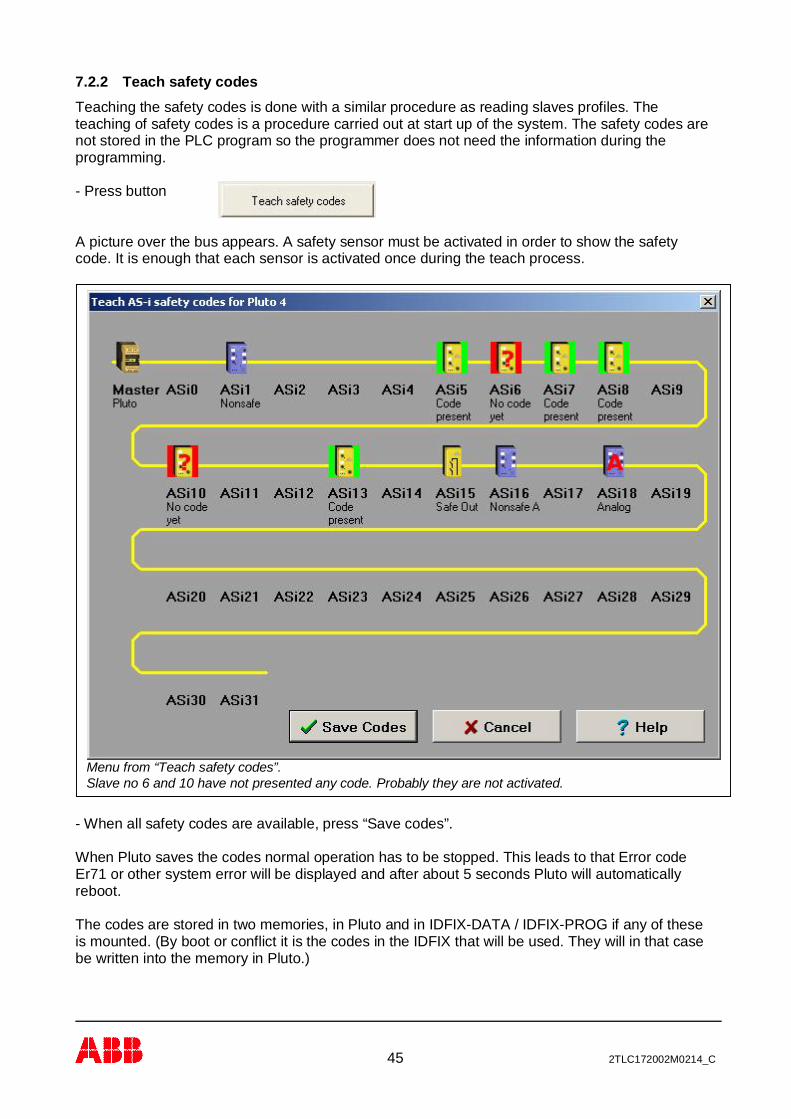
7.2.2 Teach safety codesTeaching the safety codes is done with a similar procedure as reading slaves profiles. Theteaching of safety codes is a procedure carried out at start up of the system. The safety codes arenot stored in the PLC program so the programmer does not need the information during theprogramming.
- Press button
A picture over the bus appears. A safety sensor must be activated in order to show the safetycode. It is enough that each sensor is activated once during the teach process.
- When all safety codes are available, press “Save codes”.
When Pluto saves the codes normal operation has to be stopped. This leads to that Error codeEr71 or other system error will be displayed and after about 5 seconds Pluto will automaticallyreboot.
The codes are stored in two memories, in Pluto and in IDFIX-DATA / IDFIX-PROG if any of theseis mounted. (By boot or conflict it is the codes in the IDFIX that will be used. They will in that casebe written into the memory in Pluto.)
Menu from “Teach safety codes”.Slave no 6 and 10 have not presented any code. Probably they are not activated.

46 2TLC172002M0214_C
7.2.2.1 Set slave output
Some safety slaves require that certain data output or parameter is set in order for the slave totransmit the safety code. Click “Teach safety codes”, right click on the slave symbol, left click “Setparam and Data”, and then select which output to set. When “Code present” is shown, click “Savecodes”.
7.3 Other online toolsUnder Toolsà AS-i there are some online tools
Right click on the slave, left click “Set param and Data”, and select which output to set.
47 2TLC172002M0214_C
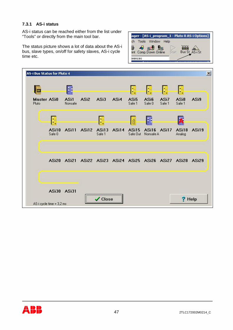
7.3.1 AS-i statusAS-i status can be reached either from the list under“Tools” or directly from the main tool bar.
The status picture shows a lot of data about the AS-ibus, slave types, on/off for safety slaves, AS-i cycletime etc.
48 2TLC172002M0214_C
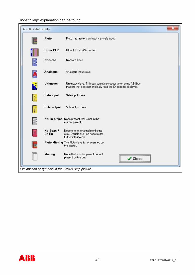
Under “Help” explanation can be found.
Explanation of symbols in the Status Help picture.

49 2TLC172002M0214_C
7.3.2 Show code tableAll safety codes are shown in a list.
7.3.3 Teach code tableThe same function as “Teach safety codes” on the page AS-i options.(See 7.2.2 above)
7.3.4 Erase code tableIt is also possible to erase the safety codes from the memory in Pluto and IDFIX-DATA / IDFIX-PROG (if mounted).
Note that the safety codes are not stored in the PLC program which means that if the program iserased the safety codes are still stored.

50 2TLC172002M0214_C
7.3.5 Change address on a slave
Example of address change. Slave 13 is re-addressed to 12
Result after address change

51 2TLC172002M0214_C
8 Analogue inputs Pluto D20 and D45 – Function blocksPluto D20 is equipped with 4, and Pluto D45 with 8, safe 4-20mA/0-10V analogue inputs.These inputs (D20: IA0 - IA3, D45: IA0 – IA7) can be configured in Pluto Manager as either“ordinary” failsafe inputs, as analogue inputs 0-10V or as analogue inputs 4-20mA.
For analogue input 0-10V the function block “ReadVoltage” is needed, and for analogue input4-20mA the function block “ReadCurrent” is needed. Both of these function blocks are includedin the “Analog01.fps” library. Included are also 32-bit versions of the function blocks(“ReadVoltage_32” and “ReadCurrent_32”) for use with Double Registers.
IA0.0 and IA0.1 are configured as Analogue input 0-10V, andIA0.2 and IA0.3 are configured as Analogue input 4-20mA.
ReadVoltage and ReadCurrent function blocks.
52 2TLC172002M0214_C
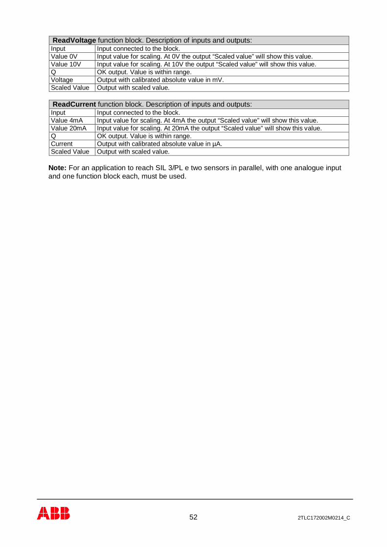
ReadVoltage function block. Description of inputs and outputs:Input Input connected to the block.Value 0V Input value for scaling. At 0V the output “Scaled value” will show this value.Value 10V Input value for scaling. At 10V the output “Scaled value” will show this value.Q OK output. Value is within range.Voltage Output with calibrated absolute value in mV.Scaled Value Output with scaled value.
ReadCurrent function block. Description of inputs and outputs:Input Input connected to the block.Value 4mA Input value for scaling. At 4mA the output “Scaled value” will show this value.Value 20mA Input value for scaling. At 20mA the output “Scaled value” will show this value.Q OK output. Value is within range.Current Output with calibrated absolute value in µA.Scaled Value Output with scaled value.
Note: For an application to reach SIL 3/PL e two sensors in parallel, with one analogue inputand one function block each, must be used.

53 2TLC172002M0214_C
The example shows the scaling of two different sensors into temperature, °C. TC2RTI is a standardfunction block for two channel monitoring with reset.
8.1 Application example with two sensors – Temperature measurementWith the application example below, using two different sensors, Category 4/PL e can beachieved.
54 2TLC172002M0214_C
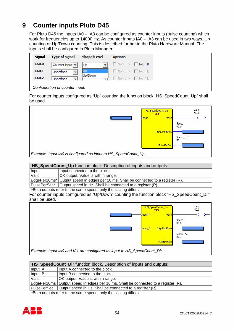
9 Counter inputs Pluto D45For Pluto D45 the inputs IA0 – IA3 can be configured as counter inputs (pulse counting) whichwork for frequencies up to 14000 Hz. As counter inputs IA0 – IA3 can be used in two ways, Upcounting or Up/Down counting. This is described further in the Pluto Hardware Manual. Theinputs shall be configured in Pluto Manager.
For counter inputs configured as “Up” counting the function block “HS_SpeedCount_Up” shallbe used.
HS_SpeedCount_Up function block. Description of inputs and outputs:Input Input connected to the block.Valid OK output. Value is within range.EdgePer10ms* Output speed in edges per 10 ms. Shall be connected to a register (R).PulsePerSec* Output speed in Hz. Shall be connected to a register (R).*Both outputs refer to the same speed, only the scaling differs.
For counter inputs configured as “Up/Down” counting the function block “HS_SpeedCount_Dir”shall be used.
HS_SpeedCount_Dir function block. Description of inputs and outputs:Input_A Input A connected to the block.Input_B Input B connected to the block.Valid OK output. Value is within range.EdgePer10ms Output speed in edges per 10 ms. Shall be connected to a register (R).PulsePerSec Output speed in Hz. Shall be connected to a register (R).*Both outputs refer to the same speed, only the scaling differs.
Configuration of counter input.
Example: Input IA0 is configured as input to HS_SpeedCount_Up.
Example: Input IA0 and IA1 are configured as input to HS_SpeedCount_Dir.
55 2TLC172002M0214_C
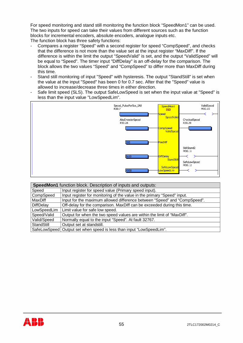
For speed monitoring and stand still monitoring the function block “SpeedMon1” can be used.The two inputs for speed can take their values from different sources such as the functionblocks for incremental encoders, absolute encoders, analogue inputs etc.The function block has three safety functions:- Compares a register “Speed” with a second register for speed “CompSpeed”, and checks
that the difference is not more than the value set at the input register “MaxDiff”. If thedifference is within the limit the output “SpeedValid” is set, and the output “ValidSpeed” willbe equal to “Speed”. The timer input "DiffDelay" is an off-delay for the comparison. Theblock allows the two values “Speed” and “CompSpeed” to differ more than MaxDiff duringthis time.
- Stand still monitoring of input "Speed" with hysteresis. The output "StandStill" is set whenthe value at the input "Speed" has been 0 for 0.7 sec. After that the "Speed" value isallowed to increase/decrease three times in either direction.
- Safe limit speed (SLS). The output SafeLowSpeed is set when the input value at "Speed" isless than the input value "LowSpeedLim".
SpeedMon1 function block. Description of inputs and outputs:Speed Input register for speed value (Primary speed input).CompSpeed Input register for monitoring of the value in the primary “Speed” input.MaxDiff Input for the maximum allowed difference between “Speed” and “CompSpeed”.DiffDelay Off-delay for the comparison. MaxDiff can be exceeded during this time.LowSpeedLim Limit value for safe low speed.Speed/Valid Output for when the two speed values are within the limit of “MaxDiff”.Valid/Speed Normally equal to the input “Speed”. At fault 32767.StandStill Output set at standstill.SafeLowSpeed Output set when speed is less than input “LowSpeedLim”.
56 2TLC172002M0214_C
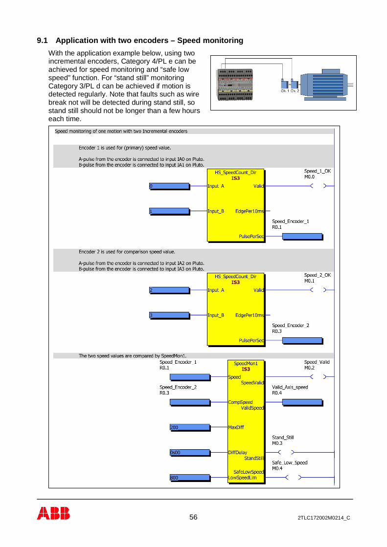
9.1 Application with two encoders – Speed monitoringWith the application example below, using twoincremental encoders, Category 4/PL e can beachieved for speed monitoring and “safe lowspeed” function. For “stand still” monitoringCategory 3/PL d can be achieved if motion isdetected regularly. Note that faults such as wirebreak not will be detected during stand still, sostand still should not be longer than a few hourseach time.
57 2TLC172002M0214_C
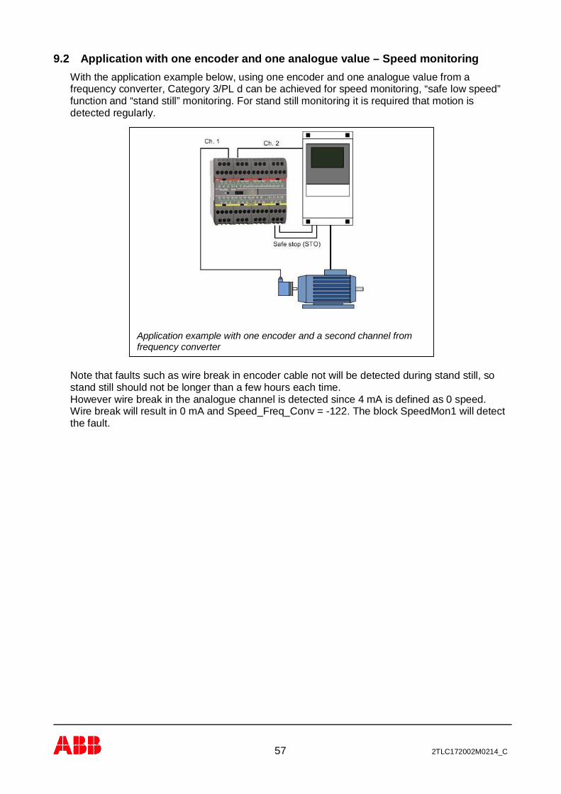
Application example with one encoder and a second channel fromfrequency converter
9.2 Application with one encoder and one analogue value – Speed monitoringWith the application example below, using one encoder and one analogue value from afrequency converter, Category 3/PL d can be achieved for speed monitoring, “safe low speed”function and “stand still” monitoring. For stand still monitoring it is required that motion isdetected regularly.
Note that faults such as wire break in encoder cable not will be detected during stand still, sostand still should not be longer than a few hours each time.However wire break in the analogue channel is detected since 4 mA is defined as 0 speed.Wire break will result in 0 mA and Speed_Freq_Conv = -122. The block SpeedMon1 will detectthe fault.

58 2TLC172002M0214_C
Program example for speed monitoring with one encoder and one analogue channel.
59 2TLC172002M0214_C
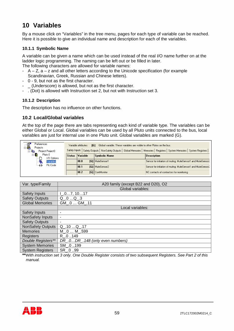
10 VariablesBy a mouse click on “Variables” in the tree menu, pages for each type of variable can be reached.Here it is possible to give an individual name and description for each of the variables.
10.1.1 Symbolic NameA variable can be given a name which can be used instead of the real I/O name further on at theladder logic programming. The naming can be left out or be filled in later.The following characters are allowed for variable names:- A – Z, a – z and all other letters according to the Unicode specification (for example
Scandinavian, Greek, Russian and Chinese letters).- 0 - 9, but not as the first character.- _ (Underscore) is allowed, but not as the first character.- . (Dot) is allowed with Instruction set 2, but not with Instruction set 3.
10.1.2 DescriptionThe description has no influence on other functions.
10.2 Local/Global variablesAt the top of the page there are tabs representing each kind of variable type. The variables can beeither Global or Local. Global variables can be used by all Pluto units connected to the bus, localvariables are just for internal use in one Pluto unit. Global variables are marked (G).
Var. type/Family A20 family (except B22 and D20), O2Global variables:
Safety Inputs I_.0…7, 10…17Safety Outputs Q_.0 …Q_.3Global Memories GM_.0 … GM_.11
Local variables:Safety Inputs -NonSafety Inputs -Safety Outputs -NonSafety Outputs Q_.10 …Q_.17Memories M_.0 … M_.599Registers R_.0 ..149Double Registers** DR_.0…DR_.148 (only even numbers)System Memories SM_.0 ..199System Registers SR_.0 ..99**With instruction set 3 only. One Double Register consists of two subsequent Registers. See Part 2 of this
manual.
60 2TLC172002M0214_C
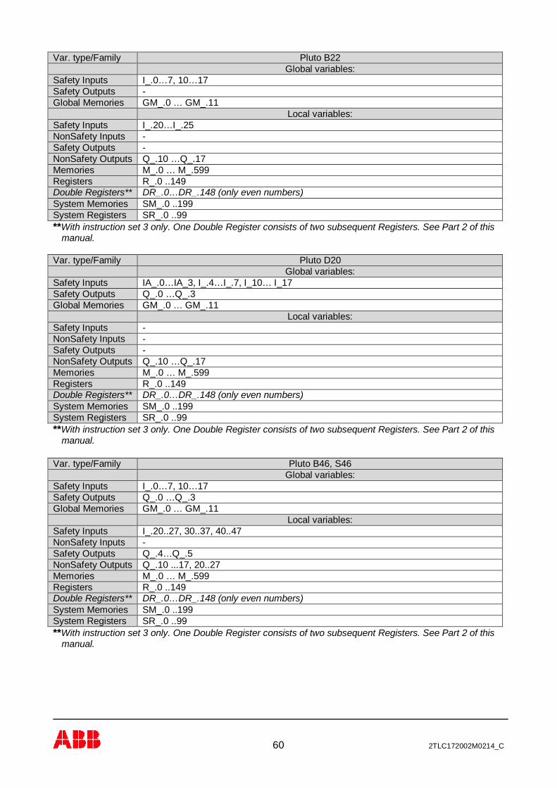
Var. type/Family Pluto B22Global variables:
Safety Inputs I_.0…7, 10…17Safety Outputs -Global Memories GM_.0 … GM_.11
Local variables:Safety Inputs I_.20…I_.25NonSafety Inputs -Safety Outputs -NonSafety Outputs Q_.10 …Q_.17Memories M_.0 … M_.599Registers R_.0 ..149Double Registers** DR_.0…DR_.148 (only even numbers)System Memories SM_.0 ..199System Registers SR_.0 ..99**With instruction set 3 only. One Double Register consists of two subsequent Registers. See Part 2 of this
manual.
Var. type/Family Pluto D20Global variables:
Safety Inputs IA_.0…IA_3, I_.4…I_.7, I_10… I_17Safety Outputs Q_.0 …Q_.3Global Memories GM_.0 … GM_.11
Local variables:Safety Inputs -NonSafety Inputs -Safety Outputs -NonSafety Outputs Q_.10 …Q_.17Memories M_.0 … M_.599Registers R_.0 ..149Double Registers** DR_.0…DR_.148 (only even numbers)System Memories SM_.0 ..199System Registers SR_.0 ..99**With instruction set 3 only. One Double Register consists of two subsequent Registers. See Part 2 of this
manual.
Var. type/Family Pluto B46, S46Global variables:
Safety Inputs I_.0…7, 10…17Safety Outputs Q_.0 …Q_.3Global Memories GM_.0 … GM_.11
Local variables:Safety Inputs I_.20..27, 30..37, 40..47NonSafety Inputs -Safety Outputs Q_.4…Q_.5NonSafety Outputs Q_.10 ...17, 20..27Memories M_.0 … M_.599Registers R_.0 ..149Double Registers** DR_.0…DR_.148 (only even numbers)System Memories SM_.0 ..199System Registers SR_.0 ..99**With instruction set 3 only. One Double Register consists of two subsequent Registers. See Part 2 of this
manual.
61 2TLC172002M0214_C
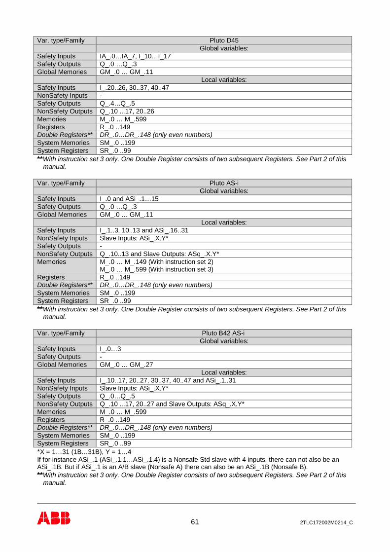
Var. type/Family Pluto D45Global variables:
Safety Inputs IA_.0…IA_7, I_10…I_17Safety Outputs Q_.0 …Q_.3Global Memories GM_.0 … GM_.11
Local variables:Safety Inputs I_.20..26, 30..37, 40..47NonSafety Inputs -Safety Outputs Q_.4…Q_.5NonSafety Outputs Q_.10 ...17, 20..26Memories M_.0 … M_.599Registers R_.0 ..149Double Registers** DR_.0…DR_.148 (only even numbers)System Memories SM_.0 ..199System Registers SR_.0 ..99**With instruction set 3 only. One Double Register consists of two subsequent Registers. See Part 2 of this
manual.
Var. type/Family Pluto AS-iGlobal variables:
Safety Inputs I_.0 and ASi_.1…15Safety Outputs Q_.0 …Q_.3Global Memories GM_.0 … GM_.11
Local variables:Safety Inputs I_.1..3, 10..13 and ASi_.16..31NonSafety Inputs Slave Inputs: ASi_.X.Y*Safety Outputs -NonSafety Outputs Q_.10..13 and Slave Outputs: ASq_.X.Y*Memories M_.0 … M_.149 (With instruction set 2)
M_.0 … M_.599 (With instruction set 3)Registers R_.0 ..149Double Registers** DR_.0…DR_.148 (only even numbers)System Memories SM_.0 ..199System Registers SR_.0 ..99**With instruction set 3 only. One Double Register consists of two subsequent Registers. See Part 2 of this
manual.
Var. type/Family Pluto B42 AS-iGlobal variables:
Safety Inputs I_.0…3Safety Outputs -Global Memories GM_.0 … GM_.27
Local variables:Safety Inputs I_.10..17, 20..27, 30..37, 40..47 and ASi_.1..31NonSafety Inputs Slave Inputs: ASi_.X.Y*Safety Outputs Q_.0…Q_.5NonSafety Outputs Q_.10 ...17, 20..27 and Slave Outputs: ASq_.X.Y*Memories M_.0 … M_.599Registers R_.0 ..149Double Registers** DR_.0…DR_.148 (only even numbers)System Memories SM_.0 ..199System Registers SR_.0 ..99*X = 1…31 (1B…31B), Y = 1…4If for instance ASi_.1 (ASi_.1.1…ASi_.1.4) is a Nonsafe Std slave with 4 inputs, there can not also be anASi_.1B. But if ASi_.1 is an A/B slave (Nonsafe A) there can also be an ASi_.1B (Nonsafe B).**With instruction set 3 only. One Double Register consists of two subsequent Registers. See Part 2 of this
manual.
62 2TLC172002M0214_C
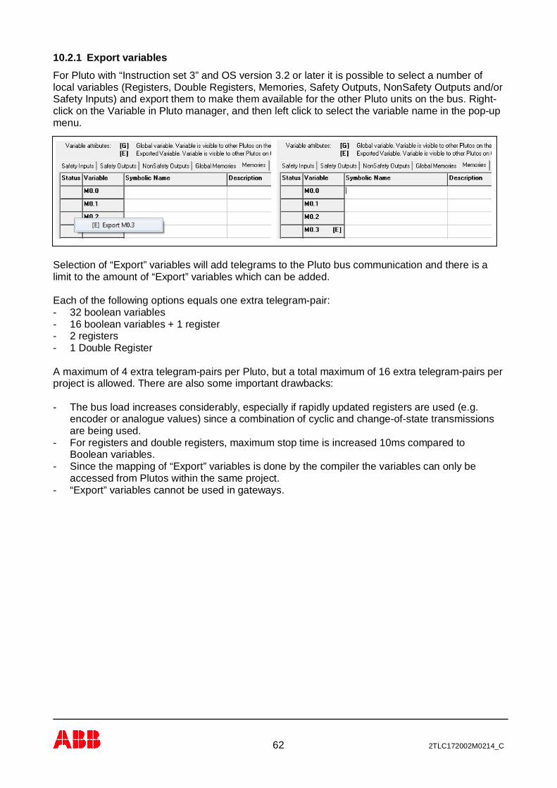
10.2.1 Export variablesFor Pluto with “Instruction set 3” and OS version 3.2 or later it is possible to select a number oflocal variables (Registers, Double Registers, Memories, Safety Outputs, NonSafety Outputs and/orSafety Inputs) and export them to make them available for the other Pluto units on the bus. Right-click on the Variable in Pluto manager, and then left click to select the variable name in the pop-upmenu.
Selection of “Export” variables will add telegrams to the Pluto bus communication and there is alimit to the amount of “Export” variables which can be added.
Each of the following options equals one extra telegram-pair:- 32 boolean variables- 16 boolean variables + 1 register- 2 registers- 1 Double Register
A maximum of 4 extra telegram-pairs per Pluto, but a total maximum of 16 extra telegram-pairs perproject is allowed. There are also some important drawbacks:
- The bus load increases considerably, especially if rapidly updated registers are used (e.g.encoder or analogue values) since a combination of cyclic and change-of-state transmissionsare being used.
- For registers and double registers, maximum stop time is increased 10ms compared toBoolean variables.
- Since the mapping of “Export” variables is done by the compiler the variables can only beaccessed from Plutos within the same project.
- “Export” variables cannot be used in gateways.
63 2TLC172002M0214_C
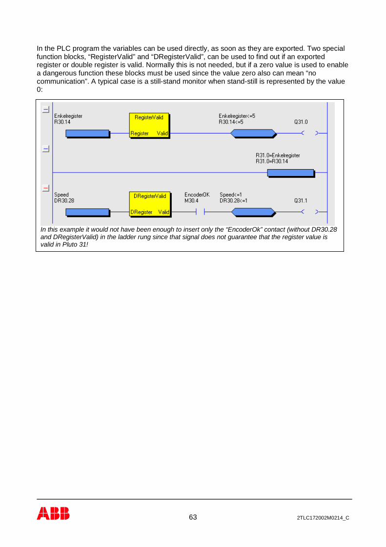
In the PLC program the variables can be used directly, as soon as they are exported. Two specialfunction blocks, “RegisterValid” and “DRegisterValid”, can be used to find out if an exportedregister or double register is valid. Normally this is not needed, but if a zero value is used to enablea dangerous function these blocks must be used since the value zero also can mean “nocommunication”. A typical case is a still-stand monitor when stand-still is represented by the value0:
In this example it would not have been enough to insert only the “EncoderOk” contact (without DR30.28and DRegisterValid) in the ladder rung since that signal does not guarantee that the register value isvalid in Pluto 31!
64 2TLC172002M0214_C
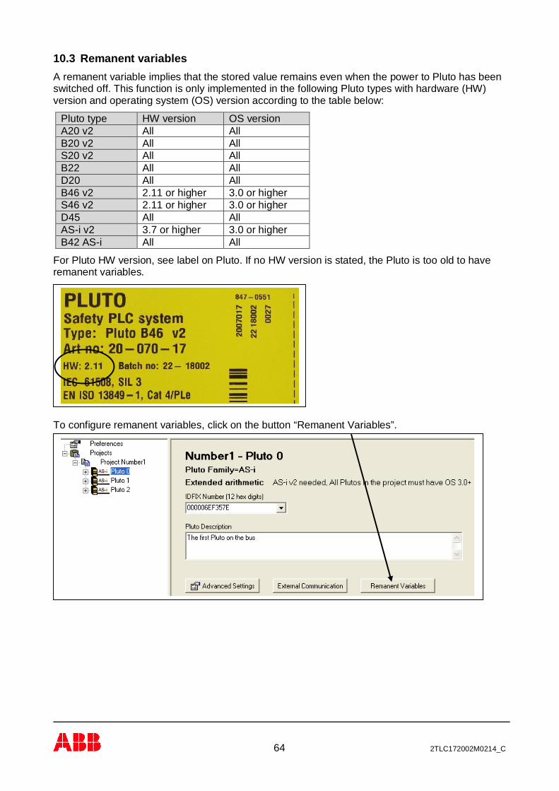
10.3 Remanent variablesA remanent variable implies that the stored value remains even when the power to Pluto has beenswitched off. This function is only implemented in the following Pluto types with hardware (HW)version and operating system (OS) version according to the table below:
Pluto type HW version OS versionA20 v2 All AllB20 v2 All AllS20 v2 All AllB22 All AllD20 All AllB46 v2 2.11 or higher 3.0 or higherS46 v2 2.11 or higher 3.0 or higherD45 All AllAS-i v2 3.7 or higher 3.0 or higherB42 AS-i All All
For Pluto HW version, see label on Pluto. If no HW version is stated, the Pluto is too old to haveremanent variables.
To configure remanent variables, click on the button “Remanent Variables”.
65 2TLC172002M0214_C
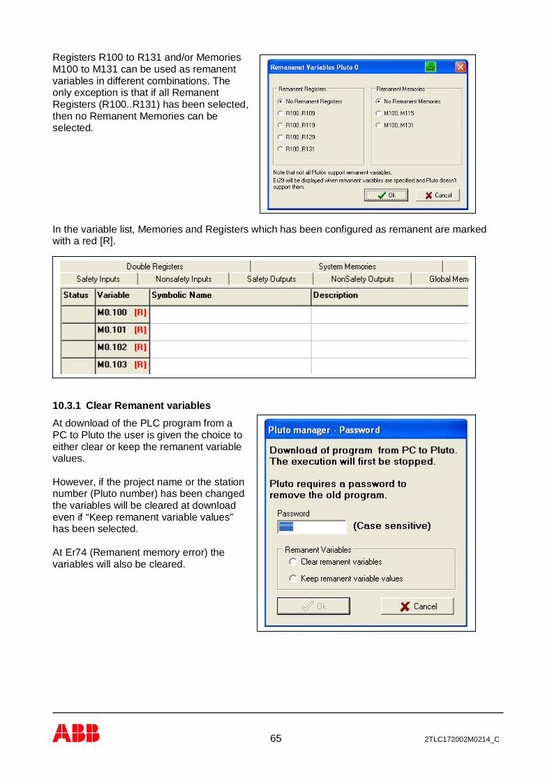
Registers R100 to R131 and/or MemoriesM100 to M131 can be used as remanentvariables in different combinations. Theonly exception is that if all RemanentRegisters (R100..R131) has been selected,then no Remanent Memories can beselected.
In the variable list, Memories and Registers which has been configured as remanent are markedwith a red [R].
10.3.1 Clear Remanent variablesAt download of the PLC program from aPC to Pluto the user is given the choice toeither clear or keep the remanent variablevalues.
However, if the project name or the stationnumber (Pluto number) has been changedthe variables will be cleared at downloadeven if “Keep remanent variable values”has been selected.
At Er74 (Remanent memory error) thevariables will also be cleared.
66 2TLC172002M0214_C
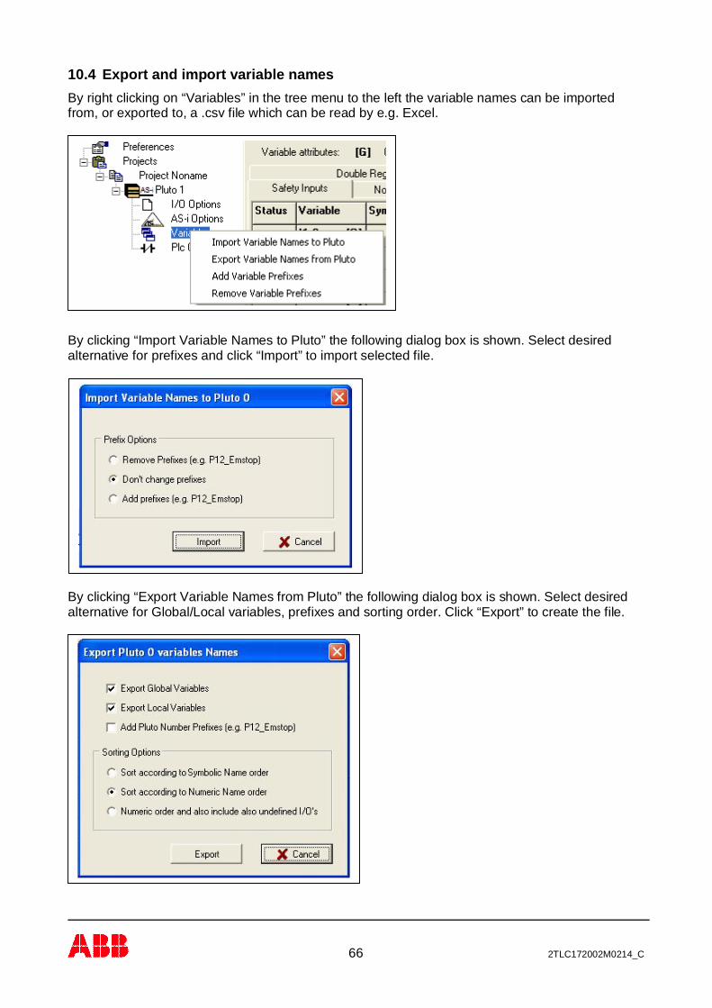
10.4 Export and import variable namesBy right clicking on “Variables” in the tree menu to the left the variable names can be importedfrom, or exported to, a .csv file which can be read by e.g. Excel.
By clicking “Import Variable Names to Pluto” the following dialog box is shown. Select desiredalternative for prefixes and click “Import” to import selected file.
By clicking “Export Variable Names from Pluto” the following dialog box is shown. Select desiredalternative for Global/Local variables, prefixes and sorting order. Click “Export” to create the file.

67 2TLC172002M0214_C
11 Ladder logic programmingBy a mouse click on “PLC Code” in the tree menu the page for ladder logic programming is shown.
The ladder logic program is built up with networks, also called rungs. These are numbered on theleft side.
By a right mouse click in a network the following dialog box appears.The options Cut, Copy, Paste and Delete Networks operate as mostother windows programs and lead to new dialog boxes.
By selecting “New Network” a new network is opened and inserted belowthe network were the mouse click is carried out.

68 2TLC172002M0214_C
11.1 Edit modeEdit mode can be entered in two ways, either by selecting “New Network” as described above orby a left mouse click on an existing network. Only one network can be edited at a time.
A network in Edit mode is high-lighted, the lines between the components are red and hit boxesare shown. The hit boxes show where it is possible to connect a line. In edit mode it is possible todrag around, insert, disconnect, delete, etc. lines and ladder components.
Operations in edit mode:Draw a line: Do a left mouse click (and release the button) in a “hit box” for a
component. The “hit boxes” show the connection points. Move the cursor tothe component where the end of the line is to be connected and fix it with aleft click.
Change a line: By clicking the mouse on a line outside the “hit boxes”, the line is grabbed.It is now possible to:- Stretch it to a third point and fix it with a left mouse click.- Go to one of the “hit boxes” and disconnect it with a left mouse click.
When the line is detached it can be fixed to another component or deletedwith a mouse click outside a “hit box”.
- Make a right mouse click and a dialog box “Delete line” is shown.- Un-grab it with a new left mouse click.
Change componentsproperties: A double left mouse click on a component leads to a dialog box for
changing Variable name, NO, NC, Pulse function etc.
Change components: By a right mouse click on a component a dialog box with three options isshown.- “Components properties.” for giving or changing the name or function.- “Disconnect component” for deleting all connections to the component.- “Delete component” for deletion of the component.
Moving components: Press and keep left mouse button down on a component and drag it.Release the mouse button at the new place required.

69 2TLC172002M0214_C
11.2 Tool barThe tool bar is shown in edit mode and is used for the insertion of ladder components.
To insert a component, click on the corresponding symbol. The cursor then takes the form of thesymbol. Place it where you want to have it in the network, fix with a left mouse click and fill in theproperties.
Tool bar components:
Standard ladder contact components. (Leads to the dialog box below.)
Standard ladder output components.Leads to the dialog box below.
TimersLeads to a dialog box for selection of different types of timers.
70 2TLC172002M0214_C
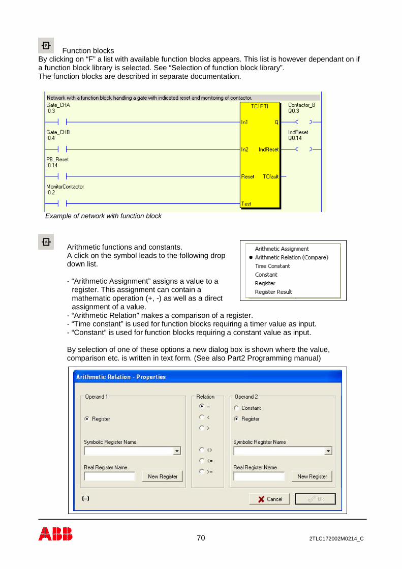
Function blocksBy clicking on “F” a list with available function blocks appears. This list is however dependant on ifa function block library is selected. See “Selection of function block library”.The function blocks are described in separate documentation.
Arithmetic functions and constants.A click on the symbol leads to the following dropdown list.
- “Arithmetic Assignment” assigns a value to aregister. This assignment can contain amathematic operation (+, -) as well as a directassignment of a value.
- “Arithmetic Relation” makes a comparison of a register.- “Time constant” is used for function blocks requiring a timer value as input.- “Constant” is used for function blocks requiring a constant value as input.
By selection of one of these options a new dialog box is shown where the value,comparison etc. is written in text form. (See also Part2 Programming manual)
Example of network with function block
71 2TLC172002M0214_C
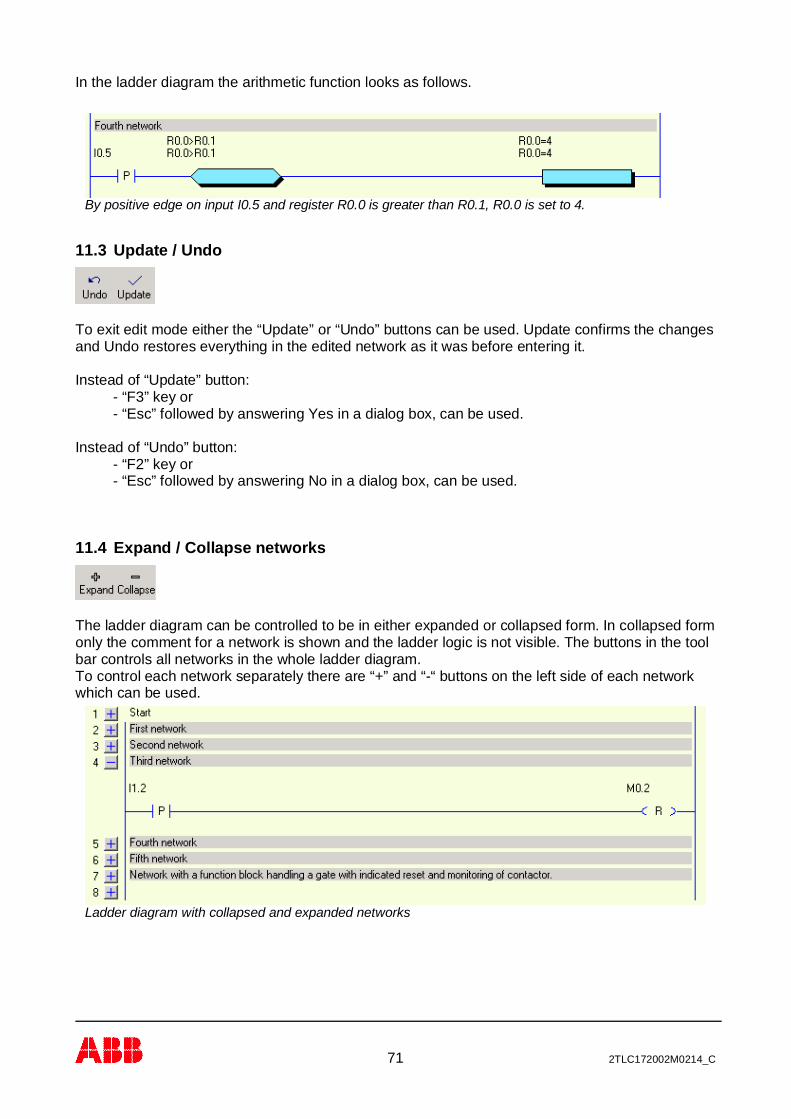
In the ladder diagram the arithmetic function looks as follows.
11.3 Update / Undo
To exit edit mode either the “Update” or “Undo” buttons can be used. Update confirms the changesand Undo restores everything in the edited network as it was before entering it.
Instead of “Update” button:- “F3” key or- “Esc” followed by answering Yes in a dialog box, can be used.
Instead of “Undo” button:- “F2” key or- “Esc” followed by answering No in a dialog box, can be used.
11.4 Expand / Collapse networks
The ladder diagram can be controlled to be in either expanded or collapsed form. In collapsed formonly the comment for a network is shown and the ladder logic is not visible. The buttons in the toolbar controls all networks in the whole ladder diagram.To control each network separately there are “+” and “-“ buttons on the left side of each networkwhich can be used.
Ladder diagram with collapsed and expanded networks
By positive edge on input I0.5 and register R0.0 is greater than R0.1, R0.0 is set to 4.
72 2TLC172002M0214_C
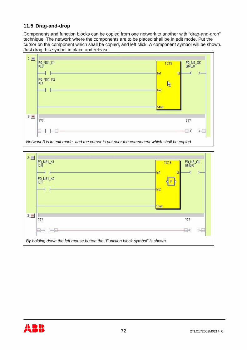
11.5 Drag-and-dropComponents and function blocks can be copied from one network to another with “drag-and-drop”technique. The network where the components are to be placed shall be in edit mode. Put thecursor on the component which shall be copied, and left click. A component symbol will be shown.Just drag this symbol in place and release.
Network 3 is in edit mode, and the cursor is put over the component which shall be copied.
By holding down the left mouse button the “Function block symbol” is shown.

73 2TLC172002M0214_C
Drag the component in place and release the mouse.
74 2TLC172002M0214_C
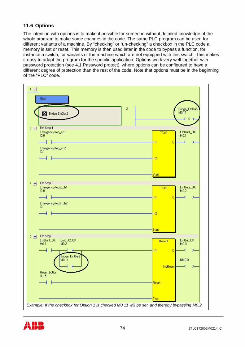
11.6 OptionsThe intention with options is to make it possible for someone without detailed knowledge of thewhole program to make some changes in the code. The same PLC program can be used fordifferent variants of a machine. By “checking” or “un-checking” a checkbox in the PLC code amemory is set or reset. This memory is then used later in the code to bypass a function, forinstance a switch, for variants of the machine which are not equipped with this switch. This makesit easy to adapt the program for the specific application. Options work very well together withpassword protection (see 4.1 Password protect), where options can be configured to have adifferent degree of protection than the rest of the code. Note that options must be in the beginningof the “PLC” code.
Example: If the checkbox for Option 1 is checked M0.11 will be set, and thereby bypassing M0.2.
75 2TLC172002M0214_C
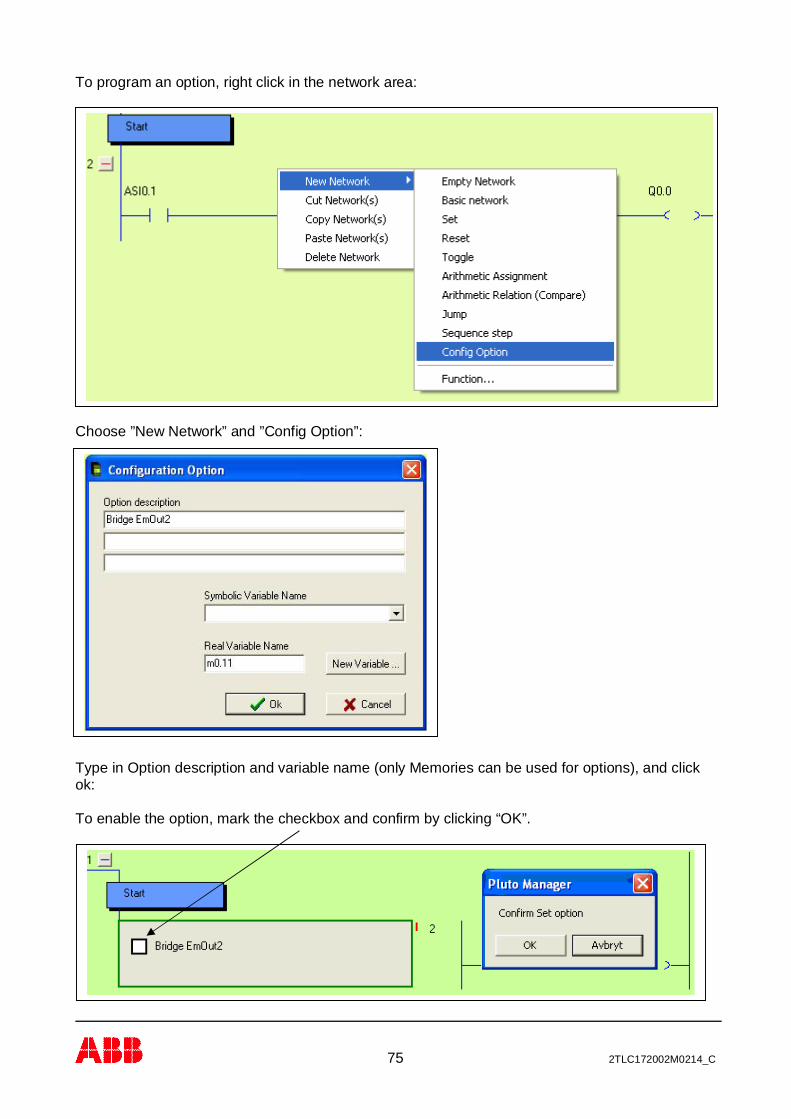
To program an option, right click in the network area:
Choose ”New Network” and ”Config Option”:
Type in Option description and variable name (only Memories can be used for options), and clickok:
To enable the option, mark the checkbox and confirm by clicking “OK”.

76 2TLC172002M0214_C
11.7 SequencesIn addition to the ordinary PLC code it is possible to have 9 Sequences with a maximum of 254steps in each sequence.
To open a new sequence:Right click on the Pluto symbol in the tree menuà Select “New Sequence”à Enter a sequencenumber 1-9 in the next dialog box.
M0.11 is now set.
A very simple sequence.

77 2TLC172002M0214_C
12 Project setup
12.1 Function librariesThe Pluto system offers the possibility to use pre-programmed function blocks / macros fordifferent safety functions and safety devices. These function blocks are stored in separate libraryfiles with file extension .fps. Standard libraries are included in Pluto Manager but it is also possibleto make user specific libraries. Several library files can be loaded in one project.
By a mouse click on “Function libraries”/ “Change” on the Project [Name] page a dialog box withthree options appears.- “Add standard Library”: Pluto Manager looks for files at “..\PlutoManager\Library” where they
are normally stored by the installation program.- “Add User Library”: Pluto Manager looks for the files in the directory where the project files are
stored. User libraries are files with user specific function blocks.For making a function block see special manual.
- “Remove Library” is used for deleting a file in the list.
Function library Func05.fps is selected.
78 2TLC172002M0214_C
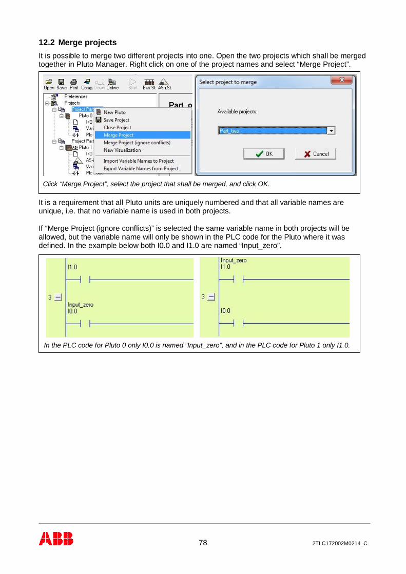
12.2 Merge projectsIt is possible to merge two different projects into one. Open the two projects which shall be mergedtogether in Pluto Manager. Right click on one of the project names and select “Merge Project”.
It is a requirement that all Pluto units are uniquely numbered and that all variable names areunique, i.e. that no variable name is used in both projects.
If “Merge Project (ignore conflicts)” is selected the same variable name in both projects will beallowed, but the variable name will only be shown in the PLC code for the Pluto where it wasdefined. In the example below both I0.0 and I1.0 are named “Input_zero”.
Click “Merge Project”, select the project that shall be merged, and click OK.
In the PLC code for Pluto 0 only I0.0 is named “Input_zero”, and in the PLC code for Pluto 1 only I1.0.
79 2TLC172002M0214_C
13 Compilation
Pluto Manager saves the program in a file with extension “.sps”, but this cannot be downloaded toa Pluto unit before being compiled. The compiler checks the program code in the sps-file againstsyntax faults and produces a file in hex format (.hps), which can be downloaded.By clicking on the “Comp” button the compilation is started and a text window appears on thescreen. At the end of the compilation the message “0 Error (s) detected …… Result=OK” appears,if everything is passed. Pluto Manager prevents most syntax faults but not 100% and it cantherefore happen that the compiler gives fault messages.
Note. Pluto Manager and the compiler just checks for syntax faults, when the code is notcorresponding with rules of the language. Logic faults, like an emergency stop that controls anincorrect output cannot be detected by the software tools. Programs must therefore be reviewedand safety applications carefully tested before the use.

80 2TLC172002M0214_C
14 General Preferences
This page contains preferences related to the PC-computer.
For communication via Pluto USB cable, select the first “VCP” COM port from the list.For communication via the serial port, select the “Serial” COM port from the list.
Update interval in online mode. Lower update interval makes the computer slower.
The function blocks (described under 9) have a description, visible by a double click on them in editmode. The language of this description can be selected here.

81 2TLC172002M0214_C
The size of Hit Boxes and if they shall be shown in the ladder diagram can be set.
When Auto Connect is ticked, ladder components are automatically connected when they areinserted on a line.
In Edit mode the ladder components are separated from each other.
As default the ladder diagrams are opened in expanded from.
ColoursThe colours in Pluto Manager can be changed by the user.
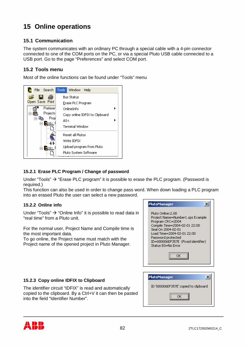
82 2TLC172002M0214_C
15 Online operations
15.1 CommunicationThe system communicates with an ordinary PC through a special cable with a 4-pin connectorconnected to one of the COM ports on the PC, or via a special Pluto USB cable connected to aUSB port. Go to the page “Preferences” and select COM port.
15.2 Tools menuMost of the online functions can be found under “Tools” menu
15.2.1 Erase PLC Program / Change of passwordUnder “Tools”à “Erase PLC program” it is possible to erase the PLC program. (Password isrequired.)This function can also be used in order to change pass word. When down loading a PLC programinto an erased Pluto the user can select a new password.
15.2.2 Online infoUnder “Tools”à “Online Info” it is possible to read data in“real time” from a Pluto unit.
For the normal user, Project Name and Compile time isthe most important data.To go online, the Project name must match with theProject name of the opened project in Pluto Manager.
15.2.3 Copy online IDFIX to ClipboardThe identifier circuit “IDFIX” is read and automaticallycopied to the clipboard. By a Ctrl+V it can then be pastedinto the field “Identifier Number”.

83 2TLC172002M0214_C
15.2.4 Terminal windowAnother way to communicate with a Pluto unit, is to open a terminal window. In this mode the PC isjust a terminal. Everything typed on the keyboard is sent to the Pluto unit and everything written inthe terminal window is written by the Pluto unit.A lot of things can be monitored via the terminal like I/O:s, compile date, program name etc.. It isalso possible to load new programs by typing “pl” followed by a click on the “Send File”-button.By typing “h” (help) available commands are listed.
Instead of this terminal a standard terminal program can be used such as HyperTerm in Windows.
15.2.5 Reset all PlutosThe command will Reset / (reboot) allunits connected to the bus. The Resethas the same function as power off/onand can be necessary in situations asafter change of baudrate or reset of somefaults.
Example of terminal communication. Pluto_a> is prompt. Input i0.0 is monitored, allchanges of state are logged. Next command is ”h” which lists all available commands.

84 2TLC172002M0214_C
15.2.6 Write IDFIXFunction for programmableidentifier circuits “IDFIX”.It is possible to put in thenumber manually for examplein order to make a copy of anexisting, or let the systemsuggest a number.By selection of “Eraseprotected ID” the circuit cannever be changed again.
Note that after writing ID thePluto must be reset (poweroff/on) to enter normaloperation again.
15.2.7 Upload Program from PlutoThe PLC program can be uploaded from Pluto and saved as a .uhx file on a PC. If ”Include sourcecode in compiled file” was selected when the program was loaded to Pluto (see 3.3 Include sourcefile) the source file (.sps) can also be uploaded. Select “Upload program from Pluto” from the Toolsmenu.
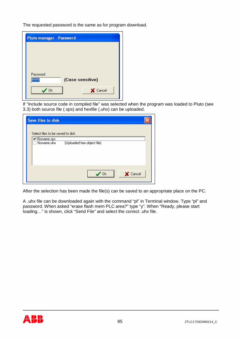
85 2TLC172002M0214_C
The requested password is the same as for program download.
If ”Include source code in compiled file” was selected when the program was loaded to Pluto (see3.3) both source file (.sps) and hexfile (.uhx) can be uploaded.
After the selection has been made the file(s) can be saved to an appropriate place on the PC.
A .uhx file can be downloaded again with the command “pl” in Terminal window. Type “pl” andpassword. When asked “erase flash mem PLC area?” type “y”. When “Ready, please startloading…” is shown, click “Send File” and select the correct .uhx file.
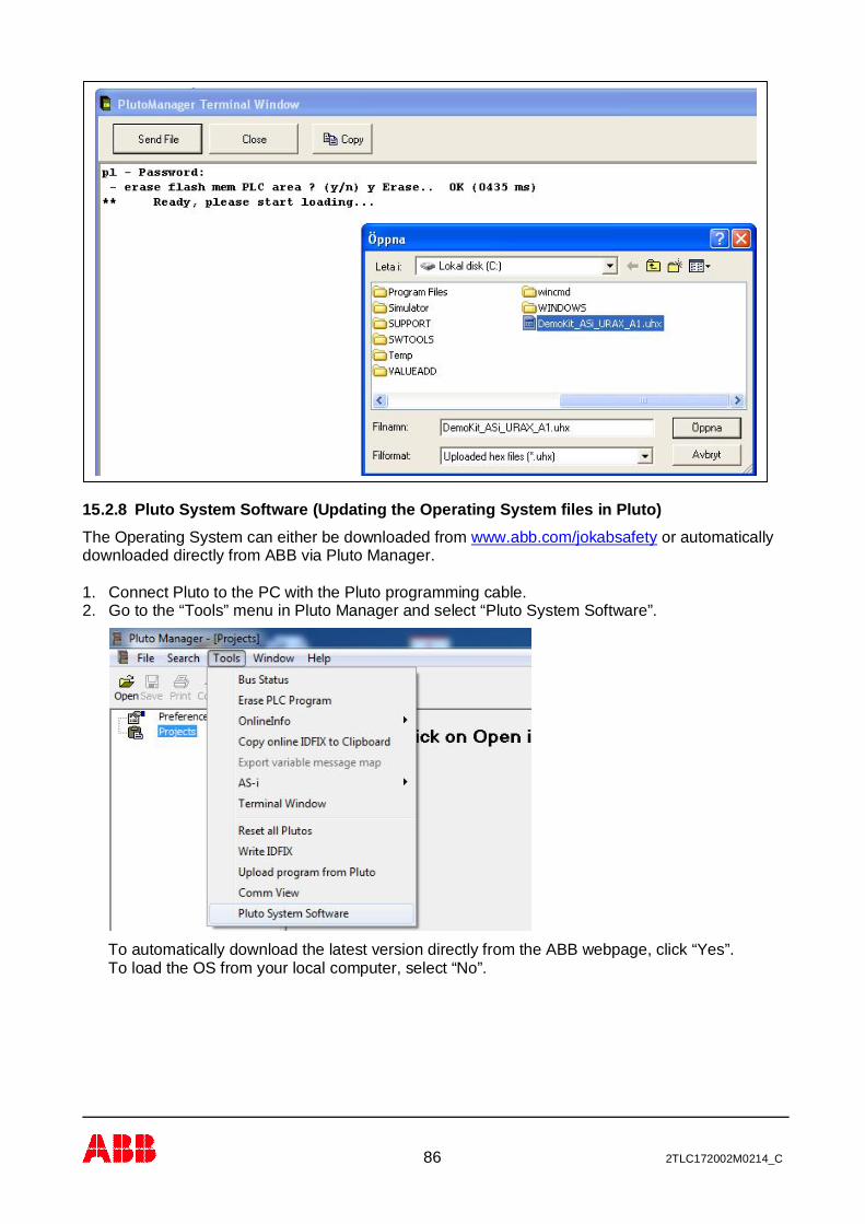
86 2TLC172002M0214_C
15.2.8 Pluto System Software (Updating the Operating System files in Pluto)The Operating System can either be downloaded from www.abb.com/jokabsafety or automaticallydownloaded directly from ABB via Pluto Manager.
1. Connect Pluto to the PC with the Pluto programming cable.2. Go to the “Tools” menu in Pluto Manager and select “Pluto System Software”.
To automatically download the latest version directly from the ABB webpage, click “Yes”.To load the OS from your local computer, select “No”.

87 2TLC172002M0214_C
3. If “Yes” was selected: The latest version for the connected Pluto model is presented.(If “No” was selected, this box will not be presented.)
To download click “OK”.
Select the OS and click “Open”. The download will start.If “No” was selected earlier (to not download directly from ABB), locate the OS file on the localcomputer and click “Open”.
To confirm and restart Pluto, click “Yes”.
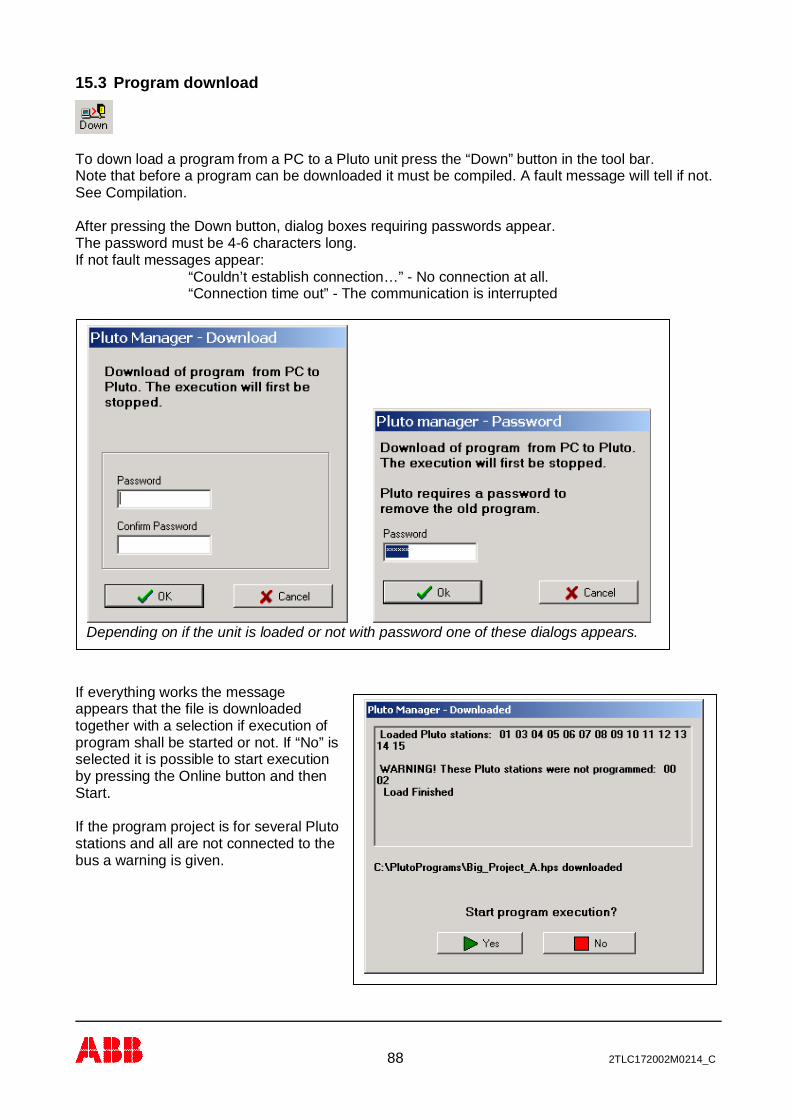
88 2TLC172002M0214_C
15.3 Program download
To down load a program from a PC to a Pluto unit press the “Down” button in the tool bar.Note that before a program can be downloaded it must be compiled. A fault message will tell if not.See Compilation.
After pressing the Down button, dialog boxes requiring passwords appear.The password must be 4-6 characters long.If not fault messages appear:
“Couldn’t establish connection…” - No connection at all.“Connection time out” - The communication is interrupted
If everything works the messageappears that the file is downloadedtogether with a selection if execution ofprogram shall be started or not. If “No” isselected it is possible to start executionby pressing the Online button and thenStart.
If the program project is for several Plutostations and all are not connected to thebus a warning is given.
Depending on if the unit is loaded or not with password one of these dialogs appears.

89 2TLC172002M0214_C
15.4 Insertion of Pluto unit in existing project afterwardsWhen Pluto units are loaded with program for several units they check each other so they haveexactly the same version of the program code. By mismatch they do not accept each others I/Os.
If a unit belonging to a program project is connected to the bus afterwards the following situationscan appear depending on what PLC program it is loaded with:
Alt. 1 - The new Pluto is empty of PLC program (message code Er20) and is fitted with correctIDFIX circuit.The new Pluto can be loaded with program by a new download from the PC to any of the Pluto:s ofthe same program project.It can also be programmed by using self programming without PC. By pressing the ‘K’ button in thePluto front panel in 2 seconds the display flashes “L” which indicates that it is ready for selfprogramming. By another activation of the “K” button the program load is started indicated by asteady “L” on the display.
Alt. 2 – The new Pluto is fitted with correct IDFIX circuit but loaded with wrong version of theprogram.By connection all units of the project will give error code Er27 because they detect units belongingto their own program project but with mismatching program as the new unit has wrong version. Theunits will run the PLC program but will not accept I/Os in Pluto units with mismatching program.By a new download to any of the units in the project all of them will be updated with the sameversion.
15.5 Change of baud rate, error code Er26A Pluto unit cannot change baud rate during operation. If a unit is loaded with a program with newbaud rate it will continue with the old baud rate and indicate Er26. Er26 indicates that a unit runswith another baud rate than it is programmed for.By reboot either by power off/on or via Pluto Manager “Tools”à “Reset all Plutos” the unit canchange baud rate.
Also if an empty (Er20) standalone unit is loaded with program it will indicate Er26 and has to berebooted in order to start with programmed baud rate.
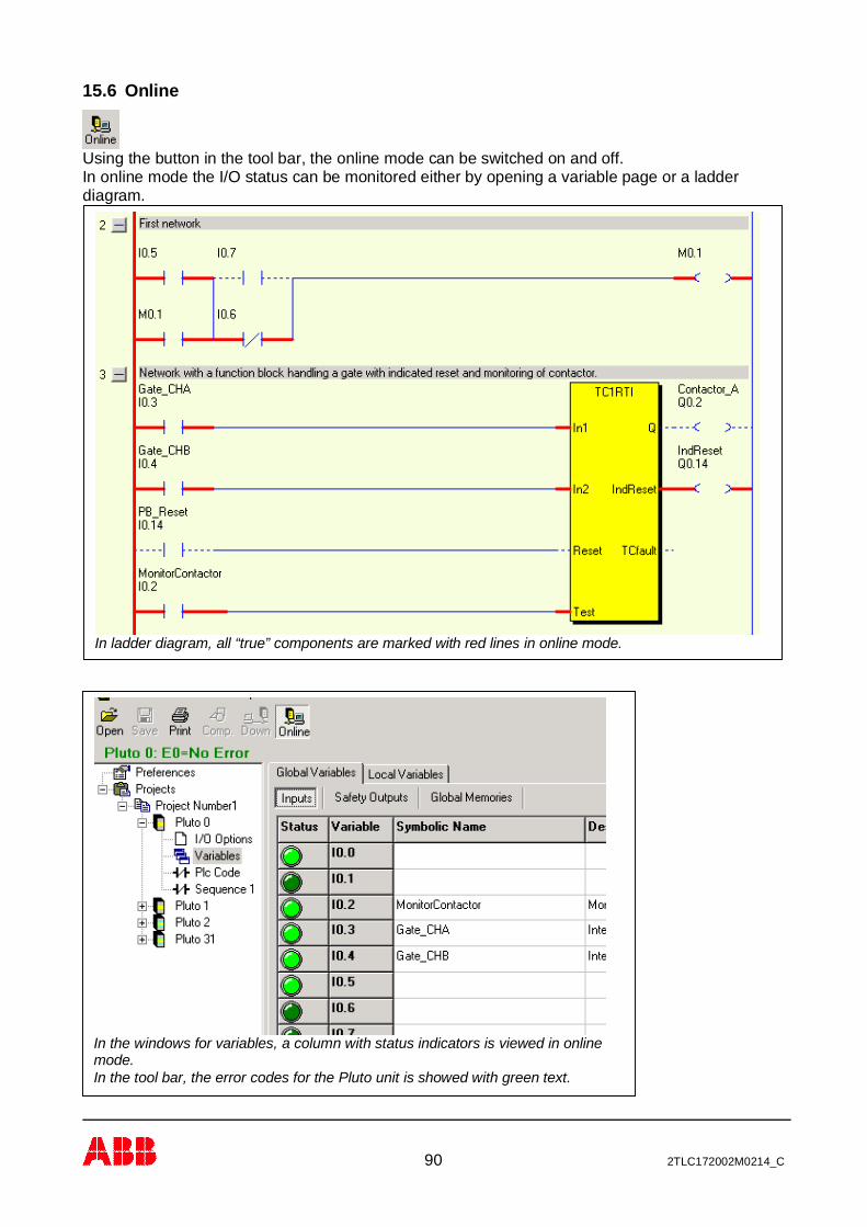
90 2TLC172002M0214_C
15.6 Online
Using the button in the tool bar, the online mode can be switched on and off.In online mode the I/O status can be monitored either by opening a variable page or a ladderdiagram.
In ladder diagram, all “true” components are marked with red lines in online mode.
In the windows for variables, a column with status indicators is viewed in onlinemode.In the tool bar, the error codes for the Pluto unit is showed with green text.
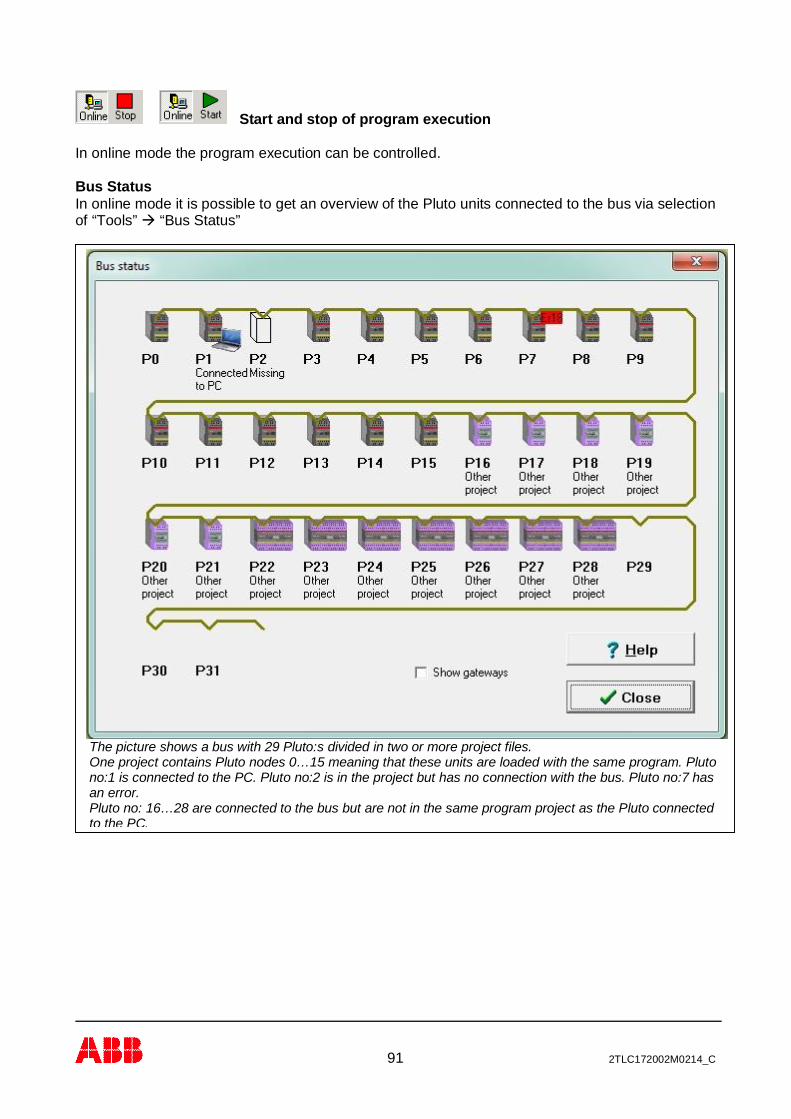
91 2TLC172002M0214_C
Start and stop of program execution
In online mode the program execution can be controlled.
Bus StatusIn online mode it is possible to get an overview of the Pluto units connected to the bus via selectionof “Tools”à “Bus Status”
The picture shows a bus with 29 Pluto:s divided in two or more project files.One project contains Pluto nodes 0…15 meaning that these units are loaded with the same program. Plutono:1 is connected to the PC. Pluto no:2 is in the project but has no connection with the bus. Pluto no:7 hasan error.Pluto no: 16…28 are connected to the bus but are not in the same program project as the Pluto connectedto the PC.

92 2TLC172002M0214_C
Explanation of Bus Status
Under Help button the following picture with explanation is displayed.

93 2TLC172002M0214_C
15.7 SealIn the dialog box “Online info” (see 13.2.2) there is a text line telling “Seal On” or “Seal Off”.After download of a program the text “Seal off” is shown. This indicates that the program ischanged but not sealed.The purpose of the seal is just to give an indication that the program is changed and has noinfluence on the function.
Depending on the licence code, Pluto Manager can be set up with three different alternatives withor without the possibility to write seal.Alternative 1: Seal function is not available for the user.Alternative 2: Seal can be loaded separately after program load.Alternative 3: Seal is automatically loaded by program load.A user company can then make a system where some people are authorized to review programsand confirm by downloading a seal.
To write a seal: “Tool”à “Write Seal”à A message “Seal written” indicates if success.
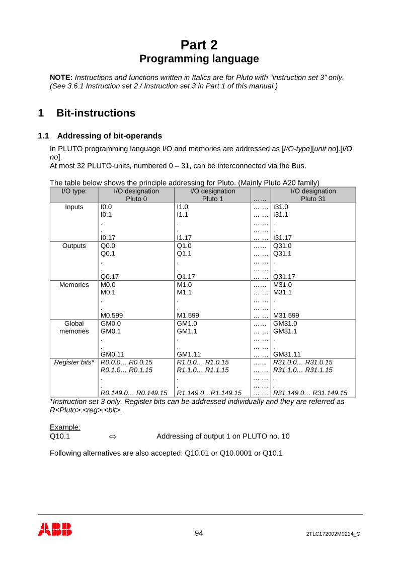
94 2TLC172002M0214_C
Part 2Programming language
NOTE: Instructions and functions written in Italics are for Pluto with “instruction set 3” only.(See 3.6.1 Instruction set 2 / Instruction set 3 in Part 1 of this manual.)
1 Bit-instructions
1.1 Addressing of bit-operandsIn PLUTO programming language I/O and memories are addressed as [I/O-type][unit no].[I/Ono].At most 32 PLUTO-units, numbered 0 – 31, can be interconnected via the Bus.
The table below shows the principle addressing for Pluto. (Mainly Pluto A20 family)I/O type: I/O designation
Pluto 0I/O designation
Pluto 1 ……I/O designation
Pluto 31Inputs I0.0
I0.1..I0.17
I1.0I1.1..I1.17
… …… …… …… …… …
I31.0I31.1..I31.17
Outputs Q0.0Q0.1..Q0.17
Q1.0Q1.1..Q1.17
……… …… …… …… …
Q31.0Q31.1..Q31.17
Memories M0.0M0.1..M0.599
M1.0M1.1..M1.599
……… …… …… …… …
M31.0M31.1..M31.599
Globalmemories
GM0.0GM0.1..GM0.11
GM1.0GM1.1..GM1.11
……… …… …… …… …
GM31.0GM31.1..GM31.11
Register bits* R0.0.0… R0.0.15R0.1.0… R0.1.15..R0.149.0… R0.149.15
R1.0.0… R1.0.15R1.1.0… R1.1.15..R1.149.0…R1.149.15
……… …… …… …… …
R31.0.0… R31.0.15R31.1.0… R31.1.15..R31.149.0… R31.149.15
*Instruction set 3 only. Register bits can be addressed individually and they are referred asR<Pluto>.<reg>.<bit>.
Example:Q10.1 Û Addressing of output 1 on PLUTO no. 10
Following alternatives are also accepted: Q10.01 or Q10.0001 or Q10.1
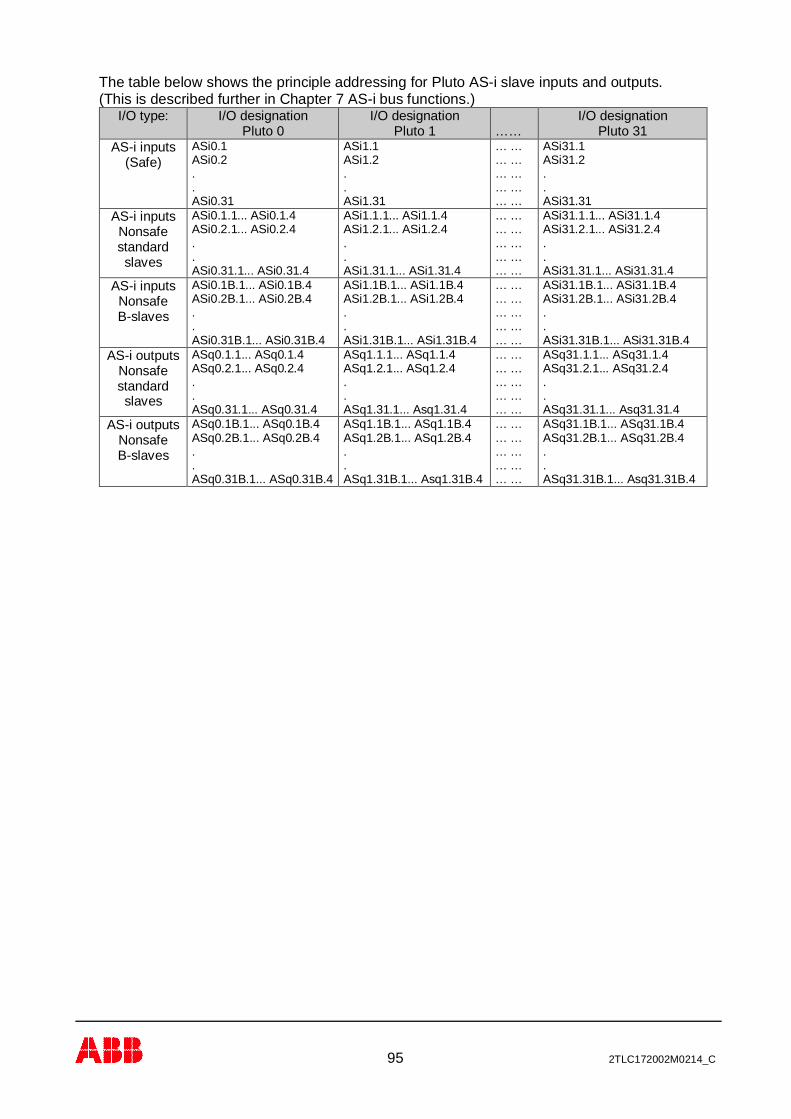
95 2TLC172002M0214_C
The table below shows the principle addressing for Pluto AS-i slave inputs and outputs.(This is described further in Chapter 7 AS-i bus functions.)
I/O type: I/O designationPluto 0
I/O designationPluto 1 ……
I/O designationPluto 31
AS-i inputs(Safe)
ASi0.1ASi0.2..ASi0.31
ASi1.1ASi1.2..ASi1.31
… …… …… …… …… …
ASi31.1ASi31.2..ASi31.31
AS-i inputsNonsafestandardslaves
ASi0.1.1... ASi0.1.4ASi0.2.1... ASi0.2.4..ASi0.31.1... ASi0.31.4
ASi1.1.1... ASi1.1.4ASi1.2.1... ASi1.2.4..ASi1.31.1... ASi1.31.4
… …… …… …… …… …
ASi31.1.1... ASi31.1.4ASi31.2.1... ASi31.2.4..ASi31.31.1... ASi31.31.4
AS-i inputsNonsafeB-slaves
ASi0.1B.1... ASi0.1B.4ASi0.2B.1... ASi0.2B.4..ASi0.31B.1... ASi0.31B.4
ASi1.1B.1... ASi1.1B.4ASi1.2B.1... ASi1.2B.4..ASi1.31B.1... ASi1.31B.4
… …… …… …… …… …
ASi31.1B.1... ASi31.1B.4ASi31.2B.1... ASi31.2B.4..ASi31.31B.1... ASi31.31B.4
AS-i outputsNonsafestandardslaves
ASq0.1.1... ASq0.1.4ASq0.2.1... ASq0.2.4..ASq0.31.1... ASq0.31.4
ASq1.1.1... ASq1.1.4ASq1.2.1... ASq1.2.4..ASq1.31.1... Asq1.31.4
… …… …… …… …… …
ASq31.1.1... ASq31.1.4ASq31.2.1... ASq31.2.4..ASq31.31.1... Asq31.31.4
AS-i outputsNonsafeB-slaves
ASq0.1B.1... ASq0.1B.4ASq0.2B.1... ASq0.2B.4..ASq0.31B.1... ASq0.31B.4
ASq1.1B.1... ASq1.1B.4ASq1.2B.1... ASq1.2B.4..ASq1.31B.1... Asq1.31B.4
… …… …… …… …… …
ASq31.1B.1... ASq31.1B.4ASq31.2B.1... ASq31.2B.4..ASq31.31B.1... Asq31.31B.4
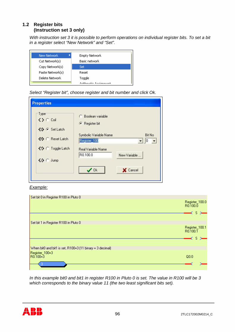
96 2TLC172002M0214_C
1.2 Register bits(Instruction set 3 only)
With instruction set 3 it is possible to perform operations on individual register bits. To set a bitin a register select “New Network” and “Set”.
Select “Register bit”, choose register and bit number and click Ok.
Example:
In this example bit0 and bit1 in register R100 in Pluto 0 is set. The value in R100 will be 3which corresponds to the binary value 11 (the two least significant bits set).

97 2TLC172002M0214_C
1.3 Boolean instructionsPLUTO programming language follows the rules for ladder programming of IEC 1131-3 whenprogramming with Pluto Manager.
By programming in text form using an text editor the programming language follows theBoolean laws and utilises AND, OR, NOT and EXECUTION -commands.
Program syntax in text form:Instruction: Program syntax:
AND *OR +
NOT /EXECUTION =
Example:
In ladder form:
Equivalent text form:
Q0.1 = I0.0 + I0.2 * I1.0 ; Start up; (semicolon) defines start of program comments.
Explanation: Output Q0.0 is on when input I0.0 or both of I0.2 and I1.0 is on (‘1’).
Example with negation:
In ladder form:
Equivalent text form:
Q0.1 = /I0.0 + I0.2*I1.0
According to the boolean laws AND-instructions (*) are executed before OR-instructions (+). Byusing brackets the instruction order can be changed.
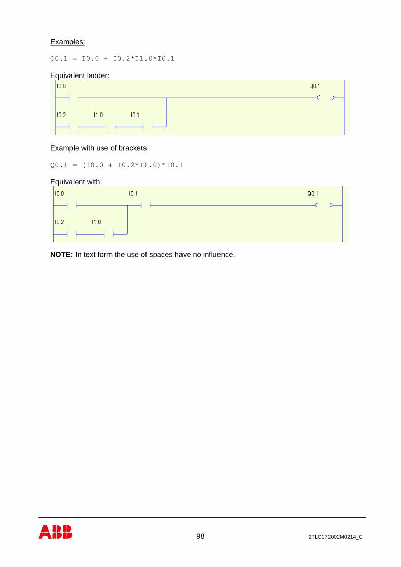
98 2TLC172002M0214_C
Examples:
Q0.1 = I0.0 + I0.2*I1.0*I0.1
Equivalent ladder:
Example with use of brackets
Q0.1 = (I0.0 + I0.2*I1.0)*I0.1
Equivalent with:
NOTE: In text form the use of spaces have no influence.
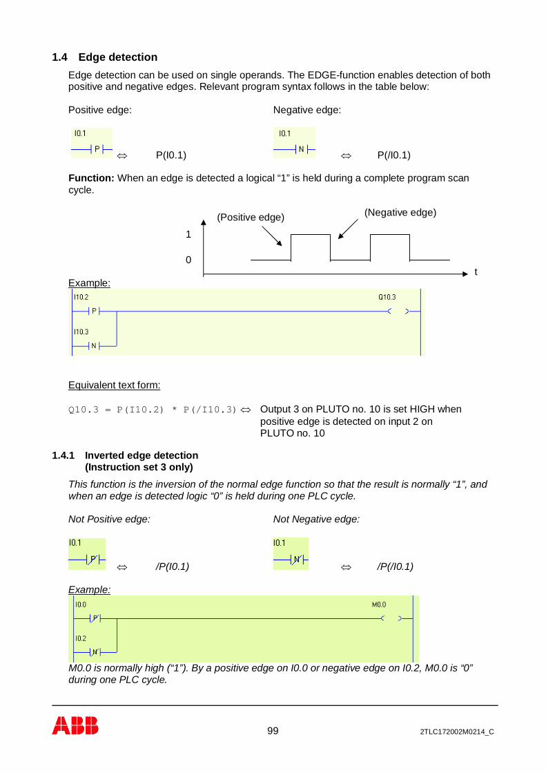
99 2TLC172002M0214_C
1.4 Edge detectionEdge detection can be used on single operands. The EDGE-function enables detection of bothpositive and negative edges. Relevant program syntax follows in the table below:
Positive edge: Negative edge:
Û P(I0.1) Û P(/I0.1)
Function: When an edge is detected a logical “1” is held during a complete program scancycle.
Example:
Equivalent text form:
Q10.3 = P(I10.2) * P(/I10.3)Û Output 3 on PLUTO no. 10 is set HIGH whenpositive edge is detected on input 2 onPLUTO no. 10
1.4.1 Inverted edge detection(Instruction set 3 only)
This function is the inversion of the normal edge function so that the result is normally “1”, andwhen an edge is detected logic “0” is held during one PLC cycle.
Not Positive edge: Not Negative edge:
Û /P(I0.1) Û /P(/I0.1)
Example:
M0.0 is normally high (“1”). By a positive edge on I0.0 or negative edge on I0.2, M0.0 is “0”during one PLC cycle.
(Negative edge)(Positive edge)
1
0t
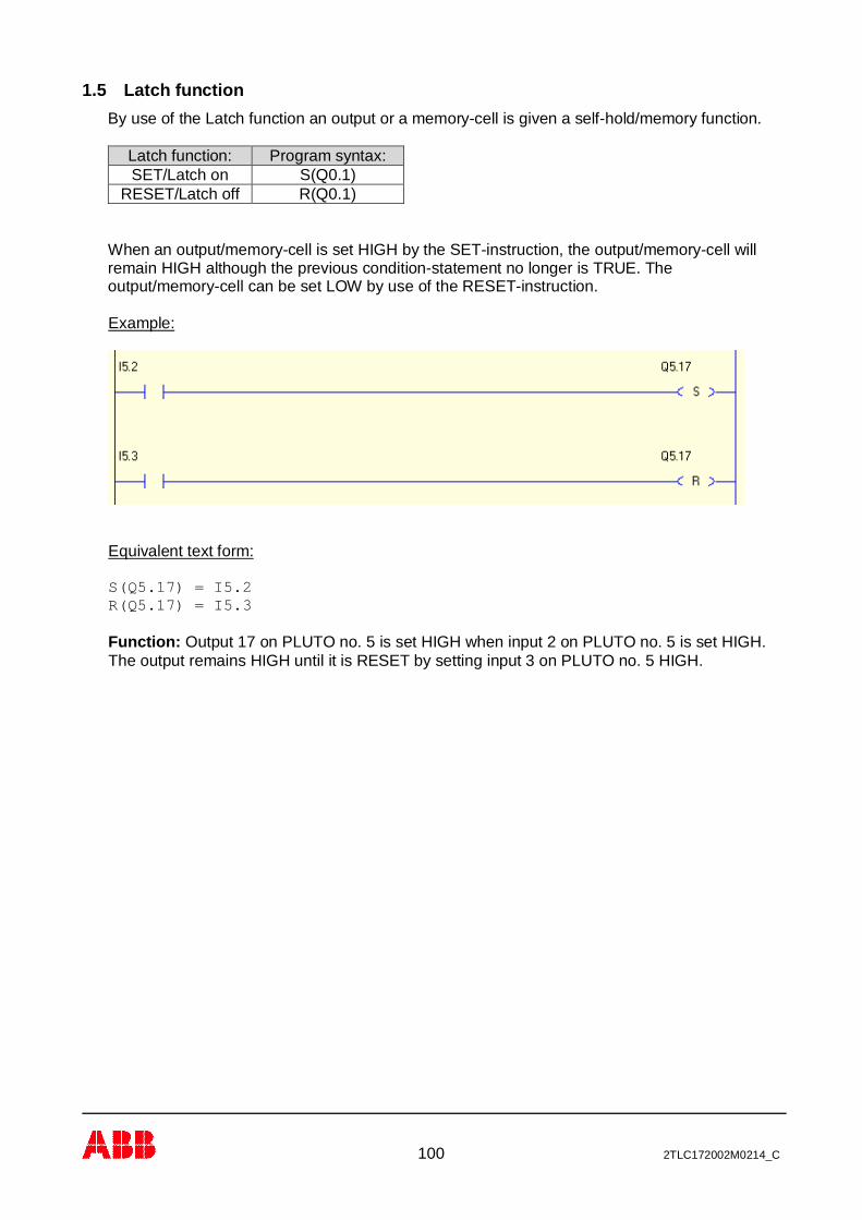
100 2TLC172002M0214_C
1.5 Latch functionBy use of the Latch function an output or a memory-cell is given a self-hold/memory function.
Latch function: Program syntax:SET/Latch on S(Q0.1)
RESET/Latch off R(Q0.1)
When an output/memory-cell is set HIGH by the SET-instruction, the output/memory-cell willremain HIGH although the previous condition-statement no longer is TRUE. Theoutput/memory-cell can be set LOW by use of the RESET-instruction.
Example:
Equivalent text form:
S(Q5.17) = I5.2R(Q5.17) = I5.3
Function: Output 17 on PLUTO no. 5 is set HIGH when input 2 on PLUTO no. 5 is set HIGH.The output remains HIGH until it is RESET by setting input 3 on PLUTO no. 5 HIGH.

101 2TLC172002M0214_C
1.6 Toggle functionThe Toggle function toggles the state of an operand (Q, M or GM).
Toggle function: Program syntax:Toggle state T(Q0.1)
Example:
Equivalent text form:
T(Q4.2) = P(I4.1)
Function: Toggle of output 2 on PLUTO no. 4 changes state from 0 -> 1 or 1 -> 0 on positiveedge of input 1 on PLUTO no. 4.
NOTE: In this example edge instruction is used to avoid that Q4.2 toggles more than once.Otherwise the output will toggle ON/OFF every PLC cycle.

102 2TLC172002M0214_C
1.7 TimersPLUTO has 50 timers that all can be used simultaneously in an active sequence step (seesequences). The timers have a resolution of 10 ms and can be defined in the time-interval 0.01– 655.35 s.
Timer: Value: Program syntax: Old Programsyntax:
TON 0.01- 655.35 s. TON (nnSnn) T(nnSnn)TPS 0.01- 655.35 s. TPS (nnSnn) /T(nnSnn)TOF* 0.01- 655.35 s. TOF(nnSnn) -
*Instruction set 3 only
Û TON(10s45) Û TPS(5s0) Û TOF(1s0)
ON-delayed timer (10.45 s.) Pulse timer (5.0 s.) Off-delayed timer (1.0 s.)*
The “s” -symbol corresponds to decimal sign
Function: There are three types of timers: ON-delayed, pulse timers and Off-delayed timer.(Off-delayed timer is only defined with instruction set 3 selected.)
ON-delayed timers (TON) start when the boolean instructions on the left side of the timerinstruction is TRUE. When the specified time is elapsed, and as long as the input stays high,the timer is TRUE (“1”).Pulse timers (TPS) are activated in the same way but they are TRUE (“1”) from start and goFALSE (“0”) when the time has elapsed, or when the input goes low.Off-delayed timers (TOF) are TRUE (“1”) when the boolean instructions on the left side of thetimer instruction is TRUE. When the input goes FALSE (“0”) the timer starts to count down, andwhen the specified time is elapsed the timer goes FALSE (“0”).
Exemple:
Equivalent text form: Q0.10 = I0.2 * TON(5s10)
Function: When input I0.2 is set HIGH the timer with time-delay of 5.10s is activated.Output Q0.10 is set HIGH when the time is elapsed.

103 2TLC172002M0214_C
Example:
Equivalent text form: Q0.12 = I0.4 * TPS(3s5)
Function: When input I0.4 is set HIGH the timer output and then output Q0.12 is immediatelyset.After a delay of 3.5 s the timer switches output Q0.12 off.
Equivalent text form: Q0.11 = I0.3 * TON(2s5) * I0.0
Function: When input I0.3 is set HIGH the timer is activated.After a delay of 2.5 s and if input I0.0 is HIGH, output Q0.11 switches on.Note that the expression after to the right of the timer (I0.0) has no influence on the timer.
Exemple:
Equivalent text form: Q0.13 = I0.5 * TOF(1s00)
Function: When input I0.5 is set HIGH the output Q0.13 is immediately set. When input I0.5goes LOW the timer with time-delay of 1.00s is activated. Output Q0.13 is set LOW when thetime is elapsed.
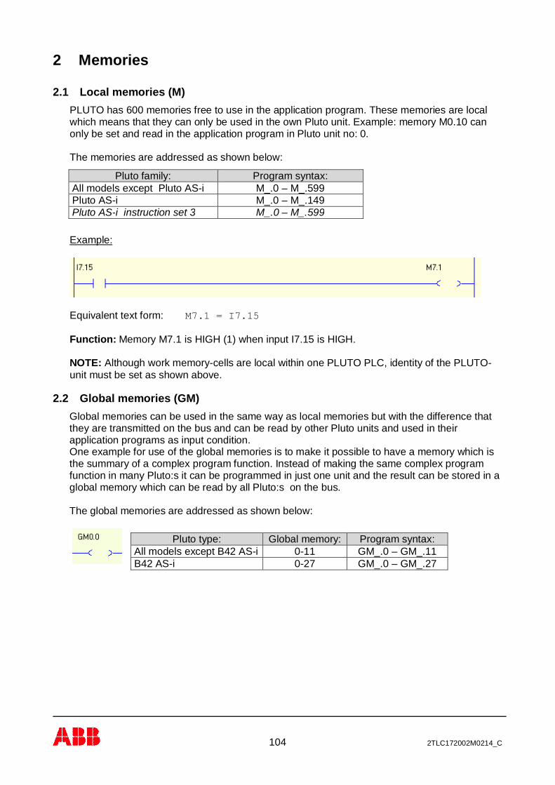
104 2TLC172002M0214_C
2 Memories
2.1 Local memories (M)PLUTO has 600 memories free to use in the application program. These memories are localwhich means that they can only be used in the own Pluto unit. Example: memory M0.10 canonly be set and read in the application program in Pluto unit no: 0.
The memories are addressed as shown below:
Example:
Equivalent text form: M7.1 = I7.15
Function: Memory M7.1 is HIGH (1) when input I7.15 is HIGH.
NOTE: Although work memory-cells are local within one PLUTO PLC, identity of the PLUTO-unit must be set as shown above.
2.2 Global memories (GM)Global memories can be used in the same way as local memories but with the difference thatthey are transmitted on the bus and can be read by other Pluto units and used in theirapplication programs as input condition.One example for use of the global memories is to make it possible to have a memory which isthe summary of a complex program function. Instead of making the same complex programfunction in many Pluto:s it can be programmed in just one unit and the result can be stored in aglobal memory which can be read by all Pluto:s on the bus.
The global memories are addressed as shown below:
Pluto family: Program syntax:All models except Pluto AS-i M_.0 – M_.599Pluto AS-i M_.0 – M_.149Pluto AS-i instruction set 3 M_.0 – M_.599
Pluto type: Global memory: Program syntax:All models except B42 AS-i 0-11 GM_.0 – GM_.11B42 AS-i 0-27 GM_.0 – GM_.27
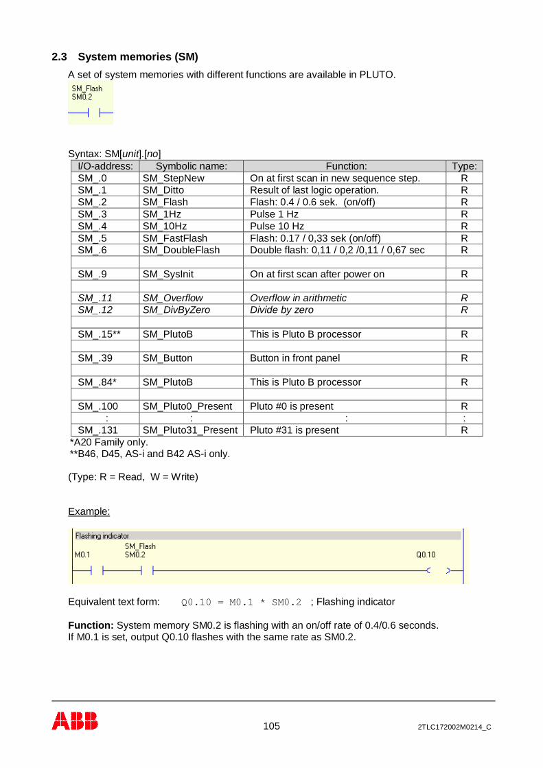
105 2TLC172002M0214_C
2.3 System memories (SM)A set of system memories with different functions are available in PLUTO.
Syntax: SM[unit].[no]I/O-address: Symbolic name: Function: Type:SM_.0 SM_StepNew On at first scan in new sequence step. RSM_.1 SM_Ditto Result of last logic operation. RSM_.2 SM_Flash Flash: 0.4 / 0.6 sek. (on/off) RSM_.3 SM_1Hz Pulse 1 Hz RSM_.4 SM_10Hz Pulse 10 Hz RSM_.5 SM_FastFlash Flash: 0.17 / 0,33 sek (on/off) RSM_.6 SM_DoubleFlash Double flash: 0,11 / 0,2 /0,11 / 0,67 sec R
SM_.9 SM_SysInit On at first scan after power on R
SM_.11 SM_Overflow Overflow in arithmetic RSM_.12 SM_DivByZero Divide by zero R
SM_.15** SM_PlutoB This is Pluto B processor R
SM_.39 SM_Button Button in front panel R
SM_.84* SM_PlutoB This is Pluto B processor R
SM_.100 SM_Pluto0_Present Pluto #0 is present R: : : :
SM_.131 SM_Pluto31_Present Pluto #31 is present R*A20 Family only.**B46, D45, AS-i and B42 AS-i only.
(Type: R = Read, W = Write)
Example:
Equivalent text form: Q0.10 = M0.1 * SM0.2 ; Flashing indicator
Function: System memory SM0.2 is flashing with an on/off rate of 0.4/0.6 seconds.If M0.1 is set, output Q0.10 flashes with the same rate as SM0.2.
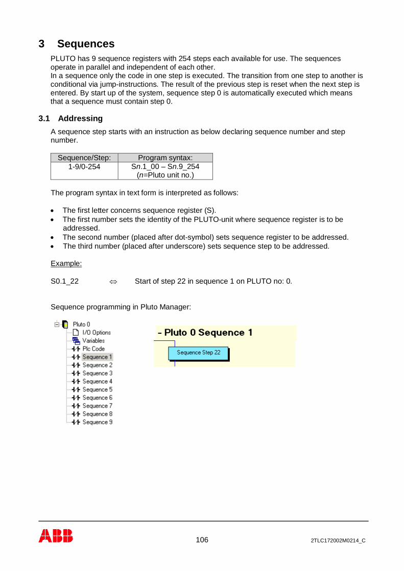
106 2TLC172002M0214_C
3 SequencesPLUTO has 9 sequence registers with 254 steps each available for use. The sequencesoperate in parallel and independent of each other.In a sequence only the code in one step is executed. The transition from one step to another isconditional via jump-instructions. The result of the previous step is reset when the next step isentered. By start up of the system, sequence step 0 is automatically executed which meansthat a sequence must contain step 0.
3.1 AddressingA sequence step starts with an instruction as below declaring sequence number and stepnumber.
Sequence/Step: Program syntax:1-9/0-254 Sn.1_00 – Sn.9_254
(n=Pluto unit no.)
The program syntax in text form is interpreted as follows:
· The first letter concerns sequence register (S).· The first number sets the identity of the PLUTO-unit where sequence register is to be
addressed.· The second number (placed after dot-symbol) sets sequence register to be addressed.· The third number (placed after underscore) sets sequence step to be addressed.
Example:
S0.1_22 Û Start of step 22 in sequence 1 on PLUTO no: 0.
Sequence programming in Pluto Manager:
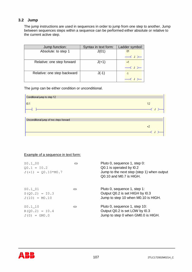
107 2TLC172002M0214_C
3.2 JumpThe jump instructions are used in sequences in order to jump from one step to another. Jumpbetween sequences steps within a sequence can be performed either absolute or relative tothe current active step.
Jump function: Syntax in text form: Ladder symbol:Absolute: to step 1 J(01)
Relative: one step forward J(+1)
Relative: one step backward J(-1)
The jump can be either condition or unconditional.
Example of a sequence in text form:
S0.1_00 Û Pluto 0, sequence 1, step 0:Q0.1 = I0.2 Q0.1 is operated by I0.2J(+1) = Q0.10*M0.7 Jump to the next step (step 1) when output
Q0.10 and M0.7 is HIGH.
S0.1_01 Û Pluto 0, sequence 1, step 1:S(Q0.2) = I0.3 Output Q0.2 is set HIGH by I0.3J(10) = M0.10 Jump to step 10 when M0.10 is HIGH.
S0.1_10 Û Pluto 0, sequence 1, step 10:R(Q0.2) = I0.4 Output Q0.2 is set LOW by I0.3J(0) = GM0.0 Jump to step 0 when GM0.0 is HIGH.

108 2TLC172002M0214_C
The equivalence in ladder
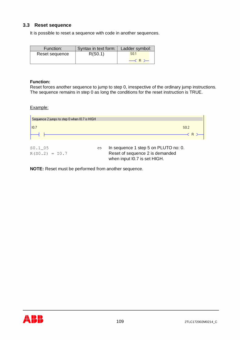
109 2TLC172002M0214_C
3.3 Reset sequenceIt is possible to reset a sequence with code in another sequences.
Function: Syntax in text form: Ladder symbol:Reset sequence R(S0.1)
Function:Reset forces another sequence to jump to step 0, irrespective of the ordinary jump instructions.The sequence remains in step 0 as long the conditions for the reset instruction is TRUE.
Example:
S0.1_05 Û In sequence 1 step 5 on PLUTO no: 0.R(S0.2) = I0.7 Reset of sequence 2 is demanded
when input I0.7 is set HIGH.
NOTE: Reset must be performed from another sequence.
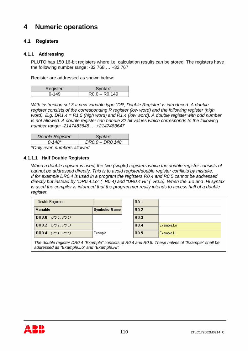
110 2TLC172002M0214_C
4 Numeric operations
4.1 Registers
4.1.1 AddressingPLUTO has 150 16-bit registers where i.e. calculation results can be stored. The registers havethe following number range: -32 768 … +32 767
Register are addressed as shown below:
Register: Syntax:0-149 R0.0 – R0.149
With instruction set 3 a new variable type “DR, Double Register” is introduced. A doubleregister consists of the corresponding R register (low word) and the following register (highword). E.g. DR1.4 = R1.5 (high word) and R1.4 (low word). A double register with odd numberis not allowed. A double register can handle 32 bit values which corresponds to the followingnumber range: -2147483648 … +2147483647
Double Register: Syntax:0-148* DR0.0 – DR0.148
*Only even numbers allowed
4.1.1.1 Half Double RegistersWhen a double register is used, the two (single) registers which the double register consists ofcannot be addressed directly. This is to avoid register/double register conflicts by mistake.If for example DR0.4 is used in a program the registers R0.4 and R0.5 cannot be addresseddirectly but instead by “DR0.4.Lo” (=R0.4) and “DR0.4.Hi” (=R0.5). When the .Lo and .Hi syntaxis used the compiler is informed that the programmer really intends to access half of a doubleregister.
The double register DR0.4 “Example” consists of R0.4 and R0.5. These halves of “Example” shall beaddressed as “Example.Lo” and “Example.Hi”.

111 2TLC172002M0214_C
4.1.2 OperationsAssignment of register (with Instruction set 2)
Operation: Syntax for Registers:Increment by 1 (R0.100++)
Decrement by 1 (R0.100--)Add constant (R0.100 += 77)
Subtract constant (R0.100 – = 77)Assign with absolute value = 1 (R0.100 = 1)
Addition with other register(R0.100 = R0.100 + R0.102) (R0.100 += R0.102)Subtract with other register
(R0.100 = R0.100 – R0.102) (R0.100 – = R0.102)Assign with other reg. value (R0.100 = R0.102)
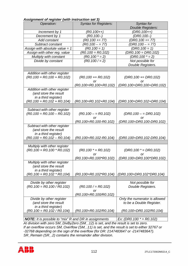
112 2TLC172002M0214_C
Assignment of register (with instruction set 3)Operation: Syntax for Registers: Syntax for
Double Registers:Increment by 1 (R0.100++) (DR0.100++)
Decrement by 1 (R0.100--) (DR0.100--)Add constant (R0.100 += 77) (DR0.100 += 77)
Subtract constant (R0.100 – = 77) (DR0.100 – = 77)Assign with absolute value = 1 (R0.100 = 1) (DR0.100 = 1)
Assign with other reg. value (R0.100 = R0.102) (DR0.100 = DR0.102)Multiply with constant (R0.100 * = 2) (DR0.100 * = 2)
Divide by constant (R0.100 / = 2) Not possible forDouble Registers.
Addition with other register(R0.100 = R0.100 + R0.102) (R0.100 += R0.102)
or(R0.100=R0.100+R0.102)
(DR0.100 += DR0.102)or
(DR0.100=DR0.100+DR0.102)Addition with other register
(and store the resultin a third register)
(R0.100 = R0.102 + R0.104) (R0.100=R0.102+R0.104) (DR0.100=DR0.102+DR0.104)
Subtract with other register(R0.100 = R0.100 – R0.102) (R0.100 – = R0.102)
or(R0.100=R0.100-R0.102)
(DR0.100 – = DR0.102)or
(DR0.100=DR0.100-DR0.102)Subtract with other register
(and store the resultin a third register)
(R0.100 = R0.102 – R0.104) (R0.100=R0.102-R0.104) (DR0.100=DR0.102-DR0.104)
Multiply with other register(R0.100 = R0.100 * R0.102) (R0.100 * = R0.102)
or(R0.100=R0.100*R0.102)
(DR0.100 * = DR0.102)or
(DR0.100=DR0.100*DR0.102)Multiply with other register
(and store the resultin a third register)
(R0.100 = R0.102 * R0.104) (R0.100=R0.102*R0.104) (DR0.100=DR0.102*DR0.104)
Divide by other register(R0.100 = R0.100 / R0.102) (R0.100 / = R0.102)
or(R0.100=R0.100/R0.102)
Not possible forDouble Registers.
Divide by other register(and store the result
in a third register)(R0.100 = R0.102 / R0.104) (R0.100=R0.102/R0.104)
Only the numerator is allowedto be a Double Register.
(R0.100=DR0.102/R0.104)
NOTE: It is possible to “mix” R and DR in assignments Ex: (DR0.100 * = R0.102)At division with zero SM_DivByZero (SM_.12) is set, and the result is set to zero.If an overflow occurs SM_Overflow (SM_.11) is set, and the result is set to either 32767 or-32768 depending on the sign of the overflow (for DR: 2147483647 or -2147483647).SR_Remain (SR_.2) contains the remainder after division.
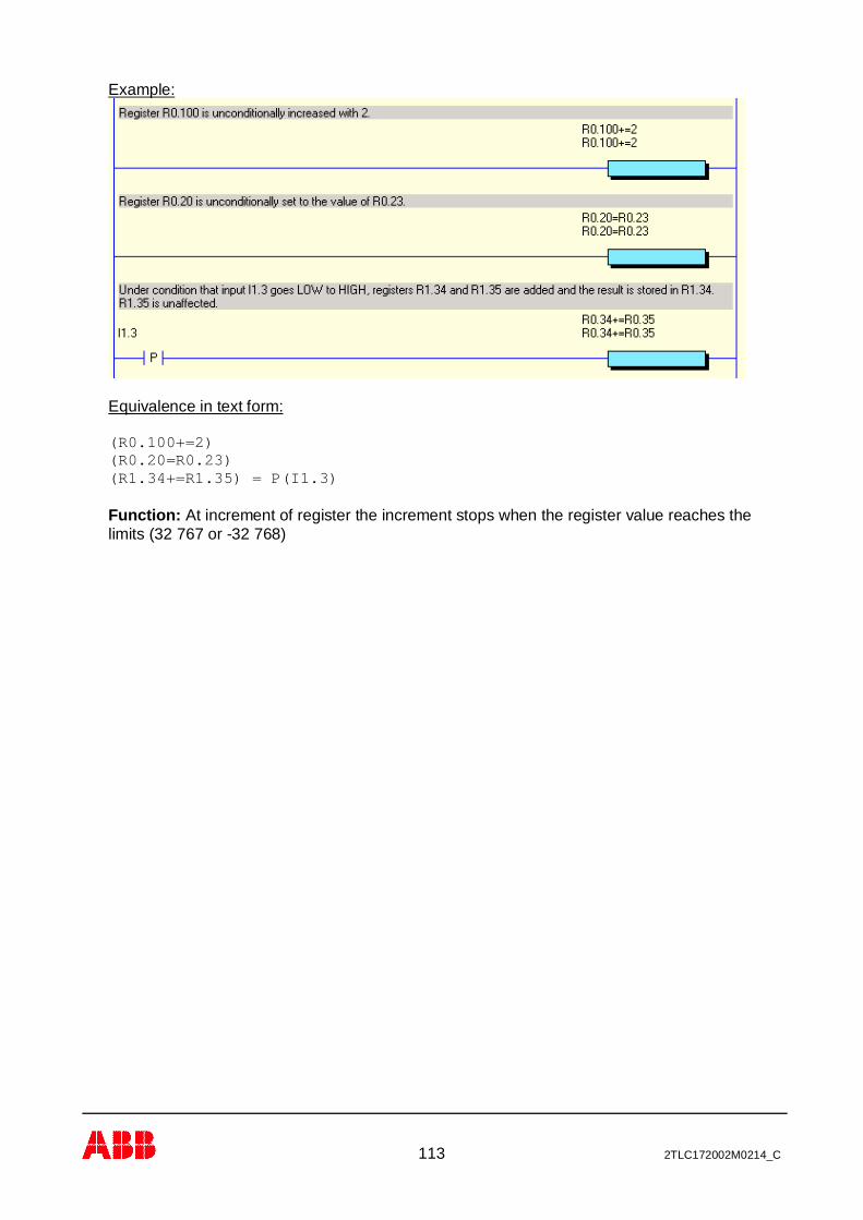
113 2TLC172002M0214_C
Example:
Equivalence in text form:
(R0.100+=2)(R0.20=R0.23)(R1.34+=R1.35) = P(I1.3)
Function: At increment of register the increment stops when the register value reaches thelimits (32 767 or -32 768)

114 2TLC172002M0214_C
Comparison of registerComparison: Syntax for Registers: Syntax for
DoubleRegisters:Equal to (constant) (R0.100=1) (DR0.100=1)
Greater than (R0.100>1) (DR0.100>1)Less than (R0.100<1) (DR0.100<1)
Greater than or Equal to (R0.100>=1) (DR0.100>=1)Less than or Equal to (R0.100<=1) (DR0.100<=1)Equal (two registers) (R0.100=R0.101) (DR0.100=DR0.102)
Greater than (R0.100>R0.101) (DR0.100>DR0.102)Less than (R0.100< R0.101) (DR0.100< DR0.102)
Greater than or Equal to (R0.100>= R0.101) (DR0.100>= DR0.102)Less than or Equal to (R0.100<= R0.101) (DR0.100<= DR0.102)
Example:
In text form: Q0.10 = (R0.98>=4)
In text form: M0.10 = (R0.22=R0.35)* I0.4
In text form: (R0.9++) = (R0.12>R0.14)
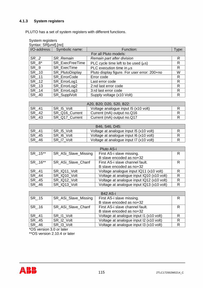
115 2TLC172002M0214_C
4.1.3 System registers
PLUTO has a set of system registers with different functions.
System registersSyntax: SR[unit].[no]I/O-address: Symbolic name: Function: Type:
For all Pluto models:SR_.2 SR_Remain Remain part after division RSR_.8* SR_ExecFreeTime PLC cycle time left to be used (ms) RSR_.9 SR_ExecTime PLC execution time in ms RSR_.10 SR_PlutoDisplay Pluto display figure. For user error: 200+no WSR_.11 SR_ErrorCode Error code RSR_.12 SR_ErrorLog1 Last error code RSR_.13 SR_ErrorLog2 2:nd last error code RSR_.14 SR_ErrorLog3 3:rd last error code RSR_.40 SR_SupplVolt Supply voltage (x10 Volt) R
A20, B20; D20, S20, B22:SR_.41 SR_I5_Volt Voltage analogue input I5 (x10 volt) RSR_.42 SR_Q16_Current Current (mA) output no.Q16 RSR_.43 SR_Q17_Current Current (mA) output no.Q17 R
B46, S46, D45:SR_.41 SR_I5_Volt Voltage at analogue input I5 (x10 volt) RSR_.45 SR_I6_Volt Voltage at analogue input I6 (x10 volt) RSR_.46 SR_I7_Volt Voltage at analogue input I7 (x10 volt) R
Pluto AS-iSR_.15** SR_ASi_Slave_Missing First AS-i slave missing.
B slave encoded as no+32R
SR_.16** SR_ASi_Slave_Chanf First AS-i slave channel fault.B slave encoded as no+32
R
SR_.41 SR_IQ11_Volt Voltage analogue input IQ11 (x10 volt) RSR_.44 SR_IQ10_Volt Voltage at analogue input IQ10 (x10 volt) RSR_.45 SR_IQ12_Volt Voltage at analogue input IQ12 (x10 volt) RSR_.46 SR_IQ13_Volt Voltage at analogue input IQ13 (x10 volt) R
B42 AS-iSR_.15 SR_ASi_Slave_Missing First AS-i slave missing.
B slave encoded as no+32R
SR_.16 SR_ASi_Slave_Chanf First AS-i slave channel fault.B slave encoded as no+32
R
SR_.41 SR_I1_Volt Voltage at analogue input I1 (x10 volt) RSR_.45 SR_I2_Volt Voltage at analogue input I2 (x10 volt) RSR_.46 SR_I3_Volt Voltage at analogue input I3 (x10 volt) R
*OS version 3.0 or later**OS version 2.10.4 or later

116 2TLC172002M0214_C
Example:
In text form: Q0.12 = (SR0.40<180) * SM0.5
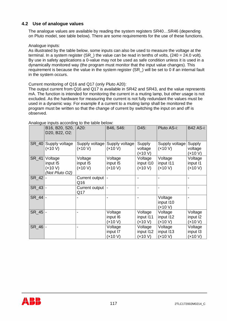
117 2TLC172002M0214_C
4.2 Use of analogue valuesThe analogue values are available by reading the system registers SR40…SR46 (dependingon Pluto model, see table below). There are some requirements for the use of these functions.
Analogue inputs:As illustrated by the table below, some inputs can also be used to measure the voltage at theterminal. In a system register (SR_) the value can be read in tenths of volts, (240 = 24.0 volt).By use in safety applications a 0-value may not be used as safe condition unless it is used in adynamically monitored way (the program must monitor that the input value changes). Thisrequirement is because the value in the system register (SR_) will be set to 0 if an internal faultin the system occurs.
Current monitoring of Q16 and Q17 (only Pluto A20):The output current from Q16 and Q17 is available in SR42 and SR43, and the value representsmA. The function is intended for monitoring the current in a muting lamp, but other usage is notexcluded. As the hardware for measuring the current is not fully redundant the values must beused in a dynamic way. For example if a current to a muting lamp shall be monitored theprogram must be written so that the change of current by switching the input on and off isobserved.
Analogue inputs according to the table below:B16, B20, S20,D20, B22, O2:
A20: B46, S46: D45: Pluto AS-i: B42 AS-i:
SR_40 Supply voltage(×10 V)
Supply voltage(×10 V)
Supply voltage(×10 V)
Supplyvoltage(×10 V)
Supply voltage(×10 V)
Supplyvoltage(×10 V)
SR_41 Voltageinput I5(×10 V)(Not Pluto O2)
Voltageinput I5(×10 V)
Voltageinput I5(×10 V)
Voltageinput I10(×10 V)
Voltageinput I11(×10 V)
Voltageinput I1(×10 V)
SR_42 - Current outputQ16
- - - -
SR_43 - Current outputQ17
- - - -
SR_44 - - - - Voltageinput I10(×10 V)
-
SR_45 - - Voltageinput I6(×10 V)
Voltageinput I11(×10 V)
Voltageinput I12(×10 V)
Voltageinput I2(×10 V)
SR_46 - - Voltageinput I7(×10 V)
Voltageinput I12(×10 V)
Voltageinput I13(×10 V)
Voltageinput I3(×10 V)

118 2TLC172002M0214_C
Example:
In text form:
M0.100 = (SR0.42>180) M0.101 = M0.100 * (SR0.42<400) * (P(M0.100) + M0.101)

119 2TLC172002M0214_C
5 Program declaration in text formIn the beginning of the program file different declarations are made. These declarationsdescribe the hardware environment for the Pluto unit.
For more information about the function of the different hardware options see the ‘Operatinginstructions, Hardware’
5.1 Identity, station number and Pluto familyEach unit must have a station number 0-31.It is also possible to connect an external identifier circuit containing a unique 12 figurehexadecimal number. Then it is also necessary to declare the Pluto family.These two settings are declared as:
! id_pluto:[stn.number]=[identifier number] for Pluto A20 family.! id_pluto_Double:[stn.number]=[identifier number] for Pluto double family.! id_pluto_ASi:[stn.number]=[identifier number] for Pluto AS-i! id_pluto_B42_ASi:[stn.number]=[identifier number] for Pluto B42 AS-i
If identifier is not connected the system will accept this if the identifier number is declared as000000000000 (12 zero).
Example:
! id_pluto:00=ffff00007FA3 Û The Pluto-unit is given station number 0and an identifier with number ffff00007FA3must be connected to the unit.
! id_pluto:23=000000000000 Û The Pluto-unit is given station number 23and the unit shall run without identifier.
5.2 Declaration of program codeSince it is possible to have program code for several units stored in one unit it must bedeclared to which Pluto unit a code part belongs to.
Syntax:
! pgm_pluto:[station no.]
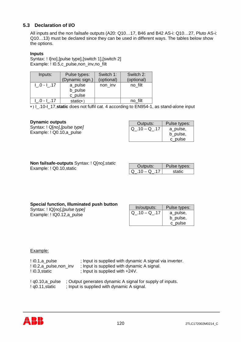
120 2TLC172002M0214_C
5.3 Declaration of I/OAll inputs and the non failsafe outputs (A20: Q10…17, B46 and B42 AS-i: Q10…27, Pluto AS-i:Q10…13) must be declared since they can be used in different ways. The tables below showthe options.
InputsSyntax: ! I[no],[pulse type],[switch 1],[switch 2]Example: ! I0.5,c_pulse,non_inv,no_filt
Inputs: Pulse types:(Dynamic sign.)
Switch 1:(optional)
Switch 2:(optional)
I_.0 - I_.17 a_pulseb_pulsec_pulse
non_inv no_filt
I_.0 - I_.17 static*) no_filt*) I_.10-I_17,static does not fulfil cat. 4 according to EN954-1, as stand-alone input
Dynamic outputsSyntax: ! Q[no],[pulse type]Example: ! Q0.10,a_pulse
Non failsafe-outputs Syntax: ! Q[no],staticExample: ! Q0.10,static
Special function, Illuminated push buttonSyntax: ! IQ[no],[pulse type]Example: ! IQ0.12,a_pulse
Example:
! i0.1,a_pulse ; Input is supplied with dynamic A signal via inverter.! i0.2,a_pulse,non_inv ; Input is supplied with dynamic A signal.! i0.3,static ; Input is supplied with +24V.
! q0.10,a_pulse ; Output generates dynamic A signal for supply of inputs.! q0.11,static ; Input is supplied with dynamic A signal.
Outputs: Pulse types:Q_.10 – Q_.17 a_pulse,
b_pulse,c_pulse
Outputs: Pulse types:Q_.10 – Q_.17 static
In/outputs: Pulse types:Q_.10 – Q_.17 a_pulse,
b_pulse,c_pulse
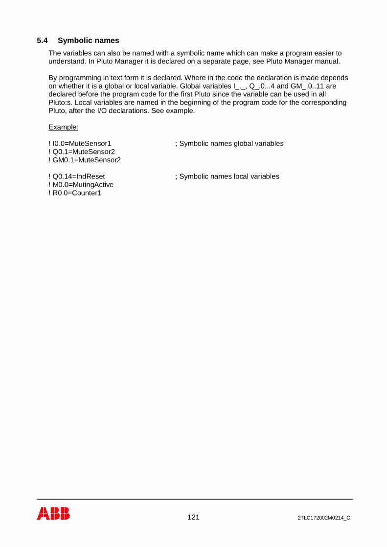
121 2TLC172002M0214_C
5.4 Symbolic namesThe variables can also be named with a symbolic name which can make a program easier tounderstand. In Pluto Manager it is declared on a separate page, see Pluto Manager manual.
By programming in text form it is declared. Where in the code the declaration is made dependson whether it is a global or local variable. Global variables I_._, Q_.0...4 and GM_.0..11 aredeclared before the program code for the first Pluto since the variable can be used in allPluto:s. Local variables are named in the beginning of the program code for the correspondingPluto, after the I/O declarations. See example.
Example:
! I0.0=MuteSensor1 ; Symbolic names global variables! Q0.1=MuteSensor2! GM0.1=MuteSensor2
! Q0.14=IndReset ; Symbolic names local variables! M0.0=MutingActive! R0.0=Counter1

122 2TLC172002M0214_C
6 Program example in text formThis program example is the program for the installation example showed in “Operatinginstruction, Hardware”.
$name Example, manual
! id_pluto:00=000034AD4AE1
! pgm_pluto:00
! q0.10,a_pulse ; Dynamic output A
! i0.00,static ; Muting sensor 1! i0.01,a_pulse,non_inv ; Muting sensor 2! i0.02,a_pulse,non_inv ; Test Contactors! i0.12,a_pulse ; Emergency stop PB! i0.13,a_pulse ; JSL Lightbeam! iq0.14,a_pulse ; Reset with indicator
;**********************************************
s0.0_0 ; Main sequence start
q0.2 = i0.12 * (i0.13 + m0.0) * ( (p(i0.14) * i0.02) + q0.2)q0.3 = q0.2
; All safety outputs active when Emergency stop(I0.12); and JSL(I.13) or muting(M0.0) are active.; Reset(I0.14) and Test(I0.02) are also needed in the; start condition.
q0.14 = /q0.2 ; Reset indication active when outputs not active
;**********************************************
s0.1_0 ; Muting Sequencej(+1)=/i0.00*/i0.01*(SR0.43<100) ; Start condition: both sensors not active
s0.1_1q0.17 = i0.00 * i0.01 * i0.13j(+1) = q0.17 * (SR0.43<100) ; Muting start when both sensors and JSL actives0.1_2m0.0 ; M0.0, Memory muting activeq0.17 ; Indicator muting activej(0) = /i0.00 + /i0.01 ; Muting stopped by either sensor not active
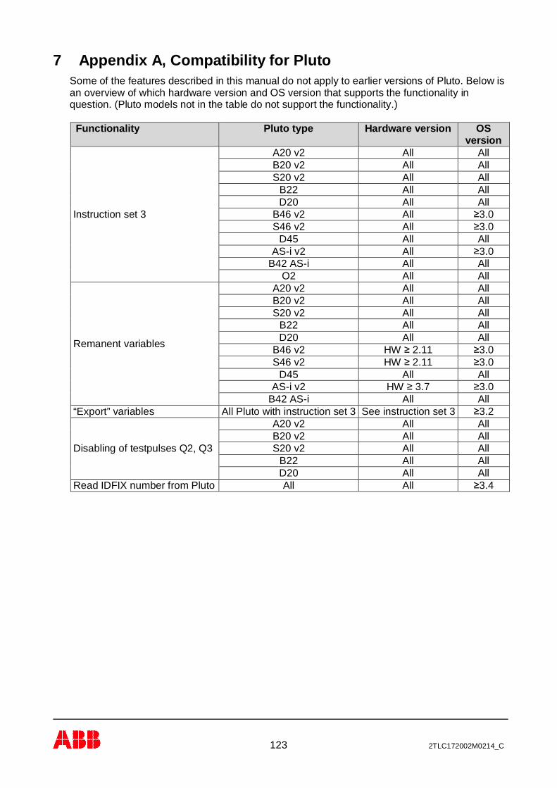
123 2TLC172002M0214_C
7 Appendix A, Compatibility for PlutoSome of the features described in this manual do not apply to earlier versions of Pluto. Below isan overview of which hardware version and OS version that supports the functionality inquestion. (Pluto models not in the table do not support the functionality.)
Functionality Pluto type Hardware version OSversion
Instruction set 3
A20 v2 All AllB20 v2 All AllS20 v2 All All
B22 All AllD20 All All
B46 v2 All ≥3.0S46 v2 All ≥3.0
D45 All AllAS-i v2 All ≥3.0
B42 AS-i All AllO2 All All
Remanent variables
A20 v2 All AllB20 v2 All AllS20 v2 All All
B22 All AllD20 All All
B46 v2 HW ≥ 2.11 ≥3.0S46 v2 HW ≥ 2.11 ≥3.0
D45 All AllAS-i v2 HW ≥ 3.7 ≥3.0
B42 AS-i All All“Export” variables All Pluto with instruction set 3 See instruction set 3 ≥3.2
Disabling of testpulses Q2, Q3
A20 v2 All AllB20 v2 All AllS20 v2 All All
B22 All AllD20 All All
Read IDFIX number from Pluto All All ≥3.4

124 2TLC172002M0214_C
Contact informationAustraliaABB Australia Pty LimitedLow Voltage ProductsTel: +61 (0)1300 660 299Fax: +61 (0)1300 853 138Mob: +61 (0)401 714 392E-mail: [email protected]: www.abbaustralia.com.au
AustriaABB AB, Jokab SafetyTel: +43 (0)1 601 09-6204Fax: +43 (0)1 601 09-8600E-mail: [email protected]: www.abb.at
BelgiumABB N.V.Tel: +32 27186884Fax: +32 27186831E-mail: [email protected]
BrazilABB LtdaProdutos de Baixa TensãoABB Atende: 0800 014 9111Fax: +55 11 3688-9977Web: www.abb.com.br
CanadaABB Inc.Tel: +1 514 420 3100 Ext 3269Fax: +1 514 420 3137Mobile: +1 514 247 4025E-mail: [email protected]: www.abb.com
ChinaABB (China) LimitedTel: 86-21-23287948Telefax: 86-21-23288558Mobile: 86-186 2182 1159E-mail: [email protected]
Czech RepublicABB AB, Jokab SafetyTel: +420 543 145 482Fax: +420 543 243 489E-mail: [email protected]: www.abb.cz
DenmarkJOKAB SAFETY DK A/STel: +45 44 34 14 54Fax: +45 44 99 14 54E-mail: [email protected]: www.jokabsafety.dk
ABB A/STel: +45 4450 4450Fax: +45 4359 5920E-mail: [email protected]: www.abb.dk
FinlandABB OyWeb: www.abb.fi
FranceABB FranceDivision Produits Basse TensionTel: 0825 38 63 55Fax: 0825 87 09 26Web: www.abb.com
GermanyABB STOTZ-KONTAKT GmbHTel: +49 (0) 7424-95865-0Fax: +49 (0) 7424-95865-99E-mail: [email protected]: www.jokabsafety.com
GreeceΑΒΒ SATel: +30 210.28.91.900Fax: +30 210.28.91.999E-mail: [email protected] [email protected]: www.abb.com
IrelandABB Ltd.Tel +353 1 4057 381Fax: +353 1 4057 312Mobile: +353 86 2532891E-mail: [email protected]
IsraelABB Technologies Ltd.Tel: +972 4 851-9204Mobile: +972 52 485-6284E-mail: [email protected]: www.abb.co.il
ItalyABB S.p.A.Tel. +39 02 2414.1Fax +39 02 2414.2330Web: www.abb.it
KoreaABB KOREALow-voltage ProductTel: +82 2 528 3177Fax: +82 2 528 2350Web: www.jokabsafety.co.kr
MalaysiaABB MalaysiaTel: +60356284888 4282E-mail: [email protected]
NetherlandsABB b.v.Tel:+31 (0) 10 - 4078 947Fax: +31 (0) 10 – 4078 090E-mail: [email protected]: www.abb.nl
NorwayABB ASTel: +47 03500Fax: +47 32858021Mobile: +47 40918930E-mail: [email protected]: www.abb.no
PolandABB Sp. z.o.oTel: +48 728 401 403Fax: 22 220 22 23E-mail: [email protected], [email protected]: www.abb.pl
PortugalAsea Brown Boveri S.A.Low Voltage Products - Baixa TensãoTel: +35 214 256 000Fax: +35 214 256 390Web: www.abb.es
SloveniaABB d.o.o.Tel: +386 1 2445 455Fax: +386 1 2445 490E-mail: [email protected]
SpainAsea Brown Boveri S.A.Tel: +34 93 4842121Fax: +34 93 484 21 90Web: www.abb.es
South AfricaABBTel: +27 10 202 5906Fax: +27 11 579 8203Mobile: +27 82 500 7990E-mail: [email protected]
SwedenABB AB, Jokab SafetyVarlabergsvägen 11SE-434 39 KungsbackaTel: +46 21 32 50 00Fax: +40 67 15 601Mail: [email protected]: www.abb.com/jokabsafety
SwitzerlandABB Schweiz AGIndustrie- und GebäudeautomationTel: +41 58 586 00 00Fax: +41 58 586 06 01E-mail: [email protected]: www.abb.ch
TurkeyABB Elektrik Sanayi A.ŞTel: 0216 528 22 00Fax: 0216 365 29 44
United KingdomABB Ltd/JOKAB SAFETY UKTel: +44 (0) 2476 368500Fax: +44 (0) 2476 368401E-mail: [email protected]: www.jokabsafety.com
USA/MexicoABB Jokab Safety North AmericaTel: +1 519 735 1055Fax: +1 519 7351299E-mail: [email protected]: www.jokabsafetyna.com


