Embed Size (px)
Citation preview
Computers & Geosciences 29 (2003) 685–694
Portable digital seismological AC station over mobiletelephone network and internet
Carlos A. Vargas-Jimeneza,*, Sergio Rinc !on-Boterob
aDepartamento de Geociencias, Universidad Nacional de Colombia, sede Bogot !a, ColombiabFacultad de Ingenier!ıa, Universidad de Manizales, Manizales, Colombia
Received 1 November 2001; received in revised form 31 October 2002; accepted 15 November 2002
Abstract
We have developed a portable station with a low-frequency signal conditioning and acquisition system for seismic
event recording. This station records events in different modes and transmits them in the cellular mobile telephone
network via active pages. Setup of the station is done directly at the station or remotely via a TCP-IP connection to the
site. The designed station has a 101 dB dynamic range and nine channels. Three are for the tri-axial array geophones.
The other six are used for the acquisition of signals with less than 100 samples per second requirements (temperature,
radiometry, inclinometers, battery monitoring, etc.). The station software allows detection of seismic events using a
short-term/long-term coverage standard algorithm, as well as threshold detection, periodic capture and continuous
channel capture. The conditioning and acquisition system was designed as an embedded command-driven system with
its own real-time clock and storage memory.
r 2003 Elsevier Science Ltd. All rights reserved.
Keywords: Seismic station; CDPD; Data acquisition; Data transmission
1. Introduction
Field stations allow the capture of signals such as
those coming from sensors for seismic registration,
water-level measurement in rivers, environment tem-
perature, precipitation, and many other variables, which
are transmitted so that they can be analyzed.
In general, most of the seismic monitoring stations are
based on conventional telemetry systems or autonomous
captures. In the first case, requirements for acceptable
transmission conditions are not always met (no line of
sight, high-retransmission costs, etc.), and in the second
case, qualified personnel are required to collect the
information at the site periodically.
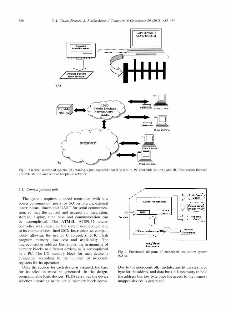
In the present work, a portable station is proposed
with connection to the cellular mobile telephone
network (Fig. 1). The station acquires seismic signals
for post-processing and analysis, including data
storage and generation of events that can be remotely
requested.
2. Embedded acquisition system
The seismic events capture is done using a tri-axial
geophone, that is, sensors which register the earth’s
ground velocity in three directions E,N,Z (East–West,
North–South, Up–Down). The analog seismic signals,
as well as others coming from temperature sensors,
inclination, etc., are captured, conditioned and con-
verted into digital signals that are processed on the
computer, using the embedded acquisition system
(SAE). Data request handling is received via RS232
serial port interface.
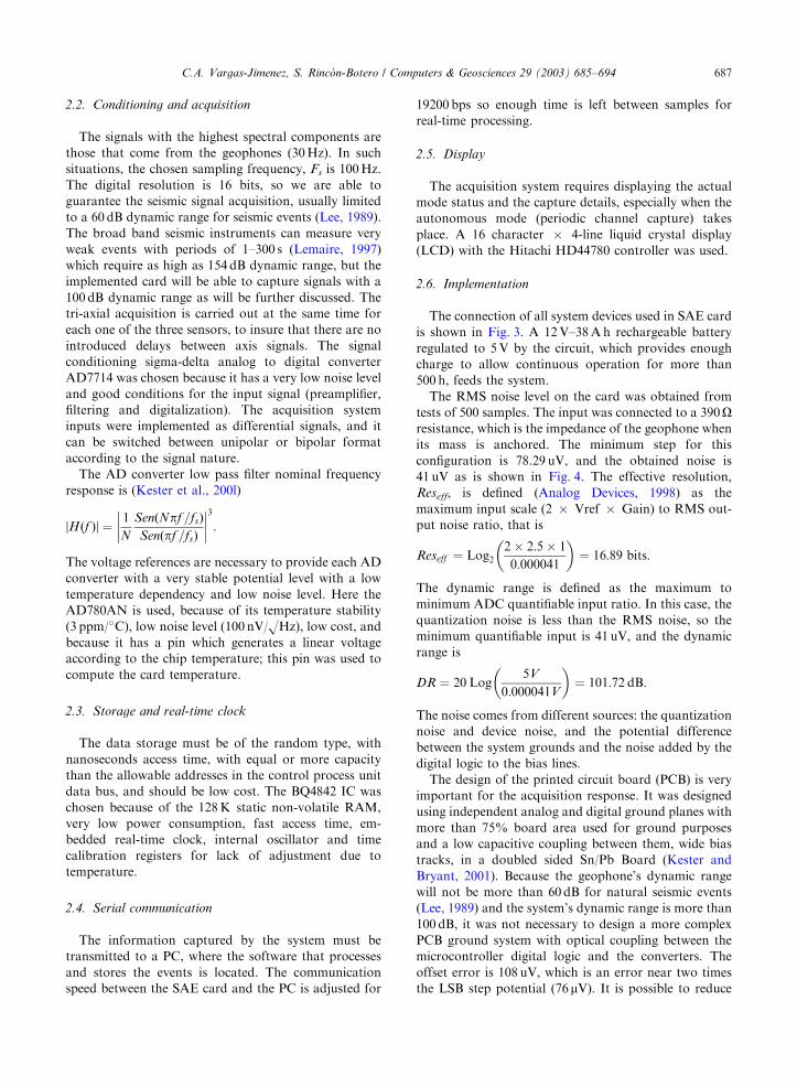
The SAE system is composed of the Conditioning and
Signal Capture Unit, Central Unit (microcontroller),
Memory and Storage Unit, Time Base Unit, Serial
Interface and Display (Fig. 2).
ARTICLE IN PRESS
*Corresponding author.
E-mail address: [email protected]
(C.A. Vargas-Jimenez).
0098-3004/03/$ - see front matter r 2003 Elsevier Science Ltd. All rights reserved.
doi:10.1016/S0098-3004(03)00041-4
2.1. Control process unit
The system requires a speed controller, with low
power consumption, ports for I/O peripherals, external
interruptions, timers and UART for serial communica-
tion, so that the control and acquisition integration,
storage, display, time base and communication can
be accomplished. The ATMEL AT89C55 micro-
controller was chosen in the system development due
to its characteristics: Intel 805X Instruction set compat-
ibility allowing the use of C compilers, 20K Flash
program memory, low cost and availability. The
microcontroller address bus allows the assignment of
memory blocks to different devices, as is accomplished
in a PC. The I/O memory block for each device is
designated according to the number of necessary
registers for its operation.
Once the address for each device is assigned, the base
for its selection must be generated. In the design,
programmable logic devices (PLD) carry out the device
selection according to the actual memory block access.
Due to the microcontroller architecture (it uses a shared
byte for the address and data bus), it is necessary to hold
the address bus low byte once the access to the memory
mapped devices is generated.
ARTICLE IN PRESS
Fig. 1. General scheme of system: (A) Analog signal captured that it is sent to PC (portable station); and (B) Connection between
portable station and cellular telephone network.
Fig. 2. Functional diagram of embedded acquisition system
(SAE).
C.A. Vargas-Jimenez, S. Rinc !on-Botero / Computers & Geosciences 29 (2003) 685–694686
2.2. Conditioning and acquisition
The signals with the highest spectral components are
those that come from the geophones (30Hz). In such
situations, the chosen sampling frequency, Fs is 100Hz.
The digital resolution is 16 bits, so we are able to
guarantee the seismic signal acquisition, usually limited
to a 60 dB dynamic range for seismic events (Lee, 1989).
The broad band seismic instruments can measure very
weak events with periods of 1–300 s (Lemaire, 1997)
which require as high as 154 dB dynamic range, but the
implemented card will be able to capture signals with a
100 dB dynamic range as will be further discussed. The
tri-axial acquisition is carried out at the same time for
each one of the three sensors, to insure that there are no
introduced delays between axis signals. The signal
conditioning sigma-delta analog to digital converter
AD7714 was chosen because it has a very low noise level
and good conditions for the input signal (preamplifier,
filtering and digitalization). The acquisition system
inputs were implemented as differential signals, and it
can be switched between unipolar or bipolar format
according to the signal nature.
The AD converter low pass filter nominal frequency
response is (Kester et al., 200l)
jHðf Þj ¼1
N
SenðNpf =fsÞSenðpf =fsÞ
��������3
:
The voltage references are necessary to provide each AD
converter with a very stable potential level with a low
temperature dependency and low noise level. Here the
AD780AN is used, because of its temperature stability
(3 ppm/�C), low noise level (100 nV/OHz), low cost, andbecause it has a pin which generates a linear voltage
according to the chip temperature; this pin was used to
compute the card temperature.
2.3. Storage and real-time clock
The data storage must be of the random type, with
nanoseconds access time, with equal or more capacity
than the allowable addresses in the control process unit
data bus, and should be low cost. The BQ4842 IC was
chosen because of the 128K static non-volatile RAM,
very low power consumption, fast access time, em-
bedded real-time clock, internal oscillator and time
calibration registers for lack of adjustment due to
temperature.
2.4. Serial communication
The information captured by the system must be
transmitted to a PC, where the software that processes
and stores the events is located. The communication
speed between the SAE card and the PC is adjusted for
19200 bps so enough time is left between samples for
real-time processing.
2.5. Display
The acquisition system requires displaying the actual
mode status and the capture details, especially when the
autonomous mode (periodic channel capture) takes
place. A 16 character � 4-line liquid crystal display
(LCD) with the Hitachi HD44780 controller was used.
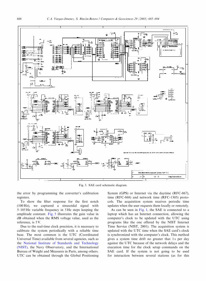
2.6. Implementation
The connection of all system devices used in SAE card
is shown in Fig. 3. A 12V–38Ah rechargeable battery
regulated to 5V by the circuit, which provides enough
charge to allow continuous operation for more than
500 h, feeds the system.
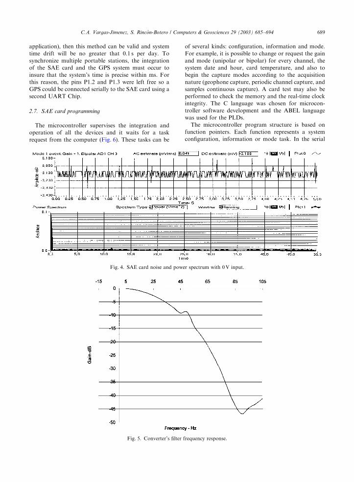
The RMS noise level on the card was obtained from
tests of 500 samples. The input was connected to a 390Oresistance, which is the impedance of the geophone when
its mass is anchored. The minimum step for this
configuration is 78.29 uV, and the obtained noise is
41 uV as is shown in Fig. 4. The effective resolution,
Reseff, is defined (Analog Devices, 1998) as the
maximum input scale (2 � Vref � Gain) to RMS out-
put noise ratio, that is
Reseff ¼ Log22� 2:5� 10:000041
� �¼ 16:89 bits:
The dynamic range is defined as the maximum to
minimum ADC quantifiable input ratio. In this case, the
quantization noise is less than the RMS noise, so the
minimum quantifiable input is 41 uV, and the dynamic
range is
DR ¼ 20 Log5V
0:000041V
� �¼ 101:72 dB:
The noise comes from different sources: the quantization
noise and device noise, and the potential difference
between the system grounds and the noise added by the
digital logic to the bias lines.
The design of the printed circuit board (PCB) is very
important for the acquisition response. It was designed
using independent analog and digital ground planes with
more than 75% board area used for ground purposes
and a low capacitive coupling between them, wide bias
tracks, in a doubled sided Sn/Pb Board (Kester and
Bryant, 2001). Because the geophone’s dynamic range
will not be more than 60 dB for natural seismic events
(Lee, 1989) and the system’s dynamic range is more than
100 dB, it was not necessary to design a more complex
PCB ground system with optical coupling between the
microcontroller digital logic and the converters. The
offset error is 108 uV, which is an error near two times
the LSB step potential (76 mV). It is possible to reduce
ARTICLE IN PRESSC.A. Vargas-Jimenez, S. Rinc !on-Botero / Computers & Geosciences 29 (2003) 685–694 687
the error by programming the converter’s calibration
registers.
To show the filter response for the first notch
(100Hz), we captured a sinusoidal signal with
5–105Hz variable frequency in 5Hz steps keeping the
amplitude constant. Fig. 5 illustrates the gain value in
dB obtained when the RMS voltage value, used as the
reference, is 5V.
Due to the real-time clock precision, it is necessary to
calibrate the system periodically with a reliable time
base. The most common is the UTC (Coordinated
Universal Time) available from several agencies, such as
the National Institute of Standards and Technology
(NIST), the Navy Observatory, and the International
Bureau of Weight and Measures in Paris, among others.
UTC can be obtained through the Global Positioning
System (GPS) or Internet via the daytime (RFC-867),
time (RFC-868) and network time (RFC-1305) proto-
cols. The acquisition system receives periodic time
updates when the user requests them locally or remotely.
As can be seen in Fig. 1, the SAE is connected to a
laptop which has an Internet connection, allowing the
computer’s clock to be updated with the UTC using
programs like the one offered by the NIST Internet
Time Service (NIST, 2001). The acquisition system is
updated with the UTC time when the SAE card’s clock
is synchronized with the computer’s clock. This method
gives a system time drift no greater that 1 s per day
against the UTC because of the network delays and the
execution time for the clock setup commands on the
SAE card. If the system is not going to be used
for interaction between several stations (as for this
ARTICLE IN PRESS
Fig. 3. SAE card schematic diagram.
C.A. Vargas-Jimenez, S. Rinc !on-Botero / Computers & Geosciences 29 (2003) 685–694688
application), then this method can be valid and system
time drift will be no greater that 0.1 s per day. To
synchronize multiple portable stations, the integration
of the SAE card and the GPS system must occur to
insure that the system’s time is precise within ms. For
this reason, the pins P1.2 and P1.3 were left free so a
GPS could be connected serially to the SAE card using a
second UART Chip.
2.7. SAE card programming
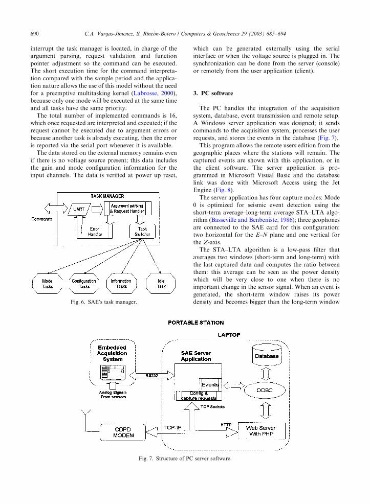
The microcontroller supervises the integration and
operation of all the devices and it waits for a task
request from the computer (Fig. 6). These tasks can be
of several kinds: configuration, information and mode.
For example, it is possible to change or request the gain
and mode (unipolar or bipolar) for every channel, the
system date and hour, card temperature, and also to
begin the capture modes according to the acquisition
nature (geophone capture, periodic channel capture, and
samples continuous capture). A card test may also be
performed to check the memory and the real-time clock
integrity. The C language was chosen for microcon-
troller software development and the ABEL language
was used for the PLDs.
The microcontroller program structure is based on
function pointers. Each function represents a system
configuration, information or mode task. In the serial
ARTICLE IN PRESS
Fig. 5. Converter’s filter frequency response.
Fig. 4. SAE card noise and power spectrum with 0V input.
C.A. Vargas-Jimenez, S. Rinc !on-Botero / Computers & Geosciences 29 (2003) 685–694 689
interrupt the task manager is located, in charge of the
argument parsing, request validation and function
pointer adjustment so the command can be executed.
The short execution time for the command interpreta-
tion compared with the sample period and the applica-
tion nature allows the use of this model without the need
for a preemptive multitasking kernel (Labrosse, 2000),
because only one mode will be executed at the same time
and all tasks have the same priority.
The total number of implemented commands is 16,
which once requested are interpreted and executed; if the
request cannot be executed due to argument errors or
because another task is already executing, then the error
is reported via the serial port whenever it is available.
The data stored on the external memory remains even
if there is no voltage source present; this data includes
the gain and mode configuration information for the
input channels. The data is verified at power up reset,
which can be generated externally using the serial
interface or when the voltage source is plugged in. The
synchronization can be done from the server (console)
or remotely from the user application (client).
3. PC software
The PC handles the integration of the acquisition
system, database, event transmission and remote setup.
A Windows server application was designed; it sends
commands to the acquisition system, processes the user
requests, and stores the events in the database (Fig. 7).
This program allows the remote users edition from the
geographic places where the stations will remain. The
captured events are shown with this application, or in
the client software. The server application is pro-
grammed in Microsoft Visual Basic and the database
link was done with Microsoft Access using the Jet
Engine (Fig. 8).
The server application has four capture modes: Mode
0 is optimized for seismic event detection using the
short-term average–long-term average STA–LTA algo-
rithm (Basseville and Benbeniste, 1986); three geophones
are connected to the SAE card for this configuration:
two horizontal for the E–N plane and one vertical for
the Z-axis.
The STA–LTA algorithm is a low-pass filter that
averages two windows (short-term and long-term) with
the last captured data and computes the ratio between
them: this average can be seen as the power density
which will be very close to one when there is no
important change in the sensor signal. When an event is
generated, the short-term window raises its power
density and becomes bigger than the long-term window
ARTICLE IN PRESS
Fig. 6. SAE’s task manager.
Fig. 7. Structure of PC server software.
C.A. Vargas-Jimenez, S. Rinc !on-Botero / Computers & Geosciences 29 (2003) 685–694690
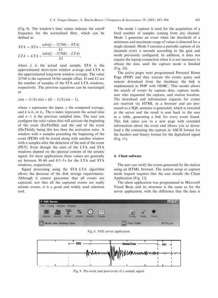
(Fig. 9). The window’s time values indicate the cutoff
frequency for the normalized filter, which can be
defined as
STA ¼ STA þðabsðfi � 32768Þ � STAÞ
k1;
LTA ¼ LTA þðabsðfi � 32768Þ � LTAÞ
k2;
where fi is the actual read sample, STA is the
approximated short-term window average and LTA is
the approximated long-term window average. The value
32768 is the captured 16-bit sample offset. kl and k2 are
the number of samples of the STA and LTA windows,
respectively. The previous equations can be rearranged
as
yðnÞ ¼ ð1=kÞ xðnÞ þ ððk � 1Þ=kÞ yðn � 1Þ;
where x represents the input, y the computed average,
and k is k1 or k2. The n index represents the actual time
and n�1 is the previous sampled time. The user canconfigure the ratio values that will activate the beginning
of the event (EnThrHld) and the end of the event
(DisThrld), being this less than the activation ratio. A
window with n samples preceding the beginning of the
event (PEM) will be stored along with another window
with n samples after the detection of the end of the event
(PET). Even though the sizes of the LTA and STA
windows depend on the spectral content of the seismic
signal, for most applications these values are generally
set between 30–60 and 0.5–3 s for the LTA and STA
windows, respectively.
Signal processing using the STA–LTA algorithm
allows the decrease of the disk storage requirements.
Although it cannot guarantee that all events are
captured, nor that all the captured events are really
seismic events, it is a good and widely used selection
tool.
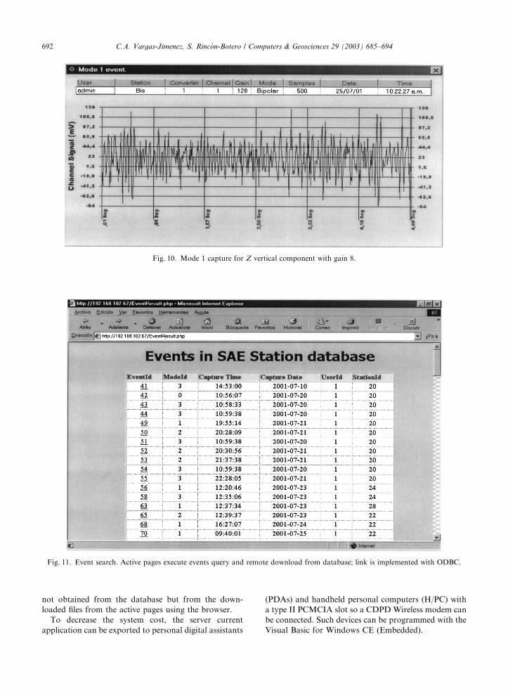
The mode 1 capture is used for the acquisition of a
fixed number of samples coming from any channel.
Mode 2 generates an event when the threshold of a
minimum and maximum range of values is detected for a
single channel. Mode 3 executes a periodic capture of six
channels every n seconds according to the gain and
mode previously configured. In addition, it does not
require the laptop connection when it is not necessary to
obtain the data until the capture mode is finished
(Fig. 10).
The active pages were programmed Personal Home
Page (PHP) and they execute the events query and
remote download from the database; the link is
implemented in PHP with ODBC. This model allows
the search of events by capture date, capture mode,
user who requested the capture, and station location.
The download and information requests for events
are received via HTML in a browser and are pro-
cessed so a SQL sentence is generated, which is executed
at the server and the result is sent back to the user
in a table, generating a link for every event found.
This link takes you to a new page with extended
information about the event and allows you to down-
load a file containing the capture in ASCII format for
the headers and binary format for the digitalized signal
(Fig. 11).
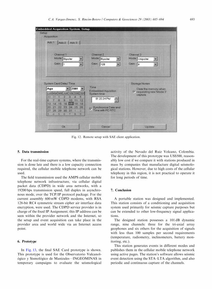
4. Client software
The user can verify the events generated by the station
using an HTML browser. The station setup or capture
mode request requires that the user installs the Client
Application (Fig. 12).
The client application was programmed in Microsoft
Visual Basic and its structure is the same as for the
server application, with the difference that the data is
ARTICLE IN PRESS
Fig. 8. SAE server application.
Fig. 9. Pre-event and post-event of a seismic signal.
C.A. Vargas-Jimenez, S. Rinc !on-Botero / Computers & Geosciences 29 (2003) 685–694 691
not obtained from the database but from the down-
loaded files from the active pages using the browser.
To decrease the system cost, the server current
application can be exported to personal digital assistants
(PDAs) and handheld personal computers (H/PC) with
a type II PCMCIA slot so a CDPDWireless modem can
be connected. Such devices can be programmed with the
Visual Basic for Windows CE (Embedded).
ARTICLE IN PRESS
Fig. 11. Event search. Active pages execute events query and remote download from database; link is implemented with ODBC.
Fig. 10. Mode 1 capture for Z vertical component with gain 8.
C.A. Vargas-Jimenez, S. Rinc !on-Botero / Computers & Geosciences 29 (2003) 685–694692
5. Data transmission
For the real-time capture systems, where the transmis-
sion is done late and there is a low capacity connection
required, the cellular mobile telephone network can be
used.
The field transmission used the AMPS cellular mobile
telephone network infrastructure, via cellular digital
packet data (CDPD) in wide area networks, with a
19200 bps transmission speed, full duplex in asynchro-
nous mode, over the TCP/IP protocol package. For the
current assembly 600mW CDPD modems, with RSA
128-bit RC4 symmetric stream cipher air interface data
encryption, were used. The CDPD service provider is in
charge of the fixed IP Assignment; this IP address can be
seen within the provider network and the Internet, so
the setup and event acquisition can take place in the
provider area and world wide via an Internet access
point.
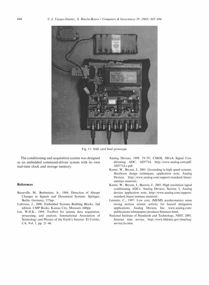
6. Prototype
In Fig. 13, the final SAE Card prototype is shown.
This prototype is used for the Observatorio Vulcanol-!ogico y Sismol !ogico de Manizales—INGEOMINAS in
temporary campaigns to evaluate the seismological
activity of the Nevado del Ruiz Volcano, Colombia.
The development of this prototype was US$500, reason-
ably low cost if we compare it with stations produced in
mass by companies that manufacture digital seismolo-
gical stations. However, due to high costs of the cellular
telephony in this region, it is not practical to operate it
for long periods of time.
7. Conclusion
A portable station was designed and implemented.
This station consists of a conditioning and acquisition
system used primarily for seismic capture purposes but
can be extended to other low-frequency signal applica-
tions.
The designed station possesses a 101 dB dynamic
range, nine channels: three for the tri-axial array
geophones and six others for the acquisition of signals
with less than 100 samples per second requirements
(temperature, radiometry, inclinometers, battery mon-
itoring, etc.).
This station generates events in different modes and
publishes them in the cellular mobile telephone network
using active pages. The station’s software allows seismic
event detection using the STA–LTA algorithm, and also
periodic and continuous capture of the channels.
ARTICLE IN PRESS
Fig. 12. Remote setup with SAE client application.
C.A. Vargas-Jimenez, S. Rinc !on-Botero / Computers & Geosciences 29 (2003) 685–694 693
The conditioning and acquisition system was designed
as an embedded command-driven system with its own
real-time clock and storage memory.
References
Basseville, M., Benbeniste, A., 1986. Detection of Abrupt
Changes in Signals and Dynamical Systems. Springer,
Berlin, Germany, 373pp.
Labrosse, J., 2000. Embedded Systems Building Blocks, 2nd
edition. CMP Books, Kansas City, Missouri, 640pp.
Lee, W.H.K., 1989. Toolbox for seismic data acquisition,
processing, and analysis. International Association of
Seismology and Physics of the Earth’s Interior, El Cerrito,
CA, Vol. 1, pp. 21–46.
Analog Devices, 1998. 3V/5V, CMOS, 500 uA Signal Con-
ditioning ADC, AD7714, http://www.analog.com/pdf/
AD7714 c.pdf.
Kester, W., Bryant, J., 2001. Grounding in high speed systems.
Hardware design techniques, application note, Analog
Devices, http://www.analog.com/support/standard linear/
seminar material/.
Kester, W., Bryant, J., Buxton, J., 2001. High resolution signal
conditioning ADCs. Analog Devices, Section 3, Analog
devices application note, http://www.analog.com/support/
standard linear/seminar material/.
Lemaire, C., 1997. Low cost, iMEMS accelerometers sense
strong motion seismic activity for hazard mitigation
applications. Analog Devices, Inc. www.analog.com/
publications/whitepapers/products/Seismart.html.
National Institute of Standards and Technology, NIST, 2001.
Internet time service, http://www.bldrdoc.gov/timefreq/
service/its.htm.
ARTICLE IN PRESS
Fig. 13. SAE card final prototype.
C.A. Vargas-Jimenez, S. Rinc !on-Botero / Computers & Geosciences 29 (2003) 685–694694