Embed Size (px)
Citation preview
Calibration
WIKA data sheet CT 18.03
Page 1 of 14WIKA data sheet CT 18.03 ∙ 10/2020
Data sheets showing similar products:Hand-held pressure indicator; model CPH6300; see data sheet CT 12.01
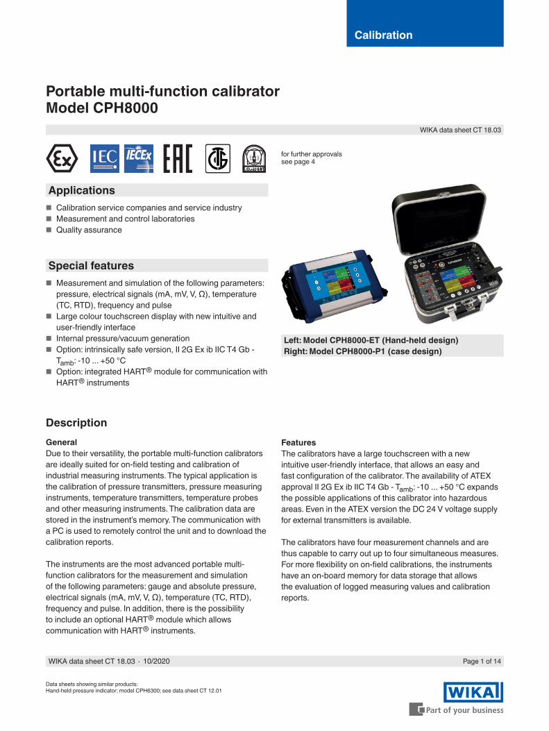
Portable multi-function calibratorModel CPH8000
DescriptionGeneralDue to their versatility, the portable multi-function calibrators are ideally suited for on-field testing and calibration of industrial measuring instruments. The typical application is the calibration of pressure transmitters, pressure measuring instruments, temperature transmitters, temperature probes and other measuring instruments. The calibration data are stored in the instrument’s memory. The communication with a PC is used to remotely control the unit and to download the calibration reports.
The instruments are the most advanced portable multi-function calibrators for the measurement and simulation of the following parameters: gauge and absolute pressure, electrical signals (mA, mV, V, Ω), temperature (TC, RTD), frequency and pulse. In addition, there is the possibility to include an optional HART® module which allows communication with HART® instruments.
FeaturesThe calibrators have a large touchscreen with a new intuitive user-friendly interface, that allows an easy and fast configuration of the calibrator. The availability of ATEX approval II 2G Ex ib IIC T4 Gb - Tamb: -10 ... +50 °C expands the possible applications of this calibrator into hazardous areas. Even in the ATEX version the DC 24 V voltage supply for external transmitters is available.
The calibrators have four measurement channels and are thus capable to carry out up to four simultaneous measures. For more flexibility on on-field calibrations, the instruments have an on-board memory for data storage that allows the evaluation of logged measuring values and calibration reports.
for further approvals see page 4
Applications ■ Calibration service companies and service industry ■ Measurement and control laboratories ■ Quality assurance
Special features ■ Measurement and simulation of the following parameters:
pressure, electrical signals (mA, mV, V, Ω), temperature (TC, RTD), frequency and pulse
■ Large colour touchscreen display with new intuitive and user-friendly interface
■ Internal pressure/vacuum generation ■ Option: intrinsically safe version, II 2G Ex ib IIC T4 Gb -
Tamb: -10 ... +50 °C ■ Option: integrated HART® module for communication with
HART® instruments
Left: Model CPH8000-ET (Hand-held design)Right: Model CPH8000-P1 (case design)
WIKA data sheet CT 18.03 ∙ 10/2020 Page 2 of 14
Specifications
Base instrumentIndication
Display Touchscreen + 5 keysDimensions 640 x 480 Dots
Dot size: 0.06 x 0.06 mm (0.002 x 0.002 in)Backlighting LED
Electrical input and outputNumber and type DIN-plug inputs for electrical parameters, resistance thermometers and thermocouplesResistance thermometer (RTD) Pt100 (385, 3616, 3906, 3926, 3923), Pt200, Pt500, Pt1000 (385, 3916), Ni100, Ni120, Cu10,
Cu100Thermocouples Types J, K, T, F, R, S, B, U, L, N, E, CVoltage signal Input: DC ±100 mV, ±2 V, ±80 V
Output: DC 20 VCurrent signal Input: DC ±100 mA
Output: DC 20 mAFrequency signal 0 ... 50,000 HzPulses signal 1 ... 999,999Resistance 0 ... 10,000 ΩVoltage supply DC 24 V
HART® communicationHART® module Based on HART® universal and common practice commandsResistance HART® resistance 250 Ω (activatable)Loop current max. DC 24 mAVoltage supply DC 24 V
The multi-function calibrator can be modularly configured with up to two input and two output modules as well as one HART® module and one output module, which are galvanically isolated from each other. The measurement/simulation of the electrical signals or temperature as well as up to six pressure sensors (four internal and two external sensors) enables the operator to configure the calibrator according to his specific requirements.
The new multi-function calibrator model CPH8000 include the new high-precision sensors manufactured by Mensor.
The internal reference sensor CPR8100 and the external reference sensor CPT8100 can be configured for gauge or absolute pressure types and is characterised over the full pressure and temperature range to achieve up to 0.02 % FS accuracy and up to 0.02 % of reading accuracy for the barometer.
The environmental parameters module (option) is another plus of CPH8000, it allows the monitoring of the barometric pressure, the ambient temperature and the relative humidity. The values will be stored in the calibration report.
PressureThe model CPH8000-P1 has an integrated pressure/vacuum generation by means of a built in hand pump from -0.9 ... +21 bar [-13 ... +300 psi]. The presence of a fine precision regulator allows the operator to adjust small pressure increments.
Many different pressure configurations are available, e.g.: ■ In combination with internal pressure sensors that can be
connected to the internal pump (up to 21 bar [300 psi]). ■ In combination with external pressure sensors that can be
connected directly to the external plugs.
Low-pressure internal sensors are protected against overpressure by means of protection valves. High flexibility in measurement is given by the availability of multiple pressure engineering units.
WIKA data sheet CT 18.03 ∙ 10/2020 Page 3 of 14
Base instrumentConnections
Pressure connection 1/8 BSP (female)Overpressure safety 2 x pressure range; static pressure < 3.5 bar [< 50 psi]Wetted parts Ranges ≤ 0.350 bar [≤ 5 psi] - Silicon, 316 SS, glass-filled resins, epoxy
Ranges > 0.350 ... 100 bar [> 5 ... 1,500 psi] - 316 SSRanges > 100 bar [> 1,500 psi] - 316 SS, fluorocarbon rubber
Permissible media Ranges ≤ 0.350 bar [≤ 5 psi] - clean, dry, non-corrosive gasesRanges > 0.350 bar [> 5 psi] - media compatible with the listed wetted parts
Compensated temperature range -10 ... +50 °C [14 ... 122 °F]Measuring rate 10 values/second, (not adjustable)Units bar, mbar, psi, psf, Pa, hPa, kPa, MPa, torr, atm, kg/cm², kg/m², mmHg (0 °C), cmHg (0 °C),
mHg (0 °C), inHg (0 °C), mmH2O (4 °C), cmH₂O (4 °C), mH₂O (4 °C), inH₂O (4 °C), ftH₂O (4 °C)
Voltage supplyOperating voltage AC 100 ... 240 V, 50/60 HzBattery type Rechargeable battery NiMHBattery life (fully charged) 6 ... 8 hours for typical usage
Permissible ambient conditionsOperating temperature -10 ... +50 °C [14 ... 122 °F]Storage temperature -30 ... +80 °C [-22 ... +176 °F]Relative humidity Operating humidity: 10 ... 90 % r. h. (non-condensing)
Storage humidity: 0 ... 90 % r. h. (non-condensing)
CaseMaterial Front panel aluminiumIngress protection IP54Dimensions 330 x 270 x 170 mm [13 x 10.6 x 7 in]Weight approx. 3 kg [6 lbs 6 oz] (ET version)
approx. 6 kg [13 lbs 2 oz] (P1 version)
Safety-related characteristic valuesATEX directive II 2G Ex ib IIC T4 Gb - Tamb: -10 ... +50 °CConnection values
Max. voltage U0 = 29.7 VMax. current I0 = 31 mAMax. power P0 = 0.92 WMax. effective internal capacitance C0 = 69 nFMax. effective internal inductance L0 = 30 mH
Power supply circuitMax. voltage Ui = 30 VMax. current Ii = 100 mAMax. power Pi = 0.75 WMax. effective internal capacitance Ci = negligibleMax. effective internal inductance Li = negligible
WIKA data sheet CT 18.03 ∙ 10/2020 Page 4 of 14
Approvals
Approvals included in the scope of delivery
Logo Description CountryEU declaration of conformity European UnionEMC directiveEN 61326 emission (group 1, class B) and immunity (portable test and measuring equipment)RoHS directive
Optional approvals
Logo Description CountryATEX directiveHazardous areasII 2G Ex ib IIC T4 Gb - Tamb: -10 ... +50 °C
European Union
IECExHazardous areasEx ib IIC T4 Gb - Tamb: -10 ... +50 °C
International
EAC ■ Electromagnetic compatibility ■ Low voltage directive
Eurasian Economic Community
DNOP-MakNIIHazardous areas
Ukraine
BelGIMMetrology, measurement technology
Belarus
- MTSCHSPermission for commissioning
Kazakhstan
Certificates
CertificateCalibration ■ 3.1 calibration certificate per DIN EN 10204
■ ACCREDIA calibration certificateRecommended recalibration interval 1 year (dependent on conditions of use)
Approvals and certificates, see website
WIKA data sheet CT 18.03 ∙ 10/2020 Page 5 of 14
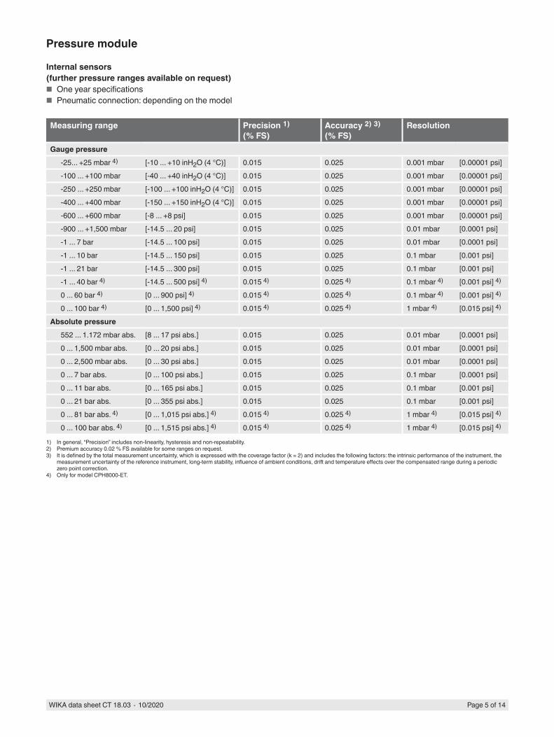
Pressure module
Internal sensors(further pressure ranges available on request)
■ One year specifications ■ Pneumatic connection: depending on the model
Measuring range Precision 1)(% FS)
Accuracy 2) 3)(% FS)
Resolution
Gauge pressure-25... +25 mbar 4) [-10 ... +10 inH2O (4 °C)] 0.015 0.025 0.001 mbar [0.00001 psi]-100 ... +100 mbar [-40 ... +40 inH2O (4 °C)] 0.015 0.025 0.001 mbar [0.00001 psi]-250 ... +250 mbar [-100 ... +100 inH2O (4 °C)] 0.015 0.025 0.001 mbar [0.00001 psi]-400 ... +400 mbar [-150 ... +150 inH2O (4 °C)] 0.015 0.025 0.001 mbar [0.00001 psi]-600 ... +600 mbar [-8 ... +8 psi] 0.015 0.025 0.001 mbar [0.00001 psi]-900 ... +1,500 mbar [-14.5 ... 20 psi] 0.015 0.025 0.01 mbar [0.0001 psi]-1 ... 7 bar [-14.5 ... 100 psi] 0.015 0.025 0.01 mbar [0.0001 psi]-1 ... 10 bar [-14.5 ... 150 psi] 0.015 0.025 0.1 mbar [0.001 psi]-1 ... 21 bar [-14.5 ... 300 psi] 0.015 0.025 0.1 mbar [0.001 psi]-1 ... 40 bar 4) [-14.5 ... 500 psi] 4) 0.015 4) 0.025 4) 0.1 mbar 4) [0.001 psi] 4)
0 ... 60 bar 4) [0 ... 900 psi] 4) 0.015 4) 0.025 4) 0.1 mbar 4) [0.001 psi] 4)
0 ... 100 bar 4) [0 ... 1,500 psi] 4) 0.015 4) 0.025 4) 1 mbar 4) [0.015 psi] 4)
Absolute pressure552 ... 1.172 mbar abs. [8 ... 17 psi abs.] 0.015 0.025 0.01 mbar [0.0001 psi]0 ... 1,500 mbar abs. [0 ... 20 psi abs.] 0.015 0.025 0.01 mbar [0.0001 psi]0 ... 2,500 mbar abs. [0 ... 30 psi abs.] 0.015 0.025 0.01 mbar [0.0001 psi]0 ... 7 bar abs. [0 ... 100 psi abs.] 0.015 0.025 0.1 mbar [0.0001 psi]0 ... 11 bar abs. [0 ... 165 psi abs.] 0.015 0.025 0.1 mbar [0.001 psi]0 ... 21 bar abs. [0 ... 355 psi abs.] 0.015 0.025 0.1 mbar [0.001 psi]0 ... 81 bar abs. 4) [0 ... 1,015 psi abs.] 4) 0.015 4) 0.025 4) 1 mbar 4) [0.015 psi] 4)
0 ... 100 bar abs. 4) [0 ... 1,515 psi abs.] 4) 0.015 4) 0.025 4) 1 mbar 4) [0.015 psi] 4)
1) In general, “Precision” includes non-linearity, hysteresis and non-repeatability.2) Premium accuracy 0.02 % FS available for some ranges on request.3) It is defined by the total measurement uncertainty, which is expressed with the coverage factor (k = 2) and includes the following factors: the intrinsic performance of the instrument, the
measurement uncertainty of the reference instrument, long-term stability, influence of ambient conditions, drift and temperature effects over the compensated range during a periodic zero point correction.
4) Only for model CPH8000-ET.
WIKA data sheet CT 18.03 ∙ 10/2020 Page 6 of 14
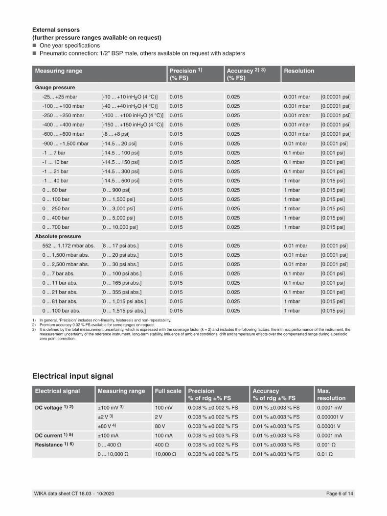
External sensors(further pressure ranges available on request)
■ One year specifications ■ Pneumatic connection: 1/2" BSP male, others available on request with adapters
Measuring range Precision 1)(% FS)
Accuracy 2) 3)(% FS)
Resolution
Gauge pressure-25... +25 mbar [-10 ... +10 inH2O (4 °C)] 0.015 0.025 0.001 mbar [0.00001 psi]-100 ... +100 mbar [-40 ... +40 inH2O (4 °C)] 0.015 0.025 0.001 mbar [0.00001 psi]-250 ... +250 mbar [-100 ... +100 inH2O (4 °C)] 0.015 0.025 0.001 mbar [0.00001 psi]-400 ... +400 mbar [-150 ... +150 inH2O (4 °C)] 0.015 0.025 0.001 mbar [0.00001 psi]-600 ... +600 mbar [-8 ... +8 psi] 0.015 0.025 0.001 mbar [0.00001 psi]
-900 ... +1,500 mbar [-14.5 ... 20 psi] 0.015 0.025 0.01 mbar [0.0001 psi]-1 ... 7 bar [-14.5 ... 100 psi] 0.015 0.025 0.1 mbar [0.001 psi]-1 ... 10 bar [-14.5 ... 150 psi] 0.015 0.025 0.1 mbar [0.001 psi]-1 ... 21 bar [-14.5 ... 300 psi] 0.015 0.025 0.1 mbar [0.001 psi]-1 ... 40 bar [-14.5 ... 500 psi] 0.015 0.025 1 mbar [0.015 psi]0 ... 60 bar [0 ... 900 psi] 0.015 0.025 1 mbar [0.015 psi]0 ... 100 bar [0 ... 1,500 psi] 0.015 0.025 1 mbar [0.015 psi]0 ... 250 bar [0 ... 3,000 psi] 0.015 0.025 1 mbar [0.015 psi]0 ... 400 bar [0 ... 5,000 psi] 0.015 0.025 1 mbar [0.015 psi]0 ... 700 bar [0 ... 10,000 psi] 0.015 0.025 1 mbar [0.015 psi]
Absolute pressure552 ... 1.172 mbar abs. [8 ... 17 psi abs.] 0.015 0.025 0.01 mbar [0.0001 psi]0 ... 1,500 mbar abs. [0 ... 20 psi abs.] 0.015 0.025 0.01 mbar [0.0001 psi]0 ... 2,500 mbar abs. [0 ... 30 psi abs.] 0.015 0.025 0.01 mbar [0.0001 psi]0 ... 7 bar abs. [0 ... 100 psi abs.] 0.015 0.025 0.1 mbar [0.001 psi]0 ... 11 bar abs. [0 ... 165 psi abs.] 0.015 0.025 0.1 mbar [0.001 psi]0 ... 21 bar abs. [0 ... 355 psi abs.] 0.015 0.025 0.1 mbar [0.001 psi]0 ... 81 bar abs. [0 ... 1,015 psi abs.] 0.015 0.025 1 mbar [0.015 psi]0 ... 100 bar abs. [0 ... 1,515 psi abs.] 0.015 0.025 1 mbar [0.015 psi]
1) In general, “Precision” includes non-linearity, hysteresis and non-repeatability.2) Premium accuracy 0.02 % FS available for some ranges on request.3) It is defined by the total measurement uncertainty, which is expressed with the coverage factor (k = 2) and includes the following factors: the intrinsic performance of the instrument, the
measurement uncertainty of the reference instrument, long-term stability, influence of ambient conditions, drift and temperature effects over the compensated range during a periodic zero point correction.
Electrical input signal
Electrical signal Measuring range Full scale Precision% of rdg ±% FS
Accuracy% of rdg ±% FS
Max. resolution
DC voltage 1) 2) ±100 mV 3) 100 mV 0.008 % ±0.002 % FS 0.01 % ±0.003 % FS 0.0001 mV±2 V 3) 2 V 0.008 % ±0.002 % FS 0.01 % ±0.003 % FS 0.000001 V±80 V 4) 80 V 0.008 % ±0.002 % FS 0.01 % ±0.003 % FS 0.00001 V
DC current 1) 5) ±100 mA 100 mA 0.008 % ±0.003 % FS 0.01 % ±0.003 % FS 0.0001 mAResistance 1) 6) 0 ... 400 Ω 400 Ω 0.008 % ±0.002 % FS 0.01 % ±0.003 % FS 0.001 Ω
0 ... 10,000 Ω 10,000 Ω 0.008 % ±0.002 % FS 0.01 % ±0.003 % FS 0.01 Ω
WIKA data sheet CT 18.03 ∙ 10/2020 Page 7 of 14
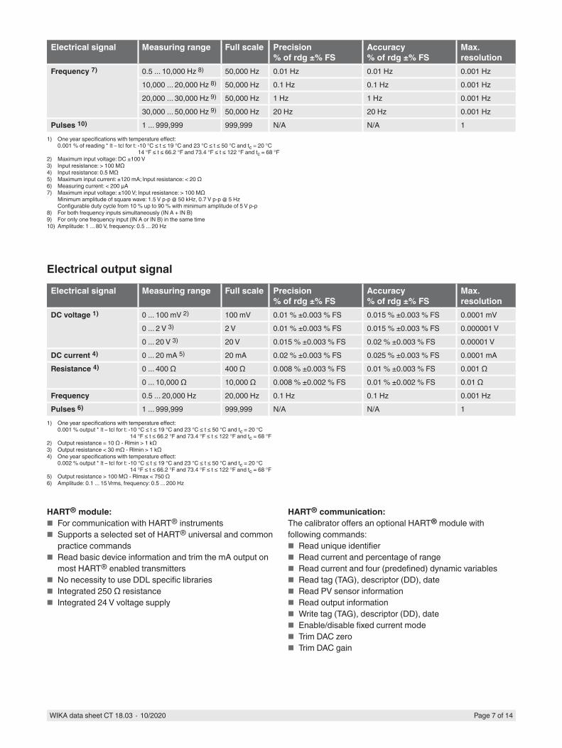
HART® module: ■ For communication with HART® instruments ■ Supports a selected set of HART® universal and common
practice commands ■ Read basic device information and trim the mA output on
most HART® enabled transmitters ■ No necessity to use DDL specific libraries ■ Integrated 250 Ω resistance ■ Integrated 24 V voltage supply
HART® communication:The calibrator offers an optional HART® module with following commands:
■ Read unique identifier ■ Read current and percentage of range ■ Read current and four (predefined) dynamic variables ■ Read tag (TAG), descriptor (DD), date ■ Read PV sensor information ■ Read output information ■ Write tag (TAG), descriptor (DD), date ■ Enable/disable fixed current mode ■ Trim DAC zero ■ Trim DAC gain
Electrical signal Measuring range Full scale Precision% of rdg ±% FS
Accuracy% of rdg ±% FS
Max. resolution
Frequency 7) 0.5 ... 10,000 Hz 8) 50,000 Hz 0.01 Hz 0.01 Hz 0.001 Hz10,000 ... 20,000 Hz 8) 50,000 Hz 0.1 Hz 0.1 Hz 0.001 Hz20,000 ... 30,000 Hz 9) 50,000 Hz 1 Hz 1 Hz 0.001 Hz30,000 ... 50,000 Hz 9) 50,000 Hz 20 Hz 20 Hz 0.001 Hz
Pulses 10) 1 ... 999,999 999,999 N/A N/A 11) One year specifications with temperature effect:
0.001 % of reading * |t – tc| for t: -10 °C ≤ t ≤ 19 °C and 23 °C ≤ t ≤ 50 °C and tc = 20 °C14 °F ≤ t ≤ 66.2 °F and 73.4 °F ≤ t ≤ 122 °F and tc = 68 °F
2) Maximum input voltage: DC ±100 V3) Input resistance: > 100 MΩ4) Input resistance: 0.5 MΩ5) Maximum input current: ±120 mA; Input resistance: < 20 Ω6) Measuring current: < 200 µA7) Maximum input voltage: ±100 V; Input resistance: > 100 MΩ
Minimum amplitude of square wave: 1.5 V p-p @ 50 kHz, 0.7 V p-p @ 5 HzConfigurable duty cycle from 10 % up to 90 % with minimum amplitude of 5 V p-p
8) For both frequency inputs simultaneously (IN A + IN B)9) For only one frequency input (IN A or IN B) in the same time10) Amplitude: 1 ... 80 V, frequency: 0.5 ... 20 Hz
Electrical output signal
Electrical signal Measuring range Full scale Precision% of rdg ±% FS
Accuracy% of rdg ±% FS
Max. resolution
DC voltage 1) 0 ... 100 mV 2) 100 mV 0.01 % ±0.003 % FS 0.015 % ±0.003 % FS 0.0001 mV0 ... 2 V 3) 2 V 0.01 % ±0.003 % FS 0.015 % ±0.003 % FS 0.000001 V0 ... 20 V 3) 20 V 0.015 % ±0.003 % FS 0.02 % ±0.003 % FS 0.00001 V
DC current 4) 0 ... 20 mA 5) 20 mA 0.02 % ±0.003 % FS 0.025 % ±0.003 % FS 0.0001 mAResistance 4) 0 ... 400 Ω 400 Ω 0.008 % ±0.003 % FS 0.01 % ±0.003 % FS 0.001 Ω
0 ... 10,000 Ω 10,000 Ω 0.008 % ±0.002 % FS 0.01 % ±0.002 % FS 0.01 ΩFrequency 0.5 ... 20,000 Hz 20,000 Hz 0.1 Hz 0.1 Hz 0.001 HzPulses 6) 1 ... 999,999 999,999 N/A N/A 1
1) One year specifications with temperature effect:0.001 % output * |t – tc| for t: -10 °C ≤ t ≤ 19 °C and 23 °C ≤ t ≤ 50 °C and tc = 20 °C
14 °F ≤ t ≤ 66.2 °F and 73.4 °F ≤ t ≤ 122 °F and tc = 68 °F2) Output resistance = 10 Ω - Rlmin > 1 kΩ3) Output resistance < 30 mΩ - Rlmin > 1 kΩ4) One year specifications with temperature effect:
0.002 % output * |t – tc| for t: -10 °C ≤ t ≤ 19 °C and 23 °C ≤ t ≤ 50 °C and tc = 20 °C14 °F ≤ t ≤ 66.2 °F and 73.4 °F ≤ t ≤ 122 °F and tc = 68 °F
5) Output resistance > 100 MΩ - Rlmax < 750 Ω6) Amplitude: 0.1 ... 15 Vrms, frequency: 0.5 ... 200 Hz
WIKA data sheet CT 18.03 ∙ 10/2020 Page 8 of 14
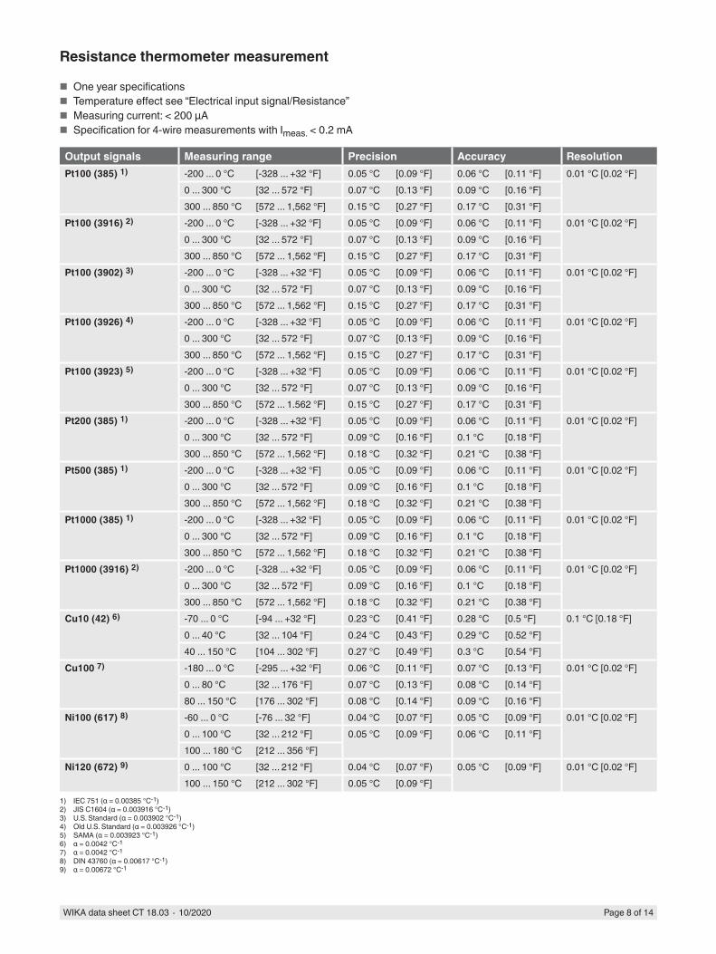
Resistance thermometer measurement
■ One year specifications ■ Temperature effect see “Electrical input signal/Resistance” ■ Measuring current: < 200 µA ■ Specification for 4-wire measurements with Imeas. < 0.2 mA
Output signals Measuring range Precision Accuracy ResolutionPt100 (385) 1) -200 ... 0 °C [-328 ... +32 °F] 0.05 °C [0.09 °F] 0.06 °C [0.11 °F] 0.01 °C [0.02 °F]
0 ... 300 °C [32 ... 572 °F] 0.07 °C [0.13 °F] 0.09 °C [0.16 °F]300 ... 850 °C [572 ... 1,562 °F] 0.15 °C [0.27 °F] 0.17 °C [0.31 °F]
Pt100 (3916) 2) -200 ... 0 °C [-328 ... +32 °F] 0.05 °C [0.09 °F] 0.06 °C [0.11 °F] 0.01 °C [0.02 °F]0 ... 300 °C [32 ... 572 °F] 0.07 °C [0.13 °F] 0.09 °C [0.16 °F]300 ... 850 °C [572 ... 1,562 °F] 0.15 °C [0.27 °F] 0.17 °C [0.31 °F]
Pt100 (3902) 3) -200 ... 0 °C [-328 ... +32 °F] 0.05 °C [0.09 °F] 0.06 °C [0.11 °F] 0.01 °C [0.02 °F]0 ... 300 °C [32 ... 572 °F] 0.07 °C [0.13 °F] 0.09 °C [0.16 °F]300 ... 850 °C [572 ... 1,562 °F] 0.15 °C [0.27 °F] 0.17 °C [0.31 °F]
Pt100 (3926) 4) -200 ... 0 °C [-328 ... +32 °F] 0.05 °C [0.09 °F] 0.06 °C [0.11 °F] 0.01 °C [0.02 °F]0 ... 300 °C [32 ... 572 °F] 0.07 °C [0.13 °F] 0.09 °C [0.16 °F]300 ... 850 °C [572 ... 1,562 °F] 0.15 °C [0.27 °F] 0.17 °C [0.31 °F]
Pt100 (3923) 5) -200 ... 0 °C [-328 ... +32 °F] 0.05 °C [0.09 °F] 0.06 °C [0.11 °F] 0.01 °C [0.02 °F]0 ... 300 °C [32 ... 572 °F] 0.07 °C [0.13 °F] 0.09 °C [0.16 °F]300 ... 850 °C [572 ... 1.562 °F] 0.15 °C [0.27 °F] 0.17 °C [0.31 °F]
Pt200 (385) 1) -200 ... 0 °C [-328 ... +32 °F] 0.05 °C [0.09 °F] 0.06 °C [0.11 °F] 0.01 °C [0.02 °F]0 ... 300 °C [32 ... 572 °F] 0.09 °C [0.16 °F] 0.1 °C [0.18 °F]300 ... 850 °C [572 ... 1,562 °F] 0.18 °C [0.32 °F] 0.21 °C [0.38 °F]
Pt500 (385) 1) -200 ... 0 °C [-328 ... +32 °F] 0.05 °C [0.09 °F] 0.06 °C [0.11 °F] 0.01 °C [0.02 °F]0 ... 300 °C [32 ... 572 °F] 0.09 °C [0.16 °F] 0.1 °C [0.18 °F]300 ... 850 °C [572 ... 1,562 °F] 0.18 °C [0.32 °F] 0.21 °C [0.38 °F]
Pt1000 (385) 1) -200 ... 0 °C [-328 ... +32 °F] 0.05 °C [0.09 °F] 0.06 °C [0.11 °F] 0.01 °C [0.02 °F]0 ... 300 °C [32 ... 572 °F] 0.09 °C [0.16 °F] 0.1 °C [0.18 °F]300 ... 850 °C [572 ... 1,562 °F] 0.18 °C [0.32 °F] 0.21 °C [0.38 °F]
Pt1000 (3916) 2) -200 ... 0 °C [-328 ... +32 °F] 0.05 °C [0.09 °F] 0.06 °C [0.11 °F] 0.01 °C [0.02 °F]0 ... 300 °C [32 ... 572 °F] 0.09 °C [0.16 °F] 0.1 °C [0.18 °F]300 ... 850 °C [572 ... 1,562 °F] 0.18 °C [0.32 °F] 0.21 °C [0.38 °F]
Cu10 (42) 6) -70 ... 0 °C [-94 ... +32 °F] 0.23 °C [0.41 °F] 0.28 °C [0.5 °F] 0.1 °C [0.18 °F]0 ... 40 °C [32 ... 104 °F] 0.24 °C [0.43 °F] 0.29 °C [0.52 °F]40 ... 150 °C [104 ... 302 °F] 0.27 °C [0.49 °F] 0.3 °C [0.54 °F]
Cu100 7) -180 ... 0 °C [-295 ... +32 °F] 0.06 °C [0.11 °F] 0.07 °C [0.13 °F] 0.01 °C [0.02 °F]0 ... 80 °C [32 ... 176 °F] 0.07 °C [0.13 °F] 0.08 °C [0.14 °F]80 ... 150 °C [176 ... 302 °F] 0.08 °C [0.14 °F] 0.09 °C [0.16 °F]
Ni100 (617) 8) -60 ... 0 °C [-76 ... 32 °F] 0.04 °C [0.07 °F] 0.05 °C [0.09 °F] 0.01 °C [0.02 °F]0 ... 100 °C [32 ... 212 °F] 0.05 °C [0.09 °F] 0.06 °C [0.11 °F]100 ... 180 °C [212 ... 356 °F]
Ni120 (672) 9) 0 ... 100 °C [32 ... 212 °F] 0.04 °C [0.07 °F) 0.05 °C [0.09 °F] 0.01 °C [0.02 °F]100 ... 150 °C [212 ... 302 °F] 0.05 °C [0.09 °F]
1) IEC 751 (α = 0.00385 °C-1)2) JIS C1604 (α = 0.003916 °C-1)3) U.S. Standard (α = 0.003902 °C-1)4) Old U.S. Standard (α = 0.003926 °C-1)5) SAMA (α = 0.003923 °C-1)6) α = 0.0042 °C-17) α = 0.0042 °C-18) DIN 43760 (α = 0.00617 °C-1)9) α = 0.00672 °C-1
WIKA data sheet CT 18.03 ∙ 10/2020 Page 9 of 14
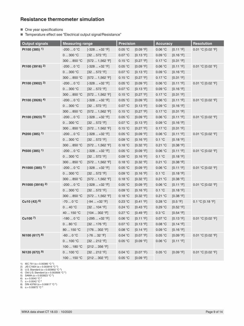
Resistance thermometer simulation
■ One year specifications ■ Temperature effect see “Electrical output signal/Resistance”
Output signals Measuring range Precision Accuracy ResolutionPt100 (385) 1) -200 ... 0 °C [-328 ... +32 °F] 0.05 °C [0.09 °F] 0.06 °C [0.11 °F] 0.01 °C [0.02 °F]
0 ... 300 °C [32 ... 572 °F] 0.07 °C [0.13 °F] 0.09 °C [0.16 °F]300 ... 850 °C [572 ... 1,562 °F] 0.15 °C [0.27 °F] 0.17 °C [0.31 °F]
Pt100 (3916) 2) -200 ... 0 °C [-328 ... +32 °F] 0.05 °C [0.09 °F] 0.06 °C [0.11 °F] 0.01 °C [0.02 °F]0 ... 300 °C [32 ... 572 °F] 0.07 °C [0.13 °F] 0.09 °C [0.16 °F]300 ... 850 °C [572 ... 1,562 °F] 0.15 °C [0.27 °F] 0.17 °C [0.31 °F]
Pt100 (3902) 3) -200 ... 0 °C [-328 ... +32 °F] 0.05 °C [0.09 °F] 0.06 °C [0.11 °F] 0.01 °C [0.02 °F]0 ... 300 °C [32 ... 572 °F] 0.07 °C [0.13 °F] 0.09 °C [0.16 °F]300 ... 850 °C [572 ... 1,562 °F] 0.15 °C [0.27 °F] 0.17 °C [0.31 °F]
Pt100 (3926) 4) -200 ... 0 °C [-328 ... +32 °F] 0.05 °C [0.09 °F] 0.06 °C [0.11 °F] 0.01 °C [0.02 °F]0 ... 300 °C [32 ... 572 °F] 0.07 °C [0.13 °F] 0.09 °C [0.16 °F]300 ... 850 °C [572 ... 1,562 °F] 0.15 °C [0.27 °F] 0.17 °C [0.31 °F]
Pt100 (3923) 5) -200 ... 0 °C [-328 ... +32 °F] 0.05 °C [0.09 °F] 0.06 °C [0.11 °F] 0.01 °C [0.02 °F]0 ... 300 °C [32 ... 572 °F] 0.07 °C [0.13 °F] 0.09 °C [0.16 °F]300 ... 850 °C [572 ... 1.562 °F] 0.15 °C [0.27 °F] 0.17 °C [0.31 °F]
Pt200 (385) 1) -200 ... 0 °C [-328 ... +32 °F] 0.05 °C [0.09 °F] 0.06 °C [0.11 °F] 0.01 °C [0.02 °F]0 ... 300 °C [32 ... 572 °F] 0.09 °C [0.16 °F] 0.1 °C [0.18 °F]300 ... 850 °C [572 ... 1,562 °F] 0.18 °C [0.32 °F] 0.21 °C [0.38 °F]
Pt500 (385) 1) -200 ... 0 °C [-328 ... +32 °F] 0.05 °C [0.09 °F] 0.06 °C [0.11 °F] 0.01 °C [0.02 °F]0 ... 300 °C [32 ... 572 °F] 0.09 °C [0.16 °F] 0.1 °C [0.18 °F]300 ... 850 °C [572 ... 1,562 °F] 0.18 °C [0.32 °F] 0.21 °C [0.38 °F]
Pt1000 (385) 1) -200 ... 0 °C [-328 ... +32 °F] 0.05 °C [0.09 °F] 0.06 °C [0.11 °F] 0.01 °C [0.02 °F]0 ... 300 °C [32 ... 572 °F] 0.09 °C [0.16 °F] 0.1 °C [0.18 °F]300 ... 850 °C [572 ... 1,562 °F] 0.18 °C [0.32 °F] 0.21 °C [0.38 °F]
Pt1000 (3916) 2) -200 ... 0 °C [-328 ... +32 °F] 0.05 °C [0.09 °F] 0.06 °C [0.11 °F] 0.01 °C [0.02 °F]0 ... 300 °C [32 ... 572 °F] 0.09 °C [0.16 °F] 0.1 °C [0.18 °F]300 ... 850 °C [572 ... 1,562 °F] 0.18 °C [0.32 °F] 0.21 °C [0.38 °F]
Cu10 (42) 6) -70 ... 0 °C [-94 ... +32 °F] 0.23 °C [0.41 °F] 0.28 °C [0.5 °F] 0.1 °C [0.18 °F]0 ... 40 °C [32 ... 104 °F] 0.24 °C [0.43 °F] 0.29 °C [0.52 °F]40 ... 150 °C [104 ... 302 °F] 0.27 °C [0.49 °F] 0.3 °C [0.54 °F]
Cu100 7) -180 ... 0 °C [-295 ... +32 °F] 0.06 °C [0.11 °F] 0.07 °C [0.13 °F] 0.01 °C [0.02 °F]0 ... 80 °C [32 ... 176 °F] 0.07 °C [0.13 °F] 0.08 °C [0.14 °F]80 ... 150 °C [176 ... 302 °F] 0.08 °C [0.14 °F] 0.09 °C [0.16 °F]
Ni100 (617) 8) -60 ... 0 °C [-76 ... 32 °F] 0.04 °C [0.07 °F] 0.05 °C [0.09 °F] 0.01 °C [0.02 °F]0 ... 100 °C [32 ... 212 °F] 0.05 °C [0.09 °F] 0.06 °C [0.11 °F]100 ... 180 °C [212 ... 356 °F]
Ni120 (672) 9) 0 ... 100 °C [32 ... 212 °F] 0.04 °C [0.07 °F) 0.05 °C [0.09 °F] 0.01 °C [0.02 °F]100 ... 150 °C [212 ... 302 °F] 0.05 °C [0.09 °F]
1) IEC 751 (α = 0.00385 °C-1)2) JIS C1604 (α = 0.003916 °C-1)3) U.S. Standard (α = 0.003902 °C-1)4) Old U.S. Standard (α = 0.003926 °C-1)5) SAMA (α = 0.003923 °C-1)6) α = 0.0042 °C-17) α = 0.0042 °C-18) DIN 43760 (α = 0.00617 °C-1)9) α = 0.00672 °C-1
WIKA data sheet CT 18.03 ∙ 10/2020 Page 10 of 14
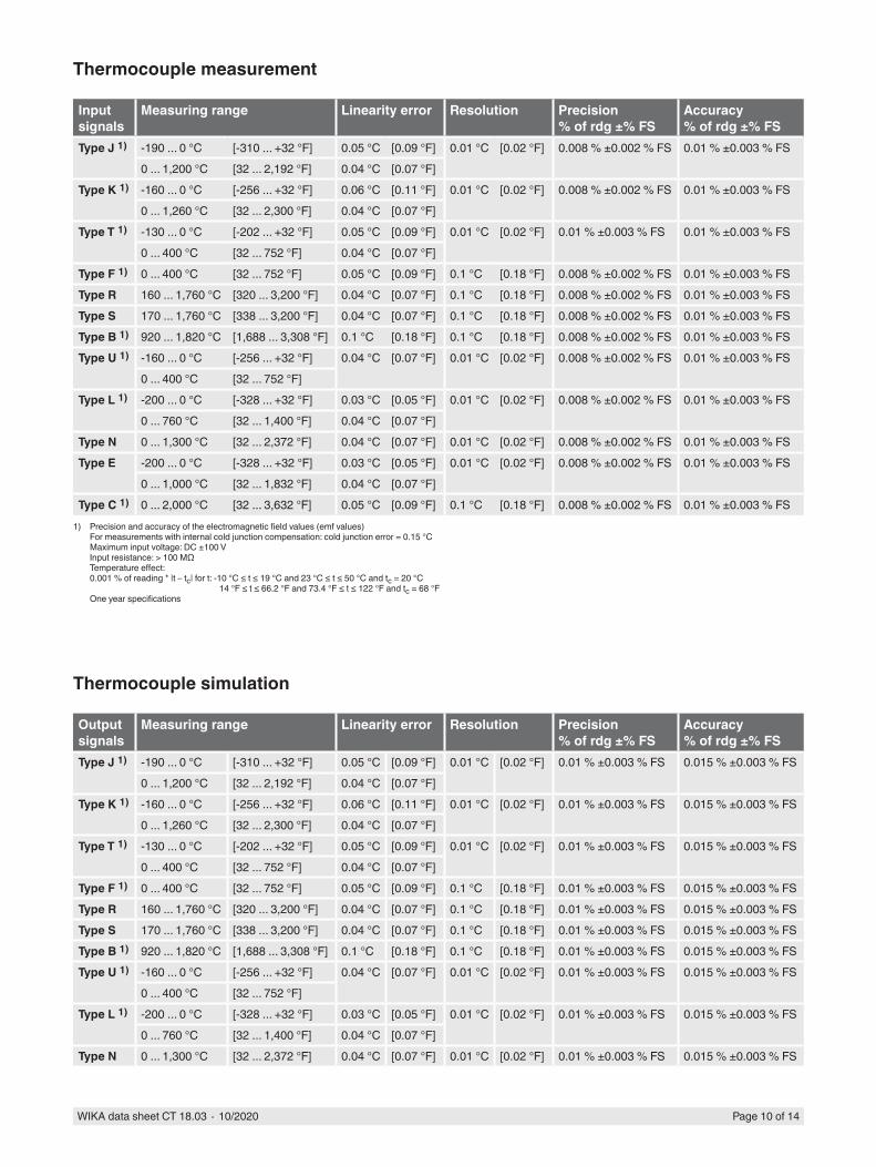
Thermocouple measurement
Input signals
Measuring range Linearity error Resolution Precision% of rdg ±% FS
Accuracy% of rdg ±% FS
Type J 1) -190 ... 0 °C [-310 ... +32 °F] 0.05 °C [0.09 °F] 0.01 °C [0.02 °F] 0.008 % ±0.002 % FS 0.01 % ±0.003 % FS0 ... 1,200 °C [32 ... 2,192 °F] 0.04 °C [0.07 °F]
Type K 1) -160 ... 0 °C [-256 ... +32 °F] 0.06 °C [0.11 °F] 0.01 °C [0.02 °F] 0.008 % ±0.002 % FS 0.01 % ±0.003 % FS0 ... 1,260 °C [32 ... 2,300 °F] 0.04 °C [0.07 °F]
Type T 1) -130 ... 0 °C [-202 ... +32 °F] 0.05 °C [0.09 °F] 0.01 °C [0.02 °F] 0.01 % ±0.003 % FS 0.01 % ±0.003 % FS0 ... 400 °C [32 ... 752 °F] 0.04 °C [0.07 °F]
Type F 1) 0 ... 400 °C [32 ... 752 °F] 0.05 °C [0.09 °F] 0.1 °C [0.18 °F] 0.008 % ±0.002 % FS 0.01 % ±0.003 % FSType R 160 ... 1,760 °C [320 ... 3,200 °F] 0.04 °C [0.07 °F] 0.1 °C [0.18 °F] 0.008 % ±0.002 % FS 0.01 % ±0.003 % FSType S 170 ... 1,760 °C [338 ... 3,200 °F] 0.04 °C [0.07 °F] 0.1 °C [0.18 °F] 0.008 % ±0.002 % FS 0.01 % ±0.003 % FSType B 1) 920 ... 1,820 °C [1,688 ... 3,308 °F] 0.1 °C [0.18 °F] 0.1 °C [0.18 °F] 0.008 % ±0.002 % FS 0.01 % ±0.003 % FSType U 1) -160 ... 0 °C [-256 ... +32 °F] 0.04 °C [0.07 °F] 0.01 °C [0.02 °F] 0.008 % ±0.002 % FS 0.01 % ±0.003 % FS
0 ... 400 °C [32 ... 752 °F]Type L 1) -200 ... 0 °C [-328 ... +32 °F] 0.03 °C [0.05 °F] 0.01 °C [0.02 °F] 0.008 % ±0.002 % FS 0.01 % ±0.003 % FS
0 ... 760 °C [32 ... 1,400 °F] 0.04 °C [0.07 °F]Type N 0 ... 1,300 °C [32 ... 2,372 °F] 0.04 °C [0.07 °F] 0.01 °C [0.02 °F] 0.008 % ±0.002 % FS 0.01 % ±0.003 % FSType E -200 ... 0 °C [-328 ... +32 °F] 0.03 °C [0.05 °F] 0.01 °C [0.02 °F] 0.008 % ±0.002 % FS 0.01 % ±0.003 % FS
0 ... 1,000 °C [32 ... 1,832 °F] 0.04 °C [0.07 °F]Type C 1) 0 ... 2,000 °C [32 ... 3,632 °F] 0.05 °C [0.09 °F] 0.1 °C [0.18 °F] 0.008 % ±0.002 % FS 0.01 % ±0.003 % FS
1) Precision and accuracy of the electromagnetic field values (emf values)For measurements with internal cold junction compensation: cold junction error = 0.15 °CMaximum input voltage: DC ±100 VInput resistance: > 100 MΩTemperature effect:0.001 % of reading * |t – tc| for t: -10 °C ≤ t ≤ 19 °C and 23 °C ≤ t ≤ 50 °C and tc = 20 °C
14 °F ≤ t ≤ 66.2 °F and 73.4 °F ≤ t ≤ 122 °F and tc = 68 °FOne year specifications
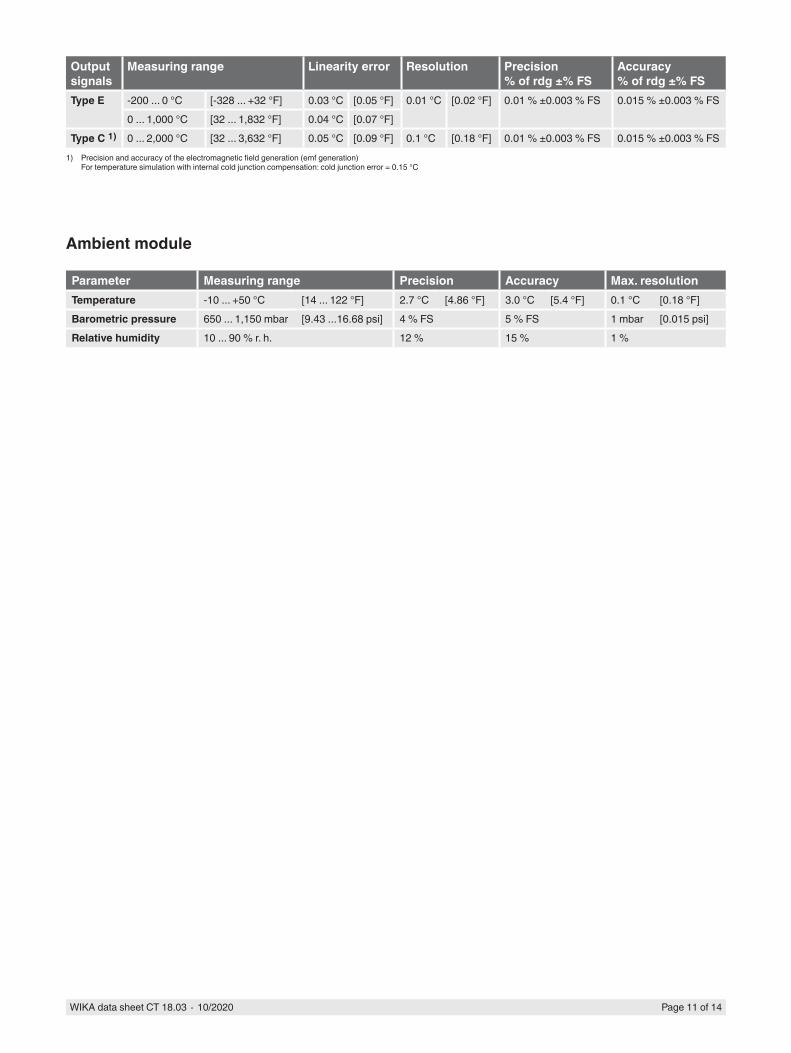
Thermocouple simulation
Output signals
Measuring range Linearity error Resolution Precision% of rdg ±% FS
Accuracy% of rdg ±% FS
Type J 1) -190 ... 0 °C [-310 ... +32 °F] 0.05 °C [0.09 °F] 0.01 °C [0.02 °F] 0.01 % ±0.003 % FS 0.015 % ±0.003 % FS0 ... 1,200 °C [32 ... 2,192 °F] 0.04 °C [0.07 °F]
Type K 1) -160 ... 0 °C [-256 ... +32 °F] 0.06 °C [0.11 °F] 0.01 °C [0.02 °F] 0.01 % ±0.003 % FS 0.015 % ±0.003 % FS0 ... 1,260 °C [32 ... 2,300 °F] 0.04 °C [0.07 °F]
Type T 1) -130 ... 0 °C [-202 ... +32 °F] 0.05 °C [0.09 °F] 0.01 °C [0.02 °F] 0.01 % ±0.003 % FS 0.015 % ±0.003 % FS0 ... 400 °C [32 ... 752 °F] 0.04 °C [0.07 °F]
Type F 1) 0 ... 400 °C [32 ... 752 °F] 0.05 °C [0.09 °F] 0.1 °C [0.18 °F] 0.01 % ±0.003 % FS 0.015 % ±0.003 % FSType R 160 ... 1,760 °C [320 ... 3,200 °F] 0.04 °C [0.07 °F] 0.1 °C [0.18 °F] 0.01 % ±0.003 % FS 0.015 % ±0.003 % FSType S 170 ... 1,760 °C [338 ... 3,200 °F] 0.04 °C [0.07 °F] 0.1 °C [0.18 °F] 0.01 % ±0.003 % FS 0.015 % ±0.003 % FSType B 1) 920 ... 1,820 °C [1,688 ... 3,308 °F] 0.1 °C [0.18 °F] 0.1 °C [0.18 °F] 0.01 % ±0.003 % FS 0.015 % ±0.003 % FSType U 1) -160 ... 0 °C [-256 ... +32 °F] 0.04 °C [0.07 °F] 0.01 °C [0.02 °F] 0.01 % ±0.003 % FS 0.015 % ±0.003 % FS
0 ... 400 °C [32 ... 752 °F]Type L 1) -200 ... 0 °C [-328 ... +32 °F] 0.03 °C [0.05 °F] 0.01 °C [0.02 °F] 0.01 % ±0.003 % FS 0.015 % ±0.003 % FS
0 ... 760 °C [32 ... 1,400 °F] 0.04 °C [0.07 °F]Type N 0 ... 1,300 °C [32 ... 2,372 °F] 0.04 °C [0.07 °F] 0.01 °C [0.02 °F] 0.01 % ±0.003 % FS 0.015 % ±0.003 % FS
WIKA data sheet CT 18.03 ∙ 10/2020 Page 11 of 14
Output signals
Measuring range Linearity error Resolution Precision% of rdg ±% FS
Accuracy% of rdg ±% FS
Type E -200 ... 0 °C [-328 ... +32 °F] 0.03 °C [0.05 °F] 0.01 °C [0.02 °F] 0.01 % ±0.003 % FS 0.015 % ±0.003 % FS0 ... 1,000 °C [32 ... 1,832 °F] 0.04 °C [0.07 °F]
Type C 1) 0 ... 2,000 °C [32 ... 3,632 °F] 0.05 °C [0.09 °F] 0.1 °C [0.18 °F] 0.01 % ±0.003 % FS 0.015 % ±0.003 % FS1) Precision and accuracy of the electromagnetic field generation (emf generation)
For temperature simulation with internal cold junction compensation: cold junction error = 0.15 °C
Ambient module
Parameter Measuring range Precision Accuracy Max. resolutionTemperature -10 ... +50 °C [14 ... 122 °F] 2.7 °C [4.86 °F] 3.0 °C [5.4 °F] 0.1 °C [0.18 °F]Barometric pressure 650 ... 1,150 mbar [9.43 ...16.68 psi] 4 % FS 5 % FS 1 mbar [0.015 psi]Relative humidity 10 ... 90 % r. h. 12 % 15 % 1 %
WIKA data sheet CT 18.03 ∙ 10/2020 Page 12 of 14
226
[8.9
0]
250
[9.8
4]
313 [12.32]
203
[7.9
9]
HART
CPH8000/ISII 2G Ex ib IIC T4 Gb
117,5 [4,63]
36,4
8 [1
,44]
87,3
0 [3
,44]
15 [0,5
9]
75 [2
,95]
P / V
ADJ
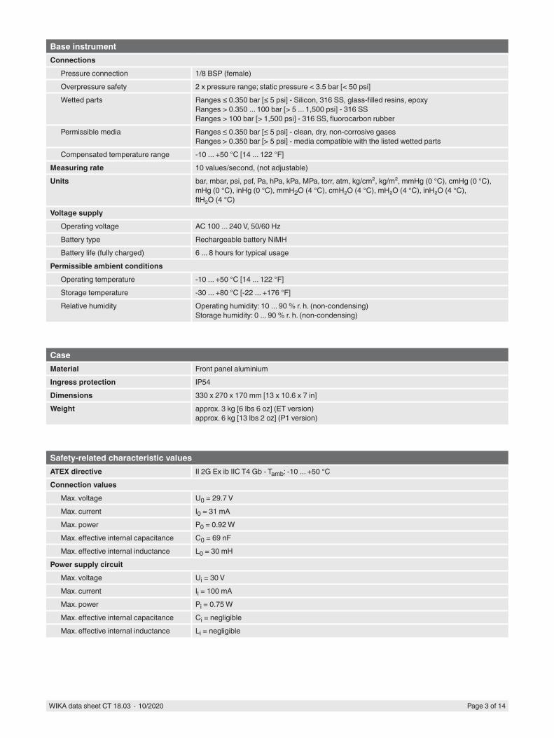
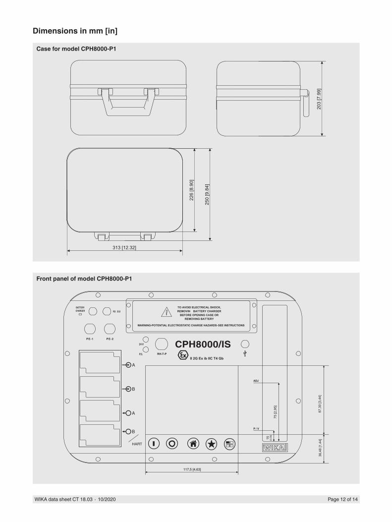
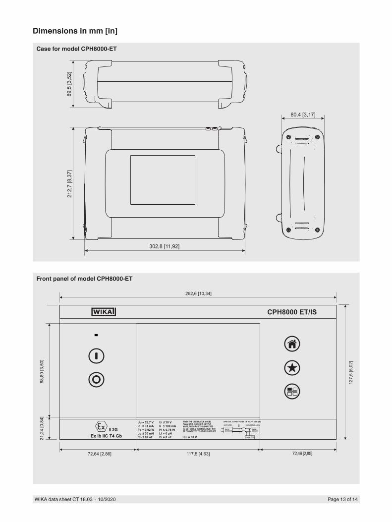
Dimensions in mm [in]
Case for model CPH8000-P1
Front panel of model CPH8000-P1
WIKA data sheet CT 18.03 ∙ 10/2020 Page 13 of 14
302,8 [11,92]
212,
7 [8
,37]
80,4 [3,17]
89,5
[3,5
2]
Pascal ET/IS
FIELDDEVICE
HAZARDOUS AREA
SAFEBARRIER
SAFE AREA
SPECIAL CONDITIONS OF SAFE USE (X)WHEN THE CALIBRATOR MODELPascal ET/IS IS USED IN OUTPUTMODE, THE CIRCUITS CONNECTEDTO OUT OR P.S. TERMINAL MUST NOTBE CONNECTED TO OTHER SUPPLIES
Um = 60 V
Ii ≤ 100 mAUi ≤ 30 V
Pi ≤ 0,75 W
Ci = 0 nFLi = 0 µH
Uo = 29,7 VIo = 31 mAPo = 0,92 WLo ≤ 30 mHCo ≤ 69 nF
Ex ib IIC T4 Gb
CPH8000 ET/IS
127,
5 [5
,02]
72,46 [2,85]117,5 [4,63]72,64 [2,86]
21,2
4 [0
,84]
88,8
0 [3
,50]
262,6 [10,34]
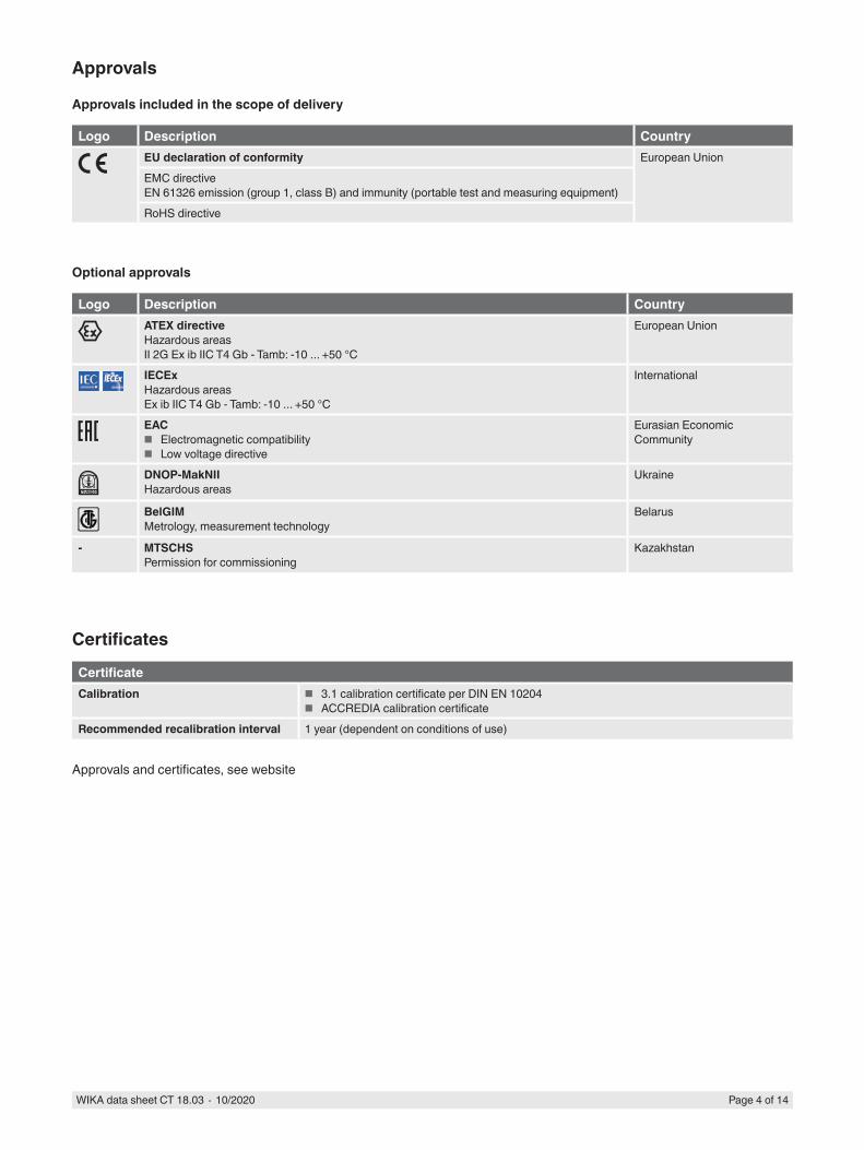
Dimensions in mm [in]
Case for model CPH8000-ET
Front panel of model CPH8000-ET
WIKA data sheet CT 18.03 ∙ 10/2020 Page 14 of 14
© 10/2020/ WIKA Alexander Wiegand SE & Co. KG, all rights reserved.The specifications given in this document represent the state of engineering at the time of publishing.We reserve the right to make modifications to the specifications and materials.
10/2
020
EN
WIKA Alexander Wiegand SE & Co. KGAlexander-Wiegand-Straße 3063911 Klingenberg/GermanyTel. +49 9372 132-0Fax +49 9372 [email protected]
Ordering informationVersion / Explosion protection / Electrical input module / Electrical module calibration / Electrical output module / Electrical module calibration / Ambient module / Ambient module calibration / Internal pressure sensor / Barometer / Barometer calibration / Connection for external reference sensor CPT8100 / Liquid trap / Software / USB-port / Package / Additional order information
Scope of delivery
■ Portable multi-function calibrator model CPH8000 ■ Operating instructions ■ AC adapter ■ CPH8000 report software ■ RS-232 interface cable ■ RS-232 to USB adapter ■ Test-cable set; order no. 241076 ■ Pneumatic pressure set; order no. 241028 and 241029
(depending on pressure range) ■ 3.1 calibration certificate per DIN EN 10204
Option
■ ATEX approval ■ IECEx approval ■ ACCREDIA calibration certificate ■ Ambient module module ■ Liquid trap ■ Hydraulic test pumps ■ Pneumatic test pumps ■ PasLog software
CPH8000 report softwareThe CPH8000 report software allows the configuration in A4 format of the calibration reports and/or certificates according to users standards.Importing stored reports from the instrument by RS-232 serial interface/USB (with adapter) makes Pascal report the safer software system to support any calibration procedure in accordance with ISO 9000 standards.
Software
PasLog softwareThe PasLog software allows the download and the management of the logging data from the instrument to the PC. Data can be displayed and print out in a tabular format as well as in a graphical one. The user interface can be customised.


