Embed Size (px)
Citation preview

S A I P R A T E I K B H A S G I
P O R T F O L I O
DATE OF BIRTH
NATIONALITY
CONTACT
ADDRESS
AVAILABILITY
31/10/1990
Indian
07479646567 [email protected]
No 427Cleveland GardensLondonW2 6DE.
February 2015
S a i P r a t e i k B h a s g i
I am a qualified and skilled architect, with a masters in Architecture & Urbanism (AADRL) from the AA School of Architecture. I have a great appreciation of the importance of ‘Design and Fabrication’ in our lives and more importantly, in the life and profession of an architect. The past seven years of my learning process strong-ly reflects this admiration.
My path to AADRL was paved by a strong understanding of a plethora of architec-tural styles and my keen interest in design articulation. This spectrum ranges from Historical Indian concepts to Contemporary world styles. I have spent a substantial part of my graduate studies experimenting with these and this has piqued my inter-est further in the concepts of design, to say the least.
Over the past 16 months, I have explored the ideas of material and design com-putation. This exploration harmoniously culminated in a thesis about robotically fabricated material systems, whose design and structural applications were inves-tigated through extensive prototyping. This has given me a first-hand experience and exposure to the use and customization of the latest tools in the architecture fabrication industry.
In addition to broadening my architectural knowledge at AA, I have successful-ly developed technical, parametric, prototyping and digital skills to solve design problems. And working in a team has helped me develop cooperation, manage-ment, leadership, critical analysis and several interpersonal skills. I would like to particularly highlight my ability to coordinate and manage the strengths and sensi-bilities within the team
Apart from architecture, my key interests lie in music mixing and street photog-raphy, samples of which have been included in the portfolio. Hope you find this document interesting.
EDUCATION
WORKSHOPS
PROFESSIONAL EXPERIENCE
SKILLS
Architectural Association School Of ArchitectureMaster of Architecture & Urbanism (M.Arch) Design Research Laboratory (AADRL)Thesis : WIREDTutor : Shajay Bhooshan
Fabric Formwork Structures, KADK, Copenhagen.Tutor : Mark West, Shajay Bhooshan, Alicia Nahmad.
Basic’s of Robotics, IAAC, Barcelona.Tutor : Luis Fraguada, Shajay Bhooshan, Alex Dubor.
INT HAB Architecture + Design Studio, Bangalore.Architectural InternProjects : Manjaya Shetty apartments, Mangalore, India. Technical drawings, Physical modelling. Pavani Petals Row housing,Hyderabad, India. Design development, Technical drawings. Babu Residential interiors, Bangalore, India. Design development, Drawings, Site work. Raghavan interiors, Bangalore, India. Design development, Drawings, Site work.
CUBE Architects, Bangalore.Architectural InternProjects : Raguvendra residence, Bangalore, India. Design development, Technical drawings. B-blunt salon interiors, Bangalore, India. Design development, Technical drawings, Site work. Ozone Urbana Marketing Suite, Bangalore, India. As-built drawings, Area Statements.
ModellingAutocad (2D and 3D), Maya, Rhinoceros, Grasshopper, Google SketchUp, Mental Ray and Key Shot(Rendering).CodeC++, Processing.Graphics & PresentationAdobe Photoshop, Illustrator, InDesign, After-Effects, MS Powerpoint.
CNC Machine, Laser Cutter and Rapid Prototyping.
Fluent in English, Hindi, and Kannada (Native).
M.S.Ramaiah Institute Of Technology, Bangalore. Bachelor of Architecture (B.Arch)Thesis : MUDRA - School Of Performing Arts.Tutor : S. Jotirmay CGPA : 8.9/10
09/2013 - 01/2015
04/2014
04/2014
01/2013 - 05/2013
Softwares
Fabrication
Languages
06/2011 - 08/2011
08/2008 - 06/2013
Built Unbuilt Under Construction
REFERENCES
LINKS
THEODORE SPYROPOULOSDirector - MinimaformsDirector - AADrlAA School Of Architecture36 Bedford SquareLondonWC1B [email protected]
SHAJAY BHOOSHANDesigner - Zaha Hadid ArchitectsCourse Master - AADrlAA School Of Architecture36 Bedford SquareLondonWC1B [email protected]+447838717055
AR. SACHIN SHETTYPrincipal ArchitectInt - Hab Architecture + Design Studio.4-s4 Ranka Park ApartmentsLalbagh [email protected]+919844040660
http://issuu.com/saiprateikbhasgi
https://www.mixcloud.com/prateiik/
Issuu
Mixcloud
ACHIEVEMENTS
Work featured in AArchitecture 21, - ‘Let the Paper Fold and Unfold’,Curve Folding, AA School Of Architecture.
Winner “Google” Design Event and South Zone Cultural Trophy, ZoNasa, Manipal, Karnataka, India.
2013
2010
ACADEMIC
Graduate Work
i - AADRL Thesis : WIRED.
ii - Workshop 2 : Material Computation - Ferro Fluid Behaviour.
iii - Workshop 1 : Paper Folding - Curve Folded Furniture.
Workshops i - Mark West Fabric Form-work structures.
Undergraduate Work
i - Graduate Thesis : MUDRA - School of Performing Arts. ii - Transport Hub Design.
PROFESSIONAL
i - Manjaya Shetty Apartments, Mangalore, India.
ii - Babu Residence Interiors, Bangalore, India.
iii - Pavani Petals row housing, Hyderabad, India.
iv - Ozone Urbana Marketing Suite, Bangalore, India.
v - B- blunt Salon Interiors, Bangalore, India.
STREET PHOTOGRAPHY 2014 - 2015.
1
2
3
INDEX


A C A D E M I C
DESIGNMATERIAL ROBOTICS
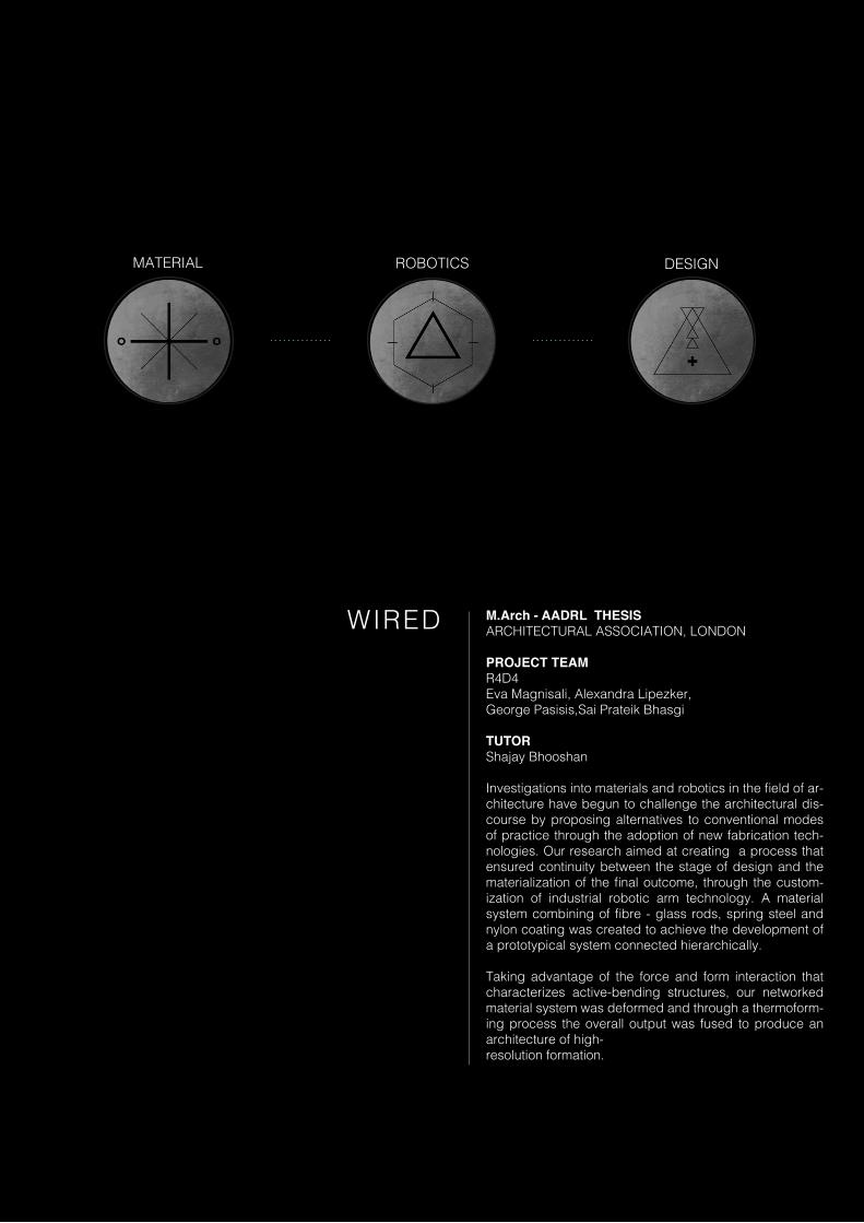
WIRED M.Arch - AADRL THESISARCHITECTURAL ASSOCIATION, LONDON
PROJECT TEAMR4D4Eva Magnisali, Alexandra Lipezker,George Pasisis,Sai Prateik Bhasgi
TUTORShajay Bhooshan
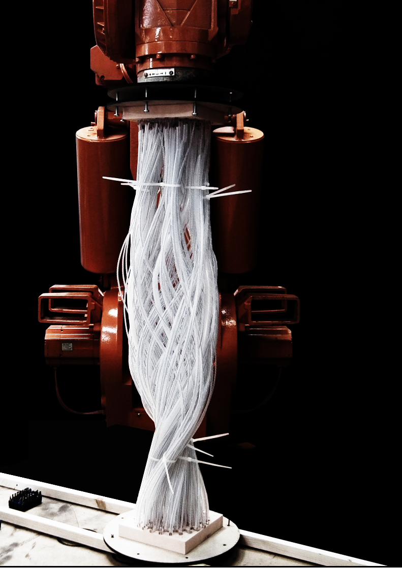
Investigations into materials and robotics in the field of ar-chitecture have begun to challenge the architectural dis-course by proposing alternatives to conventional modes of practice through the adoption of new fabrication tech-nologies. Our research aimed at creating a process that ensured continuity between the stage of design and the materialization of the final outcome, through the custom-ization of industrial robotic arm technology. A material system combining of fibre - glass rods, spring steel and nylon coating was created to achieve the development of a prototypical system connected hierarchically.
Taking advantage of the force and form interaction that characterizes active-bending structures, our networked material system was deformed and through a thermoform-ing process the overall output was fused to produce an architecture of high-resolution formation.
10
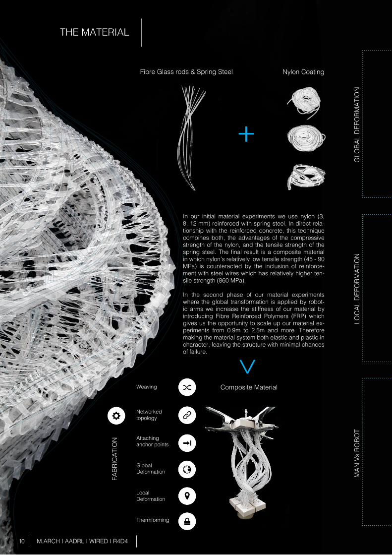
THE MATERIAL
M.ARCH I AADRL I WIRED I R4D4
GLO
BAL
DEF
ORM
ATIO
N
LOC
AL D
EFO
RMAT
ION
M
AN V
s RO
BOT
FABR
ICAT
ION
In our initial material experiments we use nylon (3, 8, 12 mm) reinforced with spring steel. In direct rela-tionship with the reinforced concrete, this technique combines both, the advantages of the compressive strength of the nylon, and the tensile strength of the spring steel. The final result is a composite material in which nylon’s relatively low tensile strength (45 - 90 MPa) is counteracted by the inclusion of reinforce-ment with steel wires which has relatively higher ten-sile strength (860 MPa).
In the second phase of our material experiments where the global transformation is applied by robot-ic arms we increase the stiffness of our material by introducing Fibre Reinforced Polymers (FRP) which gives us the opportunity to scale up our material ex-periments from 0.9m to 2.5m and more. Therefore making the material system both elastic and plastic in character, leaving the structure with minimal chances of failure.
Fibre Glass rods & Spring Steel Nylon Coating
Composite MaterialWeaving
Networked topology
Attachinganchor points
GlobalDeformation
LocalDeformation
Thermforming
+>
11 M.ARCH I AADRL I WIRED I R4D4
Different Global Results
Different Global Results
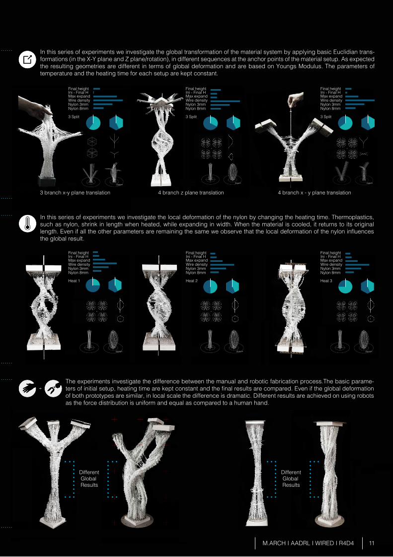
In this series of experiments we investigate the local deformation of the nylon by changing the heating time. Thermoplastics, such as nylon, shrink in length when heated, while expanding in width. When the material is cooled, it returns to its original length. Even if all the other parameters are remaining the same we observe that the local deformation of the nylon influences the global result.
In this series of experiments we investigate the global transformation of the material system by applying basic Euclidian trans-formations (in the X-Y plane and Z plane/rotation), in different sequences at the anchor points of the material setup. As expected the resulting geometries are different in terms of global deformation and are based on Youngs Modulus. The parameters of temperature and the heating time for each setup are kept constant.
The experiments investigate the difference between the manual and robotic fabrication process.The basic parame-ters of initial setup, heating time are kept constant and the final results are compared. Even if the global deformation of both prototypes are similar, in local scale the difference is dramatic. Different results are achieved on using robots as the force distribution is uniform and equal as compared to a human hand.
3 branch x-y plane translation
Final height
Final height
Final height
Final height Final height
Ini - Final H
Ini - Final H
Ini - Final H
Ini - Final H Ini - Final H
Max expand
Max expand
Max expand
Max expand Max expand
Wire density
Wire density
Wire density
Wire density Wire density
Nylon 3mm
Nylon 3mm
Nylon 3mm
Nylon 3mm Nylon 3mm
Nylon 8mm
Nylon 8mm
Nylon 8mm
Nylon 8mm Nylon 8mm
3 Split
Heat 1
3 Split
Heat 2 Heat 3
4 branch z plane translation 4 branch x - y plane translation
Final heightIni - Final H Max expandWire densityNylon 3mmNylon 8mm
3 Split
12 M.ARCH I AADRL I WIRED I R4D4
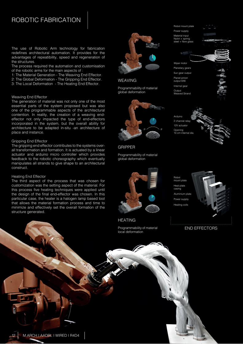
ROBOTIC FABRICATION
The use of Robotic Arm technology for fabrication redefines architectural automation. It provides for the advantages of repeatibility, speed and regeneration of the structures.The process required the automation and customisation of the robotic arms for the main aspects of :1: The Material Generation - The Weaving End Effector.2: The Global Deformation - The Gripping End Effector.3: The Local Deformation - The Heating End Effector.
Weaving End EffectorThe generation of material was not only one of the most essential parts of the system proposed but was also one of the programmable aspects of the architectural contention. In reality, the creation of a weaving end-effector not only impacted the type of end-effectors incorporated in the system, but the overall ability for architecture to be adapted in-situ -an architecture of place and instance.
Gripping End EffectorThe gripping end effector contributes to the systems over-all transformation and formation. It is actuated by a linear actuator and arduino micro controller which provides feedback to the robotic choreography which eventually manipulates all strands to give shape to an architectural construct.
Heating End EffectorThe third aspect of the process that was chosen for customization was the setting aspect of the material. For this process five heating techniques were applied until the design of the final end-effector was chosen. In this particular case, the heater is a halogen lamp based tool that allows the material formation process and time to minimize and effectively set the overall formation of the structure generated.
Programmability of material global deformation
Programmability of material global deformation
Programmability of material local deformation
WEAVING
GRIPPER
HEATING
END EFFECTORS
PP
Heat plate casing
Aluminium plate
Power supply
Heating coils
Robot mount plate
2 channel relay
12V actuator
Opening10 cm internal dia.
Arduino
Planetary gears
Wiper motor
Material input Nylon + spring steel + fibre glass
Power supply
Robot mount plate
Sun gear output
Planet pinion output 6X6
Internal gear
OutputWeaved Strand
Anchor point end effector Mid/Control point end effector V 1.0
HalogenHeater
Mid/Control point end effector V 1.0
13 M.ARCH I AADRL I WIRED I R4D4
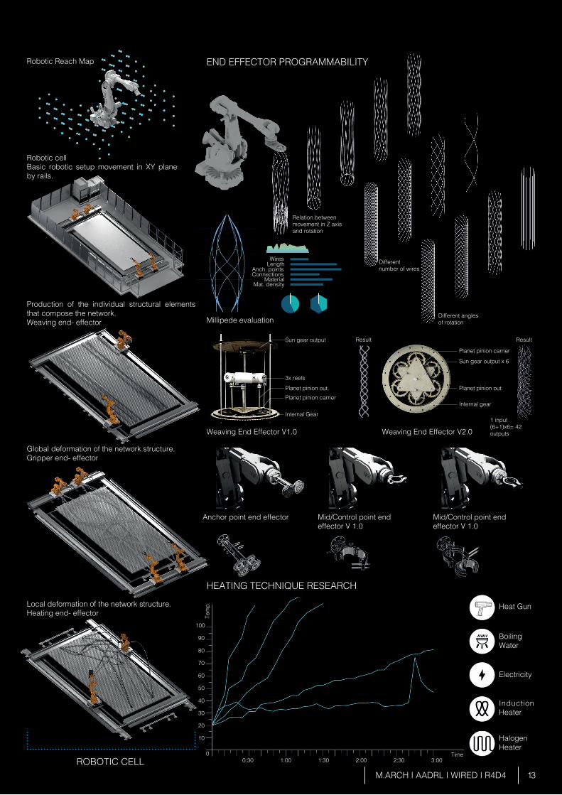
Robotic cell Basic robotic setup movement in XY plane by rails.
Production of the individual structural elements that compose the network.Weaving end- effector
Global deformation of the network structure.Gripper end- effector
Weaving End Effector V1.0
Millipede evaluation
Heat Gun
Boiling Water
Electricity
Induction Heater
Weaving End Effector V2.0
Local deformation of the network structure.Heating end- effector
ROBOTIC CELL
END EFFECTOR PROGRAMMABILITY
HEATING TECHNIQUE RESEARCH
Robotic Reach Map
Wires
Sun gear output Result
3x reels
Planet pinion out. Planet pinion out.
Sun gear output x 6
Planet pinion carrier
Relation between movement in Z axis and rotation
Different number of wires
Different anglesof rotation
Internal gear
1 input(6+1)x6= 42 outputs
Planet pinion carrier
Internal Gear
0:300
10
20
30
40
50
60
70
80
90
100
1:00 1:30 2:00 2:30 3:00Time
Tem
p.
LengthAnch. pointsConnections
MaterialMat. density
Result
14
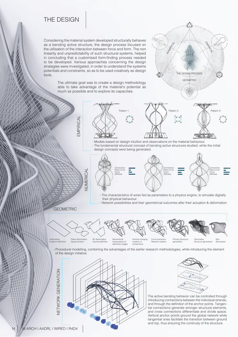
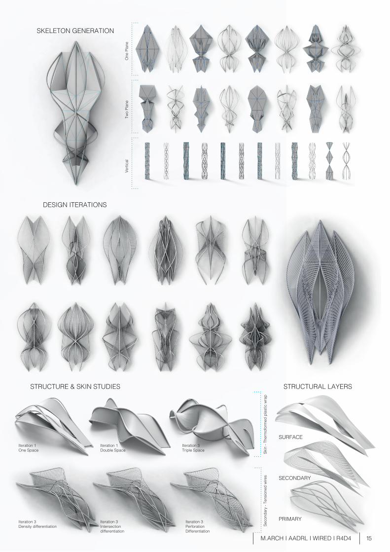
Considering the material system developed structurally behaves as a bending active structure, the design process focused on the utilisation of the interaction between force and form. The non linearity and unpredictability of such structural systems, helped in concluding that a customised form-finding process needed to be developed. Various approaches concerning the design strategies were investigated, in order to understand the systems potentials and constraints, so as to be used creatively as design tools.
The ultimate goal was to create a design methodology able to take advantage of the material’s potential as much as possible and to explore its capacities.
GEOMETRIC
THE DESIGN PROCESS
EMPIRICAL
NUMER
ICAL
- Models based on design intuition and observations on the material behaviour. - The fundamental structural concept of bending active structures studied, while the initial design concepts were being generated.
EMPI
RIC
AL
Pattern 1 Pattern 2 Pattern 3
- The characteristics of wires fed as parameters to a physics engine, to simulate digitally their physical behaviour. - Network possibilities and their geometrical outcomes after their actuation & deformation
Initial setup Footprint definition
Plane deformationSpace division
3D deformationvolume definition
Geometrical manipulation of deformers edges
Vertices mergingcreation of connections
Curve extraction Netwrok creation
Primary Structure generation
Secondary Structure generation
SkinGeneration
NU
MER
ICAL
GEOMETRIC
Plane of refForce
Stiffness
Connection Connection ConnectionPlane of ref Plane of ref
ForceStiffness
ForceStiffness
M.ARCH I AADRL I WIRED I R4D4
NET
WO
RK G
ENER
ATIO
N
The active bending behavior can be controlled through introducing connections between the individual strands, and through the definition of the anchor points. Tangen-tial connections generate stronger structural elements, and cross connections differentiate and divide space. Vertical anchor points ground the global network while tangential ones facilitate the transition between ground and top, thus ensuring the continuity of the structure.
A BC
D EF
G HI
JK L
- Procedural modelling, combining the advantages of the earlier research methodologies, while introducing the element of the design initiative.
THE DESIGN
15
Iteration 1One Space
Iteration 1Double Space
Iteration 3Triple Space
SURFACE
SECONDARY
PRIMARYIteration 3PerforationDifferentiation
Iteration 3Intersection differentiation
Iteration 3Density differentiation
M.ARCH I AADRL I WIRED I R4D4
SKELETON GENERATION
DESIGN ITERATIONS
STRUCTURE & SKIN STUDIES STRUCTURAL LAYERS
Two
Plan
eO
ne P
lane
Verti
cal
Seco
ndar
y - T
ensi
oned
wire
sSk
in -
Ther
mof
orm
ed p
last
ic w
rap
16 M.ARCH I AADRL I WIRED I R4D4
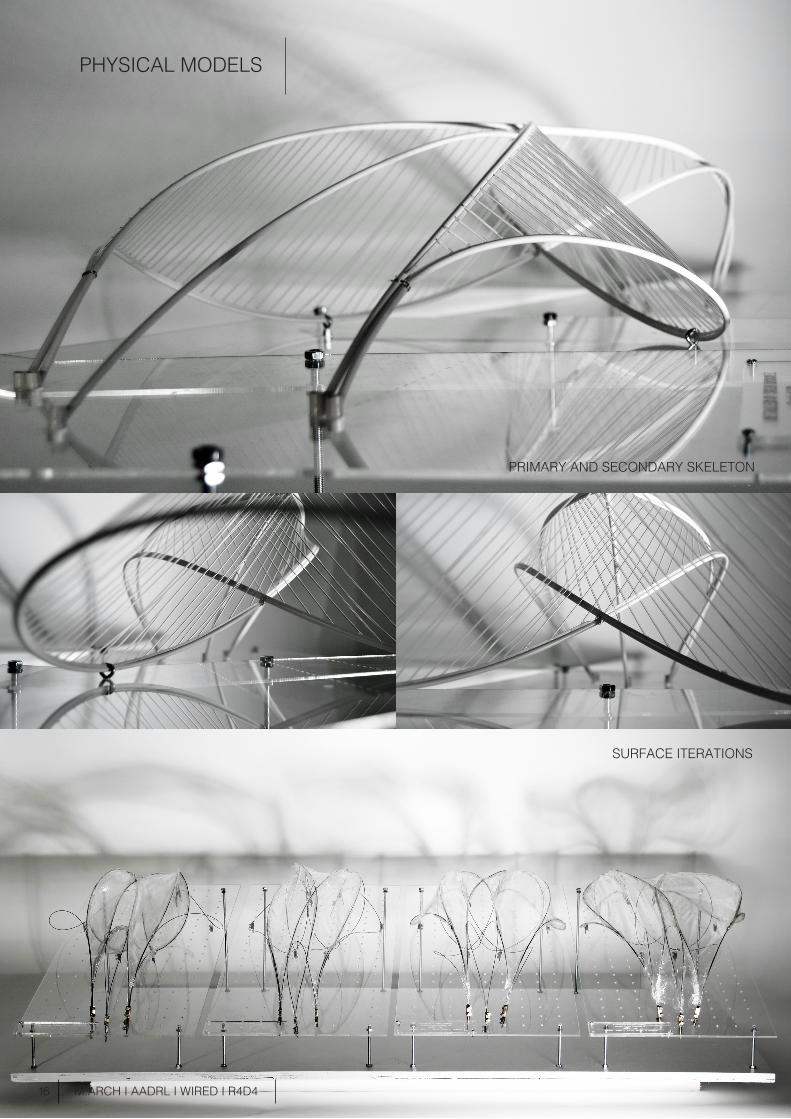
PHYSICAL MODELS
PRIMARY AND SECONDARY SKELETON
SURFACE ITERATIONS
17 M.ARCH I AADRL I WIRED I R4D4
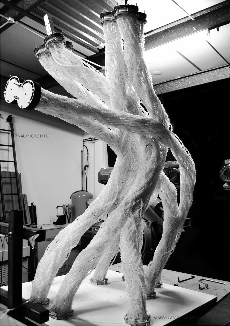
FINAL PROTOTYPE
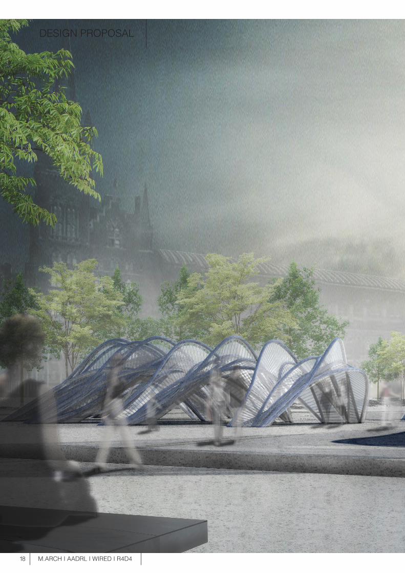
DESIGN PROPOSAL
18 M.ARCH I AADRL I WIRED I R4D4
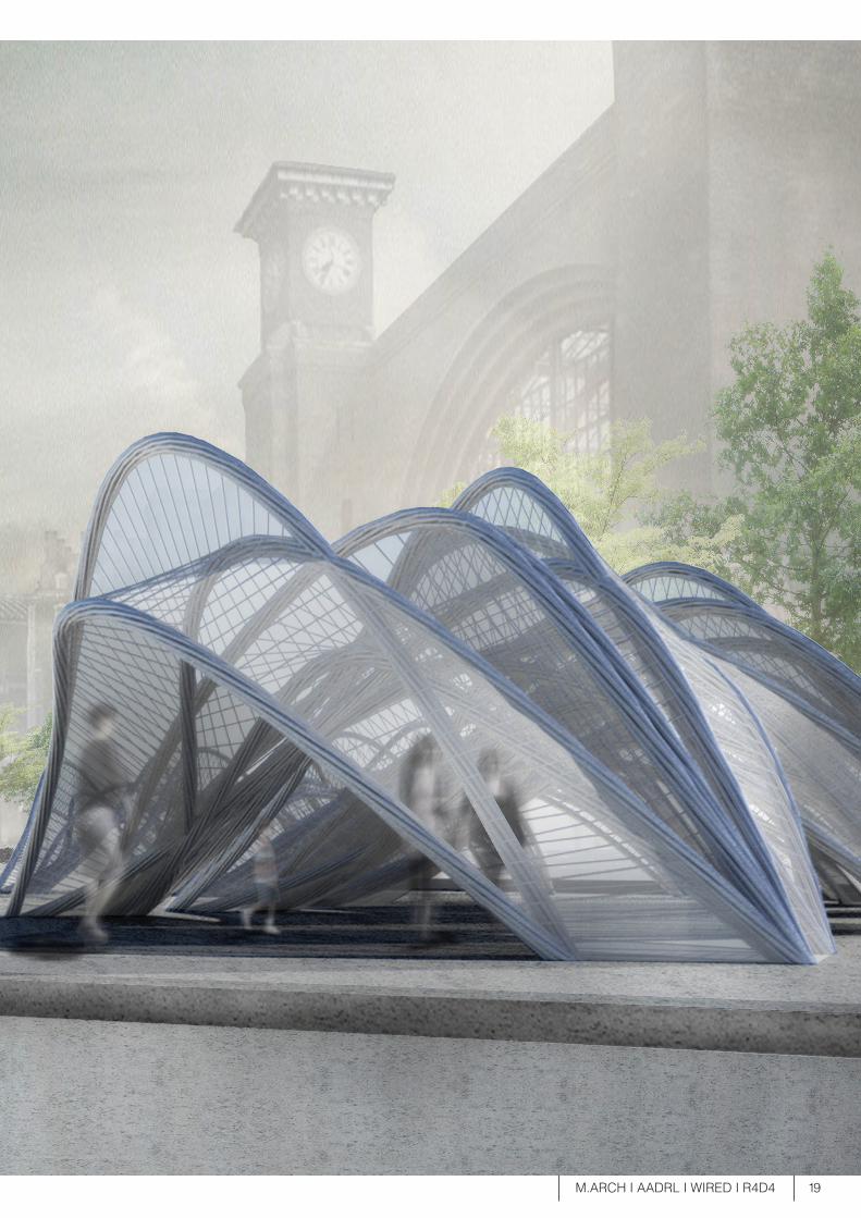
19 M.ARCH I AADRL I WIRED I R4D4
20
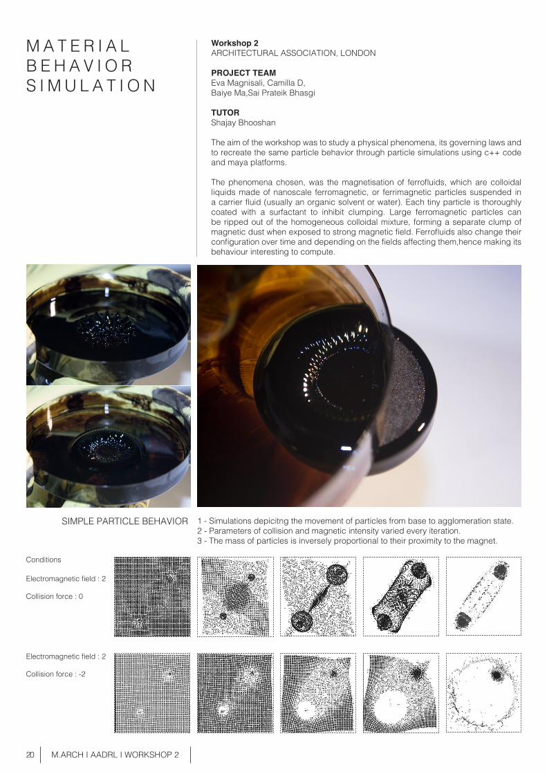
SIMPLE PARTICLE BEHAVIOR
M.ARCH I AADRL I WORKSHOP 2
1 - Simulations depicitng the movement of particles from base to agglomeration state.2 - Parameters of collision and magnetic intensity varied every iteration.3 - The mass of particles is inversely proportional to their proximity to the magnet.
Electromagnetic field : 2
Collision force : 0
Conditions
Electromagnetic field : 2
Collision force : -2
M A T E R I A L B E H A V I O RS I M U L A T I O N
Workshop 2ARCHITECTURAL ASSOCIATION, LONDON
PROJECT TEAMEva Magnisali, Camilla D,Baiye Ma,Sai Prateik Bhasgi
TUTORShajay Bhooshan
The aim of the workshop was to study a physical phenomena, its governing laws and to recreate the same particle behavior through particle simulations using c++ code and maya platforms.
The phenomena chosen, was the magnetisation of ferrofluids, which are colloidal liquids made of nanoscale ferromagnetic, or ferrimagnetic particles suspended in a carrier fluid (usually an organic solvent or water). Each tiny particle is thoroughly coated with a surfactant to inhibit clumping. Large ferromagnetic particles can be ripped out of the homogeneous colloidal mixture, forming a separate clump of magnetic dust when exposed to strong magnetic field. Ferrofluids also change their configuration over time and depending on the fields affecting them,hence making its behaviour interesting to compute.
21 M.ARCH I AADRL I WORKSHOP 2
1 - Simulations generating patterns created by ferrofluids and magnets.2 - Using maya N-particles as ferrofluids and polygonal primitives as passive colliders.3 - Parameters of collision and bounce factor kept constant, number of magnets and colliders changed.
2 - Simulation of complex particle behavior under electromagnetic field using combina- tion of the objects as the magnets.
ORGANIC PATTERN GENERATION
No of magnets : 8
No of colliders : 9
Collision factor : 0.5
Bounce factor : 0.3
Elecric field : 10 E - 30 E
Charge : -5Q
Weight of magnetic : 1Centers
Elecric field : 10 E - 30 E
Charge : -5Q
Weight of magnetic : 1Centers
Elecric field : 10 E - 100 E
Charge : -5Q
Weight of magnetic : 1Centers
No of magnets : 8
No of colliders : 9
Collision factor : 0.5
Bounce factor : 0.3
Conditions
Conditions
- The ferrofluid is a liquid material system that solidifes its dynamic form and acquires stability on interaction with magnets. - Taking this into consideration we transform a dynamic system (point cloud) into a material system through solid geometry(mesh) conversion into a soft system (N-Cloth) composed of N particles, and applying electromagnetic field to the same.
1 - In this part, we use C++ to simulate simple particle behavior under electromagnetic field and single imported object as the magnets.
Obj.
20
20
10
10
30
30
Obj.
Obj.
ELECTROMAGNETIC FIELD
Obj.
50
C
10
A
100
B
22
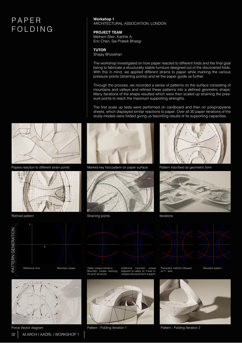
Papers reaction to different strain points
Refined pattern
Force Vector diagram Pattern - Folding Iteration 1 Pattern - Folding Iteration 2
Reference Axis Mountain crease Valley crease normal to Mountain crease erecting the arch structure
Additional mountain crease adjacent to valley on Y-axis in-creases structural arch support
Precedent method followed on Y - axis.
Resultant pattern
PATT
ERN
GEN
ERAT
ION
Marked key fold pattern on paper surface
Straining points
Pattern inscribed as geometric form
Iterations
X
Y
M.ARCH I AADRL I WORKSHOP 1
P A P E R F O L D I N G
Workshop 1ARCHITECTURAL ASSOCIATION, LONDON
PROJECT TEAMMelhem Sfeir, Karthik A,Eric Chen, Sai Prateik Bhasgi
TUTORShajay Bhooshan
The workshop investigated on how paper reacted to different folds and the final goal being to fabricate a structurally stable furniture designed out of the discovered folds.With this in mind, we applied different strains to paper while marking the various pressure points (straining points) and let the paper guide us further.
Through the process, we recorded a series of patterns on the surface consisting of mountains and valleys and refined these patterns into a defined geometric shape. Many iterations of the shape resulted which were then scaled up straining the pres-sure points to reach the maximum supporting strengths.
The first scale up tests were performed on cardboard and then on polypropylene sheets, which displayed similar reactions to paper. Over all 30 paper iterations of the study models were folded giving us fascinting results of its supporting capacities.
23
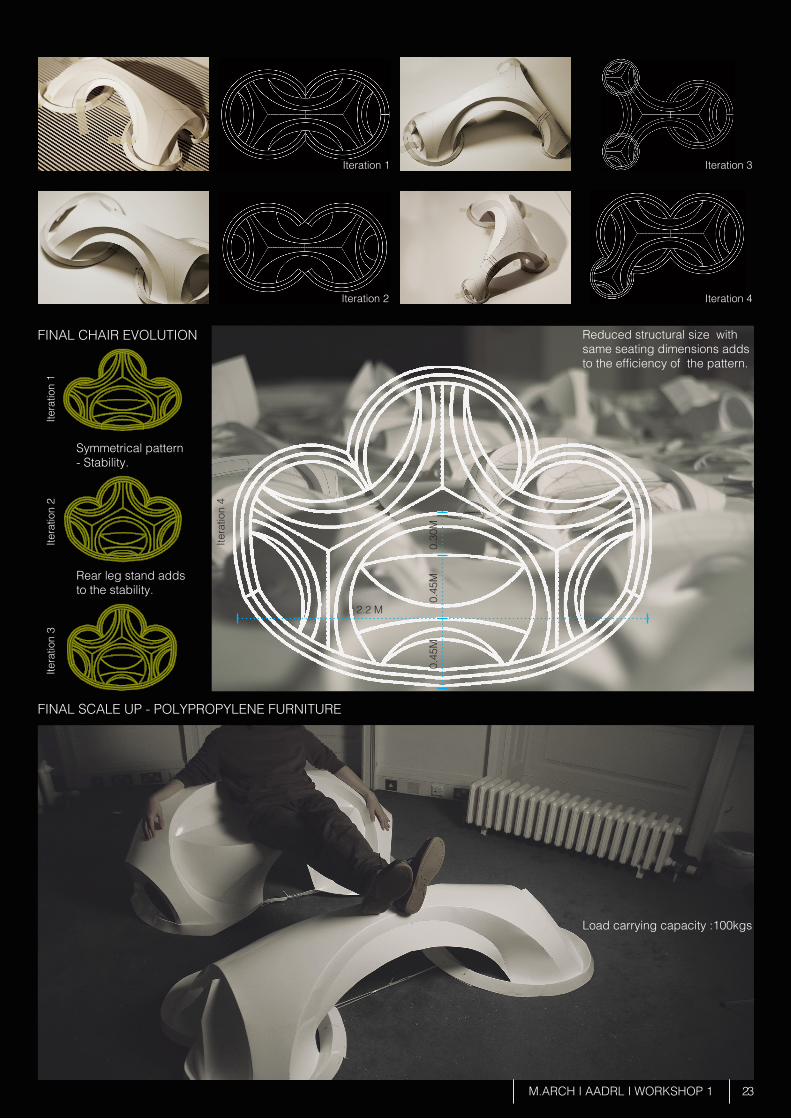
Iteration 1
Iteration 2
Itera
tion
1Ite
ratio
n 2
Itera
tion
3
Itera
tion
4
Iteration 3
Iteration 4
FINAL CHAIR EVOLUTION
FINAL SCALE UP - POLYPROPYLENE FURNITURE
0.30
M0.
45M
0.45
M
2.2 M
M.ARCH I AADRL I WORKSHOP 1
Reduced structural size with same seating dimensions adds to the efficiency of the pattern.
Symmetrical pattern - Stability.
Rear leg stand adds to the stability.
Load carrying capacity :100kgs
24
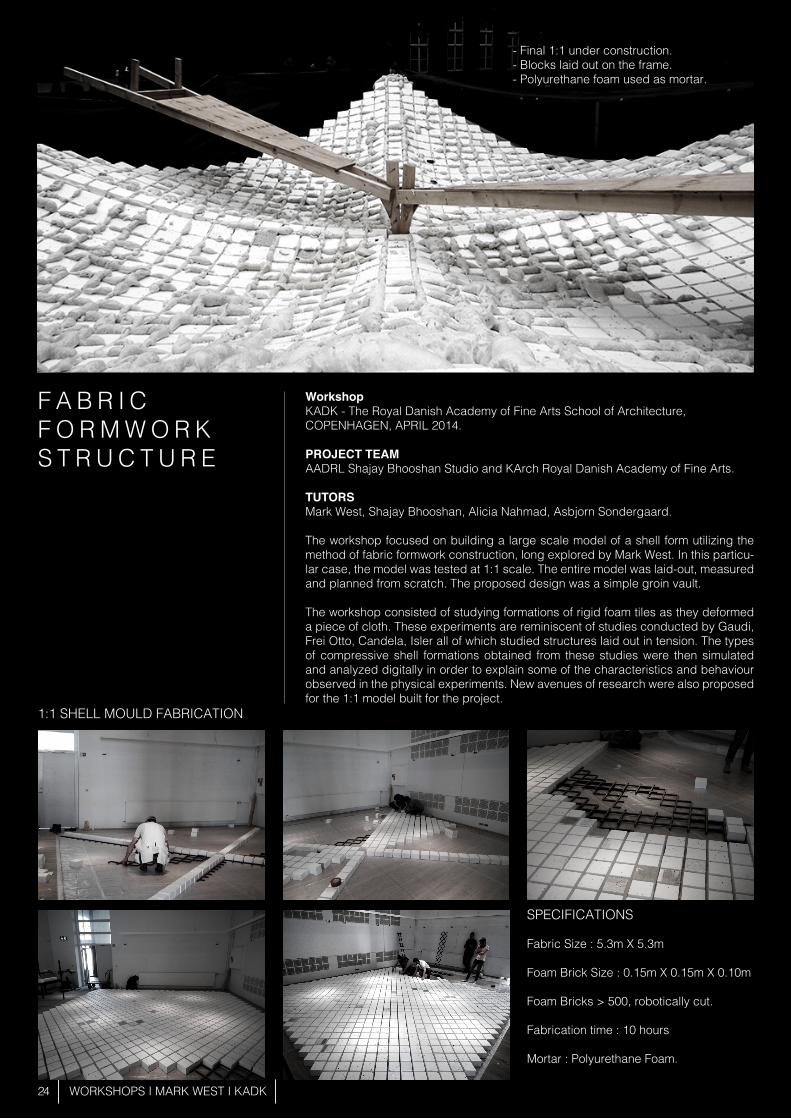
F A B R I CF O R M W O R KS T R U C T U R E
Workshop KADK - The Royal Danish Academy of Fine Arts School of Architecture, COPENHAGEN, APRIL 2014.
PROJECT TEAMAADRL Shajay Bhooshan Studio and KArch Royal Danish Academy of Fine Arts.
TUTORSMark West, Shajay Bhooshan, Alicia Nahmad, Asbjorn Sondergaard.
The workshop focused on building a large scale model of a shell form utilizing the method of fabric formwork construction, long explored by Mark West. In this particu-lar case, the model was tested at 1:1 scale. The entire model was laid-out, measured and planned from scratch. The proposed design was a simple groin vault.
The workshop consisted of studying formations of rigid foam tiles as they deformed a piece of cloth. These experiments are reminiscent of studies conducted by Gaudi, Frei Otto, Candela, Isler all of which studied structures laid out in tension. The types of compressive shell formations obtained from these studies were then simulated and analyzed digitally in order to explain some of the characteristics and behaviour observed in the physical experiments. New avenues of research were also proposed for the 1:1 model built for the project.
WORKSHOPS I MARK WEST I KADK
SPECIFICATIONS
Fabric Size : 5.3m X 5.3m
Foam Brick Size : 0.15m X 0.15m X 0.10m
Foam Bricks > 500, robotically cut.
Fabrication time : 10 hours
Mortar : Polyurethane Foam.
1:1 SHELL MOULD FABRICATION
- Final 1:1 under construction. - Blocks laid out on the frame. - Polyurethane foam used as mortar.
25 WORKSHOPS I MARK WEST I KADK
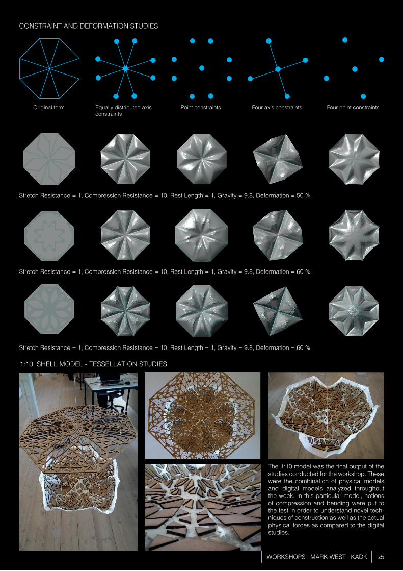
The 1:10 model was the final output of the studies conducted for the workshop. These were the combination of physical models and digital models analyzed throughout the week. In this particular model, notions of compression and bending were put to the test in order to understand novel tech-niques of construction as well as the actual physical forces as compared to the digital studies.
1:10 SHELL MODEL - TESSELLATION STUDIES
CONSTRAINT AND DEFORMATION STUDIES
Original form Equally distributed axisconstraints
Point constraints Four axis constraints Four point constraints
Stretch Resistance = 1, Compression Resistance = 10, Rest Length = 1, Gravity = 9.8, Deformation = 50 %
Stretch Resistance = 1, Compression Resistance = 10, Rest Length = 1, Gravity = 9.8, Deformation = 60 %
Stretch Resistance = 1, Compression Resistance = 10, Rest Length = 1, Gravity = 9.8, Deformation = 60 %
26
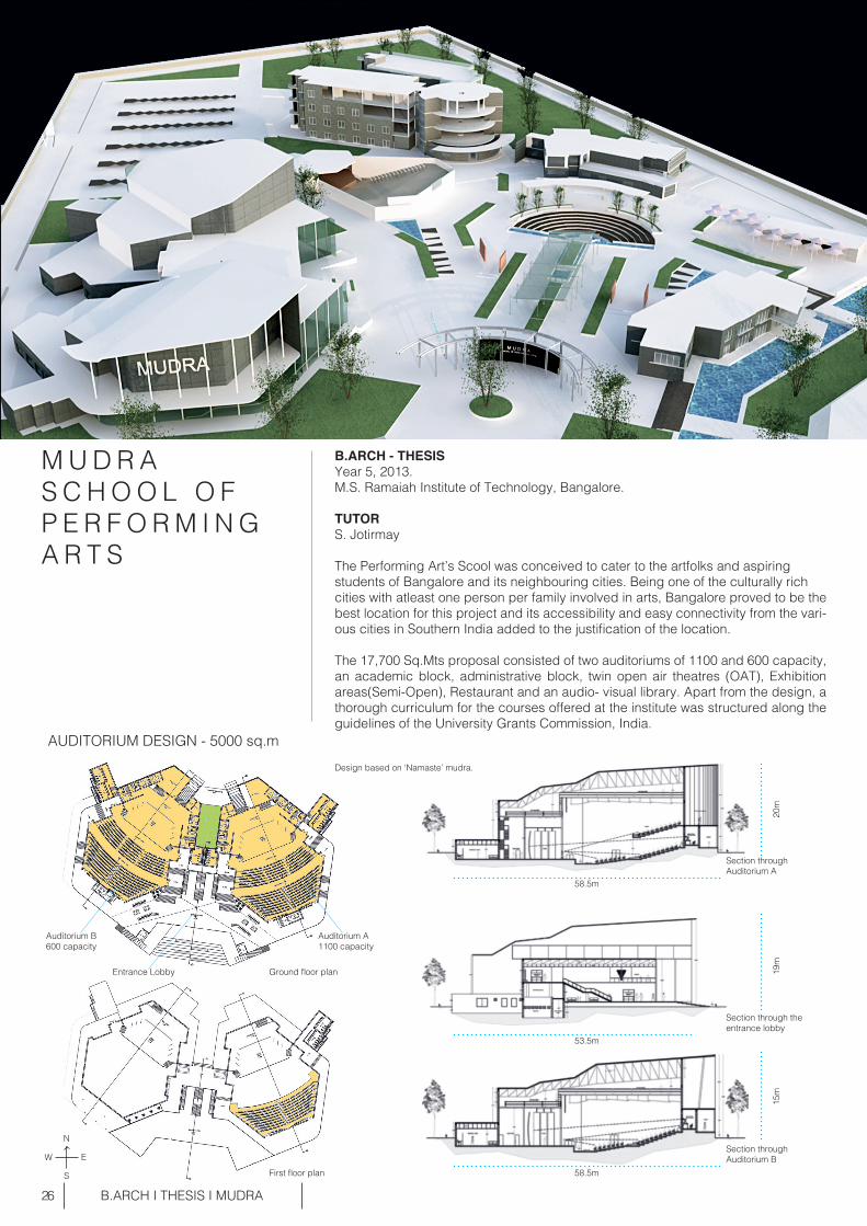
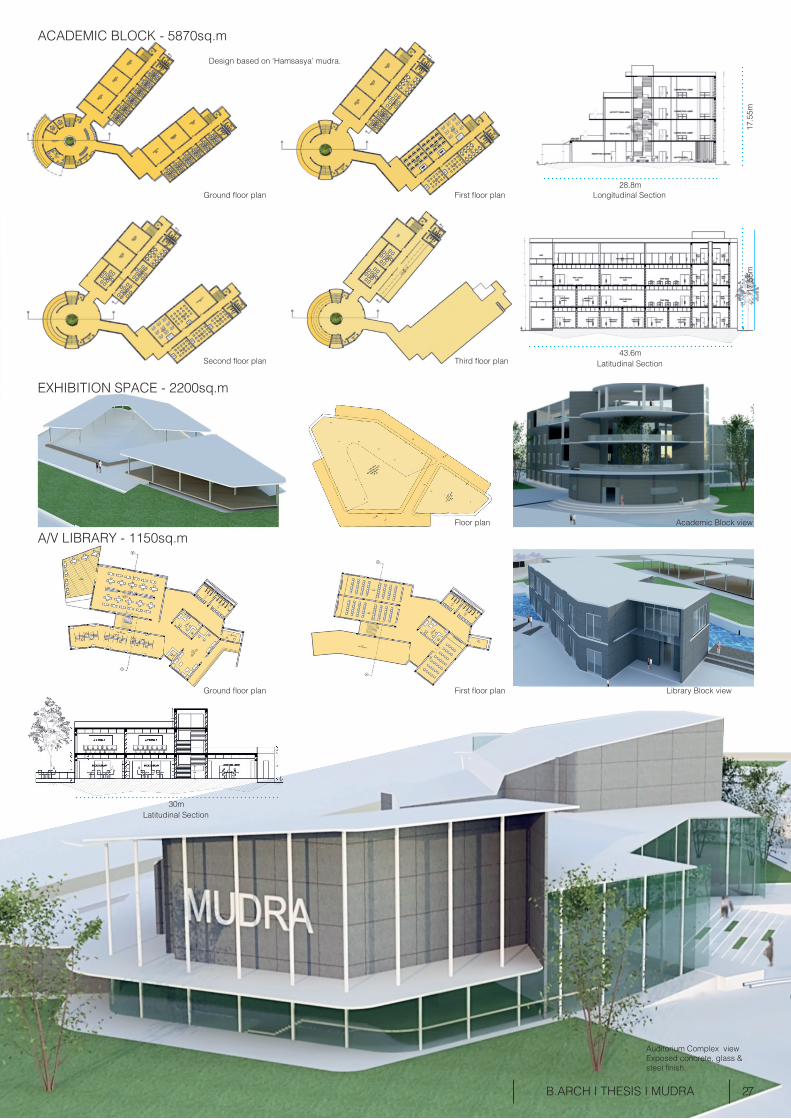
M U D R A S C H O O L O F P E R F O R M I N GA R T S
B.ARCH - THESISYear 5, 2013. M.S. Ramaiah Institute of Technology, Bangalore.
TUTORS. Jotirmay
The Performing Art’s Scool was conceived to cater to the artfolks and aspiring students of Bangalore and its neighbouring cities. Being one of the culturally rich cities with atleast one person per family involved in arts, Bangalore proved to be the best location for this project and its accessibility and easy connectivity from the vari-ous cities in Southern India added to the justification of the location.
The 17,700 Sq.Mts proposal consisted of two auditoriums of 1100 and 600 capacity, an academic block, administrative block, twin open air theatres (OAT), Exhibition areas(Semi-Open), Restaurant and an audio- visual library. Apart from the design, a thorough curriculum for the courses offered at the institute was structured along the guidelines of the University Grants Commission, India.
B.ARCH I THESIS I MUDRA
AUDITORIUM DESIGN - 5000 sq.m
Ground floor plan
20m
58.5m
58.5m
15m
19m
Entrance Lobby
Auditorium A1100 capacity
Design based on ‘Namaste’ mudra.
Auditorium B600 capacity
Section through the entrance lobby
Section throughAuditorium A
Section through Auditorium B
First floor plan
53.5m
N
S
EW
27 B.ARCH I THESIS I MUDRA
Design based on ‘Hamsasya’ mudra.
ACADEMIC BLOCK - 5870sq.m
EXHIBITION SPACE - 2200sq.m
A/V LIBRARY - 1150sq.m
Ground floor plan
Ground floor plan First floor plan Library Block view
Floor plan Academic Block view
Second floor plan Third floor plan
First floor plan Longitudinal Section
Latitudinal Section
17.5
5m
28.8m
43.6m
17.5
5m
Auditorium Complex viewExposed concrete, glass &steel finish.
Latitudinal Section30m
28
KSRTC TERMINAL :13,012 sq.mBMTC TERMINAL : 1,373 sq.m
B.ARCH I TRANSPORT HUB DESIGN
U R B A N T R A N S P O R TH U B
TRANSPORT HUB DESIGN FOR YESHWANTPUR (SUBURB OF BANGALORE)
B.ARCH Year 4, 2012
This Urban scale project at Yeshwantpur was designed to make better the transport facilities at the suburb. Known to have many industries and institutes, Yeshwantpur receives daily travellers form the neighbouring cities and near by villages with the only main mode of transport being the railways. Therefore it became crucial to con-ceive a bus transport hub at this node.
The hub was designed as 3 radiaitng sectors originating from the south west corner of the site, consisting of a shopping mall, BMTC (Bangalore Metropolitan Transport Corporation) serving locally and KSRTC ( Karnataka State Road Transport Corpora-tion) serving different cities, along with lodging and restaurant facilities at the same terminal.Two key problems addressed while designing the hub were segregating the BMTC and KSRTC bus circulation. And tackling the entry and exit of private vehicles, taxis and pedestrians so that they do not interfere with the circulation of the buses.
TERMINAL HUB SITE PLAN
SITE AREA : 61,158 sq.mBUILT AREA : 31,256 sq.mFLOOR AREA RATIO ACHIEVED : 0.51
Transport Hub view
KSRTC Terminal View
KSRTC Terminal
Bus Depot
Lodging &Restaurant
BMTC Terminal
Shopping Mall
KSRTC Entry
BMTC Entry
Site Location
BMTC Bus CirculationKSRTC Bus Circulation
N
S
EW
29 B.ARCH I TRANSPORT HUB DESIGN
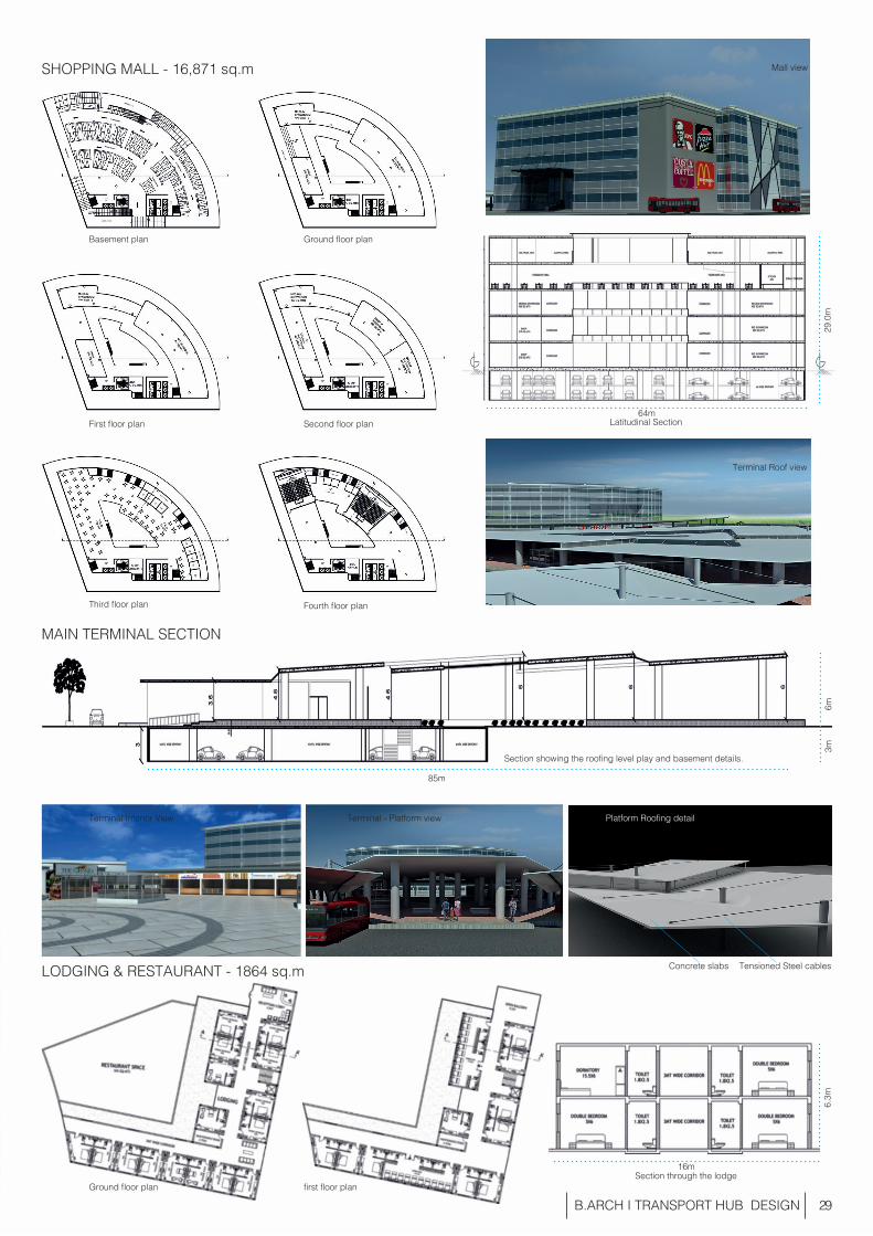
MAIN TERMINAL SECTION
SHOPPING MALL - 16,871 sq.m
Ground floor plan
first floor planSection through the lodge
Basement plan
Ground floor plan
Second floor plan
Fourth floor plan
First floor plan
Third floor plan
LODGING & RESTAURANT - 1864 sq.m
Section showing the roofing level play and basement details.
Latitudinal Section
Mall view
Terminal Roof view
64m
85m
Terminal Interior View Terminal - Platform view Platform Roofing detail
Concrete slabs Tensioned Steel cables
29.0
m6m
3m6.
3m
16m


P R O F E S S I O N A L
32
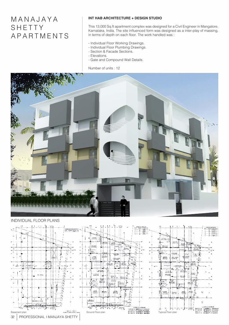
M A N A J A Y A S H E T T YA P A R T M E N T S
INT HAB ARCHITECTURE + DESIGN STUDIO
This 13,000 Sq.ft apartment complex was designed for a Civil Engineer in Mangalore, Karnataka, India. The site influenced form was designed as a inter-play of massing, in terms of depth on each floor. The work handled was :
- Individual Floor Working Drawings.- Individual Floor Plumbing Drawings.- Section & Facade Sections.- Elevations.- Gate and Compound Wall Details.
Number of units : 12
PROFESSIONAL I MANJAYA SHETTY
INDIVIDUAL FLOOR PLANS
Basement plan Ground Floor plan Typical Floor plan
N
S
EW
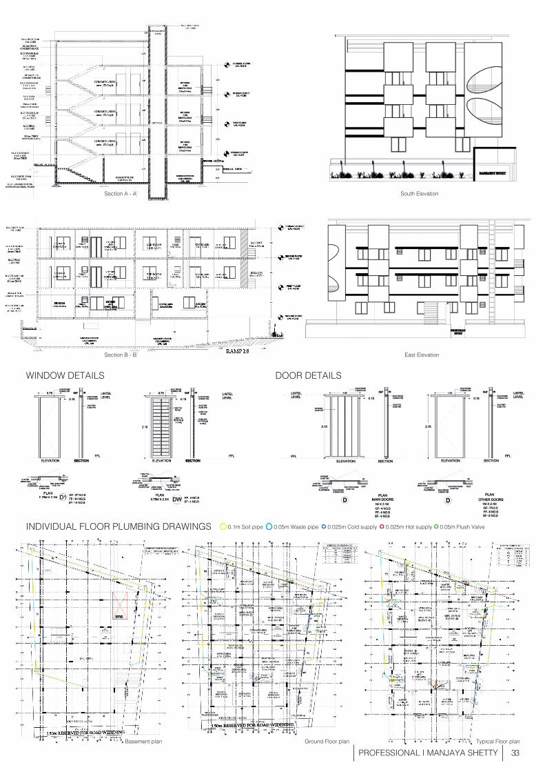
33 PROFESSIONAL I MANJAYA SHETTY
INDIVIDUAL FLOOR PLUMBING DRAWINGS
WINDOW DETAILS DOOR DETAILS
Basement plan Ground Floor plan
0.1m Soil pipe 0.05m Waste pipe 0.025m Cold supply 0.025m Hot supply 0.05m Flush Valve
Typical Floor plan
Section A - A’
Section B - B’ East Elevation
South Elevation
34
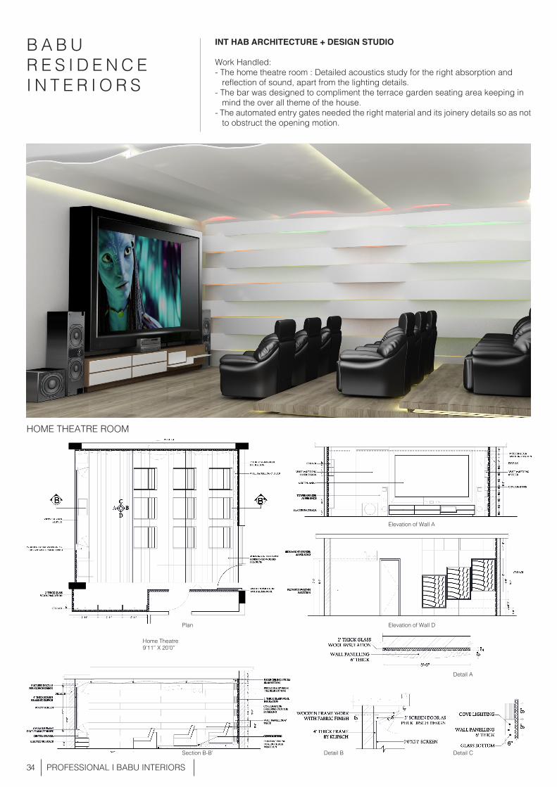
B A B U R E S I D E N C E I N T E R I O R S
INT HAB ARCHITECTURE + DESIGN STUDIO
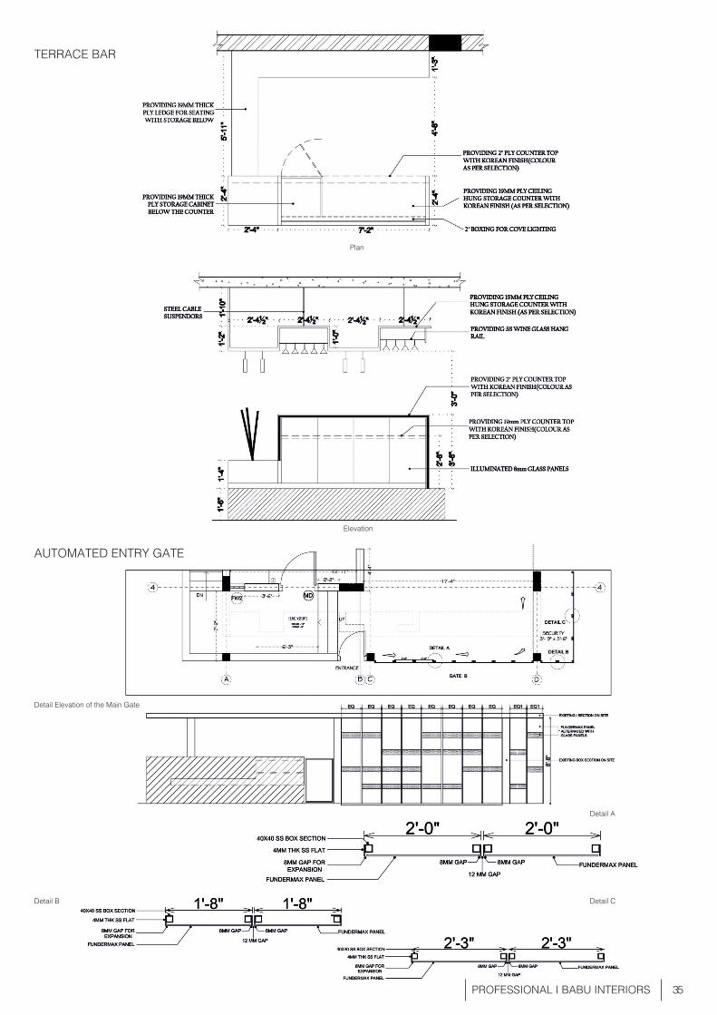
Work Handled: - The home theatre room : Detailed acoustics study for the right absorption and reflection of sound, apart from the lighting details. - The bar was designed to compliment the terrace garden seating area keeping in mind the over all theme of the house. - The automated entry gates needed the right material and its joinery details so as not to obstruct the opening motion.
PROFESSIONAL I BABU INTERIORS
HOME THEATRE ROOM
Plan
Home Theatre9’11” X 20’0”
Section B-B’ Detail B Detail C
Detail A
Elevation of Wall A
Elevation of Wall D
35 PROFESSIONAL I BABU INTERIORS
TERRACE BAR
AUTOMATED ENTRY GATE
Plan
Elevation
Detail Elevation of the Main Gate
Detail A
Detail CDetail B
36
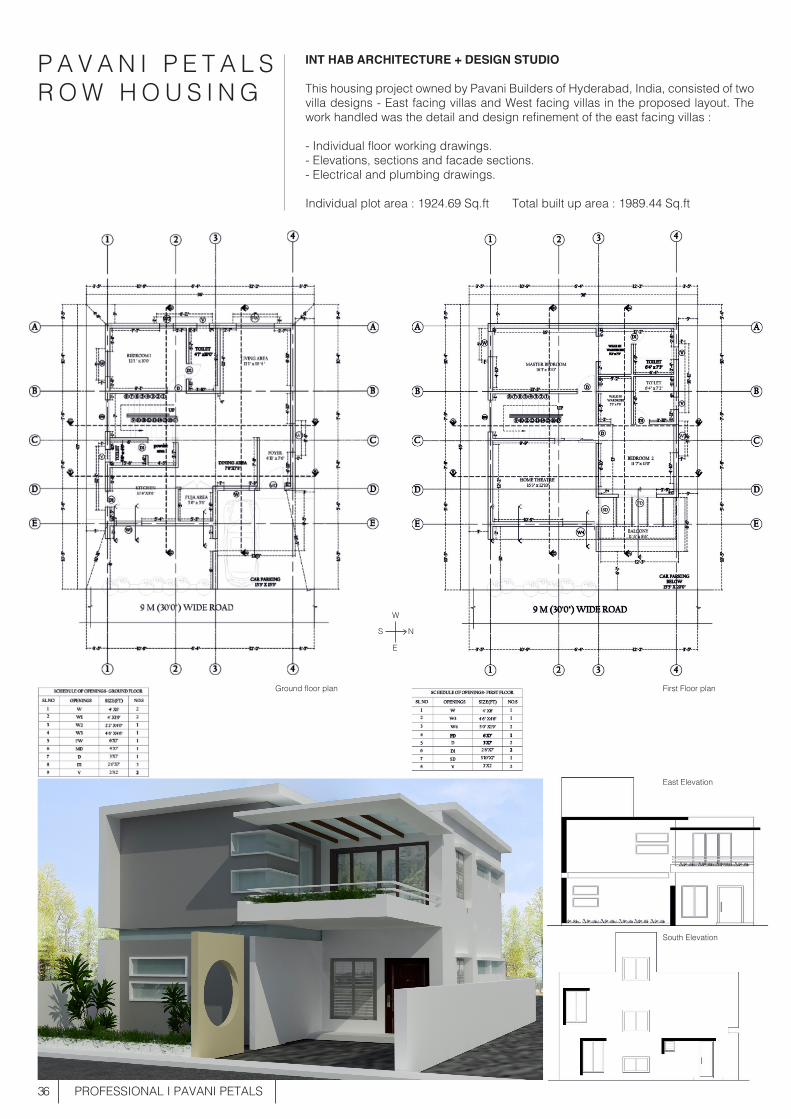
P A V A N I P E T A L SR O W H O U S I N G
INT HAB ARCHITECTURE + DESIGN STUDIO
This housing project owned by Pavani Builders of Hyderabad, India, consisted of two villa designs - East facing villas and West facing villas in the proposed layout. The work handled was the detail and design refinement of the east facing villas :
- Individual floor working drawings.- Elevations, sections and facade sections.- Electrical and plumbing drawings.
Individual plot area : 1924.69 Sq.ft Total built up area : 1989.44 Sq.ft
PROFESSIONAL I PAVANI PETALS
Ground floor plan First Floor plan
East Elevation
South Elevation
NS
E
W
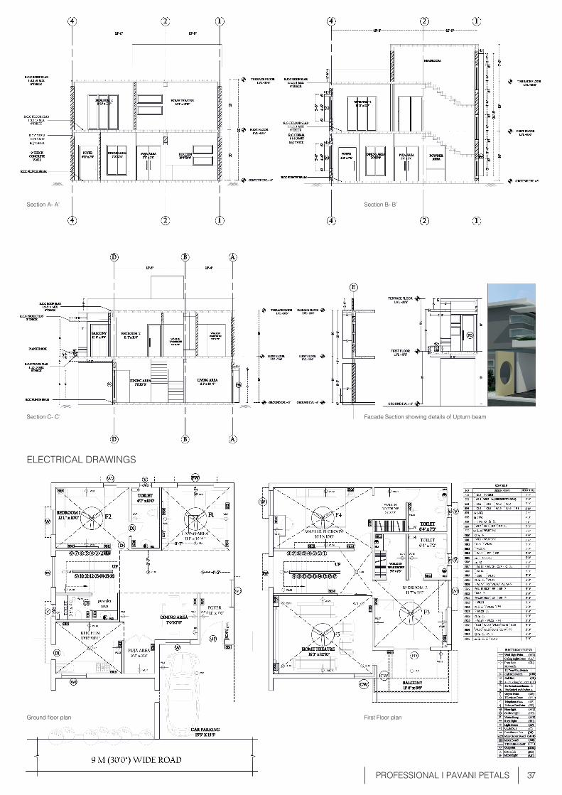
37 PROFESSIONAL I PAVANI PETALS
Section A- A’ Section B- B’
Section C- C’ Facade Section showing details of Upturn beam
ELECTRICAL DRAWINGS
Ground floor plan First Floor plan
38
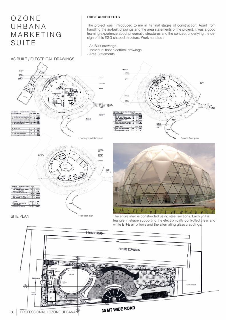
O Z O N E U R B A N AM A R K E T I N G S U I T E
CUBE ARCHITECTS
The project was introduced to me in its final stages of construction. Apart from handling the as-built drawings and the area statements of the project, it was a good learning experience about pneumatic structures and the concept underlying the de-sign of this EGG shaped structure. Work handled :
- As-Built drawings.- Individual floor electrical drawings.- Area Statements.
PROFESSIONAL I OZONE URBANA
The entire shell is constructed using steel sections. Each unit a triangle in shape supporting the electronically controlled clear and white ETFE air pillows and the alternating glass claddings.
Lower ground floor plan
First floor plan
Ground floor plan
AS BUILT / ELECTRICAL DRAWINGS
SITE PLAN
39 PROFESSIONAL I OZONE URBANA
South Elevation
West Elevation
East Elevation
North Elevation
LATITUDINAL SECTION
N
S
EW
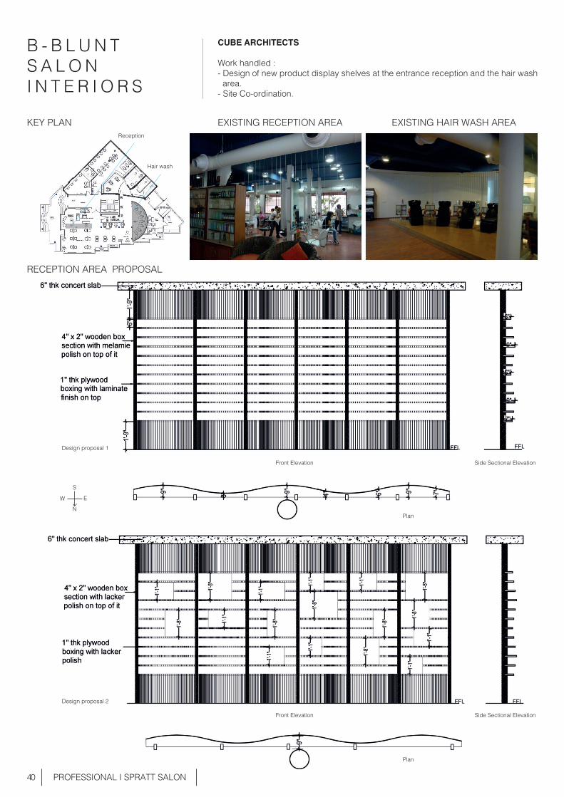
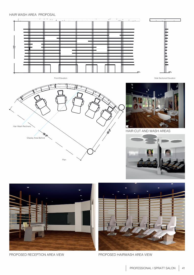
40 PROFESSIONAL I SPRATT SALON
B - B L U N T S A L O NI N T E R I O R S
CUBE ARCHITECTS
Work handled : - Design of new product display shelves at the entrance reception and the hair wash area. - Site Co-ordination.
RECEPTION AREA PROPOSAL
EXISTING RECEPTION AREAKEY PLAN EXISTING HAIR WASH AREA
Design proposal 1
Plan
Side Sectional Elevation
Side Sectional Elevation
Front Elevation
Reception
Hair wash
Front Elevation
Plan
Design proposal 2
41 PROFESSIONAL I SPRATT SALON
PROPOSED RECEPTION AREA VIEW
HAIR CUT AND WASH AREAS
PROPOSED HAIRWASH AREA VIEW
HAIR WASH AREA PROPOSAL
Side Sectional ElevationFront Elevation
Hair Wash Recliners
Display Area Behind
Plan

42 STREET PHOTOGRAPHY I 2013 - 15
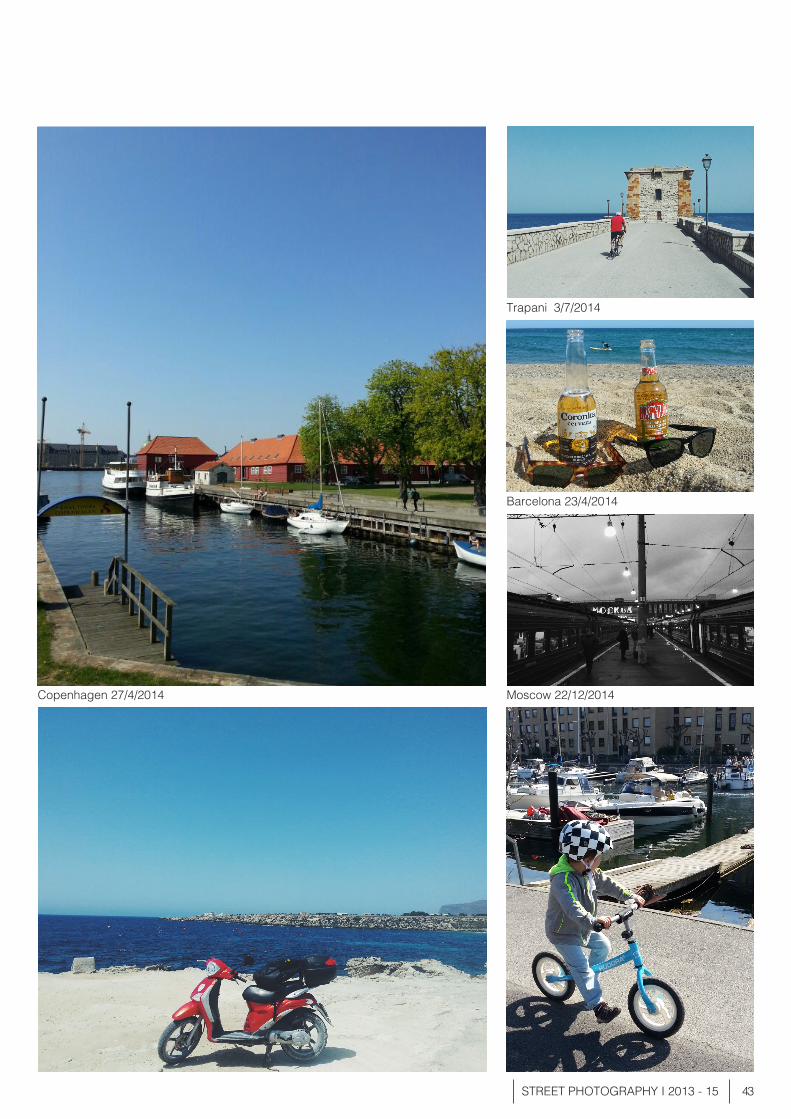
S T R E E TP H O T O G R A P H Y LONDON - COPENHAGEN - BARCELONA - SICILY 2014 - 15.
Camden Stable Market - 25/1/2015
Camden Market - 25/1/2015
South Acton - 6/2/2015
Portobello Road 15/7/2014
43STREET PHOTOGRAPHY I 2013 - 15
Copenhagen 27/4/2014 Moscow 22/12/2014
Barcelona 23/4/2014
Trapani 3/7/2014