Embed Size (px)
Citation preview
Power LineAmpacity
SystemTheory, Modeling, and Applications
Anjan K. Deb, Ph.D., P.E.Electrotech Consultant
Boca Raton London New York Washington, D.C.CRC Press
CRC PressTaylor & Francis Group6000 Broken Sound Parkway NW, Suite 300Boca Raton, FL 33487-2742
© 2000 by Taylor & Francis Group, LLCCRC Press is an imprint of Taylor & Francis Group, an Informa business
No claim to original U.S. Government works
Printed on acid-free paperVersion Date: 20161206
International Standard Book Number-13: 978-0-8493-1306-6 (Hardback)
This book contains information obtained from authentic and highly regarded sources. Reasonable efforts have been made to publish reliable data and information, but the author and publisher cannot assume responsibility for the validity of all materials or the consequences of their use. The authors and publishers have attempted to trace the copyright holders of all material reproduced in this publication and apologize to copyright holders if permission to publish in this form has not been obtained. If any copyright material has not been acknowledged please write and let us know so we may rectify in any future reprint.
Except as permitted under U.S. Copyright Law, no part of this book may be reprinted, reproduced, transmitted, or utilized in any form by any electronic, mechanical, or other means, now known or hereafter invented, including photocopying, microfilming, and recording, or in any information storage or retrieval system, without written permission from the publishers.
For permission to photocopy or use material electronically from this work, please access www.copyright.com (http://www.copyright.com/) or contact the Copyright Clearance Center, Inc. (CCC), 222 Rosewood Drive, Danvers, MA 01923, 978-750-8400. CCC is a not-for-profit organization that provides licenses and registration for a variety of users. For organizations that have been granted a photocopy license by the CCC, a separate system of payment has been arranged.
Trademark Notice: Product or corporate names may be trademarks or registered trademarks, and are used only for identification and explanation without intent to infringe.
Library of Congress Cataloging‑in‑Publication Data
Deb, Anjan K.Powerline ampacity system : theory, modeling, and applications / Anjan K. Deb.
p. cm.Includes bibliographical references and index. ISBN 0-8493-1306-61. Powerline ampacity--Mathematical models. 2. Electric cables--Evaluation. 3. Electric lines--Evaluation--Mathematical models. 4.
Electric power systems--Load dispatching. 5. Electric currents--Measurement--Mathematics. 6. Amperes. I. Title.
TK3307 .D35 2000621.319--dc21 00-036093
Visit the Taylor & Francis Web site athttp://www.taylorandfrancis.com
and the CRC Press Web site athttp://www.crcpress.com

Dedication
This book is dedicated to my wife Meeta and my family and friends
1306/fm/frame Page 10 Saturday, May 27, 2000 4:36 PM
About the Author
Dr. Anjan K. Deb is a registered professional electrical engineer in the state ofCalifornia, and is a principal in ELECTROTECH Consultant, a transmission linesoftware and consulting company that he started in 1990. He has 20 years’ experiencein high-voltage power transmission lines, substation automation, and electric powersystems. He has authored or co-authored more than 20 research publications in thearea of transmission line conductor thermal ratings, and has been awarded a U.S.patent for the invention of the LINEAMPS™ program.
Dr. Deb works as a consultant for electric power companies in all regions of theworld, offering seminars and custom software solutions for increasing transmissionline capacity by dynamic thermal ratings. As stated in this book, the LINEAMPSsoftware developed by the author is used in several countries.
After receiving a bachelor’s degree in electrical engineering from MACT India,Dr. Deb began his transmission line engineering career at EMC India, where heworked on the research and development of conductors and line hardware. He wentto Algiers to work for the National Electrical and Electronics Company, where hedesigned and manufactured high-voltage substations. While working in Algeria, hereceived a French government scholarship to study Electrotechnique at the Conser-vatoire National des Arts et Métiers, Paris, France, where he received the equivalentof a master’s degree in electrical engineering. He then received training at theElectricité de France (EDF) Research Center at Paris. EDF is the national electricpower supply company of France. At EDF, Dr. Deb performed theoretical andexperimental research on the heating of conductors and transmission line ampacity.
Dr. Deb came to the U.S. and began working for Pacific Gas & Electric (PG&E),San Francisco, where he developed and successfully implemented a real-time line-rating system for PG&E. While working at PG&E, he joined a doctoral degreeprogram at the Columbia Pacific University, and earned a Ph.D. after completing allcourses and preparing a doctoral dissertation on the subject of transmission lineampacity.
In addition to solving transmission line electrical and mechanical problems, Dr.Deb is interested in adaptive forecasting, energy management and developing intel-ligent computer applications for power. He is presently working on projects relatedto intelligent software development by the application of artificial intelligence, expertsystems, object-oriented modeling, fuzzy sets, and neural networks. He also main-tains the LINEAMPS website for interaction with program users, and for reportingnew developments. He can be reached by e-mail at [email protected], and on the Webat http://www.lineamps.com.
1306/fm/frame Page 5 Tuesday, May 30, 2000 10:27 AM
Preface
It is my great pleasure to present a book on transmission line ampacity. While thereare several books devoted to transmission line voltage, there are few books that focuson line currents, computer modeling of line ampacity with power system applica-tions, and the environmental impact of high currents. A unique contribution of thisbook is the development of a complete theory for the calculation of transmissionline ampacity suitable for steady state operation and dynamic and transient condi-tions. To bring this theory into practice I have developed an object-model of the lineampacity system and implemented a declarative style of programming by rules. Theend product is a state-of-the-art, user-friendly windows program with a good graph-ical user interface that can be used easily in all geographic regions.
As we enter the 21st century we shall have to develop new methods to maximizethe capacity of existing transmission and distribution facilities. The power systemmay have to be operated more closely to generation stability limits for better utili-zation of existing facilities. Adding new lines will become more difficult as publicawareness of environmental protection and land use increases.
To keep pace with increasing electric energy usage in the next millennium, newlines will be required for more efficient electricity transmission and distribution.Hopefully, with the help of material presented in this book, the transmission lineengineer will make better decisions regarding the choice of conductors, environmen-tal impact, system operation, and cost optimization.
This book is primarily for practicing electric power company engineers andconsultants who are responsible for the planning, operations, design, construction,and costing of overhead powerlines. It is also a useful source of reference for variousgovernment authorities, electricity regulators, and electric energy policy makers whowant to get a firm grip on technical issues concerning the movement of electricenergy from one location to another, environmental concerns, and up-to-date knowl-edge of existing and future transmission line technologies.
Academicians and students will find material covering theoretical concepts ofconductor thermal modeling, the analysis of conductor ampacity, powerline EMFdeveloped from Maxwell’s equations and Ampere’s law, power flow with variableline ratings, stability analysis, power electronic devices, and flexible AC transmis-sion. These will complement the existing large number of excellent textbooks onelectric power systems.
This book has been developed from more than 20 years of my experience inworking with various electric power companies in Asia, Africa, Europe, and NorthAmerica. I am particularly grateful to Electricité de France, Paris, for the variousinteractions with the members of the Departement Etudes et Recherche since 1978,where I initiated research on the heating of conductors. Pacific Gas & ElectricCompany, San Ramon, California, offered me an excellent environment for research
1306/fm/frame Page 3 Saturday, May 27, 2000 4:36 PM
and development when I worked as a consultant on transmission line dynamicthermal ratings.
Thanks are due to several users of the LINEAMPS program, includingTransPower, New Zealand; Hydro Quebec, Canada; and Korea Electric Power Com-pany for their valuable feedback and support which has enabled me to enhance thecomputer program. The kind technical support offered by Mr. Graham of Intellicorp,California, during the development of the LINEAMPS program is gratefullyacknowledged.
Thanks are due to Dr. Peter Pick, Dean, and Dr. John Heldt, Mentor, of ColumbiaPacific University, California, for their guidance while I prepared a doctoral disser-tation, and for their continued encouragement to write this book. I thank Ms.Genevieve Gauthier, Research Engineer, Institute de Recherche Hydro Quebec,Canada, for going through the initial manuscript and kindly pointing out errors andomissions. Last, but not the least, I am grateful to Professor R. Bonnefille, Universityof Paris VI, and Professor J. F. Rialland for their lectures and teachings on Elec-trotechnique at the Conservatoire National des Arts et Métiers, Paris, France.
As in most modern electrical engineering books, SI (System International) unitsare used consistently throughout. Complex numbers are denoted by an upperscore,for example, a complex current I∠θ = I·ejθ is represented by , and a vector isdenoted by an upper arrow like .*
The LINEAMPS computer program described in this book is a commercialsoftware program available from:
ELECTROTECH Consultant4221 Minstrell LaneFairfax, VA 22033, USA(703) 322-8345
For additional details of the program and to obtain new information concerningrecent developments on high currents and transmission line ampacity, readers mayvisit LINEAMPS on the Web at http://www.lineamps.com.
Anjan K. Deb, Ph.D.
* I have followed the same notation used by Gayle F. Miner in Lines and Electromagnetic Fields forEngineers, Oxford University Press, New York, 1996.
IrH
1306/fm/frame Page 4 Saturday, May 27, 2000 4:36 PM
Contents
Chapter 1
Introduction
........................................................................................11.1 Organization of Book and Chapter Description ..................................11.2 Introducing the Powerline Ampacity System ......................................31.3 Electric Power System Overview.........................................................3
1.3.1 Transmission Grid .................................................................31.3.2 Overhead Transmission Line.................................................41.3.3 High-Voltage Substation........................................................81.3.4 Energy Control Center...........................................................9
1.4 Factors Affecting Transmission Capacity and Remedial Measures.............................................................................11
1.5 New Developments For Transmission Capacity Enhancement .........121.6 Dynamic Line Rating Cost–Benefit Analysis ....................................121.7 Chapter Summary ...............................................................................12
Chapter 2
Line Rating Methods
.......................................................................152.1 Historical Backround..........................................................................15
2.1.1 Early Works on Conductor Thermal Rating .......................152.1.2 IEEE and Cigré Standards...................................................152.1.3 Utility Practice .....................................................................15
2.2 Line Rating Methods ..........................................................................162.2.1 Defining the Line Ampacity Problem .................................162.2.2 Static and Dynamic Line Ratings .......................................172.2.3 Weather-Dependent Systems ...............................................182.2.4 Online Temperature Monitoring System.............................192.2.5 Online Tension Monitoring System ....................................212.2.6 Sag-Monitoring System.......................................................222.2.7 Distributed Temperature Sensor System .............................232.2.8 Object-Oriented Modeling and Expert Line
Rating System......................................................................252.3 Chapter Summary ...............................................................................26
Chapter 3
Theory of Transmission Line Ampacity
........................................273.1 Introduction.........................................................................................273.2 Conductor Thermal Modeling ............................................................28
3.2.1 General Heat Equation ........................................................283.2.2 Differential Equation of Conductor Temperature ...............293.2.3 Steady-State Ampacity ........................................................293.2.4 Dynamic Ampacity ..............................................................363.2.5 Transient Ampacity..............................................................44
1306/fm/frame Page 7 Tuesday, May 30, 2000 10:27 AM
3.2.6 Radial Conductor Temperature............................................473.3 Chapter Summary ...............................................................................49Appendix 3 AC Resistance of ACSR ..........................................................51
Chapter 4
Experimental Verification of Transmission Line Ampacity
.........614.1 Introduction.........................................................................................614.2 Wind Tunnel Experiments ..................................................................614.3 Experiment in Outdoor Test Span......................................................634.4 Comparison of LINEAMPS with IEEE and Cigré............................66
4.4.1 Steady-State Ampacity ........................................................664.4.2 Dynamic Ampacity ..............................................................71
4.5 Measurement of Transmission Line Conductor Temperature ...........714.6 Chapter Summary ...............................................................................72
Chapter 5
Elevated Temperature Effects
.........................................................735.1 Introduction.........................................................................................73
5.1.1 Existing Programs................................................................745.2 Transmission Line Sag and Tension — A
Probabilistic Approach .......................................................................745.2.1 The Transmission Line Sag–Tension Problem ...................755.2.2 Methodology........................................................................755.2.3 Computer Programs.............................................................77
5.3 Change of State Equation...................................................................785.3.1 Results..................................................................................795.3.2 Conductor Stress/Strain Relationship..................................80
5.4 Permanent Elongation of Conductor..................................................805.4.1 Geometric Settlement ..........................................................815.4.2 Metallurgical Creep .............................................................815.4.3 Recursive Estimation of Permanent Elongation .................82
5.5 Loss of Strength..................................................................................835.5.1 Percentile Method................................................................835.5.2 Recursive Estimation of Loss of Strength ..........................84
5.6 Chapter Summary ...............................................................................84Appendix 5 Sag and Tension Calculations ..............................................87
Chapter 6
Transmission Line Electric and Magnetic Fields
.........................936.1 Introduction.........................................................................................936.2 Transmission Line Magnetic Field.....................................................93
6.2.1 The Magnetic Field of a Conductor....................................946.2.2 The Magnetic Field of a Three-Phase Powerline ...............986.2.3 The Magnetic Field of Different Transmission
Line Geometry...................................................................1006.2.4 EMF Mitigation .................................................................102
6.3 Transmission Line Electric Field .....................................................1086.4 Chapter Summary .............................................................................113
1306/fm/frame Page 8 Tuesday, May 30, 2000 10:27 AM
Chapter 7
Weather Modeling for Forecasting Transmission Line Ampacity
.............................................................................................1157.1 Introduction.......................................................................................1157.2 Fourier Series Model ........................................................................1167.3 Real-Time Forecasting......................................................................1237.4 Artificial Neural Network Model .....................................................1277.5 Modeling by Fuzzy Sets...................................................................1327.6 Solar Radiation Model......................................................................1377.7 Chapter Summary .............................................................................139
Chapter 8
Computer Modeling
.......................................................................1438.1 Introduction .....................................................................................143
8.1.1 From Theory to Practice....................................................1438.1.2 The LINEAMPS Expert System .......................................143
8.2 Object Model of Transmission Line Ampacity System...................1448.2.1 LINEAMPS Object Model................................................1448.2.2 Transmission Line Object..................................................1458.2.3 Weather Station Object......................................................1488.2.4 Conductor Object...............................................................1508.2.5 Cartograph Object..............................................................152
8.3 Expert System Design ......................................................................1548.3.1 Goal-Oriented Programming .............................................1558.3.2 Expert System Rules .........................................................157
8.4 Program Description.........................................................................1598.4.1 LINEAMPS Windows .......................................................1598.4.2 Modeling Transmission Line and Environment................1598.4.3 LINEAMPS Control Panel ................................................159
8.5 Chapter Summary .............................................................................162
Chapter 9
New Methods of Increasing Transmission Capacity
..................1639.1 Introduction.......................................................................................1639.2 Advancement in Power Semiconductor Devices .............................1639.3 Flexible AC Transmission ................................................................1689.4 Chapter Summary .............................................................................181
Chapter 10
Applications
...................................................................................18310.1 Introduction.......................................................................................18310.2 Economic Operation .........................................................................183
10.2.1 Formulation of the Optimization Problem........................18410.2.2 Electricity Generation Cost Saving in Interconnected
Transmission Network.......................................................18610.3 Stability .............................................................................................190
10.3.1 Dynamic Stability ..............................................................19110.3.2 Transient Stability..............................................................193
10.4 Transmission Planning......................................................................19510.5 Long-Distance Transmission ............................................................198
1306/fm/frame Page 9 Tuesday, May 30, 2000 10:27 AM
10.6 Protection ..........................................................................................20110.7 Chapter Summary .............................................................................204
Appendix 10.1 Transmission Line Equations ....................................................205
Chapter 11
Summary, Future Plans, and Conclusion
..................................20911.1 Summary...........................................................................................20911.2 Main Contributions...........................................................................21211.3 Suggestions for Future Work............................................................21911.4 A Plan to Develop LINEAMPS for America ..................................22511.5 Conclusion ........................................................................................226
Bibliography
.........................................................................................................229
Appendices A1–A8: Conductor Data
.................................................................235
Appendix B: Wire Properties
.............................................................................243
Index
......................................................................................................................245
1306/fm/frame Page 10 Tuesday, May 30, 2000 10:27 AM
1
1
Introduction
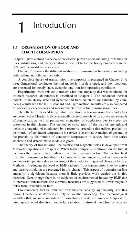
1.1 ORGANIZATION OF BOOK AND CHAPTER DESCRIPTION
Chapter 1 gives a broad overview of the electric power system including transmissionlines, substations, and energy control centers. Data for electricity production in theU.S. and the world are also given.
Chapter 2 presents the different methods of transmission line rating, includingboth on-line and off-line methods.
A complete theory of transmission line ampacity is presented in Chapter 3. Athree-dimensional conductor thermal model is first developed, and then solutionsare presented for steady-state, dynamic, and transient operating conditions.
Experimental work related to transmission line ampacity that was conducted indifferent research laboratories is described in Chapter 4. The conductor thermalmodels in the steady-state and dynamic and transient states are validated by com-paring results with the IEEE standard and Cigré method. Results are also comparedto laboratory experiments and measurements from actual transmission lines.
The effects of elevated temperature operation on transmission line conductorsare presented in Chapter 5. Experimentally derived models of loss of tensile strengthof conductors, as well as permanent elongation of conductors due to creep, arepresented in this chapter. The method of calculation of the loss of strength andinelastic elongation of conductors by a recursive procedure that utilizes probabilitydistribution of conductor temperature in service is described. A method of generatingthe probability distribution of conductor temperature in service from time seriesstochastic and deterministic models is given.
The theory of transmission line electric and magnetic fields is developed fromMaxwell's equations in Chapter 6. When higher ampacity is allowed on the line, itincreases the magnetic field radiated from the transmission line. The electric fieldfrom the transmission line does not change with line ampacity, but increases withconductor temperature due to lowering of the conductor to ground clearance by sag.Methods of reducing the level of EMF radiated from transmission lines by activeand passive shielding are presented in this chapter. This aspect of transmission lineampacity is significant because there is little previous work carried out in thisdirection. Even though there is no evidence of environmental impact by EMF dueto increased transmission line currents, measures are suggested to lower magneticfields from transmission lines.
Environmental factors influence transmission capacity significantly. For thisreason Chapter 7 is devoted entirely to weather modeling. The meteorologicalvariables that are most important to powerline capacity are ambient temperature,wind speed, wind direction, and solar radiation. Statistical modeling of weather
1306/C01/frame Page 1 Tuesday, May 30, 2000 10:43 AM
2
Powerline Ampacity System: Theory, Modeling, and Applications
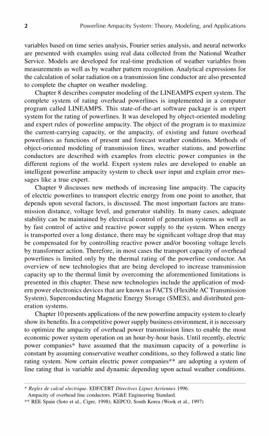
variables based on time series analysis, Fourier series analysis, and neural networksare presented with examples using real data collected from the National WeatherService. Models are developed for real-time prediction of weather variables frommeasurements as well as by weather pattern recognition. Analytical expressions forthe calculation of solar radiation on a transmission line conductor are also presentedto complete the chapter on weather modeling.
Chapter 8 describes computer modeling of the LINEAMPS expert system. Thecomplete system of rating overhead powerlines is implemented in a computerprogram called LINEAMPS. This state-of-the-art software package is an expertsystem for the rating of powerlines. It was developed by object-oriented modelingand expert rules of powerline ampacity. The object of the program is to maximizethe current-carrying capacity, or the ampacity, of existing and future overheadpowerlines as functions of present and forecast weather conditions. Methods ofobject-oriented modeling of transmission lines, weather stations, and powerlineconductors are described with examples from electric power companies in thedifferent regions of the world. Expert system rules are developed to enable anintelligent powerline ampacity system to check user input and explain error mes-sages like a true expert.
Chapter 9 discusses new methods of increasing line ampacity. The capacityof electric powerlines to transport electric energy from one point to another, thatdepends upon several factors, is discussed. The most important factors are trans-mission distance, voltage level, and generator stability. In many cases, adequatestability can be maintained by electrical control of generation systems as well asby fast control of active and reactive power supply to the system. When energyis transported over a long distance, there may be significant voltage drop that maybe compensated for by controlling reactive power and/or boosting voltage levelsby transformer action. Therefore, in most cases the transport capacity of overheadpowerlines is limited only by the thermal rating of the powerline conductor. Anoverview of new technologies that are being developed to increase transmissioncapacity up to the thermal limit by overcoming the aforementioned limitations ispresented in this chapter. These new technologies include the application of mod-ern power electronics devices that are known as FACTS (Flexible AC TransmissionSystem), Superconducting Magnetic Energy Storage (SMES), and distributed gen-eration systems.
Chapter 10 presents applications of the new powerline ampacity system to clearlyshow its benefits. In a competitive power supply business environment, it is necessaryto optimize the ampacity of overhead power transmission lines to enable the mosteconomic power system operation on an hour-by-hour basis. Until recently, electricpower companies* have assumed that the maximum capacity of a powerline isconstant by assuming conservative weather conditions, so they followed a static linerating system. Now certain electric power companies** are adopting a system ofline rating that is variable and dynamic depending upon actual weather conditions.
*
Regles de calcul electrique
. EDF/CERT
Directives Lignes Aeriennes
1996.Ampacity of overhead line conductors. PG&E Engineering Standard.
** REE Spain (Soto et al., Cigre, 1998); KEPCO, South Korea (Wook et al., 1997)
1306/C01/frame Page 2 Tuesday, May 30, 2000 10:43 AM
Introduction
3
The thermal rating of a transmission line depends upon the maximum design tem-perature of the line, and the temperature of a conductor varies as a function of linecurrent and meteorological conditions. Therefore, for the same value of maximumconductor temperature, higher line currents are possible if there are favorable mete-orological conditions. In this chapter, a system of equations for the economic oper-ation of diverse generation sources in an interconnected power system is developedthat utilizes a dynamic line rating system. The economic benefits of a dynamic linerating system are demonstrated by giving an example of an interconnected trans-mission network having a diverse mix of electricity generation sources. The chapterconcludes with a discussion of increased competition in the electric power supplyindustry in a power pool system of operations, and the important role of the powerlineampacity system presented in this book.
Chapter 11 gives a summary of main contributions made in this book, presentsfuture plans and new transmission and distribution technologies, describes the role ofIndependent System Operators (ISO) and power-pool operations from the point ofview of transmission line capacity. It provides a discussion on deregulation and howthe line ampacity system facilitates greater competition in the electric supply business.
1.2 INTRODUCING THE POWERLINE AMPACITY SYSTEM
As the demand for electricity increases, there is a need to increase electricitygeneration, transmission, and distribution capacities to match demand. While thelocation and construction of a generation facility is relatively easy, it is becomingincreasingly difficult to construct new lines. As a result, electric power authoritieseverywhere are searching for new ways to maximize the capacity of powerlines.One of the methods used to increase line capacity is dynamic thermal rating.
The object of this book is to develop a complete system of rating overheadpowerlines by presenting theory, algorithms, and a methodology for implementationin a computer program. The development of a computer program by object-orientedmodeling and expert system rules is also described in detail. The end product is easyto use and suitable for application in all geographic regions. The different methodsof increasing line ampacity by FACTS are described, and the impact of highertransmission line ampacity on electric and magnetic fields is analyzed with numericalexamples. Application of the powerline ampacity system in the economic operationof a power system is presented, and considerable cost savings are shown by thedeferment of capital investment required for the construction of new lines, and byenabling greater utilization of low-cost energy sources.
1.3 ELECTRIC POWER SYSTEM OVERVIEW
1.3.1 T
RANSMISSION
G
RID
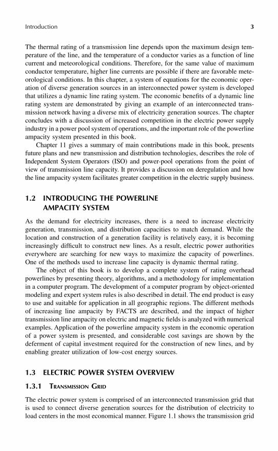
The electric power system is comprised of an interconnected transmission grid thatis used to connect diverse generation sources for the distribution of electricity toload centers in the most economical manner. Figure 1.1 shows the transmission grid
1306/C01/frame Page 3 Tuesday, May 30, 2000 10:43 AM
4
Powerline Ampacity System: Theory, Modeling, and Applications
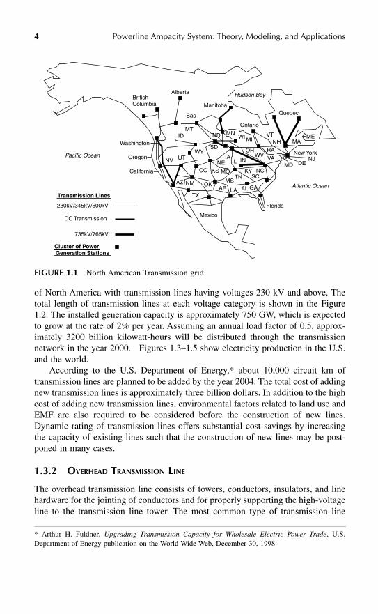
of North America with transmission lines having voltages 230 kV and above. Thetotal length of transmission lines at each voltage category is shown in the Figure1.2. The installed generation capacity is approximately 750 GW, which is expectedto grow at the rate of 2% per year. Assuming an annual load factor of 0.5, approx-imately 3200 billion
kilowatt-hours will be distributed through the transmissionnetwork in the year 2000. Figures 1.3–1.5 show electricity production in the U.S.and the world.
According to the U.S. Department of Energy,* about 10,000 circuit km oftransmission lines are planned to be added by the year 2004. The total cost of addingnew transmission lines is approximately three billion dollars. In addition to the highcost of adding new transmission lines, environmental factors related to land use andEMF are also required to be considered before the construction of new lines.Dynamic rating of transmission lines offers substantial cost savings by increasingthe capacity of existing lines such that the construction of new lines may be post-poned in many cases.
1.3.2 O
VERHEAD
T
RANSMISSION
L
INE
The overhead transmission line consists of towers, conductors, insulators, and linehardware for the jointing of conductors and for properly supporting the high-voltageline to the transmission line tower. The most common type of transmission line
FIGURE 1.1
North American Transmission grid.
* Arthur H. Fuldner,
Upgrading Transmission Capacity for Wholesale Electric Power Trade
, U.S.Department of Energy publication on the World Wide Web, December 30, 1998.
Pacific Ocean
Washington
Oregon
California
AlbertaBritishColumbia Manitoba
Sas
MTID
NV UT
CO
AZ NM OK
TX
Mexico
KS MO
NE IA
IL IN
SD OH
MI MNND
Hudson Bay
Ontario
WI
KY SC
NC
MS AR LA AL GA
Florida
Atlantic Ocean
New York NJ
DE MD
ME MA
Quebec
VT NH
RA
VA WV
TN
WY
Transmission Lines
Cluster of PowerGeneration Stations
230kV/345kV/500kV
735kV/765kV
DC Transmission
1306/C01/frame Page 4 Tuesday, May 30, 2000 10:43 AM
Introduction
5
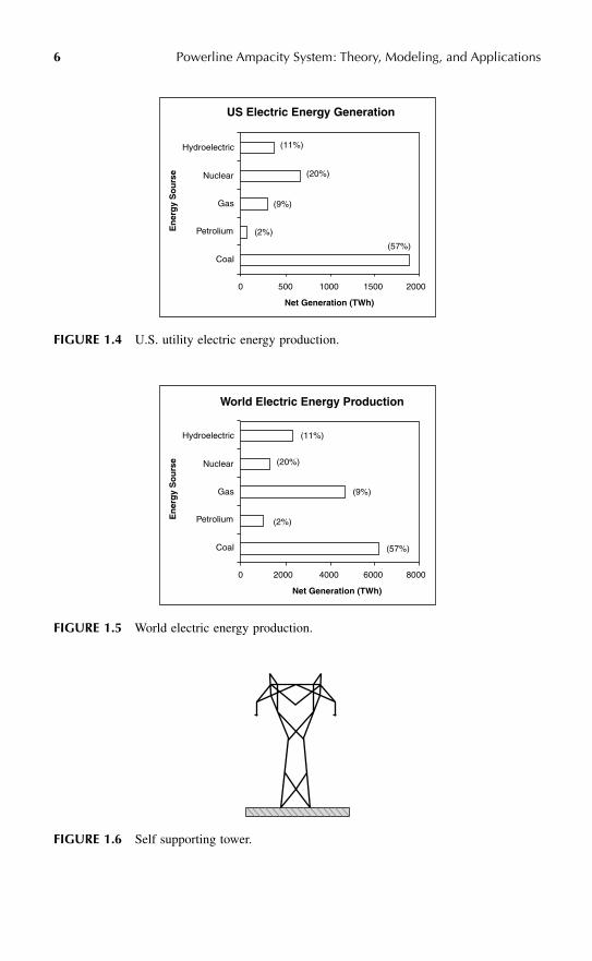
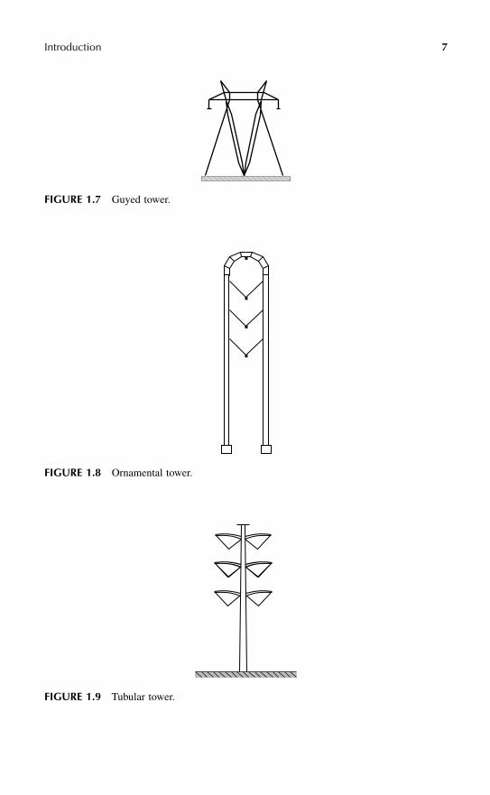
towers are self-supporting towers, and guyed and pole towers. Some typical examplesof towers are shown in Figures 1.6–1.9.
Aluminum Conductor Steel Reinforced (ACSR) is the most widely used type ofcurrent-carrying conductor. All Aluminum Conductors (AAC) are used in coastalregions for high corrosion resistance and also for applications requiring lower resis-tance, where the high strength of a steel core is not required. More recently, AllAluminum Alloy conductors have been used for their light weight and high strength-to-weight ratio, which enables longer spans with less sag. Other hybrid conductorshaving various proportions of aluminum, aluminum alloy, and steel wires are also usedfor special applications. The popular type of hybrid conductors are Aluminum Con-ductor Alloy Reinforced (ACAR) and Aluminum Alloy Conductor Steel Reinforced(AACSR). Some examples of commonly used powerline conductors according tovarious standards are given in Appendix A (Thrash, 1999; Koch, 1999; Hitachi, 1999).
FIGURE 1.2
Total transmission line circuit km in North America according to transmissionvoltage category.
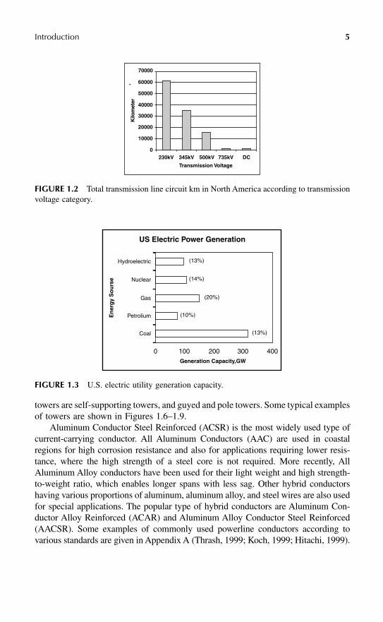
FIGURE 1.3
U.S. electric utility generation capacity.
Transmission Voltage
500kV 735kV345kV230kV DC
70000
60000
50000
40000
30000
20000
10000
0
Kilo
met
er
Hydroelectric
US Electric Power Generation
(13%)
Nuclear (14%)
Gas (20%)
Petrolium (10%)
Coal (13%)
En
erg
y S
ou
rse
0 100 200 300 400
Generation Capacity,GW
1306/C01/frame Page 5 Tuesday, May 30, 2000 10:43 AM
6
Powerline Ampacity System: Theory, Modeling, and Applications
FIGURE 1.4
U.S. utility electric energy production.
FIGURE 1.5
World electric energy production.
FIGURE 1.6
Self supporting tower.
Hydroelectric
Nuclear
Gas
Petrolium
Coal
US Electric Energy Generation
(11%)
(20%)
(9%)
(2%)
(57%)
En
erg
y S
ou
rse
0 500 1000 1500 2000
Net Generation (TWh)
Hydroelectric
Nuclear
Gas
Petrolium
Coal
World Electric Energy Production
(11%)
(20%)
(9%)
(2%)
(57%)
En
erg
y S
ou
rse
0 2000 4000 6000 8000
Net Generation (TWh)
1306/C01/frame Page 6 Tuesday, May 30, 2000 10:43 AM
Introduction
7
FIGURE 1.7
Guyed tower.
FIGURE 1.8
Ornamental tower.
FIGURE 1.9
Tubular tower.
1306/C01/frame Page 7 Tuesday, May 30, 2000 10:43 AM
8
Powerline Ampacity System: Theory, Modeling, and Applications
High-temperature conductors are used for bulk power transmission in heavilyloaded circuits where a high degree of reliability is required. Steel Supported AluminumConductor (SSAC) allows high-temperature operation with minimum sag. In the SSACconductor, the current-carrying aluminum wires are in the annealed state and do notbear any tension. The tension is borne entirely by the high-strength steel wires. In thenewer high-temperature, high-ampacity conductors, aluminum zirconium alloy wiresare used to carry high current, and Invar alloy reinforced steel wires are used for the core.
Recently, compact conductor designs have been available that offer lower lossesfor the same cross-sectional area of the conductor. Compact design is made possibleby the trapezoidal shaping of wires instead of wires having the circular cross-sectionsused in conventional ACSR conductors. For better aerodynamic performance, con-ductors are also available with concentric gaps inside the conductor which offerbetter damping of wind-induced vibrations.
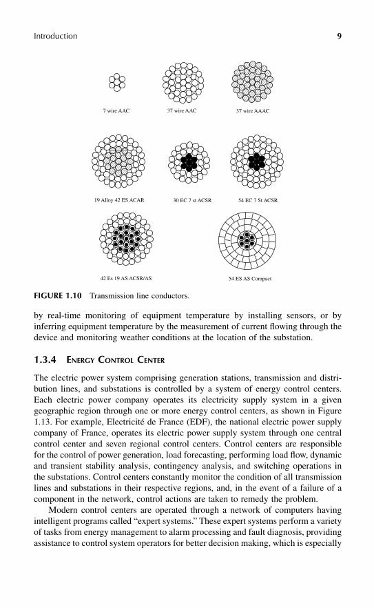
Another recent development in transmission line conductor technology is theintegration of optical fiber communication technology in the manufacture of pow-erline conductors. In an Optical Ground Wire (OPGW) system, a fiberoptic cable isplaced inside the core of the overhead ground wire. In certain transmission lineapplications, the fiberoptic cable is placed inside the core of the power conductor.Communication by fiber optics offers a noise-free system of data communication inthe electric utility environment since communication by optical fiber is unaffectedby electromagnetic disturbances. The different types of conductors are shown inFigure 1.10. Important physical properties of the different types of wires used in themanufacture of powerline conductors are given in Appendix B.
1.3.3 H
IGH
-V
OLTAGE
S
UBSTATION
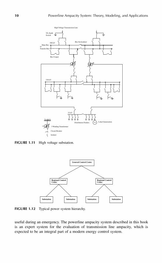
The electric substation is an important component of the electric power system. Thesubstation is a hub for receiving electricity from where electricity is distributed toload centers, as well as to other substations. Voltage transformation is carried outin the substation by transformers. A transmission substation is generally used forinterconnection with other substations where power can be rerouted by switchingaction. In a distribution substation, electricity is received by high-voltage transmis-sion lines and transformed for distribution at lower voltages. Besides transformers,there are other important devices in a substation, including bus bars, circuit breakers,interrupters, isolators, wave traps, instrument transformers for the measurement ofhigh voltage and current, inductive and capacitive reactors for the control of reactivepower flow, protective relays, metering, control and communication equipment, andother low-voltage equipment for station auxiliary power supply.
A typical layout of a high-voltage substation is shown in Figure 1.11. When adynamic line rating system is implemented in an electric utility system, it is alsoimportant to have knowledge of the current rating of all substation equipment inaddition to powerline conductor ratings. Substation switching devices are generallydesigned to withstand short circuit currents, and have sufficient continuous overloadcurrent capability. Transformer ratings, on the other hand, need to be examined moreclosely. A system of dynamic rating of substation equipment may be implemented
1306/C01/frame Page 8 Tuesday, May 30, 2000 10:43 AM
Introduction
9
by real-time monitoring of equipment temperature by installing sensors, or byinferring equipment temperature by the measurement of current flowing through thedevice and monitoring weather conditions at the location of the substation.
1.3.4 E
NERGY
C
ONTROL
C
ENTER
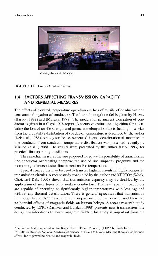
The electric power system comprising generation stations, transmission and distri-bution lines, and substations is controlled by a system of energy control centers.Each electric power company operates its electricity supply system in a givengeographic region through one or more energy control centers, as shown in Figure1.13. For example, Electricité de France (EDF), the national electric power supplycompany of France, operates its electric power supply system through one centralcontrol center and seven regional control centers. Control centers are responsiblefor the control of power generation, load forecasting, performing load flow, dynamicand transient stability analysis, contingency analysis, and switching operations inthe substations. Control centers constantly monitor the condition of all transmissionlines and substations in their respective regions, and, in the event of a failure of acomponent in the network, control actions are taken to remedy the problem.
Modern control centers are operated through a network of computers havingintelligent programs called “expert systems.” These expert systems perform a varietyof tasks from energy management to alarm processing and fault diagnosis, providingassistance to control system operators for better decision making, which is especially
FIGURE 1.10
Transmission line conductors.
7 wire AAC 37 wire AAC 37 wire AAAC
54 EC 7 St ACSR30 EC 7 st ACSR19 Alloy 42 ES ACAR
42 Es 19 AS ACSR/AS 54 ES AS Compact
1306/C01/frame Page 9 Tuesday, May 30, 2000 10:43 AM
10
Powerline Ampacity System: Theory, Modeling, and Applications
useful during an emergency. The powerline ampacity system described in this bookis an expert system for the evaluation of transmission line ampacity, which isexpected to be an integral part of a modern energy control system.
FIGURE 1.11
High voltage substation.
FIGURE 1.12
Typical power system hierarchy.
T/L EarthSwitch
Main Bus
Bus Couper
Bus Sectioalizer
Transfer BusO
500 kV
High Voltage Transmission Line
Lokal GenereationDistribution Feeders
33 kV
3 Winding Transformer
Symbols
Circuit Breaker
Isolator
230 kV
General Control Center
Regional Control Center
Regional Control Center
Substation Substation Substation Substation
1306/C01/frame Page 10 Tuesday, May 30, 2000 10:43 AM
Introduction
11
1.4 FACTORS AFFECTING TRANSMISSION CAPACITY AND REMEDIAL MEASURES
The effects of elevated temperature operation are loss of tensile of conductors andpermanent elongation of conductors. The loss of strength model is given by Harvey(Harvey, 1972) and (Morgan, 1978). The models for permanent elongation of con-ductor is given in a Cigré 1978 report. A recursive estimation algorithm for calcu-lating the loss of tensile strength and permanent elongation due to heating in servicefrom the probability distribution of conductor temperature is described by the author(Deb et al., 1985). A study for the assessment of thermal deterioration of transmissionline conductor from conductor temperature distribution was presented recently byMizuno et al. (1998). The results were presented by the author (Deb, 1993) forpractical line operating conditions.
The remedial measures that are proposed to reduce the possibility of transmissionline conductor overheating comprise the use of line ampacity programs and themonitoring of transmission line current and/or temperature.
Special conductors may be used to transfer higher currents in highly congestedtransmission circuits. A recent study conducted by the author and KEPCO* (Wook,Choi, and Deb, 1997) shows that transmission capacity may be doubled by theapplication of new types of powerline conductors. The new types of conductorsare capable of operating at significantly higher temperatures with less sag andwithout any thermal deterioration. There is general agreement that transmissionline magnetic fields** have minimum impact on the environment, and there areno harmful effects of magnetic fields on human beings. A recent research studyconducted by EPRI (Rashkes and Lordan, 1998) presents new transmission linedesign considerations to lower magnetic fields. This study is important from the
FIGURE 1.13
Energy Control Center.
* Author worked as a consultant for Korea Electric Power Company (KEPCO), South Korea.** EMF Conference. National Academy of Science, U.S.A. 1994, concluded that there are no harmfuleffects due to powerline electric and magnetic fields.
1306/C01/frame Page 11 Tuesday, May 30, 2000 10:43 AM
12
Powerline Ampacity System: Theory, Modeling, and Applications
point of view of transmission line ampacity so that future transmission lines canbe constructed with higher power transfer capability and minimum magnetic field.
1.5 NEW DEVELOPMENTS FOR TRANSMISSION CAPACITY ENHANCEMENT
There are other electrical network constraints that must be satisfied before transmis-sion lines can be operated at their maximum thermal capacities. The most importantconstraints are voltage levels and generator stability limits. New methods and devicesto improve transmission system voltage levels and generation stability limits includeFACTS (Flexible AC Transmission System) (Hingorani, 1995).
FACTS technology makes use of recent developments in modern power elec-tronics and superconductivity (Feak, 1997) to enhance transmission capacity. Arecent FACTS development is the Unified Power Flow Controller (UPFC) (Norozianet al., 1997). Another important development is the invention of a new type ofgenerator called the “Powerformer” (
MPS Review
, 1998b) that eliminates the needfor a transformer by generating electricity at high voltage at the level of transmissionsystem voltage. The new type of generator produces greater reactive power to elevategrid voltage levels, and also enhances generation stability when required. Therefore,by connecting Powerformer directly to the transmission grid, yet higher levels oftransmission capacity may be achieved. These studies show that there is considerableinterest in maximizing the capacity of existing assets. By the introduction of thesenew technologies in the electrical power system, it is now becoming possible tooperate transmission lines close to thermal ratings, when required.
1.6 DYNAMIC LINE RATING COST-BENEFIT ANALYSIS
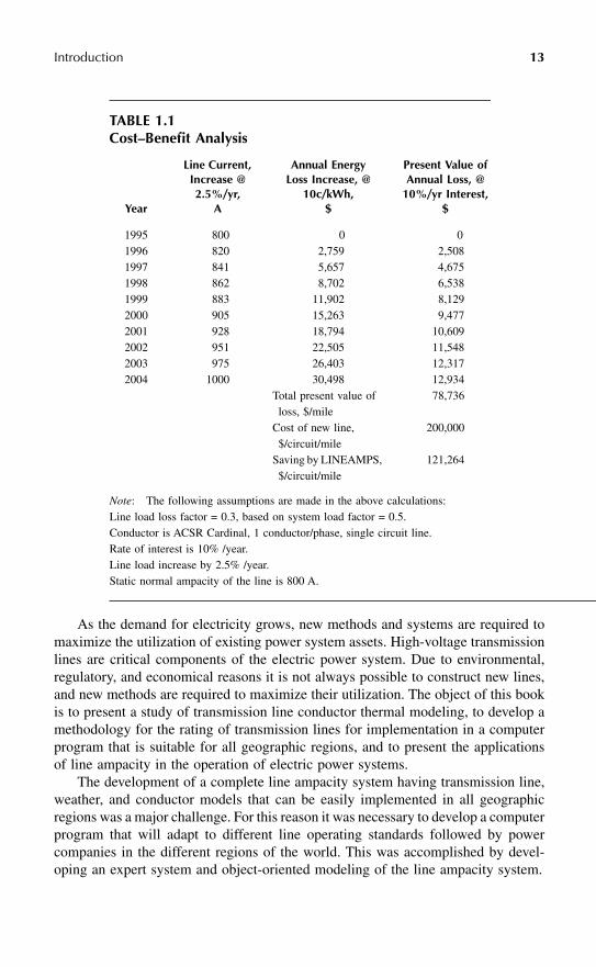
A cost benefit analysis was carried out by the cost capitalization method and theresults are presented in Table 1.1. It is assumed that line current will increase at therate of 2.5% per year. The results show that the capitalized cost of higher losses dueto the increase in line current by deferment of new line construction for a period of10 years is significantly lower than the cost of constructing a new line in the SanFrancisco Bay area.
In addition to cost savings achieved by postponing the construction of new lines,dynamic line rating systems also offer substantial operational cost savings. In Chap-ter 10, a study is presented which show 16% economy achieved by dynamic linerating by facilitating the transfer of low-cost surplus hydroelectric energy throughoverhead lines. To undertake this study, an economic load flow program was devel-oped to simulate an interconnected transmission network with diverse generationsources (Hall and Deb, 1988a; Deb, 1994; Yalcinov and Short, 1998).
1.7 CHAPTER SUMMARY
An introduction to the subject of transmission line ampacity is presented in thischapter by giving an overview of the electric power system. The significance of thestudy and the main contributions in each chapter are summarized.
1306/C01/frame Page 12 Tuesday, May 30, 2000 10:43 AM
Introduction
13
As the demand for electricity grows, new methods and systems are required tomaximize the utilization of existing power system assets. High-voltage transmissionlines are critical components of the electric power system. Due to environmental,regulatory, and economical reasons it is not always possible to construct new lines,and new methods are required to maximize their utilization. The object of this bookis to present a study of transmission line conductor thermal modeling, to develop amethodology for the rating of transmission lines for implementation in a computerprogram that is suitable for all geographic regions, and to present the applicationsof line ampacity in the operation of electric power systems.
The development of a complete line ampacity system having transmission line,weather, and conductor models that can be easily implemented in all geographicregions was a major challenge. For this reason it was necessary to develop a computerprogram that will adapt to different line operating standards followed by powercompanies in the different regions of the world. This was accomplished by devel-oping an expert system and object-oriented modeling of the line ampacity system.
TABLE 1.1Cost–Benefit Analysis
Year
Line Current, Increase @ 2.5%/yr,
A
Annual EnergyLoss Increase, @
10c/kWh, $
Present Value ofAnnual Loss, @
10%/yr Interest,$
1995 800 0 01996 820 2,759 2,5081997 841 5,657 4,6751998 862 8,702 6,5381999 883 11,902 8,1292000 905 15,263 9,4772001 928 18,794 10,6092002 951 22,505 11,5482003 975 26,403 12,3172004 1000 30,498 12,934
Total present value of loss, $/mile
78,736
Cost of new line, $/circuit/mile
200,000
Saving by LINEAMPS, $/circuit/mile
121,264
Note
: The following assumptions are made in the above calculations:Line load loss factor = 0.3, based on system load factor = 0.5.Conductor is ACSR Cardinal, 1 conductor/phase, single circuit line.Rate of interest is 10% /year.Line load increase by 2.5% /year.Static normal ampacity of the line is 800 A.
1306/C01/frame Page 13 Tuesday, May 30, 2000 10:43 AM
14
Powerline Ampacity System: Theory, Modeling, and Applications
The economic incentives for implementing a dynamic line rating system areclearly established by showing the approximately 60% cost saving by the defermentof new line construction. The factors limiting line capacity are clearly brought out,and the means to overcome these are explained.
1306/C01/frame Page 14 Tuesday, May 30, 2000 10:43 AM

References Ampère, André-Marie , 1827. Memoir on the Mathematical Theory of Electrodynamic Phenomena, Uniquely Deduced from Experience.Encyclopedia Britannica. Alexandrov et al., 1998. Overhead line designing in view of environmental constraints. Compact overhead lines. Cigré, 1998, Paris. Anand, V.P. , Deb, Anjan K. , and Mukherjee, P.K. 1984. Choice of conductors for 400kV transmission lines. Central Board of Irrigationand Power, New Delhi, India. Barkovitch, B.D. Hawk . 1996. Starting a New Course in California. IEEE Spectrum, Vol. 33, July 1996, p26. Bergen, Arthur R. , 1986. Power System Analysis, Prentice Hall. Black, W.Z. et al., 1987. Critical span analysis of overhead conductors. IEEE/PES Conference Paper Number 87 SM 560-6, SanFrancisco. Black, W.Z. and W.R. Byrd , 1983. Real-time ampacity model for overhead lines. IEEE Transactions on Power Apparatus and Systems,Vol. PAS-102, No. 7. Böhme et al., 1998. Overhead transmission lines: design aimed to reduce the permitting time. Cigre, 1998 paper Number 22/33/36-06. Bonicel, J.P. , Tatat, O. , 1998. Aerial optical cables along electrical power lines. REE, No. 3, March 1998. Booch, G. , 1993. Object Oriented Design with Applications, The Benjamin/Cummings Publishing Co. Borgard, L. , 1999. Grid voltage support at your finger tips. Portable SMES units provide Wisconsin Public Service Corporation voltage andVAR support. Transmission & Distribution, Vol. 51, No. 9, October 1999. Bousquet, Jean-Luc , Loreau, B. , Bechet, D. , and Delomel, J.C. , 1997. Un nouveau conducteur compact homogène en alliaged’aluminium pour les lignes 400 kV. REE No.10, November 1997. Buckles, W. , Hassenzahl, W.V. , 2000. Superconducting Magnetic Energy Storage. IEEE Power Engineering Review, Volume 20, Number5, p. 16–20, May 2000. Burchette, Sam N. , 1989. Helicopter maintenance on energized EHV transmission lines. Transmission & Distribution, Vol. 41, No. 11,November 1989. CEA Report, 1980. Development for an accurate model of ACSR conductor for calculating sags at high temperatures-Part II: Sag-TensionProgram-STESS. Cibulka, L. , Steeley, W.J. , and Deb, A.K. , 1992. Le système ATLAS de PG&E d’évaluation dynamique de la capacité thermique d’uneligne de transport. Conférence Internationale des Grands Réseaux Électriques, Paris. Cigré , 1999. The use of weather predictions for transmission line thermal ratings. Electra No. 186, October 1999. Cigré , 1999. The thermal behaviour of overhead conductors. Section 4. Mathematical model for evaluation of conductor temperature inthe adiabatic state. Working Group 22.12. Cigré , 1997. The thermal behaviour of overhead conductors. Section 3. Report prepared by Cigré Working Group 22.12. Cigré , 1992. Section 1 and 2, Electra # 144. Cigré , 1978. Permanent elongation of conductors predictor equations and evaluation methods. Cigré report # WG-05-22-78. Cigré Panel Session, 1998. Impact of Deregulation on Operation and Planning of Large Power Systems. Cigré Regional Meeting, 1996. Power Pool Arrangements and Economic Load Dispatch. New Delhi, India, 13–14 October 1996. Cigré Symposium, 1991. Compacting Overhead Transmission Lines, Leningrad, USSR, 3–5 June 1991. Cigré Symposium, 1985. High Currents in Power Systems under Normal, Emergency and Fault Conditions. Cigré Symposium, Brussels, Belgium, 3–5 June 1985. Cox, Earl , 2000. What’s the object? Bringing object oriented machine intelligence to web-hosted applications. PC AI, March/April 2000. Davidson, Glen , 1969. Short-term thermal rating for bare overhead conductors. IEEE Vol. PAS-88, Number 3. Davis, M.W. 1977. A new thermal rating approach: the real-time thermal rating system for strategic overhead conductor transmission lines.Part I: General description and justification of the real-time thermal rating system. IEEE Transaction PAS, Vol. 96. Deb, Anjan Kumar , 1999. Object-oriented expert powerline ampacity system. US Patent Number 5,933,355 issued on August 3, 1999. Deb, Anjan Kumar, 1998a. LINEAMPS: Line Ampacity System Comparison of Result with IEEE and Cigré. Contribution to Cigré 98, Paris,France. Deb, Anjan Kumar, 1998b. A method for the calculation of transmission line conductor temperature and current from general heatequation. A Syntopicon Discussion on Descartes. Project IV, Columbia Pacific University, San Rafael, CA. Deb, Anjan Kumar, 1998c. Application of neural network and fuzzy set theory. Response 6 CPU Course # EG 628: Ecology. January 23,1998. Deb, Anjan Kumar, 1995a. Object oriented expert system estimates power line ampacity. IEEE Computer Application in Power, Vol. 8, No.3. Deb, Anjan Kumar, 1995b. Object-oriented expert line ampacity system. Cigré Regional Meeting on Power Pool Arrangements andEconomical Load Despatch. New Delhi, India. Deb, Anjan Kumar , 1994. Thermal rating of overhead line conductor, SIEMENS, Electrizitwirtschaft, Germany Deb, Anjan Kumar , 1993. Probabilistic design of transmission line sag and tension. International Conference on Electricity DistributionSystem, Birmingham, UK. Deb, Anjan Kumar , 1982. Etude de la capacite thermique des conducteurs de lignes aeriennes. Memoire EDF/CNAM. Deb, Anjan K. , Singh, S.N. , and Ghoshal, T.K. 1985. Higher service current in overhead lines. Cigré Brussels Symposium on HighCurrents in Electric Network under Normal and Emergency Conditions, Brussels. Waterman, Donald A. , 1986. A Guide to Expert Systems, Addison Wesley, Reading, MA. Dorf, Richard C. , 1993. The Electrical Engineering Handbook, CRC Press, Boca Raton. Douglass, Dale A. , 1986. Weather-dependent versus static thermal line ratings. IEEE Power Engineering Society, Transmission andDistribution Meeting, Anaheim, California, September 14-19, 1986, Paper 86 T&D 503-7. Discussion contribution of above paper by AnjanK. Deb. Duffie, John A. , Beckman, William A. , 1980. Solar Engineering of Thermal Processes, John Wiley & Sons, New York, 1980. Eberhart, R.C. , Dobbins, R.W. , 1990. Neural Networks PC Tools – A Practical Guide, Academic Press, New York. Electricity Today, 1998. An Industrial Customer’s Guide to an Open Electricity Market, Vol. 10, No. 8, September 1998.
Faraday, Michael , 1834. Experimental Researches in Electricity. Encyclopaedia Britannica. Feak, S.D. , 1997. Superconducting magnetic energy storage (SMES) utility application studies. IEEE PES SM 472-1 T-PWRS. Foss, Stephen D. , Maraio, Robert , 1989. Dynamic line rating in the operating environment. IEEE Transmission and DistributionConference paper # 89 TD 431-8 PWRD. Ghanoum, E. , 1983. “Probabilistic Design of Transmission Lines”, Part I, II. IEEE Transactions on Power Apparatus and Systems, Vol.PAS-102, No. 9, 1983. Giacomo, D. , Nicolini, G.P. , and Paoli, P. , 1979. Criteria for the statistical evaluation of the temperature in conductors, thermal ratingproblems. Report prepared by CIGRE working group 22. Cigré Sienna Colloquium. Italy. Hall, J. F. , Savoullis, J. , and Deb, Anjan K. , 1988. Wind tunnel studies of transmission line conductor temperature. IEEE Transactions onPower Delivery, Vol. 3, No. 4, pp. 801–812. Hall, J.F. and Deb, Anjan K. , 1988a. Economic evaluation of dynamic thermal rating by adaptive forecasting. IEEE Transactions on PowerDelivery, Vol. 3, No. 4, pp. 2048–2055. Hall, J.F. and Deb, Anjan K. , 1988b. Prediction of overhead transmission line ampacity by stochastic and deterministic models. IEEETransactions on Power Delivery, Vol. 3, No. 2. Harvey, J. R. , 1972. Effect of elevated temperature operation on the strength of aluminum conductors. IEEE Transactions, PowerEngineering Society. Haykin, S. , 1999. Neural Networks - A Comprehensive Foundation. 2nd Edition, Prentice Hall, Englewood Cliffs, NJ. Hingorani, N.G. , Gyugyi, L. , 2000. Understanding FACTS-Concepts and Technology of Flexible AC Transmission System. IEEE Press,2000. Hitachi , 1999. Wire catalog. Howington, B.S. and Ramon, G.J. , 1984. Dynamic thermal line rating, summary and status of the state-of-the-art technology. IEEE/PES1984 Summer Meeting, Seattle. House, P.D. and Tuttle, H. , 1957. Current carrying capacity of ACSR. AIEE Transactions. IEEE Power Engineering Review. 1998. Supergrids. A Win-Win Solution for Sustainable Development. Volume 18, Number 8, August1998. IEEE Std 738. 1993. IEEE Standard for calculating the current-temperature relationship of bare overhead conductors. Jackson, R.L. and Price, C.F. , 1985. Examination of continuous and thermal capacity of overhead lines. Cigré Brussels Symposium onHigh Currents in Electric Network under Normal and Emergency Conditions, Brussels. Johannet, P. , Dalle, B. , 1979. Calcul des chutes de tension, des échauffements et des efforts électrodynamiques en cas de court-circuit.Lignes Aériennes. Techniques de l’ingénieur 12-1979. Kappa P.C. , 1998. Object-Oriented Application Development Software, Version 2.4. Intellicorp, Mountain View California, 1998. Kennedy, B. 2000. Artificial intelligence improves power quality. Electrical World Vol. 214, No. 3, May/June 2000. Koch, B. , 1999. Conductor developments help extend T&D systems. Electrical World, Vol. 213, No. 3, May/June 1999. Koval, D.O. , Billinton, R. , 1970. Determination of transmission line ampacities by probability and numerical methods. IEEE Transactionson Power Apparatus and Systems, Vol. 89, No. 7. Kronfeld, Kevin M. , Tribble, Alan C. , 1998. Expert System vs. Procedural Language Development. PC AI, July/August 1998. Lankford, Craig B. , 1989. ALCOA’s Sag and Tension Program Enhanced for PC Use. Transmission and Distribution Journal, Vol 41, No11, November 1989. Stevens, Lawrence , 1993. Artificial Intelligence. The Search for the Perfect Machine. Hayden Book Company. Lee, K.Y. et al., 1998. Adaptive Hopfield Neural Networks for Economical Load Dispatch. IEEE Transactions on Power Apparatus andSystems, Vol. 13, No. 2, May 1998. Legrand, M.J.C. , 1945. Les limites de puissancet des lignes électriques aériennes du fait de l’échauffement. Cigré. Mauldin, T. Paul , Steeley, William J. , Deb, A.K. 1988. Dynamic thermal rating of transmission lines independent of critical span analysis.International Conference on High Technology in the Power Industry, Phoenix. March 1–4. Miner, Gayle F. , 1996. Lines and Electromagnetic Fields for Engineers. Oxford University Press, New York. Machowski, Jan , Bialek, Janusz W. , Bumby, James R. , 1998. Power System Dynamics and Stability, John Wiley & Sons. Mizuno, Yukio , Nakamura , Hisahide, Adomah , Kwabena , Naito, Katsuhiko , 1998. Assessment of thermal deterioration of transmissionline conductor by probabilistic method. IEEE Transactions on Power Delivery, Vol. 13, No. 1. Mizuno, Yukio , Adomah , Kwabena, Naito , Katsuhiko , 2000. Probabilistic Assessment of the Reduction in Tensile Strength of anOverhead Line’s Conductor with Reference to Climate Data. IEEE paper number PE015PRD (2-2000). Morgan, Vincent T. , 1991. Thermal behaviour of electrical conductors. Research Studies Press Ltd., Somerset, UK. Morgan, V.T. , 1978. The loss of tensile strength of hard-drawn conductors by annealing in service. IEEE Transactions, Power EngineeringSociety. MPS Review Article. 1998a. New system improves IT functionality. Modern Power System, UK. MPS Review Article. 1998b. Generation without transformers: Introducing Powerformer. Modern Power Systems, UK. Muhamed Aganagic , K.H. Abdul-Rahman , Waight, J.G. , 1998. Spot pricing of capacities for generation and transmission of reserve in anextended Poolco model. IEEE Transactions on Power Systems, Vol. 13, No. 3, August 1998. Nasar, S.A. , Trutt, F.C. , 1999. Electric Power Systems, CRC Press, Boca Raton. National Electric Safety Code. 1997. C2-1997. Negnevitsky, Michael , 1998. A knowledge-based tutoring system for teaching fault analysis. IEEE Transactions on Power Systems, Vol.13, No. 1, February. Noroozian, M. , Ängquist, L. , Ghandhari, M. , Andersen, G. , 1997. Use of UPFC for optimal power flow control. IEEE Transactions onPower Delivery, Vol. 12, No. 4. Ozisik, M. Necati , 1985. Heat Transfer. McGraw Hill, New York. Pfaffenberger, R.C. , Patterson, J.H. , Statistical Methods for Business and Economics, Richard D. Irwin, Inc. PG&E Standard. 1978. Ampacity of Overhead Conductors. PG&E Report. 1989. Risk Analysis of ATLAS at three PG&E locations. PG&E report 1989. Prepared by Anjan K. Deb with contributionsfrom William J. Steeley (PG&E) and Benjamin L. Norris (PG&E).
Porcheron, Y. , Hautefeuille, P. , 1982. Lignes Aériennes. Techniques de l’Ingénieur, Paris. Priestley, M.B. , 1981. Spectral Analysis and Time Series, Volume 1, II. Academic Press, New York. Rashkes, V.S. , Lordan, R. , 1998. Magnetic Field Reduction Methods: Efficiency and Costs. IEEE Transactions on Power Delivery, Vol.13, No. 2. Redding, J.L. 1993. A Method for Determining Probability Based Allowable Current Ratings For BPA’s Transmission Lines. IEEE/PES1993 Winter Meeting Conference Paper # 93WM 077-8PWRD, Columbus, Ohio, January 31–February 5, 1993. Renchon, R. , Daumerie, G. , 1956. Image thermique de ligne aérienne. Cigré, (30 May–9 June). Saadat, H. , 1999. Power System Analysis, McGraw Hill, New York. Schmidt, N.P. , 1997. Comparison between IEEE and Cigré Ampacity Standards. IEEE PE-749-PWRD-0-06-1997. Discussion contributionby Anjan K. Deb. Schweppe, Fred C. et al., 1988. Spot Pricing of Electricity. Kluwer Academic Publishers Seppa, T.O. , et al., 1998. Use of on-line tension monitoring for real-time thermal ratings, ice loads, and other environmental effects. Cigré98 paper # 22–102. Soto, F. et al., 1998. Increasing the capacity of overhead lines in the 400kV Spanish transmission network: real-time thermal ratings. Cigré‘98 paper # 22-211. Southwire , 1994. Overhead Conductor Manual. Southwire Company, Carrolton, GA. Steeley, W.J. , Norris, B.L. , and Deb, A.K. , 1991. Ambient temperature corrected dynamic transmission line ratings at two PG&Elocations. IEEE Transactions on Power Delivery, Vol. 6, No. 3. Subrahmanyam, V. , 1996. Power Electronics, John Wiley & Sons, New York. System for rating electric power transmission lines and equipment. 1992. U.S. Patent 5,140,257. Taylor, Odin , Smith , Peter, MacIntyre , John, Tait , John ., 1998. Expert Systems for Power Industry. Handbook of Expert Systems.Editor: Jay Liebowitz. CRC Press, Boca Raton. Thrash, R.F. , 1999. Transmission conductors – A review of the design and selection criteria. Southwire Company. Urbain, J.P. , 1998. Intensité admissibles dans les conducteurs de lignes aériennes HTB lors des regimes temporaires de secours. EDFCNIR 98. Waldorf, Stephen P. , Engelhardt, John S. , 1998. The first ten years of real-time ratings on underground transmission circuits, overheadlines, switchgear and power transformers. Electricity Today. Vol. 10, No. 2, February 1998. Waterman, Donald A. , 1987. A Guide to Expert Systems, Addison Wesley, Reading, MA. Wong . K.P., Yuryevich ., 1998. Evolutionary-Programming-Based Algorithm for Environmentally-Constrained Economic Dispatch. IEEETransactions on Power Delivery, Vol. 13, No. 2, May 1998, p. 301–306. Wood, Allen J. , Wollenberg, Bruce F. , 1996. Power Generation Operation and Control, John Wiley & Sons, New York. Wook, M. Byong , Choi , Michael, Deb , Anjan K. , 1997. Line rating system boosts economical energy transfer. IEEE ComputerApplication in Power, Vol. 8, No. 3. Yalcinov, T. , Short, M.J. , 1998. Neural Networks for Solving Economic Dispatch Problem with Transmission Capacity Constraints. IEEETransactions on Power Systems, Vol. 13, No. 2.