Embed Size (px)
Citation preview
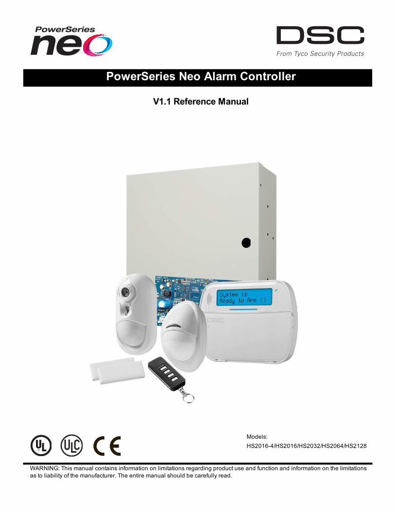
PowerSeries Neo Alarm Controller
V1.1 Reference Manual
Models:HS2016-4/HS2016/HS2032/HS2064/HS2128
WARNING: This manual contains information on limitations regarding product use and function and information on the limitationsas to liability of the manufacturer. The entire manual should be carefully read.
Safety Instructions for Service PersonnelWarning: When using equipment connected to the telephone network, always follow the basic safety instructions providedwith this product. Save these instructions for future reference. Inform the end-user of the safety precautions that must beobserved when operating this equipment.Before Installing The EquipmentEnsure your package includes the following items:
l Installation and User manuals, including the SAFETY INSTRUCTIONS.READ and SAVE these instructions!Follow all WARNINGS AND INSTRUCTIONS specified within this document and/or on the equipment.
l HS2016-4/HS2016/2032/2064/2128 alarm controllerl Power Supply, direct plug-inl Mounting hardware
Selecting A Suitable Location For The Alarm ControllerUse the following list as a guide to find a suitable location to install this equipment:
l Locate near a telephone socket and power outlet.l Select a location free from vibration and shock.l Place alarm controller on a flat, stable surface and follow the installation instructions.
Do NOT locate this product where people may walk on the secondary circuit cable(s).Do NOT connect alarm controller to electrical the same circuit as large appliances.Do NOT select a location that exposes your alarm controller to direct sunlight, excessive heat, moisture, vapors, chemicals ordust.Do NOT install this equipment near water. (e.g., bath tub, kitchen/laundry sink, wet basement, near a swimming pool).Do NOT install this equipment and accessories in areas where risk of explosion exists.Do NOT connect this equipment to electrical outlets controlled by wall switches or automatic timers.AVOID interference sources.AVOID installing equipment near heaters, air conditioners, ventilators, and refrigerators.AVOID locating equipment close to or on top of large metal objects (e.g., wall studs).See "Locating Detectors and Escape Plan" on page 221 for information on locating smoke and CO detectors.SAFETY Precautions Required During Installation
l NEVER install this equipment and/or telephone wiring during a lightning storm.l NEVER touch uninsulated telephone wires or terminals unless the telephone line has been disconnected at the net-work interface.
l Position cables so that accidents can not occur. Connected cables must NOT be subject to excessive mechanicalstrain.
l Use only the power supply provided with this equipment. Use of unauthorized power supplies may cause damage.l For direct plug-in versions, use the transformer supplied with the device.
WARNING: THIS EQUIPMENT HAS NOMAINS ON/OFF SWITCH. THE PLUGOF THE DIRECT PLUG-IN POWER SUPPLYIS INTENDED TO SERVE AS THE DISCONNECTING DEVICE IF THE EQUIPMENTMUST BE QUICKLY DISCONNECTED.IT IS IMPERATIVE THAT ACCESS TO THE MAINS PLUG AND ASSOCIATED MAINS SOCKET/OUTLET IS NEVEROBSTRUCTED.IMPORTANT NOTE FOR NORTH AMERICA!This alarm system must be installed and used within an environment that provides the pollution degree max 2 and over-voltages category II NON- HAZARDOUS LOCATIONS, indoor only. The equipment is DIRECT PLUG- IN (externaltransformer) and is designed to be installed, serviced and/or repaired by service persons only; [service person is defined asa person having the appropriate technical training and experience necessary to be aware of hazards to which that personmay be exposed in performing a task and of measures to minimize the risks to that person or other persons]. This equipmenthas no mains on/off switch; if the equipment must be quickly disconnected, the plug of the direct plug-in power supply isintended to serve as the disconnecting device; it is imperative that access to the mains plug and associated mainssocket/outlet, is never obstructed. There are no parts replaceable by the end-user within this equipment. The wiring (cables)
- 2 -

used for installation of the alarm system and accessories, shall be insulated with PVC, TFE, PTFE, FEP, Neoprene orPolyamide.(a) The equipment enclosure must be secured to the building structure before operation.(b) Internal wiring must be routed in a manner that prevents:- Excessive strain or loosening of wire on terminal connections;- Damage of conductor insulation(c) Disposal of used batteries must be made in accordance with local waste recovery and recycling regulations.(d) Before servicing, DISCONNECT the power and telephone connection.(e) DO NOT route any wiring over circuit boards.(f) The installer is responsible to ensure that a readily accessible disconnect device is incorporated in the building forpermanently connected installations.The power supply must be Class II, FAIL SAFE with double or reinforced insulation between the PRIMARY andSECONDARY CIRCUIT/ENCLOSURE and be an approved type acceptable to the local authorities. All national wiring rulesmust be observed.IMPORTANT NOTE FOR INTERNATIONAL MARKET (EU, AUS, NZ, etc.)!This equipment is stationary-fixed and must be installed by Service Persons only (Service Person is defined as a personhaving the appropriate technical training and experience necessary to be aware of hazards to which that person may beexposed in performing a task and of measures to minimize the risks to that person or other persons). It must be installed andused within an environment that provides the pollution degree max 2, over voltages category II, in non-hazardous, indoorlocations only.When using equipment connected to the mains and/or to the telecommunication network, there are basic safety instructionsthat should always be followed. Refer to the safety instructions provided with this product and save them for future reference.To reduce the risk of fire, electric shock and/or injury, observe the following:Do not attempt to service this product yourself. Opening or removing the cover may expose you to dangerous voltage orother risk. Refer servicing to qualified service persons. Never open the device yourself. Use authorized accessories onlywith this equipment. DO NOT leave and/or deposit ANY object on the top of the cabinet of this equipment! The cabinet as it isinstalled on the wall is not designed to support any supplementary weight! Do not spill any liquids on the cabinet. Do nottouch the equipment and its connected cables during an electrical storm; there may be a risk of electric shock. Never touchuninsulated wires or terminals unless the equipment has been disconnected from the mains supply and from thetelecommunication network! Ensure that cables are positioned so that accidents cannot occur. Connected cables must notbe subject to excessive mechanical strain. Do not spill any type of liquid on the equipment. Do not use the Alarm system toreport a gas leak if the system is near a leak. Do not subject the connected cables to an excessive mechanical strain.These safety instructions should not prevent you from contacting the distributor and/or the manufacturer to obtain any furtherclarification and/or answers to your concerns.
- 3 -
ContentsSection 1: Introduction 7
1.1 About the System 7Section 2: Installation 12
2.1 Overview of Installation Process 122.2 Alarm Controller Installation 122.3 Wiring 132.4 Installing Modules 18
Section 3: Configuration 293.1 Basic Configuration Steps 293.2 Using the Keypad 293.3 Enrollment 303.4 Working with Partitions 323.5 Trouble Indicators 333.6 Keypad Partition Setup 333.7 Alternate Communicator Setup 353.8 Local Firmware Upgrade 363.9 Testing the System 36
Section 4: System Operation 374.1 Arming and Disarming 374.2 Partition vs. Global Keypad 374.3 Labels 384.4 Annunciation 394.5 Keypad Function Keys 394.6 Language Selection 424.7 [*] Commands 424.8 SMS Command and Control 554.9 Visual Verification 56
Section 5: Programming 575.1 How to Program 575.2 Programming Methods 575.3 Programming Descriptions 61
Section 6: ProgrammingWorksheets 1226.1 Label Programming 1226.2 Zone Setup 1276.3 System Times 1306.4 Access Codes 1326.5 PGM Programming 1326.6 System Lockout 1456.7 System Options 1456.8 Auto-Arm/Disarm 1506.9 Partition and Zone Assignment 1546.10 Communications 1566.11 DLS Programming 166
- 4 -
6.12 Virtual Inputs 1666.13 Schedule Programming 1676.14 Audio Module Programming 1726.15 Wireless Programming 1776.16 Alternative Communicators 1786.17 Keypad Programming 1786.18 Template Programming 1806.19 System Information and Testing 1806.20 Module Programming 1816.21 Testing 1826.22 Battery Settings 1826.23 Restoring Factory Defaults 183
Section 7: Troubleshooting 1847.1 Testing 1847.2 Troubleshooting 184
Appendix 1: Reporting Codes 192Appendix 2: Word Library 201Appendix 3: Template Programming Tables 202Appendix 4: Regulatory Approvals 208Appendix 5: ASCII Characters 215Appendix 6: Wiring Diagrams 216Appendix 7: Specifications 2198.0 Index 229
- 5 -

- 7 -
Section 1: Introduction
1.1 About the System
The PowerSeries Neo alarm panel is a feature-rich, scalable alarm system designed for residential and light commercialuse. The alarm panel supports both hardwired and wireless devices. This section lists the features of the alarm panel, avail-able models, and compatible devices.The following symbols are used to indicate features or methods of operation that are only available in a particular market. Nosymbol indicates the feature or operation is available for all markets unless noted specifically otherwise.
CP-01
- North America
EN - Europe
NFA2P
- France
UK - United Kingdom
1.1.1 FeaturesThe following features are available on the PowerSeries Neo alarm controller.
Zones, Wireless Keypads, Wireless Keys, Panic Pendents and Proximity Tagsl 16, 32, 64, or 128 wireless or hardwired zones supported, including 6 or 8 hardwired zones available on the con-troller.
l 40 zone types and 14 programmable zone attributesl Up to 16 separate wireless keypads supportedl Up to 32 separate wireless keys or supportedl Up to 94 separate proximity tags supported
Access Codesl Up to 97 access codes: 94 (level 2-EN) one system master code (level 3-EN), one installer code (level 3-EN), andone maintenance code
l Programmable attributes for each user code ("Access Code Attributes" on page 49)
Programmable Outputs (PGMs)l Up to 4 programmable outputs (PGM) on the alarm controller with 49 available optionsl 22, 38, 80, 148 maximum programmable outputs
System Supervision FeaturesThe PowerSeries Neo continuously monitors a number of possible trouble conditions and provides audible and visual indic-ation at the keypad. Trouble conditions include:
l AC power failurel Zone troublel Fire troublel Telephone line troublel Communicator troublel Low battery conditionl RF jaml AUX power supply faultl Failure to communicatel Module fault (supervisory or tamper)
Additional Featuresl 2-way wireless device supportl Visual verification (images + audio)l Proximity tag supportl PGM schedulingl Quick arming
Section 1: Introduction
l User, partition, module, zone and system labelsl Programmable system loop responsel Keypad and panel software versions viewable through keypadl Doorbell zone typel Low battery PGM type
1.1.2 Available ModelsThe following alarm controller models are available:
l HS2016-4l HS2016l HS2032l HS2064l HS2128
Note: Not all models are available in all markets.
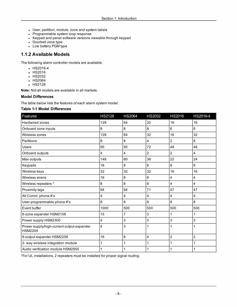
Model DifferencesThe table below lists the features of each alarm system model.
Table 1-1 Model Differences
Features HS2128 HS2064 HS2032 HS2016 HS2016-4Hardwired zones 128 64 32 16 16
Onboard zone inputs 8 8 8 6 8
Wireless zones 128 64 32 16 32
Partitions 8 8 4 2 8
Users 95 95 72 48 48
Onboard outputs 4 4 2 2 4
Max outputs 148 80 38 22 24
Keypads 16 8 8 8 8
Wireless keys 32 32 32 16 16
Wireless sirens 16 8 8 4 4
Wireless repeaters * 8 8 8 4 4
Proximity tags 94 94 71 47 47
Alt Comm. phone #’s 4 4 4 4 4
User-programmable phone #’s 8 8 8 8 8
Event buffer 1000 500 500 500 500
8-zone expander HSM2108 15 7 3 1 1
Power supply HSM2300 4 3 3 3 3
Power supply/high-current output expanderHSM2204
4 3 1 1 1
8-output expander HSM2208 16 8 4 2 2
2- way wireless integration module 1 1 1 1 1
Audio verification module HSM2955 1 1 1 1 1
*For UL installations, 2 repeaters must be installed for proper signal routing.
- 8 -
Section 1: Introduction
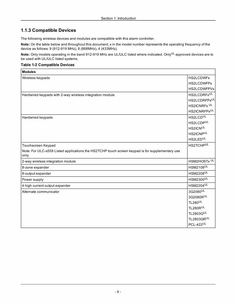
1.1.3 Compatible DevicesThe following wireless devices and modules are compatible with this alarm controller.
Note: On the table below and throughout this document, x in the model number represents the operating frequency of thedevice as follows: 9 (912-919 MHz), 8 (868MHz), 4 (433MHz).
Note: Only models operating in the band 912-919 MHz are UL/ULC listed where indicated. OnlyUL approved devices are tobe used with UL/ULC listed systems.
Table 1-2 Compatible Devices
Modules
Wireless keypads HS2LCDWFxHS2LCDWFPxHS2LCDWFPVx
Hardwired keypads with 2-way wireless integration module HS2LCDRFxUL
HS2LCDRFPxUL
HS2ICNRFx UL
HS2ICNRFPxUL
Hardwired keypads HS2LCDUL
HS2LCDPUL
HS2ICNUL
HS2ICNPUL
HS2LEDUL
Touchscreen KeypadNote: For ULC-s559 Listed applications the HS2TCHP touch screen keypad is for supplementary useonly.
HS2TCHPUL
2-way wireless integration module HSM2HOSTx UL
8-zone expander HSM2108UL
8-output expander HSM2208UL
Power supply HSM2300UL
4 high current output expander HSM2204UL
Alternate communicator 3G2080UL
3G2080RUL
TL280UL
TL280RUL
TL2803GUL
TL2803GRUL
PCL-422UL
- 9 -
Section 1: Introduction
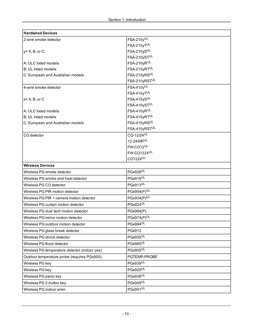
Hardwired Devices
2-wire smoke detector
y= A, B, or C
A: ULC listed modelsB: UL listed modelsC: European and Australian models
FSA-210yUL
FSA-210yTUL
FSA-210ySUL
FSA-210ySTUL
FSA-210yRUL
FSA-210yRTUL
FSA-210yRSUL
FSA-210yRSTUL
4-wire smoke detector
x= A, B, or C
A: ULC listed modelsB: UL listed modelsC: European and Australian models
FSA-410yUL
FSA-410yTUL
FSA-410ySUL
FSA-410ySTUL
FSA-410yRUL
FSA-410yRTUL
FSA-410yRSUL
FSA-410yRSTUL
CO detector CO-12/24UL
12-24SIRUL
FW-CO12UL
FW-CO1224UL
CO1224UL
Wireless Devices
Wireless PG smoke detector PGx926UL
Wireless PG smoke and heat detector PGx916UL
Wireless PG CO detector PGx913UL
Wireless PG PIR motion detector PGx904(P)UL
Wireless PG PIR + camera motion detector PGx934(P)UL
Wireless PG curtain motion detector PGx924UL
Wireless PG dual tech motion detector PGx984(P)
Wireless PGmirror motion detector PGx974(P)UL
Wireless PG outdoor motion detector PGx994UL
Wireless PG glass break detector PGx912
Wireless PG shock detector PGx935UL
Wireless PG flood detector PGx985UL
Wireless PG temperature detector (indoor use) PGx905UL
Outdoor temperature probe (requires PGx905) PGTEMP-PROBE
Wireless PG key PGx939UL
Wireless PG key PGx929UL
Wireless PG panic key PGx938UL
Wireless PG 2-button key PGx949UL
Wireless PG indoor siren PGx901UL
- 10 -
Section 1: Introduction
Wireless PG outdoor siren PGx911UL
Wireless PG repeater PGx920UL
Wireless PG door/window contact PGx975UL
Wireless PG door/window contact w/ AUX PGx945UL
Central Station Receivers
SG-System I, II, III, IV, 5
Enclosures
The HS2128/HS2064/HS2032/HS2016 main board can be installed in the metal enclosures listed below: Tamperprotection switches can be installed on all enclosures, including door opening protection and/or removal from the mountingposition. Doors can be secured using screws or keylock.• Model PC5003C (removable door) made of 22Ga steel, painted, dimensions: 248mm(L) x 298mm(W) x 76mm(H), weight:4.5Kg (with PCB, 7AH battery and transformer included)• Model Power UC1 made of 18Ga steel, painted, dimensions: 315mm(L) x 319mm(W) x 100mm(H), weight: 6.15Kg (withPCB, 7AH battery and transformer included).....For EN50131-1 Grade 2 compliant installations, all holes on the side of the cabinets shall be covered (plugged) if noaccessories are installed in the cabinet that will use these mounting holes.The equipment enclosure shall be secured to the building structure before operation. Use 4 screws (appropriate for the wallmaterial on which it is attached) inserted through the four mounting holes provided in the back of the enclosure base.
- 11 -
- 12 -
Section 2: Installation
2.1 Overview of Installation Process
The steps below are provided to assist with the installation of the alarm system. Read over this section to get an overallunderstanding of the order of installation. Working from this plan can help reduce problems and reduce the overall timerequired for installation.Step 1 – Create a LayoutDraw a rough sketch of the site and include all alarm detection devices, zone expanders, keypads and other required mod-ules.Step 2 – Mount the PanelDecide on a location for the alarm panel and secure it to the wall using suitable mounting hardware. See "Mounting theEnclosure" on page 12.Step 3 – Wire the Alarm ControllerWire each of the modules to the alarm controller following the guidelines provided in section "Corbus Wiring" on page 15.Step 4 – Wire ZonesComplete all zone wiring. Follow the guidelines provided in section "Zone Wiring" on page 21 to connect zones using nor-mally closed loops, single EOL resistor, double EOL resistors, fire zones and keyswitch arming zones.Step 5 – Complete WiringComplete all other wiring including bells or sirens, telephone line connections, ground connections or any other wiringnecessary. Follow the guidelines provided in section "Terminal Descriptions" on page 13.Step 6 – Power up the Control PanelOnce all zone and alarm controller wiring is complete, connect the battery before applying AC, and power up the system.The alarm controller will not power up if only the battery is connected.Step 7 – Enroll Keypads and ModulesAll keypads must be enrolled in order to operate on the system. To enroll the first keypad, see "Enrolling the First Keypad "on page 31. To enroll optional keypads, enter installer's programming section [902][000]. For more information, see "ModuleProgramming" on page 117.Step 8 – Confirm Module SupervisionBy default, all modules are supervised upon installation. Supervision is enabled at all times. To confirm that each module isproperly supervised, see "[903] Confirm Module" on page 118.Step 9 – Enroll Wireless DevicesWireless devices are enrolled via the wireless transceiver module (HSM2HOSTx) or RF keypad and Installer Programmingsection [804]. See "Wireless Programming" on page 116 to enroll wireless devices.Step 10 – Program the SystemSection 5 on "Programming" on page 57 provides a complete description of how to program the alarm controller. It containscomplete descriptions of the various programmable features and options. Fill out the programming worksheets starting at"Programming Worksheets" on page 122 completely before attempting to program the system.Step 11 – Test the SystemTest the panel completely to ensure that all features and functions operate as programmed.
2.2 Alarm Controller Installation
Begin the installation by mounting the alarm controller in the metal enclosure using the stand-offs provided. Optional mod-ules, such as the HSM2108 and HSM2208, can also be mounted in the enclosure.Install hardware in the sequence indicated on the following pages.
2.2.1 Mounting the EnclosureLocate the panel in a dry area, preferably near an unswitched AC power source and the incoming telephone line. Completeall wiring before applying AC or connecting the battery.
Section 2: Installation
2.3 Wiring
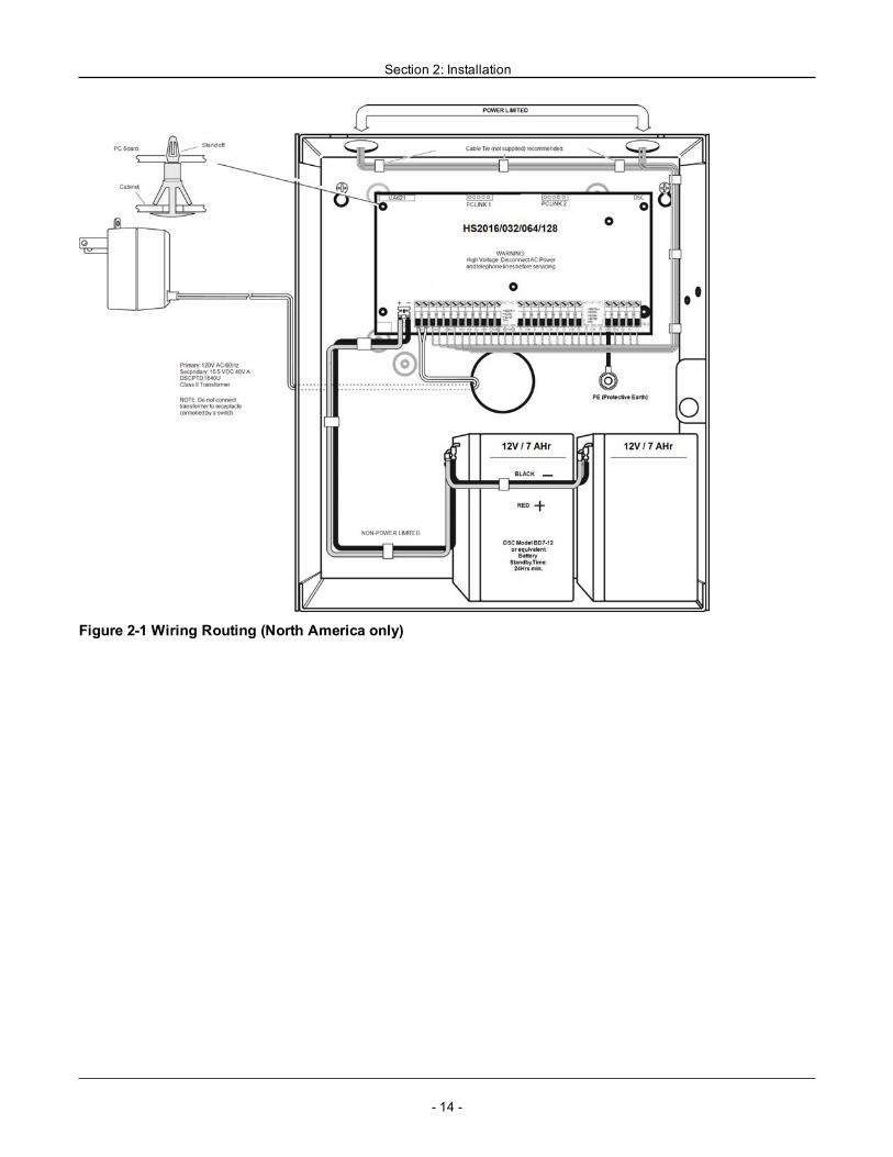
All wiring entry points on the enclosure are designated by arrows. All circuits are classified UL power limited except for thebattery leads. Minimum 1/4” (6.4mm) separation must be maintained at all points between power limited and non-power lim-ited wiring and connections.
2.3.1 Terminal DescriptionsThe following terminals are available on the PowerSeries Neo alarm controller.
Terminal DescriptionBAT+, BAT- Battery terminals. Use to provide backup power and additional current when system demands exceed the
power output of the transformer, such as when the system is in alarm.Do not connect the battery until all other wiring is complete.
AC Power terminals.Connect the battery before connecting the AC. Do not connect the battery or transformer until all other wiringis complete.
AUX+, AUX- Auxiliary terminals. Use to power modules, detectors, relays, LEDs, etc. (700mA MAX). Connect the positiveside of device to AUX+, the negative side to AUX-.
BELL+,BELL-
Bell/Siren power (700mA MAX). Connect the positive side of any alarm warning device to BELL+, thenegative side to BELL-.
RED, BLK,YEL, GRN
Corbus terminals. Use to provide communication between the alarm controller and connected modules. Eachmodule has four Corbus terminals that must be connected to the Corbus.
PGM1 toPGM4
Programmable output terminals. Use to activate devices such as LEDs.(PGM1, PGM3, and PGM4: 50mA PGM2: 300mA or can be configured as an input)
Z1 to Z8COM
Zone input terminals. Ideally, each zone should have one detection device; however, multiple detectiondevices can be wired to the same zone.
EGND Earth ground connection.
TIP, RING,T-1, R-1
Telephone line terminals.
PCLINK_1 DLS/SA
PCLINK_2 DLS/SA, Alternate Communicator
2.3.2 Wire Routing for Power & Non-Power LimitedAll wiring entry points are designated on the diagram by arrows. All circuits are classified UL installation power limitedexcept for the battery leads which are not power limited.A minimum ¼” (6.4mm) separation must be maintained at all points between power limited and non-power limited wiringand connections. See "Wiring Diagrams" on page 216 for expanded diagrams.
Note:Wire entry for power limited wiring must be separated by a different entry access from non-power limited wiring.
- 13 -
Section 2: Installation
Figure 2-1 Wiring Routing (North America only)
- 14 -
Section 2: Installation
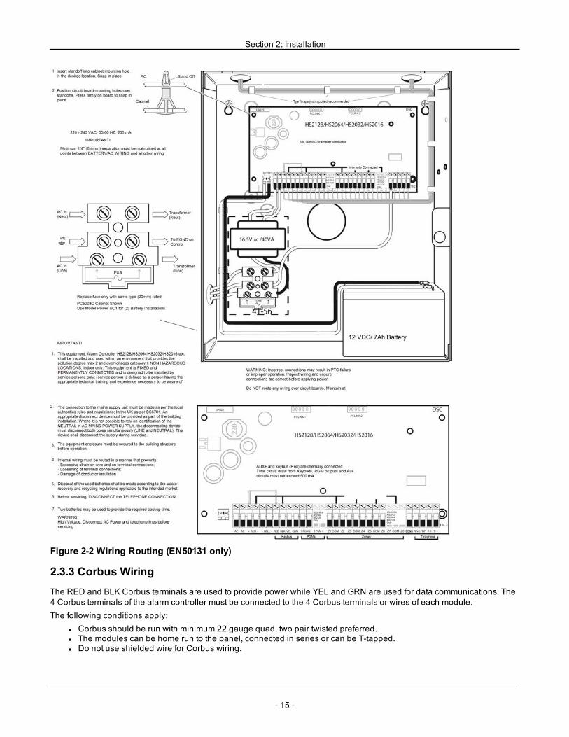
Figure 2-2 Wiring Routing (EN50131 only)
2.3.3 Corbus WiringThe RED and BLK Corbus terminals are used to provide power while YEL and GRN are used for data communications. The4 Corbus terminals of the alarm controller must be connected to the 4 Corbus terminals or wires of each module.The following conditions apply:
l Corbus should be run with minimum 22 gauge quad, two pair twisted preferred.l The modules can be home run to the panel, connected in series or can be T-tapped.l Do not use shielded wire for Corbus wiring.
- 15 -
Section 2: Installation
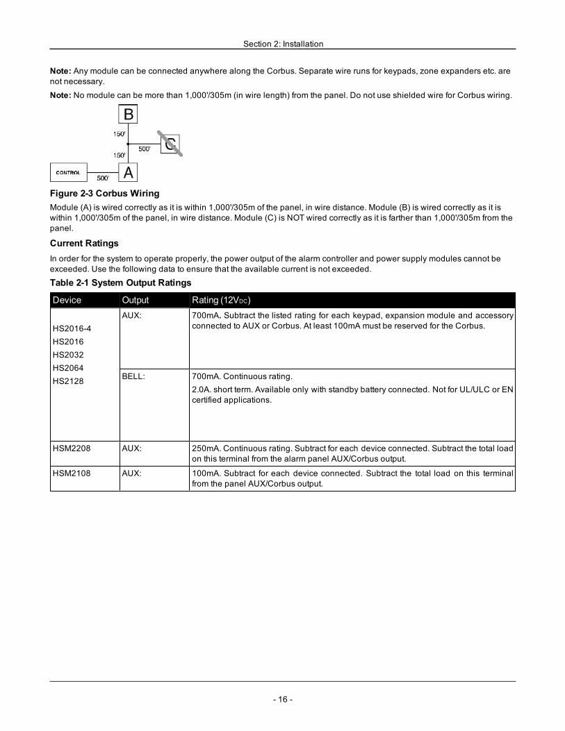
Note: Any module can be connected anywhere along the Corbus. Separate wire runs for keypads, zone expanders etc. arenot necessary.
Note: No module can be more than 1,000'/305m (in wire length) from the panel. Do not use shielded wire for Corbus wiring.
Figure 2-3 Corbus WiringModule (A) is wired correctly as it is within 1,000'/305m of the panel, in wire distance. Module (B) is wired correctly as it iswithin 1,000'/305m of the panel, in wire distance. Module (C) is NOT wired correctly as it is farther than 1,000'/305m from thepanel.
Current RatingsIn order for the system to operate properly, the power output of the alarm controller and power supply modules cannot beexceeded. Use the following data to ensure that the available current is not exceeded.
Table 2-1 System Output Ratings
Device Output Rating (12VDC)
HS2016-4HS2016HS2032HS2064HS2128
AUX: 700mA. Subtract the listed rating for each keypad, expansion module and accessoryconnected to AUX or Corbus. At least 100mA must be reserved for the Corbus.
BELL: 700mA. Continuous rating.2.0A. short term. Available only with standby battery connected. Not for UL/ULC or ENcertified applications.
HSM2208 AUX: 250mA. Continuous rating. Subtract for each device connected. Subtract the total loadon this terminal from the alarm panel AUX/Corbus output.
HSM2108 AUX: 100mA. Subtract for each device connected. Subtract the total load on this terminalfrom the panel AUX/Corbus output.
- 16 -
Section 2: Installation
Alarm Controller Current CalculationMaximum (Standby or Alarm)
AUX (700mA max. including PGMs 1-4)
Corbus (700mA max.)***
PCLink+ (Alt. Com.:125mA)
Total (must not exceed 700mA)
*** See "Corbus Current Calculation Chart" on page 17.For UL,ULC and Commercial Listed applications, the total standby and alarm current cannot exceed 700mA.
Table 2-2 Corbus Current Calculation Chart
Item Current (mA) x Quantity Total (mA)HS2016-4/HS2016/HS2032/HS2064/HS2128 85 X 1 85
HS2LCD 105 x
HS2ICN 105 x
HS2LED 105 x
HS2LCDP 105 x
HS2ICNP 105 x
HS2LCDRF 105 x
HS2ICNRF 105 x
HS2ICNRFP 105 x
HS2TCHP 160 x
Current required for connected devices =
HSM2108* 30 x
AUX output current of HSM2108
HSM2208* 40 x
AUX output current of HSM2208
HSM2300/2204* 35 x
HSM2HOSTx 35 x
HSM2955** x
3G208(R)/TL2803G(R)/TL280(R) 125 (PCLINK) x
Total Corbus Current =
- 17 -
Section 2: Installation
*These units draw current from the Corbus to power devices external to the module. This current must be added to the totalCorbus current. See manufacturer's specifications for the current draw of each device.** For HSM2955 current draw refer to HSM2955 installation manual.
Line LossVoltage loss through wire resistance must be considered for all installations. To ensure proper operation, at least 12.5VDCmust be applied to all modules on the system (when AC is connected and the battery is fully charged). If less than 12.5VDC isapplied, system operation is adversely affected.To correct the problem, try any or all of the following:1. Connect a HSM2300/2204 power supply between the alarm controller and the module to provide additional power to theCorbus.2. Reduce the length of the Corbus run to the module.3. Increase the gauge of wire.
Capacitance LimitsAn increase in capacitance on the Corbus affects data transmission and causes the system to slow down. Capacitanceincreases for every foot of wire added to the Corbus. The capacitance rating of the wire used will determine the maximumlength of the Corbus.For example, 22-gauge, non-shielded, 4-conductor wire has a typical capacitance rating of 20 picofarads per foot (which is20nF/1000’). For every 1000' of wire added – regardless of where it is run – the capacitance of the Corbus increases by20nF.The following table indicates the total wire distance allowed for the capacitance rating of the wire used:
Table 2-3 Wire Capacitance
Wire Capacitance per 1000’ (300m) Total Corbus Wire Length15nF 5300’/1616m
20nF 4000’/1220m
25nF 3200’/976m
30nF 2666’/810m
35nF 2280’/693m
40nF 2000’/608m
2.4 Installing Modules
Remove all power from the system while connecting modules to the alarm controller.
2.4.1 Zone ExpanderThe main alarm controller has connection terminals for zones 1 to 8. Additional HSM2108 zone expanders may be added toincrease the number of zones on the system. Each zone expander consists of one group of 8 zones. At enrollment, the zoneexpander is automatically assigned to the next available zone slot. Connect the RED, BLK, YEL and GRN terminals to theCorbus terminals on the alarm panel. Board current draw: 30mA.
- 18 -
Section 2: Installation
Figure 2-4 HSM2108 Zone ExpanderRefer to the HSM2108 installation sheet for more information.
2.4.2 Output ExpanderThe HSM2208 module is used to add up to 8 low-current programmable outputs to the alarm system.The 4-wire Corbus connection is used by the panel to communicate with the module. Connect the RED, BLK, YEL and GRNterminals to the Corbus terminals on the alarm panel. Board current draw: 40mA.
Figure 2-5 HSM2208 Output Expander
2.4.3 Wireless Transceiver ModuleThe HSM2HOSTx 2-way wireless integration module provides communication between wireless devices and the alarm con-troller.Connect the HSM2HOSTx to the 4-wire Corbus of the alarm controller according to the following diagram.
Figure 2-6 HSM2HOSTx Wiring DiagramAfter you have completed the wiring, reconnect power to the security system. Board currant draw: 35mA
- 19 -
Section 2: Installation
2.4.4 Power Supply WiringThe HSM2300/2204 power supply/high-current output module provides up to 1.0A of additional current and can be used toadd up to four programmable outputs (HSM2204 only) to the alarm system.The 4-wire Corbus connection provides communication between the module and alarm panel. Connect the RED, BLK, YELand GRN terminals to the Corbus terminals on the alarm controller. If O1 is not used, connect to Aux with a 1K resistor. Boardcurrent draw: 1.2A.
Figure 2-7 Power Supply Wiring
2.4.5 Keypad WiringTo wire a keypad to the alarm controller, remove the keypad backplate (refer to the keypad installation sheet) and connectthe RED, BLK, YEL and GRN terminals to the corresponding terminals on the alarm controller.
Keypad Zone/PGM WiringHardwired devices can be connected to hardwired keypads with inputs (zone) or outputs (PGM). This saves from runningwires back to the control panel for every device.To connect a zone device to HS2LCD, HS2ICON, HS2LED and HS2TCHP keypads, run one wire to the P/Z terminal and theother to B. For powered devices, use red and black to supply power to the device. Run the red wire to the R (positive) ter-minal and the black wire to the B (negative) terminal.Keypad zones support Normally Closed Loops, Single End of Line and Double End of Line.To connect the PGM output, run one wire to the P/Z terminal and the other to R.
- 20 -
Section 2: Installation
Figure 2-8 Keypad P/Z TerminalsNote:When using end of line supervision, connect the zone according to one of the configurations outlined in "Zone Wiring"on page 21. End of line resistors must be placed on the device end of the loop, not at the keypad.
Assigning Keypad ZonesWhen using keypad zone inputs, each input used must be assigned a zone number in Installer Programming.First, ensure that you have enrolled all installed keypads into the desired slots (See "[902] Add/Remove Modules" on page117). Next, assign keypad zones by entering programming section [861]-[876], subsection 011 for keypads 1-16. Enter a 3-digit zone number for each of the keypad zones. This number must be programmed into the slot location that the keypad isassigned to.
Note: If a keypad zone input is assigned to zone number 1 to 8, the corresponding zone cannot be used on the main controlpanel.
Once the keypad zones are assigned, you must also program zone definitions and zone attributes. See "[001] Zone Types"on page 64 and See "Zone Setup" on page 64.
2.4.6 HSM2955 WiringFor wiring information refer to HSM2955 Installation manual #29008435xxx.
2.4.7 Alternate Communicator WiringSee Alternate Communicator installation manual.
2.4.8 Zone WiringPower down the alarm controller and complete all zone wiring.Zones can be wired to supervise normally open devices (e.g., smoke detectors) or normally closed devices (e.g., door con-tacts). The alarm panel can also be programmed for single end-of-line or double end-of-line resistors.Zone programming is done using the following programming sections:
l [001] selects zone definitionl [013] Opt [1] for normally closed or EOL; Opt [2] for SEOL or DEOLl [201 - 208] partition assignment.
Observe the following guidelines when wiring zones:l For UL listed installations use SEOL or DEOL onlyl Minimum 22 AWGwire, maximum 18 AWGl Do not use shielded wirel Do not exceed 100Ω wire resistance. Refer to the following table:
- 21 -
Section 2: Installation
Table 2-4 Burglary Zone Wiring Chart
Wire Gauge Maximum Length to EOLResistor (ft/meters)22 3000 / 914
20 4900 / 1493
19 6200 / 1889
18 7800 / 2377
Figures are based on maximum wiring resistance of 100Ω.
Normally ClosedConnect hardwired devices to any Z terminal and any Com terminal. Wire normally closed devices in series.
Note: For UL Installations, do not use normally closed loops.
Figure 2-9 Normally ClosedThe following table shows zone status under certain conditions for NC Loops:
Table 2-5 NC Loop Status
Loop Resistance Loop Status0Ω (shorted wire, loop shorted) Secure
Infinite (broken wire, loop open) Violated
Single End-of-Line (SEOL) ResistorWhen SEOL resistors are installed at the end of a zone loop, the alarm panel detects if the circuit is secure, open, or shorted.The SEOL resistor must be installed at the end of the loop for proper supervision.To enable SEOL supervision, program section [013], options [1] and [2] to OFF.
Note: This option should be selected if either normally closed or normally open detection devices or contacts are used.
Figure 2-10 SEOL WiringThe following table shows zone status under certain conditions for SEOL:
Table 2-6 SEOL Loop Status
Loop Resistance Loop Status0Ω (shorted wire, loop shorted) Violated
5600Ω (contact closed) Secure
Infinite (broken wire, loop open) Violated
- 22 -
Section 2: Installation
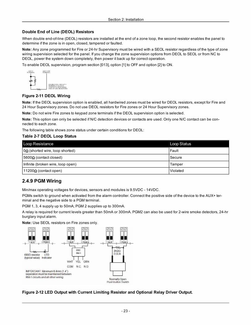
Double End of Line (DEOL) ResistorsWhen double end-of-line (DEOL) resistors are installed at the end of a zone loop, the second resistor enables the panel todetermine if the zone is in open, closed, tampered or faulted.
Note: Any zone programmed for Fire or 24-hr Supervisory must be wired with a SEOL resistor regardless of the type of zonewiring supervision selected for the panel. If you change the zone supervision options from DEOL to SEOL or from NC toDEOL, power the system down completely, then power it back up for correct operation.
To enable DEOL supervision, program section [013], option [1] to OFF and option [2] to ON.
Figure 2-11 DEOL WiringNote: If the DEOL supervision option is enabled, all hardwired zones must be wired for DEOL resistors, except for Fire and24 Hour Supervisory zones. Do not use DEOL resistors for Fire zones or 24 Hour Supervisory zones.
Note: Do not wire Fire zones to keypad zone terminals if the DEOL supervision option is selected.Note: This option can only be selected if N/C detection devices or contacts are used. Only one N/C contact can be con-nected to each zone.
The following table shows zone status under certain conditions for DEOL:
Table 2-7 DEOL Loop Status
Loop Resistance Loop Status0Ω (shorted wire, loop shorted) Fault
5600Ω (contact closed) Secure
Infinite (broken wire, loop open) Tamper
11200Ω (contact open) Violated
2.4.9 PGMWiringMin/max operating voltages for devices, sensors and modules is 9.5VDC - 14VDC.PGMs switch to ground when activated from the alarm controller. Connect the positive side of the device to the AUX+ ter-minal and the negative side to a PGM terminal.PGM 1, 3, 4 supply up to 50mA; PGM 2 supplies up to 300mA.A relay is required for current levels greater than 50mA or 300mA. PGM2 can also be used for 2-wire smoke detectors, 24-hrburglary input alarm.
Note: Use SEOL resistors on Fire zones only.
Figure 2-12 LED Output with Current Limiting Resistor and Optional Relay Driver Output.
- 23 -
Section 2: Installation
UL Compatibility ID For FSA-210B Series is: FS200
Note: For ULC listed installations, use FSA-210A and FSA-410A series.
2.4.10 Bell WiringThese terminals supply 700mA of current at 10.4 - 12.5VDC for commercial/ residential installations. To comply with NFPA72 Temporal Three Pattern requirements, section [013] Opt [8] must be ON. Note that steady, pulsed alarms are also sup-ported.
Figure 2-13 Bell WiringThe Bell output is supervised and power limited by 2A thermistor. If unused, connect a 1000Ω resistor across Bell+ and Bell-to prevent the panel from displaying a trouble. See "[*][2] Trouble Display" on page 44.
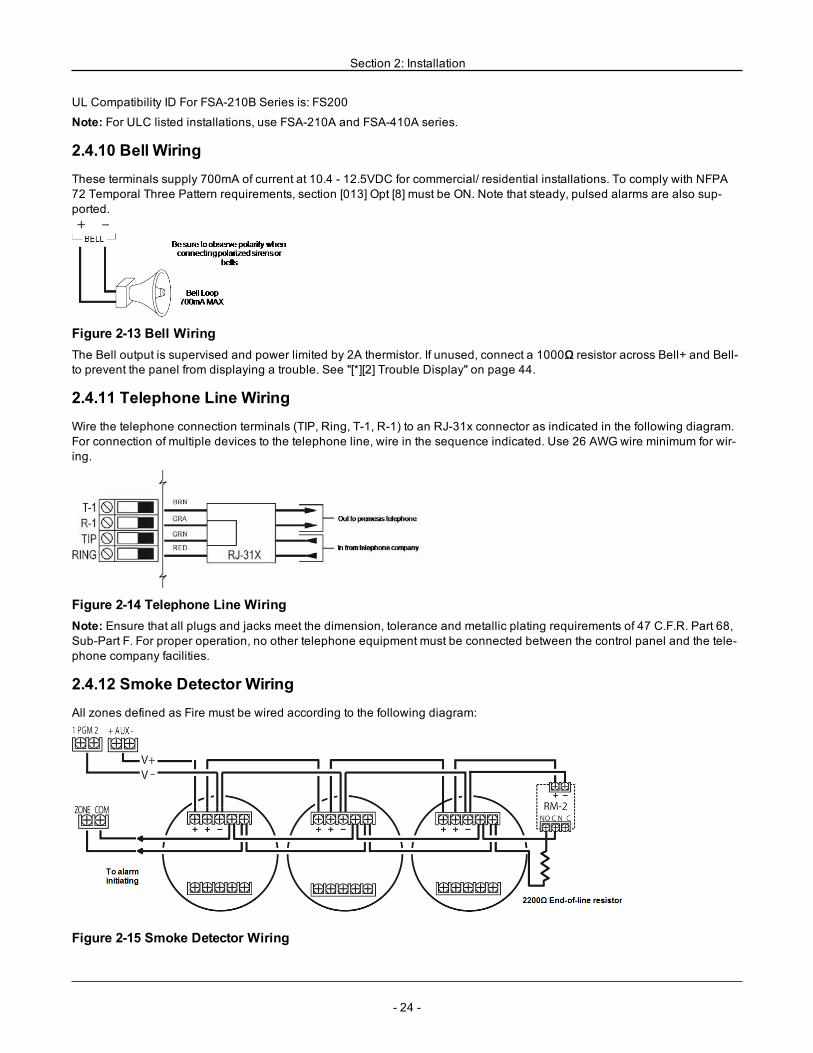
2.4.11 Telephone Line WiringWire the telephone connection terminals (TIP, Ring, T-1, R-1) to an RJ-31x connector as indicated in the following diagram.For connection of multiple devices to the telephone line, wire in the sequence indicated. Use 26 AWGwire minimum for wir-ing.
Figure 2-14 Telephone Line WiringNote: Ensure that all plugs and jacks meet the dimension, tolerance and metallic plating requirements of 47 C.F.R. Part 68,Sub-Part F. For proper operation, no other telephone equipment must be connected between the control panel and the tele-phone company facilities.
2.4.12 Smoke Detector WiringAll zones defined as Fire must be wired according to the following diagram:
Figure 2-15 Smoke Detector Wiring
- 24 -
Section 2: Installation
See "[001] Zone Types" on page 64 for fire zone operation.
Note: Smoke detectors must be latching type. To reset a smoke detector, enter [*][7][2].
Table 2-8 Compatible 4-Wire Smoke Detectors
FSA-410B FSA-410BLST FSA-410BRST
FSA-410BT FSA-410BR FSA-410BLRST
FSA-410BS FSA-410BRT
FSA-410BST FSA-410BRS
Current ratings for DSC FSA-410 Series: 25mA - 90mA
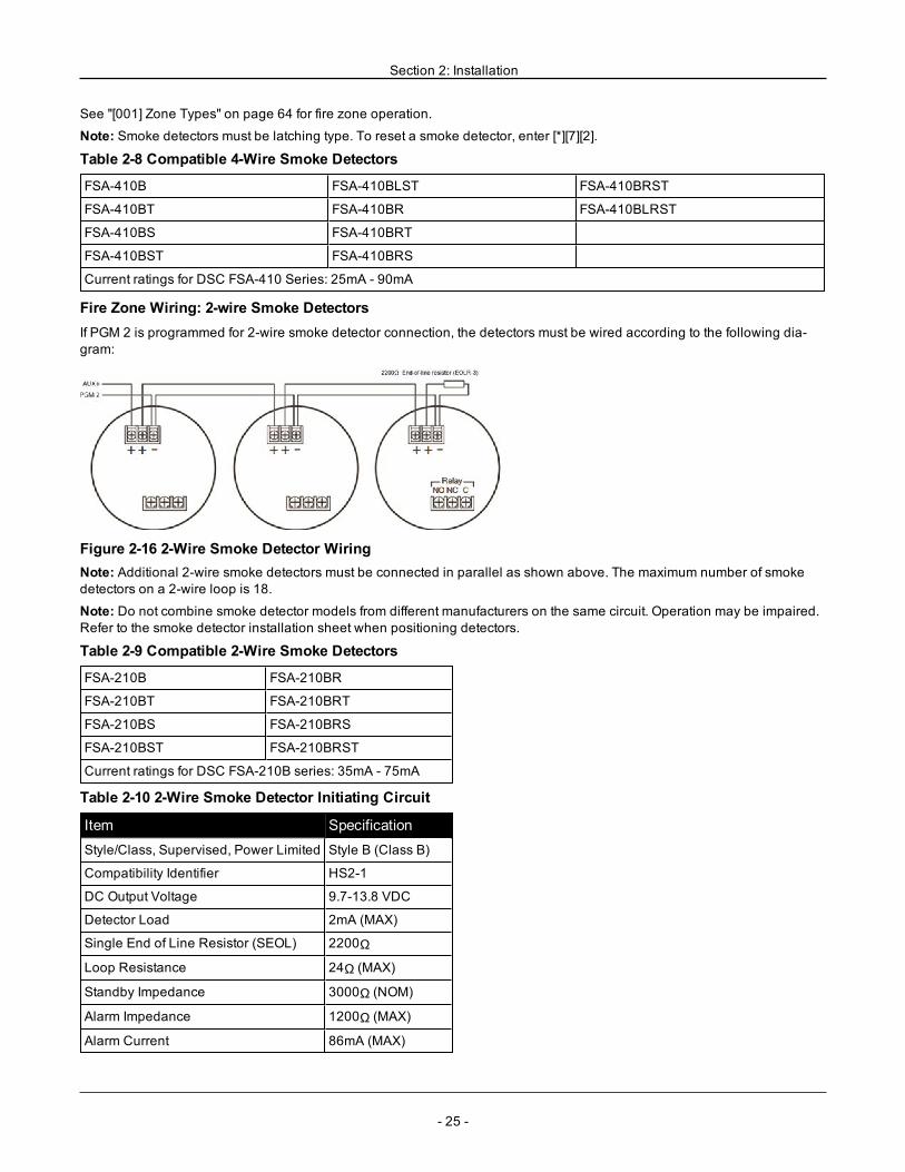
Fire Zone Wiring: 2-wire Smoke DetectorsIf PGM 2 is programmed for 2-wire smoke detector connection, the detectors must be wired according to the following dia-gram:
Figure 2-16 2-Wire Smoke Detector WiringNote: Additional 2-wire smoke detectors must be connected in parallel as shown above. The maximum number of smokedetectors on a 2-wire loop is 18.
Note: Do not combine smoke detector models from different manufacturers on the same circuit. Operation may be impaired.Refer to the smoke detector installation sheet when positioning detectors.
Table 2-9 Compatible 2-Wire Smoke Detectors
FSA-210B FSA-210BR
FSA-210BT FSA-210BRT
FSA-210BS FSA-210BRS
FSA-210BST FSA-210BRST
Current ratings for DSC FSA-210B series: 35mA - 75mA
Table 2-10 2-Wire Smoke Detector Initiating Circuit
Item SpecificationStyle/Class, Supervised, Power Limited Style B (Class B)
Compatibility Identifier HS2-1
DC Output Voltage 9.7-13.8 VDC
Detector Load 2mA (MAX)
Single End of Line Resistor (SEOL) 2200Ω
Loop Resistance 24Ω (MAX)
Standby Impedance 3000Ω (NOM)
Alarm Impedance 1200Ω (MAX)
Alarm Current 86mA (MAX)
- 25 -
Section 2: Installation
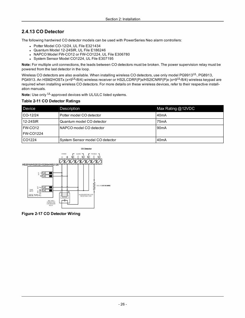
2.4.13 CO DetectorThe following hardwired CO detector models can be used with PowerSeries Neo alarm controllers:
l Potter Model CO-12/24, UL File E321434l Quantum Model 12-24SIR, UL File E186246l NAPCOModel FW-CO12 or FW-CO1224, UL File E306780l System Sensor Model CO1224, UL File E307195
Note: For multiple unit connections, the leads between CO detectors must be broken. The power supervision relay must bepowered from the last detector in the loop.
Wireless CO detectors are also available. When installing wireless CO detectors, use only model PG9913UL, PG8913,PG4913. An HSM2HOSTx (x=9UL/8/4) wireless receiver or HS2LCDRF(P)x/HS2ICNRF(P)x (x=9UL/8/4) wireless keypad arerequired when installing wireless CO detectors. For more details on these wireless devices, refer to their respective install-ation manuals.
Note: Use only ULapproved devices with UL/ULC listed systems.
Table 2-11 CO Detector Ratings
Device Description Max Rating@12VDCCO-12/24 Potter model CO detector 40mA
12-24SIR Quantum model CO detector 75mA
FW-CO12FW-CO1224
NAPCOmodel CO detector 90mA
CO1224 System Sensor model CO detector 40mA
Figure 2-17 CO Detector Wiring
- 26 -
Section 2: Installation
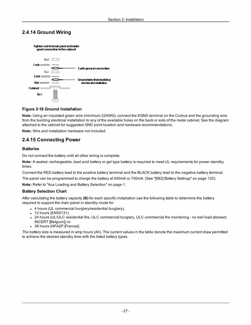
2.4.14 Ground Wiring
Figure 2-18 Ground InstallationNote: Using an insulated green wire (minimum 22AWG), connect the EGND terminal on the Corbus and the grounding wirefrom the building electrical installation to any of the available holes on the back or side of the metal cabinet. See the diagramattached to the cabinet for suggested GND point location and hardware recommendations.
Note:Wire and installation hardware not included.
2.4.15 Connecting Power
BatteriesDo not connect the battery until all other wiring is complete.
Note: A sealed, rechargeable, lead acid battery or gel type battery is required to meet UL requirements for power standbytimes.
Connect the RED battery lead to the positive battery terminal and the BLACK battery lead to the negative battery terminal.The panel can be programmed to charge the battery at 400mA or 700mA. (See "[982] Battery Settings" on page 120).
Note: Refer to "Aux Loading and Battery Selection" on page 1.
Battery Selection ChartAfter calculating the battery capacity (B) for each specific installation use the following table to determine the batteryrequired to support the main panel in standby mode for
l 4 hours (UL commercial burglary/residential burglary),l 12 hours (EN50131),l 24 hours (UL/ULC residential fire, ULC commercial burglary, ULC commercial fire monitoring - no bell load allowed;INCERT [Belgium]) or
l 36 hours (NFA2P [France]).The battery size is measured in amp hours (Ah). The current values in the table denote the maximum current draw permittedto achieve the desired standby time with the listed battery types.
- 27 -
Section 2: Installation
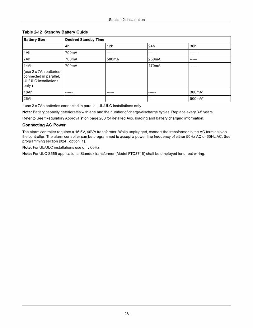
Table 2-12 Standby Battery Guide
Battery Size Desired Standby Time
4h 12h 24h 36h
4Ah 700mA ------ ------ ------
7Ah 700mA 500mA 250mA ------
14Ah(use 2 x 7Ah batteriesconnected in parallel,UL/ULC installationsonly )
700mA 470mA ------
18Ah ------ ------ ------ 300mA*
26Ah ------ ------ ------ 500mA*
* use 2 x 7Ah batteries connected in parallel, UL/ULC installations only
Note: Battery capacity deteriorates with age and the number of charge/discharge cycles. Replace every 3-5 years.Refer to See "Regulatory Approvals" on page 208 for detailed Aux. loading and battery charging information.
Connecting AC PowerThe alarm controller requires a 16.5V, 40VA transformer. While unplugged, connect the transformer to the AC terminals onthe controller. The alarm controller can be programmed to accept a power line frequency of either 50Hz AC or 60Hz AC. Seeprogramming section [024], option [1].
Note: For UL/ULC installations use only 60Hz.
Note: For ULC S559 applications, Standex transformer (Model FTC3716) shall be employed for direct-wiring.
- 28 -
- 29 -
Section 3: Configuration
3.1 Basic Configuration Steps
Once basic installation of the alarm panel is complete, the following general configuration options should be set:l create partitions, See "Working with Partitions " on page 32l assign keypads to partitions, see "Keypad Partition Setup " on page 33l assign sirens to partitions, see "Bell/Siren Operation " on page 32l create global zones, see "Global Zones " on page 33l set up partition account codes, see "Communications" on page 34l set up partition timers, see "System Times" on page 70l enroll wireless modules and devices, see "Enrolling Modules" on page 30l assign zone types, see "[001] Zone Types" on page 64, and attributes, see "[002] Zone Attributes" on page 68l create zone labels, see "Adding Labels" on page 61l add users, see "Assign Access Codes" on page 47l set up the alternate communicator if equipped, see "Alternate Communicator Setup" on page 35l program phone numbers, see "System Communications" on page 106l set up call directions for the central monitoring station, see "System Communications" on page 106l set up system timers, see "System Times" on page 70l configure reporting codes, see "Reporting" on page 100l test the system, see "Testing the System" on page 36
3.2 Using the Keypad
The PowerSeries Neo alarm panel is compatible with several different keypad types (see "Compatible Devices" on page 9);However, all keypads have certain basic functionality in common.
3.2.1 Special Keys
Scroll symbols < > on keypads with LCD displays indicate that options can be viewed by pressing the scroll keys.These keys can also be used to position the cursor.The [*] key is similar in function to the “Enter” key on a personal computer. It is generally used to accept the existing pro-gramming option. It is also the first key entry for [*] commands and can be used to enter the letters A-F when in Installer Pro-gramming mode.The [#] key is similar in function to the “ESC” (escape) key on a personal computer. It is generally used to exit the current pro-gramming section or to return to the previous one.
3.2.2 LED IndicatorsKeypads have the following status lights that provide visual indication of basic system status:
Ready: Panel is ready to be armed.
Armed: Panel is armed.
Trouble: System trouble. Enter [*][2] to view troubles.
AC Power: ON=AC present. OFF=AC absent.
Panel Status LED OperationThe red status LED, located on the alarm controller PCB, indicates the following:
l Power up sequence – flashes rapidly until the end of the power-up sequence.l Firmware indication – flashes during the firmware upgrade process. If the firmware upgrade fails, the LED flashes rap-idly.
l Trouble indication – Flashes when troubles are present. Troubles are indicated according to the following priority:1 flash - no keypads enrolled2 flashes - module supervision trouble3 flashes - bus low voltage
Section 3: Configuration
4 flashes - low battery trouble5 flashes - AC trouble6 flashes - AUX trouble7 flashes - bell trouble8 flashes - TLM trouble
How to Enter DataConventions Used In This ManualBrackets [ ] indicate numbers or symbols that must be entered on the keypad.e.g., [*][8][Installer Code][804] requires the following key entries:[*][8][5555][804][*] initiates a special command.[5555] is the default installer code. The default installer code should be changed during initial programming of the system.[804] indicates the particular programming section being accessed.
Entering Letters Manually (System Labels)1. In Installer Programming, enter the section requiring text input.2. Use the arrow keys [<][>] to move the cursor to a blank space or existing character.3. Press the number key corresponding to the appropriate letter. Each number button accesses three letters and a number.The first press of the number key displays the first letter. The second press displays the second letter, etc.
1A, B, C, 1
2D, E, F, 2
3G, H, I, 3
4J, K, L, 4
5M, N, O, 5
6P, Q, R, 6
7S, T, U, 7
8V,W, X, 8
9Y, Z, 9,0
0Space
4. To select lower case letters press [*]. The Select Options list opens. Scroll to “lower case” and press [*] again to select.5. When the required letter or number is displayed use the arrow keys [<][>] to scroll to the next letter.6. When finished, press the [*] key, use the [<][>] keys to scroll to “Save” then press [*].7. Continue from step 2 until all labels are programmed.For information on entering hexadecimal data, see "Programming Hex and Decimal Data" on page 60.
3.3 Enrollment
All optional modules and devices must be enrolled on the system. During enrollment, the electronic serial number (ESN) ofeach device is identified to the control panel and zones are assigned. A wireless transceiver HSM2HOST or an RF keypadmust be enrolled first before wireless devices can be enrolled.
3.3.1 Enrolling ModulesDuring automatic and manual enrollment, if an attempt is made to enroll more than the maximum number of modules, anerror tone sounds and a message is displayed on LCD keypads.
Table 3-1 Module Capacity
Module HS2016-4 HS2016 HS2032 HS2064 HS2128HSM2108 8 Zone expander 1 1 3 7 15
HSM2208 8 Output expander 2 2 4 8 16
- 30 -
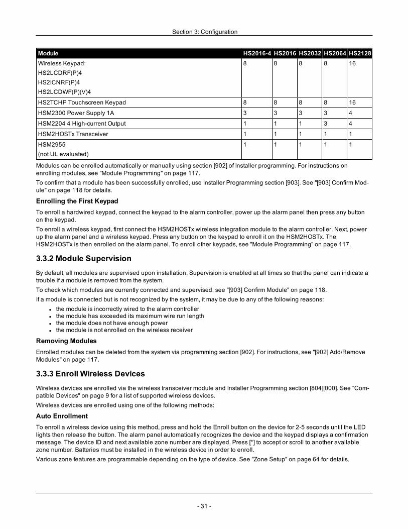
Section 3: Configuration
Module HS2016-4 HS2016 HS2032 HS2064 HS2128Wireless Keypad:HS2LCDRF(P)4HS2ICNRF(P)4HS2LCDWF(P)(V)4
8 8 8 8 16
HS2TCHP Touchscreen Keypad 8 8 8 8 16
HSM2300 Power Supply 1A 3 3 3 3 4
HSM2204 4 High-current Output 1 1 1 3 4
HSM2HOSTx Transceiver 1 1 1 1 1
HSM2955(not UL evaluated)
1 1 1 1 1
Modules can be enrolled automatically or manually using section [902] of Installer programming. For instructions onenrolling modules, see "Module Programming" on page 117.To confirm that a module has been successfully enrolled, use Installer Programming section [903]. See "[903] Confirm Mod-ule" on page 118 for details.
Enrolling the First KeypadTo enroll a hardwired keypad, connect the keypad to the alarm controller, power up the alarm panel then press any buttonon the keypad.To enroll a wireless keypad, first connect the HSM2HOSTx wireless integration module to the alarm controller. Next, powerup the alarm panel and a wireless keypad. Press any button on the keypad to enroll it on the HSM2HOSTx. TheHSM2HOSTx is then enrolled on the alarm panel. To enroll other keypads, see "Module Programming" on page 117.
3.3.2 Module SupervisionBy default, all modules are supervised upon installation. Supervision is enabled at all times so that the panel can indicate atrouble if a module is removed from the system.To check which modules are currently connected and supervised, see "[903] Confirm Module" on page 118.If a module is connected but is not recognized by the system, it may be due to any of the following reasons:
l the module is incorrectly wired to the alarm controllerl the module has exceeded its maximum wire run lengthl the module does not have enough powerl the module is not enrolled on the wireless receiver
Removing ModulesEnrolled modules can be deleted from the system via programming section [902]. For instructions, see "[902] Add/RemoveModules" on page 117.
3.3.3 Enroll Wireless DevicesWireless devices are enrolled via the wireless transceiver module and Installer Programming section [804][000]. See "Com-patible Devices" on page 9 for a list of supported wireless devices.Wireless devices are enrolled using one of the following methods:
Auto EnrollmentTo enroll a wireless device using this method, press and hold the Enroll button on the device for 2-5 seconds until the LEDlights then release the button. The alarm panel automatically recognizes the device and the keypad displays a confirmationmessage. The device ID and next available zone number are displayed. Press [*] to accept or scroll to another availablezone number. Batteries must be installed in the wireless device in order to enroll.Various zone features are programmable depending on the type of device. See "Zone Setup" on page 64 for details.
- 31 -
Section 3: Configuration
Pre-EnrollmentPre-enrollment is a two step process. The first step requires entering each device ID ([804][001]-[716]). Every wireless devicehas an ID printed on the sticker attached to the device. The format is XXX-YYYY where:
l XXX identifies the type or model of the devicel YYYY is a short encrypted ID used by the system to identify the specific device
Pre-enrollment can be done at a remote location and using DLS/SA. The second step is to press the enrollment button onthe device, usually done on location. Installer Programming does not have to be entered at this step. Both steps must be per-formed in order to complete the enrollment.
3.4 Working with Partitions
A partition is a limited area of the premises that operates independently from the other areas. Partitioning a system can bebeneficial if the property has outbuildings that need to be secured independently of a main area or if the home has a sep-arate apartment.Each partition can have its own keypad or a keypad can have access to all partitions (only if all partitions belong to the sameowner). User access to partitions is controlled via access codes. A master code can access the entire system and partitions,while a user code is limited to assigned partitions.Setting up a partition requires configuration of the following:
l create the partitionl define bell/siren operationl assign keypadsl assign zonesl assign users
3.4.1 Setting Up a PartitionPartitions are added or removed from the system by applying or removing a partition mask via Installer Programming section[200]. The number of available partitions depends on the alarm panel model. See "[200] Partition Mask" on page 98 for moreinformation.
3.4.2 Bell/Siren OperationEach partition must have a siren. The system siren connected to the bell output of the alarm controller can be mounted in acentral location within hearing range of all partitions. Each partition can also have wireless sirens activated only on theassigned partition. See "Wireless Programming" on page 116 for details.
Single Siren Output OperationWith a siren shared across all partitions, control over activation/deactivation of the output depends on the partition that ini-tiated the alarm sequence. Only the partition that originated the alarm can deactivate the bell output.Global zones, such as smoke detectors shared by multiple partitions, can deactivate the siren on all partitions the zone isassigned to.
Multiple Siren Output OperationWhen multiple sirens are used in the installation, they can be programmed to sound alarm conditions for all partitions, or forindividual partitions by using a partition enable mask.If hardwired sirens are used, this is accomplished via bus power supplies with a supervised high-current output. The outputis then programmed as a Fire and Burglary PGM output type.
Note: Only the first output of the HSM2204 output module has bell supervision. Some conditions, such as an installer systemtest, may override the partition assignment and cause all sirens to activate. User system tests only activate the sirens/outputsassigned to that partition.
- 32 -
Section 3: Configuration
3.5 Trouble Indicators
Both audible and visual trouble indications are available on all partitions. For more information, see "[*][2] Trouble Display"on page 44.Programming section [013] option 3 controls whether or not troubles are indicated when the alarm system is armed.
3.6 Keypad Partition Setup
Keypads can be configured to control an individual partition or all partitions. In general, a partition keypad controls the par-tition it is assigned to. A Global keypad controls all partitions. Global keypads should be placed in common areas of thepremises, such as points of entry or reception areas, where the ability to arm and disarm more than one partition at a time isrequired.Partition keypads can also be temporarily loaned to other partitions.To select a keypad operating mode:1. Enter Installer Programming: [*][8][installer code].2. Select [861]-[876] to program keypads 1-16.
l Press [000] for partition assignment.l For Global operation, key in 00.l To assign a keypad to a partition, key in 01-08 for partition 1-8.
3. Press the [#] and reapeat step 2 for next keypad. When finished programming all keypads, press the [#] key twice to exitprogramming.Users are assigned partition access rights via the [*][5] menu.
3.6.1 Loaned Partition SetupTo loan a keypad to another partition:1. Press and hold [#]. The keypad switches to Global display.2. Select a partition by pressing digits 1 to 8. The keypad is temporarily loaned to another partition.If the keypad is inactive for more than 30 seconds, it reverts to its assigned partition.
3.6.2 Global ZonesIf a zone is added to more than one partition, it becomes a global zone. A global zone is only armed when all assigned par-titions are armed and is disarmed when any assigned partition is disarmed.Global zones behave as follows:
l A global Stay/Away type zone is not activated until all partitions the zone is assigned to are armed in the Away mode.Interiors must be activated on all partitions for the global Stay/Away zone to be active.
l A shared zone bypassed on one partition is bypassed on all partitions the zone is assigned to.l An entry delay started on a global zone sounds an entry delay on all keypads assigned to partitions the global zoneis assigned to.
l A global Delay type zone follows the longest programmed delay time of the partitions it is assigned to.
3.6.3 Fire and CO Zone TypesFire zones only place the partition they are assigned to into alarm. Other partitions retain their current state.A fire reset only resets partitions they are assigned to.One or more fire zones may be located on any partition.On alarm, the fire auto-scroll display appears on all partition keypads and on all global keypads. Fire alarm silence and firesystem reset may be done directly on any partition keypad. To silence a fire or CO alarm from a global keypad requires thatthe global keypad be loaned to one of the partitions the zone is assigned to.
- 33 -
Section 3: Configuration
3.6.4 Bell/PGM SupportPGMs must be assigned to one or more partitions. See section [007] for partition assignment.
Note: Bell PGM type requires supervision and follows arming squawks by partition.
3.6.5 CommunicationsAccount codes are assigned to all system and partition events.For SIA communications, a single account code (programmed in section [310][000]) is used for all events. The partition isidentified via Nri1-8. System events use Nri0.When using communication formats other than SIA, individual account codes can be programmed for each partition. See "[310] Account Codes" on page 106.
3.6.6 Assign ZonesPartition zone assignments are completed using sections [201] - [208] for partitions 1 - 8. Subsections [001 - 016] are thenused to enable or disable banks of 8 zones on the partition.
3.6.7 Assign UsersAcess [*][5] using the master code, select the desired user code and enter digit 4 to modify the partitions that can accept theuser code.
3.6.8 Factory DefaultsIndividual modules, as well as the alarm panel itself, can have their programming returned to factory default settings. Hard-ware is defaulted via the following Installer Programming sections:
l [991] Default Keypadsl 000 – Default all keypad programmingl 001-016 – Default keypads 1-8
l [993] Default alternate communicatorl [996] Default wireless receiverl [998] Default HSM2955l [999] Default system
See "Defaults" on page 121 for more information.
Default All labelsUse programming section [000][999]. The following labels are returned to factory default settings:
l Zone Labell Partition Labelsl Module Labelsl Partition 1-8 Command Output 1 to 4 Labelsl Schedule 1 to 4 Labelsl Event Labelsl User Labels
System and module programming is not affected.
Hardware Reset Main Control PanelPerform the following to restore the main control panel to default settings:1. Power down the system.2. Remove all wires between Zone 1 and PGM 1 on the alarm controller.3. Connect a short between Zone 1 and PGM.4. Power up the system (AC only) for 60 seconds.5. Power down the system and remove the short.6. Power up the system again. Factory defaults are restored.
- 34 -
Section 3: Configuration
Hardware default is logged to the event buffer.
Note: Hardware default is not available when installers lockout is enabled.
3.7 Alternate Communicator Setup
The alternate communicator is an optional wireless or ethernet communications device that can be used as a backup to thePSTN connection or as a primary means of communication between the alarm panel and the central monitoring station. Thealternate communicator communicates via 3G (HSPA) or Ethernet.The following configuration steps are required to set up the alternate communicator:
l Install the alternate communicator and wire it to the alarm panel (use PCLINK_2 header)l Enroll the alternate cellular communicator with Connect 24l Set the communication path: [300]l Enable the alternate communicator: [382] option 5l Enable event reporting: [307]/[308]l Program communication delay timer: [377]l Program DLS access: [401] option 07
Refer to the 3G2080(R)/ TL2803G(R)/ TL280(R) installation manual for details.
3.7.1 Real Time ClockThis feature synchronizes the alarm panel time and date with that of the alternate communicator, provided real time clocksupport is available. Time and date are updated at 4:05 PM or when the system time is lost. This feature is enabled/disabledin Installer Programming section [024] option 5.
3.7.2 Communication PathsThe path of communication between the alarm panel and the central station must be established through either the alarmpanel’s on-board Public Switched Telephone Network (PSTN) connection or through the alternate communicator (cellular orEthernet) if equipped.Paths to four receivers can be programmed in Installer Programming section [300] options 001 - 004.For more information, see "[300] Panel/Receiver Communication Paths " on page 99.
3.7.3 Communications OptionsThe following alarm panel options must be programmed when configuring the alternate communicator:[300] option 02: communication path (see "[300] Panel/Receiver Communication Paths " on page 99)[380] option 01: communications enabled/disabled (see "[380] Communicator Option 1" on page 109)[382] option 05: enable communicator and all associated options: telephone number, reporting code and call direction ("[382] Communicator Option 3" on page 111)[308][351]-[356] reporting codes (see "[351] Alternate Communicator 1")[401] option 7: DLS access (see "[401] System Test Events")
3.7.4 Communication Attempt LimitIf a telephone line monitoring (TLM) trouble is present, the number of PSTN dialing attempts is reduced from the pro-grammed value to 0 attempts. See programming section [380] Communicator Option 1 for details.
3.7.5 Supervision RestoreIf the alarm system experiences a failure to communicate (FTC) with the central monitoring station, it automatically attemptsto transmit the event when communications are restored.
- 35 -
Section 3: Configuration
3.7.6 Remote Firmware UpgradeFirmware upgrades can be automatically pushed to the alarm panel and modules from Connect 24 or DLS. A message is dis-played on LCD keypads indicating a firmware upgrade is available. On all keypads, the blue proximity tag bar flashes onesecond on - one second off.Users authorize the firmware upgrade through [*][6][Master Code][17].During the update, a message indicating that a firmware upgrade is in progress is displayed on the LCD keypad. If the firm-ware update fails, an error message is displayed on LCD keypads.Firmware updates are performed under the following conditions:
l The system is not armedl No AC trouble is presentl No low battery trouble is presentl No FTC trouble is presentl Every alarm in memory has been viewedl No events are being communicatedl An alternate communicator is present
Remote firmware upgrade is possible for the following modules:l hardwired keypads, including HS2LCDRFl wireless transceiversl alternate communicators
Note: For UL listed installations, do not use remote programming unless an installer is on the premises.
3.8 Local Firmware UpgradeAlarm panel firmware can be upgraded locally via DLS. Firmware upgrade prevention rules are ignored when performing alocal firmware upgrade.
Note: [382][5] must be enabled to perform a local firmware upgrade.
To perform a local firmware upgrade:1. Remove the front cover of the alarm panel and plug the DLS header into the PCLink 2 connector on the alarm controller.2. Open the Flash Utility within DLS, select the latest firmware file from the Web or browse to a saved flash file on your harddrive. Follow the steps as prompted by the Flash Utility application. A message is displayed when download is complete.3. Once the firmware update is complete, the system powers up.
3.9 Testing the System
Installer Walk TestWalk test enables the installer to test the operation of each detector by tripping zones, causing an actual alarm. Enter section[901] to initiate a walk test. When a zone is tripped, all system sirens emit a tone to indicate that the zone is working correctly.After 15 minutes without zone activity, the walk test terminates automatically. To manually exit walk test mode, enter [901]again.
3.9.1 Viewing the Event BufferThe event buffer contains logs of events that have occurred on the alarm system beginning with the most recent. The capa-city of the event buffer is scalable and can hold 500/1000 events (depending on panel model) before rolling over. The bufferdisplays events according to their time stamp, beginning with the most recent. The event buffer can be uploaded using DLS.Each event displays the time and date, a description of the event, the zone label, access code number or any other pertinentinformation. To view the event buffer, press [*][6][Master Code][*].
- 36 -

- 37 -
Section 4: SystemOperation
4.1 Arming and Disarming
The following table describes the various arming and disarming methods available.
Table 4-1 Arming/Disarming Methods
Method DescriptionAway Arm for 2 seconds + [Access Code*]
Stay Arm for 2 seconds + [Access Code*]
Night Arm when armed in stay mode [*][1] + [Access Code*]
Disarm [Access Code]
No-Entry Arming [*][9] + [Access Code]
Quick Arm/Quick Exit [*][0]
* - requiring an access code can be programmed in Section [015]For detailed arming/disarming instructions, see the PowerSeries Neo User Manual.
4.2 Partition vs. Global Keypad
Keypads can be configured to control an individual partition or all partitions (see "Keypad Partition Setup " on page 33).Loaning a keypad to another partition does not require an access code; However, no function that requires an access codecan be performed on that partition unless the user’s code has sufficient permission.
4.2.1 Single Partition OperationSingle partition keypads provide access to alarm functionality for an assigned partition.Single partition keypads behave as follows:
l Display the armed state of the partitionl Display open zones, if the zone belongs to the partition the keypad is onl Display bypassed zones and allow zone bypassing or creating bypass groups of zones assigned to the keypad par-tition
l Display system troubles (system low battery, system component faults/tampers)l Display alarms in memory that occurred on the partitionl Allow the door chime to be enabled/disabledl Activate system test (sounds bells/PGMs assigned to the partition)l Allow label programming ( user labels for the partition)l Control command outputs (those assigned to the partition, or global outputs such as smoke detector reset)l Display temperature (not evaluated by UL)
4.2.2 Global/Multiple Partition OperationGlobal keypads display a list of all active partitions or assigned partitions along with their current state. The Global statusscreen displays the following:
12345678 (RA!N----)
R = ReadyA = Armed! = AlarmN = Not ReadyX = Exit DelayE = Entry DelayP = Pre-Alert- = Partition not enabled
Section 4: System Operation
In the following example, partition 1 is armed, partition 2 is disarmed and ready, partition 3 is disarmed and not ready, par-tition 4 is in alarm, partition 5 is indicating exit delay, partition 6 is in entry delay, partition 7 is in auto-arm pre-alert and par-tition 8 is not enabled.1 2 3 4 5 6 7 8A R N ! X E P -
Global keypads behave as follows:l Troubles are displayed and sounded on the global keypad. Troubles can be viewed from the global keypad displayby pressing the right scroll key then (*). The Troubles menu is displayed. An access code may be required to enterthe [*][2] menu depending on system programming.
l Keypad function keys can be programmed for Global Stay Arm, Global Away Arm and Global Disarm.l Multiple partition arming may be done from a global keypad assigned to the same partitions as the user.
4.3 Labels
Various custom labels can be created to make identification of the alarm system, partitions, zones and modules simpler.Labels are created by inputting text manually, by selecting words from the Word Library or by downloading/uploading usingDLS. See "Adding Labels" on page 61
4.3.1 System LabelThis feature is used to program a custom label for the security system. This label is used in the event buffer when systemevents occur. The maximum label size is 14 ASCII characters.See "[100] System Label" on page 63 for programming details.
4.3.2 Zone LabelsCustomized labels can be created for each zone on the alarm system. These labels are used on various displays and eventsto identify the zone. The maximum label size is 14 x 2 ASCII characters.See "[001]-[128] Zone Labels" on page 61 for more details.
4.3.3 Partition LabelsEach partition on the alarm system can have a unique label to identify it. This label is displayed on partition keypads andevent messages. The maximum label size is 14 x 2 ASCII characters.See "[101]-[108] Partition 1-8 Labels" on page 63 for more details.
4.3.4 Module LabelsLabels can be created for the following optional system modules:
l keypadsl 8 zone expander modulesl 8 output expander modulesl wireless transceiverl power supplyl 4 high-current output modulel alternate communicator modulel audio modulel sirenl repeater
The maximum label size is 14 ASCII characters.See "[801] Keypad Labels" on page 63 for more details.
4.3.5 Event LabelsCustomizable labels can be created for the following events:
- 38 -
Section 4: System Operation
l Fire alarml Fail to arml Alarm when armedl CO alarm
The maximum label size is 14 ASCII characters. See page 61 for more details.
4.3.6 Partition Command Output LabelsThis feature is used to program custom labels for command outputs. These labels are used with output activation events inthe event buffer. The maximum label size is 14 x 2 ASCII characters. See "[201]-[208][001]-[004] Partition Command OutputLabels" on page 63 for more details.
4.4 Annunciation
4.4.1 Door ChimeThe keypad can be programmed to use one of four different door chime tones for each zone on the system. Chime is activeonly during the disarm state. Only one door chime option can be enabled for each zone.
l Beepsl Bing-Bongl Ding-Dongl Alarm Tonel Zone Name - Voice Annunciation (HS2LCDWF keypads only)
Chime is enabled/disabled on a partition using the [*][4] command.
4.4.2 Temperature DisplayIndoor and outdoor temperature can be displayed on system keypads if configured in keypad programming section [861]-[876]>[023] option 7, and sections [041]-[042]. Temperature is detected using wireless temperature sensors installed on thesystem. Refer to "Compatible Devices" on page 9.Global keypads only display outdoor temperature.
4.4.3 Low Temperature WarningKeypads can be configured to detect low ambient temperature.If the temperature at the keypad drops to 6° C ± 2° C (43° F ± 3°F), the keypad zone goes into alarm. When the temperaturerises above 9° C ± 2° C (48° F ± 3° F), the keypad zone is restored.When this option is enabled, the keypad’s zone input functionality is disabled.Refer to section [861]-[876]>[023] option 8 for more information.
Note: This feature has not been evaluated by UL/ULC.
4.5 Keypad Function Keys
Keypads have 5 programmable function keys that can be configured to perform one of the following actions:
Table 4-2 Function Key Programming Options
[00] Null Function Key [17] Arm Interior
[02] Instant Stay Arm [21]-[24] Command Output 1 to 4[*][71] - [*][74]
[03] Stay Arm [29] Bypass Group Recall
[04] Away Arm [31] Local PGM Activate
[05] [*][9] No-Entry Arm [32] Bypass Mode
- 39 -
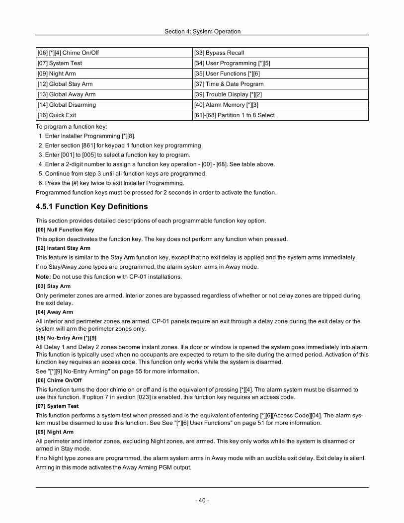
Section 4: System Operation
[06] [*][4] Chime On/Off [33] Bypass Recall
[07] System Test [34] User Programming [*][5]
[09] Night Arm [35] User Functions [*][6]
[12] Global Stay Arm [37] Time & Date Program
[13] Global Away Arm [39] Trouble Display [*][2]
[14] Global Disarming [40] Alarm Memory [*][3]
[16] Quick Exit [61]-[68] Partition 1 to 8 Select
To program a function key:1. Enter Installer Programming [*][8].2. Enter section [861] for keypad 1 function key programming.3. Enter [001] to [005] to select a function key to program.4. Enter a 2-digit number to assign a function key operation - [00] - [68]. See table above.5. Continue from step 3 until all function keys are programmed.6. Press the [#] key twice to exit Installer Programming.Programmed function keys must be pressed for 2 seconds in order to activate the function.
4.5.1 Function Key DefinitionsThis section provides detailed descriptions of each programmable function key option.[00] Null Function Key
This option deactivates the function key. The key does not perform any function when pressed.[02] Instant Stay Arm
This feature is similar to the Stay Arm function key, except that no exit delay is applied and the system arms immediately.If no Stay/Away zone types are programmed, the alarm system arms in Away mode.
Note: Do not use this function with CP-01 installations.[03] Stay Arm
Only perimeter zones are armed. Interior zones are bypassed regardless of whether or not delay zones are tripped duringthe exit delay.[04] Away Arm
All interior and perimeter zones are armed. CP-01 panels require an exit through a delay zone during the exit delay or thesystem will arm the perimeter zones only.[05] No-Entry Arm [*][9]
All Delay 1 and Delay 2 zones become instant zones. If a door or window is opened the system goes immediately into alarm.This function is typically used when no occupants are expected to return to the site during the armed period. Activation of thisfunction key requires an access code. This function only works while the system is disarmed.See "[*][9] No-Entry Arming" on page 55 for more information.[06] Chime On/Off
This function turns the door chime on or off and is the equivalent of pressing [*][4]. The alarm system must be disarmed touse this function. If option 7 in section [023] is enabled, this function key requires an access code.[07] System Test
This function performs a system test when pressed and is the equivalent of entering [*][6][Access Code][04]. The alarm sys-tem must be disarmed to use this function. See See "[*][6] User Functions" on page 51 for more information.[09] Night Arm
All perimeter and interior zones, excluding Night zones, are armed. This key only works while the system is disarmed orarmed in Stay mode.If no Night type zones are programmed, the alarm system arms in Away mode with an audible exit delay. Exit delay is silent.Arming in this mode activates the Away Arming PGM output.
- 40 -
Section 4: System Operation
[12] Global Stay Arm
This function arms all partitions assigned to the user in Stay mode, provided they are ready to arm. If a partition is not ready,the system cannot be armed. An access code is required with this option.[13] Global Away Arm
This function arms all partitions assigned to the user in Away mode, provided they are ready to arm. If a partition is not ready,the system cannot be armed. An access code is required with this option.[14] Global Disarming
This function disarms all partitions assigned to the user. An access code is required with this option.[16] Quick Exit
Pushing this key allows the user to open and close an entry/exit door without disarming the system. This function is equi-valent to entering [*][0] at the keypad while the partition is armed. If quick exit is not enabled on the system, or if the system isdisarmed, pressing this key causes an error tone. An access code is not required to use this key. See "[015] System Option3" on page 87 for more information.[17] Arm Interior
This key removes or enables automatic bypass on all Stay/Away zones (equivalent to pressing [*][1] while armed).If this function is performed while stay armed and, Night zones are programmed, the system arms in Night mode. If no Nightzones are programmed, the system arms in Away mode. If armed in Night or Away mode, this key switches the system backto Stay mode. Pressing this key does not switch the arming mode from Night to Away.This key only works while the system is armed and requires an access code entry if section [015] option 4 is disabled.[21]-[24] Command Output 1 to 4
This function controls command outputs 1-4 and is the equivalent of entering [*][7][X], where X is 1, 3 or 4.An access code is required to use this function.Selecting command output 2 is the equivalent of pressing [*][7][2] sensor reset. See "103 – Sensor Reset [*][7][2]" on page 73for more information.[29] Bypass Group Recall
This function bypasses all zones belonging to the bypass group.Zones must be saved in the bypass group for this function key to operate. An access code is required to use this feature ifsection [023] option 4 is enabled.
Note: Do not use with wireless keys.[31] Local PGM Activate
This function controls a PGM connected to a keypad.[32] Bypass Mode
This function places the keypad in Zone Bypass mode. Selecting this function is the equivalent of pressing [*][1] while dis-armed. If an access code is required for bypassing, the user must enter the access code before using this function. Anaccess code is required if section [023] option 4 is enabled.[33] Bypass Recall
This function bypasses the same set of zones that were bypassed the last time the partition was armed. This function is equi-valent to pressing [999] while in the [*][1] menu. An access code is required to use this feature if section [023] option 4 isenabled.[34] User Programming
This function is the equivalent of entering [*][5]. A master or supervisor access code is required to use this function. This keyonly works while the system is disarmed.[35] User Functions
This function puts the keypad in user programming mode and is the equivalent of entering [*][6]. An access code is requiredto use this function. If section [023] option 8 is off, only the Master or Supervisor code can access the [*][6] menu.[37] Time & Date Program
This function places the keypad in date/time programming mode. A valid access code is required.
- 41 -
Section 4: System Operation
[39] Trouble Display
This function puts the keypad in trouble display mode and is equivalent to pressing [*][2]. This function only works while thesystem is disarmed. This function key requires a code if section [023] option 5 is enabled.[40] Alarm Memory
This function puts the keypad in alarm memory display mode and is equivalent to pressing [*][3]. This function only workswhile the system is disarmed. This function key requires a code if section [023] option 6 is enabled.[61]-[68] Partition 1 to 8 Select
This function selects partition 1-8 when the assigned key is pressed. Pressing and holding the key for 2 seconds selects thenext partition.
4.6 Language Selection
The keypad can be programmed to display messages and labels in different languages. Perform the following from theInstaller Programming menu:1. Enter installer programming [*][8][installer code]2. Enter section [000]>[000].3. Select a language using the scroll buttons or by entering a hotkey:
Table 4-3 Languages
[01] – English [15] – Greek
[02] – Spanish [16] – Turkish
[03] – Portuguese [18] – Croatian
[04] – French [19] – Hungarian
[05] – Italian [20] – Romanian
[06] – Dutch [21] – Russian
[07] – Polish [22] – Bulgarian
[08] – Czech [23] – Latvian
[09] – Finish [24] – Lithuanian
[10] – German [25] – Ukrainian
[11] – Swedish [26] – Slovakian
[12] – Norwegian [27] – Serbian
[13] – Danish [28] – Estonian
[14] – Hebrew [29] – Slovenian
4. Press [#] to exit.
4.7 [*] Commands
[*] commands provide convenient access to alarm system features. The following commands are available:[*][1] Bypass zones[*][2] View troubles[*][3] View alarms in memory[*][4] Door chime on/off[*][5] User programming[*][6] User functions[*][7] Command output 1-4 on/off[*][8] Installer programming mode
- 42 -
Section 4: System Operation
[*][9] No entry arming[*][0] Quick arm/ExitWhile in a [*] command menu, use the [*] key to select an option and the [#] key to exit to the previous screen. On an LCDkeypad, use the scroll keys to view options.
4.7.1 [*][1] Bypass or Stay/Away/Night ZonesThe [*][1] command functions differently depending on whether the system is armed or disarmed.
Note: For UL/ULC listed installations, group bypass is not allowed.
When The Alarm System is DisarmedUsers can bypass individual zones or a programmed group of zones using the [*][1] keypad command. Zones are commonlybypassed if users want to have access to an area while the partition is armed, or to bypass a defective zone (bad contact,damaged wiring) until service can be provided. A bypassed zone does not cause an alarm.When the partition is disarmed, all zones that were bypassed using [*][1] are no longer bypassed, except for 24-hr zones.If the Code Required for Bypass option is enabled, an access code is required to enter bypass mode. Only access codeswith the Bypass attribute enabled can bypass zones (see "Access Code Attributes" on page 49).
Bypassing zones with an LCD keypad:1. Ensure the system is disarmed.2. Press [*] to enter the function menu. The keypad displays “Press [*] for < > Zone Bypass.”3. Press [1] or [*], then key in your access code (if required).4. Scroll to a zone or key in the three-digit zone number. Only zones enabled for zone bypassing are displayed. Enter the 3-digit zone number or scroll to the desired zone and press [*] to bypass the zone.“B” appears on the display to indicate the zone is bypassed. If a zone is open, “O” appears on the display. When an openzone is bypassed, the “O” is replaced by “B.”5. To clear a bypassed zone, repeat the above procedure. The “B” disappears from the display indicating that the zone isno longer bypassed.6. To exit bypass mode and return to the ready state, press [#].
Bypassing zones with a LED/ICON keypad:1. Ensure the system is disarmed.2. Press [*][1], then enter your access code (if required).3. Enter the three-digit number of the zone(s) to be bypassed. The zone light turns on to indicate that the zone is bypassed.4. To clear a bypassed zone, repeat the above procedure. On LED keypads, the zone light turns off to indicate that the zoneis no longer bypassed.5. To exit bypass mode and return to the ready state, press [#].
Note: LED Keypads display the bypass status of zones 1-16 only.
Other Bypass Features:The following features are also available on the [*][1] zone bypass menu:Bypass Open Zones
Displays all currently open or bypassed zones. Use the scroll keys to view zones. Open zones are indicated by an (O). Tobypass a zone, press [*]. A bypassed zone is indicated by a (B).
Note: Zones with tampers or faults must be manually bypassed.Bypass Group
Displays a programmed group of zones (bypass group) commonly bypassed. Press [*] to bypass all zones in the group.Program Bypass Group
To program a bypass group, bypass all desired zones then select Bypass Options > Program Bypass Group. The selectedzones are saved to the bypass group. When finished, press [#] to exit.In order to program a bypass group, a master or supervisor code with access to the appropriate partition must be used.
- 43 -
Section 4: System Operation
Bypass Recall
Press [*] while in this menu to bypass the same group of zones that were bypassed the last time the partition was armed.Clear Bypasses
Press [*] to clear all bypasses.Shortcuts from the [*][1] base menu:
991 = bypass group995 = program group 1998 = bypass open zones999 = bypass recall000 = clear group
When The Alarm System is ArmedWhen the system is armed, pressing [*][1] toggles between stay, away or night arming. If a night zone is on the system, press-ing [*][1] either prompts the user for an access code if required, or sounds an acknowledgment tone and changes the armingmode.
Note: If section [022], Option 5 [Stay/Away Toggle] is on, the system does not change from Away to Stay mode.
The zone attribute for zone bypassing must be enabled (see section [002] Zone Attributes, Option 04).Holdup zones should not be part of bypass groups.A zone that is manually bypassed via [*][1] will bypass the alarm, fault, and tamper conditions when DEOL is used.If a 24-hour zone is bypassed, ensure that the zone is restored or disabled before removing the bypass.
4.7.2 [*][2] Trouble DisplayThis feature is used to view system troubles. If a trouble is present, the keypad Trouble indicator illuminates and an audibleindication is emitted (two short beeps every 10 seconds, except while in AC failure). Silence the audible indicator by press-ing [#].Troubles may be viewed while the system is armed or disarmed. The system may be programmed to show all troubles whilearmed or only fire troubles. See section [13] option 3 on page 86 for details.The system can be configured to require a user code to view [*][2] system troubles. See section [023] option 5.To view trouble conditions:
l Press [*][2] to enter the Trouble menu.l On an LCD keypad, scroll to a trouble type then press [*] to view the specific trouble. The zone name and trouble con-dition for each trouble are displayed on the screen.
l On LED/ICON keypads, zone indicator lights illuminate to identify existing trouble types (e.g., Zone light 1 representsService Required trouble type). Press the number key corresponding to a zone light to view the specific trouble.Lights 1-12 illuminate to indicate the trouble as follows:
Table 4-4 : Trouble Indications
Trouble 01 – Service Required:[01] Bell Circuit Trouble: The bell circuit is open.[02] RF Jam: The HSM2HOSTx has detected an RF Jam condition.[03] Aux Supply Trouble: The alarm controller, HSM2204 or HSM2300 has an overcurrent condition on Aux.[04] Loss of Clock: System time and date require programming.[05] Output 1 Fault: An HSM2204 module has detected an open condition on output #1.
- 44 -
Section 4: System Operation
Trouble 02 – Battery Trouble:[01] Panel Low Battery Trouble: The battery voltage (under load) is below 11.5V. Restores at 12.5V.[02] Panel No Battery: No battery connected to alarm controller.[04] HSM2204 01 - 04 Low Battery: An HSM2204 has a battery voltage less than 11.5V.[05] HSM2204 01 - 04 No Battery: No battery connected to HSM2204.[07] HSM2300 01 - 04 Low Battery: An HSM2300 has a battery voltage less than 11.5V[08] HSM2300 01 - 04 No Battery: No battery connected to HSM2300.Trouble 03 – Bus Voltage:[01] HSM2HOSTx Bus Low Voltage: The HSM2HOSTx module has measured less than 6.3V on its Aux input.[02] Keypad 01 - 16 Bus Low Voltage: A hardwired keypad has a bus voltage of less than 6.9V for ICON/LCD (RF version)and 7.7V for non-RF models.[04] HSM2108 01 - 15 Bus Low Voltage: A zone expander has a bus voltage of less than 5.9V.[05] HSM2300 01 - 04 Bus Low Voltage: A power supply has a bus voltage of less than 6.9V.[06] HSM2204 01 - 04 Bus Low Voltage: A high current output module has a bus voltage of less than 6.9V.[08] HSM2208 01 - 16 Bus Low Voltage: The low current output module has detected a voltage less than 5.9V on its auxinput.[09] HSM2955 Bus Low Voltage: The audio module has detected a voltage less than 9.65V on its aux input.
Trouble 04 – AC Troubles:[01] Zone 001 - 128 AC Trouble: An AC trouble has been detected on a PGX934 PIR + Camera.[03] Siren 01 - 16 AC: A siren has an AC trouble.[04] Repeater 01 - 08 AC: A wireless repeater has an AC trouble.[05] HSM2300 01 - 04 AC: An HSM2300 has an AC trouble.[06] HSM2204 01 - 04 AC: An HSM2204 has an AC trouble.[07] Panel AC: The alarm controller has an AC failure condition.
Trouble 05 – Device Faults:[01] Zone 001 - 128: A zone is in fault. Additional information displayed on LCD keypads for the following troubles: FireTrouble (2-W Smoke, PGX916, PGX926), Freeze (PGX905), Self Test (PGX984), CO (PGX913), and Probe Disconnected(PGX905). Also generated by a short on hardwired zones when DEOL is used or by a wireless supervisory fault.[02] Keypad 01 - 16: A wireless or hardwired keypad is in fault.[03] Siren 01 - 16: A siren is in fault.[04] Repeater 01 - 08: A wireless repeater is in fault (supervisory or loss of AC/DC).
Trouble 06 – Device Low Battery:[01] Zone 001- 128: Wireless zone has a low battery.[02] Keypad 01-16: Keypad has a low battery.[03] Siren 01 - 16: Siren has a low battery.[04] Repeater 01 - 08: Repeater has a low battery.[05] User 01 - 95: Wireless Key has a low battery.
Trouble 07 – Device Tampers:[01] Zone 001 - 128 Tamper: A wireless or hardwired zone configured for DEOL operation is in tamper.[02] Keypad 01 - 16 Tamper: A hardwired or wireless keypad is in tamper.[03] Siren 01 - 16 Tamper: A wireless siren is in tamper.[04] Repeater 01 - 08 Tamper: A wireless repeater is in tamper.[05] Audio Station 01 - 04 Tamper: An audio station connected to an HSM2955 is in tamper.
- 45 -
Section 4: System Operation
Trouble 08 – RF Delinquency Trouble:[01] Zone 001 - 128 RF Delinquency: No response from a wireless zone for 13 minutes. This trouble prevents arming untilacknowledged or cleared using [*][2].[02] Keypad 01 - 16 RF Delinquency: No response from a wireless keypad for 13 minutes.[03] Siren 01 - 16 RF Delinquency: No response from a wireless siren for 13 minutes.[04] Repeater 01 - 16 RF Delinquency: No response from a wireless repeater for 13 minutes.
Trouble 09 – Module Supervisory Trouble:[01] HSM2HOSTx not responding.[02] Keypad 01 - 16 not responding.[04] HSM2108 01 - 15 not responding.[05] HSM2300 01 - 04 not responding.[06] HSM2204 01 - 04 not responding.[08] HSM2208 01 - 16 not responding.[09] HSM2955 is not responding.Trouble 10 – Module Tamper:[01] HSM2HOSTx Tamper.[02] Keypad 01 - 16 Tamper.[04] HSM2108 01 - 15 Tamper.[05] HSM2300 01 - 04 Tamper.[06] HSM2204 01 - 04 Tamper.[08] HSM2208 01 - 16 Tamper.[09] HSM2955 TamperTrouble 11 – Communications:[01] TLM: Telephone line disconnected from control panel.[02] Receiver 01-04 FTC Trouble: Failure to communicate using programmed receiver paths.[03] Alt. Comm SIM Lock: SIM card has incorrect or unrecognized PIN.[04] Alt. Comm Cellular: Radio or SIM card failure, low signal strength detected, or cellular network fault.[05] Alt. Comm Ethernet: Ethernet connection unavailable. A valid IP address is either not programmed or the module wasunable to get an IP with DHCP.[06] Receiver 01-04 Absent: Alternate communicator unable to initialize a receiver.[07] Receiver 01-04 Supervision: Alternate communicator unable to communicate with a receiver.[09] Alt. Comm Fault: The alternate communicator has stopped responding.[10] Alt Comm FTC Trouble: The alternate communicator has failed to communicate an internal event not generated by thepanel.
Trouble 12 – Not Networked Troubles:[01] Zone 001-128 Not Networked Trouble: Generated when a zone becomes out of sync with the wireless network or hasnot been synchronized with the network after enrollment.[02] Keypad 01-16 Not Networked Trouble: Generated when a keypad becomes out of sync with the wireless network orhas not been synchronized with the network after enrollment.[03] Siren 01-16 Not Networked Trouble: Generated when a siren becomes out of sync with the wireless network or hasnot been synchronized with the network after enrollment.[04] Repeater 01-08 Not Networked Trouble: Generated when a repeater becomes out of sync with the wireless network orhas not been synchronized with the network after enrollment.[05] User 01 - 95 Not Networked Trouble: Generated when a wireless key becomes out of sync with the wireless networkor has not been synchronized with the network after enrollment.
- 46 -
Section 4: System Operation
IMPORTANT!Ensure you have the following information available before contacting Customer Support :
l Alarm controller type and version, (e.g., HSM2064 1.0):
Note: Version number can be accessed by entering [*][Installer Code][900] on any LCD keypad. This information is also loc-ated on a sticker on the printed circuit board.
l List of modules connected to control panel, (e.g., HSM2108, HSM2HOSTx etc.) .
4.7.3 [*][3] Alarm Memory DisplayThe Memory light flashes if an alarm, tamper or fault event occurred during the last armed period or while the panel was dis-armed (24 hour zones). Press [*][3] to view zones in alarm memory. To clear the memory, arm and disarm the system. Whenviewing alarms in memory, LCD keypads indicate the last zone that has gone into alarm first, followed by other alarms innumerical order.This feature can be programmed to require an access code. See "[023] System Option 11" on page 94, option 6 for details.A programmable function key may be configured to display alarms in memory. See "Keypad Function Keys" on page 39 fordetails.
4.7.4 [*][4] Door Chime Enable/DisableWhen this feature is enabled, the keypad emits a tone whenever a zone programmed as a Chime type is opened or closed.Pressing [*][4] toggles between enabled and disabled. The door chime attribute for each zone is programmed in section[861]-[876], subsections [101]-[228].A function key can also be programmed to enable/disable this feature. See "Keypad Function Keys" on page 39 for details.This feature may require an access code. See "[023] System Option 11" on page 94, option 7 for details.The following door chime sounds may be selected:
l 6 beepsl "Bing-Bong"l "Ding-Dong"l Alarm tonel Zone Name -Voice Annunciation (HS2LCDWF keypads only)
4.7.5 [*][5] Program Access CodesUse this section to perform the following functions:
l press [1] to program user codes 02-95, and master code 01l press [2] to enroll a proximity tagl press [3] to add a custom label for each userl press [4] to assign users to partitionsl press [5] to program user attributes
Assign Access CodesIn order to access alarm system functionality, users must be added to the system. This involves creating a unique accesscode and assigning attributes to each user. Access codes are programmed via the [*][5] menu.
- 47 -
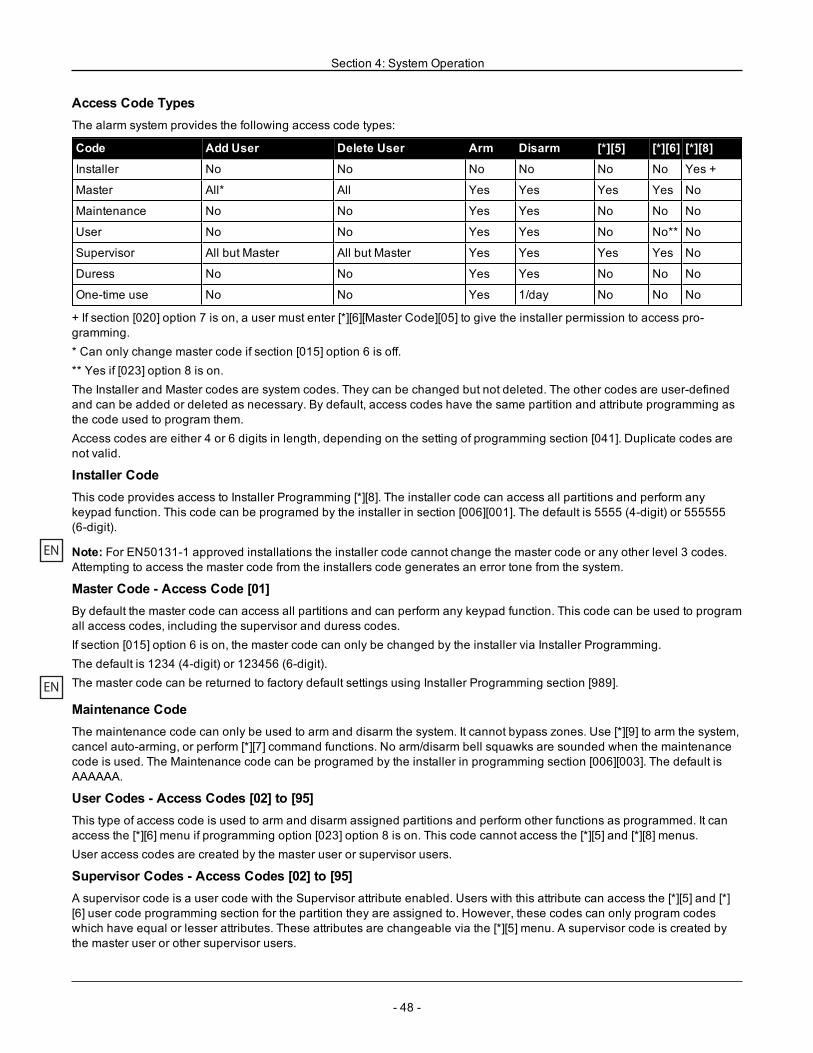
Section 4: System Operation
Access Code TypesThe alarm system provides the following access code types:
Code Add User Delete User Arm Disarm [*][5] [*][6] [*][8]
Installer No No No No No No Yes +
Master All* All Yes Yes Yes Yes No
Maintenance No No Yes Yes No No No
User No No Yes Yes No No** No
Supervisor All but Master All but Master Yes Yes Yes Yes No
Duress No No Yes Yes No No No
One-time use No No Yes 1/day No No No
+ If section [020] option 7 is on, a user must enter [*][6][Master Code][05] to give the installer permission to access pro-gramming.* Can only change master code if section [015] option 6 is off.** Yes if [023] option 8 is on.The Installer and Master codes are system codes. They can be changed but not deleted. The other codes are user-definedand can be added or deleted as necessary. By default, access codes have the same partition and attribute programming asthe code used to program them.Access codes are either 4 or 6 digits in length, depending on the setting of programming section [041]. Duplicate codes arenot valid.
Installer CodeThis code provides access to Installer Programming [*][8]. The installer code can access all partitions and perform anykeypad function. This code can be programed by the installer in section [006][001]. The default is 5555 (4-digit) or 555555(6-digit).
EN Note: For EN50131-1 approved installations the installer code cannot change the master code or any other level 3 codes.Attempting to access the master code from the installers code generates an error tone from the system.
Master Code - Access Code [01]By default the master code can access all partitions and can perform any keypad function. This code can be used to programall access codes, including the supervisor and duress codes.If section [015] option 6 is on, the master code can only be changed by the installer via Installer Programming.The default is 1234 (4-digit) or 123456 (6-digit).
EN The master code can be returned to factory default settings using Installer Programming section [989].
Maintenance CodeThe maintenance code can only be used to arm and disarm the system. It cannot bypass zones. Use [*][9] to arm the system,cancel auto-arming, or perform [*][7] command functions. No arm/disarm bell squawks are sounded when the maintenancecode is used. The Maintenance code can be programed by the installer in programming section [006][003]. The default isAAAAAA.
User Codes - Access Codes [02] to [95]This type of access code is used to arm and disarm assigned partitions and perform other functions as programmed. It canaccess the [*][6] menu if programming option [023] option 8 is on. This code cannot access the [*][5] and [*][8] menus.User access codes are created by the master user or supervisor users.
Supervisor Codes - Access Codes [02] to [95]A supervisor code is a user code with the Supervisor attribute enabled. Users with this attribute can access the [*][5] and [*][6] user code programming section for the partition they are assigned to. However, these codes can only program codeswhich have equal or lesser attributes. These attributes are changeable via the [*][5] menu. A supervisor code is created bythe master user or other supervisor users.
- 48 -
Section 4: System Operation
Duress Codes - Access Codes [02] to [95]Duress codes function the same as user access codes, except they transmit a duress reporting code when used to performany function on the system.Duress codes cannot be used to access [*][5], [*][6] or [*][8] menus.Duress codes are created by the master user or supervisor users.
Note: Section [019] option 6 must be on to select the Duress Codes attribute.
One Time Use CodeA one time use code is a user code with the One Time User attribute enabled. This access code enables the user to arm thealarm system an unlimited number of times. However, a user with this code can only disarm the system once per day. Theability to disarm is reset at midnight or when the one time user code is keyed in by the master code user.
Note: One time use code cannot be applied to wireless keys.One time use codes are created by the master user or supervisor users.
To add an access code using an LCD keypad:1. Press [*][5][master/supervisor code] to edit access codes 02-95.2. Use the scroll keys to select a user then press [*] to edit.3. On the “Press (*) for Access Code” menu, press [*]. The current access code is displayed.4. Key in the new access code. The code is saved when the last number is keyed in.To erase an access code, select the user number and enter [*] as the first digit. All digits of the access code must beentered.A “-” beside a user code indicates it is not programmed. A “P” indicates the code is programmed. A “T” indicates the code isprogrammed and a proximity tag is enrolled.
On an LED/ICON keypad:1. Press [*][5][master/supervisor code]2. Key in a 2-digit user number.3. Press [1] to select access code.4. Key in a new access code.
Access Code AttributesEach user code has 6 attributes that can be toggled on or off.The default attributes of an access code are the same as the code used to enter [*][5], whether a new code is programmed oran existing one is edited. The available attributes are as follows:
l Supervisorl Duress codel Zone bypassingl Remote accessl Bell squawkl One time use code
1 – SupervisorConverts standard user into supervisor user. See " " on page 47 for details.
2 – Duress CodeConverts standard user code into duress code. See " " on page 47 for details.
3 – Zone BypassingUsers with this attribute can bypass zones. Section [023] option 4, Access code required for [*][1], must be on to use thisattribute.
4 – Remote AccessUsers with this attribute can access the alarm system remotely via SMS.
- 49 -
Section 4: System Operation
7 – Bell SquawkWhen this option is assigned, the main bell squawks when the alarm system is away armed. For example, use the arm/dis-arm bell squawk attribute to have wireless key access codes squawk the bell, while other codes are silent. To do this, enablethis attribute on all access codes associated with wireless keys. This option is off by default for all access codes.
Note: One squawk indicates arming completed; two squawks indicates disarming completed.Note: This feature is independent of the system option “Bell Squawk on Away Arming.” See "[017] System Option 5" on page89
The master code's attributes cannot be changed from default. The bell squawk is off at default.
8 – One Time Use CodeConverts standard user code into one time use code. See " " on page 47 for details. Do not apply this code to users with wire-less keys assigned.
Using an LCD keypad:1. Press [*][5][Master Code].2. Use the scroll keys to choose a user (02-95) then press [*] to select.3. Scroll to “Press [*] for User Options” then press [*] to select.4. Scroll to a user attribute and press [*] to toggle it on or off.
Using an LED/ICON keypad:1. Press [*][5][Master Code].2. Key in the 2-digit number of the access code to edit. [5] for attribute programming.3. Press the keypad number key corresponding to an attribute to toggle it on or off.
Add User LabelsCustom labels can be programmed for each user to more easily identify them on the alarm system. Labels can be a max-imum of 16 characters.
Using an LCD keypad:1. Press [*][5] then select a user (02-95).2. On the “Press [*] for User Labels” screen, press [*].3. Key in the custom user label. For instructions on how to input labels, See "Adding Labels" on page 61
Assigning Proximity TagsThis section is used to assign proximity tags to users.
Note: A proximity tag cannot be assigned to the master code.
Using an LCD keypad:1. In the [*][5] menu, select a user or enter a user number.2. Select “Press [*] for Prox Tag”, then pass the enrolled tag near the tag reader on the keypad. A proximity tag can only beassigned to one user at a time. Invalid (un-enrolled) proximity tags cannot be used.To delete a proximity tag:1. Select a user and then select Press [*] for Prox Tag.2. Press the [*] key when prompted to delete the proximity tag.Using an LED/ICON keypad:1. Press [*][5][Master/Supervisor Code].2. Key in a 2-digit user code.3. Key in [2].4. Pass the enrolled tag near the tag reader on the keypad.
- 50 -
Section 4: System Operation
To increase authentication flexibility, user access can be achieved by entering a valid user code or by swiping a proximitytag. Alternatively, users can be required to enter a valid access code and present a proximity tag. See "[040] User Authentic-ation" on page 97.
Note: A proximity tag can not be assigned to the Master code. If a user code with a proximity tag is deleted, the proximity tagmust be re-enrolled.
Assigning Users to PartitionsEach user code must be assigned to a partition(s) in order for the user to be recognized by the alarm system. By default,each code has the attributes of the code used to program it.Using an LCD keypad:1. Press [*][5][Master Code] then select a user (02-95). An “N” indicates they are not yet assigned to a partition. A “Y” indic-ates they are assigned to a partition.2. Scroll to the partition assignment screen then press [*].3. Use the number keys to assign partitions.4. Press [#] to exit.
Note: The master code has access to all partitions and cannot be modified.Using an LED/ICON keypad:1. Press [*][5][Master/Supervisor Code].2. Key in the 2-digit access code of the user.3. Key in [4]. A zone lights illuminates to indicate which partition the user is currently assigned to. (e.g., if zone light 1 is on,the code is assigned to partition 1).4. Press the keypad number key corresponding to the appropriate partition (e.g., press 1 to assign the user to partition 1).
User Authentication OptionsThe alarm panel can be configured to accept one of two user authentication methods:1. User code or proximity tag - the user can access the system by entering a valid code or by presenting a proximity tag.2. User code and proximity tag - the user must enter a valid code and present a proximity tag to access the system. Theuser code and proximity tag must match. For example, if the tag is associated with user 04, user code 04 must be enteredafter presenting the tag. Any other user code is treated as invalid.See "[040] User Authentication" on page 97.
Note: An access code does not have to be programmed in order for a proximity tag or wireless key to be operational.
4.7.6 [*][6] User FunctionsThe [*][6] command provides access to functions described below. If section [023] option 8 is on, any user code can accessthis menu. If option 7 is off, only the master code can access this menu.Event Buffer
Menu: [*][6][Master Code] > Event BufferKeypad: [*][6][Master Code] > [*]This option is used to view system events stored in the event buffer.Events are listed in the order they occurred, starting with the most recent. The time and date are listed for all events. Someevents may have a second screen with a description. An asterisk (*) on the first screen indicates that a second screen isavailable.If programmed, the event buffer automatically uploads to DLS/SA when it reaches 75% capacity. See section [410] options 3and 5.System Test
Menu: [*][6][Master Code] > System TestKeypad: [*][6][Master Code] + 04Select this option to test the alarm system's bell output, keypad buzzer and lights, communicator and standby battery.
- 51 -
Section 4: System Operation
Time and Date
Use this section to program the alarm system clock.Menu: [*][6][Master Code] > Time and DateKeypad: [*][6][Master Code] + 01Enter time and date using the following format: (HH:MM); (MM-DD-YY). Valid time entries are 00-23 hours, 00-59 minutes.Valid date entries are 01-12 months, 01-31 days.Other programming options that may affect this user function:See "System Times" on page 70.Auto-Arm/Disarm
Menu: [*][6][Master Code] > Auto Arm/DisarmKeypad: [*][6][Master Code] + 02With this feature enabled, the alarm system automatically arms in away mode (stay/away zones active) or disarms at a pro-grammed time each day (see Auto-Arm Time below). The keypad emits three beeps to indicate the system is armed and onelong beep to indicate it is disarmed.All arming inhibit features such as latching tampers, AC inhibit, etc. also inhibit Auto Arming and send the Auto Arm Can-cellation code.Auto-Arm Time
Menu: [*][6][Master Code] > Auto Arm TimeKeypad: [*][6][Master Code] + 03This function is used to program the time of day each alarm system partition automatically arms. To program an auto-armtime, select a day of the week and then key in the time. On LED/ICON keypads, zone lights 1-7 represent Sunday toSaturday. Valid time entries are 00-23 hours: 00-59 minutes.At the programmed time, the keypad buzzers beep for a programmed duration (for ULC commercial burglary installationsminimum duration is 10 minutes) to warn that automatic arming is in progress. The siren also squawks once every 10seconds during this warning period if programmed to do so. When the warning period is complete, the exit delay elapsesthen the system arms in away mode.Auto-arming can be canceled or postponed only by entering a valid access code during the programmed warning period.When a code is entered, the warning is silenced and auto-arming is canceled or postponed, depending on the auto-armpostpone timer. The Auto Arm Cancellation reporting code is transmitted (if programmed).
Note: Auto-arming will not silence an active bell.Note: The Auto Arm Cancellation reporting code is also transmitted if arming is inhibited by one of the following:
l AC / DC Inhibit Arml Latching System Tampersl Zone Expander Supervisory Fault
Other programming options that may affect this function:See "[151]-[158] Partition Auto-Arm/Disarm" on page 97See "[014] System Option 2" on page 86Enable DLS/Allow System Service
Menu: [*][6][Master Code] > System Serv/DLSKeypad: [*][6][Master Code] + 05This function enables and disables the DLS window for either 1 or 6 hours depending on the programming of section [025]option [7].This function also enables the end user to provide or deny access to [*][8] Installer Programming. When enabled, theinstaller can access Installer Programming either by DLS or via [*8] if a pre-programmed window has been set. After the win-dow has expired, Installer Programming is unavailable again until the window is re-opened.
Note: DLS programming is not UL tested.
Other programming options that may affect this function:See "[020] System Option 8" on page 91, and see "[021] System Option 9" on page 93See "[025] System Option 13" on page 96, bit "7 – 1 Hour DLS Window"
- 52 -
Section 4: System Operation
User Call-up
Menu: [*][6][Master Code] > User Call-upKeypad: [*][6][Master Code] + 06When selected, this function makes a single attempt to call the downloading computer. The downloading computer must bewaiting for the call before downloading can be performed. Only one call-up is attempted. If a DLS phone number is not pro-grammed, the alarm panel attempts to reach the DLS computer via IP connection. If the communicator is not properly con-figured for IP, an error tone is sounded.User Walk TestMenu: [*][6][access code] > Walk TestKeypad: [*][6][access code] + 08Selecting this function places the alarm panel into user walk test mode. The Ready, Armed and Trouble LEDs on the keypadflash to indicate that the test is active. If zones are tripped during a walk test, the system sounds a steady 2-second tone onall keypads to indicate that the zone is working correctly.The walk test can be stopped at any time by re-entering [*][6][Master Code][08] on the keypad. The test automatically ter-minates after 15 minutes of inactivity. An audible warning begins 5 minutes prior to automatic termination.
Note: Fire and COalarms are not tested in user's walk test. If a fire or CO alarm is detected, walk test ends automatically and theappropriate reporting codesare sent immediately to the monitoring station. Refer to the manufacturers instructions provided withCOand Fire detectors for testing. This feature is not available in CP-01 systems.Late to Open
Menu: [*][6][Master Code] > Late To OpenKeypad: [*][6][Master Code] + 09This function enables or disables the Late to Open option. This option sends a reporting code to the central monitoring sta-tion if the partition has not been disarmed by a programmed time.Other programming options that may affect this function:See "[201] Open/Close Events 1", option "[211] Miscellaneous Open/Close Events" on page 102.Late to Open Time
Menu: [*][6][Master Code] > Late To Open TimeKeypad: [*][6][Master Code] + 10This function is used to program the time of day the partition must be disarmed by when the Late to Open option is enabled.A separate time can be programmed for each day of the week. Valid data entries are 00:00 - 23:59. 99:99 disables the late toopen feature for the selected day.Select a day of the week by scrolling while in the Late to Open menu, or by using keys 1-7 to select Sunday to Saturdayrespectively.SMS Programming
Menu: [*][6][Master Code] > SMS ProgrammingKeypad: [*][6][Master Code] + 11This function is used to program up to 8 phone numbers for SMS command access and communications. SMS enablesusers to send commands to the alarm panel via a mobile device.Leave an SMS phone number blank to disable it. SMS phone numbers are not related to phone numbers used to dial thecentral monitoring station.
Note: If SMS command and control features are disabled then this function is not accessible. See the alternate com-municator installation manual for more information.Brightness Control
Menu: [*][6][Master Code] > Brightness ControlKeypad: [*][6][Master Code] + 12This function is used to change the brightness level of keypad display backlighting. Use the scroll keys to increase anddecrease brightness or enter a value from 00 to 15. Selecting 00 turns off keypad backlighting.Contrast Control
Menu: [*][6][Master Code] > Contrast
- 53 -
Section 4: System Operation
Keypad: [*][6][Master Code] + 13This function is used to change the contrast level of keypad displays. Use the scroll keys to increase and decrease contrastor enter a value from 00 to 15. Selecting 00 turns off keypad contrast.Buzzer Control
Menu: [*][6][Master Code] > Buzzer ControlKeypad: [*][6][Master Code] + 14This function is used to change the volume level of keypad buzzers.Use the scroll keys (LCD keypads) or the [*] key (LED/ICON keypads) to increase and decrease volume or key in a valuefrom 00 to 15. Selecting 00 turns off the keypad buzzer.
Note: For UL/ULC listed installations, do not turn off the keypad sounder.Authorize Firmware Update
Menu: [*][6][Master Code] > Authorize UpdateKeypad: [*][6][Master Code] + 17This function is used to give authorization to the system to start the firmware upgrade process after all firmware upgrade filesfor the keypads, HSM2HOST, control panel and alternate communicator have been fully downloaded.Once this option is activated, the keypads and system automatically exit [*][6] and indicate that the firmware update is in pro-gress.Interactive Services
Menu: [*][6][Master Code] > Interactive ServKeypad: [*][6][Master Code] + 18This function is used by an alternate communicator to open the Interactive Services menu.
4.7.7 [*][7] Command Outputs 1-4Menu: [*][7][master code if required] > Output ControlKeypad: [*][7][master code if required]This option is used to activate or deactivate command outputs 1 to 4 for each partition and enable command outputs to fol-low a schedule.Using an LCD keypad:1. Press [*][7] to enter Output Control mode.2. Scroll to an output and press [*] to select it, or key in a command output number. The output is toggled on or off or canactivate for a fixed period of time.3. Press [*][7][9] and enter the system master or supervisor code. Scroll to each command output and press [*] to enable ordisable the use of a programmed schedule to control the output.Using an LED/ICON keypad:1. Press [*][7] to enter Output Control mode.2. Key in a command output number. The output is toggled on or off.3. Press [*][7][9] and enter the system master or supervisor code. Press digits 1 to 4 to enable or disable the use of a pro-grammed schedule to control the output.
Note: If no command outputs are programmed this function is not available. Other programming options that may affect thisuser function:
See "121-124 – Command Outputs 1-4" on page 74
4.7.8 [*][8] Installer ProgrammingUse this option to place the alarm system in Installer Programming mode. Installer Programming is used to manually pro-gram alarm panel and module options. An installer’s code is required to access this function.Installer Programming is exited automatically after 20 minutes of inactivity.When viewing data in sections with an LCD keypad, use the [<] and [>] keys to scroll.
- 54 -
Section 4: System Operation
Other programming options that may affect this user function:See "[990] Installer Lockout Enable/Disable" on page 121
4.7.9 [*][9] No-Entry ArmingThis function is used to arm the alarm system while occupants are on the premises. Pressing [*][9] and then keying in anaccess code arms the panel without an entry delay on delay type zones and bypasses stay/away and night type zones.After the exit delay, delay 1 and delay 2 type zones behave the same as instant zones. Stay/away zones remain bypassed.The entry delay can be activated or deactivated at any time while the system is armed using [*][9].
Note: If the alarm system is armed using [*][9], disarming is only possible from a keypad inside the premises unless a wire-less key is used.
Note: Entry of a valid access code is required following this key only when the system is disarmed. When armed, if pro-gramming section [015] option 4 (Quick Arming/Function Key) is off, an access code entry is required.
Global delay zones always have an entry delay, even if the system is armed using [*][9].
4.7.10 [*][0] Quick Arm/ExitThis feature operates differently depending on whether or not the alarm system is armed or disarmed.When disarmed:
Pressing [*][0] arms the alarm system without having to enter an access code. This provides a fast method of arming for reg-ular users and allows users without an access code to arm the system.
Note: The Quick Arm feature (section [015] option 4) must be enabled in order for this function to operate as intended. Func-tion keys also will not require an access code when this option is enabled.When armed:
This feature provides a means to exit the premises while the alarm system is armed without having to disarm then rearm it.Pressing [*][0] starts a 2-minute timer that enables any door programmed as a delay zone to be opened and closed oncewithout triggering an alarm.If the door is not closed at the end of the 2-minute timer, the entry delay sequence begins. Any additional activity on anotherzone triggers the associated alarm or delay sequence.
4.8 SMS Command and Control
The user can perform certain functions on the alarm panel by remote using SMS text messages. In addition, the systemsends SMS messages to the user to confirm commands . SMS programming options are accessed through programmingsection [851].The security system only responds to SMS messages sent from designated phone numbers (programmed in section [851]>[311]-[342]).For more information on SMS command and control, and for a complete listing of communicator programming options, referto the alternate communicator installation manual.
4.8.1 SMS Command and Control FunctionsThe following alarm system functions are controllable via SMS:
l Stay arm the systeml Away arm the systeml Night arm the systeml Disarm the systeml Activate/deactivate command output 1-4l System status requestl Alarm memory requestl Zone bypassl Zone unbypass
SMS text messages must be formatted as follows:<function name><space><partition #><space><access code>
- 55 -
Section 4: System Operation
e.g., Stay Arm partition 1 1234Once the command is received and executed by the alarm system, the user receives a confirmation text message.
Note: Do not use Away Arm if Push to Set [001][072] or Final Door Set [001][016] zones are programmed.
4.9 Visual Verification
This feature enables the central station operator to view captured images of the premises in the event of an alarm event.Combination camera/motion detectors can be installed throughout the premises to provide visual verification coverage. Themicrophone on the camera PIR can be disabled.Visual verification sessions are triggered by the following:
l Fire keyl Medical keyl Panic keyl Alarms detected by armed PIR Cameras
To set up video verification on a partition:l Enroll the camera PIR; [804]l Set video verification options; [804]>[841]:
l [001] Visual Verification Enable/Disablel [002] View Time Windowl [003] View Other Alarms
l Input a custom label to identify the camera PIR; [000]>[001]l Enable this option on the alternate communicator (section [10] option 2).
Refer to the Camera PIR installation manual for more details.
Note: Visual Verification has not been evaluated by UL and shall be disabled for UL certified installations.Note:While an image is being transferred from the PIR camera to a central station receiver, the product cannot capture addi-tional images.
- 56 -
- 57 -
Section 5: Programming
5.1 How to Program
This section describes how to view alarm system programming options using the supported keypad types.
5.2 Programming Methods
The alarm system can be programmed using the following methods:
Table 5-1 Programming Methods
Method Description Procedure
Template pro-gramming
Use pre-defined templates to quickly apply basic programmingand to set up DLS downloading.
Press [899] at the “Enter Section” screen.See Template Programming below fordetails.
DLS pro-gramming
Download and apply programming using DLS 5 v1.3 for Neo v1.0panels and DLS 5 v1.4+ for Neo v1.0 and v1.1 products.
For local DLS, use a PC-Link cable andlaptop with DLS-5 software installed.For remote DLS, use a telephone line, cel-lular network or the Internet.
Installer pro-gramming
Manually program all alarm system and device options. Press [*][8][installer code] while the sys-tem is disarmed.
5.2.1 Template ProgrammingTemplate programming allows the installer to quickly program the minimum functions required for basic operation. Theinstaller is prompted to enter a 5-digit code that selects predefined programming configurations:Digit 1 – zone 1-8 definition optionsDigit 2 – system EOL optionsDigit 3 – alarm controller communications optionsDigit 4 – alarm controller call directionsDigit 5 – DLS connection options(See "Template Programming Tables" on page 202 for programming information).Perform template programming after completing the hardware installation. Ensure you have the information listed belowavailable. Record this information in the programming worksheets for future reference:
l Monitoring station telephone number - provided by the alarm monitoring service.l Monitoring station account code - provided by the alarm monitoring service.l Downloading access code.l Entry delay - installer defined.l Exit delay - installer defined.l Installer code - programmable, unique 4-digit code. The default value is [5555].
To perform template programming:1. Enter [*][8][installer code][899]. If this section has been entered accidentally, press # to exit and the system programmingwill not be changed.2. At the “Enter Data” screen, enter a 5 digit value representing the desired programming options. Reference the templateprogramming tables to determine what values are required for the installation.
Once the 5 digit number has been entered, the installer cannot exit until all sections are completed. Enter new dataand/or press the [#] key to accept the displayed data and proceed to the next section. Changing a single digit, thenpressing the [#] key advances to the next section but does not save the changed data.
3. After entering a 5 digit template programming value, the first telephone number is displayed. Enter the monitoring stationtelephone number after the “D.” Press [#] to complete the entry.4. After programming the first telephone number, enter a system account code.
Section 5: Programming
l The system account code can be any 4 or 6-digit combination of numbers (0-9) and letters (A-F).l To enter letters A through F, press [*] then the numbers 1 through 6 for the letter A through F respectively. Press [*]again to revert back to decimal entry. E.g., to enter “1234FF” press [1234*66].See "[310] Account Codes" on page 106 for additional details. When the system account code programming is com-pleted, enter a partition 1 account code using the same method as the system account code.
5. After programming the partition 1 account code, the downloading access code is displayed. Enter the new downloadingaccess code or press [#] to proceed to the next step. The downloading access code must changed from its default value.6. The next value is a 3 digit partition 1 entry delay time. Press [>][>][>] to accept the default time of 30 seconds (030) orenter an entry delay between 001 and 255. E.g., Press 020 for a delay of 20 seconds. See "[005] System Times" on page70 for additional details. The CP-01 models of the Neo panel will not accept a value less than 30 seconds.7. The next value is a 3 digit partition 1 exit delay time. Press [>][>][>] to accept the default time of 120 seconds or enter anexit delay between 001 and 255. E.g., press 030 for a delay of 30 seconds. See "[005] System Times" on page 70 for addi-tional details. The CP-01 models of the Neo panel will not accept a value less than 45 seconds.8. After programming the exit delay, enter a 4 or 6-digit installer code, depending on the value in "[041] Access Code Digits"on page 97. See "[006] Installer Defined Access Codes" on page 71 for installer code details.9. Template Programming will automatically exit after the installer's code has been programmed.
5.2.2 DLS ProgrammingDLS programming involves downloading custom programming using DLS software and a computer. This can be done loc-ally or by remote.
Note: For UL listed systems an installer must be on the premises.
Local Programming With PC-LinkFollow the steps below in the sequence indicated to set up local programming using DLS:1. Connect AC Wiring.
In a new installation, the backup battery requires 24 Hrs. charging. AC Power is required for PC-Link Programminguntil the battery is charged.
2. Plug the PC-Link header into the alarm controller. A DLS session is initiated on the DLS computer.3. When the session is complete, remove the PC-Link cable from the alarm controller.4. Complete the installation.
Remote ProgrammingDLS programming can be performed remotely by connecting to the alarm system via telephone line, cellular network or Eth-ernet.Refer to Refer to "[401] DLS/SA Options" on page 113. for details.
Note: AC Power must be present for the alarm system to answer incoming calls from DLS.
5.2.3 Installer ProgrammingInstaller Programming is used to manually program alarm system options. Access this mode by keying in [*][8][InstallerCode]. Use the scroll keys to navigate through the menus or jump directly to a specific section by keying in a section number.Programming consists of toggling on and off options in each section or by populating data fields. For descriptions of all pro-gramming options, see "Programming Descriptions" on page 61.
5.2.4 Viewing ProgrammingProgramming sections can be viewed from any system keypad. The method for viewing and selecting programming optionsusing LCD, LED and ICON keypads depends on the keypad type used. See below for specific instructions on programmingwith each keypad type.Generally, programming options are accessed in the following way:1. Enter Installer Programming mode ([*][8]).2. Navigate to a specific programming section.
- 58 -
Section 5: Programming
3. Select an option to view or change its programming.All programming options are numbered and can be accessed by navigating through the menu (LCD) or by keying in the pro-gram section number. For toggle options, the name of the option is displayed (LCD) or LEDs 1-8 are illuminated (LED andICON).Use the keypad numbers to toggle options on or off. Sections requiring data input, such as phone numbers, display the fulldata in fields up to 32 characters long (LCD). To input data, use the scroll keys to select a character then press the keypadbutton corresponding to the number/letter required. Scroll to the next character and repeat the procedure as needed. Pressthe [#] key to save changes and exit the program section.The programming worksheets and descriptions later in this section provide a place to record custom programming settingsand are numerically listed to assist in locating specific sections.
Keypad TypesThe sections below describe how programming is viewed and interpreted using each of the supported keypad types. Formore information on each keypad type, see the instruction sheet included with the keypad.LED and ICONBoth of these keypads use LEDs to communicate information. The programming icon illuminates to indicate the alarm sys-tem is in Installer Programming mode. The Armed light turns off and the Ready light turns on while in a programming section.Programming sections fall under two categories: those that require options to be “toggled” on or off, and those that requiredata to be keyed in.Toggle options are indicated across the top of the display using zone numbers 1-8. For example, if options 1 and 4 are on,the display appears as follows on the different keypads:
41
Figure 5-1 LED and ICON displaysTo enable or disable a toggle option, press the number key on the keypad corresponding to the option.Sections requiring data input, such as phone numbers, display information in a binary format using zone LEDs 1-4 asdescribed in the following chart:
Figure 5-2When a section is entered, the keypad immediately displays the first digit of information programmed. Using the example inFigure 5 above, if zone 1 and 4 are illuminated, the first programmed digit in the section is 9. Use the scroll key [>] toadvance to the next digit.For sections that require multiple two or three-digit numbers, the keypad beeps three times after each entry and moves to thenext item on the list. After the last digit in the section is entered, the keypad beeps rapidly eight times and exits the pro-gramming section. The Ready light turns off and the Armed light turns on.To exit programming at any time, press the [#] key. All changes made up to that point are saved.LCD KeypadLCD keypads use a full-message display that provides visual and numerical navigation through the programming sections.The Armed light illuminates when Installer Programming mode is activated. Use the scroll keys to move through menuoptions and press [*] to select. Alternatively, enter a specific section number. The Armed light flashes to indicate a sub-sec-tion has been selected. Press [*] to select a sub-section. The Ready light illuminates and the information programmed in thesection is displayed.
- 59 -
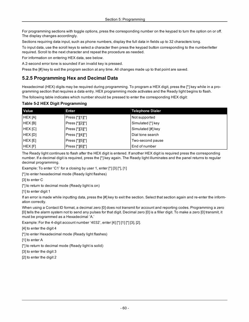
Section 5: Programming
For programming sections with toggle options, press the corresponding number on the keypad to turn the option on or off.The display changes accordingly.Sections requiring data input, such as phone numbers, display the full data in fields up to 32 characters long.To input data, use the scroll keys to select a character then press the keypad button corresponding to the number/letterrequired. Scroll to the next character and repeat the procedure as needed.For information on entering HEX data, see below.A 2-second error tone is sounded if an invalid key is pressed.Press the [#] key to exit the program section at any time. All changes made up to that point are saved.
5.2.5 Programming Hex and Decimal DataHexadecimal (HEX) digits may be required during programming. To program a HEX digit, press the [*] key while in a pro-gramming section that requires a data entry. HEX programming mode activates and the Ready light begins to flash.The following table indicates which number should be pressed to enter the corresponding HEX digit:
Table 5-2 HEX Digit Programming
Value Enter Telephone Dialer
HEX [A]HEX [B]HEX [C]HEX [D]HEX [E]HEX [F]
Press [*][1][*]Press [*][2][*]Press [*][3][*]Press [*][4][*]Press [*][5][*]Press [*][6][*]
Not supportedSimulated [*] keySimulated [#] keyDial tone searchTwo-second pauseEnd of number
The Ready light continues to flash after the HEX digit is entered. If another HEX digit is required press the correspondingnumber. If a decimal digit is required, press the [*] key again. The Ready light illuminates and the panel returns to regulardecimal programming.Example: To enter ‘C1’ for a closing by user 1, enter [*] [3] [*], [1][*] to enter hexadecimal mode (Ready light flashes)[3] to enter C[*] to return to decimal mode (Ready light is on)[1] to enter digit 1If an error is made while inputting data, press the [#] key to exit the section. Select that section again and re-enter the inform-ation correctly.When using a Contact ID format, a decimal zero [0] does not transmit for account and reporting codes. Programming a zero[0] tells the alarm system not to send any pulses for that digit. Decimal zero [0] is a filler digit. To make a zero [0] transmit, itmust be programmed as a Hexadecimal ‘A.’Example: For the 4-digit account number ‘4032’, enter [4] [*] [1] [*] [3], [2].[4] to enter the digit 4[*] to enter Hexadecimal mode (Ready light flashes)[1] to enter A[*] to return to decimal mode (Ready light is solid)[3] to enter the digit 3[2] to enter the digit 2
- 60 -
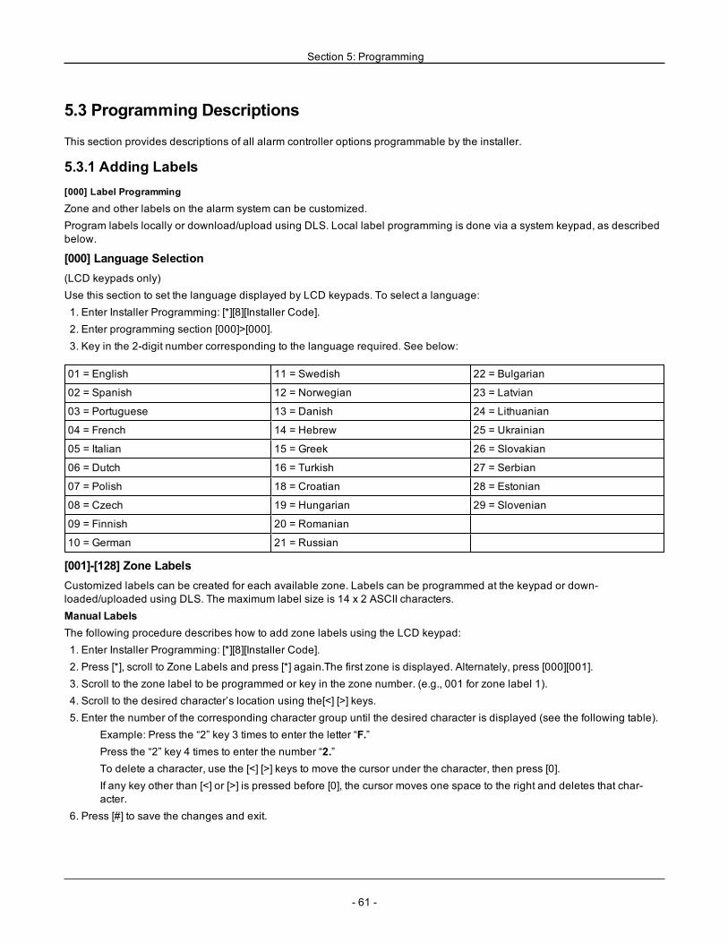
Section 5: Programming
5.3 Programming Descriptions
This section provides descriptions of all alarm controller options programmable by the installer.
5.3.1 Adding Labels[000] Label Programming
Zone and other labels on the alarm system can be customized.Program labels locally or download/upload using DLS. Local label programming is done via a system keypad, as describedbelow.
[000] Language Selection(LCD keypads only)Use this section to set the language displayed by LCD keypads. To select a language:1. Enter Installer Programming: [*][8][Installer Code].2. Enter programming section [000]>[000].3. Key in the 2-digit number corresponding to the language required. See below:
01 = English 11 = Swedish 22 = Bulgarian
02 = Spanish 12 = Norwegian 23 = Latvian
03 = Portuguese 13 = Danish 24 = Lithuanian
04 = French 14 = Hebrew 25 = Ukrainian
05 = Italian 15 = Greek 26 = Slovakian
06 = Dutch 16 = Turkish 27 = Serbian
07 = Polish 18 = Croatian 28 = Estonian
08 = Czech 19 = Hungarian 29 = Slovenian
09 = Finnish 20 = Romanian
10 = German 21 = Russian
[001]-[128] Zone LabelsCustomized labels can be created for each available zone. Labels can be programmed at the keypad or down-loaded/uploaded using DLS. The maximum label size is 14 x 2 ASCII characters.Manual LabelsThe following procedure describes how to add zone labels using the LCD keypad:1. Enter Installer Programming: [*][8][Installer Code].2. Press [*], scroll to Zone Labels and press [*] again.The first zone is displayed. Alternately, press [000][001].3. Scroll to the zone label to be programmed or key in the zone number. (e.g., 001 for zone label 1).4. Scroll to the desired character’s location using the[<] [>] keys.5. Enter the number of the corresponding character group until the desired character is displayed (see the following table).
Example: Press the “2” key 3 times to enter the letter “F.”Press the “2” key 4 times to enter the number “2.”To delete a character, use the [<] [>] keys to move the cursor under the character, then press [0].If any key other than [<] or [>] is pressed before [0], the cursor moves one space to the right and deletes that char-acter.
6. Press [#] to save the changes and exit.
- 61 -
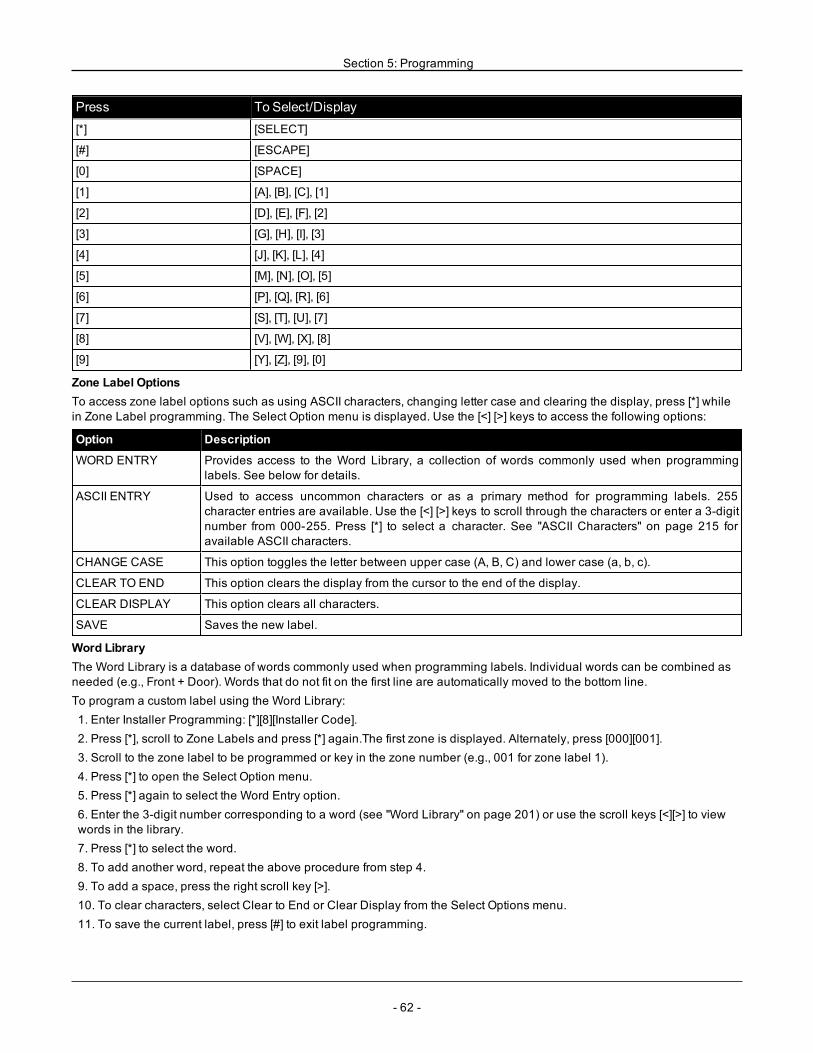
Section 5: Programming
Press To Select/Display[*] [SELECT]
[#] [ESCAPE]
[0] [SPACE]
[1] [A], [B], [C], [1]
[2] [D], [E], [F], [2]
[3] [G], [H], [I], [3]
[4] [J], [K], [L], [4]
[5] [M], [N], [O], [5]
[6] [P], [Q], [R], [6]
[7] [S], [T], [U], [7]
[8] [V], [W], [X], [8]
[9] [Y], [Z], [9], [0]
Zone Label OptionsTo access zone label options such as using ASCII characters, changing letter case and clearing the display, press [*] whilein Zone Label programming. The Select Option menu is displayed. Use the [<] [>] keys to access the following options:
Option Description
WORD ENTRY Provides access to the Word Library, a collection of words commonly used when programminglabels. See below for details.
ASCII ENTRY Used to access uncommon characters or as a primary method for programming labels. 255character entries are available. Use the [<] [>] keys to scroll through the characters or enter a 3-digitnumber from 000-255. Press [*] to select a character. See "ASCII Characters" on page 215 foravailable ASCII characters.
CHANGE CASE This option toggles the letter between upper case (A, B, C) and lower case (a, b, c).
CLEAR TO END This option clears the display from the cursor to the end of the display.
CLEAR DISPLAY This option clears all characters.
SAVE Saves the new label.
Word LibraryThe Word Library is a database of words commonly used when programming labels. Individual words can be combined asneeded (e.g., Front + Door). Words that do not fit on the first line are automatically moved to the bottom line.To program a custom label using the Word Library:1. Enter Installer Programming: [*][8][Installer Code].2. Press [*], scroll to Zone Labels and press [*] again.The first zone is displayed. Alternately, press [000][001].3. Scroll to the zone label to be programmed or key in the zone number (e.g., 001 for zone label 1).4. Press [*] to open the Select Option menu.5. Press [*] again to select the Word Entry option.6. Enter the 3-digit number corresponding to a word (see "Word Library" on page 201) or use the scroll keys [<][>] to viewwords in the library.7. Press [*] to select the word.8. To add another word, repeat the above procedure from step 4.9. To add a space, press the right scroll key [>].10. To clear characters, select Clear to End or Clear Display from the Select Options menu.11. To save the current label, press [#] to exit label programming.
- 62 -
Section 5: Programming
[051] Zone Tamper LabelThis label is displayed when a zone is tampered. The maximum label size is 14 x 1 ASCII characters.
[052] Zone Fault LabelThis label is displayed when a zone is in fault. The maximum label size is 14 x 1 ASCII characters.
[064] CO Alarm MessageUse this section to program a custom label that is displayed on keypads during a carbon monoxide alarm. The maximumlabel size is 14 x 2 characters.
[065] Fire Alarm MessageUse this section to program a custom label that is displayed on keypads during a fire alarm. The maximum label size is 14 x2 characters.
[066] Fail To Arm Event MessageThis message is displayed on all partition keypads if a user attempts to arm the system when it is not ready to arm. The mes-sage clears after five seconds. The maximum label size is 16 x 2 characters.
[067] Alarm When Armed Event MessageThis message is displayed if an alarm occurred while the system was armed. The message is displayed when the system isdisarmed and remains on the screen for 5 seconds. Following this, the zones that went into alarm are displayed. The max-imum label size is 16 x 2 characters.
[100] System LabelUse this section to program a custom label for the security system. This label is used in the event buffer when system eventsoccur. The maximum label size is 14 x 1 characters.
[101]-[108] Partition 1-8 LabelsUse this section to program a name for each partition for display on partition keypads and event messages. The maximumlabel size is 14 x 2 characters. See "Programming" on page 57 for specific instructions on how to program labels.
[201]-[208][001]-[004] Partition Command Output LabelsUse this section to program custom labels for command outputs. These labels are used with output activation events in theevent buffer. Enter subsection [201] to [208] to select partition 1 to 8, then enter subsection [001] to [004] to select commandoutput 1 to 4 label.The maximum label size is 14 x 2 characters. See "Programming" on page 57 for specific instructions on how to programlabels.
[601]-[604] Schedule LabelsUse this section to program custom labels for command output schedules. These labels are used to identify schedules forPGM command outputs 1-4. The maximum label size is 16 characters. See "Programming" on page 57 for specific instruc-tions on how to program labels.
[801] Keypad LabelsUse this section to create custom labels for keypads on the system. Select 001-016 for keypads 1-16.
[802][001]-[015] HSM2108 Zone Expander LabelsUse this section to create custom labels for Zone expanders on the system. Select 001-015 for zone expanders 1-15.
[803][001]-[016] HSM2208 Output Expander LabelUse this section to create a custom label for the output expander. Select 001 for HSM2208. Select 001-016 for outputexpanders 1-16.
[806] HSM2HOSTx LabelUse this section to create a custom label for the 2-way wireless transceiver.
- 63 -
Section 5: Programming
[808] HSM2955 LabelUse this section to create a custom label for the 2-way wireless transceiver.
[809][001]-[004] HS2300 Power Supply LabelUse this section to create custom labels for power supplies on the system. Select 001-004 for power supply 1-4.
[810][001]-[004] HS2204 High-Current Output Supply LabelUse this section to create custom labels for high-current output supplies on the system. Select 001-004 for output supply 1-4.
[815] Alternate Communicator LabelUse this section to create a custom label for the alternate communicator.
[820][001]-[016] Siren LabelsUse this section to create custom labels for sirens on the system. Select 001-016 for sirens 1-16.
[821][001]-[008] Repeater LabelsUse this section to create custom labels for wireless repeaters on the system. Select 001-008 for repeater 1-8.
[999][Installer Code][999] Default LabelsThis section is used to return all labels to factory settings. Installer code is required to verify deletion.
5.3.2 Zone SetupThe following section describes zone programming options. To program a zone type, first enter section [001] and then entera 3 digit zone number from 001 - 128. After entering a new zone type for the desired zone number, the keypad will auto-matically advance to the next zone.
[001] Zone TypesA zone type defines how a zone operates within the system and how it responds when triggered.[001]-[128] Select ZoneEvery zone on the system must be assigned a zone type. The available zone types are listed below.000 – Null ZoneAssign to all unused zones.001 – Delay 1Commonly assigned to primary points of entry. Follows entry delay 1 and exit delay timers (section [005]). Arming the alarmsystem starts the exit delay timer. After the exit delay has expired, opening the door starts the entry delay timer. During entrydelay, the keypad buzzer prompts the user to disarm the system.002 – Delay 2Commonly assigned to secondary points of entry (further from the keypad). Follows entry delay 2 timer (section [005]).003 – InstantCommonly used for perimeter doors and windows, this zone type follows the exit delay. The alarm is triggered instantly if thezone is tripped after the exit delay expires.004 – InteriorCommonly assigned to interior motion sensors near a point of entry, such as a foyer or hallway, that must be accessed toreach the keypad. The alarm is activated if the system is armed and a delay type zone (e.g., front door) is not tripped first, or ifthe entry/exit timer expires before the alarm is disarmed. Otherwise, the zone is instant if tripped.005 – Interior Stay/AwaySimilar to Interior zone type except that the system bypasses the zone when armed in Stay mode. Commonly used to activ-ate perimeter zones while permitting free movement throughout the interior.006 – Delay Stay/AwaySimilar to delay 1 except that the zone is bypassed when armed in Stay mode. Commonly used with motion detectors thatcover an entry point.
- 64 -
Section 5: Programming
007 – Delayed 24-Hour FireThis zone is used with smoke detectors and functions similar to the standard fire zone, except the communicator delays thealarm memory and transmission by 30 seconds. If the alarm is acknowledged by pressing any key, the siren is silenced andthe transmission aborted. If the smoke detector is not restored after the alarm has been acknowledged, the siren output activ-ates after 90 seconds and another 30-second delay starts. A code is required to silence the alarm. A tamper or fault causes afire trouble to log and transmit.
Note: The supervision options (NC, EOL, DEOL) do not affect the functionality of this zone. The restored state of this zonetype is 5k6, the alarm state is short and the trouble state is open.
008 – Standard 24-Hour FireThis zone is used with smoke detectors. The siren sounds instantly when the smoke detector is activated. If enabled, the com-municator immediately transmits the alarm to the monitoring station. A tamper or fault of this zone type causes a fire troubleto log and transmit.
Note: The supervision options (NC, EOL, DEOL) do not affect the functionality of this zone. The restored state of this zonetype is 5.6k, the alarm state is short and the trouble state is open.
009 – Instant Stay/AwayCommonly assigned to interior motion sensors. This zone type is bypassed when armed in Stay mode, but functions like anInstant zone [003] when armed in Away mode.010 – Interior DelayCommonly assigned to interior motion sensors. When Away armed, this zone type functions like the Interior zone type. WhenStay or night armed, tripping the zone activates entry delay 1. Tripping this zone during exit delay does not cause the systemto arm in Away mode, as tripping a regular Delay type zone does.011 – Day ZoneCommonly used in areas where immediate notification of entry is desired. When disarmed, tripping this zone activates thekeypad buzzer but does not log or report the event. When armed, tripping this zone activates the siren then logs and reportsthe event.
Note: An alarm during exit delay causes the siren to activate and remain on when exit delay expires.
012 – Night ZoneCommonly assigned to interior motion detectors in areas accessed during the night. This zone functions like an InteriorStay/Away zone [005] when armed using any method except the following: If Stay armed, this zone is bypassed; if armedusing [*][1], this zone is bypassed.016 – Final Door Set (Non CP-01 panels only)This zone type does not use an exit timer (infinite exit delay). The door must be opened then closed to complete the armingsequence. The arming method determines if infinite exit delay is applied. See the table below.
Note: Disable Exit Delay Termination with this zone type.If this zone type is bypassed, the alarm system cannot be Away armed.
Arming Method Infinite Exit Delay Arming ModeUser Code Y AwayKeyswitch Y AwayAway Key Y AwayWireless Key Away Y Away*0 Arm Y Away*9 Arm N StayStay Key N StayWireless Key Stay N StayRemote Access/SMS - Do Not UseDLS Arm N AwayNAA Arming N Away
Note:When Troubles/Open Zones Cancel Arming is enabled with this zone, any troubles or open zones on the system can-cel arming when the zone is tripped and restored.Due to the potential energy requirements of infinite exit delay, wireless keypads MUST be powered by a transformer.
- 65 -
Section 5: Programming
If a wireless key is used to away arm the system, the door must still be opened then closed to complete the armingsequence. The indoor siren will activate until the exit delay has expired.017 – 24-Hour BurglaryThis zone type is active at all times. It reports an alarm if the alarm system is armed or disarmed. This zone type sounds thesiren for the length of Bell time-out if the audible attribute is enabled.018 – 24-Hour Bell/BuzzerWhen the alarm system is armed and this type of zone is tripped, the siren activates for the duration of the bell time-out. If thealarm system is disarmed when this type of zone is tripped, the keypad buzzer activates until an access code is entered.023 – 24-Hour SupervisoryThis zone is active and reports alarms at all times when tripped. The siren and keypad buzzer do not activate.
Note: The supervision options (NC, EOL, DEOL) do not affect the functionality of this zone. The restored state of this zonetype is 5.6k, the alarm state is short and the trouble state is open. For use with normally open contacts.
024 – 24-Hour Supervisory BuzzerWhen tripped, the keypad buzzer emits a steady tone until a valid access code is entered.025 – Auto Verify Fire(Hardwired smoke detectors)When the zone is activated, a 30-second delay begins but no fire alarm sounds. If the same zone is activated again up to 60seconds after the delay expires, the alarm is triggered immediately. If the same zone is activated after 60 seconds, the entiresequence begins again.If a second fire zone is violated during the auto-verify sequence, both zones a fire alarm is immediately triggered.(Wireless smoke detectors)When the zone is activated, a 40-second delay begins. The alarm is triggered if the zone is still faulted after 30 seconds. Ifthe zone is no longer in alarm, an 80-second verification timer begins. If any fire zone is activated during this period, thealarm is triggered.If another fire zone is activated during the auto verify sequence, both zones go into alarm immediately.
Note:Wireless smoke detectors used with this zone type must have a built in siren to act as a pre-alert to the system alarm.
Note: The supervision options (NC, EOL, DEOL) do not affect the functionality of this zone. The restored state of this zonetype is 5.6kΩ, the alarm state is short and the trouble state is open.
027 – Fire SupervisoryWhen this zone is tripped, the keypad buzzer activates and a supervisory alarm is sent to the monitoring station. A validaccess code must be entered to silence the buzzer.
Note: The supervision options (NC, EOL, DEOL) do not affect the functionality of this zone. The restored state of this zonetype is 5.6k, the alarm state is short and the trouble state is open.
040 – 24-Hour GasInstant alarm when activated, audible alarm at default.This zone type may be assigned to any device type.041 – 24-Hour COThis zone type is used with CO detectors. In the event of an alarm, a distinctive siren cadence is sounded. This is followed bya 5-second pause and then repeated. After 4 minutes, the 5-second pause is extended to 60 seconds; however, BTOmustbe programmed with a value of 5 minutes or higher. The siren is silenced when an access code is entered or the siren timesout.
Note: The supervision options (NC, EOL, DEOL) do not affect the functionality of this zone. The restored state of this zonetype is 5k6, the alarm state is short and the trouble state is open. For use with normally open contacts.
042 – 24-Hour HoldupInstant alarm when activated, silent alarm at default.
Note: Not for use in UL listed installations.043 – 24-Hour PanicInstant alarm when activated, audible alarm at default.
- 66 -
Section 5: Programming
045 – 24-Hour HeatInstant alarm when activated, audible alarm at default.
Note: For use with normally closed contacts.046 – 24-Hour MedicalInstant alarm when activated, audible alarm at default.047 – 24-Hour EmergencyInstant alarm when activated, audible alarm at default.048 – 24-Hour SprinklerInstant alarm when activated, audible alarm at default.049 – 24-Hour FloodInstant alarm when activated, audible alarm at default.051 – 24-Hour Latching TamperInstant alarm when activated, audible alarm at default. The alarm system cannot be armed until Installer Programming isentered after the zone is restored.052 – 24-Hour Non-AlarmThis zone is active at all times but does not cause an alarm. Zone attributes such as Zone Bypassing and Door Chime affectthe functionality of this zone. This zone type can also be assigned to a temperature sensor if indoor/outdoor temperature dis-play is required without temperature warnings or alarm conditions.056 –24 Hour High TemperatureThis zone type is used with temperature sensors and is activated when the temperature rises above a programmedthreshold (set in section [804][xxx][019-020]). Instant alarm when activated, audible alarm at default. This zone type gen-erates an alarm when the system is armed or disarmed.
Note: The temperature threshold includes a 3 °C (5-6 °F) difference between a given state and its restored condition. Forexample, an alarm at 6 °C is restored at 3°C (High temperature) or 9°C (Low temperature), depending upon the zone typeselected.
The zone type for temperature sensors must be 24 Hour High/Low Temperature in order for the sensor to operate properly.057 –24 Hour Low TemperatureThis zone type is used with temperature sensors and is activated when the temperature drops below a programmedthreshold (set in section [804][xxx][019-020]). Instant alarm when activated, audible alarm at default. This zone type gen-erates an alarm when the system is armed or disarmed.060 – 24-Hour Non-Latching TamperThis zone is always active and reports a tamper condition with no audible alarm when opened or tamper/faulted.066 – Momentary Keyswitch ArmOften used with a keyswitch module*, turning the key alternately arms and disarms the system and silences the alarms.Tampers and faults only initiate their respective trouble sequence. The keypad gives no indication when this zone type isactivated.
Note:With audible alarm active, using the keyswitch when disarmed is the same as entering an access code at the keypad.Using the keyswitch during the first 30 seconds of a delayed fire alarm is the same as pressing a key at the keypad (the 90second delay starts). Activation of a keyswitch zone arms or disarms the system. Activation of this zone type is NOT loggednor is the Police code transmitted. Bypassed zones of this type are not un-bypassed when the system is disarmed. When thezone is bypassed, a zone bypass event buffer log and communication occurs immediately, NOT when the system is armed.
*Keyswitch module not for use in UL/ULC listed installations.067 – Maintained Keyswitch ArmOften used with a keyswitch module, turning the key (open state) arms the system. Turning the key back (restored state) dis-arms the system. Tampers and faults only initiate their respective trouble sequence.Note: DO NOT use for wireless zones. Activation of the zone does not log or transmit the Police code. Bypassed zones ofthis type are not un-bypassed when the system is disarmed. When the zone is bypassed, a zone bypass event buffer log andcommunication occurs immediately, NOT when the system is armed.
- 67 -
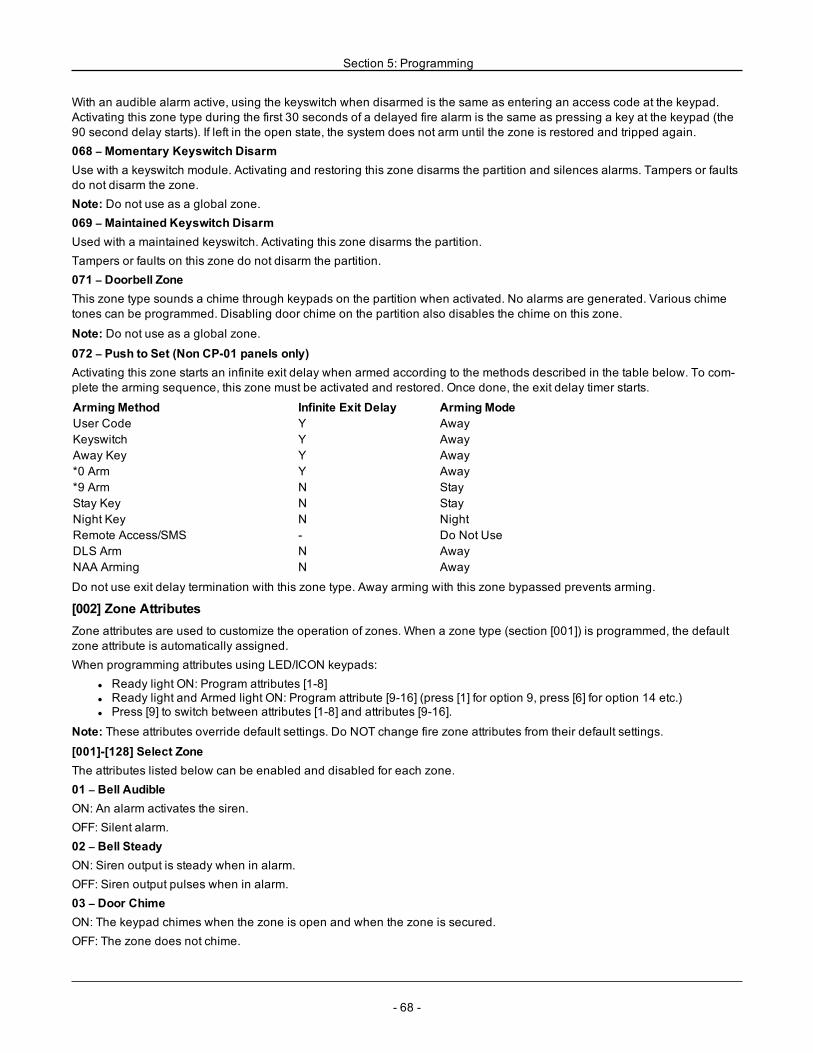
Section 5: Programming
With an audible alarm active, using the keyswitch when disarmed is the same as entering an access code at the keypad.Activating this zone type during the first 30 seconds of a delayed fire alarm is the same as pressing a key at the keypad (the90 second delay starts). If left in the open state, the system does not arm until the zone is restored and tripped again.068 – Momentary Keyswitch DisarmUse with a keyswitch module. Activating and restoring this zone disarms the partition and silences alarms. Tampers or faultsdo not disarm the zone.Note: Do not use as a global zone.069 – Maintained Keyswitch DisarmUsed with a maintained keyswitch. Activating this zone disarms the partition.Tampers or faults on this zone do not disarm the partition.071 – Doorbell ZoneThis zone type sounds a chime through keypads on the partition when activated. No alarms are generated. Various chimetones can be programmed. Disabling door chime on the partition also disables the chime on this zone.
Note: Do not use as a global zone.072 – Push to Set (Non CP-01 panels only)Activating this zone starts an infinite exit delay when armed according to the methods described in the table below. To com-plete the arming sequence, this zone must be activated and restored. Once done, the exit delay timer starts.
Arming Method Infinite Exit Delay Arming ModeUser Code Y AwayKeyswitch Y AwayAway Key Y Away*0 Arm Y Away*9 Arm N StayStay Key N StayNight Key N NightRemote Access/SMS - Do Not UseDLS Arm N AwayNAA Arming N Away
Do not use exit delay termination with this zone type. Away arming with this zone bypassed prevents arming.
[002] Zone AttributesZone attributes are used to customize the operation of zones. When a zone type (section [001]) is programmed, the defaultzone attribute is automatically assigned.When programming attributes using LED/ICON keypads:
l Ready light ON: Program attributes [1-8]l Ready light and Armed light ON: Program attribute [9-16] (press [1] for option 9, press [6] for option 14 etc.)l Press [9] to switch between attributes [1-8] and attributes [9-16].
Note: These attributes override default settings. Do NOT change fire zone attributes from their default settings.
[001]-[128] Select ZoneThe attributes listed below can be enabled and disabled for each zone.01 – Bell AudibleON: An alarm activates the siren.OFF: Silent alarm.02 – Bell SteadyON: Siren output is steady when in alarm.OFF: Siren output pulses when in alarm.03 – Door ChimeON: The keypad chimes when the zone is open and when the zone is secured.OFF: The zone does not chime.
- 68 -
Section 5: Programming
04 – Bypass EnabledON: The zone can be manually bypassed.OFF: The zone cannot be bypassed.05 – Force ArmON: The system can be armed with the zone open. The zone is temporarily bypassed and, when secured, is monitored bythe system.
EN ON: When open zones cancel arming is enabled [021][7], the system can begin arming with an open, force armable zone,but if the zone is still open when the exit delay timer expires, the arming will be cancelled.OFF: The system cannot be armed if the zone is open.06 – Swinger Shut DownON: When the zone goes into alarm for the number of times programmed in the Swinger Shutdown Counter ( [377]Communication Variables), it shuts down with no further transmissions sent to the monitoring station. The siren followsswinger shutdown if programmed.OFF: Swinger shutdown is disabled. All alarms are transmitted.07 – Transmission DelayON: Reporting of zone alarms is delayed for the programmed time in section 377 (See "[377] Communication Variables" onpage 107). If a valid access code is entered within this time, no alarm signal is communicated.OFF: When an alarm occurs, the reporting code is transmitted immediately.08 – Burglary VerificationON: Enabled for cross zoning/police code. Zone alarms are not communicated until a burglary verified event occurs.OFF: Not enabled for cross zoning/police code.09 – Normally Closed (NC)ON: The zone requires a normally closed loop.OFF: The zone follows programming in section [013] option 2.See note after option 11.10 – Single End of Line (SEOL) ResistorsON: The zone requires a single end-of-line resistor (5.6K).OFF: The zone follows programming in section [013] option 2.See note after option 11.11 – Double End of Line (DEOL)ON: The zone requires two end-of-line resistors (5.6K).OFF: The zone follows programming in section [013] option 2.
Note: If more than 1 option is enabled for options 09, 10, and 11 the lowest attribute number takes precedence. If options 09and 10 are both enabled the zone follows the normally closed loop configuration.
12 – Fast Loop/Normal Loop ResponseON: Follows a fast loop response of 50ms.OFF: Follows a normal loop response as programmed in the Zone Loop Response Time section.13 – 2-Way Audio AttributeON: Panel is able to initiate a 2 way audio session.OFF: Only the microphone turns on, initiating a a Listen-in only session. The speaker remains off.14 – Hold Up VerificationON: An alarm from zones of this type can contribute to a verified hold up alarm. Use this attribute with Panic and Hold Upzones.OFF: An alarm from zones of this type does not contribute to a verified hold up alarm. The zone does not cause the hold upverification timer to start counting down, or generate a verified hold up if the alarm is detected while the timer is running.
- 69 -
Section 5: Programming
5.3.3 System TimesThis section describes how to program various timers applicable to the entire alarm system.[005] System Times
This is the base menu used by installers to program timers, including system area [000], partition timers [001]-[008], and day-light saving time [901]/[902].
[000] – System AreaBell Cutoff TimeSystem sirens follow this timer. Fire alarms follow this timer if section [014] option 8 (Fire Bell Continues Option) is off.System tampers follow this timer. The bell cutoff time is programmed in minutes. Valid entries are 001 to 255 minutes.Keypad buzzer alarms do not follow this timer.Bell Delay TimeThe Bell Delay Timer determines how long the bell will be delayed after a zone alarm event. Valid entries are 000-255where 000 disables this feature.Burglary Verification TimerIf another zone with the Burglary Verification attribute enabled is violated within the duration of this timer, a burglary verifiedevent is communicated and logged. “Burglary Verified” is displayed on the keypad when the system is disarmed.The burglary verification timer is programmed in minutes. Valid entries are 000 to 255 minutes.Holdup Verification TimerA holdup alarm is immediately communicated to the monitoring station and the holdup verification timer starts. Aprogrammable counter determines the number of additional holdup events that must occur before the timer expires to createa verified holdup event. Once this happens, the holdup event is logged and communicated.
Note: Not for use with UL/ULC listed installations. 000 disables this feature.
Zone Loop Response TimeLoop response time is a 3- digit entry from 005 to 255 programmed in 10ms increments. The minimum available loopresponse time is 50ms (e.g., program 005 for 50ms).Automatic Clock AdjustThis value adds or subtracts seconds from the system clock at the end of each day to compensate for inaccuracies. Todetermine the adjustment value, monitor the time lost or gained by the alarm system over a period of time and calculate theaverage gains or loses.Example #1: The clock loses an average of 9 seconds per day. Program the alarm controller to adjust the clock by 51seconds for the last minute of each day. This speeds up the alarm controller’s clock by 9 seconds, correcting the problem.Example #2: The clock gains an average of 11 seconds per day. Program the alarm controller to adjust the clock by 71seconds for the last minute of each day. This slows down the alarm controller’s clock by 11 seconds, correcting the problem.If the Auto-arm time is set for 23:59, any change to the Clock Adjust option will directly affect the Auto-arm pre-alert time.
[001]-[008] Partition 1-8 TimersThe following timers can be applied to each partition.
Note: For UL installations, the Entry Delay plus the Communications Delay must not exceed 60 seconds.Entry Delay 1:This value determines the entry delay time for delay 1 type zones. Valid entries are 001 to 255 seconds.Entry Delay 2:This value determines the entry delay time for delay 2 type zones. Valid entries are 001 to 255 seconds.
Note: The system follows the entry timer that activates first.
Exit Delay:This value determines the exit delay time when arming the system. During exit delay, both the Ready and Armed LEDs areon. When the exit delay expires, both LEDs turn off.
EN Note: European products will only activate the armed LED at the end of exit delay.
- 70 -
Section 5: Programming
Settle Delay:This timer enables a programmable, short duration bypass of all zones on the partition at the time of arming. It allows motiondetectors to restore when the system is armed to help prevent false alarms.The typical value for this timer is 5 seconds, but can be increased if false alarms persist. Program 000 for no settle delay.The settle delay duration is programmed in seconds. Valid entries are 000 to 010 seconds.
[900] – Bell Delay Partition MaskThis option enables or disables the Bell Delay feature for individual partitions. When the option is enabled, Bell Delay isapplied to the selected partition during alarm conditions. When the option is disabled, Bell Delay is not applied. The defaultsetting is (Y): enabled.
[901]/[902] – Daylight Savings Begin/EndDaylight Begin [001] and Daylight End [002]:Set the date and time daylight savings starts and ends.Month
Valid entries are 001-012 (January to December).Week
Valid entries are 000-005.Enter “000” to program a specific date (1-31) in the Day field. Enter 001-005 to program the specific week of the month. 005is the last week of the month.Day
1-31 (if 000 is programmed in the Week field). 0-6 (Saturday-Sunday) if 001-005 is programmed in the Week field.Hour
Valid entries are 00-23 hours. This is the time of day to advance or turn the clock back.Increment
Valid entries are 1 or 2 hours. This is the number of hours to advance or turn the clock back.
5.3.4 Access CodesThis section is used by installers to program the installer code, the master code and the maintenance code. For informationon programming other access codes, see "[*][5] Program Access Codes" on page 47.
[006] Installer Defined Access CodesThis is the base menu used by installers to program the installer code [001], the master code [002] and the maintenancecode [003]. See below for details.[001] – Installer CodeThis code is used by the installer to gain access to Installer Programming [*][8]. Users with this access code have access toall levels of system programming.
EN Note: For EN50131-1 approved installations the installer code cannot change the master code or any other level 3 codes.[002] – Master CodeThis code is used by the master user, a person designated to perform operational tasks beyond those of the standard user.The master code provides access to functionality in the [*][5] and [*][6] menus.[003] – Maintenance CodeThis code is usually assigned temporarily to maintenance personnel who must deactivate the alarm to enter the premises.The maintenance code can arm and disarm the system, but does not grant access to any other functionality.
- 71 -

Section 5: Programming
5.3.5 [007] - [008] PGM ConfigurationThis section describes how to set up and configure programmable outputs.PGMs are used to send electrical current to external devices such as lights and sirens, usually when an alarm event occurs.The alarm controller provides up to three 50mA PGMs and one 300mA PGM. PGM outputs can be expanded using theoptional 8-output expander (HSM2208) and the 4 high-current output expander (HSM2204).Programming an output is a four-step process:1. Program the PGM2. Assign the PGM to a partition.3. Assign an output attribute.4. Assign an output option.Refer to See "[011] PGM Configuration Options" on page 85 for PGM slot alignment.
[007] PGM ProgrammingThis is the base menu used by the installer to assign PGMs to the main bell and a partition.[000] Main Bell Partition AssignmentThis programming section is used to define which partitions activate the main bell when they go into alarm. All partitions areselected by default.[001]-[164] PGM Partition AssignmentThis option enables the installer to assign each PGM output to a partition. To assign a PGM to a partition, first select the PGMoutput (PGM 001-164), then select the partition (1-8).
Note: This field is only supported by PGM types that have multiple partition capabilities (e.g., command outputs, away arm-ing). It does not affect system outputs (e.g., ground start pulse).
[008] PGM Timer Programming[000] PGM Minutes/SecondsThis option determines if the timer is in minutes or seconds.[001]-[164] PGM TimerThis timer programs the duration (in seconds or minutes) that PGMs 1-164 activate if programmed to follow the PGM Timer.Select option 001-164 for PGM 1-164.This option does not affect outputs programmed as Sensor Reset.
5.3.6 [009] PGM TypesThe output types described in this section can be assigned to alarm controller and output expander module PGMs. Eachalarm controller supports up to 2 or 4 PGMs and can be expanded using HSM2208 output expander and HSM2204 High-Current output modulemodules. PGM attributes are defined in section "[010] PGM Attributes" on page 77.[001]-[164] Select PGM
100 – Null PGMThis option deactivates the PGM output
101 – Burglary and Fire Bell FollowerThis PGM output follows:
l Fire pre-alertsl Temporal three fire signal (if enabled)l All audible burglary and fire alarms by partitionl Bell cut-off timel Bell squawk conditionsl Audible exit fault
This output activates when the alarm output is active and turns off when the alarm output is silenced. The siren patternmatches the programmed cadence for the zone that went into alarm. Cadence priority is as follows:
- 72 -
Section 5: Programming
l fire alarm cadencel CO alarm cadencel other alarm cadences
The main siren still activates for all alarms.
102 – Delayed Fire and BurglaryThis output type operates the same as the Burglary and Fire Bell Follower (PGM type 01), but does not activate until the trans-mission delay time expires.When a zone with transmission delay enabled is tripped, the Bell, Regular Fire and Burglary PGMs activate. At the end of thetransmission delay, the delayed Fire and Burglary output activates.This PGM is usually used to control outdoor sirens. If a false alarm occurs, the user has time to disarm the system before theexternal sirens activate.
Note: If a zone alarm occurs but does not follow transmission delay, this PGM activates immediately, even if transmissiondelay is active for a different zone alarm.
This output activates for audible exit fault and does not interfere with the operation of any other programmable output.
103 – Sensor Reset [*][7][2]This output is normally active and deactivates for 5 seconds when a [*][7][2] fire reset command is entered or when an autoverified fire alarm is detected. This option is used to reset power for latching smoke detectors. The keypad buzzer does notsound for the 5-second period. See "Smoke Detector Wiring" on page 24 for instructions on wiring smoke detectors.
104 – 2-Wire SmokeWhen this PGM is programmed, the onboard PGM functions as an input instead of an output. 2-wire smoke detectors can beconnected to this input, which means that a zone input does not need to be used.The PGM is also supervised, and a trouble condition is generated if a 2.2KΩ resistor is not present between the PGM ter-minal and Aux+.The 2-wire smoke detector input creates an instant and latching alarm.
109 – Courtesy PulseCourtesy pulse causes an output to activate for the entry and exit times, plus 2 minutes. This option is typically used to activ-ate a courtesy light near the exit door for the duration of the entry/exit times.
111 – Keypad Buzzer FollowPGM output activates with the keypad buzzer when triggered by the events below. The PGM output remains active for theduration of the keypad buzzer.
l 24-hour supervisory buzzer zone alarml Auto-arm and no activity arming pre-alert.l No activity arm pre-alertl Entry delayl Audible exit faultl Audible exit delayl Door chime
This PGM type does not activate for local key presses or trouble beeps.
114 – Ready to ArmThis PGM activates when the system is ready to arm (all non-force armed zones on the system are restored). The PGM out-put de-activates when an access code is entered to arm the system and the exit delay begins. This PGM operates asdescribed during walk test mode (if all zones are restored).
115 – System Armed StatusThis output activates when all selected partitions are armed (end of the exit delay) in either Stay or Away modes. The outputde-activates when the system is disarmed.
- 73 -
Section 5: Programming
116 – Away Armed StatusThis PGM switches on when the system is armed with stay/away zones activated. If the system is armed with the stay/awayzones always active, then the away output is active.
117 – Stay Armed StatusThis PGM output activates if the system is armed with the stay/away zones bypassed.
120 – Away Armed with No Zone Bypasses StatusWhen assigned to a single partition, this PGM output activates when the system is armed with stay/away and night zones act-ive, and no zones are bypassed.If assigned to multiple partitions, all partitions must be armed in away mode with no bypassed zones before the PGM activ-ates. If a force armable zone is violated at the time of arming, the PGM does not activate. When the zone is restored, thePGM activates.
121-124 – Command Outputs 1-4Command Outputs 1-4 are user-activated by entering [*] [7] [1-4] at any keypad. When an output is activated, three acknow-ledgment beeps are sounded.PGM outputs of this type can be programmed to follow a pre-defined schedule (programmed in section "[601]-[604] Sched-ule Labels" on page 63). Even if the output follows a schedule it can be manually turned ON, OFF or follow the schedulethrough [*][7].To select a schedule for these PGM outputs to follow, see "[009] PGM Types " on page 72
129 – Partition Status Alarm MemoryThis feature is intended to be used on a keyswitch plate, with a light controlled by this PGM to indicate system status. Whenthe partition is armed, the output activates (steady) at the:
NA beginning of exit delay
EN end of exit delay.If an alarm occurs on the armed partition, the output flashes for the remainder of the armed period. If an alarm occurs on adisarmed partition (24 Hr Zone), the output flashes until the alarm is acknowledged.This output will not activate during a walk test or for FMP key, holdup or audible/silent PGM2 input alarms.132 – Holdup OutputWhen a Holdup zone (Type [042]) goes into alarm, this output activates until the partition is either armed (access code, key-switch, [*][0], etc.) or disarmed. A tamper or fault on a holdup zone type does not activate this output. This output does notactivate in Walk Test mode. If a global holdup alarm occurs, each partition with holdup zones assigned must be armed or dis-armed before the holdup output deactivates. If holdup alarms occur on multiple partitions, an access code must be enteredat each partition before the output deactivates.
Note: Not for use with UL/ULC listed installations.
134 – 24-Hour Silent Input (PGM 2)With this input the keypad does not indicate an alarm, the siren remains silent, and the signal is sent to the central station.This input does not follow swinger shutdown. A 2.2KΩ EOL resistor is required for this input (to Aux+). If a short or openoccurs, an alarm is generated.
UL Note: Not for use with UL installations.
135 – 24-Hour Audible Input (PGM 2)LCD keypads indicate that the system is in alarm, the siren sounds for the duration of bell timeout, and the signal is sent tothe central station. This input does not follow swinger shutdown. A 2.2KΩ EOL resistor is required for this input (to Aux+). If ashort or open occurs, an alarm is generated for all partitions and sirens. PGM partition assignment does not affect this PGMtype.
- 74 -
Section 5: Programming
146 – TLM and AlarmThis output activates when a telephone line fault condition is present AND an alarm occurs. The output remains active untilan access code is entered to disarm or the TLM trouble is restored. The output activates for all audible and silent alarms(except duress) if a TLM trouble is present. If an alarm activates this output in the disarmed state, it will deactivate when thesystem is armed or the telephone line is restored. This output type also activates if alarms are in memory (not only for cur-rently active alarms) when the TLM fault occurs. The alarms in memory must have exceeded the bell timeout.
147 – KissoffThis PGM output activates for two seconds after the alarm system receives a kissoff signal from the central station.
148 – Ground StartThis output activates for two seconds before the alarm system attempts dialing to obtain a dial tone on Ground Start tele-phone equipment. Two 2-second pauses must be inserted at the beginning of the telephone number when using this option.
149 – Alternate CommunicatorThis output can be used to trigger inputs on a third-party communicator for the purpose of triggering alarm communicationsto a monitoring station. This output can be programmed to activate when any of the following system events (alarms) occuron the system:
l Fire (Fire Key, Fire Zones)l Panic (Panic Key and Panic Zones)l Burglary (Delay, Instant, Interior, Stay/Away and 24-hour Burglary Zones)l Opening/Closing Eventsl Zone Auto-Bypass. (Please see 08 – Zone Auto-Bypass for details).l Medical (Medical Key, Medical and Emergency Zones)l Burglary Verifiedl Opening After Alarml Emergency Alarml Duress Alarml Holdup Verified
In the armed state, this output deactivates when the system is disarmed. If an alarm activates this output in the disarmedstate, the output deactivates if a valid access code is entered within the bell timeout or if the system is armed after the belltimeout has expired.This output activates for silent and audible alarms or medical conditions only. It will not activate during pre-alert or delays.
Note: The PGM attributes for this option, programmed in section [010], differ from the standard selection of attributes nor-mally programmed.
Note:When this PGM is configured to provide Opening/Closing status, the PGM must be programmed as a timed output, notlatching.
155 – System TroubleThis output can be programmed to activate when any of the following trouble conditions are present:
l Service Requiredl Loss of Clockl DC Troublel Bus Voltagel AC Troublel Device Faultl Device Low Batteryl Device Tamperl RF Delinquencyl Module Supervisoryl Module Tamperl Communicationsl Not Networked
This output deactivates when all of the selected trouble conditions are cleared.
- 75 -
Section 5: Programming
156 – Latched System Event (Strobe)This output can be used to notify the home owner, before they enter the premises, that an alarm has occurred. This outputcan be programmed to activate when any of the following alarms occur on the system:
l Burglary (Delay, Instant, Interior, Stay/Away and 24-Hour Burglary Zones)l Fire (Fire Key, Fire Zones)l Panic (Panic Key and Panic Zones)l Medical (Medical Key, Medical and Emergency Zones)l Supervisory (Supervisory, Freezer and Water Zones)l Priority (Gas, Heat, Sprinkler and 24-Hour Latching Zones)l Holdup (Holdup zones)l Output follows pulse timer (section "[008] PGM Timer Programming" on page 72).l Duressl Emergencyl CO Alarml Fire Supervisoryl Fire trouble
This output does not activate during pre-alert or delays.In the armed state, the output deactivates only once the system is disarmed.If an alarm activates this output in the disarmed state, the output deactivates when a user enters a valid access code duringbell timeout. The output also deactivates if someone arms the system after the bell timeout has expired.If assigned to a single partition, the output activates when an enabled alarm event occurs on the assigned partition. Whenassigned to multiple partitions, the output activates when an alarm occurs on any partition and, if configured to latch, willdeactivate when any partition is disarmed. (or a valid disarming procedure is used).
157 – System TamperThis output activates when any tamper condition is present and deactivates when all tamper conditions are cleared (if set forsteady operation). If set for a pulsed operation, the output deactivates when the PGM Output timer expires. These tampersinclude zone tampers (DEOL), case tampers, TLM trouble, RF jam, and all zone and device tampers.
Note: This PGM does not activate for alternate communicator fault.
161 – DC TroubleThis output activates when one of the following low battery conditions is detected:
l Alarm controller low or absent batteryl Module low or absent batteryl Wireless zone low batteryl Wireless keypad low batteryl Wireless siren low batteryl Wireless key low battery
The output can be configured to follow the state of the low battery trouble(s) or it can activate for a period of time and auto-matically restore.
165 – Proximity Tag UsedThis output activates when the selected proximity tag is presented.Assign this output to a user by entering a user number from 002 to 095. To enable this attribute for all proximity tags, enter000 in PGM attribute [011]. See "[007] - [008] PGM Configuration" on page 72.
175 – Bell Status and Programming Access OutputThis PGM activates when the siren, Installer Programming mode or DLS/SA is active. It deactivates after bell timeout, whenInstaller Programming is exited or when DLS/SA programming is disconnected.
176 – Remote OperationThis output is activated and deactivated remotely on command from DLS software.
Note: Not for use with UL/ULC listed installations.
- 76 -
Section 5: Programming
184 – Open After AlarmThis output activates when the system has been disarmed after an alarm. It deactivates when a valid user code is entered orwhen the PGM Output timer expires.
200 – Zone Follower - PGM By ZoneThis option allows the PGM to activate when the assigned zone is opened and deactivate when the zone is restored or, if pro-grammed, when a valid access code is entered. This PGM follows the state of the assigned zone, regardless of the partitionthe zone or PGM is assigned to.To program which zone the PGM will follow, see "[011] PGM Configuration Options" on page 85.
201-216 – Zone Follower (Zones 1-128)This output type is assigned to a group of zones and is normally activated, but deactivates when a zone is tripped. Zones areassigned to this output in the following groups:
201 – Zones 1-8 209 – Zones 65-72202 – Zones 9-16 210 – Zones 73-80203 – Zones 17-24 211 – Zones 81-88204 – Zones 25-32 212 – Zones 89-96205 – Zones 33-40 213 – Zones 97-104206 – Zones 41-48 214 – Zones 105-112207 – Zones 49-56 215 – Zones 113-120208 – Zones 57-64 216 – Zones 121-128
If multiple zones are enabled, any active zone in that group triggers the output. The PGM will not activate again until allzones are restored.
5.3.7 [010] PGM AttributesThe following options are used to program the operating characteristics of the main bell and PGM outputs.
[000] Main Bell MaskThis programming section is used to configure the types of audible alarms that trigger the main bell output on the alarm con-troller. All options are selected by default.Fire AlarmON: Fire alarm ([F] key, Fire zones) activates the main siren.OFF: Fire alarm does not activate the main siren.CO AlarmON: CO alarm activates the main siren.OFF: CO alarm does not activate the main siren.Burglary AlarmON: Burglary alarm (Delay, Instant, Interior, Stay/Away, Night, Interior Delay, Instant Stay/Away, Day, 24-hour Burglary)activates the main siren.OFF: Burglary alarm does not activate the main siren.24-Hour Flood AlarmON: Main bell activates in the event of a 24-Hour Flood alarm.OFF: Main bell does not activate in the event of a 24-Hour Flood alarm.Bell SquawksON: Squawks activate the main siren. Bell squawks must be enabled to use the following options:
l Bell Squawk on arm (single)l Bell Squawk on disarm (double)l Bell Duration Auto-Arm (single every second)l Bell Squawk on Exit (single every second)l Bell Squawk on Entry (single every second)l Bell Squawk on Trouble (single every 10 seconds)
- 77 -
Section 5: Programming
OFF: Squawks do not activate the main siren.
[001]-[164] PGM 001-164 AttributesThe following PGM attributes can be assigned to a PGM. Each attribute has various toggle options, depending on the PGMtype selected (section [009]).101 – Fire and Burglary01 – True Output/Inverted
ON: deactivated during normal operation. Activated when triggered.OFF: active during normal operation. Deactivated when triggered.
102 – Delay Fire and Burglary01 – True Output/Inverted
ON: deactivated during normal operation. Activated when triggered.OFF: active during normal operation. Deactivated when triggered.
103 – Sensor Reset [*][7][2]01 – True Output/Inverted
ON: deactivated during normal operation. Activated when triggered.OFF: active during normal operation. Deactivated when triggered.
03 – Access Code Required / No Code Required
ON: Access code required for activationOFF: No access code required for activation
109 – Courtesy Pulse01 – True Output/Inverted
ON: deactivated during normal operation. Activated when triggered.OFF: active during normal operation. Deactivated when triggered.
111 – Keypad Buzzer Follow01 – True Output/Inverted
ON: deactivated during normal operation, activated when triggered.OFF: activated during normal operation, deactivated when triggered.
02 – Timed Output
ON: output remains active until the PGM output timer expires.OFF: output remains active until the buzzer condition ends.
09 – Entry Delay
ON: activates on entry delay.OFF: does not activate on entry.
10 – Exit Delay
ON: activates on exit delay.OFF: does not activate on exit delay.
11 – Door Chime
ON: activates when chime is enabled.OFF: does not activate when chime is enabled.
12 – Keypad Buzzer Zone
ON: activates when keypad buzzer goes into alarm.OFF: does not activate when keypad buzzer goes into alarm.
13 – Audible Exit Fault
ON: activates when audible exit fault pre-alert begins.OFF: does not activate when audible exit fault pre-alert begins.
- 78 -
Section 5: Programming
14 – Auto-Arm Pre-Alert
ON: activates when auto-arming pre-alert begins.OFF: does not activate when auto-arming pre-alert begins.
114 – Ready To Arm01 – True Output/Inverted
ON: deactivated during normal operation. Activated when triggered.OFF: active during normal operation. Deactivated when triggered.
115 – Armed Status01 – True Output/Inverted
ON: deactivated during normal operation. Activated when triggered.OFF: active during normal operation. Deactivated when triggered.
116 – Armed Away Mode01 – True Output/Inverted
ON: deactivated during normal operation. Activated when triggered.OFF: active during normal operation. Deactivated when triggered.
117 – Armed Stay Mode01 – True Output/Inverted
ON: deactivated during normal operation. Activated when triggered.OFF: active during normal operation. Deactivated when triggered.
120 – Away Armed with No Zone Bypasses Status01 – True Output/Inverted
ON: deactivated during normal operation, activated when triggered.OFF: activated during normal operation, deactivated when triggered.
121-124 – Command Output 1-401 – True Output/Inverted
ON: deactivated during normal operation, activated when triggered.OFF: activated during normal operation, deactivated when triggered.
02 – Timed Output / Latched Output
ON: output remains active until the PGM output timer expires.OFF: output remains active until an access code has been entered.
03 - Access Code Required / No Code Required
ON: access code required for activation.OFF: no access code required for activation.
129 – Partition Status Alarm Memory01 – True Output/Inverted
ON: deactivated during normal operation. Activated when triggered.OFF: active during normal operation. Deactivated when triggered.
132 – Holdup Output01 – True Output/Inverted
ON: deactivated during normal operation. Activated when triggered.OFF: active during normal operation. Deactivated when triggered.
146 – TLM Alarm01 – True Output/Inverted
ON: deactivated during normal operation. Activated when triggered.OFF: active during normal operation. Deactivated when triggered.
- 79 -
Section 5: Programming
147 – Kissoff Output01 – True Output/Inverted
ON: deactivated during normal operation. Activated when triggered.OFF: active during normal operation. Deactivated when triggered.
148 – Ground Start01 – True Output/Inverted
ON: deactivated during normal operation. Activated when triggered.OFF: active during normal operation. Deactivated when triggered.
149 – Alternate Communicator01 – True Output/Inverted
ON: deactivated during normal operation, activated when triggered.OFF: activated during normal operation, deactivated when triggered.
02 – Timed Output / Latched Output
ON: output remains active until the PGM output timer expires.OFF: output remains active until an access code has been entered.
04 – Fire Alarm
ON: activates with fire alarm, [F] key, fire zones, 2-wire smoke.OFF: does not activate with fire alarm.
05 – Panic Alarm
ON: activates with panic alarm, [P] key, panic zones.OFF: does not activate with panic alarm.
06 – Burglary Alarm
ON: activates with burglary alarm.OFF: does not activate with burglary alarm.
07 – Open/Close
ON: activates with opening or closing.OFF: does not activate with opening or closing.
08 – Zone Auto-Bypass
ON: activates when a zone is automatically bypassed.OFF: does not activate when a zone is automatically bypassed.
09 – Medical Alarm
ON: activates with medical alarm, [+] key, medical zones.OFF: does not activate with medical alarm.
10 – Burglary Verified
ON: activates with burglary verified alarm (or police code).OFF: does not activate with burglary verified alarm.
11 – Open After Alarm
ON: activates when the system is disarmed with an alarm in memory.OFF: does not activate when the system is disarmed with an alarm in memory.
12 – Emergency Alarm
ON: activates with zone emergency alarm.OFF: does not activate with zone emergency alarm.
13 – Duress Alarm
ON: activates with duress alarm.OFF: does not activate with duress alarm.
- 80 -
Section 5: Programming
14 – Hold Up verified
ON: activates when a verified holdup event is detected.OFF: does not activate when a verified holdup event is detected.
155 – System Trouble01 – True Output/Inverted
ON: deactivated during normal operation, activated when triggered.OFF: activated during normal operation, deactivated when triggered.
02 – Timed Output / Latched Output
ON: output remains active until the PGM output timer expires.OFF: output remains active until an access code has been entered.
04 – Service Required
ON: activates on service required trouble condition.OFF: does not activate on service required trouble condition.
05 – Loss of Clock
ON: activates on loss of clock trouble condition.OFF: does not activate on loss of clock trouble condition.
06 – DC Trouble
ON: activates if a panel low or no battery trouble is detected, or if an HSM2204/2300 1-4 low or no battery trouble isdetected.OFF: does not activate on DC Trouble condition.
07 – Bus Voltage
ON: activates when a system module has measured a low Aux voltage.OFF: does not activate for a module low voltage trouble.
08 – AC Trouble
ON: activates when any system device detects an AC Failure condition.OFF: does not activate for AC Failure conditions.
09 – Device Fault
ON: activates if one of the following device fault conditions is present:l zone 001 – 128 faultl keypad 01 – 16 faultl siren 01 – 16 faultl repeater 01 – 08 faultl fire troublel CO troublel gas troublel heat troublel freeze troublel probe disconnected troublel self test troubleOFF: does not activate if a device fault condition is present.
10 – Device Low Battery
ON: activates if any of the following device low battery conditions is present:l zone 001 – 128l keypad 01 – 16l siren 01 – 16l repeater 01 – 08l user 01 – 32 (wireless keys)OFF: does not activate if a device low battery condition is present.
11 – Device Tamper
ON: activates if any of the following device tamper conditions is present:
- 81 -
Section 5: Programming
l zone 001 – 128l keypad 01 – 16l siren 01 – 16l repeater 01 – 08OFF – does not activate if a device tamper condition is present.
12 – RF Delinquency
ON: activates if any of the following RF delinquency troubles is detected:l zone 001 – 128l keypad 01 – 16l siren 01 – 16l repeater 01 – 08OFF – does not activate if an RF delinquency condition is present.
13 – Module Supervisory
ON – activates if any of the following module supervisory troubles is detected:l HSM2HOSTl keypad 01 – 16l zone expander 01 – 15l HSM2204 1 – 4l HSM2300 1 – 4l HSM2208 01 – 16OFF – does not activate if a module supervisory trouble is detected.
14 – Module Tamper
ON – activates if any of the following module tamper conditions is present:l HSM2HOSTl Keypad 01 – 16l Zone expander 01 – 15l HSM2204 1 – 4l HSM2300 1 – 4l HSM2208 01 – 16 tamper troublesOFF – does not activate if a module tamper condition is present.
15 – Communications
ON – activates if any of the following communications conditions is present:l TLM troublel FTC receiver 1 – 4l SIM Lock troublel Cellular Troublel Ethernet Troublel Receiver 1 – 4 absentl Receiver 1 – 4 supervision troublel SMS Configuration troublel Alt comm. Fault.OFF – does not activate if a communications trouble condition is present.
16: – Not Networked
ON – activates if any of the following not networked conditions is present:l Zone 001 – 128l Keypad 01 – 16l Siren 01 – 16l Repeater 01 – 08l User 01 – 95 (wireless keys) not networked troublesOFF – does not activate if a not networked trouble condition is present.
156 – Latched System Event01 – True Output/Inverted
ON: deactivated during normal operation. Activated when triggered.
- 82 -
Section 5: Programming
OFF: activated during normal operation. Deactivated when triggered.02 – Timed Output / Latched Output
ON: output remains active until the PGM output timer expires.OFF: output remains active until an access code has been entered.
04 – Fire Alarm
ON: activates with fire alarm, [F] key, fire zones, 2-wire smoke.OFF: does not activate with fire alarm.
05 – Panic Alarm
ON: activates on panic alarm (audible or silent).OFF: does not activate on panic alarm.
06 – Burglary Alarm
ON: activates on burglary alarm.OFF: does not activate on burglary alarm.
07 – Medical Alarm
ON: activates on medical alarm.OFF: does not activate on medical alarm.
08 – Supervisory
ON: activates on supervisory alarm.OFF: does not activate on supervisory alarm.
09 – Priority Event
ON: activates on priority alarm.OFF: does not activate on priority alarm.
10 – Holdup
ON: activates on holdup alarm.OFF: does not activate on Holdup alarm.
11 – Duress Alarm
ON: activates on duress alarm.OFF: does not activate on duress alarm.
12 – Emergency Alarm
ON: activates on emergency alarm.OFF: does not activate on emergency alarm.
13 – Fire Supervisory
ON: activates on fire supervisory alarm.OFF: does not activate on fire supervisory alarm.
14 – Fire Trouble
ON: activates on fire trouble condition.OFF: does not activate on fire trouble condition.
15– CO Alarm
ON: activates on CO alarm.OFF: does not activate on CO alarm.
157 – System Tamper01 – True Output/Inverted
ON: deactivated during normal operation. Activated when triggered.OFF: activated during normal operation. Deactivated when triggered.
09 – System/Module Tampers
ON: activates when any module tamper condition occurs.
- 83 -
Section 5: Programming
OFF: does not activate when any module tamper condition occurs.10 – Zone Tampers
ON: activates when any zone tamper condition occurs.OFF: does not activate when zone tamper conditions occur.
161 – DC Trouble01 – True Output/Inverted
ON: deactivated during normal operation. Activated when triggered.OFF: activated during normal operation. Deactivated when triggered.
02 – PGM Timer
ON: output remains active until an access code is entered or certain criteria have been met, depending on the PGMtype.OFF: output remains active until the PGM output timer expires.
09 – Battery Low
ON: activates when a low battery trouble occurs.OFF: does not activate when a low battery trouble occurs.
10 – Battery Absent
ON: activates when a battery absent trouble occurs.OFF: does not activate when a battery absent trouble occurs.
165 – Prox Used01 – True Output/Inverted
ON: deactivated during normal operation. Activated when triggered.OFF: activated during normal operation. Deactivated when triggered.
175 – Bell Prog Access01 – True Output/Inverted
ON: deactivated during normal operation. Activated when triggered.OFF: activated during normal operation. Deactivated when triggered.
176 – Remote Operation01 – True Output/Inverted
ON: deactivated during normal operation. Activated when triggered.OFF: activated during normal operation. Deactivated when triggered.
184 – Open After Alarm01 – True Output/Inverted
ON: deactivated during normal operation. Activated when triggered.OFF: activated during normal operation. Deactivated when triggered.
200 - Zone Follower - Single Zone01 – True Output/Inverted
ON: deactivated during normal operation, activated when triggered.OFF: activated during normal operation, deactivated when triggered.
02 – Timed OutputON: output remains active until the PGM output timer expires.OFF: output remains active until the zone is restored.
201 – 216 Zone Follower Zones 1-12801 – True Output/Inverted
ON: deactivated during normal operation. Activated when triggered.OFF: activated during normal operation. Deactivated when triggered.
- 84 -
Section 5: Programming
02 – Timed Output
ON: output remains active until the PGM output timer expires.OFF: output remains active until an access code has been entered.
09-16 – Zone Terminals 1-8
ON: zones associated with terminals 1-8 are enabled for zone follower operation.OFF: zones are not enabled for zone follower operation.
5.3.8 [011] PGM Configuration OptionsThis section is used to configure PGM types that offer multiple options.
[001]-[164] Select PGMThe following options may be selected for each PGM:
Zone Follow PGM By ZoneThis option is used to specify the zone that PGM type 200 follows. Enter 001-128 to select zone 1-128.
Proximity Tag UsedThis option is used to define which proximity tag will activate PGM outputs programmed as [165] Prox Used. Enter 000 toenable this PGM attribute for all user proximity tags, or enter user number 002-095 to have this attribute activated by a spe-cific user proximity tag.
Command Output 1-4This option is used to assign a schedule, programmed in section [601]-[604], for the command output PGMs to follow.
5.3.9 [012] System Lockout
Keypad Lockout – Number of Invalid Local AttemptsThis option controls the number of invalid access code entries allowed before the keypad is locked.When keypad lockout occurs, the system is inaccessible by keypad for the programmed duration. If the number of invalidattempts is not reached within one hour, or if a valid access code is entered, the counter is reset to 0. Valid entries are 000 to255 minutes. Entering 000 disables the feature. Presenting an invalid tag counts toward keypad lockout.
Note: For EN 50131 certified installations, maximum number of attempts is 10.
Keypad Lockout DurationThis programming option determines the length of time the keypad is locked out for. If the system cold starts while in keypadlockout, the lockout is removed. Valid entries are 000 to 255 minutes. Entering 000 disables keypad lockout.
EN Note: For EN 50131 certified installations, minimum of duration is 2 minutes.
Remote Lockout DLSThis programming option determines the number of invalid access code entries allowed via SMS or DLS before remoteaccess is locked out for the programmed duration (see below). If the number of invalid attempts is not reached within onehour, or if a valid access code is entered through SMS or DLS, the counter is reset to 0. The valid entries are 003 to 255attempts. Default is 6 attempts. The number of invalid attempts is fixed at 5 when using System Administrator Software andthe lockout duration is 1 hour.
EN Note: DLS tries to connect using the programmed DLS Access code first and, if unsuccessful, using the default DLS accesscode. Two failed attempts are counted if both codes are incorrect.
Remote Lockout DurationThis programming option determines how long the remote lockout lasts. If the system cold starts while in remote lockout, thelockout restarts for the programmed duration. Valid entries are 001 to 255 minutes. Entering 000 disables remote lockout.
- 85 -
Section 5: Programming
5.3.10 System Options
[013] System Option 1
1 – NC Loop/EOLON: All zones are wired as normally closed circuits with returns connected to a COM terminal. The end-of-line resistor is notrequired. An alarm is generated when the circuit is opened.OFF: All zones must be wired with an end-of-line resistor configuration, determined by option 2 below.
Note: The valid EOL value is 5600 Ohms (5.6KΩ).2 – DEOL/SEOLON: All zones use Double-End-of-Line resistors, except Standard Fire, Delayed Fire, Auto-Verified Fire, Co and Supervisoryzone types. DEOL resistors enable detection of zone faults and tampers. The tamper resistor (5.6KΩ) is placed in parallelacross the alarm activating device, and the single EOL resistor (5.6KΩ) is placed between the alarm and tamper contacts.This allows detection of zone faults (shorted zone), tampers (open zone), alarms (11.2KΩ), and restored zones (5.6KΩ).If the zone is disarmed and placed in the tamper or fault state, trouble beeps sound on all system keypads until a key ispressed on each partition. A zone tamper is sent to the monitoring station if programmed. If the zone is armed and a tamperis activated, the tamper alarm and zone alarm are logged and transmitted.OFF: All zones must have a 5.6KΩ resistor. If the zone is shorted or open, it is in the tripped state. If the zone is open and pro-grammed as a fire zone, it is in the trouble state. The EOL and DEOL zone attributes override this system option.
Note: Zone Faults (Supervisories) on wireless zones do not cause an audible alarm while armed.
3 – Show All Troubles When ArmedON: The Trouble LED illuminates when troubles are present on the system in both the armed and disarmed state.OFF: The Trouble LED illuminates for all troubles while disarmed, but only for Fire Troubles while armed.4 – Tamper/Faults Do Not Show As OpenON: The zone LED does not illuminate if the zone is in the tamper or fault states. Only the Trouble LED illuminates.OFF: The respective zone LED illuminates if the zone is in the tamper or fault states. The Trouble LED also illuminates.5 – Auto-Arm Schedule in [*][6]ON: The auto-arm schedules ([151] - [158]) are accessible to installers via [*][6] as well as Installer Programming.OFF: The auto-arm schedules ([151] - [158]) are only accessible to installers via Installer Programming.
Note: This toggle controls access for all eight partitions.6 – Audible Exit FaultON: If a delay type zone is violated after the exit delay has expired, an entry delay warning is sounded through the keypadand siren indicating that an improper exit was made. If the alarm system is disarmed within the entry delay period no signalis sent.OFF: The entry delay warning is sounded only through the keypad.7 – Event Buffer Follows SwingerON: Once an event reaches its swinger shutdown limit programmed in "[377] Communication Variables" on page 107, it willno longer log events to the event buffer until the swinger shutdown is reset. This avoids filling the event buffer with falseevents.OFF: The event buffer continues to log events to the buffer even after the event has gone into swinger shutdown.8 – Temporal Three Fire SignalingON: All fire bells sound in the temporal three pattern. Cadence is as follows: (500ms ON, 500ms OFF, 500ms ON, 500msOFF, 500ms ON, 1.5 sec. OFF).OFF: All fire bells will sound with the standard 1 second on/1 second off fire bell cadence.
Note: Must be on for UL/ULC installations.
[014] System Option 21 – Bell SquawkON: The siren emits a single squawk when armed in any manner, including Auto-arm, and a double squawk when disarmed.
- 86 -
Section 5: Programming
When the system is disarmed, the siren emits a series of three squawk pairs to indicate alarms in memory.OFF: The siren does not squawk when arming or disarming.
NA Note: For UL/ULC, must be enabled if wireless keys are used with the alarm system.
2 – Bell Squawk on Auto-ArmON: The siren squawks once every 10 seconds during the auto-arm pre-alert time.OFF: The siren does not squawk during auto-arm pre-alert.3 – Bell Squawk On ExitON: The siren squawks once per second during exit delay, changing to 3 squawks per second for the final 10 seconds.OFF: The siren does not squawk for exit delay conditions.4 – Bell Squawk On EntryON: The siren pulses with the same timing as the keypad buzzer during entry delay, changing to 3 squawks per second forthe final 10 seconds.OFF: The siren does not activate during entry delay.5 – Bell Squawk On TroubleON: When a trouble condition exists on the system, the siren squawks 2 times every 10 seconds (as per the keypad buzzer).The siren is silenced when the keypad beeps are silenced (any key pressed on keypad).OFF: The siren does not activate with a trouble condition.6 – Not Used7 – Exit Delay TerminationON: The exit delay is reduced to 5 seconds once a Delay 1 zone is restored. Force-Arm Delay 1 type zones also end the exitdelay.OFF: The exit delay timer continues to count even after the delay zone is restored.All audible options associated with the exit delay function are silenced until the time programmed for the exit delay haselapsed.8 – Fire Bell ContinuesON: For all Fire type alarms, the siren sounds until an access code is entered to silence the alarm or disarm the systemregardless of the time programmed for bell timeout.OFF: For all Fire type alarms, the siren sounds for the length of Bell Timeout or until an access code is entered.
ULC Note: Must be disabled for ULC installations.
[015] System Option 31 – [F] Key EnabledON: Pressing and holding the [F] key for 2 seconds triggers a Fire alarm.OFF: The [F] key does not sound or report an alarm when pressed.
Note: Use only for residential fire installations.2 – [P] Key EnabledON: When a valid [P] key alarm is generated, the keypad buzzer emits a series of 3 beeps to acknowledge the alarm and thesiren sounds for the length of bell timeout.OFF: When a valid [P] key alarm is generated, the keypad buzzer and the siren are silent, but the alarm is still transmitted (ifprogrammed).
Note: Fire, Medical, and Panic key transmissions follow the partition 1 alarm/restore call direction options (Fire, Medical, andPanic key). The Fire, Medical, Panic keys operate even if keypad blanking and keypad lockout are active.
3 – Quick ExitON: When the system is armed, users may enter the [*][0] command to temporarily bypass a single Delay 1 or Delay 2 zoneto exit the premises. Only one delay zone may be activated. Activity on another delay zone initiates the appropriate alarmsequence. If the delay zone is still open two minutes after the [*][0] command is entered, entry delay is initiated. If armed inthe Stay mode, the automatic bypass on Stay/Away zones remains.
- 87 -
Section 5: Programming
OFF: When the system is armed, users can not perform a quick exit using [*][0].4 – Quick Arming /Function KeyON: [*][0] arming and Stay/Away function keys may be used to arm the system without the entry of a valid access code.OFF: [*][0] arming is not permitted. All arming functions require the entry of an access code to activate (including Stay/Awaykeys).5 – Not Used6 – Master Code Not User ChangeableON: The master code (access code 01) may not be changed by the user and may only be programmed in Installer Pro-gramming.OFF: The master code may be programmed by the user using the [*][5][Master Code] command. The master code may alsobe programmed in Installer Programming.7 – Telephone Line Monitor EnableON: The TLM function is active and the system indicates a trouble condition when using the [*][2] View Trouble Conditionscommand.OFF: The TLM function is deactivated and telephone line troubles are not indicated by the system.
NA Note: Must be ON for UL/ULC listed installations.
8 – Telephone Line Monitor Audible When ArmedON: When the system is disarmed, a telephone line monitor trouble generates a trouble indication as described above. If thesystem is armed, a telephone line monitor trouble generates an audible alarm on the siren for the duration programmed forbell timeout or until an access code is entered to disarm.OFF: Telephone line troubles generate a trouble indication, the Trouble LED illuminates, and the keypad buzzer beeps untila key is pressed.
[016] System Option 41 – AC Trouble DisplayON: If AC power fails, the condition is reported to the monitoring station and is indicated as a trouble condition on the systemkeypads.OFF: If AC power fails, the condition is reported, but the Trouble light on the system keypads is off. The trouble is displayed in[*][2].
NA Note: Must be ON for UL/ULC listed installations.
2 – AC Trouble Light FlashesON: When AC power is lost, the Trouble light flashes in the base “Ready” and “Armed” mode within 30 seconds of powerloss. When AC restores, the Trouble light stops flashing within 30 seconds. If enabled, this option overrides the AC displayoption.OFF: When AC power is lost, the Trouble light illuminates but does not flash.3 – Keypad BlankingON: If no keys are pressed for 30 seconds, all keypad lights except backlighting (if enabled) are shut off until the nextkeypress, entry delay, audible alarm or keypad buzzer condition.Keypad function keys still operate when the keypad is blank, unless the function key is programmed to require an accesscode. Keypad Blanking While Armed overrides this feature. When a partition is armed and in alarm, entering a code toremove blanking silences the alarm and disarms the system.OFF: The keypad lights remain ON at all times.4 – Keypad Blanking Requires CodeON: A valid access code must be entered before a blanked keypad can be used. Information becomes inaccessible to level1 users.OFF: Pressing any key on a blanked keypad removes keypad blanking.
CP-01 Note: Keypad Blanking Requires Code must be set to off for CP-01 listed installations.
- 88 -
Section 5: Programming
5 – Keypad BacklightingON: All keypads on the system have backlighting on at all times.OFF: All keypads on the system have backlighting off.6 – Power Save ModeON: If AC power fails, all keypad lights including backlighting are shut OFF. The keypad lights come back ON after akeypress, entry delay, audible alarm or keypad buzzer condition (except door chime). Keypad lights return to the off stateafter 30 seconds of inactivity.OFF: If AC power fails, keypads do not go into power save mode.7 – Bypass Display When ArmedON: The Bypass status light is on if zones are bypassed when the system is armed.OFF: The Bypass light is on only while the system is disarmed to indicate that zones on the system are bypassed. When thesystem is armed, the Bypass light is off.The Bypass status light is on if Stay/Away zones are auto bypassed at the time of arming regardless of whether or not thisoption is enabled. This option only enables and disables manual bypass display.8 – Keypad Tampers EnabledON: All keypads containing tamper switches generate tamper alarms and restores.OFF: The tamper switches on all keypads do not generate tamper alarms.
Note: If this option is used, all keypads should be properly installed and secured (tamper restored) before enabling theoption.
NA Note: Must be ON for UL/ULC commercial burglary listed installations.
[017] System Option 51 – Chime on OpeningON: When a zone with the door chime attribute ON is opened, the system keypads and sound door chime beeps.OFF: When a zone with the door chime attribute ON is opened, the system keypads do not sound door chime beeps.2 – Chime on ClosingON: When a zone with the door chime attribute ON is closed, the system keypads and sirens (if enabled) sound door chimebeeps.OFF: When a zone with the door chime attribute ON is closed, the system keypads and sirens (if enabled) do not sound doorchime beeps.3 – RF Jam Trouble BeepsON: Trouble beeps sound when an RF Jam Trouble is detectedOFF: Trouble beeps do not sound when an RF Jam Trouble is detected4 – Multi HitON: Alarms from the same zone within the Burglary Verification Timer duration cause the police code or burglary verified tobe logged and transmitted. The number of zone trips required to create a confirmed alarm depends on the value of the pro-grammable burglary verification counter.OFF: Alarms from the same zone within the Burglary Verification Timer duration do not cause the police code or burglary veri-fied to be logged and transmitted.
Note: This feature only applies to zones defined as Interior, Interior Delay, Interior Stay/Away, Instant Stay/Away, DelayStay/Away, or Night Zones (PIR Zones).
5 – Late to CloseON: Provides an audible warning if the alarm system has not been armed by a programmed time of day but does not arm thealarm system. The alarm system communicates and logs a Late to Close event at the end of the Auto-arm/Postpone pre-alertfor each partition.OFF: The alarm system will neither communicate nor log a Late to Close event at the time programmed for Auto-arm for eachpartition.
- 89 -
Section 5: Programming
Note: If the Auto-arm toggle option is disabled, the Auto-arm Pre-alert still occurs when a time is programmed for that day (ifenabled) and the event is logged and communicated. This option does not directly affect the functionality of Auto-arm. If Lateto Close is enabled and Auto-arming is not, LCD keypads display “System Arming in Progress” during the Late to Close Pre-alert.
6 – Daylight Savings TimeON: The alarm system adjusts between Daylight and Standard times according to the times programmed in System Timers([005] options 001-002).
Note: Auto-arm and Test Transmissions should not be attempted between 0200 and 0300 hours, as they will be missed dur-ing a daylight savings clock adjust. Events programmed to occur between 0100 and 0200 will occur twice during a daylightsavings clock adjust. Daylight Savings Time programming should not conflict with the Auto-arm and Test Transmissions pro-gramming.
OFF: The alarm system makes no automatic time adjustments for Daylight Saving time.7 – Not Used8 – Bell Squawk on Away Arm/ Disarm OnlyON: Bell Squawks are only heard when away arming, as well as when disarming from Away mode. This feature prevents thesiren from activating when arming in stay and night modes.OFF: Bell Squawks are heard during all types of arming and disarming.
Note: This option follows the “Bell Squawk Attribute” features if they are enabled.
[018] System Option 61 – Test Transmission ExceptionON: The alarm system does not send a test transmission if a transmission was sent to the receiver within the programmedinterval as set in section [377]>[003] – Periodic Test Transmission Cycle.OFF: Test transmissions are always sent at the programmed interval.2 – Real-Time Bypass ReportingON: When a non-24-hour zone is bypassed in [*][1], the system immediately logs and communicates the bypass status of thezone.Global Zones: 24-hour and non-24 hour zone bypasses are logged and communicated in real time. Non-24 hour zone unby-pass events are generated when the last assigned partition is disarmed.OFF: When a non 24-hour zone is bypassed in [*][1], the system logs and communicates the bypass status of the zone onlyafter the partition is armed. This option is applied regardless of how zones are bypassed in [*][1], recall bypass group, clearall bypasses, bypass open zones, bypass recall as well as other methods such as bypassing via ITv2 or DLS.Global Zones: 24-hour zone bypasses are logged and communicated in real time. Non 24-hour zone bypass events arelogged and communicated when armed. Non 24-hour zone unbypass events are logged and communicated when the lastpartition is disarmed.3 – Not Used4 – Not Used5 – Keypad Buzzer Follows BellON: The keypad buzzer activates with all bell activity for the selected partition.OFF: The keypad buzzer only activates with alarms programmed to do so.6 – Not Used7 – Exit Delay RestartON: Opening a delay zone door after it has already been opened and closed during an exit delay restarts the exit delaytimer. Further openings and closings do not restart the timer.OFF: Delay zone openings and closings do not restart the exit delay.8 – AC Fail Trouble BeepsON: System keypads beep when an AC trouble event occurs.OFF: System keypads are silent during AC troubles.
- 90 -
Section 5: Programming
[019] System Option 71 – Audible Wireless Device FaultON: If a wireless zone fault occurs while armed, the siren sounds for the duration of Bell Time Out. This option only affectszone definitions that are considered armed. The following zone types do not generate an alarm when faulted while stayarmed: interior stay away zone, delay stay away zone, instant stay away zone, night zone. The following zone types do notgenerate an audible alarm in any armed state (stay, away, or night): 24-hour supervisory, 24-hour non-alarm, 24-hour CO,delayed 24-hour Fire, standard 24-hour fire, Auto-verified fire.When the partition is armed, wireless supervisory troubles from sirens, keypads and repeaters generate audible alarm con-ditions.If Tamper/Fault Detection is enabled, these events can start the burglary verified timer and affect the burglary verifiedcounter.OFF: Wireless device faults do not sound the siren.2 – Latching TroublesON: Troubles remain on the system until viewed via [*][2], even if they are restored. The trouble condition is cleared when the[#] key is pressed from the [*][2] menu after the trouble has restored. The Trouble LED turns off unless other troubles arepresent. The trouble is not cleared if the [*][2] menu times out before the [#] key is pressed.OFF: Troubles are cleared once restored.3 – Not Used4 – R ButtonON: When the panel goes off hook to communicate, it performs a dial tone check. If no dialtone is detected, the panel willwait 20 seconds and perform another 5 second dial tone search. If dial tone is still not present, the panel force dials if pro-grammed to do so. This entire sequence counts as one dialing attempt.OFF: If no dial tone is present, the panel does not attempt to switch to a second phone line.5 – Audible Bus FaultON: All module supervisory trouble conditions activate the siren.OFF: Only zone expander supervisory trouble conditions while armed activate the siren.6 – Duress Codes
ON: The duress code attribute can be enabled/disabled from the [*][5] menu. For UK BS8243 installations the default is off.OFF: The duress code attribute is not programmable from the [*][5] menu.7 – Temperature in CelsiusON: Temperature is displayed in Celsius on LCD keypads.OFF: Temperature is displayed in Fahrenheit on LCD keypads.8 – Reset After Zone ActivationON: Only a police code\sequential detection alarm requires a remote reset once the partition has been disarmed.OFF: Any burglary alarm requires a remote reset once the partition has been disarmed.
[020] System Option 81 – Access Code Entry During Entry DelayON: During entry delay the alarm system can only be disarmed using a keyswitch or proximity tag. When the siren is activean access code can still be used to disarm the system.OFF: An access code can be used to disarm the system during entry delay.2 – EU Entry ProcedureON: If an alarm occurs on a zone when entry delay is not active, the siren activates and the alarm is communicated imme-diately, depending on the zone type tripped.When entry delay is active, all burglary type alarms activate the siren, but communication of the alarm is delayed by 30seconds. When entry delay expires, the alarm is not communicated unless the siren has been active for at least 30 seconds.Police code is not generated as a result of alarms triggered during entry delay, although the Burglary Verification Timerstarts after entry delay and the 30-second communication delay expire.
- 91 -
Section 5: Programming
This feature is only active when the partition is armed.OFF: Burglary alarms that occur during entry delay activate the siren and are communicated immediately. Two exceptionsare if the bell delay timer is programmed and if transmission delay is enabled for the zone in alarm. In both cases, the alarmfollows the timer.3 – [*][8] Access While ArmedON: This option ensures [*][8] installer programming is accessible from a keypad on a disarmed partition while other par-titions on the system are still armed.
UL Note: For UL listed installations, this option must be disabled.OFF: [*][8] installer programming is not available when any partition on the system is armed. All partitions must be disarmedand the siren must be off before [*][8] is accessible.4 – Remote ResetON: If an alarm occurs on a burglary zone, the system is locked out after disarming. It remains locked until a 4-digit resetcode, provided by the installer/central station, is keyed in. If a duress code is used to disarm the partition, the system is notlocked out.In the disarmed state, only Audible 24 Hour Burglary zones, Audible 24 Hour Latching Tamper zones, and Audible 24 Hourzone on PGM 2 cause lockout.To obtain the reset code, the user must provide a corresponding system lock code, displayed on the keypad when one of thefollowing conditions occurs:
l the system has been disarmed (Duress Code excluded)l the bell has timed out (24Hr zones)l an access code has been entered (24Hr zones)
On an LCD keypad, the message “REMOTE RESET RQD” is displayed on the top line and “CODE” along with the actualcode is displayed across the bottom line.On an LED keypad, the reset number is scrolled across the screen.While the system is locked out, the only options available are [*][3], [*][6], [*][7], and [*][8]. Accessing [*][8] Installer Pro-gramming unlocks the alarm system. The system continues to function (alarms, tampers, etc) while the system is locked out.Lock out follows both transmission and bell delays.OFF: The system is not locked out after an alarm occurs.
NA Note: Not for use with UL/ULC listed installations.
5 – Engineer’s Reset (EU)ON: If the alarm system has gone into alarm during the previous armed period, or if a 24-hour alarm has occurred (armed ordisarmed), the system cannot be armed (Ready light OFF) until Installer Programming is entered or Engineer’s Reset is per-formed via DLS. “Reset Required” is displayed on the keypad. This feature applies to tampers and faults in both armed anddisarmed states and does not apply to module tampers, system supervisories, zone expander alarms or PGM 2 input alarms.
Note: If Engineer’s Reset is triggered during exit delay, the system still arms. Troubles cannot be overridden while Engin-eer’s Reset is enabled.
OFF: The system does not require Engineer’s Reset or to be placed into Installer Programming in order to arm the alarm sys-tem after an alarm.6 – Keyswitch Disarming During Entry DelayON: Keyswitches, proximity tags and wireless keys disarm the alarm system only if an entry delay is active.OFF: Keyswitches, proximity tags and wireless keys disarm the alarm system regardless of entry delay.7 – Installer Access and DLSON: The user must enter [*][6][access code][05] before the installer can access Installer Programming by DLS or via thekeypad ([*][8]).Installer Programming remains accessible for 6 hours, during which time the installer can enter/exit or connect with DLS anunlimited number of times.OFF: The installer can access Installer Programming without the user entering [*][6].8 – Troubles Inhibit ArmingON: The following troubles prevent arming until restored:
- 92 -
Section 5: Programming
l Tampers on the alarm system, modules and zonesl Corbus troublesl AC troubles on the alarm system and modulesl Battery troubles on the alarm system, modules and zonesl Transmission troubles (FTC, TLM, GPRS, Ethernet)l Bell troubles
The alarm system can still be armed if troubles are overridden. To perform a trouble override, while in the Trouble Menu ([*][2]), scroll right or left and press [*] when Trouble Acknowledgment is displayed on the keypad. Alternatively, press the [9]key to acknowledge and override the existing troubles.To override open zones, faulted zones or tampered zones use the Zone Bypass feature.OFF: The system can be armed even when troubles are present.
Note:When Engineer’s Reset is on, trouble conditions cannot be overridden. Zone Expander supervisory troubles cannotbe acknowledged and overridden. These conditions must be restored before the panel can be armed.
Note:When [024][3] is enabled, AC/DC Inhibit Arming, the AC or DC trouble must be restored before the system can bearmed.
[021] System Option 91 – Trouble DisplayON: If the panel is both armed and keypad blanking is active, when a trouble is present the keypad trouble LED will remainoff . When the system is disarmed, or if blanking is removed, the trouble LED will be active if a trouble is present.OFF: The trouble LED will turn off when keypad blanking is active only while armed.2 – Keypad Blanking while ArmedON: If [016][3] is disabled, 30 seconds after the exit delay terminates, the keypad blanks (no indicator lights).OFF:The keypad blanks when the system is armed or disarmed.
EN Note: For systems compliant with EN50131-1 and EN50131-3, option [021] bit 2 “Keypad blanking while armed” must beON.
3– Auto-Arming BypassON: All zones open at the end of the auto-arming exit delay are automatically force armed.OFF: Only zones with the Force Arm attribute enabled are automatically force armed.
Note: Force arming not used for UL/ULC listed installations (requires manual bypass).
4 – Ready DisplayON: The keypad ready LED will continue to show system ready status while keypad blanking is active.OFF: The keypad ready LED will turn off when keypad blanking is active.5 – PGM BlankingThis feature is meant to be used in conjunction with the keypad blanking while armed feature.
EN ON:This feature is necessary to comply with EN50131-1:2006.When the system enters blanking mode, any PGMs programmed as Armed Status, Ready Status, Away Armed Status, orStay Armed Status will de-activate. If blanking is cleared by pressing a key, or entering an access code depending on howthe panel is configured, these PGMs must re-activate if they would have normally been ON if blanking was disabled.OFF: When the system enters blanking mode, any PGMs programmed as Armed Status, Ready Status, Away Armed Status,Stay Armed Status) operate normally.6 – Armed DisplayON: The keypad armed LED will continue to show Armed status while keypad blanking is active.OFF: The keypad armed LED will turn off when keypad blanking is active.7 – Open Zones Cancels ArmingON: The system cannot be armed while zones are open unless the zones are bypassed using [*][1]. In order to bypass openzones, the bypass attribute needs to be enabled for the zone.OFF: Open zones do not prevent arming.
- 93 -
Section 5: Programming
8 – Audible Exit Delay for Stay ArmingON: When the system is armed in Stay mode the exit delay is sounded by 1 beep every 3 seconds.OFF: When the system is armed in Stay mode the exit delay is silent.
[022] System Option 101 – [F] Key OptionON: When the [F] key is pressed, acknowledge beeps are only emitted from the keypad. The siren does not sound.OFF: [F] key acknowledgment beeps are emitted from the keypad and the siren.2 – Not Used3 – Not Used4 – Transmission Counter in HoursON: The alarm system sends a test transmission after the programmed number of hours in the test transmission cycle (Sec-tion [377], Option 003).OFF: The alarm system sends a test transmission after the programmed number of days.5 – Away to Stay ToggleON: The alarm system cannot be switched from Away to Stay mode by pressing the [Stay] function key.OFF: The alarm system can be switched from Away to Stay mode by pressing the [Stay] function key.6 – 2-Way Audio DisconnectON: The system does not disconnect the 2-way audio session if a new event needs to be communicated.
Note: This option applies to new alarm events only. All non-alarm events (except Fire Troubles) are communicated after the2-Way session has ended.
OFF: The system disconnects the 2-way audio session if a new event occurs.7 – Trouble Beeps are SilentON: When a trouble is detected on the system, trouble beeps are not sounded at the keypad with the exception of Firetroubles.OFF: When a trouble is detected on the system, trouble beeps are sounded at the keypad.
Note: This option must be OFF for UL Residential Fire applications.8 – Keyswitch Arms in Away ModeON: Keyswitch arming arms the alarm system in away mode.OFF: Keyswitches only arm the system in away mode if an entry/exit zone is violated during exit delay.
[023] System Option 111 – Ready LED Flashes for Force ArmON: If a force arm capable zone is tripped, partition keypads flash the ready LED in the disarmed state instead of illuminatingit steadily. If a non-force arm capable zone is tripped, the ready LED turns off.OFF: If a force arm capable zone is tripped, the Ready LED is illuminated steadily. If a non-force arm capable zone is tripped,the Ready LED turns off.2 – Not Used3 – Tamper/Fault DetectionON: The following trouble conditions, when configured to generate audible alarm conditions, will contribute to a burglary veri-fication sequence when sequential detection is used. When enabled, a bell circuit trouble will also generate an audiblealarm condition using other sirens that assigned to the partition.
l TLM troublel Bell circuit troublel Zone faultl Module supervisory troublel Alternate Communicator faultl Ethernet Trouble
OFF: Trouble conditions are displayed and processed as standard operation.
- 94 -
Section 5: Programming
Note: This option applies to the Sequential Detection feature only.4 – Access Code Required for [*][1]ON: When using the [*][1] Bypass Zones command, an access code must be input before zones are bypassed.OFF: An access code is not required to bypass zones using [*][1].5 – Access Code Required for [*][2]ON: When using the [*][2] View Troubles command, an access code must be input before system troubles can be viewed.OFF: An access code is not required to view troubles using [*][2].6 – Access Code Required for [*][3]ON: When using the [*][3] View Alarms in Memory command, an access code must be input before the alarm memory can beviewed.OFF: An access code is not required to view alarms in memory using [*][3].7 – Access Code Required for [*][4]ON: When using the [*][4] Chimes command, an access code must be input before chimes can be toggled on and off.OFF: An access code is not required to toggle chimes using [*][4].8 – [*][6] AccessibilityON: All user codes provide access to the [*][6] menu.OFF: Only the master code provides access to the [*][6] menu.
[024] System Option 121 – 50Hz AC/60Hz ACON: Incoming AC power cycles at 50Hz.OFF: Incoming AC power cycles at 60Hz.
NA Note: For UL/ULC listed systems, use only 60Hz setting.
2 – Crystal TimebaseON: In situations where AC power input is unstable, the alarm controller’s internal crystal is used as the time base.OFF: The 50 or 60 Hz AC power input is used as the time base.3 – AC/DC Inhibits ArmingON: The system cannot be armed when an AC or DC trouble is present. This includes keypad, keyswitch, automatic, andDLS arming. An error tone is generated if the user attempts to arm the system during an AC/DC trouble.
Note: Displaying AC troubles ([016] option 2) is strongly recommended if this option is enabled.
OFF: The system can be armed, regardless of the presence of an AC or DC trouble and does not check the system batteryupon arming.4 – Tampers Inhibit ArmingON: Tampers must be restored through Installer Programming before the system can be armed (including no-activity and key-switch arming).When this option is enabled, manual zone bypassing does not bypass the tamper or fault states (DEOL). This feature alsoapplies to zone faults.OFF: Tamper troubles do not latch and do not prevent arming.5 – Real-Time ClockON: The alarm system sends a real-time clock request to the alternate communicator at 4:05 PM or when system time is lost.The system uses the acquired time as system time.OFF: The alarm system does not send a real-time clock request to the alternate communicator. Local time setting is used asthe system time.
- 95 -
Section 5: Programming
6 – Not Used7 – Not Used8 – DLS DisconnectON: All events except Periodic Test Transmission, Periodic Test with Trouble, and System Test are considered priorityevents. If DLS is active when an event occurs, the alarm system immediately terminates the connection in order to com-municate the new events.OFF: Only the following alarm type events terminate a DLS session:
l Zone alarmsl FMP key alarmsl Duress alarmsl Zone expander supervisory alarmsl 2-wire smoke alarms
[025] System Option 131 – European DialON: Pulse dialing make/break ratio is 33/67.OFF: Pulse dialing make/break ratio is 40/60.2 – Force DialON: The system dials the central station phone number even if no dial tone is present. The process is as follows:1. Dial programmed phone number.2. If no dial tone detected, terminate call.3. Search for dial tone for 5 seconds.4. If no dial tone detected, hang up for 20 seconds.5. Search for dial tone for 5 seconds.6. If no dial tone detected, dial anyway.OFF: No attempt is made to contact the central station if dial tone is not present.
UL Note: Force Dial must be enabled for UL installations.3 – Test Transmission Counter in MinutesON – When the option is on, the Periodic Test Transmission interval programmed in section [377][003] will be 000-255minutes instead of 000-255 days or hours.OFF – When the option is off, the Periodic Test Transmission interval programmed in section [377][003] will be 000-255days, or hours if option 4 in section [022] is enabled.
4 – Not Used5 – I.D. ToneON: After the telephone number is dialed, the alarm system emits a tone (as specified by I.D. Tone Frequency option) for500ms every two seconds to indicate that a digital equipment call is in progress.OFF: I.D. tone is disabled.6 – Tone Generated-2100HzON: 2100 Hz I.D. tone.OFF: 1300 Hz I.D. tone.7 – 1 Hour DLS WindowON: When DLS access is enabled ([*][6] option 5 ON), Installer Programming is accessible through DLS or the [*][8] menuonly once during a 1-hour window.OFF: When DLS access is enabled, Installer Programming is accessible through DLS or the [*][8] menu an unlimited numberof times during a 6-hour window.8 – FTC Audible BellON: If a Failure to Communicate trouble is generated while the system is armed, the siren activates for the length of bell time-out or until the system is disarmed.
- 96 -
Section 5: Programming
OFF: If a Failure to Communicate trouble is generated while the alarm system is armed, the siren does not activate but thekeypad buzzer emits trouble beeps until a key is pressed.
[040] User AuthenticationThis feature enables the installer or master user to select one of two user authentication methods:01 – User Code or Proximity TagThe user can access the system by entering a valid code or by presenting a proximity tag.02 – User Code and Proximity TagThe user must enter a valid code and present a proximity tag whenever the system prompts for an access code. A proximitytag is not required to enter [*][8] Installer Programming.
Note:When this option is enabled, the proximity tag and code must belong to the same user.
[041] Access Code Digits00 – 4-Digit Access CodesUser access codes are 4 digits long.01 – 6-Digit Access CodesUser access codes are 6 digits long.
[042] Verified EventsBurglary Verified CounterThis option programs the number of zone activations required to verify an alarm. Valid entries are 000 to 255.Holdup Verification CounterThis counter determines the number of alarms that must occur within the Holdup verification window before a confirmed Hol-dup alarm is logged and communicated. Zones with the holdup verification zone attribute enabled contribute to the gen-eration of a confirmed Holdup alarm in conjunction with this counter and the holdup verification timer.Burglary Verification SelectionUse this section to select one of the following burglary verification timer modes:
Mode Description001 Police Code The burglary verification timer operates in minutes.
002 Cross Zoning The burglary verification timer operates in seconds. The first alarm in the sequence does not log orcommunicate the alarm or activate the bell.
003 SequentialDetection
The burglary verification timer operates in minutes. The first alarm in the sequence causes an audiblebell.
5.3.11 Partition Setup
[151]-[158] Partition Auto-Arm/DisarmEnter section 151 to 158 for partition 1 to 8 auto-arm/disarm configuration.[001] – Partition Auto-Arming TimesUse this section to program the time of day a partition is automatically armed. A different auto-arming time can be pro-grammed for each day of the week from Sunday to Saturday. Time is in 24-hour format (HH:MM) and valid entries are from00:00 to 23:59.Conditions that cancel auto-arming if enabled:
l Open zones (depending on the settings of the zone)l AC/DC troublesl System troublesl Any valid disarming procedure - proximity tag, access code, disarm key, etc.
[002] – Partition Auto-Disarm TimesUse this section to program the time of day a partition is disarmed. A different auto-disarming time can be programmed foreach day of the week from Sunday to Saturday. Time is in 24-hour format (HH:MM) and valid entries are from 00:00 to 23:59.
- 97 -
Section 5: Programming
Note: If entry delay is active at auto-disarm time, the system does not disarm. A valid disarming procedure is required by theuser who initiated the entry delay.
[003] – Partition Auto-Disarming Holiday SchedulesUse this section to select a holiday schedule group.See "[711]-[714] Holiday Schedules" on page 115 for more information.[004] – Partition Auto-Arming Pre-Alert TimerUse this section to program the duration of the auto-arm pre-alert. The system arms when the pre-alert timer expires. Validentries are from 001 - 255 minutes.If a valid access code is keyed in, this timer is postponed for the length of time programmed in Partition Auto-Arm Postponetimer (see below). The pre-alert timer can be postponed multiple times. Keyswitches and proximity tags can be used to can-cel auto-arming.[005] – Partition Auto-Arm Postpone TimerUse this section to program the length of time the auto-arm pre-alert timer is postponed for. Valid entries are between 001and 255 minutes. 000 cancels the postpone timer.When the postpone timer expires, the Auto-arm pre-alert timer restarts (unless the partition is armed). If left uninterrupted thepartition arms at the end of the pre-alert.If a code is entered during the pre-alert, auto-arm cancel/postpone is logged and communicated and the postpone timerstarts. When the postpone timer expires, pre-alert is sounded again and the cycle repeats. The Auto-arm may be postponedmultiple times.[006] – Partition No Activity Arming TimerUse this section to program the duration of the No Activity timer. If this timer expires and no zones have been activated, thepartition arms in Away mode (exit delay will not sound). When the timer expires, keypad buzzers activate for the time pro-grammed in No Activity Arming Pre-Alert (see below).The timer restarts when a delay type zone is restored. The timer does not restart when the system is disarmed. The timerstops if an un-bypassed zone is tripped, tampered or restored or with any keypad activity.Separate No Activity Arming timers are provided for each partition.Valid entries are from 000 – 255 minutes. 000 disables this feature.[007] – Partition No Activity Arming Pre-Alert TimerUse this section to program the duration of the No Activity Arming pre-alert that sounds when the No-Activity timer for the par-tition expires. If any key is pressed or zone is activated or restored, the Auto-Arm pre-alert is aborted.Valid entries are 000 - 255 minutes. 000 disables this feature.
[200] Partition MaskA partition is a limited area of the premises which operates independently from the other areas. Partitions are added orremoved from the system by applying or removing a partition mask.[001] – Partition 1 to 8 Enable MaskSelect options 01-08 to enable or disable partitions.Partition 1 is always enabled. Partitions 2 to 8 are selectable.The number of available partitions depends on the model, as shown below:
Model Zones PartitionsHS2128 128 8
HS2064 64 8
HS2032 32 4
HS2016 16 2
HS2016-4 32 8
- 98 -
Section 5: Programming
[201]-[208] Partition Zone AssignmentZones can be assigned to any partition. Global zones are zones assigned to more than one partition. A global zone is onlyarmed when all assigned partitions are armed. The zone is disarmed when any of the assigned partitions is disarmed. Bydefault, zones 1 through 8 are assigned to partition 1.To assign zones to partitions, first select a partition [201]-[208], then select a zone group [001]-[016] and then a zone (1-8):
ZoneGroup Zones ZoneGroup Zones001 1-8 009 65-72
002 9-16 010 73-80
003 17-24 011 81-88
004 25-32 012 89-96
005 33-40 013 97-104
006 41-48 014 105-112
007 49-56 015 113-120
008 57-64 016 121-128
All zones assigned to a partition are supervised and operate according to the zone type programmed. If a zone is notassigned to a partition, it is not supervised and all activity on the zone is ignored by the system.
[300] Panel/Receiver Communication PathsThis section is used to select the path of communications between the alarm system and the central station.Paths can be established through either the alarm system’s on-board Public Switched Telephone Network (PSTN) con-nection or through the alternate communicator (cellular or Ethernet) if equipped.Paths to four receivers can be programmed using sections 001 - 004. The communications path for each receiver is definedby selecting one of the following six options:[01] Phone LineEvents are communicated through the alarm system phone line programmed in section [301]. If Phone Line is selected forreceiver 1, the phone number programmed in section [301] option [001] is used. If Phone Line is selected for receiver 2, thephone number programmed in section [301] option [002] is used, etc.[02] Alternate Communicator Auto RoutingSelecting this option enables the alternate communicator to determine which communications path to use (Ethernetprimary/secondary, and/or cellular primary/secondary). See the alternate communicator manual for details.[03] Alternate Communicator Receiver 1Events are communicated through IP receiver 1.[04] Alternate Communicator Receiver 2Events are communicated through IP receiver 2.[05] Alternate Communicator Receiver 3Events are communicated through cellular receiver 1.[06] Alternate Communicator Receiver 4Events are communicated through cellular receiver 2.To use PSTN as the communications path, program section [300] options 001 through 004 as [01] PSTN 1.To use the alternate communicator to establish a communications path, program two of the receivers (section [300] options001, 002, 003 or 004) as [03] and [04] for Ethernet, and two of the receivers as [05] and [06] for cellular.
[301] Phone Number ProgrammingSection [301] is used to program up to 4 telephone numbers used to communicate with the central station over PSTN.[001] The phone number used to communicate with receiver 1[002] The phone number used to communicate with receiver 2[003] The phone number used to communicate with receiver 3
- 99 -
Section 5: Programming
[004] The phone number used to communicate with receiver 4All telephone numbers can be a maximum of 32 digits. Hexadecimal digits may be included to perform the following func-tions:
l HEX B ([*] [2] [*]) - to dial "*"l HEX C ([*] [3] [*]) - to dial "#"l HEX D ([*] [4] [*]) - for an additional dial tone search, as required by PBX telephone systems.l HEX E ([*] [5] [*]) - to insert a 2-second pause in the telephone number. This causes a static delay of 2 secondsbefore any additional dial tone search in a phone number.
l HEX F ([*] [6] [*]) - represents the end of the Phone Number (everything after F is ignored).l Pressing [#] in these sections exits and saves the entire phone number.
The alarm system does not attempt to communicate using PSTN if no phone number is programmed.
[304] Call Waiting Cancel StringUse this section to program a string that, when pressed, disables call waiting on a phone line. Call waiting cancel is typically*70 in most areas. Dialing this string before a phone number disables call waiting for the duration of the call.When this section is programmed and Call Waiting Cancel Options is ON (see "[382] Communicator Option 3" on page 111),the alarm system dials this string before the phone number. This is only done on the first dialing attempt for each phone num-ber.This is a 6-digit field. Fill unused digits with Hex F.
5.3.12 Reporting
[307] Zone ReportingZone alarms, tampers and faults are transmitted to the central station using automatic contact ID or SIA formats. Reportingcan be toggled on or off by zone using toggle options 1-6 in subsections 001-128.Reporting Codes.
[308] Event ReportingSystem events are transmitted to the central station using automatic contact ID or SIA formats. Reporting can be disabled bytoggle options, programmable in the following sub-sections.See "Reporting Codes" on page 192 for event code descriptions.[001] Miscellaneous Alarm 1The reporting codes in this section are sent to the Alarm & Restore call direction group.1 – Duress Alarm
Sent when a duress code is used to perform any function on the system.2 – Opening After Alarm
Sent during disarming if an alarm occurred during the previous armed period.3 – Recent Closing Alarm
Sent if an alarm occurs within 2 minutes of the exit time expiration (for the first alarm only). Zone alarm transmission delaysdo not affect this reporting code.4/5 – Zone Expander Supervisory Alarm/ Restore
Sent when the system loses communication with the following modules:l Zone Expander Modulel Keypad with an on-board I/O configured as a zone
This reporting code is independent of the general system supervisory code sent to the Alarms and Restores call directiongroup.6 – Burglary Verified
When using Cross Zoning, this reporting code is sent when two crossed zones go into alarm during the cross zone timer.When using Police Code, this reporting code is sent when any two zones that have the burglary verification attribute enabledgo into alarm. In both cases, only one reporting code is sent during each armed to armed period. Arming the system resetsthe zone alarm count for police code.
- 100 -
Section 5: Programming
7 – Burglary Not Verified
When using Cross Zoning, this reporting code is sent if the cross zone timer is initiated by the first cross zone alarm, but isnot verified by a second alarm before the timer expires.8 – Alarm Cancel
Sent when a valid access code is entered during the communications cancel window. The central station acknowledges can-cellation by providing a keypad ringback.[002] Miscellaneous Alarm 21 – Holdup Verified
Sent when the configured Holdup verified conditions have been met.
NA Note: Not for use with UL/ULC listed installations.
[011] Priority Alarms 1The reporting codes in this section are sent to the Alarm & Restore call direction group and apply to all system keypads.1/2 – Keypad Fire Alarm-[F] Key Alarm/Restore
Sent when [F] Key alarms/restores occur.3/4 – Keypad Medical Alarm-[M] Key Alarm/Restore
Sent when [M] Key alarms/restores occur. The keypad beeps 10 times when the medical alarm is successfully com-municated to the alarm monitoring station.5/6 – Keypad Panic Alarm-[P] Key Alarm/Restore
Sent when [P] Key alarms/restores occur.7/8 – Auxiliary Input Alarm/ Restore
Sent when an alarm condition occurs/ is restored on PGM 2 (if configured as an input).[021] Fire Alarms 13/4 – PGM 2 2-Wire Alarm/Restore
When PGM 2 is programmed as a 2-wire smoke alarm, this reporting code is sent when an alarm condition is detected andwhen it is restored.[101] Tamper Events3/4 – Module Tamper/Restore
This reporting code is transmitted when a system module enters a tamper alarm state and uses the System Tamper Alarmand Tamper Restore call direction.5 – Keypad Lockout
Sent when a number of invalid access codes have been entered at a system keypad.This reporting code is sent to the system Tamper Alarm & Tamper Restore call direction group.7 – Remote Lockout
Sent when a number of invalid access codes have been entered through DLS or Integration. This reporting code is sent tothe system Tamper Alarm & Tamper Restore call direction group.[201] Open/Close Events 11/2 – User Closing/Opening
This reporting code is transmitted when a user arms/disarms a partition and uses the Opening and Closing call direction.5/6 – Special Closing/Opening
This reporting code is transmitted when a partition is closed/opened using quick arm ([*][0]), downloading, or Stay or Awayfunction keys without an access code. The Opening and Closing call direction group is used for this reporting code.7/8 – Keyswitch Opening/Closing
This reporting code is transmitted when a keyswitch zone is used to arm or disarm the system.[202] Open/Close Events 21 – Automatic Closing
This reporting code is transmitted when a partition is automatically armed or schedule armed and uses the Opening call dir-ection group.
- 101 -
Section 5: Programming
2 – Automatic Disarm
This reporting code is transmitted when a partition is automatically disarmed when a scheduled time of day is reached.3 – Auto Arm Cancellation/Postpone
This reporting code is transmitted when the automatic arm sequence is canceled during a pre-alert and uses the Openingand Closing call direction group.[211] Miscellaneous Open/Close Events1/2 – Late to Close/Open
This reporting code is transmitted when a partition is not disarmed before the automatic disarm time, when the late to openoption, ([*][6], option 9) is enabled. The Opening and Closing call direction group is used for this reporting code.5 – Exit Fault
This reporting code is transmitted when an exit error occurs and entry delay expires before the system is disarmed. TheAlarms and Restores call direction group is used for this reporting code.If the delay zone that caused the exit error has cross zoning enabled, the exit fault and zone alarm transmits if a second zoneis not tripped. The local alarm sequence follows cross zoning rules. The exit error is transmitted with the zone alarm thatcaused the fault, even if that zone has transmission delay enabled.[221] Bypass Events1/2 – Automatic Zone Bypass/Unbypass
This reporting code is transmitted when a zone is automatically bypassed/unbypassed and uses the Opening and Closingcall direction group.
UK Note: Must be enabled in UK.03 – Partial Closing
This reporting code is transmitted if zones are manually bypassed at the time of arming or force armed by automatic arming.The Opening and Closing call direction group is used for this reporting code.Automatic bypasses caused by stay arming do not cause transmission of this code.[301] Panel Events 11/2 – Panel AC Fail Trouble/Restore
This reporting code is transmitted when the alarm system AC supply fails or has been restored. A programmable delayapplies to both the trouble and the restore. This reporting code is sent to the System Maintenance call direction group.3/4 – Panel Low Battery Trouble/Restore
These reporting codes are transmitted when the panel battery voltage falls below 11.5VD or is restored. These reportingcodes are sent to the System Maintenance call direction group.5/6 – Panel Battery Absent Trouble/Restore
These reporting codes are transmitted when the panel battery is not connected or is restored. These reporting codes aresent to the System Maintenance call direction group and are transmitted when the panel battery is detected as absent.[302] Panel Events 21/2 – Bell Circuit Trouble/Restore
This reporting code is transmitted when a bell trouble condition occurs or is restored on the system.This reporting code issent to the System Maintenance call direction group.3/4 – Telephone Line Trouble and Restore
This reporting code is transmitted when an alarm controller TLM trouble occurs or is restored. The TLM trouble is com-municated over an unaffected communication path if available.This reporting code is sent to the System Maintenance call direction group.5/6 – Auxiliary Power Supply Trouble/Restore
This reporting code is transmitted when an auxiliary voltage supply trouble occurs or is restored. This reporting code is sentto the System Maintenance call direction group.
Note:When the electronic fuse built in to the auxiliary power supply is tripped due to a short or high current draw, the alarmsystem must be powered down then back up to reset the fuse.
- 102 -
Section 5: Programming
[305] Panel Events 53/4 – PGM 2 2-Wire Trouble/Restore
This reporting code is transmitted when a trouble condition on PGM 2, configured as two-wire smoke, occurs or is restored.This reporting code is sent to the System Maintenance call direction group.[311] Maintenance Events 11/2 – RF Jam Trouble/Restore
Sent when RF jam troubles occur/are restored. The following events cause RF jam troubles:l Wireless repeater jammingl RF jam
3/4 – Fire Trouble/Restore
Sent when a low sensitivity, tamper or internal fault condition/restore is detected on a wireless smoke detector.5 – Cold Start
Sent when power is restored to the alarm system after total power failure. The code is sent after 2 minutes to allow the alarmcontroller to stabilize.6 – Delinquency
When the Delinquency option is off (page 103), this code is transmitted if the alarm system has not been armed for the num-ber of days programmed in the Delinquency Transmission Delay (page 108).When the Delinquency option is on, this code is transmitted when no zone activity has been detected on the system for thenumber of hours programmed in Delinquency Transmission Delay.7 – Self Test Trouble
Sent when a self test trouble occurs for an outdoor PIR.8 – Self Test Trouble Restore
Sent when a self test trouble has been restored for an outdoor PIR.[312] Maintenance Events 21/2 – Installer Lead In/ Lead Out
The Installer Lead In and Lead Out reporting codes are sent when the alarm system enters and exits Installer Programmingrespectively.When Installer Programming is automatically exited after PC-Link is activated, the Installer Lead Out event is not com-municated until after the DLS session is complete.3/4 – DLS Lead In/Lead Out
The DLS Lead In reporting code is sent:l after DLS communication has been successfully established, but before the alarm system calls back the down-loading computer. This code is only transmitted when call back is enabled.
l on user-initiated call-up.The DLS Lead Out reporting code is sent when a DLS session is successfully ended.
Note: If DLS is terminated by an alarm, the DLS Lead Out reporting code is not transmitted.5/6 – SA Lead In/Lead Out
The SA Lead In reporting code is sent:l after SA communication has been successfully established, but before the alarm system calls back the downloadingcomputer. This code is only transmitted when call back is enabled.
l on user-initiated call-up.The SA Lead Out reporting code is sent when an SA session is successfully ended. The SA Lead Out reporting code is stillsent if the session is terminated by an alarm.7 – Event Buffer 75% Full
Sent when the event buffer reaches a threshold of 75% without being uploaded.[313] Maintenance Events 31/2 – Firmware Update Begin/was Successful
Sent when a remote firmware update is initiated/ is successfully completed.
- 103 -
Section 5: Programming
3 – Firmware Update Fail
Sent after an unsuccessful remote firmware update.[314] Maintenance Events 41/2 – Gas Trouble/Restore
Sent when a trouble occurs or is restored on a wireless gas detector.3/4 – Heat Trouble/Restore
Sent when a heat trouble occurs or is restored on a wireless temperature detector.5/6 – Freeze Trouble/Restore
Sent when a freeze trouble occurs or is restored on a wireless temperature detector.7/8 – Probe Disconnected Trouble/Restore
Sent when a probe disconnected trouble occurs or is restored on a wireless temperature detector.[321] Receiver Events2/4/6/8 – Receiver 1 - 4 FTC Restore
Sent when the panel detects an FTC trouble.[331] Module Events 11/2 – Module AC Trouble/Restore
This reporting code is transmitted when a module’s AC supply fails or has been restored. A programmable delay applies toboth the trouble and the restore. This reporting code is sent to the System Maintenance call direction group.3/4 – Module Battery Trouble/Restore
These reporting codes are transmitted when a module’s battery voltage falls below 11.5VDC or is restored. These reportingcodes are sent to the System Maintenance call direction group.5/6 – Module Battery Absent/Restore
These reporting codes are transmitted when a module’s battery is detected as absent or restored. These reporting codes aresent to the System Maintenance call direction group.[332] Module Events 21/2 – Module Low Voltage Trouble/Restore
Sent when module voltage drops below acceptable levels or is restored.3/4 – Module Supervisory Trouble/Restore
Sent when communication with a module is lost or restored.5/6 – Module Aux Trouble/Restore
Sent when a high current output module or power supply module experiences an auxiliary voltage supply trouble.[335] Module Events 51/2 – Output 1 Fault/Restore
This reporting code is sent when the first output on the high-current output expander module goes into fault (open or short)or is restored.Only the first output on the high-current expander module is supervised.[351] Alternate Communicator 11/2 – Alt. Comm Communications Fault/Restore
Sent when the system loses or restores communications with the alternate communicator.3/4 – Not used5/6 – Not used7/8 – Alt. Comm Radio/SIM Failure/RestoreSent when the alternate communicator experiences trouble or restore of the radio/SIM.[352] Alternate Communicator 21/2 – Alt. Comm Network Fault/Restore
Sent when the alternate communicator loses or restores communication with the network.5/6 – Alt. Comm Ethernet Trouble /Restore
Sent when the alternate communicator detects a network absent condition or DHCP failure or restore.
- 104 -
Section 5: Programming
[354] Alternate Communicator 4Receiver 1 to 4 Trouble and Restore
Sent when the alternate communicator detects a trouble or restore condition on receiver 1-4.1/2 – Receiver 1 Trouble/Restore3/4 – Receiver 2 Trouble/Restore5/6 – Receiver 3 Trouble/Restore7/8 – Receiver 4 Trouble/Restore[355] Alternate Communicator 5Receiver 1 to 4 Supervision Failure and Restore
Sent when the alternate communicator detects a supervision trouble for the Ethernet receiver (1, 2) or the GPRS receiver (3,4).1/2 – Receiver 1 Supervision Failure/Restore3/4 – Receiver 2 Supervision Failure/Restore5/6 – Receiver 3 Supervision Failure/Restore7/8 – Receiver 4 Supervision Failure/Restore[361] Wireless Device Events1/2 – Wireless Device AC Failure/Restore
These options are used to enable wireless device AC failure/restore reporting codes. These reporting codes are sent whena wireless device experiences an AC failure/restore.3/4 – Wireless Device Low Battery Trouble/Restore
These options are used to enable wireless device low battery trouble/restore reporting codes. These codes are sent when awireless device experiences a low battery trouble/restore.5/6 – Wireless Device Fault/Restore
These options are used to enable wireless device fault/restore reporting codes. This reporting code is sent when a wirelessdevice experiences a supervisory fault.[401] System Test Events1/2 – Walk Test Start/End
Sent when installer walk test is initiated and terminated.These reporting codes are in addition to the alarm reporting codes for the zones that are tripped during the walk test period,if configured in section "[382] Communicator Option 3" on page 111.3 – Periodic Test Transmission
Sent when the test transmission programmed in section "[401] System Test Events" on page 105 occurs.4 – Periodic Test Transmission with Trouble
Sent when any of the following trouble conditions are present during a periodic test transmission:l Fire Zone Troublel Battery Troublel Fire Zone Alarm (2-Wire Smoke)l Aux Troublel Fire Troublel Bell Troublel Fire Tamper/Low Sensitivity (WLS)l Module Supervisoryl Fire Zones Bypassedl Ground Faultl Fire Supervisory (Wireless)l TLM Troublel AC Troublel FTC Trouble
This reporting code is sent in place of the standard Periodic Test Transmission code.
- 105 -
Section 5: Programming
5 – System Test
Sent when a manual system test is performed ([*][6][Master Code][04]).
5.3.13 System CommunicationsThe programming options in this section are used to configure communications between the alarm system and the centralstation.
[309] System Call DirectionUse this programming option to select the central station receivers that system events are communicated to. A system eventcan be sent to multiple receivers.[001] Maintenance Events/Restores (all troubles except tampers)These options control which receiver paths are enabled for maintenance events. To assign a maintenance event to areceiver, select from the following list:[01] Receiver 1[02] Receiver 2[03] Receiver 3[04] Receiver 4[002] Test TransmissionsThese options control which receiver paths are enabled for test transmission events. To assign a test transmission event to areceiver, select from the following list:[01] Receiver 1[02] Receiver 2[03] Receiver 3[04] Receiver 4
[310] Account CodesThese programming sections are used to set the system and partition account codes.[000] System Account CodeThe system account code is used to identify the alarm system when communicating system events to the central station. Thesystem account code can be either 4 or 6 digits long. Program a 6-digit code only when using the SIA reporting format. SIAuses this account code for all partitions and system events. All other reporting formats use a 4-digit system account code toreport system maintenance (e.g., low battery, zone fault) and test transmission events. To program a 4-digit code, add FF tothe last two digits.[001]-[008] Partition Account CodesUse these sections to program account codes for each partition.When using formats Contact ID, these account codes identify the alarm system to the central station when communicatingpartition-specific events.
Note: The system will not communicate if the account code is not programmed. When this condition occurs, Account CodeNot Programmed is briefly displayed on the keypad when exiting Installer Programming mode.
Note: If no phone numbers are programmed, the error message does not occur.
[311]-[318] Partition Call DirectionsUse this programming option to select the central station receivers that partition events are communicated to. Call directionscan be programmed for each partition. Each event can be sent to one of four receivers.[001] Alarm/ RestoreThese options control which receiver paths are enabled for Partition 1-8 Alarm and Restore event reporting codes.To assign an event to a receiver, select one of the following options:[01] Receiver 1[02] Receiver 2[03] Receiver 3
- 106 -
Section 5: Programming
[04] Receiver 4[002] Tampers (Including System Tampers)/ RestoreThese options control which receiver paths are enabled for Partition 1-8 Tamper and Restore event reporting codes.To assign an event to a receiver, select one of the following options:[01] Receiver 1[02] Receiver 2[03] Receiver 3[04] Receiver 4[003] Openings/ ClosingThese options control which receiver paths are enabled for Partition 1-8 Opening and Closing event reporting codes. Toassign an event to a receiver, select one of the following options:[01] Receiver 1[02] Receiver 2[03] Receiver 3[04] Receiver 4
[350] Communicator FormatsUse this programming option to assign a communicator format to each of the four receivers programmed in section [301].The available communicator formats are as follows:
03 DTMF Contact ID
04 SIA FSK
To assign a communications format, select a receiver (option [001]-[004]) then enter the 2-digit code corresponding to thechosen format. For detailed descriptions of each format, see "Reporting Codes" on page 192.
[377] Communication Variables[001] – Swinger ShutdownAlarms/Restores
This value defines the number of communication attempts made for alarm/restore events, per zone, before the zone goesinto swinger shutdown. Valid entries are 000 to 014. For CP-01, entries are from 001-006.Once the programmed number of alarm/restore events have been communicated, no further alarm/restore events for thezone are communicated until swinger shutdown is reset. The last restore event is not communicated until swinger is cleared.For example, if the swinger shutdown limit for zone alarms is set to [003], the cycle is as follows: alarm/restore, alarm/restore,alarm...8 hours or arm/disarm...restore.The bell output is not activated for alarms on zones that have exceeded the swinger shutdown counter limit. Swinger shut-down on global zones log once to the system area.
CP-01 Note: Swinger shutdown resets on all partitions when any partition on the system is armed or disarmed, or every day at mid-night. For CP-01, swinger shutdown is restored after 8 hours of inactivity.
Once reset, the alarm system communicates normally.
Note: The event buffer can follow swinger shutdown if enabled.Tampers/Restores
This value defines the number of times the same system tamper event occurs before going into swinger shutdown. Validentries are 000 to 014.Maintenance Troubles/Restores
This value defines the number of times the same system Maintenance (trouble) type event occurs before going into swingershutdown. Fire troubles follow the Maintenance Swinger Shutdown variable.[002] – Communication DelaysTransmission Delay (seconds)
This value defines the delay before an alarm is transmitted.
- 107 -
Section 5: Programming
The delay is for zones which have the Transmission Delay attribute enabled. Valid entries are from 000 to 255 seconds (0-45 seconds for CP-01). Each partition shares the same active timer. If the delay is already active due to an alarm on a dif-ferent partition, any new activity on another partition does not restart the communications delay timer.Burglary verified events are postponed until after the transmission delay expires. When a valid disarming procedure is usedwhile the transmission delay is active, a communications canceled message is briefly displayed on the keypad when thedelay is canceled.
NA Note: For UL/ULC listed installations, the entry delay plus communication delay cannot exceed 45 seconds.AC Failure Communication Delay (minutes or hours)
This value determines the delay before an AC failure or AC restore is reported. The AC failure or restore is still displayedimmediately. Valid entries are from 000 to 255 minutes/hours (max. 180 minutes for UL commercial installations). Selectionof minutes or hours for the delay is set in section "[382] Communicator Option 3" on page 111.
Note: If AC Failure Communications Delay is programmed as 000, the AC Failure Trouble reporting code is sent imme-diately.
ULC Note: For ULC commercial fire monitoring, the setting shall be 180 minutes.TLM Trouble Delay
Use this section to program the number of valid checks (3 second intervals) required before a telephone line trouble is gen-erated. Valid entries are 000-255 for trouble annunciation and transmission delays of 3 to 765 Seconds (12.75 Minutes).Wireless Zone Low Battery Transmission Delay (in days)
When a zone reports a low battery condition, the trouble is indicated immediately on the keypad, but the transmission to themonitoring station is delayed by the number of days programmed in this section. If the low battery condition is not correctedbefore the delay expires, the low battery condition is transmitted. The Low Battery Restore transmission is not delayed.Delinquency Transmission Delay
The value in this section determines the period of time before a delinquency event is generated.Delinquency delay is measured in days if using closing delinquency or hours if using activity delinquency as programmed insection [311] option 6. Valid entries are [001]-[255] or [000] to disable.Communications Cancel Window
After the transmission Delay expires and a zone alarm is transmitted, the communications cancel window begins.If an access code is entered during this window, a reporting code is communicated and logged. If the window expireswithout an access code entry or a code is entered after the window, the communications canceled event is not logged orcommunicated.
Note: The cancel window does not start after an [F][M][P] key alarm.[003] – Periodic Test Transmission Cycle
This value determines the period between test transmissions. Valid entries are [000]-[255]. Whether this interval is in hoursor days is determined by section [022], option 4.
NA Note: For UL/ULC listed installations, the test interval is 24 hours.
[004] – Periodic Test Transmission Time of DayEnter a 4-digit time using the 24-hour clock format (HH:MM).Valid entries are from 00 to 23 for the hours (HH) and 00 to 59 for the minutes (MM).To disable the test transmission time of day, enter [9999] in this section.
Note: This time should not be set for the same time as Day Light Savings time.[011] – Maximum Dialing AttemptsThis section is used to program the number of dialing attempts made to each telephone number when communicating. Validentries are 002-005.
NA Note: For UL/ULC listed installations, this value must be set to 005.
[012] – Delay Between PSTN AttemptsThis programmable timer adds a delay before the next call is attempted over PSTN. Valid entries are 000-255, with a defaultof 3 seconds (making a total of 8 seconds: 3-second delay + standard 5-second dial tone search).
- 108 -
Section 5: Programming
[013] – Delay Between Force AttemptsThis programming option is used to set the length of time the alarm system waits between the first dialing attempt and theforce dial attempt.Valid Entries are 001-255 seconds. Default is 020.[014] – Post Dial Wait for HandshakeThis option is used to program the length of time the communicator waits for a valid initial handshake from the receiver afterdialing the programmed telephone number. Valid entries are 001 to 255 seconds.
UL Note: Maximum 45 seconds for UL installations.
[015] – T-Link Wait for AckThis option is used to program the length of time the communicator waits for an acknowledge after transmitting via IP/GS.Valid entries are 001 to 255. Default is 60 seconds.[016] –IP/Cellular Fault Check TimerThis section is used to program the number of poll commands sent without valid poll responses before the alarm system gen-erates a trouble condition. The checks occur at 3-second intervals.Valid entries are 003-255 for trouble annunciation and transmission.The trouble restore is not delayed.
[380] Communicator Option 11 – Communications Enabled/DisabledON: (Default) The system communicator is enabled and all events with reporting codes are reported to the monitoring sta-tion. Refer to the Telephone Number, Reporting Code and Call Direction programming sections.OFF: The system communicator is disabled and no events are reported to the monitoring station.
Note: Disabling the communicator clears all FTC troubles.
2 – Restore On Bell TimeoutON: Zone restore reporting codes are not transmitted until the zone has been restored and the bell timeout has expired. If thezone is not restored when the bell cut-off time expires, the restore is transmitted when the zone physically restores or whenthe system is disarmed.
Note: 24-hour zones will not restore until the zone is physically restoredOFF: Zone restore reporting codes are transmitted when the zone is physically restored. If zones are still active when the sys-tem is disarmed, the restore codes are transmitted when the system is disarmed.3 – Pulse DialingON: The alarm system dials telephone numbers using pulse (rotary) dialing.OFF: The alarm system dials telephone numbers using DTMF (dual tone multi-frequency) touch-tone dialing.4 – Pulse Dial after 5th AttemptON: If DTMF dialing is enabled, the alarm system dials telephone numbers using DTMF dialing for the first 4 attempts. Ifunsuccessful, the alarm system switches to pulse (rotary) dialing for the remaining attempts.OFF: If DTMF dialing is enabled, the alarm system dials telephone numbers using DTMF dialing for all dialing attempts.5 – Parallel CommunicationsON: Parallel communications is enabled. The alarm system attempts to communicate through all available receivers at thesame time. Once acknowledgment is provided by any of the receivers, the alarm system communicates the next event. Ifmore than one receiver is configured for PSTN, the backup procedure described below is followed.OFF: Parallel communications is disabled. If receiver 1 fails, the alarm system attempts to communicate with the next avail-able receiver (2-4) in sequence.
Note: See "[384] Communicator Backup Options" on page 112 for communicator backup programming.6 – Alternate DialON: After each failed dialing attempt, the communicator switches to the next backup receiver in the sequence:
l Receiver 2 backs up Receiver 1l Receiver 3 backs up Receiver 2
- 109 -
Section 5: Programming
l Receiver 4 backs up Receiver 3This continues until communication is successful or the sequence has been repeated 5 times (depending on the number ofmaximum dialing attempts). If all 5 attempts fail, an FTC trouble for the primary phone number is logged. All backup receiversautomatically use the same call directions and format as the primary receiver.OFF: After 5 failed attempts to communicate with the primary receiver, the communicator switches to the next backupreceiver in the sequence and makes up to 5 more attempts. This continues until communication is successful or until allbackup receivers fail, at which point an FTC trouble for the primary number is logged.7 – Reduced Dialing AttemptsON: If a TLM trouble is present, The alarm system immediately attempts to call the backup receiver. This option only appliesto PSTN. Backup communications must be enabled. See option 5, Parallel Communications.A minimum of two receivers should be enabled for this feature to operate as intended. This feature should not be enabledunless the panel is programmed to use backup communication paths.OFF: If a TLM trouble is present, the number of dialing attempts programmed shall be attempted before moving on to thebackup receiver.8 – Activity DelinquencyON: Inactivity on a partition for a programmed duration (section [377] option 002, Delinquency Transmission Delay) transmitsa Delinquency code to the central station. This option is designed to help monitor the elderly or disabled. The counter isreset if zone activity is detected or if the system is armed. The Delinquency Transmission Delay is in hours.
Note: Delinquency code is not transmitted while Away armed. Activity on bypassed zones does not affect this timer.OFF: The Delinquency reporting code is sent when the programmed number of days for delinquency (section [377]) expireswithout the partition being Armed. Once the code is sent, the timer is not started again until the partition has been armed.Each day programmed in the counter represents one day plus the time it takes for the partition to reach midnight. To disablethis feature, program 000 in section [377]>[002] option 5.
[381] Communicator Option 21 – Keypad RingbackON: When the Opening After Alarm reporting code is successfully transmitted to a programmed telephone number, thekeypad emits a series of 8 beeps to confirm to the occupant that the code was sent and received. Ringback occurs for eachsuccessfully reported Opening After Alarm code.OFF: When the Opening After Alarm reporting code is successfully transmitted to a programmed telephone number, thekeypad does not sound ringback.2 – Bell RingbackON: When the Opening After Alarm reporting code is successfully transmitted to a programmed telephone number, the sirenemits a series of 8 squawks to confirm to the occupant that the code was sent and received. Ringback occurs for each suc-cessfully reported Opening After Alarm code.OFF: When the Opening After Alarm reporting code is successfully transmitted to a programmed telephone number, the sirendoes not sound ringback.4 – Closing Confirmation Enabled/DisabledON: When a Closing reporting code is successfully transmitted to a programmed telephone number, the keypad emits aseries of 8 beeps to confirm to the occupant that the Closing Code was sent and received.OFF: No keypad ringback is generated when a Closing reporting code is successfully transmitted.8 – Communications Priority Enabled/DisabledON: Events follow the priority level indicated in ULC-S559 standard.Concurrent event communications are prioritized in the following order (highest to lowest priority):1. Fire Alarms2. CO Alarm3. Fire Supervisories4. Fire Trouble5. Monitoring (Medical, Panic or Security)6. All others such as restorals for fire alarms, supervisories, troubles and monitoring.
- 110 -
Section 5: Programming
7. FTC'ed eventsOFF: Events are communicated in the order they occur.
ULC Note: Must be ON for ULC commercial fire monitoring listed installations.
[382] Communicator Option 31 – Not Used2 – Walk Test CommunicationsON: Zone alarms that occur during Walk Test are communicated if programmed to do so.OFF: Zone alarms during Walk Test are not communicated. FMP key alarms are still communicated.4 – Call Waiting CancelON: The call waiting cancel string (See "[304] Call Waiting Cancel String" on page 100) is used on the first attempt to dialeach phone number. It is not used on any further dialing attempts.OFF: The call waiting cancel string is not dialed.5 – Alternate Communicator Enable/DisableON: The system communicates using the alternate communicator. All related programming options, reporting and super-vision are enabled when programmed via PC-Link2.OFF: The alternate communicator and all associated programming functionality are disabled. The auto time update feature isdisabled.
Note: If alternate communicator troubles are present when the communicator is disabled, the troubles are logged, com-municated, and cleared from [*][2]. When the communicator is re-enabled, the trouble conditions are again logged, com-municated and indicated in [*][2]. This option must be enabled when attempting to perform a firmware upgrade using the PC-link header.
6 – AC Failure Communication Delay in Hours/MinutesON: The AC failure communication delay (section [377]>[002] option 2) is programmed in hours.OFF: The AC failure communication delay is programmed in minutes.8 – Tamper LimitON: When disarmed, the system only communicates module tampers. Zone tampers are not communicated.OFF: When disarmed, the system communicates all tampers.
[383] Communicator Option 41 – Phone Number Account CodeON: The account code communicated to the central station follows the phone number the event is programmed to com-municate on (programmed in section "[310] Account Codes" on page 106):
l Receiver 1 all events will follow partition 1 account codel Receiver 2 all events will follow partition 2 account codel Receiver 3 all events will follow partition 3 account codel Receiver 4 all events will follow partition 4 account code
OFF: Events follow the account code assigned to each partition when communicating.
Note: This feature only works with CID2 – 4 or 6-Digit System Account CodeON: The programmable account code in section [310][000] is 6 digits long (used for SIA format).OFF: The programmable account code in section [310][000] is 4 digits long.5 – Communicate FTC EventsON: The alarm system communicates FTC (failure to communicate) events. The FTC Trouble/Restore reporting code trans-mission follows the call direction the events are assigned to.OFF: FTC events are not communicated. FTC Trouble/Restore reporting codes are communicated to the Maintenance calldirection group after the next successful communication.
- 111 -
Section 5: Programming
6 – Not used
[384] Communicator Backup Options2 – Receiver 2 Backup OptionON: Receiver 2 backs up Receiver 1. Receiver 2 is only used if an FTC event is detected on Receiver 1.Receiver 2 uses the same format programmed for Receiver 1.OFF: Receiver 2 is independent and will communicate if a number and format are programmed.3 – Receiver 3 Backup OptionON: Receiver 3 backs up Receiver 2. Receiver 3 is only used if an FTC event is detected on Receiver 2.Receiver 3 uses the same format programmed for Receiver 2.OFF: Receiver 3 is independent and will communicate if a number and format are programmed.4 – Receiver 4 Backup OptionON: Receiver 4 backs up Receiver 3. Receiver 4 is only used if an FTC event is detected on Receiver 3.Receiver 4 uses the same format programmed for Receiver 3.OFF: Receiver 4 is independent and will communicate if a number and format are programmed.
[385] Audio Module Talk\Listen Mask1- Talk/Listen on Receiver 1ON: 2-way audio sessions can be initiated over receiver 1.OFF: Regardless of other 2-way audio programming, 2-way audio sessions cannot be initiated over receiver 1.2- Talk/Listen on Receiver 2ON: 2-way audio sessions can be initiated over receiver 2.OFF: Regardless of other 2-way audio programming, 2-way audio sessions cannot be initiated over receiver 2.3-Talk/Listen on Receiver 3ON: 2-way audio sessions can be initiated over receiver 3.OFF: Regardless of other 2-way audio programming, 2-way audio sessions cannot be initiated over receiver 3.4-Talk/Listen on Receiver 4ON: 2-way audio sessions can be initiated over receiver 4.OFF: Regardless of other 2-way audio programming, 2-way audio sessions cannot be initiated over receiver 4.
5.3.14 DLS ProgrammingDownloading allows programming of the entire alarm system via a computer. All functions and features, changes and status,such as trouble conditions and open zones, can be viewed or programmed by downloading.The following downloading options are available:
l 6-hour window on start up: When the alarm system is powered up, downloading access is available for 6 hours. Thisprovides the option of downloading without having to complete any keypad programming.
l Double call method: The installer initiates a downloading window by calling the alarm system, hanging up, then call-ing back again.
l User enabled DLS window: The user initiates a downloading window using [*][6][Master code][05]. This can be a 6-hour window where the installer initiates and terminates downloading as many times as necessary, or it can be a 1-hour, 1 use window.
l User initiated call-up: the user can initiate a downloading session using [*][6][Master Code][06].l On-site downloading using PC-Link: The installer connects a computer directly to the alarm system to perform on-sitedownloading.
l Auto event buffer upload: The Event buffer is automatically uploaded to the DLS/SA computer when it reaches 75%full.
Refer to the DLS/SA programming sections described below for configuration options.
- 112 -
Section 5: Programming
[401] DLS/SA Options1 – Double CallON: Calls for downloading or SA are answered if a successful double call routine is detected. Have the downloading com-puter call the system and let the telephone line ring once or twice. After 1 or 2 rings, hang up. If called back within the dur-ation of the double call timer (section [405]), the alarm system answers on the first ring.OFF : Incoming calls are not answered using the double call routine unless the user enables the DLS window.
Note: This feature controls the DLS window for PSTN connections only.
2 – User Enables/Disables DLSON : The [*][6][Master Code][05] command enables a 6-hour window where, on power-up, downloading calls are answeredif a successful double call routine is detected.OFF: The user cannot enable a downloading window.3 – DLS CallBackON : When a downloading call is answered, both the computer and the alarm system hang up. The alarm system then callsthe downloading computer back using the downloading telephone number and begins the DLS session.
Note: Disable this option if using more than one downloading computer.OFF : After successful validation, the downloading computer gains immediate access to the alarm system.4 – User Call-UpON : A single call attempt can be made to the downloading computer using [*][6][Master Code][06].OFF: [*][6][Master Code][06] does not allow initiation of a downloading session.6 – Panel Call-Up and Baud RateON : When a DLS/SA session is initiated by the user, the initial header is sent at 300 baud.OFF: When a DLS/SA session is initiated by the user, the initial header is sent at 110 baud. The alarm system will thenswitch to 300 baud in order to receive the response from the DLS computer.7 – Alternate Communicator DLSON: When this feature is enabled, the alarm system responds to DLS requests through the alternate communicator IP or cel-lular paths at any time, regardless of whether the DLS window is active or not.However, if a pre-defined number of consecutive incorrect DLS access codes is detected (See "Remote Lockout DLS" onpage 85) while trying to establish a connection, alternate communicator DLS access is locked out until the next hour roll-over.OFF: When this feature is disabled, the alarm system only responds to DLS requests through the alternate communicator IPor cellular paths when the DLS window is active.The DLS/SA window is active following a power up or if enabled using [*][6][maser code][05] (System Service/DLS).
Note: This option controls DLS over alternate communicator only.
[402] PSTN DLS Phone Number ProgrammingThis section is used to program the telephone number for DLS downloading over PSTN. This phone number is used for UserCall Up, Periodic DLS and DLS Call back. If no phone number is programmed, the system attempts to use the alternate com-municator IP path (if configured).The maximum number length is 32 digits.
[403] DLS Access CodeThis 6-digit hexadecimal code allows the alarm system to confirm the identity of the downloading computer.If the code does not match the computer, the alarm system does not allow DLS access.Once a DLS connection is established, the operator is allowed three attempts to enter the correct access code. If theseattempts are unsuccessful, the alarm system disconnects and a new attempt must be made.If cellular or IP paths are used for the DLS connection, a pre-programmed number of unsuccessful attempts causes a 1-hourDLS lockout. Number of attempts is programmed in section [012].
[404] DLS/SA Panel IDThis 10-digit hexadecimal code identifies the alarm system to the downloading computer.
- 113 -

Section 5: Programming
[405] PSTN Double Call TimerUse this section to program the amount of time that can elapse between the first and second call when using Double Calldownloading. Valid entries are 001 to 255 (seconds).
[406] PSTN Number of Rings to Answer OnThe value in this section determines how many rings are required in order to establish a DLS connection. Default value is000 rings. Valid entries are [000]-[020].
Note: If Double-Call option and Number of Rings to Answer are enabled, either one will work depending on how theinstaller calls the alarm system.
[407] SA Access CodeThis 6-digit hexadecimal code allows the alarm system to confirm the identity of the downloading computer.If the code does not match the computer, the alarm system does not allow uploading/downloading.Programming the access code as FFFFFF disables SA access.Once an SA connection is established, multiple attempts to input the correct downloading access code (programmed in[012]) is allowed.The operator is allowed three attempts to enter the correct access code. If these attempts are unsuccessful, the alarm systemdisconnects and a new attempt must be made.If cellular or IP paths are used for the SA connection, up to five unsuccessful attempts causes a 1-hour SA lockout (See"Remote Lockout DLS" on page 85).
[410] Automatic DLS/SA Options[001] – Auto DLS Options1 – Periodic DLS
ON: Upload/download commands programmed in advance (batch files) are periodically downloaded to the DLS computer.See below to program the times and days when this occurs.
Note: The computer must be waiting for a call in order for this feature to work.OFF: The alarm system does not periodically call the downloading computer.3 – DLS on Event Buffer %75 Full
ON: The alarm system automatically calls the downloading computer with DLS when the Event Buffer 75% full event occurs.This option is independent of the actual transmission of the Event Buffer 75% full event (the event does not need to be trans-mitted for the panel to perform the automatic upload).The panel first communicates the Event Buffer 75% full event (if enabled) using either PSTN or IP and then performs the auto-matic download.OFF: The alarm system does not automatically call the downloading computer when the Event Buffer 75% full event occurs.8 – DLS on Programming Change
ON: When the panel returns to the "Ready to Arm" screen after a programming change, 15 minutes later the alarm systemautomatically calls the downloading computer.OFF: The alarm system does not automatically call the downloading computer when the system programming changes.[002] Periodic DLS DaysThis section is used to program the number of days between periodic DLS downloads. Valid entries are from 001 to 255days.[003] Periodic DLS TimeThis section is used to program the time of day periodic DLS download takes place. Time is in 24-hour format and the defaultis 00:00 (midnight).[007] Delay Call WindowThis section is used to define a user call-up window. Users can only initiate a downloading session during this window.When a value is entered in this section, the setting in Periodic DLS Time (see the option above) is overridden. When 00:00 isentered in this field, the alarm system initiates a DLS call at the time programmed in Periodic DLS Time. Start and end timesmust be defined using 24-hour format (e.g., 13:30) and cannot span a day (e.g., start time of 23:00 and an end time of 01:00).
- 114 -
Section 5: Programming
5.3.15 Virtual InputsWhen using an alternate communicator, virtual zones can be mapped to configured system zones.[560][001]-[032]
Assign corresponding 3 digit zone number to virtual input and then the virtual input can be controlled by an alternate com-municator. Refer to the communicator manual for more information
5.3.16 Schedule ProgrammingThe sections described below are used for programming scheduled operating times for PGM command outputs 1-4.
[601]-[604] Programming Schedule 1-4These sections are used to define schedules for PGM command outputs 1-4 operation. When a PGM is configured for timedoutput operation, it activates at the programmed start time and will turn off after the programmed duration. For example, 5seconds.Each schedule contains 4 intervals, for Command Outputs 1-4. Within each interval, a start time and end time can be pro-grammed for each day of the week. Holiday schedules 1-4 can also be selected. To enable the command output to follow aschedule, program the command output in section [009] and then enter schedule 001 - 004 in section [011].[101]-[102] Set Start Time/ End TimeUsed to program the time of day the schedule interval begins and ends. (HH:MM). Valid entries are 0000-2359 and 9999.The end time must be equal to or greater than the start time. 9999 is used when an interval needs to extend past 24 hours.To do this, program the start time of the first interval then the end time with 9999. Program the start time of the second intervalas 9999 and the end time with the desired time when the output should deactivate. Select the day of the week the schedulewill end.
Note: If two intervals in a schedule are programmed with the same start time, the schedule follows the interval with thelongest end time.
[103] Days AssignmentUsed to program the day of the week that the schedule interval starts and ends. Use the scroll keys to select a day thentoggle the option on. Multiple days of the week can be enabled.[104] Holiday AssignmentProgram PGMs to follow holiday schedule group 1-4. Select (Y) to enable. If all days of the week for an interval are disabled(N), the schedule activates on the enabled holidays.
[711]-[714] Holiday SchedulesUse this section to program holiday schedules. During holiday schedules, other scheduled events do not occur. Enter sec-tion 711 to 714 for holiday group 1 to 4.Each of the four available holiday groups can have up to 99 holiday schedules programmed.[001]-[099] Holiday Dates 1-99Program holiday dates in the following format: MMDDYYMM valid entries are 01 to 12DD valid entries are 01 to 31YY valid entries are 00 to 99
5.3.17 [802] Audio Verification Module ProgrammingThis module provides 2-way audio communication between the central station and the occupants of the premises.
Note: For complete programming descriptions and worksheets, see the Audio Verification module installation manual.
- 115 -
Section 5: Programming
5.3.18 Wireless Programming
[804] Wireless ProgrammingThis programming section is used to enroll, program and delete wireless devices. Note that the HSM2HOSTx wireless trans-ceiver or RF model keypad must be installed in order to enroll wireless devices.[000] – Wireless Device EnrollmentTo enroll a wireless device using this method, press and hold the Enroll button on the device for 2-5 seconds until the LEDilluminates then release the button. The alarm system automatically discovers the device and the keypad displays a con-firmation message. The device ID, type and the next available zone number are displayed. Press [*] to accept or scroll toanother available zone number. Batteries must be installed in the wireless device in order to enroll.
Note: Ensure wireless signal strength is adequate before mounting the wireless device. See the instructions provided withthe wireless device for details.
Note: For complete wireless device programming descriptions and worksheets, see the HSM2Hostx wireless transceiverinstallation manual.
[850] Cellular Signal StrengthThis section is used to view both the cellular signal strength and the radio technology in use.
Table 5-3 : Cellular Technology
Display TechnologyGP GPRS
ED EDGE
HS HSPA
H+ HSPA
CD CDMA
EV EVDO
5 bars indicate maximum signal strength. 0 bars indicate the communicator is not connected to the network.
[851] Alternate Communicator ProgrammingSee the alternate communicator installation manual for programming instructions.
[860] Display Keypad Slot NumberThe 2-digit slot number of the keypad being used is displayed in this read only section.
[861]-[876] Keypad ProgrammingUse section [861] to [876] to configure keypads 1 to 16. For information on keypad programming, refer to the installationsheet supplied with the keypad.
EN Note: For EN50131 compliant installations [861][021] options 1 and 2 must be disabled.
[899] Template ProgrammingTemplate programming allows quick programming of the minimum functions required for basic operation. This section isused to view current template programming options and to define certain system parameters. Press the (#) key to accept thedisplayed value and advance to the next option. The following options are available:
l 5-digit Template Code: Displays the current 5-digit template programming code (default: 00000). Each digit in thecode selects a set of pre-defined programming options, as described below:
l Digit 1 - zone 1-8 definition optionsl Digit 2 - system EOL optionsl Digit 3 - alarm controller communications optionsl Digit 4 - reporting code configurationsl Digit 5 - DLS connection options
l Central Station Telephone Number: The phone number used to contact the central monitoring station (32 characterlimit).
- 116 -

Section 5: Programming
l Central Station Account Code: The account code used in programming section [310]. This is a 4 or 6-digit entry.l Partition Account Code: Used to identify partition-specific events. All 4 digits must be entered in order to complete theentry.
l This account code is entered into programming section [310][001].l DLS Access Code: The 6-digit DLS access code used in programming section [403].l Partition 1 Entry Delay: The 3-digit entry delay duration for partition 1, in seconds, used in programming [005][001]option 1.
l Partition 1 Exit Delay: The 3-digit exit delay duration for partition 1, in seconds, used in programming section [005][001] option 3.
l Installer Code: The 4 or 6-digit installer access code used in programming section [006][001].For more information on template programming, see "Template Programming Tables" on page 202.
5.3.19 Systems Information
[900] System Information[000] – Control Panel VersionThis read-only section contains the model number, software version, hardware revision, of the alarm controller. For example,an entry of 1234 is read as version 12.34.[001]-[524] – Module InformationThis read-only section is used to view the model number, software version, and hardware revision information of the mod-ules enrolled on the alarm system.To view information for a specific module, scroll to the corresponding section:[001]-[016] keypads[101]-[115] 8-zone expansion module[201] 8-output expansion module[460] Alternate Communicator[461] HSM2Host module[501]-[504] 1A power supply module[521]-[524] high-current output modules 1-4
[901] Installer Walk Test Mode Enable/DisableThis mode tests the operation of each detector in the system. Enter section [901] to initiate a walk test. While in Walk Testmode, the Ready, Armed, and Trouble LED's on the keypad flash to indicate that the test is active. When a zone is trippedduring the test, a 2-second tone sounds on all system keypads to indicate that the zone is working correctly.After 10 minutes without zone activity, the alarm system emits 5 beeps every 10 seconds from all keypads. After another 5minutes of inactivity, Walk Test terminates automatically.To manually exit walk test mode, enter [901] again.
5.3.20 Module ProgrammingUse this section to add, remove and confirm the following modules:
l Keypads see "Compatible Devices" on page 9l 8-zone expander module (HSM2108)l 8-output expander module (HSM2208)l Power supply (HSM2300)l 4-output power supply (HSM2204)l Wireless transceiver (HSM2HOSTx)l Audio Verification Module (HSM2955)
Once added, modules are supervised by the system.
[902] Add/Remove ModulesModules can be enrolled automatically our manually. In either case, the serial number of the device is used as an identifier.Select one of the enrollment options described below.
- 117 -
Section 5: Programming
[000] – Auto Enroll ModulesWhen this mode is selected, the alarm system automatically enrolls all modules connected to the Corbus. The total numberof modules currently enrolled are displayed on the keypad.
l Enter sub-section [000] to begin auto enrollment of all new modules. The auto enroll screen will show the following:l KP = Number of keypad type modulesl IO = Number of zone and output type modulesl M = Number of other type modules
Devices are assigned to the next available slot. The slot assignment can be modified using subsections [002] and[003].
[001] – Enroll ModulesTo enroll modules individually:1. Enter programming section [902][001].2. When prompted, key in the serial number of the module found on the PCB. An error tone is sounded if an invalid serialnumber is used.3. To cancel enrollment of a module, press [#].[002] – Module Slot Assignment (LED, LCD, ICON)This section is used to change the slot number a module is enrolled in. To change the slot number:1. Enter programming section [902][002].2. Key in the serial number of the module.3. When prompted, key in the new two-digit slot number. The previous slot assignment is replaced with the new one. Anerror tone sounds if an invalid slot number is keyed in.[003] – Edit Module Slot Assignment (LCD Keypad Only)Like [002], this section is also used to change the slot number of a module. With this option, however, the serial number isnot required. To change the slot number:1. Enter programming section [902][002].2. Use the scroll keys to locate the module then press [*] to select.3. Key in the new two-digit slot number. The previous slot assignment is replaced with the new one. An error tone sounds ifan invalid slot number is keyed in.
Deleting ModulesThe following sections are used to remove modules from the system:[101] – Keypads[102] – 8-zone Expander Modules[103] – 8-output Expander Modules[106] – HSM2Host[108] – HSM2955[109] – Power Supply[110] – 4 High Current Output1. After entering section [902], scroll to the module type you want to delete (101-110).2. Press [*] to select the module type then scroll to the specific module you want to delete.3. Press [*] to select the module then, when prompted, press [*] again to delete.
[903] Confirm ModuleThe following sections are used to confirm enrollment of individual modules, their serial and slot numbers, and to locatethem physically:[000] – View All Modules[101] – Keypads[102] – 8-zone Expander Modules[103] – 8-output Expander Modules
- 118 -
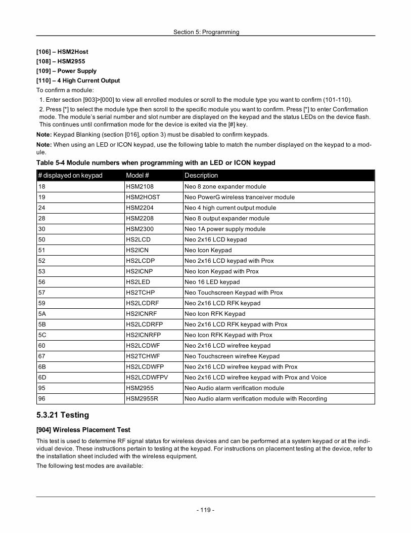
Section 5: Programming
[106] – HSM2Host[108] – HSM2955[109] – Power Supply[110] – 4 High Current OutputTo confirm a module:1. Enter section [903]>[000] to view all enrolled modules or scroll to the module type you want to confirm (101-110).2. Press [*] to select the module type then scroll to the specific module you want to confirm. Press [*] to enter Confirmationmode. The module’s serial number and slot number are displayed on the keypad and the status LEDs on the device flash.This continues until confirmation mode for the device is exited via the [#] key.
Note: Keypad Blanking (section [016], option 3) must be disabled to confirm keypads.
Note:When using an LED or ICON keypad, use the following table to match the number displayed on the keypad to a mod-ule.
Table 5-4 Module numbers when programming with an LED or ICON keypad
# displayed on keypad Model # Description18 HSM2108 Neo 8 zone expander module
19 HSM2HOST Neo PowerG wireless tranceiver module
24 HSM2204 Neo 4 high current output module
28 HSM2208 Neo 8 output expander module
30 HSM2300 Neo 1A power supply module
50 HS2LCD Neo 2x16 LCD keypad
51 HS2ICN Neo Icon Keypad
52 HS2LCDP Neo 2x16 LCD keypad with Prox
53 HS2ICNP Neo Icon Keypad with Prox
56 HS2LED Neo 16 LED keypad
57 HS2TCHP Neo Touchscreen Keypad with Prox
59 HS2LCDRF Neo 2x16 LCD RFK keypad
5A HS2ICNRF Neo Icon RFK Keypad
5B HS2LCDRFP Neo 2x16 LCD RFK keypad with Prox
5C HS2ICNRFP Neo Icon RFK Keypad with Prox
60 HS2LCDWF Neo 2x16 LCD wirefree keypad
67 HS2TCHWF Neo Touchscreen wirefree Keypad
6B HS2LCDWFP Neo 2x16 LCD wirefree keypad with Prox
6D HS2LCDWFPV Neo 2x16 LCD wirefree keypad with Prox and Voice
95 HSM2955 Neo Audio alarm verification module
96 HSM2955R Neo Audio alarm verification module with Recording
5.3.21 Testing
[904] Wireless Placement TestThis test is used to determine RF signal status for wireless devices and can be performed at a system keypad or at the indi-vidual device. These instructions pertain to testing at the keypad. For instructions on placement testing at the device, refer tothe installation sheet included with the wireless equipment.The following test modes are available:
- 119 -
Section 5: Programming
[001]-[128] Placement Test Zones 1-128Test wireless devices individually by zone (LCD keypads only).[521]-[528] Placement Test Repeaters 1-8Test each enrolled wireless repeater (LCD keypads only).[551]-[566] Placement Test Sirens 1-16Test each enrolled wireless siren (LCD keypads only).[601]-[632] Placement Test Wireless keys 1-32Test individual wireless keys. Once in this section, press a button on the wireless key to begin the test (LCD keypads only).[701]-[716] Placement Test Wireless Keypads 1-16Test each enrolled wireless keypad (LCD keypads only).Two test results are provided:
l 24-hour: Average status results received during a 24-hour period.l Now: Signal status results of the current test.
During testing, the Ready and Armed LED's flash to indicate data is being received. A flashing Trouble LED indicates RFinterference. The following status indicators may be displayed:
Table 5-5 Wireless Device Status Indications
Keypad StatusStrong Strong signal strength
Good Good signal strength
Poor Poor signal strength
1-Way The device is operating in 1-way mode only. The alarm panel cannot configure or control the device
Not Test Displayed as the Now result if no test was performed.
None Always displayed as the 24-hour result when testing wireless keys.
[912] Soak TestThis feature is used to diagnose false alarms. After a false alarm has occurred on a zone, Soak Test mode impedes any aud-ible alarm conditions or additional false alarm reporting. A record of the false alarm is stored for diagnostic purposes.[000] – Soak Test DurationThis option is used to program the length of time the system remains in soak test. The default is 14 days.[001]-[128] Zone Soak TestSoak test can be performed on individual zones. The zone remains in soak test, regardless of the status of the system, untilthe soak test timer has expired. If the system is armed when the timer expires, the zones are removed from soak test whenthe system is disarmed.No communications occur for events from a zone in soak test, with the exception of low battery and low battery restoreevents and faults generated by low sensitivity in a smoke detector.A message indicating that the zone is in soak test is displayed when scrolling left or right in the base disarmed keypadmenu.
Note: Soak test is not applied to temperature detector events if it is enabled.
[982] Battery Settings[000] – Panel Battery Settings01 – When disabled, the panel battery is charged at 400mA. When enabled, the battery is charged at 700mA.[010] – High Current Output BatteryEnables and disables the high-current battery charge option for HSM2204 1-4.[020] – 1A Power Supply BatteryEnables and disables the high-current battery charge option for HSM2300 1-4.
- 120 -
Section 5: Programming
5.3.22 Defaults
[989] Default Master CodeThis section is used to default the master code to the factory default. After entering this section, key in the installer code then989.[989][installer code][989] or [*].
Note: Feature is only available for EN models of NEO.
[990] Installer Lockout Enable/DisableWhen this option is enabled, an installer can not perform a hardware default; attempts to do so are logged to the event buf-fer.An audible indication of installer lockout is provided when powering up the alarm system (the phone line relay clicks rap-idly). Software default changes can still be made while installer lockout is enabled.[990][installer code][990] or [*].
[991] Default KeypadsThis programming option is used to return system keypads to factory default settings.
[901]- [916] – Default Keypads 1-16This section resets individual keypads to factory defaults. After entering this section, select the keypad to default, key in theinstaller code then 991 (or press [*]).[999] – Default All KeypadsThis section resets all system keypads to factory defaults. After entering this section, key in the installer code then (*) or 991.
[993] Default Alternate CommunicatorThis section resets the alternate communicator to factory defaults. Enter [993][installer code][993 or *].
[996] Default Wireless ReceiverThis section resets the wireless receiver (HSM2HOSTx) to factory defaults. Enter [996][installer code][996 or *].
[998] Default HSM2955This section resets the audio module (HSM2955) to factory defaults. Enter [998][installer code][998 or *].
[999] Default SystemThis section resets the alarm controller to factory defaults. Enter [999][installer code][999 or *].
- 121 -
- 122 -
Section 6: ProgrammingWorksheetsNote: EN listed options are required for EN 50131 Compliant Installations.
6.1 Label Programming
[000] Label ProgrammingDescription on page 61
[000] – Language Selection (2-digit decimal; Default: 01)
01 – English02 – Spanish03 – Portuguese04 – French05 – Italian
06 – Dutch07 – Polish08 – Czech09 – Finish10 – German
11 – Swedish12 – Norwegian13 – Danish14 – Hebrew15 – Greek
16 – Turkish18 – Croatian19 – Hungarian20 – Romanian21 – Russian
22 – Bulgarian23 – Latvian24 – Lithuanian25 – Ukrainian26 – Slovakian
27 – Serbian28 – Estonian29 – Slovenian
[000] [001] Zone Labels (2 x 14 Characters)Description on page 61
001: 002: 003:
004: 005: 006:
007: 008: 009:
010: 011: 012:
013: 014: 015:
016: 017: 018:
019: 020: 021:
022: 023: 024:
025: 026: 027:
028: 029: 030:
031 032: 033:
034: 035: 036:
037: 038: 039:
040: 041: 042:
043: 044: 045:
046: 047: 048:
049: 050: 051:
052: 053: 054:
055: 056: 057:
058: 059: 060:
061: 062: 063:
064: 065: 066:
067: 068: 069:
070: 071: 072:
073: 074: 075:
076: 077: 078:
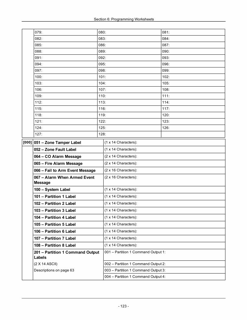
Section 6: Programming Worksheets
079: 080: 081:
082: 083: 084:
085: 086: 087:
088: 089: 090:
091: 092: 093:
094: 095: 096:
097: 098: 099:
100: 101: 102:
103: 104: 105:
106: 107: 108:
109: 110: 111:
112: 113: 114:
115: 116: 117:
118: 119: 120:
121: 122: 123:
124: 125: 126:
127: 128:
[000] 051 – Zone Tamper Label (1 x 14 Characters):
052 – Zone Fault Label (1 x 14 Characters):
064 – CO Alarm Message (2 x 14 Characters):
065 – Fire Alarm Message (2 x 14 Characters):
066 – Fail to Arm Event Message (2 x 16 Characters):
067 – Alarm When Armed EventMessage
(2 x 16 Characters):
100 – System Label (1 x 14 Characters):
101 – Partition 1 Label (1 x 14 Characters):
102 – Partition 2 Label (1 x 14 Characters):
103 – Partition 3 Label (1 x 14 Characters):
104 – Partition 4 Label (1 x 14 Characters):
105 – Partition 5 Label (1 x 14 Characters):
106 – Partition 6 Label (1 x 14 Characters):
107 – Partition 7 Label (1 x 14 Characters):
108 – Partition 8 Label (1 x 14 Characters):
201 – Partition 1 Command OutputLabels
001 – Partition 1 Command Output 1:
(2 X 14 ASCII) 002 – Partition 1 Command Output 2:
Descriptions on page 63 003 – Partition 1 Command Output 3:
004 – Partition 1 Command Output 4:
- 123 -
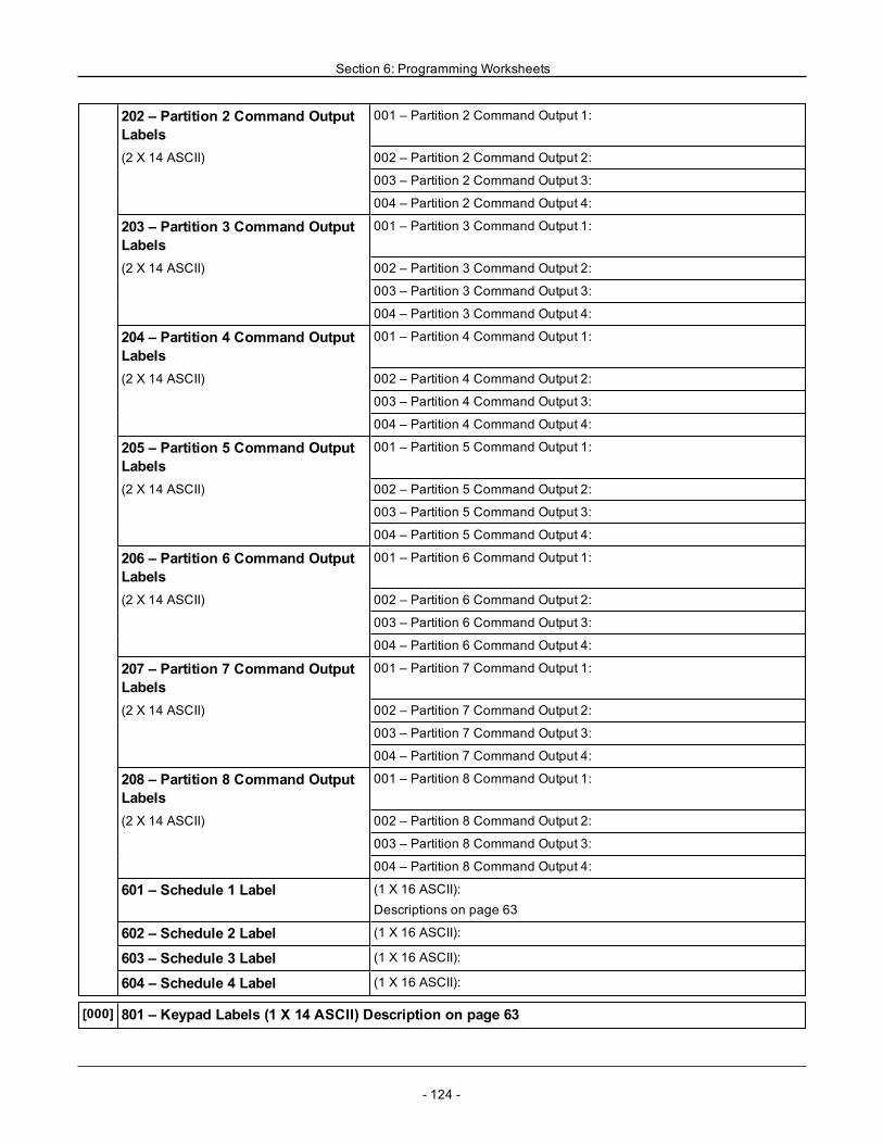
Section 6: Programming Worksheets
202 – Partition 2 Command OutputLabels
001 – Partition 2 Command Output 1:
(2 X 14 ASCII) 002 – Partition 2 Command Output 2:
003 – Partition 2 Command Output 3:
004 – Partition 2 Command Output 4:
203 – Partition 3 Command OutputLabels
001 – Partition 3 Command Output 1:
(2 X 14 ASCII) 002 – Partition 3 Command Output 2:
003 – Partition 3 Command Output 3:
004 – Partition 3 Command Output 4:
204 – Partition 4 Command OutputLabels
001 – Partition 4 Command Output 1:
(2 X 14 ASCII) 002 – Partition 4 Command Output 2:
003 – Partition 4 Command Output 3:
004 – Partition 4 Command Output 4:
205 – Partition 5 Command OutputLabels
001 – Partition 5 Command Output 1:
(2 X 14 ASCII) 002 – Partition 5 Command Output 2:
003 – Partition 5 Command Output 3:
004 – Partition 5 Command Output 4:
206 – Partition 6 Command OutputLabels
001 – Partition 6 Command Output 1:
(2 X 14 ASCII) 002 – Partition 6 Command Output 2:
003 – Partition 6 Command Output 3:
004 – Partition 6 Command Output 4:
207 – Partition 7 Command OutputLabels
001 – Partition 7 Command Output 1:
(2 X 14 ASCII) 002 – Partition 7 Command Output 2:
003 – Partition 7 Command Output 3:
004 – Partition 7 Command Output 4:
208 – Partition 8 Command OutputLabels
001 – Partition 8 Command Output 1:
(2 X 14 ASCII) 002 – Partition 8 Command Output 2:
003 – Partition 8 Command Output 3:
004 – Partition 8 Command Output 4:
601 – Schedule 1 Label (1 X 16 ASCII):Descriptions on page 63
602 – Schedule 2 Label (1 X 16 ASCII):
603 – Schedule 3 Label (1 X 16 ASCII):
604 – Schedule 4 Label (1 X 16 ASCII):
[000] 801 – Keypad Labels (1 X 14 ASCII) Description on page 63
- 124 -
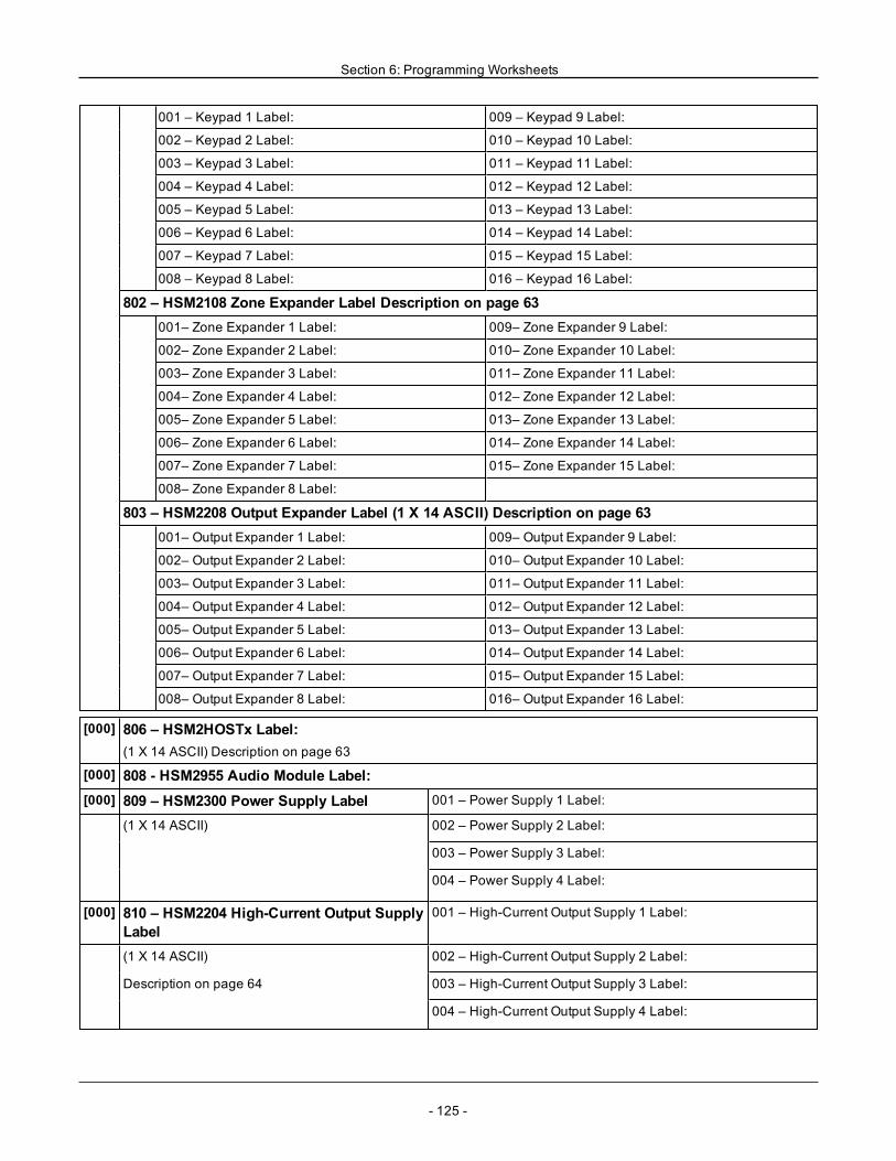
Section 6: Programming Worksheets
001 – Keypad 1 Label: 009 – Keypad 9 Label:
002 – Keypad 2 Label: 010 – Keypad 10 Label:
003 – Keypad 3 Label: 011 – Keypad 11 Label:
004 – Keypad 4 Label: 012 – Keypad 12 Label:
005 – Keypad 5 Label: 013 – Keypad 13 Label:
006 – Keypad 6 Label: 014 – Keypad 14 Label:
007 – Keypad 7 Label: 015 – Keypad 15 Label:
008 – Keypad 8 Label: 016 – Keypad 16 Label:
802 – HSM2108 Zone Expander Label Description on page 63001– Zone Expander 1 Label: 009– Zone Expander 9 Label:
002– Zone Expander 2 Label: 010– Zone Expander 10 Label:
003– Zone Expander 3 Label: 011– Zone Expander 11 Label:
004– Zone Expander 4 Label: 012– Zone Expander 12 Label:
005– Zone Expander 5 Label: 013– Zone Expander 13 Label:
006– Zone Expander 6 Label: 014– Zone Expander 14 Label:
007– Zone Expander 7 Label: 015– Zone Expander 15 Label:
008– Zone Expander 8 Label:
803 – HSM2208 Output Expander Label (1 X 14 ASCII) Description on page 63001– Output Expander 1 Label: 009– Output Expander 9 Label:
002– Output Expander 2 Label: 010– Output Expander 10 Label:
003– Output Expander 3 Label: 011– Output Expander 11 Label:
004– Output Expander 4 Label: 012– Output Expander 12 Label:
005– Output Expander 5 Label: 013– Output Expander 13 Label:
006– Output Expander 6 Label: 014– Output Expander 14 Label:
007– Output Expander 7 Label: 015– Output Expander 15 Label:
008– Output Expander 8 Label: 016– Output Expander 16 Label:
[000] 806 – HSM2HOSTx Label:(1 X 14 ASCII) Description on page 63
[000] 808 - HSM2955 Audio Module Label:[000] 809 – HSM2300 Power Supply Label 001 – Power Supply 1 Label:
(1 X 14 ASCII) 002 – Power Supply 2 Label:
003 – Power Supply 3 Label:
004 – Power Supply 4 Label:
[000] 810 – HSM2204 High-Current Output SupplyLabel
001 – High-Current Output Supply 1 Label:
(1 X 14 ASCII) 002 – High-Current Output Supply 2 Label:
Description on page 64 003 – High-Current Output Supply 3 Label:
004 – High-Current Output Supply 4 Label:
- 125 -
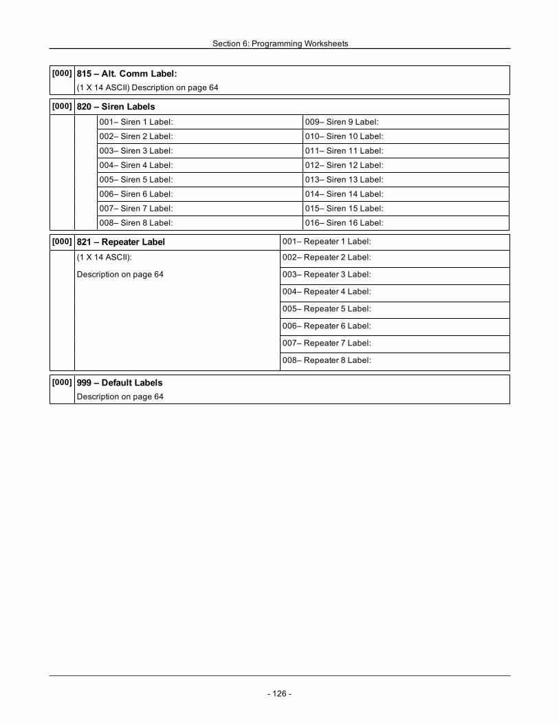
Section 6: Programming Worksheets
[000] 815 – Alt. Comm Label:(1 X 14 ASCII) Description on page 64
[000] 820 – Siren Labels001– Siren 1 Label: 009– Siren 9 Label:
002– Siren 2 Label: 010– Siren 10 Label:
003– Siren 3 Label: 011– Siren 11 Label:
004– Siren 4 Label: 012– Siren 12 Label:
005– Siren 5 Label: 013– Siren 13 Label:
006– Siren 6 Label: 014– Siren 14 Label:
007– Siren 7 Label: 015– Siren 15 Label:
008– Siren 8 Label: 016– Siren 16 Label:
[000] 821 – Repeater Label 001– Repeater 1 Label:
(1 X 14 ASCII): 002– Repeater 2 Label:
Description on page 64 003– Repeater 3 Label:
004– Repeater 4 Label:
005– Repeater 5 Label:
006– Repeater 6 Label:
007– Repeater 7 Label:
008– Repeater 8 Label:
[000] 999 – Default LabelsDescription on page 64
- 126 -
Section 6: Programming Worksheets
6.2 Zone Setup
[001] [001 - 128] Zone TypeAvailable Zone TypesDefault = 000Description on page 64* Not UL evaluated
000 – Null Zone001 – Delay 1002 – Delay 2003 – Instant004 – Interior005 – Interior Stay/Away006 – Delay Stay/Away007 – Delayed 24-Hour Fire008 – Standard 24-Hour Fire009 – Instant Stay/Away010 – Interior Delay011 – Day Zone012 – Night Zone016 – Final Door Set017 – 24-Hour Burglary
018 – 24-Hour Bell/Buzzer023 – 24-Hour Supervisory024 – 24-Hour SupervisoryBuzzer025 – Auto Verified Fire027 – Fire Supervisory040 – 24-Hour Gas041 – 24-Hour CO042 – 24-Hour Holdup*043 – 24-Hour Panic045 – 24-Hour Heat046 – 24-Hour Medical047 – 24-Hour Emergency048 – 24-Hour Sprinkler*049 – 24-Hour Flood
051 – 24-Hour Latching Tamper052 – 24-Hour Non-Alarm056 – 24-Hour High Temperature057 – 24 Hour Low Temperature060 – 24-Hour Non-LatchingTamper066 – Momentary Keyswitch Arm067 – Maintained Keyswitch Arm068 – Momentary Keyswitch Dis-arm069 – Maintained Keyswitch Dis-arm071 – Door Bell072 – Push to Set
[002] [001 - 128] Zone AttributesAvailable Zone AttributesSee next page for defaultsDescription on page 68
1 – Bell Audible2 – Bell Steady3 – Door Chime4 – BypassEnabled
5 – Force Arm6 – Swinger Shut-down7 – TransmissionDelay8 – Burglary Veri-fication
9 – Normally Close10 – Single EOL11 – Double EOL12 – Fast/Normal LoopResponse
13 – Zone 2-way Audio Activ-ation14 – Hold Up Verification
- 127 -
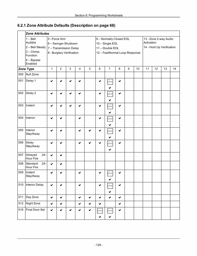
Section 6: Programming Worksheets
6.2.1 Zone Attribute Defaults (Description on page 68)
Zone Attributes1 – BellAudible2 – Bell Steady3 – ChimeFunction4 – BypassEnabled
5 –Force Arm6 – Swinger Shutdown7 – Transmission Delay8 - Burglary Verification
9 – Normally Closed EOL10 – Single EOL11 – Double EOL12 – Fast/Normal Loop Response
13 - Zone 2-way AudioActivation14 - Hold Up Verification
Zone Type 1 2 3 4 5 6 7 8 9 10 11 12 13 14
000 Null Zone
001 Delay 1 a a a a a CP-01
a
a
002 Delay 2 a a a a a CP-01
a
a
003 Instant a a a a a CP-01
a
a
004 Interior a a a a CP-01
a
a
005 InteriorStay/Away
a a a a a CP-01
a
a
006 DelayStay/Away
a a a a a CP-01
a
a
007 Delayed 24-Hour Fire
a a
008 Standard 24-Hour Fire
a a
009 InstantStay/Away
a a a a CP-01
a
a
010 Interior Delay a a a a CP-01
a
a
011 Day Zone a a a a a a a
012 Night Zone a a a a a a
016 Final Door Set a a a a a CP-01
a
CP-01
a
a
- 128 -
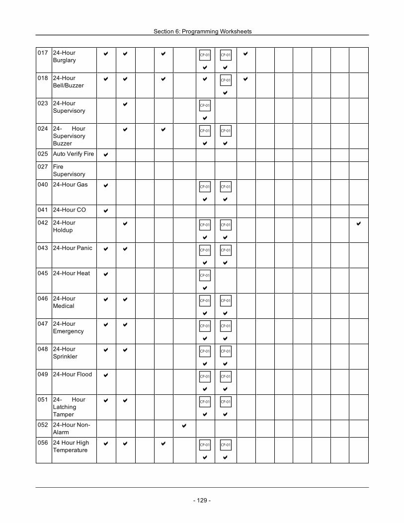
Section 6: Programming Worksheets
017 24-HourBurglary
a a a CP-01
a
CP-01
a
a
018 24-HourBell/Buzzer
a a a a CP-01
a
a
023 24-HourSupervisory
a CP-01
a
024 24- HourSupervisoryBuzzer
a a CP-01
a
CP-01
a
025 Auto Verify Fire a
027 FireSupervisory
040 24-Hour Gas a CP-01
a
CP-01
a
041 24-Hour CO a
042 24-HourHoldup
a CP-01
a
CP-01
a
a
043 24-Hour Panic a a CP-01
a
CP-01
a
045 24-Hour Heat a CP-01
a
046 24-HourMedical
a a CP-01
a
CP-01
a
047 24-HourEmergency
a a CP-01
a
CP-01
a
048 24-HourSprinkler
a a CP-01
a
CP-01
a
049 24-Hour Flood a CP-01
a
CP-01
a
051 24- HourLatchingTamper
a a CP-01
a
CP-01
a
052 24-Hour Non-Alarm
a
056 24 Hour HighTemperature
a a a CP-01
a
CP-01
a
- 129 -
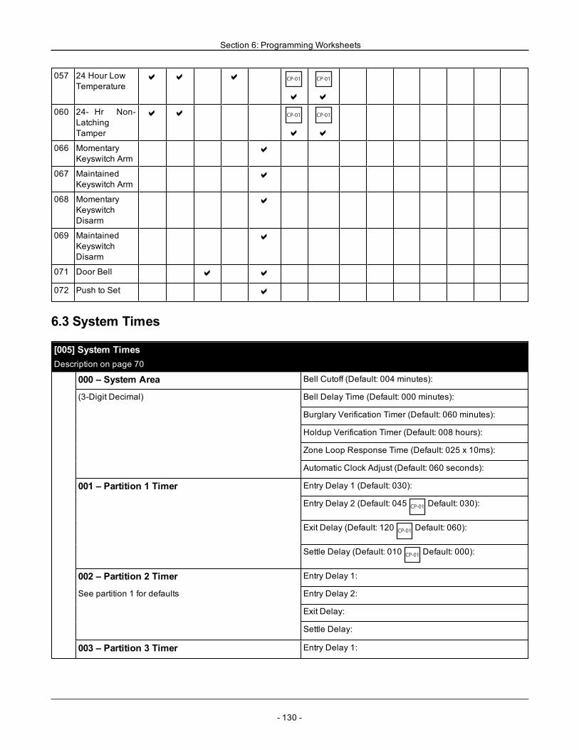
Section 6: Programming Worksheets
057 24 Hour LowTemperature
a a a CP-01
a
CP-01
a
060 24- Hr Non-LatchingTamper
a a CP-01
a
CP-01
a
066 MomentaryKeyswitch Arm
a
067 MaintainedKeyswitch Arm
a
068 MomentaryKeyswitchDisarm
a
069 MaintainedKeyswitchDisarm
a
071 Door Bell a a
072 Push to Set a
6.3 System Times
[005] System TimesDescription on page 70
000 – System Area Bell Cutoff (Default: 004 minutes):
(3-Digit Decimal) Bell Delay Time (Default: 000 minutes):
Burglary Verification Timer (Default: 060 minutes):
Holdup Verification Timer (Default: 008 hours):
Zone Loop Response Time (Default: 025 x 10ms):
Automatic Clock Adjust (Default: 060 seconds):
001 – Partition 1 Timer Entry Delay 1 (Default: 030):
Entry Delay 2 (Default: 045CP-01
Default: 030):
Exit Delay (Default: 120CP-01
Default: 060):
Settle Delay (Default: 010CP-01
Default: 000):
002 – Partition 2 Timer Entry Delay 1:
See partition 1 for defaults Entry Delay 2:
Exit Delay:
Settle Delay:
003 – Partition 3 Timer Entry Delay 1:
- 130 -
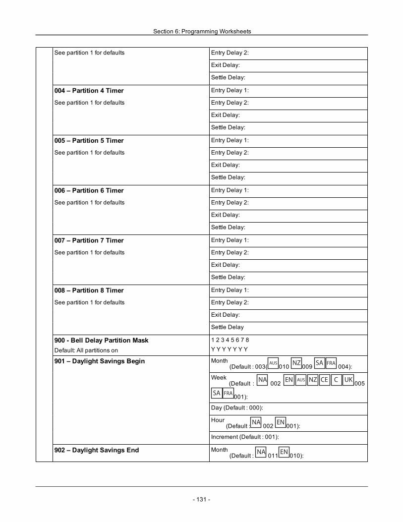
Section 6: Programming Worksheets
See partition 1 for defaults Entry Delay 2:
Exit Delay:
Settle Delay:
004 – Partition 4 Timer Entry Delay 1:
See partition 1 for defaults Entry Delay 2:
Exit Delay:
Settle Delay:
005 – Partition 5 Timer Entry Delay 1:
See partition 1 for defaults Entry Delay 2:
Exit Delay:
Settle Delay:
006 – Partition 6 Timer Entry Delay 1:
See partition 1 for defaults Entry Delay 2:
Exit Delay:
Settle Delay:
007 – Partition 7 Timer Entry Delay 1:
See partition 1 for defaults Entry Delay 2:
Exit Delay:
Settle Delay:
008 – Partition 8 Timer Entry Delay 1:
See partition 1 for defaults Entry Delay 2:
Exit Delay:
Settle Delay
900 - Bell Delay Partition MaskDefault: All partitions on
1 2 3 4 5 6 7 8Y Y Y Y Y Y Y
901 – Daylight Savings Begin Month(Default : 003(
AUS010 NZ 009 SA FRA 004):
Week(Default : NA 002 EN AUS NZ CE C UK 005
SA FRA 001):
Day (Default : 000):
Hour(Default : NA 002 EN 001):
Increment (Default : 001):
902 – Daylight Savings End Month(Default : NA 011 EN 010):
- 131 -
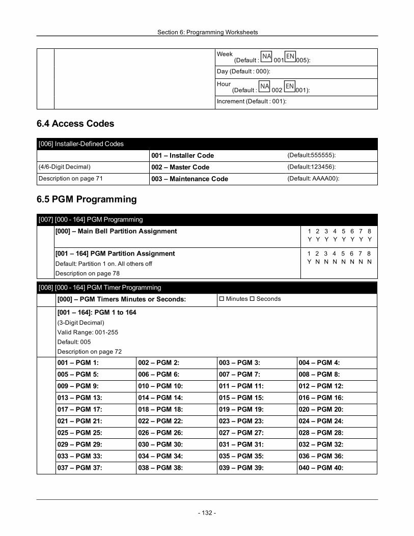
Section 6: Programming Worksheets
Week(Default : NA 001 EN 005):
Day (Default : 000):
Hour(Default : NA 002 EN 001):
Increment (Default : 001):
6.4 Access Codes
[006] Installer-Defined Codes
001 – Installer Code (Default:555555):
(4/6-Digit Decimal) 002 – Master Code (Default:123456):
Description on page 71 003 – Maintenance Code (Default: AAAA00):
6.5 PGM Programming
[007] [000 - 164] PGM Programming
[000] – Main Bell Partition Assignment 1 2 3 4 5 6 7 8Y Y Y Y Y Y Y Y
[001 – 164] PGM Partition AssignmentDefault: Partition 1 on. All others offDescription on page 78
1 2 3 4 5 6 7 8Y N N N N N N N
[008] [000 - 164] PGM Timer Programming
[000] – PGM Timers Minutes or Seconds: o Minuteso Seconds
[001 – 164]: PGM 1 to 164(3-Digit Decimal)Valid Range: 001-255Default: 005Description on page 72
001 – PGM 1: 002 – PGM 2: 003 – PGM 3: 004 – PGM 4:005 – PGM 5: 006 – PGM 6: 007 – PGM 7: 008 – PGM 8:009 – PGM 9: 010 – PGM 10: 011 – PGM 11: 012 – PGM 12:013 – PGM 13: 014 – PGM 14: 015 – PGM 15: 016 – PGM 16:017 – PGM 17: 018 – PGM 18: 019 – PGM 19: 020 – PGM 20:021 – PGM 21: 022 – PGM 22: 023 – PGM 23: 024 – PGM 24:025 – PGM 25: 026 – PGM 26: 027 – PGM 27: 028 – PGM 28:029 – PGM 29: 030 – PGM 30: 031 – PGM 31: 032 – PGM 32:033 – PGM 33: 034 – PGM 34: 035 – PGM 35: 036 – PGM 36:037 – PGM 37: 038 – PGM 38: 039 – PGM 39: 040 – PGM 40:
- 132 -
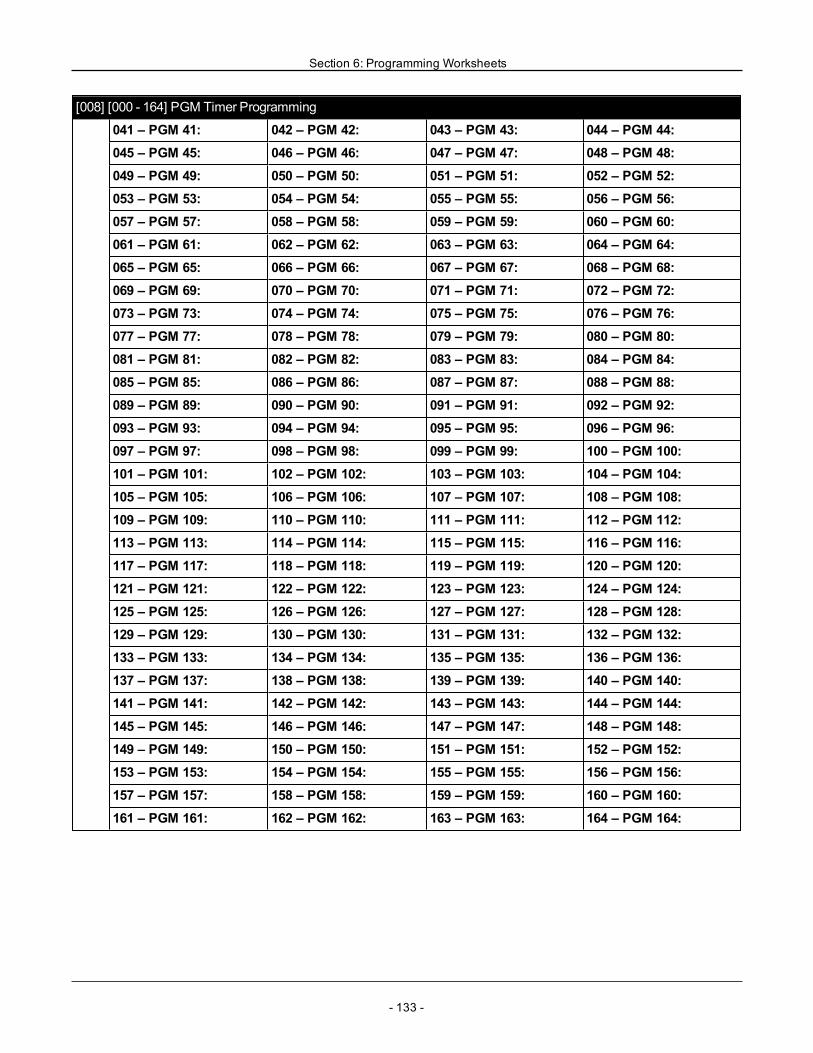
Section 6: Programming Worksheets
[008] [000 - 164] PGM Timer Programming
041 – PGM 41: 042 – PGM 42: 043 – PGM 43: 044 – PGM 44:045 – PGM 45: 046 – PGM 46: 047 – PGM 47: 048 – PGM 48:049 – PGM 49: 050 – PGM 50: 051 – PGM 51: 052 – PGM 52:053 – PGM 53: 054 – PGM 54: 055 – PGM 55: 056 – PGM 56:057 – PGM 57: 058 – PGM 58: 059 – PGM 59: 060 – PGM 60:061 – PGM 61: 062 – PGM 62: 063 – PGM 63: 064 – PGM 64:065 – PGM 65: 066 – PGM 66: 067 – PGM 67: 068 – PGM 68:069 – PGM 69: 070 – PGM 70: 071 – PGM 71: 072 – PGM 72:073 – PGM 73: 074 – PGM 74: 075 – PGM 75: 076 – PGM 76:077 – PGM 77: 078 – PGM 78: 079 – PGM 79: 080 – PGM 80:081 – PGM 81: 082 – PGM 82: 083 – PGM 83: 084 – PGM 84:085 – PGM 85: 086 – PGM 86: 087 – PGM 87: 088 – PGM 88:089 – PGM 89: 090 – PGM 90: 091 – PGM 91: 092 – PGM 92:093 – PGM 93: 094 – PGM 94: 095 – PGM 95: 096 – PGM 96:097 – PGM 97: 098 – PGM 98: 099 – PGM 99: 100 – PGM 100:101 – PGM 101: 102 – PGM 102: 103 – PGM 103: 104 – PGM 104:105 – PGM 105: 106 – PGM 106: 107 – PGM 107: 108 – PGM 108:109 – PGM 109: 110 – PGM 110: 111 – PGM 111: 112 – PGM 112:113 – PGM 113: 114 – PGM 114: 115 – PGM 115: 116 – PGM 116:117 – PGM 117: 118 – PGM 118: 119 – PGM 119: 120 – PGM 120:121 – PGM 121: 122 – PGM 122: 123 – PGM 123: 124 – PGM 124:125 – PGM 125: 126 – PGM 126: 127 – PGM 127: 128 – PGM 128:129 – PGM 129: 130 – PGM 130: 131 – PGM 131: 132 – PGM 132:133 – PGM 133: 134 – PGM 134: 135 – PGM 135: 136 – PGM 136:137 – PGM 137: 138 – PGM 138: 139 – PGM 139: 140 – PGM 140:141 – PGM 141: 142 – PGM 142: 143 – PGM 143: 144 – PGM 144:145 – PGM 145: 146 – PGM 146: 147 – PGM 147: 148 – PGM 148:149 – PGM 149: 150 – PGM 150: 151 – PGM 151: 152 – PGM 152:153 – PGM 153: 154 – PGM 154: 155 – PGM 155: 156 – PGM 156:157 – PGM 157: 158 – PGM 158: 159 – PGM 159: 160 – PGM 160:161 – PGM 161: 162 – PGM 162: 163 – PGM 163: 164 – PGM 164:
- 133 -
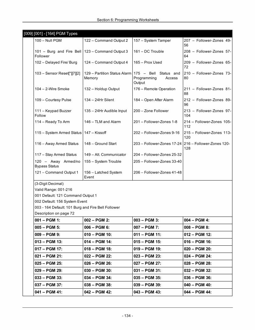
Section 6: Programming Worksheets
[009] [001] - [164] PGM Types100 – Null PGM 122 – Command Output 2 157 – System Tamper 207 – Follower-Zones 49-
56
101 – Burg and Fire BellFollower
123 – Command Output 3 161 – DC Trouble 208 – Follower-Zones 57-64
102 – Delayed Fire/ Burg 124 – Command Output 4 165 – Prox Used 209 – Follower-Zones 65-72
103 – Sensor Reset[*][7][2] 129 – Partition Status AlarmMemory
175 – Bell Status andProgramming AccessOutput
210 – Follower-Zones 73-80
104 – 2-Wire Smoke 132 – Holdup Output 176 – Remote Operation 211 – Follower-Zones 81-88
109 – Courtesy Pulse 134 – 24Hr Silent 184 – Open After Alarm 212 – Follower-Zones 89-96
111 – Keypad BuzzerFollow
135 – 24Hr Audible Input 200 – Zone Follower 213 – Follower-Zones 97-104
114 – Ready To Arm 146 – TLM and Alarm 201 – Follower-Zones 1-8 214 – Follower-Zones 105-112
115 – System Armed Status 147 – Kissoff 202 – Follower-Zones 9-16 215 – Follower-Zones 113-120
116 – Away Armed Status 148 – Ground Start 203 – Follower-Zones 17-24 216 – Follower-Zones 120-128
117 – Stay Armed Status 149 – Alt. Communicator 204 – Follower-Zones 25-32
120 – Away Armed/noBypass Status
155 – System Trouble 205 – Follower-Zones 33-40
121 – Command Output 1 156 – Latched SystemEvent
206 – Follower-Zones 41-48
(3-Digit Decimal)Valid Range: 001-216001 Default: 121 Command Output 1002 Default: 156 System Event003 - 164 Default: 101 Burg and Fire Bell FollowerDescription on page 72
001 – PGM 1: 002 – PGM 2: 003 – PGM 3: 004 – PGM 4:005 – PGM 5: 006 – PGM 6: 007 – PGM 7: 008 – PGM 8:009 – PGM 9: 010 – PGM 10: 011 – PGM 11: 012 – PGM 12:013 – PGM 13: 014 – PGM 14: 015 – PGM 15: 016 – PGM 16:017 – PGM 17: 018 – PGM 18: 019 – PGM 19: 020 – PGM 20:021 – PGM 21: 022 – PGM 22: 023 – PGM 23: 024 – PGM 24:025 – PGM 25: 026 – PGM 26: 027 – PGM 27: 028 – PGM 28:029 – PGM 29: 030 – PGM 30: 031 – PGM 31: 032 – PGM 32:033 – PGM 33: 034 – PGM 34: 035 – PGM 35: 036 – PGM 36:037 – PGM 37: 038 – PGM 38: 039 – PGM 39: 040 – PGM 40:041 – PGM 41: 042 – PGM 42: 043 – PGM 43: 044 – PGM 44:
- 134 -
Section 6: Programming Worksheets
[009] [001] - [164] PGM Types
045 – PGM 45: 046 – PGM 46: 047 – PGM 47: 048 – PGM 48:049 – PGM 49: 050 – PGM 50: 051 – PGM 51: 052 – PGM 52:053 – PGM 53: 054 – PGM 54: 055 – PGM 55: 056 – PGM 56:057 – PGM 57: 058 – PGM 58: 059 – PGM 59: 060 – PGM 60:061 – PGM 61: 062 – PGM 62: 063 – PGM 63: 064 – PGM 64:065 – PGM 65: 066 – PGM 66: 067 – PGM 67: 068 – PGM 68:069 – PGM 69: 070 – PGM 70: 071 – PGM 71: 072 – PGM 72:073 – PGM 73: 074 – PGM 74: 075 – PGM 75: 076 – PGM 76:077 – PGM 77: 078 – PGM 78: 079 – PGM 79: 080 – PGM 80:081 – PGM 81: 082 – PGM 82: 083 – PGM 83: 084 – PGM 84:085 – PGM 85: 086 – PGM 86: 087 – PGM 87: 088 – PGM 88:089 – PGM 89: 090 – PGM 90: 091 – PGM 91: 092 – PGM 92:093 – PGM 93: 094 – PGM 94: 095 – PGM 95: 096 – PGM 96:097 – PGM 97: 098 – PGM 98: 099 – PGM 99: 100 – PGM 100:101 – PGM 101: 102 – PGM 102: 103 – PGM 103: 104 – PGM 104:105 – PGM 105: 106 – PGM 106: 107 – PGM 107: 108 – PGM 108:109 – PGM 109: 110 – PGM 110: 111 – PGM 111: 112 – PGM 112:113 – PGM 113: 114 – PGM 114: 115 – PGM 115: 116 – PGM 116:117 – PGM 117: 118 – PGM 118: 119 – PGM 119: 120 – PGM 120:121 – PGM 121: 122 – PGM 122: 123 – PGM 123: 124 – PGM 124:125 – PGM 125: 126 – PGM 126: 127 – PGM 127: 128 – PGM 128:129 – PGM 129: 130 – PGM 130: 131 – PGM 131: 132 – PGM 132:133 – PGM 133: 134 – PGM 134: 135 – PGM 135: 136 – PGM 136:137 – PGM 137: 138 – PGM 138: 139 – PGM 139: 140 – PGM 140:141 – PGM 141: 142 – PGM 142: 143 – PGM 143: 144 – PGM 144:145 – PGM 145: 146 – PGM 146: 147 – PGM 147: 148 – PGM 148:149 – PGM 149: 150 – PGM 150: 151 – PGM 151: 152 – PGM 152:153 – PGM 153: 154 – PGM 154: 155 – PGM 155: 156 – PGM 156:157 – PGM 157: 158 – PGM 158: 159 – PGM 159: 160 – PGM 160:161 – PGM 161: 162 – PGM 162: 163 – PGM 163: 164 – PGM 164:
- 135 -
Section 6: Programming Worksheets
[010] [000 - 164] PGM Attributes
[000] – Main BellMaskDescription on page 77
R 01 – Fire AlarmR 02 – CO AlarmR 03 – Burglary AlarmR 04 – Flood AlarmR 05 – Bell Squawks
001-164 PGM Attributes
PGM 1-164: 100 – Null PGM
101 – Fire and Burglary R 01 – True Output
102 – Delay Fire and Burg R 01 – True Output
103 – Sensor Reset [*][7][2] o 03 – Code Required
109 – Courtesy Pulse R 01 – True Output
111 – Keypad Buzzer Follow R 01 – True Outputo 02 – Timed OutputR 09 – Entry DelayR 10 – Exit DelayR 12 – Keypad Buzzer ZoneR 13 – Audible Exit ZoneR 14 – Auto-Arm Pre-Alert
114 – Ready To Arm R 01 – True Output
115 – Armed Status R 01 – True Output
116 – Armed Away Mode R 01 – True Output
117 – Armed Stay Mode R 01 – True Output
120 – Away Armed NoBypass
R 01 – True Output
121 – Command Output 1 R 01 – True Outputo 02 – Timed OutputR 03 – Code Required
R Schedule 001
122 – Command Output 2 R 01 – True Outputo 02 – Timed Outputo 03 – Code Required
R Schedule 001
123 – Command Output 3 R 01 – True Outputo 02 – Timed Outputo 03 – Code Required
R Schedule 001
124 – Command Output 4 R 01 – True Outputo 02 – Timed Outputo 03 – Code Required
R Schedule 001
129 – Partition Status AlarmMemory
R 01 – True Output
132 – Holdup Output R 01 – True Outputo 02 – Timed Output
- 136 -
Section 6: Programming Worksheets
[010] [000 - 164] PGM Attributes133 - Burglary Verified R 01 – True Output
146 – TLM And Alarm R 01 – True Output
147 – Kissoff Output R 01 – True Output
148 – Ground Start R 01 – True Output
149 – AlternateCommunicator
R 01 – True OutputR 02 – Timed Outputo 04 – Fire Alarmo 05 – Panic Alarmo 06 – Burglary Alarmo 07 – Open/Closeo 08 – Zone Auto Bypasso 09 – Medical Alarmo 10 – Burglary Verifiedo 11 – Open After Alarmo 12 – Emergency Alarmo 13 – Duress Alarmo 14 – Holdup Verified
155 – System Trouble R 01 – True Outputo 02 – Timed OutputR 04 – Service RequiredR 05 – Loss of ClockR 06 – DC TroubleR 07 – Bus VoltageR 08 – AC TroubleR 09 – Device FaultR 10 – Device BatteryR 11 – Device TamperR 12 – RF DelinquencyR 13 – Module SupervisoryR 14 – Module TamperR 15 – CommunicationsR 16 – Not Networked
- 137 -
Section 6: Programming Worksheets
[010] [000 - 164] PGM Attributes156 – Latched System Event R 01 – True Output
o 02 – Timed OutputR 04 – Fire AlarmR 05 – Panic AlarmR 06 – Burglary AlarmR 07 – Medical AlarmR 08 – SupervisoryR 09 – Priority EventR 10 – HoldupR 11 – Duress AlarmR 12 – Emergency AlarmR 13 – Fire SupervisoryR 14 – Fire TroubleR 15 – CO Alarm
157 – System Tamper R 01 – True Outputo 02 – Timed OutputR 09 – Module TamperR 10 – Zone Tampers
161 – DC Trouble R 01 – True Outputo 02 – Timed OutputR 09 – Battery LowR 10 – Battery Absent
165 – Prox Used R 01 – True Output
175 – Bell Prog Access R 01 – True Output
176 – Remote Operation R 01 – True Outputo 02 – Timed Output
184 – Open After Alarm R 01 – True OutputR 02 – Timed Output
200 – Zone Follow by Zone R 01 – True Outputo 02 – Timed Output
- 138 -
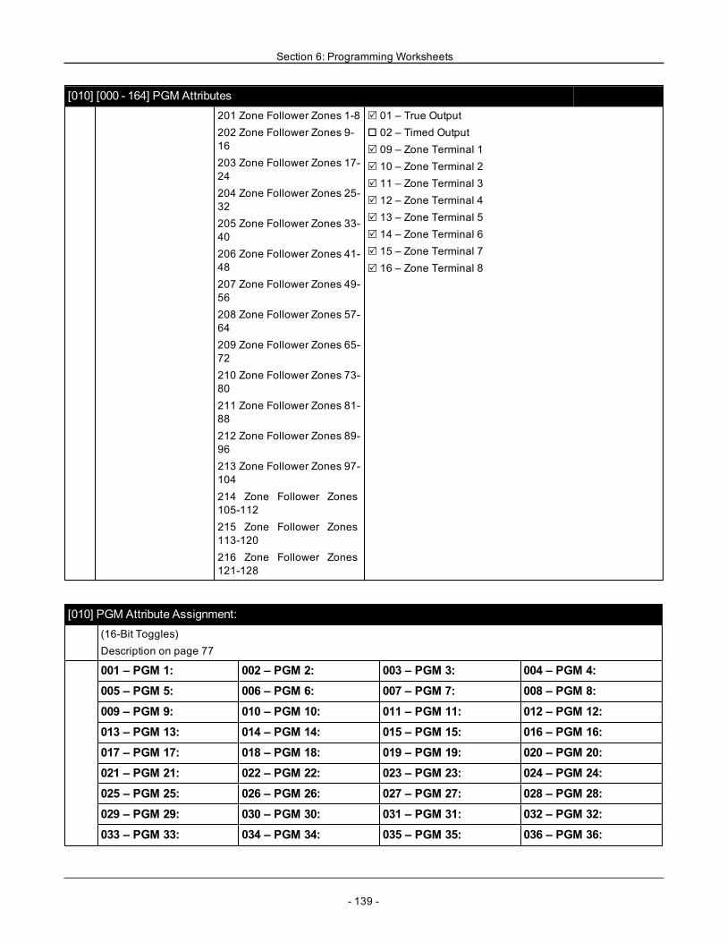
Section 6: Programming Worksheets
[010] [000 - 164] PGM Attributes201 Zone Follower Zones 1-8202 Zone Follower Zones 9-16203 Zone Follower Zones 17-24204 Zone Follower Zones 25-32205 Zone Follower Zones 33-40206 Zone Follower Zones 41-48207 Zone Follower Zones 49-56208 Zone Follower Zones 57-64209 Zone Follower Zones 65-72210 Zone Follower Zones 73-80211 Zone Follower Zones 81-88212 Zone Follower Zones 89-96213 Zone Follower Zones 97-104214 Zone Follower Zones105-112215 Zone Follower Zones113-120216 Zone Follower Zones121-128
R 01 – True Outputo 02 – Timed OutputR 09 – Zone Terminal 1R 10 – Zone Terminal 2R 11 – Zone Terminal 3R 12 – Zone Terminal 4R 13 – Zone Terminal 5R 14 – Zone Terminal 6R 15 – Zone Terminal 7R 16 – Zone Terminal 8
[010] PGM Attribute Assignment:(16-Bit Toggles)Description on page 77
001 – PGM 1: 002 – PGM 2: 003 – PGM 3: 004 – PGM 4:005 – PGM 5: 006 – PGM 6: 007 – PGM 7: 008 – PGM 8:009 – PGM 9: 010 – PGM 10: 011 – PGM 11: 012 – PGM 12:013 – PGM 13: 014 – PGM 14: 015 – PGM 15: 016 – PGM 16:017 – PGM 17: 018 – PGM 18: 019 – PGM 19: 020 – PGM 20:021 – PGM 21: 022 – PGM 22: 023 – PGM 23: 024 – PGM 24:025 – PGM 25: 026 – PGM 26: 027 – PGM 27: 028 – PGM 28:029 – PGM 29: 030 – PGM 30: 031 – PGM 31: 032 – PGM 32:033 – PGM 33: 034 – PGM 34: 035 – PGM 35: 036 – PGM 36:
- 139 -
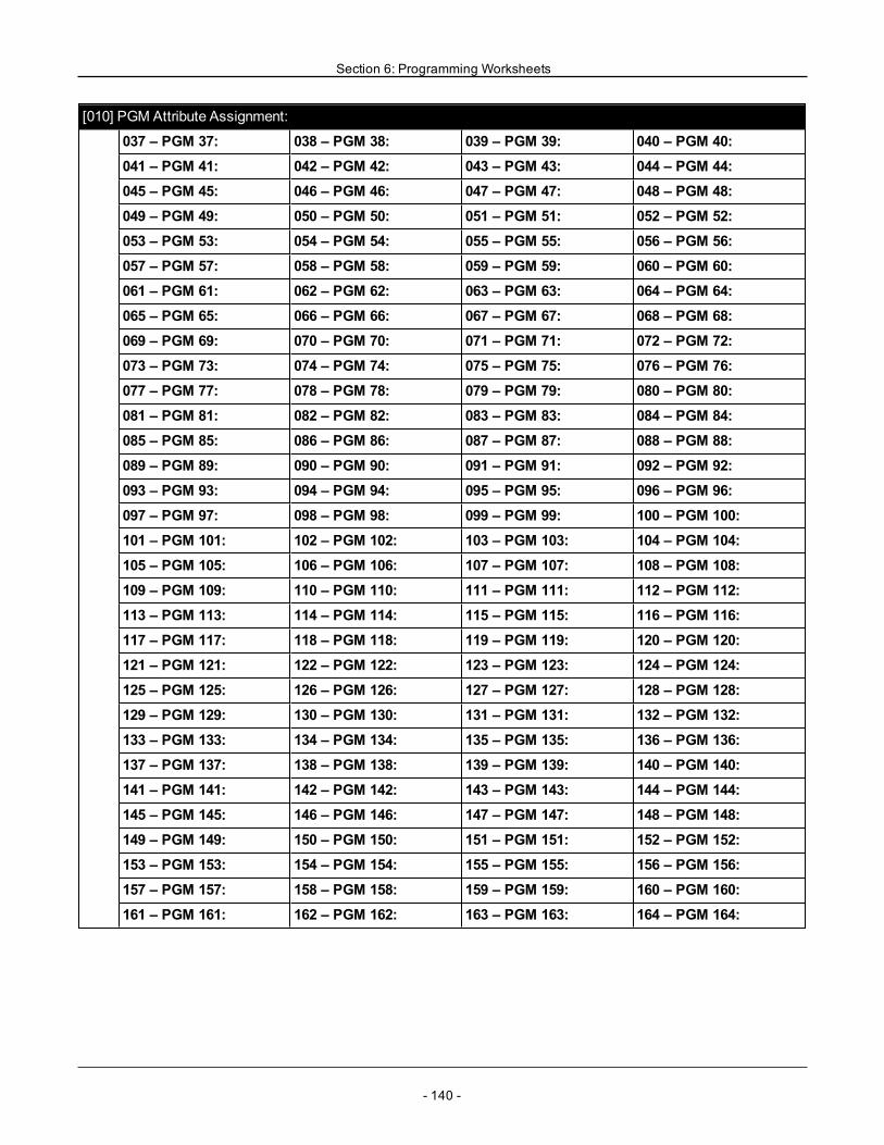
Section 6: Programming Worksheets
[010] PGM Attribute Assignment:
037 – PGM 37: 038 – PGM 38: 039 – PGM 39: 040 – PGM 40:041 – PGM 41: 042 – PGM 42: 043 – PGM 43: 044 – PGM 44:045 – PGM 45: 046 – PGM 46: 047 – PGM 47: 048 – PGM 48:049 – PGM 49: 050 – PGM 50: 051 – PGM 51: 052 – PGM 52:053 – PGM 53: 054 – PGM 54: 055 – PGM 55: 056 – PGM 56:057 – PGM 57: 058 – PGM 58: 059 – PGM 59: 060 – PGM 60:061 – PGM 61: 062 – PGM 62: 063 – PGM 63: 064 – PGM 64:065 – PGM 65: 066 – PGM 66: 067 – PGM 67: 068 – PGM 68:069 – PGM 69: 070 – PGM 70: 071 – PGM 71: 072 – PGM 72:073 – PGM 73: 074 – PGM 74: 075 – PGM 75: 076 – PGM 76:077 – PGM 77: 078 – PGM 78: 079 – PGM 79: 080 – PGM 80:081 – PGM 81: 082 – PGM 82: 083 – PGM 83: 084 – PGM 84:085 – PGM 85: 086 – PGM 86: 087 – PGM 87: 088 – PGM 88:089 – PGM 89: 090 – PGM 90: 091 – PGM 91: 092 – PGM 92:093 – PGM 93: 094 – PGM 94: 095 – PGM 95: 096 – PGM 96:097 – PGM 97: 098 – PGM 98: 099 – PGM 99: 100 – PGM 100:101 – PGM 101: 102 – PGM 102: 103 – PGM 103: 104 – PGM 104:105 – PGM 105: 106 – PGM 106: 107 – PGM 107: 108 – PGM 108:109 – PGM 109: 110 – PGM 110: 111 – PGM 111: 112 – PGM 112:113 – PGM 113: 114 – PGM 114: 115 – PGM 115: 116 – PGM 116:117 – PGM 117: 118 – PGM 118: 119 – PGM 119: 120 – PGM 120:121 – PGM 121: 122 – PGM 122: 123 – PGM 123: 124 – PGM 124:125 – PGM 125: 126 – PGM 126: 127 – PGM 127: 128 – PGM 128:129 – PGM 129: 130 – PGM 130: 131 – PGM 131: 132 – PGM 132:133 – PGM 133: 134 – PGM 134: 135 – PGM 135: 136 – PGM 136:137 – PGM 137: 138 – PGM 138: 139 – PGM 139: 140 – PGM 140:141 – PGM 141: 142 – PGM 142: 143 – PGM 143: 144 – PGM 144:145 – PGM 145: 146 – PGM 146: 147 – PGM 147: 148 – PGM 148:149 – PGM 149: 150 – PGM 150: 151 – PGM 151: 152 – PGM 152:153 – PGM 153: 154 – PGM 154: 155 – PGM 155: 156 – PGM 156:157 – PGM 157: 158 – PGM 158: 159 – PGM 159: 160 – PGM 160:161 – PGM 161: 162 – PGM 162: 163 – PGM 163: 164 – PGM 164:
- 140 -
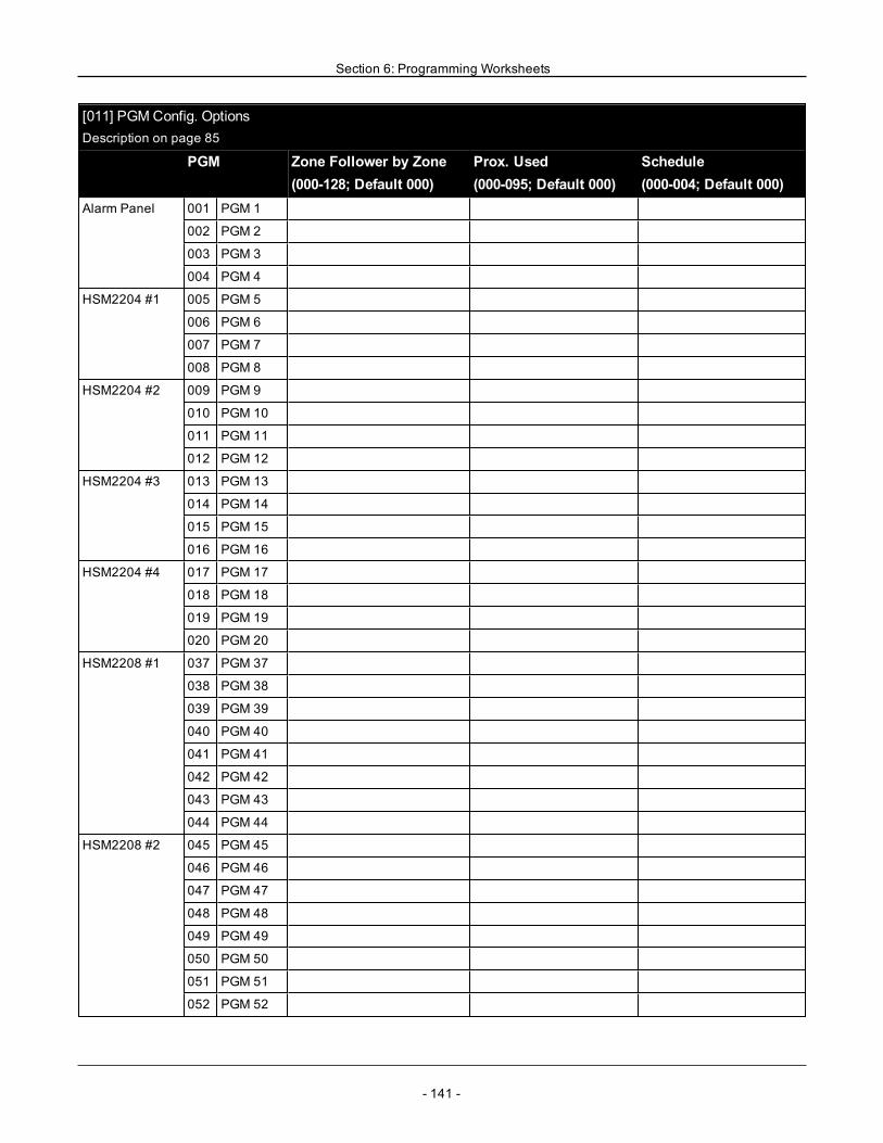
Section 6: Programming Worksheets
[011] PGMConfig. OptionsDescription on page 85
PGM Zone Follower by Zone(000-128; Default 000)
Prox. Used(000-095; Default 000)
Schedule(000-004; Default 000)
Alarm Panel 001 PGM 1
002 PGM 2
003 PGM 3
004 PGM 4
HSM2204 #1 005 PGM 5
006 PGM 6
007 PGM 7
008 PGM 8
HSM2204 #2 009 PGM 9
010 PGM 10
011 PGM 11
012 PGM 12
HSM2204 #3 013 PGM 13
014 PGM 14
015 PGM 15
016 PGM 16
HSM2204 #4 017 PGM 17
018 PGM 18
019 PGM 19
020 PGM 20
HSM2208 #1 037 PGM 37
038 PGM 38
039 PGM 39
040 PGM 40
041 PGM 41
042 PGM 42
043 PGM 43
044 PGM 44
HSM2208 #2 045 PGM 45
046 PGM 46
047 PGM 47
048 PGM 48
049 PGM 49
050 PGM 50
051 PGM 51
052 PGM 52
- 141 -

Section 6: Programming Worksheets
[011] PGMConfig. OptionsDescription on page 85
PGM Zone Follower by Zone(000-128; Default 000)
Prox. Used(000-095; Default 000)
Schedule(000-004; Default 000)
HSM2208 #3 053 PGM 53
054 PGM 54
055 PGM 55
056 PGM 56
057 PGM 57
058 PGM 58
059 PGM 59
060 PGM 60
HSM2208 #4 061 PGM 61
062 PGM 62
063 PGM 63
064 PGM 64
065 PGM 65
066 PGM 66
067 PGM 67
068 PGM 68
HSM2208 #5 069 PGM 69
070 PGM 70
071 PGM 71
072 PGM 72
073 PGM 73
074 PGM 74
075 PGM 75
076 PGM 76
HSM2208 #6 077 PGM 77
078 PGM 78
079 PGM 79
080 PGM 80
081 PGM 81
082 PGM 82
083 PGM 83
084 PGM 84
HSM2208 #7 085 PGM 85
086 PGM 86
087 PGM 87
088 PGM 88
- 142 -

Section 6: Programming Worksheets
[011] PGMConfig. OptionsDescription on page 85
PGM Zone Follower by Zone(000-128; Default 000)
Prox. Used(000-095; Default 000)
Schedule(000-004; Default 000)
089 PGM 89
090 PGM 90
091 PGM 91
092 PGM 92
HSM2208 #8 093 PGM 93
094 PGM 94
095 PGM 95
096 PGM 96
097 PGM 97
098 PGM 98
099 PGM 99
100 PGM 100
HSM2208 #9 101 PGM 101
102 PGM 102
103 PGM 103
104 PGM 104
105 PGM 105
106 PGM 106
107 PGM 107
108 PGM 108
HSM2208 #10 109 PGM 109
110 PGM 110
111 PGM 111
112 PGM 112
113 PGM 113
114 PGM 114
115 PGM 115
116 PGM 116
HSM2208 #11 117 PGM 117
118 PGM 118
119 PGM 119
120 PGM 120
121 PGM 121
122 PGM 122
123 PGM 123
124 PGM 124
- 143 -

Section 6: Programming Worksheets
[011] PGMConfig. OptionsDescription on page 85
PGM Zone Follower by Zone(000-128; Default 000)
Prox. Used(000-095; Default 000)
Schedule(000-004; Default 000)
HSM2208 #12 125 PGM 125
126 PGM 126
127 PGM 127
128 PGM 128
129 PGM 129
130 PGM 130
131 PGM 131
132 PGM 132
HSM2208 #13 133 PGM 133
134 PGM 134
135 PGM 135
136 PGM 136
137 PGM 137
138 PGM 138
139 PGM 139
140 PGM 140
HSM2208 #14 141 PGM 141
142 PGM 142
143 PGM 143
144 PGM 144
145 PGM 145
146 PGM 146
147 PGM 147
148 PGM 148
HSM2208 #15 149 PGM 149
150 PGM 150
151 PGM 151
152 PGM 152
153 PGM 153
154 PGM 154
155 PGM 155
156 PGM 156
HSM2208 #16 157 PGM 157
158 PGM 158
159 PGM 159
160 PGM 160
- 144 -
Section 6: Programming Worksheets
[011] PGMConfig. OptionsDescription on page 85
PGM Zone Follower by Zone(000-128; Default 000)
Prox. Used(000-095; Default 000)
Schedule(000-004; Default 000)
161 PGM 161
162 PGM 162
163 PGM 163
164 PGM 164
6.6 System Lockout
[012] System Lockout(3-Digit Decimal)Description on page 85
Keypad Lockout: (Range: 000-255; Default 000)
Note: For EN installations maximum programmed lockout of 10attempts.
Keypad Lockout Duration: (Range: 001-255; Default 000)
Note: For EN installations minimum programmed duration of 2 minutes.
Remote Lockout: (Range: 003-255; Default 006)
Remote Lockout Duration: (Range: 001-255; Default 060)
6.7 System Options
[013] System Options 1Description on page 86
o 1 – NC Loop/EOL
o 2 – DEOL/SEOL
EN R 2 – DEOL/SEOL
R 3 – Show All Troubles When Armed
o 4 – Tamper/Faults Open Zone
R 5 – Auto-Arm Schedule in [*][6]
R 6 – Audible Exit Fault
R 7 – Event Buffer Follows Swinger
o 8 – Temporal Three Fire Signaling
[014] System Options 2Description on page 86
o 1 – Bell Squawk
o 2 – Bell Squawk on Auto-Arm
o 3 – Bell Squawk on Exit
- 145 -
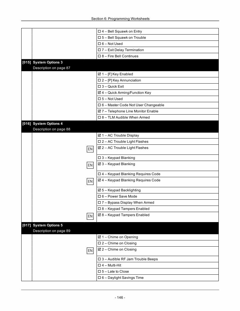
Section 6: Programming Worksheets
o 4 – Bell Squawk on Entry
o 5 – Bell Squawk on Trouble
o 6 – Not Used
o 7 – Exit Delay Termination
o 8 – Fire Bell Continues
[015] System Options 3Description on page 87
R 1 – [F] Key Enabled
o 2 – [P] Key Annunciation
o 3 – Quick Exit
R 4 – Quick Arming/Function Key
o 5 – Not Used
o 6 – Master Code Not User Changeable
R 7 – Telephone Line Monitor Enable
o 8 – TLM Audible When Armed
[016] System Options 4Description on page 88
R 1 – AC Trouble Display
o 2 – AC Trouble Light Flashes
EN R 2 – AC Trouble Light Flashes
o 3 – Keypad Blanking
EN R 3 – Keypad Blanking
o 4 – Keypad Blanking Requires Code
EN R 4 – Keypad Blanking Requires Code
R 5 – Keypad Backlighting
o 6 – Power Save Mode
o 7 – Bypass Display When Armed
o 8 – Keypad Tampers Enabled
EN R 8 – Keypad Tampers Enabled
[017] System Options 5Description on page 89
R 1 – Chime on Opening
o 2 – Chime on Closing
EN R 2 – Chime on Closing
o 3 – Audible RF Jam Trouble Beeps
o 4 – Multi-Hit
o 5 – Late to Close
o 6 – Daylight Savings Time
- 146 -
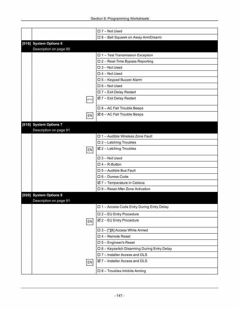
Section 6: Programming Worksheets
o 7 – Not Used
o 8 – Bell Squawk on Away Arm/Disarm
[018] System Options 6Description on page 90
o 1 – Test Transmission Exception
o 2 – Real-Time Bypass Reporting
o 3 – Not Used
o 4 – Not Used
o 5 – Keypad Buzzer Alarm
o 6 – Not Used
o 7 – Exit Delay Restart
CP-01R 7 – Exit Delay Restart
o 8 – AC Fail Trouble Beeps
EN R 8 – AC Fail Trouble Beeps
[019] System Options 7Description on page 91
o 1 – Audible Wireless Zone Fault
o 2 – Latching Troubles
EN R 2 – Latching Troubles
o 3 – Not Used
o 4 – R-Button
o 5 – Audible Bus Fault
o 6 – Duress Code
R 7 – Temperature in Celsius
o 8 – Reset After Zone Activation
[020] System Options 8Description on page 91
o 1 – Access Code Entry During Entry Delay
o 2 – EU Entry Procedure
EN R 2 – EU Entry Procedure
o 3 – [*][8] Access While Armed
o 4 – Remote Reset
o 5 – Engineer's Reset
o 6 – Keyswitch Disarming During Entry Delay
o 7 – Installer Access and DLS
EN R 7 – Installer Access and DLS
o 8 – Troubles Inhibits Arming
- 147 -
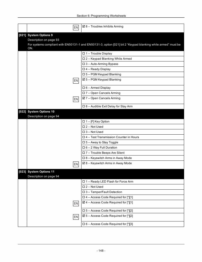
Section 6: Programming Worksheets
EN R 8 – Troubles Inhibits Arming
[021] System Options 9Description on page 93For systems compliant with EN50131-1 and EN50131-3, option [021] bit 2 “Keypad blanking while armed” must beON.
o 1 – Trouble Display
o 2 – Keypad Blanking While Armed
o 3 – Auto-Arming Bypass
o 4 – Ready Display
o 5 – PGM Keypad Blanking
EN R 5 – PGM Keypad Blanking
o 6 – Armed Display
o 7 – Open Cancels Arming
EN R 7 – Open Cancels Arming
o 8 – Audible Exit Delay for Stay Arm
[022] System Options 10Description on page 94
o 1 – [F] Key Option
o 2 – Not Used
o 3 – Not Used
o 4 – Test Transmission Counter in Hours
o 5 – Away to Stay Toggle
o 6 – 2 Way Full Duration
o 7 – Trouble Beeps Are Silent
o 8 – Keyswitch Arms in Away Mode
EN R 8 – Keyswitch Arms in Away Mode
[023] System Options 11Description on page 94
o 1 – Ready LED Flash for Force Arm
o 2 – Not Used
o 3 – Tamper/Fault Detection
o 4 – Access Code Required for [*][1]
EN R 4 – Access Code Required for [*][1]
o 5 – Access Code Required for [*][2]
EN R 5 – Access Code Required for [*][2]
o 6 – Access Code Required for [*][3]
- 148 -
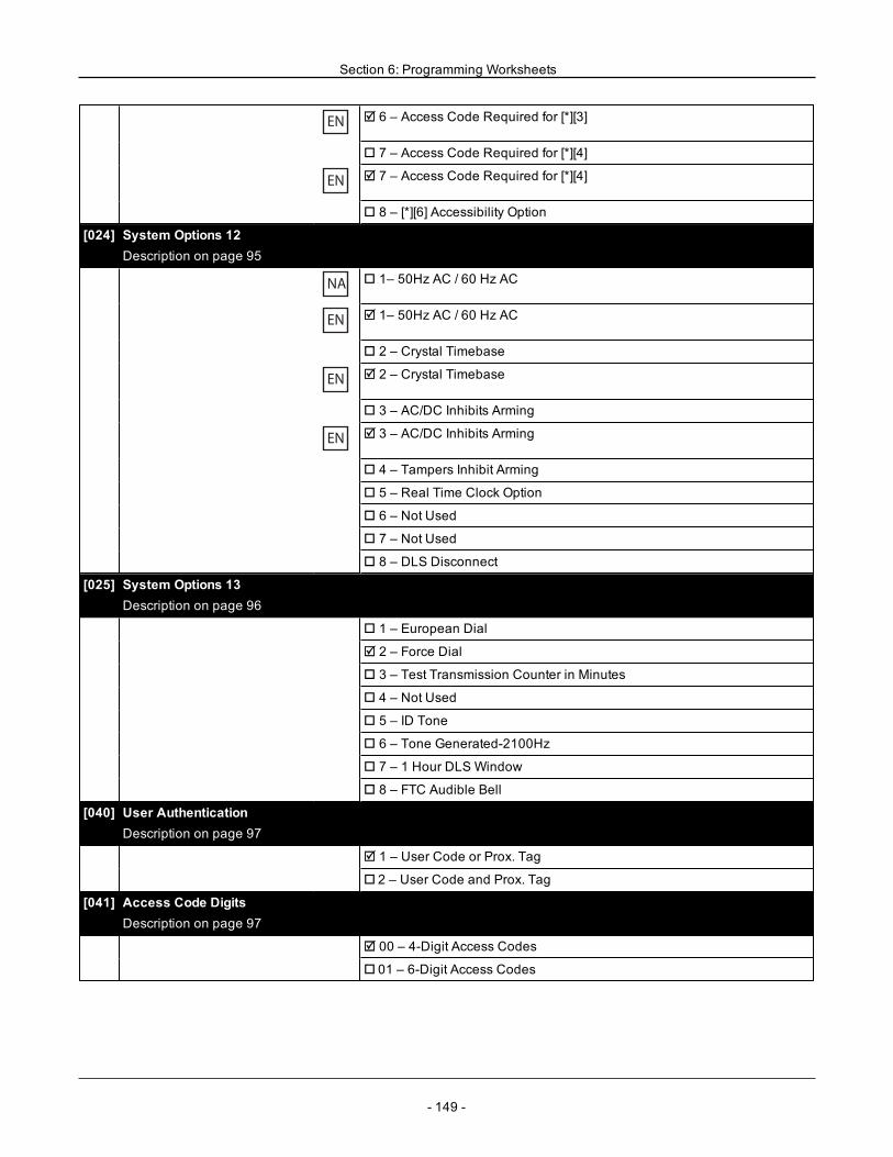
Section 6: Programming Worksheets
EN R 6 – Access Code Required for [*][3]
o 7 – Access Code Required for [*][4]
EN R 7 – Access Code Required for [*][4]
o 8 – [*][6] Accessibility Option
[024] System Options 12Description on page 95
NA o 1– 50Hz AC / 60 Hz AC
EN R 1– 50Hz AC / 60 Hz AC
o 2 – Crystal Timebase
EN R 2 – Crystal Timebase
o 3 – AC/DC Inhibits Arming
EN R 3 – AC/DC Inhibits Arming
o 4 – Tampers Inhibit Arming
o 5 – Real Time Clock Option
o 6 – Not Used
o 7 – Not Used
o 8 – DLS Disconnect
[025] System Options 13Description on page 96
o 1 – European Dial
R 2 – Force Dial
o 3 – Test Transmission Counter in Minutes
o 4 – Not Used
o 5 – ID Tone
o 6 – Tone Generated-2100Hz
o 7 – 1 Hour DLS Window
o 8 – FTC Audible Bell
[040] User AuthenticationDescription on page 97
R 1 – User Code or Prox. Tag
o 2 – User Code and Prox. Tag
[041] Access Code DigitsDescription on page 97
R 00 – 4-Digit Access Codes
o 01 – 6-Digit Access Codes
- 149 -
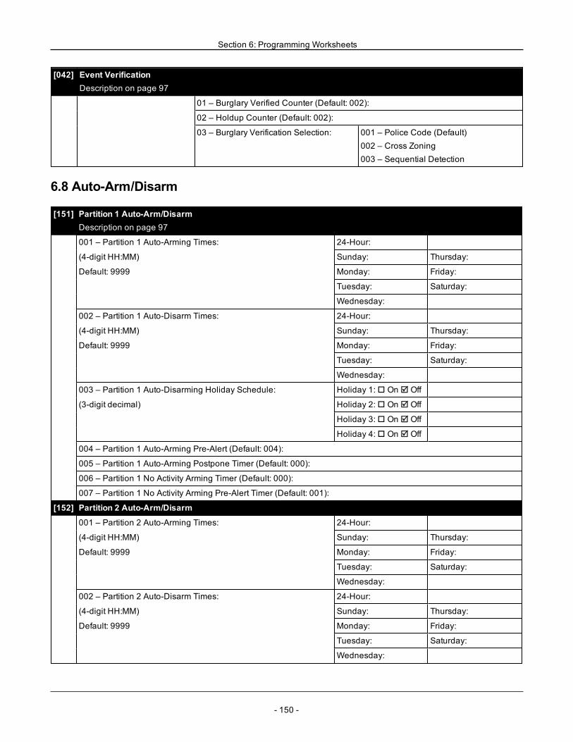
Section 6: Programming Worksheets
[042] Event VerificationDescription on page 97
01 – Burglary Verified Counter (Default: 002):
02 – Holdup Counter (Default: 002):
03 – Burglary Verification Selection: 001 – Police Code (Default)002 – Cross Zoning003 – Sequential Detection
6.8 Auto-Arm/Disarm
[151] Partition 1 Auto-Arm/DisarmDescription on page 97
001 – Partition 1 Auto-Arming Times: 24-Hour:
(4-digit HH:MM) Sunday: Thursday:
Default: 9999 Monday: Friday:
Tuesday: Saturday:
Wednesday:
002 – Partition 1 Auto-Disarm Times: 24-Hour:
(4-digit HH:MM) Sunday: Thursday:
Default: 9999 Monday: Friday:
Tuesday: Saturday:
Wednesday:
003 – Partition 1 Auto-Disarming Holiday Schedule: Holiday 1:o On R Off
(3-digit decimal) Holiday 2:o On R Off
Holiday 3:o On R Off
Holiday 4:o On R Off
004 – Partition 1 Auto-Arming Pre-Alert (Default: 004):
005 – Partition 1 Auto-Arming Postpone Timer (Default: 000):
006 – Partition 1 No Activity Arming Timer (Default: 000):
007 – Partition 1 No Activity Arming Pre-Alert Timer (Default: 001):
[152] Partition 2 Auto-Arm/Disarm
001 – Partition 2 Auto-Arming Times: 24-Hour:
(4-digit HH:MM) Sunday: Thursday:
Default: 9999 Monday: Friday:
Tuesday: Saturday:
Wednesday:
002 – Partition 2 Auto-Disarm Times: 24-Hour:
(4-digit HH:MM) Sunday: Thursday:
Default: 9999 Monday: Friday:
Tuesday: Saturday:
Wednesday:
- 150 -
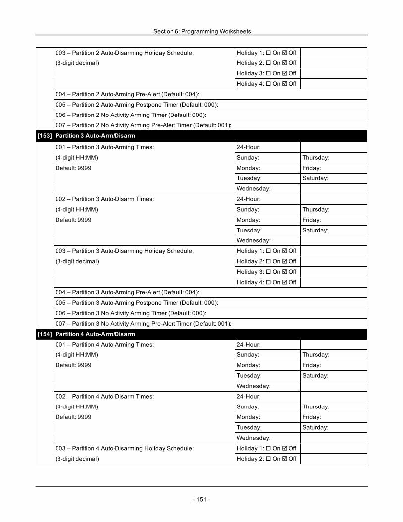
Section 6: Programming Worksheets
003 – Partition 2 Auto-Disarming Holiday Schedule: Holiday 1:o On R Off
(3-digit decimal) Holiday 2:o On R Off
Holiday 3:o On R Off
Holiday 4:o On R Off
004 – Partition 2 Auto-Arming Pre-Alert (Default: 004):
005 – Partition 2 Auto-Arming Postpone Timer (Default: 000):
006 – Partition 2 No Activity Arming Timer (Default: 000):
007 – Partition 2 No Activity Arming Pre-Alert Timer (Default: 001):
[153] Partition 3 Auto-Arm/Disarm
001 – Partition 3 Auto-Arming Times: 24-Hour:
(4-digit HH:MM) Sunday: Thursday:
Default: 9999 Monday: Friday:
Tuesday: Saturday:
Wednesday:
002 – Partition 3 Auto-Disarm Times: 24-Hour:
(4-digit HH:MM) Sunday: Thursday:
Default: 9999 Monday: Friday:
Tuesday: Saturday:
Wednesday:
003 – Partition 3 Auto-Disarming Holiday Schedule: Holiday 1:o On R Off
(3-digit decimal) Holiday 2:o On R Off
Holiday 3:o On R Off
Holiday 4:o On R Off
004 – Partition 3 Auto-Arming Pre-Alert (Default: 004):
005 – Partition 3 Auto-Arming Postpone Timer (Default: 000):
006 – Partition 3 No Activity Arming Timer (Default: 000):
007 – Partition 3 No Activity Arming Pre-Alert Timer (Default: 001):
[154] Partition 4 Auto-Arm/Disarm
001 – Partition 4 Auto-Arming Times: 24-Hour:
(4-digit HH:MM) Sunday: Thursday:
Default: 9999 Monday: Friday:
Tuesday: Saturday:
Wednesday:
002 – Partition 4 Auto-Disarm Times: 24-Hour:
(4-digit HH:MM) Sunday: Thursday:
Default: 9999 Monday: Friday:
Tuesday: Saturday:
Wednesday:
003 – Partition 4 Auto-Disarming Holiday Schedule: Holiday 1:o On R Off
(3-digit decimal) Holiday 2:o On R Off
- 151 -
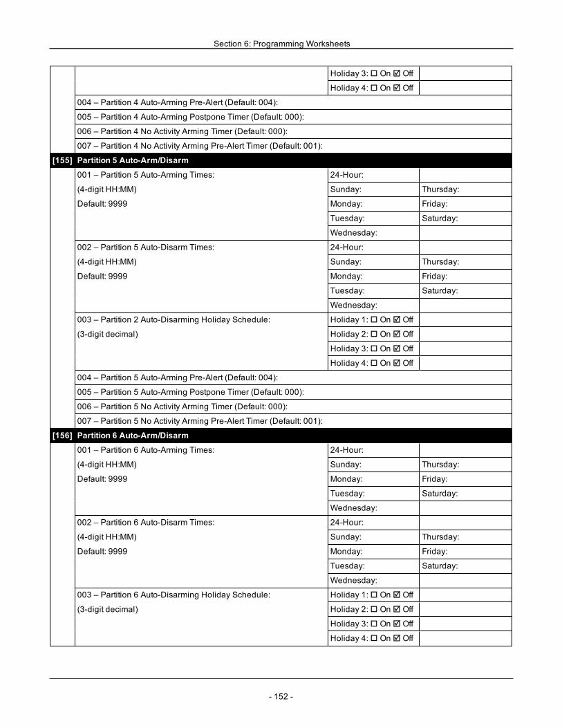
Section 6: Programming Worksheets
Holiday 3:o On R Off
Holiday 4:o On R Off
004 – Partition 4 Auto-Arming Pre-Alert (Default: 004):
005 – Partition 4 Auto-Arming Postpone Timer (Default: 000):
006 – Partition 4 No Activity Arming Timer (Default: 000):
007 – Partition 4 No Activity Arming Pre-Alert Timer (Default: 001):
[155] Partition 5 Auto-Arm/Disarm
001 – Partition 5 Auto-Arming Times: 24-Hour:
(4-digit HH:MM) Sunday: Thursday:
Default: 9999 Monday: Friday:
Tuesday: Saturday:
Wednesday:
002 – Partition 5 Auto-Disarm Times: 24-Hour:
(4-digit HH:MM) Sunday: Thursday:
Default: 9999 Monday: Friday:
Tuesday: Saturday:
Wednesday:
003 – Partition 2 Auto-Disarming Holiday Schedule: Holiday 1:o On R Off
(3-digit decimal) Holiday 2:o On R Off
Holiday 3:o On R Off
Holiday 4:o On R Off
004 – Partition 5 Auto-Arming Pre-Alert (Default: 004):
005 – Partition 5 Auto-Arming Postpone Timer (Default: 000):
006 – Partition 5 No Activity Arming Timer (Default: 000):
007 – Partition 5 No Activity Arming Pre-Alert Timer (Default: 001):
[156] Partition 6 Auto-Arm/Disarm
001 – Partition 6 Auto-Arming Times: 24-Hour:
(4-digit HH:MM) Sunday: Thursday:
Default: 9999 Monday: Friday:
Tuesday: Saturday:
Wednesday:
002 – Partition 6 Auto-Disarm Times: 24-Hour:
(4-digit HH:MM) Sunday: Thursday:
Default: 9999 Monday: Friday:
Tuesday: Saturday:
Wednesday:
003 – Partition 6 Auto-Disarming Holiday Schedule: Holiday 1:o On R Off
(3-digit decimal) Holiday 2:o On R Off
Holiday 3:o On R Off
Holiday 4:o On R Off
- 152 -
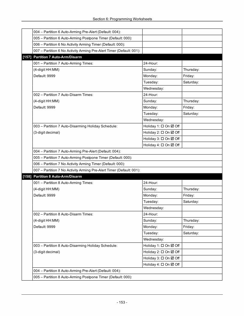
Section 6: Programming Worksheets
004 – Partition 6 Auto-Arming Pre-Alert (Default: 004):
005 – Partition 6 Auto-Arming Postpone Timer (Default: 000):
006 – Partition 6 No Activity Arming Timer (Default: 000):
007 – Partition 6 No Activity Arming Pre-Alert Timer (Default: 001):
[157] Partition 7 Auto-Arm/Disarm
001 – Partition 7 Auto-Arming Times: 24-Hour:
(4-digit HH:MM) Sunday: Thursday:
Default: 9999 Monday: Friday:
Tuesday: Saturday:
Wednesday:
002 – Partition 7 Auto-Disarm Times: 24-Hour:
(4-digit HH:MM) Sunday: Thursday:
Default: 9999 Monday: Friday:
Tuesday: Saturday:
Wednesday:
003 – Partition 7 Auto-Disarming Holiday Schedule: Holiday 1:o On R Off
(3-digit decimal) Holiday 2:o On R Off
Holiday 3:o On R Off
Holiday 4:o On R Off
004 – Partition 7 Auto-Arming Pre-Alert (Default: 004):
005 – Partition 7 Auto-Arming Postpone Timer (Default: 000):
006 – Partition 7 No Activity Arming Timer (Default: 000):
007 – Partition 7 No Activity Arming Pre-Alert Timer (Default: 001):
[158] Partition 8 Auto-Arm/Disarm
001 – Partition 8 Auto-Arming Times: 24-Hour:
(4-digit HH:MM) Sunday: Thursday:
Default: 9999 Monday: Friday:
Tuesday: Saturday:
Wednesday:
002 – Partition 8 Auto-Disarm Times: 24-Hour:
(4-digit HH:MM) Sunday: Thursday:
Default: 9999 Monday: Friday:
Tuesday: Saturday:
Wednesday:
003 – Partition 8 Auto-Disarming Holiday Schedule: Holiday 1:o On R Off
(3-digit decimal) Holiday 2:o On R Off
Holiday 3:o On R Off
Holiday 4:o On R Off
004 – Partition 8 Auto-Arming Pre-Alert (Default: 004):
005 – Partition 8 Auto-Arming Postpone Timer (Default: 000):
- 153 -
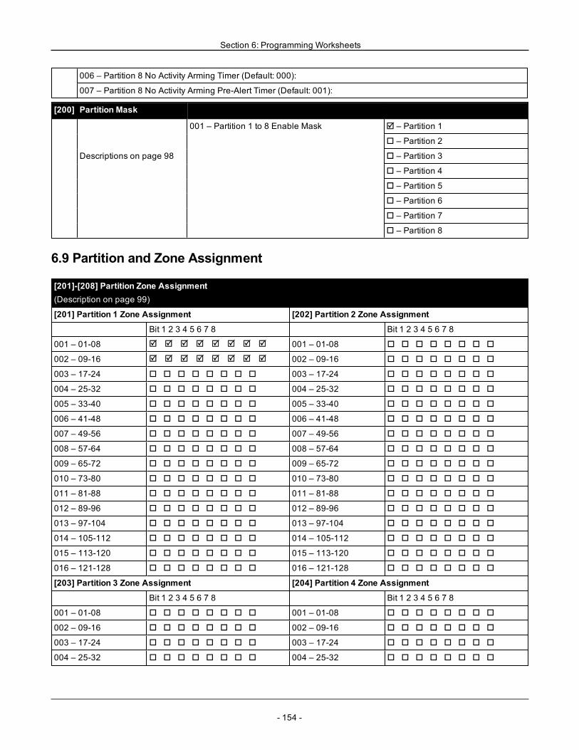
Section 6: Programming Worksheets
006 – Partition 8 No Activity Arming Timer (Default: 000):
007 – Partition 8 No Activity Arming Pre-Alert Timer (Default: 001):
[200] Partition Mask
001 – Partition 1 to 8 Enable Mask R – Partition 1
o – Partition 2
Descriptions on page 98 o – Partition 3
o – Partition 4
o – Partition 5
o – Partition 6
o – Partition 7
o – Partition 8
6.9 Partition and Zone Assignment
[201]-[208] Partition Zone Assignment(Description on page 99)
[201] Partition 1 Zone Assignment [202] Partition 2 Zone Assignment
Bit 1 2 3 4 5 6 7 8 Bit 1 2 3 4 5 6 7 8
001 – 01-08 R R R R R R R R 001 – 01-08 o o o o o o o o
002 – 09-16 R R R R R R R R 002 – 09-16 o o o o o o o o
003 – 17-24 o o o o o o o o 003 – 17-24 o o o o o o o o
004 – 25-32 o o o o o o o o 004 – 25-32 o o o o o o o o
005 – 33-40 o o o o o o o o 005 – 33-40 o o o o o o o o
006 – 41-48 o o o o o o o o 006 – 41-48 o o o o o o o o
007 – 49-56 o o o o o o o o 007 – 49-56 o o o o o o o o
008 – 57-64 o o o o o o o o 008 – 57-64 o o o o o o o o
009 – 65-72 o o o o o o o o 009 – 65-72 o o o o o o o o
010 – 73-80 o o o o o o o o 010 – 73-80 o o o o o o o o
011 – 81-88 o o o o o o o o 011 – 81-88 o o o o o o o o
012 – 89-96 o o o o o o o o 012 – 89-96 o o o o o o o o
013 – 97-104 o o o o o o o o 013 – 97-104 o o o o o o o o
014 – 105-112 o o o o o o o o 014 – 105-112 o o o o o o o o
015 – 113-120 o o o o o o o o 015 – 113-120 o o o o o o o o
016 – 121-128 o o o o o o o o 016 – 121-128 o o o o o o o o
[203] Partition 3 Zone Assignment [204] Partition 4 Zone Assignment
Bit 1 2 3 4 5 6 7 8 Bit 1 2 3 4 5 6 7 8
001 – 01-08 o o o o o o o o 001 – 01-08 o o o o o o o o
002 – 09-16 o o o o o o o o 002 – 09-16 o o o o o o o o
003 – 17-24 o o o o o o o o 003 – 17-24 o o o o o o o o
004 – 25-32 o o o o o o o o 004 – 25-32 o o o o o o o o
- 154 -
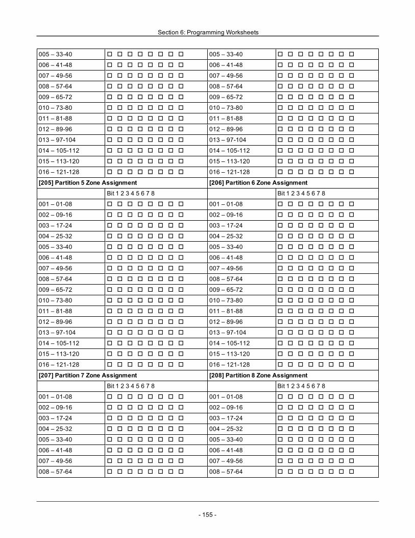
Section 6: Programming Worksheets
005 – 33-40 o o o o o o o o 005 – 33-40 o o o o o o o o
006 – 41-48 o o o o o o o o 006 – 41-48 o o o o o o o o
007 – 49-56 o o o o o o o o 007 – 49-56 o o o o o o o o
008 – 57-64 o o o o o o o o 008 – 57-64 o o o o o o o o
009 – 65-72 o o o o o o o o 009 – 65-72 o o o o o o o o
010 – 73-80 o o o o o o o o 010 – 73-80 o o o o o o o o
011 – 81-88 o o o o o o o o 011 – 81-88 o o o o o o o o
012 – 89-96 o o o o o o o o 012 – 89-96 o o o o o o o o
013 – 97-104 o o o o o o o o 013 – 97-104 o o o o o o o o
014 – 105-112 o o o o o o o o 014 – 105-112 o o o o o o o o
015 – 113-120 o o o o o o o o 015 – 113-120 o o o o o o o o
016 – 121-128 o o o o o o o o 016 – 121-128 o o o o o o o o
[205] Partition 5 Zone Assignment [206] Partition 6 Zone Assignment
Bit 1 2 3 4 5 6 7 8 Bit 1 2 3 4 5 6 7 8
001 – 01-08 o o o o o o o o 001 – 01-08 o o o o o o o o
002 – 09-16 o o o o o o o o 002 – 09-16 o o o o o o o o
003 – 17-24 o o o o o o o o 003 – 17-24 o o o o o o o o
004 – 25-32 o o o o o o o o 004 – 25-32 o o o o o o o o
005 – 33-40 o o o o o o o o 005 – 33-40 o o o o o o o o
006 – 41-48 o o o o o o o o 006 – 41-48 o o o o o o o o
007 – 49-56 o o o o o o o o 007 – 49-56 o o o o o o o o
008 – 57-64 o o o o o o o o 008 – 57-64 o o o o o o o o
009 – 65-72 o o o o o o o o 009 – 65-72 o o o o o o o o
010 – 73-80 o o o o o o o o 010 – 73-80 o o o o o o o o
011 – 81-88 o o o o o o o o 011 – 81-88 o o o o o o o o
012 – 89-96 o o o o o o o o 012 – 89-96 o o o o o o o o
013 – 97-104 o o o o o o o o 013 – 97-104 o o o o o o o o
014 – 105-112 o o o o o o o o 014 – 105-112 o o o o o o o o
015 – 113-120 o o o o o o o o 015 – 113-120 o o o o o o o o
016 – 121-128 o o o o o o o o 016 – 121-128 o o o o o o o o
[207] Partition 7 Zone Assignment [208] Partition 8 Zone Assignment
Bit 1 2 3 4 5 6 7 8 Bit 1 2 3 4 5 6 7 8
001 – 01-08 o o o o o o o o 001 – 01-08 o o o o o o o o
002 – 09-16 o o o o o o o o 002 – 09-16 o o o o o o o o
003 – 17-24 o o o o o o o o 003 – 17-24 o o o o o o o o
004 – 25-32 o o o o o o o o 004 – 25-32 o o o o o o o o
005 – 33-40 o o o o o o o o 005 – 33-40 o o o o o o o o
006 – 41-48 o o o o o o o o 006 – 41-48 o o o o o o o o
007 – 49-56 o o o o o o o o 007 – 49-56 o o o o o o o o
008 – 57-64 o o o o o o o o 008 – 57-64 o o o o o o o o
- 155 -
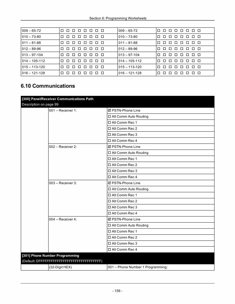
Section 6: Programming Worksheets
009 – 65-72 o o o o o o o o 009 – 65-72 o o o o o o o o
010 – 73-80 o o o o o o o o 010 – 73-80 o o o o o o o o
011 – 81-88 o o o o o o o o 011 – 81-88 o o o o o o o o
012 – 89-96 o o o o o o o o 012 – 89-96 o o o o o o o o
013 – 97-104 o o o o o o o o 013 – 97-104 o o o o o o o o
014 – 105-112 o o o o o o o o 014 – 105-112 o o o o o o o o
015 – 113-120 o o o o o o o o 015 – 113-120 o o o o o o o o
016 – 121-128 o o o o o o o o 016 – 121-128 o o o o o o o o
6.10 Communications
[300] Panel/Receiver Communications PathDescription on page 99
001 – Receiver 1: R PSTN-Phone Line
o Alt Comm Auto Routing
o Alt Comm Rec 1
o Alt Comm Rec 2
o Alt Comm Rec 3
o Alt Comm Rec 4
002 – Receiver 2: R PSTN-Phone Line
o Alt Comm Auto Routing
o Alt Comm Rec 1
o Alt Comm Rec 2
o Alt Comm Rec 3
o Alt Comm Rec 4
003 – Receiver 3: R PSTN-Phone Line
o Alt Comm Auto Routing
o Alt Comm Rec 1
o Alt Comm Rec 2
o Alt Comm Rec 3
o Alt Comm Rec 4
004 – Receiver 4: R PSTN-Phone Line
o Alt Comm Auto Routing
o Alt Comm Rec 1
o Alt Comm Rec 2
o Alt Comm Rec 3
o Alt Comm Rec 4
[301] Phone Number Programming(Default: DFFFFFFFFFFFFFFFFFFFFFFFFFFFFFFF)
(32-Digit HEX) 001 – Phone Number 1 Programming:
- 156 -
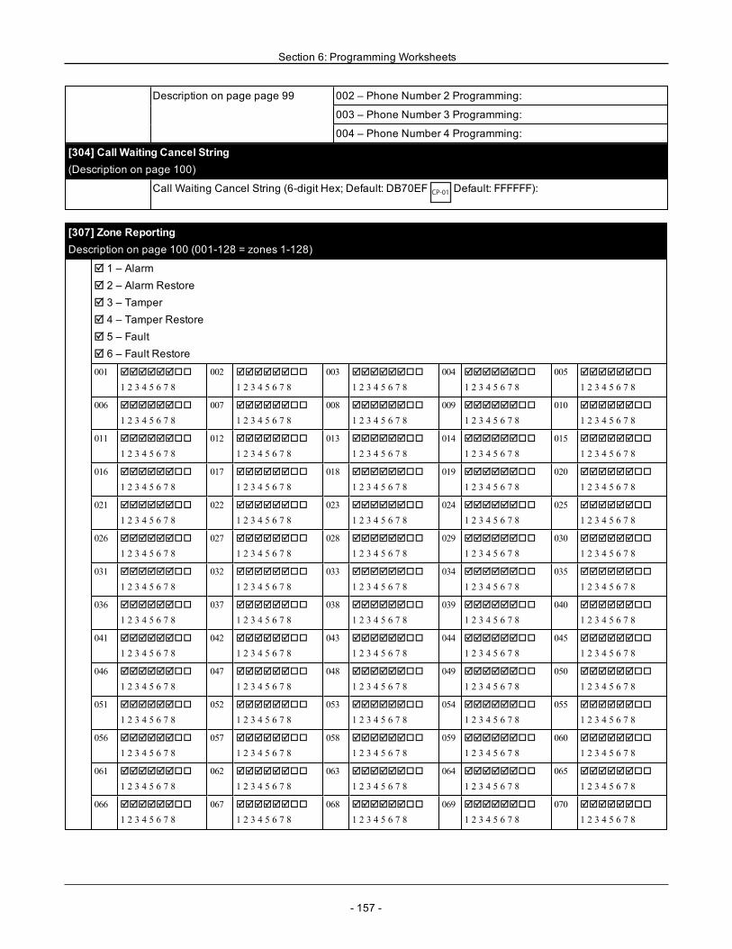
Section 6: Programming Worksheets
Description on page page 99 002 – Phone Number 2 Programming:
003 – Phone Number 3 Programming:
004 – Phone Number 4 Programming:
[304] Call Waiting Cancel String(Description on page 100)
Call Waiting Cancel String (6-digit Hex; Default: DB70EFCP-01
Default: FFFFFF):
[307] Zone ReportingDescription on page 100 (001-128 = zones 1-128)
R 1 – AlarmR 2 – Alarm RestoreR 3 – TamperR 4 – Tamper RestoreR 5 – FaultR 6 – Fault Restore001 RRRRRRoo
1 2 3 4 5 6 7 8002 RRRRRRoo
1 2 3 4 5 6 7 8003 RRRRRRoo
1 2 3 4 5 6 7 8004 RRRRRRoo
1 2 3 4 5 6 7 8005 RRRRRRoo
1 2 3 4 5 6 7 8
006 RRRRRRoo
1 2 3 4 5 6 7 8007 RRRRRRoo
1 2 3 4 5 6 7 8008 RRRRRRoo
1 2 3 4 5 6 7 8009 RRRRRRoo
1 2 3 4 5 6 7 8010 RRRRRRoo
1 2 3 4 5 6 7 8
011 RRRRRRoo
1 2 3 4 5 6 7 8012 RRRRRRoo
1 2 3 4 5 6 7 8013 RRRRRRoo
1 2 3 4 5 6 7 8014 RRRRRRoo
1 2 3 4 5 6 7 8015 RRRRRRoo
1 2 3 4 5 6 7 8
016 RRRRRRoo
1 2 3 4 5 6 7 8017 RRRRRRoo
1 2 3 4 5 6 7 8018 RRRRRRoo
1 2 3 4 5 6 7 8019 RRRRRRoo
1 2 3 4 5 6 7 8020 RRRRRRoo
1 2 3 4 5 6 7 8
021 RRRRRRoo
1 2 3 4 5 6 7 8022 RRRRRRoo
1 2 3 4 5 6 7 8023 RRRRRRoo
1 2 3 4 5 6 7 8024 RRRRRRoo
1 2 3 4 5 6 7 8025 RRRRRRoo
1 2 3 4 5 6 7 8
026 RRRRRRoo
1 2 3 4 5 6 7 8027 RRRRRRoo
1 2 3 4 5 6 7 8028 RRRRRRoo
1 2 3 4 5 6 7 8029 RRRRRRoo
1 2 3 4 5 6 7 8030 RRRRRRoo
1 2 3 4 5 6 7 8
031 RRRRRRoo
1 2 3 4 5 6 7 8032 RRRRRRoo
1 2 3 4 5 6 7 8033 RRRRRRoo
1 2 3 4 5 6 7 8034 RRRRRRoo
1 2 3 4 5 6 7 8035 RRRRRRoo
1 2 3 4 5 6 7 8
036 RRRRRRoo
1 2 3 4 5 6 7 8037 RRRRRRoo
1 2 3 4 5 6 7 8038 RRRRRRoo
1 2 3 4 5 6 7 8039 RRRRRRoo
1 2 3 4 5 6 7 8040 RRRRRRoo
1 2 3 4 5 6 7 8
041 RRRRRRoo
1 2 3 4 5 6 7 8042 RRRRRRoo
1 2 3 4 5 6 7 8043 RRRRRRoo
1 2 3 4 5 6 7 8044 RRRRRRoo
1 2 3 4 5 6 7 8045 RRRRRRoo
1 2 3 4 5 6 7 8
046 RRRRRRoo
1 2 3 4 5 6 7 8047 RRRRRRoo
1 2 3 4 5 6 7 8048 RRRRRRoo
1 2 3 4 5 6 7 8049 RRRRRRoo
1 2 3 4 5 6 7 8050 RRRRRRoo
1 2 3 4 5 6 7 8
051 RRRRRRoo
1 2 3 4 5 6 7 8052 RRRRRRoo
1 2 3 4 5 6 7 8053 RRRRRRoo
1 2 3 4 5 6 7 8054 RRRRRRoo
1 2 3 4 5 6 7 8055 RRRRRRoo
1 2 3 4 5 6 7 8
056 RRRRRRoo
1 2 3 4 5 6 7 8057 RRRRRRoo
1 2 3 4 5 6 7 8058 RRRRRRoo
1 2 3 4 5 6 7 8059 RRRRRRoo
1 2 3 4 5 6 7 8060 RRRRRRoo
1 2 3 4 5 6 7 8
061 RRRRRRoo
1 2 3 4 5 6 7 8062 RRRRRRoo
1 2 3 4 5 6 7 8063 RRRRRRoo
1 2 3 4 5 6 7 8064 RRRRRRoo
1 2 3 4 5 6 7 8065 RRRRRRoo
1 2 3 4 5 6 7 8
066 RRRRRRoo
1 2 3 4 5 6 7 8067 RRRRRRoo
1 2 3 4 5 6 7 8068 RRRRRRoo
1 2 3 4 5 6 7 8069 RRRRRRoo
1 2 3 4 5 6 7 8070 RRRRRRoo
1 2 3 4 5 6 7 8
- 157 -
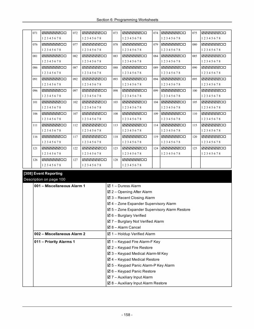
Section 6: Programming Worksheets
071 RRRRRRoo
1 2 3 4 5 6 7 8072 RRRRRRoo
1 2 3 4 5 6 7 8073 RRRRRRoo
1 2 3 4 5 6 7 8074 RRRRRRoo
1 2 3 4 5 6 7 8075 RRRRRRoo
1 2 3 4 5 6 7 8
076 RRRRRRoo
1 2 3 4 5 6 7 8077 RRRRRRoo
1 2 3 4 5 6 7 8078 RRRRRRoo
1 2 3 4 5 6 7 8079 RRRRRRoo
1 2 3 4 5 6 7 8080 RRRRRRoo
1 2 3 4 5 6 7 8
081 RRRRRRoo
1 2 3 4 5 6 7 8082 RRRRRRoo
1 2 3 4 5 6 7 8083 RRRRRRoo
1 2 3 4 5 6 7 8084 RRRRRRoo
1 2 3 4 5 6 7 8085 RRRRRRoo
1 2 3 4 5 6 7 8
086 RRRRRRoo
1 2 3 4 5 6 7 8087 RRRRRRoo
1 2 3 4 5 6 7 8088 RRRRRRoo
1 2 3 4 5 6 7 8089 RRRRRRoo
1 2 3 4 5 6 7 8090 RRRRRRoo
1 2 3 4 5 6 7 8
091 RRRRRRoo
1 2 3 4 5 6 7 8092 RRRRRRoo
1 2 3 4 5 6 7 8093 RRRRRRoo
1 2 3 4 5 6 7 8094 RRRRRRoo
1 2 3 4 5 6 7 8095 RRRRRRoo
1 2 3 4 5 6 7 8
096 RRRRRRoo
1 2 3 4 5 6 7 8097 RRRRRRoo
1 2 3 4 5 6 7 8098 RRRRRRoo
1 2 3 4 5 6 7 8099 RRRRRRoo
1 2 3 4 5 6 7 8100 RRRRRRoo
1 2 3 4 5 6 7 8
101 RRRRRRoo
1 2 3 4 5 6 7 8102 RRRRRRoo
1 2 3 4 5 6 7 8103 RRRRRRoo
1 2 3 4 5 6 7 8104 RRRRRRoo
1 2 3 4 5 6 7 8105 RRRRRRoo
1 2 3 4 5 6 7 8
106 RRRRRRoo
1 2 3 4 5 6 7 8107 RRRRRRoo
1 2 3 4 5 6 7 8108 RRRRRRoo
1 2 3 4 5 6 7 8109 RRRRRRoo
1 2 3 4 5 6 7 8110 RRRRRRoo
1 2 3 4 5 6 7 8
111 RRRRRRoo
1 2 3 4 5 6 7 8112 RRRRRRoo
1 2 3 4 5 6 7 8113 RRRRRRoo
1 2 3 4 5 6 7 8114 RRRRRRoo
1 2 3 4 5 6 7 8115 RRRRRRoo
1 2 3 4 5 6 7 8
116 RRRRRRoo
1 2 3 4 5 6 7 8117 RRRRRRoo
1 2 3 4 5 6 7 8118 RRRRRRoo
1 2 3 4 5 6 7 8119 RRRRRRoo
1 2 3 4 5 6 7 8120 RRRRRRoo
1 2 3 4 5 6 7 8
121 RRRRRRoo
1 2 3 4 5 6 7 8122 RRRRRRoo
1 2 3 4 5 6 7 8123 RRRRRRoo
1 2 3 4 5 6 7 8124 RRRRRRoo
1 2 3 4 5 6 7 8125 RRRRRRoo
1 2 3 4 5 6 7 8
126 RRRRRRoo
1 2 3 4 5 6 7 8127 RRRRRRoo
1 2 3 4 5 6 7 8128 RRRRRRoo
1 2 3 4 5 6 7 8
[308] Event ReportingDescription on page 100
001 – Miscellaneous Alarm 1 R 1 – Duress AlarmR 2 – Opening After AlarmR 3 – Recent Closing AlarmR 4 – Zone Expander Supervisory AlarmR 5 – Zone Expander Supervisory Alarm RestoreR 6 – Burglary VerifiedR 7 – Burglary Not Verified AlarmR 8 – Alarm Cancel
002 – Miscellaneous Alarm 2 R 1 – Holdup Verified Alarm
011 – Priority Alarms 1 R 1 – Keypad Fire Alarm-F KeyR 2 – Keypad Fire RestoreR 3 – Keypad Medical Alarm-M KeyR 4 – Keypad Medical RestoreR 5 – Keypad Panic Alarm-P Key AlarmR 6 – Keypad Panic RestoreR 7 – Auxiliary Input AlarmR 8 – Auxiliary Input Alarm Restore
- 158 -
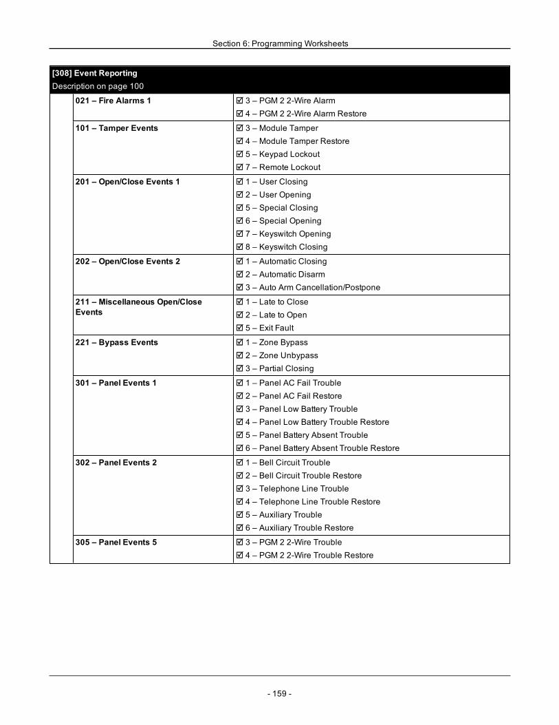
Section 6: Programming Worksheets
[308] Event ReportingDescription on page 100
021 – Fire Alarms 1 R 3 – PGM 2 2-Wire AlarmR 4 – PGM 2 2-Wire Alarm Restore
101 – Tamper Events R 3 – Module TamperR 4 – Module Tamper RestoreR 5 – Keypad LockoutR 7 – Remote Lockout
201 – Open/Close Events 1 R 1 – User ClosingR 2 – User OpeningR 5 – Special ClosingR 6 – Special OpeningR 7 – Keyswitch OpeningR 8 – Keyswitch Closing
202 – Open/Close Events 2 R 1 – Automatic ClosingR 2 – Automatic DisarmR 3 – Auto Arm Cancellation/Postpone
211 – Miscellaneous Open/CloseEvents
R 1 – Late to CloseR 2 – Late to OpenR 5 – Exit Fault
221 – Bypass Events R 1 – Zone BypassR 2 – Zone UnbypassR 3 – Partial Closing
301 – Panel Events 1 R 1 – Panel AC Fail TroubleR 2 – Panel AC Fail RestoreR 3 – Panel Low Battery TroubleR 4 – Panel Low Battery Trouble RestoreR 5 – Panel Battery Absent TroubleR 6 – Panel Battery Absent Trouble Restore
302 – Panel Events 2 R 1 – Bell Circuit TroubleR 2 – Bell Circuit Trouble RestoreR 3 – Telephone Line TroubleR 4 – Telephone Line Trouble RestoreR 5 – Auxiliary TroubleR 6 – Auxiliary Trouble Restore
305 – Panel Events 5 R 3 – PGM 2 2-Wire TroubleR 4 – PGM 2 2-Wire Trouble Restore
- 159 -
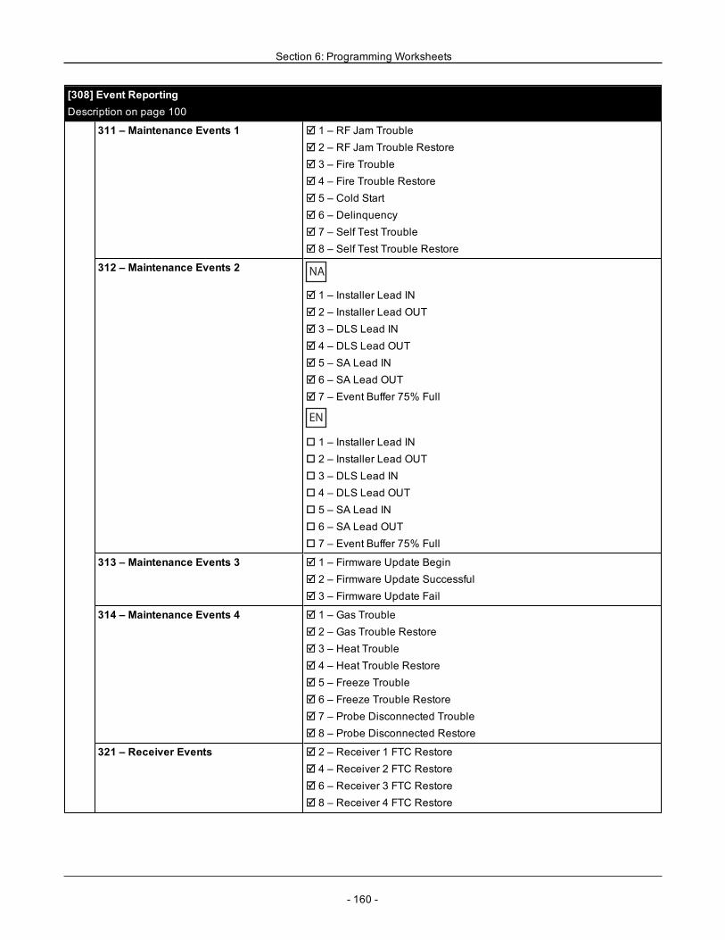
Section 6: Programming Worksheets
[308] Event ReportingDescription on page 100
311 – Maintenance Events 1 R 1 – RF Jam TroubleR 2 – RF Jam Trouble RestoreR 3 – Fire TroubleR 4 – Fire Trouble RestoreR 5 – Cold StartR 6 – DelinquencyR 7 – Self Test TroubleR 8 – Self Test Trouble Restore
312 – Maintenance Events 2 NA
R 1 – Installer Lead INR 2 – Installer Lead OUTR 3 – DLS Lead INR 4 – DLS Lead OUTR 5 – SA Lead INR 6 – SA Lead OUTR 7 – Event Buffer 75% Full
EN
o 1 – Installer Lead INo 2 – Installer Lead OUTo 3 – DLS Lead INo 4 – DLS Lead OUTo 5 – SA Lead INo 6 – SA Lead OUTo 7 – Event Buffer 75% Full
313 – Maintenance Events 3 R 1 – Firmware Update BeginR 2 – Firmware Update SuccessfulR 3 – Firmware Update Fail
314 – Maintenance Events 4 R 1 – Gas TroubleR 2 – Gas Trouble RestoreR 3 – Heat TroubleR 4 – Heat Trouble RestoreR 5 – Freeze TroubleR 6 – Freeze Trouble RestoreR 7 – Probe Disconnected TroubleR 8 – Probe Disconnected Restore
321 – Receiver Events R 2 – Receiver 1 FTC RestoreR 4 – Receiver 2 FTC RestoreR 6 – Receiver 3 FTC RestoreR 8 – Receiver 4 FTC Restore
- 160 -
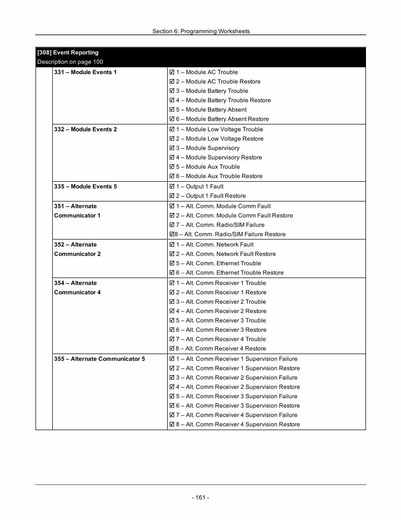
Section 6: Programming Worksheets
[308] Event ReportingDescription on page 100
331 – Module Events 1 R 1 – Module AC TroubleR 2 – Module AC Trouble RestoreR 3 – Module Battery TroubleR 4 – Module Battery Trouble RestoreR 5 – Module Battery AbsentR 6 – Module Battery Absent Restore
332 – Module Events 2 R 1 – Module Low Voltage TroubleR 2 – Module Low Voltage RestoreR 3 – Module SupervisoryR 4 – Module Supervisory RestoreR 5 – Module Aux TroubleR 6 – Module Aux Trouble Restore
335 – Module Events 5 R 1 – Output 1 FaultR 2 – Output 1 Fault Restore
351 – AlternateCommunicator 1
R 1 – Alt. Comm. Module Comm FaultR 2 – Alt. Comm. Module Comm Fault RestoreR 7 – Alt. Comm. Radio/SIM FailureR8 – Alt. Comm. Radio/SIM Failure Restore
352 – AlternateCommunicator 2
R 1 – Alt. Comm. Network FaultR 2 – Alt. Comm. Network Fault RestoreR 5 – Alt. Comm. Ethernet TroubleR 6 – Alt. Comm. Ethernet Trouble Restore
354 – AlternateCommunicator 4
R 1 – Alt. Comm Receiver 1 TroubleR 2 – Alt. Comm Receiver 1 RestoreR 3 – Alt. Comm Receiver 2 TroubleR 4 – Alt. Comm Receiver 2 RestoreR 5 – Alt. Comm Receiver 3 TroubleR 6 – Alt. Comm Receiver 3 RestoreR 7 – Alt. Comm Receiver 4 TroubleR 8 – Alt. Comm Receiver 4 Restore
355 – Alternate Communicator 5 R 1 – Alt. Comm Receiver 1 Supervision FailureR 2 – Alt. Comm Receiver 1 Supervision RestoreR 3 – Alt. Comm Receiver 2 Supervision FailureR 4 – Alt. Comm Receiver 2 Supervision RestoreR 5 – Alt. Comm Receiver 3 Supervision FailureR 6 – Alt. Comm Receiver 3 Supervision RestoreR 7 – Alt. Comm Receiver 4 Supervision FailureR 8 – Alt. Comm Receiver 4 Supervision Restore
- 161 -
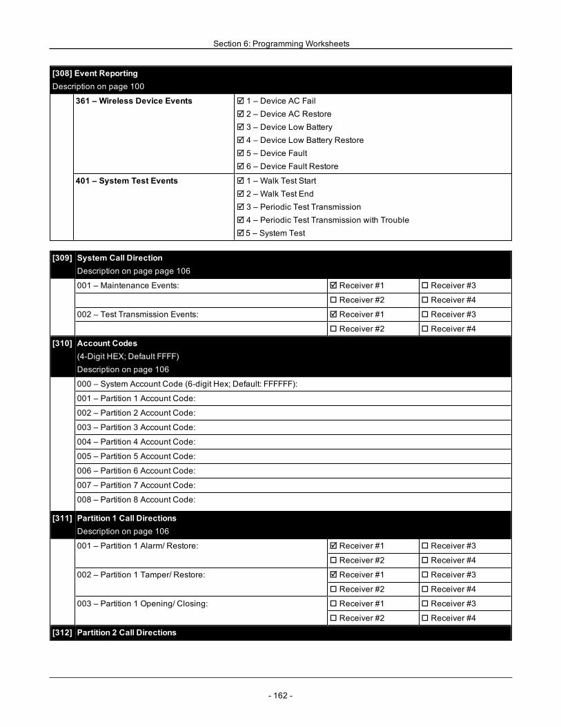
Section 6: Programming Worksheets
[308] Event ReportingDescription on page 100
361 – Wireless Device Events R 1 – Device AC FailR 2 – Device AC RestoreR 3 – Device Low BatteryR 4 – Device Low Battery RestoreR 5 – Device FaultR 6 – Device Fault Restore
401 – System Test Events R 1 – Walk Test StartR 2 – Walk Test EndR 3 – Periodic Test TransmissionR 4 – Periodic Test Transmission with TroubleR 5 – System Test
[309] System Call DirectionDescription on page page 106
001 – Maintenance Events: R Receiver #1 o Receiver #3
o Receiver #2 o Receiver #4
002 – Test Transmission Events: R Receiver #1 o Receiver #3
o Receiver #2 o Receiver #4
[310] Account Codes(4-Digit HEX; Default FFFF)Description on page 106
000 – System Account Code (6-digit Hex; Default: FFFFFF):
001 – Partition 1 Account Code:
002 – Partition 2 Account Code:
003 – Partition 3 Account Code:
004 – Partition 4 Account Code:
005 – Partition 5 Account Code:
006 – Partition 6 Account Code:
007 – Partition 7 Account Code:
008 – Partition 8 Account Code:
[311] Partition 1 Call DirectionsDescription on page 106
001 – Partition 1 Alarm/ Restore: R Receiver #1 o Receiver #3
o Receiver #2 o Receiver #4
002 – Partition 1 Tamper/ Restore: R Receiver #1 o Receiver #3
o Receiver #2 o Receiver #4
003 – Partition 1 Opening/ Closing: o Receiver #1 o Receiver #3
o Receiver #2 o Receiver #4
[312] Partition 2 Call Directions
- 162 -
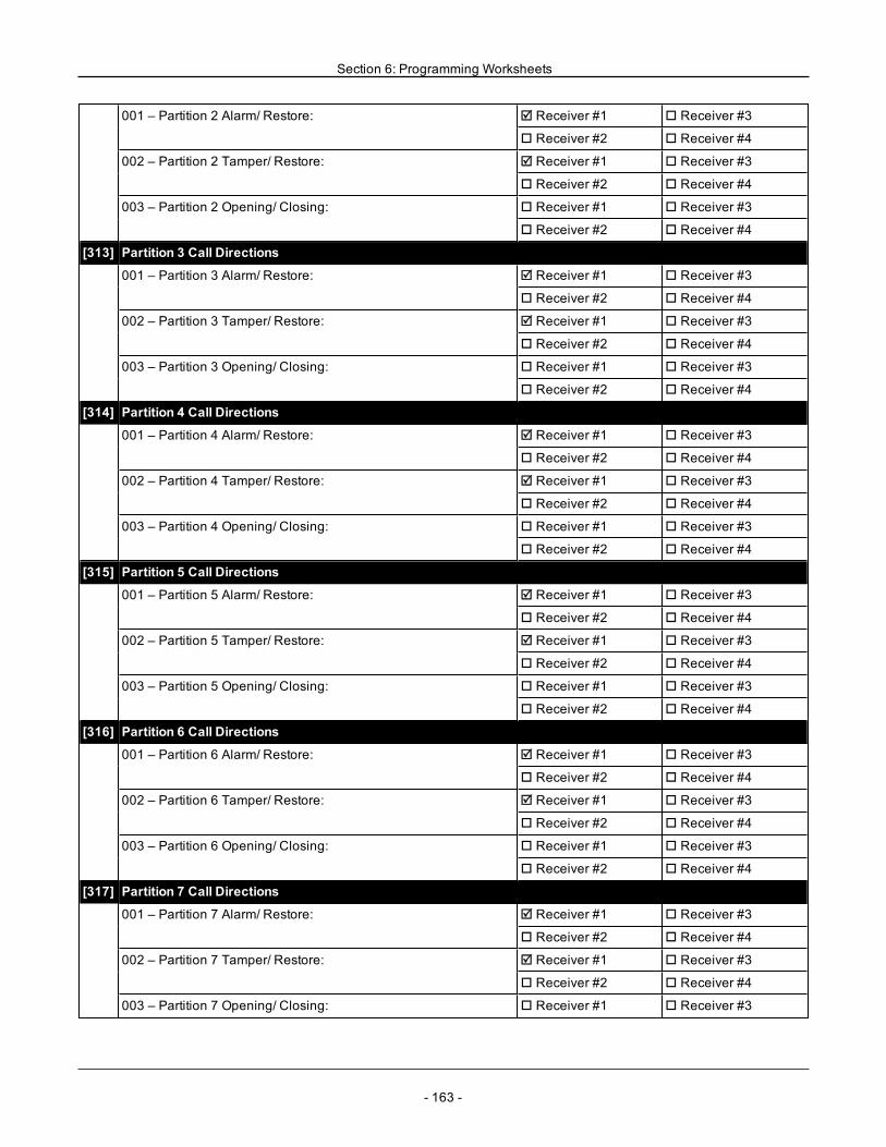
Section 6: Programming Worksheets
001 – Partition 2 Alarm/ Restore: R Receiver #1 o Receiver #3
o Receiver #2 o Receiver #4
002 – Partition 2 Tamper/ Restore: R Receiver #1 o Receiver #3
o Receiver #2 o Receiver #4
003 – Partition 2 Opening/ Closing: o Receiver #1 o Receiver #3
o Receiver #2 o Receiver #4
[313] Partition 3 Call Directions
001 – Partition 3 Alarm/ Restore: R Receiver #1 o Receiver #3
o Receiver #2 o Receiver #4
002 – Partition 3 Tamper/ Restore: R Receiver #1 o Receiver #3
o Receiver #2 o Receiver #4
003 – Partition 3 Opening/ Closing: o Receiver #1 o Receiver #3
o Receiver #2 o Receiver #4
[314] Partition 4 Call Directions
001 – Partition 4 Alarm/ Restore: R Receiver #1 o Receiver #3
o Receiver #2 o Receiver #4
002 – Partition 4 Tamper/ Restore: R Receiver #1 o Receiver #3
o Receiver #2 o Receiver #4
003 – Partition 4 Opening/ Closing: o Receiver #1 o Receiver #3
o Receiver #2 o Receiver #4
[315] Partition 5 Call Directions
001 – Partition 5 Alarm/ Restore: R Receiver #1 o Receiver #3
o Receiver #2 o Receiver #4
002 – Partition 5 Tamper/ Restore: R Receiver #1 o Receiver #3
o Receiver #2 o Receiver #4
003 – Partition 5 Opening/ Closing: o Receiver #1 o Receiver #3
o Receiver #2 o Receiver #4
[316] Partition 6 Call Directions
001 – Partition 6 Alarm/ Restore: R Receiver #1 o Receiver #3
o Receiver #2 o Receiver #4
002 – Partition 6 Tamper/ Restore: R Receiver #1 o Receiver #3
o Receiver #2 o Receiver #4
003 – Partition 6 Opening/ Closing: o Receiver #1 o Receiver #3
o Receiver #2 o Receiver #4
[317] Partition 7 Call Directions
001 – Partition 7 Alarm/ Restore: R Receiver #1 o Receiver #3
o Receiver #2 o Receiver #4
002 – Partition 7 Tamper/ Restore: R Receiver #1 o Receiver #3
o Receiver #2 o Receiver #4
003 – Partition 7 Opening/ Closing: o Receiver #1 o Receiver #3
- 163 -
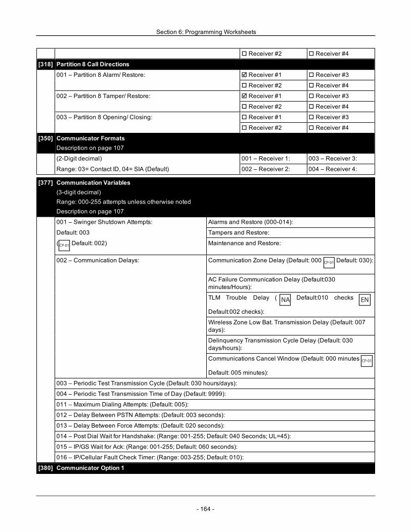
Section 6: Programming Worksheets
o Receiver #2 o Receiver #4
[318] Partition 8 Call Directions
001 – Partition 8 Alarm/ Restore: R Receiver #1 o Receiver #3
o Receiver #2 o Receiver #4
002 – Partition 8 Tamper/ Restore: R Receiver #1 o Receiver #3
o Receiver #2 o Receiver #4
003 – Partition 8 Opening/ Closing: o Receiver #1 o Receiver #3
o Receiver #2 o Receiver #4
[350] Communicator FormatsDescription on page 107
(2-Digit decimal) 001 – Receiver 1: 003 – Receiver 3:
Range: 03= Contact ID, 04= SIA (Default) 002 – Receiver 2: 004 – Receiver 4:
[377] Communication Variables(3-digit decimal)Range: 000-255 attempts unless otherwise notedDescription on page 107
001 – Swinger Shutdown Attempts: Alarms and Restore (000-014):
Default: 003 Tampers and Restore:
(CP-01
Default: 002) Maintenance and Restore:
002 – Communication Delays: Communication Zone Delay (Default: 000CP-01
Default: 030):
AC Failure Communication Delay (Default:030minutes/Hours):
TLM Trouble Delay ( NA Default:010 checks EN
Default:002 checks):
Wireless Zone Low Bat. Transmission Delay (Default: 007days):
Delinquency Transmission Cycle Delay (Default: 030days/hours):
Communications Cancel Window (Default: 000 minutesCP-01
Default: 005 minutes):
003 – Periodic Test Transmission Cycle (Default: 030 hours/days):
004 – Periodic Test Transmission Time of Day (Default: 9999):
011 – Maximum Dialing Attempts: (Default: 005):
012 – Delay Between PSTN Attempts: (Default: 003 seconds):
013 – Delay Between Force Attempts: (Default: 020 seconds):
014 – Post Dial Wait for Handshake: (Range: 001-255; Default: 040 Seconds; UL=45):
015 – IP/GS Wait for Ack: (Range: 001-255; Default: 060 seconds):
016 – IP/Cellular Fault Check Timer: (Range: 003-255; Default: 010):
[380] Communicator Option 1
- 164 -
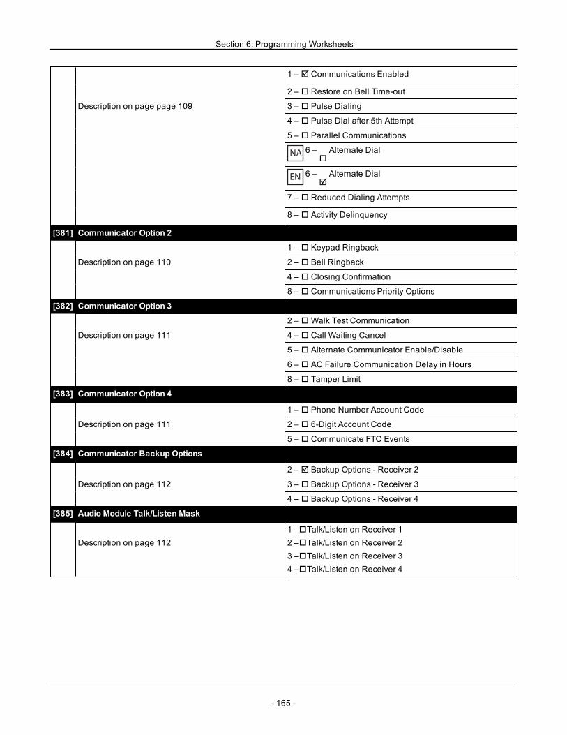
Section 6: Programming Worksheets
1 – R Communications Enabled
2 – o Restore on Bell Time-out
Description on page page 109 3 – o Pulse Dialing
4 – o Pulse Dial after 5th Attempt
5 – o Parallel Communications
NA 6 –oAlternate Dial
EN 6 –RAlternate Dial
7 – o Reduced Dialing Attempts
8 – o Activity Delinquency
[381] Communicator Option 2
1 – o Keypad Ringback
Description on page 110 2 – o Bell Ringback
4 – o Closing Confirmation
8 – o Communications Priority Options
[382] Communicator Option 3
2 – oWalk Test Communication
Description on page 111 4 – o Call Waiting Cancel
5 – o Alternate Communicator Enable/Disable
6 – o AC Failure Communication Delay in Hours
8 – o Tamper Limit
[383] Communicator Option 4
1 – o Phone Number Account Code
Description on page 111 2 – o 6-Digit Account Code
5 – o Communicate FTC Events
[384] Communicator Backup Options
2 – R Backup Options - Receiver 2
Description on page 112 3 – o Backup Options - Receiver 3
4 – o Backup Options - Receiver 4
[385] Audio Module Talk/Listen Mask
Description on page 1121 –oTalk/Listen on Receiver 12 –oTalk/Listen on Receiver 23 –oTalk/Listen on Receiver 34 –oTalk/Listen on Receiver 4
- 165 -
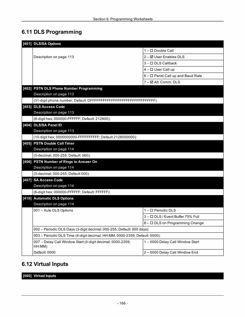
Section 6: Programming Worksheets
6.11 DLS Programming
[401] DLS/SA Options
1 – o Double Call
Description on page 113 2 – R User Enables DLS
3 – o DLS Callback
4 – o User Call up
6 – o Panel Call up and Baud Rate
7 – R Alt. Comm. DLS
[402] PSTN DLS Phone Number ProgrammingDescription on page 113
(31-digit phone number; Default: DFFFFFFFFFFFFFFFFFFFFFFFFFFFFFFF):
[403] DLS Access CodeDescription on page 113
(6-digit hex; 000000-FFFFFF; Default: 212800):
[404] DLS/SA Panel IDDescription on page 113
(10-digit hex; 0000000000-FFFFFFFFFF; Default 2128000000):
[405] PSTN Double Call TimerDescription on page 114
(3-decimal; 000-255; Default: 060):
[406] PSTN Number of Rings to Answer OnDescription on page 114
(3-decimal; 000-255; Default 000):
[407] SA Access CodeDescription on page 114
(6-digit hex; 000000-FFFFFF; Default: FFFFFF):
[410] Automatic DLS OptionsDescription on page 114
001 – Auto DLS Options 1 – o Periodic DLS
3 – o DLS / Event Buffer 75% Full
8 – o DLS on Programming Change
002 – Periodic DLS Days (3-digit decimal; 000-255; Default: 000 days):
003 – Periodic DLS Time (4-digit decimal; HH:MM; 0000-2359; Default: 0000):
007 – Delay Call Window Start (4-digit decimal; 0000-2359;HH:MM)
1 – 0000 Delay Call Window Start
Default: 0000 2 – 0000 Delay Call Window End
6.12 Virtual Inputs
[560] Virtual Inputs
- 166 -
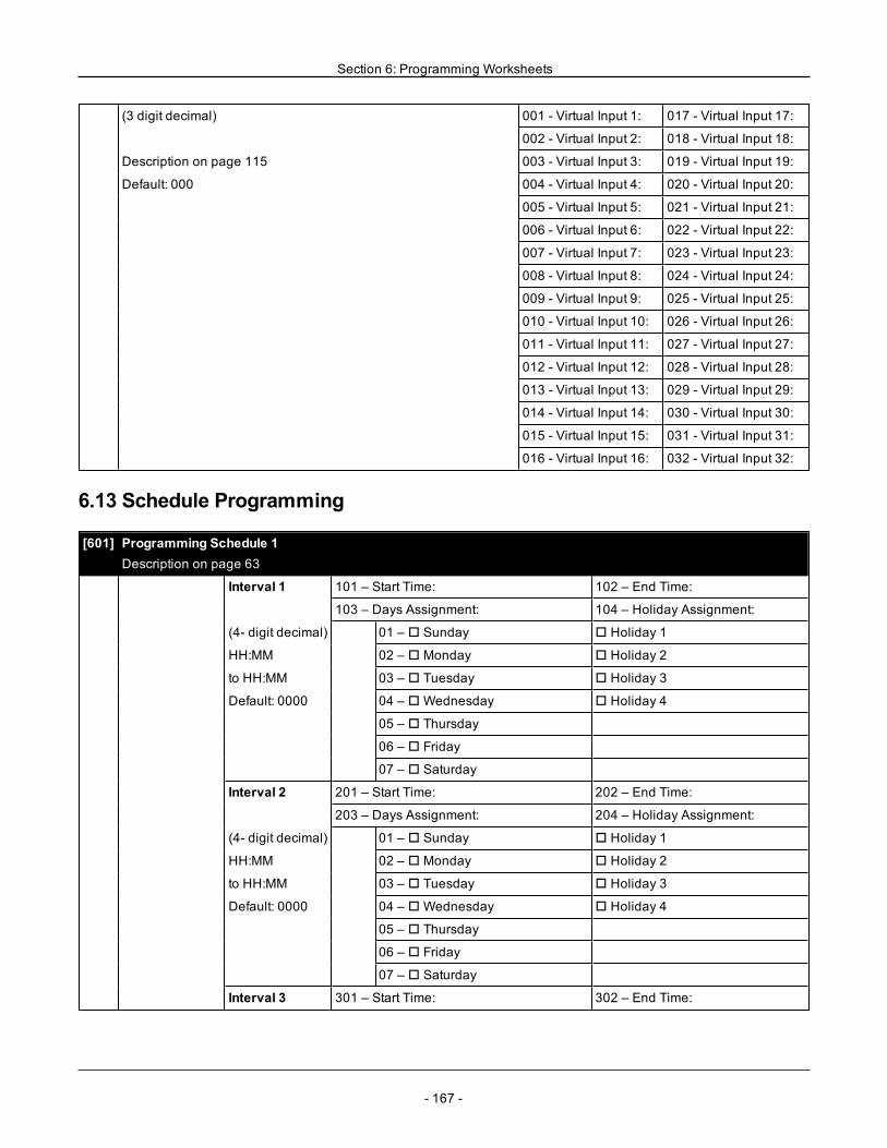
Section 6: Programming Worksheets
(3 digit decimal) 001 - Virtual Input 1: 017 - Virtual Input 17:
002 - Virtual Input 2: 018 - Virtual Input 18:
Description on page 115 003 - Virtual Input 3: 019 - Virtual Input 19:
Default: 000 004 - Virtual Input 4: 020 - Virtual Input 20:
005 - Virtual Input 5: 021 - Virtual Input 21:
006 - Virtual Input 6: 022 - Virtual Input 22:
007 - Virtual Input 7: 023 - Virtual Input 23:
008 - Virtual Input 8: 024 - Virtual Input 24:
009 - Virtual Input 9: 025 - Virtual Input 25:
010 - Virtual Input 10: 026 - Virtual Input 26:
011 - Virtual Input 11: 027 - Virtual Input 27:
012 - Virtual Input 12: 028 - Virtual Input 28:
013 - Virtual Input 13: 029 - Virtual Input 29:
014 - Virtual Input 14: 030 - Virtual Input 30:
015 - Virtual Input 15: 031 - Virtual Input 31:
016 - Virtual Input 16: 032 - Virtual Input 32:
6.13 Schedule Programming
[601] Programming Schedule 1Description on page 63
Interval 1 101 – Start Time: 102 – End Time:
103 – Days Assignment: 104 – Holiday Assignment:
(4- digit decimal) 01 – o Sunday o Holiday 1
HH:MM 02 – o Monday o Holiday 2
to HH:MM 03 – o Tuesday o Holiday 3
Default: 0000 04 – oWednesday o Holiday 4
05 – o Thursday
06 – o Friday
07 – o Saturday
Interval 2 201 – Start Time: 202 – End Time:
203 – Days Assignment: 204 – Holiday Assignment:
(4- digit decimal) 01 – o Sunday o Holiday 1
HH:MM 02 – o Monday o Holiday 2
to HH:MM 03 – o Tuesday o Holiday 3
Default: 0000 04 – oWednesday o Holiday 4
05 – o Thursday
06 – o Friday
07 – o Saturday
Interval 3 301 – Start Time: 302 – End Time:
- 167 -
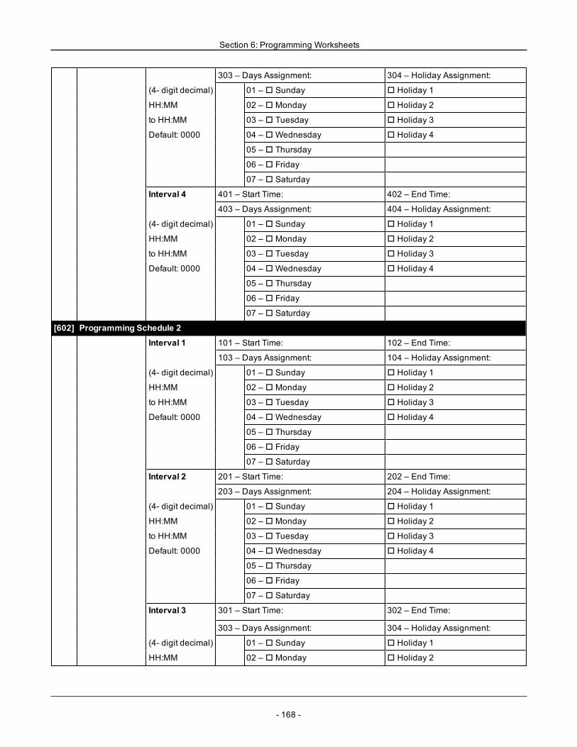
Section 6: Programming Worksheets
303 – Days Assignment: 304 – Holiday Assignment:
(4- digit decimal) 01 – o Sunday o Holiday 1
HH:MM 02 – o Monday o Holiday 2
to HH:MM 03 – o Tuesday o Holiday 3
Default: 0000 04 – oWednesday o Holiday 4
05 – o Thursday
06 – o Friday
07 – o Saturday
Interval 4 401 – Start Time: 402 – End Time:
403 – Days Assignment: 404 – Holiday Assignment:
(4- digit decimal) 01 – o Sunday o Holiday 1
HH:MM 02 – o Monday o Holiday 2
to HH:MM 03 – o Tuesday o Holiday 3
Default: 0000 04 – oWednesday o Holiday 4
05 – o Thursday
06 – o Friday
07 – o Saturday
[602] Programming Schedule 2
Interval 1 101 – Start Time: 102 – End Time:
103 – Days Assignment: 104 – Holiday Assignment:
(4- digit decimal) 01 – o Sunday o Holiday 1
HH:MM 02 – o Monday o Holiday 2
to HH:MM 03 – o Tuesday o Holiday 3
Default: 0000 04 – oWednesday o Holiday 4
05 – o Thursday
06 – o Friday
07 – o Saturday
Interval 2 201 – Start Time: 202 – End Time:
203 – Days Assignment: 204 – Holiday Assignment:
(4- digit decimal) 01 – o Sunday o Holiday 1
HH:MM 02 – o Monday o Holiday 2
to HH:MM 03 – o Tuesday o Holiday 3
Default: 0000 04 – oWednesday o Holiday 4
05 – o Thursday
06 – o Friday
07 – o Saturday
Interval 3 301 – Start Time: 302 – End Time:
303 – Days Assignment: 304 – Holiday Assignment:
(4- digit decimal) 01 – o Sunday o Holiday 1
HH:MM 02 – o Monday o Holiday 2
- 168 -
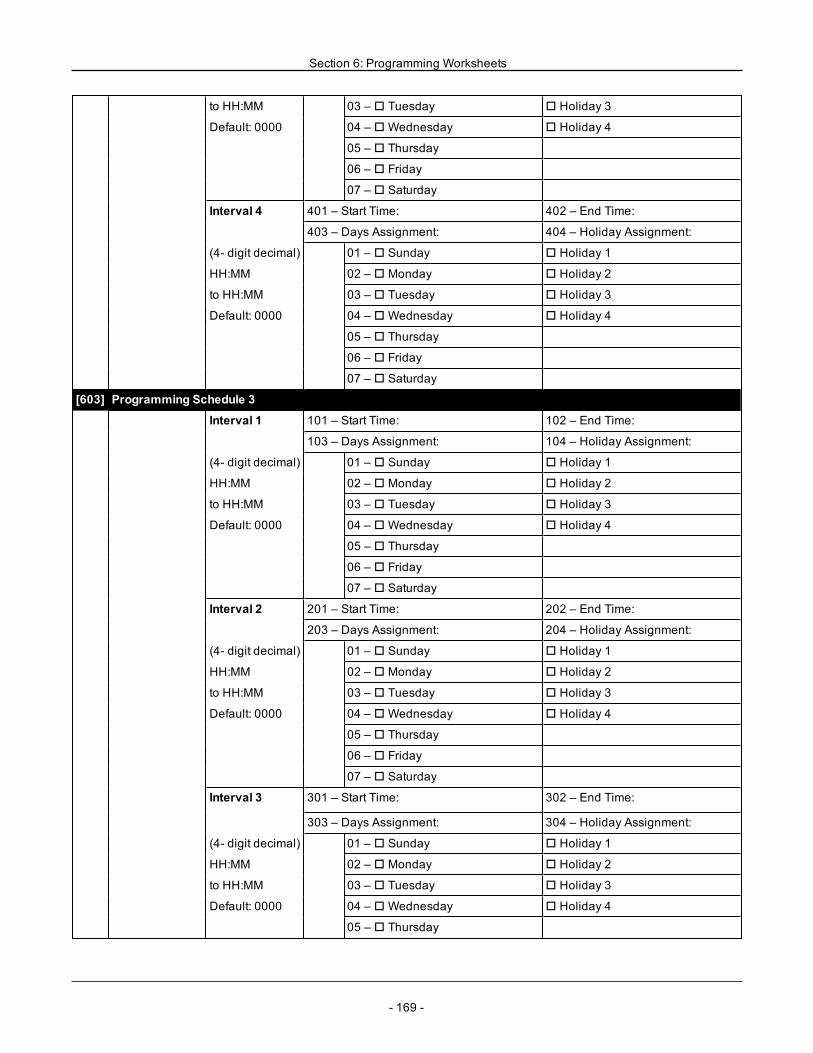
Section 6: Programming Worksheets
to HH:MM 03 – o Tuesday o Holiday 3
Default: 0000 04 – oWednesday o Holiday 4
05 – o Thursday
06 – o Friday
07 – o Saturday
Interval 4 401 – Start Time: 402 – End Time:
403 – Days Assignment: 404 – Holiday Assignment:
(4- digit decimal) 01 – o Sunday o Holiday 1
HH:MM 02 – o Monday o Holiday 2
to HH:MM 03 – o Tuesday o Holiday 3
Default: 0000 04 – oWednesday o Holiday 4
05 – o Thursday
06 – o Friday
07 – o Saturday
[603] Programming Schedule 3
Interval 1 101 – Start Time: 102 – End Time:
103 – Days Assignment: 104 – Holiday Assignment:
(4- digit decimal) 01 – o Sunday o Holiday 1
HH:MM 02 – o Monday o Holiday 2
to HH:MM 03 – o Tuesday o Holiday 3
Default: 0000 04 – oWednesday o Holiday 4
05 – o Thursday
06 – o Friday
07 – o Saturday
Interval 2 201 – Start Time: 202 – End Time:
203 – Days Assignment: 204 – Holiday Assignment:
(4- digit decimal) 01 – o Sunday o Holiday 1
HH:MM 02 – o Monday o Holiday 2
to HH:MM 03 – o Tuesday o Holiday 3
Default: 0000 04 – oWednesday o Holiday 4
05 – o Thursday
06 – o Friday
07 – o Saturday
Interval 3 301 – Start Time: 302 – End Time:
303 – Days Assignment: 304 – Holiday Assignment:
(4- digit decimal) 01 – o Sunday o Holiday 1
HH:MM 02 – o Monday o Holiday 2
to HH:MM 03 – o Tuesday o Holiday 3
Default: 0000 04 – oWednesday o Holiday 4
05 – o Thursday
- 169 -
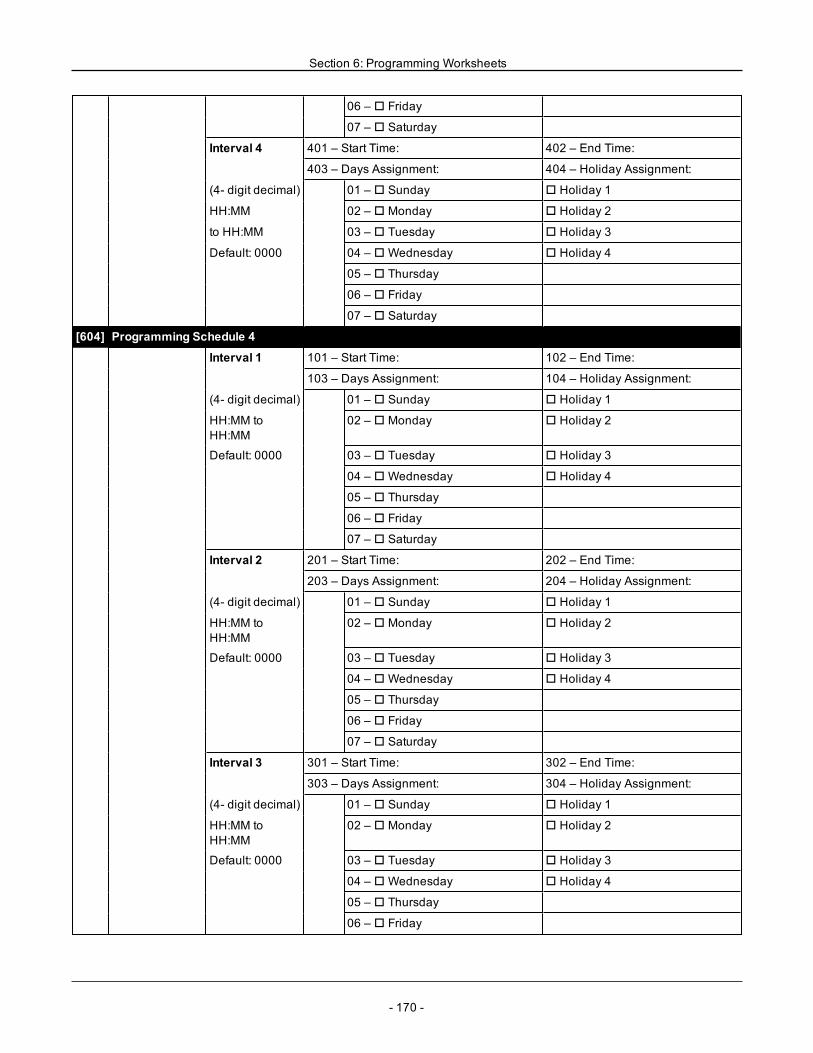
Section 6: Programming Worksheets
06 – o Friday
07 – o Saturday
Interval 4 401 – Start Time: 402 – End Time:
403 – Days Assignment: 404 – Holiday Assignment:
(4- digit decimal) 01 – o Sunday o Holiday 1
HH:MM 02 – o Monday o Holiday 2
to HH:MM 03 – o Tuesday o Holiday 3
Default: 0000 04 – oWednesday o Holiday 4
05 – o Thursday
06 – o Friday
07 – o Saturday
[604] Programming Schedule 4
Interval 1 101 – Start Time: 102 – End Time:
103 – Days Assignment: 104 – Holiday Assignment:
(4- digit decimal) 01 – o Sunday o Holiday 1
HH:MM toHH:MM
02 – o Monday o Holiday 2
Default: 0000 03 – o Tuesday o Holiday 3
04 – oWednesday o Holiday 4
05 – o Thursday
06 – o Friday
07 – o Saturday
Interval 2 201 – Start Time: 202 – End Time:
203 – Days Assignment: 204 – Holiday Assignment:
(4- digit decimal) 01 – o Sunday o Holiday 1
HH:MM toHH:MM
02 – o Monday o Holiday 2
Default: 0000 03 – o Tuesday o Holiday 3
04 – oWednesday o Holiday 4
05 – o Thursday
06 – o Friday
07 – o Saturday
Interval 3 301 – Start Time: 302 – End Time:
303 – Days Assignment: 304 – Holiday Assignment:
(4- digit decimal) 01 – o Sunday o Holiday 1
HH:MM toHH:MM
02 – o Monday o Holiday 2
Default: 0000 03 – o Tuesday o Holiday 3
04 – oWednesday o Holiday 4
05 – o Thursday
06 – o Friday
- 170 -
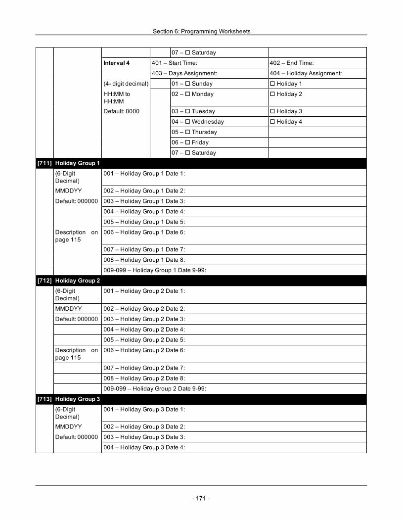
Section 6: Programming Worksheets
07 – o Saturday
Interval 4 401 – Start Time: 402 – End Time:
403 – Days Assignment: 404 – Holiday Assignment:
(4- digit decimal) 01 – o Sunday o Holiday 1
HH:MM toHH:MM
02 – o Monday o Holiday 2
Default: 0000 03 – o Tuesday o Holiday 3
04 – oWednesday o Holiday 4
05 – o Thursday
06 – o Friday
07 – o Saturday
[711] Holiday Group 1
(6-DigitDecimal)
001 – Holiday Group 1 Date 1:
MMDDYY 002 – Holiday Group 1 Date 2:
Default: 000000 003 – Holiday Group 1 Date 3:
004 – Holiday Group 1 Date 4:
005 – Holiday Group 1 Date 5:
Description onpage 115
006 – Holiday Group 1 Date 6:
007 – Holiday Group 1 Date 7:
008 – Holiday Group 1 Date 8:
009-099 – Holiday Group 1 Date 9-99:
[712] Holiday Group 2
(6-DigitDecimal)
001 – Holiday Group 2 Date 1:
MMDDYY 002 – Holiday Group 2 Date 2:
Default: 000000 003 – Holiday Group 2 Date 3:
004 – Holiday Group 2 Date 4:
005 – Holiday Group 2 Date 5:
Description onpage 115
006 – Holiday Group 2 Date 6:
007 – Holiday Group 2 Date 7:
008 – Holiday Group 2 Date 8:
009-099 – Holiday Group 2 Date 9-99:
[713] Holiday Group 3
(6-DigitDecimal)
001 – Holiday Group 3 Date 1:
MMDDYY 002 – Holiday Group 3 Date 2:
Default: 000000 003 – Holiday Group 3 Date 3:
004 – Holiday Group 3 Date 4:
- 171 -
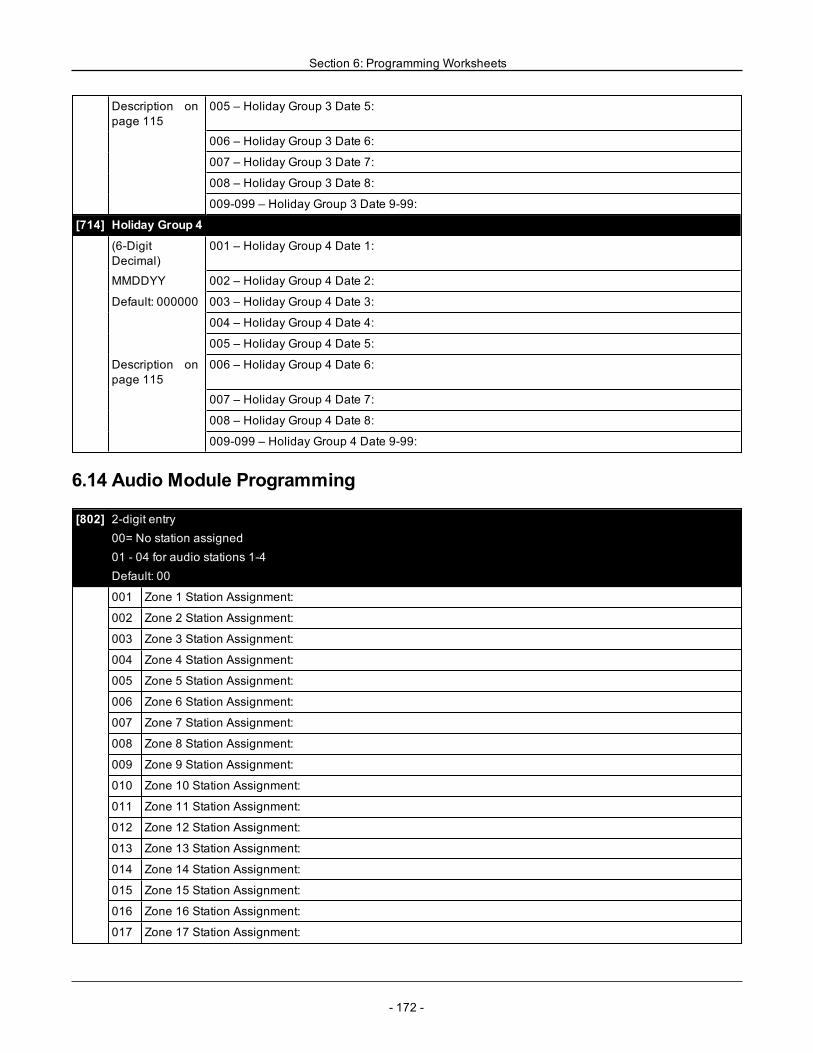
Section 6: Programming Worksheets
Description onpage 115
005 – Holiday Group 3 Date 5:
006 – Holiday Group 3 Date 6:
007 – Holiday Group 3 Date 7:
008 – Holiday Group 3 Date 8:
009-099 – Holiday Group 3 Date 9-99:
[714] Holiday Group 4
(6-DigitDecimal)
001 – Holiday Group 4 Date 1:
MMDDYY 002 – Holiday Group 4 Date 2:
Default: 000000 003 – Holiday Group 4 Date 3:
004 – Holiday Group 4 Date 4:
005 – Holiday Group 4 Date 5:
Description onpage 115
006 – Holiday Group 4 Date 6:
007 – Holiday Group 4 Date 7:
008 – Holiday Group 4 Date 8:
009-099 – Holiday Group 4 Date 9-99:
6.14 Audio Module Programming
[802] 2-digit entry00= No station assigned01 - 04 for audio stations 1-4Default: 00
001 Zone 1 Station Assignment:
002 Zone 2 Station Assignment:
003 Zone 3 Station Assignment:
004 Zone 4 Station Assignment:
005 Zone 5 Station Assignment:
006 Zone 6 Station Assignment:
007 Zone 7 Station Assignment:
008 Zone 8 Station Assignment:
009 Zone 9 Station Assignment:
010 Zone 10 Station Assignment:
011 Zone 11 Station Assignment:
012 Zone 12 Station Assignment:
013 Zone 13 Station Assignment:
014 Zone 14 Station Assignment:
015 Zone 15 Station Assignment:
016 Zone 16 Station Assignment:
017 Zone 17 Station Assignment:
- 172 -

Section 6: Programming Worksheets
018 Zone 18 Station Assignment:
019 Zone 19 Station Assignment:
020 Zone 20 Station Assignment:
021 Zone 21 Station Assignment:
022 Zone 22 Station Assignment:
023 Zone 23 Station Assignment:
024 Zone 24 Station Assignment:
025 Zone 25 Station Assignment:
026 Zone 26 Station Assignment:
027 Zone 27 Station Assignment:
028 Zone 28 Station Assignment:
029 Zone 29 Station Assignment:
030 Zone 30 Station Assignment:
031 Zone 31 Station Assignment:
032 Zone 32 Station Assignment:
033 Zone 33 Station Assignment:
034 Zone 34 Station Assignment:
035 Zone 35 Station Assignment:
036 Zone 36 Station Assignment:
037 Zone 37 Station Assignment:
038 Zone 38 Station Assignment:
039 Zone 39 Station Assignment:
040 Zone 40 Station Assignment:
041 Zone 41 Station Assignment:
042 Zone 42 Station Assignment:
043 Zone 43 Station Assignment:
044 Zone 44 Station Assignment:
045 Zone 45 Station Assignment:
046 Zone 46 Station Assignment:
047 Zone 47 Station Assignment:
048 Zone 48 Station Assignment:
049 Zone 49 Station Assignment:
050 Zone 50 Station Assignment:
051 Zone 51 Station Assignment:
052 Zone 52 Station Assignment:
053 Zone 53 Station Assignment:
054 Zone 54 Station Assignment:
055 Zone 55 Station Assignment:
056 Zone 56 Station Assignment:
057 Zone 57 Station Assignment:
- 173 -
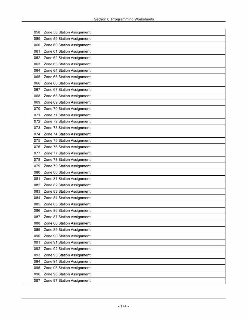
Section 6: Programming Worksheets
058 Zone 58 Station Assignment:
059 Zone 59 Station Assignment:
060 Zone 60 Station Assignment:
061 Zone 61 Station Assignment:
062 Zone 62 Station Assignment:
063 Zone 63 Station Assignment:
064 Zone 64 Station Assignment:
065 Zone 65 Station Assignment:
066 Zone 66 Station Assignment:
067 Zone 67 Station Assignment:
068 Zone 68 Station Assignment:
069 Zone 69 Station Assignment:
070 Zone 70 Station Assignment:
071 Zone 71 Station Assignment:
072 Zone 72 Station Assignment:
073 Zone 73 Station Assignment:
074 Zone 74 Station Assignment:
075 Zone 75 Station Assignment:
076 Zone 76 Station Assignment:
077 Zone 77 Station Assignment:
078 Zone 78 Station Assignment:
079 Zone 79 Station Assignment:
080 Zone 80 Station Assignment:
081 Zone 81 Station Assignment:
082 Zone 82 Station Assignment:
083 Zone 83 Station Assignment:
084 Zone 84 Station Assignment:
085 Zone 85 Station Assignment:
086 Zone 86 Station Assignment:
087 Zone 87 Station Assignment:
088 Zone 88 Station Assignment:
089 Zone 89 Station Assignment:
090 Zone 90 Station Assignment:
091 Zone 91 Station Assignment:
092 Zone 92 Station Assignment:
093 Zone 93 Station Assignment:
094 Zone 94 Station Assignment:
095 Zone 95 Station Assignment:
096 Zone 96 Station Assignment:
097 Zone 97 Station Assignment:
- 174 -
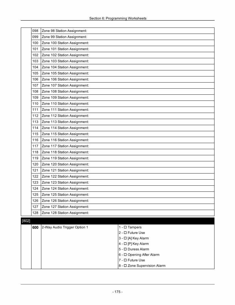
Section 6: Programming Worksheets
098 Zone 98 Station Assignment:
099 Zone 99 Station Assignment:
100 Zone 100 Station Assignment:
101 Zone 101 Station Assignment:
102 Zone 102 Station Assignment:
103 Zone 103 Station Assignment:
104 Zone 104 Station Assignment:
105 Zone 105 Station Assignment:
106 Zone 106 Station Assignment:
107 Zone 107 Station Assignment:
108 Zone 108 Station Assignment:
109 Zone 109 Station Assignment:
110 Zone 110 Station Assignment:
111 Zone 111 Station Assignment:
112 Zone 112 Station Assignment:
113 Zone 113 Station Assignment:
114 Zone 114 Station Assignment:
115 Zone 115 Station Assignment:
116 Zone 116 Station Assignment:
117 Zone 117 Station Assignment:
118 Zone 118 Station Assignment:
119 Zone 119 Station Assignment:
120 Zone 120 Station Assignment:
121 Zone 121 Station Assignment:
122 Zone 122 Station Assignment:
123 Zone 123 Station Assignment:
124 Zone 124 Station Assignment:
125 Zone 125 Station Assignment:
126 Zone 126 Station Assignment:
127 Zone 127 Station Assignment:
128 Zone 128 Station Assignment:
[802]
600 2-Way Audio Trigger Option 1 1 -o Tampers2 -o Future Use3 -o [A] Key Alarm4 -o [P] Key Alarm5 -o Duress Alarm6 -o Opening After Alarm7 -o Future Use8 -o Zone Supervision Alarm
- 175 -
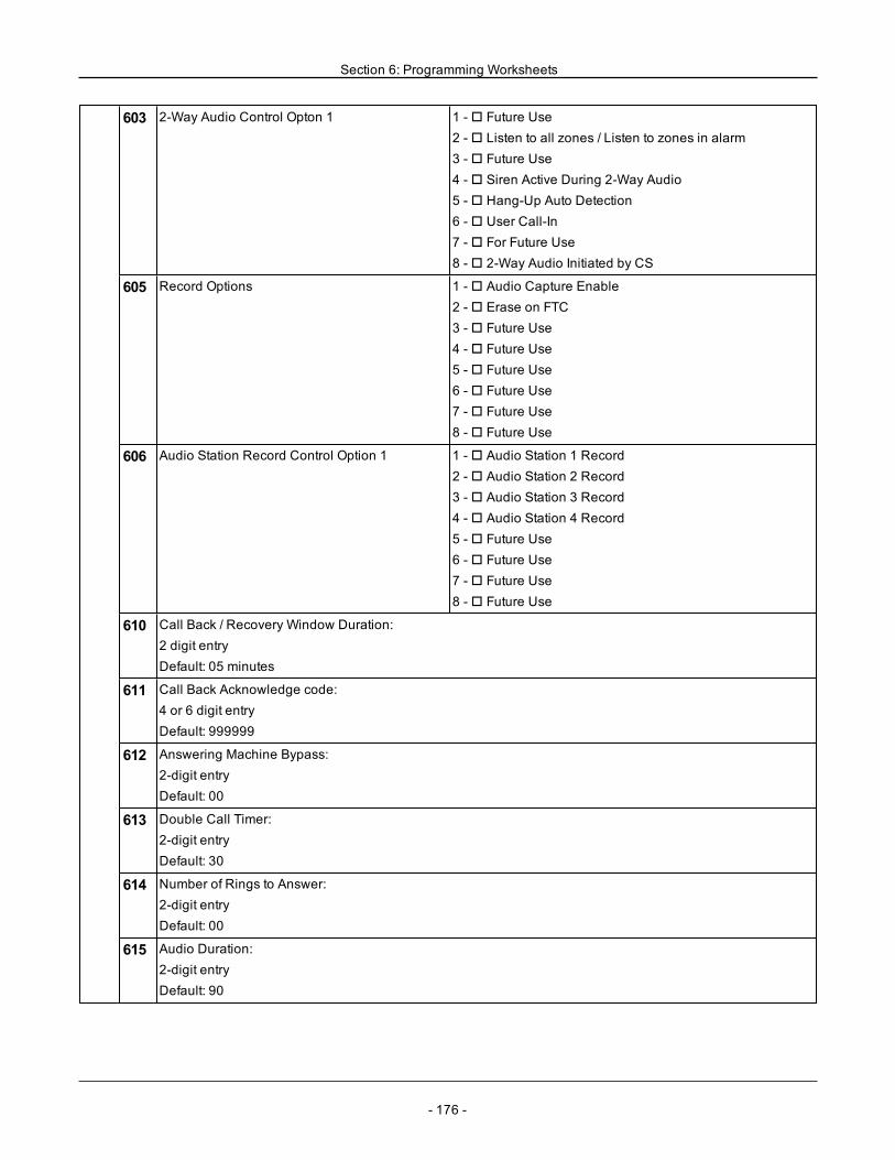
Section 6: Programming Worksheets
603 2-Way Audio Control Opton 1 1 -o Future Use2 -o Listen to all zones / Listen to zones in alarm3 -o Future Use4 -o Siren Active During 2-Way Audio5 -o Hang-Up Auto Detection6 -o User Call-In7 -o For Future Use8 -o 2-Way Audio Initiated by CS
605 Record Options 1 -o Audio Capture Enable2 -o Erase on FTC3 -o Future Use4 -o Future Use5 -o Future Use6 -o Future Use7 -o Future Use8 -o Future Use
606 Audio Station Record Control Option 1 1 -o Audio Station 1 Record2 -o Audio Station 2 Record3 -o Audio Station 3 Record4 -o Audio Station 4 Record5 -o Future Use6 -o Future Use7 -o Future Use8 -o Future Use
610 Call Back / Recovery Window Duration:2 digit entryDefault: 05 minutes
611 Call Back Acknowledge code:4 or 6 digit entryDefault: 999999
612 Answering Machine Bypass:2-digit entryDefault: 00
613 Double Call Timer:2-digit entryDefault: 30
614 Number of Rings to Answer:2-digit entryDefault: 00
615 Audio Duration:2-digit entryDefault: 90
- 176 -
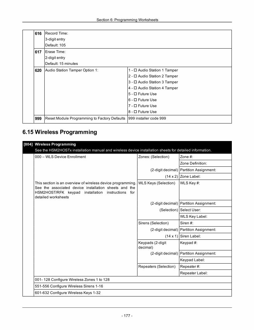
Section 6: Programming Worksheets
616 Record Time:3-digit entryDefault: 105
617 Erase Time:2-digit entryDefault: 15 minutes
620 Audio Station Tamper Option 1: 1 -o Audio Station 1 Tamper2 -o Audio Station 2 Tamper3 -o Audio Station 3 Tamper4 -o Audio Station 4 Tamper5 -o Future Use6 -o Future Use7 -o Future Use8 -o Future Use
999 Reset Module Programming to Factory Defaults 999 installer code 999
6.15 Wireless Programming
[804] Wireless ProgrammingSee the HSM2HOSTx installation manual and wireless device installation sheets for detailed information.
000 – WLS Device Enrollment Zones: (Selection) Zone #:
Zone Definition:
(2-digit decimal) Partition Assignment:
(14 x 2) Zone Label:
This section is an overview of wireless device programming.See the associated device installation sheets and theHSM2HOST/RFK keypad installation instructions fordetailed worksheets
WLS Keys (Selection) WLS Key #:
(2-digit decimal) Partition Assignment:
(Selection) Select User:
WLS Key Label:
Sirens (Selection) Siren #:
(2-digit decimal) Partition Assignment:
(14 x 1) Siren Label:
Keypads (2-digitdecimal)
Keypad #:
(2-digit decimal) Partition Assignment:
Keypad Label:
Repeaters (Selection) Repeater #:
Repeater Label:
001- 128 Configure Wireless Zones 1 to 128
551-556 Configure Wireless Sirens 1-16
601-632 Configure Wireless Keys 1-32
- 177 -
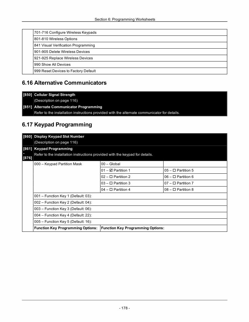
Section 6: Programming Worksheets
701-716 Configure Wireless Keypads
801-810 Wireless Options
841 Visual Verification Programming
901-905 Delete Wireless Devices
921-925 Replace Wireless Devices
990 Show All Devices
999 Reset Devices to Factory Default
6.16 Alternative Communicators
[850] Cellular Signal Strength(Description on page 116)
[851] Alternate Communicator ProgrammingRefer to the installation instructions provided with the alternate communicator for details.
6.17 Keypad Programming
[860] Display Keypad Slot Number(Description on page 116)
[861]-[876]
Keypad ProgrammingRefer to the installation instructions provided with the keypad for details.
000 – Keypad Partition Mask 00 – Global
01 – R Partition 1 05 – o Partition 5
02 – o Partition 2 06 – o Partition 6
03 – o Partition 3 07 – o Partition 7
04 – o Partition 4 08 – o Partition 8
001 – Function Key 1 (Default: 03):
002 – Function Key 2 (Default: 04):
003 – Function Key 3 (Default: 06):
004 – Function Key 4 (Default: 22):
005 – Function Key 5 (Default: 16):
Function Key Programming Options: Function Key Programming Options:
- 178 -
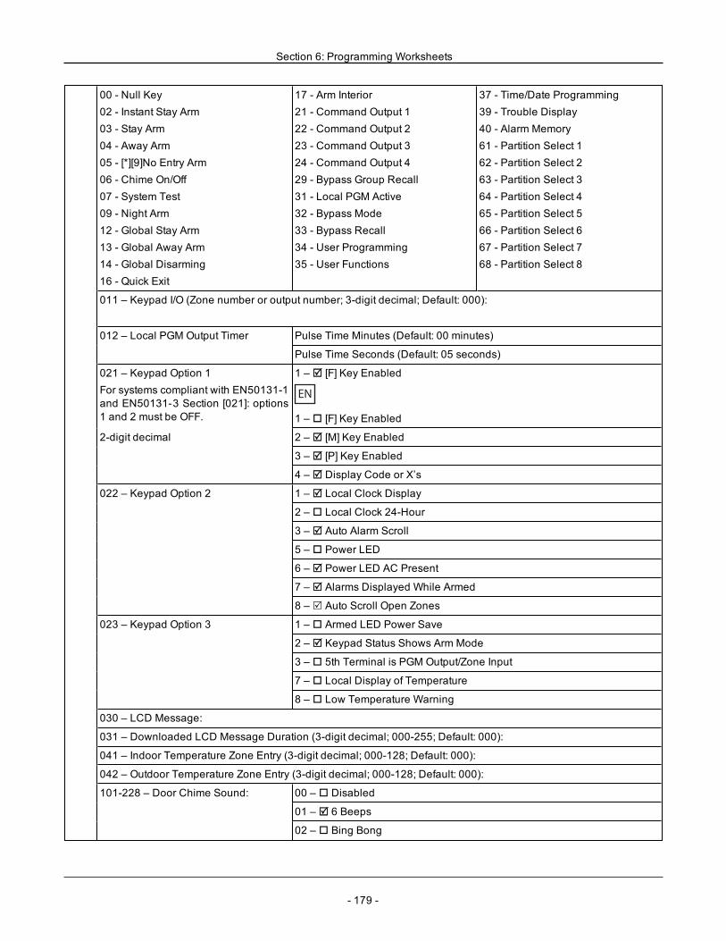
Section 6: Programming Worksheets
00 - Null Key02 - Instant Stay Arm03 - Stay Arm04 - Away Arm05 - [*][9]No Entry Arm06 - Chime On/Off07 - System Test09 - Night Arm12 - Global Stay Arm13 - Global Away Arm14 - Global Disarming16 - Quick Exit
17 - Arm Interior21 - Command Output 122 - Command Output 223 - Command Output 324 - Command Output 429 - Bypass Group Recall31 - Local PGM Active32 - Bypass Mode33 - Bypass Recall34 - User Programming35 - User Functions
37 - Time/Date Programming39 - Trouble Display40 - Alarm Memory61 - Partition Select 162 - Partition Select 263 - Partition Select 364 - Partition Select 465 - Partition Select 566 - Partition Select 667 - Partition Select 768 - Partition Select 8
011 – Keypad I/O (Zone number or output number; 3-digit decimal; Default: 000):
012 – Local PGM Output Timer Pulse Time Minutes (Default: 00 minutes)
Pulse Time Seconds (Default: 05 seconds)
021 – Keypad Option 1For systems compliant with EN50131-1and EN50131-3 Section [021]: options1 and 2 must be OFF.
1 – R [F] Key Enabled
EN
1 – o [F] Key Enabled
2-digit decimal 2 – R [M] Key Enabled
3 – R [P] Key Enabled
4 – R Display Code or X’s
022 – Keypad Option 2 1 – R Local Clock Display
2 – o Local Clock 24-Hour
3 – R Auto Alarm Scroll
5 – o Power LED
6 – R Power LED AC Present
7 – R Alarms Displayed While Armed
8 – R Auto Scroll Open Zones
023 – Keypad Option 3 1 – o Armed LED Power Save
2 – R Keypad Status Shows Arm Mode
3 – o 5th Terminal is PGM Output/Zone Input
7 – o Local Display of Temperature
8 – o Low Temperature Warning
030 – LCD Message:
031 – Downloaded LCD Message Duration (3-digit decimal; 000-255; Default: 000):
041 – Indoor Temperature Zone Entry (3-digit decimal; 000-128; Default: 000):
042 – Outdoor Temperature Zone Entry (3-digit decimal; 000-128; Default: 000):
101-228 – Door Chime Sound: 00 – o Disabled
01 – R 6 Beeps
02 – o Bing Bong
- 179 -
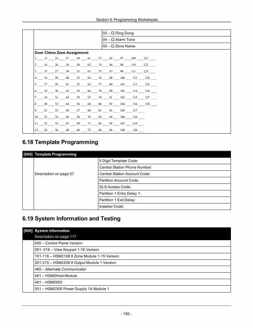
Section 6: Programming Worksheets
03 – o Ding Dong
04 – o Alarm Tone
05 – o Zone Name
Door Chime Zone Assignment:1 ____ 13 ____ 25 ____ 37 ____ 49 ____ 61 ____ 73 ____ 85 ____ 97 ____ 109 ____ 121 ____
2 ____ 14 ____ 26 ____ 38 ____ 50 ____ 62 ____ 74 ____ 86 ____ 98 ____ 110 ____ 122 ____
3 ____ 15 ____ 27 ____ 39 ____ 51 ____ 63 ____ 75 ____ 87 ____ 99 ____ 111 ____ 123 ____
4 ____ 16 ____ 28 ____ 40 ____ 52 ____ 64 ____ 76 ____ 88 ____ 100 ____ 112 ____ 124 ____
5 ____ 17 ____ 29 ____ 41 ____ 53 ____ 65 ____ 77 ____ 89 ____ 101 ____ 113 ____ 125 ____
6 ____ 18 ____ 30 ____ 42 ____ 54 ____ 66 ____ 78 ____ 90 ____ 102 ____ 114 ____ 126 ____
7 ____ 19 ____ 31 ____ 43 ____ 55 ____ 67 ____ 79 ____ 91 ____ 103 ____ 115 ____ 127 ____
8 ____ 20 ____ 32 ____ 44 ____ 56 ____ 68 ____ 80 ____ 92 ____ 104 ____ 116 ____ 128 ____
9 ____ 21 ____ 33 ____ 45 ____ 57 ____ 69 ____ 81 ____ 93 ____ 105 ____ 117 ____
10 ___ 22 ____ 34 ____ 46 ____ 58 ____ 70 ____ 82 ____ 94 ____ 106 ____ 118 ____
11 ___ 23 ____ 35 ____ 47 ____ 59 ____ 71 ____ 83 ____ 95 ____ 107 ____ 119 ____
12 ___ 24 ____ 36 ____ 48 ____ 60 ____ 72 ____ 84 ____ 96 ____ 108 ____ 120 ____
6.18 Template Programming
[899] Template Programming
5 Digit Template Code:
Central Station Phone Number:
Description on page 57 Central Station Account Code:
Partition Account Code:
DLS Access Code:
Partition 1 Entry Delay 1:
Partition 1 Exit Delay:
Installer Code:
6.19 System Information and Testing
[900] System InformationDescription on page 117
000 – Control Panel Version
001- 016 – View Keypad 1-16 Version
101-116 – HSM2108 8 Zone Module 1-15 Version
201-215 – HSM2208 8 Output Module 1 Version
460 – Alternate Communicator
461 – HSM2Host Module
481 – HSM2955
501 – HSM2300 Power Supply 1A Module 1
- 180 -
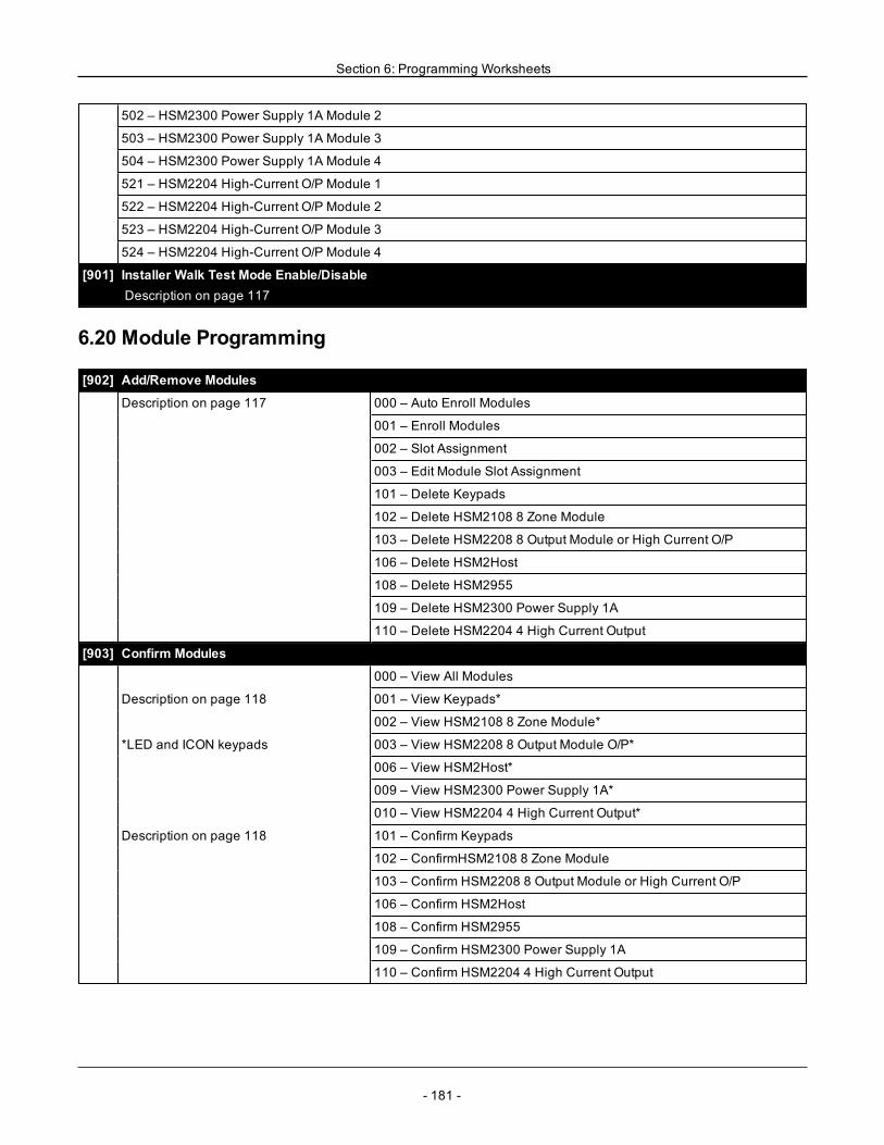
Section 6: Programming Worksheets
502 – HSM2300 Power Supply 1A Module 2
503 – HSM2300 Power Supply 1A Module 3
504 – HSM2300 Power Supply 1A Module 4
521 – HSM2204 High-Current O/P Module 1
522 – HSM2204 High-Current O/P Module 2
523 – HSM2204 High-Current O/P Module 3
524 – HSM2204 High-Current O/P Module 4
[901] Installer Walk Test Mode Enable/DisableDescription on page 117
6.20 Module Programming
[902] Add/Remove Modules
Description on page 117 000 – Auto Enroll Modules
001 – Enroll Modules
002 – Slot Assignment
003 – Edit Module Slot Assignment
101 – Delete Keypads
102 – Delete HSM2108 8 Zone Module
103 – Delete HSM2208 8 Output Module or High Current O/P
106 – Delete HSM2Host
108 – Delete HSM2955
109 – Delete HSM2300 Power Supply 1A
110 – Delete HSM2204 4 High Current Output
[903] Confirm Modules
000 – View All Modules
Description on page 118 001 – View Keypads*
002 – View HSM2108 8 Zone Module*
*LED and ICON keypads 003 – View HSM2208 8 Output Module O/P*
006 – View HSM2Host*
009 – View HSM2300 Power Supply 1A*
010 – View HSM2204 4 High Current Output*
Description on page 118 101 – Confirm Keypads
102 – ConfirmHSM2108 8 Zone Module
103 – Confirm HSM2208 8 Output Module or High Current O/P
106 – Confirm HSM2Host
108 – Confirm HSM2955
109 – Confirm HSM2300 Power Supply 1A
110 – Confirm HSM2204 4 High Current Output
- 181 -
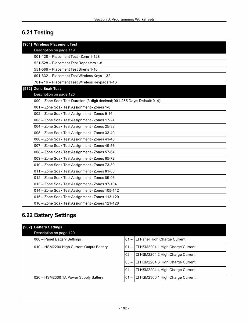
Section 6: Programming Worksheets
6.21 Testing
[904] Wireless Placement TestDescription on page 119
001-128 – Placement Test - Zone 1-128
521-528 – Placement Test Repeaters 1-8
551-566 – Placement Test Sirens 1-16
601-632 – Placement Test Wireless Keys 1-32
701-716 – Placement Test Wireless Keypads 1-16
[912] Zone Soak TestDescription on page 120
000 – Zone Soak Test Duration (3-digit decimal; 001-255 Days; Default: 014):
001 – Zone Soak Test Assignment - Zones 1-8
002 – Zone Soak Test Assignment - Zones 9-16
003 – Zone Soak Test Assignment - Zones 17-24
004 – Zone Soak Test Assignment - Zones 25-32
005 – Zone Soak Test Assignment - Zones 33-40
006 – Zone Soak Test Assignment - Zones 41-48
007 – Zone Soak Test Assignment - Zones 49-56
008 – Zone Soak Test Assignment - Zones 57-64
009 – Zone Soak Test Assignment - Zones 65-72
010 – Zone Soak Test Assignment - Zones 73-80
011 – Zone Soak Test Assignment - Zones 81-88
012 – Zone Soak Test Assignment - Zones 89-96
013 – Zone Soak Test Assignment - Zones 97-104
014 – Zone Soak Test Assignment - Zones 105-112
015 – Zone Soak Test Assignment - Zones 113-120
016 – Zone Soak Test Assignment - Zones 121-128
6.22 Battery Settings
[982] Battery SettingsDescription on page 120
000 – Panel Battery Settings 01 – o Panel High Charge Current
010 – HSM2204 High Current Output Battery 01 – o HSM2204 1 High Charge Current
02 – o HSM2204 2 High Charge Current
03 – o HSM2204 3 High Charge Current
04 – o HSM2204 4 High Charge Current
020 – HSM2300 1A Power Supply Battery 01 – o HSM2300 1 High Charge Current
- 182 -
Section 6: Programming Worksheets
02 – o HSM2300 2 High Charge Current
03 – o HSM2300 3 High Charge Current
04 – o HSM2300 4 High Charge Current
6.23 Restoring Factory Defaults
[989] Default Master Code
[990] Installer Lockout Enable/Disable
[991] Default Keypads999 – Default All Keypads
901-916 – Default Keypad 1-16
[993] Default Alt Comm
[996] Default HSM2HOSTWireless Receiver
[988] Default HSM2955
[999] Default System(Descriptions on page 121)
- 183 -
- 184 -
Section 7: Troubleshooting
7.1 Testing
l Power up systeml Program options as required (See "Programming Descriptions" on page 61).l Trip, then restore zonesl Verify correct reporting codes are sent to the central station
7.2 Troubleshooting
LCD programmable-message keypad:l Press [*][2] followed by access code if required to view a trouble conditionl The trouble light flashes and the LCD displays the first trouble conditionl Use the arrow keys to scroll through all trouble conditions present on the system
Note:When additional information is available for a specific trouble condition, a [*] is displayed. Press the [*] key to view theadditional information.
LED and ICON keypads:l Press [*][2] to view a trouble conditionl The trouble light flashesl Refer to the trouble summary list below to determine the trouble condition(s) present on the system
7.2.1 [*][2] Trouble SummaryThe list below describes the trouble indications displayed on keypads.
Trouble Detailed Trouble01 – Service Required 01 – Bell circuit
02 – RF jam detected03 – Aux supply trouble
04 – Time and date05 – Output 1 fault
02 – Module Low Battery 01 – Panel low battery02 – Panel no battery04 – HSM2204 1-4 low battery
05 – HSM2204 1-4 no battery07 – HSM2300 1-4 low battery08 – HSM2300 1-4 no battery
03 – Bus Voltage 01 – HSM2HOSTx voltage02 – Keypad 1-16 voltage04 – HSM2108 1-15 voltage05 – HSM2300 1-4 voltage
06 – HSM2204 1-4 voltage08 – HSM2208 1-4 voltage09 – HSM2955 1-4 voltage
04 – AC Troubles 01 – Zone 1-128 AC03 – Siren 1-16 AC04 – Repeater 1-8 AC
05 – HSM2300 1-4 AC06 – HSM2204 1-4 AC07 – Alarm Controller AC
05 – Device Faults 01 – Zone 001 - 12802 – Keypad 1-16
03 – Siren 1-1604 – Repeater 1-8
06 – Device Low Battery 01 – Zone 1-12802 – Keypad 1-1603 – Siren 1-16
04 – Repeater 1-805 – User 1-32
07 – Device Tampers 01 – Zone 1-12802 – Keypad 1-1603 – Siren 1-16
04 – Repeater 1-805 – Audio Station 01 - 04
Section 7: Troubleshooting
Trouble Detailed Trouble08 – RF Delinquency 01 – Zone 1-128
02 – Keypad 1-1603 – Siren 1-1604 – Repeater 1-8
09 – Module Supervisory 01 – HSM2HOSTx02 – Keypad 1-1604 – HSM2108 1-1505 – HSM2300 1-4
06 – HSM220408 – HSM2208 1-409 – HSM2955
10 – Module Tamper 01 – HSM2HOSTx02 – Keypad 1-1604 – HSM2108 1-1505 – HSM2300 1-4
06 – HSM220408 – HSM2208 1-409 – HSM2955
11 – Communications 01 – TLM02 – FTC Receiver 1-403 – Alt. comm SIM lock04 – Alt. comm cellular05 – Alt. comm Ethernet
06 – Receiver 1-4 absent07 – Receiver 1-4 supervision09 – Alt. comm fault10 – Alt. comm FTC trouble
12 – Not Networked 01 – Zone 1-12802 – Keypad 1-1603 – Siren 1-16
04 – Repeater 1-805 – User 1-32
Trouble [1] Service Required Press [01] to determine specific troubleTrouble Troubleshooting
[01] Bell CircuitBell+, Bell-...open circuit.
Disconnect Bell-/+ leads and measure resistance:Open circuit indicates break in wiring or defective siren/bell.Jumper Bell+/- with 1K resistor (Brown, Black, Red):
[02] RF Jam DetectedWireless receiver - excessive noise detected.
Check event buffer to determine specific trouble.If buffer logs RF jam, check for RF interference.Disable RF Jam: section [804] sub-section [801].
[03] Aux SupplyAn auxiliary power supply trouble is present.
Check for a short between Aux+ and Aux- or other system ground.Ensure the aux current draw has not exceeded the documented limits.
[04] Time and DateThe alarm controller internal clock is not set .
To program the time and date:Enter [*][6][Master Code] then press [01].Enter the time and date (24- hour clock) using the following format:HH:MM MM/DD/YYe.g.,. For 6:00 pm, June 29, 2010:Enter: [18] [00] [06] [29] [10]
[05] Output 1 FaultHSM2204 output#1 open circuit.
If output #1 is unused: ensure terminals O1, AUX are jumpered with 1Kresistor (brown, black, red).If output #1 is used: disconnect wire leads from O1, AUX terminals,measure resistance of leads:Open circuit indicates a break in wiring.
- 185 -
Section 7: Troubleshooting
Trouble [2] Module Battery Trouble Press [02] to determine specific troubleTrouble Troubleshooting
[01] Panel Low BatteryThe panel detects that the battery is below thelow battery threshold (less than 11.5VDC).NOTE: This trouble condition will not clear untilthe battery voltage is 12.5VDC min., under load.NOTE: If battery is new allow 1 hour to charge.
Verify voltage measured across AC terminals is 16-18 VAC. Replacetransformer if required.Disconnect battery wire leads:Verify battery charging voltage measured across battery leads = 13.70 -13.80 VDC.Connect battery, remove AC power.Verify measured voltage across Aux terminals is 12.5VDC min.
[02] Panel No BatteryThe panel detects that no battery is present orthat the battery is shorted.
Verify battery is connected.Refer to troubleshooting steps for panel low battery.
[04] 4 High Current output 1-4 Low Battery(HSM2204)HSM2204 battery less than 11.5VDC.NOTE: This trouble condition will not clear untilthe battery voltage is 12.5VDC min., under load.Charge battery. It may be low due to a longperiod without AC.
Replace battery if it is no longer able to hold a charge due to age.
[05] 4 High Current output 1-4 No Battery(HSM2204)Enter 05 to view which HSM2204 does not havea battery connected.
Verify battery is connected.Refer to troubleshooting steps for panel low battery.
[07] Power Supply 1-4 Low Battery (HSM2300)Enter 07 to view which HSM2300 has a batteryvoltage less than 11.5V.
Charge battery. It may be low due to a long period without AC.Replace battery if it is no longer able to hold a charge due to age.
[08] Power Supply 1-4 No Battery (HSM2300)Enter 08 to view which HSM2300 does not havea battery connected.
Verify battery is connected.Refer to troubleshooting steps for panel low battery.
- 186 -
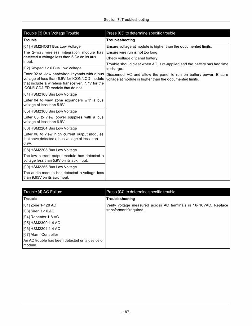
Section 7: Troubleshooting
Trouble [3] Bus Voltage Trouble Press [03] to determine specific troubleTrouble Troubleshooting
[01] HSM2HOST Bus Low VoltageThe 2- way wireless integration module hasdetected a voltage less than 6.3V on its auxinput.
Ensure voltage at module is higher than the documented limits.Ensure wire run is not too long.Check voltage of panel battery.Trouble should clear when AC is re-applied and the battery has had timeto charge.Disconnect AC and allow the panel to run on battery power. Ensurevoltage at module is higher than the documented limits.
[02] Keypad 1-16 Bus Low VoltageEnter 02 to view hardwired keypads with a busvoltage of less than 6.9V for ICON/LCD modelsthat include a wireless transceiver, 7.7V for theICON/LCD/LED models that do not.
[04] HSM2108 Bus Low VoltageEnter 04 to view zone expanders with a busvoltage of less than 5.9V.
[05] HSM2300 Bus Low VoltageEnter 05 to view power supplies with a busvoltage of less than 6.9V.
[06] HSM2204 Bus Low VoltageEnter 06 to view high current output modulesthat have detected a bus voltage of less than6.9V.
[08] HSM2208 Bus Low VoltageThe low current output module has detected avoltage less than 5.9V on its aux input.
[09] HSM2255 Bus Low VoltageThe audio module has detected a voltage lessthan 9.65V on its aux input.
Trouble [4] AC Failure Press [04] to determine specific troubleTrouble Troubleshooting
[01] Zone 1-128 AC[03] Siren 1-16 AC[04] Repeater 1-8 AC[05] HSM2300 1-4 AC[06] HSM2204 1-4 AC[07] Alarm ControllerAn AC trouble has been detected on a device ormodule.
Verify voltage measured across AC terminals is 16- 18VAC. Replacetransformer if required.
- 187 -
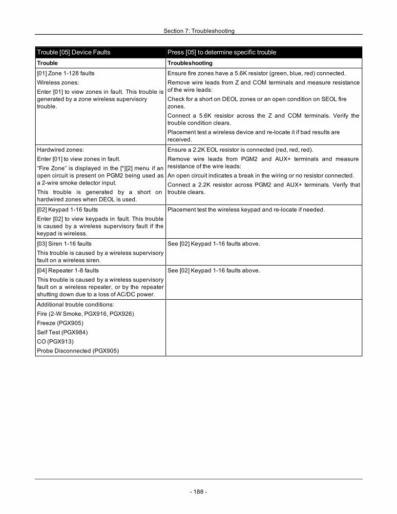
Section 7: Troubleshooting
Trouble [05] Device Faults Press [05] to determine specific troubleTrouble Troubleshooting
[01] Zone 1-128 faultsWireless zones:Enter [01] to view zones in fault. This trouble isgenerated by a zone wireless supervisorytrouble.
Ensure fire zones have a 5.6K resistor (green, blue, red) connected.Remove wire leads from Z and COM terminals and measure resistanceof the wire leads:Check for a short on DEOL zones or an open condition on SEOL firezones.Connect a 5.6K resistor across the Z and COM terminals. Verify thetrouble condition clears.Placement test a wireless device and re-locate it if bad results arereceived.
Hardwired zones:Enter [01] to view zones in fault.“Fire Zone” is displayed in the [*][2] menu if anopen circuit is present on PGM2 being used asa 2-wire smoke detector input.This trouble is generated by a short onhardwired zones when DEOL is used.
Ensure a 2.2K EOL resistor is connected (red, red, red).Remove wire leads from PGM2 and AUX+ terminals and measureresistance of the wire leads:An open circuit indicates a break in the wiring or no resistor connected.Connect a 2.2K resistor across PGM2 and AUX+ terminals. Verify thattrouble clears.
[02] Keypad 1-16 faultsEnter [02] to view keypads in fault. This troubleis caused by a wireless supervisory fault if thekeypad is wireless.
Placement test the wireless keypad and re-locate if needed.
[03] Siren 1-16 faultsThis trouble is caused by a wireless supervisoryfault on a wireless siren.
See [02] Keypad 1-16 faults above.
[04] Repeater 1-8 faultsThis trouble is caused by a wireless supervisoryfault on a wireless repeater, or by the repeatershutting down due to a loss of AC/DC power.
See [02] Keypad 1-16 faults above.
Additional trouble conditions:Fire (2-W Smoke, PGX916, PGX926)Freeze (PGX905)Self Test (PGX984)CO (PGX913)Probe Disconnected (PGX905)
- 188 -
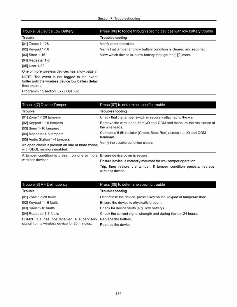
Section 7: Troubleshooting
Trouble [6] Device Low Battery Press [06] to toggle through specific devices with low battery troubleTrouble Troubleshooting
[01] Zones 1-128[02] Keypad 1-16[03] Siren 1-16[04] Repeater 1-8[05] User 1-32One or more wireless devices has a low battery.NOTE: The event is not logged to the eventbuffer until the wireless device low battery delaytime expires.Programming section [377], Opt 002.
Verify zone operation.Verify that tamper and low battery condition is cleared and reported.View which device is in low battery through the [*][2] menu.
Trouble [7] Device Tamper Press [07] to determine specific troubleTrouble Troubleshooting
[01] Zone 1-128 tampers[02] Keypad 1-16 tampers[03] Siren 1-16 tampers[04] Repeater 1-8 tampers[05] Audio Station 1-4 tampersAn open circuit is present on one or more zoneswith DEOL resistors enabled.
Check that the tamper switch is securely attached to the wall.Remove the wire leads from I/O and COM and measure the resistance ofthe wire leads.Connect a 5.6K resistor (Green, Blue, Red) across the I/O and COMterminals.Verify the trouble condition clears.
A tamper condition is present on one or morewireless devices.
Ensure device cover is secure.Ensure device is correctly mounted for wall tamper operation.Trip, then restore the tamper. If tamper condition persists, replacewireless device.
Trouble [8] RF Delinquency Press [08] to determine specific troubleTrouble Troubleshooting
[01] Zone 1-128 faults[02] Keypad 1-16 faults[03] Siren 1-16 faults[04] Repeater 1-8 faultsHSM2HOST has not received a supervisorysignal from a wireless device for 20 minutes.
Open/close the device, press a key on the keypad or tamper/restore.Ensure the device is physically present.Check for device faults (e.g., low battery).Check the current signal strength and during the last 24 hours.Replace the battery.Replace the device.
- 189 -
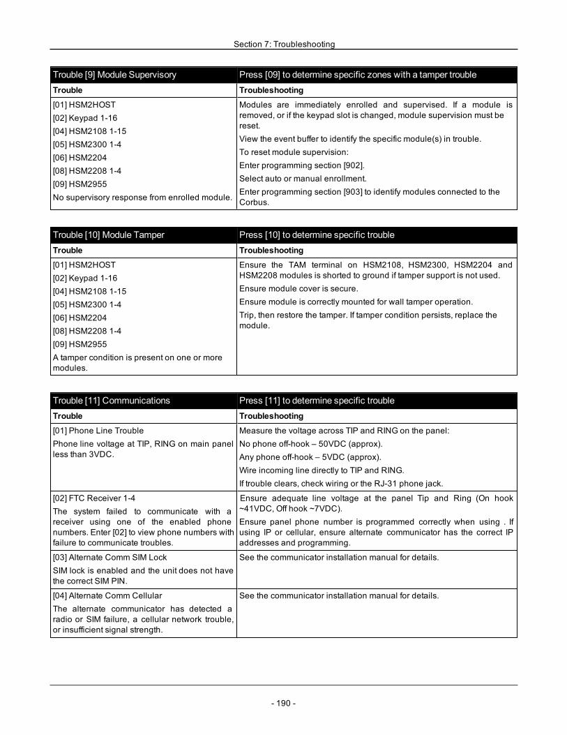
Section 7: Troubleshooting
Trouble [9] Module Supervisory Press [09] to determine specific zones with a tamper troubleTrouble Troubleshooting
[01] HSM2HOST[02] Keypad 1-16[04] HSM2108 1-15[05] HSM2300 1-4[06] HSM2204[08] HSM2208 1-4[09] HSM2955No supervisory response from enrolled module.
Modules are immediately enrolled and supervised. If a module isremoved, or if the keypad slot is changed, module supervision must bereset.View the event buffer to identify the specific module(s) in trouble.To reset module supervision:Enter programming section [902].Select auto or manual enrollment.Enter programming section [903] to identify modules connected to theCorbus.
Trouble [10] Module Tamper Press [10] to determine specific troubleTrouble Troubleshooting
[01] HSM2HOST[02] Keypad 1-16[04] HSM2108 1-15[05] HSM2300 1-4[06] HSM2204[08] HSM2208 1-4[09] HSM2955A tamper condition is present on one or moremodules.
Ensure the TAM terminal on HSM2108, HSM2300, HSM2204 andHSM2208 modules is shorted to ground if tamper support is not used.Ensure module cover is secure.Ensure module is correctly mounted for wall tamper operation.Trip, then restore the tamper. If tamper condition persists, replace themodule.
Trouble [11] Communications Press [11] to determine specific troubleTrouble Troubleshooting
[01] Phone Line TroublePhone line voltage at TIP, RING on main panelless than 3VDC.
Measure the voltage across TIP and RING on the panel:No phone off-hook – 50VDC (approx).Any phone off-hook – 5VDC (approx).Wire incoming line directly to TIP and RING.If trouble clears, check wiring or the RJ-31 phone jack.
[02] FTC Receiver 1-4The system failed to communicate with areceiver using one of the enabled phonenumbers. Enter [02] to view phone numbers withfailure to communicate troubles.
Ensure adequate line voltage at the panel Tip and Ring (On hook~41VDC, Off hook ~7VDC).Ensure panel phone number is programmed correctly when using . Ifusing IP or cellular, ensure alternate communicator has the correct IPaddresses and programming.
[03] Alternate Comm SIM LockSIM lock is enabled and the unit does not havethe correct SIM PIN.
See the communicator installation manual for details.
[04] Alternate Comm CellularThe alternate communicator has detected aradio or SIM failure, a cellular network trouble,or insufficient signal strength.
See the communicator installation manual for details.
- 190 -
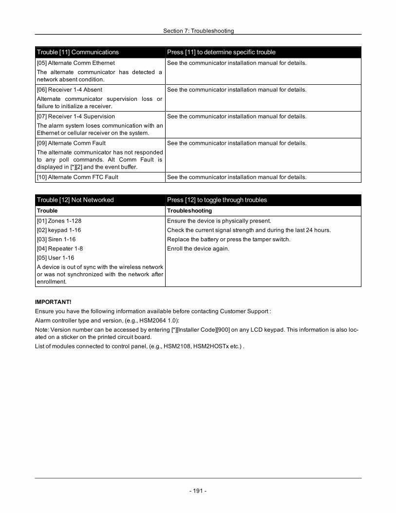
Section 7: Troubleshooting
Trouble [11] Communications Press [11] to determine specific trouble[05] Alternate Comm EthernetThe alternate communicator has detected anetwork absent condition.
See the communicator installation manual for details.
[06] Receiver 1-4 AbsentAlternate communicator supervision loss orfailure to initialize a receiver.
See the communicator installation manual for details.
[07] Receiver 1-4 SupervisionThe alarm system loses communication with anEthernet or cellular receiver on the system.
See the communicator installation manual for details.
[09] Alternate Comm FaultThe alternate communicator has not respondedto any poll commands. Alt Comm Fault isdisplayed in [*][2] and the event buffer.
See the communicator installation manual for details.
[10] Alternate Comm FTC Fault See the communicator installation manual for details.
Trouble [12] Not Networked Press [12] to toggle through troublesTrouble Troubleshooting
[01] Zones 1-128[02] keypad 1-16[03] Siren 1-16[04] Repeater 1-8[05] User 1-16A device is out of sync with the wireless networkor was not synchronized with the network afterenrollment.
Ensure the device is physically present.Check the current signal strength and during the last 24 hours.Replace the battery or press the tamper switch.Enroll the device again.
IMPORTANT!Ensure you have the following information available before contacting Customer Support :Alarm controller type and version, (e.g., HSM2064 1.0):Note: Version number can be accessed by entering [*][Installer Code][900] on any LCD keypad. This information is also loc-ated on a sticker on the printed circuit board.List of modules connected to control panel, (e.g., HSM2108, HSM2HOSTx etc.) .
- 191 -
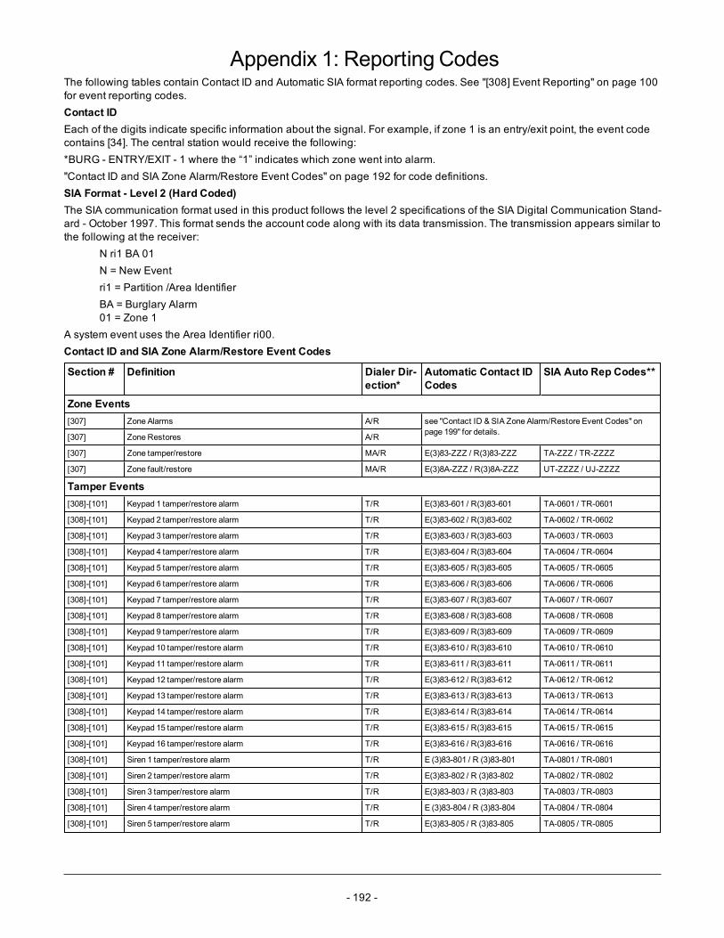
- 192 -
Appendix 1: Reporting CodesThe following tables contain Contact ID and Automatic SIA format reporting codes. See "[308] Event Reporting" on page 100for event reporting codes.Contact IDEach of the digits indicate specific information about the signal. For example, if zone 1 is an entry/exit point, the event codecontains [34]. The central station would receive the following:*BURG - ENTRY/EXIT - 1 where the “1” indicates which zone went into alarm."Contact ID and SIA Zone Alarm/Restore Event Codes" on page 192 for code definitions.SIA Format - Level 2 (Hard Coded)The SIA communication format used in this product follows the level 2 specifications of the SIA Digital Communication Stand-ard - October 1997. This format sends the account code along with its data transmission. The transmission appears similar tothe following at the receiver:
N ri1 BA 01N = New Eventri1 = Partition /Area IdentifierBA = Burglary Alarm01 = Zone 1
A system event uses the Area Identifier ri00.Contact ID and SIA Zone Alarm/Restore Event Codes
Section # Definition Dialer Dir-ection*
Automatic Contact IDCodes
SIA Auto Rep Codes**
Zone Events[307] Zone Alarms A/R see "Contact ID & SIA Zone Alarm/Restore Event Codes" on
page 199" for details.[307] Zone Restores A/R
[307] Zone tamper/restore MA/R E(3)83-ZZZ / R(3)83-ZZZ TA-ZZZ / TR-ZZZZ
[307] Zone fault/restore MA/R E(3)8A-ZZZ / R(3)8A-ZZZ UT-ZZZZ / UJ-ZZZZ
Tamper Events[308]-[101] Keypad 1 tamper/restore alarm T/R E(3)83-601 / R(3)83-601 TA-0601 / TR-0601
[308]-[101] Keypad 2 tamper/restore alarm T/R E(3)83-602 / R(3)83-602 TA-0602 / TR-0602
[308]-[101] Keypad 3 tamper/restore alarm T/R E(3)83-603 / R(3)83-603 TA-0603 / TR-0603
[308]-[101] Keypad 4 tamper/restore alarm T/R E(3)83-604 / R(3)83-604 TA-0604 / TR-0604
[308]-[101] Keypad 5 tamper/restore alarm T/R E(3)83-605 / R(3)83-605 TA-0605 / TR-0605
[308]-[101] Keypad 6 tamper/restore alarm T/R E(3)83-606 / R(3)83-606 TA-0606 / TR-0606
[308]-[101] Keypad 7 tamper/restore alarm T/R E(3)83-607 / R(3)83-607 TA-0607 / TR-0607
[308]-[101] Keypad 8 tamper/restore alarm T/R E(3)83-608 / R(3)83-608 TA-0608 / TR-0608
[308]-[101] Keypad 9 tamper/restore alarm T/R E(3)83-609 / R(3)83-609 TA-0609 / TR-0609
[308]-[101] Keypad 10 tamper/restore alarm T/R E(3)83-610 / R(3)83-610 TA-0610 / TR-0610
[308]-[101] Keypad 11 tamper/restore alarm T/R E(3)83-611 / R(3)83-611 TA-0611 / TR-0611
[308]-[101] Keypad 12 tamper/restore alarm T/R E(3)83-612 / R(3)83-612 TA-0612 / TR-0612
[308]-[101] Keypad 13 tamper/restore alarm T/R E(3)83-613 / R(3)83-613 TA-0613 / TR-0613
[308]-[101] Keypad 14 tamper/restore alarm T/R E(3)83-614 / R(3)83-614 TA-0614 / TR-0614
[308]-[101] Keypad 15 tamper/restore alarm T/R E(3)83-615 / R(3)83-615 TA-0615 / TR-0615
[308]-[101] Keypad 16 tamper/restore alarm T/R E(3)83-616 / R(3)83-616 TA-0616 / TR-0616
[308]-[101] Siren 1 tamper/restore alarm T/R E (3)83-801 / R (3)83-801 TA-0801 / TR-0801
[308]-[101] Siren 2 tamper/restore alarm T/R E(3)83-802 / R (3)83-802 TA-0802 / TR-0802
[308]-[101] Siren 3 tamper/restore alarm T/R E(3)83-803 / R (3)83-803 TA-0803 / TR-0803
[308]-[101] Siren 4 tamper/restore alarm T/R E (3)83-804 / R (3)83-804 TA-0804 / TR-0804
[308]-[101] Siren 5 tamper/restore alarm T/R E(3)83-805 / R (3)83-805 TA-0805 / TR-0805
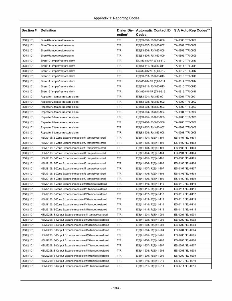
Appendix 1: Reporting Codes
Section # Definition Dialer Dir-ection*
Automatic Contact IDCodes
SIA Auto Rep Codes**
[308]-[101] Siren 6 tamper/restore alarm T/R E(3)83-806 / R (3)83-806 TA-0806 / TR-0806
[308]-[101] Siren 7 tamper/restore alarm T/R E(3)83-807 / R (3)83-807 TA-0807 / TR-0807
[308]-[101] Siren 8 tamper/restore alarm T/R E(3)83-808 / R (3)83-808 TA-0808 / TR-0808
[308]-[101] Siren 9 tamper/restore alarm T/R E(3)83-809 / R (3)83-809 TA-0809 / TR-0809
[308]-[101] Siren 10 tamper/restore alarm T/R E (3)83-810 / R (3)83-810 TA-0810 / TR-0810
[308]-[101] Siren 11 tamper/restore alarm T/R E(3)83-811 / R (3)83-811 TA-0811 / TR-0811
[308]-[101] Siren 12 tamper/restore alarm T/R E (3)83-812 / R (3)83-812 TA-0812 / TR-0812
[308]-[101] Siren 13 tamper/restore alarm T/R E(3)83-813 / R (3)83-813 TA-0813 / TR-0813
[308]-[101] Siren 14 tamper/restore alarm T/R E (3)83-814 / R (3)83-814 TA-0814 / TR-0814
[308]-[101] Siren 15 tamper/restore alarm T/R E(3)83-815 / R (3)83-815 TA-0815 / TR-0815
[308]-[101] Siren 16 tamper/restore alarm T/R E (3)83-816 / R (3)83-816 TA-0816 / TR-0816
[308]-[101] Repeater 1 tamper/restore alarm T/R E(3)83-901 / R (3)83-901 TA-0901 / TR-0901
[308]-[101] Repeater 2 tamper/restore alarm T/R E(3)83-902 / R (3)83-902 TA-0902 / TR-0902
[308]-[101] Repeater 3 tamper/restore alarm T/R E(3)83-903 / R (3)83-903 TA-0903 / TR-0903
[308]-[101] Repeater 4 tamper/restore alarm T/R E(3)83-904 / R (3)83-904 TA-0904 / TR-0904
[308]-[101] Repeater 5 tamper/restore alarm T/R E(3)83-905 / R (3)83-905 TA-0905 / TR-0905
[308]-[101] Repeater 6 tamper/restore alarm T/R E(3)83-906 / R (3)83-906 TA-0906 / TR-0906
[308]-[101] Repeater 7 tamper/restore alarm T/R E(3)83-907 / R (3)83-907 TA-0907 / TR-0907
[308]-[101] Repeater 8 tamper/restore alarm T/R E(3)83-908 / R (3)83-908 TA-0908 / TR-0908
[308]-[101] HSM2108: 8-Zone Expander module #1 tamper/restored T/R E(3)41-101 / R(3)41-101 ES-0101 / EJ-0101
[308]-[101] HSM2108: 8-Zone Expander module #2 tamper/restored T/R E(3)41-102 / R(3)41-102 ES-0102 / EJ-0102
[308]-[101] HSM2108: 8-Zone Expander module #3 tamper/restored T/R E(3)41-103 / R(3)41-103 ES-0103 / EJ-0103
[308]-[101] HSM2108: 8-Zone Expander module #4 tamper/restored T/R E(3)41-104 / R(3)41-104 ES-0104 / EJ-0104
[308]-[101] HSM2108: 8-Zone Expander module #5 tamper/restored T/R E(3)41-105 / R(3)41-105 ES-0105 / EJ-0105
[308]-[101] HSM2108: 8-Zone Expander module #6 tamper/restored T/R E(3)41-106 / R(3)41-106 ES-0106 / EJ-0106
[308]-[101] HSM2108: 8-Zone Expander module #7 tamper/restored T/R E(3)41-107 / R(3)41-107 ES-0107 / EJ-0107
[308]-[101] HSM2108: 8-Zone Expander module #8 tamper/restored T/R E(3)41-108 / R(3)41-108 ES-0108 / EJ-0108
[308]-[101] HSM2108: 8-Zone Expander module #9 tamper/restored T/R E(3)41-109 / R(3)41-109 ES-0109 / EJ-0109
[308]-[101] HSM2108: 8-Zone Expander module #10 tamper/restored T/R E(3)41-110 / R(3)41-110 ES-0110 / EJ-0110
[308]-[101] HSM2108: 8-Zone Expander module #11 tamper/restored T/R E(3)41-111 / R(3)41-111 ES-0111 / EJ-0111
[308]-[101] HSM2108: 8-Zone Expander module #12 tamper/restored T/R E(3)41-112 / R(3)41-112 ES-0112 / EJ-0112
[308]-[101] HSM2108: 8-Zone Expander module #13 tamper/restored T/R E(3)41-113 / R(3)41-113 ES-0113 / EJ-0113
[308]-[101] HSM2108: 8-Zone Expander module #14 tamper/restored T/R E(3)41-114 / R(3)41-114 ES-0114 / EJ-0114
[308]-[101] HSM2108: 8-Zone Expander module #15 tamper/restored T/R E(3)41-115 / R(3)41-115 ES-0115 / EJ-0115
[308]-[101] HSM2208: 8-Output Expander module #1 tamper/restored T/R E(3)41-201 / R(3)41-201 ES-0201 / EJ-0201
[308]-[101] HSM2208: 8-Output Expander module #12 tamper/restored T/R E(3)41-202 / R(3)41-202 ES-0202 / EJ-0202
[308]-[101] HSM2208: 8-Output Expander module #13 tamper/restored T/R E(3)41-203 / R(3)41-203 ES-0203 / EJ-0203
[308]-[101] HSM2208: 8-Output Expander module #14 tamper/restored T/R E(3)41-204 / R(3)41-204 ES-0204 / EJ-0204
[308]-[101] HSM2208: 8-Output Expander module #15 tamper/restored T/R E(3)41-205 / R(3)41-205 ES-0205 / EJ-0205
[308]-[101] HSM2208: 8-Output Expander module #15 tamper/restored T/R E(3)41-206 / R(3)41-206 ES-0206 / EJ-0206
[308]-[101] HSM2208: 8-Output Expander module #17 tamper/restored T/R E(3)41-207 / R(3)41-207 ES-0207 / EJ-0207
[308]-[101] HSM2208: 8-Output Expander module #18 tamper/restored T/R E(3)41-208 / R(3)41-208 ES-0208 / EJ-0208
[308]-[101] HSM2208: 8-Output Expander module #19 tamper/restored T/R E(3)41-209 / R(3)41-209 ES-0209 / EJ-0209
[308]-[101] HSM2208: 8-Output Expander module #10 tamper/restored T/R E(3)41-210 / R(3)41-210 ES-0210 / EJ-0210
[308]-[101] HSM2208: 8-Output Expander module #11 tamper/restored T/R E(3)41-211 / R(3)41-211 ES-0211 / EJ-0211
- 193 -
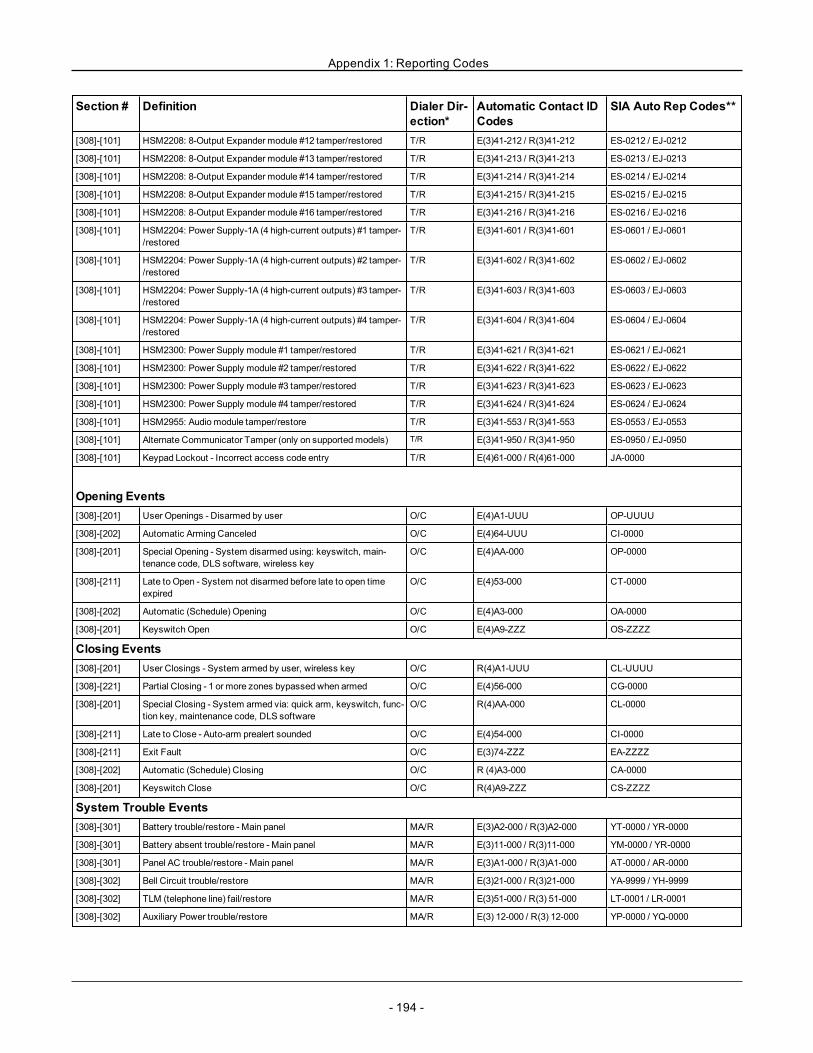
Appendix 1: Reporting Codes
Section # Definition Dialer Dir-ection*
Automatic Contact IDCodes
SIA Auto Rep Codes**
[308]-[101] HSM2208: 8-Output Expander module #12 tamper/restored T/R E(3)41-212 / R(3)41-212 ES-0212 / EJ-0212
[308]-[101] HSM2208: 8-Output Expander module #13 tamper/restored T/R E(3)41-213 / R(3)41-213 ES-0213 / EJ-0213
[308]-[101] HSM2208: 8-Output Expander module #14 tamper/restored T/R E(3)41-214 / R(3)41-214 ES-0214 / EJ-0214
[308]-[101] HSM2208: 8-Output Expander module #15 tamper/restored T/R E(3)41-215 / R(3)41-215 ES-0215 / EJ-0215
[308]-[101] HSM2208: 8-Output Expander module #16 tamper/restored T/R E(3)41-216 / R(3)41-216 ES-0216 / EJ-0216
[308]-[101] HSM2204: Power Supply-1A (4 high-current outputs) #1 tamper-/restored
T/R E(3)41-601 / R(3)41-601 ES-0601 / EJ-0601
[308]-[101] HSM2204: Power Supply-1A (4 high-current outputs) #2 tamper-/restored
T/R E(3)41-602 / R(3)41-602 ES-0602 / EJ-0602
[308]-[101] HSM2204: Power Supply-1A (4 high-current outputs) #3 tamper-/restored
T/R E(3)41-603 / R(3)41-603 ES-0603 / EJ-0603
[308]-[101] HSM2204: Power Supply-1A (4 high-current outputs) #4 tamper-/restored
T/R E(3)41-604 / R(3)41-604 ES-0604 / EJ-0604
[308]-[101] HSM2300: Power Supply module #1 tamper/restored T/R E(3)41-621 / R(3)41-621 ES-0621 / EJ-0621
[308]-[101] HSM2300: Power Supply module #2 tamper/restored T/R E(3)41-622 / R(3)41-622 ES-0622 / EJ-0622
[308]-[101] HSM2300: Power Supply module #3 tamper/restored T/R E(3)41-623 / R(3)41-623 ES-0623 / EJ-0623
[308]-[101] HSM2300: Power Supply module #4 tamper/restored T/R E(3)41-624 / R(3)41-624 ES-0624 / EJ-0624
[308]-[101] HSM2955: Audiomodule tamper/restore T/R E(3)41-553 / R(3)41-553 ES-0553 / EJ-0553
[308]-[101] Alternate Communicator Tamper (only on supportedmodels) T/R E(3)41-950 / R(3)41-950 ES-0950 / EJ-0950
[308]-[101] Keypad Lockout - Incorrect access code entry T/R E(4)61-000 / R(4)61-000 JA-0000
Opening Events[308]-[201] User Openings - Disarmed by user O/C E(4)A1-UUU OP-UUUU
[308]-[202] Automatic Arming Canceled O/C E(4)64-UUU CI-0000
[308]-[201] Special Opening - System disarmed using: keyswitch, main-tenance code, DLS software, wireless key
O/C E(4)AA-000 OP-0000
[308]-[211] Late to Open - System not disarmed before late to open timeexpired
O/C E(4)53-000 CT-0000
[308]-[202] Automatic (Schedule) Opening O/C E(4)A3-000 OA-0000
[308]-[201] Keyswitch Open O/C E(4)A9-ZZZ OS-ZZZZ
Closing Events[308]-[201] User Closings - System armed by user, wireless key O/C R(4)A1-UUU CL-UUUU
[308]-[221] Partial Closing - 1 or more zones bypassed when armed O/C E(4)56-000 CG-0000
[308]-[201] Special Closing - System armed via: quick arm, keyswitch, func-tion key, maintenance code, DLS software
O/C R(4)AA-000 CL-0000
[308]-[211] Late to Close - Auto-arm prealert sounded O/C E(4)54-000 CI-0000
[308]-[211] Exit Fault O/C E(3)74-ZZZ EA-ZZZZ
[308]-[202] Automatic (Schedule) Closing O/C R (4)A3-000 CA-0000
[308]-[201] Keyswitch Close O/C R(4)A9-ZZZ CS-ZZZZ
System Trouble Events[308]-[301] Battery trouble/restore - Main panel MA/R E(3)A2-000 / R(3)A2-000 YT-0000 / YR-0000
[308]-[301] Battery absent trouble/restore - Main panel MA/R E(3)11-000 / R(3)11-000 YM-0000 / YR-0000
[308]-[301] Panel AC trouble/restore - Main panel MA/R E(3)A1-000 / R(3)A1-000 AT-0000 / AR-0000
[308]-[302] Bell Circuit trouble/restore MA/R E(3)21-000 / R(3)21-000 YA-9999 / YH-9999
[308]-[302] TLM (telephone line) fail/restore MA/R E(3)51-000 / R(3) 51-000 LT-0001 / LR-0001
[308]-[302] Auxiliary Power trouble/restore MA/R E(3) 12-000 / R(3) 12-000 YP-0000 / YQ-0000
- 194 -
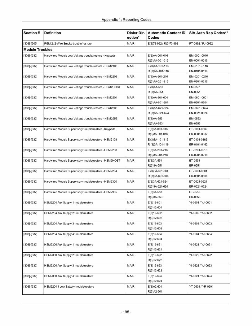
Appendix 1: Reporting Codes
Section # Definition Dialer Dir-ection*
Automatic Contact IDCodes
SIA Auto Rep Codes**
[308]-[305] PGM 2, 2-Wire Smoke trouble/restore MA/R E(3)73-992 / R(3)73-992 FT-0992 / FJ-0992
Module Troubles[308]-[332] HardwiredModule Low Voltage trouble/restore - Keypads MA/R E(3)AA-001-016
R(3)AA-001-016
EM-0001-0016
EN-0001-0016
[308]-[332] HardwiredModule Low Voltage trouble/restore - HSM2108 MA/R E (3)AA-101-116
R (3)AA-101-116
EM-0101-0116
EN-0101-0116
[308]-[332] HardwiredModule Low Voltage trouble/restore - HSM2208 MA/R E(3)AA-201-216
R(3)AA-201-216
EM-0201-0216
EN-0201-0216
[308]-[332] HardwiredModule Low Voltage trouble/restore - HSM2HOST MA/R E (3)AA-551
R (3)AA-551
EM-0551
EN-0551
[308]-[332] HardwiredModule Low Voltage trouble/restore - HSM2204 MA/R E(3)AA-601-604
R(3)AA-601-604
EM-0601-0601
EN-0601-0604
[308]-[332] HardwiredModule Low Voltage trouble/restore - HSM2300 MA/R E (3)AA-621-624
R (3)AA-621-624
EM-0621-0624
EN-0621-0624
[308]-[332] HardwiredModule Low Voltage trouble/restore - HSM2955 MA/R E(3)AA-553
R(3)AA-553
EM-0553
EN-0553
[308]-[332] HardwiredModule Supervisory trouble/restore - Keypads MA/R E(3)3A-001-016
R(3)3A-001-016
ET-0001-0032
ER-0001-0032
[308]-[332] HardwiredModule Supervisory trouble/restore - HSM2108 MA/R E (3)3A-101-116
R (3)3A-101-116
ET-0101-0162
ER-0101-0162
[308]-[332] HardwiredModule Supervisory trouble/restore - HSM2208 MA/R E(3)3A-201-216
R(3)3A-201-216
ET-0201-0216
ER-0201-0216
[308]-[332] HardwiredModule Supervisory trouble/restore - HSM2HOST MA/R E(3)3A-551
R(3)3A-551
ET-0551
ER-0551
[308]-[332] HardwiredModule Supervisory trouble/restore - HSM2204 MA/R E (3)3A-601-604
R (3)3A-601-604
ET-0601-0601
ER-0601-0604
[308]-[332] HardwiredModule Supervisory trouble/restore - HSM2300 MA/R E(3)3A-621-624
R(3)3A-621-624
ET-0621-0624
ER-0621-0624
[308]-[332] HardwiredModule Supervisory trouble/restore - HSM2955 MA/R E(3)3A-553
R(3)3A-553
ET-0553
ER-0553
[308]-[332] HSM2204 Aux Supply 1 trouble/restore MA/R E(3)12-601
R(3)12-601
YI-0601 / YJ-0601
[308]-[332] HSM2204 Aux Supply 2 trouble/restore MA/R E(3)12-602
R(3)12-602
YI-0602 / YJ-0602
[308]-[332] HSM2204 Aux Supply 3 trouble/restore MA/R E(3)12-603
R(3)12-603
YI-0603 / YJ-0603
[308]-[332] HSM2204 Aux Supply 4 trouble/restore MA/R E(3)12-604
R(3)12-604
YI-0604 / YJ-0604
[308]-[332] HSM2300 Aux Supply 1 trouble/restore MA/R E(3)12-621
R(3)12-621
YI-0621 / YJ-0621
[308]-[332] HSM2300 Aux Supply 2 trouble/restore MA/R E(3)12-622
R(3)12-622
YI-0622 / YJ-0622
[308]-[332] HSM2300 Aux Supply 3 trouble/restore MA/R E(3)12-623
R(3)12-623
YI-0623 / YJ-0623
[308]-[332] HSM2300 Aux Supply 4 trouble/restore MA/R E(3)12-624
R(3)12-624
YI-0624 / YJ-0624
[308]-[332] HSM2204 1 Low Battery trouble/restore MA/R E(3)A2-601
R(3)A2-601
YT-0601 / YR-0601
- 195 -
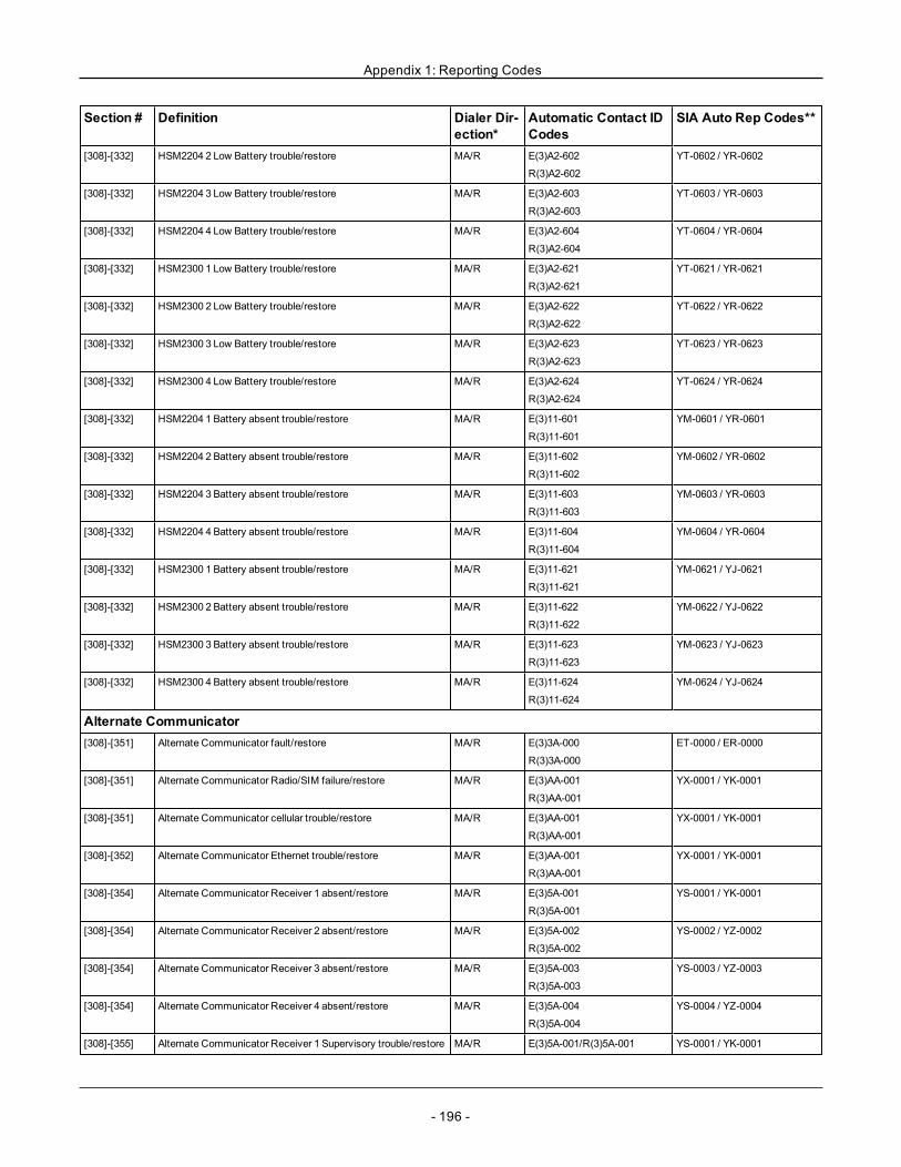
Appendix 1: Reporting Codes
Section # Definition Dialer Dir-ection*
Automatic Contact IDCodes
SIA Auto Rep Codes**
[308]-[332] HSM2204 2 Low Battery trouble/restore MA/R E(3)A2-602
R(3)A2-602
YT-0602 / YR-0602
[308]-[332] HSM2204 3 Low Battery trouble/restore MA/R E(3)A2-603
R(3)A2-603
YT-0603 / YR-0603
[308]-[332] HSM2204 4 Low Battery trouble/restore MA/R E(3)A2-604
R(3)A2-604
YT-0604 / YR-0604
[308]-[332] HSM2300 1 Low Battery trouble/restore MA/R E(3)A2-621
R(3)A2-621
YT-0621 / YR-0621
[308]-[332] HSM2300 2 Low Battery trouble/restore MA/R E(3)A2-622
R(3)A2-622
YT-0622 / YR-0622
[308]-[332] HSM2300 3 Low Battery trouble/restore MA/R E(3)A2-623
R(3)A2-623
YT-0623 / YR-0623
[308]-[332] HSM2300 4 Low Battery trouble/restore MA/R E(3)A2-624
R(3)A2-624
YT-0624 / YR-0624
[308]-[332] HSM2204 1 Battery absent trouble/restore MA/R E(3)11-601
R(3)11-601
YM-0601 / YR-0601
[308]-[332] HSM2204 2 Battery absent trouble/restore MA/R E(3)11-602
R(3)11-602
YM-0602 / YR-0602
[308]-[332] HSM2204 3 Battery absent trouble/restore MA/R E(3)11-603
R(3)11-603
YM-0603 / YR-0603
[308]-[332] HSM2204 4 Battery absent trouble/restore MA/R E(3)11-604
R(3)11-604
YM-0604 / YR-0604
[308]-[332] HSM2300 1 Battery absent trouble/restore MA/R E(3)11-621
R(3)11-621
YM-0621 / YJ-0621
[308]-[332] HSM2300 2 Battery absent trouble/restore MA/R E(3)11-622
R(3)11-622
YM-0622 / YJ-0622
[308]-[332] HSM2300 3 Battery absent trouble/restore MA/R E(3)11-623
R(3)11-623
YM-0623 / YJ-0623
[308]-[332] HSM2300 4 Battery absent trouble/restore MA/R E(3)11-624
R(3)11-624
YM-0624 / YJ-0624
Alternate Communicator[308]-[351] Alternate Communicator fault/restore MA/R E(3)3A-000
R(3)3A-000
ET-0000 / ER-0000
[308]-[351] Alternate Communicator Radio/SIM failure/restore MA/R E(3)AA-001
R(3)AA-001
YX-0001 / YK-0001
[308]-[351] Alternate Communicator cellular trouble/restore MA/R E(3)AA-001
R(3)AA-001
YX-0001 / YK-0001
[308]-[352] Alternate Communicator Ethernet trouble/restore MA/R E(3)AA-001
R(3)AA-001
YX-0001 / YK-0001
[308]-[354] Alternate Communicator Receiver 1 absent/restore MA/R E(3)5A-001
R(3)5A-001
YS-0001 / YK-0001
[308]-[354] Alternate Communicator Receiver 2 absent/restore MA/R E(3)5A-002
R(3)5A-002
YS-0002 / YZ-0002
[308]-[354] Alternate Communicator Receiver 3 absent/restore MA/R E(3)5A-003
R(3)5A-003
YS-0003 / YZ-0003
[308]-[354] Alternate Communicator Receiver 4 absent/restore MA/R E(3)5A-004
R(3)5A-004
YS-0004 / YZ-0004
[308]-[355] Alternate Communicator Receiver 1 Supervisory trouble/restore MA/R E(3)5A-001/R(3)5A-001 YS-0001 / YK-0001
- 196 -
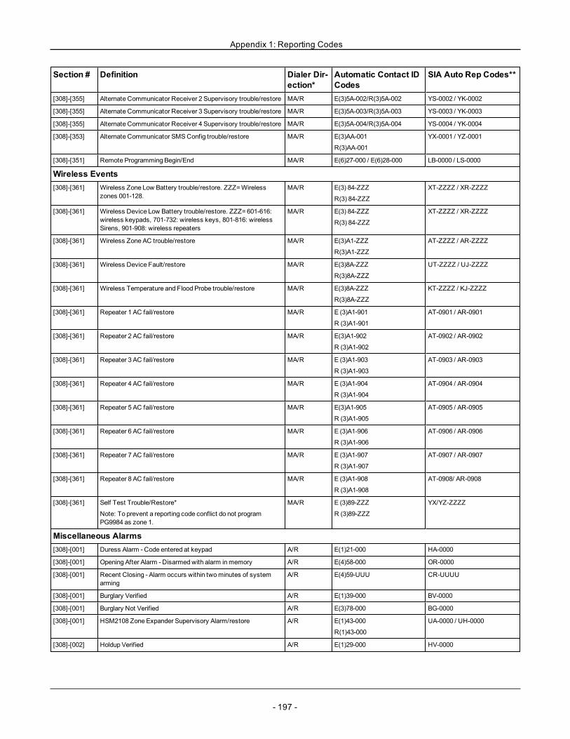
Appendix 1: Reporting Codes
Section # Definition Dialer Dir-ection*
Automatic Contact IDCodes
SIA Auto Rep Codes**
[308]-[355] Alternate Communicator Receiver 2 Supervisory trouble/restore MA/R E(3)5A-002/R(3)5A-002 YS-0002 / YK-0002
[308]-[355] Alternate Communicator Receiver 3 Supervisory trouble/restore MA/R E(3)5A-003/R(3)5A-003 YS-0003 / YK-0003
[308]-[355] Alternate Communicator Receiver 4 Supervisory trouble/restore MA/R E(3)5A-004/R(3)5A-004 YS-0004 / YK-0004
[308]-[353] Alternate Communicator SMSConfig trouble/restore MA/R E(3)AA-001
R(3)AA-001
YX-0001 / YZ-0001
[308]-[351] Remote Programming Begin/End MA/R E(6)27-000 / E(6)28-000 LB-0000 / LS-0000
Wireless Events[308]-[361] Wireless Zone Low Battery trouble/restore. ZZZ=Wireless
zones 001-128.MA/R E(3) 84-ZZZ
R(3) 84-ZZZ
XT-ZZZZ / XR-ZZZZ
[308]-[361] Wireless Device Low Battery trouble/restore. ZZZ=601-616:wireless keypads, 701-732: wireless keys, 801-816: wirelessSirens, 901-908: wireless repeaters
MA/R E(3) 84-ZZZ
R(3) 84-ZZZ
XT-ZZZZ / XR-ZZZZ
[308]-[361] Wireless Zone AC trouble/restore MA/R E(3)A1-ZZZ
R(3)A1-ZZZ
AT-ZZZZ / AR-ZZZZ
[308]-[361] Wireless Device Fault/restore MA/R E(3)8A-ZZZ
R(3)8A-ZZZ
UT-ZZZZ / UJ-ZZZZ
[308]-[361] Wireless Temperature and Flood Probe trouble/restore MA/R E(3)8A-ZZZ
R(3)8A-ZZZ
KT-ZZZZ / KJ-ZZZZ
[308]-[361] Repeater 1 AC fail/restore MA/R E (3)A1-901
R (3)A1-901
AT-0901 / AR-0901
[308]-[361] Repeater 2 AC fail/restore MA/R E(3)A1-902
R (3)A1-902
AT-0902 / AR-0902
[308]-[361] Repeater 3 AC fail/restore MA/R E (3)A1-903
R (3)A1-903
AT-0903 / AR-0903
[308]-[361] Repeater 4 AC fail/restore MA/R E (3)A1-904
R (3)A1-904
AT-0904 / AR-0904
[308]-[361] Repeater 5 AC fail/restore MA/R E(3)A1-905
R (3)A1-905
AT-0905 / AR-0905
[308]-[361] Repeater 6 AC fail/restore MA/R E (3)A1-906
R (3)A1-906
AT-0906 / AR-0906
[308]-[361] Repeater 7 AC fail/restore MA/R E (3)A1-907
R (3)A1-907
AT-0907 / AR-0907
[308]-[361] Repeater 8 AC fail/restore MA/R E (3)A1-908
R (3)A1-908
AT-0908/ AR-0908
[308]-[361] Self Test Trouble/Restore*
Note: To prevent a reporting code conflict do not programPG9984 as zone 1.
MA/R E (3)89-ZZZ
R (3)89-ZZZ
YX/YZ-ZZZZ
Miscellaneous Alarms[308]-[001] Duress Alarm - Code entered at keypad A/R E(1)21-000 HA-0000
[308]-[001] Opening After Alarm - Disarmed with alarm inmemory A/R E(4)58-000 OR-0000
[308]-[001] Recent Closing - Alarm occurs within twominutes of systemarming
A/R E(4)59-UUU CR-UUUU
[308]-[001] Burglary Verified A/R E(1)39-000 BV-0000
[308]-[001] Burglary Not Verified A/R E(3)78-000 BG-0000
[308]-[001] HSM2108 Zone Expander Supervisory Alarm/restore A/R E(1)43-000
R(1)43-000
UA-0000 / UH-0000
[308]-[002] Holdup Verified A/R E(1)29-000 HV-0000
- 197 -
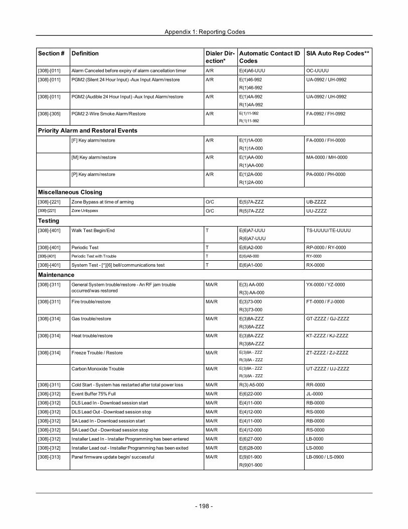
Appendix 1: Reporting Codes
Section # Definition Dialer Dir-ection*
Automatic Contact IDCodes
SIA Auto Rep Codes**
[308]-[011] Alarm Canceled before expiry of alarm cancellation timer A/R E(4)A6-UUU OC-UUUU
[308]-[011] PGM2 (Silent 24 Hour Input) -Aux Input Alarm/restore A/R E(1)46-992
R(1)46-992
UA-0992 / UH-0992
[308]-[011] PGM2 (Audible 24 Hour Input) -Aux Input Alarm/restore A/R E(1)4A-992
R(1)4A-992
UA-0992 / UH-0992
[308]-[305] PGM2 2-Wire Smoke Alarm/Restore A/R E(1)11-992
R(1)11-992
FA-0992 / FH-0992
Priority Alarm and Restoral Events[F] Key alarm/restore A/R E(1)1A-000
R(1)1A-000
FA-0000 / FH-0000
[M] Key alarm/restore A/R E(1)AA-000
R(1)AA-000
MA-0000 / MH-0000
[P] Key alarm/restore A/R E(1)2A-000
R(1)2A-000
PA-0000 / PH-0000
Miscellaneous Closing[308]-[221] Zone Bypass at time of arming O/C E(5)7A-ZZZ UB-ZZZZ
[308]-[221] Zone Unbypass O/C R(5)7A-ZZZ UU-ZZZZ
Testing[308]-[401] Walk Test Begin/End T E(6)A7-UUU
R(6)A7-UUU
TS-UUUU/TE-UUUU
[308]-[401] Periodic Test T E(6)A2-000 RP-0000 / RY-0000
[308]-[401] Periodic Test with Trouble T E(6)A8-000 RY-0000
[308]-[401] System Test - [*][6] bell/communications test T E(6)A1-000 RX-0000
Maintenance[308]-[311] General System trouble/restore - An RF jam trouble
occurred/was restoredMA/R E(3) AA-000
R(3) AA-000
YX-0000 / YZ-0000
[308]-[311] Fire trouble/restore MA/R E(3)73-000
R(3)73-000
FT-0000 / FJ-0000
[308]-[314] Gas trouble/restore MA/R E(3)8A-ZZZ
R(3)8A-ZZZ
GT-ZZZZ / GJ-ZZZZ
[308]-[314] Heat trouble/restore MA/R E(3)8A-ZZZ
R(3)8A-ZZZ
KT-ZZZZ / KJ-ZZZZ
[308]-[314] Freeze Trouble / Restore MA/R E(3)8A - ZZZ
R(3)8A - ZZZ
ZT-ZZZZ / ZJ-ZZZZ
CarbonMonoxide Trouble MA/R E(3)8A - ZZZ
R(3)8A - ZZZ
UT-ZZZZ / UJ-ZZZZ
[308]-[311] Cold Start - System has restarted after total power loss MA/R R(3) A5-000 RR-0000
[308]-[312] Event Buffer 75%Full MA/R E(6)22-000 JL-0000
[308]-[312] DLS Lead In - Download session start MA/R E(4)11-000 RB-0000
[308]-[312] DLS LeadOut - Download session stop MA/R E(4)12-000 RS-0000
[308]-[312] SA Lead In - Download session start MA/R E(4)11-000 RB-0000
[308]-[312] SA LeadOut - Download session stop MA/R E(4)12-000 RS-0000
[308]-[312] Installer Lead In - Installer Programming has been entered MA/R E(6)27-000 LB-0000
[308]-[312] Installer Lead out - Installer Programming has been exited MA/R E(6)28-000 LS-0000
[308]-[313] Panel firmware update begin/ successful MA/R E(9)01-900
R(9)01-900
LB-0900 / LS-0900
- 198 -
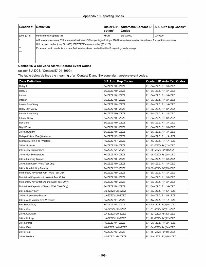
Appendix 1: Reporting Codes
Section # Definition Dialer Dir-ection*
Automatic Contact IDCodes
SIA Auto Rep Codes**
[308]-[313] Panel firmware update fail MA/R E(9)02-900 LU-0900
*
**
***
A/R =alarms/restores; T/R = tampers/restorers; O/C =openings/closings; MA/R =maintenance alarms/restores; T = test transmissions
UUU =user number (user 001-095); ZZZ/ZZZZ = zone number (001-128).
Zones and panic pendants are identified, wireless keys can be identified for openings and closings.
Contact ID & SIA Zone Alarm/Restore Event Codes(as per SIA DCS: ‘Contact ID’ 01-1999):The table below defines the meaning of all Contact ID and SIA zone alarm/restore event codes.
Zone Definition SIA Auto Rep Codes Contact ID Auto Rep CodesDelay 1 BA-ZZZZ / BH-ZZZZ E(1) 3A - ZZZ / R(1)3A- ZZZ
Delay 2 BA-ZZZZ / BH-ZZZZ E(1) 3A - ZZZ / R(1)3A- ZZZ
Instant BA-ZZZZ / BH-ZZZZ E(1) 3A - ZZZ / R(1)3A- ZZZ
Interior BA-ZZZZ / BH-ZZZZ E(1) 3A - ZZZ / R(1)3A- ZZZ
Interior Stay/Away BA-ZZZZ / BH-ZZZZ E(1) 3A - ZZZ / R(1)3A- ZZZ
Delay Stay/Away BA-ZZZZ / BH-ZZZZ E(1) 3A - ZZZ / R(1)3A- ZZZ
Instant Stay/Away BA-ZZZZ / BH-ZZZZ E(1) 3A - ZZZ / R(1)3A- ZZZ
Interior Delay BA-ZZZZ / BH-ZZZZ E(1) 3A - ZZZ / R(1)3A- ZZZ
Day Zone BA-ZZZZ / BH-ZZZZ E(1) 3A - ZZZ / R(1)3A- ZZZ
Night Zone BA-ZZZZ / BH-ZZZZ E(1) 3A - ZZZ / R(1)3A- ZZZ
24-Hr. Burglary BA-ZZZZ / BH-ZZZZ E(1) 3A - ZZZ / R(1)3A- ZZZ
Delayed 24-Hr. Fire (Wireless) FA-ZZZZ / FH-ZZZZ E(1) 1A - ZZZ / R(1)1A - ZZZ
Standard 24-Hr. Fire (Wireless) FA-ZZZZ / FH-ZZZZ E(1) 1A - ZZZ / R(1)1A - ZZZ
24-Hr. Sprinkler SA-ZZZZ / SH-ZZZZ E(1) 13 - ZZZ / R(1)13 - ZZZ
24-Hr.Low Temperature ZA-ZZZZ / ZH-ZZZZ E(1) 59 - ZZZ / R(1)59-ZZZ
24-Hr High Temperature KA-ZZZZ / KH-ZZZZ E(1) 58 - ZZZ / R(1)58 - ZZZ
24-Hr. Latching Tamper BA-ZZZZ / BH-ZZZZ E(1) 3A - ZZZ / R(1)3A- ZZZ
24-Hr. Non Alarm (Walk Test Only) BA-ZZZZ / BH-ZZZZ E(1) 3A - ZZZ / R(1)3A- ZZZ
24-Hr. Non-latching Tamper TA-ZZZZ / TR-ZZZZ E(3) 83 - ZZZ / R(3)83 - ZZZ
Momentary Keyswitch Arm (Walk Test Only) BA-ZZZZ / BH-ZZZZ E(1) 3A - ZZZ / R(1)3A- ZZZ
Maintained Keyswitch Arm (Walk Test Only) BA-ZZZZ / BH-ZZZZ E(1) 3A - ZZZ / R(1)3A- ZZZ
Momentary Keyswitch Disarm (Walk Test Only) BA-ZZZZ / BH-ZZZZ E(1) 3A - ZZZ / R(1)3A- ZZZ
Maintained Keyswitch Disarm (Walk Test Only) BA-ZZZZ / BH-ZZZZ E(1) 3A - ZZZ / R(1)3A- ZZZ
24-Hr. Supervisory US-ZZZZ / UR-ZZZZ E(1) 5A - ZZZ / R(1)5A - ZZZ
24-Hr. Supervisory Buzzer UA-ZZZZ / UH-ZZZZ E(1) 5A - ZZZ / R(1)5A - ZZZ
24-Hr. Auto Verified Fire (Wireless) FA-ZZZZ / FH-ZZZZ E(1) 1A - ZZZ / R(1)1A - ZZZ
Fire Supervisory FS-ZZZZ / FV-ZZZZ E(2) AA - ZZZ / R(2)AA - ZZZ
24-Hr. Gas GA-ZZZZ / GH-ZZZZ E(1) 51 - ZZZ / R(1)51 - ZZZ
24-Hr. COAlarm GA-ZZZZ / GH-ZZZZ E(1) 62 - ZZZ / R(1)62 - ZZZ
24-Hr. Holdup HA-ZZZZ / HH-ZZZZ E(1) 22 - ZZZ / R(1)22 - ZZZ
24-Hr. Panic PA-ZZZZ / PH-ZZZZ E(1) 2A - ZZZ / R(1)2A - ZZZ
24-Hr. Flood WA-ZZZZ / WH-ZZZZ E(1) 54 - ZZZ / R(1)54 - ZZZ
24-Hr Heat KA-ZZZZ / KH-ZZZZ E(1) 58 - ZZZ / R(1)58 - ZZZ
24-Hr. Medical MA-ZZZZ / MH-ZZZZ E(1) AA - ZZZ / R(1)AA - ZZZ
- 199 -

Appendix 1: Reporting Codes
Zone Definition SIA Auto Rep Codes Contact ID Auto Rep Codes24-Hr. Emergency QA-ZZZZ / QH-ZZZZ E(1) A1 - ZZZ / R(1)A1 - ZZZ
Doorbell Zone/Restore (Walk Test Only) BH-ZZZZ / BH-ZZZZ E(1) 3A - ZZZ / R(1)3A - ZZZ
Push to Set (Walk Test Only) BA-ZZZZ / BH-ZZZZ E(1) 3A - ZZZ / R(1)3A - ZZZ
Final Door Set BA-ZZZZ / BH-ZZZZ E(1) 3A - ZZZ / R(1)3A - ZZZ
ZZZ/ZZZZ = zones 001-128
- 200 -

- 201 -
Appendix 2: Word Library
Item # Text Item # Text Item # Text Item # Text Item # Text Item # Text
001 Aborted 042 Control 083 Garage 124 Motion 165 Shop 206 E
002 AC 043 Date 084 Gas 125 No 166 Side 207 F
003 Access 044 Daughter’s 085 Glass 126 North 167 Siren 208 G
004 Active 045 Degrees 086 Goodbye 127 Not 168 Sliding 209 H
005 Activity 046 Delay 087 Gym 128 Now 169 Smoke 210 I
006 Alarm 047 Den 088 Hallway 129 Number 170 Son’s 211 J
007 All 048 Desk 089 Heat 130 Off 171 Sound 212 K
008 AM 049 Detector 090 Hello 131 Office 172 South 213 L
009 Area 050 Dining 091 Help 132 OK 173 Special 214 M
010 Arm 051 Disarmed 092 High 133 On 174 Stairs 215 N
011 Armed 052 Door 093 Home 134 Open 175 Stay 216 O
012 Arming 053 Down 094 House 135 Opening 176 Sun 217 P
013 Attic 054 Download 095 In 136 Panic 177 Supervisory 218 Q
014 Auxiliary 055 Downstairs 096 Install 137 Partition 178 System 219 R
015 Away 056 Drawer 097 Interior 138 Patio 179 Tamper 220 S
016 Baby 057 Driveway 098 Intrusion 139 Pet 180 Temperature 221 T
017 Back 058 Duct 099 Invalid 140 Phone 181 Test 222 U
018 Bar 059 Duress 100 Is 141 Please 182 Time 223 V
019 Basement 060 East 101 Key 142 PM 183 To 224 W
020 Bathroom 061 EnergySaver
102 Kids 143 Police 184 Touchpad 225 X
021 Battery 062 Enter 103 Kitchen 144 Pool 185 Trouble 226 Y
022 Bedroom 063 Entry 104 Latchkey 145 Porch 186 Unbypass 227 Z
023 Bonus 064 Error 105 Laundry 146 Power 187 Unit 228 (Space)
024 Bottom 065 Exercise 106 Left 147 Press 188 Up 229 ’(Apostrophe)
025 Breezeway 066 Exit 107 Level 148 Program 189 West 230 - (Dash)
026 Building 067 Exterior 108 Library 149 Progress 190 Window 231 _ (Under-score)
027 Bus 068 Factory 109 Light 150 Quiet 191 Zone 232 *
028 Bypass 069 Failure 110 Lights 151 Rear 192 0 233 #
029 Bypassed 070 Family 111 Living 152 Receiver 193 1 234 :
030 Enclosure 071 Father’s 112 Load 153 Report 194 2 235 /
031 Cancelled 072 Feature 113 Loading 154 RF 195 3 236 ?
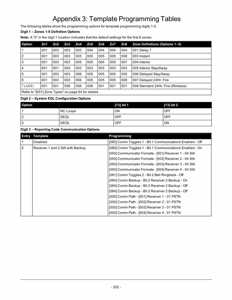
- 202 -
Appendix 3: Template Programming TablesThe following tables show the programming options for template programming digits 1-5.Digit 1 – Zones 1-8 Definition OptionsNote: A “0” in the digit 1 location indicates that the default settings for the first 8 zones
Option Zn1 Zn2 Zn3 Zn4 Zn5 Zn6 Zn7 Zn8 Zone Definitions (Options 1- 6)
1 001 003 003 003 004 004 004 004 001 Delay 1
2 001 003 003 005 005 005 005 008 003 Instant
3 001 003 003 005 005 005 005 007 004 Interior
4 001 001 003 003 003 003 003 003 005 Interior Stay/Away
5 001 003 003 006 005 005 005 005 006 Delayed Stay/Away
6 001 003 003 006 005 005 005 008 007 Delayed 24Hr. Fire
7 (ADT) 001 001 006 006 006 001 001 001 008 Standard 24Hr. Fire (Wireless)
Refer to "[001] Zone Types" on page 64 for details.
Digit 2 – System EOL Configuration Options
Option [13] bit 1 [13] bit 2
1 NC Loops ON OFF
2 SEOL OFF OFF
3 DEOL OFF ON
Digit 3 – Reporting Code Communication Options
Entry Template Programming
1 Disabled [380] Comm Toggles 1 - Bit 1 Communications Enabled - Off
2 Receiver 1 and 2 SIA with Backup [380] Comm Toggles 1 - Bit 1 Communications Enabled - On[350] Communicator Formats - [001] Receiver 1 - 04 SIA[350] Communicator Formats - [002] Receiver 2 - 04 SIA[350] Communicator Formats - [003] Receiver 3 - 04 SIA[350] Communicator Formats - [004] Receiver 4 - 04 SIA[381] Comm Toggles 2 - Bit 2 Bell Ringback - Off[384] Comm Backup - Bit 2 Receiver 2 Backup - On[384] Comm Backup - Bit 2 Receiver 2 Backup - Off[384] Comm Backup - Bit 2 Receiver 2 Backup - Off[300] Comm Path - [001] Receiver 1 - 01 PSTN[300] Comm Path - [002] Receiver 2 - 01 PSTN[300] Comm Path - [003] Receiver 3 - 01 PSTN[300] Comm Path - [004] Receiver 4 - 01 PSTN
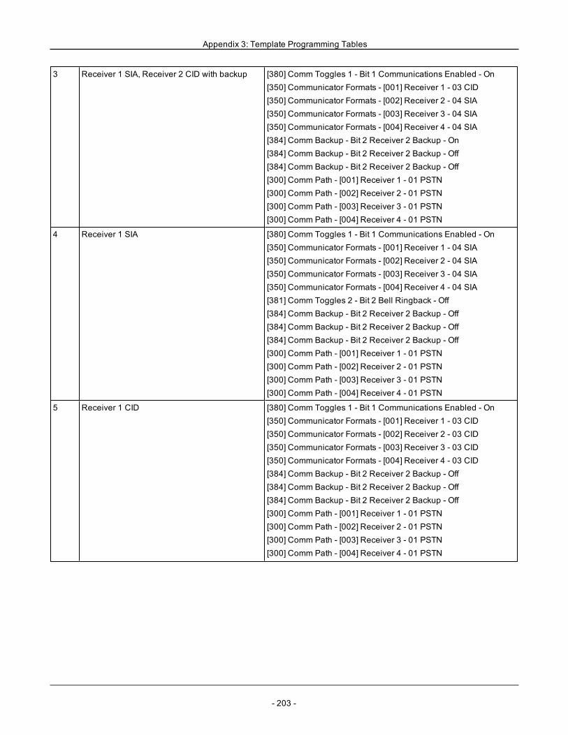
Appendix 3: Template Programming Tables
3 Receiver 1 SIA, Receiver 2 CID with backup [380] Comm Toggles 1 - Bit 1 Communications Enabled - On[350] Communicator Formats - [001] Receiver 1 - 03 CID[350] Communicator Formats - [002] Receiver 2 - 04 SIA[350] Communicator Formats - [003] Receiver 3 - 04 SIA[350] Communicator Formats - [004] Receiver 4 - 04 SIA[384] Comm Backup - Bit 2 Receiver 2 Backup - On[384] Comm Backup - Bit 2 Receiver 2 Backup - Off[384] Comm Backup - Bit 2 Receiver 2 Backup - Off[300] Comm Path - [001] Receiver 1 - 01 PSTN[300] Comm Path - [002] Receiver 2 - 01 PSTN[300] Comm Path - [003] Receiver 3 - 01 PSTN[300] Comm Path - [004] Receiver 4 - 01 PSTN
4 Receiver 1 SIA [380] Comm Toggles 1 - Bit 1 Communications Enabled - On[350] Communicator Formats - [001] Receiver 1 - 04 SIA[350] Communicator Formats - [002] Receiver 2 - 04 SIA[350] Communicator Formats - [003] Receiver 3 - 04 SIA[350] Communicator Formats - [004] Receiver 4 - 04 SIA[381] Comm Toggles 2 - Bit 2 Bell Ringback - Off[384] Comm Backup - Bit 2 Receiver 2 Backup - Off[384] Comm Backup - Bit 2 Receiver 2 Backup - Off[384] Comm Backup - Bit 2 Receiver 2 Backup - Off[300] Comm Path - [001] Receiver 1 - 01 PSTN[300] Comm Path - [002] Receiver 2 - 01 PSTN[300] Comm Path - [003] Receiver 3 - 01 PSTN[300] Comm Path - [004] Receiver 4 - 01 PSTN
5 Receiver 1 CID [380] Comm Toggles 1 - Bit 1 Communications Enabled - On[350] Communicator Formats - [001] Receiver 1 - 03 CID[350] Communicator Formats - [002] Receiver 2 - 03 CID[350] Communicator Formats - [003] Receiver 3 - 03 CID[350] Communicator Formats - [004] Receiver 4 - 03 CID[384] Comm Backup - Bit 2 Receiver 2 Backup - Off[384] Comm Backup - Bit 2 Receiver 2 Backup - Off[384] Comm Backup - Bit 2 Receiver 2 Backup - Off[300] Comm Path - [001] Receiver 1 - 01 PSTN[300] Comm Path - [002] Receiver 2 - 01 PSTN[300] Comm Path - [003] Receiver 3 - 01 PSTN[300] Comm Path - [004] Receiver 4 - 01 PSTN
- 203 -
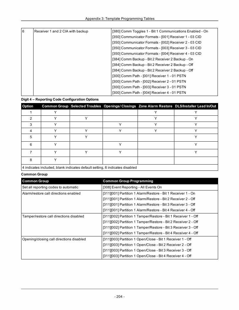
Appendix 3: Template Programming Tables
6 Receiver 1 and 2 CIA with backup [380] Comm Toggles 1 - Bit 1 Communications Enabled - On[350] Communicator Formats - [001] Receiver 1 - 03 CID[350] Communicator Formats - [002] Receiver 2 - 03 CID[350] Communicator Formats - [003] Receiver 3 - 03 CID[350] Communicator Formats - [004] Receiver 4 - 03 CID[384] Comm Backup - Bit 2 Receiver 2 Backup - On[384] Comm Backup - Bit 2 Receiver 2 Backup - Off[384] Comm Backup - Bit 2 Receiver 2 Backup - Off[300] Comm Path - [001] Receiver 1 - 01 PSTN[300] Comm Path - [002] Receiver 2 - 01 PSTN[300] Comm Path - [003] Receiver 3 - 01 PSTN[300] Comm Path - [004] Receiver 4 - 01 PSTN
Digit 4 – Reporting Code Configuration Options
Option Common Group Selected Troubles Openings/ Closings Zone Alarm Restore DLS/Installer Lead In/Out
1 Y Y Y
2 Y Y Y Y
3 Y Y Y Y
4 Y Y Y Y Y
5 Y Y Y
6 Y Y Y
7 Y Y Y Y
8 Y
4 indicates included, blank indicates default setting, 6 indicates disabled
Common Group
Common Group Common Group Programming
Set all reporting codes to automatic [308] Event Reporting - All Events On
Alarm/restore call directions enabled [311][001] Partition 1 Alarm/Restore - Bit 1 Receiver 1 - On[311][001] Partition 1 Alarm/Restore - Bit 2 Receiver 2 - Off[311][001] Partition 1 Alarm/Restore - Bit 3 Receiver 3 - Off[311][001] Partition 1 Alarm/Restore - Bit 4 Receiver 4 - Off
Tamper/restore call directions disabled [311][002] Partition 1 Tamper/Restore - Bit 1 Receiver 1 - Off[311][002] Partition 1 Tamper/Restore - Bit 2 Receiver 2 - Off[311][002] Partition 1 Tamper/Restore - Bit 3 Receiver 3 - Off[311][002] Partition 1 Tamper/Restore - Bit 4 Receiver 4 - Off
Opening/closing call directions disabled [311][003] Partition 1 Open/Close - Bit 1 Receiver 1 - Off[311][003] Partition 1 Open/Close - Bit 2 Receiver 2 - Off[311][003] Partition 1 Open/Close - Bit 3 Receiver 3 - Off[311][003] Partition 1 Open/Close - Bit 4 Receiver 4 - Off
- 204 -
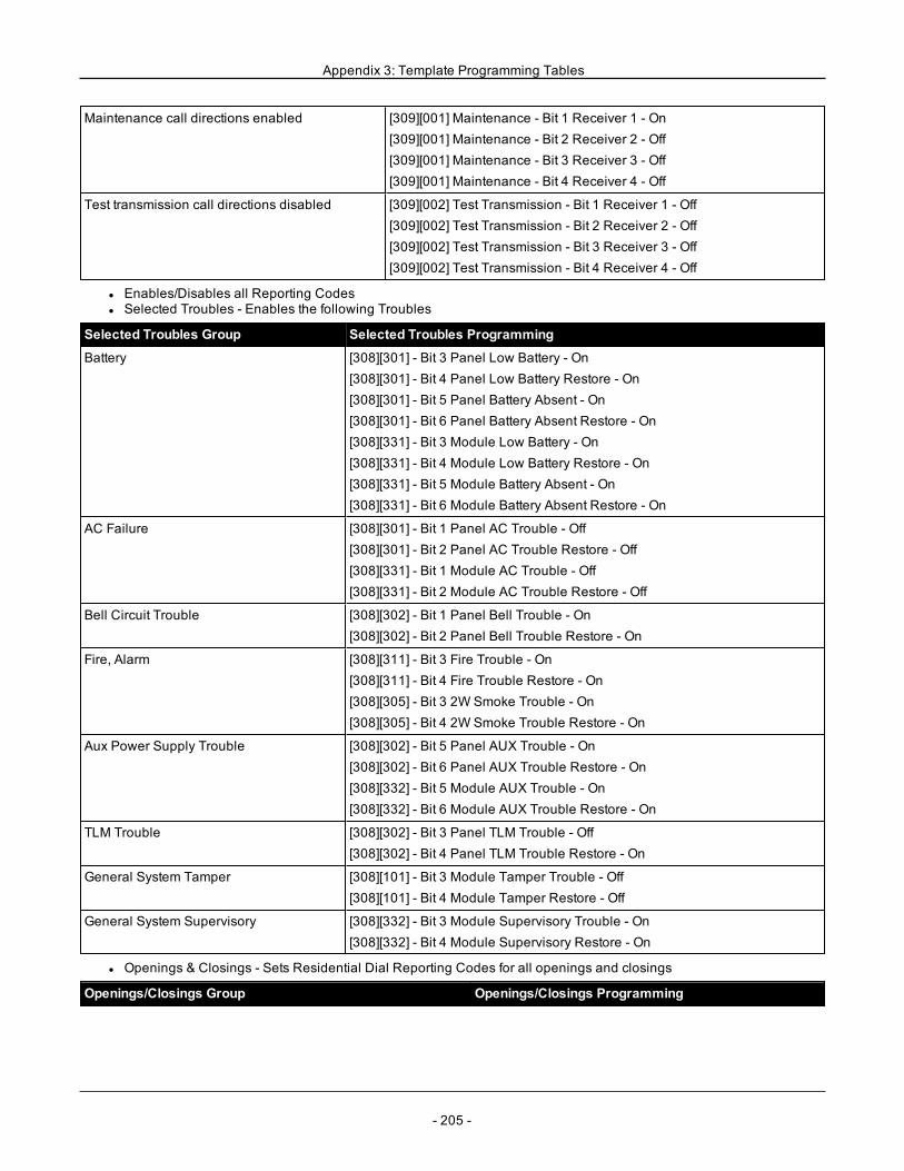
Appendix 3: Template Programming Tables
Maintenance call directions enabled [309][001] Maintenance - Bit 1 Receiver 1 - On[309][001] Maintenance - Bit 2 Receiver 2 - Off[309][001] Maintenance - Bit 3 Receiver 3 - Off[309][001] Maintenance - Bit 4 Receiver 4 - Off
Test transmission call directions disabled [309][002] Test Transmission - Bit 1 Receiver 1 - Off[309][002] Test Transmission - Bit 2 Receiver 2 - Off[309][002] Test Transmission - Bit 3 Receiver 3 - Off[309][002] Test Transmission - Bit 4 Receiver 4 - Off
l Enables/Disables all Reporting Codesl Selected Troubles - Enables the following Troubles
Selected Troubles Group Selected Troubles Programming
Battery [308][301] - Bit 3 Panel Low Battery - On[308][301] - Bit 4 Panel Low Battery Restore - On[308][301] - Bit 5 Panel Battery Absent - On[308][301] - Bit 6 Panel Battery Absent Restore - On[308][331] - Bit 3 Module Low Battery - On[308][331] - Bit 4 Module Low Battery Restore - On[308][331] - Bit 5 Module Battery Absent - On[308][331] - Bit 6 Module Battery Absent Restore - On
AC Failure [308][301] - Bit 1 Panel AC Trouble - Off[308][301] - Bit 2 Panel AC Trouble Restore - Off[308][331] - Bit 1 Module AC Trouble - Off[308][331] - Bit 2 Module AC Trouble Restore - Off
Bell Circuit Trouble [308][302] - Bit 1 Panel Bell Trouble - On[308][302] - Bit 2 Panel Bell Trouble Restore - On
Fire, Alarm [308][311] - Bit 3 Fire Trouble - On[308][311] - Bit 4 Fire Trouble Restore - On[308][305] - Bit 3 2W Smoke Trouble - On[308][305] - Bit 4 2W Smoke Trouble Restore - On
Aux Power Supply Trouble [308][302] - Bit 5 Panel AUX Trouble - On[308][302] - Bit 6 Panel AUX Trouble Restore - On[308][332] - Bit 5 Module AUX Trouble - On[308][332] - Bit 6 Module AUX Trouble Restore - On
TLM Trouble [308][302] - Bit 3 Panel TLM Trouble - Off[308][302] - Bit 4 Panel TLM Trouble Restore - On
General System Tamper [308][101] - Bit 3 Module Tamper Trouble - Off[308][101] - Bit 4 Module Tamper Restore - Off
General System Supervisory [308][332] - Bit 3 Module Supervisory Trouble - On[308][332] - Bit 4 Module Supervisory Restore - On
l Openings & Closings - Sets Residential Dial Reporting Codes for all openings and closings
Openings/Closings Group Openings/Closings Programming
- 205 -
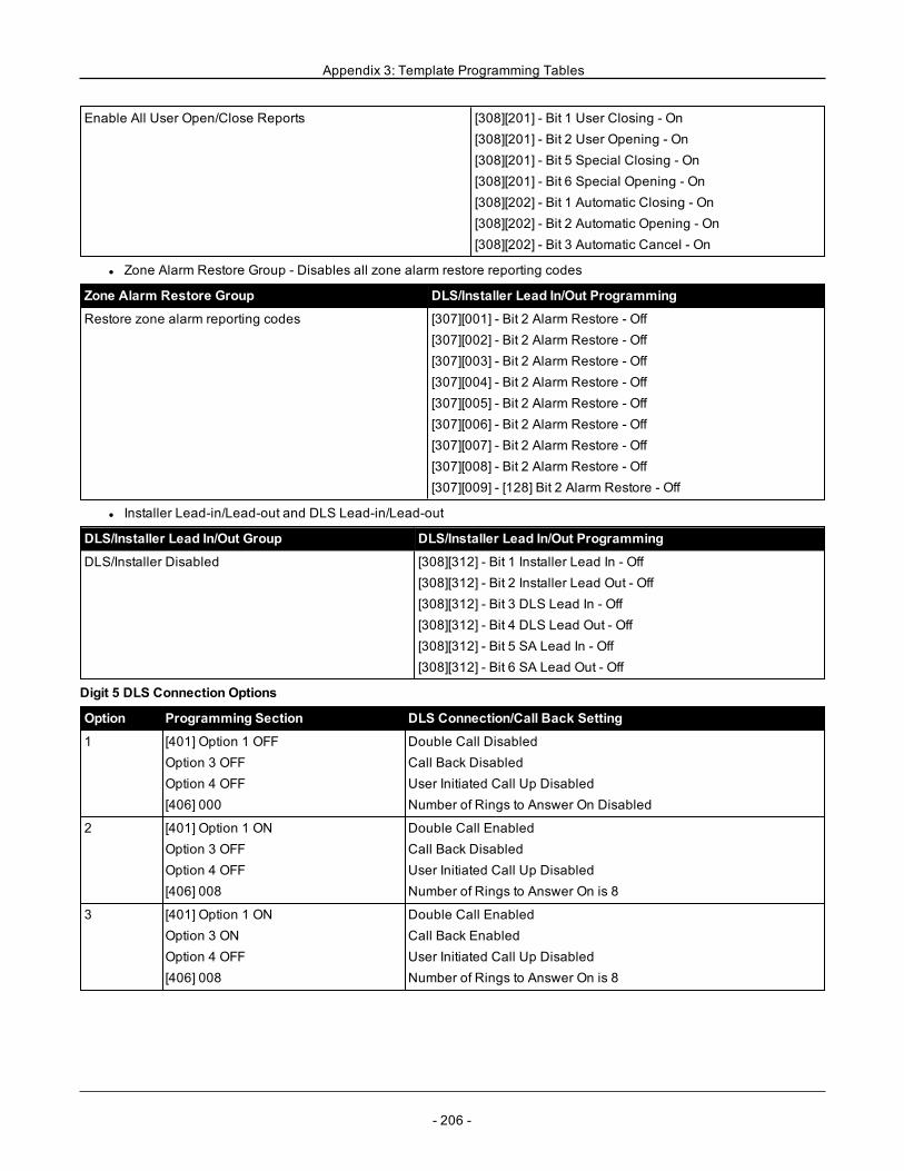
Appendix 3: Template Programming Tables
Enable All User Open/Close Reports [308][201] - Bit 1 User Closing - On[308][201] - Bit 2 User Opening - On[308][201] - Bit 5 Special Closing - On[308][201] - Bit 6 Special Opening - On[308][202] - Bit 1 Automatic Closing - On[308][202] - Bit 2 Automatic Opening - On[308][202] - Bit 3 Automatic Cancel - On
l Zone Alarm Restore Group - Disables all zone alarm restore reporting codes
Zone Alarm Restore Group DLS/Installer Lead In/Out Programming
Restore zone alarm reporting codes [307][001] - Bit 2 Alarm Restore - Off[307][002] - Bit 2 Alarm Restore - Off[307][003] - Bit 2 Alarm Restore - Off[307][004] - Bit 2 Alarm Restore - Off[307][005] - Bit 2 Alarm Restore - Off[307][006] - Bit 2 Alarm Restore - Off[307][007] - Bit 2 Alarm Restore - Off[307][008] - Bit 2 Alarm Restore - Off[307][009] - [128] Bit 2 Alarm Restore - Off
l Installer Lead-in/Lead-out and DLS Lead-in/Lead-out
DLS/Installer Lead In/Out Group DLS/Installer Lead In/Out Programming
DLS/Installer Disabled [308][312] - Bit 1 Installer Lead In - Off[308][312] - Bit 2 Installer Lead Out - Off[308][312] - Bit 3 DLS Lead In - Off[308][312] - Bit 4 DLS Lead Out - Off[308][312] - Bit 5 SA Lead In - Off[308][312] - Bit 6 SA Lead Out - Off
Digit 5 DLS Connection Options
Option Programming Section DLS Connection/Call Back Setting
1 [401] Option 1 OFFOption 3 OFFOption 4 OFF[406] 000
Double Call DisabledCall Back DisabledUser Initiated Call Up DisabledNumber of Rings to Answer On Disabled
2 [401] Option 1 ONOption 3 OFFOption 4 OFF[406] 008
Double Call EnabledCall Back DisabledUser Initiated Call Up DisabledNumber of Rings to Answer On is 8
3 [401] Option 1 ONOption 3 ONOption 4 OFF[406] 008
Double Call EnabledCall Back EnabledUser Initiated Call Up DisabledNumber of Rings to Answer On is 8
- 206 -
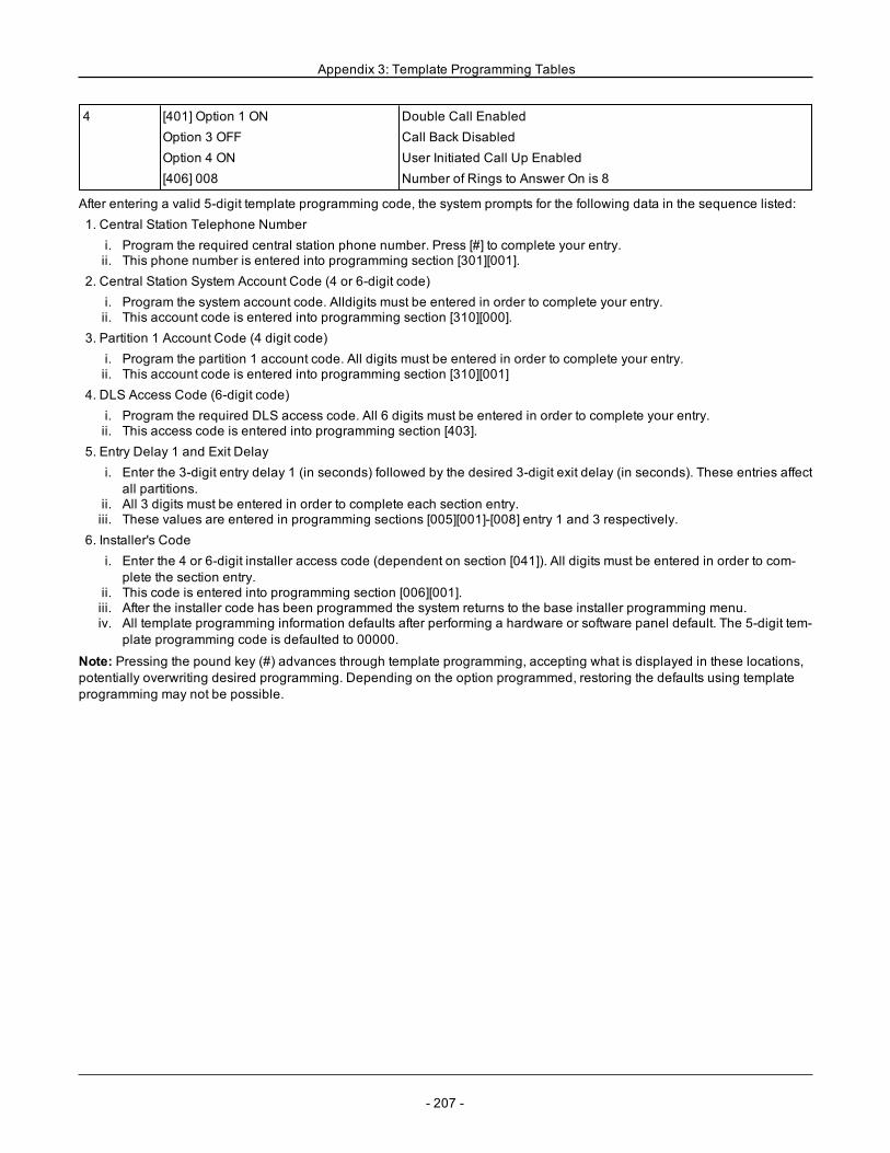
Appendix 3: Template Programming Tables
4 [401] Option 1 ONOption 3 OFFOption 4 ON[406] 008
Double Call EnabledCall Back DisabledUser Initiated Call Up EnabledNumber of Rings to Answer On is 8
After entering a valid 5-digit template programming code, the system prompts for the following data in the sequence listed:1. Central Station Telephone Number
i. Program the required central station phone number. Press [#] to complete your entry.ii. This phone number is entered into programming section [301][001].
2. Central Station System Account Code (4 or 6-digit code)i. Program the system account code. Alldigits must be entered in order to complete your entry.ii. This account code is entered into programming section [310][000].
3. Partition 1 Account Code (4 digit code)i. Program the partition 1 account code. All digits must be entered in order to complete your entry.ii. This account code is entered into programming section [310][001]
4. DLS Access Code (6-digit code)i. Program the required DLS access code. All 6 digits must be entered in order to complete your entry.ii. This access code is entered into programming section [403].
5. Entry Delay 1 and Exit Delayi. Enter the 3-digit entry delay 1 (in seconds) followed by the desired 3-digit exit delay (in seconds). These entries affect
all partitions.ii. All 3 digits must be entered in order to complete each section entry.iii. These values are entered in programming sections [005][001]-[008] entry 1 and 3 respectively.
6. Installer's Codei. Enter the 4 or 6-digit installer access code (dependent on section [041]). All digits must be entered in order to com-
plete the section entry.ii. This code is entered into programming section [006][001].iii. After the installer code has been programmed the system returns to the base installer programming menu.iv. All template programming information defaults after performing a hardware or software panel default. The 5-digit tem-
plate programming code is defaulted to 00000.
Note: Pressing the pound key (#) advances through template programming, accepting what is displayed in these locations,potentially overwriting desired programming. Depending on the option programmed, restoring the defaults using templateprogramming may not be possible.
- 207 -
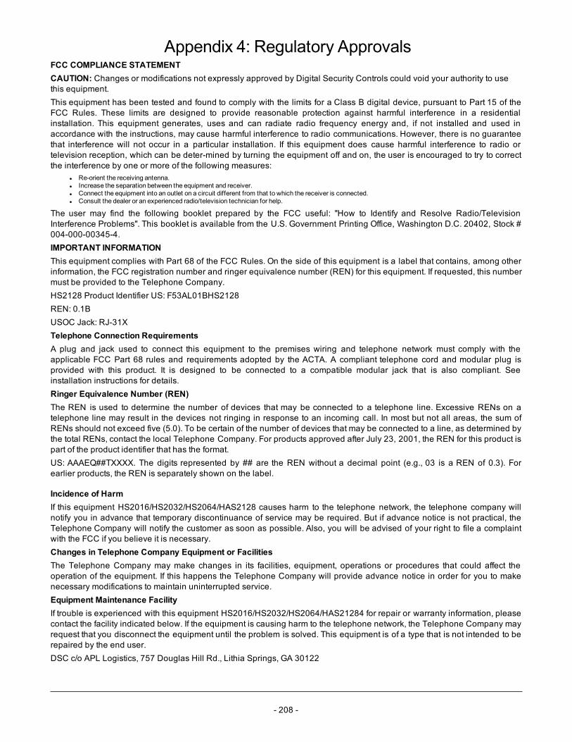
- 208 -
Appendix 4: Regulatory ApprovalsFCC COMPLIANCE STATEMENTCAUTION: Changes or modifications not expressly approved by Digital Security Controls could void your authority to usethis equipment.This equipment has been tested and found to comply with the limits for a Class B digital device, pursuant to Part 15 of theFCC Rules. These limits are designed to provide reasonable protection against harmful interference in a residentialinstallation. This equipment generates, uses and can radiate radio frequency energy and, if not installed and used inaccordance with the instructions, may cause harmful interference to radio communications. However, there is no guaranteethat interference will not occur in a particular installation. If this equipment does cause harmful interference to radio ortelevision reception, which can be deter-mined by turning the equipment off and on, the user is encouraged to try to correctthe interference by one or more of the following measures:
l Re-orient the receiving antenna.l Increase the separation between the equipment and receiver.l Connect the equipment into an outlet on a circuit different from that to which the receiver is connected.l Consult the dealer or an experienced radio/television technician for help.
The user may find the following booklet prepared by the FCC useful: "How to Identify and Resolve Radio/TelevisionInterference Problems". This booklet is available from the U.S. Government Printing Office, Washington D.C. 20402, Stock #004-000-00345-4.IMPORTANT INFORMATIONThis equipment complies with Part 68 of the FCC Rules. On the side of this equipment is a label that contains, among otherinformation, the FCC registration number and ringer equivalence number (REN) for this equipment. If requested, this numbermust be provided to the Telephone Company.HS2128 Product Identifier US: F53AL01BHS2128REN: 0.1BUSOC Jack: RJ-31XTelephone Connection RequirementsA plug and jack used to connect this equipment to the premises wiring and telephone network must comply with theapplicable FCC Part 68 rules and requirements adopted by the ACTA. A compliant telephone cord and modular plug isprovided with this product. It is designed to be connected to a compatible modular jack that is also compliant. Seeinstallation instructions for details.Ringer Equivalence Number (REN)The REN is used to determine the number of devices that may be connected to a telephone line. Excessive RENs on atelephone line may result in the devices not ringing in response to an incoming call. In most but not all areas, the sum ofRENs should not exceed five (5.0). To be certain of the number of devices that may be connected to a line, as determined bythe total RENs, contact the local Telephone Company. For products approved after July 23, 2001, the REN for this product ispart of the product identifier that has the format.US: AAAEQ##TXXXX. The digits represented by ## are the REN without a decimal point (e.g., 03 is a REN of 0.3). Forearlier products, the REN is separately shown on the label.
Incidence of HarmIf this equipment HS2016/HS2032/HS2064/HAS2128 causes harm to the telephone network, the telephone company willnotify you in advance that temporary discontinuance of service may be required. But if advance notice is not practical, theTelephone Company will notify the customer as soon as possible. Also, you will be advised of your right to file a complaintwith the FCC if you believe it is necessary.Changes in Telephone Company Equipment or FacilitiesThe Telephone Company may make changes in its facilities, equipment, operations or procedures that could affect theoperation of the equipment. If this happens the Telephone Company will provide advance notice in order for you to makenecessary modifications to maintain uninterrupted service.Equipment Maintenance FacilityIf trouble is experienced with this equipment HS2016/HS2032/HS2064/HAS21284 for repair or warranty information, pleasecontact the facility indicated below. If the equipment is causing harm to the telephone network, the Telephone Company mayrequest that you disconnect the equipment until the problem is solved. This equipment is of a type that is not intended to berepaired by the end user.DSC c/o APL Logistics, 757 Douglas Hill Rd., Lithia Springs, GA 30122
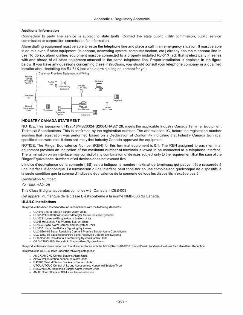
Appendix 4: Regulatory Approvals
Additional InformationConnection to party line service is subject to state tariffs. Contact the state public utility commission, public servicecommission or corporation commission for information.Alarm dialling equipment must be able to seize the telephone line and place a call in an emergency situation. It must be ableto do this even if other equipment (telephone, answering system, computer modem, etc.) already has the telephone line inuse. To do so, alarm dialling equipment must be connected to a properly installed RJ-31X jack that is electrically in serieswith and ahead of all other equipment attached to the same telephone line. Proper installation is depicted in the figurebelow. If you have any questions concerning these instructions, you should consult your telephone company or a qualifiedinstaller about installing the RJ-31X jack and alarm dialling equipment for you.
INDUSTRY CANADA STATEMENTNOTICE: This Equipment, HS2016/HS2032/HS2064/HAS2128, meets the applicable Industry Canada Terminal EquipmentTechnical Specifications. This is confirmed by the registration number. The abbreviation, IC, before the registration numbersignifies that registration was performed based on a Declaration of Conformity indicating that Industry Canada technicalspecifications were met. It does not imply that Industry Canada approved the equipmentNOTICE: The Ringer Equivalence Number (REN) for this terminal equipment is 0.1. The REN assigned to each terminalequipment provides an indication of the maximum number of terminals allowed to be connected to a telephone interface.The termination on an interface may consist of any combination of devices subject only to the requirement that the sum of theRinger Equivalence Numbers of all devices does not exceed five.L’indice d’équivalence de la sonnerie (IES) sert à indiquer le nombre maximal de terminaux qui peuvent être raccordés àune interface téléphonique. La terminaison d’une interface peut consister en une combinaison quelconque de dispositifs, àla seule condition que la somme d’indices d’équivalence de la sonnerie de tous les dispositifs n’excède pas 5.Certification Number:IC: 160A-HS2128This Class B digital apparatus complies with Canadian ICES-003.Cet appareil numérique de la classe B est conforme à la norme NMB-003 du Canada.UL/ULC InstallationsThis product has been tested and found in compliance with the following standards:
l UL1610 Central-Station Burglar-Alarm Unitsl UL365 Police Station Connected Burglar Alarm Units and Systemsl UL1023 Household Burglar-Alarm System Unitsl UL985 Household FireWarning System Unitsl UL1635 Digital Alarm Communicator System Unitsl UL1637 HomeHealth Care Signaling Equipmentl ULC-S304-06 Signal Receiving Centre & Premise Burglar Alarm Control Unitsl ULC-S559-04 Equipment for Fire Signal Receiving Centers and Systemsl ULC-S545-02 Residential FireWarning System Control Unitsl ORD-C1023-1974 Household Burglar-Alarm System Units
This product has also been tested and found in compliance with the ANSI/SIA CP-01-2010 Control Panel Standard – Features for False Alarm Reduction.
This product is UL/ULC listed under the following categories:
l AMCX/AMCXC Central Stations Alarm Unitsl APAW Police-station-connected Alarm Unitsl DAYRC Central Station Fire Alarm System Unitsl UTOU/UTOUC Control Units and Accessories, Household System Typel NBSX/NBSXC Household Burglar Alarm System Unitsl AMTBControl Panels, SIA False Alarm Reduction
- 209 -
Appendix 4: Regulatory Approvals
The product is labeled with the UL and ULC listingmarks along with the SIA CP-01 compliance statement (Also Classified in accordance with SIA-CP-01 Standard) asproof of compliance with the abovementioned standards. For further information on this product’s listings please also refer to the official listing guides published at theULweb site (www.ul.com) under Online Directions Section.
UL/ULC Residential Fire and Burglary Installations:For ULC Installations refer to the Standard for the Installation of Residential FireWarning Systems, CAN/ULC-S540.
l All burglary-type zones shall be configured with SEOL or DEOL configuration. Usemodel EOLR-2.l (refer to section [002], bit 10 or 11 shall be ON)l Use at least one PG9926 or PG9916 Smoke Detector for Fire Installations (section [001], fire zone shall be programmed as type 025)l The entry delay shall not exceed 45 seconds (refer to section [005])l The exit delay shall not exceed 60 seconds (refer to section [005])l Theminimum Bell Time-out is 4minutes (refer to section [005])
Note: For ULC Residential Fire Installations theminimum Bell Time-out is 5minutes
For UL HomeHealth Care Installations theminimum Bell Time-out is 5min.
For UL Commercial Burglary Installations minimum Bell Time-out is 15min.
l Temporal Three Fire Signal shall be enabled (section [013], opt.8 ON)l Arm/Disarm Bell Squawk shall be enabled when using wireless key PG4939, PG4929, PG4949 (section [014], option 1 shall be ON)l A code shall be required for bypassing (section [023], option 4 shall be ON)l Trouble beeps shall be enabled (section [022], option 7 shall be ON)l AC trouble indication LED shall be enabled (Keypad Programming, section [022], options 5 and 6 shall be ON)l DACT Communicator shall be enabled for Supervising StationMonitoring (section [380], option 1 shall be ON)
Note: The DACT communicator for this product has no line security.
l Telephone LineMonitoring (TLM) shall be enabled (section [015], option 7 shall be ON)
Note: This product is programmed to perform 5 (min.) to 10 (max.) attempts for communication of an event to the supervising station. If unsuccessful, a Fail To Com-municate (FTC) trouble is generated.
l Test transmission cycle shall be set for monthly transmission (refer to section [351])
Note: For ULC Residential/Commercial installations set for daily test transmission
l Wireless Supervision window shall be set to 4 hours for Fire Installations (Wireless Programming, section [804]>[802] shall be programmedwith the value16)
l Wireless Supervision window shall be set to 4 hours for Burglary Installations only (Wireless Programming, section [804]>[802] shall be programmedwith thevalue 96)
l RF Jam detection shall be enabled (refer toWireless Programming (section [804][801], option 00 shall be OFF)l New Alarms will Disconnect 2-way Audio (section [022], opt 6 OFF)
UL Central Station and Police Connect with Standard or Encrypted Line Security Servicel The installationmust use theModels TL2803G(R) IP/3G Interface, 3G2080(R) 3G Interface or TL280(R) IP Interface, which communicates over Cellular
Data Network or an Ethernet network 10/100BaseT to the compatible Sur-Gard System I/II/III/IV receiver.l Polling time shall be 200 seconds and compromise detection time shall be 6min.l For Encrypted line security applications, theModels TL2803G(R) IP/3G Interface, 3G2080(R) 3G Interface or TL280(R) IP Interface shall have the Encryp-
tion Key enabled (AES128 bit encryption algorithm is validated under NIST Certificate No.2645l Wireless Supervision window shall be enabled (refer toWireless Programming, sections [804]>[802])
UL Local, Central Station and Police Connect with No Line Security Servicel The installation shall use a Bell which is UL Listed for Mercantile local alarms. An example of a UL Listed bell that can be used is AmsecoModel MBL10B bell
with Model AB-12 bell housing. Connections from the control unit to the bell shall bemade in conduit. (Optional for central Station)l The bell timeout shall be programmed for 15minutes minimuml At least one system remote keypad with tamper switch shall be employedl The integral DACT shall be enabled and shall be programmed to provide a low battery transmissionl The control panel shall be in the attack resistant enclosure. The separately listed CMC-1 or PC4050CA attack resistant enclosure shall be employedl Themaximum entry delay time shall not exceed 45s as a result of the attack test. Themaximum exit delay time shall not exceed 60 s.l A tamper switch shall be used to protect the enclosure cover of the control unit. A tamper switch shall also be used on the keypad rear to detect removal from
the wall.l 24 h check in transmission shall be enabledl Open/Closing acknowledgement enabled.(Not Police Station)l The Installation shall use the internal dialer (DACT) alone or in conjunction with Models TL2803G(R) IP/3G Interface, 3G2080(R) 3G Interface or TL280(R) IP
Interface, which communicates over Cellular Data Network or an Ethernet network 10/100BaseT to the compatible Sur-Gard System I/II/III/IV receiver.
UL Home Health Care Signaling Equipmentl Theremust be at least two keypads, one of either one of the compatible keypads models HS2LED, HS2LCD(P), HS2ICN(P), HS2LCDRF(P)9, HS2ICNRF
(P)9 and HS2TCHPl Each system shall be programmed to activate an audible Trouble signal within 90 seconds upon loss of microprocessor memoryl The HS2TCHP shall be used along with another compatible model keypad in order to provide audible supervision for homehealth care or medical install-
ations.
ULC Central Station Fire and Burglary Monitoring Installationsl For installation requirements, levels of security, communicationmodules and configurations (Refer to the ULC Installation Information Sheet, DSC
#29002157)l Use a CSA/cUL approved transformer (hardwired connections required for Fire Monitoring)l All tamper circuits may be connected to the same zonel HS2TCHP touch screen keypad is for supplementary use only with ULC Commercial Fire Monitoring
- 210 -
Appendix 4: Regulatory Approvals
ProgrammingThe notes in the programming sections of the PowerSeries Neo ReferenceManual describing the system configurations for UL/ULC listed installations shall be imple-mented.
Control of the Protected PremisesIn order to have a UL certificated system, the protected area is to be under the responsibility of one ownership andmanagement (i.e., one business under one name).This may be a group of buildings attached or unattached with different addresses but under the responsibility of someone havingmutual interest. The person of mutualinterest is not the alarm-installing company.
Note: This does not apply to strip mall applications where each independent business must have their own separate alarm system.
e.g.,1: a commercial partitioned system that has an office and a warehouse area in a building where each area can be armed or disarmed independently.
e.g.,2: a residential system partitioned so that the garage area is armed separately from the house.
Each of the above examples is under the sole responsibility of a single owner. The bell and DACT power supply must be in a protected area including partitioned sys-tems. The bell and DACT power supply must be located where it can be heard by the person or persons responsible for maintaining the security system during thedaily arming cycle.
Bell LocationThe alarm sounding device (bell) shall be located where it can be heard by the person operating the security system during the daily arming and disarming cycle.
Protection of the Control Unitl The local control unit and the local power supply must be protected in one of the following ways:l The control unit and audible alarm devicemust be in a protected area which is armed 24 hours a day.l Each partitionmust arm the area protecting the control unit and the audible alarm device power supply. This may require duplicate protection armed by each
partition. Access to this protected area, without causing and alarm, will require that all partitions be disarmed.l In all cases described above, the protected area for the control unit must be programmed as not-bypassable.
Casual UsersThe installer should caution the user(s) not to give system information (e.g., codes, bypass methods, etc.) to casual users (baby-sitters or service people). Only theOne-TimeUse codes shall be given to casual users.
User InformationThe installer should advise the users and note in the User’s Manual:
l Service organization name and telephone numberl The programmed exit timel The programmed entry timel Test system weeklyl The installer code cannot arm or disarm the system
EU Compliance StatementThis Product is in Conformity with EMC Directive 2004/108/EC based on results using harmonizedstandards in accordance with article 10(5), R&TTE Directive 1999/5/EC based on Following Annex III of the directive andLVD directive 2006/95/EC based on results using Harmonized standards.This product meets the requirements of Class II, Grade 2 equipment as per EN50131-1: 2006+A1:2009, EN50131-3:2009,EN50131-6:2008 (Type A), EN50136-1-1:1997, EN50136-2-1, EN50136-2-3 (ATS2) Standards.This device is suitable for use in systems with the following notification options.A (use of two warning devices and internal dialer requiredB (self-powered warning device and internal dialer requiredC (use of DSC compatible alternate communicator in back-up or redundant mode)D (use of DSC compatible alternate communicator with encryption enabled required.)For EN50131 compliant installations only the intrusion portion of the alarm system has been investigated. Fire Alarm andAuxiliary (Medical) Alarm functions were not included in the evaluation of this product under the requirements of the abovementioned standards.Additional features implemented for EN 50131 Grade 2:Fire alarm and CO alarm annunciationAuxiliary (medical) alarm annunciationOptional feature implemented for EN 50131 Grade 2:Removal from mounting tamper detection for non wire-free componentsThe model HS2128, HS2064, HS2032, HS2016 Control Panel has been certified by Telefication according to EN50131-1:2006 +A1:2009, EN50131-3:2009, EN50131-6:2008 (Type A) and EN50136-1:1997 (ATS2) for Grade 2, Class II.
UK Compliance Statement
- 211 -
Appendix 4: Regulatory Approvals
In the UK this product is suitable for use in systems installed to conform to PD 6662:2010 at Grade 2 and environmentalclass 2 with the following notification options: A, B, C, D, X.The CIE and notification equipment should be located and supervised to minimize the risk of vandalism or sabotage. It ispreferable for the CIE, signaling and network equipment to be located in an area where a confirmed activation will begenerated.HS2128, HS2064, HS2032, HS2016 are compliant with criteria for sequentially confirmed intruder alarm systems as perStandard BS8243:2010.For an alarm condition to be regarded as sequentially confirmed:a) The HS2128, HS2064, HS2032, HS20163 should be configured so that at least two separate alarm conditions arereported, each originating from an independent detector within the confirmation time; Section [042] option 003 (SequentialDetection), section [005]>[000], Burglary Verification Timer set to a value between 30 and 60.b) The two detectors should either be of:1) different technologies which are permitted to have overlapping areas of coverage; or2) the same single technology and not have overlapping areas of coverage.To be regarded as independent, each detector should be configured to report alarm conditions separately to the HS2128,HS2064, HS2032, HS2016.The HS2128, HS2064, HS2032, HS2016 are capable of supporting the completion of the full setting procedure by one of thefollowing methods:a) push button switch mounted outside the supervised premises. Instructions to be provided for the zone type to beprogrammed for the key arming; orb) protective switch (i.e., door contact) fitted to the final exit door of the alarmed premises or area. Use zone type 016 (FinalDoor Set) for the final exit door.In this case the setting procedure is a two-stage process of initiating the setting procedure within the supervised premises(e.g., using wireless key PG8929,G8939, G8938, G8949 or user code) followed by completion of setting by one of the twomethods described above.This prohibits the use of a timed exit procedure.If a protective switch (i.e. door contact) is used as the method of completion of setting, then the keypad should be sited nearto the final exit door so that the IAS can be unset promptly. Where appropriate, additional internal audible indications(PG8911 indoor sirens) should be provided so that persons within a building are informed that the HS2128, HS2064,HS2032, HS2016 are due to be set. Additional keypads should be provided, where appropriate, so that if the alarm panel isset there are means available locally within the supervised premises to unset the system.HS2128, HS2064, HS2032, HS2016 are capable of supporting the following unsetting methods in accordance with BS8243:6.4.2 Prevention of entry to the supervised premises before the HS2128, HS2064, HS2032, HS2016 are unset. Unsettingusing PG8929,G8939, G8938, G8949 wireless key before entering the supervised premises causes or permits the initialentry door to be unlocked. Program PGM1 or PGM2 in Section [009] to activate when system is disarmed and release themag-lock on the entry door.Compliance labeling should be removed or adjusted if non-compliant configurationsare selected.
- 212 -
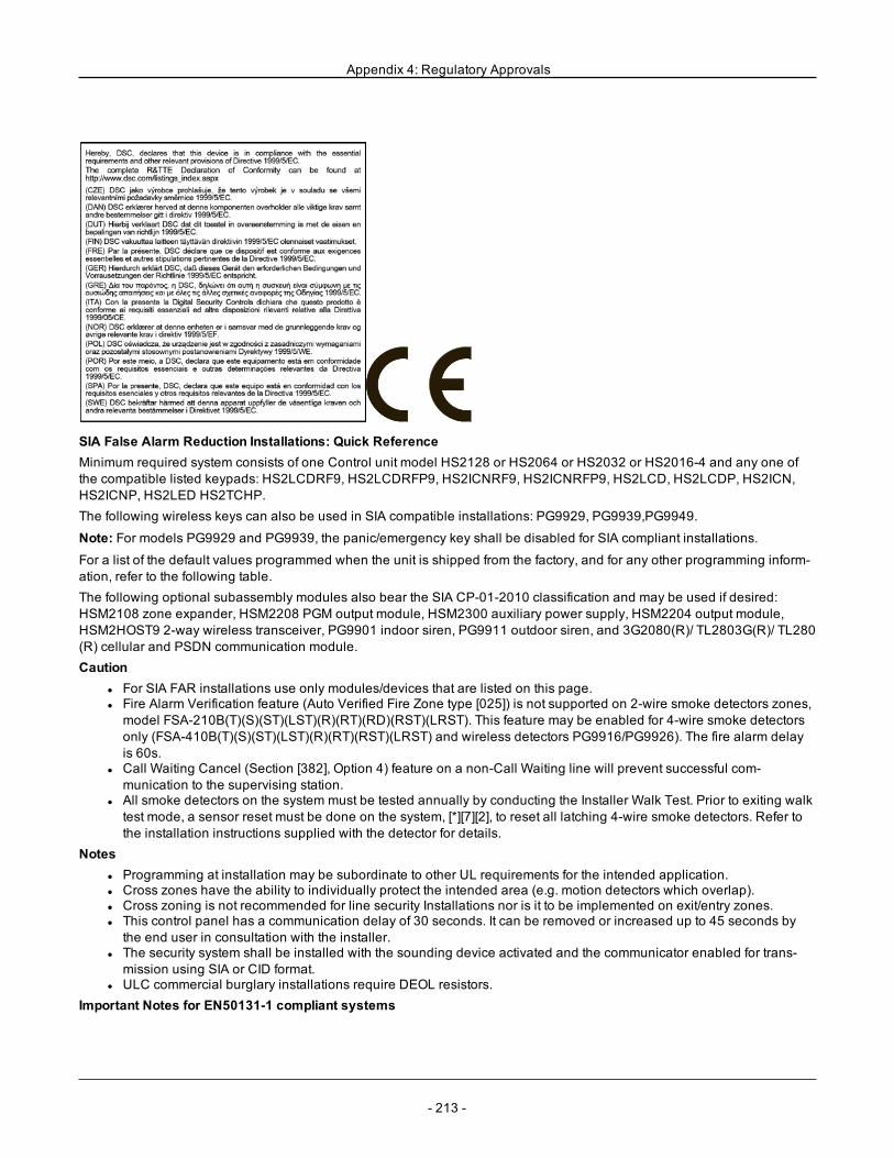
Appendix 4: Regulatory Approvals
SIA False Alarm Reduction Installations: Quick ReferenceMinimum required system consists of one Control unit model HS2128 or HS2064 or HS2032 or HS2016-4 and any one ofthe compatible listed keypads: HS2LCDRF9, HS2LCDRFP9, HS2ICNRF9, HS2ICNRFP9, HS2LCD, HS2LCDP, HS2ICN,HS2ICNP, HS2LED HS2TCHP.The following wireless keys can also be used in SIA compatible installations: PG9929, PG9939,PG9949.
Note: For models PG9929 and PG9939, the panic/emergency key shall be disabled for SIA compliant installations.
For a list of the default values programmed when the unit is shipped from the factory, and for any other programming inform-ation, refer to the following table.The following optional subassembly modules also bear the SIA CP-01-2010 classification and may be used if desired:HSM2108 zone expander, HSM2208 PGM output module, HSM2300 auxiliary power supply, HSM2204 output module,HSM2HOST9 2-way wireless transceiver, PG9901 indoor siren, PG9911 outdoor siren, and 3G2080(R)/ TL2803G(R)/ TL280(R) cellular and PSDN communication module.Caution
l For SIA FAR installations use only modules/devices that are listed on this page.l Fire Alarm Verification feature (Auto Verified Fire Zone type [025]) is not supported on 2-wire smoke detectors zones,model FSA-210B(T)(S)(ST)(LST)(R)(RT)(RD)(RST)(LRST). This feature may be enabled for 4-wire smoke detectorsonly (FSA-410B(T)(S)(ST)(LST)(R)(RT)(RST)(LRST) and wireless detectors PG9916/PG9926). The fire alarm delayis 60s.
l Call Waiting Cancel (Section [382], Option 4) feature on a non-Call Waiting line will prevent successful com-munication to the supervising station.
l All smoke detectors on the system must be tested annually by conducting the Installer Walk Test. Prior to exiting walktest mode, a sensor reset must be done on the system, [*][7][2], to reset all latching 4-wire smoke detectors. Refer tothe installation instructions supplied with the detector for details.
Notesl Programming at installation may be subordinate to other UL requirements for the intended application.l Cross zones have the ability to individually protect the intended area (e.g. motion detectors which overlap).l Cross zoning is not recommended for line security Installations nor is it to be implemented on exit/entry zones.l This control panel has a communication delay of 30 seconds. It can be removed or increased up to 45 seconds bythe end user in consultation with the installer.
l The security system shall be installed with the sounding device activated and the communicator enabled for trans-mission using SIA or CID format.
l ULC commercial burglary installations require DEOL resistors.Important Notes for EN50131-1 compliant systems
- 213 -
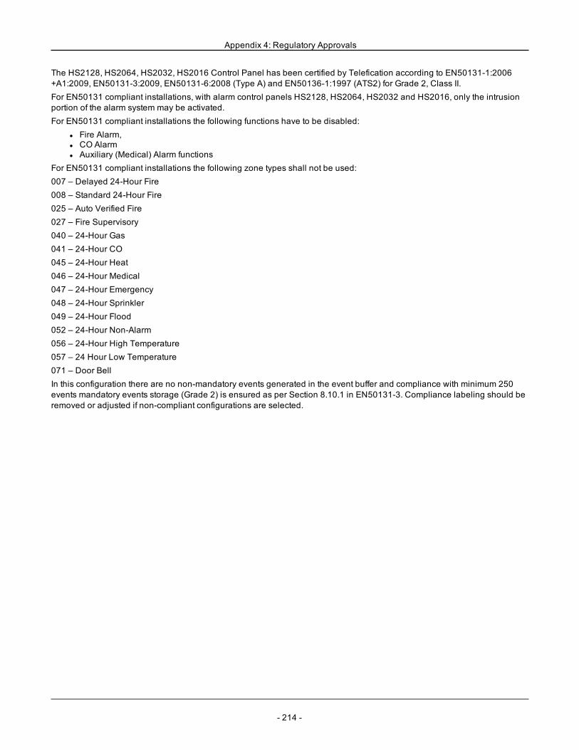
Appendix 4: Regulatory Approvals
The HS2128, HS2064, HS2032, HS2016 Control Panel has been certified by Telefication according to EN50131-1:2006+A1:2009, EN50131-3:2009, EN50131-6:2008 (Type A) and EN50136-1:1997 (ATS2) for Grade 2, Class II.For EN50131 compliant installations, with alarm control panels HS2128, HS2064, HS2032 and HS2016, only the intrusionportion of the alarm system may be activated.For EN50131 compliant installations the following functions have to be disabled:
l Fire Alarm,l CO Alarml Auxiliary (Medical) Alarm functions
For EN50131 compliant installations the following zone types shall not be used:007 – Delayed 24-Hour Fire008 – Standard 24-Hour Fire025 – Auto Verified Fire027 – Fire Supervisory040 – 24-Hour Gas041 – 24-Hour CO045 – 24-Hour Heat046 – 24-Hour Medical047 – 24-Hour Emergency048 – 24-Hour Sprinkler049 – 24-Hour Flood052 – 24-Hour Non-Alarm056 – 24-Hour High Temperature057 – 24 Hour Low Temperature071 – Door BellIn this configuration there are no non-mandatory events generated in the event buffer and compliance with minimum 250events mandatory events storage (Grade 2) is ensured as per Section 8.10.1 in EN50131-3. Compliance labeling should beremoved or adjusted if non-compliant configurations are selected.
- 214 -
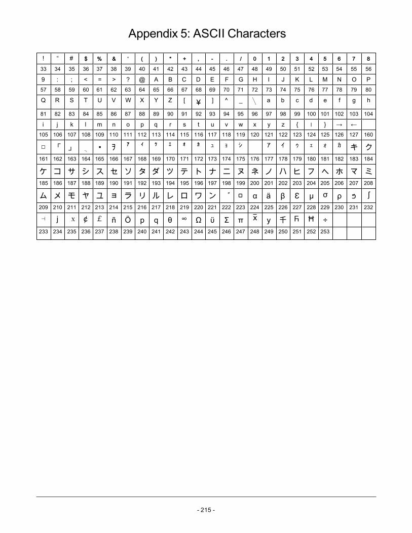
- 215 -
Appendix 5: ASCII Characters
! “ # $ % & ‘ ( ) * + , - . / 0 1 2 3 4 5 6 7 8
33 34 35 36 37 38 39 40 41 42 43 44 45 46 47 48 49 50 51 52 53 54 55 56
9 : ; < = > ? @ A B C D E F G H I J K L M N O P57 58 59 60 61 62 63 64 65 66 67 68 69 70 71 72 73 74 75 76 77 78 79 80
Q R S T U V W X Y Z [ ¥ ] ^ _ a b c d e f g h
81 82 83 84 85 86 87 88 89 90 91 92 93 94 95 96 97 98 99 100 101 102 103 104
i j k l m n o p q r s t u v w x y z ׀ → ←105 106 107 108 109 110 111 112 113 114 115 116 117 118 119 120 121 122 123 124 125 126 127 160
「 」 ヲ ア ィ ゥ ェ ォ カ ュ ョ シ ア イ ゥ ェ ォ カ キ ク161 162 163 164 165 166 167 168 169 170 171 172 173 174 175 176 177 178 179 180 181 182 183 184
ケ コ サ シ ス セ ソ タ ダ ツ テ ト ナ ニ ヌ ネ ノ ハ ヒ フ ヘ ホ マ ミ185 186 187 188 189 190 191 192 193 194 195 196 197 198 199 200 201 202 203 204 205 206 207 208
ム メ モ ヤ ユ ョ ラ リ ル レ ロ ワ ン α ä β Ɛ μ σ ρ ϧ ʃ209 210 211 212 213 214 215 216 217 218 219 220 221 222 223 224 225 226 227 228 229 230 231 232
⊣ ϳ x ¢ £ ñ Ö p q θ ∞ Ω ϋ Σ π X y 千 Ⴌ Ħ ÷233 234 235 236 237 238 239 240 241 242 243 244 245 246 247 248 249 250 251 252 253
- 216 -
Appendix 6: Wiring DiagramsHS2016, HS2032, HS2064, HS2128 UL/ULC Wiring Diagram
Note: For ULC installations, please refer to the ULC Installation Information Sheet part#29002157.
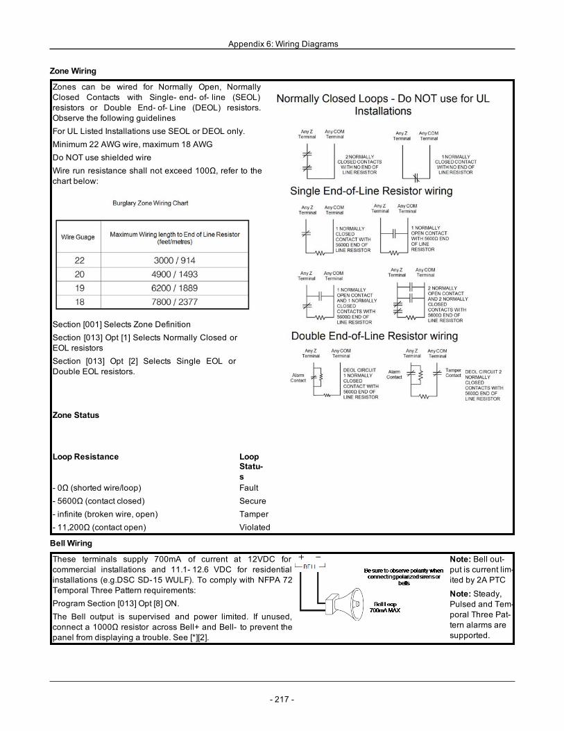
Appendix 6: Wiring Diagrams
Zone Wiring
Zones can be wired for Normally Open, NormallyClosed Contacts with Single- end- of- line (SEOL)resistors or Double End- of- Line (DEOL) resistors.Observe the following guidelinesFor UL Listed Installations use SEOL or DEOL only.Minimum 22 AWGwire, maximum 18 AWGDo NOT use shielded wireWire run resistance shall not exceed 100Ω, refer to thechart below:
Section [001] Selects Zone DefinitionSection [013] Opt [1] Selects Normally Closed orEOL resistorsSection [013] Opt [2] Selects Single EOL orDouble EOL resistors.
Zone Status
Loop Resistance LoopStatu-s
- 0Ω (shorted wire/loop)- 5600Ω (contact closed)- infinite (broken wire, open)- 11,200Ω (contact open)
FaultSecureTamperViolated
Bell Wiring
These terminals supply 700mA of current at 12VDC forcommercial installations and 11.1- 12.6 VDC for residentialinstallations (e.g.DSC SD-15 WULF). To comply with NFPA 72Temporal Three Pattern requirements:Program Section [013] Opt [8] ON.The Bell output is supervised and power limited. If unused,connect a 1000Ω resistor across Bell+ and Bell- to prevent thepanel from displaying a trouble. See [*][2].
Note: Bell out-put is current lim-ited by 2A PTC
Note: Steady,Pulsed and Tem-poral Three Pat-tern alarms aresupported.
- 217 -
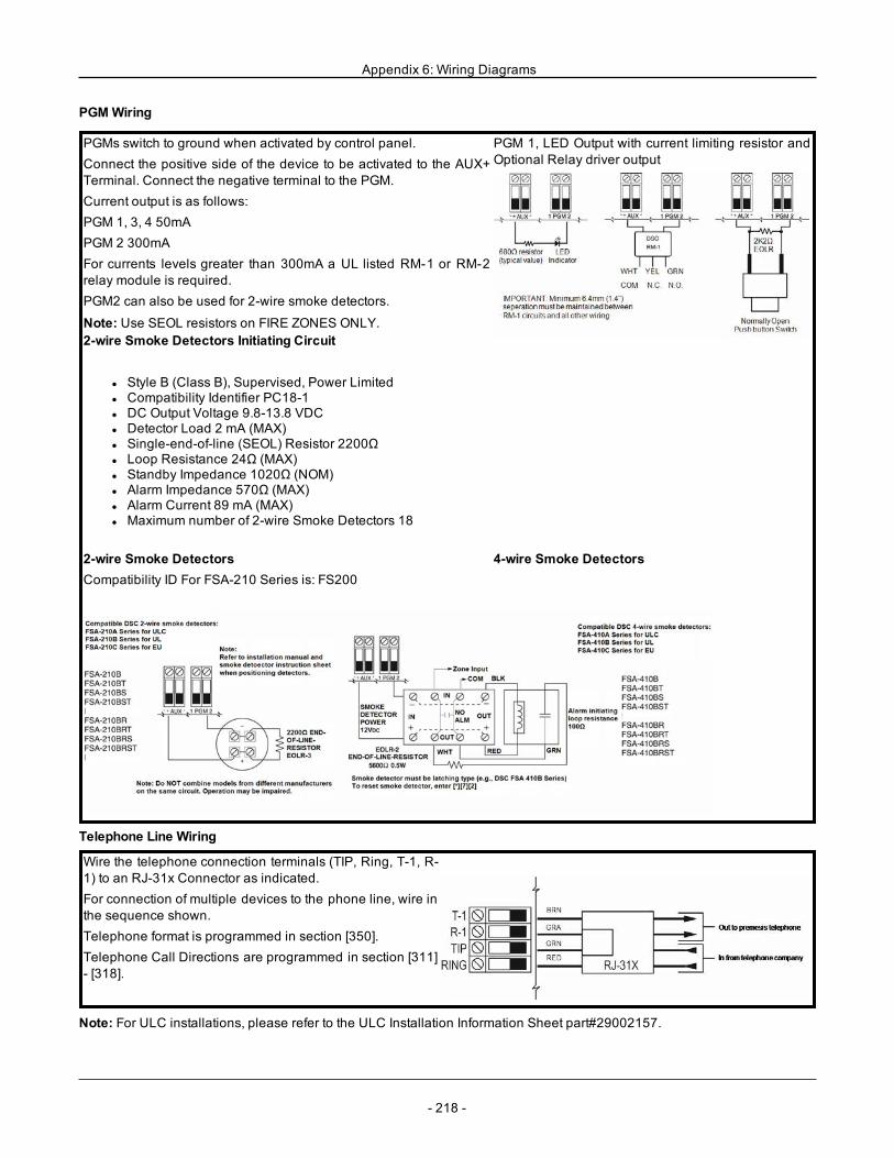
Appendix 6: Wiring Diagrams
PGMWiring
PGMs switch to ground when activated by control panel.Connect the positive side of the device to be activated to the AUX+Terminal. Connect the negative terminal to the PGM.Current output is as follows:PGM 1, 3, 4 50mAPGM 2 300mAFor currents levels greater than 300mA a UL listed RM-1 or RM-2relay module is required.PGM2 can also be used for 2-wire smoke detectors.
Note: Use SEOL resistors on FIRE ZONES ONLY.
PGM 1, LED Output with current limiting resistor andOptional Relay driver output
2-wire Smoke Detectors Initiating Circuit
l Style B (Class B), Supervised, Power Limitedl Compatibility Identifier PC18-1l DC Output Voltage 9.8-13.8 VDCl Detector Load 2 mA (MAX)l Single-end-of-line (SEOL) Resistor 2200Ωl Loop Resistance 24Ω (MAX)l Standby Impedance 1020Ω (NOM)l Alarm Impedance 570Ω (MAX)l Alarm Current 89 mA (MAX)l Maximum number of 2-wire Smoke Detectors 18
2-wire Smoke DetectorsCompatibility ID For FSA-210 Series is: FS200
4-wire Smoke Detectors
Telephone Line Wiring
Wire the telephone connection terminals (TIP, Ring, T-1, R-1) to an RJ-31x Connector as indicated.For connection of multiple devices to the phone line, wire inthe sequence shown.Telephone format is programmed in section [350].Telephone Call Directions are programmed in section [311]- [318].
Note: For ULC installations, please refer to the ULC Installation Information Sheet part#29002157.
- 218 -

- 219 -
Appendix 7: SpecificationsZone Configuration
l 16, 32, 64, or 128 wireless zones supported and up to 8 hardwired zones available on the controllerl 40 zone types and 14 programmable zone attributesl Zone configurations available: normally closed, single EOL and DEOL supervisedl Hardwired zone expansion (fully supervised) available using the model HSM2108 (eight zone expander module)l Wireless zone expansion (fully supervised) available using the HSM2Host 2-way wireless integration module (oper-ating at 915MHz (North America), 433MHz (Europe) and 868MHz (international)
Access Codesl Up to 97 access codes: 94 (level 2-EN), one system master code (level 3-EN), one installer code (level 3-EN), andone maintenance code
l Programmable attributes for each user code (see "Access Code Attributes" on page 49)l When using 6-digit access codes, the minimum number of variations of access codes are 10526 forHS2128/HS2064,13888 for HS2032 and 20833 for HS2016-4
Warning Device Outputl Integral sounder capable of 85 dB @ 3m, self-powered type Zl 2 remote, wireless indoor/outdoor warning devices supported: models PGX901 (indoor), PGX911 (outdoor) (X=4, 8,or 9)
l Programmable as steady, pulsed or temporal three (as per ISO8201) and temporal four (CO alarm) outputl Warning device sounds alarms in the following priority: fire, CO, burg
Memoryl CMOS EEPROM memoryl Retains programming and system status on AC or battery failure for 20 years min. (not verified by UL)
Power Supply - North AmericaTransformer: DSC PTD1640U, PTD1640Primary: 120V, 60Hz Class IISecondary: 16.5VAC, 40VA Max.Power Supply - International
l Input ratings: 220V-240Vac, 50/60Hz, 200mAl Transformer required, mounted in the same enclosure, permanently connectedl Transformer secondary ratings: 16.5Vac, 40VA min.
Note: For installations using the transformer mounted inside the cabinet, replace fuse only with the same type (20mm) rated250V/315mA.
Regulated power supply:l 1.7A regulated, supervised and integral to the control unitl Type A as per EN50131-6 Standardl 700mA auxiliary supply, 12V DCl Positive temperature coefficient (PTC) for Bell, Aux+ and Battery terminalsl Reverse battery detection/protectionl Supervision for AC power and low batteryl Normal and high current battery charge optionsl Supervised battery charging circuit
Current draw (panel):l 85mA (nominal) 2A(Max)
Bell Output:l 12V, 700mA supervised (1k Ohm) bell output (current limited at 2 amps)l Steady, Pulsed, Temporal 3 fire, Temporal 4 CO alarm cadencesl Bell short detection (software + hardware)
Aux+:l Voltage range = 9.6V - 13.8V DCl Current = 700mA (shared with Corbus R(ed))l Output ripple voltage: 270mVp-p max.
Appendix 7: Specifications
l Onboard programmable outputs:l PGM 1 - 50mA switched programmable outputl PGM 2 - 300mA current-limited switched programmable output. 2-Wire smoke detectors (90mA current lim-ited) are supported using this PGM
l PGM 3 - 50mA switched programmable outputl PGM 4 - 50mA switched programmable outputl Hardware PGM over current protection
Batteryl 12V sealed lead acid, rechargeablel Battery capacity:
l 4 hours (UL commercial burglary/residential burglary),l 12 hours (EN50131),l 24 hours (UL/ULC resi fire, ULC com burglary, ULC com fire monitoring - no bell load allowed); INCERT [Bel-gium])
Note: For T 014 compliance (INCERT certification), only 14Ah (2x7Ah) batteries were tested and are accepted forINCERT certified systems.
l Maximum standby time: 24 hours (with 14Ah battery and Aux current limited to 470mA)l Recharging time to 80% 72 hoursl Recharging rate: 240mA (12 hours max.), 480mA (24 hour backup)l Backup time: 24 hours (UL)l Battery lifespan: 3-5 yearsl Low battery trouble indication threshold 11.5VDCl Battery restore voltage 12.5Vl Main board current draw (battery only):
l HS2016-4/32/64/128 (no alternate communicator) standby 85mA DCl HS2016-4/32/64/128, (including alternate communicator) standby 190mA DCl Transmit (alternate communicator module) 195mA DC
l Resettable fuses (PTC) used on circuit boardl Supervision for loss of primary power source (AC fail), battery loss or battery low voltage (battery trouble) with indic-ation provided on the keypad
l Internal clock locked to AC power frequencyOperating Environmental Conditions
l Temperature range: UL= 0°C to +49°C (32°F-120°F), EN= -10°C to 55°C (50°F-131°F)l Relative humidity: <93% non condensing
Alarm Transmitter Equipment (ATE) Specificationl Digital dialer integral to the main control boardl Supports SIA and Contact IDl Complies with TS203 021-1, -2, -3 Telecom equipment requirements and EN50136-1-1, EN50136-2-1, EN50136-2-3ATS 2
l Optional Dual IP/Cellular communicators (3G2080(R)/ TL2803G(R)/ TL280(R)) can be installed in the same enclos-ure and configured as primary or back-up, with AES 128-bit encryption
l Compliant with EN50136-1-1, EN50136-2-1 ATS2 requirementsSystem Supervision FeaturesThe PowerSeries Neo continuously monitors a number of possible trouble conditions and provides audible and visual indic-ation at the keypad. Trouble conditions include:
l AC power failurel Zone troublel Fire troublel Telephone line troublel Communicator troublel Low battery conditionl RF jaml AUX power supply faultl Failure to communicatel Module fault (supervisory or tamper)
Additional Features
- 220 -
Appendix 7: Specifications
l 2-way wireless device supportl Visual verification (images + audio)*l Proximity tag supportl PGM schedulingl Quick armingl User, partition, module, zone and system labelsl Soak test*l Programmable system loop responsel Keypad and panel software versions viewable through keypadl Doorbell zone typel Low battery PGM type
*Feature not evaluated by UL/ULC.Locating Detectors and Escape PlanThe following information is for general guidance only and it is recommended that local fire codes and regulations be con-sulted when locating and installing smoke and CO alarms.Smoke DetectorsResearch has shown that all hostile fires in homes generate smoke to a greater or lesser extent. Experiments with typicalfires in homes indicate that detectable quantities of smoke precede detectable levels of heat in most cases. For these reas-ons, smoke alarms should be installed outside of each sleeping area and on each storey of the home.The following information is for general guidance only and it is recommended that local fire codes and regulations be con-sulted when locating and installing smoke alarms.It is recommended that additional smoke alarms beyond those required for minimum protection be installed. Additionalareas that should be protected include: the basement; bedrooms, especially where smokers sleep; dining rooms; furnaceand utility rooms; and any hallways not protected by the required units. On smooth ceilings, detectors may be spaced 9.1m(30 feet) apart as a guide. Other spacing may be required depending on ceiling height, air movement, the presence of joists,uninsulated ceilings, etc. Consult National Fire Alarm Code NFPA 72, CAN/ULC-S553-02 or other appropriate nationalstandards for installation recommendations.
l Do not locate smoke detectors at the top of peaked or gabled ceilings; the dead air space in these locations may pre-vent the unit from detecting smoke.
l Avoid areas with turbulent air flow, such as near doors, fans or windows. Rapid air movement around the detectormay prevent smoke from entering the unit.
l Do not locate detectors in areas of high humidity.l Do not locate detectors in areas where the temperature rises above 38ºC (100ºF) or falls below 5ºC (41ºF).l Smoke detectors should always be installed in USA in accordance with Chapter 11 of NFPA 72, the National FireAlarm Code: 11.5.1.1.
Where required by applicable laws, codes, or standards for a specific type of occupancy, approved single- and multiple-sta-tion smoke alarms shall be installed as follows:1. In all sleeping rooms and guest rooms.2. Outside of each separate dwelling unit sleeping area, within 6.4 m (21 ft) of any door to a sleeping room, the distancemeasured along a path of travel.3. On every level of a dwelling unit, including basements.4. On every level of a residential board and care occupancy (small facility), including basements and excluding crawlspaces and unfinished attics.5. In the living area(s) of a guest suite.6. In the living area(s) of a residential board and care occupancy (small facility).
- 221 -
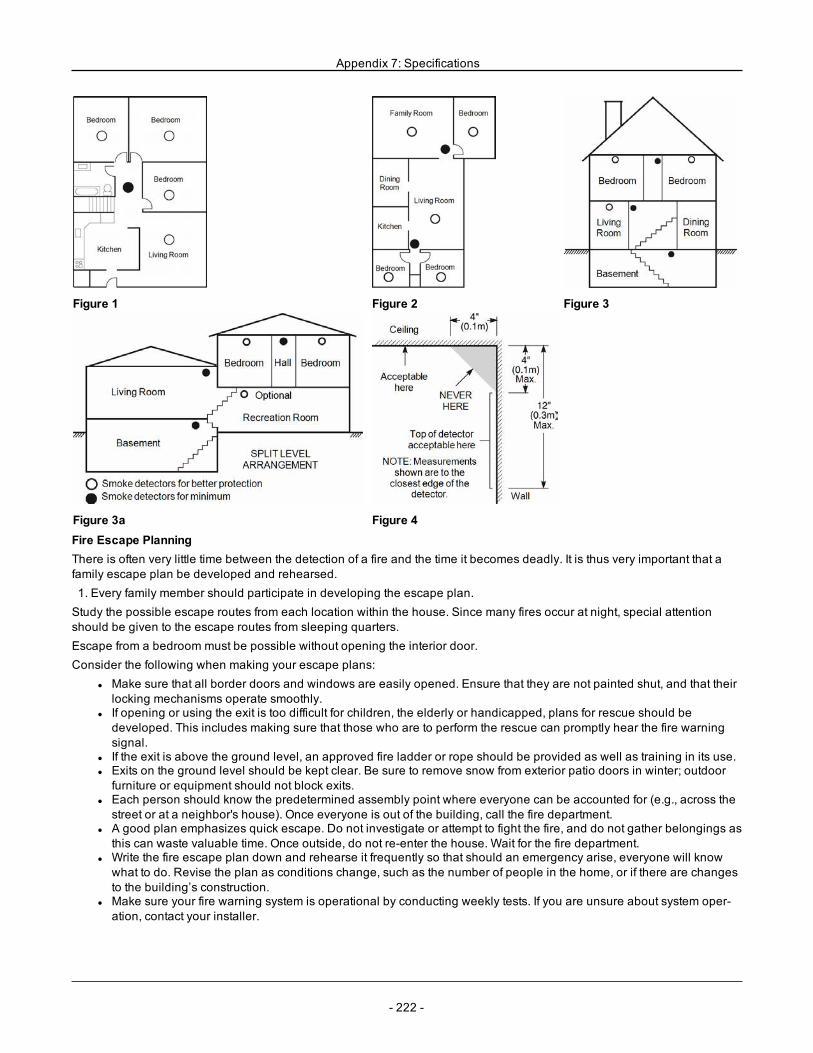
Appendix 7: Specifications
Figure 1 Figure 2 Figure 3
Figure 3a Figure 4Fire Escape PlanningThere is often very little time between the detection of a fire and the time it becomes deadly. It is thus very important that afamily escape plan be developed and rehearsed.1. Every family member should participate in developing the escape plan.Study the possible escape routes from each location within the house. Since many fires occur at night, special attentionshould be given to the escape routes from sleeping quarters.Escape from a bedroom must be possible without opening the interior door.Consider the following when making your escape plans:
l Make sure that all border doors and windows are easily opened. Ensure that they are not painted shut, and that theirlocking mechanisms operate smoothly.
l If opening or using the exit is too difficult for children, the elderly or handicapped, plans for rescue should bedeveloped. This includes making sure that those who are to perform the rescue can promptly hear the fire warningsignal.
l If the exit is above the ground level, an approved fire ladder or rope should be provided as well as training in its use.l Exits on the ground level should be kept clear. Be sure to remove snow from exterior patio doors in winter; outdoorfurniture or equipment should not block exits.
l Each person should know the predetermined assembly point where everyone can be accounted for (e.g., across thestreet or at a neighbor's house). Once everyone is out of the building, call the fire department.
l A good plan emphasizes quick escape. Do not investigate or attempt to fight the fire, and do not gather belongings asthis can waste valuable time. Once outside, do not re-enter the house. Wait for the fire department.
l Write the fire escape plan down and rehearse it frequently so that should an emergency arise, everyone will knowwhat to do. Revise the plan as conditions change, such as the number of people in the home, or if there are changesto the building’s construction.
l Make sure your fire warning system is operational by conducting weekly tests. If you are unsure about system oper-ation, contact your installer.
- 222 -
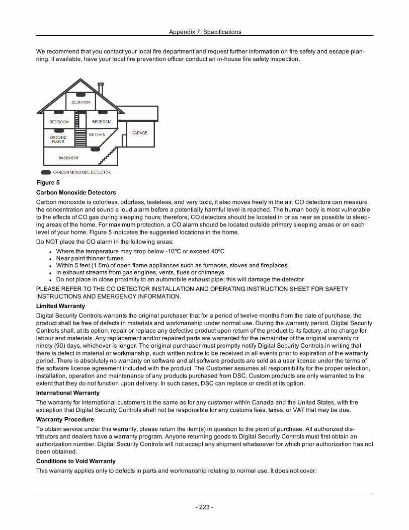
Appendix 7: Specifications
We recommend that you contact your local fire department and request further information on fire safety and escape plan-ning. If available, have your local fire prevention officer conduct an in-house fire safety inspection.
Figure 5Carbon Monoxide DetectorsCarbon monoxide is colorless, odorless, tasteless, and very toxic, it also moves freely in the air. CO detectors can measurethe concentration and sound a loud alarm before a potentially harmful level is reached. The human body is most vulnerableto the effects of CO gas during sleeping hours; therefore, CO detectors should be located in or as near as possible to sleep-ing areas of the home. For maximum protection, a CO alarm should be located outside primary sleeping areas or on eachlevel of your home. Figure 5 indicates the suggested locations in the home.Do NOT place the CO alarm in the following areas:
l Where the temperature may drop below -10ºC or exceed 40ºCl Near paint thinner fumesl Within 5 feet (1.5m) of open flame appliances such as furnaces, stoves and fireplacesl In exhaust streams from gas engines, vents, flues or chimneysl Do not place in close proximity to an automobile exhaust pipe; this will damage the detector
PLEASE REFER TO THE CO DETECTOR INSTALLATION AND OPERATING INSTRUCTION SHEET FOR SAFETYINSTRUCTIONS AND EMERGENCY INFORMATION.LimitedWarrantyDigital Security Controls warrants the original purchaser that for a period of twelve months from the date of purchase, theproduct shall be free of defects in materials and workmanship under normal use. During the warranty period, Digital SecurityControls shall, at its option, repair or replace any defective product upon return of the product to its factory, at no charge forlabour and materials. Any replacement and/or repaired parts are warranted for the remainder of the original warranty orninety (90) days, whichever is longer. The original purchaser must promptly notify Digital Security Controls in writing thatthere is defect in material or workmanship, such written notice to be received in all events prior to expiration of the warrantyperiod. There is absolutely no warranty on software and all software products are sold as a user license under the terms ofthe software license agreement included with the product. The Customer assumes all responsibility for the proper selection,installation, operation and maintenance of any products purchased from DSC. Custom products are only warranted to theextent that they do not function upon delivery. In such cases, DSC can replace or credit at its option.International WarrantyThe warranty for international customers is the same as for any customer within Canada and the United States, with theexception that Digital Security Controls shall not be responsible for any customs fees, taxes, or VAT that may be due.Warranty ProcedureTo obtain service under this warranty, please return the item(s) in question to the point of purchase. All authorized dis-tributors and dealers have a warranty program. Anyone returning goods to Digital Security Controls must first obtain anauthorization number. Digital Security Controls will not accept any shipment whatsoever for which prior authorization has notbeen obtained.Conditions to Void WarrantyThis warranty applies only to defects in parts and workmanship relating to normal use. It does not cover:
- 223 -
Appendix 7: Specifications
l damage incurred in shipping or handling;l damage caused by disaster such as fire, flood, wind, earthquake or lightning;l damage due to causes beyond the control of Digital Security Controls such as excessive voltage, mechanical shockor water damage;
l damage caused by unauthorized attachment, alterations, modifications or foreign objects;l damage caused by peripherals (unless such peripherals were supplied by Digital Security Controls Ltd.);l defects caused by failure to provide a suitable installation environment for the products;l damage caused by use of the products for purposes other than those for which it was designed;l damage from improper maintenance;l damage arising out of any other abuse, mishandling or improper application of the products.
Items Not Covered by WarrantyIn addition to the items which void the Warranty, the following items shall not be covered by Warranty: (i) freight cost to therepair centre; (ii) products which are not identified with DSC's product label and lot number or serial number; (iii) productsdisassembled or repaired in such a manner as to adversely affect performance or prevent adequate inspection or testing toverify any warranty claim. Access cards or tags returned for replacement under warranty will be credited or replaced atDSC's option. Products not covered by this warranty, or otherwise out of warranty due to age, misuse, or damage shall beevaluated, and a repair estimate shall be provided. No repair work will be performed until a valid purchase order is receivedfrom the Customer and a Return Merchandise Authorization number (RMA) is issued by DSC's Customer Service.Digital Security Controls Ltd.’s liability for failure to repair the product under this warranty after a reasonable number ofattempts will be limited to a replacement of the product, as the exclusive remedy for breach of warranty. Under no cir-cumstances shall Digital Security Controls be liable for any special, incidental, or consequential damages based uponbreach of warranty, breach of contract, negligence, strict liability, or any other legal theory. Such damages include, but arenot limited to, loss of profits, loss of the product or any associated equipment, cost of capital, cost of substitute or replacementequipment, facilities or services, down time, purchaser’s time, the claims of third parties, including customers, and injury toproperty. The laws of some jurisdictions limit or do not allow the disclaimer of consequential damages. If the laws of such ajurisdiction apply to any claim by or against DSC, the limitations and disclaimers contained here shall be to the greatestextent permitted by law. Some states do not allow the exclusion or limitation of incidental or consequential damages, so thatthe above may not apply to you.Disclaimer of WarrantiesThis warranty contains the entire warranty and shall be in lieu of any and all other warranties, whether expressed or implied(including all implied warranties of merchantability or fitness for a particular purpose) and of all other obligations or liabilitieson the part of Digital Security Controls. Digital Security Controls neither assumes responsibility for, nor authorizes any otherperson purporting to act on its behalf to modify or to change this warranty, nor to assume for it any other warranty or liabilityconcerning this product. This disclaimer of warranties and limited warranty are governed by the laws of the province ofOntario, Canada.WARNING: Digital Security Controls recommends that the entire system be completely tested on a regular basis. However,despite frequent testing, and due to, but not limited to, criminal tampering or electrical disruption, it is possible for this productto fail to perform as expected.Out of Warranty RepairsDigital Security Controls will at its option repair or replace out-of-warranty products which are returned to its factory accord-ing to the following conditions. Anyone returning goods to Digital Security Controls must first obtain an authorization number.Digital Security Controls will not accept any shipment whatsoever for which prior authorization has not been obtained.Products which Digital Security Controls determines to be repairable will be repaired and returned. A set fee which DigitalSecurity Controls has predetermined and which may be revised from time to time, will be charged for each unit repaired.Products which Digital Security Controls determines not to be repairable will be replaced by the nearest equivalent productavailable at that time. The current market price of the replacement product will be charged for each replacement unit.WARNING - READ CAREFULLYNote to InstallersThis warning contains vital information. As the only individual in contact with system users, it is your responsibility to bringeach item in this warning to the attention of the users of this system.System FailuresThis system has been carefully designed to be as effective as possible. There are circumstances, however, involving fire,burglary, or other types of emergencies where it may not provide protection. Any alarm system of any type may be
- 224 -
Appendix 7: Specifications
compromised deliberately or may fail to operate as expected for a variety of reasons. Some but not all of these reasons maybe:Inadequate InstallationA security system must be installed properly in order to provide adequate protection. Every installation should be evaluatedby a security professional to ensure that all access points and areas are covered. Locks and latches on windows and doorsmust be secure and operate as intended. Windows, doors, walls, ceilings and other building materials must be of sufficientstrength and construction to provide the level of protection expected. A reevaluation must be done during and after any con-struction activity. An evaluation by the fire and/or police department is highly recommended if this service is available.Criminal KnowledgeThis system contains security features which were known to be effective at the time of manufacture. It is possible for personswith criminal intent to develop techniques which reduce the effectiveness of these features. It is important that a security sys-tem be reviewed periodically to ensure that its features remain effective and that it be updated or replaced if it is found that itdoes not provide the protection expected.Access by IntrudersIntruders may enter through an unprotected access point, circumvent a sensing device, evade detection by moving throughan area of insufficient coverage, disconnect a warning device, or interfere with or prevent the proper operation of the system.Power FailureControl units, intrusion detectors, smoke detectors and many other security devices require an adequate power supply forproper operation. If a device operates from batteries, it is possible for the batteries to fail. Even if the batteries have not failed,they must be charged, in good condition and installed correctly. If a device operates only by AC power, any interruption, how-ever brief, will render that device inoperative while it does not have power. Power interruptions of any length are oftenaccompanied by voltage fluctuations which may damage electronic equipment such as a security system. After a power inter-ruption has occurred, immediately conduct a complete system test to ensure that the system operates as intended.Failure of Replaceable BatteriesThis system’s wireless transmitters have been designed to provide several years of battery life under normal conditions. Theexpected battery life is a function of the device environment, usage and type. Ambient conditions such as high humidity, highor low temperatures, or large temperature fluctuations may reduce the expected battery life. While each transmitting devicehas a low battery monitor which identifies when the batteries need to be replaced, this monitor may fail to operate as expec-ted. Regular testing and maintenance will keep the system in good operating condition.Compromise of Radio Frequency (Wireless) DevicesSignals may not reach the receiver under all circumstances which could include metal objects placed on or near the radiopath or deliberate jamming or other inadvertent radio signal interference.System UsersA user may not be able to operate a panic or emergency switch possibly due to permanent or temporary physical disability,inability to reach the device in time, or unfamiliarity with the correct operation. It is important that all system users be trainedin the correct operation of the alarm system and that they know how to respond when the system indicates an alarm.Smoke DetectorsSmoke detectors that are a part of this system may not properly alert occupants of a fire for a number of reasons, some ofwhich follow. The smoke detectors may have been improperly installed or positioned. Smoke may not be able to reach thesmoke detectors, such as when the fire is in a chimney, walls or roofs, or on the other side of closed doors. Smoke detectorsmay not detect smoke from fires on another level of the residence or building.Every fire is different in the amount of smoke produced and the rate of burning. Smoke detectors cannot sense all types offires equally well. Smoke detectors may not provide timely warning of fires caused by carelessness or safety hazards suchas smoking in bed, violent explosions, escaping gas, improper storage of flammable materials, overloaded electrical circuits,children playing with matches or arson.Even if the smoke detector operates as intended, there may be circumstances when there is insufficient warning to allow alloccupants to escape in time to avoid injury or death.Motion DetectorsMotion detectors can only detect motion within the designated areas as shown in their respective installation instructions.They cannot discriminate between intruders and intended occupants. Motion detectors do not provide volumetric area pro-tection. They have multiple beams of detection and motion can only be detected in unobstructed areas covered by thesebeams. They cannot detect motion which occurs behind walls, ceilings, floor, closed doors, glass partitions, glass doors or
- 225 -
Appendix 7: Specifications
windows. Any type of tampering whether intentional or unintentional such as masking, painting, or spraying of any materialon the lenses, mirrors, windows or any other part of the detection system will impair its proper operation.Passive infrared motion detectors operate by sensing changes in temperature. However their effectiveness can be reducedwhen the ambient temperature rises near or above body temperature or if there are intentional or unintentional sources ofheat in or near the detection area. Some of these heat sources could be heaters, radiators, stoves, barbeques, fireplaces,sunlight, steam vents, lighting and so on.Warning DevicesWarning devices such as sirens, bells, horns, or strobes may not warn people or waken someone sleeping if there is an inter-vening wall or door. If warning devices are located on a different level of the residence or premise, then it is less likely thatthe occupants will be alerted or awakened. Audible warning devices may be interfered with by other noise sources such asstereos, radios, televisions, air conditioners or other appliances, or passing traffic. Audible warning devices, however loud,may not be heard by a hearing-impaired person.Telephone LinesIf telephone lines are used to transmit alarms, they may be out of service or busy for certain periods of time. Also an intrudermay cut the telephone line or defeat its operation by more sophisticated means which may be difficult to detect.Insufficient TimeThere may be circumstances when the system will operate as intended, yet the occupants will not be protected from theemergency due to their inability to respond to the warnings in a timely manner. If the system is monitored, the response maynot occur in time to protect the occupants or their belongings.Component FailureAlthough every effort has been made to make this system as reliable as possible, the system may fail to function as intendeddue to the failure of a component.Inadequate TestingMost problems that would prevent an alarm system from operating as intended can be found by regular testing and main-tenance. The complete system should be tested weekly and immediately after a break-in, an attempted break-in, a fire, astorm, an earthquake, an accident, or any kind of construction activity inside or outside the premises. The testing shouldinclude all sensing devices, keypads, consoles, alarm indicating devices and any other operational devices that are part ofthe system.Security and InsuranceRegardless of its capabilities, an alarm system is not a substitute for property or life insurance. An alarm system also is not asubstitute for property owners, renters, or other occupants to act prudently to prevent or minimize the harmful effects of anemergency situation.IMPORTANT - READ CAREFULLY:DSC Software purchased with or without Products and Components is copyrighted and is purchased under the followinglicense terms:
l This End-User License Agreement (“EULA”) is a legal agreement between You (the company, individual or entitywho acquired the Software and any related Hardware) and Digital Security Controls, a division of Tyco SafetyProducts Canada Ltd. (“DSC”), the manufacturer of the integrated security systems and the developer of the softwareand any related products or components (“HARDWARE”) which You acquired.
l If the DSC software product (“SOFTWARE PRODUCT” or “SOFTWARE”) is intended to be accompanied byHARDWARE, and is NOT accompanied by new HARDWARE, You may not use, copy or install the SOFTWAREPRODUCT. The SOFTWARE PRODUCT includes computer software, and may include associated media, printedmaterials, and “online” or electronic documentation.
l Any software provided along with the SOFTWARE PRODUCT that is associated with a separate end-user licenseagreement is licensed to You under the terms of that license agreement.
l By installing, copying, downloading, storing, accessing or otherwise using the SOFTWARE PRODUCT, You agreeunconditionally to be bound by the terms of this EULA, even if this EULA is deemed to be a modification of any pre-vious arrangement or contract. If You do not agree to the terms of this EULA, DSC is unwilling to license theSOFTWARE PRODUCT to You, and You have no right to use it.
SOFTWARE PRODUCT LICENSEThe SOFTWARE PRODUCT is protected by copyright laws and international copyright treaties, as well as other intellectualproperty laws and treaties. The SOFTWARE PRODUCT is licensed, not sold.
- 226 -
Appendix 7: Specifications
1. GRANT OF LICENSE This EULA grants You the following rights:(a) Software Installation and Use - For each license You acquire, You may have only one copy of the SOFTWAREPRODUCT installed.(b) Storage/Network Use - The SOFTWARE PRODUCTmay not be installed, accessed, displayed, run, shared or used con-currently on or from different computers, including a workstation, terminal or other digital electronic device (“Device”). Inother words, if You have several workstations, You will have to acquire a license for each workstation where the SOFTWAREwill be used.(c) Backup Copy - You may make back-up copies of the SOFTWARE PRODUCT, but You may only have one copy perlicense installed at any given time. You may use the back-up copy solely for archival purposes. Except as expresslyprovided in this EULA, You may not otherwise make copies of the SOFTWARE PRODUCT, including the printed materialsaccompanying the SOFTWARE.2. DESCRIPTION OF OTHER RIGHTS AND LIMITATIONS(a) Limitations on Reverse Engineering, Decompilation and Disassembly - You may not reverse engineer, decompile, or dis-assemble the SOFTWARE PRODUCT, except and only to the extent that such activity is expressly permitted by applicablelaw notwithstanding this limitation. You may not make any changes or modifications to the Software, without the written per-mission of an officer of DSC. You may not remove any proprietary notices, marks or labels from the Software Product. Youshall institute reasonable measures to ensure compliance with the terms and conditions of this EULA.(b) Separation of Components - The SOFTWARE PRODUCT is licensed as a single product. Its component parts may not beseparated for use on more than one HARDWARE unit.(c) Single INTEGRATED PRODUCT - If You acquired this SOFTWARE with HARDWARE, then the SOFTWARE PRODUCTis licensed with the HARDWARE as a single integrated product. In this case, the SOFTWARE PRODUCTmay only be usedwith the HARDWARE as set forth in this EULA.(d) Rental - You may not rent, lease or lend the SOFTWARE PRODUCT. You may not make it available to others or post it ona server or web site.(e) Software Product Transfer - You may transfer all of Your rights under this EULA only as part of a permanent sale or trans-fer of the HARDWARE, provided You retain no copies, You transfer all of the SOFTWARE PRODUCT (including all com-ponent parts, the media and printed materials, any upgrades and this EULA), and provided the recipient agrees to the termsof this EULA. If the SOFTWARE PRODUCT is an upgrade, any transfer must also include all prior versions of theSOFTWARE PRODUCT.(f) Termination - Without prejudice to any other rights, DSC may terminate this EULA if You fail to comply with the terms andconditions of this EULA. In such event, You must destroy all copies of the SOFTWARE PRODUCT and all of its componentparts.(g) Trademarks - This EULA does not grant You any rights in connection with any trademarks or service marks of DSC or itssuppliers.3. COPYRIGHT - All title and intellectual property rights in and to the SOFTWARE PRODUCT (including but not limited to anyimages, photographs, and text incorporated into the SOFTWARE PRODUCT), the accompanying printed materials, and anycopies of the SOFTWARE PRODUCT, are owned by DSC or its suppliers. You may not copy the printed materials accom-panying the SOFTWARE PRODUCT. All title and intellectual property rights in and to the content which may be accessedthrough use of the SOFTWARE PRODUCT are the property of the respective content owner and may be protected by applic-able copyright or other intellectual property laws and treaties. This EULA grants You no rights to use such content. All rightsnot expressly granted under this EULA are reserved by DSC and its suppliers.4. EXPORT RESTRICTIONS - You agree that You will not export or re-export the SOFTWARE PRODUCT to any country,person, or entity subject to Canadian export restrictions.5. CHOICE OF LAW - This Software License Agreement is governed by the laws of the Province of Ontario, Canada.6. ARBITRATION - All disputes arising in connection with this Agreement shall be determined by final and binding arbit-ration in accordance with the Arbitration Act, and the parties agree to be bound by the arbitrator’s decision. The placeof arbitration shall be Toronto, Canada, and the installation manual of the arbitration shall be English.7. LIMITED WARRANTY(a) NOWARRANTY - DSC PROVIDES THE SOFTWARE “AS IS” WITHOUTWARRANTY. DSC DOES NOTWARRANT THATTHE SOFTWARE WILL MEET YOUR REQUIREMENTS OR THAT OPERATION OF THE SOFTWARE WILL BEUNINTERRUPTED OR ERROR-FREE.
- 227 -
Appendix 7: Specifications
(b) CHANGES IN OPERATING ENVIRONMENT - DSC shall not be responsible for problems caused by changes in the oper-ating characteristics of the HARDWARE, or for problems in the interaction of the SOFTWARE PRODUCT with non-DSC-SOFTWARE or HARDWARE PRODUCTS.(c) LIMITATION OF LIABILITY; WARRANTY REFLECTS ALLOCATION OF RISK - IN ANY EVENT, IF ANY STATUTEIMPLIES WARRANTIES OR CONDITIONS NOT STATED IN THIS LICENSE AGREEMENT, DSC’S ENTIRE LIABILITYUNDER ANY PROVISION OF THIS LICENSE AGREEMENT SHALL BE LIMITED TO THE GREATER OF THE AMOUNTACTUALLY PAID BY YOU TO LICENSE THE SOFTWARE PRODUCT AND FIVE CANADIAN DOLLARS (CAD$5.00).BECAUSE SOME JURISDICTIONS DO NOT ALLOW THE EXCLUSION OR LIMITATION OF LIABILITY FORCONSEQUENTIAL OR INCIDENTAL DAMAGES, THE ABOVE LIMITATION MAY NOT APPLY TO YOU.(d) DISCLAIMER OFWARRANTIES - THIS WARRANTY CONTAINS THE ENTIRE WARRANTY AND SHALL BE IN LIEU OFANY AND ALL OTHER WARRANTIES, WHETHER EXPRESSED OR IMPLIED (INCLUDING ALL IMPLIED WARRANTIESOF MERCHANTABILITY OR FITNESS FOR A PARTICULAR PURPOSE) AND OF ALL OTHER OBLIGATIONS ORLIABILITIES ON THE PART OF DSC. DSC MAKES NOOTHER WARRANTIES. DSC NEITHER ASSUMES NORAUTHORIZES ANY OTHER PERSON PURPORTING TO ACT ON ITS BEHALF TOMODIFY OR TO CHANGE THISWARRANTY, NOR TO ASSUME FOR IT ANY OTHER WARRANTY OR LIABILITY CONCERNING THIS SOFTWAREPRODUCT.(e) EXCLUSIVE REMEDY AND LIMITATION OFWARRANTY - UNDER NO CIRCUMSTANCES SHALL DSC BE LIABLEFOR ANY SPECIAL, INCIDENTAL, CONSEQUENTIAL OR INDIRECT DAMAGES BASED UPON BREACH OFWARRANTY,BREACH OF CONTRACT, NEGLIGENCE, STRICT LIABILITY, OR ANY OTHER LEGAL THEORY. SUCH DAMAGESINCLUDE, BUT ARE NOT LIMITED TO, LOSS OF PROFITS, LOSS OF THE SOFTWARE PRODUCT OR ANY ASSOCIATEDEQUIPMENT, COST OF CAPITAL, COST OF SUBSTITUTE OR REPLACEMENT EQUIPMENT, FACILITIES OR SERVICES,DOWN TIME, PURCHASERS TIME, THE CLAIMS OF THIRD PARTIES, INCLUDING CUSTOMERS, AND INJURY TOPROPERTY.WARNING: DSC recommends that the entire system be completely tested on a regular basis. However, despite frequent test-ing, and due to, but not limited to, criminal tampering or electrical disruption, it is possible for this SOFTWARE PRODUCT tofail to perform as expected.
- 228 -
- 229 -
8.0 Index
[
[*][6] Accessibility Option 95[*][8] Access While Armed 92[P] Key Annunciation 87
1
1 – Test Transmission ExceptionOption 90
2
2-way Audio attribute 1272-Wire Smoke 73200 Baud Open/Close Identifier
Toggle 9424-Hour Bell/Buzzer 66, 12724-Hour Burglary 66, 12724-Hour CO 66, 127, 136-13924-Hour Emergency 67, 12724-Hour Flood 6724-Hour Gas 66, 12724-Hour Heat 67, 12724-Hour High Temperature 12724-Hour Holdup 66, 12724-Hour Latch Tamper 67, 12724-Hour Medical 67, 12724-Hour Non-Alarm 67, 12724-Hour Non-Latching Tamper 6724-Hour Non Latch 12724-Hour Panic 66, 12724-Hour Sprinkler 67, 12724-Hour Supervisory 66, 12724-Hour Supervisory Buzzer 66,
12724-Hour Water 12724 Hour Low Temperature 67, 127
4
4-Digit Access Codes 97
5
50Hz AC/60Hz AC 95
6
6-Digit Access Codes 97
A
About the System 7AC Fail Trouble Beeps Option 90AC Failure Communication
Delay 108, 111AC Trouble Display Option 88AC Trouble Option 88AC/DC Inhibits Arming 95Access Code Entry During Entry
Delay 91Access Code Length 97Access Code Required for [*][1] 95Access Code Required for [*][2] 95Access Code Required for [*][3] 95Access Code Required for [*][4] 95Access Codes 55Access codes, adding 49Account Code 111Account Code Error Checking 112Account Codes 106, 162Activity Delinquency 110Add/Remove Modules 117Alarm Canceled 101Alarm Memory Display 47Alarm When Armed Event
Message 63Alt. Comm Battery
Trouble/Restore 104Alt. Comm Communications
Fault/Restore 104Alt. Comm Ethernet Trouble
/Restore 104Alt. Comm Power Supply
Trouble/Restore 104Alt. Comm Radio/SIM Fail-
ure/Restore 104Alternate Communicator 75Alternate Communicator Auto Rout-
ing (dual-path) 99Alternate Communicator DLS/SA
Option 113Alternate Communicator Enable/Dis-
able 111Alternate Communicator Label 64Alternate Communicator,
Installing 18
Alternate Dial 109Annunciation 39Approvals 208ASCII Characters 62ASCII Entry 62Audible 24-Hour Input 74Audible Bus Fault Option 91Audible Exit Delay 87Audible Exit Delay for Stay
Arming 94Audible Exit Fault 86Audio Verification 56Auto-Arm Schedule
Programming 86Auto-Arm Time 52Auto-Arm/Disarm 52Auto-Arming Bypass 93Auto Arm
Cancellation/Postpone 102Auto Detection 35Auto DLS Options 114Auto Enroll Modules 118Auto Verify Fire 66, 127Automatic Clock Adjust 70Automatic Closing/Opening 101Automatic DLS/SA Options 114Automatic Zone
Bypass/Unbypass 102Aux Power Wiring 24Auxiliary Input Alarm and
Restore 101Auxiliary Power Supply
Trouble/Restore 102Available Models 8Available User Codes 48Away Armed Status 74Away Armed with No Zone Bypasses
Status 74Away to Stay Toggle 94
B
Batteries, wiring 27Battery Settings 120Bell Circuit Trouble/Restore 102Bell Cutoff 70Bell Cutoff Time 70
Bell Delay Time 70Bell Duration Auto-Arm 87Bell Pulsed 127Bell Squawk Attribute 50Bell Squawk on Away Arm-
ing/Disarming 90Bell Squawk on Away Arm-
ing/Disarming Option 90Bell Squawk On Entry Option 87Bell Squawk On Exit Option 87Bell Squawk On Trouble Option 87Bell Squawk Option 86Bell Status and Programming
Access Output 76Bell Wiring 21Bell/PGM Support 34Bell/Siren Configuration 32Bell/Siren Operation 32binary data input 59Brightness Control 53Bulglary Verified Counter 97Burglary and Fire Bell Follower 72Burglary Not Verified 101Burglary Verification 69Burglary Verification Selection 97Burglary Verification Timer 70Burglary Verified 100Buzzer Control 54Bypass Enabled 69, 127Bypass Open Zones 43-44Bypass Recall 44Bypass Status Display Option 89Bypass Stay/Away/Night Zones 43
C
Call Waiting Cancel 111Call Waiting Cancel String 100, 157Capacitance 18Change Case 62Chime Function 68, 127Chime on Closing 89Chime on Opening 89Clear Bypasses 44Clear Display 62Clear to End 62
Closing Confirmation 110CO Alarm Message 63CO Detector, Wiring 26Cold Start 103Combus
capacitance 18line loss 18
Command Outputs 1-4 54, 74Command Outputs 1, 3, 4 54Communication Attempt Limit 35Communication Delay 107Communication Paths 35, 99Communication Variables 107Communications 34Communications
Enabled/Disabled 109Communications Options 35Communications Paths 156Communications Priority 110Communicator Backup Options 112Communicator Formats 107, 164Communicator Option One 109Compatible Devices 9Configuration steps 29Confirm Module 118Connecting Power 21Contact ID 192Contrast Control 53Control Panel Information 117Control Panel Installation 12Controls and Indicators 29Corbus Wiring 15Courtesy Pulse 73Cross Zone Timer 70Crystal Timebase 95Current Rating
module 17
D
Data, Entering 30Day Zone 65, 127Daylight Savings Begin/End 71Daylight Savings Time 90Daylight Savings Time Option 90DC Trouble 76
Default All KeypadProgramming 121
Default All labels 34Default Alternate
Communicator 121Default Keypads 1-8 121Default Labels 64Default Master Code 121Default System 121Default, Hardware 34Defaults 121Delay 1 64, 127Delay 2 64, 127Delay Call Window 114Delay Stay/Away 64, 127Delayed 24-Hour Fire 65, 127Delayed Fire and Burglary 73Delete Module 118Delinquency 103, 110DEOL 69, 127Device Supervision 31DLS Access Code 113DLS Call-Back
Enabled/Disabled 113DLS Disconnect 96DLS Lead In and Lead Out 103DLS Phone Number
Programming 113DLS Programming 58, 112DLS Window 96DLS/SA Panel ID 113Door Bell 68, 127Door Chime 39Door Chime Enable/Disable 47Double Call 113Double End of Line Resistors 23DTMF/Pulse Dialing Option 109Duress Alarm 100Duress Code Attribute 49Duress Codes 49, 91
E
Enable DLS/Allow SystemService 52
End-of-Line Options SEOL/SEOL 86Enrolling 1st Keypad 31
- 230 -
Enrolling Devices 30Enrolling Keypads 30Entry Delay 1 70Entry Delay 1-2 70Entry Delay 2 70Entry Delay Only Attribute 49EU Entry Procedure 91European Dial 96Event Buffer 51Event Buffer 75% Full 103Event Buffer Swinger 86Event Buffers, Viewing 36Event Reporting 100Exit Delay 70Exit Delay Restart 90Exit Delay Termination Option 87Exit Fault 102
F
Fail To Arm Event Message 63Fast Loop/Normal Loop
Response 69, 127Faults and Errors 201Final Door Set 65, 127Fire Alarm Message 63Fire and CO Zone Types 33Fire Bell Timeout Option 87Fire Key Option 87Fire Key Options 94Fire Supervisory 66, 127Fire Trouble & Restore 103Firmware Update Begin/was Suc-
cessful 103Firmware Update Fail 104Force Arm 69, 127Force Dial Option 96Freeze Trouble/Restore 104FTC Bell Option 96FTC Events Communicate 111Full Enrollment 31Function Key Definitions 40Function Keys 39
G
Gas Trouble/Restore 104Global Keypad, vs Partition 37
Global Zones 33Global/Multi Partition 33Global/Multiple Partition
Operation 37Ground Start 75Ground Wiring 27
H
Hardware Default 34Hardware Reset 34Heat Trouble/Restore 104Hex and Decimal Data, Pro-
gramming 60HEX Programming 60High-Current Output Supply
Label 64High Current Output Battery 120Hold-Up Verification Counter 97Hold-Up Verified 101Holdup Output 74Holdup Time 70Holiday Schedules 115HSM2HOST Label 63
I
I.D. Tone Option 96ICON keypad 59Installation 12Installer Access and DLS Option 92Installer Code 48, 71Installer Defined Codes 132Installer Lead In and Lead Out 103Installer LockoutLockout 121Installer Programming 54, 58Installer Walk Test 36Installer Walk Test
Enable/Disable 117Instant 64, 127Instant Stay/Away 65, 127Interior 64, 127Interior Delay 65, 127Interior Stay/Away 64, 127Interval Toggles-Holidays 115IP/Cellular Fault Check Timer 109IP/GS Wait for Ack 164
K
Keypad Backlighting Option 89Keypad Blanking Option 88Keypad Blanking Requires Code 88Keypad Buzzer Alarm Option 90Keypad Buzzer Follow 73Keypad Fire Alarm 101Keypad Function Keys 39Keypad Labels 63Keypad Lockout 85, 101Keypad Lockout, Number of Invalid
Local Attempts 85Keypad Medical Alarm 101Keypad Panic Alarm 101Keypad Partition Operation 33Keypad Tampers Option 89Keypad Types 59Keypad Zone Assignment 21Keypads, Default to Factory Set-
tingsDefault Keypads 121Keyswitch Arms in Away Mode 94Keyswitch Disarming During Entry
Delay 92Kissoff 75
L
Label 61Label Programming 61labels, defaulting 34Labels, Event 38Labels, Module 38Labels, Partition 38Labels, Partition Command
Output 39Labels, Zone 38Land Line Test Transmission
Option 96Language Selection 42, 61Latch Tamper 67, 127Latched System Event (Strobe) 76Latching Troubles Option 91Late to Close Option 89Late to Close/Open 102Late to Open 53Late to Open Time 53
- 231 -
LCD Keypad 59LED Indicators 29LED keypad 59letter case 62Line Loss 18Loaned Partition 33Local Firmware Upgrade 36Lockout 85Low Temperature Warning 39
M
Main Bell Mask 77Main Bell Operational Mask 72Maintain Arm 67, 127Maintain Disarm 68, 127Maintenance Code 48, 71Manual Enroll 118Manual Enrollment 32Master Code 48, 71Master Code Option 88Model Differences 8Module AC Trouble/Restore 104Module Aux Trouble/Restore 104Module Battery Absent/Restore 104Module Battery Trouble/Restore 104Module Information 117Module Labels 38Module Low Voltage
Trouble/Restor 104Module Supervisory
Trouble/Restore 104Module Tamper/Restore 101Modules, Installing 18Modules, Removing 31Momentary Arm 67, 127Momentary Disarm 68, 127Mounting 12Multiple Siren Output Operation 32
N
NC Loop/EOL 86Network Fault and Restore 104Night Zone 65, 127No Entry Arming 55Normally Closed 69Normally Closed (NC) Loops 127
Null PGM 72Null Zone 64, 127Number of Rings to Answer On 114
O
One Time User Code 49One Time User Code Attribute 50Open After Alarm 77Open Cancels Arming 93Open/Close Events 101Opening after Alarm 100Opening After Alarm Bell
Ringback 110Opening After Alarm Keypad Ring-
back 110Output 1 Fault/Restore 104Output Expander Label 63Output Expander, Installing 19Overview of Installation Process 12
P
Panel AC Fail Trouble/Restore 102Panel Battery Absent
Trouble/Restore 102Panel Battery Settings 120Panel Call-Up Baud Rate
Option 113Panel Low Battery
Trouble/Restore 102Panel/Receiver Communication
Paths 99Parallel Communications 109Partial Closing 102Partition 1-8 Labels 63Partition 1-8 Timer 70Partition 1 to 8 Enable Mask 98Partition Account Codes 106Partition Auto-Arm Postpone
Timer 98Partition Auto-Arm/ Disarm 150-153Partition Auto-Arm/Disarm 97Partition Auto-Arming Pre-Alert Ti
mer 98Partition Auto-Arming Times 97Partition Auto-Disarming Holiday
Schedules 98Partition Auto-Disarming Times 97
Partition Call Directions 106Partition Command Output
Labels 39, 63, 123-124Partition Labels 38Partition Mask 98, 154Partition No Activity Arm Timer 98Partition No Activity Arming Pre-Alert
Duration 98Partition Status Alarm Memory 74Partition vs. Global Keypad 37Partition Zone Assignment 99Partition, Setting Up 32Partitions, Assigning to Users 51Partitions, Working With 32PC-Link, Local Programming
with 58PC-Link, Programming 58Periodic DLS 114Periodic DLS Days 114Periodic DLS Time 114Periodic Test Transmission 105Periodic Test Transmission with
Trouble 105PGM 1-28 Attributes 78PGM 2 2-Wire Alarm/Restore 101PGM 2 Two-Wire
Trouble/Restore 103PGM Attributes 77, 136PGM Configuration Options 85, 141PGM Partition Assignment 72, 132PGM Timer Programming 72PGM Timers 132, 141PGMWiring 21Phone Number Account Code 111Phone Number Programming, Cen-
tral Station 99Placement Test Wireless keys 120Placement Test Zones 1-128 120Power-up Sequence 30Power Save Mode Option 89Power Supply Label 64Pre-Enrollment 32Priority Alarms 101Probe Disconnected
Trouble/Restore 104Program Group 1 43
- 232 -
Program User Codes 47Programming Methods 61Programming Schedule 1 115Programming, DLS 58Programming, How to 57Programming, Installer 58Proximity Tag Used 76Proximity Tags, Assigning 50PSTN 1 Communication Path 99PSTN Double Call Timer 114Pulse Dial after 5th attempt 109Push to Set 68, 127
Q
Quick Arm/Exit 55Quick Arming /Function Key
Option 88Quick Exit Option 87
R
Ready LED Flashes for Force Arm-ing 94
Ready to Arm 73Real-Time Redundant Com-
munications 35Real Time Clock 35Real Time Clock Option 95Receiver 1 to 4 FTC Trouble and
Restore 104Receiver 1 to 4 Supervision Failure
and Restore 105Receiver 1 to 4 Trouble and
Restore 105Receiver 2 Backup Option 112Receiver 3 Backup Option 112Receiver 4 Backup Option 112Recent Closing 100Reduced Dialing Attempts 110Regulatory Approvals 202, 208,
215-216Remote Firmware Upgrade 35Remote Firmware Upgrade, Mod-
ules 36Remote Firmware Upgrade,
Panel 36Remote Lockout 85Remote Lockout Duration 85
Remote Operation 76Remote Programming 58Remote Reset 92Repeater Labels 64Reporting 100Reporting Codes 192Restore Transmission on Bell
Timeout 109RF Jam Trouble/Restore 103
S
SA Access Code 114SA Lead In and Lead Out 103Save Label 62Schedule Labels 63Schedule Programming 115Select Option menu 62Sensor Reset [*][7][2] 73SEOL 69Sequential Detection 127Set End Day 115Set End Time 115Set Start Day 115Set Start Time 115Settle Delay 71Shared Zones 33SIA Format 192Silent 24-Hour Input 74Single End of Line (SEOL)
Resistors 127Single Partition 33Single Partition Operation 37Single Siren Output Operation 32Siren Labels 64Smoke Detector, Wiring 19SMS Command and Control 55SMS Messages 56SMS Programming 53Soak Test 120Soak Test Timer 120Special Closing/Opening 101Specifications 7Standard 24-Hour Fire 127Status LED 29Stay Armed Status 74
Supervision 31Supervision Restore 35Supervisor Attribute 49Supervisor Codes 48Swinger Shut Down 69Swinger Shutdown 107, 127System Account Code 106, 111System Area 70System Armed Status 73System Call Direction 106, 162System Information 117System Label 63System Labels 38System Lockout 85System Option 1 86System Option 10 94System Option 11 94, 148System Option 12 95System Option 13 149System Option 2 86System Option 3 87, 146System Option 4 88System Option 5 89, 146System Option 6 90System Option 7 91, 147System Option 8 91System Option 9 93, 148System Tamper 76System Test 51, 106System Trouble 75
T
Tamper/Fault Detection 94Tampers Inhibit Arming 95Telephone Line Monitor Audible
When Armed 88Telephone Line Monitor Option 88Telephone Line Trouble and
Restore 102Telephone Line Wiring 21Temperature Display 39Temperature in Celsius 91Template Programming 57Temporal Three Fire Signaling 86Test Transmission Cycle 108
- 233 -
Test Transmission Receiver 111Testing 119Testing the System 36Time and Date 52TLM and Alarm 75TLM Trouble Delay 108Tone Generated-1200Hz 96Transmission Counter in Hours 94Transmission Delay 69, 127Trouble Beeps Control 94Trouble Display 44Trouble Indicators 33Troubles Inhibit Arming Option 92Troubleshooting 184
U
User Authentication 97User Authentication Options 51, 55User Call-up 53User Call-Up Enabled/Disabled 113User Closing/Opening 101User code and proximity tag 97User Code Attributes 49User code or proximity tag 97User Codes 48User Codes, Assigning 47User Enables/Disables DLS 113User Functions 51User Labels, Adding 50User Walk Test 53Using the Keypad 29
V
Video Verification 56Viewing Event Buffers 36Viewing Programming 58Voice Chime 39
W
Walk Test Communications 111Walk Test Start & End 105Wireless Device AC
Failure/Restore 105Wireless Device Fault/Restore 105Wireless Device Low Battery Trans-
mission Delay 108
Wireless Device Low BatteryTrouble/Restore 105
Wireless Devices, Enrolling 31Wireless Placement Test 119Wireless Receiver, DefaultDefault
Wireless Receiver 121Wireless Transceiver Module,
Wiring 19Wiring 13Word Library 62Words 62
Z
Zone Assignment, Partition 99Zone Attributes 68, 127Zone Bypassing Attribute 49Zone Expander Labels 63Zone Expander Supervisory Alarm
and Restore 100Zone Expander, Installing 18Zone Fault Label 63Zone Follow PGM By Zone 77Zone Follower 77Zone Label Options 62Zone Labels 38, 61Zone Loop Options 86Zone Loop Response Time 70Zone Reporting 100Zone Soak Test 120Zone Tamper Label 63Zone Types 64, 127Zone Types, Fire and CO 33Zone Wiring 21
- 234 -

The trademarks, logos, and service marks displayed on this document are registered in the United States [or other countries]. Any mis-use of the trademarks is strictly prohibited and Tyco will aggressively enforce its intellectual property rights to the fullest extent of thelaw, including pursuit of criminal prosecution wherever necessary. All trademarks not owned by Tyco are the property of their respect-ive owners, and are used with permission or allowed under applicable laws.Product offerings and specifications are subject to change without notice. Actual products may vary from photos. Not all productsinclude all features. Availability varies by region; contact your sales representative.
© 2015 Tyco Security ProductsAll Rights Reserved.Tech Support: 1-800-387-3630 (Canada & U.S.)or 905-760-3000www.dsc.com
29009047R002
EuropeThis product is in conformity with:EMC Directive 2004/108/EC based on results using harmonized standards in accordance with article 10(5),R&TTE Directive 1999/5/EC based on following Annex III of the directive andLVD Directive 2006/95/EC based on results using harmonized standards.The product is labelled with the CE mark as proof of compliance with the above mentioned European Directives. Also a CE declar-ation of conformity (DoC) for this product can be found at www.dsc.com under Agency Listings section.
N5167
This Digital Security
Controls HS2128 Security
System may be connected
to the Telecom Network
PTC 211 / 13 / 055
TELEPERMIT
RN
= 0
.5 This Digital Security
Controls HS064 Security
System may be connected
to the Telecom Network
PTC 211 / 13 / 056
TELEPERMIT
RN
= 0
.5
This Digital Security
Controls HS2032 Security
System may be connected
to the Telecom Network
PTC 211 / 13 / 057
TELEPERMIT
RN
= 0
.5 This Digital Security
Controls HS2016 Security
System may be connected
to the Telecom Network
PTC 211 / 13 / 058
TELEPERMITR
N =
0.5


