Embed Size (px)
Citation preview
Pc
SI
a
ARRAA
KPMPNCPTN
1
ti
0d
Precision Engineering 34 (2010) 286–300
Contents lists available at ScienceDirect
Precision Engineering
journa l homepage: www.e lsev ier .com/ locate /prec is ion
ractical controller design for precision positioning, independent of frictionharacteristic
hin-Horng Chong ∗, Kaiji Satonterdisciplinary Graduate School of Science and Engineering, Tokyo Institute of Technology, 4259 Nagatsuta, Midori-ku, Yokohama 226-8502, Japan
r t i c l e i n f o
rticle history:eceived 10 December 2008eceived in revised form 23 June 2009ccepted 6 July 2009vailable online 6 October 2009
eywords:recisionotion control
ractical controlleron-contact mechanismontact mechanismositioning controlracking controlCTF control
a b s t r a c t
In this contribution, a practical controller design for non-contact mechanism and contact mechanismis discussed. The design procedure is applicable and totally independent of friction characteristic. Thus,designer does not need to consider the friction characteristic of a mechanism and it is a valuable con-troller approach in industry. The practical controller design procedure which based on current NominalCharacteristic Trajectory Following (NCTF) controller is proposed and improved. The NCTF controller iscomprehensive, comprising of a Nominal Characteristic Trajectory (NCT) and a PI compensator, which isfree from exact modeling and parameter identification. In NCTF controller design, the NCT is constructedfrom the open-loop responses of the mechanism. The designed input signal for open-loop experiment isneeded to satisfy the following two conditions: (1) the displacement by the input signal must be smallerthan the working range of the mechanism to avoid any damage to the mechanism; (2) the suitable inputsignal needs to produce sufficient rapid and smooth response during deceleration to satisfy the desiredspecifications because the response significantly influences the reference following characteristic of thecontrol system. So far, the NCTF controllers had been implemented to the mechanisms which have suffi-cient large damping characteristics and it was natural to satisfy the condition (1). However, non-contactand low damping mechanisms do not have sufficient damping characteristics. Since the high dampingcharacteristics of the mechanism have been used before, the condition (2) is still not yet been considered.Therefore, the design procedure of the input signal satisfying the two conditions is proposed and verifiedby experiments in this paper. The common conditions of the input signal which is independent of fric-tion characteristic of the mechanisms are discussed. Then, the experimental verifications are performedusing non-contact mechanism and contact mechanism. In this paper, the performance evaluation is dis-cussed separately in two parts. In part 1, by using the non-contact mechanism, the positioning resultsof two different NCTs are compared in order to show the usefulness of the modified suitable input. Inpart 2, the contact mechanism is used to show the effectiveness of the NCTF controller with its sim-ple and practical design procedure, which is independent of friction characteristic. The effectiveness ofthe Continuous Motion NCTF controller is verified with the PID controller experimentally in positioning
control and tracking control. The experimental results prove that the displacements of the open-loopresponses for NCTs are always smaller than the working range and the design procedure of the input sig-nal is successfully independent of the friction characteristic of the mechanism. Overall, the ContinuousMotion NCTF controller which has simple and practical design procedure exhibits the high performancein positioning and tracking control with contact mechanism and non-contact mechanism, as comparedto the PID controller. The PID controller shows the low adaptability in motion control performances fornism
both conditions of mecha. Introduction
Precision motion systems have been steadily gathering momen-um and attention over the last century in terms of research andndustrial machines such as machine tools, measuring machines,
∗ Corresponding author. Tel.: +81 45 924 5045; fax: +81 45 924 5483.E-mail address: [email protected] (S.-H. Chong).
141-6359/$ – see front matter © 2009 Elsevier Inc. All rights reserved.oi:10.1016/j.precisioneng.2009.09.006
.© 2009 Elsevier Inc. All rights reserved.
and semiconductor manufacturing systems. The demands forhigher productivity and product quality in industry call for thedevelopment of high performance positioning control. The non-friction mechanism has been hailed as the motion mechanism of
the current and next generation because of its simplicity and supe-rior performance. It is probably popular solution for high-speed andhigh-precision motion control in industry nowadays. Furthermore,friction mechanism which is still commonly used in industry hashighly nonlinearities characteristic and may result in steady-state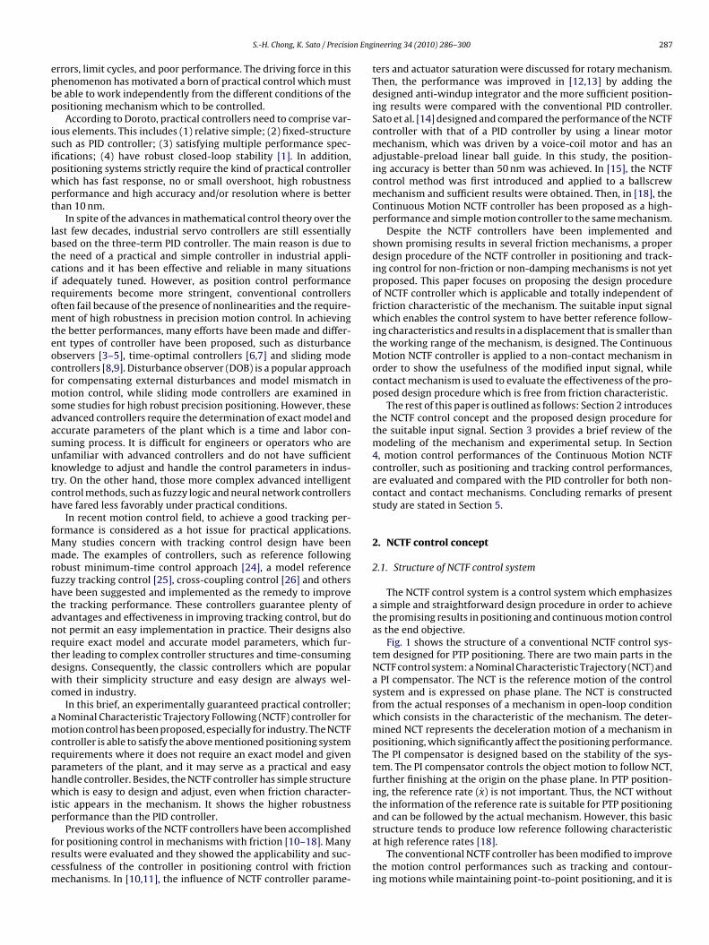
n Eng
epbp
isipwpt
lbtciromteocfmsaasuktch
fMmrfhtanrtdwc
amcrphwip
frcm
S.-H. Chong, K. Sato / Precisio
rrors, limit cycles, and poor performance. The driving force in thishenomenon has motivated a born of practical control which muste able to work independently from the different conditions of theositioning mechanism which to be controlled.
According to Doroto, practical controllers need to comprise var-ous elements. This includes (1) relative simple; (2) fixed-structureuch as PID controller; (3) satisfying multiple performance spec-fications; (4) have robust closed-loop stability [1]. In addition,ositioning systems strictly require the kind of practical controllerhich has fast response, no or small overshoot, high robustnesserformance and high accuracy and/or resolution where is betterhan 10 nm.
In spite of the advances in mathematical control theory over theast few decades, industrial servo controllers are still essentiallyased on the three-term PID controller. The main reason is due tohe need of a practical and simple controller in industrial appli-ations and it has been effective and reliable in many situationsf adequately tuned. However, as position control performanceequirements become more stringent, conventional controllersften fail because of the presence of nonlinearities and the require-ent of high robustness in precision motion control. In achieving
he better performances, many efforts have been made and differ-nt types of controller have been proposed, such as disturbancebservers [3–5], time-optimal controllers [6,7] and sliding modeontrollers [8,9]. Disturbance observer (DOB) is a popular approachor compensating external disturbances and model mismatch in
otion control, while sliding mode controllers are examined inome studies for high robust precision positioning. However, thesedvanced controllers require the determination of exact model andccurate parameters of the plant which is a time and labor con-uming process. It is difficult for engineers or operators who arenfamiliar with advanced controllers and do not have sufficientnowledge to adjust and handle the control parameters in indus-ry. On the other hand, those more complex advanced intelligentontrol methods, such as fuzzy logic and neural network controllersave fared less favorably under practical conditions.
In recent motion control field, to achieve a good tracking per-ormance is considered as a hot issue for practical applications.
any studies concern with tracking control design have beenade. The examples of controllers, such as reference following
obust minimum-time control approach [24], a model referenceuzzy tracking control [25], cross-coupling control [26] and othersave been suggested and implemented as the remedy to improvehe tracking performance. These controllers guarantee plenty ofdvantages and effectiveness in improving tracking control, but doot permit an easy implementation in practice. Their designs alsoequire exact model and accurate model parameters, which fur-her leading to complex controller structures and time-consumingesigns. Consequently, the classic controllers which are popularith their simplicity structure and easy design are always wel-
omed in industry.In this brief, an experimentally guaranteed practical controller;
Nominal Characteristic Trajectory Following (NCTF) controller forotion control has been proposed, especially for industry. The NCTF
ontroller is able to satisfy the above mentioned positioning systemequirements where it does not require an exact model and givenarameters of the plant, and it may serve as a practical and easyandle controller. Besides, the NCTF controller has simple structurehich is easy to design and adjust, even when friction character-
stic appears in the mechanism. It shows the higher robustnesserformance than the PID controller.
Previous works of the NCTF controllers have been accomplishedor positioning control in mechanisms with friction [10–18]. Manyesults were evaluated and they showed the applicability and suc-essfulness of the controller in positioning control with frictionechanisms. In [10,11], the influence of NCTF controller parame-
ineering 34 (2010) 286–300 287
ters and actuator saturation were discussed for rotary mechanism.Then, the performance was improved in [12,13] by adding thedesigned anti-windup integrator and the more sufficient position-ing results were compared with the conventional PID controller.Sato et al. [14] designed and compared the performance of the NCTFcontroller with that of a PID controller by using a linear motormechanism, which was driven by a voice-coil motor and has anadjustable-preload linear ball guide. In this study, the position-ing accuracy is better than 50 nm was achieved. In [15], the NCTFcontrol method was first introduced and applied to a ballscrewmechanism and sufficient results were obtained. Then, in [18], theContinuous Motion NCTF controller has been proposed as a high-performance and simple motion controller to the same mechanism.
Despite the NCTF controllers have been implemented andshown promising results in several friction mechanisms, a properdesign procedure of the NCTF controller in positioning and track-ing control for non-friction or non-damping mechanisms is not yetproposed. This paper focuses on proposing the design procedureof NCTF controller which is applicable and totally independent offriction characteristic of the mechanism. The suitable input signalwhich enables the control system to have better reference follow-ing characteristics and results in a displacement that is smaller thanthe working range of the mechanism, is designed. The ContinuousMotion NCTF controller is applied to a non-contact mechanism inorder to show the usefulness of the modified input signal, whilecontact mechanism is used to evaluate the effectiveness of the pro-posed design procedure which is free from friction characteristic.
The rest of this paper is outlined as follows: Section 2 introducesthe NCTF control concept and the proposed design procedure forthe suitable input signal. Section 3 provides a brief review of themodeling of the mechanism and experimental setup. In Section4, motion control performances of the Continuous Motion NCTFcontroller, such as positioning and tracking control performances,are evaluated and compared with the PID controller for both non-contact and contact mechanisms. Concluding remarks of presentstudy are stated in Section 5.
2. NCTF control concept
2.1. Structure of NCTF control system
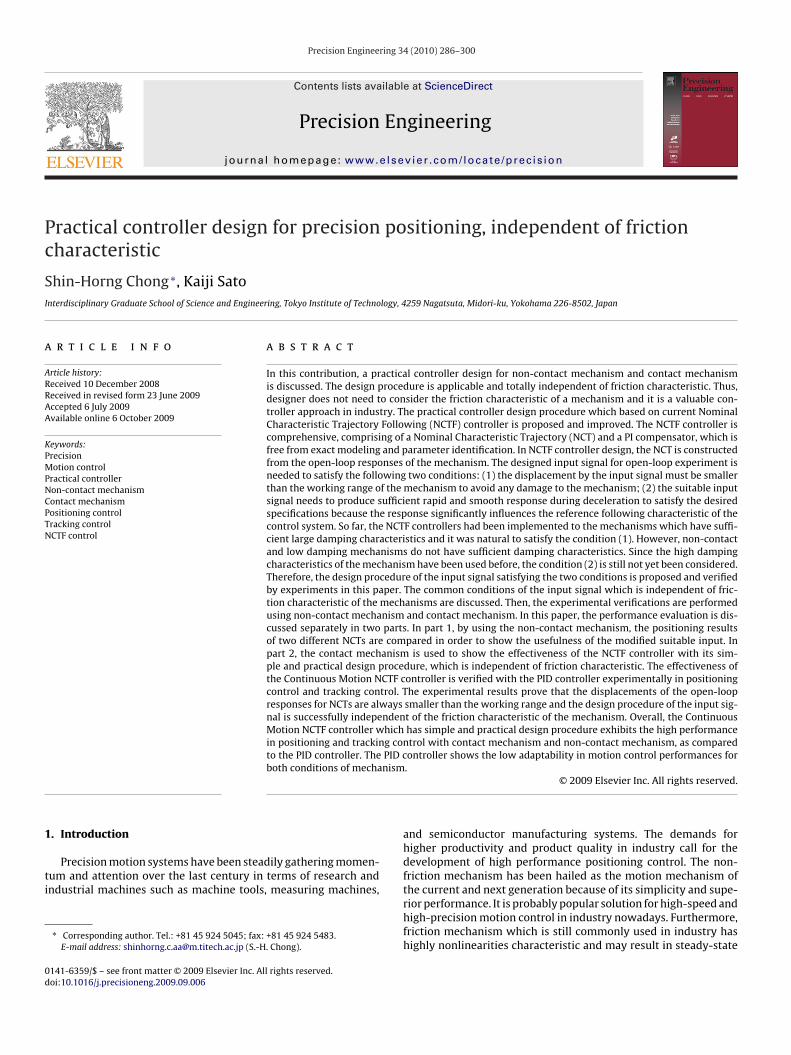
The NCTF control system is a control system which emphasizesa simple and straightforward design procedure in order to achievethe promising results in positioning and continuous motion controlas the end objective.
Fig. 1 shows the structure of a conventional NCTF control sys-tem designed for PTP positioning. There are two main parts in theNCTF control system: a Nominal Characteristic Trajectory (NCT) anda PI compensator. The NCT is the reference motion of the controlsystem and is expressed on phase plane. The NCT is constructedfrom the actual responses of a mechanism in open-loop conditionwhich consists in the characteristic of the mechanism. The deter-mined NCT represents the deceleration motion of a mechanism inpositioning, which significantly affect the positioning performance.The PI compensator is designed based on the stability of the sys-tem. The PI compensator controls the object motion to follow NCT,further finishing at the origin on the phase plane. In PTP position-ing, the reference rate (x) is not important. Thus, the NCT withoutthe information of the reference rate is suitable for PTP positioningand can be followed by the actual mechanism. However, this basic
structure tends to produce low reference following characteristicat high reference rates [18].The conventional NCTF controller has been modified to improvethe motion control performances such as tracking and contour-ing motions while maintaining point-to-point positioning, and it is
288 S.-H. Chong, K. Sato / Precision Engineering 34 (2010) 286–300
venti
rtMmcercwP
abcIsddocrew
2
i
Fig. 1. Structure of the con
eferred as the Continuous Motion NCTF controller. Fig. 2 presentshe structure of the Continuous Motion NCTF controller. Sato and
aeda [18] designed and implemented this controller on leadscrewechanisms. As compared to a conventional NCTF controller, the
ontroller is remaining simple and the reference rate (x) is consid-red. The input signal to the PI compensator includes the referenceate (x), thereby helps to speed up the mechanism movement. Basi-ally, the Continuous Motion and the conventional NCTF controllerill have the identical controller structure and same control law in
TP positioning when x is zero.As mentioned before, the controller which is easy to design and
pplied practically is needed in nowadays. Recently, some model-ased controllers such as sliding mode controller or seeking modeontroller is very well-known controller in hard disk drives [19].n the field of HDD drive, even though these controllers have aimilar control structure and include the reference element of theeceleration motion, such as square root map, those controlleresigns require exact dynamic model information and knowledgef control theory, which makes them difficult to use in practice. Inontrast, NCTF controller is easy to design and adjust. It does notequire exact modeling, known model parameters, or much knowl-dge of control theory. This makes it is user-friendly to engineersho are lack of control theory knowledge to handle.
.2. Universal NCT design
In this section, the universal NCTF design procedure which isndependent from friction characteristic is discussed. Basically, the
Fig. 2. Structure of the Continuous Motion NCTF control system.
onal NCTF control system.
design procedure remains same as the conventional one. The onlyimproved part has been designed is the open-loop input signal.
The designed input signal is capable to satisfy the two impor-tant conditions. First, the displacement by the input signal must besmaller than the short working range of the mechanism to avoidany damage to the mechanism. Second, the designed input signalhas the advantage to construct the NCT for sufficient rapid andsmooth response near the reference position. The suitable inputsignal needs to produce sufficient rapid and smooth response dur-ing deceleration to satisfy the desired specifications because theresponse significantly influences the reference following charac-teristic of the control system. The design procedure of the inputsignal satisfying the two conditions is discussed in the next section.
2.2.1. Design procedureA simple and practical method is always mainly considered in
the NCTF controller design procedure. In this paper, the same designprocedure is applied to the non-contact mechanism and contactmechanism. Since the Continuous Motion NCTF controller has thealmost similar controller structure as the conventional one, thesame design procedure is used.
Generally, the design procedure of the NCTF controller is com-prised of three basic steps:
(i) The mechanism is driven with an open-loop step input and itsdisplacement and velocity are measured.
In this paper, since the non-contact mechanism does nothave sufficient large damping characteristic, the input signalis designed to make sure the mechanism moves within theworking range to avoid any damage to the mechanism. Thedetail of the suitable input signal design is discussed in nextsection.
(ii) The NCT is constructed on the phase plane using the displace-ment and velocity of the mechanism during deceleration.
The construction of NCT does not require the exact dynamicinformation of the mechanism. The obtained decelerationvelocity and displacement from open loop are used to con-struct the NCT without any additional element or step. Thediscussion about the constructed NCT is shown in Section 4.
S.-H. Chong, K. Sato / Precision Eng
Ft
(
2
dbTwsemi
crmtaa
Gp(s) = X(s)U(s)
= Kf
Ms2= Kfm
s2(3)
where Kfm = Kf/M.
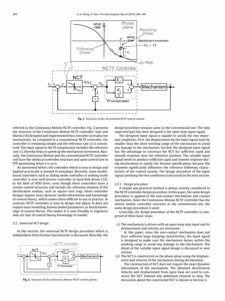
ig. 3. Input signals for open-loop experiment (applicable for non-contact and con-act mechanisms).
iii) The PI compensator is designed based on the open-loopresponses and NCT information. In order to consider the realcharacteristic of the mechanism in designing PI compensator,a practical stability limit is determined.
The practical stability limit of the actual mechanism is foundby driving the mechanism with the NCTF controller using onlythe proportional element. The value of gain is increased untilcontinuous oscillations are generated which indicates the exis-tence of instability. However, the non-damping mechanismtends to oscillate with any value of proportional gain. Thus, theamplitude of oscillation is decided for determining the suitableproportional gain. Once the continuous oscillation is over thedecided threshold, the gain is determined as maximum valueof the proportional gain and it is referred as Kpu (actual ultimateproportional gain). The practical stability limit �p is given as
�p = Kpu
(Kfm
2ωn
)Kfm = xf
urt21
(1)
The compensator gains are calculated by using equationsbelow:
Kp = 2�ωn
KfmKi = ω2
n
Kfm(2)
Overall, the design procedure of the NCTF controller has shownthe simplicity and the easy adjustment of the controller.Additionally, it is useful to be applied to both non-contactmechanism and contact mechanisms.
.2.2. Input signal designFig. 3 presents the basic symmetry step wise input signal and the
esigned suitable input signal for open-loop experiment which haseen applied on non-contact mechanism and contact mechanism.he suitable input signal is modified from the basic symmetry stepise input signal. The most important characteristic of the input
ignal designed for non-friction mechanism is a symmetrical prop-rty. Only the symmetrical input is able to stop the non-dampingechanism within the working range during the open-loop exper-
ment.The modification of the basic symmetry step wise input signal is
onsidered due to result in a smoother open-loop deceleration time
esponses for better positioning performance with non-dampingechanism and the mechanism has friction condition. As the effort,he basic symmetry step wise input signal is modified with the highttenuation near stopping position. The curve with high attenu-tion near stopping position is obtained exponentially. The high
ineering 34 (2010) 286–300 289
attenuation input near the stopping position could help the con-trol system to drive the mechanism smoothly near the origin andend-up a smoothness motion trajectory. The characteristic nearthe reference position is always important for positioning andinfluences the positioning accuracy. The reference following char-acteristic of the control system depends on the inclination nearthe reference position. The modified input signal is expected toproduce sufficient rapid and smooth response during deceleration.Furthermore, it is expected to enable the control system to havebetter reference following characteristic and increases the incli-nation near the origin. Besides, the modified input signal containsthe characteristic of conventional input shaping profile which isimportant in avoiding the stimulation of high frequency dynamicsin positioning apparatus.
During designing the suitable input signal, the duty time t1 andt2 are important criteria. The t1 is chosen when the displacementis less than or half of the working range of the mechanism. Then,t2 is determined when the velocities are same at the both cross-point as shown in Fig. 3 and stops smoothly. The same velocities atthe cross-point are important to make sure the mechanism stopswithin the working range. The ur is designed so that the movementof mechanism is in the short working range and not causing anydamage to the mechanism.
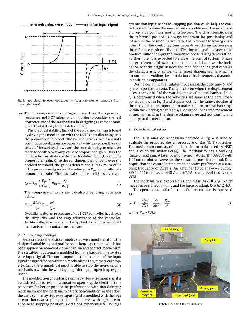
3. Experimental setup
The 1DOF air-slide mechanism depicted in Fig. 4 is used toevaluate the proposed design procedure of the NCTF controller.The mechanism consists of an air-guide (manufactured by NSK)and a voice-coil motor (VCM). The mechanism has a workingrange of ±22 mm. A laser position sensor (AGILENT 10897B) with1.24 nm resolution serves as the sensor for position control. Dataacquisition and controller implementation are performed at a sam-pling frequency of 2.5 kHz. An amplifier (Bipolar Power Supply,BPS40-15) is limited at ±40 V and ±7.5 A, is employed to drive theVCM.
The mechanism is expressed as one mass (M = 10.5 kg) whichmoves in one direction only and the force constant, Kf is 6.12 N/A.
The open-loop transfer function of the mechanism is expressedas
Fig. 4. 1DOF air-slide mechanism.
290 S.-H. Chong, K. Sato / Precision Engineering 34 (2010) 286–300
niFuet
Fc
Fig. 5. The adjusting unit for friction characteristic (contact mechanism).
As can be seen in Fig. 4, the mechanism is fundamentally underon-contact (non-friction) condition. When a contact mechanism
s needed, the adjusting unit for friction characteristic as shown in
ig. 5 is used. The contact condition between the plastic bar in thenit and the table is adjustable and the mechanism of Fig. 4 can beasily changed into a contact mechanism. In this paper, the con-act mechanism has a friction characteristic with the small frictionig. 6. Open-loop responses for S1 and S2 of non-contact mechanism (non-frictionondition).
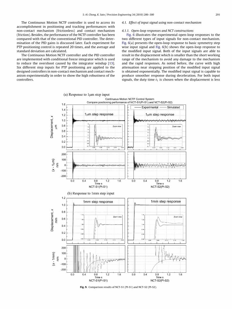
Fig. 7. Constructed NCTs from open-loop responses (non-contact mechanism).
coefficient, fmax 0.35 N and damping coefficient which is generatedby using grease is 9.3 N s/m.
4. Performance evaluation
In this section, the performance evaluation is discussed sepa-rately in two parts. First, by using the non-contact mechanism, thepositioning results of two NCTs are compared. The usefulness of
the modified suitable input signal is shown in this paper. Then, thecontact mechanism is used to show the effectiveness of the NCTFcontrollers with their simple and practical design procedure, whichis independent of friction characteristic.Fig. 8. Practical stability limit (non-contact mechanism).
n Eng
an(cmPs
atSdac
and the rapid responses. As noted before, the curve with highattenuation near stopping position of the modified input signal
S.-H. Chong, K. Sato / Precisio
The Continuous Motion NCTF controller is used to access itsccomplishment in positioning and tracking performances withon-contact mechanism (frictionless) and contact mechanismfriction). Besides, the performance of the NCTF controller has beenompared with that of the conventional PID controller. The deter-ination of the PID gains is discussed later. Each experiment for
TP positioning control is repeated 20 times, and the average andtandard deviation are calculated.
The Continuous Motion NCTF controller and the PID controllerre implemented with conditional freeze integrator which is usedo reduce the overshoot caused by the integrator windup [13].ix different step inputs for PTP positioning are applied to the
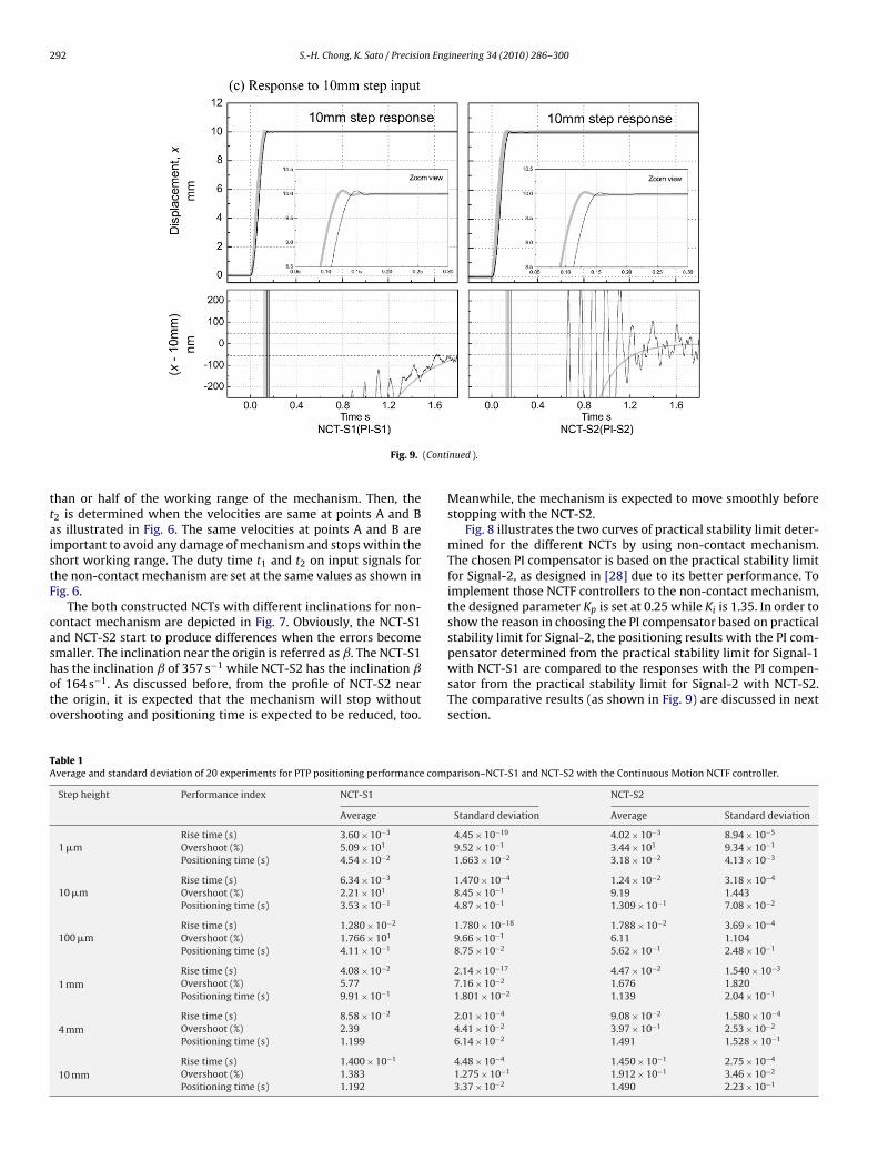
esigned controllers in non-contact mechanism and contact mech-nism experimentally in order to show the high robustness of theontrollers.Fig. 9. Comparison results of NCT-S
ineering 34 (2010) 286–300 291
4.1. Effect of input signal using non-contact mechanism
4.1.1. Open-loop responses and NCT constructionsFig. 6 illustrates the experimental open-loop responses to the
two different types of input signals for non-contact mechanism.Fig. 6(a) presents the open-loop response to basic symmetry stepwise input signal and Fig. 6(b) shows the open-loop response tothe modified input signal. Both of the input signals are able toresult in the displacement which is smaller than the short workingrange of the mechanism to avoid any damage to the mechanism
is obtained exponentially. The modified input signal is capable toproduce smoother response during deceleration. For both inputsignals, the duty time t1 is chosen when the displacement is less
1 (PI-S1) and NCT-S2 (PI-S2).
292 S.-H. Chong, K. Sato / Precision Engineering 34 (2010) 286–300
(Conti
ttaistF
cashoto
TA
Fig. 9.
han or half of the working range of the mechanism. Then, the2 is determined when the velocities are same at points A and Bs illustrated in Fig. 6. The same velocities at points A and B aremportant to avoid any damage of mechanism and stops within thehort working range. The duty time t1 and t2 on input signals forhe non-contact mechanism are set at the same values as shown inig. 6.
The both constructed NCTs with different inclinations for non-ontact mechanism are depicted in Fig. 7. Obviously, the NCT-S1nd NCT-S2 start to produce differences when the errors becomemaller. The inclination near the origin is referred as ˇ. The NCT-S1
as the inclination ˇ of 357 s−1 while NCT-S2 has the inclination ˇf 164 s−1. As discussed before, from the profile of NCT-S2 nearhe origin, it is expected that the mechanism will stop withoutvershooting and positioning time is expected to be reduced, too.able 1verage and standard deviation of 20 experiments for PTP positioning performance comp
Step height Performance index NCT-S1
Average
1 �mRise time (s) 3.60 × 10⁻³
Overshoot (%) 5.09 × 101
Positioning time (s) 4.54 × 10⁻²
10 �mRise time (s) 6.34 × 10⁻³
Overshoot (%) 2.21 × 101
Positioning time (s) 3.53 × 10⁻¹
100 �mRise time (s) 1.280 × 10⁻²
Overshoot (%) 1.766 × 101
Positioning time (s) 4.11 × 10⁻¹
1 mmRise time (s) 4.08 × 10⁻²
Overshoot (%) 5.77Positioning time (s) 9.91 × 10⁻¹
4 mmRise time (s) 8.58 × 10⁻²
Overshoot (%) 2.39Positioning time (s) 1.199
10 mmRise time (s) 1.400 × 10⁻¹
Overshoot (%) 1.383Positioning time (s) 1.192
nued ).
Meanwhile, the mechanism is expected to move smoothly beforestopping with the NCT-S2.
Fig. 8 illustrates the two curves of practical stability limit deter-mined for the different NCTs by using non-contact mechanism.The chosen PI compensator is based on the practical stability limitfor Signal-2, as designed in [28] due to its better performance. Toimplement those NCTF controllers to the non-contact mechanism,the designed parameter Kp is set at 0.25 while Ki is 1.35. In order toshow the reason in choosing the PI compensator based on practicalstability limit for Signal-2, the positioning results with the PI com-pensator determined from the practical stability limit for Signal-1
with NCT-S1 are compared to the responses with the PI compen-sator from the practical stability limit for Signal-2 with NCT-S2.The comparative results (as shown in Fig. 9) are discussed in nextsection.arison–NCT-S1 and NCT-S2 with the Continuous Motion NCTF controller.
NCT-S2
Standard deviation Average Standard deviation
4.45 × 10⁻¹⁹ 4.02 × 10⁻³ 8.94 × 10⁻⁵
9.52 × 10⁻¹ 3.44 × 101 9.34 × 10⁻¹
1.663 × 10⁻² 3.18 × 10⁻² 4.13 × 10⁻³
1.470 × 10⁻⁴ 1.24 × 10⁻² 3.18 × 10⁻⁴
8.45 × 10⁻¹ 9.19 1.4434.87 × 10−1 1.309 × 10⁻¹ 7.08 × 10⁻²
1.780 × 10⁻¹⁸ 1.788 × 10⁻² 3.69 × 10⁻⁴
9.66 × 10⁻¹ 6.11 1.1048.75 × 10−2 5.62 × 10⁻¹ 2.48 × 10⁻¹
2.14 × 10⁻¹⁷ 4.47 × 10⁻² 1.540 × 10⁻³
7.16 × 10⁻² 1.676 1.8201.801 × 10−2 1.139 2.04 × 10⁻¹
2.01 × 10⁻⁴ 9.08 × 10⁻² 1.580 × 10⁻⁴
4.41 × 10⁻² 3.97 × 10⁻¹ 2.53 × 10⁻²
6.14 × 10⁻² 1.491 1.528 × 10⁻¹
4.48 × 10⁻⁴ 1.450 × 10⁻¹ 2.75 × 10⁻⁴
1.275 × 10⁻¹ 1.912 × 10⁻¹ 3.46 × 10⁻²
3.37 × 10⁻² 1.490 2.23 × 10⁻¹
S.-H. Chong, K. Sato / Precision Engineering 34 (2010) 286–300 293
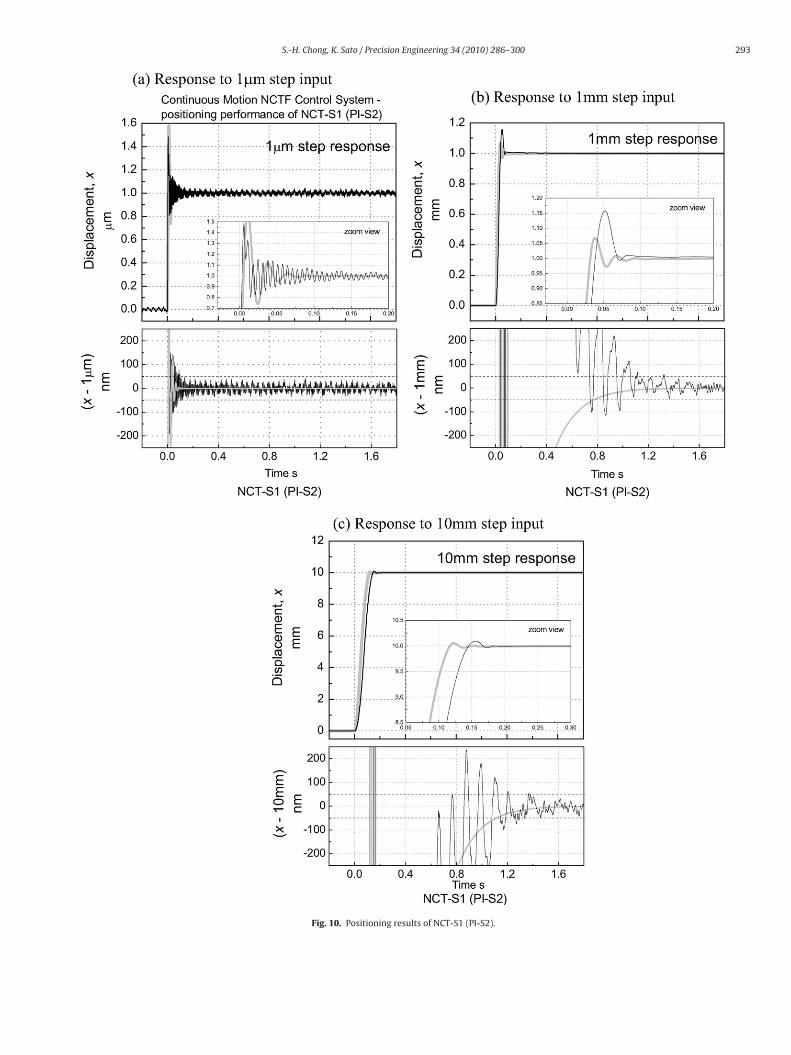
Fig. 10. Positioning results of NCT-S1 (PI-S2).
2 n Engineering 34 (2010) 286–300
4N
tdmrsoSb
SstNft
p1itplrSSbsAsirsvft
SftNSASatotdotit
yosS1aieas
94 S.-H. Chong, K. Sato / Precisio
.1.2. Comparison of the Continuous Motion NCTF controller withCT-S1 and NCT-S2
A mechanism with non-damping characteristic is easier to causehe overshoot before stopping. As mentioned before, the aim toesign the modified Signal-2 is to softly attenuate the mechanismotion. As it approaches origin on the phase plane and follows
eference trajectory, it is expected to produce sufficient rapid andmooth response during deceleration and to reduce and/or avoidvershoot of the positioning system. Therefore, the ability of NCT-2 to improve the transient response of the positioning system is aeneficial outcome of the designed control system.
Before comparing and discussing the positioning results by NCT-1 and NCT-S2 with the PI compensator determined from practicaltability limit for Signal-2, first the PI compensator from the prac-ical stability limit for Signal-1 (PI-S1: Kp = 0.25, Ki = 0.65) withCT-S1 and the PI compensator from the practical stability limit
or Signal-2 (PI-S2: Kp = 0.25, Ki = 1.35) with NCT-S2 is applied tohe mechanism.
Fig. 9 illustrates the experimental and simulated comparisonositioning results by NCT-S1 (PI-S1) with NCT-S2 (PI-S2) for 1 �m,mm and 10 mm step inputs. There is small difference of position-
ng performance between the NCT-S1 (PI-S1) with NCT-S2 (PI-S2)o 1 �m and 1 mm step inputs. However, the PI compensator fromractical stability limit for Signal-1 with NCT-S1 results in much
onger positioning time to reach the steady state at the 10 mm stepesponse than the PI compensator from practical stability limit forignal-2 with NCT-S2. At the 10 mm step response of NCT-S1 (PI-1), the plot verifies that the response could not reach steady statey 1.8 s. By contrast, the 10 mm step response of NCT-S2 (PI-S2)hows better positioning time and reaches steady state by 1.4 s.s expected, the smaller Ki from PI-S1 causes the extremely largeteady-state error albeit the PI compensators from practical stabil-ty limit for Signal-1 and Signal-2 do not cause large overshoot. Theesults show that the PI compensator determined from practicaltability limit for Signal-1 is not a satisfactory compensator to pro-ide a higher positioning performance. Hence, the PI compensatorrom practical stability limit for Signal-2 is selected to be used forhe rest of the experiments.
Then, in order to compare the positioning performances by NCT-1 and NCT-S2 of the PI compensator from practical stability limitor Signal-2, the response of NCT-S2 (PI-S2) in Fig. 9 is comparedo the response NCT-S1 (PI-S2) in Fig. 10. The Continuous MotionCTF controller which works along with those both NCT-S1 (PI-2) and NCT-S2 (PI-S2) is applied to the non-contact mechanism.s observed from the responses of the NCT-S1 (PI-S2) and NCT-2 (PI-S2), the simulated responses, which are drawn in grey-line,gree well with the experimental ones. However, marked vibra-ion could be found in experimental results only. As noted in [20],vershoot and settling time represent the closeness of the responseo the desired response. For the quantitative comparison, Table 1etails the average and standard deviation PTP positioning resultsf 20 experiments under each NCT in terms of rise time, positioningime and overshoot percentage. In this paper, the positioning timendicates the time of the control system takes to reduce the erroro less than 100 nm.
Clearly, the NCT-S1 (PI-S2) which has inclination ˇ of 357 s−1
ields the higher percentage of overshoot than the step responsesf NCT-S2 (PI-S2) for the six reference step inputs. By contrast, asummarized in Table 1, the NCTF control system with NCT-S1 (PI-2) has taken shorter positioning time to reduce the error less than00 nm for the reference inputs of 100 �m, 1 mm, 4 mm, and 10 mm
s compared to NCT-S2 (PI-S2). However, the differences are smalln comparison with NCT-S1 (PI-S2). Table 1 shows that, when refer-nce step inputs 1 �m and 10 �m, the positioning times of NCT-S2re shorter than the NCT-S1. One possible reason to explain thehorter positioning time of NCT-S1 is due to the theory that theFig. 11. Tracking performance with sine wave reference input (frequency 0.1 Hz andamplitude 1 mm).
higher inclination near the origin on phase plane is determinedas the criteria to shorter the positioning time. Overall, the resultsprove that the modified input signal (Signal-2) has a better perfor-mance than the original one, especially in elimination of overshoot.
4.1.3. Comparison of control performance of the ContinuousMotion NCTF controller (NCT-S2) and the PID controller
In order to elucidate the advantage and effectiveness of the Con-tinuous Motion NCTF controller for non-contact mechanism, the
performance is compared with the PID controller. The NCT andcontroller parameters designed in [28] are used for the Contin-uous Motion NCTF control system. The PID gains are determinedbased on the condition that its control system has the same sensi-tivity as the NCTF one near the reference position. The gains were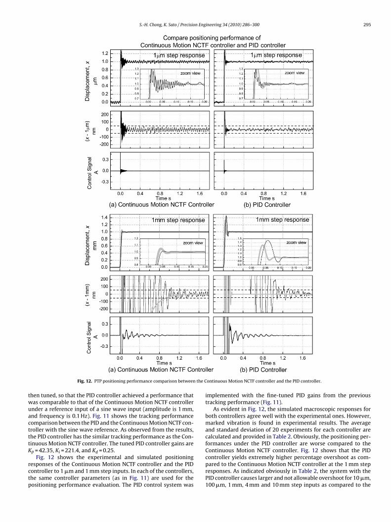
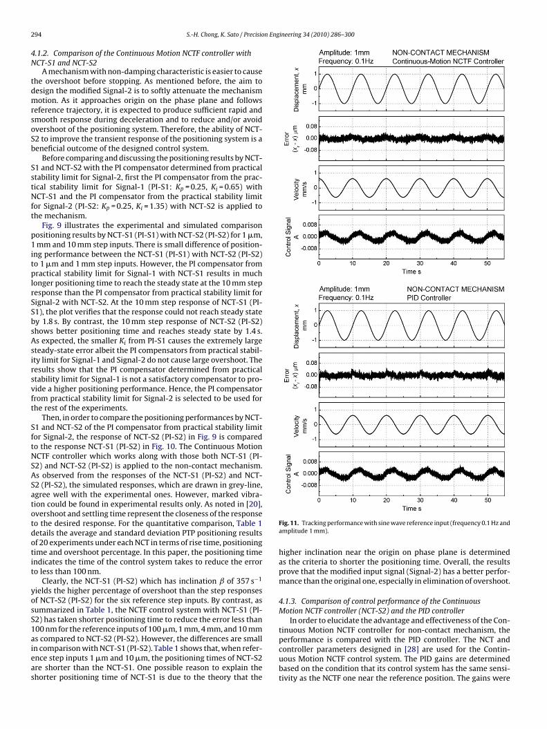
S.-H. Chong, K. Sato / Precision Engineering 34 (2010) 286–300 295
the C
twuactttK
rctp
Fig. 12. PTP positioning performance comparison between
hen tuned, so that the PID controller achieved a performance thatas comparable to that of the Continuous Motion NCTF controllernder a reference input of a sine wave input (amplitude is 1 mm,nd frequency is 0.1 Hz). Fig. 11 shows the tracking performanceomparison between the PID and the Continuous Motion NCTF con-roller with the sine wave reference. As observed from the results,he PID controller has the similar tracking performance as the Con-inuous Motion NCTF controller. The tuned PID controller gains arep = 42.35, Ki = 221.4, and Kd = 0.25.
Fig. 12 shows the experimental and simulated positioningesponses of the Continuous Motion NCTF controller and the PIDontroller to 1 �m and 1 mm step inputs. In each of the controllers,he same controller parameters (as in Fig. 11) are used for theositioning performance evaluation. The PID control system was
ontinuous Motion NCTF controller and the PID controller.
implemented with the fine-tuned PID gains from the previoustracking performance (Fig. 11).
As evident in Fig. 12, the simulated macroscopic responses forboth controllers agree well with the experimental ones. However,marked vibration is found in experimental results. The averageand standard deviation of 20 experiments for each controller arecalculated and provided in Table 2. Obviously, the positioning per-formances under the PID controller are worse compared to theContinuous Motion NCTF controller. Fig. 12 shows that the PID
controller yields extremely higher percentage overshoot as com-pared to the Continuous Motion NCTF controller at the 1 mm stepresponses. As indicated obviously in Table 2, the system with thePID controller causes larger and not allowable overshoot for 10 �m,100 �m, 1 mm, 4 mm and 10 mm step inputs as compared to the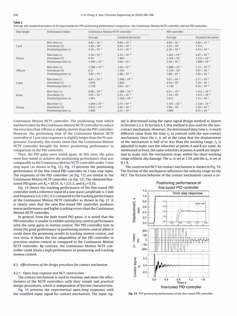
296 S.-H. Chong, K. Sato / Precision Engineering 34 (2010) 286–300
Table 2Average and standard deviation of 20 experiments for PTP positioning performance comparison—the Continuous Motion NCTF controller and the PID controller.
Step height Performance index Continuous Motion NCTF controller PID controller
Average Standard deviation Average Standard deviation
1 �mRise time (s) 4.02 × 10⁻³ 8.94 × 10⁻⁵ 4.66 × 10⁻³ 9.40 × 10⁻⁵
Overshoot (%) 3.44 × 101 9.34 × 10⁻¹ 3.23 × 101 1.314Positioning time (s) 3.18 × 10⁻² 4.13 × 10⁻³ 2.32 × 10⁻² 4.53 × 10⁻³
10 �mRise time (s) 1.24 × 10⁻² 3.18 × 10⁻⁴ 1.261 × 10⁻² 4.47 × 10⁻⁵
Overshoot (%) 9.19 1.443 1.159 × 101 1.141 × 10⁻¹
Positioning time (s) 1.309 × 10⁻¹ 7.08 × 10⁻² 2.34 × 10⁻¹ 1.989 × 10⁻²
100 �mRise time (s) 1.788 × 10⁻² 3.69 × 10⁻⁴ 1.600 × 10⁻² 7.12 × 10⁻¹⁸
Overshoot (%) 6.11 1.104 1.129 × 101 5.67 × 10⁻³
Positioning time (s) 5.62 × 10⁻¹ 2.48 × 10⁻¹ 7.60 × 10⁻¹ 3.56 × 10⁻³
1 mmRise time (s) 4.47 × 10⁻² 1.540 × 10⁻³ 3.61 × 10⁻² 2.77 × 10⁻⁴
Overshoot (%) 1.676 1.820 4.54 × 101 7.29 × 10⁻¹
Positioning time (s) 1.139 2.04 × 10⁻¹ 1.138 6.76 × 10⁻²
4 mmRise time (s) 9.08 × 10⁻² 1.580 × 10⁻⁴ 6.91 × 10⁻² 1.412 × 10⁻⁴
Overshoot (%) 3.97 × 10⁻¹ 2.53 × 10⁻² 7.14 × 101 1.312 × 10⁻²
Positioning time (s) 1.491 1.528 × 10⁻¹ 1.612 7.23 × 10⁻¹
2.73.42.2
ChtHcpNc
wcspTCt
caoiwM
PwrcvpNtm
4
4
td
t
range without any damage. The ur is set at 1.5A and the ua is set at0.1 A.
The constructed NCT for contact mechanism is shown in Fig. 16.The friction of the mechanism influences the velocity range on theNCT. The friction behavior of the contact mechanism causes a cir-
10 mmRise time (s) 1.450 × 10⁻¹
Overshoot (%) 1.912 × 10⁻¹
Positioning time (s) 1.490
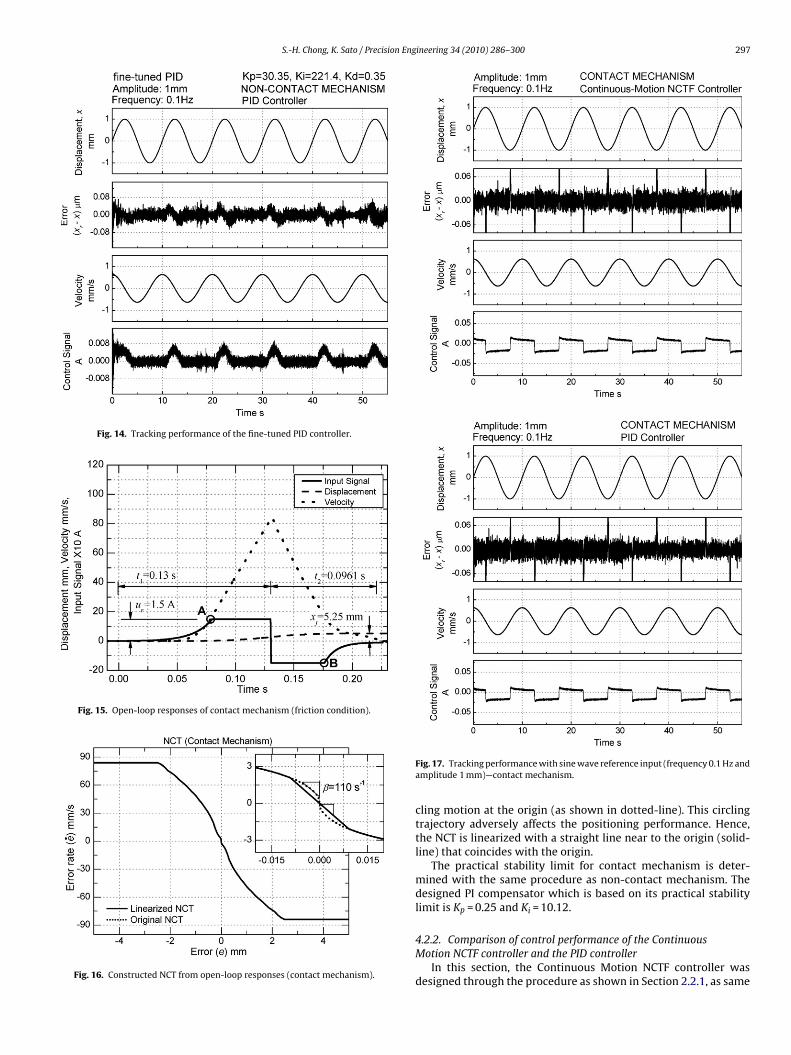
ontinuous Motion NCTF controller. The positioning time whichad been taken by the Continuous Motion NCTF controller to reducehe error less than 100 nm is slightly shorter than the PID controller.owever, the positioning time of the Continuous Motion NCTFontroller at 1 �m step responses is slightly longer than the PI com-ensator. Generally, the results show that the Continuous MotionCTF controller brought the better positioning performance inomparison to the PID controller.
Then, the PID gains were tuned again. At this time, the gainsere fine-tuned to achieve the positioning performance that was
omparable to the Continuous Motion NCTF controller under 1 mmtep input (as shown in Fig. 12). Fig. 13 presents the positioningerformance of the fine-tuned PID controller to 1 mm step input.he responses of the PID controller (as Fig. 13) are similar to theontinuous Motion NCTF controller (as Fig. 12). The obtained fine-uned PID gains are Kp = 30.35, Ki = 221.5, and Kd = 0.35.
Fig. 14 shows the tracking performance of the fine-tuned PIDontroller with a reference input of a sine wave (amplitude is 1 mmnd frequency is 0.1 Hz). It is compared to the tracking performancef the Continuous Motion NCTF controller as shown in Fig. 11. Its clearly seen that the new fine-tuned PID controller produces
orse performance and higher tracking errors than the Continuousotion NCTF controller.In general, from the both tuned PID gains, it is noted that the
ID controller is unable to exhibit satisfactory control performanceith the same gains in motion control. The PID controller fails to
etain the good performance in positioning motion control albeit itould show the promising results in tracking motion control, andice versa. It shows the low adaptability of the PID controller inrecision motion control as compared to the Continuous MotionCTF controller. By contrast, the Continuous Motion NCTF con-
roller could retain a high performance in positioning and trackingotion control.
.2. Effectiveness of the design procedure for contact mechanism
.2.1. Open-loop response and NCT construction
The contact mechanism is used to examine and show the effec-iveness of the NCTF controllers with their simple and practicalesign procedures, which is independent of friction characteristic.
Fig. 15 presents the experimental open-loop responses withhe modified input signal for contact mechanism. The input sig-
5 × 10⁻⁴ 1.101 × 10⁻¹ 1.334 × 10⁻⁴
6 × 10⁻² 7.94 × 101 3.34 × 10⁻²
3 × 10⁻¹ 1.800 8.51 × 10⁻¹
nal is determined using the input signal design method as shownin Section 2.2.2. In Section 4.1, this method is also used for the non-contact mechanism. However, the determined duty time t1 is muchdifferent value from the time t2 in contrast with the non-contactmechanism. Once the t1 is set at the value that the displacementof the mechanism is half of or less than the working range, t2 isadjusted to make sure the velocities at points A and B are same. Asmentioned at front, the same velocities at points A and B are impor-tant to make sure the mechanism stops within the short working
Fig. 13. PTP positioning performance of the fine-tuned PID controller.
S.-H. Chong, K. Sato / Precision Engineering 34 (2010) 286–300 297
Fig. 14. Tracking performance of the fine-tuned PID controller.
Fig. 15. Open-loop responses of contact mechanism (friction condition).
Fig. 16. Constructed NCT from open-loop responses (contact mechanism).
Fig. 17. Tracking performance with sine wave reference input (frequency 0.1 Hz andamplitude 1 mm)—contact mechanism.
cling motion at the origin (as shown in dotted-line). This circlingtrajectory adversely affects the positioning performance. Hence,the NCT is linearized with a straight line near to the origin (solid-line) that coincides with the origin.
The practical stability limit for contact mechanism is deter-mined with the same procedure as non-contact mechanism. Thedesigned PI compensator which is based on its practical stabilitylimit is Kp = 0.25 and Ki = 10.12.
4.2.2. Comparison of control performance of the ContinuousMotion NCTF controller and the PID controller
In this section, the Continuous Motion NCTF controller wasdesigned through the procedure as shown in Section 2.2.1, as same
298 S.-H. Chong, K. Sato / Precision Engineering 34 (2010) 286–300
nuous
adasrttwtbtcuK
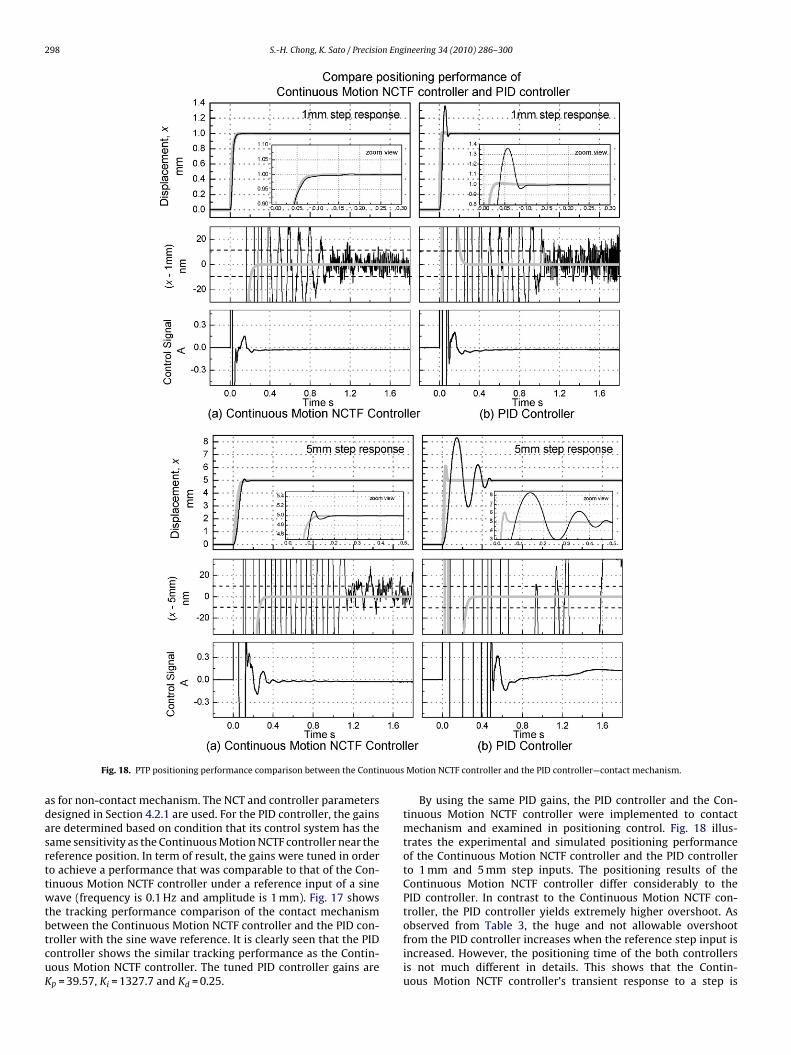
Fig. 18. PTP positioning performance comparison between the Conti
s for non-contact mechanism. The NCT and controller parametersesigned in Section 4.2.1 are used. For the PID controller, the gainsre determined based on condition that its control system has theame sensitivity as the Continuous Motion NCTF controller near theeference position. In term of result, the gains were tuned in ordero achieve a performance that was comparable to that of the Con-inuous Motion NCTF controller under a reference input of a sineave (frequency is 0.1 Hz and amplitude is 1 mm). Fig. 17 shows
he tracking performance comparison of the contact mechanism
etween the Continuous Motion NCTF controller and the PID con-roller with the sine wave reference. It is clearly seen that the PIDontroller shows the similar tracking performance as the Contin-ous Motion NCTF controller. The tuned PID controller gains arep = 39.57, Ki = 1327.7 and Kd = 0.25.Motion NCTF controller and the PID controller—contact mechanism.
By using the same PID gains, the PID controller and the Con-tinuous Motion NCTF controller were implemented to contactmechanism and examined in positioning control. Fig. 18 illus-trates the experimental and simulated positioning performanceof the Continuous Motion NCTF controller and the PID controllerto 1 mm and 5 mm step inputs. The positioning results of theContinuous Motion NCTF controller differ considerably to thePID controller. In contrast to the Continuous Motion NCTF con-troller, the PID controller yields extremely higher overshoot. As
observed from Table 3, the huge and not allowable overshootfrom the PID controller increases when the reference step input isincreased. However, the positioning time of the both controllersis not much different in details. This shows that the Contin-uous Motion NCTF controller’s transient response to a step is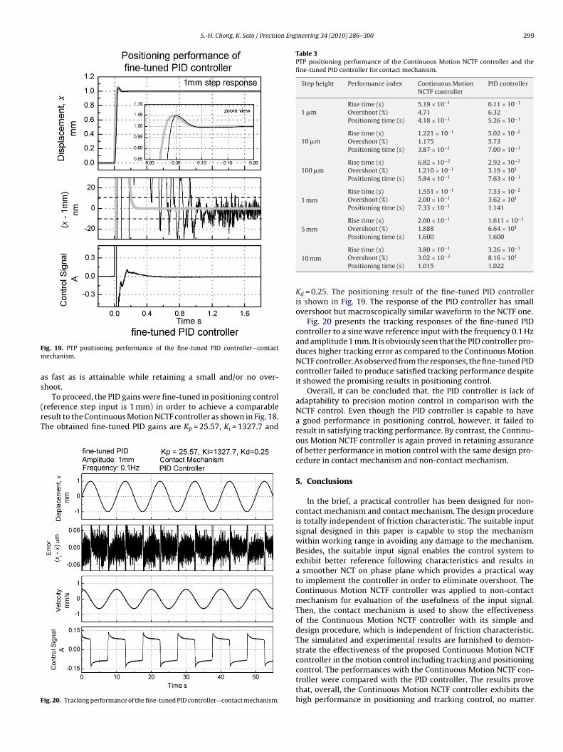
S.-H. Chong, K. Sato / Precision Engineering 34 (2010) 286–300 299
Fm
as
(rT
F
Table 3PTP positioning performance of the Continuous Motion NCTF controller and thefine-tuned PID controller for contact mechanism.
Step height Performance index Continuous MotionNCTF controller
PID controller
1 �mRise time (s) 5.19 × 10⁻¹ 6.11 × 10⁻¹
Overshoot (%) 4.71 6.32Positioning time (s) 4.18 × 10⁻¹ 5.26 × 10⁻¹
10 �mRise time (s) 1.221 × 10⁻¹ 5.02 × 10⁻²
Overshoot (%) 1.175 5.73Positioning time (s) 3.87 × 10⁻¹ 7.00 × 10⁻¹
100 �mRise time (s) 6.82 × 10⁻² 2.92 × 10⁻²
Overshoot (%) 1.210 × 10⁻¹ 3.19 × 101
Positioning time (s) 5.84 × 10⁻¹ 7.63 × 10⁻¹
1 mmRise time (s) 1.551 × 10⁻¹ 7.53 × 10⁻²
Overshoot (%) 2.00 × 10⁻¹ 3.62 × 101
Positioning time (s) 7.33 × 10⁻¹ 1.141
5 mmRise time (s) 2.00 × 10⁻¹ 1.611 × 10⁻¹
Overshoot (%) 1.888 6.64 × 101
Positioning time (s) 1.600 1.600
ig. 19. PTP positioning performance of the fine-tuned PID controller—contactechanism.
s fast as is attainable while retaining a small and/or no over-hoot.
To proceed, the PID gains were fine-tuned in positioning controlreference step input is 1 mm) in order to achieve a comparableesult to the Continuous Motion NCTF controller as shown in Fig. 18.he obtained fine-tuned PID gains are Kp = 25.57, Ki = 1327.7 and
ig. 20. Tracking performance of the fine-tuned PID controller—contact mechanism.
10 mmRise time (s) 3.80 × 10⁻¹ 3.26 × 10⁻¹
Overshoot (%) 3.02 × 10⁻³ 8.16 × 101
Positioning time (s) 1.015 1.022
Kd = 0.25. The positioning result of the fine-tuned PID controlleris shown in Fig. 19. The response of the PID controller has smallovershoot but macroscopically similar waveform to the NCTF one.
Fig. 20 presents the tracking responses of the fine-tuned PIDcontroller to a sine wave reference input with the frequency 0.1 Hzand amplitude 1 mm. It is obviously seen that the PID controller pro-duces higher tracking error as compared to the Continuous MotionNCTF controller. As observed from the responses, the fine-tuned PIDcontroller failed to produce satisfied tracking performance despiteit showed the promising results in positioning control.
Overall, it can be concluded that, the PID controller is lack ofadaptability to precision motion control in comparison with theNCTF control. Even though the PID controller is capable to havea good performance in positioning control, however, it failed toresult in satisfying tracking performance. By contrast, the Continu-ous Motion NCTF controller is again proved in retaining assuranceof better performance in motion control with the same design pro-cedure in contact mechanism and non-contact mechanism.
5. Conclusions
In the brief, a practical controller has been designed for non-contact mechanism and contact mechanism. The design procedureis totally independent of friction characteristic. The suitable inputsignal designed in this paper is capable to stop the mechanismwithin working range in avoiding any damage to the mechanism.Besides, the suitable input signal enables the control system toexhibit better reference following characteristics and results ina smoother NCT on phase plane which provides a practical wayto implement the controller in order to eliminate overshoot. TheContinuous Motion NCTF controller was applied to non-contactmechanism for evaluation of the usefulness of the input signal.Then, the contact mechanism is used to show the effectivenessof the Continuous Motion NCTF controller with its simple anddesign procedure, which is independent of friction characteristic.The simulated and experimental results are furnished to demon-strate the effectiveness of the proposed Continuous Motion NCTF
controller in the motion control including tracking and positioningcontrol. The performances with the Continuous Motion NCTF con-troller were compared with the PID controller. The results provethat, overall, the Continuous Motion NCTF controller exhibits thehigh performance in positioning and tracking control, no matter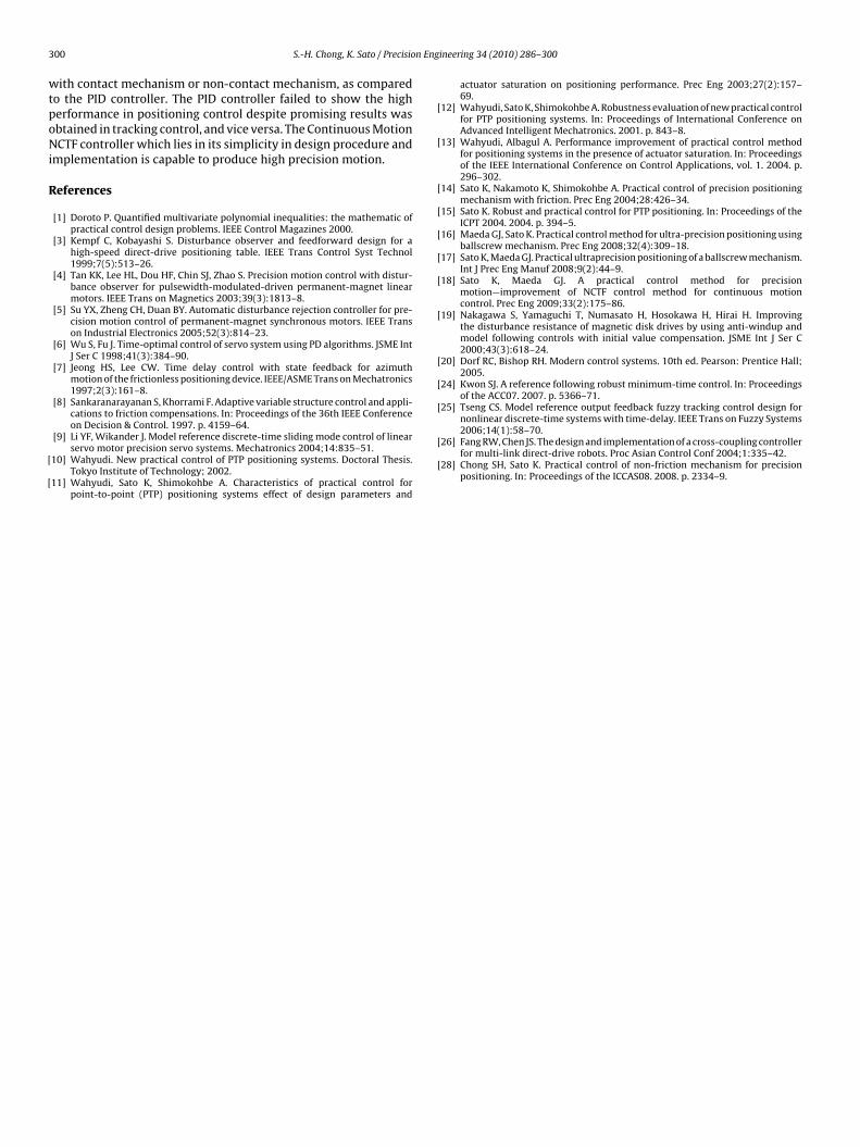
3 n Eng
wtpoNi
R
[
[
[
[
[
[
[
[
[
[
[
[
[nonlinear discrete-time systems with time-delay. IEEE Trans on Fuzzy Systems
00 S.-H. Chong, K. Sato / Precisio
ith contact mechanism or non-contact mechanism, as comparedo the PID controller. The PID controller failed to show the higherformance in positioning control despite promising results wasbtained in tracking control, and vice versa. The Continuous MotionCTF controller which lies in its simplicity in design procedure and
mplementation is capable to produce high precision motion.
eferences
[1] Doroto P. Quantified multivariate polynomial inequalities: the mathematic ofpractical control design problems. IEEE Control Magazines 2000.
[3] Kempf C, Kobayashi S. Disturbance observer and feedforward design for ahigh-speed direct-drive positioning table. IEEE Trans Control Syst Technol1999;7(5):513–26.
[4] Tan KK, Lee HL, Dou HF, Chin SJ, Zhao S. Precision motion control with distur-bance observer for pulsewidth-modulated-driven permanent-magnet linearmotors. IEEE Trans on Magnetics 2003;39(3):1813–8.
[5] Su YX, Zheng CH, Duan BY. Automatic disturbance rejection controller for pre-cision motion control of permanent-magnet synchronous motors. IEEE Transon Industrial Electronics 2005;52(3):814–23.
[6] Wu S, Fu J. Time-optimal control of servo system using PD algorithms. JSME IntJ Ser C 1998;41(3):384–90.
[7] Jeong HS, Lee CW. Time delay control with state feedback for azimuthmotion of the frictionless positioning device. IEEE/ASME Trans on Mechatronics1997;2(3):161–8.
[8] Sankaranarayanan S, Khorrami F. Adaptive variable structure control and appli-cations to friction compensations. In: Proceedings of the 36th IEEE Conferenceon Decision & Control. 1997. p. 4159–64.
[9] Li YF, Wikander J. Model reference discrete-time sliding mode control of linearservo motor precision servo systems. Mechatronics 2004;14:835–51.
10] Wahyudi. New practical control of PTP positioning systems. Doctoral Thesis.Tokyo Institute of Technology; 2002.
11] Wahyudi, Sato K, Shimokohbe A. Characteristics of practical control forpoint-to-point (PTP) positioning systems effect of design parameters and
[
[
ineering 34 (2010) 286–300
actuator saturation on positioning performance. Prec Eng 2003;27(2):157–69.
12] Wahyudi, Sato K, Shimokohbe A. Robustness evaluation of new practical controlfor PTP positioning systems. In: Proceedings of International Conference onAdvanced Intelligent Mechatronics. 2001. p. 843–8.
13] Wahyudi, Albagul A. Performance improvement of practical control methodfor positioning systems in the presence of actuator saturation. In: Proceedingsof the IEEE International Conference on Control Applications, vol. 1. 2004. p.296–302.
14] Sato K, Nakamoto K, Shimokohbe A. Practical control of precision positioningmechanism with friction. Prec Eng 2004;28:426–34.
15] Sato K. Robust and practical control for PTP positioning. In: Proceedings of theICPT 2004. 2004. p. 394–5.
16] Maeda GJ, Sato K. Practical control method for ultra-precision positioning usingballscrew mechanism. Prec Eng 2008;32(4):309–18.
17] Sato K, Maeda GJ. Practical ultraprecision positioning of a ballscrew mechanism.Int J Prec Eng Manuf 2008;9(2):44–9.
18] Sato K, Maeda GJ. A practical control method for precisionmotion—improvement of NCTF control method for continuous motioncontrol. Prec Eng 2009;33(2):175–86.
19] Nakagawa S, Yamaguchi T, Numasato H, Hosokawa H, Hirai H. Improvingthe disturbance resistance of magnetic disk drives by using anti-windup andmodel following controls with initial value compensation. JSME Int J Ser C2000;43(3):618–24.
20] Dorf RC, Bishop RH. Modern control systems. 10th ed. Pearson: Prentice Hall;2005.
24] Kwon SJ. A reference following robust minimum-time control. In: Proceedingsof the ACC07. 2007. p. 5366–71.
25] Tseng CS. Model reference output feedback fuzzy tracking control design for
2006;14(1):58–70.26] Fang RW, Chen JS. The design and implementation of a cross-coupling controller
for multi-link direct-drive robots. Proc Asian Control Conf 2004;1:335–42.28] Chong SH, Sato K. Practical control of non-friction mechanism for precision
positioning. In: Proceedings of the ICCAS08. 2008. p. 2334–9.


