Embed Size (px)
Citation preview

PRACTICAL PHARMACY.

Digitized by the Internet Archive in 2018 with funding from
Wellcome Library
https://archive.org/details/b29318531
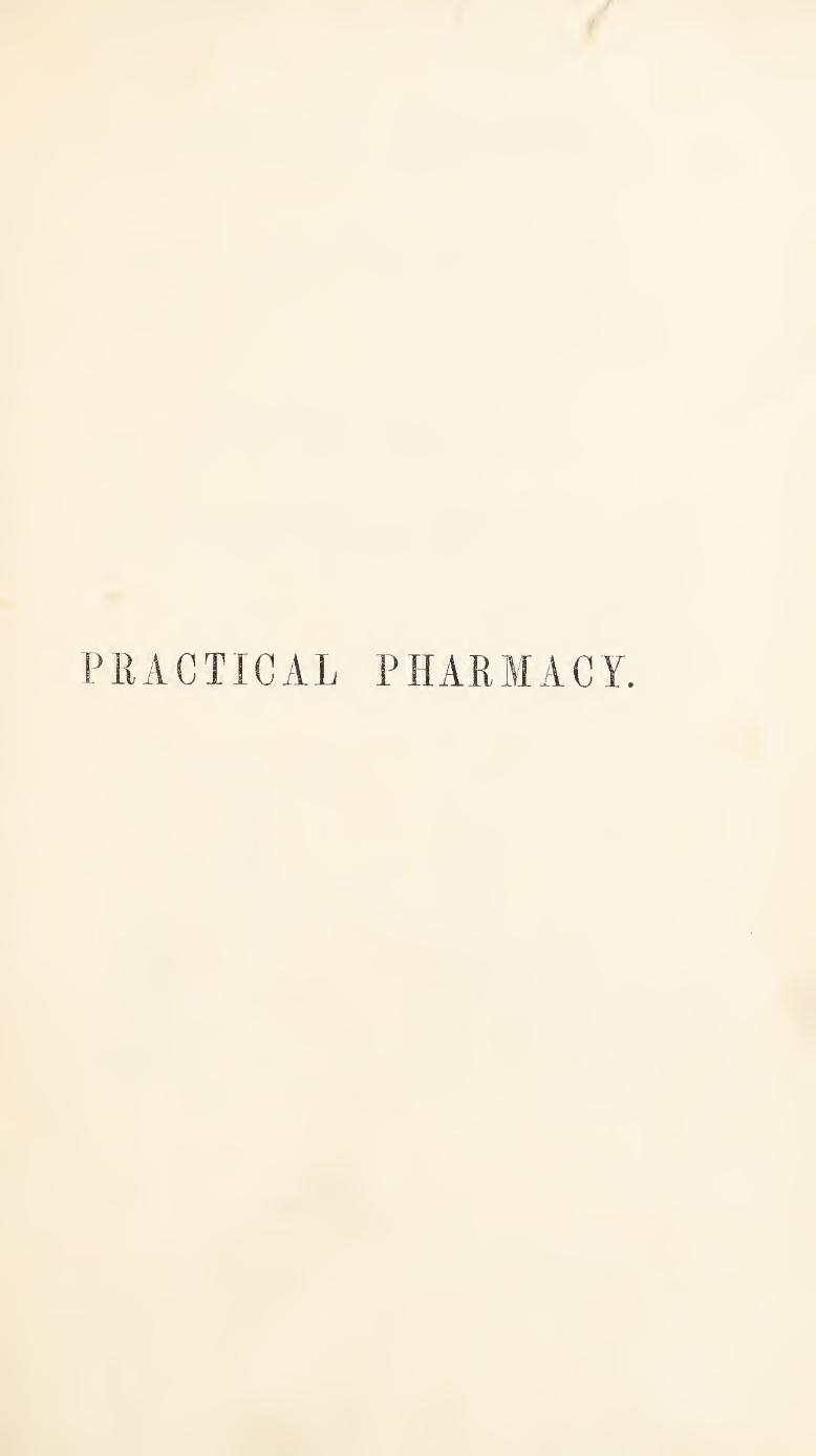
PRACTICAL PHARMACY:
THE ARRANGEMENTS, APPARATUS, AND MANIPULATIONS,
OF THE PHARMACEUTICAL SHOP AND LABORATORY.
BY
FRANCIS MOHR, Ph. D., ASSESSOR PHARMACI.R OF THE ROYAL PRUSSIAN COLLEGE OP MEDICINE, COBLENTZ ;
THEOPHILUS REDWOOD, PROFESSOR OF CHEMISTRY AND PHARMACY TO THE PHARMACEUTICAL SOCIETY
OF GREAT BRITAIN.
ILLUSTRATED BY FOUR HUNDRED ENGRAVINGS ON WOOD.
LONDON;
TAYLOR, WALTON, AND MABERLY, UPPER GOWER STREET, AND IVY LANE, PATERNOSTER ROW.
1849

1 H!3T0»IC'L '
\ medical
LONDON;
Printed by S. and J. Bekti-ey, Wilson, and Fley,
Bangor House, Shoe Lane.
P R E F A C E.
A Work on Practical Pharmacy, embracing a Description of
Apparatus and Manipulations, has long been considered a deside¬
ratum in this country, and I have repeatedly been urged by
members of the Pharmaceutical Body to undertake the prepara¬
tion of such a work. The pressure of other engagements, how¬
ever, prevented my doing so, until an opportunity was presented,
by the appearance of Dr. Mohr s “ Manual of Pharmaceutical
Technology,” for laying before the English reader the results
of the personal experience ” of one of the most eminent of the
continental pharmaceutists. Under these circumstances, I un-
deitook to edit a translation of those parts of Dr. MbhPs book
which might be thought to convey the most practically useful
information, and to make such additions as would meet the re¬
quirements of English Pharmaceutical Chemists. In proceeding
with this undertaking, it was found necessary to make much more
extensive additions of new matter, and alterations in that taken
from the Grerman, than had in the first instance been contemplated.
This may be ascribed to the fact, that the circumstances by which
the pharmaceutists are surrounded, in England and in Germany,
are very different; and that, therefore, the arrangements provided
and suitable in the one case, are, in many respects, inapplicable to
VI PREFACE.
the other. The original matter which has been introduced, in¬
cluding upwards of one hundred and sixty of the engraving's,
constitutes about two thirds of the volume, and this is enclosed
within brackets, [ ], to distinguish it from that which has been
translated. It is due, however, to the German author to state,
that a faithful translation has not, in any part, been attempted, the
paramount object having been to suit the matter to the wants
of those for whom it is designed.
T. R.
19, Montague Street, Russell Square,
December, 1848.
CONTENTS.
PAGE
GENERAL ARRANGEMENTS . 1
Shop or Dispensary . . ih
Arrangements for heating . . 3 „ for lighting . 10 „ for ventilating . 12
Division of shop into compartments 14 The dispensing counter . .15
Laboratory .... 21
Store-room . . . .22
Store-cellar .... 23
Drying-room or Loft . . z'd.
Powdbring-room . . . a.
SPECIAL ARRANGEMENTS, AP¬
PARATUS, AND OPERA¬
TIONS .... 25
Drying Closet
Steam Apparatus
Reindorf’s Apparatus Cucurbit and head Evaporating pans Steam-funnel . . . . Hot-air Chamber . Sand-bath . . . . Condensing Apparatus .
Distillation with the Cucurbit
Digestion and Infusion
Solution, Liquefaction, Saponi¬
fication, ETC.
Vaporization . . . .
Mechanical Stirrer . Laboratory Alarum
Steam-boilers and Apparatus
Ventilation of Laboratory
Preparation of Extracts
Aqueous Extracts Displacement process Press of Count Real Evaporatiori over naked fire . Evaporation by Water-bath or
Steam-bath Evaporation m vacuo Spontaneous evaporation
Alcoholic and Ethereal Extracts .
ib.
27
28 29 ih. 30 ih. 33 ib.
36
37
40
ib.
41 44
46
52
55
56 59 ib. 67
68 71 76 83
PAGE
Preparation of Tinctures . 86
By Maceration (Pharmacopoeia pro¬ cess) . . . . . 87
By Maceration (Dr. Burton’s pro¬ cess) .87
By Percolation or Displacement . 89
The Press .... 96
Horizontal Press . . .98 Vertical Press . . .104 Hydraulic Press . , .109
Process op Expression . . 114
Press-bags, &c.115
Furnace Operations . . II7
Fuel_.118 Crucibles . . . . II9
Air or Wind Furnace . . 120 Blast Furnaces . . .124
Double Belloivs . . .125 Crucible Furnace . . . 126 Seftstroem's Furnace . .127 Common Blast Furnace . 128 Centrifugal Blower . . .129
Flame Furnace . . . 131
Common Portable Furnaces . .133
Distillation in Glass and Earthenware . . .135
Retorts.136
Receivers . . . . .137 Arrangement of Apparatus . 138 Gas Furnaces .... I45
Flasks.147
Retort Stand . . . .148 Condensers .... ib. Process of Distillation . .150 Furnace and Sand-pot for retort 163 Stone-ware Still . . .165 Stone-ware Condenser . . 166
Dry or Destructive Distillation 167
Distillation of Waters and
Essential Oils . . . 168
Preservation and Rectiiucation
OP Essential Oils . .175
Rectification of Ether . 176
Generation and Absorption of
Gases . . . .179
Carbonic Acid .... ih.
Ylll CONTENTS
(tENEHATlON OF Gases, continued. page
Sulphuretted Hydrogen . . 183 Chlorine . . . . .185 Generating-veasels, Wash-bottles 186“ Safety-tuljes, Woulf’s and other
Condensing Apparatus 188 Escape for Noxious Gases • 192
Sublimation • 194
Benzoic Acid • ib. Calomel 196
Filtration .... • 199
Filtering Media 200 Construction of Filters 202 Continuous Filtration • 213 Wash-bottles . • 216
Clarification . . . .
Coarse Comminution of Vege-
218
TABLE Substances • 219
Chopping-trough • ib. Cutting or Slicing-knife • 220
„ self-supplying 222 Cradle-knife • 223 Rolling-knife . • 224 Chinese Cutting-trough • ib.
Pulverization op Drugs ib.
By Contusion • 225 Mortar and Spring-pestle • ib. Stampers 9 ib.
By trituration • 231 Marble Mortars • ib. Porphyry Slab and Midler • 232 Levigating Apparatus * 233 Drug-mill . « 235 Sifting Apparatus . • 236
Drug-grinding • ib.
GranulatiOxN of Metals . • 247
Granulating-box • 248
Elutriation • 250
Decantation . ib.
With a guiding-rod • 251 Over a greased rim . • 252
Syphons .... . 253
Pipettes • 259
Weighing and Measuring • 260
Balances 261 W eights .... , ib. Measures ....
Determination of Specific Gra-
267
VITIES . 272
Of solids .... 273 Of liquids • 276
Stoppering of Glass Bottles . 290
Removal of Fi.xed Stoppers .
Desiccation of Bottles, Flasks,
292
ETC. .... 295
The Tying of Knots
PAGE
. 296
The Capping Knot . . 297 „ Binding Knot . 298 ,, Pyrotechnical Knot . . ib. „ Beer Knot . . 299 „ Champagne Knot . 300
Cutting, Drilling, and Bending Glass .... 802
Connecting and Luting op Ap¬ paratus . . . .312
Indian-rubber Connecters . . ib. Cork-borers . . . .313 Tube Connexions . . .315
Coating Glass and Porcelain Vessels with Copper . .318
Preparation of Waxed Paper 320
Casting of Zinc, Potash, and Lunar Caustic . . 321
Closed Operating Chamber or Closet .... 323
THE DISPENSING OF MEDI¬
CINES .... 825
Means for Preserving Clean¬ liness .... 326
Aids to Dispensing . . . 827
Infusions and Decoctions 331
Reading the Prescription . 335
Preparation of Mixtures 337
99 Draughts . 339
99 Drops . 340
99 Emulsions . 341
99 Powders 344
99 Electuaries, I 1
9*' Conserves, i t 345
99 Linctus . t 1
99 Lozenges . . ib.
99 Pills 347
99 Capsules . . 358
99 Gargles, Injeo-
TIONS, ETC. . 361
99 Lotions, Lini-
MENTS, ETC. . ib.
99 Ointments . 362
99 Suppositories . 363
95 Cataplasms . ib.
99 Plasters . ib.
Inhalation of Gases 375
99 Vapours . 377
99 F UMES 383
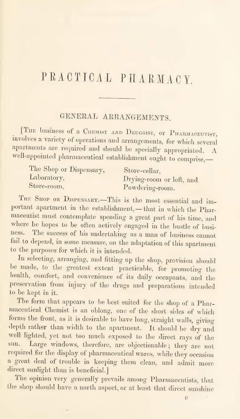
PRACTICAL PHARMACY.
GENERAL ARRANGEMENTS.
[The business of a Chemist and Druggist, or Pharmaceutist,
involves a variety of operations and arrangements, for which several
apartments are required and should be specially appropriated. A
well-appointed pharmaceutical establishment ought to comprise,_
The Shop or Dispensary,
Laboratory,
Store-room,
Store-cellar,
Drying-room or loft, and
P owdering-room.
The Shop or Dispensary.—This is the most essential and im¬
portant apartment in the establishment, —that in which the Phar¬
maceutist must contemplate spending a great part of his time, and
where he hopes to be often actively engaged in the bustle of busi¬
ness. The success of his undertaking as a man of business cannot
fad to depend, in some measure, on the adaptation of this apartment to the purposes for which it is intended.
In selecting, arranging’, and fitting up the shop, provision should
be made, to the greatest extent practicable, for promoting the
health, comfort, and convenience of its daily occupants, and the
preservation from injury of the drugs and preparations intended to be kept in it.
The form that appears to be best suited for the shop of a Phar¬
maceutical Chemist is an oblong, one of the short sides of which
forms the front, as it is desirable to have long, straight walls, giving’
depth rather than width to the apartment. It should be dry and
well lighted, yet not too much exposed to the direct rays of the
sun. Large windows, therefore, are objectionable; they are not
required for the display of jiharmaceutical wares, while they occasion
a great deal of trouble in keeping them clean, and admit more direct sunlight than is beneficial.]
The opinion very generally prevails among Pharmaceutists, that
the shop should have a north aspect, or at least that direct sunshine
B
2 ARRANGEMENT OF SHOP.
should he entirely excluded; but I have no hesitation in expressing
my dissent from this opinion.
The entrance to the shop ought not to be directly from the
street, but from the passage to the house. There are several objec¬
tions to having the entrance directly from the street: it occasions
the admission of wind, dust, and wet, when the door is opened, and
renders it difficult to regulate the temperature of the room, and
ensure the comfort and freedom from unnecessary disturbance of
those engaged in conducting the business.
[In free-trade England, however, it is generally considered desi¬
rable to make the access to the shop as easy and obvious as possible.
I have heard calculations made, by some approved economists, to
shew the loss a tradesman sustains in consequence of his shop-floor
being elevated too much above the level of the street, thus rendering
it necessary for customers to ascend two or three steps on entering.
One step, if it be a low and easy one, is considered beneficial, the
advantage resulting from the exclusion of wet and dirt being more
than equivalent to the obstruction it imposes on the facility of ad¬
mission ; but every step beyond this is calculated to involve a loss
to the owner of the shop. A good economist will also be careful
to provide easy means for opening and shutting the shop-door: an
imperfect latch or inconvenient handle to the door, by occasioning*
annoyance to the customer, becomes a source of injury to the
tradesman.
Among the arrangements connected with the fitting of the shop,
there are none more important in their influences on the health and
comfort of the inmates, than those by which provision is made for
heating, lighting, and mntilating the apartment. No pains should
be spared in rendering the means for effecting these objects as com¬
plete and perfect as possible. The expense incurred will be a pro¬
fitable investment, if it ensures the complete fulfilment of the objects
proposed, by making the place of business a fit place for healthful
recreation, instead of being, as it too often is, an imperfectly-heated
and badly-ventilated apartment, where body and mind are benumbed
with cold or oppressed with vitiated air. Are there not many, both
employers and employed, whose longings to be released from the
restraints of business occupations may be traced, at least in part, to
these atmospheric influences ?
One of the first questions to be settled, therefore, in connection with
the fitting of the shop, should be,—what are the best means for regu¬
lating the heat, light, and ventilation of the apartment I It is desirable
that these means should be planned and finally arranged in connec¬
tion with the other fittings of the shop, so that they may be made
HEATING THE SHOP. 3
subservient to each other. No plan that could be proposed for
etfecting these objects would be equally applicable in all cases, dif¬
ferences in the size and construction of apartments rendering that
which may be suitable in one case inapplicable in another. The
following suggestions, however, may probably prove useful under a
variety of circumstances.
Arrangements for Heating the Shop.—It is desirable that the
means adopted for this purpose should be economical and efficient
when used, and that their disuse should involve no inconvenience ;
for there are only a few months in the year during which artificial
heat is required in the shop.
The most common arrangement for warming shops consists in the
use of a stove fixed near the centre of the room. In these cases the
flue is sometimes made to descend, and is then carried underneath
the ceiling of the room below until it reaches the chimney. The
heat is communicated to the atmosphere both by radiation, and by
conduction from the contact of air with the heated surface of the
stove. If the stove be much heated, as is the case with common
stoves of this kind, a disagreeable flavour is sometimes communi¬
cated to the air, in consequence of the decomposition or vola¬
tilization of organic matter, either floating in the atmosphere or
otherwise brought in contact with the hot metal. Dr. Arnott's
stoves, which never become heated to a very high temperature,
are not subject to this objection, and are at the same time
economical and efficient.
Gas stoves are occasionally used for warming shops. A patent
has been taken out by Mr. Rickets for a stove of this kind which
requires no chimney. It consists of an external cylindrical case,
within which gas jets are ignited, and these are made to heat a
number of tubes fixed within the stove, through which air passes.
The heat, however, is principally diffused by radiation.
These stoves are objectionable if used without a chimney, on
account of their adding the carbonic acid, and other noxious pro¬
ducts of the combustion of the gas, to the atmosphere of the
room.
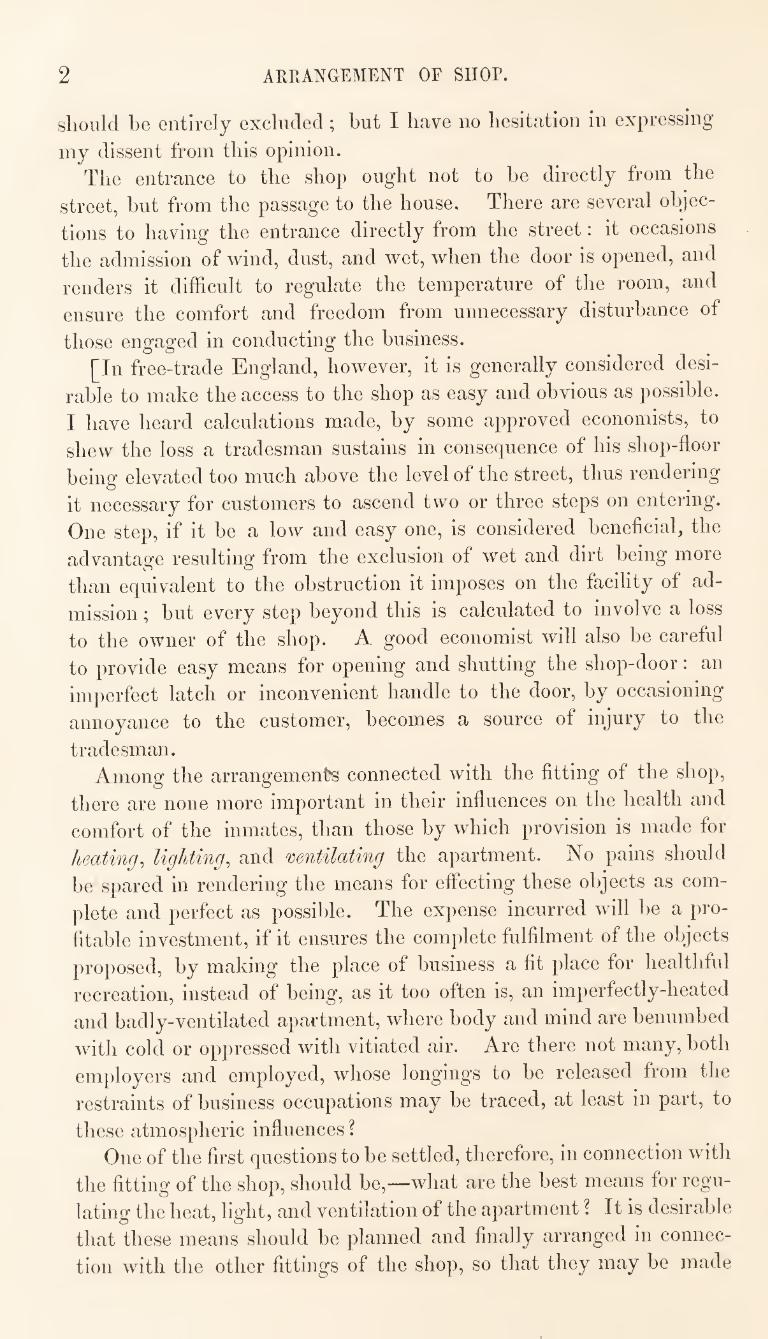
There is another kind of gas-stove or furnace, fitted up by Mr.
Rickets and other gas-fitters, which although not generally used
expressly for heating rooms, may, in some cases, in addition to its
application to other useful purposes, be made available for warming
a small shop.
Fig. 1, represents a section of one of these furnaces. A, is an iron
tube, about two feet long and two, three, or four inches in diameter,
open at both ends. At 0, about two inches from the top, a disk of
I GAS FURNACES.
fine wire gauze (fig. 2) is securely fixed,
so as to form a diaphragm, on which
are put some pieces of broken pumice-
stone to fill the upper part of the tube.
B, is a gas-pipe from which gas is ah
lowed to escape into the tube A, where,
on ascending, it mixes with the atmo¬
spheric air, which has free ingress at
the bottom. This mixture of gas and
air, passing through the wire gauze, is
ignited on the surface of the pumice-
stone. The wire gauze is used to pre¬
vent the communication of the ignition
to the combustible mixture below it,
while the pumice-stone, becoming red-
hot, forms a good radiating surface.
The quantity of gas admitted into the Mixed-gas fuenace. should be such, that the gaseous
mixture shall burn with a pale blue flame 'perfectly free from
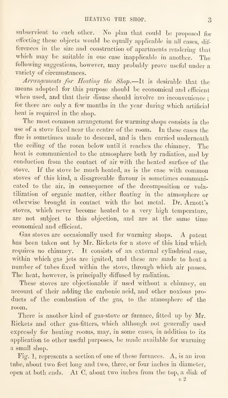
smoke. A furnace of this kind
may be lighted in an in¬
stant ; it affords sufficient
heat for making a decoction,
heating a plaster spatula, or
for any other similar pur¬
pose ; and it occasions no
annoyance from dust or
smoke. Several of them
may be fixed contiguously to
each other, as shewn in fig.
3, so that two or more may
be lighted at the same time,
when required, and a great
amount of heat may in this
way be produced.
Means ought to be pro¬
vided for conveying away
the products of combustion
from this, in common with
every other, kind of stove or
furnace, instead of allowing
them to contaminate the air of the apartment; yet the effects of
Mixed-gas Furnace.
PHARMACEUTICAL STOYE. 5
using either of the gas-stoves above described without a chimney,
would not be more injurious than those resulting from the ordinary
combustion of the same quantity of gas in lamps.
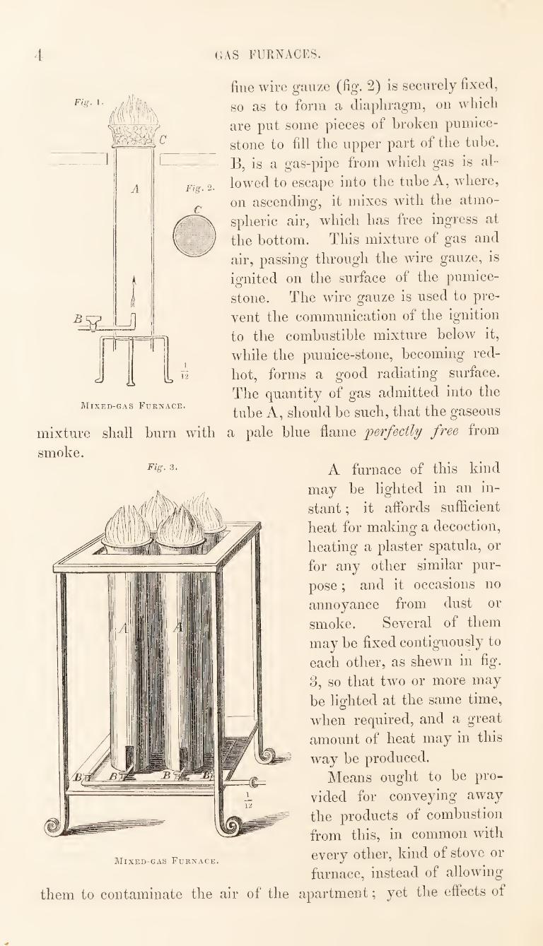
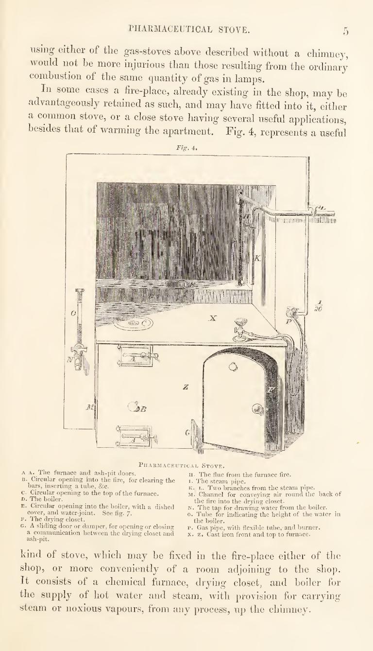
In some cases a fire-place, already existing in the shop, may be
advantageously retained as such, and may have fitted into it, either
a common stove, or a close stove having several useful applications,
besides that of warming the apartment. Fig. 4, represents a useful
Fig. 4.
Pharmaceutical Stove.
A A. The furnace and ash-pit doors. B. Circular opening into the fire, for clearing the
bars, inserting a tube, &c. c. Circular opening to the top of the furnace. H. The boiler.
E. Circular opening into the boiler, with a dished cover, and water-joint. See fig. 7.
F. The drying closet. G. A sliding door or damper, for opening or closing
a communication between the drying closet and ash-pit.
n. The flue from the furnace fire. I. The steam pipe. K. L. Two branches from the steam pipe, M. Channel for conveying air round the back of
the fire into the drying closet. N. The tap for drawing water from the boiler. O. Tube for indicating the height of the water in
the boiler. p. Gas pipe, with flexible tube, and burner. X. z. Cast iron front and top to furnace.
kind of stove, which may be fixed in the fire-place either of the
shop, or more conveniently of a room adjoining to the shop.
It consists of a chemical furnace, drying closet, and boiler for
the supply of hot water and steam, with provision for carrying
steam or noxious vapours, from any process, up the chimney.
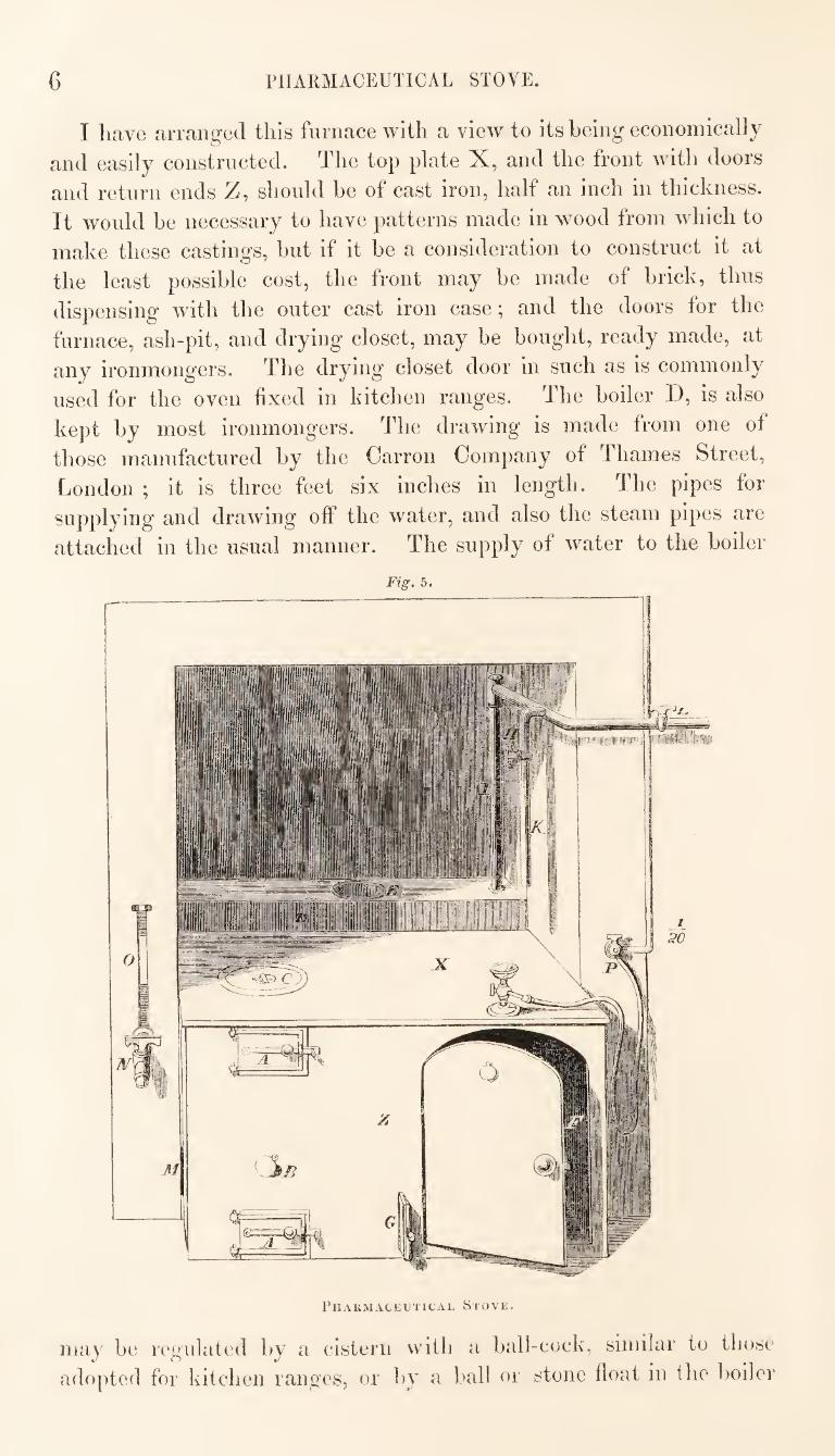
6 PHARMACEUTICAL STOVE.
I have arranged this furnace with a view to its being economically
and easily constructed. The top plate X, and the front with doors
and return ends Z, should be of cast iron, half an inch in thickness.
It would be necessary to have patterns made in wood from which to
make these castings, but if it be a consideration to construct it at
the least possible cost, the front may be made of brick, thus
dispensing with the outer cast iron case; and the doors for the
furnace, ash-pit, and drying closet, may be bought, ready made, at
any ironmongers. The drying closet door in such as is commonly
used for the oven fixed in kitchen ranges. The boiler D, is also
kept by most ironmongers. The drawing is made from one of
those manufactured by the Carron Company of Thames Street,
London ; it is three feet six inches in length. The pipes for
supplying and drawing off the water, and also the steam pipes are
attached in the usual manner. The supply of water to the boiler
Fig. 5.
Phakmackutical Stove.
may be regulated by a cistern with a ball-cock, similar to those
adopted for kitchen ranges, or by a ball or stone float in the boiler
PHARMACEUTICAL STOVE. 7
itself, similar to those generally used with steam boilers. The
former of these plans is perhaps the least expensive, and most easily
effected in country places; it is, however, subject to this objection,
that in using the steam, a certain amount of pressure is required in
the boiler, which will force the*" water into the supply cistern, and
sometimes cause it to overflow there. This result may be obviated
by having a stop-cock between the supply cistern and the boiler, so
that, when pressure is required, this communication may be cut off.
In this case, and indeed under any circumstances, it would be
desirable to have a glass tube O, for indicating the height of
the water in the boiler. One end of this tube is inserted into the
pipe of the tap N, and the other end communicates by a piece of
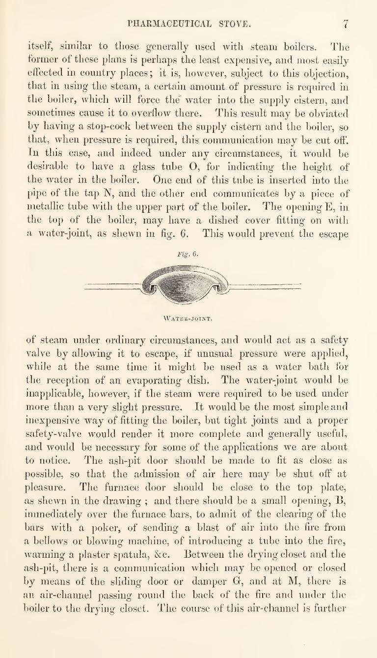
metallic tube with the upper part of the boiler. The opening E, in
the top of the boiler, may have a dished cover fitting on with
a water-joint, as shewn in fig. 6. This would prevent the escape
Fig. 6,
Water-joint.
of steam under ordinary circumstances, and would act as a safety
valve by allowing it to escape, if unusual pressure were applied,
while at the same time it might be used as a water bath for
the reception of an evaporating dish. The water-joint would be
inapplicable, however, if the steam were required to be used under
more than a very slight pressure. It would be the most simple and
inexpensive way of fitting the boiler, but tight joints and a proper
safety-valve would render it more complete and generally useful,
and would be necessary for some of the applications we are about
to notice. The ash-pit door should be made to fit as close as
possible, so that the admission of air here may be shut off at
pleasure. The furnace door should be close to the top plate,
as shewn in the drawing ; and there should be a small opening, B,
immediately over the furnace bars, to admit of the clearing of the
bars with a poker, of sending a blast of air into the fire from
a bellows or blowing machine, of introducing a tube into the fire,
warming a plaster spatula, &c. Between the drying closet and the
ash-pit, there is a communication which may be opened or closed
by means of the sliding door or damper G, and at M, there is
an air-channel passing round the back of the fire and under the
boiler to the drying closet. The course of this air-channel is further
8 I^IIAIIMACEUTICAL STOVE.
blievvn ill fig. 9 . When the furnace is in action, if the ash-
[)it door be shut, and the damper G, drawn out, the air sup¬
plied to the fire will be necessarily drawn from the drying closet,
vvdiile ffesh air, warmed by its proximity to the fire, will at
the same time enter the closet through the channel M, A constant
cuiient of warm dry air will thus be maintained through the drying
closet, which will render it very efficient for the purposes to which
it is applied. The circular opening 0, in the top of the furnace,
will receive a pan, small still, or other similar vessel. Decoctions
may be boiled in flat bottomed saucepans merely placed on the
hot plate over the flue, a little further back than the opening
0. The top of the boiler may be used for any process to which it
is applicable, requiring the heat of boiling water.
The iron plate forming the top of the drying closet at X,
will have only the slight heat which it acquires by conduction from
the fire. Processes involving the liberation of noxious vapours,
may be conveniently conducted here, as the vapours will pass
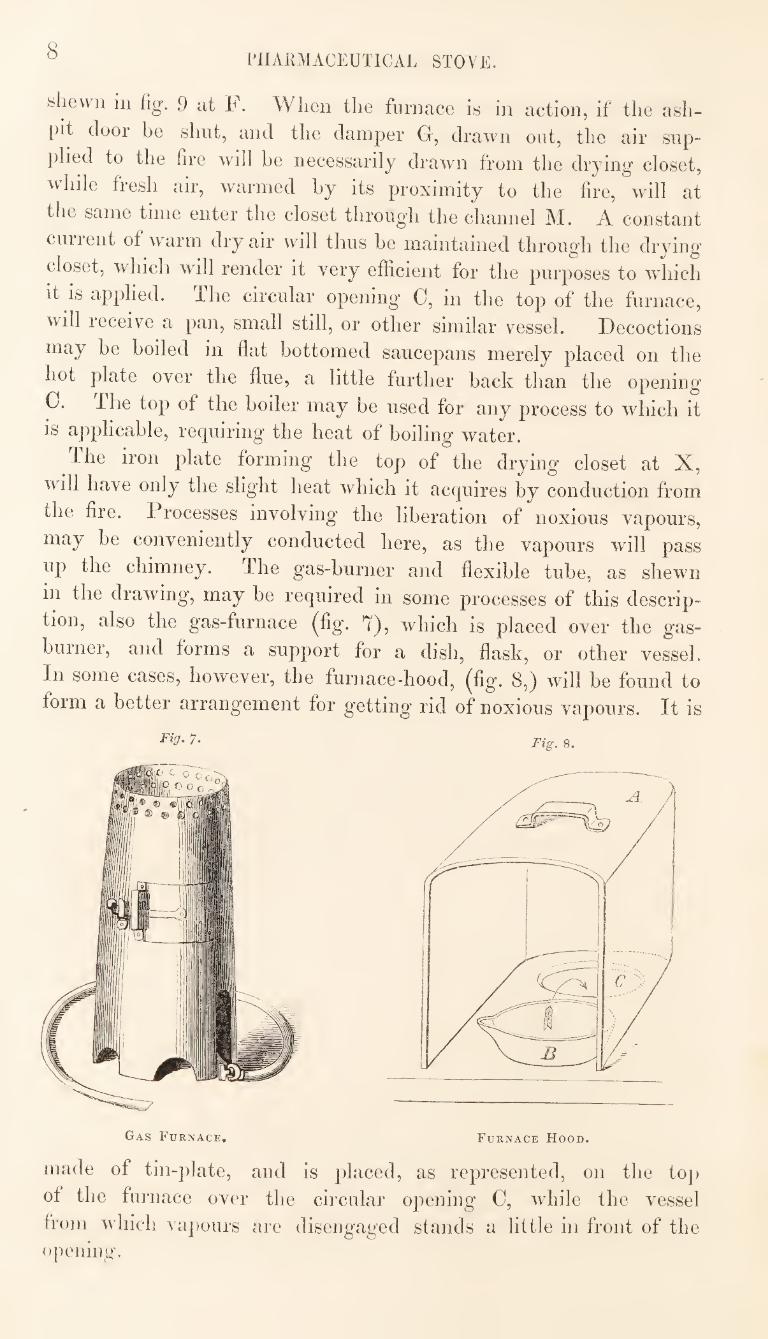
up the chimney. The gas-burner and flexible tube, as shewn
in the drawing, may be required in some processes of this descrip¬
tion, also the gas-furnace (fig. 7), which is placed over the gas-
burner, and forms a support for a dish, flask, or other vessel.
In some cases, however, the furnace-hood, (fig. 8,) will be found to
form a better arrangement for getting rid of noxious vapours. It is
^^3- 7. Fig. 8.
Gas Furnace, Furnace Hood.
made of tin-plate, and is placed, as represented, on the toj)
of the furnace over the circular opening C, while the vessel
from which va])ours are disengaged stands a little in front of the
opening.
PHARMACEUTICAL STOVE. 9
Fig. 9.
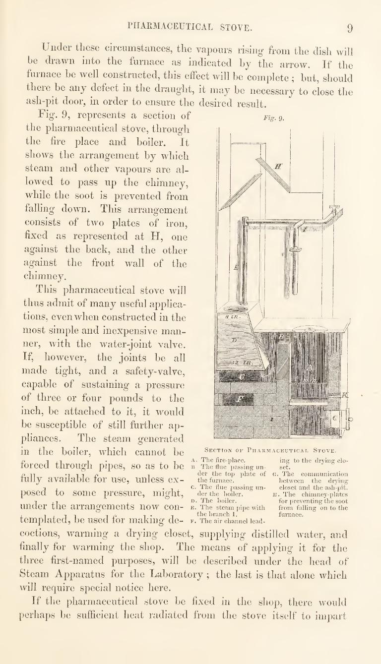
Under these circumstances, the vapours rising from the dish will
be drawn into the furnace as indicated by the arrow. If the
furnace be well constructed, this eifect will be complete ; hut, should
theie he any defect in the draught, it may he necessary to close the
ash-pit door, in order to ensure the desired result.
Fig. 9, represents a section of
the pharmaceutical stove, through
the fire place and hoiler. It
shows the arrangement hy which
steam and other vapours are al¬
lowed to pass up the chimney,
while the soot is prevented from
falling down. This arrangement
consists of two plates of iron,
fixed as represented at H, one
against the back, and the other
against the front wall of the
chimney.
This pharmaceutical stove will
thus admit of many useful applica¬
tions, even when constructed in the
most simple and inexpensive man¬
ner, with the water-joint valve.
If, however, the joints he all
made tight, and a safety-valve,
capable of sustaining a pressure
of three or four pounds to the
inch, he attached to it, it would
he susceptible of still further ap¬
pliances. The steam generated
in the hoiler, which cannot he section of Pharmaceutical Stoye.
P 1 1 • I 1 The fire-place. inff to the dryinar clo- torCed through pipes, so as to be b The tlue passing un- set.
PIT Miir* 1 top plate of c. The communication lully available tor use, unless ex— the furnace. between the drying
I . . c. The flue passing un- closet and the ash-pit. posed to some pressure, might, der the boiler. k. The chimney-plates
1,1 D. The boiler. for preventing the soot under the arrangements now con- e. The steam pipe with from failing on to the , ijii IP !• 1 the branch 1. furnace. templated, be used tor making de- f. The air channel lead-
coctions, warming a drying closet, supplying distilled water, and
finally for warming the shop. The means of applying it for the
three first-named purposes, will be described under the head of
Steam Apparatus for the Laboratory ; the last is that alone which
will require special notice here.
If the pharmaceutical stove he fixed in the shop, there would
perhaps he sufficient heat radiated from the stove itself to impart
10 GAS LIGHTING,
the required warmth to the atmosphere of the room; hut, should
this he the case in cold weather, it is obvious that the same diffu¬
sion of heat in warm weather would become oppressive and in¬
jurious. Yet the stove, if rendered serviceable to the fullest extent
of which it is susceptible, should he in daily operation throughout
the year. It would be found more convenient, therefore, to have the
stove in a separate apartment, contiguous to the shop ; or, if this
cannot be done, efficient means must he provided for carrying
off the heated air, when this is required.
The use of a steam-heating-pipe presents a most unobjectionable
method of communicating heat to an apartment. In the case now
under consideration, it would only be necessary to have a pipe about
three or four inches in diameter, running the entire length of the
shop, and fixed in, on, or near to, the floor, with a branch from
the pipe L, fig. 4, to supply it with steam from the boiler. This
steam-pipe may be made of cast iron, but if one of a suitable size
could he obtained, coated on the inside with the enamel now so
extensively applied to iron utensils, it would possess this advantage,
that the water which would be condensed in it would be available
for use as distilled water. The steam pipe should have a little
inclination towards the end furthest from the boiler, so that the
condensed water may run off from that end into a suitable vessel,
fixed for its collection.
The best position for the steam-heating-pipe would he the space
between the floor and the ceiling below, with an iron grating placed
over it, or the interior of the counter, with openings to admit of the
circulation of air around it. It is calculated that the steam-pipe for
heating a room^should have one square foot of surface exposed, for
every 200 cubic feet of space to he warmed.
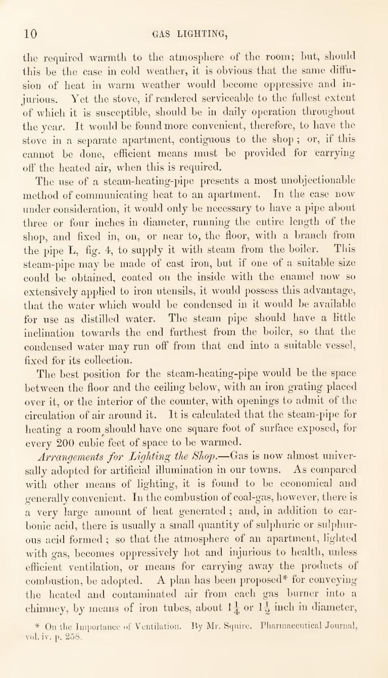
Arrangements for Lighting the Shop.—Gas is now almost univer¬
sally adopted for artificial illumination in our towns. As compared
with other means of lighting, it is found to he economical and
generally convenient. In the combustion of coal-gas, however, there is
a very large amount of heat generated ; and, in addition to car¬
bonic acid, there is usually a small quantity of sulphuric or sulphur¬
ous acid formed ; so that the atmosphere of an apartment, lighted
with gas, becomes oppressively hot and injurious to health, unless
efficient ventilation, or means for carrying away the products of
combustion, he adopted. A plan has been proposed* for conveying
the heated and contaminated air from each gas burner into a
chimney, by means of iron tubes, about or inch in diameter,
* On the Iin})orttince of Ventiktioii. Hy Mr. Squire. Pharmaceutical Journal, vol. iv. p. 258.
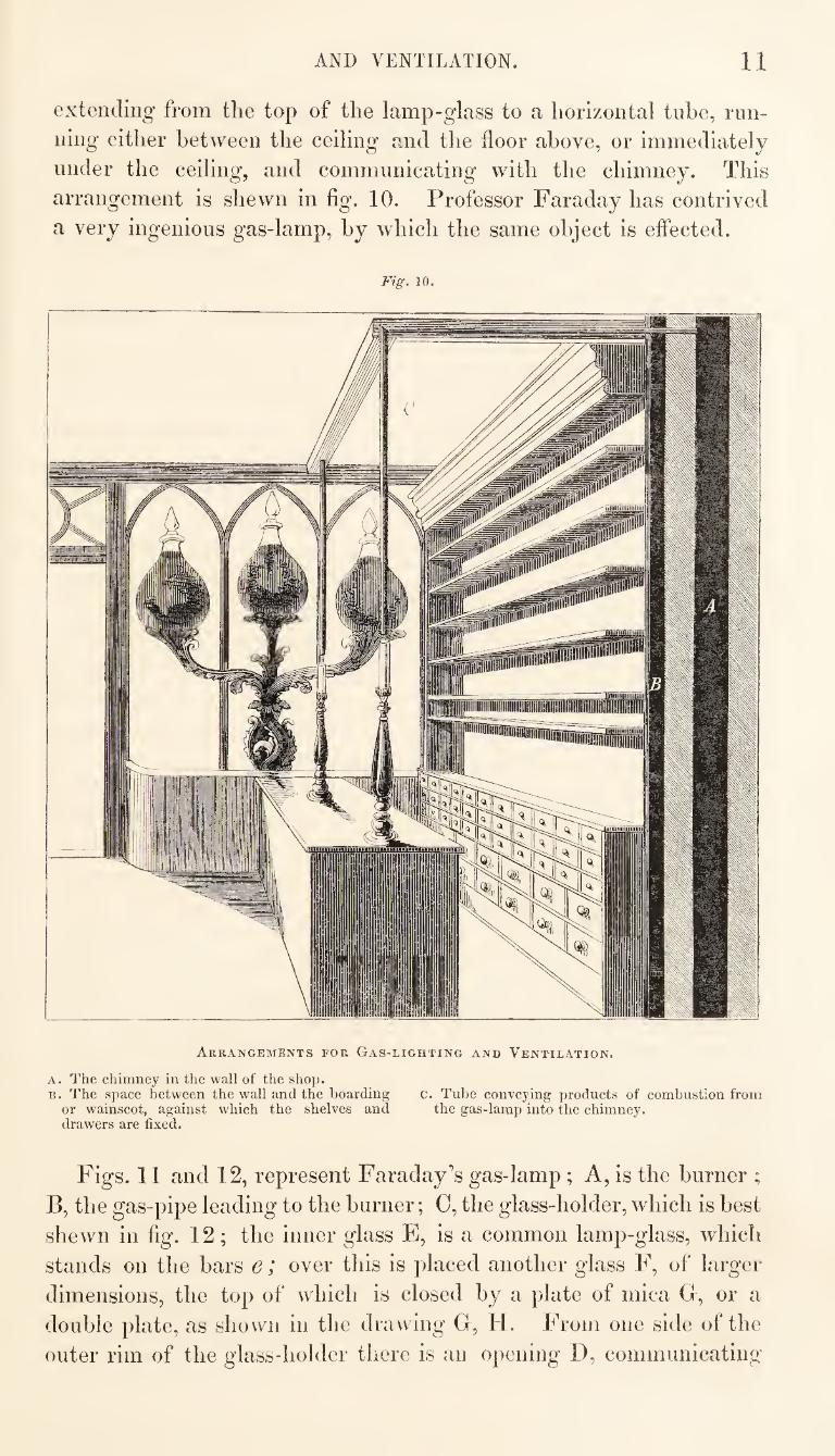
AND VENTILATION. 11
extending from the top of the lamp-glass to a horizontal tube, run¬
ning either between the ceiling and the floor above, or immediately
under the ceiling, and communicating with the chimney. This
arrangement is shewn in fig. 10. Professor Faraday has contrived
a very ingenious gas-lamp, by which the same object is effected.
Fig. 10.
Arrangements for Gas-lighting and Ventilation.
A. The chimney in the wall of the shop. B. The space between the wall and the boarding c. Tube conveying products of combustion from
or wainscot, against which the shelves and the gas-lamp into the chimney. drawers are fixed.
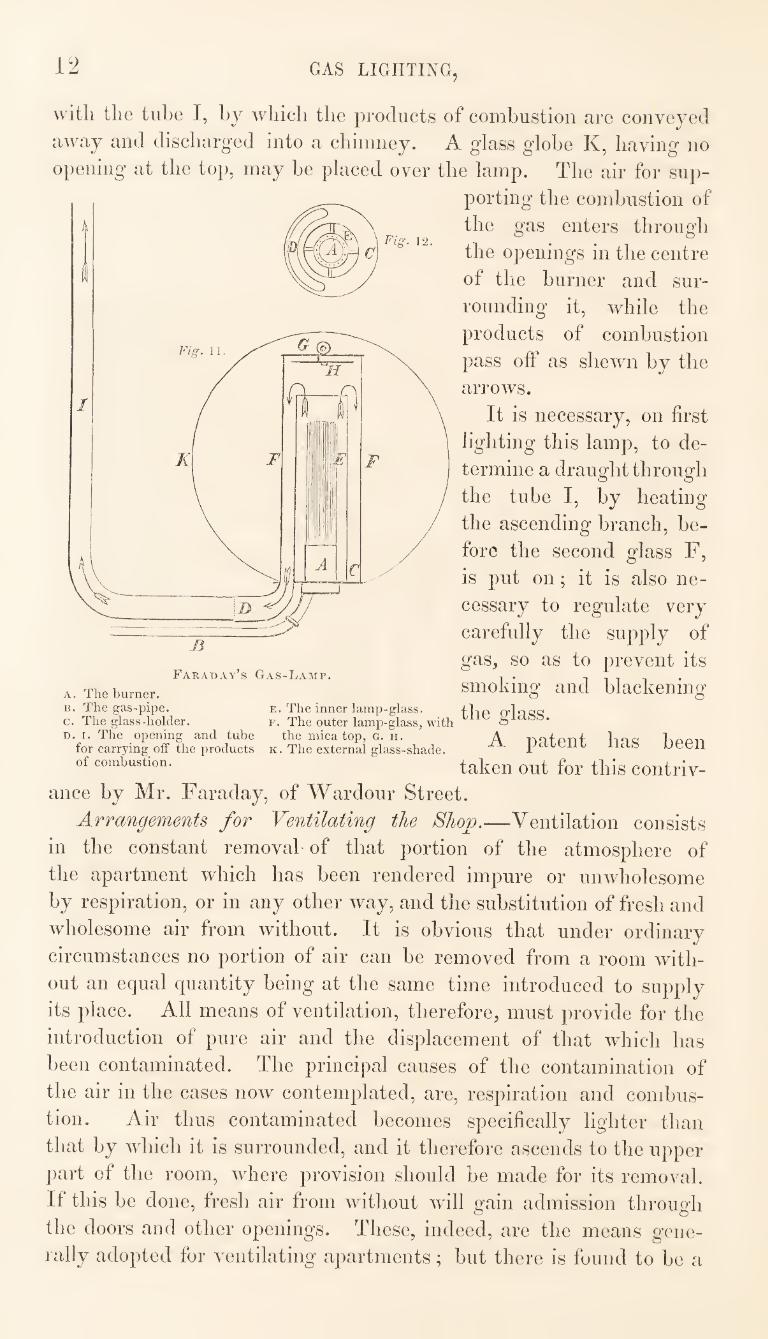
Figs. 11 and 12, represent Faraday’s gas-lamp ; A, is the burner ;
E, the gas-pipe leading to the burner; C, the glass-holder, which is best
shewn in fig. 12; the inner glass E, is a common lamp-glass, which
stands on the bars e; over this is placed another glass F, of larger
dimensions, the top of which is closed by a plate of mica G, or a
double plate, as shown in the drawing G, H. From one side of the
outer rim of the glass-holder there is an opening D, communicating
12 GAS LIGHTING,
Fig. 12.
with the tube I, by which the products of combustion arc conveyed
away and discharged into a chimney. A glass globe K, having no
opening at the top, may be placed over the lamp. The air for sup¬
porting the combustion of
the gas enters through
the openings in the centre
of the burner and sur¬
rounding it, while the
products of combustion
pass off as shewn by the
arrows.
It is necessary, on first
ligliting this lamp, to de¬
termine a draught through
the tube I, by heating
the ascending branch, be¬
fore the second glass F,
is put on; it is also ne¬
cessary to regulate very
carefully the supply of
gas, so as to prevent its
smoking and blacken in c o o
the glass.
A patent has been
taken out for this contriv¬
ance by Mr. Faraday, of Wardour Street.
Arrangements for Ventilating the Shop.—Ventilation consists
in the constant removal of that portion of the atmosphere of
the apartment which has been rendered impure or unwholesome
by respiration, or in any other way, and the substitution of fresh and
wholesome air from without. It is obvious that under ordinary
circumstances no portion of air can be removed from a room with¬
out an equal quantity being at the same time introduced to supply
its place. All means of ventilation, therefore, must provide for the
introduction of pure air and the disj)lacement of that which has
been contaminated. The principal causes of the contamination of
the air in the cases now contemplated, are, respiration and combus¬
tion. Air thus contaminated becomes specifically lighter than
that by which it is surrounded, and it therefore ascends to the upper
part of the room, where provision should be made for its removal.
If this be done, fresh air from without will gain admission through
the doors and other openings. These, indeed, are the means gene¬
rally adopted for ventilating apartments; but there is found to be a
Faraday’s Gas-Lamp.
A. The burner. B. The gas-pipe. e. The inner lamp-glass. c. The glass-holder. f. The outer lamp-glass, with D. I. The opening and tube the mica top, o. h.
for carrying off the products k. The external glass-shade, of combustion.
AND VENTILATION. 18
great impediment to the efficient adoption of these means, arising from the fear of exposure to draughts of cold air, and the difficulty of guarding against this evil.
The two principal points to be considered, therefore, in reference to ventilation, are; 1st, the means hy which the vitiated air may be rapidly removed from the upper part of the room; and 2ndly, the means for introducing fresh air, which shall be so diffused or pre¬ viously warmed, as not to occasion the sensation of cold draughts or currents of air.
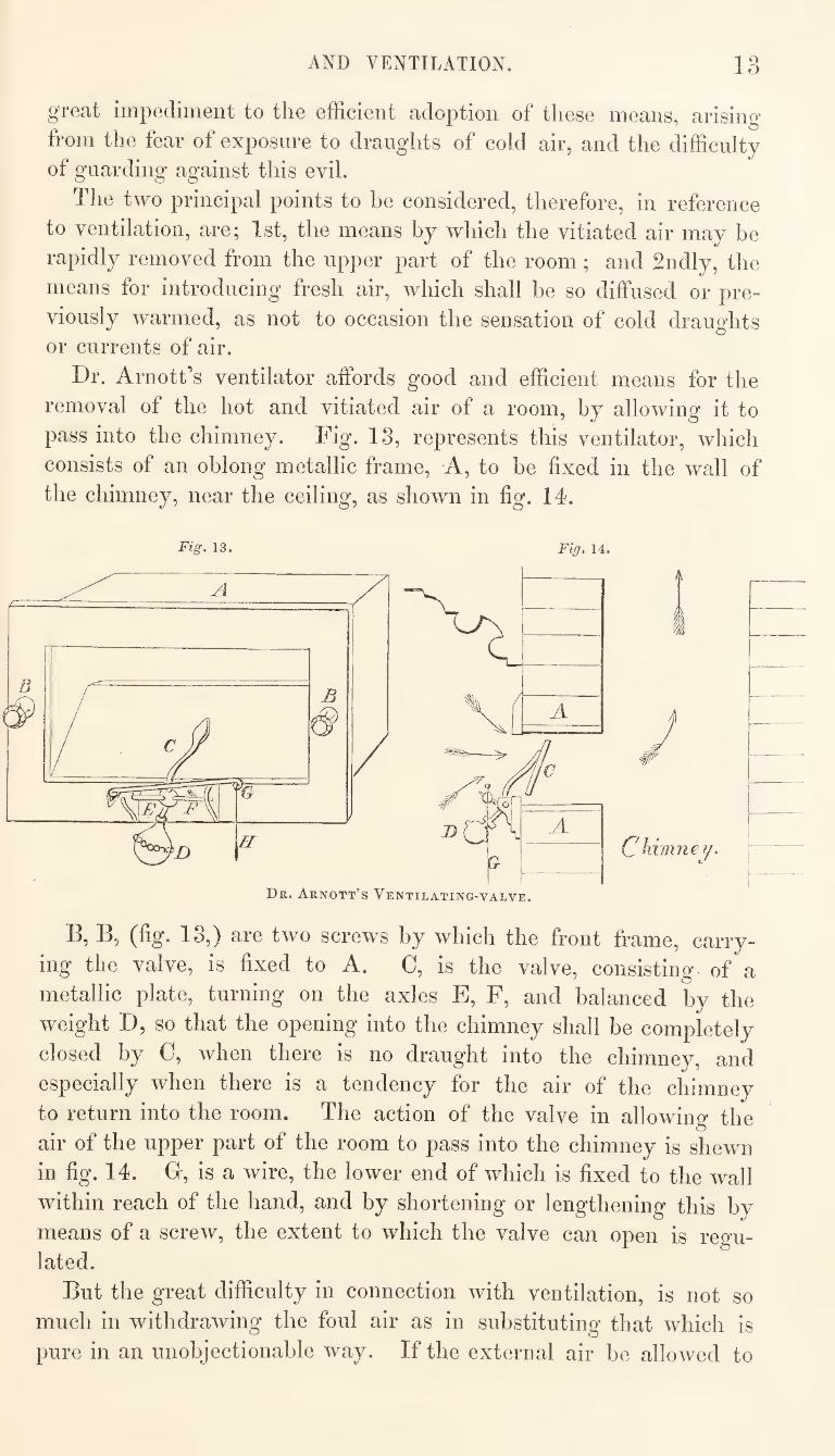
Dr. Arnott’s ventilator affords good and efficient means for the removal of the hot and vitiated air of a room, by allowing it to pass into the chimney. Fig. 13, represents this ventilator, which consists of an oblong metallic frame. A, to be fixed in the wtill of the chimney, near the ceiling, as shown in fig. 14.
Fig. 13, Fig, 14.
Dr. Arnott’s Ventilating-valve.
I
C himne ?/.
B, B, (fig. 18,) are two screws by which the front frame, carry¬ ing the valve, is fixed to A. 0, is the valve, consisting of a metallic plate, turning on the axles E, F, and balanced by the weight D, so that the opening into the chimney shall be completely closed by 0, when there is no draught into the chimney, and especially when there is a tendency for the air of the chimney to return into the room. The action of the valve in allowing the air of the upper part of the room to pass into the chimney is shewn in fig. 14. G, is a wire, the lower end of which is fixed to the wall within reach of the hand, and by shortening or lengthening this hy means of a screw, the extent to which the valve can open is regu¬ lated.
But the great difficulty in connection with ventilation, is not so much in withdrawing the foul air as in substituting that which is pure in an unobjectionable way. If the external air he allowed to
14 DIVISION OF SHOP.
enter the apartment at only a few points, it will almost inevitably
occasion cold currents that will prove sources of annoyance. Means
have been tried for cansing a mechanical diffusion of the cold air as
it enters, but none of these have completely answered. A patent
has been taken out for a ventilator to be fixed in the window, which
consists of a number of slips of glass fitted into one of the squares,
in the same way as louver board ventilators are constructed. The
object of this is to divide the air, as it enters, into several strata,
and to give to these an upward direction, so that the cold air may
pass along the ceiling, and thus become to some extent warmed and
diffused before its descent. But the objection still applies to this
method, that the air is admitted at a few points only, and if there
be much difference between the temperatures of the external air
and of that within the room, there will frequently be complaints of
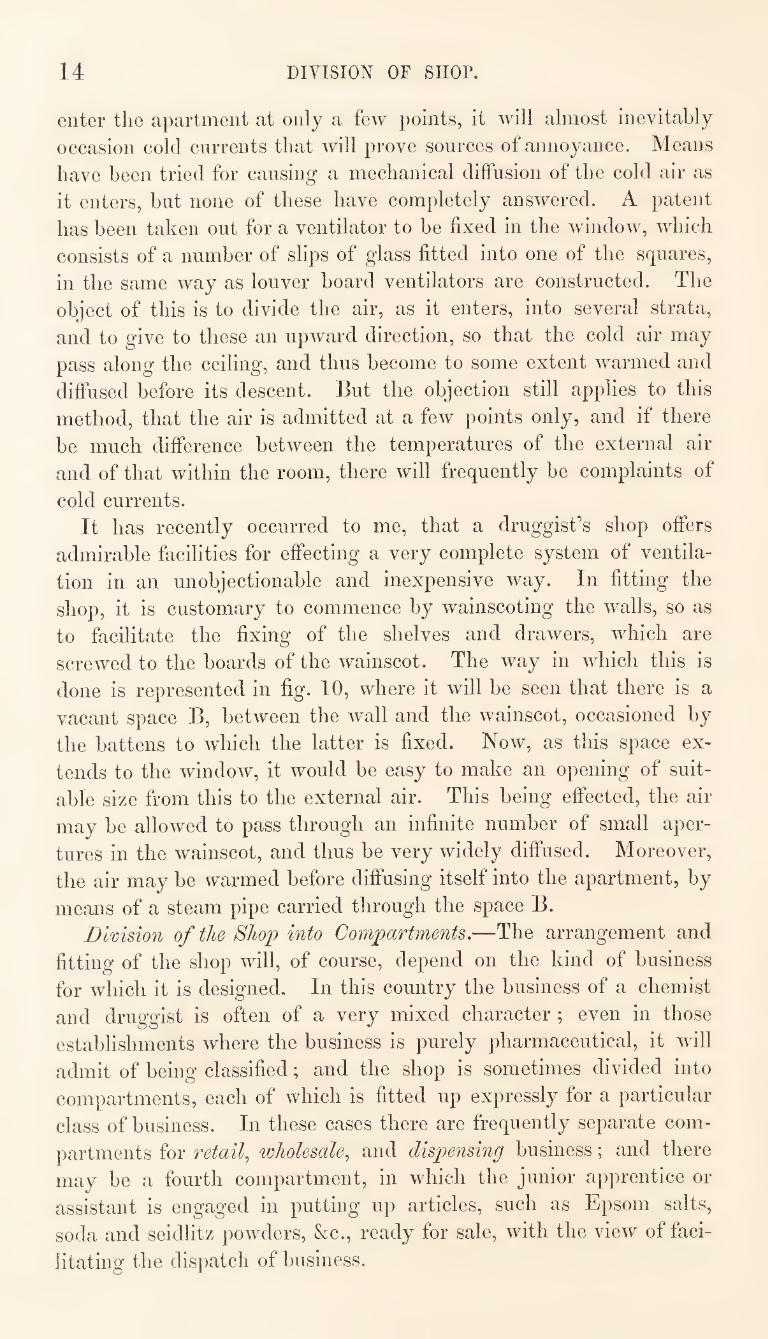
cold currents. It has recently occurred to me, that a druggist’s shop offers
admirable facilities for effecting a very complete system of ventila¬
tion in an unobjectionable and inexpensive way. In fitting the
shop, it is customary to commence by wainscoting the walls, so as
to facilitate the fixing of the shelves and drawers, which are
screwed to the boards of the wainscot. The way in which this is
done is represented in fig. 10, where it will be seen that there is a
vacant space B, between the wall and the wainscot, occasioned by
the battens to which the latter is fixed. Now, as this space ex¬
tends to the window, it would be easy to make an opening of suit¬
able size from this to the external air. This being effected, the air
may be allowed to pass through an infinite number of small aper¬
tures in the wainscot, and thus be very widely diffused. Moreover,
the air may be warmed before diffusing itself into the apartment, by
means of a steam pipe carried through the space B.
Division of the Shop into Compartments.—The arrangement and
fitting of the shop will, of course, depend on the kind of business
for which it is designed. In this country the business of a chemist
and druggist is often of a very mixed character ; even in those
establishments where the business is purely pharmaceutical, it will
admit of being classified; and the shop is sometimes divided into
compartments, each of which is fitted up expressly for a particular
class of business. In these cases there are frequently separate com¬
partments for retail.^ wholesale.^ and dispensing business; and there
may be a fourth compartment, in which the junior apprentice or
assistant is engaged in putting up articles, such as Epsom salts,
soda and seidlitz powders, &c., ready for sale, with the view of faci¬
litating the dispatch of business.
DISPENSING COUNTER. 15
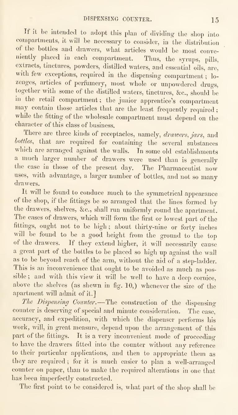
If it be intended to adopt this plan of dividing the shop into
compartments, it will be necessary to consider, in the distribution
of the bottles and drawers, what articles would be most conve¬
niently placed in each compartment. Thus, the syrups, pills,
extracts, tinctures, powders, distilled waters, and essential oils, are,
with few exceptions, required in the dispensing compartment; lo¬
zenges, articles of perfumery, most whole or unpowdered drugs,
together with some of the distilled waters, tinctures, &c., should be
in the retail compartment; the junior apprentice’s compartment
may contain those articles that are the least frequently required;
while the fitting of the wholesale compartment must depend on the character of this class of business.
There are three kinds of receptacles, namely, drawers^ jars^ and
bottles^ that are required for containing the several substances
Avhich are arranged against the walls. In some old establishments
a much larger number of drawers were used than is generally
the case in those of the present day. The Pharmaceutist now
uses, with advantage, a larger number of bottles, and not so many drawers.
It will be found to conduce much to the symmetrical appearance
of the shop, if the fittings be so arrang'ed that the lines formed by
the drawers, shelves, &c., shall run uniformly round the apartment.
The cases of drawers, which will form the first or lowest part of the
fittings, ought not to be high; about thirty-nine or forty inches
will be found to be a good height from the ground to the top
of the drawers. If they extend higher, it will necessarily cause
a great part of the bottles to be placed so high up against the wall
as to be beyond reach of the arm, without the aid of a step-ladder.
This is an inconvenience that ought to be avoided as much as pos¬
sible ; and with this view it will be well to have a deep cornice,
above the shelves (^as shewn in fig. 10,) whenever the size of the apartment will admit of it.]
The Dispensing Counter.—The construction of the dispensing
counter is deserving of special and minute consideration. The ease,
accuracy, and expedition, with which the dispenser performs his
work, will, in great measure, depend upon the arrangement of this
part of the fittings. It is a very inconvenient mode of proceeding
to have the drawers fitted into the counter without any reference
to their particular applications, and then to appropriate them as
they are required ; for it is much easier to plan a well-arranged
counter on paper, than to make the required alterations in one that
has been imperfectly constructed.
The first point to be considered is, what part of the shop shall be
16 DISPENSING COUNTER.
appropriated to tliis department s It is desirable tliat tlie dispens¬
ing counter should be so placed that it shall command good light,
and that those engaged at it may not be exposed to unnecessary
interruptions. A question may arise, as to what is the best direc¬
tion for the light to fall S When this can be made a matter of
choice, it will be found advantageous to have the window to the
left hand of the dispenser, so that his right hand may not cast a
shadow over his work.
The height of the dispensing counter is a matter of some import¬
ance ; if it be too low, it will affect injuriously the health and
stature of the dispenser, by causing him to stoop, and this, from con¬
stant habit, has been found to occasion a slight curvature of the
spine, which has been called the dispensers" hump. Thirty-six
inches will be found to be a good height for the counter. The top
should be of hard wood, and should be at least two inches in thick¬
ness. The arrangement of the drawers, however, is the most important
consideration in reference to the construction of the dispensing
counter. A difference of opinion appears to exist, as to whether it
is most convenient to have a great number of small drawers, or a
smaller number of large ones, with internal divisions in them. I
think there are several reasons for preferring the latter. The fol¬
lowing arrangement of a dispensing counter is given as one that has
been found practically convenient.
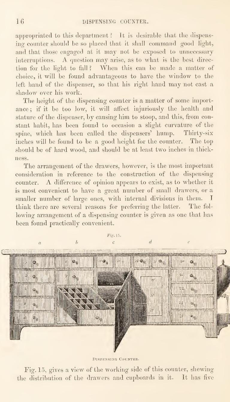
Fig. 15.
abed e
Dispensing Counter.
Fig. 15, gives a view of the working side of this counter, shewing
the distribution of the drawers and cupboards in it. It has five
DISPENSING COUNTER. 17
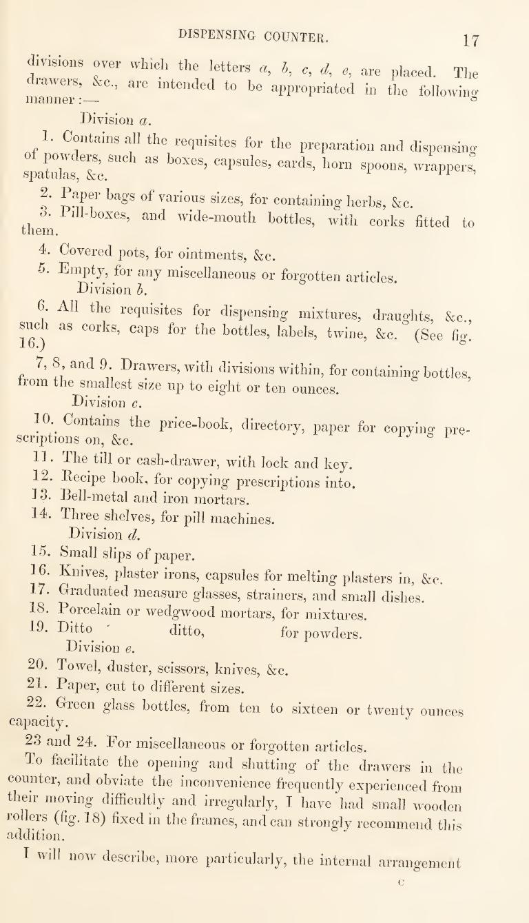
divisions over which the letters a, b, c, d, e, are placed. The
drawers, &c., are intended to he appropriated in the following maimer:— >=>
Division a.
1. Contains all the requisites for the preparation and dispensina-
Tpatidls ""fee wrappers,
2. Paper hags of various sizes, for containing herbs, &c.
o. lill-hoxes, and wide-mouth bottles, with corks fitted to them.
4. Covered pots, for ointments, &c.
5. Empty, for any miscellaneous or forgotten articles Division b.
6. Ail the requisites for dispensing mixtures, draughts, &c.,
such as corks, caps for the bottles, labels, twine, &c. (See fig.
7. 8 and 9 Drawers, with divisions within, for containing bottles,
irom the smallest size up to eight or ten ounces.
Division c.
do. Contains the price-book, directory, paper for copying- pre¬ scriptions on, &c. ^ r 1 1J 6 1 V
11. The till or cash-drawer, with lock and key.
12. Recipe book, for copying prescriptions into.
13. Bell-metal and iron mortars.
14. Three shelves, for pill machines.
Division d.
15. Small slips of paper.
16. Knives, plaster irons, capsules for melting plasters in, &c,
17. Graduated measure glasses, strainers, and small dishes.
18. Porcelain or wedgwood mortars, for mixtures.
19. Ditto ditto, for powders.
Division e.
20. Towel, duster, scissors, knives, &c.
21. Paper, cut to different sizes.
22. ^ Gieen glass bottles, from ten to sixteen or twenty ounces capacity.
23 and 24. For miscellaneous or forgotten articles.
To faeditate the opening and shutting of the drawers in the
counter, and obviate the inconvenience frequently experienced from
their moving difficultly and irregularly, I have'had small wooden
rollers (fig. 18) fixed in the frames, and can strongly recommend this addition.
I wdl now describe, more particularly, the internal arrangement
c
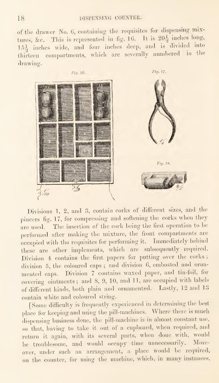
18 DISPENSING OOUNTEPt.
of the drawer No. 0, coiitaiiiiiig tlie requisites for dispensing mix¬
tures, &c. This is represented in fig. Ifi. It is 20^ inches long,
15^ inches wide, and four inches deep, and is divided into
thirteen compartments, which are severally numbered in the
drawing.
Fig. 16. PW- 17.
Divisions 1, 2, and 3, contain corks of different sizes, and the
pincers fig. 17, for compressing and softening the corks when they
are used. The insertion of the cork being the first operation to be
performed after making the mixture, the front compartments are
occupied with the requisites for performing it. Immediately behind
these are other implements, which are .subsequently required.
Division 4 contains the first papers for putting over the corks ;
division 5, the coloured caps ; and division 6, embossed and orna¬
mented caps. Division 7 contains waxed paper, and tin-foil, for
covering ointments; and 8, 9, 10, and 11, are occupied with labels
of different kinds, both plain and ornamented. Lastly, 12 and 13
contain white and coloured string. [Some difficulty is frequently experienced in determining the best
place for keeping and using the pill-machines. Where there is much
dispensing business done, the pill-machine is in almost constant use,
so that, having to take it out of a cupboard, when required, and
return it again, with its several parts, when done with, would
be troublesome, and would occupy time unnecessarily. More¬
over, under such an arrangement, a place would be required,
on the counter, for using the machine, which, in many instances.
DISPENSING COUNTER. 19
could not be conveniently spared, and the powder employed for
rolling out the pills, would occasion dust, which, together with
the machine itself, would interfere with the neatness and clean-
liness which ought to characterize the dispensing counter.
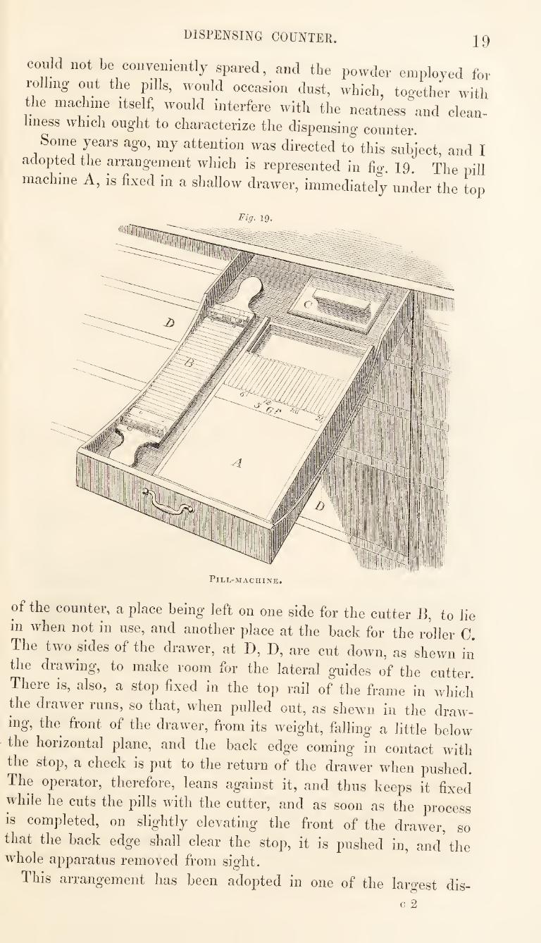
Some years ago, my attention was directed to this subject, and I
adopted the arrangement which is represented in fig. 19. The pill
machine A, is fixed in a shallow drawer, immediately under the top
Fig. 19.
of the counter, a place being left on one side for the cutter B, to lie
in when not in use, and another place at the back for the roller 0.
The two sides of the drawer, at D, D, are cut down, as shewn in
the drawing, to make room for the lateral guides of the cutter.
There is, also, a stop fixed in the top rail of the frame in which
the drawer runs, so that, when pulled out, as shewn in the draw¬
ing, the front of the drawer, from its w'eight, falling a little below
the horizontal plane, and the back edge coming in contact with
the stop, a check is put to the return of the drawer when pushed.
The operator, therefore, leans against it, and thus keeps it fixed
while he cuts the pills with the cutter, and as soon as the process
is completed, on slightly elevating the front of the drawer, so
that the back edge shall clear the stop, it is pushed in, and the whole apparatus removed from sight.
This arrangement has been adopted in one of the largest dis-
20 DISPENSING COUNTER.
peiising estaUlislimeiits in London, and lias been found practically
convenient. The ointment slab might be disposed of in a similar way.
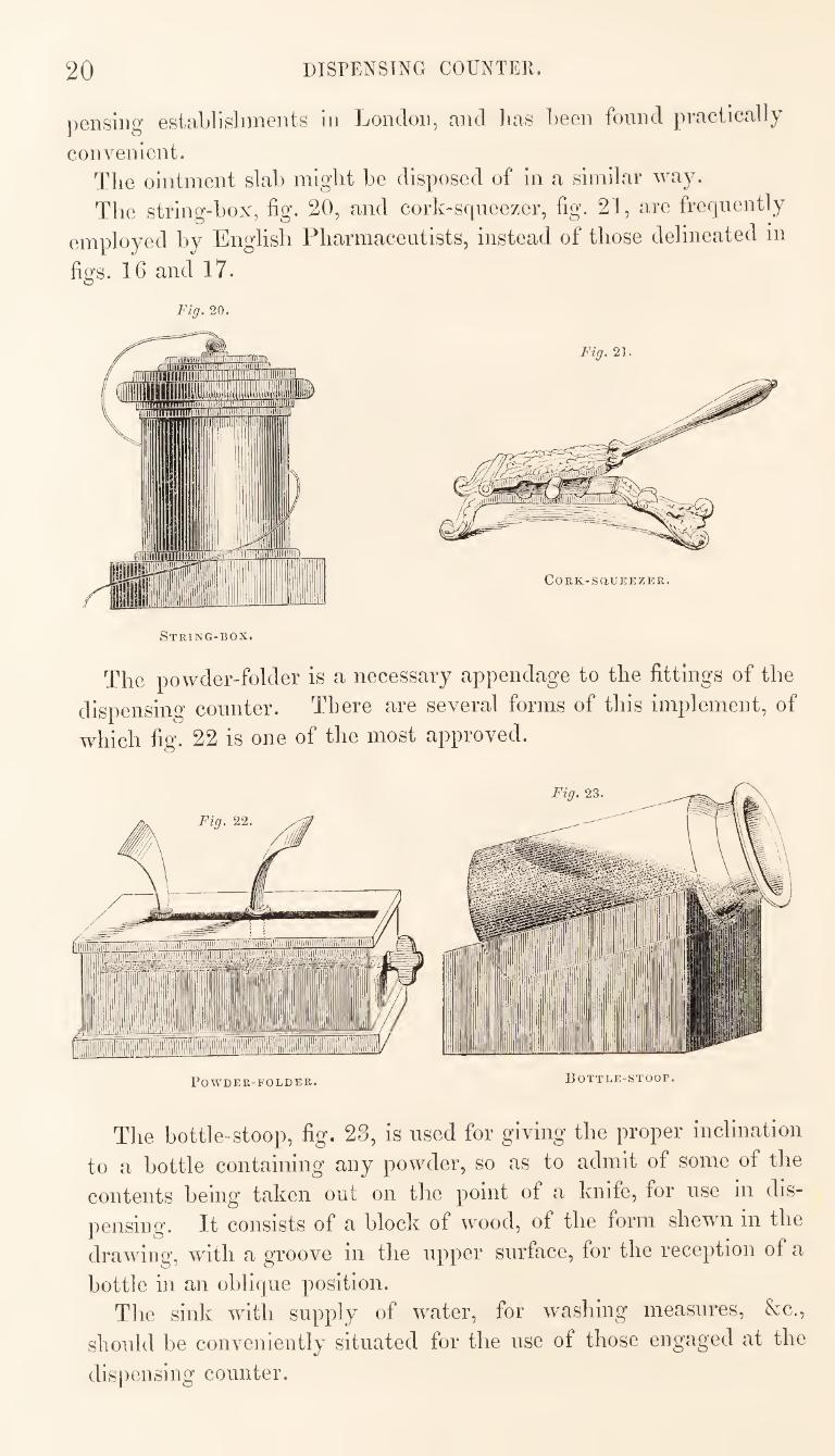
The string-box, fig. 20, and cork~sqneezer, fig. 21, are frequently
employed by English Pharmacentists, instead of those delineated in
figs. 16 and 17.
Fig. 20.
String-box.
The powder-folder is a necessary appendage to the fittings of the
dispensing counter. There are several forms of this implement, of
which fig. 22 is one of the most approved.
Fig. 23
Bottle-stoop.
The bottle-stoop, fig. 23, is nsed for giving the proper inclination
to a bottle containing any powder, so as to admit of some of the
contents being taken out on the point of a knife, for use in dis¬
pensing. It consists of a block of wood, of the form shewn in the
drawing, with a groove in the upper surface, for the reception of a
bottle in an oblique position. The sink with supply of water, for washing measures, &c,,
should be conveniently situated for the use of those engaged at the
dispensing counter.
LABOEATOKY. 21
Fig. 24,
Fig. 25
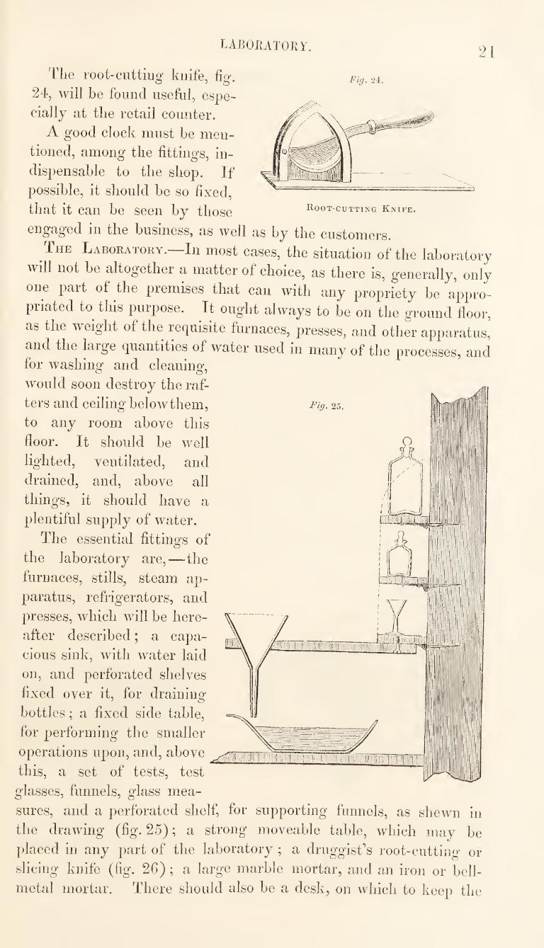
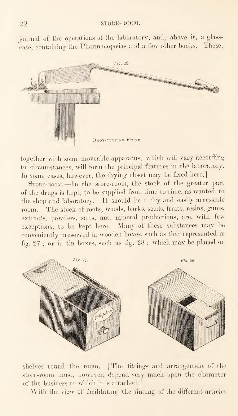
Tlie root-cuttiiiQ' knife, fio-.
24, will be found useful, espe¬
cially at the retail counter.
A good clock must be men¬
tioned, among the fittings, in¬
dispensable to the shop. If
possible, it should be so fixed, that it can be seen by those Root-cutting Knife.
engaged in the business, as well as by the customers.
The Labobatoky.—In most cases, the situation of the laboratory
will not be altogether a matter of choice, as there is, generally, only
one part of the premises that can with any propriety be appro¬
priated to this purpose. It ought always to be on the ground floor,
as the weight of the requisite furnaces, presses, and other apparatus,
and the large quantities of water used in many of the processes, and for washing and cleaning,
would soon destroy the raf¬
ters and ceiling belowthem,
to any room above this
floor. It should be well
lighted, ventilated, and
drained, and, above all
things, it should have a
plentiful supply of water.
The essential fittings of
the laboratory are,—the
furnaces, stills, steam ap¬
paratus, refrigerators, and
presses, which will be here¬
after described; a capa¬
cious sink, with water laid
on, and perforated shelves
fixed over it, for draining-
bottles ; a fixed side table,
for performing the smaller
operations upon, and, above
this, a set of tests, test
glasses, funnels, glass mea¬
sures, and a perforated shelf, for supporting funnels, as shewn in
the drawing (fig. 25); a strong moveable table, which may be
placed in any part of the laboratory ; a druggist’s root-cutting or
slicing knife (fig. 26); a large marble mortar, and an iron or bell-
metal mortar. There should also be a desk, on which to keep the
22 STORE-ROOM.
iournal of the operations of the laboratory, and, above it, a glass-
case, containing the Pharmacopoeias and a few other books. These,
together with some moveable apparatus, which will vary according
to circumstances, will form the principal features in the laboratory.
In some cases, however, the drying closet may be fixed here.]
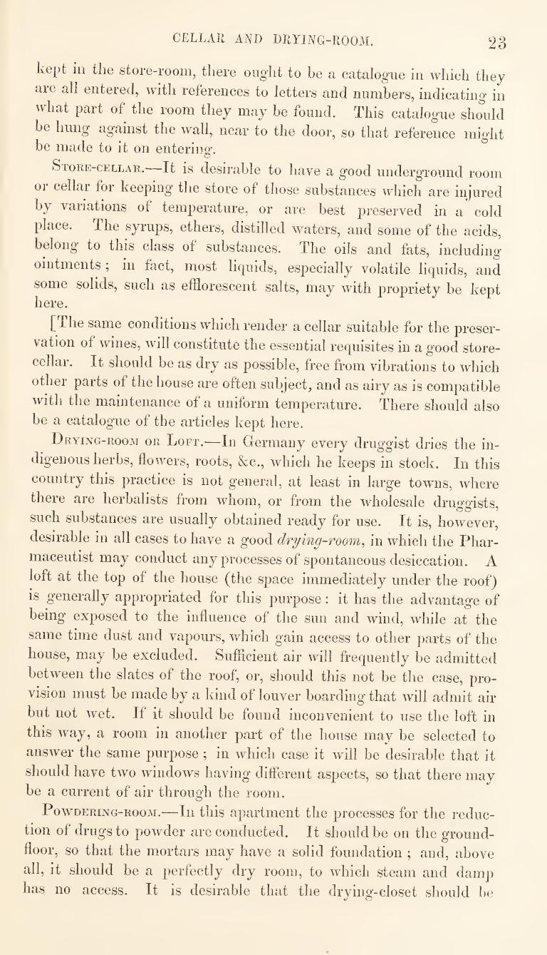
Store-room.—In the store-room, the stock of the greater part
of the drugs is kept, to be supplied from time to time, as wanted, to
the shop and laboratory. It should be a dry and easily accessible
room. The stock of roots, woods, barks, seeds, fruits, resins, gums,
extracts, powders, salts, and mineral productions, are, with few
exceptions, to be kept here. Many of these substances may be
conveniently preserved in wooden boxes, such as that represented in
fig. 27 ; or in tin boxes, such as fig. 28 ; which may be placed on
shelves round the room. [The fittings and arrangement of the
store-room must, however, depend very much upon the character
of the business to which it is attached.]
With the view of facilitating the finding of the different articles
CELLAR AND DRYING-ROOM. 23
kept in the store-room, there oug'ht to he a catalogue in which they
are all entered, with references to letters and numbers, indicating in
what part of the room they may be found. This catalogue should
be hung against the wall, near to the door, so that reference might be made to it on enteriuo’.
O
SroRE-CELLAR.—It is desirable to have a good underground room
or cellar for keeping the store of those substances which are injured
by variations of temperature, or are best preserved in a cold
place. The syrups, ethers, distilled waters, and some of the acids,
belong to this class of substances. The oils and fats, including
ointments , in fact, most liquids, especially volatile liquids, and
some solids, such as efflorescent salts, may with propriety be kept here.
[The same conditions which render a cellar suitable for the preser¬
vation of wines, will constitute the essential requisites in a good store-
cellar. It should be as dry as possible, free from vibrations to which
other parts of the house are often subject, and as airy as is compatible
with the maintenance of a uniform temperature. There should also
be a catalogue of the articles kept here.
Drying-room or Loft.—In Germany every druggist dries the in¬
digenous herbs, flowers, roots, &c., which he keeps in stock. In this
country this practice is not general, at least in large towns, where
there are herbalists from whom, or from the wholesale druggists,
such substances are usually obtained ready for use. It is, however,
desirable in all cases to have a good drying-room^ in which the Phar¬
maceutist may conduct any processes of spontaneous desiccation. A
loft at the top of the house (the space immediately under the roof)
is generally appropriated for this purpose; it has the advantage of
being exposed to the influence of the sun and wind, while at the
same time dust and vapours, which gain access to other parts of the
house, may be excluded. Sufficient air will frequently be admitted
between the slates of the roof, or, should this not be the case, pro¬
vision must be made by a kind of louver boarding that will admit air
but not wet. If it should be found inconvenient to use the loft in
this way, a room in another part of the house may be selected to
answer the same purpose ; in which case it will be desirable that it
should have two windows having different aspects, so that there may
be a current of air through the room.
PowDERiNG-ROOM.—Ill tliis apartment the processes for the reduc¬
tion of drugs to powder are conducted. It should be on the ground-
floor, so that the mortars may have a solid foundation ; and, above
all, it should be a perfectly dry room, to which steam and damp
has no access. It is desirable that the drying-closet should be
24 rOWDEKING-ROOM.
Fig. ‘2(J.
contiguous to, or at least easy of access
from, this room, as it is often necessary in
powdering drugs that they, as well as the
sieves, should be put into the closet several
times during the process.
The only fittings required in the pow-
dering-room are, the mortars with spring-
pestles ; the sieves, which should be kept
in drawers or boxes; and a strong table
on which to use the sieves. There may
also be added to the fittings of this room,
if the space will admit, a porphyry slab
and muller, and the root-cutting knife
(fig. 26), which would otherwise be in the
laboratory.
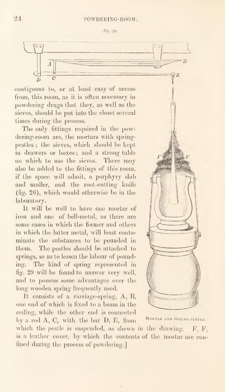
It will be well to have one mortar of
iron and one of bell-metal, as there are
some cases in which the former and others
in which the latter metal, will least conta¬
minate the substances to be pounded in
them. The pestles should be attached to
springs, so as to lessen the labour of pound¬
ing. The kind of spring represented in
fig. 29 will be found to answer very well,
and to possess some advantages over the
long wooden spring frequently used.
It consists of a carriage-spring. A, B,
one end of which is fixed to a beam in the
ceiling, while the other end is connected
by a rod A, 0, with the bar D, E, from
which the pestle is suspended, as shewn in the drawing. F, F
is a leather cover, by which the contents of the mortar are con
fined during the process of powdering.]
Mortar and Spring-pestle.
DRYING-CLOSET. ^ ()
Special Arrangements, Apparatus, and Operations.
Drying-closet,—A good, efficient drying-closet is an important
desideiatiim to tlie I harniaceutical Olieimst. Not only is it required
for drying herbs, flowers, &c., so as to fit them for preservation, hut
in many operations of the shop and laboratory, and in all those of
the powdering-room, its services are called into requisition.
In constructing a drying-closet, the method of heating it should
be a primary consideration. It ought always to he ready for use,
however trifling the purpose may be for which it is required. It is
therefore desirable that it should not he heated by a fire appropriated
expressly to that purpose, but should borrow heat from some source
where a continual supply is necessarily maintained. The expense
of an exclusive fire would frequently cause the closet to be left
inoperative ; or even if put into operation, the fire may be neglected
from forgetfulness, and the closet thus rendered inefficient.
From these considerations, and principally from those of economy,
it has long been attempted to attach the drying-closet to a fire-place
in constant use, the spare heat of which may he thus appropriated.
It is sometimes attached to the Beinclorf apparatus,, but this is not
always found to be a convenient arrangement, at least in the way in
which it is usually effected, which consists in carrying the flue of the
furnace underneath the floor and then through the closet. The heat
thus derived from this furnace is insufficient for the purpose required,
and the method of applying it causes an obstruction to the draught
of the furnace, especially on first lighting the fire.
I have found it a better plan to transfer the drying-closet to the
kitchen, by which means the space it would otherwise occupy in the
laboratory is saved, and the use of a constant and powerful fire is
obtained, without additional expense or exclusive attention.
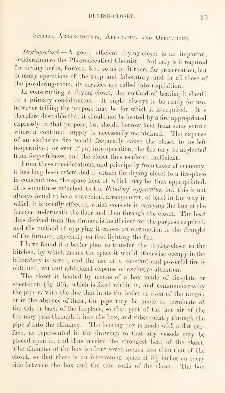
The closet is heated by means of a box made of tin-plate or
sheet-iron (fig. SO), which is fixed within it, and communicates by
the pipe G, With the flue that heats the boiler or oven of the range \
or in the absence of these, the pipe may be made to terminate at
the side or hack of the fireplace, so that part of the hot air of the
fire may pass through it into the box, and subsequently through the
pipe d into the chimney. The heating box is made with a fiat sur¬
face, as represented in the drawing, so that any vessels may he
placed upon it, and thus receive the strongest heat of the closet.
The diameter of the box is about seven inches less than that of the
closet, so that there is an intervening space of 3l- inches on every
side between the box and the side walls of the closet. The box
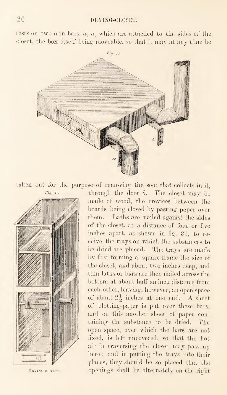
26 DRYING-CLOSET
rests on two iron bars, a, wliicli are attached to the sides of the
closet, the box itself being moveable, so that it may at any time be
Fig. 30.
Fig. 31.
taken out for the purpose of removing the soot that collects in it,
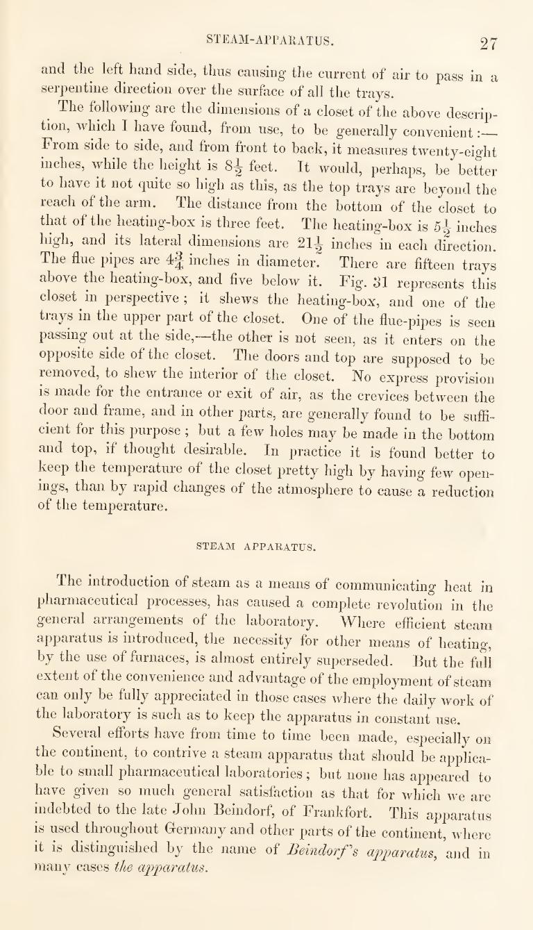
through the door h. The closet may be
made of wood, the crevices between the
boards being closed by pasting paper over
them. Laths are nailed against the sides
of the closet, at a distance of four or five
inches apart, as shewn in fig. 3J, to re¬
ceive the trays on which the substances to
be dried are placed. The trays are made
by first forming a square frame the size of
the closet, and about two Inches deep, and
thin laths or bars are then nailed across the
bottom at about half an inch distance from
each other, leaving, however, an open space
of about inches at one end. A sheet
of blotting-paper is put over these bars,
and on this another sheet of paper con¬
taining the substance to be dried. The
open space, over which the bars are not
fixed, is left uncovered, so that the hot
air in traversing the closet may pass up
here ; and in putting the trays into their
places, they should be so placed that the
Drying-closet. opeuiugs shall be alternately on the right
STEAM-APPARATUS. 27
and the left hand side, thus causing the current of air to pass in a
serpentine direction over the surface of all the trays.
^ The following are the dimensions of a closet of the above descrip¬
tion, which I have found, from use, to be generally convenient:_
Fiom side to side, and from front to back, it measures twenty-eight
inches, while the height is 8^ feet. It would, perhaps, be better
to have it not quite so high as this, as the top trays are beyond the
reach of the arm. The distance from the bottom of the closet to
that of the heating-box is three feet. The heating-box is 5^ inches
high, and its lateral dimensions are 21^ inches in each direction.
The flue pipes are 4^ inches in diameter. There are fifteen trays
above the heating-box, and five below it. Fig. SI represents this
closet m perspective ; it shews the heating-box, and one of the
trays in the upper part of the closet. One of the flue-pipes is seen
passing out at the side, the other is not seen, as it enters on the
opposite side of the closet. The doors and top are supposed to be
removed, to shew the interior of the closet. No express provision
is made for the entrance or exit of air, as the crevices between the
door and frame, and in other parts, are generally found to be suffi¬
cient for this purpose ; but a few holes may be made in the bottom
and top, if thought desirable. In practice it is found better to
keep the temperature of the closet pretty high by having few open-
ings, than by lapid changes of the atmosphere to cause a reduction of the temperature.
STEAM APPARATUS.
The introduction of steam as a means of communicating heat in
pharmaceutical processes, has caused a complete revolution in the
general arrangements of the laboratory. Where efficient steam
apparatus is introduced, the necessity for other means of heating,
by the use of furnaces, is almost entirely superseded. Hut the full
extent of the convenience and advantage of the employment of steam
can only be fully appreciated in those cases where the daily work of
the laboratory is such as to keep the apparatus in constant use.
Several efforts have from time to time been made, especially on
the continent, to contrive a steam apparatus that should be applica¬
ble to small pharmaceutical laboratories ^ but none has appeared to
have given so much general satisfaction as that for which we are
indebted to the late John Beindorf, of Frankfort. This apparatus
is used throughout Germany and other parts of the continent, where
it is distinguished by the name of Beindorf s apparatus, and in
many cases the apparatus.
28 liElNDORF APPARATUS.
neiiidorf liiiiiself, ])revious to his (lentil, wliicli occurrecl in l83o,
IkkI sujiplied the apparatus to a great many persons, and was in the
liahit of making tliem of two different sizes. The manufacture of
them is still continued by his widow, who now conducts the busi¬
ness : but other manufacturers have adopted the form, or at least
the i)rinciple, of the original apparatus, and they are now, therefore,
made in many of the large towns.
ddie following description of the apparatus, including improve¬
ments or alterations introduced by myself, applies to that of the
smaller size.
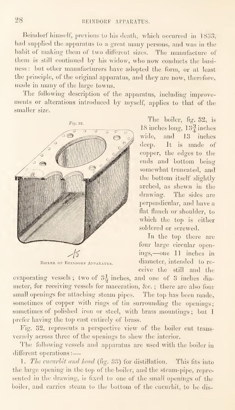
The boiler, fig. 82, is
18 inches long, 1 Scinches
wide, and 13 inches
deep. It is made of
copper, the edges to the
ends and bottom being
somewhat truncated, and
the bottom itself slightly
arched, as shewn in the
drawing. The sides are
perpendicular, and have a
flat dancli or shoulder, to
which the top is either
soldered or screwed.
In the top there are
four large circular open¬
ings,—one 11 inches in
diameter, intended to re¬
ceive the still and the
evaporating vessels ; two of 3-^ inches, and one of 8 inches dia¬
meter, for receiving vessels for maceration, &c. ; there are also four
small openings for attaching steam pipes. The top has been made,
sometimes of copper with rings of tin surrounding the openings;
sometimes of polished iron or steel, with brass mountings; but 1
prefer having the top cast entirely of brass.
Fig. 32, represents a perspective view of the boiler cut trans¬
versely across three of the openings to shew the interior.
The following vessels and apparatus are used with the boiler in
different operations:—
1. The cucurbit and heaxl (fig. S3) for distillation. This fits into
the large opening in the top of the boiler, and the steam-pipe, repre¬
sented in the drawing, is fixed to one of the small oj)enings of the
boiler, and carries steam to the bottom of the cucurbit, to be dis-
Fig. 32.
Boiler of Beindorf Apparatus.
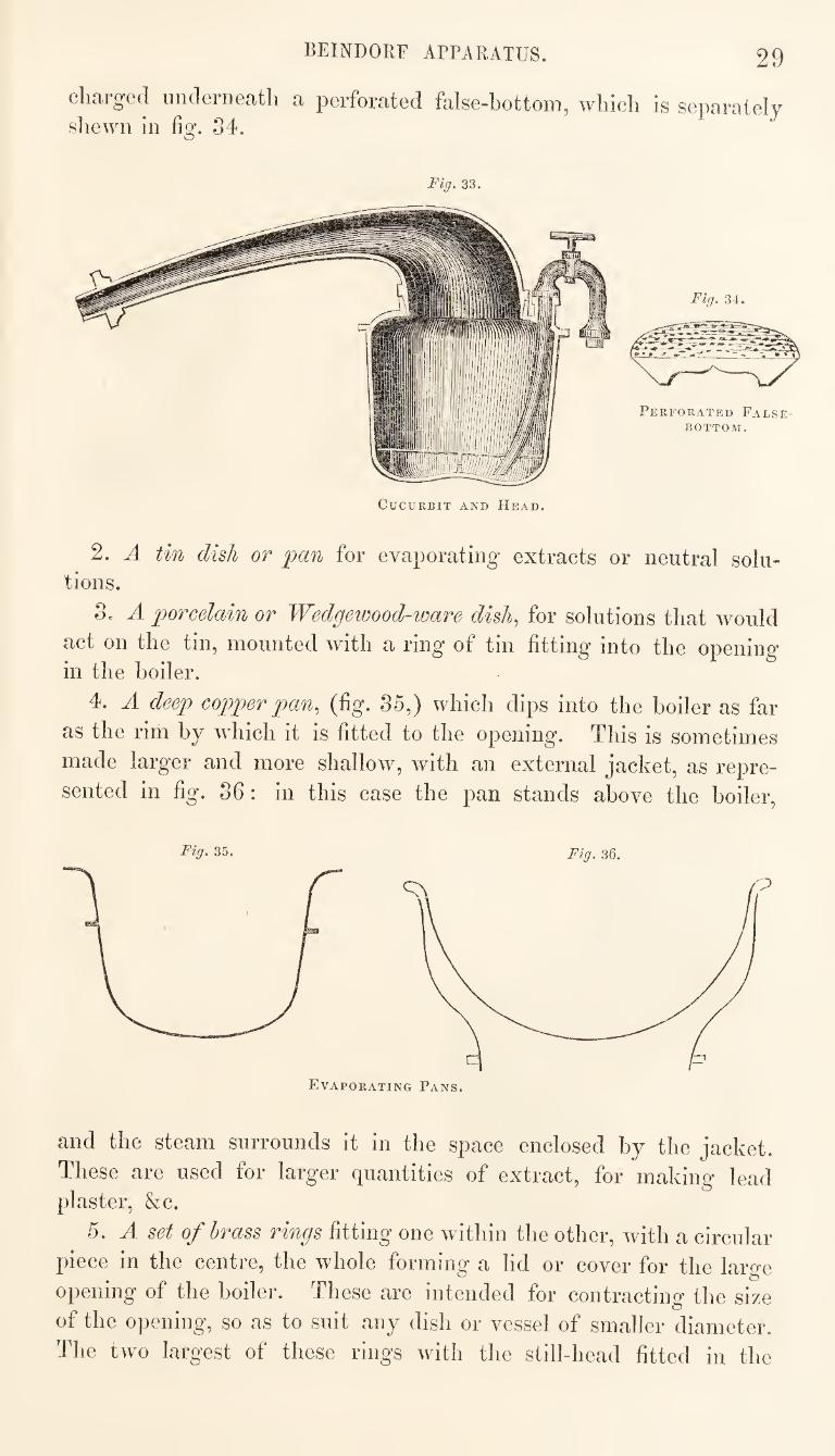
BEINDORF APPARATUS. 29
charged underneath a perforated false-hottom, which is separately sliewn in fig. 34.
Fig. 33,
Perforated False-
bottom.
Fig, 34.
Cucurbit and Head.
2. A tin dish or pan for evaporating extracts or neutral solu¬ tions.
3. A porcelain or Wedgewood-ware disli^ for solutions that would
act on the tin, mounted with a ring of tin fitting into the opening in the boiler.
4. A deep copper pan., (fig. 35,) which dips into the boiler as far
as the rim by which it is fitted to the opening. This is sometimes
made larger and more shallow, with an external jacket, as repre¬
sented in fig. 36: in this case the pan stands above the boiler.
Evaporating Pans.
and the steam surrounds it in the space enclosed by the jacket.
These are used for larger quantities of extract, for making lead plaster, &c.
5. A set of brass rings fitting one within the other, with a circular
piece in the centre, the whole forming a lid or cover for the large
opening of the boiler. These are intended for contracting- the size
of the opening, so as to suit any dish or vessel of smaller diameter.
The two largest of these rings with the still-head fitted in the
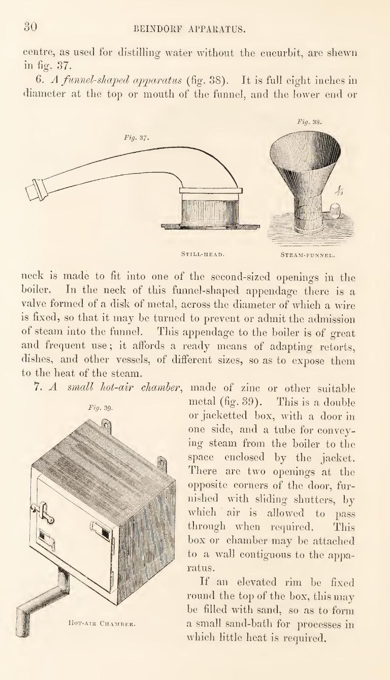
30 BEINDOllF APPARATUS.
centre, as used for distilling water without the cucurbit, are shewn
in fig. 37.
6. A funnel-shaped apparatus (fig. 38). It is full eiglit inches in
diameter at the top or mouth of the funnel, and the lower end or
Fig, 38.
neck is made to fit into one of the second-sized openings in the
boiler. In the neck of this funnel-shaped appendage there is a
valve formed of a disk of metal, across the diameter of which a wire
is fixed, so that it may be turned to prevent or admit the admission
of steam into the funnel. This appendage to the boiler is of great
and frequent use; it affords a ready means of adapting retorts,
dishes, and other vessels, of different sizes, so as to expose them to the heat of the steam.
7. A small hot-air chamber,^
Fig. 39.
made of zinc or other suitable
metal (fig. 89). This is a double
or jacketted box, with a door in
one side, and a tube for convey¬
ing steam from the boiler to the
space enclosed by the jacket.
There are two openings at the
opposite corners of the door, fur¬
nished with sliding shutters, by
which air is allowed to pass
through when required. This
box or chamber may be attached
to a wall contiguous to the appa¬
ratus.
If an elevated rim be fixed
round the top of the box, this may
be filled with sand, so as to form
a small sand-bath for processes in
which little heat is required.
BEINDOllF APPARATUS. 31
Fig. 40.
The Eeindorf apparatus is not calculated for sending a strong jet
of steam through pipes, as the least opposing pressure would cause
the escape of the steam through the imperfect joints by which the several appendages are fitted into the top of the boiler.
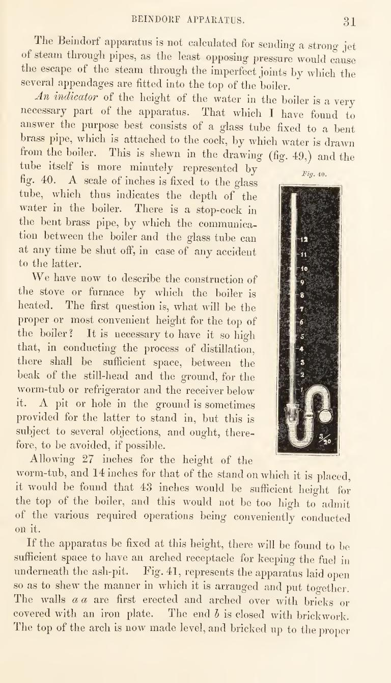
-An indiccttoT of the height of the water in the boiler is a very
necessary part of the apparatus. That which I have found to
answer the purpose best consists of a glass tube fixed to a bent
brass pipe, which is attached to the cock, by which water is drawn
from the boiler. This is shewn in the drawing (fig. 49,j and the
tube itself is more minutely represented by
fig. 40. A scale of inches is fixed to the glass
tube, which thus indicates the depth of the
water in the boiler. There is a stop-cock in
the bent brass pipe, by which the communica¬
tion between the boiler and the glass tube can
at any time be shut off, in case of any accident to the latter.
We have now to describe the construction of
the stove or furnace by which the boiler is
heated. The first question is, what will be the
proper or most convenient height for the top of
the boiler ? It is necessary to have it so high
that, in conducting the process of distillation,
there shall be sufficient space, between the
beak of the still-head and the ground, for the
worm-tub or refrigerator and the receiver below
it. A pit or hole in the ground is sometimes
provided for the latter to stand in, but this is
subject to several objections, and ought, there¬
fore, to be avoided, if possible.
Allowing 27 inches for the height of the
worm-tub, and 14 inches for that of the stand on which it is placed,
it would be found that 43 inches would be sufficient height for
the top of the boiler, and this would not be too high to admit
of the various required operations being conveniently conducted on it.
If the apparatus be fixed at this height, there will be found to be
sufficient space to have an arched receptacle for keeping the fuel in
underneath the ash-pit. Fig. 41, represents the apparatus laid open
so as to shew the manner in which it is arranged and put together.
The walls a a are first erected and arched over with bricks or
covered with an iron plate. The end 1) is closed with brickwork.
The top of the arch is now made level, and bricked up to the proper
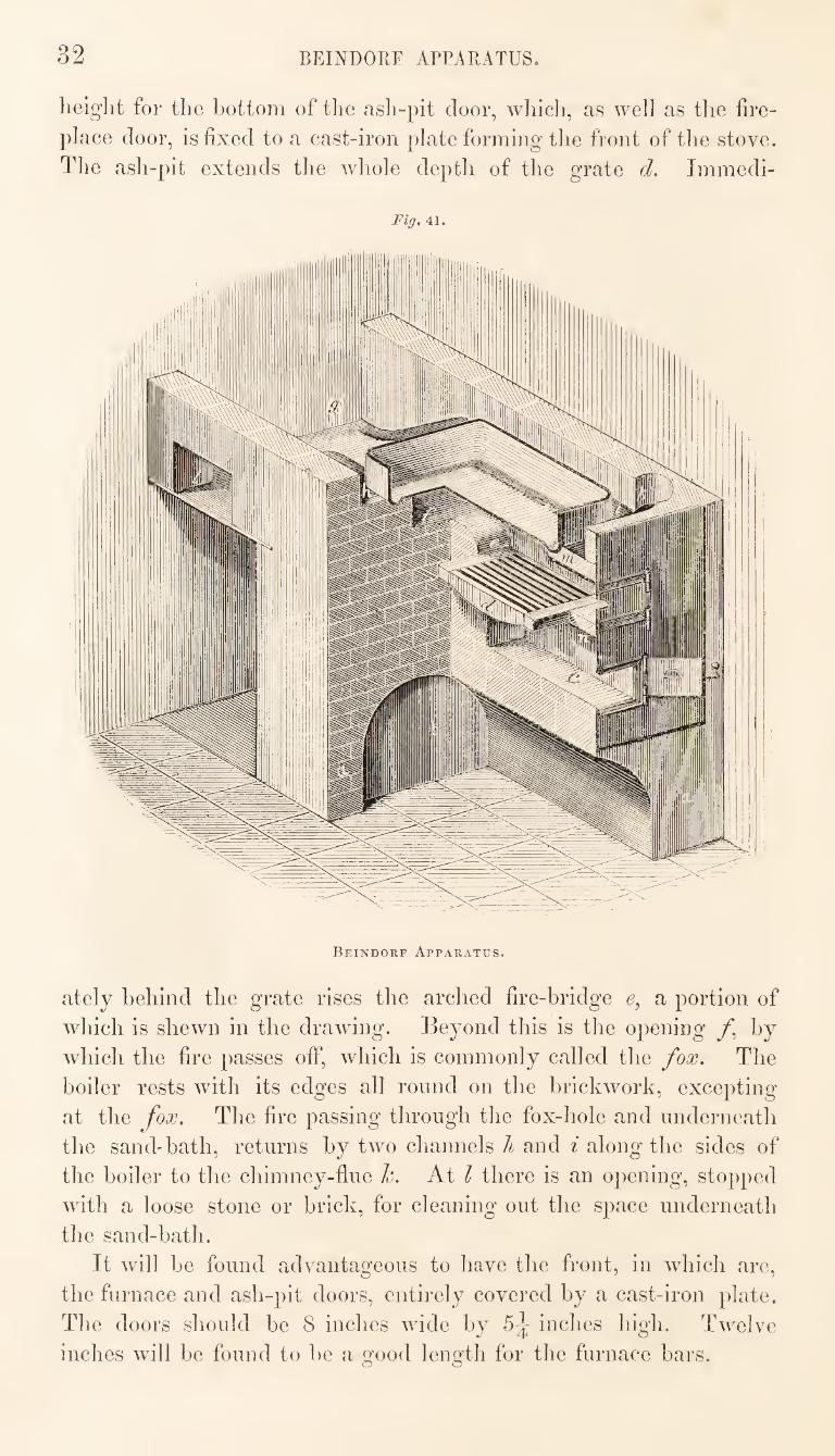
32 BEINDOKF APPARATUS.
height for tlie bottom of the ash-pit door, wliich, as well as the fire¬
place door, is fixed to a cast-iron i)late forming the front of tlie stove.
The ash-pit extends the wliole depth of the grate d. Immedi-
Fig, 41.
Beindorf Apparatus.
ately behind the grate rises the arched fire-bridge e, a portion of
which is shewn in the drawing. Beyond this is the opening by
which the fire passes oif, which is commonly called the fox. The
boiler rests with its edges all round on the brickwork, excepting
at the fox. The fire passing through the fox-hole and underneath
the sand-bath, returns by two channels h and i along the sides of
the boiler to the chimney-flue h. At I there is an opening, stopped
with a loose stone or brick, for cleaning out the space underneath
the sand-bath.
It will be found advantageous to have the front, in which are,
the furnace and ash-pit doors, entirely covered by a cast-iron plate.
The doors should be 8 inches wide by 5^ inches high. Twelve
inches will be found to be a good length for the furnace bars.
BEINDOPtF ArPAUATUS. 3
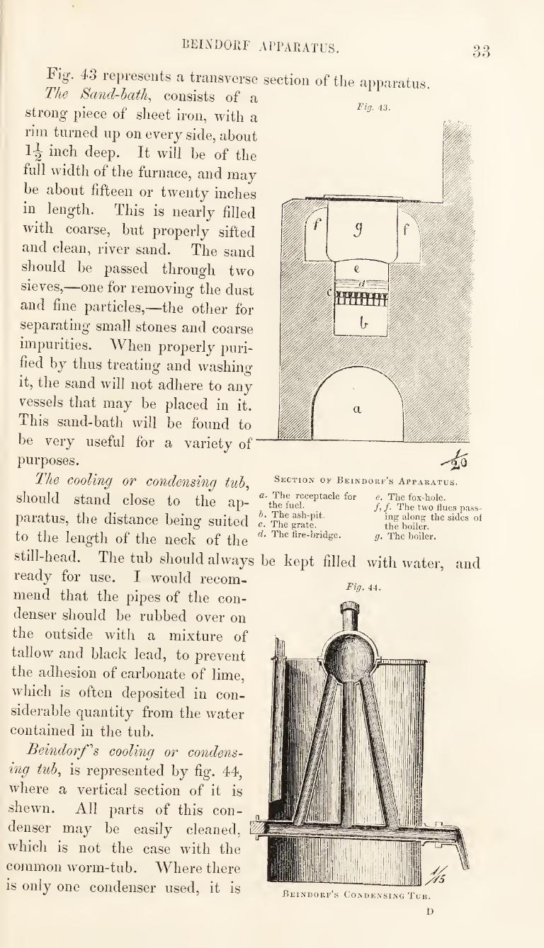
Fig. 43.
Fig. 43 represents a transverse section of the apparatus The Sand-hath^ consists of a
strong piece of sheet iron, with a
rim turned up on every side, about
inch deep. It will be of the
full width of the furnace, and may
be about fifteen or twenty inches
in length. This is nearly filled
with coarse, but properly sifted
and clean, river sand. The sand
should be passed through two
sieves,—one for removing the dust
and fine particles,—the other for
separating small stones and coarse
impurities. When properly puri¬
fied by thus treating and washing
it, the sand will not adhere to any
vessels that may be placed in it.
This sand-bath will be found to
be very useful for a variety of
purposes.
The cooling or condensing tuh,
should stand close to the ap- “'thJf
paratus, the distance being suited The
to the length of the neck of the
Section of Beindorf’s Apparatus.
e. The fox-hole. /, /. The two flues pass¬
ing along the sides o: the boiler.
g. The boiler.
still-head. The tub should always be kept filled with water,
ready for use. I would recom¬
mend that the pipes of the con¬
denser should be rubbed over on
the outside with a mixture of
tallow and black lead, to prevent
the adhesion of carbonate of lime,
which is often deposited in con¬
siderable quantity from the water
contained in the tub.
Beindorf''s cooling or condens¬
ing tuh^ is represented by fig. 44,
where a vertical section of it is
shewn. All parts of this con¬
denser may be easily cleaned,
which is not the case with the
common worm-tub. Where there
is only one condenser used, it is
am
Fig. 44.
Beindorf’s Condensing Tub.
34 CONDENSING APPARATUS.
quite indispensable that it should admit of being perfectly cleaned,
otherwise the product of each process will be contaminated with
some part of that which preceded it.
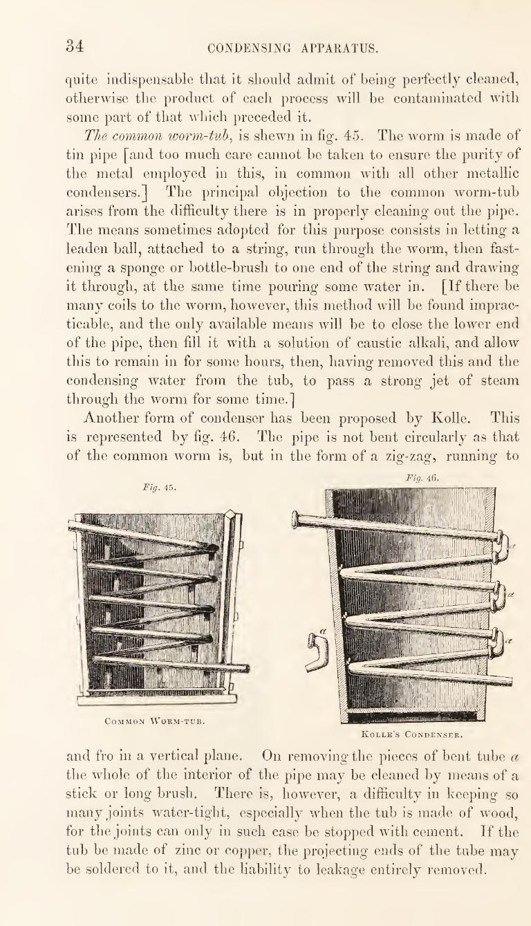
The common worm-tub^ is shewn in fig. 45. The worm is made of
tin pipe [and too much care cannot be taken to ensure the purity of
the metal employed in this, in common with all other metallic
condensers.] The principal objection to the common worm-tub
arises from the difficulty there is in properly cleaning out the pipe.
The means sometimes adopted for this purpose consists in letting a
leaden ball, attached to a string, run through the worm, then fast¬
ening a sponge or bottle-brush to one end of the string and drawing
it through, at the same time pouring some water in. [If there be
many coils to the worm, however, this method will be found imprac¬
ticable, and the only available means will be to close the lower end
of the pipe, then fill it with a solution of caustic alkali, and allow
this to remain in for some hours, then, having removed this and the
condensing water from the tub, to pass a strong jet of steam
through the worm for some time.]
Another form of condenser has been proposed by Kolle. This
is represented by fig. 46. The pipe is not bent circularly as that
of the common worm is, but in the form of a zig-zag, running to
Fiq. 46.
Kolle’s Condenser.
and fro in a vertical plane. On removing the pieces of bent tube a
the whole of the interior of the pipe may be cleaned by means of a
stick or long brush. There is, however, a difficulty in keeping so
many joints water-tight, especially when the tub is made of wood,
for the joints can only in such case be stopped with cement. If the
tub be made of zinc or copper, the projecting ends of the tube may
be soldered to it, and the liability to leakage entirely removed.
CONDENSING APPARATUS 35
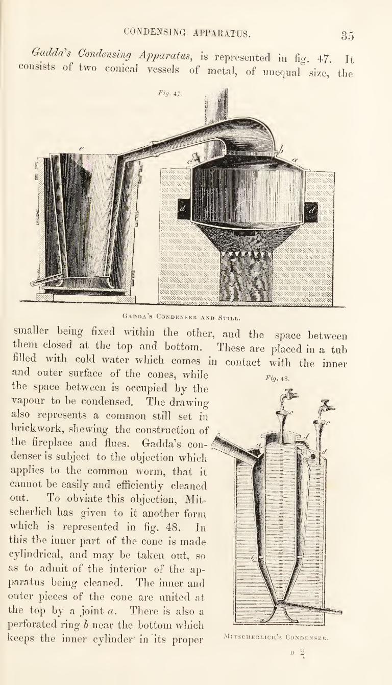
Gadda's Condensing Apparatus, is represented in %. 47. Jt
consists of two conical vessels of metal, of unequar size," the
Fig. 48.
Gadda’s Condenser and Still.
smaller being fixed within the other, and the space between
them closed at the top and bottom. These are placed in a tub
filled with cold water which comes in contact with the inner
and outer surface of the cones, while
the space between is occupied by the
vapour to be condensed. The drawing
also represents a common still set in
brickwork, shewing the construction of
the fireplace and flues. Gadda’s con¬
denser is subject to the objection which
applies to the common worm, that it
cannot be easily and efficiently cleaned
out. To obviate this objection, Mit-
scherlich has given to it another form
which is represented in fig. 48. In
this the inner part of the cone is made
cylindrical, and may be taken out, so
as to admit of the interior of the ap¬
paratus being cleaned. The inner and
outer pieces of the cone are united at
the top by a joint a. There is also a
perforated ring h near the bottom which
keeps the inner cylinder in its proper lUiTscuERLicn’s Condenser.
D 2
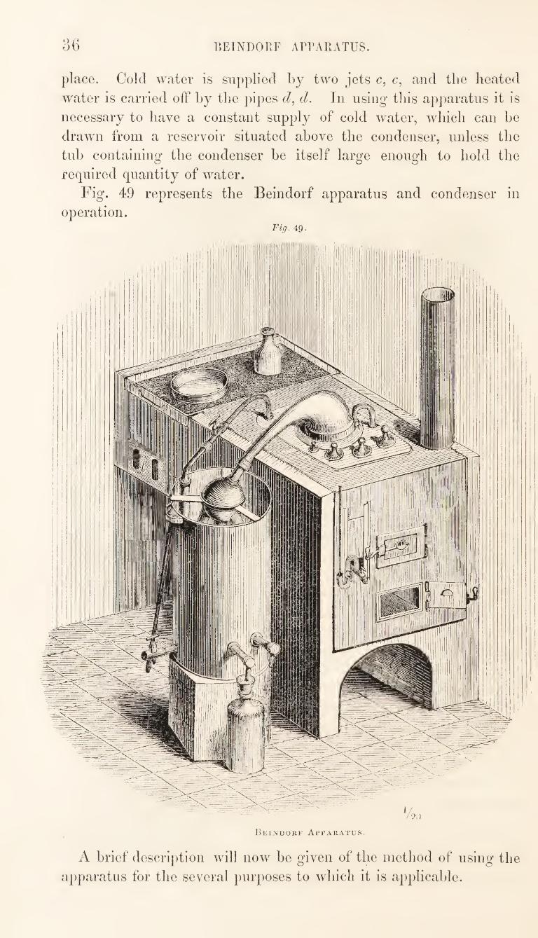
r.EINDORF ArrAKATUS
place. Cold water is supplied by two jets c, c, and the heated
water is carried off by the pipes d. In using tins apparatus it is
necessary to have a constant supply of cold water, which can be
drawn from a reservoir situated above the condenser, unless the
tub containing the condenser be itself large enough to hold the
required quantity of water.
Fig. 49 represents the Beindorf apparatus and condenser in
operation. Fig. 49.
Beindorf Apparatus.
A brief description will now be given of the method of using the
a])paratus for the several purposes to which it is applicable.
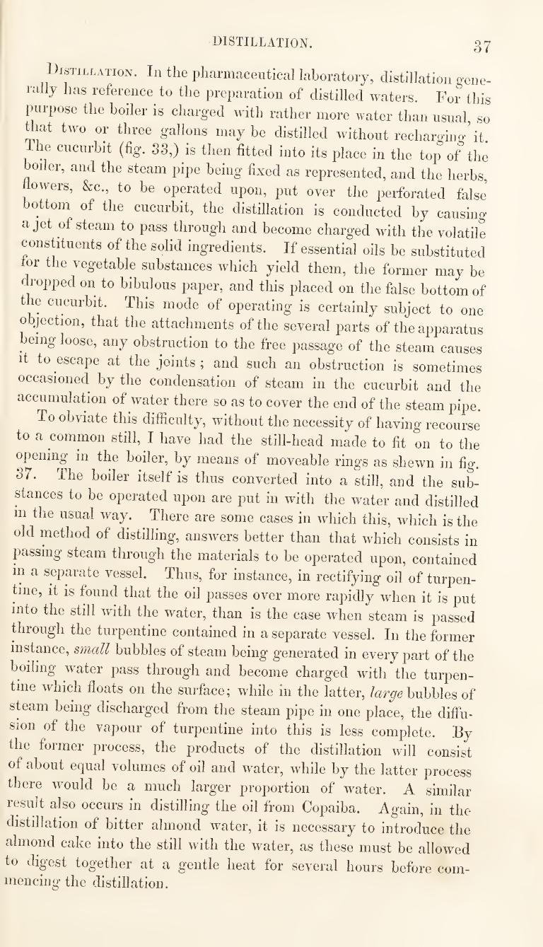
distillation. 37
Distillation. In the pharmaceutical laboratory, distillation gene¬ rally has reference to the preparation of distilled waters. For this
inirpose the boiler is charged with rather more water than usual so
Uiat two or three gallons maybe distilled without recharging it.
re cucurbit (fig. S3,) is then fitted into its place in the top of the
boiler, and the steam pipe being fixed as represented, and the herbs,
hovTers, &c., to be operated upon, put over the perforated false
bottom of the cucurbit, the distillation is conducted by causing
a jet of steam to pass through and become charged wdtli the volatile
constituents of the solid ingredients. If essential oils be substituted
tor the vegetable substances which yield them, the former may be
dropped on to bibulous paper, and this placed on the false bottom of
t le cucurbit. This mode of operating is certainly subject to one
objection, that the attachments of the several parts of the apparatus
passage of the steam causes it to escape at the joints; and such an obstruction is sometimes
occasioned by the condensation of steam in the cucurbit and the
accumulation of water there so as to cover the end of the steam pipe.
To obviate this difficulty, without the necessity of having recourse
to a common still, I have had the still-head made to fit on to the
opening m the boiler, by means of moveable rings as shewn in fig. 37. The boiler itself is thus converted into a still, and the sub¬
stances to be operated upon are put in wdth the water and distilled
in the usual way. There are some cases in which this, which is the
old method of distilling, answers better than that which consists in
passing steam through the materials to be operated upon, contained
in a separate vessel. Thus, for instance, in rectifying oil of turpen¬
tine, it is found that the oil passes over more rapidly when it is put
into the still with the water, than is the case when steam is passed
through the turpentine contained in a separate vessel. In the former
instance, small bubbles of steam being generated in every part of the
boiling water pass through and become charged with the turpen¬
tine which floats on the surface; while in the latter, bubbles of
steam being discharged from the steam pipe in one place, the diffu¬
sion of the vapour of turpentine into this is less complete. By
the former process, the products of the distillation will consist
of about equal volumes of oil and water, while by the latter process
there would be a much larger proportion of water. A similar
result also occurs in distilling the oil from Copaiba. Again, in the
distillation of bitter almond water, it is necessary to introduce the
almond cake into the still with the water, as these must be allowed
to digest together at a gentle heat for several hours before com¬
mencing the distillation.
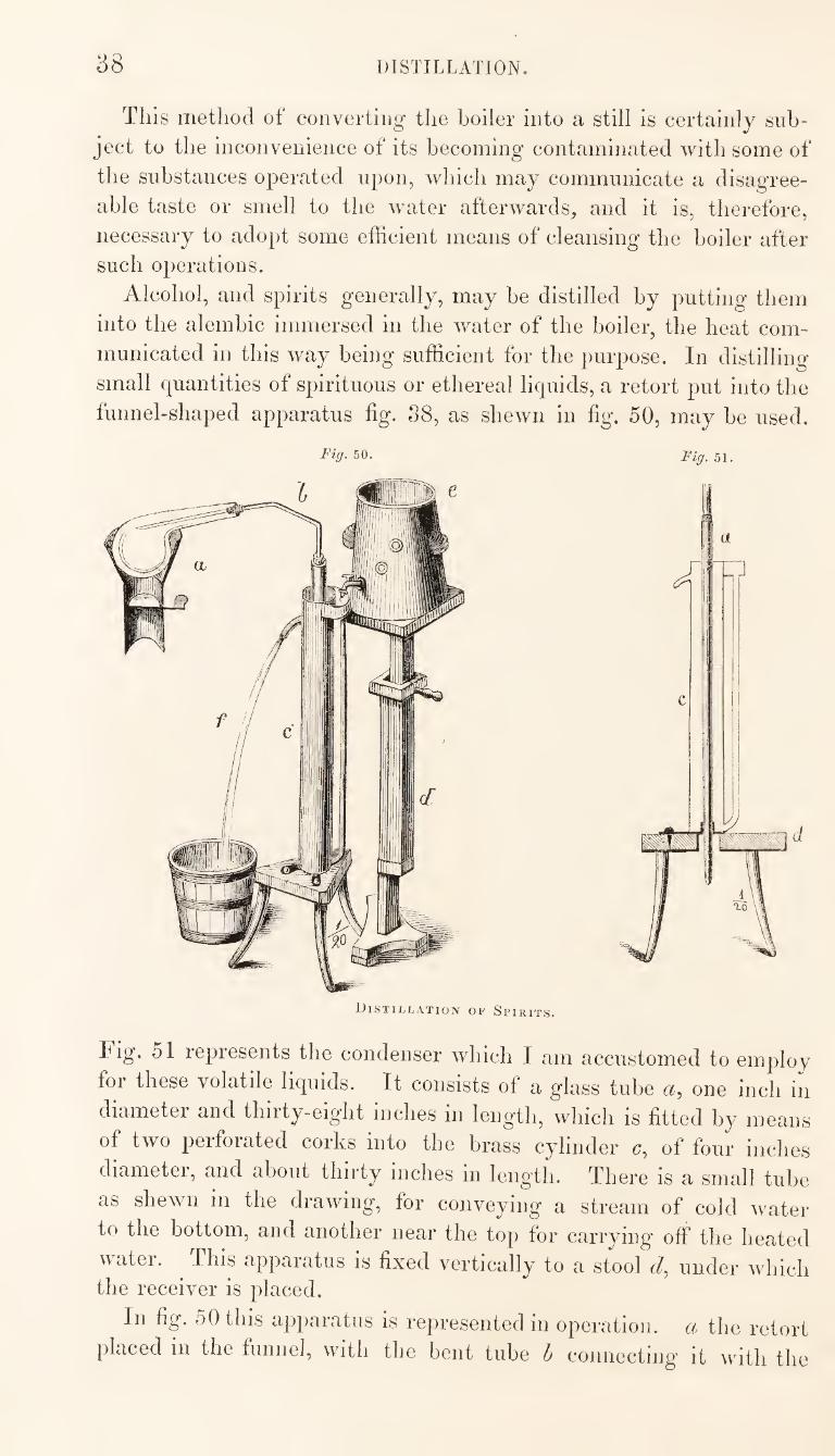
38 DISTILLATION.
This method of convertiiig- the boiler into a still is certainly sub¬ ject to the inconvenience of its becoming contaminated with some of the substances operated upon, which may communicate a disagree¬ able taste or smell to the water afterwards, and it is, therefore, necessary to adopt some efficient means of cleansing the boiler after such operations.
Alcohol, and spirits generally, may be distilled by putting them into the alembic immersed in the water of the boiler, the heat com¬ municated in this way being sufficient for the purpose. In distilling small quantities of spirituous or ethereal liquids, a retort put into the funnel-shaped apparatus fig. S8, as shewn in fig. 50, may be used.
50. Fig. 51.
Distillation of Spirits.
Fig. 51 represents the condenser which I am accustomed to employ for these volatile liquids. It consists of a glass tube a, one inch in diameter and thirty-eight inches in length, which is fitted by means of two perforated corks into the brass cylinder of four inches diametei, and about thirty inches in length. There is a small tube as shewn in the drawing, for conveying a stream of cold water to the bottom, and another near the top for carrying off the heated water. ^ This apparatus is fixed vertically to a stool d, under Avhich the receiver is placed.
In fig. 50 this apparatus is represented in operation, a the retort placed in the funnel, with the bent tube h connecting it with the
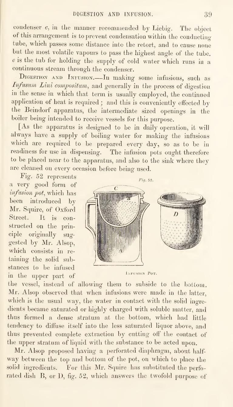
DIGESTION AND INFUSION. 39
condenser in the manner recommended by Liebig. The object
of this arrangement is to prevent condensation within the conducting
tube, which passes some distance into the retort, and to cause none
but the most volatile vapours to pass the highest angle of the tube.
e is the tub for holding the supply of cold water which runs in a
continuous stream through the condenser.
Digestion and Infusion.—In making some infusions, such as
Infusum Lini compositum^ and generally in the process of digestion
in the sense in which that term is usually employed, the continued
Fig. 52.
application of heat is required ; and this is conveniently effected by
the Beindorf apparatus, the intermediate sized openings in the
boiler being intended to receive vessels for this purpose.
[As the apparatus is designed to be in daily operation, it will
always have a supply of boiling water for making the infusions
which are required to be prepared every day, so as to be in
readiness for use in dispensing. The infusion pots ought therefore
to be placed near to the apparatus, and also to the sink where they
are cleaned on every occasion before being used.
Fig. 52 represents
a very good form of
infusion pot^ which has
been introduced by
Mr. Squire, of Oxford
Street. It is con¬
structed on the prin¬
ciple originally sug¬
gested by Mr. Alsop,
which consists in re¬
taining the solid sub¬
stances to be infused
in the upper part of
the vessel, instead of allowing them to subside to the bottom.
Mr. Alsop observed that w'hen infusions were made in the latter,
which is the usual way, the water in contact with the solid ingre¬
dients became saturated or highly charged with soluble matter, and
thus formed a dense stratum at the bottom, which had little
tendency to diffuse itself into the less saturated liquor above, and
thus prevented complete extraction by cutting off the contact of
the upper stratum of liquid with the substance to be acted upon.
Mr. Alsop proposed having a perforated diaphragm, about half¬
way between the top and bottom of the pot, on which to place the
solid ingredients. For this Mr. Squire has substituted the perfo¬
rated dish B, or D, fig. 52, which answers the twofold purpose of
40 SOLUTION, LIQUEFACTION, ETC.
supporting the solid substances in the upper part of the liquid, and
of straining the infusion when it has stood long enough, by merely
lifting this out. The angles within and without the pot are rounded
off wherever this is practicable, so that the vessel may be the more easily kept clean.]
Solution, Liquefaction, Saponification, &c.—The solution of
salts, of gum, of extracts, the liquefaction of fats, ointments, and
plasters, and other processes of this description, are performed in
round-bottomed vessels of tin, copper, or Wedge wood-ware, placed
over one of the openings in the boiler. Lead plaster may also
he made in the larg'e pan by the heat of the boiler, and by con¬
ducting the process in this way, the liability of spoiling the product
by the application of too strong a heat, which is always incurred
when the ingredients are heated over the naked fire, is entirely
avoided. 13ut the time required for eftecting the complete saponifi¬
cation of the oil by the water-bath heat, is much more than it would
be if a stronger heat were applied, two or three days being occupied
in the former case to complete what might be made in little more than as many hours in the latter.
Vaporization. This process is of very frequent occurrence in
the pharmaceutical laboratory. Extracts, solutions of salts, purified
honey, and a variety of other substances, require in the course
of their preparation, to be deprived of a part of their water. There
are two ways in which this is effected; first, by generating steam at
the bottom of the vessel, and throughout the liquid, which is called
ebullition or boiling, and secondly, by generating steam only from
the surface of the liquid, which is sometimes distinguished as
evaporation or surface evaporation. By the former process the con¬
centration is effected most rapidly, but it is subject to some objec¬
tions. In the first place there is a greater dissipation and loss
of any aromatic or volatile constituents that the liquid may originally
have contained, than would occur from surface evaporation. There
is also a danger of decomposing or burning any organic matter
that may be pie»ent, and the liability to this increases as the inspis-
sation proceeds. Extracts made in this way, if incautiously inspis¬
sated, fieqiiently become to a great extent insoluble in water ;
whereas, had they been otherwise prepared, they would have been entirely, or almost entirely, soluble.
As the Beindorf apparatus will not admit of the steam beino-
exposed to more than a very slight pressure, it will never attain a
temperature sufficient to cause the ebullition of an aqueous liquor con¬
tained in one of the evaporating pans ; for even should the steam in
the boiler be a few degrees above the boiling point, the obstruction
to the free transmission of the heat in its passage through the metal
EVAPORATION. 41
pan, and still more if the pan be of earthenware, will cause the
contents of the pan to be four or live degrees lower.
Surface evaporation^ however, as it takes place at a temperature
below the boiling point of the liquid, may be effected with this
apparatus in either of the pans, figs. 35 and 36. This kind of
evaporation depends upon the diffusion of the vapour into the
superincumbent air, and therefore the rapidity of the evaporation is
greatly increased by maintaining a constant change of atmosphere,
that which is charged with vapour being replaced by dry air
into which diffusion can take place freely. Indeed, if the liquid
were contained in a close or covered vessel, such as a still, evapo ¬
ration from the surface would not proceed at all after the air in the
still had become charged with vapour, unless some mechanical
means were adopted by which a change or current of air may
be effected through the vessel. It is also desirable, with the view
of promoting this kind of evaporation, that as large a surface
as possible of the liquid should be exposed to the air, and that this
should be constantly changed so as rapidly to substitute the warmer
J3articles from below for those which have been cooled by the influence of evaporation.
In the inspissation of extracts and other similar preparations,
and especially where this is effected by surface evaporation, it
is necessary to keep the substance constantly agitated by stirring
it. The process of stirring not only causes a new surface, and a
more extended surface to be exposed to the air, but at the same time
it occasions a change of the atmosphere in contact with the liquid.
But how is this very essential, yet tedious and insignificant
process of stirring, to be effected ? If, as is usually the case, it be
done by manual labour, the whole time of an assistant will be
occupied in doing that which one of his fingers could accomplish;
while at the same time from the very tediousness and insignificance of the work, it is often neglected.
The Stirrer.—Having experienced these inconveniences, I have
provided a remedy for them, by constructing a mechanical stirrer.
This is a machine which, when wound up, will keep the contents of
a pan continually, and regularly stirred for about three hours,
without any personal attention. Fig. 55, represents this apparatus.
It consists of three spindles or pivots set in an iron frame. The
first, or principal pivot, a fig. 55, carries a wooden barrel two inches
and a quarter in diameter, and four inches and a half long. At the
front or outer end, there is a projecting rim to prevent the cord
from slipping off, and to occasion the return of the coil. This pivot
passes through the frame, and carries at the end a double winch
ICj Jc, the handles of which arc of unequal distance from the
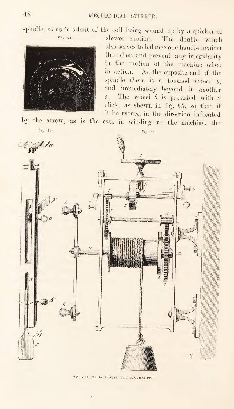
42 MECHANICAL STIRRER.
spindle, so as to admit of the coil being wound up by a quicker or
53. slower motion. The double winch
also serves to balance one handle against
the other, and prevent any irregularity
in the motion of the machine when
in action. At the oj^posite end of the
spindle there is a toothed wheel 5,
and immediately beyond it another
c. The wheel h is provided with a
click, as shewn in fig. 53, so that if
it be turned in the direction indicated by the arrow, as is the case in winding up the machine, the
54. 55_
Apparatus for Stirring Extracts.
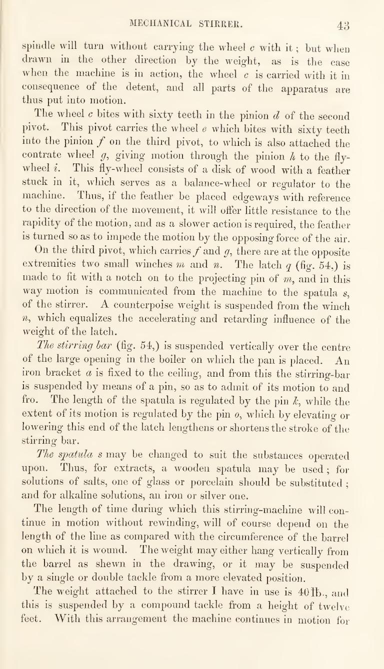
MECHANICAL STIRRER. 43
spindle will turn without carrying the wheel c with it ; but when
drawn in the other direction by the weight, as is the case
when the machine is in action, the wheel c is carried with it in
consequence of the detent, and all parts of the apparatus are thus put into motion.
The wheel c bites with sixty teeth in the pinion d of the second
pivot. This pivot carries the wheel e which bites with sixty teeth
into the pinion f on the third pivot, to which is also attached the
contrate wheel giving motion through the pinion h to the fly¬
wheel i. This fly-wheel consists of a disk of wood with a feather
stuck in it, which serves as a balance-wheel or regulator to the
machine. Thus, if the feather be placed edgeways with reference
to the direction of the movement, it will offer little resistance to the
rapidity of the motion, and as a slowernction is required, the feather
is turned so as to impede the motion by the opposing force of the air.
On the third pivot, which carries f and g, there are at the opposite
extremities two small winches m and n. The latch q (fig. 54,) is
made to fit with a notch on to the projecting pin of m, and in this
way motion is communicated from the machine to the spatula s,
of the stirrer. A counterpoise weight is suspended from the winch
which equalizes the accelerating and retarding influence of the weight of the latch.
The stirring har (fig. 54,) is suspended vertically over the centre
of the large opening in the boiler on which the pan is placed. An
iron bracket a is fixed to the ceiling, and from this the stirring-bar
is suspended by means of a pin, so as to admit of its motion to and
fro. The length of the spatula is regulated by the pin while the
extent of its motion is regulated by the pin o, which by elevating or
lowering this end of the latch lengthens or shortens the stroke of the stirring bar.
The spatula s may be changed to suit the substances operated
upon. Thus, for extracts, a wooden spatula may be used ; for
solutions of salts, one of glass or porcelain should be substituted ;
and for alkaline solutions, an iron or silver one.
The length of time during which this stirring-machine will con¬
tinue in motion without rewinding, will of course depend on the
length of the line as compared with the circumference of the barrel
on which it is wound. The weight may either hang vertically from
the barrel as shewn in the drawing, or it may be suspended
by a single or double tackle from a more elevated position.
The weight attached to the stirrer I have in use is 404b-, and
this is suspended by a compound tackle from a height of twelve
feet. With this arrangement the machine continues in motion for
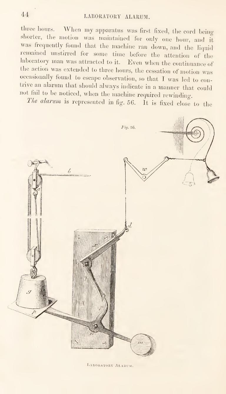
44 LABORATORY ALARUM.
three hours. When my apparatus was first fixed, the cord being
shorter, tlie motion was maintained for only one hour, and it
was frequently found that the machine ran down, and the liquid
remained unstirred for some time before the attention of the
laboratory man was attracted to it. Even when the continuance of
the action was extended to three hours, the cessation of motion was
occasionally found to escaiie observation, so that I was led to con¬
trive an alarum that should always indicate in a manner that could
not fail to be noticed, Avhen the machine required rewinding.
The alarum is represented in fig. 56. It is fixed clos^to the
Laboratory Alarum.
LABORATORY ALARUM. 45
lloor, immediately imdoi* the descejiding weight. Tlie principal
parts of the mechanism of the alarum are attached to a hoard A,
^\hich is fixed against the wall. The weight g as it descends comes
on to the plate p fixed to one end of a bar of iron working on a pivot
n, and having a counterpoise m at the other end. The plate
p being pressed downward by the weight, the arm of the lever
f communicates motion to the cranks, o, and and on
its passing the end q of the first crank, the spring of the bell
is thrown into active motion and the alarm sounded.
This alarum has been found to be efficient; it works well, and is
audible throughout the house; and if there be but one assistant
engaged, he will immediately be informed, even if he be at the
counter, that the stirrer requires re-winding.
When the apparatus is not in use, the lower end of the stirring-
bar may be fixed up against the ceiling, so as to be out of the way,
and indeed the whole of the mechanism should be fixed at such a
height as not to interfere with any other operation that may have to be performed.
The mechanism of an old clock or a roasting jack, may be used for constructing a stirring machine.
The effect of agitation in promoting the evaporation of a liquid
is very marked. I have calculated, that, in making extracts with
the apparatus here described, the evaporation will be at the rate of
about one pound of water in an hour; so that, if the process be com¬
menced at eight o’clock in the morning, about fourteen pounds of
water may be evaporated by ten o’clock at night.
The Beindorf apparatus possesses advantages in its cheapness, the
small space it occupies, the numerous purposes to which it is appli¬
cable, and the facility with which the several parts are put together
or disconnected. But, on the other hand, it is subject to some objec¬
tions, the most serious of which is, that the steam cannot be put
under sufficient pressure to admit of its use for some purposes
to which it might otherwise be advantageously applied. The size
of this apparatus is also, in some cases, found insufficient to enable it
to meet the requirements of the laboratory, [and this would certainly
be the case where there is much work to be done]. With the view
of meeting the latter objection, a double apparatus is sometimes
used ; but instead of resorting to this expedient, I would rather
recommend the adoption of an entirely different arrangement, and
the substitution of a proper steam boiler to which the different apparatus may be attached by pipes.
Figs. 57, 58, and 59 represent a cylindrical boiler, with the fire-
flue passing through it, which is the form most frequently adopted
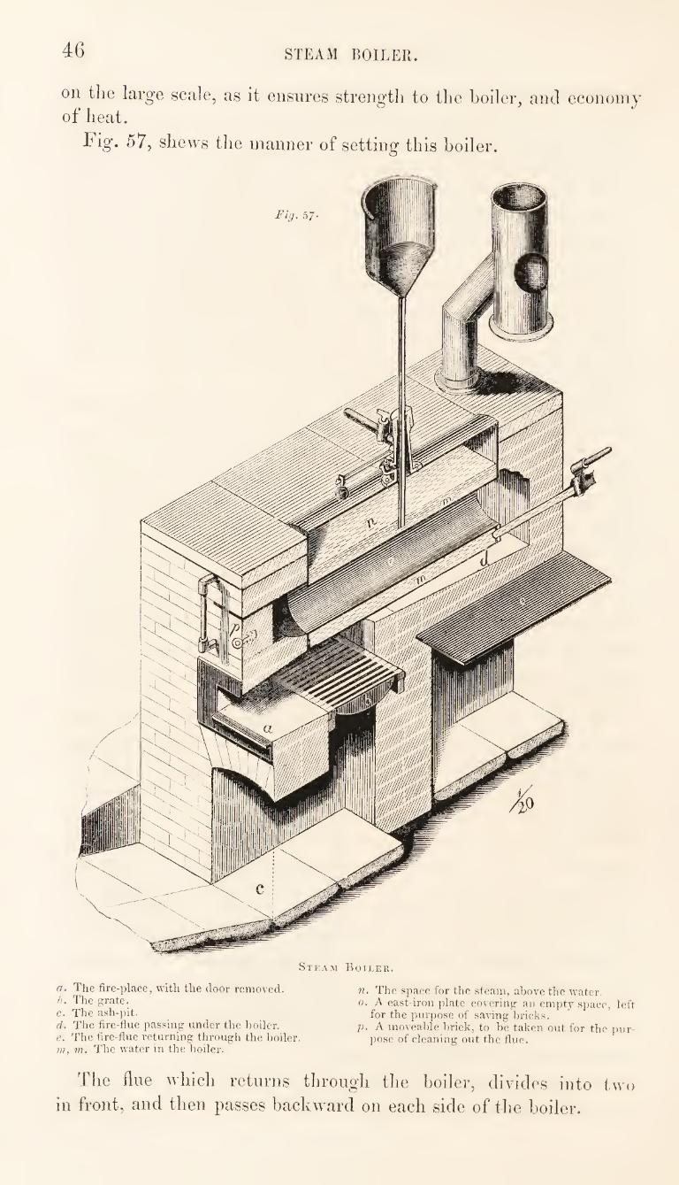
46 STEAM BOILER.
on the large scale, as it ensures strength to the boiler, aiul economy of heat.
Fig. 57, shews the manner of setting this boiler.
Steam Boiler.
a. The fire-place, with the door removed. h. The g:rate. c. The ash-pit. d. The fire-flue passing under the boiler. e. The fire-flue returning through the boiler. m, m. The water in the boiler.
n. The space for the steam, above the water. 0. A cast-iron plate covering an empt_v .space, left
for the purpose of saving bricks. p. A moveable brick, to be taken out for the jmr-
pose of cleaning out the flue.
The flue which returns through the boiler, divides into two
in front, and then passes backward on each side of the boiler.
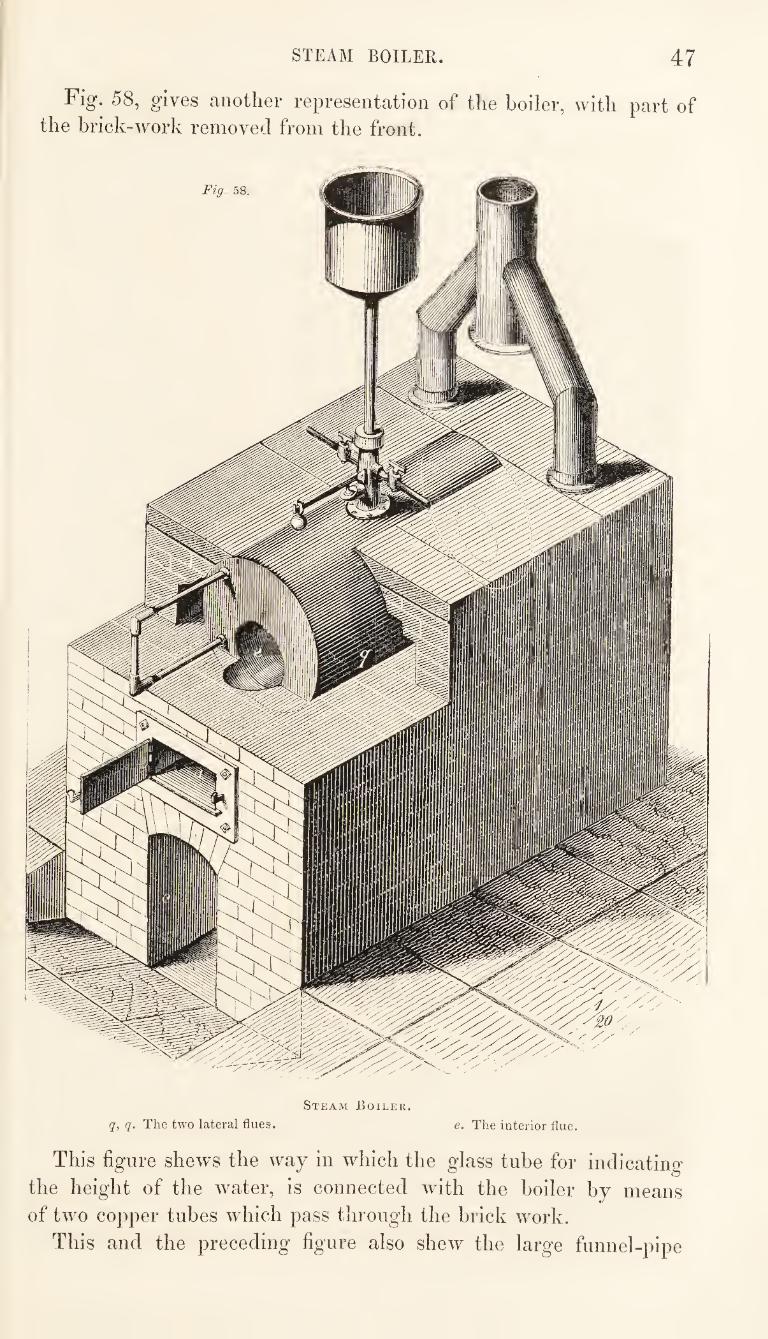
STEAM BOILER. 47
Fig. 58, gives another representation of the boiler, with part of the brick-work removed from the front.
Steam Boiler.
q, q. The two lateral flues. e. The interior flue.
This figure shews the way in which the glass tube for indicating
the height of the water, is connected with the boiler by means
of two copper tubes which pass through the brick work.
This and the preceding figure also shew the large funnel-pipe
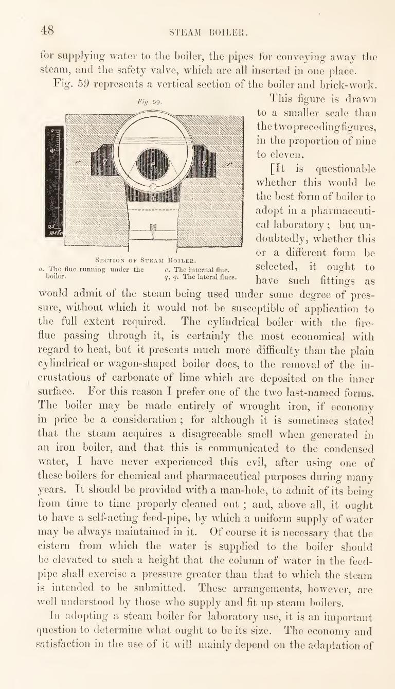
48 STEAM BOILER.
for su])plyiiig water to the boiler, tlie pipes for conveying away tlie
steam, and the safety valve, wliicli are all Inserted in one jdace.
Fig. 59 represents a vertical section of the boiler and brick-work.
This figure is drawn
to a smaller scale than
the two preceding figures,
in the proportion of nine
to eleven.
[It is questionable
whether this would be
the best form of boiler to
adopt in a pharmaceuti¬
cal laboratory; but un¬
doubtedly, whether this
or a different form be
selected, it ought to
have such fittings as would admit of the steam being used under some degree of pres¬
sure, without which it would not be susceptible of application to
the full extent required. The cylindrical boiler with the fire-
flue passing through it, is certainly the most economical with
regard to heat, but it presents much more difficulty than the plain
cylindrical or wagon-shaped boiler does, to the removal of the in¬
crustations of carbonate of lime which are deposited on the inner
surface. For this reason I prefer one of the two last-named forms.
The boiler may be made entirely of wrought iron, if economy
in price be a consideration ; for although it is sometimes stated
that the steam acquires a disagreeable smell when generated in
an iron boiler, and that this is communicated to the condensed
water, I have never experienced this evil, after using one of
these boilers for chemical and pharmaceutical purposes during many
years. It should be provided with a man-hole, to admit of its being
from time to time properly cleaned out ; and, above all, it ought
to have a self-acting feed-pipe, by which a uniform supply of water
may be always maintained in it. Of course it is necessary that the
cistern from which the water is supplied to the boiler should
be elevated to such a height that the column of water in the feed¬
pipe shall exercise a pressure greater than that to which the steam
is intended to be submitted. These arrangements, however, are
well understood by those who supply and fit up steam boilers.
In adopting a steam boiler for laboratory use, it is an important
question to determine what ought to be its size. The economy and
satisfaction in the use of it will mainly depend on the adaptation of
Fig. 59.
Section of Steam Boiler.
a. The flue running under the e. The internal flue, iioiler. g, q. The lateral flues.
STEAM APPARATUS FOR LABORATORY. 49
the size of the boiler to the work required to be clone by it. The
calculation generally acted upon is, that a boiler having a bottom
surface of four or live square feet, if well set, will vaporise a cubic
foot, or about six gallons, of water per hour. If, however, the steam
be required under pressure, the quantity generated will be propor- tionably less. ^
There are few^ cases where it is intended to be practically applied
in a pharmaceutical laboratory, in which it would be wise to have a
boiler of less capacity than thirty or forty gallons ; and from this up
to a hundred gallons may be considered to comprise the sizes best adapted for the purpose contemplated.
The steam boiler is intended to supersede, almost entirely,
the necessity for other means of heating, by the use of furnaces ;
but, to accomplish this to the fullest extent practicable, the boiler
and apparatus must admit of the steam being* used under a pressure varying from five to ten pounds on the square inch.
The boiler will be in daily, or almost daily use, this being
one of the conditions contemplated, and it will generally be the
only source of heat in the laboratory. It is very desirable and
important, therefore, so to arrange the apparatus, that the heat
generated here may be economised as much as possible, by
applying it in the most efficient manner to the most useful purposes.
In setting the boiler, it will be found advantageous, instead of
enclosing it almost entirely in brick-work, as shewn in fig. 58,
to have the upper part, to the depth of a few inches, covered with
sand, so as to form a sand-bath. This, from the equable tempe¬
rature at which it will be maintained, will be very useful in a variety of processes.
The chimney of the furnace should be made, if possible, to
abut upon a drying closet, which would thus derive some of the
unexpended heat of the fire. The closet may be further heated by
means of a steam-box, of similar form to the box represented in
fig. SO. This box may either be fixed as shewn in fig. SI, or it
may form the bottom of the closet. It should be made of copper,
well tinned on the inside, and should be connected with the boiler
by a steam pipe of rather large diameter, the termination of which
m the box should be near the top, so that the condensed water
which collects there may not run into the boiler, but be conveyed
by a tin pipe into a vessel suitable for its reception. A tin pipe
may also be carried from the top of the steam-box, and made
to traverse the back of the closet in a serpentine direction, being
finally terminated at the upper end by a valve. In this way the
E
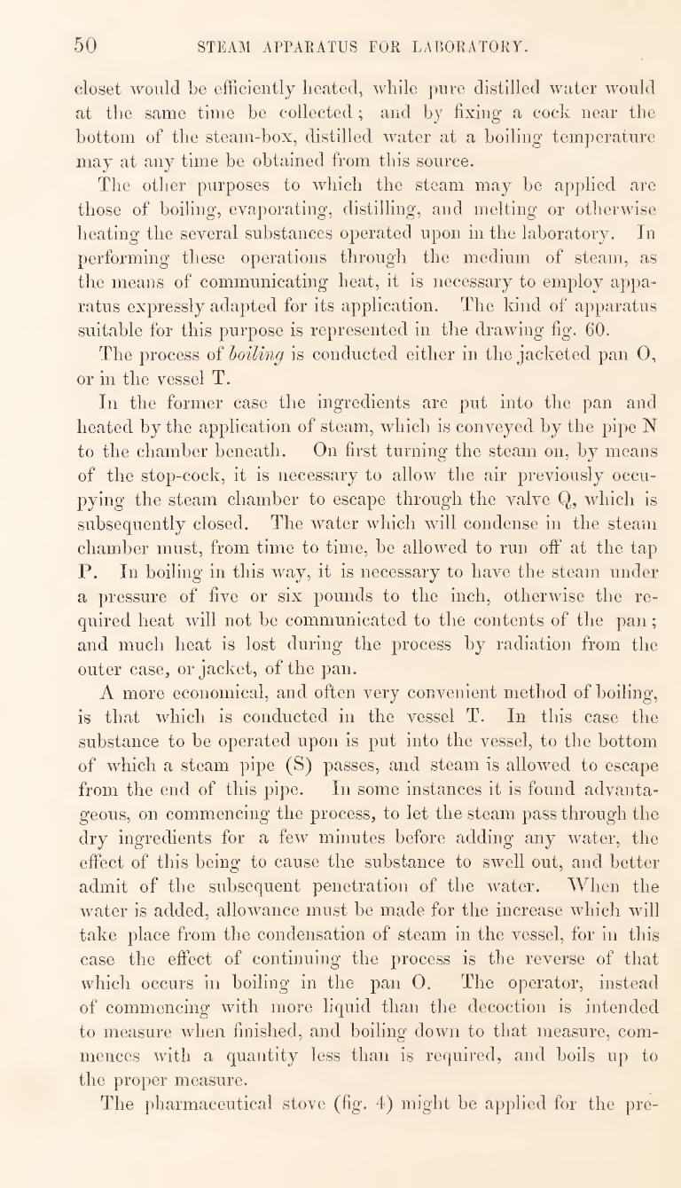
50 STEAM APPARATUS FOR LABORATORY.
closet would be efficiently heated, while pure distilled water would
at the same time he collected ; and hy fixing a cock near the
bottom of the steam-box, distilled water at a boiling temperature
may at any time be obtained from this source.
The other purposes to which the steam may be applied are
those of boiling, evaporating, distilling, and melting or otherwise
heating the several substances operated upon in the laboratory. In
performing these operations through the medium of steam, as
the means of communicating heat, it is necessary to employ appa¬
ratus expressly adapted for its application. The kind of apparatus
suitable for this purpose is represented in the drawing fig. 60.
The process of boiling is conducted either in the jacketed pan O,
or in the vessel T.
In the former case the ingredients are put into the pan and
heated by the application of steam, which is conveyed by the pipe N
to the chamber beneath. On first turning the steam on, by means
of the stop-cock, it is necessary to allow the air previously occu¬
pying the steam chamber to escape through the valve Q, which is
subsequently closed. The water which will condense in the steam
chamber must, from time to time, be allowed to run off at the tap
P. In boiling in this way, it is necessary to have the steam under
a pressure of five or six pounds to the inch, otherwise the re¬
quired heat will not be communicated to the contents of the pan;
and much heat is lost during the process by radiation from the
outer case, or jacket, of the pan.
A more economical, and often very convenient method of boiling,
is that which is conducted in the vessel T. In this case the
substance to be operated upon is put into the vessel, to the bottom
of which a steam pipe (S) passes, and steam is allowed to escape
from the end of this pipe. In some instances it is found advanta¬
geous, on commencing the process, to let the steam pass through the
dry ingredients for a few minutes before adding any water, the
effect of this being to cause the substance to swell out, and better
admit of the subsequent penetration of the water. When the
water is added, allowance must be made for the increase which will
take place from the condensation of steam in the vessel, for in this
case the effect of continuing the process is the reverse of that
which occurs in boiling in the pan 0. The operator, instead
of commencing with more liquid than the decoction is intended
to measure when finished, and boiling down to that measure, com¬
mences with a quantity less than is required, and boils up to
the proper measure.
The pharmaceutical stove (fig. 4) might be applied for the pre-
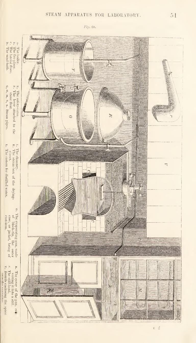
51 STEAM APPARATUS FOR LABORATORY.
Fig. (jo.
)
52 STEAM AITARATUS FOR LABORATORY.
paration of decoctions in this way, a suitable vessel being so placed
that the pipe K shall reach to near the bottom of it.
The process of evaporation is conducted in the pan 0. A me¬
chanical stirrer may be used for expediting the process; but there
are certain precautions which it will be necessary to observe in the
use of this instrument in the evaporation of extracts, which will be
further alluded to hereafter.
There is perhaps no process in the pharmaceutical laboratory
that occasions so much annoyance, in the way in which it is usually
conducted, as that of evaporation, and this arises from the large
rpiantity of steam generated, which fills the apartment and often
interferes injuriously with other operations. It is very important,
if possible, to get rid of this steam and prevent its diffusion into the
room. This might be done by putting the cover R on the pan, and
fixing a pipe to the opening in the top, so as to convey the vapour
into the open air. The pan would be thus converted into a still,
and the evil alluded to entirely prevented; moreover, there would
be a manifest advantage in conducting the process in this way,
in as much as the substance under operation would be less exposed
to the action of atmospheric air than it would in the open pan.
There are, however, some difficulties in the adoption of this arrange¬
ment, which require to be met by special provisions. If the steam
has to be conveyed to a height of many feet above the pan, much
condensation will take place in the pipe, and the process of evapo¬
ration will thus be considerably retarded. This evil may be obviated
in the following manner :—Instead of fixing the cover R on the top of
the pan, as would be done in distilling, three or four blocks of wood,
about four inches deep, are placed on the rim of the pan, and the
cover is made to rest on these, so that there shall be an open space
to this extent all around between the pan and the cover. The air
enters freely through this opening, and mixing with the steam at an
elevated temperature, they pass off together through the pipe above.
The pipe ought to be at least six or eight inches in diameter, so as
to admit of a large volume of air passing off with the steam, in
which case little or no condensation will take place. The space
between the pan and the cover admits also of the introduction of a
stirrer to be worked with the hand. This plan answers very well
for getting rid of the steam, but while the difficulty arising from
the condensation of vapour in the steam pipe is thus obviated,
the evil of admitting atmospheric air into the pan is at the same
time effected. Another, and probably a preferable arrangement,
might therefore be adopted, which consists in fitting the cover to
the pan without the blocks, and placing over the opening at the
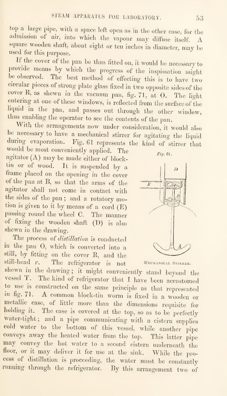
STEAM APPARATUS FOR LARORATORY. 53
top a large pipe, with a space left open as in the other case, for the
admission of air, into which the vapour may cliffnse itself. A
square wooden shaft, about eight or ten inches in diameter, may be used for this purpose.
If the cover of the pan be thus fitted on, it would be necessary to
provide means by which the progress of the inspissation might
be observed. The best method of effecting this is to have two
circular pieces of strong plate glass fixed in two opposite sides of the
cover E, as shewn in the vacuum pan, fig. 71, at 0. The light
entering at one of these windows, is reflected from the surface of the
liquid in the pan, and passes out through the other window,
thus miabling the operator to see the contents of the pan.
With the arrangements now under consideration, it would also
be necessary to have a mechanical stirrer for agitating the liquid
during evaporation. Fig. 61 represents the kind of stirrer that would be most conveniently applied. The Fig, 6l. agitator (A) may be made either of block-
tin or of wood. It is suspended by a
frame placed on the opening in the cover
of the pan at B, so that the arms of the
agitator shall not come in contact with
the sides of the pan; and a rotatory mo¬
tion is given to it by means of a cord (E)
passing round the wheel 0. The manner
of fixing the wooden shaft (D) is also shewn in the drawino*.
o
The process of distillation is conducted
in the pan O, which is converted into a
still, by fitting on the cover E, and the
still-head r. The refrigerator is not
shewn in the drawing; it might conveniently stand beyond the
vessel T. The kind of lefrigerator that I have been accustomed
to use IS constructed on the same principle as that represented
in fig. 7l. A common block-tin worm is fixed in a wooden or
metallic case, of little more than the dimensions requisite for
holding it. The case is covered at the top, so as to be perfectly
water-tight; and a pipe communicating with a cistern supplies
cold water to the bottom of this vessel, while another pipe
conveys away the heated water from the top. This latter pipe
may convey the hot water to a second cistern underneath the
floor, or it may deliver it for use at the sink. While the pro¬
cess of distillation is proceeding, the water must be constantly
running through the refrigerator. By this arrangement two of
Mechanical Stirrer.
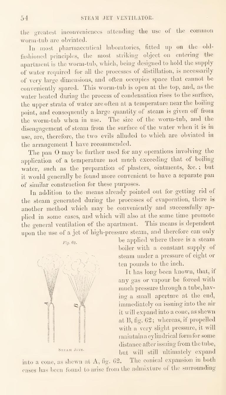
54 STEAM JET VENTTLATOll.
the greatest iiicouveiiieiices attending the use of the common
worm-tub are obviated. In most pharmaceutical laboratories, fitted up on the old-
fasliioned principles, the most striking object on entering the
ai)artment is the worm-tub, which, being designed to hold the supply
of water required for all the processes of distillation, is necessarily
of very large dimensions, and often occupies space that cannot be
conveniently spared. This worm-tub is open at the top, and, as the
water heated during the process of condensation rises to the surface,
the upper strata of water are often at a temperature near the boiling
point, and consequently a large quantity of steam is given off from
the worm-tub when in use. The size of the worm-tub, and the
disengagement of steam from the surface of the water when it is in
use, are, therefore, the two evils alluded to which are obviated in
the arrangement I have recommended. The pan 0 may be further used for any operations involving the
application of a temperature not much exceeding that of boiling
water, such as the preparation of plasters, ointments, &c. ; but
it would generally be found more convenient to have a separate pan
of similar construction for these purposes. In addition to the means already pointed out for getting rid of
the steam generated during the processes of evaporation, there is
another method which may be conveniently and successfully ap¬
plied in some cases, and which will also at the same time promote
the general ventilation of the apartment. This means is dependent
upon the use of a jet of high-pressure steam, and therefore can only be applied where there is a steam
boiler with a constant supply of
steam under a pressure of eight or
ten pounds to the inch.
It has long been known, that, if
any gas or vapour be forced with
much pressure through a tube, hav¬
ing a small aperture at the end,
immediately on issuing into the air
it will expand into a cone, as shewn
at B, fig. 62; whereas, if propelled
with a very slight pressure, it will
maintain a cylindrical form for some
distance after issuing from the tube,
but will still ultimately expand
into a cone, as shewn at A, fig. 62. The conical expansion in both
cases has been found to arise from the admixture of the surrounding
Fig. 62.
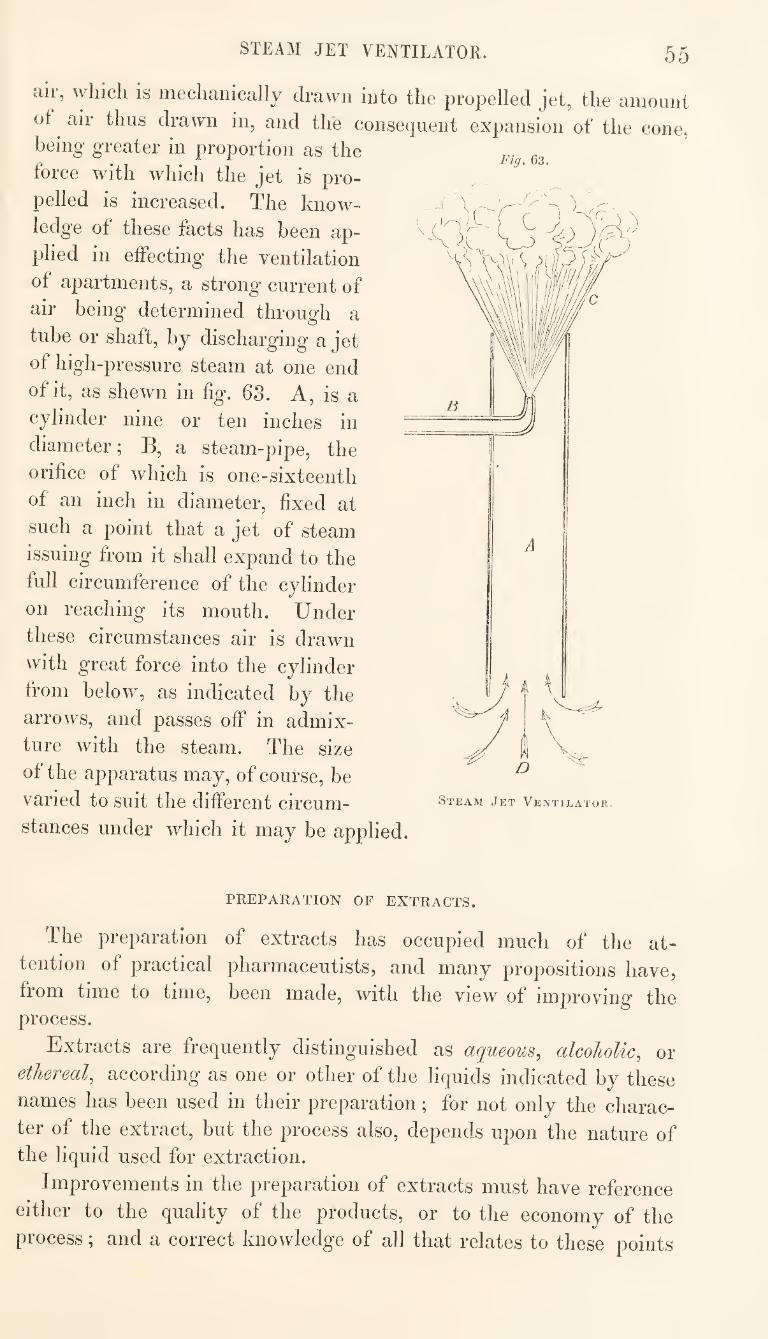
STEAM JET VENTILATOR.
Fig, 63.
55
air, which is mechanically drawn into the propelled jet, the amount
of air thus drawn in, and the consequent expansion of the cone, being greater in proportion as the
force with which the jet is pro¬
pelled is increased. The know¬
ledge of these facts has been ap¬
plied in effecting the ventilation
of apartments, a strong current of
air being determined through a
tube or shaft, by discharging a jet
of high-pressure steam at one end
of it, as shewn in hg. 63. A, is a
cylinder nine or ten inches in
diameter; B, a steam-pipe, the
orifice of which is one-sixteenth
of an inch in diameter, fixed at
such a point that a jet of steam
issuing from it shall expand to the
full circumference of the cylinder
on reaching its mouth. Under
these circumstances air is drawn
with great force into the cylinder
from below, as indicated by the
arrows, and passes off in admix¬
ture with the steam. The size
of the apparatus may, of course, be
varied to suit the different circum¬
stances under which it may be applied.
Steam Jet Ventilator.
PREPARATION OF EXTRACTS.
The preparation of extracts has occupied much of the at¬
tention of practical pharmaceutists, and many propositions have,
from time to time, been made, with the view of improving the process.
Extracts are frequently distinguished as aqueous, alcoholic, or
ethereal, according as one or other of the liquids indicated by these
names has been used in their preparation; for not only the charac¬
ter of the extract, but the process also, depends upon the nature of the liquid used for extraction.
Improvements in the preparation of extracts must have reference
either to the quality of the products, or to the economy of the
process; and a correct knowledge of all that relates to these points
PREPAIUTION OF EXTRACTS. oG
is essential in determining which is the best of the many methods
of proceeding which have been suggested.
Aqueous Extracts. — Berzelius, in his work on chemistry, has
entered very fully into the theoretical questions relating to the
nature and preparation of extracts. He has shewn that they un¬
dergo important changes, and ultimately are completely spoiled, if
long exposed to the action of heat, and especially a high tempe¬
rature. Great care, therefore, ought to be taken, to avoid this
source of deterioration.
There are three ways of preparing aqueous extracts, or rather
of making the solutions from which they are prepared :— 1st, By
boiling the solid ingredients with water; 2ndly, By digesting
them in boiling water; and, 3rdly, By macerating them in cold
water.
Extraction by boiling, can only be applied with advantage to
hard woods, roots, and barks, such as guaiacum wood, quassia, Pe¬
ruvian bark, cascarilla bark, See., which are with difficulty exhausted
of their soluble parts. The substance to be operated upon is first
to be cut or sliced, and then boiled with just enough water to cover
it, and admit of its being well stirred with a spatula. It is better
to avoid active ebullition, and induce only a gentle simmering,
[which should be continued for a quarter of an hour or twenty
minutes.] The decoction is then poured into a strainer and al¬
lowed to drain; and the solid ingredients are twice more treated in
the same way with fresh portions of water. These several decoc¬
tions are mixed together, allowed to settle, and then the clear
liquor evaporated over the water-bath.
It should be observed, however, that, in making extract of Peru¬
vian bark, the sediment which forms in the decoction as it cools is
not to be separated and rejected.
In evaporating the liquor, a small quantity only should be intro¬
duced into the pan at a time; and when this has been evaporated,
with the constant use of the stirrer, to the consistence of syrup,
it should be taken out and the process repeated on another portion,
until the whole has been thus reduced. Finally, these syrupy
liquors, being united, are to be carefully evaporated to the consist¬
ence of an extract.
Formerly all aqueous extracts were directed to be made from
decoctions of the solid ingredients. In process of time, however, it
was ascertained, by experiment, that in most cases it was more
advantageous to effect the extraction by means of infusion than by
decoction. Thus, for instance, well authenticated experiments have
shewn that
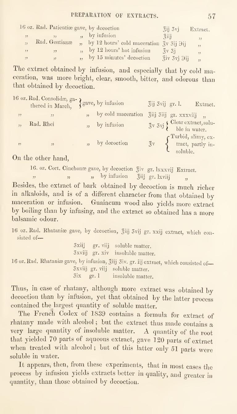
rREPARATION OF EXTRACTS. 57
16 oz. Rad. Patientise gave, by decoction
„ by infusion Rad. Gentianae
^7
57
55
55
Jij 3vj
^iij by 12 hours’ cold maceration Jv 3ij 9ij
by 12 hours’ hot infusion Jv 3j
by 15 minutes’ decoction Jiv 3vj 9ij
Extract.
55
55
55
55
55
55
55
55
Rad. Rhei
55
The extract obtained by infusion, and especially that by cold ma¬
ceration, was more bright, clear, smooth, bitter, and odorous than that obtained by decoction.
16 oz. Rad. Consolidae, ga- ) thered in March, | S'i’Ve, by infusion 3ij 3vij gr. 1. Extract.
55 by cold maceration jiij 3iij gr. xxxviij „
„ by infusion 3. V Clear extract,solu- i ble in water. {Turbid, slimy, ex¬
tract, partly in¬
soluble.
On the other hand,
16. oz. Cort. Cinchonae gave, by decoction ^iv gr. Ixxxvij Extract.
55 55 55 by infusion Jiij gr. Ixviij „
Besides, the extract of bark obtained by decoction is much richer
in alkaloids, and is of a dilferent character from that obtained by
maceration or infusion. Gruaiacum wood also yields more extract
by boiling than by infusing, and the extract so obtained has a more balsamic odour.
16 oz. Rad. Rhatanise gave, by decoction, Jiij 3vij gr. xxij extract, which con¬ sisted of—
3xiij gr. viij soluble matter.
3xviij gr. xiv insoluble matter.
16 oz. Rad. Rhataniee gave, by infusion, ^iij 3iv. gr. iij extract, which consisted of—
3xviij gr. viij soluble matter.
3ix gr. 1 insoluble matter.
Thus, in case of rhatany, although more extract was obtained by
decoction than by infusion, yet that obtained by the latter process contained the largest quantity of soluble matter.
The French Codex of 1839 contains a formula for extract of
rhatany made with alcohol; but the extract thus made contains a
very large quantity of insoluble matter. A quantity of the root
that yielded 70 parts of aqueous extract, gave 120 parts of extract
when treated with alcohol; but of this latter only 51 parts were soluble in water.
It appears, then, from these experiments, that in most cases the
process by infusion yields extracts better in quality, and greater in quantity, than those obtained by decoction.
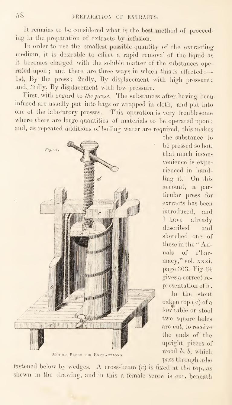
58 PRErARATlON OF EXTRACTS.
Fi>j. 64.
It remtiiiis to be considered vvliat is the best method of proceed¬
ing in the preparation of extracts by infusion.
In order to use the smallest possible quantity of the extracting
medium, it is desirable to elFect a rapid removal of the liquid as
it becomes charged with the soluble matter of the substances ope¬
rated upon ; and there are three ways in which this is effected :—
1st, By the press; 2ndly, By displacement with high pressure;
and, Srdly, By displacement with low pressure.
First, with regard to the press. The substances after having' been
infused are usually put into bags or wrapped in cloth, and put into
one of the laboratory presses. This operation is very troublesome
where there are large quantities of materials to be operated upon ;
and, as repeated additions of boiling water are required, this makes
the substance to
be pressed so hot,
that much incon¬
venience is expe¬
rienced in hand¬
ling it. On this
account, a par¬
ticular press for
extracts has been
introduced, and
I have already
described and
sketched one of
these in the “An¬
nals of Phar¬
macy,” vol. xxxi.
page 303. Fig.64
gives a correct re¬
presentation of it.
In the stout
oatei top ia) of a
low table or stool
two square holes
are cut, to receive
the ends of the
upright pieces of
wood which
pass through to be fastened below by wedges. A cross-beam (c) is fixed at the top, as
shewn in the drawing, and in this a female screw is cut, beneath
Mohr’s Press for Extractions.
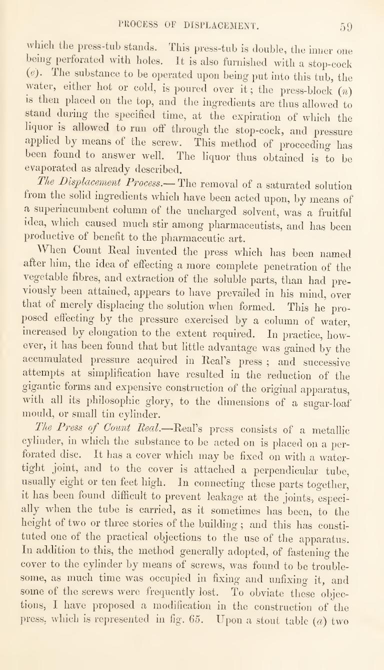
PROCESS OF DISPLACEMENT. 59
^vhicli the press-tub stands. This press-tub is double, the inner one
being perforated with holes. It is also furnished with a stop-cock
(e). The substance to be operated upon being put into this tub, the
water, either hot or cold, is poured over it; the press-block (n)
is then placed on the top, and the ingredients are thus allowed to
stand during the specified time, at the expiration of which the
liquor is allowed to run otF through the stop-cock, and pressure
applied by means of the screw. This method of proceeding has
been found to answer well. The liquor thus obtained is to be evaporated as already described.
The Displacement Process.— The removal of a saturated solution
fiom the solid ingredients which have been acted upon, by means of
a superincumbent column of the uncharged solvent, was a fruitful
idea, which caused much stir among pharmaceutists, and has been productive of benefit to the pharmaceutic art.
^Vhen Count Real invented the press which has been named
after him, the idea of effecting a more complete penetration of the
vegetable fibres, and extraction of the soluble parts, than had pre¬
viously been attained, appears to have prevailed in his mind, over
that of merely displacing the solution when formed. This he pro¬
posed effecting by the pressure exercised by a column of water,
increased by elongation to the extent required. In practice, how¬
ever, it has been found that but little advantage was gained by the
accumulated pressure acquired in Reafs press ; and successive
attempts at simplification have resulted in the reduction of the
gigantic forms and expensive construction of the original apparatus,
with all its philosophic glory, to the dimensions of a sugar-loaf mould, or small tin cylinder.
The Press of Count Peal.—-Real s press consists of a metallic
cylinder, in which the substance to be acted on is placed on a per¬
forated disc. It has a cover which may be fixed on with a water¬
tight joint, and to the cover is attached a perpendicular tube,
usually eight or ten feet high. In connecting these parts together,
it has been found difficult to prevent leakag’e at the joints, especi¬
ally when the tube is carried, as it sometimes has been, to the
height of two or three stories of the building; and this has consti¬
tuted one of the practical objections to the use of the apparatus.
In addition to this, the method generally adopted, of fastening the
cover to the cylinder by means of screws, was found to be trouble¬
some, as much time was occupied in fixing and unfixing it, and
some of the screws were frequently lost. To obviate these objec¬
tions, I have proposed a modification in the construction of the
press, which is represented in fig. 65. Upon a stout table («) two
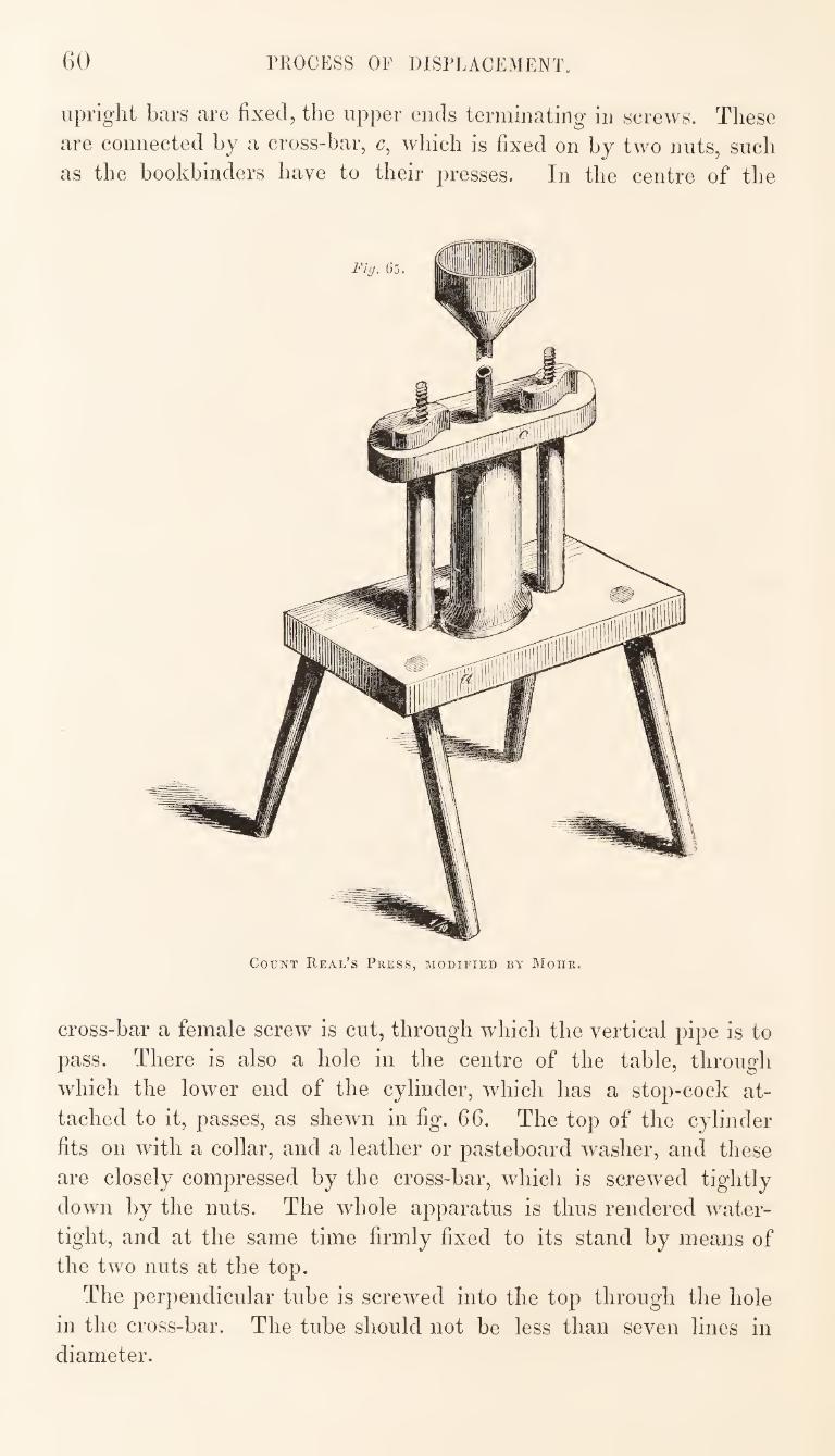
60 PROCESS OF DISPLACEMENT.
upright bars are fixed, the upper ends terminating in screws. These
are connected by a cross-bar, which is fixed on by two nuts, such
as the bookbinders have to their presses. In the centre of the
Count Real’s Press, modified by Mohr.
cross-bar a female screw is cut, through which the vertical pipe is to
pass. There is also a hole in the centre of the table, through
which the lower end of the cylinder, which has a stop-cock at¬
tached to it, passes, as shewn in fig. 66. The top of the cylinder
fits on with a collar, and a leather or pasteboard washer, and these
are closely compressed by the cross-bar, which is screwed tightly
down by the nuts. The whole apparatus is thus rendered water¬
tight, and at the same time firmly fixed to its stand by means of
the two nuts at the top.
The perpendicular tube is screwed into the top through the hole
in the cross-bar. The tube should not be less than seven lines in diameter.
PROCESS OF DISPLACEMENT. 61
The substances to be acted upon are
placed in the cylinder, over the perfo¬
rated strainer, in a dry or moist state,
with certain precautions which will be
subsequently stated ; and the cover
being* fitted on, and the pressure-pipe
fixed in its place, water is poured in
through the funnel at the top, so that
the ingredients in the cylinder shall be
exposed to the pressure of a column of
water. After standing for some hours,
the liquor is slowly drawn off through
the stop-cock at the bottom, while fresh water is added from above.
The principal objection to this appa¬
ratus is that the liquid passes too rapidly
through the solid ingredients, in conse-
Fig, 66, Fig. 67,
it
Fig. 68,
Real’s Press, modified by Mohr.
quence of the pressure exercised by the column of liquid in the tube.
With a few additions, the apparatus above described may be
rendered applicable for use as a mechanical press. For this pur¬
pose, a cylindrical strainer (fig. 67) must be made to fit into the
cylinder of the press and to stand on the perforated disc at the
bottom.^ The materials are placed inside this, and a small press-
block (fig. 68) put over them. The cover of the press and the ver¬
tical pipe are dispensed with, and, in place of the latter, a screw
with a lever-handle at the upper end is passed through the hole in
the cioss-bai, which, as already stated, has a female screw cut in
it, and this screw, acting on the press-block, effects the required pressure.
This application of the apparatus is very convenient in opera¬
ting with spirit, as it admits of the extraction and the expression
being effected in the same vessel, and thus the loss from evajioration
and otherwise, that would occur in transferring the materials to another vessel, is avoided.
The objections which attach to the use of ReaPs press, have led
to the adoption of a more simple method of effecting displacement,
in which high pressure is avoided. Indeed, the process of displace¬
ment by low pressure may be said to have entirely superseded the
other. The ReaPs press may be reduced to a low pressure dis¬
placement apparatus, as a slipper would be made out of an old boot, by removing all the upper portions.
The outer cylinder of the ReaPs press, placed on a suitable
stand, is all that is required for a displacement apparatus.
PROCESS OF DISPLACEMENT. G2
The method of manipulating’ with this apparatus, so as to obtain
satisfactory results, is not, liowever so simple and easy as might he
imagined ; and the French pharmaceutists have accordingly been
occupied for years in classifying the different vegetable substances
according to the treatment they severally require in submitting
them to this process.
The process of displacement consists in pouring the liquid to be
used over the solid ingredients, previously reduced to a state of
division, and confined in a cylinder of greater length than diameter,
and thus causing the liquid to pass through many layers of the
solid body, until it becomes charged with the soluble matter, which
it extracts and carries away with it.
The advantage of this process is said to consist in its effecting
the exhaustion of the solid substances acted upon, of their soluble
matter, with a smaller quantity of liquid than would be required
under other circumstances. This is said to be accomplished in con¬
sequence of each particle of liquid coming successively in contact
with a great number of particles of solid matter, while at the
same time the latter particles are also successively acted upon by a
great number of particles of the liquid.
If, as is assumed in the above theory, there were no obstacle to
the equal penetration, in all parts, of the mass of solid matter, and
of the separate particles of which it is composed, by the liquid, and,
further, if there were no disposition in the different parts of the
liquid to intermingle with each other, the process would, indeed,
accomplish all that could be desired. In practice, however, such
satisfactory results are but rarely obtained. It is found that the
fluid does not pass with the same facility through the pieces of
solid matter as it does through the interstices between these pieces;
that it frequently flows more freely through one part of the mass
than another, in consequence of unequal packing of the materials, or
from some other cause ; and, further, that, however well the mate¬
rials may have been packed in the first instance, as the solvent
extracts the soluble parts, the remaining solid matter occupies less
space; and the mass, shrinking from this cause, forms a number
of channels through which the fluid flows without further effect.
Yet, notwithstanding these disadvantages, there are some cases in
which the process of displacement is found to be available wdth
much advantage.
In the application of this process, an essential condition of success
is the reduction of the solid substances to the proper state of
division. The opinion which has been formed by many persons,
that certain substances of a mucilaginous nature are impenetrable,
63 PROCESS OF DISPLiCEMENT.
and cannot be exhausted by displacement, has probably been formed in conseiiuence of a want of proper attention to the above con- yon. There are, I believe, few substances that do not admit
ot being treated by this process, if all the necessary conditions be
Leays, herbs, or the tops of plants, when properly dried and made friable, may be rubbed through a sieve of about 10 meshes to the square inch, or they may be cut up and then passed through
le sieve. ^ Barks, roots, and all kinds of wood, are properly cut up, or bruised in a mortar or mill, and finally sifted, the coarse powder only being used, while the fine is set aside for some other purpose.
Mucilaginous substances should be less finely comminuted than those of a more woody nature.
It would be difficult to describe the degree of division necessary for each separate substance ; this must be left to the judgment and experience of the operator. It would be equally difficuft to decide how much of the solid substance ought to be put into the cylinder at once, as this depends on the nature of the substance.
There are two methods of proceeding in the treatment of vegetable powders by displacement : one consists in packing the dry substance in the apparatus, and pouring the liquid over it until it begins to run out at the bottom, when the moistened mass is allowed to stand for some time with the stop-cock shut off before the displacement is commenced; the other consists in moistening the powder in a separate vessel, allowing it to stand for some time, and then packing it in the cylinder of the apqjaratus.
The former of these methods offers no advantage over the other, while it is frequently found that the powder does not become completely moistened when thus treated, and hence that one of the principal objects of maceration is frustrated. [It also occurs, frequently, that, when the powder is moistened in the cylinder of the apparatus, it swells on the addition of the liquid, and thus becomes so tightly packed as to re.sist the further passage of the liquid. This inconvenience is principally experienced when water is used as the extracting agent.]
A dry sponge imbibes water but sluggishly ; while, on the other hand, a moistened and expressed one absorbs it greedily: so, m like manner, a dry powder offers some resistance to the entrance of water; while in a moistened powder the absorption is promoted, through the influence of capillary attraction. The resistance offered by the dry powder arises partly from the formation of an impenetrable coating on the surface, by the swelling of the first
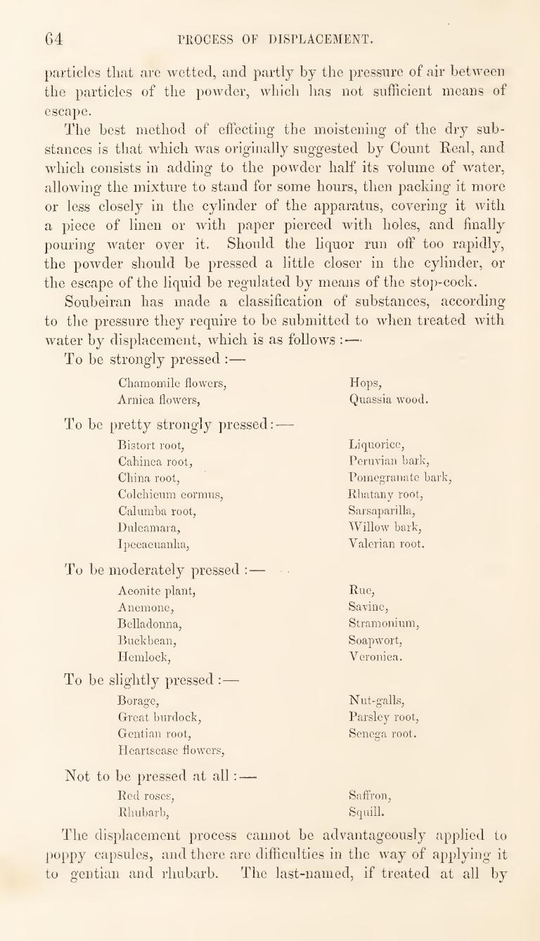
64 PROCESS OF DISPLACEMENT.
particles that are wetted, and partly by the pressure of air between
the particles of the powder, which has not sufficient means of
escape.
The best method of effecting the moistening of the dry sub¬
stances is that which was originally suggested by Count Real, and
which consists in adding to the powder half its volume of water,
allowing the mixture to stand for some hours, then packing it more
or less closely in the cylinder of the apparatus, covering it with
a piece of linen or with paper pierced with holes, and finally
pouring water over it. Should the liquor run off too rapidly,
the powder should be pressed a little closer in the cylinder, or
the escape of the liquid be regulated by means of the stop-cock.
Soubeiran has made a classification of substances, according
to the pressure they require to be submitted to when treated with
water by displacement, which is as follows :—
To be strongly pressed :—
Chamomile flowers, Hops,
Arnica flowers, Quassia wood.
pretty strongly pressed:—
Bistort root. Liquorice,
Cahinca root. Peruvian bark.
China root. Pomegranate bark.
Colchicum cormns. Rhatany root.
Calumha root. Sarsaparilla,
Dulcamara, Willow bark.
Ipecacuanha, Valerian root.
moderately pressed :—
Aconite plant. Rue,
Anemone, Savine,
Belladonna, Stramonium,
Buckbean, Soapwort,
Hemlock, Veronica.
slightly pressed :—
Borage, Nut-galls,
Great burdock. Parsley root.
Gentian root. Senega root.
Heartsease flowers,
> be pressed at all : —
Red roses. Saffron,
Rhubarb, Squill.
The displacement process cannot be advantageously applied to
poppy capsules, and there are difficulties in the way of applying it
to gentian and rhubarb. The last-named, if treated at all by
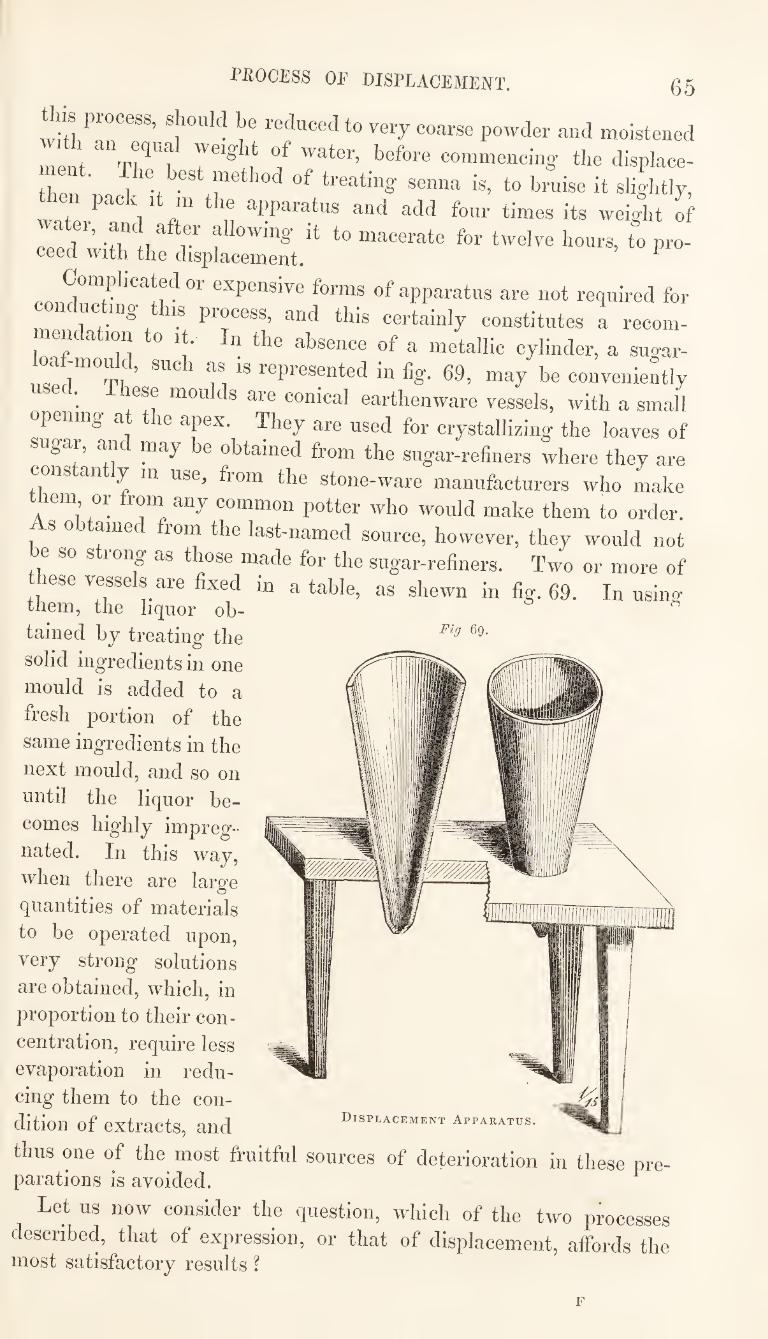
Fig 69.
PEOCESS OF DISPLACEMENT. 65
this process, should be reduced to very coarse powder and moistened
ment 7 commencing the displace-
then ' treating senna is, to bruise it slightly,
Wat \ * a” 7 ®nd add four times its weight of
Ifr 7l 1 7 f I^®«rs, to pro- ceed with the displacement. ^
Complicated or expensive forms of apparatus are not required for
n uc ing IS process, and this certainly constitutes a recom-
meiK ation to it. In the absence of a metallic cylinder, a sugar-
, “ti represMted in fig. 69, may be conveniently c • lese moulds are conical earthenware vessels, with a small
opening at the apex, ^ley are used for crystallizing the loaves of
g r, an may e obtained from the sugar-refiners where they are
01s an y m use, fiom the stone-ware manufacturers who make
em, or rom any common potter who would make them to order,
s 0 amec lom the last-named source, however, they would not
e so s long as those made for the sugar-refiners. Two or more of
these vessels are fixed in a table, as shewn in fig. 69. In using them, the liquor oh-
tained by treating the
solid ingredients in one
mould is added to a
fresh portion of the
same ingredients in the
next mould, and so on
until the liquor be¬
comes highly impreg¬
nated. In this w^ay,
when there are large
quantities of materials
to be operated upon,
very strong solutions
are obtained, which, in
proportion to their con¬
centration, require less
evaporation in redu¬
cing them to the con¬
dition of extracts, and
thus one of the most fruitful sources of deterioration in these pre- parations is avoided.
Let us now consider the question, which of the two processes
described, that of expression, or that of displacement, affords the most satisfactory results ?
Displacement Apparatus.
6G PROCESS OF DISPLACEMENT.
According to my view and experience, the advantage is on the
side of the process of expression.
The process of displacement offers advantages only when conti¬
nued uninterruptedly with large quantities of the same materials,
so that solutions which are comparatively weak may be rendered
stronger by using them to act on fresh portions of unexhausted
materials. In pharmaceutical operations this is rarely possible, as
the quantities operated upon are generally small. The influence
produced by the extent of the operations will afford an explanation
of the difference in the results which have been obtained in the
application of this process in large and in small laboratories. The
process of expression is not subject to this defect, the results being
alike with small as with large quantities.
In the displacement process the solutions first obtained are the
most concentrated, but they soon decrease in strength, and continue
for some time to get weaker, although still sufflciently strong to
prevent their being rejected; and if there be no more substance to
be acted upon by these weak solutions, there is no alternative but
to concentrate them by evaporation. In the process of expression,
the liquor obtained is of the same degree of concentration through¬
out the operation. It is true that the marc still retains a small
quantity of liquor similar to that which has been expressed, but
this may in great measure be removed by the addition of a little
more water, and a second expression. Substances which are with
much difficulty treated by displacement, such as rhubarb, gentian,
nutgalls, &c., present no difficulties in the process of expression ;
indeed, this is frequently resorted to as the readiest means of finish¬
ing the operation after beginning it by the other. Expression is
advantageous, in many cases, from its tending to burst the fibres,
which in their unbroken state retain portions of soluble matter, or
of solution, which is not otherwise easily removed.
Moreover, with regard to the time required for conducting either
process, the press again has the advantage. By the application of
heat the extraction may be accelerated, and the expression then
effected as soon as deemed expedient. In the case of ordinary
displacement, no further heat can be applied; and with substances
of a mucilaginous nature the percolation is so slow, that the ingre¬
dients frequently become mouldy and spoil before the process is
finished. Sometimes the percolation stops altogether, and in these
cases there is no other remedy than resorting to the press.
Finally, I conclude, from these several views of the question,
that the process of expression, with properly constructed apparatus,
is preferable to that of displacement.
67 pkeparation of extracts.
[In the preparation of extracts the quality of the product will
c epend less upon the means adopted for extracting the soluble
la ei lom the vegetable substances operated upon, than upon lose y which the inspissation of the solutions is effected.
An extract, for medicinal use, ought to contain the active consti-
ueiits of the substance from which it is made, if possible, in an
unaltered condition. It should represent the infusion, decoction,
incture, or juice, by the evaporation of which it is obtained, in
every respect, excepting the state of concentration of the active ingredients, and the permanency of their condition.
ExtracU are, or ought to be, composed of a number of chemi¬
cal constituents, or proximate vegetable principles, educed and not
produced, during the process of preparation. Among these consti-
uents aie, staich, gum, sugar, pectin, albumen, gluten, vegetable
aci s, a haloids and allied bodies, oils, resins, and colouring matters.
lese substances are very liable to undergo decomposition or
c langes of constitution, especially when exposed to the action of
^at and atmospheric air; and it is with the view of preventing
these changes that different modifications of the process of evapora” tion in making extracts have been proposed.
Evaporation may be effected :—
1. By the direct radiation of heat from a fire upon the bottom
of an uncovered evaporating-pan or dish. This is called evapora¬ tion over the naked fire.
2. By the conduction or convection of heat to the pan, through
the medium of water or steam. This is called evaporation by the ivater-hath or steam-hatJi.
S. By the application of heat by either of the foregoing methods,
togethei with the removal of atmospheric contact and pressure
from the surface of the evaporating liquid. This is called eva- poration in racuo.
4. By the spontaneous diffusion of the vapour of the liquid into
the atmosphere, assisted by a current of air passing over the sur¬
face of the liquid. This is called spontaneous evaporation.
Evaporation over the naked fire^ is sometimes resorted to where
lapid concentration is required. Where a large quantity of decoc¬
tion or infusion has to be inspissated to the consistence of an
extract, it is not unusual to adopt this method of concentrating the
liquor in the first instance, before resorting to the use of the water-
bath. This indeed is the mode of proceeding which is prescribed
by the London College, in the preparation of many of the extracts
ordered m the Pharmacopoeia. Thus, the extracts of gentian,
liquorice, hop, poppy, sarsaparilla, dandelion, &c., are directed to be
68 PREPARATTON OE EXTRACTS.
made by macerating tlie vegetable ingredients in boiling water for
twenty-four hours, then boiling down to one-half, straining the
liquor while hot, and finally evaporating to a proper consistence in
the water-bath. In these cases it must have been intended that
the boiling down to one-half should be performed over the naked
fire; for the liquors could not be boiled in the water-bath, which
is the only other process alluded to in the Pharmacopoeia for the
preparation of extracts.
This method of evaporation, however, is subject to great objec¬
tions, although, certainly, these do not apply so strongly in reference
to the first concentration of the liquors, as to the subsequent inspis-
sation of the extract. Yet, in every stage of the process, evapora¬
tion over the naked fire, with an uncased open pan, is liable, in
unskilful hands, to result in the injury, if not destruction, of the
properties of the product. It cannot be denied, indeed, that a
skilful and experienced operator will often effect all that can be
desired with these means of evaporation, but with deficiency of
judgment, or want of attention and care, an opposite result would
inevitably be attained. In evaporating a liquid over the naked fire, especial attention
should be paid'to the condition of the fire, and the position of the
pan in reference to it. The pan ought in no case to be in contact
with the ignited fuel: the heat received by the pan should be that of
radiation, not of conduction. There should even be a considerable
distance between the bottom of the pan and the surface of the fire,
especially when the extract begins to thicken ; the fire should now,
also, be clear and low, so that an equable and not too intense heat
may radiate upwards. Moreover, in operating in this way, it is not
desirable to have a very small quantity of extract in the pan at a
time, as in this case it would be more difficult to avoid the applica¬
tion of undue heat. Evaporation hy the water-bath^ or steam-bath^ has almost wholly
superseded the process last described, and is the method now gene¬
rally adopted in the preparation of extracts. The water-bath and
the steam-bath are here classed together, because they have some
characters in common; but in the practical application of these two
means for effecting evaporation, it will be found that they differ
from each other in some important particulars.
The water-bath is an arrangement by which the heat of boiling
water is applied to the outer surface of the vessel containing the
evaporating liquid. Thus, a double or jacketed pan, with the inter¬
mediate space between the pan and its outer case partly filled with
water, constitutes a water-bath. If this be placed over a fire, the
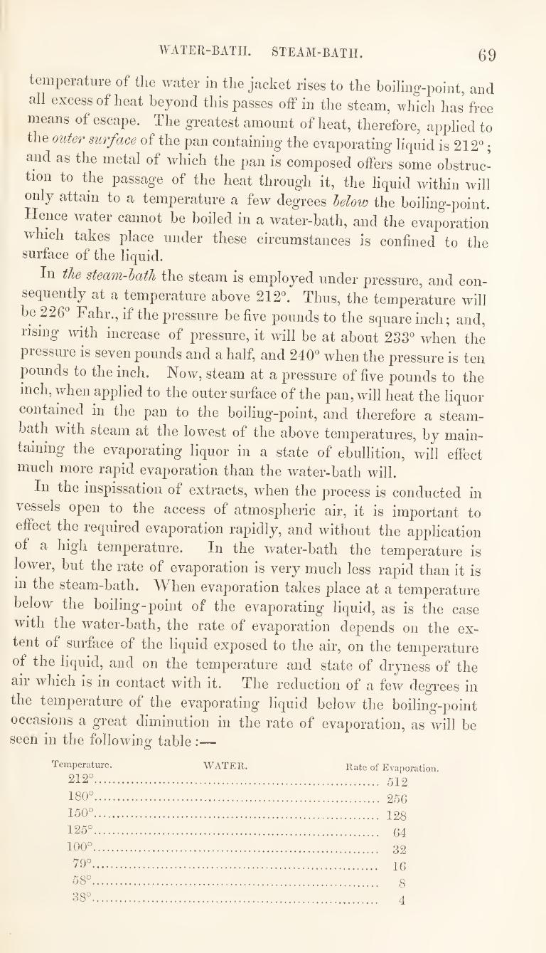
WATER-BATH. STEAM-BATH. 69
temperature of the water in the jacket rises to the boiling-point, and
all excess of heat beyond this passes off in the steam, which has free
means of escape. The greatest amount of heat, therefore, applied to
the outer surface of the pan containing the evaporating liquid is 212^;
and as the metal of which the pan is composed offers some obstruc¬
tion to the passage of the heat through it, the liquid within will
only attain to a temperature a few degrees Moio the boiling-point.
Hence water cannot be boiled in a water-bath, and the evaporation
which takes place under these circumstances is confined to the surface of the liquid.
In the steam-hath the steam is employed under pressure, and con¬
sequently at a temperature above 212^ Thus, the temperature will
be 226° Fahr., if the pressure be five pounds to the square inch; and,
rising with increase of pressure, it will be at about 233° when the
pressure is seven pounds and a half, and 240° when the pressure is ten
pounds to the inch. Now, steam at a pressure of five pounds to the
inch, when applied to the outer surface of the pan, will heat the liquor
contained m the pan to the boiling-point, and therefore a steam-
bath with steam at the lowest of the above temperatures, by main¬
taining the evaporating liquor in a state of ebullition, will effect
much more rapid evaporation than the water-bath will.
In the inspissation of extracts, when the process is conducted in
vessels open to the access of atmospheric air, it is important to
effect the required evaporation rapidly, and without the application
of a high temperature. In the water-bath the temperature is
lower, but the rate of evaporation is very much less rapid than it is
Ill the steam-bath. When evaporation takes place at a temperature
below the boiling-point of the evaporating liquid, as is the case
with the water-bath, the rate of evaporation depends on the ex¬
tent of surface of the liquid exposed to the air, on the temperature
of the liquid, and on the temperature and state of dryness of the
air which is in contact with it. The reduction of a few degrees in
the temperature of the evaporating liquid below the boiling-point
occasions a great diminution in the rate of evaporation, as will be seen in the following table :—
Temperature. WATER. Rate of Evaporation.
212°. 512
180°. 256
150°. 128
125°. 64
100°. 32
79°. 16
58°. 8
38°. 4
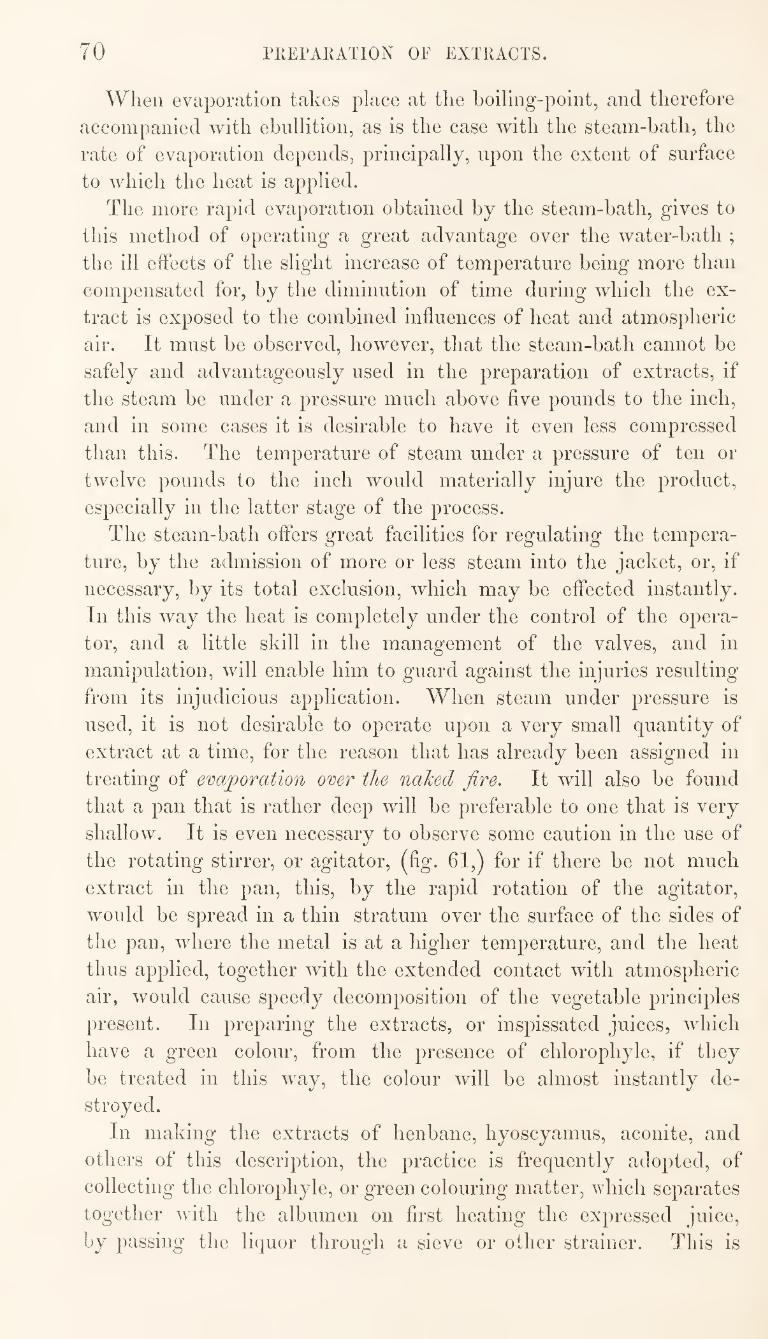
70 PKErAKATION OF EXTRACTS.
When evaporation takes place at the boiling-point, and therefore
accompanied with ebullition, as is the case with the steam-bath, the
rate of evaporation depends, principally, upon the extent of surface
to which the heat is applied.
The more rapid evaporation obtained by the steam-bath, gives to
this method of operating a great advantage over the water-bath ;
the ill effects of the slight increase of temperature being more than
compensated for, by the diminution of time during which the ex¬
tract is exposed to the combined influences of heat and atmospheric
air. It must be observed, however, that the steam-bath cannot be
safely and advantageously used in the preparation of extracts, if
the steam be under a pressure much above five pounds to the inch,
and in some cases it is desirable to have it even less compressed
than this. The temperature of steam under a pressure of ten or
twelve pounds to the inch would materially injure the product,
especially in the latter stage of the process.
The steam-bath offers great facilities for regulating the tempera¬
ture, by the admission of more or less steam into the jacket, or, if
necessary, by its total exclusion, which may be effected instantly.
In this way the heat is completely under the control of the opera¬
tor, and a little skill in the management of the valves, and in
manipulation, will enable him to guard against the Injuries resulting
from its injudicious application. When steam under pressure is
used, it is not desirable to operate upon a very small quantity of
extract at a time, for the reason that has already been assigned in
treating of evaporation over the naked fire. It will also be found
that a pan that is rather deep will be preferable to one that is very
shallow. It is even necessary to observe some caution in the use of
the rotating stirrer, or agitator, (fig. 61,) for if there be not much
extract in the pan, this, by the rapid rotation of the agitator,
woidd be spread in a thin stratum over the surface of the sides of
the pan, where the metal is at a higher temperature, and the heat
thus applied, together with the extended contact with atmospheric
air, would cause speedy decomposition of the vegetable principles
present. In preparing the extracts, or inspissated juices, which
have a green colour, from the presence of chlorophyle, if they
be treated in this way, the colour will be almost instantly de¬
stroyed.
In making the extracts of henbane, hyoscyamus, aconite, and
others of this description, the practice is frequently adopted, of
collecting the chlorophyle, or green colouring matter, which separates
together with the albumen on first heating the expressed juice,
by passing the liquor through a sieve or other strainer. This is
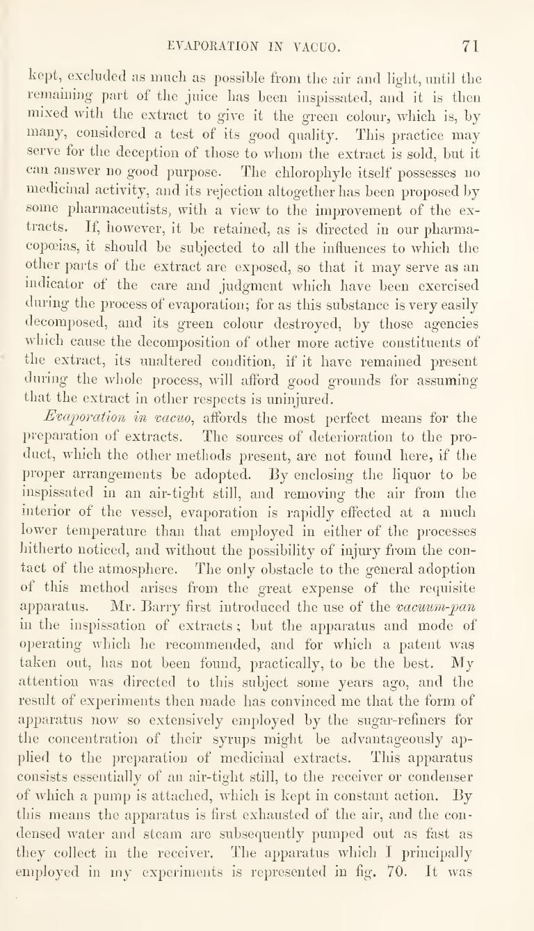
EVAPORATION IN VACUO. 71
kept, excluded as much as possible from the air and light, until the
remaining part of the juice has been inspissated, and it is then
mixed with the extract to give it the green colour, which is, by
many, considered a test of its good quality. This practice may
serve for the deception of those to whom the extract is sold, but it
can answer no good purpose. The chlorophyle itself possesses no
medicinal activity, and its rejection altogether has been proposed by
some pharmaceutists, with a view to the improvement of the ex¬
tracts. If, however, it be retained, as is directed in our pharma¬
copoeias, it should be subjected to all the influences to which the
other parts of the extract are exposed, so that it may serve as an
indicator of the care and judgment which have been exercised
during the process of evaporation; for as this substance is very easily
olecomposed, and its green colour destroyed, by those agencies
which cause the decomposition of other more active constituents of
the extract, its unaltered condition, if it have remained present
during the whole process, will aflbrd good grounds for assuming
that the extract in other respects is uninjured.
Evajporation in 'cacuo^ aflbrds the most perfect means for the
preparation of extracts. The sources of deterioration to the pro¬
duct, which the other methods present, are not found here, if the
proper arrangements be adopted. By enclosing the liquor to be
inspissated in an air-tight still, and removing the air from the
interior of the vessel, evaporation is rapidly effected at a much
lower temperature than that employed in either of the processes
hitherto noticed, and without the possibility of injury from the con¬
tact of the atmosphere. The only obstacle to the general adoption
of this method arises from the great expense of the requisite
apparatus. Mr. Barry first introduced the use of the 'cacuwn-pan
in the inspissation of extracts ; but the apparatus and mode of
operating which he recommended, and for which a patent was
taken out, has not been found, practically, to be the best. My
attention was directed to this subject some years ago, and the
result of experiments then made has convinced me that the form of
apparatus now so extensively employed by the sugar-refiners for
the concentration of their syrups might be advantageously ap¬
plied to the preparation of medicinal extracts. This apparatus
consists essentially of an air-tight still, to the receiver or condenser
of which a pump is attached, which is kept in constant action. By
this means the apparatus is first exhausted of the air, and the con¬
densed water and steam are subsequently pumped out as fast as
they collect in the receiver. The apparatus which I principally
employed in my experiments is represented in fig. 70. It was
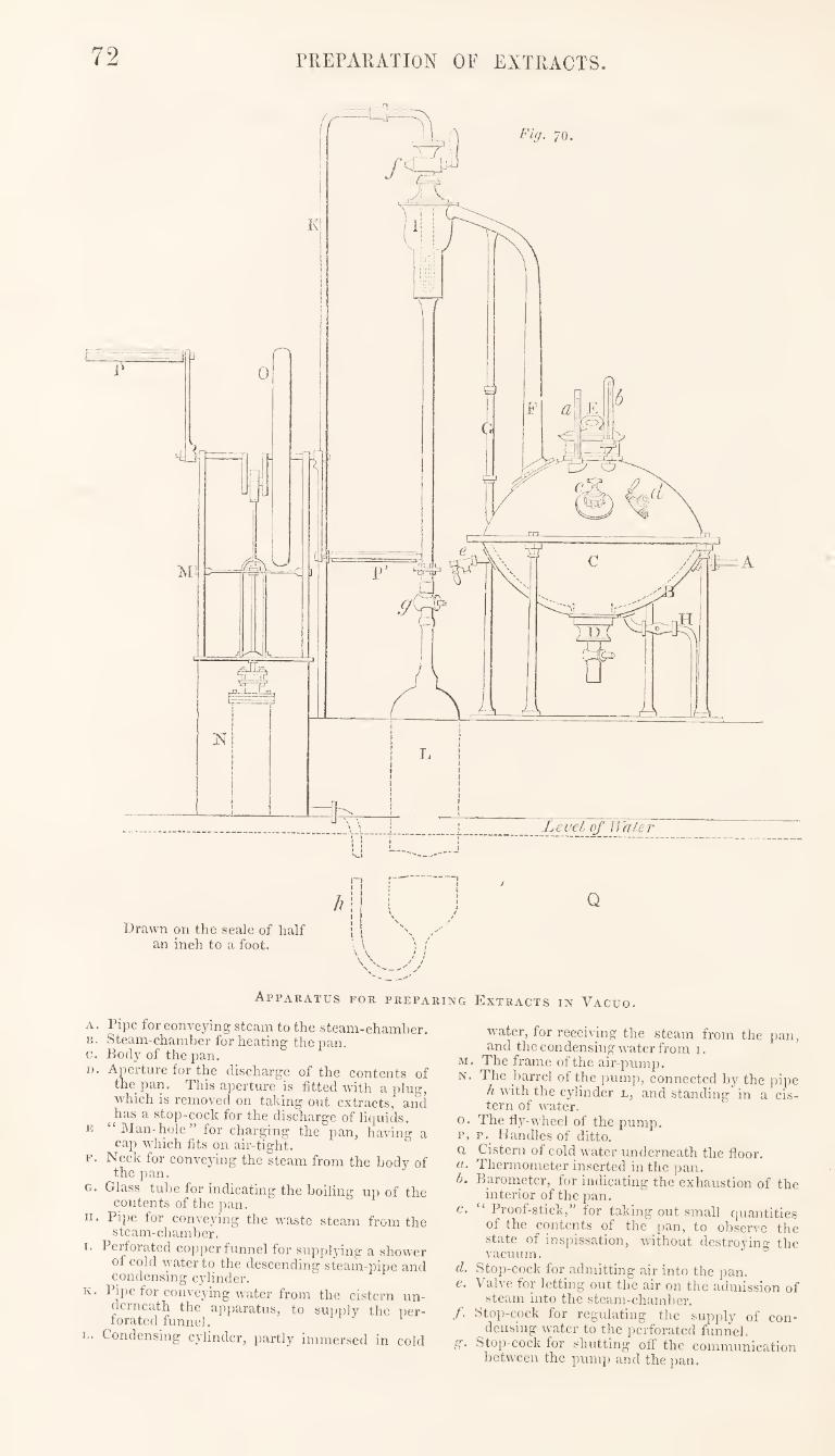
72 rREPARATION OF EXTRACTS.
Apparatus for preparing Extracts in Vacuo.
A. Pipe for conveying steam to the steam-chamber, B. Steam-chamber for heating the pan. c. Body of the pan.
I). Aperture for the discharge of the contents of the pan. This aperture is fitted with a plug, which is removed on taking out extracts, and has a stop-cock for the discharge of liquids.
E Man-hole for charging the pan, having a cap which fits on air-tight.
F. Neck for conveying the steam from the body of the pan.
G. Glass tube for indicating the boiling up of the contents of the pan.
H. Pipe for conveying the M^aste steam from the steam-chamber.
I. Perforated copper funnel for supplying a shower of cold water to the descending steam-pipe and condensing cylinder.
K. Pipe for conveying water from the cistern un¬ derneath the apparatus, to supiily the per¬ forated funnel.
p. Condensing cylinder, partly immersed in cold
water, for receiving the steam from the pan, and the condensing water from i.
M. The frame of the air-pump. N. The barrel of the pump, connected by the pipe
h with the cylinder l, and standing in a cis¬ tern of water.
o. The riy-wheel of the pump. p, p. Handles of ditto. a Cistern of cold water underneath the floor. a. Thermometer inserted in the pan. h. Barometer, for indicating the exhaustion of the
interior of the pan.
c. “ Proof-stick,” for taking out small quantities of the contents of the pan, to obsen^e the state of inspissation, without destroying the vacuum.
d. Stop-cock for admitting air into the pan. e. Valve for letting out the air on the admission of
steam into the steam-chamber. f. Stop-cock for regulating the supply of con¬
densing water to the perforated funnel. ,g. Sto])-cock for shutting off the communication
between the pump and the pan.
EVAPORATION IN VACUO. 73
originally made as a model of a sugar-pan, and is adapted for
working about fifteen gallons of liquor at a time. The drawing,
however, differs in some respects from the arrangements now
generally adopted by the sugar-refiners. The neck (F) is now
usually made much shorter and thicker than the drawing repre¬
sents, and the perforated funnel (I) is dispensed with, the steam
itself being pumped into a cistern of water, where it is condensed.
It would also be desirable to have the steam-chamber (B) much
more capacious than it is here represented.
The liquid to be inspissated is put into the pan at E, and the
cap fitted on. The steam is now admitted into the steam-chamber,
and the air exhausted from the interior of the apparatus by means
of the pump. A vacuum being produced, active ebullition will
take place when the temperature rises to about 120*^ Fahr. The
vapour passes up the neck (F) and through the descending pipe into
the cylinder L. A jet of cold water is now allowed to run at
and is dispersed in a shower by means of the perforated funnel
(I), assisting to condense the steam in its passage into L, from
whence it is removed, together with the condensed steam and any
air remaining in the apparatus, by means of the pump. The
pumping is continued until the completion of the process, and thus
a pretty complete vacuum is maintained, and a rapid evaporation
ensured.
As the loss of some of the contents of the pan may arise from
their boiling up through the neck (F), and being carried off by the
pump, a glass tube (G) is made to communicate between the pan
and the upper part of the neck, so that when the liquid is seen to
rise in this tube, the pumping is immediately stopped, and, if
necessary, air is admitted into the pan by the stop-cock which
effectually suppresses the ebullition. No more water should be
admitted through the perforated funnel (I) than is sufficient, with
the external application of cold water to the cylinder, for the con¬
densation of the steam. This is ascertained from the temperature
of the descending steam-pipe and the upper part of the cylinder.
The admission of too much water would tend to destroy the
vacuum, by supplying air to the interior of the apparatus.
The steam used for heating the pan ought not to be under a pres¬
sure of more than one or two pounds to the inch, and there should
be a plentiful supply of it. The amount of heat carried off during
evaporation is precisely the same in this process as it would be if
conducted under the pressure of the atmosphere at a much higher
temperature, for at whatever temperature the vapour of water
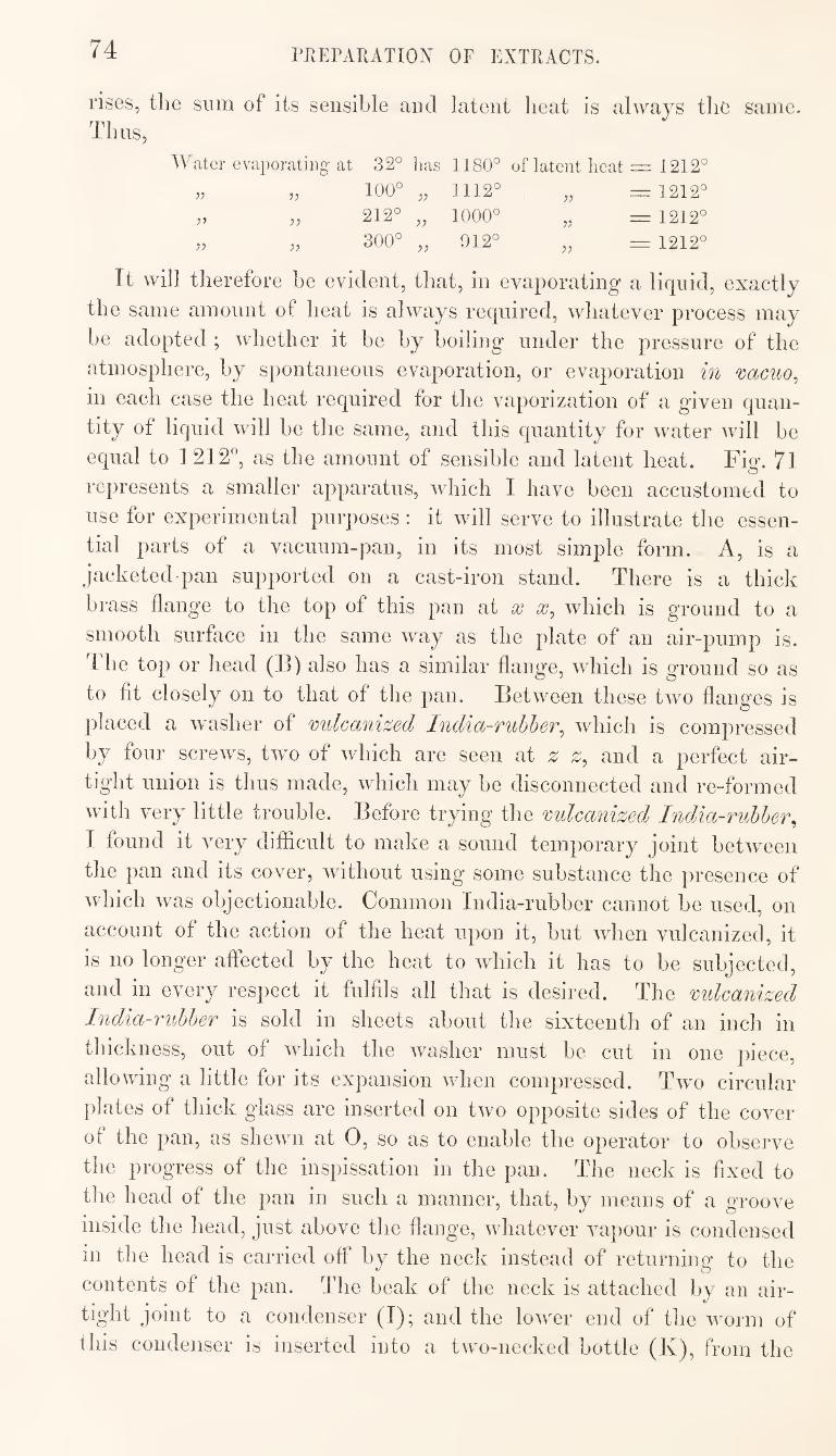
74 PrvEPARATION OF EXTRACTS.
rises, the sum of its sensible and latent heat is always the same. Tims,
Water evaporating at 32° has 1180° of latent heat = 1212°
100° „ 1112° = 1212°
212° „ 1000° = 1212°
}) 300° „ 912° 1212°
It will therefore be evident, that, in evaporating a liquid, exactly
the same amount of heat is always required, whatever process may
be adopted ; whether it be by boiling under the pressure of the
atmosphere, by spontaneous evaporation, or evaporation in mcuo,
in each case the heat required for the vaporization of a given quan¬
tity of liquid will be the same, and this quantity for water will be
equal to 1212°, as the amount of sensible and latent heat. Fig. 7l
represents a smaller apparatus, which I have been accustomed to
use for experimental purposes : it will serve to illustrate the essen¬
tial parts of a vacuum-pan, in its most simple form. A, is a
jacketed pan supported on a cast-iron stand. There is a thick
brass flange to the top of this pan at x which is ground to a
smooth surface in the same way as the plate of an air-pump is.
The top or head (13) also has a similar flange, which is ground so as
to fit closely on to that of the pan. Between these two flanges is
placed a wmsher of vulcanized India-rubber^ which is compressed
by four screws, twm of which are seen at z^ and a perfect air¬
tight union is thus made, which may be disconnected and re-formed
with very little trouble. Before trying the vulcanized India-rubber^
I found it very difficult to make a sound temporary joint between
the pan and its cover, without using some substance the presence of
which was objectionable. Common India-rubber cannot be used, on
account of the action of the heat upon it, but when vulcanized, it
is no longer affected by the heat to which it has to be subjected,
and in every respect it fulfils all that is desired. The vulcanized
India-rubber is sold in sheets about the sixteenth of an inch in
thickness, out of which the washer must be cut in one piece,
allowing a little for its expansion wdien compressed. Two circular
plates of thick glass are inserted on two opposite sides of the cover
of the pan, as shewn at 0, so as to enable the operator to observe
the progress of the inspissation in the pan. The neck is fixed to
the head of the pan in such a manner, that, by means of a groove
inside the head, just above the flange, whatever vapour is condensed
in the head is carried off by the neck instead of returning to the
contents of the pan. The beak of the neck is attached by an air-
tight joint to a condenser (I); and the lower end of the worm of
this condenser is inserted into a two-necked bottle (K), from the
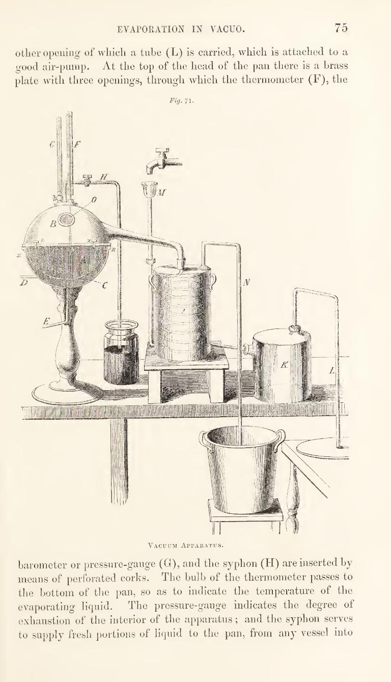
EVAPORATION IN VACUO. 75
other opening of which a tube (L) is carried, which is attached to a
good air-pump. At the top of the head of the pan there is a brass
plate with three openings, through which the thermometer (F), the
Fig. 71.
Vacuum Apparatus.
barometer or pressure-gauge (G), and the syphon (H) are inserted by
means of perforated corks. The bulb of the thermometer passes to
the bottom of the pan, so as to indicate the temperature of the
evaporating liquid. The pressure-gauge indicates the degree of
exhaustion of the interior of the apparatus; and the syphon serves
to supply fresh portions of liquid to the pan, from any vessel into
7G PREPAIUTION OF EXTRACTS.
wliicli the lower end of it is immersed, by opening the stop-cock,
during the progress of the evaporation, without aflhcting the
vacuum.
The liquid to be evaporated being introduced into the pan, and
the joints all made tight, exhaustion is effected by the pump, which
communicates with the receiver (K), the worm of the condenser (T),
and the interior of the pan (A). When the mercury in the pressure-
gauge has been reduced to a column of four or five inches, steam is
conveyed through the pipe D, to the steam-chamber (C), while the
water which collects here from condensation is carried off by the
pipe E. The action of the pump should now be resumed, and
continued throughout the process. The licpiid, if aqueous, will
commence boiling when heated to about 120° Fahr., and the evapo¬
ration may be actively kept up at a temperature varying from this
point to 140° Fahr., according to the degree of exhaustion main¬
tained and the state of inspissation of the extract. The condenser
must be continuously supplied with cold water, which enters through
the tube M at the bottom, while the hot water passes off from the
top through the tube N.
It may be well to observe, that the preparation of extract of
sarsaparilla by this process is attended with considerable difficulty,
in consequence of the tendency of the liquor to froth up, and thus
pass over into the receiver.
Spontaneoif^s evaporation^ has within the last few years been very
successfully applied in the preparation of extracts. This process
consists in the means for effecting evaporation at the ordinary tem¬
perature of the atmosphere. Practically, however, artificial heat to
a certain extent is generally employed, and the process is still
called one of spontaneous evaporation, if conducted at the tempera¬
ture of a drying-room. The first specimens of extract prepared by
this process were made by exposing the liquid in shallow vessels to
the direct rays of the sun. Extracts of very good quality have
been thus made from the expressed juices of some of our indigenous
plants, such as hemlock, henbane, belladonna, dandelion, &c., by
merely exposing them, in large shallow pans, in the open air, during
fine warm summer weather. But the climate of this country is too
uncertain to admit of the general adoption of this means of inspis¬
sation, and numerous contrivances have therefore been resorted
to for promoting evaporation at low temperatures by artificial
means.
The evaporation of water and other liquids at temperatures below
their boiling-points is due to the diffusion of tlieir vapours into the
superincumbent atmosidiere. All gases and vapours have a tendency
SPONTANEOUS EVAPORATION. 77
to diffuse themselves into—that is, to become intimately mixed
with—other gases or vapours that they have access to. In the
case of water, it is found that the extent to which the diffusion of
its vapour will take place in air, is the same as would occur at a
like temperature into a vacuum of the same area. The amount
depends on the temperature of the air or vacuous space. Thus, the
quantity of vapour of water that a given volume of air is capa¬
ble of holding in diffusion at 60® Fahr. is double what it would
be at 40®.
In effecting spontaneous evaporation, therefore, the rapidity with
which the process is conducted will depend,—1. On the premom
state of dryness of the air; for as air can only hold a certain limited
quantity of vapour of water in suspension, whatever it may already
contain will so far limit its power of inducing diffusion; and if it
be already saturated, no further diffusion can take place into it:
2. On the temperature of the air; for the higher the temperature,
other circumstances being equal, the greater the amount of vapour
it is capable of taking up : 3. On the removal of the superincumbent
air as soon as diffusion has taJcen place into it; for the speed with
which the vapour rises is greatly retarded as the air becomes partly
saturated.
The most effectual means for promoting spontaneous evaporation
consists in causing a current of warm dry air, to pass over the
surface of the evaporating liquid. In fact, an efficient drying-
closet, or drying-room, constitutes the essential part of the required
arrangement; but in the preparation of extracts it is much more
important to adopt all practicable means for expediting the process,
than it would be in the ordinary use of a drying-closet for the
desiccation of plants or drugs.
The principal obstacle to the application of spontaneous evapora¬
tion in the preparation of extracts arises from the difficulty there is
in ensuring the speedy evaporation by this means of large quantities
of liquid in all states of the weather. Most of the plans hitherto
recommended have been applicable only to operations on the small
scale; indeed, the process has hitherto been applied principally to
the preparation of small quantities of some particular extracts,
which are supposed to be much injured by the application of heat.
Some of the specimens thus prepared, however, have been of very
superior quality, possessing the peculiar flavour and aroma of the
plant, I think, in a higher degree than is usually the case with those
prepared by the vacuum process. It is a question, therefore, deserv¬
ing careful investigation, whether it be not possible to construct
such a drying-closet as shall ensure the uniform, speedy, and eco-
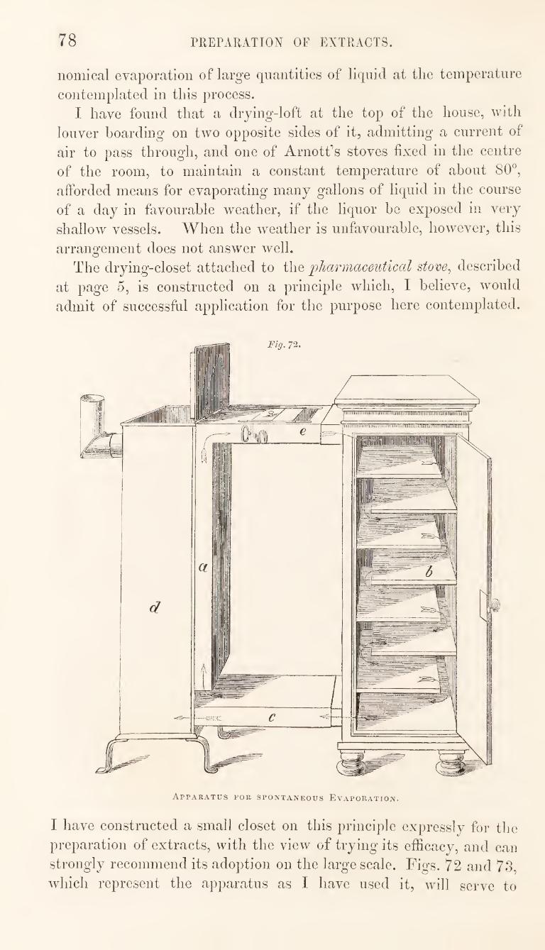
78 PREPARATION OF EXTRACTS.
nomical evaporation of large quantities of liquid at the temperature
contemplated in this process.
I have found that a drying-loft at the top of the house, with
louver boarding on two opposite sides of it, admitting a current of
air to pass through, and one of Arnott’s stoves fixed in the centre
of the room, to maintain a constant temperature of about 80^^,
afforded means for evaporating many gallons of liquid in the course
of a day in fiivourable weather, if the liquor be exposed in very
shallow vessels. When the weather is unfavourable, however, this
arrangement does not answer well.
The drying-closet attached to the pharmaceutical stove^ described
at page 5, is constructed on a principle which, I believe, would
admit of successful application for the purpose here contemplated.
Apparatus for spontaneous Evaporation.
I have constructed a small closet on this principle expres.sly for tlie
preparation of extracts, with the view of trying its efficacy, and can
strongly recommend its adoption on the large scale. Figs. 72 and 73,
which represent the apparatus as I have used it, will serve to
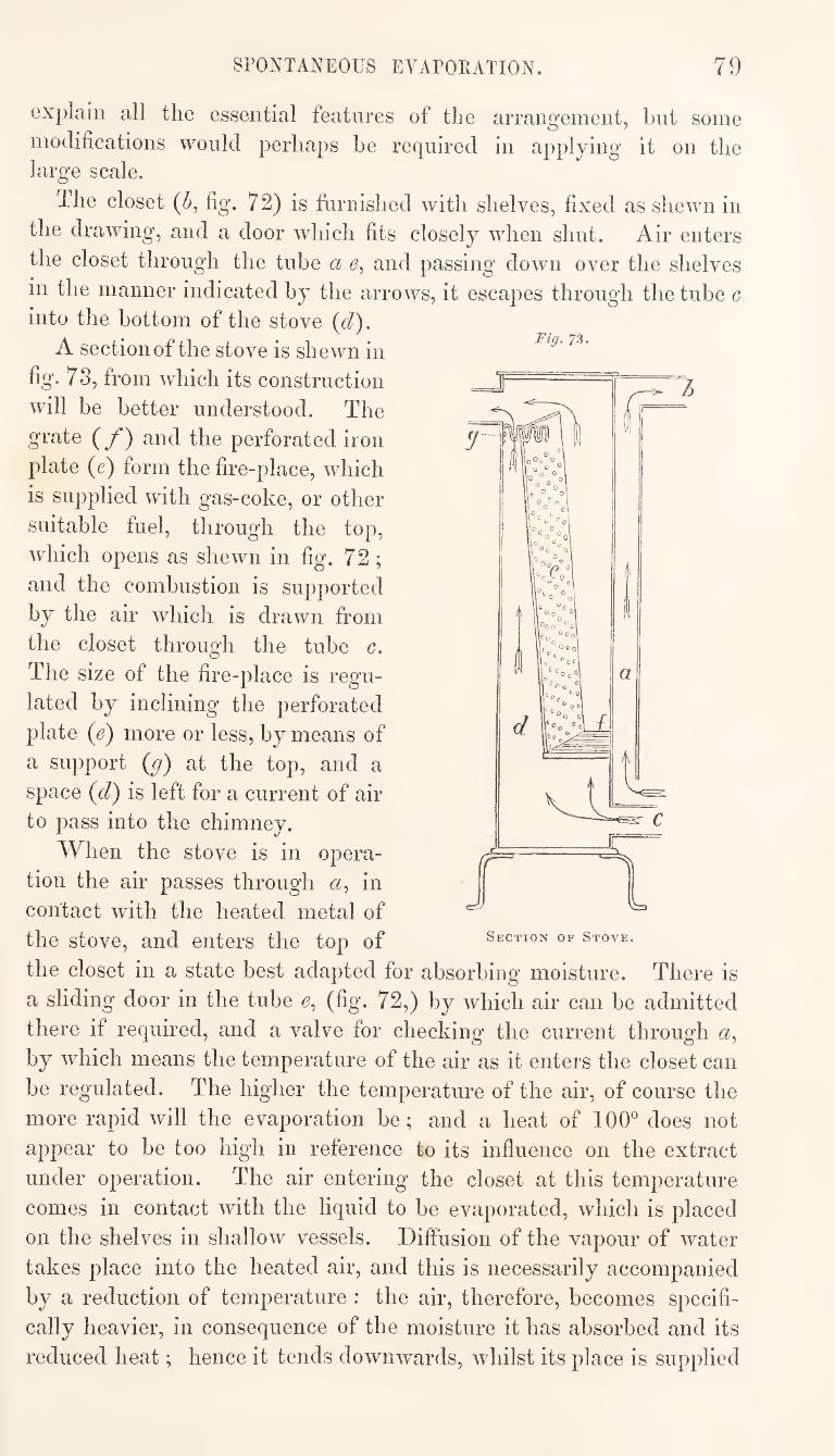
SPONTANEOUS EVAPORATION. 79
explain all the essential features of the arrangement, but some
modifications would perhaps be required in applying it on the large scale.
The closet (5, fig. 72) is furnished with shelves, fixed as shewn in
the drawing, and a door which fits closely when shut. Air enters
the closet through the tube a and passing down over the shelves
in the manner indicated by the arrows, it escapes through the tube c into the bottom of the stove {d).
A section of the stove is shewn in
fig. 73, from which its construction
will be better understood. The
grate (y*) and the perforated iron
plate (e) form the fire-place, which
is supplied with gas-coke, or other
suitable fuel, through the top,
which opens as shewn in fig. 72;
and the combustion is supported
by the air which is drawn from
the closet through the tube c.
The size of the fire-place is regu¬
lated by inclining the perforated
plate (e) more or less, by means of
a siqiport (g) at the top, and a
space (d) is left for a current of air
to pass into the chimney.
When the stove is in opera¬
tion the air passes through a, in
contact with the heated metal of
the stove, and enters the top of
the closet in a state best adapted for absorbing moisture. There is
a sliding door in the tube e, (fig. 72,) by which air can be admitted
there if required, and a valve for checking the current through a,
by which means the temperature of the air as it enters the closet can
be regulated. The higher the temperature of the air, of course the
more rapid will the evaporation be; and a heat of 100"^ does not
appear to be too high in reference to its influence on the extract
under operation. The air entering the closet at this temperature
comes in contact with the liquid to be evaporated, which is placed
on the shelves in shallow vessels. Diffusion of the vapour of water
takes place into the heated air, and this is necessarily accompanied
by a reduction of temperature : the air, therefore, becomes specifi¬
cally heavier, in consequence of the moisture it has absorbed and its
reduced heat; hence it tends downwards, whilst its place is supplied
Fig. 73.
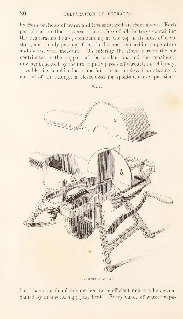
80 PREPARATION OF EXTRACTS.
by fresh particles of warm and less saturated air from above. Each
particle of air thus traverses the surface of all the trays containing
the evaporating liquid, commencing at the top in its most efficient
state, and finally passing off at the bottom reduced in temperature
and loaded with moisture. On entering the stove, part of the air
contributes to the support of the combustion, and the remainder,
now again heated by the fire, rapidly passes off through the chimney.
A blowing-machine has sometimes been employed for sending a
current of air through a closet used for spontaneous evaporation ;
Fig. 74.
Blowing Machine.
but I have not found this method to be efficient unless it be accom¬
panied by means for supplying heat. Every ounce of water evapo-
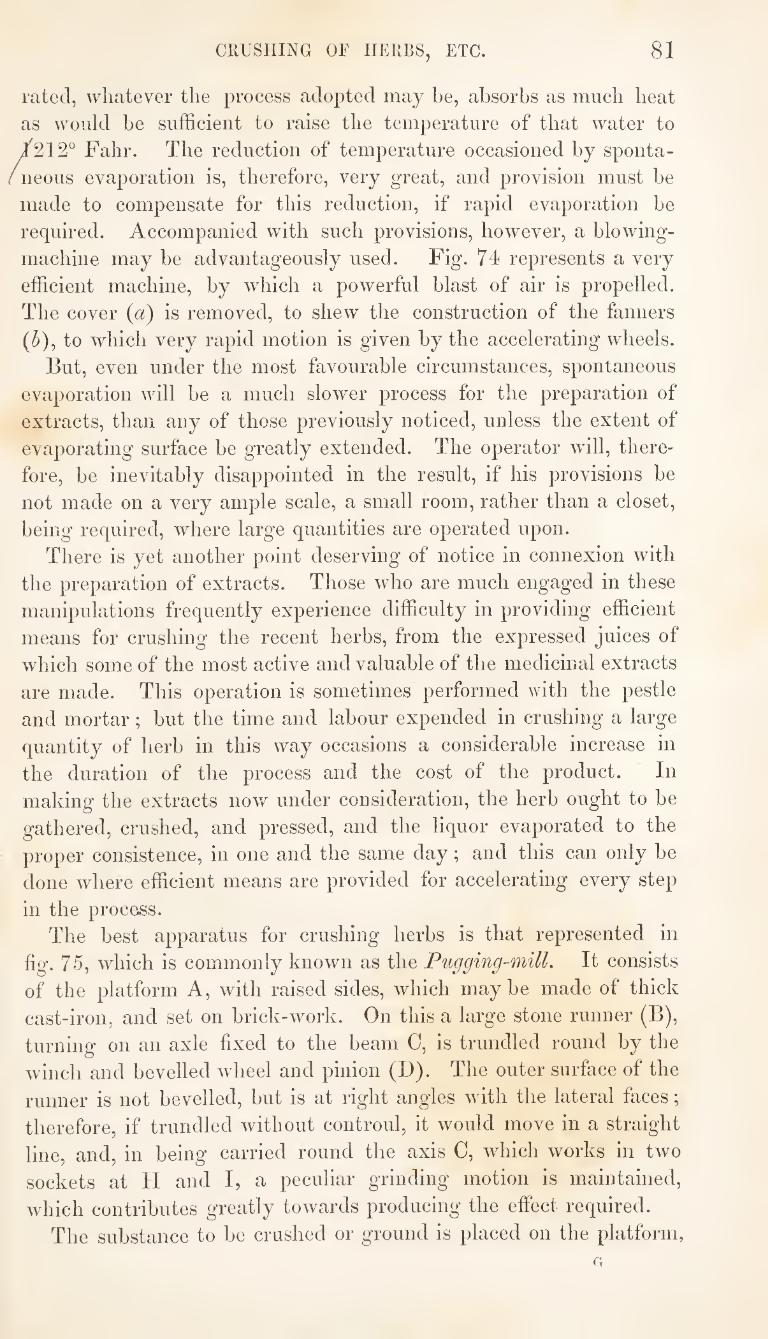
81 CRUSHING OF HERBS, ETC.
rated, whatever the process adopted may he, absorbs as much heat
as would be sufficient to raise the temperature of that water to
Fahr. The reduction of temperature occasioned by sponta¬
neous evaporation is, therefore, very great, and provision must be
made to compensate for this reduction, if rapid evaporation be
required. Accompanied with such provisions, however, a blowing-
machine may be advantageously used. Fig. 74 represents a very
efficient machine, by which a powerful blast of air is propelled.
The cover {a) is removed, to shew the construction of the fanners
(5), to which very rapid motion is given by the accelerating wheels.
But, even under the most favourable circumstances, spontaneous
evaporation will be a much slower process for the preparation of
extracts, than any of those previously noticed, unless the extent of
evaporating surface be greatly extended. The operator will, there-
fore, be inevitably disappointed in the result, if his provisions be
not made on a very ample scale, a small room, rather than a closet,
being required, where large quantities are operated upon.
There is yet another point deserving of notice in connexion with
the preparation of extracts. Those who are much engaged in these
manipulations frequently experience difficulty in providing efficient
means for crushing the recent herbs, from the expressed juices of
which some of the most active and valuable of the medicinal extracts
are made. This operation is sometimes performed with the pestle
and mortar; but the time and labour expended in crushing a large
quantity of herb in this way occasions a considerable increase in
the duration of the process and the cost of the product. In
making the extracts now under consideration, the herb ought to be
gathered, crushed, and pressed, and the liquor evaporated to the
proper consistence, in one and the same day; and this can only be
done where efficient means are provided for accelerating every step
in the process. The best apparatus for crushing herbs is that represented in
fig. 75, which is commonly known as the Pugging-mill. It consists
of the platform A, with raised sides, which may be made of thick
cast-iron, and set on brick-work. On this a large stone runner (B),
turning on an axle fixed to the beam 0, is trundled round by the
winch and bevelled wheel and pinion (D). The outer surface of the
runner is not bevelled, but is at right angles with the lateral faces;
therefore, if trundled without controul, it would move in a straight
line, and, in being carried round the axis C, which works in two
sockets at H and I, a peculiar grinding motion is maintained,
which contributes greatly towards producing the effect required.
The substance to be crushed or ground is placed on the platform, G
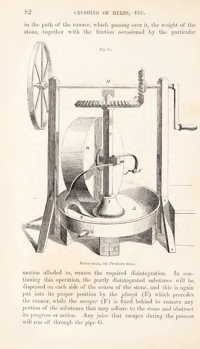
82 CRUSHING OF HERBS, ETC.
ill the path of the runner, which passing over it, the w^eight of the
stone, together with the friction occasioned by the particular
Drug-mill, or Pugging-mill.
motion alluded to, causes the required disintegration. In con¬
tinuing this operation, the partly disintegrated substance will be
dispersed on each side of the course of the stone, and this is again
put into its proper position by the plough (E) which precedes
the runner, while the scraper (F) is fixed behind to remove any
portion of the substance that may adhere to the stone and obstruct
its progress or action. Any juice that escapes during the process will run otf through the pipe G.
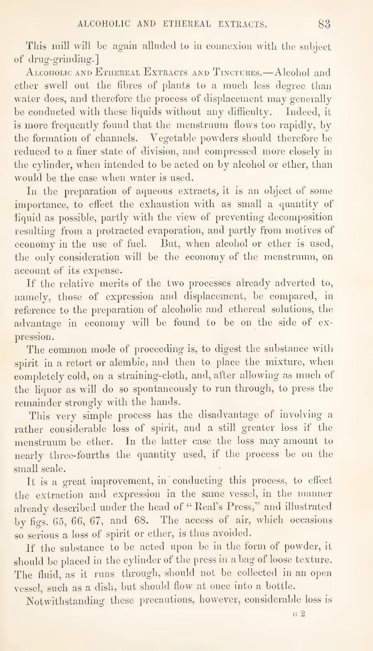
ALCOHOLIC AND ETHEREAL EXTRACTS. 83
This mill will be again alluded to in connexion with the subject
of drug-grinding.]
Alcoholic and Ethereal Extracts and Tinctures.—Alcohol and
ether swell out the fibres of plants to a much less degree than
water does, and therefore the process of displacement may generally
be conducted with these liquids without any difficulty. Indeed, it
is more frequently found that the menstruum flows too rapidly, by
the formation of channels. Vegetable powders should therefore be
reduced to a finer state of division, and compressed more closely in
the cylinder, when intended to be acted on by alcohol or ether, than
would be the case when water is used.
In the preparation of aqueous extracts, it is an object of some
importance, to effect the exhaustion with as small a quantity of
liquid as possible, partly with the view of preventing decomposition
resulting from a protracted evaporation, and partly from motives of
economy in the use of fuel. But, when alcohol or ether is used,
the only consideration will be the economy of the menstruum, on
account of its expense.
If the relative merits of the two processes already adverted to,
namely, those of expression and displacement, be compared, in
reference to the preparation of alcoholic and ethereal solutions, the
advantage in economy will be found to be on the side of ex¬
pression. The common mode of proceeding is, to digest the substance with
spirit in a retort or alembic, and then to place the mixture, when
completely cold, on a straining-cloth, and, after allowing as much of
the liquor as will do so spontaneously to run through, to press the
remainder strongly with the hands. This very simple process has the disadvantage of involving a
rather considerable loss of spirit, and a still greater loss if the
menstruum be ether. In the latter case the loss may amount to
nearly three-fourths the quantity used, if the process be on the
small scale. It is a great improvement, in * conducting this process, to effect
the extraction and expression in the same vessel, in the manner
already described under the head of “ ReaPs Press,’’ and illustrated
by figs. 65, 66, 67, and 68. The access of air, which occasions
so serious a loss of spirit or ether, is thus avoided.
If the substance to be acted upon be in the form of powder, it
should be placed in the cylinder of the press in a bag of loose texture.
The fluid, as it runs through, should not be collected in an open
vessel, such as a dish, but should flow at once into a bottle.
Notwithstanding these precautions, however, considerable loss is
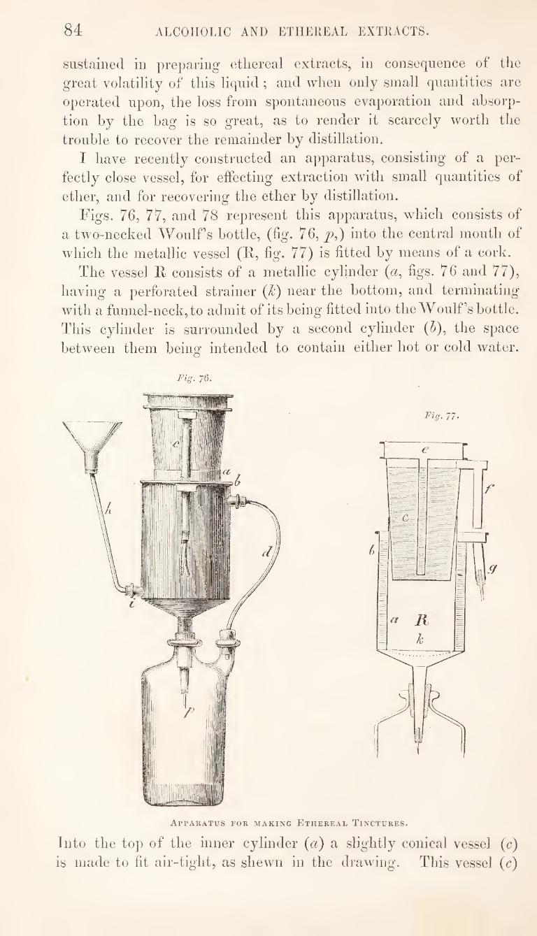
84 ALCOHOLIC AND ETHEREAL EXTRACTS.
sustained in preparing ethereal extracts, in consequence of the
great volatility of this liquid ; and when only small quantities are
operated upon, the loss from spontaneous evaporation and absorp¬
tion by the bag is so great, as to render it scarcely worth the
trouble to recover the remainder by distillation.
I have recently constructed an apparatus, consisting of a per¬
fectly close vessel, for etfecting extraction with small quantities of
ether, and for recovering the ether by distillation.
Figs. 76, 77, and 78 represent this apparatus, which consists of
a two-necked Woulfs bottle, (fig. 76, ^,) into the central mouth of
which the metallic vessel (F, fig. 77) is fitted by means of a cork.
The vessel F consists of a metallic cylinder (a, figs. 76 and 77),
having a perforated strainer (k) near the bottom, and terminating
with a funnel-neck, to admit of its being fitted into the Woulfs bottle.
This cylinder is surrounded by a second cylinder (5), the space
between them being intended to contain either hot or cold water.
Fig. 76.
Apparatus for making Ethereal Tinctures.
Into the top of the inner cylinder (a) a slightly conical vessel (c)
is made to fit air-tight, as shewn in the drawing. This vessel (c)
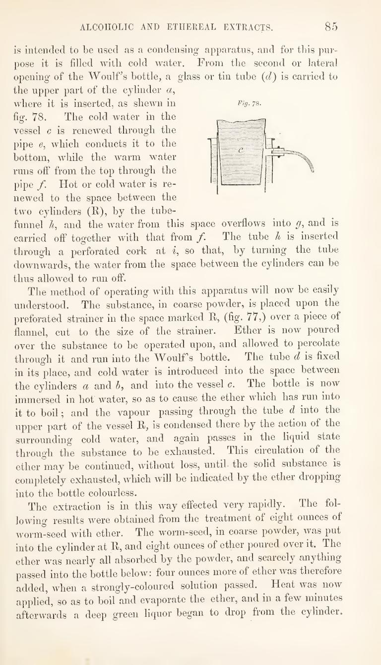
ALCOHOLIC AND ETHEREAL EXTRACTS. 85
is intended to be used as a condensing apparatus, and for tl)is pur¬
pose it is filled with cold water. From the second or lateral
opening of the WoulFs bottle, a glass or tin tube {d) is carried to
the upper part of the cylinder
where it is inserted, as shewn in
fig. 78. The cold water in the
vessel c is renewed through the
pipe 0, which conducts it to the
bottom, while the warm water
runs off from the top through the
pipe f. Hot or cold water is re¬
newed to the space between the
two cylinders (F), by the tube- funnel A, and the water from this space overflows into and is
carried off together with that from f. The tube h is inserted
through a perforated cork at so that, by turning the tube
downwards, the water from the space between the cylinders can be
thus allowed to run off. The method of operating with this apparatus will now be easily
understood. The substance, in coarse powder, is placed upon the
preforated strainer in the space marked R, (fig. 77,) over a piece of
flannel, cut to the size of the strainer. Ether is now poured
over the substance to be operated upon, and allowed to percolate
throug'h it and run into the WoulFs bottle. The tube d is fixed
in its place, and cold water is introduced into the space between
the cylinders a and h, and into the vessel c. The bottle is now
immersed in hot water, so as to cause the ether which has run into
it to boil; and the vapour passing through the tube d into the
upper part of the vessel R, is condensed there by the action of the
surrounding cold water, and again passes in the liquid state
through the substance to be exhausted. This circulation of the
ether may be continued, without loss, until, the solid substance is
completely exhausted, which will be indicated by the ether dropping
into the bottle colourless. The extraction is in this way effected very rapidly. The fol¬
lowing results w^ere obtained from the treatment of eight ounces of
worm-seed with ether. The worm-seed, in coarse powder, was put
into the cylinder at R, and eight ounces of ether poured over it. The
ether was nearly all absorbed by the powder, and scarcely anything
passed into the bottle below: four ounces more of ether was therefore
added, when a strongly-coloured solution passed. Heat was now
applied, so as to boil and evaporate the ether, and in a few minutes
afterwards a deep green liquor began to drop from the cylinder.
Fig. 78.
8G PREPARATION OF TINCTURES
As the lieat was continued and increased, the returning liquor
increased in quantity, so as to run in a stream, until the perfect ex¬
haustion of the worm-seed was indicated by the return of colour¬
less ether. The apparatus was now taken out of the warm water,
and allowed to cool. The cold water was in the next place
removed from the space between the cylinders a and 5, by turn¬
ing down the tube A, and the water was also emptied out of the
condenser (c). The tube d was removed, the neck of the bottle
into which this had been inserted being at the same time closed
with a cork ; while from the opening into the cylinder, where the
other end of the tube d had been inserted, a tube was fixed con¬
necting it with a Liebig’s condenser. Hot water was now poured
through the funnel and tube It into the space between the cylin¬
ders, which, heating and vaporising the ether with which the
powder was saturated, caused it to distil over through the con¬
denser. This being completed, the vessel R and its appendages
was removed from the Wonlf’s bottle, and a tube made to connect
the mouth of the bottle with the Liebig’s condenser ; when hot
water being again applied to the bottle, the ether distilled off, until
a syrupy liquor was left, which was finally evaporated to the con¬ sistence of butter in a porcelain dish.
The eight ounces of worm-seed was thus completely exhausted
in an hour and a half, with twelve ounces of ether, of which nine
ounces was again recovered by distillation, and the resulting extract
weighed ten drachms. With greater care in the condensation of the
ether, I think another ounce might have been recovered.
This apparatus may also be applied in the process of extraction
with spirit; but in this case it is necessary to apply more heat, by
using a solution of chloride of calcium or a sand-bath.
If the principle of this apparatus were carried out on the large
scale, and a metallic vessel employed instead of the glass bottle,
the exhaustion of sabadilla-seeds, and even of bark, for the pre¬
paration of the alkaloids, might, no doubt, be accomplished with the smallest possible loss of alcohol.
[In making Tinctures the principal objects to be aimed at are—
1. To effect the solution of those parts of the solid ingredients used which are intended to be administered.
2. To obtain transparent solutions, which, when made at dif¬ ferent periods, shall not vary in strength or composition.
o. To effect the above objects with the smallest possible loss of ingredients, or expenditure of time.
Three different processes have been adopted for the preparation of tinctures
BY MACERATION. 87
1. The process by maceration as directed in tlie London Phar¬
macopoeia. 2. The process by maceration as modified by Dr. Tiurton.
S. The process by percolation or displacement.
Preparation of Tinctures hy Maceration as directed in the London
Pharmacopoeia.—This is a very simple process : it consists in put¬
ting the solid and liquid ingredients, together, into a stoppered
glass vessel; allowing them to stand, generally for fourteen days,
frequently shaking them during this time ; and, lastly, straining off
the solution. This is the method which, formerly, was always
adopted for the preparation of tinctures. It has been thought,
however, to be subject to some objections, and hence the introduc¬
tion of other processes. When dry solid ingredients, either animal
or vegetable, are macerated in spirit or other similar menstrua,
as is the case in this process, the liquid immediately in contact
wdth the solid matter at the bottom of the macerating vessel forms
a saturated solution, which, being more dense than the liquid above
it, prevents the contact and solvent action of the latter. It is on
this account that the vessel is directed to be frequently shaken
during the maceration; but when large vessels are employed, agita¬
tion is not easily effected, and, under any circumstances, the repe¬
tition of this very necessary part of the process is liable to be
neglected. Preparation of Tinctures hy Maceration as modified hy Dr.
Burton.—This process has been proposed with the view of obviating
the objections which apply to the process of maceration as usually
conducted. It differs from the preceding in the adoption of an
arrangement for suspending the solid ingredients near the top of
the liquid, instead of allowing them to subside to the bottom. This
is effected, either by having a perforated diaphragm midway
between the top and bottom of the macerating vessel, on which the
ingredients are put, or by. enclosing the ingredients in a bag and
suspending this bag by a string. The advantages of this method of conducting the process as com¬
pared with the other are, that there is no necessity for shaking the
vessel, and that the exhaustion of the ingredients is effected in a
shorter time. The process is automatic : when the spirit begins to
act on the solid, a coloured tincture will be seen to gravitate
through the colourless and lighter spirit by which it is surrounded,
the latter, at the same time, ascending and coming into contact
with the solid matter. A descending and ascending current is
thus established throughout the fluid, and continues until no more
soluble matter is extracted.
88 PREPARATION OF TINCTURES
This process is founded on the same principle as Mr. A]sop\s method of making infusions, and a vessel, somewhat similar in con¬ struction to the infusion-])ot described at page 39, might he used for effecting the maceration in the way proposed. It would be necessary, however, to have means for preventing evaporation of the spirit during the process, and this with a cylindrical vessel the mouth of which is not contracted involves some difficulty, and con¬ stitutes probably the greatest impediment to the general adoption of the process.
In making tinctures by maceration, according to either of the foregoing processes, it is important to attend uniformly to the in¬ structions given, with regard to the time during which the ingre¬ dients are allowed to macerate. It is, however, sometimes difficult strictly to observe these instructions, especially where small quan¬ tities only are made at a time.
dhe number of tinctures employed in medicine is so great, and their consumption necessarily so unequal, that scarcely a week will elapse without its being found necessary to commence the prepara¬ tion of some of them. There will, generally, therefore, be several tinctures macerating at the same time, which have been com¬ menced at different periods, and it is difficult to recollect or attend to the precise time when the maceration in each case ought to ter¬ minate. The consequence of this is, that tinctures are often mace¬ rated for a much longer time than the Pharmacopoeia directs. This is a common source of error in operating by this process, for the characters and properties of a tincture which has been allowed to remain for a long time in contact with the solid ingredients will often be found to differ considerably from what they would have been if the process had been terminated earlier.
Again : it often happens that the necessity for commencing the preparation of a tincture is only discovered when the stock on hand is nearly or entirely exhausted, and the tincture may perhaps be wanted for use before the maceration has continued for the proper length of time, so that there is a strong temptation to use it in its unfinished state. This is another evil resulting from the length of time occupied in the process of maceration. Moreover, when small quantities of tincture are made at a time, it is difficult to press the dregs completely, so as to avoid considerable loss of the product from this cause. Hence, many persons allow the dregs to accumu¬ late in the macerating-vessel, making several fresh portions of tinc¬ ture in contact with the dregs of previous preparations, until enough has accumulated to admit of their being efficiently pressed. This method of operating is subject, in an increased degree, to the objec-
BY PERCOLATION OR DISPLACEMENT. 89
tlon which has already been urged against the prolongation of the
process of maceration beyond the specified time. Thus the process
for the preparation of tinctures by maceration is subject to some
practical objections or difficulties. These are frequently expe¬
rienced, and it was at one time thought that an easy means of
obviating them had been discovered in the adoption of the process
next to be described. Preparation of Tinctures hy the process of Percolation or Dis¬
placement.—This process is of comparatively recent introduction as
a means of preparing medicines, although it has long been employed
in the arts. It is sometimes called lixiviation., and under this desig¬
nation it is especially applied to the solution of certain salts, as, for
instance, in the preparation of soap-makers’ ley. It is, of course,
merely employed m those cases where only a part of the solid in¬
gredients to which a liquid is added are soluble. In making caustic leys for the soap-maker, it is important to
recover all the alkali in solution from the mixture of lime and pot¬
ash or soda, without using an undue quantity of water. This is
done by allowing the solution first formed to run off from the solid
residue, so much only remaining as is absorbed by the mass of
moist carbonate of lime. This latter portion of solution is next
removed by pouring some water over the surface of the wet mass,
and allowing the liquid to run off through an opening at the bottom
of the vessel in which the process is conducted. Under these cir¬
cumstances the alkaline solution is displaced by the pressure of the
column of water above it, and this displacement may be effected
without any appreciable admixture of the two liquids, so that the
whole of the alkaline solution is obtained without its being diluted
to any sensible extent. The same process is applied in a somewhat similar manner in
brewing, with the view of obtaining as large a proportion as pos¬
sible of saccharine matter from the grain in a concentrated state ;
and in this case the process is sometimes called sparging. In
both the above instances water is used as the menstruum, and the
process is usually conducted continuously with repeated quantities
of fresh ingredients under circumstances which greatly favour its
successful application. The results have proved satisfactory.
In making tinctures by this process spirit is used as the men¬
struum, and the circumstances under which the process is conducted
are less favourable, than m the other cases mentioned, to its com¬
plete success. The results, therefore, have proved but partially
satisfactory. There are some cases, however, in which displacement
may be advantageously applied in the preparation of tinctures , it
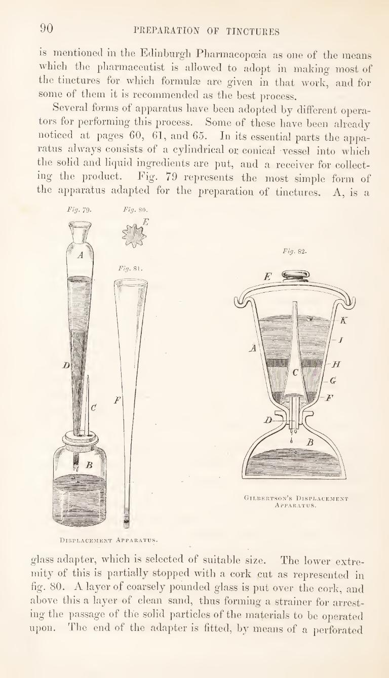
90 PREPARATION OF TINCTURES
is mentioned in the Edinburgli Pharmacopoeia as one of the means
which the pharmaceutist is allowed to adopt in making most of
the tinctures for which formula} are given in that work, and for
some of them it is recommended as the best process.
Several forms of apparatus have been adopted by different opera¬
tors for performing this process. Some of these have been already
noticed at pages 60, 61, and 65. In its essential parts the appa¬
ratus always consists of a cylindrical or conical vessel into which
the solid and liquid ingredients are put, and a receiver for collect¬
ing the product. Fig- 79 represents the most simple form of
the apparatus adapted for the j^reparation of tinctures. A, is a
Fig. 79. Fig. 80.
Displacemekt Apparatus.
glass adapter, which is selected of suitable size. The lower extre¬
mity of this is partially stopped with a cork cut as represented in
fig. 80. A layer of coarsely pounded glass is put over the cork, and
above this a layer of clean sand, thus forming a strainer for arrest¬
ing the passage of the solid particles of the materials to be operated
upon. The end of the adapter is fitted, by means of a perforated
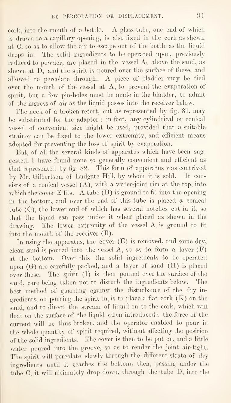
BY PERCOLATION OR DISPLACEMENT. 91
cork, into the mouth of a bottle. A glass tube, one end of which
is drawn to a capillary opening, is also fixed in the cork as shewn
at 0, so as to allow the air to escape out of the bottle as the liquid
drops in. The solid ingredients to be operated upon, previously
reduced to powder, are placed in the vessel A, above the sand, as
shewn at D, and the spirit is poured over the surface of these, and
allowed to percolate through. A piece of bladder may be tied
over the mouth of the vessel at A, to prevent the evaporation of
spirit, but a few pin-holes must be made in the bladder, to admit
of the ingress of air as the liquid passes into the receiver below.
The neck of a broken retort, cut as represented by fig. 81, may
be substituted for the adapter ; in fact, any cylindrical or conical
vessel of convenient size might be used, provided that a suitable
strainer can be fixed to the lower extremity, and efficient means
adopted for preventing the loss of spirit by evaporation.
But, of all the several kinds of apparatus which have been sug¬
gested, I have found none so generally convenient and efficient as
that represented by fig. 82. This form of apparatus was contrived
by Mr. Gilbertson, of Ludgate Hill, by whom it is sold. It con¬
sists of a conical vessel (A), wfith a water-joint rim at the top, into
which the cover E fits. A tube (D) is ground to fit into the opening
in the bottom, and over the end of this tube is placed a conical
tube (C), the lower end of which has several notches cut in it, so
that the liquid can pass under it when placed as shewn in the
drawing. The lower extremity of the vessel A is ground to fit
into the mouth of the receiver (B).
In using the apparatus, the cover (E) is removed, and some dry,
clean sand is poured into the vessel A, so as to form a layer (F)
at the bottom. Over this the solid ingredients to be operated
upon (G) are carefully packed, and a layer of sand (H) is placed
over these. The spirit (I) is then poured over the surface of the
sand, care being taken not to disturb the ingredients below. The
best method of guarding against the disturbance of the dry in¬
gredients, on pouring the spirit in, is to place a flat cork (K) on the
sand, and to direct the stream of liquid on to the cork, which will
float on the surface of the liquid when introduced ; the force of the
current will be thus broken, and the operator enabled to pour in
the whole quantity of spirit required, without affecting the position
of the solid ingredients. The cover is then to be put on, and a little
water poured into the groove, so as to render the joint air-tight.
The spirit will percolate slowly through the different strata of dry
ingredients until it reaches the bottom, then, passing under the
tube C, it will ultimately drop down, through the tube D, into the
92 PREPARATION OF TINCTURES
receiver, while, a,t the same time, an equal volume of air passes up
through the tubes to supply its place in the upper vessel, and
equalise the pressure. Thus arranged, the apparatus is perfectly
air-tight, so that no loss from evaporation can occur, however long
the process may be in operation. The form and size of the
apparatus, also, are such as to admit of the solid ingredients being
properly packed in the vessel A, upon the skilful performance of
which the success of the process principally depends. In most
cases it is desirable to use these ingredients in fine powder, and, in
some instances, they may be advantageously mixed with coarse
sand, which, by separating the particles, will facilitate the percola¬
tion of the liquid. If the ingredients be properly packed, the spirit,
when first added, will be slowly absorbed by the powder, and will
descend equally on every side, forming a line round the circum¬
ference of the vessel, which will gradually pass downwards until
the tincture begins to flow through the tube D. Some experience
and judgment are required in regulating the degree of pressure to be
applied in packing the powders, or, if necessary, mixing them with
sand, so as to ensure a regular and continued percolation ; and, as
differences in the nature of the substances operated upon, the
degree of comminution to which they have been subjected, and the
form and size of the apparatus employed, so far influence the results
as to occasion the necessity for some modifications in the method of
operating, no precise instructions can be given that would be appli¬
cable to all cases.
The process answers remarkably well for extracting the whole of
the soluble matter from ginger, Cayenne pepper, cantharides, ipeca¬
cuanha, and other substances, from which occasionally concentrated
tinctures are required to be made. There is probably no case in
which the result is more satisfactory than in the preparation of
Essence of ginger. The ginger should be used in fine powder ; in¬
deed, in all cases in which substances such as those above named
are operated upon, I consider it essential to the complete success of
the process that they should be in a state of minute division. The
powder being introduced into the displacement apparatus, and care¬
fully packed with a slight pressure, so that there shall be no open
spaces or channels through which the liquid can pass more freely
than through other parts, the layer of sand is placed over the sur¬
face of it, and, by means of the cork float, a portion of spirit, rather
more than equal in weight to the ginger used, is introduced. The ab¬
sorption of the spirit will immediately commence, and if the line indi¬
cating the division between the part of the powder which is wetted
by the spirit and that which remains dry form a pretty uniform circle
BY PERCOLATION OR DISPLACEMENT. 93
round the cylinder, and progress downward nninterrnptedly as the
absorption proceeds; and, further, if this descent of the spirit
through the ginger take place at the rate of about an inch in five
minutes, it may he inferred that the powder has been well packed,
and equally compressed in all parts. The quantity of spirit men¬
tioned will be just that which the ginger and the sand will be
capable of absorbing, without any, or more than a few drops,
passing into the receiver. When the absorption is finished, the
apparatus should be allowed to stand without further addition of
spirit for an hour or two, so that complete penetration of the
particles of ginger, and solution of all the soluble parts, by the
spirit, may take place. At the conclusion of this maceration, the
displacement of the tincture is to be effected, by carefully pouring
another portion of spirit, equal to that previously absorbed by the
solid ingredients, into the upper part of the cylinder, using the
cork float as before, so as to prevent any disturbance of the moist
ingredients below. The liquid, which was previously retained in
contact with the particles of solid matter by the force of capillary
attraction, is now forced downwards by the pressure of the column
of liquid above; it will begin, therefore, to flow through the tube
D, into the receiver B, and, if all the conditions mentioned have
been properly observed, this displacement of the saturated tinc¬
ture by the superincumbent spirit wdll take place without the
occurrence of more than a very slight admixture of the two
liquids. The progress of this part of the process will be indicated
by a line shewing where the two liquids join, the liquid above this
line being nearly pure spirit, while that below it is a dark-coloured
tincture. When this line has reached the bottom of the cylinder,
the tincture formed by the solvent action of the first portion of
spirit on the ginger will have been displaced, as completely as the
process will admit. It will be found, however, that the displace¬
ment is not perfect, and this arises principally from the circum¬
stance that the particles of which the powdered ginger is com¬
posed are porous. The spirit first added fills the pores of each
joarticle, as well as the interstices between the different particles;
but, as the former are smaller and more confined than the latter,
the second portion of. spirit, or displacing column, passes more
freely through the interstices than through the minute pores of
the particles; and, therefore, while the tincture filling the inter¬
stices is completely, that contained in the pores is but partially
displaced. It will be observed, on close examination, during the
process, that the line of demarcation between the two columns of
liquid, to which allusion has already been made, becomes some-
94 rilEPARATION OF TINCTURES
what less defined and distinct as it approaches the bottom of the
cylinder, a shading in the upper column being perceptible, which
is occasioned by the diffusion and accumulation of the contents of
the minute pores in the displacing liquid. Thus, a part of the
tincture first formed will be mixed with the second portion of
spirit added, or that used for the purpose of displacement, until
the minutest pores have at length been emptied of their original
contents. In order to recover the whole of the soluble matter,
therefore, it will be necessary to displace at least a part of the
second portion of spirit; but the tincture thus procured will be much weaker than the preceding.
In operating in this way, nearly the whole of the active and
soluble constituents of the ginger are obtained in solution in the
first portion of tincture displaced, and, by continuing the jirocess
until a quantity of tincture rather less than double the weight of
the ginger has passed into the receiver, the solid residue will be
so completely exhausted as not to retain the slightest taste or smell.
But although a very concentrated solution is thus obtained, and
the whole of the soluble matter is recovered, the process would
not be an economical one if the spirit used for displacing the tinc¬
ture were not recoverable. The displacement of this spirit by
means of water is, therefore, the next step in the process. This
is done by pouring water over the surface of the solid residue, in
the same manner as the spirit was previously added. Pure spirit
will in the first instance flow into the receiver as the column of
water descends; but long before the whole of the spirit present has
been thus recovered, it will be found to have an admixture of
water with it, which will progressively increase in quantity. In
fact, the displacement of spirit by water is less complete than that
of a tincture by spirit. In the latter case, as already stated, the
porosity of the solid ingredients presents the principal impediment
to the attainment of a perfect result; but in the former case, in
addition to this, there are two other causes of obstruction. These
are, first, the tendency to combination which exists between spirit
and water; and, secondly, the tendency to change places, which
the water and spirit will have under the circumstances of their
position, in consequence of the greater specific gravity of the
former. The whole of the spirit may, however, be recovered,
partly in its original state of concentration, and partly diluted to a
greater or less extent with water. This unavoidable dilution of
the spirit during its recovery is a great defect in the process of dis¬
placement, for it generally happens that the recovered spirit is too
much contaminated by the solid ingredients to admit of its being
BY PEIICOLATION OR DISPLACEMENT. 95
used for other purposes without being purified by distillation, and
in its diluted state it cannot even be employed in repeating the
process for the same tincture. The preparation of Essence of Ginger, in the manner here de¬
scribed, affords a good illustration of the application of the process
of displacement under favourable circumstances. The substance
acted on may be used, as it ought to be, in the state of fine
powder; this powder readily gives up the whole of its soluble
constituents to spirit; when moistened with spirit, it forms a mass
through which percolation takes place with facility; and the ex¬
traction of the soluble parts does not cause much contraction of the
volume of the solid matter. In cases where these conditions are
not so well fulfilled, the application of the process will be less satis¬
factory, or some modifications of the process will be required. If
the substance to be acted upon cannot be used in the state of fine
powder, the interstices between the particles will necessarily be
larger and more unequal, the pores and vessels contained within the
particles will be more closed and confined, and the disparity
between the size of the interstices and that of the pores and vessels
will be greater; so that the liquid once absorbed into these pores
and vessels will be removed with greater difficulty, while that
occupying the interstices will flow with increased facility. If the
soluble constituents are not easily extracted by the solvent em¬
ployed, as is the case in treating ergot of rye with spirit, perfect
exhaustion of the solid ingredients may not be effected in the time
usually occupied by this process.
If the solid ingredients, when moistened with spirit, form a
tenacious mass, the liquid will sometimes not percolate through this,
or will percolate very slowly, so that it becomes necessary to mix
the ingredients with coarse sand or pounded glass, to separate the
particles and facilitate percolation.
Moreover, if the extraction of the soluble parts causes much
contraction of the volume of the solid matter, it will be difficult, if
not impossible, to prevent the formation of fissures through which
the percolating liquid will almost exclusively run. In this case, an
admixture of sand will lessen the evil.
The process, however, modified according to circumstances, may
be applied, with greater or less advantage, in the preparation of
most of the tinctures used in medicine, as stated by the authors of
the “ Edinburgh Pharmacopoeia.”
In reviewing the several advantages and disadvantages which
attach respectively to the two processes which are recognised in the
Pritish Pharmacopoeias, namely, the process of maceration, and the
tid: press. 9G
process of displacement^ it would appear, on the one hand, that the
objections to the process of maceration apply more strongly to its
adoption on the small, than on the large scale ; and, on the other
hand, that the process of displacement is less applicable to opera¬
tions on the large, than on the small scale.
When tinctures are made in large quantities, percolation is never
likely to supersede maceration, on account of any practical advan¬
tages it may possess. If the prescribed directions be duly attended
to, the process of maceration is unexceptionable. This process is
more simple than the other ; the mode of operating is more uni¬
form,—it is, in fact, always the same ; it requires less of skill and
dexterity in conducting it; it requires less constant attention during
its progress, which, in operating on large quantities, is a considera¬
tion ; and, finally, the apparatus required is less complicated.
When only small quantities of tincture are made at a time, and
kept in stock, the adoption of the process of displacement will often
he found convenient and advantageous. It offers the means of
making a tincture in two or three hours, which by the other process
would require as many weeks. The process being thus completed
in so short a time, for the quantity contemplated might be made at
one operation, it would not be so likely as the other to experience
neglect during the performance of it, or a deviation from the pre¬
scribed instructions ; the product would therefore he more uniform.
Finally, in many cases, the tincture and spirit may be removed
from the dregs more completely, in operating on small quantities,
by this process, than by the other. ■ Even in those establishments where tinctures are generally made
by maceration, the process of displacement will he found useful as a
resort in cases of emergency, and for the preparation of some
particular tinctures.]
THE PRESS.
The press is used in pharmaceutical laboratories for effecting the
separation of liquids from solids, where much force is required.
In the use of this instrument, the power of the human arm is
increased, by mechanical means, at the expense of time and space.
The screw and the lever are generally applied for this purpose.
Bramalfs hydraulic press is but rarely used in the laboratory,
the circumstances under which it would have to be employed being
such as to cause frequent derangements of its complicated structure,
and these derangements requiring the assistance of a class of
mechanists who are not to be met with in every locality.
THE PRESS. 97
The screw-press, being less complicated than Bramah's, is not
so liable to accidents. Consisting only of solid parts, it is less
affected by being left unused for some time. Its construction is
simple and easily comprehended by any person, and the repairs
which it may require can be executed by the common mechanists in wood and iron.
There are two kinds of screw-press,—one having a single screw,
and the other two screws. The screw in the former is vertical,
effecting a downward pressure on the bag, which is placed horizon¬
tally. In the latter the screw acts horizontally, while the bag is
placed in a vertical position.
Opinions are divided as to the relative advantages of these two
kinds of jwess. There is no doubt that the single-screw-press,
as commonly constructed, is inferior to the double-screw-press;
but I think I shall be able to shew that the former may, by an
improved construction, be rendered quite as useful and compact as the latter.
The following are the objections which principally apply to the
single-screw-press as usually constructed :—
1. The press-block attached to the screw frequently loses its
hoirzontal position, being turned to one side in consequence of some
defect in filling or placing the bag, so that it becomes necessary
in the middle of an operation to unscrew the press and re-arrange
the bag. If this be neglected, the press-block wdll come in contact
with the sides of the box, thus causing violent friction and partial
resistance ; the screw itself is also liable to be injured from its
being forced out of the perpendicular.
2. The expressed liquid does not run off freely from a press-box
placed horizontally. If the press be so arranged that it may be
tilted, it would be necessary that the means by which it is fixed
to the wall should be moveable ; and, as the press cannot be used
while in the tilted position, much trouble would be involved in
thus repeatedly moving the press every time it is used.
S. The use of this kind of press is not free from some danger.
The entire force of the lever is directed horizontally, and is sus-
tamed by the fastening of the press to the wall. If the application
of much force should cause the fastening to give way, or the lever
to break, the operator may suffer serious injury; and damage in
other respects would necessarily be incurred. Accidents from this
cause are not unfrequent.
4. With this press the male screw alone moves, while the female
screw or nut remains stationary. Under these circumstances the
screw suffers a severe torsion, as the tangential impulse received
H
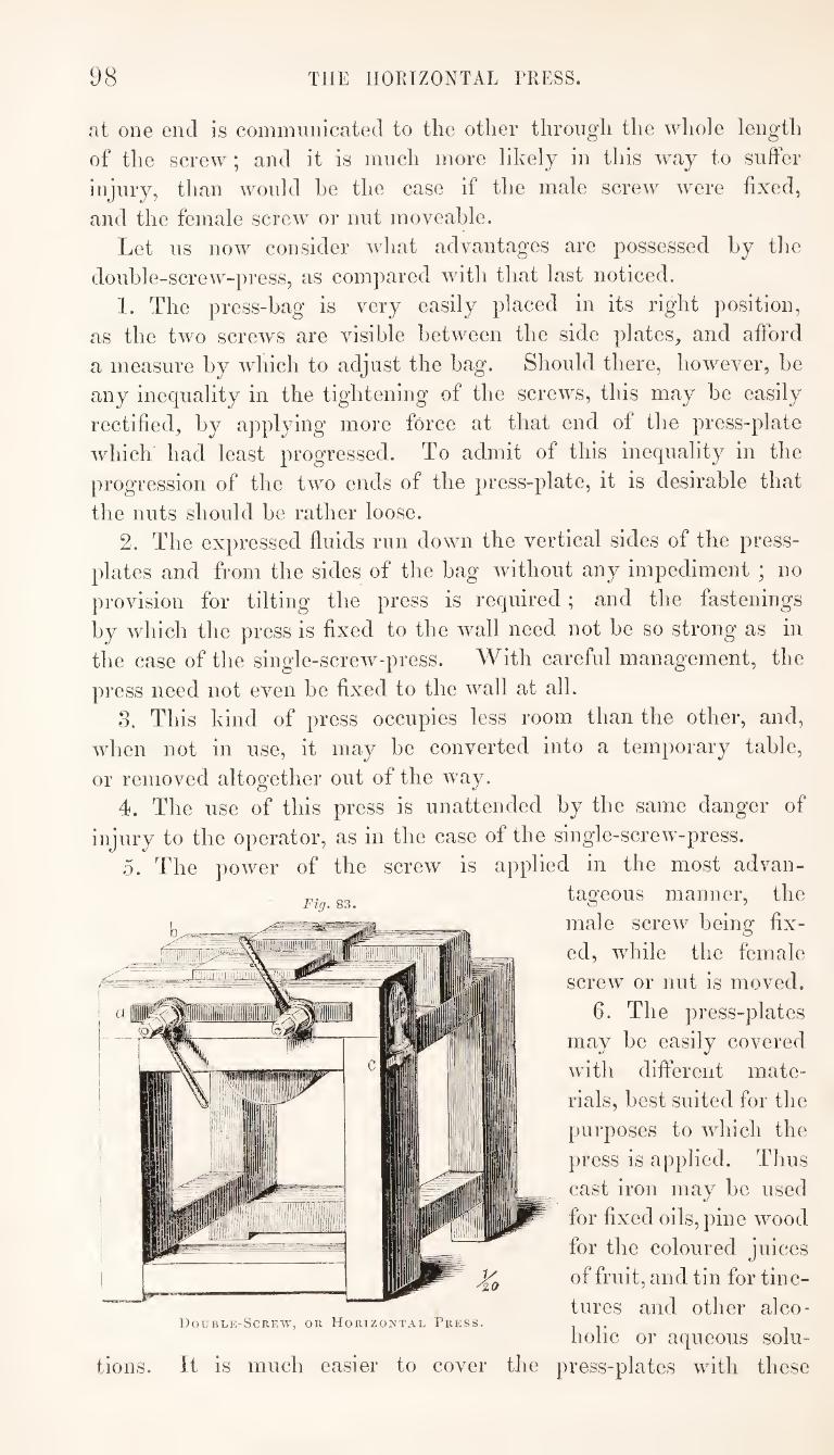
98 THE HORIZONTAL PRESS.
at one end Is commnnicated to tlie other through the whole length
of the screw ; and it is much more likely in this way to suffer
injury, than would he the case if the male screw were fixed,
and the female screw or nut moveable.
Let ns now consider what advantages are possessed by the
double-screw-press, as compared with that last noticed.
1. The press-bag is very easily placed in its right position,
as the two screws are visible between the side plates, and afford
a measure by which to adjust the bag. Should there, however, he
any inequality in the tightening of the screws, this may be easily
rectified, by applying more force at that end of the press-plate
which had least progressed. To admit of this inequality in the
progression of the two ends of the press-plate, it is desirable that
the nuts should be rather loose.
2. The expressed fluids run down the vertical sides of the press-
plates and from the sides of the bag without any impediment ; no
provision for tilting the press is required; and the fastenings
by which the press is fixed to the wall need not be so strong as in
the case of the single-screw-press. With careful management, the
press need not even be fixed to the wall at all.
3. This kind of press occupies less room than the other, and,
when not in use, it may be converted into a temporary table,
or removed altogether out of the way.
4. The use of this press is unattended by the same danger of
injury to the operator, as in the case of the single-screw-press.
5. The power of the screw is applied in the most advan¬
tageous manner, the
male screw being fix¬
ed, while the female
screw or nut is moved.
6. The press-plates
may be easily covered
with different mate¬
rials, best suited for the
purposes to wdiich the
press is applied. Thus
cast iron may be used
for fixed oils, pine wood
for the coloured juices
of fruit, and tin for tinc¬
tures and other alco- Double-Screw, or Horizontal Press. it
holic or aqueous solu¬
tions. It is much easier to cover the press-plates with these
Fig. 83.
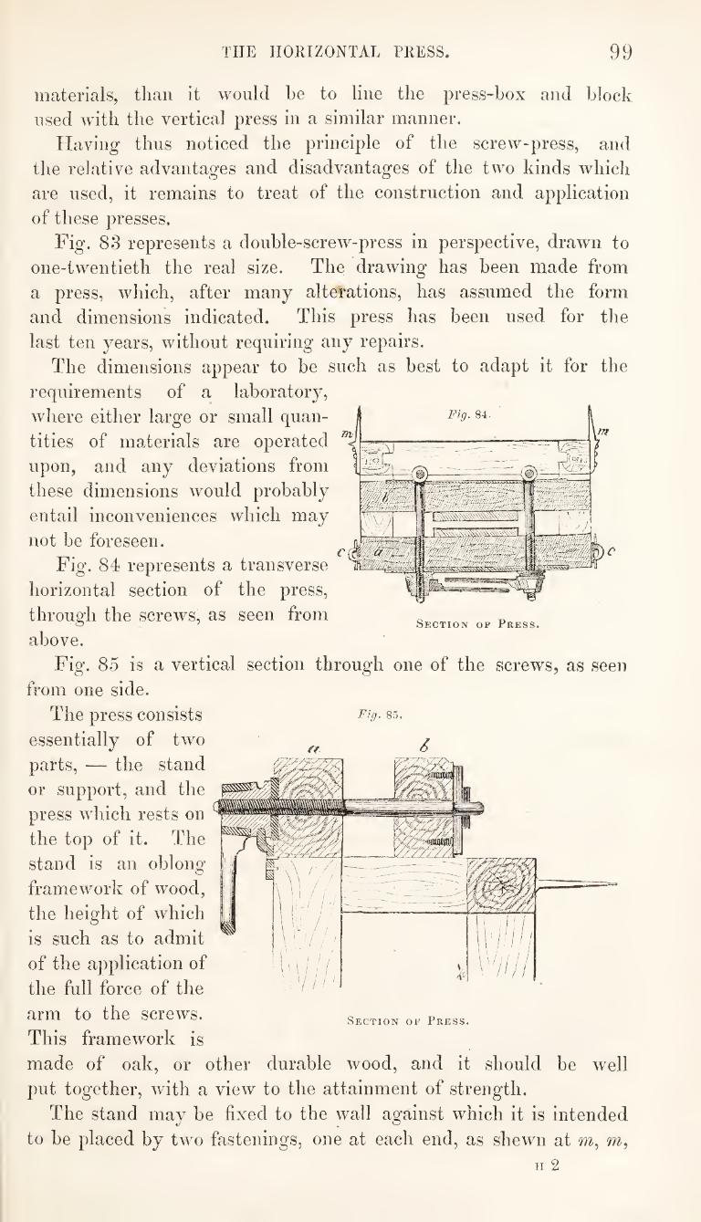
THE HORIZONTAL PRESS. 99
materials, than it would be to line the press-box and block
used with the vertical press in a similar manner.
Having thus noticed the principle of the screw-press, and
the relative advantages and disadvantages of the two kinds which
are used, it remains to treat of the construction and application
of these presses.
Fig. 83 represents a double-screw-press in perspective, drawn to
one-twentieth the real size. The drawing has been made from
a press, which, after many alterations, has assumed the form
and dimensions indicated. This press has been used for the
last ten years, without requiring any repairs.
The dimensions appear to be such as best to adapt it for the
requirements of a laboratory,
where either large or small quan¬
tities of materials are operated
upon, and any deviations from
these dimensions would probably
entail inconveniences which may
not he foreseen.
Fig. 84 represents a transverse
horizontal section of the press,
through the screws, as seen from
above.
Fig. 85 is a vertical section through one of the screws, as seen
from one side.
The press consists F^g- §5.
essentially of two g
parts, — the stand
or support, and the
press which rests on
the top of it. The
stand is an oblong
framework of wood,
the height of which
is such as to admit
of the application of
the full force of the
arm to the screws.
This framework is
made of oak, or other durable wood, and it should be well
put together, with a view to the attainment of strength.
The stand may be fixed to the wall against which it is intended
to be placed by two fastenings, one at each end, as shewn at m.
Section of Press.
Section of Press.
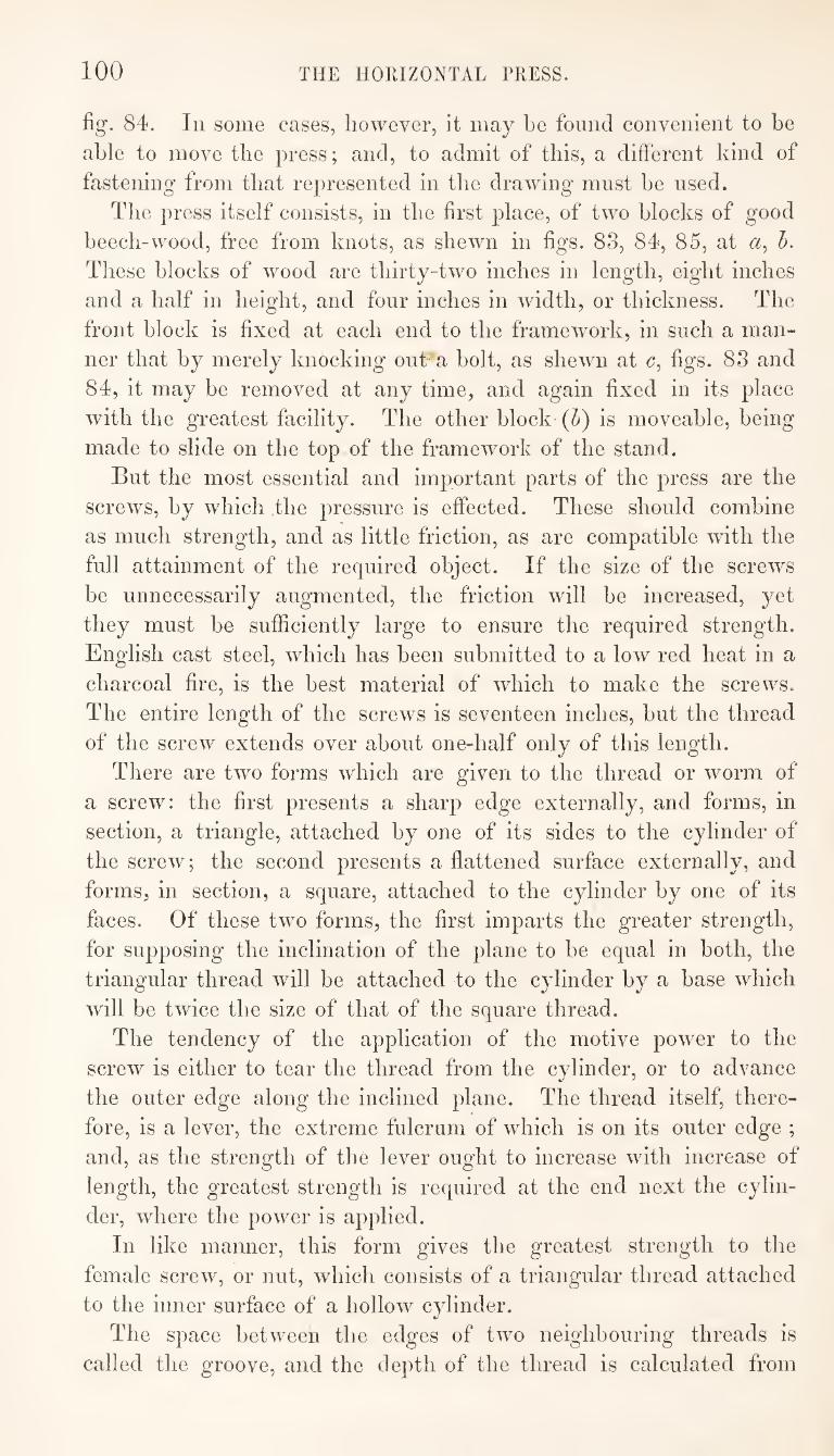
100 THE HORIZONTAL PRESS.
fig. 84. In some cases, however, it may be found convenient to be
able to move the press; and, to admit of this, a different kind of
fastening from that represented in the drawing must be used.
The press itself consists, in the first place, of two blocks of good
beech-wood, free from knots, as shewn in figs. 83, 84, 85, at h.
These blocks of wood are thirty-two inches in length, eight inches
and a half in height, and four inches in width, or thickness. The
front block is fixed at each end to the framework, in such a man¬
ner that by merely knocking out a holt, as shewn at c, figs. 83 and
84, it may be removed at any time, and again fixed in its place
with the greatest facility. The other block (b) is moveable, being
made to slide on the top of the framework of the stand.
But the most essential and important parts of the press are the
screws, by which the pressure is effected. These should combine
as much strength, and as little friction, as are compatible with the
full attainment of the required object. If the size of the screws
be unnecessarily augmented, the friction will be increased, yet
they must be sufficiently large to ensure the required strength.
English cast steel, which has been submitted to a low red heat in a
charcoal fire, is the best material of which to make the screws.
The entire length of the screws is seventeen inches, but the thread
of the screw extends over about one-half only of this length.
There are two forms which are given to the thread or worm of
a screw: the first presents a sharp edge externally, and forms, in
section, a triangle, attached by one of its sides to the cylinder of
the screw; the second presents a flattened surface externally, and
forms, in section, a square, attached to the cylinder by one of its
faces. Of these two forms, the first imparts the greater strength,
for supposing the inclination of the plane to be equal in both, the
triangular thread will be attached to the cylinder by a base which
will be twice the size of that of the square thread.
The tendency of the application of the motive power to the
screw is either to tear the thread from the cylinder, or to advance
the outer edge along the inclined plane. The thread itself, there¬
fore, is a lever, the extreme fulcrum of which is on its outer edge ;
and, as the strength of the lever ought to increase with increase of
length, the greatest strength is required at the end next the cylin¬
der, where the power is applied.
In like manner, this form gives the greatest strength to the
female screw, or nut, which consists of a triangular thread attached
to the inner surface of a hollow cylinder.
The space between the edges of two neighbouring threads is
called the groove, and the depth of the thread is calculated from

THE HORIZONTAL TRESS. 101
the outer edge to the cylinder. A good screw ought to be so cut
that the depth of the groove shall be greater than the base of the
thread. A transverse section of the thread, therefore, would repre¬
sent, not an equilateral, but an isosceles triangle, the most acute
angle of which forms the outer edge. In determining the pro¬
per depth and width for the groove of a screw, a due proportion
must be observed between the thickness of the entire body of the
screw and the dimensions of the thread. If the groove he cut too
deep in proportion to the size of the cylinder, the latter will he in¬
capable of offering a power of resistance equal to that of the
thread; and, on the other hand, if it be made too shallow, the
cylinder would bear a force greater than the thread could sustain.
Supposing the original size of the cylinder from which the screw is
to be cut to be one inch in diameter, the groove should be one line
and a half in width, and two lines in depth, thus leaving eight lines
or two-thirds of an inch as the diameter of the remaining cylinder.
Each of the press-plates, or blocks of wood, (a^ 5, figs. 83, 84,
85, ) is strengthened by a strong plate of iron, fixed as shewn at
fig. 83. The screws of the press pass through these plates, as well
as through the blocks, and the holes made for the screws should be
rather oblong, so as to admit, to a slight extent, of the unequal
progression of the two ends of the block. Between the iron plate
and the nut of the screw there should be a ring of polished steel,
forming a sort of washer.
The nuts are turned by levers, having hexagonal holes, or
sockets, into which the nuts exactly fit. The hexagonal form is
the best for the sockets of the levers, for if, as is sometimes the
case, they have a quadrangular form, there will be too little choice of
position in fitting the lever on, so as to exert the force with greatest
effect; while, on the other hand, if they have the octagonal form,
the angles will be so obtuse, that after some wear the lever will lose
its purchase, and turn without effect.
Two short levers are used in
the first instance, which may he ^
turned quickly, and afford suffi¬
cient power when much pressure
is not required. The manner in
which these levers are made to
clear each other is shewn in fig. c
86, their length being such that
each may describe a complete
circle without touching the screw
of the other. Section of Press.
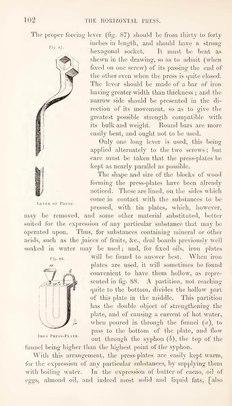
102 THE HORIZONTAL PRESS.
Fig. 87.
Lever of Press'.
The proper forcing lever (fig. 87) should be from thirty to forty
inches in length, and should have a strong
hexagonal socket. It must be bent as
shewn in the drawing, so as to admit (when
fixed on one screw) of its passing the end of
the other even when the press is quite closed.
The lever should be made of a bar of iron
having greater width than thickness ; and the
. narrow side should be presented in the di“
rection of its movement, so as to give the
greatest possible strength compatible with
its bulk and weight. Round bars are more
easily bent, and ought not to be used.
Only one long lever is used, this being
applied alternately to the two screws; but
care must be taken that the press-plates be
kept as nearly parallel as possible.
The shape and size of the blocks of wood
forming the press-plates have been already
noticed. These are lined, on the sides which
come in contact with the substances to be
pressed, with tin plates, which, however,
may be removed, and some other material substituted, better
suited for the expression of any particular substance that may be
operated upon. Thus, for substances containing mineral or other
acids, such as the juices of fruits, &c., deal boards previously well
soaked in water may be used; and, for fixed oils, iron plates
will be found to answer best. AVhen iron
plates are used, it will sometimes be found
convenient to have them hollow, as repre¬
sented in fig. 88. A partition, not reaching
quite to the bottom, divides the hollow part
of this plate in the middle. This partition
has the double object of strengthening the
plate, and of causing a current of hot water,
when poured in through the funnel (a), to
pass to the bottom of the plate, and flow
out through the syphon (^), the top of the
funnel being higher than the highest point of the syphon.
With this arrangement, the press-plates are easily kept warm,
for the expression of any particular substances, by supplying them
with boiling water. In the expression of butter of cacao, oil of
eggs, almond oil, and indeed most solid and liquid fats, [also
Fig. 88.
ff
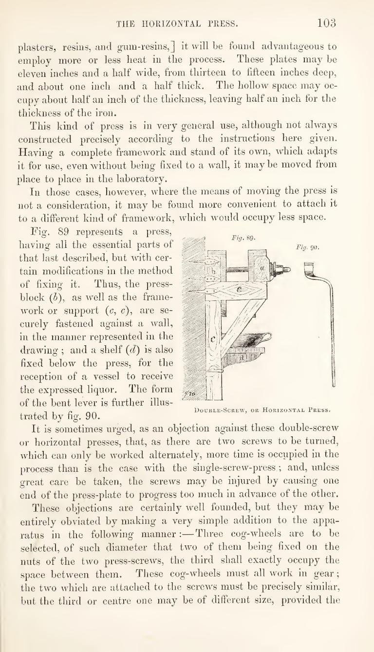
THE HORIZONTAL PRESS. 103
plasters, resins, and gum-resins,] it will be found advantageous to
employ more or less heat in the process. These plates ma}" be
eleven inches and a half wide, from thirteen to fifteen inches deep,
and about one inch and a half thick. The hollow space may oc¬
cupy about half an inch of the thickness, leaving half an inch for the
thickness of the iron.
This kind of press is in very general use, although not always
constructed precisely according to the instructions here given.
Having a complete framework and stand of its own, which adapts
it for use, even without being fixed to a wall, it may be moved from
place to place in the laboratory.
In those cases, however, where the means of moving the press is
not a consideration, it may be found more convenient to attach it
to a different kind of framework, which would occupy less space.
Fig. 89 represents a press,
having all the essential parts of
that last described, but with cer¬
tain modifications in the method
of fixing it. Thus, the press-
block (J>), as well as the frame¬
work or support (c, c), are se¬
curely fastened against a wall,
in the manner represented in the
drawing ; and a shelf (d) is also
fixed below the press, for the
reception of a vessel to receive
the expressed liquor. The form
of the bent lever is further illus¬
trated by fig. 90.
It is sometimes urged, as an objection against these double-screw
or horizontal presses, that, as there are two screws to be turned,
which can only be worked alternately, more time is occupied in the
process than is the case with the single-screw-press ; and, unless
great care be taken, the screws may be injured by causing one
end of the press-plate to progress too much in advance of the other.
These objections are certainly well founded, but they may be
entirely obviated by making a very simple addition to the appa¬
ratus in the following manner:—Three cog-wheels are to be
selected, of such diameter that two of them being fixed on the
nuts of the two press-screws, the third shall exactly occupy the
space between them. These cog-wheels must all work in gear;
the two which are attached to the screws must be precisely similar,
but the third or centre one may be of different size^ provided the
Double-Screw, or Horizontal Press.
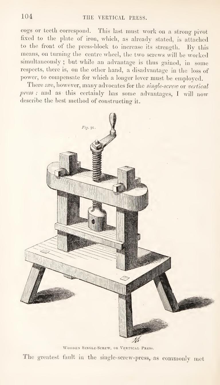
104 THE VERTICAL PRESS.
cogs or teeth correspond. This last must work on a strong pivot
fixed to the plate of iron, which, as already stated, is attached
to the front of the press-block to increase its strength. By this
means, on turning the centre wheel, the two screws will be worked
simultaneously ; but while an advantage is thus gained, in some
respects, there is, on the other hand, a disadvantage in the loss of
power, to compensate for which a longer lever must be employed.
There are, however, many advocates for the single-screw or vertical
press ; and as this certainly has some advantag’es, I will now
describe the best method of constructing it.
Fig. 91
Wooden Single-Screw, or Vertical Press.
The greatest fault in the single-screw-press, as commonly met
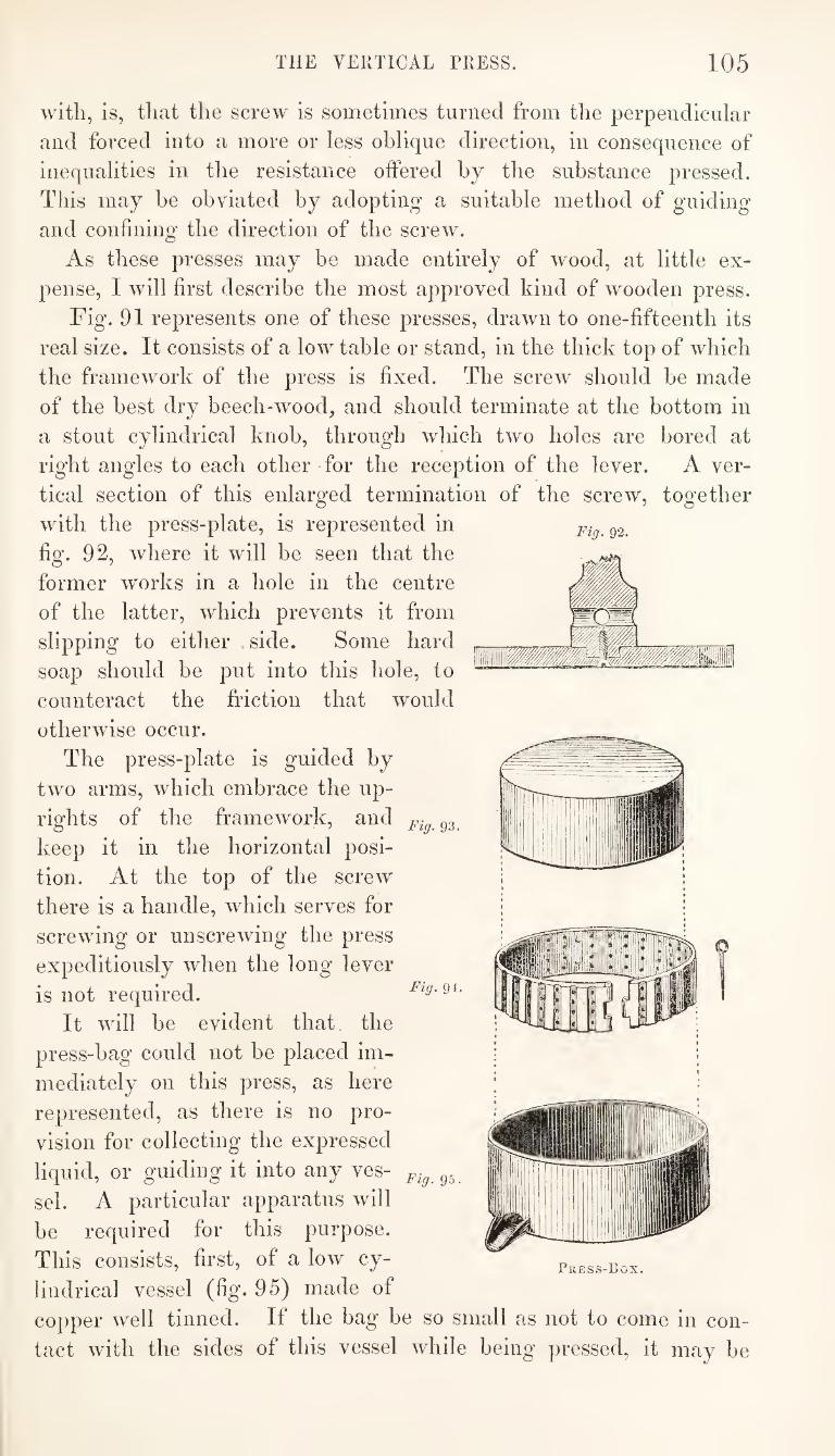
THE VERTICAL PRESS. 105
PI WM 1 p
li
il
with, is, that the screw is sometimes turned from the perpendicular
and forced into a more or less oblique direction, in consequence of
inequalities in the resistance otfered by the substance pressed.
This may be obviated by adopting a suitable method of guiding
and confining the direction of the screw.
As these presses may be made entirely of wood, at little ex¬
pense, I will first describe the most approved kind of wooden press.
Fig. 91 represents one of these presses, drawn to one-fifteenth its
real size. It consists of a low table or stand, in the thick top of which
the framework of the press is fixed. The screw should be made
of the best dry beech-wood, and should terminate at the bottom in
a stout cylindrical knob, through which two holes are bored at
right angles to each other for the reception of the lever. A ver¬
tical section of this enlarged termination of the screw, together
with the press-plate, is represented in ^2.
fig. 92, where it will be seen that the
former works in a hole in the centre
of the latter, which prevents it from
slipping to either side. Some hard
soap should be put into this hole, to
counteract the friction that would
otherwise occur.
The press-plate is guided by
two arms, which embrace the up¬
rights of the framework, and gg
keep it in the horizontal posi¬
tion. At the top of the screw
there is a handle, which serves for
screwing or unscrewing the press
expeditiously when the long lever
is not required.
It will be evident that the
press-bag could not be placed im¬
mediately on this press, as here
represented, as there is no pro¬
vision for collecting the expressed
liquid, or guiding it into any ves- gg.
sel. A particular apparatus will
be required for this purpose.
This consists, first, of a low cy¬
lindrical vessel (fig. 95) made of
copper well tinned. It the bag be so small as not to come in con¬
tact with the sides of this vessel while being pressed, it may be
Fig. 94.
Press-Box.
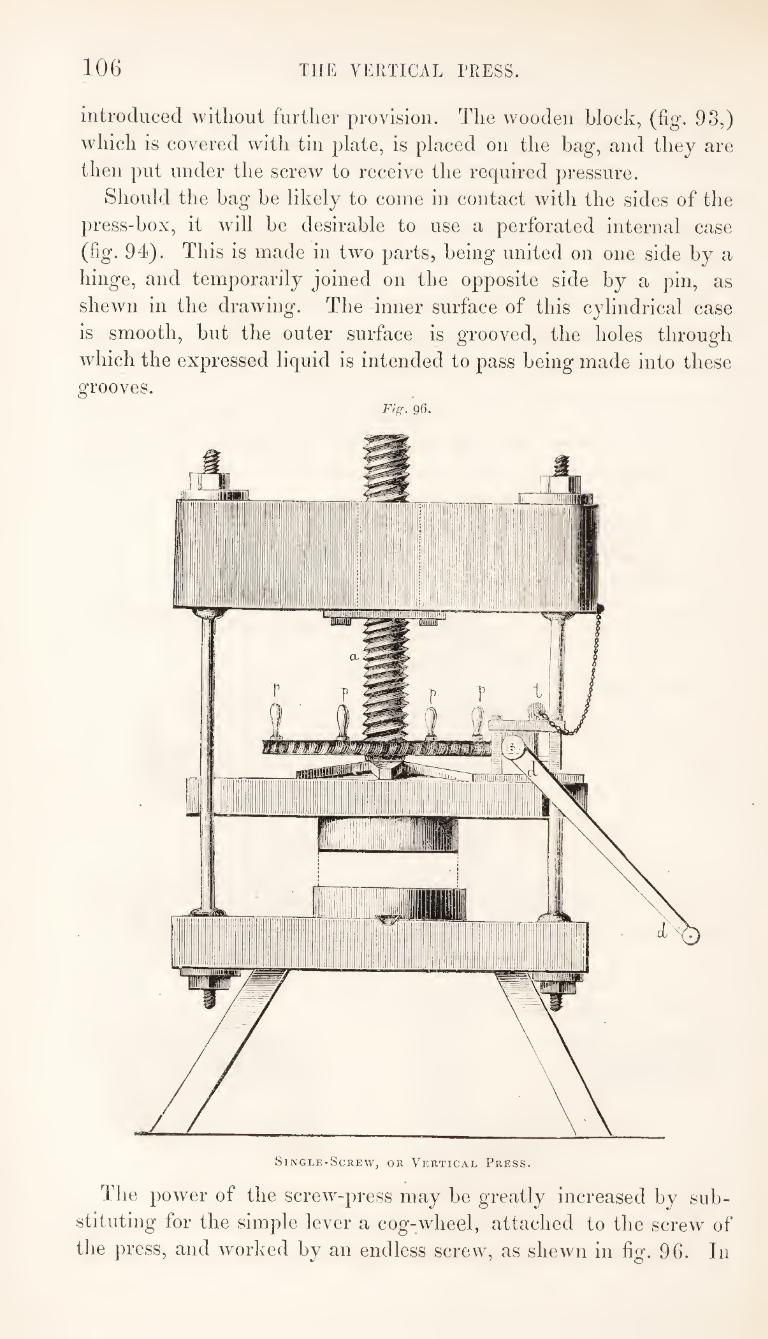
106 THE VERTICAL TRESS.
introduced without further provision. The wooden block, (fig. 93,)
which is covered with tin plate, is placed on the hag, and they are
then put under the screw to receive the required pressure.
Should the bag be likely to come in contact with the sides of the
press-box, it will be desirable to use a perforated internal case
(fig. 94). This is made in two parts, being united on one side by a
hinge, and temporarily joined on the opposite side by a pin, as
shewn in the drawing. The inner surface of this cylindrical case
is smooth, but the outer surface is grooved, the holes through
which the expressed liquid is intended to pass being made into these
grooves. Fig. 96.
Single-Screw, or Vertical Press.
1 he power of the screw-press may be greatly increased by sub¬
stituting for the simple lever a cog-wheel, attached to the screw of
the press, and worked by an endless screw, as shewn in fig. 96. In
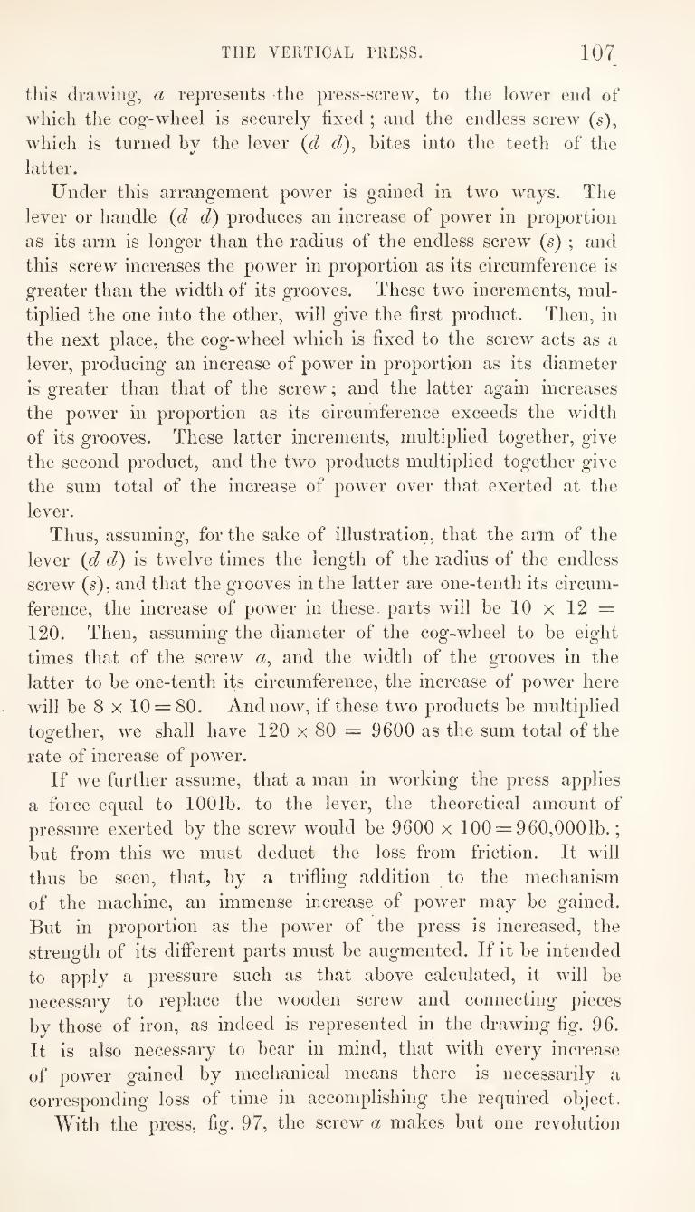
THE VERTICAL TRESS. 107
this drawing, a represents the press-screw, to the lower end of
which the cog-wheel is securely fixed ; and the endless screw (s),
which is turned by the lever {d <7), bites into the teeth of the
latter.
Under this arrangement power is gained in two ways. The
lever or handle {d d) produces an increase of power in proportion
as its arm is longer than the radius of the endless screw (s) ; and
this screw increases the power in proportion as its circumference is
greater than the width of its grooves. These two increments, mul¬
tiplied the one into the other, will give the first product. Then, in
the next place, the cog-wheel which is fixed to the screw acts as a
lever, producing an increase of power in proportion as its diameter
is greater than that of the screw; and the latter again increases
the power in proportion as its circumference exceeds the width
of its grooves. These latter increments, multiplied together, give
the second product, and the two products multiplied together give
the sum total of the increase of power over that exerted at the
lever.
Thus, assuming, for the sake of illustration, that the arm of the
lever {d d) is twelve times the length of the radius of the endless
screw (5), and that the grooves in the latter are one-tenth its circum¬
ference, the increase of power in these parts will be 10 x 12 =
120. Then, assuming the diameter of the cog-wheel to be eight
times that of the screw a, and the width of the grooves in the
latter to be one-tenth its circumference, the increase of power here
wdll be 8 X 10 = 80. And now, if these two products be multiplied
together, we shall have 120 x 80 = 9600 as the sum total of the
rate of increase of pow'er.
If w'e further assume, that a man in working the press applies
a force equal to 100lb. to the lever, the theoretical amount of
pressure exerted by the screw would be 9600 x 100 = 960,00016.;
but from this we must deduct the loss from friction. It wdll
thus be seen, that, by a trifling addition to the mechanism
of the machine, an immense increase of power may be gained.
But in proportion as the powder of the press is increased, the
strength of its dilFerent parts must be augmented. If it be intended
to apply a pressure such as that above calculated, it will be
necessary to replace the wooden screw and connecting pieces
by those of iron, as indeed is represented in the drawing fig. 96.
It is also necessary to bear in mind, that with every increase
of power gained by mechanical means there is necessarily a
corresponding loss of time in accomplishing the required object.
With the press, fig. 97, the screw a makes but one revolution
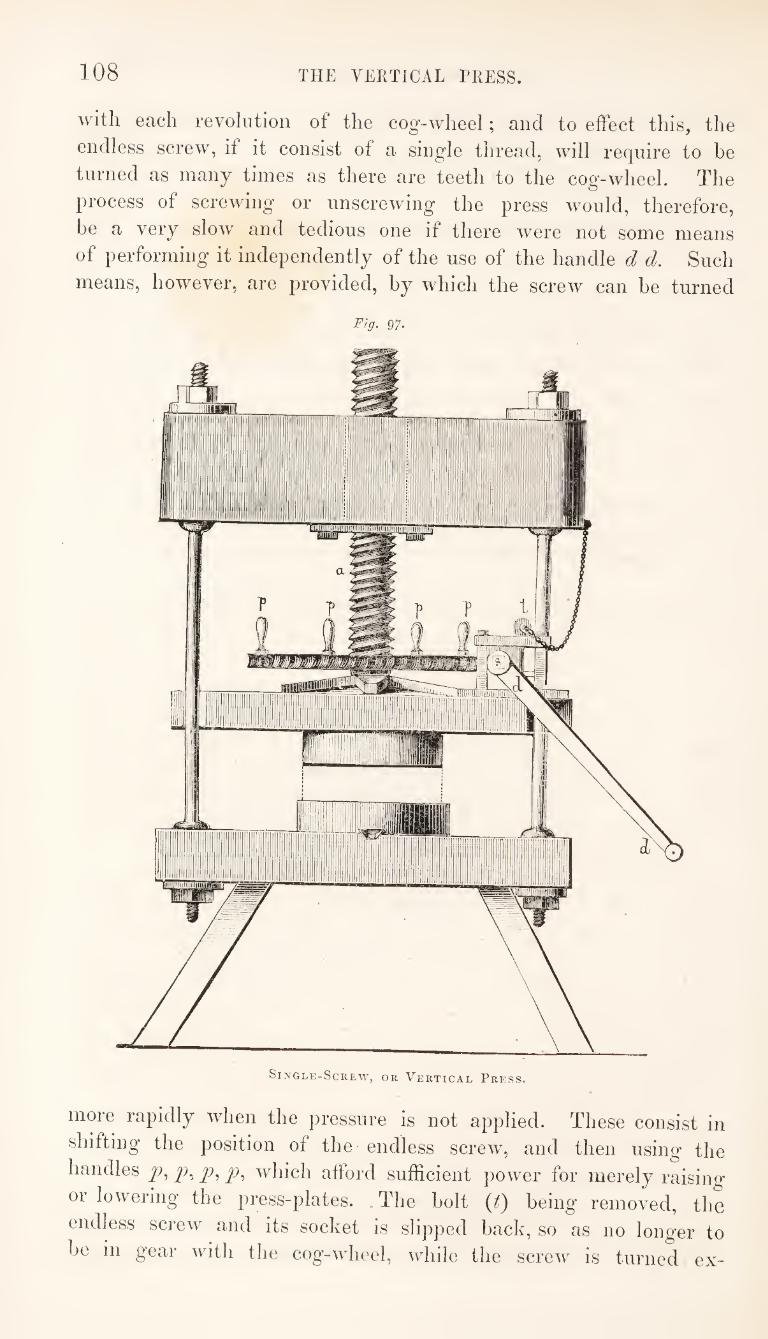
108 THE VERTICAL TRESS.
with each revolution of the cog-wheel; and to effect this, the
endless screw, if it consist of a single thread, will require to be
turned as many times as there are teeth to the cog-wheel. The
process of screwing or unscrewing the press would, therefore,
be a very slow and tedious one if there were not some means
of performing it independently of the use of the handle d d. Such
means, however, are provided, by which the screw can be turned
Fig. 97.
more rapidly when the pressure is not applied. These consist in
shifting the position of the endless screw, and then using the
handles y), y), y), which afford sufficient power for merely raising
or lowering the press-plates. The bolt {f) being removed, the
endless screw and its socket is slipped back, so as no longer to
be in gear with the cog-wheel, while the screw is turned ex-
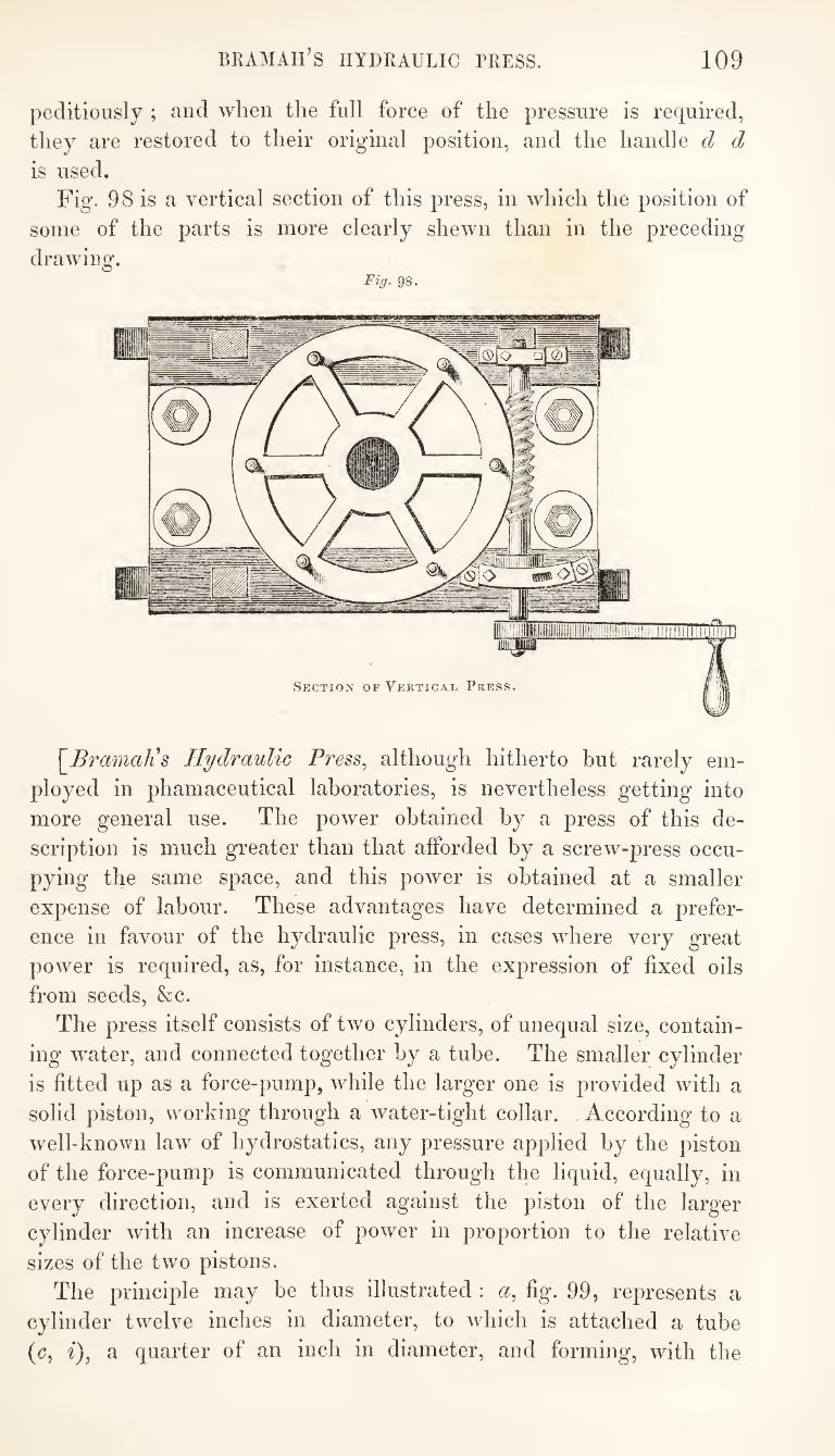
BRAMAH’S HYDRAULIC PRESS. 109
peditiously ; and when the full force of the pressure is required,
they are restored to their original position, and the handle d d
is used. Fig. 98 is a vertical section of this press, in which the position of
some of the parts is more clearly shewn than in the preceding
drawing. Fig. 98.
\_BramaKs Hydraulic Press^ although hitherto but rarely em¬
ployed in phamaceutical laboratories, is nevertheless getting into
more general use. The power obtained by a press of this de¬
scription is much greater than that afforded by a screw-press occu¬
pying the same space, and this power is obtained at a smaller
expense of labour. These advantages have determined a prefer¬
ence in favour of the hydraulic press, in cases where very great
power is required, as, for instance, in the expression of fixed oils
from seeds, &c.
The press itself consists of two cylinders, of unequal size, contain¬
ing water, and connected together by a tube. The smaller cylinder
is fitted up as a force-pump, while the larger one is provided with a
solid piston, working through a water-tight collar. According to a
well-known law of hydrostatics, any pressure applied by the piston
of the force-pump is communicated through the liquid, equally, in
every direction, and is exerted against the piston of the larger
cylinder with an increase of power in proportion to the relative
sizes of the two pistons.
The principle may be thus illustrated : a, fig. 99, represents a
cylinder twelve inches in diameter, to which is attached a tube
(c, i), a quarter of an inch in diameter, and forming, with the
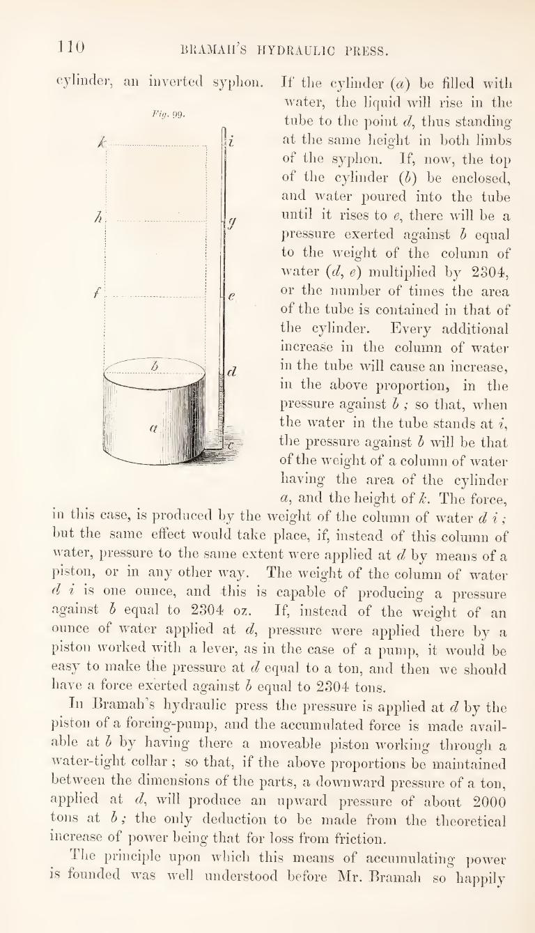
110 BKAMAIl'S HYDRAULIC PRESS.
If the cylinder (a) be filled 'vvitli
water, the liquid will rise in the
tube to the point d, thus standing
at the same height in both limbs
of the syphon. If, now, the top
of the cylinder (5) be enclosed,
and water poured into the tube
until it rises to e, there will be a
pressure exerted against 5 equal
to the weight of the column of
water (d, e) multiplied by 2304,
or the number of times the area
of the tube is contained in that of
the cylinder. Every additional
increase in the column of water
in the tube will cause an increase,
in the above proportion, in the
pressure against 6 ; so that, when
the water in the tube stands at i,
the pressure against 5 will be that
of the weight of a column of water
having the area of the cylinder
(2, and the height of /i\ The force, 111 tins case, is produced by the weight of the column of water d i;
but the same effect would take place, if, instead of this column of
water, pressure to the same extent were applied at d by means of a
piston, or in any other way. The weight of the column of water
dj i is one ounce, and this is capable of producing a pressure
against h equal to 2304 oz. If, instead of the weight of an
ounce of water applied at d, pressure were applied there by a
piston worked with a lever, as in the case of a pump, it would be
easy to make the pressure at d equal to a ton, and then we should
have a force exerted against h equal to 2304 tons.
In Eramalks hydraulic press the pressure is applied at d by the
piston of a forcing-pump, and the accumulated force is made avail¬
able at h by having there a moveable piston working through a
water-tight collar ; so that, if the above proportions be maintained
between the dimensions of the parts, a downward pressure of a ton,
applied at c/, will produce an upward pressure of about 2000
tons at h; the only deduction to be made from the theoretical
increase of power being that for loss from friction.
The principle upon which this means of accumulating powder
is founded was well understood before Mr. Bramah so happily
cylinder, an inverted sypho
Fig. gg.
• . 'V •
BRAMAIi’S HYDRAULIC PRESS. Ill
applied it in the construction of his press. The same principle is
involved in Count Real’s press, described at page 59. Tt may be
thus expressed:—Pressure is exerted in liquids equally in every
direction; and the pressure which the bottom or sides of a
vessel containing a liquid sustains will be in proportion to their
extent of surface, and to the perpendicular height of the column of
liquid above, without reference to the capacity of the vessel or
the quantity of liquid it contains. Thus, the same pressure is
exerted on the bottom of the cylinder (fig. 99,) when the
water stands in the tube at as would be the case if the cylinder
were extended to and filled with water.
Bramah’s merit consisted in the application of a well-known
principle for the economical j^roduction of immense power available
for mechanical purposes. This application was made the subject
of a patent in 1795, in the specification of which Mr. Bramah
describes his press as a hydra-mechanical engine. But, although
the application of the principle was secured by this patent, a
difficulty was at first experienced in the construction of the
machine, wdiich greatly detracted from the value of the discovery.
It was found impossible, by any means then known, to make
the packing of the collar, through which the piston of the large
cylinder of the press moves, so tight as to prevent the escape
of w'ater when the full pressure of the machine was applied,
without at the same time rendering the piston immoveable by
the unaided power of the operator when the pressure was taken off.
At length, however, a method of packing the piston was discovered
by the original patentee, which completely removed this difficulty.
This method consists in the use of a leather collar, the construction
and application of which is as simple as the principle of its action
is scientific; and so perfectly satisfactory is the effect of this
contrivance, that it leaves nothing to be desired.
Fig. 100 represents a small hydraulic press, which I have been
accustomed to use for several years. The framework of the press
is made of cast iron, and it rests on a strong wooden stand. A, is a
cistern containing water, in which is placed a small forcing-pump
worked by a lever-handle, which may be lengthened when more power
is required. This pump communicates with the strong cast-iron
cylinder (D), by means of the metallic tube (B). The piston (E),
sometimes called the mm, moves through a water-tight collar,
which is secured in its place by the cap of the cylinder; and, as the
piston rises, it carries with it the iron plate, called the follower.,
on which the substance to be pressed is placed. The pressure
is effected against the head of the press, where there is also
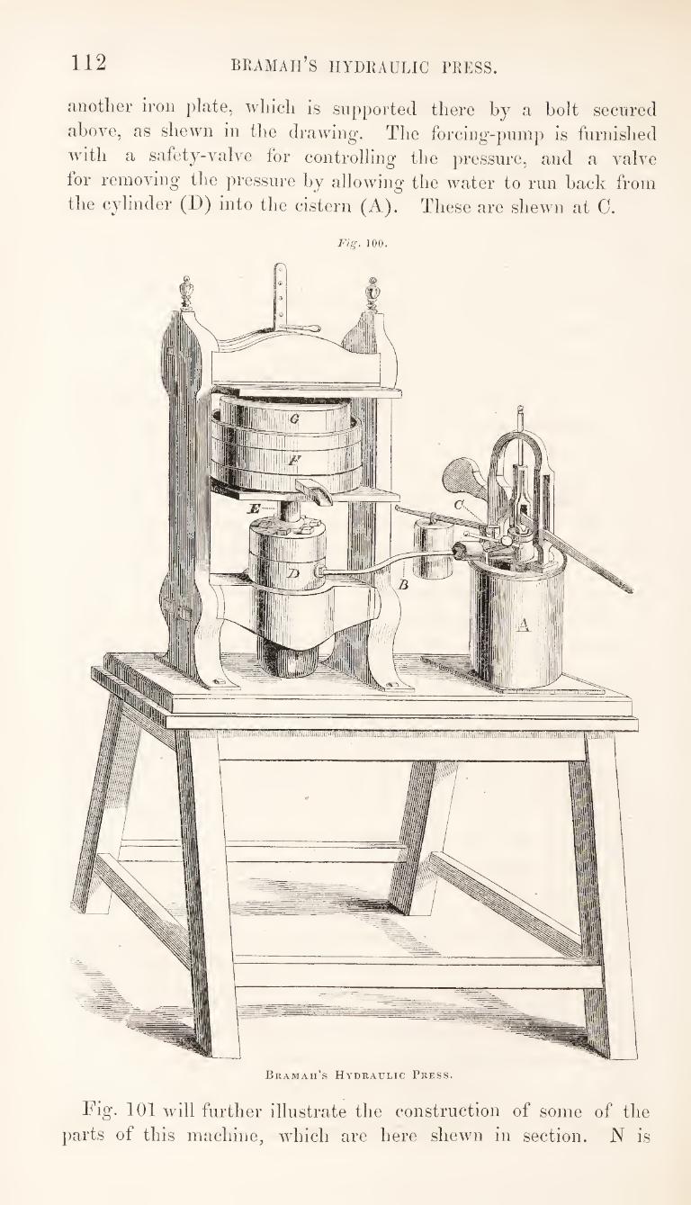
112 BRAMAIl’S HYDRAULIC PRESS
another iron plate, which is supported there by a bolt secured
above, as shewn in the drawing. The forcing-pump is furnished
with a safety-valve for controlling the pressure, and a valve
for removing the pressure by allowing the water to run hack from
the cylinder (D) into the cistern (A). These are shewn at 0.
Fig. 100.
Bramah’s Hydraulic Press.
Fig. 101 will further illustrate the construction of some of the
parts of this machine, which are here shewn in section. N is
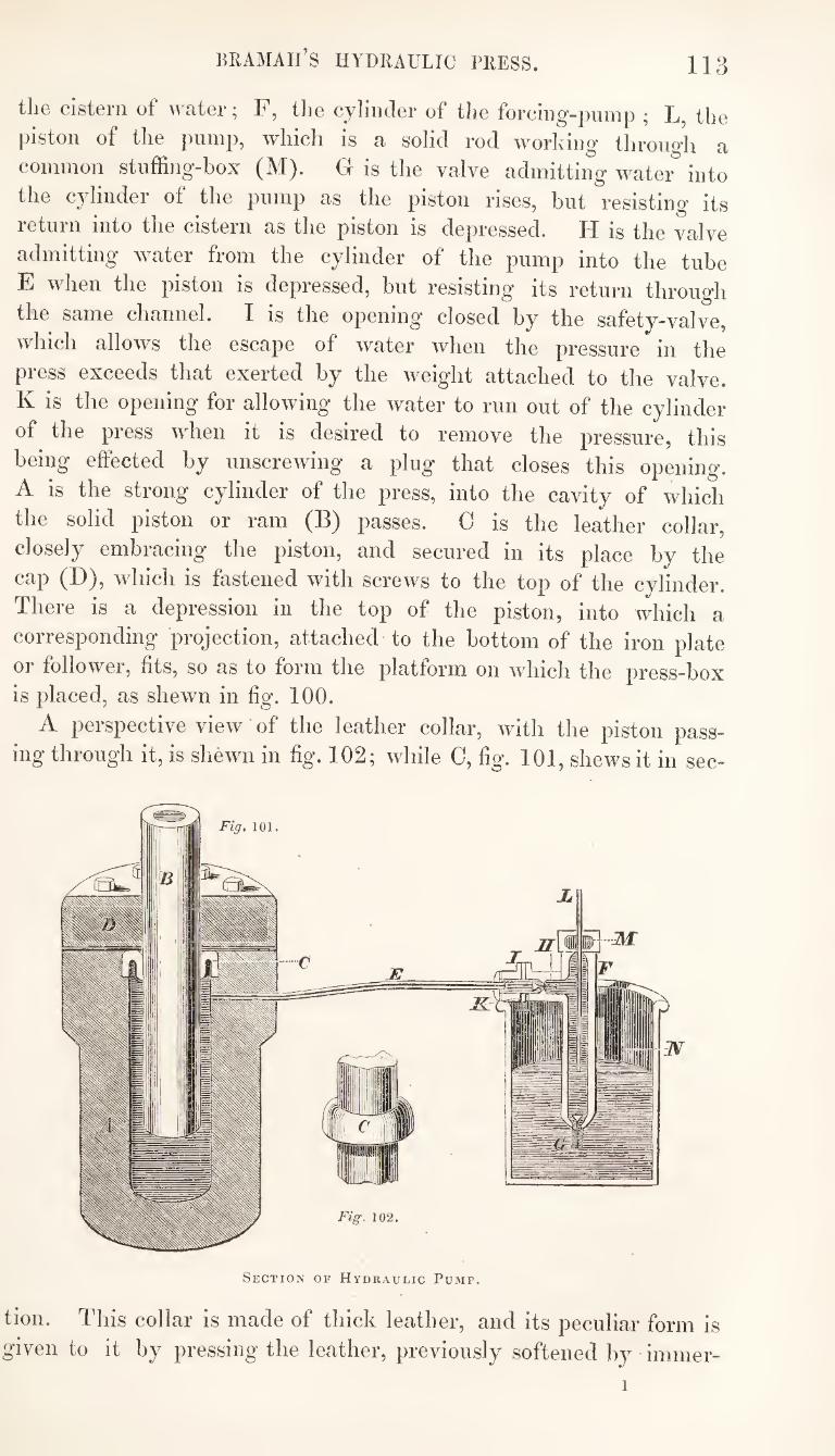
Bramah’s hydraulic press. 113
the cistern of water; F, tlie cylinder of the forcing-pump ; L, the piston of the pump, whicli is a solid rod working through a common stuffing-box (M). G is the valve admitting water into the cylinder of the pump as the piston rises, but resisting its return into the cistern as the piston is depressed. H is the valve admitting water from the cylinder of the pump into the tube E when the piston is depressed, but resisting its return through the same channel. I is the opening closed by the safety-valve, which allows the escape of water when the pressure in the press exceeds that exerted by the weight attached to the valve. K is the opening for allowing the water to run out of the cylinder of the press when it is desired to remove the pressure, this being effected by unscrewing a plug that closes this opening. A is the strong cylinder of the press, into the cavity of which the solid piston or ram (B) passes. C is the leather collar, closely embracing the piston, and secured in its place by the cap (D), which is fastened with screws to the top of the cylinder. There is a depression in the top of the piston, into which a corresponding projection, attached to the bottom of the iron plate or follower, fits, so as to form the platform on which the press-box is placed, as shewn in fig. 100.
A perspective view of the leather collar, with the piston pass¬ ing through it, is shewn in fig. 102; while 0, fig. 101, shews it in sec-
Section oi’’ Hydraulic Pump.
tion. This collar is made of thick leather, and its peculiar form is given to it by pressing the leather, previously softened by immer-
1
114 PROCESS OF EXPRESSION.
sion in water, into a circular groove, and afterwards cutting a hole
in the centre to fit the piston.
It will he seen, from the section, fig. 101, that the outer fold ot
the collar fits into a notch in the cylinder made for its reception,
while the inner fold embraces the piston, to which its sharp edge
fits closely on every side. The great advantage of this kind of packing is, that the tightness
with which the piston is embraced by the collar will be in propor¬
tion to the pressure of the water; for, in accordance with the prin¬
ciple already stated, that pressure in liquids is equal in all directions,
the water filling the space between the two folds of the collar will
exert a lateral pressure, which will always resist the passage of the
liquid between the collar and the piston. This lateral pressure upon
the folds of the collar, by which the packing is tightened, will
increase with every increase of power applied to the press, and it
will also decrease as soon as the power is removed, so that when the
water is let off the collar will relax the tightness of its grasp, and
the piston (B) will descend into the cylinder by its own weight.
The piston (B, fig. 101) is frequently made of cast iron; and
where the press is in constant use, this may probably answer very
well; but under other circumstances it is objectionable, inasmuch
as the iron becomes oxidised, and the piston does not then pass
freely through the collar. I have found it necessary to have the
iron-piston, which my press originally had, replaced by one made of
gun-metal, and since this substitution it has never got out of order.
A manufacturer of these presses states, that the lowest price at
which a press, such as that I have described, and of a suitable size
for pharmaceutical purposes, could be made, would be from twenty
to thirty guineas.
THE PROCESS OF EXPRESSION.
In using any one of the presses here described, some means are
frequently required, beyond those hitherto noticed, for confining
the solid part of the substance to be pressed during the process of
expression. When a press-box, such as that figured at page 105,
is employed, the substance is not unfrequently put directly into the
inner case of the box without anything intervening; sometimes,
however, the substance is enclosed in a press-cloth or hag^ previously
to its introduction into the box, and there are cases in which this
method of operating is necessary.
The tincture-presses most commonly used by pharmaceutists who
operate upon small quantities of ingredients at a time, are con-
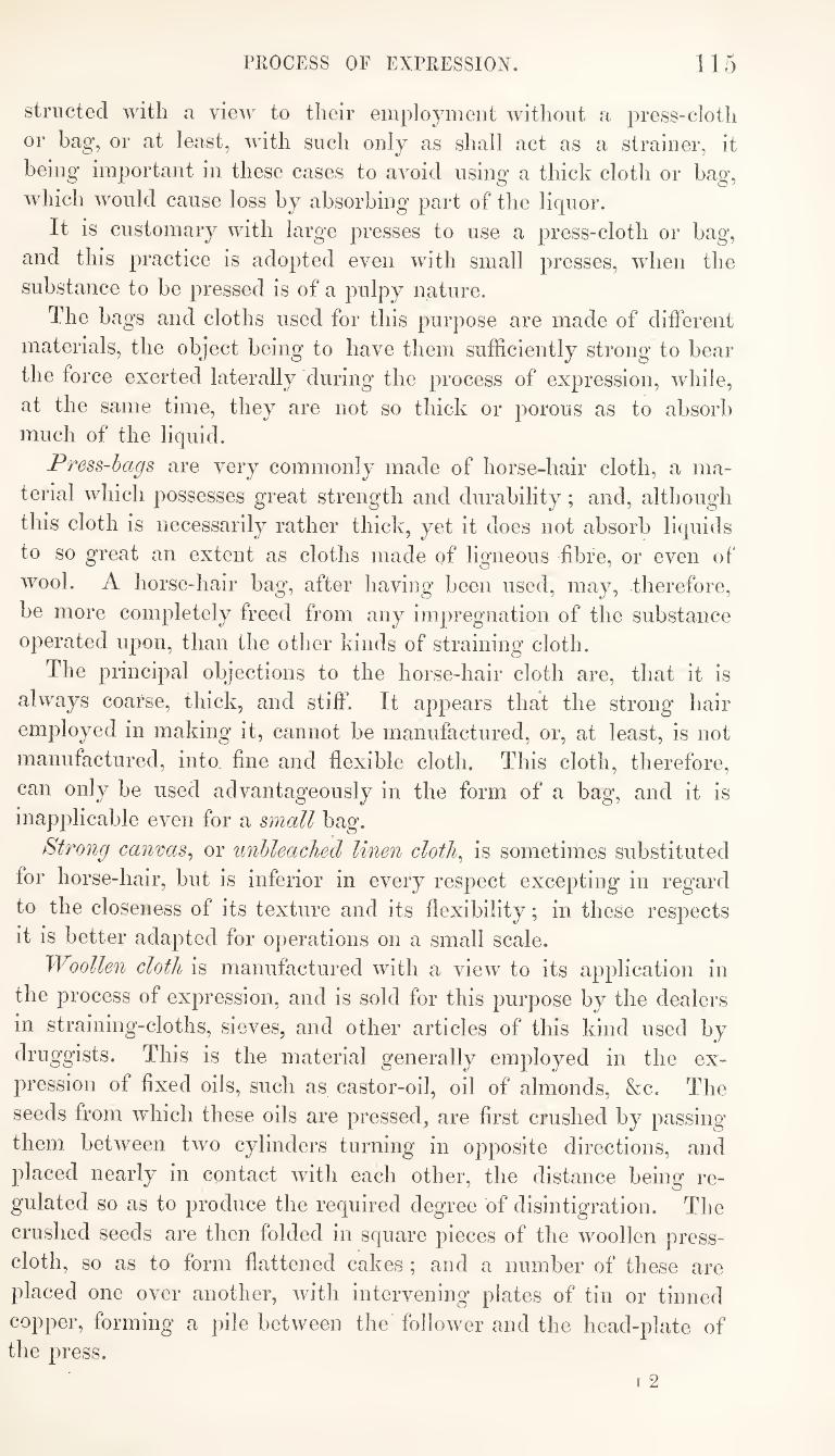
PROCESS OF EXPRESSION. 115
striictecl with a view to their employment without a press-cloth
or hag, or at least, with such only as shall act as a strainer, it
being important in these cases to avoid using a thick cloth or bag,
which W'ould cause loss by absorbing part of the liquor.
It is customary with large presses to use a press-cloth or bag,
and this practice is adopted even with small presses, when the
substance to be pressed is of a pulpy nature.
The bags and cloths used for this purpose are made of different
materials, the object being to have them sufficiently strong to bear
the force exerted laterally during the process of expression, while,
at the same time, they are not so thick or porous as to absorb much of the liquid.
Press-hags are very commonly made of horse-hair cloth, a ma¬
terial which possesses great strength and durability; and, although
this cloth is necessarily rather thick, yet it does not absorb liquids
to so great an extent as cloths made of ligneous fibre, or even of
wool. A horse-hair bag, after having been used, may, therefore,
be more completely freed from any impregnation of the substance
operated upon, than the other kinds of straining cloth.
The principal objections to the horse-hair cloth are, that it is
always coarse, thick, and stiff. It appears that the strong hair
employed in making it, cannot be manufactured, or, at least, is not
manufactured, into fine and flexible cloth. This cloth, therefore,
can only be used advantageously in the form of a bag, and it is
inapplicable even for a small bag.
Strong canvas^ or unbleached linen cloth^ is sometimes substituted
for horse-hair, but is inferior in every respect excepting in regard
to the closeness of its texture and its flexibility; in these respects
it is better adapted for operations on a small scale.
Woollen cloth is manufactured with a view to its application in
the process of expression, and is sold for this purpose by the dealers
in straining-cloths, sieves, and other articles of this kind used by
druggists. This is the material generally employed in the ex¬
pression of fixed oils, such as castor-oil, oil of almonds, &c. The
seeds from which these oils are pressed, are first crushed by passing
them between two cylinders turning in opposite directions, and
placed nearly in contact with each other, the distance being re¬
gulated so as to produce the required degree of disintigration. The
crushed seeds are then folded in square pieces of the woollen press-
cloth, so as to form flattened cakes ; and a number of these are
placed one over another, with intervening plates of tin or tinned
copper, forming a pile between the follower and the head-plate of the press.
IIG PROCESS OF EXPRESSION.
Ill conducting the process of expression, the substance to be
[iressed being confined in tlie manner best suited to the circum¬
stances of the case, the pressure must be gradually apidied. If
the substance be in a soft and pulpy state, it will be necessary to
begin with a very slight pressure, for as the force applied will, in
this case, be communicated equally in every direction, according to
the law of hydrostatics, the bag or cloth would inevitably give
way, or the substance escape through the apertures intended for
the flow of the liquid, if much force were exerted. When part of
the liquid has been pressed out, and the remaining substance has
become more firm, increased pressure may be applied, and ulti¬
mately, as the contents of the bag become solid, the full force of the press may be safely exerted.
The effect of applying pressure in this way, to a substance
consisting of solid and liquid particles, is, to cause the nearer
approach of the former to each other, while the latter are displaced
and forced out through the apertures provided for this purpose.
Much force is required to overcome the resistance offered by the
pressure of the liquid, and also by the elasticity of the solid par¬
ticles themselves. Great compression cannot be effected suddenly,
with the means usually resorted to, continued application of the
pressure for sometime being necessary, so that the solid particles
may approach nearer and nearer as the elasticity by which they
were kept apart is gradually overcome and destroyed. Thus, after
effecting as much compression as the means provided will admit at
one effort, if the press with its contents be left unrelaxed for a few
minutes, it will be found, at the expiration of this time, that further
compression may be effected by the renewed application of the
same power. It is by following up the effects in this way, with
intervals of cessation in the application of new force, that the
required object is ultimately attained.
To accomplish the object efficiently by these means, it is neces¬
sary that the press should be capable of maintaining unrelaxed the
degree of compression which has been produced at each successive
effort, and that it should not allow the particles, by their elastic
force, to regain, to any extent, their original condition. This
quality is possessed to a greater extent by the screw-press than by
the hydraulic-press. The former will maintain for an indefinite
length of time any degree of compression which may have been
given to the substance placed in it; but not so the latter. The
pressure in the hydraulic-press, being communicated through a
liquid, and maintained by the action of valves, it is found prac¬
tically impossible, with the kind of skill usually bestowed in the
FURNACE OPERATIONS. 117
manufacture of these presses, to prevent a slight leakage, which
causes a relaxation of the pressure when the pump is not in action.
It is necessary, therefore, more frequently to renew the force, in
conducting the process of expression with the hydraulic-press, than is the case with the screw-press.]
FUUNACE-OPEliATlONS.
OPERATIONS OF GLOWING OR HEATING TO REDNESS.
The heating of a body until it becomes luminous, is called glow-
ing (gluhen) or heating to redness. All solid bodies, when they
acquire a certain temperature, become luminous, and the tempe¬
rature is often estimated by the intensity of the light which is
emitted; thus the terms red-heat., cherry-red-heat., and white-heat.,
are used to designate degrees of temperature, which cannot be
conveniently measured by the instruments commonly used for such
purposes. Red-heat is the lowest temperature contemplated in
these operations; it is produced by the slow combustion of fuel
maintained m a furnace or stove without any strong draught of
air. White-heat is the most intense heat that can be obtained
in a furnace, aided by a powerful draught or artificial blast.
Cherry-red-heat is intermediate between the two others; it is the
most useful for many chemical purposes. [Professor Daniell, by
the use of his pyrometer, estimated the temperature at which solid
bodies begin to be luminous, at between 800° and 900° of Fah¬
renheit’s scale ; he has represented a red-heat as equal to 980°
Fahr.; a white-heat may be represented as equal to about 8000°
Fahr.; and a cherry-red-'heat about midway between the two.]
We shall have occasion here to treat of the practical means by
which these degrees of heat may be obtained. As a general rule,
it is considered desirable, in pharmaceutical laboratories, to avoid, as
much as possible, having recourse to operations requiring these high
temperatures, for as they occur but rarely, the fire has to be
lighted expressly for each process, in a furnace previously cold,
and therefore requiring some time and expenditure of fuel to get
it into a state fit for use. On this account, and also on account of
the loss incurred from the fracture of crucibles, and unavoidable
waste of the materials operated upon, many substances which, in
their preparation, were formerly heated to redness, are now pre¬
pared by a less expensive and troublesome process. Yet there
still are cases in which recourse is obliged to be had to this method
118 FUEL FOR FURNACES.
ot operating, and therefore the implements for conducting it ought
not to he wanting in a well-appointed laboratory.
Fuel.—Charcoal is the most convenient fuel to use in these
operations. It ignites easily, will burn readily in stoves of all
kinds, whatever their construction may be, and leaves no slag. It
presents the advantages, therefore, of being more cleanly, and more
easily managed, than other kinds of fuel ; but on the other hand,
it is more expensive, (especially in England,) and it burns away more quickly.
Couiinfion Mineral Coal is cheaper than charcoal; it requires a
stronger draught to maintain its combustion, and it leaves slags
and a greater amount of ash, which tend to block up the grate; it affords, however, a stronger heat.
CoJce., that is, coal deprived of its gaseous and sulphurous con¬
stituents, affords, when the combustion is maintained with a suffi¬
cient draught or blast of air, a stronger heat than any other kind of
fuel. It supports combustion for a long time, and therefore a fire
does not require to be fed so often with this fuel as it would if
charcoal were used, which is a great advantage in many operations,
dhere is a marked distinction between a coke fire and a charcoal
fire, which is worthy of notice. In a coke fire there is very
little flame, and this scarcely extends beyond the fuel itself, while
charcoal burns with a considerable flame, resulting from the com¬
bustion of carbonic oxide gas. The reason of this is, evidently,
that the carbonic acid produced by the combustion is not so readily
converted into carbonic oxide by passing through red-hot coke as
through the more easily oxidisable charcoal. From the same cause
the heat is most intense in a coke fire at the place of the draught,
while in a charcoal fire it is distributed more equally throughout.
On this account, as well as for other reasons, a coke fire is econo¬
mical, as there is a smaller consumption of fuel, arising from the
production of carbonic oxide in the part of the furnace not used.
Moreover, charcoal burns Avith a crackling noise, and throws off a
great number of sparks, which are troublesome, and even danger¬
ous to the eyes of the operator, an inconvenience not experienced
in the use of coke; and as the latter burns only at a strong heat,
the combustion soon slackens, and ceases when the hloAving is
suspended or the draught checked at the conclusion of a pro¬
cess, and the unconsumed fuel is thus saved for another operation.
[There are two kinds of coke used in this country, Avhicli are
distinguished as gas-cohe and oven-coJce. The former is obtained as
a secondary [)roduct in the manufacture of coal-gas; the latter is
made by a distinct process in ovens constructed expressly with a
FUEL.—CRUCIBLES. 119
view to the production of a good heat-producing fuel. The pro¬
perties of these two kinds of coke differ so considerably that they
cannot be indiscriminately employed for the same purposes.
Gas-coJce is much more easily combustible than oven-coke, that is
to say, it burns at a lower temperature. When mixed with a small
quantity of coal, it may be burned, as it frequently is burned, in
open stoves, and even without this admixture it forms an excellent
fuel for close stoves or furnaces, even for those in which there is
not a strong draught.
Oven-coJce can only be burned in furnaces having a strong
draught; indeed, an artificial blast is generally required to ensure
its active combustion. When burned under these circumstances,
however, the combustion is more enduring, and the heat produced
more intense, than would be the case if gas-coke were used. It
forms the best fuel, therefore, for air or blast furnaces, and is
generally employed where intense heat is required, as, for instance, in the smelting of iron.]
Wood^ peat^ or brown coal^ if used in the processes now under
consideration, are employed in a different manner from that adopted
with the fuels previously noticed. The crucible containing the
substance to be acted upon is not placed immediately in contact
with the ignited fuel, but merely exposed to the flame resulting
from its combustion ; these fuels, therefore, require a furnace of
particular construction, which will be described hereafter. Peat
and brown coal should be well dried before being used, and even
then are only fit for use in these operations, when they burn with
very little residue.
Crucibles.—In conducting the process of glowing^ the substance
to be heated to redness is generally put into a crucible. The
crucibles used for this purpose have either round or triangular
mouths. There is no particular reason for giving the preference to
one rather than the other of these forms, unless it be that in some
cases the round crucible may be better suited to the shape of the
furnace into which it is intended to be introduced. The best cru¬
cibles for the purposes here contemplated are those made at Hesse,
called Hessean crucibles. These are so good and cheap that there
is little inducement for substituting any other kind. Black-lead
crucibles are much less frequently used, being more expensive, and
not so generally applicable.
[Hessean crucibles are commonly used in England, and are
generally better than any others met with. Among those made in
this country, the Cornish crucibles are the best, and some of
these are, perhaps, not inferior to the Hessean.]
120 AIR-FURNACE OR WIND-FURNACE.
It usually happens that the crucible is destroyed during the pro¬
cess, or rendered unfit for use on any subsequent occasion. This
is especially the case when the substance operated upon undergoes
fusion. When it remains unfused, in the state of powder, as is the
case with the oxides of zinc, iron, and copper, &c., the same cru¬
cible may, with careful and judicious management, be made to serve
for two or three operations.
The crucible ought not to be placed immediately on the grate or
bars of the furnace, but on a stand provided for its reception.
Stands, composed of the same materials as the crucibles, are made
for this purpose, but, in the absence of such, a piece of brick, or
an old crucible placed bottom upwards, may be used. When
pieces of brick are used, as these are often to a certain extent
fusible, and would in such case adhere to the bottom of the cru¬
cible, thus occasioning inconvenience on withdrawing it from the
lire, it is desirable to guard against such result by jiutting a layer
of sand or bone-ash between the crucible and its stand.
A little management is required in putting the crucible into the
fire. It ought not to be exposed to a strong heat without previous
preparation, for if it be too suddenly heated it will almost inevit¬
ably crack from unequal contraction. The cold crucible should,
therefore, be gradually warmed by placing it on the top of the
furnace, or in any suitable place for this purpose, previously to its
introduction to the fire. The fracture of a crucible is sometimes
caused by putting into it pieces of metal, which are intended to be
fused, in such a way that, extending across the crucible from one
side to the other, and fitting in tightly while cold, there is no
room left for their expansion when heated.
Small crucibles having a capacity equal to about four ounces,
may, in most cases, be heated in any one of the laboratory furnaces
that may be in use for other purposes. Indeed, crucibles of six or
twelve ounces' capacity may often be heated in this way, or at
least by the use of a small portable furnace. When the crucible
has a capacity of a pound or more, it becomes necessary to use
a furnace constructed expressly for such operations. There are
several kinds of furnace used for this purpose, but the wind-fur¬
nace^ which is the oldest, is still generally preferred : it affords the
means of efficiently heating crucibles of any size.
The air or wind-furnace.—This furnace should be constructed of
the best fire-bricks, and it should be connected with a high chim-
ney, so as to ensure a good draught. The interior of the furnace
may be made either square or round, each of these forms having
its own ])eculiar advantages and defects. The round form is con-
AIR-FUKNACE OR WIND-FURNACE. 121
venient for the reception of a crucible, and economical in the
consumption of fuel, for the corners in the square furnace con¬
tribute little to the available heat when used for these operations;
but it is not so easily constructed as the other, unless fire-bricks,
shaped for the purpose, are employed, and these cannot always he
obtained. There are some processes, however, in which the square
furnace is more convenient than the round, and as the former of
these is always more easily built than the other, and especially
with bricks of the usual shape, preference is generally given to this
form.
In erecting a wind-furnace, it is desirable to select a situation for
it in which there is easy access to a suitable chimney without
carrying the flue horizontally for any distance, or having any sharp
angles that might impede the draught. It has been recommended,
that this furnace should be built over an underground-vault or
cellar, so that by breaking through the arch of the vault a supply
of air may be obtained from below for the fire. This plan, how¬
ever, presents few advantages, and is subject to some objections.
I prefer having the draught-hole of the furnace made in the floor
of the laboratory, beneath and in front of the furnace, the part
projecting beyond the furnace being covered with an iron grating
through which the air is admitted.
The grate or bars of the furnace ought to be as near the floor as
possible, so that the whole elevation should not be inconveniently
high, and that the operator may be able to introduce or remove
crucibles and other apparatus through the opening at the top. The
draught-hole or ash-hole may be either on a level with the floor, as
shewn in figs. 103 and 101, or it may be immediately under the
floor, as already mentioned, and projecting in front of the furnace,
with a moveable iron grating over it, which may be taken up to
remove the ashes from beneath. The mouth of the furnace is
covered with a cast-iron plate, coated on the inside with fire-clay
to protect it from the action of the fire, and fixed as shewn in the
drawings. This plate is raised and lowered by means of a chain
passing over a pulley, when the crucible is introduced or removed,
or fresh fuel is supplied to the fire. There is a small hole in the
centre of the iron ])late through which the progress of any operation
which is going on in the furnace can be observed. Fig. 103 repre¬
sents a vertical section, and fig. 101 a front view of this furnace
with the cover partly raised.
The furnace-bars are sometimes made of wrought, sometimes of
cast-iron. The latter are certainly to be preferred, inasmuch as
they are cheaper, and are made of a more suitable form than those
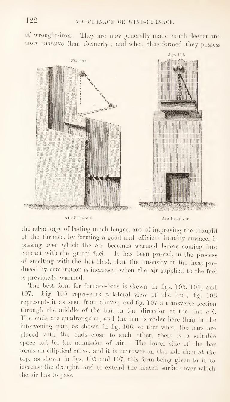
122 AIR-FURNACE OR WIND-FURNACE.
of wrouglit-iroii. They are now generally made mneli deeper and
more massive than formerly ; and when thus formed they possess
Fig. 104.
Air-Furnace. Air-Furnace.
the advantage of lasting much longer, and of improving the draught
of the furnace, by forming a good and efficient heating surface, in
passing over which the air becomes warmed before coming into
contact with the ignited fuel. It has been proved, in the process
of smelting with the- hot-blast, that the intensity of the heat pro¬
duced by combustion is increased when the air supplied to the fuel
is previously warmed.
The best form for furnace-bars is shewn in figs. 105, 106, and
107. Fig. 105 represents a lateral view of the bar; fig. 106
represents it as seen from above ; and fig. 107 a transverse section
through the middle of the bar, in the direction of the line ah.
The ends are quadrangular, and the bar is wider here than in the
intervening part, as shewn in lig. 106, so that when the bars are
placed with the ends, close to each other, there is a suitable
space left for the admission of air. ' The lower side of the bar
forms an elliptical curve, and it is narrower on this side than at the
top, as shewn in figs. 105 and 107, this form being given to it to
increase the draught, and to extend the heated surface over which
the air has to pass.
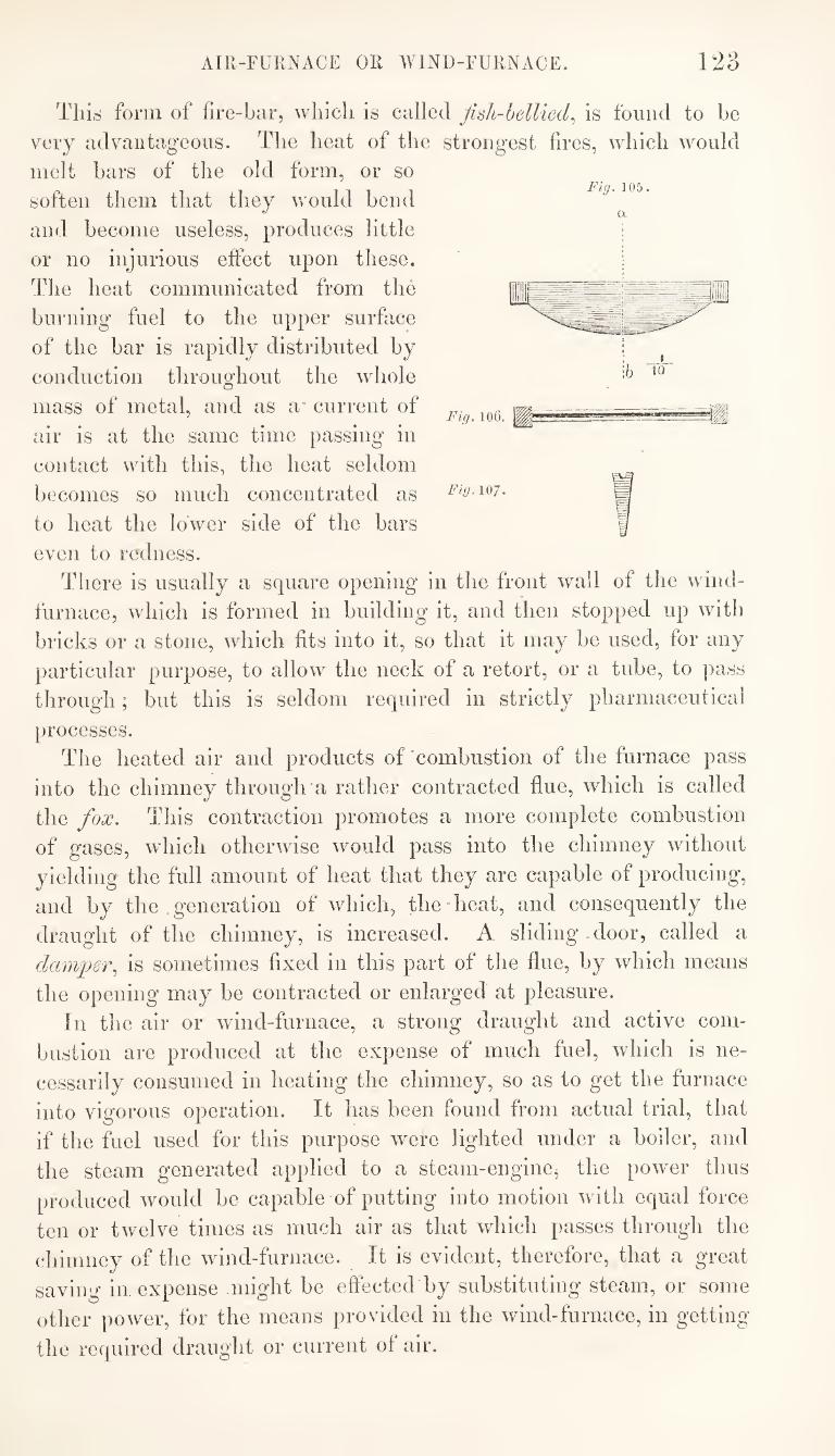
AIR-FUllNACE OR WIND-FURNACE. 123
Fig. 105.
Tliis form of fire-bar, wliicli is called Jish-bellied., is found to be
very advantageous. The heat of the strongest fires, which would
melt bars of the old form, or so
soften them that they would bend
and become useless, produces little
or no injurious effect upon these.
The heat communicated from the
biu'ning fuel to the upper surface
of the bar is rapidly distributed by
conduction throughout the whole
mass of metal, and as a* current of
air is at the same time passing in
contact with this, the heat seldom
becomes so much concentrated as
to heat the lower side of the bars
even to redness.
There is usually a square opening in the front wall of the wind-
furnace, which is formed in building it, and then stopped up with
bricks or a stone, which fits into it, so that it may be used, for any
particular purpose, to allow the neck of a retort, or a tube, to ])ass
through; but this is seldom required in strictly pharmaceutical
processes.
The heated air and products of'combustion of the furnace pass
into the chimney through a rather contracted flue, which is called
the fox. This contraction promotes a more complete combustion
of gases, which otherwise would pass into the chimney without
yielding the full amount of heat that they are capable of producing,
and by the generation of which, theTieat, and consequently the
draught of the chimney, is increased. A sliding .door, called a
dam])6r^ is sometimes fixed in this part of the flue, by which means
the opening may be contracted or enlarged at pleasure.
In the air or wind-furnace, a strong draught and active com¬
bustion are produced at the expense of much fuel, which is ne¬
cessarily consumed in heating the chimney, so as to get the furnace
into vigorous operation. It has been found from actual trial, that
if the fuel used for this purpose were lighted under a boiler, and
the steam generated applied to a steam-engine^ the powder thus
produced would be capable of putting into motion with equal force
ten or twelve times as much air as that which passes through the
chimney of the wind-furnace. It is evident, therefore, that a great
saving in expense might be effected by substituting steam, or some
other power, for the means provided in the wind-furnace, in getting
the required draught or current of air.
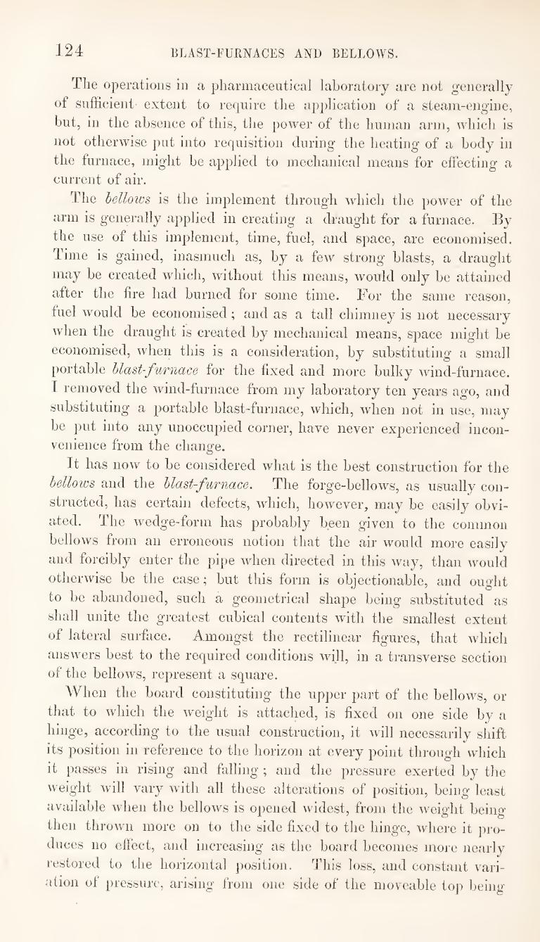
124 BLAST-FURNACES AND BELLOWS.
The operations in a pharmaceutical laboratory are not generally
of sufficient extent to require tlie application of a steam-engine,
but, in the absence of this, the power of the human arm, which is
not otherwise put into requisition during the heating of a body in
the furnace, might be applied to mechanical means for effecting a
current of air.
The bellows is the implement through which the power of the
arm is generally applied in creating a draught for a furnace. By
the use of this implement, time, fuel, and space, are economised.
Time is gained, inasmuch as, by a few strong blasts, a draught
may be created which, without this means, would only be attained
after the fire had burned for some time. For the same reason,
fuel would be economised; and as a tall chimney is not necessary
when the draught is created by mechanical means, space might be
economised, when this is a consideration, by substituting a small
portable blast-furnace for the fixed and more bulky wind-furnace.
I removed the wind-furnace from my laboratory ten years ago, and
substituting a portable blast-furnace, which, when not in use, may
be put into any unoccupied corner, have never experienced incon¬
venience from the change.
It has now to be considered what is the best construction for the
bellows and the blast-furnace. The forge-bellows, as usually con¬
structed, has certain defects, which, however, may be easily obvi¬
ated. The wedge-form has probably been given to the common
bellows from an erroneous notion that the air would more easily
and forcibly enter the pipe when directed in this way, than would
otherwise be the case; but this form is objectionable, and ought
to be abandoned, such a geometrical shape being substituted as
shall unite the greatest cubical contents with the smallest extent
of lateral surface. Amongst the rectilinear figures, that which
answers best to the required conditions will, in a transverse section
of the bellows, represent a square.
When the board constituting the upper part of the bellows, or
that to which the weight is attached, is fixed on one side by a
hinge, according to the usual construction, it will necessarily shift
its position in reference to the horizon at every point through wliich
it passes in rising and falling ; and the pressure exerted by the
weight will vary with all these alterations of position, being least
available when the bellows is opened widest, from the weight being
then thrown more on to the side fixed to the hinge, where it pro¬
duces no effect, and increasing as the board becomes more nearly
restored to the horizontal position. This loss, and constant vari¬
ation of pressure, arising from one side of the moveable top being
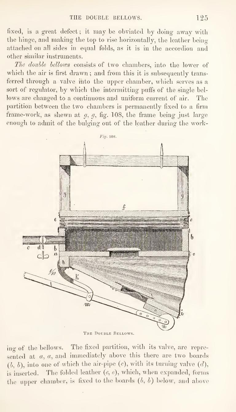
THE DOUBLE BELLOWS. 125
fixed, is a great defect; it may be obviated by doing away with
the hinge, and making the top to rise horizontally, the leather being
attached on all sides in equal folds, as it is in the accordion and
other similar instruments.
The double bellows consists of two chambers, into the lower of
which the air is first drawn; and from this it is subsequently trans¬
ferred through a valve into the upper chamber, which serves as a
sort of regulator, by which the intermitting puffs of the single bel¬
low's are changed to a continuous and uniform current of air. The
partition between the two chambers is permanently fixed to a firm
frame-work, as shewn at fig. 108, the frame being just large
enough to admit of the bulging out of the leather during the work-
Fig. 108.
The Double Bellows,
ing of the bellows. The fixed partition, with its valve, are repre¬
sented at <2, <2, and immediately above this there are two boards
{b, b), into one of which the air-pipe (c), with its turniog valve (d),
is inserted. The folded leather (e, e), which, when expanded, forms
the upper chamber, is fixed to the boards (b, b) l)elow, and above
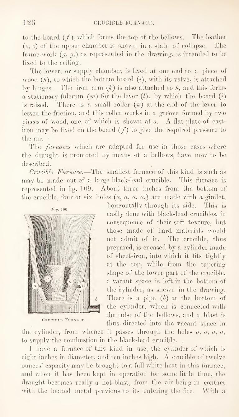
12G CRUCIBLE-FURNACE.
to the board (/), which forms the toj) of the bellows. The leather
(6, e) of the upper chamber is shewn in a state of collapse. The
frame-work (p, as represented in the drawing, is intended to be
fixed to the ceiling’.
The lower, or supply chamber, is fixed at one end to a piece of
wood (4), to which the bottom hoard (^), with its valve, is attached
by hinges. The iron arm {Jc^ is also attached to 7^, and this forms
a stationary fulcrum (m) for the lever (7), by which the hoard (i)
is raised. There is a small roller (n) at the end of the lever to
lessen the friction, and this roller-works in a gro'ove formed by two
pieces of wood, one of which is shewn at o. A flat plate of cast-
iron may be fixed on the board (f) to give the required pressure to
the air.
The furnaces which are adapted for use in those cases where
the draught is promoted by means of a bellows, have now to be
described.
Crucible Furnace.—The smallest furnace of this kind is such as
may be made out of a large black-lead crucible. This furnace is
represented in fig. 109. About three inches from the bottom of
the crucible, four or six holes {a, a, «, ai) are made with a gimlet,
horizontally through its side. This is
easily done with black-lead crucibles, in
consequence of their soft texture, but
those made of hard materials wmuld
not admit of it. The crucible, thus
prepared, is encased by a cylinder made
of sheet-iron, into which it fits tightly
-at the top, while from the tapering
shape of the lower part of the crucible,
a vacant space is left in the bottom of
the cylinder, as shewn in the drawing.
There is a pipe (h) at the bottom of
the cylinder, which is connected with
the tube of the bellows, and a blast is
thus directed into the vacant space in
the cylinder, from whence it passes through the holes «, a^ a^ a.,
to supply*the combustion in the black-lead crucible.
I have a furnace of this kind in use, the cylinder of which is
eight inches in diameter, and ten inches high. A crucible of twelve
ounces'* capacity may be brought to a full white-heat in this furnace,
and when it has been kept in operation for some little time, the
draught becomes really a hot-blast, from the air being in contact
with the heated metal previous to its entering the fire. ^Vith a
Fig. 109.
Crucible Furnace.
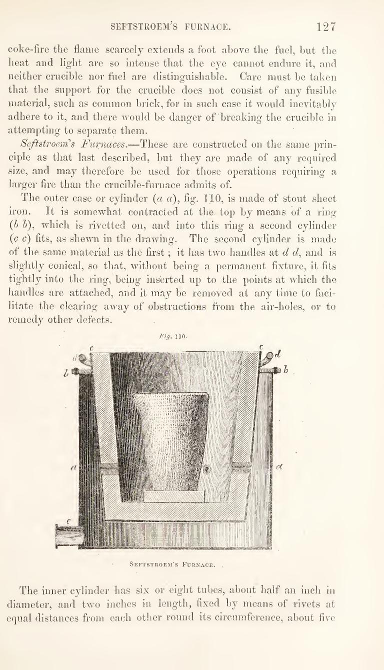
seftstroem’s furnace. 127
coke-fire the flame scarcely extends a foot above the fuel, but the
heat and light are so intense that the eye cannot endure it, and
neither crucible nor fuel are distinguishable. Care must be taken
that the support for the crucible does not consist of any fusible
material, such as common brick, for in such case it would inevitably
adhere to it, and there would be danger of breaking the crucible in
attempting to separate them.
Seftstroeiih s Furnaces,—These are constructed on the same prin¬
ciple as that last described, but they are made of any required
size, and may therefore be used for those operations requiring a
larger fire than the crucible-furnace admits of.
The outer case or cylinder {a a)^ fig. 110, is made of stout sheet
iron. It is somewhat contracted at the top by means of a ring
{h ^), which is rivetted on, and into this ring a second cylinder
{c c) fits, as shewn in the drawing. The second cylinder is made
of the same material as the first; it has two handles at d <7, and is
slightly conical, so that, without being a permanent fixture, it fits
tightly into the ring, being inserted up to the points at which the
handles are attached, and it may be removed at any time to faci¬
litate the clearing away of obstructions from the air-holes, or to
remedy other defects.
Fig, 110.
Seftstroem’s Furnace.
The inner cylinder has six or eight tubes, about half an inch in
diameter, and two inches in length, fixed by means of rivets at
equal distances from each other round its circumference, about five
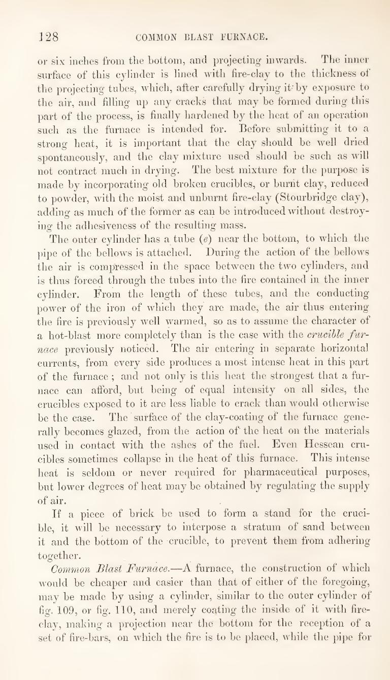
J28 COMMON BLAST FURNACE.
or six inches from the bottom, and projecting inwards. The inner
surface of this cylinder is lined with fire-clay to the thickness of
the projecting tubes, which, after carefully drying it-by exposure to
the air, and filling up any cracks that may be formed during this
part of the process, is finally hardened by the heat of an operation
such as the furnace is intended for. Before submitting it to a
strong heat, it is important that the clay should be well dried
spontaneously, and the clay mixture used should be such as will
not contract much in drying. The best mixture for the purpose is
made by incorporating old broken crucibles, or burnt clay, reduced
to powder, with the moist and unburnt fire-clay (Stourbridge clay),
adding as much of the former as can be introduced without destroy¬
ing the adhesiveness of the resulting mass.
The outer cylinder has a tube (e) near the bottom, to which the
pipe of the bellows is attached. During the action of the belloAvs
the air is compressed in the space between the two cylinders, and
is thus forced through the tubes into the fire contained in the inner
cylinder. From the length of these tubes, and the conducting
power of the iron of which they are made, the air thus entering
the fire is previously well warmed, so as to assume the character of
a hot-blast more completely than is the case with the crucible fur¬
nace previously noticed. The air entering in separate horizontal
currents, from every side produces a most intense heat in this part
of the furnace ; and not only is this heat the strongest that a fur¬
nace can afford, but being of equal intensity on all sides, the
crucibles exposed to it are less liable to crack than would otherwise
be the case. The surface of the clay-coating of the furnace gene¬
rally becomes glazed, from the action of the heat on the materials
used in contact with the ashes of the fuel. Even Hessean cru¬
cibles sometimes collapse in the heat of this furnace. This intense
heat is seldom or never required for pharmaceutical purposes,
but lower degrees of heat may be obtained by regulating the supply
of air.
If a piece of brick be used to form a stand for the cruci¬
ble, it will be necessary to interpose a stratum of sand between
it and the bottom of the crucible, to prevent them from adhering
together.
Common Blast Furnace.—A furnace, the construction of which
would be cheaper and easier than that of either of the foregoing,
may be made by using a cylinder, similar to the outer cylinder of
fig. 109, or fig. 110, and merely coating the inside of it with fire¬
clay, making a projection near the bottom for the reception of a
set of fire-bars, on which the fire is to be placed, while the pipe for
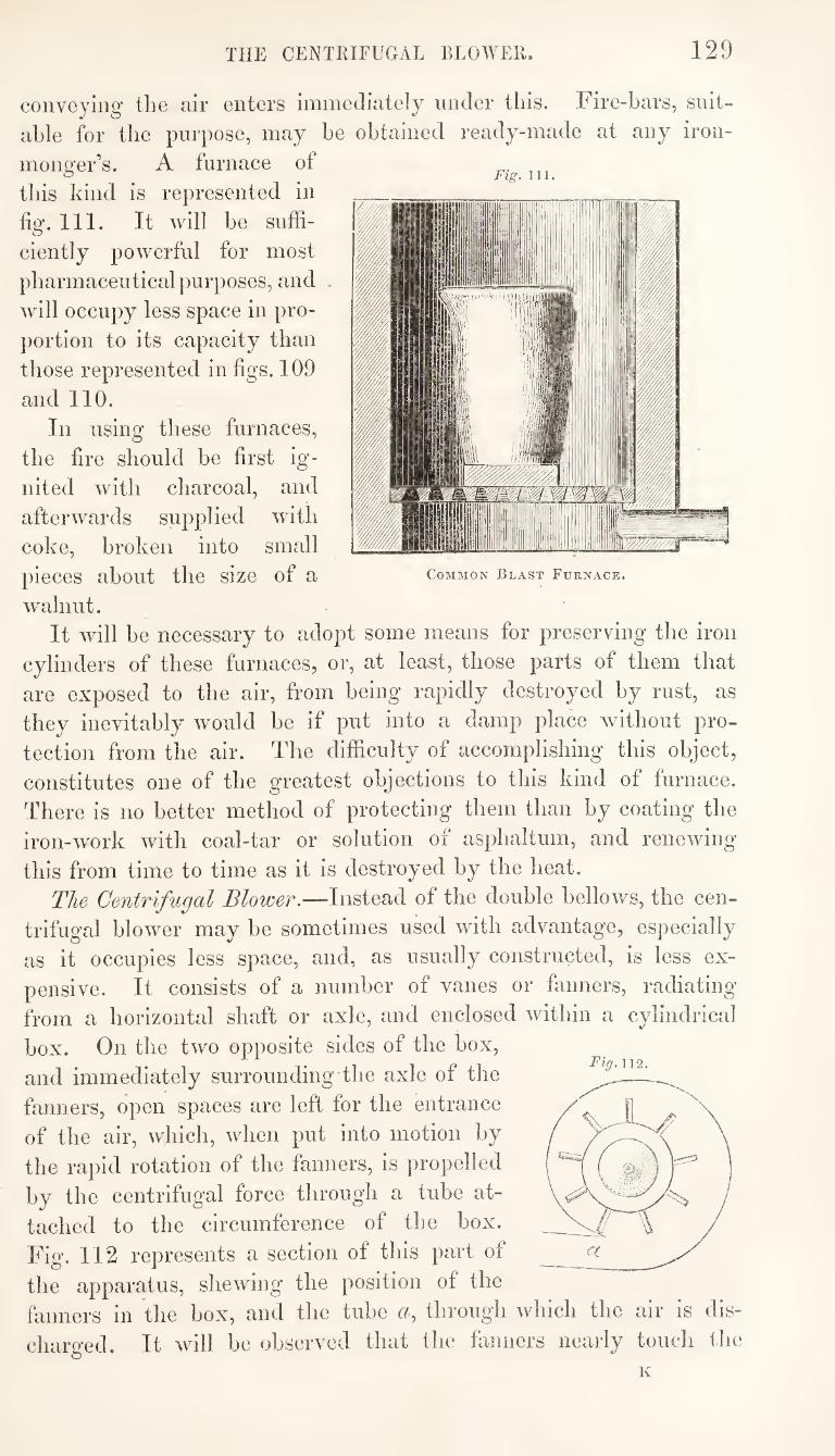
THE CENTRIFUGAL BLOWER. 129
Fig. Ill,
Common Blast Furnace.
coiiveyiHg the air enters immediately under this. Fire-bars, suit¬
able for the purpose, may be obtained ready-made at any iron¬
monger’s. A furnace of
this kind is represented in
fig. 111. It will be suffi¬
ciently powerful for most
pharmaceutical purposes, and .
will occupy less space in pro¬
portion to its capacity than
those represented in figs. 109
and 110.
In using these furnaces,
the fire should be first ig¬
nited with charcoal, and
afterwards supplied with
coke, broken into small
pieces about the size of a
walnut.
It will be necessary to adopt some means for preserving the iron
cylinders of these furnaces, or, at least, those parts of them that
are exposed to the air, from being rapidly destroyed by rust, as
they inevitably would be if put into a damp place without pro¬
tection from the air. The difficulty of accomplishing this object,
constitutes one of the greatest objections to this kind of furnace.
There is no better method of protecting them than by coating the
iron-work with coal-tar or solution of asphaltum, and renewing
this from time to time as it is destroyed by the heat.
The Centrifugal Blower.—Instead of the double bellows, the cen¬
trifugal blower may be sometimes used with advantage, especially
as it occupies less space, and, as usually constructed, is less ex¬
pensive. It consists of a number of vanes or fanners, radiating
from a horizontal shaft or axle, and enclosed within a cylindrical
box. On the two opposite sides of the box,
and immediately surrounding-the axle of the
fanners, open spaces are left for the entrance
of the air, which, when put into motion by
the rapid rotation of the fanners, is propelled
by the centrifugal force through a tube at¬
tached to the circumference of the box.
Fig. 112 represents a section of this part of
the apparatus, skewing the position of the
fanners in the box, and the tube «, through which the air is dis-
charo’ed. It will be observed that the fanners nearly touch the o “
K
Fig.112.
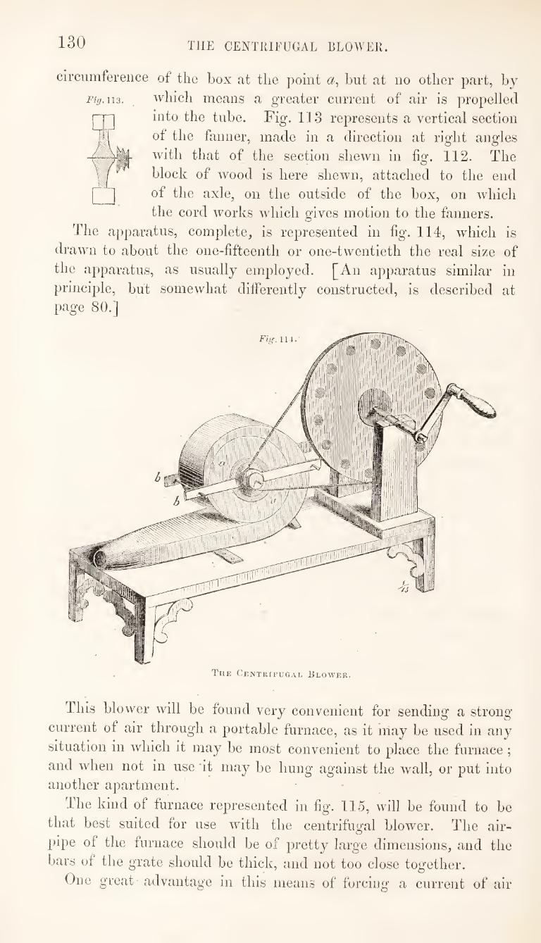
130 THE CENTRIFUGAL BLOWER.
circumference of the box at the point hut at no other part, by
Fig. 1X3. which means a greater current of air is propelled
into the tube. Fig. 113 represents a vertical section
of the fanner, made in a direction at right angles
with that of the section shewn in fig. 112. The
block of wood is here shewn, attached to the end
of the axle, on the outside of the box, on which
the cord works which gives motion to the fanners.
The apparatus, complete, is represented in fig. 114, which is
drawn to about the one-fifteenth or one-twentieth the real size of
the apparatus, as usually employed. [An apparatus similar in
principle, hut somewhat differently constructed, is described at
page 80.]
Fig. 114.
The Centrifugal Blower.
This blower will be found very convenient for sending a strong
current of air through a portable furnace, as it inay be used in any
situation in which it may be most convenient to place the furnace;
and when not in use 'it may be hung against the wall, or put into
another apartment.
The kind of furnace represented in fig. 115, will be found to be
that best suited for use with the centrifugal blower. The air-
pipe of the furnace should be of pretty large dimensions, and the
bars of the grate should be thick, and not too close together.
One great advantage in this means of forcing a current of air
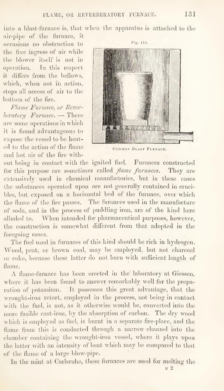
131 FLAME, OK KEVEKBEKATOKY FURNACE.
Fig. 115.
Common Blast Furnace.
into a blast-furnace is, that when the apparatus is attached to the
air-pipe of the furnace, it
occasions no obstruction to
the free ingress of air while
the blower itself is not in
operation. In this respect
it differs from the bellows,
which, when not in action,
stops all access of air to the
bottom of the fire.
Flame Furnace^ or Rever¬
beratory Furnace. —■ There
are some operations in which
it is found advantageous to
expose the vessel to be heat¬
ed to the action of the flame
and hot air of the fire with¬
out being in contact with the ignited fuel. Furnaces constructed
for this purpose are sometimes called flame furnaces. They are
extensively used in chemical manufactories, but in these cases
the substances operated upon are not generally contained in cruci¬
bles, but exposed on a horizontal bed of the furnace, over which
the flame of the fire passes. The furnaces used in the manufacture
of soda, and in the process of puddling iron, are of the kind here
alluded to. AVhen intended for pharmaceutical purposes, however,
the construction is somewhat different from that adopted in the
foregoing cases.
The fuel used in furnaces of this kind should be rich in hydrogen.
Wood, peat, or brown coal, may be employed, but not charcoal
or coke, because these latter do not burn with sufficient length of
flame.
A flame-furnace has been erected in the* laboratory at Giessen,
where it has been found to answer remarkably well for the prepa¬
ration of potassium. It possesses this great advantage, that the
wrought-iron retort, employed in the process, not being in contact
with the fuel, is not, as it otherwise would be, converted into the
more fusible cast-iron, by the absorption of carbon. The dry wood
which is employed as fuel, is burnt in a separate fire-place, and the
flame from this is conducted through a narrow channel into the
chamber containing the wrought-iron vessel, where it plays upon
the latter with an intensity of heat which may be compared to that
of the flame of a large blow-pipe.
In the mint at Carlsruhe, these furnaces are used for melting the
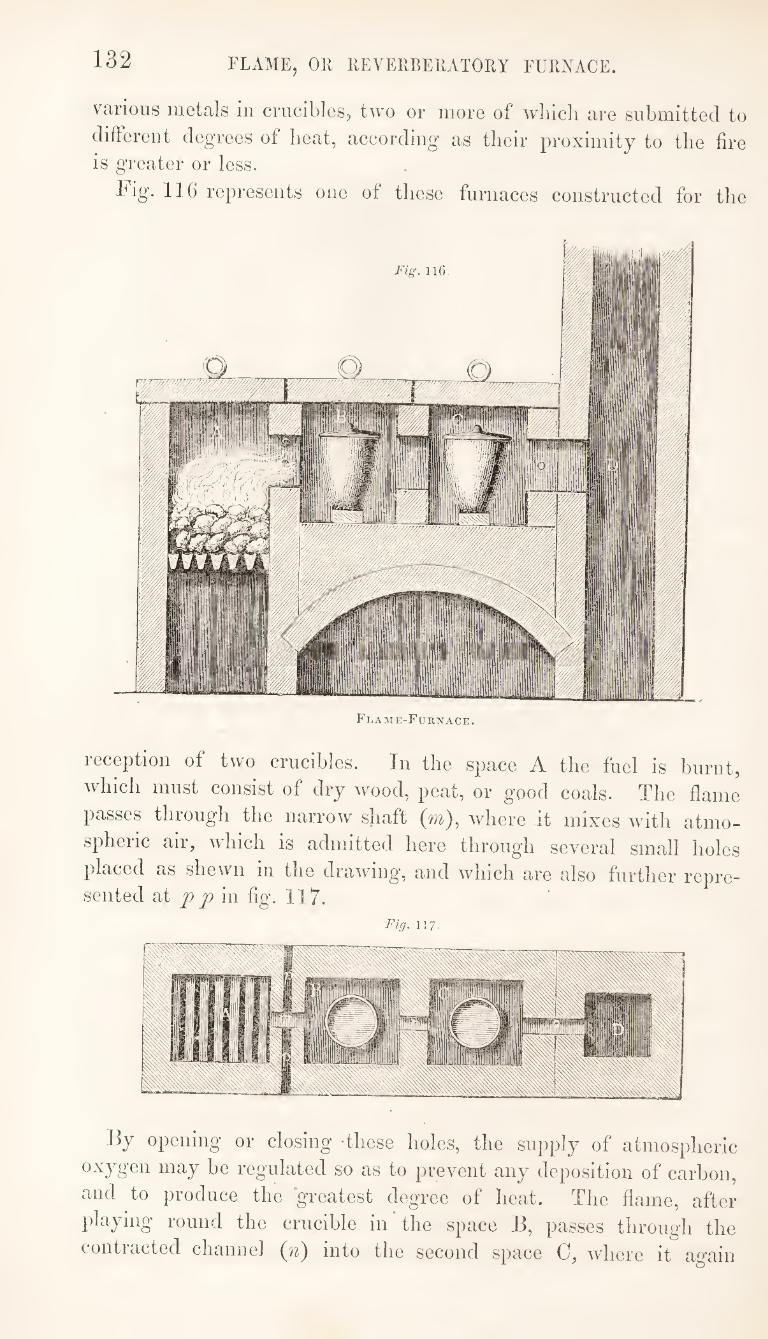
132 FLAME, Oil IIEVERBEIIATORY FURNACE.
various metals in crucibles, two or more of which are submitted to
diftereut degrees of heat, according as their proximity to the fire
is greater or less.
hig. 116 represents one of these furnaces constructed for the
Flame-Furnace.
1 eceptioii of two crucibles. In the space A the fuel is burnt,
which must consist of dry wood, peat, or good coals. The flame
passes through the narrow shaft (m), where it mixes with atmo¬
spheric air, which is admitted here through several small holes
placed as shewn in the drawing, and which are also further repre¬ sented at 11 ]) in fig. 117.
Fig. 117,
By opening or closing these holes, the supply of atmospheric
oxygen may be regulated so as to prevent any deposition of carbon,
and to produce the greatest degree of heat. The flame, after
})laying round the crucible in the space B, passes through the
contiacted channel into the second space C, where it again
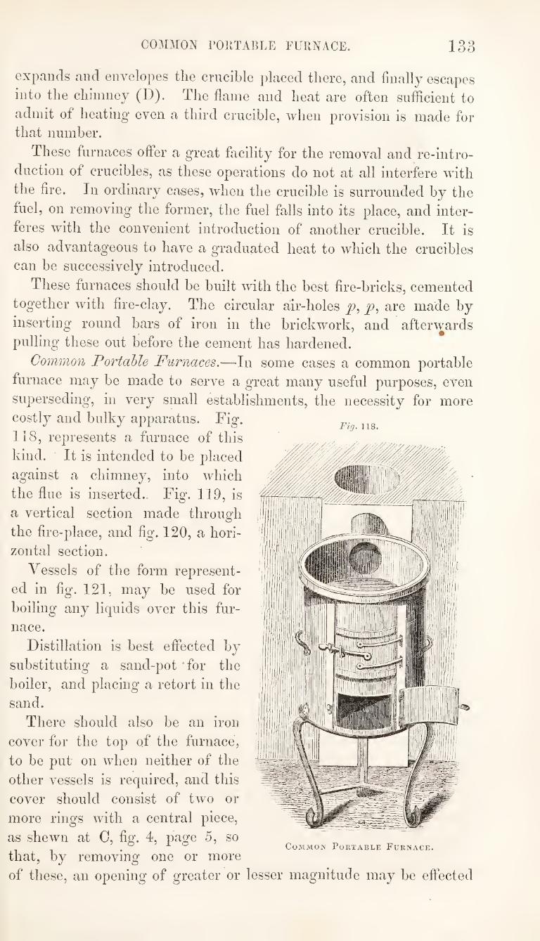
COMMON rOllTABLE FURNACE. 133
expands and envelopes the crucible placed there, and finally escapes
into the chimney (D). The flame and heat are often sufficient to
admit of heating even a third crucible, when provision is made for
that number.
These furnaces offer a great facility for the removal and re-intro¬
duction of crucibles, as these operations do not at all interfere with
the fire. In ordinary cases, when the crucible is surrounded by the
fuel, on removing the former, the fuel falls into its place, and inter¬
feres with the convenient introduction of another crucible. It is
also advantageous to have a graduated heat to which the crucibles
can be successively introduced.
These furnaces should be built with the best fire-bricks, cemented
together with fire-clay. The circular air-holes j?, are made by
inserting round bars of iron in the brickwork, and afterwards
pulling these out before the cement has hardened.
Common Portable Furnaces.—In some cases a common portable
furnace may be made to serve a great many useful purposes, even
superseding, in very small establishments, the necessity for more
costly and bulky apparatus. Fig.
118, represents a furnace of this
kind. It is intended to be placed
against a chimney, into which
the flue is inserted.. Fig. 119, is
a vertical section made through
the fire-place, and fig. 120, a hori¬
zontal section.
Vessels of the form represent¬
ed in fig. 121, may be used for
boiling any liquids over this fur¬
nace.
Distillation is best eflfected by
substituting a sand-pot 'for the
boiler, and placing a retort in the
sand.
There should also be an iron
cover for the top of the furnace,
to be put on when neither of the
other vessels is required, and this
cover should consist of two or
more rings with a central piece,
as shewn at 0, fig. 4, page 5, so
that, by removing one or more
of these, an opening of greater or lesser magnitude may be effected
Fig. 118.
Common Portable Furnace.
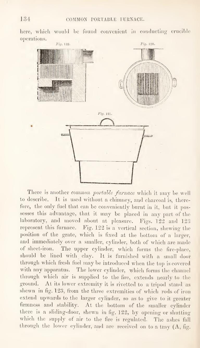
134 COMMON PORTABLE EURNACE.
here, which would be found convenient in conducting’ crucible
operations. Fig. 119. Fig. 120.
There is another common jjortable furnace which it may be well
to describe. It is used without a chimney, and charcoal is, there¬
fore, the only fuel that can be conveniently burnt in it, but it pos¬
sesses this advantage, that it may be placed in any part of the
laboratory, and moved about at pleasure. Figs. 122 and 123
represent this furnace. Fig. 122 is a vertical section, shewing the
position of the grate, which is fixed at the bottom of a larger,
and immediately over a smaller, cylinder, both of which are made
of sheet-iron. The upper cylinder, which forms the fire-place,
should be lined with clay. It is furnished with a small door
through which fresh fuel may be introduced when the top is covered
with any apparatus. The lower cylinder, which forms the channel
through which air is supplied to the fire, extends nearly to the
ground. At its lower extremity it is rivetted to a tripod stand as
shewn in fig. 123, from the three extremities of which rods of iron
extend upwards to the larger cylinder, so as to give to it greater
firmness and stability. At the bottom of the smaller cylinder
there is a sliding-door, shewn in fig. 122, by opening or shutting
which the supply of air to the fire is regulated. The ashes fall
through the lower cylinder, and are received on to a tray (A, fig.
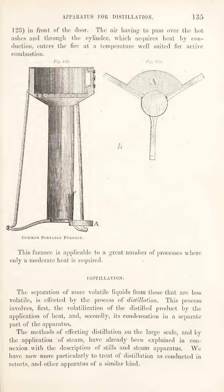
APPARATUS FOR DISTILLATION. 135
123) in front of the door. The air having to pass over the hot
ashes and through the cylinder, which acquires heat by con¬
duction, enters the fire at a temperature well suited for active
combustion. Fig. 122. ■ Fig. 12.'?.
This furnace is applicable to a great number of processes where
only a moderate heat is required.
DISTILLATION.
The separation of more volatile liquids from those that are less
volatile, is effected by the process of distillation. This process
involves, first, the volatilization of the distilled product by the
application of heat, and, secondly, its condensation in a separate
part of the apparatus.
The methods of effecting distillation ,on the large scale, and by
the application of steam, have already been explained in con¬
nexion with the description of stills arid steam apparatus. We
have now more particularly to treat of distillation as conducted in
retorts, and other apparatus of a similar kind.
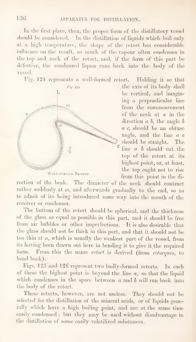
ArrAllATlIS FOR DISTILLATION. 13()
Fig. 124.
Well-formed Retort.
In the first place, tlien, the proper form of the distillatory vessel
should he considered. In the distillation of liquids Avhich boil only
at a high temperature, the shape of the retort has considerable
influence on the result, as much of the vapour often condenses in
the top and neck of the retort, and, if the form of this part be
defective, the condensed liquor runs back into the body of the
vessel.
Fig. 124 represents a well-formed retort. Holding it so that
the axis of its body shall
be vertical, and imagin¬
ing a perpendicular line
from the commencement
of the neck at a in the
direction a h, the angle h
a c, should be an obtuse
angle, and the line a c
should be straight. The
line a b should cut the
top of the retort at its
highest point, or, at least,
the top ought not to rise
from this point in the di¬
rection of the beak. The diameter of the neck should contract
rather suddenly at m, and afterwards gradually to the end, so as
to admit of its being introduced some way into the mouth of the
receiver or condenser.
The bottom of the retort should be spherical, and the thickness
of the glass as equal as possible in this part, and it should be free
from air bubbles or other imperfections. • It is also desirable that
the glass should not be thick in this part, and that it should not be
too thin at n, which is usually the weakest part of the vessel, from
its having been drawn out here in bending it to give it the required
form. From this the name retort is derived (from retorqueo^ to
bend back).
Figs. 125 and 126 represent two badly-formed retorts. In each
of these the highest point is beyond the line a, so that the liquid
which condenses in the space between a and h will run back into
the body of the retort.
These retorts, however, are not useless. They should not be
selected for the distillation of the mineral acids, or of liquids gene¬
rally which have a high boiling point, and are at the same time
easily condensed ; but they may be used without disadvantage in
the distillation of some easily volatilized substances.
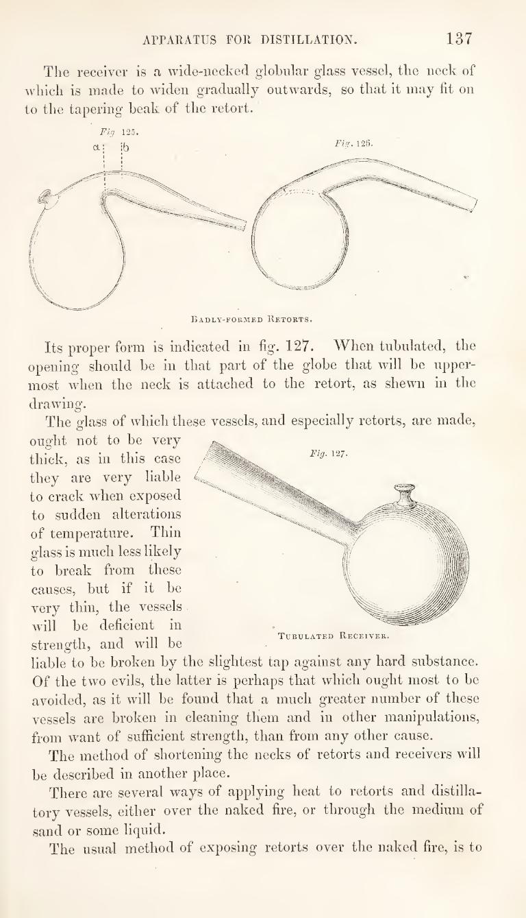
APPARATUS FOR DISTILLATION. 137
The receiver is a wide-necked globular glass vessel, tlie neck of
which is made to widen gradually outwards, so that it may fit on
to the tapering beak of the retort.
Fig 125.
Badly-formed Retorts.
Fig. 127.
4->
Its proper form is indicated in fig. 127. When tubulated, the
opening should be in that part of the globe that will be upper¬
most when the neck is attached to the retort, as shewn in the
drawing.
The glass of which these vessels, and especially retorts, are made,
ought not to be very
thick, as in this case
they are very liable
to crack when exposed
to sudden alterations
of temperature. Thin
glass is much less likely
to break from these
causes, but if it be
very thin, the vessels
will be deficient in
strength, and will be
liable to be broken by the slightest tap against any hard substance.
Of the two evils, the latter is perhaps that which ought most to be
avoided, as it will be found that a much greater number of these
vessels are broken in cleaning them and in other manipulations,
from want of sufficient strength, than from any other cause.
The method of shortening the necks of retorts and receivers will
be described in another place.
There are several ways of applying heat to retorts and distilla¬
tory vessels, either over the naked fire, or through the medium of
sand or some liquid.
The usual method of exposing retorts over the naked fire, is to
Tubulated Receiver.
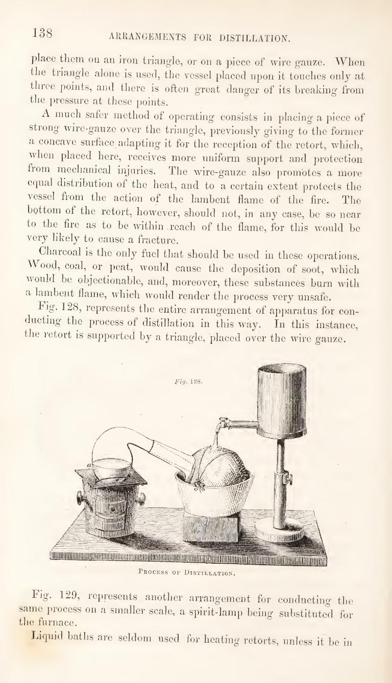
138 ARRANGEMENTS FOR DISTILLATION.
place tliem on an iron triangle, or on a piece of wire gauze. When the triangle alone is used, the vessel placed upon it touches only at thiee points, and there is often great danger of its breaking from the pressure at these points.
A much safer method ot operating consists in placing a piece of stiong wire-gauze over the triangle, previously giving to the former a concave surface adapting it for the reception of the retort, which, when placed here, receives more uniform support and protection fiom mechanical injuries. The wire-gauze also promotes a more equal distribution of the heat, and to a certain extent protects the vessel from the action of the lambent flame of the fire. The bottom of the retort, however, should not, in any case, be so near to the fire as to be within reach of the flame, for this would be very likely to cause a fracture.
^Charcoal is the only fuel that should be used in these operations, ood, coal, or peat, would cause the deposition of soot, which
would be objectionable, and, moreover, these substances burn with a lambent flame, which would render the process very unsafe.
Fig. 128, represents the entire arrangement of apparatus for con¬ ducting the process of distillation in this way. In this instance, the letort is supported by a triangle, placed over the wire ganze.
Process of Distillation.
Fig. 129, represents another arrangement for conducting tlie same process on a smaller scale, a spirit-lamp being substituted for the furnace.
Liquid baths are seldom used for heating retorts, unless it be in
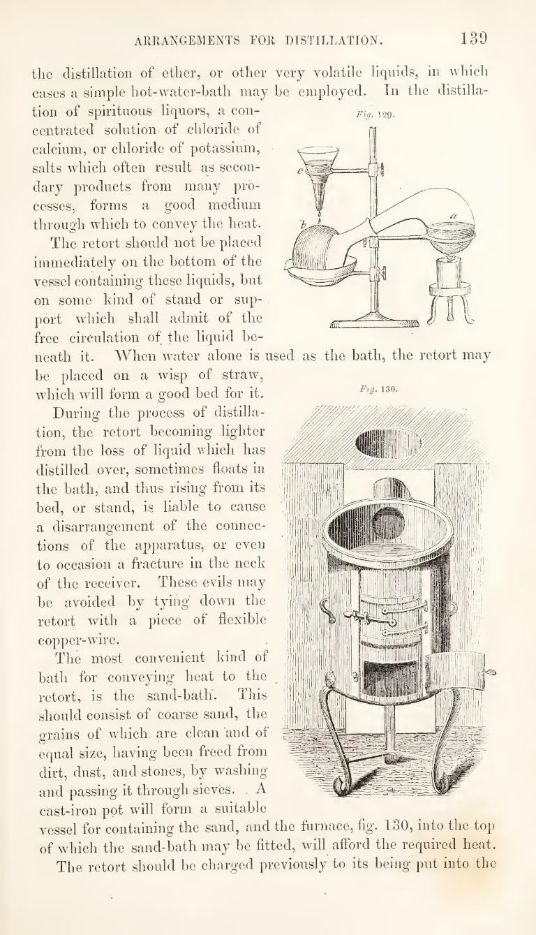
ARRANGEMENTS FOR DISTILLATION. 139
Fig. 129.
Fig. 130.
the distillation of ether, or other very volatile liquids, in which
cases a simple hot-water-bath may be employed. In the distilla¬
tion of spirituous liquors, a con¬
centrated solution of chloride of
calcium, or chloride of potassium,
salts which often result as secon¬
dary products from many pro¬
cesses, forms a good medium
through wliich to convey the heat.
The retort should not be placed
immediately on the bottom of the
vessel containing these liquids, but
on some kind of stand or sup¬
port which shall admit of the
free circulation of the liquid be¬
neath it. When winter alone is used as the bath, the retort may
be placed on a wasp of straw,
wdiich will form a good bed for it.
During the process of distilla¬
tion, the retort becoming lighter
from the loss of liquid which has
distilled over, sometimes floats in
the bath, and thus rising from its
bed, or stand, is liable to cause
a disarrangement of the connec¬
tions of the apparatus, or even
to occasion a fracture in the neck
of the receiver. These evils may
be avoided by tying down the
retort with a piece of flexible
copper-ware.
The most convenient kind of
bath for conveying heat to the
retort, is the sand-bath. This
should consist of coarse sand, the
grains of which are clean and of
equal size, having been freed from
dirt, dust, and stones, by washing
and passing it through sieves. A
cast-iron pot will form a suitable
vessel for containing the sand, and the furnace, fig. 180, into the top
of which the sand-bath may be fitted, will afford the required heat.
The retort should be charged previously to its being put into the
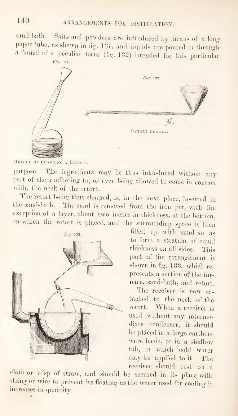
140 arrangements for distillation.
sand-bath. Salts and powders are introduced by means of a long
papei tube, as shewn in fig. ISI, and liquids are poured in through
a fniinol of a peculiar form (%. J 32) iiitemled for this particular Fig. 131.
Method of Charging a Retort.
Fig. 132.
Retort Funnel.
purpose. The ingredients may be thus introduced without any
part of them adhering to, or even being allowed to come in contact with, the neck of the retort.
The retort being thus charged, is, in the next place, inserted in
the sand-bath. The sand is removed from the iron pot, with the
exception of a layer, about two inches in thickness, at the bottom,
on which the retort is placed, and the surrounding space is then
filled up with sand so as
to form a stratum of equal
thickness on all sides. This
part of the arrangement is
shewn in fig. 133, which re¬
presents a section of the fur¬
nace, sand-bath, and retort.
The receiver is now at¬
tached to the neck of the
retort. When a receiver is
used without any interme¬
diate condenser, it should
be placed in a large eartlien-
ware basin, or in a shallow
tub, in which cold water
may be applied to it. The
receiver should rest on a cloth or wisp of straw, and should be secured in its place with
string or wire to prevent its floating as the water used for cooling it increases in quantity. ^
ARRANGEMENTS FOR DISTILLATION. 141
In most cases it will be found desirable to use a tubulated
receiver, so as to allow any uncondensable vapours to escape
through a bent tube attached to the tubulus. If a plain receiver
be used, the connexion between the beak of the retort and the
mouth of the receiver, must be such as to admit of the escape of
air or gases here, for in all cases the contained air of the vessels
will undergo expansion on the application of heat, and the pressure
which would be thus produced, if no provision were made for its
escape, would probably cause a fracture in the weaker parts of the
retort. In the distillation of nitric acid, it is customary to use a
plain receiver, merely inserting the neck of the retort loosely into
it, and taking care that it pass some way into the body of the
receiver. In most other cases it is preferable to make a close con¬
nexion at the mouth of the receiver, and to allow uncondensed
gases to escape at the tubulus.
The connection at the mouth of the receiver may be made in
several different w^ays, but some soft substance should always be
interposed between the retort and receiver, otherwise a fracture
would be very likely to take place, if the two unyielding surfaces
be brought into contact. A piece of folded paper is generally used
as the interposed substance; and when this has been fixed in its
place, some luting may be applied to the juncture on the outside, so
as to render it airtight. A strip of sheet India-rubber is sometimes
substituted for paper, and answers the purpose well, as it is less
easily acted upon by chemical agents than paper is, and, moreover,
it renders the connexion airtight without the use of luting. It
will be obvious, however, that in the distillation of ether and
essential oils, the use of caoutchouc would be inappropriate.
The top^of the receiver is covered with a cloth, and cold w^ater
is allowed to fall on to this in a continuous stream, as shewm in figs.
128 and 129.
[There are some cases in which this method of effecting the con¬
densation of distilled products will be found to be the best, as, for
instance, in the distillation of liquids which are easily condensable,
and in collecting which it is desirable to avoid any loss of the pro¬
duct from adhesion to the condenser, or any contact with organic
substances ‘such as would be used in making the connexions of
more complicated apparatus.]
In most cases, however, in which substances are distilled from a
retort, this arrangement would be subject to several objections.
It would often be difficult to effect the condensation-completely in
this way, and sometimes the receiver, becoming much more heated
in one part than another, may crack from the application of cold
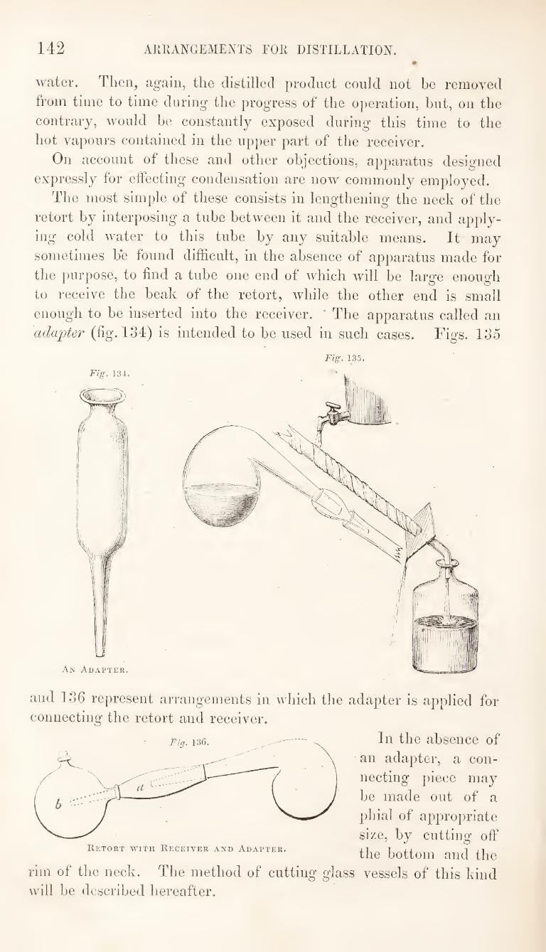
142 ARRANGEMENTS FOR DISTILLATION. #
water. Then, ag-aiii, the distilled product could not be removed
from time to time during the progress of the operation, but, on the
contrary, would be constantly exposed during this time to the
hot vapours contained in the upper part of the receiver.
On account of these and other objections, apparatus designed
expressly for effecting condensation are now commonly employed.
The most simple of these consists in lengthening the neck of the
retort by interposing a tube between it and the receiver, and apply¬
ing cold water to this tube by any suitable means. It may
sometimes be found difficult, in the absence of apparatus made for
the purpose, to find a tube one end of which will be large enough
to receive the beak of the retort, while the other end is small
enough to be inserted into the receiver. * The apparatus called an
adapter (fig. 134) is intended to be used in such cases. Figs. 135
Fig. 134.
An Adapter.
and 136 represent arrangements in which tlie adapter is applied for connecting the retort and receiver.
In the absence of
an adapter, a con¬
necting piece may
be made out of a
pbial of appropriate
size, by cutting off
the bottom and the
vessels of this kind rim of the neck. The method of cuttiim ffiass O O
will be described hereafter.
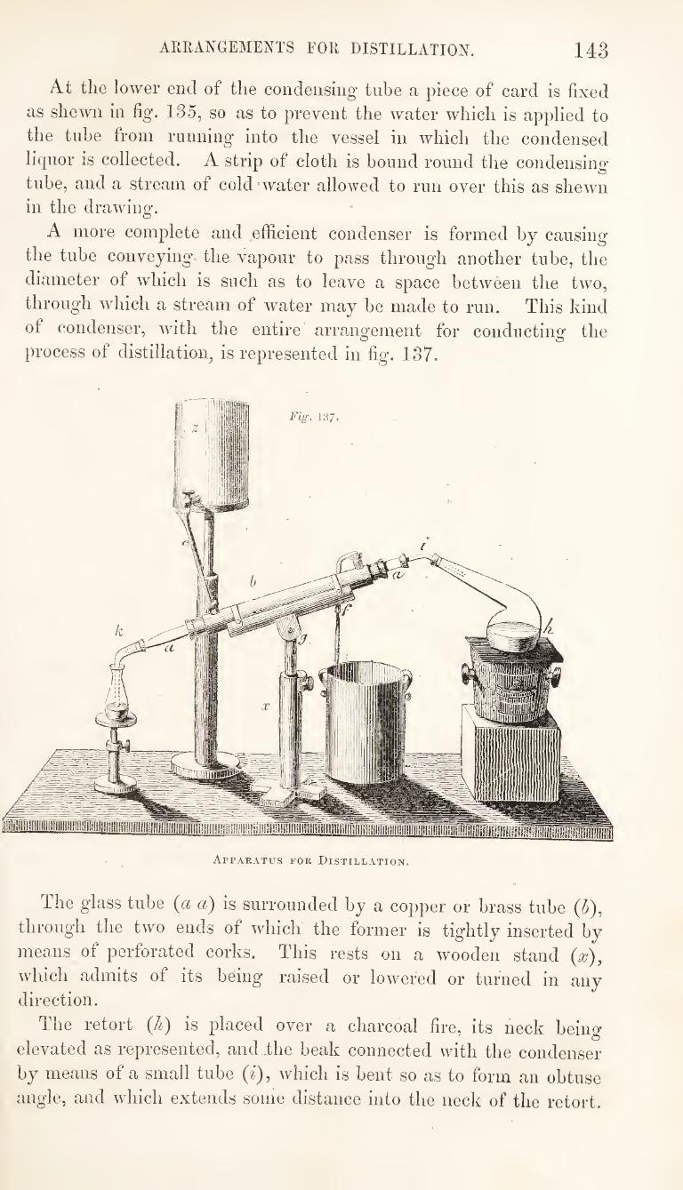
ARRANGEMENTS FOR DISTILLATION. 143
At the lower end of the condensing tube a piece of card is fixed
as shewn in fig. 135, so as to prevent the water which is applied to
the tube from running into the vessel in which the condensed
liquor is collected. A strip of cloth is bound round the condensing
tube, and a stream of cold'water allowed to run over this as shewn in the drawing.
A more complete and efficient condenser is formed by causing
the tube conveying the vapour to pass through another tube, the
diameter of which is such as to leave a space between the two,
through which a stream of water may be made to run. This kind
of condenser, with the entire arrano-ement for conductinof the
process of distillation, is represented in fig. 137.
The glass tube (a a) is surrounded by a copper or brass tube (5),
through the two ends of which the former is tightly inserted by
means of perforated corks. This rests on a wooden stand {x),
which admits of its being raised or lowered or turned in any direction.
The retort {li) is placed over a charcoal fire, its neck being
elevated as represented, and .the beak connected with the condenser
by means of a small tube (^), which is bent so as to form an obtuse
angle, and which extends some distance into the neck of the retort.
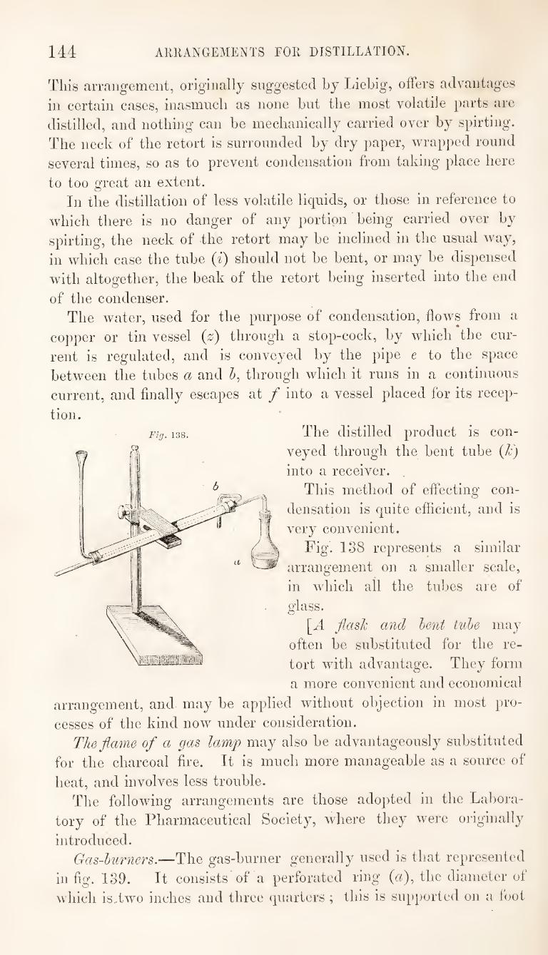
144 AKRANGEMENTS FOR DISTILLATION.
This arrangement, originally suggested by Liebig, offers advantages
in certain cases, inasmucb as none but the most volatile parts are
distilled, and nothing can be mechanically carried over by spirting.
The neck of the retort is surrounded by dry paper, wrapped round
several times, so as to prevent condensation from taking place here
to too great an extent. In the distillation of less volatile liquids, or those in reference to
which there is no danger of any portion being carried over by
spirting, the neck of the retort may be inclined in the usual way,
in which case the tube (i) should not be bent, or may be dispensed
with altogether, the beak of the retort being inserted into the end
of the condenser. The water, used for the purpose of condensation, flows from a
copper or tin vessel (z) through a stop-cock, by which the cur¬
rent is regulated, and is conveyed by the pipe e to the space
between the tubes a and 5, through which it runs in a continuous
current, and finally escapes at / into a vessel placed for its recep¬
tion. The distilled product is con¬
veyed through the bent tube (/c)
into a receiver.
This method of effecting con¬
densation is quite efficient, and is
very convenient.
Fig. 138 represents a similar
arrangement on a smaller scale,
in which all the tubes are of
glass.
[A flash and hent tube may
often be substituted for the re¬
tort with advantage. They form
a more convenient and economical
arrangement, and may be applied without objection in most pro¬
cesses of the kind now under consideration.
The flame of a gas lamp may also be advantageously substituted
for the charcoal fire. It is much more manageable as a source of
heat, and involves less trouble. The following arrangements are those adopted in the Labora¬
tory of the Pharmaceutical Society, where they were originally
introduced. Gas-burners.—The gas-burner generally used is that represented
in fig. 139. It consists of a perforated ring (a), the diameter of
which is,two inches and three quarters ; this is supported on a foot
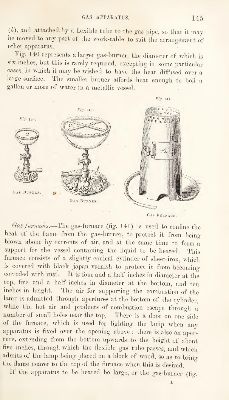
GAS APPARATUS. 145
(<^), and attached by a flexible tube to the gas-pipe, so that it may
be moved to any part of the work-table to suit the arrangement of other apparatus.
^ Fig. 140 represents a larger gas-burner, the diameter of which is
six inches, but this is rarely required, excepting in some particular
cases, in which it may be wished to have the heat diffused over a
large surface. The smaller burner affords heat enough to boil a gallon or more of water in a metallic vessel.
Fig. 141.
Gas-furnaces.—The gas-furnace (fig. 141) is used to confine the
heat of the flame from the gas-burner, to protect it from being
blown about by currents of air, and at the same time to form a
support for the vessel containing the liquid to be heated. This
furnace consists of a slightly conical cylinder of sheet-iron, which
is covered with black japan varnish to protect it from becoming
corroded with rust. It is four and a half inches in diameter at the
top, five and a half inches in diameter at the bottom, and ten
inches in height. The air for supporting the combustion of the
lamp is admitted through apertures at the bottom of the cylinder,
while the hot air and products of combustion escape through a
number of small holes near the top. There is a door on one side
of the furnace, which is used for lighting the lamp when any
apparatus is fixed over the opening above ; there is also an aper¬
ture, extending from the bottom upwards to the height of about
five inches, through which the flexible gas tube passes, and which
admits of the lamp being placed on a block of wood, so as to bring
the flame nearer to the top of the furnace when this is desired.
If the apparatus to be heated be large, or the gas-burner (fig.
L
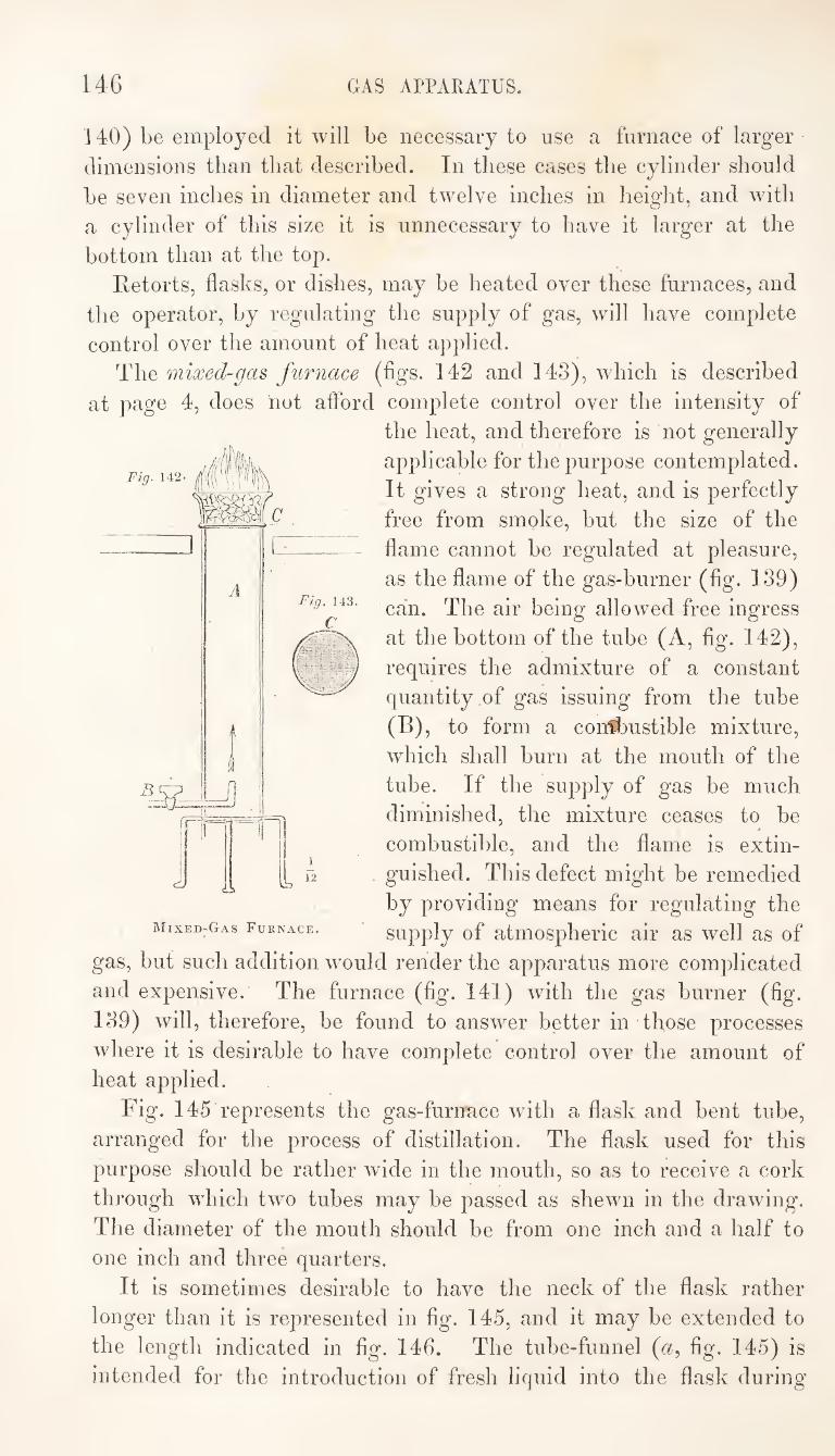
146 GAS APPARATUS.
Fig. 142
A
140) be employed it will be necessary to use a furnace of larger
dimensions than that described. In these cases the cylinder should
be seven inches in diameter and twelve inches in height, and with
a cylinder of this size it is unnecessary to have it larger at the
bottom than at the top.
Retorts, flasks, or dishes, may be heated over these furnaces, and
the operator, by regulating the supply of gas, will have complete
control over the amount of heat applied.
The mixed-gas furnace (figs. 142 and 143), which is described
at page 4, does not aftbrd complete control over the intensity of
the heat, and therefore is not generally
applicable for the purpose contemplated.
It gives a strong heat, and is perfectly
free from smoke, but the size of the
flame cannot be regulated at pleasure,
as the flame of the gas-burner (fig. 139)
can. The air being allowed free ingress
at the bottom of the tube (A, fig. 142),
requires the admixture of a constant
quantity of gas issuing from the tube
(B), to form a con^3ustible mixture,
which shall burn at the mouth of the
tube. If the supply of gas be much
diminished, the mixture ceases to be
combustible, and the flame is extin-
. guished. This defect might be remedied
by providing means for regulating the
supply of atmospheric air as well as of
gas, but such addition wmuld render the apparatus more complicated
and expensive. The furnace (fig. 141) with the gas burner (fig.
139) will, therefore, be found to answer better in those processes
where it is desirable to have complete control over the amount of
heat applied.
Fig. 145 represents the gas-furirace wdth a flask and bent tube,
arranged for the process of distillation. The flask used for this
purpose should be rather wide in the mouth, so as to receive a cork
through which two tubes may be passed as shewn in the drawing.
The diameter of the mouth should be from one inch and a half to
one inch and three quarters.
It is sometimes desirable to have the neck of the flask rather
longer than it is represented in fig. 145, and it may be extended to
the length indicated in fig. 146. The tube-funnel (a, fig. 145) is
intended for the introduction of fresh liquid into the flask during
y
MixeD'Gas Furnace,
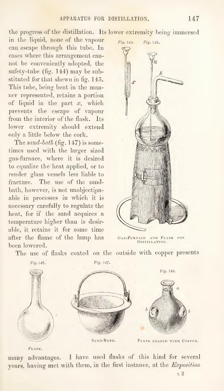
APPARATUS FOR DISTILLATION. 147
the progress of the distillation. Its lower extremity being immersed
in the liquid, none of the vapour
can escape through this tube. In
cases where this arrangement can¬
not be conveniently adopted, the
safety-tube (fig. 144) may be sub¬
stituted for that shewn in fig. 145.
This tube, being bent in the man¬
ner represented, retains a portion
of liquid in the part which
prevents the escape of vapour
from the interior of the flask. Its
lower extremity should extend
only a little below the cork.
The sand-hatJi (fig. 147) is some¬
times used with the larger sized
gas-furnace, wdiere it is desired
to equalize the heat applied, or to
render glass vessels less liable to
fracture. The use of the sand-
bath, however, is not unobjection¬
able in processes in which it is
necessary carefully to regulate the
heat, for if the sand acquires a
temperature higher than is desir¬
able, it retains it for some time
after the flame of the lamp has
been lowered.
The use of flasks coated on the
Fig, 144. Fig, 145.
Gas-Furnace and Flask for Distillation.
outside with copper presents
Fig.146. Fig, 147.
Flask.
many advantages. I have used flasks of this kind for several
years, having met with them, in the first instance, at the Exposition
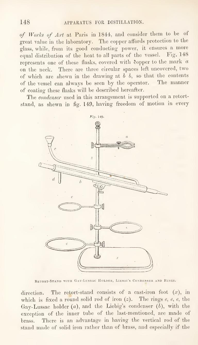
148 APPARATUS FOR DISTILLATION.
of Wo7'ks of Art at Paris in 1844, and consider tliem to be of
great value in the laboratory. The copper aifords protection to the
glass, while, from its good conducting power, it ensures a more
equal distribution of the heat to all parts of the vessel. Fig. 148
represents one of these flasks, covered with Copper to the mark a
on the neck. There are three circular spaces left uncovered, two
of which are shewn in the drawing at h J, so that the contents
of the vessel can always he seen by the operator. The manner
of coatinof these flasks will he described hereafter.
The condenser used in this arrangement is supported on a retort-
stand, as shewn in flg. 149, having freedom of motion in every
Tig. 149-
Retort-Stand WITH Gay-Lussac Holder, Liebig’s Condenser and Rings.
direction. The retort-stand consists of a cast-iron foot (^), in
which is fixed a round solid rod of iron (z). The rings e, e, e, the
Ga^^-Lussac holder (a), and the Liebig's condenser (h), with the
exception of the inner tube of the last-mentioned, are made of
brass. There is an advantage in having the vertical rod of the
stand made of solid iron rather than of brass, and especially if the
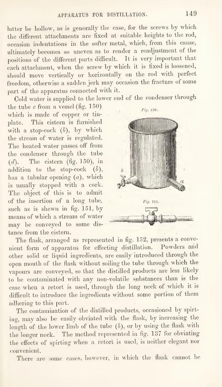
APPARATUS FOR DISTILLATION. 149
latter be hollow, as is generally the case, for the screws by which
the different attachments are fixed at suitable heights to the rod,
occasion indentations in the softer metal, which, from this cause,
ultimately becomes so uneven as to render a readjustment of the
positions of the different parts difficult. It is very important that
each attachment, when the screw by which it is fixed is loosened,
should move vertically or horizontally on the rod with perfect
freedom, otherwise a sudden jerk may occasion the fracture of some
part of the apparatus connected with it. Cold water is supplied to the lower end of the condenser through
the tube c from a vessel (fig. 150)
which is made of copper or tin¬
plate. This cistern is furnished
with a stop-cock (5), by which
the stream of water is regulated.
The heated water passes off from
the condenser through the tube
{d). The cistern (fig. 150), in
addition to the stop-cock (5),
has a tubular opening (a), which
is usually stopped with a cork.
The object of this is to admit
of the insertion of a long tube,
such as is shewn in fig. 151, by
means of which a stream of water
may be conveyed to some dis¬
tance from the cistern. The flask, arranged as represented in fig. 152, presents a conve¬
nient form of apparatus for effecting distillation. Powders arid
other solid or liquid ingredients, are easily introduced through the
open mouth of the flask without soiling the tube through which the
vapours are conveyed, so that the distilled products are less likely
to be contaminated with any non-volatile substances than is the
case when a retort is used, through the long neck of which it is
difficult to introduce the ingredients without some portion of them
adhering to this part. The contamination of the distilled products, occasioned by spirt¬
ing, may also be easily obviated with the flask, by increasing the
length of the lower limb of the tube (^), or by using the flask with
the longer neck. The method represented in fig. 137 for obviating
the effects of spirting when a retort is used, is neither elegant nor
convenient. There are some cases, however, in which the flask cannot be
Fig, 150.
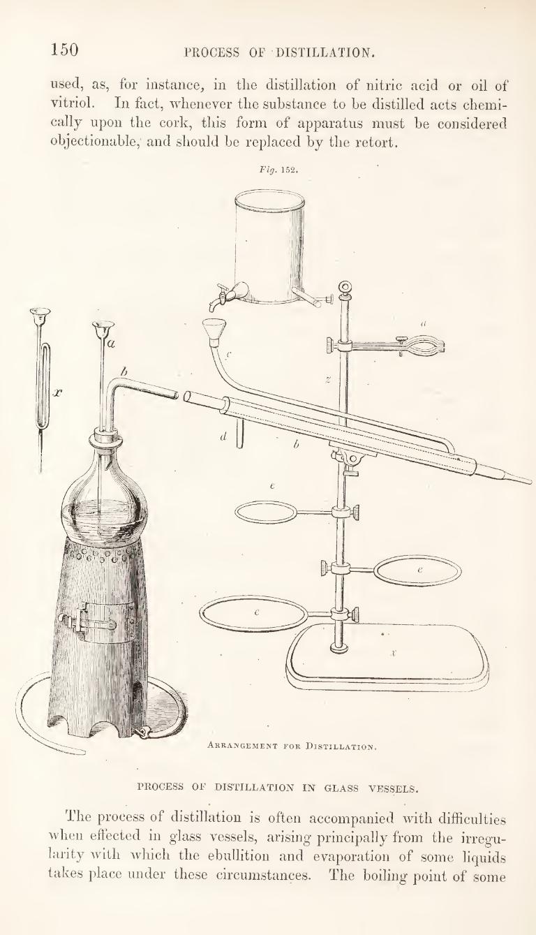
150 PROCESS OF DISTILLATION.
used, as, for instance, in the distillation of nitric acid or oil of
vitriol. In fact, whenever the substance to be distilled acts chemi¬
cally upon the cork, this form of apparatus must be considered
objectionable, and should be replaced by the retort.
Fig. 152.
Arrangement for Distillation.
PROCESS OF DISTILLATION IN GLASS VESSELS.
The process of distillation is often accompanied with difficulties
when eftected in glass vessels, arising principally from the irregu¬
larity with which the ebullition and evaporation of some liquids
takes place under these circumstances. The boiling point of some
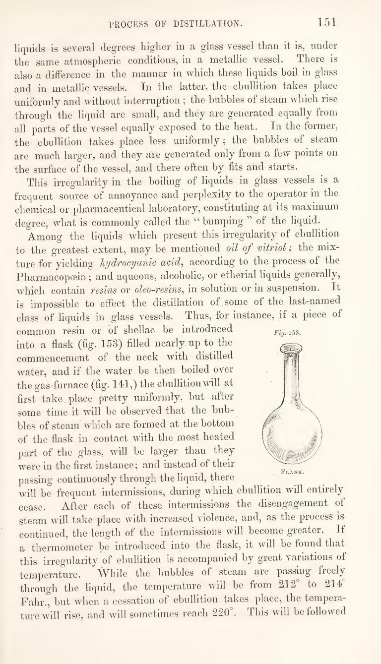
PROCESS OF DISTILLATION. 151
liquids is several degrees higher in a glass vessel than it is, under
the same atmospheric conditions, in a metallic vessel. There is
also a difference in the manner in which these liquids boil in glass
and in metallic vessels. In the latter, the ebullition takes place
uniformly and without interruption ; the bubbles of steam which rise
through the liquid are small, and they are generated equally from
all parts of the vessel equally exposed to the heat. In the former,
the ebullition takes place less uniformly ; the bubbles of steam
are much larger, and they are generated only from a few points on
the surface of the vessel, and there often by fits and starts.
This irregularity in the boiling of liquids in glass vessels is a
frequent source of annoyance and perplexity to the operator in the
chemical or pharmaceutical laboratory, constituting at its maximum
degree, what is commonly called the “bumping’’ of the liquid.
Among the liquids which present this irregularity of ebullition
to the greatest extent, may be mentioned oil of mtriol; the mix¬
ture for yielding hydrocyanic acid^ according to the process of the
Pharmacopoeia; and aqueous, alcoholic, or etherial liquids generally,
which contain resins or oleo-resins^ in solution or in suspension. It
Fig. 153.
is impossible to effect the distillation of some of the last-named
class of liquids in glass vessels. Thus, for instance, if a piece of
common resin or of shellac be introduced
into a flask (fig. 153) filled nearly up to the
commencement of the neck with distilled
water, and if the water be then boiled over
the gas-furnace (fig. 141,) the ebullition will at
first take place pretty uniformly, but after
some time it will be observed that the bub-^
bles of steam which are formed at the bottom
of the flask in contact with the most heated
part of the glass, will be larger than they
were in the first instance; and instead of their ^
passing continuously through the liquid, there will be frequent intermissions, during which ebullition will entirely
cease. After each of these intermissions the disengagement of
steam will take place with increased violence, and, as the process is
continued, the length of the intermissions will become greater. If
a thermometer be introduced into the flask, it will be found that
this irregularity of ebullition is accompanied by great variations of
temperature. While the bubbles of steam are passing freely
through the liquid, the temperature will be from 212 to 214
Fahr., but when a cessation of ebullition takes place, the tempera¬
ture will rise, and will sometimes reach 220k This will be followed
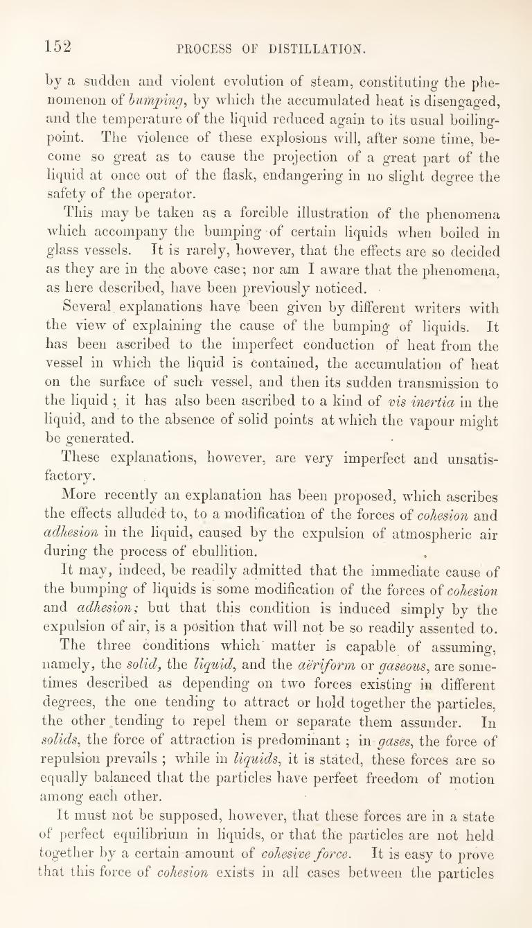
152 PROCESS OF DISTILLATION.
by a sudden and violent evolution of steam, constituting tlie phe¬
nomenon of humping, by which the accumulated heat is disengaged,
and the temperature of the liquid reduced again to its usual boiling-
point. The violence of these explosions will, after some time, be¬
come so great as to cause the projection of a great part of the
liquid at once out of the flask, endangering in no slight degree the
safety of the operator.
This may be taken as a forcible illustration of the phenomena
which accompany the bumping of certain liquids when boiled in
glass vessels. It is rarely, however, that the effects are so decided
as they are in the above case ; nor am I aware that the phenomena,
as here described, have been previously noticed.
Several explanations have been given by different writers with
the view of explaining the cause of the bumping of liquids. It
has been ascribed to the imperfect conduction of heat from the
vessel in which the liquid is contained, the accumulation of heat
on the surface of such vessel, and then its sudden transmission to
the liquid ; it has also been ascribed to a kind of ms inertia in the
liquid, and to the absence of solid points at which the vapour might
be generated.
These explanations, however, are very imperfect and unsatis¬ factory.
More recently an explanation has been proposed, which ascribes
the effects alluded to, to a modification of the forces of cohesion and
adhesion in the liquid, caused by the expulsion of atmospheric air during the process of ebullition.
It may, indeed, be readily admitted that the immediate cause of
the bumping of liquids is some modification of the forces of cohesion
and adhesion; but that this condition is induced simply by the
expulsion of air, is a position that will not be so readily assented to.
The three conditions which matter is capable of assuming,
namely, the solid, the liquid, and the aeriform or gaseous, are some¬
times described as depending on two forces existing in different
degrees, the one tending to attract or hold together the particles,
the other .tending to repel them or separate them assunder. In
solids, the force of attraction is predominant ; in gases, the force of
repulsion prevails ; while in liquids, it is stated, these forces are so
equally balanced that the particles have perfect freedom of motion
among each other.
It must not be supposed, however, that these forces are in a state
of perfect equilibrium in liquids, or that the particles are not held
together by a certain amount of cohesive force. It is easy to prove
that this force of cohesion exists in all cases between the particles
PKOCESS OF DISTILLATION. 153
of a liquid. A good illustration of it is afforded in the familiar
experiment of blowing a soap-bubble. This force may be roughly
estimated by suspending a plate of glass to one end of the beam
of a balance, adjusting the balance so that the glass shall be exactly
equipoised, then placing a vessel of water under the glass with the
two surfaces parallel to each other, and allowing contact to take
place. Tt will be found that some force will be required to break
the contact, which may be estimated by the weights put into the
opposite pan of the balance. An exemplification of the force of adhesion existing between a
liquid and a solid body with which it is in contact, is afforded in
the instances of capillarity, which are familiar to every one.
It cannot be denied, then, that the forces of cohesion and adhesion
exist; the former, between the particles of a liquid ; and the latter,
between the liquid and the vessel containing it. It will be evident,
too, on considering what occurs in the boiling of a liquid, that these
forces, in addition to the pressure of the atmosphere, have to be
overcome by the repulsive influence of the heat. In the boiling of
water, bubbles of steam are formed at the bottom of the vessel
containing it; and as the particles of the liquid are separated from
the surface of the vessel, as w'ell as from each other, on the forma¬
tion of each bubble of steam, it is evident that the tension of the
steam thus generated,, must be equal to the pressure of the atmo¬
sphere, ^lus the force of cohesion between the particles of liquid, or
of adhesion between the liquid and the surface of the vessel
containing it. Now, when water is boiled in a metallic vessel, it has been
found by Marcet, from some very carefully performed experiments,
that the temperature of the steam after quitting the water, is about
a third of a degree lower than that of the boiling water. This
difference of a third of a degree, then, may be considered to represent
a measure of the force of cohesion or adhesion in the water.
In glass vessels, the difference between the temperature of the
steam after quitting the water, and that of the boiling water,
amounts to more than the third of a degree, and this increased dif¬
ference accords with the higher boiling point of water in glass than
in metallic vessels. It is inferred, therefore, that the forces of
cohesion and adhesion are greater when water is boiled in glass
than in metallic vessels. But the results of these experiments afford a very inadequate
indication of the extent to which the forces of cohesion and adhe¬
sion are capable of existing in water and other liquids. It appears,
from the investigations of Mr. Henry, of Prince Town, in America,
154 PKOCESS OF DISTILLATION.
and of M. Donne, a Belgian Chemist, that these forces frequently
exist in liquids to a much greater extent than had previously been
supposed.
Donne found that oil of mtriol^ completely freed from air, intro¬
duced into the closed limb on an inverted syphon tube, and placed
under the receiver of an air-pump, is retained there in opposition
to the force of gravity, through the power of cohesion and adhesion
in the liquid.
The apparatus represented in fig. 154, will illustrate this experi¬
ment. The closed limb of the tube (B) is
filled with oil of vitriol, and the correspond¬
ing limb of the smaller tube (0) is filled with
mercury. The tubes being fixed to a stand,
are placed under the receiver (A), over an
air-pump, and the air is then pumped out.
The tube (0) containing the mercury, will
indicate the degree to which the receiver is
exhausted. A great number of air-bubbles
will be extricated from the oil of vitriol as
the exhaustion proceeds, and it will be neces¬
sary to re-admit the air into the receiver, and
remove the portion of air which will be found
to have collected in the top of the closed limb
of B, as long as any air continues to be dis¬
engaged from the oil of vitriol, on ex¬
hausting the receiver. This will not be
completely effected in less than six or eight days.
On commencing this operation, it will be
observed that the height of the columns of
oil of vitriol and of mercury supported in the
sealed limbs of the tubes by the pressure of
the atmosphere in the receiver, will be in
the same proportion as the specific gravities of
the liquids; that is to say, that mercury being 7'3 times heavier
than oil of vitriol, the column of oil of vitriol will be 7*3 times
longer than that of mercury. Thus, when the column of mercury
is half an inch, that of the oil of vitriol will be rather more than
three and a half inches. When, however, the greater part of the
air has been extracted from the oil of vitriol, the respective heights
of the columns will no longer maintain this relation with any cer¬
tainty. The oil of vitriol will frequently not fall in the tube (B)
until long after the time at which such a result has been indicated
Forces of Cohesion and
Adhesion in Oil of Vitriol.
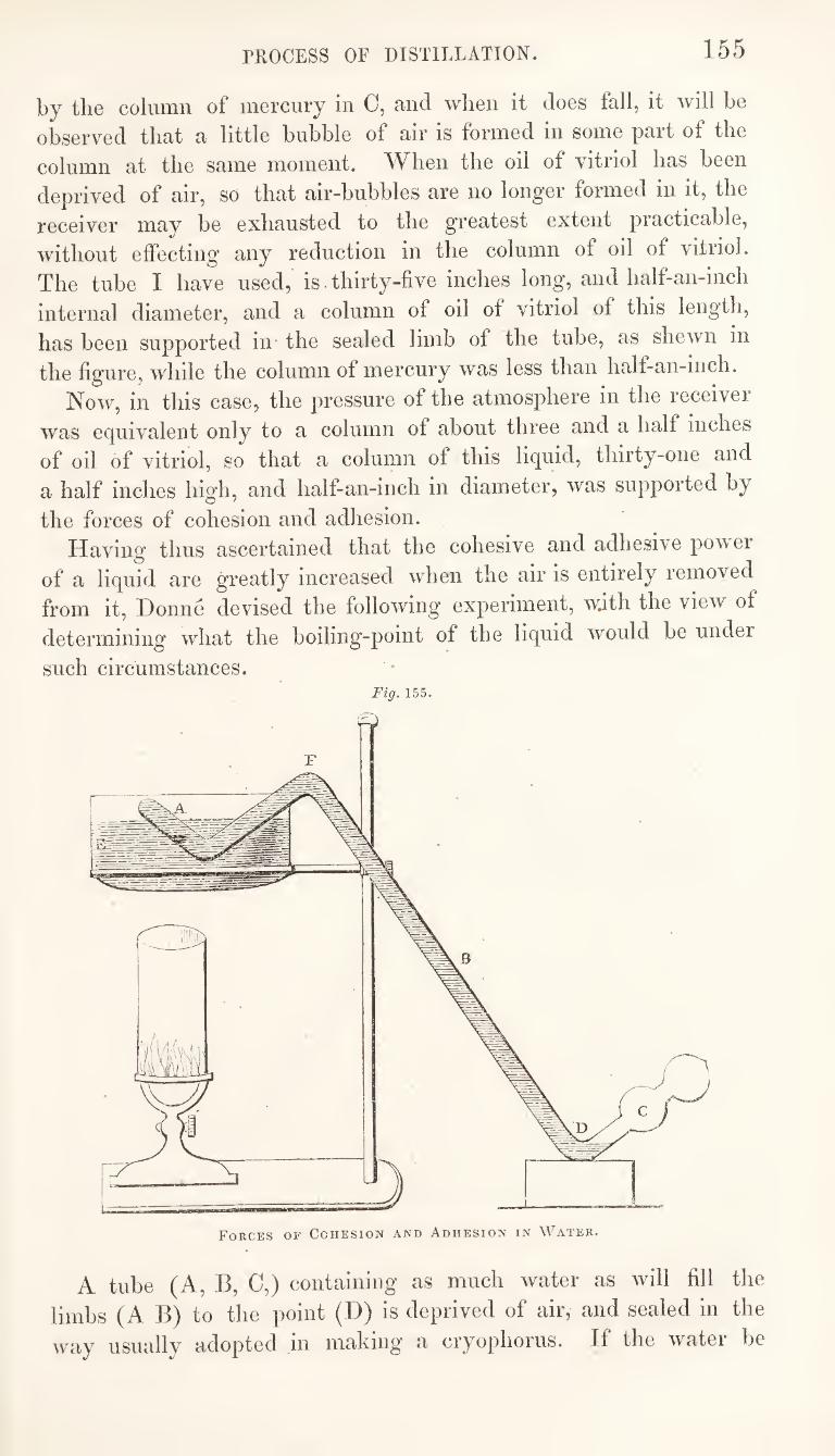
PROCESS OF DISTILLATION. 155
by the column of mercury in C, and when it does fall, it will be
observed that a little bubble of air is formed in some part of the
column at the same moment. When the oil of vitriol has been
deprived of air, so that air-bubbles are no longer formed in it, the
receiver may be exhausted to the greatest extent practicable,
without effecting any reduction in the column of oil of vitriol.
The tube I have used, is thirty-five inches long, and half-an-inch
internal diameter, and a column of oil of vitriol of this length,
has been supported in the sealed limb of the tube, as shewn in
the figure, whde the column of mercury was less than half-an-inch.
Now, in this case, the pressure of the atmos^diere in the receiver
was equivalent only to a column of about three and a half inches
of oil of vitriol, so that a column of this liquid, thirty-one and
a half inches high, and half-an-inch in diameter, was supported by
the forces of cohesion and adhesion. Having thus ascertained that the cohesive and adhesive powei
of a liquid are greatly increased when the air is entirely removed
from it, Donne devised the following experiment, with the view of
determining what the boiling-point of the liquid would be under
such circumstances. Fig. 155.
A tube (A, B, C,) containing as much water as will fill the
limbs (A B) to the point (D) is deprived of air, and sealed in the
way usuallv adopted in making’ a cryophorus. If the watei be
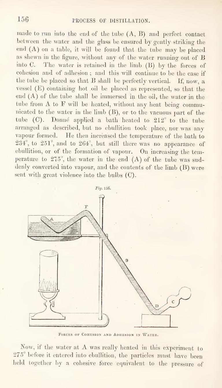
156 PROCESS OF DISTILLATION.
made to run into the end of the tube (A, B) and perfect contact
between the water and the glass be ensured by gently striking the
end (A) on a table, it will be found that the tube may be placed
as shewn in the figure, without any of the water running out of B
into C. The water is retained in the limb (B) by the forces of
cohesion and of adhesion ; and this will continue to be the case if
the tube be placed so that B shall be perfectly vertical. If, now, a
vessel (E) containing hot oil be placed as represented, so that the
end (A) of the tube shall be immersed in the oil, the water in the
tube from A to F will be heated, without any heat being commu¬
nicated to the water in the limb (B), or to the vacuous part of the
tube (C). Donne applied a bath heated to 212° to the tube
arranged as described, but no ebullition took place, nor was any
vapour formed. He then increased the temperature of the bath to
234°, to 251°, and to 264°, but still there was no appearance of
ebullition, or of the formation of vapour. On increasing the tem¬
perature to 275°, the water in the end (A) of the tube was sud¬
denly converted into vapour, and the contents of the limb (B) were
sent with great violence into the bulbs (0).
Fig. 156.
Now, if the water at A was really heated in this experiment to
275° before it entered into ebullition, the particles must have been
held together by a cohesive force equivalent to the pressure of
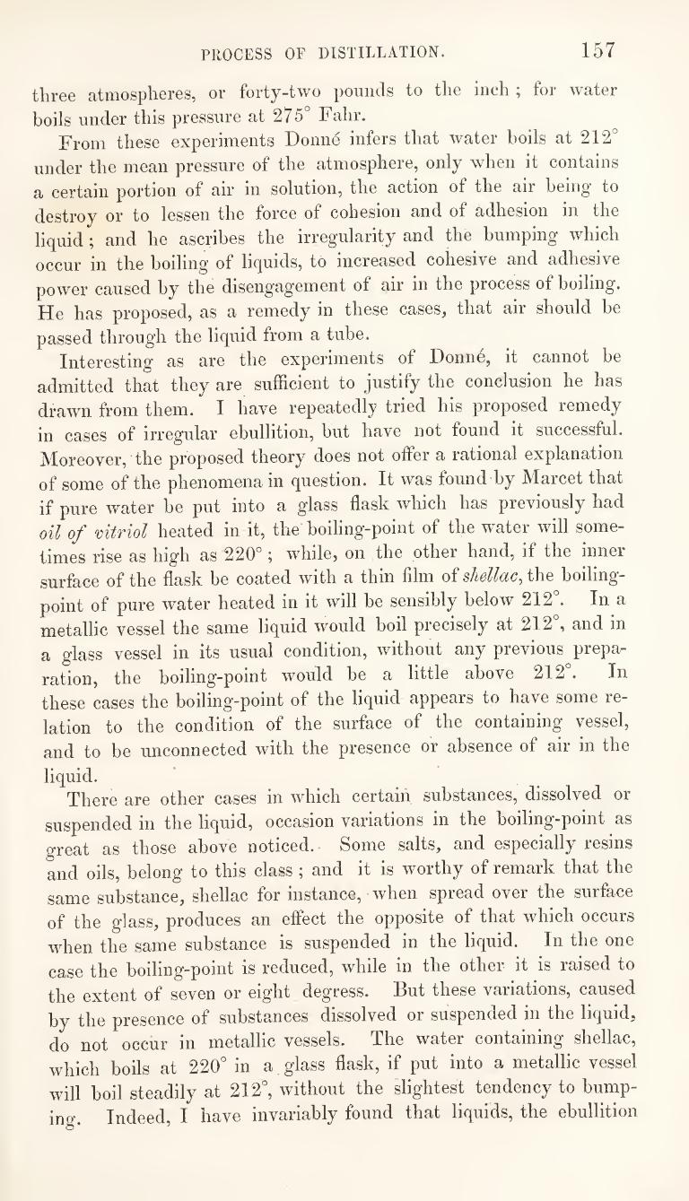
PROCESS OF DISTILLATION. 157
tlir66 atiiiospliGros, or forty-two pounds to tlio incli ^ foi wutGr
boils under this pressure at 275° Falir. From these experiments Donne infers that water boils at 212°
under the mean pressure of the atmosphere, only when it contains
a certain portion of air in solution, the action of the air being to
destroy or to lessen the force of cohesion and of adhesion in the
liquid ; and he ascribes the irregularity and the bumping which
occur in the boiling of liquids, to increased cohesive and adhesive
power caused by the disengagement of air in the process of boiling.
He has proposed, as a remedy in these cases, that air should be
passed through the liquid from a tube. Interesting as are the experiments of Donn6, it cannot be
admitted that they are sufficient to justify the conclusion he has
drawn from them. I have repeatedly tried his proposed remedy
in cases of irregular ebullition, but have not found it successful.
IVIoreover, the proposed theory does not offer a rational explanation
of some of the phenomena in question. It was found by Marcet that
if pure water be put into a glass flask which has previously had
oil of mtriol heated in it, the boiling-point of the water will some¬
times rise as high as 220°; while, on the other hand, if the inner
surface of the flask be coated with a thin film of shellac, the boiling-
point of pure water heated in it will be sensibly below 212°. In a
metallic vessel the same liquid would boil precisely at 212°, and in
a glass vessel in its usual condition, without any previous prepa¬
ration, the boiling-point would be a little above 212°. In
these cases the boiling-point of the liquid appears to have some re¬
lation to the condition of the surface of the containing vessel,
and to be unconnected with the presence or absence of air in the
liquid. There are other cases in which certain substances, dissolved or
suspended in the liquid, occasion variations in the boiling-point as
great as those above noticed. Some salts, and especially resins
and oils, belong to this class ; and it is worthy of remark that the
same substance, shellac for instance, when spread over the surface
of the glass, produces an effect the opposite of that which occurs
when the same substance is suspended in the liquid. In the one
case the boiling-point is reduced, while in the other it is raised to
the extent of seven or eight degress. But these variations, caused
by the presence of substances dissolved or suspended in the liquid,
do not occur in metallic vessels. The water containing shellac,
which boils at 220° in a glass flask, if put into a metallic vessel
will boil steadily at 212°, without the slightest tendency to bump¬
ing. Indeed, I have invariably found that liquids, the ebullition
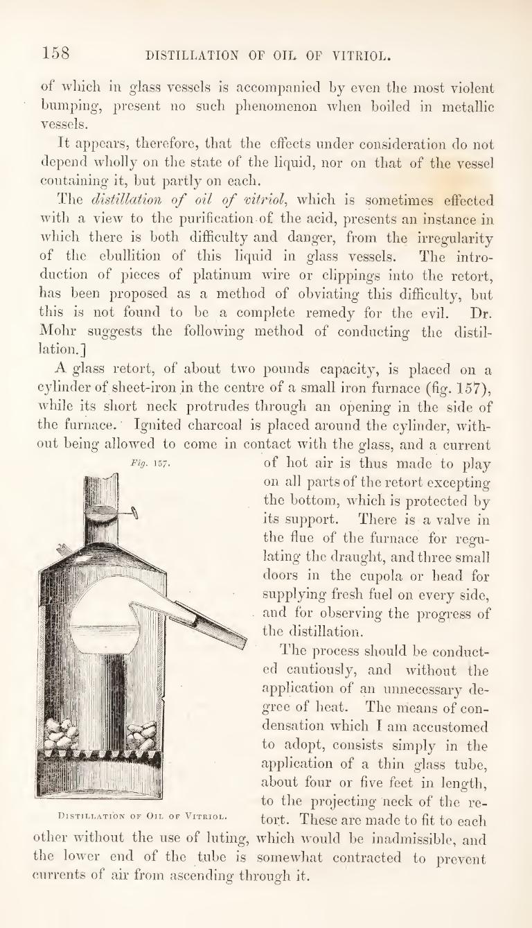
158 DISTILLATION OF OIL OF VITRIOL.
of which in glass vessels is accompanied by even the most violent
bumping, present no such phenomenon when boiled in metallic vessels.
It appears, therefore, that the effects under consideration do not
depend wholly on the state of the liquid, nor on that of the vessel
containing it, but partly on each.
The distillation of oil of mtriol^ which is sometimes effected
with a view to the purification of the acid, presents an instance in
which there is both difficulty and danger, from the irregularity
of the ebullition of this liquid in glass vessels. The intro¬
duction of pieces of platinum wire or clippings into the retort,
has been proposed as a method of obviating this difficulty, but
this is not found to be a complete remedy for the evil. Dr.
Mohr suggests the following method of conducting the distil¬ lation.]
A glass retort, of about two pounds capacity, is placed on a
cylinder of sheet-iron in the centre of a small iron furnace (fig. 157),
while its short neck protrudes through an opening in the side of
the furnace. Ignited charcoal is placed around the cylinder, with¬
out being allowed to come in contact with the glass, and a current
of hot air is thus made to play
on all parts of the retort excepting
the bottom, which is protected by
its support. There is a valve in
the flue of the furnace for regu¬
lating the draught, and three small
doors in the cupola or head for
supplying fresh fuel on every side,
and for observing the progress of
the distillation.
The process should be conduct¬
ed cautiously, and without the
application of an unnecessary de¬
gree of heat. The means of con¬
densation which I am accustomed
to adopt, consists simply in the
application of a thin glass tube,
about four or five feet in length,
to the projecting neck of the re¬
tort. These are made to fit to each
other without the use of luting, which would be inadmissible, and
the lower end of the tube is somewhat contracted to prevent
currents of air from ascending through it.
Fig. 157.
Distillation of Oil of Vitriol.
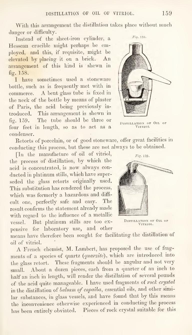
DISTILLATION OF OIL OF VITRIOL. 159
With this arrangement the distillation takes place without much
danger or difficulty. Instead of the sheet-iron cylinder, a
Hessean crucible might perhaps be em¬
ployed, and this, if requisite, might be
elevated by placing it on a brick. An
arrangement of this kind is shewn in
fig. 158. I have sometimes used a stoneware
bottle, such as is frequently met with in
commerce. A bent glass tube is fixed in
the neck of the bottle by means of plaster
of Paris, the acid being previously in¬
troduced. This arrangement is shewn in
fig. 159. The tube should be three or
four feet in length, so as to act as a
condenser. Eetorts of porcelain, or of good stoneware, offer great facilities in
conducting this process, but these are not always to be obtained.
[In the manufacture of oil of vitriol,
the process of distillation, by which the
acid is concentrated, is now always con¬
ducted in platinum stills, wdiich have super¬
seded the glass retorts originally used.
This substitution has rendered the process,
which was formerly a hazardous and diffi¬
cult one, perfectly safe and easy. The
result confirms the statement already made
with regard to the influence of a metallic
vessel. But platinum stills are too ex¬
pensive for laboratory use, and other means have therefore been sought for facilitating the distillation of
oil of vitriol. A French chemist, M. Lambert, has proposed the use of frag¬
ments of a species of quartz {quarzite)^ which are introduced into
the glass retort. These fragments should be angular and not very
small. About a dozen pieces, each from a quarter of an inch to
half an inch in length, will render the distillation of several pounds
of the acid quite manageable. I have used fragments of rocJc crystal
in the distillation of halsam of copaiba, essential oils, and other simi¬
lar substances, in glass vessels, and have found that by this means
the inconvenience otherwise experienced in conducting the process
has been entirely obviated. Pieces of rock crystal suitable for this
Fig. 159.
Distillation of Oil of
Vitriol.
Fig. 158.
Distillation of Oil of
Vitriol
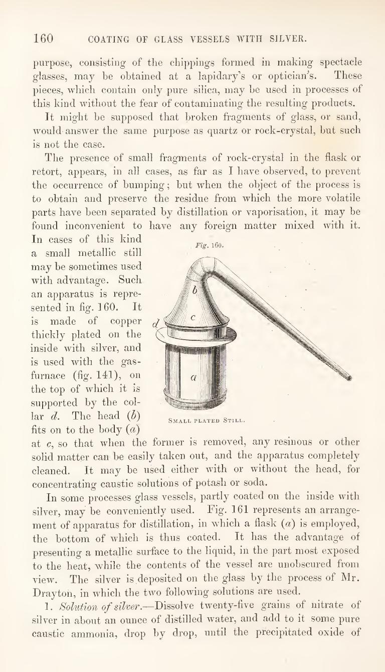
160 COATING OF GLASS VESSELS AVITH SILVER.
Fig. 160.
purpose, consisting of the chippings formed in making spectacle
glasses, may be obtained at a lapidary's or optician^s. These
pieces, which contain only pure silica, may he used in processes of
this kind without the fear of contaminating the resulting products.
It might be supposed that broken fragments of glass, or sand,
would answer the same purpose as quartz or rock-crystal, but such
is not the case.
The presence of small fragments of rock-crystal in the flask or
retort, appears, in all cases, as far as I have observed, to prevent
the occurrence of bumping; but when the object of the process is
to obtain and preserve the residue from which the more volatile
parts have been separated by distillation or vaporisation, it may be
found inconvenient to have any foreign matter mixed with it.
In cases of this kind
a small metallic still
may be sometimes used
with advantage. Such
an apparatus is repre¬
sented in fig. 160. It
is made of copper
thickly plated on the
inside with silver, and
is used with the gas-
furnace (fig. Ill), on
the top of which it is
supported by the col¬
lar d. The head (b)
fits on to the body {a) at c, so that when the former is removed, any resinous or other
solid matter can be easily taken out, and the apparatus completely
cleaned. It may be used either with or without the head, for
concentrating caustic solutions of potash or soda.
In some processes glass vessels, partly coated on the inside with
silver, may be conveniently used. Fig. 161 represents an arrange¬
ment of apparatus for distillation, in which a flask {a) is employed,
the bottom of which is thus coated. It has the advantage of
presenting a metallic surface to the liquid, in the part most exposed
to the heat, while the contents of the vessel are unobscured from
view. The silver is deposited on the glass by the process of Mr.
Drayton, in which the two following* solutions are used.
I. Solution of silver.—Dissolve twenty-five grains of nitrate of
silver in about an ounce of distilled water, and add to it some pure
caustic ammonia, drop by drop, until the precipitated oxide of
Small plated Still.
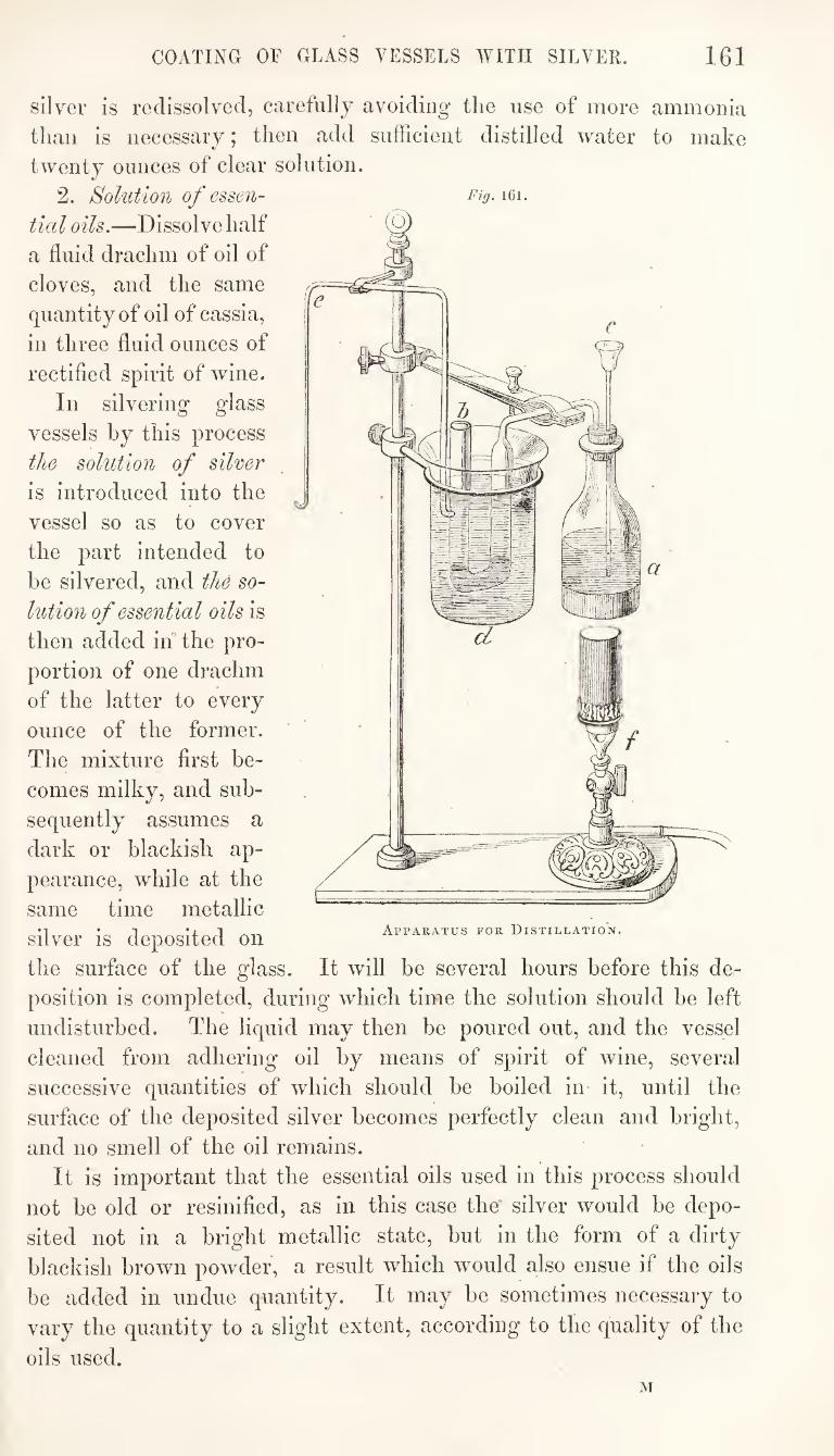
COATING OF GLASS VESSELS WITH SILVER. 161
silver is redissolved, carefully avoiding the use of more ammonia
than is necessary; then add sufficient distilled water to make
twenty ounces of clear solution.
2. Solution of essen-
tial oils.—Dissolve half
a fluid drachm of oil of
cloves, and the same
quantity of oil of cassia,
in three fluid ounces of
rectified spirit of wine.
In silvering glass
vessels by this process
the solution of silver
is introduced into the
vessel so as to cover
the part intended to
be silvered, and the so¬
lution of essential oils is
then added in the pro¬
portion of one drachm
of the latter to every
ounce of the former.
The mixture first be¬
comes milky, and sub¬
sequently assumes a
dark or blackish ap¬
pearance, while at the
same time metallic
silver is deposited on
the surface of the glass. It will be several hours before this de¬
position is completed, during which time the solution should be left
undisturbed. The liquid may then be poured out, and the vessel
cleaned from adhering oil by means of spirit of wine, several
successive quantities of which should be boiled in it, until the
surface of the deposited silver becomes perfectly clean and bright,
and no smell of the oil remains.
It is important that the essential oils used in this process should
not be old or resinified, as in this case the' silver would be depo¬
sited not in a bright metallic state, but in the form of a dirty
blackish brown powder, a result which would also ensue if the oils
be added in undue quantity. It may be sometimes necessary to
vary the quantity to a slight extent, according to tire quality of the
oils used. M
Apparatus for Distillation.
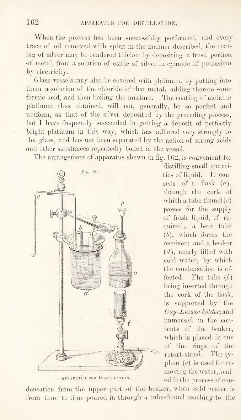
162 APPARATUS FOR DISTILLATION.
Fig. 16
When the process has been successfully performed, and every
trace of oil removed with spirit in the manner described, the coat¬
ing of silver may he rendered thicker by depositing a fresh portion
of metal, from a solution of oxide of silver in cyanide of potassium
by electricity.
Glass vessels may also be covered with platinum, by putting into
them a solution of the chloride of that metal, adding thereto some
formic acid, and then boiling the mixture. The coating of metallic
platinum thus obtained, will not, generally, be so perfect and
uniform, as that of the silver deposited by the preceding process,
but I have frequently succeeded in getting a deposit of perfectly
bright platinum in this way, which has adhered very strongly to
the glass, and has not been separated by the action of strong acids
and other substances repeatedly boiled in the vessel.
The arrangement of apparatus shewn in fig. 162, is convenient for
distilling small quanti¬
ties of liquid. It con¬
sists of a flask (a),
through the cork of
which a tube-funnel (c)
])asses for the supply
of fresh liquid, if re¬
quired ; a bent tube
(^), which forms the
receiver; and a beaker
' {d), nearly filled with
cold water, by which
the condensation is ef¬
fected. The tube (b)
being inserted through
the cork of the flask,
is supported by the
Gay-Lussac holder
immersed in the con¬
tents of the beaker,
which is placed in one
of the rings of the
retort-stand. The sy¬
phon {e) is used for re¬
moving the water, heat¬
ed in the process of con¬
densation from the upper part of the beaker, when cold water is
from time to time poured in through a tube-funnel reaching to the
Apparatus for Distillation.
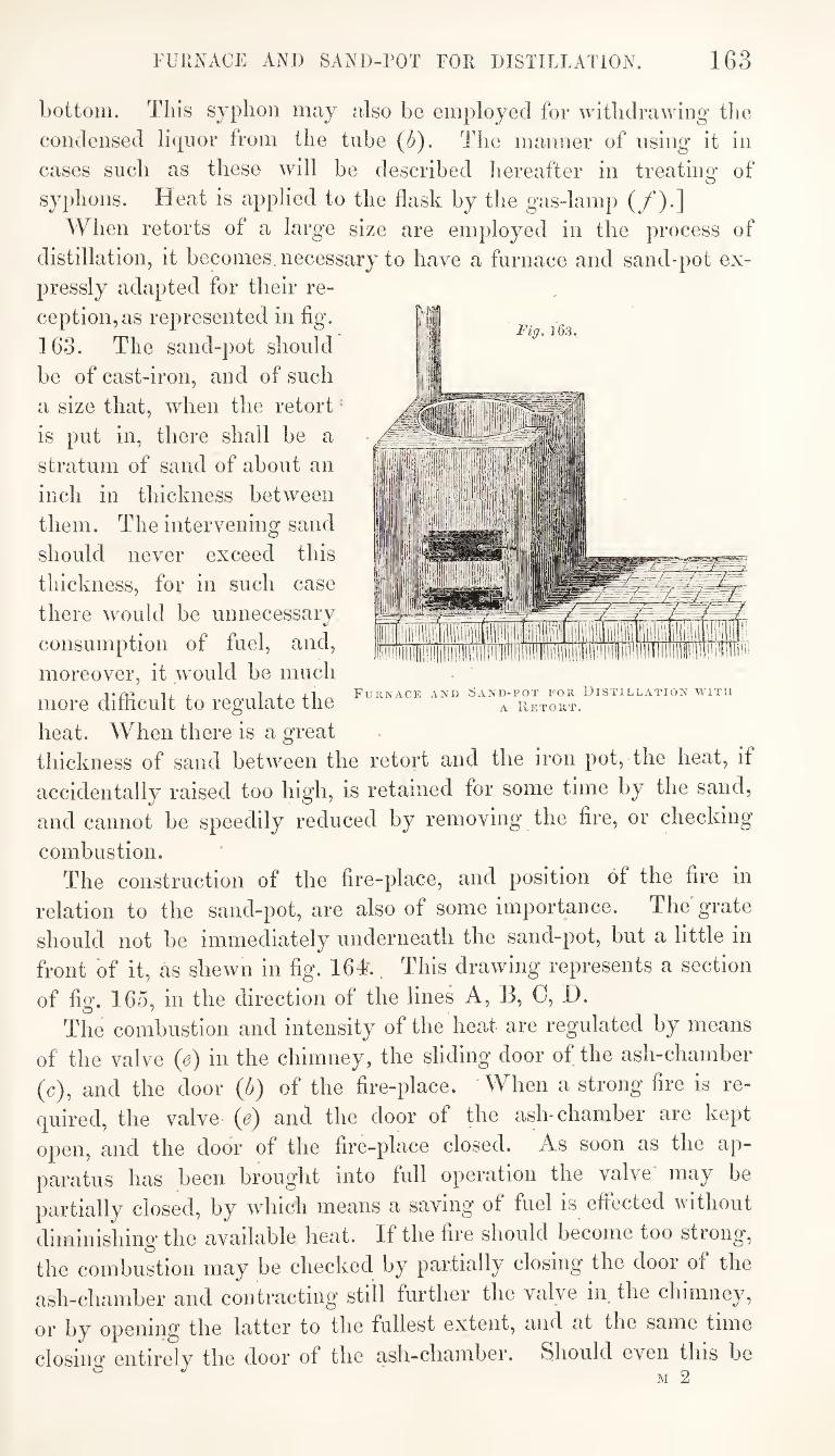
FURNACE AND SAND-ROT FOR DISTILLATION. 163
Fig. 163.
Furnace and Sand-pot for Distillation with A Retort.
bottom. This syphon may also be employed for withdrawing’ the condensed liquor from the tube (^). The manner of using it in cases such as these will be described hereafter in treating of syphons. Heat is applied to the flask by the gas-lamp (/*).]
When retorts of a large size are employed in the process of distillation, it becomes, necessary to have a furnace and sand-pot ex¬ pressly adapted for their re¬ ception, as represented in flg. 163. The sand-pot should be of cast-iron, and of such a size that, when the retort' is put in, there shall be a stratum of sand of about an inch in thickness between them. The intervening sand should never exceed this thickness, for in such case there would be unnecessary consumption of fuel, and, moreover, it would be much more diflicult to regulate the heat. When there is a great thickness of sand between the retort and the iron pot, the heat, if accidentally raised too high, is retained for some time by the sand, and cannot be speedily reduced by removing the fire, or checking
combustion. The construction of the fire-place, and position of the fire in
relation to the sand-pot, are also of some importance. The grate should not be immediately underneath the sand-pot, but a little in front of it, as shewn in fig. 164 This drawing represents a section
of fig. 165, in the direction of the lines A, B, C, D. The combustion and intensity of the heat are regulated by means
of the valve (e) in the chimney, the sliding door of the ash-chamber (c), and the door (5) of the fire-place. When a strong fire is re¬ quired, the valve (e) and the door of the ash-chamber are kept open, and the door of the fire-place closed. As soon as the ap¬ paratus has been brought into full operation the valve may be partially closed, by which means a saving of fuel is efiected without diminishing the available heat. If the fire should become too strong, the combustion may be checked by partially closing the door of the ash-chamber and contracting still further the valve in the chimney, or by opening the latter to the fullest extent, and at the same time
closing entirely the door of the ash-chamber. Should even this be M 2
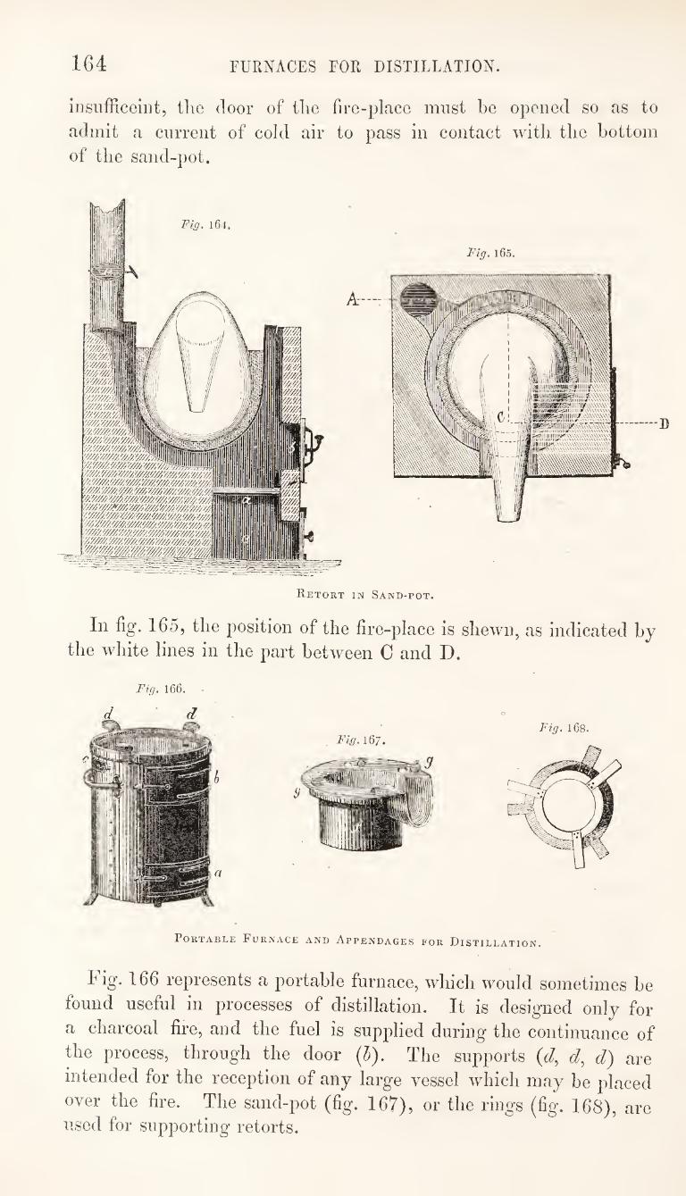
164 FURNACES FOR DISTILLATION.
menfficeint, the door of the fire-place must be opened so as to
admit a current of cold air to pass hi contact with the bottom
of the sand-pot.
Fig. l6 t
Fig. lG5.
Retort in Sand-pot.
In fig. 165, the position of the fire-place is shewn, as indicated by
the white lines in the part between 0 and D.
Fig. 166.
d d
Portable Furnace and Appendages for Distillation.
Fig. 166 represents a portable furnace, which would sometimes be
found useful in processes of distillation. It is designed only for
a charcoal fire, and the fuel is supplied during the continuance of
the process, through the door (5). The supports {d^ d) are
intended for the reception of any large vessel which may be placed
over the fire. The sand-pot (fig. 167), or the rings (fig. 168), are used for supporting retorts.
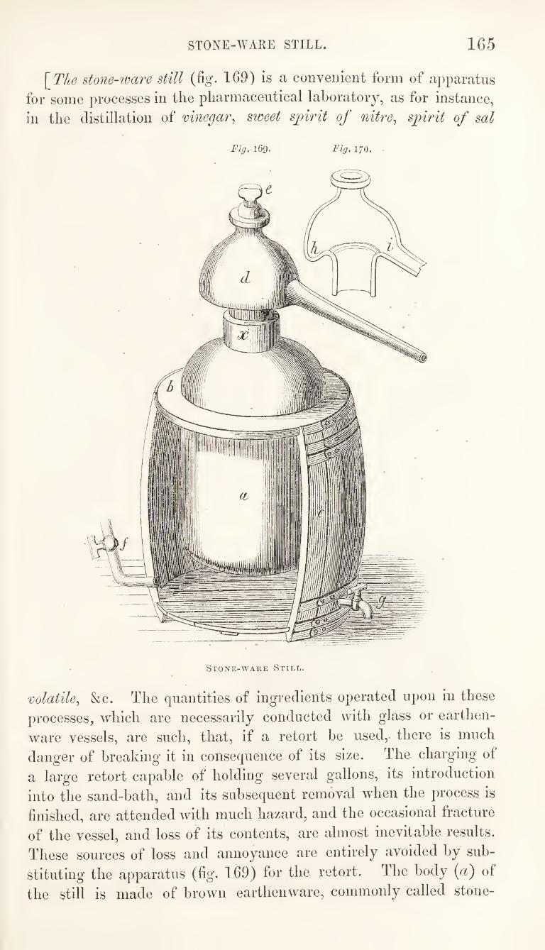
STONE-WARE STILL. 165
\Tlie stone-ware still (%. 169) is a convenient form of apparatus
for some processes in the pharmaceutical laboratory, as for instance,
in the distillation of vinegar^ sweet spirit of nitre, spirit of sal
Fig, 169. Fig. 170.
Stone-ware Still.
volatile, &c. The quantities of ingredients operated upon in these
processes, which are necessarily conducted with glass or earthen¬
ware vessels, are such, that, if a retort be used, there is much
danger of breaking it in consequence of its size. The charging of
a large retort capable of holding several gallons, its introduction
into the sand-bath, and its subsequent removal when the process is
finished, are attended with much hazard, and the occasional fracture
of the vessel, and loss of its contents, are almost inevitable results.
These sources of loss and annoyance are entirely avoided by sub¬
stituting the apparatus (fig. 169) for the retort. The body {a) of
the still is made of brown earthenware, commonly called stone-
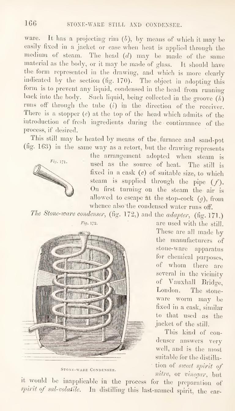
166 STONE-WARE STILL AND CONDENSER.
ware. It has a projecting rim (/;), by means of which it may he
easily fixed in a jacket or case when heat is applied through the
medium of steam. The head (t/) may he made of the same
material as the body, or it may he made of glass. It shonld have
the form represented in the drawing, and which is more clearly
indicated by the section (fig. 170). The object in adopting this
form is to prevent any liquid, condensed in the head from running
hack into the body. Such liquid, being collected in the groove (h)
runs off through the tube (i) in the direction of the receiver.
There is a stopper (e) at -the top of the head which admits of the
introduction of fresh ingredients during the continuance of the process, if desired.
This still may be heated by means of the furnace and sand-pot
(fig. 163) in the same way as a retort, but the drawing represents
the arrangement adopted when steam is
used as the source of heat. The still is
fixed in a cask ((?) of suitable size, to which
steam is supplied through the pipe (/).
On first turning on the steam the air is
allowed to escape at the stop-cock (y), from
whence also the condensed water runs off.
The Stone-ware condenser, (fig. 172,) and the adai^ter, (fig. I7l,)
172. ' are used with the still.
These are all made by
the manufacturers of
stone-ware apparatus
for chemical purposes,
of whom there are
several in the vicinity
of V auxhall Brido-e,
London. The stone¬
ware worm may he
fixed in a cask, similar
to that used as the
jacket of the still.
This kind of con¬
denser answers very
well, and is the most
suitable for the distilla-
rii], 171.
^ tion of sweet spirit of Stone-ware Condenser. . , ^
nitre, or vinegar, but it would be inapplicable in the process for the prejiaration of
spirit of sal-volatile. In distilling this last-named spirit, the car-
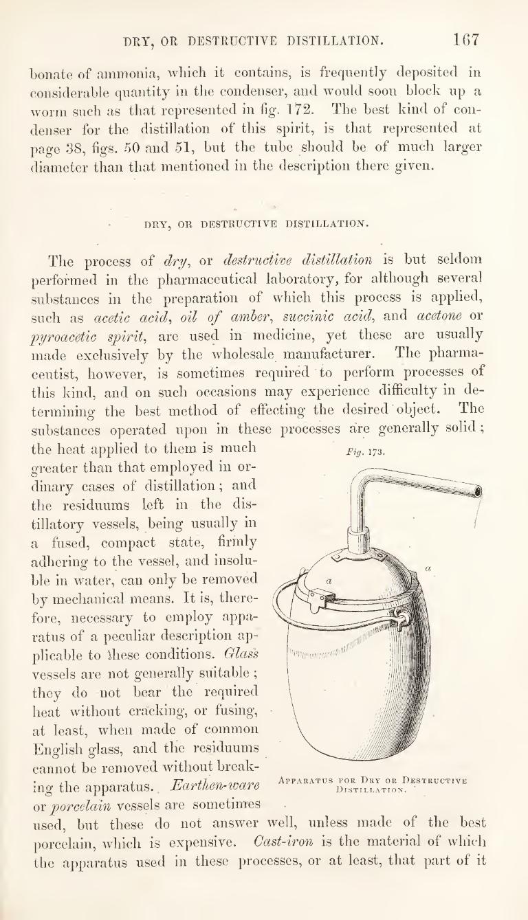
167 DRY, OR DESTRUCTIVE DISTILLATION.
bonate of ammonia, wliicli it contains, is frequently deposited in
considerable quantity in the condenser, and would soon block up a
worm such as that represented in hg. 172. The best kind of con¬
denser for the distillation of this spirit, is that represented at
page 38, figs. 50 and 51, but the tube should be of much larger
diameter than that mentioned in the description there given.
DRY, OR DESTRUCTIVE DISTILLATION.
The process of dry^ or destructive distillation is but seldom
performed in the pharmaceutical laboratory, for although several
substances in the preparation of which this process is applied,
such as acetic acid^ oil of amber^ succinic acid^ and acetone or
'pyroacetic spirit^ are used in medicine, yet these are usually
made exclusively by the wholesale manufacturer. The pharma¬
ceutist, however, is sometimes required to perform processes of
this kind, and on such occasions may experience difficulty in de¬
termining the best method of effecting* the desired object. The
substances operated upon in these processes are generally solid ;
the heat applied to them is much
greater than that employed in or¬
dinary cases of distillation; and
the residuums left in the dis¬
tillatory vessels, being usually in
a fused, compact state, firmly
adhering to the vessel, and insolu¬
ble in water, can only be removed
by mechanical means. It is, there¬
fore, necessary to employ appa¬
ratus of a peculiar description ap¬
plicable to Ihese conditions. Glass
vessels are not generally suitable ;
they do not bear the required
heat without cracking, or fusing,
at least, when made of common
English glass, and the residuums
cannot be removed without break¬
ing the apparatus.. Eartlien-icare
(OY porcelain vessels are sometimes
used, but these do not answer well, unless made of the best
porcelain, which is expensive. Cast-iron is the material of which
the apparatus used in these processes, or at least, that part of it
Fig. 173.
Apparatus for Dry or Destructive
Distillation.
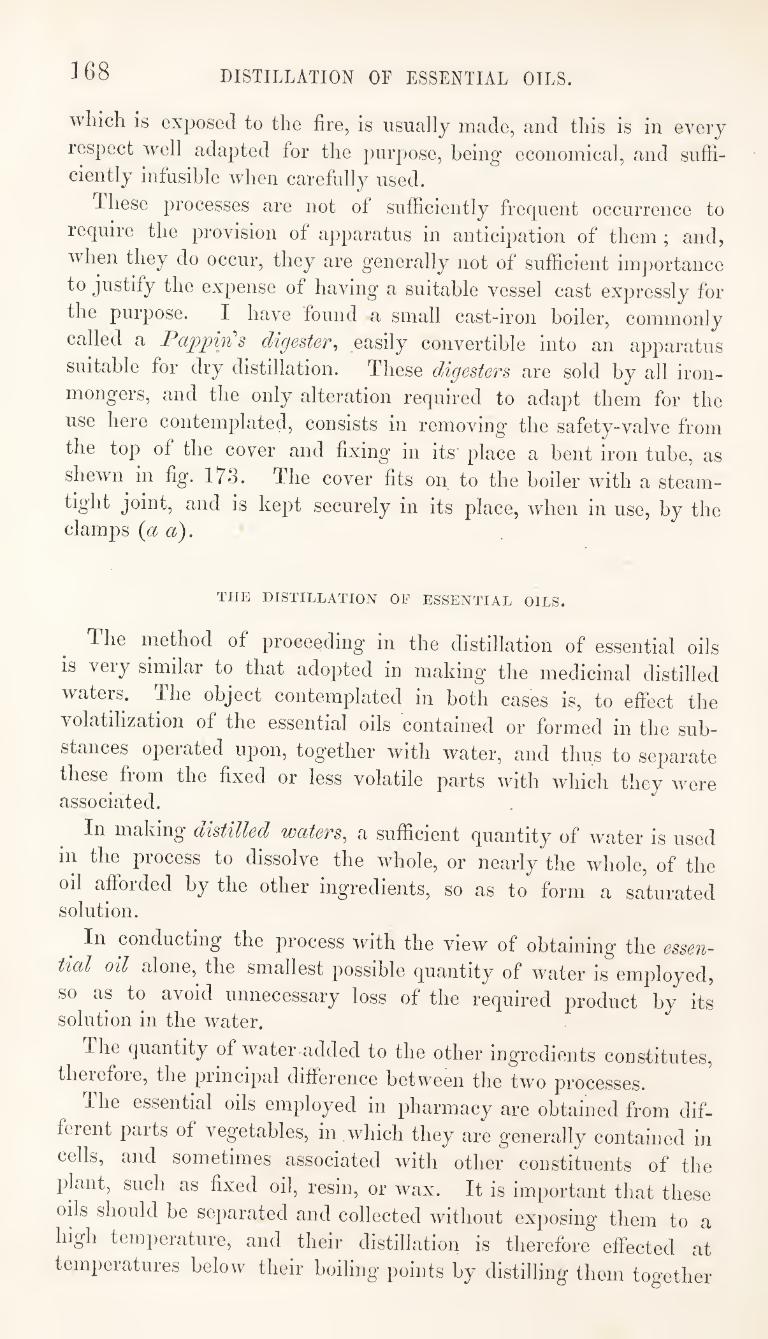
1G8 DISTILLATION OF ESSENTIAL OILS.
wliich is exposed to the fire, is usually made, and this is in every
respect well adapted for the purpose, being economical, and suffi¬ ciently infusible when carefully used.
Ihese processes are not of sufficiently frequent occurrence to
require the provision of apparatus in anticipation of them ; and,
when they do occur, they are generally not of sufficient imj)ortance
to justify the expense of having a suitable vessel cast expressly for
the purpose. I have found a small cast-iron boiler, commonly
called a Pctppin s digestev-i easily convertible into an apparatus
suitable for dry distillation. These digesters are sold by all iron¬
mongers, and the only alteration required to adapt them for the
use here contemplated, consists in removing the safety-valve from
the top of the cover and fixing in its place a bent iron tube, as
shewn in fig. 173. The cover fits on to the boiler with a steam-
is kept securely in its place, when in use, by the clamps {a a).
THE DISTILLATION OF ESSENTIAL OILS.
The method of proceeding in the distillation of essential oils
is very similar to that adopted in making the medicinal distilled
waters. The object contemplated in both cases is, to effect the
volatilization of the essential oils contained or formed in the sub¬
stances operated upon, together with water, and thus to separate
these^ from the fixed or less volatile parts with which they were associated.
In making distilled waters, a sufficient quantity of water is used
in the process to dissolve the whole, or nearly the whole, of the
oil afforded by the other ingredients, so as to form a saturated solution.
In conducting the process with the view of obtaining the essen¬
tial oil alone, the smallest possible quantity of water is employed,
so as to avoid unnecessary loss of the required product by its solution in the water.
The quantity of water-added to the other ingredients constitutes,
theiefoie, the piincipal difference between the two processes.
I he essential oils employed in pharmacy are obtained from dif¬
ferent paits of vegetables, in which they are generally contained in
cells, and sometimes associated with other constituents of the
plant, such as fixed oil, resin, or wax. It is important that these
ods should be separated and collected without exposing them to a
high temperature, and their distillation is therefore effected at
temperatures below their boiling points by distilling them together
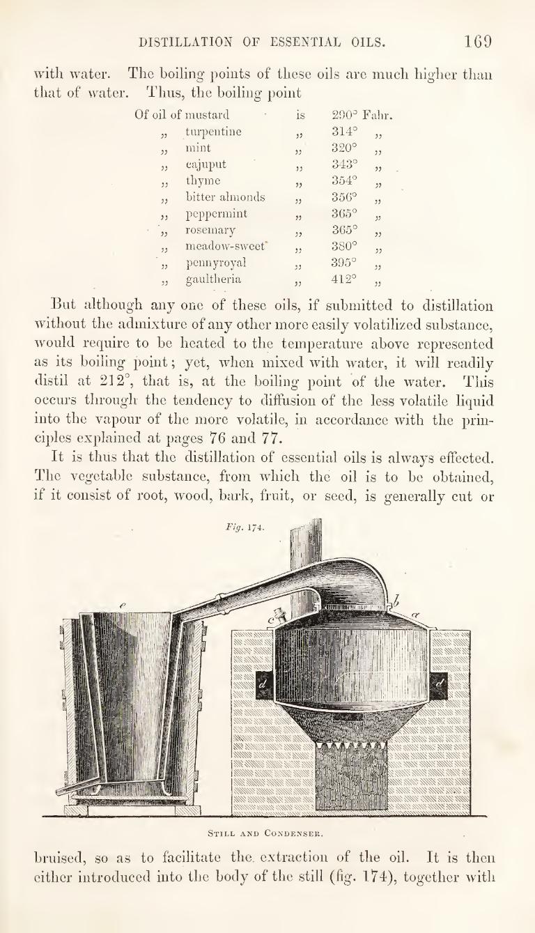
DISTILLATION OF ESSENTIAL OILS. 169
with water. The boiling points of these oils are much higher than
that of water. Thus, the boiling point
Of oil of mustard is 290^ Fahr.
5? tuipentine jj 314^ 55 mint )) 320° 55
}} cajuput 343° 55
jj thyme 354° 55
V bitter almonds 55 356° 55
)} peppermint 55 365° 55
V rosemary 55 365° 55
V meadow-sweet* 55 380° 55
jj pennyroyal 55 395° 55 gaultheria 55 412° 55
But although any one of these oils. if submitted to distillation
without the admixture of any other more easily volatilized substance,
would require to he heated to the temperature above represented
as its boiling point; yet, when mixed with water, it will readily
distil at 212°, that is, at the boiling point of the water. This
occurs through the tendency to diffusion of the less volatile liquid
into the vapour of the more volatile, in accordance with the prin¬
ciples explained at pages 76 and 77.
It is thus that the distillation of essential oils is always effected.
The vegetable substance, from which the oil is to be obtained,
if it consist of root, wood, bark, fruit, or seed, is generally cut or
Still and Condenser.
bruised, so as to facilitate the extraction of the oil. It is then
either introduced into the body of the still (fig. 174), together with
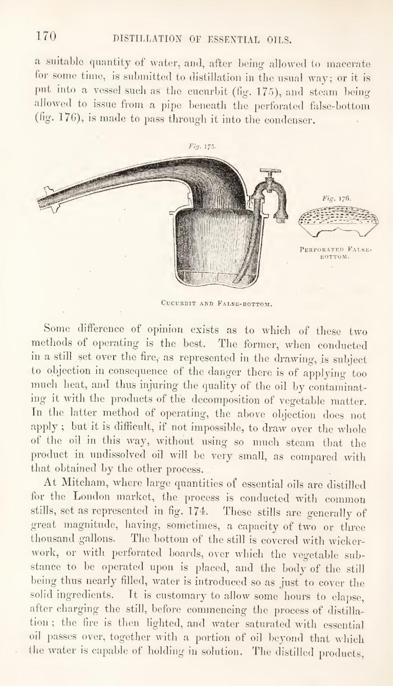
170 DISTILLATION OF ESSENTIAL OILS.
a suitable quantity of water, and, after being allowed to macerate
for some time, is submitted to distillation in the usual way; or it is
put into a vessel such as the cucurbit (fig. 175), and steam being
allowed to issue from a pipe beneath the perforated false-bottom
(% 176), is made to pass through it into the condenser.
Fig. 175.
Cucurbit and False-bottom.
Some difference of opinion exists as to which of these two
methods of operating is the best. The former, when conducted
in a still set over the fire,- as represented in the drawing, is subject
to objection in consequence of the danger there is of applying too
much heat, and thus injuring the quality of the oil by contaminat¬
ing it with the products of the decomposition of vegetable matter.
In the latter method of operating, the above objection does not
apply ; but it is difficult, if not impossible, to draw over tbe whole
of the oil in this way, without using so much steam that the
product in undissolved oil will be very small, as compared with that obtained by the other process.
At Mitcham, where large quantities of essential oils are distilled
for the London market, the process is conducted with common
stills, set as represented in fig. 174. These stills are generally of
great magnitude, having, sometimes, a capacity of two or three
thousand gallons. The bottom of the still is covered with wicker¬
work, or with perforated boards, over which the vegetable sub¬
stance to be operated upon is placed, and the body of the still
being thus nearly filled, water is introduced so as just to cover the
solid ingredients. It is customary to allow some hours to elapse,
after charging the still, before commencing the process of distilla¬
tion ; the fire is then lighted, and water saturated with essential
oil passes over, together with a portion of oil beyond that which
the water is capable of holding in solution. The distilled products.
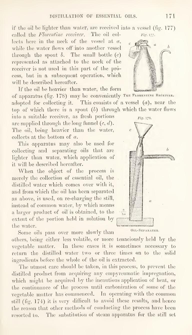
DISTILLATION OF ESSENTIAL OILS. 171
Fig. 178.
if the oil be lighter than water, are received into a vessel (lig. 177)
called the Florentine receiver. The oil col- Fig. 177.
lects here in the nech of the vessel at
while the water flows off into another vessel
through the spout h. The small bottle (c)
represented as attached to the neck of the
receiver is not used in this part of the pro¬
cess, hut in a subsequent operation, which
will he described hereafter.
If the oil he heavier than water, the form of apparatus (fig. 178) may he conveniently the Florentine receiver.
adopted for collecting it. This consists of a vessel (a), near the
top of which there is a spout (b) through which the water flows
into a suitable receiver, as fresh portions
are supplied through the long funnel (c, cl).
The oil, being heavier than the water,
collects at the bottom of a.
This 'apparatus may also be used for
collecting and separating oils that are
lighter than water, which application of
it will be described hereafter.
AVhen the object of the process is
merely the collection of essential oil, the
distilled water which comes over with it,
and from which the oil has been separated
as above, is used, on re-charging the still,
instead of common water, by which means
a larger product of oil is obtained, to the
extent of the portion held in solution by
the water.
Some oils pass over more slowly than
others, being either less volatile, or more tenaciously held by the
vegetable matter. In these cases it is sometimes necessary to
return the distilled water two or three times on to the solid
ingredients before the whole of the oil is extracted.
The utmost care should be taken, in this process, to prevent the
distilled product from acquiring any empyreumatic impregnation,
which might be acquired by the incautious application of heat, or
the continuance of the process until carbonization of some of the
vegetable matter has commenced. In operating with the common
still (fig. I7d) it is very difficult to avoid these results, and hence
the reason that other methods of conducting the process have been
resorted to. The substitution of steam apparatus for the still set
Oil-Separater.
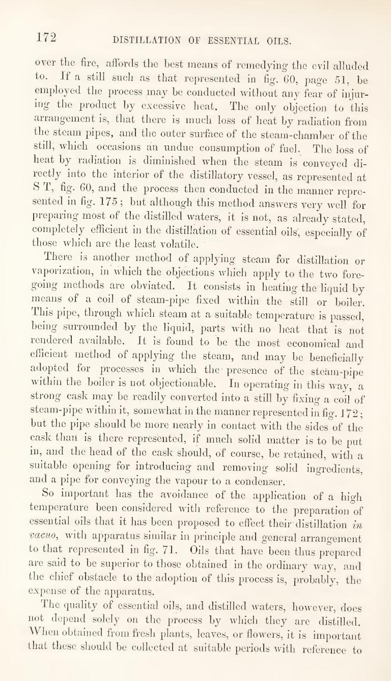
172 DISTILLATION OF ESSENTIAL OILS.
over the fire, affords the best means of remedying the evil alluded
to. If a still such as that represented in fig. 60, page 51, be
employed the process may be conducted without any fear of injur¬
ing the product by excessive heat. The only objection to this
ariangement is, that there is much loss of heat by radiation from
the steam pipes, and the outer surface of the steam-chamber of the
still, which occasions an undue consumption of fuel. The loss of
heat by radiation is diminished when the steam is conveyed di-
lectly into the interior of the distillatory vessel, as represented at
S T, fig. 60, and the process then conducted in the manner repre¬
sented in fig. 175; but although this method answers very well for
prepaiing most of the distilled waters, it is not, as already stated,
completely efficient in the distillation of essential oils, especially of those which are the least volatile.
There is another method of applying steam for distillation or
vaporization, in which the objections which apply to the two fore¬
going methods are obviated. It consists in heating the liquid by
means of a coil of steam-pipe fixed within the still or boiler.
This pipe, through which steam at a suitable temperature is passed,
being surrounded by the liquid, parts with no heat that is not
rendered available. It is found to be the most economical and
efficient method of applying the steam, and may be beneficially
adopted for processes in which the presence of the steam-pipe
within the boiler is not objectionable. In operating in this way, a
strong cask may be readily converted into a still by fixing a coil of
steam-pipe within it, somewhat in the manner represented in fig. J 72;
but the pipe should be more nearly in contact with the sides of the
cask than is there represented, if much solid matter is to be put
in, and the head of the cask should, of course, be retained, with a
suitable opening for introducing and removing solid ingredients
and a pipe for conveying the vapour to a condenser.
So important has the avoidance of the application of a high
temperature been considered with reference to the preparation of
essential oils that it has been proposed to effect their distillation in
mcuo, with apparatus similar in principle and general arrangement
to that represented in fig. 71. Oils that have been thus prepared
are said to be superior to those obtained in the ordinary way, and
the chief obstacle to the adoption of this process is, probably, the expense of the apparatus.
Ihe quality of essential oils, and distilled waters, however, does
not depend solely on the process by which they are distilled.
When obtained from fresh plants, leaves, or flowers, it is important
that these should be collected at suitable periods with reference to
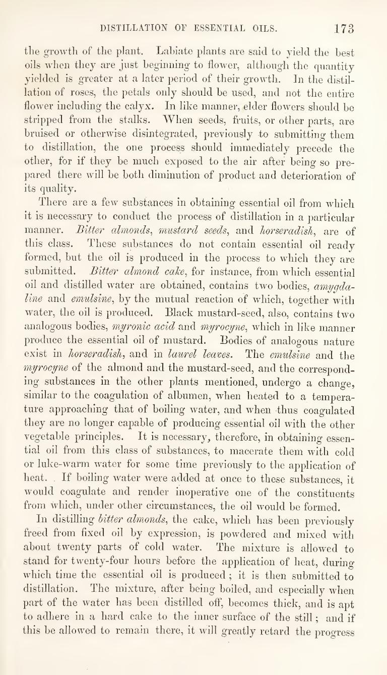
DISTILLATION OF ESSENTIAL OILS. 173
the growth of the plant. Labiate plants are said to yield the best
oils when they are just beginning to flower, although the quantity
yielded is greater at a later period of their growth. In the distil¬
lation of roses, the petals only should be used, and not the entire
flower including the calyx. In like manner, elder flowers should be
stripped from the stalks. When seeds, fruits, or other parts, are
bruised or otherwise disintegrated, previously to submitting them
to distillation, the one process should immediately precede the
other, for if they be much exposed to the air after being so pre¬
pared there will be both diminution of product and deterioration of
its quality.
There are a few substances in obtaining essential oil from which
it is necessary to conduct the process of distillation in a particular
manner. Bitter almonds^ mustard seeds^ and horseradish^ are of
this class. These substances do not contain essential oil ready
formed, but the oil is produced in the process to which they are
submitted. Bitter almond caJce^ for instance, from which essential
oil and distilled water are obtained, contains two bodies, amygda¬
line and emulsine^ by the mutual reaction of which, together with
water, the oil is produced. Black mustard-seed, also, contains two
analogous bodies, myronic acid and myrocyne^ which in like manner
produce the essential oil of mustard. Bodies of analogous nature
exist in horseradish^ and in laurel leares. The emulsine and the
myrocyne of the almond and the mustard-seed, and the correspond¬
ing substances in the other plants mentioned, undergo a change,
similar to the coagulation of albumen, when heated to a tempera¬
ture approaching that of boiling water, and when thus coagulated
they are no longer capable of producing essential oil with the other
vegetable principles. It is necessary, therefore, in obtaining essen¬
tial oil from this class of substances, to macerate them with cold
or luke-warm water for some time previously to the application of
heat. If boiling water were added at once to these substances, it
would coagulate and render inoperative one of the constituents
from which, under other circumstances, the oil would be formed.
In distilling Utter almonds, the cake, which has been previously
freed from flxed oil by expression, is powdered and mixed with
about twenty parts of cold water. The mixture is allowed to
stand for twenty-four hours before the application of heat, during
which time the essential oil is produced ; it is then submitted to
distillation. The mixture, after being boiled, and especially when
part of the water has been distilled off, becomes thick, and is apt
to adhere in a hard cake to the inner surface of the still; and if
this be allowed to remain there, it will greatly retard the progress
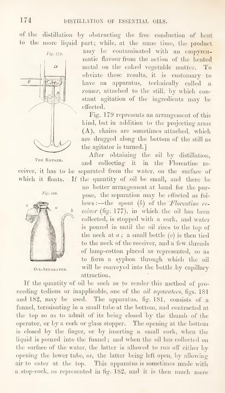
174 DISTILLATION OF ESSENTIAL OILS.
The Rouser.
Fig. 180.
of the distillation hj oLstrncting the free condiiction of heat
to the more liquid ])art; while, at the same time, the product
Fig. lyg. 1*^ contaminated with an empyreu- matic flavour from the action of the heated
metal on the caked vegetable matter. To
obviate these results, it is customary to
have an apparatus, technically called a
rouser^ attached to the still, by which con¬
stant agitation of the ingredients may he
effected.
Fig. 179'represents an arrangement of this
kind, but in addition to the projecting arms
(A), chains are sometimes attached, which
are dragged along the bottom of the still as
the agitator is turned.]
After obtaining the oil by distillation,
and collecting it in the Florentine re¬
ceiver, it has to be separated from the water, on the surface of
which it floats. If the quantity of .oil be small, and there be
no better arrangement at hand for the pur¬
pose, the separation may be effected as fol¬
lows :—the spout of the Florentine re¬
ceiver (fig. 177), in which, the oil has been
collected, is stopped with a cork, and water
is poured in until the oil rises to the top of
the neck at a ; a small bottle (c) is then tied
to the neck of the receiver, and a few threads
of lamp-cotton placed as represented, so as
to form a syphon through which the oil
will be conveyed into the bottle .by capillary
attraction.
If the quantity of oil be such as to render this method of pro¬
ceeding tedious or inapplicable, one of the oil se]oarater8., figs. 181
and 182, may be used. The apparatus, fig. 181, consists of a
funnel, terminating in a small tube at the bottom, and contracted at
the top so as to admit of its being closed by the thumb of the
operator, or by a cork or glass stopper. The opening at the bottom
is closed by the finger, or by inserting a small cork, when the
liquid is poured into the funnel; and wTien the oil has collected on
the surface of the water, the latter is allowed to run off either by
opening the lower tube, or, the latter being left open, by allowing
air to enter at the top. This apparatus is sometimes made with
a stop-cock, as represented in fig. 182, and it is then much more
Oil-Separater.
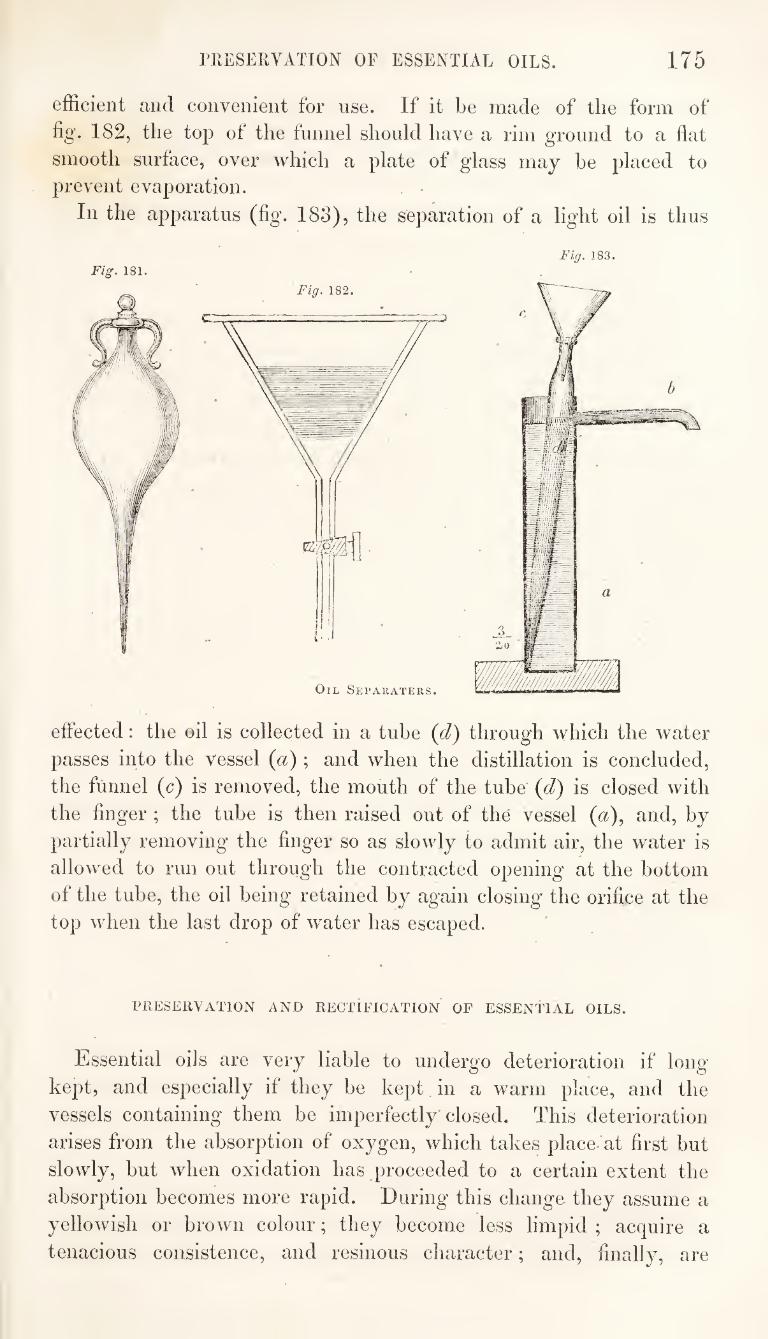
ITvESERVATION OF ESSENTIAL OILS. 175
efficient and convenient for use. If it be made of the form of
fig. 182, the top of the funnel should have a rim ground to a flat
smooth surface, over which a plate of glass may be placed to prevent evaporation. . •
In the apparatus (fig. 183), the separation of a light oil is thus
Fig. 181. Fig. 183.
Fig. 182.
Oil Sepakaters.
effected: the oil is collected in a tube (d) through which the water
passes into the vessel {a); and when the distillation is concluded,
the funnel {c) is removed, the mouth of the tube (d) is closed with
the finger ; the tube is then raised out of the vessel (a), and, by
partially removing the finger so as slowly to admit air, the water is
allowed to run out through the contracted opening at the bottom
of the tube, the oil being retained by again closing' the orifice at the
top when the last drop of water has escaped.
PRESERVATION AND RECTIFICATION OF ESSENTIAL OILS.
Essential oils are very liable to undergo deterioration if long
kejit, and especially if they be kept in a warm place, and the
vessels containing them be imperfectly closed. This deterioration
arises from the absorption of oxygen, which takes place at first but
slowly, but when oxidation has proceeded to a certain extent the
absorption becomes more rapid. During this change they assume a
yellowish or brown colour; they become less limpid ; acquire a
tenacious consistence, and resinous character; and, finally, are
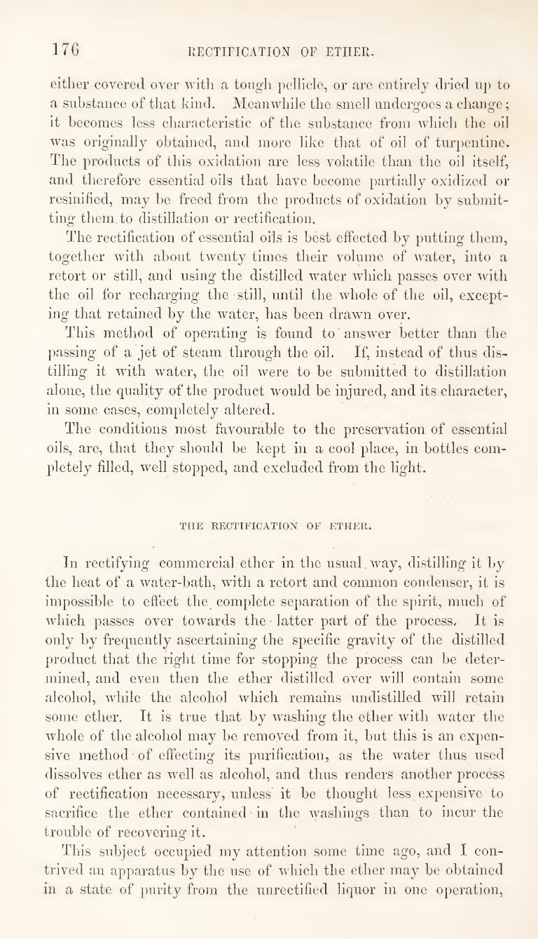
176 RECTIFICATION OF ETHER.
either covered over with a tough pellicle, or are entirely dried up to
a substance of that kind. Meanwhile the smell undergoes a change;
it becomes less characteristic of the substance from which the oil
was originally obtained, and more like that of oil of turpentine.
The products of this oxidation are less volatile than the oil itself,
and therefore essential oils that have become partially oxidized or
resinified, may be freed from the products of oxidation by submit¬
ting them to distillation or rectification.
The rectification of essential oils is best effected by putting them,
together with about twenty times their volume of water, into a
retort or still, and using the distilled water which passes over with
the oil for recharging the still, until the whole of the oil, except¬
ing that retained by the water, has been drawn over.
This method of operating is found to answer better than the
passing of a jet of steam through the oil. If, instead of thus dis¬
tilling it with water, the oil were to be submitted to distillation
alone, the quality of the product would be injured, and its character,
in some cases, completely altered.
The conditions most favourable to the preservation of essential
oils, are, that they should be kept in a cool place, in bottles com¬
pletely filled, well stopped, and excluded from the light.
THE RECTIFICATION OF ETHER.
In rectifying commercial ether in the usual way, distilling it by
the heat of a water-bath, with a retort and common condenser, it is
impossible to effect the complete separation of the spirit, much of
which passes over towards the latter part of the process. It is
only by frequently ascertaining the specific gravity of the distilled
product that the right time for stopping the process can be deter¬
mined, and even then the ether distilled over will contain some
alcohol, while the alcohol which remains undistilled will retain
some ether. It is true that by washing the ether with water the
whole of the alcohol may be removed from it, but this is an expen¬
sive method-of effecting its purification, as the water thus used
dissolves ether as well as alcohol, and thus renders another process
of rectification necessary, unless it be thought less expensive to
sacrifice the ether contained in the washings than to incur the
trouble of recovering it.
This subject occupied my attention some time ago, and I con¬
trived an apparatus by the use of which the ether may be obtained
in a state of purity from the unrectified liquor in one operation.
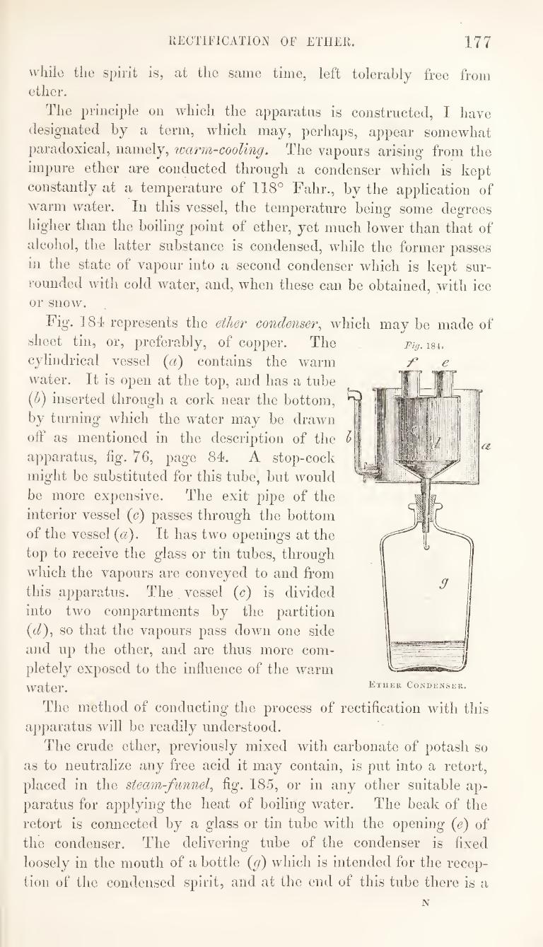
RECTIFICATION OF ETHER. 177
uliilo the spirit is, at the same time, left tolerably free from ether.
The principle on whicli the apparatus is constructed, I have
designated by a term, which may, perhaps, appear somewhat
paradoxical, namely, loarm-cooling. The vapours arising from the
impure ether are conducted through a condenser which is kept
constantly at a temperature of 118° Fahr., by the application of
warm water. In this vessel, the temperature being some degrees
liigher than the boiling point of ether, yet much lower than that of
alcohol, the latter substance is condensed, while the former passes
in the state of vapour into a second condenser which is kept sur¬
rounded with cold water, and, when these can be obtained, with ice or snow.
Fig. 181 represents the ether condenser^ which may be made of
sheet tin, or, preferably, of copper. The
cylindrical vessel {a) contains the warm
water. It is open at the top, and has a tube
{h) inserted through a cork near the bottom,
by turning which the water may be drawn
off as mentioned in the description of the
apparatus, %. 76, page 81. A stop-cock
might be substituted for this tube, but would
be more expensive. The exit pipe of the
interior vessel (c) passes through the bottom
of the vessel {a). It has two openings at the
top to receive the glass or tin tubes, through
which the vapours are conveyed to and from
this apparatus. The vessel (c) is divided
into two compartments by the partition
(t/), so that the vapours pass down one side
and up the other, and are thus more com¬
pletely exposed to the influence of the warm IhTHER Condenser.
The method of conducting the process of rectification with this
apparatus will be readily understood.
The crude ether, previously mixed with carbonate of potash so
as to neutralize any free acid it may contain, is put into a retort,
placed in the steam-funnel^ fig. 185, or in any other suitable ap¬
paratus for applying the heat of boiling water. The beak of the
retort is connected by a glass or tin tube with the opening {e) of
the condenser. The delivering tube of the condenser is fixed
loosely in the mouth of a bottle (p) which is intended for the recep¬
tion of the condensed spirit, and at the end of this tube there is a
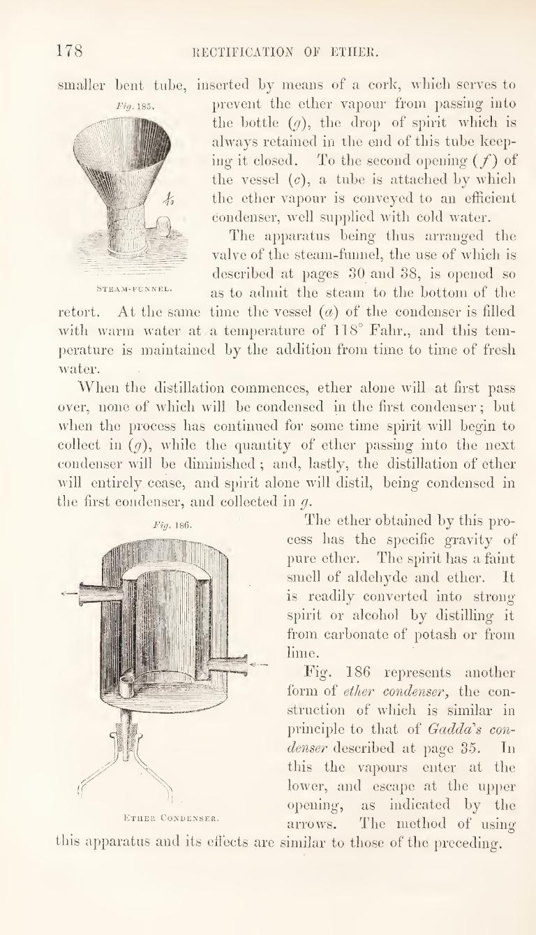
178 RECTIFICATION OF ETHER.
Fig. 185.
smaller bent tube, inserted by means of a cork, wliich serves to
prevent the ether vapour from passing into
the bottle (y), the drop of spirit which is
always retained in the end of this tube keep¬
ing it closed. To the second opening {/) of
the vessel (c), a tube is attached by which
the ether vapour is conveyed to an efficient
condenser, well supplied with cold water.
The apparatus being thus arranged the
valve of the steam-funnel, the use of which is
-described at pages 30 and 38, is opened so Steam-funnel. admit tllG SteaiU tO the bottOlU of the
retort. At the same time the vessel {a) of the condenser is filled
with warm water at a temperature of 118° Fahr., and this tem¬
perature is maintained by the addition from time to time of fresh
waiter.
When the distillation commences, ether alone will at first pass
over, none of which will be condensed in the first condenser; but
when the process has continued for some time spirit will begin to
collect in (y), while the quantity of ether passing into the next
condenser will be diminished ; and, lastly, the distillation of ether
will entirely cease, and spirit alone will distil, being condensed in
the first condenser, and collected in g.
Fig. 186.
this apparatus and its effects are
The ether obtained by this pro¬
cess has the specific gravity of
pure ether. The spirit has a faint
smell of aldehyde and ether. It
is readily converted into strong
spirit or alcohol by distilling it
from carbonate of potash or from
lime.
Fig. 186 represents another
form of ether condenser, the con¬
struction of which is similar in
jirinciple to that of Gaddas con¬
denser described at page 35. In
this the vapours enter at the
lower, and escape at the upper
opening, as indicated by the
arrows. The method of using
similar to those of the preceding.
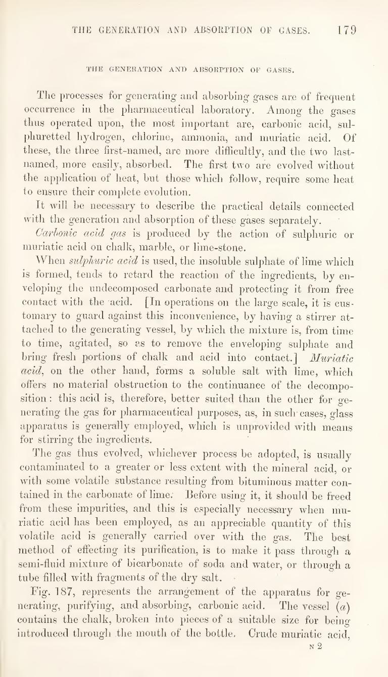
THE GENERATION AND ABSORTTION OF GASES. 179
THE GENERATION AND ABSORPTION OF GASES.
The processes for generating and absorbing gases are of frequent
occurrence in the pharmaceutical laboratory. Among the gases
thus operated upon, the most important are, carbonic acid, sul¬
phuretted hydrogen, chlorine, ammonia, and muriatic acid. Of
these, the three first-named, are more difficultly, and the two last-
named, more easily, absorbed. The first two are evolved without
the application of heat, but those which follow, require some heat
to ensure their complete evolution.
It will be necessary to describe the practical details connected
with the generation and absorption of these gases separately.
Carhonic acid gas is produced by the action of sulphuric or
muriatic acid on chalk, marble, or lime-stone.
When sulphuric acid is used, the insoluble sulphate of lime which
is formed, tends to retard the reaction of the ingredients, by en¬
veloping the undecomposed carbonate and protecting it from free
contact with the acid. [In operations on the large scale, it is cus¬
tomary to guard against this inconvenience, by having a stirrer at¬
tached to the generating vessel, by which the mixture is, from time
to time, agitated, so as to remove the enveloping sulphate and
bring fresh portions of chalk and acid into contact.] Muriatic
acid^ on the other hand, forms a soluble salt with lime, which
offers no material obstruction to the continuance of the decompo¬
sition : this acid is, therefore, better suited than the other for ge¬
nerating the gas for pharmaceutical purposes, as, in such cases, glass
apparatus is generally employed, which is unprovided with means
for stirring the ingredients.
The gas thus evolved, whichever process be adopted, is usually
contaminated to a greater or less extent with the mineral acid, or
with some volatile substance resulting from bituminous matter con¬
tained in the carbonate of lime. Before using it, it should be freed
from these impurities, and this is especially necessary when mu¬
riatic acid has been employed, as an appreciable quantity of this
volatile acid is generally carried over with the gas. The best
method of effecting its purification, is to make it pass through a
semi-fluid mixture of bicarbonate of soda and water, or through a
tube filled with fragments of the dry salt.
Fig. 187, represents the arrangement of the apparatus for ge¬
nerating, purifying, and absorbing, carbonic acid. The vessel {a)
contains the chalk, broken into pieces of a suitable size for being
introduced through the mouth of the bottle. Crude muriatic acid.
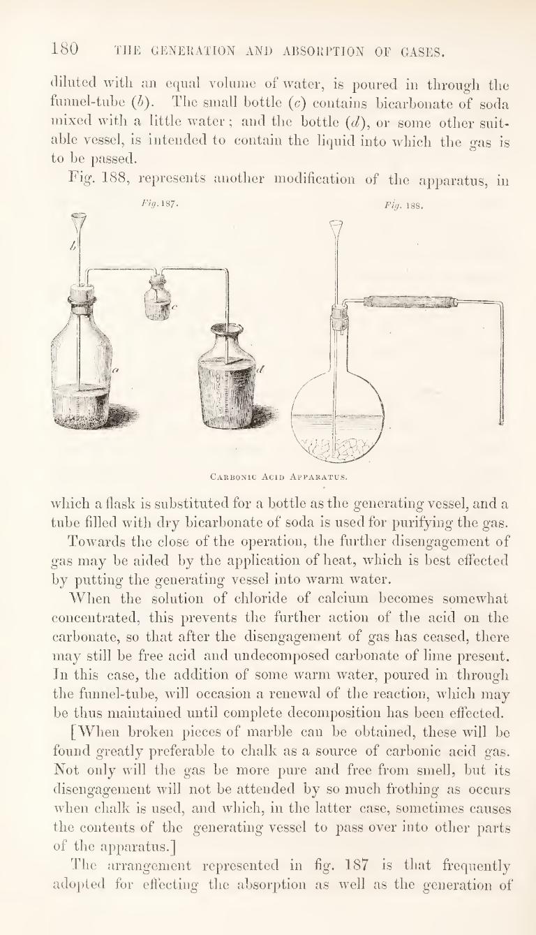
180 THE GENERATION AND ABSORPTION OF GASES.
diluted with un equal volume of water, is poured in through the
funnel-tuhe (/j). The small bottle (c) contains bicarbonate of soda
mixed with a little water ; and the bottle (d), or some other suit¬
able vessel, is intended to contain the liquid into which the gas is to be passed.
Fig. 188, represents another modification of the apparatus, in
Fig.\Q7- Fig.lSQ.
Carbonic Acid Apparatus.
which a flask is substituted for a bottle as the generating vessel, and a
tube filled with dry bicarbonate of soda is used for purifying the gas.
Towards the close of the operation, the further disengagement of
gas may be aided by the application of heat, which is best effected
by putting the generating vessel into warm water.
When the solution of chloride of calcium becomes somewhat
concentrated, this prevents the further action of the acid on the
carbonate, so that after the disengagement of gas has ceased, there
may still be free acid and undecomposed carbonate of lime present.
In this case, the addition of some warm water, poured in through
the funnel-tube, will occasion a renewal of the reaction, which may
be thus maintained until complete decomposition has been effected.
[When broken pieces of marble can be obtained, these will be
found greatly preferable to chalk as a source of carbonic acid gas.
Not only will the gas be more pure and free from smell, but its
disengagement will not be attended by so much frothing as occurs
when chalk is used, and which, in the latter case, sometimes causes
the contents of the generating vessel to pass over into other parts
of the apparatus.]
The arrangement represented in fig. 187 is that frequently
adopted for effecting the absorption as well as the generation of
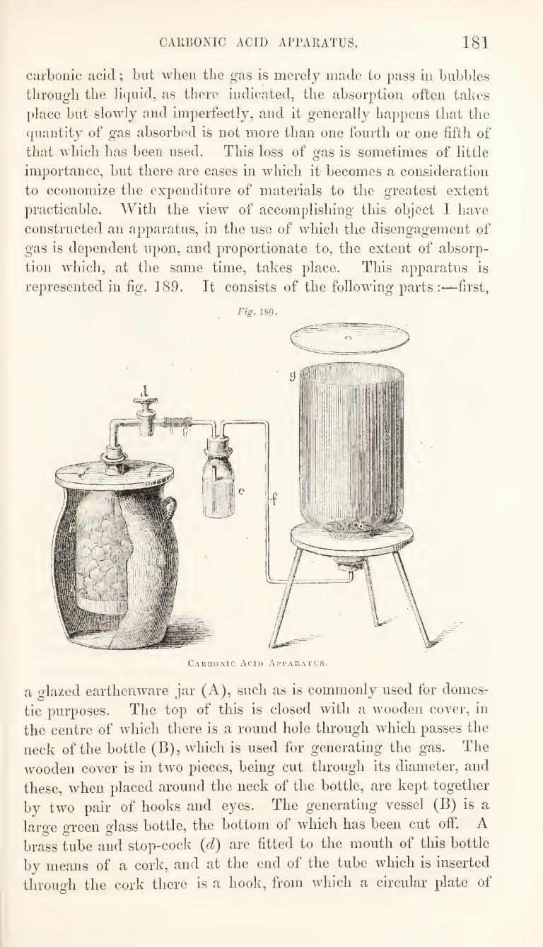
CARBONIC ACID APPARATUS. 181
carbonic acid; but when the gas is merely made to pass in bubbles
through the liquid, as there indicated, the absorption often takes
place but slowly and imperfectly, and it generally happens that the
quautity of gas absorbed is not more than one fourth or one fifth of
that which has been used. This loss of gas is sometimes of little
importance, but there are cases in which it becomes a consideration
to economize the expenditure of materials to the greatest extent
practicable. With the view of accomplishing this object I have
constructed an apparatus, in the use of which the disengagement of
gas is dependent upon, and proportionate to, the extent of absorp¬
tion wdiich, at the same time, takes place. This apparatus is
represented in fig. 189. It consists of the following parts :—first,
Fig. 18P.
Carbonic Acid Apparatus.
a glazed earthenware jar (A), such as is commonly used for domes¬
tic purposes. The top of this is closed with a wmoden cover, in
the centre of which there is a round hole through which passes the
neck of the bottle (B), which is used for generating the gas. The
wooden cover is in two pieces, being cut through its diameter, and
these, when placed around the neck of the bottle, are kept together
by two pair of hooks and eyes. The generating vessel (B) is a
large green glass bottle, the bottom of which has been cut off. A
brass tube and stop-cock {d) are fitted to the mouth of this bottle
by means of a cork, and at the end of the tube which is inserted
through the cork there is a hook, from which a circular plate of
182 THE GENERATION AND ABSORPTION OF GASES.
brass or lead is suspended by a wire for supporting tlie fragments
of marble or chalk. This ])art of the a])})aratus resembles the
gas-generator of the well known Ddbereiners lamp, which was originally invented by Gay Lussac.
The generator (]>) fig. 190 is filled in the following manner :—the
circular plate being removed, the bottle is turned with its bottom up¬
wards, and held by the wire attached to the end of the brass tube,
while the pieces of chalk or mai-ble are packed in so as nearlv to
fill it. The plate of brass or lead is then placed over the carbonate
of lime, and the wire is passed through a hole in the centre of the
plate, and secured by means of a nut, which screws on to the end
of the wire. Crude muriatic acid, diluted with a little water,
having been poured into the jar (A), the bottle (B) is fixed in its
place, as shewn in the drawing. So long as the stop-cock (e/)
remains closed, the acid will be prevented from entering the bottle
(B) by the elasticity of the air contained in it, but on turning {d)
the air will escape through the tube, and the acid coming in contact
with the carbonate of lime, carbonic acid will be disengaged. If
now the stop-cock be again closed, or there be any obstruction to
the escape of the gas, the carbonic acid accumulating in the gene¬
rator will displace the muriatic acid from the bottle^ B, and the
further evolution of gas will cease. In proportion as the gas
escapes from B, in consequence of its finding an exit at the other
end of the apparatus, or being absorbed there, the muriatic acid
will re-enter and decompose a further portion of carbonate, thus
keeping up a uniform supply of carbonic acid equivalent to the consumption of it.
The other parts of the apparatus, as represented in the drawing,
are intended for the preparation of Ucarhonate of soda. The gas,
after passing through the stop-cock (<^), is purified in the manner
alieady described, in the bottle and is then conveyed througli the
tube (/) into the vessel (0.) This vessel consists of a large bottle,
the bottom of which has been cut ofl, and the edge ground to a
perfectly smooth, flat surface, over which a circular disk of ground
plate-glass, having a small hole in the centre, fits closely. There is
also at the bottom of this vessel a perforated wooden disk upon
which the salt intended to absorb the gas is placed.
As bicarbonate of soda contains but one atom of water, while
the carbonate contains ten atoms, it is found advantageous to use a
mixture of three parts by weight of anhydrous, and one part of
crystallized carbonate of soda. This mixture is put loosely into
the vessel (Cj, so as nearly to All it. The rim of the vessel is then
covered with tallow, or other hard grease, and the glass-plate fitted

CARBONIC ACID ARPARATUS. 183
on so as to be air-tight. The stop-cock {d) is now opened, and carbonic acid, being rapidly disengaged, soon displaces the atmo- Sjdieric air from the apparatus, this gas escaping through the small
Fig. 190.
Carbonic Acid Apparatus.
hole in the glass-plate which is not yet closed. When the air has
been thus chased out, and it is found that carbonic acid begins to
escape, the hole is to be closed with some wax, and the glass-plate
loaded with weights to prevent any further escape of gas. Absorption
of carbonic acid by the carbonate of soda will now commence. At
first this will take place slowly, but after a little while the salt
will become warm, and the action much more energetic. Indeed,
the absorption, sometimes, proceeds so rapidly, that the solution is
drawn over from the generator into the absorbing vessel. It is
principally with the view of preventing this result that the stop¬
cock (d) is attached to the apparatus, as by this means the com¬
munication between the vessels (B) and (C) can be instantly cut off
when the liquid is seen to rise unduly in the former. Hence it is
necessary careftdly to watch the process, at least until the action
has ceased to be energetic.
Sulplmreited hydrogen is produced by the action of diluted sul¬
phuric or muriatic acid on sulphuret of iron. As sulphuric acid
forms a soluble salt with oxide of iron, and is less volatile than
muriatic acid it is used in preference to the other in this process.
The gas may be generated in an apparatus similar to that repre-
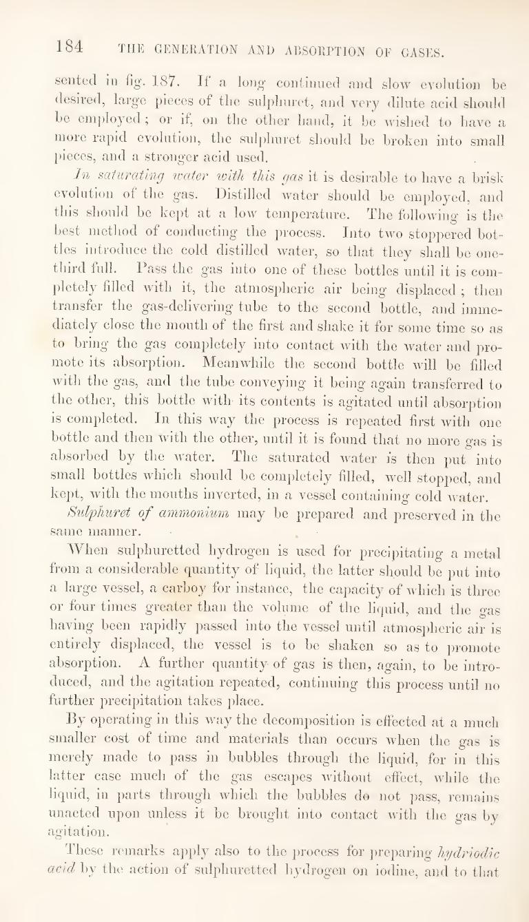
184 THE GENERATION AND ADSORPTION OF GASES.
seiited in fig. 187. If a, long coiitiiniod and slow evcilntion be
desired, large pieces of the snlplinret, and very dilute acid should
he eni])loyed ; or if, on the other hand, it he wished to have a
more rapid evolution, the suljiliuret should he broken into small pieces, and a stronger acid used.
In saturating water with this gas it is desirable to have a brisk
evolution of the gas. Distilled water should he employed, and
this should he kept at a low temperature. The following is the
best method of conducting the process. Into two stoppered bot¬
tles introduce the cold distilled water, so that they shall he one-
third full. Pass the gas into one of these bottles until it is com¬
pletely filled with it, the atmospheric air being displaced ; then
transfer the gas-delivering' tube to the second bottle, and imme¬
diately close the mouth of the first and shake it for some time so as
to bring the gas completely into contact with the water and pro¬
mote its absorption. Meanwhile the second bottle will he filled
with the gas, and the tube conveying it being again transferred to
the other, this bottle with its contents is agitated until absorption
is completed. In this way the process is repeated first with one
bottle and then Avith the other, until it is found that no more gas is
absorbed by the Avater. The saturated Avater is then put into
small bottles Avhich should be completely filled, Avell stopped, and
kept, Avith the mouths inverted, in a vessel containing cold AA'ater.
Sulphuret of ammonium may be prepared and preserved in the
same manner.
When sulphuretted hydrogen is used for precipitating a metal
from a considerable quantity of liquid, the latter should be put into
a large vessel, a carboy for instance, the capacity of Avhich is three
or four times greater than the volume of the liquid, and the gas
having been rapidly passed into the vessel until atmospheric air is
entirely displaced, the vessel is to be shaken so as to promote
absorption. A further quantity of gas is then, again, to be intro¬
duced, and the agitation repeated, continuing this process until no further precipitation takes place.
By operating in this Avay the decomposition is effected at a much smaller cost of time and materials than occurs when the gas is merely made to pass in bubbles through the liquid, for in this latter case much of the gas escapes Avithout effect, Avhile the liquid, in parts through Avhich the bubbles do not pass, remains unacted upon unless it be brought into contact Avith the gas by agitation.
These remarks a])ply also to the process for jweparing hydriodic
acid by the action of sulphuretted hydrogen on iodine, and to that
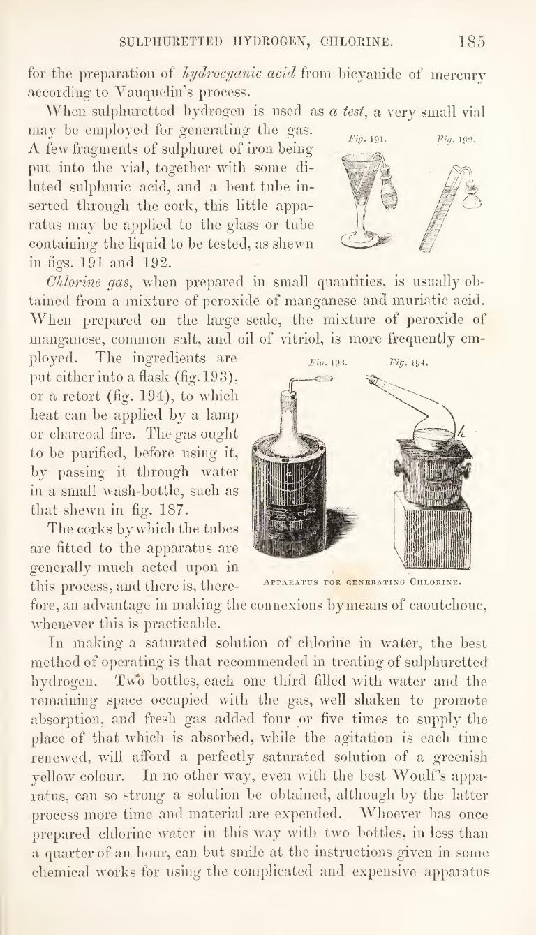
SULPHURETTED HYDROGEN, CHLORINE. 185
Fig. 191. Fig. 192.
Fig. 193. Fig. 194.
for the preparation of hydrocyanic acid from bicyanide of mercnry
according to Vanqueliids process.
When sulphuretted hydrogen is used as a test., a very small vial
may be employed for generating the gas.
A few fragments of snlphuret of iron being
put into the vial, together wdth some di¬
luted sulphuric acid, and a bent tube in¬
serted through the cork, this little appa¬
ratus may be applied to the glass or tube
containing the liquid to be tested, as shewn
in figs. 191 and 192.
Chlorine gas^ when prepared in small quantities, is usually ob¬
tained from a mixture of peroxide of manganese and muriatic acid.
When prepared on the large scale, the mixture of peroxide of
manganese, common salt, and oil of vitriol, is more frequently em¬
ployed. The ingredients are
put either into a flask (fig. 193),
or a retort (fig. 194), to which
heat can be applied by a lamp
or charcoal fire. The gas ought
to be purified, before using it,
by passing it through water
in a small wash-bottle, such as
that shewn in fig. 187.
The corks by which the tubes
are fitted to the apparatus are
generally much acted upon in
this process, and there is, there¬
fore, an advantage in making the connexions by means of caoutchouc,
whenever this is practicable.
In making a saturated solution of chlorine in water, the best
method of operating is that recommended in treating of sulphuretted
hydrogen. Two bottles, each one third filled with water and the
remaining space occupied with the gas, well shaken to promote
absorption, and fresh gas added four or five times to supply the
place of that which is absorbed, while the agitation is each time
renewed, wfill aflbrd a perfectly saturated solution of a greenish
yellow colour. In no other way, even with the best Woolf’s appa¬
ratus, can so strong a solution be obtained, although by the latter
process more time and material are expended. Whoever has once
prepared chlorine w'ater in this way with two bottles, in less than
a quarter of an hour, can but smile at the instructions given in some
chemical works for using the complicated and expensive apparatus
Apparatus for generating Chlorine.
186 THE ABSORPTION OF GASES.
of Woulf, with its four bottles, twelve necks, and as many pierced
corks and connecting' and safety tubes. This pbilosopbical toy is al¬
ready going’ out of use. For gases wbicb are easily absorbed, sucb as
ciMiiionicL and muTicttic ctcid^ it is not rec^uired, and for gases wbicb
are not so readily absorbed, sucb as chlorine^ sul^diuretted hydrogen,
and carhonic acid, it is inefficient, or, at least, is less efficient tban
the metbod above described. The last-named gases pass rapidly
tbrougb the water in bubbles, the volumes of wbicb are but little
diminisbed in tbeir passage, especially if the gases be mixed with
any quantity of atmospberic air. It is only by extending and re¬
newing the contact of the gas with the liquid, by shaking them
well together, that complete absorption can be effected. A tem-
jierature of from 48° to 50° Fabr. is that at wbicb water is capable of dissolving the largest quantity of chlorine.
Notwitbstanding what lias been stated above with reference to
Woulffs apparatus, it may sometimes be found convenient to use
one or more of the bottles of wbicb it is composed, in operating on
gases. When a gas lias to be passed tbrougb more tban one vessel,
there is an advantage in using bottles wbicb have separate openings
foi each tube. The corks wbicb are fitted into these openings are
common bottle corks, of wbicb there is no difficulty in finding those
of suitable size, and each cork has but one perforation. After
using the apparatus, if it be dismounted, the corks should always
be taken out and kept in a drawer until wanted again, for if left
inserted in the bottles they lose much of tbeir elasticity, and cease to form air-tight connexions.
Wide mouthed bottles, the corks of wbicb admit of two or three
tubes being passed tbrougb them, are sometimes substituted for the
Woulf’s bottles ; but not only are the corks used in this arrange¬
ment more expensive in the first instance, but, if they be put away
for subsequent use, they are not so easily refitted, on again mount¬
ing the apparatus, as would be the case with the smaller corks of
the Woulf’s arrangement. If the apparatus be nof taken to pieces
after using it, the corks should, at least, be taken out and left par¬
tially inserted or merely resting on the mouths of the bottles, so
that they may remain in a fit state for being tightly inserted when subsequently required for use.
Fig. 195 represents a convenient metbod of mounting a Woulf’s
bottle. Into the widest mouth of the bottle a glass tube, the
diameter of wbicb is as large as the opening for its insertion will
admit, is cemented by means of sealing-wax, so that its lower
extremity shall reach nearly to the bottom of the vessel. This
tube is intended to form a permanent fixture in the bottle. The
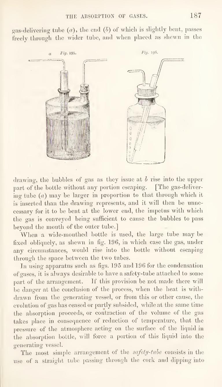
THE ABSORPTION OF GASES. 187
^'as-delivering tube («), the end (h) of which is slightly bent, passes
freely tlirougli the wider tube, and when placed as shewn in the
drawing, the bubbles of gas as they issue at b rise into the upper
part of the bottle without any portion escaping. [The gas-deliver¬
ing tube (a) may he larger in proportion to that through which it
is inserted than the drawing represents, and it will then he unne¬
cessary for it to he bent at the lower end, the impetus with which
the gas is conveyed being sufficient to cause the hubbies to pass
beyond the mouth of the outer tube.]
When a wide-mouthed bottle is used, the large tube may be
fixed obliquely, as shewn in fig. 196, in which case the gas, under
any circumstances, would rise into the bottle without escaping
through the space between the two tubes.
In using apparatus such as figs. 195 and 196 for the condensation
of gases, it is always desirable to have a safety-tube attached to some
part of the arrangement. If this provision be not made there will
be danger at the conclusion of the process, when the heat is with¬
drawn from the generating vessel, or from this or other cause, the
evolution of gas has ceased or partly subsided, while at the same time
the absorption proceeds, or contraction of the volume of the gas
takes place in consequence of reduction of temperature, that the
pressure of the atmosphere acting on the surface of the liquid in
the absorption bottle, will force a portion of this liquid into the
generating vessel. The most simple arrangement of the safety-tube consists in the
use of a straight tube passing through the cork and dipping into
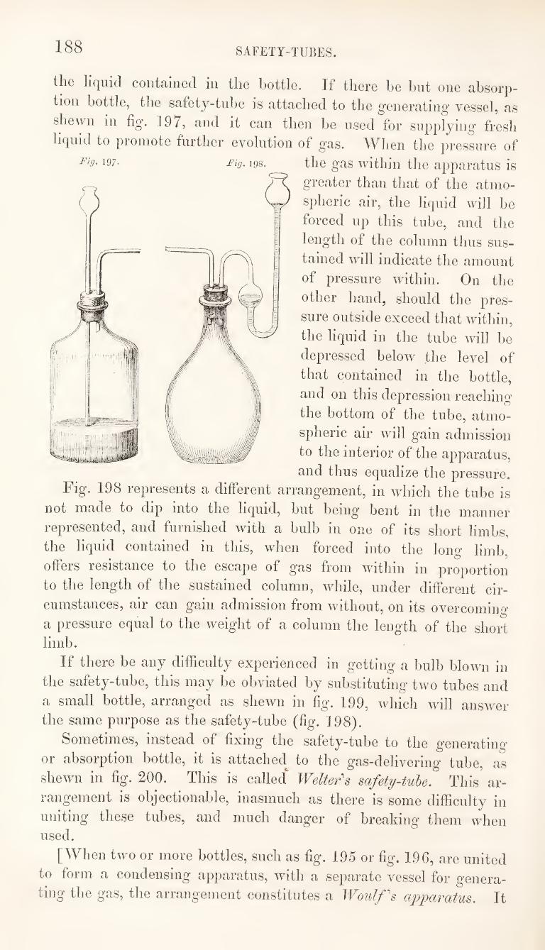
188 SAFETY-TUBES.
the liquid contained in the bottle. If there be but one absorp¬ tion bottle, the safety-tube is attached to the generating’ vessel, as shewn in fig. 197, and it can then be used for supplying fresh liquid to promote further evolution of gas. When the pressure of
197- Fig. 198. the gas within the apparatus is
greater than that of the atmo¬ spheric air, the liquid will be forced up this tube, and the length of the column thus sus¬ tained will indicate the amount of pressure within. On the other hand, should the pres¬ sure outside exceed that within, the liquid in the tube will be depressed below the level of that contained in the bottle, and on this depression reaching the bottom of the tube, atmo¬ spheric air will gain admission to the interior of the apparatus, and thus equalize the pressure.
Fig. 198 lepresents a different arrang’ement, in which the tube is not made to dip into the liquid, but being bent in the manner represented, and furnished with a bulb in one of its short limbs, the liquid contained in this, when forced into the long limb, offers resistance to the escape of gas from within in proportion to the length of the sustained column, while, under different cir¬ cumstances, air can gain admission from without, on its overcomino' a pressure equal to the weight of a column the length of the short limb.
If there be any difficulty experienced in getting a bulb blown in the safety-tube, this may be obviated by substituting two tubes and a small bottle, arranged as shewn in fig. 199, which will answer the same purpose as the safety-tube (fig. 198).
Sometimes, instead of fixing the safety-tube to the generating or absorption bottle, it is attached to the gas-delivering tube, as shewn in fig. 200. This is called" Welter^ safety-tube. This ar¬ rangement is objectionable, inasmuch as there is some difficulty in uniting these tubes, and much danger of breaking them when used.
[When two or more bottles, such as fig. 195 or fig. 196, are united to form a condensing apparatus, with a separate vessel for genera¬ ting the gas, the arrangement constitutes a Woulfs aj)paratus. It
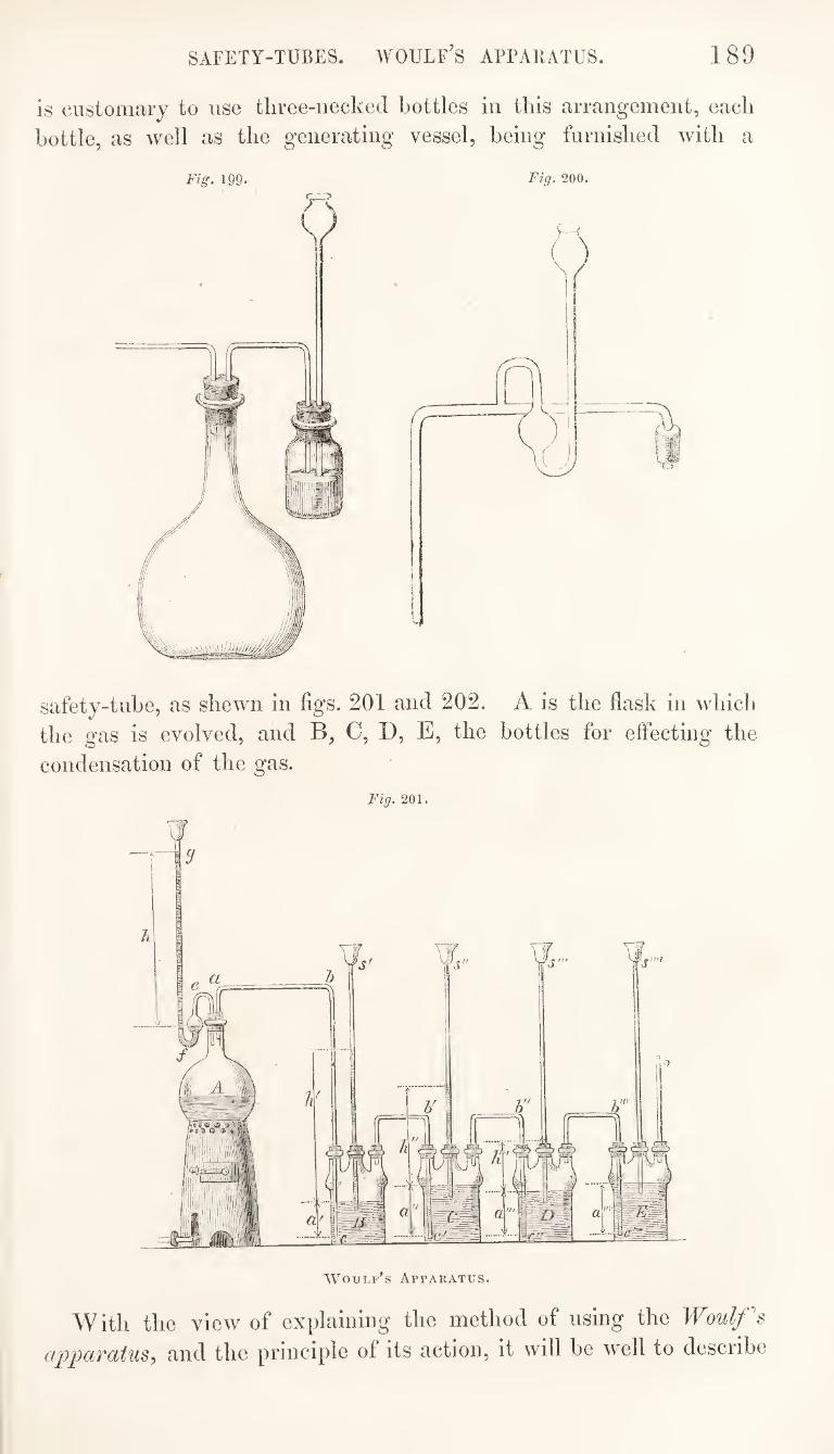
SAFETY-TUBES. WOULF’S APPARATUS. 189
is customary to use tliree-iiecked bottles in this arrangement, each
bottle, as well as the generating vessel, being furnished with a
Fig. 199. Fig. 200.
safety-tube, as shewn in figs. 201 and 202. A is the flask in whicli
the gas is evolved, and B, C, D, E, the bottles for effecting the
condensation of the gas.
Fig. 201.
With the view of explaining the method of using the Woulf's
apparatus, and the principle of its action, it will be well to describe
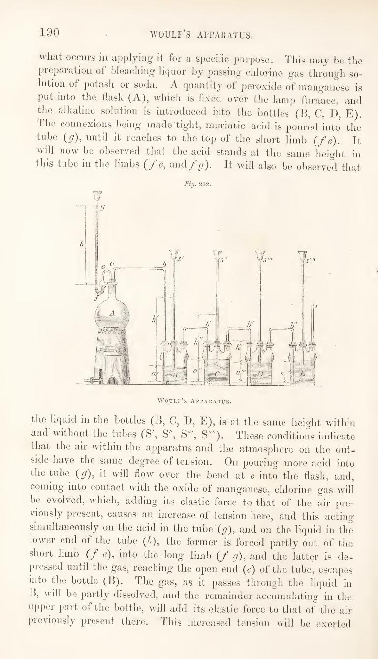
190 woulf’s apparatus.
what occurs in ^ip]>lyiug it for a specific purpose. This may be the
piepaiatioii of bleaching’ lirjuor by passing’ chlorine g’as through so¬
lution of jiotash or soda. A (|uantity of peroxide of manganese is
put into the flask (A), which is fixed over the lamp furnace, and
the alkaline solution is introduced into the bottles (B, C, 1), E).
The connexioiis being made'tight, muriatic acid is poured into the
tube (y), until it reaches to the top of the short limb {f e). It
will now be observed that the acid stands at the same height in
this tube in the limbs {f e, and/y). It will also be observed that
Fig. 202.
Woulf’s Apparatus.
the licpiid in the bottles (B, C, D, E), is at the same height within
and without the tubes (S', S", S'", S""). These conditions indicate
that the air within the apparatus and the atmosphere on the out¬
side have the same degree of tension. On pouring more acid into
the tube (y), it will flow over the bend at e into the flask, and,
coming into contact with the oxide of manganese, chlorine gas will
be evolved, which, adding its elastic force to that of the air pre¬
viously present, causes an increase of tension here, and this acting
simultaneously on the acid in the tube (y), and on the liquid in the
lower end of the tube (5), the former is forced partly out of the
short limb (/* ^), into the long limb (/* y), and the latter is de¬
pressed until the gas, reaching' the open end (c) of the tube, escapes
into the bottle (B). The gas, as it passes through the liquid in
k, will be partly dissolved, and the remainder accumulating in the
upper part of the bottle, will add its elastic force to that of the air
previously present there. This increased tension will be exerted
191 WOULF’S APPAIUTUS.
upon the surface of the liquid in the bottle (B), and within the
tube {h') in the bottle (0), while the surface of the liquid within
the tube (S') will bear only the pressure of the external air to
which it is exposed ; a portion of the liquid from B will, therefore,
be forced up into the tube (S'), and the weight of the column thus
supported will be equivalent to the increased tension of the gas in the
upper part of B beyond that of the external air. There will also be
a like difference between the tension of the gas in contact with the
surface of the liquid in the tube (Z>'), and that of the air in the upper
part of the bottle (0) into which none of the gas has yet entered, so
that the liquid in the lower part of h' will be depressed to a degree
proportionate to this difference, and if the density of the liquids in
B and C be equal, the depression of the liquid in will be to the
same extent as the elevation of the liquid in S'. The gas, accumu¬
lating in B will soon force the liquid out of h\ and escaping at c',
it will enter the bottle (C), where the same effect will be produced
as in the previous bottle (B). From C the gas will pass into D ;
from thence into E, and any residue that may accumulate here will
escape through the open tube into the atmosphere. When the gas
has commenced issuing from the tube (c'") into the bottle (E), it
will be 'found that there will be a column of liquid supported in
each of the tubes (S', S", and S'''), by the tension of the gas con¬
tained in the upper part of the bottles (B, 0, and D). These
columns of liquid will be of unequal lengths, the tension of the gas
being different in each bottle. The liquid will not be elevated in
the tube (S""), because the gas in the bottle (E), having free means
of escape into the atmosphere, will have the same tension only as
the external air. The column of liquid If' in the tube S'" will be
equal to the column a!"'; the column If in the tube S", will be
equal to If + a'" ; the column h' in the tube S', will be equal to
If + a'; and the column li in the tube will be equal to A' + a. Thus the columns of liquid in the safety-tubes indicate the degrees
of tension of the gas in the bottles to which they are attached.
The increased tension of the gas will tend to promote its solution,
and this being greatest in the first bottle (B), the liquid in this
bottle will become most saturated.
The objects contemplated in the adoption of this form of ap¬
paratus are, the application of pressure to promote the absorption
of the gas, and the extension of contact by making the gas pass
through several successive quantities of the liquid.
If, in conducting the process under notice, the evolution of
chlorine in the flask (A) should become suspended before the alka¬
line solution has been fully saturated, the absorption of the gas in the
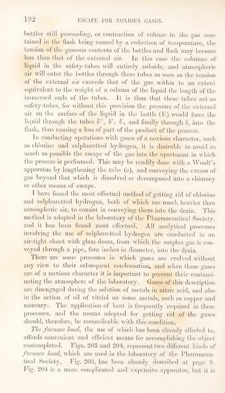
192 ESCAPE FOR NOXIOUS GASES.
bottles still proceeding, or contraction of volume in the gas con¬
tained in the flask being caused by a reduction of temperature, the
tension of the gaseous contents of the bottles and flask may become
less than that of the external air. In this case the columns of
liquid in the safety-tubes will entirely subside, and atmospheric
air will enter the bottles through these tubes as soon as the tension
of the external air exceeds that of the gas within to an extent
equivalent to the weight of a column of the liquid the length of the
immersed ends of the tubes. It is thus that these tubes act as
safety-tubes, for without this provision the pressure of the external
air on the surface of the liquid in the bottle (E) would force the
liquid through the tubes h% h\ and finally through h, into the
flask, thus causing a loss of part of the product of the process.
In conducting operations with gases of a noxious character, such
as chlorine and sulphuretted hydrogen, it is desirable to avoid as
much as possible the escape of the gas into the apartment in which
the process is performed. This may be readily done with a AVoulf's
apparatus by lengthening the tube (o), and conveying the excess of
gas beyond that which is dissolved or decomposed into a chimney or other means of escape.
I have found the most effectual method of getting rid of chlorine
and sulphuretted hydrogen, both of which are much heavier than
atmospheric air, to consist in conveying them into the drain. This
method is adopted in the laboratory of the Pharmaceutical Society,
and it has been found most effectual. All analytical jwocesses
involving the use of sulphuretted hydrogen are conducted in an
air-tight closet with glass doors, from which the surplus gas is con¬
veyed through a pipe, four inches in diameter, into the drain.
There are some processes in which gases are evolved without
any view to their subsequent condensation^ and when these gases
are of a noxious character it is important to prevent their contami¬
nating the atmosphere of the laboratory. Gases of this description
are disengaged during the solution of metals in nitric acid, and also
in the action of oil of vitriol on some metals, such as copper and
mercury. The application of heat is frequently required in these
processes, and the means adopted for getting rid of the gases
should, therefore, be reconcileable with this condition.
The furnace hood^ the use of which has been already alluded to,
affords convenient and efficient means for accomplishing the object
contemplated. Figs. 203 and 204, represent two different kinds of
furnace hoocl^ which are used in the laboratory of the Pharmaceu¬
tical Society, Fig. 203, has been already described at page 8.
Fig. 204 is a more complicated and expensive apparatus, but it is
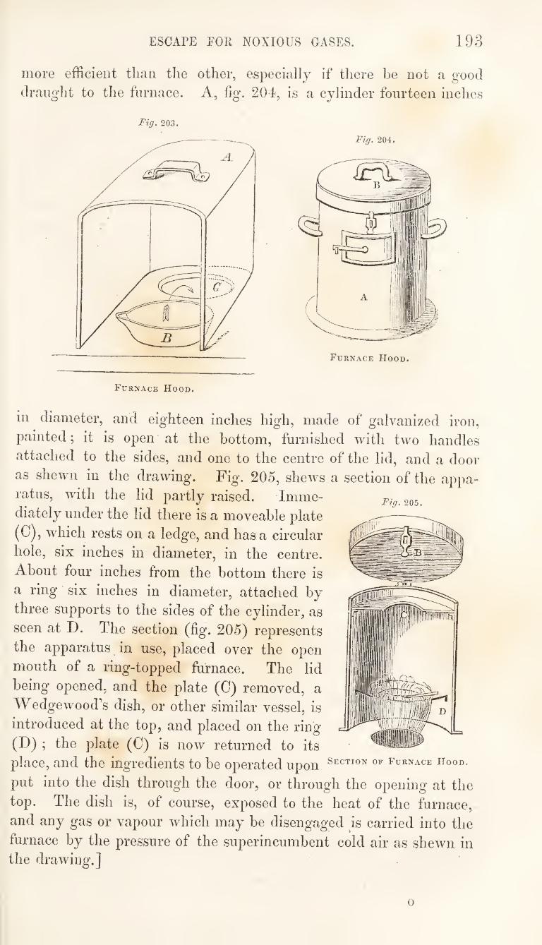
ESCAPE FOR NOXIOUS GASES. 193
more efficient tlinn tlie other, especially if there be not a good
draught to the furnace. A, fig. 20d, is a cylinder fourteen inches
Fig. 203. Fig. 204.
Fig. 205.
in diameter, and eighteen inches high, made of galvanized iron,
painted; it is open at the bottom, furnished with two handles
attached to the sides, and one to the centre of the lid, and a door
as shewn in the drawing. Fig. 205, shews a section of the appa¬ ratus, with the lid partly raised. Imme¬
diately under the lid there is a moveable plate
(C) , which rests on a ledge, and has a circular
hole, six inches in diameter, in the centre.
About four inches from the bottom there is
a ring six inches in diameter, attached by
three supports to the sides of the cylinder, as
seen at D. The section (fig. 205) represents
the apparatus in use, placed over the open
mouth of a ring-topped furnace. The lid
being opened, and the plate (0) removed, a
Wedgewood’s dish, or other similar vessel, is
introduced at the top, and placed on the ring
(D) ; the plate (C) is now returned to its
place, and the ingredients to be operated upon furnace hood.
put into the dish through the door, or through the opening at the
top. The dish is, of course, exposed to the heat of the furnace,
and any gas or vapour which may be disengaged is carried into the
furnace by the pressure of the superincumbent cold air as shewn in the drawing.]
o
194 PROCESS OF SUBLIMATION.
SUBLIMATION.
The process of sublimation resembles that of distillation, in being
generally adopted with a view to the separation of unequally
volatile substances, the more volatile of wbicb is first converted
into vapour by the application of beat, and then condensed in a
part of the apparatus in wbicb it can be conveniently collected.
The two processes, however, differ essentially in this, that distilla¬
tion is applied to the elimination of products wbicb are liquid, and
sublimation to that of those which are solid.
Most medicinal substances which are prepared by sublimation, are
invariably made on the large scale, by wholesale manufacturers. Of
this class, are salammoniac, carbonate of ammonia, corrosive sub¬
limate, cinnabar, and flowers of sulphur, wbicb are never prepared
in the pharmaceutical laboratory. Cases do occur, however, in
which the pharmaceutist has occasion to resort to the process of
sublimation, and some explanation must, therefore, be given of the
apparatus to be used, and the arrangements generally adopted.
Benzoic acid and calomel are selected, as substances, the prepa¬
ration of which by sublimation, will comprise those details which
will be most practically useful to the pharmaceutist.
Sublimed benzoic acid is prepared from the resinous substance
commonly called gum benzoin. The method formerly adopted for
subliming the acid, was to put the benzoin, in powder, into a
Hessian crucible, and to invert a paper bag over the mouth of the
crucible, while heat was applied in any suitable manner. In
operating in this way, much of the acid was lost in consequence of
the vapours passing through the paper and escaping; there was also
considerable loss from decomposition of the acid by the strong heat
which was required to drive the vapours through the thick cake of
resin at the bottom of the crucible. The product in benzoic acid
was, therefore, less than it ought to be, while an increased quantity
of empyreumatic oil, resulting from decomposition by heat, was at
the same time formed, which tended to contaminate the sublimed
acid.
Many years ago I introduced, and published an account of, a
subliming apparatus, in the use of which the evils above alluded to
are avoided. This apparatus has been extensively employed, and
experience has established it in the estimation of practical men.
The subliming vessel consists of a shallow cast-iron pot or pan,
about eight inches in diameter and two inches deep. The bottom
is perfectly flat and the sides perpendicular. The benzoin, in
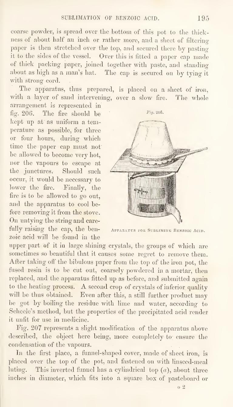
SUBLIMATION OF BENZOIC ACID. 195
coarse powder, is spread over the bottom of this pot to the thick¬
ness of about half an inch or rather more, and a sheet of filterina*
paper is then stretched over the top, and secured there by pasting
it to the sides of the vessel. Over this is fitted a paper cap made
of thick packing paper, joined together with paste, and standing
about as high as a man’s hat. The cap is secured on by tying it with strong cord.
The apparatus, thus prepared, is placed on a sheet of iron,
with a layer of sand intervening, over a slow fire. The whole
arrangement is represented in
fig. 206. The fire should be
kept up at as uniform a tem¬
perature as possible, for three
or four hours, during which
time the paper cap must not'
be allowed to become very hot,
nor the vapours to escape at
the junctures. Should such
occur, it would be necessary to
lower the fire. Finally, the
fire is to be allowed to go out,
and the apparatus to cool be¬
fore removing it from the stove.
On untying the string and care¬
fully raising the cap, the ben¬
zoic acid will be -found in the
upper part of it in large shining crystals, the groups of which are
sometimes so beautiful that it causes some regret to remove them.
After taking off the bibulous paper from the top of the iron pot, the
fused resin is to be cut out, coarsely powdered in a mortar, then
replaced, and the apparatus fitted up as before, and submitted again
to the heating process. A second crop of crystals of inferior quality
will be thus obtained. Even after this, a still further product may
be got by boiling the residue with lime and water, according to
Scheele’s method, but the properties of the precipitated acid render
it unfit for use in medicine.
Fig. 207 represents a slight modification of the apparatus above
described, the object here being, more completely to* ensure the
condensation of the vapours.
In the first place, a funnel-shaped cover, made of sheet iron, is
placed over the top of the pot, and fastened on with linseed-meal
luting. This inverted funnel has a cylindrical top ((z), about three
inches in diameter, which fits into a square box of pasteboard or
Fig. 206.
Apparatus for Subliming Benzoic Acid.
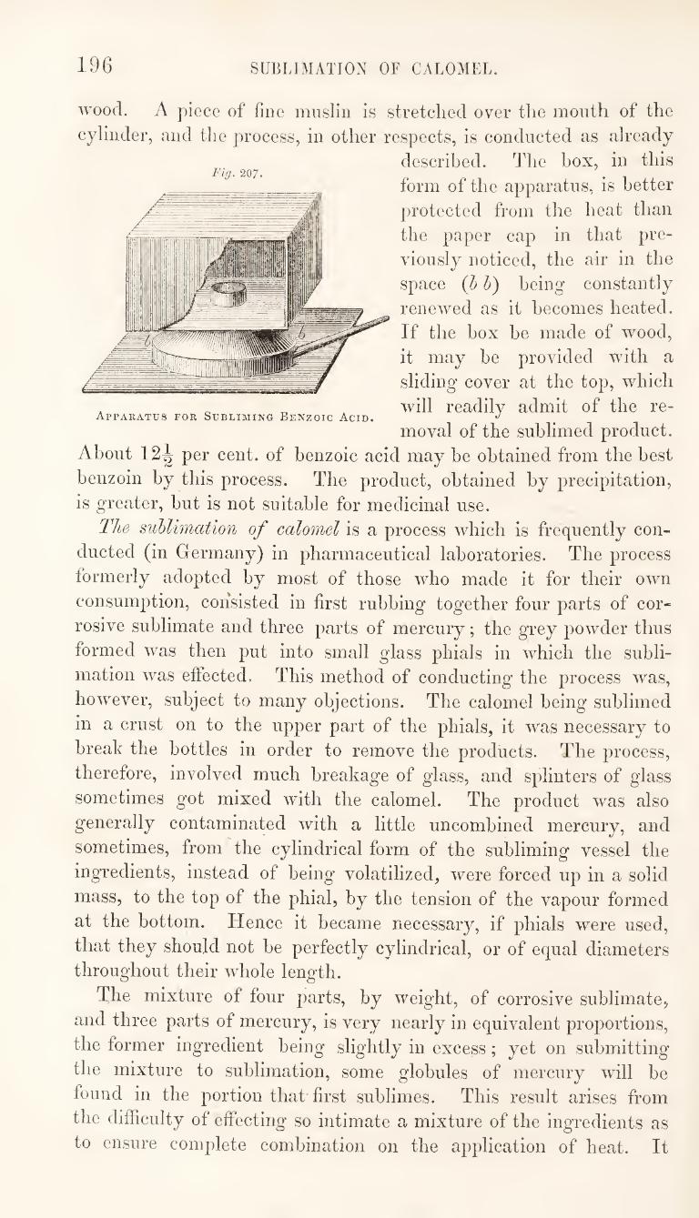
196 SUBLIMATION OF CALOMEL.
wood. A piece of fine mnslin is stretched over tlie mouth of the
cylinder, and the process, in other respects, is conducted as already
described. The box, in this
form of the apparatus, is better
protected from the heat than
the paper cap in that pre¬
viously noticed, the air in the
space {h h) being constantly
renewed as it becomes heated.
If the box be made of wood,
it may be provided with a
sliding cover at the top, which
, ^ . will readily admit of the re- Apparatus for Subliming Benzoic Acid.
moval of the sublimed product.
About 12^ per cent, of benzoic acid may be obtained from the best
benzoin by this process. The product, obtained by precipitation,
is greater, but is not suitable for medicinal use.
Tlie sublimation of calomel is a process which is frequently con¬
ducted (in Germany) in pharmaceutical laboratories. The process
formerly adopted by most of those who made it for their own
consumption, consisted in first rubbing together four parts of cor¬
rosive sublimate and three parts of mercury; the grey powder thus
formed was then put into small glass phials in which the subli¬
mation was effected. This method of conducting the process was,
however, subject to many objections. The calomel being sublimed
in a crust on to the upper part of the phials, it was necessary to
break the bottles in order to remove the products. The process,
therefore, involved much breakage of glass, and splinters of glass
sometimes got mixed with the calomel. The product was also
generally contaminated with a little uncombined mercury, and
sometimes, from the cylindrical form of the subliming vessel the
ingredients, instead of being volatilized, were forced up in a solid
mass, to the top of the phial, by the tension of the vapour formed
at the bottom. Hence it became necessary, if phials were used,
that they should not be perfectly cylindrical, or of equal diameters throughout their whole length.
The mixture of four parts, by weight, of corrosive sublimate,
and three parts of mercury, is very nearly in equivalent proportions,
the former ingTedient being slightly in excess; yet on submitting
the mixture to sublimation, some globules of mercury will be
found in the portion that first sublimes. This result arises from
the difficulty of effecting so intimate a mixture of the ingredients as
to ensure complete combination on the application of heat. It
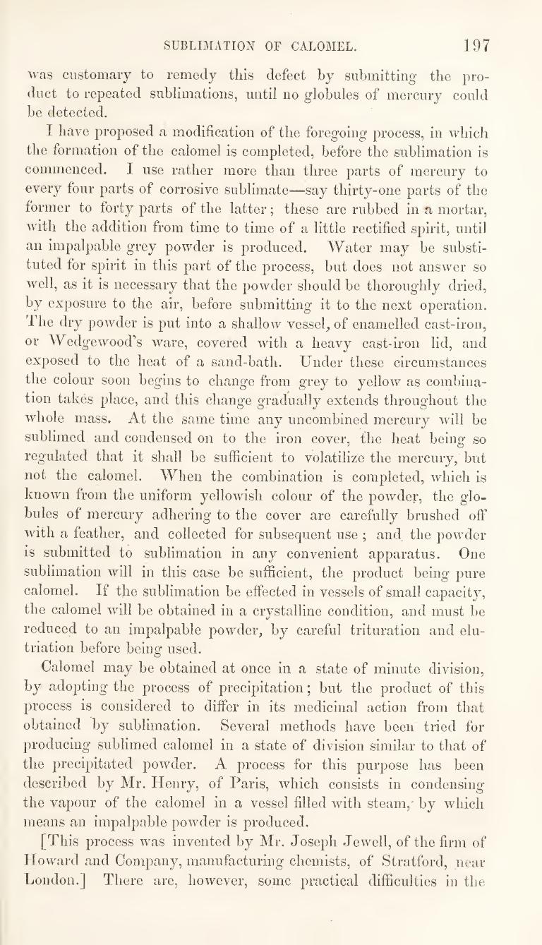
SUBLIMATION OF CALOMEL. 197
was customary to remedy this defect by submitting the pro¬
duct to repeated sublimations, until no globules of mercury could be detected.
I have proposed a modification of the foregoing process, in which
the formation of the calomel is completed, before the sublimation is
commenced. I use rather more than three parts of mercury to
every four parts of corrosive sublimate—say thirty-one parts of the
former to forty parts of the latter; these are rubbed in a, mortar,
with the addition from time to time of a little rectified spirit, until
an impalpable grey powder is produced. Water may be substi¬
tuted for spirit in this part of the process, but does not answer so
well, as it is necessary that the powder should be thoroughly dried,
by exposure to the air, before submitting it to the next operation.
The dry powder is put into a shallow vessel, of enamelled cast-iron,
or Wedgewood’s Avare, covered with a heavy cast-iron lid, and
exposed to the heat of a sand-bath. Under these circumstances
the colour soon begins to change from grey to yellow as combina¬
tion takes place, and this change gradually extends throughout tlie
whole mass. At the same time any uncombined mercury will be
sublimed and condensed on to the iron cover, the heat being so
regulated that it shall be sufficient to volatilize the mercury, but
not the calomel. When the combination is completed, which is
known from the uniform yellowish colour of the powder, the glo¬
bules of mercury adhering to the cover are carefully brushed off
with a feather, and collected for subsequent use ; and the powder
is submitted to sublimation in any convenient apparatus. One
sublimation will in this case be sufficient, the product being pure
calomel. If the sublimation be effected in vessels of small capacity,
the calomel will be obtained in a crystalline condition, and must be
reduced to an impalpable powder, by careful trituration and elu- triation before being used.
Calomel may be obtained at once in a state of minute division,
by adopting the process of precipitation; but the product of this
process is considered to differ in its medicinal action from that
obtained by sublimation. Several methods have been tried for
producing sublimed calomel in a state of division similar to that of
the precipitated powder. A process for this purpose has been
described by Mr. Henry, of Paris, which consists in condensing
the vapour of the calomel in a vessel filled with steam,* by which
means an impalpable poAvder is produced.
[This process was invented by Mr. Joseph JeAvell, of the firm of
IIoAvard and Company, manufacturing chemists, of Stratford, near
London.] There are, hoAVCver, some practical difficulties in the
198 SUBLIMATION OF CALOMEL.
adoption of this process, and other means have been since disco¬
vered by which a similar result is more easily obtained.
The following process fulfils the desired object satisfactorily.
The calomel is first prepared in the manner already described, by
heating the mixture of corrosive sublimate and mercury until com¬
bination has been effected. It is then sublimed in the apparatus of
which a representation is given in fig. 208. An earthen tube
Apparatus foe subliming Calomel,
about two niches and a guarter in diameter, and ten or twelve
inches long, is fixed across a small iron furnace. This tube should
be made of a mixture of fire-clay and sand, cajiable of bearing
the action of a dull red heat, without cracking. To one end of it
an earthen plug or stopper is fitted, through which passes a pipe
connected with a bellows. To the other end, a tube (c), of much larger
diameter, is attached, which communicates with a wooden box {d),
T he inside of this box is lined with glazed paper, and over the top
of it a cloth is stretched, which is secured in its jilace by a
sheet iron funnel forming the top of the box. The funnel is termi¬
nated by a pipe (/’), three or four inches in diameter, and about
three feet long. Around this pipe there is a small iron corridor for the reception of ignited charcoal.
In conducting the process of sublimation with this apparatus.
SUBLIMATION.—FILTBATION. 199
the calomel is introduced into the pipe (6), and fires are kindled in
the furnace (a), and in the corridor (£?). When the vapours of
calomel begin to be formed a current of air is forced through the
pipe by means of a double bellows, or centrifugal blower, which,
mixing with the vapour, carries it into the box (c^), while at the
same time the vapour is condensed, and its further progress is
arrested by the cloth (m). When the tube (/’) gets well heated,
there may be sufficient draught through the apparatus without
using the bellows, in wdiich case the plug must be removed from
the mouth of the tube (5), and the process can then be maintained
uninterruptedly for a great length of time, fresh portions of the
powder being introduced into the tube as the sublimation proceeds.
[It is not necessary in this process to have a current of air pass¬
ing through the apparatus, provided that the vessel or chamber
into which the vapours are conducted be of ample size, so that by
the admixture of a large quantity of cool air condensation may be
speedily effected. In fact, the condition of the products obtained
by sublimation are always influenced by the size and position of the
receiver in which the vapours are condensed. If the receiver be
small, and if it be immediately contiguous to the vessel from which
the substance is sublimed, the product will assume a crystalline
condition, the temperature being such as to admit of the slow and
regular aggregation of the particles. If, on the other hand, the
receiver be large, or if, from its position, the air within it be kept
cool, the sublimed product will assume a more or less amorphous
condition, the condensation being so rapid that no symmetrical
arrangement of the particles can take place.]
• FILTRATION.
{The 2^rocess of filtration consists in the separation of liquids
from substances held by them in suspension, by causing the former
to pass through the pores of media which are impervious to the
latter. When the solid matter to be removed is a powder wdiich
subsides on standing, this is called a precipitate^ and the liquid
separated by filtration is called the filtrate. In some cases, filtration
is adopted merely for the purpose of rendering turbid liquids clear
and transparent, the substances collected on the filter being re¬
jected; in other cases, the object of the process is to collect
and preserve the substance wdiich remains on the filter, wdiile the
liquid is thrown away; in other instances again, the preservation
of both precipitate and filtrate is desired. The materials employed
200 FILTERING MEDIA.
as filtering media, when prepared for use, are called filters. These
mateiials are of dilierent kinds, some being organic, such as
cloths of linen, cotton, or wool, and paper made of these materials,
whde others are inorganic, such as sand, pounded glass, asbestos, rock crystal, and charcoal.
I ilteiing^media may, therefore, be divided into two classes, the
organic and the inorganic. The organic media may, again, be
divided into those which are of vegetable^ and those which are of
animal origin. ]3esides these distinctions, there is another fre¬
quently made, although not always admitted, which is founded on
the greater or lesser porousness of the filtering material. Thus,
cloth filters are more porous, and offer less obstruction to the
passage of any solid particles, than paper filters. Cloth filters,
therefore, are generally used in those cases where the solid par¬
ticles to be removed are not very finely divided, or where their
complete separation is not an object of much importance, while,
at the same time, rapid filtration is required. The process thus
conducted is sometimes called straining, but it differs not essentially
froin those ^ processes which, being conducted with less porous
media, are, in such cases, distinguished as filtering.
The substances used as filtering media are :—
Woollen cloth or fiannel, which may be of different degrees of thickness and of closeness of texture.
^ Gahco, or other fabric of cotton. There is a material of this
kind called swans-down, which is used in some cases where fine straining is required.
Linen, or other fabric of flax or hemp.
Filtering paper, of which there are a great many different kinds, but they may all be classed under two heads:—
1. Filtering paper made from cotton or linen rags. This con¬
stitutes the thinner and whiter kinds of filtering paper.
2. Filteiing papei made from woollen materials. This constitutes
the thicker and coarser kinds of filtering paper. It is more porous than the other, and is used for rapid filtration.
There is often some difficulty experienced in getting filtering paper
of good quality. It should be easily permeated by the liquids to be
tered, without allowing any solid particles to pass through. It
should present a tolerably smooth surface, so that any precipitate
collected on it, might be easily removed, and not absorbed into the
pores. It should also be strong enough to support the weight of
the substance filtered, when placed in a funnel, without breaking.
Moreover, it should contain nothing that is soluble in the liquids to be filtered.
FILTERING MEDIA. 201
Sand.—This should be rather large-grained, and perfectly free
from organic matter. It should be purified by washing it with
diluted hydrochloric acid, and subsequently with water.
Powdered glass^ consisting of common wine-bottle glass, reduced
to coarse powder in an iron mortar, sorted by the use of sieves of
different degrees of fineness, and then washed with diluted acid and
water. Powdered rock crystal^ prepared in the same way as the glass,
from chippings formed in cutting spectacle glasses, or from other
fragments of rock crystal. It is preferable to either sand or glass,
being less readily acted on by the liquids in the filtration of which
it is used. It should be prepared ready for use, reduced to
different degrees of comminution, and each kind kept separately.
Asbestos., in the fibrous state, which has been purified by heating
it to redness, and then washing it wfith diluted acid and water.
Animal charcoal., in rough grains, resembling very coarse gun¬
powder. This is made on the large scale by manufacturers who
supply the sugar refiners. These substances cannot be indiscriminately used in all processes
of filtration. It is necessary to make a selection of a suitable
material in each process, and some judgment is required in deter¬
mining what kind of filter is best adapted for the substance under
operation.
Woollen cloth is suitable for filtering a great number of substances
employed in medicine. The filters used for syrups and for many
aqueous decoctions, and expressed vegetable juices are made of this
material. This is also the proper material to employ for straining
plasters and ointments, or any substances of an oily nature.
Woollen material, whether in the form of cloth, such as flannel,
or in that of paper, is inapplicable for the filtration of alkaline
solutions, which exert a solvent action on the wool.
Linen and cotton cloths., and paper made of these materials., are
used in a great variety of cases. They may be employed for the
filtration of alkaline solutions, especially linen, which answers the
purpose best. Linen or cotton cloths are also generally used for
collecting and washing precipitates, where the quantities operated
on are considerable. The paper of this kind is perhaps most
suitable for the filtration of alcoholic and ethereal solutions. Tinc¬
tures, however, are frequently filtered through the coarse paper
made from woollen materials.
Sand., Powdered glass, Bock crystal, and Asbestos, are employed
in the filtration of strong alkaline or acid solutions, which would
exercise a chemical action on organic filtering media.
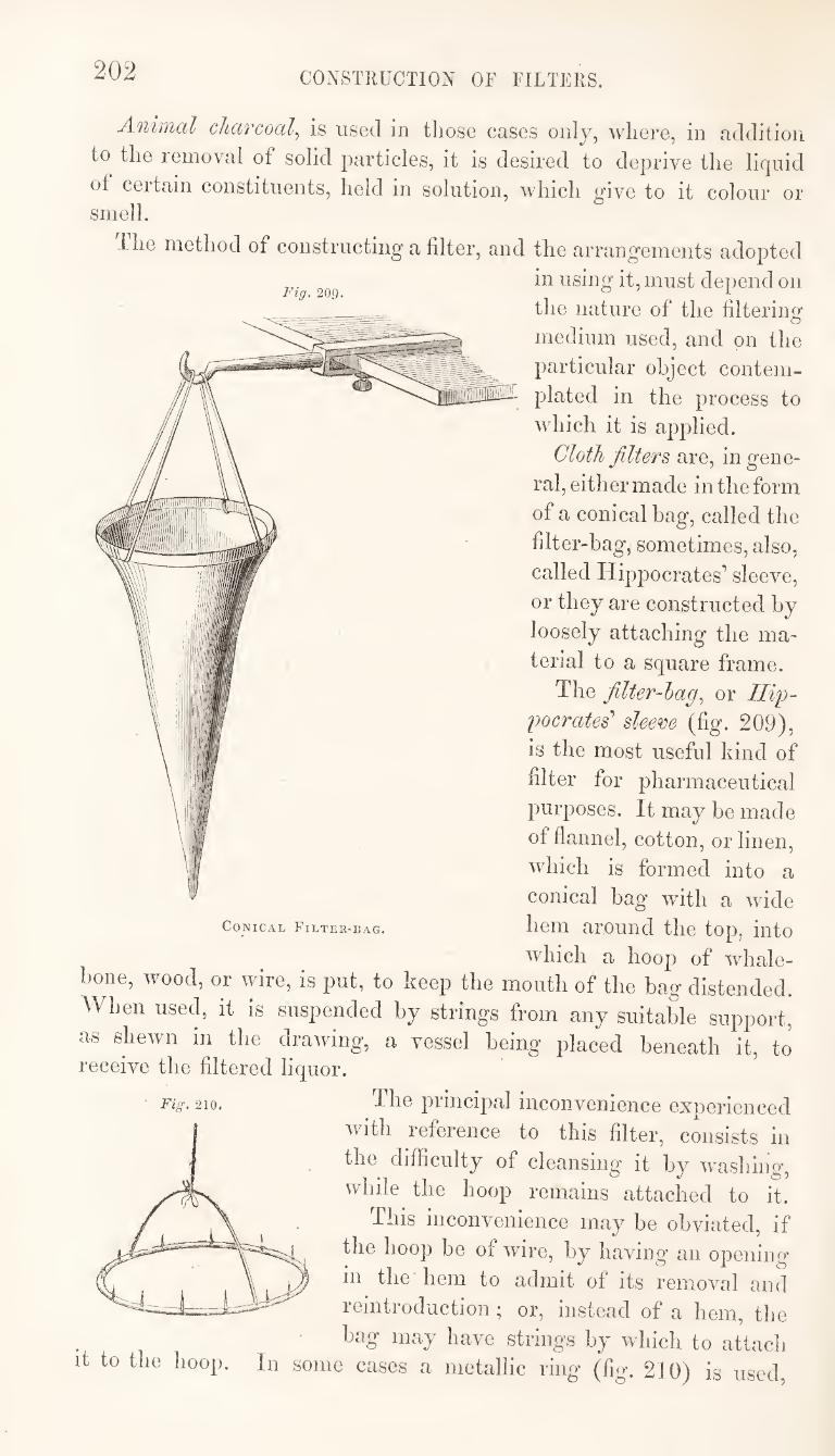
202 CONSTUUCTIOfJ OF FILTERS.
Fig. 209.
Animal charcoal., is used in those eases only, where, in addition
to the removal of solid particles, it is desired to deprive the liquid
of certain constituents, held in solution, which give to it colour or smell.
llie method of constructing a filter, and the arrangements adopted
in using it, must depend on
the nature of the filtering
medium used, and on the
particular object contem¬
plated in the process to
which it is applied.
Cloth filters are, in gene¬
ral, either made in the form
of a conical bag, called the
filter-bag, sometimes, also,
called Hippocrates’ sleeve,
or they are constructed by
loosely attaching the ma¬
terial to a square frame.
The filter-hag., or IliiJ-
gocrates' sleem (fig. 209),
is the most useful kind of
filter for 23harmaceutical
purposes. It may be made
of flannel, cotton, or linen,
which is formed into a
conical bag with a wide
hem around the top, into
which a hoop of whale- bone, wood, or wire, is put, to keep the mouth of the bag distended.
When used, it is suspended by strings from any suitable support,
as shewn in the drawing, a vessel being placed beneath it, to receive the filtered liquor.
The principal inconvenience experienced
with reference to this filter, consists in
the difficulty of cleansing it by washing,
vvlnle the hoop remains attached to it.
This inconvenience may be obviated, if
the hoop be of wire, by having an opening
in the hem to admit of its removal and
reintroduction; or, instead of a hem, the
bag may have strings by which to attach
it to the hoop. In some cases a metallic ring (fig. 210) is used.
Conical Filter-bag.
Fig. 210.
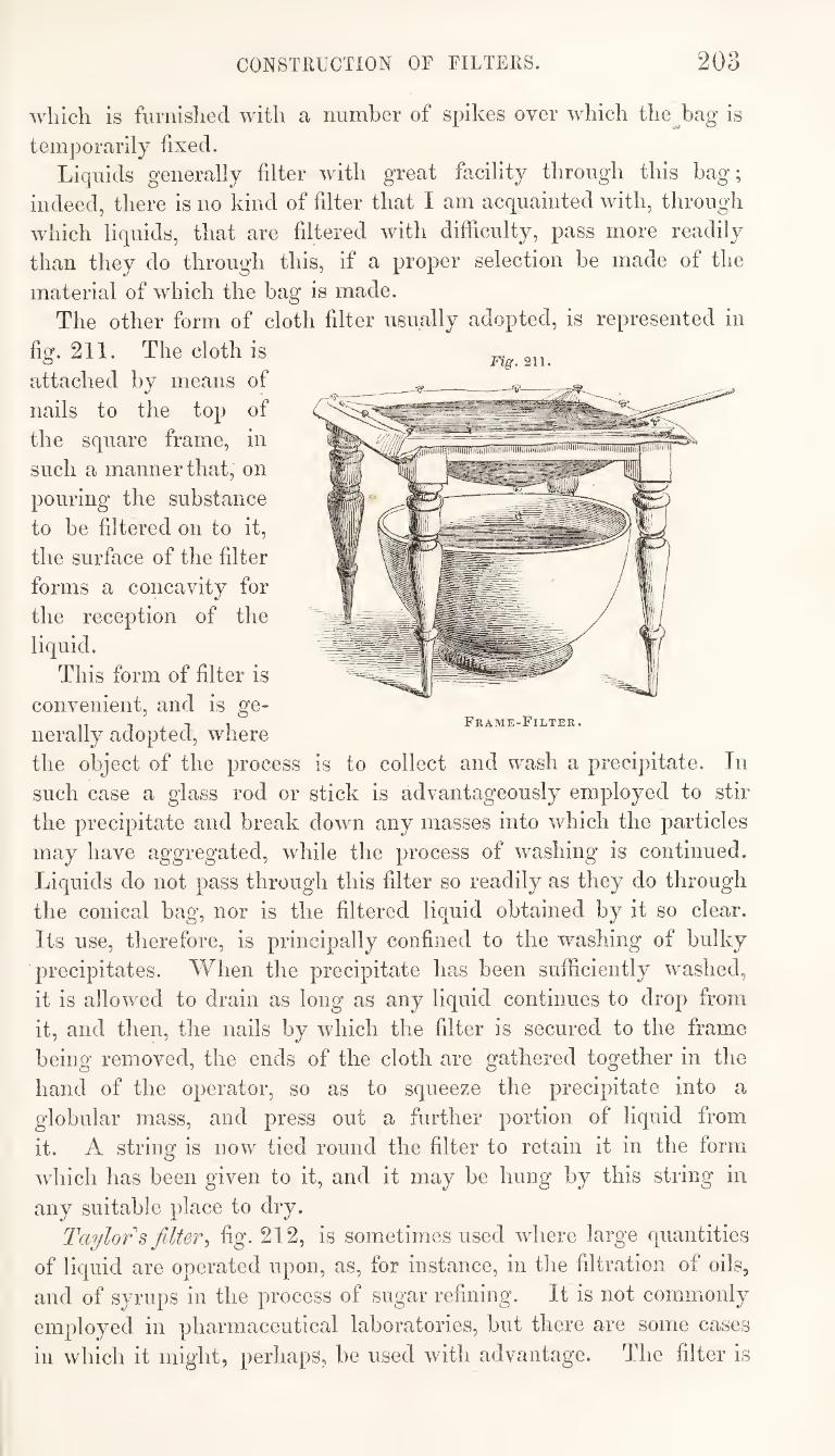
CONSTRUCTION OF FILTERS. 203
which is furnished with a number of spikes over which the^bag is
temporarily fixed.
Liquids generally filter with great facility through this bag;
indeed, there is no kind of filter that I am acquainted with, through
which liquids, that are filtered with difficulty, pass more readily
than they do through this, if a proper selection be made of the
material of which the bag is made.
The other form of cloth filter usually adopted, is represented in
fig. 211. The cloth is
attached by means of
nails to the top of
the square frame, in
such a manner that, on
pouring the substance
to be filtered on to it,
the surface of the filter
forms a concavity for
the reception of the
liquid.
This form of filter is
convenient, and is ge¬
nerally adopted, where
the object of the process is to collect and wash a precipitate. In
such case a glass rod or stick is advantageously employed to stir
the precipitate and break down any masses into which the particles
may have aggregated, while the process of washing is continued.
Liquids do not pass through this filter so readily as they do through
the conical bag, nor is the filtered liquid obtained by it so clear.
Its use, therefore, is principally confined to the washing of bulky
precipitates. When the precipitate has been sufficiently washed,
it is allowed to drain as long as any liquid continues to drop from
it, and then, the nails by which the filter is secured to the frame
being removed, the ends of the cloth are gathered together in the
hand of the operator, so as to squeeze the precipitate into a
globular mass, and press out a further portion of liquid from
it. A string is now tied round the filter to retain it in the form
which has been given to it, and it may be hung' by this string in
any suitable place to dry.
Taylor s filter^ fig. 212, is sometimes used where large quantities
of liquid are operated upon, as, for instance, in the filtration of oils,
and of syrups in the process of sugar refining. It is not commonly
employed in pharmaceutical laboratories, but there are some cases
in which it might, perhaps, be used with advantage. The filter is
Frame-Filter.
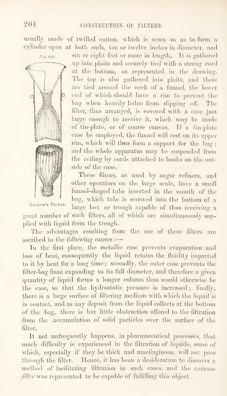
204 CONSTRUCTION OF FILTERS.
Fig. 212.
usually made of twilled cotton, whicli is sewn so as to form a
cylinder open at both ends, ten or twelve inches in diameter, and
six or eight feet or more in length. It is gathered
up into plaits and securely tied with a strong cord
at the bottom, as represented in the drawing.
The top is also gathered into plaits, and these
are tied around tlie neck of a funnel, the lower
end of which should have a rim to prevent the
bag when heavily laden from slipping off. The
filter, thus arranged, is covered with a case just
large enough to receive it, which may be made
of tin-plate, or of coarse canvas. If a tin-plate
case be employed, the funnel will rest on its upper
rim, which will thus form a support for the bag ;
and the whole apparatus may be suspended from
the ceiling by cords attached to hooks on the out¬
side of the case.
These filters, as used by sugar refiners, and
other operators on the large scale, have a small
funnel-shaped tube inserted in the mouth of the
bag, which tube is screwed into the bottom of a Taylor’s Filter.
large box or trough capable of thus receiving a
great number of such filters, all of which are simultaneously sup¬
plied with liquid from the trough.
The advantages resulting from the use of these filters are
ascribed to the following causes :—
In the first place, the metallic case prevents evaporation and
loss of heat, consequently the liquid retains the fluidity imparted
to it by heat for a long time; secondly, the outer case prevents the
filter-bag from expanding to its full diameter, and therefore a given
quantity of liquid forms a longer column than would otherwise be
the case, so that the hydrostatic pressure is increased ; finally,
there is a large surface of filtering medium with which the liquid is
in contact, and as any deposit from the liquid collects at the bottom
of the bag, there is but little obstruction offered to the filtration
from the accumulation of solid particles over the surface of the
filter.
It not unfrequently happens, in pharmaceutical processes, that
much difficulty is experienced in the filtration of liquids, some of
which, especially if they be thick and mucilaginous, will not pass
through the filter. Hence, it has been a desideratum to discover a
method of facilitating filtration in such cases, and the vacuum
filter was represented to be capable of fulfilling this object.
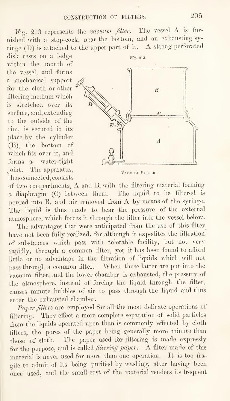
CONSTRUCTION OF FILTERS. 205
Fig. 213 represents the vacuum filter. The vessel A is fur¬
nished with a stop-cock, near the bottom, and an exhausting sy-
ringe (D) is attaclied to the upper part of it. A strong perforated
Fig. 213. disk rests on a ledge
within the mouth of
the vessel, and forms
a mechanical support
for the cloth or other
filtering medium which
is stretched over its
surface, and, extending
to the outside of the
rim, is secured in its
place by the cylinder
(B), the bottom of
which fits over it, and
forms a water-tight
joint. The apparatus,
thus connected, consists
of two compartments, A and B, with the filtering material forming
a diaphragm (C) between them. The liquid to be filtered is
poured into B, and air removed from A by means of the syringe.
A
Vacuum Filter.
The liquid is thus made to bear the pressure of the external
atmosphere, which forces it through the filter into the vessel below.
The advantages that were anticipated from the use of this filter^
have not been fully realized, for although it expedites the filtration
of substances which pass with tolerable facility, but not very
rapidly, through a common filter, yet it has been found to afford
little or no advantage in the filtration of liquids which will not
pass through a common filter. When these latter are put into the
vacuum filter, and the lower chamber is exhausted, the pressure of
the atmosphere, instead of forcing the liquid through the filter,
causes minute bubbles of air to pass through the liquid and thus
enter the exhausted chamber.
Paper filters, are employed for all the most delicate operations of
filtering. They effect a more complete separation of solid particles
from the liquids operated upon than is commonly effected by cloth
filters, the pores of the paper being generally more minute than
those of cloth. The paper used for filtering is made expressly
for the purpose, and is called filtering paper. A filter made of this
material is never used for more than one operation. It is too fra¬
gile to admit of its being purified by washing, after having been
once used, and the small cost of the material renders its frequent
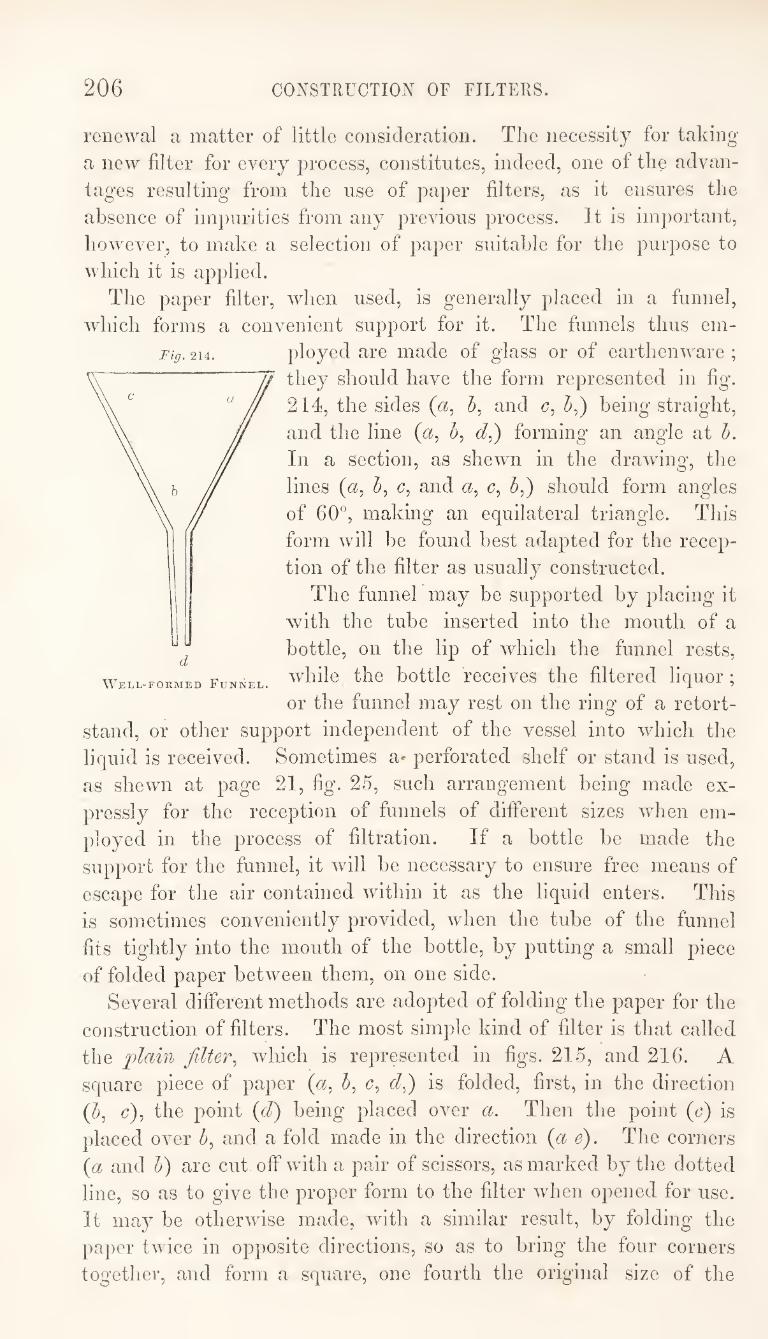
206 CONSTRUCTION OF FILTERS.
renewal a matter of little consideration. The necessity for taking
a new filter for every process, constitutes, indeed, one of the advan¬
tages resulting from the use of paper filters, as it ensures the
absence of impurities from any previous process. It is important,
however, to make a selection of paper suitable for the purpose to
which it is applied.
The paper filter, when used, is generally placed in a funnel,
which forms a convenient support for it. The funnels thus em¬
ployed are made of glass or of earthenware ;
they should have the form represented in fig.
214, the sides (a, 5, and c, 5,) being straight,
and the line forming an angle at h.
In a section, as shewn in the drawdng, the
lines (a, c, and c, J,) should form angles
of 60°, making an equilateral triangle. This
form will be found best adapted for the recep¬
tion of the filter as usually constructed.
The funnel may be supported by placing it
with the tube inserted into the mouth of a
bottle, on the lip of which the funnel rests,
while the bottle receives the filtered liquor;
or the funnel may rest on the ring of a retort-
stand, or other support independent of the vessel into which the
liquid is received. Sometimes a* perforated shelf or stand is used,
as shewn at page 21, fig. 25, such arrangement being made ex¬
pressly for the reception of funnels of different sizes when em¬
ployed in the process of filtration. If a bottle be made the
support for the funnel, it will be necessary to ensure free means of
escape for the air contained within it as the liquid enters. This
is sometimes conveniently provided, when the tube of the funnel
fits tightly into the mouth of the bottle, by putting a small piece
of folded paper between them, on one side.
Several different methods are adopted of folding the paper for the
construction of filters. The most simple kind of filter is that called
the ])la%n filter^ which is represented in figs. 215, and 216. A
square piece of paper («, 5, c, is folded, first, in the direction
(^, c), the point (d) being placed over a. Then the point (c) is
placed over and a fold made in the direction (a e). The corners
{a and h) are cut off with a pair of scissors, as marked by the dotted
line, so as to give the proper form to the filter when opened for use.
It may be otherwise made, with a similar result, by folding the
paper twice in opposite directions, so as to bring the four corners
together, and form a square, one fourth the original size of the
d Well-formed Funnel.
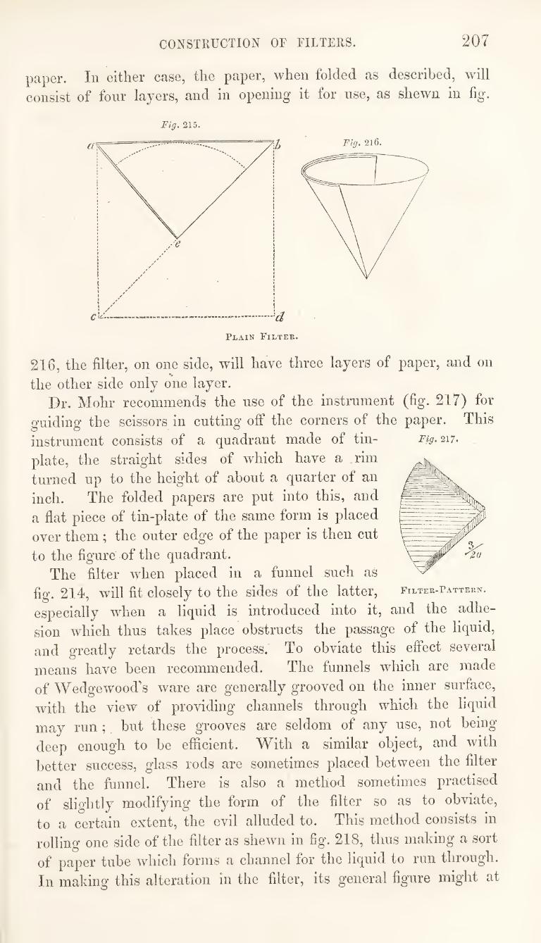
CONSTRUCTION OF FILTERS. 207
paper. In either case, the paper, when folded as described, will
consist of four layers, and in opening it for use, as shewn in fig.
216, the filter, on one side, will have three layers of paper, and on
the other side only one layer.
Dr, Mohr recommends the use of the Instrument (fig. 217) for
guiding the scissors in cutting off the corners of the paper. This
instrument consists of a quadrant made of tin¬
plate, the straight sides of which have a rim
turned up to the height of about a quarter of an
inch. The folded papers are put into this, and
a flat piece of tin-plate of the same form is placed
over them ; the outer edge of the paper is then cut
to the figure of the quadrant.
The filter when placed in a funnel such as
fig. 214, will fit closely to the sides of the latter,
especially when a liquid is introduced into it, and the adhe¬
sion which thus takes place obstructs the passage of the liquid,
and greatly retards the process. To obviate this effect several
means have been recommended. The funnels which are made
of Wedge wood’s ware are generally grooved on the inner surface,
with the view of providing channels through which the liquid
may run ; but these grooves are seldom of any use, not being
deep enough to be efficient. With a similar object, and with
better success, glass rods are sometimes placed between the filter
and the funnel. There is also a method sometimes practised
of slightly modifying the form of the filter so as to obviate,
to a certain extent, the evil alluded to. This method consists in
rolling one side of the filter as shewn in fig. 218, thus making a sort
of paper tube which forms a channel for the liquid to run through.
In making this alteration in the filter, its general figure might at
Fig. 217.
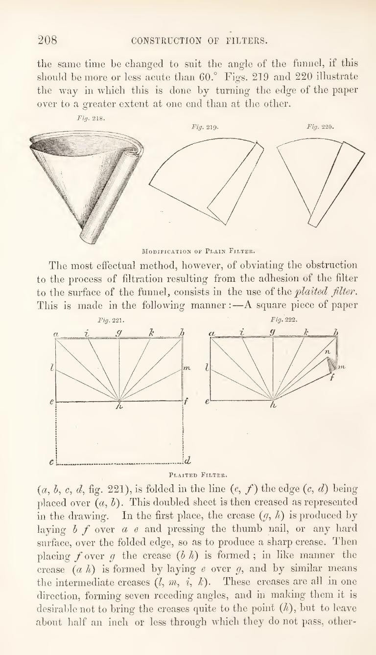
208 CONSTRUCTION OF FILTERS.
the same time be changed to suit the angle of the funnel, if this
should be more or less acute than 60.° Figs. 219 and 220 illustrate
the way in which this is done by turning the edge of the paper
over to a greater extent at one end than at the other.
Fig. 218. Fig. 219. Fig. 220.
Modification of Plain Filter.
The most effectual method, however, of obviating the obstruction
to the process of filtration resulting from the adhesion of the filter
to the surface of the funnel, consists in the use of the plaited filter.
This is made in the following manner:—A square piece of paper
221. Fig. 222.
{a, h, c, d., fig. 221), is folded in the line (e, /) the edge (c, d) being
placed over (r^, V). This doubled sheet is then creased as represented
in the drawing. In the first place, the crease (//, A) is produced by
laying h f over a e and pressing the thumb nail, or any hard
surface, over the folded edge, so as to produce a sharp crease. Then
placing f over g the crease {fi li) is formed ; in like manner the
crease {gl li) is formed by laying e over and by similar means
the intermediate creases (^, /I). These creases are all in one
direction, forming seven receding angles, and in making them it is
desirable not to bring the creases quite to the point (/^), but to leave
about half an inch or less through wFich they do not pass, other-
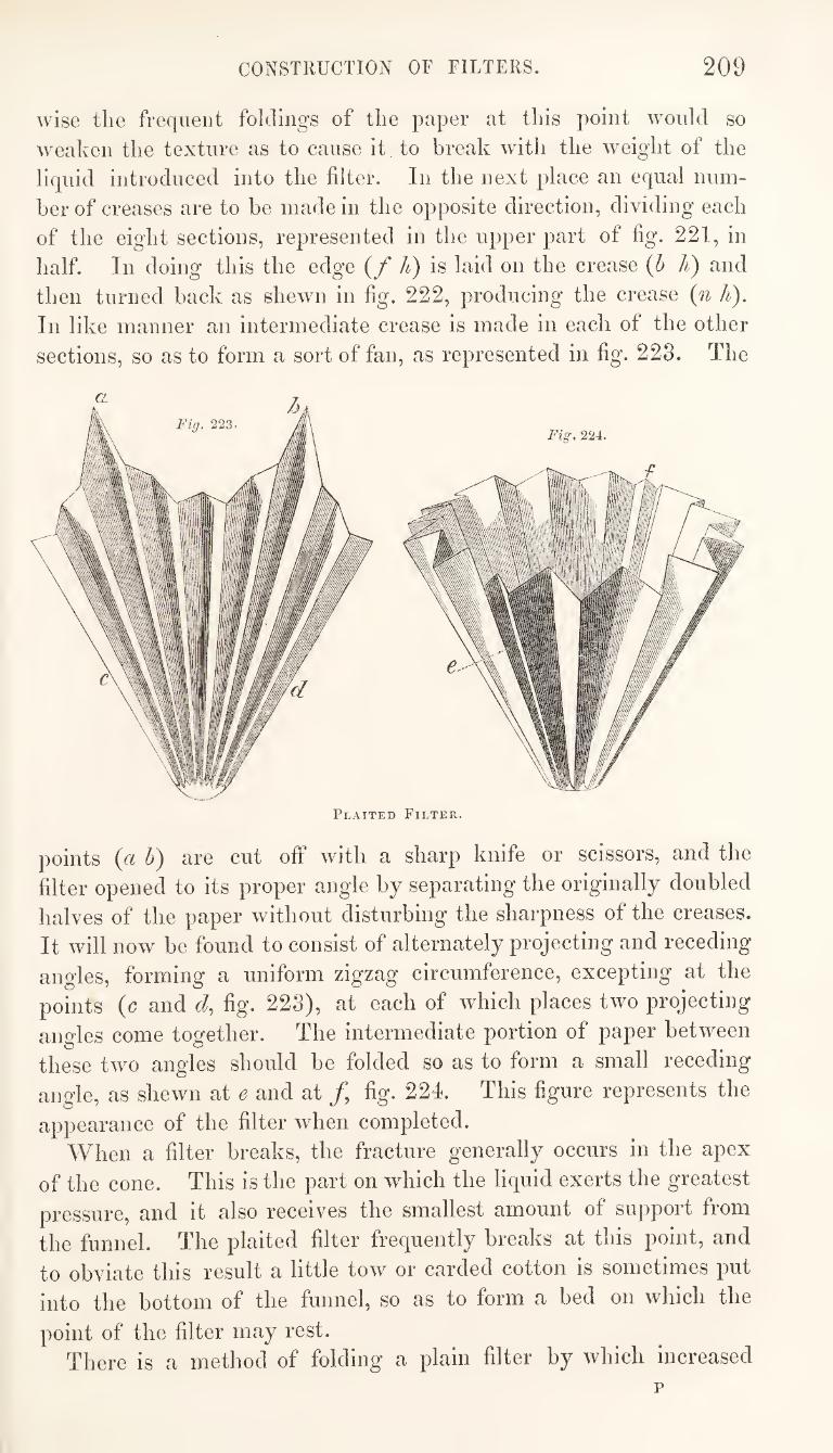
CONSTRUCTION OF FILTERS. 209
wise the frequent foldings of the paper at this point would so
weaken the texture as to cause it to break with the weight of the
liquid introduced into the filter. In the next place an equal num¬
ber of creases are to be made in the opposite direction, dividing each
of the eight sections, represented in the upper part of fig. 221, in
half. In doing this the edge {f It) is laid on the crease {b li) and
then turned back as shewn in fig. 222, producing the crease {n h).
In like manner an intermediate crease is made in each of the other
sections, so as to form a sort of fan, as represented in fig. 223. The
Plaited Filter.
points {a h) are cut off with a sharp knife or scissors, and the
filter opened to its proper angle by separating the originally doubled
halves of the paper without disturbing the sharpness of the creases.
It will now be found to consist of alternately projecting and receding
angles, forming a uniform zigzag circumference, excepting at the
points {c and d, fig. 223), at each of which places two projecting
angles come together. The intermediate portion of paper between
these two angles should be folded so as to form a small receding
angle, as shewn at e and at /, fig. 224. This figure represents the
appearance of the filter when completed.
When a filter breaks, the fracture generally occurs in the apex
of the cone. This is the part on which the liquid exerts the greatest
pressure, and it also receives the smallest amount of support from
the funnel. The plaited filter frequently breaks at this point, and
to obviate this result a little tow or carded cotton is sometimes put
into the bottom of the funnel, so as to form a bed on which the
point of the filter may rest.
There is a method of folding a plain filter by which increased
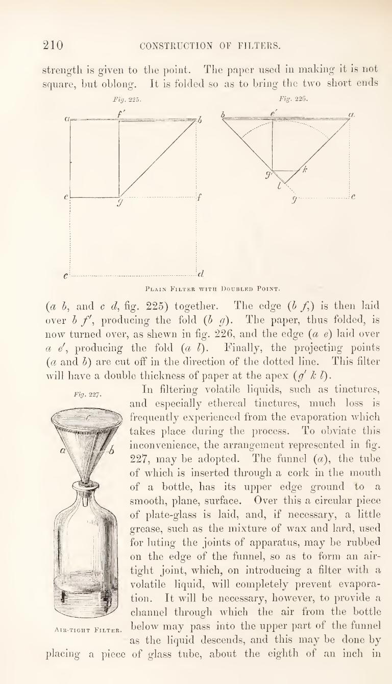
210 CONSTRUCTION OF FILTERS.
strength is given to the point. The paper used in making it is not
square, hut oblong. It is folded so as to bring the two short ends
Fig. 225. Fig. 226.
Plain Filter with Doubled Point.
Fig. 227.
{a and c r/, fig. 225) together. The edge (5 /,) is then laid
over h f\ producing the fold (b g). The paper, thus folded, is
now turned over, as shewn in fig. 226, and the edge {^ol e) laid over
a /, producing the fold (a 1). Finally, the projecting points
{a and h) are cut off in the direction of the dotted line. This filter
will have a double thickness of paper at the apex {g' k 1).
In filtering volatile liquids, such as tinctures,
and especially ethereal tinctures, much loss is
frequently experienced from the evaporation which
takes place during the process. To obviate this
inconvenience, the arrangement represented in fig.
227, may be adopted. The funnel (a), the tube
of which is inserted through a cork in the mouth
of a bottle, has its upper edge ground to a
smooth, plane, surface. Over this a circular piece
of plate-glass is laid, and, if necessary, a little
grease, such as the mixture of wax and lard, used
for luting the joints of apparatus, may be rubbed
on the edge of the funnel, so as to form an air¬
tight joint, which, on introducing a filter with a
volatile liquid, will completely prevent evapora¬
tion. It will be necessary, however, to provide a
channel through which the air from the bottle
Air-tight Filter. ^gIow may pass iiito the Upper part of the funnel
as the liquid descends, and this may be done by
placing a piece of glass tube, about the eighth of an inch in
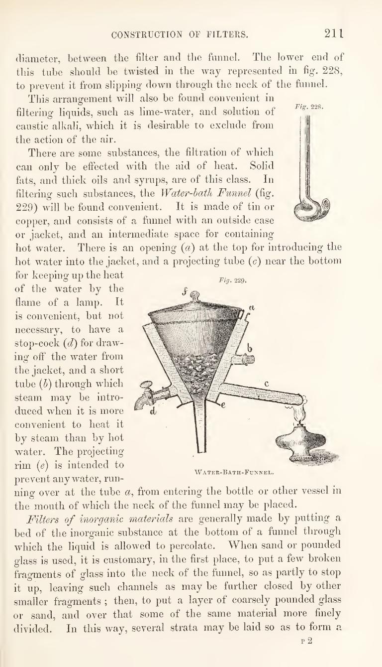
CONSTRUCTION OF FILTERS. 211
diameter, between the filter and the funnel. The lower end of
this tube should he twisted in the way represented in fig. 228,
to prevent it from slipping down through the neck of the funnel.
This arrangement will also he found convenient in
filtering liquids, such as lime-water, and solution of
caustic alkali, which it is desirable to exclude from
the action of the air.
There are some substances, the filtration of which
can only he effected with the aid of heat. Solid
fats, and thick oils and syrups, are of this class. In
filtering such substances, the Water-hath Funnel (fig.
229) will be found convenient. It is made of tin or
copper, and consists of a funnel with an outside case
or jacket, and an intermediate space for containing
hot water. There is an opening {a) at the top for introducing the
hot water into the jacket, and a projecting tube (<?) near the bottom
for keeping up the heat
of the water by the
flame of a lamp. It
is convenient, but not
necessary, to have a
stop-cock {d) for draw¬
ing off the water from
the jacket, and a short
tube (h) through which
steam may be intro¬
duced when it is more
convenient to heat it
by steam than by hot
water. The projecting
rim (e) is intended to
prevent any water, run¬
ning over at the tube «, from entering the bottle or other vessel in
the mouth of which the neck of the funnel may be placed.
Filters of inorganic materials are generally made by putting a
bed of the inorganic substance at the bottom of a funnel through
which the liquid is allowed to percolate. When sand or pounded
glass is used, it is customary, in the first place, to put a few broken
fragments of glass into the neck of the funnel, so as partly to stop
it up, leaving such channels as may be further closed by other
smaller fragments ; then, to put a layer of coarsely pounded glass
or sand, and over that some of the same material more finely
divided. In this way, several strata may be laid so as to form a
rig. 229.
Water-Bath-Funnel.
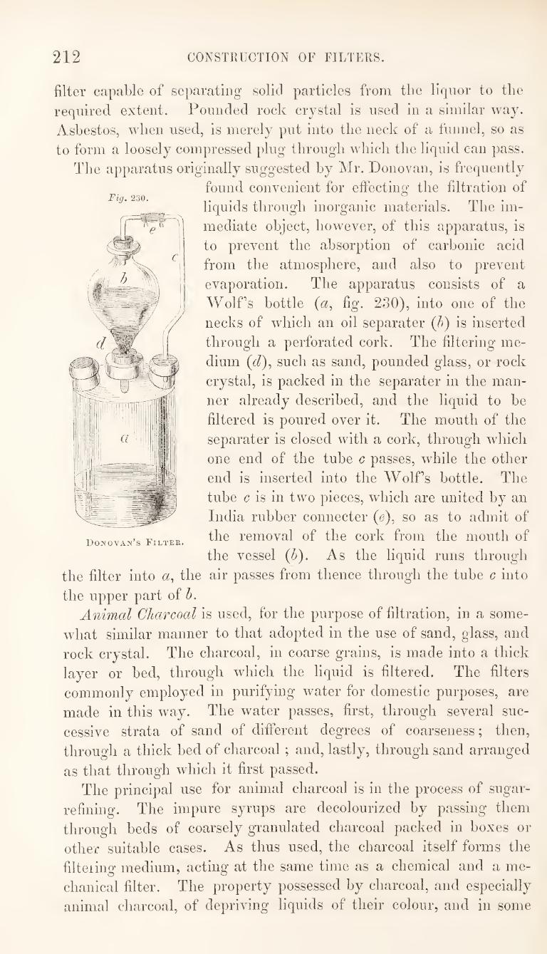
212 CONSTRUCTION OF FILTERS.
filter capable of separating solid particles from the liqnor to the
required extent. Pounded rock crystal is used in a similar way.
Asbestos, when used, is merely put into the neck of a funnel, so as
to form a loosely compressed plug through which the liquid can pass.
The apparatus originally suggested by Mr. Donovan, is frequently
found convenient for effecting the filtration of
liquids through inorganic materials. The im¬
mediate object, however, of this apparatus, is
to prevent the absorption of carbonic acid
from the atmosphere, and also to prevent
evaporation. The apparatus consists of a
Wolf’s bottle (a, fig. 230), into one of the
necks of which an oil separater (A) is inserted
through a perforated cork. The filtering me¬
dium (d), such as sand, pounded glass, or rock
crystal, is packed in the separater in the man¬
ner already described, and the liquid to he
filtered is poured over it. The mouth of the
separater is closed with a cork, through which
one end of the tube c passes, while the other
end is inserted into the Wolfs bottle. The
tube c is in two pieces, wdiich are united by an
India rubber connecter (e), so as to admit of
the removal of the cork from the mouth of
the vessel (6). As the liquid runs through
the filter into a, the air passes from thence through the tube c into
the upper part of A
Animal Charcoal is used, for the purpose of filtration, in a some¬
what similar manner to that adopted in the use of sand, glass, and
rock crystal. The charcoal, in coarse grains, is made into a thick
layer or bed, through which the liquid is filtered. The filters
commonly employed in purifying water for domestic purposes, are
made in this way. The water passes, first, through several suc¬
cessive strata of sand of different degrees of coarseness; then,
through a thick bed of charcoal ; and, lastly, through sand arranged
as that through which it first passed.
The principal use for animal charcoal is in the process of sugar-
refiniug. The impure syrups are decolourized by passing them
through beds of coarsely granulated charcoal packed in boxes or
other suitable cases. As thus used, the charcoal itself forms the
filteiing medium, acting at the same time as a chemical and a me¬
chanical filter. The property possessed by charcoal, and especially
animal charcoal, of depriving liquids of their colour, and in some
Fig. 230.
Donovan’s Filter.
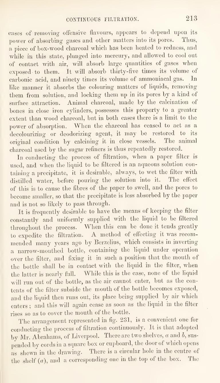
CONTINUOUS FILTRATION. 213
cases of removing offensive flavours, appears to deiiend upon its power of absorbing gases and other matters into its pores. Thus, a piece of box-wmod charcoal which has been heated to redness, and while in this state, plunged into mercury, and allowed to cool out of contact with air, will absorb large quantities of gases when exposed to them. It will absorb thirty-five times its volume of carbonic acid, and ninety times its volume of ammoniacal gas. In like manner it absorbs the colouring matters of liquids, removing them from solution, and locking them up in its pores by a kind of surface attraction. Animal charcoal, made by the calcination of bones in close iron cylinders, possesses this property to a greater extent than wood charcoal, but in both cases there is a limit to the power of absorption. When the charcoal has ceased to act as a decolourizing or deodorizing agent, it may be restored to its original condition by calcining it in close vessels. The animal charcoal used by the sugar refiners is thus repeatedly restored.
In conducting the process of filtration, when a paper filter is used, and when the liquid to be filtered is an aqueous solution con¬ taining a precipitate, it is desirable, always, to wet the filter with distilled water, before pouring the solution into it. The effect of this is to cause the fibres of the paper to swell, and the pores to become smaller, so that the precipitate is less absorbed by the paper
and is not so likely to pass through. It is frequently desirable to have the means of keeping the filter
constantly and uniformly supplied with the liquid to be filtered throughout the process. When this can be done it tends greatly to expedite the filtration. A method of effecting it was recom¬ mended many years ago by Berzelius, which consists in inverting a narrow-mouthed bottle, containing the liquid under operation over the filter, and fixing it in such a position that the mouth of the bottle shall be in contact with the liquid in the filter, when the latter is nearly full. While this is the case, none of the liquid will run out of the bottle, as the air cannot enter, but as the con¬ tents of the filter subside the mouth of the bottle becomes exposed, and the liquid then runs out, its place being supplied by air which enters ; and this will again cease as soon as the liquid in the filter
rises so as to cover the mouth of the bottle. The arrangement represented in fig* 231, is a convenient one for
conducting the process of filtration continuously. It is that adopted by Mr. Abrahams, of Liverpool. There are two shelves, a and 5, sus¬ pended by cords in a square box or cupboard, the door of which opens as shewn in the drawing. There is a circular hole in the centre of the shelf {a), and a corresponding one in the top of the box. The
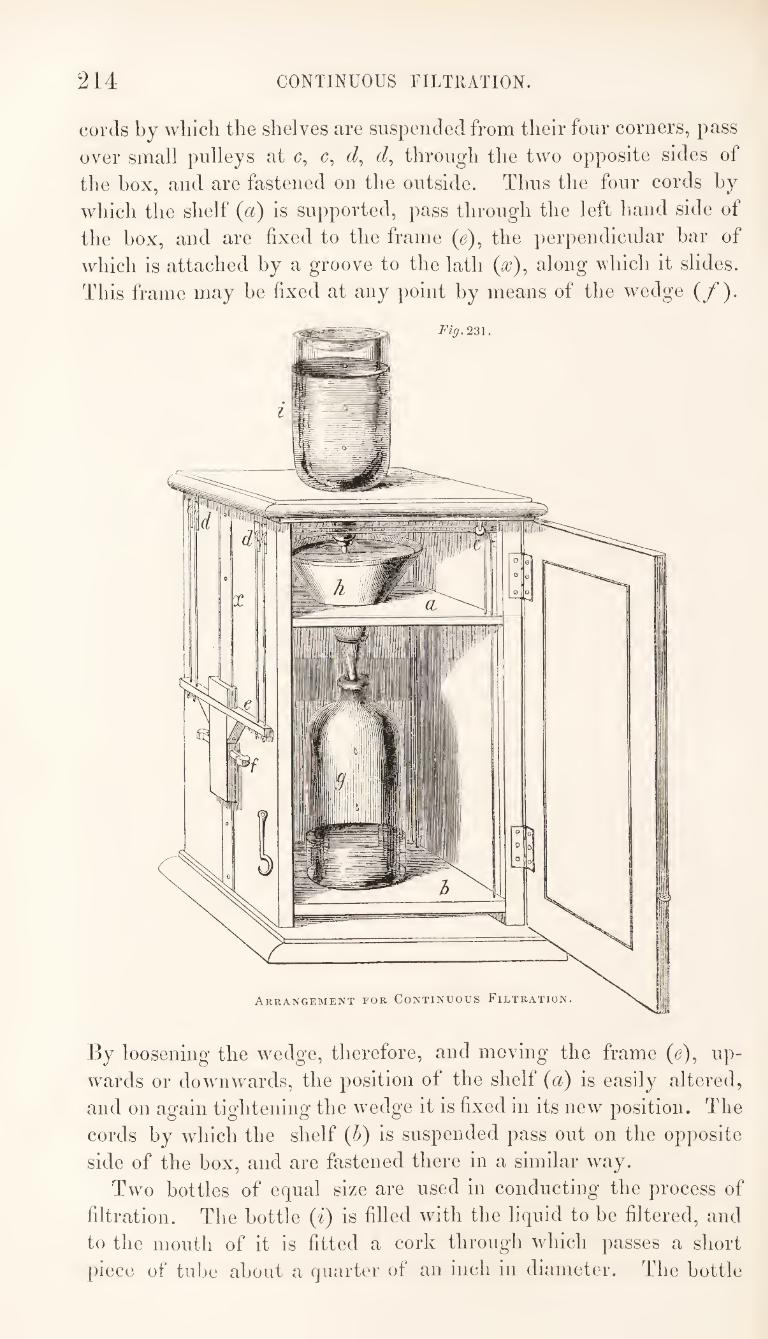
214 CONTINUOUS FILTllATION.
cords by which the shelves are suspended from their four corners, pass
over small pulleys at c, c, t/, through the two opposite sides of
the box, and are fastened on the outside. Thus the four cords by
which the shelf {a) is supported, pass through the left hand side of
the box, and are fixed to the frame (e), the perpendicular bar of
which is attached by a groove to the lath (a?), along which it slides.
This frame may be fixed at any point by means of the wedge (/)•
By loosening the wedge, therefore, and moving the frame (<?), up¬
wards or downwards, the position of the shelf (a) is easily altered,
and on again tightening the wedge it is fixed in its new position. The
cords by which the shelf (6) is suspended pass out on the opposite
side of the box, and are fastened there in a similar way.
Two bottles of equal size are used in conducting the process of
filtration. The bottle (i) is filled with the liquid to be filtered, and
to the mouth of it is fitted a cork through which passes a short
piece of tube about a quarter of an inch in diameter. The bottle
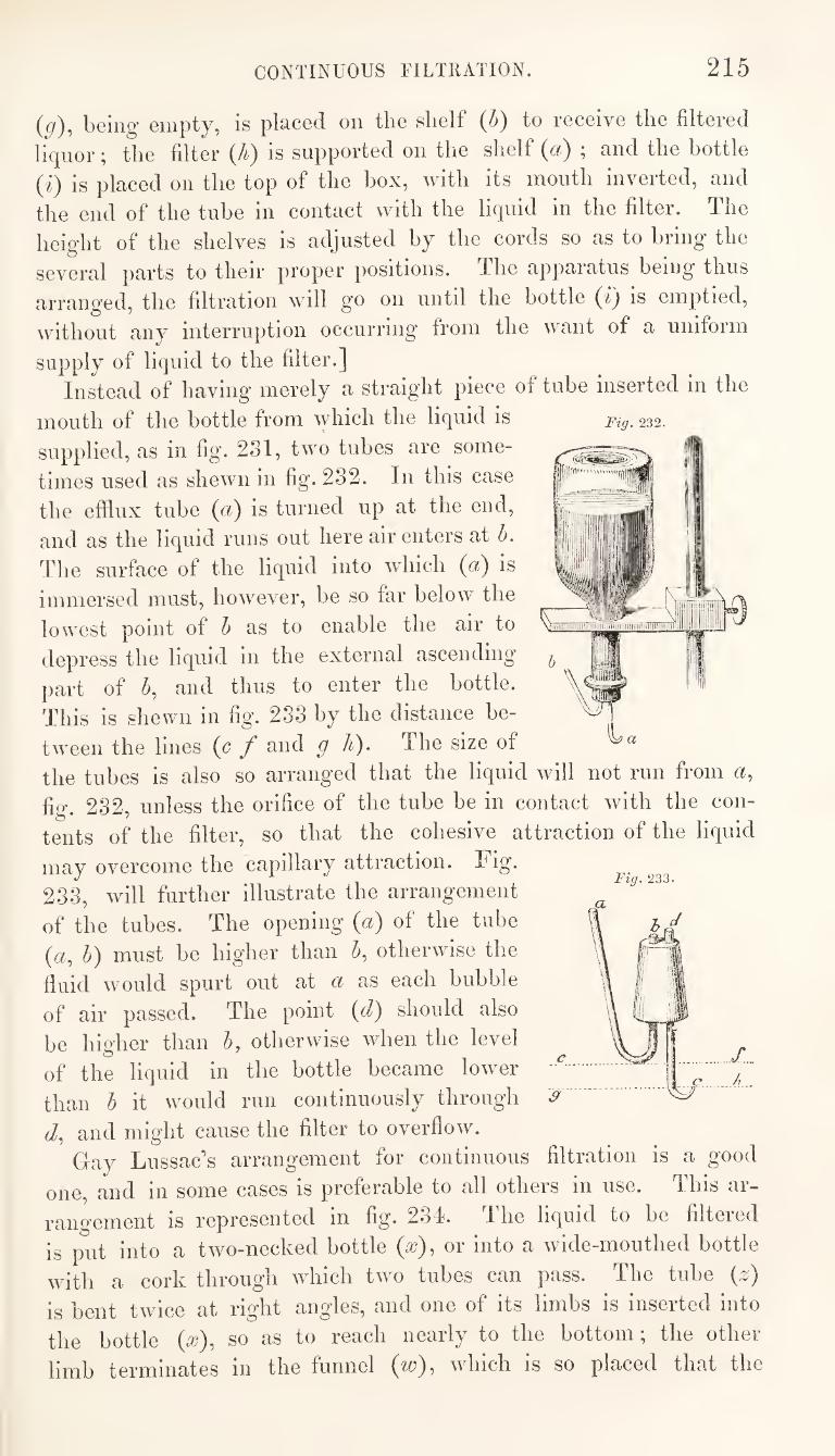
CONTINUOUS FILTIUTION. 215
{g), being empty, is placed on the shelf {h) to receive the filtered
liquor; the filter {h) is supported on the shelf (a) ; and the bottle
(i) is placed on the top of the box, with its mouth inverted, and
the end of the tube in contact with the liquid in the filter. The
height of the shelves is adjusted by the cords so as to bring the
several parts to their proper positions. The apparatus being thus
arranged, the filtration will go on until the bottle {i) is emptied,
without any interruption occurring from the want of a uniform
supply of liquid to the filter.]
Instead of having merely a straight piece of tube inserted in the
mouth of the bottle from which the liquid is
supplied, as in fig. 231, two tubes are some¬
times used as shewn in fig. 232. In this case
the efflux tube (a) is turned up at the end,
and as the liquid runs out here air enters at b.
The surface of the liquid into which (a) is
immersed must, however, be so far below the
lowest point of h as to enable the air to
depress the liquid in the external ascending
part of 5, and thus to enter the bottle.
This is shewn in fig’. 233 by the distance be¬
tween the lines (c / and g A). The size of
the tubes is also so arranged that the liquid will not run from a,
fig. 232, unless the orifice of the tube be in contact with the con¬
tents of the filter, so that the cohesive attraction of the liquid
may overcome the capillary attraction. Fig.
233, will further illustrate the arrangement
of the tubes. The opening («) of the tube
(«, b) must be higher than b, otherwise the
fluid would spurt out at a as each bubble
of air passed. The point {d) slionld also
be higher than b, otherwise when the level
of the liquid in the bottle became lower
than b it would run continuously through
t/, and might cause the filter to overflow.
Gay Lussac’s arrangement for continuous filtration is a good
one, and in some cases is preferable to all others in use. This ar¬
rangement IS represented in fig. 234. Ihe liquid to be filteied
is put into a two-necked bottle (^), or into a wide-mouthed bottle
with a cork through which two tubes can pass. The tube (;2;)
is bent twice at right angles, and one of its limbs is inserted into
the bottle (^), so as to reach nearly to the bottom; the other
limb terminates in the funnel (w), which is so placed that the
Fig. 233.
Fig. 232.
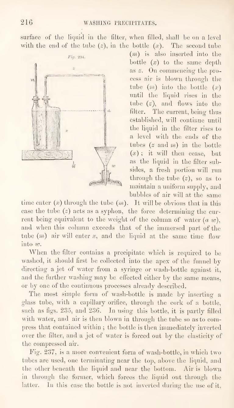
216 WASHING PKECIPITATES.
A
surface of the liquid in the filter, when filled, shall be on a level
with the end of the tube (0), in the bottle {x). The second tube
(m) is also inserted into the
bottle {x) to the same depth
as 2^. On commencing the pro¬
cess air is blown through the
tube (m) into the bottle (x)
until the liquid rises in the
tube (2;), and flows into the
filter. The current, being thus
established, will continue until
the liquid in the filter rises to
a level with the ends of the
tubes (z and m) in the bottle
(x) ; it will then cease, but
as the liquid in the filter sub¬
sides, a fresh portion will run
through the tube (z)^ so as to
maintain a uniform supply, and
bubbles of air will at the same
time enter (x) through the tube (m). It will be obvious that in this
case the tube (z) acts as a syphon, the force determining the cur¬
rent being equivalent to the weight of the column of water (a w)^
and when this column exceeds that of the immersed part of the
tube (m) air will enter x, and the liquid at the same time flow
into w.
When the Alter contains a precipitate which is required to be
washed, it should first be collected into the apex of the funnel by
directing a jet of w^ater from a syringe or w'ash-bottle against it,
and the further washing may be effected either by the same means,
or by one of the continuous processes already described.
The most simple form of wash-bottle is made by inserting a
glass tube, with a capillary orifice, through the cork of a bottle,
such as figs. 235, and 236. In using this bottle, it is partly filled
with water, and air is then blown in through the tube so as to com¬
press that contained within ; the bottle is then immediately inverted
over the filter, and a jet of water is forced out by the elasticity of
the compressed air.
Fig. 237, is a more convenient form of wash-bottle, in which two
tubes are used, one terminating near the top, above the liquid, and
the other beneath the liquid and near the bottom. Air is bloAvii
in through the former, which forces the liquid out through the
hitter. In this case the bottle is not inverted during the use of it.
Fig. 234.
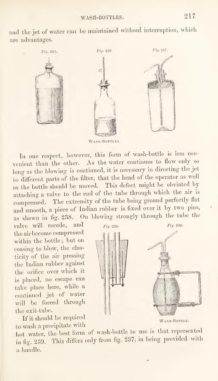
WASH-BOTTLES. 217
and the jet of water can be maintained without interruption, which
are advantages.
J’ig. 235. 236. Fig. 2^7-
Wash-Bottles.
Fig. 238. Fig. 239.
In one respect, however, this form of wash-bottle is less con¬
venient than the other. As the water continues to flow only so
long as the blowing is continued, it is necessary in directing the jet
to different parts of the filter, that the head of the operator as well
as the bottle should he moved. This defect might be obviated by
attaching a valve to the end of the tube through which the air is
compressed. The extremity of the tube being ground perfectly flat
and smooth, a piece of Indian rubber is fixed over it by two pins,
as shewn in fig. 288. On blowing strongly through the tube the
valve will recede, and
the airhecome compressed
within the bottle ; hut on
ceasing to blow, the elas¬
ticity of the air pressing
the Indian rubber against
the orifice over which it
is placed, no escape can
take place here, while a
continued jet of water
will be forced through
the exit-tube.
If it should he required
to wash a precipitate with hot water, the best form of wash-bottle to use is that represented
in fig. 239. This differs only from fig. 237, in being provided with
a handle.
Wash-Bottle.
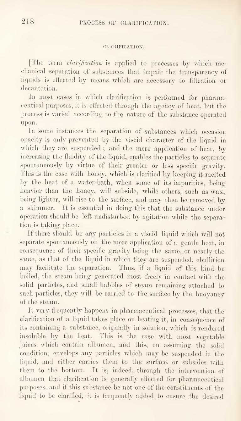
218 PROCESS OF CLARIFICATION.
CLARIFICATION.
[The term clarification is applied to processes by which me¬
chanical separation of substances that impair the transparency of
li([iiids is effected by means which are accessory to filtration or
decantation.
In most cases in which clarification is performed for pharma¬
ceutical purposes, it is effected through the agency of heat, hut the
process is varied according to the nature of the substance operated
upon.
In some instances the separation of substances which occasion
opacity is only prevented by the viscid character of the liquid in
which they are suspended ; and the mere application of heat, by
increasing the fluidity of the liquid, enables the particles to separate
spontaneously by virtue of their greater or less specific gravity.
This is the case with honey, which is clarified by keeping it melted
by the heat of a water-bath, when some of its impurities, being’
heavier than the honey, will subside, while others, such as wax,
being lighter, will rise to the surface, and may then be removed by
a skimmer. It is essential in doing this that the substance under
operation should be left undisturbed by agitation while the separa¬
tion is taking place.
If there should be any particles in a viscid liquid which will not
separate spontaneously on the mere application of a gentle heat, in
consequence of their specific gravity being the same, or nearly the
same, as that of the liquid in which they are suspended, ebullition
may facilitate the separation. Thus, if a liquid of this kind be
boiled, the steam being generated most freely in contact with the
solid particles, and small bubbles of steam remaining attached to
such particles, they will be carried to the surface by the buoyancy
of the steam.
It very frequently happens in pharmaceutical processes, that the
clarification of a liquid takes place on heating it, in consequence of
its containing a substance, originally in solution, which is rendered
insoluble by the heat. This is the case with most vegetable
juices which contain albumen, and this, on assuming the solid
condition, envelops any particles which may be suspended in the
liquid, and either carries them to the surface, or subsides with
them to the bottom. It is, indeed, through the intervention of
albumen that clarification is generally effected for pharmaceutical
purposes, and if this substance be not one of the constituents of the
liquid to be clarified, it is frequently added to ensure the desired
COARSE COMMINUTION. 219
result. In using albumen for this purpose, it must be added to
the liquid before the application of heat. White of egg is the
kind of albumen generally employed, and this should be first mixed
with a little water, then the mixture intimately diffused thiough
the liquid, which should be gradually heated until coagulation
takes place, without disturbing it by stirring or other agitation.
It is necessary to be cautious in the use of albumen as a clarify¬
ing agent in pharmaceutical processes, as it sometimes combines
with, and thus causes the separation of, some of the active con¬
stituents of the liquid to which it is added.]
COAKSE COMMINUTION OF VEGETABLE SUBSTANCES.
A great number of vegetable substances are prepared for use by
submhtiiig them to coarse comminution. They are employed m
this state for making infusions and decoctions, and many are also
sold, under the name of species, for the purposes of private dis¬
pensing. The term species is properly applied to a mixture of
several kinds of vegetable substances, but such a mixture cannot
be made, so as to be uniform, without reducing all the ingredients
to an equal degree of comminution. This particular kind of com¬
minution has latterly been looked upon as the distinctive character
of what are called species, and the term is therefore, now, fre¬
quently applied to coarsely comminuted vegetable substances, even
when consisting of only one kind. The means by which comminution is effected, are chosen accord¬
ing to the nature of the substances operated upon, and the purposes
to which they are applied. If the process be adopted foi the
preparation of vegetable substances as species, much care should be
taken to reduce the particles to as equal a size as possible, and for
this purpose the cutting or slicing-lnife is generally employed. If
the substance should consist of flowers, leaves, or herbs, these are
most easily comminuted by means of the rolling-Jcnife, or cradle-
knife. On the other hand, if the object of the process be to cut
hard woods, roots, or barks, preparatory to their being powdered,
the clopping-trough may be advantageously used. The substances
cut with the last-named instrument will not be reduced to frag¬
ments of equal size, but in the cases alluded to this is not im¬
portant. . ^ i The chopping-trough, fig. 240, consists of two separate parts, the
bottom, or chopping-board (a), and the cylinder (6), which rests
upon, but is not fixed to, the former. The chopping-board is about
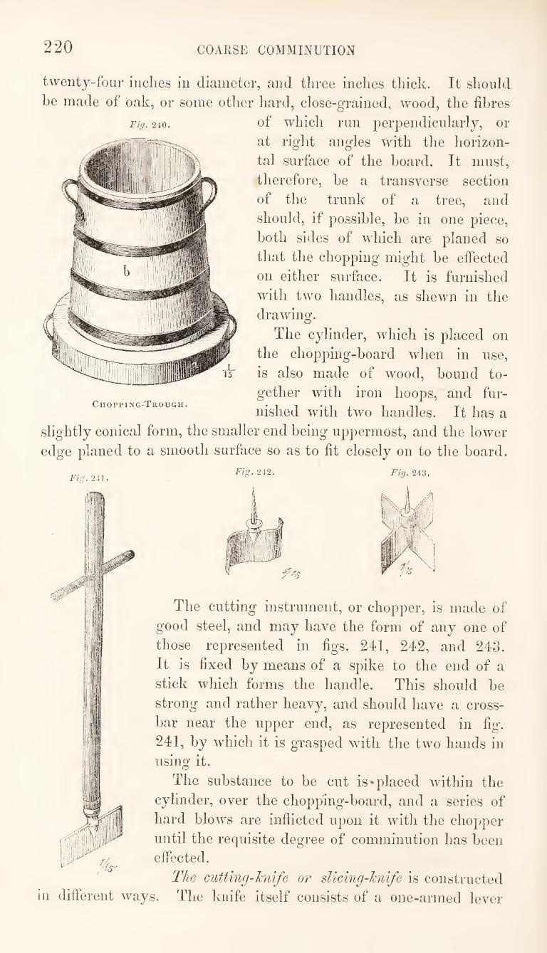
220 COARSE COMMINUTION
Fig. 240.
twenty-four inches in diameter, and three inches thick. It should
he made of oak, or some other hard, close-grained, wood, the fibres
of which run perpendicularly, or
at right angles with the horizon¬
tal surface of the hoard. It must,
therefore, be a transverse section
of the trunk of a tree, and
should, if possible, be in one piece,
both sides of which are planed so
that the chopping might he effected
on either surface. It is furnished
with two handles, as shewn in the
drawing.
The cylinder, which is placed on
the chopping-hoard when in use,
is also made of wood, hound to¬
gether with iron hoops, and fur¬
nished with two handles. It has a
slightly conical form, the smaller end being uppermost, and the lower
edge planed to a smooth surface so as to fit closely on to the hoard.
Chopping-Trough.
211. Fig. 242. Fig. 243.
The cutting instrument, or chopper, is made of
good steel, and may have the form of any one of
those represented in figs. 241, 242, and 243.
It is fixed hy means of a spike to the end of a
stick which forms the handle. This should he
strong and rather heavy, and should have a cross¬
bar near the upper end, as represented in fig.
241, by which it is grasped with the two hands in
using it.
The substance to be cut is‘placed within the
cylinder, over the chopping-hoard, and a series of
hard blows are inflicted upon it with the chopper
until the requisite degree of comminution has been
effected.
The cutting-hnife or sUcing-Jcnife is constructed
ill different ways. The knife itself consists of a one-armed lever
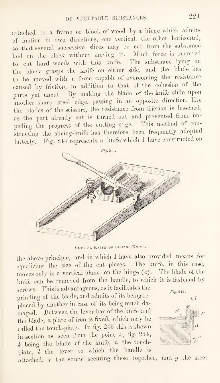
OF VEGETABLE SUBSTANCES. 221
cittaclied to a frame or block of wood by a lunge wliicb admits
of motion in two directions, one vertical, the other horizontal,
so that several successive slices may be cut from the substance
laid on the block without moving it. Much force is required
to cut hard woods with this knife. The substance lying on
the block grasps the knife on either side, and the blade has
to be moved with a force capable of overcoming the resistance
caused by friclion, in addition to that of the cohesion of the
parts yet uncut. By making the blade of the knife slide upon
another sharp steel edge, passing in an opposite^ direction, like
the blades of the scissors, the resistance from friction is lessened,
as the part already cut is turned out and prevented from im¬
peding the progress of the cutting edge. This method of con¬
structing the slicing-knife has therefore been frequently adopted
latterly. Fig. 244 represents a knife which I have constructed on
the above principle, and in which I have also provided means for
equalizing the size of the cut pieces. The knife, in this case,
moves only in a vertical plane, on the hinge (a). The blade of the
knife can be removed from the handle, to which it is fastened by
Fig. 245 screws. This is advantageous, as it facilitates the
grinding of the blade, and admits of its being re¬
placed by another in case of its being much da¬
maged. Between the lever-bar of the knife and
the blade, a plate of iron is fixed, which may be
called the touch-plate. In fig. 245 this is shewn
in section as seen from the point fig. 244,
k being the blade of the knife, n the touch-
plate, I the lever to which the handle is
attached, r the screw securing these together, and g the steel
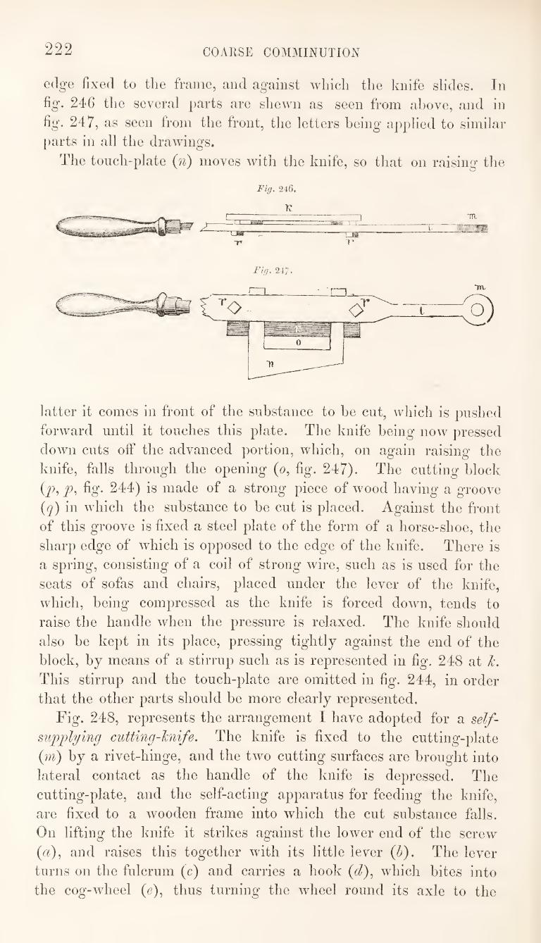
222 COARSE COMMINUTION
edge fixed to the frame, and against which the knife slides. In
fig. 246 the several parts are shewn as seen from above, and in
fig. 247, as seen from the front, the letters being applied to similar
j)arts in all the drawings.
The touch-plate (n) moves with the knife, so that on raising the
Fiff. 246.
K
latter it comes in front of the substance to he cut, which is pushed
forward until it touches this plate. The knife being now pressed
down cuts oif the advanced portion, which, on again raising the
knife, falls through the opening (o, fig. 247). The cutting block
(^, fig. 244) is made of a strong piece of wood having a groove
(q) in which the substance to be cut is placed. Against the front
of this groove is fixed a steel plate of the form of a horse-shoe, the
sharp edge of w^hich is opposed to the edge of the knife. There is
a spring, consisting of a coil of strong wire, such as is used for the
seats of sofas and chairs, placed under the lever of the knife,
which, being compressed as the knife is forced down, tends to
raise the handle when the pressure is relaxed. The knife should
also be kept in its place, pressing tightly against the end of the
block, by means of a stirrup such as is represented in fig. 248 at k.
This stirrup and the touch-plate are omitted in fig. 244, in order
that the other parts should be more clearly represented.
Fig. 248, represents the arrangement I have adopted for a self-
suppfying cutting-kni/e. The knife is fixed to the cutting-plate
(m) by a rivet-hinge, and the two cutting surfaces are brought into
lateral contact as the handle of the knife is depressed. The
cutting-plate, and the self-acting apparatus for feeding the knife,
are fixed to a wooden frame into which the cut substance falls.
On lifting the knife it strikes against the lower end of the screw
(a), and raises this together with its little lever (h). The lever
turns on the fulcrum (c) and carries a hook (d), which bites into
the cog-wdieel (e), thus turning the wheel round its axle to the
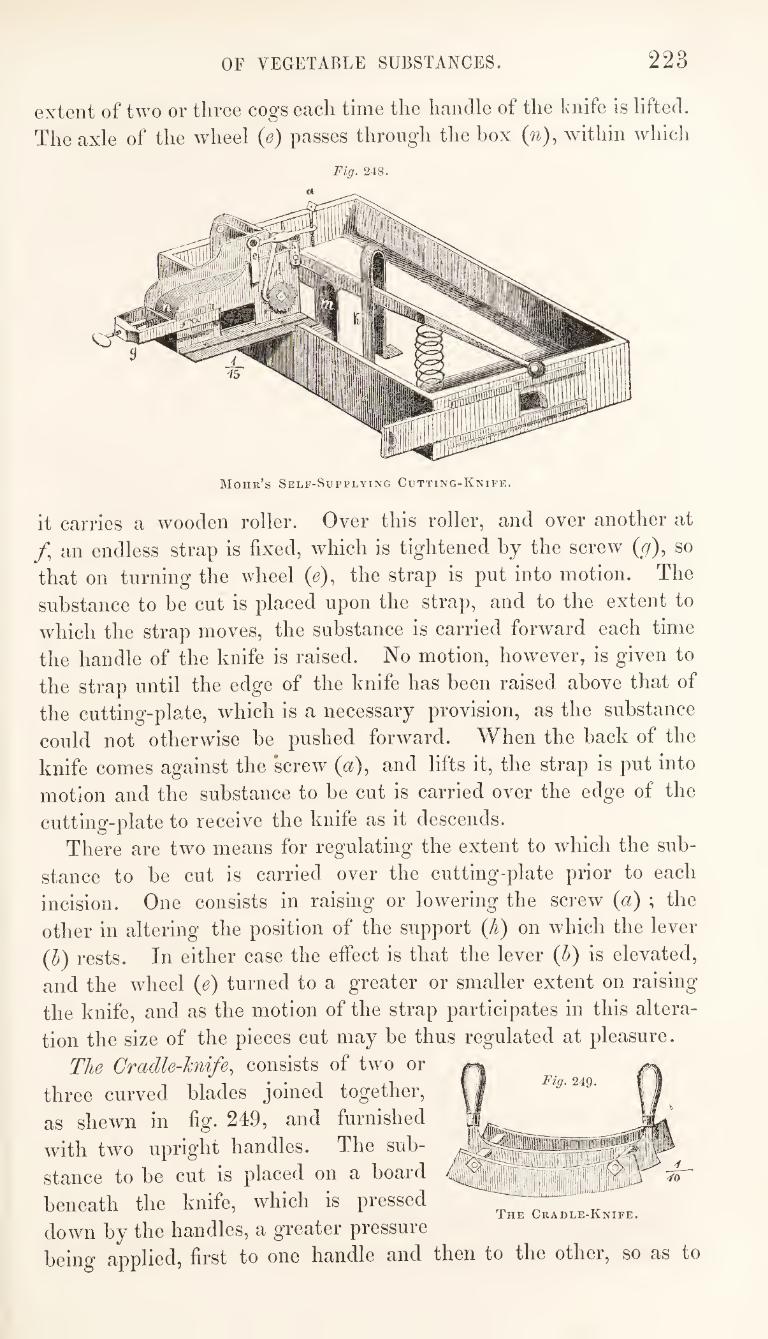
OF VEGETABLE SUBSTANCES. 223
extent of two or three cogs each time the handle of the knife is lifted.
The axle of the wheel (e) passes through the box (n), within which
Fig. 248.
Mohr’s Self-Supplying Cutting-Knife.
it carries a wooden roller. Over this roller, and over another at
/, an endless strap is fixed, which is tightened by the screw (r/), so
that on turning the wheel (e), the strap is put into motion. The
substance to be cut is placed upon the strap, and to the extent to
which the strap moves, the substance is carried forward each time
the handle of the knife is raised. No motion, however, is given to
the strap until the edge of the knife has been raised above that of
the cutting-plate, which is a necessary provision, as the substance
could not otherwise be pushed forward. When the back of the
knife comes against the 'screw (a), and lifts it, the strap is put into
motion and the substance to be cut is carried over the edge of the
cutting-plate to receive the knife as it descends.
There are two means for regulating the extent to which the sub¬
stance to be cut is carried over the cutting-plate prior to each
incision. One consists in raising or lowering the screw (a) ; the
other in altering the position of the support (h) on which the lever
(5) rests. In either case the effect is that the lever (b) is elevated,
and the wheel {e) turned to a greater or smaller extent on raising
the knife, and as the motion of the strap participates in this altera¬
tion the size of the pieces cut may be thus regulated at pleasure.
The Cradle-hiife^ consists of two or
three curved blades joined together,
as shewn in fig. 249, and furnished
wdth two upright handles. The sub¬
stance to be cut is placed on a board
beneath the knife, which is pressed ^ The Cradle-Knife.
down by the handles, a greater pressure
being applied, first to one handle and then to the other, so as to
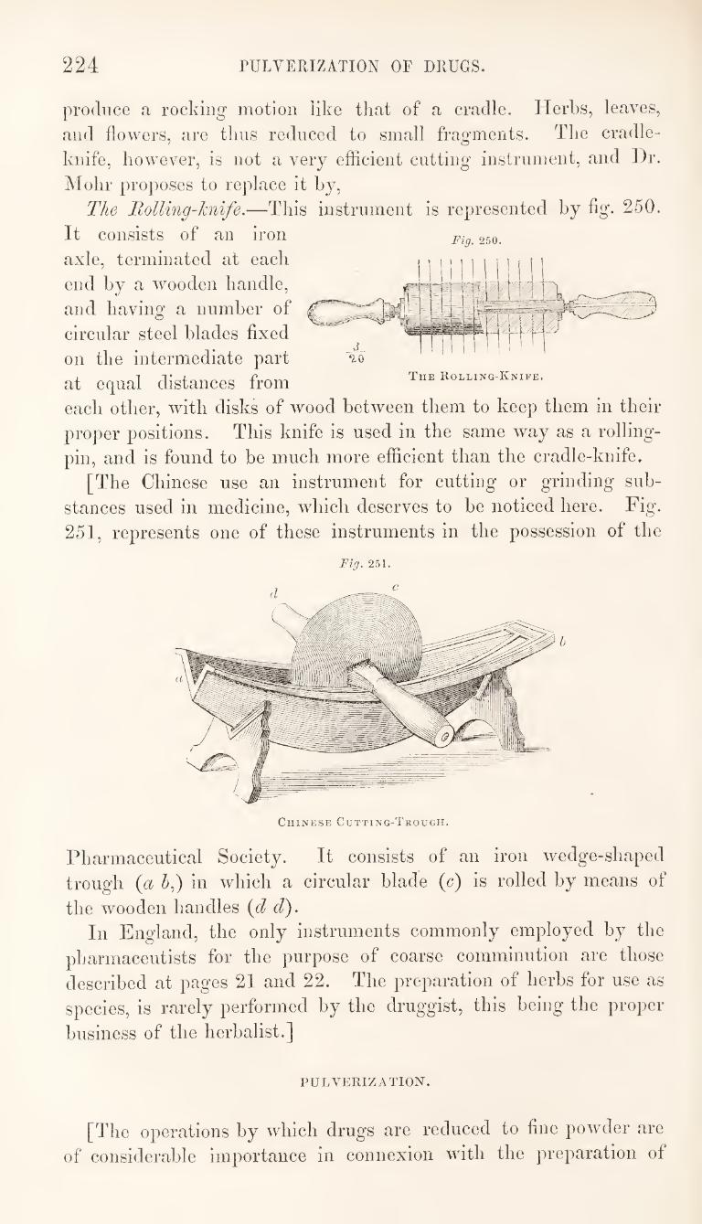
224 PULVERIZATION OF DRUGS.
Fig. 250.
produce a rocking motion like tliat of a cradle. Herbs, leaves,
and flowers, are tliiis reduced to small fragments. The cradle-
knife, however, is not a very efficient cutting instrument, and Dr.
IMohr proposes to replace it by.
The Tolling-hnife.—This instrument is represented by fig. 250.
It consists of an iron
axle, terminated at each
end by a wooden handle,
and having a number of
circular steel blades fixed
on the intermediate part
at equal distances from
each other, with disks of wood between them to keep them in their
proper positions. This knife is used in the same way as a rolling-
pin, and is found to be much more efficient than the cradle-knife.
[The Chinese use an instrument for cutting or grinding sub¬
stances used in medicine, which deserves to be noticed here. Fig.
251, represents one of these instruments in the possession of the
Tue Rolling-Knife.
Fig. 251.
Ciiine.se Cutting-Trough.
Pharmaceutical Society. It consists of an iron Avedge-shaped
trough {a 5,) in which a circular blade (c) is rolled by means of
the wooden handles {d d). In England, the only instruments commonly employed by the
pharmaceutists for the purpose of coarse comminution are those
described at pages 21 and 22. The preparation of herbs for use as
species, is rarely performed by the druggist, this being the proper
business of the herbalist.]
PULVERIZATION.
[The operations by which drugs are reduced to fine powder are
of considerable importance in connexion with the preparation of
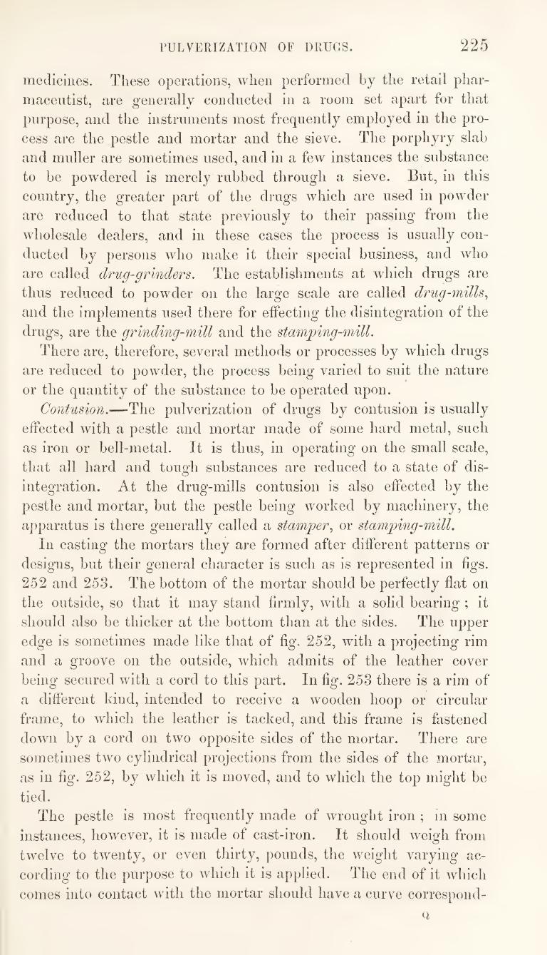
PULVERIZATION OF DRUGS. 225
meellcines. These operations, when performed by the retail phar¬
maceutist, are generally conducted in a room set apart for that
purpose, and the instruments most frequently employed in the pro¬
cess are the pestle and mortar and the sieve. The porphyry slab
and muller are sometimes used, and in a few instances the substance
to be powdered is merely rubbed through a sieve. But, in this
country, the greater part of the drugs which are used in powder
are reduced to that state previously to their passing from the
wholesale dealers, and in these cases the process is usually con¬
ducted by persons who make it their special business, and who
are called drug-grinder8. The establishments at which drugs are
thus reduced to powder on the large scale are called drug-mills^
and the implements used there for effecting the disintegration of the
drugs, are the grinding-mill and the stmnping-mill.
There are, therefore, several methods or processes by which drugs
are reduced to powder, the process being varied to suit the nature
or the quantity of the substance to be operated upon.
Contusion.—The pulverization of drugs by contusion is usually
effected with a pestle and mortar made of some hard metal, such
as iron or bell-metal. It is thus, in operating on the small scale,
that all hard and tough substances are reduced to a state of dis¬
integration. At the drug-mills contusion is also effected by the
pestle and mortar, but the pestle being worked by machinery, the
apparatus is there generally called a stamper., or stamping-mill.
In casting the mortars they are formed after different patterns or
designs, but their general character is such as is represented in figs.
252 and 253. The bottom of the mortar should be perfectly flat on
the outside, so that it may stand firmly, with a solid bearing ; it
should also be thicker at the bottom than at the sides. The upper
edge is sometimes made like that of fig. 252, with a projecting rim
and a groove on the outside, which admits of the leather cover
being secured with a cord to this part. In fig. 253 there is a rim of
a different kind, intended to receive a wooden hoop or circular
frame, to which the leather is tacked, and this frame is fastened
down by a cord on two opposite sides of the mortar. There are
sometimes two cylindrical projections from the sides of the mortar,
as in fig. 252, by which it is moved, and to which the top might be
tied.
The pestle is most frequently made of wrought iron ; in some
instances, however, it is made of cast-iron. It should weigh from
twelve to twenty, or even thirty, pounds, the weight varying ac¬
cording to the purpose to which it is applied. The end of it which
comes into contact with the mortar should have a curve correspond-
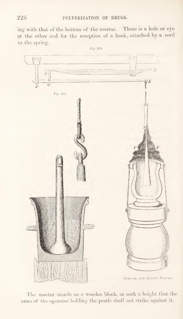
226 rULVERIZATION OF DRUGS.
ing with that of the bottom of the mortar. There is a hole or eye
at the other end for the reception of a hook, attached hy a cord
to the spring. Fig. 253.
The mortar stands on a wooden block, at such a height that the
arms of the operator liolding the pestle shall not strike against it.
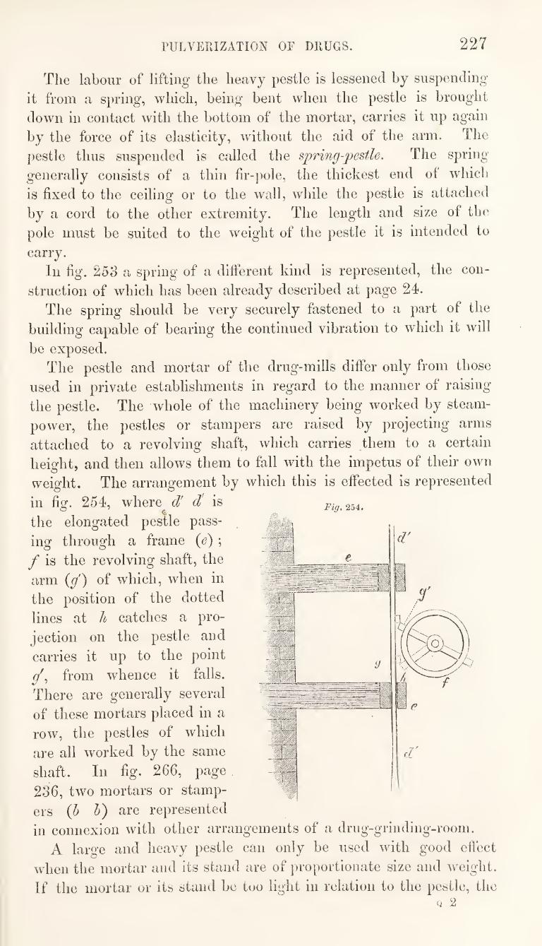
PULVERIZATION OF DRUGS. 227
The labour of lifting the heavy pestle is lessened by suspending
it from a spring, which, being bent when the pestle is brought
down in contact with the bottom of the mortar, carries it up again
by the force of its elasticity, without the aid of the arm. The
pestle thus suspended is called the spring-pestle. The spring
generally consists of a thin fir-]^ole, the thickest end of which
is fixed to the ceiling or to the wall, while the pestle is attached
by a cord to the other extremity. The length and size of the
pole must be suited to the weight of the pestle it is intended to
carry. In fig. 25o a spring of a different kind is represented, the con¬
struction of which has been already described at page 24.
The spring should be very securely fastened to a part of the
building capable of bearing the continued vibration to which it will
be exposed. The pestle and mortar of the drug-mills differ only from those
used in private establishments in regard to the manner of raising
the pestle. The whole of the machinery being worked by steam-
power, the pestles or stampers are raised by projecting arms
attached to a revolving shaft, which carries them to a certain
height, and then allows them to fall with the impetus of their own
weight. The arrangement by which this is effected is represented
in fig. 254, where d! d' is
the elongated pestle pass¬
ing through a frame (e) ;
f is the revolving shaft, the
arm (g') of which, when in
the position of the dotted
lines at h catches a pro¬
jection on the pestle and
carries it up to the point
from whence it falls.
There are generally several
of these mortars placed in a
row, the pestles of which
are all worked by the same
shaft. In fig. 266, page
236, two mortars or stamp¬
ers (h h) are represented
in connexion with other arrangements of a drug-grinding-room.
A large and heavy pestle can only be used with good effect
when the mortar and its stand are of proportionate size and weight.
If the mortar or its stand be too light in relation to the pestle, the
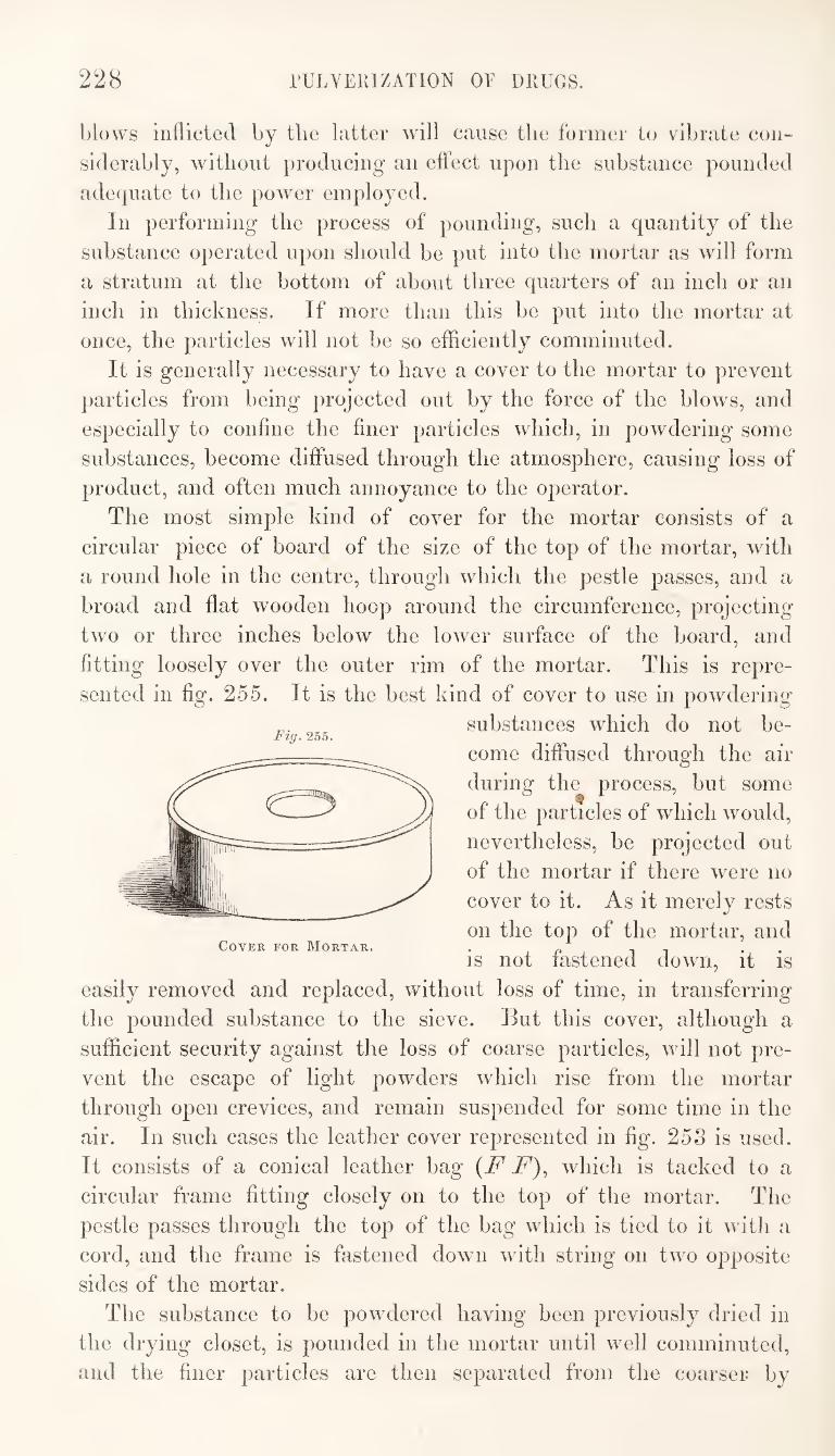
228 rULVERlZATION OF DRUGS.
blows inflicted by the latter will cause the former to vibrate con¬
siderably, without producing an effect upon the substance pounded
adequate to the power employed.
In performing the process of pounding, such a quantity of the
substance operated upon should be put into the mortar as will form
a stratum at the bottom of about three quarters of an inch or an
inch in thickness. If more than this be put into the mortar at
once, the particles will not be so efficiently comminuted.
It is generally necessary to have a cover to the mortar to prevent
particles from being projected out by the force of the blows, and
especially to confine the finer particles which, in powdering some
substances, become diffused through the atmosphere, causing loss of
product, and often much annoyance to the operator.
The most simple kind of cover for the mortar consists of a
circular piece of board of the size of the top of the mortar, with
a round hole in the centre, through which the pestle passes, and a
broad and flat wooden hoop around the circumference, projecting
two or three inches below the lower surface of the Ijoard, and
fitting loosely over the outer rim of the mortar. This is repre¬
sented in fig. 255. It is the best kind of cover to use in powdering
substances which do not be¬
come diffused through the aiT
during the process, but some
of the particles of which would,
nevertheless, be projected out
of the mortar if there were no
cover to it. As it merely rests
on the top of the mortar, and Cover for Mortar. . p , , . .
IS not fastened down, it is
easily removed and replaced, without loss of time, in transferring
the pounded substance to the sieve. But this cover, although a
sufficient security against the loss of coarse particles, will not pre¬
vent the escape of light powders which rise from the mortar
through open crevices, and remain suspended for some time in the
air. In such cases the leather cover represented in fig. 25S is used.
It consists of a conical leather bag {F F)^ which is tacked to a
circular frame fitting closely on to the top of the mortar. The
pestle passes through the top of the bag which is tied to it witli a
cord, and the frame is fastened down with string on two opposite
sides of the mortar.
The substance to be powdered having been previously dried in
the drying closet, is pounded in the mortar until well comminuted,
and the finer particles are then separated from the coarser by
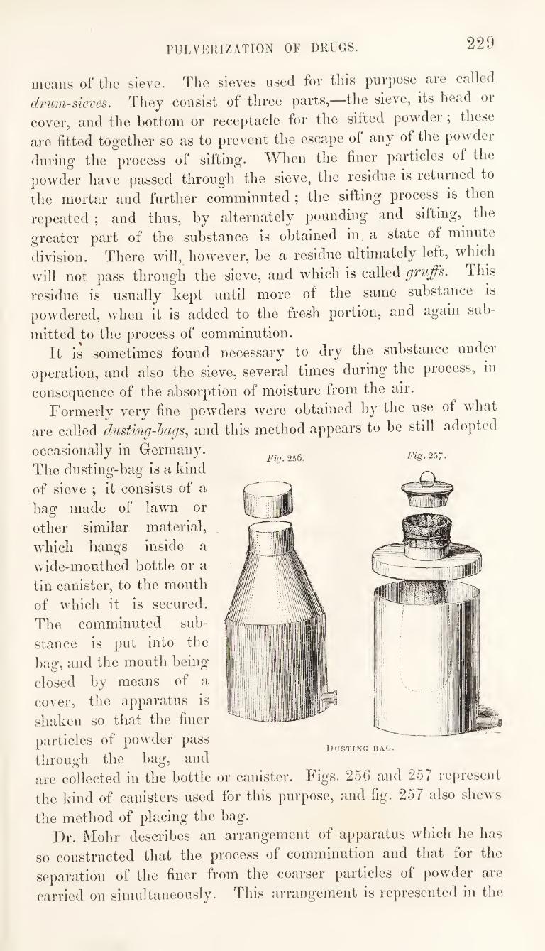
PULVERIZATION OF DRUGS. 229
means of the sieve. The sieves used for this purpose are called
druM-sieves. They consist of three parts,—the sieve, its head oi
cover, and the bottom or receptacle for the sifted powder; these
are fitted together so as to prevent the escape of any of the powder
during the process of sifting. When the finer particles of the
powder have passed through the sieve, the residue is returned to
the mortar and further comminuted ; the sifting process is then
Fig. 256. Fig. 257.
repeated ; and thus, by alternately pounding and sifting,^ the
greater part of the substance is obtained in a state of minute
division. There will, however, be a residue ultimately left, which
will not pass through the sieve, and which is called gruffs. This
residue is usually kept until more of the same substance is
powdered, when it is added to the fresh portion, and again sub¬
mitted to the process of comminution. It is sometimes found necessary to dry the substance under
operation, and also the sieve, several times during the process, in
consequence of the absorption of moisture from the air.
Formerly very fine powders were obtained by the use of what
are called dusting-hags^ and this method appears to be still adopted
occasionally in Germany.
The dusting-bag is a kind
of sieve ; it consists of a
bag made of lawn or
other similar material,
which hangs inside a
wide-mouthed bottle or a
tin canister, to the mouth
of which it is secured.
The comminuted sub¬
stance is put into the
bag, and the mouth being
closed by means of a
cover, the apparatus is
shaken so that the finer
particles of powder pass
through the bag, and are collected in the bottle or canister. Figs. 256 and 257 represent
the kind of canisters used for this purpose, and fig. 257 also shews
the method of placing the bag.
Ousting bag.
Dr. Mohr describes an arrangement of apparatus which he has
so constructed that the process of comminution and that for the
separation of the finer from the coarser particles of powder are
carried on simultaneously. This arrangement is represented in the
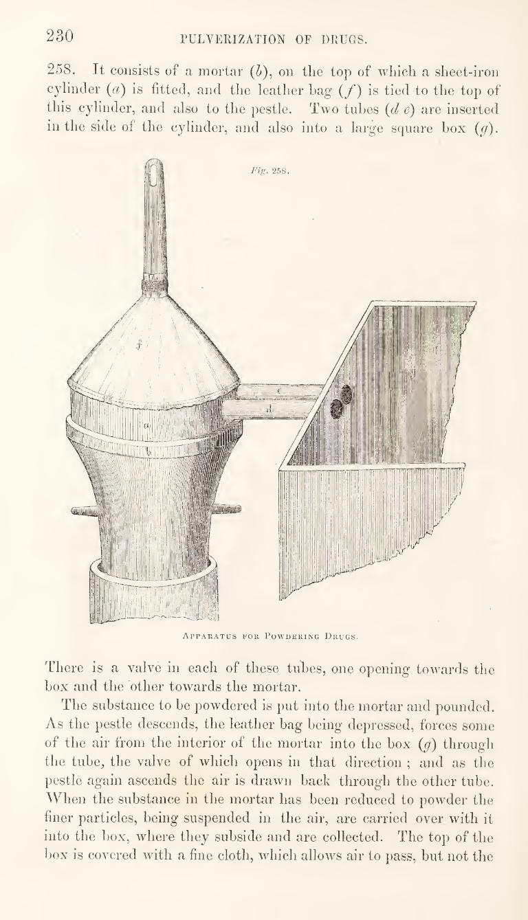
230 rULVERIZATION OF DRUGS.
258. It consists of a, mortar (5), on the top of which a sheet-iron
cylinder {a) is fitted, and the leather hag { f) is tied to the top of
this C3dinder, and also to the pestle. Two tubes {d e) are inserted
in the side of the c^dinder, and also into a large square box {g).
Apparatus for Powdering Drugs.
There is a valve in each of these tubes, one opening towards the
box and the other towards the mortar.
The substance to be powdered is put into the mortar and pounded.
As the pestle descends, the leather bag being depressed, forces some
of the air from the interior of the mortar into the box {g) through
the tube, the valve of which opens in that direction ; and as the
pestle again ascends the air is drawn back through the other tube.
When the substance in the mortar has been reduced to powder the
finer particles, being suspended in the air, are carried over with it
into the ])ox, where they subside and are collected. The top of the
box is covered with a fine cloth, which allows air to pass, but not the
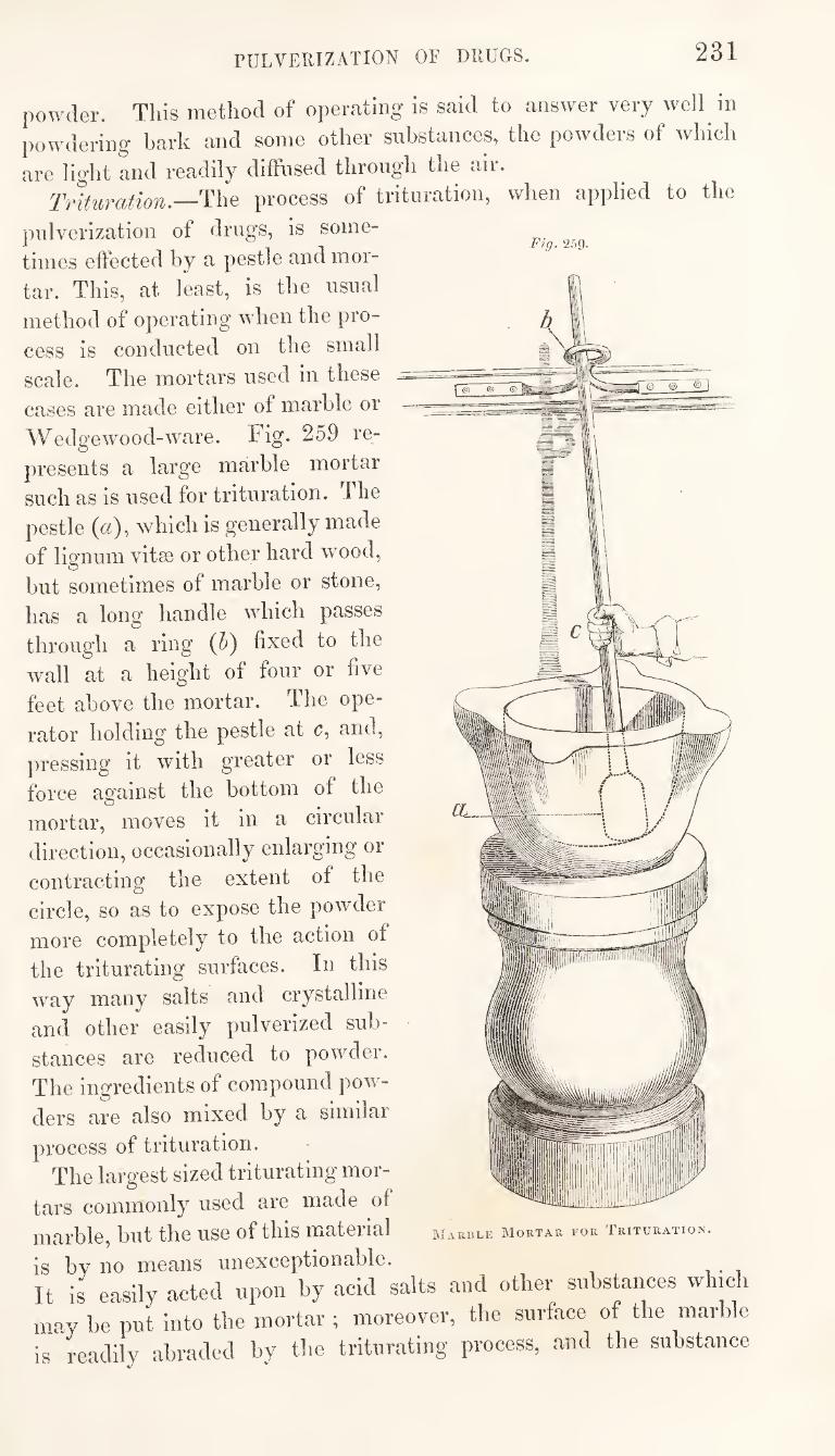
rULVEUIZATION OF DRUGS. 231
powder,
powdering
nre light and readily
Trituration.—T he
pulverization of
times effected by a pestle and mor¬
tar. This, at least, is the nsnal
method of operating when the pro¬
cess is conducted on the small
scale. The mortars used in these
cases are made either of marble or
Wedge wood-ware. Fig. 259 re¬
presents a large marble mortar
such as is used for trituration. The
pestle ((z), which is generally made
of lignum vitse or other hard wood,
but sometimes of marble or stone,
has a long handle which passes
through a ring (5) fixed to the
wall at a height of four or five
feet above the mortar. The ope¬
rator holding the pestle at c, and,
])ressing it with greater or less
force against the bottom of the
mortar, moves it in a circular
direction, occasionally enlarging or
contracting the extent of the
circle, so as to expose the powder
more completely to the action of
the triturating surfaces. In this
way many salts and crystalline
and other easily pulverized sub¬
stances are reduced to powder.
The ingredients of compound pow¬
ders are also mixed by a similar
process of trituration.
The largest sized triturating mor¬
tars commonly used are made of
marble, but the use of this material
Fig. 259-
is by no means unexceptionable. It is easily acted upon by acid salts and other substances which
may be put into the mortar ; moreover, the surface of the marble
is readily abraded by the triturating process, and the substance
This method of operating is said to answer very well in
bark and some other substances, the powders of which
diffused through the air.
process of trituration, when applied to the
drugs, is some-
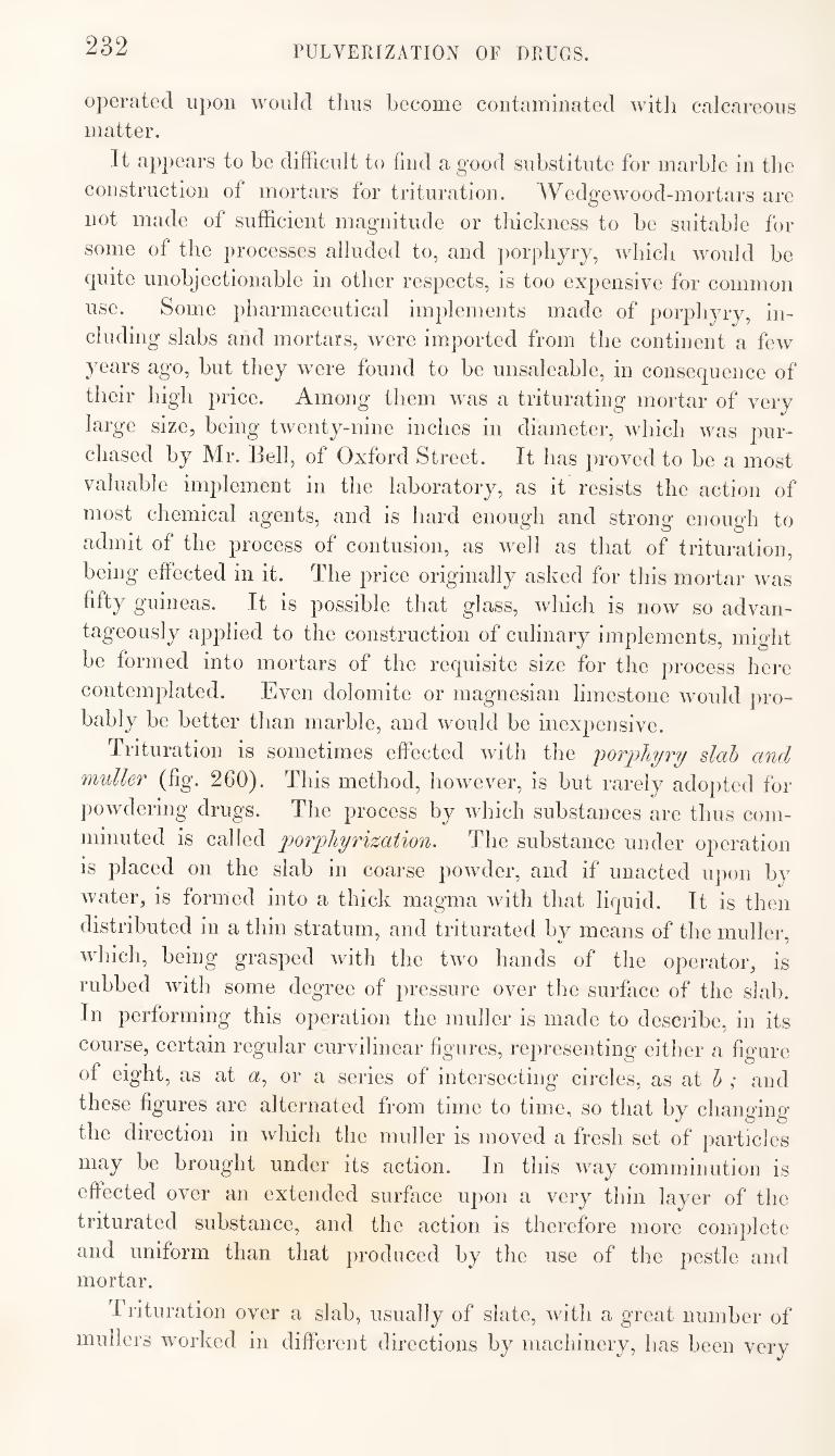
232 PULVERIZATION OF DRUGS.
operated upon would thus become contaminated with calcareous
matter.
It appears to be difficult to find a good substitute for marble in the
construction of mortars for trituration. Wedge wood-mortars are
not made of sufficient magnitude or thickness to be suitable for
some of the processes alluded to, and por])liyry, wliicli would be
quite unobjectionable in other respects, is too expensive for common
use. Some pharmaceutical implements made of porphyry, in¬
cluding slabs and mortars, were imported from the continent a few
years ago, but they were found to be unsaleable, in consequence of
their high price. Among them was a triturating mortar of very
large size, being twenty-nine inches in diameter, which was pur¬
chased by Mr. Bell, of Oxford Street. It has proved to be a most
valuable implement in the laboratory, as it resists the action of
most chemical agents, and is hard enough and strong enough to
admit of the process of contusion, as w^ell as that of trituration,
being effected in it. The price originally asked for this mortar was
fifty guineas. It is possible that glass, which is now so advan¬
tageously applied to the construction of culinary implements, might
be formed into mortars of the requisite size for the process here
contemplated. Even dolomite or magnesian limestone would pro¬
bably be better than marble, and would be inexpensive.
Trituration is sometimes effected with the j^orphyry slab and
muller (fig. 260). This method, however, is but rarely adopted for
])owdering drugs. The process by which substances are thus com¬
minuted is called porpliyrization. The substance under operation
is placed on the slab in coarse powder, and if unacted upon by
water, is formed into a thick magma with that liquid. It is then
distributed in a thin stratum, and triturated by means of the muller. 7
which, being grasped with the two hands of the operator, is
rubbed with some degree of pressure over the surface of the slab.
In performing this operation the muller is made to describe, in its
course, certain regular curvilinear figures, representing either a figure
of eight, as at a, or a series of intersecting circles, as at h ; and
these figures are alternated from time to time, so that by changing
the direction in which the muller is moved a fresh set of particles
may be brought under its action. In this way comminution is
effected over an extended surface upon a very thin layer of the
triturated substance, and the action is therefore more complete
and uniform than that produced by the use of the pestle and mortar.
Trituration over a slab, usually of slate, with a great number of
mullers worked in different directions by machinery, has been very
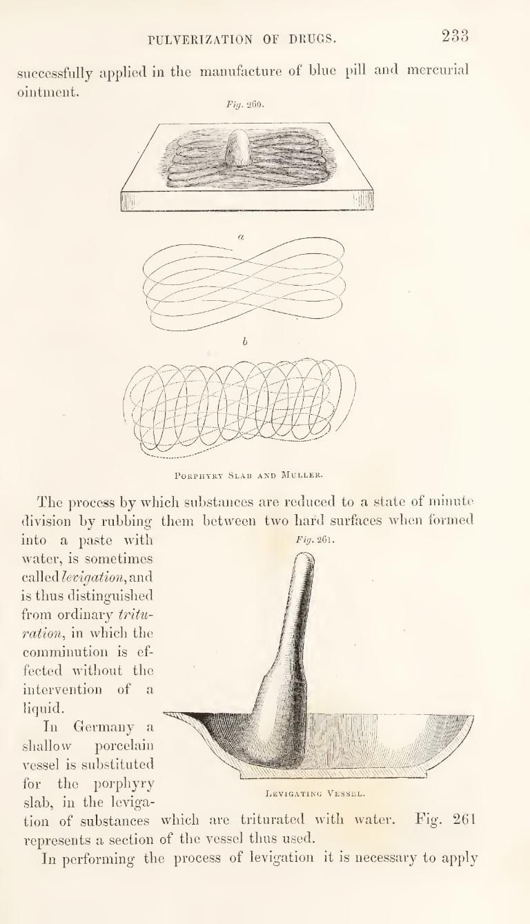
PULVERIZATION OF DRUGS. 233
successfully applied in the manufacture of blue pill and mercurial
ointment. Fig. 260.
Porphyry Slab and IMuller.
The process by which substances are reduced to a state of minute
division by rubbing them between two hard surfaces when formed
into a paste with Fig.2&\.
water, is sometimes
called lemgation^ and
is thus distinguished
from ordinary tritu¬
ration^ in which the
comminution is ef¬
fected without the
intervention of a
liquid.
In Germany a
shallow porcelain
vessel is substituted
for the porphyry . 1 1 • Levigating Vessel.
slab, m the leviga-
tion of substances which are triturated with w^ater. Fig. 261
represents a section of the vessel thus used.
In performing the process of levigation it is necessary to apply
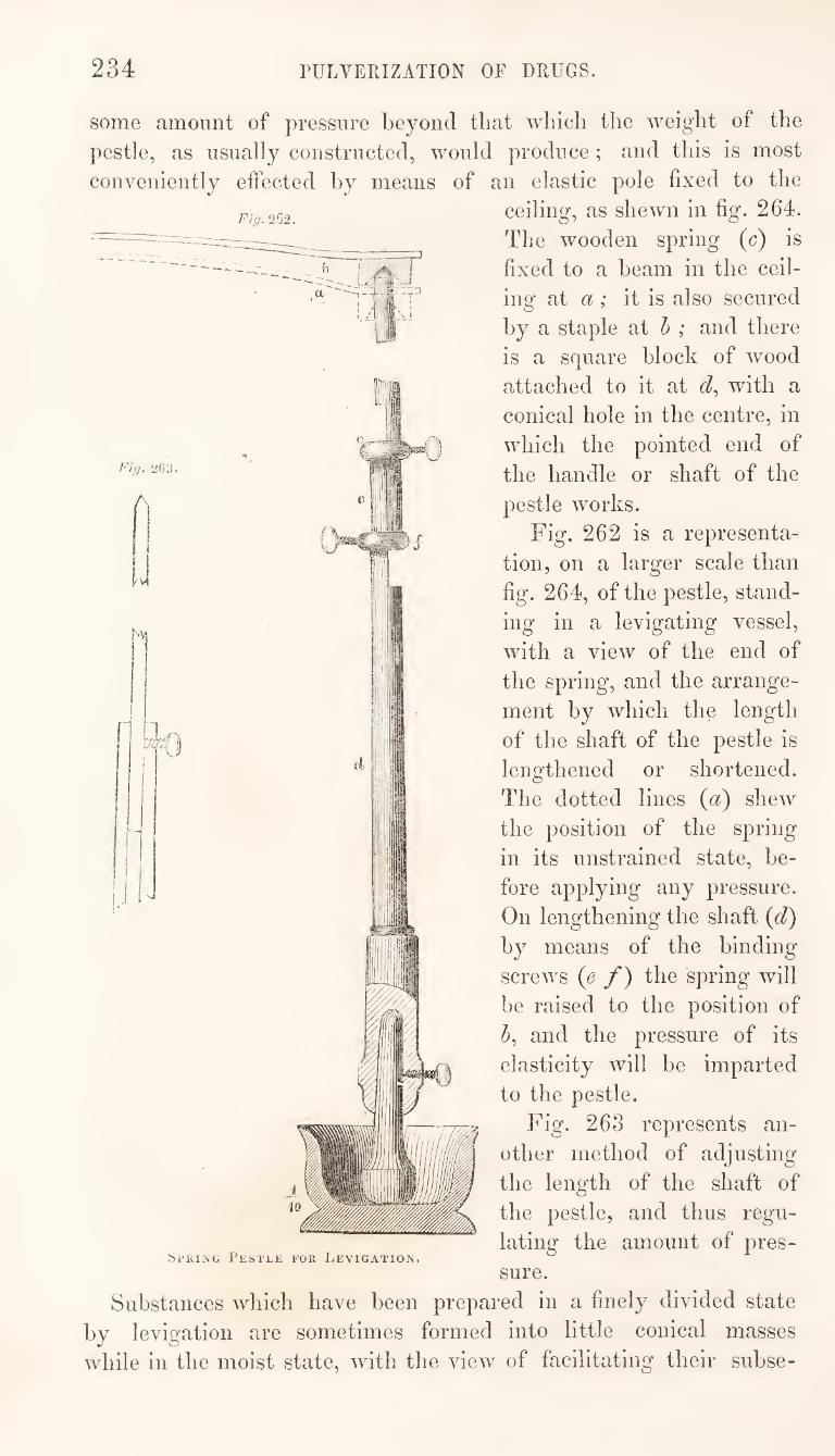
234 PULVERIZATION OF DRUGS.
Fig. 2 02.
Fig. 263.
some amount of pressure beyond that which tlie weight of the
pestle, as usually constructed, would produce; and this is most
conveniently effected hy means of an elastic pole fixed to the
ceiling, as shewn in fig. 264.
The wooden spring (c) is
fixed to a beam in the ceil¬
ing at a; it is also secured
hy a staple at h ; and there
is a square block of wood
attached to it at with a
conical hole in the centre, in
which the pointed end of
the handle or shaft of the
pestle works.
Fig. 262 is a representa¬
tion, on a larger scale than
fig. 264, of the pestle, stand¬
ing in a levigating vessel,
with a view of the end of
the spring, and the arrange¬
ment hy which the length
of the shaft of the pestle is
lengthened or shortened.
The dotted lines (a) shew
the position of the spring
in its unstrained state, be¬
fore applying any pressure.
On lengthening the shaft (d)
hy means of the binding
screws (e f) the spring will
he raised to the position of
and the pressure of its
elasticity will he imparted
to the pestle.
Fig. 263 represents an¬
other method of adjusting
the length of the shaft of
the pestle, and thus regu¬
lating the amount of pres¬
sure.
Substances which have been prepared in a finely divided state
hy levigation are sometimes formed into little conical masses
while in the moist state, with the view of facilitating their suhse-
SpRiNG Pestle for Levigation.
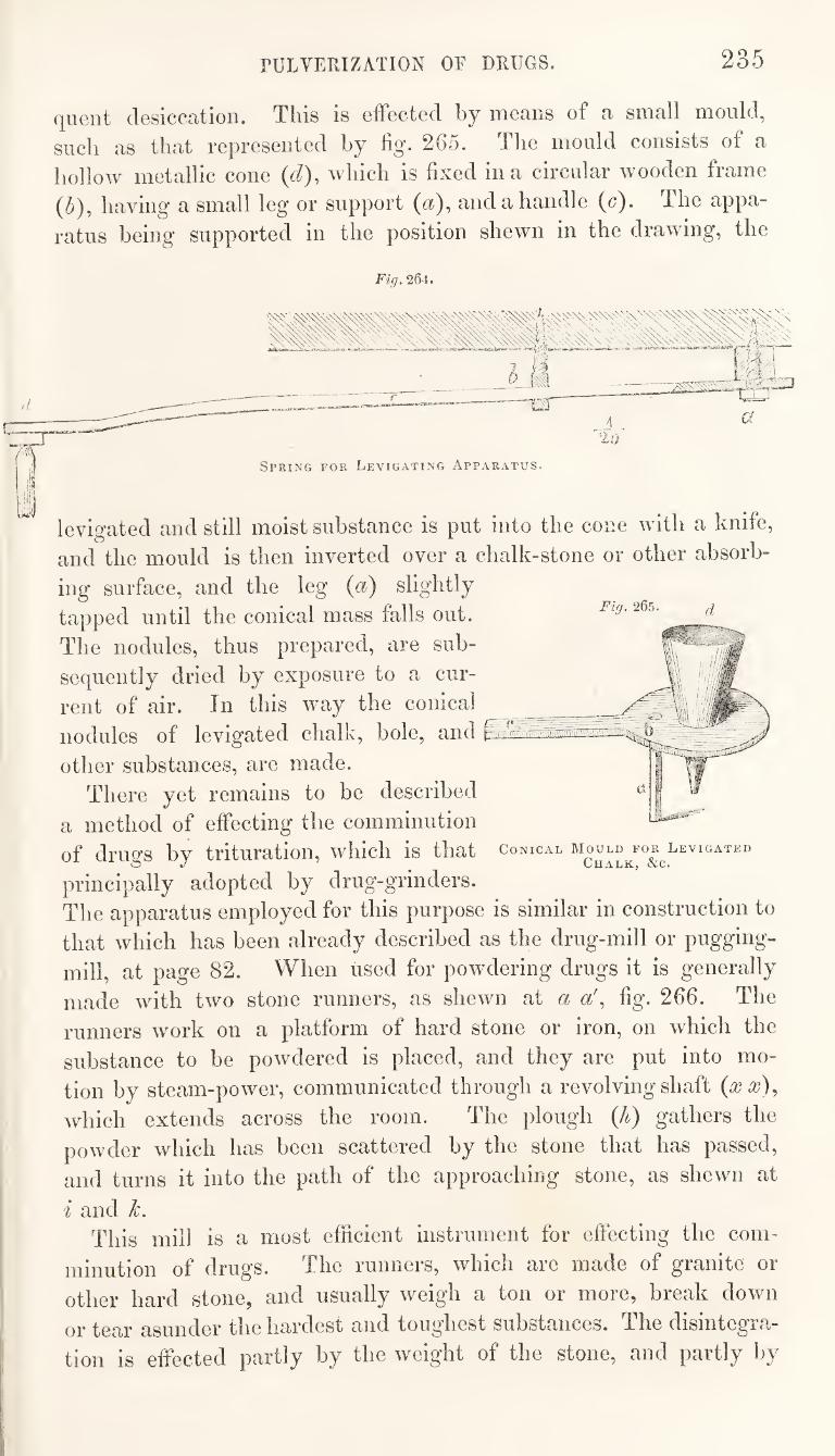
rULVERIZATION OF DRUGS. 235
quent desiccation. This is effected by means of a small mould,
such as that represented by fig. 265. The mould consists of a
hollow metallic cone {d), which is fixed in a circular wooden frame
(5), having a small leg or support («), and a handle (c). The appa¬
ratus being supported in the position shewn in the drawing, the
Fig. 264.
Fig. 265.
Conical Mould for Levigated
Chalk, &c.
levigated and still moist substance is put into the cone with a knife,
and the mould is then inverted over a chalk-stone or other absorb¬
ing surface, and the leg {a) slightly
tapped until the conical mass falls out.
The nodules, thus prepared, are sub¬
sequently dried by exposure to a cur¬
rent of air. In this way the conical
nodules of levigated chalk, bole, and @
other substances, are made.
There yet remains to be described
a method of effecting the comminution
of drugs by trituration, which is that
principally adopted by drug-grinders.
The apparatus employed for this purpose is similar in construction to
that which has been already described as the drug-mill or pugging-
mill, at page 82. When used for powdering drugs it is generally
made with two stone runners, as shewn at a a\ fig. 266. The
runners work on a platform of hard stone or iron, on which the
substance to be powdered is placed, and they are put into mo¬
tion by steam-power, communicated through a revolving shaft {xx)^
which extends across the room. The plough (A) gathers the
powder which has been scattered by the stone that has passed,
and turns it into the path of the approaching stone, as shewn at
i and k. This mill is a most efficient instrument for effecting the com¬
minution of drugs. The runners, which are made of granite or
other hard stone, and usually weigh a ton or moie, break down
or tear asunder the hardest and toughest substances. The disintegra¬
tion is effected partly by the weight of the stone, and partly by
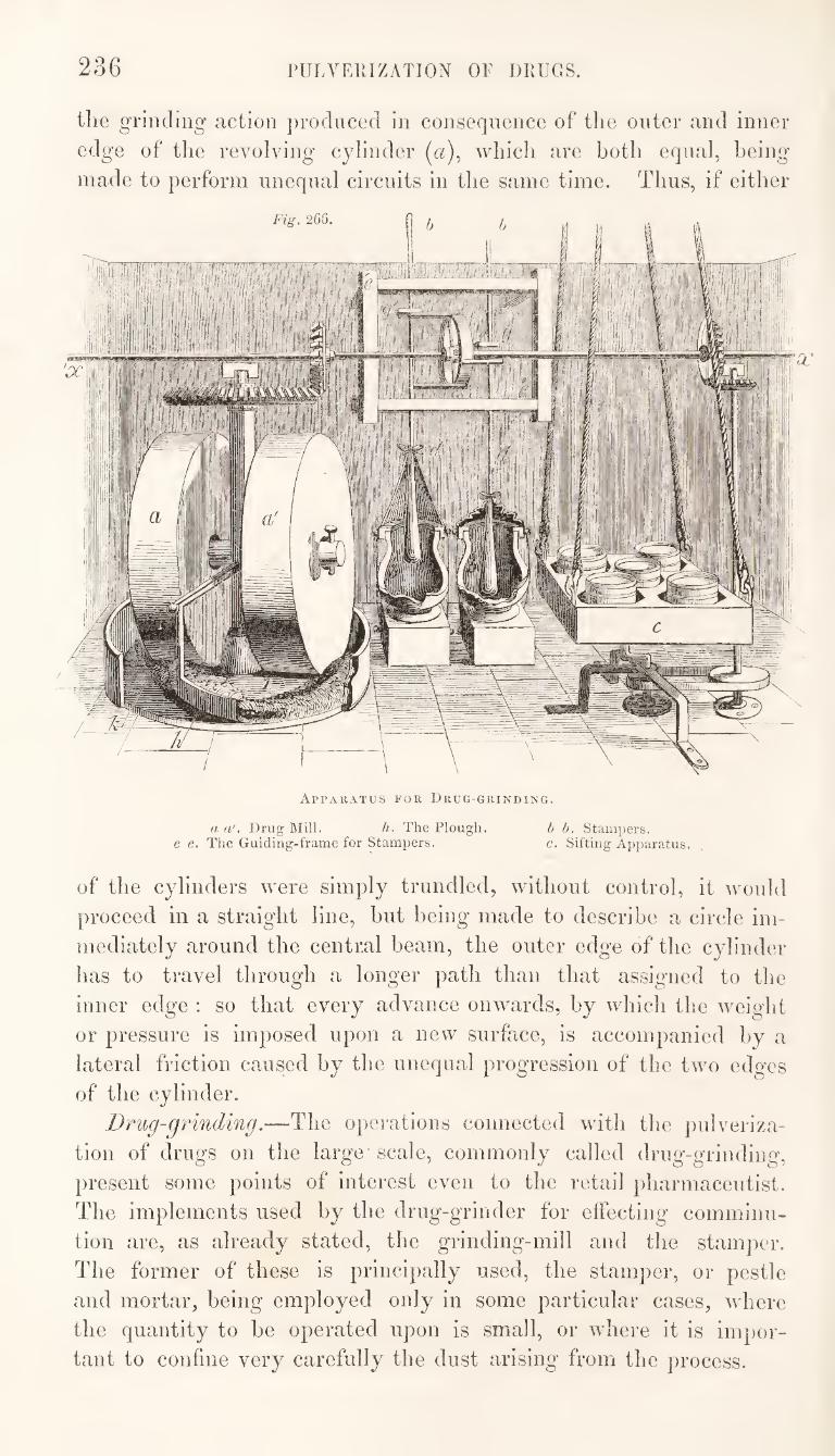
236 rULVERIZATION OF DRUGS.
the grinding action ])r(Kluced in consequence of the outer and inner
edge of the revolving cylinder (a), which are both equal, being
made to perform unequal circuits in the same time. Thus, if either
Apparatus for Drug-grinding.
a a'. Drug Mill. h. The Plough. b b. Stampers. e e. The Guiding-frame for Stampers. c. Sifting Apparatus.
of the cylinders were simply trundled, without control, it would
proceed in a straight line, but being made to describe a circle im¬
mediately around the central beam, the outer edge of the cylinder
has to travel through a longer path than that assigned to the
inner edge : so that every advance onwards, by which the weiglit
or pressure is imposed upon a new surface, is accompanied by a
lateral friction caused by the unequal progression of the two edges
of the cylinder.
Drug-grinding.—The operations connected with the pulveriza¬
tion of drugs on the large scale, commonly called drug-grinding,
present some points of interest even to the retail pharmaceutist.
The implements used by the drug-grinder for effecting comminu¬
tion are, as already stated, the grinding-mill and the stamper.
The former of these is principally used, the stamper, or pestle
and mortar, being employed only in some particular cases, where
the quantity to he operated upon is small, or where it is impor¬
tant to confine very carefully the dust arising from the process.
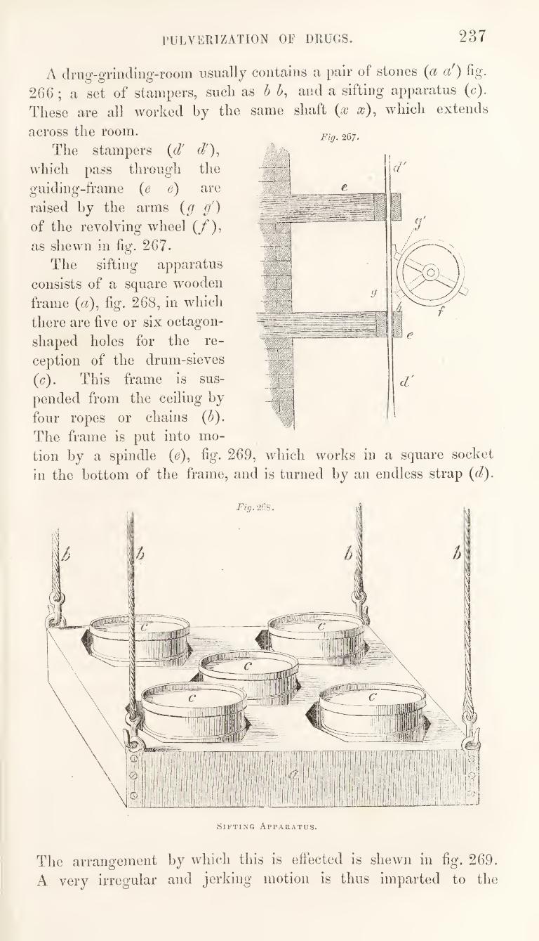
rULVERIZATION OF DRUGS. 237
A drug-grinding-room usually contains a pair of stones (a a') fig.
266 ; a set of stampers, such as h h, and a sifting apparatus (c).
These are all worked by the same shaft as), which extends
across the room.
The stampers {d' d'),
which pass through the
guiding-frame (e e) are
raised by the arms {g g')
of the revolving wheel (/),
as shewn in fig. 267.
The sifting apparatus
consists of a square wooden
frame (a), fig, 268, in which
there are five or six octagon¬
shaped holes for the re¬
ception of the drum-sieves
(c). This frame is sus¬
pended from the ceiling by
four ropes or chains {h).
The frame is put into mo¬
tion by a spindle {e), fig. 269, which works in a square socket
in the bottom of the frame, and is turned by an endless strap {d).
Sifting Apparatus.
The arrangement by which this is effected is shewn in fig. 269.
A very irregular and jerking motion is thus imparted to the
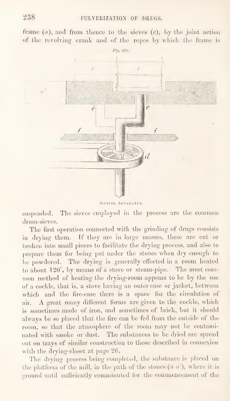
238 PULVERIZATION OF DRUGS.
frame (a), and from thence to the sieves ((?), by the joint action of the revolving crank and of the ropes by which the frame is
Fig, 269,
suspended. The sieves employed in the process are the common
drum-sieves. The first operation connected with the grinding of drugs consists
in drying them. If they are in large masses, these are cut or broken into small pieces to facilitate the drying process, and also to prepare them for being put under the stones when dry enough to be powdered. The drying is generally effected in a room heated to about 120°, by means of a stove or steam-pipe. The most com¬ mon method of heating the drying-room appears to be by the use of a cockle, that is, a stove having an outer case or jacket, between which and the fire-case there is a space for the circulation of air. A great many different forms are given to the cockle, which is sometimes made of iron, and sometimes of brick, but it should always be so placed that the fire can be fed from the outside of the room, so that the atmosphere of the room may not be contami¬ nated with smoke or dust. The substances to be dried are spread out on trays of similar construction to those described in connexion with the drying-closet at page 26.
The drying process being completed, the substance is placed on the platform of the mill, in the path of the stones {ci cb), where it is o'l'ound until sufficiently comminuted for the commencement of the
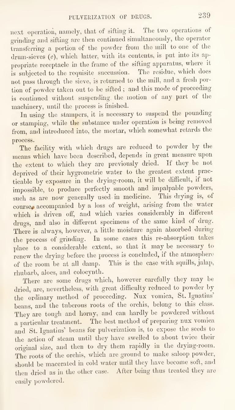
PULVERIZATION OF DRUGS. 239
next opGratioii, iiciiiiGly, that of sifting it. TIig two oporations of
grinding and sifting arG tliGii continnGd siniultaiiGOUsly, tliG opGiator
transfGiTing’ a portion of tliG powdor from tliG mill to oiig of tliG
drum-siGVGS (c), which lattor, with its contGiits, is put into its ap-
propriatG rGCoptaclo in tliG framo of tho sifting apparatus, whoro it
is subjoctod to tho roquisito siiccussion. The rosiduG, which does
not pass through the sieve, is returned to the mill, and a fresh por¬
tion of powder taken out to be sifted; and this mode of proceeding
is continued without suspending the motion ot any part of the
machinery, until the process is finished. In using the stampers, it is necessary to suspend the pounding
or stamping, while the substance under operation is being removed
from, and introduced into, the mortar, which somewhat retards the
process. The facility with which drugs are reduced to powder by the
means which have been described, depends in great measure upon
the extent to which they are previously dried. If they be not
deprived of their hygrometric water to the greatest extent prac¬
ticable by exposure in the drying-room, it will be difficult, if not
impossible, to produce perfectly smooth and impalpable powders,
such as are now generally used in medicine. This drying is, of
course.^ accompanied by a loss of weight, arising from the ■watei
which is driven off, and which varies considerably in different
drugs, and also in different specimens of the same kind of drug.
There is always, however, a little moisture again absorbed during
the process of grinding. In some cases this re-absorption takes
place to a considerable extent, so that it may be necessary to
renew the drying before the process is concluded, if the atmosphere
of the room be at all damp. This is the case with squills, jalap,
rhubarb, aloes, and colocynth. There are some drugs which, however carefully they may be
dried, are, nevertheless, with great difficulty reduced to powder by
the ordinary method of proceeding. Nux vomica, St. Ignatius’
beans, and the tuberous roots of the orchis, belong to this class.
They are tough and horny, and can hardly be powdered without
a particular treatment. The best method of preparing nux vomica
and St. Ignatius’ beans for pulverization is, to expose the seeds to
the action of steam until they have swelled to about twice their
original size, and then to dry them rapidly in the drying-room.
The roots of the orchis, which are ground to make saloop powder,
should be macerated in cold water until they have become soft, and
then dried as in the other case. After being thus treated they are
easily powdered.
240 PULVERIZATION OF DRUGS.
Some substances cannot be powdered alone; tliey require the
addition of other bodies which facilitate the disintegration. Thus
the addition of a few drops of spirit renders the pulverization of
camphor easy, although it could not be effected without it. The
process, when thus conducted, is sometimes called pulverization hy
mediation. It is a common practice with drug-grinders to add a small
quantity of olive oil or oil of almonds to some drugs during the })ro-
cess of grinding. This is found to facilitate the comminution, and
greatly to improve the appearance of the powder.
Agaric is a substance which it is extremely difficult to powder
alone, and a method has therefore been proposed for powdering it
by mediation. It is cut into small pieces, wetted with mucilage of
tragacanth, and then dried, previously to submitting it to the pro¬
cess of grinding. The addition of a foreign body, which the powder
retains, cannot, however, be sanctioned, excepting under particular
circumstances, such as the impossibility of otherwise effecting the
object. It is stated in some pharmaceutical works that colocynth
is powdered by mediation, in the same way as that above described
for the pulverization of agaric ; but in this case the addition of a
foreign body is certainly unnecessary, and I believe that no such
addition is made by the drug-grinders in this country. %
Phosphorus is powdered by mediation, and this, indeed, is the
only way in which it can be obtained in a state of minute division.
The best mediatory substance to* use is spirit. The phosphorus
being put into a bottle with some spirit, a gentle heat is applied,
by plunging the bottle into warm water, until the phosphorus
melts; the mouth of the bottle is then closed and brisk agitation
continued until it has cooled, when the phosphorus wall be found to
be in a finely-divided state. Water might be substituted for spirit,
but. does not answer so well.
A method of a somewhat analogous nature to that last described
is adopted for powdering some salts which are not easily reduced to
powder by trituration. The salts are dissolved in water, and the
solution evaporated to dryness whilst constant and active agitation
is maintained. This is a very 'convenient and economical method
of obtaining salammoniac in powder. It is also adopted for gra¬
nulating salt of tartar, and tartrate of potash.
Substances, the particles of which readily adhere wdien sub¬
mitted to pressure, but which, nevertheless, are not held together
by a strong cohesive force, are sometimes powdered hy friction over
a perforated surface. Thus magnesia and other similar substances,
are merely rubbed over the surface of a sieve.
rULVERIZATION OF DllUGS. 241
Such are the various methods adopted in effecting the pulveriza¬
tion of drugs, and which are applied, according to the requirements
of the several cases, to most kinds of solid substances employed in
medicine—to some, in order to make them more suitable for admi¬
nistration—to others, in order to fit them for subsequent operations.
It is, therefore, an interesting and important subject of enquiry, in
connection with a process of such general use in the preparation of
medicines,—how far is it practicable to preserve the chemical con¬
dition of the substances operated upon unaltered, and their medi¬
cinal efficacy unimpaired ? The operations connected with the processes of drug-grinding do
not seem to be calculated to promote chemical change in the con¬
stituents of the powder; for, although the disintegration, by
exposing a larger surface to the action of the air, may be some¬
what unfavourable to the permanence of the proximate consti¬
tuents of vegetable substances, yet the complete desiccation which
forms part of the process will exercise a conservative influence to
probably an equal extent. This, at least, would be the case if the
powder, when prepared, be put into close bottles and kept for only
a moderate length of time. The principal, if not the only necessary, cause of deterioration
to the product in the process of drug-grinding, is the long-conti¬
nued application of heat to which the drugs are exposed in the
drying-room. There are many substances which cannot be thus
dried without having a portion of their active volatile ingredients
driven off, as well as the water they contained. The strong smell
which fills the drying-room when opium, or myrrh, or cinnamon,
are under operation, affords sufficient evidence that some volatile
matter besides water is escaping, and that the resulting powders
cannot strictly represent the drugs from which they are made.
All substances which contain volatile principles must lose a portion
of these during the drying process which precedes and sometimes
accompanies that of pulverization; and if the efficacy of the
medicine depend upon these volatile parts, the product must be
injured by the process to which it is submitted. Thus, myrrh,
valerian, cardamoms, cinnamon, and spices generally, lose some of
their efficacy in being reduced to fine powder.
But a large proportion of our drugs are not subject to de¬
terioration from loss of volatile constituents; and in these cases,
if care be exercised in conducting the process of drying, the pow¬
ders obtained by the usual method of operating, will possess
all the medicinal properties of the crude materials. Thus, rhu¬
barb, jalap, ipecacuanha, colocynth, scammony, gamboge, and R
242 PULVERIZATION OF DRUGS.
many other drugs, are not necessarily injured in the process of
powdering.
There are some drugs which not only suffer no injury in being
powdered, hut which actually contain, when pulverized, a larger
proportion of the active constituents than were present in the crude
unpowdered substance. This arises from the circumstance that the
less active parts are separated and rejected during the process.
Thus, for instance, the powder of ipecacuanha, if properly pre¬
pared, contains more of the emetic principle than the root from
which it is made. The principle upon which the emetic property of
ipecacuanha depends, exists chiefly in the cortical part of the root,
and as this is the most easily pulverizable, it passes first through
the sieve, while the less active ligneous part, being more tough,
remains to the last, and may he, and generally is, rejected as
gruffs.
Besides the loss of water and other volatile constituents, which
are driven off in the drying-room, there is also, necessarily, a
dissipation and loss, to a certain extent, of solid particles of
powder, which are diffused through the atmosphere of the room
in which the pulverization is conducted, or which adhere to the
apparatus.
With these exceptions the product, including the gruffs or unsifted
part, ought to be identical with the substance it represents; that is
to say, should consist of the same particles, and no others, in the
same chemical condition as they existed in previously to the pro¬
cess of powdering.
If no active constituents be lost in the drying process, the
strength of the powder will be greater than that of the crude drug,
to the extent of the quantity of water and inactive matter which
have been separated and rejected. It would be very desirable to
ascertain what the average increase of strength is in those drugs
which suffer no deterioration in the process of powdering; and also
what is the exact nature of the deterioration necessarily sustained
by drugs such as myrrh, ginger, cardamoms, and cascarilla, which
contain, and must therefore lose, active volatile constituents.
Next to the preservation of the medicinal efficacy of the drug,
the most important object for attainment is uniformity of strength
in the product. What security has the physician that a grain of
opium, or ten grains of jalap, obtained from a particular source,
shall be equivalent to the same quantities of those substances
obtained elsewhere ?
There are several causes which tend to affect the uniformity of
the strength of those medicines which consist of parts or crude pro-
PULVERIZATION OF DRUGS. 243
ducts of plants. In the first place, these drugs, in their natural or
original state, are not uniform in composition and properties.
Different specimens of cinchona bark yield very different propor¬
tions of the alkaloid, upon which the efficacy of the drug depends ;
other drugs differ to an equal extent,—in fact, what drug can be
mentioned of which there are not good and bad specimens in the
market. The practical knowledge and experience of the druggist
are called into requisition in selecting the good from the bad, and
thus two classes, at least, are formed. It must be admitted, how¬
ever, that the criterions of excellence usually adopted in these
cases are often founded upon qualities of an extrinsic character,
which have no definite relation to medicinal properties.
There are other causes which affect the uniformity of strength
and properties of drugs in their more advanced states of preparation.
That drugs are sometimes adulterated is a notorious fact. That
the practice of adulteration has prevailed to an extent greatly
prejudicial to the advancement of the science of medicine, and
discreditable to the medical legislation of the country, admits not
of a doubt. But a great and progressive improvement has cer¬
tainly taken place within the last few years, and there is, at the
present time, an evident desire among wholesale and retail drug¬
gists, to discourage and suppress the sale of bad drugs.
We may discard as unworthy of notice the exaggerated state¬
ments which have been published with reference to the wholesale
substitution of fabricated powders for genuine drugs. Such cases,
if they ever existed, must have been isolated and extraordinary
exceptions to the practice generally pursued. There is reason to
believe, however, that absolute identity of composition between the
powders used in medicine, and the drugs they represent, is not
always maintained to the greatest practicable extent; and among the
causes tending to this effect, there is probably none more influential
than the conventional practice of the trade, in reference to the
allowance for loss of product during the process of drug-grinding.
It has already been stated that the loss of weight which drugs
undergo in the process of grinding is occasioned by the evaporation
of water and other volatile constituents in the drying-room, and by
the waste from dissipation in the form of dust, and from adhesion to
the apparatus in the grinding-room. It must be obvious that the
amount of loss thus sustained will not be uniform ; it will vary
according to the nature of the substance under operation, and even
with substances of the same nature the loss will depend upon the
quantity operated upon at a time and their state of dryness when
sent to the mill. Some drugs are frequently met with in commerce
244 PULVERIZATION OF DRUGS.
in a perfectly moist state, such as opium, aloes, scammony, and
jalap. The loss of weight in drying these drugs must of course he
considerably greater than that which occurs with other less moist
specimens, or with substances such as rhubarb, ipecacuanha, or
hark, which are never met with in a moist state. Now there is in
this variable condition of drugs as to dryness, a source of disagree¬
ment between the druggist and the drug-grinder, which probably
has led to the adoption of a practice that has prevailed throughout
the trade, with one or two recent exceptions, of making a uniform
allowance for loss of weight in grinding, whatever the nature or
quality of the drug might be.
The rule which for many years has been adopted among the
London drug-grinders, is to allow four pounds on every hundred¬
weight of the substance ground for loss in the process. Thus, if a
hundred-weight (112 lbs.) of rhubarb be sent to the drug-grinders,
108 lbs. of powder, includiug the gruffs, are returned. It matters
not what condition the rhubarb may be in, the drug-grinder is
expected to produce 108 lbs. of powder from the hundred-weight
of raw material. The same allowance is also made, unless other¬
wise agreed between the parties, for all other drugs which require
drying previously to their being powdered. In some cases the
practice appears to be to receive 116 lbs. of the undried drug, and
to return 112 lbs. of dry powder. This is called the four per cent,
system ; four pounds being the allowance for loss upon every
hundred-weight of substance powdered. Some substances, however,
such as cream of tartar and sulphuret of antimony, do not require
to be dried before being powdered, and the allowance for loss on
these substances is only two per cent.
There has, until quite recently, been only one exception to the
adoption, to a greater or less extent, of this, which is called the
per centage or four per cent, system, by the drug-grinders of
London; and so completely does the system appear to have been
established by long custom, that although several attempts have
been made to relinquish it, yet there are still some druggists who
contend that the specified allowance is a fair average of the loss
necessarily occurring in the process of drug-grinding.
I am indebted to Messrs. S. and Gr. Allen, for a statement
extracted from their books, shewing the loss of weight sustained
in powdering drugs at their mills. Every drug powdered at this
establishment is weighed when received at the mill; and the
ground products, consisting of fine powder and gruffs, are again
weighed before being returned to the druggist. These weights are all
entered in their books, a separate account being kept for each kind of
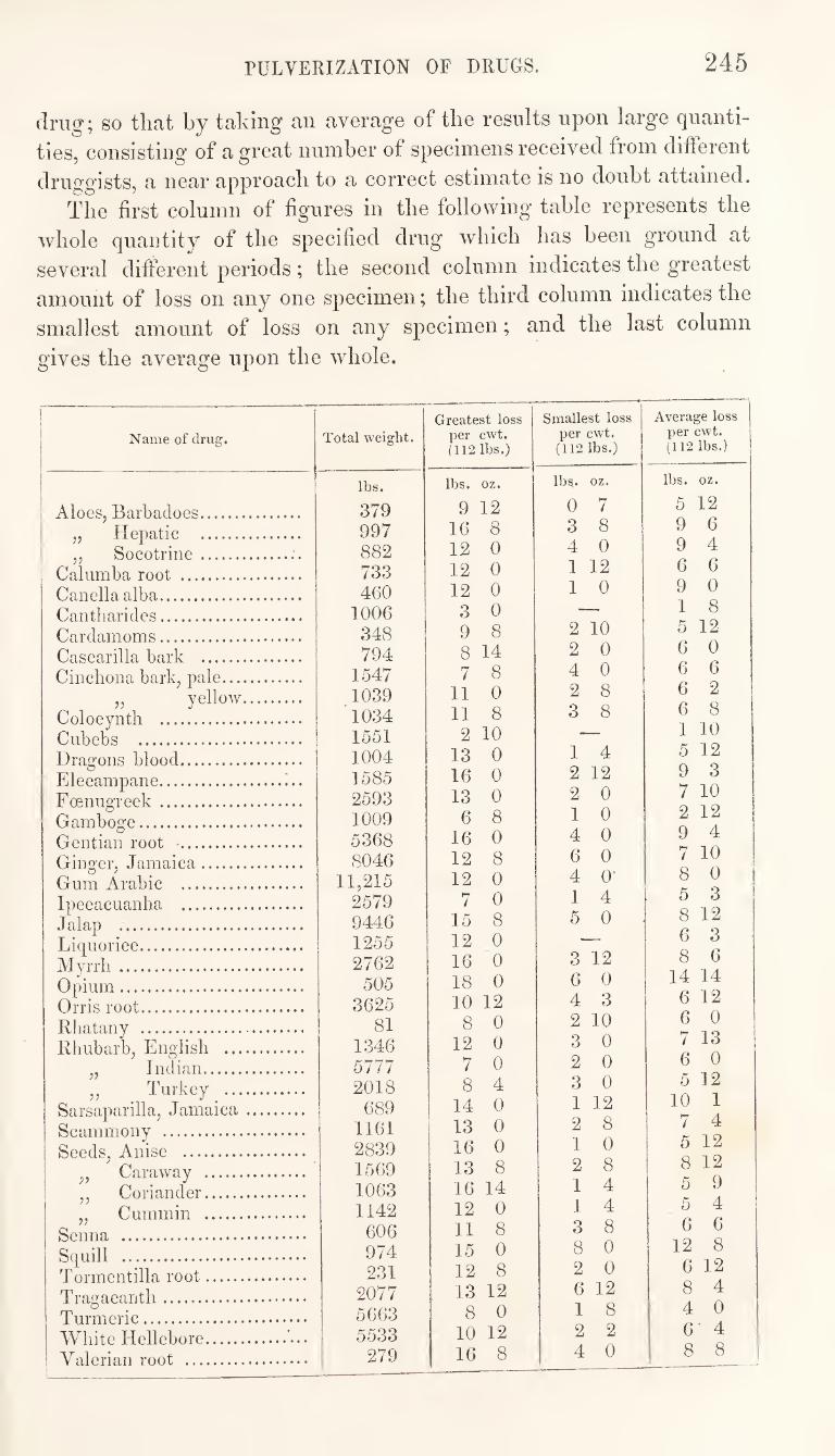
PULVERIZATION OF DRUGS. 245
drug; so that by taking an average of the results upon large quanti¬
ties, consisting of a great number of specimens received from different
druggists, a near approach to a correct estimate is no doubt attained.
The first column of figures in the following table represents the
whole quantity of the specified drug which has been ground at
several different periods; the second column indicates the greatest
amount of loss on any one specimen; the third column indicates the
smallest amount of loss on any specimen; and the last column
gives the average upon the whole.
Name of drug. Total weight. Greatest loss
per cwt. (112 lbs.)
Smallest loss per cwt. (112 lbs.)
Average loss per cwt. (112 lbs.)
Aloes, Barbadoes. „ Hepatic . „ Socotrine.
Calumba root . Canellaalba. Cantharides. Cardamoms. Cascarilla bark . Cinchona bark, pale.
,, yellow. Colocynth . Cubebs . Dragons blood. Elecampane.. Foenugreek . Gamboge. Gentian root ■. Ginger, Jamaica. Gum Arabic . Ipecacuanha . Jalap . Liquorice. Alyrrh . Opium. Orris root. Rhatany . Rhubarb, English .
„ Indian. „ _ Turkey _.
Sarsaparilla, Jamaica. Scammony . Seeds, Anise .
,, Caraway . „ Coriander. „ Cummin .
Senna . Squill . Tormentilla root. Tragacanth. Turmeric. White Hellebore. Valerian root .
lbs.
379 997 882 733 460
1006 348 794
1547 1039 1034 1551 1004 1585 2593 1009 5368 8046
11,215 2579 9446 1255 2762
505 3625
81 1346 5777 2018
689 1161 2839 1569 1063 1142 606 974 231
2077 5663 5533
279
lbs. oz.
9 12 16 8 12 0 12 0 12 0
3 0 9 8 8 14 7 8
11 0 11 8
2 10 13 0 16 0 13 0
6 8 16 0 12 8 12 0
7 0 15 8 12 0 16 0 18 0 10 12
8 0 12 0
7 0 8 4
14 0 13 0 16 0 13 8 16 14 12 0 11 8 15 0 12 8 13 12
8 0 10 12 16 8
lbs,, oz.
0 7 3 8 4 0 1 12 1 0
2 10 2 0 4 0 2 8 3 8
1 4 2 12 2 0 1 0 4 0 6 0 4 0- 1 4 5 0
3 12 6 0 4 3 2 10 3 0 2 0 3 0 1 12 2 8 1 0 2 8 1 4 1 4 3 8 8 0 2 0 6 12 1 8 2 2 4 0
lbs. oz.
5 12 9 6 9 4 6 6 9 0 1 8 5 12 6 0 6 6 6 2 6 8 1 10 5 12 9 3 7 10 2 12 9 4 7 10 8 0 5 3 8 12 6 3 8 6
14 14 6 12 6 0 7 13 6 0 5 12
10 1 7 4 5 12 8 12 5 9 5 4 6 6
12 8 6 12 8 4 4 0 6 4 8 8
246 PULVERIZATION OF DRUGS.
It appears from this table that the average loss in powdering
drugs is more than four per cent, in nearly all cases, and that in
some it is considerably more. Now, can it he reasonably sup-
})osed that, in these cases, the drug-grinder will supply good rhubarb
or jalap, gentian or ginger, for the water which has been imbibed
ill a damp warehouse or cellar ? He is required to make up a
certain quantity of powder, evidently more than the crude drug
produces, but how is he to do it ? Does he keep a stock from which
to supply the deficiences of all the drugs he grinds, and go to
market and purchase more when his stock is exhausted ; or is there
some magical powder in his mill ?
A drug-grinder's mill (a «, fig. 266) is a very different thing
from the pestle and mortar of the druggist, although they are both
employed for the same purpose. The druggist, when he has used
the pestle and mortar, cleans it preparatory for the next operation,
by washing it out with water. The drug-grinder also requires to
clean his mill. Rhubarb must not be ground after aloes, nor ginger
after jalap, without previously well cleaning the ponderous stones
and other parts of the apparatus. But how shall this be done ? A
drug-mill cannot be cleaned by washing it with water,—if for no
other reason, it would be objectionable on account of its making the
room and apparatus damp, which are required to be perfectly dry.
Instead of water, saw^dust is used for cleaning the drug-mill.
After grinding any drug, in order to remove the adhering particles
from the mill, sawdust is ground until the mill is rendered sweet
and clean.
Sawdust, then, is indispensable at a drug-mill, as necessary as
water is in a druggist's shop, and if the druggist sends damp jalap,
containing fifteen per cent, of winter, to be ground, and requires dry
powder to be returned, with only four per cent, of deduction for
loss, he adopts a conventional method of asking for some of the rin¬
sing of the mill,—a veritable “ powder of post.”
The four per cent, system cannot fail to induce a reduction in the
strength of powdered drugs. If this reduction tended to equalize
the strength of different specimens, there might be some excuse
for it ; but the effect of the system must obviously be to cause a
reduction, in an inverse ratio to the previous strength of the drugs,
so that the weakest and worst drugs will be most diluted. But
this objection, which applies to the very principle of the system, is
not the most serious objection to which it is subject. It sanctions
the practice of admixture, and affords facilities for those, who are
so disposed, to pursue a ruinous competition in price at the sacrifice
of quality.
GRANULATION OF METALS. 247
There are two causes which, I believe, principally tend to frus¬
trate the efforts of those who are endeavouring to put a stop to
tlie adulteration of drugs ; one is, tlie sale of cheap medicines by
o-rocers and others not educated as pharmaceutists, who are unable
to distinguish the good from the bad, or indifferent as to which they
sell; and the other is, fhe continuance of the four per cent, system
in connexion with drug-grinding,—a system which has no claim for
support, save the long-established usage of the trade. It should be
the enlightened policy of an educated body of pharmaceutists^ to
afford a fair remuneration for honest industry, and this being
secured, both druggist and drug-grinder would rejoice to he re¬
lieved from the hereditary trammels of the present system.]
GRANULATION OF METALS.
[There are some metals, such as zinc and tin, which, previously to
their application for certain purposes, are reduced to a granular
condition. The process by which this is effected is called granu-
IjQj t%0'Yh
Tlie granulation of zinc is effected in two different ways, one
being intended for the reduction of the metal to a coarse, and the
other to a more minute state of division. Coarsely granulated zinc is prepared by melting the metal m an
iron ladle, and pouring it in a thin and intermitting stream into a
large pan filled with water. Little conical nodules are thus ob¬
tained, which present the metal in a convenient form and condition
for actinc upon it with acids. In performing the process it is ne¬
cessary to be careful that the melted metal be not too rapidly
poured into the water, and that there is a sufficient quantity of
water in the pan to prevent the projection of hot metal or water
over the operator. Fmuhj granulated zinc is prepared by rubbing the melted metal m
an iron mortar, and continuing the process until it has herome
solid. In its ordinary condition, as obtained by casting it in
blocks, zinc is rather brittle, but sufficiently tough to resist any
efforts at powdering it, as antimony is powdered, by mere contusion
in a mortar. If heated to about 300° F., it becomes malleable and
ductile, and if submitted to the process of rolling while at this tem¬
perature, it not only readily admits of extension into sheets, but
afterwards retains its malleability when it has cooled. At a tem¬
perature of 400° or a little higher, it entirely loses its ductile pro¬
perty and becomes so brittle that it can he rubbed to powder in a
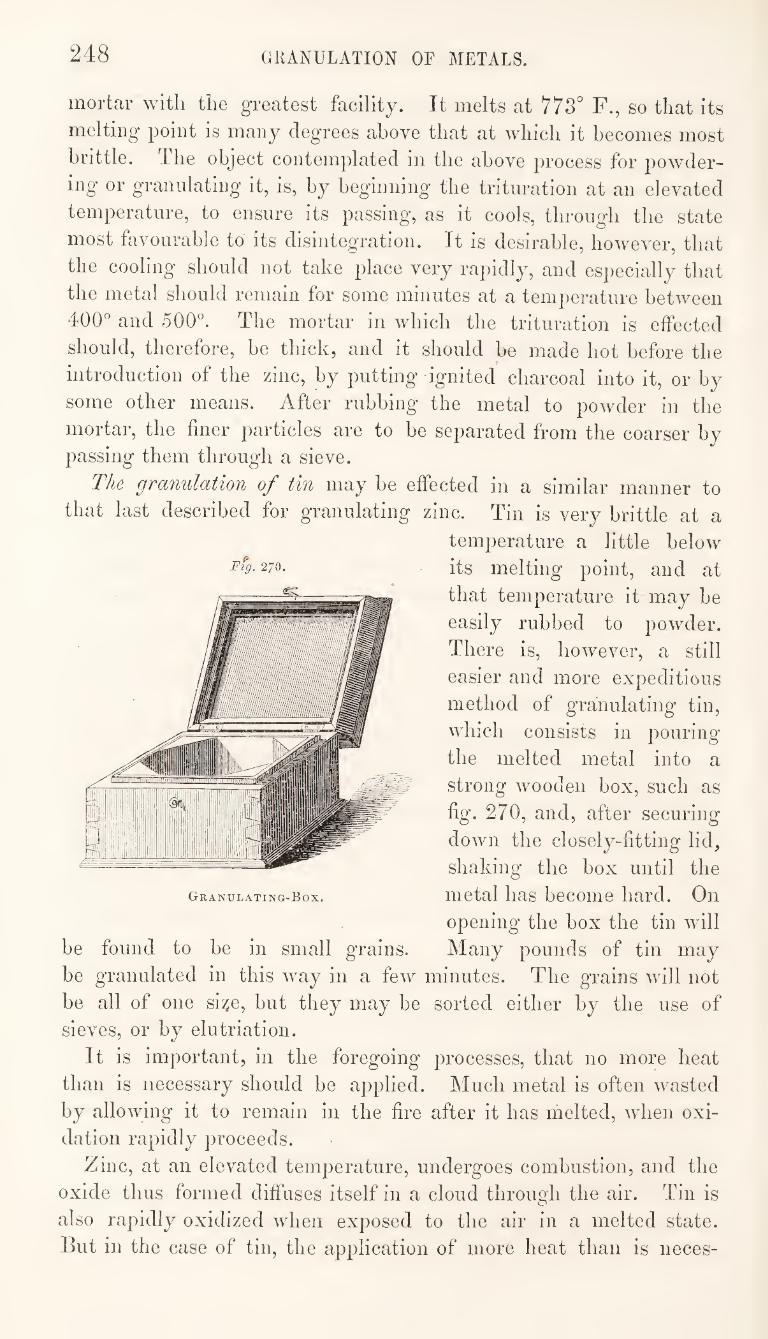
248 GRANULATION OF METALS.
mortar Avith tlie greatest facility. It melts at 778'’ F., so that its
melting point is many degrees above that at which it becomes most
brittle. 4 he object contemplated in the above process for powder¬
ing or granulating it, is, by beginning the trituration at an elevated
temperature, to ensure its passing, as it cools, through the state
most fjLivourable to its disintegration. It is desirable, however, that
the cooling should not take place very rapidly, and especially that
the metal should remain for some minutes at a temperature between
400° and 500°. The mortar in which the trituration is effected
should, therefore, be thick, and it should be made hot before the
introduction of the zinc, by putting ignited charcoal into it, or by
some other means. After rubbing the metal to powder in the
mortar, the finer particles are to be separated from the coarser by
passing them through a sieve.
The granulation of tin may be effected in a similar manner to
that last described for granulating zinc. Tin is very brittle at a
temperature a little below
^^9- 2/0. its melting point, and at
that temperature it may be
easily rubbed to powder.
There is, however, a still
easier and more expeditious
method of granulating tin,
which consists in pouring
the melted metal into a
? strong wooden box, such as
fig. 270, and, after securing
down the closely-fitting lid,
shaking the box until the
metal has become hard. On
opening the box the tin will
be found to be in small grains. Many pounds of tin may
be granulated in this way in a few minutes. The grains will not
be all of one si^e, but they may be sorted either by the use of
sieves, or by elutriation.
It is important, in the foregoing processes, that no more heat
than is necessary should be applied. Much metal is often wasted
by allowing it to remain in the fire after it has melted, when oxi¬
dation rapidly proceeds.
Zinc, at an elevated temperature, undergoes combustion, and the
oxide thus formed diffuses itself in a cloud through the air. Tin is
also rapidly oxidized when exposed to the air in a melted state.
I3ut in the case of tin, the application of more heat than is neces-
3 . rri„
'ii-liij
pm
Granulating-Box.
GRANULATION OF METALS. 249
sary for its fusion is also objectionable on account of its causing the
carbonization of the granulating-box. It is customary to guard
against this effect by rubbing some chalk over the inner surface of
the box. This tends to protect the wood, but it causes the granu¬
lated tin to be contaminated with chalk, which has to be subse¬
quently removed by washing the metal with diluted acetic acid.
Iron is granulated by the mechanic’s file, which supplies the
filings so frequently employed in the laboratory. But iron filings
obtained from this source are very impure, and it is necessary to
submit them to some process of purification before they are used for
any pharmaceutical preparations. They are generally contaminated
with grease which is used in the process of filing, and they also
contain a considerable quantity of oxide.
The best method of purifying iron filings is to triturate them in a
Wedge wood’s-ware mortar with solution of caustic potash, pouring
off the solution, from time to time, while the oxide remains sus¬
pended in it, and repeating the trituration with fresh potash, or,
after the second or third addition, with pure water; thus removing
impurities partly by solution, and partly by elutriation. The
filings will speedily become bright and clean with this treatment,
and when the oxide has been entirely removed,—the elutriation
being always effected with pure water towards the latter part of the
process,—they are to be drained for a few minutes, then washed
with a little spirit, and dried quickly over a stove.
Gold and silver are sometimes reduced to powder or small grains,
and the processes by which the disintegration of these metals is
effected are peculiar.
The ^powder either of gold or of silver may be prepared by
rubbing the metal, in the form of leaf, on the porphyry slab witli
some honey until it is reduced to a finely-divided state, and then
dissolving out the honey with water. Sulphate of potash or cream
of tartar is sometimes substituted for the honey, or used with it,
in which case hot water is employed as a more ready solvent of the
salt. If required in larger quantity, gold may be obtained in
powder by first forming an amalgam with it, and then distilling off
the mercury. Silver may also be treated in the same way. A
convenient method of obtaining pure silver in the form of powder
or minute grains is, to reduce chloride of silver by boiling it with
solution of caustic potash and a little honey.
Some salts, such as salt of tartar, are said to be granulated when
they are obtained in small, irregular crystals, by a particular treat¬
ment, which has been already described in connexion with the
pulverization of drugs.]
250 ELUTRIATION. DECANTATION.
ELUTRIATION.
[The process of elutriation has been already alluded to as a method
by which the finer particles of a powder are separated from the
coarser. The process consists in diffusing the powder through
water, allowing the larger and heavier particles to subside, and then
decanting the liquor, with the smaller particles still held in sus¬
pension, into another vessel, and allowing them to subside there.
It is obvious that the process can only be applied to those substances
which are not dissolved or chemically acted upon by water. It is
used for separating impurities from chalk. It is also applied in the
separation or sorting of the different sized grains of emery. The
process is a very convenient one for dividing a powder consist¬
ing of different sized grains into several parts, each containing
particles of tolerably uniform dimensions. On mixing the pow¬
der in its original state with the water, the largest particles
subside the soonest, and the longer the mixture is allowed to
rest the more uniformly small will be the particles remaining in
suspension. If the liquor containing these be now decanted, and
more water added to the powder that remains, another set of
particles less finely comminuted will be obtained by allowing rather
a shorter time for subsidence. The process may thus be repeated
for an indefinite number of times, according to the kind of separation
required.
Powdered or granulated tin is one of the substances wdiich is
frequently sorted by elutriation. Iron-filings are purified by this
process.]
DECANTATION.
[The term decantation is applied in pharmacy to the act of pouring
a liquid from a precipitate or sediment contained in the same vessel.
Oases constantly occur in the laboratory in which this operation
is required to be performed. Thus, in the process of elutriation,
the liquor containing a part of the powder originally diffused
through it, is decanted from that part of the powder which has
subsided.
The mere pouring of a liquid from one vessel to another, how¬
ever simple it may appear, is not always an eas}^ operation, espe¬
cially to the uninitiated. The form of the vessel, the extent to
which the liquid fills it, and the nature of the liquid, materially
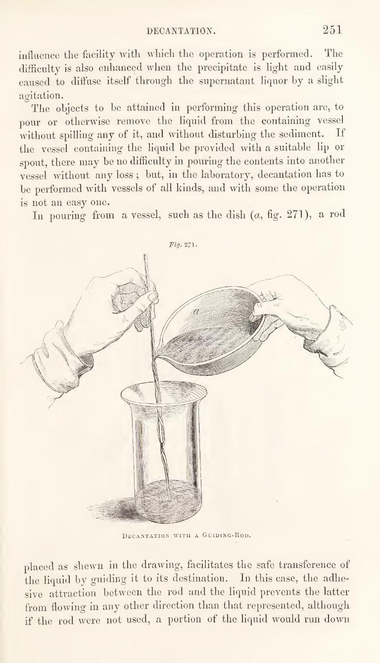
DECANTATION. 251
influence the facility with which the operation is performed. The
difficulty is also enhanced when the precipitate is light and easily
caused to diffuse itself through the supernatant liquor by a slight
agitation. O
The objects to be attained in performing this operation are, to
pour or otherwise remove the liquid from the containing vessel
without spilling any of it, and without disturbing the sediment. If
the vessel containing the liquid be provided with a suitable lip or
spout, there may be no difficulty in pouring the contents into another
vessel without any loss ; but, in the laboratory, decantation has to
be performed with vessels of all kinds, and with some the operation
is not an easy one.
In pouring from a vessel, such as the dish (a, fig. 271), a rod
Fiff. 271.
Decantation with a Guiding-Rod.
placed as shewn in the drawing, facilitates the safe transference of
the liquid by guiding it to its destination. In this case, the adhe¬
sive attraction between the rod and the liquid prevents the latter
from flowing in any other direction than that represented, although
if the rod were not used, a portion of the liquid would run down
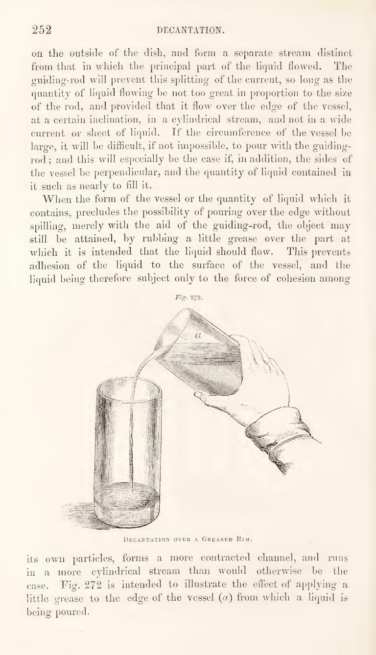
252 DECANTATION.
on the outside of the dish, and form a separate stream distinct
from that in which the principal part of the liquid flowed. The
guiding-rod will prevent this splitting of the current, so long as the
quantity of liquid flowing he not too great in proportion to the size
of the rod, and provided that it flow over the edge of the vessel,
at a certain inclination, in a cylindrical stream, and not in a wide
current or sheet of liquid. If the circumference of the vessel be
large, it will be difficult, if not impossible, to pour with the guiding-
rod ; and this will especially be the case if, in addition, the sides of
the vessel he perpendicular, and the quantity of liquid contained in
it such as nearly to fill it.
When the form of the vessel or the quantity of liquid which it
contains, precludes the possibility of pouring over the edge without
spilling, merely with the aid of the guiding-rod, the object may
still be attained, by rubbing a little grease over the part at
which it is intended that the liquid should flow. This prevents
adhesion of the liquid to the surface of the vessel, and the
liquid being therefore subject only to the force of cohesion among
Fig. 272.
its own particles, forms a more contracted channel, and runs
in a more cylindrical stream than would otherwise he the
case. Fig. 272 is intended to illustrate the effect of aj)plying a
little grease to the edge of the vessel {a) from which a liquid is
being poured.
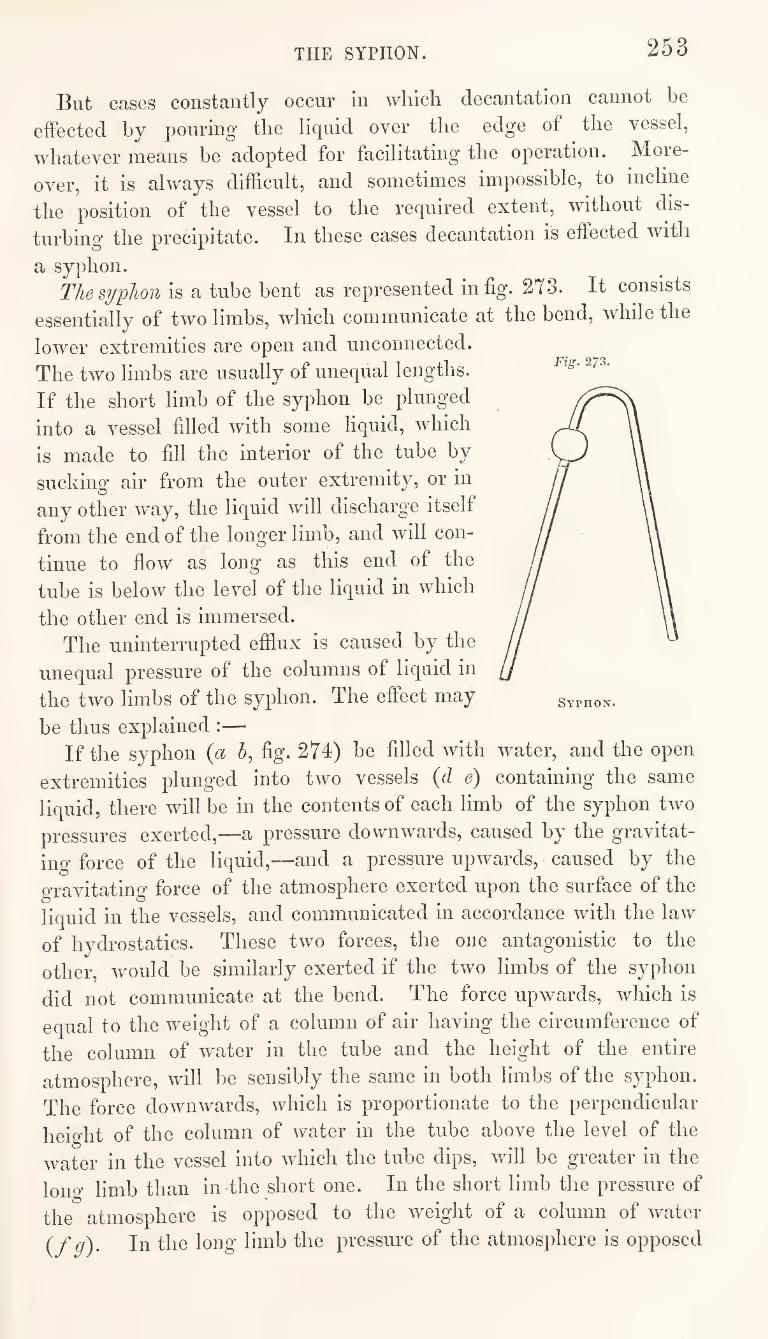
THE SYPHON. 253
But cases constantly occur in which decantation cannot be
effected by pouring the liquid over the edge of the vessel,
whatever means be adopted for facilitating the operation. More¬
over, it is always difficult, and sometimes impossible, to incline
the position of the vessel to the required extent, without dis¬
turbing the precipitate. In these cases decantation is effected with
a syphon. The siphon is a tube bent as represented in fig. 273. It consists
essentially of two limbs, which communicate at the bend, while the
lower extremities are open and unconnected.
The two limbs are usually of unequal lengths.
If the short limb of the syphon be plunged
into a vessel filled with some liquid, which
is made to fill the interior of the tube by
suckino- air from the outer extremity, or in
any other way, the liquid will discharge itself
from the end of the longer limb, and will con¬
tinue to flow as long as this end of the
tube is below the level of the liquid in which
the other end is immersed.
The uninterrupted efflux is caused by the
unequal pressure of the columns of liquid in
the two limbs of the syphon. The effect may
be thus explained :—
If the syphon (a 5, fig. 274) be filled with water, and the open
extremities plunged into two vessels (d e) containing the same
liquid, there will be in the contents of each limb of the syphon two
pressures exerted,—a pressure downwards, caused by the gravitat¬
ing force of the liquid,—and a pressure upwards, caused by the
gravitating force of the atmosphere exerted upon the surface of the
liquid in the vessels, and communicated in accordance with the law
of hydrostatics. These two forces, the one antagonistic to the
other, would be similarly exerted if the two limbs of the syphon
did not communicate at the bend. The force upwards, which is
equal to the weight of a column of air having the circumference of
the column of water in the tube and the height of the entire
atmosphere, will be sensibly the same in both limbs of the syphon.
The force downwards, which is proportionate to the perpendicular
height of the column of water in the tube above the level of the
water in the vessel into which the tube dips, will be greater in the
long limb than in-the short one. In the short limb the pressure of
the atmosphere is opposed to the weight of a column of water
(f q). In the long limb the pressure of the atmosphere is opposed
Fig. 273.
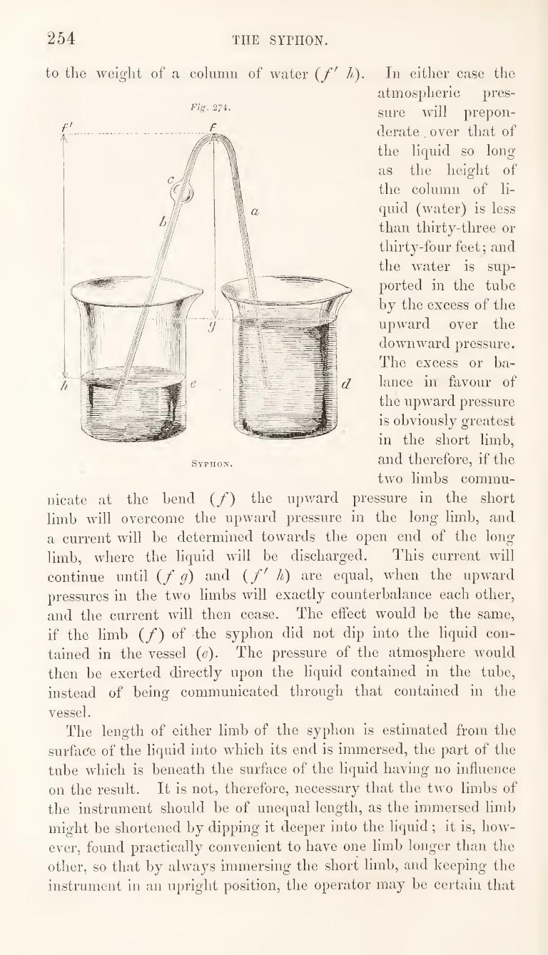
254 THE SYPHON.
to tlie weight of a column of water In either case the
atmospheric pres-
sure will prepon¬
derate . over that of
the liquid so long
as the height of
the column of li¬
quid (water) is less
than thirty-three or
thirty-four feet; and
the water is sup¬
ported in the tube
by the excess of the
upward over the
downward pressure.
The excess or ba¬
lance in favour of
the upward pressure
is obviously greatest
in the short limb,
Syphon. S'lid therefore, if the
two limbs commu¬
nicate at the bend (/) the upward pressure in the short
limb will overcome the upward pressure in the long limb, and
a current will be determined towards the open end of the long
limb, where the liquid will be discharged. This current wall
continue until (/ g) and (/' li) are equal, when the upward
pressures in the two limbs will exactly counterbalance each other,
and the current will then cease. The effect would be the same,
if the limb (/) of the syphon did not dip into the liquid con¬
tained in the vessel (e). The pressure of the atmosphere would
then be exerted directly upon the liquid contained in the tube,
instead of being communicated through that contained in the
vessel.
The length of either limb of the syphon is estimated from the
surfacfe of the liquid into wdiich its end is immersed, the part of the
tube which is beneath the surface of the liquid having no influence
on the result. It is not, therefore, necessary that the two limbs of
the instrument should be of unequal length, as the immersed limb
might be shortened by dipping it deeper into the liquid; it is, how¬
ever, found practically convenient to have one limb longer than the
other, so that by always immersing the short limb, and keeping the
instrument in an upright position, the operator may be certain that
THE SYPHON. 255
the external limb contains the longest column of liquid, and that the
current will therefore be continuous.
The bulb represented in the upper part of the long limb of the
syphon in figs. 273 and 274, is not essential, and is not taken into
account in the foregoing description, but will be alluded to hereafter.
In using a plain syphon, consisting simply of a bent tube, such
as fig. 273, without the bulb, it is necessary to get it filled with
the liquid to be decanted, either by withdrawing the air with the
mouth from one extremity while the other extremity is immersed
in the liquid, or by inverting the tube, pouring the liquid in at one
of the open ends until both limbs are full, then stopping the two
orifices with a finger of each hand, and immersing the end of one of
the limbs while the liquid is allowed to run from the other. The
former of these methods is inelegant, and with some liquids is im¬
practicable. The latter method is also impracticable in some cases,
as for instance, where the liquid is of a strongly caustic character,
into which the finger could not be safely introduced, or where it
has to be decanted from a vessel the mouth of which would not
admit the hand.
Two modifications have been made in the form of the syphon
with the view of remedying the above defects. One of these modi¬
fications consists in having a bulb blown in the long limb of the
instrument, as shewn in fig. 273. In using this form of syphon,
the tube is inverted and liquid poured in until it is entirely full, the
extremity of the long limb is closed by placing a finger over it, and
the instrument being restored to its proper position, the contents of
the short limb are allowed to run out; the end of the short limb is
now immersed in the liquid to be decanted, and on removing the
finger from the other end, the fluid descending from the bulb by its
own weight, draws the liquid from the vessel into the short limb
until a current is established throughout, as shewn in fig. 274, the
bulb remaining partly empty. It is necessary, in this case, that
the capacity of the bulb shall be rather more than equal to that of
the short limb of the syphon, so that the air originally present in
the tube {a) may be retained in the bulb while the current of liquid
passes through its centre. The other modification is represented in
fig. 275. It consists in having a small tube attached to the long
limb near to its lower end, and extending upwards to the bend,
where it is turned outwards. This tube is used for withdrawing
the air with the mouth while the end of the short limb is immersed
in the liquid to be decanted, and a finger is placed over the orifice
of the long limb. In withdrawing the air, the syphon should be
turned until the long limb is nearly horizontal, the end to which
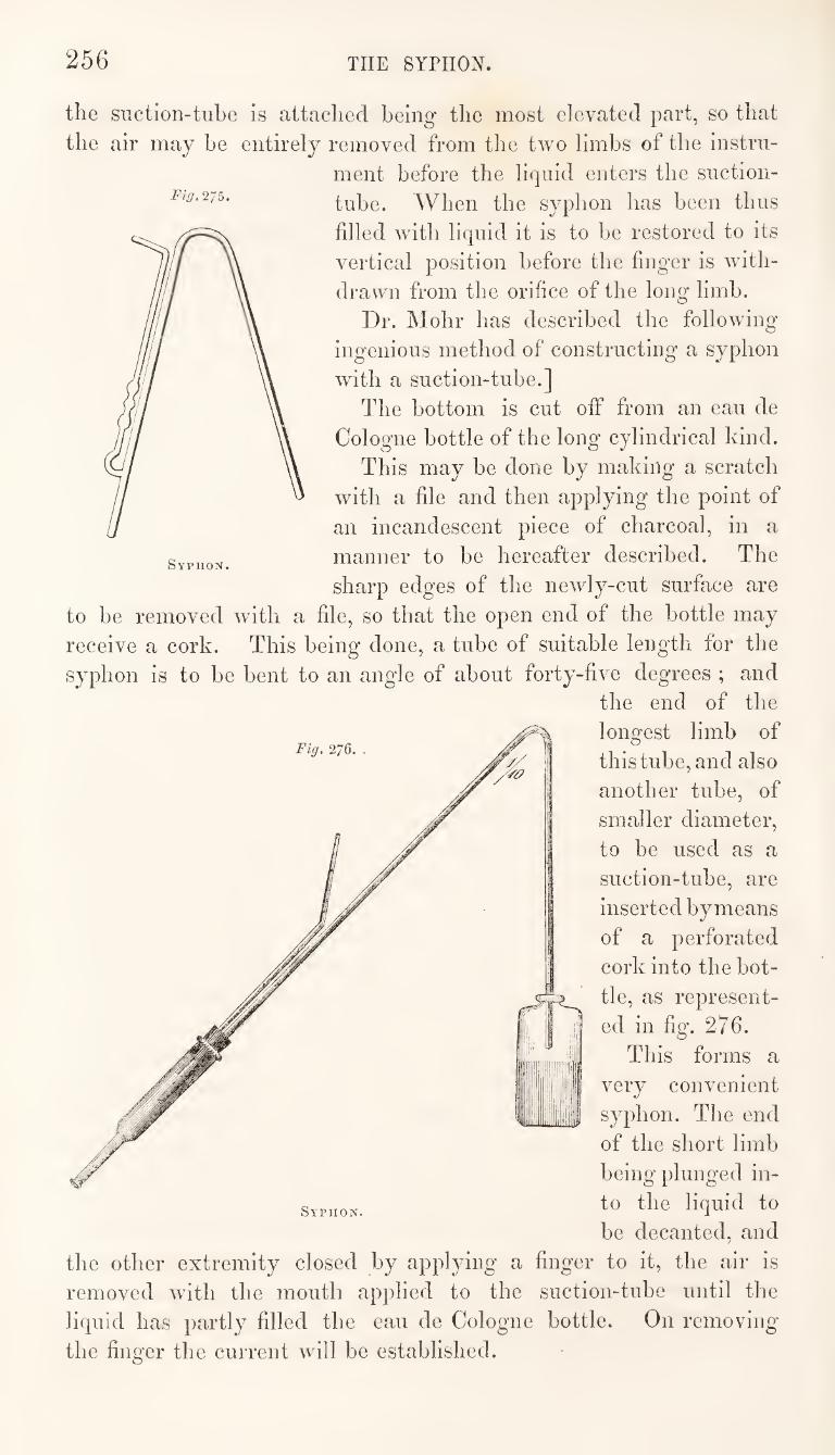
256 THE SYPHON.
Fig. 275.
the suction-tube is attached being the most elevated part, so that
the air may he entirely removed from the two limbs of the instru¬
ment before the liquid enters the suction-
tube. When the syphon has been thus
filled with liquid it is to be restored to its
vertical position before the finger is with¬
drawn from the orifice of the long limb.
Dr. Mohr has described the following
ingenious method of constructing a syphon
with a suction-tube.]
The bottom is cut off from an eau de
Cologne bottle of the long cylindrical kind.
This may be done by making a scratch
with a file and then applying the point of
an incandescent piece of charcoal, in a
manner to be hereafter described. The
sharp edges of the newly-cut surface are
to be removed with a file, so that the open end of the bottle may
receive a cork. This being done, a tube of suitable length for the
syphon is to be bent to an angle of about forty-five degrees ; and
the end of the
longest limb of
this tube, and also
another tube, of
smaller diameter,
to be used as a
suction-tube, are
inserted by means
of a perforated
cork into the bot¬
tle, as represent¬
ed in fig. 276.
This forms a
very convenient
syphon. The end
of the short limb
being plunged in¬
to the liquid to
be decanted, and
the other extremity closed by applying a finger to it, the air is
removed wdth the mouth applied to the suction-tube until the
liquid has partly filled the eau de Cologne bottle. On removing
the finger the current will be established.
Fig. 276.
Syphon.
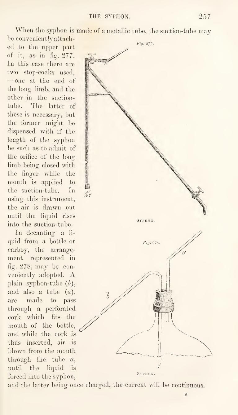
THE SYPHON. 257
Fig. 2
When the syphon is made of a metallic tube, the suction-tube may
be conveniently attach¬
ed to the upper part
of it, as in fig*. 277.
In this case there are
two stop-cocks used,
—one at the end of
the long limb, and the
other in the suction-
tube. The latter of
these is necessary, but
the former might be
dispensed with if the
length of the syphon
be such as to admit of
the orifice of the lonof
limb being closed with
the finger while the
mouth is applied to
the suction-tube. In
using this instrument,
the air is drawn out
until the liquid rises
into the suction-tube.
In decanting a li¬
quid from a bottle or
carboy, the arrange¬
ment represented in
fig. 278, may be con¬
veniently adopted. A
plain syphon-tube (5),
and also a tube (u),
are made to pass
through a perforated
cork which fits the
mouth of the bottle,
and while the cork is
thus inserted, air is
blown from the mouth
through the tube a,
until the liquid is
forced into the syphon,
and the latter being once charged, the current will be continuous.
s
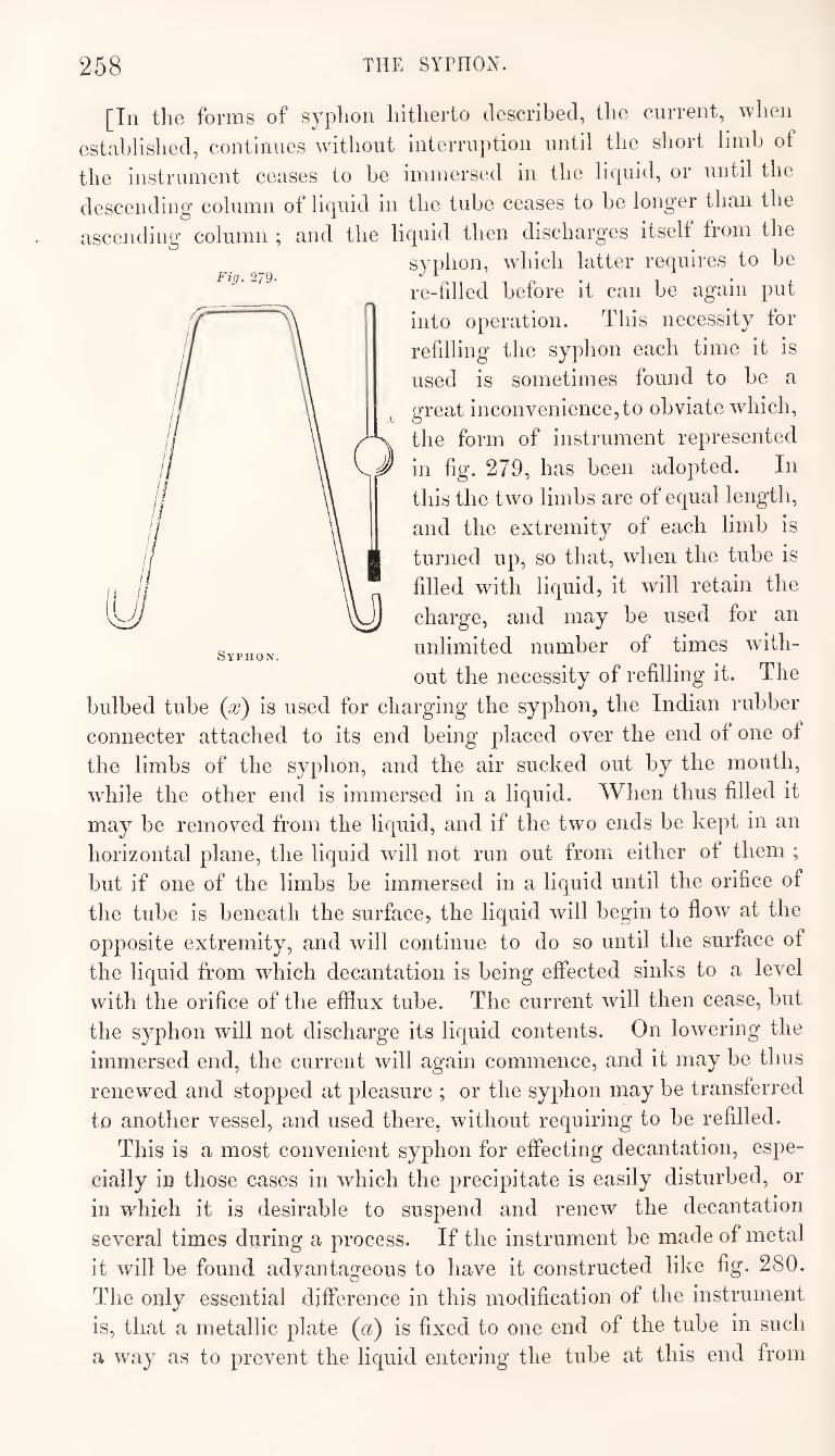
258 THE SYPHON.
[In the forms of syphon hitherto described, the current, ^rhen
established, continues without interruption until the short limb of
the instrument ceases to be immersed in the liquid, or until the
descending column of liquid in the tube ceases to be longer than the
ascending column ; and the liquid then discharges itself from the
syphon, which latter requires to be
re-filled before it can be again put
into operation. This necessity for
refilling the syphon each time it is
used is sometimes found to he a
great inconvenience,to obviate which,
the form of instrument represented
in fig. 279, has been adopted. In
this the two limbs are of equal length,
and the extremity of each limb is
turned up, so that, when the tube is
filled with liquid, it will retain the
charge, and may be used for an
unlimited number of times with¬
out the necessity of refilling it. The
bulbed tube {x) is used for charging the syphon, the Indian rubber
connecter attached to its end being placed over the end of one of
the limbs of the syphon, and the air sucked out by the mouth,
while the other end is immersed in a liquid. When thus filled it
may be removed from the liquid, and if the two ends be kept in an
horizontal plane, the liquid will not run out from either of them ;
but if one of the limbs be immersed in a liquid until the orifice of
the tube is beneath the surface, the liquid will begin to flow at the
opposite extremity, and will continue to do so until the surface of
the liquid from which decantation is being effected sinks to a level
with the orifice of the efflux tube. The current will then cease, but
the syphon will not discharge its liquid contents. On lowering the
immersed end, the current will again commence, and it may be thus
renewed and stopped at pleasure ; or the syphon may be transferred
to another vessel, and used there, without requiring to be refilled.
This is a most convenient syphon for effecting decantation, espe¬
cially in those cases in which the precipitate is easily disturbed, or
in which it is desirable to suspend and renew the decantation
several times during a process. If the instrument be made of metal
it will be found advantageous to have it constructed like fig. 280.
The only essential difference in this modification of the instrument
is, that a metallic plate (a) is fixed to one end of the tube in such
a way as to prevent the liquid entering the tube at this end from
Fig. 279.
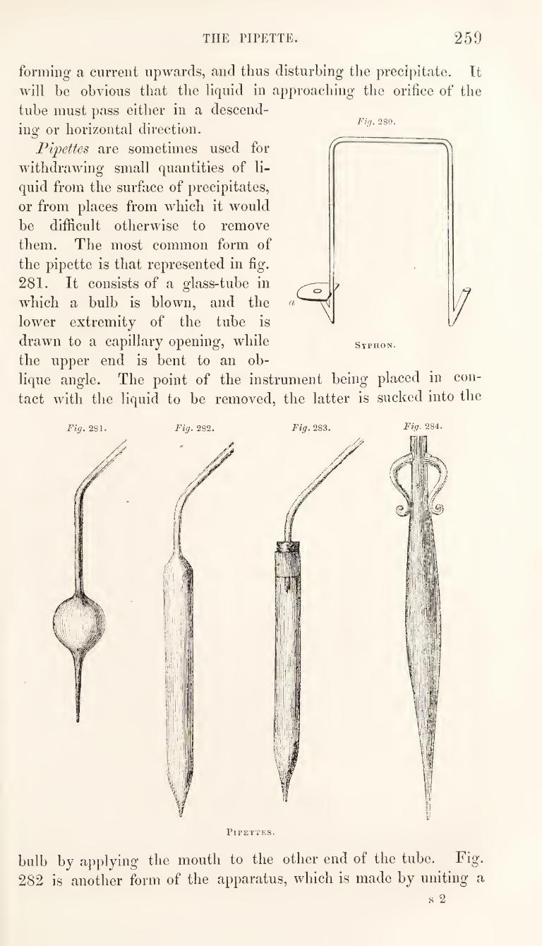
259 THE PIPETTE.
Fifj. 280.
forming a current upwards, and thus disturbing the precipitate. It
will be obvious that the liquid in approaching the orifice of the
tube must pass either in a descend¬
ing or horizontal direction.
Pipettes are sometimes used for
withdrawing small quantities of li¬
quid from the surface of precipitates,
or from places from which it would
be difficult otherwise to remove
them. The most common form of
the pipette is that represented in fig.
281. It consists of a glass-tube in
which a bulb is blown, and the
lower extremity of the tube is
drawn to a capillary opening, while
the upper end is bent to an ob¬
lique angle. The point of the instrument being placed in con¬
tact with the liquid to be removed, the latter is sucked into the
Syphon.
Fig. 281.
bulb by applying the mouth to the other end of the tube. Fig*
282 is another form of the apparatus, which is made by uniting a
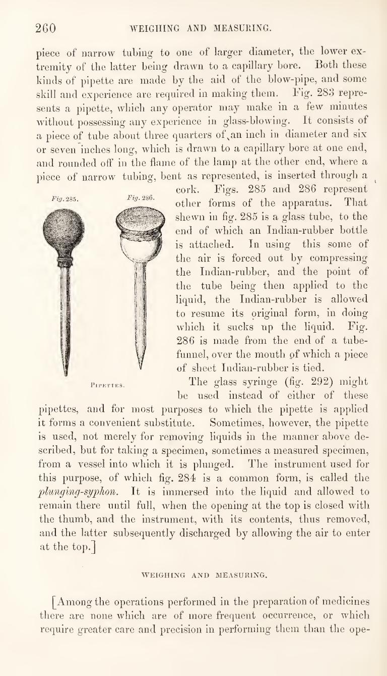
260 WEIGHING AND MEASURING.
piece of narrow tubing to one of larger diameter, the lower ex¬
tremity of the latter being drawn to a capillary bore. Both these
kinds of pipette are made by the aid of the blow-pipe, and some
skill and experience are required in making them. Fig. 283 repre¬
sents a pipette, which any operator may make in a few minutes
without possessing any experience in glass-blowing. It consists of
a piece of tube about three quarters of^an inch in diameter and six
or seven inches long, which is drawn to a capillary bore at one end,
and rounded off in the flame of the lamp at the other end, where a
piece of narrow tubing, bent as represented, is inserted through a
cork. Figs. 285 and 286 represent
other forms of the apparatus. That
shewn in fig. 285 is a glass tube, to the
end of which an Indian-rubber bottle
is attached. In using this some of
the air is forced out by compressing
the Indian-rubber, and the point of
the tube being then applied to the
liquid, the Indian-rubber is allowed
to resume its original form, in doing
which it sucks up the liquid. Fig.
286 is made from the end of a tube-
funnel, over the mouth pf which a piece
of sheet Indian-rubber is tied.
The glass syringe (fig. 292) might
be used instead of either of these
pipettes, and for most purposes to which the pipette is applied
it forms a convenient substitute. Sometimes, however, the pipette
is used, not merely for removing liquids in the manner above de¬
scribed, but for taking a specimen, sometimes a measured specimen,
from a vessel into which it is plunged. The instrument used for
this purpose, of which fig. 284 is a common form, is called the
plunging-syphon. It is immersed into the liquid and allowed to
remain there until full, when the opening at the top is closed with
the thumb, and the instrument, with its contents, thus removed,
and the latter subsequently discharged by allowing the air to enter
at the top.]
Fig.2Sb. Fig. 2S6.
Pipettes.
I
WEIGHING AND MEASURING.
[Among the operations performed in the preparation of medicines
there are none which are of more frequent occurrence, or which
require greater care and precision in performing them than the ope-
WEIGHING AND MEASURING. 261
rations of weighing and measuring. In selling medicines, in dis¬
pensing medicines, and in preparing or manufacturing the different
medicinal compounds, there are constant occasions for the use of the
balance and the measure. These instruments are intended for the
accurate adjustment of the quantities of the substances employed
in our operations; but the full accomplishment of the object con
templated will depend in a great degree upon the proper construc¬
tion of the instruments, the care with which they are preserved,
and the manual dexterity with which they are used.
The weight of a body is the measure of its gravitating force, and
this is in direct proportion to its mass, or the quantity of matter
which it contains. This force is expressed with relation to some
known standard of resistance, which is just sufficient to prevent the
body from falling to the ground. The standards thus used, how¬
ever, are perfectly arbitrary, and they frequently differ in different
countries, which is a great evil.
In the first instance, some natural products, such as seeds, which
were easily attainable, and the weight of which was pretty uniform,
were used as units, from which other denominations of weight
were calculated. Thus, by a law passed in the year 1266, it was
enacted, “ That an English penny, called a sterling, round and
without clipping, shall weigh thirty-two wheat corns^ from the
midst of the ear, and twenty pence shall make an ounce, and twelve
ounces one pound.”
Not only have different countries adopted different standards of
weight, but even in the same country, as in this and others, two or
more different standards have been recognized and used at the same
time. The inconveniences resulting from this practice have long
been felt, and the attention of scientific men has, for many years,
been directed to the subject, with the view of fixing upon one
standard which could at any time be tested by comparison with
some phenomenon of constant and unvarying occurrence. Such a
standard, it is hoped, will ultimately be adopted by all civilized
countries, to the exclusion of every other.
In this country an attempt has been made to introduce a greater
degree of uniformity and certainty than originally existed with
reference of our weights and measures.
The imperial standard weight, or troy pound of 5760 grains,
from which all our other weights are now calculated, is determined,
in case of any doubt, by comparison with a given measure of
distilled water, weighed at a temperature of 62^ bahr., the ba¬
rometer standing at thirty inches. Thus, a cubic inch of distilled
water weighed in air with brass weights, at the temperature above
262 WEIGHING AND MEASURING.
stated, “ is equal to two hundred and fifty-two grains and four
hundred and fifty-eight thousandth parts of a grain, of which, as
aforesaid, the imperial standard troy pound contains 5760.’’
The measure from which the weight is estimated, is determined
by means of a pendulum vibrating seconds of time, in a vacuum, at
the latitude of London, and at the level of the sea. It has been
found that the length of such a pendulum, in comparison with our
yard of thirty-six inches, would be thirty-nine inches and one
thousand three hundred and ninety-three ten thousandth parts of an
inch (:39T393 inches). This, then, is the foundation of our standard
both of weights and measures ; and if, from any circumstance, all
the weights and measures in the country, including those which
are kept for comparison in the custody of the Clerk of the House
of Commons, should he destroyed, we have the means of renewing
them with the absolute certainty of their being the same.
But all that our legislature has done, has been to fix and afford
the means of perpetuating certain standards of weight and measure
which were previously in use among us, excepting in regard to some
slight alterations which were, at the same time, made in some of
of the minor divisions.
In France, in the days of the memorable revolution of 1792,
when all regard for ancient customs and institutions was openly
repudiated, a much more sweeping and radical change was made,
and a system established, which is admitted by all scientific men
to be the most complete, philosophic, and generally convenient,
that the wit of man has yet suggested. The French philosophers
were not satisfied with attempting to reconcile old standards with
new and scientific principles ;—they did not merely propose to
frame a system of weights and measures for the use of the French
people ; but their ambition fostered the belief that they were framing
systems for the whole world, and in this particular instance it is
not improbable that their anticipations may he realized. Already
French weights and measures are adopted by scientific men through¬
out a great part of Europe; and even in England, where they have
not yet been generally adopted, the feeling is daily becoming
stronger in their favour.
In the French system, as in ours, the unit from which all the
other calculations are made, is a measure of extension. They did
not, however, take the pendulum for estimating their unit, hut the
measurement of the meridian of the earth. Thus, the ten mil¬
lionth part of a quarter of the earth’s meridian, is the unit from which
their calculations are made. This unit, or first measure, is called
the metre (from the Greek word measure). It is thirty-nine
WEIGHING AND MEASURING. 263
incliGS and tlirGG hundred and seventy-one thousandth parts of an inch of our measure (39-371 inches). The metre is divided into ten parts, each of which is called a di0cim&tT6 ,* and this is again divided into ten parts, each of which is called a centinnetre.
A cubic decimetre is called a litro^ and this is taken as the unit
of measures of capacity. A cubic centimetre of distilled water, at its maximum density,
that is at a temperature of 39'5^ Fahr., is taken as the unit of weights, and is called a gTctimme. All the subdivisions and mul¬ tiples of these units, are by tens, and the system is, therefore,
called the decimal system. The importance of having a good and uniform system of weights
and measures, cannot be too highly estimated in a scientific point
of view. Weights, as already stated, are used for estimating the resistance
required to overcome the gravitating forces of bodies. In applying them, an instrument is employed, which is called the halance. This instrument is a lever, supported at its centre of gravity, in such a way as to afford to it the greatest practicable freedom of motion. Different forms and degrees of sensibility are given to the balance, so as to adapt it for the different circumstances under which it is applied. The lever, or beam, is generally supported on knife-edges, and, according to the sharpness of these, and the hard¬ ness of the planes on which they rest, will be the delicacy of the indi¬ cations. In some cases several grains are required to give the pre¬ ponderance to one end of the lever over the other, while the most delicate balances will turn with the five hundredth or one thousandth part of a grain. Inflexibility in the lever, and perfect equality in the length of its arms, are the most important points in reference to the truthfulness of a balance as usually constructed. The slightest variation in these respects would entirely vitiate the result
of a weighing. But, however accurate may be the weights, and however delicate
and well constructed the balance may be, the indications afforded are not, in the majority of cases, the true weights of the bodies weighed. The means usually adopted for determining the weight of a body are, in one respect, defective. We weigh bodies in a gravitating medium, and therefore do not determine their absolute gravitating force. Every one is familiar with the fact, that if a solid body be put into water, the force required to prevent it from sinking is less than that which would be required for supporting it in the air. In fact, when a body is immersed in water there is a force equivalent to the weight of the volume of water displaced by
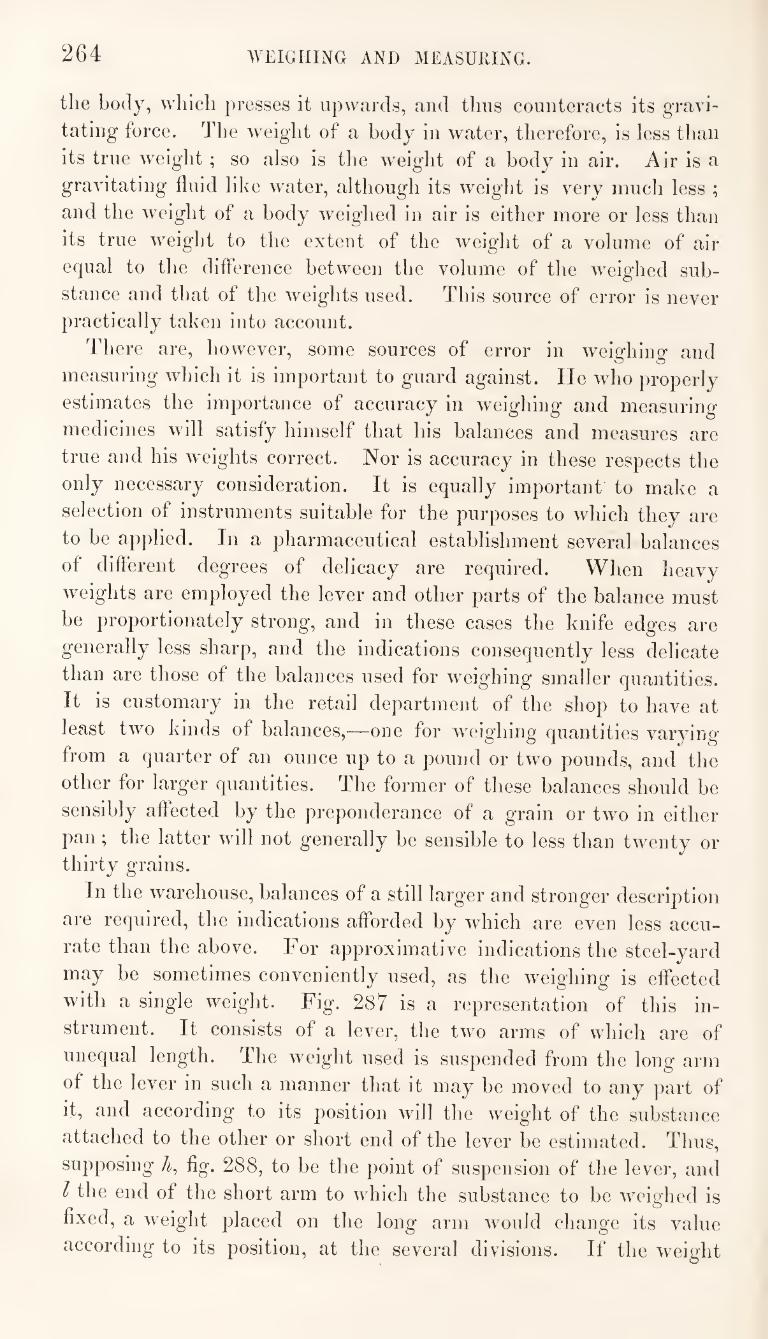
264 WEIGHING AND MEASURING.
the body, which presses it upwards, and thus counteracts its gravi¬
tating force. The weight of a body in water, therefore, is less than
its true weight ; so also is the weight of a body in air. Air is a
gravitating fluid like water, although its weight is very much less ;
and the weight of a body weighed in air is either more or less than
its true weight to the extent of the weight of a volume of air
equal to the difference between the volume of the weighed sub¬
stance and that of the weights used. This source of error is never
})ractically taken into account.
There are, however, some sources of error in weighing and
measuring which it is important to guard against. He who properly
estimates the importance of accuracy in weighing and measuring
medicines will satisfy himself that his balances and measures are
true and his weights correct. Nor is accuracy in these respects the
only necessary consideration. It is equally important to make a
selection of instruments suitable for the purposes to which they are
to be applied. In a pharmaceutical establishment several balances
of different degrees of delicacy are required. When heavy
weights are employed the lever and other parts of the balance must
be proportionately strong, and in these cases the knife edges are
generally less sharp, and the indications consequently less delicate
than are those of the balances used for weighing smaller quantities.
It is customary in the retail department of the shop to have at
least two kinds of balances,—one for weighing quantities varying
from a quarter of an ounce up to a pound or two pounds, and the
other for larger quantities. The former of these balances should be
sensibly affected by the preponderance of a grain or two in either
pan ; the latter will not generally be sensible to less than twenty or
thirty grains.
In the warehouse, balances of a still larger and stronger description
are required, the indications afforded by which are even less accu¬
rate than the above. For approximative indications the steel-yard
may be sometimes conveniently used, as the weighing is effected
with a single weight. Fig. 287 is a representation of this in¬
strument. It consists of a lever, the two arms of which are of
unequal length. The weight used is suspended from the long arm
of the lever in such a manner that it may be moved to any part of
it, and according to its position will the weight of the substance
attached to the other or short end of the lever be estimated. Thus,
supposing fig. 288, to be the point of suspension of the lever, and
I the end of the short arm to which the substance to be weighed is
fixed, a weight placed on the long arm would change its value
according to its position, at the several divisions. If the weight
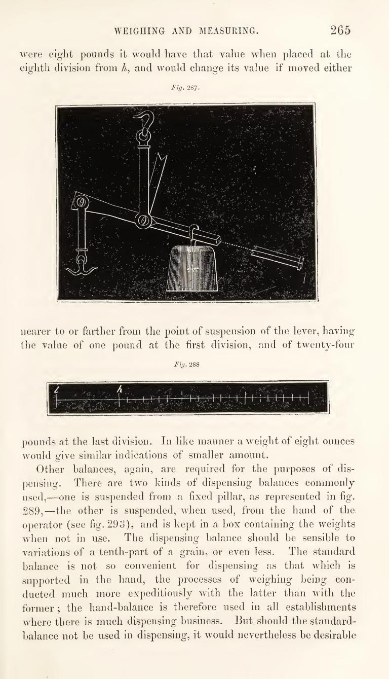
WEIGHING AND MEASURING. 265
were eight pounds it would have that value when placed at the
eighth division from A, and would change its value if moved either
Fig. 287,
nearer to or farther from the point of suspension of the lever, having
the value of one pound at the first division, and of twenty-four
Fig, 288
pounds at the last division. In like manner a weight of eight ounces
would give similar indications of smaller amount.
Other balances, again, are required for the purposes of dis¬
pensing. There are two kinds of dispensing balances commonly
used,—one is suspended from a fixed pillar, as represented in fig.
289,—the other is suspended, when used, from the hand of the
operator (see fig. 29o), and is kept in a box containing the weights
when not in use. The dispensing balance should be sensible to
variations of a tenth-part of a grain, or even less. The standard
balance is not so convenient for dispensing as that which is
supported in the hand, the processes of weighing being con¬
ducted much more expeditiously with the latter than with the
former ; the hand-balance is therefore used in all establishments
where there is much dispensing business. But should the standard-
balance not be used in dispensing, it would nevertheless be desirable
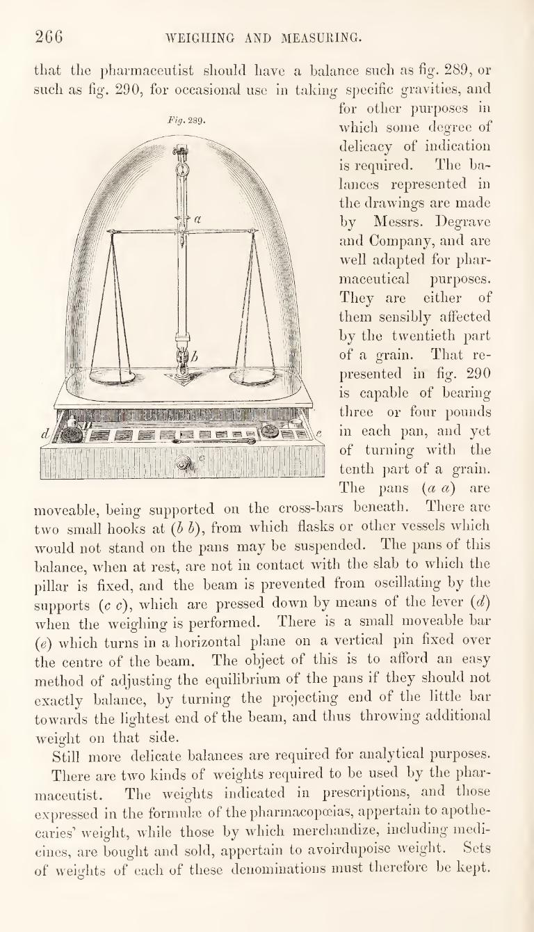
2G6 AVEIGIIING AND MEASURING.
Fig. 289.
that the pharmaceutist should have a balance such as fig. 289, or
such as fig. 290, for occasional use in taking specific gravities, and
for other purposes in
which some degree of
delicacy of indication
is required. The ba¬
lances represented in
the drawings are made
by Messrs. Degrave
and Company, and are
well adapted for phar¬
maceutical purposes.
They are either of
them sensibly affected
by the twentieth part
of a grain. That re¬
presented in fig. 290
is capable of bearing
three or four pounds
in each pan, and yet
of turning with the
tenth part of a grain.
The pans {a a) are
moveable, being supported on the cross-bars beneath. There are
two small hooks at {h h), from which flasks or other vessels which
would not stand on the pans may be suspended. The pans of this
balance, when at rest, are not in contact with the slab to which the
pillar is fixed, and the beam is prevented from oscillating by the
supports (c c), which are pressed down by means of the lever {d)
when the weighing is performed. There is a small moveable bar
which turns in a horizontal plane on a vertical pin fixed over
the centre of the beam. The object of this is to afford an easy
method of adjusting the equilibrium of the pans if they should not
exactly balance, by turning the projecting end of the little bar
towards the lightest end of the beam, and thus throwing additional
weight on that side. Still more delicate balances are required for analytical purposes.
There are two kinds of weights required to be used by the phar¬
maceutist. The weig'hts indicated in prescriptions, and those
expressed in the formulcG of the pharmacopoeias, appertain to apothe¬
caries’ weight, wdiile those by which merchandize, including medi¬
cines, are bought and sold, appertain to avoirdiipoise weight. Sets
of weiuflits of each of these denominations must therefore be kept.
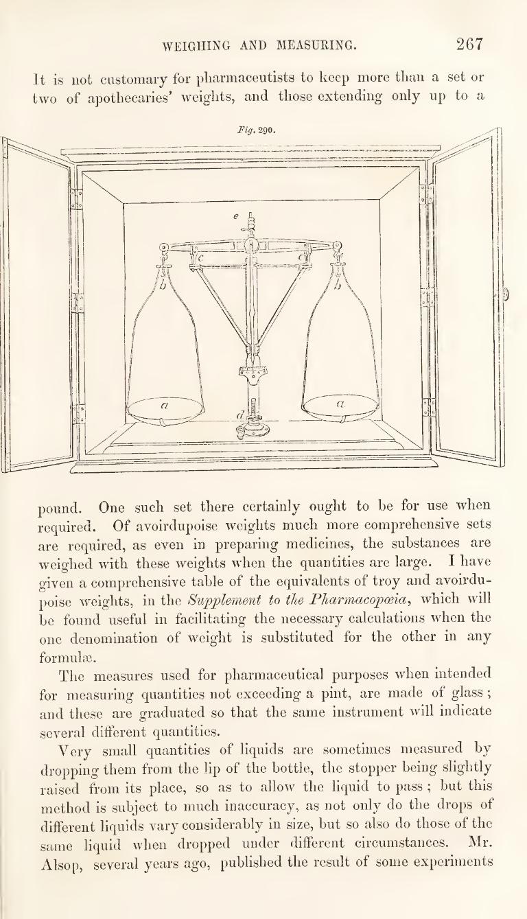
WEIGHING AND MEASURING. 267
It is not customary for pharmaceutists to keep more than a set or
two of apothecaries’ weights, and those extending only up to a
pound. One such set there certainly ought to be for use when
required. Of avoirdupoise weights much more comprehensive sets
are required, as even in preparing medicines, the substances are
weighed with these weights when the quantities are large. I have
given a comprehensive table of the equivalents of troy and avoirdu¬
poise weights, in the Supplement to the Pharmacopoeia^ which will
be found useful in facilitating the necessary calculations when the
one denomination of weight is substituted for the other in any
formulae. The measures used for pharmaceutical purposes when intended
for measuring quantities not exceeding a pint, are made of glass ;
and these are graduated so that the same instrument will indicate
several different quantities. Very small quantities of liquids are sometimes measured by
dropping them from the lip of the bottle, the stopper being slightly
raised from its place, so as to allow the liquid to pass ; but this
method is subject to much inaccuracy, as not only do the drops of
different liquids vary considerably in size, but so also do those of the
same liquid when dropped under different circumstances. Mr.
Alsop, several years ago, published the result of some experiments
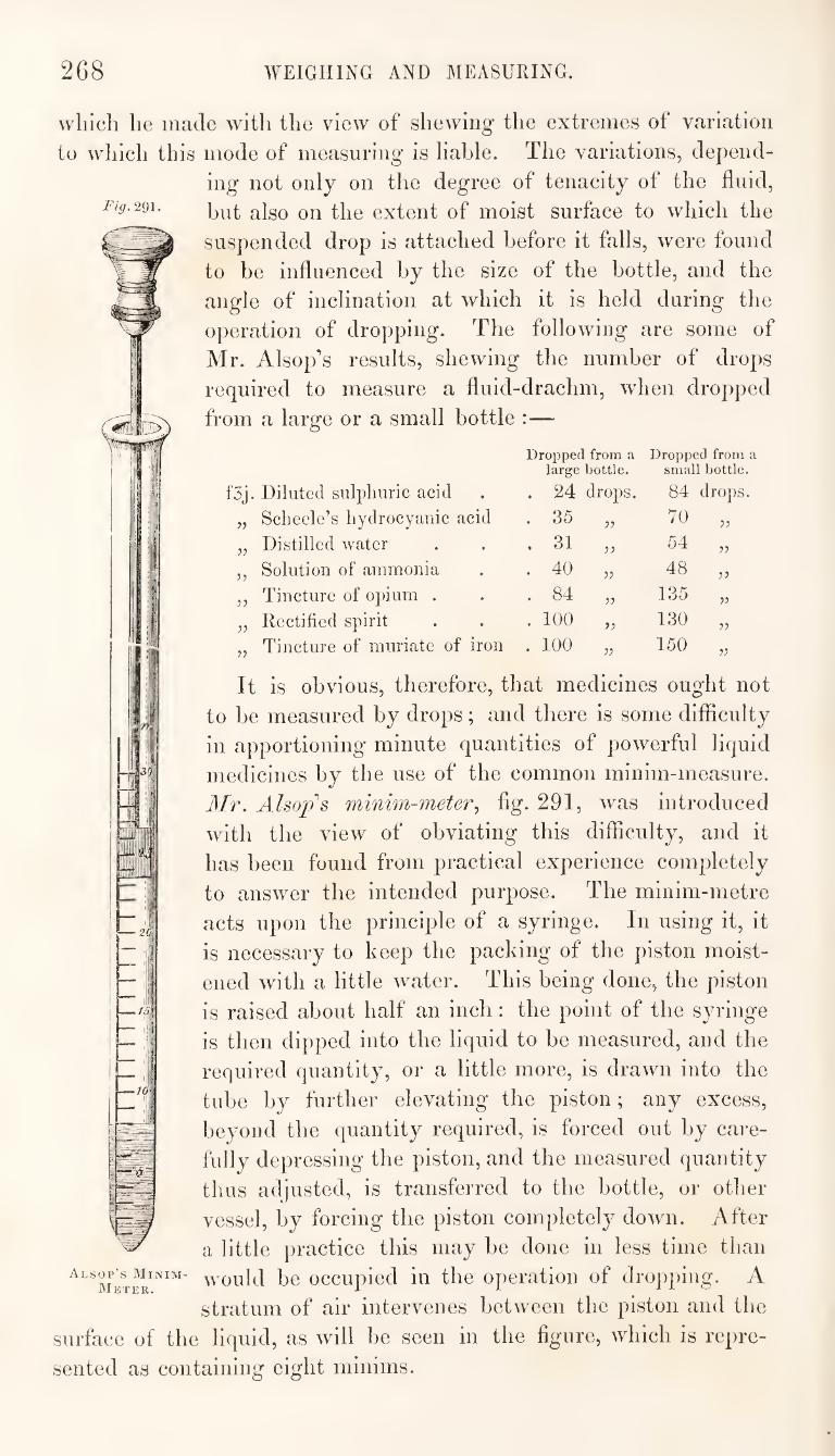
268 WEIGHING AND MEASURING.
\yliicli lie made with the view of shewing the extremes of variation
to which this mode of measuring is liable. The variations, depend¬
ing not only on the degree of tenacity of the fluid,
Fig.2^\. extent of moist surface to which the
suspended drop is attached before it falls, were found
to be influenced by the size of the bottle, and the
angle of inclination at which it is held during the
operation of dropping. The following are some of
Mr. Alsop’s results, shewing the number of drops
required to measure a fluid-drachm, when dropped
from a large or a small bottle :—
f3j. Diluted sulpliiiric acid
Dropped from a large bottle.
. 24 drops.
Dropped from a small bottle.
84 drops.
Sclieele’s liyclrocyauic acid . 35 55 70 55
55 Distilled water . 31 55
54 55
55 Solution of ammonia . 40 55 48 55
55 Tincture of opium . . 84 55
135 55
55 Rectified spirit . 100 55 130
55
55 Tincture of muriate of iron . 100 55 150 55
It is obvious, therefore, that medicines ought not
to be measured by drops; and there is some difficulty
in apportioning minute quantities of powerful liquid
medicines by the use of the common minim-measure.
Mr. Alsop's minim-meter., flg. 291, was introduced
with the view of obviating this difficulty, and it
has been found from practical experience completely
to answer the intended purpose. The minim-metre
acts upon the principle of a syringe. In using it, it
is necessary to keep the packing of the piston moist¬
ened with a little water. This being done, the piston
is raised about half an inch : the point of the syringe
is then dipped into the liquid to be measured, and the
required quantity, or a little more, is drawn into the
tube by further elevating the piston; any excess,
beyond the quantity required, is forced out by care¬
fully depressing the piston, and the measured quantity
thus adjusted, is transferred to the bottle, or other
vessel, by forcing the piston completely down. After
a little practice this may be done in less time than
would be occupied in the operation of dropping. A
stratum of air intervenes between the piston and the
surface of the liquid, as will be seen in the figure, which is repre¬
sented as containing eight minims.
Alsop’s Minim- Meter.
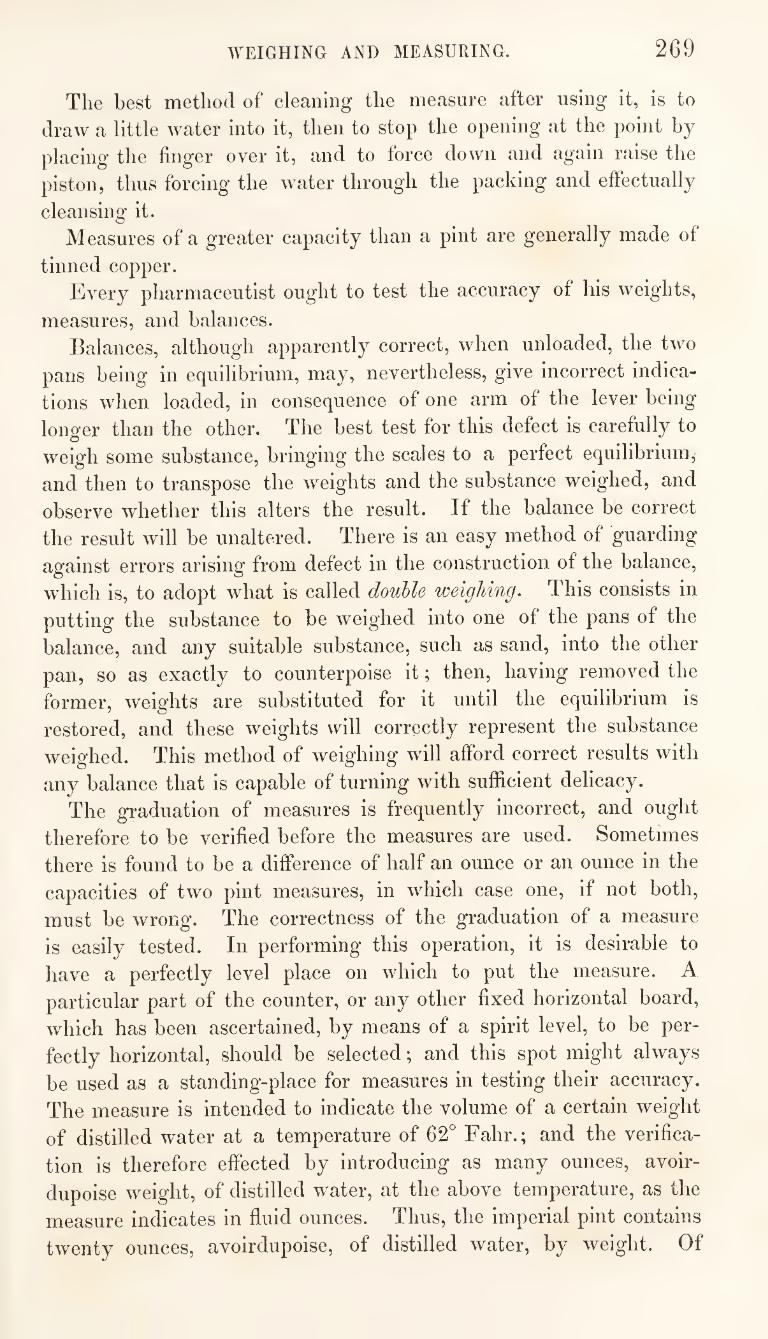
WEIGHING AND MEASURING. 269
The best method of cleaning the measure after using it, is to
draw a little water into it, then to stop the opening at the point by
placing the finger over it, and to force down and again raise the
piston, thus forcing the water through the packing and effectually
cleansing it. Measures of a greater capacity than a pint are generally made of
tinned copper. Every pharmaceutist ought to test the accuracy of his weights,
measures, and balances. Balances, although apparently correct, when unloaded, the two
pans being in equilibrium, may, nevertheless, give incorrect indica¬
tions when loaded, in consequence of one arm of the lever being
longer than the other. The best test for this defect is carefully to
weigh some substance, bringing the scales to a perfect equilibrium,
and then to transpose the weights and the substance weighed, and
observe whether this alters the result. If the balance be correct
the result will be unaltered. There is an easy method of guarding
against errors arising from defect in the construction of the balance,
which is, to adopt what is called double weighing. This consists in
putting the substance to be weighed into one of the pans of the
balance, and any suitable substance, such as sand, into the other
pan, so as exactly to counterpoise it; then, having removed the
former, weights are substituted for it until the equilibrium is
restored, and these weights will correctly represent the substance
weighed. This method of weighing wdll afford correct results with
any balance that is capable of turning with sufficient delicacy.
The graduation of measures is frequently incorrect, and ought
therefore to be verified before the measures are used. Sometimes
there is found to be a difference of half an ounce or an ounce in the
capacities of two pint measures, in which case one, if not both,
must be wrong. The correctness of the graduation of a measure
is easily tested. In performing this operation, it is desirable to
have a perfectly level place on which to put the measure. A
particular part of the counter, or any other fixed horizontal board,
which has been ascertained, by means of a spirit level, to be per¬
fectly horizontal, should be selected; and this spot might always
be used as a standing-place for measures in testing their accuracy.
The measure is intended to indicate the volume of a certain weight
of distilled water at a temperature of 62° Fahr.; and the verifica¬
tion is therefore effected by introducing as many ounces, avoir-
dupoise weight, of distilled w^ater, at the above temperature, as the
measure Indicates in fluid ounces. Thus, the imperial pint contains
twenty ounces, avoirdupoise, of distilled water, by weight. Of
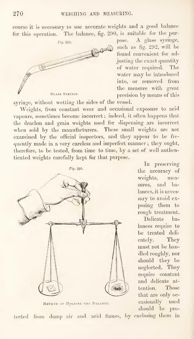
270 WEIGHING AND MEASURING.
course it is necessary to use accurate weights and a good balance
for this operation. The balance, fig. 290, is suitable for the pur¬ pose. A glass syringe,
such as fig. 292, will be
found convenient for ad¬
justing the exact quantity
of water required. The
water may be introduced
into, or removed from
the measure with great
precision by means of this
syringe, without wetting the sides of the vessel.
Weights, from constant wear and occasional exposure to acid
vapours, sometimes become incorrect; indeed, it often happens that
the drachm and grain weights used for dispensing are incorrect
when sold by the manufacturers. These small weights are not
examined by the official inspectors, and they appear to be fre¬
quently made in a very careless and imperfect manner; they ought,
therefore, to be tested, from time to time, by a set of well authen¬
ticated weights carefully kept for that purpose.
Fig. 292.
Fig. 293.
I\Ietiiod of Holding the Balance.
tected from damp air and acid fumes, by
In preserving
the accuracy of
weights, mea¬
sures, and ba¬
lances, it is neces¬
sary to avoid ex¬
posing them to
rough treatment.
Delicate ba¬
lances require to
be treated deli¬
cately. They
must not be han¬
dled roughly, nor
should they be
neglected. They
require constant
and delicate at¬
tention. Those
that are only oc¬
casionally used
should be pro¬
enclosing them in
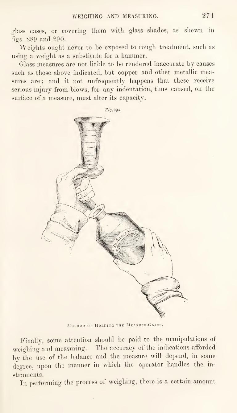
WEIGHING AND MEASURING. 271
Finally, some attention should be paid to the manipulations of
weighing and measuring. The accuracy of the indications afforded
by the use of the balance and the measure will depend, in some
degree, upon the manner in which the operator handles the in¬
struments. In performing the process of weighing, there is a certain amount
glass cases, or covering them with glass shades, as shewn in
figs. 289 and 290.
Weights ought never to be exposed to rough treatment, such as
using a weight as a substitute for a hammer.
Glass measures are not liable to be rendered inaccurate by causes
such as those above indicated, but copper and other metallic mea¬
sures are; and it not unfrequently happens that these receive
serious injury from blows, for any indentation, thus caused, on the
surface of a measure, must alter its capacity.
Fig. 294.
Method of Holding the Measure-Glass.
272 DETERMINATION OF
of manual dexterity required, which practice alone can impart.
The proper suspension of the dispensing scales from the hand ; the
preservation of the equilibrium of the beam by resting the pans on
a solid surface while the substance to he weighed is being intro¬
duced ; and the steady, not too lofty, nor too hasty, elevation of
the hand, in trying the equilibrium of the loaded pans, contribute
not only to the accuracy ot the result of the process, but also to the
ease and elegance with which it is eftected. See fig. 293.
Again, in measuring, it is necessary to acquire a proper and
easy method of holding the measure-glass. It should be held in
such a manner that the stopper of the bottle from which any liquid
is about to he poured into it, may be removed by the same hand;
and that, subsequently, the measure can be raised, so that the
surface of the liquid shall be level with the eye of the operator,
while the measure itself is kept perfectly upright. See fig. 294.
The practised operator, if he be really alive to the importance of
strict accuracy in the results of his operations, will acquire dexterity
and elegance in the methods of conducting these processes, which
result from the best adaptation of every movement for the attain¬
ment of the object contemplated.]
DETERMINATION OF SPECIFIC GRAVITIES.
[The pharmaceutist has frequent occasion to refer to specific
gravity, as a distinctive character of bodies, and it is impoitant
that he should be able to perform with facility the operations by
which this character is determined.
All bodies are assumed to admit of compression and expansion;
their solid and impenetrable particles, therefore, are not in absolute
contact, the distances varying under different ciicumstances.
JMdss.^ expresses the number of material particles contained in a
body; and density represents the relation of the mass, that is, of
the number of particles, or quantity of matter, to the volume, or
space which the body occupies. Hence, density means comparative
mass. The measure of the gravitating force of a body, expressed with
relation to some known standard, which serves as a unit, is the
absolute weight of the body. The amount of this weight will be in
direct proportion to the mass ^ it has no fixed relation to the
volume. Specific gravity, on the other hand, expresses the relation
of the weight to the volume of the body. A little observation
would soon shew that every body occupying a given space, has
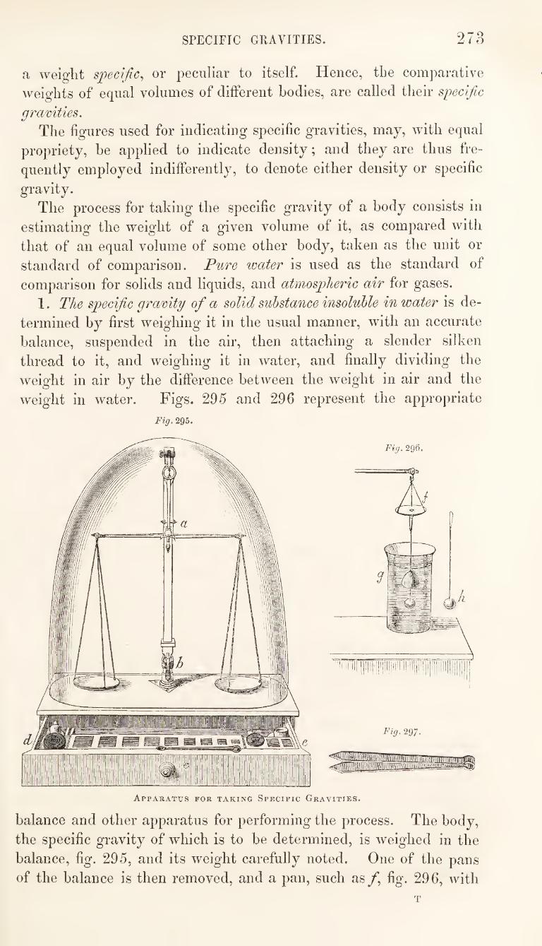
SPECIFIC GRAVITIES. 273
a weight specific^ or peculiar to itself. Hence, the comparative
weights of equal volumes of different bodies, are called their specific
gravities. The figures used for indicating specific gravities, may, with equal
propriety, be applied to indicate density; and they are thus fre¬
quently employed indifferently, to denote either density or specific
gravity.
The process for taking the specific gravity of a body consists in
estimating the weight of a given volume of it, as compared with
that of an equal volume of some other body, taken as the unit or
standard of comparison. Pure water is used as the standard of
comparison for solids and liquids, and atmospheric air for gases.
1. The specific gravity of a solid substance insolulile in water is de¬
termined by first weighing it in the usual manner, with an accurate
balance, suspended in the air, then attaching a slender silken
thread to it, and weighing it in water, and finally dividing the
weight in air by the difference between the weight in air and the
weight in water. Figs. 295 and 296 represent the appropriate
Fig. 295.
Appaeatus for taking Specific Gravities.
balance and other apparatus for performing the process. The body,
the specific gravity of which is to be determined, is w'eighed in the
balance, fig. 295, and its weight carefully noted. One of the pans
of the balance is then removed, and a pan, such as/, fig. 296, with
274 DETERMINATION OF
short strings and a small hook at the bottom of the pan, is substituted
for it, and the equilibrium adjusted. The substance under opera¬
tion is attached to a fine silken thread, a horse-hair, or very thin
platinum wire, as shewn at A, fig. 29 G ; this is then fixed to the
hook at the bottom of the small pan (/’), and a glass vessel, such
as nearly filled with distilled water, being placed under it, the
suspended body (A) is immersed in the water, and its weight taken
under these circumstances. The object in thus weighing the body
in water is, to ascertain the weight of a volume of water equal to
that of the body immersed. The process is founded upon the well-
known facts, that a solid body, such as a piece of glass or metal,
that is impervious to water, on being immersed in that liquid, dis¬
places a volume of water equal to that of the body so immersed;
and that the surrounding liquid exercises a pressure upwards, upon
such body, equivalent to the weight of the volume of water dis¬
placed. Thus the weight of a body weighed as above in water,
is equal to the absolute weight of the body, minus the weight of an
equal volume of water; and, therefore, on deducting the weight of
the body in water from its weight in air, the quotient will he the
weight of a volume of water equal to that of the body so weighed.
We thus obtain, first, the absolute weight of the body, and,
secondly, the weight of an equal volume of water. The specific
gravity is obtained by dividing the former by the latter.
Thus, a leaden bullet is found to weigh 398 grains in air: when
immersed in water, its weight is 362*4 grains, and the difference
between these two weights, namely, 35*6 grains, is the weight of
the volume of water displaced by the bullet, or of a volume of water
equal to that of the bullet. The volume of water being taken as
unity, the specific gravity of the bullet is found by the following
equation:— 35*6 : 1 : : 398 : 11*176, the specific gravity of the bullet.
2. In taking the specific gravity of a solid substance lighter than
neater^ some modification of the process is required, but we have,
nevertheless, the same preliminary points to determine : first, the
weight of the substance in air: and, secondly, the weight of an
equal volume of water. This may be illustrated by describing the
method of taking the specific gravity of a piece of wax. The
weight of the wax in air is 105*4 grains. On immersing the wax
in water, two pressures are exerted—a pressure downwards, equal
to the gravity or weight of the wax, and a pressure upwards, equal
to the weight of the volume of water displaced by the wax ; but
the specific gravity of water being greater than that of wax, the
upward pressure preponderates, and the wax rises to the surface.
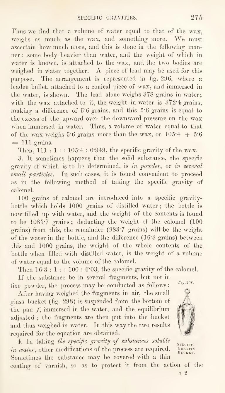
SPECIFIC GRAVITIES. 275
Thus we find that a volume of water equal to that of the wax,
weighs as much as the wax, and something more. We must
ascertain how much more, and this is done in the following man¬
ner : some body heavier than water, and the weight of which in
water is known, is attached to the wax, and the two bodies are
weighed in water together. A piece of lead may be used for this
purpose. The arrangement is represented in fig. 296, where a
leaden bullet, attached to a conical piece of wax, and immersed in
the water, is shewn. The lead alone weighs 878 grains in water;
with the wax attached to it, the weight in water is 872*4 grains,
making a difference of 5*6 grains, and this 5*6 grains is equal to
the excess of the upward over the downward pressure on the wax
when immersed in water. Thus, a volume of water equal to that
of the wax weighs 5*6 grains more than the w'ax, or 105*4 + 5*6
= 111 grains. Then, 111:1:: 105*4 : 0*949, the specific gravity of the wax.
8. It sometimes happens that the solid substance, the specific
gravity of which is to be determined, is in powder^ or in several
small particles. In such cases, it is found convenient to proceed
as in the following method of taking the specific gravity of
calomel.
100 grains of calomel are introduced into a specific gravity-
bottle which holds 1000 grains of distilled water ; the bottle is
now filled up with water, and the weight of the contents is found
to be 1088*7 grains; deducting the weight of the calomel (100
grains) from this, the remainder (988*7 grains) will be the weight
of the water in the bottle, and the difference (16*8 grains) between
this and 1000 grains, the weight of the whole contents of the
bottle when filled with distilled water, is the weight of a volume
of water equal to the volume of the calomel.
Then 16*8 : 1 : : 100 : 6*08, the specific gravity of the calomel.
If the substance be in several fragments, but not in
fine powder, the process may be conducted as follows:
After having weighed the fragments in air, the small
glass bucket (fig. 298) is suspended from the bottom of
the pan /*, immersed in the water, and the equilibrium
adjusted ; the fragments are then put into the bucket
and thus weighed in water. In this way the two results
required for the equation are obtained.
4. In taking the specific gravity of substances soluble
in water., other modifications of the process are required.
Sometimes the substance may be covered with a thin
coating of varnish, so as to protect it from the action of the
Fig. 298.
Specific
Gravity
Bucket.
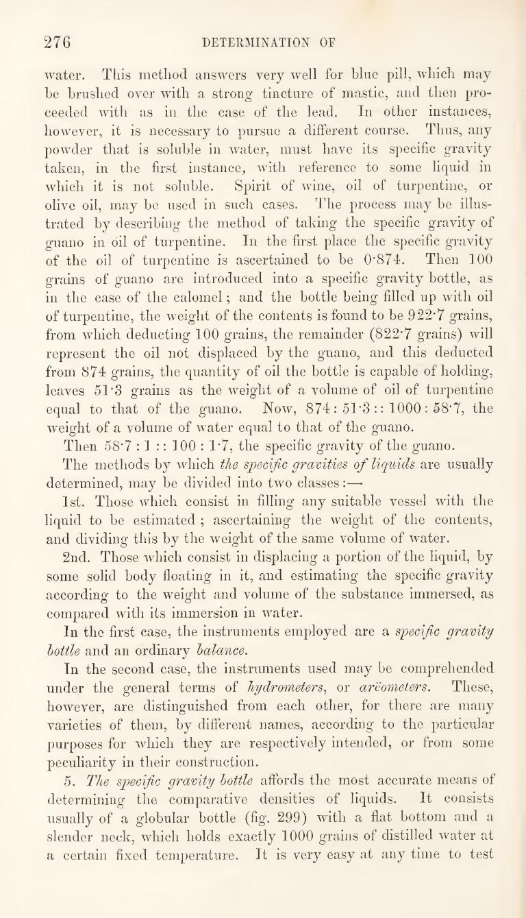
276 DETERMINATION OF
water. This method answers very well for blue pill, which may
be brushed over with a strong tincture of mastic, and then pro¬
ceeded with as in the case of the lead. In other instances,
however, it is necessary to pursue a different course. Thus, any
powder that is soluble in water, must have its specific gravity
taken, in the first instance, with reference to some liquid in
which it is not soluble. Spirit of wine, oil of turpentine, or
olive oil, may be used in such cases. The process may be illus¬
trated by describing the method of taking the specific gravity of
guano in oil of turpentine. In the first place the specific gravity
of the oil of turpentine is ascertained to be 0*874. Then 100
grains of guano are introduced into a specific gravity bottle, as
in the case of the calomel; and the bottle being filled up with oil
of turpentine, the weight of the contents is found to be 922*7 grains,
from which deducting 100 grains, the remainder (822*7 grains) will
represent the oil not displaced by the guano, and this deducted
from 874 grains, the quantity of oil the bottle is capable of holding,
leaves 51*3 grains as the weight of a volume of oil of turpentine
equal to that of the guano. Now, 874: 51*3 :: 1000 : fi8*7, the
weight of a volume of water equal to that of the guano.
Then 58*7 : 1 :: 100 : 1*7, the specific gravity of the guano.
The methods by which the specific gravities of liquids are usually
determined, may be divided into two classes:—•
1st. Those which consist in filling any suitable vessel with the
liquid to be estimated ; ascertaining the weight of the contents,
and dividing this by the weight of the same volume of water.
2nd. Those which consist in displacing a portion of the liquid, by
some solid body floating in it, and estimating the specific gravity
according to the weight and volume of the substance immersed, as
compared with its immersion in water.
In the first case, the instruments employed are a specific gravity
bottle and an ordinary balance.
In the second case, the instruments used may be comprehended
under the general terms of hydrometers^ or areometers. These,
however, are distinguished from each other, for there are many
varieties of them, by different names, according to the particular
purposes for which they are respectively intended, or from some
peculiarity in their construction.
5. The specific gravity bottle affords the most accurate means of
determining the comparative densities of liquids. It consists
usually of a globular bottle (fig. 299) with a flat bottom and a
slender neck, which holds exactly 1000 grains of distilled water at
a certain fixed temperature. It is very easy at any time to test
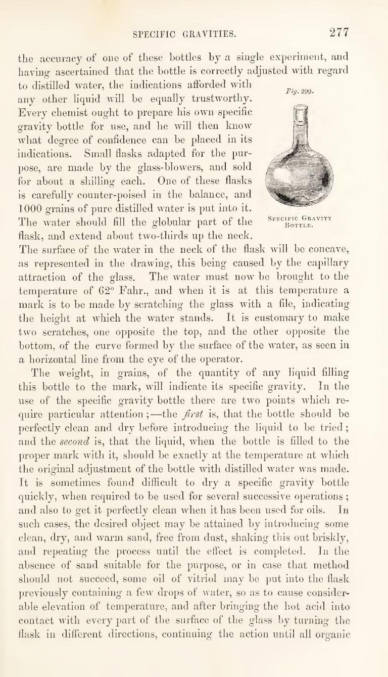
SPECIFIC GRAVITIES. 277
the accuracy of one of these bottles by a single experiment, and
having ascertained that the bottle is correctly adjusted with regard
to distilled water, the indications afforded with
any other liquid will be equally trustworthy.
Every chemist ought to prepare his own specific
gravity bottle for use, and he will then know
what degree of confidence can be placed in its
indications. Small flasks adapted for the pur¬
pose, are made by the glass-blowers, and sold
for about a shilling each. One of these flasks
is carefully counter-poised in the balance, and
1000 grains of pure distilled water is put into it.
The water should fill the globular part of the
flask, and extend about two-thirds up the neck.
The surface of the water in the neck of the flask will be concave,
as represented in the drawing, this being caused by the capillary
attraction of the glass. The water must now be brought to the
temperature of 62° Fahr., and when it is at this temperature a
mark is to be made by scratching the glass with a file, indicating
the height at which the water stands. It is customary to make
two scratches, one opposite the top, and the other opposite the
bottom, of the curve formed by the surface of the water, as seen in
a horizontal line from the eye of the operator.
The weight, in grains, of the quantity of any liquid filling
this bottle to the mark, will indicate its specific gravity. In the
use of the specific gravity bottle there are two points which re¬
quire particular attention;—the Jlrst is, that the bottle should be
perfectly clean and dry before introducing the liquid to he tried ;
and the second is, that the liquid, when the bottle is filled to the
proper mark with it, should be exactly at the temperature at which
the original adjustment of the bottle with distilled water was made.
It is sometimes found difficult to dry a specific gravity bottle
quickly, when required to be used for several successive operations;
and also to get it perfectly clean when it has been used for oils. In
such cases, the desired object may he attained by introducing some
clean, dry, and warm sand, free from dust, shaking this out briskly,
and repeating the process until the effect is completed. In the
absence of sand suitable for the purpose, or in case that method
should not succeed, some oil of vitriol may be put into the flask
previously containing a few drops of water, so as to cause consider¬
able elevation of temperature, and after bringing the hot acid into
contact with every part of the surface of the glass by turning the
flask in different directions, continuing the action until all organic
278 DETERMINATION OF
matter has been removed, the acid is poured out, and the flask well
washed with water. After being washed, it should be drained for
a few minutes, and then placed on the sand-bath until it has become
hot. A small glass tube, of four or five inches in length, which
passes freely through the neck of the flask, is now introduced, and
the mouth being applied to the end of the tube, air is drawn into
the lungs so as to establish a current and constant change of air in
the bottle. In this way it may be cleaned and dried in a few
minutes.
With regard to the temperature at which the specific gravity
bottle is to be used, it must be borne in mind that the London
Pharmacopoeia directs specific gravities to be always taken at 62®
Fahr., and therefore every English pharmaceutist ought to have
his specific gravity bottles adjusted at this temperature, at which,
also, he should of course use them. The manufacturers of these
instruments, unless they receive express instructions to the con¬
trary, usually adjust them at 60® Fahr.
Hydrometers^ or areometers^ are floating instruments, and their
application for the purpose of determining the specific gravities of
liquids, depends upon the fact that a body immersed in any liquid
sustains a pressure from below upwards, equal to the weight of the
volume of liquid displaced by such body.
The use of hydrometers for determining the specific gravities of
liquids, has been traced back to a period about 300 years before
Christ; an instrument of this kind being described as the inven¬
tion of Archimedes, the Sicilian mathematician. It subsequently fell
into disuse, but was again brought into notice by Basil Valentine.
There are two kinds of hydrometers, which may be taken as
types for all the different varieties in regard to construction :—
1st. Those which are always immersed into the liquids to be
tried, to the same depth, and to which weights are added to adjust
the instrument to the density of any particular liquid. Of this
description are Fahrenheit’s, Nicholson’s, and Guyton de Morveau’s
hydrometers. These instruments indicate the weight of a given
volume of any liquid.
2nd. Those which are always used with the same weight, but
which sink into the liquids to be tried, to different depths, accord¬
ing to the densities of the liquids. These usually have graduated
scales attached to their stems. Of this description are the common
glass hydrometers generally, including those of Baume, Cartier,
Gay Lussac, Twaddle, Zanetti, &c., and the specific gravity beads.
These instruments indicate the volume of a given weight of any
liquid.
SPECIFIC GRAVITIES. 279
Sikes’s and Dicas’s hydrometers combine some of the prin¬
ciples of both types, having moveable weights and graduated
scales. Hydrometers may also be divided into two classes, as follows:
1st. Those having a general application for determining the
comparative densities of any liquids. 2nd. Those intended for special application, as for estimating
the comparative strengths of spirits, or the comparative densities
of syrups, oils, &c. Fahrenheit’s, Nicholson’s, Gruyton de Morveau s, and the com¬
mon glass hydrometers, including Baum6’s, Cartier s. Twaddle s,
Zanetti’s, and the specific gravity beads, belong to the first class.
Gay Lussac’s, Sikes’s, and Dicas’s hydrometers, the saccharo-
meter, urinometer, elaeometer, and galactometer, belong to the
second class. 6. Fahrenheit^s hydrometer consists of two glass bulbs blown
on a tube, like a common hydrometer, excepting that the upper
bulb is larger, and the stem is terminated at the top in the form of
a cup or funnel. The lower bulb is loaded with mercury, but not
so as to cause the entire immersion of the instrument, when put
into water, without the addition of weights to the cup at the top
of the stem. There is a mark about the middle of the stem, which
is the point at which the hydrometer is made to float, by putting the
requisite weights into the cup. 7. Nicholson''s hydrometer is a modification of Fahrenheit’s. It
is made of brass, and consists of a hollow globe, to which a very
slender stem, surmounted by a cup, is attached; on the opposite
side of the globe there is another cup, fixed in a kind of stirrup
and loaded, so that this shall always be the lowest point of the
instrument when immersed in any liquid. The form of this instru¬
ment therefore differs from that of Fahrenheit’s in the lower bulb
of the latter being replaced by the loaded cup. There is a mark
on the stem indicating the point at which the hydrometer is to be
made to float by the proper adjustment of the weights. The
weight of the loaded instrument, when sunk to the proper point, is
the weight of the volume of liquid displaced by it. It gives, there¬
fore, the relative weights of equal volumes of the liquids into which
it is introduced. This instrument is also sometimes called the Gra-
rimeter; it is usually made to displace ^000 or 4000 grains of water,
and is sensible to the tenth of a grain in this quantity.
This instrument is applicable, also, for taking the specific gravi¬
ties of solid substances. By placing the solid body in the cup at
the top of the stem, and then adjusting the additional weights
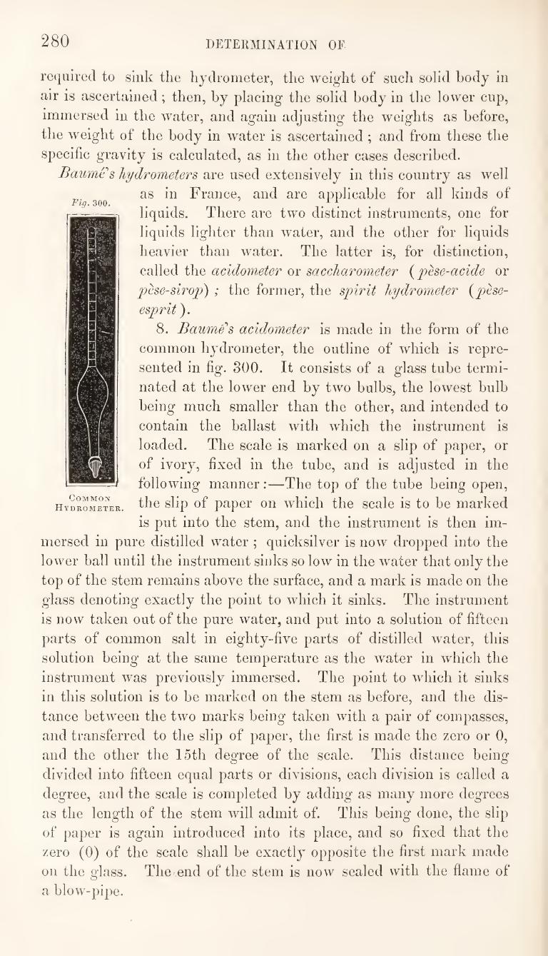
280 dp:termination of
Fig. 300.
required to sink the hydrometer, the weight of such solid body in
air is ascertained; then, by placing the solid body in the lower cup,
immersed in the water, and again adjusting the weights as before,
the weight of the body in water is ascertained ; and from these the
specific gravity is calculated, as in the other cases described.
Baumes hydrometers are used extensively in this country as well
as in France, and are applicable for all kinds of
liquids. There are two distinct instruments, one for
liquids lighter than water, and the other for liquids
heavier than water. The latter is, for distinction,
called the acidometer or saccharometer {phe-acide or
pese-sirop) ; the former, the spirit hydrometer i^phe-
esprit).
8. Baumes acidometer is made in the form of the
common hydrometer, the outline of which is repre¬
sented in fig. 800. It consists of a glass tube termi¬
nated at the lower end by two bulbs, the lowest bulb
being much smaller than the other, and intended to
contain the ballast with which the instrument is
loaded. The scale is marked on a slip of paper, or
of ivory, fixed in the tube, and is adjusted in the
following manner:—The top of the tube being open,
the slip of paper on which the scale is to be marked
is put into the stem, and the instrument is then im¬
mersed in pure distilled water ; quicksilver is now dropped into the
lower ball until the instrument sinks so low in the water that only the
top of the stem remains above the surface, and a mark is made on the
glass denoting exactly the point to which it sinks. The instrument
is now taken out of the pure water, and put into a solution of fifteen
parts of common salt in eighty-five parts of distilled water, this
solution being at the same temperature as the water in which the
instrument was previously immersed. The point to which it sinks
in this solution is to be marked on the stem as before, and the dis¬
tance between the two marks being taken with a pair of compasses,
and transferred to the slip of paper, the first is made the zero or 0,
and the other the loth degree of the scale. This distance being
divided into fifteen equal parts or divisions, each division is called a
degree, and the scale is completed by adding as many more degrees
as the length of the stem will admit of. This being done, the slip
of paper is again introduced into its place, and so fixed that the
zero (0) of the scale shall be exactly opposite the first mark made
on the glass. The end of the stem is now sealed with the flame of
a blow-pipe.
Common
Hydrometer,
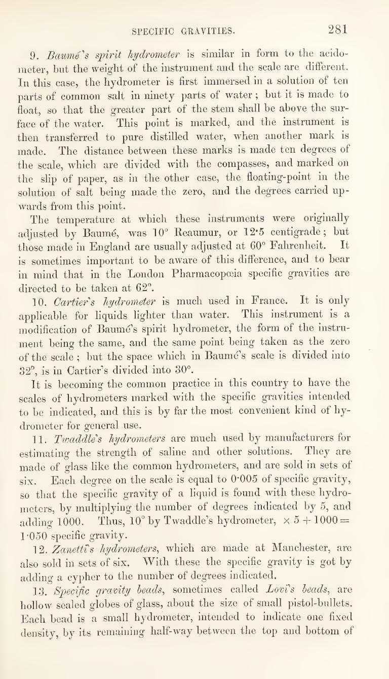
SPECIFIC GRAVITIES. 281
9. Bcmm6''s spirit hydrometer is similar in form to the acido-
meter, but the weight of the instrument and the scale are different.
In this case, the hydrometer is first immersed in a solution of ten
parts of common salt in ninety parts of water; but it is made to
float, so that the greater part of the stem shall be above the sur¬
face of the water. This point is marked, and the instrument is
then transferred to pure distilled water, when another mark is
made. The distance between these marks is made ten degrees of
the scale, which are divided with the compasses, and marked on
the slip of paper, as in the other case, the floating-point in the
solution of salt being made the zero, and the degrees carried up¬
wards from this point. The temperature at which these instruments were originally
adjusted by Baume, was 10° Reaumur, or 12*5 centigrade; but
those made in England are usually adjusted at 60° Fahrenheit. It
is sometimes important to be aware of this difference, and to bear
in mind that in the London Pharmacopoeia specific gravities are
directed to be taken at 62°. 10. Cartiers hydrometer is much used in France. It is only
applicable for liquids lighter than water. This instrument is a
modification of Baume s spirit hydrometer, the form of the instru¬
ment being the same, and the same point being taken as the zero
of the scale ; but the space which in Baume’s scale is divided into
32'’, is in Cartier’s divided into 30°. It is becoming the common practice in this country to have the
scales of hydrometers marked with the specific gravities intended
to be indicated, and this is by far the most convenient kind of hy¬
drometer for general use. 11. Twaddle's hydrometers are much used by manufacturers for
estimating the strength of saline and other solutions. They are
made of glass like the common hydrometers, and are sold in sets of
six. Each degree on the scale is equal to 0*005 of specific gravity,
so that the specific gravity of a liquid is found with these hydro¬
meters, by multiplying the number of degrees indicated by 5, and
adding 1000. Thus, 10° by Twaddle’s hydrometer, x 5 -f 1000 =
1*050 specific gravity. 12. Zanettis hydrometers^ which are made at Manchester, are
also sold in sets of six. With these the specific gravity is got by
adding a cypher to the number of degrees indicated.
13. Specific gravity heads^ sometimes called Lovis heads^ are
hollow sealed globes of glass, about the size of small pistol-bullets.
Each bead is a small hydrometer, intended to indicate one fixed
density, by its remaining half-way between the top and bottom of
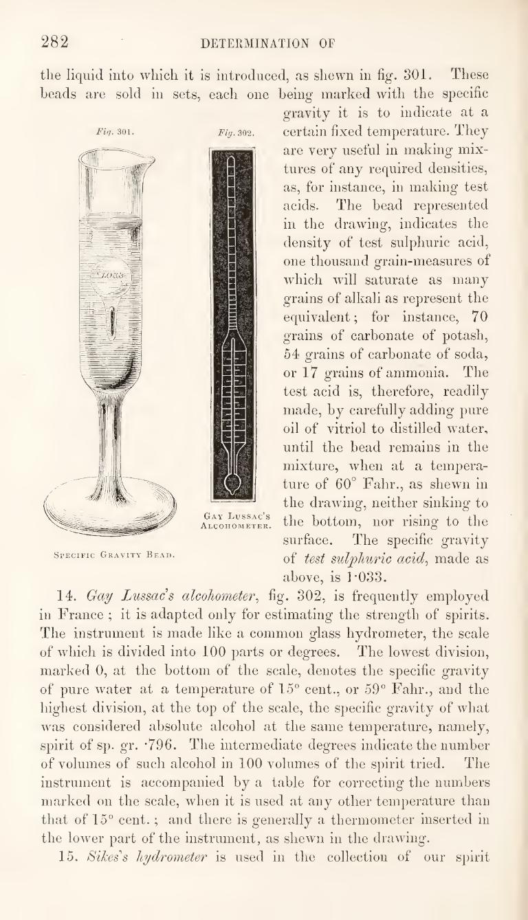
282 DETERMINATION OF
Fiq. 301. Fig. 302.
the liquid into which it is introduced, as shewn in fig. 301. These
heads are sold in sets, each one being marked with the specific
gravity it is to indicate at a
certain fixed temperature. They
are very useful in making mix¬
tures of any required densities,
as, for instance, in making test
acids. The bead represented
in the drawing, indicates the
density of test sulphuric acid,
one thousand grain-measures of
which will saturate as many
grains of alkali as represent the
equivalent; for instance, 7 0
grains of carbonate of potash,
54 grains of carbonate of soda,
or 17 grains of ammonia. The
test acid is, therefore, readily
made, by carefully adding pure
oil of vitriol to distilled water,
until the bead remains in the
mixture, when at a tempera¬
ture of 60° Fahr., as shewn in
the drawing, neither sinking to
the bottom, nor rising to the
surface. The specific gravity
of test sulphuric acid.^ made as
above, is F033.
14. Gay Lussacs alcohometer^ fig. 802, is frequently employed
in France ; it is adapted only for estimating the strength of spirits.
The instrument is made like a common glass hydrometer, the scale
of which is divided into 100 parts or degrees. The lowest division,
marked 0, at the bottom of the scale, denotes the specific gravity
of pure water at a temperature of 15° cent., or 59° Fahr., and the
highest division, at the top of the scale, the specific gravity of what
was considered absolute alcohol at the same temperature, namely,
spirit of sp. gr. *796. The intermediate degrees indicate the number
of volumes of such alcohol in 100 volumes of the spirit tried. The
instrument is accompanied by a table for correcting the numbers
marked on the scale, when it is used at any other temperature than
that of 15° cent. ; and there is generally a thermometer inserted in
the lower part of the instrument, as shewn in the drawing.
15. Sikes’'s hydrometer is used in the collection of our spirit
Gay Lussac’s
Alcohometer.
Specific Gravity Bead.
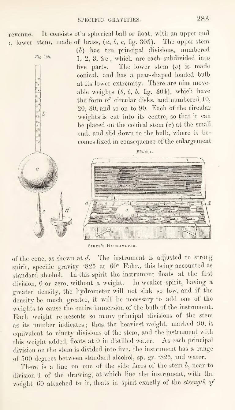
SPECIFIC GRAVITIES. 283
revenue. It consists of a spherical ball or float, with an upper and
a lower stem, made of brass, (a, h, c, fig. 308). The upper stem
(5) has ten principal divisions, numbered
1, 2, 3, &c., which are each subdivided into
five parts. The lower stem (c) is made
conical, and has a pear-shaped loaded bulb
at its lower extremity. There are nine move-
able weights (5, 5, 5, fig. 304), which have
the form of circular disks, and numbered 10,
20, 30, and so on to 90. Each of the circular
weights is cut into its centre, so that it can
be placed on the conical stem (c) at the small
end, and slid down to the bulb, where it be¬
comes fixed in consequence of the enlargement
Fig. 304.
Sikes’s Hydrometer.
of the cone, as shewn at d. The instrument is adjusted to strong
spirit, specific gravity *825 at 60^ Fahr., this being accounted as
standard alcohol. In this spirit the instrument floats at the first
division, 0 or zero, without a weight. In weaker spirit, having a
greater density, the hydrometer will not sink so low, and if the
density be much greater, it will be necessary to add one of the
weio-hts to cause the entire immersion of the bulb of the instrument. O
Each weight represents so many principal divisions of the stem
as its number indicates ; thus the heaviest weight, marked 90, is
equivalent to ninety divi,sions of the stem, and the instrument with
this weight added, floats at 0 in distilled water. As each principal
division on the stem is divided into five, the instrument has a range
of 500 degrees between standard alcohol, sp. gr. *825, and water.
There is a line on one of the side faces of the stem 5, near to
division I of the drawing, at which line the instrument, with the
weight 60 attached to it, floats in spirit exactly of the strength of
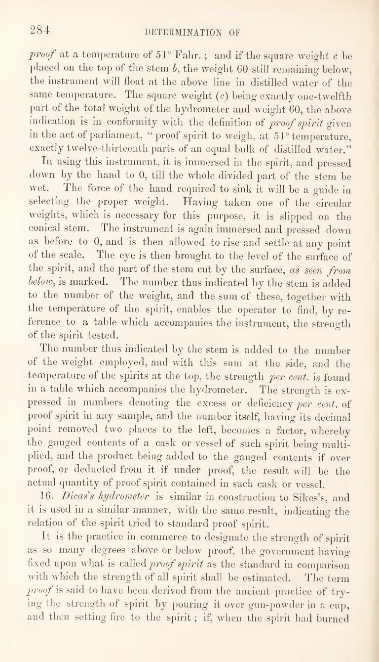
284 DETERMINATION OF
proof at a temperature of 51“ Falir. ; and if the square weight c be
placed on the top of the stem 5, the weight 60 still remaining below,
the instrument will float at the above line in distilled water of the
same temperature. The square weight (c) being exactly one-twelfth
part of the total weight of the hydrometer and weight 60, the above
indication is in conformity with the definition of proof spirit given
in the act of parliament, “proof spirit to weigh, at 51 “ temperature,
exactly twelve-thirteenth parts of an equal bulk of distilled water.’’
In using this instrument, it is immersed in the spirit, and pressed
down by the hand to 0, till the whole divided part of the stem be
wet. The force of the hand required to sink it will be a guide in
selecting the proper weight. Having taken one of the circular
weights, which is necessary for this purpose, it is slipped on the
conical stem. The instrument is again immersed and pressed down
as before to 0, and is then allowed to rise and settle at any point
of the scale. The eye is then brought to the level of the surface of
the spirit, and the part of the stem cut by the surface, as seen from
below^ is marked. The number thus indicated by the stem is added
to the number of the weight, and the sum of these, together with
the temperature of the sj^irit, enables the operator to find, by re¬
ference to a table which accompanies the instrument, the strength
of the spirit tested.
The number thus indicated by the stem is added to the number
of the weight employed, and with this sum at the side, and the
temperature of the spirits at the top, the strength per cent, is found
in a table which accompanies the hydrometer. The strength is ex¬
pressed in numbers denoting the excess or deficiency per cent, of
proof spirit in any sample, and the number itself, having its decimal
point removed two places to the left, becomes a factor, whereby
the gauged contents of a cask or vessel of such spirit being multi¬
plied, and the product being added to the gauged contents if over
proof, or deducted from it if under proof, the result will be the
actual quantity of proof spirit contained in such cask or vessel.
16. Bicas's hydrometer is similar in construction to Sikes’s, and
it is used in a similar manner, with the same result, indicating the
relation of the spirit tried to standard proof spirit.
It is the practice in commerce to designate the strength of spirit
as so many degrees above or below proof, the government having
fixed upon what is coWqH proof spirit as the standard in comparison
with which the strength of all spirit shall be estimated. The term
proof is said to have been derived from the ancient practice of try¬
ing the strength of spirit by pouring it over gun-2:)owder in a cup,
and then setting fire to the sjjirit; if, when the spirit had burned
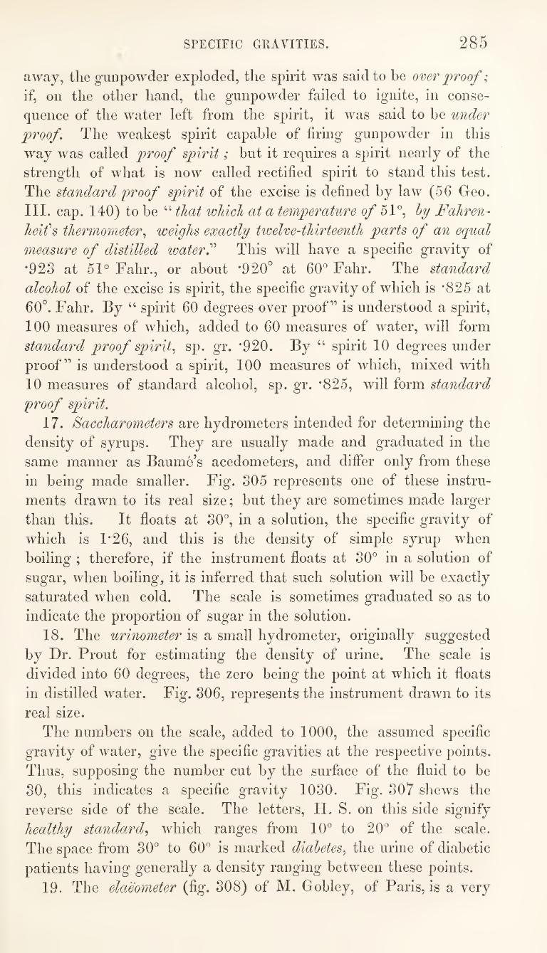
SPECIFIC GRAVITIES. 285
away, the gunpowder exploded, the spirit was said to be over proof;
if, on the other hand, the gunpowder failed to ignite, in conse¬
quence of the water left from the spirit, it was said to be under
proof. The weakest spirit capable of firing gunpowder in this
way was called proof spirit; but it requires a spirit nearly of the
strength of what is now called rectified spirit to stand this test.
The standard proof spirit of the excise is defined by law (56 Geo.
III. cap. 140) to be “ that which at a temperature o/ 51®, Fahren-
heifs thermometer^ weighs exactly twelve-thirteenth parts of an equal
measure of distilled loater^’’ This will have a specific gravity of
*923 at 51° Fahr., or about *920° at 60® Fahr. The standard
alcohol of the excise is spirit, the specific gravity of which is *825 at
60°. Fahr. By “ spirit 60 degrees over proof” is understood a spirit,
100 measures of which, added to 60 measures of water, will form
standard proof spirit,, sp. gr. *920. By “ spirit 10 degrees under
proof” is understood a spirit, 100 measures of which, mixed with
10 measures of standard alcohol, sp. gr. *825, will form standard
proof spirit.
17. Saccharometers are hydrometers intended for determining the
density of syrups. They are usually made and graduated in the
same manner as Baume’s acedometers, and differ only from these
in being made smaller. Fig. 805 represents one of these instru¬
ments drawn to its real size; but they are sometimes made larger
than this. It floats at 30®, in a solution, the specific gravity of
which is 1*26, and this is the density of simple syrup when
boiling; therefore, if the instrument floats at 30® in a solution of
sugar, when boiling, it is inferred that such solution will be exactly
saturated when cold. The scale is sometimes graduated so as to
indicate the proportion of sugar in the solution.
18. The urinometer is a small hydrometer, originally suggested
by Dr. Prout for estimating the density of urine. The scale is
divided into 60 degrees, the zero being the point at which it floats
in distilled water. Fig. 306, represents the instrument drawn to its
real size.
The numbers on the scale, added to 1000, the assumed specific
gravity of water, give the specific gravities at the respective points.
Thus, supposing the number cut by the surface of the fluid to be
30, this indicates a specific gravity 1030. Fig. 307 shews the
reverse side of the scale. The letters, H, S. on this side signify
healthy standard,^ which ranges from 10® to 20® of the scale.
The space from 30® to 60® is marked diabetes, the urine of diabetic
patients having generally a density ranging between these points.
19. The elaeometer (fig. 808) of M. Gobley, of Paris, is a very
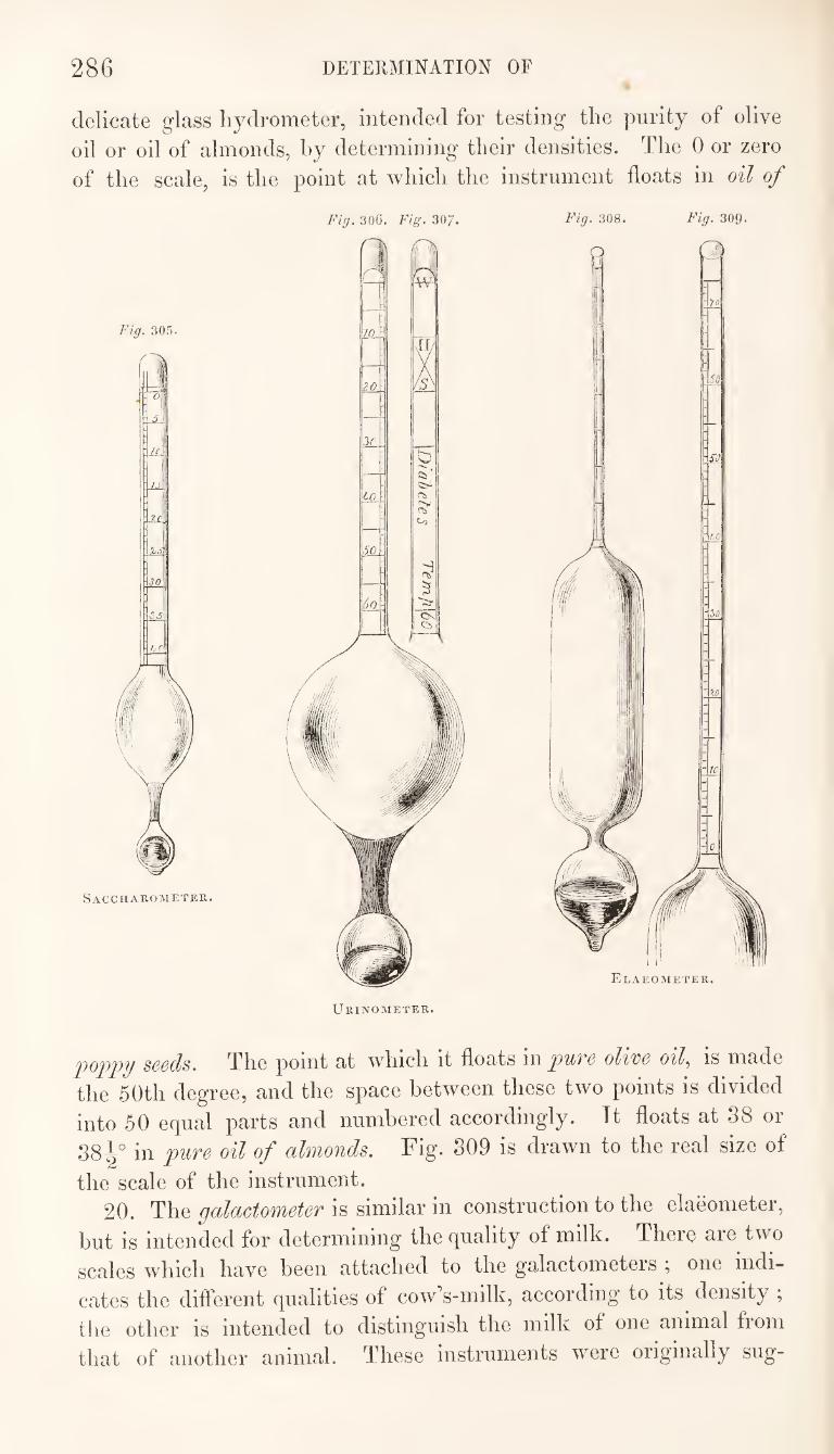
286 DETERMINATION OF
delicate glass hydrometer, intended for testing the parity of olive
oil or oil of almonds, by determining their densities. The 0 or zero
of the scale, is the point at which the instrument floats in oil of
Fig. 305.
SACCHAROMETER.
Fig. 306. Fig. 307.
po]ip7j seeds. The point at which it floats in pure olim oil, is made
the 50th degree, and the space between these two points is divided
into 50 equal parts and numbered accordingly. Tt floats at 38 or
38l° in pure oil of almonds. Fig. 309 is drawn to the real size of
the scale of the instrument. 20. The is similar in construction to the elaeometer,
but is intended for determining the quality of milk. There are two
scales which have been attached to the galactometeis , one indi¬
cates the different qualities of cow’s-milk, according to its density ;
the other is intended to distinguish the milk of one animal from
that of another animal. These instruments were originally sug-
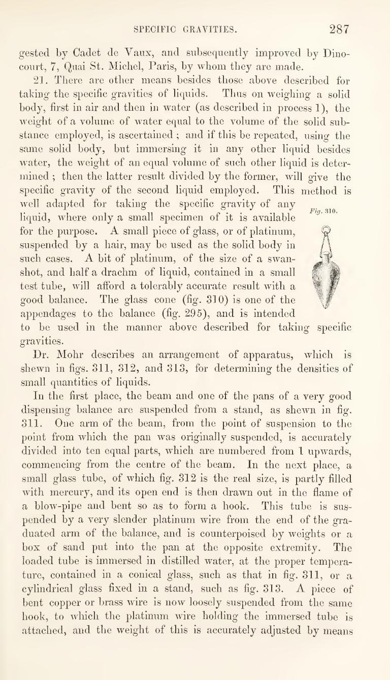
SPECIFIC GRAVITIES. 287
Fig. 310.
gested by Cadet de Vaux, and subsequently improved by Dino¬
court, 7, Quai St. Michel, Paris, by whom they are made.
21. There are other means besides those above described for
taking the specific gravities of liquids. Thus on weighing a solid
body, first in air and then in water (as described in process 1), the
weight of a volume of water equal to the volume of the solid sub¬
stance employed, is ascertained ; and if this be repeated, using the
same solid body, but immersing it in any other liquid besides
water, the weight of an equal volume of such other liquid is deter¬
mined ; then the latter result divided by the former, will give the
specific gravity of the second liquid employed. This method is
well adapted for taking the specific gravity of any
liquid, where only a small specimen of it is available
for the purpose. A small piece of glass, or of platinum,
suspended by a hair, may be used as the solid body in
such cases. A bit of platinum, of the size of a swan-
shot, and half a drachm of liquid, contained in a small
test tube, will afford a tolerably accurate result with a
good balance. The glass cone (fig. 310) is one of the
appendages to the balance (fig. 295), and is intended
to be used in the manner above described for taking specific
gravities.
Dr. Mohr describes an arrangement of apparatus, which is
shewn in figs. 311, 312, and 313, for determining the densities of
small quantities of liquids.
In the first place, the beam and one of the pans of a very good
dispensing balance are suspended from a stand, as shewn in fig.
311. One arm of the beam, from the point of suspension to the
point from w'hich the pan was originally suspended, is accurately
divided into ten equal parts, which are numbered from 1 upwards,
commencing from the centre of the beam. In the next place, a
small glass tube, of which fig. 312 is the real size, is partly filled
wfith mercury, and its open end is then drawn out in the flame of
a blow-pipe and bent so as to form a hook. This tube is sus¬
pended by a very slender platinum wire from the end of the gra¬
duated arm of the balance, and is counterpoised by weights or a
box of sand put into the pan at the opposite extremity. The
loaded tube is immersed in distilled water, at the proper tempera¬
ture, contained in a conical glass, such as that in fig. 311, or a
cylindrical glass fixed in a stand, such as fig. 313. A piece of
bent copper or brass wire is now loosely suspended from the same
hook, to which the platinum wire holding the immersed tube is
attached, and the weight of this is accurately adjusted by means
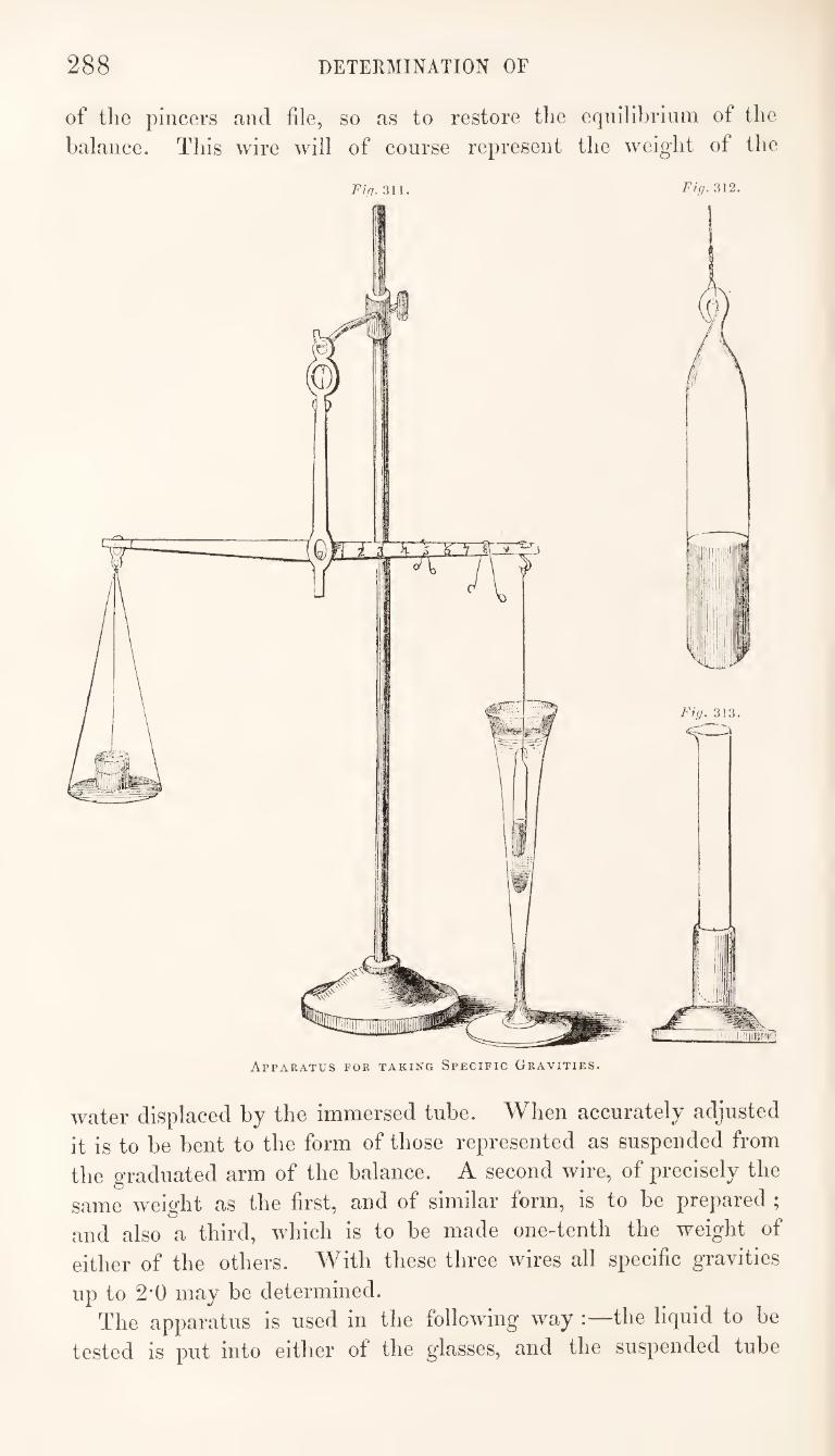
288 DETERMINATION OF
of the pincers and file, so as to restore the equilibrium of the balance. This wire will of course represent the weight of the
water displaced by the immersed tube. When accurately adjusted it is to be bent to the form of those represented as suspended from the graduated arm of the balance. A second wire, of precisely the same w'eight as the first, and of similar form, is to be prepared ; and also a third, which is to be made one-tenth the weight of either of the others. With these three wires all specific gTavities
up to 2’0 may be determined. The apparatus is used in the following way :—the liquid to he
tested is put into either of the glasses, and the suspended tube
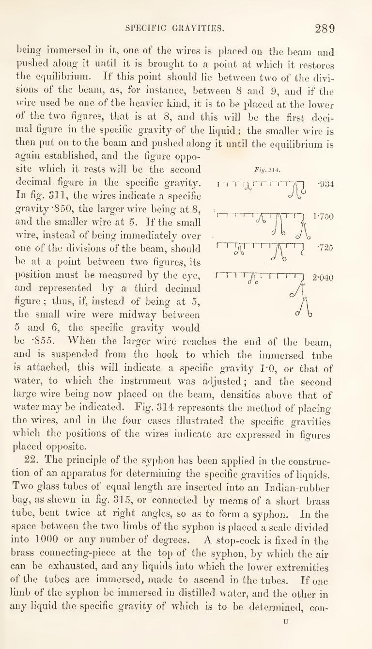
SPECIFIC GRAVITIES. 289
being immersed in it, one of the wires is placed on the beam and
pushed along it until it is brought to a point at which it restores
the equilibrium. If this point should lie between two of the divi¬
sions of the beam, as, for instance, between 8 and 9, and if the
wire used be one of the heavier kind, it is to be placed at the lower
of the two figures, that is at 8, and this will be the first deci¬
mal figure in the specific gravity of the liquid; the smaller wire is
then put on to the beam and pushed along it until the equilibrium is again established, and the figure oppo¬
site which it rests will be the second
decimal figure in the specific gravity.
In fig. 311, the wires indicate a specific
gravity *850, the larger wire being at 8,
and the smaller wire at 5. If the small
wire, instead of being immediately over
one of the divisions of the beam, should
be at a point between two figures, its
position must be measured by the eye,
and represented by a third decimal
figure ; thus, if, instead of being at 5,
the small wire were midway between
5 and 6, the specific gravity would
be *855. When the larger wire reaches the end of the beam,
and is suspended from the hook to which the immersed tube
is attached, this will indicate a specific gravity 1*0, or that of
water, to which the instrument was adjusted; and the second
large wire being now placed on the beam, densities above that of
water may be indicated. Fig. 314 represents the method of placing
the wires, and in the four cases illustrated the specific gravities
which the positions of the wires indicate are expressed in figures placed opposite.
22. The principle of the syphon has been applied in the construc¬
tion of an apparatus for determining the specific gravities of liquids.
Two glass tubes of equal length are inserted into an Indian-rubber
bag, as shewn in fig. 315, or connected by means of a short brass
tube, bent twice at right angles, so as to form a syphon. In the
space between the two limbs of the syphon is placed a scale divided
into 1000 or any number of degrees. A stop-cock is fixed in the
brass connecting-piece at the top of the syphon, by which the air
can be exhausted, and any liquids into which the lower extremities
of the tubes are immersed, made to ascend in the tubes. If one
limb of the syphon be immersed in distilled water, and tbe other in
any liquid the specific gravity of which is to be determined, con-
Fig. 314.
I 1 •934
A n o
U
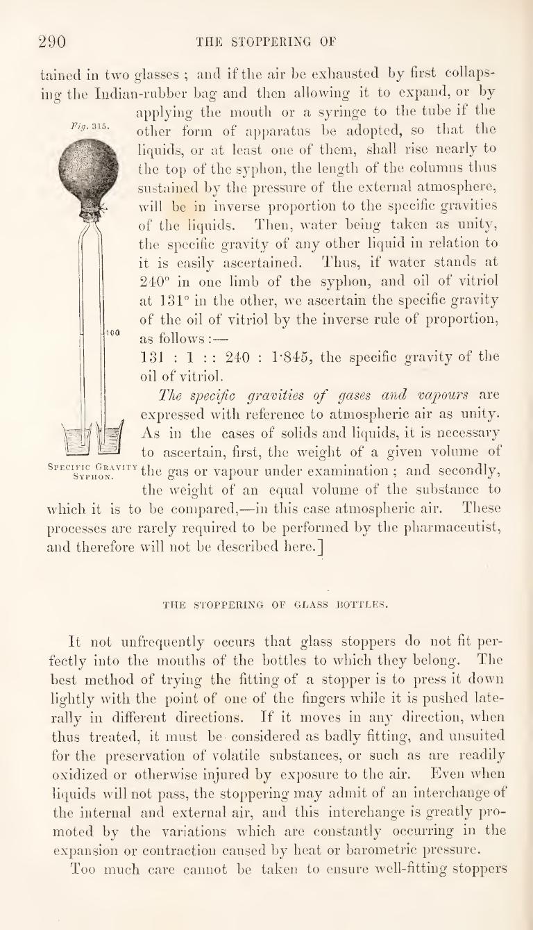
290 THE STOPPERING OF
tained in two glasses ; and if the air be exhausted by first collaps¬
ing the Indian-rnhber bag and then allowing it to expand, or by
applying the mouth or a syringe to the tube if the
other form of apparatus be adopted, so that the
liquids, or at least one of them, shall rise nearly to
the top of the syphon, the length of the columns thus
sustained by the pressure of the external atmosphere,
will be in inverse proportion to the specific gravities
of the liquids. Then, water being taken as unity,
the specific gravity of any other liquid in relation to
it is easily ascertained. Thus, if water stands at
240” in one limb of the syphon, and oil of vitriol
at 131° in the other, we ascertain the specific gravity
of the oil of vitriol by the inverse rule of proportion,
as follows :—
131 : 1 : : 240 : T845, the specific gravity of the
oil of vitriol.
The specific gravities of gases and vapours are
expressed with reference to atmospheric air as unity.
As in the cases of solids and liquids, it is necessary
to ascertain, first, the weight of a given volume of
SpecificjiRAviTY gas or vapour uudcr examination ; and secondly,
the weight of an equal volume of the substance to
which it is to be compared,—in this case atmospheric air. These
processes are rarely required to be performed by the pharmaceutist,
and therefore will not be described here.]
Fig. 315.
THE STOPPERING OF GLASS BOTTLES.
It not unfrequently occurs that glass stoppers do not fit per¬
fectly into the mouths of the bottles to which they belong. The
best method of trying the fitting of a stopper is to press it down
lightly with the point of one of the fingers while it is pushed late¬
rally in different directions. If it moves in any direction, when
thus treated, it must be considered as badly fitting, and unsuited
for the preservation of volatile substances, or such as are readily
oxidized or otherwise injured by exposure to the air. Even when
liquids will not pass, the stoppering may admit of an interchange of
the internal and external air, and this interchange is greatly pro¬
moted by the variations which are constantly occurring in the
expansion or contraction caused by heat or barometric pressure.
Too much care cannot be taken to ensure well-fitting stoppers
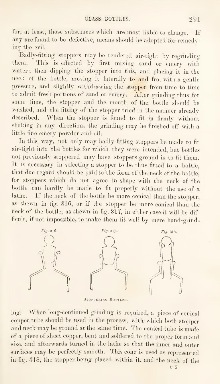
GLASS BOTTLES. 291
for, at least, those substances which are most liable to change. If
any are found to be defective, means should be adopted for remedy¬
ing the evil.
Badly-fitting stoppers may be rendered air-tight by regrinding
them. This is effected by first mixing sand or emery with
water; then dipping the stopper into this, and placing it in the
neck of the bottle, moving it laterally to and fro, with a gentle
pressure, and slightly withdrawing the stopper from time to time
to admit fresh portions of sand or emery. After grinding thus for
some time, the stopper and the mouth of the bottle should be
washed, and the fitting of the stopper tried in the manner already
described. When the stopper is found to fit in firmly without
shaking in any direction, the grinding may be finished off with a
little fine emery powder and oil.
In this way, not only may badly-fitting stoppers be made to fit
air-tight into the bottles for which they were intended, but bottles
not previously stoppered may have stoppers ground in to fit them.
It is necessary in selecting a stopper to be thus fitted to a bottle,
that due regard should be paid to the form of the neck of the bottle,
for stoppers which do not agree in shape with the neck of the
bottle can hardly be made to fit properly without the use of a
lathe. If the neck of the bottle be more conical than the stopper,
as shewn in fig. 316, or if the stopper be more conical than the
neck of the bottle, as shewn in fig. 317, in either case it will be dif¬
ficult, if not impossible, to make them fit well by mere hand-grind-
317. Fig. ms.
Stoppering Bottles.
ing. When long-continued grinding is required, a piece of conical
copper tube should be used in the process, with which both stopper
and neck may be ground at the same time. The conical tube is made
of a piece of sheet copper, bent and soldered to the proper form and
size, and afterwards turned in the lathe so that the inner and outer
surfaces may be perfectly smooth. This cone is used as represented
in fig. 318, the stopper being placed within it, and the neck of the
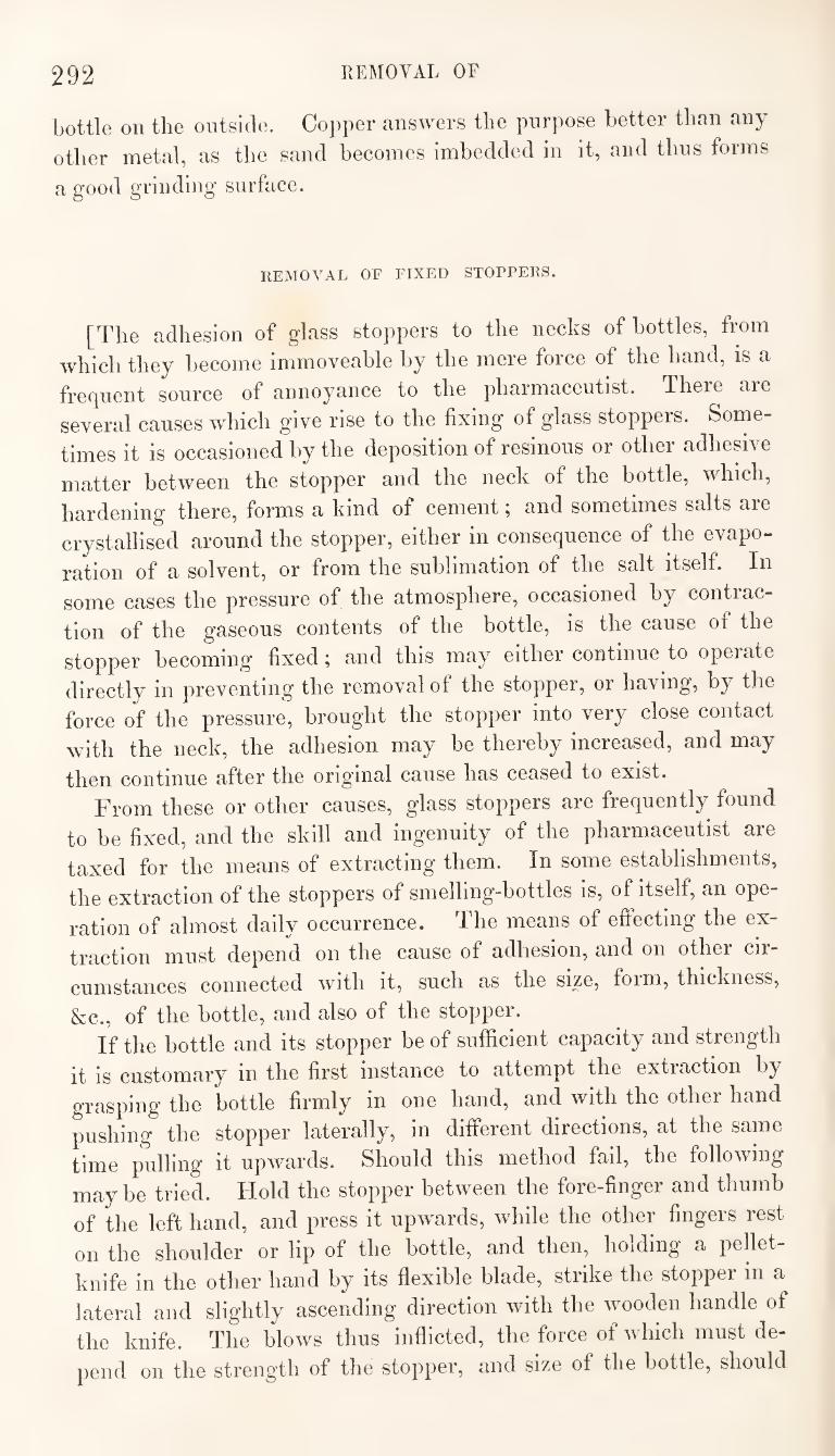
292 REMOVAL OF
bottle on the ontsicle. Copper answers the purpose better than any
other metal, as the sand becomes imbedded in it, and thus forms
a good grinding surface.
REMOVAL OF FIXED STOPPERS.
[The adhesion of glass stoppers to the necks of bottles, from
which they become immoveable by the mere force of the hand, is a
fre(]uent source of annoyance to the pharmaceutist. There are
several causes which give rise to the fixing of glass stoppers. Some¬
times it is occasioned by the deposition of resinous or other adhesive
matter between the stopper and the neck of the bottle, which,
hardening there, forms a kind of cement; and sometimes salts are
crystallised around the stopper, either in consequence of the evapo¬
ration of a solvent, or from the sublimation of the salt itself. In
some cases the pressure of the atmosphere, occasioned by contrac¬
tion of the gaseous contents of the bottle, is the cause of the
stopper becoming fixed; and this may either continue to operate
directly in preventing the removal of the stopper, or having, by the
force of the pressure, brought the stopper into very close contact
with the neck, the adhesion may be thereby increased, and may
then continue after the origanal cause has ceased to exist.
From these or other causes, glass stoppers are frequently found
to be fixed, and the skill and ingenuity of the pharmaceutist are
taxed for the means of extracting them. In some establishments,
the extraction of the stoppers of smelling-bottles is, of itself, an ope¬
ration of almost daily occurrence. The means of effecting the ex¬
traction must depend on the cause of adhesion, and on other cir¬
cumstances connected with it, such as the size, foim, thickness,
&e., of the bottle, and also of the stopper.
If the bottle and its stopper be of sufficient capacity and strength
it is customary in the first instance to attempt the extraction by
grasping the bottle firmly in one hand, and with the other hand
pushing the stopper laterally, in different directions, at the same
time pulling it upwards. Should this method fail, the following
maybe tried. Hold the stopper between the fore-finger and thumb
of the left hand, and press it upwards, while the other fingers rest
on the shoulder or lip of the bottle, and then, holding a pellet-
knife in the other hand by its flexible blade, strike the stopper in a
lateral and slightly ascending direction with the wooden handle of
the knife. The blows thus inflicted, the force of which must de¬
pend on the strength of the stopper, and size of the bottle, should
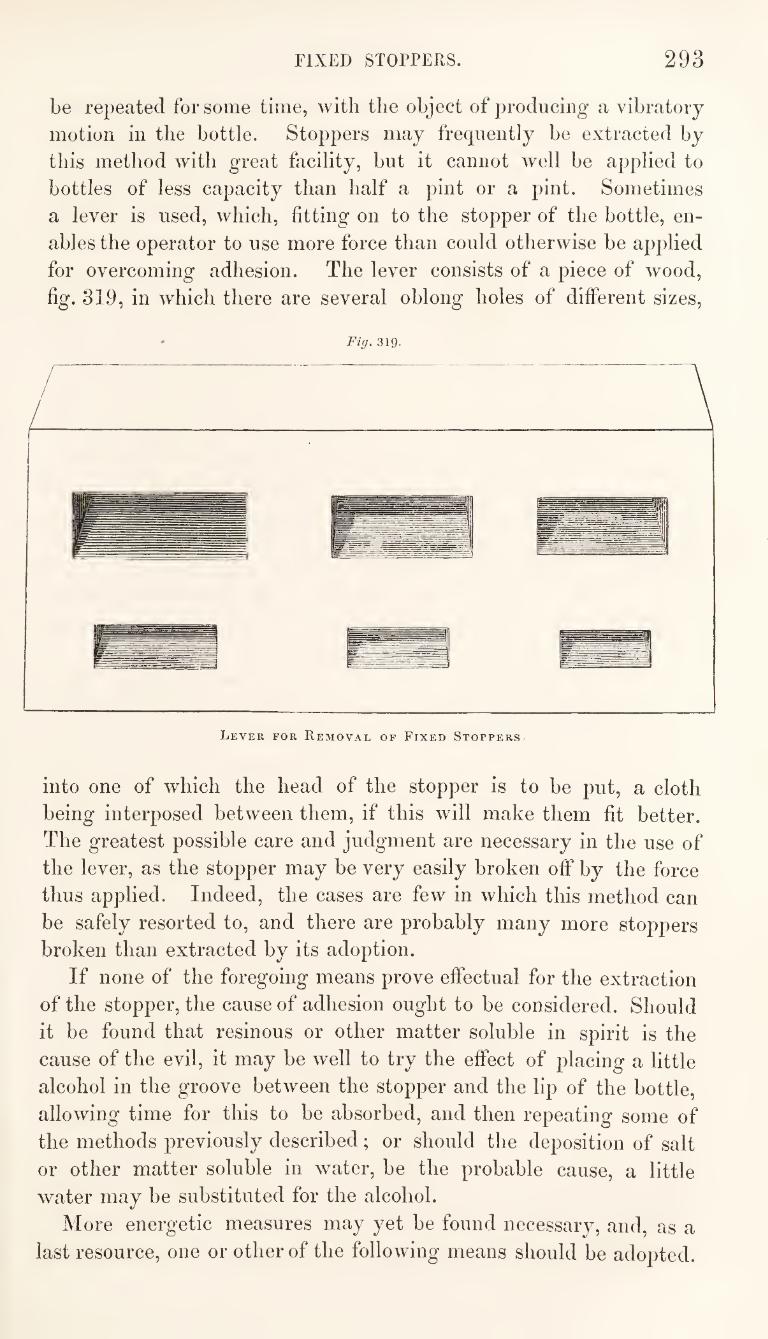
FIXED STOPPERS. 293
be repeated for some time, with the object of producing a vibratory
motion in the bottle. Stoppers may frequently be extracted by
this method with great facility, but it cannot well be applied to
bottles of less capacity than half a pint or a pint. Sometimes
a lever is used, which, fitting on to the stopper of the bottle, en¬
ables the operator to use more force than could otherwise be applied
for overcoming adhesion. The lever consists of a piece of wood,
fig. 319, in which there are several oblong holes of different sizes.
Fig. 319.
Lever for Removal of Fixed Stoppers
into one of which the head of the stopper is to be put, a cloth
being interposed between them, if this will make them fit better.
The greatest possible care and judgment are necessary in the use of
the lever, as the stopper may be very easily broken off by the force
thus applied. Indeed, the cases are few in which this method can
be safely resorted to, and there are probably many more stoppers
broken than extracted by its adoption.
If none of the foregoing means prove effectual for the extraction
of the stopper, the cause of adhesion ought to be considered. Should
it be found that resinous or other matter soluble in spirit is the
cause of the evil, it may be well to try the effect of placing a little
alcohol in the groove between the stopper and the lip of the bottle,
allowing time for this to be absorbed, and then repeating some of
the methods previously described; or should the deposition of salt
or other matter soluble in water, be the probable cause, a little
water may be substituted for the alcohol.
More energetic measures may yet be found necessary, and, as a
last resource, one or other of the following means should be adopted.
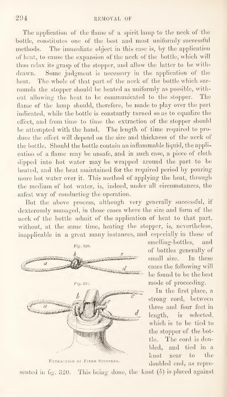
294 REMOVAL OF
The application of the flame of a spirit lamp to the neck of the
bottle, constitutes one of the best and most uniformly successful
methods. The immediate object in this case is, by the a})plication
of heat, to cause the expansion of the neck of the bottle, which will
thus relax its grasp of the stopper, and allow the latter to be with¬
drawn. Some judgment is necessary in the application of the
heat. The whole of that part of the neck of the bottle which sur¬
rounds the stopper should be heated as uniformly as possible, with¬
out allowing the heat to be communicated to the stopper. The
flame of the lamp should, therefore, be made to play over the part
indicated, while the bottle is constantly turned so as to equalize the
eftect, and from time to time the extraction of the stopper should
be attempted with the hand. The length of time required to pro¬
duce the effect will depend on the size and thickness of the neck of
the bottle. Should the bottle contain an inflammable liquid, the appli¬
cation of a flame may be unsafe, and in such case, a piece of cloth
dipped into hot water may be wrapped around the part to be
heated, and the heat maintained for the required period by pouring
more hot water over it. This method of applying the heat, through
the medium of hot water, is, indeed, under all circumstances, the
safest way of conducting the operation.
But the above process, although very generally successful, if
dexterously managed, in those cases where the size and form of the
neck of the bottle admit of the application of heat to that part,
without, at the same time, heating the stopper, is, nevertheless,
inapplicable in a great many instances, and especially in those of
smelling-bottles, and
of bottles generally of
small size. In these
cases the following will
be found to be the best
mode of proceeding.
In the first place, a
strong cord, between
three and four feet in
length, is selected,
which is to be tied to
the stopper of the bot¬
tle. The cord is dou¬
bled, and tied in a
knot near to the P^XTRACTION OF FiXED STOPPERS. Till 1
doubled end, as repre¬
sented in fig. b20. This beiug done, the knot (h) is placed against
Fig. 321.
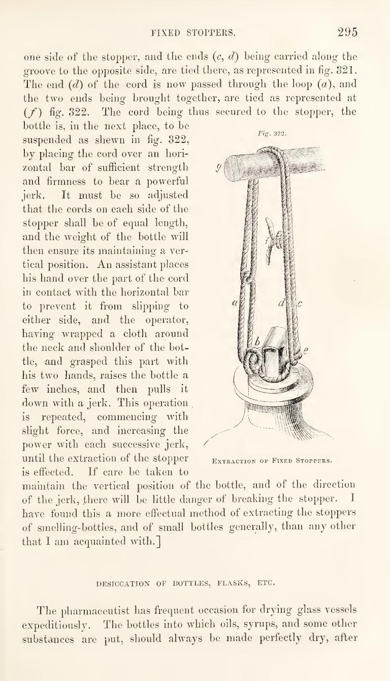
FIXED STOPPERS. 295
Fig. 322.
one side of the stopper, and the ends (<?, d) being carried along the
groove to the opposite side, are tied there, as represented in fig. S21.
The end (d) of the cord is now passed through the loop (a), and
the two ends being brought together, are tied as represented at
(/*) fig. 822. The cord being thus secured to the stopper, the
bottle is, in the next place, to be
suspended as shewn in fig. 822,
by placing the cord over an hori¬
zontal bar of sufficient strength
and firmness to hear a powerful
jerk. It must be so adjusted
that the cords on each side of the
stopper shall be of equal length,
and the weight of the bottle will
then ensure its maintaining a ver¬
tical position. An assistant places
his hand over the part of the cord
in contact with the horizontal bar
to prevent it from slipping to
either side, and the operator,
having wrapped a cloth around
the neck and shoulder of the bot¬
tle, and grasped this part with
his two hands, raises the bottle a
few inches, and then pulls it
down with a jerk. This operation
is repeated, commencing with
slight force, and increasing the
power with each successive jerk,
until the extraction of the stopper
is effected. If care be taken to
Extraction of Fixed Stoppers.
maintain the vertical position of the bottle, and of the direction
of the jerk, there will be little danger of breaking the stopper. I
have found this a more effectual method of extracting the stoppers
of smelling-bottles, and of small bottles generally, than any other
that I am acquainted with.]
DESICCATION OF BOTTLES, FLASKS, ETC.
The pharmaceutist has frequent occasion for drying glass vessels
expeditiously. The bottles into which oils, syrups, and some other
substances are put, should always be made perfectly dry, after
296 DESICCATION OF BOTTLES, ETC.
washing them, before they are used for the purposes intended.
Vessels having only one orifice, and that a contracted one, do not
readily part with their moisture, unless a particular arrangement
be adopted for promoting desiccation. Many days or even weeks
would elapse before a bottle, which has been just rinsed with
water, would become perfectly dry if it were merely exposed in a
dry room at the mean temperature of the atmosphere. To ensure
rapid desiccation a current of warm air should be made to pass
through the vessel.
The best method of proceeding is, to warm the vessel, by placing
it on a sand-bath, or in some other warm situation, and then to
blow into it Avith a bellows. The warm air loaded with moisture,
is displaced by a current of comparatively dry air, which becoming
heated from contact Avith the A^essel, is capable of taking up and
carrying away some of the moisture which remains. By operating
in this way, and repeating the application of heat and the bloAving
as often as is necessary, complete desiccation may be very speedily
effected. It is necessary, however, to observe that the vessel not
only appears to be dry while it is warm, but that this continues to
be the case after it has cooled ; for moisture which the air holds in
solution when warm is sometimes deposited again as the tempera¬
ture falls.
In the absence of a suitable belloAvs a glass tube and the human
lungs might be used Avith similar effect, although in this case the
desiccation would not be so rapid. The tube should be long enough
to reach to the bottom of the vessel, while it projects some inches
above the orifice. After heating the vessel as previously described,
the tube is introduced, and the operator, having exhausted his
lungs, applies his mouth to the end of the tube and makes a long
inspiration. The moist air of the vessel is thus drawn into the
lungs, and dry air from without enters to supply its place. The
process is repeated in this way until the vessel is completely dried.
Tubes, when sealed at one end, are dried in the manner above
described. If they be open at each end the desiccation is much
more easily and quickly effected. It is then only necessary to hold
them in an oblique position over the flame of a lamp or other
source of heat. A current of air Avill thus be determined upwards
Avhich Avill soon carry off the moisture.
ON TYING KNOTS.
There is some art involved even in the tying of a string, and
inconvenience is not unfrequently occasioned by a badly constructed
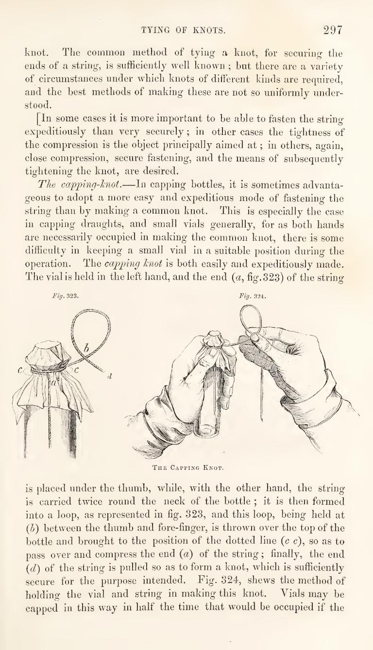
TYING OF KNOTS. 297
knot. The common method of tying a knot, for securing the
ends of a string, is sufficiently well known ; but there are a variety
of circumstances under which knots of different kinds are required,
and the best methods of making these are not so uniformly under¬
stood.
[In some cases it is more important to be able to fasten the string
expeditiously than very securely; in other cases the tightness of
the compression is the object principally aimed at; in others, again,
close compression, secure fastening, and the means of subsequently
tightening the knot, are desired.
The capping-knot.—In capping bottles, it is sometimes advanta¬
geous to adopt a more easy and expeditious mode of fastening the
string than by making a common knot. This is especially the case
in capping draughts, and small vials generally, for as both hands
are necessarily occupied in making the common knot, there is some
difficulty in keeping a small vial in a suitable position during the
operation. The capping knot is both easily and expeditiously made.
The vial is held in the left hand, and the end (<x, fig. 323) of the string
Fig, 323. Fig, 324.
The Capping Knot.
is placed under the thumb, while, with the other hand, the string
is carried twice round the neck of the bottle ; it is then formed
into a loop, as represented in fig. 323, and this loop, being held at
(5) between the thumb and fore-finger, is thrown over the top of the
bottle and brought to the position of the dotted line {c c), so as to
pass over and compress the end {d) of the string; finally, the end
{cl) of the string is pulled so as to form a knot, which is sufficiently
secure for the purpose intended. Fig. 324, shews the method of
holding the vial and string in making this knot. Vials may be
capped in this way in half the time that would be occupied if the
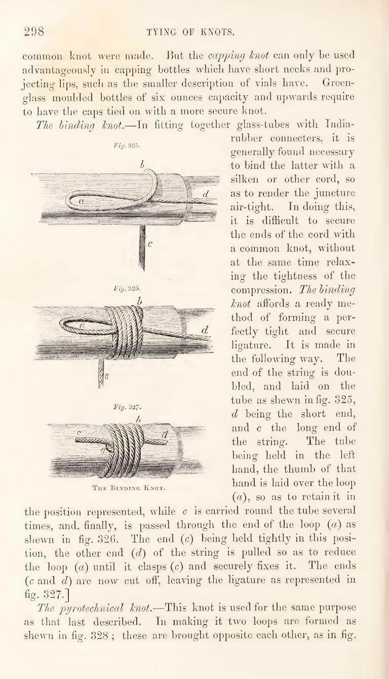
298 TYIiXG OF KNOTS.
common knot were made. Jkit the capimig knot can only be used
advantageously in capping bottles wbicb have short necks and pro¬
jecting lips, such as the smaller description of vials have. Green-
glass moulded bottles of six ounces capacity and upwards require
to have the caps tied on with a more secure knot.
The binding knot.—In fitting together glass-tubes with India-
rubber connecters, it is
generally found necessary
to bind the latter wdth a
silken or other cord, so
as to render the juncture
air-tight. In doing this,
it is difficult to secure
the ends of the cord with
a common knot, without
at the same time relax¬
ing the tightness of the
compression. The binding
knot affords a ready me¬
thod of forming a per¬
fectly tight and secure
ligature. It is made in
the following way. The
end of the string is dou¬
bled, and laid on the
tube as shewn in fig. 325,
d being the short end,
and c the long end of
the string. The tube
being held in the left
hand, the thumb of that
hand is laid over the loop
(a), so as to retain it in
the position represented, while c is carried round the tube several
times, and, finally, is passed through the end of the loop (a) as
shewn in fig. 326. The end (c) being held tightly in this posi¬
tion, the other end {d) of the string is pulled so as to reduce
the loop {a) until it clasps (c) and securely fixes it. The ends
{c and d) are now cut off, leaving the ligature as represented in
fig. 327.]
The pyrotechnical knot.—This knot is used for the same purpose
as that last described. In making it two loops are formed as
shewn in fig. 328 ; these are brought opposite each other, as in fig.
Fig. 325.
Fig. 326.
Tue Binding Knot.
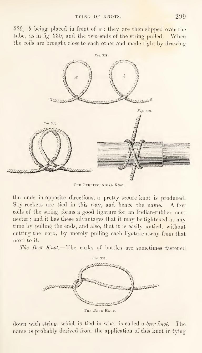
TYING OF KNOTS. 299
329, h being placed in front of a ; they are then slipped over the
tube, as in fig. 330, and the two ends of the string pulled. When
the coils are brought close to each other and made tight by drawing
Fig. 328.
The Pyrotechnical Knot.
the ends in opposite directions, a pretty secure knot is produced.
Sky-rockets are tied in this way, and hence the name. A few
coils of the string forms a good ligature for an Indian-rubber con¬
necter ; and it has these advantages that it may be tightened at any
time by pulling the ends, and also, that it is easily untied, without
cutting the cord, by merely pulling each ligature away from that
next to it.
The Beer Knot.—The corks of bottles are sometimes fastened
Tig. 331 .
down with string, which is tied in what is called a leer hiot. The
name is probably derived from the application of this knot in tying
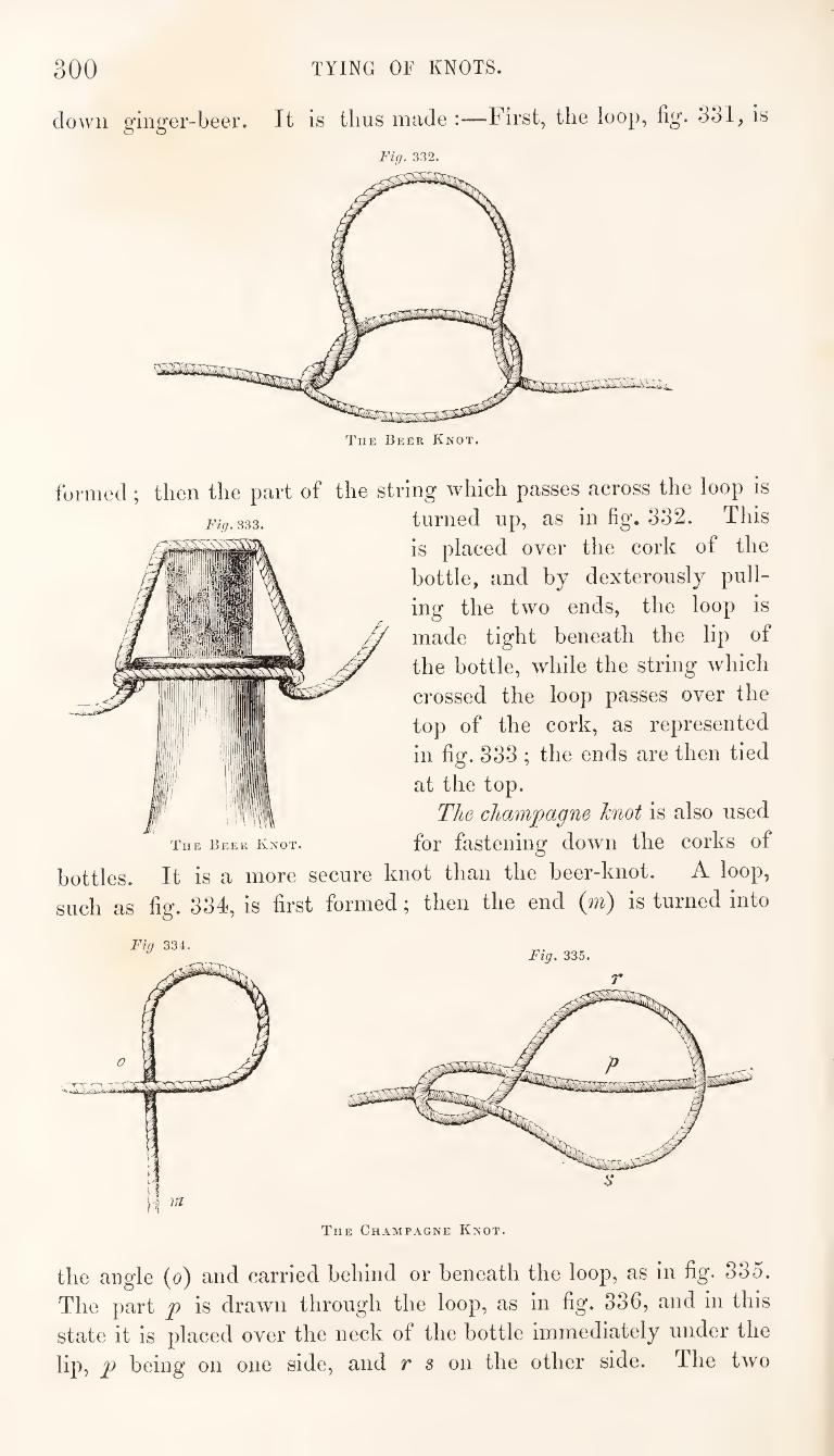
300 TYING OF KNOTS.
clown ginger-beer. It is thus made :—First, the loop, fig. 331, is
Fig. 332.
The Beer Knot.
Fig. 333.
formed; then the part of the string which passes across the loop is
turned up, as in fig. 332. This
is placed over the cork of the
bottle, and by dexterously pull¬
ing the two ends, the loop is
made tight beneath the lip of
the bottle, while the string which
crossed the loop passes over the
top of the cork, as represented
in fig. 333 ; the ends are then tied
at the top.
The champagne Jcnot is also used
for fastening down the corks of The Beer Knot.
bottles. It is a more secure knot than the beer-knot. A loop,
such as fig. 334, is first formed; then the end (m) is turned into
Fig 334. Fig. 335.
r
The Champagne Knot.
the augle (o) and carried behind or beneath the loop, as in fig. 335.
The part p is drawn through the loop, as in fig. 336, and in this
state it is placed over the neck of the bottle immediately under the
lip, p being on one side, and r s on the other side. The two
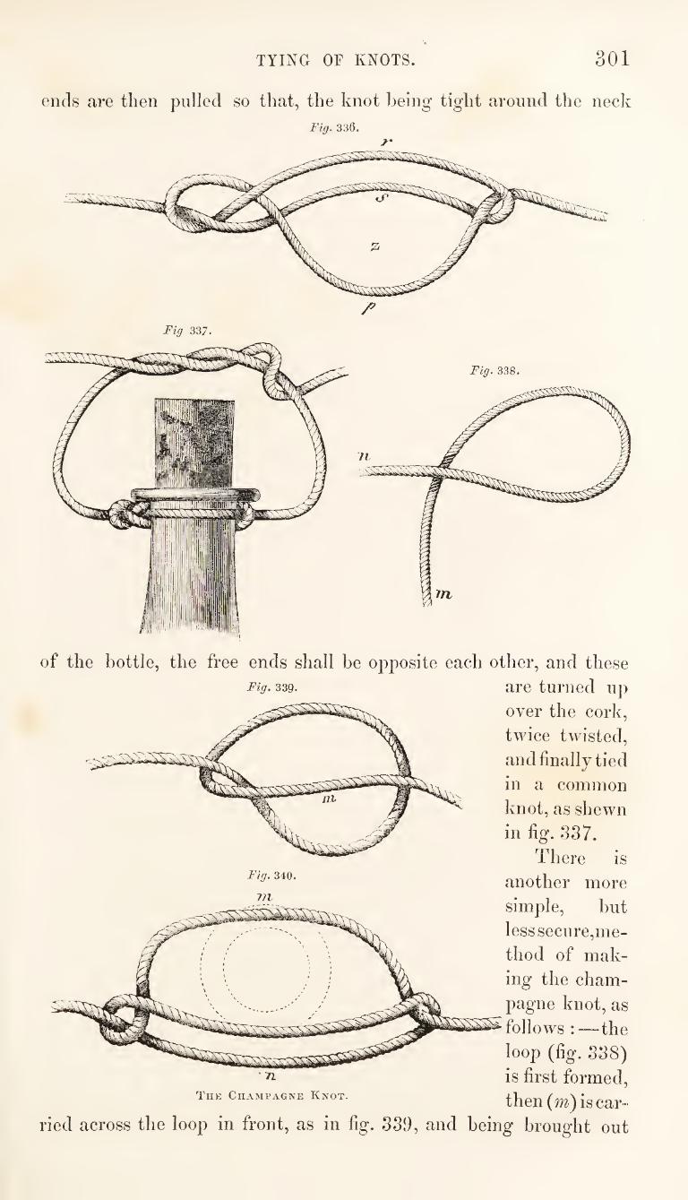
TYING OF KNOTS. 301
ends are then pulled so that, the knot being tight around the neck
Fig. 330.
Fig 337.
Fig. 338.
Fig. 340.
of the bottle, the free ends shall be opposite each other, and these
Fig. 339. are turned up
over the cork,
twice twisted,
and finally tied
in a common
knot, as shewn
in fig. 337.
There is
another more
simple, but
less seciire,me-
thod of mak¬
ing the cham¬
pagne knot, as
follows:—the
loop (fig. 338)
is first formed,
then (m) is car¬
ried across the loop in front, as in fig. 339, and being brought out
771
TL
Thk Champagne Knot.
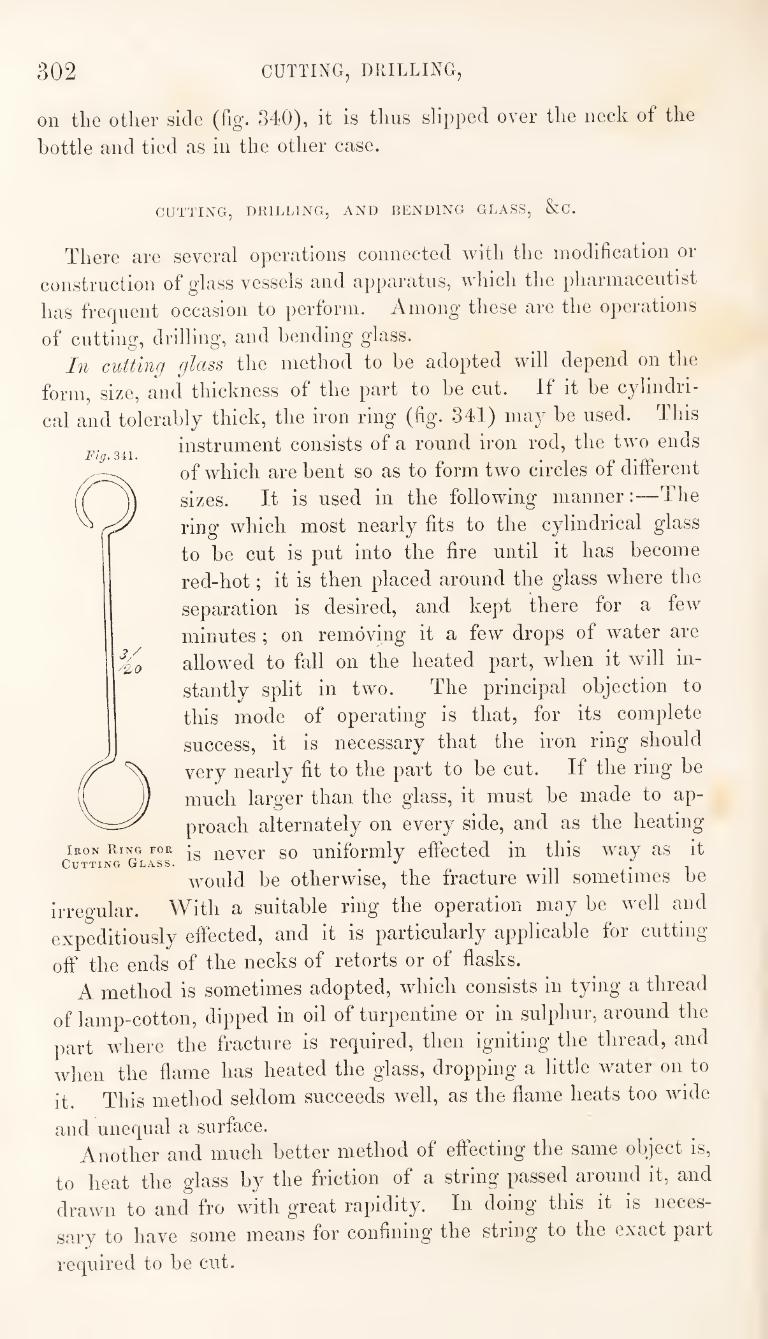
302 CUTTING, DRILLING,
on the other side (fig. 340), it is thus slipped over the neck of the
bottle and tied as in the other case.
CUTTING, DRILLING, AND RENDING GLASS, &;C.
There are several operations connected with the modification or
construction of glass vessels and apparatus, which the pharmaceutist
has frequent occasion to perform. Among these are the operations
of cutting, drilling, and bending glass.
In cutting glass the method to be adopted will depend on the
form, size, and thickness of the part to he cut. If it he cyhndii-
cal and tolerably thick, the iron ring (hg. 341) may he used. This
instrument consists of a round iron rod, the two ends
of which are bent so as to form two circles of different
sizes. It is used in the following manner:—The
ring which most nearly fits to the cylindrical glass
to be cut is put into the fire until it has become
red-hot; it is then placed around the glass where the
separation is desired, and kept there for a few
minutes ; on removing it a few drops of water are
allowed to fall on the heated part, when it will in¬
stantly split in two. The principal objection to
this mode of operating is that, for its complete
success, it is necessary that the iron ring should
very nearly fit to the part to be cut. If the ring* be
much larger than the glass, it must he made to ap¬
proach alternately on every side, and as the heating
Iron Ring for never SO uniformlv effected in this way as it Cutting Glass. ^ .
would be otherwise, the fracture will somekmes be
irregular. With a suitable ring the operation may be well and
expeditiously effected, and it is particularly applicable for cutting
off the ends of the necks of retorts or of flasks.
A method is sometimes adopted, which consists in tying a thread
of lamp-cotton, dipped in oil of turpentine or in sulphur, around the
part where the fracture is required, then igniting the thread, and
when the flame has heated the glass, dropping a little water on to
it. This method seldom succeeds well, as the flame heats too wide
and unequal a surface. Another and much better method of effecting the same object is,
to heat the glass by the friction of a string passed around it, and
drawn to and fro with great rapidity. In doing this it is neces¬
sary to have some means for confining the string to the exact part
required to be cut.
Fig.Ml.
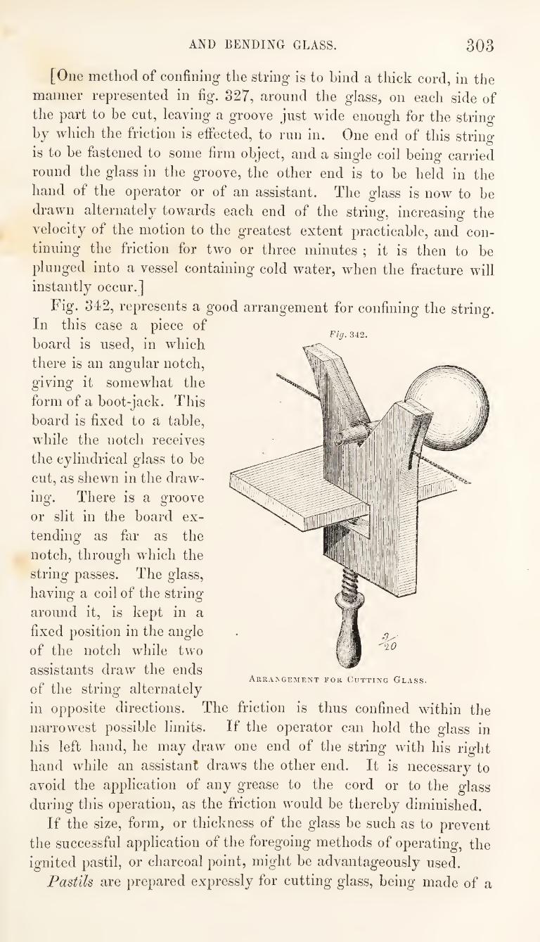
AND BENDING GLASS. 303
Fig. 342.
[One method of confining the string is to hind a thick cord, in the
manner represented in fig. 827, around the glass, on each side of
the part to be cut, leaving a groove just wide enough for the string
by which the friction is effected, to run in. One end of this string
is to be fastened to some firm object, and a single coil being carried
round the glass in the groove, the other end is to be held in the
hand of the operator or of an assistant. The glass is now to be
drawn alternately towards each end of the string, increasing the
velocity of the motion to the greatest extent practicable, and con¬
tinuing the friction for two or three minutes ; it is then to be
plunged into a vessel containing cold water, when the fracture will
instantly occur.]
Fig. 342, represents a good arrangement for confining the string.
In this case a piece of
board is used, in which
there is an angular notch,
giving it somewhat the
form of a boot-jack. This
board is fixed to a table,
while the notch receives
the cylindrical glass to be
cut, as shewn in the draw¬
ing. There is a groove
or slit in the board ex¬
tending as far as the
notch, through which the
string passes. The glass,
having a coil of the string
around it, is kept in a
fixed position in the angle
of the notch while two
assistants draw the ends
of the string alternately
in opposite directions. The friction is thus confined within the
narrowest possible limits. If the operator can hold the glass in
his left hand, he may draw one end of the string with his right
hand while an assistant draws the other end. It is necessary to
avoid the application of any grease to the cord or to the glass
during this operation, as the friction would be thereby diminished.
If the size, form, or thickness of the glass be such as to prevent
the successful application of the foregoing methods of operating, the
ignited pastil, or charcoal point, might be advantageously used.
Pastils are prepared expressly for cutting glass, being made of a
Arrangement for Gutting Glass.
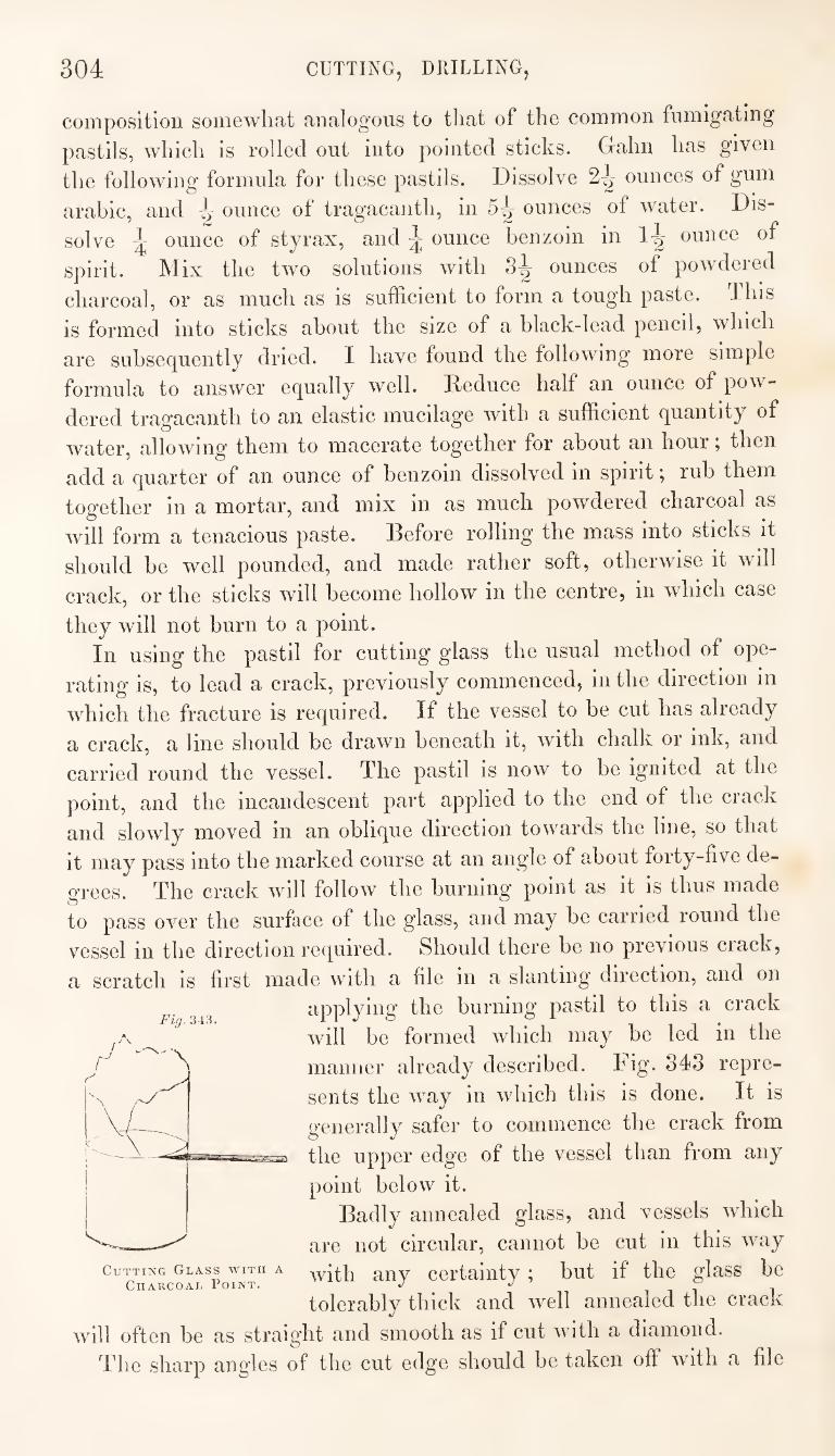
304 CUTTING, DRILLING,
composition somewhat analogous to that of the common fumigating
pastils, which is rolled out into pointed sticks. Gahn has given
the following formula for these pastils. Dissolve 2^ ounces of gum
arabic, and onnce of tragacanth, in 5^ ounces of water. Dis¬
solve ^ ounce of styrax, and ^ ounce benzoin in 1-^ ounce of
spirit. Mix the two solutions with 8^ ounces of powdered
charcoal, or as much as is sufficient to form a tough paste. This
is formed into sticks about the size of a black-lead pencil, which
are subsequently dried. I have found the following more simple
formula to answer equally well. Reduce half an ounce of pow¬
dered traofacanth to an elastic mucilage with a sufficient quantity of
water, allowing them to macerate together for about an hour; then
add a quarter of an ounce of benzoin dissolved in spirit; rub them
together in a mortar, and mix in as much powdered charcoal as
will form a tenacious paste. Before rolling the mass into sticks it
should be well pounded, and made rather soft, otherwise it will
crack, or the sticks will become hollow in the centre, in which case
they will not burn to a point.
In using the pastil for cutting glass the usual method of ope¬
rating is, to lead a crack, previously commenced, in the direction in
which the fracture is required. If the vessel to be cut has already
a crack, a line should be drawn beneath it, with chalk or ink, and
carried round the vessel. The pastil is now to be ignited at the
point, and the incandescent part applied to the end of the crack
and slowly moved in an oblique direction towards the line, so that
it may pass into the marked course at an angle of about forty-five de¬
grees. The crack will follow the burning point as it is thus made
to pass over the surface of the glass, and may be carried round the
vessel in the direction required. Should there be no previous crack,
a scratch is first made with a file in a slanting direction, and on
applying the burning pastil to this a crack
will be formed which may be led in the
manner already described. Dig- 343 repre¬
sents the way in which this is done. It is
generally safer to commence the crack from
the upper edge of the vessel than from any
point below it.
Badly annealed glass, and vessels which
are not circular, cannot be cut in this way
with any certainty; but if the glass be
tolerably thick and well annealed the crack
will often be as straight and smooth as if cut with a diamond.
The sharp angles of the cut edge should be taken off with a file
Flff.343,
Cutting Glass with a
Charcoal Point.
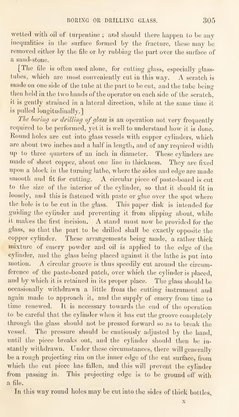
BORING OR DRILLING GLASS. 305
wetted with oil of turpentine ; and should there happen to be any
inequalities in the surface formed by the fracture, these may be
removed either by the file or by rubbing the part over the surface of
a sand-stone.
[The file is often used alone, for cutting glass, especially glass-
tubes, which are most conveniently cut in this way. A scratch is
made on one side of the tube at the part to be cut, and the tube being
then held in the two hands of the operator on each side of the scratch,
it is gently strained in a lateral direction, while at the same time it
is pulled longitudinally.]
The horing or drilling of glass is an operation not very frequently
required to be performed, yet it is well to understand how it is done.
Round holes are cut into glass vessels with copper cylinders, which
are about two inches and a half in length, and of any required width
up to three quarters of an inch in diameter. These cylinders are
made of sheet copper, about one line in thickness. They are fixed
upon a block in the turning lathe, where the sides and edge are made
smooth and fit for cutting. A circular piece of paste-board is cut
to the size of the interior of the cylinder, so that it should fit in
loosely, and this is fastened with paste or glue over the spot where
the hole is to be cut in the glass. This paper disk is intended for
guiding the cylinder and preventing it from slipping about, while
it makes the first incision. A stand must now be provided for the
glass, so that the part to be drilled shall be exactly opposite the
copper cylinder. These arrangements being made, a rather thick
mixture of emery powder and oil is applied to the edge of the
cylinder, and the glass being placed against it the lathe is put into
motion. A circular groove is thus speedily cut around the circum¬
ference of the paste-board patch, over which the cylinder is placed,
and by which it is retained in its proper place. The glass should be
occasionally withdrawn a little from the cutting instrument and
again made to approach it, and the supply of emery from time to
time renewed. It is necessary towards the end of the operation
to be careful that the cylinder when it has cut the groove completely
through the glass should not be pressed forward so as to break the
vessel. The pressure should be cautiously adjusted by the hand,
until the piece breaks out, and the cylinder should then be in¬
stantly withdrawn. Under these circumstances, there will generally
be a rough projecting rim on the inner edge of the cut surface, from
which the cut piece has fallen, and this will prevent the cylinder
from passing in. This projecting edge is to be ground off with
a file.
In this way round holes may be cut into the sides of thick bottles.
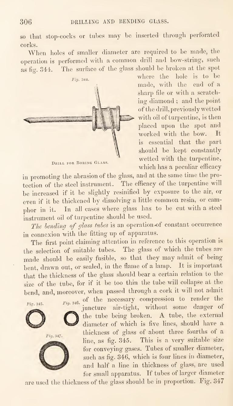
306 DRILLING AND BENDING GLASS.
Fig. 344.
Drill for Boring Glass.
SO that stop-cocks or tubes may be inserted through perforated
corks. When holes of smaller diameter are required to be made, the
operation is performed with a common drill and bow-string, such
as fig. 344. The surface of the glass should be broken at the spot
where the hole is to be
made, with the end of a
sharp file or with a scratch¬
ing diamond ; and the point
of the drill, previously wetted
with oil of turpentine, is then
placed upon the spot and
worked with the bow. It
is essential that the part
should be kept constantly
wetted with the turpentine,
which has a peculiar efficacy
in promoting the abrasion of the glass, and at the same time the pro¬
tection of the steel instrument. The efficacy of the turpentine will
be increased if it be slightly resinified by exposure to the air, or
even if it be thickened by dissolving a little common resin, or cam¬
phor in it. In all cases where glass has to be cut with a steel
instrument oil of turpentine should be used.
The bending of glass tubes is an operation ^f constant occurrence
in connexion with the fitting up of apparatus.
The first point claiming attention in reference to this operation is
the selection of suitable tubes. The glass of which the tubes are
made should be easily fusible, so that they may admit of being
bent, drawn out, or sealed, in the flame of a lamp. It is important
that the thickness of the glass should bear a certain relation to the
size of the tube, for if it be too thin the tube will collapse at the
bend, and, moreover, when passed through a cork it will not admit
of the necessary compression to render the
juncture air-tight, without some danger of
the tube being broken, A tube, the external
diameter of which is five lines, should have a
thickness of glass of about three fourths of a
line, as fig. 345. This is a very suitable size
for conveying gases. Tubes of smaller diameter,
such as fig. 346, which is four lines in diameter,
and half a line in thickness of glass, are used
for small apparatus. If tubes of larger diameter
are used the thickness of the glass should be in proportion. Fig. 347
Fig. 345.
Fig. 347.
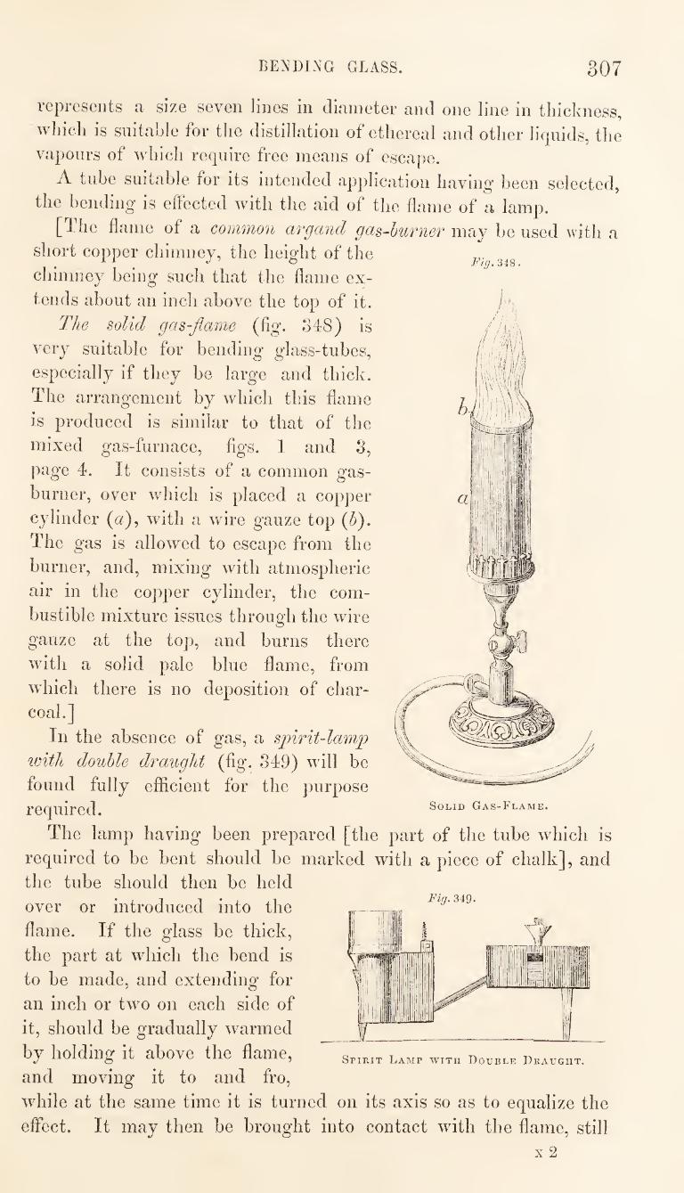
BENDING GLASS. 307
Fig. 348.
/ll
represents a size seven lines in diameter and one line in thickness,
which is suitable for the distillation of ethereal and other liquids, the
vapours of which require free means of escape.
A tube suitable for its intended application having been selected,
the bending is effected with the aid of the flame of a lamp.
[The flame of a common argcmd gas-burner may be used with a
short copper chimney, the height of the
chimney being such that the flame ex¬
tends about an inch above the top of it.
The solid gas-flame (fig. S48) is
very suitable for bending glass-tubes,
especially if they he large and thick.
The arrangement by which this flame
is produced is similar to that of the
mixed gas-furnace, figs. 1 and S,
page 4. It consists of a common gas-
burner, over which is placed a copper
cylinder (a), with a wire gauze top {fl).
The gas is allowed to escape from the
burner, and, mixing with atmospheric
air in the copper cylinder, the com¬
bustible mixture issues through the wire
gauze at the top, and burns there
with a solid pale blue flame, from
which there is no deposition of char¬
coal.]
In the absence of gas, a spirit-lamp
with double draught (fig. 349) will be
found fully efficient for the purpose
required. Solid Gas-Flame.
Fig. 349.
The lamp having been prepared [the part of the tube which is
required to be bent should be marked with a piece of chalk], and
the tube should then be held
over or introduced into the
flame. If the glass be thick,
the part at which the bend is
to be made, and extending for
an inch or two on each side of
it, should be gradually warmed
by holding it above the flame,
and moving it to and fro,
while at the same time it is turned on its axis so as to equalize the
effect. It may then be brought into contact with the flame, still
Spirit Lamp with Double Draught.
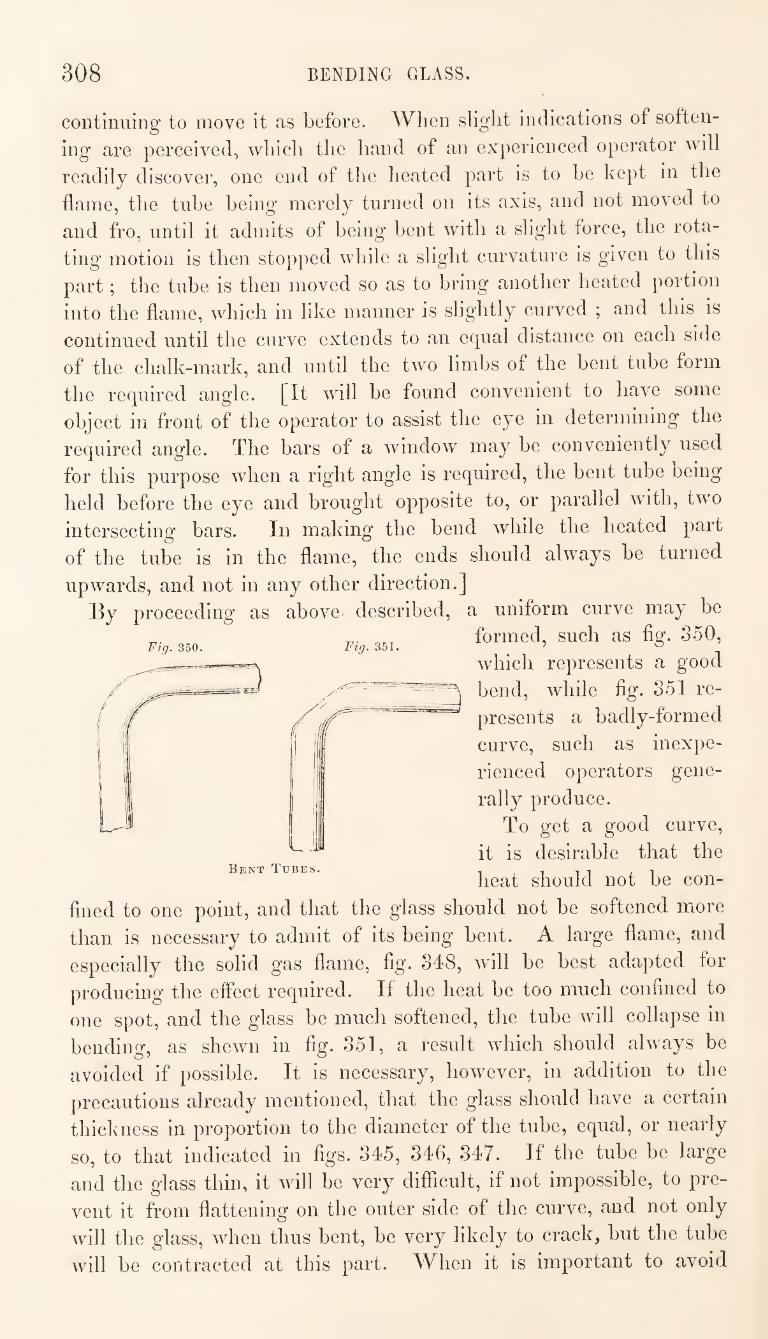
308 BENDING GLASS.
continuing to move it as before. When slight indications of soften¬
ing are perceived, which the hand of an experienced operator will
readily discover, one end of the heated part is to be kept in the
flame, the tube being merely turned on its axis, and not moved to
and fro, until it admits of being bent with a slight force, the rota¬
ting motion is then stopped while a slight curvature is given to this
part ; the tube is then moved so as to bring another heated portion
into the flame, which in like manner is slightly curved ; and this is
continued until the curve extends to an egual distance on each side
of the chalk-mark, and until the two limbs of the bent tube form
Fig. 350. Fig. 351,
the required angle. [It will be found convenient to have some
object in front of the operator to assist the eye in determining the
required angle. The bars of a window may be conveniently used
for this purpose when a right angle is required, the bent tube being
held before the eye and brought opposite to, or parallel with, two
intersecting bars. In making the bend while the heated part
of the tube is in the flame, the ends should always be turned
upwards, and not in any other direction.]
By proceeding as above described, a uniform curve may be
formed, such as fig. 350,
which represents a good
bend, while fig. 351 re¬
presents a badly-formed
curve, such as inexpe¬
rienced operators gene¬
rally produce.
To get a good curve,
it is desirable that the
heat should not be con¬
fined to one point, and that the glass should not be softened more
than is necessary to admit of its being bent. A large flame, and
especially the solid gas flame, fig. 348, will be best adapted for
producing the effect required. If the heat be too much confined to
one spot, and the glass be much softened, the tube will collapse in
bending, as shewn in fig. 351, a result which should always be
avoided if possible. It is necessary, however, in addition to the
L '
Bent Tubes.
precautions already mentioned, that the glass should have a certain
thickness in proportion to the diameter of the tube, equal, or nearly
so, to that indicated in figs. 345, 346, 347. If the tube be large
and the glass thin, it will be very difficult, if not impossible, to pre¬
vent it from flattening on the outer side of the curve, and not only
will the glass, when thus bent, be very likely to crack, but the tube
will be contracted at this part. When it is important to avoid
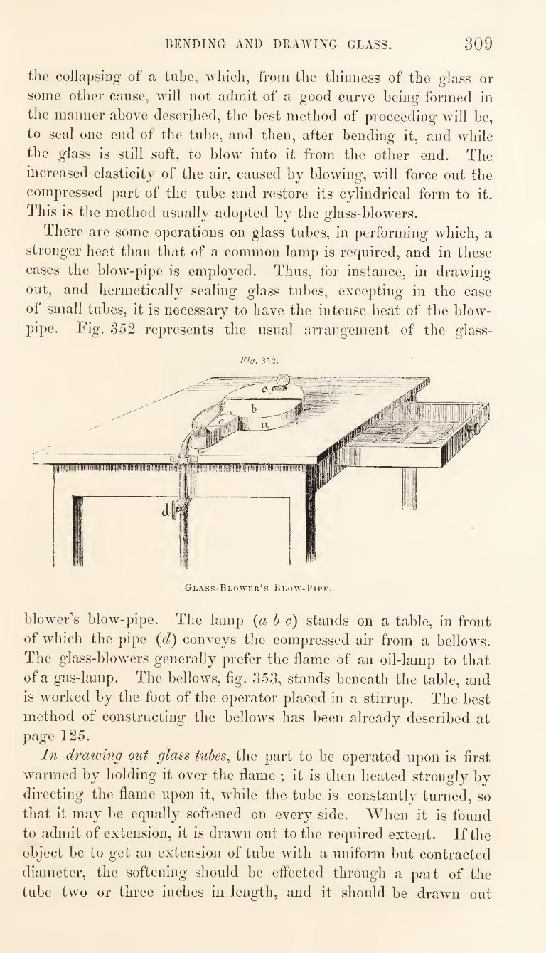
BENDING AND DRAWING GLASS. 309
the collapsing- of a tube, which, from the thinness of the glass or
some other cause, will not admit of a good curve being formed in
the manner above described, the best method of proceeding will be,
to seal one end of the tube, and then, after bending it, and while
the glass is still soft, to blow into it from the other end. The
increased elasticity of the air, caused by blowdng, will force out the
compressed part of the tube and restore its cylindrical form to it.
This is the method usually adopted by the glass-blowers.
There are some operations on glass tubes, in performing which, a
stronger heat than that of a common lamp is required, and in these
cases the blow-pipe is employed. Thus, for instance, in drawing
out, and hermetically sealing glass tubes, excepting in the case
of small tubes, it is necessary to have the intense heat of the blow'-
pipe. Fig. 352 represents the usual arrangement of the glass-
F^a. 352.
blow'eFs blow-pipe. The lamp {a h c) stands on a table, in front
of which the pipe {d) conveys the compressed air from a bellows.
The glass-blowers generally prefer the flame of an oil-lamp to that
of a gas-lamp. The bellows, fig. 353, stands beneath the table, and
is worked by the foot of the operator placed in a stirrup. The best
method of constructing the bellows has been already described at
page 125.
In drawing out glass tubes^ the part to be operated upon is first
warmed by holding it over the flame ; it is then heated strongly by
directing the flame upon it, while the tube is constantly turned, so
that it may be equally softened on every side. When it is found
to admit of extension, it is drawn out to the required extent. If the
object be to get an extension of tube with a uniform but contracted
diameter, the softening should be effected through a part of the
tube two or three inches in length, and it should be drawn out
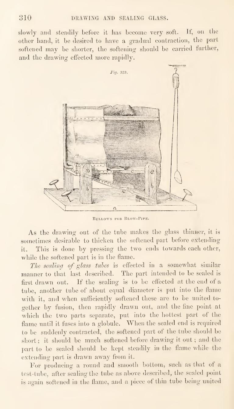
810 DRAWING AND SEALING GLASS.
slowly and steadily before it has become very soft. If, on the
other hand, it he desired to have a gradual contraction, the part
softened may he shorter, the softening should he carried further,
and the drawing effected more rapidly.
Bellows i^or Blow-Pipe.
As the drawing out of the tube makes the glass thinner, it is
sometimes desirable to thicken the softened part before extending
it. This is done by pressing the two ends towards each other,
while the softened part is in the flame.
The sealing of glass tubes is effected in a somewhat similar
manner to that last described. The part intended to he sealed is
first drawn out. If the sealing is to he effected at the end of a
tube, another tube of about equal diameter is put into the flame
with it, and when sufficiently softened these are to be united to¬
gether by fusion, then rapidly drawn out, and the fine point at
which the two parts separate, put into the hottest part of the
flame until it fuses into a globule. When the sealed end is required
to be suddenly contracted, the softened part of the tube should be
short; it should be much softened before drawing it out ; and the
part to be sealed should be kept steadily in the flame while the
extending part is drawn away from it.
For ])roducing a round and smooth bottom, such as that of a
test-tube, after sealing the tube as above described, the sealed point
is again softened in the flame, and a piece of thin tube being united
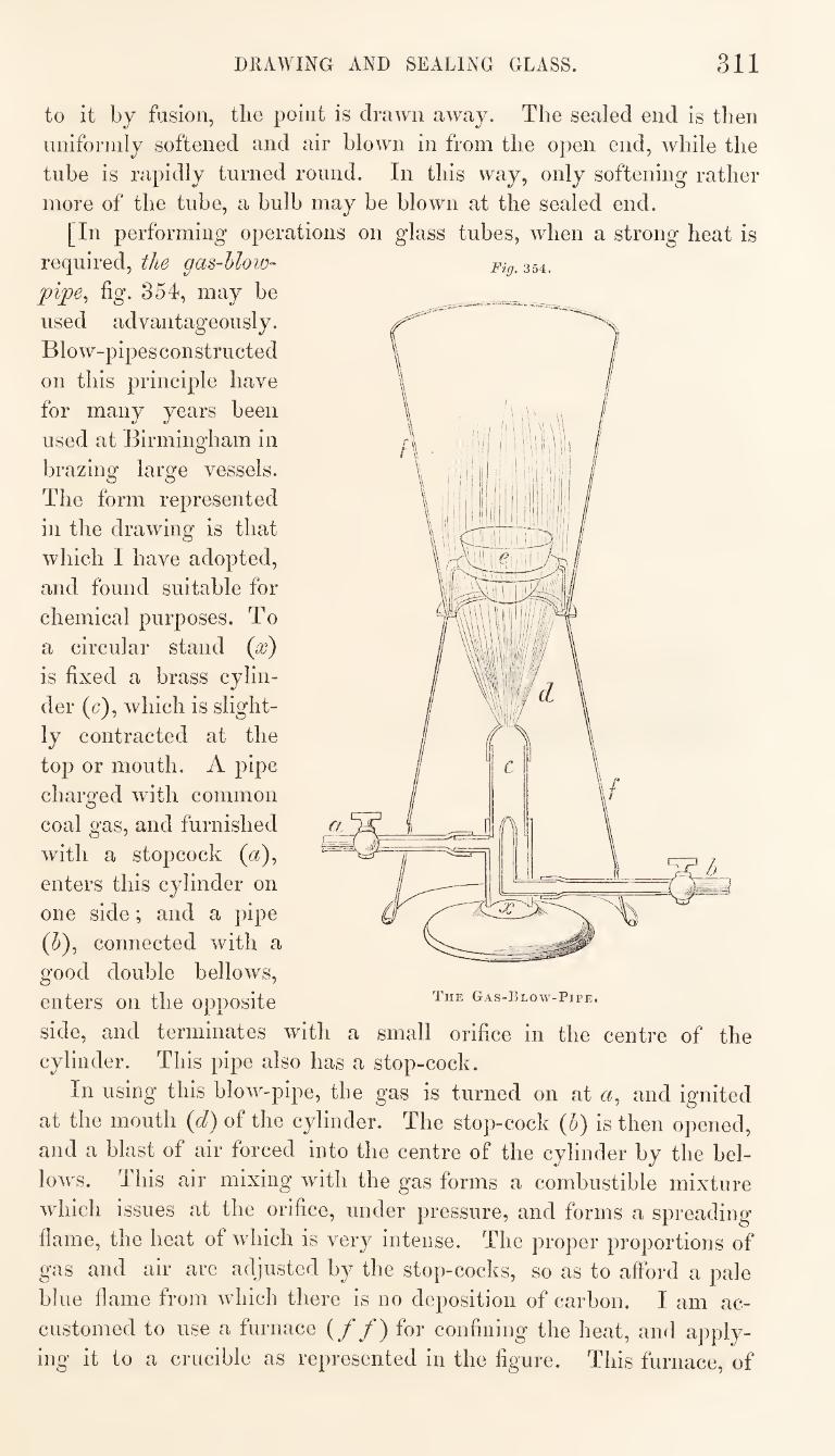
DRAWING AND SEALING GLASS. 311
to it by fusion, the point is drawn away. The sealed end is then
nniformly softened and air blown in from the open end, while the
tube is rapidly turned round. In this way, only softening rather
more of the tube, a bulb may be blown at the sealed end.
[In performing operations on glass tubes, when a strong heat is
required, the gas-hlow-
pijpe^ fig. 354, may be
used advantageously.
Blow-pipes constructed
on this principle have
for many years been
used at Birmingham in
brazing large vessels.
The form represented
in the drawing is that
which I have adopted,
and found suitable for
chemical purposes. To
a circular stand {x)
is fixed a brass cylin¬
der (c), which is slight¬
ly contracted at the
top or mouth, A pipe
charged with common
coal gas, and furnished
with a stopcock (^z),
enters this cylinder on
one side; and a pipe
connected with a
good double bellows,
enters on the opposite
side, and terminates with a small orifice in the centre of the
cylinder. This pipe also has a stop-cock.
In using this blow-pipe, the gas is turned on at a, and ignited
at the mouth {d) of the cylinder. The stop-cock {h) is then opened,
and a blast of air forced into the centre of the cylinder by the bel¬
lows. This air mixing with the gas forms a combustible mixture
which issues at the orifice, under pressure, and forms a spreading
flame, the heat of which is very intense. The proper proportions of
gas and air are adjusted by the stop-cocks, so as to afford a pale
blue flame from which there is no deposition of carbon. I am ac¬
customed to use a furnace (//) for confining the heat, and apply¬
ing it to a crucible as represented in the figure. This furnace, of
Fig. 354.
The Gas-Blow-Pipe.
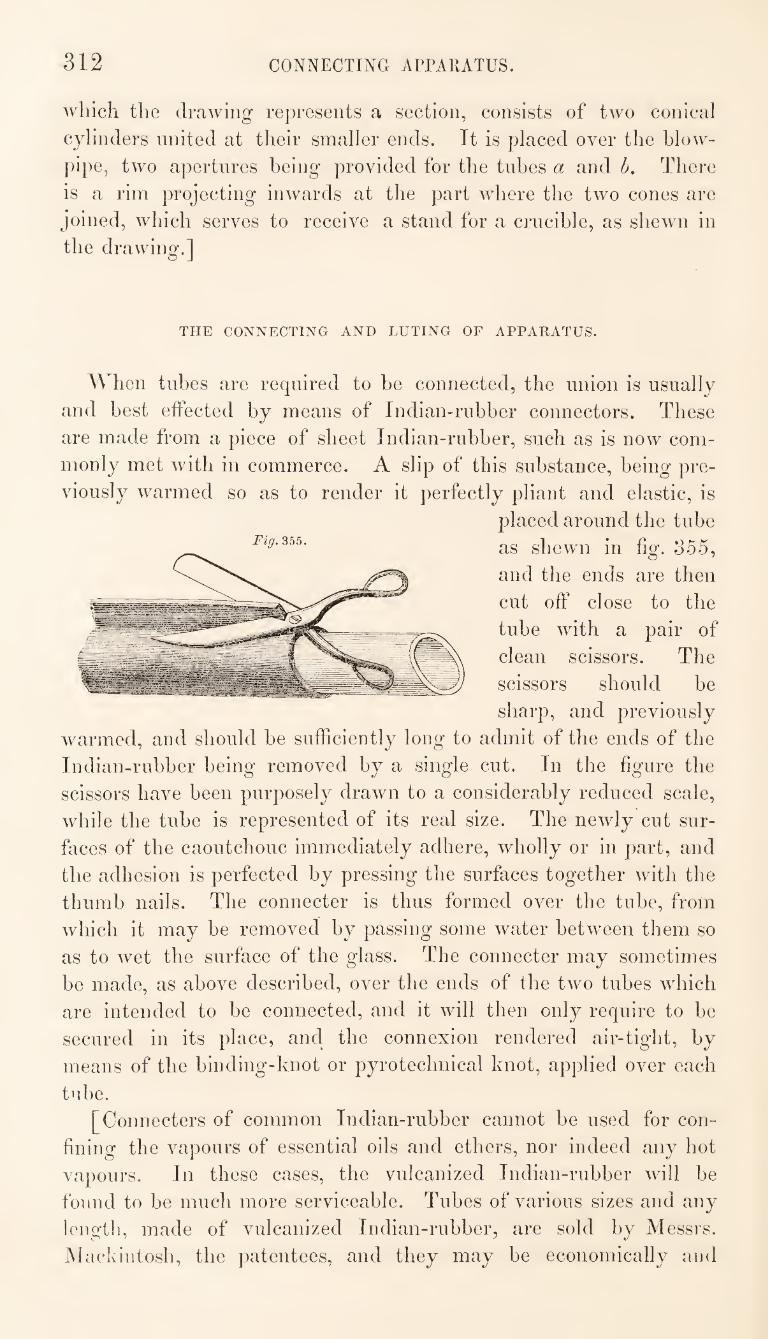
312 CONNECTING APPARATUS.
which the drawing represents a section, consists of two conical
cylinders united at their smaller ends. It is placed over the blow¬
pipe, two apertures being provided for the tubes a and h. There
is a rim projecting inwards at the part where the two cones are
joined, which serves to receive a stand for a crucible, as shewn in
the drawing.]
THE CONNECTING AND LUTING OF APPARATUS-
When tubes are required to he connected, the union is usually
and best effected by means of Indian-rubber connectors. These
are made from a piece of sheet Indian-rubber, such as is now com¬
monly met with in commerce. A slip of this substance, being pre¬
viously warmed so as to render it perfectly pliant and elastic, is
placed around the tube
as shewn in fig. o55,
and the ends are then
cut off close to the
tube with a pair of
clean scissors. The
scissors should be
sharp, and previously
warmed, and should be sufficiently long to admit of the ends of the
Indian-rubber being removed by a single cut. In the figure the
scissors have been purposely drawn to a considerably reduced scale,
while the tube is represented of its real size. The newly cut sur¬
faces of the caoutchouc immediately adhere, wholly or in part, and
the adhesion is perfected by pressing the surfaces together with the
thumb nails. The connecter is thus formed over the tube, from
which it may be removed by passing some water between them so
as to wet the surface of the glass. The connecter may sometimes
be made, as above described, over the ends of the two tubes which
are intended to be connected, and it will then only require to be
secured in its place, and the connexion rendered air-tight, by
means of the binding-knot or pyrotechnical knot, applied over each
tube.
[Connecters of common Indian-rubber cannot be used for con¬
fining the vapours of essential oils and ethers, nor indeed any hot
vapours. In these cases, the vulcanized Indian-rubher will be
found to be much more serviceable. Tubes of various sizes and any
length, made of vulcanized Indian-rubber, are sold by Messrs.
Mackintosh, the patentees, and they may be economically and
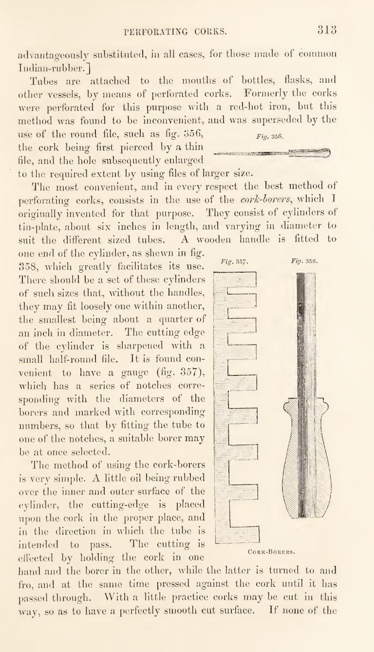
PERFORATING CORKS. 313
Fig. 357. Fig. 358.
m'A
advantageously substituted, in all cases, for those made of common
Indian-rubber.] Tubes are attached to the mouths of bottles, flasks, and
other vessels, by means of perforated corks. Formerly the corks were perforated for this purpose with a red-hot iron, hut this method was found to he inconvenient, and was superseded by the
use of the round file, such as fig. 356, Fig. 356. the cork being first pierced by a thin file, and the hole subsequently enlarged to the required extent by using files of larger size.
The most convenient, and in every respect the best method of perforating corks, consists in the use of the cork-borers^ which I originally invented for that purpose. They consist of cylinders of tin-plate, about six inches in length, and varying in diameter to suit the different sized tubes. A wooden handle is fitted to
one end of the cylinder, as shewn in fig. 358, which greatly fiicilitates its use. There should he a set of these cylinders of such sizes that, without the handles, they may fit loosely one within another, the smallest being about a quarter of an inch in diameter. The cutting edge of the cylinder is sharpened with a small half-round file. It is found con¬ venient to have a gauge (fig. 857), which has a series of notches corre¬ sponding with the diameters of the borers and marked with corresponding numbers, so that by fitting the tube to one of the notches, a suitable borer may be at once selected.
The method of using the cork-borers is very simple. A little oil being rubbed over the inner and outer surface of the cylinder, the cutting-edge is placed upon the cork in the proper place, and in the direction in which the tube is intended to pass. The cutting is effected by holding the cork in one hand and the borer in the other, while the latter is turned to and fro, and at the same time pressed against the cork until it has passed through. With a little practice corks may be cut in this way, so as to have a perfectly smooth cut surface. If none of the
Cork-Borers.
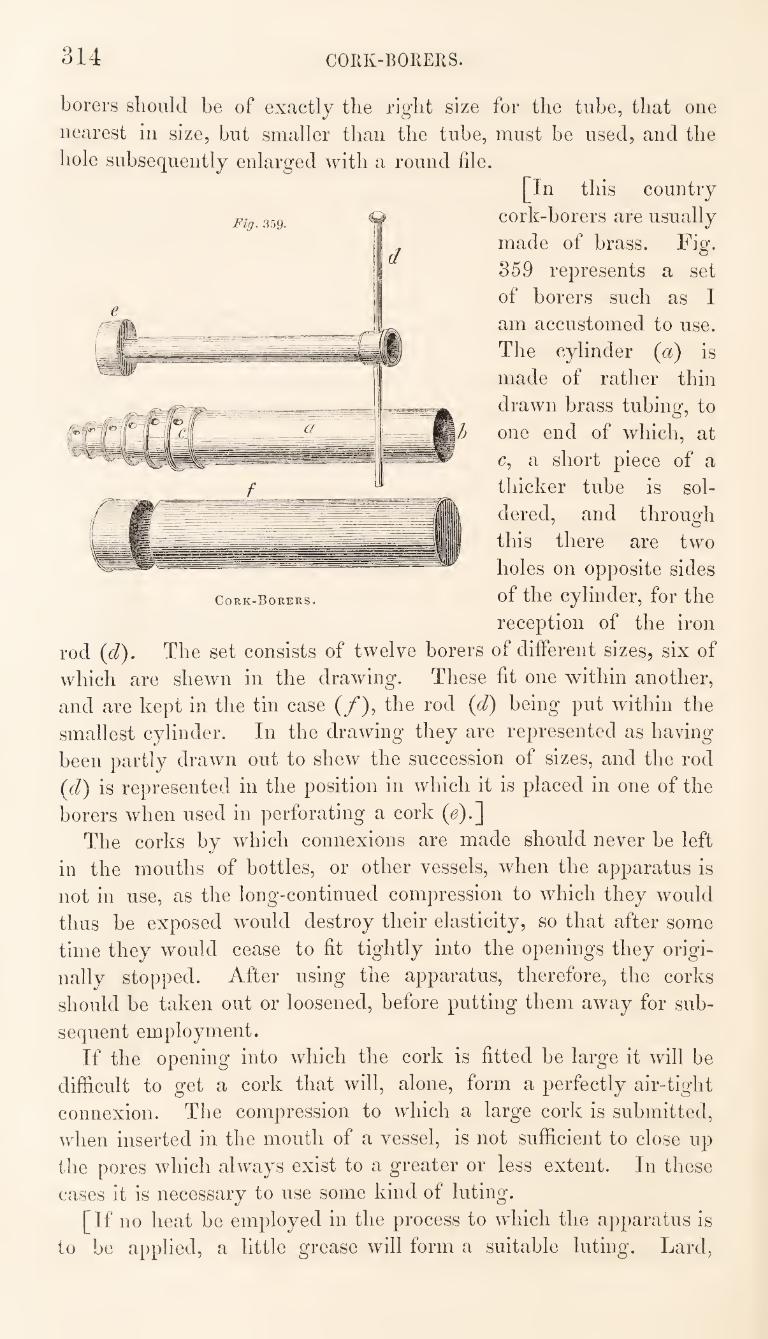
314 CORK-BOREKS.
borers should be of exactly the right size for the tube, that one
nearest in size, but smaller than the tube, must be used, and the
hole subsequently enlarged with a round file.
[In this country
cork-borers are usually
made of brass. Fig.
859 represents a set
of borers such as I
am accustomed to use.
The cylinder (a) is
made of rather thin
drawn brass tubing, to
one end of which, at
c, a short piece of a
thicker tube is sol¬
dered, and through
this there are two
holes on opposite sides
Cork-Borers. of the Cylinder, for the
reception of the iron
rod (d). The set consists of twelve borers of different sizes, six of
which are shewn in the drawing. These fit one within another,
and are kept in the tin case (/), the rod (d) being put within the
smallest cylinder. In the drawing they are represented as having
been partly drawn out to shew the succession of sizes, and the rod
(d) is represented in the position in which it is placed in one of the
borers when used in perforating a cork (e).]
The corks by which connexions are made should never be left
in the mouths of bottles, or other vessels, when the apparatus is
not in use, as the long-continued compression to which they would
thus be exposed would destroy their elasticity, so that after some
time they would cease to fit tightly into the openings they origi¬
nally stopped. After using the apparatus, therefore, the corks
should be taken out or loosened, before putting them away for sub¬
sequent employment.
If the opening into which the cork is fitted be large it will be
difficult to get a cork that will, alone, form a perfectly air-tight
connexion. The compression to which a large cork is submitted,
when inserted in the mouth of a vessel, is not sufficient to close up
the pores which always exist to a greater or less extent. In these
cases it is necessary to use some kind of luting.
[If no heat be employed in the process to which the apparatus is
to be applied, a little grease will form a suitable luting. Lard,
Fig. 359-
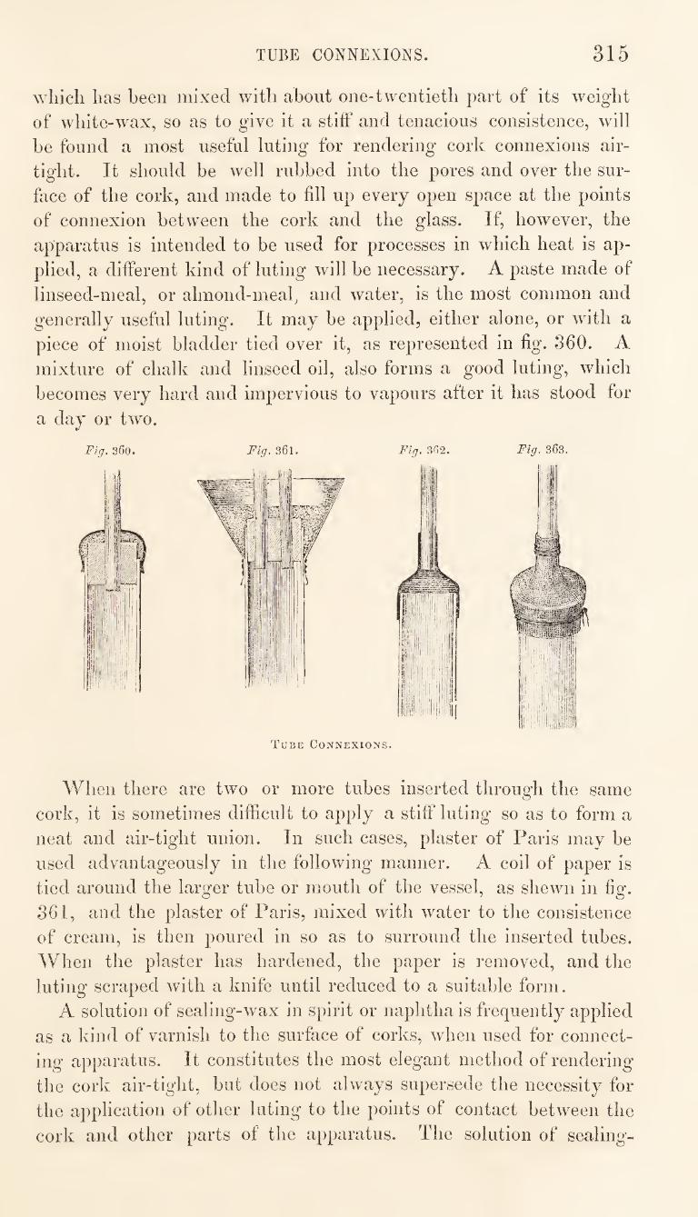
TUBE CONNEXIONS. 315
which has been mixed with about one-twentieth part of its weight
of white-wax, so as to give it a stift‘ and tenacious consistence, will
be found a most useful luting for rendering cork connexions air¬
tight. It should be well rubbed into the pores and over the sur¬
face of the cork, and made to fill up every open space at the points
of connexion between the cork and the glass. If, however, the
apparatus is intended to be used for processes in which heat is ap¬
plied, a different kind of luting will be necessary. A paste made of
linseed-meal, or almond-meal, and water, is the most common and
generally useful luting. It may be applied, either alone, or with a
piece of moist bladder tied over it, as represented in fig. 360. A
mixture of chalk and linseed oil, also forms a good luting, which
becomes very hard and impervious to vapours after it has stood for
a day or two.
Fig. 360. Fig. 361. Fig. 362.
Tube Connexions.
Fig. 363.
When there are two or more tubes inserted through the same
cork, it is sometimes difficult to apply a stiff luting so as to form a
neat and air-tight union. In such cases, plaster of Paris may be
used advantageously in the following manner. A coil of paper is
tied around the larger tube or mouth of the vessel, as shewn in fig.
361, and the plaster of Paris, mixed with water to the consistence
of cream, is then poured in so as to surround the inserted tubes.
When the plaster has hardened, the paper is removed, and the
luting scraped with a knife until reduced to a suitable form.
A solution of sealing-wax in spirit or naphtha is frequently applied
as a kind of varnish to the surface of corks, when used for connect-
ing apparatus. It constitutes the most elegant method of rendering
the cork air-tight, but does not always supersede the necessity for
the application of other luting to the points of contact between the
cork and other parts of the apparatus. The solution of sealing-
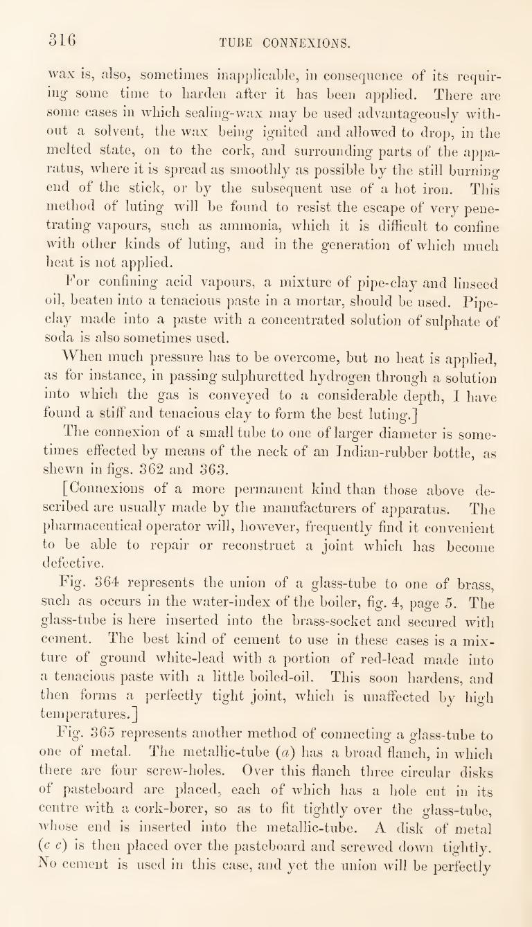
316 TUBE CONNEXIONS.
wax is, also, sometimes iria[)])]icable, in consequence of its requir¬
ing some time to harden after it has been applied. There are
some cases in which sealing-wax may be used advantageously with¬
out a solvent, the wax being ignited and allowed to drop, in the
melted state, on to the cork, and surrounding parts of the appa¬
ratus, where it is spread as smoothly as possible by the still burning
end of the stick, or by the subsequent use of a hot iron. This
method of luting will be found to resist the escape of very pene¬
trating vapours, such as ammonia, which it is difficult to confine
with other kinds of luting, and in the generation of which much
heat is not applied.
For confining acid vapours, a mixture of pipe-clay and linseed
oil, beaten into a tenacious paste in a mortar, should be used. Pipe¬
clay made into a paste with a concentrated solution of sulphate of
soda is also sometimes used.
When much pressure has to be overcome, but no heat is applied,
as for instance, in passing sulphuretted hydrogen through a solution
into which the gas is conveyed to a considerable depth, I have
found a stiff and tenacious clay to form the best luting.]
The connexion of a small tube to one of larger diameter is some¬
times effected by means of the neck of an Indian-rubber bottle, as
shewn in figs. 862 and 863.
[Connexions of a more permanent kind than those above de¬
scribed are usually made by the manufacturers of apparatus. The
pharmaceutical operator will, however, frequently find it convenient
to be able to repair or reconstruct a joint which has become
defective.
Fig. 864 represents the union of a glass-tube to one of brass,
such as occurs in the water-index of the boiler, fig. 4, page 5. The
glass-tube is here inserted into the brass-socket and secured with
cement. The best kind of cement to use in these cases is a mix¬
ture of ground white-lead with a portion of red-lead made into
a tenacious paste with a little boiled-oil. This soon hardens, and
then forms a perfectly tight joint, which is unaffected by high
temperatures.]
Fig. 865 represents another method of connecting a glass-tube to
one of metal. The metallic-tube (a) has a broad flanch, in which
there are four screw-holes. Over this flanch three circular disks
of pasteboard are placed, each of which has a hole cut in its
centre with a cork-borer, so as to fit tightly over the glass-tube,
whose end is inserted into the metallic-tube. A disk of metal
(c c) is then placed over the pasteboard and screwed down, tightly.
No cement is used in this case, and yet the union will be perfectly
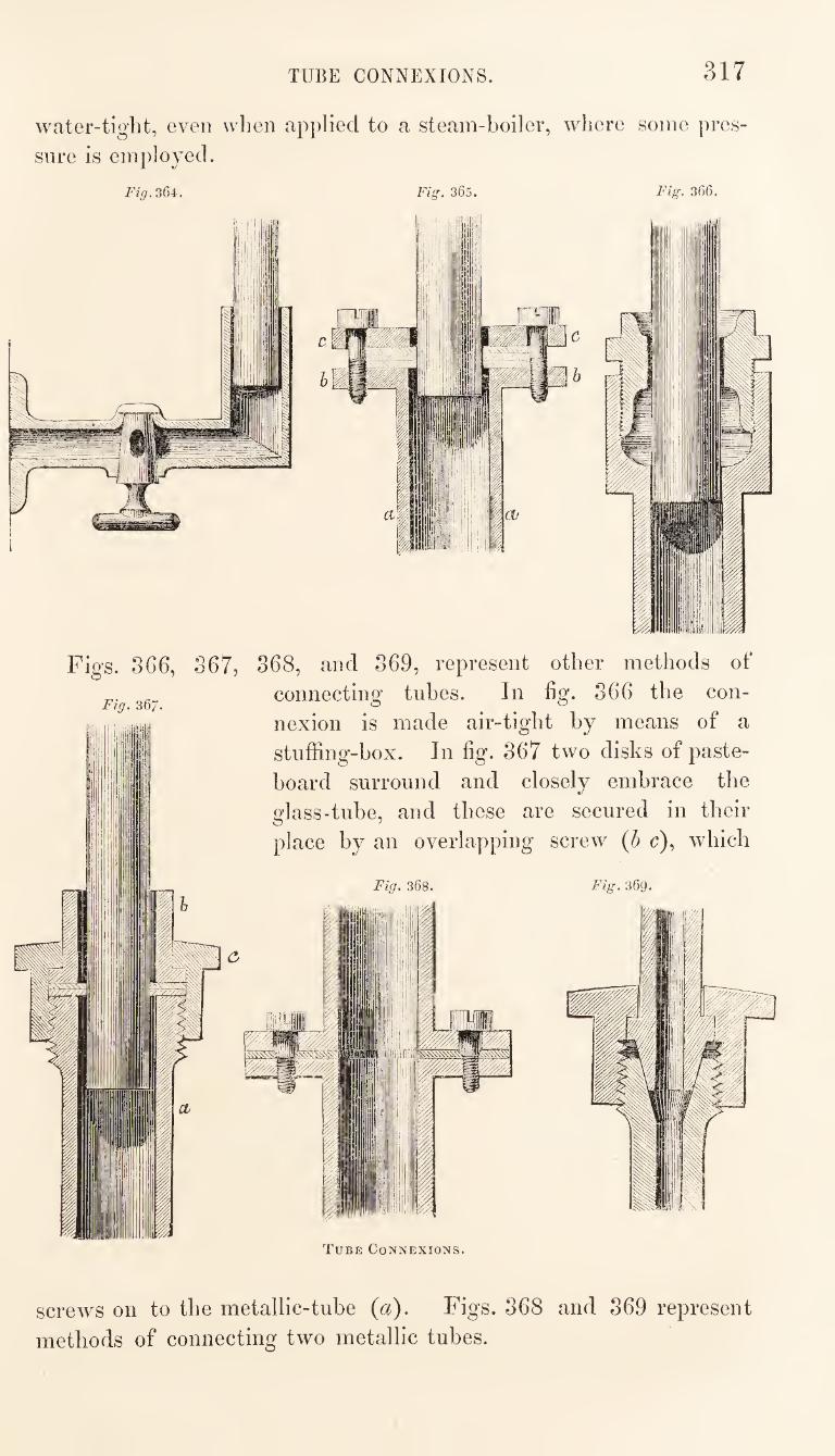
TUBE CONNEXIONS. 317
water-tight, even when applied to a steam-boiler, where some pres¬
sure is employed.
Figs. 866, 367,
Fig, 367.
<3
868, and 369, represent other methods of
connecting tubes. In fig. 366 the con¬
nexion is made air-tight by means of a
stnffing-box. In fig. 367 two disks of paste¬
board surround and closely embrace the
glass-tube, and these are secured in their
place by an overlapping screw {h c), which
screws on to the metallic-tube {a). Figs. 368 and 369 represent
methods of connecting two metallic tubes.
318 COATING GLASS WITH COPPER.
COATING OF GLASS AND FORCELATN VESSELS WITH COPPER.
At the exposition of works of art and manufacture in Paris, in
the summer of 1844, there were exhibited glass and porcelain ves¬
sels of different kinds coated with copper. The metallic coating
was perfectly smooth and of uniform thickness, and the adhesion
appeared to be perfect in every part. Among the vessels thus
coated were flasks, retorts, receivers, evaporating dishes, &c. It
was evident that the copper must have been deposited on these
vessels by electricity, and that it rendered them much less liable to
breakage, either from sudden changes of temperature or from other
causes, than they otherwise would be.
After my return home, having brought some of the coated vessels
as patterns, I made several experiments, with the view of ascer¬
taining the best method of effecting this useful application of the
electrotype process.
The first step in the process must of course be to cover the sur¬
face of the vessel with some substance capable of conducting elec¬
tricity. In my early experiments I put a thin coating of copal-
varnish over the part on which the copper was intended to be
deposited, and while this was yet adhesive it was covered with
thin leaves of Dutch-metal. A conducting surface being formed in
this way, and the varnish allowed to dry, the vessel was filled with
water and immersed in a solution of sulphate of copper, such as is
generally used for electrotyping, contained in a large earthen pan.
In the same pan was placed a porous earthen vessel filled with
diluted sulphuric acid, and containing a zinc cylinder, from which a
copper wire was made to communicate with the conducting surface
of the vessel to be coated. The part of the wire that passed
through the solution of copper was isolated by enclosing it with
sealing-wax in a glass tube. With this simple arrangement a suf¬
ficient deposit of copper was obtained in three or four days, care
being taken from day to day to turn the vessel under operation so
as to present a new surface towards the zinc cylinder, as the copper
is always deposited more rapidly on the parts facing the zinc than
on any others. Fig. 370 represents the whole arrangement.
In subsequent experiments I found that metallic bronze-powder
brushed over a thin coating of varnish forms the best conducting
surface on which to deposit the copper.
[ My experience in the use and preparation of vessels coated with
copper dates from the same period as that of Dr. Mohr. I brought
several coated glass-vessels from Paris in 1844, some of which have
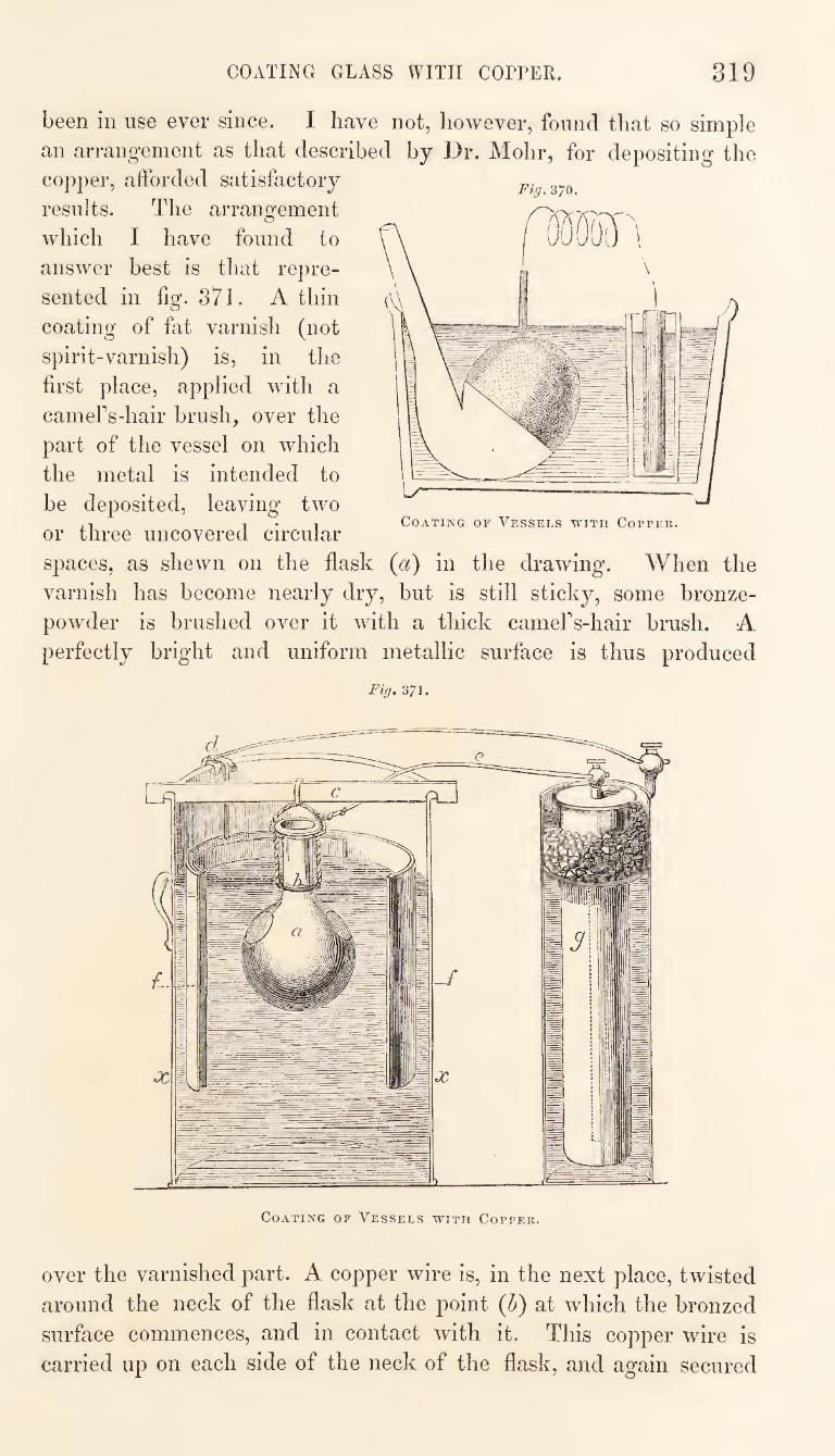
COxVTING GLASS ^ITII COPPER 319
been in use ever since. I have not, however, found that so simple
an arrangement as that described by Dr. Mohr, for depositing the
copper, afforded satisfactory
results. The arrangement
which I have found to
answer best is that repre¬
sented in fig. 371. A thin
coating of fat varnish (not
spirit-varnish) is, in the
first place, applied with a
cameFs-hair brush, over the
part of the vessel on which
the metal is intended to
be deposited, leaving two
or three uncovered circular
spaces, as shewn on the flask (^i^) in the drawing. When the
varnish has become nearly dry, but is still sticky, some bronze-
powder is brushed over it with a thick camers-hair brush. A
perfectly bright and uniform metallic surface is thus produced
Fig. 371.
Fig. 370.
Coating or Vessels with Coppee.
Coating of Vessels with Copper.
over the varnished part. A copper wire is, in the next place, twisted
around the neck of the flask at the point {h) at which the bronzed
surface commences, and in contact with it. This copper wire is
carried up on each side of the neck of the flask, and again secured
320 WAXED PAPER.
immediately below the projecting rim or lip, from whence it is
formed into a loop over the mouth of the vessel. The flask, thus
prepared, is filled with water, and a sufficient quantity of shots put
into it to make it sink in the solution of copper. The solution con¬
sists of two parts of a saturated solution of sulphate of copper, and
one part of a saturated solution of sulphate of soda to which as
much sulphate of copper as it is capable of dissolving has been sub¬
sequently added. This solution is put into a large copper vessel
^), across the top of which is placed a bar of wood (c), from
which the flask is suspended. A sheet of copper, coiled into a cir¬
cular form {f y*) is also immersed in the solution so as to surround
the flask, and a copper wire {d) connects this with the positive pole
of a constant battery, while the flask is at the same time connected
with the negative pole by the wire (e). The battery (y) is a
large DanieFs battery of the usual kind. With this arrangement
the copper will be deposited of sufficient thickness in about twm
days.
There are several advantages in the use of glass-vessels thus
coated with copper. They are rendered less liable to be broken
than they otherwise would be : when exposed to the flame of a
lamp the heat is more equally distributed over the surface of the
vessel, and condensation is prevented in the upper part of the globe
when used for distillation. I have not found any indications of a
separation of the metal from the glass, even after long use I am
informed, however, that they do not answer for the distillation of
liquids which boil at a very high temperature. On applying them
for the distillation of oil of vitriol, it has been found that the copper
speedily becomes oxidized, and the coating thus destroyed.]
PREPAKATION ' OF WAXED-PAPER.
Tissue-paper is most advantageously employed for making
waxed-paper. It absorbs but little wax, and when prepared has an
elegant appearance, and is easily moulded to the mouth of the
gallipot or other vessel to which it may be applied. In accordance
with its name, waxed-paper should be prepared with wax, but
practically it is frequently made by impregnating the paper with
stearine, and sometimes with oil. Stearine appears to answer nearly
as well as wax.
Waxed-paper is prepared in the following way. A plate of iron,
the upper surface of which is quite clean, is placed over a furnace
until it has become warm. On the iron-plate a sheet of stout
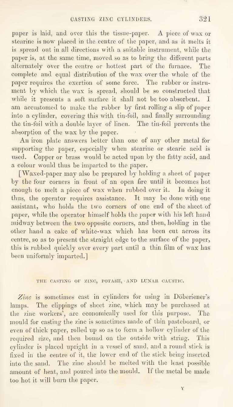
CASTING ZINC CYLINDERS. 321
paper is laid, and over this the tissue-paper. A piece of wax or
stearine is now placed in the centre of the paper, and as it melts it
is spread out in all directions with a suitable instrument, while the
paper is, at the same time, moved so as to bring the different parts
alternately over the centre or hottest part of the furnace. The
complete and equal distribution of the wax over the whole of the
paper requires the exertion of some force. The rubber or instru¬
ment by which the wax is spread, should be so constructed that
while it presents a soft surface it shall not be too absorbent. I
am accustomed to make the rubber by first rolling a slip of paper
into a cylinder, covering this with tin-foil, and finally surrounding
the tin-foil with a double layer of linen. The tin-foil prevents the
absorption of the wax by the paper.
An iron plate answers better than one of any other metal for
supporting the paper, especially when stearine or stearic acid is
used. Copper or brass would be acted upon by the fatty acid, and
a colour would thus be imparted to the paper.
[Waxed-paper may also be prepared by holding a sheet of paper
by the four corners in front of an open fire until it becomes hot
enough to melt a piece of wax when rubbed over it. In doing it
thus, the operator requires assistance. It may be done with one
assistant, who holds the two corners of one end of the sheet of
paper, while the operator himself holds the paper with his left hand
midway between the two opposite corners, and then, holding in the
other hand a cake of white-wax which has been cut across its
centre, so as to present the straight edge to the surface of the paper,
this is rubbed quickly over every part until a thin film of wax has
been uniformly imparted.]
THE CASTING OF ZINC, POTASH, AND LUNAE CAUSTIC.
Zinc is sometimes cast in cylinders for using in Doberiener’s
lamps. The clippings of sheet zinc, which may be purchased at
the zinc workers’, are economically used for this purpose. The
mould for casting the zinc is sometimes made of thin pasteboard, or
even of thick paper, rolled up so as to form a hollow cylinder of the
required size, and then bound on the outside with string. This
cylinder is placed upright in a vessel of sand, and a round stick is
fixed in the centre of it, tlie lower end of the stick being inserted
into the sand. The zinc should be melted with the least possible
amount of heat, and poured into the mould. If the metal be made
too hot it will burn the paper.
Y
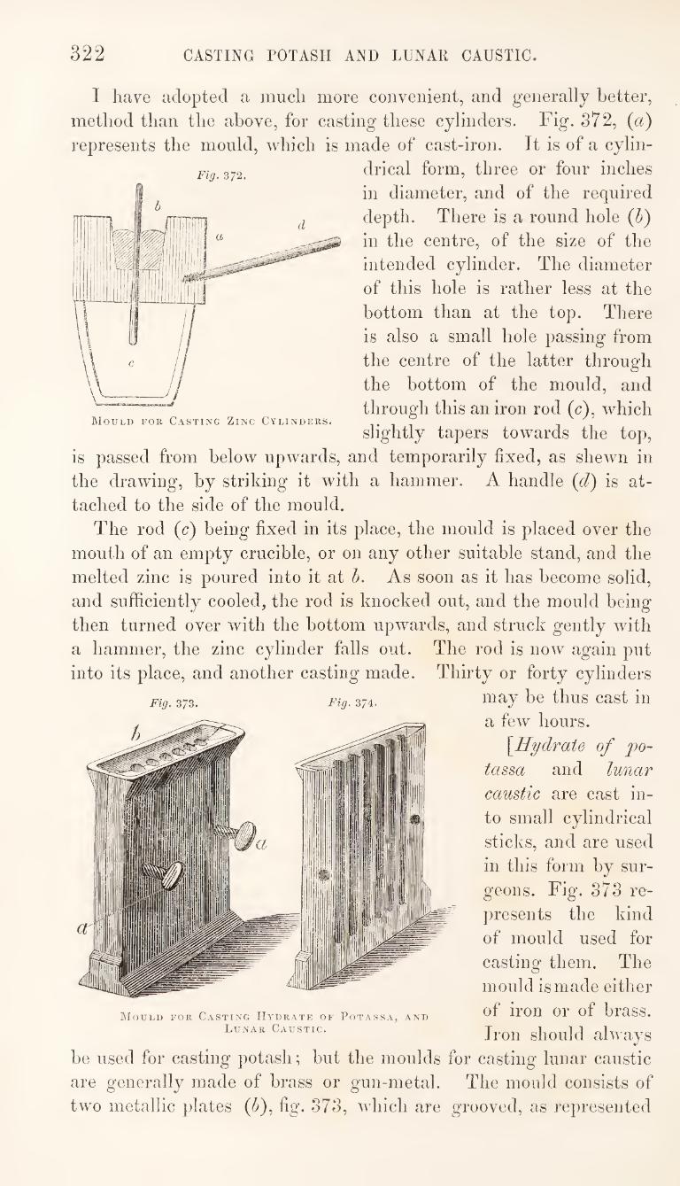
322 CASTING POTASH AND LUNAR CAUSTIC.
Fig. 372.
I have adopted a much more convenient, and generally better,
method than the above, for casting these cylinders. Fig. 872, (a)
represents the mould, which is made of cast-iron. It is of a cylin¬
drical form, three or four inches
in diameter, and of the required
depth. There is a round hole {b)
in the centre, of the size of the
intended cylinder. The diameter
of this hole is rather less at the
bottom than at the top. There
is also a small hole passing from
the centre of the latter through
the bottom of the mould, and
through this an iron rod (c), which
slightly tapers towards the top,
is passed from below upwards, and temporarily fixed, as shewn in
the drawing, by striking it with a hammer. A handle (d) is at¬
tached to the side of the mould.
The rod (c) being fixed in its place, the mould is placed over the
mout h of an empty crucible, or on any other suitable stand, and the
melted zinc is poured into it at b. As soon as it has become solid,
and sufficiently cooled, the rod is knocked out, and the mould being
then turned over with the bottom upwards, and struck gently with
a hammer, the zinc cylinder falls out. The rod is now again put
into its place, and another casting made. Thirty or forty cylinders
Fig. 373. Fig. 374. “^y be thus cast in
/ ^ hours. " [Hydrate of po-
tassa and lunar
caustic are cast in¬
to small cylindrical
sticks, and are used
in this form by sur¬
geons. Fig. 373 re¬
presents the kind
of mould used for
casting them. The
mould is made either
of iron or of brass.
Iron should always
be used for casting potash; but the moulds for casting lunar caustic
are generally made of brass or gun-metal. The mould consists of
two metallic plates (^), fig. 373, which are grooved, as represented
Mould for Casting Hydrate of Potassa, and
Lunar Caustic.
CLOSED OEERATING CHAMBER. 323
in fig. 374. These plates are joined together by the screws {a a)
and the substance to be cast is poured, in the melted state, into the
cavity at the top, and allowed to run into the grooves. When it
has hardened, the mould is unscrewed, the two plates taken asunder,
and the cylinders removed from the grooves.]
CLOSED OPERATING CHAMBER OR CLOSET.
There are so many operations in the laboratory in which noxious
vapours are evolved, that it is always desirable, if it can be so
arranged, to have a chamber or closet communicating with the
chimney, and having a glazed door in front by which the escape of
vapours into the apartment may be prevented. A closet of this de¬
scription is represented in fig. 875. It should be fixed against a
chimney, into which all vapours evolved in it may be conducted
through an opening provided for the purpose near the top of the
closet. It should also be so situated that sufficient light may enter
through the glazed door in front. The closet from which the
drawing, fig. 375, has been made, is constructed in the following
manner.
Two thin brick walls {a a) are run up to form the sides of the
closet. These are about three feet and a half distant from each
other, and they project about twenty-seven inches from the wall of
the room. The operating table (h) is fixed at a height of thirty-
two inches from the ground, and consists of a cast-iron plate resting
on a stone slab. The iron plate is made to slide in a groove on
each side, so that it may be easily removed and replaced at any
time, without otherwise disturbing the closet. The height of the
table is so arranged that a dish or other vessel, placed on a small
furnace within the closet, shall be in such a position as to admit of
the contents being closely observed by the operator.
The space between the operating table (h) and the ceiling is en¬
closed, partly by a brick wall, and partly by a glass door. The
upper half is bricked in the same way as the sides of the closet, the
brickwork being supported on a strong iron bar. The lower half is
enclosed with a glazed sash, running in a frame like a common
window-sash, and counterbalanced by a weight.
The space below the operating table is divided into two compart¬
ments by a wall. Fuel is kept in one of these compartments, and
apparatus in the other.
A double-acting bellows is fixed near the ceiling, and the rope
and stirrup {m) by which this is worked hangs on the left hand
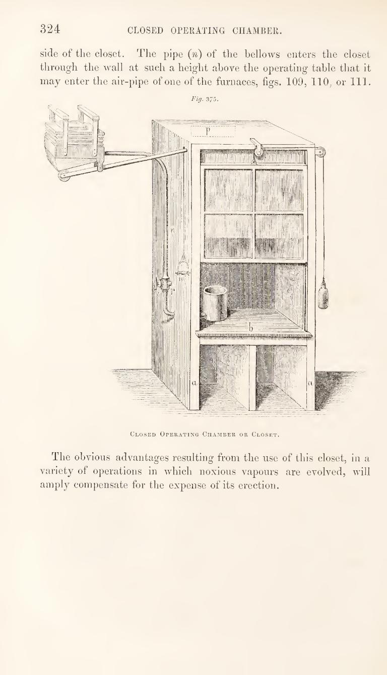
324 CLOSED OPERATING CHAMBER.
side of the closet. The pipe (n) of the bellows enters the closet
through the wall at such a height above the operating table that it
may enter the air-pipe of one of the furnaces, figs. 109, 110, or 111.
Closed Operating Chamber or Closet.
The obvious advantages resulting from the use of this closet, in a
variety of operations in which noxious vapours are evolved, will
amply compensate for the expense of its erection.
325
THE DISPENSING OF MEDICINES.
The extemporaneous admixture and preparation of medicines
from the prescriptions of medical men, and the supply or adminis¬
tration of remedial agents to the public, constitutes the primary
objects, and most ostensible duties of the pharmaceutist. All other
operations are performed in anticipation of those connected with
the dispensing of medicines.
The duties of the dispenser are of a very important nature, and
for their due discharge a certain combination of qualities is required
in the individual who undertakes them. With some degree of
physical strength and agility, he should combine a quick perception,
sound judgment, and firmness of resolution. He should maintain a
constant and lively attention to every operation, however trifling,
with which he may be occupied, and evince, both by night and by
day, a readiness to fulfil his duty in serving others, even at the
sacrifice of his own convenience and pleasure.
The art of dispensing is generally learnt from practical demon¬
stration, and this indeed, is the only method of acquiring expertness
in the various manipulations which the art involves. It is not,
therefore, contemplated in the observations which will be otfered
here, to supersede the necessity for practical instruction, but merely
to give the results of many years’ observation, with the view of
supplying some facts to the less experienced, and of inducing
a habit of observation and reflection with reference to the most
apparently simple phenomena.
The operations of dispensing are carried on at the counter appro¬
priated to that purpose, either in front and within view of the
customers, or behind a screen which intercepts the view. The con¬
struction of the dispensing counter, without the screen, has been
described elsewhere. The screen, which usually consists of a cur¬
tain, or of a wooden erection, on the front edge of the counter, and
extending to about the height of a man’s shoulder, or not quite so
high, is generally adopted in the north of Germany. There is
much difference of opinion with regard to the supposed advantage
of this arrangement. As much, probably, might be said against it
as in its favour. To the dispenser, it may be more agreeable to
carry on his operations behind the screen, where he is not exposed
to the scrutinizing eye of the patients, who might otherwise be
watching his fruitless attempts at effecting the combination of some
326 MEANS FOR PRESERVING CLEANLINESS.
rebellious constituents of a pill-mass, or criticising the accuracy
with which he divides out a powder into the separate doses. But
on the other hand, an accomplished dispenser should be capable of
evincing his skill by adroitly overcoming difficulties; and the
stimulus which the observation of the customer affords to the culti¬
vation of habitual expertness and careful attention, is one of the
advantages of the unscreened counter.
The existence of the screen will naturally excite in the mind of
the customer a suspicion that something is being done with which
the operator is anxious that he should not become acquainted ; and
it is also calculated to induce carelessness on the part of the
operator, which would probably become habitual. Under such
circumstances, the dispenser may be sometimes seen in his dressing-
gown and slippers,—a habit which cannot be too strongly con¬
demned. He should every morning make his appearance, from
the commencement of the hours of business, neatly, but not ex¬
pensively dressed. Before his customers, and indeed at all times,
while engaged in the operations of dispensing, he should be careful
to observe the greatest possible cleanliness, and to avoid everything
that would be calculated to excite feelings of disgust.
The dispenser who licks the lip of the syrup-bottle, after pour¬
ing out what he requires;—who removes any foreign body from a
mixture by putting his finger into it, or puts a cork between his
teeth to soften it and make it fit the mouth of a bottle, might be
compared to an ill-bred person, who, at meal-time, drinks from the
decanter, helps himself to salt with his fingers, or cuts bread from
the loaf with a knife which has just been in his mouth. He who
prepares the dose for the sickly, and often fastidious patient,
should be especially careful that he add no extraneous repulsiveness
to that which, of necessity, belongs to the prescribed remedy.
MEANS FOR PRESERVING CLEANLINESS.
The means by which cleanliness is preserved, should be amply
provided in the dispensary. The most important of these means is
water. A sin^ with water laid on^ in a convenient situation, for the
use of those engaged in dispensing, is indispensable. If there
should not be a water-cistern on the premises, from which a supply
might be conveyed to the sink by a pipe, it will be necessary to
provide a vessel for this purpose. It is desirable that the cistern
should not be at a great height above the stop-cock at which the
water is drawn, as the force of the current would in that case be
AIDS TO DISPENSING. 327
SO great as to cause much splashing of the water in using it for
washine- a measure-glass or other vessel. The size of the tap
should also be such that it may pass into the mouth of a bottle.
A good sponge is another requisite. It should have a string
attached to it, by which it is hung from a nail in some suitable
place. The sponge is used for wiping up any water, or substances
soluble in water, that might be spilled on the counter. It is kept
in a moist state, so that it will readily absorb any liquid, and it
should always be washed and squeezed before being returned to its
place after use. Care should be taken, however, that the sponge
is never used for wiping any kind of grease, as this would render
it subsequently useless, until it be well cleaned with soap or car¬
bonate of soda and hot water. Two towels^ or cloths^ will also be required, which should be of
different degrees of fineness. These may be kept in a drawer, but
must be ready of access. Many dispensers appear to be ignorant
of the proper use of the towel. The finer towel ought to be used
only for wiping clean water off the bottles, measures, or other
objects which have been wetted, or which require delicate cleaning.
The coarser towel may be employed for removing dust from the
counter, or for other similar purposes. But it should be borne in
mind that whatever dirt is removed from an object with the towel,
may become attached to the next object to which the towel is
applied. The practice so commonly adopted, of wiping up all
kinds of dirt with the towel, seems to indicate a great want of
discernment or reflection in the operator, for such conduct, after
two or three repetitions of it, only increases his difficulties by ren¬
dering the towel of no further use. Powders, or anything more
than a sprinkling of dust, should be always removed with a dust¬
ing-brush, or the coarse towel should be used in such a way as to
remove the dust from the object without holding it in its texture.
Syrups, mixtures, extracts, and all substances of this kind, which
are soluble in water, should be removed with the wet sponge, and
the place then wiped dry with the towel. All greasy substances
should be carefully removed with blotting-paper, saw-dust, or a
piece of tow. A little attention to these points will save a great
deal of inconvenience and trouble, and will greatly facilitate the
maintenance of cleanliness.
AIDS TO DISPENSING.
[There are several preparations which may be made for the
purpose of aiding or expediting the operations of dispensing. If
328 AIDS TO DISPENSING.
by adopting such means, the properties of the medicines are not
altered, while the pharmaceutist is enabled with greater facility to
dispense them, no possible objection can be urged against the
practice. Indeed, in some cases, there is decided advantage, inde¬
pendently of the saving of time, in having the requirements of
prescriptions met by anticipation, and operations which are ordered
extemporaneously, performed during leisure hours, when greater attention can be devoted to them.
Thus, for instance, many salts which are frequently ordered in
prescriptions, are advantageously kept in fine powder, in which
state they will more readily dissolve in any fluid. In this way the
use of a mortar, which otherwise would be required, may be dis¬
pensed with, in effecting solution. It is important, however, that
due care should be taken to ascertain that the salt, when powdered,
has the same composition as the crystals, or, at least, that there is
some known and definite relation between them. Efflorescent
salts, such as carbonate of soda, and sulphate of soda, would lose
a portion of their winter of crystallization in being powdered, unless
the process were conducted with special precautions. Sesquicar-
bonate of ammonia would also be likely to undergo some change.
These salts, even if ascertained to be unaltered in composition when
first reduced to powder, would be more likely to undergo change
from exposure to the air in this state than they would if the crystals
were unbroken. Moreover, it would be more difficult to detect
the occurrence of change by the eye, in the case of the powder,
than it would be in that of the properly crystallized salt. But
there are many salts, such as salammoniac, nitrate of potash, alum,
and sulphate of magnesia, which are not subject to the changes
indicated from mere exposure to the air. It would be necessary,
of course, carefully to distinguish between salts powdered with
their w^ater of crystallization, and those, such as alum and sulphate
of magnesia, which are sometimes rendered anhydrous before being powdered.
Again, there are some salts which may be very conveniently
kept in solution for use in dispensing. Of this class, are sulphate
of magnesia, salammoniac, and carbonate of potash. It is desirable,
unless there be some obvious reason for doing otherwise, to make
such solutions of uniform strength; and the strength should be such
as to admit of easy calculation in determining the quantity of so¬
lution that shall contain a specified quantity of the salt. As the
solution would be always apportioned by measurement (in Eng¬
land), while the salt is ordered by weight, the weight of the latter
should bear a simple relation to the volume of the former. The
AIDS TO DISPENSING. 329
most convenient proportions will be those in which f^iv of the so¬
lution shall contain ^i of the salt. A solution of this kind is made
by dissolving 5v, troy-weight, of the salt in water, and making the
solution to measure f5xx. Solutions thus made, of the salts above-
named, will be of such strength that there will be no chance of any
portion of the salt being deposited in cold weather, while, at the
same time, calculations will be easily made. The labels of the
bottles should indicate the strength of the solutions.
There are some salts which are not unfrequently ordered in
prescriptions, but which, nevertheless, cannot be kept in solution
in consequence of their undergoing decomposition. Emetic tartar
(potassio-tartrate of antimony) is a salt of this kind, and indeed
most salts which contain organic acids belong to the same class.
Salts, the solubility of which varies much with differences of
temperature, cannot often be conveniently kept in solution, unless
much diluted, as the strength of the solution would be liable to
variation from the deposition of crystals in cold weather. This is
the case with sulphate of soda and nitrate of potash, which, although
very soluble at temperatures above 60° or 70°, are very much less
soluble at low temperatures.
There are other substances which may be kept in solution, such
as manna, extract of liquorice, and gum ammoniacum. The phar¬
maceutist will, of course, be guided in his selection of those which
it will be most desirable to keep thus prepared, by the common
requirements of the locality in which he is situated. The practice
of a neighbouring physician may render a preparation useful in a
particular place, while there would be no demand for it in a
different locality.
In some places, Griffiths’s Mixture (the Mistura Ferri composita
of the Pharmacopoeia), is very frequently ordered in prescrip¬
tions, and as some time is occupied in properly preparing this mix¬
ture, it may, in such case, be kept partly prepared beforehand, by
which means the operation of dispensing it will be greatly expe¬
dited. The emulsion of myrrh, carefully made from picked pieces
of the gum-resin, which, when broken, present an opaque and milky
appearance in the centre, and to which all the ingredients, except¬
ing the sulphate of iron, have been added, may be kept in a
stoppered bottle for several weeks without undergoing any change,
and the mixture will be at any time completed by adding to a
portion of it the proper quantity of sulphate of iron.
Aromatic confection is sometimes kept mixed with wateiq so
that f^ij of it shall contain of the confection. This mixture
requires to be shaken up in the bottle in which it is kept, so that
330 AIDS TO DISPENSING.
the ingredients may be held in suspension wlien a portion of it is
poured out. It should not be long kept thus mixed, as it is liable
to undergo fermentive decomposition, especially in warm weather.
Some extracts and pill-masses may he conveniently kei)t, for
use in dispensing, in a state different from that in which they
are ordered in the Pharmacopoeia. Thus, it is often found ad¬
vantageous to have compound extract of colocyntli in the form of
powder, as well as in the soft state. Extract of jalap is also kept
in powder. The pharmaceutist should always prepare these powders
himself. The greatest possible care and attention are required to
avoid injuring the qualities of the extracts in the desiccation to
which they are submitted. An accurate determination must also
he made of the relation in weight which the powder bears to the
extract in its original state, and this relation should be specified on
the label of the bottle in which it is kept.
Plummer s pill {Pilulcc hydrargyri cJiloridi compositec of the
Pharmacopceia), is frequently kept in powder, one of the ingre¬
dients, namely, the treacle, being omitted ; by which means the
strength is increased one-fifth. The object in adopting this method
of keeping the pill, is to obviate the inconvenience often expe¬
rienced, when it is kept for some time in the form pill-mass, made
with treacle, from its becoming hard and intractable. In using
the powder the difference in strength must be taken into account,
and the treacle or other excipient added.
The concentrated infusions constitute important, perhaps the most
important, aids to dispensing. These preparations have come into
very general use, and in many establishments they are always sub¬
stituted for the infusions made according to the instructions of the
college. It is very questionable whether the practice of using con¬
centrated infusions in dispensing medicines can be justified, except¬
ing under particular circumstances. Some concentrated infusions,
which I have met with in commerce, certainly afford, when diluted,
very near approximations in all their sensible qualities, to the
infusions made in the ordinary way, but others have been found to
be of a very different character, and to be greatly deficient in
strength, or in the properties peculiar to the infusions they repre¬
sent. In all cases, where circumstances will admit, I think, the
use of concentrated infusions ought to be avoided, at least, until
they are sanctioned by the college. Every pharmaceutist should,
however, be provided with the means of supplying the best sub¬
stitute for a properly and recently made infusion in a case of
emero'encv. O «/
When the dispensing-counter has a boarded screen in front of
INFUSIONS AND DECOCTIONS. 331
tlie dispenser, a very useful aid to his operations may be afforded
by liaviug a set of small bottles, containing those substances which
are most frequently ordered in prescriptions, arranged on shelves
against the screen.]
INFUSIONS AND DECOCTIONS.
[The preparation of infusions and decoctions is a very troublesome,
yet necessary part of the operations connected with the dispensing
department. Much difficulty and inconvenience are frequently
experienced, especially in houses where there is not much dis¬
pensing, in providing a supply of these preparations, at the times
and in the quantities suited to -the daily requirements of the
business. In consequence of their proneness to undergo change,
they cannot be kept, under ordinary conditions, for more than a
day or two, especially in warm weather. They ought, therefore,
to be made on the day on which they are used in dispensing, other¬
wise they may be sent out in a state of incipient decomposition.
If they be not prepared in anticipation of the requirements of the
day, much inconvenient delay will often be occasioned in supply¬
ing medicines that are ordered; and if they are prepared every
morning in readiness, there will often be much waste in conse¬
quence of the uncertainty of the demand.
It is not customary to keep decoctions ready made, excepting,
occasionally, decoction of bark, or any particular one which local or
temporary circumstances niay call into unusual requisition. It is
also very rarely found necessary to keep the whole of the infusions
in readiness, l3ut their use is much more general than that of the
decoctions, and some of them, such as the infusions of senna and
roses, are in daily use in most localities.
The nature and extent of the business will indicate the amount
of daily preparation required in reference to the supply of infusions
and decoctions; and, in accordance with this, means for preparing
them must be provided. The pharmaceutical stove, described at page 5, if kept in daily
operation, will afford efficient accommodation, as far as regards the
supply of boiling-water and of heat.
The infusion-pot, fig. 376, which has been described at page 89,
is the vessel best suited for making infusions in ; and a flat-bot¬
tomed saucepan, such as fig. 877, may be conveniently used for
boiling decoctions. A saucepan of this kind may be placed on the
hot plate of the pharmaceutical stove, where two or three of them
may be kept boiling at the same time.
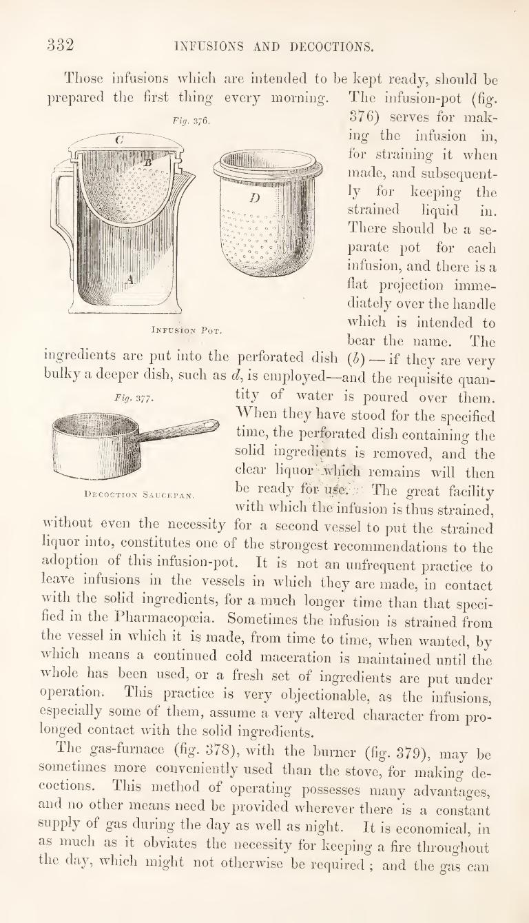
332 INFUSIONS AND DECOCTIONS.
C
Those infusions wliich are intended to be kept ready, should be
prepared the first thing every morning. The infusion-pot (fig.
Fig.z7Q. S7C) serves for mak¬
ing the infusion in,
for straining it when
made, and subsequent¬
ly for keeping the
strained liquid in.
There should be a se¬
parate pot for each
infusion, and there is a
flat projection imme¬
diately over the handle
which is intended to
bear the name. The ingredients are put into the perforated dish (5) — if they are very
bulky a deeper dish, such as is employed—and the requisite quan-
Fig. 377. water is j)oured over them. When they have stood for the specified
time, the perforated dish containing the
solid ingredients is removed, and the
clear liquor which remains will then
be ready for- tts^e.;; The great facility
with which the infusion is thus strained, without even the necessity for a second vessel to put the strained
liquor into, constitutes one of the strongest recommendations to the
adoption of this infusion-pot. It is not an unfrequent practice to
leave infusions in the vessels in which they are made, in contact
with the solid ingredients, for a much longer time than that speci¬
fied in the Pharmacopceia. Sometimes the infusion is strained from
the vessel in which it is made, from time to time, when wanted, by
which means a continued cold maceration is maintained untiUhe
whole has been used, or a fresh set of ingredients are put under
operation. This practice is very objectionable, as the infusions,
especially some of them, assume a very altered character from pro¬ longed contact with the solid ingredients.
The gas-furnace (fig. 878), with the burner (fig. 879), may be
sometimes more conveniently used than the stove, for making de¬
coctions. This method of operating possesses many advantages,
and no other means need be provided wherever there is a constant
supply of gas during the day as well as night. It is economical, in
as much as it obviates the necessity for keeping a fire throughout the day, which might not otherwise be required ; and the gas can
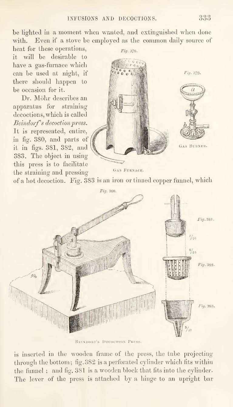
INFUSIONS AND DECOCTIONS. 333
Fig. 378.
Gas Furnace.
Fig. 379.
be lighted in a moment when wanted, and extinguished when done
with. Even if a stove be employed as the common daily source of
heat for these operations,
it will be desirable to
have a gas-furnace which
can be used at night, if
there should happen to
be occasion for it.
Dr. Mohr describes an
apparatus for straining
decoctions, which is called
Beindorfs decoction press.
It is represented, entire,
in fig. 880, and parts of
it in figs. 881, 882, and
888. The object in using
this press is to facilitate
the straining and pressing
of a hot decoction. Fig. 888 is an iron or tinned copper funnel, which
Gas Burner.
Fig. 380.
Fig. 381.
Fig. 382.
Fig. 383.
Beinuorf’s Decoction Press.
is inserted in the wooden frame of the press, the tube projecting
through the bottom; fig.882 is a perforated cylinder which fits within
the funnel ; and fig. 881 is a wooden block that fits into the cylinder-
The lever of the press is attached by a hinge to an upright bar
334 INFUSIONS AND DECOCTIONS.
forming the fulcrum, which turns in a socket, so that when tlie
block (fig. o81) is fixed to the lever, as shewn in fig. 380, this may
be turned from the mouth of the funnel to admit of the introduction
or removal of the ingredients to be pressed, and again brought over
the cylinder when pressure is required. A straining-cloth is first
put into the cylinder, and a vessel placed beneath the frame to
receive the strained liquor ; the decoction is then poured in, and
pressure applied by means of the lever and attached block.
The foregoing arrangements, for the preparation of infusions and
decoctions would fully meet the requirements of a good dispensing
business, and with such provisions the only difficulty and inconve¬
nience likely to be felt would be those contingent upon the uncer¬
tainty of the demand for the preparations in question, and the
constant attention required in maintaining an adequate supply of
them. Much more difficulty, however, is experienced by those
who have very little dispensing business. In these cases the demand
for infusions is often insufficient to induce the daily preparation of
any of them in anticipation of their being required; yet they are
occasionally called for ; and if a customer, who has previously had
his medicine dispensed elsewhere, without delay, is told that the
preparation of it will occupy several hours, he sometimes becomes
mistrustful of the disi^enser, or impatient of the delay. This is a
frequent source of annoyance to the pharmaceutist, and has been one
reason for the adoption, so generally, of the concentrated infusions
in place of those made according to the Pharmacopoeia.
Mr. Alsop has suggested a good method of preserving infusions,
which might be very advantageously adopted by those who have
not a sufficient demand for them to make it worth while to prepare
them daily. The infusion is introduced into bottles provided with
well-ground stoppers, and which are filled to the brim. If the
infusion was not hot when put into the bottles, it must be subse¬
quently made so by plunging the bottles into boiling-water, and
leaving them there for some minutes. The stoppers, which should
be of rather a conical form, tapering downw^ards, and smeared with
a little wax, so that they may fit perfectly air-tight, and not
become immovably fixed in the mouths of the bottles, are now to
be inserted. In doing this each stopper will displace a portion of
liquid from the mouth of the bottle, thus ensuring the total absence
of air. As the liquid cools it will contract, and leave a vacuum in
the upper part of the bottle. If the operation be carefully con¬
ducted, so as completely to exclude the air, the infusion will keep
for weeks, or even for months, without undergoing any change. Mr.
Alsop states that he has kept infusion of cusparia in this way for
READING THE PRESCRIPTION. 335
nine months, including the summer months, and at the end of
that time it was in every respect as good as when first made. He
suggests that the stopper of each bottle used for this purpose
should be tied to the neck of the bottle, to prevent its being
misplaced.]
READING THE PRESCRIPTION.
[Whena prescription is presented for preparation, the first thing
to be done is, to read and to understand it. This is sometimes the
most difficult part of the dispenser's duty. It requires the exercise
of serious attention, quick perception, sound judgment, and prompt
decision. The writing in prescriptions is often very bad, and the
words are mostly abbreviated; moreover, the language in which
prescriptions are written is, in the majority of cases, very imper¬
fectly known to both the writer and the reader. There are, it is
true, but a limited number of formal expressions which are com¬
monly used for conveying the requisite instructions, and a know¬
ledge of these is easily acquired ; but the pharmaceutist will not
be qualified for his duties as a dispenser, if he possesses only a
knowledge by rote of the expressions most frequently used in
prescriptions. The prescription is intended as a medium of com¬
munication between the prescriber and the dispenser, and an
acquaintance with the language in which it is written is quite as
requisite to the latter as to the former.
The dispenser has a two-fold difficulty to contend with; he must
first decipher, and then translate the writing of the prescription.
Moreover, he must do this not only correctly but promptly. If he
stand poring over the prescription for too long a time, it may induce
a suspicion on the part of the customer, that either he is ignorant or
the physician careless. Nothing should be done that could possibly
tend to weaken the confidence of the patient in prescriber or
dispenser. The prescription should be first looked over with the view of
determining certain leading points, the knowledge of which will
greatly facilitate the comprehension of minute details. The ques¬
tions relating to these points will present themselves somewhat in
the following order:—is the medicine intended for internal or
external use ?—is it to be in the form of a mixture, powder, pill,
ointment, or what other form ?—what is the quantity ordered, and
what the dose ? These points being determined, for which a single
glance of an experienced eye will suffice, a more careful examina¬
tion of every word and symbol must follow, with the view of fixing
336 HEADING THE PRESCRIPTION.
definitively in the mind, what are the several ingredients ordered,
and the directions with reference to them. Should a doubt arise
in deciphering the names of any of the ingredients, the knowledge
of the purpose, form, and method of administering the medicine,
will aid in the decision of such points, by affording suggestions as to
what would be suitable and what inappropriate. It is much better
to meet any difficulty that might arise with the previous knowledge
of every attainable fact that could assist the judgment, rather than
to seek these aids after an erroneous idea has been impressed upon
the mind. In deciphering the writing it will often be found advan¬
tageous to compare the characters in a doubtful word with those
most nearly resembling them in some part of the prescription which
is intelligible. Should the difficulty still remain, the opinion of a
second party, when attainable, should be sought; and in doing this,
let not false pride prevent the inquiry being made from those who
are capable of judging. Such inquiries, however, should not be
made, if it can he avoided, in the presence of the customer.
Sometimes a word may occur in a prescription which is quite
legible, but the meaning of which is not understood, in which case
reference should be made to a dictionary, or other book, in which
the terms used in prescriptions are explained, and in this case,
again, it should be done without exciting the suspicion of the
customer that any doubt exists as to the meaning of the j^re-
scription.
If, after adopting all these means, it he still found impossible to
read or to comprehend the instructions contained in the prescrip¬
tion, it will be the duty of the dispenser to ascertain who the
prescriber is, and to apply to him for an explanation.
But difficulties such as we have here contemplated are of rare
occurrence. There is generally no difficulty that an experienced
dispenser does not easily overcome in reading and understanding
prescriptions. If the medicine be waited for, let as little delay as possible occur
before the preparation of it is commenced. A good and accom¬
plished dispenser will make it his study to inspire a belief that he
quickly comprehends and promptly executes the orders which are
entrusted to him. While the prescription is in course of preparation it should be
placed in such a position that the operator can read it while he is
dispensing the medicine. A small stand is sometimes provided for
this purpose, on which the prescription is secured by means of a
paper-weight, and being thus elevated, it is not liable to be soiled
by any liquid that might be spilled over the counter.]
PREPARATION OF MIXTURES. 337
MIXTURES ; DRAUGHTS ; DROPS.
[Mixtures.—The term mixture is generally applied to a liquid
medicine, not intended for local application, which is administered
by the mouth in an undiluted state, and of which the bottle in
which it is dispensed contains more than one dose. It is a very
common form for the administration of medicines.
Mixtures intended for adults usually measure four, six, or eight
ounces. Sometimes, however, they extend to a pint or even a
quart. When intended for children the quantity is generally from
an ounce to four ounces.
The ingredients which usually enter into the composition of mix¬
tures are salts and other solid bodies which are soluble in or easily
miscible with aqueous menstrua, together with tinctures, spirits,
syrups, infusions, decoctions, and distilled waters.
In preparing a mixture, the dispenser has to consider how he can
best effect the solution of solid substances which are soluble; the
equal diffusion of those which are insoluble, throughout the men¬
struum ; and the intimate admixture of all the ingredients of what¬
ever kind, so that every dose, when taken, shall be of similar com¬
position. It is not necessary, nor is it always desirable, or even practica¬
ble, to mix the ingredients in the order in which they are named
in the prescription. The dispenser is expected to exercise his
judgment in determining the best method of effecting the combina¬
tion. Sometimes the ingredients require to be mixed in a mortar ; in
this case, of course, a Wedge wood’s mortar would be employed.
The mortar should not be used, however, unless it be necessary.
If all the ingredients consist of liquids which are miscible, they
are poured at once from the measure-glass into the bottle, and
mixed by agitation. It is customary to measure those ingredients
first, the quantities of which are smallest, and to add the most
bulky ingredient, which is often a mere menstruum for the others,
last. There are cases, however, in which it is desirable to deviate
from this course, as for instance, in adding hydrocyanic acid, or
other very volatile substances, which should be added last, to pre¬
vent loss from evaporation.
When salts, or other substances readily soluble in the principal
menstruum, are ordered, their solution may frequently be effected
quite as well in the bottle as it would be in a mortar. In such
case the salts should be used in fine powder, being more easily dis¬
solved when in this state. There are some salts the solution of z
338 PREPARATION OF MIXTURES.
whicli is greatly focilitated by the use of warm water. Of this class are alum and sulphate of soda.
Some powders, such as magnesia, wdiich are insoluble, hut easily diffused through a liquid, may also he mixed with the liquid ingre¬ dients by merely shaking them together in the bottle. In doing this, it is well to introduce a small quantity of liquid before the powder, which will prevent the latter from adhering to the glass.
Powders which do iiot mix readily with liquids, such as rhubarb or gum, must be triturated in a mortar, commencing the tritura¬ tion with a small quantity of liquid, and adding more when the powder has been brought to the state of a thin paste.
Extracts and electuaries also require to be rubbed in a mortar with a portion of liquid before putting them into the bottle.
In Germany and other continental countries, liquid as well as solid ingredients are always weighed ; in this country the quan¬ tities of liquids are apportioned by measure, which is a much more convenient practice. Even should the letter indicating the prefix fluid be omitted in the symbol by which the quantity of a liquid is expressed, we should understand it to mean a measured quantity. Thus, of a tincture, spirit, or syrup, would be construed to mean a fluid-drachm, and not a drachm by weight.
Tlie bottles used for putting medicines into are made of certain definite sizes, such as f§vj, f^viij, f^x, f^xij, &c., and physicians generally regulate the quantities of ingredients ordered in mixtures so as to correspond with the common sized bottles. Sometimes, however, this point is not observed by the prescriber, and the phar¬ maceutist may experience difficulty in finding a bottle that will exactly hold the quantity ordered, especially since moulded bottles have been brought into general use. If a mixture should measure seven ounces, a six-ounce bottle would not hold it, and an eight- ounce bottle would be but partly filled by it. In such case, if a stated proportion of the entire mixture be directed to be taken for a dose it may be allowable to add a little distilled water, or a little more of the menstruum, if it be inactive, so as to make the quantity more nearly correspond with the capacity of the bottle. This would be not only justifiable but necessary, if the bottle be marked with the divisions of its capacity, as is sometimes the case, to assist the patient in apportioning the dose.
Much perplexity has been caused by the change which has been introduced in the capacity of the pint measure. Medical men sometimes order half-a-pint or a pint of liquid under the impression that these quantities are still, as formerly, equivalent to f^Gij and f^xvj, whereas the capacity of the pint is now=f^xx. The phar-
PREPARATION OF DRAUGHTS. 339
macentist has but one safe and straightforward course to pursue in
these cases. In the absence of specific instructions to the contrary,
his text-book and guide is the Pharmacopoeia, and according to this
authority the symbols Oj, and Oss, are synonymous with f Jxx,
and
Draughts.—The draught differs only from the mixture in being
dispensed in bottles, each of which contains but one dose. The
practice of ordering medicines, which are taken repeatedly, in the
form of draughts, is not now so common as it was formerly. Such
medicines are now more frequently prescribed in the form of mix¬
ture. There are some cases, however, in which there is decided
advantage, in having medicines put up in draughts. Such is the
case when it is important that the doses should be very carefully
apportioned, and also when the medicine is liable to undergo change
from the action of atmospheric air. Thus, for instance, the Mistura
Ferri composita^ if dispensed in the form of mixture, will undergo
continued and rapid change after the first dose has been taken out
of the bottle, the protocarbonate of iron passing to the state of
peroxide ; whereas, if it be dispensed in draughts, and the bottles
be filled and well corked, no such change will occur.
The quantity of liquid contained in a draught usually varies
from f^x to f^xiv; sometimes, however, it amounts to f^ij.
The vials, used for dispensing draughts in, should be kept sorted,
of several different sizes, such as f^x, f^xij, and f^xiv.
It is customary, when a prescription directs that a draught shall
be taken twice a-day, or three times a day, to send a sufficient sup¬
ply for two days, unless there be express instructions to the con¬
trary. If, however, the draught be taken only once a-day, a
supply for three days may be sent, if the medicine will keep good
for that time.
The requisite number of vials, of the proper size, are in the first
jdace selected, and it is desirable that these should correspond as
nearly as possible, not only in capacity, but also in length and
general appearance. The vials are put into the draught-stand^ and
the operator, in the next place, proceeds to mix the ingredients for
the draughts. The instructions which have been given with refer¬
ence to the dispensing of mixtures, will not apply, in some respects,
to the preparation of draughts. It is not customary to weigh and
measure the ingredients for each draught separately; consequently
the solution of salts, and the admixture of easily diffusible solid
substances cannot be effected in the bottles. The principal ingre¬
dients for the whole number of draughts are mixed in a measure-
glass of sufficient ca})acity, a mortar being used, if necessary, for
340 niEPARATION OF DROPS.
])romotiiig‘ solution or intimate admixture, of solids ; and to these
as much of the menstruum, or least active constituent, is added,
as will about half fill the vials. This mixture is poured into the
vials, and equally divided between them, the correctness of the
division being determined by the eye of the operator ; and the vials
are then filled up with the remaining part of the menstruum.
It is necessary, in thus operating, to be careful that all soluble
solids are completely dissolved before commencing the division ot
the mixture, and that insoluble substances are kept constantly
suspended while the division is effected. If there should he any
powder ordered in the draughts which cannot be kept suspended
while the mixture is apportioned to the several vials, it will he
necessary to weigh this out and introduce it into the vials sepa¬
rately.
After filling the vials each to an equal extent, they are corked
and capped with paper. The operation of tying on the caps will
be most expeditiously and elegantly effected by means of the
capping-Jcnot^ which is described at page 297.
The vials, thus far prepared, are to be wiped with a clean
cloth ; the directions for taking them are to he attached to one,
which is distinguished from the others by being wrapped in a paper
which extends only half-way up to the shoulder of the bottle, leav¬
ing the label partly uncovered, while each of the others is entirely
enveloped in a wrapper; and finally the whole of them are enclosed
in a wrapper so as to form a neat parcel. If there he three draughts
they are placed side by side in the parcel; four draughts are placed
in two layers each consisting of two : and six draughts form two
layers, each consisting of three.
Drops.—If a medicine consist of tinctures, spirits, or other
similar preparation, the dose of which is a teaspoonful or less, if it
be diluted when administered, and the intended application of it,
he similar to that of a mixture, it is generally distinguished by the
name of drops. No particular instructions are necessary in the preparation of
drops, unless it be where some solid substance has to be dissolved.
Drops generally consist of clear solutions, and of more or less
active medicines. If the medicine should be sent to a patient
with any soluble substance in an imperfectly dissolved state, an
unfavourable impression with regard to the carefulness and atten¬
tion of the dispenser might be produced. The pharmaceutist
has, therefore, to exercise his judgment, in producing at once such
a state of combination as will he permanent. Thus, it disulpliate of
quina should be a constituent either of drops, or a mixture, its
PREPARATION OF EMULSIONS. 341
solution being promoted by the addition of diluted sulphuric acid,
the acid should not be added immediately to the salt, as in this case
a compound would be formed which would be very slowly dissolved,
whereas, if the salt be first diffused through a little liquid, and the
acid then added, the solution will take place immediately.]
EMULSIONS.
[An emulsion is a mechanical mixture, having a milky appearance,
of an oil, fit, or resin, with water, the admixture being promoted
and rendered more or less permanent, by the presence of an alkali
or gum, or some equivalent substance, such as albumen or caseine.
The milk of animals, as a natural production, may be con¬
sidered a good type of this class of preparations. In this case, the
fat or butter is diffused through an aqueous liquor, and held in
suspension by the presence of caseine, sugar, and alkaline salts.
The milky juices of plants present other instances of emulsions
existing ready formed in nature.
The emulsions used in medicine, are produced by artificial
means, but in their leading characters they resemble those met
with in nature. They are formed, either by triturating certain
seeds, which contain the necessary constituents for the production
of an emulsion, with water; or by mixing the separate ingredients
directly with each other, in such a way as to effect the desired
object.
The most simple and easy method of forming an emulsion is, by
triturating some suitable seeds, such as those of the almond, with
water. Almond emulsion is thus made. The almonds being first
deprived of their skins, by immersing them in hot water until the
skins are loose and then pressing them between two fingers, are
bruised in a Wedgewood’s mortar, a little water being added, from
time to time, to prevent the separation of oil, which otherwise
would take place. When the almonds have been well comminuted
and formed into a thin paste with water, by pounding and tri¬
turation, the remainder of the water is added to form the emulsion,
and this is subsequently strained to separate the woody fibre of the
seeds. The fixed oil of the almond forms the emulsion through
the intervention of a portion of gum, and more especially of an
albuminous constituent called emulsin, both of which are con¬
tained in the seed. Other seeds, besides those of the almond, may
be used for making emulsions. In Germany, the poppy-seed is
frequently employed for this purpose.
342 PREPARATION OF EMULSIONS.
Emulsions are made with gum-resins, such as myrrli^ ammonia-
cum^ and asafoetida^ in a similar way to that described for making
almond emulsion. The gum-resin is first bruised in a mortar, then
triturated with a small quantity of water, and finally diluted with
the remainder of the water, and strained or decanted from the
insoluble residue. Good specimens of the gum-resins should be
selected for this purpose. In selecting myrrh for making emulsions,
those pieces only should be used which, when broken, present a
milky appearance within. Powdered myrrh should never be
used.
Emulsions are sometimes made with expressed oils and an alkali.
One of the most common emulsions, used as a simple remedy for
cough, is formed by agitating some oil of almonds with solution of
potash or spirit of ammonia and water. This is the first case in
which we shall have to consider the method of operating when the
separate ingredients have to be mixed by artificial means for the
production of an emulsion. Six drachms of oil of almonds, one
drachm of solution of potash, and five ounces of distilled water, will
form a good emulsion if mixed in the proper way. It is not
sufficient, however, to put these substances together and shake
them or triturate them: there is a certain order and proportion
in which they must be mixed. The best method of proceeding is,
to put the oil into the bottle with rather less than its volume of
water; to add the alkali to these, and shake them well together.
An intimate admixture, of a perfectly milky character, is thus
obtained, which may be diluted with the remainder of the water
so as to form a good emulsion. If much water were put into the
bottle in the first instance, or if the oil alone were shaken with the
solution of potash in an undiluted state, the result would not be
equally satisfactory.
Emulsions are frequently made with expressed oils or oleo-resins
and mucilage. Castor oil and balsam of copaiba are often made
into emulsions in this way. Much more art is required in making
the emulsion of copaiba than that of castor oil, and a description
of the method of proceeding, when the former of these substances
is used, will, therefore, serve to illustrate the means most condu¬
cive to success in either case.
The mucilage used for making copaiba into an emulsion, ought
to be rather thicker than that made according to the Pharma¬
copoeia. On this account, and also with the view of obviating the
chance of any acid, caused by fermentation, being present in the
mucilage, it is better to use powdered gum-arabic. If mucilage be
ordered, one-third the quantity of gum may be substituted. One
PREPARATION OF EMULSIONS. 343
drachm of gum will suffice for three drachms of the oleo-resiii, and
these may be formed into an emulsion with five or six ounces of
water, in the following way. The gum is first triturated with a
little water, in a Wedge wood’s mortar, so as to form a thick mu¬
cilage ; to this a few drops of the copaiba are added, and the tritu¬
ration is continued until the ingredients are completely mixed.
More of the copaiba is then put in, and the trituration maintained,
until the mixture assumes the condition of a thick emulsion. This
must now be diluted with a little water (^fs or before adding
more copaiba. Without this dilution the mixture would assume a
condition in which it would no longer mix with water. When the
whole of the copaiba has been mixed in, with sufficient water to
prevent it from becoming too thick, the remainder of the water
may be added. Tincture or other ingredients should not be in¬
troduced until the emulsion has been completely formed.
If, instead of adding the oil gradually to the mucilage, the
mucilage were added to the oil, a good emulsion would not be
formed; and, although it is desirable on commencing the ad¬
mixture to have the mucilage rather thick, yet, after part of the
oil has been incorporated, some degree of dilution becomes ne¬
cessary.
Mucilage answers better than an alkali for making an emulsion
with castor oil or copaiba, but the alkali forms the best emulsion
with oil of almonds. A good emulsion formed with either of these
agents alone, is often caused to separate if the other be added.
Thus, the emulsion made with oil of almonds and potash, will
lose, in great measure, its milky character, on the addition of
mucilage.
The presence of soluble salts in an emulsion generally tends to
cause a separation of the oil. Much spirit will produce a similar
effect, especially in emulsions made with mucilage ; and acids, in
those made with alkali. Alkaline salts, however, in small quantity,
are beneficial. Thus, a little borax will often be found greatly to
improve an emulsion.
There are some substances which cannot be formed into good
emulsions with an alkali or with mucilage. Spermaceti and other
solid fats belong to this class, and so also does oil of turpentine.
In such cases yolk of egg is the best agent for effecting the ad¬
mixture, the ingredients being rubbed tog’ether in a moitar ; and,
should any difficulty be expected, the oily or fatty body should be
added gradually to the yolk of egg, and the mixture diluted with
a little water, from time to time, as it thickens.
Scammony mixes very readily into an emulsion with a little
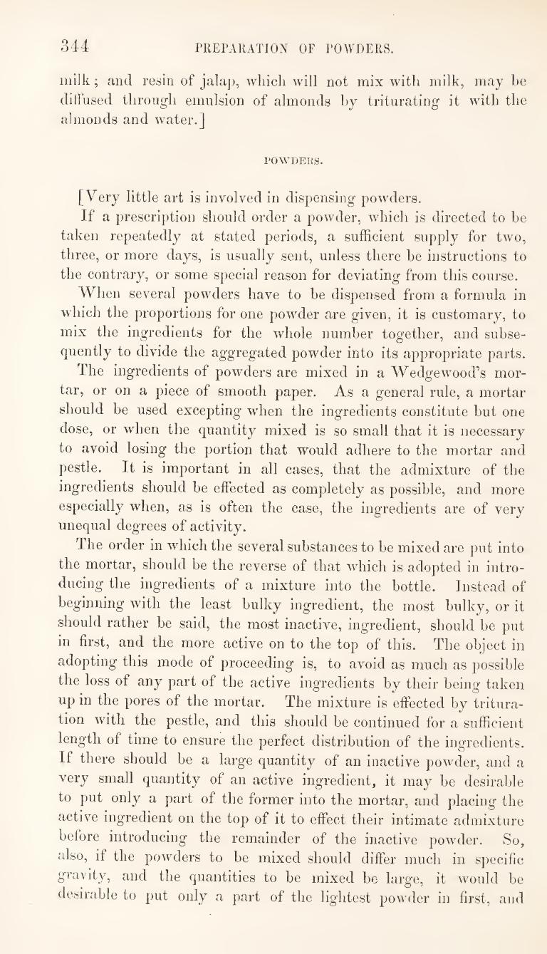
344 PREPARATION OF POWDERS.
inllk; and resin of jalaj), which will not mix with milk, may be
diffused through emulsion of almonds by triturating it with the
almonds and water.]
POWIJEKS.
[Very little art is involved in dispensing powders.
If a prescription should order a powder, which is directed to be
taken repeatedly at stated periods, a sufficient supply for two,
three, or more days, is usually sent, unless there be instructions to
the contrary, or some special reason for deviating from this course.
When several powders have to be dispensed from a formula in
which the proportions for one powder are given, it is customary, to
mix the ingredients for the whole number together, and subse¬
quently to divide the aggregated powder into its appropriate parts.
The ingredients of powders are mixed in a Wedgewood’s mor¬
tar, or on a piece of smooth paper. As a general rule, a mortar
should be used excepting when the ingredients constitute but one
dose, or when the quantity mixed is so small that it is necessary
to avoid losing the portion that would adhere to the mortar and
pestle. It is important in all cases, that the admixture of the
ingredients should be effected as completely as possible, and more
especially when, as is often the case, the ingredients are of very
unequal degrees of activity.
The order in which the several substances to be mixed are put into
the mortar, should be the reverse of that which is adopted in intro¬
ducing the ingredients of a mixture into the bottle. Instead of
beginning with the least bulky ingredient, the most bulky, or it
should rather be said, the most inactive, ingredient, should be put
in first, and the more active on to the top of this. The object in
adopting this mode of proceeding is, to avoid as much as possible
the loss of any part of the active ingredients by their being taken
up in the pores of the mortar. The mixture is effected by tritura¬
tion with the pestle, and this should be continued for a sufficient
length of time to ensure the perfect distribution of the ingredients.
If there should be a large quantity of an inactive powder, and a
very small quantity of an active ingredient, it may be desirable
to put only a part of the former into the mortar, and placing the
active ingredient on the top of it to effect their intimate admixture
before introducing the remainder of the inactive powder. So,
also, if the powders to be mixed should differ much in specific
gravity, and the quantities to be mixed be large, it would be
desirable to put only a part of the lightest powder in first, and
345 PREPARATION OF ELECTUARIES, ETC.
after that has been mixed with the other ingredients, to add the
remainder. After effecting the due admixture of the ingredients, if they are to
be divided into several separate doses, the papers for their reception
are spread out on the counter and the powder is distributed to each
on the point of the knife. The equality of the division is generally
determined by the eye of the operator, but as some persons are
incapable of distinguishing differences of quantity with sufficient
accuracy by the eye, the use of the balance should in such cases
be resorted to. There are some powders, containing volatile ingredients, which
are advantageously enclosed in waxed-paper.
When a powder, consisting of several doses, is sent out, undi¬
vided, the patient being left to apportion the dose on taking it, it
should alway, unless otherwise desired, be put into a wide-mouthed
bottle.]
ELECTUARIES; CONSERVES; LINCTUS.
[The electuary or confection is a very ancient form for the admi¬
nistration of medicines. It consists of solid substances which are
brought to the condition of a thin paste by admixture with some
saccharine or mucilaginous liquid.
The conserve is a preparation, similar in consistence to the elec¬
tuary or confection. The names seem to indicate that in the con¬
serve {conserve, to keep,) the saccharine matter is used for the pur¬
pose of preserving the substance to which it is added, while in the
confection {conficio, to make up,) the saccharine liquid is added
only to impart convenience of form.
The linctus differs from the two preceding forms in being made
thinner. The name appears to be derived from the word lingo, to
lick, the consistence being such that it can be licked from a spoon.
These forms of medicine are very rarely prescribed in the present
day, and no particular directions are required for their preparation.]
LOZENGES.
[The lozenge is a very common and convenient form for those me¬
dicines which are intended to act, by continued application, on the
pharynx and upper part of the trachia.
A great variety of lozenges are kept by the pharmaceutist, but
these are almost always made by the confectioner. Sometimes,
346 PREPARATION OF LOZENGES.
however, the pharmaceutist has occasion to prepare medicines of
this kind himself.
Lozenges may be divided into three classes:—
1st. Those, the principal basis of which is sugar, and in the pre¬
paration of which the ingredients are combined without the aid of
heat. The application of the term lozenge is sometimes confined to
these.
2nd. Those, the principal basis of which is sugar, and which in
their preparation are rendered fluid by means of heat. These are
sometimes distinguished by the name of drops.
3rd. Those which retain a permanently soft and pasty consist¬
ence, their principal basis being generally a vegetable juice or
pulp. These are usually called pastes.
1. Lozenges.—In making the first class of lozenges, the sugar is
employed in powder ; other more active ingredients are added, in
the state either of powder or liquid ; and the mixture is formed
into a tenacious paste with the addition of some liquid, either water
or mucilage.
The liquid, which appears to answer best for making lozenges
is mucilage of tragacanth. This is made from the best gum traga-
canth, which should be carefully picked to ensure the absence of
any foreign matter that might discolour the lozenges. The gum,
which should not be used in the state of powder, is mixed with
eight or ten times its weight of distilled water, and allowed to
stand in a warm place for a day or two. It is then strained
through a cloth, and subsequently beaten up in a mortar.
The sugar being mixed with the other ingredients, the mixture
is made into a stifi" paste with the mucilage. Sometimes, part of
the sugar is mixed with the powder or other active ingredients of
the lozenges, while the remainder of the sugar is made into a thin
paste with the mucilage, and then the two mixtures are incorporated.
The paste is rolled out on a marble slab, some powdered starch
being used to prevent adhesion to the slab or to the roller. A
frame of wood or iron, of the thickness of a lozenge, is placed on
the slab, so that by rolling out the paste until the roller comes on
to the frame, the paste will have a uniform and proper thickness.
The lozenges ai-e cut out of the extended paste with a small tin¬
plate punch, which gives them the required shape and size. They
are then placed on sieves in a drying-room or closet until they
become hard and dry.
2. Drops.—In making the second class of lozenges, commonly
called drops., the sugar is used in coarse powder, all the finest par¬
ticles having been removed by means of a sieve. A little water or
PREPARATION OF PILLS. 347
other liquid, such as the formula may direct, and also any ingre¬
dients intended for colouring or flavouring the drops, are added to
the sug’ar so as to moisten it. A portion of this mixture is put
into a small pan furnished with a lip and suitable handle, and this
is placed over a clear fire until the sugar has melted. The pan is
now removed from the fire, and the melted mixture is allowed to
drop, in quantities sufficient to form masses of the required size, on
to a greased iron or tin plate. The drops are allowed to harden,
and are then removed.
3. Pastes.'—The third class of lozenges usually consist of in¬
spissated juices, or decoctions, to which gum, sugar, and other in¬
gredients are added. They are brought to the proper consistence,
either by the application of heat, and then poured into flat tin
moulds, or they are mixed without heat, and rolled out on a
marble slab, in the manner already described.]
PILLS.
[There is probably no form of medicine more frequently prescribed
than that of the pill. It is a form well adapted for the adminis¬
tration of many medicines, including those of a fetid or nauseous
character, those whose specific gravities render them difficult of
administration wdien mixed with liquids ; those which are designed
to act slowly, such as alteratives, and those, the action of which is
desired to be retarded until the medicine shall reach the lower
intestines. Among the substances which enter into the composition of pills, are
the vegetable and other extracts, the resins, gum-resins, balsams, and
essential oils. These are more frequently administered in the form
of pill than in any other form, and with them are combined many
powders and mineral preparations.
The object in forming a pill-mass is to obtain a consistent, firm,
and adherent paste, which shall be sufficiently plastic to admit of
being moulded without adhering to the mould, and sufficiently stiff
to prevent the pills from losing their shape when made into the
proper form. A pill-mass may be said to consist of twm essential parts,—the
active ingredients which enter into its composition, whether of a
solid or liquid nature,—and the excipient, by which the proper
degree of consistence and tenacity are given to the former.
The substances employed as excipients in pill-making are both
numerous and of very different natures. The most common are,
348 PREPARATION OF PILLS.
mucilage, soap, water, spirit, or tinctures, gum, sugar,
magnesia, starch, &c.
The principal art in pill-making consists in selecting the pro])er
substances as excipients to suit the j^eculiar nature of the other
ingredients of the pills.
The pill-mass ought to possess tenacity or adhesiveness^ firmness^
and plasticity; and it will be well to consider what the conditions
are upon which these properties depend, and how they are best
attained.
TJie tenacity or adhesiveness of the mass depends upon two prin¬
cipal conditions. The first of these is, the presence of a property
inherent in the particles of the substance, through which they are
readily made to attach themselves to particles of the same, or of a
different kind ; and the second is, the existence of a certain state of
partial fluidity or softness, which appears to promote, and, indeed,
to be essential to, that particular kind of tenacity under con¬
sideration. Deprive an otherwise adhesive substance of all tendency
to finidity, and you deprive it of its adhesiveness. In order, then,
that a body should be tenacious or adhesive, it is necessary that it
should have some of its particles in a fluid or semi-fluid state.
Hence, a substance which, when deprived of all tendency to fluidity,
possesses no adhesiveness whatever, wdll sometimes become ad¬
hesive on adding a small quantity of some liquid which is capable
of acting as a solvent. Resin, when perfectly dry and hard, has
no adhesiveness, yet it becomes adhesive on adding a few drops of
spirit, which acts as a solvent of some of its particles. Gum, in
like manner, which is not adhesive when dry, becomes so on the
addition of water. But by this method of adding an excipient
which, without possessing any adhesiveness itself, acts simply as a
solvent of some of the solid particles present, we can only develope^
—we cannot impart adhesiveness. If the property of adhesiveness
be not inherent in the solid substance, the use of an excipient which
acts merely as a solvent, will not be sufficient. Thus, the addition
of spirit does not render camphor adhesive, because there is none of
that property inherent in the camphor. In cases of this kind,
therefore, it is necessary to employ excipients which possess and can
impart adhesiveness.
Firmness is the next requisite property in the pill-mass—a pro¬
perty not less essential than that of adhesiveness or tenacity. The
pill-mass should have a due degree of firmness, so that the pills
when formed shall retain their shape. Now, whilst a state of
solution or fluidity of some of the particles is essential to adhe¬
siveness, so, on the other hand, the hardness and insolubility of
PREPARATION OF PILLS. 349
others of the particles is necessary to ensure the requisite firmness.
These two properties, then, depend upon opposite conditions,—
the one, upon partial solution or fluidity,—the other, upon the
hardness and insoluhility of a part of the ingredients.
The firmness of a pill-mass,—that state in which the pills will re¬
tain their shape,—is a very important point to attain in pill-making.
The mass may possess the proper degree of adhesiveness, and he of
a good consistence for rolling into pills, and yet, from its not having
a sufficient proportion of the ingredients in a hard and insoluble
state, it may be subject to this serious objection, that the pills made
from it will lose their globular form, and perhaps run into one mass
in the box. This result will be very likely to occur, if a liquid
excipient be employed which is capable of acting as a perfect
solvent to every part of the solid ingredients of the pill-mass.
Pills formed from a resin, perfectly soluble in spirit, and which has
been moistened with spirit to form the mass, can hardly he made
to retain the globular form, unless the whole, or nearly the whole,
of the spirit be again driven off.
The method of proceeding in making pills is similar to that
adopted in building a house,—both bricks and mortar must he used,
—the bricks to give solidity and firmness, and the mortar to act as
a cement in causing the solid particles to adhere together. The
condition of pills made from a mass the whole of which is in a semi¬
fluid state, might be compared to that of a house built of nothing
but mortar. When, therefore, a pill-mass is in such a state that
the pills made from it refuse to retain their shape, it may he inferred
that more bricks are required, that is to say, that there is a defi¬
ciency of solid, insoluble, particles, to give firmness and stability to
the structure.
Plasticity is the next and last requisite in the pill-mass. A mass
may possess so much firmness—so much hardness—that it will not
take the form we wish to give it ; or, on the other hand, it may
have so large a proportion of the particles in a semifluid condition,
that it cannot retain the form which has been given to it. The
medium between these two states is the condition required. A mass
to he well adapted for making into pills, should possess adhesive¬
ness and firmness duly balanced one against the other, and this, in
fact, constitutes the plastic condition.
Such, then, are the conditions to be fulfilled in forming a good
pill-mass, and with a view to the realization of which, the selection
of excipients should be made.
But there are other considerations besides those above alluded to,
which ought to influence the selection of excipients. Those sub-
350 PREPARATION OF PILLS.
stances only, slionld be used as excipients wliich, fulfilling the S])e-
citied requirements in other resjiects, will not he incompatihle with
any of the ingredients of the pills ; will modify as little as possible
their action, either by causing them to become hard, or in any
other way ; and will not unnecessarily or inconveniently increase
their size.
I^owdered gum, either gum Arabic, or more frequently gum tra-
gacanth, is often employed as an excipient, without discrimination,
whenever increased tenacity is required in the pill-mass, or there is
a superabundance of moisture in the prescribed ingredients. This
practice of constantly adding gum is very objectionable, as it often
causes the pills to become so hard that their operation is materially
modified. Pills prepared in this way will sometimes pass through
the intestines without being dissolved, producing, of course, little or
no action. There are many cases in which the use of gum is justi¬
fiable, and cannot be well avoided, but the indiscriminate use of it,
especially of tragacanth, cannot be too strongly condemned.
The physician frequently names, in the prescription, some parti¬
cular excipient, which is directed to be used. Whenever this is
done the instructions of the prescriber should be carried out if prac¬
ticable. It is not always, however, that this is practicable, and
then the dispenser must follow his owm judgment. It would be
much better that the selection of excipients in these cases should
be always left to those who dispense the medicines, as the prescriber
rarely possesses the practical knowledge requisite to enable him to
determine wdiatkindof excipient is required. AVe frequently find
two or three soft extracts, which when combined are too soft to
admit of being properly made into pills, ordered to be mixed with
mucilage or syrup quantum sufficiat. In this case, although the
dispenser cannot act up to the letter, yet he may carry out the spirit
of the instructions, by using gum or sugar.
A few instances will now be specified in illustration of the fore¬
going principles, and with the view of more fnlly explaining the
mode of proceeding in the preparation of pills. The principal sub¬
stances which enter into the composition of pills will here be
divided into classes wdnch wall be considered separately.
Rhuharl) may be taken as the type of a class of substances fre¬
quently administered in the form of pill. Jalap^ ipecacuanha,
ginger^ conium^ digitalis^ and other vegetable powders belong to this
class. Now, taking these substances as a class, syrup is perhaps the
best excipient to use for giving them the pilular form. With some
of these powalers, the use of an excipient that possesses and can
impart adhesiveness is necessary ; and with all of them the presence
PREPARATION OF PILLS. 351
of sugar is beneficial in preserving* the vegetable principles from
decomposition, and preventing the pills from becoming very bard.
Simple syrup is commonly used as the excipient, but there is an
advantage in the substitution of uncrystallizable for the crystalline
sugar which the simple syrup contains ; treacle, therefore, is some¬
times employed with advantage. If it be desired to deprive the
treacle of its peculiar taste and smell, and of some of its colour, this
may be done by diluting it with three or four times its weight of
water, filtering the solution through a bed of animal charcoal, and
finally evaporating it to the required consistence. Powdered
coiiium, and other powders of this kind, retain their properties un¬
impaired for a great length of time when made into pills with a
syrup of uncrystallizable sugar.
There are cases, however, in which the use of syrup with some of
the powders alluded to is subject to inconvenience. Thus, wdien
rhubarb or jalap is made into pills, it is often desirable to have as
large a quantity as possible of the active ingredients in each pill.
From three to five grains of the powder are frequently prescribed
in a pill, and in such case it is desirable to use an excipient that
will add as little as possible to the bulk. If syrup be used as the
excipient for rhubarb, it will be found that a drachm of the powder
will require a fluid-drachm of syrup ; and this would make pills of
four or five grains of rhubarb inconveniently large. Where it is
important to add as little as possible to the bulk of the pill, water
may be used as the excipient for rhubarb. It does not form so
plastic a mass as syrup does ; and, moreover, the pills, if long kept,
become very hard, but the size of the pills will be less than would
be the case if syrup were used. Spirit, especially rectified spirit,
does not answer so well as water.
In making rhubarb into pills with syrup, the whole of the syrup
required for forming the mass should be added at once. A drachm
of powdered rhubarb requires a fluid-drachm of syrup. If a portion
of this quantity of syrup be first mixed with the rhubarb, a hard
mass would be formed, not sufficiently plastic to admit of being
made into pills, and which it would be found very difficult to incor¬
porate with the further portion of syrup required. On adding the
required quantity of syrup at once the mass is formed without any
difficulty. The mode of proceeding in this case is just the reverse
of that which should be adopted when a hard elastic extract, such
as some specimens of extract of rhubarb, has to be incorporated
with a powder such as calomel or ipecacuanha, through the inter¬
vention of a liquid excipient, such as syrup. Under such circum¬
stances the quantity of syrup required should be added very gra-
352 PREPARATION OF PILLS.
dually. If the whole of the syrup were put in at once, so as to
make a very soft })aste with the pow'der, the hard extract would
slip about in this, and might perchance be projected out of the mor¬
tar in the attempt at ejecting the incorporation of the ingredients,
ddie quantity of syrup first added should be only sufficient to foim
a very stiff and tenacious paste wdth the powder, and this should
be partly incorporated with the extract before adding more.
Jalap is sometimes made into pills with tincture of jalap, when
it is desired to have as much of the active ingredient as possible m
each pill. In this case the spirit, as a solvent of some of the
adhesive constituents of the jalap, imparts some degree of tenacity
to the mass. The ingredients, how^ever, do not yield a very plastic
mass, and to succeed well in forming the pills, it is desirable to add
the full quantity of tincture required at once, to make the mass
rather soft, and to roll out the pills as quickly as possible.
In making TliubaTh and ^ingen pills^ spirit and soap are some¬
times used as excipients with advantage, ^jfs of rhubarb, 5j of
essence of ginger, and 9j of castile soap, will form a mass which
may be divided into twenty-four pills, the size of which will not be
inconveniently large. If strong essence of ginger, made as desciibed
at pag'e 92, be employed, each pill will contain the active mattei
of fully two grains of ginger. The soap should be first rubbed
with the essence, the rhubarb added, and the mixture allowed to
stand until, by the evaporation of part of the spirit, it has acquired
a good pilular consistence.
Aloes may be taken as the type of the next class of substances
to be noticed. The resinous extracts^ resins, and gum-resins, will
come into the same class. Soap, mucilage, proof spirit, and alkaline
solutions, will be found to be suitable excipients in these cases.
Aloes form an excellent pill-mass with a few drops of compound
decoction of aloes, the efficacy of wdiich probably depends upon the
presence of the alkali. The gum-resins will assume a good pilular
consistence on pounding them with a little carbonate of potash
without any other addition. The resins sometimes require a little
spirit, but unless there be other solid ingredients present which are
insoluble in the spirit, the pills thus made will often lose their shape.
In such case soap should be substituted for spirit. Thus, the
aloes and mastic dinner pills, when spirit is used in making them,
inevitably lose their globular form, but this will not occur if soap
and a little w ater be employed as the excipients, ^vj of aloes, ^ij of
mastic, ^ss of soap, and f ^ss of water, mixed in an iron mortar pre¬
viously made hot, will afford a good plastic mass while warm, and
if rolled out while in this state, the pills may be ke])t in quantity
PREPARATION OF PILLS. 353
without losing* their form. They may also be made with tolerable
success with mucilage.
The volatile oils and oleo~resins constitute a class of substances
which are occasionally made into pills, and in such case require
peculiar excipients. Balsam of copaiba may be taken as a type of
this class. Magnesia is the excipient most generally applicable.
The copaiba balsam will generally assume a pilular consistence
when mixed with an equal weight of carbonate of magnesia, and
this is the best method of solidifying it, when the pills are required
for immediate use. If the balsam should contain an unusually
large proportion of essential oil it may require more of the excipient,
or it may be found convenient to dissolve a little white wax in the
balsam previously to the addition of the magnesia. Sometimes the
balsam is solidified by the addition of white wax alone. When
sufficient time can be taken for the purpose, a very small quantity
of calcined magnesia may be made to solidify balsam of copaiba or
any of the fluid turpentines. One part of recently calcined mag¬
nesia, added to sixteen quarts of balsam of copaiba, or true Venice
turpentine, and allowed to stand for a week or two, will become
solid and fit to form into pills. The mixture should be exposed to
a gentle heat for about an hour, and should subsequently be stirred
from time to time until it becomes solid. In this case, as in that
previously alluded to, it must be observed that some specimens of
copaiba, which are very rich in volatile oil, do not completely soli¬
dify without the addition of wax or of a portion of turpentine, such
as Bordeaux turpentine. The peculiar action of the magnesia con¬
sists in the formation of a soap with the acid resins of the copaiba
or turpentine, and this soap absorbs the volatile oil, which is the
other constituent of the oleo-resin. Quick lime might be substituted
for magnesia, and in some cases has been found to answer better.
Certain volatile oils^ without any other active ingredients, are
sometimes prescribed in the form of pill. Thus, oils of pimento^
cloves^ peppermint^ &c., have been ordered to the extent of three or
four drops in each pill, the selection of an appropriate excipient
being left to the dispenser. The best excipients to use in such case
are soap and magnesia.
Calomel will form the type of a class of powders requiring an exci¬
pient which possesses and can impart adhesiveness. Emetic tartar^
antimonial powder^ and many other substances of this kind will
come into the same class. Conserve of hips is a very useful exci¬
pient for this class of substances, at least for those of them which
are not decomposed by the vegetable acid contained in the con-
It answers very well for making calomel pills, the pills serve.
354 PREPAKATION OF PILLS.
retaining a soft consistenee for a great length of time. In some
cases crumb of bread, treacle, or extract of liquorice, may be sub¬
stituted for it. Pills made with crumb of bread, however, become
very hard after being kept for some time. Castor oil is an excellent
excipient for the com'pound calomel pills of the Pharmacopoeia. The
mass when made with this excipient will retain a uniformly good
consistence, which is not the case when treacle is used.
Crumb of bread is frequently employed as the excipient for
creasote^ and for some active agents which are administered in very
small doses.
The effect, in some cases, of a judiciously selected excipient is
quite surprising, and the pharmaceutical student would find that
the subject offers an interesting field for further experiment.
When it is found that a substance so apparently ill-adapted for
making into pills as a liquid oleo-resin, may be rendered fit for
that purpose by the addition of a very small quantity of magnesia
or lime, and that fatty substances, such as mercurial ointment,
will assume a pilular consistence on the addition of a little phos¬
phate of lime, he may hope to find equally simple means for sub¬
jecting other apparently intractable substances to the required
purpose.
In all cases it is very important that the whole of the ingre¬
dients of the pill-mass should be perfectly mixed and incorporated.
When small quantities of active medicines form part of the ingre¬
dients, the precaution already alluded to in reference to the pre¬
paration of powders should be observed, that is, that such sub¬
stances should be placed on the top of other less active ingredients,
and well mixed with them.
The pill-mass being formed, the next operation consists in di¬
viding it into pills. This is effected by means of the pill-machine.
Little need be said with reference to the use of this instrument.
In most cases the formation of the pills is a simple and easy pro¬
cess, yet cases will sometimes occur, in which, after exeMsing all
his skill in making the pill-mass, the dispenser will find it difficult
to roll the mass into pills, in consequence of its tendency to crumble.
This is the case with jalap pills made with tincture of jalap, and
more especially with the pills of volatile oil magnesia and soap.
When the mass has a great tendency to crumble, the processes of
forming the mass and of rolling out the pills, should be performed
as quickly as possible. The mass should be made rather soft, and
then immediately rolled and cut into pills, with a quick and
dexterous hand, avoiding the application of much pressure in the
process of rolling.
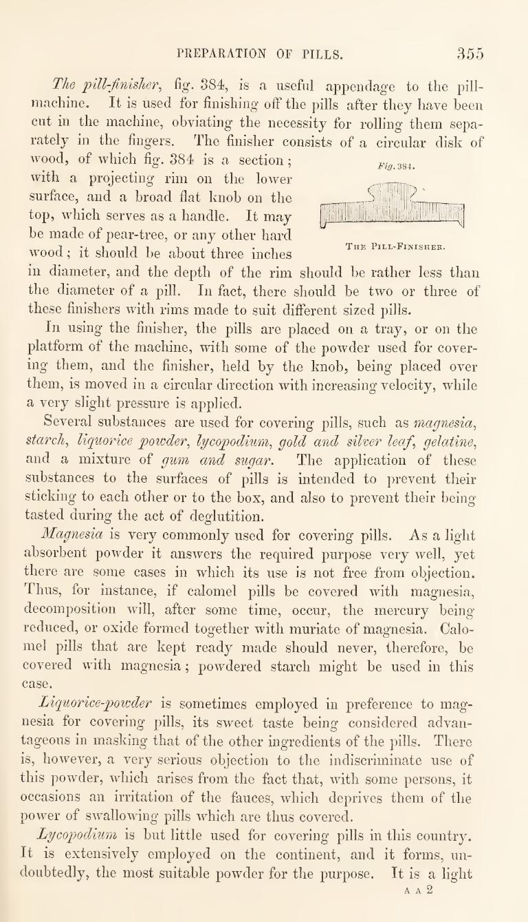
PREPARATION OF PILLS. 355
imTF HD
II
The Pill-Finisher.
The pill-finisher^ fig. 884, is a useful appendage to the pill-
machine. It is used for finishing off the pills after they have been
cut in the machine, obviating the necessity for rolling them sepa¬
rately in the fingers. The finisher consists of a circular disk of
wood, of which fig. 884 is a section;
with a projecting rim on the lower
surface, and a broad flat knob on the
top, which serves as a handle. It may
be made of pear-tree, or any other hard
wood; it should be about three inches
in diameter, and the dej^th of the rim should be rather less than
the diameter of a pill. In fact, there should be two or three of
these finishers with rims made to suit different sized pills.
In using the finisher, the pills are placed on a tray, or on the
platform of the machine, with some of the powder used for cover¬
ing them, and the finisher, held by the knob, being placed over
them, is moved in a circular direction with increasing velocity, while
a very slight pressure is applied.
Several substances are used for covering pills, such as magnesia^
starchy liquorice powder^ lycopodium^ gold and silver leaf^ gelatine^
and a mixture of gum and sugar. The application of these
substances to the surfaces of pills is intended to prevent their
sticking to each other or to the box, and also to prevent their being
tasted during the act of deglutition.
Magnesia is very commonly used for covering pills. As a light
absorbent powder it answers the required purpose very well, yet
there are some cases in which its use is not free from objection.
Thus, for instance, if calomel pills be covered with magnesia,
decomposition will, after some time, occur, the mercury being
reduced, or oxide formed together with muriate of magnesia. Calo¬
mel pills that are kept ready made should never, therefore, be
covered with magnesia; powdered starch might be used in this
case.
Liquorice-powder is sometimes employed in preference to mag¬
nesia for covering pills, its sweet taste being considered advan¬
tageous in masking that of the other ingredients of the pills. There
is, however, a very serious objection to the indiscriminate use of
this powder, which arises from the fact that, with some persons, it
occasions an irritation of the fauces, which deprives them of the
power of swallowing pills which are thus covered.
Lycopodium is but little used for covering pills in this country.
It is extensively employed on the continent, and it forms, un¬
doubtedly, the most suitable powder for the purpose. It is a light A A 2
PREPARATION OF PILLS. 356
powder, the particles of which readily adliere to the moist surfaces
of pills, without becoming themselves moist. It is also free from
taste, and has no tendency to cause or to undergo decomposition.
AVhen lycopodium is used it should be applied to the pills^ on the
machine or in the finisher, and none of the powder excepting that
which adheres to the surfaces of the pills should be put into the box.
Pills thus prepared have a much cleaner and more finished appear¬
ance than those to which a quantity of unattached powder is_ added
as is generally the case when magnesia or liquorice-powder is used.
The application of gold or silver-leaf to the surface of pills is a
very ancient method of covering them. The gilded or silvered pill
is still occasionally administered, but much less frequently than
formerly. The method of gilding pills is very simple. The pills
are first rolled and cut on the machine, the mass having been pie
viously made rather stiff, and little or no powder of any kind used
on the pill-machine. Two or three sheets of gold-leaf are now put
into a suitable box. A turned box of a globular form, consisting
of two hemispheres fitting together, and the capacity of which is
about two ounces, is usually employed; but, in the absence of this,
a two ounce chip-box will answer the purpose. The meta ic
leaves being put loosely into the box, the fore-finger and thumb of
each hand of the operator is moistened with thin mucilage of gum-
acacia, and two pills being rolled in the fingers so as to moisten
their surfaces and render them adhesive, these are dropped into the
box ; others of the pills are subsequently treated in the same w'ay,
taking care that none of the pills thus introduced shall come into
contact with the ungilded surfaces of those^ previously put in.
When six or eight pills have been introduced into the box, the lid
is put on, and a circular motion is given to the box, by which the
gilding is effected. The process is repeated in this way until the
whole number of pills required have received the metallic coating.
The same mode of operating is adopted when silver-leaf is used.
Of all the methods adopted for covering pills this is the most
objectionable. Gilded pills have often been found to pass through
the entire alimentary canal without undergoing any alteration,
being completely protected by their metallic covering.
The covering of pills with gelatine is the most elegant and ethcient
method of fulfilling the objects contemplated in the processes now
under notice. A pill, when thus covered, has a clean, shining,
surface, which is dry, hard, and not at all sticky. No powder is,
therefore, required in addition to the gelatine. The ingredients o
the pill, being enclosed in a gelatinous case, are preserved from the
action of the air, and, to a certain extent, are prevented from under-
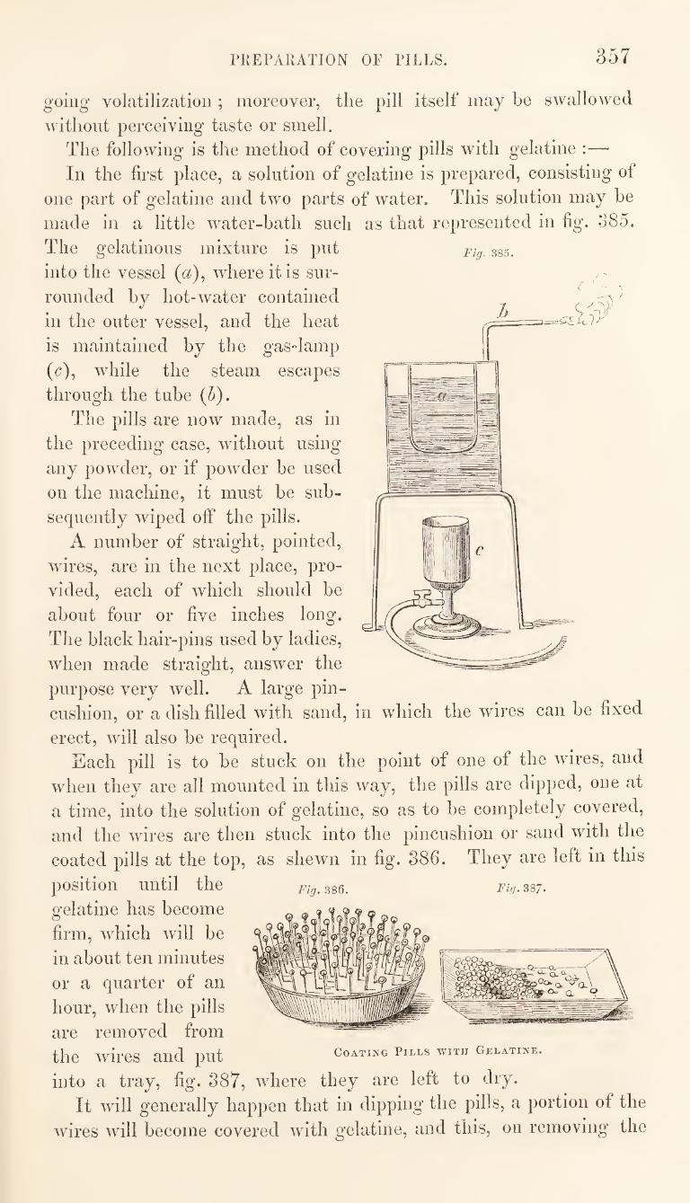
PUEPAIUTION OF PILLS. 357
Fig. 385.
going volatilization ; moreover, the pill itself may be swallowed
without perceiving taste or smell.
The following is the method of covering pills with gelatine :—
In the first place, a solution of gelatine is prepared, consisting of
one part of gelatine and two parts of water. This solution may be
made in a little water-bath such as that represented in fig. 385.
The gelatinous mixture is put
into the vessel («), where it is sur¬
rounded by hot-water contained
in the outer vessel, and the heat
is maintained by the gas-lamp
(c), while the steam escapes
through the tube (5).
The pills are now made, as in
the preceding case, without using
any powder, or if powder be used
on the machine, it must be sub¬
sequently wiped off the pills.
A number of straight, pointed,
wires, are in the next place, pro¬
vided, each of which should be
about four or five inches long.
The black hair-pins used by ladies,
when made straight, answer the
purpose very well. A large pin¬
cushion, or a dish filled with sand, in which the wires can be fixed
erect, will also be required.
Each pill is to be stuck on the point of one of the wires, and
when they are all mounted in this way, the pills are dipped, one at
a time, into the solution of gelatine, so as to be completely covered,
and the wires are then stuck into the pincushion or sand with the
coated pills at the top, as shewn in fig. 886. They are left in this
position until the Fig.mQ. Fig.^sj. gelatine has become
firm, which will be
in about ten minutes
or a quarter of an
hour, when the pills
are removed from the wires and put coating pills with gelatine.
into a tray, fig. 887, where they are left to dry.
It will generally happen that in dipping the pills, a portion of the
wires will become covered with gelatine, and this, on removing the
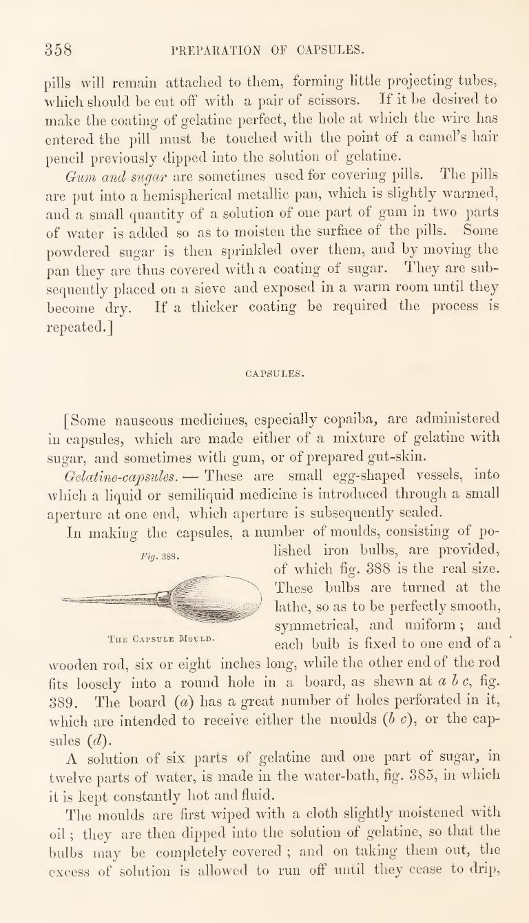
358 PREPARATION OF CAPSULES.
pills will remain attached to them, forming little projecting tubes,
which should be cut off with a pair of scissors. If it be desired to
make the coating of gelatine perfect, the hole at which the wire has
entered the pill must be touched with the point of a camel’s hair
pencil previously dipped into the solution of gelatine.
Gum and sugar are sometimes used for covering pills. The pills
are put into a hemispherical metallic pan, which is slightly warmed,
and a small quantity of a solution of one part of gum in two parts
of water is added so as to moisten the surface of the pills. Some
powdered sugar is then sprinkled over them, and by moving the
pan they are thus covered with a coating of sugar. They are sub¬
sequently placed on a sieve and exposed in a warm room until they
become dry. If a thicker coating be required the process is
repeated.]
CAPSULES.
[Some nauseous medicines, especially copaiba, are administered
in capsules, which are made either of a mixture of gelatine with
sugar, and sometimes with gum, or of prepared gut-skin.
Gelatine-capsules. — These are small egg-shaped vessels, into
which a liquid or semiliquid medicine is introduced through a small
aperture at one end, which aperture is subsequently sealed.
In making the capsules, a number of moulds, consisting of po-
ggg^ lished iron bulbs, are provided,
of which fig. 388 is the real size.
These bulbs are turned at the
lathe, so as to be perfectly smooth,
symmetrical, and uniform; and
each bulb is fixed to one end of a
wooden rod, six or eight inches long, while the other end of the rod
fits loosely into a round hole in a board, as shewn at 5 u, fig.
389. The board {a) has a great number of holes perforated in it,
which are intended to receive either the moulds {h c), or the cap¬
sules (d). A solution of six parts of gelatine and one part of sugar, in
twelve parts of water, is made in the water-bath, fig. 385, in which
The Capsule Mould.
it is kept constantly hot and fluid.
The moulds are first wiped with a cloth slightly moistened with
oil ; they are then dipped into the solution of gelatine, so that the
bulbs may be completely covered ; and on taking them out, the
excess of solution is allowed to run off until they cease to drip.
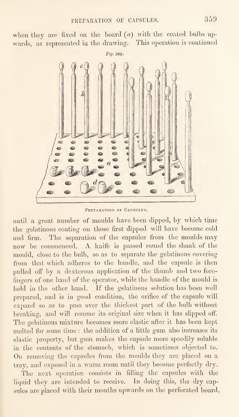
PREPARATION OF CAPSULES. 359
when they are fixed on the board (a) with tlie coated bulbs up¬
wards, as represented in the drawing. This operation is continued
Fig. 389.
until a great number of moulds have been dipped, by which time
the gelatinous coating on those first dipped will have become cold
and firm. The separation of the capsules from the moulds may
now be commenced. A knife is passed round the shank of the
mould, close to the bulb, so as to separate the gelatinous covering
from that which adheres to the handle, and the capsule is then
pulled off by a dexterous application of the thumb and two fore¬
fingers of one hand of the operator, while the handle of the mould is
held in the other hand. If the gelatinous solution has been well
prepared, and is in good condition, the orifice of the capsule will
expand so as to pass over the thickest part of the bulb without
breaking, and will resume its original size when it has slipped off.
The gelatinous mixture becomes more elastic after it has been kept
melted for some time : the addition of a little gum also increases its
elastic property, but gum makes the capsule more speedily soluble
in the contents of the stomach, which is sometimes objected to.
On removing the capsules from the moulds they are placed on a
tray, and exposed in a warm room until they become perfectly dry.
The next operation consists in filling the capsules with the
liquid they are intended to receive. In doing this, the dry cap¬
sules are placed with their mouths upwards on the perforated board.
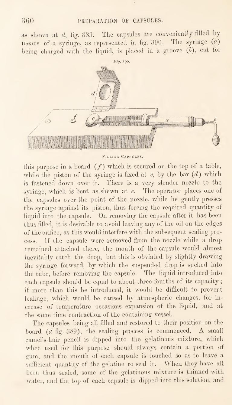
360 PREPARATION OF CAPSULES.
as shewn at d, %. S89. The capsules are conveniently filled by
means of a syringe, as represented in fig. 390. The syringe (a)
being charged with the liquid, is placed in a groove (^), cut for
Fig. 390.
Filling Capsules.
this purpose in a board (/) which is secured on the top of a table,
while the piston of the syringe is fixed at c, by the bar {d) which
is fastened down over it. There is a very slender nozzle to the
syringe, which is bent as shewn at e. The operator places one of
the capsules over the point of the nozzle, while he gently presses
the syringe against its piston, thus forcing the required quantity of
liquid into the capsule. On removing the capsule after it has been
thus filled, it is desirable to avoid leaving any of the oil on the edges
of the orifice, as this would interfere with the subsequent sealing pro¬
cess. If the capsule were removed from the nozzle while a drop
remained attached there, the mouth of the capsule would almost
inevitably catch the drop, but this is obviated by slightly drawing
the syringe forward, by which the suspended drop is sucked into
the tube, before removing the capsule. The liquid introduced into
each capsule should be equal to about three-fourths of its capacity;
if more than this be introduced, it would be difficult to prevent
leakage, which would be caused by atmospheric changes, for in¬
crease of temperature occasions expansion of the liquid, and at
the same time contraction of the containing vessel.
The capsules being all filled and restored to their position on the
board (d fig. 389), the sealing process is commenced. A small
cameUsdiair pencil is dipped into the gelatinous mixture, which
when used for this purpose should always contain a portion of
gum, and the mouth of each capsule is touched so as to leave a
sufficient quantity of the gelatine to seal it. When they have all
been thus sealed, some of the gelatinous mixture is thinned with
water, and the top of each capsule is dipped into this solution, and
GARGLES; INJECTIONS; LOTIONS, ETC. 361
then again placed, with the sealed end upwards, on the board.
By this last operation a little cap is formed over the mouth of the
capsule, which renders the sealing more secure.
Finally, when dry, the sealed capsules are put on to a cloth
slightly moistened with oil, and rubbed, so as to give them a
clean and polished appearance.
Membrane capsules,—A patent has been taken out for the ma¬
nufacture of capsules from animal membrane, which is purified
and prepared for this purpose. The prepared and moist membrane
is stretched over a mould so as to give it the form of a conical bag.
Into this, when dry, the liquid is introduced ; the mouth of the
bag is then tied with silk, and sealed with a little gelatinous
varnish.
These capsules possess some advantages over those made of
gelatine. In proportion to their external size, they hold more
liquid than the gelatine capsules do, in consequence of the mem¬
brane of which they are made being very thin. They are also very
flexible and compressible, which is a great recommendation with
some patients, who are fearful of attempting to swallow a hard,
rigid, body, of the size of a capsule. Moreover, the membrane
being less rapidly dissolved than the gelatine mixture is, by the
juices of the stomach, the capsules made of the former do not
discharge their contents so soon as those made of the latter, and
eructations are, therefore, less likely to ensue.]
GARGLES ; ENEMAS ; INJECTIONS.
[These forms of medicine resemble the mixture in their general
characters, and the mode of preparing them is similar. Being
intended for local application, and not to be introduced into the
stomach, the labels attached to them should clearly indicate this
distinction. The old method of administering enemas with a pipe
and bag is now entirely superseded by the use of the syringe.]
LOTIONS, LINIMENTS, EMBROCATIONS.
[These are medicines, of a more or less fluid character, which are
intended for external application. The lotion,, as the name implies,
is a wash, and it may be for any part of the body. Lotions for
the eyes are sometimes called Collyriums, The terms liniment and
embrocation are frequently used synonymously ; the former, however.
3G2 LINIMENTS; OINTMENTS.
being derived from linOy to besmear, is applicable to something
thick as well as fluid, while the latter, being derived from
to moisten or foment, applies exclusively to a liquid.
It has been proposed that liquid medicines intended for external
use should be always dispensed in bottles made of blue glass, to
distinguish them from those designed for internal administration,
the latter being dispensed in white glass. If such a practice were
universally adopted, it would certainly be a good method of guard¬
ing against accidents which sometimes occur in consequence of an
embrocation being mistaken for a draught. It is questionable,
however, whether the partial adoption of the practice would be
beneficial; but it is very important, at all events, that there should
be some prominent indication, in the form of label or otherwise, to
distinguish external applications from medicines to be administered
through the stomach.]
OINTMENTS.
[Under the general denomination of Ointments are included medi¬
cines intended for external application, the principal basis of which
consists of some kind of grease, which is either naturally, or from
the admixture of other substances, in the condition of a soft solid.
Ointments to which a firm consistence has been imparted by the
addition of wax are sometimes called Cerates. Salts and other solid substances are frequently ordered to be
extemporaneously mixed with ointments, and the principal art
connected with the dispensing of this form of medicine, consists in
the adoption of the best methods of effecting the most intimate
admixture of such ingredients, or of any others which may not
readily combine. Ointments are mixed either in a Wedgewood’s mortar or on a
marble slab. The mortar should always be used when salts or
other substances, which require to be previously powdered, form part
of the ingredients. The presence of hard particles, giving a gritty
character to the ointment, is very objectionable, and would indicate
want of skill, or of careful attention, in the dispenser. The mere
admixture of two or more ointments may be effected by rubbing
them on the slab with a spatula.
Some salts, such as iodide of potassium, are with difficulty reduced
to fine powder even in a mortar, and in these cases it is desirable,
when practicable, to add some liquid which shall act as a solvent
before the addition of the unctuous constituents of the ointment.
Thus, iodide of potassium, if it be first dissolved by a few drops
SUPPOSITORIES; CATAPLASMS; PLASTERS. 363
of water, before mixing it with the grease, will form a per¬ fectly smooth ointment, which it would be difficult otherwise to
obtain. Ointments are dispensed in covered gallipots, and it is customary
to put a piece of waxed paper over the top of the pot, beneath the cover, so as to prevent the latter from becoming smeared with the
grease.] '
SUPPOSITOEIES.
[ The suppository is a form of medicine now very rarely adopted. It is intended for the administration of medicinal agents to the rectum. The ingredients are made into a paste, which is usually rolled into a conical form, like a pastil. Soft soap or grease is generally used as the excipients for giving the required consistence
to suppositories.]
CATAPLASMS.
[ The cataplasm or poultice generally consists of a pulpy substance, capable of absorbing much moisture, which is applied to various parts of the body in a moist state. Poultices are almost always prepared by the nurse : their action usually depends upon the liquids with which they are moistened, or the heat which the mass retains. The solid ingredients of the poultice being useful only for holding a large quantity of liquid, which is thus applied continuously to a diseased part, it has been proposed to substitute an absorbent fabric, called the spongio-piline^ which is made expressly for the purpose. This is a kind of thick cloth, composed in great measure of sponge. Over one of its surfaces there is a thin coating of some water-proof material, which prevents evaporation, when the other
side, previously wetted, is applied to the skin.]
PLASTERS.
[Plasters are solid and tenacious compounds, intended for external application. They frequently contain the oleate and margarate of oxide of lead as a principal basis ; wax, resin, solid fats, and essen¬ tial oils, are also among the ingredients which often enter into their composition. At the usual temperature of the human body they should be flexible, and more or less adhesive, but not so soft as
to run.
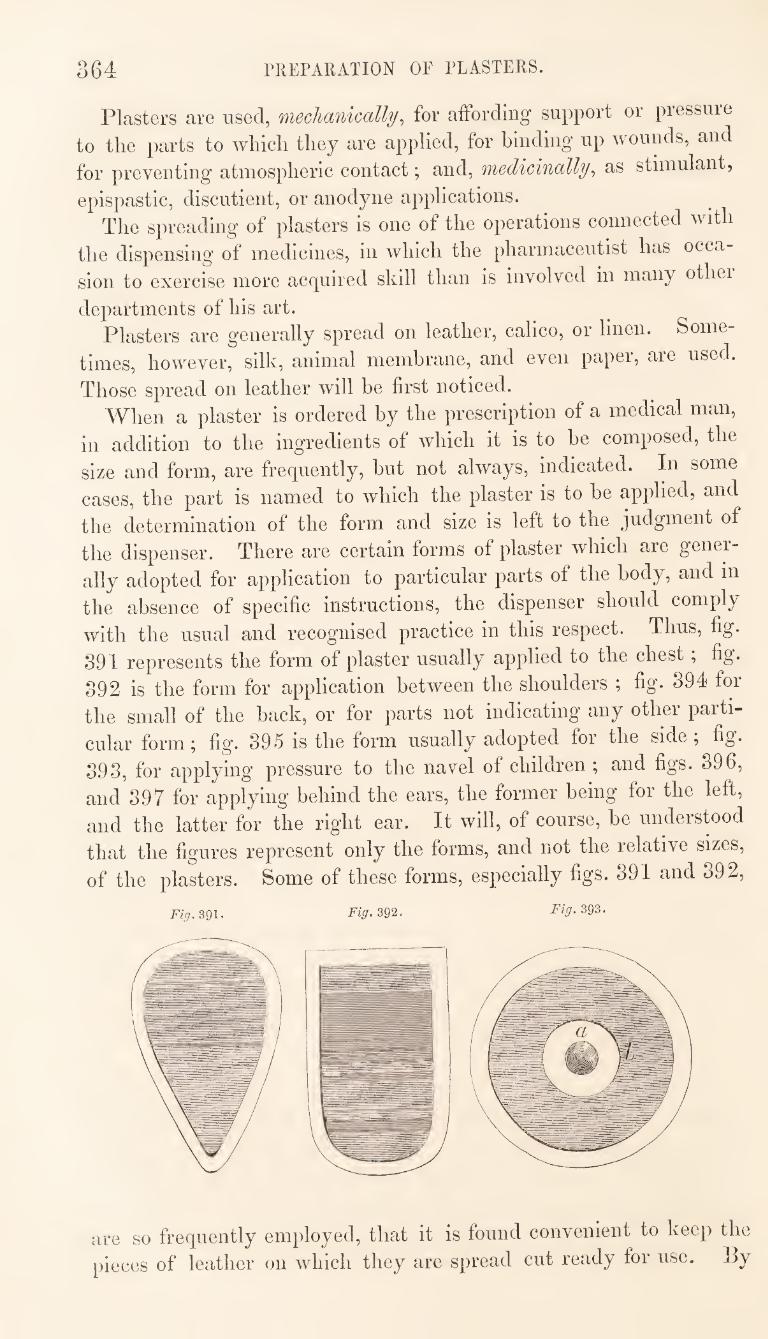
364 PREPARATION OF PLASTERS.
Plasters are used, mechanically^ for affording support or pressure
to the parts to which they are applied, for binding up wounds, and
for preventing atmospheric contact; and, medicinally^ as stimulant,
epispastic, discutient, or anodyne applications.
The spreading of plasters is one of the operations connected with
the dispensing of medicines, in which the pharmaceutist has occa¬
sion to exercise more acquired skill than is involved in many othei
departments of his art. Plasters are generally spread on leather, calico, or linen. Some¬
times, however, silk, animal membrane, and even papei, are used.
Those spread on leather will be first noticed.
When a plaster is ordered by the prescription of a medical man,
in addition to the ingredients of which it is to be composed, the
size and form, are frequently, but not always, indicated. In some
cases, the part is named to which the plaster is to be applied, and
the determination of the form and size is left to the judgment of
the dispenser. There are certain forms of plaster which are gener¬
ally adopted for application to particular parts of the body, and in
the absence of specific instructions, the dispenser should comply
with the usual and recognised practice in this respect. Thus, fig.
891 represents the form of plaster usually applied to the chest, fig.
892 is the form for application between the shoulders ; fig. 894 for
the small of the back, or for parts not indicating’ any other paiti-
cular form; fig. 895 is the form usually adopted for the side \ fig.
898, for applying pressure to the navel of children ; and figs. 896,
and 897 for applying behind the ears, the former being for the left,
and the latter for the right ear. It will, of course, be understood
that the figures represent only the forms, and not the relative sizes,
of the plasters. Some of these forms, especially figs. 891 and 892,
Fig. 391. Fig, 392. Fig. 393.
are so frequently employed, that it is found convenient to keep the
pieces of leather on which they are spread cut ready for use. By
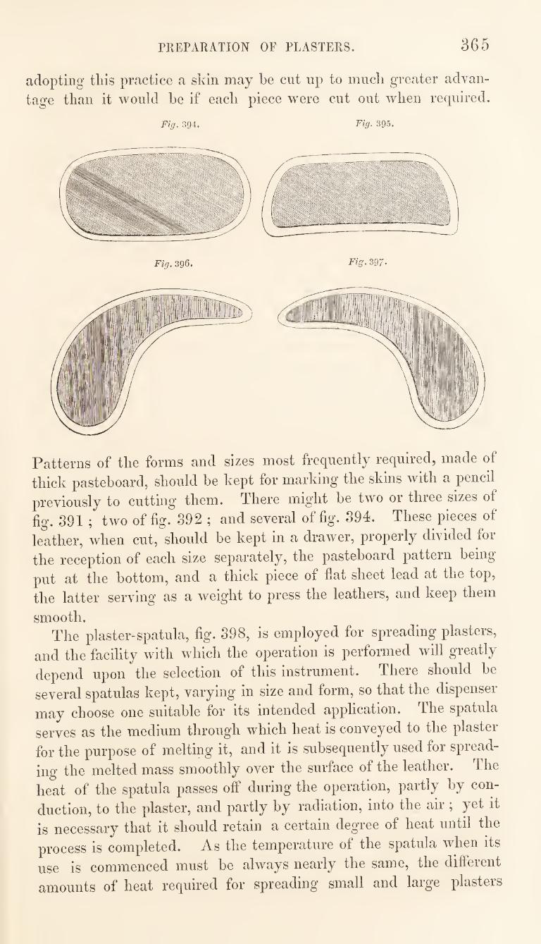
PREPARATION OF PLASTERS. 365
adopting this practice a skin may be cut up to much greater advan¬
tage than it would be if each piece were cut out when required.
Fig. 394. Fig. 395.
Patterns of the forms and sizes most frequently required, made of
thick pasteboard, should be kept for marking the skins with a pencil
previously to cutting them. There might be two or three sizes of
fig. 891 ; two of fig. 892 ; and several of fig. 894. These pieces of
leather, when cut, should be kept in a drawer, propeily divided foi
the reception of each size separately, the pasteboard pattern being
put at the bottom, and a thick piece of flat sheet lead at the top,
the latter serving as a weight to press the leathers, and keep them
smooth. The plaster-spatula, fig. 898, is employed for spreading plasters,
and the facility with which the operation is performed will greatly
depend upon the selection of this instrument. There should be
several spatulas kept, varying in size and form, so that the dispenser
may choose one suitable for its intended application. The spatula
serves as the medium through which heat is conveyed to the plaster
for the purpose of melting it, and it is subsequently used for spread¬
ing the melted mass smoothly over the surface of the leather. The
heat of the spatula passes off during the operation, partly by con¬
duction, to the plaster, and partly by radiation, into the air ; yet it
is necessary that it should retain a certain degree of heat until the
process is completed. As the temperature of the spatula when its
use is commenced must be always nearly the same, the different
amounts of heat required for spreading small and large plasters
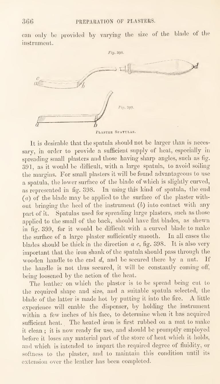
36G PREPARATION OF PLASTERS.
can only be provided by varying the size of the blade of the
instrument.
Fig. 398.
It is desirable that the spatula should not be larger than is neces¬
sary, in order to provide a sufficient supply of heat, especially in
spreading small plasters and those having sharp angles, such as fig.
891, as it would be difficult, with a large spatula, to avoid soiling
the margins. For small plasters it will be found advantageous to use
a spatula, the lower surface of the blade of which is slightly curved,
as represented in fig. 898. In using this kind of spatula, the end
(a) of the blade may be applied to the surface of the plaster with¬
out bringing the heel of the instrument {h) into contact with any
part of it. Spatulas used for spreading large plasters, such as those
applied to the small of the back, should have flat blades, as shewn
in fig. 899, for it w^ould be difficult with a curved blade to make
the surface of a large plaster sufficiently smooth. In all cases the
blades should be thick in the direction a c, fig. 898. It is also very
important that the iron shank of the spatula should pass through the
wooden handle to the end d, and be secured there by a nut. If
the handle is not thus secured, it will be constantly coming off,
being loosened by the action of the heat.
The leather on which the plaster is to be spread being cut to
the required shape and size, and a suitable spatula selected, the
blade of the latter is made hot by putting it into the fire. A little
experience will enable the dispenser, by holding the instrument
within a few inches of his face, to determine when it has acquired
sufficient heat. The heated iron is first rubbed on a mat to make
it clean ; it is now ready for use, and should be promptly employed
before it loses any material part of the store of heat which it holds,
and which is intended to impart the required degree of fluidity, or
softness to the plaster, and to maintain this condition until its
extension over the leather has been completed.
rREPARATION OF PLASTERS. 367
Ten or twelve sheets of paper arc placed upon the counter, and
the leather is laid on the top of these. The paper forms a bed of a
due degree of elasticity, and which prevents the too rapid con¬
duction of heat from the plaster while it is being spread. If the
leather were laid directly on the counter, or with only one or two
sheets of paper intervening, the heat of the liquefied plaster would
be rapidly carried off by the cold surface of the polished wood.
Before commencing the melting of the plaster, the leather is
smoothed out by passing the hot iron over it, and, in doing this,
it is very necessary to be careful that the iron is not so hot as to
cause the leather to shrivel up. If the spatula be in a fit state for
melting the plaster, it will not injure the leather when applied to it.
If the material of which the plaster is composed be sufficiently
adhesive to ensure its remaining fixed to the part of the body to
which it is applied, it is spread, without any previous preparation
of the leather, to within about half an inch of the edge, leaving a mar¬
gin of this width of uncovered leather ; but plasters possessing little
or no adhesiveness, ought to be surrounded by an adhesive margin,
and in such case the margin must be prepared before spreading the
plaster. There are two methods of preparing the adhesive margin,
—the adhesive plaster may be either spread entirely over the
leather to the very edge, or it may be merely applied around the
edge of the leather, so as to form a border of about an inch in
width. The former of these methods should be adopted if the
plaster, when exposed to the heat of the body, is liable to run
through the leather, as is the case with the blistering plaster of
the Pharmacopoeia, for the substratum of adhesive plaster would
tend to prevent such a result. In other cases it may he un¬
necessary to protect the leather, and even desirable to avoid
increasing the thickness of the plaster by having two strata
throughout.
When the adhesive plaster is merely spread as a border around
the edge of the leather, it is customary to melt the plaster by ap¬
plying the end of a roll of it to the hot iron, allowing it to drop as
it liquefies on to the part of the leather to be covered, and subse¬
quently to spread it with the spatula. In doing this the iron should
be only just hot enough to melt the plaster, as otherwise the drops
of hot melted plaster would occasion permanent marks on the
leather, which would disfigure its subsequent appearance.
When the adhesive plaster is extended over the whole of the
leather, it should be allowed, as it liquefies from contact with the
hot iron, to run on to a piece of strong paper, and transferred from
thence to the leather.
368 PREPARATION OF PLASTERS.
The adhesive margin, if required, having been prepared as above
directed, the spreading of the plaster may be proceeded with. ^ The
spatula, after being used for the preceding operation, will require to
be heated again before it can be applied for melting another portion
of plaster. The melting of the plaster may be effected in the manner already
described, by applying the hot iron to one end of a roll of pfastei,
and allowing the liquefied portion to run on to a piece of stiong
paper, from whence it is subsequently transferred to the leather. If
the leather has not been rendered adhesive, the paper on which the
melted plaster is received should be placed upon it while the process
of liquefaction is being conducted, so that whatever heat passes off
by conduction, may be communicated to the leather and to the
paper beneath it, and these being thus warmed, the subsequent
cooling of the plaster, while it is being spread, will take place moie
slowly. Every available means by which the expenditure of heat
can be economised should be put into requisition in spieading a
plaster, especially if it be of large size. The careless or inexpeii-
enced operator will sometimes commit the two-fold error of com¬
mencing the melting of the plaster by the application of a spatula
heated to such a temperature that it causes a decomposition of
some of the constituents of the plaster, and the evolution ^ of
acrid vapours, while, at the same time, the means of economising
heat are so imperfectly adopted, that the mass becomes hard
and intractable before its extension over the leather has been com¬
pleted. When the blade of the spatula has expended so much of its
heat in melting the plaster, that it is scarcely hot enough to melt
any more, it will be in a fit condition for spreading the melted
mass. The method of effecting the extension can be properly
acquired only by practical experience; it may be observed,
however, that the plaster should not be spread out to its
furthest intended limits until it has passed from the fluid or semi¬
fluid to the plastic condition. It is only while in this latter
condition that it can receive with effect the last finishing touches
of a skilful hand. When completed, the plaster should be of
equal thickness in all parts ; the surface should be even, but
not too glossy; and the edge should rise perpendiculaily fiom the
margin. There are some special cases in which a mode of proceeding
somewhat different from that previously described is required to be
adopted, as for instance, in preparing the plaster, fig. 393, for
applying pressure to the navel of a child. This plaster has a
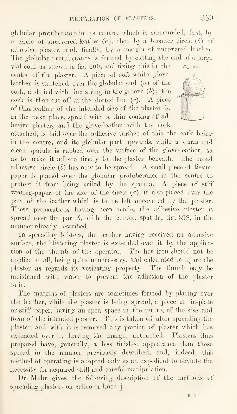
PREFARATION OF PLASTERS. 369
Fig. 400.
globular protuberance in its centre, wliicli is snrronnded, first, by
a circle of uncovered leather ((^), then by a broader circle (I)) of
adhesive plaster, and, finally, by a margin of uncovered leather.
The globular protuberance is formed by cutting the end of a large
vial cork as shewn in fig. 400, and fixing this in the
centre of the plaster. A piece of soft white glove-
leather is stretched over the globular end (a) of the
cork, and tied with fine string in the groove (5); the
cork is then cut off at the dotted line (c). A piece
of thin leather of the intended size of the plaster is,
in the next place, spread with a thin coating of ad¬
hesive plaster, and the glove-leather with the cork
attached, is laid over the adhesive surface of this, the cork being*
in the centre, and its globular part upwards, while a warm and
clean spatula is rubbed over the surface of the glove-leather, so
as to make it adhere firmly to the plaster beneath. The broad
adhesive circle {h) has now to be spread. A small piece of tissue-
paper is placed over the globular protuberance in the centre to
protect it from being soiled by the spatula. A piece of stitf
writing-paper, of the size of the circle {a)^ is also placed over the
part of the leather w^hich is to be left uncovered by the plaster.
These preparations having been made, the adhesive plaster is
spread over the part 5, with the curved spatula, fig. 898, in the
manner already described.
In spreading blisters, the leather having received an adhesive
surface, the blistering plaster is extended over it by the applica¬
tion of the thumb of the operator. The hot iron should not be
applied at all, being quite unnecessary, and calculated to injure the
plaster as regards its vesicating property. The thumb may be
moistened with water to prevent the adhesion of the plaster
to it.
The margins of plasters are sometimes formed by placing over
the leather, while the plaster is being spread, a piece of tin-plate
or stiff paper, having an open space in the centre, of the size and
form of the intended plaster. This is taken off after spreading the
plaster, and with it is removed any portion of plaster which has
extended over it, leaving the margin untouched. Plasters thus
prepared have, generally, a less finished appearance than those
spread in the manner previously described, and, indeed, this
method of operating is adopted only as an expedient to obviate the
necessity for acquired skill and careful manipulation.
Dr. Mohr gives the following description of the methods of
spreading plasters on calico or linen.]
13 B
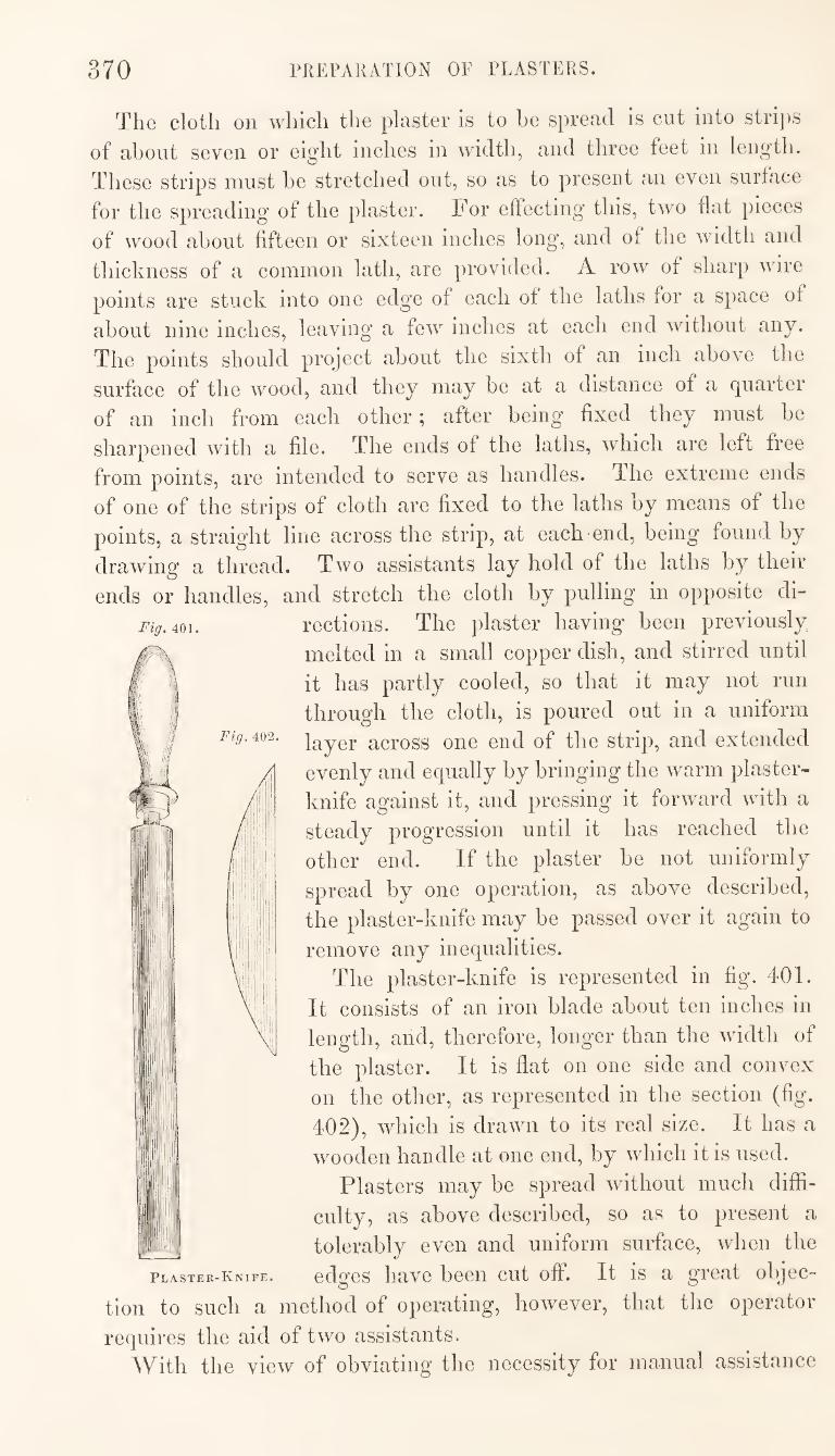
370 PREPARATION OF PLASTERS.
The cloth on which the plaster is to he spread is cut into stri])S
of about seven or eight inches in width, and three feet in length.
These strips must be stretched out, so as to present an even surface
for the spreading of the plaster. For effecting this, two fiat pieces
of wood about fifteen or sixteen inches long, and of the width and
thickness of a common lath, are provided. A row of sharp wire
points are stuck into one edge of each of the laths for a space of
about nine inches, leaving a few inches at each end without any.
The points should project about the sixth of an inch above the
surface of the wood, and they may be at a distance of a quarter
of an inch from each other; after being fixed they must be
sharpened with a file. The ends of the laths, which are left free
from points, are intended to serve as handles. The extreme ends
of one of the strips of cloth are fixed to the laths by means of the
points, a straight line across the strip, at each end, being found by
drawing a thi^ead. Two assistants lay hold of the laths by their
ends or handles, and stretch the cloth by pulling in opposite di¬
rections. The plaster having been previously
melted in a small copper dish, and stirred until
it has partly cooled, so that it may not run
through the cloth, is poured out in a uniform
Fig. ^^2. across one end of the strip, and extended J evenly and equally by bringing the warm plaster-
knife against it, and pressing it forward with a
steady progression until it has reached the
other end. If the plaster be not uniformly
j'!' ! spread by one operation, as above described,
the plaster-knife may be passed over it again to
A i remove any inequalities.
The plaster-knife is represented in fig. 401.
Nil It consists of an iron blade about ten inches in
length, and, therefore, longer than the width of
the plaster. It is flat on one side and convex
on the other, as represented in the section (fig.
402), which is drawn to its real size. It has a
wooden handle at one end, by which it is used.
Plasters may be spread without much diffi¬
culty, as above described, so as to present a
tolerably even and uniform surface, when the
Knife. edges liave been cut off. It is a great objec¬
tion to such a method of operating, however, that the operator
requires the aid of two assistants.
With the view of obviating the necessity for manual assistance
Fig, 401.
Plaster-
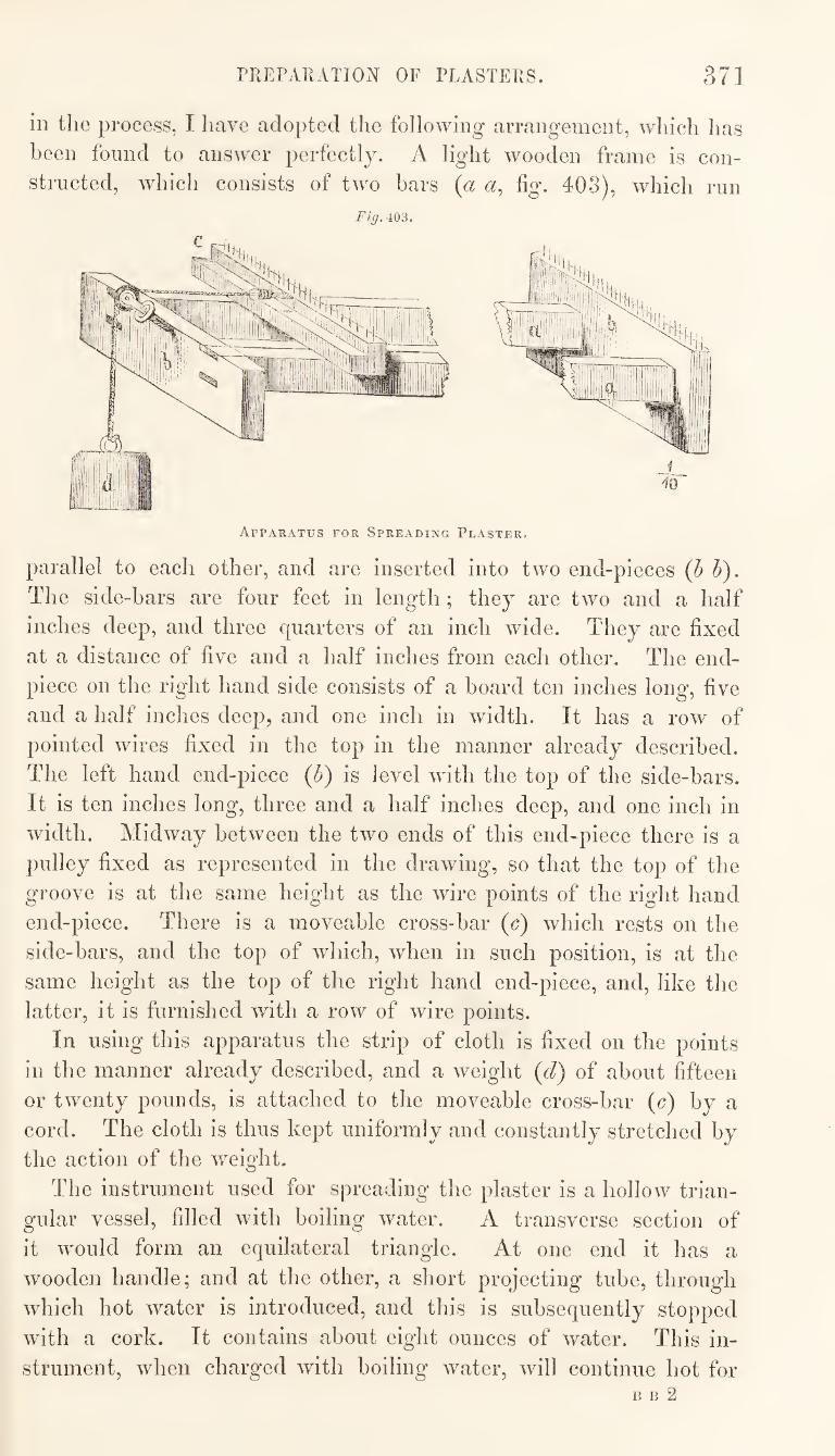
TREPARATION OF PLASTERS. 371
in the process, I have adopted the following arrangement, which has
been found to answer perfectly. A light wooden frame is con¬
structed, which consists of two bars {a a, fig. 403), which run
Fig. 403.
parallel to each other, and are inserted into two end-pieces (h h). The side-bars are four feet in length; they are two and a half
inches deep, and three quarters of an inch wide. They are fixed
at a distance of five and a half inches from each other. The end-
piece on the right hand side consists of a board ten inches long, five
and a half inches deep, and one inch in width. It has a row of
pointed wires fixed in the top in the manner already described.
The left hand end-piece (b) is level with the top of the side-bars.
It is ten inches long, three and a half inches deep, and one inch in
width. Midway between the two ends of this end-piece there is a
pulley fixed as represented in the drawing, so that the top of the
groove is at the same height as the wire points of the right hand
end-piece. There is a moveable cross-bar (c) which rests on the
side-bars, and the top of which, when in such position, is at the
same height as the top of the right hand end-piece, and, like the
latter, it is furnished with a row of wire points.
In using this apparatus the strip of cloth is fixed on the points
in the manner already described, and a weight (d) of about fifteen
or twenty pounds, is attached to the moveable cross-bar (c) by a
cord. The cloth is thus kept uniformly and constantly stretched by
the action of the weight.
The instrument used for spreading the plaster is a hollow trian¬
gular vessel, filled with boiling water. A transverse section of
it would form an equilateral triangle. At one end it has a
wooden handle; and at the other, a short projecting tube, through
which hot water is introduced, and this is subsequently stopped
with a cork. It contains about eight ounces of water. This in¬
strument, when charged Avith boiling water, will continue hot for B B 2
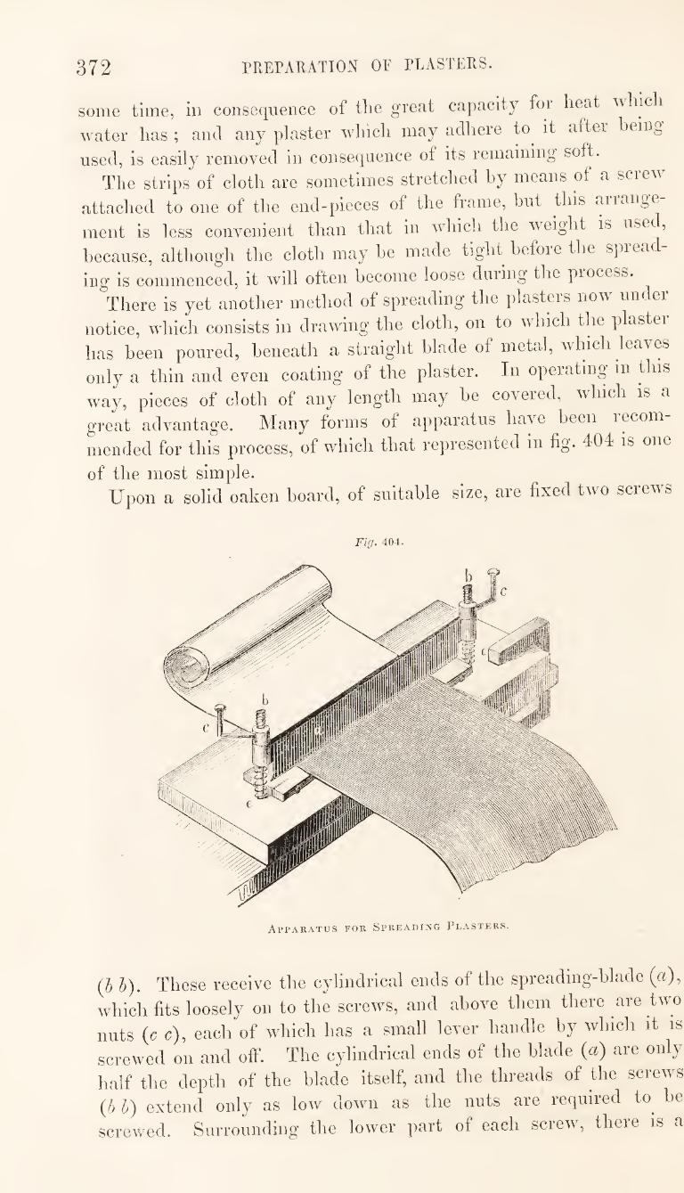
372 PREPAUATION OF PLASTERS.
some time, in consequence of the great capacity for heat uhic i
water has ; and any plaster which may adhere to^ it after being
used, is easily removed in consequence ot its remaining soft.
The strips of cloth are sometimes stretched by means of a screw
attached to one of the end-pieces of the frame, but this aiiange
ment is less convenient than that in which the weight is uset,
because, although the cloth may be made tight before the spread
ing is commerrced, it will ofterr becorrre loose durirrg the process.
There is yet another method of spreading the plasters now under
notice, which consists in drawing the cloth, on to whrch the plaster
has been poured, beneath a straight blade of metal, which leaves
only a thin and even coating of the plaster. In operating in this
way, pieces of cloth of any length may be covered, which is a
great advarrtage. Many forms of apparatus have been recom
mended for this process, of which that represented in fig. 404 is one
of the most simple. Upon a solid oaken board, of suitable size, are fixed two screws
Fig. 404.
Apparatus for Spreading Plasters.
(h h). These receive the cylindrical ends of the spreading-blade («),
which fits loosely on to the screws, and above them there are two
nuts (c c), each of which has a small lever handle by which it is
screwed on and off. The cylindrical ends of the blade («) are only
half the depth of the blade itself, and the threads of the screws
{!> h) extend only as low down as the nuts are required to he
screwed. Surrounding the lower part of each screw, there is a
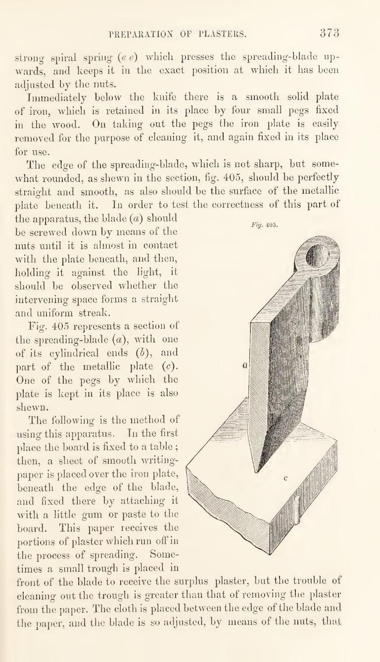
PREPARATION OF PLASTERS. 373
strong spiral spring (e e) which presses the spreading-blade up¬
wards, and keeps it in the exact position at which it has been
adjusted by the nuts.
Immediately below the knife there is a smooth solid plate
of iron, which is retained in its place by four small pegs fixed
in the wood. On taking out the pegs the iron plate is easily
removed for the purpose of cleaning it, and again fixed in its place
for use.
The edge of the spreading-blade, which is not sharp, but some¬
what rounded, as shewn in the section, fig. 405, should be perfectly
straight and smooth, as also should be the surface of the metallic
plate beneath it. In order to test the correctness of this part of
the apparatus, the blade (a) should
be screwed down by means of the
nuts until it is almost in contact
with the plate beneath, and then,
holding it against the light, it
should be observed whether the
intervening space forms a straight
and uniform streak.
Fig. 405 represents a section of
the spreading-blade (a), with one
of its cylindrical ends (5), and
part of the metallic plate (c). One of the pegs by which the
plate is kept in its place is also
shewn.
The following is the method of
using this apparatus. In the first
place the board is fixed to a table ;
then, a sheet of smooth writing-
paper is placed over the iron plate,
beneath the edge of the blade,
and fixed there by attaching it
with a little gum or paste to the
board. This paper receives the
portions of plaster which run off in
the process of spreading. Some¬
times a small trough is placed in
front of the blade to receive the surplus plaster, but the trouble of
cleaning out the trough is greater than that of removing the plaster
from the paper. The cloth is placed between the edge of the blade and
the paper, and the blade is so adjusted, by means of the nuts, that
374 PREPARATION OF PLASTERS.
while the cloth can be drawn through with tolerable facility, it never¬
theless occasions some friction. The plaster, in a semifluid state, is
now poured on to the cloth immediately behind the spreading-blade,
and the cloth is drawn through, steadily and not too rapidly, on the
opposite side. If the coating of plaster is found to be too thick,
the blade must be depressed a little more, care being taken that
this is done equally at both ends. Should a knot occur in the
cloth, so as to prevent it from passing beneath the blade, it will be
necessary to unscrew one or both of the nuts to admit of its passage,
and then to restore the blade to its original position. It would be
found advantageous to examine the cloth before commencing the
spreading of the plaster, and to remove any knots that may he
found in it. The examination is conveniently effected by passing
the cloth through the apparatus, screwed rather close, before adding
the plaster, the apparatus itself being the best test of the absence
of knots.
The strips of plaster, after being spread should be hung across
a line in a cold cellar, and left there for ten or twelve hours, to
harden. They may then be rubbed over with a little soap, which
prevents their adhering together when rolled up.
Cerated-clotli is made by drawing strips of calico or linen through
a melted mixture of eight parts of white wax, four parts of olive
oil, and one part of Venice turpentine : and subsequently, before
the adhering mixture has cooled, passing the slips between two
wooden rollers, by which the superfluous cerate is removed.
Court-i^laster is prepared by spreading a solution of isinglass over
the surface of silk. The solution is made by soaking two ounces of
the best isinglass in sixteen ounces of water, and when the former
has become soft, adding sixteen ounces of rectified spirit. The
mixture is digested, with the heat of a water-bath, in a partially
closed vessel, until solution has been effected, and the product is
then strained through linen.
The silk on which the plaster is to be spread is stretched by
means of an apparatus similar to fig. 408, and the solution is then
laid on, while in a fluid state, with a camers-hair brush, several suc¬
cessive layers of it being applied as the preceding ones have become
dry.
It is frequently recommended that a thin coat of an alcoholic
solution of balsam of Peru, or resin of benzoin, should be applied
over the surface of the last layer of isinglass ; but this addition is of
very questionable advantage, as it is apt to occasion irritation of the
part to which the plaster is attached. The silk used for the pur¬
pose may be black, white, or flesh-coloured.
INHALATION. 375
[ Transparent isinglass plaster is now frequently used for surgical
purposes. It is made by spreading a solution of isinglass, similar to
that above described, over the surface of oiled silk or animal mem¬
brane ; the latter answers best. The peritoneal membrane of the
cascuni of the ox is prepared expressly for this purpose. The best
method of applying the gelatinous solution is, to stretch the moist
membrane over the surface of a flat deal board, attaching it by
small nails at its extreme edges. When the membrane has dried,
the gelatinous solution is brushed over it with a flat varnishing
brush, the motion of the brush being maintained in one direction, as
in painting wood. This coating is allowed to dry spontaneously,
and then another is applied in a similar way, only observing to
move the brush in a direction at right angles with that previously
adopted. Four or five coats are thus successively laid on, changing
the direction of the brush each time, and using rather a thinner
gelatinous solution for the last coat than for those preceding. When
a sufficient coating of gelatine has been thus formed, the membrane
is to be turned over on the board, so as to bring the uncoated sur¬
face upwards, and a thin coat of drying oil is to be applied on this
side.]
Blistering-tissue^ which is sometimes substituted for the ordinary
blistering-plaster, is prepared in the following way. Any quantity
of powdered cantharides is treated with ether until it is entirely ex¬
hausted. This will be best effected by the use of the apparatus
described at page 84, fig. 76. The ether is subsequently distilled
off by the heat of warm water, when a greenish oily residue, of the
consistence of butter, will be obtained. This is a powerful vesicat¬
ing agent. It is mixed with twice its weight of melted white wax,
and the mixture is spread in a very thin layer over the surface of
paper. The spreading is best effected by means of the apparatus
fig. 404. Gout-paper is prepared in a similar way to that last described,
by spreading a mixture of an ethereal or a spirituous extract of the
bark of mezereon root, with wax, spermaceti, and oil, over the sur¬
face of paper.
INHALATION.
[The inhalation of the fumes of orpiment is said to have been
practised in the time of Gralen, and it is probable that from that
time to the present medicines, in the state of vapour, have been oc¬
casionally administered through the lungs.
376 INHALATION OF GASES.
In the latter part of the last century the attention of medical
men was prominently directed to this method of combating disease,
by Dr. Beddoes, who in conjunction with Mr. Watt and others,
pursued a lengthened course of experiments, with the view of deter¬
mining the action of various gases upon the human system, when
inhaled. Sir Humphrey Davy commenced his career as a chemist
in the capacity of assistant to Dr. Beddoes, at the Pneumatic Insti¬
tution, which was established at Clifton, about the year 1796, for
the administration of gases.
More recently renewed interest has been excited with reference
to the subject of inhalation, in consequence of the remarkable effects
which have been found to result from the administration of the
vapours of ether and chloroform.
It is probable that other substances, besides those which have
hitherto been used in this way, will be found to admit of advanta¬
geous application, by administering them in a gaseous state through
the lungs ; and as chemists may expect to be applied to for assist¬
ance in devising the best methods of operating in such cases, it
may be well to direct attention here to some of the conditions es¬
sential to the successful administration of gases, vapours, and fumes.
The terms gas^ vaj)our, and fume, will be here used in their
popular significations. By the term gas is meant an aeriform fluid
which retains this condition at all ordinary temperatures. The
term mpour is used to signify a solid or liquid body which has
assumed the aeriform condition under the influence of heat, but
which would return to its original state when exposed to a dimi¬
nished temperature. The term fume signifies a vapour in the act
of condensation, the condensed particles being still suspended in
the surrounding air. Fumes are therefore distinguishable from
gases and vapours in being visible, and more or less opaque. Me¬
dicinal agents are administered by inhalation in each of these three
states.
Among the gases which have been employed therapeutically, are
oxygen, nitrous oxide, and chlorine. These substances, as the
term applied to them indicates, being permanently aeriform, may
be collected and retained, unmixed with other matter, in vessels
suitable for their reception. They are administered either in a pure
or a diluted state.
Oxygen gas has been sometimes given alone, but more frequently
mixed with a portion of atmospheric air. The admixture may be
made with perfect accuracy, by means of the usual pneumatic ap¬
paratus, and the mixed gases may be inhaled from a bladder or an
oiled silk bag, or directly from a gasometer.
INHALATION OF VAPOURS. 377
Nitrous oxide gas^ like oxygen, is given either alone or mixed
with atmospheric air. It is generally inhaled from a bladder or
oiled silk bag.
Chlorine cannot be administered alone. Even when considerably
diluted with common air the attempt to inhale it might prove
fatal to the individual. Extremely minute quantities only, mixed
with air, can be safely taken into the lungs. The usual and best
method of administering this gas is, to put some warm water into
the bottom of a bottle, such as fig. 406, furnished with two glass
tubes inserted through a cork ; to add about half an ounce of an
aqueous solution of chlorine to the water ; and then to inhale
through the bent tube. The mouth-piece is not required in this
case, the inhalation being effected from the open end of the bent
glass-tube. As the patient draws air out of the bottle through this
tube, fresh air from without enters through the straight tube, and,
passing in bubbles through the liquid, it carries a portion of chlorine
with it, and thus becomes sufficiently charged with the gas. There
is no danger, in this w'ay, of getting too strong a dose.
The vapours of water, of acetic acid, of the volatile constituents
of certain plants, of tar, &c., have long been occasionally applied
by inhalation ; and within the last year or two the vapours of ether
and chloroform have been extensively administered in the same way,
as anaesthetic agents. In all these cases the substances administered
are incapable of existing in the aeriform state at the temperatures
at which they are inhaled, if exposed to the pressure of the atmo¬
sphere, and unmixed with permanent gases.
A liquid, water for instance, does not assume the aeriform con¬
dition, so as to be capable of resisting the pressure of the atmo¬
sphere and occupying a space free from other matter, unless it has
a large quantity of heat in combination with it, and is maintained
at a temperature of at least 212^. Pure steam, therefore, cannot
exist, under the pressure of the atmosphere, at a lower temperature
than 212°. When the temperature falls below this point, conden¬
sation commences, and the vapour^ which was invisible, becomes,
under certain circumstances, converted into a fume, which is visible
steam containing a great number of minute globules of water,
resulting from the condensation.
Other liquids, besides water, have certain temperatures at which
they are capable of maintaining the aeriform condition under the
pressure of the atmosphere, and these temperatures are called their
boiling points, the boiling of a liquid being the result of its transi¬
tion from the liquid to the aeriform state. Thus, ether boils at
about 96°, and chloroform at 141° ; and at these, but not at lower
378 INHALATION OF VAPOUIIS.
temperatures, the vapours would be capable of occupying spaces
free from other matter, and of being inhaled in a pure state.
Ihit the vapours of many licpiids, iu common with gases, have a
tendency to dilfuse themselves through aeriform fluids, and if the
s})ace into which this difiusiou takes place be occupied by a perma¬
nent gas, the diffused vapour will be capable of maintaining its aeri¬
form condition under pressures and at temperatures at which it could
not otherwise exist in this state. Thus, although the vapour of
water is incapable of occupying a space free from other matter,
under the pressure of the atmosphere, at a lower temperature than
212°, yet its vapour diffuses itself into atmospheric air and other
permanent gases, and thus maintains the aeriform condition, at all
common'temperatures. So in like manner, the vapours of ether, of
chloroform, and other volatile licjuids, readily diffuse themselves
into air and gases generally, at low temperatures, and they thus
become permanently aeriform under such conditions.
It is in the state of diffusion with atmospheric air that the vola¬
tile substances now under notice are administered by inhalation.
The diffusion of the vapour of water, at temperatures below the
boiling point of that liciuid, has been already alluded to in treating
of spontaneous evaporation, at page 76, but the object there has
been to shew how diffusion affects the loss of a volatile hguid from
an open vessel. Here, we have to consider the circumstances
aftecting the accumulation of the vapour of a volatile liquid in a
space previously filled with air. These circumstances may be thus
briefly stated. If ajar, partly filled with dry air, be inverted over water in the
pneumatic trough, and left there for some time, a portion of the
water will become converted into vapour, and this will diffuse itself
equally throughout the air, and will increase the volume of the
aeriform contents of the jar, displacing part of the water. At
length, the further accumulation of the vapour of water will cease ;
diffusion will now have taken place to the greatest extent possible
under the circumstances. During the formation of the vapour
of water, which thus becomes diffused into the air of the jar, a
reduction of temperature takes place, in consequence of some of the
sensible heat of the air and vaporizing liquid being rendered latent
in the transformation of water into steam. The diffusion, however,
will not permanently stop until the heat of the air in the jar has
become equalized with that of surrounding objects, for the tem¬
perature of the air will be found to set the limit to the extent of
diffusion. If, after diffusion has ceased, the temperature be reduced,
a ^lortion of the vapour will immediately be condensed ; oi if, on
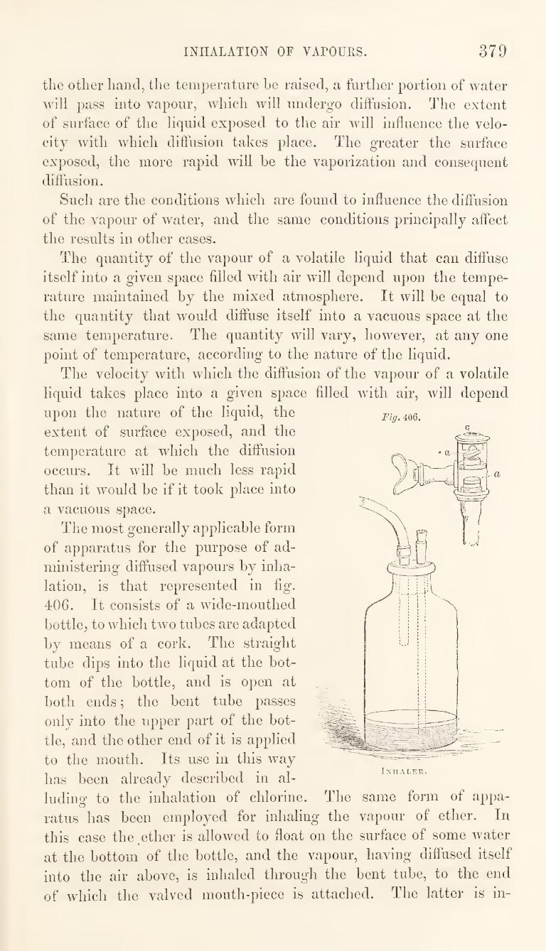
INHALATION OF VAFOULS. 379
the other hand, the temperature be raised, a further portion of water
will pass into vapour, which will undergo diifiision. The extent
of surface of the liquid exposed to the air will influence the velo¬
city with which diffusion takes place. The greater the surface
exposed, the more rapid will be the vaporization and consequent
diffusion.
Such are the conditions which are found to influence the diffusion
of the vapour of water, and the same conditions principally affect
the results in other cases.
The quantity of the vapour of a volatile liquid that can diffuse
itself into a given space filled with air will depend upon the tempe¬
rature maintained by the mixed atmosphere. It will be equal to
the quantity that would diffuse itself into a vacuous space at the
same temperature. The quantity will vary, however, at any one
point of temperature, according to the nature of the liquid.
The velocity with which the diffusion of the vapour of a volatile
liquid takes place into a given space filled with air, will depend
upon the nature of the liquid, the
extent of surface exposed, and the
temperature at which the diffusion
occurs. It will be much less rapid
than it would be if it took place into
a vacuous space.
The most generally applicable form
of apparatus for the purpose of ad¬
ministering diffused vapours by inha¬
lation, is that represented in fig.
406. It consists of a wide-mouthed
bottle, to which two tubes are adapted
by means of a cork. The straight
tube dips into the liquid at the bot¬
tom of the bottle, and is open at
both ends; the bent tube passes
only into the upper part of the bot¬
tle, and the other end of it is applied
to the mouth. Its use in this way
has been already described in al¬
luding to the inhalation of chlorine. The same form of appa¬
ratus has been employed for inhaling the vapour of ether. In
this case the ether is allowed to float on the surface of some water
at the bottom of the bottle, and the vapour, having diffused itself
into the air above, is inhaled througli the bent tube, to the end
of which the valved mouth-piece is attached. The latter is in-
Fig, 406.
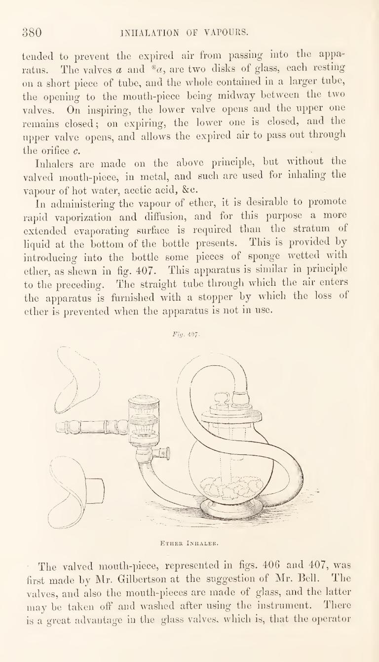
380 INHALATION OF VAFOURS.
tended to prevent the expired air from passing into the appa¬
ratus. The valves d and are two disks of glass, each resting
on a short piece of tube, and the whole contained in a larger tube,
the opening to the mouth-piece being midway between the two
valves. On inspiring, the lower valve opens and the upper one
remains closed; on expiring, the lower one is closed, and the
upper valve opens, and allows the expired air to pass out through
the orifice c. Inhalers are made on the above principle, but without the
valved mouth-piece, in metal, and such are used for inhaling the
vapour of hot water, acetic acid, &c.
In administering the vapour of ether, it is desirable to promote
rapid vaporization and diffusion, and for this purpose a more
extended evaporating surface is required than the stratum of
liquid at the bottom of the bottle presents. This is provided by
introducing into the bottle some pieces of sponge wetted with
ether, as shewn in fig. 407. This apparatus is similar in principle
to the preceding. The straight tube through which the air enters
the apparatus is furnished with a stopper by which the loss of
ether is prevented when the apparatus is not in use.
Fl(j. 407'
The valved mouth-piece, represented in figs. 406 and 407, was
first made by Mr. Gilbertson at the suggestion of Mr. Bell. The
valves, and also the mouth-pieces are made of glass, and the latter
may be taken off and washed after using the instrument. There
is a great advantage in the glass valves, which is, that the operator
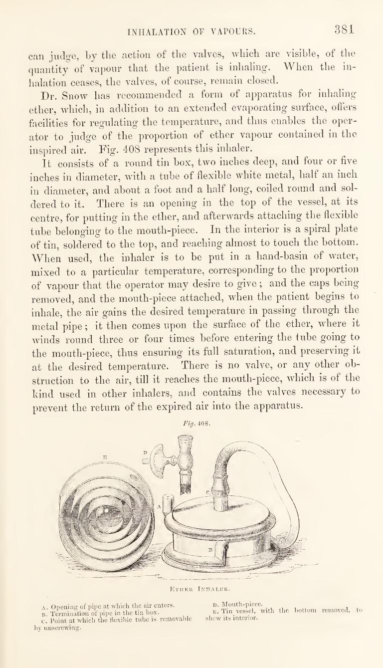
INHALATION OF VAPOURS. 381
can judge, by the action of the valves, which are visible, of the
quantity of vapour that the patient is inhaling. AYhen the in¬
halation ceases, the valves, of course, remain closed.
Dr. Snow has recommended a form of apparatus for inhaling
ether, which, in addition to an extended evaporating surface, offers
facilities for regulating the temperature, and thus enables the oper¬
ator to judge of the proportion of ether vapour contained in the
inspired air. 408 represents this inhaler.
It consists of a round tin box, two inches deep, and four or five
inches in diameter, with a tube of flexible white metal, half an inch
in diameter, and about a foot and a half long, coiled round and sol¬
dered to it. There is an opening in the top of the vessel, at its
centre, for putting in the ether, and afterwards attaching the flexible
tube belonging to the mouth-piece. In the interior is a spiral plate
of tin, soldered to the top, and reaching almost to touch the bottom.
When used, the inhaler is to be put in a hand-basin of water,
mixed to a particular temperature, corresponding to the proportion
of vapour that the operator may desire to give; and the caps being
removed, and the mouth-piece attached, when the patient begins to
inhale, the air gains the desired temperature in passing through the
metal pipe; it then comes upon the surface of the ether, where it
winds round three or four times before entering the tube going to
the mouth-piece, thus ensuring its full saturation, and preserving it
at the desired temperature. There is no valve, or any other ob¬
struction to the air, till it reaches the mouth-piece, which is of the
kind used in other inhalers, and contains the valves necessary to
prevent the return of the expired air into the apparatus.
Fig. 408.
Ether Inhaler.
A. Opening of pipe at wliich the air enters. B. Termination of pipe in the tin box. c. Point at which the flexible tube is removable
by unscrewing.
D. Mouth-piece. E. Tin vessel, with the l)ottom removed, to
shew its interior.
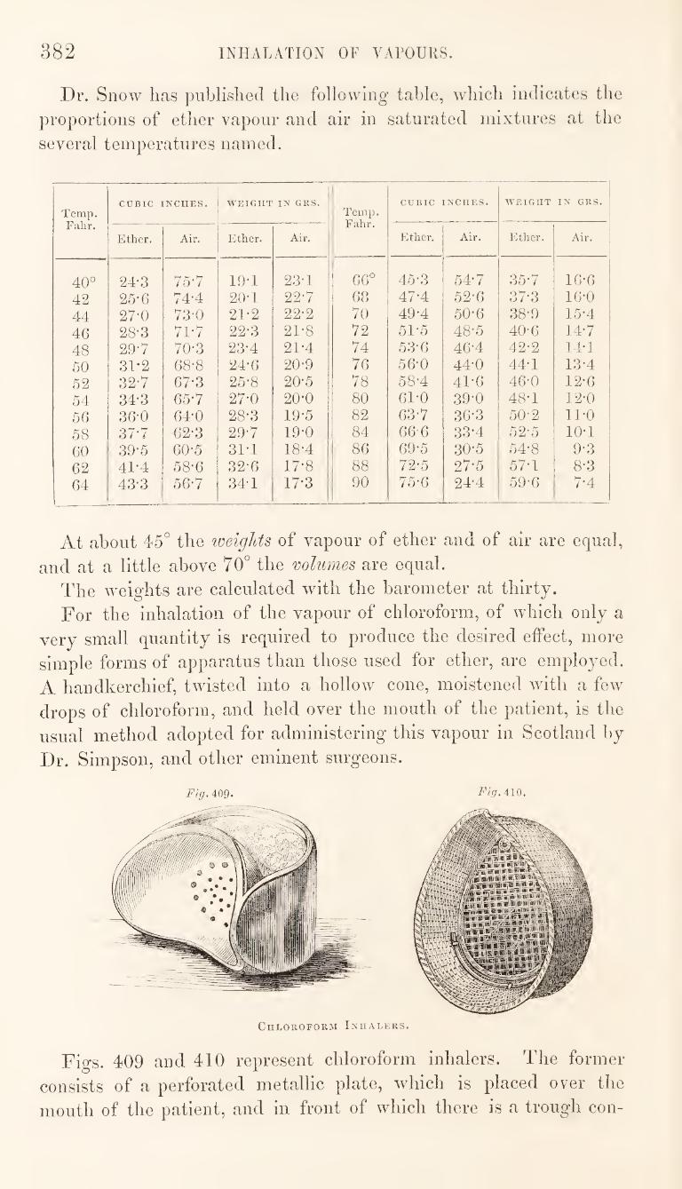
382 INHALATION OF VAPOURS.
Dr. Snow has published the following table, which indicates the
proportions of ether vapour and air in saturated mixtures at the
several temperatures named.
Temp. Falir.
CUBIC INCHES. WEIGHT IN GRS. Temp. Fahr.
CUBIC INCHES. WEIGHT IN GRS.
Ether. Air. Ether. Air. Ether. Air. Ether. Air.
40° 24-3 75-7 19-1 23-1 66° 45-3 547 357 16-6 42 25-6 74-4 20-1 227 68 47-4 52-6 37-3 16-0 44 27-0 73-0 21-2 22-2 70 49-4 50-6 38-9 15-4
46 28-3 71-7 22-3 21-8 72 51-5 48-5 40-6 147 48 29-7 70-3 23-4 21-4 74 53-6 46-4 42-2 14-1 50 31-2 68'8 24-6 20-9 76 56‘0 44-0 44-1 13-4 52 32-7 67-3 25-8 20-5 78 58-4 41-6 46-0 12-6 54 34-3 65*7 27-0 20’0 80 61-0 39-0 48-1 12-0 56 36-0 64-0 28-3 19-5 82 637 36-3 50-2 ll'O
58 37-7 62-3 29-7 19-0 84 66'6 33-4 52-5 10-1 60 39'5 60-5 31-1 18-4 86 69-5 30-5 54-8 9-3 62 41-4 58-6 32-6 17*8 88 72-5 27-5 57-1 8-3 64 43-3 56-7 34-1 17-3 90 75-6 24-4 59-6 7-4
At about 45° the loeights of vapour of ether and of air are equal,
and at a little above 70° the volumes are equal.
The w'eights are calculated with the barometer at thirty.
For the inhalation of the vapour of chloroform, of which only a
very small quantity is required to produce the desired effect, more
simple forms of apparatus than those used for ether, are emplo3^ed.
A handkerchief, twisted into a hollow cone, moistened with a few
drops of chloroform, and held over the mouth of the patient, is the
usual method adopted for administering this vapour in Scotland by
Dr. Simpson, and other eminent surgeons.
409. Fig.AlQ.
Chloroform Inhalers.
Figs. 409 and 410 represent chloroform inhalers. The former
consists of a perforated metallic plate, wdiich is placed over the
mouth of the patient, and in front of which there is a trough con-
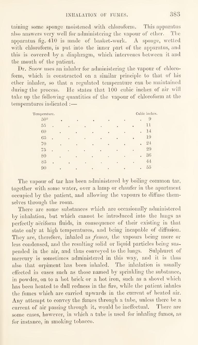
INHALATION OF FUMES. 383
taining some sponge moistened with chloroform. This apparatus
also answers very well for administering the vapour of ether. The
apparatus fig. 410 is made of basket-work. A sponge, wetted
with chloroform, is put into the inner part of the apparatus, and
this is covered by a diajdiragm, which intervenes between it and
the mouth of the patient.
Dr. Snow uses an inhaler for administering the vapour of chloro¬
form, which is constructed on a similar principle to that of his
ether inhaler, so that a regulated temperature can be maintained
during the process. He states that 100 cubic inches of air will
take up the following quantities of the vapour of chloroform at the
temperatures indicated :—
Temperature. Cubic inches.
50° , . . . . 9
55 9 • t, * 11
• • m •
O . 14
65 . 19
70 ... . . 24
/ O • • * • 29
80 ... . . 36
85 . 44
90 ... . . . 55
The vapour of tar has been administered by boiling common tar,
together with some water, over a lamp or chaufer in the apartment
occupied by the patient, and allowing the vapours to diffuse them¬
selves through the room.
There are some substances which are occasionally administered
by inhalation, but which cannot be introduced into the lungs as
perfectly aeriform fluids, in consequence of their existing in that
state only at high temperatures, and being incapable of diffusion.
They are, therefore, inhaled as fumes^ the vapours being more or
less condensed, and the resulting solid or liquid particles being sus¬
pended in the air, and thus conveyed to the lungs. Sulphuret of
mercury is sometimes administered in this way, and it is thus
also that orpiment has been inhaled. The inhalation is usually
effected in cases such as those named by sprinkling the substance,
in powder, on to a hot brick or a hot iron, such as a shovel which
has been heated to dull redness in the fire, while the patient inhales
the fumes which are carried upwards in the current of heated air.
Any attempt to convey the fumes through a tube, unless there be a
current of air passing through it, would be ineffectual. There are
some cases, however, in which a tube is used for inhaling fumes, as
for instance, in smoking tobacco.
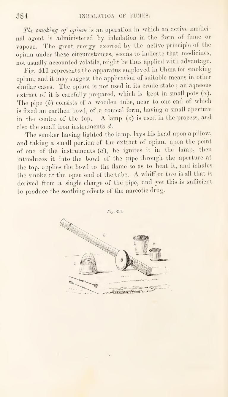
384 INHALATION OF FUMES.
The smoking of ogglum- is an operation in Avhich an active medici¬
nal agent is administered by inhalation in the form of fame or
vapour. The great energy exerted hy the active principle of the
opium under these circumstances, seems to indicate that medicines,
not usually accounted volatile, might he thus applied with advantage.
Fig. 411 represents the apparatus employed in China for smoking
opium, and it may suggest the application of suitable means in other
similar cases. The opium is not used In its crude state ; an aqueous
extract of it is carefully prepared, which is kept in small pots (a).
The pipe (6) consists of a wooden tube, near to one end of which
is fixed an earthen howl, of a conical form, having a small aperture
in the centre of the top. A lamp (c) is used in the process, and
also the small iron instruments d. The smoker having' lighted the lamp, lays his head upon a pillow,
and taking a small portion of the extract of opium upon the point
of one of the instruments ((^), he ignites it in the lamp, then
introduces it into the howl of the pipe through the aperture at
the top, applies the bowl to the flame so as to heat it, and inhales
the smoke at the open end of the tube. A whiff or two is all that is
derived from a single charge of the pipe, and yet this is sufficient
to produce the soothing effects of the narcotic drug.
Fiff. 411.
INDEX.
A.
Acidometer, Baume’s, 280. Adapter, 142. Aids to dispensing, 327. Air-furnace, or wind-furnace, 120. ,, tight filter, 210.
Alarum, laboratory, 44. Alcoholic and ethereal extracts and tinc¬
tures, 83. Alcohometer, Gay-Lussac’s, 282. Alsop’s minim-meter, 268. Apparatus, Beindorf’s, 27, 32, 36.
,, displacement, 65, 90. „ „ Gilbertson’s, 90. „ carbonic acid, 180, 181. „ for distillation, 136, 143, 161. ,, „ drug-grinding, 236. 99
99
95
99
99
99
99
99
99
99
99
99
99
99
Gadda’s condensing, 35. for generating chlorine, 185. „ making ethereal tinctures, 84. „ powdering drugs, 230. „ preparing extracts in vacuo, 72.
sifting, 237. for spontaneous evaporation, 78. for spreading plasters, 371, 372. steam, 27.
„ for laboratory, 49. for stirring extracts, 42. „ subliming benzoic acid, 195. „ „ calomel, 198. „ taking specific gravities, 273,
288. ,, vacuum, 75. „ Woulf’s, 188, 190.
Aqueous extracts, 56. Areometers, or Hydrometers, 278. Arnott’s, Dr., ventilating valve, 13. Arrangements for cutting glass, 303.
„ of shop, 2. „ for distillation, 138. „ „ gas-lighting and ventila¬
tion, 11. „ general, 1. „ for heating the shop, 3. „ „ lighting the shop, 10. „ „ ventilating the shop, 12.
B.
Bags, dusting, 229. „ press, 115.
Balance, method of holding, 270. Balances, 266, 267. Baume’s acidometer, 280.
„ hydrometers, 280. ,, spirit hydrometer, 281.
Beer-knot, 299. Beindorf’s apparatus, 27, 32, 36.
„ condenser, 33. „ decoction-press,.333.
Bellov/s for blow-pipe, 310. ,, double, 125.
Bending of glass tubes, 306. Bent tubes, 308. Benzoic acid, sublimation of, 194. Binding-knot, 298. Blast-furnace, 124.
„ common, 128, 131. Blistering tissue, 375. Blower, centrifugal, 80, 129. Blow-pipe, gas, 311.
„ glass-blower's, 309. Blowing-machine, 80, 129. Boiler, steam, 46, 47. Boring or drilling glass, 305. Bottle, specific gravity, 277.
„ stoop, 20. Bottles, stoppering of, 290.
„ wash, 217. Box, granulating, 248. Bramah's hydraulic-press, 96, 109, 112. Bucket, specific gravity, 175. Burners, gas, 144.
C.
Calomel, sublimation of, 196. Capping-knot, 297. Capsule-mould, 358. Capsules, 358.
„ filling of, 360. „ membrane, 361. „ preparation of, 359.
Carbonic acid apparatus, 180, 181. „ „ generation and absorption of,
185. Cartier’s hydrometer, 281. Casting of zinc, potash, and lunar caustic,
321. Cataplasms, 363. Cellar, store, 23. Centrifugal blower, 80, 129. Cerated-cloth, 374.
C C
386 INDEX.
Cerates, 362. Champagne-knot, 300. Chineso cutting-trough, 224. Chlorine gas, generation and absorption of,
185. Chloroform inhalers, 382. Chopping-trough, 220. Clarification, 218. Closed operating chamber or closet, 324. Closet, drying, 25. Cloth, cerated, 374. Coarse comminution of vegetable substances,
219. Coating glass with copper, 318.
„ vessels with silver, IGl. Cohesion and adhesion in oil of vitriol,
forces of, 154. „ „ water,forces of,
155. Collyriums, 361. Comminution, coarse, of vegetable sub¬
stances, 219. Common blast-furnace, 128, 131.
„ portable furnace, 133, 135. „ worm tub, 34.
Condenser, Beindorf’s, 33. „ common, 34. „ ether, 177, 178. „ Gadda’s, 35.
Kobe’s, 34. Liebig’s, 148.
„ Mitscherlich’s, 35. „ stoneware, 166.
Conical filter-bag, 202, „ mould for levigated chalk, 235.
Connecting and luting of apparatus, 312. Conserves, preparation of, 345. Continuous filtration, 214. Cooling or condensing tub, 33. Cork borers, 313, 314.
,, squeezers, 18,20. Counter, dispensing, 15, 16. Court-plaster, 374. Cover for mortar, 228. Covering of pills with gelatine, 356. Cradle-knife, 223. Crucible furnace, 126. Crucibles, 119.
„ Hessean, 119. Crushing of herbs, 81. Cucurbit, 29.
„ and false bottom, 1 70. Cutting, drilling, and bending glass, 302.
„ knife, 220. „ „ Mohr’s self-supplying, 223.
trough, Chinese, 224. 59
95
D.
Decantation, 250. over a greased rim, 252. with a guiding rod, 251.
Decoction press, Beindorf’s, 333. „ saucepan, 332.
Decoctions and infusions, 331. Desiccation of bottles, flasks, &c., 295.
Determination of specific gravities, 272. Dicas’s hydrometer, 284. Digester, Pappin’s, 168. Digestion and infusion, 39. Dispensary or shop, 1. Dispensing, aids to, 327.
,, counter, 15, 16. ,, of medicines, 325.
Displacement apparatus, 65. „ „ Gilbertson’s, 90. ,, process, 58.
Distillation, 37, 135, ,, apparatus for, 136, 143, 161. ,, arrangements for, 138, 150. ,, dry or destructive, 167. ,, of essential oils, 168. „ in glass vessels, 1 50. ,, of oil of vitriol, 158. ,, process of, 138. „ of spirits, 38.
Division of shop into compartments, 14. Donovan’s filter, 212. Double bellows, 125.
,, screw, or horizontal press, 98. Draughts, preparation of, 339. Drawing out glass tubes, 309. Drill for boring glass, 306. Drilling or boring glass, 305. Drops, preparation of, 340. Drug grinding, apparatus for, 236.
„ mill, or pugging mill, 82. Drugs, pulverization of, 224.
„ „ apparatus for, 230. Dry or destructive distillation, 167. Drying closet, 25.
„ room, or loft, 23. Dusting bags, 229.
E.
Elaeometer, 285. Electuaries ; conserves ; linctus ; preparation
of, 345. Elutriation, 250. Embrocations, 361. Emulsions, preparation of, 341. Enemas, 361. Escape for noxious gases, 192. Essential oils, distillation of, 168.
„ „ preservation and rectification of, 175.
„ „ solution of, 161. Ether condenser, 177, 178.
,, inhaler, 380. „ rectification of, 175.
Ethereal extracts and tinctures, 83. „ tinctures, apparatus for making, 84.
Evaporating pans, 29. Evaporation over the naked fire, 67.
,, spontaneous, 76. ,, „ apparatus for, 78.
„ surface, 41. „ in vacuo, 71. „ by the water bath, or steam
bath, 68. „ of water, rates of, at different
temperatures, 69.
INDEX. 387
Ex tracts, apparatus for preparing in vacuo, 72. „ „ for stirring, 42. „ aqueous, 56. ,, preparation of, 55, 67. „ and tinctures, alcoholic and ethe¬
real, 83.
F.
Fahrenheit’s hydrometer, 279. Faraday’s gas lamp, 12. Filling capsules, 360. Filter, air-tight, 210.
„ bag, conical, 202. „ Donovan’s, 212. „ frame, 203. „ pattern, 207. „ plain, 206. „ plaited, 208, 209. „ Taylor’s, 203. ,, vacuum, 205.
Filtering media, 200. Filters, construction of, 202.
,, of inorganic materials, 211. „ paper, 205.
Filtration, 199. „ continuous, 214.
Fixed stoppers, modes of removing, 293. Flame furnace, 131. Flask, 147, 151.
„ coated with copper, 147. Florentine receiver, 171. Forces of cohesion and adhesion in oil of
vitriol, 154. „ of cohesion and adhesion in water,
155. Frame filter, 203. Fuel for furnaces, 118. Funnel, retort, 140.
„ steam, 30, 178. ,, water-bath, 211.
Furnace and appendages, portable, 164. „ air or wind, 120. „ blast, 124. „ common blast, 128. „ „ portable, 133, 135. „ crucible, 126. „ flame or reverberatory, 131. „ gas, 8,145. „ ,, Ricket’s, 4. „ hood, 8, 193. „ mixed gas, 4, 146. „ operations, 117. „ and sand pot for distillation, 163. „ Seftstroem’s, 127.
G.
Gadda’s condensing apparatus, 90. Galactometer, 286. Gargles, 361. Gas blow-pipe, 311.
„ burners, 144. „ carbonic acid, generation and absorp¬
tion of, 185.
Gas chlorine, generation and absorption of, 185.
„ flame, solid, 307. „ furnace, Ricket’s, 4. „ furnaces, 4, 8, 145, 333. „ lamp, Faraday’s, 12. „ lighting and ventilation, 11. ,, stove, 3.
Gases, generation and absorption of, 179. Gay Lussao’s alcohometer, 282.
„ holder, 148. Gelatine, coating of pills with, 856. General arrangements, 1. Generation and absorption of gases, 179. Gilbertson’s displacement apparatus, 90. Gilding and silvering pills, 356. Glass blower’s blow-pipe, 309.
„ boring or drilling of, 305. ,, cutting with a charcoal point, 304. „ drill for boring, 306. „ syringe, 270. „ tubes, bending of, 306. „ „ drawing out, 309. „ „ sealing of, 310. „ vessels, coating of with silver, 161.
Gout paper, 375. Granulating box, 248. Granulation of gold and silver, 249.
„ iron, 249. „ metals, 247. ,, salts, 249. „ tin, 248. „ zinc, 247.
Gravimeter, 279. Gum and sugar, coating of pills with, 358.
H.
Heating the shop, arrangements for, 3. Hessean crucibles, 119. Holder, Gay Lussac, 148. Hood, furnace, 8, 193. Horizontal press, 98. Hot air chamber, 30. Hydraulic press, Bramah’s, 96, 109, 112. Hydrometer, Baume’s, 280.
„ Cartier’s, 281. „ common, 280. ,, Dicas’s, 284. „ Fahrenheit’s, 27 9. ,, Nicholson’s, 279. „ Sikes’s, 282. „ Twaddle’s, 281. „ Zanetti’s, 281.
Hydrometers or areometers, 278.
I.
Index, water, 31. Infusion and digestion, 39.
„ pot, 89, 332. Infusions and decoctions, 331. Inhalation, 375. Inhaler, 379.
„ ether, 380.
388 INDEX.
Inhalers, chloroform, 382. Injections, 361. Iron, granulation of, 249. Isinglass plaster, transparent, 375.
J.
Joint, water, 7.
K.
Knife, cradle, 223. „ cutting or slicing, 220. „ cutting, Mohr’s self-supplying, 223. „ plaster, 370. ,, rolling, 224. „ root cutting, 21, 22.
Knot, beer, 299. „ binding, 298. „ capping, 297. ,, champagne, 300. „ pyrotechnical, 299.
Knots, tying of, 296. Kobe’s condenser, 34.
L.
Laboratory, 21. „ alarum, 44. „ steam apparatus for, 49.
Lamp, gas, Faraday’s, 12. „ spirit, with double draught, 307.
Lever for removal of fixed stoppers, 293. Levigated chalk, conical mould for, 235. Levigating apparatus, spring for, 235.
„ vessel, 233. Levigation, spring pestle for, 234. Liebig’s condenser, 148. Lighting the shop, arrangements for, 10. Linctus, preparation of, 345. Liniments, 361. Liquefaction, 40. Lixiviation, 89. Loft or drying-room, 23. Lotions, 361. Lovi’s beads, 281. Lozenges, preparation of, 345. Lunar caustic, casting of, 321.
M.
Machine, blowing, 80. Marble mortar for trituration, 231. Means for preserving cleanliness, 326. Measuring and weighing, 260. Mechanical stirrer, 42, 53. Medicines, dispensing of, 325. Membrane capsules, 361. Metals, granulation of, 247. Method of charging a retort, 140.
„ holding the balance, 270. „ „ measure glass, 271.
Mill, drug, 82, 236. Minim-meter, Alsop’s, 268.
Mitscherlich’s condenser, 35. Mixed gas-furnace, 4, 146. Mixtures, preparation of, 337. Mohr’s press for extractions, 58.
„ self-supplying cutting-knife, 223. Mortar, cover for, 228.
„ and spring pestle, 24, 226. „ for trituration, 231.
Mould, capsule, 358. „ for casting hydrate of potassa and
lunar caustic, 322. „ for casting zinc cylinders, 322.
N.
Nicholson’s hydrometer, 279. Noxious gases, escape for, 192.
O.
Oil separators, I7l, 174, 175. „ of vitriol, distillation of, 158. „ „ forces of cohesion and adhesion
in, 154. Oils, essential, distillation of, 168.
„ rectification of, 175. „ solution of, 161.
Ointments, 362. Operating chamber or closet, closed, 324. Operations, furnace, 117.
„ of glowing or heating to redness, 117.
Opium, smoking of, 384. „ pipe, 384.
P.
Pans, evaporating, 29. Paper filters, 205. Paper, gout, 375. Pappin’s digester, 168. Pastils for cutting glass, 303. Perforated false bottom, 170. Pestle, spring for levigation, 234.
„ „ and mortar, 24, 226. Pharmaceutical stove, 5.
„ section of, 9. Pill finisher, 355.
,, machine, 19. Pills, coating of with gelatine, 356.
,, „ gum and sugar, 358. „ gilding and silvering of, 356. ,, preparation of, 344.
Pipettes, 259, 260. Pipe, opium, 384. Plain filter, 206. Plaited filter, 208, 209. Plaster knife, 370.
,, apparatus for spreading, 371, 372. „ court, 374. „ transparent isinglass, 375. „ spatulas, 366.
Plasters, preparation of, 363. Plated still, 160.
INDEX. 389
PlunglnjT syphon, 260. Porphyrization, 232. Porphyry slab and mullor, 233. Portable furnace and appendages, 164.
„ common, 133, 135. Pot, infusion, 39. Potash, casting of, 321. Poultices, 363. Powder-folder, 20. Powdering-room, 23. Powders, preparation of, 344. Precipitates, washing, 216. Preparation of capsules, 359.
„ draughts, 339. „ drops, 340. „ electuaries, conserves, linctus,
345.
99
99
99
99
99
99
9?
99
99
emulsions, 341. extracts, 55, 67.
„ in vacuo, apparatus for, 72.
lozenges, 345. mixtures, 337. pills, 347. powders, 344. tinctures by maceration ns
directed in the London Pharmacopoeia, 87.
tinctures by maceration, as modified by Dr. Burton,
„ tinctures by percolation or displacement, 89.
„ waxed paper, 320. Preservation and rectification of essential
oils, 175. Press-bags, 115.
„ Bramah’s hydraulic, 96, 109, 112.
„ Count Real’s, 60. „ decoction, Beindorf’s, 333. „ for extractions, Mohr’s, 58. „ horizontal, or double screw, 98. „ screw, 97. „ vertical, or single screw, 106.
„ wooden, 104.
Presses, tincture, 114. Process of displacement, 59.
„ distillation, 138. „ expression, 114.
Pugging-mill, or drug-mill, 82. Pulverization of drugs, 224.
„ apparatus for, 230. „ by mediation, 240.
Pyrotechnical knot, 299.
R.
Reading the prescription, 335. Real’s, Count, press, 60. Receiver, Florentine, 171.
„ tubulated, 137- Rectification of essential oils, 175.
„ ether, 176. Removal of fixed stoppers, 292, Retort, badly formed, 137.
„ funnel, 140.
Retort, method of charging, 140. „ with receiver and adapter, 142. „ in sand-pot, 164. „ stand, 148. ,, well-formed, 136.
Reverberatory furnace, 131. Ricket’s gas-stove, or furnace, 3. Ring for cutting glass, 302. Rolling-knife, 224. Room, drying, 23.
„ powdering, 23. „ store, 22.
Root cutting-knife, 21, 22. Rouser, the, 174.
S.
Saccharometers, 285. Safety-tubes, 188. Sand-bath, 33, 147. Saponification, 40. Screw-press, 97. Sealing of glass tubes, 310. Section of pharmaceutical stove, 9. Seftstroem’s furnaces, 127. Shop, arrangement of, 2.
„ arrangements for heating, 3. „ „ lighting, 10. „ „ ventilating, 12. „ or dispensary, 1. „ division of, into compartments, 14.
Sifting apparatus, 237. Sikes’s hydrometer, 282. Silver, granulation of, 249.
„ solution of, 160. Silvering and gilding pills, 356. Single screw, or vertical-press, 104, 106. Slicing-knife, 220. Small plated still, 160. Smoking of opium, 384. Solution, 40.
„ of essential oils, 161. „ silver, 160.
Spatulas, plaster, 366. Specific gravities, apparatus for taking, 273,
288. „ „ determination of, 272.
Specific gravity beads, 281. „ „ bottle, 277. „ „ bucket, 275. „ „ syphon, 290.
Spirit hydrometer, Baume’s, 281. „ lamp with double draught, 307.
Spirits, distillation of, 38. Spontaneous evaporation, 76.
,, „ apparatus for, 78.
Spongio-piline, 363. Spring pestle, 227.
„ for levigation, 234. „ and mortar, 24.
,, for levigating apparatus, 235. Steam apparatus, 27.
„ ,, for laboratory, 49. ,, bath, 69. ,, boiler, 46, 47. ,, funnel, 30, 178.
INDEX, 390
Steam jet ventilation, 55. „ jets, 54.
Steel yard, 265. Still and condenser, 169.
„ head, 30. „ plated, 160. „ stone-ware, 165.
Stirrer, mechanical, 42, 53, Stirring extracts, apparatus for, 42. Stone-ware condenser, 166.
„ still, 165. Stoppering of glass bottles, 290. Store-cellar, 23.
,, room, 22. Stove, gas, 3.
„ pharmaceutical, 5. „ „ section of, 9.
String-box, 20. Sublimation, 194.
of calomel, 196. „ „ apparatus for, 198.
Sublimed benzoic acid, 194. Sugar and gum, coating of pills with, 358. Sulphuret of ammonium, preparation of, 184. Sulphuretted hydrogen, generation and ab¬
sorption of, 183. Suppositories, 363. Surface evaporation, 41. Syphon, plunging, 260.
„ specific gravity, 290. Syphons, 253, 254, 256, 257, 259. Syrmge, glass, 270.
T.
Taylor’s filter, 203. Tin, granulation of, 248. Tincture presses, 114. Tinctures, ethereal, apparatus for making,
84. „ preparation of by maceration, 87. „ „ of by the process of
percolation or displacement, 89.
Tissue, blistering, 375. Transparent isinglass plaster, 375. Trituration, mortar for, 231. Trough, chopping, 220.
„ cutting, Chinese, 224.
Tub, cooling or condensing, 33. „ „ Beindorf’s, 33.
Tubulated receiver, 137. Tube connexions, 315, 317. Tubes, bent, 308. Twaddle's h3"drometers, 281. Tying of knots, 296.
U.
Urinometer, 285.
V.
Vacuum apparatus, 75. „ filter, 205.
Valve, ventilating. Dr. Arnott’s, 13. Vaporization, 40. Ventilating the shop, 12.
„ valve. Dr. Arnott’s, 13. Ventilation, arrangements for, 11.
„ steam jet, 55. Vertical press, 104, 106. Vessel, levigating, 233. Vitriol, oil of, distillation of, 158.
„ forces of cohesion and adhe¬ sion in, 154.
Wash bottles, 217. Washing precipitates, 216. Water-bath, 68.
„ funnel, 211, „ forces of cohesion and adhesion in,
155. „ index, 31. „ joint, 7.
Waxed paper, preparation of, 320. Weighing and measuring, 260. Welter’s safety tube, 188. Wind furnace, 120. Worm-tub, common, 34. Woulf’s apparatus, 188, 190.
Z.
Zanetti’s hydrometers, 281. Zinc cylinders, moidd for casting, 322.
„ granulation of, 247.
THE END.
Loxuon: l‘nutcd by S. & J. Huntley, Wilson, und Fllv.
Haiigor House, Shoe Lane.
One Volume 8w. with Diagrams on Wood, lO.s. doth,
ELEMENTS
OF
MATERIA MEDICA AND THERAPEUTICS.
BY
EDWARD BALLARD, M.D.,
MEDICAL TUTOR IN UNIVERSITY COLLEGE, LONDON ;
AND
A. B. GARROD, M.D., ASSISTANT PHYSICIAN IN UNIVERSITY COLLEGE HOSPITAL.
In introducing another work upon Materia Medica, in addition to those
already before the public, the writers desire that it should he looked upon
as strictly elementary ; and, in so far as the description of the drugs is
concerned, nothing more than a compilation. The necessity for this
outline has been pressed upon them for some time by students with whom
they are respectively connected, as well as by gentlemen in considerable
practice, both of whom felt the inconvenience of reading through extended
treatises, with a view to those essential points of instruction which might
he conveyed in fewer words and be less encumbered with extrinsic matter. Without depreciating, then, the larger works in our language as books of
reference, the present is intended to he one every word of which the
student ought to read, and with whose entire contents he should render
himself familiar. Besides endeavouring to curtail the subject, it has been a primary
object to facilitate its study by arrangement; accordingly, every article
has been treated of, as far as practicable, under the same heads and in a
similar manner. The general principles of Therapeutics, with those of
Chemistry and Natural History, in their application to Materia Medica,
have been included in separate Introductions, in order to avoid repetition
and to exhibit a connected view of each. It will also he observed, that
those articles only which are rendered officinal by the London College are
admitted into the body of the work j all others, which have been regarded
as deserving a place in the Materia Medica, having been thrown into an
Appendix, together with those therapeutical means to which a distinct
place could not be assigned on the plan adopted. The authors beg to assure gentlemen advanced in their studies, or
2
already engaged in the active duties of their profession, that it is far from
their wish dogmatically to decide upon doubtful questions of therapeutics;
since here, as well as upon the action of medicines (at all times delicate
ground), they have merely advanced the opinions which they have adopted
themselves, leaving it to the professional reader to deal with them as his
judgment will suggest. They would willingly have avoided entering upon
the latter of these points at all, feeling, as they do, that, even now,
chemical science is only just beginning to indicate the road which must
be travelled for its solution ; but, at the same time, they were in an equal
degree convinced that some standard, however imperfect, must be raised,
around which the student may collect individual facts.
As respects the sources of their information, but little need be said.
For the description of the British drugs the large works of Drs. Thomson,
Pereira, and Christison, have been carefully collated and very freely used,
and the established authors on Chemistry, Natural History, and Medicine,
have been consulted in matters connected with these departments ; while,
at the same time, the writers have not neglected the resources which their
own experience has afforded them.
In dividing the labour of preparation, each has assumed the portion
most agreeable to his usual train of thought and reading. As regards the
body of the work, the greater part of the Inorganic Division has fallen to
the share of Dr. Garrod, who has also written all that is included under
the head of Chemical Composition and Relations in the Organic Depart¬
ment. The whole of the Natural History and the Organic Materia Medica,
with the above exception, have been undertaken by Dr. Ballard; while it
has been endeavoured to avoid error by each submitting his own portion to
the suggestions of the other. The several Introductions bear the names of
their authors. In the last place, the writers feel happy in having an
opportunity of ex*pressing their acknowledgments to Dr. Sharpey and
Professor Quain, for the very kind manner in which they have forwarded
their project, and for the very friendly spirit in which, not on this occasion
only, but on many others, they have favoured them with their valuable
counsel. It has been their wish, in the plan they have pursued, to imi¬
tate their admirable method of imparting instruction ; and if any of the
opinions expressed may vary from those which they learned from them in
the lecture-room, they feel convinced that it will be attributed only to that
free exercise of judgment which, even in opposition to their own doctrines,
they have ever been the first to promote amongst their pupils.
October Is^, 1845.
LONDON : TAYLOR, WALTON, AND MABERLY,
UPPER GOWER-STREET ; AND IVY-LANE, PATERNOSTER-ROW.
January, 1849.
iw
PRINTED FOR
TAYLOR, WALTON, & MALE ELY,
28j Upper Gower Street, & 27, Ivy Lane, Paternoster Row.
iOictionary of Greek and Homan Hiography and Mythology.
By various Writers. Edited by Dr. William Smith. Complete in three volumes medium 8vo, £5 15s. 6c?. cloth lettered.
(Just Published.')
Subscribers are reyiiicsted immediately to complete their Sets.
Dictionary of Greek and Homan Antiquities.
By various Writers. Edited by Dr. William Smith. Second Edition. Revised throughout, with very numerous Additions and Alterations. One thick volume 8vo,with several hundred Engravings on Wood. £2. 2s. Published.)
Sharpey—Quain.-Dr. Quain^s Anatomy.
Fifth Edition. Edited by Dr. Sharpey and Mr. Quain, Professors of Anatomy and Physiology in University College, London. Complete in 2 vols. 8vo. Illustrated by four hundred Engravings on Wood. Price £2 cloth lettered. (Just Published.)
*** The Work may also be had for a short time in Three Parts.
Part I., 13s. [ Part II., 14s. j Part III., 13s.
Mohr—Hedwood.-Practical Pharmacy.
Comprising the Arrangements, Apparatus, and Manipulations of the Pharmaceutical Shop and Laboratory. By Francis Mohr, Ph.D., Assessor Pharmacise of the Royal Prussian College oi Medicine, Coblentz, and Theophilus Redwood, Professor ot Pharmacy to the Pharmaceutical Society of Great Britain. One volume, 8VO, illustrated by four hundred Engravings on Wood 12s. 6c?. cloth lettered. (Just Published.)
[Bradbury & Evans, Printers, Wbitefriars.]
2 WOrx.KS PRINTED FOR TAYLOR, WALTON, & MABERLY,
Woodcroft.-A Sketch of the Origin and Pro¬ gress of Steam Wavigati©n, from Authentic
I^ocuments« By Bennet Woodcroft, Professor of Macliincry in University College,
London. With seventeen Lithographic Plates and Woodcuts. Fcap. 4to. i 125. cloth. ' (Jlist imllislLed.) j
ISllis.-demonstrations of Anatomy ; I A Guide to the knowledge of the Human Body by Dissection. By George i
ViNER Ellis, Junior Professor of Anatomy in University College, London. I Second Edition, re-written. Small 8vo. Part I., 12s. 6f?. {Just published.) \
*** The purchaser of Part I.will he entitled to receive Part II. on publication, free of further j payment. Part II., completing the work, is to be ready by October. ;
Series of Works by the Eev. Gorham B. Abbott. (Brother of the Author of The Young Christian.)
THE NEW ENGLISH SPELLING-BOOK. Designed to teach Ortho- I graphy and Orthoepy : with a Critical Analysis of the Language, and a Classification of its Elements. On a New Plan. By the Rev. Gorham D. Abbott. Second Edition. 12mo, Is. Qd. cloth. -
FIRST ENGLISH READER. Edited hy the Rev. Gorham D. Abbott. Illustrated by Engravings on Wood. 12mo, 2s. Qd. cloth.
SECOND ENGLISH READER. Edited hy the Rev. Gorham D. Abbott. | 12mo, 3s. Qd. cloth.
Liebig—Gregory.-Researches into the Motion of the Juices in the Animal Body, |
I By Justus Liebig, M. D., Professor of Chemistry in the University of H Giessen. Edited by William Gregory, M.D., Professor of Chemistry in ' the University of Edinburgh. 8vo. 5s. !
This work contains in connection with the Author’s remarks on the effects of evaporation j in plants, his opinion as to the origin of the potato disease; also, a very ingenious plan | by a German, for the protection of the potato plant from disease.
Be Morgan.-Formal Logic ■ Or, the Calculus of Inference, Necessary and Probable. By Augustus De |
Morgan, Professor of Mathematics in University College, London. 8vo. 12s.
Liebig—Gregory.-Turner^s Chemistry. Eighth Edition. Edited hy Justus Liebig, M.D., Professor of Chemistry
in the University of Giessen, and William Gregory, M.D., Professor of j
Chemistry in the University of Edinburgh. Complete in 1 volume, 8vo, ll. 10s.
The Wo7dc may also be had in Two Parts.
Part I.—INORGANIC CHEMISTRY. 15s. cloth.
II.—ORGANIC CHEMISTRY. 15s. cloth.
“ The present is, in short, the most complete and the most luminous system of Chemistry in the English language; and we know no one in France or Germany that comes near it.”—■ ‘ Edmhurgh Medical and Surgical Journal, Jan. 1, 1847. j
28, UPPER GOWER STREET, AND 27, IVY LANE. 3
Kirkes—Paget.-A lIa®d«Bo©l£ of Physiology. By William Senhouse Kirkes, M.D. ; assisted by James Paget, Lec-
; turer on General Anatomy and Physiology at St. Bartholomew’s Hospital, j With Illustrations on Steel and Wood. 12mo, 12s. (id. cloth.
{Just Published.)
Guesses at Truth.—By Two Brothers. First Series. Third Edition. Fcap. 8vo. Cs. cloth. Second Series. Second Edition, with large additions. Fcp. 8vo. Is. cloth.
Batham on the Bnglish language. Second Edition. Revised, with large Additions. 8vo. 155.
I “Let him, though he know no chai’aeters but those of his mother tongue, read ! through the book as well as he can, and we will answer that he will, at the close, find I himself in the possession of much larger and clearer notions of general grammar, and
especially of comparative etymology, than he would have supposed possible at the outset, lie will find here an historical and analytical view, comprisingthe general ethnographical relations of the English Language, and that, too, in a much more readable form than
I he may imagine. At all events it will set him thinking, and, in whatever nook or corner of the kingdom or of the world his lot may be cast, observing too; for the very
j dialect of the province will acquire a new interest, and help him in his studies.” ' English Journal of Education.
Schmitz.-Cheap Bditi©n ©f Miehuhr^s Bectures on the Hist©ry of Rome from the Barliest
j Times to the Beath of Constantine. I Edited by Dr. L. Schmitz, Rector of the High School of Edinburgh. [ Complete in 3 volumes, 8vo. 20s.
*** Vol. I., 8s. (sold separately); Vols. II. and HI., 6s. each.
“ It is this real utility of structure and treatment which renders the Lectures under review more popular, and to tyros in Niebuhr’s theories more useful, than his history, to which they form a fitting introduction or companion.”—Spectator.
Binwood.-Bexicon to .®schylus. Containing a Critical Explanation of the more difficult Passages in the
' Seven Tragedies. By the Rev. W. Linwood, A.M., M.R.A.S. Second Edition, revised throughout. 8vo. 12s.
“ We have much pleasure in recommending the work to the notice of students, who will derive very great assistance from it in the study of Htschylus.”
Classical Museum, No. I.
Schmitz.-A History of Rome, the Earliest Times to the Death of Commodus, a.h. 192. By Dr. L.
Schmitz, Rector of the High School of Edinburgh, Editor of Niebuhr’s Lectures. One thick volume, 12mo, "Is. Qd. cloth, or 8s. Qd. strongly bound
in leather.
This work presents, in a popular form, the results of the investigations of the most distinguished scholars, especially those of Niebuhr, Arnold, Goettling, Rubino, and Becker. The whole is based upon a careful examination of the original sources.
“It will undoubtedly take the place of every other Text-Book of the kind in eur Schools and Colleges.”—Bibliotheca Sacra (American), Aug. 1847.
4 1
WORKS PRINTED FOR TAYLOR, WALTON, & MABERLY,
j Liebig—Playfair and Gregory.-Chemistry in its Applications to Agriculture and Physiology.
By Justus Liebig, M.D., Ph.D., F.R.S., Professor of Chemistry in the University of Giessen. Edited from the Manuscript of the Author, by Lyon
Playfair, Ph.D., and William Gregory, M.D. Fourth Edition, revised.
8vo, IOa'. 6a?. cloth. “ It is not too much to say, that the publication of Professor Liehiy’s Organic Che¬
mistry of Agriculture constitutes an era of great importance in the history of Agi'icul- tural Science. Its acceptance as a. standard is utiavoidahle; for following closely in the straight path of inductive Philosophy, the conclusions which are drawn from its data are incontrovertihle. We can truly say, that we have never risen from the perusal ot a book with a more thorough comictioii of the profound knowledge, extensive reading, and practical research of its author, and of the invincible power and imprytance of its reasonings and conclusions, than we have gained from the present volume.” Silliman s Journal.
Liebig—Gregory.-Animal Chemistry 5 Or, Chemistry in its Applications to Physiology and Pathology. By Justus
Liebig, M.D., Ph.D., Professor of Chemistry in the University of Giessen. Edited, from the Author’s Manuscript, by William Gregory, M.D., Professor of Chemistry in the University of Edinburgh. Third Edition, almost wholly re-written. 8vo. Pa/rt I, (tli6 first licilf of iii& worJf) 6s. 6cL. cloth, just puhlished.
“ Under the heads of animal heat; of the nutrition of the carnivora andherbivora ; of the origin and use of the bile; of the relation between the change of matler and the consumption of oxygen ; of the origin and use of the non-nitrogeniscd elemeius of food, and particularly of fat, and their relative value as sources of heat; ot the etfects of alcohol and fermented liquors; of the effects produced on the volume ot the inspired air by the different articles of food; and lastly, of the true functions ot the intestinal canal, and the origin, nature, and composition of the faeces, w ith their rgiafron to the food, and to the supply of oxygen;—under all these heads, the reader will hnd such an amount of new and interesting matter as must satisfy him that we have entered on the true path of discovery, and that the industi-y of modern chemists has been most profitably employed during the period which has elapsed since the first edition ot this work appeared.”—From the Editor's Advertisement.
Part II., completing the Worh, will he ready very soon. It has heen delayed for the results of important investigations.
I Latham.-An ISnglish Grammar for the Use of Schools.
By B. G. Latham, A.M., Fellow of King’s College, Camliridge. Second Edition. 12mo, 4s. 6d. cloth.
“A work in which Grammar, no longer an assemblage of conventional rules of speech, becomes a philosophical analysis of our language, and an elementary intellectual exercise adapted to the highest purposes of instruction.”—il/hnffes c/ Council of Education (St. Mark’s College), Vol. 1. 1845.
The Classical Museum; A Journal of Philology and of Ancient History and Literature. 8to.
Vol. II., 12.S. 6d. cloth. Vols. III. to VI., each Ms. 6d. cloth.
The work is continued Quarterly. Price of each Part, 3s. 6d. Part XXII.
is just published.
Sub Rege Sacerdos.-Comments on Bishop Hampden^s Case,
With an Epitomised Report of the Proceedings. By E. S. Creasy, M.A., of Lincoln’s Inn, Barrister-at-Law ; Professor of History in University College,
London. 8vo, 3s.
28, UPPER GOWER STREET, AND 27, IVY LANE, 5
j
I (£lass((al 3S(og;va})iDg> |i —♦—
'i DICTIONARY OP GREEK AND ROMAN ANTIQUITIES. Edited by Dr. William Smith. New Edition. One thick vol. 8vo. £2. 2s., cloth
|| lettered. (See page 1.)
|i DICTIONAHY OF GREEK AND ROMAN BIOGRAPHY j AND MYTHOLOGY. Edited by William Smith, LL.D. Medium 8vo. i Illustrated by numerous Engravings on Wood. Complete in Three Volumes.
I Vol. I. (1100 pages), IZ. 16s. cloth lettered. II. (1200 pages), IZ. 16s. ditto.
I III. Completing the Work, £2 3s. 6cZ. (Just puilished.)
' *** Subscribers are requested immediately to complete their copies.
I “ There is no need of pronouncing any formal eulogium on this new Classical Dic- j tionary, for in fact it is the only one with any pretensions to the name in our language;
and as such it must form part of the library of every student who desires to become acquainted with the mind of antiquity.”—AthencBiim.
|i NIEBUHR^S HISTORY OF ROME, FROM THE EARLIEST TIMES TO THE DEATH OF CONSTANTINE. 5 vols. 8vo, 3Z. 2s. Qd.
[j Vols. I. and II., Translated by Bishop Thirl wall and Archdeacon
li Hare. 16s. each. il 1; Vol. III. Translated by Dr. Smith and Dr. Schmitz. 18s. 6cZ. jj Vols, IV. and V. Lectures. Edited by Dr. Schmitz. 2 vols. 12s.
NIEBUHR^S LECTURES ON THE HISTORY OF ROME, FROM THE EARLIEST TIMES TO THE DEATH OF CONSTAN-
! TINE. Edited by Dr, L. Schmitz, Rector of the High School of Edinburgh. Cheap Edition. 3 vols. 8vo. 20s. cloth.
I I. Earliest History to the First Punic War. 1 vol. 8vo, 8s. (See p. 3.) II. First Punic War to the Death of Constantine, 2 vols. 8vo, 12s.
“ They maybe used as an introduction to, or as a running commentary on, Niebuhr’s great work,.,. Even those who by a careful study have acquired a thorough familiarity
I with the three volrunes of the Roman History, will find in these Lectures much that is I new and striking.”—Preface.
SCHMITZ’S HISTORY OF ROME, FROM THE EARLIEST TIMES TO THE DEATH OF COMMODUS. 1 vol. 12mo. Is. 6d. cloth, or 8s. Qd. strongly bound in leather. (Seepage 3.)
ROBSON^S QUESTIONS ON DR. SCFIMITZ^S HISTORY j OF ROME. 12mo, 2s.
i AKERMAN^S (J. Y.) NUMISMATIC MANUAL; or, Guide i TO THE Collection and Study op Greek, Roman, and English Coins.
j 8VO, with numerous Engravings, IZ. Is.
j A SCHOOL DICTIONARY OF ANTIQUITIES ; selected and abridged from the “ Dictionary of Greek and Roman Antiquities.” By William Smith, LL.D. One small volume. Two Hundred Woodcuts. 10s. 6cZ.
KEATS^ (JOHN) POETICAL WORKS. In one vol. leap., with a Portrait from a Drawing by Hilton. Price 5s. cloth.
“ As it is, there is not a poet living who could surpass the material of ‘ Endymion,’ a poem, with all its faults, far more full of beauties.”—tVillis’s PencilUngs by the Way.
! EXERCISES IN LOGIC; designed for the Use of Students in ! Colleges. By J. T. Gray, Ph.D. 12mo. Price 3s. 6cZ. cloth.
G WORKS PRINTED FOR TAYLOR, WALTON, & MABERLY,
#)aturnl POTTER’S ELEMENTARY TREATISE ON MECHANICS,
for the use of the Junior University Students. By Richard Potter, A.M., late Fellow of Queen’s College, Cambridge, Professor of Natural Philosophy in University College, London. Second Edition, revised, 8vo, with numerous
Diagi’ams. os. GtL cloth.
POTTER’S ELEMENTARY TREATISE ON OPTICS. 8vo, with numerous Diagrams. 9s. Gd. cloth.
This volume contains all the requisite propositions carried to first approximations ; and the construction of Reflecting and Refracting Telescopes and Microscopes, the Solar, Oxyhydrogen and Lucernal Microscopes; the Magic and Phantasmagoria Lantern; the Daguerreotype; Camera Obscura; Hadley’s Sextant and Reflecting Circles ; the Optical Square; the Screw Micrometer; the Goniometer, &c.
YOUNG'S LECTUEES ON NATUEAL PHILOSOPHY AND THE MECHANICAL ARTS. A New Edition, with References and Notes, by the Rev. P. Kelland, M.A., F.R S. London and Edinburgh, late Fellow of Queen’s College, Cambridge, Professor of Mathematics, &c. in the University of Edinburgh. 2 vols. 8vo, with 43 Copper Plates. IZ, 45. cloth.
“ All who seek information should know that Young is not merely a popular writer, hut by far the most popular of those whose accuracy can be relied on in a vast range of subjects, and who have actually written through that range.”—Athe?icBum.
TWELVE PLANISPHEEES, forming a Guide to the Stars for every Night in the Year, with an Introduction. 8vo. 6s. Gd. cloth.
DE MORGAN’S ELEMENTS or ARITHMETIC. By Augustus De Morgan, Professor of Mathematics in University College, London. Fifth Edition, with Eleven new Appendixes. Royal 12mo. 5s. cloth.
“ At the time when this work was first published, the importance of establishing arithmetic in the young mind, upon reason and demonstration, was not admitted by many. The case is now altered: schools exist in which rational arithmetic is taught, and mere rules are made to do no more than their proper duty. There is no necessity to advocate a change which is actually in progress, as the works which are published every day sufficiently show. And my principal reason for alluding to the subject here is merely to warn those who want nothmg but routine, that this is not the book for their purpose.”—Author’’s Preface.
DE MOEGAN'S AEITHMETICAL BOOKS AND AUTHOES. From the invention of Printing to the present time ; being Brief Notices of a large number of Works drawn up from actual inspection. Royal 12mo. 6s.
“ A great number of persons are employed in teaching arithmetic in the United Kingdom. In publishing this work, I have the hope of placing before many of them more material for the prevention of inaccurate knowledge of the literature of their science than they have hitherto been able to command, without both expense and research.”—Preface.
DE MOEGAN'S ELEMENTS OF ALGEBEA, preliminary to | the Differential Calculus. Second Edition. Royal 12mo. 95. cloth. !
DE MOEGAN'S ELEMENTS OE TEIGONOMETEY AND I TRIGONOMETRICAL ANALYSIS, preliminary to the Differential Calculus, j
Royal 12mo. 9s. cloth.
TABLES OF LOGAEITHMS, COMMON AND TEIGONO- METRICAL, TO FIVE PLACES. Under the Superintendence of the Society for the Diffusion of Useful Knowledge. Foolscap 8vo. 3s. sewed.
EEINEE'S LESSONS ON FOEM; or, An Introduction to Geometry, as given in a Pestalozzian School, Cheam, Surrey. 12mo, with
numerous Diagrams. 3s. 6cZ. cloth. “ It has been found in the actual use of these lessons, for a considerable period, that a
larger average number of pupils are brought to study the Mathematics with decided j success, and that all pursue them in a superior manner.”—Rev. Dr. Mayo.
28, UPPER GOWER STREET, AND 27, IVY LANE. 7
REINER^S LESSONS ON NUMBER, as given at a Pestaloz- ’ ziau School, at Cheam, Surrey. Second Edition, Consisting of I THE MASTER’S MANUAL. 12mo. 4.-. 6d cloth. I THE SCHOLAR’S PRAXIS. 12mo. 2.s. hound.
i RITCHIE^S PRINCIPLES OE GEOMETRY, familiarly Ulus- ' trated, and applied to a variety of useful purposes. Designed for the Instruc¬
tion of Young Persons. Second Edition, revised and enlarged. 12mo, with 150 Woodcuts. Ss. 6d. cloth.
I RITCHIUS PRINCIPLES OE THE DIEEERENTIAL AND j INTEGRAL CALCULUS, familiarly Illustrated and apphed to a variety of I useful purposes. Second Edition. Revised by J. A. Spencer, B.A., Assistant I Mathematical Master in University College School. 12mo, with Diagrams.
4s. 6cl. cloth. “ Dr. E-itchie was a man of clear head, apt at illustration and fond of elements.
We have heard that he wrote this work when, late in life, he began to learn the subject. We believe our readers would find it a useful first hook.”—Athenceum.
BARLOAMS TABLES OE SQUARES, CUBES, SQUARE ROOTS, CUBE ROOTS, and RECIPROCALS, up to 10,000. Stereotype Edition, examined and corrected. Under the Superintendence of the Society for the Difusion of Usefid Knoioledge. Royal 12mo. 8s.
“ They will be foimd useful to the more scientific class of Engineers and Surveyors, for immediately obtaining results which are now usually got by logarithmic calculation, or the sliding rule; to actuaries (in the table of reciprocals); to schoolmasters, for ob¬ taining examples of the ordinary rules of Arithmetic; to all, in fact, who are calculators by choice or necessity, though of com'se to some more than to others.”—Preface.
Errent Jiitrohuttcirp iietturrs. ! PROFESSOR SCOTT ON THE ACADEMICAL STUDY OP ' A VERNACULAR LITERATURE. 8vo. Is.
I PROEESSOR NEWMAN ON THE RELATIONS OE FREE 1 KNOWLEDGE TO MORAL SENTIMENT. 8vo. Is.
- PROEESSOR RAMSAY. PASSAGES IN THE HISTORY i OF GEOLOGY. 8vo. Is.
J3(arfe0 an& SournaR THE LITERARY DIARY, or Complete Common-Place Book.
Post 4to, ruled throughout and half-bound. 12s.
A POCKET COMMON-PLACE BOOK. With Locke’s Index. Post 8VO, half-bound. 8s. Qd.
THE STUDENUS JOURNAL. Arranged, Printed, and Ruled for receiving an Account of every Day’s Employment for the space of One Year. Post 8vo, half-bound. 4s. Qd.
THE PRIVATE DIARY, formed on the Plan of The StudenPs Journal,” for general Use. Post 8vo, half-bound. As. 6c7.
OUTLINE MAPS: — Mercator — Europe — British Isles. Three Maps, folio, stitched in cover. Is. ; single Maps, Ad. each.
GEOGRAPHICAL PROJECTIONS Mercator—Europe— British Isles. Three Maps, folio, stitched in cover. Is.; single Maps, Ad. each.
TEACHING MAPS :—England, Wales, and Part of Scotland. I. Rivers, Mountains, &c. Price Qd. II. Towns. Price Qd.
8 WORKS PRINTED FOR TAYLOR, WALTON, & MABERLY,
GRESK.
Linwood^s Lexicon to ^scliylus. New Edition, revised. 8vo. (Seepage 2).
Allen's New Greek Delectus; being Sentences for Translation from Greek into English, and English into Greek; arranged in a systematic progression. By Dr. Raphael Kuhnek. Translated and Edited from the German. Second Edition,
revised. 12mo. 4s. cloth.
“ It is an analjTical and synthetical praxis on the forms of the Greek language, communicating, by the way, considerable knowledge of the sjmtax, and information on points connected with the Greek writers.”—Preface.
Allen's Constructive Greek Ex¬ ercises, for teaching Greek from the begin¬ ning by writing. Second Edition, revised and enlarged. 12mo. 5s. cloth.
The pupil, on beginning Greek, needs no book besides this. He has here Grammar, Vocabulary, and Exercise Book.
Hardy's Anabasis of Cyrus^ Book I., Chapters 1 to 6. Literal and Inter¬ linear Translation of the First Chapter, and a Lexicon to the whole, 12mo. .3s. 6d. cloth.
London Greek Grammar; de¬ signed to exhibit, in small compass, the Elements of the Greek Language. Edited by a Graduate of the University of Oxford. Fifth Edition. 12mo. 3s. Gd. cloth.
Plato : tbe Apology of Socrates, the Crito, and Part of the Phsedo; with Notes (translated into English) from Stall-
BAUM and ScHleiermacher’s Introductions. Edited by Dr. Wm. Smith. 12mo. 4s. 6(f. cl.
Life of Socrates. By Dr. G. WiGGERS. Translated from the German, with Notes. 12mo. 3s. Gd.
Contents Life of Socrates, by Wiggers— Life of Socrates, by Diogenes Laertius— Schleiermacher on the Worth of Socrates
as a Philosopher.
Tayler's (Rev. Charles) Intro¬ duction to the Art of Composing Greek lambics, in Imitation of the Greek Trage¬ dians, designed for the Use of Schools.
12mo. 2s. Gd.
Greek Authors, selected for the use of Scnor’B ; containing portions of Lucian’s Dialogues, Anacreon, Homer’s Iliad, Xenophon’s Memorabilia, and Hero¬ dotus. 12mo, 3s. Gd. cloth.
Taylor's What is the Power of the Greek Article ? 8vo, 3s. Gd.
Pour Gospels in Greek, for the use of Schools. Fcap. Svo, 3s. Gd. cloth.
EATITir.
Allen's New Latin Delectus ; being Sentences for Translation from Latin into English, and English into Latin; ar¬ ranged in a systematic progression, on the Plan of the Greek Delectus. Second Edition,
revised. 12mo, 4s. cloth.
Robson's Constructive Latin Exercises, for teaching the Elements of the Language on a system of Analysis and Syn¬ thesis, with Copious Vocabularies. By J. Robson, B.A., Assistant Master in Uni¬ versity College School. 12mo, Gs. Gd.
Allen's Etymological Analysis of Latin Verbs. Fcap. 8vo, 5s.
Allen's Eclogse Ciceronianse; containing Narrations, Maxims, Descrip¬ tions, Characters, Philosophical Pieces, and Letters. Selected from the Works of Cicero.
12mo, 2s. Gd. cloth.
Caesar for Beginners. Latin and English ; with the original Text at the end.
12mo, 3s. Gd. cloth.
Hall's Principal Roots of the Latin Language, simplified by a display of their incorporation into the English Tongue; with copious Notes. Fifth Edition. 12mo,
4s. Gd. cloth.
Hodgson's (Provost of Eton) Mythology for Versification ; or a Brief Sketch of the Fables of the Ancients, pre¬ pared to be rendered into Latin Verse. Fourth Edition. 12mo, 3s. cloth. Key to ditto. Svo, 7s. cloth.
Hodgson's (Provost of Eton) Select Portions of Sacred History, conveyed in sense for Latin Verses. Third Edition. 12mo, 3s. 6ci. cloth. Key to ditto. Royal Svo, 10s. Gd. cloth.
Hodgson's (Provost of Eton) Sacred Lyrics; or. Extracts from the Pro¬ phetical and other Scriptures of the Old Testament; adapted to Latin Versification in the principal Metres of Horace. 12mo,
6s. Gd. cloth.
Caesar's Helvetic War. In Latin and English, Interlinear, with the original Text at the end. 12mo, 2s. cloth.
Latin Authors, selected for the use of Schools; containing portions of Phsedrus, Ovid’s Metamorphoses, Virgil’s A5neid, Csesar, and Tacitus. 12mo, 3s. Gd.
cloth.
28, UPPER GOWER STREET, AND 27, IVY LANE. 9
London Latin Grammar; in¬ cluding the Eton Syntax and Pi’osody in English, accompanied with Notes. Edited by a Graduate of the University of Oxford. Twelfth Edition. 12mo, 2s. 6d. cloth.
New Latin Leading Book •, con¬ sisting of short Sentences, easy Narrations, and Descriptions, selected from Caesar’s Gallic War ; arranged in systematic pro¬ gression. With a Dictionary. 12mo. Ss.
6d. cloth.
‘ ‘ The plan of this work differs in one important point from other works of a similar kind. The sentences have been selected exclusively from Caesar’s Commentary on the Gallic War, instead of being taken from different authors, as has usually been the case. There is an obvious advantage in this plan ; the same words are con¬ tinually repeated by the same author in a simple narrative; and the pupil thus becomes accus¬ tomed to his style, and finds the work of transla¬ tion grow easier every day, which cannot be the case when the extracts are taken from many dif¬ ferent authors, whose style must of com'se vary exceedingly.”—Preface.
Tacitus. Germania, Agricola, and First Book of the Annals. With Notes translated into English, from Ruperti, Passow, Walch, and Botticher’s remarks on the style of Tacitus. 12mo. 5s. cloth.
Virgiks JEneid. The First Six Books, with an interpaged translation, line for line, and numerous Notes. Second Edition. 12mo. 6V. 6d.
Cicero. — Pro Lege Manilia. 12mo, sewed, U.
ETJGIiISH.
Latham's English Language. Second Edition revised. 1 vol. 8vo. 15^.
(See page 3.)
Latham's First Outlines of Lo¬ gic, applied to Grammar and Etymology.
12mo, n. 6ci. cloth.
Latham's Elementary English Grammar. For the Use of Schools. Second Edition. 12mo. 4^. Gd. cloth.
‘ ‘ Ills comparison of the old Saxon forms with th« modern English, his classification of verbs under the heads of weak and strong forms, and his remarks on the derivation and consUucLion of English words, afford evidence of laborious inves¬ tigation and research, and are a valuable conUibu- tion towards reducing our language within its proper limits.”—Classical Museum.
Green's Questions on the above, with an Index of Reference. 12mo. cloth,
\s. 6d.
ZTA1.XA.TJ.
Panizzi's Extracts from Italian Prose Writers. One thick volume, 12mo. ! 10#. 6d. boards. j
Panizzi's Elementary Italian Grammar. 12mo. 3s. bound.
FRSINrCH.
Complete Course of the French | Language. By P. F. Merlet, Professor of j
French in University College, London. j
Merlet's French Grammar, | divided into Three Parts ; the Pronuncia¬ tion, the Accidence, and the Syntax. New Edition. 12mo. 5s. 6d. bound.
Merlet's Key to the French Grammar. 12mo. 3s. 6(Z, bound.
Merlet's Le Traducteur; or. His¬ torical, Dramatic, and Miscellaneous Selections from the best French Writers; accompanied by Explanatory Notes ; a selection of Idioms, &c. New Edition.
12mo. 5s. 6d. bound.
Merlet's Petit Tableau Litteraire de la France ; containing an Essay on French Literature, with Specimens of the best Authors, from the earliest period to the present time ; a sequel to “ Le Tra¬ ducteur.” 12mo. 6s. bound.
Merlet's Dictionary of Difficul¬ ties; Appendix to the French Grammar. Second Edition. 12mo. 4s-bound. Con¬ taining an explanation of the peculiarities of the French Language—Complete List of Adjectives, showing why they are placed before or after the Substantive—Compre¬ hensive List of Idioms, and Proverbs now in use — List of Synonymes — Mercantile Expressions, Phrases, and Letters, &c. &c.
HEBRBW.
Hurwitz's Grammar of the He¬ brew Language. 8vo. 13s. cloth. Or in Two Parts, sold separately: Elements.
8vo. Cloth, 4s. 6d. Etymology and Syn¬
tax. 8vo. Cloth, 9s.
“Mr. Hurwitz’s Grammar is the best ele¬ mentary work of its kind extant in the English lan¬ guage.”—Journal of Education, Ao. 9.
Greenfield's Book of Genesis in English Hebrew, accompanied by an Inter¬ linear Translation, substantially the same as the authorised English version ; Philo¬ logical Notes, and a Grammatical Introduc¬ tion. Fourth Edition. 8vo. 8s. cloth. With the original Text in Hebrew characters at
the end. 8vo. 10s. 6d. cloth.
10 WORKS PRINTED FOR TAYLOR, WALTON, & MABERLY,
INTEELINEAR TRANSLATIONS.
LOCKE'S SYSTEM OP CLASSICAL INSTRUCTION, Restoring the Method of Teaching formerly practised in all Public Schools. The Series consists of the following Interlinear Translations ; with the Original Text, in which the quantity of the doubtful Vowels is denoted ; Critical and Explanatory Notes, &c.
*** By means of these Works, that excellent System of Tuition is effectually restored which was established by Dean Colet, Erasmus, and Lilly, at the foundation of St. Paul’s School, and was then enjoined by authority of the State,'to be adopted in all other Pubhc Semi¬ naries of Learning throughout the kingdom. Each volmne 2s. 6d.
Latin.
1. Pha^drus’s Fables of ..^sop.
2. Ovid’s Metamorphoses. Book I. 3. Virgil’s ^Eneid. Book I. 4. Parsing Lessons to Virgil.
5. C..esar’s Invasion of Britain.
6. Tacitus’s Life of Agricola. Part I.
Italian.
Stories from Italian Writers :—Al-
FIERI, BaRETTI, CaSTIGLIONE, &C.
Greek.
1. Lucian’s Dialogues. Selections. 2. The Odes of Anacreon.
3. Homer’s Iliad. Book I.
4. Parsing Lessons to Homer.
5. Xenophon’s Memorabilia. Book I. 6. Herodotus’s Histories. Selections.
French.
SiSMONDI ; THE BaTTLES OF CrESSY AND
PoiCTIERS.
German.
Stories from German Writers.
An Essay, explanatory of the System. I2mo. . . . O5. 6cZ.
A Iso, to accompany the Latin and Greek Series.
The London Latin Grammar. I2mo.25. Qd. The London Greek Grammar. 12mo.35. Qd.
simim. The Singing Master. Sixth
Edition (one half the original price). 8vo. 65. cloth lettered, gilt edges.
No. I. FIRST LESSONS IN SINGING AND THE NOTATION OF MUSIC. Pi-ice \s.
No. 11. RUDIMENTS OF THE SCIENCE OF HARMONY, OR THOROUGH BASS. Price I5.
No, III. THE FIRST CLASS TUNE-BOOK. Thirty Simple and Pleasing Airs, ar¬ ranged, with Suitable Words, for Young Children. Price I5.
No. IV. THE SECOND CLASS TUNE- BOOK. Price I5. 6cJ.
No. V. THE HYMN TUNE-BOOK. Price Is. Qd.
The Vocal Exercises, Moral Songs and Hymns,
with the Music, may also be had, printed on 87 Cards. Price 2d. each Card, or Twenty-five for 3s.
The Words without the Music may be had in Three Small Books.
Moral Songs from the First Class Tune- Book, \d.
-—— Second Class Tune- Book, \d.
Hymns from the Hymn Tune-Book, l^d.
Helen S. Herschelhs Fireside Harmony; or Domestic Recreation in Part Singing. A Selection of favourite old Glees, Rounds, and Canons; arranged to words suitable for Families and Schools. Second Edition. Demy 8vo. (oblong) 2s.6d.
28, UPPER GOWER STREET, AND 27, IVY LANE. 11
DRAWING. Lineal Drawing Copies for tlie
Earliest Instruction. Comprising 200 Sub¬ jects on 24 sheets, mounted on 12 pieces of thick pasteboard. By the Author of “ Drawing for Young Children.” In a Port¬
folio, 5s. 6d,
Drawing Copies for Elementary Instruction. By the Author of “Drawing forA'oung Children.” 2 Sets, each consist¬ ing of 12 Subjects, mounted on thick paste¬ board. 35. 6d. each Set, in a Portfolio.
Deacon's Elements of Perspec¬ tive Drawing, or the Science of Deline¬ ating Real Objects. Being a IManual of Directions for using a Set of Models, com¬ posing a variety of Picturesque Forms. Suitable for the Practice of Beginners. Illustrated with Eight Plates, 8vo. 45.
Drawing Models, consisting of Forms for constructing various Buildings, Gateways, Castles, Bridges, &c. The Build¬ ings will be found sufficiently large to be drawn from by a numerous Class at the same time. In a Box, with a small Trea¬ tise on Drawing and Perspective. Price 21. lf)5. Length of the Box, 18| inches ; breadth, 13 inches ; height, 82 inches.
Traclisell's Drawing Models, consisting of Rectilinear Figures, Polygonal and Mixtilinear Models, Models chiefly for Shading, and Models for application and further practice. Price of the complete set lOL Any Figure may be purchased separately.
The whole Collection, with the exception of the houses, is painted white, to resemble plaster.
A complete Collection on a larger scale, such as that used in the Mechanics’ Institu¬ tion, Liverpool, 15L
A detailed Prospectus may be had on application.
Drawing Materials. A Quarto Copy Book of 24 leaves, common
paper, Qd. Ditto . . ditto
paper of superior quality, I5. 3d. Pencils with very thick lead, B.B.B. 25. per
half dozen. Ditto .... ditto . . F. at
l5. 6d. ditto. Drawing Chalk, 9d. per dozen sticks, in a Box. Port-crayons for holding the Chalk, 4d. each.
EDUCATIONAL MODELS
FOR THE USE OF SCHOOLS, MECHANICS’ INSTITUTIONS, AND FOR
PRIVATE INSTRUCTION.
A Set of Apparatus for Hydro¬ statics, Hydraulics, and Pneumatics ; with a Pamphlet containing full Descriptions and Directions for Performing many Ex¬ periments. Price 6L 65. in a box.
Apparatus for Coliesion, Capil¬ lary Attraction, Electric and Magnetic Attraction, Impenetrability and Inertia; with Descriptions and Diagrams. Price
2I5. in a box.
A Machine for Illustrating Cen¬ trifugal Motion; including a representa¬ tion of the Governor of a Steam Engine.
In a box, IO5.
Attwood's Machine for Explain¬ ing the Laws of Falling Bodies: with Apparatus attached for Illustrating the Theory of the Pendulum. Price of Att- wood’s Machine, with a “Companion,” 21. 2s. ; additional Apparatus, for the Pen¬
dulum, \l, l5.
Sets of Mechanical Powers; containing the Lever—Wheel and Axle— A Series of Pulleys—The Inclined Plane- Wedge—Screw; with Examples of the Parallelogram of Forces—Centre of Gravity —Friction—Collision of Elastic Bodies— Compound Lever. £ s. d,
1. For large Lecture-rooms (size of the frame : height 3 feet 1 inch; width, 3 feet).8 8 0
2. For Schools and smaller Lecture- rooms (height of the frame, 2 feet 6 inehes; width 2 feet 3 inches) .5 5 0
3. A Smaller Set, omitting the Pa¬ rallelogram of Forces and Col¬ lision of Elastic Bodies (height of the frame, 2 feet 1 inch; width, 1 foot 115 inches) . . 2 12 6
4. A Commoner Set (height of the frame, 2 feet; width, 19 inches) 163
The Bent Lever. Convertible into a Bent Lever or Toggle Joint Press. With weights, and a description. Price IO5.
12 WORKS PRINTED FOR TAYLOR, WALTON, & MABERLY,
EBUCATIOWAIi IVIOEEZ.S—continued^
Apparatus for Magnetism. Price 18^. in a box.
A Train of Spur Wheels, mounted on a mahogany stand, with weights. Price 21s. in a box.
A Double Inclined Plane, with an Application of the Composition and Resolution of Forces. In a box, 10^.
A Portable Hydrostatic Bellows; with Description and Diagram, including a weight. Price 2n. in a box.
A Sectional Model of the Steh.m Engine; by which the motions of the several parts, its internal structure, and the high and low pressure principles, can be easily explained. Price 21. 2s. in a box.
A Pyrometer, for Showing the Expansion of Metals. Price IS^.
Diagrams in Wood, to Illus¬ trate Dr. Lardner’s Euclid. Solid Geo¬ metry, Book I. Price "Js. 6d.
MINASI’S MECHANICAL DIAGRAMS. For the Use of Lecturers, and Schools. Complete in Five Numbers, each containing Three Sheets of Diagrams, price 3a’. each Number, coloured, illustrating the following subjects:— 1 & 2. Composition of Forces.—3. Equilibrium.—4 & 5. Levers —fi. Steelyard, Brady Ba¬ lance, and Danish Balance.—7- Wheel and Axle.—8. Inclined plane.—9, 10,11, Pulleys.— 12. Hunter’s Screw.—13 & 14. Toothed Wheels.—15. Combination of the Mechanical Powers.
The Diagrams are printed on large sheets of paper, measuring 2 feet 11 inches by 2 feet. This size will be found suited for large lecture rooms.
Geometrical Solids. The Five Regular Solids —1. Tetrahedron; 2. Octa¬ hedron ; 3. Icosahedron; 4. Hexahe¬ dron ; 5. Pentagonal Dodecahedron; 6- Rhomboidal Dodecahedron; 7. Bipyra- midal Dodecahedron ; 8. Trapezohedron. Pyramids.—9. Triangular; 10. Quadri¬ lateral; 11. Hexagonal; 12. Octagonal. Prisms.—13. Triangular; 14. Quadri¬ lateral; 15. Hexagonal; 16. Octagonal.— 17. Sphere; 18. Cylinder; 19. Cone. The Set in a box, 9s.
Another Set, containing the Conic Sections. Price 16j.
A Larger Set. Price 11. 115. Qd.
An Instrument for Teaching Geometry ; convertible into a Theodolite, Spirit Level, Hadley’s Sextant, and Wollas¬ ton’s Goniometer. Price 21. 12j. 6d, in a box.
A Pair of Large Dividers, for making Diagrams Price 4:?.
on a black board.
CHEMISTRY.
TURNER’S ELEAIENTS OF CHEMISTRY. Eighth Edition. Edited by Justus Liebig, M.D., Professor of Chemistry in the LFniversity of Giessen, and William Gregory, M.D., Pi’ofessor of Chemistry in the University of Edinburgh. 1 vol. 8vo. ll. iOs. (See page 2.)
Also, in Two Parts.
Part I.—INORGANIC CHEMISTRY. 15s.
II.—ORGANIC CHEMISTRY. 15^.
“ The present is, in short, the most complete and the most luminous system of Chemistry in the English language; and we know no one in France or Germany that comes near it.”—Edinburgh Medical and Surgical Journal, Jan. 1, 1847.
GREGORY’S OUTLINES OF CHEMISTRY, for the use of Students. By William Gregory, M.D., Professor of Chemistry in the Uni¬ versity of Edinburgh. Second Edition, revised and enlarged. Complete in 1 vol. foolscap 8vo, 12s. cloth. Part I.—(Inorganic Chemistry), 5s. cloth. Part II.— (Organic Chemistry), 7s. cloth.
‘ ‘ This is beyond comparison the best introduction to Chemistry which has yet appeared. The directions lor preparing substances are usually confined to the best method, so that brevity and selectness are combined. The size and price of this little work, as well as its intrinsic merits, commend it to every student of Chemistry.”—Lancet.
28, UPPER GOWER STREET, AND 27, IVY LANE 13
WILL’S OUTLINES OE THE COURSE OE QUALITATIVE ANALYSIS FOLLOWED IN THE GIESSEN LABORATORY. By Henry Will, Pli.D., Professor Extraordinary of Chemisti’y in the University of Giessen. With a Preface, by Baron Liebig, 8vo, 6s. ; or with the Tables
mounted on linen, 7s.
“ The present work contains an accurate description of the course I have followed in my laboratory, with great advantage, for twenty-five years.”—Baron Liebig.
PARNELL’S ELEMENTS OE CHEMICAL ANALYSIS, QUALITATIVE AND QUANTITATIVE. By Edward Andrew Parnell,
Author of Applied Chemistry ; in Arts, Manufactures, and Domestic
Economy.” Second Edition, revised throughout, and enlarged by the addition
of 200 pages 8vo, 14^. cloth.
PARNELL’S APPLIED CHEMISTRY; IN MANUFAC¬ TURES, ARTS, AND DOMESTIC ECONOMY. With numerous Wood
Engravings and Illustrations.
Vol. /., 13s. cloth lettered, contains:— Preliminary Observations—Gas Illumination—Preservation of Wood—
Dyeing and Calico Printing.
Yol.II., 13s., cloth lettered, contains:— Ql^ss—Starch—Tanning—Caoutchouc—Borax and the Boracic Lagoons
•—Soap—Sulphur and Sulphuric Acid, and Soda.
PETZHOLDT’S LECTURES TO FARMERS ON AGRICUL¬ TURAL CHEMISTRY. People’s Edition. 1 vol. small 8 vo., 4s. 6d. sewed ;
5s. cloth. “The author does not overload his subject with needless details, which is the vice of
some such books, but he confines the reader to those points only which he ought to be well acquainted with, and these he explains in a clear and simple yf&y.”—Gardeners’ Chronicle.
LIEBIG’S RESEARCHES INTO THE MOTION OF THE JUICES IN THE ANIMAL BODY. 8vo. 5s. (See page 2.)
LIEBIG’S FAMILIAR LETTERS ON CHEMISTRY, AND ITS RELATIONS TO COMMERCE, PHYSIOLOGY, AND AGRICUL¬ TURE. Third Edition. Foolscap 8vo, 4s. 6d.
LIEBIG’S FAMILIAR LETTERS ON CHEMISTRY, Second Series. THE PHILOSOPHICAL PRINCIPLES AND GENERAL LAWS OF THE SCIENCE. Foolscap 8vo, 5s.
“ The plan of the Letters is as simple and intelligible as their style. The author sets out with a general consideration of Chemistry; and of the rank to which it is entitled among the other sciences; treats shortly of chemical affinity and chemical equivalents, illustrating the symbols and formulae by which these affinities are expressed; explains the atomic theory; considers the relation of heat, light, elech'icity, and gravity to chemical force, and shows wherein these forces differ from what has been called the vital principle ; and lastly discusses the transibrmations—fermentation, putrefaction, and decay—which take place in organic bodies when removed from the influence of vitality.”—Chamhers’ Journal. Notice of Second Series.
LIEBIG’S ANIMAL CHEMISTRY; or, CHEMISTRY IN ITS APPLICATIONS TO PHYSIOLOGY AND PATHOLOGY. Third Edition, almost wholly re-written. Part I., 65. 6d. cloth. (See page 4.)
LIEBIG’S CHEMISTRY IN ITS APPLICATIONS TO AGRI¬ CULTURE and physiology. Fourth Edition, revised. 8vo, IO5. 6(7. cloth. (See page 4.)
PORTRAIT OE PROFESSOR LIEBIG. Is. M.
14 WORKS PRINTED FOR TAYLOR, WALTON, & MABERLY,
I CHE!M£STXS.ir—continued.
I PLATTNER ON THE USE OP THE BLOWPIPE IN THE i EXAMINATION OF MINERALS, ORES, FURNACE PRODUCTS, I AND OTHER METALLIC COMBINATIONS. Translated, with Notes,
,i by Dr. J. S. Muspratt. With a Preface by Professor Liebig. Illustrated !t by numerous Wood Engravings. 1 vol. 8vo, IO5. Gel.
|| FRESENIUS AND WILLIS NEW METHODS OF ALKA- !j LIMETRY, and of determining the Commercial Value of Acids, and ii Manganese. I2mo, 4s. cloth.
ij “ This little work will prove of the highest importance to Calico Printers, Bleachers, I Dyers, Manufacturers of Soap, Paper, and Prussiate of Potash; also to Chemists, and
to dealers in Alkalies, Acids, &c.”
INSTRUCTIONS FOR MAKING UNFERMENTED BREAD; Ij with Observations on its Properties, Medicinal and Economic. By a Physi-
: ciAN. Fifteenth Edition, containing the New Formulse. 8vo, 3cl.; or, II Postage free, 5d.
I ‘‘The author, by directing attention to a subject of the highest importance in a I social and economical, as well as a medical point of view, has rendered a great service I to the public.”—Edinburgh Medical and Surgical Journal.
“We recommend this Pamphlet to the serious attention of the public.”—Times.
SURGICAL ANATOMY.
:! MORTON’S SURGICAL ANATOMY OP THE PRINCIPAL I REGIONS. Royal 8vo. Plates and Woodcuts. ‘
PERINA5UM. Four Plates and Three Woodcuts. 6s. plain, 7s. 6d. coloured. GROIN, FEMORAL AND POPLITEAL REGIONS. Eight Plates and Eleven
Wood Engravings. 9s. plain, 13^. coloured. INGUINAL HERNIA, TESTIS AND ITS COVERINGS. Five Plates and
Eleven Woodcuts. 12.s'. coloured, 85. plain. EIGHT PLATES OF THE HEAD AND NECK, THE AXILLA, AND
BEND OF THE ELBOW. 13^. coloured, 7s. 6d. plain.
“ The production (volume on the Groin) is altogether one which we can conscientiously recommend to the working student.The work will constitute a complete and elaborate treatise, that cannot fail to be highly useful to surgeons in general.”— and Foreign Medical Review.
“The present work (Inguinal Hernia) is a worthy successor to those on the Groin and Perinmum, and will prove, we do not doubt, as great a favourite with students.”— Med.-Chir. Rev., April, 1841.
CUTLEE^S SURGEON^S PRACTICAL GUIDE IN DRESS¬ ING AND IN THE METHODIC APPLICATION OF BANDAGES. Second Edition. 100 Engravings on Wood. Foolscap 8vo, 6s. 6d.
“This appears to be a valuable little treatise. The author seems to have spared no pains in procuring correct descriptions of all the surgical apparatus at present employed in bandaging and drtssing, both at home and abroad. He has given numerous illustra¬ tions in the form of well-executed Woodcuts, and has altogether produced what we conceive to be a very useful, and by no means an expensive publication.”—Medical Gazette, Nov. 10, 1834.
HIND’S TWENTY PLATES OF FRACTURES OF THE EXTREMITIES. Second Edition. Folio, 1/. 4s. cloth.
PORTRAIT OP ROBERT LISTON, ESQ. 2s. M.
28, UPPER GOWER STREET, AND 27, IVY LANE 15
ANATOMBCAL PLATES,
CHEAP ISSUE (ONE-THIRD LESS THAN THE ORIGINAL PRICE). Noio Ready.
Complete in \Z Monthly Parts, each IO5. Qd.plain, 20s. coloured, of
A SERIES OP ANATOMICAL PLATES, IN LITHO- GP..APHY : With References and Physiological Comments, illustrating the Structure of the different Parts of the Human Body. Edited by Jones
Quain, M.D., and Erasmus Wilson, F.R.S.
the work BIAY also be had in separate portions, bound in CLOTH, as follows :— Former Price. Present Price. Former Price. Present Price.
Plain. Plain. Coloured. Coloured. c£. s. d. s. d. c£. s. d. s. d.
MUSCLES, 51 Plates . . .2 16 0 1 18 0 5 5 0 3 12 0
VESSELS, 50 Plates . . ..214 0 1 18 0 3 18 0 3 3 0
NERVES, 38 Plates. . . .24 0 1 10 0 4 2 0 2 16 0
VISCERA, 32 Plates . . ..118 0 1 5 0 3 10 0 2 8 0
BONES & LIGAMENTS, 30 Plates 2 0 0 1 5 0 2 15 0 1 11 6
Also complete in 2 vols. royal folio, half-bound morocco, gilt tops, price 81. 8s. plain, 14Z. coloured.
ANATOMY. -^—
DR. QUAIN^S ANATOMY. Fifth Edition. Edited by Dr.
Sharpey and Mr. Quain. Illustrated by several hundred Engravings on Wood. 2 vols. 8vo, 2Z. cloth lettered. (See page 1.)
Also (for a short time) in Three Parts.
Part I., 13^. | Part II., Ids. j Part III., 13^.
ELLISES DEMONSTRATIONS OF ANATOMY. A Guide to the Dissection of the Human Body. Second Edition. Small 8vo. (Jzist published.')
MACLISE’S morphological STUDIES IN SEARCH OF THE ARCHETYPE SKELETON OF VERTEBRATED ANIMALS. Illustrated in 54 Plates, One volume, small folio, 21. 12^. Gd.
“The present volume is a most grateful and refreshing sight, exhibiting in every page evidence of accurate investigation, of profound reasoning and extended knowledge, both general and professional.”—Lancet.
MATERIA MEDSCA AND PHARMACY.
MOHR AND REDWOOD’S PRACTICAL PHARMACY. The Arrangements, Apparatus, and Manipulations of the Pharmaceutical Shop and Laboratory. 8vo, with 400 Engravings on wood. 12s. Gd. cloth lettered.
BALLARD AND GARROD’S ELEMENTS OF MATERIA MEDIC A AND THERAPEUTICS. One volume 8vo, with Diagrams on Wood. 12s. cloth.
“As a manual for students, it is the best that has yet appeared, and will he found to contain much matter well worthy of perusal by the practitioner.”—Hanking’’s Report.
16 WORKS PRINTED FOR TAYLOR, WALTON, & MABERLY.
PHYSIOLOGY. HAND-BOOK OP PHYSIOLOGY. By W. S. Kirkes, M.D.,
Medical Registrar and Demonstrator of Morbid Anatomy at St. Bartholomew’s Hospital; assisted by James Paget, Lecturer on General Anatomy and Phy¬ siology at St. Bartholomew’s Hospital. With Illustrations on Steel and Wood.
12mo, 12s. GcZ. cloth.
MULLER’S ELEMENTS OP PHYSIOLOGY. Translated, with Notes, by William Baly, M.D. Steel Plates and very numerous En¬ gravings on Wood. 2 thick vols. 8vo. 205. each.
EECENT ADVANCES IN THE PHYSIOLOGY OF MO¬ TION, THE SENSES, GENERATION AND DEVELOPMENT. By William Baly, M.D., F.R S., Physician to Milbank Prison, and W. S. Kirkes, M.D. ; being a Supplement to the Second Volume of Professor Muller’s Elements of Physiology. With numerous Illustrations. 8vo, 5s. 6d.
“To those who possess Muller’s Elements, it is indispensable—to others who have not this useful work it will be found most serviceable in giving them at a small expense an insight into the recent progress of Physiology.”—Medical Gazette.
MULLER’S EMBRYOLOGY, WITH THE PHYSIOLOGY OF GENERATION. Translated, with Notes, by Dr. Baly (from Muller’s Elements of Physiology and Supplement). 8vo, with numerous Illustrations,
Is. 6d. cloth.
MULLER^S PHYSIOLOGY OE THE SENSES, VOICE, AND MUSCULAR MOTION, WITH THE MENTAL FACULTIES. Translated, with Notes, by Dr. Baly (from Muller’s Elements of Physiology and Supplement). 8vo. 7s. 6d. cloth.
MEDICINE. MURPHY’S (PROPESSOR) LECTURES ON NATURAL
AND DIFFICULT PARTURITION. One volume 8vo, with numerous Engravings on Wood. 9s. cloth.
“ The whole of these Lectures, which refer to difficult and laborious labours, and to the apulicadon of instruments, will be found of the very greatest value.”—Lancet.
CHLOROEORM IN THE PRACTICE OF MIDWIFERY. By Edward W. Murphy, A.M., M.D., Professor of Midwifery in Univer¬ sity College, London. 8vo. Is. (Free by post. Is. Id.)
DR. DAVID D. DAVIS’S ELEMENTS OP OBSTETRIC ME- DICINE. Second Edition. With a 4to Volume containing all the Plates of the original 4to Edition. \l. Is. 6d. cloth.
WALSHE ON THE NATURE AND TREATMENT OP CANCER. One vol. 8vo, with Illustrations. 16s.
“The chapter upon this most important subject (Treatment) is very full and com¬ plete. Dr. AValshe has taken great pains to examine the alleged virtues of almost every remedy and of every plan of medication that has been proposed.”—Me<i.-67dr. Revieio.
WALSHE ON THE PHYSICAL DIAGNOSIS OP DISEASES OF THE LUNGS. Foolscap 8vo. 6s. 6d. cloth.
“ The treatise is one of extraordinary merit. Indeed we do not hesitate to say, that there exists in no language any work on the Physical Diagnosis of the Diseases of the Lungs, suited for students, so clear and precise, and at the same time so compi ehensive and practical, as this.”—British and Foreign Medical Review.
DR. BENCE JONES’S APPLICATION OP LIEBIG’S PHY- SIOLOGY TO THE PREVENTION AND CURE OF GRAVEL, CAL¬
CULUS, AND GOUT. 8vo. 6s.
BRADBURY AND EVANS, PRINTERS, WIIITEERIARS.