Embed Size (px)
Citation preview

1st International Conference on Restoration of Heritage Masonry Structures Cairo, Egypt April 24-27, 2006
P18-1
Practices of Brick Masonry Construction in Turkey and their Seismic Behaviors during Earthquakes
Ali Ural1, Adem Doğangün2 1 Research Assistant, Dept. of Civil Engng. Karadeniz Technical University, Trabzon, Turkey, [email protected]
2 Professor, Department of Civil Engng, Karadeniz Technical University, Trabzon, Turkey, [email protected]
Abstract Masonry construction is commonly used in many countries all over the world. They are built using blocks made of mud, stone, cement or brick and their mechanical behaviors are less understood according to structures with constructed using reinforced concrete. In recent years many moderate and strong earthquakes destroyed and damaged a lot of brick masonry structures in Turkey. And also many people, stayed in debris of masonry structures during these destructive earthquakes.
In this study brick masonry structures commonly used in Turkey are briefly introduced. Seismic code requirements about masonry structures in Turkey are discussed and shown on a sample brick masonry building which is badly damaged during the Bingöl Earthquake occurred in 1st May 2003. Damaged masonry buildings photos taken after destructive earthquakes in Turkey and some information related to causes of damages are presented. The most commonly used analysis method for the masonry structures is the finite element analysis. This method is also used in this study. For more accurate results, the model is considered in nonlinear range and Drucker-Prager yield criterion is considered for the Time History Analysis. At the end of the study, results obtained from analyses are compared with the damages occurred in the brick masonry building during the Bingöl earthquake. Keywords: Brick masonry structures, Turkey earthquakes, damage, nonlinear analysis. Introduction The brick masonry structures are the products of cultural heritage of people who live in Anatolia. According to the national building census in 2000, the masonry construction is the most used type of building in Turkey 1. Building numbers are given comparatively in Table 1 and Table 2.

P18-2
Table 1: Number of buildings in Turkey according to structural system 1. Structural System Number of buildings (%)
Frame construction 3,792,092 48.38 % Bearing wall construction 4,001,954 51.05 % Tunnel model system 6,378 0.08 % Prefabricated 23,311 0.3 % Unknown 14,940 0.19 % TOTAL 7,838,675 100 %
Table 2: Number of buildings in Turkey according to physical cases 1. Structural System A B C D E Total
Frame construction 2,797,982 816,041 116,903 15,646 45,520 3,792,092 Bearing wall construction 1,979,396 1,388,095 462,123 115,054 57,286 4,001,954 Tunnel model system 6,075 224 18 1 60 6,378 Prefabricated 16,700 4,978 779 350 504 23,311 Unknown 7,283 3,115 875 737 2,930 14,940 A: Not necessary alteration and repair B: Basic alteration and repair C: Main alteration and repair
D: Ruin building E: Unknown
Most of the masonry constructions have been constructed as to be unreinforced masonry in
Turkey. In these buildings, all load bearing walls are composed of masonry units like stone or clay brick and mortar. However there is no wall reinforcement such as steel reinforcing bars within the walls. These buildings have been built with the traditional rules and very little attention is given to the earthquake resistant. Confined masonry structures are one of another most widely used construction systems 2, thought limited confined masonry buildings have been constructed in Turkey. But according to the Turkish Earthquake Code (TEC) 3, only the confined masonry buildings are given permission to build. In this system, all of the load-bearing walls are to confine all sides with horizontal and vertical confining (tie, bond) elements shown in Figure 1.
Figure 1- Some requirements for confined masonry given in TEC.
≥1,5m (for earthquake zone 1 and 2)≥1,0m (for earthquake zone 3 and 4)
≥200mm
≥0,5m
≤3m
≤4m
≥200m
≤3m
φ≥120mm φ8mm
≤200mm
Min φ10 φ8mm
≤250mm
Confining elements (bond beams, tie elements)

P18-3
It is worth to comment here that the horizontal and vertical confinement elements shown in Figure 1 are not fully intended to carry loads. But according to Tomaževič 4, these elements, especially tie-columns prevent disintegration and improve the ductility of masonry when subjected to severe seismic loading. Unfortunately, Turkey is located on one of the most active earthquake areas on earth. Therefore numerous big scale earthquakes have happened in Turkey. Main destructive earthquakes occurred in Turkey between of 1992-2006 are summarized in Table 3.
Table 3: Some information about recent destructive earthquakes in Turkey.
People Recorded
maximum ground acceleration (m/s2) Earthquake
Mw or Ms Death Injured E-W N-S V
App. duration,
(s)
May 01, 2003 Bingöl 5-6 6.4 168 520 5.45 2.76 4.72 15 January 27, 2003 Pülümür 7 6.0 1 6 - - - - February 03,2002 Sultandağı 8 6.3 42 325 0.94 1.13 0.35 10 June 6, 2000, Çankırı 9-10 5.9 3 200 0.63 0.62 0.40 10 November 12,1999 Düzce 11 7.1 372 - 5.14 4.08 2.00 25 August 17, 1999 Kocaeli 12 7.4 15370 23954 3.22 2.30 2.41 40 June 27, 1998 Ceyhan 13-14 6.2 146 94 2.73 2.23 0.86 25 October 01, 1995 Dinar 15-16 6.1 94 240 2.05 2.83 0.20 15 March 13, 1992 Erzincan 15-17 6.3 653 3850 4.92 3.89 2.44 20
Experiences from past earthquakes show that masonry buildings carefully designed exhibit
good performance. In other words, these masonry structures which behaved in elastic range due to good quality of material, large sections and dimensions performed well in natural hazards as earthquakes throughout the history. Unfortunately, many other masonry buildings which had weak performance damaged or collapsed due to these earthquakes. Therefore hundreds of people had lost their lives or badly injured. So it is very important to know the seismic behaviors of masonry buildings to survive the earthquake only slightly damaged or even undamaged due to most of the population is still living in these buildings.
Understanding of the behavior of a structure during an earthquake is the first step required in a design of earthquake resistant structures. Whereas, a limited amount of information and guidebook are currently available on the seismic behavior of masonry construction in Turkey. In general, after an earthquake, most of the researchers study on the seismic behavior of reinforced concrete structures and they discuss some of the deficiencies and mistakes of this type of structures which are heavily damaged or collapsed. But, masonry buildings have been widely used building type and have caused many loss of life and economic losses. Seismic damages and preventive code requirements As mentioned above many masonry structures in Turkey were severely damaged or collapsed due to strong ground motions. This is partly due to unstable conditions as poor quality mud mortar, heavy earthen roof topping and irregularities of load-bearing walls about in-plane and vertical directions. According to Tomaževič 18 , in many cases, characteristic diagonal cracks in
P18-4
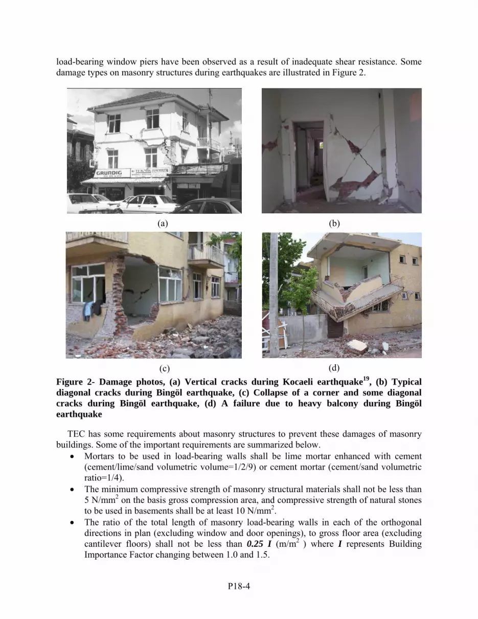
load-bearing window piers have been observed as a result of inadequate shear resistance. Some damage types on masonry structures during earthquakes are illustrated in Figure 2.
Figure 2- Damage photos, (a) Vertical cracks during Kocaeli earthquake19, (b) Typical diagonal cracks during Bingöl earthquake, (c) Collapse of a corner and some diagonal cracks during Bingöl earthquake, (d) A failure due to heavy balcony during Bingöl earthquake TEC has some requirements about masonry structures to prevent these damages of masonry buildings. Some of the important requirements are summarized below.
• Mortars to be used in load-bearing walls shall be lime mortar enhanced with cement (cement/lime/sand volumetric volume=1/2/9) or cement mortar (cement/sand volumetric ratio=1/4).
• The minimum compressive strength of masonry structural materials shall not be less than 5 N/mm2 on the basis gross compression area, and compressive strength of natural stones to be used in basements shall be at least 10 N/mm2.
• The ratio of the total length of masonry load-bearing walls in each of the orthogonal directions in plan (excluding window and door openings), to gross floor area (excluding cantilever floors) shall not be less than 0.25 I (m/m2 ) where I represents Building Importance Factor changing between 1.0 and 1.5.
(b) (a)
(c) (d)

P18-5
• Plan length of the load-bearing wall segment between the corner of a building and the nearest window or door opening to the corner shall not be less than 1.5 m in the first and second seismic zones and 1.0 m in the third and fourth seismic zones.
• Excluding the corners of buildings, plan lengths of the load-bearing wall segments between the window or door openings shall not be less than 1.0 m in the first and second seismic zones and 0.8 m in the third and fourth seismic zones.
• Excluding the corners of buildings, plan length of a load-bearing wall segment between intersection of the orthogonal walls and the nearest window or door opening shall not be less than 0.5 m in the all seismic zones. Otherwise, reinforced concrete confining elements shall be made on both sides of the openings along the height of the storey.
Seismic analysis of a brick masonry building Seismic analysis is carried out the sample two-storey masonry building heavily damaged during the May 1th, 2003 Bingöl earthquake. Plan dimensions of the sample buildings are shown in Figure 3. Corner at the intersection of 1 and A axis collapsed (see Figure 2d) and bearing wall at the intersection of 1 and D axis in the first storey failed (see Figure 2c).
Figure 3- Plan view of considered brick masonry building
0.7m
1.3m 2.2m 1.2m 0.5 0.5 0.5 1.1m 2m 1m
3.5m 2.8m 4.1m
4.5m 1.8m
2.6m
1.
1m
1.1m
1.
6m
0.7m
2.
9m
0.7m
2.
2m
0.7m
1.
6m
1.1m
0.
8m2.
2m
1.1m
1.1m
x y
1 2 3 4 5
A
B
C
D
E
1 2 3 4 5
E
D
C
B
A
P18-6
The requirements related to dimensions given TEC were examined for the sample building. It is seen from this examination that, the building has not satisfied the requirements presented below:
• Vertical confining elements were not used for structural system. • The ratio of the total length of masonry load-bearing walls in each of the orthogonal
directions in plan (also called the length of hatched area) (ℓd) to gross floor area (A) should be equal or greater than 0.25 I m/m2. Where, I is the Building Importance Factor. Since A=127.6 m2 and ℓd =25.8 m, this requirement is not satisfied as this ratio, ℓd/A =0.20<0.25 I.
• Plan length of the load-bearing wall segment between the corner of a building and the nearest window or door opening to the corner shall not be less than 1.5 m in the first seismic zones (where it is assumed that maximum ground acceleration is 0.4g). These distances were smaller than 1.5m for almost all corners of the sample building.
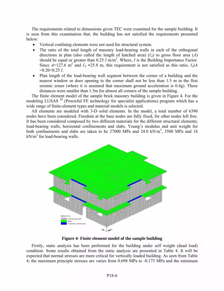
The finite element model of the sample brick masonry building is given in Figure 4. For the modeling LUSAS 20 (Powerful FE technology for specialist applications) program which has a wide range of finite-element types and material models is selected.
All elements are modeled with 3-D solid elements. In the model, a total number of 6390 nodes have been considered. Freedom at the base nodes are fully fixed, for other nodes left free. It has been considered composed by two different materials for the different structural elements; load-bearing walls, horizontal confinements and slabs. Young’s modulus and unit weight for both confinements and slabs are taken to be 27000 MPa and 24.0 kN/m3, 3500 MPa and 18 kN/m3 for load-bearing walls.
Figure 4- Finite element model of the sample building
Firstly, static analysis has been performed for the building under self weight (dead load) condition. Some results obtained from the static analysis are presented in Table 4. It will be expected that normal stresses are more critical for vertically loaded building. As seen from Table 4; the maximum principle stresses are varies from 0.698 MPa to -0.175 MPa and the minimum

P18-7
principle stresses are varies from 0.078 MPa to -0.760 MPa. The stresses occurred on the model are lower then the values if it is considered the average maximum principle stress for masonry units is 10 MPa and minimum principle stress is 1 MPa. Consequently there is not any damage because of the self weight of the building.
Table 4: Results of the static analysis LINEAR ANALYSIS Current Selected Load ID = 1 Averaged Stress Components In Global Axes Node SX SY SZ SXY SYZ SZX Maximum 0.6435E+00 0.6626E+00 0.1097E+00 0.1089E+00 0.9726E-01 0.7381E-01 Node 19809 19914 10142 19502 25624 28000 Minimum -0.7121E+00 -0.7155E+00 -0.4190E+00 -0.1228E+00 -0.1115E+00 -0.7975E-01 Node 14337 14833 3711 29148 19331 27671 Max Maximum Principal Value 6.98297036E-01 at Node 19809 Min Maximum Principal Value -1.75482557E-01 at Node 6295 Max Minimum Principal Value 7.78327194E-02 at Node 19914 Min Minimum Principal Value -7.60702902E-01 at Node 14833 Total Strain Energy For Active Set = 2.05837552E+05
Secondly, seismic analysis is carried out to investigate where stress concentration occurred and to compare with the damages. Mode number taken into account in eigenvalue analysis for the sample building is thirty. Here are only ten of these modes are given in Table 5.
Table 5: Results of the eigenvalue analysis of the building (first ten modes)
Mode number Eigenvalue Period (sec.) Sum mass X Sum mass Y Sum mass Z 1 5723 0.083 0.49E-03 0.76 0.104E-03 2 8643 0.068 0.58 0.76 0.132E-03 3 12320 0.057 0.73 0.76 0.152E-03 4 41368 0.031 0.72 0.83 0.281E-01 5 43896 0.030 0.73 0.83 0.429E-01 6 46389 0.029 0.73 0.83 0.561E-01 7 47048 0.029 0.73 0.84 0.667E-01 8 48233 0.029 0.76 0.85 0.696E-01 9 50297 0.028 0.76 0.85 0.744E-01
10 51321 0.028 0.77 0.85 0.997E-01 For seismic analysis the response spectrum analysis has been performed with thirty modes. Elastic response acceleration spectra for both x, y and z components of the Bingöl Earthquake with 5 percent damping is taken into account as shown in Figure 5.
Figure 5- Acceleration response spectra for the Bingöl earthquake
0
0.5
1
1.5
2
2.5
0 0.5 1 1.5 2 2.5 3 3.5 4 4.5 5
Z-direction
Y-direction
X-directionDamping=0.05
Acc
eler
atio
n re
spon
se (m
/s2 )
Period (sec)

P18-8
As seen from Figure 5, because of occurrence of maximum acceleration in X direction, the analysis has been performed for X direction. Maximum lateral displacement for brick masonry building was determined as 1.73 mm. The maximum and minimum principle stresses are 1.568 MPa and 0.28 MPa respectively. All of these values are also seen from Figure 6a,b,c. As seen from the same figure, vertical displacement at the corner which balcony supported is nearly as the maximum vertical displacement of the building. Also the damage as seen from Figure 2c was occurred due to the maximum shear stress at about YZ plane. The stress contour map about this damage is also seen from Figure 6d.
Figure 6- Deformed mesh and some stress contours about sample building in the end of the
analysis
a)Max.Displacements (mm)
b)Max.Principle Stress (MPa)
d)Shear stress at about YZ plane (MPa)
c)Min.Principle Stress (MPa)

P18-9
After determining the damage locations, time history analysis has been performed with Bingöl Earthquake acceleration records using material nonlinearity. It is essential to choose a suitable yield criterion in order to analyze any member of Drucker-Prager yield criterion which is a smooth approximation of the Mohr-Coulomb theory is used to model the nonlinear behavior of masonry. c and φ are the parameters which define the strength of materials are used by the LUSAS program in plastic analysis 21. The most suitable values for the parameters, c=3.5 MPa and φ=35o are selected. The shear stress-time graph has been obtained from the point of bottom of the wall as a result of the nonlinear time history analysis. Also it can be seen from Figure 7. From this figure, the point reached the maximum value at about 7 seconds.
Figure 7- Shear stress-time graph at the base of the building
Conclusions A lot of brick masonry structures destroyed and damaged during moderate or strong earthquakes in Turkey. And also many people, stayed in debris of masonry structures during these destructive earthquakes. Many people still live in masonry buildings in Turkey. Therefore, necessary emphasizes should also given this type of structures when designing and contracting. And the structural control studies must be done by the experts to reduce the loss of human lives during next earthquakes.
Many historical masonry buildings which assumed as cultural heritage for community and their performance should be reassessed for next earthquakes. In this context, the strengthening techniques, used on the other bearing systems, studied to increase the seismic behaviors for masonry buildings.
It must be very careful to design of heavy balcony with long span length when designing masonry buildings.
In the present work a finite element method of analysis of a sample brick masonry building which was badly suffered due to Bingöl Earthquake, exhibiting linear and nonlinear material behavior under static and seismic loading was presented. More studies related to this subject should be carried out, and authors have also focused their attention on this subject.
Time (sec)
Shea
r Stre
s (M
Pa)

P18-10
References 1. BC, 2000, National building census, State Institute of Statistics Prime Ministry Republic of
Turkey. 2. Tomaževič, M., Klemenc, I., 1997a, Verification of seismic resistance of confined masonry
buildings, Earthquake Engineering and Structural Dynamics, 26, 1073-1088. 3. Ministry of Public Works and Settlement, 1998, Specification for structures to be built in
disaster areas, Government of Republic of Turkey. 4. Tomaževič, M., Klemenc, I., 1997b, Seismic behavior of confined masonry walls,
Earthquake Engineering and Structural Dynamics, 26, 1059-1071. 5. KOERI, 2003, May 1, 2003 Bingöl (Turkey) Earthquake preliminary report, Kandilli
Observatory and Earthquake Research Institute, University of Boğaziçi. 6. Emre, Ö., Herece, E., Doğan, A., Parlak, O., Özaksoy, V., Çıplak, R. et al., 2003, A
preliminary report on the Bingöl Earthquake of May 1st, 2003, General Directorate of Mineral Research and Exploration. Report No: 10585. (in Turkish)
7. KOREI, 2004, Jan 27, 2003 Pülümür-Tunceli (Turkey) Earthquake preliminary report, Kandilli Observatory and Earthquake Research Institute, University of Boğaziçi.
8. Erdik, M., Uckan, E., Sesetyan, K., Demircioglu, M.B., Celep, U. and Biro Y., 2002, Feb 3, 2002 Sultandağı (Turkey) Earthquake. Kandilli Observatory and Earthquake Research Institute, University of Boğaziçi.
9. Demirtas, R., Erkmen, C., Yaman, M., Iravul, Y., Baran, B., Baykal, M. et al., 2000, Preliminary report of the, Çankırı Earthquake of June 06, 2000.
10. Kasapoğlu, K.E., Ulusay, R., Gökçeoğlu, C. and Köse, O., 2000, Report of the Orta (Çankırı) Earthquake of June 06, 2000, Hacattepe University.
11. Sucuoğlu, H. and Gür, T., 2000, Düzce: the city subjected to two big earthquakes in three months, Engineering report for The Marmara and Düzce earthquakes, METU. (in Turkish)
12. KOERI, 1999, Extent of the damage, Kandilli Observatory and Earthquake Research Institute.
13. Adalier, K. and Aydıngün, O., 2001, Structural engineering aspects of the June 27, 1998 Adana-Ceyhan (Turkey) earthquake, Engineering Structures, 23, 343-355.
14. Tezcan, S.S. and Boduroğlu, M. H., 1998, A reconnaissance report June 27, 1998 Adana Ceyhan Earthquake (Turkey). Turkish Earthquake Foundation, TDV/TR 005-026.
15. Bağcı, G., Yatman, A., Özdemir, S. and Altın N., 2004, Destructive earthquakes in Turkey, Bulletin of Earthquake Research, 69, 113-126.
16. USGS, 2004, Significant Earthquakes of the World, United States Geological Survey, Denver.
17. Bayülke, N. and Yılmaz, R., 1993, Damage distribution of the March 13, 1992 Erzincan Earthquake, Report, Ministry of Public Works and Settlement. (in Turkish)
18. Tomaževič, M., 2000, Earthquake-resistant design of masonry buildings, Slovenian National Building and Civil Engineering Institute.
19. Bruneau, M., 2002, Building damage from the Marmara, Turkey earthquake of August 17, 1999, Journal of Seismology, 6, 357-377.
20. LUSAS, 2006, LUSAS finite element analysis software products, Finite Element System, FEA Ltd, United Kingdom.
21. Doran, B., 2003, Elastic-plastic analysis of R/C coupled shear walls; The equivalent stiffness ratio of the tie elements, J. Indian Inst. Sci., 83, 87-94.


