Embed Size (px)
Citation preview

ERD15014B Oct 1, 2016
Precision Reduction Gear RVTM
E series
C series
Original series
Operation Manual
<Applicable model>
RV- △E , RV- △C , RV-
above indicates the torque code. above indicates the series code. For the applicable models, refer to “Model” indicated on the shipping label of the product.
This manual must be thoroughly read and understood before using the product.
Be sure to deliver this operation manual to the system manager and the person in charge of the operation.
Keep this manual in the specified location so that it can be immediately referred to whenever necessary.
®
Contents
Important Information ...................................................................................................... i 1. Intended use of this product ..................................................................................................................................... i 2. Rules to ensure safe use of this product ................................................................................................................... i 3. Sharing of hazard information with users ............................................................................................................... ii 4. Product disposal...................................................................................................................................................... ii 5. Other important notes ............................................................................................................................................. ii
About This Manual .......................................................................................................... iii 1. Users of this manual .............................................................................................................................................. iii 2. Copyrights .............................................................................................................................................................. iii
Warranty .......................................................................................................................... iv
Glossary ........................................................................................................................... v
Chapter 1 About safety .................................................................................................... 11.1. About warnings ..................................................................................................................................................... 1
1.2. Type and indication of warning ............................................................................................................................ 1
1.3. General precautions .............................................................................................................................................. 2
Chapter 2 Product overview ............................................................................................ 32.1. Name of each section ............................................................................................................................................ 3
2.2. Parts codes of catalog products ............................................................................................................................. 4
Chapter 3 Transportation and storage of product ......................................................... 53.1. Transportation ....................................................................................................................................................... 5
3.2. Storage .................................................................................................................................................................. 6
Chapter 4 Preparations for installation .......................................................................... 74.1. Installation environment ....................................................................................................................................... 7
4.2. Preparation of required components ..................................................................................................................... 8
4.3. Unpacking ........................................................................................................................................................... 19
4.4. Lifting of this product ......................................................................................................................................... 23
Chapter 5 Installation ..................................................................................................... 245.1. Bolt tightening torque ......................................................................................................................................... 24
5.2. Installation work ................................................................................................................................................. 25
Contents
Contents
Chapter 6 Filling the Lubricant ..................................................................................... 536.1. Precautions when handling the lubricant ............................................................................................................ 53
6.2. Reduction gear mounting direction and amount of lubricant .............................................................................. 55
6.3. Lubricant filling procedure ................................................................................................................................. 61
Chapter 7 Operation ....................................................................................................... 637.1. Checking before operation .................................................................................................................................. 63
7.2. Running-in operation .......................................................................................................................................... 63
7.3. Precautions for operation .................................................................................................................................... 63
Chapter 8 Maintenance and inspection ........................................................................ 658.1. Precautions on maintenance ................................................................................................................................ 65
8.2. Daily inspection .................................................................................................................................................. 65
8.3. Lubricant replacement ........................................................................................................................................ 66
8.4. Troubleshooting checksheet ................................................................................................................................ 69
Appendix: Design Scheme of Input Gear ...................................................................... 68
CONTACT INFORMATION

Important Information
i
1. Intended use of this product This product was designed and manufactured as a reduction gear that decelerates the rotation of the motor and transmits the rotational torque. Do not use this product for other purposes.
Do not modify the reduction gear or use it outside its specified range. This could cause injury or damage to the reduction gear.
The specifications indicated in the product catalog are based on Nabtesco evaluation methods. This product should only be used after confirming that it is appropriate for the operating conditions of your system. This could cause injury or damage to the reduction gear.
2. Rules to ensure safe use of this product It is impossible for Nabtesco Corporation (referred to as “Nabtesco” hereafter) to foresee any potential hazards related to this product and hazards caused by human errors or peripheral devices.
There are also various points that must be observed and operations that are prohibited in relation to the use of this product, but it is also impossible to note all of them in this manual.
For this reason, it is necessary to take appropriate safety measures when operating this product, in addition to the points noted in this manual.
The particularly important information for safe handling of this product is noted below. This information applies to all workers involved, including the manager and supervisor of this product.
The “procedures” referred to in this manual indicate all the acts performed on this product during transportation, installation, operation, and maintenance/inspection.
Be sure to read this manual
Before using this product, thoroughly read this manual and understand all the content of this manual. Also, observe the safety precautions described in this manual.
Conditions for workers
The worker must have a fundamental knowledge of this product The worker must be aware of the potential hazards of this product and have adequate knowledge to
avoid hazardous situations
The worker must be able to take appropriate measures to avoid hazardous situations
Important Information

Important Information
ii
Observe the relevant laws, regulations, ordinances, and bylaws.
Observe the relevant laws, regulations, ordinances, and bylaws enacted by the related countries and local governments.
Prevention of accidents
To prevent accidents, do not perform any procedures not noted in this manual. Also, do not use this product for any purposes other than those noted at the beginning of this manual.
If any abnormalities are found, take appropriate measures immediately to prevent any accidents, serious injury, or damage.
Everyone, including workers and supervisors, must voluntarily take measures to ensure safety and well-being, as this can prevent accidents.
3. Sharing of hazard information with users When selling or transferring this product embedded in a device, etc., hand this manual to the person who actually uses or manages the device (the person/group in charge). Or, add the necessary information concerning handling and maintenance procedures for preventing the accidents and failures described in this manual to the contents of the operation manual of the device.
4. Product disposal When disposing of this product, drain the lubricant completely and handle it according to the ordinances of the local government and entrust the disposal to an industrial waste disposal specialist.
5. Other important notes It is strictly prohibited to reverse-engineer the internal parts of this product.

About This Manual
iii
1. Users of this manual If this product is operated by non-native speakers of English, the customer is responsible for conducting safety training and giving operation instructions to those workers.
2. Copyrights The copy right for this manual belongs to Nabtesco Corporation. Unauthorized reprinting, reproduction, copying, or translation of this manual in whole or in part is strictly prohibited.
About This Manual

Warranty
iv
1. In the case where Nabtesco confirms that a defect of the Product was caused due to Nabtesco’s design or manufacture within the Warranty Period of the Product, Nabtesco shall repair or replace such defective Product at its cost. The Warranty Period shall be from the delivery of the Product by Nabtesco or its distributor to you (“Customer”) until the end of one (1) year thereafter, or the end of two thousand (2,000) hours from the initial operation of Customer's equipment incorporating the Product at end user's production line, whichever comes earlier.
2. Unless otherwise expressly agreed between the parties in writing, the warranty obligations for the Product shall be limited to the repair or replacement set forth herein. OTHER THAN A PROVIDED HEREIN, THERE ARE NO WARRANTIES ON THE PRODUCT, EXPRESS OR IMPLIED, INCLUDING WITHOUT LIMITATION ANY IMPLIED WARRANTY OF MERCHANTABILITY OR FITNESS FOR A PARTICULAR PURPOSE.
3. The warranty obligation under Section 1 above shall not apply if:
a) the defect was caused due to the use of the Product deviated from the Specifications or the working conditions provided by Nabtesco;
b) the defect was caused due to exposure to foreign substances or contamination (dirt, sand, etc.)
c) lubricant or spare part other than the ones recommended by Nabtesco was used in the Product;
d) the Product was used in an unusual environment (such as high temperature, high humidity, a lot of dust, corrosive/volatile/inflammable gas, pressurized/depressurized air, under water/liquid or others except for those expressly stated in the Specifications);
e) the Product was disassembled, re-assembled, repaired or modified by anyone other than Nabtesco;
f ) the defect was caused due to the equipment into which the Product was installed;
g) the defect was caused due to an accident such as fire, earthquake, lightning, flood or others; or
h) the defect was due to any cause other than the design or manufacturing of the Product.
4. The warranty period for the repaired/replaced Product/part under Section 1 above shall be the rest of the initial Warranty Period of the defective Product subjected to such repair/replace.
Warranty

Glossary
v
Rated service life The lifetime resulting from the operation with the rated torque and the rated output speed is referred to as the “rated service life”.
Allowable acceleration/deceleration torque When the machine starts or stops, the load torque to be applied to the reduction gear is larger than the constant-speed load torque due to the effect of the inertia torque of the rotating part. In such a situation, the allowable torque during acceleration/deceleration is referred to as “allowable acceleration/deceleration torque”.
Note: Be careful that the load torque, which is applied at startup and stop, does not exceed the allowable acceleration/deceleration torque.
Momentary maximum allowable torque A large torque may be applied to the reduction gear due to execution of emergency stop or by an external shock. In such a situation, the allowable value of the momentary applied torque is referred to as “momentary maximum allowable torque”.
Note: Be careful that the momentary excessive torque does not exceed the momentary maximum allowable torque.
Allowable output speed The allowable value for the reduction gear’s output speed during operation without a load is referred to as the “allowable output speed”. Note: Depending on the conditions of use (duty ratio, load, ambient temperature), the reduction gear
surface temperature may exceed 60°C even when the speed is under the allowable output speed. In such a case, either take cooling measures or use the reduction gear at a speed that keeps the surface temperature at 60°C or lower.
Allowable Moment and Maximum Thrust Load The external load moment or thrust load may be applied to the reduction gear during normal operation. The allowable values at this time are referred to as “allowable moment” and “maximum thrust load” respectively.
Note 1: The above specification values are noted in the catalog or separately provided specification sheet. Note 2: The “reduction gear” described in this manual indicates the E series, C series, or Original series
of the product.
Load
torq
ue
External shock torque
Max. torque for startup
Constant torque
Time
Max. torque for stop
Shock torque at emergency stop
Glossary

Chapter 1 About safety
1
Chapter 1 About safety
The safety precautions noted in this chapter should be used as guidelines to prevent injury of workers who perform transportation, installation, operation, and maintenance of this product, as well as damage to the product.
1.1. About warnings This manual alerts workers to hazardous situations and precautions related to this product in the following manner:
1. Safety regulations are described in Chapter 1 “About safety” in this manual2. Warning statements are noted in this manual
1.2. Type and indication of warning Warnings for potential hazards during operation are given according to the following four categories in this manual. If you fail to observe these warning statements, it could result in lethal injury or serious damage and malfunction of the product.
Indicates a hazardous situation that, if not avoided, is highly likely to result in death or serious injury.
Indicates a potentially hazardous situation that, if not avoided, could result in death or serious injury.
Indicates a potentially hazardous situation that, if not avoided, could result in minor or moderate injury.
Indicates a potentially hazardous situation that, if not avoided, could result in physical damage.
Provides important information for correct use of this product, as well as supplemental explanation for the main body of the text or other information that helps to prevent erroneous operation.
Note
Important

Chapter 1 About safety
2
1.3. General precautions This section describes general precautions for safe use of this product. For precautions concerning transportation, installation, operation, maintenance, and inspection, be sure to confirm the contents of the relevant chapter.
Do not modify or disassemble the reduction gear in a manner not described in this manual. This could cause injury or damage to the reduction gear.
Transportation, installation, operation, maintenance, and inspection of the reduction gear must be performed by personnel who fully understand this manual. The person in charge of the operation and manager of the reduction gear must not allow anyone without an understanding of the contents of this manual to operate it. This could cause injury or damage to the reduction gear.
Do not put your fingers or any object into the opening of the reduction gear. If a belt or chain is used for connection of the drive sections, do not put your fingers or any object into the clearance of the protective cover, etc., as it could cause injury.
If any abnormalities or damage to the reduction gear are found, stop the operation immediately. Incorrect motion could cause injury.
The reduction gear could become extremely hot during operation. After stopping the operation, never touch the reduction gear until it is completely cooled. Touching the reduction gear could cause burns.
Handle the lubricant according to the instructions given in this manual. Failure to do so could impair your health.
This reduction gear is not filled with lubricant. Fill the reduction gear with an appropriate amount of Nabtesco-recommended lubricant before use. Failure to do so could cause damage to the reduction gear.
Return the tools and other necessary items to the specified location after use. If a tool, bolt, nut, or other foreign object is trapped in the system, it could cause damage to the reduction gear.
Avoid excessive impact or vibration of the reduction gear Failure to do so could cause damage to the reduction gear.
Note

Chapter 2 Product overview
3
Chapter 2 Product overview
This chapter provides an overview of this product.
2.1. Name of each section This section provides an explanation of the name of each section.
If the shape of the actual section differs from the illustration below, refer to the separately provided “Outer dimensions” drawings and specification sheet.
(1) E series
(2) C series
Fig. 2-1
Tapped hole for shaft installation
Shaft
Case O-ring groove on the case
Tapped hole for hanging bolt
Case fixing hole
Spur gear
Standard input gear
(Optional)
Fig. 2-2
Shaft
Case
O-ring groove on the case
Tapped hole for hanging bolt
Case fixing hole
Spur gear(Optional)
Tapped hole for center tube installation
Hole for shaft installation
Center gear

Chapter 2 Product overview
4
(3) Original series
The shape of the reduction gear may differ from the illustration depending on the ordered specifications.
2.2. Parts codes of catalog products The parts codes are assigned as follows for the E series, C series and original series catalog products.
For detailed specifications of those products not included in the catalog, refer to the separately provided “External dimensions” drawings and specification sheet. If anything is unclear, refer to our contactinformation.
<Parts codes of catalog products for E series and original series>
Example) P35E001B00, P35E001D00, P35E001F00 Only for the E series and original series, when the third digit from the end of the parts code is “B”, “D”, or “F”, the code indicates a catalog product. Any other codes indicate products not included in the catalog. For the parts code, check “Parts code” indicated on the shipping label of the product (Fig. 4-8).
<Parts codes of catalog products for C series> P10L010-00, P10L014-00, P10L017-00, P10L018-00, P21L014-00, P21L015-00, P21L018-00, P21L019-00, P31L012-00, P31L013-00, P31L014-00, P31L015-00, P41L013-00, P41L014-00, P41L017-00, P41L018-00, P51L004-00, P51L005-00, P51L009-00, P51L010-00, P65L002-00, P65L013-00, P65L021-00, P65L023-00, P76L004-00, and P76L014-00
Only for the C series, the above parts codes indicate the catalog products. Any other codes indicate products not included in the catalog. For the parts code, check “Parts code” indicated on the shipping label of the product (Fig. 4-8).
Note: The last two digits of the parts code, within the range from 00 to 99 (“00” in the above parts code), indicate the revision code.
Fig. 2-3
Tapped hole for shaft installation
Shaft
Case O-ring groove on the case
Tapped hole for hanging bolt Case fixing hole
Spur gear
Standard input gear(Optional)
Removal tap
Important

Chapter 3 Transportation and storage of product
5
Chapter 3 Transportation and storage of product
This chapter describes the transportation and storage of this product.
3.1. Transportation Transport the product in an appropriate manner according to the weights indicated in the separately
provided “Outer dimensions” drawings and specifications. If the reduction gear needs to be lifted after unpacking, also refer to “4.4 Lifting of this product”. For the catalog products described in “2.2. Parts codes of catalog products”, refer to the weights of
the reduction gears listed below. Do not stack the packing boxes containing this product too high. Avoid excessive impact or vibration of the reduction gear.
Table 3-1 Model Weight (kg) Model Weight (kg) Model Weight (kg)RV-6E 2.5 RV-10C 4.6 RV-15 3.6
RV-20E 4.7 RV-27C 8.5 RV-30 6.2
RV-40E 9.3 RV-50C 14.6 RV-60 9.7
RV-80E 13.1 RV-100C 19.5 RV-160 19.5
RV-110E 17.4 RV-200C 55.6 RV-320 34
RV-160E 26.4 RV-320C 79.5 RV-450 47
RV-320E 44.3 RV-500C 154 RV-550 72
RV-450E 66.4
If the packing boxes containing the reduction gear are stacked too high during transportation, they may collapse and fall down, causing injury or damage to the reduction gear.
Applying excessive impact or vibration to the reduction gear could cause damage to the reduction gear.
Each weight listed in the above table, as well as in the separately provided “Outer dimensions” drawings and specification sheet, indicates the weight of the reduction gear only. It does not include the weight of the packing box or optional parts, etc.
The actual weight of the reduction gear may slightly differ from that listed in the above table, depending on the specifications.
Note
Important

Chapter 3 Transportation and storage of product
6
3.2. Storage To avoid rust, corrosion, or deterioration of the sealing material, etc., and collapse of stored packing boxes, store the product in the following location.
Location where the ambient temperature is between -10°C to 40°C. Location where the humidity is less than 85% and no condensation occurs Location that is not directly affected by wind and rain Location that is free from combustible/volatile/corrosive gas or dust. Stable location that is free from any danger of collapse Location with little vibration
If the packing boxes containing the reduction gear are stacked too high during transportation, they may collapse and fall down, causing injury or damage to the reduction gear.
Store the reduction gear under the same conditions as those before unpacking. If it is left upside down, it could cause damage to the reduction gear.
Although the reduction gear is coated with rust prevention oil before shipping, it is not designed for long-term storage. If it is stored for a long period, check the condition of the reduction gear periodically and perform rust prevention treatment as necessary. If rust occurs, it could cause the leakage of lubricant or premature damage to the reduction gear.
If the reduction gear is used or operated after it has not been used for a long period of time, confirm that it is free from rust or corrosion and that the sealing material is free from deformation or cracks beforehand. If the reduction gear is used without checking these points, it could cause the leakage of lubricant or premature damage to the reduction gear.
Note

Chapter 4 Preparations for installation
7
Chapter 4 Preparations for installation
This chapter describes the preparation for installing this product.
Before designing the equipment, take care regarding the following precautions.
When the reduction gear is used for human transportation equipment, install an effective safety unit as a fail-safe mechanism, in case of an unexpected failure in the reduction gear.
When the reduction gear is used for elevating equipment, install an effective safety unit for preventing falls caused by idle running as a fail-safe mechanism, in case of an unexpected failure in the reduction gear.
Install an oil receiver, etc., to prevent damage in case of lubricant leakage due to a failure or lifetime expiration.
As this product may have residual rust prevention agent coated on it before shipping, wipe it off as necessary.
When the reduction gear is used for human transportation equipment, install an effective safety unit as a fail-safe mechanism, in case of an unexpected failure in the reduction gear. If you fail to install it, it could cause injury in case the equipment goes out of control or falls off.
When the reduction gear is used for elevating equipment, install an effective safety unit for preventing falls caused by idle running as a fail-safe mechanism, in case of an unexpected failure in the reduction gear. If you fail to install it, it could cause injury in case the elevating unit falls off.
4.1. Installation environment Use this product under the following environment:
Location where the ambient temperature is between -10°C to 40°C Location where the humidity is less than 85% and no condensation occurs Location where the altitude is less than 1,000 m Well-ventilated location
Do not install the reduction gear at the following locations.
Location where a lot of dust is collected Outdoors that can be directly affected by wind and rain Location near the environment that contains combustible/explosive/corrosive gases and flammable
materials Location where the magnetic fields or vibration occur
If the required installation environment cannot be established/met, contact our service representative in advance.
When using this product under special conditions (clean room, equipment for food, medical equipment, concentrated alkali, high-pressure steam, etc.), contact our service representative in advance.
Important

Chapter 4 Preparations for installation
8
4.2. Preparation of required components The following components and materials are required for installing this product. Check the
components/materials and prepare them at each customer’s site. If the shape of the actual section differs from the illustration below, refer to the separately provided
“Outer dimensions” drawings and specification sheet. Prepare the input gear, motor mounting flange, case installation component, and shaft installation
component that have been designed and manufactured based on the catalog and separately provided “Outer dimensions” drawings and specification sheet.
Fig. 4-1 (E series)
Fig. 4-3 (Original series)
Fig. 4-2 (C series)

Chapter 4 Preparations for installation
9
The actual components may differ from the required components shown in the above illustration, depending on the customer’s equipment.
The above is an illustration of the bolt-clamping output shaft type from the catalog. Note that a pin is required for the pin/bolt clamping output shaft type.
Seal the shaft mounting surface of the reduction gear and shaft installation component using liquid sealants.
If liquid sealants cannot be used, use an O-ring (I) and high-torque seal washer.
4.2.1. Input gear Prepare the input gear for motor rotation into the reduction gear. For the design of the input gear,
refer to “Appendix: Design Scheme of Input Gear”.
The prepared gear teeth must meet the specifications and materials described in “Appendix: Design Scheme of Input Gear”. An operation error due to damage or wear of the gear teeth could cause injury.
If the input gear has an oil sealing surface, take extra care so that no scratch will be made on the oil sealing surface when handling the input gear. Any scratches could cause leakage of the lubricant.
Take extra care so that no scratch will be made on the gear tooth section when handling the input gear. Any scratches could cause abnormal noise.
The customer is requested to prepare the oil seals used for sealing the circumference of the input gear.
The standard input gear, which is an optional component, is not provided with installation components such as bolts and keys. Prepare them as necessary at each customer’s site.
4.2.2. Flange and its installation components
Motor mounting flange
Prepare the motor mounting flange for fixing the motor on the reduction gear input side. In order to avoid contact with reduction gear components, refer to the sizes indicated in the “Outer
dimensions” drawings when designing the motor mounting flange. Confirm that a tapped hole for injecting/draining grease is installed in the motor mounting flange. It
will be necessary for filling or replacing the lubricant after installing the reduction gear.
Important
Note
Important

Chapter 4 Preparations for installation
10
Design the motor mounting flange to the following accuracy. If the installation accuracy is poor, it will result in vibration, noise, and increase in backlash. If a model other than those listed below is used, contact our service representative.
<Installation accuracy> (E series)
Table 4-1
<Installation accuracy> (C series)
Table 4-2
<Installation accuracy> (Original series)
The reduction gear of the original series will be embedded in the equipment as a component. When designing a system, be sure that the external thrust load and radial load are not applied to the reduction gear.
Table 4-3
Fig. 4-4
(110E or above) Model
Concentricity tolerance a (mm)
ModelConcentricity
tolerancea (mm)
Parallelism tolerance b (mm)
Fig. 4-5
ModelCircumference
deviation tolerancea (mm)
Runout tolerance b (mm)
Runout tolerance c (mm)
Concentricity tolerance d (mm)
Dimension accuracy on the mounting side

Chapter 4 Preparations for installation
11
Fig. 4-6
Confirm that the design of the prepared motor mounting flange conforms to the size and quantity of the case mounting bolts indicated in the separately provided “Outer dimensions” drawings and specification sheet. For the catalog products described in “2.2. Parts codes of catalog products”, refer to the size and quantity of the bolts listed in Table 4-4 in “4.2.3 Reduction gear mounting bolts”.
If no tapped hole for injecting/draining grease is installed in the motor mounting flange, the lubricant cannot be filled/replaced after installing the reduction gear.
Case installation component
Prepare the case installation component for the reduction gear. The component can also be embedded in the motor mounting flange.
Confirm that the design of the prepared case installation component conforms to the size and quantity of the case mounting bolts indicated in the separately provided “Outer dimensions” drawings and specification sheet. For the catalog products described in “2.2. Parts codes of catalog products”, refer to the size and quantity of the bolts listed in Table 4-4 in “4.2.3 Reduction gear mounting bolts”.
After attaching the reduction gear, bring the dial gauge in contact with the location shown in the illustration and rotate the output shaft of the reduction gear by a turn. At this point, be sure that the deviation in the gauge reading is 0.02 mm or less.
Output shaft mating face
Case mating face
(Inside mating part)
(Outside mating part)
Use either of the inside or outside for mating part B of the output shaft. For the RV-320, RV-450, and RV-550, only the inside mating part can be used.

Chapter 4 Preparations for installation
12
Shaft installation component
Prepare the installation component for the output shaft of the reduction gear. Confirm that the component is structured so that the lubricant can be sealed with an O-ring or liquid
sealant. Confirm that a tapped hole for injecting/draining grease is installed in the shaft installation
component. It will be necessary for filling or replacing the lubricant after installing the reduction gear.
Confirm that the design of the prepared shaft installation component conforms to the size and quantity of the shaft mounting bolts indicated in the separately provided “Outer dimensions” drawings and specification sheet. For the catalog products described in “2.2. Parts codes of catalog products”, refer to the size and quantity of the bolts listed in Table 4-5 in “4.2.3 Reduction gear mounting bolts”.
If no tapped hole for injecting/draining grease is installed in the shaft installation component, the lubricant cannot be filled/replaced after installing the reduction gear.

Chapter 4 Preparations for installation
13
4.2.3. Reduction gear mounting bolts Prepare bolts according to the size and quantity of the motor mounting flange, case installation bolts
and shaft installation bolts indicated in the separately provided “Outer dimensions” drawings and specification sheet.
For the catalog products described in “2.2. Parts codes of catalog products”, refer to the size and quantity of the bolts listed in Table 4-4 and Table 4-5.
Select the appropriate bolt length based on the mounting dimensions of the components prepared by the customer and the reduction gear.
Prepare the following bolts recommended by Nabtesco. However, be sure to use a taper pin for the pin/bolt clamping output shaft type*.
Hexagon socket head cap screw JIS B 1176 : 2006 Strength class JIS B 1051: 2000 Grade 12.9 Thread JIS B 0209 : 2001 6g
For motor mounting flange and case installation component
Table 4-4 For shaft installation component
Table 4-5
Model Bolt tightening type
* Pin/bolt clamping output shaft type or
through bolt type Model Bolt tightening type
* Pin/bolt clamping output shaft type or
through bolt type Nominal size
× pitchRequired
Qty. Nominal size
× pitchRequired
Qty. Nominal size
× pitchRequired
Qty. Nominal size
× pitchRequired
Qty. RV-6E M5 × 0.8 8 - - RV-6E M8 × 1.25 6 - -
RV-20E M6 × 1.0 16 M6 × 1.0 8 RV-20E M10 × 1.5 6 M10 × 1.5 4 RV-40E M8 × 1.25 16 M8 × 1.25 8 RV-40E M14 × 2.0 6 M12 × 1.75 4
RV-80E M8 × 1.25 16 M8 × 1.25 8 RV-80E M8 × 1.25 M10 × 1.5
12 6 M12 × 1.75 3
RV-110E M10 × 1.5 12 - - RV-110E M12 × 1.75 12 - -
RV-160E M12 × 1.75 12 M12 × 1.75 8 RV-160E M8 × 1.25 M16 × 2.0
15 6 M14 × 2.0 3
RV-320E M12 × 1.75 16 M12 × 1.75 8 RV-320E M10 × 1.5 M16 × 2.0
18 6 M16 × 2.0 3
RV-450E M12 × 1.75 24 M12 × 1.75 12 RV-450E M12 × 1.75M16 × 2.0
21 6 M16 × 2.0 3
RV-10C M6 × 1.0 8 M6 × 1.0 8 RV-10C M8 × 1.25 6 M10 × 1.5 4 RV-27C M6 × 1.0 12 M6 × 1.0 12 RV-27C M8 × 1.25 8 M12 × 1.75 4 RV-50C M8 × 1.25 8 M8 × 1.25 8 RV-50C M10 × 1.5 9 M12 × 1.75 6
RV-100C M10 × 1.5 14 M10 × 1.5 14 RV-100C M12 × 1.75 9 M14 × 2.0 6 RV-200C M12 × 1.75 8 M12 × 1.75 8 RV-200C M16 × 2.0 9 M16 × 2.0 6 RV-320C M12 × 1.75 16 M12 × 1.75 18 RV-320C M16 × 2.0 15 M18 × 2.5 9 RV-500C M12 × 1.75 24 - - RV-500C M16 × 2.0 18 - -
RV-15 - - M6 × 1.0 6 RV-15 - - M8 × 1.25 6 RV-30 - - M6 × 1.0 12 RV-30 - - M10 × 1.5 6 RV-60 - - M8 × 1.25 8 RV-60 - - M10 × 1.5 3
RV-160 M10 × 1.5 16 M12 × 1.75 12 RV-160 M10 × 1.5M14 × 2.0
12 6 M14 × 2.0 3
RV-320 M12 × 1.75 16 M12 × 1.75 8 RV-320 M16 × 2.0 21 M16 × 2.0 3 RV-450 M12 × 1.75 24 M12 × 1.75 12 RV-450 M16 × 2.0 21 M16 × 2.0 3
RV-550 M14 × 2.0 24 M14 × 2.0 24 RV-550 M8 × 1.25M16 × 2.0
6 24 M16 × 2.0 24

Chapter 4 Preparations for installation
14
(Unit: mm)
4.2.4. Serrated lock washer for hexagon socket head cap screw Prepare the following serrated lock washer for hexagon socket head cap screw recommended by
Nabtesco: Name: Belleville lock washer (made by Heiwa Hatsujyo Industry Co., Ltd.)Corporation symbol: CDW-H,
CDW-L (Only for M5)Material: S50C to S70CHardness: HR40 to 48
Table 4-6
When using any equivalent washer, select it with special care given to its outside diameter (ø D).
Nominal size
ID and OD of Belleville spring washer t H
ød øD5 5.25 8.5 0.6 0.85 6 6.4 10 1.0 1.25 8 8.4 13 1.2 1.55 10 10.6 16 1.5 1.9 12 12.6 18 1.8 2.2 14 14.6 21 2.0 2.5 16 16.9 24 2.3 2.8 18 18.9 27 2.6 3.15 20 20.9 30 2.8 3.55
Important
Fig. 4-7
Assemble the bolt so that the bolt head faces this side

Chapter 4 Preparations for installation
15
4.2.5. Liquid sealant
Seal the shaft mounting surface of the reduction gear and shaft installation component using liquid sealants. Prepare the following liquid sealants recommended by Nabtesco.
Table 4-7 Name Manufacturer Characteristics and applications
ThreeBond 1211 ThreeBond • Silicone-based, solventless type • Semi-dry gasket
HermeSeal SS-60F Nihon Hermetics Co.
• One-part, non-solvent elastic sealant • Metal contact side (flange surface) seal • Any product basically equivalent to
ThreeBond 1211
Loctite 515 Henkel • Anaerobic flange sealant • Metal contact side (flange surface) seal
Do not use the above liquid sealants if the component of the customer’s device is made of copper or copper alloy.
4.2.6. O-ring
Use the O-rings indicated in the separately provided “Outer dimensions” drawings and specification sheet. If there is no indication, select the size of the O-ring appropriate for the surface to be sealed.
For the catalog products described in “2.2. Parts codes of catalog products”, prepare the O-rings with the numbers listed in Table 4-8, 4-9 and Table 4-10.
If it is difficult to purchase any of the O-rings in the table below, select an O-ring based on the design standard of each manufacturer by referring to the dimensions listed above. Selecting an inappropriate O-ring could cause leakage of the lubricant.
O-ring (I)
If the shaft mounting surface and shaft installation component of the reduction gear cannot be sealed using liquid sealants, prepare the O-ring (I). The O-rings applicable to the O-ring (I) for the catalog products described in “2.2 Parts codes of catalog products” are listed in the table below. When an O-ring (I) is used, seal the mounting holes on the shaft installation component using the high-torque seal washers..
(Reference: “4.2.5 Liquid sealant”)
O-ring (I) JIS B 2401: 2012, SAE AS568
Note
Note

Chapter 4 Preparations for installation
16
Table 4-8 (Unit: mm) (Unit: mm)
Model O-ring number
O-ring dimensions Model O-ring
number
O-ring dimensions Inside
diameterWidth Inside
diameterWidth
RV-20E (A) *1 AS568-045 ø101.32 ø1.78 RV-450 AS568-275 ø266.29 ø3.53 RV-20E (B) *1 S100 *2 ø99.5 ø2.0 RV-10C *3 AS568-032 ø47.35 ø1.78
RV-40E S132 *2 ø131.5 ø2.0 RV-10C *3 S100 *2 ø99.5 ø2.0 RV-80E AS568-163 ø152.07 ø2.62 RV-27C *3 S75 *2 ø74.5 ø2.0 RV-110E AS568-167 ø177.47 ø2.62 RV-27C *3 S120 *2 ø119.5 ø2.0 RV-160E AS568-265 ø196.44 ø3.53 RV-50C *3 S100 *2 ø99.5 ø2.0 RV-320E AS568-271 ø234.54 ø3.53 RV-50C *3 S150 *2 ø149.5 ø2.0 RV-450E AS568-275 ø266.29 ø3.53 RV-100C *3 G115 ø114.4 ø3.1
RV-15 G105 ø104.4 ø3.1 RV-100C *3 AS568-165 ø164.77 ø2.62 RV-30 G135 ø134.4 ø3.1 RV-200C *3 S150 *2 ø149.5 ø2.0 RV-60 AS568-163 ø152.07 ø2.62 RV-200C *3 AS568-271 ø234.54 ø3.53
RV-160 AS568-265 ø196.44 ø3.53 RV-320C *3 G210 ø209.3 ø5.7 RV-320 AS568-271 ø234.54 ø3.53 RV-320C *3 G290 ø289.3 ø5.7
*1 For the RV-20E O-ring, use either (A) or (B).
*2 Numbers S100, S132, S75, S120, and S150 are the manufacturer’s own standards.
*3 For the model of the RV-C type, both O-rings are necessary.

Chapter 4 Preparations for installation
17
O-ring (II)
Prepare an O-ring (II) for sealing the installation section of the reduction gear and motor mounting flange. The O-rings applicable to the O-ring (II) for the catalog products described in “2.2 Parts codes of catalog products” are listed in the table below. If an O-ring cannot be used due to the structure, seal the section using a liquid sealant, etc.
(Reference: “4.2.5 Liquid sealant”)
Table 4-9 (Unit: mm) (Unit: mm)
Model O-ring number
O-ring dimensions Model O-ring number
O-ring dimensions Inside
diameterWidth Inside
diameter Width
RV-6E S100 *1 ø99.5 ø2.0 RV-50C AS568-169 ø190.17 ø2.62 RV-20E S120 *1 ø119.5 ø2.0 RV-100C AS568-173 ø215.57 ø2.62 RV-40E AS568-258 ø151.99 ø3.53 RV-200C AS568-277 ø291.69 ø3.53 RV-80E AS568-263 ø183.74 ø3.53 RV-320C AS568-281 ø380.59 ø3.53 RV-110E G190 ø189.3 ø5.7 RV-500C G460 ø459.3 ø5.7 RV-160E G220 ø219.3 ø5.7 RV-60 AS568-165 ø164.77 ø2.62 RV-320E G270 ø269.3 ø5.7 RV-320 AS568-178 ø247.32 ø2.62 RV-450E G300 ø299.3 ø5.7 RV-450 AS568-276 ø278.99 ø3.53 RV-10C AS568-048 ø120.37 ø1.78 RV-550 No.3.5-312 *2 ø312.0 ø3.5 RV-27C AS568-163 ø152.07 ø2.62
*1 Numbers S100 and S120 are the manufacturer’s own standards.
*2 The O-ring of number 3.5-312 is a special type. For purchase of the O-ring, please contact us.
O-ring (III)
Prepare an O-ring (III) for sealing the installation section of the reduction gear and center tube. The O-rings applicable to the O-ring (III) for the catalog products described in “2.2 Parts codes of catalog products” are listed in the table below. If an O-ring cannot be used due to the structure, seal the section using a liquid sealant, etc.
(Reference: “4.2.5 Liquid sealant”)
O-ring (II) JIS B 2401: 2012, SAE AS568
O-ring (III) JIS B 2401 : 2012

Chapter 4 Preparations for installation
18
Table 4-10 (Unit: mm) (Unit: mm)
Model O-ring number
O-ring dimensions Model O-ring
number
O-ring dimensions Inside
diameterWidth Inside
diameterWidth
RV-10C CO 0625 *1 ø29.7 ø2.4 RV-200C G95 ø94.4 ø3.1 RV-27C CO 0634 *1 ø42.2 ø2.4 RV-320C G135 ø134.4 ø3.1 RV-50C CO 0643 *1 ø59.6 ø3.5 RV-500C G145 ø144.4 ø3.1
RV-100C S70 *2 ø69.5 ø2.0
*1 The number CO type is an O-ring manufactured by NOK.
*2 Number S70 is the manufacturer’s own standard.
4.2.7. Lubricant Prepare the Nabtesco-specified lubricant. For purchase of the lubricant, contact our customer
representatives Do not mix it with other lubricants.
Table 4-11Brand specified by
Nabtesco VIGOGREASE* RE0
Operating temperature range (ambient temperature)
-10 to 40°C
* VIGOGREASE is registered trademark of Nabtesco Corporation.
In order to take advantage of the performance of this product, use the Nabtesco-specified lubricant. Using other types of lubricant could cause deterioration of performance and premature damage.
Mixing with other lubricants could cause deterioration of performance, generation of abnormal noise, and premature damage.
4.2.8. Plug for tapped hole for injecting/draining grease
Prepare plugs for tapped holes for injecting/draining grease used for the motor mounting flange and shaft installation component. Also prepare seal tapes and other necessary items.
4.2.9. Taper pin with screw
For the pin/bolt clamping output shaft type, prepare a taper pin with screw for tightening the case installation component or shaft installation component to the case or shaft section of the reduction gear. For the size of the taper pin with screw to be prepared, refer to the pin hole described in the catalog and separately provided “Outer dimensions” drawings and specification sheet.
Note

Chapter 4 Preparations for installation
19
Made in Japan
4.3. Unpacking Check the following points when unpacking.
Before using this product, check the contents of the packing box and confirm that all the ordered items are included.
Check the top and bottom direction of the packing box and unpack it.
When transporting the reduction gear, take extra care so that it will not fall down or topple over. A fall of the reduction gear could cause injury to the workers or damage to the reduction gear.
Before using this product, check the contents of the packing box and confirm that all the ordered items are included. If an incorrect part is installed, it could cause injury to the workers or damage to the customer’s device and the reduction gear.
If it is left upside down, it could cause damage to the reduction gear.
When unpacking, the internal parts of the reduction gear remain exposed. Take extra care so that no foreign matter adheres to the reduction gear when it is installed in the customer’s equipment and filled with lubricant. If foreign matter adheres, it may lead to deterioration of reduction gear performance and also to deterioration of durability or premature damage.
The reduction gear is coated with rust prevention oil before shipping. Therefore, if it is used as it is, the rust prevention oil could ooze from the bolt hole or flange mating face during operation. In addition, the rust prevention oil makes the reduction gear slippery. Wipe it off as necessary before use.
4.3.1. Checking the shipping label
Check the shipping label to confirm that it matches the product you have ordered.
Fig. 4-8
Note
Important
Shipping label
Example
Bottom
TopNabtesco Corporation
型式 RV-40E-105
品目 P35E003D00
S/N R040-2E30001
インプットギヤ キャクサキ

Chapter 4 Preparations for installation
20
When inquiring about this product, the model, parts code, and S/N (serial number) indicated on the shipping label are needed. Write them down when unpacking and keep them for cases in which they are needed.
4.3.2. Checking the contents
Confirm that the contents of the packing box match the items in the illustration below when unpacking.
Fig. 4-9
The contents of the packing box and shape of the reduction gear may differ from the illustration above depending on the ordered specifications.
The input gear is optional.
Cautions to the reduction gear when it is installed
Input gear (Optional)
Reduction gear main unit
Packing material
Important
Important

Chapter 4 Preparations for installation
21
4.3.3. Label indication
A label is attached to the circumference of the main unit casing of this product.
The following describes the contents of the label.
This label proves that this product is a Nabtesco precision reduction gear. Be careful not to peel off the label.
4.3.4. About sealing tape
Sealing tape that has a clear left half and yellow right half is affixed to the label as shown in the photo below.
When the customer coats the circumference of the reduction gear, this label is hidden. After coating and drying, peel off the sealing tape to make the label visible.
Note: When the customer uses a substance other than urethane or epoxy, contact us.
Even when coating is not performed on the circumference of the reduction gear, the sealing tape may peel off and enter the customer’s equipment. For this reason, be sure to peel off the sealing tape.
Note: When degreasing the reduction gear, do not use the degreasing agents shown below.
Ketone system (MEK, MIBK), ester system (ethyl acetate, butyl acetate), aromatic system (toluene, xylene)
Procedure for peeling off sealing tape (1) The sealing tape has a two-layer structure. Pinch the right end of the first tape.
Logo of Precision Reduction Gear RV Serial number
Our logo
Fig. 4-10
QR code (Reading this QR code will display our Website URL and the serial number.)
Fig. 4-11
Important

Chapter 4 Preparations for installation
22
(2) Peel off about two-thirds of the first tape toward the left.
(3) After that, pull it toward the right in order to peel off the yellow portion of the second tape. Check that the yellow portion is removed from the surface after the tape has been peeled off.
If you do not peel off the sealing tape, it may peel off later and enter the reduction gear. This may cause deterioration of performance such as abnormal noise, vibration, or torque irregularity. Also, this tape may adhere to the lip of the oil seal, causing leakage of the lubricant.
If a coating or degreasing agent other than those specified is used, the label tape may peel off and enter the reduction gear. This may cause deterioration of performance such as abnormal noise, vibration, or torque irregularity. Also, this tape may adhere to the lip of the oil seal, causing leakage of the lubricant.
Fig. 4-12
Fig. 4-13
Note

Chapter 4 Preparations for installation
23
4.4. Lifting of this product
When lifting the product, use the tap holes for the hanging bolts described in the separately provided “Outer dimensions” drawings and specifications.
Do not enter the area under the reduction gear when lifting the reduction gear. When lifting the reduction gear, be sure to use a lifter that can withstand the weight of the reduction
gear. For the weights of the products not included in the catalog described in “2.2. Parts codes of catalog
products”, refer to the separately provided “Outer dimensions” drawings and specification sheet. For the catalog products described in “2.2. Parts codes of catalog products”, use the following
hanging bolts.
Table 4-12
Do not enter the area under the reduction gear when lifting the reduction gear. If the reduction gear falls down, it could cause injury.
When lifting the reduction gear, be sure to use a lifter that can withstand the weight of the reduction gear. Otherwise, the lifter will be damaged, and the reduction gear could fall down and topple over, which may result in injury.
The actual weight of the reduction gear may slightly differ from that listed in the above table, depending on the specifications.
Model Hanging bolt
Nominal size × pitch (mm)
Qty. Weight (kg)
RV-25N M5 × 0.8 2 3.8
RV-42N M6 × 1.0 2 6.3
RV-60N M6 × 1.0 2 8.9
RV-80N M8 × 1.25 2 9.3
RV-100N M8 × 1.25 2 13.0
RV-125N M10 × 1.5 2 13.9
RV-160N M10 × 1.5 2 22.1
RV-380N M10 × 1.5 2 44
RV-500N M8 × 1.25 2 57.2
RV-700N M12 × 1.75 2 102
Fig. 4-14
Tapped hole for hanging bolt (2 locations)
Chapter 5 Installation
24
Chapter 5 Installation
This chapter describes the installation of this product.
Before installation, take care regarding the following precautions.
Do not stand on top of the reduction gear or put anything on it. Be sure to install the reduction gear with the correct orientation.
Standing on top of the reduction gear or putting something on it could cause damage to the reduction gear.
Installing the reduction gear with an incorrect orientation could cause damage to the customer’s device and the reduction gear.
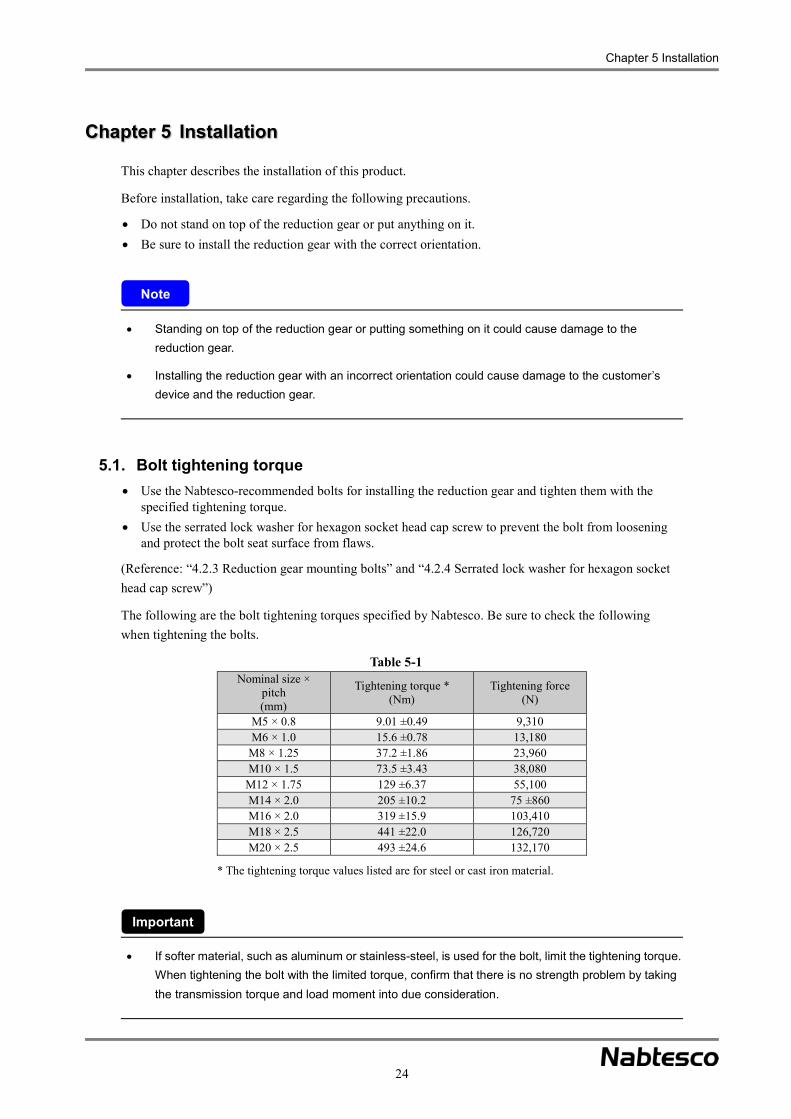
5.1. Bolt tightening torque Use the Nabtesco-recommended bolts for installing the reduction gear and tighten them with the
specified tightening torque. Use the serrated lock washer for hexagon socket head cap screw to prevent the bolt from loosening
and protect the bolt seat surface from flaws.
(Reference: “4.2.3 Reduction gear mounting bolts” and “4.2.4 Serrated lock washer for hexagon socket head cap screw”)
The following are the bolt tightening torques specified by Nabtesco. Be sure to check the following when tightening the bolts.
Table 5-1 Nominal size ×
pitch(mm)
Tightening torque *(Nm)
Tightening force (N)
M5 × 0.8 9.01 ±0.49 9,310 M6 × 1.0 15.6 ±0.78 13,180
M8 × 1.25 37.2 ±1.86 23,960 M10 × 1.5 73.5 ±3.43 38,080
M12 × 1.75 129 ±6.37 55,100 M14 × 2.0 205 ±10.2 75 ±860M16 × 2.0 319 ±15.9 103,410 M18 × 2.5 441 ±22.0 126,720 M20 × 2.5 493 ±24.6 132,170
* The tightening torque values listed are for steel or cast iron material.
If softer material, such as aluminum or stainless-steel, is used for the bolt, limit the tightening torque. When tightening the bolt with the limited torque, confirm that there is no strength problem by taking the transmission torque and load moment into due consideration.
Note
Important

Chapter 5 Installation
25
5.2. Installation work
The installation procedure may differ from the contents of this manual, depending on the shape of the components designed by the customer.
5.2.1. Installing the reduction gear
The following describes the installation of the reduction gear.
The reduction gear is coated with rust prevention oil before shipping. Wipe off the rust prevention oil as necessary during installation. In particular, be sure to wipe it off from the mounting surface and bolt seat surface.
For the E series
Perform steps 1 to 11 by taking care regarding the following precautions. For the pin/bolt clamping output shaft type, perform steps 7 to 11 first, and then steps 1 to 4.
• Align the case mounting holes of the reduction gear with the Step 1 positions of the tapped holes for the case installation component, and then attach the reduction gear to the case installation component.
• Confirm that the centering shaft of the reduction gear (case section) is correctly fitted into the centering hole of the case installation component.
• Check that there is no foreign matter adhering to the mounting surface.
If there is foreign matter adhering to the mounting surface, the mounting surface of the reduction gear may be deformed, which could cause deterioration of performance, such as abnormal noise and torque irregularity, and durability.
The shape of the reduction gear may differ from the illustration below depending on the ordered specifications.
Important
Note
Fig. 5-1
Case installation component
Reduction gear
Mat
ing
sect
ion
of c
ase
inst
alla
tion
com
pone
nt (h
ole
side
) M
atin
g se
ctio
n of
redu
ctio
n ge
ar (s
haft
side
)

Chapter 5 Installation
26
• Insert an O-ring (II) into the groove on the case for the Step 2 reduction gear.
• If the product does not feature an O-ring groove, prepare a groove on the customer's component, or seal the area with a liquid sealant.
• If an O-ring cannot be used due to the structure, seal the section using a liquid sealant, etc. (Reference: “4.2.5 Liquid sealant” and “4.2.6 O-rings”)
When a liquid sealant is used, take extra care so that it will not leak into the case installation bolt section. If the leaking liquid sealant is mixed into the reduction gear, it could cause deterioration of performance, such as abnormal noise, vibration, and torque irregularity. Also, if the liquid sealant adheres to the lip of the oil seal, it could cause leakage of the lubricant.
When a liquid sealant is used, take extra care so that it will not leak into the case installation bolt section. It could deteriorate the bolt tightening force, and eventually result in deterioration of the transmission torque.
When a liquid sealant is used, follow the instructions of the detailed coating method given by the manufacturer of the sealant to be used.
• Align the mounting holes of the motor mounting flange with the mounting holes of the reduction Step 3 gear (case section) and positions of the tapped holes for the case installation component, and then attach the motor mounting flange to the reduction gear.
• Take extra care so that the O-ring is not caught by the mating section.
• Confirm that the centering shaft of the reduction gear (case section) is correctly fitted into the centering hole of the motor mounting flange.
• Check that there is no foreign matter adhering to the mounting surface .
If the O-ring is caught by the mating section, it could cause leakage of the lubricant.
If there is foreign matter adhering to the mounting surface, the mounting surface of the reduction gear may be deformed, which could cause deterioration of performance, such as abnormal noise and torque irregularity, and durability.
The shape of the motor mounting flange may differ from the illustration above, depending on the customer’s equipment or shape of the reduction gear.
Fig. 5-2 Note
Note
Fig. 5-2
O-ring (II)
Reduction gear
O-ring groove on the case
Fig. 5-3
Motor mounting flange
Reduction gear
Mat
ing
sect
ion
of re
duct
ion
gear
(sha
ft si
de)
Mat
ing
sect
ion
of m
otor
mou
ntin
g fla
nge
(hol
e si
de)

Chapter 5 Installation
27
• Using the hexagon socket head cap screw and serrated lock washer for the hexagon socket head Step 4 cap screw, tighten each component.
• Be sure to tighten the hexagon socket head cap screw with the specified tightening torque.
(Reference: “4.2.3. Reduction gear mounting bolts”, “4.2.4. Serrated lock washer for hexagon socket head cap screw”, and “5.1. Bolt tightening torque”)
If the hexagon socket head cap screw is not tightened with the specified torque, the reduction gear does not deliver the designed performance. In addition, it could cause injury and damage to the customer’s device and the reduction gear.
• Seal the shaft installation component and reduction gear (shaft section) using liquid sealants.Step 5 • If a liquid sealant cannot be used, prepare an O-ring groove on the shaft installation component and
attach an O-ring (I).
• Take extra care so that the O-ring is not caught by the mounting surface.
• Confirm that the centering shaft of the reduction gear (shaft section) is correctly fitted into the centering hole of the shaft installation component.
• When designing the shape of the shaft installation component, either the inner or outer centering shaft of the reduction gear (shaft section) should be used.
• Check that there is no foreign matter adhering to the mounting surface .
• Align the mounting holes of the shaft installation component with the positions of the tapped holes of the reduction gear (shaft section), and then attach the shaft installation component to the reduction gear.
Fig. 5-4
Case installation component
Reduction gearMotor mounting flange
Serrated lockwasher
Hexagon socket head cap screw

Chapter 5 Installation
28
If an O-ring is caught by the mounting surface, it could cause leakage of the lubricant.
If there is foreign matter adhering to the mounting surface, the mounting surface of the reduction gear may be deformed, which could cause deterioration of performance, such as abnormal noise and torque irregularity, and durability.
The shape of the shaft installation component may differ from the illustration above, depending on the customer’s equipment or shape of the reduction gear.
When sealing with a liquid sealant
When sealing the section with a liquid sealant, coat the liquid sealant onto the area at the shaft mounting surface. For the coating area, refer to the illustration on the right.
Apply coating seamlessly in the coating area. Take extra care so that the liquid sealant will not
leak into the reduction gear or mounting bolt section.
For the pin/bolt clamping output shaft type (20E, 40E), apply the liquid sealant around the mounting hole.
For the detailed coating procedure, follow the instructions given by the manufacturer of the sealant to be used.
(Reference: “4.2.5 Liquid sealant”)
If a coating is not applied at some points within the coating range, it could cause leakage of the lubricant.
If the leaking liquid sealant enters the reduction gear, it could cause deterioration of performance, such as abnormal noise, vibration, and torque irregularity. Also, if the liquid sealant adheres to the lip of the oil seal, it could cause leakage of the lubricant.
If it leaks into the shaft mounting bolt section, it could deteriorate the bolt tightening force, and eventually result in deterioration of the transmission torque.
Note
Note
Fig. 5-5
Shaft installation component
Reduction gear
Mat
ing
sect
ion
of s
haft
inst
alla
tion
com
pone
nt (h
ole
side
)
Mat
ing
sect
ion
of re
duct
ion
gear
(s
haft
side
)
O-ring (II)
Fig. 5-6
Area to apply liquid sealant

Chapter 5 Installation
29
• If an O-ring (I) was used for sealing in step 5 above, fix the shaft installation component to the Step 6 reduction gear using the hexagon socket head cap screw and high-torque seal washer.
• If a liquid sealant was used for sealing in step 5 above, fix the shaft installation component to the reduction gear using the hexagon socket head cap screw and serrated lock washers for the hexagon socket head cap screw.
• Be sure to tighten the hexagon socket head cap screw with the specified tightening torque.
(Reference: “4.2.3. Reduction gear mounting bolts”, “4.2.4. Serrated lock washer for hexagon socket head cap screw”, and “5.1. Bolt tightening torque”)
Note: For the bolt-clamping output shaft type, this is the end of the procedure.
If the hexagon socket head cap screw is not tightened with the specified torque, the reduction gear does not deliver the designed performance. In addition, it could cause injury and damage to the customer’s device and the reduction gear.
• For the pin/bolt clamping output shaft type, drill both a pin pilot hole for the reduction gear and a Step 7 hole on the shaft installation component simultaneously using a reamer. Then, seal the reduction gear and the shaft installation component using a liquid sealant or O-ring (I), and tap the taper pin according to step 5.
• When drilling holes using a reamer, masking is necessary so that cutting chips will not enter the reduction gear.
• Using the hexagon socket head cap screw and serrated lock washer for the hexagon socket head cap screw, fix the shaft installation component to the reduction gear. Be sure to tighten the hexagon socket head cap screw with the specified tightening torque. (Reference: “4.2.3. Reduction gear mounting bolts”, “4.2.4. Serrated lock washer for hexagon socket head cap screw”, “4.2.9. Taper pin with screw”, and “5.1. Bolt tightening torque”) Note: The procedure varies only for model RV-80E. For this model, see steps 8 to 11.
Fig. 5-7
Shaft installation component Reduction gear
Serrated lock washeror high-torque seal washer
Hexagon socket head cap screw

Chapter 5 Installation
30
If the hexagon socket head cap screw is not tightened with the specified torque, the reduction gear does not deliver the designed performance. In addition, it could cause injury and damage to the customer’s device and the reduction gear.
If the cutting chips are trapped in the reduction gear while drilling holes using a reamer, they could adhere to the gear, and eventually cause deterioration of performance, such as abnormal noise, vibration, and torque irregularity, and durability. Also, if the liquid sealant adheres to the lip of the oil seal, it could cause leakage of the lubricant.
• For model RV-80E with the pin/bolt clamping Step 8 output shaft type, temporarily fix the shaft side of the reduction gear to the shaft installation component with the specified tightening torque using the hexagon socket head cap screw. (Reference: “4.2.3. Reduction gear mounting bolts” and “5.1. Bolt tightening torque”) Note: For any models except for RV-80E, steps 8 to 11 are not necessary.
Fig. 5-8
Shaft installation component
O-ring (I)
Reduction gear
Serrated lock washerHexagon socket head cap screw
Taper pin with screw
Note
Fig. 5-9
Shaft installation component
Reduction gear
Hexagon socket head cap screw(Temporarily fixed)

Chapter 5 Installation
31
• Remove the taper pin (with M8 screw) Step 9 embedded in the reduction gear.
• Through the hole from which the taper pin has been removed, drill both a hole on the shaft installation component and a taper pin hole (ø10) simultaneously using a reamer.
• Remove the bolt used for temporarily tightening the reduction gear, and then remove the cutting burrs.
• When drilling holes using a reamer, masking is necessary so that cutting chips will not enter the reduction gear.
The reduction gear may fall off when removing the temporary bolt. In order to prevent this, before removing the bolt, be sure to take measures to prevent dropping of the reduction gear. A fall of the reduction gear could cause injury to the workers or damage to the reduction gear.
If the cutting chips are trapped in the reduction gear while drilling holes using a reamer, they could adhere to the gear, and eventually cause deterioration of performance, such as abnormal noise, vibration, and torque irregularity, and durability. Also, if the liquid sealant adheres to the lip of the oil seal, it could cause leakage of the lubricant.
• After attaching the reduction gear, Step 10 shaft installation component, and O-ring (I) according to step 5 above, tap the taper pin.
• Tighten the removed bolt with the specified tightening torque. (Reference: “4.2.9. Taper pin with screw” and “5.1. Bolt tightening torque ”)
If the hexagon socket head cap screw is not tightened with the specified torque, the reduction gear does not deliver the designed performance. In addition, it could cause injury and damage to the customer’s device and the reduction gear.
Note
Fig. 5-10
Taper pin with screw(with M8 screw)
Fig. 5-11
O-ring (I)
Shaft installation component
Taper pin with screw

Chapter 5 Installation
32
• Do not fail to tap the taper pin (with M8 screw) Step 11 embedded in the reduction gear.
• Perform steps 1 and 4.
For the C series (bolt-clamping output shaft type)
Perform steps 1 to 6 by taking care regarding the following precautions.
• Attach an O-ring (III) to the center tube, and then Step 1 attach the center tube to the reduction gear according to the positions of the tapped holes on the shaft. (Reference: “4.2.6 O-rings”)
• Take extra care so that the O-ring is not caught by the mating section.
• Confirm that the centering shaft of the center tube is correctly fitted into the centering hole of the reduction gear (shaft section).
• Check that there is no foreign matter adhering to the mounting surface.
If the O-ring is caught by the mating section, it could cause leakage of the lubricant.
If there is foreign matter adhering to the mounting surface, the mounting surface of the reduction gear may be deformed, which could cause deterioration of performance, such as abnormal noise and torque irregularity, and durability.
The shape of the reduction gear may differ from the illustration below depending on the ordered specifications.
Note
Fig. 5-12
Taper pin with screw
Taper pin with screw
(with M8 screw)
Fig. 5-13
Hexagon socket head cap screw
Reduction gear
Center tube
O-ring (III)

Chapter 5 Installation
33
• Attach the deep groove ball bearing to the center gear, and Step 2 then mate the center gear with the deep groove ball bearing and spur gear on the reduction gear side.
• Confirm that the inner ring of the deep groove ball bearing is correctly fitted into the centering shaft of the center gear.
• Check that there is no foreign matter adhering to the mating part (centering location), center gear, and deep groove ball bearing .
If there is foreign matter adhering to the mating part (centering location), the mounting surface of the reduction gear may be deformed, which could cause deterioration of performance, such as abnormal noise and torque irregularity, and durability.
• Insert an O-ring (II) into the groove on the case for Step 3 the reduction gear.
• If the product does not feature an O-ring groove, seal the section using a liquid sealant, etc.
• If an O-ring cannot be used due to the structure, seal the section using a liquid sealant, etc. (Reference: “4.2.5 Liquid sealant”)
• When a liquid sealant is used, take extra care so that it will not leak into the reduction gear.
• When a liquid sealant is used, take extra care so that it will not leak into the case installation bolt section.
• When a liquid sealant is used, follow the instructions of the detailed coating method given by the manufacturer of the sealant to be used.
When a liquid sealant is used, if the leaking liquid sealant enters the reduction gear, it could cause deterioration of performance, such as abnormal noise, vibration, and torque irregularity. Also, if the liquid sealant adheres to the lip of the oil seal, it could cause leakage of the lubricant.
When a liquid sealant is used, if it leaks into the case mounting bolt section, it could deteriorate the bolt tightening force, and eventually result in deterioration of the transmission torque.
Note
Note
Fig. 5-14
Reduction gear
Deep groove ball bearing
Center gear
Fig. 5-15
O-ring groove on the case
Reduction gear
O-ring (II)

Chapter 5 Installation
34
• Attach an oil seal and plugs for the tapped Step 4 holes for injecting/draining grease to the case installation component.
• Align the mounting holes of the reduction gear (case section) with the positions of the mounting holes for the case installation component, and then attach the case installation component to the reduction gear.
• Take extra care so that the O-ring is not caught by the mating section.
• Confirm that the centering shaft of the reduction gear (case section) is correctly fitted into the centering hole of the case installation component.
• Check that there is no foreign matter adhering to the mounting surface .
If the O-ring is caught by the mating section, it could cause leakage of the lubricant.
If there is foreign matter adhering to the mounting surface, the mounting surface of the reduction gear may be deformed, which could cause deterioration of performance, such as abnormal noise and torque irregularity, and durability.
The shape of the shaft installation component may differ from the illustration above, depending on the customer’s equipment or shape of the reduction gear. The installation orientation and necessity for installing the deep groove ball bearing, oil seal, and plugs for tapped holes for injecting/draining grease should be determined depending on the customer's equipment.
• Using the hexagon socket head cap Step 5 screw and serrated lock washer for the hexagon socket head cap screw, tighten each component.
• Be sure to tighten the hexagon socket head cap screw with the specified tightening torque.
• Attach the deep groove ball bearing for supporting the input gear to the case installation component.
• Check that there is no foreign matter adhering to the mounting surface .
(Reference: “4.2.3. Reduction gear mounting bolts”, “4.2.4. Serrated lock washer for hexagon socket head cap screw”, and “5.1. Bolt tightening torque”)
Note
Fig. 5-16
Plug for tapped hole for injecting/draining grease
Case installation componentReduction gear
Mat
ing
sect
ion
of re
duct
ion
gear
(s
haft
side
)
Mat
ing
sect
ion
of c
ase
inst
alla
tion
com
pone
nt (h
ole
side
)
Oil seal
Fig. 5-17
Serrated lock washer
Hexagon socket head cap screw
Deep groove ball bearing
Case installation component
Reduction gear

Chapter 5 Installation
35
If the hexagon socket head cap screw is not tightened with the specified torque, the reduction gear does not deliver the designed performance. In addition, it could cause injury and damage to the customer’s device and the reduction gear.
If there is foreign matter adhering to the mounting surface, the mounting surface of the reduction gear may be deformed, which could cause deterioration of performance, such as abnormal noise and torque irregularity and durability.
• Align the mounting holes of the Step 6 shaft installation component with the positions of the tapped holes of the reduction gear (shaft section), and then attach the shaft installation component to the reduction gear.
• Confirm that the centering shaft of the reduction gear (shaft section) is correctly fitted into the centering hole of the shaft installation component.
• Check that there is no foreign matter adhering to the mounting surface.
• Using the hexagon socket head cap screw and serrated lock washer for the hexagon socket head cap screw, fix the shaft installation component to the reduction gear.
• Be sure to tighten the hexagon socket head cap screw with the specified tightening torque. (Reference: “4.2.3. Reduction gear mounting bolts”, “4.2.4. Serrated lock washer for hexagon socket head cap screw”, and “5.1. Bolt tightening torque”)
If the hexagon socket head cap screw is not tightened with the specified torque, the reduction gear does not deliver the designed performance. In addition, it could cause injury and damage to the customer’s device and the reduction gear.
Note
Fig. 5-18
Shaft installation component
Serrated lock washer
Hexagon socket head cap screw
Mat
ing
sect
ion
of s
haft
inst
alla
tion
com
pone
nt (h
ole
side
)M
atin
g se
ctio
n of
redu
ctio
n ge
ar
(sha
ft si
de)

Chapter 5 Installation
36
If there is foreign matter adhering to the mounting surface, the mounting surface of the reduction gear may be deformed, which could cause deterioration of performance, such as abnormal noise and torque irregularity, and durability.
The shape of the shaft installation component may differ from the illustration above, depending on the customer’s equipment or shape of the reduction gear.
For the C series (through-bolt and pin-clamping output shaft type)
Perform steps 1 to 7 by taking care regarding the following precautions.
• Attach an O-ring (III) to the center tube, and then Step 1 attach the center tube to the reduction gear according to the positions of the tapped holes on the shaft. (Reference: “4.2.6 O-rings”)
• Take extra care so that the O-ring is not caught by the mating section.
• Confirm that the centering shaft of the center tube is correctly fitted into the centering hole of the reduction gear (shaft section).
• Check that there is no foreign matter adhering to the mounting surface.
If the O-ring is caught by the mating section, it could cause leakage of the lubricant.
If there is foreign matter adhering to the mounting surface, the mounting surface of the reduction gear may be deformed, which could cause deterioration of performance, such as abnormal noise and torque irregularity, and durability.
The shape of the reduction gear may differ from the illustration below depending on the ordered specifications.
• Attach an O-ring (I) to the shaft mounting surface of the reduction gear.Step 2 • If the product does not feature an O-ring groove, prepare a groove on the customer's component, or
seal the area with a liquid sealant.
• If an O-ring cannot be used due to the structure, seal the section using a liquid sealant, etc.
Note
Note
Fig. 5-19
Hexagon socket head cap screw
Reduction gear
Centertube
O-ring (III)

Chapter 5 Installation
37
When sealing with an O-ring
Fit an O-ring (I) into the groove on the shaft mounting surface.
(Reference: “4.2.6 O-rings”)
When sealing with a liquid sealant
When sealing the section with a liquid sealant, coat the liquid sealant onto the area on the shaft mounting surface. For the coating area, refer to the illustration on the right.
Apply coating seamlessly in the coating area. Take extra care so that the liquid sealant will
not leak into the reduction gear. Take extra care so that the liquid sealant will
not leak into the shaft mounting bolt section. For the detailed coating procedure, follow the
instructions given by the manufacturer of the sealant to be used.
(Reference: “4.2.5 Liquid sealant”)
If a coating is not applied at some points within the coating range, it could cause leakage of the lubricant.
If the leaking liquid sealant enters the reduction gear, it could cause deterioration of performance, such as abnormal noise, vibration, and torque irregularity. Also, if the liquid sealant adheres to the lip of the oil seal, it could cause leakage of the lubricant.
If it leaks into the shaft mounting bolt section, it could deteriorate the bolt tightening force, and eventually result in deterioration of the transmission torque.
Note
Fig. 5-20
O-ring (I)
O-ring groove on the shaft
Fig. 5-21
Area to apply liquid sealant

Chapter 5 Installation
38
• Align the tapped holes of the shaft installation component with the positions of the mounting holes Step 3 of the reduction gear (shaft section), and then attach the shaft installation component to the reduction gear.
• Take extra care so that the O-ring is not caught by the mounting surface.
• Confirm that the centering shaft of the reduction gear (shaft section) is correctly fitted into the centering hole of the shaft installation component.
• Check that there is no foreign matter adhering to the mounting surface.
• Using the hexagon socket head cap screw and serrated lock washer for the hexagon socket head cap screw, fix the shaft installation component to the reduction gear.
• Be sure to tighten the hexagon socket head cap screw with the specified tightening torque.
(Reference: “4.2.3. Reduction gear mounting bolts”, “4.2.4. Serrated lock washer for hexagon socket head cap screw”, and “5.1. Bolt tightening torque”)
If an O-ring is caught by the mounting surface, it could cause leakage of the lubricant.
If there is foreign matter adhering to the mounting surface, the mounting surface of the reduction gear may be deformed, which could cause deterioration of performance, such as abnormal noise and torque irregularity, and durability.
The shape of the shaft installation component may differ from the illustration above, depending on the customer’s equipment or shape of the reduction gear.
If the hexagon socket head cap screw is not tightened with the specified torque, the reduction gear does not deliver the designed performance. In addition, it could cause injury and damage to the customer’s device and the reduction gear.
Note
Fig. 5-22
Reduction gear
Hexagon socket head cap screw
Serrated lock washer
Mat
ing
sect
ion
of s
haft
inst
alla
tion
com
pone
nt (h
ole
side
)
Mat
ing
sect
ion
of re
duct
ion
gear
(s
haft
side
)
Shaft installation component

Chapter 5 Installation
39
• Attach the deep groove ball bearing to the Step 4 center gear, and then mate the center gear with the deep groove ball bearing and spur gear on the reduction gear side.
• Confirm that the inner ring of the deep groove ball bearing is correctly fitted into the centering shaft of the center gear.
• Check that there is no foreign matter adhering to the mating part (centering location), center gear, and deep groove ball bearing.
If there is foreign matter adhering to the mating part (centering location), the mounting surface of the reduction gear may be deformed, which could cause deterioration of performance, such as abnormal noise and torque irregularity, and durability.
• Insert an O-ring (II) into the groove on the case Step 5 for the reduction gear.
• If the product does not feature an O-ring groove, seal the section using a liquid sealant, etc.
• If an O-ring cannot be used due to the structure, seal the section using a liquid sealant, etc. (Reference: “4.2.5 Liquid sealant”)
• When a liquid sealant is used, take extra care so that it will not leak into the reduction gear.
• When a liquid sealant is used, take extra care so that it will not leak into the case installation bolt section.
• When a liquid sealant is used, follow the instructions of the detailed coating method given by the manufacturer of the sealant to be used.
When a liquid sealant is used, if the leaking liquid sealant enters the reduction gear, it could cause deterioration of performance, such as abnormal noise, vibration, and torque irregularity. Also, if the liquid sealant adheres to the lip of the oil seal, it could cause leakage of the lubricant.
When a liquid sealant is used, if it leaks into the case mounting bolt section, it could deteriorate the bolt tightening force, and eventually result in deterioration of the transmission torque.
Note
Fig. 5-23
Reductiongear
Deep groove ball bearing
Center gear
Fig. 5-24
O-ring groove on the caseReduction gear
O-ring (II)
Note

Chapter 5 Installation
40
• Attach an oil seal and plugs for the tapped holes for injecting/draining grease to the case Step 6 installation component.
• Align the mounting holes of the reduction gear (case section) with the positions of the tapped holes of the case installation component, and then attach the case installation component to the reduction gear.
• Take extra care so that the O-ring is not caught by the mating section.
• Confirm that the centering shaft of the reduction gear (case section) is correctly fitted into the centering hole of the case installation component.
• Check that there is no foreign matter adhering to the mounting surface.
If the O-ring is caught by the mating section, it could cause leakage of the lubricant.
If there is foreign matter adhering to the mounting surface, the mounting surface of the reduction gear may be deformed, which could cause deterioration of performance, such as abnormal noise and torque irregularity, and durability.
The shape of the shaft installation component may differ from the illustration above, depending on the customer’s equipment or shape of the reduction gear. The installation orientation and necessity for installing the deep groove ball bearing, oil seal, and plugs for tapped holes for injecting/draining grease should be determined depending on the customer's equipment.
• Using the hexagon socket head cap screw and serrated lock washer for the hexagon socket head Step 7 cap screw, tighten each component.
• Be sure to tighten the hexagon socket head cap screw with the specified tightening torque.
• Attach the deep groove ball bearing for supporting the input gear to the case installation component.
• Check that there is no foreign matter adhering to the mounting surface. (Reference: “4.2.3. Reduction gear mounting bolts”, “4.2.4. Serrated lock washer for hexagon socket head cap screw”, and “5.1. Bolt tightening torque”)
If the hexagon socket head cap screw is not tightened with the specified torque, the reduction gear does not deliver the designed performance. In addition, it could cause injury and damage to the customer’s device and the reduction gear.
Note
Fig. 5-25
Plug for tapped hole for injecting/draining grease
Mat
ing
sect
ion
of re
duct
ion
gear
(s
haft
side
)
Mat
ing
sect
ion
of c
ase
inst
alla
tion
com
pone
nt (h
ole
side
)
Oil seal
Case installation component
Reduction gear

Chapter 5 Installation
41
If there is foreign matter adhering to the mounting surface, the mounting surface of the reduction gear may be deformed, which could cause deterioration of performance, such as abnormal noise and torque irregularity and durability.
Fig. 5-26
Serrated lock washer
Hexagon socket head cap screw
Deep groove ball bearing
Case installation component
Note
Reduction gear

Chapter 5 Installation
42
For the original series
Perform steps 1 to 6 by taking care regarding the following precautions.
• Prepare an O-ring groove on the shaft installation component and attach an O-ring (I). Step 1 • Align the tapped holes of the shaft installation component with the positions of the mounting holes
of the reduction gear (shaft section), and then attach the shaft installation component to the reduction gear.
• Using the hexagon socket head cap screw and serrated lock washer for the hexagon socket head cap screw, temporarily fix the shaft installation component to the reduction gear.
• Take extra care so that the O-ring is not caught by the mounting surface.
• Confirm that the centering shaft of the reduction gear (shaft section) is correctly fitted into the centering hole of the shaft installation component.
• When designing the shaft installation component, either the inner or outer centering shaft of the reduction gear (shaft section) should be used.
• Check that there is no foreign matter adhering to the mounting surface.
• If an O-ring cannot be used due to the structure, seal the section using a liquid sealant, etc.
(Reference: “4.2.3 Reduction gear mounting bolts”, “4.2.4 Serrated lock washer for hexagon socket head cap screw”, “4.2.5. Liquid sealant”, and “4.2.6 O-rings”)
If an O-ring is caught by the mounting surface, it could cause leakage of the lubricant.
If there is foreign matter adhering to the mounting surface, the mounting surface of the reduction gear may be deformed, which could cause deterioration of performance, such as abnormal noise and torque irregularity, and durability.
The shape of the shaft installation component may differ from the illustration above, depending on the customer’s equipment or shape of the reduction gear. The installation orientation and necessity for installing the external load support bearing, case installation component, and plugs for tapped holes for injecting/draining grease should be determined depending on the customer's equipment.
Note
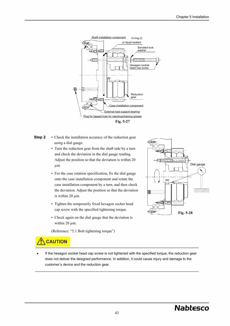
Chapter 5 Installation
43
• Check the installation accuracy of the reduction gear Step 2 using a dial gauge.
• Turn the reduction gear from the shaft side by a turn and check the deviation in the dial gauge reading. Adjust the position so that the deviation is within 20 µm.
• For the case rotation specification, fix the dial gauge onto the case installation component and rotate the case installation component by a turn, and then check the deviation. Adjust the position so that the deviation is within 20 µm.
• Tighten the temporarily fixed hexagon socket head cap screw with the specified tightening torque.
• Check again on the dial gauge that the deviation is within 20 µm.
(Reference: “5.1 Bolt tightening torque”)
If the hexagon socket head cap screw is not tightened with the specified torque, the reduction gear does not deliver the designed performance. In addition, it could cause injury and damage to the customer’s device and the reduction gear.
Fig. 5-27
Shaft installation component O-ring (I)or liquid sealant
Hexagon socket head cap screw
Serrated lock washer
Reduction gear
Case installation component
External load support bearing
Plug for tapped hole for injecting/draining grease
Fig. 5-28
Dial gauge

Chapter 5 Installation
44
• For the pin-bolt clamping output shaft type, drill both a pin pilot hole for the reduction gear and a Step 3 hole on the shaft installation component simultaneously using a reamer, and then tap the taper pin.
• When drilling holes using a reamer, masking is necessary so that cutting chips will not enter the reduction gear.
(Reference: “4.2.9. Taper pin with screw” )
Note: For the two-crank shaft type, rotate the reduction gear until the marked position on the crank shaft reaches the position indicated in Fig. 5-29. Then, drill holes simultaneously using a reamer.
If the cutting chips are trapped in the reduction gear while drilling holes using a reamer, they could adhere to the gear, and eventually cause deterioration of performance, such as abnormal noise, vibration, and torque irregularity, and durability. Also, if the liquid sealant adheres to the lip of the oil seal, it could cause leakage of the lubricant.
• Insert an O-ring (II) into the groove on the case for Step 4 the reduction gear.
• If the product does not feature an O-ring groove, seal the section using a liquid sealant, etc.
(Reference: “4.2.5 Liquid sealant” and “4.2.6 O-rings”)
Fig. 5-30
Taper pin
Fig. 5-29
Crank shaft
Marked position
Approx. 90°
Note
Fig. 5-31
Reduction gear
O-ring (II)
O-ring groove on the case

Chapter 5 Installation
45
When a liquid sealant is used, if the leaking liquid sealant enters the reduction gear, it could cause deterioration of performance, such as abnormal noise, vibration, and torque irregularity. Also, if the liquid sealant adheres to the lip of the oil seal, it could cause leakage of the lubricant.
When a liquid sealant is used, if it leaks into the case mounting bolt section, it could deteriorate the bolt tightening force, and eventually result in deterioration of the transmission torque.
When a liquid sealant is used, follow the instructions of the detailed coating method given by the manufacturer of the sealant to be used.
• Rotate the shaft to fit the case installation Step 5 component into the case mounting hole.
• Align the mounting holes of the motor mounting flange with the mounting holes of the reduction gear (case section) and positions of the tapped holes for the case installation component, and then attach the motor mounting flange to the reduction gear.
• Take extra care so that the O-ring is not caught by the mating section.
• Confirm that the centering shaft of the reduction gear (case section) is correctly fitted into the centering hole of the motor mounting flange.
• Check that there is no foreign matter adhering to the mounting surface.
If the O-ring is caught by the mating section, it could cause leakage of the lubricant.
If there is foreign matter adhering to the mounting surface, the mounting surface of the reduction gear may be deformed, which could cause deterioration of performance, such as abnormal noise and torque irregularity, and durability.
The shape of the motor mounting flange may differ from the illustration above, depending on the customer’s equipment or shape of the reduction gear.
• Temporarily tighten the hexagon socket head cap screw attached with a serrated lock washer. Step 6 • After confirming that the case of the reduction gear turns smoothly with an average torque, further
tighten the hexagon socket head cap screw with the specified torque. (Another method is to turn the case using the input gear or dummy input gear.)
Note
Note
Fig. 5-32
Case installation component Motor mounting
flange
Reduction gear
Mat
ing
sect
ion
of re
duct
ion
gear
(s
haft
side
)M
atin
g se
ctio
n of
mot
or m
ount
ing
flang
e (h
ole
side
)

Chapter 5 Installation
46
• If the hexagon socket head cap screw is tightened with the specified torque before performing adjustment completely, it could cause deterioration of performance, such as vibration or torque irregularity.
• For the pin/bolt clamping output shaft type, drill both a pin pilot hole for the reduction gear (case section) and a hole on the case installation component simultaneously using a reamer, and then tap the taper pin.
• When drilling holes using a reamer, masking is necessary so that cutting chips will not enter the reduction gear.
(Reference: “4.2.3. Reduction gear mounting bolts”, “4.2.4. Serrated lock washer for hexagon socket head cap screw”, “4.2.9. Taper pin with screw”, and “5.1. Bolt tightening torque”)
If the hexagon socket head cap screw is not tightened with the specified torque, the reduction gear does not deliver the designed performance. In addition, it could cause injury and damage to the customer’s device and the reduction gear.
If the installation accuracy of the reduction gear is poor (deviation in the gauge reading is excessive), it could cause deterioration of performance, such as vibration or torque irregularity and durability.
For the two-crank shaft type, when only one spur gear of the reduction gear is turned by hand, resistance becomes large in approximately two locations due to the phase relationship between the crank shaft and RV gear. However, it is not a problem.
If the cutting chips are trapped in the reduction gear while drilling holes using a reamer, they could adhere to the gear, and eventually cause deterioration of performance, such as abnormal noise, vibration, and torque irregularity, and durability. Also, if the liquid sealant adheres to the lip of the oil seal, it could cause leakage of the lubricant.
Fig. 5-33
Motor mounting flange
Serrated lock washer
Hexagon socket head cap screw
Dummy input gear
Taper pin
Reduction gear
Note

Chapter 5 Installation
47
5.2.2. Installing the input gear
For straight shafts (attached to motor shaft tip)
The following is an example when fixing the input gear to the motor shaft using a bolt.
Perform steps 1 to 3 by taking care regarding the following precautions.
Avoid impact to the motor shaft when attaching the input gear. The outer diameters of the bolt head and seal washer should be smaller than the root circle diameter
of the input gear.
Avoid impact to the motor shaft when attaching the input gear, as it could damage the motor.
If the outer diameters of the bolt head and seal washer are larger than the root circle diameter of the input gear, the bolt and seal washer will interfere with the spur gear, and therefore, the gear cannot be installed or could be damaged.
• Attach a key to the motor shaft. Step 1
• Attach the input gear to the motor shaft. Step 2 • Check that there is no foreign matter adhering to the mounting surface.
If any particle adheres to the mounting surface, appropriate installation accuracy cannot be obtained. It could cause deterioration of performance, such as abnormal noise and vibration, and also lead to damage of the motor.
• Fix the input gear to the motor shaft using a hexagon socket head cap screw. Step 3 • Using a thread-locking sealant for screws, lock the hexagon socket head cap screw.
If necessary, seal the area with a seal washer, etc. Otherwise, it could cause the leakage of lubricant.
Check the depths of the input gear hole and motor shaft screw before selecting an appropriate size and length of the hexagon socket head cap screw.
Note
Note
Important

Chapter 5 Installation
48
For straight shafts (attached to motor shaft base)
The following is an example when fixing the input gear to the motor shaft using a set screw.
Perform steps 1 to 3 by taking care regarding the following precautions.
Avoid impact to the motor shaft when attaching the input gear.
Avoid impact to the motor shaft when attaching the input gear, as it could damage the motor.
• Attach a key to the motor shaft. Step 1
• Attach the input gear to the motor shaft. Step 2 • Check that there is no foreign matter adhering to the mounting surface
If any particle adheres to the mounting surface, appropriate installation accuracy cannot be obtained. It could cause deterioration of performance, such as abnormal noise and vibration, and also lead to damage of the motor.
• Tighten the input gear to the motor shaft using a set screw. Step 3 • Using a thread-locking sealant for screws, lock the set screw.
Seal washer
Input gearKey
Motor
Hexagon socket head cap screw
Fig. 5-34
Note
Note

Chapter 5 Installation
49
If a thread-locking sealant is not used for the set screw, a clearance will be generated in the keyway, which could cause deterioration of performance, such as abnormal noise and vibration, and also lead to damage of the motor.
For tapered shafts
The following is an example when fixing the input gear to the motor shaft using a draw bolt and a hexagon nut.
Perform steps 1 to 4 by taking care regarding the following precautions.
Avoid impact to the motor shaft when attaching the input gear. The outer diameters of the hexagon nut and seal washer should be smaller than the root circle
diameter of the input gear.
Avoid impact to the motor shaft when attaching the input gear, as it could damage the motor.
If the outer diameters of the hexagon nut and seal washer are larger than the diameter of the teeth bottom of the input gear, the hexagon nut and seal washer will interfere with the spur gear, and therefore, the gear cannot be installed or could be damaged.
• Attach the draw bolt to the motor shaft. Step 1
• Attach the Woodruff key to the motor shaft. Step 2
• Attach the input gear to the motor shaft. Step 3 • Check that there is no foreign matter adhering to the mounting surface.
Fig. 5-35
Input gear Motor
Set screw
Key
Note
Note
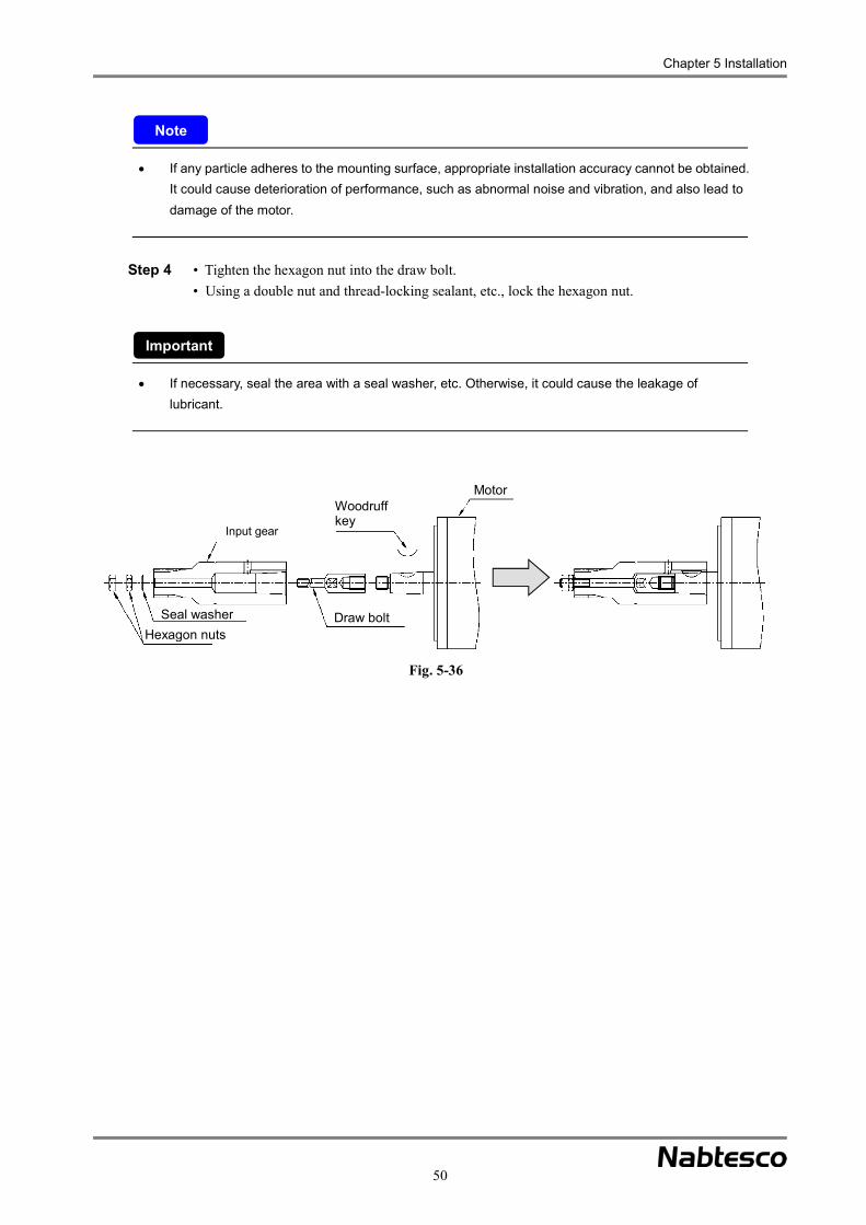
Chapter 5 Installation
50
If any particle adheres to the mounting surface, appropriate installation accuracy cannot be obtained. It could cause deterioration of performance, such as abnormal noise and vibration, and also lead to damage of the motor.
• Tighten the hexagon nut into the draw bolt. Step 4 • Using a double nut and thread-locking sealant, etc., lock the hexagon nut.
If necessary, seal the area with a seal washer, etc. Otherwise, it could cause the leakage of lubricant.
Fig. 5-36
Input gear
Seal washerHexagon nuts
Woodruff key
Motor
Draw bolt
Note
Important
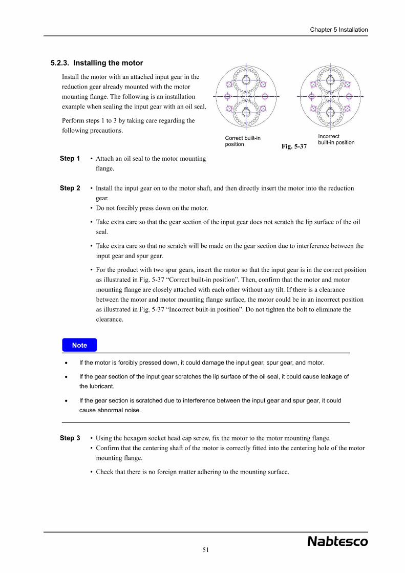
Chapter 5 Installation
51
5.2.3. Installing the motor
Install the motor with an attached input gear in the reduction gear already mounted with the motor mounting flange. The following is an installation example when sealing the input gear with an oil seal.
Perform steps 1 to 3 by taking care regarding the following precautions.
• Attach an oil seal to the motor mounting Step 1 flange.
• Install the input gear on to the motor shaft, and then directly insert the motor into the reduction Step 2 gear.
• Do not forcibly press down on the motor.
• Take extra care so that the gear section of the input gear does not scratch the lip surface of the oil seal.
• Take extra care so that no scratch will be made on the gear section due to interference between the input gear and spur gear.
• For the product with two spur gears, insert the motor so that the input gear is in the correct position as illustrated in Fig. 5-37 “Correct built-in position”. Then, confirm that the motor and motor mounting flange are closely attached with each other without any tilt. If there is a clearance between the motor and motor mounting flange surface, the motor could be in an incorrect position as illustrated in Fig. 5-37 “Incorrect built-in position”. Do not tighten the bolt to eliminate the clearance.
If the motor is forcibly pressed down, it could damage the input gear, spur gear, and motor.
If the gear section of the input gear scratches the lip surface of the oil seal, it could cause leakage of the lubricant.
If the gear section is scratched due to interference between the input gear and spur gear, it could cause abnormal noise.
• Using the hexagon socket head cap screw, fix the motor to the motor mounting flange. Step 3 • Confirm that the centering shaft of the motor is correctly fitted into the centering hole of the motor
mounting flange.
• Check that there is no foreign matter adhering to the mounting surface.
Note
Fig. 5-37 Correct built-in position
Incorrect built-in position

Chapter 5 Installation
52
If any particle adheres to the mounting surface, appropriate installation accuracy cannot be obtained. It could cause deterioration of performance, such as abnormal noise and vibration, and also lead to damage of the motor.
* There are various ways to install the motor, depending on the shape of the reduction gear or customer’s equipment. For the installation methods other than the above examples, check the “External dimensions” drawings and specification sheet. If anything is unclear, contact our service representative.
Fig. 5-38
Motor mounting flange
Oil seal Motor
Motor mounting bolt
Input gear
Note
Chapter 6 Filling the Lubricant
53
Chapter 6 Filling the Lubricant
This chapter describes the filling of lubricant.
Before filling the lubricant, take care regarding the following precautions.
This product is not filled with lubricant when shipped from Nabtesco. Before operating the product, be sure to fill it with an appropriate amount of lubricant specified by Nabtesco.
When pneumatic pressure is used for filling the lubricant, set the pressure below 0.03 MPa. Be sure to leave a space about 10% of the total volume to be filled with the lubricant.
If the internal pressure of the reduction gear increases, an oil seal could fall off or lubricant could leak.
If overfilled, the temperature increases during operation and the internal pressure also increases. As a result, an oil seal could fall off or lubricant could leak.
If the filling amount of the lubricant is insufficient, it could cause premature damage to the reduction gear.
6.1. Precautions when handling the lubricant This section describes the precautions when handling lubricants.
Before handling the lubricant, read the precautions described on the container of the lubricant and use it correctly. Improper use could impair your health.
Wear protective goggles to protect your eyes from the lubricant. If it gets into your eyes, it could cause inflammation.
Wear rubber gloves to protect your skin from the lubricant. If it touches your skin, it could cause inflammation.
Do not eat or put the lubricant into your mouth. If it gets into your mouth, it could cause diarrhea or vomiting.
If anything is unclear, refer to the Safety Data Sheet. If it is not available, contact our service representative.
Note
Important

Chapter 6 Filling the Lubricant
54
Emergency remedy
If the lubricant gets into your eyes, rinse your eyes with clean water for 15 minutes and consult a physician.
If the lubricant contacts the skin, wipe it off completely and thoroughly rinse the affected area with water and soap.
If the lubricant is inhaled, move to a fresh air location and cover your body with a blanket to keep yourself warm and calm. Then, consult a physician.
If the lubricant is swallowed, do not force yourself to vomit and consult a physician.
Disposal of waste grease and container
It is required by law to dispose of the grease and container in the specified manner. Dispose of the grease and container appropriately according to the law.
If anything is unclear, check the disposal precautions described in the Safety Data Sheet or contact our service representative.
Storage
To prevent particles and moisture from being mixed into the container, seal it tightly. Keep it away from the direct sunlight, fire, and heat sources, and store it in a cool and dark place.

Chapter 6 Filling the Lubricant
55
6.2. Reduction gear mounting direction and amount of lubricant The amount of grease the reduction gear requires will differ according to the orientation in which the gear is installed. The amount of lubricant required and the target range (the areas in the diagram) for each mounting direction of the catalog products described in “2.2 Parts codes of catalog products” are indicated below. Set the amount of lubricant according to the customer’s installation environment based on this information.
6.2.1. Horizontal shaft installation
For the E series and original series
The amount of lubricant the reduction gear requires and the target range (the areas in the diagram) when the reduction gear is installed in the horizontal shaft are indicated in Fig. 6-1. Each amount does not include the space (the areas in the diagram) on the motor mounting side. Therefore, if there is a blank space, also fill the space. Leave a space about 10% of the total volume of the internal capacity of the reduction gear (the areas in the diagram) and the space on the motor mounting side (the areas in the diagram). For the amount of lubricant for the products not included in the catalog, contact our service representative individually.
Fig. 6-1
Shaft installation component
Target range
Shaft installation component
Target range
Tapped hole for injecting/draining grease
Tapped hole for injecting/draining grease
Tapped hole for injecting/draining grease
Tapped hole for injecting/draining grease
Motor
Motor
E series Original series

Chapter 6 Filling the Lubricant
56
Table 6-1
Model Required amount Dimensions a
Model Required amount Dimensions a
(cc) (g)*1 (mm) (cc) (g)*1 (mm) RV-6E 42 (38) 17 RV-15 88 (79) 17
RV-20E 87 (78) 15 RV-30 162 (146) 15.5 RV-40E 195 (176) 21 RV-60 258 (232) 10.5
RV-80E1 *2 383 (345) 21 RV-160 448 (403) 17 RV-80E2 *2 345 (311) 21 RV-320 884 (796) 21.6 RV-110E 432 (389) 6.5 RV-450 1,453 (1,308) 21 RV-160E 630 (567) 10.5 RV-550 1,967 (1,770) 24 RV-320E 1,040 (936) 15.5 RV-450E 1,596 (1,436) 18
*1 Density of VIGOGREASE RE0: 0.9 g/cc
*2. (1) indicates the amount of lubricant for the bolt-clamping output shaft type, and (2) for the pin/bolt clamping output shaft type.
For the C series
The amount of lubricant the reduction gear requires and the target range (the areas in the diagram) when the reduction gear is installed in the horizontal shaft are indicated in Fig. 6-2. If there is a blank space inside (e.g., when a center tube is used), exclude the volume of the blank space. Each amount does not include the space (the areas in the diagram) on the motor mounting side. Therefore, if there is a blank space, also fill the space. Leave a space about 10% of the total volume of the internal capacity of the reduction gear (the areas in the diagram) and the space on the motor mounting side (the areas in the diagram). The space on the motor mounting side (theareas in the diagram) includes the center gear external capacity (the areas in the diagram) and the external capacity of the reduction gear (the areas in the diagram). Therefore, when calculating the volume of the space on the motor mounting side, exclude the relevant external capacity. (The center gear external capacity and reduction gear external capacity indicated in Table 6-2 are those of the catalog products. For the products not included in the catalog, contact our service representative.)

Chapter 6 Filling the Lubricant
57
Table 6-2
Model
Required amount Dimensions a
(mm) Dimensions b
(mm)
Reduction gear
external capacity
(cc)
Center gear external
capacity (cc)(cc) (g)*1
RV-10C 147 (132) 9.5 16.85 4 70 RV-27C 266 (239) 10 21.35 10 83 RV-50C 498 (448) 11 23.35 21 208
RV-100C 756 (680) 9.9 29.45 57 369 RV-200C 1,831 (1,648) 18.5 37.7 93 642 RV-320C 3,536 (3,182) 25 46.75 197 1,275 RV-500C 5,934 (5,341) 32 49.7 310 1,803
*1. Density of VIGOGREASE RE0: 0.9 g/cc
Be sure to leave a space about 10% of the total volume. If overfilled, the temperature increases during operation and the internal pressure also increases. As a result, an oil seal could fall off or lubricant could leak.
If the filling amount of the lubricant is insufficient, it could cause premature damage to the reduction gear.
The shape of the reduction gear may differ from the illustration in Fig. 6-1 and Fig. 6-2 above, depending on the ordered specifications. For details on the shape, refer to the catalog and the separately provided “Outer dimensions” drawings and specification sheet.
C seriesFig. 6-2
Shaft installation component
Target rangeTapped hole for injecting/draining grease
Tapped hole for injecting/draining grease
Motor
Center gear external capacity
Reduction gear external capacity
Note

Chapter 6 Filling the Lubricant
58
6.2.2. Vertical shaft installation
For the E series and original series
The amount of lubricant the reduction gear requires and the target range (the areas in the diagram) when the reduction gear is installed in the vertical shaft are indicated in Fig. 6-3. Each amount does not include the space (the areas in the diagram) on the motor mounting side. Therefore, if there is a blank space, also fill the space. Leave a space about 10% of the total volume of the internal capacity of the reduction gear (the areas in the diagram) and the space on the motor mounting side (the areas in the diagram). For the amount of lubricant for the products not included in the catalog, contact our service representative individually.
Fig. 6-3
Vertical shaft installation (with shaft facing downward)
Vertical shaft installation (with shaft facing upward)
E series
Original series
Shaft installation component
Original series
E series
Shaft installation component
Shaft installation component
Shaft installation component
Tapped hole for injecting/draining grease
Tapped hole for injecting/draining grease
Tapped hole for injecting/draining greaseTapped hole for
injecting/draining grease
Motor
Motor
Motor
Motor
Tapped hole for injecting/draining grease
Tapped hole for injecting/draining grease
Tapped hole for injecting/draining grease
Tapped hole for injecting/draining grease
Lubricant surface
Lubricant surface
Lubricant surface
Lubricant surface
Targ
et ra
nge
Targ
et ra
nge
Targ
et ra
nge
Targ
et ra
nge

Chapter 6 Filling the Lubricant
59
Table 6-3
Model Required amount
Dimensions a Model
Required amount
Dimensions a
(cc) (g)*1 (mm) (cc) (g)*1 (mm) RV-6E 48 (43) 17 RV-15 101 (91) 17
RV-20E 100 (90) 15 RV-30 186 (167) 15.5 RV-40E 224 (202) 21 RV-60 296 (266) 10.5
RV-80E1 *2 439 (395) 21 RV-160 514 (463) 17 RV-80E2 *2 396 (356) 21 RV-320 1,014 (913) 21.6 RV-110E 495 (446) 6.5 RV-450 1,663 (1,497) 21 RV-160E 694 (625) 10.5 RV-550 2,257 (2,031) 24 RV-320E 1,193 (1,074) 15.5 RV-450E 1,831 (1,648) 18
*1. Density of VIGOGREASE RE0: 0.9 g/cc
*2. (1) indicates the amount of lubricant for the bolt-clamping output shaft type, and (2) for the pin/bolt clamping output shaft type.
For the C series
The amount of lubricant the reduction gear requires and the target range (the areas in the diagram) when the reduction gear is installed in the vertical shaft are indicated in Fig. 6-4. If there is a blank space inside (e.g., when a center tube is used), exclude the volume of the blank space. Each amount does not include the space (the areas in the diagram) on the motor mounting side. Therefore, if there is a blank space, also fill the space. Leave a space about 10% of the total volume of the internal capacity of the reduction gear (the areas in the diagram) and the space on the motor mounting side (the areas in the diagram). The space on the motor mounting side (areas in the diagram) includes the center gear external capacity (the areas in the diagram) and the external capacity of the reduction gear (the areas in the diagram). Therefore, when calculating the volume of the space on the motor mounting side, exclude the relevant external capacity. (The center gear external capacity and reduction gear external capacity indicated in Table 6-4 are those of the catalog products. For the products not included in the catalog, contact our service representative.)

Chapter 6 Filling the Lubricant
60
Table 6-4
Model
Required amount Dimensions
a (mm)
Dimensions b
(mm)
Reduction gear
external capacity
(cc)
Center gear
external capacity
(cc) (cc) (g)*1
RV-10C 167 (150) 9.5 16.85 4 70 RV-27C 305 (275) 10 21.35 10 83 RV-50C 571 (514) 11 23.35 21 208
RV-100C 857 (771) 9.9 29.45 57 369 RV-200C 2,076 (1,868) 18.5 37.7 93 642 RV-320C 4,047 (3,642) 25 46.75 197 1,275 RV-500C 6,900 (6,210) 32 49.7 310 1,803
*1. Density of VIGOGREASE RE0: 0.9 g/cc
Be sure to leave a space about 10% of the total volume. If overfilled, the temperature increases during operation and the internal pressure also increases. As a result, an oil seal could fall off or lubricant could leak.
If the filling amount of the lubricant is insufficient, it could cause premature damage to the reduction gear.
The shape of the reduction gear may differ from the illustration in Fig. 6-3 and Fig. 6-4 above, depending on the ordered specifications. For details on the shape, refer to the catalog and the separately provided “Outer dimensions” drawings and specification sheet.
C seriesFig. 6-4
Vertical shaft installation (with shaft facing downward)
Vertical shaft installation (with shaft facing upward)
Shaft installation component
Shaft installation component
Tapped hole for injecting/draining grease
Tapped hole for injecting/draining grease
Lubricant surface
Lubricant surface
Tapped hole for injecting/draining grease
Tapped hole for injecting/draining grease
Motor
Motor
Center gear external capacity
Center gear external capacity
Reduction gear external capacity
Reduction gear external capacity
Targ
et ra
nge
Targ
et ra
nge
Note
Chapter 6 Filling the Lubricant
61
6.3. Lubricant filling procedure This section describes how to fill the lubricant.
Perform steps 1 to 7 by taking care regarding the following precautions.
When handling the lubricant, be sure to wear protective goggles and rubber gloves.
If the lubricant gets in your eyes or touches your skin, it could cause inflammation.
• Remove both of the plugs for tapped holes for injecting/draining grease, and attach a grease nipple, Step 1 etc., and then attach the injector.
If the injector is attached with the supply side down, air is less likely to accumulate in the reduction gear, which facilitates the lubricant filling procedure.
• Fill the specified lubricant using the injector. Step 2 • When filling the lubricant, be sure to remove the plug for tapped hole for injecting/draining grease
on the drain side.
• When pneumatic pressure is used for filling the lubricant, set the pressure below 0.03 MPa.
If you fail to remove the plug for tapped hole for injecting/draining grease on the drain side, the internal pressure increases. As a result, the oil seal could fall off or the oil seal lip could be reversed.
If the internal pressure of the reduction gear increases, an oil seal could fall off or lubricant could leak.
The shape of the reduction gear may differ from the illustration in Fig. 6-5 above, depending on the ordered specifications. For details on the shape, refer to the catalog and the separately provided “Outer dimensions” drawings and specification sheet.
• If the lubricant overflows from the tapped hole for injecting/draining grease on the drain side Step 3 during filling, temporarily stop the filling.
• Remove the injector from the grease nipple and plug the tapped holes for injecting/draining grease Step 4 on both the greasing and drain sides.
• Rotate the output shaft of the reduction gear by 1 or 2 turns. Step 5
Note
Important

Chapter 6 Filling the Lubricant
62
Do not use the motor to rotate the output shaft of the reduction gear for safety, if possible. If the motor is used by necessity, run the motor at a low speed and never touch the rotation section. Otherwise, you could be caught by the rotation section, which will result in serious injury.
• Repeat steps 1 to 5 until the lubricant is filled up to the specified level. Step 6
• After filling the lubricant up to the specified level, wipe the lubricant off from the tapped holes for Step 7 injecting/draining grease and cap them with plugs sealed with a seal tape, etc.
Vertical shaft installation (with shaft facing downward)
Vertical shaft installation (with shaft facing upward)
Fig. 6-5
Shaft installation component Tapped hole for injecting/draining grease (drain side)
Injector
Tapped hole for injecting/draining grease (supply side)
Motor mounting flange
Horizontal shaft installation
Motor mounting flangeTapped hole for injecting/draining grease (drain side)
Shaft installation component
Tapped hole for injecting/ draining grease (supply side)
Injector
Tapped hole for injecting/draining grease (drain side)
Shaft installation component
InjectorTapped hole for injecting/ draining grease (supply side)Motor mounting flange
Chapter 7 Operation
63
Chapter 7 Operation
This chapter describes the operation of the product.
7.1. Checking before operation After installing this product in the customer’s device, check the following points before starting operation.
The lubricant is filled correctly. Components are fixed with each other correctly. The mounting bolts are tightened securely. The rotation section rotates in the desired direction.
7.2. Running-in operation It is recommended that the running-in operation is performed after the Nabtesco-specified lubricant is added.
Abnormal noise or torque irregularity may occur during operation, depending on the characteristics of the lubricant. There is no problem with the quality when the symptom disappears after the running-in operation is performed for 30 minutes or more (until the surface temperature of the reduction gear body reaches around 50°C).
During the running-in operation, check the items in Table 8-1 on page 64.
7.3. Precautions for operation Once the pre-operation checks and running-in operation are completed, operate the device safely by observing the following precautions.
Keep away from the rotation section during operation of the device or until it is completely stopped. You could get caught by the rotation section, which will result in serious injury.
If any abnormalities, such as abnormal noise or excessive vibration are found, stop the operation immediately. Do not start the operation before the cause of the error is identified and corrective measures are taken. Incorrect motion could cause injury.
Important
Chapter 7 Operation
64
The reduction gear could become extremely hot during operation. After stopping the operation, never touch the reduction gear until it is completely cooled. Touching the reduction gear could cause burns.
Do not operate the reduction gear under a condition that exceeds the allowable acceleration/deceleration torque, allowable moment, and allowable output speed. It could cause injury to the workers or damage to the reduction gear.
Operate the reduction gear while the surface temperature is below 60°C. Failure to do so could cause premature damage.
When the reduction gear is used with the surface temperature within 40 to 60°C, refer to “8.3.1 Replacement period of lubricant”.
Note

Chapter 8 Maintenance and inspection
65
Chapter 8 Maintenance and inspection
This chapter describes how to perform maintenance and inspection.
8.1. Precautions on maintenance
Keep away from the rotation section during maintenance/inspection of the device currently in operation. You could be caught by the rotation section, which will result in serious injury.
If any abnormalities, such as abnormal noise or excessive vibration are found, stop the operation immediately. Do not start the operation before the cause of the error is identified and corrective measures are taken. Incorrect motion could cause injury.
The reduction gear could become extremely hot during operation. After stopping the operation, never touch the reduction gear until it is completely cooled. Touching the reduction gear could cause burns.
When performing maintenance, observe the following precautions and ensure safety.
Wear appropriate clothing and protective gear, including the protective goggles, gloves, and safety shoes.
Organize the surrounding area and ensure safety to prevent secondary accidents. To maintain the condition in which the device is completely stopped, turn OFF the power to the
customer’s device and take extra care so that the power will not be turned ON by accident.
8.2. Daily inspection Check the following items every day before starting the operation. Table 8 -1
Inspection item Description Noise Check for abnormal noise or sudden change of noise.
Vibration Check for excessive vibration or any sudden change.
Surface temperature Check for an excessively hot surface of the reduction gear (normally below 60°C) or any sudden change.
Bolts Check for looseness of each mounting bolt. Leakage of lubricant
Check for leakage of lubricant from the mating face or oil seal section in the vicinity of the reduction gear.
Note: Check the above items indirectly at a distance from the rotation section, such as connecting members.
If it is necessary to access the device for inspection while the device is in operation, cover the rotation section. You could be caught by the rotation section, which will result in serious injury.

Chapter 8 Maintenance and inspection
66
8.3. Lubricant replacement 8.3.1. Lubricant replacement time
When this product is operated with an appropriate amount of lubricant, the standard lubricant replacement time due to lubricant degradation is 20,000 hours. However, when operation involves a reduction gear surface temperature above 40°C (the area in the right diagram), the state of the lubricant should be checked in advance and the grease replaced earlier as necessary. For the lubricants specified by Nabtesco, refer to “4.2.7 Lubricants”
8.3.2. Lubricant replacement procedure
This section describes how to replace lubricants. Perform steps 1 to 7 by taking care regarding the following precautions.
When handling the lubricant, be sure to wear protective goggles and rubber gloves.
Check the amount of drained lubricant by catching it with a container, etc., in order to control the same amount of lubricant to be drained and filled.
When replacing the lubricant, turn OFF the power source (e.g., power supply) and execute lock-out/tag-out so that the power will not be turned ON by accident. Otherwise, you could be caught by the rotation section, which will result in injury.
If the lubricant gets in your eyes or touches your skin, it could cause inflammation.
When the safety cover near the reduction gear has been removed for replacement/maintenance of lubricant, be sure to return them to their original positions after the procedure.
If the lubricant is overfilled, there is a possibility of high internal pressure and that an oil seal could fall off, the lip could be reversed, or lubricant could leak. If the lubricant is insufficient, a lubrication failure could occur and the reduction gear could be damaged.
If the filling amount of the lubricant is insufficient, it could cause premature damage to the reduction gear.
The shape of the reduction gear may differ from the illustration in Fig. 8-2 above, depending on the ordered specifications. For details on the shape, refer to the catalog and the separately provided “Outer dimensions” drawings and specification sheet.
Note
Fig. 8-1
Ambient temperature (°C)Red
uctio
n ge
ar s
urfa
ce te
mpe
ratu
re (°
C)

Chapter 8 Maintenance and inspection
67
• Rotate the output shaft of the reduction gear so that the tapped holes for injecting/draining grease Step 1 are positioned diagonally. (When rotating the output shaft using electric power, do not approach the equipment and reduction gear. When rotating the output shaft without using electric power, perform step 2 first.)
• Turn OFF the power to the device and confirm that the device is completely stopped. Step 2 • Remove both of the plugs for the tapped holes for injecting/draining grease, and drain the lubricant Step 3
from the upper tapped hole for injecting/draining grease. • Always drain the lubricant while the reduction gear is cool.
If a tapped hole for injecting/draining grease is unplugged while the reduction gear is still hot, high-temperature lubricant sprays out, which could cause burns.
• Attach a grease nipple, etc. to the tapped hole for injecting/draining grease and then attach the Step 4 injector. (Refer to Fig. 8-2)
• Using the injector or the like, fill the lubricant through the tapped hole for injecting/draining grease Step 5 on the supply side.
• When filling the lubricant, be sure to remove the plug for tapped hole for injecting/draining grease on the drain side.
• When pneumatic pressure is used for filling the lubricant, set the pressure below 0.03 MPa.
If you fail to remove the plug for tapped hole for injecting/draining grease on the drain side, the internal pressure increases. As a result, oil seals could fall off or the oil seal lip could be reversed.
If the internal pressure of the reduction gear increases, oil seals could fall off or lubricant could leak.
• Inject the lubricant until it overflows from the tapped hole for injecting/draining grease on the Step 6 drain side.
• Remove the injector from the grease nipple and plug the tapped holes for injecting/draining grease Step 7 on both the greasing and drain sides.
• Rotate the output shaft of the reduction gear by 1 or 2 turns. Step 8
Note

Chapter 8 Maintenance and inspection
68
Fig. 8-2Vertical shaft installation
(with shaft facing downward)Vertical shaft installation
(with shaft facing upward)
Horizontal shaft installation
Shaft installation component
Shaft installation component
Shaft installation component
Tapped hole for injecting/draining grease (drain side)
Tapped hole for injecting/draining grease (drain side)
Tapped hole for injecting/draining grease (drain side)
Hose or the like
Hose or the like
Hose or the like
(Drains lubricant)
(Drains lubricant)
(Drains lubricant)Tapped hole for injecting/draining grease (supply side)
Tapped hole for injecting/draining grease (supply
Tapped hole for injecting/ draining grease (supply side) Injector
Injector
Injector
Motor mounting flange
Motor mounting flange
Motor mounting flange
Do not use the motor to rotate the output shaft of the reduction gear for safety, if possible. If the motor is used by necessity, run the motor at a low speed and never touch the rotation section. Otherwise, you could be caught by the rotation section, which will result in serious injury.
• Repeat steps 3 to 8 until the reduction gear is filled with the same amount of lubricant as that was Step 9 drained.
• It is recommended that the inside of the reduction gear is flushed so that the lubricant can be Step 10 replaced more efficiently.
• Remove the injector from the tapped hole on the supply side, and attach a hexagon socket head cap plug to the tapped hole on the drain side. Calculate output shaft conversion and set the motor rotation speed so that the output shaft rotation speed is 5 to 10 rpm. Then, rotate the motor for about one minute.
Set the rotation speed based on the output shaft conversion by taking the customer’s operation conditions into account.
• Perform steps 1 and 9 again. Step 11
• Attach the hexagon socket head cap plugs to the tapped holes for injecting/draining grease. Step 12 Replace the seal tape with a new one.
• Wipe off the lubricant adhering to the surrounding completely. Step 13
Important

Chapter 8 Maintenance and inspection
69
8.4. Troubleshooting checksheet Check the following items in the case of trouble like abnormal noise, vibration, or malfunctions. When it is not possible to resolve an abnormality even after verifying the corresponding checkpoint, obtain a “Reduction Gear Investigation Request Sheet” from our Website, fill in the necessary information, and contact us via the agent where you bought the device.
http://precision.nabtesco.com/documents/request.html
The trouble started immediately after installation of the reduction gear
Check column Item
Make sure the equipment’s drive section (the motor side or the reduction gear output surface side) is not interfering with another component.
Make sure the equipment is not under a greater than expected load (torque, moment load, thrust load). Make sure the required number of bolts are tightened uniformly with the specified tightening torque. Make sure the reduction gear, motor, or your company’s components are not installed at a slant. Make sure the specified amount of Nabtesco-specified lubricant has been added. Make sure there are no problems with the motor’s parameter settings. Make sure there are no components resonating in unity. Make sure the input gear is appropriately installed on the motor. Make sure there is no damage to the surface of the input gear teeth. Make sure the input gear specifications (precision, number of teeth, module, shift coefficient,
dimensions of each part) are correct. Make sure the flange and other components are designed and manufactured with the correct
tolerances.
The trouble started during operation
Check column Item
Make sure the equipment has not been in operation longer than the calculated service life. Make sure the surface temperature of the reduction gear is not higher than normal during operation. Make sure the operation conditions have not been changed. Make sure there are no loose or missing bolts. Make sure the equipment is not under a greater than expected load (torque, moment load, thrust load). Make sure the equipment’s drive section is not interfering with another component. Make sure an oil leak is not causing a drop in the amount of lubricant. Make sure there are no external contaminants in the gear, such as moisture or metal powder. Make sure no lubricant other than that specified is being used.
When the reduction gear is embedded in the customer’s equipment, create your own troubleshooting checksheet based on the above checkpoints.

Appendix: Design Scheme of Input Gear
70
Design Scheme of Input GearFor models RV-□E and RV-□, we have a variety of standard input gears for each speed ratio that can be additionally machined by the customers. Please machine and install the standard input gear based on the customer’s intended use, by referring to the following examples. Note: For the model and reduction speed ratio provided with the standard input gears, refer to “Dimensions of standard input gear” on page 75.
Standard input gear specifications
Material Heat treatment Carburizing, quenching and tempering Surface hardness HRC58 to 62 (excluding the carburizing prevention range)Material SCM415 Normalizing or equivalent material
<Standard input gear A: For small motors> <Standard input gear B: For large motors>
Note: The above drawing shows the shape before the additional machining is performed. Check the dimensions of each section in the “Dimensions” table on pages 69 and 70.
• Reference for additional machining
Standard input gears come equipped with center holes and ground boss outer diameter (D1). When modifying them, use the center hole or boss outer diameter (D1) as the reference surface.
Design of the input gear
Please refer to the chart below. Use it as a reference when the customer designs an input gear on their own.
Design flow
When modifying the standard input gear When manufacturing a special input gear
Appendix
Manufacture a special input gear
60°C center hole, type A
Carburizing prevention range
60°C center hole, type A
Carburizing prevention range
Refer to page 69
Refer to pages 69 to 71
Refer to pages 77 and 78
Refer to pages 69 to 71
Refer to page 71

Appendix: Design Scheme of Input Gear
71
Selection of the input gear type
There are the following two types of standard input gear: Standard input gear A: For small motors Standard input gear B: For large motors
Select the type of input gear to be used by referring to the tables below.
Applicable motor shaft diameters for standard input gear (Unit: mm) (Unit: mm)
Model Standard input gear A
Standard input gear B Model Standard input
gear A Standard input
gear B
RV-6E ø16 or less RV-160E, RV-160 Less than ø28 ø28 or more
RV-20E, RV-15 Less than ø14 ø14 or more RV-320E,
RV-320 Less than ø32 ø32 or more
RV-40E, RV-30 Less than ø19 ø19 or more RV-450E,
RV-450 Less than ø42 ø42 or more
RV-80E, RV-60 Less than ø24 ø24 or more RV-550 ø40 or less
RV-110E ø24 or less Note: Some models have only standard input gear A.
Design of the motor shaft hole
<(Design example 1: For straight shafts (attached to motor shaft tip)>
Note 1. When a tapped hole is used for the motor shaft, fix the input gear to the motor shaft with a bolt. 2. For the bolt through hole diameter (d3), radial runout, and the shaft hole position (LC), refer to “Dimensions after
modification” in the “Dimensions” table on pages 69 and 70. 3. If the bolt through hole diameter (d3) is larger than the center hole diameter on the tooth surface side (d4), it is
necessary to process the carburized surface. In such a case, confirm the applicable tools and processing conditions, etc.
4. The clearance hole diameter for the keyway (d5) is “keyway width (k) + 2 mm”, approximately. [The clearance hole diameter must be larger than the keyway width (k).]
5. Design the motor shaft hole diameter (d1) according to the motor shaft diameter to be used. 6. For the keyway width (k) and keyway height (a), refer to the specifications of the key to be used.
Image of assembly
d5 drill
Drill both at the same time
Detailed drawing of section E
Installation reference surface
Clearance

Appendix: Design Scheme of Input Gear
72
<Design example 2: For straight shafts (attached to motor shaft base)>
Note 1. When a tapped hole is not used for the motor shaft, fix the input gear to the motor shaft with a set screw. 2. If a clearance hole for the keyway cannot be drilled due to some reason, such as the plunge grinding area being
located on the outer periphery, create a recessed groove instead. 3. For the radial runout and the shaft hole position (LC), refer to “Dimensions after modification” in the “Dimensions”
table on pages 69 and 70. 4. Design the motor shaft hole diameter (d1) according to the motor shaft diameter to be used. 5. For the keyway width (k) and keyway height (a), refer to the specifications of the key to be used. 6. Design the diameter of the recessed groove for the keyway (d2) according to the following instructions.
• Recessed groove diameter for keyway
Set the diameter of the recessed groove (d2) so that it is larger than the corner of the keyway.
Although the following calculation formula is used in this example, design the diameter using appropriate values, based on the keyway tolerance, processing tolerance, etc. The following is an example of when the diameter of the recessed groove is selected based on the above calculation formula. Use it as a reference when designing.
Selection examples of recessed groove diameter (d2) (Unit: mm) (Unit: mm) Motor shaft
hole diameter ød1
Keyway width
k
Keyway height
a
Recessed groove
diameter ød2
Motor shaft hole diameter
ød1
Keyway width
k
Keyway height
a
Recessed groove
diameter ød2
8 3 9.4 12 22 8 25.3 31 9 3 10.4 13 24 8 27.3 33
10 4 11.8 15 25 8 28.3 34 11 4 12.8 16 28 8 31.3 37 14 5 16.3 20 32 10 35.3 41 15 5 17.3 21 35 10 38.3 44 16 5 18.3 22 38 10 41.3 47 17 6 19.8 24 38 12 41.3 47 19 6 21.8 26 42 12 45.3 51
Image of assembly
22
221
kda
5.022
12222
kdad ≧
5.022
12222
kdad ≧
Plunge grinding range
Tapped hole for set screw
Drill both at the same time
ClearanceInstallation reference
surface
(Recessed groove diameter)

Appendix: Design Scheme of Input Gear
73
<Design example 3: For tapered shafts>
Note 1. For the bolt through hole diameter (d3), radial runout, and the shaft hole position (LC), refer to “Dimensions after modification” in the “Dimensions” table on pages 69 and 70.
2. Design the motor shaft hole diameter (d1) according to the motor shaft diameter to be used. 3. For the keyway width (k) and keyway height (a), refer to the specifications of the key to be used. 4. There are two ways to fix the tapered shaft to the motor shaft: draw nut and draw bolt. Fix the shaft using either of
them, referring to the drawings below. 5. You can manufacture the draw nut and draw bolt on your own, or contact us.
• When fixing with a draw nut • When fixing with a draw bolt
Design of the oil seal area
<Design example 4>
If a lip surface is required for the oil seal, manufacture a new input gear and quench the D2 section, and then perform plunge grinding.
Note 1. The design specifications vary depending on the oil seal manufacturer. When designing, be sure to confirm with the manufacturer of the oil seal to be used.
2. The standard input gear is not compatible with the oil seal surface. If the lip surface is required for the oil seal, manufacture a new input gear.
3. Rubber containing fluorine is recommended for the material of the oil seal. 4. When assembling the oil seal, be careful to avoid any contact between the lip section and the gear, as it causes
scratches. 5. Design the oil seal assembly position so that the lip section of the oil seal does not fall off from the plunge grinding
range.
Dihedral chamfer
Cle
aran
ce
Cle
aran
ce
d5 drill Tapered to 1/10
Cle
aran
ce
Cle
aran
ce
No edge
(Plunge grinding range)
Seal with seal washer, etc.
(Plunge grinding)
Dihedral chamfer
Cross section Z-ZCross section Z-Z

Appendix: Design Scheme of Input Gear
74
Pass-through capacity of input gear
The following table shows which ratios can and cannot allow the input gear to pass through.
(Unit: mm)
Model
Hole diameter Depth Speed ratio adequate for shaft passage Speed ratio inadequate for
shaft passage
d1 d2 ℓ1 ℓ2 Shaft rotation Case rotation Shaft rotation Case rotation
RV-6E 19 21 18 - 53.5, 59, 79, 103 52.5, 58, 78, 102 31.43 30.42 RV-20E, RV-15 22 24 18.5 18.5 81, 105, 121, 141 80, 104, 120, 140 57 56 RV-40E, RV-30 27 30 23.5 19.5 81, 105, 121, 153 80, 104, 120, 152 57 56 RV-80E, RV-60 37 40 23 17.5 81, 101, 121, 153 80, 100, 120, 152 57 56
RV-110E 39 42 20 - 81, 111, 127.7, 161, 175.2 80, 110, 126.7, 160, 174.2 - - RV-160E, RV-160 43 47 30 22 81, 101, 129, 145, 171 80, 100, 128, 144, 170 66 *1 65 *1
RV-320E, RV-320 47 52 34 28.3 81, 101, 118.5, 129, 141, 171,
185 80, 100, 117.5, 128, 140, 170,
184 66 *1 65 *1
RV-450E, RV-450 57 62 40 28.5 81, 101, 118.5, 129, 154.8,
171, 192.42 80, 100, 117.5, 128, 153.8,
170, 191.42 66 *1 65 *1
RV-550 66 72 - - 123, 141, 163.5, 192.42 122, 140, 162.5, 191.42 - -
*1 It is not included in the input gear tooth specifications. For any requests, contact us.
As the speed ratio becomes smaller, the outer diameter of the spur gear teeth of the input gear becomes larger. Therefore, it is impossible to install the input gear by means of passing through the reduction gear. In such a case, prepare the deep groove ball bearing and C type retaining ring according to the illustration below. The dimensions of the standard input spline are marked with * on pages 73 and 74.
ℓ1 = E type
ℓ2 = Original type
Input spline
Input gearC type retaining ring for hole
C type retaining ring
for shaftDeep groove ball bearing

Appendix: Design Scheme of Input Gear
75
(Unit: mm)
Model LC LD LE LG±0.1 LH Deep groove ball bearing
RV-6E 92 10.3 16 13 7.5 6002 RV-20E, RV-15 90 11.7 17 14 9 6003 RV-40E, RV-30 103 13.9 19 16 11.5 6004
RV-80E, RV-60 *2 109 13.9 15.5 12 16 6005 RV-80E, RV-60 *3 105 13.9 19.5 16 12 6005
RV-160E 128 15.1 21 17 16 6006 RV-320E 148 16.1 22 18 20 6007 RV-450E 195 17.6 26 22.5 21 6008
*2 For the bolt-clamping output shaft type *3 For the pin/bolt clamping output shaft type
+0.10

Appendix: Design Scheme of Input Gear
76
Dimensions of standard input gear
The ratio code marked with * indicates the dimensions of the standard input spline.
For the gear tooth specifications, refer to “Gear tooth specifications for each input spline model” on page 77.

Appendix: Design Scheme of Input Gear
77

Appendix: Design Scheme of Input Gear
78
Gear tooth specifications
Refer to the specifications shown in the following tables when designing with a processed or non-standard input gear.
For a model or speed ratio other than those listed below, contact us.
Common specifications Tooth profile Full depth
Pressure angle (°) 20 Precision JIS B 1702: 1976 Grade 5
Spur gear tooth surface hardness and material Heat treatment Carburizing, quenching and tempering
Surface hardness HRC 58 to 62 Effective case depth <HV513> (mm) 0.3 to 0.7 *1
Material SCM415 Normalizing Alternate material SCM420 Normalizing
*1 The value will differ depending on the module.
Module 1 or lower More than 1 Effective case depth <HV513> (mm) 0.2 to 0.6 0.3 to 0.7
Input gear tooth specifications for each model
Effective face width

Appendix: Design Scheme of Input Gear
79

Appendix: Design Scheme of Input Gear
80

Appendix: Design Scheme of Input Gear
81
Input gear tooth specifications for each model
Refer to the specifications shown in the following tables when designing with a processed or non-standard input spline.
The specifications of the hardness and material are the same as those of the input gear.
Detailed drawing of spline section Detailed drawing of spline section Detailed drawing of spline section
Contact Information
For any inquires and requests for services related to this product, contact our service representative using the following contact information.
In such a case, please inform us of the model, parts code, and S/N (serial number) indicated on the shipping label for the packing box.
http://precision.nabtesco.com/
Europe and AfricaNabtesco Precision Europe GmbHTiefenbroicher Weg 15, 40472 Düsseldorf, Germany TEL: +49-211-173790 FAX: +49-211-364677 E-MAIL: [email protected] www.nabtesco.de
North and South America Nabtesco Motion Control Inc. 23976 Freeway Park Drive, Farmington Hills, MI 48335, USA TEL: +1-248-553-3020 FAX: +1-248-553-3070 E-MAIL: [email protected] www.nabtescomotioncontrol.com
China Shanghai Nabtesco Motion-equipment Co., Ltd. Room 1706, Hong Jia Tower, No. 388 Fu Shan Road, Pudong New Area, Shanghai 200122, China TEL: +86-21-3363-2200 FAX: +86-21-3363-2655 E-MAIL: [email protected] www.nabtesco-motion.cn
Asia and others Nabtesco Corporation Osaka Sales Office21st Fl, Dojima Avanza, 1-6-20 Dojima, Kita-ku, Osaka 530-0003, Japan TEL: +81-6-6341-7180 FAX: +81-6-6341-7182
Tsu Plant 594 Icchoda, Katada-cho, Tsu, Mie 514-8533, Japan TEL: +81-59-237-4600 FAX: +81-59-237-4610
Service Center 594 Icchoda, Katada-cho, Tsu, Mie 514-8533, Japan TEL: +81-59-237-4672 FAX: +81-59-237-4697
Nabtesco, VIGOGREASE, RV are registered trademarks or trademarks of Nabtesco Corporation. The contents of this manual are subject to change without prior notice.
The PDF data of this manual can be downloaded from the following website. http://precision.nabtesco.com/ If any addition or modification is made to the published information, the PDF data may be updated before the printed document. Due to this, please note that some contents of the PDF data may be changed or revised from those in this manual.
If there are any inconsistencies between the precautions indicated on this product or in the documents included with this product and those described in this manual, a higher priority is always assigned to the precautions indicated on this product or in the documents included with this product.
Unauthorized reprinting, reproduction, copying, or translation of this manual in whole or in part is strictly prohibited.


