Embed Size (px)
Citation preview
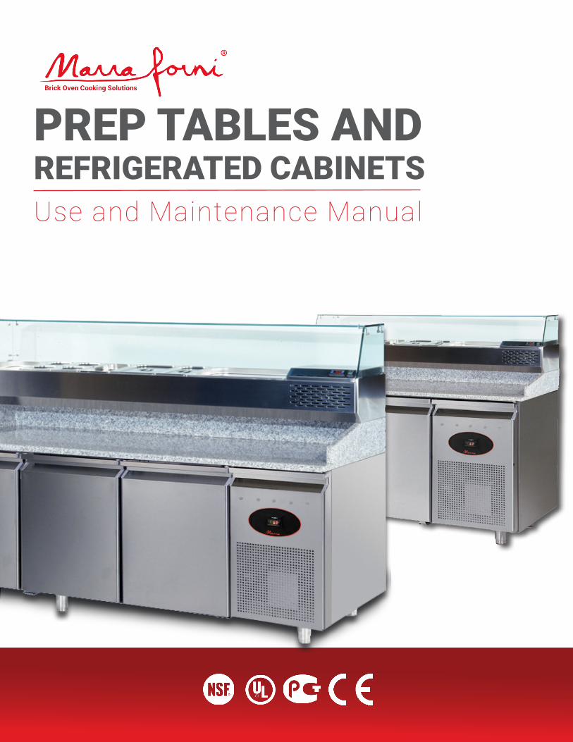
PREP TABLES AND REFRIGERATED CABINETSUse and Maintenance Manual

2
3
GENERAL INFORMATIONManufacturer
Service Centers
Certification
Guarantee
PREARRANGEMENTS OF CUSTOMER'S RESPONSIBILITY
Structure of the Manual
Aims and Contents
Who the Manual is For
Conservation
Symbols Used
DESCRIPTION AND OPERATION OF THE APPLIANCEDescription
Operation
PREARRANGEMENTSIllumination Vibration
Emission of Sound
Supplies on Request
SAFETYGeneral Warning
Foreseen Use
Unsuitable Conditions For Use Danger Zones
Switching Off the Appliance
Plaques
TRANSPORT AND MOVEMENTTransport
Storage
Checks
INSTALLATIONSet Up
Assembly
PREARRANGEMENTS CONNECTIONS
Electric
Hydraulics
PREARRANGEMENTS FOR OPTIONALS
OPERATIONSTAFF
PUTTING INTO OPERATION TIMERS
REGULATION OF TEMPERATURE
STORAGE OF FOOD
CONSERVATION OF FOOD
ROUTINE AND PLANNED MAINTENANCEBASIC SAFETY RULES
PROHIBITION OF REMOVAL OF PROTECTION AND SAFETY DEVICES
INDICATIONS FOR EMERGENCY OPERATIONS IN THE CASE OF FIRE
CLEANING OF THE EXTERIOR
CLEANING OF THE CONDENSER
PERIODIC CHECKS TO BE CARRIED OUT
NON-ROUTINE MAINTENANCE AND REPAIRSDEMOLITION
ENCLOSURES
DECLARATIONS
TECHNICAL DOCUMENTATIONTOUBLE SHOOTING
WIRE DIAGRAM
SUPPLY OF SPARE PARTS
Manual Contents
4
6
6
7
9
10
14
15
15
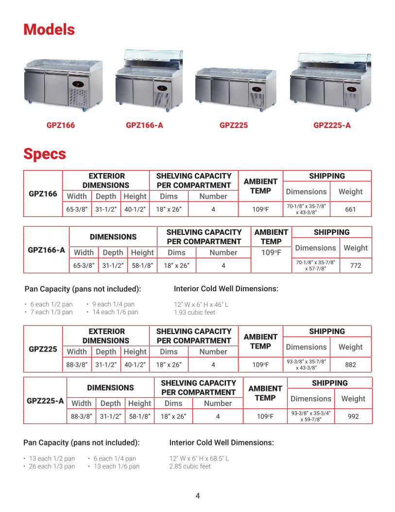
4
Specs
Models
GPZ166-A
DIMENSIONS SHELVING CAPACITY PER COMPARTMENT
AMBIENT TEMP
SHIPPING
Dimensions WeightWidth Depth Height Dims Number 109oF65-3/8” 31-1/2” 58-1/8” 18” x 26” 4 70-1/8” x 35-7/8”
x 57-7/8” 772
GPZ166
EXTERIOR DIMENSIONS
SHELVING CAPACITY PER COMPARTMENT AMBIENT
TEMP
SHIPPING
Dimensions WeightWidth Depth Height Dims Number 65-3/8” 31-1/2” 40-1/2” 18” x 26” 4 109oF 70-1/8” x 35-7/8”
x 43-3/8” 661
GPZ225
EXTERIOR DIMENSIONS
SHELVING CAPACITY PER COMPARTMENT AMBIENT
TEMP
SHIPPING
Dimensions WeightWidth Depth Height Dims Number 88-3/8” 31-1/2” 40-1/2” 18” x 26” 4 109oF 93-3/8” x 35-7/8”
x 43-3/8” 882
GPZ225-A
DIMENSIONS SHELVING CAPACITY PER COMPARTMENT AMBIENT
TEMP
SHIPPING
Dimensions WeightWidth Depth Height Dims Number 88-3/8” 31-1/2” 58-1/8” 18” x 26” 4 109oF 93-3/8” x 35-3/4”
x 59-7/8” 992
GPZ166 GPZ166-A GPZ225-AGPZ225
Interior Cold Well Dimensions:
12" W x 6" H x 68.5" L2.85 cubic feet
Pan Capacity (pans not included):
Pan Capacity (pans not included): Interior Cold Well Dimensions:
12" W x 6" H x 46" L1.93 cubic feet
• 6 each 1/2 pan• 7 each 1/3 pan
• 9 each 1/4 pan• 14 each 1/6 pan
• 13 each 1/2 pan• 26 each 1/3 pan
• 6 each 1/4 pan• 13 each 1/6 pan
5
1.1 MANUFACTURER
As the company boasts considerable experience in the field of industrial refrigeration. The technological know-how acquired, created during years of research and close contact with the production and marketing at an international level, represents the best guarantee that the manufacturer can offer. This equipment has been studied inside, externally and in its components, according to the requirements specified by your market. Furthermore every aspect has been checked for functioning and for appearance before being despatched, as shown by the CERTIFICATE OF GUARANTEE AND INSPECTION included in this documentation. To guarantee the long life of this product, use it according to the suggestions made in this manual.
1.2 SERVICE CENTRES
(Sales, Service, Spare parts and Commercial Representation)
For any requirement pertaining to use, maintenance or the request for spare parts, the Customer should use an authorised Service Centre (directly care of the manufacturer), specifying the identification details of the equipment shown on the plaques:
1.3 CERTIFICATION
The Condensed air Refrigerator Cupboards and Tables and Refrigerator Units are produced in accordance with the European Community Regulations applicable at the time of its appearance
See Plaque A at paragraph 4.6
RETAILER'S STAMP
• The serial number (stamped on the relevant plaque, see paragraph 4.6);
• The date of purchase.
1.5 PREARRANGEMENTS OF CUSTOMER’S RESPONSIBILITY
It is the Customer’s responsibility to carry out every-thing specified in the documentation. Unless different prior arrangements have been made, the following are usually the Customer’s re-sponsibility:
• Predisposition of the area, including any building work and or canalisation required;
• Electric power supply in accordance with the power regulations in the country of use;
• Cleaning materials.
1.6 STRUCTURE OF THE MANUAL
The Customer must read the information con-tained in this Manual very carefully, because the correct predisposition, installation and use are the basis of the Customer - Manufacturer agreement.
1.6.1 AIMS AND CONTENTS
This Manual aims to provide the customer with all the information necessary for not only adequate use of the equipment, but also for the safest and most autonomous use possible. It contains information regarding Technical aspects, Operation, Stopping, Maintenance, Spare Parts and Safety. Before carrying out any operation on the equipment, the User and the Qualified Technicians must carefully read the instructions contained in this Manual.
In the case of any doubts regarding the interpretation of the instructions, call the Retailer for clarification.
on the market. Because the refrigerator cupboard and table do not come into the ENCLOSED IV of the REGULATION 98/37/CEE, the manufacturer provides self-certification with the CE marking.
1.4 GUARANTEE
The new equipment is covered by a guarantee. The GUARANTEE CERTIFICATE is included with this booklet inside every product. If this booklet is not present you can ask your supplier for it, specifying:
6
1.6.2 WHO THE MANUAL IS FOR
This Manual is aimed at both Retailers and users and also to maintenance workers qualified to carry out work on the equipment. The user must not carry out work reserved for qualified Maintenance workers and/or Technicians. The Manufacturer is not responsible for any damage caused by lack of respect for this last regulation
1.6.3 SAFEKEEPING
The Manual for Use and Maintenance must be kept in the immediate vicinity of the equipment, in an appropriate holder and, above all, protected from liquids and other substances that could make it illegible.
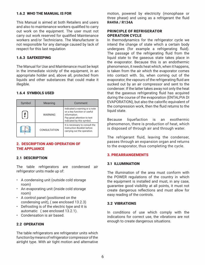
1.6.4 SYMBOLS USED
Symbol Meaning Comment
WARNING
Indicated a warning or a note on a key function or useful information.Pay great attention to text indicated by this symbol.
CONSULTATION
It is necessary to consult the Instruction Booklet before carrying out the operation.
2. DESCRIPTION AND OPERATION OF THE APPLIANCE
2.1 DESCRIPTION
The table refrigerators are condensed air refrigerator units made up of:
• A condensing unit (outside cold storage room)
• An evaporating unit (inside cold storage room)
• A control panel (positioned on the condensing unit), ( see enclosed 13.2.3)
• Defrosting is of the electric type and it is automatic ( see enclosed 13.2.1).
• Condensation is air based.
2.2 OPERATION
The table refrigerators are refrigerator units which function by means of refrigerator compressor of the airtight type. With air tight motion and alternative
motion, powered by electricity (monophase or three phase) and using as a refrigerant the fluid R449A / R134A
PRINCIPLE OF REFRIGERATOR OPERATION CYCLE In thermodynamics for the refrigerator cycle we intend the change of state which a certain body undergoes (for example a refrigerating fluid). The passage of the refrigerating fluid from the liquid state to the gaseous state takes place in the evaporator. Because this is an endothermic phenomenon, it needs heat which, when it happens, is taken from the air which the evaporator comes into contact with. So, when coming out of the evaporator, the vapours of the refrigerating fluid are sucked out by an air compressor and sent to the condenser. If the latter takes away not only the heat that the gaseous refrigerating fluid has acquired during the course of the evaporation (ENTALPIA DI EVAPORATION), but also the calorific equivalent of the compression work, then the fluid returns to the liquid state.
Because liquefaction is an exothermic phenomenon, there is production of heat, which is disposed of through air and through water. The refrigerant fluid, leaving the condenser, passes through an expansion organ and returns to the evaporator, thus completing the cycle.
3. PREARRANGEMENTS
3.1 ILLUMINATION The illumination of the area must conform with the POWER regulations of the country in which the equipment is installed and must, in any case, guarantee good visibility at all points, it must not create dangerous reflections and must allow for easy reading of the controls.
3.2 VIBRATIONS
In conditions of use which comply with the indications for correct use, the vibrations are not enough to create dangerous situations.
7
3.4 ELECTROMAGNETIC ENVIRONMENT
The refrigerator is designed to function correctly in an industrial electromagnetic environment, coming within the Emissions and Immunities foreseen by the following regulations:
EN 50081-2 Electromagnetic compatibility• General regulation for emission Part 2
Industrial environments - (1993) EN 50082-2 Electromagnetic compatibility• General regulation for Immunity Part 2
Industrial environments - (1995)
4. SAFETY
4.1 GENERAL WARNING
The user must read very carefully the information given in this Manual, with • Keep the refrigerator clean and tidy;• Do not remove or alter the plaques placed
by the Manufacturer (see 4.6);• Do not remove or bypass the safety
systems;• Do not touch the equipment with damp or
wet hands or feet;• Do not touch the equipment with bare feet;• Do not insert screwdrivers or anything
else between the protective cover and the moving parts;
• Do not pull the power cable to disconnect the appliance from the power supply;
• Before carrying out any cleaning or maintenance operation, disconnect the appliance from the electric power supply, first switching off the main switch and then removing the plug.
4.2 FORSEEN USE
The table refrigerator has been conceived and built to be used in communities, restaurants, hotels etc.4.3 FORSEEN USE
The table refrigerator must not be used :For purposes which differ from those shown in 4.2
• In an explosive, aggressive atmosphere or where there is a high concentration of oily substances or powders suspended in the air ;
• In an atmosphere with a fire risk ;• Exposed to bad weather ;• With adapters, multiple sockets or extension
leads.
3.3.1 SUPPLIES ON REQUEST It is to be understood that any modification and/or addition of accessories must be explicitly approved of and carried out by the Manufacturer.
Any alteration or modification of the fridge made by the operator and/or service operator is forbidden for security reasons. The manufacturer decline any responsibility for unautorizated modifications.
There are no danger zones during use because the table refrigerator has all the necessary safety devices. If repairs or maintenance have to be carried out requiring the removal of the safety devices, it is
necessary first to make sure that all power sources have been switched off. For this reason in the table refrigerator it is necessary to deactivate:
- The electric plant, putting the main switch off and pulling out the plug.
At the end of any work, it is absolutely imperative that all safety devices are re-activated.
4.5 SWITCHING OFF THE APPLIANCE
For switch off the fridge or table , is necessary to proceed as follows:
Congratulations, you have just purchased the finest equipment that money can buy and you should enjoy many years of exceptional service. This product has been carefully inspected and tested to ensure its performance. When you receive this, please carefully remove the front part of the crate, the plastic liner and carefully inspect the product for damage. It is your responsibility to file a freight claim with the freight company.
8
The control will also show any error codes that may occur and service should then be contacted to correct the error.
The control is pre-programmed to hold at 36o F and to lower or raise the temperature, push and hold the set button for 5 seconds and “machine status” will appear, press the set key and using the up or down arrow keys, go to Set, press the set key and using the up or down arrow keys adjust the temperature to the desired setting, then press set to confirm. You must do this within 15 seconds or the screen will revert back to the previous run screen and you must start again.
This equipment has been preset for maximum efficiency and should provide many years of service for you.
5. TRANSPORT AND MOVEMENT
READ CAREFULLY THE WARNINGS CONTAINED IN THIS MANUAL AS THEY SUPPLY IMPORTANT INFORMATION REGARDING THE SAFETY OF INSTALLATION, USE AND MAINTENANCE. KEEP THIS MANUAL SAFE FOR FURTHER CONSULTATION.
Damage to the appliance caused during transport and movement is not covered by the GUARANTEE. Repairs or substitution of damaged parts is at the Customer’s expense.
5.2 STORAGE In the case of long periods of inactivity, the table refrigerators must be stored with atten-tion to the relevant storage place and time:• Store the table refrigerator in an enclosed
area;• Protect table refrigerator from bumps or
Before removing the product from the shipping skid, PLEASE READ CAREFULLY or damage will occur that will not be covered under warranty. Because of the weight of the product, a fork truck must be used to remove it from the shipping skid. Please use wood across the forks to prevent damage to the lower trim and from damaging the base. DO NOT ATTEMPT TO PULL THE PRODUCT OFF OF THE SKID OR SEVERE DAMAGE WILL BE CAUSED TO THE BASE AND CASTERS
THIS WILL NOT BE COVERED UNDER WARRANTY.
5.1 TRANSPORT AND MOVEMENT The transport and movement of the table refrigerators must take place in the table position, respecting any indications shown 5.1 TRANSPORT AND MOVEMENT The transport and movement of the table refrigerators must take place in the table position, respecting any indications shown on the packaging. Transport must be carried out by qualified staff. The table refrigerators must be transported in such a way as to avoid any damage. The appliance is prepared for transport with or without packaging depending on the means of transport and the route. If packaged, it is in cardboard or wood, adequately protected. Movement must be carried out using a lift truck or trans-pallets with suitable forks (length at least 2/3 of the dimensions of the object) on the packaging. Transport must be carried out by qualified staff. The table refrigerators must be transported in such a way as to avoid any damage. The appliance is prepared for transport with or without packaging depending on the means of transport and the route. If packaged, it is in cardboard or wood, adequately protected. Movement must be carried out using a lift truck or trans-pallets with suitable forks (length at least 2/3 of the dimensions of the object)
9
5.3 CHECKS
Before putting table refrigerator into operation, it is necessary to carry out a series of checks to prevent errors or accidents during the activating phase:
• Check that there has not been any damage to the table refrigerator during assembly.
• Check with care the integrity of the control panel, the electric cable and the tubes.
• Check the precise connection to external energy supply.
• Check the free movement and rotation of any moving parts.
Congratulations, you have just purchased the finest equipment that money can buy and you should enjoy many years of exceptional service. This product has
been carefully inspected and tested to ensure its performance.When you receive this, please carefully remove the front part of the crate, the
plastic liner and carefully inspect the product for damage. It is your responsibility to file a freight claim with the freight company.
Before removing the product from the shipping skid,PLEASE READ CAREFULLY
or damage will occur that will not be covered under warranty.Because of the weight of the product, a fork truck must be used to remove it
from the shipping skid. Please use wood across the forks to prevent damage to the lower trim and from damaging the base.
DO NOT ATTEMPT TO PULL THE PRODUCT OFF OF THE SKID OR SEVERE DAMAGE WILL BE CAUSED TO THE BASE AND CASTERS
THIS WILL NOT BE COVERED UNDER WARRANTY.
FORKS FORKS
WOOD FRONT AND BACK
Once the equipment has been unpacked and set in place, it must be cleaned before using. Any mild spray-on cleaner can be used, such as Windex, Formula 409 or mild soap and water. This will remove any manufacturing oils and ensure a sanitary product.
If you have a prep table with a condiment rail, the prep table and condiment rail must be plugged into different circuits or it will cause electrical issues that can and will void the warranty. Both units require separate 20Amp circuits to operate properly. The use of extension cords is not allowed and will affect the operation.
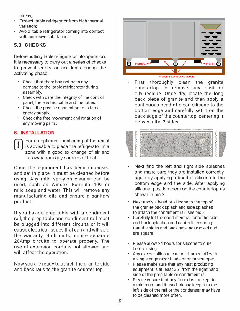
Now you are ready to attach the granite side and back rails to the granite counter top.
• First thoroughly clean the granite countertop to remove any dust or oily residue. Once dry, locate the long back piece of granite and then apply a continuous bead of clean silicone to the bottom edge and carefully set it on the back edge of the countertop, centering it between the 2 sides.
• Next find the left and right side splashes and make sure they are installed correctly, again by applying a bead of silicone to the bottom edge and the side. After applying silicone, position them on the countertop as shown in pic 3.
• Next apply a bead of silicone to the top of the granite back splash and side splashes to attach the condiment rail, see pic 3.
• Carefully lift the condiment rail onto the side and back splashes and center it, ensuring that the sides and back have not moved and are square.
• Please allow 24 hours for silicone to cure before using.
• Any excess silicone can be trimmed off with a single edge razor blade or paint scrapper.
• Please make sure that any heat producing equipment is at least 36” from the right hand side of the prep table or condiment rail.
• Please ensure that any flour dust be kept to a minimum and if used, please keep it to the left side of the rail or the condenser may have to be cleaned more often.
6. INSTALLATIONFor an optimum functioning of the unit it is advisable to place the refrigerator in a zone with a good ex change of air and far away from any sources of heat.
stress;• Protect table refrigerator from high thermal
variation;• Avoid table refrigerator coming into contact
with corrosive substances.
10
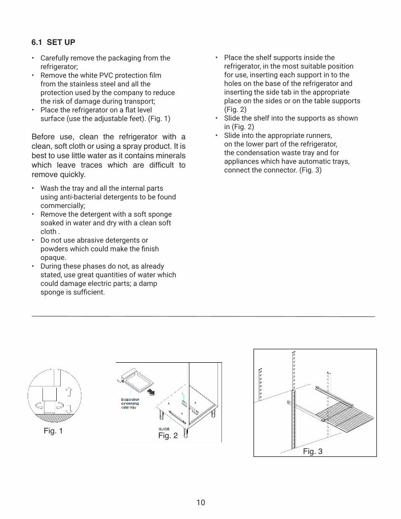
6.1 SET UP
• Carefully remove the packaging from the refrigerator;
• Remove the white PVC protection film from the stainless steel and all the protection used by the company to reduce the risk of damage during transport;
• Place the refrigerator on a flat level surface (use the adjustable feet). (Fig. 1)
Before use, clean the refrigerator with a clean, soft cloth or using a spray product. It is best to use little water as it contains minerals which leave traces which are difficult to remove quickly. • Wash the tray and all the internal parts
using anti-bacterial detergents to be found commercially;
• Remove the detergent with a soft sponge soaked in water and dry with a clean soft cloth .
• Do not use abrasive detergents or powders which could make the finish opaque.
• During these phases do not, as already stated, use great quantities of water which could damage electric parts; a damp sponge is sufficient.
• Place the shelf supports inside the refrigerator, in the most suitable position for use, inserting each support in to the holes on the base of the refrigerator and inserting the side tab in the appropriate place on the sides or on the table supports (Fig. 2)
• Slide the shelf into the supports as shown in (Fig. 2)
• Slide into the appropriate runners, on the lower part of the refrigerator, the condensation waste tray and for appliances which have automatic trays, connect the connector. (Fig. 3)
Fig. 1 Fig. 2
Fig. 3
11
Fig. 4
CONSULT THE INFORMATION CONTAINED IN PARAGRAPH 1.5
6.4 CONNECTION To avoid any kind of problem when tables are switched on is good to attend to the instruction as follow. 6.4.1 ELECTRICAL
The electrical connection of the table refrigerator is the Customer's responsibility. The connection to the power supply must respect the power supply laws of the country in which the equipment is installed. (see plaque A) • Check that the tension of the power
supply is exactly that shown on the plaque (See Plaque A)
• Check that the socket conforms to power regulations.
• Pay particular attention that there are no uncovered wires.
• Check the earth.
THE EARTH CONNECTION IS A LEGAL SAFETY REQUIREMENT (See Plaque C).
If more than one piece of equipment is placed in line, each one must have an independent power supply.
For a perfect functioning of the equipment, the maximum temperature of the environment should not exceed + 43°C (109°F).
Lack of respect for these conditions will provoke a serious decline in the functioning of the equipment, early ageing of the compressor and a much higher consumption of energy than normal (Fig. 4)
6.3 PREARANGEMENTS
• Check that the cables and the sockets are suitable for the power absorbed by the equipment. THE USE OF ADAPTORS, MULTIPLE SOCKETS AND/OR EXTENSION LEADS IS FORBIDDEN
• Ensure that the table refrigerator is not installed near to sources of heat like: ovens, radiators, direct sunlight etc.
• Leave a space of at least 75 mm (3 inches) between the back of the table refrigerator and any wall, to avoid the formation of condensation.
• The motor must be free of any obstacle which could hinder or limit the circulation through the condensing unit situated on the top side part of the refrigerator.
• The distance between the refrigerator and the ceiling must not be less than 50 cm (19¾ inches).
• Check that the environment has a sufficient change of air, in order to guarantee the cooling of the condenser and the compressor unit.
In order to safeguard the electric plant of the refrigerator from any overloads or short circuits, install a magnetothermic switch at the head of the socket with adequate interruption power (See Plaque D). 6.4.2 HYDRAULICS
If the model does not include a condenser unit, it is necessary to connect it to a drainage system for the discharge of water from defrosting using a suitable tube of appropriate dimensions.
12
7. OPERATION
7.1 PERSONNEL
The staff who are to use and install the appliance, must possess (or acquire through adequate formation and training) the following skills and must understand the contents of this manual and all the relevant Safety Information: • General technical knowledge enough o
understand the contents of the Manual.• Awareness of the main hygiene, accident
prevention and technological regulations.
7.2 PUTTING INTO OPERATION
If the equipment has been mistakenly positioned horizontally during transport, wait about 2 hours, after putting it into a vertical position, before putting it into operation.
7.3 TIMERS
See enclosed Manual for Instructions and Use 13.2.1.2 7.4 TEMPERATURE REGULATION
• The type of product which is going to be kept in the cold storage room (see attached 13.2.5);
• The temperature of the environment;• The frequency of opening.
CONSULT THE INFORMATION IN ATTACHED 13.2.1
7. 5 STORAGE OF FOOD
In order to obtain the best possible working of the refrigerator, it is necessary to respect the following indications:
• Do not put hot foods or uncovered liquids into the cold storage room;
• Wrap up or cover all foods, especially those with strong aromas or cream;
• Organise the foodstuffs inside the cold storage room in such a way as not to block the circulation of air with superfluous objects (see plaque E);
• Avoid to keep open the door for long periods of time;
• Wait a few moments before opening a door which has just been closed.
7. 6 CONSERVATION OF FOOD
The main cause of the degradation of food and other organic substances is the multipli-cation of bacteria contained in the cold stor-age rooms which make up the foodstuff. The production of bacteria is greatly slowed down if the temperature of the foodstuff is lowered, in fact, every product, on the basis of its or-ganic characteristics, requires the appropriate temperature and environmental conditions. For the conservation refrigerators, tables, freezers, cold storage rooms and mini cold storage rooms are to be used correctly;
In any case, before loading the equipment, it is necessary to wait until the cold storage room have reached the correct temperature, checking it on its thermometer. If there are any brief interruptions to the electricity supply, it is probable that the compressor might start with some delay; this is perfectly normal.
13
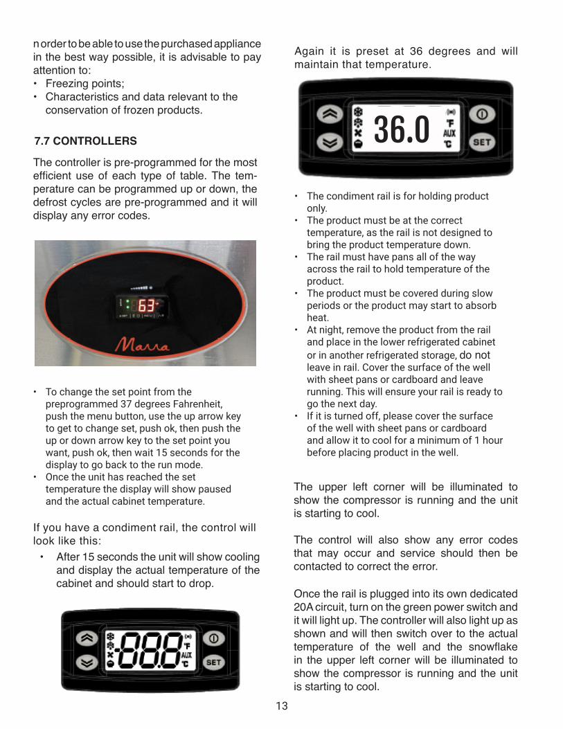
The controller is pre-programmed for the most efficient use of each type of table. The tem-perature can be programmed up or down, the defrost cycles are pre-programmed and it will display any error codes.
• After 15 seconds the unit will show cooling and display the actual temperature of the cabinet and should start to drop.
• To change the set point from the preprogrammed 37 degrees Fahrenheit, push the menu button, use the up arrow key to get to change set, push ok, then push the up or down arrow key to the set point you want, push ok, then wait 15 seconds for the display to go back to the run mode.
• Once the unit has reached the set temperature the display will show paused and the actual cabinet temperature.
If you have a condiment rail, the control will look like this:
Again it is preset at 36 degrees and will maintain that temperature.
• The condiment rail is for holding product only.
• The product must be at the correct temperature, as the rail is not designed to bring the product temperature down.
• The rail must have pans all of the way across the rail to hold temperature of the product.
• The product must be covered during slow periods or the product may start to absorb heat.
• At night, remove the product from the rail and place in the lower refrigerated cabinet or in another refrigerated storage, do not leave in rail. Cover the surface of the well with sheet pans or cardboard and leave running. This will ensure your rail is ready to go the next day.
• If it is turned off, please cover the surface of the well with sheet pans or cardboard and allow it to cool for a minimum of 1 hour before placing product in the well.
The upper left corner will be illuminated to show the compressor is running and the unit is starting to cool.
The control will also show any error codes that may occur and service should then be contacted to correct the error.
Once the rail is plugged into its own dedicated 20A circuit, turn on the green power switch and it will light up. The controller will also light up as shown and will then switch over to the actual temperature of the well and the snowflake in the upper left corner will be illuminated to show the compressor is running and the unit is starting to cool.
36.0
n order to be able to use the purchased appliance in the best way possible, it is advisable to pay attention to: • Freezing points;• Characteristics and data relevant to the
conservation of frozen products.
7.7 CONTROLLERS
14
• Freezing points;• Characteristics and data relevant to the
conservation of frozen products.
For the suggested freezing temperatures, see Attached 13.2.5.
8. ROUTINE AND PLANNED MAINTENANCE
The information contained in this chapter is aimed at the User (non specialised person) and at the Ordinary Maintenance Staff
8.1 ELEMENTARY SAFETY REGULATIONS
8.1.1 PROHIBITION OF REMOVAL SAFETY DEVICES
The removal of safety protection is absolutely forbidden for the carrying out of ordinary maintenance work.
The Manufacturer decline any responsibility for any accident caused by the lack of respect for the above written regulation.
8.1.2 INDICATIONS ON EMERGENCY OPERATIONS IN CASE OF FIRE
• Remove the plug from the socket or switch off at the mains;
• Do not use water jets;• Use powder or foam extinguishers.
8.1.3 CLEANING OF THE EXTERNAL PARTS
The following are indicated for this purpose:• Cleaning products: water and neutral
non abrasive detergents (DO NOT USE SOLVENTS) ;
• Cleaning methods: wash with a cloth or a sponge;
• Frequency: weekly.
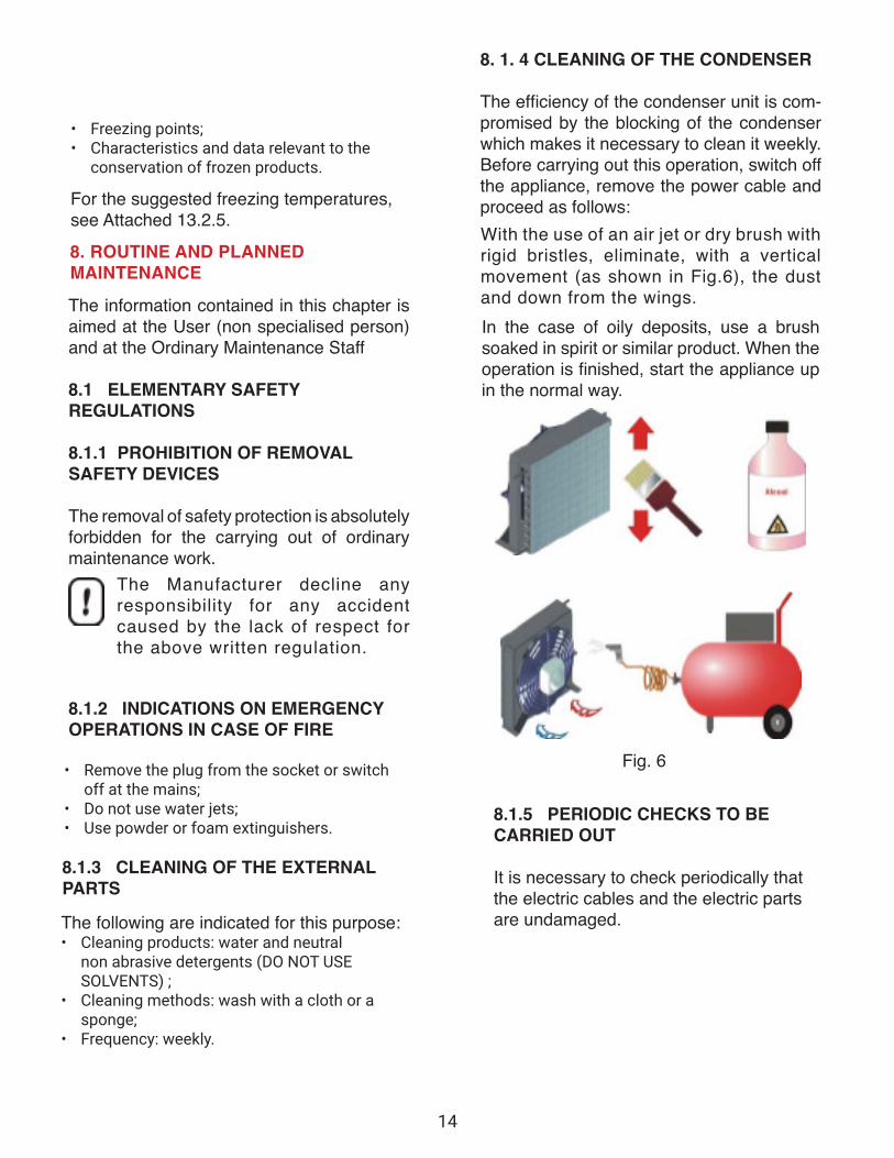
8. 1. 4 CLEANING OF THE CONDENSER The efficiency of the condenser unit is com-promised by the blocking of the condenser which makes it necessary to clean it weekly. Before carrying out this operation, switch off the appliance, remove the power cable and proceed as follows: With the use of an air jet or dry brush with rigid bristles, eliminate, with a vertical movement (as shown in Fig.6), the dust and down from the wings.In the case of oily deposits, use a brush soaked in spirit or similar product. When the operation is finished, start the appliance up in the normal way.
Fig. 6
8.1.5 PERIODIC CHECKS TO BE CARRIED OUT
It is necessary to check periodically that the electric cables and the electric parts are undamaged.
15
9. NON ROUTINE MAINTENANCE AND REPAIRS Non routine maintenance and repairs must be carried out by qualified personnel authorised by the manufacturer.
The manufacturer declines any responsibility for jobs carried out by unauthorized personnel or the use of non-original spare parts.
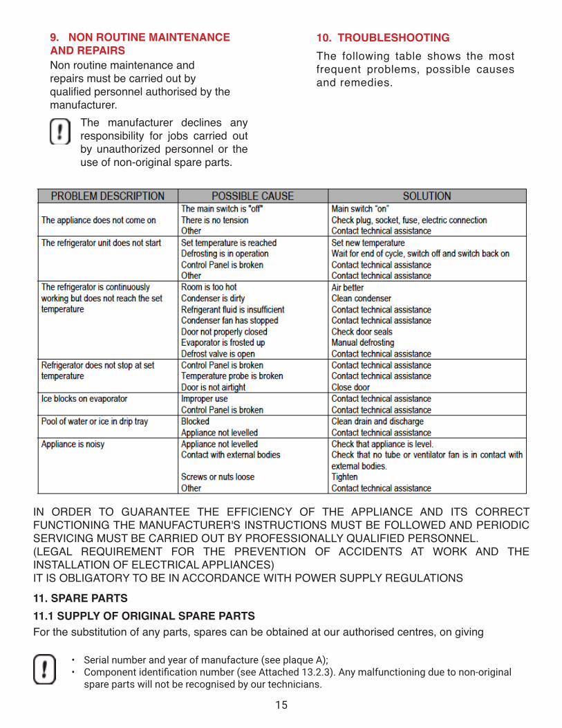
10. TROUBLESHOOTINGThe following table shows the most frequent problems, possible causes and remedies.
IN ORDER TO GUARANTEE THE EFFICIENCY OF THE APPLIANCE AND ITS CORRECT FUNCTIONING THE MANUFACTURER'S INSTRUCTIONS MUST BE FOLLOWED AND PERIODIC SERVICING MUST BE CARRIED OUT BY PROFESSIONALLY QUALIFIED PERSONNEL. (LEGAL REQUIREMENT FOR THE PREVENTION OF ACCIDENTS AT WORK AND THE INSTALLATION OF ELECTRICAL APPLIANCES) IT IS OBLIGATORY TO BE IN ACCORDANCE WITH POWER SUPPLY REGULATIONS
11. SPARE PARTS11.1 SUPPLY OF ORIGINAL SPARE PARTS For the substitution of any parts, spares can be obtained at our authorised centres, on giving
• Serial number and year of manufacture (see plaque A);• Component identification number (see Attached 13.2.3). Any malfunctioning due to non-original
spare parts will not be recognised by our technicians.
16
DEMOLITION 12. The gas present in the plant must be extracted by authorised personnel. As far as the metal mass is concerned, it is only necessary that it be divided into steel parts and others for the purpose of recy-cling.
ENCLOSURES13. 13. 1 DECLARATIONS
The following declarations are enclosed :
• Declaration of Conformity with Regulation 98/37/CE• Declaration of Conformity with Regulation 89/336/CE• Declaration of Conformity with Regulation 73/23/CE
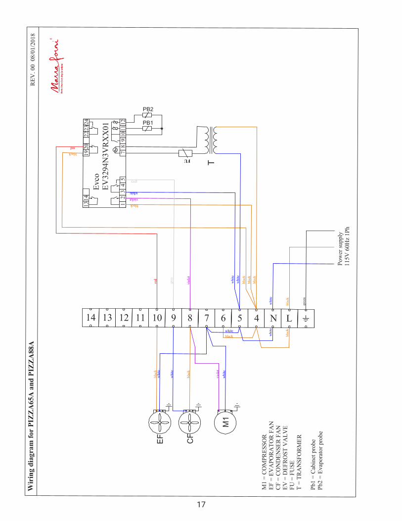
TECHNICAL DOCUMENTATION The following technical documentation is enclosed :1. Control instructions:1.1 Eletronic control;1.2 Mecanical control;2. Phonometric analyses;3. Assembly Diagram;4. Wiring diagrams;4.1 Wiring diagram for automatic evaporation of condensing water5. Advised temperatures for conservation;6. Guarantee certificate;7. Inspection certificate.
17
18
Bric
k ov
en C
ooki
ng S
olut
ions
3
Part
num
bers
to
ch
I cod
ici d
ei ri
cam
b. an
ge w
ithou
t not
ice P
l , p
otre
bber
e co
mb.
.
ease
con
tact
ser
vi
@
,are
sen
za
ce
desm
•
prea
vvis
o. R
ivolg
ersi
on
., �f
or a
ny u
pdat
e.
a se
rv,c
e@de
sm on
.it p
er a
ggio
rnam
enti
.
16
Spar
e Pa
rts m
anua
l M
odel
: MF.
GFZ2
25
�43
/�
�
(·�� .. �,�
}
��
?1
.�(36)
\�
. �
�
5
.�
@
28
29
9�
19
@J
Mod
el :M
F.GP
Z166
A
19
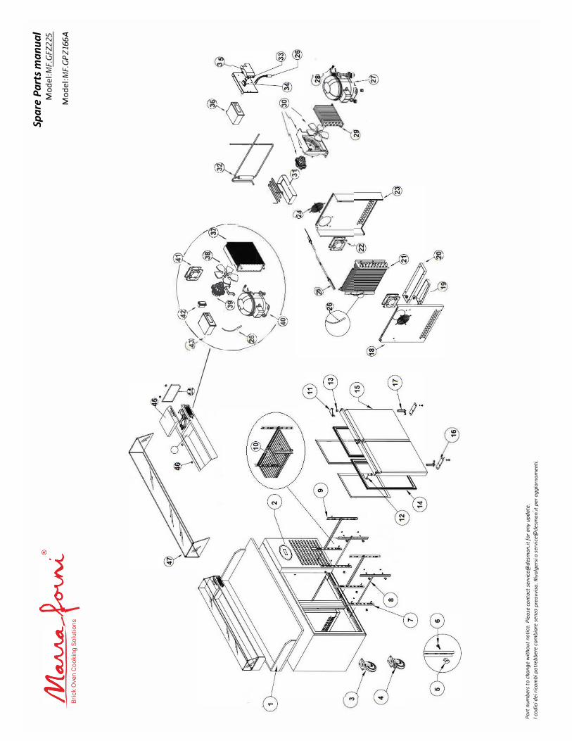
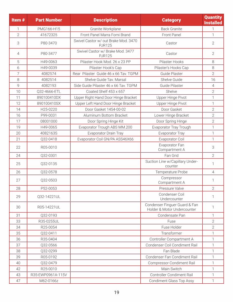
Item # Part Number Description Category Quantity Installed
1 PMG166-H15 Granite Workplane Back Granite 12 41672325 Front Panel Marra Forni Brand Front Panel 1
3 P80-3470 Swivel Castor w/ out Brake Mod. 3470 PJR125 Castor 2
4 P80-3477 Swivel Castor w/ Brake Mod. 3477 PJR125 Castor 2
5 H49-0063 Pilaster Hook Mod. 26 x 23 PP Pilaster Hooks 86 H49-0039 Pilaster Hook’s Cap Pilaster’s Hooks Cap 87 4082574 Rear Pilaster Guide 46 x 66 Tav. TGPM Guide Plaster 28 4082514 Shelve Guide Tav. Marsal Shelve Guide 169 4082193 Side Guide Pilaster 46 x 66 Tav. TGPM Guide Pilaster 4
10 Q32-4666-ETL Coated Shelf 453 x 657 Shelve 211 890100410DX Upper Right Hand Door Hinge Bracket Upper Hinge Pivot 112 890100410SX Upper Left Hand Door Hinge Bracket Upper Hinge Pivot 114 H25-0220 Door Gasket 1454-00-02 Door Gasket 216 P99-0031 Aluminum Bottom Bracket Lower Hinge Bracket 217 08001000 Door Spring Hinge Kit Door Spring Hinge 219 H49-0065 Evaporator Trough ABS MM.200 Evaporator Tray Trough 120 4082163S Evaporator Drain Tray Evaporator Tray 121 Q32-0418 Evaporator Coil GN/PA ASS46X66 Evaporator Coil 1
22 R05-0010 Evaporator Fan Compartment A 3
24 Q32-0301 Fan Grid 2
25 Q32-0135 Suction Line w/Capillary Under-counter 1
26 Q32-0578 Temperature Probe 4
27 Q32-0503 Compressor Compartment A 1
28 P52-0053 Pressure Valve 2
29 Q32-14221UL Condenser Coil Undercounter 1
30 R05-14221UL Condenser Finguer Guard & Fan Holder & Motor Undercounter 1
31 Q32-0193 Condensate Pan 133 R35-0255UL Fuse 234 R25-0054 Fuse Holder 235 Q32-0411 Transformer 136 R35-0404 Controller Compartment A 137 Q32-0566 Condenser Coil Condiment Rail 138 Q32-0299 Fan Blade 139 R05-0192 Condenser Fan Condiment Rail 140 Q32-0479 Compressor Condiment Rail 142 R25-0010 Main Switch 143 R35-EWP0961A-115V Controller Condiment Rail 147 M62-0166z Condiment Glass Top Assy 1
2010310 Southard Drive I Beltsville, MD 20705 I www.marraforni.com I 888.239.0575 Rev. March. 2022